Volume 6 Tab 2 54525 Catalog
102556-Catalog 102556-Catalog 102556-Catalog 786685 Batch10 unilog cesco-content
103068-Catalog 103068-Catalog 103068-Catalog 786685 Batch10 unilog cesco-content
449624-Catalog 1 449624-Catalog_1 449624-Catalog_1 786685 Batch10 unilog cesco-content
119852-Catalog 119852-Catalog 119852-Catalog 786685 Batch10 unilog cesco-content
119431-Catalog 119431-Catalog 119431-Catalog 786685 Batch10 unilog cesco-content
2014-10-17
: Pdf 54525-Catalog 54525-Catalog 782116 Batch10 unilog
Open the PDF directly: View PDF ![]() .
.
Page Count: 291 [warning: Documents this large are best viewed by clicking the View PDF Link!]
Volume 6—Solid-State Motor Control CA08100007E—May 2014 www.eaton.com V6-T2-1
2
2
2
2
2
2
2
2
2
2
2
2
2
2
2
2
2
2
2
2
2
2
2
2
2
2
2
2
2
2
Adjustable Frequency Drives
PowerXL DC1
PowerXL DG1
Enclosed 18-Pulse Drive
OEM Drives
2.1 PowerXL DC1 Series Drives
Product Description . . . . . . . . . . . . . . . . . . . . . . . . . . . . . . . . . . . . . . . V6-T2-2
2.2 PowerXL DA1 Series Drives
Product Description . . . . . . . . . . . . . . . . . . . . . . . . . . . . . . . . . . . . . . . V6-T2-11
2.3 M-Max Series Drives
Product Description . . . . . . . . . . . . . . . . . . . . . . . . . . . . . . . . . . . . . . . V6-T2-20
General Purpose Industrial Drives
2.4 PowerXL DG1 Series Drives
Product Description . . . . . . . . . . . . . . . . . . . . . . . . . . . . . . . . . . . . . . . V6-T2-30
2.5 SVX9000 Drives
Product Overview . . . . . . . . . . . . . . . . . . . . . . . . . . . . . . . . . . . . . . . . V6-T2-45
SVX9000 Drives
Product Description . . . . . . . . . . . . . . . . . . . . . . . . . . . . . . . . . . . . V6-T2-48
SVX9000 Enclosed Drives
Product Description . . . . . . . . . . . . . . . . . . . . . . . . . . . . . . . . . . . . V6-T2-87
SVX9000 VFD Pump Panels
Product Description . . . . . . . . . . . . . . . . . . . . . . . . . . . . . . . . . . . . V6-T2-111
General Purpose HVAC Drives
2.6 H-Max Series Drives
Product Overview . . . . . . . . . . . . . . . . . . . . . . . . . . . . . . . . . . . . . . . . V6-T2-131
H-Max Drives
Product Description . . . . . . . . . . . . . . . . . . . . . . . . . . . . . . . . . . . . V6-T2-132
H-Max IntelliPass and IntelliDisconnect Drives
Product Description . . . . . . . . . . . . . . . . . . . . . . . . . . . . . . . . . . . . V6-T2-141
Performance Drives
2.7 SPX9000 Drives
Product Description . . . . . . . . . . . . . . . . . . . . . . . . . . . . . . . . . . . . . . . V6-T2-158
2.8 Low Harmonic Drives
Enclosed Passive Filtered Drives
Product Description . . . . . . . . . . . . . . . . . . . . . . . . . . . . . . . . . . . . V6-T2-200
Enclosed 18-Pulse Drives
Product Description . . . . . . . . . . . . . . . . . . . . . . . . . . . . . . . . . . . . V6-T2-233
2.9 LCX9000 Liquid Cooled Drives
Product Description . . . . . . . . . . . . . . . . . . . . . . . . . . . . . . . . . . . . . . . V6-T2-263
2.10 SPA9000/SPN9000/SPI9000 Common DC Bus Drives
Product Description . . . . . . . . . . . . . . . . . . . . . . . . . . . . . . . . . . . . . . . V6-T2-280
Learn
Online
Drawings
Online
An Eaton
Green Solution
V6-T2-2 Volume 6—Solid-State Motor Control CA08100007E—May 2014 www.eaton.com
2
2
2
2
2
2
2
2
2
2
2
2
2
2
2
2
2
2
2
2
2
2
2
2
2
2
2
2
2
2
2.1
Adjustable Frequency Drives
PowerXL DC1 Series Drives
PowerXL DC1 Series Drives
Contents
Description Page
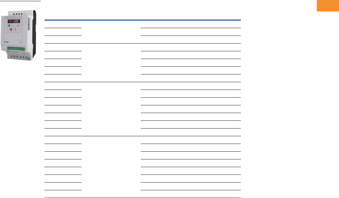
PowerXL DC1 Series Drives
Catalog Number Selection . . . . . . . . . . . . . . . . V6-T2-3
Product Selection . . . . . . . . . . . . . . . . . . . . . . . V6-T2-4
Accessories . . . . . . . . . . . . . . . . . . . . . . . . . . . V6-T2-6
Technical Data and Specifications . . . . . . . . . . V6-T2-7
Dimensions . . . . . . . . . . . . . . . . . . . . . . . . . . . V6-T2-9
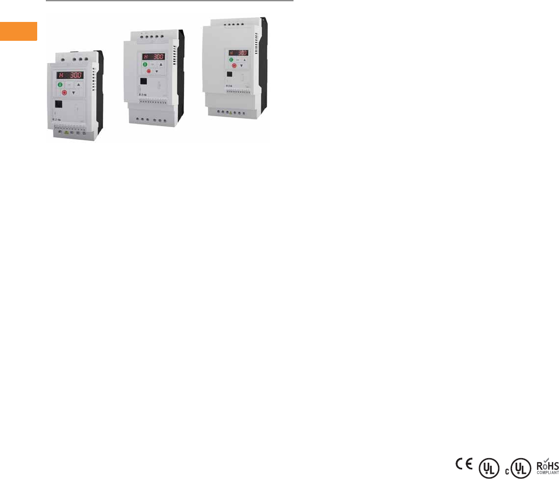
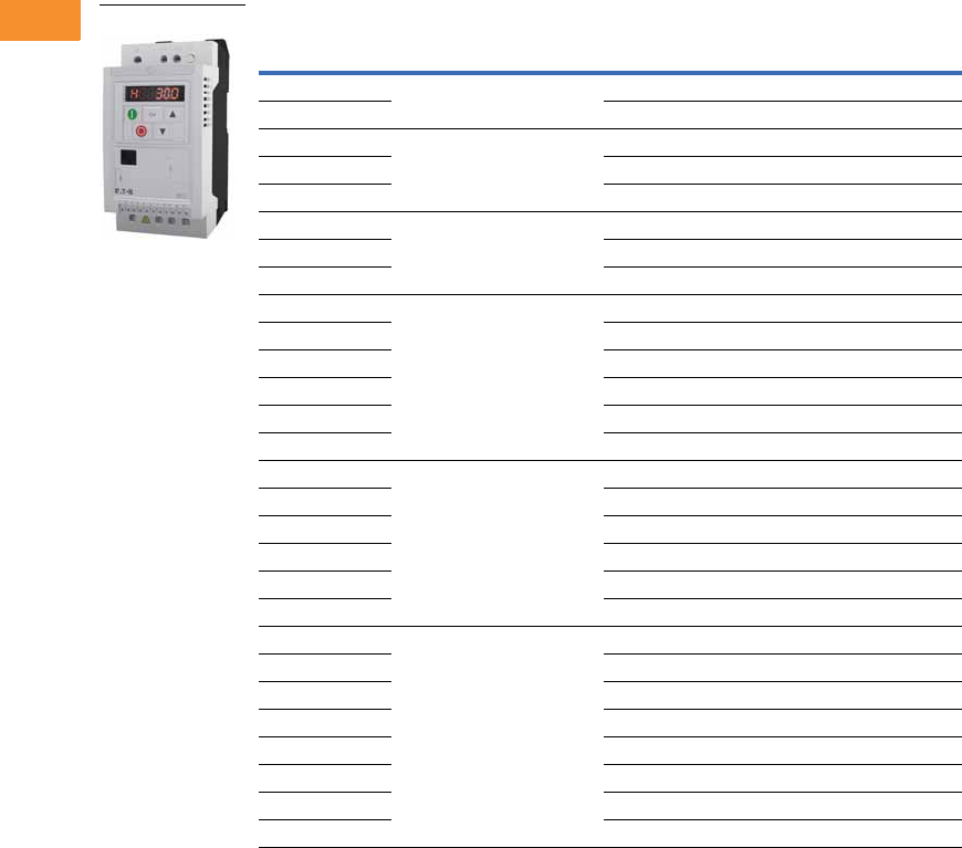
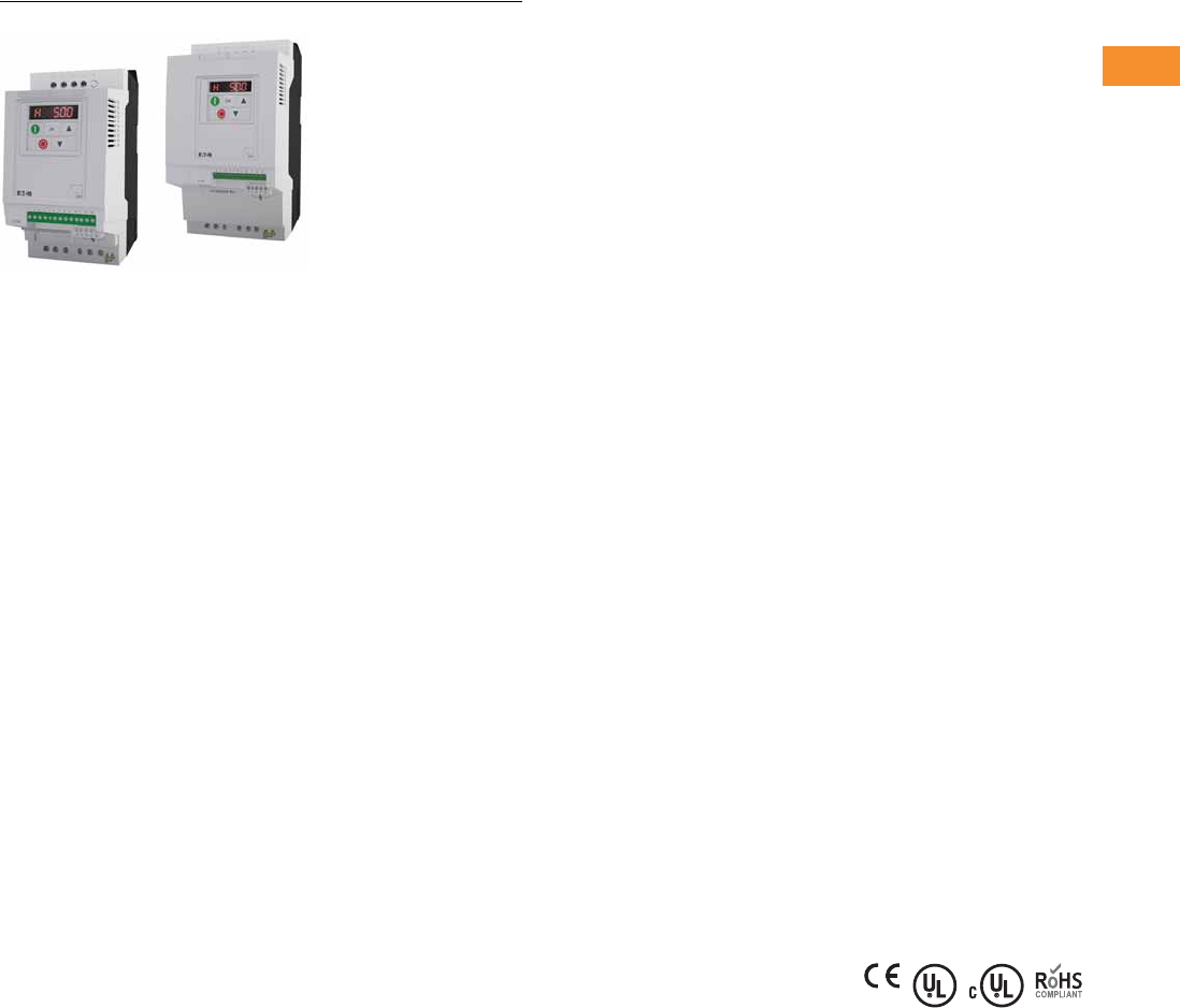
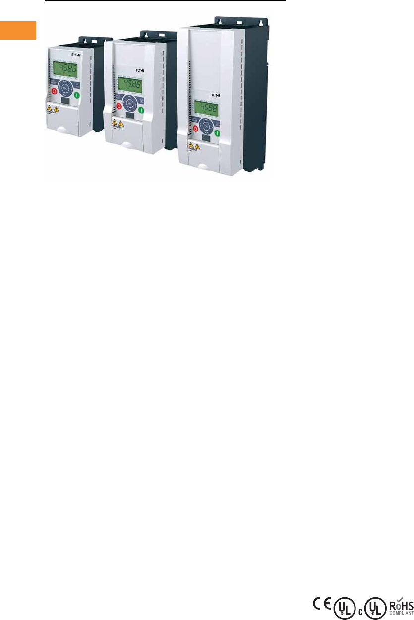
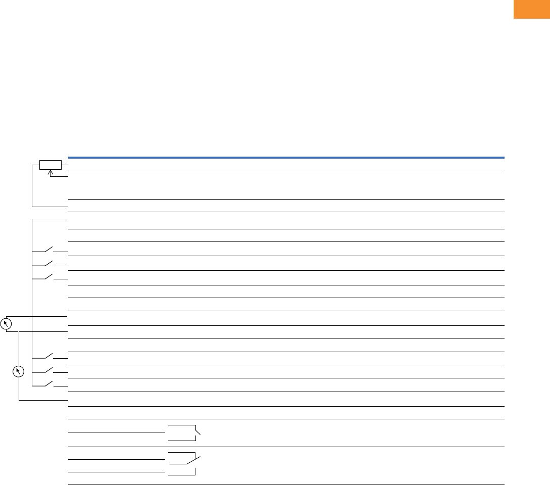
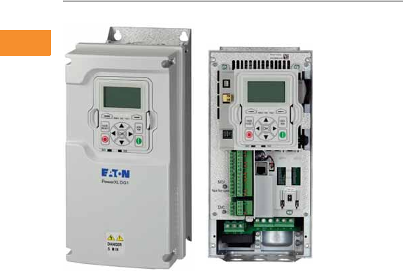
Product Description
Eaton’s PowerXL™ DC1
variable frequency drives are
the next generation of drives
specifically engineered for
today’s machinery
applications.
The DC1 is compact with
only 14 basic parameters,
SmartWire-DT
™
connectivity,
and outstanding ease of
mounting and installation.
The DC1 is perfect for quick
commissioning and is ideal
for panel builders. This drive
supports single-phase motor
applications, and detachable
terminal blocks make control
wiring much easier.
Models rated at 480 volts,
three-phase, 50/60 Hz are
available in sizes ranging from
1 to 15 hp. Models rated at
240 volts, single- or three-
phase, 50/60 Hz are available
in sizes ranging from 0.5
to 7.5 hp. Models rated at
115 volts, single-phase,
50/60 Hz are available in
the 0.5 to 3 hp size range.
Features
●Compact, space-saving
design
●
Rugged and reliable—
175%
for 2s, 50°C rated
●DIN rail and screw
mountable (FS1 and FS2)
●Side-by-side installation
●Industry-leading efficiency
delivers energy savings to
the customer
●Optional integrated EMC
filters make the unit
suitable for commercial
and industrial networks
●Brake chopper as standard
in frames 2 and higher
●Temperature-controlled fan
●RS-485/Modbus® and
CANopen™ as standard
●PI controller as standard
●SmartWire capability
●Removable I/O terminal
blocks
●Contactor style power
wiring
●Compatibility with single-
phase motors
Standards and
Certifications
Product
●Complies with EN61800-3
(2004)
EMC (At Default Settings)
●EMC Category C1, C2
and C3 at default settings
(1m, 5m, 25m)
Safety 1
●61800-5-1
●EN 60529
●CE
●UL
●cUL
●UkrSepro
●c-Tick
●RoHS compliant
Note
1See unit nameplate for more detailed
approvals.
Volume 6—Solid-State Motor Control CA08100007E—May 2014 www.eaton.com V6-T2-3
2
2
2
2
2
2
2
2
2
2
2
2
2
2
2
2
2
2
2
2
2
2
2
2
2
2
2
2
2
2
2.1
Adjustable Frequency Drives
PowerXL DC1 Series Drives
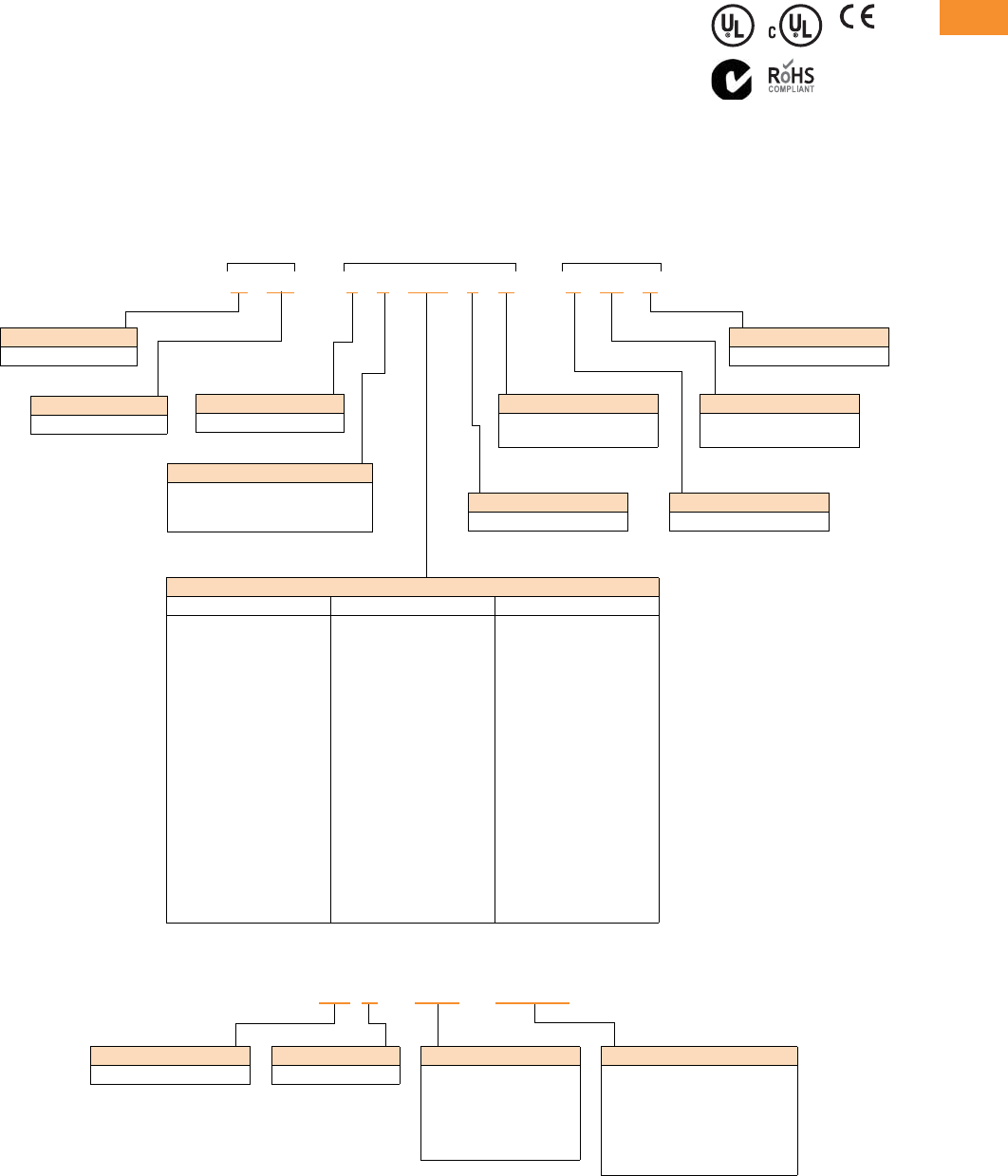
Catalog Number Selection
DC1 Series Adjustable Frequency AC Drives
DC1 -1 24D1 F N -A 20 N
Rated
Operational Current
Examples—
2D2 = 2.2A
4D1 = 4.1A
024 = 24A
Type
N= Standard basic device
Degree of Protection
20 = IP20/NEMA 0
66 = IP66/NEMA 4
6S = IP66 with disconnect/NEMA 4
Device Series
DC1 = Variable frequency drive, compact, Series 1
(D = Drives, C = Compact, 1 = Series 1)
Connection in Power Section
1= Single-phase mains connection/three-phase motor connection
3= Three-phase mains connection/three-phase motor connection
S= Single-phase mains connection/single-phase motor connection
Mains Voltage Category
1= 110V (110–115V ±10%)
2= 230V (200–240V ±10%)
4= 460V (380–480V ±10%)
D= 110V input/230V output (voltage doubler)
Display Unit (Display)
A= LED display
Brake Chopper
N= No internal brake chopper
B= Brake chopper
EMC (Radio Interference Suppression Filter)
N= No internal RFI filter
F= Internal RFI filter
V6-T2-4 Volume 6—Solid-State Motor Control CA08100007E—May 2014 www.eaton.com
2
2
2
2
2
2
2
2
2
2
2
2
2
2
2
2
2
2
2
2
2
2
2
2
2
2
2
2
2
2
2.1
Adjustable Frequency Drives
PowerXL DC1 Series Drives
Product Selection
DC1 Series IP20 Enclosure Drives 1
Notes
1 These are constant torque/high overload rated drives.
2 For all applications, select the unit such that the motor current is less than or equal to the rated continuous output current.
3 Brake chopper circuit available as standard in frames 2 and 3.
4 RFI version available. Substitute with DC1-*****F*-**** for this option.
hp 2kW Volts
100% Continuous
Current In (A)
Frame
Size 3Catalog Number
0.5 0.37 115V single-phase in/
115V single-phase out
71DC1-S17D0NN-A20N
0.75 0.55 10.5 2 DC1-S1011NB-A20N
0.5 0.37 200–240V single-phase in/
200–240V single-phase out
4.3 1 DC1-S24D3NN-A20N 4
10.75 7 1 DC1-S27D0NN-A20N 4
1.5 1.1 10 2 DC1-S2011NB-A20N 4
0.5 0.37 115V single-phase in/
230V three-phase out
2.3 1 DC1-1D2D3NN-A20N 4
10.75 4.3 1 DC1-1D4D3NN-A20N
1.5 1.1 5.8 2 DC1-1D5D8NB-A20N
0.5 0.37 200–240V single-phase in/
230V three-phase out
2.3 1 DC1-122D3NN-A20N 4
10.75 4.3 1 DC1-124D3NN-A20N 4
21.5 7 1 DC1-127D0NN-A20N 4
21.5 7 2 DC1-127D0NB-A20N 4
32.2 10.5 2 DC1-12011NB-A20N 4
54 15 3 DC1-12015NB-A20N
0.5 0.37 200–240V three-phase in/
230V three-phase out
2.3 1 DC1-322D3NN-A20N
10.75 4.3 1 DC1-324D3NN-A20N
21.5 7 1 DC1-327D0NN-A20N
21.5 7 2 DC1-327D0NB-A20N 4
32.2 10.5 2 DC1-32011NB-A20N 4
54 18 3 DC1-32018NB-A20N 4
1 0.75 380–480V three-phase in/
460V three-phase out
2.2 1 DC1-342D2NN-A20N 4
21.5 4.1 1 DC1-344D1NN-A20N 4
21.5 4.1 2 DC1-344D1NB-A20N 4
32.2 5.8 2 DC1-345D8NB-A20N 4
54 9.5 2 DC1-349D5NB-A20N 4
7.5 5.5 14 3 DC1-34014NB-A20N 4
10 7.5 18 3 DC1-34018NB-A20N 4
15 11 24 3 DC1-34024NB-A20N 4
IP20
Volume 6—Solid-State Motor Control CA08100007E—May 2014 www.eaton.com V6-T2-5
2
2
2
2
2
2
2
2
2
2
2
2
2
2
2
2
2
2
2
2
2
2
2
2
2
2
2
2
2
2
2.1
Adjustable Frequency Drives
PowerXL DC1 Series Drives
DC1 Series IP66 Enclosure Drives 1
Notes
1 These are constant torque/high overload rated drives.
2 For all applications, select the unit such that the motor current is less than or equal to the rated continuous output current.
3 Brake chopper circuit available as standard in frames 2 and 3.
4 Non-disconnect version available. Substitute with -A66N.
5 RFI version available. Substitute with DC1-*****F*-**** for this option.
hp 2kW Volts
100% Continuous
Current In (A)
Frame
Size 3Catalog Number
0.5 0.37 115V single-phase in/
115V single-phase out
71DC1-S17D0NN-A6SN 4
0.75 0.55 10.5 2 DC1-S1011NB-A6SN 4
0.5 0.37 200–240V single-phase in/
200–240V single-phase out
4.3 1 DC1-S24D3NN-A6SN 45
10.75 7 1 DC1-S27D0NN-A6SN 45
1.5 1.1 10 2 DC1-S2011NB-A6SN 45
0.5 0.37 115V single-phase in/
230V three-phase out
2.3 1 DC1-1D2D3NN-A6SN 4
10.75 4.3 1 DC1-1D4D3NN-A6SN 4
1.5 1.1 5.8 2 DC1-1D5D8NB-A6SN 4
0.5 0.37 200–240V single-phase in/
230V three-phase out
2.3 1 DC1-122D3NN-A6SN 45
10.75 4.3 1 DC1-124D3NN-A6SN 45
21.5 7 1 DC1-127D0NN-A6SN 45
21.5 7 2 DC1-127D0NB-A6SN 45
32.2 10.5 2 DC1-12011NB-A6SN 45
54 15 3 DC1-12015NB-A6SN 4
0.5 0.37 200–240V three-phase in/
230V three-phase out
2.3 1 DC1-322D3NN-A6SN 4
10.75 4.3 1 DC1-324D3NN-A6SN 4
21.5 7 1 DC1-327D0NN-A6SN 4
21.5 7 2 DC1-327D0NB-A6SN 45
32.2 10.5 2 DC1-32011NB-A6SN 45
54 18 3 DC1-32018NB-A6SN 45
1 0.75 380–480V three-phase in/
460V three-phase out
2.2 1 DC1-342D2NN-A6SN 45
21.5 4.1 1 DC1-344D1NN-A6SN 45
21.5 4.1 2 DC1-344D1NB-A6SN 45
32.2 5.8 2 DC1-345D8NB-A6SN 45
54 9.5 2 DC1-349D5NB-A6SN 45
7.5 5.5 14 3 DC1-34014NB-A6SN 45
10 7.5 18 3 DC1-34018NB-A6SN 45
IP66
IP66S

V6-T2-6 Volume 6—Solid-State Motor Control CA08100007E—May 2014 www.eaton.com
2
2
2
2
2
2
2
2
2
2
2
2
2
2
2
2
2
2
2
2
2
2
2
2
2
2
2
2
2
2
2.1
Adjustable Frequency Drives
PowerXL DC1 Series Drives
Accessories
DC1 Series
PC Communication Kit and Copy/Paste Module
Encoder Feedback Plug-In Option Module
and Miscellaneous Cards
Remote Keypad
Extension Cables and Data Cable Splitter
SmartWire Modules
Note
1Includes 1m RS-485 data cable.
Description Catalog Number
Bluetooth copy/paste communication stick DX-COM-STICK
USB PC connection kit DX-COM-PCKIT
Description Catalog Number
Local control/test option card DXC-EXT-LOCSIM
HVACO drive running and tripped relay output card DXC-EXT-2RO1AO
Dual relay output card DXC-EXT-2RO
110V logic input card DXC-EXT-IO110
230V logic input card DXC-EXT-IO230
Description Catalog Number
LED remote keypad—7-segment display, IP54 rated DX-KEY-LED 1
OLED remote keypad—full text display, multi-line text,
multi-language, IP54
DX-KEY-OLED 1
Description Catalog Number
RJ45 communication cable w/terminating resistor DX-CBL-TERM
RS-485 data cable, RJ45, 0.5m DX-CBL-RJ45-0M5
RS-485 data cable, RJ45, 1.0m DX-CBL-RJ45-1M0
RS-485 data cable, RJ45, 3.0m DX-CBL-RJ45-3M0
RS-485 three-way data cable splitter, RJ45 DX-SPL-RJ45-3SL
RS-485 data cable splitter, RJ45, (1 connector to 2 socket) DX-SPL-RJ45-2SL1PL
Description Catalog Number
SmartWire-DT interface for DC1 IP20 DX-NET-SWD3

Volume 6—Solid-State Motor Control CA08100007E—May 2014 www.eaton.com V6-T2-7
2
2
2
2
2
2
2
2
2
2
2
2
2
2
2
2
2
2
2
2
2
2
2
2
2
2
2
2
2
2
2.1
Adjustable Frequency Drives
PowerXL DC1 Series Drives
Technical Data and Specifications
DC1 Series
Ratings
PowerXL DC1 Basic Controller IP20 Standard Ratings
Programmable Parameters
Specifications
PowerXL DC1 Series Drives
Notes
1Exception: 115V single-phase in, 230V three-phase out.
2Only FS2 and FS3 drives are equipped with brake chopper circuit.
Description Specification
Protections
Overload protection 150% for 60s for every 600 seconds
Overvoltage protection Yes
Undervoltage protection Yes
Ground fault protection Yes
Overtemperature
protection
Yes
Motor overload protection Yes
Motor stall protection Yes
Description
Built-in Help card
14 Standard operation parameters
Reference scaling
Programmable start and stop functions
DC-brake at start and stop
Programmable V/Hz curve
Adjustable switching frequency
Autorestart function after fault
Protections and supervisions
Power section fault indication
External fault
Fieldbus communication
Second deceleration time
Analog input range selection, signal scaling and filtering
PI controller
Skip frequencies
Description Specification
Input Ratings
Input voltage (Vin)±10%
Input frequency (fin) 50/60 Hz (variation up to 48–62 Hz)
Connection to power Maximum of one time every 30 seconds
Output Ratings
Output voltage 0 to Vin 1
Continuous output
current
Continuous rated current IN at ambient temperature max.
122°F (50°C), 150% for 60 seconds, 175% for 2 seconds
Output frequency 0 to 500 Hz
Frequency resolution 0.1 Hz
Initial output current (IH) 175% for 2s for every 20 seconds
Torque depends on motor
Control Characteristics
Operation mode
U/f control, slip compensation
Switching frequency 4 to 32 kHz
Voltage reference 10 Vdc (max. 10 mA)
Field weakening point 0 to 500 Hz
Acceleration time 0.1 to 600 seconds
Deceleration time 0.1 to 600 seconds
Brake Resistor (Minimum Values) 2
230V Series FS2 and FS3 47 ohms
400V Series FS2 100 ohms, FS3 47 ohms
Ambient Conditions
Ambient operating
temperature
+14°F (–10°C), no frost to +122°F (+50°C): Rated loadability IN
IP20—NEMA 0
Storage temperature –40°F (–40°C) to +140°F (+60°C)
Relative humidity 0 to 95% RH, noncondensing, non-corrosive, no dripping water
Enclosure class IP20 (FS1–FS3)
V6-T2-8 Volume 6—Solid-State Motor Control CA08100007E—May 2014 www.eaton.com
2
2
2
2
2
2
2
2
2
2
2
2
2
2
2
2
2
2
2
2
2
2
2
2
2
2
2
2
2
2
2.1
Adjustable Frequency Drives
PowerXL DC1 Series Drives
Standards—DC1 Series
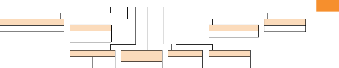
I/O Specifications
●Digital inputs DI1–DI4 are
programmable
●Digital, relay and analog
outputs are programmable
Includes:
●Four inputs (two digital and
two digital/analog)
●Analog inputs
●4–20 mA
●0–10V
●One output (analog or
digital)
●One relay output
●RS-485 interface
Reliability
●Pretested components
●Computerized testing
●Final test with full load
●Conformal-coated boards
●
Eaton’s Electrical Services &
Systems: national network
of AF drive specialists
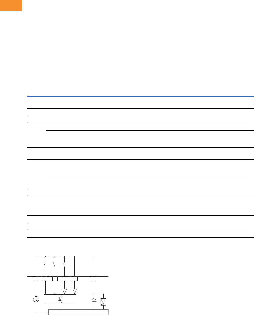
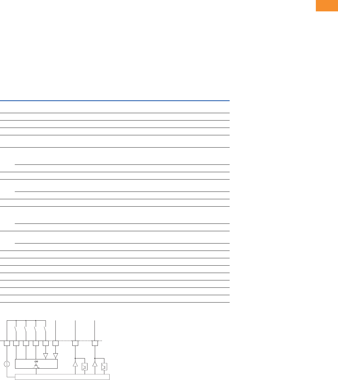
DC1 Series I/O Interface
Note
1Programmable function.
Terminal Signal Factory Preset Description
1 +24 Vdc Control voltage for DI1–DI4 — Maximum load 100 mA
Reference potential V
2 DI1 Digital Input 1 Start Enable FWD 8 to +30V (High, R1 > 6 kΩ)
3 DI2 Digital Input 2 Start Enable REV 8 to +30V (High, R1 > 6 kΩ)
4 DI3 Digital Input 3 Fixed frequency FF1 Digital: 8–30V (high)
AI2 Analog Input 2 Fixed frequency FF1 Analog: 0 to +10V (Ri >72 kΩ)
0/4–20 mA (Rß = 500 Ω)
Can be switched with parameter P16
5 +10 Vdc Reference voltage, Output (+10V) — Maximum load 10 mA
Reference potential 0V
6 AI1 Analog Input 1 Frequency reference value 1
(fixed frequency)
Analog: 0 to +10V (Ri >72 kΩ)
0/4–20 mA (Rß = 500 Ω)
Can be switched with parameter P16
DI4 Digital Input 5 Frequency reference value 1
(fixed frequency)
Digital: 8–30V (high)
7 0V Reference potential — 0V = connection terminal 9
8 AO1 Analog Output 1 Output frequency Analog: 0 to +10V, maximum 4–20 mA
Can be switched with parameter P-25
DO1 Digital Output 1 Output frequency Digital: 8 to +24V
9 0V Reference potential — 0V connection terminal 7
10 K13 Relay 1, normally open contact Active = RUN Maximum switching load: 250 Vac/6A or 30 Vdc/5A
11 K14 Relay 1, normally open contact Active = RUN Maximum switching load: 250 Vac/6A or 30 Vdc/5A
2
DI1 FWD
24V
3
DI2 REV
4
DI3
(AI2)
FF1
6
AI1
(DI4)
f-Soll
1
+24V Out
< 100 mA
8
AO
(DO)
f-Out
CPU
0 to +10V/20 mA
0 to +10V/20 mA
Volume 6—Solid-State Motor Control CA08100007E—May 2014 www.eaton.com V6-T2-9
2
2
2
2
2
2
2
2
2
2
2
2
2
2
2
2
2
2
2
2
2
2
2
2
2
2
2
2
2
2
2.1
Adjustable Frequency Drives
PowerXL DC1 Series Drives
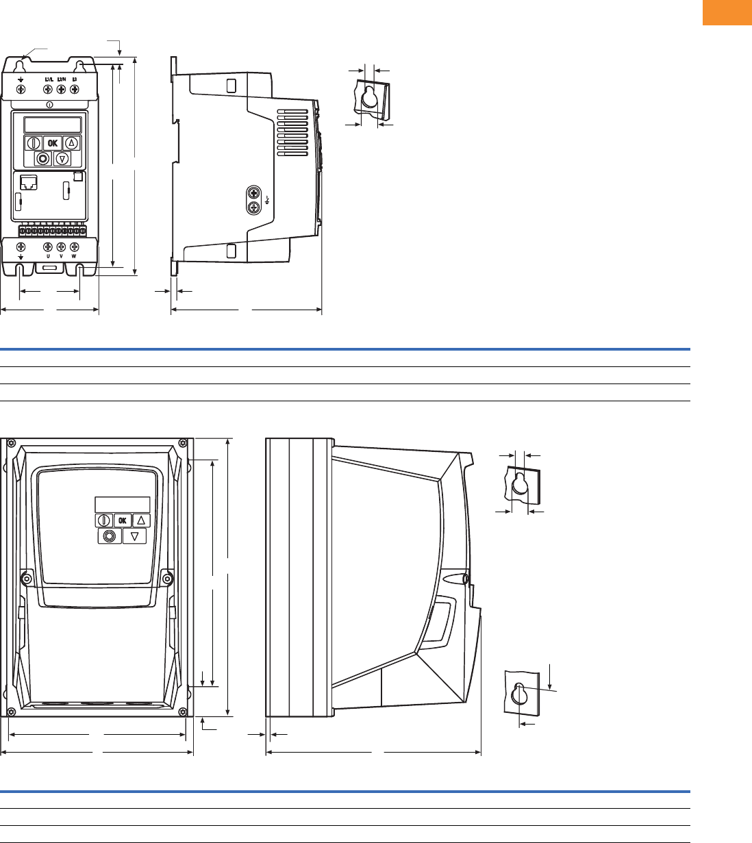
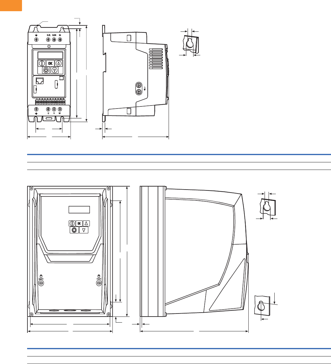
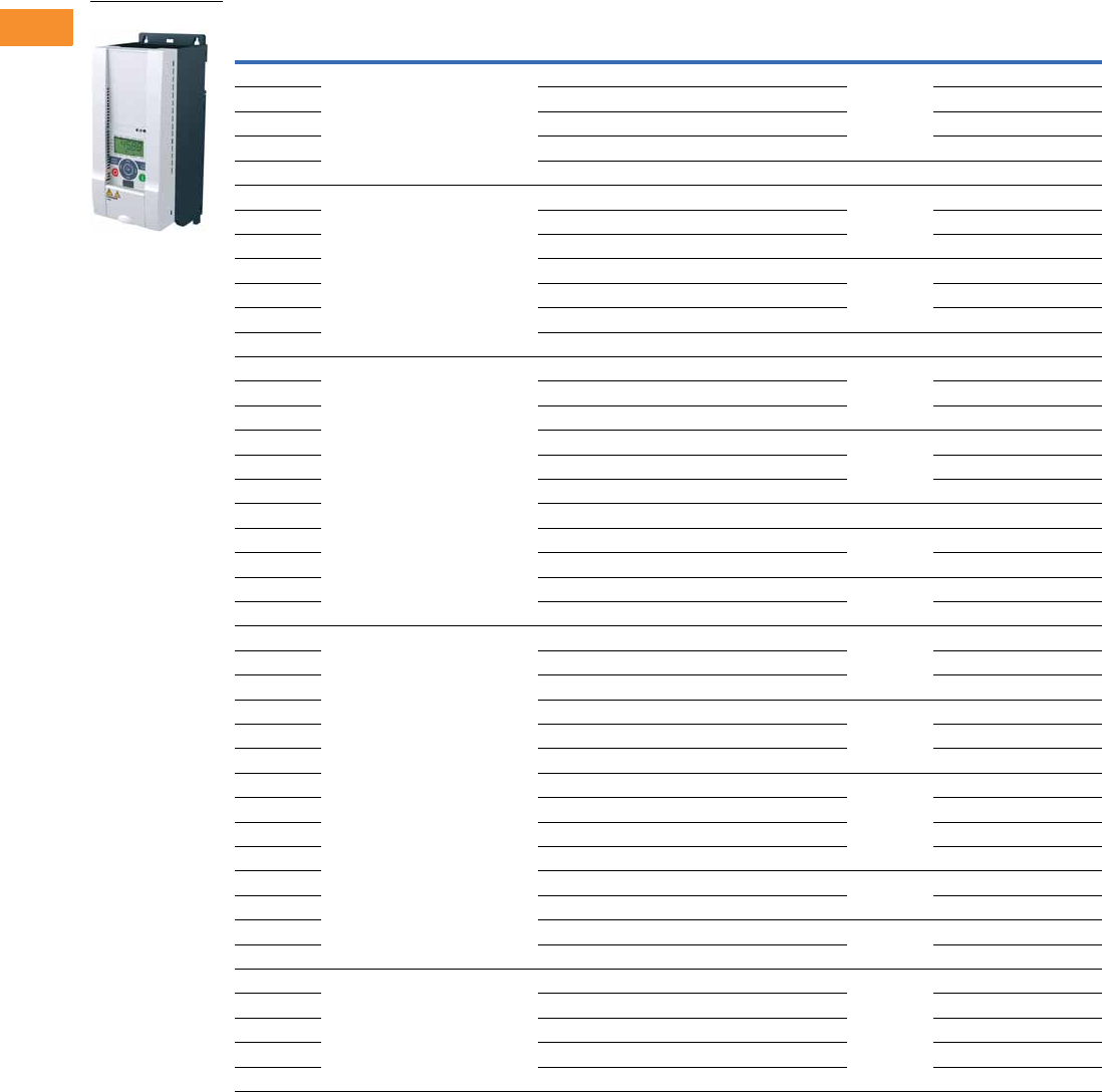
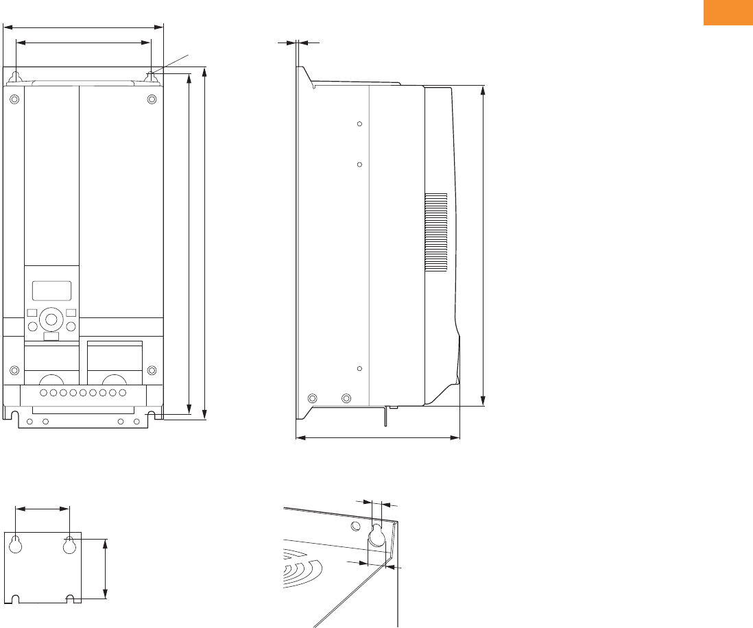
Dimensions
Approximate Dimensions in Inches (mm)
DC1, Sizes FS1–FS3, Degree of Protection IP20/NEMA 0
DC1, Sizes FS1–FS3, Degree of Protection IP66/NEMA 4
Frame
Size A A1 B B1 B2 C C1 Ø1Ø2
Weight
lbs (kg)
FS1 3.19 (81.0) 1.97 (50.0) 7.24 (184.0) 6.69 (170.0) 0.28 (7.0) 4.88 (124.0) 0.16 (4.0) 0.24 (6.0) 0.47 (12.0) 2.43 (1.1)
FS2 4.21 (107.0) 2.95 (75.0) 9.09 (231.0) 8.46 (215.0) 0.31 (8.0) 5.98 (152.0) 0.20 (5.0) 0.24 (6.0) 0.47 (12.0) 5.73 (2.6)
FS3 5.16 (131.0) 3.94 (100.0) 10.75 (273.0) 10.04 (255.0) 0.33 (8.5) 6.89 (175.0) 0.20 (5.0) 0.24 (6.0) 0.47 (12.0) 8.82 (4.0)
Frame
Size A A1 B B1 B2 C C1 Ø1Ø2
Weight
lbs (kg)
FS1 6.34 (161.0) 5.85 (148.5) 9.13 (232.0) 7.44 (189.0) 0.98 (25.0) 7.24 (184.0) 0.14 (3.5) 0.15 (4.0) 0.31 (8.0) 5.51 (2.5)
FS2 7.40 (188.0) 6.93 (176.0) 10.12 (257.0) 7.87 (200.0) 1.12 (28.5) 7.58 (192.0) 0.14 (3.5) 0.16 (4.2) 0.33 (8.5) 10.36 (4.7)
FS3 8.29 (210.5) 7.78 (197.5) 12.20 (310.0) 9.90 (251.5) 1.31 (33.4) 9.21 (234.0) 0.14 (3.5) 0.16 (4.2) 0.33 (8.5) 17.42 (7.9)
B1
A
B
Ø2
Ø1
Ø
C1
C
A1
B2
B
C
A1
B1
Ø2
Ø1
A
A1 C1
B1
B2
V6-T2-10 Volume 6—Solid-State Motor Control CA08100007E—May 2014 www.eaton.com
2
2
2
2
2
2
2
2
2
2
2
2
2
2
2
2
2
2
2
2
2
2
2
2
2
2
2
2
2
2
2.1
Adjustable Frequency Drives
PowerXL DC1 Series Drives
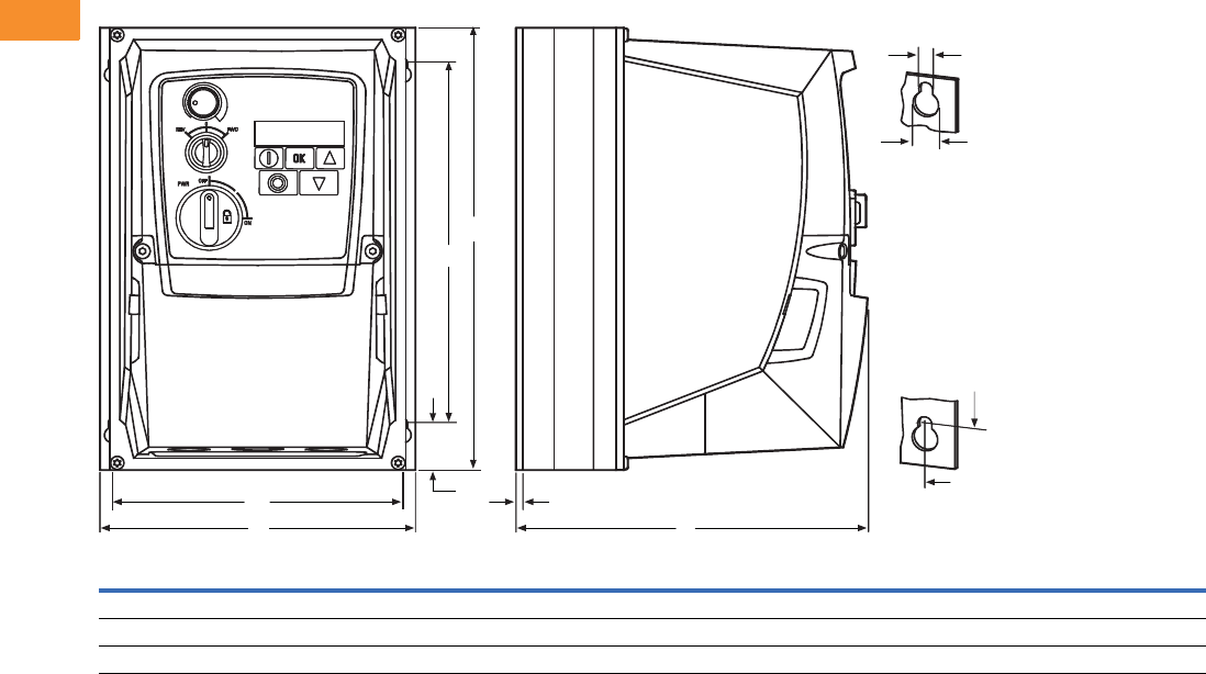
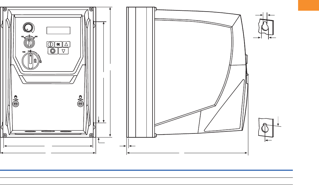
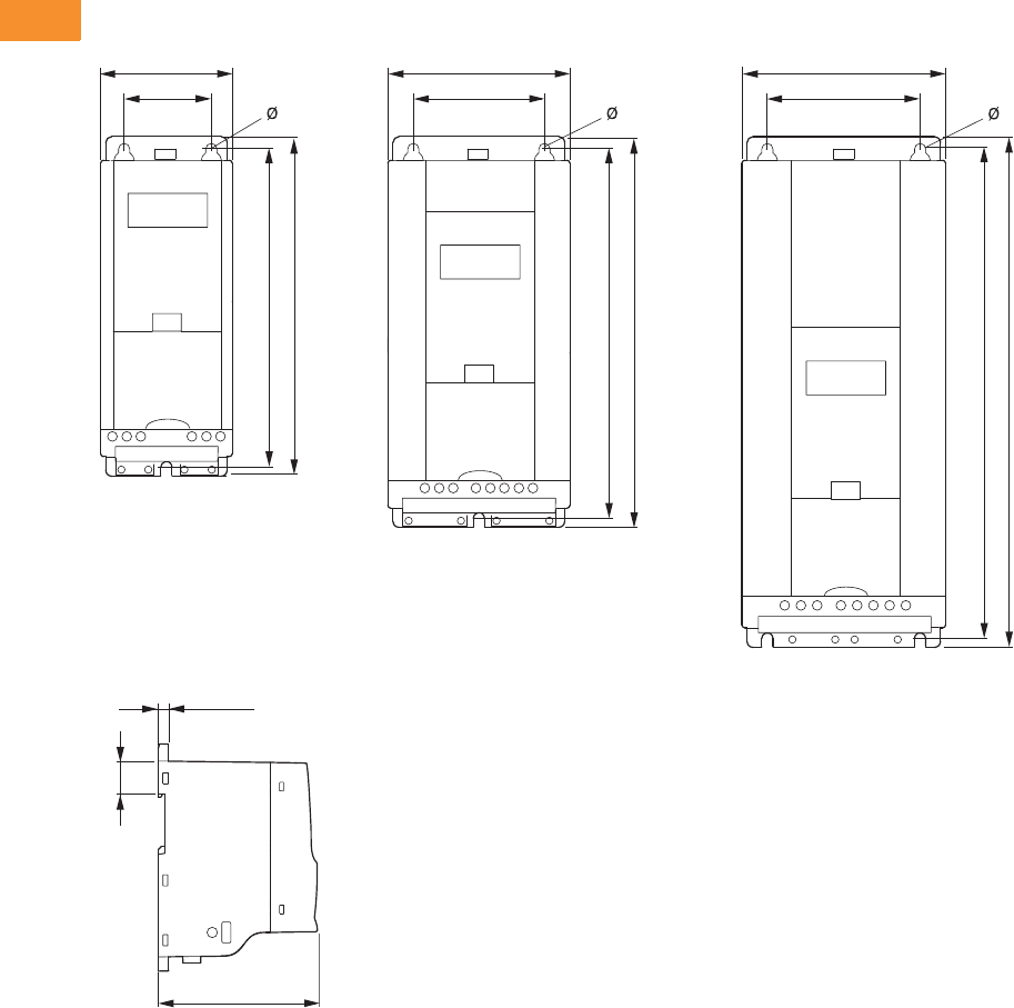
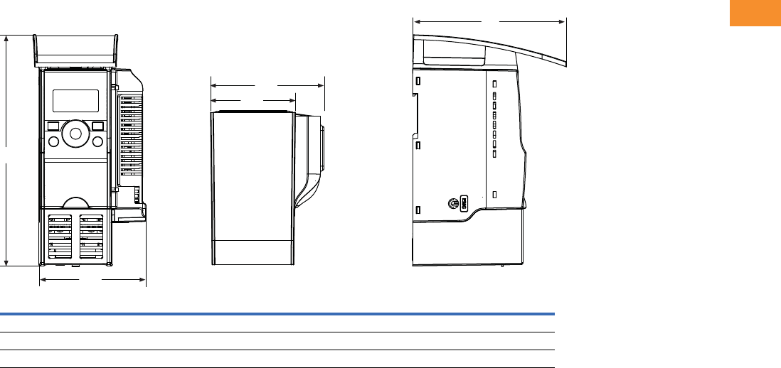
Approximate Dimensions in Inches (mm)
DC1, Sizes FS1–FS3, Degree of Protection IP66/NEMA 4, with Local Controls
Frame
Size A A1 B B1 B2 C C1 Ø1Ø2
Weight
lbs (kg)
FS1 6.34 (161.0) 5.85 (148.5) 9.13 (232.0) 7.44 (189.0) 0.98 (25.0) 7.24 (184.0) 0.14 (3.5) 0.15 (4.0) 0.31 (8.0) 6.17 (2.8)
FS2 7.40 (188.0) 6.93 (176.0) 10.12 (257.0) 7.87 (200.0) 1.12 (28.5) 7.58 (192.0) 0.14 (3.5) 0.16 (4.2) 0.33 (8.5) 11.02 (5.0)
FS3 8.29 (210.5) 7.78 (197.5) 12.20 (310.0) 9.90 (251.5) 1.31 (33.4) 9.21 (234.0) 0.14 (3.5) 0.16 (4.2) 0.33 (8.5) 18.08 (8.2)
Ø2
A1
C1A1
A C
B1
B
B1
B2
Ø1
Volume 6—Solid-State Motor Control CA08100007E—May 2014 www.eaton.com V6-T2-11
2
2
2
2
2
2
2
2
2
2
2
2
2
2
2
2
2
2
2
2
2
2
2
2
2
2
2
2
2
2
2.2
Adjustable Frequency Drives
PowerXL DA1 Series Drives
PowerXL DA1 Series Drives
Contents
Description Page
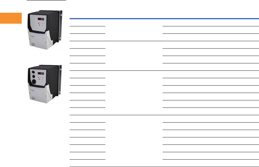
PowerXL DA1 Series Drives
Catalog Number Selection . . . . . . . . . . . . . . . . V6-T2-12
Product Selection . . . . . . . . . . . . . . . . . . . . . . . V6-T2-13
Accessories . . . . . . . . . . . . . . . . . . . . . . . . . . . V6-T2-15
Technical Data and Specifications . . . . . . . . . . V6-T2-16
Dimensions . . . . . . . . . . . . . . . . . . . . . . . . . . . V6-T2-18
Product Description
Eaton’s PowerXL™ DA1
variable frequency drives are
the next generation of drives
specifically engineered for
today’s machinery
applications.
DA1 is the perfect match for
demanding OEM applications.
High-performance processor,
safe torque off, multiple
fieldbus protocols including
SmartWire-DT, sensorless
vector control and the
possibility
to operate
permanent magnet motors
are sure to leave a lasting
impression.
Models rated at 480 volts,
three-phase, 50/60 Hz are
available in sizes ranging from
1 to 15 hp. Models rated at
240 volts, single- or three-
phase, 50/60 Hz are available
in sizes ranging from 0.5
to 7.5 hp. Models rated at
575 volts, three-phase,
50/60 Hz are available in sizes
ranging from 1 to 20 hp.
Features
●Compact, space-saving
design
●
Rugged and reliable—200%
for 4s 50°C rated
●DIN rail and screw
mountable (FS1 and FS2)
●Side-by-side installation
●Industry-leading efficiency
delivers energy savings to
the customer
●Integrated EMC filters
make the unit suitable for
commercial and industrial
networks
●Communication cards that
integrate into the drive—
●EtherNet/IP
●DeviceNet
●PROFIBUS-DP
●EtherCAT
●PROFINET
●Modbus TCP
●BACnet
●Brake chopper as standard
in frames 2 and higher
●Temperature-controlled fan
●RS-485/Modbus® and
CANopen™ as standard
●PID controller as standard
●Several fieldbus options
●SmartWire capability
●Removable I/O terminal
blocks
●Contactor style power
wiring
●200% torque at zero speed
●Ability to run permanent
magnet motors
●PLC programming
●Closed loop
●Conformal coated boards
Standards and
Certifications
Product
●Complies with EN61800-3
(2004)
EMC (At Default Settings)
●EMC Category C1, C2
and C3 at default settings
(1m, 5m, 25m)
Safety 1
●61800-5-1
●EN 60529
●CE
●UL
●cUL
●UkrSepro
●c-Tick
●RoHS compliant
Note
1See unit nameplate for more detailed
approvals.
V6-T2-12 Volume 6—Solid-State Motor Control CA08100007E—May 2014 www.eaton.com
2
2
2
2
2
2
2
2
2
2
2
2
2
2
2
2
2
2
2
2
2
2
2
2
2
2
2
2
2
2
2.2
Adjustable Frequency Drives
PowerXL DA1 Series Drives
Catalog Number Selection
DA1 Series Adjustable Frequency AC Drives
DA1 -1 24D1 F B -A 20 C
Rated
Operational Current
Examples—
2D2 = 2.2A
4D1 = 4.1A
024 = 24A
Type
C= Coated printed circuit boards
Degree of Protection
20 = IP20/NEMA 0
66 = IP66/NEMA 4
6S = IP66 with disconnect/NEMA 4
Device Series
DA1 = Variable frequency drive, compact, Series 1
(D = Drives, A = Advanced, 1 = Series 1)
Connection in Power Section
1= Single-phase mains connection/three-phase motor connection
3= Three-phase mains connection/three-phase motor connection
Mains Voltage Category
2= 230V (200–240V ±10%)
4= 400V (380–480V ±10%)
5= 575V (500–600V ±10%)
Display Unit (Display)
A= LED display
Brake Chopper
B= Brake chopper
EMC (Radio Interference Suppression Filter)
F= Internal RFI filter
Volume 6—Solid-State Motor Control CA08100007E—May 2014 www.eaton.com V6-T2-13
2
2
2
2
2
2
2
2
2
2
2
2
2
2
2
2
2
2
2
2
2
2
2
2
2
2
2
2
2
2
2.2
Adjustable Frequency Drives
PowerXL DA1 Series Drives
Product Selection
DA1 Series IP20 Enclosure Drives 1
Notes
1 These are constant torque/high overload rated drives.
2 For all applications, select the unit such that the motor current is less than or equal to the rated continuous output current.
3 Brake chopper circuit available as standard in frames 2 and 3.
hp 2kW Volts
100% Continuous
Current In (A)
Frame
Size 3Catalog Number
1 0.75 200–240V single-phase in/
230V three-phase out
4.3 2 DA1-124D3FB-A20C
21.5 7 2 DA1-127D0FB-A20C
32.2 10.5 2 DA1-12011FB-A20C
1 0.75 200–240V three-phase in/
230V three-phase out
4.3 2 DA1-324D3FB-A20C
21.5 7 2 DA1-327D0FB-A20C
32.2 10.5 2 DA1-32011FB-A20C
54 18 3 DA1-32018FB-A20C
7.5 5.5 24 3 DA1-32024FB-A20C
1 0.75 380–480V three-phase in/
460V three-phase out
2.2 2 DA1-342D2FB-A20C
21.5 4.1 2 DA1-344D1FB-A20C
32.2 5.8 2 DA1-345D8FB-A20C
54 9.5 2 DA1-349D5FB-A20C
7.5 5.5 14 3 DA1-34014FB-A20C
10 7.5 18 3 DA1-34018FB-A20C
15 11 24 3 DA1-34024FB-A20C
1 0.75 500–600V three-phase in/
575V three-phase out
2.1 2 DA1-352D1NB-A20C
24.5 3.1 2 DA1-353D1NB-A20C
32.2 4.1 2 DA1-354D1NB-A20C
54 6.5 2 DA1-356D5NB-A20C
7.5 5.5 9 2 DA1-359D0NB-A20C
10 7.5 12 3 DA1-35012NB-A20C
15 11 17 3 DA1-35017NB-A20C
20 15 22 3 DA1-35022NB-A20C
IP20
V6-T2-14 Volume 6—Solid-State Motor Control CA08100007E—May 2014 www.eaton.com
2
2
2
2
2
2
2
2
2
2
2
2
2
2
2
2
2
2
2
2
2
2
2
2
2
2
2
2
2
2
2.2
Adjustable Frequency Drives
PowerXL DA1 Series Drives
DA1 Series IP66 Enclosure Drives 1
Notes
1 These are constant torque/high overload rated drives.
2 For all applications, select the unit such that the motor current is less than or equal to the rated continuous output current.
3 Brake chopper circuit available as standard in frames 2 and 3.
4 Non-disconnect version available. Substitute with -A66C.
hp 2kW Volts
100% Continuous
Current In (A)
Frame
Size 3Catalog Number
1 0.75 200–240V single-phase in/
230V three-phase out
4.3 2 DA1-124D3FB-A6SC 4
21.5 7 2 DA1-127D0FB-A6SC 4
32.2 10.5 2 DA1-12011FB-A6SC 4
1 0.75 200–240V three-phase in/
230V three-phase out
4.3 2 DA1-324D3FB-A6SC 4
21.5 7 2 DA1-327D0FB-A6SC 4
32.2 10.5 2 DA1-32011FB-A6SC 4
54 18 3 DA1-32018FB-A6SC 4
1 0.75 380–480V three-phase in/
460V three-phase out
2.2 2 DA1-342D2FB-A6SC 4
21.5 4.1 2 DA1-344D1FB-A6SC 4
32.2 5.8 2 DA1-345D8FB-A6SC 4
54 9.5 2 DA1-349D5FB-A6SC 4
7.5 5.5 14 3 DA1-34014FB-A6SC 4
10 7.5 18 3 DA1-34018FB-A6SC 4
1 0.75 500–600V three-phase in/
575V three-phase out
2.1 2 DA1-352D1NB-A6SC
24.5 3.1 2 DA1-353D1NB-A6SC
32.2 4.1 2 DA1-354D1NB-A6SC
54 6.5 2 DA1-356D5NB-A6SC
7.5 5.5 9 2 DA1-359D0NB-A6SC
10 7.5 12 3 DA1-35012NB-A6SC
15 11 17 3 DA1-35017NB-A6SC
IP66
IP66S

Volume 6—Solid-State Motor Control CA08100007E—May 2014 www.eaton.com V6-T2-15
2
2
2
2
2
2
2
2
2
2
2
2
2
2
2
2
2
2
2
2
2
2
2
2
2
2
2
2
2
2
2.2
Adjustable Frequency Drives
PowerXL DA1 Series Drives
Accessories
DA1 Series
PC Communication Kit and Copy/Paste Module
Optional Communication Modules
Encoder Feedback Plug-In Option Module
and Miscellaneous Cards
Remote Keypad
Extension Cables and Data Cable Splitter
SmartWire Modules
Note
1Includes 1m RS-485 data cable.
Description Catalog Number
Bluetooth copy/paste communication stick DX-COM-STICK
USB PC connection kit DX-COM-PCKIT
Description Catalog Number
DeviceNet plug-in interface module DX-NET-DEVICENET
PROFIBUS-DP plug-in interface module DX-NET-PROFIBUS
EtherNet/IP plug-in interface module DX-NET-ETHERNET-2
EtherCAT plug-in interface module DX-NET-ETHERCAT-2
PROFINET plug-in interface module DX-NET-PROFINET-2
Modbus TCP plug-in interface module DX-NET-MODBUSTCP-2
BACnet plug-in interface module DX-NET-BACNETIP-2
Description Catalog Number
Relay output option module DXA-EXT-3RO
Encoder feedback plug-in option module DXA-EXT-ENCOD
Description Catalog Number
LED remote keypad—7-segment display, IP54 rated DX-KEY-LED 1
OLED remote keypad—full text display, multi-line text,
multi-language, IP54
DX-KEY-OLED 1
Description Catalog Number
RJ45 communication cable w/terminating resistor DX-CBL-TERM
RS-485 data cable, RJ45, 0.5m DX-CBL-RJ45-0M5
RS-485 data cable, RJ45, 1.0m DX-CBL-RJ45-1M0
RS-485 data cable, RJ45, 3.0m DX-CBL-RJ45-3M0
RS-485 three-way data cable splitter, RJ45 DX-SPL-RJ45-3SL
RS-485 data cable splitter, RJ45, (1 connector to 2 socket) DX-SPL-RJ45-2SL1PL
Description Catalog Number
SmartWire-DT interface for DA1 IP20 DX-NET-SWD1

V6-T2-16 Volume 6—Solid-State Motor Control CA08100007E—May 2014 www.eaton.com
2
2
2
2
2
2
2
2
2
2
2
2
2
2
2
2
2
2
2
2
2
2
2
2
2
2
2
2
2
2
2.2
Adjustable Frequency Drives
PowerXL DA1 Series Drives
Technical Data and Specifications
DA1 Series
Ratings
PowerXL DA1 Basic Controller IP20 Standard Ratings
Programmable Parameters
Specifications
PowerXL DA1 Series Drives
Notes
1Exception: 115V single-phase in, 230V three-phase out.
2Only FS2 and FS3 drives are equipped with brake chopper circuit.
Description Specification
Protections
Overload protection 150% for 60s for every 600 seconds
Overvoltage protection Yes
Undervoltage protection Yes
Ground fault protection Yes
Overtemperature
protection
Yes
Motor overload protection Yes
Motor stall protection Yes
Description
Built-in Help card
14 Standard operation parameters
Reference scaling
Programmable start and stop functions
DC-brake at start and stop
Programmable V/Hz curve
Adjustable switching frequency
Autorestart function after fault
Protections and supervisions
Power section fault indication
External fault
Fieldbus communication
Safe torque off (STO) function
Analog input range selection, signal scaling and filtering
PI controller
Skip frequencies
Description Specification
Input Ratings
Input voltage (Vin)±10%
Input frequency (fin) 50/60 Hz (variation up to 48–62 Hz)
Connection to power Maximum of one time every 30 seconds
Output Ratings
Output voltage 0 to Vin 1
Continuous output
current
Continuous rated current IN at ambient temperature max. 122°F (50°C),
150% for 60 seconds, 200% for 4 seconds
Output frequency 0 to 500 Hz
Frequency resolution 0.1 Hz
Initial output current (IH) 200% for 4s for every 40 seconds
Torque depends on motor
Control Characteristics
Operation mode
U/f control, slip compensation, sensorless vector control (SLV),
vector control with feedback (CLV)
Switching frequency 4 to 32 kHz
Voltage reference 10 Vdc (max. 10 mA)
Field weakening point 0 to 500 Hz
Acceleration time 0.1 to 600 seconds
Deceleration time 0.1 to 600 seconds
Brake Resistor (Minimum Values) 2
230V Series FS2 and FS3 15 ohms
400V Series FS2 33 ohms, FS3 22 ohms
Ambient Conditions
Ambient operating
temperature
+14°F (–10°C), no frost to +122°F (+50°C): Rated loadability IN
IP20—NEMA 0
Storage temperature –40°F (–40°C) to +140°F (+60°C)
Relative humidity 0 to 95% RH, noncondensing, non-corrosive, no dripping water
Enclosure class IP20 (FS1–FS3)
Volume 6—Solid-State Motor Control CA08100007E—May 2014 www.eaton.com V6-T2-17
2
2
2
2
2
2
2
2
2
2
2
2
2
2
2
2
2
2
2
2
2
2
2
2
2
2
2
2
2
2
2.2
Adjustable Frequency Drives
PowerXL DA1 Series Drives
Standards—DA1 Series
I/O Specifications
●Digital inputs DI1–DI5 are
programmable
●Digital, relay and analog
outputs are programmable
Includes:
●Five inputs (three digital
and two digital/analog)
●Analog inputs
●4–20 mA
●0–10V
●Two outputs (analog or
digital)
●Two relay outputs
●RS-485 interface
Reliability
●Pretested components
●Computerized testing
●Final test with full load
●Conformal-coated boards
●
Eaton’s Electrical Services &
Systems: national network
of AF drive specialists
DA1 Series I/O Interface
Note
1Programmable function.
Terminal Signal Factory Preset Description
1 +24 Vdc Control voltage for DI1–DI5 — Maximum load 100 mA
Reference potential V
2 DI1 Digital Input 1 Start Enable FWD 18 to +30V (High, R1 > 6 kΩ)
3 DI2 Digital Input 2 Start Enable REV 18 to +30V (High, R1 > 6 kΩ)
4 DI3 Digital Input 3 Fixed frequency FF1/FF2 18 to +30V (High, R1 > 6 kΩ)
5 +10 Vdc Reference voltage, Output (+10V) — Maximum load 10 mA
Reference potential 0V
6 AI1 Analog Input 1 Frequency reference value 1Analog: 0 to +10V (Ri >72 kΩ)
0/4–20 mA (Ri = 500 Ω)
Can be switched with parameter P2-30
DI4 Digital Input 5 Frequency reference value 1Digital: 8–30V (high)
7 0V Reference potential — 0V = connection terminal 9
8 AO1 Analog Output 1 Output frequency Analog: 0 to +10V, maximum 20 mA
Can be switched with parameter P2-11
DO1 Digital Output 1 Output frequency Digital: 8–24V
9 0V Reference potential — 0V connection terminal 7
10 DI4 Digital Input 4 Fixed frequency FF2 1Analog: 0 to +10V (Ri >72 kΩ)
0/4–20 mA (Ri = 500 Ω)
Can be switched with parameter P2-30
AI2 Analog Input 2 Fixed frequency FF2 1Digital: 8–30V (high)
11 AO2 Analog output 2 Output current 1Analog: 0 to +10V, maximum 4–20 mA
Can be switched with parameter P2-11
DO2 Digital output 2 Output current 1Digital: 8–24V
12 STO+ Safe Torque Off + — Enable = +24V
13 STO- Safe Torque Off – — Enable = 0V
14 K11 Relay 1, changeover contact Active = FAULT 1Maximum switching load: 250 Vac/6A or 30 Vdc/5A
15 K14 Relay 1, changeover contact (N/O) Active = FAULT 1Maximum switching load: 250 Vac/6A or 30 Vdc/5A
16 K12 Relay 1, changeover contact (N/C) Active = FAULT 1Maximum switching load: 250 Vac/6A or 30 Vdc/5A
17 K23 Relay 2, N/O contact Active = FAULT 1Maximum switching load: 250 Vac/6A or 30 Vdc/5A
18 K24 Relay 2, N/C contact Active = FAULT 1Maximum switching load: 250 Vac/6A or 30 Vdc/5A
2
DI1 FWD
+24V
4
DI3 FF1/FF2
3
DI2 REV
10
DI4
(AI2)
FF2
1
+24V Out
< 100 mA
6
AI1
(DI5)
CPU
8
AO1
(DO1)
f-Out
0 to +10V/20 mA
f-Soll
0 to +10V/20 mA
11
AO2
(DO2)
A-Out
0 to +10V/20 mA
V6-T2-18 Volume 6—Solid-State Motor Control CA08100007E—May 2014 www.eaton.com
2
2
2
2
2
2
2
2
2
2
2
2
2
2
2
2
2
2
2
2
2
2
2
2
2
2
2
2
2
2
2.2
Adjustable Frequency Drives
PowerXL DA1 Series Drives
Dimensions
Approximate Dimensions in Inches (mm)
DA1, Sizes FS2 and FS3, Degree of Protection IP20/NEMA 0
DA1, Sizes FS2 and FS3, Degree of Protection IP66/NEMA 4
Frame
Size A A1 B B1 B2 C C1 Ø1Ø2
Weight
lbs (kg)
FS2 4.21 (107.0) 2.95 (75.0) 9.09 (231.0) 8.46 (215.0) 0.31 (8.0) 7.32 (186.0) 0.20 (5.0) 0.24 (6.0) 0.47 (12.0) 3.97 (1.8)
FS3 5.16 (131.0) 3.94 (100.0) 10.75 (273.0) 10.04 (255.0) 0.33 (8.5) 8.03 (204.0) 0.20 (5.0) 0.24 (6.0) 0.47 (12.0) 7.72 (3.5)
Frame
Size A A1 B B1 B2 C C1 Ø1Ø2
Weight
lbs (kg)
FS2 7.40 (188.0) 6.93 (176.0) 10.12 (257.0) 7.87 (200.0) 0.79 (20.0) 9.42 (239.3) 0.14 (3.5) 0.16 (4.2) 0.33 (8.5) 10.4 (4.5)
FS3 8.29 (211.0) 7.78 (198.0) 12.20 (310.0) 9.90 (252.0) 0.98 (25.0) 10.48 (266.3) 0.14 (3.5) 0.16 (4.2) 0.33 (8.5) 15.9 (7.0)
B1
A
B
Ø2
Ø1
Ø
C1
C
A1
B2
A1
B1
Ø2
Ø1
B
B1
B2
CA
A1 C1
Volume 6—Solid-State Motor Control CA08100007E—May 2014 www.eaton.com V6-T2-19
2
2
2
2
2
2
2
2
2
2
2
2
2
2
2
2
2
2
2
2
2
2
2
2
2
2
2
2
2
2
2.2
Adjustable Frequency Drives
PowerXL DA1 Series Drives
Approximate Dimensions in Inches (mm)
DA1, Sizes FS2 and FS3, Degree of Protection IP66/NEMA 4, with Local Controls
Frame
Size A A1 B B1 B2 C C1 Ø1Ø2
Weight
lbs (kg)
FS2 7.40 (188.0) 6.93 (176.0) 10.12 (257.0) 7.87 (200.0) 0.79 (20.0) 9.42 (239.3) 0.14 (3.5) 0.16 (4.2) 0.33 (8.5) 10.6 (4.8)
FS3 8.29 (211.0) 7.78 (198.0) 12.20 (310.0) 9.90 (252.0) 0.98 (25.0) 10.48 (266.3) 0.14 (3.5) 0.16 (4.2) 0.33 (8.5) 16.1 (7.3)
Ø2
A1
C1A1
A C
B1
B
B1
B2
Ø1
V6-T2-20 Volume 6—Solid-State Motor Control CA08100007E—May 2014 www.eaton.com
2
2
2
2
2
2
2
2
2
2
2
2
2
2
2
2
2
2
2
2
2
2
2
2
2
2
2
2
2
2
2.3
Adjustable Frequency Drives
M-Max Series Drives
M-Max Series Drives for Machinery Applications
Contents
Description Page
M-Max Series Drives
Catalog Number Selection . . . . . . . . . . . . . . . . V6-T2-21
Product Selection . . . . . . . . . . . . . . . . . . . . . . . V6-T2-22
Accessories . . . . . . . . . . . . . . . . . . . . . . . . . . . V6-T2-23
Technical Data and Specifications . . . . . . . . . . V6-T2-24
Dimensions . . . . . . . . . . . . . . . . . . . . . . . . . . . V6-T2-26
Product Description
Eaton’s M-Max™ Series
Sensorless Vector Adjustable
Frequency AC Drives are
the next generation of drives
specifically engineered
for today’s machinery
applications. These micro-
processor-based drives have
standard features that can be
programmed to tailor the
drive’s performance to suit a
wide variety of application
requirements. The M-Max
product line uses a 32-bit
microprocessor and insulated
gate bipolar transistors
(IGBTs) that provide quiet
motor operation, high motor
efficiency, and smooth low-
speed performance. The size
and simplicity of the M-Max
make it ideal for hassle-free
installation. Models rated at
575 volts, three-phase,
50/60 Hz are available in sizes
ranging from 1 to 7-1/2 hp.
Models rated at 480 volts,
three-phase, 50/60 Hz
are available in sizes ranging
from 1/2 to 25 hp. Models
rated at 240 volts, single- or
three-phase, 50/60 Hz are
available in sizes ranging from
1/4 to 15 hp. Models rated
at 115 volts, single-phase,
50/60 Hz are available in the
1/4 to 1-1/2 hp size range.
The standard drive includes a
digital display, and operating
and programming keys on a
visually appealing, efficient
application programming
interface. The display
provides drive monitoring, as
well as adjustment and
diagnostic information. The
keys are used for digital
adjustment and programming
of the drive, as well as for
operator control. Separate
terminal blocks for control
and power wiring are
provided for customer
connections.
Features
●Ease of use—preset
application macros, startup
wizard, diagnostic
capabilities
●Compact, space-saving
design
●Rugged and reliable—
150% torque for one
minute, 50C rated,
conformal coated boards
●DIN rail and screw
mountable
●Side-by-side installation
●Industry leading efficiency
delivers energy savings to
the customer
●Integrated 5% DC choke
(FS4 and FS5)
●Integrated EMC filters
make the unit suitable for
commercial and industrial
networks
●IP21 as standard, option
for NEMA® 1 (FS4 and FS5)
●IP20 as standard, option
for IP21 and NEMA 1
(FS1–FS3)
●Brake chopper as standard
in three-phase, applications
of frames 2 (FS2) and
larger
●Temperature-controlled fan
●RS-485/Modbus® as
standard
●PID controller as standard
●Several fieldbus options
Standards and Certifications
Product
●Complies with EN61800-3
(2004)
Safety 1
●61800-5-1
●EN60204-1
●CE
●UL
●cUL
●IEC
●RoHS compliant
EMC (At Default Settings)
●EMC Category C2, C3, and
C4 (Level H): With an
internal RFI filter option
Note
1See unit nameplate for more detailed
approvals.
Volume 6—Solid-State Motor Control CA08100007E—May 2014 www.eaton.com V6-T2-21
2
2
2
2
2
2
2
2
2
2
2
2
2
2
2
2
2
2
2
2
2
2
2
2
2
2
2
2
2
2
2.3
Adjustable Frequency Drives
M-Max Series Drives
Catalog Number Selection
Software
Designation Series
AA
Description
MMX = Base catalog number
MMX 11AA 1D1 F0–0
Phase
1= Single-phase
3= Three-phase
Voltage
1= 120V
2= 230V
4= 480V
5= 575V
Output Current
1D6 =1.6A
010 = 10A
EMC Filter
F= Filter
N= No filter
Enclosure Class
0 = NEMA 0 or IP20
Option
0 = Full version
V6-T2-22 Volume 6—Solid-State Motor Control CA08100007E—May 2014 www.eaton.com
2
2
2
2
2
2
2
2
2
2
2
2
2
2
2
2
2
2
2
2
2
2
2
2
2
2
2
2
2
2
2.3
Adjustable Frequency Drives
M-Max Series Drives
Product Selection
M-Max Basic Controller
Notes
1 Horsepower ratings are based on the use of a 240V, 460V, and 575V NEMA B, four- or six-pole squirrel cage induction motor and are for reference only.
Units are to be selected such that the motor current is less than or equal to the MMX rated continuous output current.
2 For 208V, 380V, or 415V applications, select the unit such that the motor current is less than or equal to the MMX rated continuous output current.
3 Units are also available without EMC filters. Substitute -N0-0 for this option.
4 Units are also available without EMC filters and 5% DC choke. Substitute -N0-0 for this option.
hp 1Volts 2
100% Continuous
Current IN (A)
Nominal Input
Current (A)
Frame
Size Catalog Number
1/4 100–120V single-phase in
230V three-phase out
1.7 9.2 FS2 MMX11AA1D7N0-0
1/2 2.4 11.6 MMX11AA2D4N0-0
3/4 2.8 12.4 MMX11AA2D8N0-0
13.715MMX11AA3D7N0-0
1-1/2 4.8 16.5 FS3 MMX11AA4D8N0-0
1/4 200–240V single-phase in
230V three-phase out
1.7 4.2 FS1 MMX12AA1D7F0-0 3
1/2 2.4 5.7 MMX12AA2D4F0-0 3
3/4 2.8 6.6 MMX12AA2D8F0-0 3
13.78.3FS2MMX12AA3D7F0-0 3
1-1/2 4.8 11.2 MMX12AA4D8F0-0 3
2714.1MMX12AA7D0F0-0 3
3 9.6 15.8 FS3 MMX12AA9D6F0-0 3
1/4 200–240V three-phase in
230V three-phase out
1.7 2.7 FS1 MMX32AA1D7N0-0
1/2 2.4 3.5 MMX32AA2D4N0-0
3/4 2.8 3.8 MMX32AA2D8N0-0
13.74.3FS2MMX32AA3D7N0-0
1-1/2 4.8 6.8 MMX32AA4D8N0-0
278.4MMX32AA7D0N0-0
31113.4FS3MMX32AA011N0-0
5 1717FS4MMX32AA017F0-0 4
7-1/2 25 25 MMX32AA025F0-0 4
10 31 31 FS5 MMX32AA031F0-0 4
15 38 38 MMX32AA038F0-0 4
1/2 380–480V three-phase in
460V three-phase out
1.3 2.2 FS1 MMX34AA1D3F0-0 3
3/4 1.9 2.8 MMX34AA1D9F0-0 3
12.43.2MMX34AA2D4F0-0 3
1-1/2 3.3 4 FS2 MMX34AA3D3F0-0 3
24.35.6MMX34AA4D3F0-0 3
35.67.3MMX34AA5D6F0-0 3
47.69.6FS3MMX34AA7D6F0-0 3
5911.5MMX34AA9D0F0-0 3
7-1/2 12 14.9 MMX34AA012F0-0 3
10 14 18.7 MMX34AA014F0-0 3
10 16 16 FS4 MMX34AA016F0-0 4
15 23 23 MMX34AA023F0-0 4
20 31 31 FS5 MMX34AA031F0-0 4
25 38 38 MMX34AA038F0-0 4
1 575V three-phase in
575V three-phase out
1.7 2.0 FS3 MMX35AA1D7N0-0
22.73.6MMX35AA2D7N0-0
33.95.0MMX35AA3D9N0-0
56.17.6MMX35AA6D1N0-0
7-1/2 9.0 10.4 MMX35AA9D0N0-0
M-Max

Volume 6—Solid-State Motor Control CA08100007E—May 2014 www.eaton.com V6-T2-23
2
2
2
2
2
2
2
2
2
2
2
2
2
2
2
2
2
2
2
2
2
2
2
2
2
2
2
2
2
2
2.3
Adjustable Frequency Drives
M-Max Series Drives
Accessories
M-Max Copy/Paste Module
PC Cable
NEMA Type 1 Kits 1
Optional Communication Modules 2
Remote Keypad 3
Notes
1NEMA Type 1 kit provides conduit entry plate.
2Additional input and output reactors are available. Consult Eaton representative for a complete listing.
3All three components are required for remote keypad operation.
Description Catalog Number
Module is plugged onto the front of the drive to provide: upload/download of all parameters,
direct link to a PC via USB interface for parameter assignment via MaxConnect software, and
copying of parameters for a series of devices or when exchanging devices. No PC required
MMX-COM-PC
Description Catalog Number
Remote download USB to RJ-45 cable with software driver disk REM-USB-DOWN
Description Catalog Number
NEMA Type 1 and IP21 kit for frame 1 MMX-IP21-FS1
NEMA Type 1 and IP21 kit for frame 2 MMX-IP21-FS2
NEMA Type 1 and IP21 kit for frame 3 MMX-IP21-FS3
NEMA Type 1 for frame 4 MMX-CKIT-FS4
NEMA Type 1 for frame 5 MMX-CKIT-FS5
Description Catalog Number
Communication adapter kit (FS1–FS3) MMX-NET-XA
Communication adapter kit (FS4 and FS5) MMX-NET-XA-45
PROFIBUS DP network card with serial connection XMX-NET-PS-A
PROFIBUS DP network card with Sub-D connection XMX-NET-PD-A
DeviceNet network card XMX-NET-DN-A
Description Catalog Number
Keypad, bezel and cable OPTRMT-BP-HMAX
Remote copy/paste keypad MMX-REMKEY-TEXT
VFD adapter MMX-ADAPTER-RJ45

V6-T2-24 Volume 6—Solid-State Motor Control CA08100007E—May 2014 www.eaton.com
2
2
2
2
2
2
2
2
2
2
2
2
2
2
2
2
2
2
2
2
2
2
2
2
2
2
2
2
2
2
2.3
Adjustable Frequency Drives
M-Max Series Drives
Technical Data and Specifications
Ratings
M-Max Basic Controller IP20 Standard Ratings
Programmable Parameters
Specifications
M-Max Series Drives
Notes
1Exception: 115V single-phase in, 230V three-phase out.
2Only three-phase FS2 and FS3 drives are equipped with brake chopper circuit.
Description Specification
Protections
Overcurrent protection Trip limit 4.0 x IH instantaneously
Overvoltage protection 115/230V series: 437 Vdc; 400V series: 874 Vdc;
575V series: 1048 Vdc trip level
Undervoltage protection 115/230V series: 183 Vdc; 400V series: 333 Vdc;
575V series: 460 Vdc trip level
Ground fault protection Ground fault is tested before every start. In case of ground fault in
motor or motor cable, only the frequency converter is protected
Overtemperature
protection
Yes
Motor overload protection Yes
Motor stall protection Yes
Motor underload protection Yes
Description
Application macros: basic, pump, fan and high load (hoist)
Programmable start/stop and reverse signal logic (sinking or sourcing)
Reference scaling
Programmable start and stop functions
DC-brake at start and stop
Programmable V/Hz curve
Adjustable switching frequency
Autorestart function after fault
Protections and supervisions (all fully programmable; off, warning, fault)
Current signal input fault
External fault
Fieldbus communication
Eight preset speeds
Analog input range selection, signal scaling and filtering
PID controller
Skip frequencies
Description Specification
Input Ratings
Input voltage (Vin) +10%/–15%
Input frequency (fin) 50/60 Hz (variation up to 45–66 Hz)
Connection to power Once per minute or less (typical operation)
Output Ratings
Output voltage 0 to Vin 1
Continuous output
current
Continuous rated current IN at ambient temperature max.
122°F (50°C), overload 1.5 x IN max. 1 min/10 min
Output frequency 0 to 320 Hz
Frequency resolution 0.01 Hz
Initial output current (IH) Current 2 x IN for 2 seconds in every 20-second period
Torque depends on motor
Control Characteristics
Control method
Frequency control (V/Hz) open loop or sensorless vector control
Switching frequency 1.5 to 16 kHz; default 4 kHz
Frequency reference Analog input: resolution 0.1% (10-bit), accuracy ± 1% V/Hz
Panel reference: resolution 0.01 Hz
Field weakening point 30 to 320 Hz
Acceleration time 0 to 3000 sec
Deceleration time 0 to 3000 sec
Braking torque DC brake: 30% x Tn (without brake option)
Brake Resistor (Minimum Values) 2
230V Series FS2 35 ohms and FS3 26 ohms, FS4 14 ohms, FS5 9 ohms
400V Series FS2 75 ohms and FS3 54 ohms, FS4 28 ohms, FS5 17 ohms
575V Series FS3 103 ohms
Ambient Conditions
Ambient operating
temperature
14°F (–10°C), no frost to 122°F (+50°C): Rated loadability IN
Storage temperature –40°F (–40°C) to 158°F (70°C)
Relative humidity 0 to 95% RH, noncondensing, non-corrosive, no dripping water
Air quality Chemical vapors: IEC 721-3-3, unit in operation, Class 3C2; Mechanical
particles: IEC 721-3-3, unit in operation, Class 3S2
Altitude 100% load capacity (no derating) up to 3280 ft (1000m);
1% derating for each 328 ft (100m) above 3280 ft (1000m);
max. 6560 ft (2000m)
Vibration EN 60068-2-6; 3 to 150 Hz, displacement amplitude 1 mm (peak) at 3 to
15.8 Hz, max. acceleration amplitude 1G at 15.8 to 150 Hz
Shock EN 50178, IEC 68-2-27 UPS Drop test (for applicable UPS weights);
storage and shipping: max. 15G, 11 ms (in package)
Enclosure class IP20 (FS1–FS3)
IP21 (FS4 and FS5)
Volume 6—Solid-State Motor Control CA08100007E—May 2014 www.eaton.com V6-T2-25
2
2
2
2
2
2
2
2
2
2
2
2
2
2
2
2
2
2
2
2
2
2
2
2
2
2
2
2
2
2
2.3
Adjustable Frequency Drives
M-Max Series Drives
Standards
I/O Specifications
●Digital inputs DI1–DI6 are
freely programmable. The
user can assign multiple
functions to a single input
●Digital, relay, and analog
outputs are freely
programmable
Includes:
●Six digital inputs
●Two analog inputs
– 4–20 mA
–0–10V
●One analog output
●One digital output
●Two relay outputs
●RS-485 interface
Reliability
●Pretested components
●Computerized testing
●Final test with full load
●Conformal-coated boards
●
Eaton’s Electrical Services &
Systems: national network
of AF drive specialists
M-Max I/O Interface
Note
P) Parameter-selectable function.
Terminal Signal Factory Preset Description
1 +10V Ref. output voltage — Maximum load 10 mA
2 AI1 Analog signal in 1 Freq. reference P) 0–+10V Ri = 200k ohms [min.]
3 GND I/O signal ground — —
6 24V 24V output for DIs — ±20%, max. load 50 mA
7 GND I/O signal ground — —
8 DI1 Digital input 1 Start forward P) 0–+30V Ri = 12k ohms min.
9 DI2 Digital input 2 Start reverse P) —
10 DI3 Digital input 3 Preset speed P) —
A A RS-485 signal A FB communication —
B B RS-485 signal B FB communication —
4 AI2 Analog signal in 2 PI actual value P) 0[4]–20 mA, Ri = 200k ohms
5 GND I/O signal ground — —
13 GND I/O signal ground — —
14 DI4 Digital input 4 Preset speed B1 P) 0–+30V Ri = 12k ohms min.
15 DI5 Digital input 5 Fault reset P) 0–+30V Ri = 12k ohms min.
16 DI6 Digital input 6 Disable PI contr. P) 0–+30V Ri = 12k ohms min.
18 AO Analog output Output frequency P) 0(2)–10V, RL = 500 ohms
20 DO Digital signal out Active = READY P) Open collector, max. load 48V/50 mA
22 RO11 Relay out 1 Active = RUN P) Max. switching load: 250 Vac/2A or 250 Vdc/0.4A
23 RO12
24 RO21 Relay out 2 Active = FAULT P) Max. switching load: 250 Vac/2A or 250 Vdc/0.4A
25 RO22
26 RO23
Analog
OUT
AUTOGEN
Ref
Current
V6-T2-26 Volume 6—Solid-State Motor Control CA08100007E—May 2014 www.eaton.com
2
2
2
2
2
2
2
2
2
2
2
2
2
2
2
2
2
2
2
2
2
2
2
2
2
2
2
2
2
2
2.3
Adjustable Frequency Drives
M-Max Series Drives
Dimensions
Approximate Dimensions in Inches (mm)
Dimensions and Frame Sizes, FS1–FS3 (FS = Frame Size)
b1
b
a1
a
b1
b
a1
a
b1
b
a1
a
b2
c
0.28 in
(7 mm)
FS1
FS2
FS3
Volume 6—Solid-State Motor Control CA08100007E—May 2014 www.eaton.com V6-T2-27
2
2
2
2
2
2
2
2
2
2
2
2
2
2
2
2
2
2
2
2
2
2
2
2
2
2
2
2
2
2
2.3
Adjustable Frequency Drives
M-Max Series Drives
Approximate Dimensions in Inches (mm)
Dimensions and Frame Sizes, FS4 and FS5 (FS = Frame Size)
b1
a1
b2
c
b1
b
a1
a
Ø
0.28
(7.0)
Ø1
Ø2

V6-T2-28 Volume 6—Solid-State Motor Control CA08100007E—May 2014 www.eaton.com
2
2
2
2
2
2
2
2
2
2
2
2
2
2
2
2
2
2
2
2
2
2
2
2
2
2
2
2
2
2
2.3
Adjustable Frequency Drives
M-Max Series Drives
Dimensions and Frame Sizes
Note
1 in = 25.4 mm, 1 mm = 0.0394 in
Approximate Dimensions in inches (mm) Installation
SizePart Number a a1 b b1 b2 c Ø, Ø1 Ø2
MMX12AA1D7_
MMX12AA2D4_
MMX12AA2D8_
2.60
(66)
1.50
(38)
6.30
(160)
5.79
(147)
1.26
(32)
4.02
(102)
0.18
(4.5)
—FS1
MMX32AA1D7_
MMX32AA2D4_
MMX32AA2D8_
MMX34AA1D3_
MMX34AA1D9_
MMX34AA2D4_
MMX11AA1D7_
MMX11AA2D4_
MMX11AA2D8_
MMX11AA3D7_
3.54
(90)
2.46
(62.5)
7.68
(195)
7.17
(182)
1.26
(32)
4.14
(105)
2.17
(5.5)
—FS2
MMX12AA3D7_
MMX12AA4D8_
MMX12AA7D0_
MMX32AA3D7_
MMX32AA4D8_
MMX32AA7D0_
MMX34AA3D3_
MMX34AA4D3_
MMX34AA5D6_
MMX11AA4D8_ 3.94
(100)
2.95
(75)
9.96
(253)
9.53
(242)
1.34
(34)
4.41
(112)
2.17
(5.5)
—FS3
MMX12AA9D6_
MMX32AA011_
MMX34AA7D6_
MMX34AA9D0_
MMX34AA012_
MMX34AA014_
MMX35AA1D7_
MMX35AA2D7_
MMX35AA3D9_
MMX35AA6D1_
MMX35AA9D0_
MMX32AA012_
MMX32AA017_
MMX32AA025_
6.50
(165.0)
5.51
(140.0)
14.57
(370.0)
13.82
(351.0)
13.27
(337.0)
6.61
(168.0)
0.28
(7.0)
0.55
(14.0)
FS4
MMX34AA016_
MMX34AA023_
MMX32AA031_
MMX32AA038_
6.50
(165.0)
5.51
(140.0)
14.57
(414.0)
13.82
(398.0)
15.08
(383.0)
8.07
(205.0)
0.28
(7.0)
0.55
(14.0)
FS5
MMX34AA031_
MMX34AA038_
Volume 6—Solid-State Motor Control CA08100007E—May 2014 www.eaton.com V6-T2-29
2
2
2
2
2
2
2
2
2
2
2
2
2
2
2
2
2
2
2
2
2
2
2
2
2
2
2
2
2
2
2.3
Adjustable Frequency Drives
M-Max Series Drives
Approximate Dimensions in Inches (mm)
NEMA 1/IP21 M-Max Drives and Communication Adapter Kit
Frame Type H W1 W2 W3 D
FS1 8.14 (206.7) 3.77 (95.7) 2.99 (75.9) 3.98 (101.2) 5.41 (137.5)
FS2 9.90 (251.5) 4.72 (120.0) 3.97 (100.8) 4.94 (125.5) 5.68 (144.2)
FS3 12.26 (311.5) 5.12 (130.1) 4.36 (110.8) 5.33 (135.3) 6.32 (160.5)
H
W1
W2
D
W3
V6-T2-30 Volume 6—Solid-State Motor Control CA08100007E—May 2014 www.eaton.com
2
2
2
2
2
2
2
2
2
2
2
2
2
2
2
2
2
2
2
2
2
2
2
2
2
2
2
2
2
2
2.4
Adjustable Frequency Drives
PowerXL DG1 Series Drives
DG1 General Purpose Drive
Contents
Description Page
PowerXL DG1 Series Drives
Standards and Certifications . . . . . . . . . . . . . . V6-T2-31
Catalog Number Selection . . . . . . . . . . . . . . . . V6-T2-31
Product Selection . . . . . . . . . . . . . . . . . . . . . . . V6-T2-32
Accessories . . . . . . . . . . . . . . . . . . . . . . . . . . . V6-T2-34
Replacement Parts . . . . . . . . . . . . . . . . . . . . . . V6-T2-38
Technical Data and Specifications . . . . . . . . . . V6-T2-40
Dimensions . . . . . . . . . . . . . . . . . . . . . . . . . . . V6-T2-44
Product Description
The DG1 general purpose
drives are part of Eaton’s next
generation PowerXL Series of
adjustable frequency drives
specifically engineered for
today’s more demanding
commercial and industrial
applications. The power unit
makes use of the most
sophisticated semiconductor
technology and a highly
modular construction that can
be flexibly adapted to meet
the customer’s needs.
The control module was
designed to include today’s
standard communication
protocols and I/O while still
having the modularity to add
additional option cards.
Eaton’s patented Active
Energy Control is also a
standard feature on DG1
drives, offering customers
increased efficiency, safety
and reliability.
These drives continue
the tradition of robust
performance and raise
the bar on features and
functionality, ensuring
the best solution at the
right price.
Product Range
●
230V to 125 hp, 310A, 90 kW
●
480V to 250 hp, 310A, 160 kW
●
575V to 250 hp, 250A, 160 kW
Features and Benefits
Hardware
●Brake chopper standard on
Frames 1, 2, 3
●Dual overload ratings
●
110% variable torque (I
L
)
●
150% constant torque (I
H
)
●Type 1/IP21 and Type 12/
IP54 enclosures available
●Integrated common mode
reduction 5% DC link
choke with input surge
protection
●EMI/RFI filters standard on
all drives—meets EMC
Category C2
●Real-time clock—supports
calendaring and PLC
functionality
●Graphic LCD display and
keypad—supports simple
menu navigation as well as
on-screen diagnostics and
troubleshooting
●LOCAL/REMOTE operation
from keypad and two
configurable soft keys
●Control logic can be
powered from an external
auxiliary control panel—
internal drive functions and
fieldbus if necessary
●Standard I/O:
●8DI, 1DO
●2AI, 2AO
●Three relays
●Meets needs of most
communication
requirements
●Standard communications:
●EtherNet/IP,
Modbus TCP
●RS-485: Modbus RTU,
BACnet MS/TP
●Meets the needs of
most communication
requirements
●Seamless integration into
EtherNet/IP networks
via EIP-Assist I/O
tag-generation tool
●Two expansion slots—
intended to support
additional I/O or
communication protocols
as necessary
●Quick disconnect terminals
for I/O connections—
supports fast easy
installation
Software
●Active energy control—
minimizes energy losses
in your motor, resulting in
industry-leading energy
efficiency for your
application
●Quick Start Wizard upon
initial power-up supports
fast, easy installation
●Standard applications:
●Standard
●Multi-pump and fan
Control
●Multi-PID
●Multi-purpose
●Copy/paste functionality
on drive keypad—allows
for fast setup of multiple
drives
●Pre-programmed I/O—
supports fast, easy
installation for most
applications
●Dynamic motor
regenerative energy
management
●Advanced PC Tool with
diagnostic capabilities
●Two configurable keypad
soft keys
Volume 6—Solid-State Motor Control CA08100007E—May 2014 www.eaton.com V6-T2-31
2
2
2
2
2
2
2
2
2
2
2
2
2
2
2
2
2
2
2
2
2
2
2
2
2
2
2
2
2
2
2.4
Adjustable Frequency Drives
PowerXL DG1 Series Drives
Standards and Certifications
Product
●IEC/EN 61800-5-1
●IEC/EN 61800-5-2
●UL 508C
●IEC 61508
●EN 62061
●EN ISO 13849-1
EMC
●Immunity: IEC/EN 61800-3
●Category C2
Certification
●UL
●cUL
●CE
●C-Tick
●RoHS
Catalog Number Selection
PowerXL Series—DG1 General Purpose Drive
PowerXL Series—DG1 General Purpose Drive Option Boards
Internal Brake Chopper
N = No brake chopper
B = Brake chopper
Series Power Part Options
DG1 –344D8 F B –C21 C
Input/Output Voltage Rating
2 = 230V (208–240V, –15%, +10%)
4 = 400V (380–500V, –15%, +10%)
5 = 575V (525–600V, –15%, +10%)
Basic Naming
D = Drive
Output Current Rating (CT)
208–240V 380–500V 525–600V
3D7 = 3.7A, 0.55 kW, 0.75 hp
4D8 = 4.8A, 0.75 kW, 1 hp
6D6 = 6.6A, 1.1 kW, 1.5 hp
7D8 = 7.8A, 1.5 kW, 2 hp
011 = 11A, 2.2 kW, 3 hp
012 = 12.5A, 3 kW, 5 hp (VT)
017 = 17.5A, 3.7 kW, 5 hp
025 = 25A, 5.5 kW, 7.5 hp
031 = 31A, 7.5 kW, 10 hp
048 = 48A, 11 kW, 15 hp
061 = 61A, 15 kW, 20 hp
075 = 75A, 18.5 kW, 25 hp
088 = 88A, 22 kW, 30 hp
114 = 114A, 30 kW, 40 hp
143 = 143A, 37 kW, 50 hp
170 = 170A, 45 kW, 60 hp
211 = 211A, 55 kW, 75 hp
261 = 261A, 75 kW, 100 hp
2D2 = 2.2A, 0.75 kW, 1 hp
3D3 = 3.3A, 1.1 kW, 1.5 hp
4D3 = 4.3A, 1.5 kW, 2 hp
5D6 = 5.6A, 2.2 kW, 3 hp
7D6 = 7.6A, 3 kW, 5 hp
9D0 = 9A, 4 kW, 7.5 hp (VT)
012 = 12A, 5.5 kW, 7.5 hp
016 = 16A, 7.5 kW, 10 hp
023 = 23A, 11 kW, 15 hp
031 = 31A, 15 kW, 20 hp
038 = 38A, 18 kW, 25 hp
046 = 46A, 22 kW, 30 hp
061 = 61A, 30 kW, 40 hp
072 = 72A, 37 kW, 50 hp
087 = 87A, 45 kW, 60 hp
105 = 105A, 55 kW, 75 hp
140 = 140A, 75 kW, 100 hp
170 = 170A, 90 kW, 125 hp
205 = 205A, 110 kW, 150 hp
261 = 261A, 132 kW, 200 hp
3D3 = 3.3A, 1.5 kW, 2 hp
4D5 = 4.5A, 2.2 kW, 3 hp
7D5 = 7.5A, 3.7 kW, 5 hp
010 = 10A, 5.5 kW, 7.5 hp
013 = 13.5A, 7.5 kW, 10 hp
018 = 18A, 11 kW, 15 hp
022 = 22A, 15 kW, 20 hp
027 = 27A, 18 kW, 25 hp
034 = 34A, 22 kW, 30 hp
041 = 41A, 30 kW, 40 hp
052 = 52A, 37 kW, 50 hp
062 = 62A, 45 kW, 60 hp
080 = 80A, 55 kW, 75 hp
100 = 100A, 75 kW, 100 hp
125 = 125A, 90 kW, 125 hp
144 = 144A, 110 kW, 150 hp
208 = 208A, 160 kW, 200 hp
Series
G1 = General purpose
Phase Reference
3 = 3~ INPUT/3~ OUTPUT
Internal EMC Filter
F = Internal EMC filter
Coating of Boards
C = Coated
Enclosure (IP Rating)
21 = IP21/Type 1
54 = IP54/Type 12
Display Option
C = LCD (graphical)
DX G–NET– PROFB
Function
PROFIBUS = PROFIBUS
DEVICENET = DeviceNet
LONWORKS =LonWorks
CANOPEN = CANopen
SWD =SmartWire
See Accessories on Page V6-T2-34
for full offering
Series
G = General purpose
Type
NET = Communication card
EXT =I/O card
ACC = Accessory
SPR =Spare part
KEY = Keypad
CBL = Cable
Basic Naming
DX = PowerXL Drive
V6-T2-32 Volume 6—Solid-State Motor Control CA08100007E—May 2014 www.eaton.com
2
2
2
2
2
2
2
2
2
2
2
2
2
2
2
2
2
2
2
2
2
2
2
2
2
2
2
2
2
2
2.4
Adjustable Frequency Drives
PowerXL DG1 Series Drives
Product Selection
DG1 Series Drives—208–240 Volt
Type 1/IP21
Ty p e 1 2 / I P 5 4
Note
1 FR6 available in 2015.
Frame Size
230V, 50 Hz
kW Rating (CT/IH)
230V, 50 Hz
kW Rating (VT/IL)
230V, 60 Hz
hp (CT/IH)
230V, 60 Hz
hp (VT/IL)
Current
A (CT/IH)
Current
A (VT/IL) Catalog Number
FR1 0.55 0.75 0.75 1 3.7 4.8 DG1-323D7FB-C21C
0.75 1.1 1 1.5 4.8 6.6 DG1-324D8FB-C21C
1.1 1.5 1.5 2 6.6 7.8 DG1-326D6FB-C21C
1.5 2.2 2 3 7.8 11 DG1-327D8FB-C21C
2.2 3 3 — 11 12.5 DG1-32011FB-C21C
FR2 3 3.7 — 5 12.5 17.5 DG1-32012FB-C21C
3.7 5.5 5 7.5 17.5 25 DG1-32017FB-C21C
5.5 7.5 7.5 10 25 31 DG1-32025FB-C21C
FR3 7.5 11 10 15 31 48 DG1-32031FB-C21C
11 15 15 20 48 61 DG1-32048FB-C21C
FR415 18.5 20256175DG1-32061FN-C21C
18.5 22 25 30 75 88 DG1-32075FN-C21C
22 30 30 40 88 114 DG1-32088FN-C21C
FR530374050114143DG1-32114FN-C21C
37 45 50 60 143 170 DG1-32143FN-C21C
45 55 60 75 170 211 DG1-32170FN-C21C
FR6 155 75 75 100 211 261 DG1-32211FN-C21C
75 90 100 125 261 312 DG1-32261FN-C21C
Frame Size
230V, 50 Hz
kW Rating (CT/IH)
230V, 50 Hz
kW Rating (VT/IL)
230V, 60 Hz
hp (CT/IH)
230V, 60 Hz
hp (VT/IL)
Current
A (CT/IH)
Current
A (VT/IL) Catalog Number
FR1 0.55 0.75 0.75 1 3.7 4.8 DG1-323D7FB-C54C
0.75 1.1 1 1.5 4.8 6.6 DG1-324D8FB-C54C
1.1 1.5 1.5 2 6.6 7.8 DG1-326D6FB-C54C
1.5 2.2 2 3 7.8 11 DG1-327D8FB-C54C
2.2 3 3 — 11 12.5 DG1-32011FB-C54C
FR2 3 3.7 — 5 12.5 17.5 DG1-32012FB-C54C
3.7 5.5 5 7.5 17.5 25 DG1-32017FB-C54C
5.5 7.5 7.5 10 25 31 DG1-32025FB-C54C
FR3 7.5 11 10 15 31 48 DG1-32031FB-C54C
11 15 15 20 48 61 DG1-32048FB-C54C
FR415 18.5 20256175DG1-32061FN-C54C
18.5 22 25 30 75 88 DG1-32075FN-C54C
22 30 30 40 88 114 DG1-32088FN-C54C
FR530374050114143DG1-32114FN-C54C
37 45 50 60 143 170 DG1-32143FN-C54C
45 55 60 75 170 211 DG1-32170FN-C54C
FR6 155 75 75 100 211 261 DG1-32211FN-C54C
75 90 100 125 261 312 DG1-32261FN-C54C
PowerXL Series—DG1
PowerXL Series—DG1
Volume 6—Solid-State Motor Control CA08100007E—May 2014 www.eaton.com V6-T2-33
2
2
2
2
2
2
2
2
2
2
2
2
2
2
2
2
2
2
2
2
2
2
2
2
2
2
2
2
2
2
2.4
Adjustable Frequency Drives
PowerXL DG1 Series Drives
DG1 Series Drives—380–500 Volt
Type 1/IP21
Ty p e 1 2 / I P 5 4
Note
1 FR6 available in 2015.
Frame Size
400V, 50 Hz
kW Rating (CT/IH)
400V, 50 Hz
kW Rating (VT/IL)
460V, 60 Hz
hp (CT/IH)
460V, 60 Hz
hp (VT/IL)
Current
A (CT/IH)
Current
A (VT/IL) Catalog Number
FR1 0.75 1.1 1 1.5 2.2 3.3 DG1-342D2FB-C21C
1.1 1.5 1.5 2 3.3 4.3 DG1-343D3FB-C21C
1.5 2.2 2 3 4.3 5.6 DG1-344D3FB-C21C
2.2 3 3 5 5.6 7.6 DG1-345D6FB-C21C
345—7.69DG1-347D6FB-C21C
45.5—7.5912DG1-349D0FB-C21C
FR2 5.5 7.5 7.5 10 12 16 DG1-34012FB-C21C
7.5 11 10151623DG1-34016FB-C21C
11 15 15 20 23 31 DG1-34023FB-C21C
FR315 18.5 20253138DG1-34031FB-C21C
18.5 22 25 30 38 46 DG1-34038FB-C21C
22 30 30 40 46 61 DG1-34046FB-C21C
FR430 37 40506172DG1-34061FN-C21C
37 45 50 60 72 87 DG1-34072FN-C21C
45 55 60 75 87 105 DG1-34087FN-C21C
FR5557575100105140DG1-34105FN-C21C
75 90 100 125 140 170 DG1-34140FN-C21C
90 110 125 150 170 205 DG1-34170FN-C21C
FR6 1110 132 150 200 205 261 DG1-34205FN-C21C
132 160 200 250 261 310 DG1-34261FN-C21C
Frame Size
400V, 50 Hz
kW Rating (CT/IH)
400V, 50 Hz
kW Rating (VT/IL)
460V, 60 Hz
hp (CT/IH)
460V, 60 Hz
hp (VT/IL)
Current
A (CT/IH)
Current
A (VT/IL) Catalog Number
FR1 0.75 1.1 1 1.5 2.2 3.3 DG1-342D2FB-C54C
1.1 1.5 1.5 2 3.3 4.3 DG1-343D3FB-C54C
1.5 2.2 2 3 4.3 5.6 DG1-344D3FB-C54C
2.2 3 3 5 5.6 7.6 DG1-345D6FB-C54C
345—7.69DG1-347D6FB-C54C
45.5—7.5912DG1-349D0FB-C54C
FR2 5.5 7.5 7.5 10 12 16 DG1-34012FB-C54C
7.5 11 10151623DG1-34016FB-C54C
11 15 15 20 23 31 DG1-34023FB-C54C
FR315 18.5 20253138DG1-34031FB-C54C
18.5 22 25 30 38 46 DG1-34038FB-C54C
22 30 30 40 46 61 DG1-34046FB-C54C
FR430 37 40506172DG1-34061FN-C54C
37 45 50 60 72 87 DG1-34072FN-C54C
45 55 60 75 87 105 DG1-34087FN-C54C
FR5557575100105140DG1-34105FN-C54C
75 90 100 125 140 170 DG1-34140FN-C54C
90 110 125 150 170 205 DG1-34170FN-C54C
FR6 1110 132 150 200 205 261 DG1-34205FN-C54C
132 160 200 250 261 310 DG1-34261FN-C54C
PowerXL Series—DG1
PowerXL Series—DG1

V6-T2-34 Volume 6—Solid-State Motor Control CA08100007E—May 2014 www.eaton.com
2
2
2
2
2
2
2
2
2
2
2
2
2
2
2
2
2
2
2
2
2
2
2
2
2
2
2
2
2
2
2.4
Adjustable Frequency Drives
PowerXL DG1 Series Drives
Accessories
The PowerXL Series—DG1 drives can accommodate a wide
selection of expander and adapter option boards to customize
the drive for your application needs. The drive’s control unit is
designed to accept a total of two additional option boards.
The PowerXL Series—DG1 drives come with a factory-installed
standard board configuration including the following:
●Standard I/O:
●8DI, 1DO
●2AI, 2AO
●Three relays
●Standard communications:
●EtherNet/IP, Modbus TCP
●RS-485: Modbus RTU, BACnet MS/TP
PowerXL Series—DG1 I/O Card Kits
PowerXL Series—DG1 Communication Card Kits
PowerXL Series—DG1 Keypad Kits
PowerXL Series—DG1 Conversion and Flange Kits
The Type 12/IP54 option kit is used to convert a Type 1/IP21 to a
Type 12/IP54 drive. The kit includes cover, fan and grommets.
Type 12/IP54 Conversion Kits
The flange kit is used when the power section heat sink is
mounted through the back panel of an enclosure. The kit
includes hardware, top flange plate, bottom flange plate and
two side flange plates.
Flange Kits
PowerXL Series—DG1 Demo Units
Demo Units
Description Catalog Number
3 x DI, 3 x DO, 1 x thermistor, 24 Vdc/EXT option card DXG-EXT-3DI3DO1T
1 x AI, 2 x AO (isolated to control board) option card DXG-EXT-1AI2AO
3 x relay dry contact (2NO + 1NO/NC) option card DXG-EXT-3RO
3 x PT100 RTD thermistor input option card DXG-EXT-THER1
6 x DI 240 Vac input option card DXG-EXT-6DI
Description Catalog Number
PROFIBUS-DP communication card DXG-NET-PROFIBUS
CANopen communication card DXG-NET-CANOPEN
DeviceNet communication card DXG-NET-DEVICENET
PROFIBUS DB9 to 5-pin adapter card DXG-MNT-PROFIBUS
SmartWire communication card and module DXG-NET-SWD
LonWorks communication card DXG-NET-LONWORKS
Description Catalog Number
Standard keypad DXG-KEY-LCD
Remote keypad kit (0.5m cable) DXG-KEY-RMTKIT
1m remote keypad cable DXG-CBL-1M0
3m remote keypad cable DXG-CBL-3M0
Remote keypad mounting holder only DXG-KEY-HOLDER
Type 12/IP54 keypad hole plug (maintain rating without keypad) DXG-KEY-N12PLUG
Description Catalog Number
Frame 1 230V Type 12/IP54 kit DXG-ACC-2FR1N12KIT
Frame 1 480V Type 12/IP54 kit DXG-ACC-4FR1N12KIT
Frame 2 Type 12/IP54 kit DXG-ACC-FR2N12KIT
Frame 3 Type 12/IP54 kit DXG-ACC-FR3N12KIT
Description Catalog Number
Frame 1 flange kit Type 12/IP54 DXG-ACC-FR1N12FK
Frame 2 flange kit Type 12/IP54 DXG-ACC-FR2N12FK
Frame 3 flange kit Type 12/IP54 DXG-ACC-FR3N12FK
Frame 4 flange kit Type 12/IP54 DXG-ACC-FR4N12FK
Frame 5 flange kit Type 12/IP54 DXG-ACC-FR5N12FK
Description Catalog Number
DG1 control module demo stand DG1-DEMO1
DG1 full drive demo case DG1-DEMO2
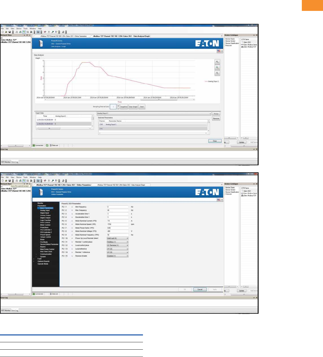
Volume 6—Solid-State Motor Control CA08100007E—May 2014 www.eaton.com V6-T2-35
2
2
2
2
2
2
2
2
2
2
2
2
2
2
2
2
2
2
2
2
2
2
2
2
2
2
2
2
2
2
2.4
Adjustable Frequency Drives
PowerXL DG1 Series Drives
PowerXpert inControl Software
The PowerXL Series PC Tool is designed for programming, controlling and monitoring of
the DG1 drives. Features include loading parameters that can be saved to a file or printed,
setting references, starting and stopping the motor, monitoring signals in graphical or text
form, and real-time display.
PowerXpert inControl Software
Description Catalog Number
Software kit (software, cable, manual) DXG-ACC-SOFTWARE
Software cable (USB to RJ45 [RS-485]) DXG-CBL-PCCABLE
Real-time clock battery DXG-ACC-RTBATT
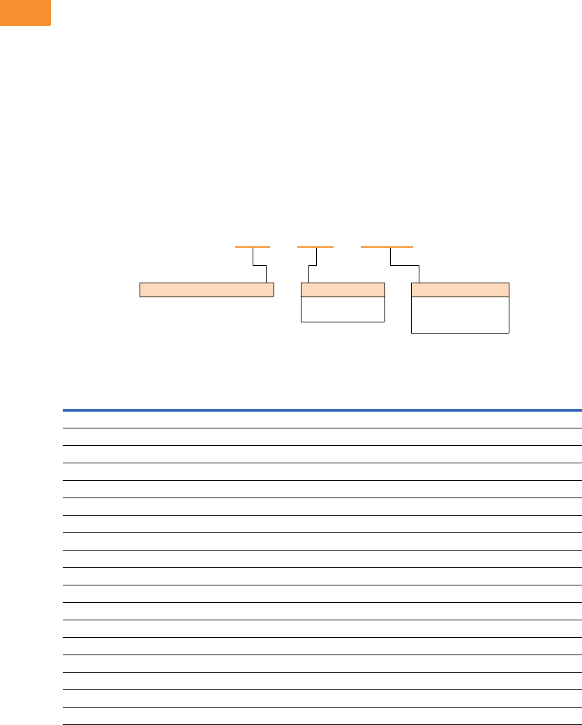
V6-T2-36 Volume 6—Solid-State Motor Control CA08100007E—May 2014 www.eaton.com
2
2
2
2
2
2
2
2
2
2
2
2
2
2
2
2
2
2
2
2
2
2
2
2
2
2
2
2
2
2
2.4
Adjustable Frequency Drives
PowerXL DG1 Series Drives
Brake Chopper Options
The brake chopper circuit
option is used for applications
that require dynamic braking.
Dynamic braking resistors are
not included with drive
purchase. Consult the factory
for additional dynamic braking
resistor selections that are
supplied separately. A list of
common resistors are listed
below and are complete
indoor assemblies, include a
pre-wired terminal block and
a thermal switch, and are not
UL Listed.
Duty Cycle
The duty cycle rating is based
on a 60-second period. For
example, the 20% duty cycle
resistor can carry 100%
current for 12 seconds out
of every 60 seconds, while
the 50% duty cycle resistor
can carry 150% current for
30 seconds out of every
60 seconds.
Torque
If the braking torque required
is less than 15%, dynamic
braking is not required
because the regenerated
energy will be dissipated in
the drive and motor losses.
Dynamic Brake Resistor—Catalog Number Selection
230V Brake Resistors
Drive hp
(CT/IH)
Minimum
Ohms
20% Duty Cycle, 100% Torque 50% Duty Cycle, 150% Torque
Catalog Number Dimensions Catalog Number Dimensions
0.75 15.0 DBR-R100-W0400 12W x 5D x 5H DBR-R100-W0800 12W x 7D x 5H
115.0DBR-R100-W0400 12W x 5D x 5H DBR-R100-W0800 12W x 7D x 5H
1.5 15.0 DBR-R100-W0400 12W x 5D x 5H DBR-R036-W1200 12W x 10D x 5H
215.0DBR-R100-W0400 12W x 5D x 5H DBR-R036-W1200 12W x 10D x 5H
315.0DBR-R036-W0800 12W x 7D x 5H DBR-R036-W2000 12W x 16D x 5H
49.0DBR-R036-W0800 12W x 7D x 5H DBR-R012-W2400 19W x 10D x 5H
59.0DBR-R036-W0800 12W x 7D x 5H DBR-R020-W2800 19W x 13D x 5H
7.5 9.0 DBR-R020-W1200 12W x 10D x 5H DBR-R012-W4800 26.5W x 10D x 5H
10 7.0 DBR-R015-W1600 12W x 13D x 5H DBR-R112-W6000 26.5W x 13D x 5H
15 7.0 DBR-R012-W2400 19W x 10D x 5H DBR-R7D8-W9000 28W x 10D x 10H
20 2.0 DBR-R9D3-W3200 19W x 10D x 5H DBR-R3D4-W012K 28W x 10D x 10H
25 2.0 DBR-R5D5-W4000 26.5W x 10D x 5H DBR-R5D1-W015K 28W x 16D x 10H
30 2.0 DBR-R4D8-W4800 26.5W x 10D x 5H DBR-R4D1-W020K 28W x 16D x 10H
40 2.0 DBR-R004-W6000 26.5W x 13D x 5H DBR-R3D4-W025K 30W x 18D x 16H
50 2.0 DBR-R3D1-W7500 26.5W x 16D x 5H DBR-R2D1-W030K 30W x 18D x 24H
60 2.0 DBR-R2D8-W9000 26.5W x 16D x 5H DBR-R002-W036K 30W x 18D x 24H
75 2.0 DBR-R2D6-W012K 28W x 10D x 10H DBR-R002-W045K 30W x 18D x 32H
100 2.0 DBR-R002-W015K 28W x 16D x 10H DBR-R002-W060K 30W x 18D x 48H
DBR –R100– W0800
Dynamic Brake Resistor Resistance
1D0 =1.0 Ohms
100 =100 Ohms
Rated Watts
0800 = 800 Watts
8000 = 8000 Watts
080K = 80,000 Watts

Volume 6—Solid-State Motor Control CA08100007E—May 2014 www.eaton.com V6-T2-37
2
2
2
2
2
2
2
2
2
2
2
2
2
2
2
2
2
2
2
2
2
2
2
2
2
2
2
2
2
2
2.4
Adjustable Frequency Drives
PowerXL DG1 Series Drives
480V Brake Resistors
Drive hp
(CT/IH)
Minimum
Ohms
20% Duty Cycle, 100% Torque 50% Duty Cycle, 150% Torque
Catalog Number Dimensions Catalog Number Dimensions
136.0DBR-R100-W0400 12W x 5D x 5H DBR-R100-W0800 12W x 7D x 5H
1.5 36.0 DBR-R100-W0400 12W x 5D x 5H DBR-R100-W1200 12W x 10D x 5H
236.0DBR-R100-W0400 12W x 5D x 5H DBR-R100-W1200 12W x 10D x 5H
336.0DBR-R100-W0800 12W x 7D x 5H DBR-R100-W2000 12W x 16D x 5H
536.0DBR-R100-W0800 12W x 7D x 5H DBR-R100-W2800 19W x 13D x 5H
636.0DBR-R100-W1200 12W x 10D x 5H DBR-R070-W4000 19W x 16D x 5H
7.5 18.0 DBR-R100-W1200 12W x 10D x 5H DBR-R020-W4800 26.5W x 13D x 5H
10 18.0 DBR-R063-W1600 12W x 13D x 5H DBR-R030-W6000 26.5W x 16D x 5H
15 18.0 DBR-R030-W2400 19W x 10D x 5H DBR-R030-W9000 28W x 10D x 10H
20 13.0 DBR-R030-W3200 19W x 13D x 5H DBR-R023-W012K 28W x 13D x 10H
25 13.0 DBR-R030-W4000 19W x 16D x 5H DBR-R013-W015K 28W x 16D x 10H
30 13.0 DBR-R020-W4800 26.5W x 13D x 5H DBR-R014-W020K 30W x 18D x 24H
40 2.0 DBR-R112-W6000 26.5W x 13D x 5H DBR-R007-W025K 30W x 18D x 16H
50 2.0 DBR-R013-W7500 26.5W x 16D x 5H DBR-R8D5-W030K 30W x 18D x 24H
60 2.0 DBR-R010-W9000 28W x 10D x 10H DBR-R7D3-W036K 30W x 18D x 24H
75 2.0 DBR-R009-W012K 28W x 13D x 10H DBR-R002-W045K 30W x 18D x 32H
100 2.0 DBR-R5D1-W015K 28W x 16D x 10H DBR-R004-W060K 30W x 18D x 40H
125 2.0 DBR-R4D1-W020K 28W x 16D x 10H DBR-R004-W070K 30W x 18D x 48H
150 2.0 DBR-R3D4-W025K 30W x 18D x 16H DBR-R3D5-W085K 30W x 18D x 56H
200 2.0 DBR-R3D3-W030K 30W x 18D x 24H DBR-R2D6-W110K 30W x 18D x 64H

V6-T2-38 Volume 6—Solid-State Motor Control CA08100007E—May 2014 www.eaton.com
2
2
2
2
2
2
2
2
2
2
2
2
2
2
2
2
2
2
2
2
2
2
2
2
2
2
2
2
2
2
2.4
Adjustable Frequency Drives
PowerXL DG1 Series Drives
Replacement Parts
Frame 1
Frame 2
Frame 3
Notes
1Factory recommended spare parts.
2575V available in 2015.
Catalog Number Catalog Number Catalog Number
Description 230V 480V 575V
Standard keypad 1DXG-KEY-LCD DXG-KEY-LCD DXG-KEY-LCD
Main control board 1DXG-SPR-CTRLBOARD DXG-SPR-CTRLBOARD DXG-SPR-CTRLBOARD
Control board cover DXG-SPR-BCOVER DXG-SPR-BCOVER DXG-SPR-BCOVER
Type 1/IP21 standard cover DXG-SPR-FR1CVR DXG-SPR-FR1CVR 2
Main fan kit 1DXG-SPR-FR1FAN DXG-SPR-FR1FAN 2
Control fan DXG-SPR-2FR1CF DXG-SPR-4FR1CF 2
Main power board DXG-SPR-2FR1MPB DXG-SPR-4FR1MPB 2
EMI board DXG-SPR-2FR1EB DXG-SPR-4FR1EB 2
Middle chassis cover DXG-SPR-FR1MCC DXG-SPR-FR1MCC 2
Outer housing DXG-SPR-FR1OH DXG-SPR-FR1OH 2
UL conduit plate DXG-SPR-FR1CPUL DXG-SPR-FR1CPUL 2
IEC conduit plate DXG-SPR-FR1CPIEC DXG-SPR-FR1CPIEC 2
Catalog Number Catalog Number Catalog Number
Description 230V 480V 575V
Standard keypad 1DXG-KEY-LCD DXG-KEY-LCD DXG-KEY-LCD
Main control board 1DXG-SPR-CTRLBOARD DXG-SPR-CTRLBOARD DXG-SPR-CTRLBOARD
Control board cover DXG-SPR-BCOVER DXG-SPR-BCOVER DXG-SPR-BCOVER
Type 1/IP21 standard cover DXG-SPR-FR2CVR DXG-SPR-FR2CVR 2
Main fan kit 1DXG-SPR-FR2FAN DXG-SPR-FR2FAN 2
Control fan DXG-SPR-FR2CF DXG-SPR-FR2CF 2
Bus capacitor DXG-SPR-2FR2BC DXG-SPR-4FR24BC 2
Main power board DXG-SPR-2FR2MPB DXG-SPR-4FR2MPB 2
EMI board DXG-SPR-2FR2EB DXG-SPR-4FR2EB 2
IGBT module DXG-SPR-FR2IGBT DXG-SPR-FR2IGBT 2
Middle chassis cover DXG-SPR-FR2MCC DXG-SPR-FR2MCC 2
Outer housing DXG-SPR-FR2OH DXG-SPR-FR2OH 2
UL conduit plate DXG-SPR-FR2CPUL DXG-SPR-FR2CPUL 2
IEC conduit plate DXG-SPR-FR2CPIEC DXG-SPR-FR2CPIEC 2
Catalog Number Catalog Number Catalog Number
Description 230V 480V 575V
Standard keypad 1DXG-KEY-LCD DXG-KEY-LCD DXG-KEY-LCD
Main control board 1DXG-SPR-CTRLBOARD DXG-SPR-CTRLBOARD DXG-SPR-CTRLBOARD
Control board cover DXG-SPR-BCOVER DXG-SPR-BCOVER DXG-SPR-BCOVER
Type 1/IP21 standard cover DXG-SPR-FR3CVR DXG-SPR-FR3CVR 2
Main fan kit 1DXG-SPR-FR3FAN DXG-SPR-FR3FAN 2
Control fan DXG-SPR-FR34CF DXG-SPR-FR34CF 2
Bus capacitor DXG-SPR-FR3BC DXG-SPR-FR3BC 2
Main power board DXG-SPR-2FR3MPB DXG-SPR-4FR3MPB 2
EMI board DXG-SPR-2FR3EB DXG-SPR-4FR3EB 2
Drive board DXG-SPR-2FR3DB DXG-SPR-4FR3DB 2
Output board DXG-SPR-FR3OB DXG-SPR-FR3OB 2
Middle chassis cover DXG-SPR-FR3MCC DXG-SPR-FR3MCC 2
Outer housing DXG-SPR-FR3OH DXG-SPR-FR3OH 2
UL conduit plate DXG-SPR-FR3CPUL DXG-SPR-FR3CPUL 2
IEC conduit plate DXG-SPR-FR3CPIEC DXG-SPR-FR3CPIEC 2

Volume 6—Solid-State Motor Control CA08100007E—May 2014 www.eaton.com V6-T2-39
2
2
2
2
2
2
2
2
2
2
2
2
2
2
2
2
2
2
2
2
2
2
2
2
2
2
2
2
2
2
2.4
Adjustable Frequency Drives
PowerXL DG1 Series Drives
Frame 4
Frame 5
Notes
1Factory recommended spare parts.
2575V available in 2015.
230V 480V 575V
Description Catalog Number Catalog Number Catalog Number
Standard keypad 1DXG-KEY-LCD DXG-KEY-LCD DXG-KEY-LCD
Main control board 1DXG-SPR-CTRLBOARD DXG-SPR-CTRLBOARD DXG-SPR-CTRLBOARD
Control board cover DXG-SPR-BCOVER DXG-SPR-BCOVER DXG-SPR-BCOVER
Type 1/IP21 standard cover DXG-SPR-FR4CVR DXG-SPR-FR4CVR 2
Main fan kit 1DXG-SPR-FR4FAN DXG-SPR-FR4FAN 2
Control fan DXG-SPR-FR34CF DXG-SPR-FR34CF 2
Bus capacitor DXG-SPR-2FR4BC DXG-SPR-4FR24BC 2
Main power board DXG-SPR-2FR4MPB DXG-SPR-4FR4MPB 2
EMI board DXG-SPR-2FR4EB DXG-SPR-4FR4EB 2
Softstart board DXG-SPR-2FR4SB DXG-SPR-4FR4SB 2
IGBT module DXG-SPR-2FR4IGBT DXG-SPR-4FR4IGBT 2
Rectifier module DXG-SPR-2FR4RM DXG-SPR-4FR4RM 2
Brake chopper module DXG-SPR-2FR4BCM DXG-SPR-4FR4BCM 2
Middle chassis cover DXG-SPR-FR4MCC DXG-SPR-FR4MCC 2
Outer housing DXG-SPR-FR4OH DXG-SPR-FR4OH 2
UL conduit plate DXG-SPR-FR4CPUL DXG-SPR-FR4CPUL 2
IEC conduit plate DXG-SPR-FR4CPIEC DXG-SPR-FR4CPIEC 2
230V 480V 575V
Description Catalog Number Catalog Number Catalog Number
Standard keypad 1DXG-KEY-LCD DXG-KEY-LCD DXG-KEY-LCD
Main control board 1DXG-SPR-CTRLBOARD DXG-SPR-CTRLBOARD DXG-SPR-CTRLBOARD
Control board cover DXG-SPR-BCOVER DXG-SPR-BCOVER DXG-SPR-BCOVER
Type 1/IP21 standard cover DXG-SPR-FR5CVR DXG-SPR-FR5CVR 2
Main fan kit 1DXG-SPR-FR5FAN DXG-SPR-FR5FAN 2
Control fan DXG-SPR-FR5CF DXG-SPR-FR5CF 2
Bus capacitor DXG-SPR-FR5BC DXG-SPR-FR5BC 2
Main power board DXG-SPR-2FR5MPB DXG-SPR-4FR5MPB 2
EMI-1 board DXG-SPR-2FR5E1B DXG-SPR-4FR5E1B 2
EMI-2 board DXG-SPR-2FR5E2B DXG-SPR-4FR5E2B 2
EMI-3 board DXG-SPR-FR5E3B DXG-SPR-FR5E3B 2
IGBT module DXG-SPR-FR5IGBT DXG-SPR-FR5IGBT 2
Rectifier module DXG-SPR-2FR5RM DXG-SPR-4FR5RM 2
Brake chopper module DXG-SPR-2FR5BCM DXG-SPR-4FR5BCM 2
Middle chassis cover DXG-SPR-FR5MCC DXG-SPR-FR5MCC 2
Outer housing DXG-SPR-FR5OH DXG-SPR-FR5OH 2
UL conduit plate DXG-SPR-FR5CPUL DXG-SPR-FR5CPUL 2
IEC conduit plate DXG-SPR-FR5IECCP DXG-SPR-FR5IECCP 2
V6-T2-40 Volume 6—Solid-State Motor Control CA08100007E—May 2014 www.eaton.com
2
2
2
2
2
2
2
2
2
2
2
2
2
2
2
2
2
2
2
2
2
2
2
2
2
2
2
2
2
2
2.4
Adjustable Frequency Drives
PowerXL DG1 Series Drives
Technical Data and Specifications
PowerXL Series—DG1 Technical Data and Specifications
Attribute Description Specification
Input ratings Input voltage Uin 208V to 240V, 380V to 500V, 525V to 600V, –15 to 10%
Input frequency 50 Hz to 60 Hz (variation up to 45 Hz to 66 Hz)
Connection to power Once per minute or less
Starting delay 3s (FR1 to FR2), 4s (FR3), 5s (FR4), 6s (FR5)
Short-circuit withstand rating 100 kAIC
Output ratings Output voltage 0 to Uin
Continuous output current IL: ambient temperature maximum 40°C, up to 60°C with derating, overload 1.1 x IL (1 min./10 min.)
IH: ambient temperature maximum 50°C, up to 60°C with derating, overload 1.5 x IH (1 min./10 min.)
Overload current 150% respectively 110% (1 min./10 min.)
Initial output current 200% (2s/20s)
Output frequency 0–400 Hz (standard)
Frequency resolution 0.01 Hz
Control characteristics Control methods Frequency control
Speed control
Open-loop speed control
Open-loop torque control
Switching frequency Range:
FR1–3: 1 kHz to 12 kHz
FR4–5: 1 kHz to 10 kHz
Defaults:
FR1–3: 4 kHz (IH), 6 kHz (IL)
FR4–5: 3.6 kHz
Automatic switching frequency derating in case of overload.
Frequency reference Analog input: resolution 0.1% (10-bit), accuracy +1%
Panel reference: resolution 0.01 Hz
Field weakening point 20 Hz to 400 Hz
Acceleration time 0.1s to 3000s
Deceleration time 0.1s to 3000s
Braking torque DC brake: 30% x Motor Rated Torque (Tn) (without brake chopper)
Dynamic braking (with optional brake chopper using an external brake resistor):
100% continuous maximum rating
Ambient conditions Ambient operating temperature –10°C (no frost) to +50°C, up to +60°C with derating (CT)
–10°C (no frost) to +40°C, up to +60°C with derating (VT)
Storage temperature –40°C to +70°C
Relative humidity 0–95% RH, noncondensing, non-corrosive
Air quality:
●Chemical vapors
●Mechanical particles
Tested according to IEC 60068-2-60 Test Key:
Flowing mixed gas corrosion test, Method 1 (H2S [hydrogen sulfide] and SO2 [sulfur dioxide])
Designed according to:
IEC 60721-3-3, unit in operation, class 3C2
IEC 60721-3-3, unit in operation, class 3S2
Altitude 100% load capacity (no derating) up to 3280 ft (1000m); 1% derating for each 328 ft (100m) above
3280 ft (1000m); max. 9842 ft (3000m) (2000m for corner grounded earth main systems)

Volume 6—Solid-State Motor Control CA08100007E—May 2014 www.eaton.com V6-T2-41
2
2
2
2
2
2
2
2
2
2
2
2
2
2
2
2
2
2
2
2
2
2
2
2
2
2
2
2
2
2
2.4
Adjustable Frequency Drives
PowerXL DG1 Series Drives
PowerXL Series—DG1 Technical Data and Specifications, continued
Attribute Description Specification
Ambient conditions,
continued
Vibration:
●EN 61800-5-1
●EN 60668-2-6
5–150 Hz
Displacement amplitude: 1 mm (peak) at 5 Hz to 15.8 Hz (FR1–FR5)
Maximum acceleration amplitude: 1g at 15.8 Hz to 150 Hz (FR1–FR5)
Shock:
●ISTA 1 A
●EN 60068-2-27
Storage and shipping: maximum 15g, 11 ms (in package)
Overvoltage Overvoltage Category III
Pollution degree Pollution Degree 2
Enclosure class IP21/Type 1 standard in entire kW/hp range
IP54/Type 12 option
Note: Keypad required to be mounted in drive for IP54/Type 12 rating
Immunity Fulfills EN 61800-3 (2004), first and second environment
MTBF FR1: 165,457 hours
FR2: 134,833 hours
FR3: 102,515 hours
FR4: 121,567 hours
FR5: 108,189 hours
FR6: Available in 2015
Standards Safety UL 508C, CSA C22.2 No. 274-13 and EN 61800-5-1
EMC +EMC2: EN 61800-3 (2004), Category C2
The drive can be modified for IT networks and corner grounding TN system
Electrostatic discharge Second environment, IEC 61000-4-2, 4 kV CD or 8 kV AD, Criterion B
Fast transient burst Second environment, IEC 61000-4-4, 2 kV/5 kHz, Criterion B
Dielectrical strength Primary to secondary: 3600 Vac/5100 Vdc
Primary to earth: 2000 Vac/2828 Vdc
Approvals EN 61800-5-1 (2007), CE, UL and cUL (see nameplate for more detailed approvals)
Fieldbus connections Onboard: EtherNet/IP, Modbus® TCP, Modbus RTU, BACnet
Safety/protections Overvoltage protection Yes
Overvoltage trip limit 240V drives: 456V
480V drives: 911V
Undervoltage protection Yes
Undervoltage trip limit 240V drives: 211V
480V drives: 370V
Earth fault protection Yes
Input phase supervision Yes
Motor phase supervision Yes
Overcurrent protection Yes
Unit overtemperature protection Yes
Motor overload protection Yes
Motor stall protection Yes
Motor underload protection Yes
DC bus overvoltage control Yes
Short-circuit protection of 24V
reference voltages
Yes
Surge protection Yes (differential mode 2 kV; common mode 4 kV)
Common coated boards Yes (prevents corrosion)
V6-T2-42 Volume 6—Solid-State Motor Control CA08100007E—May 2014 www.eaton.com
2
2
2
2
2
2
2
2
2
2
2
2
2
2
2
2
2
2
2
2
2
2
2
2
2
2
2
2
2
2
2.4
Adjustable Frequency Drives
PowerXL DG1 Series Drives
Wiring Diagram
PowerXL Series—DG1 Control Wiring Diagram
Pin Signal Name Signal Default Setting Description
1 +10V Ref. Output Voltage — 10 Vdc Supply Source
2 AI1+ Analog Input 1 0–10V Voltage Speed Reference (Programmable to 4 mA to 20 mA)
3 AI1– Analog Input 1 Ground — Analog Input 1 Common (Ground)
4 AI2+ Analog Input 2 4 mA to 20 mA Current Speed Reference (Programmable to 0–10V)
5 AI2– Analog Input 2 Ground — Analog Input 2 Common (Ground)
6 GND I/O Signal Ground — I/O Ground for Reference and Control
7 DIN5 Digital Input 5 Preset Speed B0 Sets frequency output to Preset Speed 1
8 DIN6 Digital Input 6 Preset Speed B1 Sets frequency output to Preset Speed 2
9 DIN7 Digital Input 7 Emergency Stop (TI–) Input forces VFD output to shut off
10 DIN8 Digital Input 8 Force Remote (TI+) Input takes VFD from Local to Remote
11 CMB DI5 to DI8 Common Grounded Allows source input
12 GND I/O Signal Ground — I/O Ground for Reference and Control
13 24V +24 Vdc Output — Control voltage output (100 mA max.)
14 DO1 Digital Output 1 Ready Shows the drive is ready to run
15 24Vo +24 Vdc Output — Control voltage output (100 mA max.)
16 GND I/O Signal Ground — I/O Ground for Reference and Control
17 AO1+ Analog Output 1 Output Frequency Shows Output frequency to motor 0–60 Hz (4 mA to 20 mA)
18 AO2+ Analog Output 2 Motor Current Shows Motor current of motor 0–FLA (4 mA to 20 mA)
19 24Vi +24 Vdc Input — External control voltage input
20 DIN1 Digital Input 1 Run Forward Input starts drive in forward direction (start enable)
21 DIN2 Digital Input 2 Run Reverse Input starts drive in reverse direction (start enable)
22 DIN3 Digital Input 3 External Fault Input causes drive to fault
23 DIN4 Digital Input 4 Fault Reset Input resets active faults
24 CMA DI1 to DI4 Common Grounded Allows source input
25 A RS-485 Signal A — Fieldbus Communication (Modbus, BACnet)
26 B RS-485 Signal B — Fieldbus Communication (Modbus, BACnet)
27 R3NO Relay 3 Normally Open At Speed Relay output 3 shows VFD is at Ref. Frequency
28 R1NC Relay 1 Normally Closed Run Relay output 1 shows VFD is in a run state
29 R1CM Relay 1 Common
30 R1NO Relay 1 Normally Open
31 R3CM Relay 3 Common At Speed Relay output 3 shows VFD is at Ref. Frequency
32 R2NC Relay 2 Normally Closed Fault Relay output 2 shows VFD is in a fault state
33 R2CM Relay 2 Common
34 R2NO Relay 2 Normally Open
Res
i
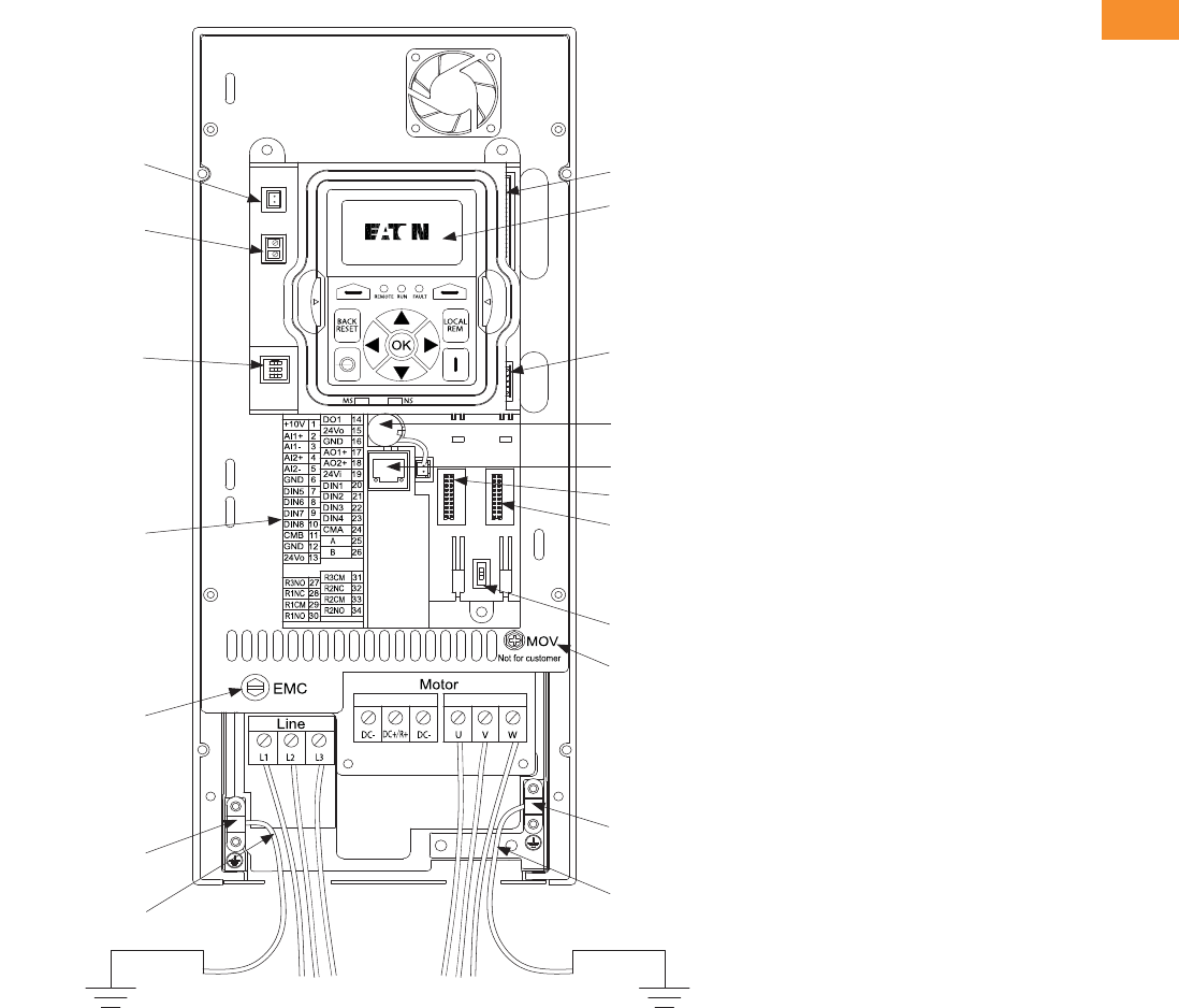
Volume 6—Solid-State Motor Control CA08100007E—May 2014 www.eaton.com V6-T2-43
2
2
2
2
2
2
2
2
2
2
2
2
2
2
2
2
2
2
2
2
2
2
2
2
2
2
2
2
2
2
2.4
Adjustable Frequency Drives
PowerXL DG1 Series Drives
Control Board Layout
PowerXL Series—DG1 Control Board Layout
Connect DSP Part
to Power Board
Keypad
Connect MCU Part
to Power Board
Battery (Standard)
RJ45 EtherNet/IP,
Modbus TCP
Optional Card A
Optional Card B
RS-485 Terminating
Resistor
Removable
MOV Screw
Motor Ground
Clamp Location
Grounding
Strap Location
Grounding
Strap Location
Line Ground
Clamp Location
Removable
EMC Screw
Control I/O
Terminals
AI Mode Selection
STO
Fan Power Wire
Line Side Motor
Line Ground
Clamp Location
ON
123
ON
1
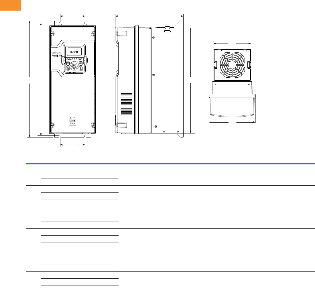
V6-T2-44 Volume 6—Solid-State Motor Control CA08100007E—May 2014 www.eaton.com
2
2
2
2
2
2
2
2
2
2
2
2
2
2
2
2
2
2
2
2
2
2
2
2
2
2
2
2
2
2
2.4
Adjustable Frequency Drives
PowerXL DG1 Series Drives
Dimensions
Approximate Dimensions in Inches (mm)
PowerXL Series—DG1 Dimensions
Note
1FR6 and 575 Vac available in 2015.
Frame
Size Voltage hp (CT/IH)kW
Amperes
(CT/IH)
Approximate Dimensions in Inches (mm) Weight
Lb (kg)D H1 H2 H3 W1W2W3W4Ø
FR1 230 Vac 0.75–3 0.55–2.2 3.5–11 7.89
(200.4)
12.87
(326.9)
12.28
(311.9)
11.50
(292.1)
6.02
(153.0)
4.80
(121.9)
3.94
(100.1)
3.94
(100.1)
0.28
(7.0)
14.33
(6.5)
480 Vac 1–5 0.75–3.7 2.3–7.6
575 Vac 12–5 1.5–3.7 3.3–7.5
FR2 230 Vac 5–7.5 3–5.5 12.5–25 9.63
(244.7)
16.50
(419.1)
15.98
(405.9)
14.96
(380.0)
6.61
(167.8)
5.28
(134.1)
3.54
(90.0)
3.54
(90.0)
0.28
(7.0)
23.37
(10.6)
480 Vac 7.5–15 5.5–11 12–23
575 Vac 17.5–15 5.5–11 10–18
FR3 230 Vac 10–15 7.5–11 31–48 10.44
(265.1)
21.97
(558.0)
21.46
(545.0)
20.43
(518.9)
8.06
(204.6)
7.24
(183.9)
4.92
(125.0)
4.92
(125.0)
0.35
(9.0)
49.82
(22.6)
480 Vac 20–30 15–22 31–46
575 Vac 120–30 15–22 22–34
FR4 230 Vac 20–30 15–22 61–88 11.57
(294.0)
24.80
(629.9)
34.31
(617.5)
23.27
(591.1)
9.36
(237.7)
9.13
(231.9)
8.07
(205.0)
8.07
(205.0)
0.35
(9.0)
77.60
(35.2)
480 Vac 40–60 30–45 61–87
575 Vac 140–60 30–45 41–62
FR5 230 Vac 40–60 30–45 114–170 13.41
(340.7)
34.98
(888.5)
29.65
(753.1)
27.83
(706.9)
11.34
(288.0)
11.10
(281.9)
8.66
(220.0)
8.66
(220.0)
0.35
(9.0)
154.32
(70.0)
480 Vac 75–125 55–90 105–170
575 Vac 175–125 55–90 80–125
FR6 1230 Vac 75–100 55–75 211–261 1111111111
480 Vac 150–200 110–150 205–261
575 Vac 1150–200 110–160 144–208
W3
H2
W4
W1
W2
H1
D
H3
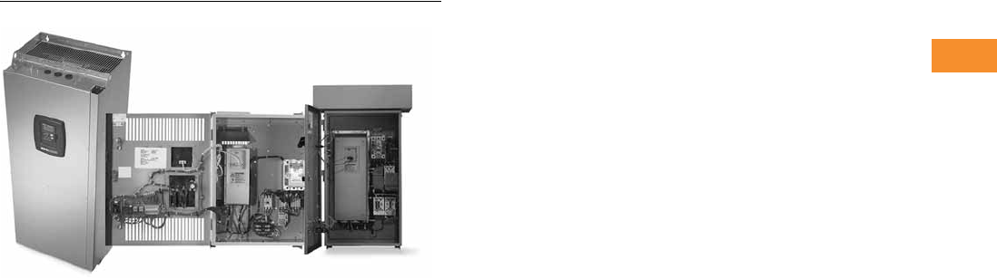
Volume 6—Solid-State Motor Control CA08100007E—May 2014 www.eaton.com V6-T2-45
2
2
2
2
2
2
2
2
2
2
2
2
2
2
2
2
2
2
2
2
2
2
2
2
2
2
2
2
2
2
2.5
Adjustable Frequency Drives
SVX9000 Drives
SVX9000 Drives
Contents
Description Page
SVX9000 Drives
SVX9000 Drives . . . . . . . . . . . . . . . . . . . . . . . . V6-T2-48
SVX9000 Enclosed Drives . . . . . . . . . . . . . . . . V6-T2-87
SVX9000 VFD Pump Panels . . . . . . . . . . . . . . . V6 -T 2- 111
Product Overview
With the SVX9000 Series
Sensorless Vector Control,
Eaton’s expanded Eaton drive
offering now covers a
complete line of PWM
adjustable frequency (speed)
drives in ratings from:
●208V—3/4 to 100 hp IH;
1 to 100 hp IL
●230V—3/4 to 100 hp IH;
1 to 125 hp IL
●480V—1 to 1900 hp IH;
1-1/2 to 2200 hp IL
●575V—2 to 2000 hp IH;
3 to 2300 hp IL
The Eaton family of drives
includes DA1, DC1, H-Max,
M-Max, SVX9000 and
SPX9000. 9000X Series drive
ratings are rated for either
high overload (IH) or low
overload (IL). IL indicates
110% overload capacity for
1 minute out of 10 minutes.
IH indicates 150% overload
capacity for 1 minute out of
10 minutes.
A full range of enclosure
types and options are
available to meet a wide array
of applications—from simple
variable torque to more
complex industrial
applications such as
conveyors, mixers and
machine controls.
Application Description
Application Engineering
Proper selection and
application of all drive system
components is essential to
assure that an adjustable
frequency drive system will
safely and reliably provide the
performance required for any
given application. The party
responsible for the overall
design and operation of the
facility must make sure that
qualified personnel are
employed to select all
components of the drive
system, including appropriate
safety devices. Eaton’s AF
Drives Application
Engineering Department is
prepared to provide
assistance to answer any
questions about the technical
capabilities of Eaton drives.
Motor Selection
The basic requirement of
motor selection is to match
the torque vs. speed
capability of the motor to the
torque vs. speed requirement
of the driven load.
Motor Torque vs. Speed
Capability
As the speed of a motor is
reduced below its 60 Hz base
speed, motor cooling
becomes less effective
because of the reduced speed
of the self-cooling fan. This
limitation determines the
maximum torque for
continuous operation at any
operating speed. The
maximum intermittent
operating torque is
determined by the motor’s
torque vs. current
characteristics and the output
current capability of the
adjustable frequency
controller.
Multiple Motor Operation
A number of motors can be
connected in parallel to a
single controller. Since the
frequency of the power
supplied by the controller is
the same for each motor, the
motors will always operate at
the same speed. Application
Engineering assistance must
be requested for all multiple
motor applications to assure
compliance with all controller
design limitations.
Special Types of Motors
Standard NEMA Designs A
and B three-phase motors are
the only motors
recommended for use in the
majority of applications, but
other types of motors are
occasionally used. If the
existing motor used in the
application or the motor
proposed for use with the
drive
system is a type other
than NEMA Design
A or B,
Application Engineering
assistance must be
requested to make certain
that the drive is properly
applied.

V6-T2-46 Volume 6—Solid-State Motor Control CA08100007E—May 2014 www.eaton.com
2
2
2
2
2
2
2
2
2
2
2
2
2
2
2
2
2
2
2
2
2
2
2
2
2
2
2
2
2
2
2.5
Adjustable Frequency Drives
SVX9000 Drives
Product Selection Guide
Controller Selection
The basic requirement of
controller selection is to
match the output current,
voltage and frequency
capabilities of the controller
with the requirements of the
connected motor.
Output Current
The controller must be
selected and applied such
that the average operating
motor current and
horsepower do not exceed
the continuous current and
horsepower ratings of the
controller. The intermittent
operating current must not
exceed the intermittent
current rating of the
controller.
Motor Protection
Eaton adjustable frequency
drives include electronic
motor overload protection
circuits that are designed to
meet the requirements of
NEC article 430-2 provided
that only one motor is
connected to the output of
the controller.
Output Voltage and Frequency
When they are shipped, AF
controllers are adjusted to
provide a maximum output
voltage and frequency
equivalent to the input line
voltage and frequency. The
controllers can be adjusted to
operate above line frequency,
but a hazard of personal injury
or equipment damage may
exist when the motor is
operated above base speed.
Before adjusting the drive to
operate above line frequency,
make sure that the motor and
the driven machinery can
safely be operated at the
resulting speed.
Features
Controller Features
Operator Control and Interface
Requirements
Since there are many
possible configurations and
many ways of achieving a
specific end result, it pays to
consider the operator control
and interface requirements
carefully. A simplified and
more economical drive
package can often be
achieved by selecting from
standard product offerings
rather than specifying a
custom designed
configuration.
Installation Compatibility
The successful application
of an AC drive requires the
assurance that the drive will
be compatible with the
environment in which it will
be installed. In planning the
installation, be sure to
carefully consider the heat
produced by the drive, the
altitude and temperature
limits and the need for clean
cooling air. Other important
considerations include
acoustical noise, vibration,
electromagnetic compatibility,
power quality, controller input
harmonic current and power
distribution equipment
requirements.
Auxiliary Equipment and
Accessories
Adjustable drives are
generally designed to have a
motor directly connected to
the controller output
terminals with no other
equipment connected in
series or parallel. Motor
starters, disconnect
switches, surge absorbers,
DV/DT suppression circuits,
output chokes, output
transformers and any other
equipment under
consideration for installation
on the output of the controller
should not be installed
without first requesting
Application Engineering
assistance. Power factor
correction capacitors must
never, under any
circumstances, be connected
at the output of the controller.
They would serve no useful
purpose, and they may
damage the controller.
Enclosure Definitions
●
NEMA Type 1/IP21
—
Enclosures are intended for
indoor use primarily to
provide a degree of
protection against contact
with enclosed equipment
and provide a degree of
protection against a limited
amount of falling dirt in
locations where unusual
service conditions do not
exist. Top or side openings
in the NEMA Type 1/IP21
enclosure allow for the free
exchange of inside and
outside air while meeting
the UL rod entry and rust
resistance design tests.
●
NEMA Type 12/IP54
—
Enclosures are intended
for indoor use primarily to
provide a degree of
protection against
circulating dust, falling dirt
and dripping noncorrosive
liquids. To meet UL drip,
dust and rust resistance
tests, NEMA Type 12/IP54
enclosures have no
openings to allow for the
exchange of inside and
outside air.
●
Chassis IP00
—Similar to
Protected Chassis IP20
except power terminals are
protected by plastic
shielding only. Primarily
intended to be mounted
inside a surrounding
protective enclosure.
●
NEMA Type 3R
—Similar in
design to NEMA Type 12/
IP54 except with more
stringent design and test
requirements.

Volume 6—Solid-State Motor Control CA08100007E—May 2014 www.eaton.com V6-T2-47
2
2
2
2
2
2
2
2
2
2
2
2
2
2
2
2
2
2
2
2
2
2
2
2
2
2
2
2
2
2
2.5
Adjustable Frequency Drives
SVX9000 Drives
Motor Protection
DV/DT and Peak Motor Voltage Solutions
Today’s AFD products offer
significantly improved
performance, but at the
potential cost of motor
insulation stress. The fast
switching time of the IGBT
devices used in newer AFDs
can cause a transmission line
effect in the output power
leads to the motor, leading to
possibly damaging voltage
levels. To meet this need,
NEMA has introduced a
motor in MG1, Part 31, which
provides an insulation system
designed to maintain normal
motor life in AFD applications.
For existing motors, a motor
protection scheme is required
for longer cable runs. Eaton
offers three standard solutions
for existing systems.
●MotoRx This solution
provides an energy
recovery system which
clamps the peak motor
voltage to a safe level
for standard motors. This
option is used when the
distance between a single
motor and the drive is
600 ft or less.
●Output Line Reactor This
option provides an output
line reactor, reducing the
DV/DT of the AFD output
voltage and lessening the
transmission line effect, to
lower the peak voltage at
the motor terminals.
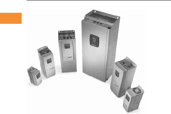
V6-T2-48 Volume 6—Solid-State Motor Control CA08100007E—May 2014 www.eaton.com
2
2
2
2
2
2
2
2
2
2
2
2
2
2
2
2
2
2
2
2
2
2
2
2
2
2
2
2
2
2
2.5
Adjustable Frequency Drives
SVX9000 Drives
SVX9000 Drives
Contents
Description Page
SVX9000 Drives
Standards and Certifications . . . . . . . . . . . . . . V6-T2-49
Catalog Number Selection . . . . . . . . . . . . . . . . V6-T2-49
Product Selection . . . . . . . . . . . . . . . . . . . . . . . V6-T2-50
Accessories . . . . . . . . . . . . . . . . . . . . . . . . . . . V6-T2-54
Options . . . . . . . . . . . . . . . . . . . . . . . . . . . . . . V6-T2-55
Replacement Parts . . . . . . . . . . . . . . . . . . . . . . V6-T2-61
Technical Data and Specifications . . . . . . . . . . V6-T2-70
Dimensions . . . . . . . . . . . . . . . . . . . . . . . . . . . V6-T2-71
SVX9000 Enclosed Drives . . . . . . . . . . . . . . . . . . . V6-T2-87
SVX9000 VFD Pump Panels . . . . . . . . . . . . . . . . . V6 -T 2- 111
SVX9000 Drives
Product Description
SVX9000 Series Adjustable
Frequency Drives from
Eaton’s Electrical Sector are
the next generation of drives
specifically engineered for
today’s commercial and
industrial applications. The
power unit makes use of the
most sophisticated
semiconductor technology
and a highly modular
construction that can be
flexibly adapted to the
customer’s needs.
The input and output
configuration (I/O) is designed
with modularity in mind. The
I/O is compromised of option
cards, each with its own input
and output configuration. The
control module is designed to
accept a total of five of these
cards. The cards contain not
only normal analog and digital
inputs but also fieldbus cards.
These drives continue the
tradition of robust
performance, and raise the
bar on features and
functionality, ensuring the
best solution at the right
price.
Features
●Robust design—proven
500,000 hours MTBF
●Integrated 3% line reactors
standard on drives from
FR4 through FR9
●EMI/RFI Filters H standard
up to 200 hp IH 480V, 100
hp IH 230V
●Simplified operating menu
allows for typical
programming changes,
while programming mode
provides control of
everything
●Quick Start Wizard built
into the programming of
the drive ensures a smooth
start-up
●Keypad can display up to
three monitored
parameters simultaneously
●LOCAL/REMOTE operation
from keypad
●Copy/paste function allows
transfer of parameter
settings from one drive to
the next
●Standard NEMA Type 12/
IP54 keypad on all drives
●The SVX can be flexibly
adapted to a variety of
needs using our pre-
installed “Seven in One”
precision application
programs consisting of:
●Basic
●Standard
●Local/remote
●Multi step speed control
●PID control
●Multi-purpose control
●Pump and fan control
with auto change
●Additional I/O and
communication cards
provide plug and play
functionality
●I/O connections with
simple quick connection
terminals
●Hand-held auxiliary 24V
power supply allows
programming/monitoring
of control module without
applying full power to the
drive
●Control logic can be
powered from an external
auxiliary control panel,
internal drive functions and
fieldbus if necessary
●Brake chopper standard
from: 1–30 hp/380–500V
3/4–15 hp/208–230V
●NEMA Type 1/IP21 and
NEMA Type 12/IP54
enclosures available,
Frame Sizes FR4–FR9
●Open chassis FR10 and
greater
●Standard option board
configuration includes an
A9 I/O board and an A2
relay output board installed
in slots A and B
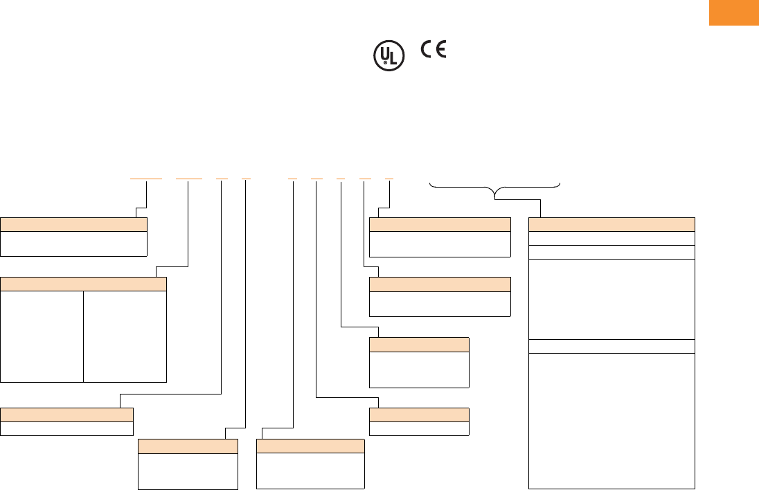
Volume 6—Solid-State Motor Control CA08100007E—May 2014 www.eaton.com V6-T2-49
2
2
2
2
2
2
2
2
2
2
2
2
2
2
2
2
2
2
2
2
2
2
2
2
2
2
2
2
2
2
2.5
Adjustable Frequency Drives
SVX9000 Drives
Standards and Certifications
Product
●IEC 61800-2
EMC (At Default Settings)
●Immunity: Fulfills all EMC
immunity requirements;
Emissions: EN 61800-3,
LEVEL H
Safety
●UL 508C
●CE
Catalog Number Selection
SVX9000 Adjustable Frequency Drives
Notes
1All 230V drives and 480V drives up to 200 hp (IH) are only available with input option 1 (EMC Level H). 480V drives 250 hp (IH) or larger are available
with input option 2 (EMC Level N). 480V drives are available with input option 4 (EMC Level L). 575V drives 200 hp (IH) or larger are only available
with input option 2. 575V drives up to 150 hp (IH) are only available with input option 4 (EMC Level L).
2480V drives up to 30 hp (IH) are only available with brake chopper option B. 480V drives 40 hp (IH) or larger come standard with brake chopper option
N. 230V drives up to 15 hp (IH) are only available with brake chopper option B. 230V drives 20 hp or larger come standard with brake chopper option
N. All 575V drives come standard without brake chopper option (N). N = No brake chopper.
3480V drives 250 hp (IH) and larger are available with enclosure style 0 (chassis); 690V drives 200 hp (IH) and larger are available with
enclosure style 0 (chassis).
4Factory promise delivery. Consult sales office for availability.
SVX 010 A 1 –4A 1 B 1 ______
Options
Options appear in alphabetical order.
Extended I/O Card Options
B1 = 6 DI, 1 ext +24 Vdc/EXT +24 Vdc
B2 = 1 RO (NC-NO), 1 RO (NO), 1 therm
B4 = 1 AI (mA isolated), 2 AO (mA isolated),
1 ext +24 Vdc/EXT + 24 Vdc
B5 = 3 RO (NO)
B8 = 1 ext +24 Vdc/EXT +24 Vdc, 3 Pt100
B9 = 1 RO (NO), 5 DI 42–240 Vac input
Communication Cards
CA = Johnson Controls N2
CI = Modbus TCP
CJ = BACnet
CQ = EtherNet/IP
C2 = Modbus
C3 = PROFIBUS DP
C4 = LonWorks
C5 = PROFIBUS DP (D9 connector)
C6 = CANopen (slave)
C7 = DeviceNet
C8 = Modbus (D9 Type connector)
D3 = RS-232 with D9 connection
Board Modifications
1 = Standard boards
2 = Conformal (varnished) coating 4
Brake Chopper Options 2
N = No brake chopper circuit
B = Internal brake chopper circuit
Input Options 1
1 = Three-phase, EMC H
2 = Three-phase, EMC N
4 = Three-phase, EMC L
Keypad
A = Alphanumeric
AFD Software Series
A = Standard software
Enclosure 3
0 = Chassis
1 = NEMA Type 1/IP21
2 = NEMA Type 12/IP54
Voltage Rating
2 = 230V (208–240)
4 = 480V (380–500)
5 = 575V (525–690)
Product Family
SVX = Open drives
SPX = Open drives FR10 and greater
Horsepower Rating
F07 = 3/4 hp
F15 = 1-1/2 hp
007 = 7-1/2 hp
010 = 10 hp
050 = 50 hp
125 = 125 hp
350 = 350 hp
700 = 700 hp
800 = 800 hp
900 = 900 hp
H10 = 1000 hp
H12 = 1200 hp
H13 = 1350 hp
H15 = 1500 hp
H16 = 1600 hp
H20 = 2000 hp
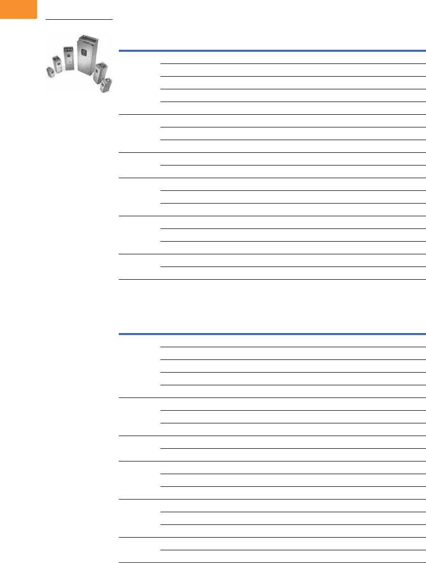
V6-T2-50 Volume 6—Solid-State Motor Control CA08100007E—May 2014 www.eaton.com
2
2
2
2
2
2
2
2
2
2
2
2
2
2
2
2
2
2
2
2
2
2
2
2
2
2
2
2
2
2
2.5
Adjustable Frequency Drives
SVX9000 Drives
Product Selection
230V SVX9000 Drives
208–240V, NEMA Type 1/IP21 Drives
208–240V, NEMA Type 12/IP54 Drives
Frame
Size hp (IH) Current (IH) hp (IL) Current (IL) Catalog Number
FR4 3/4 3.7 1 4.8 SVXF07A1-2A1B1
1 4.8 1-1/2 6.6 SVX001A1-2A1B1
1-1/2 6.6 2 7.8 SVXF15A1-2A1B1
27.8 311 SVX002A1-2A1B1
311 —12.5 SVX003A1-2A1B1
FR5 — 12.5 5 17.5 SVX004A1-2A1B1
517.5 7-1/225 SVX005A1-2A1B1
7-1/2 25 10 31 SVX007A1-2A1B1
FR61031 1548 SVX010A1-2A1B1
15 48 20 61 SVX015A1-2A1B1
FR72061 2575 SVX020A1-2A1N1
25 75 30 88 SVX025A1-2A1N1
30 88 40 114 SVX030A1-2A1N1
FR8 40 114 50 140 SVX040A1-2A1N1
50 140 60 170 SVX050A1-2A1N1
60 170 75 205 SVX060A1-2A1N1
FR9 75 205 100 261 SVX075A1-2A1N1
100 261 125 300 SVX100A1-2A1N1
Frame
Size hp (IH) Current (IH) hp (IL) Current (IL) Catalog Number
FR4 3/4 3.7 1 4.8 SVXF07A2-2A1B1
1 4.8 1-1/2 6.6 SVX001A2-2A1B1
1-1/2 6.6 2 7.8 SVXF15A2-2A1B1
27.8 311 SVX002A2-2A1B1
311 —12.5 SVX003A2-2A1B1
FR5 — 12.5 5 17.5 SVX004A2-2A1B1
517.5 7-1/225 SVX005A2-2A1B1
7-1/2 25 10 31 SVX007A2-2A1B1
FR61031 1548 SVX010A2-2A1B1
15 48 20 61 SVX015A2-2A1B1
FR72061 2575 SVX020A2-2A1N1
25 75 30 88 SVX025A2-2A1N1
30 88 40 114 SVX030A2-2A1N1
FR8 40 114 50 140 SVX040A2-2A1N1
50 140 60 170 SVX050A2-2A1N1
60 170 75 205 SVX060A2-2A1N1
FR9 75 205 100 261 SVX075A2-2A1N1
100 261 125 300 SVX100A2-2A1N1
SVX9000 Open Drives

Volume 6—Solid-State Motor Control CA08100007E—May 2014 www.eaton.com V6-T2-51
2
2
2
2
2
2
2
2
2
2
2
2
2
2
2
2
2
2
2
2
2
2
2
2
2
2
2
2
2
2
2.5
Adjustable Frequency Drives
SVX9000 Drives
480V SVX9000 Drives
380–500V, NEMA Type 1/IP21 Drives
380–500V, NEMA Type 12/IP54 Drives
Frame
Size hp (IH) Current (IH) hp (IL) Current (IL) Catalog Number
FR4 1 2.2 1-1/2 3.3 SVX001A1-4A1B1
1-1/2 3.3 2 4.3 SVXF15A1-4A1B1
24.3 35.6 SVX002A1-4A1B1
35.6 57.6 SVX003A1-4A1B1
57.6 —9 SVX005A1-4A1B1
—9 7-1/212 SVX006A1-4A1B1
FR5 7-1/2 12 10 16 SVX007A1-4A1B1
10 16 15 23 SVX010A1-4A1B1
15 23 20 31 SVX015A1-4A1B1
FR62031 2538 SVX020A1-4A1B1
25 38 30 46 SVX025A1-4A1B1
30 46 40 61 SVX030A1-4A1B1
FR74061 5072 SVX040A1-4A1N1
50 72 60 87 SVX050A1-4A1N1
60 87 75 105 SVX060A1-4A1N1
FR8 75 105 100 140 SVX075A1-4A1N1
100 140 125 170 SVX100A1-4A1N1
125 170 150 205 SVX125A1-4A1N1
FR9 150 205 200 261 SVX150A1-4A1N1
200 245 250 300 SVX200A1-4A1N1
Frame
Size hp (IH) Current (IH) hp (IL) Current (IL) Catalog Number
FR4 1 2.2 1-1/2 3.3 SVX001A2-4A1B1
1-1/2 3.3 2 4.3 SVXF15A2-4A1B1
24.3 35.6 SVX002A2-4A1B1
35.6 57.6 SVX003A2-4A1B1
57.6 —9 SVX005A2-4A1B1
— 9 7-1/2 12 SVX006A2-4A1B1
FR5 7-1/2 12 10 16 SVX007A2-4A1B1
10 16 15 23 SVX010A2-4A1B1
15 23 20 31 SVX015A2-4A1B1
FR62031 2538 SVX020A2-4A1B1
25 38 30 46 SVX025A2-4A1B1
30 46 40 61 SVX030A2-4A1B1
FR74061 5072 SVX040A2-4A1N1
50 72 60 87 SVX050A2-4A1N1
60 87 75 105 SVX060A2-4A1N1
FR8 75 105 100 140 SVX075A2-4A1N1
100 140 125 170 SVX100A2-4A1N1
125 170 150 205 SVX125A2-4A1N1
FR9 150 205 200 261 SVX150A2-4A1N1
200 245 250 300 SVX200A2-4A1N1
SVX9000 Open Drives
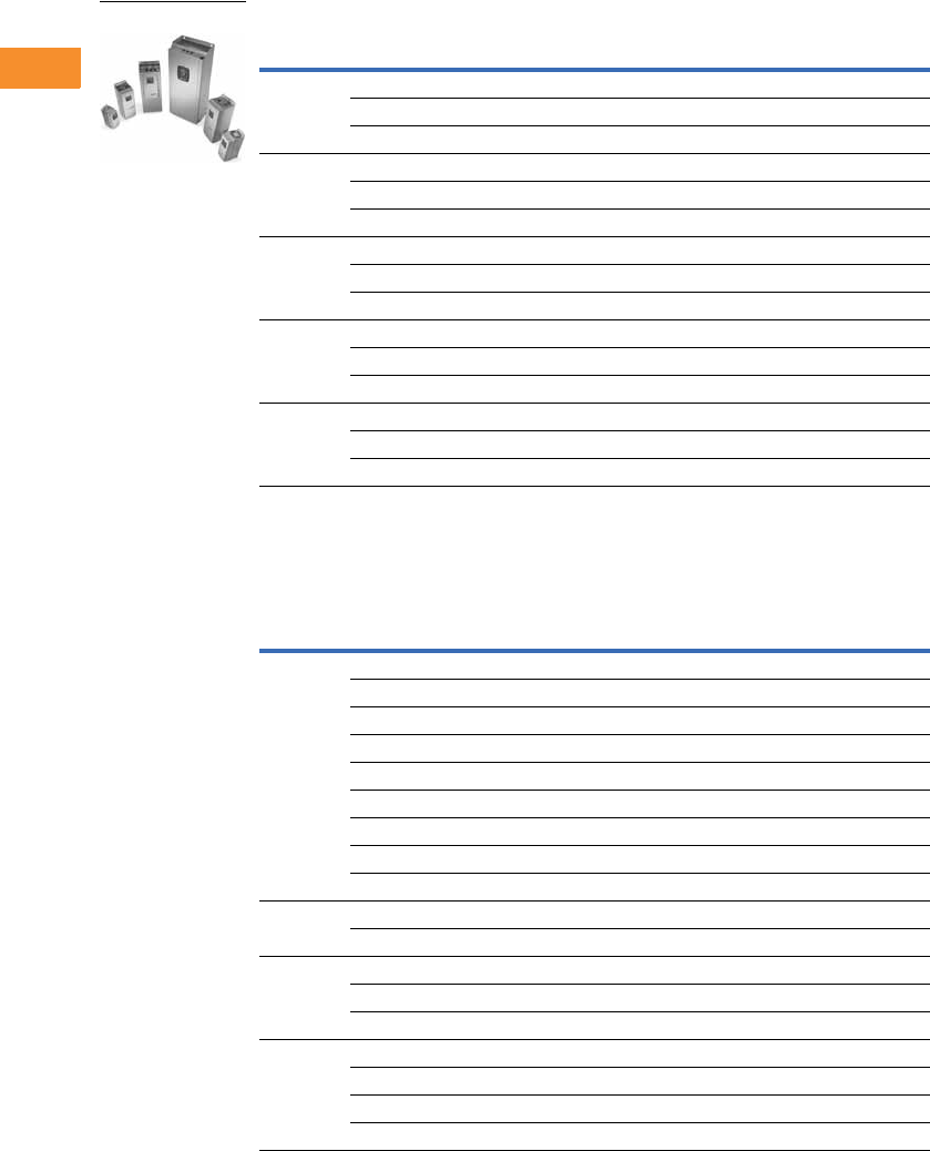
V6-T2-52 Volume 6—Solid-State Motor Control CA08100007E—May 2014 www.eaton.com
2
2
2
2
2
2
2
2
2
2
2
2
2
2
2
2
2
2
2
2
2
2
2
2
2
2
2
2
2
2
2.5
Adjustable Frequency Drives
SVX9000 Drives
380–500V, Open Chassis Drives
575V SVX9000 Drives
525–690V, NEMA Type 1/IP21 Drives
Note
1 FR10–FR14 includes 3% line reactor, but it is not integral to chassis.
Frame
Size hp (IH) Current (IH) hp (IL) Current (IL) Catalog Number
FR10 1250 330 300 385 SPX250A0-4A2N1
300 385 350 460 SPX300A0-4A2N1
350 460 400 520 SPX350A0-4A2N1
FR11 400 520 500 590 SPX400A0-4A2N1
500 590 — 650 SPX500A0-4A2N1
— 650 600 730 SPX550A0-4A2N1
FR12 600 730 — 820 SPX600A0-4A2N1
— 820 700 920 SPX650A0-4A2N1
700 920 800 1030 SPX700A0-4A2N1
FR13 800 1030 900 1150 SPX800A0-4A2N1
900 1150 1000 1300 SPX900A0-4A2N1
1000 1300 1200 1450 SPXH10A0-4A2N1
FR14 1200 1600 1500 1770 SPXH12A0-4A2N1
1600 1940 1800 2150 SPXH16A0-4A2N1
1900 2300 2200 2700 SPXH19A0-4A2N1
Frame
Size hp (IH) Current (IH) hp (IL) Current (IL) Catalog Number
FR6 2 3.3 3 4.5 SVX002A1-5A4N1
34.5 —5.5 SVX003A1-5A4N1
—5.5 5 7.5 SVX004A1-5A4N1
5 7.5 7-1/2 10 SVX005A1-5A4N1
7-1/2 10 10 13.5 SVX007A1-5A4N1
10 13.5 15 18 SVX010A1-5A4N1
15 18 20 22 SVX015A1-5A4N1
20 22 25 27 SVX020A1-5A4N1
25 27 30 34 SVX025A1-5A4N1
FR73034 4041 SVX030A1-5A4N1
40 41 50 52 SVX040A1-5A4N1
FR85052 6062 SVX050A1-5A4N1
60 62 75 80 SVX060A1-5A4N1
75 80 100 100 SVX075A1-5A4N1
FR9 100 100 125 125 SVX100A1-5A4N1
125 125 150 144 SVX125A1-5A4N1
150 144 — 170 SVX150A1-5A4N1
— 170 200 208 SVX175A1-5A4N1
SVX9000 Open Drives
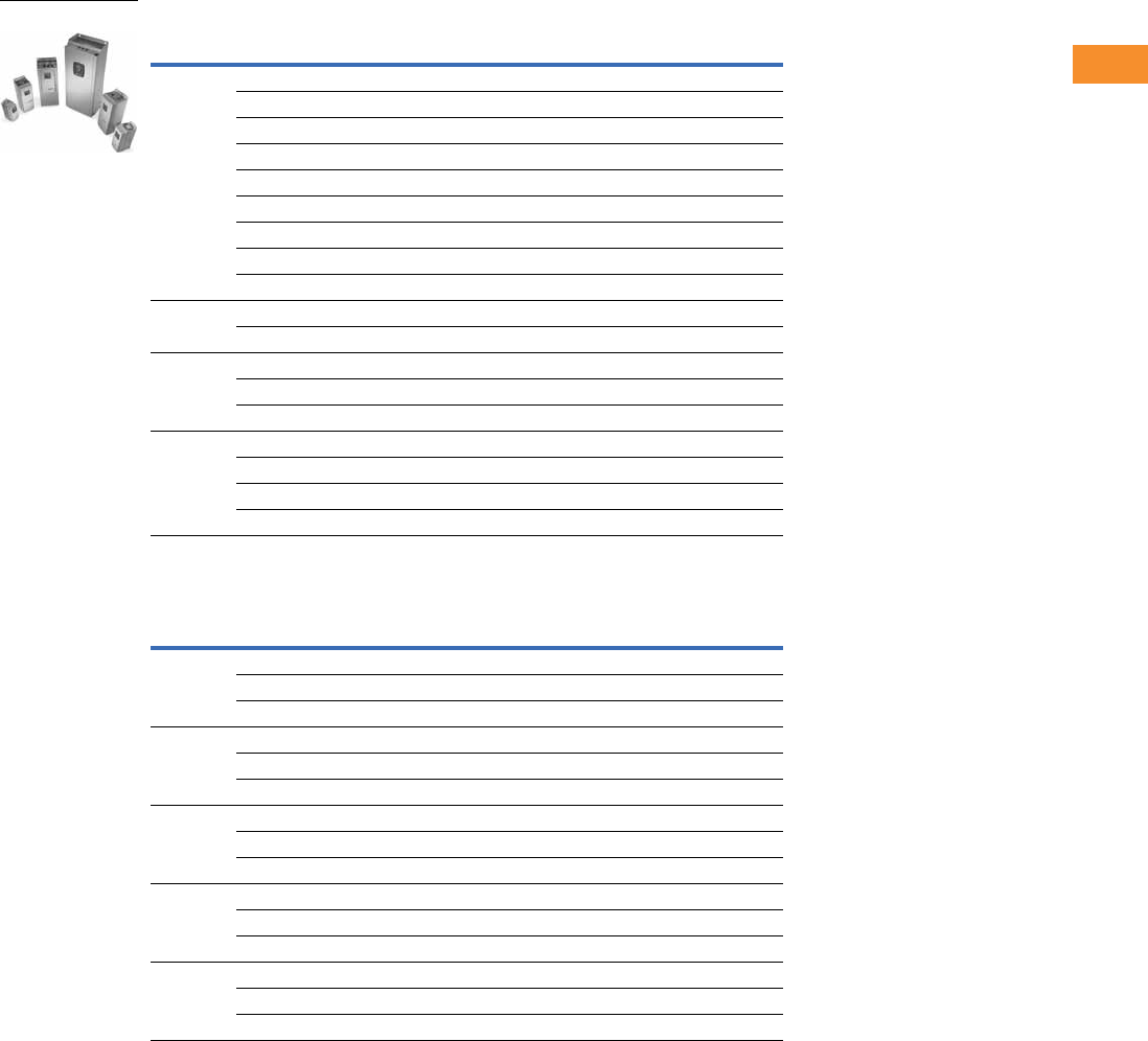
Volume 6—Solid-State Motor Control CA08100007E—May 2014 www.eaton.com V6-T2-53
2
2
2
2
2
2
2
2
2
2
2
2
2
2
2
2
2
2
2
2
2
2
2
2
2
2
2
2
2
2
2.5
Adjustable Frequency Drives
SVX9000 Drives
525–690V, NEMA Type 12/IP54 Drives
525–690V, Open Chassis Drives
Frame
Size hp (IH) Current (IH) hp (IL) Current (IL) Catalog Number
FR6 2 3.3 3 4.5 SVX002A2-5A4N1
34.5 —5.5 SVX003A2-5A4N1
—5.5 5 7.5 SVX004A2-5A4N1
5 7.5 7-1/2 10 SVX005A2-5A4N1
7-1/2 10 10 13.5 SVX007A2-5A4N1
10 13.5 15 18 SVX010A2-5A4N1
15 18 20 22 SVX015A2-5A4N1
20 22 25 27 SVX020A2-5A4N1
25 27 30 34 SVX025A2-5A4N1
FR73034 4041 SVX030A2-5A4N1
40 41 50 52 SVX040A2-5A4N1
FR85052 6062 SVX050A2-5A4N1
60 62 75 80 SVX060A2-5A4N1
75 80 100 100 SVX075A2-5A4N1
FR9 100 100 125 125 SVX100A2-5A4N1
125 125 150 144 SVX125A2-5A4N1
150 144 — 170 SVX150A2-5A4N1
— 170 200 208 SVX175A2-5A4N1
Frame
Size hp (IH) Current (IH) hp (IL) Current (IL) Catalog Number
FR10 200 208 250 261 SPX200A0-5A2N1
250 261 300 325 SPX250A0-5A2N1
300 325 400 385 SPX300A0-5A2N1
FR11 400 385 450 460 SPX400A0-5A2N1
450 460 500 502 SPX450A0-5A2N1
500 502 — 590 SPX500A0-5A2N1
FR12 — 590 600 650 SPX550A0-5A2N1
600 650 700 750 SPX600A0-5A2N1
700 750 800 820 SPX700A0-5A2N1
FR13 800 820 900 920 SPX800A0-5A2N1
900 920 1000 1030 SPX900A0-5A2N1
1000 1030 1250 1180 SPXH10A0-5A2N1
FR14 1350 1300 1500 1500 SPXH13A0-5A2N1
1500 1500 2000 1900 SPXH15A0-5A2N1
2000 1900 2300 2250 SPXH20A0-5A2N1
SVX9000 Open Drives
V6-T2-54 Volume 6—Solid-State Motor Control CA08100007E—May 2014 www.eaton.com
2
2
2
2
2
2
2
2
2
2
2
2
2
2
2
2
2
2
2
2
2
2
2
2
2
2
2
2
2
2
2.5
Adjustable Frequency Drives
SVX9000 Drives
Accessories
Demo Drive and Power Supply
Demo Drive and Power Supply
NEMA Type 12/IP54 Conversion Kit
The NEMA Type 12/IP54 kit
option is used to convert a
NEMA Type 1/IP21 to a
NEMA Type 12/IP54 drive.
The NEMA Type 12/IP54
kit consists of a metal
drive shroud, fan kit for
some frames, adaptor plate
and plugs.
NEMA Type 12/IP54 Conversion Kit
Flange Kits
Flange Kit NEMA Type 12/
IP54
The flange kit is utilized when
the power section is mounted
through the back panel of an
enclosure. Includes flange
mount brackets and NEMA
Type 12/IP54 fan
components. Metal shroud
not included.
Flange kits for NEMA Type
12/IP54 enclosure drive rating
are determined by rating of
drive.
Flange Kit NEMA Type 12/
IP54— Frames 4, 5 and 6 1
Flange Kit NEMA Type 12/
IP54—Frames 4–9
Note
1For installation of an SVX9000 NEMA Type 1/IP21 drive into a NEMA Type 12/IP54 oversized enclosure.
Description Catalog Number
9000X demo drive 9000XDEMO
Approximate Dimensions in Inches (mm) Approximate
Weight Lb (kg)Frame Size Delivery Code Length Width Height Catalog Number
FR4 W 13 (330) 7 (178) 4 (102) 4 (1.8) OPTN12FR4
FR5 16 (406) 8 (203) 7 (178) 5 (2.3) OPTN12FR5
FR6 21 (533) 10 (254) 5 (127) 7 (3.2) OPTN12FR6
Frame
Size
Delivery
Code
Catalog
Number
FR4 W OPTTHRFR4
FR5 OPTTHRFR5
FR6 OPTTHRFR6
Frame
Size
Delivery
Code
Catalog
Number
FR4 FP OPTTHR4
FR5 OPTTHR5
FR6 OPTTHR6
FR7 OPTTHR7
FR8 OPTTHR8
FR9 OPTTHR9
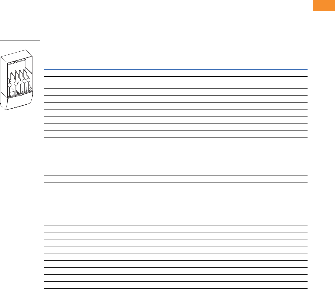
Volume 6—Solid-State Motor Control CA08100007E—May 2014 www.eaton.com V6-T2-55
2
2
2
2
2
2
2
2
2
2
2
2
2
2
2
2
2
2
2
2
2
2
2
2
2
2
2
2
2
2
2.5
Adjustable Frequency Drives
SVX9000 Drives
Options
9000X Series Option Board Kits
The 9000X Series drives can accommodate a wide selection of expander and adapter option boards
to customize the drive for your application needs. The drive’s control unit is designed to accept a
total of five option boards.
The 9000X Series factory installed standard board configuration includes an A9 I/O board and an A2
relay output board, which are installed in slots A and B.
Option Board Kits
Notes
1 AI = Analog Input; AO = Analog Output, DI = Digital Input, DO = Digital Output, RO = Relay Output
2 Option card must be installed in one of the slots listed for that card. Slot indicated in bold is the preferred location.
3 OPTC2 is a multi-protocol option card.
4 SPX9000 drives only (FR10 and larger).
Option Kit Description 1
Allowed Slot
Locations 2
Field
Installed
Factory
Installed SVX Ready Programs
Catalog
Number
Option
Designator Basic
Local/
Remote Standard MSS PID Multi-P. PFC
Standard I/O Cards
6 DI, 1 DO, 2 AI, 1AO, 1 +10 Vdc ref,
2 ext +24 Vdc/EXT +24 Vdc
AOPTA9 — ■ ■ ■ ■■■ ■
2 RO (NC-NO) B OPTA2 — ■ ■ ■ ■■■ ■
Extended I/O Cards
2 RO, therm—SPX only B OPTA3 A3 —■ ■ ■■■ ■
Encoder low volt +5V/15V/24V—SPX only C OPTA4 A4 —■ ■ ■■■ ■
Encoder high volt +15V/24V—SPX only C OPTA5 A5 —■ ■ ■■■ ■
Double encoder—SPX only C OPTA7 A7 ■ ■ ■ ■■■ ■
6 DI, 1 DO, 2 AI, 1 AO—SPX only A OPTA8 A8 —■ ■ ■■■ ■
3 DI (encoder 10–24V), out +15V/+24V,
2 DO (pulse+direction)—SPX only
COPTAE AE ■ ■ ■ ■■■ ■
6 DI, 1 ext +24 Vdc/EXT +24 Vdc B, C, D, E OPTB1 B1 —— — ——
■■
1 RO (NC-NO), 1 RO (NO), 1 therm B, C, D, E OPTB2 B2 —— — ——
■■
1 AI (mA isolated), 2 AO (mA isolated),
1 ext +24 Vdc/EXT +24 Vdc
B, C, D, E OPTB4 B4 ■ ■ ■ ■■■ ■
3 RO (NO) B, C, D, E OPTB5 B5 —— — ——
■■
1 ext +24 Vdc/EXT +24 Vdc, 3 Pt100 B, C, D, E OPTB8 B8 — — — ——— —
1 RO (NO), 5 DI 42–240 Vac input B, C, D, E OPTB9 B9 —— — ——
■■
Communication Cards
Modbus 3D, E OPTC2 C2 ■ ■ ■ ■■■ ■
Johnson Controls N2 3D, E OPTC2 CA — — — ——— —
Modbus TCP D, E OPTCI CI ■ ■ ■ ■■■ ■
BACnet D, E OPTCJ CJ ■ ■ ■ ■■■ ■
EtherNet/IP D, E OPTCQ CQ ■ ■ ■ ■■■ ■
PROFIBUS DP D, E OPTC3 C3 ■ ■ ■ ■■■ ■
LonWorks D, E OPTC4 C4 ■ ■ ■ ■■■ ■
PROFIBUS DP (D9 connector) D, E OPTC5 C5 ■ ■ ■ ■■■ ■
CANopen (slave) 4D, E OPTC6 C6 ■ ■ ■ ■■■ ■
DeviceNet D, E OPTC7 C7 ■ ■ ■ ■■■ ■
Modbus (D9 type connector) D, E OPTC8 C8 ■ ■ ■ ■■■ ■
Adapter—SPX only D, E OPTD1 D1 ■ ■ ■ ■■■ ■
Adapter—SPX only D, E OPTD2 D2 ■ ■ ■ ■■■ ■
RS-232 with D9 connection D, E OPTD3 D3 ■ ■ ■ ■■■ ■
Option Boards
ABCDE

V6-T2-56 Volume 6—Solid-State Motor Control CA08100007E—May 2014 www.eaton.com
2
2
2
2
2
2
2
2
2
2
2
2
2
2
2
2
2
2
2
2
2
2
2
2
2
2
2
2
2
2
2.5
Adjustable Frequency Drives
SVX9000 Drives
Modbus RTU Network
Communications
The Modbus Network Card
OPTC2 is used for connecting
the 9000X Drive as a slave on
a Modbus network. The
interface is connected by a
9-pin DSUB connector
(female) and the baud rate
ranges from 300 to 19200
baud. Other communication
parameters include an
address range from 1 to 247;
a parity of None, Odd or
Even; and the stop bit is 1.
PROFIBUS Network
Communications
The PROFIBUS Network Card
OPTC3 is used for connecting
the 9000X Drive as a slave
on a PROFIBUS-DP network.
The interface is connected
by a 9-pin DSUB connector
(female). The baud rates
range from 9.6K baud to 12M
baud, and the addresses
range from 1 to 127.
LonWorks Network
Communications
The LonWorks Network Card
OPTC4 is used for connecting
the 9000X Drive on a
LonWorks network. This
interface uses Standard
Network Variable Types
(SNVT) as data types. The
channel connection is
achieved using a FTT-10A
Free Topology transceiver
via a single twisted transfer
cable. The communication
speed with LonWorks is
78 kBits/s.
CANopen (Slave)
Communications
The CANopen (Slave)
Network Card OPTC6 is used
for connecting the 9000X
Drive to a host system.
According to ISO11898
standard cables to be chosen
for CAN bus should have a
nominal impedance of 120
ohms, and specific line delay
of nominal 5 nS/m. 120 ohms
line termination resistors
required for installation.
DeviceNet Network
Communications
The DeviceNet Network Card
OPTC7 is used for connecting
the 9000X Drive on a
DeviceNet Network. It
includes a 5.08 mm pluggable
connector. Transfer method
is via CAN using a two-wire
twisted shielded cable with
two-wire bus power cable
and drain. The baud rates
used for communication
include 125K baud, 250K
baud and 500K baud.
Johnson Controls
Metasys N2 Network
Communications
The OPTC2 fieldbus board
provides communication
between the 9000X Drive and
a Johnson Controls
Metasys™ N2 network. With
this connection, the drive can
be controlled, monitored and
programmed from the
Metasys system. The N2
fieldbus is available as a
factory installed option and as
a field installable kit.
Modbus/TCP Network
Communications
The Modbus/TCP Network
Card OPTCI is used for
connecting the 9000X Drive
to Ethernet networks utilizing
Modbus protocol. It includes
an RJ-45 pluggable connector.
This interface provides a
selection of standard and
custom register values to
communicate drive parameters.
The board supports 10 Mbps
and 100 Mbps communication
speeds. The IP address of the
board is configurable over
Ethernet using a supplied
software tool.
BACnet Network
Communications
The BACnet Network Card
OPTCJ is used for connecting
the 9000X Drive to BACnet
networks. It includes a
5.08 mm pluggable connector.
Data transfer is Master-Slave/
Token Passing (MS/TP)
RS-485. This interface uses
a collection of 30 Binary Value
Objects (BVOs) and 35 Analog
Value Objects (AVOs) to
communicate drive parameters.
The card supports 9.6, 19.2
and 38.4 Kbaud communication
speeds and supports network
addresses 1–127.
EtherNet/IP Network
Communications
The EtherNet/IP Network
Card OPTCK is used for
connecting the 9000X Drive
to Ethernet/Industrial Protocol
networks. It includes an
RJ-45 pluggable connector.
The interface uses CIP
objects to communicate drive
parameters (CIP is “Common
Industrial Protocol”, the same
protocol used by DeviceNet).
The board supports 10 Mbps
and 100 Mbps communication
speeds. The IP address of the
board is configurable by Static,
BOOTP and DHCP methods.

Volume 6—Solid-State Motor Control CA08100007E—May 2014 www.eaton.com V6-T2-57
2
2
2
2
2
2
2
2
2
2
2
2
2
2
2
2
2
2
2
2
2
2
2
2
2
2
2
2
2
2
2.5
Adjustable Frequency Drives
SVX9000 Drives
Control Panel Options
Factory Options
Miscellaneous Options
Factory Installed Field Installed
Description Option Code
NEMA Type 1/IP21
Catalog Number
Local/Remote Keypad SVX9000 Control Panel—This option is standard on all drives and
consists of an RS-232 connection, backlit alphanumeric LCD display with nine indicators for the
RUN status and two indicators for the control source. The nine pushbuttons on the panel are used
for panel programming and monitoring of all SVX9000 parameters. The panel is detachable and
isolated from the input line potential. Include LOC/REM key to choose control location.
A KEYPAD-LOC/REM
Keypad Remote Mounting Kit—This option is used to remote mount the SVX9000 keypad. The
footprint is compatible to the SV9000 remote mount kit. Includes 10 ft cable, keypad holder and
mounting hardware.
— OPTRMT-KIT-9000X
Description Catalog Number
9000XDrive—A PC-based tool for controlling and monitoring of the SVX9000. Features include: loading parameters that
can be saved to a file or printed, setting references, starting and stopping the motor, monitoring signals in graphical or text
form, and real-time display. To avoid damage to the drive or computer, SVDrivecable must be used.
9000XDRIVE
SVDrivecable—6 ft (1.8m) RS-232 cable (22 gauge) with a 7-pin connector on each end. Should be used in conjunction
with the 9000XDrive option to avoid damage to the SVX9000 or computer. The same cable can be used for downloading
specialized applications to the drive.
SVDRIVECABLE
External Dynamic Braking Resistors—Used with the dynamic braking chopper circuit to absorb motor regenerative
energy for stopping the load and to dissipate the energy flowing back into the drive. Resistors are separated into standard
duty and heavy-duty. Standard duty is defined as 20% duty or less with 100% braking torque, while heavy-duty is defined as
50% duty or less with 150% braking torque.
See Page V6-T2-58
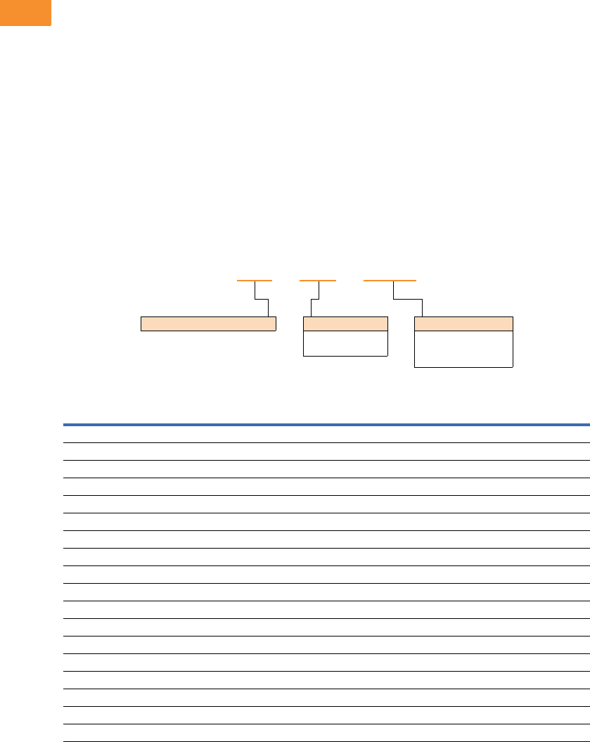
V6-T2-58 Volume 6—Solid-State Motor Control CA08100007E—May 2014 www.eaton.com
2
2
2
2
2
2
2
2
2
2
2
2
2
2
2
2
2
2
2
2
2
2
2
2
2
2
2
2
2
2
2.5
Adjustable Frequency Drives
SVX9000 Drives
Open Drive Options
Brake Chopper Options
The brake chopper circuit
option is used for applications
that require dynamic braking.
Dynamic braking resistors are
not included with drive
purchase. Consult the factory
for additional dynamic braking
resistor selections that are
supplied separately. A list of
common resistors are listed
below and are complete
indoor assemblies, include a
pre-wired terminal block and
a thermal switch, and are not
UL Listed.
Duty Cycle
The duty cycle rating is based
on a 60-second period. For
example, the 20% duty cycle
resistor can carry 100%
current for 12 seconds out
of every 60 seconds, while
the 50% duty cycle resistor
can carry 150% current for
30 seconds out of every
60 seconds.
Torque
If the braking torque required
is less than 15%, dynamic
braking is not required
because the regenerated
energy will be dissipated in
the drive and motor losses.
Dynamic Brake Resistor—Catalog Number Selection
230V Brake Resistors
Drive hp
(CT/IH)
Minimum
Ohms
20% Duty Cycle, 100% Torque 50% Duty Cycle, 150% Torque
Catalog Number Dimensions (Inches) Catalog Number Dimensions (Inches)
0.75 30.0 DBR-R100-W0400 12W x 5D x 5H DBR-R100-W0800 12W x 7D x 5H
130.0DBR-R100-W0400 12W x 5D x 5H DBR-R100-W0800 12W x 7D x 5H
1.5 30.0 DBR-R100-W0400 12W x 5D x 5H DBR-R036-W1200 12W x 10D x 5H
230.0DBR-R100-W0400 12W x 5D x 5H DBR-R036-W1200 12W x 10D x 5H
330.0DBR-R036-W0800 12W x 7D x 5H DBR-R036-W2000 12W x 16D x 5H
430.0DBR-R036-W0800 12W x 7D x 5H DBR-R030-W2400 19W x 10D x 5H
530.0DBR-R036-W0800 12W x 7D x 5H DBR-R030-W2800 19W x 13D x 5H
7.5 20.0 DBR-R020-W1200 12W x 10D x 5H DBR-R020-W4800 26.5W x 13D x 5H
10 10.0 DBR-R015-W1600 12W x 13D x 5H DBR-R112-W6000 26.5W x 13D x 5H
15 10.0 DBR-R012-W2400 19W x 10D x 5H DBR-R010-W9000 28W x 10D x 10H
20 3.3 DBR-R9D3-W3200 19W x 10D x 5H DBR-R3D4-W012K 28W x 10D x 10H
25 3.3 DBR-R5D5-W4000 26.5W x 10D x 5H DBR-R5D1-W015K 28W x 16D x 10H
30 3.3 DBR-R4D8-W4800 26.5W x 10D x 5H DBR-R4D1-W020K 28W x 16D x 10H
40 1.4 DBR-R004-W6000 26.5W x 13D x 5H DBR-R3D4-W025K 30W x 18D x 16H
50 1.4 DBR-R3D1-W7500 26.5W x 16D x 5H DBR-R2D1-W030K 30W x 18D x 24H
60 1.4 DBR-R2D8-W9000 26.5W x 16D x 5H DBR-R002-W036K 30W x 18D x 24H
75 1.4 DBR-R2D6-W012K 28W x 10D x 10H DBR-R1D5-W045K 30W x 18D x 32H
100 1.4 DBR-R002-W015K 28W x 16D x 10H DBR-R1D4-W060K 30W x 18D x 40H
DBR –R100– W0800
Dynamic Brake Resistor Resistance
1D0 =1.0 Ohms
100 =100 Ohms
Rated Watts
0800 = 800 Watts
8000 = 8000 Watts
080K = 80,000 Watts

Volume 6—Solid-State Motor Control CA08100007E—May 2014 www.eaton.com V6-T2-59
2
2
2
2
2
2
2
2
2
2
2
2
2
2
2
2
2
2
2
2
2
2
2
2
2
2
2
2
2
2
2.5
Adjustable Frequency Drives
SVX9000 Drives
480V Brake Resistors
Note
1Consult factory.
Drive hp
(CT/IH)
Minimum
Ohms
20% Duty Cycle, 100% Torque 50% Duty Cycle, 150% Torque
Catalog Number Dimensions (Inches) Catalog Number Dimensions (Inches)
163.0DBR-R100-W0400 12W x 5D x 5H DBR-R100-W0800 12W x 7D x 5H
1.5 63.0 DBR-R100-W0400 12W x 5D x 5H DBR-R100-W1200 12W x 10D x 5H
263.0DBR-R100-W0400 12W x 5D x 5H DBR-R100-W1200 12W x 10D x 5H
363.0DBR-R100-W0800 12W x 7D x 5H DBR-R100-W2000 12W x 16D x 5H
563.0DBR-R100-W0800 12W x 7D x 5H DBR-R100-W2800 19W x 13D x 5H
663.0DBR-R100-W1200 12W x 10D x 5H DBR-R070-W4000 19W x 16D x 5H
7.5 63.0 DBR-R100-W1200 12W x 10D x 5H DBR-R063-W4800 26.5W x 13D x 5H
10 63.0 DBR-R063-W1600 12W x 13D x 5H DBR-R063-W6000 26.5W x 16D x 5H
15 42.0 DBR-R042-W2400 19W x 10D x 5H DBR-R042-W9000 28W x 10D x 10H
20 21.0 DBR-R030-W3200 19W x 13D x 5H DBR-R023-W012K 28W x 13D x 10H
25 21.0 DBR-R030-W4000 19W x 16D x 5H DBR-R021-W015K 28W x 13D x 10H
30 14.0 DBR-R020-W4800 26.5W x 13D x 5H DBR-R014-W020K 30W x 18D x 24H
40 6.5 DBR-R112-W6000 26.5W x 13D x 5H DBR-R007-W025K 30W x 18D x 16H
50 6.5 DBR-R013-W7500 26.5W x 16D x 5H DBR-R8D5-W030K 30W x 18D x 24H
60 6.5 DBR-R010-W9000 28W x 10D x 10H DBR-R7D3-W036K 30W x 18D x 24H
75 3.3 DBR-R009-W012K 28W x 13D x 10H DBR-R3D3-W045K 30W x 18D x 32H
100 3.3 DBR-R5D1-W015K 28W x 16D x 10H DBR-R004-W060K 30W x 18D x 40H
125 3.3 DBR-R4D1-W020K 28W x 16D x 10H DBR-R004-W070K 30W x 18D x 48H
150 3.3 DBR-R3D4-W025K 30W x 18D x 16H DBR-R3D5-W085K 30W x 18D x 56H
200 3.3 DBR-R3D3-W030K 30W x 18D x 24H DBR-R3D3-W110K 30W x 18D x 72H
250 1.4 DBR-R2D5-W036K 30W x 18D x 24H 1—
300 1.4 DBR-R1D5-W045K 30W x 18D x 32H 1—
350 1.4 DBR-R1D4-W060K 30W x 18D x 40H 1—
400 0.9 DBR-R1D4-W060K 30W x 18D x 40H 1—
500 0.9 DBR-R0D9-W080K 30W x 18D x 48H 1—
550 0.9 DBR-R001-W085K 30W x 18D x 56H 1—

V6-T2-60 Volume 6—Solid-State Motor Control CA08100007E—May 2014 www.eaton.com
2
2
2
2
2
2
2
2
2
2
2
2
2
2
2
2
2
2
2
2
2
2
2
2
2
2
2
2
2
2
2.5
Adjustable Frequency Drives
SVX9000 Drives
575V Brake Resistors
Note
1Consult factory.
Drive hp
(CT/IH)
Minimum
Ohms
20% Duty Cycle, 100% Torque 50% Duty Cycle, 150% Torque
Catalog Number Dimensions (Inches) Catalog Number Dimensions (Inches)
2100.0DBR-R100-W0400 12W x 5D x 5H DBR-R100-W1200 12W x 10D x 5H
3100.0DBR-R100-W0800 12W x 7D x 5H DBR-R100-W2000 12W x 16D x 5H
4100.0DBR-R100-W0800 12W x 7D x 5H DBR-R100-W2400 19W x 10D x 5H
5100.0DBR-R100-W0800 12W x 7D x 5H DBR-R100-W2800 19W x 13D x 5H
7.5 100.0 DBR-R100-W1200 12W x 10D x 5H DBR-R100-W4800 26.5W x 13D x 5H
10 30.0 DBR-R063-W1600 12W x 13D x 5H DBR-R063-W6000 26.5W x 16D x 5H
15 30.0 DBR-R042-W2400 19W x 10D x 5H DBR-R042-W9000 28W x 10D x 10H
20 30.0 DBR-R030-W3200 19W x 13D x 5H DBR-R030-W012K 28W x 13D x 10H
25 30.0 DBR-R030-W4000 19W x 16D x 5H DBR-R030-W015K 28W x 16D x 10H
30 18.0 DBR-R020-W4800 26.5W x 13D x 5H DBR-R020-W020K 30W x 18D x 16H
40 18.0 DBR-R030-W6000 26.5W x 16D x 5H DBR-R184-W025K 30W x 18D x 16H
50 9.0 DBR-R013-W7500 26.5W x 16D x 5H DBR-R012-W030K 30W x 18D x 24H
60 9.0 DBR-R010-W9000 28W x 10D x 10H DBR-R010-W036K 30W x 18D x 24H
75 9.0 DBR-R009-W012K 28W x 13D x 10H DBR-R009-W045K 30W x 18D x 24H
100 7.0 DBR-R013-W015K 28W x 16D x 10H DBR-R8D4-W060K 30W x 18D x 40H
125 7.0 DBR-R8D2-W020K 30W x 18D x 10H DBR-R007-W070K 30W x 18D x 40H
150 7.0 DBR-R007-W025K 30W x 18D x 16H DBR-R006-W085K 30W x 18D x 56H
175 7.0 DBR-R007-W030K 30W x 18D x 24H DBR-R007-W100K 30W x 18D x 72H
200 2.5 DBR-R3D3-W030K 30W x 18D x 24H DBR-R2D6-W110K 30W x 18D x 64H
250 2.5 DBR-R2D5-W036K 30W x 18D x 24H DBR-R003-W140K 30W x 18D x 72H
300 2.5 DBR-R3D3-W045K 30W x 18D x 32H 1—
400 1.7 DBR-R002-W060K 30W x 18D x 48H 1—
450 1.7 DBR-R1D8-W070K 30W x 18D x 48H 1—
500 1.7 DBR-R002-W080K 30W x 18D x 56H 1—
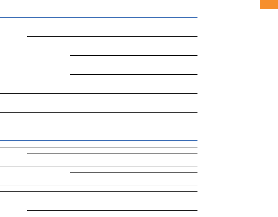
Volume 6—Solid-State Motor Control CA08100007E—May 2014 www.eaton.com V6-T2-61
2
2
2
2
2
2
2
2
2
2
2
2
2
2
2
2
2
2
2
2
2
2
2
2
2
2
2
2
2
2
2.5
Adjustable Frequency Drives
SVX9000 Drives
Replacement Parts
FR4 Spare Parts
FR5 Spare Parts
Notes
1Only for NEMA Type 12/IP54 Type drives.
2Factory recommended spare parts.
3Select one part number based on the amperage rating of the drive. Please contact EatonCare at 877-ETN-CARE for assistance.
Quantity/
Drive
230V 480V 575V
Category Description Catalog Number Catalog Number Catalog Number
Control fan NEMA Type 12 control fan 11PP01086 PP01086 —
Control module 2SVX control module 1 CSBS0000000000 CSBS0000000000 —
Standard slot A I/O card 1 OPTA9 OPTA9 —
Standard slot B I/O card 1 OPTA2 OPTA2 —
Converter Power board 31VB00308-0004-2 VB00208-0003-5 —
1VB00308-0007-2 VB00208-0004-5 —
1VB00308-0008-2 VB00208-0005-5 —
1— VB00208-0007-5 —
1— VB00208-0009-5 —
1— VB00410-0012-5-ARV —
Keypad 2SVX/SPX keypad 1 KEYPAD-LOC/REM KEYPAD-LOC/REM —
Main fan 2DC fan (main) 1 PP01060 PP01060 —
Other Mounting kit, fixing kit 1 FR00040 FR00040 —
Mounting kit, fixing kit, N12 11FR00079 FR00079 —
Control cover, plastic, N1 1 FR00006 FR00006 —
Quantity/
Drive
230V 480V 575V
Category Description Catalog Number Catalog Number Catalog Number
Control fan NEMA Type 12 control fan 11PP01088 PP01088 —
Control module 2SVX control module 1 CSBS0000000000 CSBS0000000000 —
Standard slot A I/O card 1 OPTA9 OPTA9 —
Standard slot B I/O card 1 OPTA2 OPTA2 —
Converter Power board 31VB00313-0017-2 VB00213-0016-5 —
1VB00313-0025-2 VB00213-0022-5 —
1VB00313-0031-2 VB00213-0031-5 —
Keypad 2SVX/SPX keypad 1 KEYPAD-LOC/REM KEYPAD-LOC/REM —
Main fan 2DC fan (main) 1 PP01061 PP01061 —
Other Mounting kit, fixing kit 1 FR00050 FR00050 —
Mounting kit, fixing kit, N12 11FR00081 FR00081 —
Control cover, plastic, N1 1 FR05011 FR05011 —

V6-T2-62 Volume 6—Solid-State Motor Control CA08100007E—May 2014 www.eaton.com
2
2
2
2
2
2
2
2
2
2
2
2
2
2
2
2
2
2
2
2
2
2
2
2
2
2
2
2
2
2
2.5
Adjustable Frequency Drives
SVX9000 Drives
FR6 Spare Parts
FR7 Spare Parts
Notes
1Only for NEMA Type 12/IP54 Type drives.
2Factory recommended spare parts.
3Select one part number based on the amperage rating of the drive. Please contact EatonCare at 877-ETN-CARE for assistance.
Quantity/
Drive
230V 480V 575V
Category Description Catalog Number Catalog Number Catalog Number
Control fan NEMA Type 12 control fan 11PP01049 PP01049 —
Control module 2SVX control module 1 CSBS0000000000 CSBS0000000000 CSBS0000000000
Standard slot A I/O card 1 OPTA9 OPTA9 OPTA9
Standard slot B I/O card 1 OPTA2 OPTA2 OPTA2
Converter Power board 31VB00316-0048-2 VB00416-0038-5 VB00404-0004-6
1VB00316-0061-2 VB00416-0045-5 VB00404-0005-6
1— VB00416-0061-5 VB00404-0007-6
1— — VB00404-0010-6
1— — VB00404-0013-6
1— — VB00404-0018-6
1— — VB00404-0022-6
1— — VB00404-0027-6
1— — VB00404-0034-6
DC section Bus capacitor 2 — — S00930
Keypad 2SVX/SPX keypad 1 KEYPAD-LOC/REM KEYPAD-LOC/REM KEYPAD-LOC/REM
Main fan 2DC fan (main) 1 PP01062 PP01062 —
Other Mounting kit, fixing kit 1 FR00060 FR00060 FR00060
Mounting kit, fixing kit, N12 11FR00082 FR00082 FR00082
Control cover, plastic, N1 1 FR06011 FR06011 FR06011
Quantity/
Drive
230V 480V 575V
Category Description Catalog Number Catalog Number Catalog Number
Control fan NEMA Type 12 control fan 11PP01049 PP01049 PP01049
Control module 2SVX control module 1 CSBS0000000000 CSBS0000000000 CSBS0000000000
Standard slot A I/O card 1 OPTA9 OPTA9 OPTA9
Standard slot B I/O card 1 OPTA2 OPTA2 OPTA2
Converter Power board 31VB00319-0075-2 VB00619-0072-5 VB00419-0041-6
1VB00319-0088-2 VB00619-0087-5 VB00419-0052-6
1VB00319-0114-2 VB00619-0105-5 —
DC section Bus capacitor 2 — — PP01041
Keypad 2SVX/SPX keypad 1 KEYPAD-LOC/REM KEYPAD-LOC/REM KEYPAD-LOC/REM
Main fan 2DC fan (main) 1 PP01063 PP01063 PP01063
Other Mounting kit, fixing kit 1 FR07071 FR07071 FR07071
Mounting kit, fixing kit, N12 11FR07072 FR07072 FR07072
Control cover, plastic, N1 1 FR07011 FR07011 FR07011

Volume 6—Solid-State Motor Control CA08100007E—May 2014 www.eaton.com V6-T2-63
2
2
2
2
2
2
2
2
2
2
2
2
2
2
2
2
2
2
2
2
2
2
2
2
2
2
2
2
2
2
2.5
Adjustable Frequency Drives
SVX9000 Drives
FR8 Spare Parts
Notes
1Only for NEMA Type 12/IP54 Type drives.
2Factory recommended spare parts.
3Select one part number based on the amperage rating of the drive. Please contact EatonCare at 877-ETN-CARE for assistance.
Quantity/
Drive
230V 480V 575V
Category Description Catalog Number Catalog Number Catalog Number
Control fan NEMA Type 12 control fan 11CP01180 CP01180 CP01180
Control module 2SVX control module 1 CSBS0000000000 CSBS0000000000 CSBS0000000000
Standard slot A I/O card 1 OPTA9 OPTA9 OPTA9
Standard slot B I/O card 1 OPTA2 OPTA2 OPTA2
Converter Power board 31VB00722-0140-2-ANV VB00636-0140-4-ANV VB00422-0062-5-ANV
1VB00722-0170-2-ANV VB00636-0168-4-ANV VB00422-0080-5-ANV
1VB00722-0205-2-ANV VB00636-0205-4-ANV VB00422-0100-5-ANV
IGBT 2 PP01175 PP01175 PP01127
DC section Bus capacitor 4 S00335 S00335 PP01041
Inverter Diode 3 CP01268 CP01268 CP01373
Rectifier board 1 VB00227 VB00227 VB00427
Keypad 2SVX/SPX keypad 1 KEYPAD-LOC/REM KEYPAD-LOC/REM KEYPAD-LOC/REM
Main AC fan Fan AC 1 PP01123 PP01123 PP01123
Fan fuse 2 PP20202 PP20202 PP20202
Starting cap 1 S00734 S00734 S00734
Fan driver board AC 1 VB00599 VB00799 VB00799
Isolation transformer (fan) 1 S0000113 S0000113 S0000113
Main DC fan 2DC fan 1 PP00071 PP00071 PP00071
DC power supply 1 S01016 S01016 S01016
Other Front cover, N12 11FR08079 FR08079 FR08079
Conduit plate, N12 1 FR08082 FR08082 FR08082
Front cover, N1 1 FR08106 FR08106 FR08106

V6-T2-64 Volume 6—Solid-State Motor Control CA08100007E—May 2014 www.eaton.com
2
2
2
2
2
2
2
2
2
2
2
2
2
2
2
2
2
2
2
2
2
2
2
2
2
2
2
2
2
2
2.5
Adjustable Frequency Drives
SVX9000 Drives
FR9 Spare Parts
Notes
1Factory recommended spare parts.
2Select one part number based on the amperage rating of the drive. Please contact EatonCare at 877-ETN-CARE for assistance.
Quantity/
Drive
230V 480V 575V
Category Description Catalog Number Catalog Number Catalog Number
Control fan 50 mm fan 1 PP09041 PP09041 PP09041
80 mm fan 1 PP01068 PP01068 PP01068
Control module 1SVX control module 1 CSBS0000000000 CSBS0000000000 CSBS0000000000
Standard slot A I/O card 1 OPTA9 OPTA9 OPTA9
Standard slot B I/O card 1 OPTA2 OPTA2 OPTA2
Converter Power module
21FR09-0261-2-ANV FR09-0261-4-ANV FR09-0125-5-ANV
1FR09-0300-2-ANV FR09-0300-4-ANV FR09-0144-5-ANV
1— — FR09-0170-5-ANV
Driver board 1 S00583 S00583 S00583
Shunt board 26— VB00535 VB00537
6— VB00536 VB00542
6——VB00543
DC section Balancing resistor 3 PP00052 PP00052 PP00052
Bus capacitor 8 S00335 S00335 PP01041
DC busbars DC– 1 FR09043 FR09043 FR09043
DC busbars DC+ 1 FR09044 FR09044 FR09044
DC busbars connection 1 FR09045 FR09045 FR09045
DC busbars +/– insulator 1 FR09046 FR09046 FR09046
DC busbars –/con insulator 1 FR09047 FR09047 FR09047
Inverter Rectifier module 1 FR09826 FR09822 FR09823
Diode 3 CP01268 CP01268 CP01268
Rectifier board 1 — VB00459 VB00460
Keypad 1SVX/SPX keypad 1 KEYPAD-LOC/REM KEYPAD-LOC/REM KEYPAD-LOC/REM
Main AC fan Fan AC 1 PP01080 PP01080 PP01080
Fan fuse 2 PP20202 PP20202 PP20202
Starting cap 1 S00465 S00465 S00465
Fan driver board AC 1 VB00899 VB00399 VB00299
Isolation transformer (fan) 1 PP09056 PP09055 PP09055
Main DC fan 1DC fan 1 PP00072 PP00072 PP00072
DC power supply 1 S01017 S01017 S01017
Other Front cover power 1 FR09012 FR09012 FR09012
Front cover connection 1 FR09013 FR09013 FR09013
Front power conduit 1 FR09014 FR09014 FR09014

Volume 6—Solid-State Motor Control CA08100007E—May 2014 www.eaton.com V6-T2-65
2
2
2
2
2
2
2
2
2
2
2
2
2
2
2
2
2
2
2
2
2
2
2
2
2
2
2
2
2
2
2.5
Adjustable Frequency Drives
SVX9000 Drives
FR10 Spare Parts
Notes
1Factory recommended spare parts.
2Select one part number based on the amperage rating of the drive. Please contact EatonCare at 877-ETN-CARE for assistance.
Quantity/
Drive
230V 480V 575V
Category Description Catalog Number Catalog Number Catalog Number
Control Fiber board 1 — S00451 S00451
ASIC board 1 — S00457 S00457
Control fan ASIC fan 1 — PP01096 PP01096
Control module 1SVX control module 1 — CPBS0000000000 CPBS0000000000
Standard slot A I/O card 1 — OPTA9 OPTA9
Standard slot B I/O card 1 — OPTA2 OPTA2
Converter Power module 21— FR10-0385-4-ANV FR10-0261-5-ANV
1— FR10-0460-4-ANV FR10-0325-5-ANV
1— FR10-0520-4-ANV FR10-0385-5-ANV
1— — FR10-0416-5-ANV
Driver board 1 — S00450 S00450
Driver adapter board 1 — VB00330 VB00330
Shunt board 26— VB00497 VB00510
6— VB00498 VB00511
6— VB00537 VB00545
Covers Top cover 1 — FR10340 FR10340
Side cover 2 — FR10341 FR10341
DC section Balancing resistor 2 — PP13027 PP13028
DC busbars kit (right) 1 — S0000005 S0000005
Bus capacitor 12 — S00335 S00336
Inverter Rectifier module 1 — FR10823 FR10823
Charging resistor 1 — PP00066 PP00066
Diode 3 — PP01177 PP01177
Rectifier board 1 — S00591 S00592
Keypad 1SVX/SPX keypad 1 — KEYPAD-LOC/REM KEYPAD-LOC/REM
Main AC fan Fan assembly (left) 1 — FR10846 FR10846
Fan assembly (right) 1 — FR10847 FR10847
Fan AC 2 — PP01080 PP01080
Fan fuse 4 — PP20202 PP20202
Starting cap 2 — S00528 S00528
Fan driver board AC 2 — VB00299 VB00299
Isolation transformer (left) 1 — FR10844 FR10844
Isolation transformer (right) 1 — FR10845 FR10845
Main DC fan 1DC fan 2 — PP00072 PP00072
DC power supply 2 — S01017 S01017

V6-T2-66 Volume 6—Solid-State Motor Control CA08100007E—May 2014 www.eaton.com
2
2
2
2
2
2
2
2
2
2
2
2
2
2
2
2
2
2
2
2
2
2
2
2
2
2
2
2
2
2
2.5
Adjustable Frequency Drives
SVX9000 Drives
FR11 Spare Parts
Notes
1Factory recommended spare parts.
2Select one part number based on the amperage rating of the drive. Please contact EatonCare at 877-ETN-CARE for assistance.
Quantity/
Drive
230V 480V 575V
Category Description Catalog Number Catalog Number Catalog Number
Control Fiber board 1 — S00451 S00451
ASIC board 1 — S00457 S00457
Control fan ASIC fan 1 — PP01096 PP01096
Control module 1SVX control module 1 — CPBS0000000000 CPBS0000000000
Standard slot A I/O card 1 — OPTA9 OPTA9
Standard slot B I/O card 1 — OPTA2 OPTA2
Converter Power module 21— FR11-0590-4-ANV FR11-0460-5-ANV
1— FR11-0650-4-ANV FR11-0502-5-ANV
1— FR11-0730-4-ANV FR11-0590-5-ANV
Driver board 1 — S00452 S00452
Driver adapter board 1 — VB00330 VB00330
Shunt board 29— VB00513 VB00512
9— VB00514 VB00546
9— VB00538 VB00547
Covers Top cover 1 — FR11345 FR11345
DC section Balancing resistor 3 — PP13027 PP13027
DC busbars kit (right) 3 — S0000005 S0000005
Bus capacitor 18 — S00335 S00335
Inverter Rectifier module 1 — FR10823 FR10823
Diode 3 — PP01177 PP01177
Rectifier board 1 — S00591 S00591
Keypad 1SVX/SPX keypad 1 — KEYPAD-LOC/REM KEYPAD-LOC/REM
Main AC fan Fan assembly (right) 3 — FR10847 FR10847
Fan AC 3 — PP01080 PP01080
Fan fuse 4 — PP20202 PP20202
Starting cap 3 — S00530 S00530
Fan driver board AC 3 — VB00299 VB00299
Isolation transformer (right) 3 — FR10845 FR10845
Main DC fan 1DC fan 2 — PP00072 PP00072
DC power supply 2 — S01017 S01017

Volume 6—Solid-State Motor Control CA08100007E—May 2014 www.eaton.com V6-T2-67
2
2
2
2
2
2
2
2
2
2
2
2
2
2
2
2
2
2
2
2
2
2
2
2
2
2
2
2
2
2
2.5
Adjustable Frequency Drives
SVX9000 Drives
FR12 Spare Parts
Notes
1Factory recommended spare parts.
2Select one part number based on the amperage rating of the drive. Please contact EatonCare at 877-ETN-CARE for assistance.
Quantity/
Drive
230V 480V 575V
Category Description Catalog Number Catalog Number Catalog Number
Control Fiber board 2 — S00451 S00451
ASIC board 2 — S00457 S00457
Star coupler 1 — S00593 S00593
Control fan ASIC fan 2 — PP01096 PP01096
Control module 1SVX control module 1 — CPBS0000000000 CPBS0000000000
Standard slot A I/O card 1 — OPTA9 OPTA9
Standard slot B I/O card 1 — OPTA2 OPTA2
Converter Power module 21— FR12-0820-4-ANV FR12-0650-5-ANV
1— FR12-0920-4-ANV FR12-0750-5-ANV
1— FR12-1030-4-ANV FR12-0820-5-ANV
Driver board 2 — S00450 S00450
Driver adapter board 2 — VB00330 VB00330
Shunt board 12 — VB00498 VB00511
Covers Top cover 2 — FR10340 FR10340
Side cover 4 — FR10341 FR10341
DC section Balancing resistor 4 — PP13027 PP13027
DC busbars kit (right) 2 — S0000005 S0000005
Bus capacitor 24 — S00335 S00336
Inverter Rectifier module 2 — FR10823 FR10823
Diode 3 — PP01177 PP01177
Rectifier board 2 — S00591 S00591
Keypad 1SVX/SPX keypad 1 — KEYPAD-LOC/REM KEYPAD-LOC/REM
Main AC fan Fan assembly (left) 2 — FR10846 FR10846
Fan assembly (right) 2 — FR10847 FR10847
Fan AC 4 — PP01080 PP01080
Fan fuse 8 — PP20202 PP20202
Starting cap 4 — S00528 S00528
Fan driver board AC 4 — VB00299 VB00299
Isolation transformer (left) 2 — FR10844 FR10844
Isolation transformer (right) 2 — FR10845 FR10845
Main DC fan 1DC fan 4 — PP00072 PP00072
DC power supply 4 — S01017 S01017

V6-T2-68 Volume 6—Solid-State Motor Control CA08100007E—May 2014 www.eaton.com
2
2
2
2
2
2
2
2
2
2
2
2
2
2
2
2
2
2
2
2
2
2
2
2
2
2
2
2
2
2
2.5
Adjustable Frequency Drives
SVX9000 Drives
FR13 Spare Parts
Notes
1Factory recommended spare parts.
2Select one part number based on the amperage rating of the drive. Please contact EatonCare at 877-ETN-CARE for assistance.
Quantity/
Drive
230V 480V 575V
Category Description Catalog Number Catalog Number Catalog Number
Control ASIC board 1 — S00457 S00457
ASIC assembly 1 — 60S01030 60S01030
Control fan ASIC fan 1 — PP01096 PP01096
Control module 1SVX control module 1 — CPBS0000000000 CPBS0000000000
Standard slot A I/O card 1 — OPTA9 OPTA9
Standard slot B I/O card 1 — OPTA2 OPTA2
Converter Power module 23— FI13-1150-4-ANV FR13-1030-5-ANV
3— FI13-1300-4-ANV FR13-1180-5-ANV
3— FI13-1450-4-ANV FR13-920-5-ANV
Driver board 3 — S00454 S00454
Driver adapter board 2 — VB00330 VB00330
Shunt board 218 — VB00505 VB00516
18 — VB00514 VB00517
18 — VB00541 VB00547
Covers Top cover 3 — FI10001 FI10001
Side cover 3 — FI10003 FI10003
DC section Balancing resistor 6 — PP13034 PP13034
Bus capacitor 36 — S00335 S00336
DC busbars kit 3 — FI13329 FI13329
Inverter Rectifier module 2 — FR10823 FR10823
Diode 3 — PP01177 PP01177
Rectifier board 2 — S00591 S00591
Keypad 1SVX/SPX keypad 1 — KEYPAD-LOC/REM KEYPAD-LOC/REM
Main AC fan Fan assembly (left) 3 — FI13301 FI13301
Fan AC 3 — PP01080 PP01080
Fan fuse 6 — PP20202 PP20202
Starting cap 3 — S00520 S00520
Fan driver board AC 3 — VB00299 VB00299
Isolation transformer 3 — PP10057 PP10057
Main DC fan 1DC fan 4 — PP00072 PP00072
DC power supply 4 — S01017 S01017

Volume 6—Solid-State Motor Control CA08100007E—May 2014 www.eaton.com V6-T2-69
2
2
2
2
2
2
2
2
2
2
2
2
2
2
2
2
2
2
2
2
2
2
2
2
2
2
2
2
2
2
2.5
Adjustable Frequency Drives
SVX9000 Drives
FR14 Spare Parts
Notes
1Factory recommended spare parts.
2Select one part number based on the amperage rating of the drive. Please contact EatonCare at 877-ETN-CARE for assistance.
Quantity/
Drive
230V 480V 575V
Category Description Catalog Number Catalog Number Catalog Number
Control ASIC board 2 — S00457 S00457
Star coupler 1 — S00593 S00593
ASIC assembly 2 — 60S01030 60S01030
Star coupler kit 1 — FR10860 FR10860
Control fan ASIC fan 2 — PP01096 PP01096
Control module 1SVX control module 1 — CPBS0000000000 CPBS0000000000
Standard slot A I/O card 1 — OPTA9 OPTA9
Standard slot B I/O card 1 — OPTA2 OPTA2
Converter Power module 21— FR14-1770-4-ANV FR14-1500-5-ANV
1— FR14-2150-4-ANV FR14-1900-5-ANV
1— FR14-2700-4-ANV FR14-2250-5-ANV
Driver board 6 — S00454 S00454
Driver adapter board 2 — VB00330 VB00330
Shunt board 236 — VB00541 VB00516
36 ——VB00517
Covers Top cover 6 — FI10001 FI10001
Side cover 6 — FI10003 FI10003
DC section Balancing resistor 6 — PP13034 PP13034
Bus capacitor 72 — S00335 S00336
DC busbars kit 6 — FI13329 FI13329
Inverter Rectifier module 2 — FR10823 FR10823
Diode 3 — PP01177 PP01177
Rectifier board 2 — S00591 S00591
Keypad 1SVX/SPX keypad 1 — KEYPAD-LOC/REM KEYPAD-LOC/REM
Main AC fan Fan assembly (left) 6 — FI13301 FI13301
Fan AC 6 — PP01080 PP01080
Fan fuse 12 — PP20202 PP20202
Starting cap 6 — S00520 S00520
Fan driver board AC 6 — VB00299 VB00299
Isolation transformer 6 — PP10057 PP10057
Main DC fan 1DC fan 6 — PP00072 PP00072
DC power supply 6 — S01017 S01017

V6-T2-70 Volume 6—Solid-State Motor Control CA08100007E—May 2014 www.eaton.com
2
2
2
2
2
2
2
2
2
2
2
2
2
2
2
2
2
2
2
2
2
2
2
2
2
2
2
2
2
2
2.5
Adjustable Frequency Drives
SVX9000 Drives
Technical Data and Specifications
SVX9000 Drives
Standard I/O Specifications
Description Specification
Input Ratings
Input voltage (Vin)+10%/–15%
Input frequency (fin) 50/60 Hz (variation up to 45–66 Hz)
Connection to power Once per minute or less (typical operation)
High withstand rating 100 kAIC
Output Ratings
Output voltage 0 to Vin
Continuous output current IH rated 100% at 122°F (50°C), FR9 and below
IL rated 100% at 104°F (40°C), FR9 and below
IH/IL 100% at 104°F (40°C), FR10 and above
Overload current (IH/IL)150% I
H, 110% IL for 1 min.
Output frequency 0 to 320 Hz
Frequency resolution 0.01 Hz
Initial output current (IH) 250% for 2 seconds
Control Characteristics
Control method Frequency control (V/f)
Open loop: Sensorless vector control
Closed loop: SPX9000 drives only
Switching frequency
Frame 4–6
Frame 7–12
Adjustable with parameter 2.6.9
1–16 kHz; default 10 kHz
1–10 kHz; default 3.6 kHz
Frequency reference Analog input: Resolution 0.1% (10-bit), accuracy ±1% V/Hz
Panel reference: Resolution 0.01 Hz
Field weakening point 30–320 Hz
Acceleration time 0–3000 sec.
Deceleration time 0–3000 sec.
Braking torque DC brake: 30% x Tn (without brake option)
Ambient Conditions
Ambient operating
temperature
14°F (–10°C), no frost to 122°F (50°C) IH (FR4–FR9)
14°F (–10°C), no frost to 104°F (40°C) IH (FR10 and up)
14°F (–10°C), no frost to 104°F (40°C) IL (all frames)
Storage temperature –40° to 158°F (–40° to 70°C)
Relative humidity 0 to 95% RH, noncondensing, non-corrosive,
no dripping water
Air quality Chemical vapors: IEC 721-3-3, unit in operation, class 3C2;
Mechanical particles: IEC 721-3-3, unit in operation, class 3S2
Altitude 100% load capacity (no derating) up to 3280 ft (1000m);
1% derating for each 328 ft (100m) above 3280 ft (1000m);
max. 9842 ft (3000m)
Vibration EN 50178, EN 60068-2-6; 5 to 50 Hz, displacement amplitude
1 mm (peak) at 3 to 15.8 Hz, max. acceleration amplitude
1G at 15.8 to 150 Hz
Shock EN 50178, EN 60068-2-27 UPS Drop test (for applicable UPS
weights) Storage and shipping: max. 15G, 11 ms (in package)
Enclosure class NEMA 1/IP21 or NEMA 12/IP54, open chassis/IP20
Description Specification
Control Connections
Analog input voltage 0 to 10V, R = 200 kohms (–10 to 10V joystick control) resolution
0.1%; accuracy ±1%
Analog input current 0(4) to 20 mA; Ri—250 ohms differential
Digital inputs (6) Positive or negative logic; 18 to 30 Vdc
Auxiliary voltage +24V ±15%, max. 250 mA
Output reference voltage +10V +3%, max. load 10 mA
Analog output 0(4) to 20 mA; RL max. 500 ohms;
resolution 10 bit; accuracy ±2%
Digital outputs Open collector output, 50 mA/48V
Relay outputs Two programmable Form C relay outputs
switching capacity: 24 Vdc/8A, 250 Vac/8A, 125 Vdc/0.4A
Protections
Overcurrent protection Trip limit 4.0 x IH instantaneously
Overvoltage protection Yes
Undervoltage protection Yes
Earth fault protection In case of earth fault in motor or motor cable, only the
frequency converter is protected
Input phase supervision Trips if any of the input phases are missing
Motor phase supervision Trips if any of the output phases are missing
Overtemperature protection Yes
Motor overload protection Yes
Motor stall protection Yes
Motor underload protection Yes
Short-circuit protection Yes (+24V and +10V reference voltages)
Description Specification
Six–digital input
programmable
24V: “0” <10V, “1” >18V,Ri >5 kohms
Two–analog input
configurable w/jumpers
Voltage: 0–±10V, Ri >200 kohms
Current: 0 (4)–20 mA, Ri = 250 ohms
Two–digital output
programmable
Form C relays 250 Vac
30 Vdc 2 amp resistive
One–analog output
programmable
configurable w/jumper
0–20 mA, RL max. 500 ohms 10 bits ±2%
One digital output
programmable
Open collector 48 Vdc 50 mA
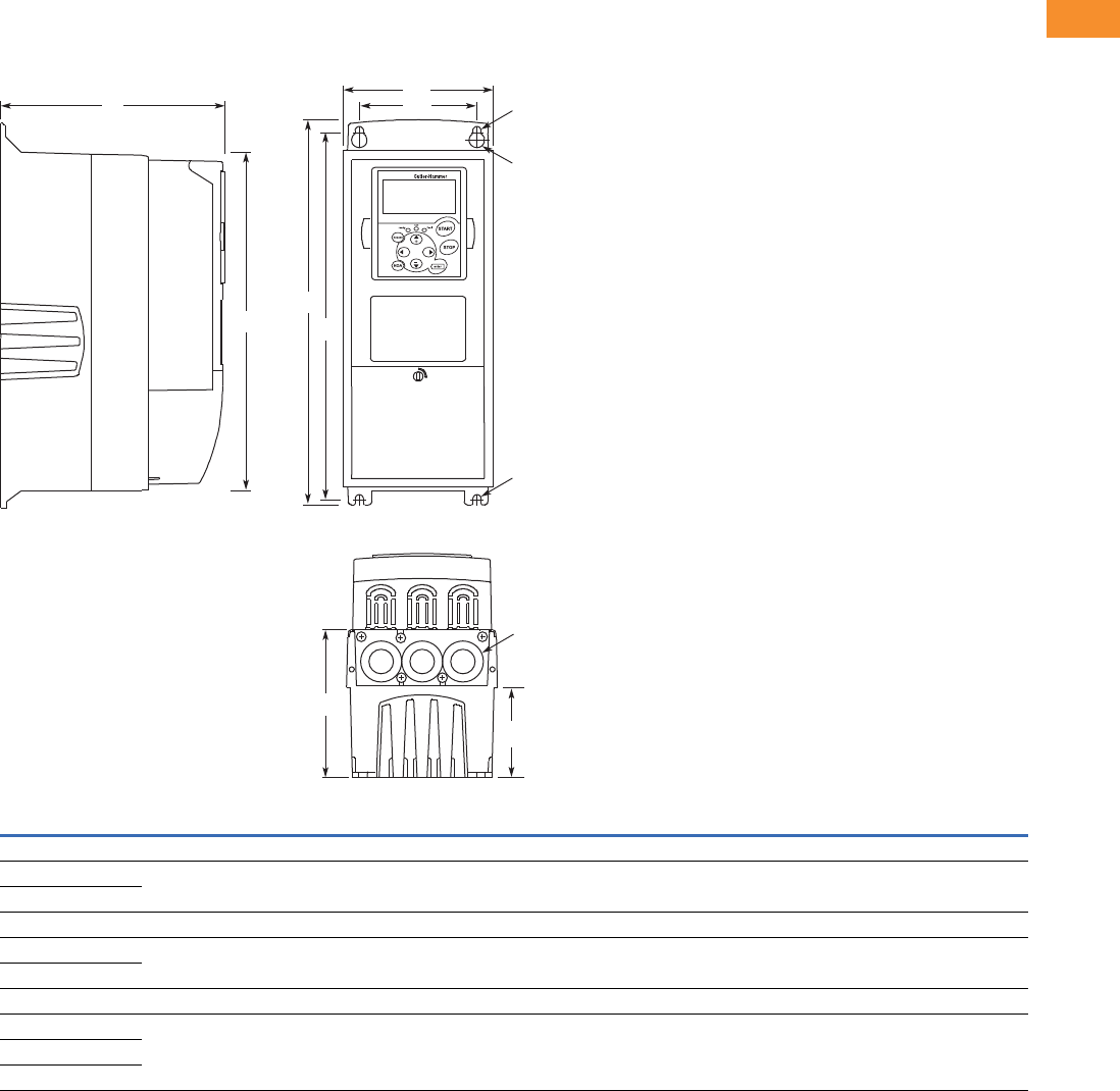
Volume 6—Solid-State Motor Control CA08100007E—May 2014 www.eaton.com V6-T2-71
2
2
2
2
2
2
2
2
2
2
2
2
2
2
2
2
2
2
2
2
2
2
2
2
2
2
2
2
2
2
2.5
Adjustable Frequency Drives
SVX9000 Drives
Dimensions
Approximate Dimensions in Inches (mm)
9000X Open Drives
NEMA Type 1/IP21 and NEMA Type 12/IP54, FR4, FR5 and FR6
Voltage hp (IH)H1H2H3D1D2D3W1W2R1 Dia.R2 Dia.
Weight
Lbs (kg)
Knockouts at Inches (mm)
N1 (O.D.)
FR4
230V 3/4–3 12.9
(327)
12.3
(313)
11.5
(292)
7.5
(190)
3.0
(77)
4.9
(126)
5.0
(128)
3.9
(100)
0.5 (13) 0.3 (7) 11.0 (5) 3 @ 1.1 (28)
480V 1–5
FR5
230V 5–7-1/2 16.5
(419)
16.0
(406)
15.3
(389)
8.4
(214)
3.9
(100)
5.8
(148)
5.6
(143)
3.9
(100)
0.5 (13) 0.3 (7) 17.9 (8) 2 @ 1.5 (37)
1 @ 1.1 (28)
480V 7-1/2–15
FR6
230V 10–15 22.0
(558)
21.3
(541)
20.4
(519)
9.3
(237)
4.2
(105)
6.5
(165)
7.6
(195)
5.8
(148)
0.6 (15.5) 0.4 (9) 40.8 (19) 3 @ 1.5 (37)
480V 20–30
575V 2–25
EATON
D1 W2
W1
R2
R1
R2
H3 H2
H1
D2
D3
Knockouts
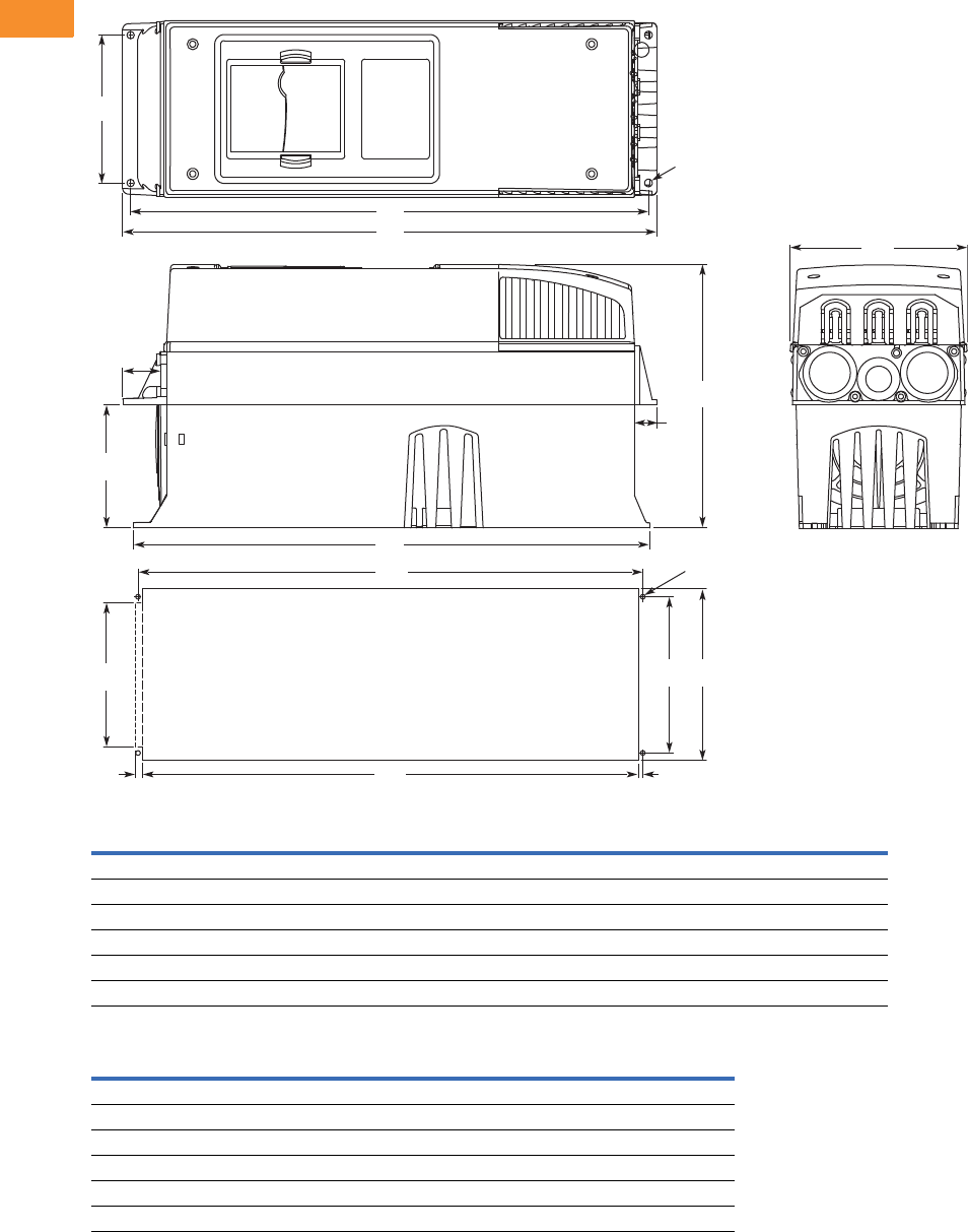
V6-T2-72 Volume 6—Solid-State Motor Control CA08100007E—May 2014 www.eaton.com
2
2
2
2
2
2
2
2
2
2
2
2
2
2
2
2
2
2
2
2
2
2
2
2
2
2
2
2
2
2
2.5
Adjustable Frequency Drives
SVX9000 Drives
Approximate Dimensions in Inches (mm)
NEMA Type 1/IP21 and NEMA Type 12/IP54 with Flange Kit, FR4, FR5 and FR6
FR4, FR5 and FR6 with Flange Kit
Flange Opening, FR4 to FR6
W1 W2 H1 H2 H3 H4 H5 D1 D2 Dia. A
FR4
5.0 (128) 4.5 (113) 13.3 (337) 12.8 (325) 12.9 (327) 1.2 (30) 0.9 (22) 7.5 (190) 3.0 (77) 0.3 (7)
FR5
5.6 (143) 4.7 (120) 17.0 (434) 16.5 (420) 16.5 (419) 1.4 (36) 0.7 (18) 8.4 (214) 3.9 (100) 0.3 (7)
FR6
7.7 (195) 6.7 (170) 22.0 (560) 21.6 (549) 22.0 (558) 1.2 (30) 0.8 (20) 9.3 (237) 4.2 (106) 0.3 (7)
W3 W4 W5 H6 H7 H8 H9 Dia. B
FR4
4.8 (123) 4.5 (113) — 12.4 (315) 12.8 (325) — 0.2 (5) 0.3 (7)
FR5
5.3 (135) 4.7 (120) — 16.2 (410) 16.5 (420) — 0.2 (5) 0.3 (7)
FR6
7.3 (185) 6.7 (170) 6.2 (157) 21.2 (539) 21.6 (549) 0.3 (7) 0.2 (5) 0.3 (7)
W2
H1
H2
D2
Flange Opening
FR4 to FR6
H4
H5
H3
W1
Dia. A
D1
W3W4
W5
Dia. B
H7
H6 H9H8
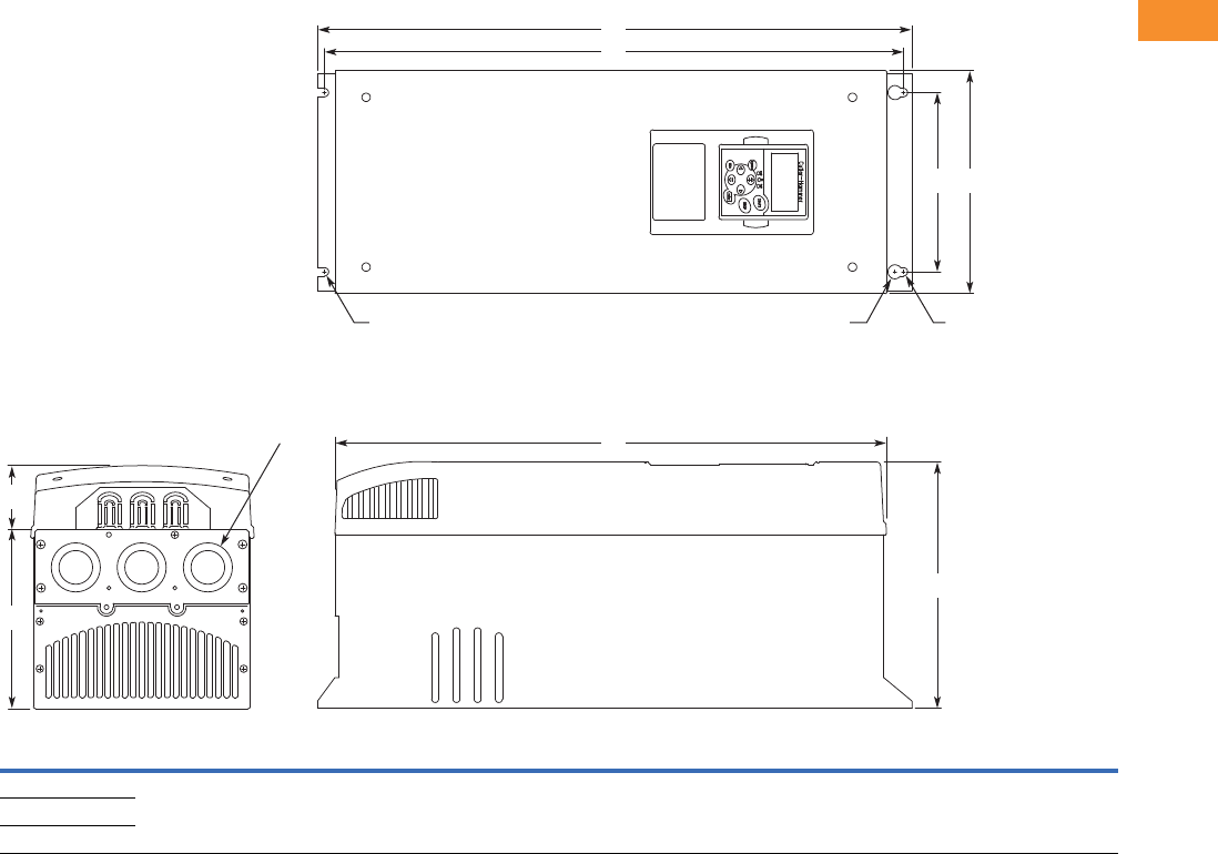
Volume 6—Solid-State Motor Control CA08100007E—May 2014 www.eaton.com V6-T2-73
2
2
2
2
2
2
2
2
2
2
2
2
2
2
2
2
2
2
2
2
2
2
2
2
2
2
2
2
2
2
2.5
Adjustable Frequency Drives
SVX9000 Drives
Approximate Dimensions in Inches (mm)
NEMA Type 1/IP21 and NEMA Type 12/IP54, FR7
Voltage hp (IH)H1H2H3D1D2D3W1W2R1 Dia.R2 Dia.
Weight
Lbs (kg)
Knockouts at Inches (mm)
N1 (O.D.)
230V 20–30 24.8 (630) 24.2 (614) 23.2 (590) 10.1 (257) 3.0 (77) 7.3 (184) 9.3 (237) 7.5 (190) 0.7 (18) 0.4 (9) 77.2 (35) 3 at 1.5 (37)
480V 40–60
575V 30–40
W2
H1
D1
D2
Knockouts
R2 R2R1
D3
H2
H3
W1
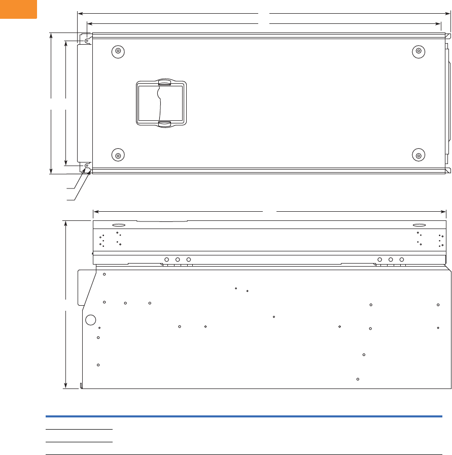
V6-T2-74 Volume 6—Solid-State Motor Control CA08100007E—May 2014 www.eaton.com
2
2
2
2
2
2
2
2
2
2
2
2
2
2
2
2
2
2
2
2
2
2
2
2
2
2
2
2
2
2
2.5
Adjustable Frequency Drives
SVX9000 Drives
Approximate Dimensions in Inches (mm)
NEMA Type 1/IP21 and NEMA Type 12/IP54, FR8
Voltage hp (IH)D1H1H2H3W1W2R1 Dia.R2 Dia.
Weight
Lbs (kg)
230V 40–60 13.5 (344) 30.1 (764) 28.8 (732) 28.4 (721) 11.5 (291) 10 (255) 0.7 (18) 0.4 (9) 127 (58)
480V 75–125
575V 50–75
D1
H2
H1
W2W1
H3
R2
R1
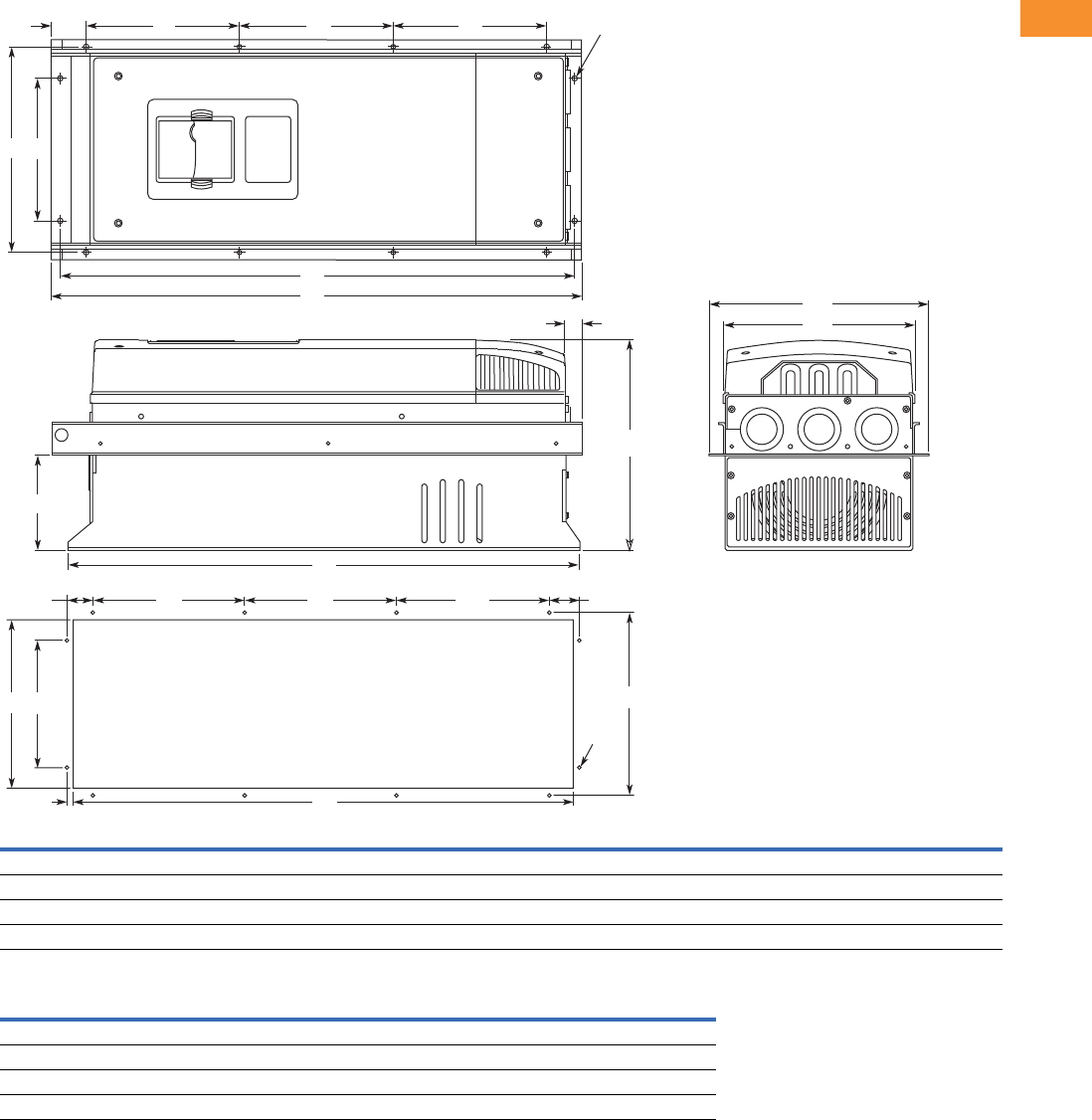
Volume 6—Solid-State Motor Control CA08100007E—May 2014 www.eaton.com V6-T2-75
2
2
2
2
2
2
2
2
2
2
2
2
2
2
2
2
2
2
2
2
2
2
2
2
2
2
2
2
2
2
2.5
Adjustable Frequency Drives
SVX9000 Drives
Approximate Dimensions in Inches (mm)
NEMA Type 1/IP21 and NEMA Type 12/IP54, with Flange Kit, FR7 and FR8
Flange Opening, FR7 and FR8
W1 W2 W3 W4 H1 H2 H3 H4 H5 H6 H7 D1 D2 Dia. A
FR7
9.3 (237) 6.8 (175) 10.6 (270) 10.0 (253) 24.9 (652) 24.8 (632) 24.8 (630) 7.4 (189) 7.4 (189) 0.9 (23) 0.8 (20) 10.1 (257) 4.6 (117) 0.3 (6)
FR8
11.2 (285) — 14.0 (355) 13.0 (330) 32.8 (832) — 29.3 (745) 10.2 (258) 10.4 (265) 1.7 (43) 2.2 (57) 13.5 (344) 4.3 (110) 0.4 (9)
W5 W6 W7 H8 H9 H10 H11 H12 H13 Dia. B
FR7
9.2 (233) 6.9 (175) 10.0 (253) 24.4 (619) 7.4 (189) 7.4 (189) 1.4 (35) 1.3 (32) 1.0 (25) 0.3 (6)
FR8
11.9 (301) — 13.0 (330) 31.9 (810) 10.2 (258) 10.4 (265) — — 1.3 (33) 0.4 (9)
H7
W3
H9
D1
W1
H9H12
H13
H11H10
H1
H2
H5 Dia. A
Dia. B
H4H4H6
W2W4
D2
W6W5 W7
H3
H8
Flange Opening
FR7/FR8
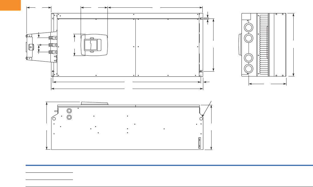
V6-T2-76 Volume 6—Solid-State Motor Control CA08100007E—May 2014 www.eaton.com
2
2
2
2
2
2
2
2
2
2
2
2
2
2
2
2
2
2
2
2
2
2
2
2
2
2
2
2
2
2
2.5
Adjustable Frequency Drives
SVX9000 Drives
Approximate Dimensions in Inches (mm)
NEMA Type 1/IP21 and NEMA Type 12/IP54 FR9
Note
1Brake resistor terminal box (H6) included when brake chopper ordered.
Voltage hp (IH) W1W2W3W4H1 H2 H3 H4
1D1 D2 D3 Dia.
Weight
Lbs (kg)
230V 75–100 18.9
(480)
15.7
(400)
0.4
(9)
2.1
(54)
45.3
(1150)
44.1
(1120)
0.6
(16)
7.4
(188)
14.2
(361.5)
13.4
(340)
11.2
(285)
0.8
(21)
321.9 (146)
480V 150–200
575V 100–175
D2
Dia.
D1
H5
W2
W4
H3H4
H2
H1
H6
W3
W5
PE
B- B+ /R+ R-
W5 W1
D3
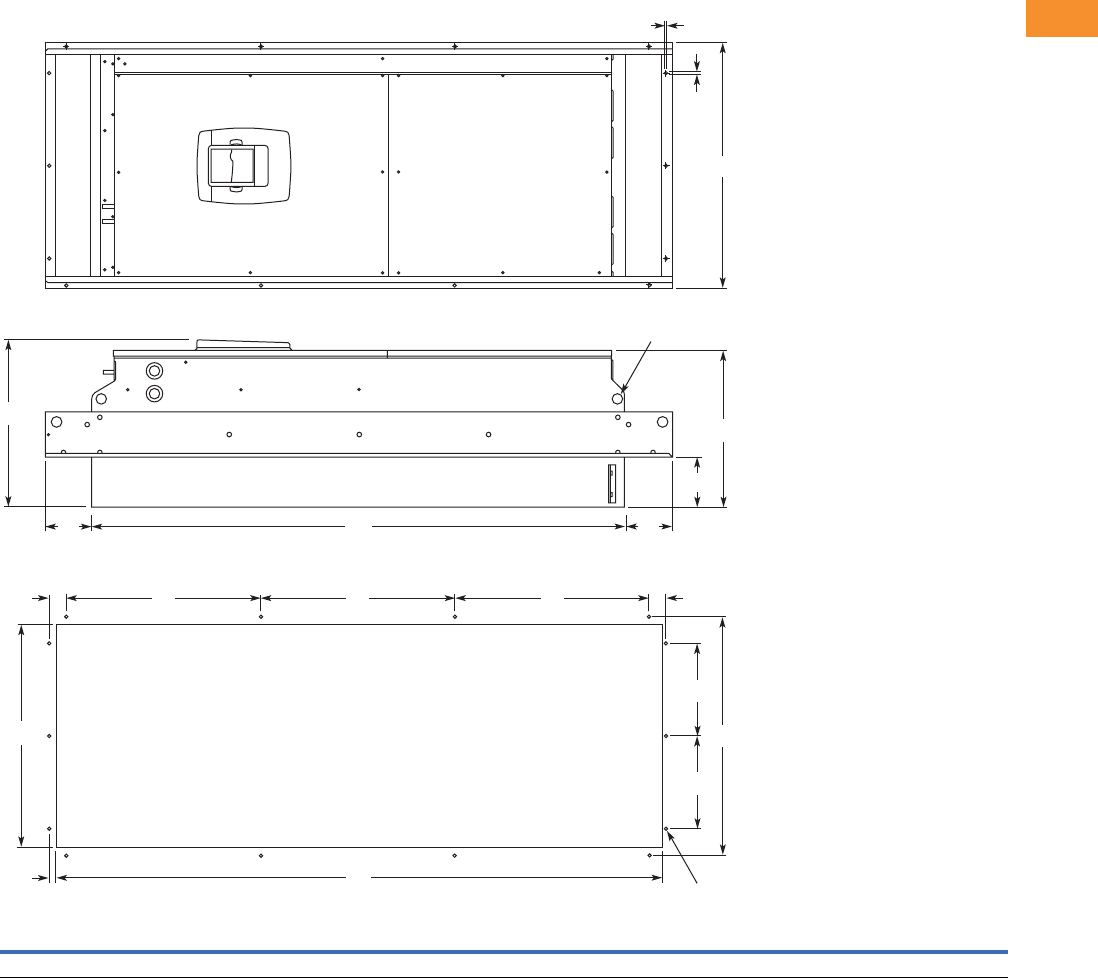
Volume 6—Solid-State Motor Control CA08100007E—May 2014 www.eaton.com V6-T2-77
2
2
2
2
2
2
2
2
2
2
2
2
2
2
2
2
2
2
2
2
2
2
2
2
2
2
2
2
2
2
2.5
Adjustable Frequency Drives
SVX9000 Drives
Approximate Dimensions in Inches (mm)
NEMA Type 1/IP21 and NEMA Type 12/IP54, FR9 with Flange Kit
W1 W2 W3 W4 W5 H1 H2 H3 H4 H5 H6 H7 D1 D2 D3 Dia.
20.9 (530) 20.0 (510) 19.1 (485) 7.9 (200) 0.2 (5.5) 51.7 (1312) 45.3 (1150) 16.5 (420) 3.9 (100) 1.4 (35) 0.4 (9) 0.1 (2) 24.9 (362) 13.4 (340) 4.3 (109) 0.8 (21)
.20 (5)
Dia.
H4
H2
D2
Dia.
D1
D3
H4
W1
H7
W5
W3
W4
H3 H3 H3 H5H5
H6 H1
W4
W2
Flange Opening
FR9
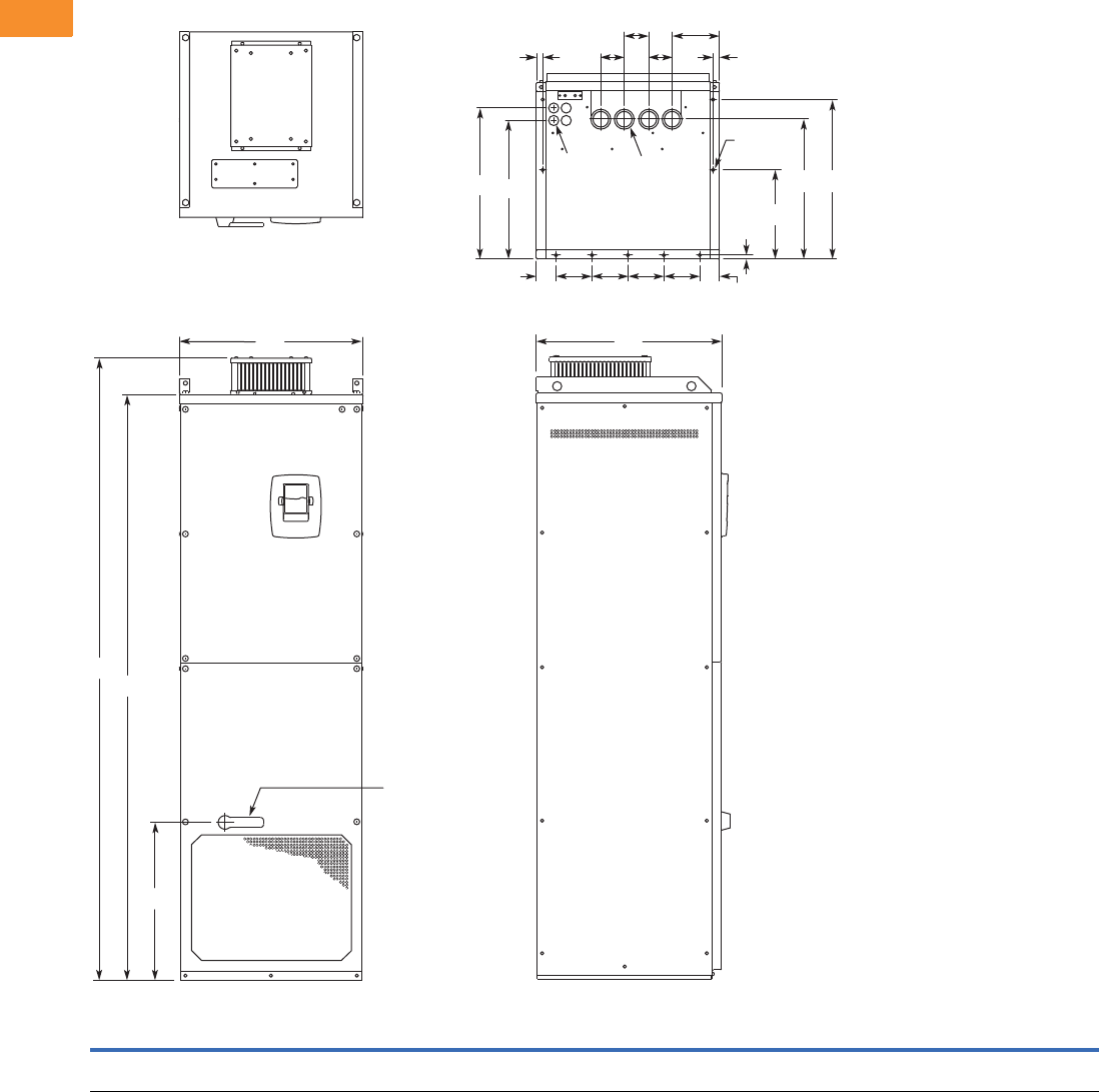
V6-T2-78 Volume 6—Solid-State Motor Control CA08100007E—May 2014 www.eaton.com
2
2
2
2
2
2
2
2
2
2
2
2
2
2
2
2
2
2
2
2
2
2
2
2
2
2
2
2
2
2
2.5
Adjustable Frequency Drives
SVX9000 Drives
Approximate Dimensions in Inches (mm)
NEMA Type 1/IP21 and NEMA Type 12/IP54, FR10 Freestanding
W1 W2 W3 W4 W5 W6 W7 H1 H2 H3 D1 D2 D3 D4 D5 D6 D7 Dia. 1 Dia. 2 Dia. 3
Weight
Lbs (kg)
23.43
(595)
2.46
(62.5)
4.53
(115)
0.79
(20)
5.95
(151)
2.95
(75)
30.11
(79)
79.45
(2018)
74.80
(1900)
20.18
(512.5)
23.70
(602)
17.44
(443)
19.02
(483)
0.47
(12)
11.22
(285)
17.60
(447)
20.08
(510)
0.83
(21)
1.89
(48)
0.43
(11)
857
(389)
Dia. 3
Dia. 2
Dia. 1
W5
W6
W4 W4
D4
D2
W2
W2
D5
D3 D6 D7
W3 W3 W3 W3
H1
H2
H3
W1 D1
Operator
(Shown with
Optional
Disconnect)
W6
W7
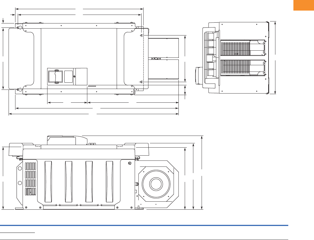
Volume 6—Solid-State Motor Control CA08100007E—May 2014 www.eaton.com V6-T2-79
2
2
2
2
2
2
2
2
2
2
2
2
2
2
2
2
2
2
2
2
2
2
2
2
2
2
2
2
2
2
2.5
Adjustable Frequency Drives
SVX9000 Drives
Approximate Dimensions in Inches (mm)
FR10 Open Chassis 1
Note
19000X FR12 is built of two FR10 modules. Please refer to SPX9000 installation manual for mounting instructions.
Voltage hp (IH)W1W2W3W4W5H1H2H3H4H5H6H7D1D2D3D4
Weight
Lbs (kg)
480V 250–350 19.7
(500)
16.7
(425)
1.2
(30)
2.6
(67)
12.8
(325)
45.9
(1165)
44.1
(1121)
34.6
(879)
33.5
(850)
0.7
(17)
24.7
(627)
10.8
(275)
19.9
(506)
17.9
(455)
16.7
(423)
16.6
(421)
518
(235)
575V 200–300
H2
W1
H7 H6
H4H5
H3
H1
W2
W3
W5
W4
D4 D2 D1
D3
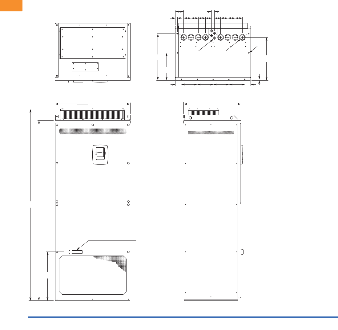
V6-T2-80 Volume 6—Solid-State Motor Control CA08100007E—May 2014 www.eaton.com
2
2
2
2
2
2
2
2
2
2
2
2
2
2
2
2
2
2
2
2
2
2
2
2
2
2
2
2
2
2
2.5
Adjustable Frequency Drives
SVX9000 Drives
Approximate Dimensions in Inches (mm)
NEMA Type 1/IP21, FR11 Freestanding Drive
Voltage hp (IH)W1W2W3W4W5W6W7W8H1H2H3D1D2D3D4D5Dia. 1Dia. 2Dia. 3
Weight
Lbs (kg)
480 400–550 31.26
(794)
2.40
(61)
6.50
(165)
0.79
(20)
3.43
(87)
2.95
(75)
2.52
(64)
1.18
(30)
79.45
(2018)
74.80
(1900)
20.18
(512.5)
23.70
(602)
11.22
(285)
19.09
(485)
0.47
(12)
17.60
(447)
0.83
(21)
1.89
(48)
0.35 x 0.43
(9 x 11)
526
(239)
H1
H2
W1 D1
H3
D2
D3
Dia. 3
D4
D5
Dia. 1 Dia. 2
W2
W2 W3 W3 W3 W3
W8
W6
W4
W6
W5
W7W7 W6W6W6W6
Operator
(Shown with
Optional
Disconnect)
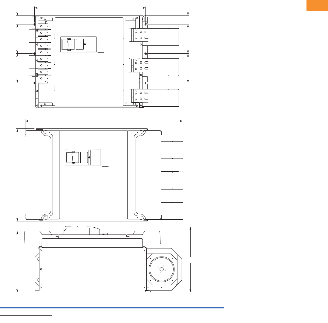
Volume 6—Solid-State Motor Control CA08100007E—May 2014 www.eaton.com V6-T2-81
2
2
2
2
2
2
2
2
2
2
2
2
2
2
2
2
2
2
2
2
2
2
2
2
2
2
2
2
2
2
2.5
Adjustable Frequency Drives
SVX9000 Drives
Approximate Dimensions in Inches (mm)
FR11 Open Chassis
Voltage hp (IH)W1W2W3H1 H2 D1 D2
Weight
Lbs (kg)
480V 400–550 27.9 (709) 8.86 (225) 2.6 (67) 45.5 (1155) 33.5 (850) 19.8 (503) 18.4 (468) 833 (378)
575V 400–500
H1
H2
D1
W2
W2
W3
W2
W2
W3
W1
Shown without
terminal cover
D2
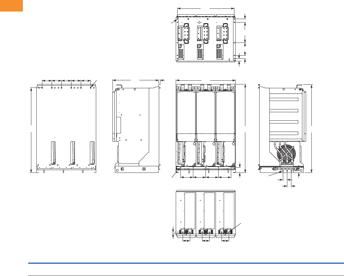
V6-T2-82 Volume 6—Solid-State Motor Control CA08100007E—May 2014 www.eaton.com
2
2
2
2
2
2
2
2
2
2
2
2
2
2
2
2
2
2
2
2
2
2
2
2
2
2
2
2
2
2
2.5
Adjustable Frequency Drives
SVX9000 Drives
Approximate Dimensions in Inches (mm)
FR13, Open Chassis Inverter
Notes
9000X FR14 is built of two FR13 modules. Please refer to SPX9000 installation manual for mounting instructions.
FR13 is built from an inverter module and a converter module. Please refer to SPX9000 installation manual for mounting instructions.
W1 W2 W3 W4 W5 H1 H2 H3 H4 H5 D1 D2 D3 D4 D5 D6 D7 D8
Dia.
1
Dia.
2
Dia.
3
Dia.
4
Weight
Lbs (kg)
27.87
(708)
5.91
(150)
26.65
(677)
4.57
(116)
3.35
(85)
41.54
(1055)
2.46
(62.5)
39.86
(1012.5)
41.34
(1050)
0.79
(20)
21.77
(553)
0.51
(13)
0.63
(16)
1.97
(50)
1.06
(27)
1.57
(40)
5.91
(150)
9.64
(244.8)
0.35x0.59
(9x15)
0.18
(4.6)
0.51
(13)
0.37
(9.5)
683
(310)
W4 W4 W4 W4 W4
H3
Dia. 1 D1 D2 W1
W2W2W2W2
H2
W5 W5 W5
D3
Dia. 3
Dia. 3 D4
D4
H5
H4H1
D5 D6
D7
D8
D6
W3
Dia. 2
Dia. 4
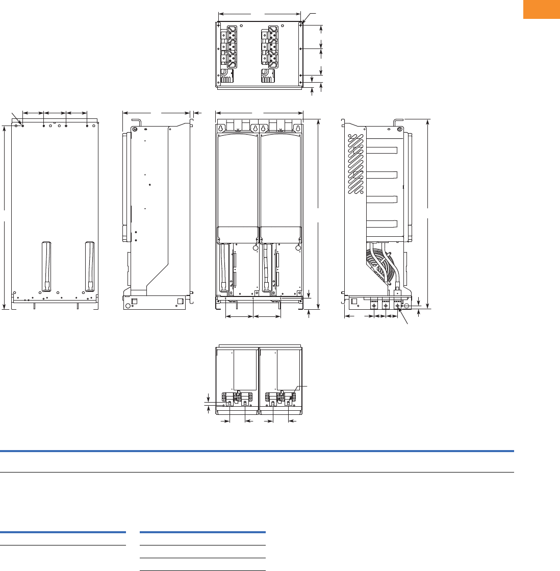
Volume 6—Solid-State Motor Control CA08100007E—May 2014 www.eaton.com V6-T2-83
2
2
2
2
2
2
2
2
2
2
2
2
2
2
2
2
2
2
2
2
2
2
2
2
2
2
2
2
2
2
2.5
Adjustable Frequency Drives
SVX9000 Drives
Approximate Dimensions in Inches (mm)
FR13, Open Chassis Converter
Number of Input Units
W1 W2 W3 W4 W5 H1 H2 H3 H4 H5 D1 D2 D3 D4 D5 D6 D7 D8 D9 Dia. 1 Dia. 2 Dia. 3
Weight
Lbs (kg)
18.74
(476)
5.91
(150)
17.52
(445)
4.57
(116)
3.35
(85)
41.54
(1055)
2.46
(62.5)
39.86
(1012.5)
41.34
(1050)
0.69
(17.5)
14.69
(373)
0.51
(13)
0.73
(18.5)
6.42
(163)
2.56
(65)
1.06
(27)
1.57
(40)
5.91
(150)
5.24
(133)
0.35x0.59
(9x15)
0.51
(13)
0.37
(9.5)
295
(134)
480V
Catalog Number hp
Input
Modules
690V
Catalog Number hp
Input
Modules
SPX800A0-4A2N1 800 2 SPX800A0-5A2N1 800 2
SPX900A0-5A2N1 900 2
SPXH10A0-5A2N1 1000 2
H3
H2
H5
H4
Dia. 1 W4 W4 W4
W5
D3 W5
D5
D4 D5
W2
W2
D1 D2
Dia. 2
Dia. 2
H1
W3 Dia. 3
D9
D8
D7
D6
W1
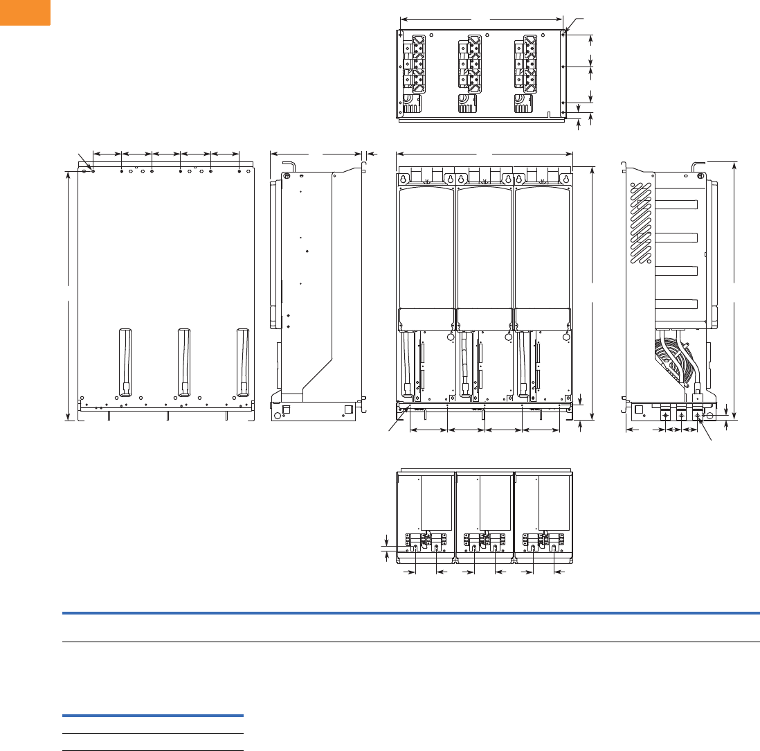
V6-T2-84 Volume 6—Solid-State Motor Control CA08100007E—May 2014 www.eaton.com
2
2
2
2
2
2
2
2
2
2
2
2
2
2
2
2
2
2
2
2
2
2
2
2
2
2
2
2
2
2
2.5
Adjustable Frequency Drives
SVX9000 Drives
Approximate Dimensions in Inches (mm)
FR13, Open Chassis Converter—900/1000 hp 480V
Number of Input Units
W1 W2 W3 W4 W5 H1 H2 H3 H4 H5 D1 D2 D3 D4 D5 D6 D7 D8 D9
Dia.
1
Dia.
2
Dia.
3
Dia.
4
Weight
Lbs (kg)
27.87
(708)
5.91
(150)
26.65
(677)
4.57
(116)
3.35
(85)
41.54
(1055)
2.46
(62.5)
39.86
(1012.5)
41.34
(1050)
0.69
(17.5)
14.69
(373)
0.51
(13)
0.73
(18.5)
6.42
(163)
2.56
(65)
1.06
(27)
1.57
(40)
5.91
(150)
5.24
(133)
0.35x0.59
(9x15)
0.18
(4.6)
0.51
(13)
0.37
(9.5)
443
(201)
480V
Catalog Number hp
Input
Modules
SPX900A0-4A2N1 900 3
SPXH10A0-4A2N1 1000 3
H3
H2
H5
Dia. 1 W4 W4 W4 W4 W4
W5
D3 W5 W5
D5
D4 D5
W2
W2
W2 W2
D1 D2
Dia. 2
Dia. 3
H1 H4
W3 Dia. 4
D9
D8
D7
D6
W1
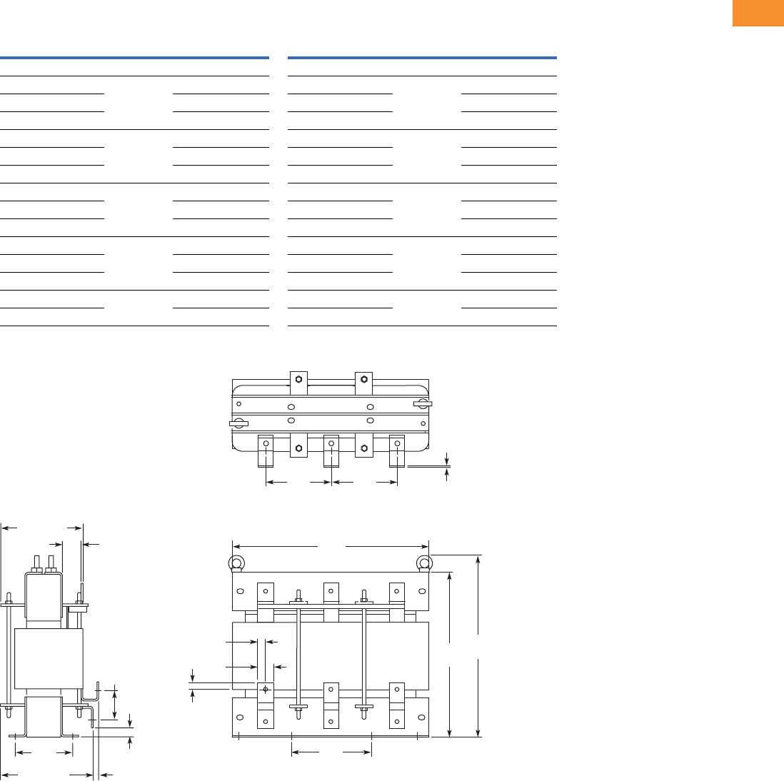
Volume 6—Solid-State Motor Control CA08100007E—May 2014 www.eaton.com V6-T2-85
2
2
2
2
2
2
2
2
2
2
2
2
2
2
2
2
2
2
2
2
2
2
2
2
2
2
2
2
2
2
2.5
Adjustable Frequency Drives
SVX9000 Drives
Approximate Dimensions in Inches (mm)
AC Choke Dimensions
Choke Types
CHK0520
Note
1Chokes are provided with all FR10–FR14 drives.
Catalog Number Frame Size Choke Type 1Catalog Number Frame Size Choke Type 1
Voltage Range 380–500V Voltage Range 525–690V
SPX 250 4 FR10 CHK0400 SPX 200 5 FR10 CHK0261
SPX 300 4 CHK0520 SPX 250 5 CHK0400
SPX 350 4 CHK0520 SPX 300 5 CHK0400
SPX 400 4 FR11 2 x CHK0400 SPX 400 5 FR11 CHK0520
SPX 500 4 2 x CHK0400 SPX 450 5 CHK0520
SPX 550 4 2 x CHK0400 SPX 500 5 2 x CHK0400
SPX 600 4 FR12 2 x CHK0520 SPX 550 5 FR12 2 x CHK0400
SPX 650 4 2 x CHK0520 SPX 600 5 2 x CHK0400
SPX 700 4 2 x CHK0520 SPX 700 5 2 x CHK0400
SPX 800 4 FR13 2 x CHK0400 SPX 800 5 FR13 2 x CHK0400
SPX 900 4 3 x CHK0520 SPX 900 5 2 x CHK0400
SPX H10 4 3 x CHK0520 SPX H10 5 2 x CHK0400
SPX H12 4 FR14 4 x CHK0520 SPX H13 5 FR14 4 x CHK0400
SPX H16 4 6 x CHK0400 SPX H15 5 6 x CHK0400
11
33
2
1
3
22
1.58
(40)
7.88
(200)
6.50
(165) 6.50
(165)
19.57
(497)
.79
(20) 15.71
(399)
17.57
(446)
.79
(20)
.24
(6)
3.03
(77)
.83
(21)
.55 (14)9.61 (244)
8.03 (204)
1.69
(43)
5.70
(145)
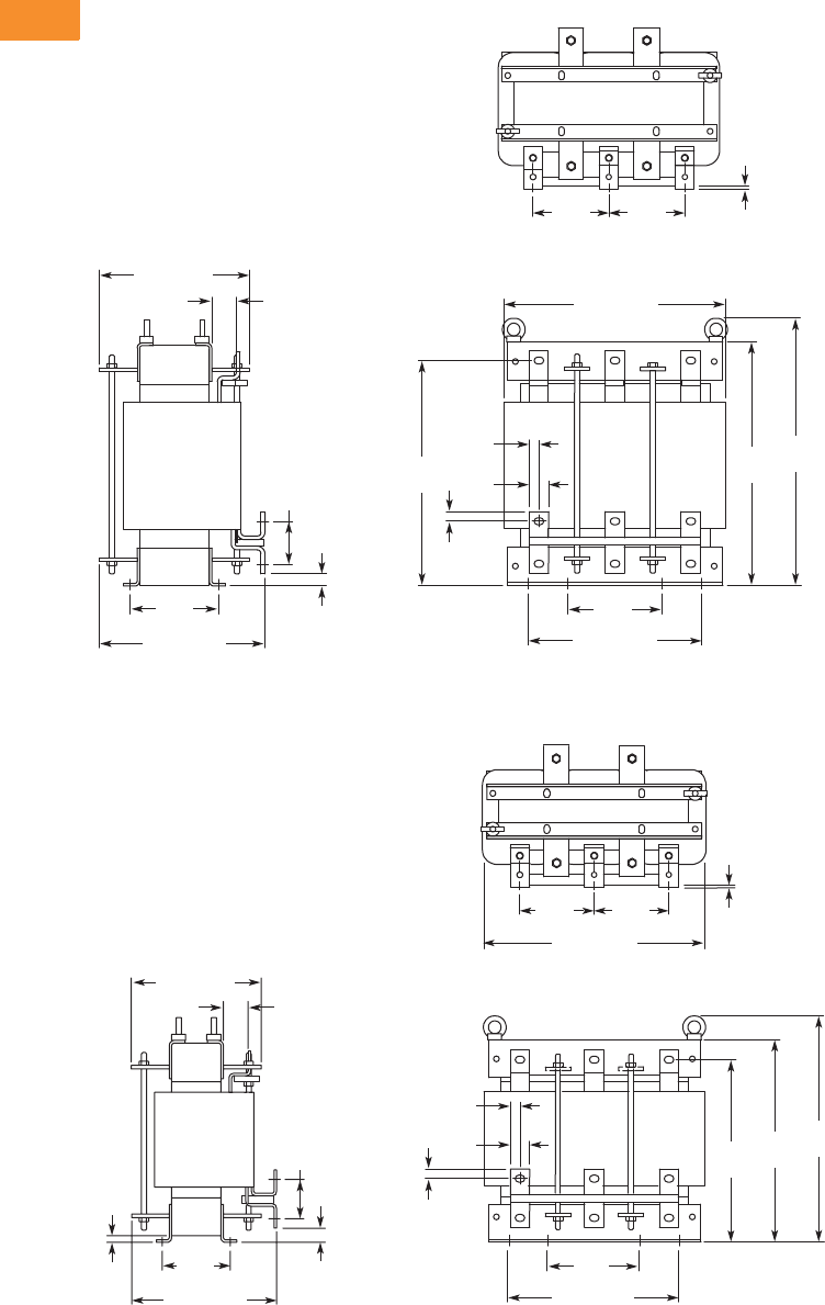
V6-T2-86 Volume 6—Solid-State Motor Control CA08100007E—May 2014 www.eaton.com
2
2
2
2
2
2
2
2
2
2
2
2
2
2
2
2
2
2
2
2
2
2
2
2
2
2
2
2
2
2
2.5
Adjustable Frequency Drives
SVX9000 Drives
Approximate Dimensions in Inches (mm)
CHK0400
CHK0261
111
33
22
3
2
10.30 (262)
9.37 (238)
1.54
(39)
1.18
(30)
5.90
(150)
13.79 (350)
4.72
(120) 4.72
(120)
10.83 (275)
.59
(15)
5.51
(140)
13.94
(354)
15.08
(383)
16.58
(421)
2.64
(67)
.75
(19)
.24
(6)
.59
(15)
13.79 (350)
4.72
(120) 4.72
(120)
.24
(6)
11
33
2
1
3
22
1.18
(30)
5.90
(150)
10.83 (275)
.59
(15)
11.30
(287)
12.56
(319)
14.06
(357)
.59
(15)
.39
(10)
.87
(22)
.75 (19)
Min.
9.06 (230)
8.11 (206)
1.54
(39)
4.25
(108)
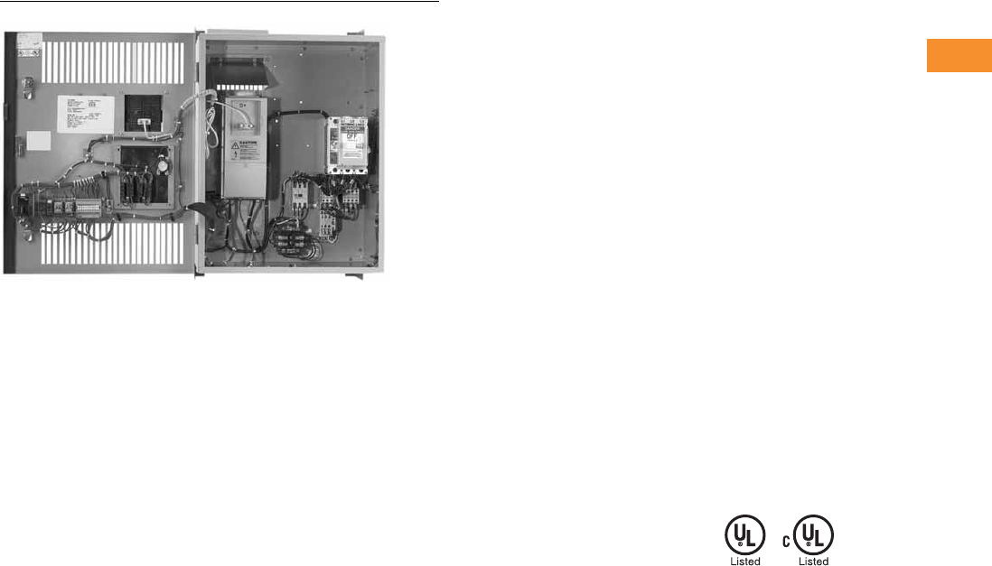
Volume 6—Solid-State Motor Control CA08100007E—May 2014 www.eaton.com V6-T2-87
2
2
2
2
2
2
2
2
2
2
2
2
2
2
2
2
2
2
2
2
2
2
2
2
2
2
2
2
2
2
2.5
Adjustable Frequency Drives
SVX9000 Drives
SVX9000 Enclosed Drives
Contents
Description Page
SVX9000 Drives . . . . . . . . . . . . . . . . . . . . . . . . . . . V6-T2-48
SVX9000 Enclosed Drives
Product Identification . . . . . . . . . . . . . . . . . . . . V6-T2-88
Catalog Number Selection . . . . . . . . . . . . . . . . V6-T2-89
Product Selection . . . . . . . . . . . . . . . . . . . . . . . V6-T2-90
Options . . . . . . . . . . . . . . . . . . . . . . . . . . . . . . . V6-T2-94
Technical Data and Specifications . . . . . . . . . . V6-T2-98
Dimensions . . . . . . . . . . . . . . . . . . . . . . . . . . . V6-T2-100
SVX9000 VFD Pump Panels . . . . . . . . . . . . . . . . . V6 -T 2-111
SVX9000 Enclosed Drives
Product Description
●Standard Enclosed—
covers a wide range of the
most commonly ordered
options. Pre-engineering
eliminates the lead time
normally associated with
customer specific options.
●
Modified Standard
Enclosed
—applies to
specific customer
requirements that vary
from the standard enclosed
offering, such as the need
for an additional indicating
light or minor modifications
to drawings.
Consult your
Eaton representative for
assistance in pricing and
lead time.
●
Custom Engineered
—
for those applications with
more unique or complex
requirements, these are
individually engineered to
the customer’s needs.
Consult your Eaton
representative for assistance
in pricing and lead time.
Features
●NEMA Type 1/IP21 or
NEMA Type 12/IP54
enclosures
●Input voltage: 208V, 230V,
480V and 575V (consult
factory)
●Complete range of control,
network and power options
●Horsepower range:
●208V—3/4 to 100 hp IH;
1 to 100 hp IL
●230V—3/4 to 100 hp IH;
1 to 100 hp IL
●480V—1 to 700 hp IH;
1-1/2 to 800 hp IL
●Padlockable disconnect
Standards and Certifications
●UL Listed
●cUL Listed
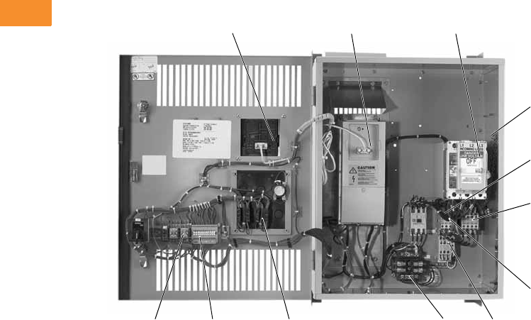
V6-T2-88 Volume 6—Solid-State Motor Control CA08100007E—May 2014 www.eaton.com
2
2
2
2
2
2
2
2
2
2
2
2
2
2
2
2
2
2
2
2
2
2
2
2
2
2
2
2
2
2
2.5
Adjustable Frequency Drives
SVX9000 Drives
Product Identification
Enclosed 9000X Series Drive
1 Door mounted keypad (included as
standard with bypass option)
2 SVX9000 variable frequency drive
3 Input disconnect
• Option P1
4 Input line fuses
• Option P3
5 Input contactor (included as
standard with bypass option)
6 Output contactor
• Option PE (included as
standard with bypass option)
7 Bypass contactor
• Option RA
• Option RB
8 Overload relay
• Option PH
• Option PI
9 115V control transformer
• Option KB
10 Bypass pilot lights and selector switches
• Option RA
• Option RB
• Option L2
• Option KF
11 Customer control and signal connection
terminal block
12 Control relay
123
4
5
6
7
89101112
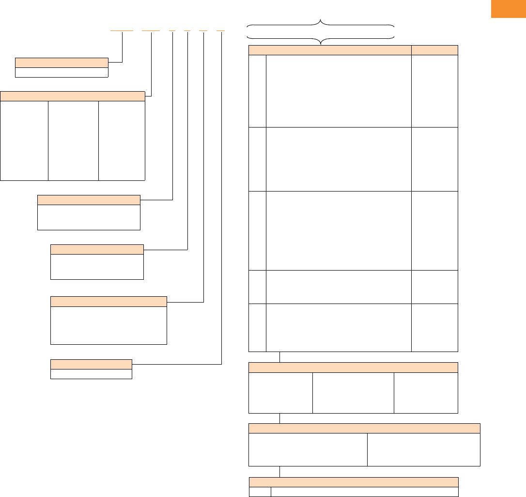
Volume 6—Solid-State Motor Control CA08100007E—May 2014 www.eaton.com V6-T2-89
2
2
2
2
2
2
2
2
2
2
2
2
2
2
2
2
2
2
2
2
2
2
2
2
2
2
2
2
2
2
2.5
Adjustable Frequency Drives
SVX9000 Drives
Catalog Number Selection
SVX9000 Enclosed NEMA Type 1/IP21 and NEMA Type 12/IP54 Drives
Notes
1Local/remote keypad is included as the standard control panel.
2Brake chopper is a factory installed option only, see drive options on Page V6-T2-49. External dynamic braking resistors not included. Consult factory.
3Includes local/remote speed reference switch.
4Some options are voltage and/or horsepower specific. Consult your Eaton representative for details.
5See Pages V6-T2-96 and V6-T2-97 for descriptions.
6See Pages V6-T2-94 and V6-T2-95 for complete descriptions.
Communication Options 6
C2 = Modbus
C3 = PROFIBUS DP
C4 = LonWorks
C5 = PROFIBUS DP
(D9 connector)
C6 = CANopen (slave)
C7 = DeviceNet
C8 = Modbus (D9 type
connector)
CA = Johnson Controls N2
CI = Modbus TCP
CJ = BACnet
CQ = EtherNet/IP
C3 = RS-232 with D9
connection
Voltage Rating
1 = 208V
2 = 230V
4 = 480V
Product Family
SVX = Enclosed drives
Horsepower Rating
F07 = 3/4 hp
001 = 1 hp
F15 = 1-1/2 hp
002 = 2 hp
003 = 3 hp
005 = 5 hp
007 = 7-1/2 hp
010 = 10 hp
015 = 15 hp
020 = 20 hp
025 = 25 hp
030 = 30 hp
040 = 40 hp
050 = 50 hp
060 = 60 hp
075 = 75 hp
100 = 100 hp
125 = 125 hp
150 = 150 hp
200 = 200 hp
250 = 250 hp
300 = 300 hp
350 = 350 hp
400 = 400 hp
500 = 500 hp
550 = 550 hp
600 = 600 hp
650 = 650 hp
700 = 700 hp
800 = 800 hp
Enclosure Rating
1 = NEMA Type 1/IP21
2 = NEMA Type 12/IP54
6 = NEMA Type 12/IP54 filtered
Application—Torque/Braking 2
A = IL/no brake chopper
B = IL/internal brake chopper
D = IH/no brake chopper
E = IH/internal brake chopper
Enclosed Style
A = Enclosed drive
SVX F07 1 4 A A _ _ _ _ _ _ _ _ _ _
Enclosed Options 145 Type
K1
K2
K4
K5
K6
KB
KF
KO
Door-mounted speed potentiometer 3
Door-mounted speed potentiometer with HOA
selector switch 3
HAND/OFF/AUTO switch (22 mm)
MANUAL/AUTO ref switch (22 mm)
START/STOP pushbuttons (22 mm)
115V control transformer (500 VA)
Bypass test switch for RA and RB
Standard elapsed time meter
Control
Control
Control
Control
Control
Control
Addl. bypass
Control
L1
L2
LA
LD
LE
LF
LJ
LU
POWER ON, RUN and FAULT pilot lights
Bypass pilot lights for RA, RB bypass options
Green RUN light (22 mm)
Green STOP light (22 mm)
Red RUN light
Red STOP light (22 mm)
White POWER ON light (22 mm)
Misc. light (22 mm)
Light
Addl. bypass
Light
Light
Light
Light
Light
Light
P1
P3
P8
PA
PE
PF
PG
PH
PI
PN
Input circuit breaker
Input line fuses (200 kAIC)
SPD (50 kA per phase)
SPD (100 kA per phase)
Output contactor
Output filter (100–300 ft)
MotoRx (300–600 ft) 1000 V/μS DV/DT filter
Single overload relay
Dual overload relays
Dual overloads for bypass
Input
Input
Input
Input
Output
Output
Output
Output
Output
Addl. bypass
RA
RB
RC
RD
Manual HOA bypass controller
Manual IOB bypass controller
Auto transfer HOA bypass controller
Auto transfer IOB bypass controller
Bypass
Bypass
Bypass
Bypass
S5
S6
S7
S8
S9
SA
Floor stand 22 in
Floor stand 12 in
10 in expansion
20 in expansion
Space heater
Space heater with CPT
Enclosure
Enclosure
Enclosure
Enclosure
Enclosure
Enclosure
Control Options
B1 = 6 DI, 1 ext +24 Vdc/EXT +24 Vdc
B2 = 1 RO (NC-NO), 1 RO (NO), 1 therm
B4 = 1 AI (mA isolated), 2 AO (mA isolated),
1 ext +24 Vdc/EXT +24 Vdc
B5 = 3 RO (NO)
B8 = 1 ext +24 Vdc/EXT +24 Vdc, 3 Pt100
B9 = 1 RO (NO), 5 DI 42–240 Vac input
Build Alphabetically and Numerically
Engineered Options
VB Varnished boards
V6-T2-90 Volume 6—Solid-State Motor Control CA08100007E—May 2014 www.eaton.com
2
2
2
2
2
2
2
2
2
2
2
2
2
2
2
2
2
2
2
2
2
2
2
2
2
2
2
2
2
2
2.5
Adjustable Frequency Drives
SVX9000 Drives
Product Selection
When Ordering
●Select a base catalog
number that meets the
application requirements—
nominal horsepower,
voltage and enclosure
rating (the enclosed drive’s
continuous output amp
rating should be equal to or
greater than the motor’s
full load amp rating). The
base enclosed package
includes a standard drive,
door mounted local/remote
keypad and enclosure.
●If dynamic brake chopper
or control/communication
option is desired, change
the appropriate code in the
base catalog number.
●Select enclosed options.
Add the codes as suffixes
to the base catalog number
in alphabetical and numeric
order.
●Read all footnotes.
208V Drives
Input Base Drives
Notes
For brake chopper options, see Page V6-T2-58.
1 See enclosure dimensions starting on Page V6-T2-100.
2 Includes drive, local/remote keypad and enclosure.
3 These units are current rated (75 IL hp 205 amps, 100 IL hp 261 amps). They do not meet NEC ampere ratings.
NEMA Type 1/IP21 NEMA Type 12/IP54
Enclosure
Size 1hp Current (A)
Frame
Size
Base Catalog
Number 2
Frame
Size
Base Catalog
Number 2
High Overload Drive and Enclosure
03/43.74SVXF0711EA 4SVXF0721EA
14.8 SVX00111EA SVX00121EA
1-1/2 6.6 SVXF1511EA SVXF1521EA
27.8 SVX00211EA SVX00221EA
311 SVX00311EA SVX00321EA
517.55 SVX00511EA 5SVX00521EA
7-1/2 25 SVX00711EA SVX00721EA
110316SVX01011EA 6SVX01021EA
15 48 SVX01511EA SVX01521EA
220617SVX02011DA 7SVX02021DA
25 75 SVX02511DA SVX02521DA
30 88 SVX03011DA SVX03021DA
3401148SVX04011DA 8SVX04021DA
4501438SVX05011DA 8SVX05021DA
5601708SVX06011DA 8SVX06021DA
75 211 9 SVX07511DA 9SVX07521DA
100 273 SVX10011DA SVX10021DA
Low Overload Drive and Enclosure
014.84SVX00111BA 4SVX00121BA
1-1/2 6.6 SVXF1511BA SVXF1521BA
27.8 SVX00211BA SVX00221BA
311 SVX00311BA SVX00321BA
517.55 SVX00511BA 5SVX00521BA
7-1/2 25 SVX00711BA SVX00721BA
10 31 SVX01011BA SVX01021BA
115486SVX01511BA 6SVX01521BA
20 61 SVX02011BA SVX02021BA
225757SVX02511AA 7SVX02521AA
30 88 SVX03011AA SVX03021AA
40 114 SVX04011AA SVX04021AA
350—8SVX05011AA 8SVX05021AA
4601708SVX06011AA 8SVX06021AA
575
3205 8 SVX07511AA 8SVX07521AA
100 3261 9 SVX10011AA 9SVX10021AA
SVX9000 Enclosed
Drives
Volume 6—Solid-State Motor Control CA08100007E—May 2014 www.eaton.com V6-T2-91
2
2
2
2
2
2
2
2
2
2
2
2
2
2
2
2
2
2
2
2
2
2
2
2
2
2
2
2
2
2
2.5
Adjustable Frequency Drives
SVX9000 Drives
230V Drives
Input Base Drives
Notes
For brake chopper options, see Page V6-T2-58.
1 See enclosure dimensions starting on Page V6-T2-100.
2 Includes drive, local/remote keypad and enclosure.
3 This unit is current rated (100 IL hp 100 amps, 261 IL hp). It is not hp rated. They do not meet NEC ampere ratings.
NEMA Type 1/IP21 NEMA Type 12/IP54
Enclosure
Size 1hp Current (A)
Frame
Size
Base Catalog
Number 2
Frame
Size
Base Catalog
Number 2
High Overload Drive and Enclosure
03/43.74SVXF0712EA 4SVXF0722EA
14.8 SVX00112EA SVX00122EA
1-1/2 6.6 SVXF1512EA SVXF1522EA
27.8 SVX00212EA SVX00222EA
311 SVX00312EA SVX00322EA
517.55 SVX00512EA 5SVX00522EA
7-1/2 25 SVX00712EA SVX00722EA
110316SVX01012EA 6SVX01022EA
15 48 SVX01512EA SVX01522EA
220617SVX02012DA 7SVX02022DA
25 75 SVX02512DA SVX02522DA
30 88 SVX03012DA SVX03022DA
3401148SVX04012DA 8SVX04022DA
4501408SVX05012DA 8SVX05022DA
5601708SVX06012DA 8SVX06022DA
75 205 9 SVX07512DA 9SVX07522DA
100 3261 SVX10012DA SVX10022DA
Low Overload Drive and Enclosure
014.84SVX00112BA 4SVX00122BA
1-1/2 6.6 SVXF1512BA SVXF1522BA
27.8 SVX00212BA SVX00222BA
311 SVX00312BA SVX00322BA
517.55 SVX00512BA 5SVX00522BA
7-1/2 25 SVX00712BA SVX00722BA
10 31 SVX01012BA SVX01022BA
115486SVX01512BA 6SVX01522BA
20 61 SVX02012BA SVX02022BA
225757SVX02512AA 7SVX02522AA
30 88 SVX03012AA SVX03022AA
40 114 SVX04012AA SVX04022AA
3501408SVX05012AA 8SVX05022AA
4601708SVX06012AA 8SVX06022AA
5752058SVX07512AA 8SVX07522AA
100 3261 9 SVX10012AA 9SVX10022AA
SVX9000 Enclosed
Drives
V6-T2-92 Volume 6—Solid-State Motor Control CA08100007E—May 2014 www.eaton.com
2
2
2
2
2
2
2
2
2
2
2
2
2
2
2
2
2
2
2
2
2
2
2
2
2
2
2
2
2
2
2.5
Adjustable Frequency Drives
SVX9000 Drives
480V Drives
Input Base Drives
Notes
For brake chopper options, see Page V6-T2-58.
1 See enclosure dimensions starting on Page V6-T2-100.
2 Includes drive, local/remote keypad and enclosure.
3 The smaller enclosure Size 6 accommodates only power options, input disconnect (P1) and input line fuses (P3).
Bypass and other options require Size 8. Adding any standard control option will not require the larger enclosure.
4 For other options, consult factory.
5 The smaller enclosure Size 8 accommodates only power options, input disconnect (P1) and input line fuses (P3).
Bypass and other options require Size 9. Adding any standard control option will not require the larger enclosure.
6 Consult factory.
NEMA Type 1/IP21 NEMA Type 12/IP54
Enclosure
Size 1hp Current (A)
Frame
Size
Base Catalog
Number 2
Frame
Size
Base Catalog
Number 2
High Overload Drive and Enclosure
012.24SVX00114EA 4SVX00124EA
1-1/2 3.3 SVXF1514EA SVXF1524EA
24.3 SVX00214EA SVX00224EA
35.6 SVX00314EA SVX00324EA
57.6 SVX00514EA SVX00524EA
7-1/2 12 5 SVX00714EA 5SVX00724EA
10 16 SVX01014EA SVX01024EA
15 23 SVX01514EA SVX01524EA
120316SVX02014EA 6SVX02024EA
25 38 SVX02514EA SVX02524EA
30 46 SVX03014EA SVX03024EA
240617SVX04014DA 7SVX04024DA
50 72 SVX05014DA SVX05024DA
60 87 SVX06014DA SVX06024DA
3751058SVX07514DA 8SVX07524DA
100 140 SVX10014DA SVX10024DA
41251708SVX12514DA 8SVX12524DA
51502059SVX15014DA 9SVX15024DA
200 245 SVX20014DA SVX20024DA
6, 8 34 250 300 10 SVX25014DA 10 SVX25064DA
300 385 SVX30014DA SVX30064DA
350 460 SVX35014DA SVX35064DA
8, 9 45 400 520 11 SVX40014DA 11 SVX40064DA
500 590 SVX50014DA SVX50064DA
550 650 SVX55014DA SVX55064DA
6600 730 12 SVX60014DA 12 SVX60064DA
650 820 SVX65014DA SVX65064DA
700 920 SVX70014DA SVX70064DA
SVX9000 Enclosed
Drives
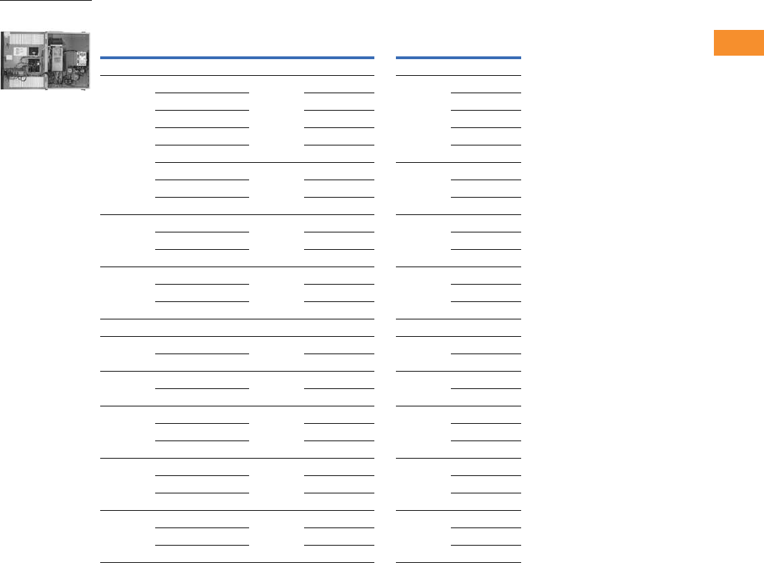
Volume 6—Solid-State Motor Control CA08100007E—May 2014 www.eaton.com V6-T2-93
2
2
2
2
2
2
2
2
2
2
2
2
2
2
2
2
2
2
2
2
2
2
2
2
2
2
2
2
2
2
2.5
Adjustable Frequency Drives
SVX9000 Drives
Input Base Drives, continued
Notes
For brake chopper options, see Page V6-T2-58.
1 See enclosure dimensions starting on Page V6-T2-100.
2 Includes drive, local/remote keypad and enclosure.
3 The smaller enclosure Size 6 accommodates only power options, input disconnect (P1) and input line fuses (P3).
Bypass and other options require Size 8. Adding any standard control option will not require the larger enclosure.
4 For other options, consult factory.
5 The smaller enclosure Size 8 accommodates only power options, input disconnect (P1) and input line fuses (P3).
Bypass and other options require Size 9. Adding any standard control option will not require the larger enclosure.
6 Consult factory.
NEMA Type 1/IP21 NEMA Type 12/IP54
Enclosure
Size 1hp Current (A)
Frame
Size
Base Catalog
Number 2
Frame
Size
Base Catalog
Number 2
Low Overload Drive and Enclosure
01-1/23.34SVXF1514BA 4SVXF1524BA
24.3 SVX00214BA SVX00224BA
35.6 SVX00314BA SVX00324BA
57.6 SVX00514BA SVX00524BA
7-1/2 12 SVX00714BA SVX00724BA
10 16 5 SVX01014BA 5SVX01024BA
15 23 SVX01514BA SVX01524BA
20 31 SVX02014BA SVX02024BA
125386SVX02514BA 6SVX02524BA
30 46 SVX03014BA SVX03024BA
40 61 SVX04014BA SVX04024BA
250727SVX05014AA 7SVX05024AA
60 87 SVX06014AA SVX06024AA
75 105 SVX07514AA SVX07524AA
31001408SVX10014AA 8SVX10024AA
41251708SVX12514AA 8SVX12524AA
150 205 SVX15014AA SVX15024AA
52002619SVX20014AA 9SVX20024AA
250 300 SVX25014AA SVX25024AA
6, 8 34 300 385 10 SVX30014AA 10 SVX30064AA
350 460 SVX35014AA SVX35064AA
400 520 SVX40014AA SVX40064AA
8, 9 45 500 590 11 SVX50014AA 11 SVX50064AA
550 650 SVX55014AA SVX55064AA
600 730 SVX60014AA SVX60064AA
6650 820 12 SVX65014AA 12 SVX65064AA
700 920 SVX70014AA SVX70064AA
800 1030 SVX80014AA SVX80064AA
SVX9000 Enclosed
Drives
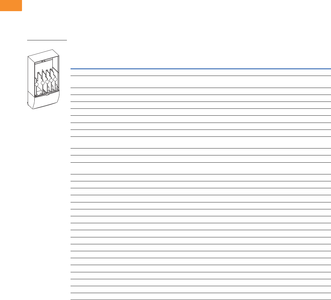
V6-T2-94 Volume 6—Solid-State Motor Control CA08100007E—May 2014 www.eaton.com
2
2
2
2
2
2
2
2
2
2
2
2
2
2
2
2
2
2
2
2
2
2
2
2
2
2
2
2
2
2
2.5
Adjustable Frequency Drives
SVX9000 Drives
Options
9000X Series Option Board Kits
The 9000X Series drives can accommodate a wide selection of expander and adapter option boards
to customize the drive for your application needs. The drive’s control unit is designed to accept a
total of five option boards.
The 9000X Series factory installed standard board configuration includes an A9 I/O board and an A2
relay output board, which are installed in slots A and B.
Option Board Kits
Notes
1 AI = Analog Input; AO = Analog Output, DI = Digital Input, DO = Digital Output, RO = Relay Output
2 Option card must be installed in one of the slots listed for that card. Slot indicated in bold is the preferred location.
3 OPTC2 is a multi-protocol option card.
Option Kit Description 1
Allowed Slot
Locations 2
Field
Installed
Factory
Installed SVX Ready Programs
Catalog
Number
Option
Designator Basic
Local/
Remote Standard MSS PID Multi-P. PFC
Standard I/O Cards
6 DI, 1 DO, 2 AI, 1AO, 1 +10 Vdc ref,
2 ext +24 Vdc/EXT +24 Vdc
AOPTA9 — ■ ■ ■ ■■■ ■
2 RO (NC-NO) B OPTA2 — ■ ■ ■ ■■■ ■
Extended I/O Cards
2 RO, therm—SPX only B OPTA3 A3 —■ ■ ■■■ ■
Encoder low volt +5V/15V/24V—SPX only C OPTA4 A4 —■ ■ ■■■ ■
Encoder high volt +15V/24V—SPX only C OPTA5 A5 —■ ■ ■■■ ■
Double encoder—SPX only C OPTA7 A7 ■ ■ ■ ■■■ ■
6 DI, 1 DO, 2 AI, 1 AO—SPX only A OPTA8 A8 —■ ■ ■■■ ■
3 DI (encoder 10–24V), out +15V/+24V,
2 DO (pulse+direction)—SPX only
COPTAE AE ■ ■ ■ ■■■ ■
6 DI, 1 ext +24 Vdc/EXT +24 Vdc B, C, D, E OPTB1 B1 —— — ——
■■
1 RO (NC-NO), 1 RO (NO), 1 therm B, C, D, E OPTB2 B2 —— — ——
■■
1 AI (mA isolated), 2 AO (mA isolated),
1 ext +24 Vdc/EXT +24 Vdc
B, C, D, E OPTB4 B4 ■ ■ ■ ■■■ ■
3 RO (NO) B, C, D, E OPTB5 B5 —— — ——
■■
1 ext +24 Vdc/EXT +24 Vdc, 3 Pt100 B, C, D, E OPTB8 B8 —— — ——— —
1 RO (NO), 5 DI 42–240 Vac input B, C, D, E OPTB9 B9 —— — ——
■■
Communication Cards
Modbus 3D, E OPTC2 C2 ■ ■ ■ ■■■ ■
Modbus TCP D, E OPTCI CI ■ ■ ■ ■■■ ■
BACnet D, E OPTCJ CJ ■ ■ ■ ■■■ ■
EtherNet/IP D, E OPTCQ CQ ■ ■ ■ ■■■ ■
Johnson Controls N2 3D, E OPTC2 CA —— — ——— —
PROFIBUS DP D, E OPTC3 C3 ■ ■ ■ ■■■ ■
LonWorks D, E OPTC4 C4 ■ ■ ■ ■■■ ■
PROFIBUS DP (D9 connector) D, E OPTC5 C5 ■ ■ ■ ■■■ ■
CANopen (slave) D, E OPTC6 C6 ■ ■ ■ ■■■ ■
DeviceNet D, E OPTC7 C7 ■ ■ ■ ■■■ ■
Modbus (D9 type connector) D, E OPTC8 C8 ■ ■ ■ ■■■ ■
Adapter—SPX only D, E OPTD1 D1 ■ ■ ■ ■■■ ■
Adapter—SPX only D, E OPTD2 D2 ■ ■ ■ ■■■ ■
RS-232 with D9 connection D, E OPTD3 D3 ■ ■ ■ ■■■ ■
Option Boards
ABCDE

Volume 6—Solid-State Motor Control CA08100007E—May 2014 www.eaton.com V6-T2-95
2
2
2
2
2
2
2
2
2
2
2
2
2
2
2
2
2
2
2
2
2
2
2
2
2
2
2
2
2
2
2.5
Adjustable Frequency Drives
SVX9000 Drives
Modbus RTU Network
Communications
The Modbus Network Card
OPTC2 is used for connecting
the 9000X Drive as a slave on
a Modbus network. The
interface is connected by a
9-pin DSUB connector
(female) and the baud rate
ranges from 300 to 19200
baud. Other communication
parameters include an
address range from 1 to 247;
a parity of None, Odd or
Even; and the stop bit is 1.
PROFIBUS Network
Communications
The PROFIBUS Network Card
OPTC3 is used for connecting
the 9000X Drive as a slave
on a PROFIBUS-DP network.
The interface is connected
by a 9-pin DSUB connector
(female). The baud rates
range from 9.6K baud to 12M
baud, and the addresses
range from 1 to 127.
LonWorks Network
Communications
The LonWorks Network Card
OPTC4 is used for connecting
the 9000X Drive on a
LonWorks network. This
interface uses Standard
Network Variable Types
(SNVT) as data types. The
channel connection is
achieved using a FTT-10A
Free Topology transceiver
via a single twisted transfer
cable. The communication
speed with LonWorks is
78 kBits/s.
CANopen (Slave)
Communications
The CANopen (Slave)
Network Card OPTC6 is used
for connecting the 9000X
Drive to a host system.
According to ISO11898
standard cables to be chosen
for CAN bus should have a
nominal impedance of 120
ohms, and specific line delay
of nominal 5 nS/m. 120 ohms
line termination resistors
required for installation.
DeviceNet Network
Communications
The DeviceNet Network Card
OPTC7 is used for connecting
the 9000X Drive on a
DeviceNet Network. It
includes a 5.08 mm pluggable
connector. Transfer method
is via CAN using a two-wire
twisted shielded cable with
two-wire bus power cable
and drain. The baud rates
used for communication
include 125K baud, 250K
baud and 500K baud.
Johnson Controls
Metasys N2 Network
Communications
The OPTC2 fieldbus board
provides communication
between the 9000X Drive and
a Johnson Controls
Metasys™ N2 network. With
this connection, the drive can
be controlled, monitored and
programmed from the
Metasys system. The N2
fieldbus is available as a
factory installed option and as
a field installable kit.
Modbus/TCP Network
Communications
The Modbus/TCP Network
Card OPTCI is used for
connecting the 9000X Drive
to Ethernet networks utilizing
Modbus protocol. It includes
an RJ-45 pluggable connector.
This interface provides a
selection of standard and
custom register values to
communicate drive parameters.
The board supports 10 Mbps
and 100 Mbps communication
speeds. The IP address of the
board is configurable over
Ethernet using a supplied
software tool.
BACnet Network
Communications
The BACnet Network Card
OPTCJ is used for connecting
the 9000X Drive to BACnet
networks. It includes a
5.08 mm pluggable connector.
Data transfer is Master-Slave/
Token Passing (MS/TP)
RS-485. This interface uses
a collection of 30 Binary Value
Objects (BVOs) and 35 Analog
Value Objects (AVOs) to
communicate drive parameters.
The card supports 9.6, 19.2
and 38.4 Kbaud communication
speeds and supports network
addresses 1–127.
EtherNet/IP Network
Communications
The EtherNet/IP Network
Card OPTCK is used for
connecting the 9000X Drive
to Ethernet/Industrial Protocol
networks. It includes an
RJ-45 pluggable connector.
The interface uses CIP
objects to communicate drive
parameters (CIP is “Common
Industrial Protocol”, the same
protocol used by DeviceNet).
The board supports 10 Mbps
and 100 Mbps communication
speeds. The IP address of the
board is configurable by Static,
BOOTP and DHCP methods.

V6-T2-96 Volume 6—Solid-State Motor Control CA08100007E—May 2014 www.eaton.com
2
2
2
2
2
2
2
2
2
2
2
2
2
2
2
2
2
2
2
2
2
2
2
2
2
2
2
2
2
2
2.5
Adjustable Frequency Drives
SVX9000 Drives
Control/Communication Option Descriptions
For availability, see Product Selection for base drive voltage required.
Available Control/Communications Options
Option Description Option Type
K1 Door-Mounted Speed Potentiometer—Provides the SVX9000 with the ability to adjust the frequency reference using a door-mounted potentiometer. This option uses
the 10 Vdc reference to generate a 0–10V signal at the analog voltage input signal terminal. When the HOA bypass option is added, the speed is controlled when the
HOA switch is in the HAND position. Without the HOA bypass option, a two-position switch (labeled local/remote) is provided on the keypad to select speed reference from the
speed potentiometer or a remote speed signal.
Control
K2 Door-Mounted Speed Potentiometer with HOA Selector Switch—Provides the SVX9000 with the ability to start/stop and adjust the speed reference from
door-mounted control devices or remotely from customer supplied inputs. In HAND position, the drive will start and the speed is controlled by the door-mounted speed
potentiometer. The drive will be disabled in the OFF position. When AUTO is selected, the drive run and speed control commands are via user-supplied dry contact and
4–20 mA signal.
Control
K4 HAND/OFF/AUTO Switch for Non-Bypass Configurations—Provides a three-position selector switch that allows the user to select either a HAND or AUTO mode of
operation. HAND mode is defaulted to k (keypad operation, and AUTO mode is defaulted to control from an external terminal source. These modes of operation can be
configured via programming to allow for alternate combinations of start and speed sources. Start and speed sources include keypad, I/O and fieldbus.
Control
K5 MANUAL/AUTO Speed Reference Switch—Provides a door-mounted selector switch for MANUAL/AUTO speed reference. Control
K6 START/STOP Pushbuttons—Provide door-mounted START and STOP pushbuttons for either bypass or non-bypass configurations. Control
KB 115V Control Transformer, 500 VA—Provides a fused control power transformer with additional 500 VA at 115V for customer use. Control
KF Bypass Test Switch for RB and RA—Allows the user to energize the AF drive for testing while operating the motor on the bypass controller. The test switch is
mounted on the inside of the enclosure door.
Addl. bypass
KO Standard Elapsed Time Meter—Provides a door-mounted elapsed run time meter. Control
L1 POWER ON, RUN and FAULT Pilot Lights —Provide a white POWER ON light that indicates power to the enclosed cabinet, a green RUN light that indicates the drive
is running and a red FAULT light that indicates a drive fault has occurred.
Light
L2 Bypass Pilot Lights for RA and RB Bypass Options—A green MOTOR ON INVERTER light indicates when the motor is running in inverter mode and an amber
MOTOR ON BYPASS light indicates when the motor is running in bypass mode. The lights are mounted on the enclosure door, above the switches.
Addl. bypass
LA Green RUN Light (22 mm)—Provides a green RUN light that indicates the drive is running. Light
LD Green STOP Light (22 mm)—Provides a green STOP light that indicates the drive is stopped. Light
LE Red RUN Pilot Light (22 mm)—Provides a red RUN pilot light that indicates the drive is running. Light
LF Red STOP Light (22 mm)—Provides a red STOP light that indicates the drive is stopped. Light
LJ White POWER ON Light (22 mm)—Provides a white POWER ON light that indicates power to the enclosed cabinet. Light
LU Misc. Light (22 mm)—Provides a misc. “user defined” pilot light. User to define light function and color. Light
P1 Input Circuit Breaker—Provides a means of short-circuit protection for the power cables between it and the SVX9000, and protection from high-level ground faults on
the power cable. Allows a convenient means of disconnecting the SVX9000 from the line and the operating mechanism can be padlocked in the OFF position. This is factory
mounted in the enclosure.
Input
P3 Input Line Fuses Rated to 200 kAIC—Provides high-level fault protection of the SVX9000 input power circuit from the load side of the fuses to the input side of the
power transistors. This option consists of three 200 kA fuses, which are factory mounted in the enclosure.
Input
P8 SPD (50 kA per Phase)—Provides a surge protection device (SPD) connected to the line side terminals and is designed to clip line side transients.
Rated for 50,000A.
Input
PA SPD (100 kA per Phase)—Provides a surge protection device (SPD) connected to the line side terminals and is designed to clip line side transients.
Rated for 100,000A.
Input
PE Output Contactor—Provides a means for positive disconnection of the drive output from the motor terminals. The contactor coil is controlled by the drive’s run or
permissive logic. NC and NO auxiliary contacts rated at 10A, 600 Vac are provided for customer use. Bypass options RB and RA include an output contactor as standard.
This option includes a low VA 115 Vac fused control power transformer and is factory mounted in the enclosure.
Output
PF Output Filter (100–300 ft)—Used to reduce the transient voltage (DV/DT) at the motor terminals. The output filter is recommended for cable lengths exceeding 100 ft
(30m) with a drive of 3 hp and above, for cable lengths of 33 ft (10m) with a drive of 2 hp and below, or for a drive rated at 525–690V. This option is mounted in the enclosure,
and may be used in conjunction with a brake chopper circuit.
Output
PG MotoRX (300–600 ft) 1000 V/μS DV/DT Filter—Used to reduce transient voltage (DV/DT) and peak voltages at the motor terminals. This option is comprised of a 0.5%
line reactor, followed by capacitive filtering and an energy recovery/clamping circuit. Unlike the output filter (See option PF), the MotoRx recovers most of the energy from the
voltage peaks, resulting in a lower voltage drop to the motor, and therefore conserving power. This option is used when the distance between a single motor and the drive
is 300–600 ft (91–183m). This option can not be used with the brake chopper circuit. The output filter (option PF) should be investigated as an alternative.
Output
PH Single Overload Relay—Uses a bimetallic overload relay to provide additional overload current protection to the motor on configurations without bypass options. It is
included with the bypass configurations for overload current protection in the bypass mode. The overload relay is mounted within the enclosure, and is manually
resettable. Heater pack included.
Output
PI Dual Overload Relays—This option is recommended when a single drive is operating two motors and overload current protection is needed for each of the motors. The
standard configuration includes two bimetallic overload relays, each sized to protect a motor with 50% of the drive hp rating. For example, a 100 hp drive would include
two overload relays sized to protect two 50 hp motors. The relays are mounted within the enclosure, and are manually resettable. Heater packs not included.
Output
PN Dual Overloads for Bypass—This option is recommended when a single drive is operating two motors in the bypass mode and overload current protection is needed
for each of the motors. The standard configuration includes two bimetallic overload relays, each sized to protect a motor with 50% of the drive hp rating. For example, a
100 hp drive would include two overload relays sized to protect two 50 hp motors. The relays are mounted within the enclosure, and are manually resettable.
Addl. bypass
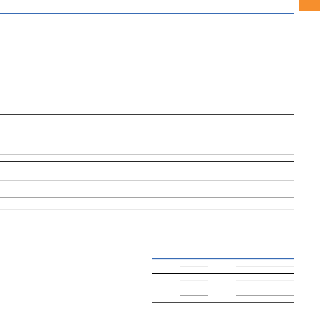
Volume 6—Solid-State Motor Control CA08100007E—May 2014 www.eaton.com V6-T2-97
2
2
2
2
2
2
2
2
2
2
2
2
2
2
2
2
2
2
2
2
2
2
2
2
2
2
2
2
2
2
2.5
Adjustable Frequency Drives
SVX9000 Drives
For availability, see Product Selection for base drive voltage required.
Available Control/Communications Options, continued
Enclosed Drive Options
Brake Chopper Options
The brake chopper circuit option is used for applications that
require dynamic braking. Dynamic braking resistors are not
included with drive purchase. Consult Page V6-T2-58 for
dynamic braking resistors
which are supplied separately.
Resistors are not UL Listed.
For brake chopper circuit selection and adder—NEMA
Type 1/IP21, NEMA Type 12/IP54, consult the factory
SVX Conversion Kit
Frame 4–7 1
Note
1The kit consists of a flange kit, adapter plate(s), hardware, remote keypad kit and
SVX9000 decal.
Option Description Option Type
RA Manual HOA Bypass Controller—The manual HAND/OFF/AUTO (HOA)—3-contactor—bypass option provides a means of bypassing the SVX9000, allowing the AC
motor to be operated at full speed directly from the AC supply line. This option consists of an input disconnect, a fused control power transformer, and a full voltage
bypass starter with a door mounted HOA selector switch and an INVERTER/BYPASS switch. The HOA switch provides the ability to start and stop the drive in the inverter
mode. For applications up to 100 hp, a Freedom Series IEC input contactor, a Freedom Series IEC output contactor, and a Freedom Series IEC starter with a bimetallic
overload relay is included. For applications above 100 hp, an Advantage input contactor, an Advantage output contactor and an Advantage starter with electronic
overload protection is included. The contactors are mechanically and electrically interlocked.
Bypass
RB Manual IOB Bypass Controller—The manual INVERTER/OFF/BYPASS (IOB)—3-contactor—bypass option provides a means of bypassing the SVX9000, allowing
the AC motor to be operated at full speed directly from the AC supply line. This option consists of an input disconnect, a fused control power transformer, and a full
voltage bypass starter with a door mounted IOB selector switch. For applications up to 100 hp, a Freedom Series IEC input contactor, a Freedom Series IEC output
contactor, and a Freedom Series IEC starter with a bimetallic overload relay is included. For applications above 100 hp, an Advantage input contactor, an Advantage
output contactor and an Advantage starter with electronic overload protection is included. The contactors are mechanically and electrically interlocked.
Bypass
RC Auto Transfer HOA Bypass Controller—The manual HAND/OFF/AUTO (HOA)—3-contactor—bypass option provides a means of bypassing the SVX9000, allowing
the AC motor to be operated at full speed directly from the AC supply line. The circuitry provides an automatic transfer of the load to “across the line” operation after a
drive trip. This option consists of an input disconnect, a fused control power transformer, and a full voltage bypass starter with a door mounted HOA selector switch and
an INVERTER/BYPASS switch. The HOA switch provides the ability to start and stop the drive in either mode. For applications up to 100 hp, a Freedom Series IEC input
contactor, a Freedom Series IEC output contactor, and a Freedom Series IEC starter with a bimetallic overload relay is included. For applications above 100 hp, an Advantage input
contactor, an Advantage output contactor and an Advantage starter with electronic overload protection is included. The contactors are mechanically and electrically
interlocked. Door-mounted pilot lights are provided which indicate bypass or inverter operation. A green light indicates when the motor is running in inverter mode and an
amber light indicates when the motor is running in bypass mode.
WARNING: The motor may restart when the overcurrent relay is reset when operating in bypass, unless the IOB selector switch is turned to the OFF position.
Bypass
RD Auto Transfer IOB Bypass Controller—The auto INVERTER/OFF/BYPASS (IOB)—3-contactor—bypass option provides a means of bypassing the SVX9000, allowing
the AC motor to be operated at full speed directly from the AC supply line. The circuitry provides an automatic transfer of the load to “across the line” operation after a
drive trip. This option consists of an input disconnect, a fused control power transformer, and a full voltage bypass starter with a door mounted IOB selector switch. For
applications up to 100 hp, a Freedom Series IEC input contactor, a Freedom Series IEC output contactor, and a Freedom Series IEC starter with a bimetallic overload relay
is included. For applications above 100 hp, an Advantage input contactor, an Advantage output contactor and an Advantage starter with electronic overload protection is
included. The contactors are mechanically and electrically interlocked. Door-mounted pilot lights are provided which indicate bypass or inverter operation. A green light
indicates when the motor is running in inverter mode and an amber light indicates when the motor is running in bypass mode.
WARNING: The motor may restart when the overcurrent relay is reset when operating in bypass, unless the IOB selector switch is turned to the OFF position.
Bypass
S5 Floor Stand 22 in—Converts a Size 1 or 2, normally wall mounted enclosure to a floor standing enclosure with a height of 22 in (558.8 mm). Enclosure
S6 Floor Stand 12 in—Converts a Size 2, normally wall mounted enclosure to a floor standing enclosure with a height of 12 in (304.8 mm). Enclosure
S7 10 in Expansion—In a Size 5 enclosure, the extension allows for bottom cable entry and additional space for customer mounted components.
NOTE: Enclosure expansion rated NEMA Type 1/IP21 only.
Enclosure
S8 20 in Expansion—In a Size 5 enclosure, the extension allows for bottom cable entry and additional space for customer mounted components. When the output filter
(option PF) is selected for a drive using a Size 5 enclosure, this expansion box is required and included in the option pricing.
Enclosure expansion rated NEMA Type 1/IP21 only.
Enclosure
S9 Space Heater—Prevents condensation from forming in the enclosure when the drive is inactive or in storage. Includes a thermostat for variable temperature control. A
200W heater is installed in enclosures 0 and 1, and a 400W heater is installed in enclosures 2–5.
Enclosure
SA Space Heater with CPT—Prevents condensation from forming in the enclosure when the drive is inactive or in storage. Includes a thermostat for variable temperature
control. A 200W heater is installed in enclosures 0 and 1, and a 400W heater is installed in enclosures 2–5. Includes a 115V supply to power heater.
Enclosure
Frame
Size
Enclosure
Size
Delivery
Code Catalog Number
FR4 0 FB10 OPTCON-SVXFR4-SZ00
1OPTCON-SVXFR4-SZ01
FR5 0 FB10 OPTCON-SVXFR5-SZ00
1OPTCON-SVXFR5-SZ01
FR6 1 FB10 OPTCON-SVXFR6-SZ01
2OPTCON-SVXFR6-SZ02
FR7 2 FB10 OPTCON-SVXFR7-SZ02

V6-T2-98 Volume 6—Solid-State Motor Control CA08100007E—May 2014 www.eaton.com
2
2
2
2
2
2
2
2
2
2
2
2
2
2
2
2
2
2
2
2
2
2
2
2
2
2
2
2
2
2
2.5
Adjustable Frequency Drives
SVX9000 Drives
Technical Data and Specifications
9000X Enclosed Drives
Description
NEMA Type 1/IP21 or NEMA Type 12/IP54
Specification
Primary Design Features
45–66 Hz input frequency Standard
Output: AC volts maximum Input voltage base
Output frequency range 0–320 Hz
Initial output current (IH) 250% for 2 seconds
Overload (1 minute [IH/IL]) 150%/110%
Enclosure space heater Optional
Oversize enclosure Standard
Output contactor Optional
Bypass motor starter Optional
Listings UL, cUL
Protection Features
Incoming line fuses Optional
AC input circuit disconnect Optional
Line reactors (3%) Standard
Phase rotation insensitive Standard
EMI filter Standard
Input phase loss protection Standard
Input overvoltage protection Standard
Line surge protection Optional
Output short-circuit protection Standard
Output ground fault protection Standard
Output phase protection Standard
Overtemperature protection Standard
DC overvoltage protection Standard
Drive overload protection Standard
Motor overload protection Standard
Programmer software Optional
Local/remote keypad Standard
Keypad lockout Standard
Fault alarm output Standard
Built-in diagnostics Standard
Description
NEMA Type 1/IP21 or NEMA Type 12/IP54
Specification
Input/Output Interface Features
Setup adjustment provisions
Remote keypad/display Standard
Personal computer Standard
Operator control provisions
Drive mounted keypad/display Standard
Remote keypad/display Standard
Conventional control elements Standard
Serial communications Optional
115 Vac control circuit Optional
Speed setting inputs
Keypad Standard
0–10 Vdc potentiometer/voltage signal Standard
4–20 mA Isolated Configurable
4–20 mA Differential Configurable
Analog outputs
Speed/frequency Standard
Torque/load/current Programmable
Motor voltage Programmable
Kilowatts Programmable
0–10 Vdc signals Configurable w/jumpers
4–20 mA DC signals Standard
Isolated signals Optional
Discrete outputs
Fault alarm Standard
Drive running Standard
Drive at set speed Programmable
Optional parameters 14
Dry contacts 1 (2 relays Form C)
Open collector outputs 1
Additional discrete outputs Optional
Communications
RS-232 Standard
RS-422/485 Optional
DeviceNet™ Optional
Modbus RTU Optional
CANopen (slave) Optional
PROFIBUS-DP Optional
Lonworks® Optional
Johnson Controls Metasys™ N2 Optional
EtherNet/IP Optional
Modbus TCP Optional
BACnet Optional

Volume 6—Solid-State Motor Control CA08100007E—May 2014 www.eaton.com V6-T2-99
2
2
2
2
2
2
2
2
2
2
2
2
2
2
2
2
2
2
2
2
2
2
2
2
2
2
2
2
2
2
2.5
Adjustable Frequency Drives
SVX9000 Drives
9000X Enclosed Drives, continued Standard I/O Specifications
I/O Specifications for Control/Communication Options
Note
1Some horsepower units include dynamic braking chopper as standard—refer to individual
drive sections.
Description
NEMA Type 1/IP21 or NEMA Type 12/IP54
Specification
Performance Features
Sensorless vector control Standard
Volts/hertz control Standard
IR and slip compensation Standard
Electronic reversing Standard
Dynamic braking Optional 1
DC braking Standard
PID setpoint controller Programmable
Critical speed lockout Standard
Current (torque) limit Standard
Adjustable acceleration/deceleration Standard
Linear or S curve accel/decel Standard
Jog at preset speed Standard
Thread/preset speeds 7 Standard, 15 Optional
Automatic restart Selectable
Coasting motor start Standard
Coast or ramp stop selection Standard
Elapsed time meter Optional
Carrier frequency adjustment 1–16 kHz
Standard Conditions for Application and Service
Operating ambient temperature 0 to 40°C
Storage temperature –40 to 60°C
Humidity (maximum), non-condensing 95%
Altitude (maximum without derate) 3300 ft (1000m)
Line voltage variation +10/–15%
Line frequency variation 45–66 Hz
Efficiency >96%
Power factor (displacement) >0.94
Description Specification
Six–digital input
programmable
24V: “0” <10V, “1” >18V,Ri >5 kohms
Two–analog input
configurable w/jumpers
Voltage: 0–±10V, Ri >200 kohms
Current: 0 (4)–20 mA, Ri = 250 ohms
Two–digital output
programmable
Form C relays 250 Vac
30 Vdc 2 amp resistive
One–analog output
programmable
configurable w/jumper
0–20 mA, RL max. 500 ohms 10 bits ±2%
One digital output
programmable
Open collector 48 Vdc 50 mA
Description Specification
Analog voltage, input 0–±10V, Ri >200 kohms
Analog current, input 0 (4)–20 mA, Ri = 250 ohms
Digital input 24V: “0” <10V, “1” >18V, Ri >5 kohms
Auxiliary voltage 24V (±20%), max. 50 mA
Reference voltage 10V ±3%, max. 10 mA
Analog current, output 0 (4)–20 mA, RL = 500 kohms resolution 10 bit,
accuracy <±2%
Analog voltage, output 0 (2)–10V, RL >1 kohms, resolution 10 bit,
accuracy <±2%
Relay output
Maximum switching voltage 300 Vdc, 250 Vac
Maximum switching load 8A/24 Vdc, 0.4A/300 Vdc, 2 kVA/250 Vac
Maximum continuous load 2A rms
Thermistor input Rtrip = 4.7 kohms
Encoder input 24V: “0” <10V, “1” >18V, Ri = 2.2 kohms
5V: “0” <2V, “1” >3V, Ri = 330 ohms
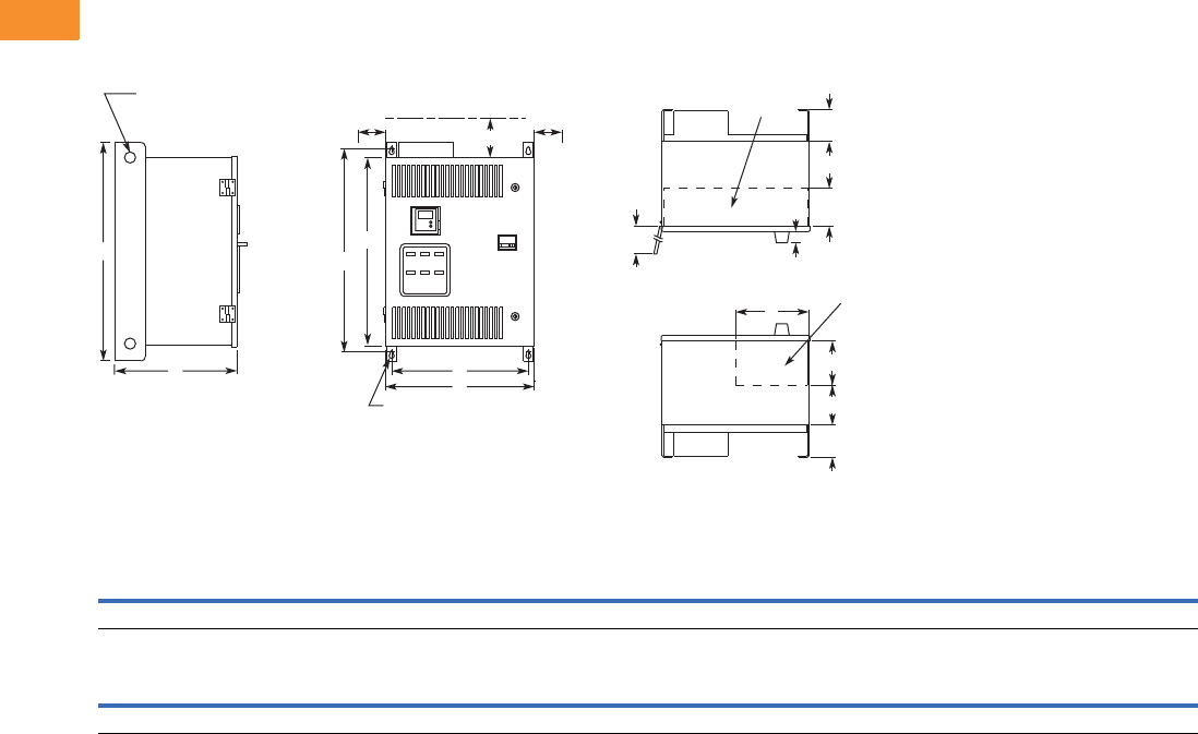
V6-T2-100 Volume 6—Solid-State Motor Control CA08100007E—May 2014 www.eaton.com
2
2
2
2
2
2
2
2
2
2
2
2
2
2
2
2
2
2
2
2
2
2
2
2
2
2
2
2
2
2
2.5
Adjustable Frequency Drives
SVX9000 Drives
Dimensions
Approximate Dimensions in Inches (mm)
9000X Enclosed Drives
Size 0
For reference only, dimensions are subject to change.
Wide High Deep Mounting Door Height Min. Air Space
ABCDD1EE1FGG1H JK
19.9 (504) 29.0 (737) 16.4 (416) 18.3 (465) — — — 27.4 (695) — — 25.4 (644) 4.0 (102) 3.0 (76)
Cable Entry
LMNPR
Door Clearance
S
CB Handle
TUVW
Max. Approx.
Shipping Weight
Lbs (kg)
5.0 (127) — — 6.0 (152) 9.6 (245) 26.4 (669) 1.5 (38) 6.3 (160) 4.3 (108) 5.3 (134) 200 (91)
0.44 (11.2)
Mounting Holes
4 Places
C D
A
1.50 (38.1)
Lifting Holes
4 Places
H
F
J
K K
S
V
U
L
T
R
W
V
P
Top View
Bottom View
NEMA Type 1/IP21, NEMA Type 12/IP54
NEMA Type 12/IP54 Includes Cover Plates Over Louvers
B
For Cable
Entry
For Cable
Entry
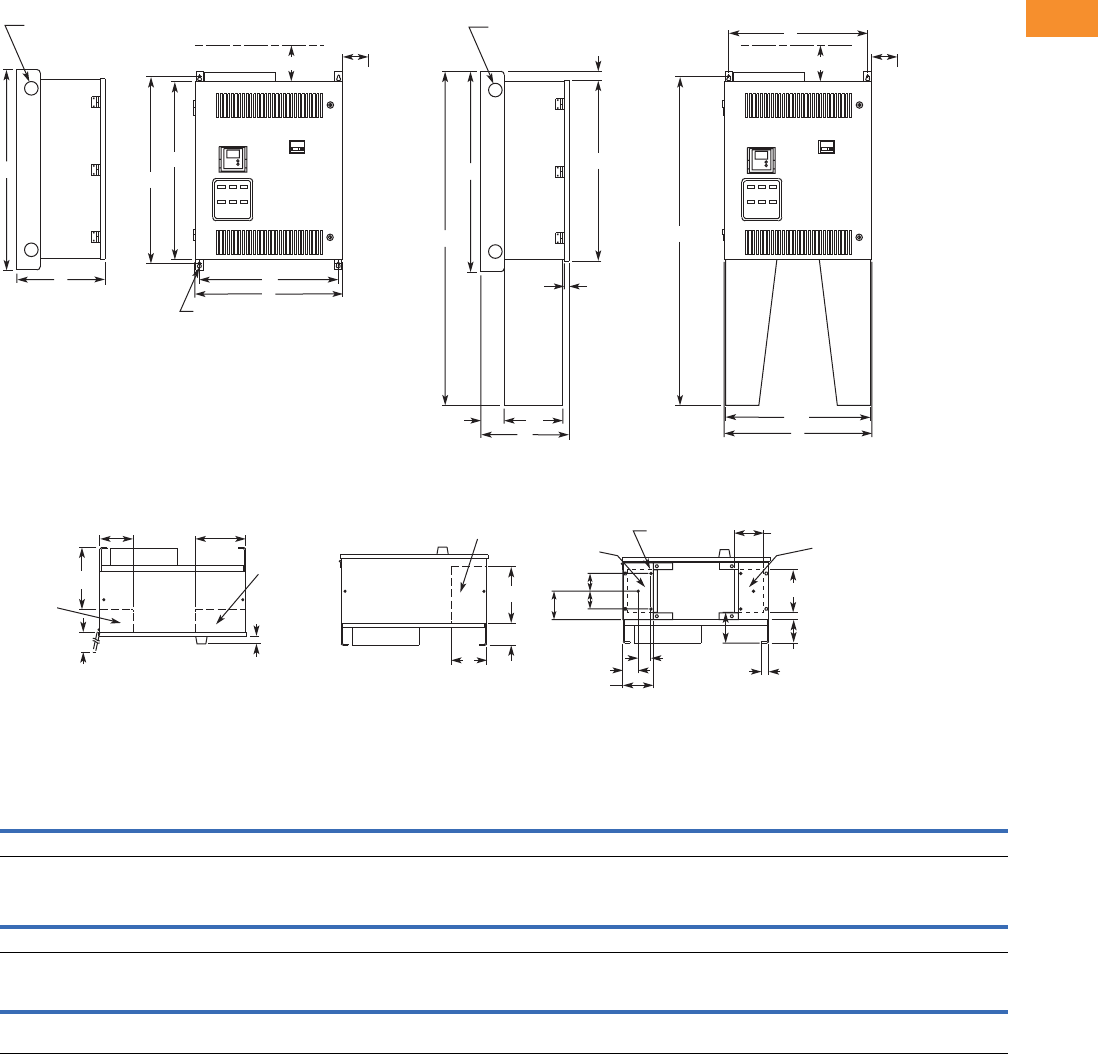
Volume 6—Solid-State Motor Control CA08100007E—May 2014 www.eaton.com V6-T2-101
2
2
2
2
2
2
2
2
2
2
2
2
2
2
2
2
2
2
2
2
2
2
2
2
2
2
2
2
2
2
2.5
Adjustable Frequency Drives
SVX9000 Drives
Approximate Dimensions in Inches (mm)
Size 1
For reference only, dimensions are subject to change.
Wide High Deep Mounting Door Height Min. Air Space
ABCDD1EE1FGG1H JK
26.4 (669) 36 (914) 16.3 (414) 24.8 (630) — — — 34.0 (864) — — 32.4 (822) 4.0 (102) 3.0 (76)
Cable Entry
LMNPR
Door Clearance
S
CB Handle
TUVW
Max. Approx.
Shipping Weight
Lbs (kg)
11.0 (279) 6.0 (152) 9.0 (229) 10.0 (254) 6.5 (165) 26.4 (669) 1.5 (38) 4.3 (108) — — 230 (104)
Floor Stand
X Y Z AA BB CC DD EE FF GG HH JJ KK LL MM NN PP RR SS TT UU VV
56.0
(1422)
4.3
(108)
11.1
(281)
1.8
(46)
0.8
(19)
55.2
(1402)
26.0
(660)
3.5
(90)
5.5
(141)
3.0
(76)
6.0
(152)
2.0
(51)
5.4
(136)
1.1
(28)
8.8
(224)
5.4
(137)
—— ————
Bottom View
C
2.50 (63.5)
Lifting Holes
4 Places
0.44 (11.2)
Mounting Holes
4 Places
D
A
0.44 (11.2)
Mounting Holes
6 Places
H
F
K K
J
M N
S
L
T
U
P
R
Top View
NEMA Type 1/IP21, NEMA Type 12/IP54
with Floor Stand
NEMA Type 1/IP21, NEMA Type 12/IP54
NEMA Type 12/IP54 Includes Cover Plates Over Louvers
B
C
2.50 (63.5)
Lifting Holes
4 Places
B
X
H
AA
DD
A
CC
J
U
MM
KK
EE
EE
FF
JJ
GG
HH
LL
NN
ZY
BB
D
Bottom View
NEMA Type 1/IP21, NEMA Type 12/IP54
with Floor Stand
For Cable
Entry
For Cable
Entry
For Cable
Entry
For Cable
Entry
For Cable
Entry
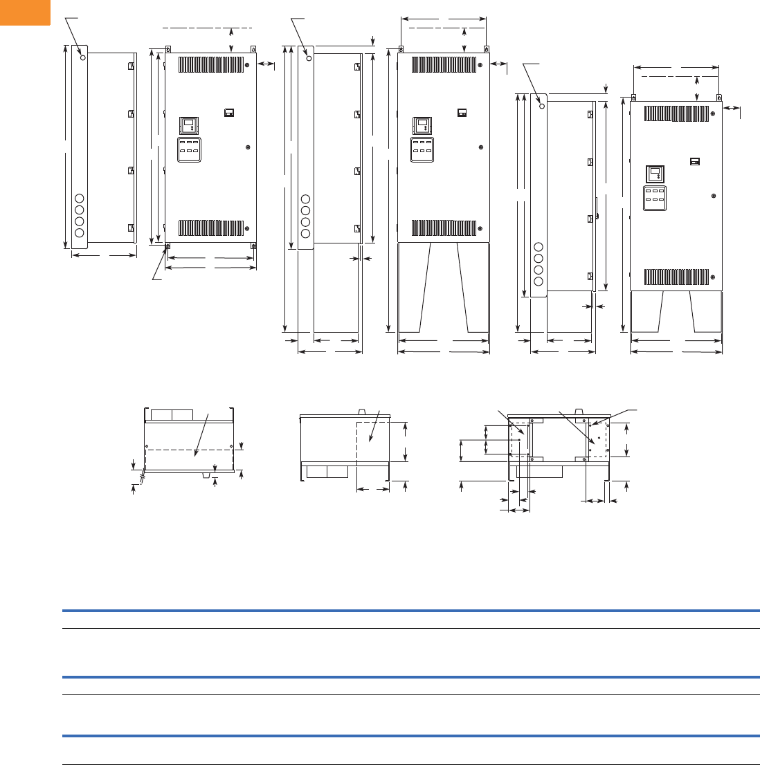
V6-T2-102 Volume 6—Solid-State Motor Control CA08100007E—May 2014 www.eaton.com
2
2
2
2
2
2
2
2
2
2
2
2
2
2
2
2
2
2
2
2
2
2
2
2
2
2
2
2
2
2
2.5
Adjustable Frequency Drives
SVX9000 Drives
Approximate Dimensions in Inches (mm)
Size 2
For reference only, dimensions are subject to change.
Wide High Deep Mounting Door Height Min. Air Space
ABCDD1EE1FGG1H JK
26.4 (669) 59.0 (1499) 19.4 (492) 24.8 (630) — — — 57.0 (1448) — — 55.4 (1406) 4.0 (102) 3.0 (76)
Cable Entry
LMNPR
Door Clearance
S
CB Handle
TUVW
Max. Approx.
Shipping Weight
Lbs (kg)
5.9 (149) — — 12.4 (315) 9.5 (241) 26.4 (669) 1.5 (38) 4.8 (121) 5.9 (151) — 380 (173)
Floor Stand
X Y Z AA BB CC DD EE FF GG HH JJ KK LL MM NN PP RR SS TT UU VV
69.0
(1753)
4.8
(121)
13.6
(344)
1.8
(46)
0.8
(19)
68.2
(1732)
26.0
(660)
4.8
(121)
6.8
(172)
3.0
(76)
6.0
(152)
2.0
(51)
5.0
(127)
1.1
(28)
11.3
(288)
79.0
(2007)
78.2
(1986)
— ————
0.44 (11.2)
Mounting Holes
4 Places
D
A
H
F
K
J
R
NEMA Type 1/IP21, NEMA Type 12/IP54
NEMA Type 12/IP54 Includes
Cover Plates Over Louvers
Bottom View
S
L
T
Top View
P
U
C
B
2.50 (63.5)
Lifting Holes
2 Places
2.50 (63.5)
Lifting Holes
2 Places
C
B
NN
H
K
K
PP
J
AA
NEMA Type 1/IP21, NEMA Type 12/IP54
with 22 in Floor Stand
DD
Z
Y
A
D
CC
J
NEMA Type 1/IP21, NEMA Type 12/IP54
with 12 in Floor Stand
DD
A
D
0.44 (11.2) Mounting
Holes 6 Places
V
MM
KK
EE
EE
FF
JJ
GG
HH
LL
U
Bottom View
NEMA Type 1/IP21, NEMA Type 12/IP54
with Floor Stand
BB
2.50 (63.5)
Lifting Holes
2 Places
C
B
XH
AA
ZY
BB
For Cable
Entry
For Cable
Entry For Cable
Entry
For Cable
Entry
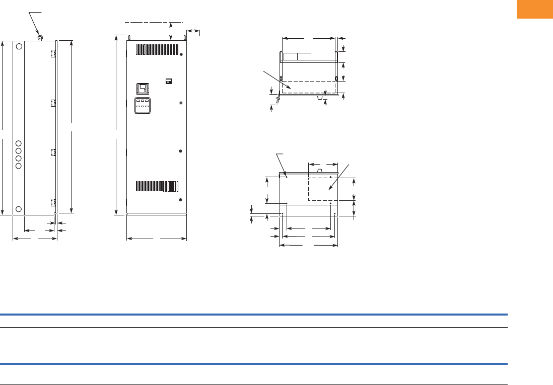
Volume 6—Solid-State Motor Control CA08100007E—May 2014 www.eaton.com V6-T2-103
2
2
2
2
2
2
2
2
2
2
2
2
2
2
2
2
2
2
2
2
2
2
2
2
2
2
2
2
2
2
2.5
Adjustable Frequency Drives
SVX9000 Drives
Approximate Dimensions in Inches (mm)
Size 3
For reference only, dimensions are subject to change.
Wide High Deep Mounting Door Height Min. Air Space
ABCDD1EE1FGG1H JK
26.4 (671) 77.0 (1956) 19.4 (493) 19.5 (495) 3.3 (83) 23.0 (584) 1.5 (38) 11.7 (298) 5.5 (140) 0.9 (24) 76.4 (1939) 4.0 (102) 3.0 (76)
Max. Approx.
Shipping Weight
Lbs (kg)
Cable Entry Door Clearance CB Handle
L M N P R S T U V W RR SS TT UU VV
5.3
(133)
23.4
(594)
10.0
(254)
1.3
(32)
12.9
(328)
26.4
(669)
1.5
(38)
8.0
(203)
4.8
(121)
6.8
(173)
79.5
(2018)
13.40
(340)
0.8
(19)
1.3
(32)
26.0
(660)
690 (313)
0.44 (11.2)
Mounting Holes
6 Places
D
D1
E1 E
VV
R
MP
0.50 (12.7)
Lifting Eyes
2 Places
H
C A
UU
SS TT
B
S
F
G
G1
V
U
L
T
Top View
Bottom View
N
W
JK
RR
NEMA Type 1/IP21, NEMA Type 12/IP54
NEMA Type 12/IP54 Includes Cover Plates Over Louvers
For Cable
Entry
For Cable
Entry
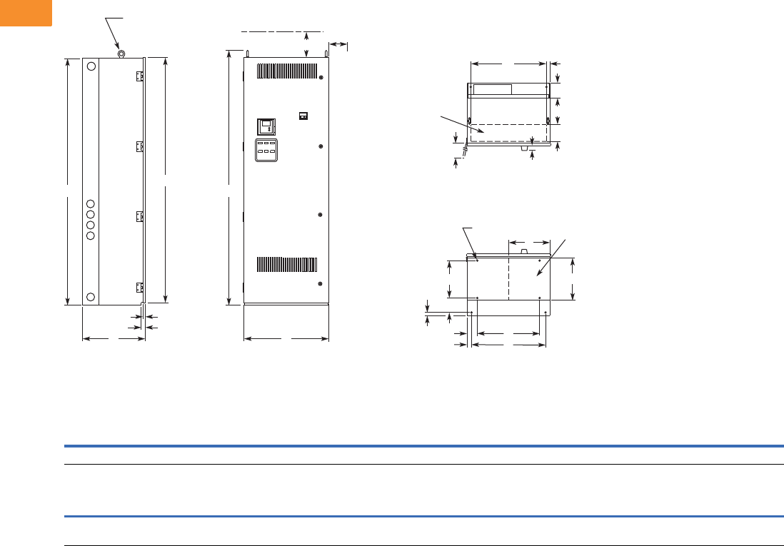
V6-T2-104 Volume 6—Solid-State Motor Control CA08100007E—May 2014 www.eaton.com
2
2
2
2
2
2
2
2
2
2
2
2
2
2
2
2
2
2
2
2
2
2
2
2
2
2
2
2
2
2
2.5
Adjustable Frequency Drives
SVX9000 Drives
Approximate Dimensions in Inches (mm)
Size 4
For reference only, dimensions are subject to change.
Wide High Deep Mounting Door Height Min. Air Space
ABCDD1EE1FGG1H JK
26.4 (671) 90.0 (2286) 19.4 (493) 19.5 (495) 3.3 (83) 23.0 (584) 1.5 (38) 11.7 (298) 5.5 (140) 0.9 (24) 89.4 (2270) 4.0 (102) 3.0 (76)
Max. Approx.
Shipping Weight
Lbs (kg)
Cable Entry Door Clearance CB Handle
L M N P R S T U V W RR SS TT UU VV
5.3
(133)
23.4
(594)
13.8
(351)
1.0
(25)
11.2
(286)
26.4
(669)
1.5
(38)
8.0
(204)
4.8
(121)
— 92.5
(2349)
0.8
(19)
1.3
(32)
— — 825 (375)
0.44 (11.2)
Mounting Holes
6 Places
D
E
R
MP
0.50 (12.7)
Lifting Eyes
2 Places
H
C A
TT
SS
B
S
F
G
V
U
L
T
Top View
Bottom View
N
JK
RR
D1
E1
G1
NEMA Type 1/IP21, NEMA Type 12/IP54
NEMA Type 12/IP54 Includes Cover Plates Over Louvers
For Cable
Entry
For Cable
Entry
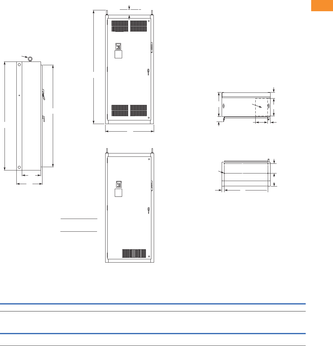
Volume 6—Solid-State Motor Control CA08100007E—May 2014 www.eaton.com V6-T2-105
2
2
2
2
2
2
2
2
2
2
2
2
2
2
2
2
2
2
2
2
2
2
2
2
2
2
2
2
2
2
2.5
Adjustable Frequency Drives
SVX9000 Drives
Approximate Dimensions in Inches (mm)
Size 5
For reference only, dimensions are subject to change.
Wide High Deep Mounting Door Height Min. Air Space
ABCDD1EE1FGG1H JK
40.0 (1016) 90.0 (2286) 21.3 (541) 36.0 (914) 2.0 (51) — — 8.0 (203) 10.8 (273) — 84.4 (2143) 4.0 (102) —
Max. Approx.
Shipping Weight
Lbs (kg)
Cable Entry Door Clearance
L M N P R S T U V W RR SS TT UU VV
15.0
(381)
10.0
(254)
4.8
(122)
2.0
(51)
—36.3
(921)
20.0
(508)
——— 94.0
(2387)
15.5
(394)
— — — 1275 (579)
M
Lifting Eyes
(2 Places)
B
H
C
SS
Side View
RR
J
A
Front View
NEMA Type 1/IP21
Front View
NEMA Type 12/IP54
S
T
0.56 (14.2) Dia.
Mounting
Holes
(4 Places)
D1 D
G
F
N
L
For Cable
Entry
P
Top View
Bottom View
IL hp
75
100
200
250
208/230V
480V
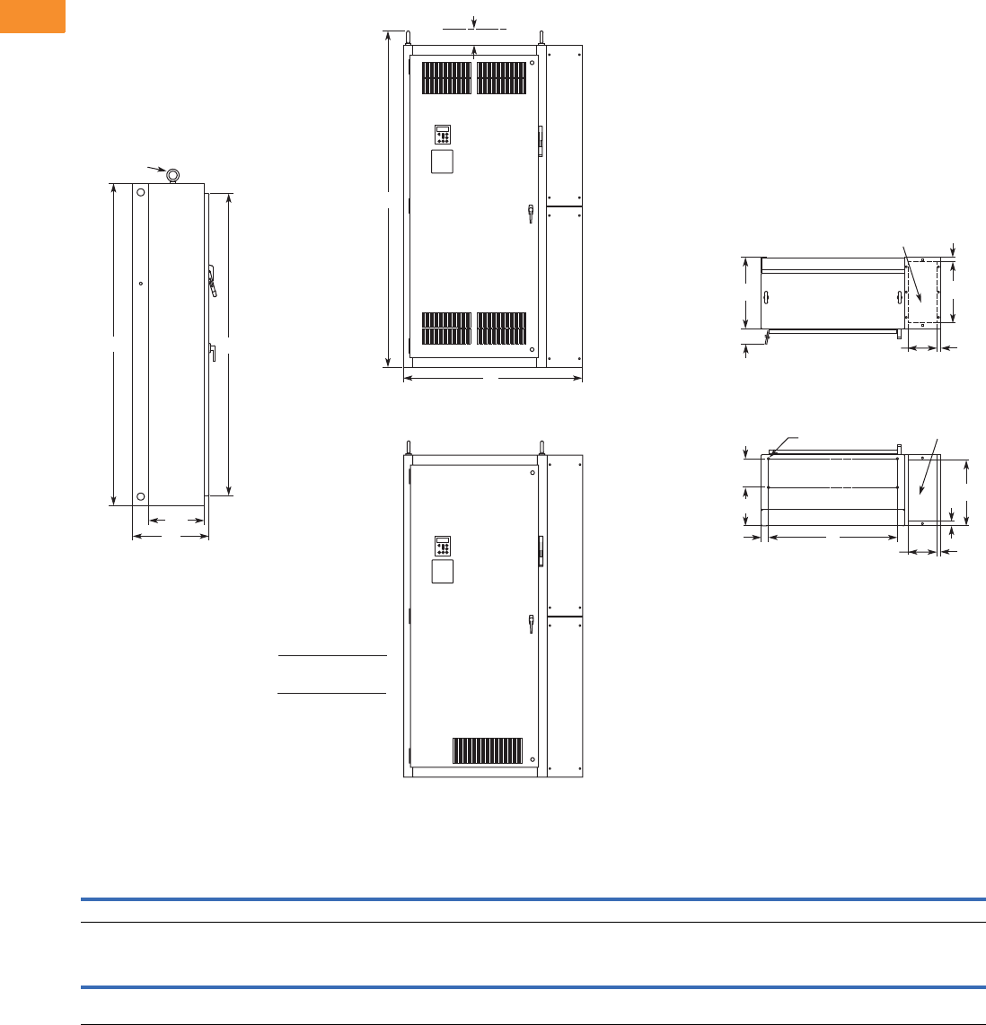
V6-T2-106 Volume 6—Solid-State Motor Control CA08100007E—May 2014 www.eaton.com
2
2
2
2
2
2
2
2
2
2
2
2
2
2
2
2
2
2
2
2
2
2
2
2
2
2
2
2
2
2
2.5
Adjustable Frequency Drives
SVX9000 Drives
Approximate Dimensions in Inches (mm)
Size 5-1P
For reference only, dimensions are subject to change.
Wide High Deep Mounting Door Height Min. Air Space
ABCDD1EE1FGG1H JK
50.0 (1270) 90.0 (2286) 21.3 (541) 36.0 (914) 2.0 (51) — — 8.0 (203) 10.8 (273) — 84.4 (2143) 4.0 (102) —
Max. Approx.
Shipping Weight
Lbs (kg)
Cable Entry Door Clearance
L M N P R S T U V W RR SS TT UU VV
17.1
(435)
8.0
(203)
1.3
(33)
1.0
(25)
—36.3
(921)
20.0
(508)
18.4
(466)
1.3
(32)
—94.0
(2387)
15.5
(394)
— — — 1375 (624)
Lifting Eyes
(2 Places)
BH
C
SS
T
F
G
S
D1 D
P
Door Clearance M
M
L
U
V
For Cable
Entry
For Cable
Entry
N
P
Top View
Bottom View
0.56 (14.2) Dia.
Mounting Holes
(4 Places)
RR
A
J
Front View
NEMA Type 1/IP21
Front View
NEMA Type 12/IP54
IL hp
75
100
200
250
208/230V
480V
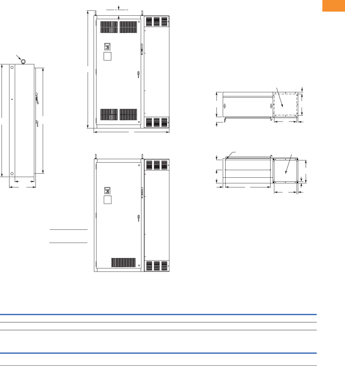
Volume 6—Solid-State Motor Control CA08100007E—May 2014 www.eaton.com V6-T2-107
2
2
2
2
2
2
2
2
2
2
2
2
2
2
2
2
2
2
2
2
2
2
2
2
2
2
2
2
2
2
2.5
Adjustable Frequency Drives
SVX9000 Drives
Approximate Dimensions in Inches (mm)
Size 5-2P
For reference only, dimensions are subject to change.
Wide High Deep Mounting Door Height Min. Air Space
ABCDD1EE1FGG1H JK
Enclosure Size 5-2P
60.0 (1524) 90.0 (2286) 21.3 (541) 36.0 (914) 2.0 (51) — — 8.0 (203) 10.8 (273) — 84.4 (2143) 4.0 (102) —
Max. Approx.
Shipping Weight
Lbs (kg)
Cable Entry Door Clearance
L M N P R S T U V W RR SS TT UU VV
17.0
(432)
18.0
(457)
1.5
(38)
1.0
(25)
0.9
(23)
36.3
(921)
20.0
(508)
18.4
(466)
1.3
(32)
—94.0
(2387)
15.5
(394)
— — — 1585 (720)
Lifting Eyes
(2 Places)
BH
C
SS
T
G
F
SDoor Clearance MP
L
For Cable
Entry N
Top View
D1 D
R
M
U
V
For Cable
Entry
Bottom View
0.56 (14.2) Dia.
Mounting Holes
(4 Places)
J
RR
A
Front View
NEMA Type 1/IP21
Front View
NEMA Type 12/IP54
IL hp
75
100
200
250
208/230V
480V
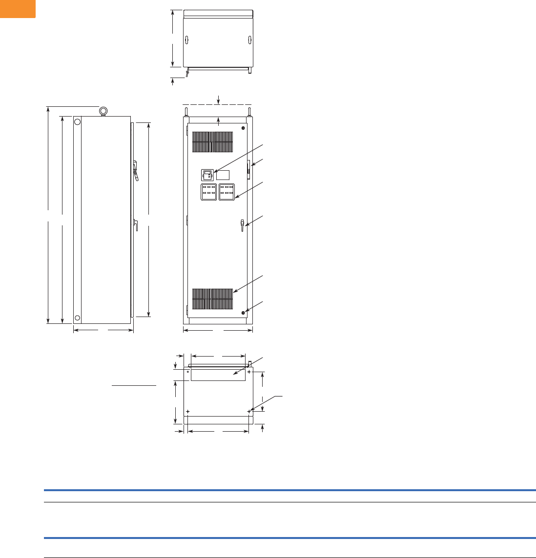
V6-T2-108 Volume 6—Solid-State Motor Control CA08100007E—May 2014 www.eaton.com
2
2
2
2
2
2
2
2
2
2
2
2
2
2
2
2
2
2
2
2
2
2
2
2
2
2
2
2
2
2
2.5
Adjustable Frequency Drives
SVX9000 Drives
Approximate Dimensions in Inches (mm)
Size 6
For reference only, dimensions are subject to change. See Page V6-T2-92, notes 3 and 5 for enclosure and option selection.
Wide High Deep Mounting Door Height Min. Air Space
ABCDD1EE1FGG1H JK
30.0 (762) 90.0 (2286) 26.0 (660) 26.5 (673) 1.8 (46) — — 17.3 (438) 5.5 (140) — 84.4 (2143) 4.0 (102) —
Max. Approx.
Shipping Weight
Lbs (kg)
Cable Entry Door Clearance
L M N P R S T U V W RR SS TT UU VV
23.5
(597)
3.3
(84)
4.5
(114)
19.3
(490)
—26.2
(667)
24.8
(629)
———93.9
(2386)
————1500 (681)
Keypad
Operator Elements When Specied,
Mounted on These Panels
Ventilating Slots
Key-Locking Handle
Quarter Turn Latch
(2 Places)
Flanged Disconnect Supplied
with Circuit Breaker When Specied
A
C
Side View
Bottom View
S
J
H
B
T
Top View
Door Clearance
RR
L
DD1
G
F
N
P
For Cable Entry
M
0.56 (14.2) Dia.
Mounting Hole –
(4 Places)
Front View
IL hp
300
350
400
480V
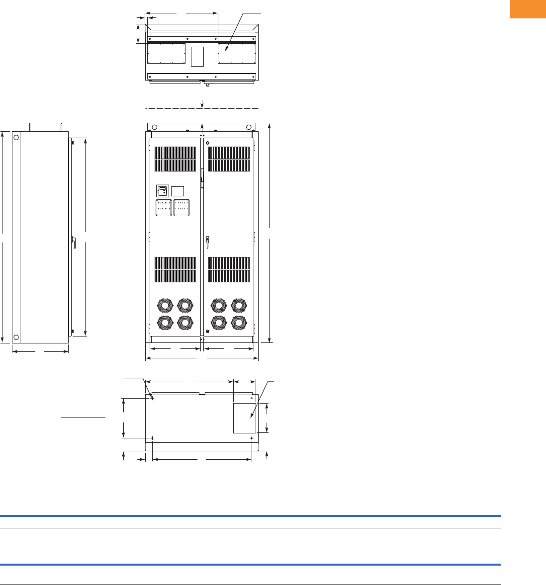
Volume 6—Solid-State Motor Control CA08100007E—May 2014 www.eaton.com V6-T2-109
2
2
2
2
2
2
2
2
2
2
2
2
2
2
2
2
2
2
2
2
2
2
2
2
2
2
2
2
2
2
2.5
Adjustable Frequency Drives
SVX9000 Drives
Approximate Dimensions in Inches (mm)
Size 8
For reference only, dimensions are subject to change. See Page V6-T2-92, notes 3 and 5 for enclosure and option selection.
Wide High Deep Mounting Door Height Min. Air Space
ABCDD1EE1FGG1H JK
48.0 (1219)90.0 (2286)24.0 (610)42.2 (1072)3.0 (77)———5.5 (139)—84.4 (2143) 4.0 (102) —
Max. Approx.
Shipping Weight
Lbs (kg)
Cable Entry
LMNPRSTUVWRRSSTTUUVV
9.5
(241)
37.5
(952)
12.5
(318)
7.7
(196)
8.3
(210)
1.3
(32)
31.0
(787)
21.5
(545)
21.3
(541)
—93.5
(2375)
— — — — 2000 (908)
T
S
LM
0.56 (14.2) Dia.
Mounting Hole –
(4 Places)
R
RR
H
B
UV
CA
For Top Cable Entry –
(2 Places)
Bottom View
Top View
Front View
Side View
For Bottom
Cable Entry
N
P
F
G
J
D
D1
IL hp
300
350
400
480V
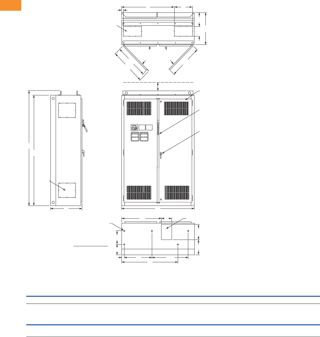
V6-T2-110 Volume 6—Solid-State Motor Control CA08100007E—May 2014 www.eaton.com
2
2
2
2
2
2
2
2
2
2
2
2
2
2
2
2
2
2
2
2
2
2
2
2
2
2
2
2
2
2
2.5
Adjustable Frequency Drives
SVX9000 Drives
Approximate Dimensions in Inches (mm)
Size 9
For reference only, dimensions are subject to change. See Page V6-T2-92, notes 3 and 5 for enclosure and option selection.
Wide High Deep Mounting Door Height Min. Air Space
ABCDD1EE1FGG1H JK
60.0 (1524) 90.0 (2286) 260.1 (664) 22.9 (582) 2.0 (51) 30.0 (762) 44.3 (1125) 10.6 (270) 10.6 (270) 8.2 (208) — 4.0 (102) —
Max. Approx.
Shipping Weight
Lbs (kg)
Cable Entry
LMNPRSTUVWRRSSTTUUVV
8.5
(216)
32.7
(831)
12.0
(305)
11.9
(303)
9.8
(249)
1.5
(38)
43.5
(1105)
15.0
(381)
7.5
(191)
25.0
(635)
93.5
(2375)
27.4
(696)
290.1
(738)
270.1
(687)
— 2500 (1135)
R
W
V
UU
J
SS
TT
Top View
STU
B
RR
AC Front View
Bottom View
Side View
Access in Top –
(2 Places)
Bottom Access
0.56 (14.2) Dia.
Mounting Hole –
(5 Places)
90° Max.
Door
Opening
P
N
D1 D
G1
G
D2
ML
E
Key-Locking Handle
Access
Plate –
4 Places
90° Max.
Door
Opening
Drive Circuit Breaker
IL hp
500
550
600
IH hp
400
500
550
480V
Openings Filtered for
NEMA Type 12/IP54 Design
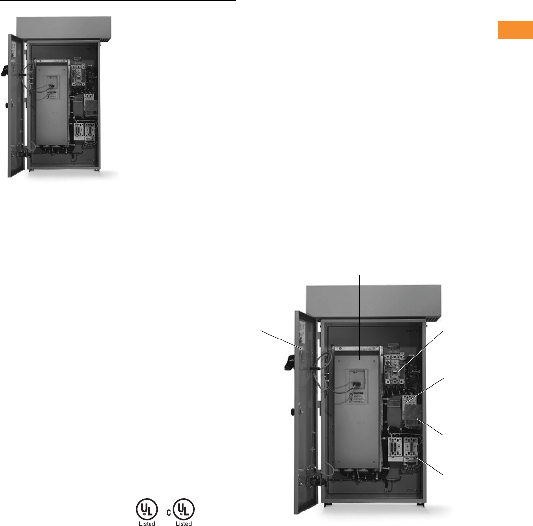
Volume 6—Solid-State Motor Control CA08100007E—May 2014 www.eaton.com V6-T2-111
2
2
2
2
2
2
2
2
2
2
2
2
2
2
2
2
2
2
2
2
2
2
2
2
2
2
2
2
2
2
2.5
Adjustable Frequency Drives
SVX9000 Drives
SVX9000 VFD Pump Panels
Contents
Description Page
SVX9000 Drives . . . . . . . . . . . . . . . . . . . . . . . . . . . V6-T2-48
SVX9000 Enclosed Drives . . . . . . . . . . . . . . . . . . . V6-T2-87
SVX9000 VFD Pump Panels
Catalog Number Selection . . . . . . . . . . . . . . . . V6-T2-112
Product Selection . . . . . . . . . . . . . . . . . . . . . . . V6-T2-113
Options . . . . . . . . . . . . . . . . . . . . . . . . . . . . . . . V6-T2-118
Technical Data and Specifications . . . . . . . . . . V6-T2-121
Wiring Diagrams . . . . . . . . . . . . . . . . . . . . . . . . V6-T2-123
Dimensions . . . . . . . . . . . . . . . . . . . . . . . . . . . V6-T2-124
SVX9000 VFD Pump Panels
Product Description
●Standard Enclosed—
covers a wide range of the
most commonly ordered
options. Pre-engineering
eliminates the lead time
normally associated with
customer specific options.
●Modified Standard
Enclosed—applies to
specific customer
requirements that vary
from the Standard
Enclosed offering, such as
the need for an additional
indicating light or minor
modifications to drawings.
Consult your Eaton
representative for
assistance in pricing and
lead time.
●Custom Engineered—for
those applications with
more unique or complex
requirements, these are
individually engineered to
the customer’s needs.
Consult your Eaton
representative for
assistance in pricing and
lead time.
Features
●NEMA Type 12/IP54 or
NEMA Type 3R enclosures
●Input voltage: 208V, 230V,
480V and 575V (consult
factory)
●Complete range of control,
network and power options
●Horsepower range:
●208V—3/4 to 100 hp IH;
1 to 100 hp IL
●230V—3/4 to 100 hp IH;
1 to 100 hp IL
●480V—1 to 350 hp IH;
1-1/2 to 400 hp IL
●Padlockable disconnect
●Single-phase input
available
Standards and Certifications
●UL Listed
●cUL Listed
Product Identification
SVX9000 Pump Application
1 SVX9000 variable frequency drive
2 Input disconnect Option P1
3 Input contactor (included as
standard with bypass option)
4 Space heater
Option S9
5 Bypass contactor
Option RA/RB
6 Door-mounted keypad
(included as standard)
3
5
1
2
4
6
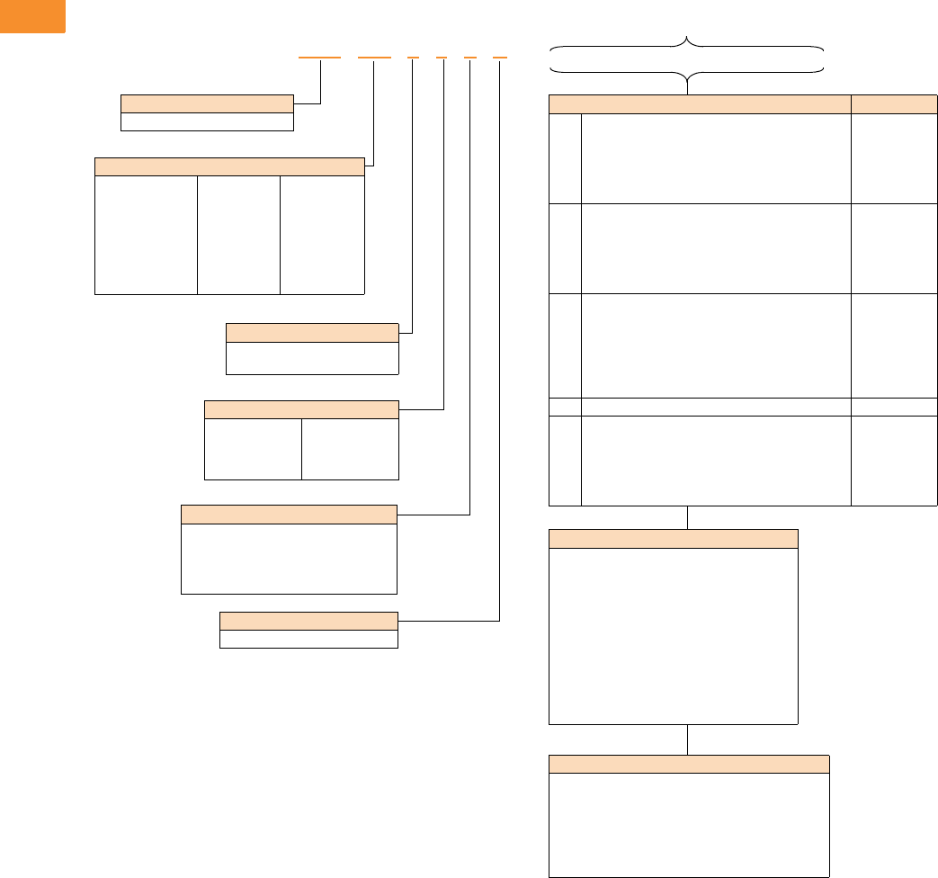
V6-T2-112 Volume 6—Solid-State Motor Control CA08100007E—May 2014 www.eaton.com
2
2
2
2
2
2
2
2
2
2
2
2
2
2
2
2
2
2
2
2
2
2
2
2
2
2
2
2
2
2
2.5
Adjustable Frequency Drives
SVX9000 Drives
Catalog Number Selection
SVX9000 Enclosed NEMA Type 12/IP54/3R Drive
Notes
1Local/remote keypad is included as the standard control panel.
2Brake chopper is a factory installed option only, see drive options on Page V6-T2-49. External dynamic braking resistors not included. See Page V6-T2-58.
3Includes local/remote speed reference switch.
4Some options are voltage and/or horsepower specific. Consult your Eaton representative for details.
5See Page V6-T2-120 for descriptions.
6See Pages V6-T2-118 and V6-T2-119 for complete descriptions.
7Bypass options applicable only in the pump panel three-phase design.
Enclosed Options 145 Type
K1
K2
K5
K6
K9
Door-mounted speed potentiometer 3
Door-mounted speed potentiometer with HOA selector
switch 3
MANUAL/AUTO reference switch (22 mm)
START and STOP pushbuttons (22 mm)
(2) Factory installed auxiliary contacts
Control
Control
Control
Control
Power
L1
L2
LD
LE
LU
LW
POWER ON, RUN and Fault pilot lights
Bypass pilot lights for RA bypass option 7
Green STOP light
Red RUN light
Misc. light (22 mm)
PTT light (22 mm)
Light
Addl. bypass
Light
Light
Light
Light
P1
P3
P8
PA
PE
PF
PG
Input circuit breaker
Input line fuses (200 kAIC)
SPD (50 kA per phase)
SPD (100 kA per phase)
Output contactor
Output filter
MotoRX (300–600 ft) 1000 V/μS DV/DT filter
Input
Input
Input
Input
Output
Output
Output
RA Manual HOA bypass controller 7Bypass
S5
S9
SA
SB
SE
SF
Floor stand 22 in
Space heater w/out CPT
Space heater w/CPT
Socket type control relay
On-delay timer
Off-delay timer
Enclosure
Enclosure
Enclosure
Enclosure
Enclosure
Enclosure
Voltage Rating
Three-phase
1 = 208V
2 = 230V
4 = 480V
Single-phase
J = 230V
K = 480V
Product Family
SVX = Enclosed drives
Horsepower Rating
F07 = 3/4 hp
001 = 1 hp
F15 = 1-1/2 hp
002 = 2 hp
003 = 3 hp
005 = 5 hp
007 = 7-1/2 hp
010 = 10 hp
015 = 15 hp
020 = 20 hp
025 = 25 hp
030 = 30 hp
040 = 40 hp
050 = 50 hp
060 = 60 hp
075 = 75 hp
100 = 100 hp
125 = 125 hp
150 = 150 hp
200 = 200 hp
250 = 250 hp
300 = 300 hp
350 = 350 hp
400 = 400 hp
Enclosure Rating
2 = NEMA Type 12/IP54
3 = NEMA Type 3R
Application—Torque/Braking 2
A = IL/no brake chopper
B = IL/internal brake chopper
D = IH/no brake chopper
E = IH/internal brake chopper
Enclosed Style
P = Pumping application
Control Options
B1 = 6 DI, 1 ext +24 Vdc/EXT +24 Vdc
B2 = 1 RO (NC-NO), 1 RO (NO), 1 therm
B4 = 1 AI (mA isolated), 2 AO (mA isolated),
1 ext +24 Vdc/EXT +24 Vdc
B5 = 3 RO (NO)
B8 = 1 ext +24 Vdc/EXT +24 Vdc, 3 Pt100
B9 = 1 RO (NO), 5 DI 42–240 Vac input
Communication Options 6
C2 = Modbus
C3 = PROFIBUS DP
C4 = LonWorks
C5 = PROFIBUS DP (D9 connector)
C6 = CANopen (slave)
C7 = DeviceNet
C8 = Modbus (D9 type connector)
CA = Johnson Controls N2
CI = Modbus TCP
CJ = BACnet
CQ = EtherNet/IP
D3 = RS-232 with D9 connection
SVX 010 2 4 E P _ _ _ _ _ _ _ _ _ _
Build Alphabetically and Numerically
Volume 6—Solid-State Motor Control CA08100007E—May 2014 www.eaton.com V6-T2-113
2
2
2
2
2
2
2
2
2
2
2
2
2
2
2
2
2
2
2
2
2
2
2
2
2
2
2
2
2
2
2.5
Adjustable Frequency Drives
SVX9000 Drives
Product Selection
When Ordering
●Select a base catalog
number that meets the
application requirements—
nominal horsepower,
voltage and enclosure
rating (the enclosed drive’s
continuous output amp
rating should be equal to or
greater than the motor’s
full load amp rating). The
base enclosed package
includes a standard drive,
door mounted local/remote
keypad and enclosure.
●If dynamic brake chopper
or control/communication
option is desired, change
the appropriate code in the
base catalog number.
●Select enclosed options.
Add the codes as suffixes
to the base catalog number
in alphabetical and numeric
order.
●Read all footnotes.
208V Drives
Pump Panel Style (Three-Phase)
Notes
1 Enclosure dimensions starting on Page V6-T2-124.
2 Includes drive, local/remote keypad and enclosure.
NEMA Type 12/IP54 NEMA Type 3R
Enclosure
Size 1hp
Frame
Size
Base Catalog
Number 2
Frame
Size
Base Catalog
Number 2
High Overload Drive and Enclosure
A3/44SVXF0721EP 4SVXF0731EP
1SVX00121EP SVX00131EP
1-1/2 SVXF1521EP SVXF1531EP
2SVX00221EP SVX00231EP
35 SVX00321EP 5SVX00331EP
5SVX00521EP SVX00531EP
7-1/2 SVX00721EP SVX00731EP
10 6 SVX01021EP 6SVX01031EP
15 SVX01521EP SVX01531EP
B207SVX02021DP 7SVX02031DP
25 SVX02521DP SVX02531DP
30 SVX03021DP SVX03031DP
C408SVX04021DP 8SVX04031DP
50 SVX05021DP SVX05031DP
60 SVX06021DP SVX06031DP
F759—9SVX07531DP
100 — SVX10031DP
Low Overload Drive and Enclosure
A14SVX00121BP 4SVX00131BP
1-1/2 SVXF1521BP SVXF1531BP
2SVX00221BP SVX00231BP
3SVX00321BP SVX00331BP
55 SVX00521BP 5SVX00531BP
7-1/2 SVX00721BP SVX00731BP
10 SVX01021BP SVX01031BP
15 6 SVX01521BP 6SVX01531BP
20 SVX02021BP SVX02031BP
B257SVX02521AP 7SVX02531AP
30 SVX03021AP SVX03031AP
40 SVX04021AP SVX04031AP
C508SVX05021AP 8SVX05031AP
60 SVX06021AP SVX06031AP
75 SVX07521AP SVX07531AP
F1009—9SVX10031AP
125 — SVX12531AP
SVX9000 Enclosed
Drives

V6-T2-114 Volume 6—Solid-State Motor Control CA08100007E—May 2014 www.eaton.com
2
2
2
2
2
2
2
2
2
2
2
2
2
2
2
2
2
2
2
2
2
2
2
2
2
2
2
2
2
2
2.5
Adjustable Frequency Drives
SVX9000 Drives
230V Drives
Pump Panel Style (Three-Phase)
Notes
1 Enclosure dimensions starting on Page V6-T2-124.
2 Includes drive, local/remote keypad and enclosure.
NEMA Type 12/IP54 NEMA Type 3R
Enclosure
Size 1hp
Frame
Size
Base Catalog
Number 2
Frame
Size
Base Catalog
Number 2
High Overload Drive and Enclosure
A3/44SVXF0722EP 4SVXF0732EP
1SVX00122EP SVX00132EP
1-1/2 SVXF1522EP SVXF1532EP
2SVX00222EP SVX00232EP
35 SVX00322EP 5SVX00332EP
5SVX00522EP SVX00532EP
7-1/2 SVX00722EP SVX00732EP
10 6 SVX01022EP 6SVX01032EP
15 SVX01522EP SVX01532EP
B207SVX02022DP 7SVX02032DP
25 SVX02522DP SVX02532DP
30 SVX03022DP SVX03032DP
C408SVX04022DP 8SVX04032DP
50 SVX05022DP SVX05032DP
60 SVX06022DP SVX06032DP
F759—9SVX07532DP
100 — SVX10032DP
Low Overload Drive and Enclosure
A14SVX00122BP 4SVX00132BP
1-1/2 SVXF1522BP SVXF1532BP
2SVX00222BP SVX00232BP
3SVX00322BP SVX00332BP
55 SVX00522BP 5SVX00532BP
7-1/2 SVX00722BP SVX00732BP
10 SVX01022BP SVX01032BP
15 6 SVX01522BP 6SVX01532BP
20 SVX02022BP SVX02032BP
B257SVX02522AP 7SVX02532AP
30 SVX03022AP SVX03032AP
40 SVX04022AP SVX04032AP
C508SVX05022AP 8SVX05032AP
60 SVX06022AP SVX06032AP
75 SVX07522AP SVX07532AP
F1009—9SVX10032AP
125 — SVX12532AP
SVX9000 Enclosed
Drives
Volume 6—Solid-State Motor Control CA08100007E—May 2014 www.eaton.com V6-T2-115
2
2
2
2
2
2
2
2
2
2
2
2
2
2
2
2
2
2
2
2
2
2
2
2
2
2
2
2
2
2
2.5
Adjustable Frequency Drives
SVX9000 Drives
230V Drives, continued
Pump Panel Style (Single-Phase)
Notes
1 Enclosure dimensions starting on Page V6-T2-124.
2 Includes drive, local/remote keypad and enclosure.
NEMA Type 12/IP54 NEMA Type 3R
Enclosure
Size 1hp
Frame
Size
Base Catalog
Number 2
Frame
Size
Base Catalog
Number 2
Low Overload Drive and Enclosure
A3/44SVXF072JBP 4SVXF073JBP
1SVX0012JBP SVX0013JBP
25 SVX0022JBP 5SVX0023JBP
3SVX0032JBP SVX0033JBP
5SVX0052JBP SVX0053JBP
7-1/2 6 SVX0072JBP 6SVX0073JBP
10 SVX0102JBP SVX0103JBP
B157SVX0152JBP 7SVX0153JBP
20 SVX0202JAP SVX0203JAP
C258SVX0252JAP 8SVX0253JAP
30 SVX0302JAP SVX0303JAP
40 SVX0402JAP SVX0403JAP
SVX9000 Enclosed
Drives
V6-T2-116 Volume 6—Solid-State Motor Control CA08100007E—May 2014 www.eaton.com
2
2
2
2
2
2
2
2
2
2
2
2
2
2
2
2
2
2
2
2
2
2
2
2
2
2
2
2
2
2
2.5
Adjustable Frequency Drives
SVX9000 Drives
480V Drives
Pump Panel Style (Three-Phase)
Notes
1 Enclosure dimensions starting on Page V6-T2-124.
2 Includes drive, local/remote keypad and enclosure.
3 FR11 has limited power options available.
NEMA Type 12/IP54 NEMA Type 3R
Enclosure
Size 1hp
Frame
Size
Base Catalog
Number 2
Frame
Size
Base Catalog
Number 2
High Overload Drive and Enclosure
A14SVX00124EP 4SVX00134EP
1-1/2 SVXF1524EP SVXF1534EP
2SVX00224EP SVX00234EP
3SVX00324EP SVX00334EP
5SVX00524EP SVX00534EP
7-1/2 5 SVX00724EP 5SVX00734EP
10 SVX01024EP SVX01034EP
15 SVX01524EP SVX01534EP
20 6 SVX02024EP 6SVX02034EP
25 SVX02524EP SVX02534EP
B307SVX03024EP 7SVX03034EP
40 SVX04024DP SVX04034DP
50 SVX05024DP SVX05034DP
60 SVX06024DP SVX06034DP
C758SVX07524DP 8SVX07534DP
100 SVX10024DP SVX10034DP
125 SVX12524DP SVX12534DP
F1509—9SVX15034DP
200 — SVX20034DP
250 10 —10 SVX25034DP
300 — SVX30034DP
350 — SVX35034DP
400 11 3—11 SVX40034DP
500 — SVX50034DP
Low Overload Drive and Enclosure
A1-1/24SVXF1524BP 4SVXF1534BP
2SVX00224BP SVX00234BP
3SVX00324BP SVX00334BP
5SVX00524BP SVX00534BP
7-1/2 SVX00724BP SVX00734BP
10 5 SVX01024BP 5SVX01034BP
15 SVX01524BP SVX01534BP
20 SVX02024BP SVX02034BP
25 6 SVX02524BP 6SVX02534BP
30 SVX03024BP SVX03034BP
B407SVX04024BP 7SVX04034BP
50 SVX05024AP SVX05034AP
60 SVX06024AP SVX06034AP
75 SVX07524AP SVX07534AP
C1008SVX10024AP 8SVX10034AP
125 SVX12524AP SVX12534AP
150 SVX15024AP SVX15034AP
F2009—9SVX20034AP
250 — SVX25034AP
300 10 —10 SVX30034AP
350 — SVX35034AP
400 — SVX40034AP
500 11 3—11 SVX50034AP
600 — SVX60034AP
SVX9000 Enclosed
Drives
Volume 6—Solid-State Motor Control CA08100007E—May 2014 www.eaton.com V6-T2-117
2
2
2
2
2
2
2
2
2
2
2
2
2
2
2
2
2
2
2
2
2
2
2
2
2
2
2
2
2
2
2.5
Adjustable Frequency Drives
SVX9000 Drives
480V Drives, continued
Pump Panel Style (Single-Phase)
Notes
1 Enclosure dimensions starting on Page V6-T2-124.
2 Includes drive, local/remote keypad and enclosure.
NEMA Type 12/IP54 NEMA Type 3R
Enclosure
Size 1hp
Frame
Size
Base Catalog
Number 2
Frame
Size
Base Catalog
Number 2
Low Overload Drive and Enclosure
A3/44SVXF072KBP 4SVXF073KBP
1SVX0012KBP SVX0013KBP
2SVX0022KBP SVX0023KBP
3SVX0032KBP SVX0033KBP
55 SVX0052KBP 5SVX0053KBP
7-1/2 SVX0072KBP SVX0073KBP
10 SVX0102KBP SVX0103KBP
15 6 SVX0152KBP 6SVX0153KBP
20 SVX0202KBP SVX0203KBP
B257SVX0252KAP 7SVX0253KAP
30 SVX0302KAP SVX0303KAP
C408SVX0402KAP 8SVX0403KAP
50 SVX0502KAP SVX0503KAP
60 SVX0602KAP SVX0603KAP
SVX9000 Enclosed
Drives
V6-T2-118 Volume 6—Solid-State Motor Control CA08100007E—May 2014 www.eaton.com
2
2
2
2
2
2
2
2
2
2
2
2
2
2
2
2
2
2
2
2
2
2
2
2
2
2
2
2
2
2
2.5
Adjustable Frequency Drives
SVX9000 Drives
Options
9000X Series Option Board Kits
The 9000X Series drives can accommodate a wide selection of expander and adapter option boards
to customize the drive for your application needs. The drive’s control unit is designed to accept a
total of five option boards.
The 9000X Series factory installed standard board configuration includes an A9 I/O board and an A2
relay output board, which are installed in slots A and B.
Option Board Kits
Notes
1 AI = Analog Input; AO = Analog Output, DI = Digital Input, DO = Digital Output, RO = Relay Output
2 Option card must be installed in one of the slots listed for that card. Slot indicated in bold is the preferred location.
3 OPTC2 is a multi-protocol option card.
Option Kit Description 1
Allowed Slot
Locations 2
Field
Installed
Factory
Installed SVX Ready Programs
Catalog
Number
Option
Designator Basic
Local/
Remote Standard MSS PID Multi-P. PFC
Standard I/O Cards
6 DI, 1 DO, 2 AI, 1AO, 1 +10 Vdc ref,
2 ext +24 Vdc/EXT +24 Vdc
AOPTA9 — ■ ■ ■ ■■■ ■
2 RO (NC-NO) B OPTA2 — ■ ■ ■ ■■■ ■
Extended I/O Cards
6 DI, 1 ext +24 Vdc/EXT +24 Vdc B, C, D, E OPTB1 B1 —— — ——
■■
1 RO (NC-NO), 1 RO (NO), 1 therm B, C, D, E OPTB2 B2 —— — ——
■■
1 AI (mA isolated), 2 AO (mA isolated),
1 ext +24 Vdc/EXT +24 Vdc
B, C, D, E OPTB4 B4 ■ ■ ■ ■■■ ■
3 RO (NO) B, C, D, E OPTB5 B5 —— — ——
■■
1 ext +24 Vdc/EXT +24 Vdc, 3 Pt100 B, C, D, E OPTB8 B8 —— — ——— —
1 RO (NO), 5 DI 42–240 Vac input B, C, D, E OPTB9 B9 —— — ——
■■
Communication Cards
Modbus 3D, E OPTC2 C2 ■ ■ ■ ■■■ ■
Modbus TCP D, E OPTCI CI ■ ■ ■ ■■■ ■
BACnet D, E OPTCJ CJ ■ ■ ■ ■■■ ■
EtherNet/IP D, E OPTCQ CQ ■ ■ ■ ■■■ ■
Johnson Controls N2 3D, E OPTC2 CA —— — ——— —
PROFIBUS DP D, E OPTC3 C3 ■ ■ ■ ■■■ ■
LonWorks D, E OPTC4 C4 ■ ■ ■ ■■■ ■
PROFIBUS DP (D9 connector) D, E OPTC5 C5 ■ ■ ■ ■■■ ■
CANopen (slave) D, E OPTC6 C6 ■ ■ ■ ■■■ ■
DeviceNet D, E OPTC7 C7 ■ ■ ■ ■■■ ■
Modbus (D9 type connector) D, E OPTC8 C8 ■ ■ ■ ■■■ ■
RS-232 with D9 connection D, E OPTD3 D3 ■ ■ ■ ■■■ ■
Option Boards
ABCDE

Volume 6—Solid-State Motor Control CA08100007E—May 2014 www.eaton.com V6-T2-119
2
2
2
2
2
2
2
2
2
2
2
2
2
2
2
2
2
2
2
2
2
2
2
2
2
2
2
2
2
2
2.5
Adjustable Frequency Drives
SVX9000 Drives
Modbus RTU Network
Communications
The Modbus Network Card
OPTC2 is used for connecting
the 9000X Drive as a slave on
a Modbus network. The
interface is connected by a
9-pin DSUB connector
(female) and the baud rate
ranges from 300 to 19200
baud. Other communication
parameters include an
address range from 1 to 247;
a parity of None, Odd or
Even; and the stop bit is 1.
PROFIBUS Network
Communications
The PROFIBUS Network Card
OPTC3 is used for connecting
the 9000X Drive as a slave
on a PROFIBUS-DP network.
The interface is connected
by a 9-pin DSUB connector
(female). The baud rates
range from 9.6K baud to 12M
baud, and the addresses
range from 1 to 127.
LonWorks Network
Communications
The LonWorks Network Card
OPTC4 is used for connecting
the 9000X Drive on a
LonWorks network. This
interface uses Standard
Network Variable Types
(SNVT) as data types. The
channel connection is
achieved using a FTT-10A
Free Topology transceiver
via a single twisted transfer
cable. The communication
speed with LonWorks is
78 kBits/s.
CANopen (Slave)
Communications
The CANopen (Slave)
Network Card OPTC6 is used
for connecting the 9000X
Drive to a host system.
According to ISO11898
standard cables to be chosen
for CAN bus should have a
nominal impedance of 120
ohms, and specific line delay
of nominal 5 nS/m. 120 ohms
line termination resistors
required for installation.
DeviceNet Network
Communications
The DeviceNet Network Card
OPTC7 is used for connecting
the 9000X Drive on a
DeviceNet Network. It
includes a 5.08 mm pluggable
connector. Transfer method
is via CAN using a two-wire
twisted shielded cable with
two-wire bus power cable
and drain. The baud rates
used for communication
include 125K baud, 250K
baud and 500K baud.
Johnson Controls
Metasys N2 Network
Communications
The OPTC2 fieldbus board
provides communication
between the 9000X Drive and
a Johnson Controls
Metasys™ N2 network. With
this connection, the drive can
be controlled, monitored and
programmed from the
Metasys system. The N2
fieldbus is available as a
factory installed option and as
a field installable kit.
Modbus/TCP Network
Communications
The Modbus/TCP Network
Card OPTCI is used for
connecting the 9000X Drive
to Ethernet networks utilizing
Modbus protocol. It includes
an RJ-45 pluggable connector.
This interface provides a
selection of standard and
custom register values to
communicate drive parameters.
The board supports 10 Mbps
and 100 Mbps communication
speeds. The IP address of the
board is configurable over
Ethernet using a supplied
software tool.
BACnet Network
Communications
The BACnet Network Card
OPTCJ is used for connecting
the 9000X Drive to BACnet
networks. It includes a
5.08 mm pluggable connector.
Data transfer is Master-Slave/
Token Passing (MS/TP)
RS-485. This interface uses
a collection of 30 Binary Value
Objects (BVOs) and 35 Analog
Value Objects (AVOs) to
communicate drive parameters.
The card supports 9.6, 19.2
and 38.4 Kbaud communication
speeds and supports network
addresses 1–127.
EtherNet/IP Network
Communications
The EtherNet/IP Network
Card OPTCK is used for
connecting the 9000X Drive
to Ethernet/Industrial Protocol
networks. It includes an
RJ-45 pluggable connector.
The interface uses CIP
objects to communicate drive
parameters (CIP is “Common
Industrial Protocol”, the same
protocol used by DeviceNet).
The board supports 10 Mbps
and 100 Mbps communication
speeds. The IP address of the
board is configurable by Static,
BOOTP and DHCP methods.

V6-T2-120 Volume 6—Solid-State Motor Control CA08100007E—May 2014 www.eaton.com
2
2
2
2
2
2
2
2
2
2
2
2
2
2
2
2
2
2
2
2
2
2
2
2
2
2
2
2
2
2
2.5
Adjustable Frequency Drives
SVX9000 Drives
Control/Communication Option Descriptions
For availability, see Product Selection for base drive voltage required.
Available Control/Communications Options
Option Description Option Type
K1 Door-Mounted Speed Potentiometer—Provides the SVX9000 with the ability to adjust the frequency reference using a door-mounted potentiometer. This option uses
the 10 Vdc reference to generate a 0–10V signal at the analog voltage input signal terminal. When the HOA bypass option is added, the speed is controlled when the
HOA switch is in the HAND position. Without the HOA bypass option, a two-position switch (labeled local/remote) is provided on the keypad to select speed reference from the
Speed Potentiometer or a remote speed signal.
Control
K2 Door-Mounted Speed Potentiometer with HOA Selector Switch—Provides the SVX9000 with the ability to start/stop and adjust the speed reference from
door-mounted control devices or remotely from customer supplied inputs. In HAND position, the drive will start and the speed is controlled by the door-mounted speed
potentiometer. The drive will be disabled in the OFF position. When AUTO is selected, the drive run and speed control commands are via user-supplied dry contact and
4–20 mA signal.
Control
K5 MANUAL/AUTO Speed Reference Switch—Provides a door-mounted selector switch for MANUAL/AUTO speed reference. Control
K6 START and STOP Pushbuttons (22 mm)—START (green) STOP (red). Provide door-mounted START and STOP pushbuttons for either bypass or
non-bypass configurations.
Control
K9 (2) Factory Installed Auxiliary Contacts—Provide two NO/NC auxiliary contacts. Power
L2 Bypass Pilot Lights for RA and RB Bypass Options—A green MOTOR ON INVERTER light indicates when the motor is running in inverter mode and an amber
MOTOR ON BYPASS light indicates when the motor is running in bypass mode. The lights are mounted on the enclosure door, above the switches.
Addl. bypass
LD Green STOP Light (22 mm)—Provides a green STOP light that indicates the drive is stopped. Light
LE Red RUN Pilot Light (22 mm)—Provides a red RUN pilot light that indicates the drive is running. Light
LU Misc. Light (22 mm)—Provides a misc. “user defined” pilot light. User to define light function and color. Light
LW PTT (Push-To-Test) Light (22 mm)—Provides misc. “user defined” PTT pilot light. User to define light function and color. Light
P1 Input Circuit Breaker—Provides a means of short-circuit protection for the power cables between it and the SVX9000, and protection from high-level ground faults on
the power cable. Allows a convenient means of disconnecting the SVX9000 from the line and the operating mechanism can be padlocked in the OFF position. This is factory
mounted in the enclosure.
Input
P3 Input Line Fuses Rated to 200 kAIC—Provide high-level fault protection of the SVX9000 input power circuit from the load side of the fuses to the input side of the
power transistors. This option consists of three 200 kA fuses, which are factory mounted in the enclosure.
Input
P8 SPD (50 kA per Phase)—Provides a surge protection device (SPD) connected to the line side terminals and is designed to clip line side transients.
Rated for 50,000A.
Input
PA SPD (100 kA per Phase)—Provides a surge protection device (SPD) connected to the line side terminals and is designed to clip line side transients.
Rated for 100,000A.
Input
PE Output Contactor—Provides a means for positive disconnection of the drive output from the motor terminals. The contactor coil is controlled by the drive’s run or
permissive logic. NC and NO auxiliary contacts rated at 10A, 600 Vac are provided for customer use. Bypass option RA includes an output contactor as standard. This
option includes a low VA 115 Vac fused control power transformer and is factory mounted in the enclosure.
Output
RA Manual HOA Bypass Controller—The Manual HAND/OFF/AUTO (HOA)—3-contactor—bypass option provides a means of bypassing the SVX9000, allowing the AC
motor to be operated at full speed directly from the AC supply line. This option consists of an input disconnect, a fused control power transformer, and a full voltage
bypass starter with a door mounted HOA selector switch and an INVERTER/BYPASS switch. The HOA switch provides the ability to start and stop the drive in the inverter
mode. For applications up to 100 hp, a Freedom Series IEC input contactor, a Freedom Series IEC output contactor, and a Freedom Series IEC starter with a bimetallic
overload relay is included. For applications above 100 hp, an Advantage input contactor, an Advantage output contactor and an Advantage starter with electronic
overload protection is included. The contactors are mechanically and electrically interlocked.
Bypass
RB Manual IOB Bypass Controller—The manual INVERTER/OFF/BYPASS (IOB)—3-contactor—bypass option provides a means of bypassing the SVX9000, allowing
the AC motor to be operated at full speed directly from the AC supply line. This option consists of an input disconnect, a fused control power transformer, and a full
voltage bypass starter with a door mounted IOB selector switch. For applications up to 100 hp, a Freedom Series IEC input contactor, a Freedom Series IEC output
contactor, and a Freedom Series IEC starter with a bimetallic overload relay is included. For applications above 100 hp, an Advantage input contactor, an Advantage
output contactor and an Advantage starter with electronic overload protection is included. The contactors are mechanically and electrically interlocked.
Bypass
S5 Floor Stand 22 in—Converts a Size A or B, normally wall mounted enclosure to a floor standing enclosure with a height of 22 in (558.8 mm). Enclosure
S9 Space Heater without CPT—Prevents condensation from forming in the enclosure when the drive is inactive or in storage. Includes a thermostat for variable
temperature control. A 200W heater is installed in enclosures A and B, and 400W heater is installed in enclosures C and D. Requires a customer supplied 115V remote
supply source.
Enclosure
SA Space Heater with CPT— Prevents condensation from forming in the enclosure when the drive is inactive or in storage. Includes a thermostat for variable temperature
control. A 200W heater is installed in enclosures A and B, and 400W heater is installed in enclosures C and D. Provided with CPT connected to load side of input disconnect.
Enclosure
SB Ice Cube Style Control Relay—Provides misc. “user defined” 4PDT control relay. Requires user to define functionality. Enclosure
SE On-Delay Timer (Delay on Make)—Provides misc. “user defined” time delay relay. Requires user to define functionality and time setting requirement. Enclosure
SF Off-Delay Timer (Delay on Break)—Provides misc. “user defined” time delay relay. Requires user to define functionality and time setting requirement. Enclosure

Volume 6—Solid-State Motor Control CA08100007E—May 2014 www.eaton.com V6-T2-121
2
2
2
2
2
2
2
2
2
2
2
2
2
2
2
2
2
2
2
2
2
2
2
2
2
2
2
2
2
2
2.5
Adjustable Frequency Drives
SVX9000 Drives
Technical Data and Specifications
9000X VFD Pump Panels
Description
NEMA Type 12/IP54 or NEMA Type 3R
Specification
Primary Design Features
45–66 Hz input frequency Standard
Output (AC volts maximum) Input voltage base
Output frequency range 0–320 Hz
Initial output current (IH) 250% for 2 seconds
Overload (1 minute [IH/IL]) 150%/110%
Enclosure space heater Optional
Oversize enclosure Standard
Output contactor Optional
Bypass motor starter Optional
Listings UL, cUL
Protection Features
Incoming line fuses Optional
AC input circuit disconnect Optional
Line reactors (3%) Standard
Phase rotation insensitive Standard
EMI filter Standard—Thru Frame 9
Input phase loss protection Standard
Input overvoltage protection Standard
Line surge protection Optional
Output short-circuit protection Standard
Output ground fault protection Standard
Output phase protection Standard
Overtemperature protection Standard
DC overvoltage protection Standard
Drive overload protection Standard
Motor overload protection Standard
Programmer software Optional
Local/remote keypad Standard
Keypad lockout Standard
Fault alarm output Standard
Built-in diagnostics Standard
Description
NEMA Type 12/IP54 or NEMA Type 3R
Specification
Input/Output Interface Features
Setup adjustment provisions
Remote keypad/display Standard
Personal computer Standard
Operator control provisions
Drive mounted keypad/display Standard
Remote keypad/display Standard
Conventional control elements Standard
Serial communications Optional
115 Vac control circuit Optional
Speed setting inputs
Keypad Standard
0–10 Vdc potentiometer/voltage signal Standard
4–20 mA isolated Configurable
4–20 mA differential Configurable
Analog outputs
Speed/frequency Standard
Torque/load/current Programmable
Motor voltage Programmable
Kilowatts Programmable
0–10 Vdc signals Configurable w/jumpers
4–20 mA DC signals Standard
Isolated signals Optional
Discrete outputs
Fault alarm Standard
Drive running Standard
Drive at set speed Programmable
Optional parameters 14
Dry contacts 1 (2 relays Form C)
Open collector outputs 1
Additional discrete outputs Optional
Communications
RS-232 Standard
RS-422/485 Optional
DeviceNet™ Optional
Modbus RTU Optional
CANopen (slave) Optional
PROFIBUS-DP Optional
Lonworks®Optional
Johnson Controls Metasys™ N2 Optional
EtherNet/IP Optional
Modbus TCP Optional
BACnet Optional

V6-T2-122 Volume 6—Solid-State Motor Control CA08100007E—May 2014 www.eaton.com
2
2
2
2
2
2
2
2
2
2
2
2
2
2
2
2
2
2
2
2
2
2
2
2
2
2
2
2
2
2
2.5
Adjustable Frequency Drives
SVX9000 Drives
9000X VFD Pump Panels, continued Standard I/O Specifications
I/O Specifications for Control/Communication Options
Note
1Some horsepower units include dynamic braking chopper as standard—refer to individual
drive sections.
Description
NEMA Type 12/IP54 or NEMA Type 3R
Specification
Performance Features
Sensorless vector control Standard
Volts/hertz control Standard
IR and slip compensation Standard
Electronic reversing Standard
Dynamic braking Optional 1
DC braking Standard
PID setpoint controller Programmable
Critical speed lockout Standard
Current (torque) limit Standard
Adjustable acceleration/deceleration Standard
Linear or S curve accel/decel Standard
Jog at preset speed Standard
Thread/preset speeds 7 Standard, 15 Optional
Automatic restart Selectable
Coasting motor start Standard
Coast or ramp stop selection Standard
Elapsed time meter Optional
Carrier frequency adjustment 1–16 kHz
Standard Conditions for Application and Service
Operating ambient temperature 0 to 40°C
Storage temperature –40 to 60°C
Humidity (maximum), non-condensing 95%
Altitude (maximum without derate) 3300 ft (1000m)
Line voltage variation +10/–15%
Line frequency variation 45–66 Hz
Efficiency >96%
Power factor (displacement) 0.96
Description Specification
Six–digital input
programmable
24V: “0” <10V, “1” >18V,Ri >5 kohms
Two–analog input
configurable w/jumpers
Voltage: 0–±10V, Ri >200 kohms
Current: 0 (4)–20 mA, Ri = 250 ohms
Two–digital output
programmable
Form C relays 250 Vac
30 Vdc 2 amp resistive
One–analog output
programmable
configurable w/jumper
0–20 mA, RL max. 500 ohms 10 bits ±2%
One digital output
programmable
Open collector 48 Vdc 50 mA
Description Specification
Analog voltage, input 0–±10V, Ri >200 kohms
Analog current, input 0 (4)–20 mA, Ri = 250 ohms
Digital input 24V: “0” <10V, “1” >18V, Ri >5 kohms
Auxiliary voltage 24V (±20%), max. 50 mA
Reference voltage 10V ±3%, max. 10 mA
Analog current, output 0 (4)–20 mA, RL = 500 kohms, resolution
10 bit, accuracy <±2%
Analog voltage, output 0 (2)–10V, RL >1 k kohms, resolution 10 bit,
accuracy <±2%
Relay output
Maximum switching voltage 300 Vdc, 250 Vac
Maximum switching load 8A/24 Vdc, 0.4A/300 Vdc, 2 kVA/250 Vac
Maximum continuous load 2A rms
Thermistor input Rtrip = 4.7 kohms
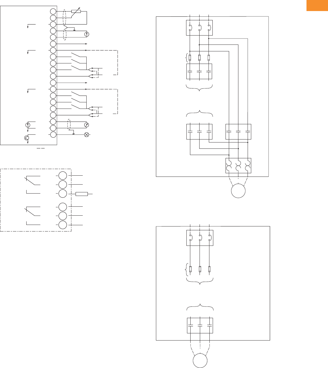
Volume 6—Solid-State Motor Control CA08100007E—May 2014 www.eaton.com V6-T2-123
2
2
2
2
2
2
2
2
2
2
2
2
2
2
2
2
2
2
2
2
2
2
2
2
2
2
2
2
2
2
2.5
Adjustable Frequency Drives
SVX9000 Drives
Wiring Diagrams
A9 Board Control Wiring
A2 Board Control Wiring
SVX9000 Pump Panel Bypass Power Wiring
SVX9000 Pump Panel Disconnect Power Wiring
20
19
18
17
16
15
14
13
12
11
10
9
8
24V
GND
24V
GND
+
0 (4)/20 mA
W
RL<500
V<+48V
I<50 mA
Input Reference
(Voltage)
Input Reference
(Current)
Indicates Connections for Inverted Signals
Control Voltage Output
Basic I/O
Board A9 AI1+
+10Vref
24Vout
24Vout
2
3
4
5
6
7
GND
AI2+
AI2-
GND
DIN1
DIN2
DIN3
CMA
DIN4
GND
DIN5
DIN6
CMB
AO1+
DO1
AO1-
1
26
25
24
23
22
21
RO1/1
RO1/2
RO1/3
RO2/1
RO2/2
RO2/3
RL
Max. Current/Voltage
Switching:
<8A / 24 Vdc
<0.4A / 300 Vdc
<2 kVA / 250 Vac
Continuously <2 Arms
AC / DC
Basic Relay
Board A2
Bypass
Incoming Power
L1 L2 L3
Circuit
Breaker
L1
To Drive Input
To Drive Output
U(T1)
L2 L3
Output
Contactor
V(T2)W(T3)
Motor
Bypass
Contactor
Overload
Relay
U(T1)
V(T2)
W(T3)
Optional Fuse
Incoming Power
L1 L2 L3
Circuit
Breaker
Optional Fuse
To Drive Input
To Drive Output
Motor
U(T1)
V(T2)
W(T3)
U(T1)
Optional
Output
Contactor
V(T2)W(T3)

V6-T2-124 Volume 6—Solid-State Motor Control CA08100007E—May 2014 www.eaton.com
2
2
2
2
2
2
2
2
2
2
2
2
2
2
2
2
2
2
2
2
2
2
2
2
2
2
2
2
2
2
2.5
Adjustable Frequency Drives
SVX9000 Drives
Dimensions
Approximate Dimensions in Inches (mm)
SVX9000 Pump Application Drives
Enclosure Box A NEMA Type 12/IP54
Voltage
AC
hp
(IH)
hp
(IL) H H1 H2 W W1 D D1
Approx.
Weight
Lbs (kg)
Approx.
Shipping Weight
Lbs (kg)
Three-Phase
208V 3/4–10 1–15 29.00
(736.6)
27.00
(685.8)
25.35
(643.9)
16.92
(429.8)
15.30
(388.6)
16.26
(413.0)
2.34
(59.4)
120 (54) 160 (73)
230V 3/4–10 1–15
480V 1–25 1–30
Single-Phase
230V — 3/4–10 29.00
(736.6)
27.00
(685.8)
25.35
(643.9)
16.92
(429.8)
15.30
(388.6)
16.26
(413.0)
2.34
(59.4)
120 (54) 160 (73)
480V — 3/4–20
3.00 (76.2)
Minimum Air
Space
Required
Both Sides
4.00 (101.6)
Minimum Free Air
Space Required
0.44 (11.2)
Mounting
Holes
(4 Places)
H2
W1
H1 H
DD1
W
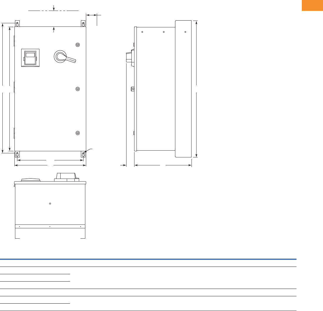
Volume 6—Solid-State Motor Control CA08100007E—May 2014 www.eaton.com V6-T2-125
2
2
2
2
2
2
2
2
2
2
2
2
2
2
2
2
2
2
2
2
2
2
2
2
2
2
2
2
2
2
2.5
Adjustable Frequency Drives
SVX9000 Drives
Approximate Dimensions in Inches (mm)
Enclosure Box B NEMA Type 12/IP54
Voltage
AC
hp
(IH)
hp
(IL) H H1 H2 W W1 D D1
Approx.
Weight
Lbs (kg)
Approx.
Shipping Weight
Lbs (kg)
Three-Phase
208V 15–25 20–30 40.00
(1016.0)
38.00
(965.2)
36.35
(923.3)
20.92
(531.4)
19.30
(490.2)
16.76
(425.7)
2.34
(59.4)
185 (84) 229 (104)
230V 15–25 20–30
480V 30–60 40–75
Single-Phase
230V — 15–20 40.00
(1016.0)
38.00
(965.2)
36.35
(923.3)
20.92
(531.4)
19.30
(490.2)
16.76
(425.7)
2.34
(59.4)
185 (84) 229 (104)
480V — 25–30
4.00 (101.6)
Minimum Free Air
Space Required
H2H1 H
3.00 (76.2)
Minimum Air
Space
Required
Both Sides
DD1
W1
W
0.44 (11.2)
Mounting
Holes
(4 Places)
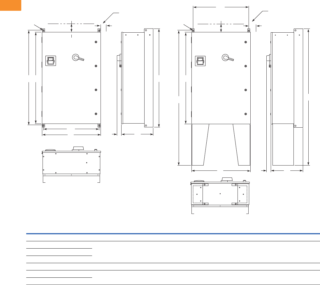
V6-T2-126 Volume 6—Solid-State Motor Control CA08100007E—May 2014 www.eaton.com
2
2
2
2
2
2
2
2
2
2
2
2
2
2
2
2
2
2
2
2
2
2
2
2
2
2
2
2
2
2
2.5
Adjustable Frequency Drives
SVX9000 Drives
Approximate Dimensions in Inches (mm)
Enclosure Box C NEMA Type 12/IP54
Note
1Consult factory.
Voltage
AC
hp
(IH)
hp
(IL) H H1 H2 H3 H4 W W1 D D1
Approx.
Shipping Weight
Lbs (kg)
Three-Phase
208V 30–50 40–60 52.00
(1320.8)
50.00
(1270.0)
48.35
(1228.1)
72.00
(1828.8)
71.19
(1808.2)
30.92
(785.4)
29.30
(744.2)
16.78
(426.2)
2.34
(59.4)
1
230V 30–50 40–60
480V 75–125 100–150
Single-Phase
230V — 25–40 52.00
(1320.8)
50.00
(1270.0)
48.35
(1228.1)
72.00
(1828.8)
71.19
(1808.2)
30.92
(785.4)
29.30
(744.2)
16.78
(426.2)
2.34
(59.4)
1
480V — 40–60
3.00 (76.2)
Minimum Air Space
Required Both Sides
4.00 (101.6) Minimum
Free Air Space Required
H3
H2
H4
WD1
W1
D
0.44 (11.2)
Mounting
Holes
(4 Places)
3.00 (76.2)
Minimum Air Space
Required Both Sides
4.00 (101.6) Minimum
Free Air Space Required
H
H2H1
D1
W
W1
D
0.44 (11.2)
Mounting
Holes
(4 Places)
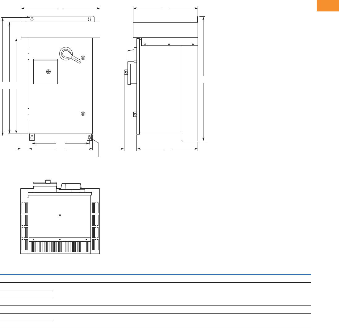
Volume 6—Solid-State Motor Control CA08100007E—May 2014 www.eaton.com V6-T2-127
2
2
2
2
2
2
2
2
2
2
2
2
2
2
2
2
2
2
2
2
2
2
2
2
2
2
2
2
2
2
2.5
Adjustable Frequency Drives
SVX9000 Drives
Approximate Dimensions in Inches (mm)
Enclosure Box A NEMA Type 3R
Voltage
AC
hp
(IH)
hp
(IL) H H1 H2 H3 W W1 W2 W3 D D1 D2
Approx.
Weight
Lbs (kg)
Approx.
Shipping Weight
Lbs (kg)
Three-Phase
208V 3/4–10 1–15 33.00
(838.2)
31.36
(796.5)
29.67
(753.6)
25.35
(643.9)
21.05
(534.7)
16.92
(429.8)
15.30
(388.6)
2.07
(52.6)
17.24
(437.9)
16.26
(413.0)
3.31
(84.1)
170 (77) 215 (98)
230V 3/4–10 1–15
480V 1–25 1–30
Single-Phase
230V — 3/4–10 33.00
(838.2)
31.36
(796.5)
29.67
(753.6)
25.35
(643.9)
21.05
(534.7)
16.92
(429.8)
15.30
(388.6)
2.07
(52.6)
17.24
(437.9)
16.26
(413.0)
3.31
(84.1)
170 (77) 215 (98)
480V — 3/4–20
H3H2H1
H
W2
W1 D2
W
3 D1
DW
0.44 (11.2)
Mounting
Holes
(4 Places)
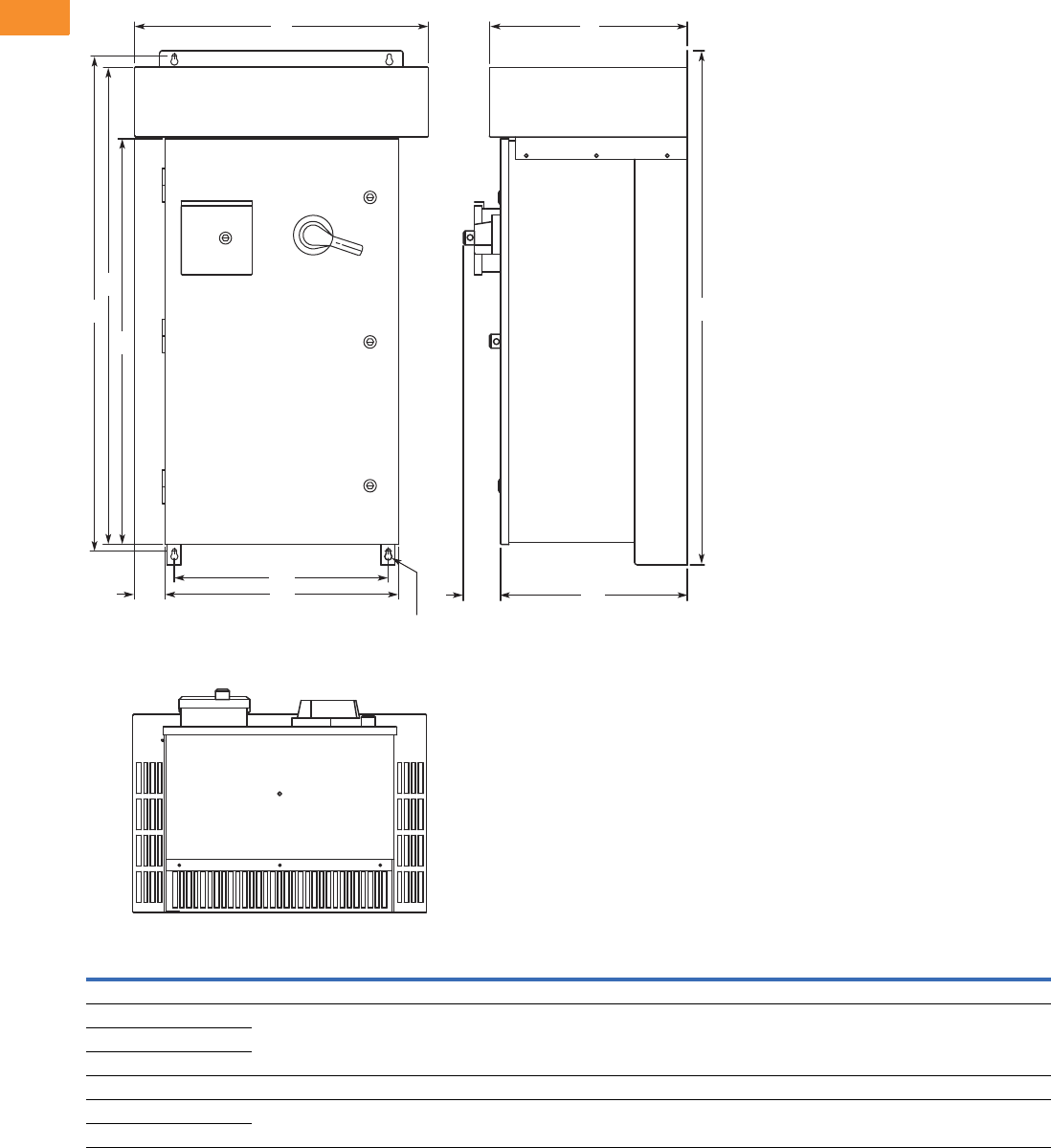
V6-T2-128 Volume 6—Solid-State Motor Control CA08100007E—May 2014 www.eaton.com
2
2
2
2
2
2
2
2
2
2
2
2
2
2
2
2
2
2
2
2
2
2
2
2
2
2
2
2
2
2
2.5
Adjustable Frequency Drives
SVX9000 Drives
Approximate Dimensions in Inches (mm)
Enclosure Box B NEMA Type 3R
Voltage
AC
hp
(IH)
hp
(IL) H H1 H2 H3 W W1 W2 W3 D D1 D2
Approx.
Weight
Lbs (kg)
Approx.
Shipping Weight
Lbs (kg)
Three-Phase
208V 15–25 20–30 46.09
(1170.7)
44.45
(1129.0)
42.77
(1086.4)
36.35
(923.3)
26.31
(668.3)
20.92
(531.4)
19.30
(490.2)
2.69
(68.3)
17.74
(450.6)
16.76
(425.7)
3.31
(84.1)
235
(107)
290
(132)
230V 15–25 20–30
480V 30–60 40–75
Single-Phase
230V — 15–20 46.09
(1170.7)
44.45
(1129.0)
42.77
(1086.4)
36.35
(923.3)
26.31
(668.3)
20.92
(531.4)
19.30
(490.2)
2.69
(68.3)
17.74
(450.6)
16.76
(425.7)
3.31
(84.1)
235
(107)
290
(132)
480V — 25–30
H3
H2
H1 H
W2
W1 D2
W
3D1
DW
0.44 (11.2)
Mounting
Holes
(4 Places)
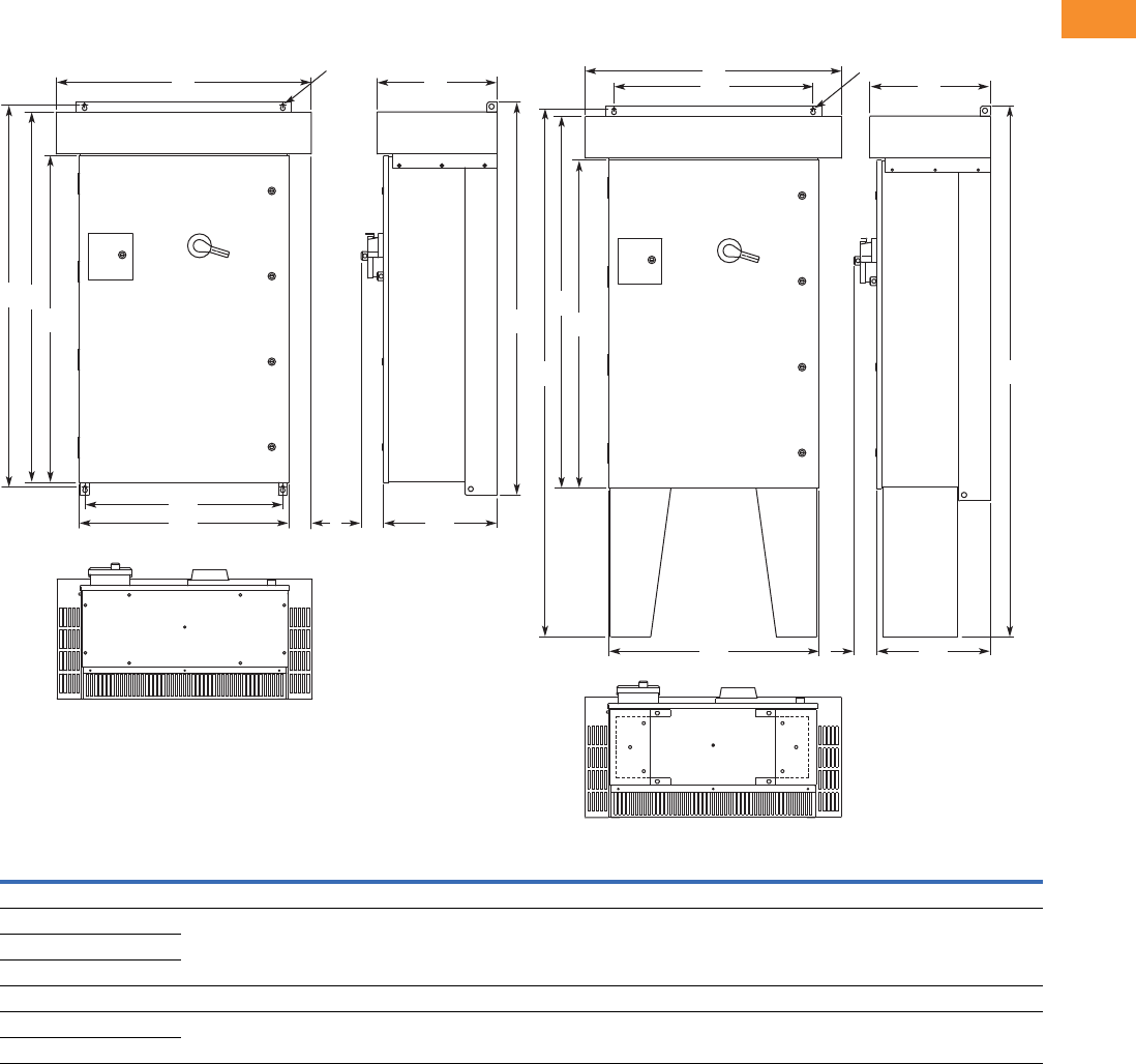
Volume 6—Solid-State Motor Control CA08100007E—May 2014 www.eaton.com V6-T2-129
2
2
2
2
2
2
2
2
2
2
2
2
2
2
2
2
2
2
2
2
2
2
2
2
2
2
2
2
2
2
2.5
Adjustable Frequency Drives
SVX9000 Drives
Approximate Dimensions in Inches (mm)
Enclosure Box C NEMA Type 3R
Note
1Consult factory.
Voltage
AC
hp
(IH)
hp
(IL) H H1 H2 H3 H4 H5 W W1 W2 W3 D D1 D2
Approx.
Weight
Lbs (kg)
Three-Phase
208 30–50 40–60 58.09
(1475.5)
56.45
(1433.8)
54.77
(1391.2)
48.35
(1228.1)
78.09
(1983.5)
77.64
(1972.1)
37.73
(958.3)
30.92
(785.4)
29.30
(744.2)
3.34
(84.8)
17.74
(450.6)
16.77
(426.0)
3.31
(84.1)
1
230 30–50 40–60
480 75–125 100–150
Single-Phase
230V — 25–40 58.09
(1475.5)
56.45
(1433.8)
54.77
(1391.2)
48.35
(1228.1)
78.09
(1983.5)
77.64
(1972.1)
37.73
(958.3)
30.92
(785.4)
29.30
(744.2)
3.34
(84.8)
17.74
(450.6)
16.77
(426.0)
3.31
(84.1)
1
480V — 40–60
0.44 (11.2)
Mounting Holes
(4 Places)
H3 H
H2
H1
W2
W1 W3 D2 D1
WD
H3
H2
H5
D2 D1
W1
W2
W
D
H4
0.44 (11.2)
Mounting Holes
(4 Places)
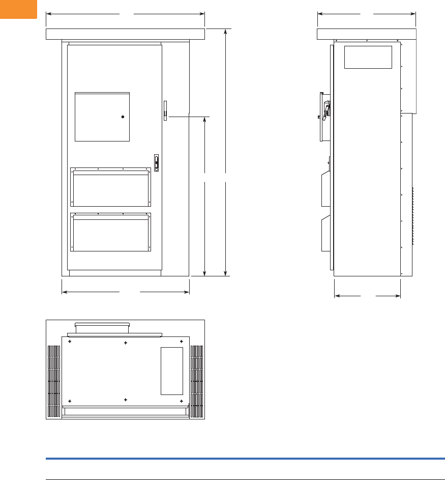
V6-T2-130 Volume 6—Solid-State Motor Control CA08100007E—May 2014 www.eaton.com
2
2
2
2
2
2
2
2
2
2
2
2
2
2
2
2
2
2
2
2
2
2
2
2
2
2
2
2
2
2
2.5
Adjustable Frequency Drives
SVX9000 Drives
Approximate Dimensions in Inches (mm)
Enclosure Size F
HH1WW1DD1
Approximate
Weight
Lbs (kg)
Approximate
Shipping Weight
Lbs (kg)
93.58
(2376.9)
69.51
(1765.60)
60.00
(1524.0)
48.00
(1219.2)
37.50
(952.5)
26.00
(660.4)
1700 (771) 1850 (839)
D
D1
HH1
W
W1
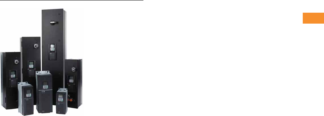
Volume 6—Solid-State Motor Control CA08100007E—May 2014 www.eaton.com V6-T2-131
2
2
2
2
2
2
2
2
2
2
2
2
2
2
2
2
2
2
2
2
2
2
2
2
2
2
2
2
2
2
2.6
Adjustable Frequency Drives
H-Max Series Drives
H-Max Series Drives
Contents
Description Page
H-Max Series Drives
H-Max Drives . . . . . . . . . . . . . . . . . . . . . . . . . . V6-T2-132
H-Max IntelliPass and
IntelliDisconnect Drives . . . . . . . . . . . . . . . . . V6-T2-141
Product Overview
H-Max Family Introduction
Eaton’s H-Max™ Series VFD
is the next generation of
drives specifically engineered
for HVAC pump and fluid
control applications. The
H-Max family of products
boasts industry leading
energy efficiency algorithms
for your applications. Not only
are the drives ultra-efficient—
they contain software that
minimizes motor winding
energy loses in your
applications. Designed for
easy installation, simple
startup, and long life; the
H-Max Series drive family
provides exceptional value
to our customers,
Product Range
Open Style Drives:
●0.75–125 hp at 230 Vac
●1.5–250 hp at 480 Vac
Note: Available in NEMA 1 or
NEMA 12 designs.
IntelliPass/IntelliDisconnect
Drives:
●1–30 hp at 208 Vac
●1–30 hp at 230 Vac
●1–75 hp at 480 Vac
Note: Available in NEMA 1,
NEMA 12, or NEMA 3R
enclosures.
Application Description
The H-Max Series drive was
designed specifically for
HVAC pump and fluid control
applications. It is intended to
be used on variable torque
loads with the intent of moving
air or liquids. With this in mind
,
the H-Max drive has onboard
I/O pre-programmed to meet
the common needs for these
applications. The H-Max drive
supports items such as
standard speed control,
PID functionality, as well as
multi-motor applications. The
drive easily supports
interlock, second motor
parameter set, as well as fire
mode functionality.
Key Feature
Active Energy Control Algorithm
Eaton’s H-Max Series drives
have been designed to provide
industry leading energy
saving
solutions. Not only is the
drive ultra-efficient, the drive
seeks the most efficient
operating point of the motor,
minimizing energy loss in the
windings per the given load
requirements. This is an
Eaton protected control
algorithm exclusive to
H-Max drives.
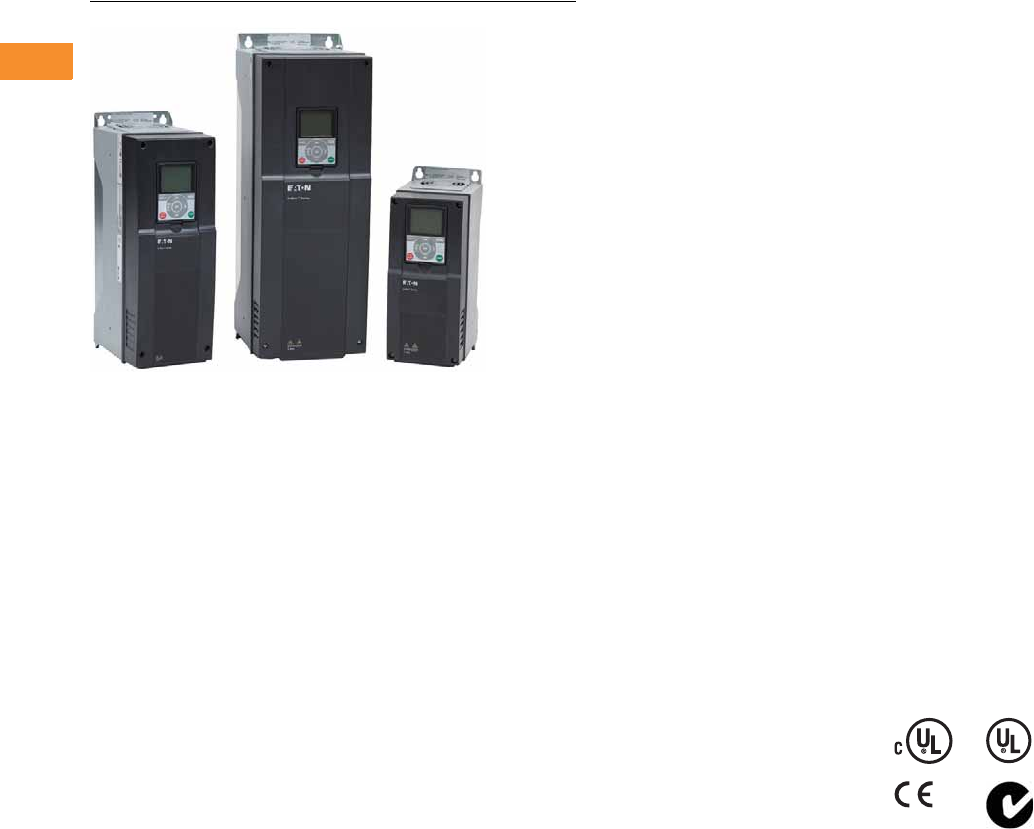
V6-T2-132 Volume 6—Solid-State Motor Control CA08100007E—May 2014 www.eaton.com
2
2
2
2
2
2
2
2
2
2
2
2
2
2
2
2
2
2
2
2
2
2
2
2
2
2
2
2
2
2
2.6
Adjustable Frequency Drives
H-Max Series Drives
H-Max Drives
Contents
Description Page
H-Max Drives
Catalog Number Selection . . . . . . . . . . . . . . . . V6-T2-133
Product Selection . . . . . . . . . . . . . . . . . . . . . . . V6-T2-134
Accessories . . . . . . . . . . . . . . . . . . . . . . . . . . . V6-T2-137
Replacement Parts . . . . . . . . . . . . . . . . . . . . . . V6-T2-137
Technical Data and Specifications . . . . . . . . . . V6-T2-138
Wiring Diagram . . . . . . . . . . . . . . . . . . . . . . . . V6-T2-139
Dimensions . . . . . . . . . . . . . . . . . . . . . . . . . . . V6-T2-140
H-Max IntelliPass and IntelliDisconnect Drives . . . V6-T2-141
H-Max Drives
Product Description
Eaton’s H-Max Series VFD
has software and hardware
designed specifically for the
HVAC, pump industry. The
ultra-efficient DC capacitor
and power structure allows
the drive to consume less
energy, lowering greenhouse
gases.
The I/O configuration is
designed
with wiring
ergonomics in mind by
including removable terminal
blocks. The main, easily
removable, control board
used for all drive frames with
six digital IN,
two analog IN,
one analog OUT, three relay
OUT
accepts two additional
I/O or communication board.
In addition, the control board
has built-in RS-485 and
Ethernet communication.
These drives continue
the tradition of robust
performance, and raise
the bar on features and
functionality, ensuring
the best solution at the
right price.
In addition to the Active
Energy Control Algorithm to
maximize motor efficiency,
the drive boasts an ultra-
efficient DC capacitor and
power structure to allow less
energy consumption,
lowering greenhouse gases.
Features and Benefits
Hardware
●Thin metal capacitor
design—ultra-efficient
drive operation and
extended self life (up to
five years without
reforming)
●Integrated 5% DC link
choke with Input surge
protection—protects
against voltage spikes and
provides a clean wave form
to the motor
●EMI/RFI filters standard on
all drives—meets EMC
Category 2 for commercial
applications
●Real-time clock—supports
calendaring and PLC
functionality
●Graphic LCD display and
keypad—supports simple
menu navigation as well as
on-screen diagnostics and
troubleshooting
●HAND-OFF-AUTO and
drive-bypass selector on
keypad—simplifies control
●Standard I/O: 6DI, 2AI,
1AO, 2 Form C RO (NO/
NC), 1 Form A RO (NO)—
supports requirements for
most installations
●Onboard RS 485: Modbus,
N2, BACnet—meets needs
of most communication
requirements
●Onboard Ethernet: BACnet/
IP, Modbus/TCP—meets
needs of most
communication
requirements
●Two expansion slots—
intended to support
additional I/O or
communication protocols
as necessary
●Quick disconnect terminals
for I/O connections—
supports fast easy
installation
Software
●Active energy control—
minimizes energy losses in
your motor resulting in
industry leading energy
efficiency for your
application
●Quick Start Wizard upon
initial power up—supports
fast easy installation
●Copy/paste functionality on
drive keypad—allows for
fast setup of multiple
drives
●Pre-programmed I/O—
supports fast easy
installation for most
applications
Standards and Certifications
Product
●IEC 61800-5-1
●CE
●UL508C
●cUL
●C-Tick Mark
●OSHPD Seismic Certified
●Plenum Rated
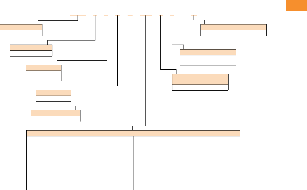
Volume 6—Solid-State Motor Control CA08100007E—May 2014 www.eaton.com V6-T2-133
2
2
2
2
2
2
2
2
2
2
2
2
2
2
2
2
2
2
2
2
2
2
2
2
2
2
2
2
2
2
2.6
Adjustable Frequency Drives
H-Max Series Drives
Catalog Number Selection
H-Max Series Drives
Notes
All boards are varnished (conformed coated). Corrosion resistant.
Battery included in all drives for real-time clock.
Keypad kit includes HOA bypass.
Keypad kit includes HOA, back reset for Europe application.
EMI/RFI filters included.
DC link choke included.
HMX 3 4 A G 3D4 2 1 -N
Software Series
A–Z
Keypad
G = Graphical panel
Voltage
2 = 200–240V
4 = 380–480V
Phase
3 = Three-phase
Product
HMX = HVAC drive
Enclosure
1 = Open NEMA Type 1 IP21
2 = Open NEMA Type 12 IP54
Input Options Frame and
Voltage Specific
2 =EMC C2
Braking/Application
N = No brake chopper (low overload)
Amperes
200–240 Volts 380–480 Volts
3D7 = 3.7A–0.75 hp, 0.55 kW
4D8 = 4.8A–1 hp, 0.75 kW
6D6 = 6.6A–1.5 hp, 1.1 kW
8D0 = 8A–2 hp, 1.5 kW
011 = 11A–3 hp, 2.2 kW
012 = 12A–4 hp, 3 kW
018 = 18A–5 hp, 4 kW
024 = 24A–7.5 hp, 5.5 kW
031 = 31A–10 hp, 7.5 kW
048 = 48A–15 hp, 11 kW
062 = 62A–20 hp, 15 kW
075 = 75A–25 hp, 18.5 kW
088 = 88A–30 hp, 22 kW
105 = 105A–40 hp, 30 kW
140 = 140A–50 hp, 37 kW
170 = 170A–60 hp, 45 kW
205 = 205A–75 hp, 55 kW
261 = 261A–100 hp, 75 kW
310 = 310A–125 hp, 90 kW
3D4 = 3.4A–1.5 hp, 1.1 kW
4D8 = 4.8–2 hp, 1.5 kW
5D6 = 5.6A–3 hp, 2.2 kW
8D0 = 8A–4 hp, 3 kW
9D6 = 9.6A–5 hp, 4 kW
012 = 12A–7.5 hp, 5.5 kW
016 = 16A–10 hp, 7.5 kW
023 = 23A–15 hp, 11 kW
031 = 31A–20 hp, 15 kW
038 = 38A–25 hp, 18.5 kW
046 = 46A–30 hp, 22 kW
061 = 61A–40 hp, 30 kW
072 = 72A–50 hp, 37 kW
087 = 87A–60 hp, 45 kW
105 = 105A–75 hp, 55 kW
140 = 140A–100 hp, 75 kW
170 = 170A–125 hp, 90 kW
205 = 205A–150 hp, 110 kW
261 = 261A–200 hp, 132 kW
310 = 310A–250 hp, 160 kW
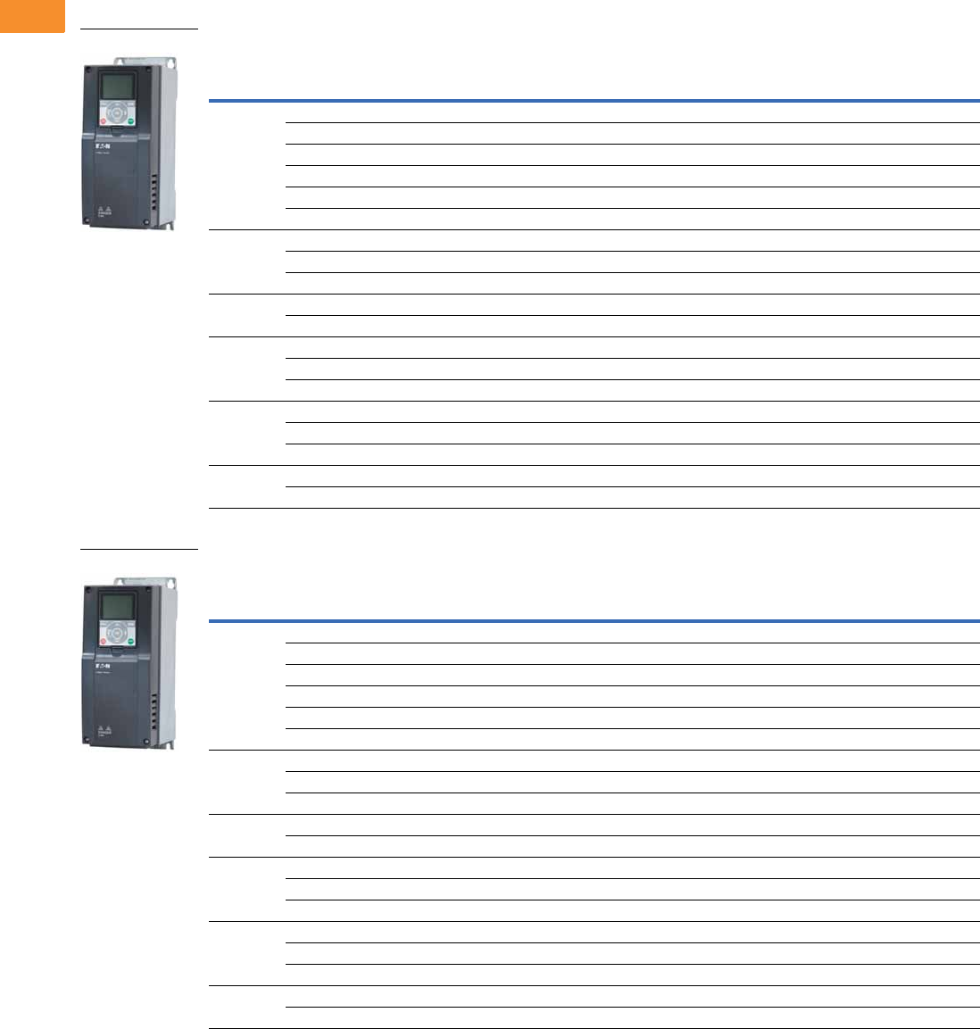
V6-T2-134 Volume 6—Solid-State Motor Control CA08100007E—May 2014 www.eaton.com
2
2
2
2
2
2
2
2
2
2
2
2
2
2
2
2
2
2
2
2
2
2
2
2
2
2
2
2
2
2
2.6
Adjustable Frequency Drives
H-Max Series Drives
Product Selection
H-Max Series Drives—230 Vac
NEMA Type 1/IP21
NEMA Type 12/IP54
Note
1 For sizing reference.
FS
Frame
Size
Drive Output Current Assigned Motor Ratings
230 Vac
NEC Amps 1
Catalog
Number
Low Overload Full
Load Amps at 40°C Horsepower
Drive kW
230 Vac/50 Hz
Low Overload Full
Load Amps at 50°C
4 3.7 0.75 0.55 3.2 2.6 HMX32AG3D721-N
4.8 1 0.75 4.2 3.7 HMX32AG4D821-N
6.6 1.5 1.1 6.6 4.8 HMX32AG6D621-N
8 2 1.5 6.8 6.6 HMX32AG8D021-N
11 3 2.2 9.6 8 HMX32AG01121-N
12.5 4 3 N/A 11 HMX32AG01221-N
5 18 5 4 15.2 12.5 HMX32AG01821-N
24 7.5 5.5 22 18 HMX32AG02421-N
31 10 7.5 28 24 HMX32AG03121-N
6 48 15 11 42 31 HMX32AG04821-N
62 20 15 54 48 HMX32AG06221-N
775 25 18.5 68 62 HMX32AG07521-N
88 30 22 80 75 HMX32AG08821-N
105 40 30 104 88 HMX32AG10521-N
8 140 50 37 130 105 HMX32AG14021-N
170 60 45 154 140 HMX32AG17021-N
205 75 55 192 170 HMX32AG20521-N
9 261 100 75 248 205 HMX32AG26121-N
310 125 90 N/A 261 HMX32AG31021-N
FS
Frame
Size
Drive Output Current Assigned Motor Ratings
230 Vac
NEC Amps 1
Catalog
Number
Low Overload Full
Load Amps at 40°C Horsepower
Drive kW
230 Vac/50 Hz
Low Overload Full
Load Amps at 50°C
4 3.7 0.75 0.55 3.2 2.6 HMX32AG3D722-N
4.8 1 0.75 4.2 3.7 HMX32AG4D822-N
6.6 1.5 1.1 6.6 4.8 HMX32AG6D622-N
8 2 1.5 6.8 6.6 HMX32AG8D022-N
11 3 2.2 9.6 8 HMX32AG01122-N
12.5 4 3 N/A 11 HMX32AG01222-N
5 18 5 4 15.2 12 HMX32AG01822-N
24 7.5 5.5 22 18 HMX32AG02422-N
31 10 7.5 28 24 HMX32AG03122-N
6 48 15 11 42 31 HMX32AG04822-N
62 20 15 54 48 HMX32AG06222-N
775 25 18.5 68 62 HMX32AG07522-N
88 30 22 80 75 HMX32AG08822-N
105 40 30 104 88 HMX32AG10522-N
8 140 50 37 130 105 HMX32AG14022-N
170 60 45 154 140 HMX32AG17022-N
205 75 55 192 170 HMX32AG20522-N
9 261 100 75 248 205 HMX32AG26122-N
310 125 90 N/A 261 HMX32AG31022-N
NEMA Type 1
NEMA Type 12
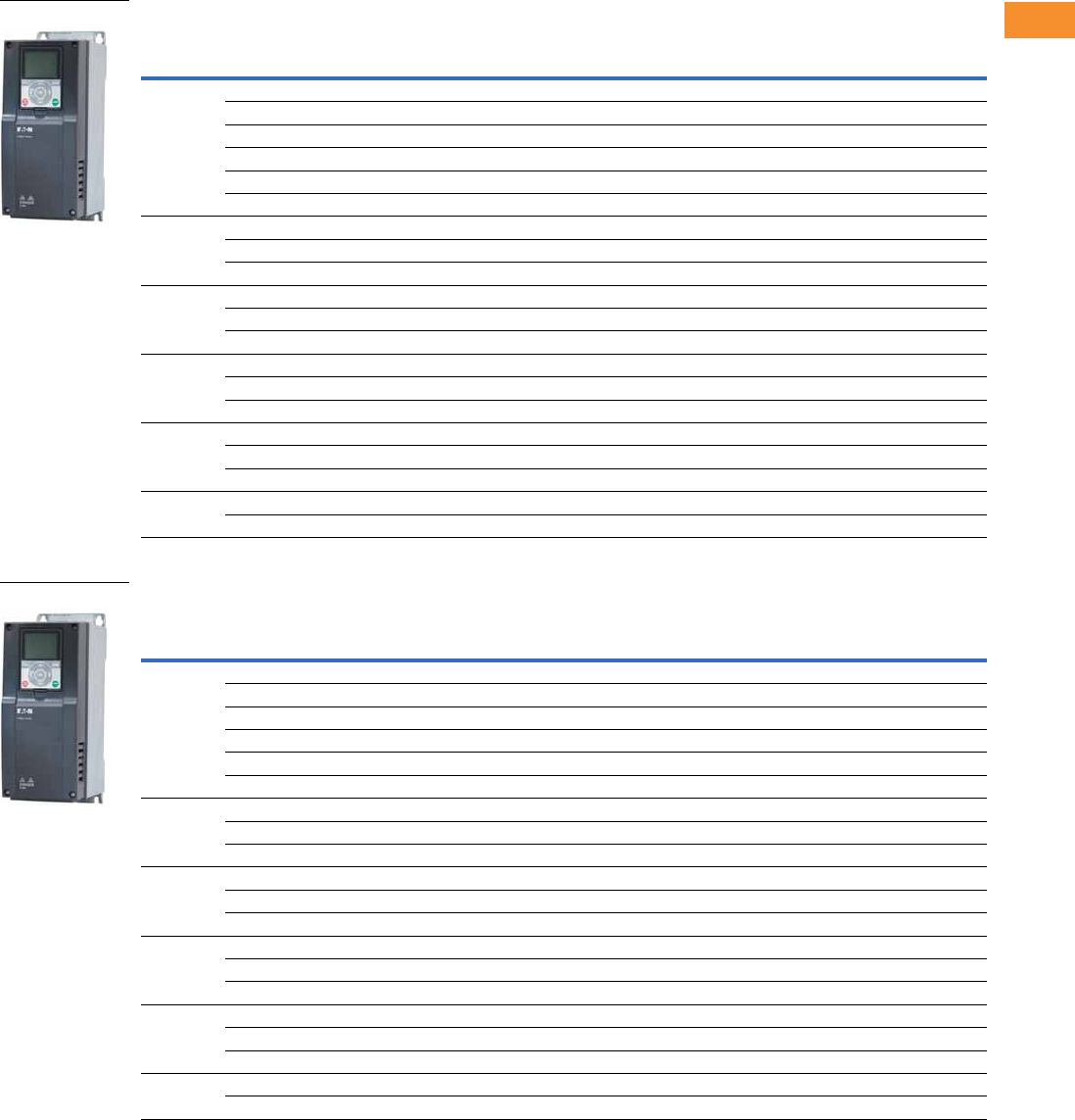
Volume 6—Solid-State Motor Control CA08100007E—May 2014 www.eaton.com V6-T2-135
2
2
2
2
2
2
2
2
2
2
2
2
2
2
2
2
2
2
2
2
2
2
2
2
2
2
2
2
2
2
2.6
Adjustable Frequency Drives
H-Max Series Drives
H-Max Series Drives—480 Vac
NEMA Type 1/IP21
NEMA Type 12/IP54
Note
1 For sizing reference.
FS
Frame
Size
Drive Output Current Assigned Motor Ratings
480 Vac
NEC Amps 1
Catalog
Number
Low Overload Full
Load Amps at 40°C Horsepower
Drive kW
400 Vac/50 Hz
Low Overload Full
Load Amps at 50°C
4 3.4 1.5 1.1 2.1 2.6 HMX34AG3D421-N
4.8 2 1.5 3.4 3.4 HMX34AG4D821-N
5.6 3 2.2 5.6 4.8 HMX34AG5D621-N
8.0 4 3.0 N/A 5.6 HMX34AG8D021-N
9.6 5 4 7.6 8 HMX34AG9D621-N
12 7.5 5.5 11 9.6 HMX34AG01221-N
5 16 10 7.5 14 12 HMX34AG01621-N
23 15 11 21 16 HMX34AG02321-N
31 20 15 27 23 HMX34AG03121-N
6 38 25 18.5 34 31 HMX34AG03821-N
46 30 22 40 38 HMX34AG04621-N
61 40 30 52 46 HMX34AG06121-N
7 72 50 37 65 61 HMX34AG07221-N
87 60 45 77 72 HMX34AG08721-N
105 75 55 96 87 HMX34AG10521-N
8 140 100 75 124 105 HMX34AG14021-N
170 125 90 156 140 HMX34AG17021-N
205 150 110 180 170 HMX34AG20521-N
9 261 200 132 240 205 HMX34AG26121-N
310 250 160 302 261 HMX34AG31021-N
FS
Frame
Size
Drive Output Current Assigned Motor Ratings
480 Vac
NEC Amps 1
Catalog
Number
Low Overload Full
Load Amps at 40°C Horsepower
Drive kW
400 Vac/50 Hz
Low Overload Full
Load Amps at 50°C
4 3.4 1.5 1.1 2.1 2.6 HMX34AG3D422-N
4.8 2 1.5 3.4 3.4 HMX34AG4D822-N
5.6 3 2.2 5.6 4.8 HMX34AG5D622-N
8.0 4 3.0 N/A 5.6 HMX34AG8D022-N
9.6 5 4 7.6 8 HMX34AG9D622-N
12 7.5 5.5 11 9.6 HMX34AG01222-N
5 16 10 7.5 14 12 HMX34AG01622-N
23 15 11 21 16 HMX34AG02322-N
31 20 15 27 23 HMX34AG03122-N
6 38 25 18.5 34 31 HMX34AG03822-N
46 30 22 40 38 HMX34AG04622-N
61 40 30 52 46 HMX34AG06122-N
7 72 50 37 65 61 HMX34AG07222-N
87 60 45 77 72 HMX34AG08722-N
105 75 55 96 87 HMX34AG10522-N
8 140 100 75 124 105 HMX34AG14022-N
170 125 90 156 140 HMX34AG17022-N
205 150 110 180 170 HMX34AG20522-N
9 261 200 132 240 205 HMX34AG26122-N
310 250 160 302 261 HMX34AG31022-N
NEMA Type 1
NEMA Type 12

V6-T2-136 Volume 6—Solid-State Motor Control CA08100007E—May 2014 www.eaton.com
2
2
2
2
2
2
2
2
2
2
2
2
2
2
2
2
2
2
2
2
2
2
2
2
2
2
2
2
2
2
2.6
Adjustable Frequency Drives
H-Max Series Drives
Onboard Network Communications
Johnson Controls
Metasys N2
H-Max Series provides
communication between the
drive and a Johnson Controls
Metasys™ N2 network. With
this connection, the drive can
be controlled, monitored and
programmed from the
Metasys system. N2 can be
selected and programmed by
the drive keypad.
BACnet
H-Max Series provides
communication to BACnet
networks. Data transfer is
master-slave/token passing
(MS/TP) RS-485.
BACnet IP
100Base-T interface.
Modbus TCP
Ethernet based protocol.
Modbus RTU
H-Max Series provides
communication to Modbus
RTU RS-485 as a slave on a
Modbus network. Other
communication parameters
include an address range
from 1–247; a parity of
None, Odd or Even; and the
stop bit is 1.
H-Max Series Option Board Kits Available for Slot B
The factory issued relay
option board can be replaced
with the following option
boards to customize the drive
for your application needs.
The standard board provides
2 Form C RO (NO/NC) and
1 Form A RO (NO).
Option Boards Mounted in Slot B
H-Max Series Option Board Kits Available for Slots D and E
The H-Max Series drives can
accommodate a wide
selection of expander and
adapter option boards to
customize the drive for your
application needs. The drive’s
control unit is designed to
accept a total of two option
boards.
The H-Max Series factory-
installed standard board
configuration includes an
I/O board and a relay
output board.
Option Boards Mounted in Slots D and E
NEMA Type 1 to NEMA Type 12/IP54 Conversion Kit
The NEMA Type 12/IP54
option kit is used to convert a
NEMA Type 1 to a NEMA
Type 12 drive.
Kit consists of a drive cover,
fan kit and plugs.
NEMA Type 12/IP54 Cover
Option Kit Description
Option Kit
Catalog Number
I/O expander card, 2 RO and thermistor input Relay Board 2
Option Kit Description
Option Kit
Catalog Number
6 x DI /DO, each digital input can be individually programmed as digital output XMX-IO-B1-A
1RO Form C (NO/NC), 1RO Form A (NO), 1 thermistor XMX-IO-B2-A
1 x AI, 2 x AO (isolated) XMX-IO-B4-A
3 x RO Form A (NO) XMX-IO-B5-A
1RO Form A (NO), 5DI 42–240 Vac input XMX-IO-B9-A
1 x AO, 1 x DO, 1 x RO XMX-IO-BF-A
LonWorks®XMX-COM-C4-A
Option Kit Description
Option Kit
Catalog Number
FS4-branded N12/IP54 cover with gasket, plastic plug, fans, Eaton logos FS4-N12KIT
FS5-branded N12/IP54 cover with gasket, plastic plug, fans, Eaton logos FS5-N12KIT
FS6-branded N12/IP54 cover with gasket, plastic plug, fans, Eaton logos FS6-N12KIT

Volume 6—Solid-State Motor Control CA08100007E—May 2014 www.eaton.com V6-T2-137
2
2
2
2
2
2
2
2
2
2
2
2
2
2
2
2
2
2
2
2
2
2
2
2
2
2
2
2
2
2
2.6
Adjustable Frequency Drives
H-Max Series Drives
Accessories
Flange Kits
The flange kit is used when the power section heat sink is
mounted through the back panel of an enclosure.
Flange Kit NEMA Type 12/IP54
Includes flange, mounting brackets, NEMA Type 12 fan
components, air shroud screws and plugs.
Frames FS4–FS7 12
Keypad Accessories
Remote Mounting Keypad Kit
Frames FS4–FS9
Drive Demo
H-Max Series Drive Demo
Demos and Power Supply
Notes
1For installation of a NEMA Type 1 drive into a NEMA Type 12 oversized enclosure.
2Frame size 8 and 9 must be ordered from the factory as a flange mount unit.
Replacement Parts
Control Board/Keypad
PC Cable
Replacement Relay Board in Slot B
Main Fan
Internal Fan
Description
Catalog
Number
NEMA Type 12/IP54
FS4 N12/IP54 flange kit
(mounting N1 drive into N12 enclosure)
FS4-Flange-N12KIT
FS5 N12/IP54 flange kit
(mounting N1 drive into N12 enclosure)
FS5-Flange-N12KIT
FS6 N12/IP54 flange kit
(mounting N1 drive into N12 enclosure)
FS6-Flange-N12KIT
FS7 N12/IP54 flange kit
(mounting N1 drive into N12 enclosure)
FS7-Flange-N12KIT
Description
Catalog
Number
Remote mounting keypad kit—bezel and cable OPTRMT-BP-HMAX
Description
Catalog
Number
H-Max Series bypass demo H-MAX-BYPASS-DEMO
Hand-held 24V auxiliary power supply—used to supply power
to the control module in order to perform keypad programming
before the drive is connected to line voltage
9000XAUX24V
Description
Current Catalog
Number
H-Max Series graphic bypass, HOA KeypadbypassHOA
H-Max Series graphic back, HOA KeypadbackHOA
Description
Catalog
Number
Remote download USB to RJ-45 cable with
software driver disk
REM-USB-Down
Description
Catalog
Number
Replacement relay board
qty 2 Form C relay, qty 1 Form A relay
Relay board 1
Description
Catalog
Number
FS4 main fan FS4-Main Fan
FS5 main fan FS5-Main Fan
FS6 main fan FS6-Main Fan
FS7 main fan FS7-Main Fan
Description
Catalog
Number
FS4 internal fan (IP54/NEMA 12) FS4-Internal Fan
FS5 internal fan (IP54/NEMA 12) FS5-Internal Fan
FS6 internal fan (IP54/NEMA 12) FS6-Internal Fan
FS7 internal fan (IP54/NEMA 12) FS7-Internal Fan

V6-T2-138 Volume 6—Solid-State Motor Control CA08100007E—May 2014 www.eaton.com
2
2
2
2
2
2
2
2
2
2
2
2
2
2
2
2
2
2
2
2
2
2
2
2
2
2
2
2
2
2
2.6
Adjustable Frequency Drives
H-Max Series Drives
Technical Data and Specifications
H-Max Series Drives
Description Specification
Input Ratings
Input voltage (Vin) 200–240 Vac, 380–480 Vac, –10%/+10%
Input frequency (fin) 50/60 Hz (variation up to 47–66 Hz)
Connection to power Once per minute or less (typical operation)
Short-circuit withstand
rating
100 kAIC
Output Ratings
Output voltage 0 to Vin/Uin line voltage in
Continuous output current Ambient temperature max. 104°F (40°C)
IL overload 1.1 x IL (1 min./10 min.)
Overload current 110% (1 min./10 min.)
Initial output current 150% for two seconds
Output frequency 0 to 320 Hz
Frequency resolution 0.01 Hz
Control Characteristics
Control method Frequency control (V/f) open loop sensorless vector control
Switching frequency 1–310 amps
FS4–9: default 6 kHz
Frequency reference Analog input: Resolution 0.1% (10-bit), accuracy ±1%
Panel reference: Resolution 0.01 Hz
Field weakening point 8 to 320 Hz
Acceleration time 0.1 to 3000 seconds
Deceleration time 0.1 to 3000 seconds
Braking torque DC brake: 30% x Tn
Ambient Conditions
Ambient operating
temperature
FS4–FS9: 14°F (–10°C), no frost to 104°F (40°C)
(Drive can operate at 122°F (50°C), see Pages V6-T2-134 and
V6-T2-135)
Storage temperature –40° to 158°F (–40° to 70°C)
Relative humidity 0 to 95% RH, noncondensing, non-corrosive, no dripping water
Air quality Chemical vapors: IEC 60721-3-3, unit in operation, Class 3C2;
Mechanical particles: IEC 60721-3-3, unit in operation, Class 3S2
Altitude 100% load capacity (no derating) up to 3280 ft (1000m);
1% derating for each 328 ft (100m) above 3280 ft (1000m);
max. 9842 ft (3000m); 380–480V
Vibration FS4–FS9: EN 61800-5-1, EN 60068-2-6; 5 to 150 Hz,
displacement amplitude 1 mm (peak) at 5 to 15.8 Hz,
max. acceleration amplitude 1G at 15.8 to 150 Hz
Shock EN 61800-5-1, EN 60068-2-27 UPS Drop test (for applicable UPS
weights) Storage and shipping: max. 15G, 11 ms (in package)
Enclosure class NEMA Type 1/IP21 or NEMA Type 12/IP54
(keypad required for IP54/Type 12)
Standards
EMC Immunity: Fulfills all EMC immunity requirements;
Emissions: EN 61800-3, LEVEL H (EMC C2)
Emissions EMC level dependent—
+EMC 2: EN61800-3 (2004) Category C2
Delivered with Class C2 EMC filtering as default.
Description Specification
Control Connections
Analog input voltage 0 to 10V, R = 200 kohms differential
Resolution 0.1%; Accuracy ±1%
DIP switch selection (voltage/current)
Analog input current 0(4) to 20 mA; Ri –250 ohms differential
Digital inputs (6) Positive or negative logic; 18 to 30 Vdc
Auxiliary voltage +24V ±10%, max. 250 mA
Output reference voltage +10V +3%, max. load 10 mA
Analog output 0–10V, 0(4) to 20 mA; RL max. 500 ohms;
Resolution 10 bit; Accuracy ±2%
DIP switch selection (voltage/current)
Relay outputs 3 programmable, 2 Form C, 1 Form A relay outputs
Switching capacity: 24 Vdc/8A, 250 Vac/8A, 125 Vdc/0.4A
Hard wire jumper Between terminal 6 and 10 factory default
DIP switch setting default RS-485 = off
A01 = current
A12 = current
A11 = voltage
Protections
Overcurrent protection Yes
Overvoltage protection Yes
DC bus regulation anti-trip Yes (accelerates or decelerates the load)
Undervoltage protection Yes
Earth fault protection Yes (in case of earth fault in motor or motor cable,
only the frequency converter is protected)
Input phase supervision Yes (trips if any of the input phases are missing)
Motor phase supervision Yes (trips if any of the output phases are missing)
Overtemperature protection Yes
Motor overload protection Yes
Motor stall protection Yes
Motor underload protection Yes
Short-circuit protection Yes
Surge protection Yes (varistor input)
Conformed coated
(varnished) boards
Yes (prevents corrosion)
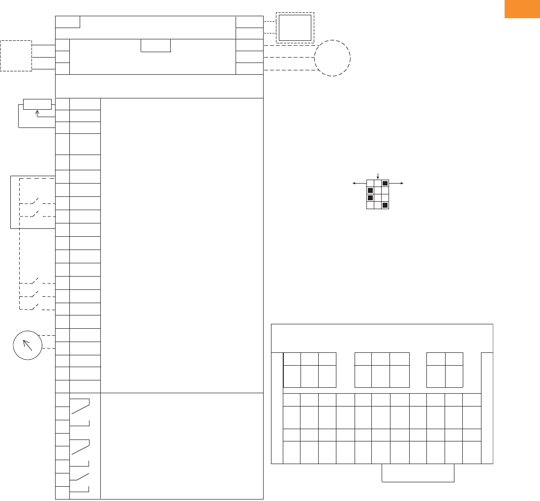
Volume 6—Solid-State Motor Control CA08100007E—May 2014 www.eaton.com V6-T2-139
2
2
2
2
2
2
2
2
2
2
2
2
2
2
2
2
2
2
2
2
2
2
2
2
2
2
2
2
2
2
2.6
Adjustable Frequency Drives
H-Max Series Drives
Wiring Diagram
Control Input/Output, PID Application
Standards
●Digital inputs D1–D6, relay
out, analog in/out are freely
programmed
●The user can assign a
single input to multiple
functions
Includes
●Six digital input
●Two analog input
●One analog output
●Three relay output
●RS-485
●Ethernet (BACnet and
Modbus)
Reliability
●Pretested components
●Conformal coated
(varnished) boards
●40°C rated
●110% overload for one
minute
●Eaton Electrical Services &
Systems national network
of AF drive specialists
Slot A
1
2
3
4
5
6
7
8
9
10
11
12
13
14
15
16
17
18
19
A
+10V
AI–1+
Vin
AI–2+
AI–2–
24Vout
GND
DIN1
DIN2
DIN3
24Vout
GND
DIN4
DIN5
DIN6
AO–1+
AO–1–
DATA-
Reference Output
Analog Input Voltage (Range 0–10 Vdc)
(can be programmed to current 4–20 mA)
Analog Output Common (Ground)
Analog Input Common
PI Setpoint or Feedback
Control Voltage Output (0.1A max.)
I/O Ground
START/STOP (Contact closed = start)
External Fault (Closed = fault)
Run Interlock Permissive IP Interlock
(Closed = OK)
DIN1–DIN6 Common
Control Voltage Output (0.1A max.)
I/O Ground
Fire Mode (Contact closed = re mode)
Force Bypass (Contact closed = bypass)
DIN1–DIN6 Common
Output Frequency (0–20 mA)
Analog Output Common (Ground)
RS-485 DATA-
Speed Select 0–100% (Preset speed)
U (T1)
V (T2)
W (T3)
R+
R-
L1
L2
L3
Three-Phase Input
Input
(Single-Phase not available)
Three-Phase
Output
DB
Chopper
Optional
Resistor
Terminal Factory Default Signal
Resistor
Analog Input Current (Range 4–20 mA)
(can be programmed to voltage 0–10 Vdc)
PI Setpoint or Feedback
BDATA+
RO1 Bypass Run
RO2 Drive Run
RO3 Fault
24 Vdc/8A
250 Vac/8A
125 Vdc/0.4A
Relay Board 1
Default Signal
21
22
23
24
25
26
32
33
Slot B
Analog
RS-485 DATA+
Factory
Jumper
COM
CMB
30
24 Vdcin
Auxiliary Input Voltage
123456 78 91011
12 13 14 15 16 17 18 19 30 A B
RS-485
Data–
RS-485
Data+
24 Vdc
in
AO1–AO1+COM
DI1–6
DI6DI5DI4GND24 Vdc
out
DI2DI1GND24 Vdc
out
AI2–AI2+AI1–AI1++10
Vdc
COM
DI1–6
DI3
21
RO1
22 23 24 25 26 32 33
NC
RO1
COM
RO1
NO
RO2
NC
RO2
COM
RO2
NO
RO3
COM
RO3
NO
Slot D __________________
Slot E __________________
Terminal Block Layout
Factory Jumper
External Interlock
Circuit
Breaker
Optional
Motor
RJ-45 BACnet/IP Ethernet Industrial Protocol
Modbus/TCP Transmission Control Protocol (Ethernet Based)
5% DC Link
Reactor
Programmable BACnet,
Modbus, FLN, N2
ON
CURRENT
CURRENT
CURRENT
RS485
AO1
AI2
AI1
OFF
VOLTAGE
VOLTAGE
VOLTAGE
Tes t
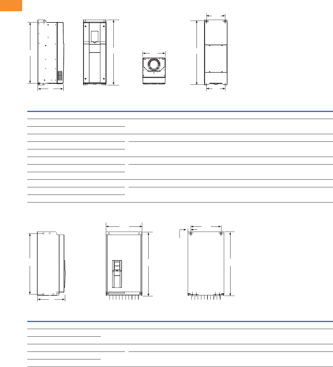
V6-T2-140 Volume 6—Solid-State Motor Control CA08100007E—May 2014 www.eaton.com
2
2
2
2
2
2
2
2
2
2
2
2
2
2
2
2
2
2
2
2
2
2
2
2
2
2
2
2
2
2
2.6
Adjustable Frequency Drives
H-Max Series Drives
Dimensions
Approximate Dimensions in Inches (mm)
H-Max Series Frames FS4–FS7
H-Max Series Frames FS8 and FS9
Note: For flange dimension, please reference User Manual.
Voltage hp kW Amps D H1
Hole
Center-to-Center
H2 H3 W1 W2 W3
Weight in
Lbs (kg)
FS4
230 Vac 0.75–4 0.55–3.0 3.7–12.5 7.77
(197.3)
12.89
(327.5)
12.32
(313.0)
11.22
(285.0)
5.04
(128.0)
3.94
(100.0)
3.94
(100.0)
13.2
(6)
480 Vac 1.5–7.5 1.1–5.5 3.4–12
FS5
230 Vac 5–10 4–7.5 18–31 8.73
(221.6)
16.50
(419.0)
15.98
(406.0)
15.04
(382.0)
5.67
(144.0)
4.53
(115.0)
3.94
(100.0)
22.0
(10)
480 Vac 10–20 7.5–15 16–31
FS6
230 Vac 15–20 11–15 48–62 9.29
(236.0)
21.93
(557.0)
21.28
(540.5)
20.24
(514.0)
7.68
(195.0)
5.83
(148.0)
5.83
(148.0)
44.1
(20)
480 Vac 25–40 18.5–30 38–61
FS7
230 Vac 25–30 18.5–30 75–105 10.49
(266.5)
25.98
(660.0)
25.39
(645.0)
24.29
(617.0)
9.06
(230.0)
7.48
(190.0)
7.48
(190.0)
82.6
(37.5)
480 Vac 50–75 37–55 72–105
Voltage hp kW Amps D H1
Hole
Center-to-Center
H2 H3 W1 W2 W3
Weight in
Lbs (kg)
FS8
230 Vac 50–75 37–55 140–205 13.76
(349.6)
38.02
(965.7)
37.26
(946.4)
37.26
(946.4)
11.42
(290.1)
9.29
(236.0)
1.42
(36.0)
154.3
(70)
480 Vac 100–150 75–110
FS9
230 Vac 100–120 75–90 261–310 14.63
(371.6)
33.09
(890.4)
31.89
(810.0)
31.89
(810.0)
18.90
(480.0)
15.75
(400.0)
1.57
(40.0)
238.1
(108)
480 Vac 200–250 132–160
W1
H3 H1 H2
W2
W3
D
H3 H1
W1 W2
W3
H2
D
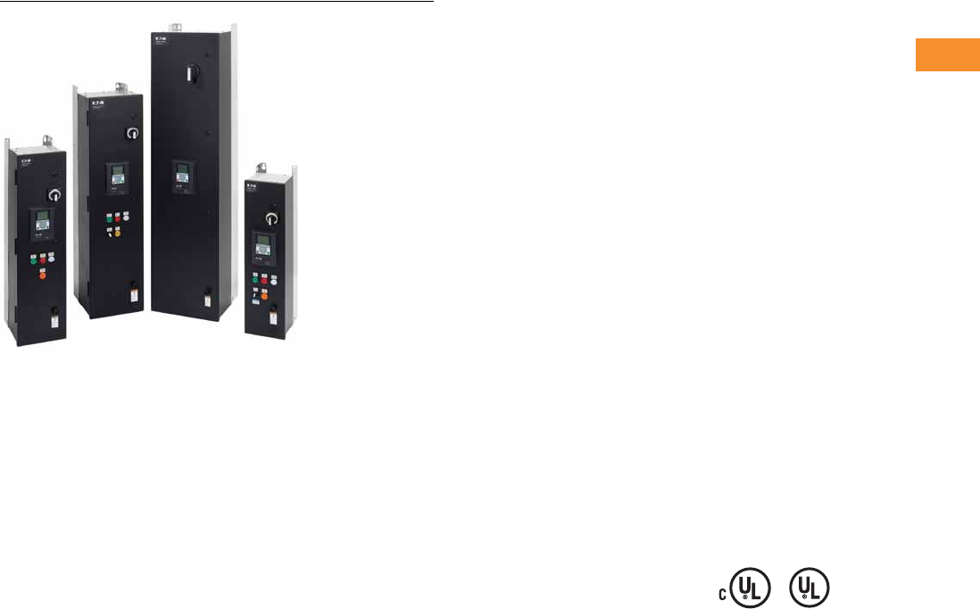
Volume 6—Solid-State Motor Control CA08100007E—May 2014 www.eaton.com V6-T2-141
2
2
2
2
2
2
2
2
2
2
2
2
2
2
2
2
2
2
2
2
2
2
2
2
2
2
2
2
2
2
2.6
Adjustable Frequency Drives
H-Max Series Drives
H-Max IntelliPass and IntelliDisconnect Drives
Contents
Description Page
H-Max Drives . . . . . . . . . . . . . . . . . . . . . . . . . . . . . V6-T2-132
H-Max IntelliPass and IntelliDisconnect Drives
Catalog Number Selection . . . . . . . . . . . . . . . . V6-T2-142
Product Selection . . . . . . . . . . . . . . . . . . . . . . . V6-T2-143
Technical Data and Specifications . . . . . . . . . . V6-T2-151
Wiring Diagrams . . . . . . . . . . . . . . . . . . . . . . . . V6-T2-152
Dimensions . . . . . . . . . . . . . . . . . . . . . . . . . . . V6-T2-154
H-Max IntelliPass and IntelliDisconnect Drives
Product Description
The IntelliPass electronic
bypass is a two or optional
three contactor design using a
24 Vdc XT Series contactor
with an optional manual
override switch that allows
the unit to run in bypass
without the H-Max Series
drive.
The IntelliPass software
parameters utilize engineering
units common to the HVAC
industry. Onboard startup
wizard guarantees flawless
commissioning with plug-
and-play screen entry.
Available in NEMA/UL Type 1,
Type 12 and Type 3R with
optional pre-engineered
operator devices to meet
all customized specification
requirements.
The IntelliPass construction
features allow for easy
installation, reliable operation
and serviceability with
additional onboard wire space,
and removable conduit plates
with knockouts.
Features and Benefits
Industry-leading energy
saving solution—uses the
Eaton H-Max drive with
Active Energy Control
algorithm.
Built to be as tough as the
application—Eaton’s robust
design boasts an industrial
grade enclosure and industry
proven components.
●Industrial Power Supply
●XT Contactors
●22 mm Pilot Devices
Designed with Our Customers
in Mind
●Removable top and bottom
entry panels
●Door-mounted graphic
display and keypad
●Easily accessible
connection terminals with
removable I/O terminal
connections
Engineered Product Solution
●The Eaton H-Max
IntelliPass and
IntelliDisconnect products
are available with a variety
of factory tested and
certified options meeting
or exceeding UL508C
requirements
Standards and Certifications
Product
●IEC 61800-5-1
●UL508C
●cUL
●OSHPD Seismic Certified
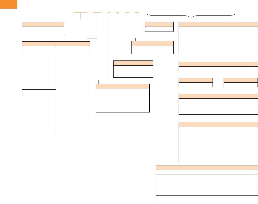
V6-T2-142 Volume 6—Solid-State Motor Control CA08100007E—May 2014 www.eaton.com
2
2
2
2
2
2
2
2
2
2
2
2
2
2
2
2
2
2
2
2
2
2
2
2
2
2
2
2
2
2
2.6
Adjustable Frequency Drives
H-Max Series Drives
Catalog Number Selection
H-Max Series IntelliPass and IntelliDisconnect Drives
Notes
IntelliPass—two contactor electronic bypass standard.
All boards are varnished. Corrosion resistant.
Battery included in all drives for real-time clock. Three year lifetime.
Keypad kit includes HOA bypass.
EMI/RFI filters included.
DC link choke included.
NEC Ampere Ratings
208 Volts 480 Volts
4D6 = 4.6A—1 hp
7D5 = 7.5A—2 hp
011 = 11A—3 hp
017 = 17A—5 hp
025 = 25A—7.5 hp
031 = 31A—10 hp
047 = 47A—15 hp
060 = 60A—20 hp
075 = 75A—25 hp
088 = 88A—30 hp
2D1 = 2.1A—1 hp
3D4 = 3.4A—2 hp
5D6 = 5.6A—3 hp
7D6 = 7.6A—5 hp
011 = 11A—7.5 hp
014 = 14A—10 hp
021 = 21A—15 hp
027 = 27A—20 hp
034 = 34A—25 hp
040 = 40A—30 hp
052 = 52A—40 hp
065 = 65A—50 hp
077 = 77A—60 hp
096 = 96A—75 hp
230 Volts
4D2 = 4.2A—1 hp
6D8 = 6.8A—2 hp
9D6 = 9.6A—3 hp
016 = 16A—5 hp
022 = 22A—7.5 hp
028 = 28A—10 hp
042 = 42A—15 hp
054 = 54A—20 hp
068 = 68A—25 hp
080 = 80A—30 hp
Enclosure Style
3= IntelliPass NEMA Type 1
4= IntelliPass NEMA Type 12
5= IntelliPass NEMA Type 3R
A= IntelliDisconnect NEMA Type 1
B= IntelliDisconnect NEMA Type 12
C= IntelliDisconnect NEMA Type 3R
Braking/Application
N= No brake chopper
(low overload)
HMX 011 3 4 N A __________
Product
HMX = HVAC drive (VT)
(low overload)
Voltage
1= 208V
2= 230V
4= 480V
Software Series
A–Z
Keypad Options
None available
Build options alphabetically and numerically.
EMC Upgrade Option
EMC C2 Standard
IntelliDisconnect Options
L3 = Pilot lights (Power ON, RUN, Fault)
P3 = Fused drive isolation
PE = Output contactor
SA = Space heater w/transformer (Type 3R only)
Optional Communications in Slot D and E
C4 =LonWorks
IntelliPass Bypass Options
L4 = Pilot lights (Power ON, RUN, Fault, Bypass)
P3 = Fused drive isolation (can not be used with P6 or MI)
P6 = Third contactor drive isolation
(cannot be used with P3, IS or MI)
M1 = Manual bypass, includes isolation contactor and pilot
lights (not available with P3, L4, P6 or IS)
SA = Space heater w/transformer (Type 3R only)
K9 = Auxiliary contacts
IS = Isolation switch (cannot be used with P6 or MI)
Standard Onboard Communications
RS-485 Communications
BACnet MS/TP = Master slave/token protocol (Universal BACnet) RS-485
Modbus RTU RS-485, ASCII or RTU, remote terminal unit 32 nodes
N2 = Johnson Controls Metasys N2 network
Onboard Ethernet-Based Communications
(port left side of keypad)
BACnet/IP Ethernet industrial protocol
Modbus/TCP Transmission control protocol (Ethernet-based)
Extended I/O Options in Slot D and E
B1 = 6 x DI /DO, Each digital input can be individually
programmed as digital output
B2 = 1RO (NC/NO), 1RO (NO), 1 Thermistor
B4 = 1 x AI, 2 x AO (isolated)
B5 =3 x RO
B9 = 1RO (NO), 5 DI 42–240 Vac input
BF = Expander IO, 1 AO, 1 DO, 1 RO
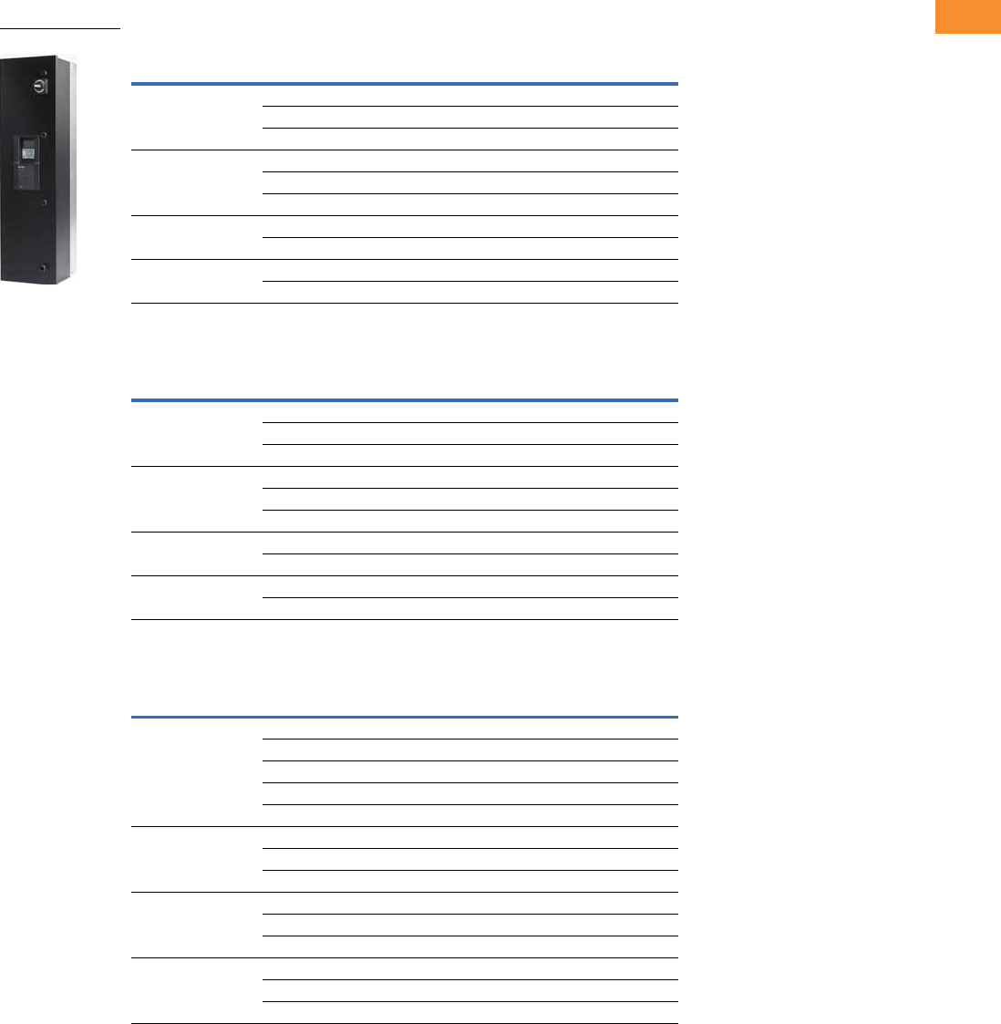
Volume 6—Solid-State Motor Control CA08100007E—May 2014 www.eaton.com V6-T2-143
2
2
2
2
2
2
2
2
2
2
2
2
2
2
2
2
2
2
2
2
2
2
2
2
2
2
2
2
2
2
2.6
Adjustable Frequency Drives
H-Max Series Drives
Product Selection
H-Max Series IntelliPass NEMA Type 1—Two Contactor Bypass Standard
208 Vac
230 Vac
480 Vac
Notes
For Wiring Diagrams, see Page V6-T2-153.
For NEMA 12 or 3R enclosures, see Catalog Number Selection on Page V6-T2-142.
Call Technical Support for NEMA 3R specifics. Enclosure size and weight differ from NEMA 1 and 12 products.
FS
Frame Size Horsepower
Drive Rated
NEC Amps Catalog Number
414.6HMX4D631NA
27.5HMX7D531NA
310.6HMX01131NA
5516.7HMX01731NA
7.5 24.2 HMX02531NA
10 30.8 HMX03131NA
61546.2HMX04731NA
20 59.4 HMX06031NA
72574.9HMX07531NA
30 88 HMX08831NA
FS
Frame Size Horsepower
Drive Rated
NEC Amps Catalog Number
414.2HMX4D232NA
26.8HMX6D832NA
39.6HMX9D632NA
5515.2HMX01632NA
7.5 22 HMX02232NA
10 28 HMX02832NA
61542HMX04232NA
20 54 HMX05432NA
72568HMX06832NA
30 80 HMX08032NA
FS
Frame Size Horsepower
Drive Rated
NEC Amps Catalog Number
412.1HMX2D134NA
23.4HMX3D434NA
35.6HMX5D634NA
57.6HMX7D634NA
7.5 11 HMX01134NA
51014HMX01434NA
15 21 HMX02134NA
20 27 HMX02734NA
62534HMX03434NA
30 40 HMX04034NA
40 52 HMX05234NA
75065HMX06534NA
60 77 HMX07734NA
75 96 HMX09634NA
HMX_
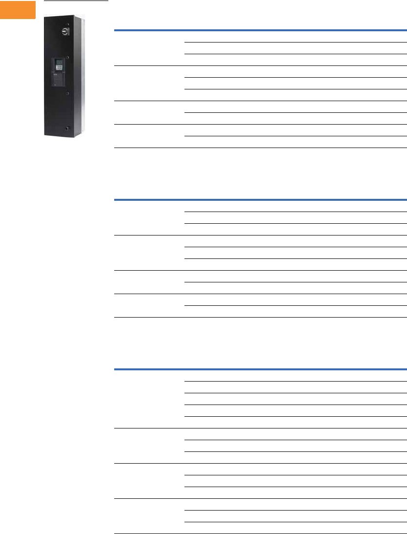
V6-T2-144 Volume 6—Solid-State Motor Control CA08100007E—May 2014 www.eaton.com
2
2
2
2
2
2
2
2
2
2
2
2
2
2
2
2
2
2
2
2
2
2
2
2
2
2
2
2
2
2
2.6
Adjustable Frequency Drives
H-Max Series Drives
H-Max Series IntelliPass NEMA Type 12—Two Contactor Bypass Standard
208 Vac
230 Vac
480 Vac
Notes
For Wiring Diagrams, see Page V6-T2-153.
For NEMA 12 or 3R enclosures, see Catalog Number Selection on Page V6-T2-142.
Call Technical Support for NEMA 3R specifics. Enclosure size and weight differ from NEMA 1 and 12 products.
FS
Frame Size Horsepower
Drive Rated
NEC Amps Catalog Number
414.6HMX4D641NA
27.5HMX7D541NA
310.6HMX01141NA
5516.7HMX01741NA
7.5 24.2 HMX02541NA
10 30.8 HMX03141NA
61546.2HMX04741NA
20 59.4 HMX06041NA
72574.9HMX07541NA
30 88 HMX08841NA
FS
Frame Size Horsepower
Drive Rated
NEC Amps Catalog Number
414.2HMX4D242NA
26.8HMX6D842NA
39.6HMX9D642NA
5515.2HMX01642NA
7.5 22 HMX02242NA
10 28 HMX02842NA
61542HMX04242NA
20 54 HMX05442NA
72568HMX06842NA
30 80 HMX08042NA
FS
Frame Size Horsepower
Drive Rated
NEC Amps Catalog Number
412.1HMX2D144NA
23.4HMX3D444NA
35.6HMX5D644NA
57.6HMX7D644NA
7.5 11 HMX01144NA
51014HMX01444NA
15 21 HMX02144NA
20 27 HMX02744NA
62534HMX03444NA
30 40 HMX04044NA
40 52 HMX05244NA
75065HMX06544NA
60 77 HMX07744NA
75 96 HMX09644NA
HMX_
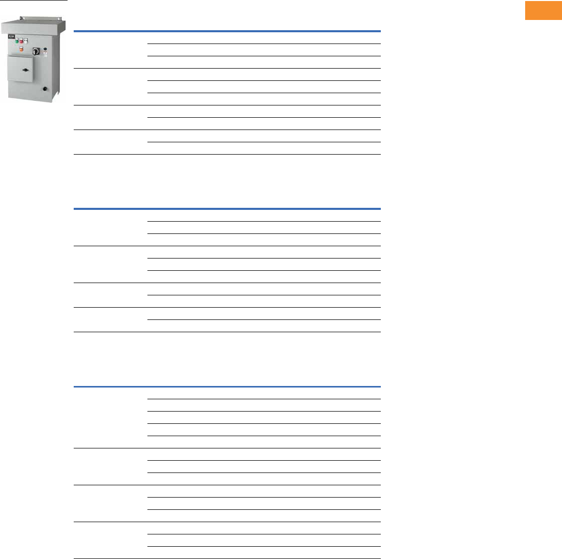
Volume 6—Solid-State Motor Control CA08100007E—May 2014 www.eaton.com V6-T2-145
2
2
2
2
2
2
2
2
2
2
2
2
2
2
2
2
2
2
2
2
2
2
2
2
2
2
2
2
2
2
2.6
Adjustable Frequency Drives
H-Max Series Drives
H-Max Series IntelliPass NEMA Type 3R—Two Contactor Bypass Standard
208 Vac
230 Vac
480 Vac
Notes
For Wiring Diagrams, see Page V6-T2-153.
For NEMA 12 or 3R enclosures, see Catalog Number Selection on Page V6-T2-142.
Call Technical Support for NEMA 3R specifics. Enclosure size and weight differ from NEMA 1 and 12 products.
FS
Frame Size Horsepower
Drive Rated
NEC Amps Catalog Number
414.6HMX4D651NA
27.5HMX7D551NA
310.6HMX01151NA
5516.7HMX01751NA
7.5 24.2 HMX02551NA
10 30.8 HMX03151NA
61546.2HMX04751NA
20 59.4 HMX06051NA
72574.9HMX07551NA
30 88 HMX08851NA
FS
Frame Size Horsepower
Drive Rated
NEC Amps Catalog Number
414.2HMX4D252NA
26.8HMX6D852NA
39.6HMX9D652NA
5515.2HMX01652NA
7.5 22 HMX02252NA
10 28 HMX02852NA
61542HMX04252NA
20 54 HMX05452NA
72568HMX06852NA
30 80 HMX08052NA
FS
Frame Size Horsepower
Drive Rated
NEC Amps Catalog Number
412.1HMX2D154NA
23.4HMX3D454NA
35.6HMX5D654NA
57.6HMX7D654NA
7.5 11 HMX01154NA
51014HMX01454NA
15 21 HMX02154NA
20 27 HMX02754NA
62534HMX03454NA
30 40 HMX04054NA
40 52 HMX05254NA
75065HMX06554NA
60 77 HMX07754NA
75 96 HMX09654NA
HMX_

V6-T2-146 Volume 6—Solid-State Motor Control CA08100007E—May 2014 www.eaton.com
2
2
2
2
2
2
2
2
2
2
2
2
2
2
2
2
2
2
2
2
2
2
2
2
2
2
2
2
2
2
2.6
Adjustable Frequency Drives
H-Max Series Drives
H-Max Series IntelliDisconnect NEMA Type 1—Main Disconnect Standard
208 Vac
230 Vac
480 Vac
Notes
For Wiring Diagrams, see Page V6-T2-153.
For NEMA 12 or 3R enclosures, see Catalog Number Selection on Page V6-T2-142.
Call Technical Support for NEMA 3R specifics. Enclosure size and weight differ from NEMA 1 and 12 products.
FS
Frame Size Horsepower
Drive Rated
NEC Amps Catalog Number
414.6HMX4D6A1NA
27.5HMX7D5A1NA
311HMX011A1NA
5517HMX017A1NA
7.5 25 HMX025A1NA
10 31 HMX031A1NA
61547HMX047A1NA
20 60 HMX060A1NA
72575HMX075A1NA
30 88 HMX088A1NA
FS
Frame Size Horsepower
Drive Rated
NEC Amps Catalog Number
414.2HMX4D2A2NA
26.8HMX6D8A2NA
39.6HMX9D6A2NA
5515.2HMX016A2NA
7.5 22 HMX022A2NA
10 28 HMX028A2NA
61542HMX042A2NA
20 54 HMX054A2NA
72568HMX068A2NA
30 80 HMX080A2NA
FS
Frame Size Horsepower
Drive Rated
NEC Amps Catalog Number
412.1HMX2D1A4NA
23.4HMX3D4A4NA
35.6HMX5D6A4NA
57.6HMX7D6A4NA
7.5 11 HMX011A4NA
51014HMX014A4NA
15 21 HMX021A4NA
20 27 HMX027A4NA
62534HMX034A4NA
30 40 HMX040A4NA
40 52 HMX052A4NA
75065HMX065A4NA
60 77 HMX077A4NA
75 96 HMX096A4NA
HMX_
Volume 6—Solid-State Motor Control CA08100007E—May 2014 www.eaton.com V6-T2-147
2
2
2
2
2
2
2
2
2
2
2
2
2
2
2
2
2
2
2
2
2
2
2
2
2
2
2
2
2
2
2.6
Adjustable Frequency Drives
H-Max Series Drives
H-Max Series IntelliDisconnect NEMA Type 12—Main Disconnect Standard
208 Vac
230 Vac
480 Vac
Notes
For Wiring Diagrams, see Page V6-T2-153.
For NEMA 12 or 3R enclosures, see Catalog Number Selection on Page V6-T2-142.
Call Technical Support for NEMA 3R specifics. Enclosure size and weight differ from NEMA 1 and 12 products.
FS
Frame Size Horsepower
Drive Rated
NEC Amps Catalog Number
414.6HMX4D6B1NA
27.5HMX7D5B1NA
311HMX011B1NA
5517HMX017B1NA
7.5 25 HMX025B1NA
10 31 HMX031B1NA
61547HMX047B1NA
20 60 HMX060B1NA
72575HMX075B1NA
30 88 HMX088B1NA
FS
Frame Size Horsepower
Drive Rated
NEC Amps Catalog Number
414.2HMX4D2B2NA
26.8HMX6D8B2NA
39.6HMX9D6B2NA
5515.2HMX016B2NA
7.5 22 HMX022B2NA
10 28 HMX028B2NA
61542HMX042B2NA
20 54 HMX054B2NA
72568HMX068B2NA
30 80 HMX080B2NA
FS
Frame Size Horsepower
Drive Rated
NEC Amps Catalog Number
412.1HMX2D1B4NA
23.4HMX3D4B4NA
35.6HMX5D6B4NA
57.6HMX7D6B4NA
7.5 11 HMX011B4NA
51014HMX014B4NA
15 21 HMX021B4NA
20 27 HMX027B4NA
62534HMX034B4NA
30 40 HMX040B4NA
40 52 HMX052B4NA
75065HMX065B4NA
60 77 HMX077B4NA
75 96 HMX096B4NA
HMX_
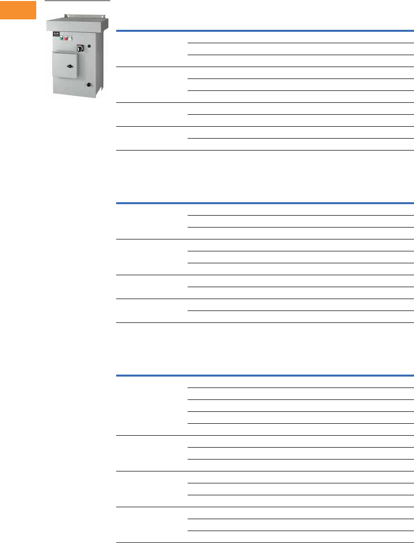
V6-T2-148 Volume 6—Solid-State Motor Control CA08100007E—May 2014 www.eaton.com
2
2
2
2
2
2
2
2
2
2
2
2
2
2
2
2
2
2
2
2
2
2
2
2
2
2
2
2
2
2
2.6
Adjustable Frequency Drives
H-Max Series Drives
H-Max Series IntelliDisconnect NEMA Type 3R—Main Disconnect Standard
208 Vac
230 Vac
480 Vac
Notes
For Wiring Diagrams, see Page V6-T2-153.
For NEMA 12 or 3R enclosures, see Catalog Number Selection on Page V6-T2-142.
Call Technical Support for NEMA 3R specifics. Enclosure size and weight differ from NEMA 1 and 12 products.
FS
Frame Size Horsepower
Drive Rated
NEC Amps Catalog Number
414.6HMX4D6C1NA
27.5HMX7D5C1NA
311HMX011C1NA
5517HMX017C1NA
7.5 25 HMX025C1NA
10 31 HMX031C1NA
61547HMX047C1NA
20 60 HMX060C1NA
72575HMX075C1NA
30 88 HMX088C1NA
FS
Frame Size Horsepower
Drive Rated
NEC Amps Catalog Number
414.2HMX4D2C2NA
26.8HMX6D8C2NA
39.6HMX9D6C2NA
5515.2HMX016C2NA
7.5 22 HMX022C2NA
10 28 HMX028C2NA
61542HMX042C2NA
20 54 HMX054C2NA
72568HMX068C2NA
30 80 HMX080C2NA
FS
Frame Size Horsepower
Drive Rated
NEC Amps Catalog Number
412.1HMX2D1C4NA
23.4HMX3D4C4NA
35.6HMX5D6C4NA
57.6HMX7D6C4NA
7.5 11 HMX011C4NA
51014HMX014C4NA
15 21 HMX021C4NA
20 27 HMX027C4NA
62534HMX034C4NA
30 40 HMX040C4NA
40 52 HMX052C4NA
75065HMX065C4NA
60 77 HMX077C4NA
75 96 HMX096C4NA
HMX_

Volume 6—Solid-State Motor Control CA08100007E—May 2014 www.eaton.com V6-T2-149
2
2
2
2
2
2
2
2
2
2
2
2
2
2
2
2
2
2
2
2
2
2
2
2
2
2
2
2
2
2
2.6
Adjustable Frequency Drives
H-Max Series Drives
Onboard Network Communications
Johnson Controls
Metasys N2
H-Max Series provides
communication between the
drive and a Johnson Controls
Metasys™ N2 network. With
this connection, the drive can
be controlled, monitored and
programmed from the
Metasys system. N2 can be
selected and programmed by
the drive keypad.
BACnet
H-Max Series provides
communication to BACnet
networks. Data transfer is
master-slave/token passing
(MS/TP) RS-485.
BACnet IP
100Base-T interface.
Modbus TCP
Ethernet based protocol.
Modbus RTU
H-Max Series provides
communication to Modbus
RTU RS-485 as a slave on a
Modbus network. Other
communication parameters
include an address range
from 1 to 247; a parity of
None, Odd or Even; and the
stop bit is 1.
.
H-Max Series Option Board Kits Available for Slots D and E
The H-Max Series drives can
accommodate a wide
selection of expander and
adapter option boards to
customize the drive for your
application needs. The drive’s
control unit is designed to
accept a total of two option
boards.
The H-Max Series factory-
installed standard board
configuration includes an
I/O board and a relay
output board.
Option Boards Mounted in Slots D and E
Option Kit Description
Option Kit
Catalog Number
6 x DI /DO, each digital input can be individually programmed as digital output XMX-IO-B1-A
1RO Form C (NO/NC), 1RO Form A (NO), 1 thermistor XMX-IO-B2-A
1 x AI, 2 x AO (isolated) XMX-IO-B4-A
3 x RO Form A (NO) XMX-IO-B5-A
1RO Form A (NO), 5DI 42–240 Vac input XMX-IO-B9-A
LonWorks XMX-COM-C4-A
1 x AO, 1 x DO, 1 x RO XMX-IO-BF-A

V6-T2-150 Volume 6—Solid-State Motor Control CA08100007E—May 2014 www.eaton.com
2
2
2
2
2
2
2
2
2
2
2
2
2
2
2
2
2
2
2
2
2
2
2
2
2
2
2
2
2
2
2.6
Adjustable Frequency Drives
H-Max Series Drives
Extended I/O Options in Slot D and E
Optional Communications in Slot D and E
IntelliDisconnect Options
IntelliPass Bypass Options
Standard Onboard Communications
Description
Suffix
Number
6 x DI /DO, Each digital input can be individually
programmed as digital output
B1
1RO (NC/NO), 1RO (NO), 1 Thermistor B2
1 x AI, 2 x AO (isolated) B4
3 x RO B5
1RO (NO), 5 DI 42–240 Vac input B9
Expander IO, 1 AO, 1 DO, 1 RO BF
Description
Suffix
Number
LonWorks C4
Description
Suffix
Number
Pilot lights (Power ON, RUN, Fault) L3
Fused drive isolation (cannot be used with PE) P3
Output contactor (cannot be used with P3) PE
Space heater w/transformer (Type 3R only) SA
Description
Suffix
Number
Pilot lights (Power ON, RUN, Fault) L4
Fused drive isolation (can not be used with P6) P3
Third contactor drive isolation (cannot be used with P3 or IS) P6
Manual bypass switch located on front door M1
Space heater w/transformer (Type 3R only) SA
Auxiliary contacts K9
Isolation switch IS
Description
Suffix
Number
RS-485 Communications
BACnet MS/TP = Master slave/token protocol (Universal BACnet) RS-485 BACnet
Modbus RTU RS-485, ASCII or RTU, remote terminal unit 32 nodes Modbus
Johnson Controls Metasys N2 network N2
Onboard Ethernet-Based Communications
(port left side of keypad)
BACnet/IP Ethernet industrial protocol BACnet
Modbus/TCP Transmission control protocol (Ethernet-based) Modbus

Volume 6—Solid-State Motor Control CA08100007E—May 2014 www.eaton.com V6-T2-151
2
2
2
2
2
2
2
2
2
2
2
2
2
2
2
2
2
2
2
2
2
2
2
2
2
2
2
2
2
2
2.6
Adjustable Frequency Drives
H-Max Series Drives
Technical Data and Specifications
Primary Design Features
H-Max Series Drives
Description IntelliPass IntelliDisconnect Description IntelliPass IntelliDisconnect
CB MMP Standard Standard Isolation switch Optional N/A
2 contactor bypass Standard N/A Top entry (power) Standard Standard
Electrical interlock Standard N/A Bottom entry (power) Standard Standard
Third contactor (isolation) Optional N/A Output contactor Standard Optional
Description Specification
Input Ratings
Input voltage (Vin) 208, 230, 480 Vac, –10%/+10%
Input frequency (fin) 50/60 Hz (variation up to 47–66 Hz)
Connection to power Once per minute or less (typical operation)
Short-circuit withstand
rating
65 kAIC combination
Output Ratings
Output voltage 0 to Vin/Uin line voltage in
Continuous output current Ambient temperature max. 104°F (40°C)
IL overload 1.1 x IL (1 min./10 min.)
Overload current 110% (1 min./10 min.)
Initial output current 150% for two seconds
Output frequency 0 to 320 Hz
Frequency resolution 0.01 Hz
Control Characteristics
Control method Frequency control (V/f) open loop sensorless vector control
Switching frequency 1–310 amps; adjustable with parameter 2.6.9
FS4–FS7: default 6 kHz
Frequency reference Analog input: Resolution 0.1% (10-bit), accuracy ±1%
Panel reference: Resolution 0.01 Hz
Field weakening point 8 to 320 Hz
Acceleration time 0.1 to 3000 seconds
Deceleration time 0.1 to 3000 seconds
Braking torque DC brake: 30% x Tn
Ambient Conditions
Ambient operating
temperature
FS4–FS7: 14°F (–10°C), no frost to 104°F (40°C)
(Drive can operate at 122°F (50°C)
Storage temperature –40° to 158°F (–40° to 70°C)
Relative humidity 0 to 95% RH, noncondensing, non-corrosive, no dripping water
Air quality Chemical vapors: IEC 60721-3-3, unit in operation, Class 3C2;
Mechanical particles: IEC 60721-3-3, unit in operation, Class 3S2
Altitude 100% load capacity (no derating) up to 3280 ft (1000m);
1% derating for each 328 ft (100m) above 3280 ft (1000m);
max. 9842 ft (3000m); 380–480V
Vibration FS4–FS7: IEC 60068-2-6, 10–150 Hz
Displacement amplitude = 1 mm peak-to-peak from 10–15.8 Hz
Max. acceleration amplitude = 1G peak from 15.8–150 Hz
Shock FS4–FS7: IEC 60068-2-27, 15G peak acceleration at 11 ms
duration, 1/2-sine. ISTA 1A Certified
Enclosure class NEMA Type 1/IP21 or NEMA Type 12/IP54
(keypad required for IP54/Type 12)
Description Specification
Standards
EMC Immunity: Fulfills all EMC immunity requirements;
Emissions: EN 61800-3, LEVEL H (EMC C2)
Emissions EMC level dependent—
+EMC 2: EN61800-3 (2004) Category C2
Delivered with Class C2 EMC filtering as default.
Control Connections
Analog input voltage 0 to 10V, R = 200 kohms differential
Resolution 0.1%; Accuracy ±1%
DIP switch selection (voltage/current)
Analog input current 0(4) to 20 mA; Ri –250 ohms differential
Digital inputs (6) Positive or negative logic; 18 to 30 Vdc
Auxiliary voltage +24V ±10%, max. 250 mA
Output reference voltage +10V +3%, max. load 10 mA
Analog output 0–10V, 0(4) to 20 mA; RL max. 500 ohms;
Resolution 10 bit; Accuracy ±2%;
DIP switch selection (voltage/current)
Relay outputs 3 programmable, 2 Form C, 1 Form A relay outputs
Switching capacity: 24 Vdc/8A, 250 Vac/8A, 125 Vdc/0.4A
Hard wire jumper Between terminal 6 and 10 factory default
DIP switch setting default RS-485 = off
A01 = current
A12 = current
A11 = voltage
Protections
Overcurrent protection Yes
Overvoltage protection Yes
DC bus regulation anti-trip Yes (accelerates or decelerates the load)
Undervoltage protection Yes
Earth fault protection Yes (in case of earth fault in motor or motor cable,
only the frequency converter is protected)
Input phase supervision Yes (trips if any of the input phases are missing)
Motor phase supervision Yes (trips if any of the output phases are missing)
Overtemperature protection Yes
Motor overload protection Yes
Motor stall protection Yes
Motor underload protection Yes
Short-circuit protection Yes
Surge protection Yes (varistor input)
Conformed coated
(varnished) board
Yes (prevents corrosion)
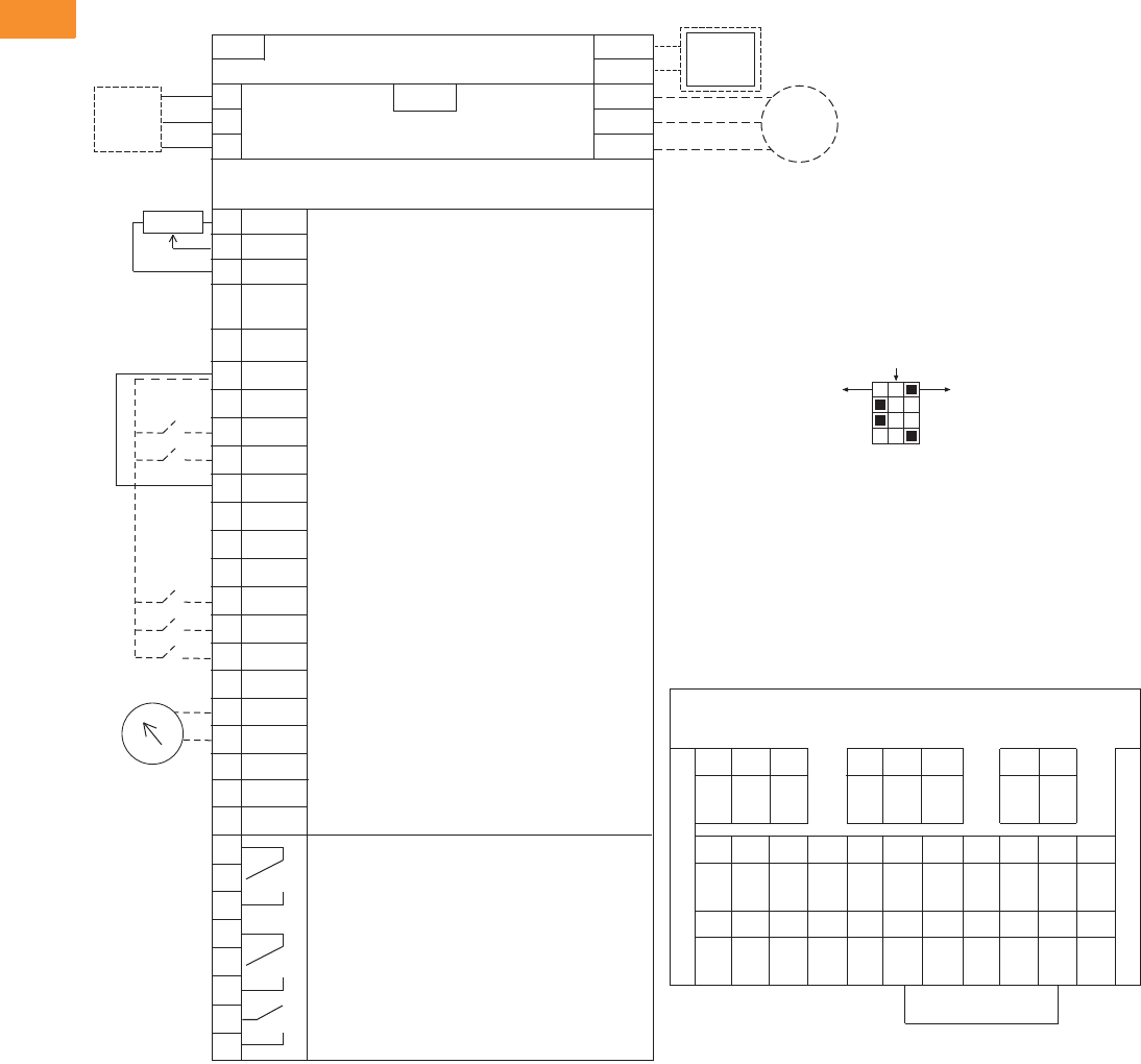
V6-T2-152 Volume 6—Solid-State Motor Control CA08100007E—May 2014 www.eaton.com
2
2
2
2
2
2
2
2
2
2
2
2
2
2
2
2
2
2
2
2
2
2
2
2
2
2
2
2
2
2
2.6
Adjustable Frequency Drives
H-Max Series Drives
Wiring Diagrams
Control Input/Output, PID Application
Standards
●Digital inputs D1–D6, relay
out, analog in/out are freely
programmed
●The user can assign a
single input to multiple
functions
Includes
●Six digital input
●Two analog input
●One analog output
●Three relay output
●RS-485
●Ethernet
Reliability
●Pretested components
●Conformal coated
(varnished) boards
●40°C rated
●110% overload for one
minute
●Eaton Electrical Services &
Systems national network
of AF drive specialists
Slot A
1
2
3
4
5
6
7
8
9
10
11
12
13
14
15
16
17
18
19
A
+10V
AI–1+
V
in
AI–2+
AI–2–
24V
out
GND
DIN1
DIN2
DIN3
24V
out
GND
DIN4
DIN5
DIN6
AO–1+
AO–1–
DATA-
Reference Output
Analog Input Voltage (Range 0–10 Vdc)
(can be programmed to current 4–20 mA)
Analog Output Common (Ground)
Analog Input Common
PI Setpoint or Feedback
Control Voltage Output (0.1A max.)
I/O Ground
START/STOP (Contact closed = start)
External Fault (Closed = fault)
Run Interlock Permissive IP Interlock
(Closed = OK)
DIN1–DIN6 Common
Control Voltage Output (0.1A max.)
I/O Ground
Fire Mode (Contact closed = re mode)
Force Bypass (Contact closed = bypass)
DIN1–DIN6 Common
Output Frequency (0–20 mA)
Analog Output Common (Ground)
RS-485 DATA-
Speed Select 0–100% (Preset speed)
U (T1)
V (T2)
W (T3)
R+
R-
L1
L2
L3
Three-Phase Input
Input
(Single-Phase not available)
Three-Phase
Output
DB
Chopper
Optional
Resistor
Terminal Factory Default Signal
Resistor
Analog Input Current (Range 4–20 mA)
(can be programmed to voltage 0–10 Vdc)
PI Setpoint or Feedback
BDATA+
RO1 Bypass Run
RO2 Drive Run
RO3 Fault
24 Vdc/8A
250 Vac/8A
125 Vdc/0.4A
Relay Board 1
Default Signal
21
22
23
24
25
26
32
33
Slot B
Analog
RS-485 DATA+
Factory
Jumper
COM
CMB
30
24 Vdc
in
Auxiliary Input Voltage
123456 78 91011
12 13 14 15 16 17 18 19 30 A B
RS-485
Data–
RS-485
Data+
24 Vdc
in
AO1–AO1+COM
DI1–6
DI6DI5DI4GND24 Vdc
out
DI2DI1GND24 Vdc
out
AI2–AI2+AI1–AI1++10
Vdc
COM
DI1–6
DI3
21
RO1
22 23 24 25 26 32 33
NC
RO1
COM
RO1
NO
RO2
NC
RO2
COM
RO2
NO
RO3
COM
RO3
NO
Slot D __________________
Slot E __________________
Terminal Block Layout
Factory Jumper
External Interlock
Circuit
Breaker
Optional
Motor
RJ-45 BACnet/IP Ethernet Industrial Protocol
Modbus/TCP Transmission Control Protocol (Ethernet Based)
5% DC Link
Reactor
Programmable BACnet,
Modbus, FLN, N2
ON
CURRENT
CURRENT
CURRENT
RS485
AO1
AI2
AI1
OFF
VOLTAGE
VOLTAGE
VOLTAGE
Tes t
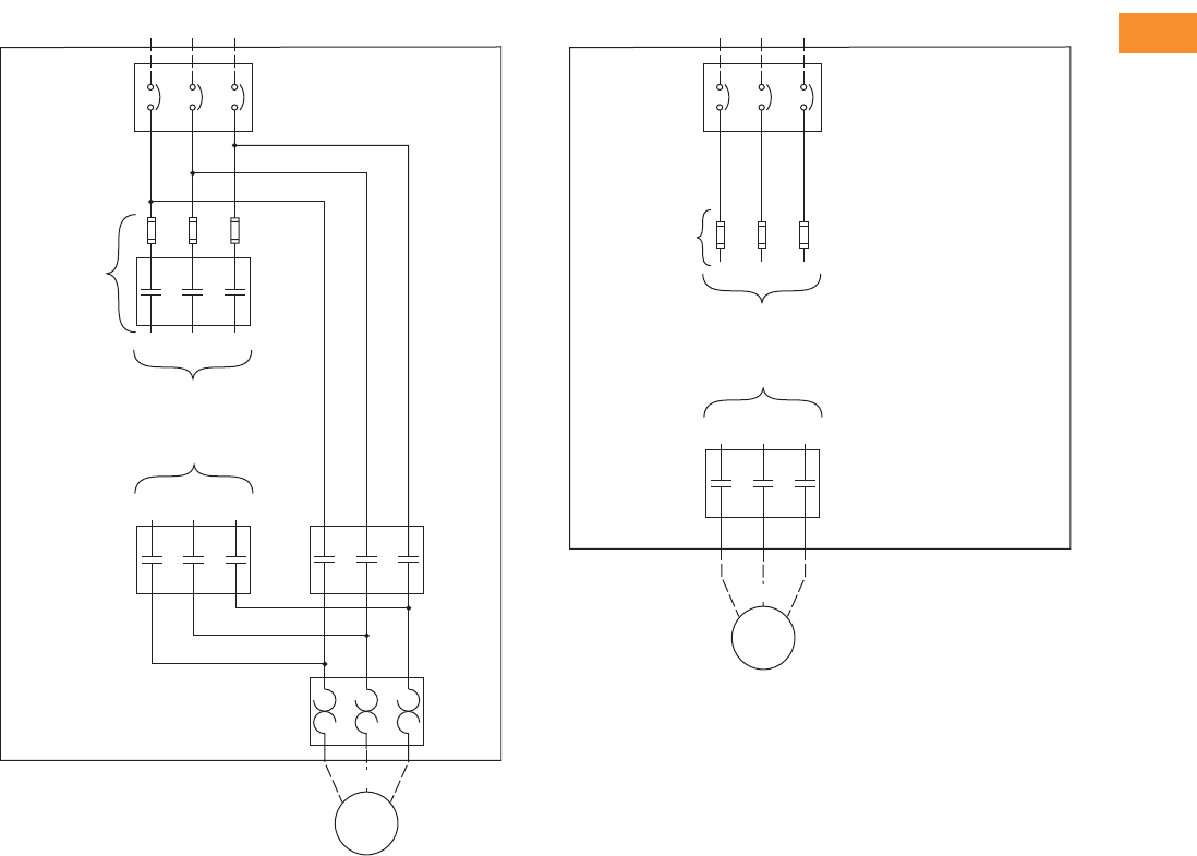
Volume 6—Solid-State Motor Control CA08100007E—May 2014 www.eaton.com V6-T2-153
2
2
2
2
2
2
2
2
2
2
2
2
2
2
2
2
2
2
2
2
2
2
2
2
2
2
2
2
2
2
2.6
Adjustable Frequency Drives
H-Max Series Drives
H-Max Series IntelliPass H-Max Series IntelliDisconnect Power Wiring
Bypass
Incoming Power
L1 L2 L3
Circuit
Breaker
L1
To Drive Input
To Drive Output
U(T1)
L2 L3
Output
Contactor
V(T2)W(T3)
Motor
Bypass
Contactor
Overload
Relay
U(T1)
V(T2)
W(T3)
Optional Fuse
or
Drive Input
Contactor
Incoming Power
L1 L2 L3
Circuit
Breaker
Optional Fuse
To Drive Input
To Drive Output
Motor
U(T1)
V(T2)
W(T3)
U(T1)
Optional
Output
Contactor
V(T2)W(T3)
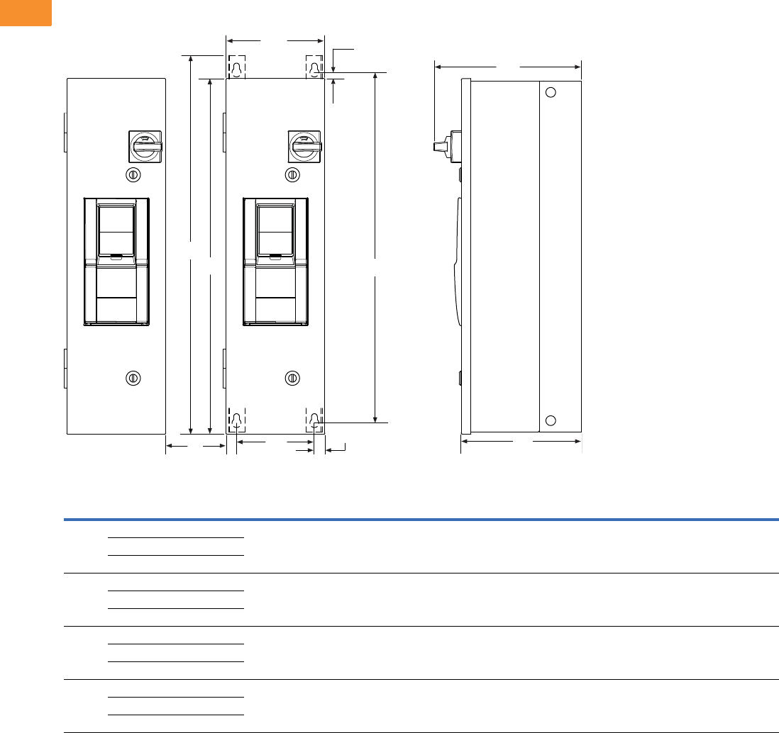
V6-T2-154 Volume 6—Solid-State Motor Control CA08100007E—May 2014 www.eaton.com
2
2
2
2
2
2
2
2
2
2
2
2
2
2
2
2
2
2
2
2
2
2
2
2
2
2
2
2
2
2
2.6
Adjustable Frequency Drives
H-Max Series Drives
Dimensions
Approximate Dimensions in Inches (mm)
H-Max Series IntelliPass and IntelliDisconnect Drives
Consult factory or use manual for final dimensions.
Note: C distance is spacing required to mount multiple drives.
Frame
Size Voltage Horsepower (IL)H1H2H3H4C W1W2W3D1D2
Weight in
Lbs (kg)
FS4 208 1–3 30.00
(762.0)
29.41
(747.1)
0.25
(6.35)
31.00
(787.4)
3.00
(76.2)
7.88
(200.2)
6.25
(158.8)
0.75
(19.1)
12.49
(317.2)
10.36
(263.1)
45 (20.41)
230 1–3
480 1–7.5
FS5 208 5–10 37.00
(939.8)
36.72
(932.7)
0.25
(6.35)
38.31
(973.0)
3.00
(76.2)
9.60
(243.8)
7.97
(202.4)
0.75
(19.1)
15.35
(390.0)
13.22
(335.8)
57.5 (26.10)
230 5–10
480 10–20
FS6 208 15–20 45.45
(1154.4)
44.81
(1138.2)
0.25
(6.35)
46.4
(1178.6)
4.00
(101.6)
11.44
(290.6)
9.75
(247.6)
0.75
(19.1)
15.80
(401.3)
13.67
(347.2)
98.0 (44.45)
230 15–20
480 25–40
FS7 208 25–30 58.51
(1486.2)
57.87
(1470.0)
0.25
(6.35)
59.46
(1510.3)
5.00
(127.0)
14.52
(368.8)
12.83
(325.9)
0.75
(19.1)
15.68
(398.3)
13.72
(348.5)
165.0 (74.84)
230 25–30
480 50–75
C
H1
W2 W3
H2
W1 H3
D1
D2
H4
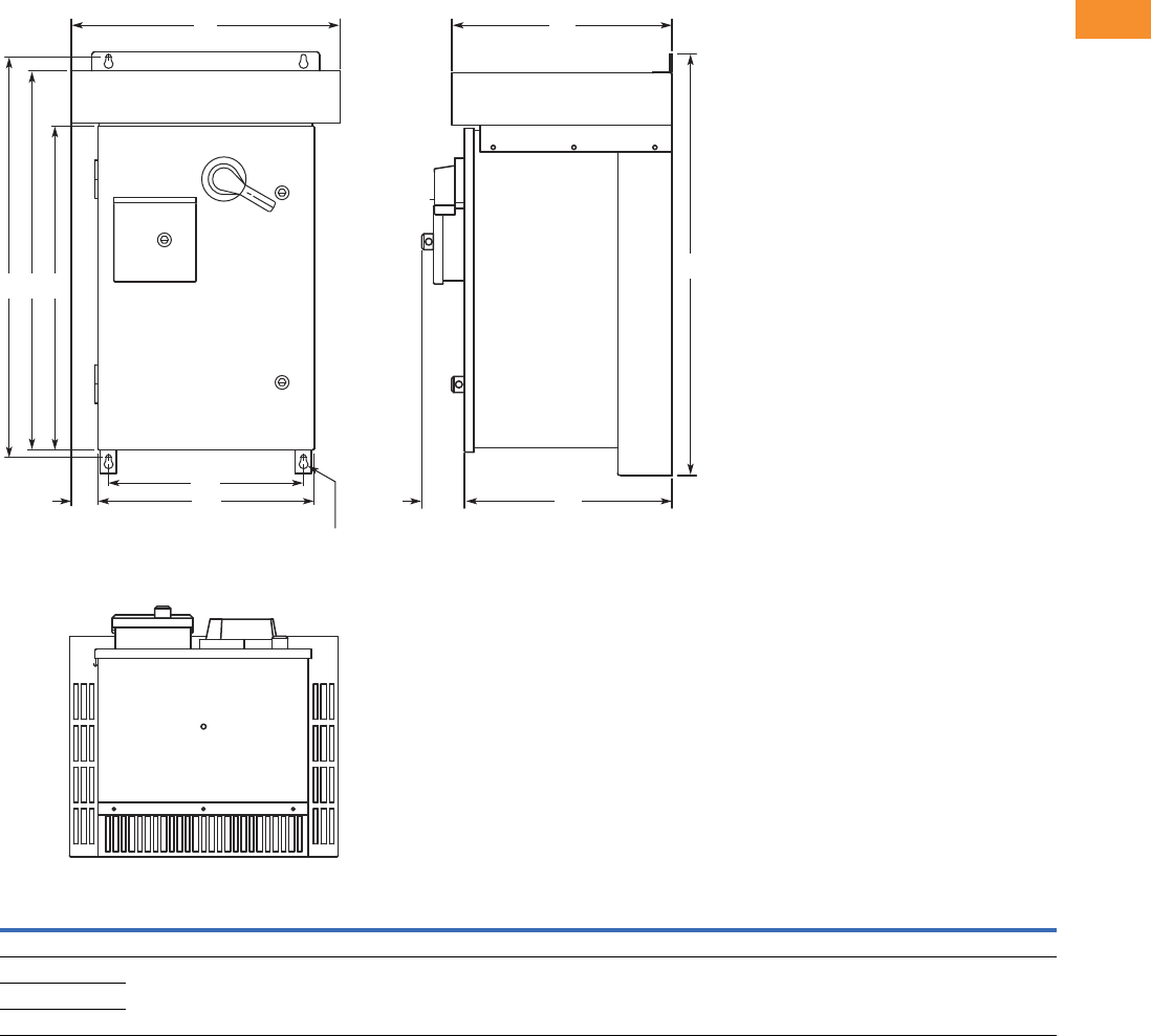
Volume 6—Solid-State Motor Control CA08100007E—May 2014 www.eaton.com V6-T2-155
2
2
2
2
2
2
2
2
2
2
2
2
2
2
2
2
2
2
2
2
2
2
2
2
2
2
2
2
2
2
2.6
Adjustable Frequency Drives
H-Max Series Drives
Approximate Dimensions in Inches (mm)
Enclosure Box A NEMA Type 3R
Voltage
AC
hp
(IL) H H1 H2 H3 W W1 W2 W3 D D1 D2
Approx.
Weight
Lbs (kg)
Approx.
Shipping Weight
Lbs (kg)
Three-Phase
208V 1–10 33.00
(838.2)
31.36
(796.5)
29.67
(753.6)
25.35
(643.9)
21.05
(534.7)
16.92
(429.8)
15.30
(388.6)
2.07
(52.6)
17.24
(437.9)
16.26
(413.0)
3.31
(84.1)
170 (77) 215 (98)
230V 1–10
480V 1–20
H3H2H1
H
W2
W1 D2
W
3 D1
DW
0.44 (11.2)
Mounting
Holes
(4 Places)
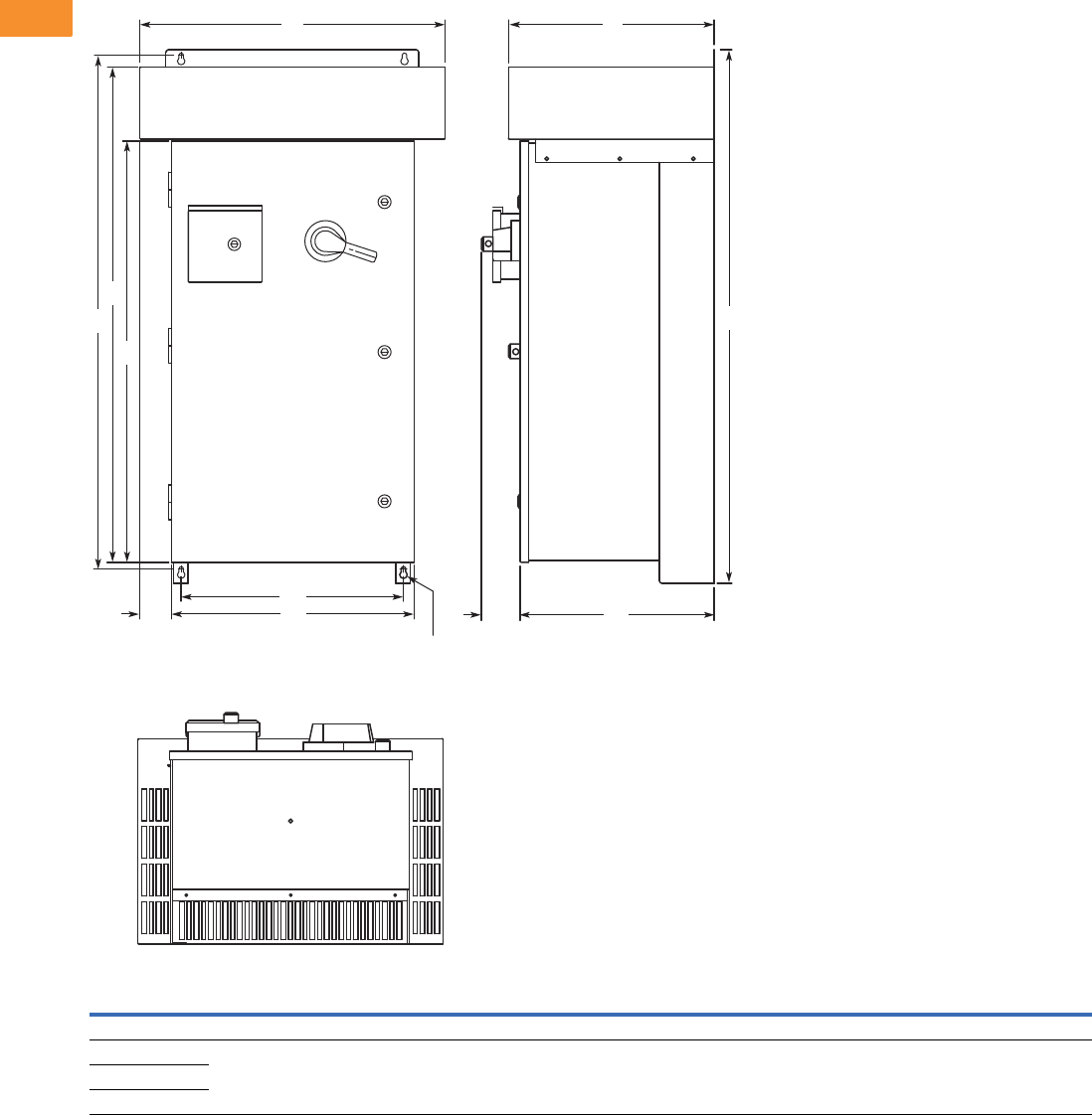
V6-T2-156 Volume 6—Solid-State Motor Control CA08100007E—May 2014 www.eaton.com
2
2
2
2
2
2
2
2
2
2
2
2
2
2
2
2
2
2
2
2
2
2
2
2
2
2
2
2
2
2
2.6
Adjustable Frequency Drives
H-Max Series Drives
Approximate Dimensions in Inches (mm)
Enclosure Box B NEMA Type 3R
Voltage
AC
hp
(IL) H H1 H2 H3 W W1 W2 W3 D D1 D2
Approx.
Weight
Lbs (kg)
Approx.
Shipping Weight
Lbs (kg)
Three-Phase
208V 15 46.09
(1170.7)
44.45
(1129.0)
42.77
(1086.4)
36.35
(923.3)
26.31
(668.3)
20.92
(531.4)
19.30
(490.2)
2.69
(68.3)
17.74
(450.6)
16.76
(425.7)
3.31
(84.1)
235 (107) 290 (132)
230V 15
480V 25–40
H3
H2
H1 H
W2
W1 D2
W
3D1
DW
0.44 (11.2)
Mounting
Holes
(4 Places)
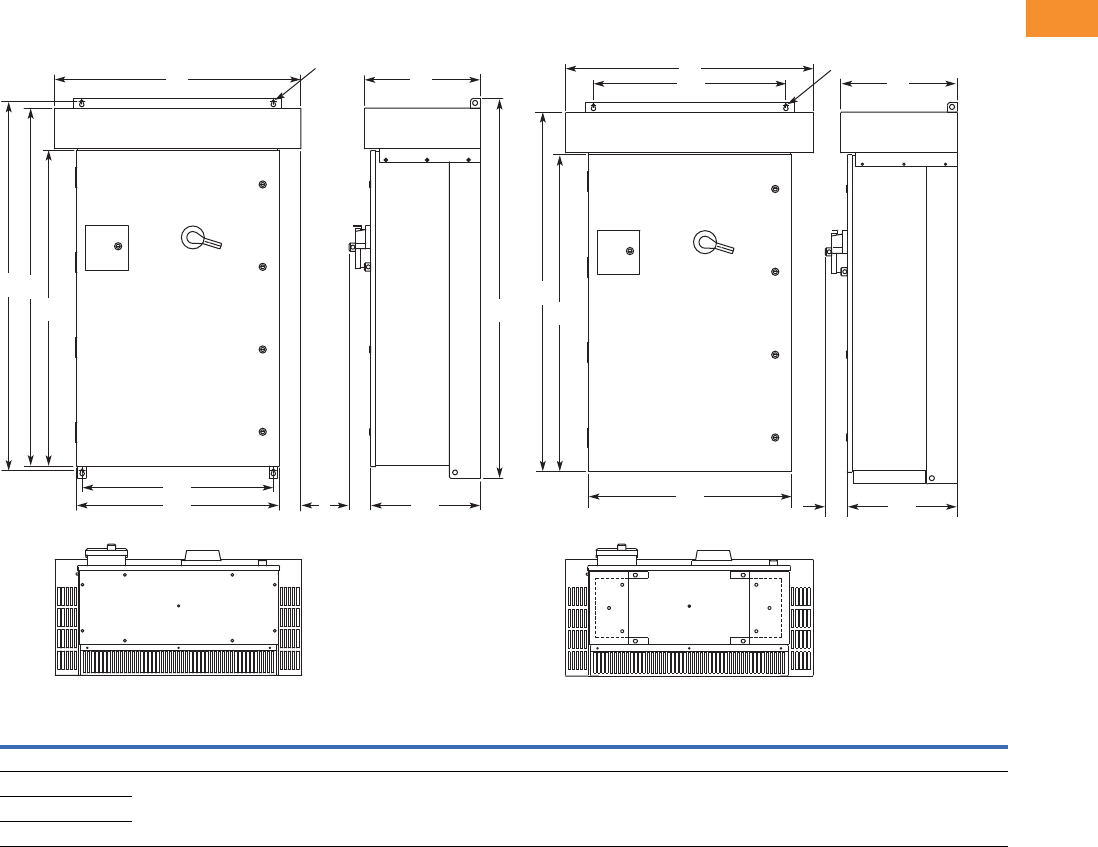
Volume 6—Solid-State Motor Control CA08100007E—May 2014 www.eaton.com V6-T2-157
2
2
2
2
2
2
2
2
2
2
2
2
2
2
2
2
2
2
2
2
2
2
2
2
2
2
2
2
2
2
2.6
Adjustable Frequency Drives
H-Max Series Drives
Approximate Dimensions in Inches (mm)
Enclosure Box C NEMA Type 3R
Note
1Consult factory.
Voltage
AC
hp
(IL) H H1 H2 H3 W W1 W2 W3 D D1 D2
Approx.
Weight
Lbs (kg)
Three-Phase
208 20–30 58.09
(1475.5)
56.45
(1433.8)
54.77
(1391.2)
48.35
(1228.1)
37.73
(958.3)
30.92
(785.4)
29.30
(744.2)
3.34
(84.8)
17.74
(450.6)
16.77
(426.0)
3.31
(84.1)
1
230 20–30
480 50–75
0.44 (11.2)
Mounting Holes
(4 Places)
H3 H
H2
H1
W2
W1 W3 D2 D1
WD
H3
H2
D2
D1
W1
W2
W
D
0.44 (11.2)
Mounting Holes
(4 Places)

V6-T2-158 Volume 6—Solid-State Motor Control CA08100007E—May 2014 www.eaton.com
2
2
2
2
2
2
2
2
2
2
2
2
2
2
2
2
2
2
2
2
2
2
2
2
2
2
2
2
2
2
2.7
Adjustable Frequency Drives
SPX9000 Drives
SPX9000 Drives
Contents
Description Page
SPX9000 Drives
Features and Benefits . . . . . . . . . . . . . . . . . . . V6-T2-159
Standards and Certifications . . . . . . . . . . . . . . V6-T2-159
Catalog Number Selection . . . . . . . . . . . . . . . . V6-T2-160
Product Selection . . . . . . . . . . . . . . . . . . . . . . . V6-T2-161
Accessories . . . . . . . . . . . . . . . . . . . . . . . . . . . V6-T2-166
Options . . . . . . . . . . . . . . . . . . . . . . . . . . . . . . V6-T2-167
Replacement Parts . . . . . . . . . . . . . . . . . . . . . . V6-T2-174
Technical Data and Specifications . . . . . . . . . . V6-T2-183
Dimensions . . . . . . . . . . . . . . . . . . . . . . . . . . . V6-T2-184
Product Description
The SPX9000 Series
Adjustable Frequency Drives
from Eaton’s Electrical Sector
are specifically designed
for high performance
applications. Equipped with
high processing power, the
SPX9000 can use information
from an encoder or a resolver
in order to provide very
precise motor control.
Sensorless vector and simple
frequency control are also
supported. Typical
applications requiring high
performance are: master-
slave drives, positioning
applications, winder tension
control and synchronization.
The core of the SPX9000
is a fast microprocessor,
providing high dynamic
performance for applications
where good motor handling
and reliability are required.
It can be used both in open
loop applications as well
as in applications requiring
encoder feedback.
The SPX9000 supports fast
drive-to-drive communication.
It also offers an integrated
data logger functionality for
analysis of dynamic events
without the need of additional
hardware. Simultaneous fast
monitoring of several drives
can be done by using the
9000Xdrive tool and CAN
communication. In
applications where reliability
and quality are essential for
high-performance, the
SPX9000 is the logical choice.
The Eaton family of drives
includes DA1, DC1, H-Max,
M-Max, SVX9000 and
SPX9000. 9000X Series drive
ratings are rated for either
high overload (IH) or low
overload (IL). IL indicates
110% overload capacity for
1 minute out of 10 minutes.
IH indicates 150% overload
capacity for 1 minute out of
10 minutes.

Volume 6—Solid-State Motor Control CA08100007E—May 2014 www.eaton.com V6-T2-159
2
2
2
2
2
2
2
2
2
2
2
2
2
2
2
2
2
2
2
2
2
2
2
2
2
2
2
2
2
2
2.7
Adjustable Frequency Drives
SPX9000 Drives
Features and Benefits
●Speed error <0.01%,
depending on the encoder
●Incremental or absolute
encoder support
●Encoder voltages of 5V
(RS-422), 15V or 24V,
depending on the option
card
●Full torque control at all
speeds, including zero
●Torque accuracy <2%;
<5% down to zero speed
●Starting torque >200%,
depending on motor and
drive sizing
●Integrated datalogger for
system analysis
●Fast multiple drive
monitoring with PC
●Full capability for master/
slave configurations
●High-speed bus (12 Mbit/s)
for fast inter-drive
communication
●High-speed applications
(up to 7200 Hz) possible
●Robust design—proven
500,000 hours MTBF
●Integrated 3% line reactors
standard on drives from
FR4 through FR9
●Line reactor is included but
is separated from chassis
●EMI/RFI Filters H standard
up to 200 hp IH 480V,
100 hp IH 230V
●Simplified operating menu
allows for typical
programming changes,
while programming mode
provides control of
everything
●Quick Start Wizard built
into the programming of
the drive ensures a smooth
start-up
●Keypad can display up to
three monitored
parameters simultaneously
●LOCAL/REMOTE operation
from keypad
●Copy/paste function allows
transfer of parameter
settings from one drive to
the next
●Standard NEMA Type 12/
IP54 keypad on all drives
●Hand-held auxiliary 240
power supply allows
programming/monitoring
of control module without
applying full power to the
drive
●The SPX can be flexibly
adapted to a variety of
needs using our pre-
installed “Seven in One”
precision application
programs consisting of:
●Basic
●Standard
●Local/remote
●Multi-step speed control
●PID control
●Multi-purpose control
●Pump and fan control
with auto change
●Additional I/O and
communication cards
provide plug and play
functionality
●I/O connections with
simple quick connection
terminals
●Control logic can be
powered from an external
auxiliary control panel,
internal drive functions and
fieldbus if necessary
●Brake chopper standard
from: 1–30 hp/380–500V
3/4–15 hp/208–230V
●NEMA Type 1/IP21
enclosures available Frame
Sizes FR4–FR11, NEMA
Type 12/IP54 enclosures
available Frame Sizes FR4–
FR10 (FR10 and FR11
freestanding drives)
●Open chassis FR10 and
greater
●Standard option board
configuration includes an
A9 I/O board and an A2
relay output board installed
in slots A and B
Standards and Certifications
Product
●IEC 61800-2
Safety
●UL 508C
EMC (at default settings)
●Immunity: Fulfills all EMC
immunity requirements;
Emissions: EN 61800-3,
LEVEL H
●UL Listed
●CE
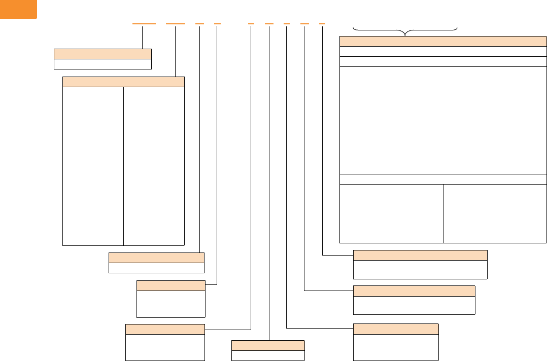
V6-T2-160 Volume 6—Solid-State Motor Control CA08100007E—May 2014 www.eaton.com
2
2
2
2
2
2
2
2
2
2
2
2
2
2
2
2
2
2
2
2
2
2
2
2
2
2
2
2
2
2
2.7
Adjustable Frequency Drives
SPX9000 Drives
Catalog Number Selection
SPX9000 Adjustable Frequency Drives
Notes
1All 230V drives and 480V drives up to 200 hp (
I
H
) are only available with input option 1 (EMC level H). 480V drives 250 hp (
I
H
) or larger are
available with input option 2 (EMC level N). 575V drives 200 hp (
I
H
) or larger are available with input option 2. 575V drives up to 150 hp (
I
H
)
are available with input option 4 (EMC level L). 480V and 690V freestanding drives are available with input option 4 (EMC level L).
2480V drives up to 30 hp (
I
H
) are only available with brake chopper option B. 480V drives 40 hp (
I
H
) or larger come standard with brake
chopper option N. 230V drives up to 15 hp (
I
H
) are only available with brake chopper option B. 230V drives 20 hp and larger come standard
with brake chopper option N. All 575V drives come standard without brake chopper option (N). N = No brake chopper.
3480V drives 250–350 hp (
I
H
) and 690V drives 200–300 hp (
I
H
) are available with enclosure style 0 (chassis). 480V and 690V FR10
freestanding drives are available with 1 (NEMA Type 1/IP21) or 2 (NEMA Type 12/IP54). FR11 freestanding drives are only available with
enclosure style 1 (NEMA Type 1/IP21).
4Factory promise delivery. Consult sales office for availability.
Keypad
A = Alphanumeric
Board Modifications
1 = Standard boards
2 = Conformal (varnished) coating 4
Brake Chopper Options 2
N = No brake chopper circuit
B = Internal brake chopper circuit
Input Options 1
1 = Three-phase, EMC H
2 = Three-phase, EMC N
4 = Three-phase, EMC L
Options
Options appear in alphabetical order.
Extended I/O Card Options
A3 = 2 RO, Therm
A4 = Encoder low volt +5V/15V24V
A5 = Encoder high volt +15V/24V
A7 = Double Encoder
A8 = 6 DI, 1 DO, 2 AI, 1AO
AE = 3 DI (Encoder 10–24V), Out +15V/+24V 2 DO (pulse + direction)
B1 = 6 DI, 1 ext +24 Vdc/EXT +24 Vdc
B2 = 1 RO (NC-NO), 1 RO (NO), 1 therm
B4 = 1 AI (mA isolated), 2 AO (mA isolated), 1 ext +24 Vdc/EXT + 24 Vdc
B5 = 3 RO (NO)
B8 = 1 ext +24 Vdc/EXT +24 Vdc, 3 Pt100
B9 = 1 RO (NO), 5 DI 42–240 Vac input
BB = SPI, absolute encoder
Communication Cards
CA = Johnson Controls N2
CI = Modbus TCP
CJ = BACnet
CQ = EtherNet/IP
C2 = Modbus
C3 = PROFIBUS DP
C4 = LonWorks
C5 = PROFIBUS DP (D9 connector)
C6 = CANopen (slave)
C7 = DeviceNet
C8 = Modbus (D9 type connector)
D1 = Adapter—SPX only
D2 = Adapter—SPX only
D3 = RS-232 with D9 connection
Product Family
SPX = Open drives
Horsepower Rating
F07 =3/4
001 =1
F15 =1-1/2
002 =2
003 =3
004 =5 (I
L)
005 =5
006 = 7-1/2 (IL)
007 =7-1/2
010 =10
015 =15
020 =20
025 =25
030 =30
040 =40
050 =50
060 =60
075 =75
100 =100
125 =125
150 =150
250 =250
300 =300
350 =350
400 =400
500 =500
550 =550
600 =600
650 =650
700 =700
800 =800
900 =900
H10 = 1000
H12 = 1200
H13 = 1350
H15 = 1500
H16 = 1600
H20 = 2000
AFD Software Series
A = Standard software
Enclosure 3
0 = Chassis
1 = NEMA Type 1/IP21
2 = NEMA Type 12/IP54
Voltage Rating
2 = 230V (208–240)
4 = 480V (380–500)
5 = 575V (525–690)
SPX 010 A 1 –4A 1 B 1 ______
Volume 6—Solid-State Motor Control CA08100007E—May 2014 www.eaton.com V6-T2-161
2
2
2
2
2
2
2
2
2
2
2
2
2
2
2
2
2
2
2
2
2
2
2
2
2
2
2
2
2
2
2.7
Adjustable Frequency Drives
SPX9000 Drives
Product Selection
230V Drives
208–240V, NEMA Type 1/IP21 Drives
208–240V, NEMA Type 12/IP54 Drives
Frame
Size hp (IH) Current (IH) hp (IL) Current (IL) Catalog Number
FR4 3/4 3.7 1 4.8 SPXF07A1-2A1B1
1 4.8 1-1/2 6.6 SPX001A1-2A1B1
1-1/2 6.6 2 7.8 SPXF15A1-2A1B1
27.8 311 SPX002A1-2A1B1
311 —12.5 SPX003A1-2A1B1
FR5 — 12.5 5 17.5 SPX004A1-2A1B1
517.5 7-1/225 SPX005A1-2A1B1
7-1/2 25 10 31 SPX007A1-2A1B1
FR61031 1548 SPX010A1-2A1B1
15 48 20 61 SPX015A1-2A1B1
FR72061 2575 SPX020A1-2A1N1
25 75 30 88 SPX025A1-2A1N1
30 88 40 114 SPX030A1-2A1N1
FR8 40 114 50 140 SPX040A1-2A1N1
50 140 60 170 SPX050A1-2A1N1
60 170 75 205 SPX060A1-2A1N1
FR9 75 205 100 261 SPX075A1-2A1N1
100 261 — — SPX100A1-2A1N1
Frame
Size hp (IH) Current (IH) hp (IL) Current (IL) Catalog Number
FR4 3/4 3.7 1 4.8 SPXF07A2-2A1B1
1 4.8 1-1/2 6.6 SPX001A2-2A1B1
1-1/2 6.6 2 7.8 SPXF15A2-2A1B1
27.8 311 SPX002A2-2A1B1
311 —12.5 SPX003A2-2A1B1
FR5 — 12.5 5 17.5 SPX004A2-2A1B1
517.5 7-1/225 SPX005A2-2A1B1
7-1/2 25 10 31 SPX007A2-2A1B1
FR61031 1548 SPX010A2-2A1B1
15 48 20 61 SPX015A2-2A1B1
FR72061 2575 SPX020A2-2A1N1
25 75 30 88 SPX025A2-2A1N1
30 88 40 114 SPX030A2-2A1N1
FR8 40 114 50 140 SPX040A2-2A1N1
50 140 60 170 SPX050A2-2A1N1
60 170 75 205 SPX060A2-2A1N1
FR9 75 205 100 261 SPX075A2-2A1N1
100 261 — — SPX100A2-2A1N1
SPX9000 Open Drives
V6-T2-162 Volume 6—Solid-State Motor Control CA08100007E—May 2014 www.eaton.com
2
2
2
2
2
2
2
2
2
2
2
2
2
2
2
2
2
2
2
2
2
2
2
2
2
2
2
2
2
2
2.7
Adjustable Frequency Drives
SPX9000 Drives
480V Drives
380–500V, NEMA Type 1/IP21 Drives
380–500V, NEMA Type 1/IP21 Freestanding Drives
Note
Integrated fuses as standard. Limited option selection available; 115V transformer (KB), light kit (L1), HOA (K4),
speed potentiometer w/HOA (K2), Disconnect switch (P2). See Freestanding Option selection on Page V6-T2-173.
Frame
Size hp (IH) Current (IH) hp (IL) Current (IL) Catalog Number
FR4 1 2.2 1-1/2 3.3 SPX001A1-4A1B1
1-1/2 3.3 2 4.3 SPXF15A1-4A1B1
24.3 35.6 SPX002A1-4A1B1
35.6 57.6 SPX003A1-4A1B1
5 7.6 — 9 SPX005A1-4A1B1
— 9 7-1/2 12 SPX006A1-4A1B1
FR5 7-1/2 12 10 16 SPX007A1-4A1B1
10 16 15 23 SPX010A1-4A1B1
15 23 20 31 SPX015A1-4A1B1
FR62031 2538 SPX020A1-4A1B1
25 38 30 46 SPX025A1-4A1B1
30 46 40 61 SPX030A1-4A1B1
FR74061 5072 SPX040A1-4A1N1
50 72 60 87 SPX050A1-4A1N1
60 87 75 105 SPX060A1-4A1N1
FR8 75 105 100 140 SPX075A1-4A1N1
100 140 125 170 SPX100A1-4A1N1
125 170 150 205 SPX125A1-4A1N1
FR9 150 205 200 261 SPX150A1-4A1N1
200 245 250 300 SPX200A1-4A1N1
Frame
Size hp (IH) Current (IH) hp (IL) Current (IL) Catalog Number
FR10 250 330 300 385 SPX250A1-4A4N1
300 385 350 460 SPX300A1-4A4N1
350 460 400 520 SPX350A1-4A4N1
FR11 400 520 500 590 SPX400A1-4A4N1
500 590 550 650 SPX500A1-4A4N1
550 650 600 730 SPX550A1-4A4N1
SPX9000 Open Drives
Volume 6—Solid-State Motor Control CA08100007E—May 2014 www.eaton.com V6-T2-163
2
2
2
2
2
2
2
2
2
2
2
2
2
2
2
2
2
2
2
2
2
2
2
2
2
2
2
2
2
2
2.7
Adjustable Frequency Drives
SPX9000 Drives
380–500V, NEMA Type 12/IP54 Drives
380–500V, NEMA Type 12/IP54 Freestanding Drives
380–500V, Open Chassis Drives
Notes
Integrated fuses as standard. Limited option selection available; 115V transformer (KB), light kit (L1), HOA (K4),
speed potentiometer w/HOA (K2), disconnect switch (P2). See Freestanding Option selection on Page V6-T2-173.
1 FR10–FR14 includes 3% line reactor, but it is not integral to chassis.
Frame
Size hp (IH) Current (IH) hp (IL) Current (IL) Catalog Number
FR4 1 2.2 1-1/2 3.3 SPX001A2-4A1B1
1-1/2 3.3 2 4.3 SPXF15A2-4A1B1
24.3 35.6 SPX002A2-4A1B1
35.6 57.6 SPX003A2-4A1B1
5 7.6 — 9 SPX005A2-4A1B1
— 9 7-1/2 12 SPX006A2-4A1B1
FR5 7-1/2 12 10 16 SPX007A2-4A1B1
10 16 15 23 SPX010A2-4A1B1
15 23 20 31 SPX015A2-4A1B1
FR62031 2538 SPX020A2-4A1B1
25 38 30 46 SPX025A2-4A1B1
30 46 40 61 SPX030A2-4A1B1
FR74061 5072 SPX040A2-4A1N1
50 72 60 87 SPX050A2-4A1N1
60 87 75 105 SPX060A2-4A1N1
FR8 75 105 100 140 SPX075A2-4A2N1
100 140 125 170 SPX100A2-4A1N1
125 170 150 205 SPX125A2-4A1N1
FR9 150 205 200 261 SPX150A2-4A1N1
200 245 250 300 SPX200A2-4A1N1
Frame
Size hp (IH) Current (IH) hp (IL) Current (IL) Catalog Number
FR10 250 330 300 385 SPX250A2-4A4N1
300 385 350 460 SPX300A2-4A4N1
350 460 400 520 SPX350A2-4A4N1
Frame
Size hp (IH) Current (IH) hp (IL) Current (IL) Catalog Number
FR10 250 330 300 385 SPX250A0-4A2N1
300 385 — 460 SPX300A0-4A2N1
350 460 400 520 SPX350A0-4A2N1
FR11 400 520 500 590 SPX400A0-4A2N1
500 590 — 650 SPX500A0-4A2N1
— 650 600 730 SPX550A0-4A2N1
FR12 600 730 — 820 SPX600A0-4A2N1
— 820 700 920 SPX650A0-4A2N1
700 920 800 1030 SPX700A0-4A2N1
FR13 800 1030 900 1150 SPX800A0-4A2N1
900 1150 1000 1300 SPX900A0-4A2N1
1000 1300 1200 1450 SPXH10A0-4A2N1
FR14 1200 1600 1500 1770 SPXH12A0-4A2N1
1600 1940 1800 2150 SPXH16A0-4A2N1
SPX9000 Open Drives
V6-T2-164 Volume 6—Solid-State Motor Control CA08100007E—May 2014 www.eaton.com
2
2
2
2
2
2
2
2
2
2
2
2
2
2
2
2
2
2
2
2
2
2
2
2
2
2
2
2
2
2
2.7
Adjustable Frequency Drives
SPX9000 Drives
575V Drives
525–690V, NEMA Type 1/IP21 Drives
525–690V, NEMA Type 1/IP21 Freestanding Drives
Note
Integrated fuses as standard. Limited option selection available; 115V transformer (KB), light kit (L1), HOA (K4),
speed potentiometer w/HOA (K2), disconnect switch (P2). See Freestanding Option selection on Page V6-T2-173.
Frame
Size hp (IH) Current (IH) hp (IL) Current (IL) Catalog Number
FR6 2 3.3 3 4.5 SPX002A1-5A4N1
34.5 —5.5 SPX003A1-5A4N1
—5.5 5 7.5 SPX004A1-5A4N1
5 7.5 7-1/2 10 SPX005A1-5A4N1
7-1/2 10 10 13.5 SPX007A1-5A4N1
10 13.5 15 18 SPX010A1-5A4N1
15 18 20 22 SPX015A1-5A4N1
20 22 25 27 SPX020A1-5A4N1
25 27 30 34 SPX025A1-5A4N1
FR73034 4041 SPX030A1-5A4N1
40 41 50 52 SPX040A1-5A4N1
FR85052 6062 SPX050A1-5A4N1
60 62 75 80 SPX060A1-5A4N1
75 80 100 100 SPX075A1-5A4N1
FR9 100 100 125 125 SPX100A1-5A4N1
125 125 150 144 SPX125A1-5A4N1
150 144 — 170 SPX150A1-5A4N1
— 170 200 208 SPX175A1-5A4N1
Frame
Size hp (IH) Current (IH) hp (IL) Current (IL) Catalog Number
FR10 200 208 250 261 SPX200A1-5A4N1
250 261 300 325 SPX250A1-5A4N1
300 325 400 385 SPX300A1-5A4N1
FR11 400 385 450 460 SPX400A1-5A4N1
450 460 500 502 SPX450A1-5A4N1
500 502 550 590 SPX500A1-5A4N1
SPX9000 Open Drives
Volume 6—Solid-State Motor Control CA08100007E—May 2014 www.eaton.com V6-T2-165
2
2
2
2
2
2
2
2
2
2
2
2
2
2
2
2
2
2
2
2
2
2
2
2
2
2
2
2
2
2
2.7
Adjustable Frequency Drives
SPX9000 Drives
525–690V, NEMA Type 12/IP54 Drives
525–690V, NEMA Type 12/IP54 Freestanding Drives
525–690V, Open Chassis Drives
Notes
Integrated fuses as standard. Limited option selection available; 115V transformer (KB), light kit (L1), HOA (K4),
speed potentiometer w/HOA (K2), disconnect switch (P2). See Freestanding Option selection on Page V6-T2-173.
1 FR10–FR14 includes 3% line reactor, but it is not integral to chassis.
Frame
Size hp (IH) Current (IH) hp (IL) Current (IL) Catalog Number
FR6 2 3.3 3 4.5 SPX002A2-5A4N1
34.5 —5.5 SPX003A2-5A4N1
—5.5 5 7.5 SPX004A2-5A4N1
5 7.5 7-1/2 10 SPX005A2-5A4N1
7-1/2 10 10 13.5 SPX007A2-5A4N1
10 13.5 15 18 SPX010A2-5A4N1
15 18 20 22 SPX015A2-5A4N1
20 22 25 27 SPX020A2-5A4N1
25 27 30 34 SPX025A2-5A4N1
FR73034 4041 SPX030A2-5A4N1
40 41 50 52 SPX040A2-5A4N1
FR85052 6062 SPX050A2-5A4N1
60 62 75 80 SPX060A2-5A4N1
75 80 100 100 SPX075A2-5A4N1
FR9 100 100 125 125 SPX100A2-5A4N1
125 125 150 144 SPX125A2-5A4N1
150 144 — 170 SPX150A2-5A4N1
— 170 200 208 SPX175A2-5A4N1
Frame
Size hp (IH) Current (IH) hp (IL) Current (IL) Catalog Number
FR10 200 208 250 261 SPX200A2-5A4N1
250 261 300 325 SPX250A2-5A4N1
300 325 400 385 SPX300A2-5A4N1
Frame
Size hp (IH) Current (IH) hp (IL) Current (IL) Catalog Number
FR10 200 208 250 261 SPX200A0-5A2N1
250 261 300 325 SPX250A0-5A2N1
300 325 400 385 SPX300A0-5A2N1
FR11 400 385 450 460 SPX400A0-5A2N1
450 460 500 502 SPX450A0-5A2N1
500 502 — 590 SPX500A0-5A2N1
FR12 — 590 600 650 SPX550A0-5A2N1
600 650 700 750 SPX600A0-5A2N1
700 750 800 820 SPX700A0-5A2N1
FR13 800 820 900 920 SPX800A0-5A2N1
900 920 1000 1030 SPX900A0-5A2N1
1000 1030 1250 1180 SPXH10A0-5A2N1
FR14 1350 1300 1500 1500 SPXH13A0-5A2N1
1500 1500 2000 1900 SPXH15A0-5A2N1
2000 1900 2300 2250 SPXH20A0-5A2N1
SPX9000 Open Drives

V6-T2-166 Volume 6—Solid-State Motor Control CA08100007E—May 2014 www.eaton.com
2
2
2
2
2
2
2
2
2
2
2
2
2
2
2
2
2
2
2
2
2
2
2
2
2
2
2
2
2
2
2.7
Adjustable Frequency Drives
SPX9000 Drives
Accessories
Demo Drive and Power Supply
Demo Drive and Power Supply
NEMA Type 12/IP54 Conversion Kit
The NEMA Type 12/IP54 kit
option is used to convert a
NEMA Type 1/IP21 to a
NEMA Type 12/IP54 drive.
The NEMA Type 12/IP54
kit consists of a metal
drive shroud, fan kit for
some frames, adaptor plate
and plugs.
NEMA Type 12/IP54 Conversion Kit
Flange Kits
Flange Kit NEMA Type
12/IP54
The flange kit is utilized when
the power section is mounted
through the back panel of an
enclosure. Includes flange
mount brackets and NEMA
Type 12/IP54 fan
components. Metal shroud
not included.
Flange kits for NEMA Type
12/IP54 enclosure drive rating
are determined by rating of
drive.
Flange Kit NEMA Type 12/
IP54— Frames 4, 5 and 6 1
Flange Kit NEMA Type 12/
IP54—Frames 4–9
Note
1For installation of an SPX9000 NEMA Type 1/IP21 drive into a NEMA Type 12/IP54 oversized enclosure.
Description Catalog Number
9000X demo drive 9000XDEMO
Approximate Dimensions in Inches (mm) Approximate
Weight Lb (kg)Frame Size Delivery Code Length Width Height Catalog Number
FR4 W 13 (330) 7 (178) 4 (102) 4 (1.8) OPTN12FR4
FR5 16 (406) 8 (203) 7 (178) 5 (2.3) OPTN12FR5
FR6 21 (533) 10 (254) 5 (127) 7 (3.2) OPTN12FR6
Frame
Size
Delivery
Code
Catalog
Number
FR4 W OPTTHRFR4
FR5 OPTTHRFR5
FR6 OPTTHRFR6
Frame
Size
Delivery
Code
Catalog
Number
FR4 FP OPTTHR4
FR5 OPTTHR5
FR6 OPTTHR6
FR7 OPTTHR7
FR8 OPTTHR8
FR9 OPTTHR9
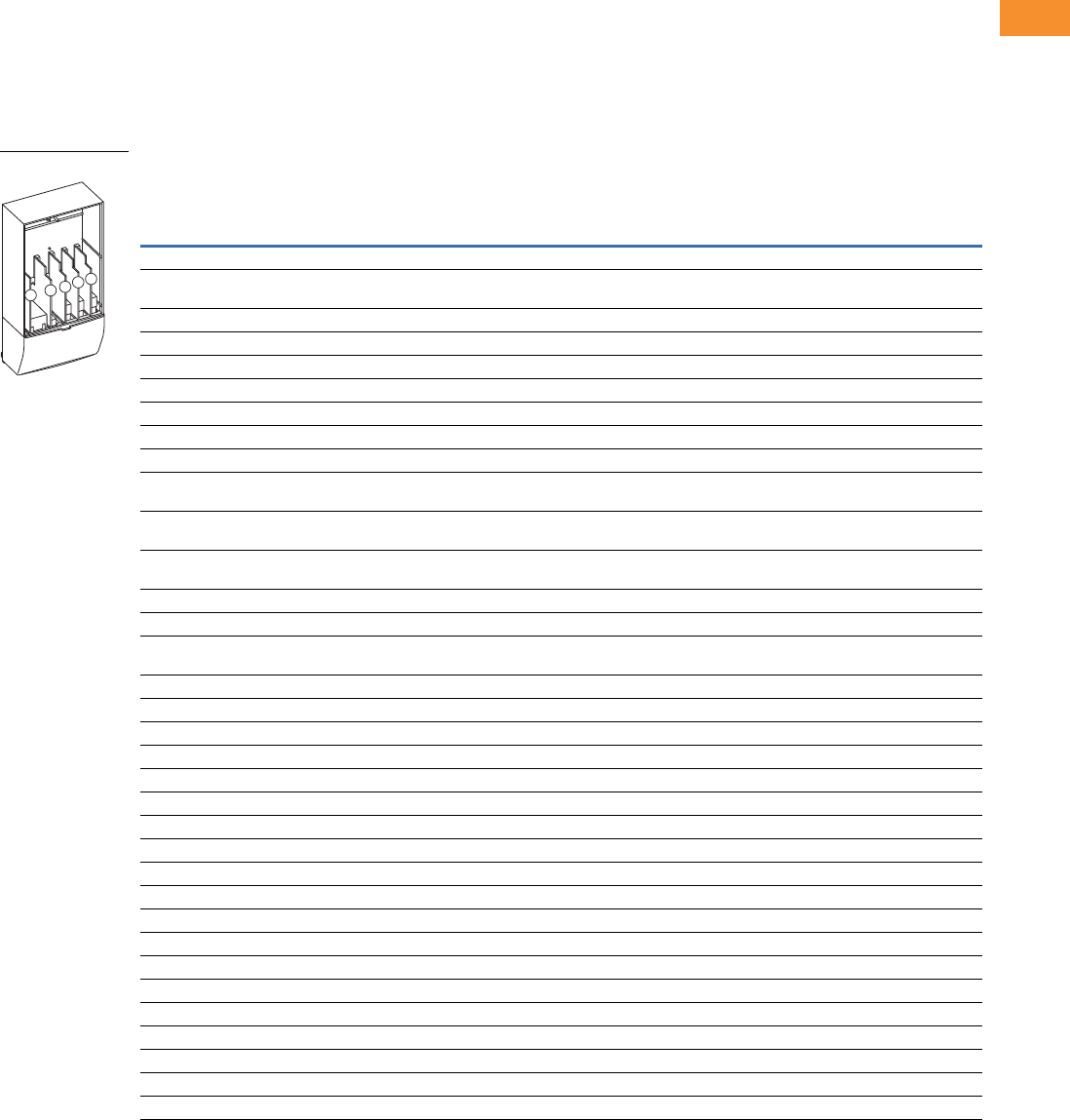
Volume 6—Solid-State Motor Control CA08100007E—May 2014 www.eaton.com V6-T2-167
2
2
2
2
2
2
2
2
2
2
2
2
2
2
2
2
2
2
2
2
2
2
2
2
2
2
2
2
2
2
2.7
Adjustable Frequency Drives
SPX9000 Drives
Options
9000X Series Option Board Kits
The 9000X Series drives can accommodate a wide selection of expander and adapter option boards
to customize the drive for your application needs. The drive’s control unit is designed to accept a
total of five option boards.
The 9000X Series factory installed standard board configuration includes an A9 I/O board and an A2
relay output board, which are installed in slots A and B.
Option Board Kits
Notes
1 AI = Analog Input; AO = Analog Output, DI = Digital Input, DO = Digital Output, RO = Relay Output
2 Option card must be installed in one of the slots listed for that card. Slot indicated in bold is the preferred location.
3 OPTC2 is a multi-protocol option card.
Option Kit Description 1
Allowed Slot
Locations 2
Field
Installed
Factory
Installed SVX Ready Programs
Catalog
Number
Option
Designator Basic
Local/
Remote Standard MSS PID Multi-P. PFC
Standard I/O Cards
6 DI, 1 DO, 2 AI, 1AO, 1 +10 Vdc ref,
2 ext +24 Vdc/EXT +24 Vdc
AOPTA9 — ■ ■ ■ ■■■ ■
2 RO (NC-NO) B OPTA2 — ■ ■ ■ ■■■ ■
Extended I/O Cards
2 RO, therm B OPTA3 A3 —■ ■ ■■■ ■
Encoder low volt +5V/15V/24V C OPTA4 A4 —■ ■ ■■■ ■
Encoder high volt +15V/24V C OPTA5 A5 —■ ■ ■■■ ■
Double encoder—SPX only C OPTA7 A7 ■ ■ ■ ■■■ ■
6 DI, 1 DO, 2 AI, 1 AO A OPTA8 A8 —■ ■ ■■■ ■
6 DI, 1 DO, 2 AI, 1AO, 1 +10 Vdc ref,
2 ext +24 Vdc/EXT +24 Vdc
AOPTA1 — ■ ■ ■ ■■■ ■
3 DI (encoder 10–24V), out +15V/+24V,
2 DO (pulse+direction)—SPX only
COPTAE AE ■ ■ ■ ■■■ ■
6 DI, 1 DO, 2 AI, 1AO, 1 +10 Vdc ref,
2 ext +24 Vdc/EXT +24 Vdc
AOPTAFA1 — ■ ■ ■ ■■■ ■
6 DI, 1 ext +24 Vdc/EXT +24 Vdc B, C, D, E OPTB1 B1 —— — ——
■■
1 RO (NC-NO), 1 RO (NO), 1 therm B, C, D, E OPTB2 B2 —— — ——
■■
1 AI (mA isolated), 2 AO (mA isolated),
1 ext +24 Vdc/EXT +24 Vdc
B, C, D, E OPTB4 B4 —■ ■ ■■■ ■
3 RO (NO) B, C, D, E OPTB5 B5 —— — ——
■■
1 ext +24 Vdc/EXT +24 Vdc, 3 Pt100 B, C, D, E OPTB8 B8 — — — ——— —
1 RO (NO), 5 DI 42–240 Vac input B, C, D, E OPTB9 B9 —— — ——
■■
SPI, absolute encoder C OPTBB BB — — — ——— —
Communication Cards
Modbus 3D, E OPTC2 C2 ■ ■ ■ ■■■ ■
Johnson Controls N2 3D, E OPTC2 CA — — — ——— —
Modbus TCP D, E OPTCI CI ■ ■ ■ ■■■ ■
BACnet D, E OPTCJ C4 ■ ■ ■ ■■■ ■
EtherNet/IP D, E OPTCQ CQ ■ ■ ■ ■■■ ■
PROFIBUS DP D, E OPTC3 C3 ■ ■ ■ ■■■ ■
LonWorks D, E OPTC4 C4 ■ ■ ■ ■■■ ■
PROFIBUS DP (D9 connector) D, E OPTC5 C5 ■ ■ ■ ■■■ ■
CANopen (slave) D, E OPTC6 C6 ■ ■ ■ ■■■ ■
DeviceNet D, E OPTC7 C7 ■ ■ ■ ■■■ ■
Modbus (D9 type connector) D, E OPTC8 C8 ■ ■ ■ ■■■ ■
Adapter—SPX only D, E OPTD1 D1 ■ ■ ■ ■■■ ■
Adapter—SPX only D, E OPTD2 D2 ■ ■ ■ ■■■ ■
RS-232 with D9 connection D, E OPTD3 D3 ■ ■ ■ ■■■ ■
Option Boards
ABCDE

V6-T2-168 Volume 6—Solid-State Motor Control CA08100007E—May 2014 www.eaton.com
2
2
2
2
2
2
2
2
2
2
2
2
2
2
2
2
2
2
2
2
2
2
2
2
2
2
2
2
2
2
2.7
Adjustable Frequency Drives
SPX9000 Drives
Modbus RTU Network
Communications
The Modbus Network Card
OPTC2 is used for connecting
the 9000X Drive as a slave on
a Modbus network. The
interface is connected by a
9-pin DSUB connector
(female) and the baud rate
ranges from 300 to 19200
baud. Other communication
parameters include an
address range from 1 to 247;
a parity of None, Odd or
Even; and the stop bit is 1.
PROFIBUS Network
Communications
The PROFIBUS Network Card
OPTC3 is used for connecting
the 9000X Drive as a slave
on a PROFIBUS-DP network.
The interface is connected
by a 9-pin DSUB connector
(female). The baud rates
range from 9.6K baud to 12M
baud, and the addresses
range from 1 to 127.
LonWorks Network
Communications
The LonWorks Network Card
OPTC4 is used for connecting
the 9000X Drive on a
LonWorks network. This
interface uses Standard
Network Variable Types
(SNVT) as data types. The
channel connection is
achieved using a FTT-10A
Free Topology transceiver
via a single twisted transfer
cable. The communication
speed with LonWorks is
78 kBits/s.
CANopen (Slave)
Communications
The CANopen (Slave)
Network Card OPTC6 is used
for connecting the 9000X
Drive to a host system.
According to ISO11898
standard cables to be chosen
for CAN bus should have a
nominal impedance of 120
ohms, and specific line delay
of nominal 5 nS/m. 120 ohms
line termination resistors
required for installation.
DeviceNet Network
Communications
The DeviceNet Network Card
OPTC7 is used for connecting
the 9000X Drive on a
DeviceNet Network. It
includes a 5.08 mm pluggable
connector. Transfer method
is via CAN using a two-wire
twisted shielded cable with
two-wire bus power cable
and drain. The baud rates
used for communication
include 125K baud, 250K
baud and 500K baud.
Johnson Controls Metasys N2
Network Communications
The OPTC2 fieldbus board
provides communication
between the 9000X Drive and
a Johnson Controls
Metasys™ N2 network. With
this connection, the drive can
be controlled, monitored and
programmed from the
Metasys system. The N2
fieldbus is available as a
factory installed option and as
a field installable kit.
Modbus/TCP Network
Communications
The Modbus/TCP Network
Card OPTCI is used for
connecting the 9000X Drive
to Ethernet networks utilizing
Modbus protocol. It includes
an RJ-45 pluggable connector.
This interface provides a
selection of standard and
custom register values to
communicate drive parameters.
The board supports 10 Mbps
and 100 Mbps communication
speeds. The IP address of the
board is configurable over
Ethernet using a supplied
software tool.
BACnet Network
Communications
The BACnet Network Card
OPTCJ is used for connecting
the 9000X Drive to BACnet
networks. It includes a
5.08 mm pluggable connector.
Data transfer is Master-Slave/
Token Passing (MS/TP)
RS-485. This interface uses
a collection of 30 Binary Value
Objects (BVOs) and 35 Analog
Value Objects (AVOs) to
communicate drive parameters.
The card supports 9.6, 19.2
and 38.4 Kbaud communication
speeds and supports network
addresses 1–127.
EtherNet/IP Network
Communications
The EtherNet/IP Network
Card OPTCK is used for
connecting the 9000X Drive
to Ethernet/Industrial Protocol
networks. It includes an
RJ-45 pluggable connector.
The interface uses CIP
objects to communicate drive
parameters (CIP is “Common
Industrial Protocol”, the same
protocol used by DeviceNet).
The board supports 10 Mbps
and 100 Mbps communication
speeds. The IP address of the
board is configurable by Static,
BOOTP and DHCP methods.

Volume 6—Solid-State Motor Control CA08100007E—May 2014 www.eaton.com V6-T2-169
2
2
2
2
2
2
2
2
2
2
2
2
2
2
2
2
2
2
2
2
2
2
2
2
2
2
2
2
2
2
2.7
Adjustable Frequency Drives
SPX9000 Drives
Control Panel Options
Factory Options
Miscellaneous Options
Factory Installed Field Installed
Description Option Code
NEMA Type 1/IP21
Catalog Number
Local/Remote Keypad SVX9000 Control Panel—This option is standard on all drives and
consists of an RS-232 connection, backlit alphanumeric LCD display with nine indicators for the
RUN status and two indicators for the control source. The nine pushbuttons on the panel are used
for panel programming and monitoring of all SVX9000 parameters. The panel is detachable and
isolated from the input line potential. Include LOC/REM key to choose control location.
A KEYPAD-LOC/REM
Keypad Remote Mounting Kit—This option is used to remote mount the SVX9000 keypad. The
footprint is compatible to the SV9000 remote mount kit. Includes 10 ft cable, keypad holder and
mounting hardware.
— OPTRMT-KIT-9000X
Keypad Blank—9000X Series select keypad for use with special and custom applications. — KEYPAD-BLANK
Description Catalog Number
9000XDrive—A PC-based tool for controlling and monitoring of the SVX9000. Features include: loading parameters that
can be saved to a file or printed, setting references, starting and stopping the motor, monitoring signals in graphical or text
form, and real-time display. To avoid damage to the drive or computer, SVDrivecable must be used.
9000XDRIVE
SVDrivecable—6 ft (1.8m) RS-232 cable (22 gauge) with a 7-pin connector on each end. Should be used in conjunction
with the 9000XDrive option to avoid damage to the SVX9000 or computer. The same cable can be used for downloading
specialized applications to the drive.
SVDRIVECABLE
External Dynamic Braking Resistors—Used with the dynamic braking chopper circuit to absorb motor regenerative
energy for stopping the load and to dissipate the energy flowing back into the drive. Resistors are separated into standard
duty and heavy-duty. Standard duty is defined as 20% duty or less with 100% braking torque, while heavy-duty is defined as
50% duty or less with 150% braking torque.
See Page V6-T2-170
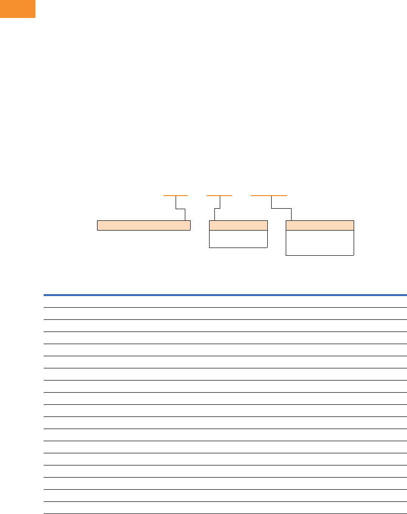
V6-T2-170 Volume 6—Solid-State Motor Control CA08100007E—May 2014 www.eaton.com
2
2
2
2
2
2
2
2
2
2
2
2
2
2
2
2
2
2
2
2
2
2
2
2
2
2
2
2
2
2
2.7
Adjustable Frequency Drives
SPX9000 Drives
SPX9000 Drive Options
Brake Chopper Options
The brake chopper circuit
option is used for applications
that require dynamic braking.
Dynamic braking resistors are
not included with drive
purchase. Consult the factory
for additional dynamic braking
resistor selections that are
supplied separately. A list of
common resistors are listed
below and are complete
indoor assemblies, include a
pre-wired terminal block and
a thermal switch, and are not
UL Listed.
Duty Cycle
The duty cycle rating is based
on a 60-second period. For
example, the 20% duty cycle
resistor can carry 100%
current for 12 seconds out
of every 60 seconds, while
the 50% duty cycle resistor
can carry 150% current for
30 seconds out of every
60 seconds.
Torque
If the braking torque required
is less than 15%, dynamic
braking is not required
because the regenerated
energy will be dissipated in
the drive and motor losses.
Dynamic Brake Resistor—Catalog Number Selection
230V Brake Resistors
Drive hp
(CT/IH)
Minimum
Ohms
20% Duty Cycle, 100% Torque 50% Duty Cycle, 150% Torque
Catalog Number Dimensions (Inches) Catalog Number Dimensions (Inches)
0.75 30.0 DBR-R100-W0400 12W x 5D x 5H DBR-R100-W0800 12W x 7D x 5H
130.0DBR-R100-W0400 12W x 5D x 5H DBR-R100-W0800 12W x 7D x 5H
1.5 30.0 DBR-R100-W0400 12W x 5D x 5H DBR-R036-W1200 12W x 10D x 5H
230.0DBR-R100-W0400 12W x 5D x 5H DBR-R036-W1200 12W x 10D x 5H
330.0DBR-R036-W0800 12W x 7D x 5H DBR-R036-W2000 12W x 16D x 5H
430.0DBR-R036-W0800 12W x 7D x 5H DBR-R030-W2400 19W x 10D x 5H
530.0DBR-R036-W0800 12W x 7D x 5H DBR-R030-W2800 19W x 13D x 5H
7.5 20.0 DBR-R020-W1200 12W x 10D x 5H DBR-R020-W4800 26.5W x 13D x 5H
10 10.0 DBR-R015-W1600 12W x 13D x 5H DBR-R112-W6000 26.5W x 13D x 5H
15 10.0 DBR-R012-W2400 19W x 10D x 5H DBR-R010-W9000 28W x 10D x 10H
20 3.3 DBR-R9D3-W3200 19W x 10D x 5H DBR-R3D4-W012K 28W x 10D x 10H
25 3.3 DBR-R5D5-W4000 26.5W x 10D x 5H DBR-R5D1-W015K 28W x 16D x 10H
30 3.3 DBR-R4D8-W4800 26.5W x 10D x 5H DBR-R4D1-W020K 28W x 16D x 10H
40 1.4 DBR-R004-W6000 26.5W x 13D x 5H DBR-R3D4-W025K 30W x 18D x 16H
50 1.4 DBR-R3D1-W7500 26.5W x 16D x 5H DBR-R2D1-W030K 30W x 18D x 24H
60 1.4 DBR-R2D8-W9000 26.5W x 16D x 5H DBR-R002-W036K 30W x 18D x 24H
75 1.4 DBR-R2D6-W012K 28W x 10D x 10H DBR-R1D5-W045K 30W x 18D x 32H
100 1.4 DBR-R002-W015K 28W x 16D x 10H DBR-R1D4-W060K 30W x 18D x 40H
DBR –R100– W0800
Dynamic Brake Resistor Resistance
1D0 =1.0 Ohms
100 =100 Ohms
Rated Watts
0800 = 800 Watts
8000 = 8000 Watts
080K = 80,000 Watts

Volume 6—Solid-State Motor Control CA08100007E—May 2014 www.eaton.com V6-T2-171
2
2
2
2
2
2
2
2
2
2
2
2
2
2
2
2
2
2
2
2
2
2
2
2
2
2
2
2
2
2
2.7
Adjustable Frequency Drives
SPX9000 Drives
480V Brake Resistors
Note
1Consult factory.
Drive hp
(CT/IH)
Minimum
Ohms
20% Duty Cycle, 100% Torque 50% Duty Cycle, 150% Torque
Catalog Number Dimensions (Inches) Catalog Number Dimensions (Inches)
163.0DBR-R100-W0400 12W x 5D x 5H DBR-R100-W0800 12W x 7D x 5H
1.5 63.0 DBR-R100-W0400 12W x 5D x 5H DBR-R100-W1200 12W x 10D x 5H
263.0DBR-R100-W0400 12W x 5D x 5H DBR-R100-W1200 12W x 10D x 5H
363.0DBR-R100-W0800 12W x 7D x 5H DBR-R100-W2000 12W x 16D x 5H
563.0DBR-R100-W0800 12W x 7D x 5H DBR-R100-W2800 19W x 13D x 5H
663.0DBR-R100-W1200 12W x 10D x 5H DBR-R070-W4000 19W x 16D x 5H
7.5 63.0 DBR-R100-W1200 12W x 10D x 5H DBR-R063-W4800 26.5W x 13D x 5H
10 63.0 DBR-R063-W1600 12W x 13D x 5H DBR-R063-W6000 26.5W x 16D x 5H
15 42.0 DBR-R042-W2400 19W x 10D x 5H DBR-R042-W9000 28W x 10D x 10H
20 21.0 DBR-R030-W3200 19W x 13D x 5H DBR-R023-W012K 28W x 13D x 10H
25 21.0 DBR-R030-W4000 19W x 16D x 5H DBR-R021-W015K 28W x 13D x 10H
30 14.0 DBR-R020-W4800 26.5W x 13D x 5H DBR-R014-W020K 30W x 18D x 24H
40 6.5 DBR-R112-W6000 26.5W x 13D x 5H DBR-R007-W025K 30W x 18D x 16H
50 6.5 DBR-R013-W7500 26.5W x 16D x 5H DBR-R8D5-W030K 30W x 18D x 24H
60 6.5 DBR-R010-W9000 28W x 10D x 10H DBR-R7D3-W036K 30W x 18D x 24H
75 3.3 DBR-R009-W012K 28W x 13D x 10H DBR-R3D3-W045K 30W x 18D x 32H
100 3.3 DBR-R5D1-W015K 28W x 16D x 10H DBR-R004-W060K 30W x 18D x 40H
125 3.3 DBR-R4D1-W020K 28W x 16D x 10H DBR-R004-W070K 30W x 18D x 48H
150 3.3 DBR-R3D4-W025K 30W x 18D x 16H DBR-R3D5-W085K 30W x 18D x 56H
200 3.3 DBR-R3D3-W030K 30W x 18D x 24H DBR-R3D3-W110K 30W x 18D x 72H
250 1.4 DBR-R2D5-W036K 30W x 18D x 24H 1—
300 1.4 DBR-R1D5-W045K 30W x 18D x 32H 1—
350 1.4 DBR-R1D4-W060K 30W x 18D x 40H 1—
400 0.9 DBR-R1D4-W060K 30W x 18D x 40H 1—
500 0.9 DBR-R0D9-W080K 30W x 18D x 48H 1—
550 0.9 DBR-R001-W085K 30W x 18D x 56H 1—

V6-T2-172 Volume 6—Solid-State Motor Control CA08100007E—May 2014 www.eaton.com
2
2
2
2
2
2
2
2
2
2
2
2
2
2
2
2
2
2
2
2
2
2
2
2
2
2
2
2
2
2
2.7
Adjustable Frequency Drives
SPX9000 Drives
575V Brake Resistors
Note
1Consult factory.
Drive hp
(CT/IH)
Minimum
Ohms
20% Duty Cycle, 100% Torque 50% Duty Cycle, 150% Torque
Catalog Number Dimensions (Inches) Catalog Number Dimensions (Inches)
2100.0DBR-R100-W0400 12W x 5D x 5H DBR-R100-W1200 12W x 10D x 5H
3100.0DBR-R100-W0800 12W x 7D x 5H DBR-R100-W2000 12W x 16D x 5H
4100.0DBR-R100-W0800 12W x 7D x 5H DBR-R100-W2400 19W x 10D x 5H
5100.0DBR-R100-W0800 12W x 7D x 5H DBR-R100-W2800 19W x 13D x 5H
7.5 100.0 DBR-R100-W1200 12W x 10D x 5H DBR-R100-W4800 26.5W x 13D x 5H
10 30.0 DBR-R063-W1600 12W x 13D x 5H DBR-R063-W6000 26.5W x 16D x 5H
15 30.0 DBR-R042-W2400 19W x 10D x 5H DBR-R042-W9000 28W x 10D x 10H
20 30.0 DBR-R030-W3200 19W x 13D x 5H DBR-R030-W012K 28W x 13D x 10H
25 30.0 DBR-R030-W4000 19W x 16D x 5H DBR-R030-W015K 28W x 16D x 10H
30 18.0 DBR-R020-W4800 26.5W x 13D x 5H DBR-R020-W020K 30W x 18D x 16H
40 18.0 DBR-R030-W6000 26.5W x 16D x 5H DBR-R184-W025K 30W x 18D x 16H
50 9.0 DBR-R013-W7500 26.5W x 16D x 5H DBR-R012-W030K 30W x 18D x 24H
60 9.0 DBR-R010-W9000 28W x 10D x 10H DBR-R010-W036K 30W x 18D x 24H
75 9.0 DBR-R009-W012K 28W x 13D x 10H DBR-R009-W045K 30W x 18D x 24H
100 7.0 DBR-R013-W015K 28W x 16D x 10H DBR-R8D4-W060K 30W x 18D x 40H
125 7.0 DBR-R8D2-W020K 30W x 18D x 10H DBR-R007-W070K 30W x 18D x 40H
150 7.0 DBR-R007-W025K 30W x 18D x 16H DBR-R006-W085K 30W x 18D x 56H
175 7.0 DBR-R007-W030K 30W x 18D x 24H DBR-R007-W100K 30W x 18D x 72H
200 2.5 DBR-R3D3-W030K 30W x 18D x 24H DBR-R2D6-W110K 30W x 18D x 64H
250 2.5 DBR-R2D5-W036K 30W x 18D x 24H DBR-R003-W140K 30W x 18D x 72H
300 2.5 DBR-R3D3-W045K 30W x 18D x 32H 1—
400 1.7 DBR-R002-W060K 30W x 18D x 48H 1—
450 1.7 DBR-R1D8-W070K 30W x 18D x 48H 1—
500 1.7 DBR-R002-W080K 30W x 18D x 56H 1—
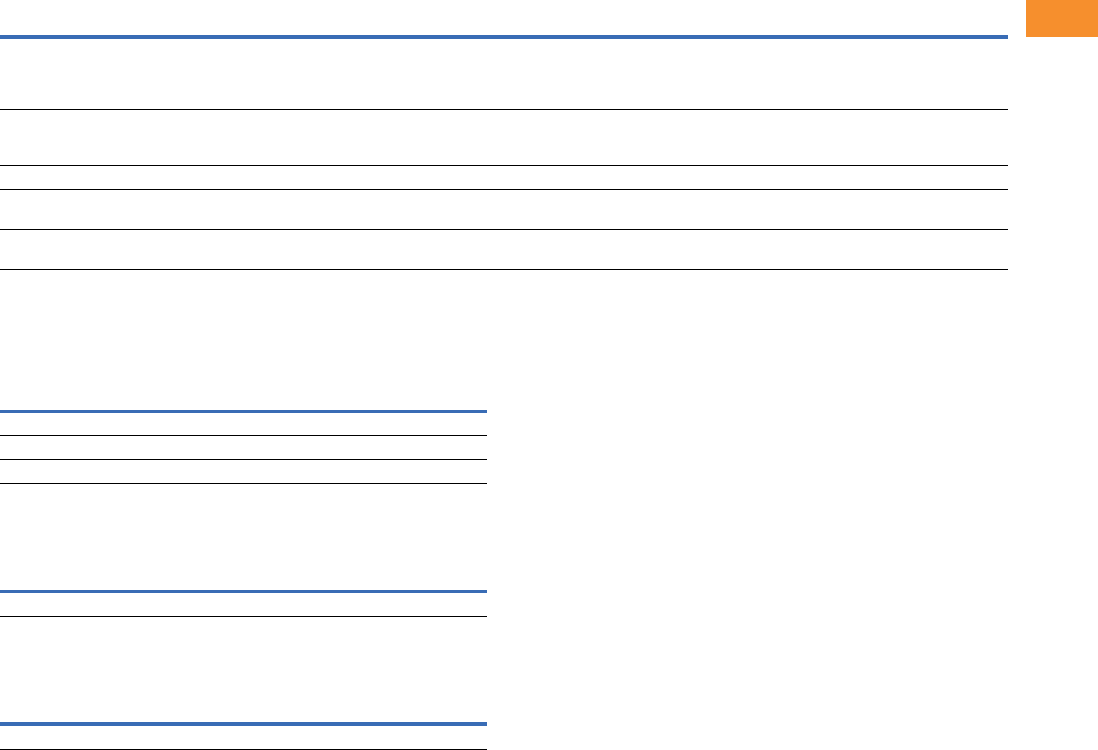
Volume 6—Solid-State Motor Control CA08100007E—May 2014 www.eaton.com V6-T2-173
2
2
2
2
2
2
2
2
2
2
2
2
2
2
2
2
2
2
2
2
2
2
2
2
2
2
2
2
2
2
2.7
Adjustable Frequency Drives
SPX9000 Drives
Control/Communication Options
Available Control/Communications Options
SPX Freestanding Options
480V and 690V Control Options, 200–550 hp 1
480V and 690V Light Options, 200–550 hp 1
Input Options, 200–550 hp 1
Notes
1Consult factory for adder information.
2Applicable with FR10 and FR11 freestanding designs only.
Option Description Option Type
K2 Door-Mounted Speed Potentiometer with HOA Selector Switch—Provides the SPX9000 with the ability to start/stop and adjust the speed reference from
door-mounted control devices or remotely from customer supplied inputs. In HAND position, the drive will start and the speed is controlled by the door-mounted
speed potentiometer. The drive will be disabled in the OFF position. When AUTO is selected, the drive run and speed control commands are via user-supplied dry
contact and 4–20 mA signal.
Control
K4 HAND/OFF/AUTO Switch for Non-Bypass Configurations—Provides a three-position selector switch that allows the user to select either a HAND or AUTO
mode of operation. HAND mode is defaulted to keypad operation, and AUTO mode is defaulted to control from an external terminal source. These modes of operation
can be configured via programming to allow for alternate combinations of start and speed sources. Start and speed sources include keypad, I/O and fieldbus.
Control
KB 115V Control Transformer, 550 VA—Provides a fused control power transformer with additional 550 VA at 115V for customer use. Control
L1 Power On and Fault Pilot Lights—Provide a white power on light that indicates power to the enclosed cabinet and a red fault light that indicates a drive fault
has occurred.
Light
P2 Disconnect Switch—Disconnect switch option is applicable only with NEMA Type 1/IP21 and NEMA Type 12/IP54 Freestanding drives. Allows a convenient
means of disconnecting the SPX9000 from the line, and the operating mechanism can be padlocked in the OFF position. This is factory-mounted in the enclosure.
Input
Description
Catalog Number
Suffix
Door-mounted speed potentiometer with HOA selector switch K2
HAND/OFF/AUTO switch (22 mm) K4
115 volt control transformer 550 VA KB
Description
Catalog Number
Suffix
Power on/fault pilot lights L1
Description
Catalog Number
Suffix
Disconnect switch P2 2

V6-T2-174 Volume 6—Solid-State Motor Control CA08100007E—May 2014 www.eaton.com
2
2
2
2
2
2
2
2
2
2
2
2
2
2
2
2
2
2
2
2
2
2
2
2
2
2
2
2
2
2
2.7
Adjustable Frequency Drives
SPX9000 Drives
Replacement Parts
FR4 Spare Parts
FR5 Spare Parts
Notes
1Only for NEMA Type 12/IP54 Type drives.
2Factory recommended spare parts.
3Select one part number based on the amperage rating of the drive. Please contact EatonCare at 877-ETN-CARE for assistance.
Quantity/
Drive
230V 480V 575V
Category Description Catalog Number Catalog Number Catalog Number
Control fan NEMA Type 12 control fan 11PP01086 PP01086 —
Control module 2SPX control module 1 CPBS0000000000 CPBS0000000000 —
Standard slot A I/O card 1 OPTA9 OPTA9 —
Standard slot B I/O card 1 OPTA2 OPTA2 —
Converter Power board 31VB00308-0004-2 VB00208-0003-5 —
1VB00308-0007-2 VB00208-0004-5 —
1VB00308-0008-2 VB00208-0005-5 —
1— VB00208-0007-5 —
1— VB00208-0009-5 —
1— VB00410-0012-5-ARV —
Keypad 2SVX/SPX keypad 1 KEYPAD-LOC/REM KEYPAD-LOC/REM —
Main fan 2DC fan (main) 1 PP01060 PP01060 —
Other Mounting kit, fixing kit 1 FR00040 FR00040 —
Mounting kit, fixing kit, N12 11FR00079 FR00079 —
Control cover, plastic, N1 1 FR00006 FR00006 —
Quantity/
Drive
230V 480V 575V
Category Description Catalog Number Catalog Number Catalog Number
Control fan NEMA Type 12 control fan 11PP01088 PP01088 —
Control module 2SPX control module 1 CPBS0000000000 CPBS0000000000 —
Standard slot A I/O card 1 OPTA9 OPTA9 —
Standard slot B I/O card 1 OPTA2 OPTA2 —
Converter Power board 31VB00313-0017-2 VB00213-0016-5 —
1VB00313-0025-2 VB00213-0022-5 —
1VB00313-0031-2 VB00213-0031-5 —
Keypad 2SVX/SPX keypad 1 KEYPAD-LOC/REM KEYPAD-LOC/REM —
Main fan 2DC fan (main) 1 PP01061 PP01061 —
Other Mounting kit, fixing kit 1 FR00050 FR00050 —
Mounting kit, fixing kit, N12 11FR00081 FR00081 —
Control cover, plastic, N1 1 FR05011 FR05011 —

Volume 6—Solid-State Motor Control CA08100007E—May 2014 www.eaton.com V6-T2-175
2
2
2
2
2
2
2
2
2
2
2
2
2
2
2
2
2
2
2
2
2
2
2
2
2
2
2
2
2
2
2.7
Adjustable Frequency Drives
SPX9000 Drives
FR6 Spare Parts
FR7 Spare Parts
Notes
1Only for NEMA Type 12/IP54 Type drives.
2Factory recommended spare parts.
3Select one part number based on the amperage rating of the drive. Please contact EatonCare at 877-ETN-CARE for assistance.
Quantity/
Drive
230V 480V 575V
Category Description Catalog Number Catalog Number Catalog Number
Control fan NEMA Type 12 control fan 11PP01049 PP01049 —
Control module 2SPX control module 1 CPBS0000000000 CPBS0000000000 CPBS0000000000
Standard slot A I/O card 1 OPTA9 OPTA9 OPTA9
Standard slot B I/O card 1 OPTA2 OPTA2 OPTA2
Converter Power board 31VB00316-0048-2 VB00416-0038-5 VB00404-0004-6
1VB00316-0061-2 VB00416-0045-5 VB00404-0005-6
1— VB00416-0061-5 VB00404-0007-6
1— — VB00404-0010-6
1— — VB00404-0013-6
1— — VB00404-0018-6
1— — VB00404-0022-6
1— — VB00404-0027-6
1— — VB00404-0034-6
DC section Bus capacitor 2 — — S00930
Keypad 2SVX/SPX keypad 1 KEYPAD-LOC/REM KEYPAD-LOC/REM KEYPAD-LOC/REM
Main fan 2DC fan (main) 1 PP01062 PP01062 —
Other Mounting kit, fixing kit 1 FR00060 FR00060 FR00060
Mounting kit, fixing kit, N12 11FR00082 FR00082 FR00082
Control cover, plastic, N1 1 FR06011 FR06011 FR06011
Quantity/
Drive
230V 480V 575V
Category Description Catalog Number Catalog Number Catalog Number
Control fan NEMA Type 12 control fan 11PP01049 PP01049 PP01049
Control module 2SPX control module 1 CPBS0000000000 CPBS0000000000 CPBS0000000000
Standard slot A I/O card 1 OPTA9 OPTA9 OPTA9
Standard slot B I/O card 1 OPTA2 OPTA2 OPTA2
Converter Power board 31VB00319-0075-2 VB00619-0072-5 VB00419-0041-6
1VB00319-0088-2 VB00619-0087-5 VB00419-0052-6
1VB00319-0114-2 VB00619-0105-5 —
DC section Bus capacitor 2 — — PP01041
Keypad 2SVX/SPX keypad 1 KEYPAD-LOC/REM KEYPAD-LOC/REM KEYPAD-LOC/REM
Main fan 2DC fan (main) 1 PP01063 PP01063 PP01063
Other Mounting kit, fixing kit 1 FR07071 FR07071 FR07071
Mounting kit, fixing kit, N12 11FR07072 FR07072 FR07072
Control cover, plastic, N1 1 FR07011 FR07011 FR07011

V6-T2-176 Volume 6—Solid-State Motor Control CA08100007E—May 2014 www.eaton.com
2
2
2
2
2
2
2
2
2
2
2
2
2
2
2
2
2
2
2
2
2
2
2
2
2
2
2
2
2
2
2.7
Adjustable Frequency Drives
SPX9000 Drives
FR8 Spare Parts
Notes
1Only for NEMA Type 12/IP54 Type drives.
2Factory recommended spare parts.
3Select one part number based on the amperage rating of the drive. Please contact EatonCare at 877-ETN-CARE for assistance.
Quantity/
Drive
230V 480V 575V
Category Description Catalog Number Catalog Number Catalog Number
Control fan NEMA Type 12 control fan 11CP01180 CP01180 CP01180
Control module 2SPX control module 1 CPBS0000000000 CPBS0000000000 CPBS0000000000
Standard slot A I/O card 1 OPTA9 OPTA9 OPTA9
Standard slot B I/O card 1 OPTA2 OPTA2 OPTA2
Converter Power board 31VB00722-0140-2-ANV VB00636-0140-4-ANV VB00422-0062-5-ANV
1VB00722-0170-2-ANV VB00636-0168-4-ANV VB00422-0080-5-ANV
1VB00722-0205-2-ANV VB00636-0205-4-ANV VB00422-0100-5-ANV
IGBT 2 PP01175 PP01175 PP01127
DC section Bus capacitor 4 S00335 S00335 PP01041
Inverter Diode 3 CP01268 CP01268 CP01373
Rectifier board 1 VB00227 VB00227 VB00427
Keypad 2SVX/SPX keypad 1 KEYPAD-LOC/REM KEYPAD-LOC/REM KEYPAD-LOC/REM
Main AC fan Fan AC 1 PP01123 PP01123 PP01123
Fan fuse 2 PP20202 PP20202 PP20202
Starting cap 1 S00734 S00734 S00734
Fan driver board AC 1 VB00599 VB00799 VB00799
Isolation transformer (fan) 1 S0000113 S0000113 S0000113
Main DC fan 2DC fan 1 PP00071 PP00071 PP00071
DC power supply 1 S01016 S01016 S01016
Other Front cover, N12 11FR08079 FR08079 FR08079
Conduit plate, N12 1 FR08082 FR08082 FR08082
Front cover, N1 1 FR08106 FR08106 FR08106

Volume 6—Solid-State Motor Control CA08100007E—May 2014 www.eaton.com V6-T2-177
2
2
2
2
2
2
2
2
2
2
2
2
2
2
2
2
2
2
2
2
2
2
2
2
2
2
2
2
2
2
2.7
Adjustable Frequency Drives
SPX9000 Drives
FR9 Spare Parts
Notes
1Factory recommended spare parts.
2Select one part number based on the amperage rating of the drive. Please contact EatonCare at 877-ETN-CARE for assistance.
Quantity/
Drive
230V 480V 575V
Category Description Catalog Number Catalog Number Catalog Number
Control fan 50 mm fan 1 PP09041 PP09041 PP09041
80 mm fan 1 PP01068 PP01068 PP01068
Control module 1SPX control module 1 CPBS0000000000 CPBS0000000000 CPBS0000000000
Standard slot A I/O card 1 OPTA9 OPTA9 OPTA9
Standard slot B I/O card 1 OPTA2 OPTA2 OPTA2
Converter Power module
21FR09-0261-2-ANV FR09-0261-4-ANV FR09-0125-5-ANV
1FR09-0300-2-ANV FR09-0300-4-ANV FR09-0144-5-ANV
1— — FR09-0170-5-ANV
Driver board 1 S00583 S00583 S00583
Shunt board 26— VB00535 VB00537
6— VB00536 VB00542
6——VB00543
DC section Balancing resistor 3 PP00052 PP00052 PP00052
Bus capacitor 8 S00335 S00335 PP01041
DC busbars DC– 1 FR09043 FR09043 FR09043
DC busbars DC+ 1 FR09044 FR09044 FR09044
DC busbars connection 1 FR09045 FR09045 FR09045
DC busbars +/– insulator 1 FR09046 FR09046 FR09046
DC busbars –/con insulator 1 FR09047 FR09047 FR09047
Inverter Rectifier module 1 FR09826 FR09822 FR09823
Diode 3 CP01268 CP01268 CP01268
Rectifier board 1 — VB00459 VB00460
Keypad 1SVX/SPX keypad 1 KEYPAD-LOC/REM KEYPAD-LOC/REM KEYPAD-LOC/REM
Main AC fan Fan AC 1 PP01080 PP01080 PP01080
Fan fuse 2 PP20202 PP20202 PP20202
Starting cap 1 S00465 S00465 S00465
Fan driver board AC 1 VB00899 VB00399 VB00299
Isolation transformer (fan) 1 PP09056 PP09055 PP09055
Main DC fan 1DC fan 1 PP00072 PP00072 PP00072
DC power supply 1 S01017 S01017 S01017
Other Front cover power 1 FR09012 FR09012 FR09012
Front cover connection 1 FR09013 FR09013 FR09013
Front power conduit 1 FR09014 FR09014 FR09014

V6-T2-178 Volume 6—Solid-State Motor Control CA08100007E—May 2014 www.eaton.com
2
2
2
2
2
2
2
2
2
2
2
2
2
2
2
2
2
2
2
2
2
2
2
2
2
2
2
2
2
2
2.7
Adjustable Frequency Drives
SPX9000 Drives
FR10 Spare Parts
Notes
1Factory recommended spare parts.
2Select one part number based on the amperage rating of the drive. Please contact EatonCare at 877-ETN-CARE for assistance.
Quantity/
Drive
230V 480V 575V
Category Description Catalog Number Catalog Number Catalog Number
Control Fiber board 1 — S00451 S00451
ASIC board 1 — S00457 S00457
Control fan ASIC fan 1 — PP01096 PP01096
Control module 1SPX control module 1 — CPBS0000000000 CPBS0000000000
Standard slot A I/O card 1 — OPTA9 OPTA9
Standard slot B I/O card 1 — OPTA2 OPTA2
Converter Power module 21— FR10-0385-4-ANV FR10-0261-5-ANV
1— FR10-0460-4-ANV FR10-0325-5-ANV
1— FR10-0520-4-ANV FR10-0385-5-ANV
1— — FR10-0416-5-ANV
Driver board 1 — S00450 S00450
Driver adapter board 1 — VB00330 VB00330
Shunt board 26— VB00497 VB00510
6— VB00498 VB00511
6— VB00537 VB00545
Covers Top cover 1 — FR10340 FR10340
Side cover 2 — FR10341 FR10341
DC section Balancing resistor 2 — PP13027 PP13028
DC busbars kit (right) 1 — S0000005 S0000005
Bus capacitor 12 — S00335 S00336
Inverter Rectifier module 1 — FR10823 FR10823
Charging resistor 1 — PP00066 PP00066
Diode 3 — PP01177 PP01177
Rectifier board 1 — S00591 S00592
Keypad 1SVX/SPX keypad 1 — KEYPAD-LOC/REM KEYPAD-LOC/REM
Main AC fan Fan assembly (left) 1 — FR10846 FR10846
Fan assembly (right) 1 — FR10847 FR10847
Fan AC 2 — PP01080 PP01080
Fan fuse 4 — PP20202 PP20202
Starting cap 2 — S00528 S00528
Fan driver board AC 2 — VB00299 VB00299
Isolation transformer (left) 1 — FR10844 FR10844
Isolation transformer (right) 1 — FR10845 FR10845
Main DC fan 1DC fan 2 — PP00072 PP00072
DC power supply 2 — S01017 S01017

Volume 6—Solid-State Motor Control CA08100007E—May 2014 www.eaton.com V6-T2-179
2
2
2
2
2
2
2
2
2
2
2
2
2
2
2
2
2
2
2
2
2
2
2
2
2
2
2
2
2
2
2.7
Adjustable Frequency Drives
SPX9000 Drives
FR11 Spare Parts
Notes
1Factory recommended spare parts.
2Select one part number based on the amperage rating of the drive. Please contact EatonCare at 877-ETN-CARE for assistance.
Quantity/
Drive
230V 480V 575V
Category Description Catalog Number Catalog Number Catalog Number
Control Fiber board 1 — S00451 S00451
ASIC board 1 — S00457 S00457
Control fan ASIC fan 1 — PP01096 PP01096
Control module 1SPX control module 1 — CPBS0000000000 CPBS0000000000
Standard slot A I/O card 1 — OPTA9 OPTA9
Standard slot B I/O card 1 — OPTA2 OPTA2
Converter Power module 21— FR11-0590-4-ANV FR11-0460-5-ANV
1— FR11-0650-4-ANV FR11-0502-5-ANV
1— FR11-0730-4-ANV FR11-0590-5-ANV
Driver board 1 — S00452 S00452
Driver adapter board 1 — VB00330 VB00330
Shunt board 29— VB00513 VB00512
9— VB00514 VB00546
9— VB00538 VB00547
Covers Top cover 1 — FR11345 FR11345
DC section Balancing resistor 3 — PP13027 PP13027
DC busbars kit (right) 3 — S0000005 S0000005
Bus capacitor 18 — S00335 S00335
Inverter Rectifier module 1 — FR10823 FR10823
Diode 3 — PP01177 PP01177
Rectifier board 1 — S00591 S00591
Keypad 1SVX/SPX keypad 1 — KEYPAD-LOC/REM KEYPAD-LOC/REM
Main AC fan Fan assembly (right) 3 — FR10847 FR10847
Fan AC 3 — PP01080 PP01080
Fan fuse 4 — PP20202 PP20202
Starting cap 3 — S00530 S00530
Fan driver board AC 3 — VB00299 VB00299
Isolation transformer (right) 3 — FR10845 FR10845
Main DC fan 1DC fan 2 — PP00072 PP00072
DC power supply 2 — S01017 S01017

V6-T2-180 Volume 6—Solid-State Motor Control CA08100007E—May 2014 www.eaton.com
2
2
2
2
2
2
2
2
2
2
2
2
2
2
2
2
2
2
2
2
2
2
2
2
2
2
2
2
2
2
2.7
Adjustable Frequency Drives
SPX9000 Drives
FR12 Spare Parts
Notes
1Factory recommended spare parts.
2Select one part number based on the amperage rating of the drive. Please contact EatonCare at 877-ETN-CARE for assistance.
Quantity/
Drive
230V 480V 575V
Category Description Catalog Number Catalog Number Catalog Number
Control Fiber board 2 — S00451 S00451
ASIC board 2 — S00457 S00457
Star coupler 1 — S00593 S00593
Control fan ASIC fan 2 — PP01096 PP01096
Control module 1SPX control module 1 — CPBS0000000000 CPBS0000000000
Standard slot A I/O card 1 — OPTA9 OPTA9
Standard slot B I/O card 1 — OPTA2 OPTA2
Converter Power module 21— FR12-0820-4-ANV FR12-0650-5-ANV
1— FR12-0920-4-ANV FR12-0750-5-ANV
1— FR12-1030-4-ANV FR12-0820-5-ANV
Driver board 2 — S00450 S00450
Driver adapter board 2 — VB00330 VB00330
Shunt board 12 — VB00498 VB00511
Covers Top cover 2 — FR10340 FR10340
Side cover 4 — FR10341 FR10341
DC section Balancing resistor 4 — PP13027 PP13027
DC busbars kit (right) 2 — S0000005 S0000005
Bus capacitor 24 — S00335 S00336
Inverter Rectifier module 2 — FR10823 FR10823
Diode 3 — PP01177 PP01177
Rectifier board 2 — S00591 S00591
Keypad 1SVX/SPX keypad 1 — KEYPAD-LOC/REM KEYPAD-LOC/REM
Main AC fan Fan assembly (left) 2 — FR10846 FR10846
Fan assembly (right) 2 — FR10847 FR10847
Fan AC 4 — PP01080 PP01080
Fan fuse 8 — PP20202 PP20202
Starting cap 4 — S00528 S00528
Fan driver board AC 4 — VB00299 VB00299
Isolation transformer (left) 2 — FR10844 FR10844
Isolation transformer (right) 2 — FR10845 FR10845
Main DC fan 1DC fan 4 — PP00072 PP00072
DC power supply 4 — S01017 S01017

Volume 6—Solid-State Motor Control CA08100007E—May 2014 www.eaton.com V6-T2-181
2
2
2
2
2
2
2
2
2
2
2
2
2
2
2
2
2
2
2
2
2
2
2
2
2
2
2
2
2
2
2.7
Adjustable Frequency Drives
SPX9000 Drives
FR13 Spare Parts
Notes
1Factory recommended spare parts.
2Select one part number based on the amperage rating of the drive. Please contact EatonCare at 877-ETN-CARE for assistance.
Quantity/
Drive
230V 480V 575V
Category Description Catalog Number Catalog Number Catalog Number
Control ASIC board 1 — S00457 S00457
ASIC assembly 1 — 60S01030 60S01030
Control fan ASIC fan 1 — PP01096 PP01096
Control module 1SPX control module 1 — CPBS0000000000 CPBS0000000000
Standard slot A I/O card 1 — OPTA9 OPTA9
Standard slot B I/O card 1 — OPTA2 OPTA2
Converter Power module 23— FI13-1150-4-ANV FR13-1030-5-ANV
3— FI13-1300-4-ANV FR13-1180-5-ANV
3— FI13-1450-4-ANV FR13-920-5-ANV
Driver board 3 — S00454 S00454
Driver adapter board 2 — VB00330 VB00330
Shunt board 218 — VB00505 VB00516
18 — VB00514 VB00517
18 — VB00541 VB00547
Covers Top cover 3 — FI10001 FI10001
Side cover 3 — FI10003 FI10003
DC section Balancing resistor 6 — PP13034 PP13034
Bus capacitor 36 — S00335 S00336
DC busbars kit 3 — FI13329 FI13329
Inverter Rectifier module 2 — FR10823 FR10823
Diode 3 — PP01177 PP01177
Rectifier board 2 — S00591 S00591
Keypad 1SVX/SPX keypad 1 — KEYPAD-LOC/REM KEYPAD-LOC/REM
Main AC fan Fan assembly (left) 3 — FI13301 FI13301
Fan AC 3 — PP01080 PP01080
Fan fuse 6 — PP20202 PP20202
Starting cap 3 — S00520 S00520
Fan driver board AC 3 — VB00299 VB00299
Isolation transformer 3 — PP10057 PP10057
Main DC fan 1DC fan 4 — PP00072 PP00072
DC power supply 4 — S01017 S01017

V6-T2-182 Volume 6—Solid-State Motor Control CA08100007E—May 2014 www.eaton.com
2
2
2
2
2
2
2
2
2
2
2
2
2
2
2
2
2
2
2
2
2
2
2
2
2
2
2
2
2
2
2.7
Adjustable Frequency Drives
SPX9000 Drives
FR14 Spare Parts
Notes
1Factory recommended spare parts.
2Select one part number based on the amperage rating of the drive. Please contact EatonCare at 877-ETN-CARE for assistance.
Quantity/
Drive
230V 480V 575V
Category Description Catalog Number Catalog Number Catalog Number
Control ASIC board 2 — S00457 S00457
Star coupler 1 — S00593 S00593
ASIC assembly 2 — 60S01030 60S01030
Star coupler kit 1 — FR10860 FR10860
Control fan ASIC fan 2 — PP01096 PP01096
Control module 1SPX control module 1 — CPBS0000000000 CPBS0000000000
Standard slot A I/O card 1 — OPTA9 OPTA9
Standard slot B I/O card 1 — OPTA2 OPTA2
Converter Power module 21— FR14-1770-4-ANV FR14-1500-5-ANV
1— FR14-2150-4-ANV FR14-1900-5-ANV
1— FR14-2700-4-ANV FR14-2250-5-ANV
Driver board 6 — S00454 S00454
Driver adapter board 2 — VB00330 VB00330
Shunt board 236 — VB00541 VB00516
36 ——VB00517
Covers Top cover 6 — FI10001 FI10001
Side cover 6 — FI10003 FI10003
DC section Balancing resistor 6 — PP13034 PP13034
Bus capacitor 72 — S00335 S00336
DC busbars kit 6 — FI13329 FI13329
Inverter Rectifier module 2 — FR10823 FR10823
Diode 3 — PP01177 PP01177
Rectifier board 2 — S00591 S00591
Keypad 1SVX/SPX keypad 1 — KEYPAD-LOC/REM KEYPAD-LOC/REM
Main AC fan Fan assembly (left) 6 — FI13301 FI13301
Fan AC 6 — PP01080 PP01080
Fan fuse 12 — PP20202 PP20202
Starting cap 6 — S00520 S00520
Fan driver board AC 6 — VB00299 VB00299
Isolation transformer 6 — PP10057 PP10057
Main DC fan 1DC fan 6 — PP00072 PP00072
DC power supply 6 — S01017 S01017

Volume 6—Solid-State Motor Control CA08100007E—May 2014 www.eaton.com V6-T2-183
2
2
2
2
2
2
2
2
2
2
2
2
2
2
2
2
2
2
2
2
2
2
2
2
2
2
2
2
2
2
2.7
Adjustable Frequency Drives
SPX9000 Drives
Technical Data and Specifications
SPX9000 Drives
Description Specification
Input Ratings
Input voltage (Vin)+10%/–15%
Input frequency (fin) 50/60 Hz (variation up to 45–66 Hz)
Connection to power Once per minute or less (typical operation)
High withstand rating 100 kAIC
Output Ratings
Output voltage 0 to Vin
Continuous output current IH rated 100% at 122°F (50°C), FR9 and below
IL rated 100% at 104°F (40°C), FR9 and below
IH/IL 100% at 104°F (40°C), FR10 and above
Overload current (
I
H
/
I
L
)150%
I
H
, 110%
I
L
for 1 min.
Output frequency 0 to 320 Hz
Frequency resolution 0.01 Hz
Initial output current (
I
H
) 250% for 2 seconds
Control Characteristics
Control method Frequency control (V/f) Open loop: sensorless vector control
Closed loop: frequency control
Closed loop: vector control
Switching frequency Adjustable with parameter 2.6.9
Frame 4–6 1 to 16 kHz; default 10 kHz
Frame 7–12 1 to 10 kHz; default 3.6 kHz
Frequency reference Analog input: Resolution 0.1% (10-bit), accuracy ±1% V/Hz
Panel reference: Resolution 0.01 Hz
Field weakening point 30 to 320 Hz
Acceleration time 0 to 3000 sec.
Deceleration time 0 to 3000 sec.
Braking torque DC brake: 30% x Tn (without brake option)
Ambient Conditions
Ambient operating
temperature
14°F (–10°C), no frost to 122°F (50°C)
I
H
(FR4–FR9)
14°F (–10°C), no frost to 104°F (40°C)
I
L
(FR10 and up)
14°F (–10°C), no frost to 104°F (40°C)
I
L
(all frames)
Storage temperature –40° to 158°F (–40° to 70°C)
Relative humidity 0 to 95% RH, noncondensing, non-corrosive,
no dripping water
Air quality Chemical vapors: IEC 721-3-3, unit in operation, class 3C2;
Mechanical particles: IEC 721-3-3, unit in operation, class 3S2
Altitude 100% load capacity (no derating) up to 3280 ft (1000m);
1% derating for each 328 ft (100m) above 3280 ft (1000m);
max. 9842 ft (3000m)
Vibration EN 50178, EN 60068-2-6; 5 to 50 Hz, displacement amplitude
1 mm (peak) at 3 to 15.8 Hz, max. acceleration amplitude
1G at 15.8 to 150 Hz
Shock EN 50178, EN 60068-2-27 UPS Drop test (for applicable UPS
weights) Storage and shipping: max. 15G, 11 ms (in package)
Enclosure class NEMA 1/IP21 or NEMA 12/IP54, open chassis/IP20
Description Specification
Control Connections
Analog input voltage 0 to 10V, R = 200 kohms (–10 to 10V joystick control) resolution
0.1%; accuracy ±1%
Analog input current 0(4) to 20 mA; Ri—250 ohms differential
Digital inputs (6) Positive or negative logic; 18 to 30 Vdc
Auxiliary voltage +24V ±15%, max. 250 mA
Output reference voltage +10V +3%, max. load 10 mA
Analog output 0(4) to 20 mA; RL max. 500 ohms;
resolution 10 bit; Accuracy ±2%
Digital outputs Open collector output, 50 mA/48V
Relay outputs 2 programmable Form C relay outputs
switching capacity: 24 Vdc/8A, 250 Vac/8A, 125 Vdc/0.4A
Protections
Overcurrent protection Trip limit 4.0 x IH instantaneously
Overvoltage protection Yes
Undervoltage protection Yes
Earth fault protection In case of earth fault in motor or motor cable, only the
frequency converter is protected
Input phase supervision Trips if any of the input phases are missing
Motor phase supervision Trips if any of the output phases are missing
Overtemperature protection Yes
Motor overload protection Yes
Motor stall protection Yes
Motor underload protection Yes
Short-circuit protection Yes (+24V and +10V reference voltages)
High Performance Features
Speed error <0.01%, depending on the encoder
Encoder support Incremental or absolute
Encoder voltages 5V (RS-422), 15V or 24V, depending on the option card
Torque control Full torque control at all speeds, including zero
Torque accuracy <2%; <5% down to zero speed
Starting torque >200%, depending on motor and drive sizing
Master/slave configurations Full capability
System analysis Integrated data logger
PC communication Fast multiple drive monitoring with PC
Inter-drive communication High-speed bus (12 Mbits/s)
High-speed applications Up to 7200 Hz
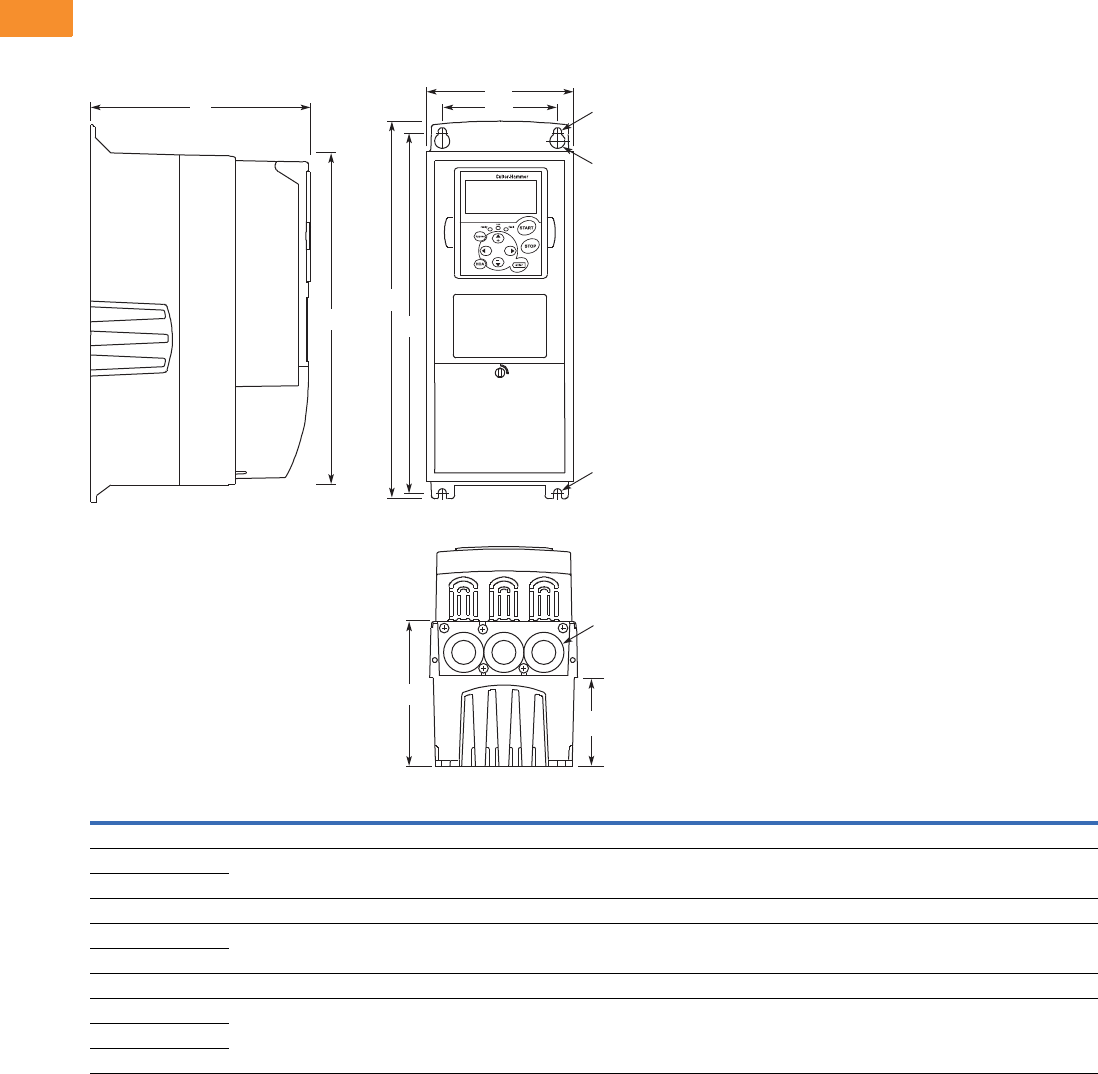
V6-T2-184 Volume 6—Solid-State Motor Control CA08100007E—May 2014 www.eaton.com
2
2
2
2
2
2
2
2
2
2
2
2
2
2
2
2
2
2
2
2
2
2
2
2
2
2
2
2
2
2
2.7
Adjustable Frequency Drives
SPX9000 Drives
Dimensions
Approximate Dimensions in Inches (mm)
9000X Drives
NEMA Type 1/IP21 and NEMA Type 12/IP54, FR4, FR5 and FR6
Voltage hp (IH)H1H2H3D1D2D3W1W2R1 Dia.R2 Dia.
Weight
Lbs (kg)
Knockouts at Inches (mm)
N1 (O.D.)
FR4
230V 3/4–3 12.9
(327)
12.3
(313)
11.5
(292)
7.5
(190)
3.0
(77)
5.0
(126)
5.04
(128)
3.9
(100)
0.5
(13)
0.3
(7)
11.0 (5) 3 at 10.1 (28)
480V 1–5
FR5
230V 5–7-1/2 16.5
(419)
16.0
(406)
15.3
(389)
8.4
(214)
3.9
(100)
5.8
(148)
5.7
(144)
3.9
(100)
0.5
(13)
0.3
(7)
17.9 (8) 2 at 1.5 (37)
1 at 10.1 (28)
480V 7-1/2–15
FR6
230V 10–15 22.0
(558)
21.3
(541)
20.4
(519)
9.3
(237)
4.2
(105)
6.5
(165)
7.7
(195)
5.8
(148)
0.6
(15.5)
0.4
(9)
40.8 (19) 3 at 1.5 (37)
480V 20–30
575V 2–25
EATON
D1 W2
W1
R2
R1
R2
H3 H2
H1
D2
D3
Knockouts
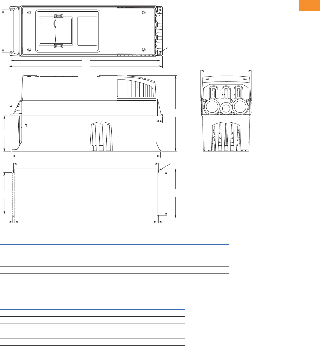
Volume 6—Solid-State Motor Control CA08100007E—May 2014 www.eaton.com V6-T2-185
2
2
2
2
2
2
2
2
2
2
2
2
2
2
2
2
2
2
2
2
2
2
2
2
2
2
2
2
2
2
2.7
Adjustable Frequency Drives
SPX9000 Drives
Approximate Dimensions in Inches (mm)
NEMA Type 1/IP21 and NEMA Type 12/IP54 with Flange Kit, FR4, FR5 and FR6
FR4, FR5 and FR6 with Flange Kit
Flange Opening, FR4 to FR6
W1 W2 H1 H2 H3 H4 H5 D1 D2 Dia. A
FR4
5.0 (128) 4.5 (113) 13.3 (337) 12.8 (325) 12.9 (327) 1.2 (30) 0.9 (22) 7.5 (190) 3.0 (77) 0.3 (7)
FR5
5.6 (143) 4.7 (120) 17.0 (434) 16.5 (420) 16.5 (419) 1.4 (36) 0.7 (18) 8.4 (214) 3.9 (100) 0.3 (7)
FR6
7.7 (195) 6.7 (170) 22.0 (560) 21.6 (549) 22.0 (558) 1.2 (30) 0.8 (20) 9.3 (237) 4.2 (106) 0.3 (7)
W3 W4 W5 H6 H7 H8 H9 Dia. B
FR4
4.8 (123) 4.5 (113) — 12.4 (315) 12.8 (325) — 0.2 (5) 0.3 (7)
FR5
5.3 (135) 4.7 (120) — 16.2 (410) 16.5 (420) — 0.2 (5) 0.3 (7)
FR6
7.3 (185) 6.7 (170) 6.2 (157) 21.2 (539) 21.6 (549) 0.3 (7) 0.2 (5) 0.3 (7)
W2
H1
H2
D2
Flange Opening
FR4 to FR6
H4
H5
H3
W1
Dia. A
D1
W3W4
W5
Dia. B
H7
H6 H9H8
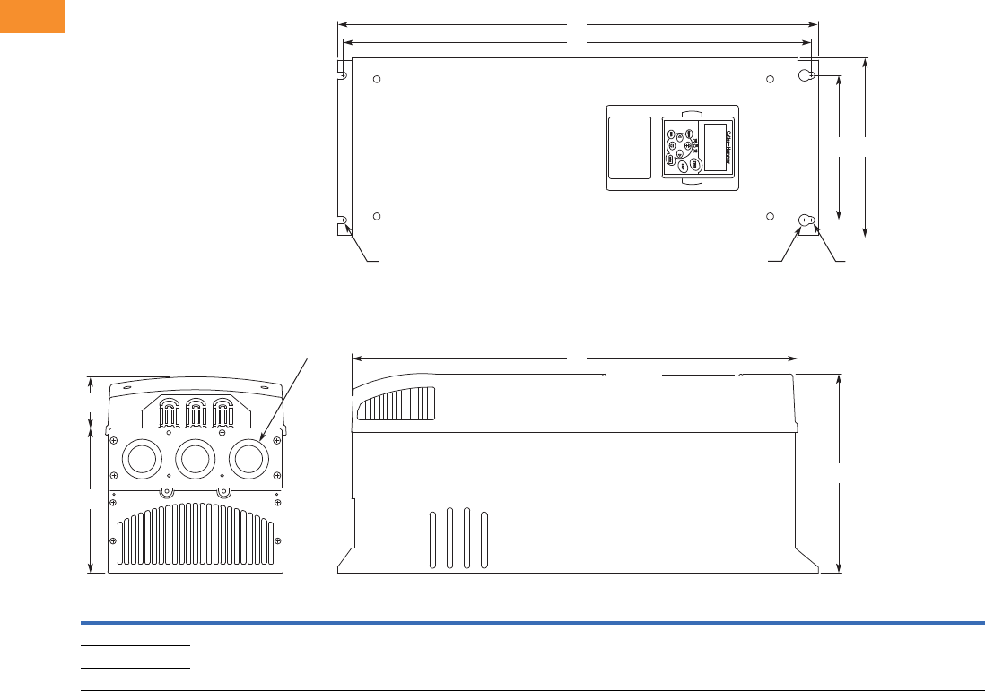
V6-T2-186 Volume 6—Solid-State Motor Control CA08100007E—May 2014 www.eaton.com
2
2
2
2
2
2
2
2
2
2
2
2
2
2
2
2
2
2
2
2
2
2
2
2
2
2
2
2
2
2
2.7
Adjustable Frequency Drives
SPX9000 Drives
Approximate Dimensions in Inches (mm)
NEMA Type 1/IP21 and NEMA Type 12/IP54, FR7
Voltage hp (IH)H1H2H3D1D2D3W1W2R1 Dia.R2 Dia.
Weight
Lbs (kg)
Knockouts at Inches (mm)
N1 (O.D.)
230V 20–30 24.8 (630) 24.2 (614) 23.2 (590) 10.1 (257) 3.0 (77) 7.3 (184) 9.3 (237) 7.5 (190) 0.7 (18) 0.4 (9) 77.2 (35) 3 at 1.5 (37)
480V 40–60
575V 30–40
W2
H1
D1
D2
Knockouts
R2 R2R1
D3
H2
H3
W1
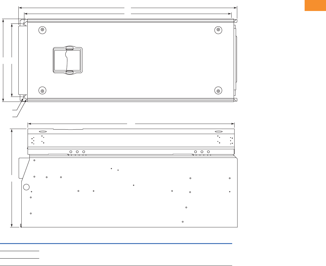
Volume 6—Solid-State Motor Control CA08100007E—May 2014 www.eaton.com V6-T2-187
2
2
2
2
2
2
2
2
2
2
2
2
2
2
2
2
2
2
2
2
2
2
2
2
2
2
2
2
2
2
2.7
Adjustable Frequency Drives
SPX9000 Drives
Approximate Dimensions in Inches (mm)
NEMA Type 1/IP21 and NEMA Type 12/IP54, FR8
Voltage hp (IH)D1H1H2H3W1W2R1 Dia.R2 Dia.
Weight
Lbs (kg)
230V 40–60 13.5 (344) 300.1 (764) 28.8 (732) 28.4 (721) 11.5 (291) 10 (255) 0.7 (18) 0.4 (9) 127 (58)
480V 75–125
575V 50–75
D1
H2
H1
W2W1
H3
R2
R1
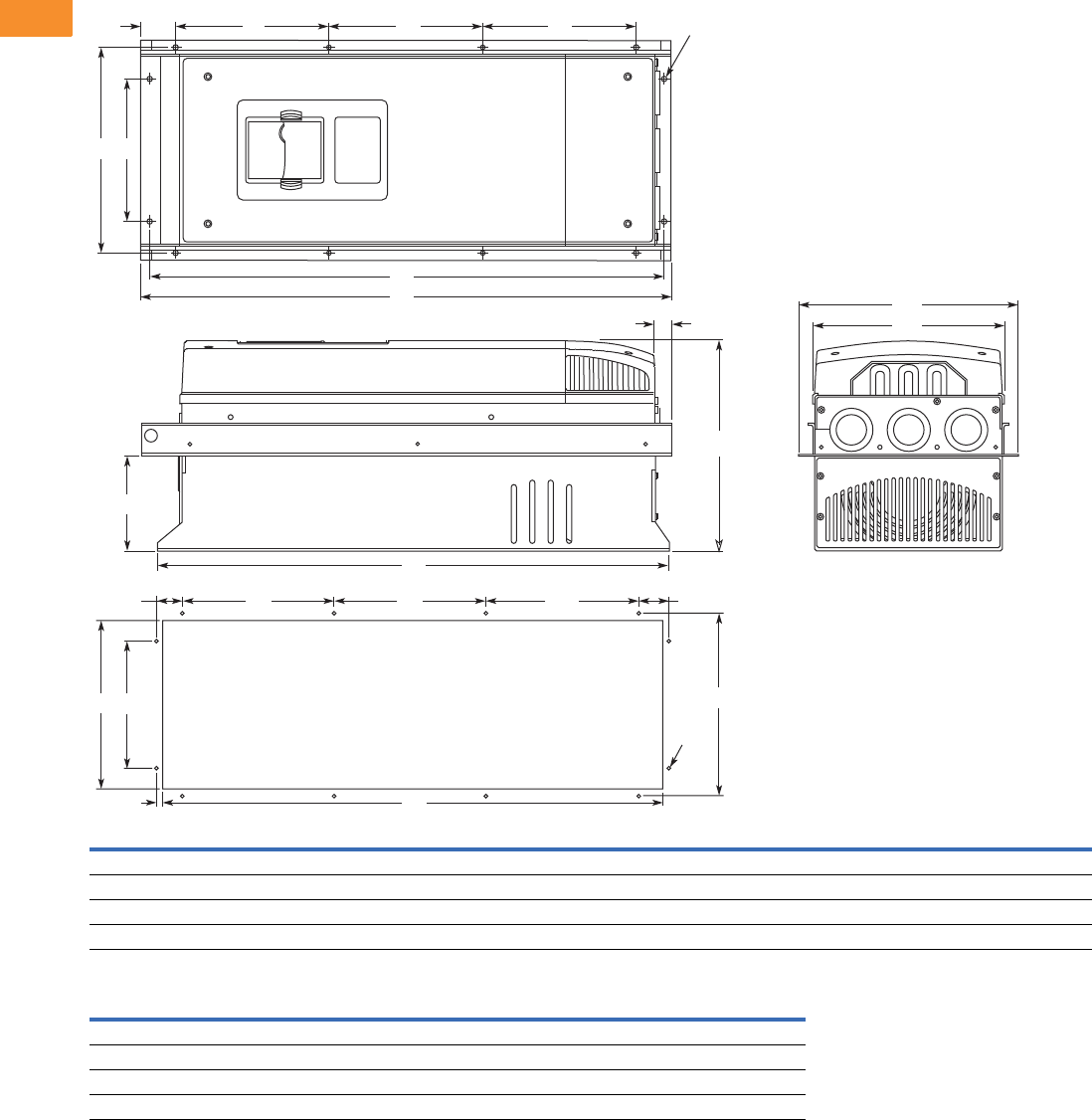
V6-T2-188 Volume 6—Solid-State Motor Control CA08100007E—May 2014 www.eaton.com
2
2
2
2
2
2
2
2
2
2
2
2
2
2
2
2
2
2
2
2
2
2
2
2
2
2
2
2
2
2
2.7
Adjustable Frequency Drives
SPX9000 Drives
Approximate Dimensions in Inches (mm)
NEMA Type 1/IP21 and NEMA Type 12/IP54, with Flange Kit, FR7 and FR8
Flange Opening, FR7 and FR8
W1 W2 W3 W4 H1 H2 H3 H4 H5 H6 H7 D1 D2 Dia. A
FR7
9.3 (237) 6.8 (175) 10.6 (270) 10.0 (253) 25.6 (652) 24.9 (632) 24.8 (630) 7.4 (189) 7.4 (189) 0.9 (23) 0.8 (20) 10.1 (257) 4.6 (117) 0.3 (6)
FR8
11.2 (285) — 14.0 (355) 13.0 (330) 32.8 (832) — 29.3 (745) 10.2 (258) 10.4 (265) 1.7 (43) 2.2 (57) 13.5 (344) 4.3 (110) 0.4 (9)
W5 W6 W7 H8 H9 H10 H11 H12 H13 Dia. B
FR7
9.2 (233) 6.9 (175) 10.0 (253) 24.4 (619) 7.4 (189) 7.4 (189) 1.4 (35) 1.3 (32) 1.0 (25) 0.3 (6)
FR8
11.9 (301) — 13.0 (330) 31.9 (810) 10.2 (258) 10.4 (265) — — 1.3 (33) 0.4 (9)
H7
W3
H9
D1
W1
H9H12
H13
H11H10
H1
H2
H5 Dia. A
Dia. B
H4H4H6
W2W4
D2
W6W5 W7
H3
H8
Flange Opening
FR7/FR8
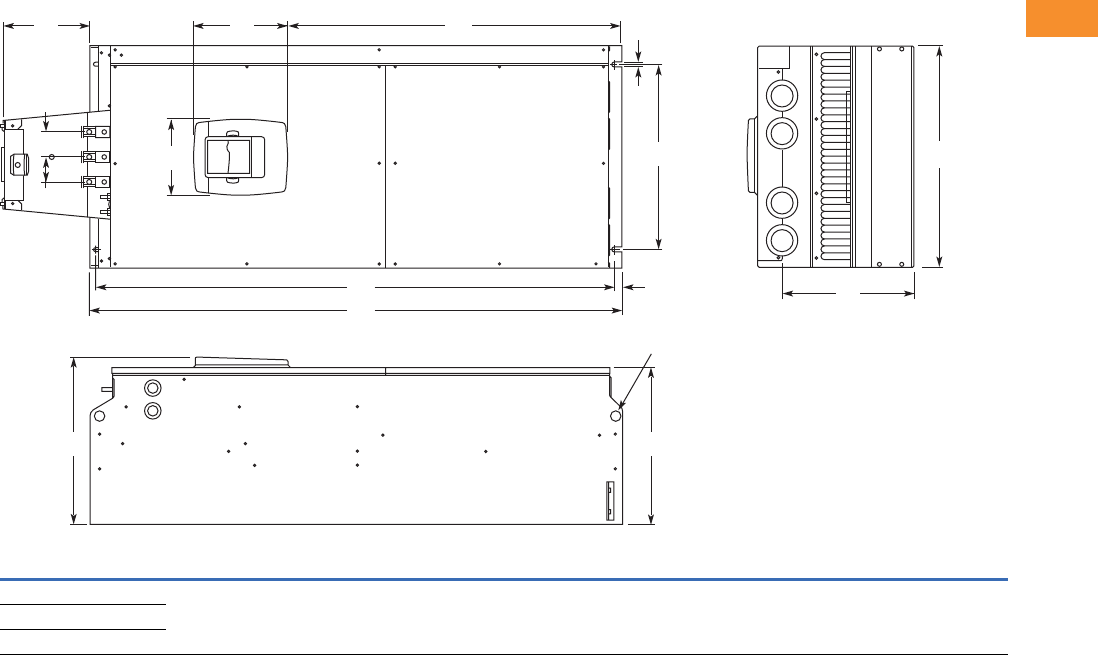
Volume 6—Solid-State Motor Control CA08100007E—May 2014 www.eaton.com V6-T2-189
2
2
2
2
2
2
2
2
2
2
2
2
2
2
2
2
2
2
2
2
2
2
2
2
2
2
2
2
2
2
2.7
Adjustable Frequency Drives
SPX9000 Drives
Approximate Dimensions in Inches (mm)
NEMA Type 1/IP21 and NEMA Type 12/IP54, FR9
Note
1Brake resistor terminal box (H6) included when brake chopper ordered.
Voltage hp (IH) W1W2W3W4H1 H2 H3 H4
1D1 D2 D3 Dia.
Weight
Lbs (kg)
230V 75–100 18.9
(480)
15.7
(400)
0.4
(9)
2.1
(54)
45.3
(1150)
44.1
(1120)
0.6
(16)
7.4
(188)
14.2
(361.5)
13.4
(340)
11.2
(285)
0.8
(21)
321.9 (146)
480V 150–200
575V 100–175
D2
Dia.
D1
H5
W2
W4
H3H4
H2
H1
H6
W3
W5
PE
B- B+ /R+ R-
W5 W1
D3
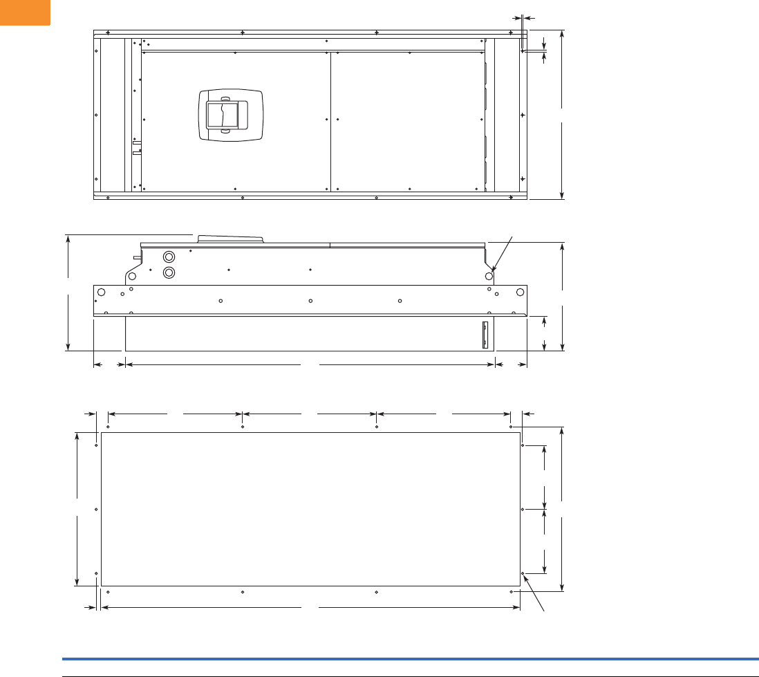
V6-T2-190 Volume 6—Solid-State Motor Control CA08100007E—May 2014 www.eaton.com
2
2
2
2
2
2
2
2
2
2
2
2
2
2
2
2
2
2
2
2
2
2
2
2
2
2
2
2
2
2
2.7
Adjustable Frequency Drives
SPX9000 Drives
Approximate Dimensions in Inches (mm)
NEMA Type 1/IP21 and NEMA Type 12/IP54, FR9 with Flange Kit
W1 W2 W3 W4 W5 H1 H2 H3 H4 H5 H6 H7 D1 D2 D3 Dia.
20.9 (530) 20.0 (510) 19.1 (485) 7.9 (200) 0.2 (5.5) 51.7 (1312) 45.3 (1150) 16.5 (420) 3.9 (100) 1.4 (35) 0.4 (9) 0.1 (2) 24.9 (362) 13.4 (340) 4.3 (109) 0.8 (21)
.20 (5)
Dia.
H4
H2
D2
Dia.
D1
D3
H4
W1
H7
W5
W3
W4
H3 H3 H3 H5H5
H6 H1
W4
W2
Flange Opening
FR9
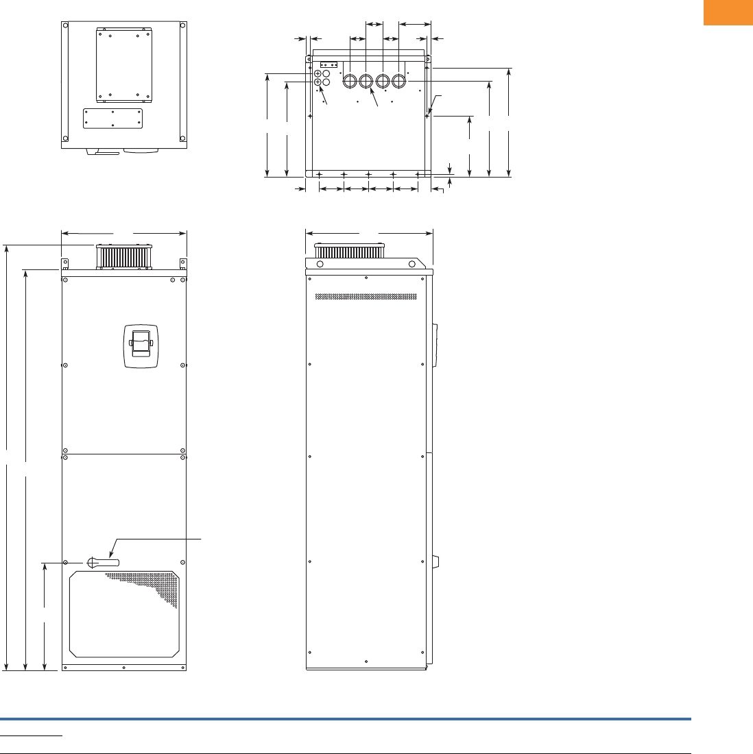
Volume 6—Solid-State Motor Control CA08100007E—May 2014 www.eaton.com V6-T2-191
2
2
2
2
2
2
2
2
2
2
2
2
2
2
2
2
2
2
2
2
2
2
2
2
2
2
2
2
2
2
2.7
Adjustable Frequency Drives
SPX9000 Drives
Approximate Dimensions in Inches (mm)
NEMA Type 1/IP21 and NEMA Type 12/IP54, FR10 Freestanding
Volts
hp
(IH) W1W2W3W4W5W6W7H1H2H3D1D2D3D4D5D6D7Dia. 1Dia. 2Dia. 3
Weight
Lbs (kg)
480V 250–350 23.43
(595)
2.46
(62.5)
4.53
(115)
0.79
(20)
5.95
(151)
2.95
(75)
30.11
(79)
79.45
(2018)
74.80
(1900)
20.18
(512.5)
23.70
(602)
17.44
(443)
19.02
(483)
0.47
(12)
11.22
(285)
17.60
(447)
20.08
(510)
0.83
(21)
1.89
(48)
0.43
(11)
875 (389)
690V 200–300
Dia. 3
Dia. 2
Dia. 1
W5
W6
W4 W4
D4
D2
W2
W2
D5
D3 D6 D7
W3 W3 W3 W3
H1
H2
H3
W1 D1
Operator
(Shown with
Optional
Disconnect)
W6
W7
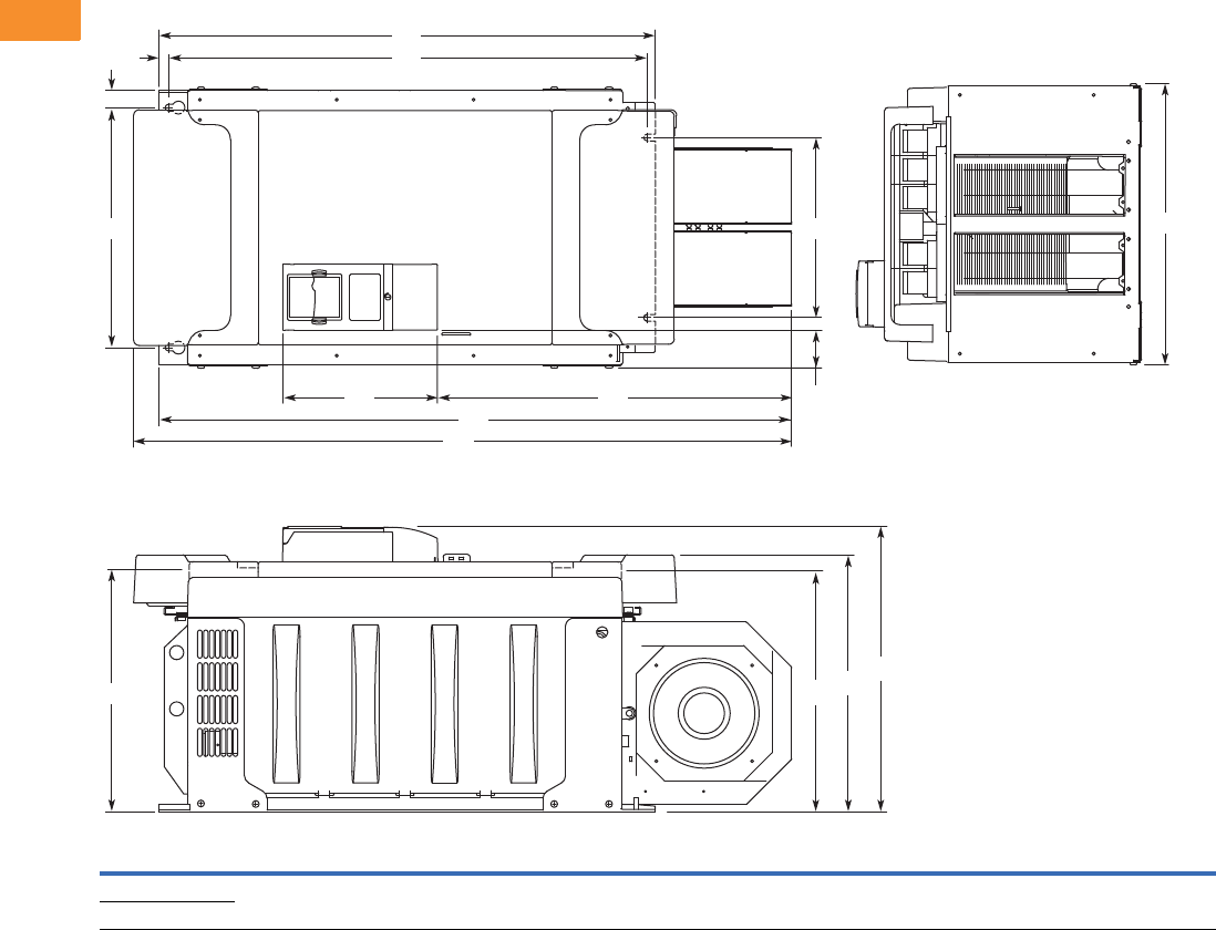
V6-T2-192 Volume 6—Solid-State Motor Control CA08100007E—May 2014 www.eaton.com
2
2
2
2
2
2
2
2
2
2
2
2
2
2
2
2
2
2
2
2
2
2
2
2
2
2
2
2
2
2
2.7
Adjustable Frequency Drives
SPX9000 Drives
Approximate Dimensions in Inches (mm)
FR10 Open Chassis 1
Note
1SPX9000X FR12 is built of two FR10 modules. Please refer to SPX9000 installation manual for mounting instructions.
Voltage hp (IH)W1W2W3W4W5H1H2H3H4H5H6H7D1D2D3D4
Weight
Lbs (kg)
480V 250–350 19.7
(500)
16.7
(425)
1.2
(30)
2.6
(67)
12.8
(325)
45.9
(1165)
44.1
(1121)
34.6
(879)
33.5
(850)
0.7
(17)
24.7
(627)
10.8
(275)
19.9
(506)
17.9
(455)
16.7
(423)
16.6
(421)
518
(235)
575V 200–300
H2
W1
H7 H6
H4H5
H3
H1
W2
W3
W5
W4
D4 D2 D1
D3
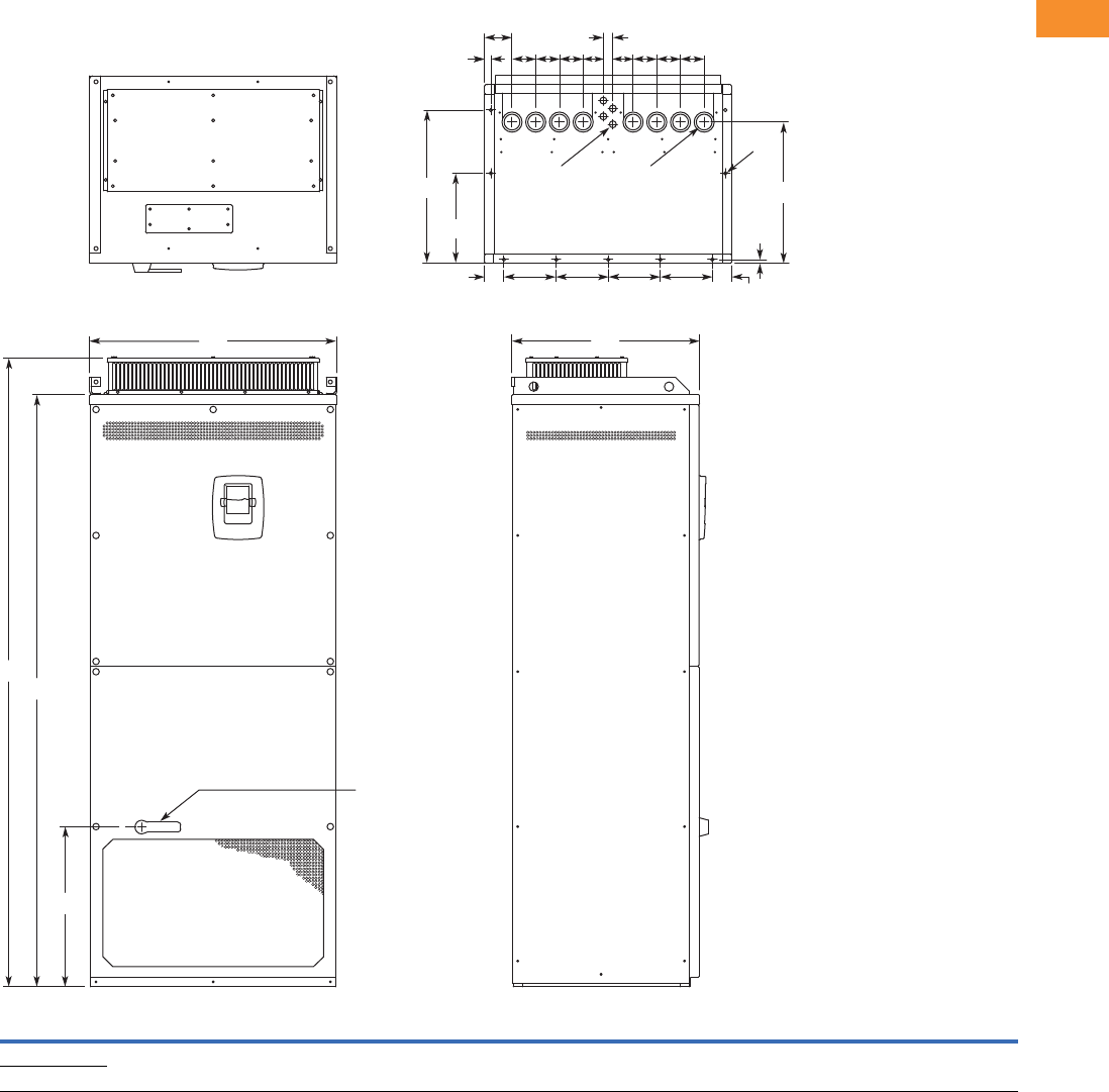
Volume 6—Solid-State Motor Control CA08100007E—May 2014 www.eaton.com V6-T2-193
2
2
2
2
2
2
2
2
2
2
2
2
2
2
2
2
2
2
2
2
2
2
2
2
2
2
2
2
2
2
2.7
Adjustable Frequency Drives
SPX9000 Drives
Approximate Dimensions in Inches (mm)
NEMA Type 1/IP21, FR11 Freestanding Drive
Voltage
hp
(IH) W1W2W3W4W5W6W7W8H1H2H3D1D2D3D4D5Dia. 1Dia. 2Dia. 3
Weight
Lbs (kg)
480V 400–550 31.26
(794)
2.40
(61)
6.50
(165)
0.79
(20)
3.43
(87)
2.95
(75)
2.52
(64)
1.18
(30)
79.45
(2018)
74.80
(1900)
20.18
(512.5)
23.70
(602)
11.22
(285)
19.09
(485)
0.47
(12)
17.60
(447)
0.83
(21)
1.89
(48)
0.35 x 0.43
(9 x 11)
526
(239)
690V 400–500
H1
H2
W1 D1
H3
D2
D3
Dia. 3
D4
D5
Dia. 1 Dia. 2
W2
W2 W3 W3 W3 W3
W8
W6
W4
W6
W5
W7W7 W6W6W6W6
Operator
(Shown with
Optional
Disconnect)
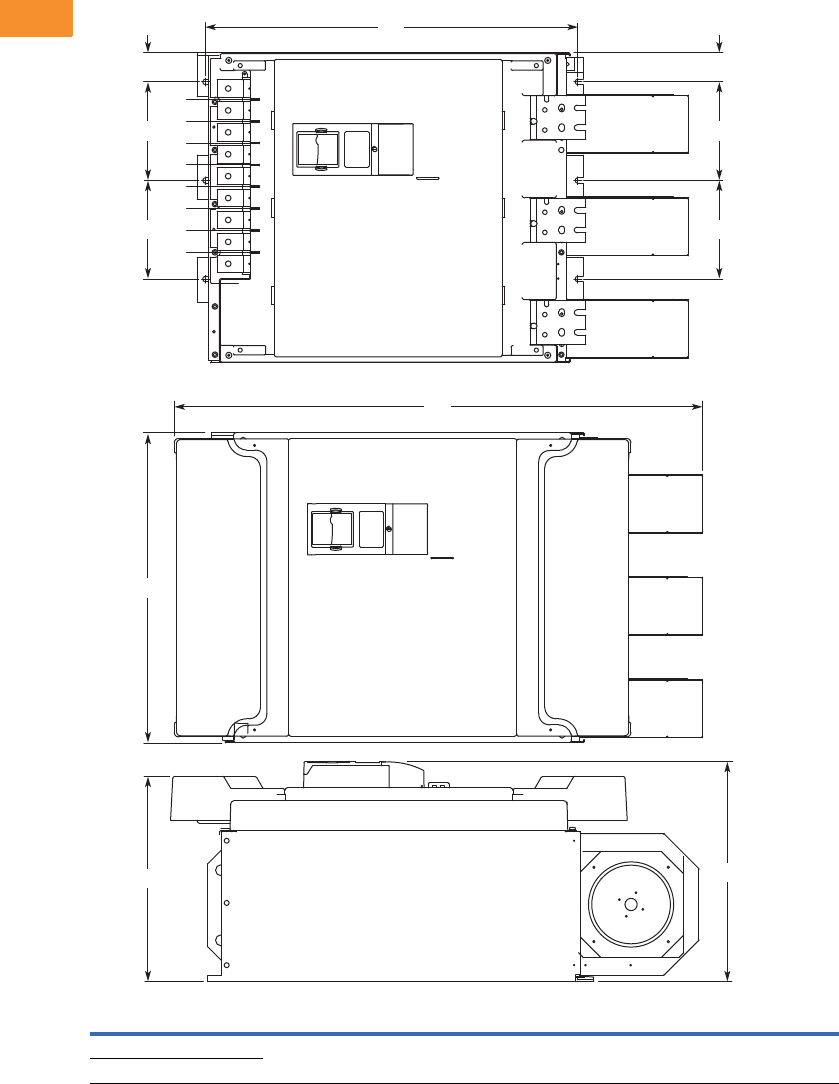
V6-T2-194 Volume 6—Solid-State Motor Control CA08100007E—May 2014 www.eaton.com
2
2
2
2
2
2
2
2
2
2
2
2
2
2
2
2
2
2
2
2
2
2
2
2
2
2
2
2
2
2
2.7
Adjustable Frequency Drives
SPX9000 Drives
Approximate Dimensions in Inches (mm)
FR11 Open Chassis
Voltage hp (IH)W1W2W3H1 H2 D1 D2
Weight
Lbs (kg)
480V 400–550 27.9 (709) 8.6 (225) 2.6 (67) 45.5 (1155) 33.5 (850) 19.8 (503) 18.4 (468) 833 (378)
575V 400–500
H1
H2
D1
W2
W2
W3
W2
W2
W3
W1
Shown without
terminal cover
D2
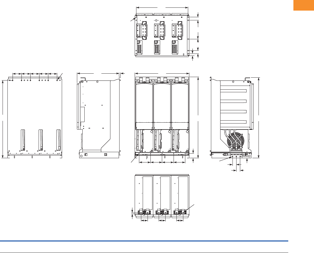
Volume 6—Solid-State Motor Control CA08100007E—May 2014 www.eaton.com V6-T2-195
2
2
2
2
2
2
2
2
2
2
2
2
2
2
2
2
2
2
2
2
2
2
2
2
2
2
2
2
2
2
2.7
Adjustable Frequency Drives
SPX9000 Drives
Approximate Dimensions in Inches (mm)
FR13, Open Chassis Inverter
Notes
9000X FR14 is built of two FR13 modules. Please refer to SPX9000 installation manual for mounting instructions.
FR13 is built from an inverter module and a converter module. Please refer to SPX9000 installation manual for mounting instructions.
W1 W2 W3 W4 W5 H1 H2 H3 H4 H5 D1 D2 D3 D4 D5 D6 D7 D8
Dia.
1
Dia.
2
Dia.
3
Dia.
4
Weight
Lbs (kg)
27.87
(708)
5.91
(150)
26.65
(677)
4.57
(116)
3.35
(85)
41.54
(1055)
2.46
(62.5)
39.86
(1012.5)
41.34
(1050)
0.79
(20)
21.77
(553)
0.51
(13)
0.63
(16)
1.97
(50)
1.06
(27)
1.57
(40)
5.91
(150)
9.64
(244.8)
0.35x0.59
(9x15)
0.18
(4.6)
0.51
(13)
0.37
(9.5)
683 (310)
W4 W4 W4 W4 W4
H3
Dia. 1 D1 D2 W1
W2W2W2W2
H2
W5 W5 W5
D3
Dia. 3
Dia. 3 D4
D4
H5
H4H1
D5 D6
D7
D8
D6
W3
Dia. 2
Dia. 4
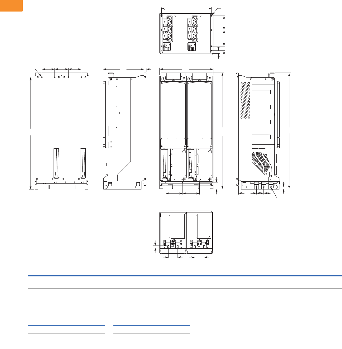
V6-T2-196 Volume 6—Solid-State Motor Control CA08100007E—May 2014 www.eaton.com
2
2
2
2
2
2
2
2
2
2
2
2
2
2
2
2
2
2
2
2
2
2
2
2
2
2
2
2
2
2
2.7
Adjustable Frequency Drives
SPX9000 Drives
Approximate Dimensions in Inches (mm)
FR13, Open Chassis Converter
Number of Input Units
W1 W2 W3 W4 W5 H1 H2 H3 H4 H5 D1 D2 D3 D4 D5 D6 D7 D8 D9 Dia. 1 Dia. 2 Dia. 3
Weight
Lbs (kg)
18.74
(476)
5.91
(150)
17.52
(445)
4.57
(116)
3.35
(85)
41.54
(1055)
2.46
(62.5)
39.86
(1012.5)
41.34
(1050)
0.69
(17.5)
14.69
(373)
0.51
(13)
0.73
(18.5)
6.42
(163)
2.56
(65)
1.06
(27)
1.57
(40)
5.91
(150)
5.24
(133)
0.35x0.59
(9x15)
0.51
(13)
0.37
(9.5)
295 (134)
480V
Catalog Number hp
Input
Modules
690V
Catalog Number hp
Input
Modules
SPX800A0-4A2N1 800 2 SPX800A0-5A2N1 800 2
SPX900A0-5A2N1 900 2
SPXH10A0-5A2N1 1000 2
H3
H2
H5
H4
Dia. 1 W4 W4 W4
W5
D3 W5
D5
D4 D5
W2
W2
D1 D2
Dia. 2
Dia. 2
H1
W3 Dia. 3
D9
D8
D7
D6
W1
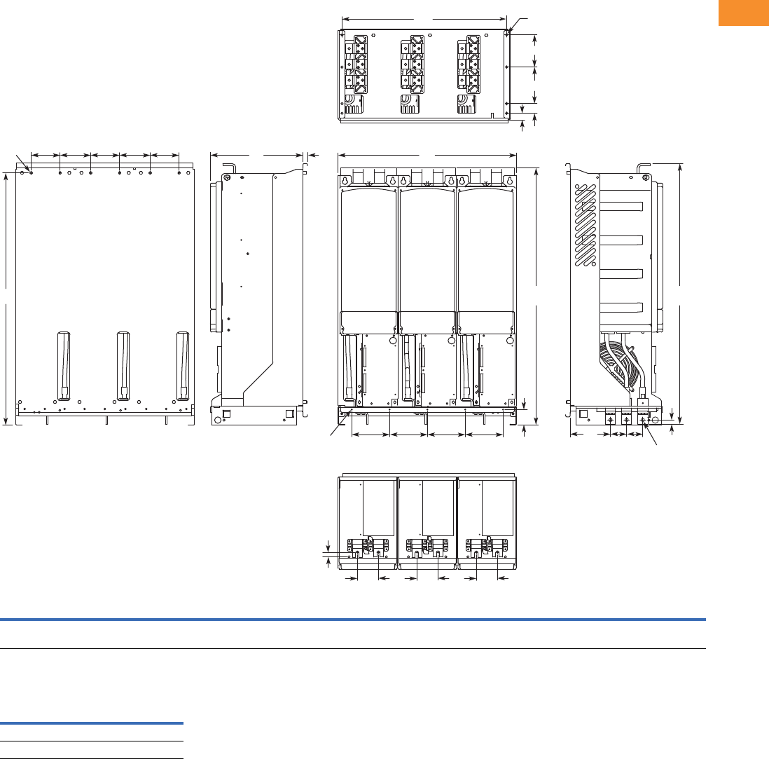
Volume 6—Solid-State Motor Control CA08100007E—May 2014 www.eaton.com V6-T2-197
2
2
2
2
2
2
2
2
2
2
2
2
2
2
2
2
2
2
2
2
2
2
2
2
2
2
2
2
2
2
2.7
Adjustable Frequency Drives
SPX9000 Drives
Approximate Dimensions in Inches (mm)
FR13, Open Chassis Converter—900/1000 hp 480V
Number of Input Units
W1 W2 W3 W4 W5 H1 H2 H3 H4 H5 D1 D2 D3 D4 D5 D6 D7 D8 D9
Dia.
1
Dia.
2
Dia.
3
Dia.
4
Weight
Lbs (kg)
27.87
(708)
5.91
(150)
26.65
(677)
4.57
(116)
3.35
(85)
41.54
(1055)
2.46
(62.5)
39.86
(1012.5)
41.34
(1050)
0.69
(17.5)
14.69
(373)
0.51
(13)
0.73
(18.5)
6.42
(163)
2.56
(65)
1.06
(27)
1.57
(40)
5.91
(150)
5.24
(133)
0.35x0.59
(9x15)
0.18
(4.6)
0.51
(13)
0.37
(9.5)
443 (201)
480V
Catalog Number hp
Input
Modules
SPX900A0-4A2N1 900 3
SPXH10A0-4A2N1 1000 3
H3
H2
H5
Dia. 1 W4 W4 W4 W4 W4
W5
D3 W5 W5
D5
D4 D5
W2
W2
W2 W2
D1 D2
Dia. 2
Dia. 3
H1 H4
W3 Dia. 4
D9
D8
D7
D6
W1
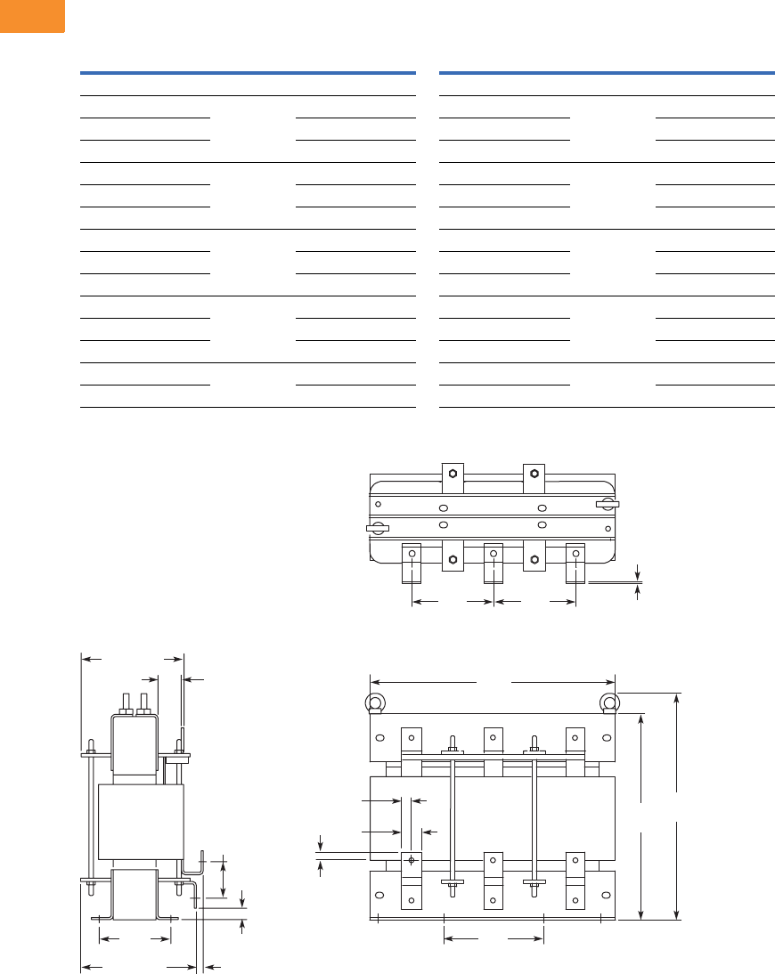
V6-T2-198 Volume 6—Solid-State Motor Control CA08100007E—May 2014 www.eaton.com
2
2
2
2
2
2
2
2
2
2
2
2
2
2
2
2
2
2
2
2
2
2
2
2
2
2
2
2
2
2
2.7
Adjustable Frequency Drives
SPX9000 Drives
Approximate Dimensions in Inches (mm)
AC Choke Dimensions
Choke Types
CHK0520
Note
1Chokes are provided with all FR10–FR14 drives.
Catalog Number Frame Size Choke Type 1Catalog Number Frame Size Choke Type 1
Voltage Range 380–500V Voltage Range 525–690V
SPX 250 4 FR10 CHK0400 SPX 200 5 FR10 CHK0261
SPX 300 4 CHK0520 SPX 250 5 CHK0400
SPX 350 4 CHK0520 SPX 300 5 CHK0400
SPX 400 4 FR11 2 x CHK0400 SPX 400 5 FR11 CHK0520
SPX 500 4 2 x CHK0400 SPX 450 5 CHK0520
SPX 550 4 2 x CHK0400 SPX 500 5 2 x CHK0400
SPX 600 4 FR12 2 x CHK0520 SPX 550 5 FR12 2 x CHK0400
SPX 650 4 2 x CHK0520 SPX 600 5 2 x CHK0400
SPX 700 4 2 x CHK0520 SPX 700 5 2 x CHK0400
SPX 800 4 FR13 2 x CHK0400 SPX 800 5 FR13 2 x CHK0400
SPX 900 4 3 x CHK0520 SPX 900 5 2 x CHK0400
SPX H10 4 3 x CHK0520 SPX H10 5 2 x CHK0400
SPX H12 4 FR14 4 x CHK0520 SPX H13 5 FR14 4 x CHK0400
SPX H16 4 6 x CHK0400 SPX H15 5 6 x CHK0400
11
33
2
1
3
22
1.58
(40)
7.88
(200)
6.50
(165) 6.50
(165)
19.57
(497)
.79
(20) 15.71
(399)
17.57
(446)
.79
(20)
.24
(6)
3.03
(77)
.83
(21)
.55 (14)9.61 (244)
8.03 (204)
1.69
(43)
5.70
(145)
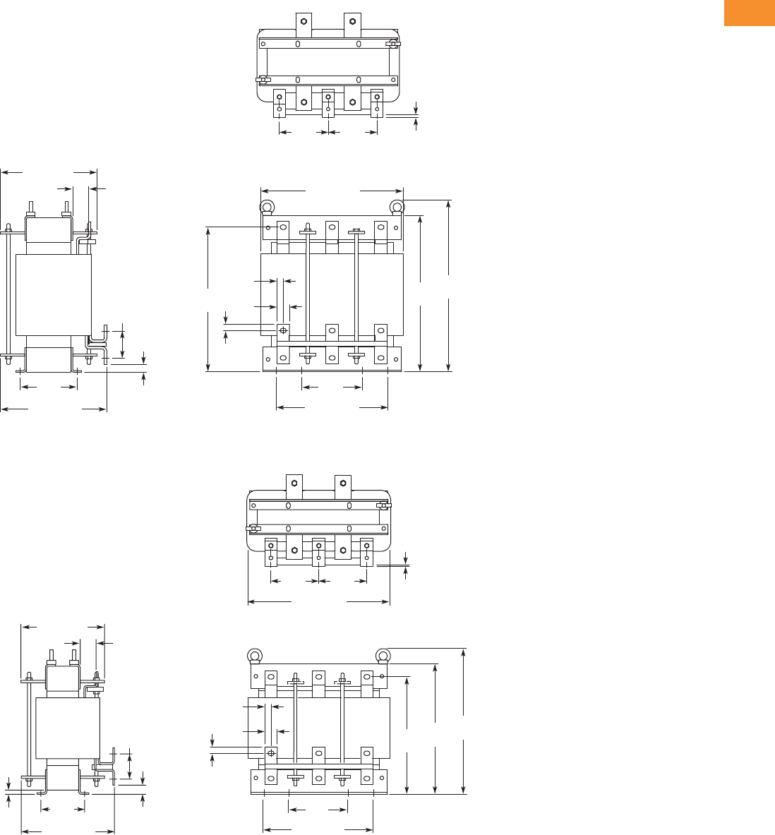
Volume 6—Solid-State Motor Control CA08100007E—May 2014 www.eaton.com V6-T2-199
2
2
2
2
2
2
2
2
2
2
2
2
2
2
2
2
2
2
2
2
2
2
2
2
2
2
2
2
2
2
2.7
Adjustable Frequency Drives
SPX9000 Drives
Approximate Dimensions in Inches (mm)
CHK0400
CHK0261
111
33
22
3
2
10.30 (262)
9.37 (238)
1.54
(39)
1.18
(30)
5.90
(150)
13.79 (350)
4.72
(120) 4.72
(120)
10.83 (275)
.59
(15)
5.51
(140)
13.94
(354)
15.08
(383)
16.58
(421)
2.64
(67)
.75
(19)
.24
(6)
.59
(15)
13.79 (350)
4.72
(120) 4.72
(120)
.24
(6)
11
33
2
1
3
22
1.18
(30)
5.90
(150)
10.83 (275)
.59
(15)
11.30
(287)
12.56
(319)
14.06
(357)
.59
(15)
.39
(10)
.87
(22)
.75 (19)
Min.
9.06 (230)
8.11 (206)
1.54
(39)
4.25
(108)
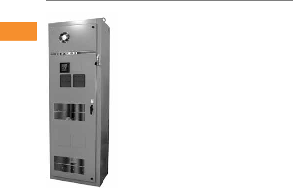
V6-T2-200 Volume 6—Solid-State Motor Control CA08100007E—May 2014 www.eaton.com
2
2
2
2
2
2
2
2
2
2
2
2
2
2
2
2
2
2
2
2
2
2
2
2
2
2
2
2
2
2
2.8
Adjustable Frequency Drives
Low Harmonic Drives
Enclosed Passive Filtered Drives
Contents
Description Page
Enclosed Passive Filtered Drives
Application Description . . . . . . . . . . . . . . . . . . V6-T2-201
Features and Benefits . . . . . . . . . . . . . . . . . . . V6-T2-207
Standards and Certifications . . . . . . . . . . . . . . V6-T2-207
Product Identification . . . . . . . . . . . . . . . . . . . . V6-T2-207
Catalog Number Selection . . . . . . . . . . . . . . . . V6-T2-208
Product Selection . . . . . . . . . . . . . . . . . . . . . . . V6-T2-209
Options . . . . . . . . . . . . . . . . . . . . . . . . . . . . . . V6-T2-216
Technical Data and Specifications . . . . . . . . . . V6-T2-221
Wiring Diagram . . . . . . . . . . . . . . . . . . . . . . . . V6-T2-223
Dimensions . . . . . . . . . . . . . . . . . . . . . . . . . . . V6-T2-224
Enclosed 18-Pulse Drives . . . . . . . . . . . . . . . . . . . V6-T2-233
Enclosed Passive Filtered Drives
Product Description
The enclosed passive filtered
clean power drives from
Eaton’s Electrical Sector
use tuned passive filters
to significantly reduce line
harmonics at the drive input
terminals.
The enclosed passive filtered
drive also delivers True
Power Factor—in addition to
reducing harmonic distortion,
the enclosed passive filtered
drive prevents transformer
overheating and overloading
of breakers and feeders,
which enables the application
of adjustable frequency
drives on generators and
other high impedance power
systems.
The 9000X family of drives
includes HVX9000, SVX9000,
SLX9000, and SPX9000.
9000X Series drive ratings are
rated for either high overload
(IH) or low overload (IL). IL
indicates 110% overload
capacity for 1 minute out of
10 minutes. IH indicates
150% overload capacity for
1 minute out of 10 minutes.
Enclosed Passive Filtered
Drive Products
●Standard Enclosed—
covers a wide range of the
most commonly ordered
options. Pre-engineering
eliminates the lead time
normally associated with
customer specific options.
Available configurations
are listed on Pages
V6-T2-207 to V6-T2-222.
●Modified Standard
Enclosed—applies to
specific customer
requirements that vary
from the Standard
Enclosed offering, such as
the need for an additional
indicating light or minor
modifications to drawings.
Contact your local sales
office for assistance in
pricing and lead time.
●Custom Engineered—for
those applications with
more unique or complex
requirements, these are
individually engineered to
the customer’s needs.
Contact your local sales
office for assistance in
pricing and lead time.
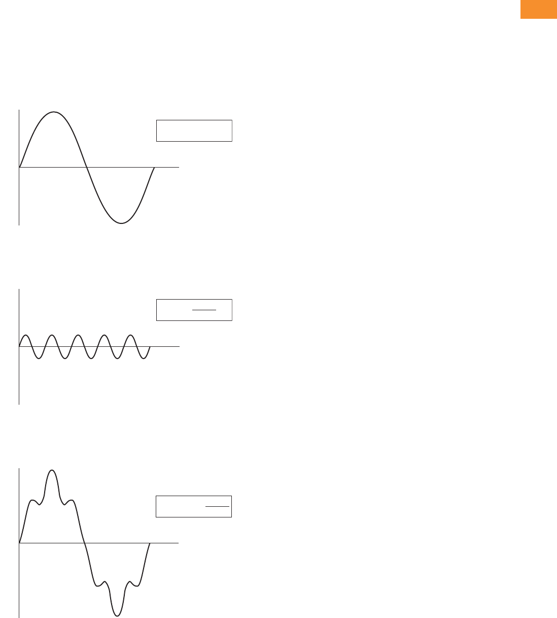
Volume 6—Solid-State Motor Control CA08100007E—May 2014 www.eaton.com V6-T2-201
2
2
2
2
2
2
2
2
2
2
2
2
2
2
2
2
2
2
2
2
2
2
2
2
2
2
2
2
2
2
2.8
Adjustable Frequency Drives
Low Harmonic Drives
Application Description
Designed to meet the IEEE
®
519-1992 requirements for
ha
rm
onic distortion, the
enclosed passive filtered
drive is an excellent choice
for small and midsize drives
applications where harmonics
are a concern.
What Are Harmonics?
Take a perfect wave with a fundamental frequency of 60 Hz,
which is close to what is supplied by the power company.
Perfect Wave
Add a second wave that is five times the fundamental frequency—
300 Hz (typical of frequency added to the line by a fluorescent light).
Second Wave
Combine the two waves. The result is a 60 Hz supply rich in
fifth harmonics.
Resulting Supply
f(x) = sin(x)
Volts
(v)
Time
(t)
f(x) = sin(5x)
5
Volts
(v)
Time
(t)
f(x) = sin(x) +
Volts
(v)
Time
(t)
sin(5x)
5
What Causes Harmonics?
Harmonics are the result of
nonlinear loads that convert
AC line voltage to DC.
Examples of equipment that
are non-linear loads are listed
below:
●AC variable frequency
drives
●DC drives
●Fluorescence lighting,
computers, UPS systems
●Industrial washing
machines, punch presses,
welders, etc.
How Can Harmonics Due to
VFDs Be Diminished?
By applying drives from the
Eaton Clean Power Drives
Family; The HCX9000,
enclosed passive filtered
drive and enclosed 18-pulse
drive.
What Are Linear Loads?
Linear loads are primarily
devices that run across the
line and do not add
harmonics. Motors are prime
examples. The downside to
having large motor linear
loads is that they draw more
energy than a VFD, because
of their inability to control
motor speed. In most
applications there is a turn
down valve used with the
motor which will reduce the
flow of the material, without
significantly reducing the load
to the motor. While this
provides some measure of
speed control, it is extremely
inefficient.
Why Be Concerned
About Harmonics?
1. Installation and utility
costs increase.
Harmonics cause
damage to transformers
and lower efficiencies
due to the IR loss.
These losses can
become significant (from
16.6–21.6%) which can
have a dramatic effect on
the HVAC systems that
are controlling the
temperatures of the
building where the
transformer and drive
equipment reside.
2. Downtime and loss of
productivity. Telephones
and data transmissions
links may not be
guaranteed to work on
the same power grids
polluted with harmonics.
3. Downtime and
nuisance trips of drives
and other equipment.
Emergency generators
have up to three times
the impedance that is
found in a conventional
utility source. Thus the
harmonic voltage can be
up to three times as
large, causing risk of
operation problems.
4. Larger motors must be
used. Motors running
across the line that are
connected on polluted
power distribution grids
can overheat or operate
at lower efficiency due to
harmonics.
5. Higher installation
costs. Transformers and
power equipment must
be oversized to
accommodate the loss of
efficiencies. This is due
to the harmonic currents
circulating through the
distribution without
performing useful work.
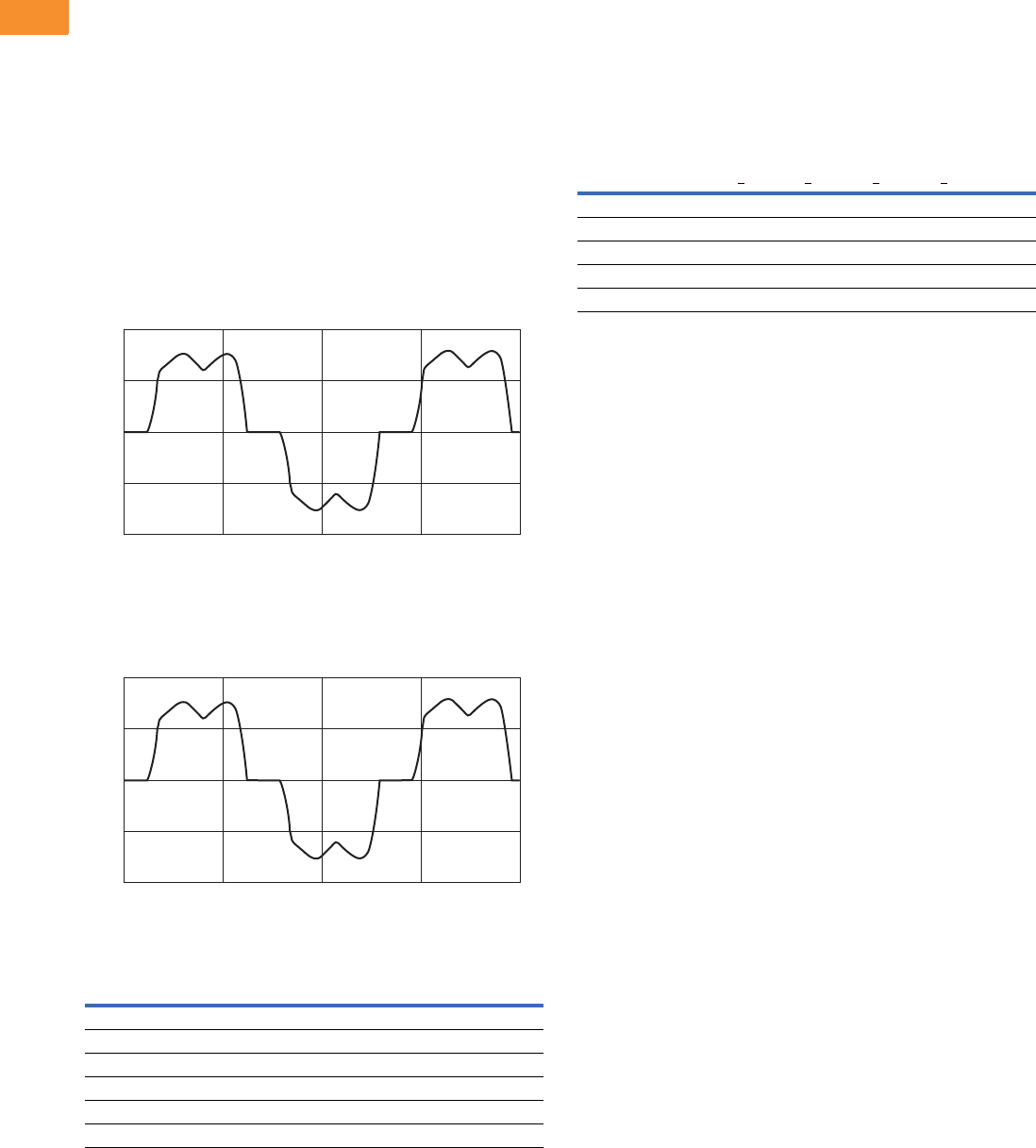
V6-T2-202 Volume 6—Solid-State Motor Control CA08100007E—May 2014 www.eaton.com
2
2
2
2
2
2
2
2
2
2
2
2
2
2
2
2
2
2
2
2
2
2
2
2
2
2
2
2
2
2
2.8
Adjustable Frequency Drives
Low Harmonic Drives
How Does a VFD Convert Three-Phase AC to a
Variable Output Voltage and Frequency?
The six-pulse VFD: The
majority of all conventional
drives that are built consist of
a six-pulse configuration. The
figure below
represents a six-
diode rectifier design that
converts three-phase utility
power to DC. The inverter
section uses IGBTs to convert
DC power to a simulated AC
sine wave that can vary in
frequency from 0–400 Hz.
The six-pulse VFD drive
creates harmonic current
distortion. The harmonic
current that is created is
energy that can not be used
by customers and causes
external heat and losses to all
components including other
drives that are on the same
power distribution. The figure
is a 100 hp drive with 45A of
damaging harmonic current.
100 hp Six-Diode Rectifier Design
100 hp Six-Pulse Nonproductive Harmonic Current
Six-Pulse Nonproductive Harmonic Current
Six-Pulse Circuit
Current harmonics
I1 = 100% I11 = 6.10% I19 = 1.77%
I5 = 22.5% I13 = 4.06% I23 = 1.12%
I7 = 9.38% I17 = 2.26% I25 = 0.86%
Power = 100 hp
Harmonic current = 45 amps
1000
Current
Amps
500
0
–500
–1000
0.100 0.10625 0.1125
Time in Seconds
0.11875 0.125
1000
Current
Amps
500
0
–500
–1000
0.100 0.10625 0.1125
Time in Seconds
0.11875 0.125
Guidelines of Meeting IEEE Std. 519-1992
Harmonic Distortion Limits
The IEEE 519-1992
Specification is a standard
that provides guidelines for
commercial and industrial
users that are implementing
medium and low voltage
equipment.
Maximum Harmonic Current Distortion in % of the
Fundamental (120V through 69,000V)
The ratio Isc/IL is the ratio of the short-circuit current available at the
point of common coupling (PCC), to the maximum fundamental load
current. Consequently, as the size of the user load decreases with
respect to the size of the system, the percentage of harmonic current
that the user is allowed to inject into the utility system increases.
Notes
TDD = Total demand distortion is the harmonic current distortion in percent of the maximum
demand load current (15 or 30 minute demand).
ISC = Maximum short-circuit current at the PCC not counting motor contribution.
IL = Maximum demand load current for all of the connected loads (fundamental frequency
component) at the PCC. All of the limits are measured at a point of common coupling.
Harmonic Order (Odd Harmonics)
Isc/ILh<11 11<h<17 17<h<23 23<h<35 35<hTDD
<20 4.0 2.0 1.5 0.6 0.3 5.0
20<50 7.0 3.5 2.5 1.0 0.5 8.0
50<100 10.0 4.5 4.0 1.5 0.7 12.0
100<1000 12.0 5.5 5.0 2.0 1.0 15.0
>1000 15.0 7.0 6.0 2.5 1.4 20.0
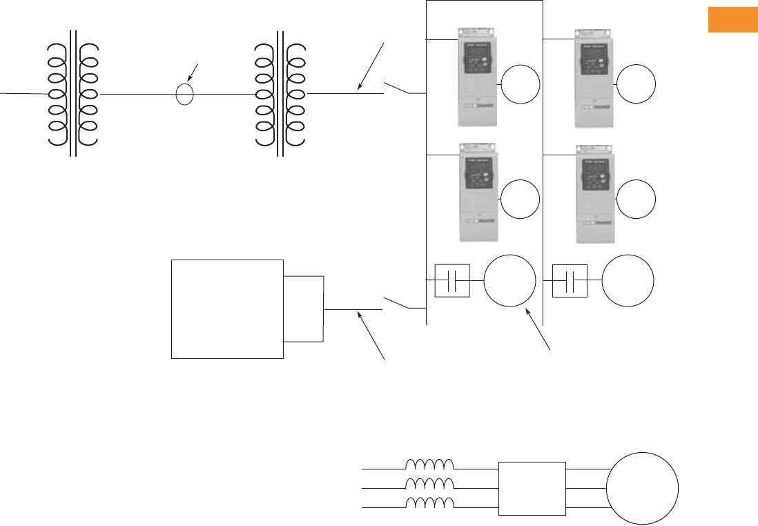
Volume 6—Solid-State Motor Control CA08100007E—May 2014 www.eaton.com V6-T2-203
2
2
2
2
2
2
2
2
2
2
2
2
2
2
2
2
2
2
2
2
2
2
2
2
2
2
2
2
2
2
2.8
Adjustable Frequency Drives
Low Harmonic Drives
One-Line Diagram for Harmonic Analysis
Terms
●PCC (Point of Common
Coupling) is defined as the
electrical connecting point
between the utility and
multiple customers per the
specifications in IEEE 519
●POA (Point of Analysis)
is defined as where the
harmonic calculations
are taken
An oscilloscope can make
all measurements at the
PCC or POA to do an on-site
harmonic evaluation.
Harmonic Reduction
Methods to Meet IEEE 519
1. Line Reactor
A line reactor is a three-phase
series inductance on the line
side of an AFD. If a line
reactor is applied on all
AFDs, it is possible to meet
IEEE guidelines where
10–25% of system loads
are AFDs, depending on the
stiffness of the line and the
value of line reactance. Line
reactors are available in
various values of percent
impedance, most typically
1–1.5%, 3% and 5%.
Note: The 9000X drives come
standard with a nominal 3% input
impedance.
____Volts ____Volts
____Volts
____kVA
____Isc
____Impedance
PCC
Utility Side
Utility Side
Transformer
____Volts ____Volts
____Volts
____kVA
____Isc
____Impedance
Customer
Transformer
Customer
Generator
____Volts
____kVA
____Isc
____Impedance
Source A
Source B
Generator
Set
AC
Motor
AC
Motor
AC
Motor
Total Linear Motor Loads
Total Non-Linear Drive Loads
____AMPS
____AMPS
AC
Motor
AC
Motor
AC
Motor
The best way to estimate AFD harmonic contribution to an electrical system is to perform a harmonic analysis based on known system
characteristics. The one line in this figure would provide the data to complete the calculations.
Line Reactor
Advantages
●Low cost
●Can provide moderate
reduction in voltage and
current harmonics
●Available in various values
of percent impedance
●Provides increased input
protection for AFD and its
semiconductors from line
transients
Disadvantages
●May not reduce harmonic
levels to below IEEE 519-
1992 guidelines
●Voltage drop due to IR loss
AFD Motor
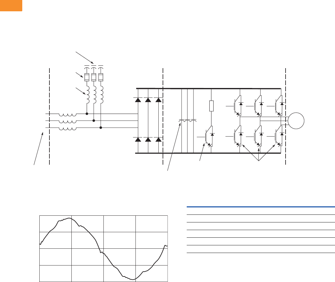
V6-T2-204 Volume 6—Solid-State Motor Control CA08100007E—May 2014 www.eaton.com
2
2
2
2
2
2
2
2
2
2
2
2
2
2
2
2
2
2
2
2
2
2
2
2
2
2
2
2
2
2
2.8
Adjustable Frequency Drives
Low Harmonic Drives
2. Passive Filters
Tuned harmonic filters
involve the series connection
of an inductor with the shunt
connection of an inductor and
capacitor to form a low
impedance path to ground for
a specific range of
frequencies. This path
presents an alternative to the
flow of harmonic currents
back into the utility source.
Enclosed Drive with Integrated Passive Filter
100 hp Enclosed 480V Drive with Integrated Passive Filter
Three-Phase
Input
AC Input
Reactor
L1A
L2A
L3A
1
2
3
Output Transistors
IGBT Section
Dynamic Braking
Transistor
6-Pulse Diode
Bridge Rectier
Converter Section
Shunt
Fusing
Tuned
Shunt
Reactor
Tuned
Harmonic
Capacitor
Inverter Section
(–) DC
(+) DC
Bus
Capacitors
AC
Motor
200
Current
Amps
100
0
–100
–200
Time
100 hp Enclosed 480V Drive with Integrated Passive Filter
Advantages
●Low cost for smaller
horsepower applications
●More effective harmonic
attenuation than 12-pulse
drives
●Provides increased input
protection for AFD from
line transients
Disadvantages
●Capacitors age over time,
unlike magnetics
●Not as effective as
18-pulse drives
●Challenging to retrofit with
bypass applications
Passive Filter
Current harmonics
I1 = 100% I11 = 0.24% I19 = 0.50%
I5 = 3.76% I13 = 1.1% I23 = 0.55%
I7 = 1.65% I17 = 0.80% I25 = 0.80%
Power = 100 hp
Hc = 8.6 Amps

Volume 6—Solid-State Motor Control CA08100007E—May 2014 www.eaton.com V6-T2-205
2
2
2
2
2
2
2
2
2
2
2
2
2
2
2
2
2
2
2
2
2
2
2
2
2
2
2
2
2
2
2.8
Adjustable Frequency Drives
Low Harmonic Drives
3. 12-Pulse Converters
A 12-pulse converter
incorporates two separate
AFD input semiconductor
bridges, which are fed from
30º phase shifted power
sources with identical
impedance. The sources may
be two isolation
transformers, where one is a
delta/wye design (which
provides the phase shift) and
the second a delta/delta
design (which does not phase
shift). The 12-pulse
arrangement allows the
harmonics from the first
converter to cancel the
harmonics of the second. Up
to approximately 85%
reduction of harmonic current
and voltage distortion may be
achieved (over standard
Basic 12-Pulse Rectifier with “Phase Shifting” Transformer
100 hp 480V Drive with 12-Pulse Rectifier
12-Pulse Diode
Bridge Rectier
Converter Section
Inverter Section
(+) DC
L1A
L2A
L3A
L1B
L2B
L3B
(-) DC
Dynamic Braking
Transistor
Output Transistors
IGBT Section
AC
Motor
12-Pulse Diode
Bridge Rectier
Converter Section
12-Pulse
Phase-Shifting
Transformer
Bus
Capacitors
200
Current
Amps
100
0
–100
–200
Time
six-pulse converter). This
permits a facility to use a
larger percentage of AFD
loads under IEEE 519-1992
guidelines than allowable
using line reactors or DC
chokes. A harmonic analysis
is required to guarantee
compliance with guidelines.
100 hp 480V Drive with 12-Pulse Rectifier
Advantages
●Reasonable cost, although
significantly more than
reactors or chokes
●Substantial reduction (up to
approx. 85%) in voltage
and current harmonics
●Provides increased input
protection for AFD and its
semiconductors from line
transients
Disadvantages
●Impedance matching of
phase shifted sources is
critical to performance
●Transformers often require
separate mounting or
larger AFD enclosures
●May not reduce
distribution harmonic levels
to below IEEE 519-1992
guidelines
●Cannot retrofit for most
AFDs
12-Pulse Circuit
Current harmonics
I1 = 100% I11 = 4.19% I19 = 0.06%
I5 = 1.25% I13 = 2.95% I23 = 0.87%
I7 = 0.48% I17 = 0.21% I25 = 0.73%
Power = 100 hp
Hc = 20 Amps
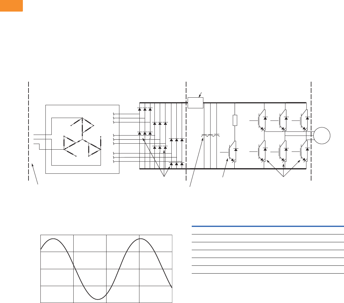
V6-T2-206 Volume 6—Solid-State Motor Control CA08100007E—May 2014 www.eaton.com
2
2
2
2
2
2
2
2
2
2
2
2
2
2
2
2
2
2
2
2
2
2
2
2
2
2
2
2
2
2
2.8
Adjustable Frequency Drives
Low Harmonic Drives
4. Clean Power Drives
When the total load is
comprised of non-linear load
such as drives, and the ratio
is lsc/IL, the greatest
harmonic mitigation is
required. Under these
conditions, the currents
drawn from the supply need
to be sinusoidal and “clean”
such that system
interference and additional
losses are negligible. Eaton’s
Enclosed 18-Pulse clean
power drive uses a phase-
shifting auto-transformer with
delta-connected winding that
carries only the ampere-turns
caused by the difference in
load currents. This results in
nine separate phases. In this
type of configuration, the
Basic 18-Pulse Rectifier with Phase-Shifting Auto-Transformer
100 hp 480V Drive with 18-Pulse Rectifiers
1
12
23
34
4
5
5
6
67
7
8
8
9
9
A
C
N
Output Transistors
IGBT Section
Dynamic Braking
Transistor
Pre-charge
Circuit
18-Pulse SCR
Bridge Rectier
Converter Section
18-Pulse
Phase-Shifting
Auto-Transformer
Inverter Section
(–) DC
(+) DC
Diode Rectiers
Bus
Capacitors
3-Phase
AC Input
1
2
3
AC
Motor
200
Current
Amps
100
0
–100
–200
Time
total kVA rating of the
transformer magnetic system
was only 48% that of the
motor load. A traditional
isolated transformer system,
with multipulse windings,
would require the full kVA
rating to be supported, which
is more common in an MV
step-down transformer.
The integrated 18-pulse clean
power drive, with near sine
wave input current and low
harmonics will meet the
requirements of IEEE 519-
1992 under all practical
operating conditions. The
comparisons with six-pulse
passive filter and 12-pulse
systems are shown on Pages
V6-T2-202, V6-T2-204 and
below.
100 hp 480V Drive with 18-Pulse Rectifiers
Advantages
●Effectively guarantees
compliance with IEEE 519-
1992
●Provides increased input
protection for AFD and its
semiconductors from line
transients
●Up to 4 times the harmonic
reduction of 12-pulse
methods
●Smaller transformer than
isolation transformer used
in 12-pulse converter
●Minimizes ripple current in
capacitors, doubling
expected capacitor life
Disadvantages
●Not as cost effective as
some other methods at
small (<50) horsepower
18-Pulse Clean Power
Current harmonics
I1 = 100% I11 = 0.24% I19 = 1.00%
I5 = 0.16% I13 = 0.10% I23 = 0.01%
I7 = 0.03% I17 = 0.86% I25 = 0.01%
Power = 100 hp
Hc = 5.9 Amps
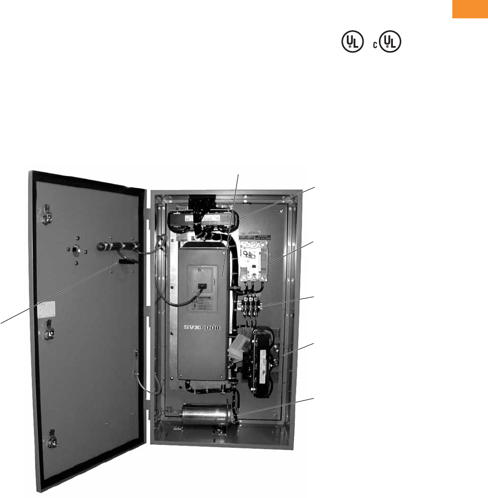
Volume 6—Solid-State Motor Control CA08100007E—May 2014 www.eaton.com V6-T2-207
2
2
2
2
2
2
2
2
2
2
2
2
2
2
2
2
2
2
2
2
2
2
2
2
2
2
2
2
2
2
2.8
Adjustable Frequency Drives
Low Harmonic Drives
Features and Benefits
New enclosed passive filtered
clean power drive features
include (at 480V):
●UL Type 1, UL Type 12, UL
Type 3R
and NEMA 12 with
gaskets and filters
●Input voltage: 480V, 230V,
575V
●Complete range of control,
network and power options
●Horsepower range:
●480V, 7-1/2–400 hp IL
●230V, 7-1/2–100 hp IL;
consult factory for
details
●575V, 15–400 hp IL;
consult factory for
details
●Single enclosure for both
drive and filter reduces
field wiring and enables
convenient bypass
installation
●Packaged solution ensures
optimal coordination of
drive and filter
Standards and Certifications
●UL
●cUL
●508C
Product Identification
Enclosed Passive Filtered Drive—UL Type 12, 40 hp
Input Reactor
Optional Breaker
Disconnect (P1)
Shunt Fusing
Tuned Shu nt
Reactor
SVX9000 Drive
Tuned Har monic
Capacitor
Door Mounted
Keypad
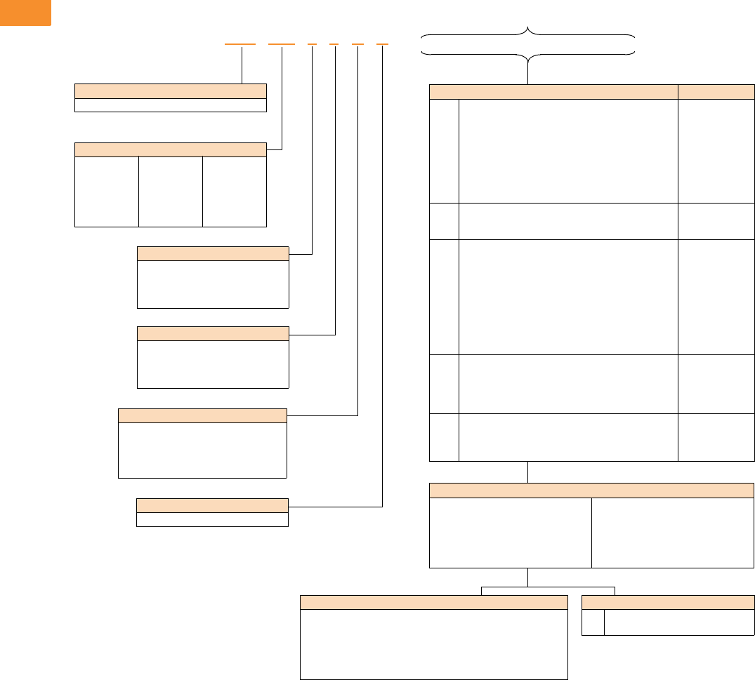
V6-T2-208 Volume 6—Solid-State Motor Control CA08100007E—May 2014 www.eaton.com
2
2
2
2
2
2
2
2
2
2
2
2
2
2
2
2
2
2
2
2
2
2
2
2
2
2
2
2
2
2
2.8
Adjustable Frequency Drives
Low Harmonic Drives
Catalog Number Selection
Enclosed Passive Filtered Drives
Notes
1Brake chopper is standard in 208V, 230V and 480V drives up to FR6; optional in all other drives.
2Local/remote keypad is included as the standard control panel.
3Some options are voltage and/or horsepower specific. Consult your Eaton representative for details.
4See Pages V6-T2-218 and V6-T2-219 for complete descriptions.
5Includes local/remote speed reference switch.
6See Pages V6-T2-216 and V6-T2-217 for complete descriptions.
7Consult Eaton for availability.
Build Alphabetically and Numerically
Voltage Rating
1 = 208V
2 = 230V
4 = 480V
5 = 575V (575–600V)
Product Family
CFX = Integrated filter clean power drive
Enclosure Rating
1 = UL Type 1
2 = UL Type 12
3 = UL Type 3R
6 = NEMA 12 filtered
Application—Torque/Braking 1
A = IL/no brake chopper
B = IL/internal brake chopper
D = IH/no brake chopper
E = IH/internal brake chopper
Enclosed Style
A = Enclosed drive
Horsepower Rating
007 = 7-1/2 hp
010 = 10 hp
015 = 15 hp
020 = 20 hp
025 = 25 hp
030 = 30 hp
040 = 40 hp
050 = 50 hp
060 = 60 hp
075 = 75 hp
100 = 100 hp
125 = 125 hp
150 = 150 hp
200 = 200 hp
250 = 250 hp
300 = 300 hp
350 = 350 hp
400 = 400 hp
CFX 050 1 4 A A _ _ _ _ _ _ _ _ _ _
Enclosed Options 234 Type
K1
K2
K3
K4
K5
K6
KF
KO
Door-mounted speed potentiometer 5
Door-mounted speed potentiometer with HOA selector
switch 5
3–15 psig follower
HAND/OFF/AUTO switch (22 mm)
MANUAL/AUTO reference switch (22 mm)
START/STOP pushbuttons (22 mm)
Bypass test switch for RA and RB
Standard elapsed time meter
Control
Control
Control
Control
Control
Control
Addl. bypass
Control
L1
L2
LE
Power, RUN and fault pilot lights
Bypass pilot lights for RA, RB, bypass options
Red RUN light
Light
Addl. bypass
Light
P1
P3
P7
P8
PE
PF
PG
PH
PI
PN
Input circuit breaker
Input line fuses (200 kAIC)
Input power surge protection
TVSS surge protective device
Output contactor
Output filter
MotoRx (up to 600 ft) 1000 V/μS DV/DT filter
Single overload relay
Dual overload relays
Dual overloads for bypass
Input
Input
Input
Input
Output
Output
Output
Output
Output
Addl. bypass
RA
RB
RC
RD
RG
Manual HOA bypass controller
Manual IOB bypass controller
Auto transfer HOA bypass controller
Auto transfer IOB bypass controller
Reduced voltage starter for bypass
Bypass
Bypass
Bypass
Bypass
Bypass
S4
S5
S6
S9
Floor stand 6 in
Floor stand 22 in
Floor stand 12 in
Space heater
Enclosure
Enclosure
Enclosure
Enclosure
Communication Options 6
C2 = Modbus
C3 = PROFIBUS DP
C4 =LonWorks
C5 = PROFIBUS DP (D9 Connector)
C6 = CANopen (Slave)
C7 = DeviceNet
C8 = Modbus (D9 type connector)
CA = Johnson Controls N2
CI = Modbus TCP
CJ = BACnet
CQ = EtherNet/IP
D3 = RS-232 with D9 connection
Engineered Options
HT
VB
High temperature rating for 50°C 7
Varnished boards
Control Options
B1 = 6 DI, 1 ext +24 Vdc/EXT +24 Vdc
B2 = 1 RO (NC-NO), 1 RO (NO), 1 therm
B4 = 1 AI (mA isolated), 2 AO (mA isolated), 1 ext +24 Vdc/EXT +24 Vdc
B5 = 3 RO (NO)
B8 = 1 ext +24 Vdc/EXT +24 Vdc, 3 Pt100
B9 = 1 RO (NO), 5 DI 42–240 Vac input

Volume 6—Solid-State Motor Control CA08100007E—May 2014 www.eaton.com V6-T2-209
2
2
2
2
2
2
2
2
2
2
2
2
2
2
2
2
2
2
2
2
2
2
2
2
2
2
2
2
2
2
2.8
Adjustable Frequency Drives
Low Harmonic Drives
Product Selection
When Ordering
●Select a base catalog
number that meets the
application requirements—
nominal horsepower,
voltage and enclosure
rating. (The enclosed
drive’s continuous output
amp rating should be equal
to or greater than the
motor’s full load amp
rating.) The base enclosed
package includes a
standard drive, door-
mounted alphanumeric
panel and enclosure.
●The enclosed passive
filtered drive product uses
the term High Overload (IH)
in place of the term
Constant Torque (CT).
Likewise, Low Overload (IL)
is used in place of the term
Variable Torque (VT). The
new terms are a more
precise description of the
rating. The older terms
included ambient
temperature ratings in
addition to overload
ratings. In order to
minimize enclosure size
and offer the highest
ambient temperature
rating, overload and
temperature ratings are
now treated separately.
Ambient temperature
ratings are shown in the
following table.
Ambient
Temperature Ratings
●If dynamic brake chopper
or control/communication
option is desired, change
the appropriate code in the
base catalog number.
●All of the programming is
exactly the same as the
standard SVX9000 drive.
●Select enclosed options.
Add the codes as suffixes
to the base catalog number
in alphabetical and numeric
order.
Note
1For high temperature rating, select
HT option code and contact factory.
Enclosure
Size IHIL
B, C, 9 140°C 40°C
7, 8 50°C 50°C
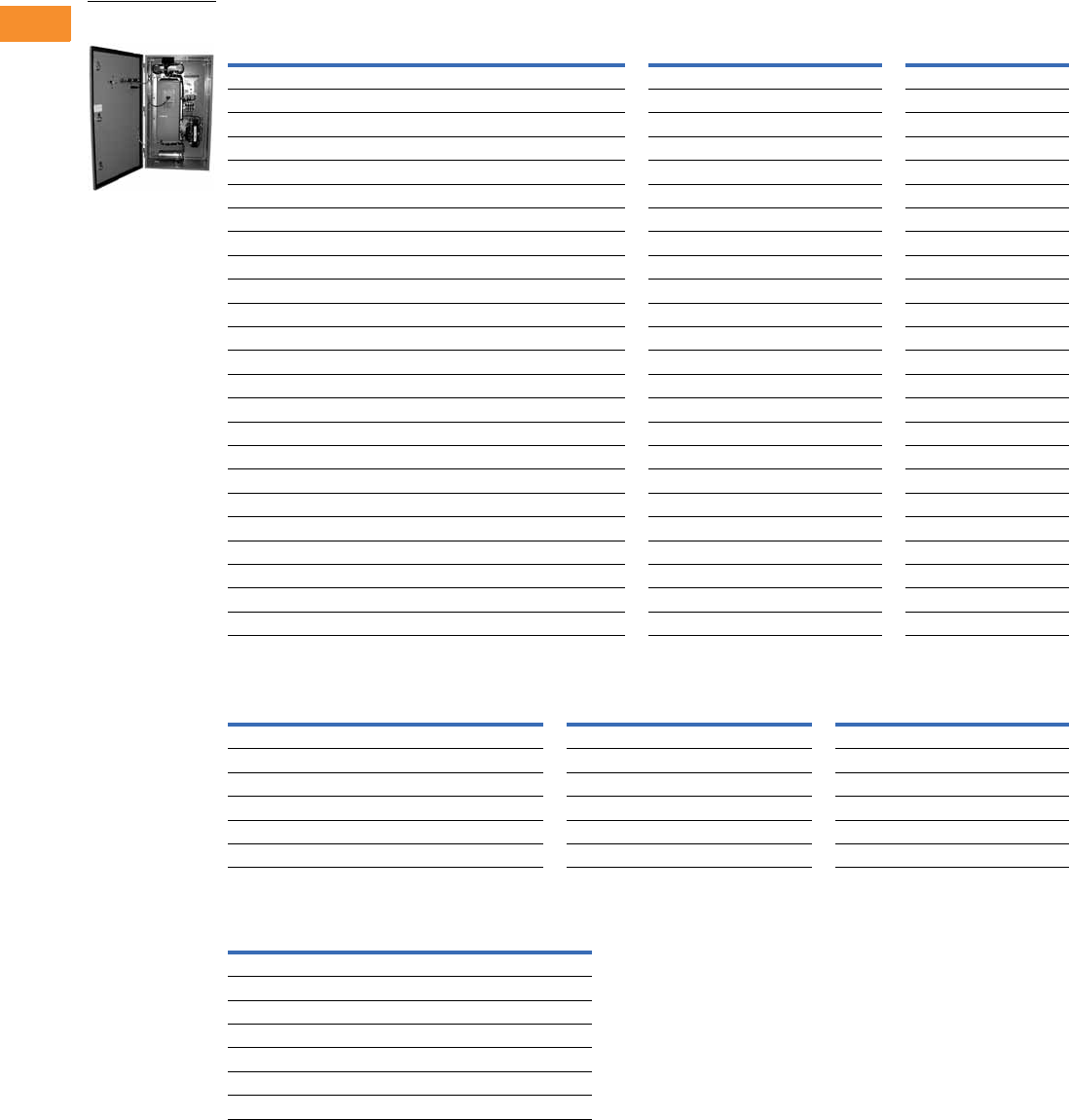
V6-T2-210 Volume 6—Solid-State Motor Control CA08100007E—May 2014 www.eaton.com
2
2
2
2
2
2
2
2
2
2
2
2
2
2
2
2
2
2
2
2
2
2
2
2
2
2
2
2
2
2
2.8
Adjustable Frequency Drives
Low Harmonic Drives
208V Drives
UL Type 1, UL Type 12, UL Type 3R and NEMA 12 Filtered
Enclosed Passive Filtered Drive Enclosure
Enclosure Dimension Drawings
Notes
1 FR5–FR7 drives not available in UL Type 1.
2 Enclosures 7 and 8 are NEMA 12 filtered.
3 Not available for UL Type 3R.
hp
NEC
Current (A)
Chassis
Frame
UL Type 1 UL Type 12 and NEMA 12 Filtered UL Type 3R
Base Catalog Number Base Catalog Number Base Catalog Number
Low Overload Drive
7-1/2 24.2 FR5 1CFX00721BA CFX00731BA
10 30.8 FR5 1CFX01021BA CFX01031BA
15 46.2 FR6 1CFX01521BA CFX01531BA
20 59.4 FR6 1CFX02021BA CFX02031BA
25 74.8 FR7 1CFX02521AA CFX02531AA
30 88 FR7 1CFX03021AA CFX03031AA
40 114 FR7 1CFX04021AA CFX04031AA
50 143 FR8 CFX05011AA CFX05061AA CFX05031AA
60 169 FR8 CFX06011AA CFX06061AA CFX06031AA
75 211 FR8 CFX07511AA CFX07561AA CFX07531AA
100 273 FR9 CFX10011AA CFX10061AA CFX10031AA
High Overload Drive
7-1/2 24.2 FR5 1CFX00721EA CFX00731EA
10 30.8 FR6 1CFX01021EA CFX01031EA
15 46.2 FR6 1CFX01521EA CFX01531EA
20 59.4 FR7 1CFX02021DA CFX02031DA
25 74.8 FR7 1CFX02521DA CFX02531DA
30 88 FR7 1CFX03021DA CFX03031DA
40 114 FR8 CFX04011DA CFX04061DA CFX04031DA
50 143 FR8 CFX05011DA CFX05061DA CFX05031DA
60 169 FR8 CFX06011DA CFX06061DA CFX06031DA
75 211 FR9 CFX07511DA CFX07561DA CFX07531DA
100 273 FR9 CFX10011DA CFX10061DA CFX10031DA
Chassis
Frame
UL Type 1 UL Type 12 UL Type 3R
Disconnect Only With Power Options Disconnect Only With Power Options Disconnect Only With Power Options
FR4 N/A N/A B C B C
FR5 N/A N/A B C B C
FR6 N/A N/A B C B C
FR7N/A7C7CD
FR87777FF
FR98888FF
Enclosure
Size UL Type 1 and UL Type 12 UL Type 3R
BSee Page V6-T2-224 See Page V6-T2-226
CSee Page V6-T2-225 See Page V6-T2-227
DN/A See Page V6-T2-228
FN/A See Page V6-T2-229
7 2See Page V6-T2-230 3
8 2See Page V6-T2-231 3
9See Page V6-T2-232 3
Enclosed Passive
Filtered Drive
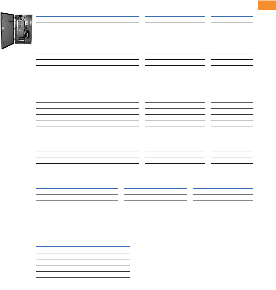
Volume 6—Solid-State Motor Control CA08100007E—May 2014 www.eaton.com V6-T2-211
2
2
2
2
2
2
2
2
2
2
2
2
2
2
2
2
2
2
2
2
2
2
2
2
2
2
2
2
2
2
2.8
Adjustable Frequency Drives
Low Harmonic Drives
230V Drives
UL Type 1, UL Type 12, UL Type 3R and NEMA 12 Filtered
Enclosed Passive Filtered Drive Enclosure
Enclosure Dimension Drawings
Notes
1 FR5–FR7 drives not available in UL Type 1.
2 Enclosures 7 and 8 are NEMA 12 filtered.
3 Not available for UL Type 3R.
hp
NEC
Current (A)
Chassis
Frame
UL Type 1 UL Type 12 and NEMA 12 Filtered UL Type 3R
Base Catalog Number Base Catalog Number Base Catalog Number
Low Overload Drive
7-1/2 22 FR5 1CFX00722BA CFX00732BA
10 28 FR5 1CFX01022BA CFX01032BA
15 42 FR6 1CFX01522BA CFX01532BA
20 54 FR6 1CFX02022BA CFX02032BA
25 68 FR7 1CFX02522AA CFX02532AA
30 80 FR7 1CFX03022AA CFX03032AA
40 104 FR7 1CFX04022AA CFX04032AA
50 130 FR8 CFX05012AA CFX05062AA CFX05032AA
60 154 FR8 CFX06012AA CFX06062AA CFX06032AA
75 192 FR8 CFX07512AA CFX07562AA CFX07532AA
100 248 FR9 CFX10012AA CFX10062AA CFX10032AA
High Overload Drive
7-1/2 22 FR5 1CFX00722EA CFX00732EA
10 28 FR6 1CFX01022EA CFX01032EA
15 42 FR6 1CFX01522EA CFX01532EA
20 54 FR7 1CFX02022DA CFX02032DA
25 68 FR7 1CFX02522DA CFX02532DA
30 80 FR7 1CFX03022DA CFX03032DA
40 104 FR8 CFX04012DA CFX04062DA CFX04032DA
50 130 FR8 CFX05012DA CFX05062DA CFX05032DA
60 154 FR8 CFX06012DA CFX06062DA CFX06032DA
75 192 FR9 CFX07512DA CFX07562DA CFX07532DA
100 248 FR9 CFX10012DA CFX10062DA CFX10032DA
Chassis
Frame
UL Type 1 UL Type 12 UL Type 3R
Disconnect Only With Power Options Disconnect Only With Power Options Disconnect Only With Power Options
FR4 N/A N/A B C B C
FR5 N/A N/A B C B C
FR6 N/A N/A B C B C
FR7N/A7C7CD
FR87777FF
FR98888FF
Enclosure
Size UL Type 1 and UL Type 12 UL Type 3R
BSee Page V6-T2-224 See Page V6-T2-226
CSee Page V6-T2-225 See Page V6-T2-227
DN/A See Page V6-T2-228
FN/A See Page V6-T2-229
7 2See Page V6-T2-230 3
8 2See Page V6-T2-231 3
9See Page V6-T2-232 3
Enclosed Passive
Filtered Drive
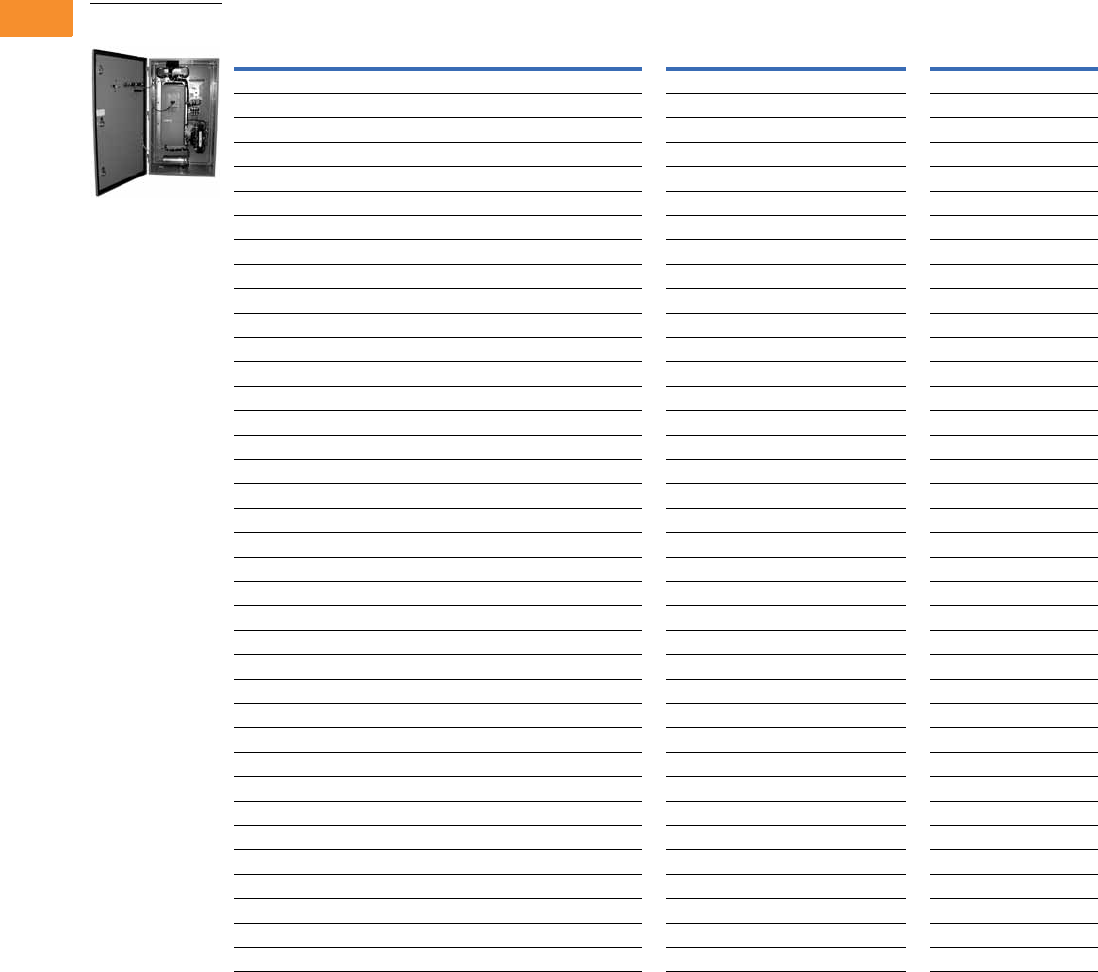
V6-T2-212 Volume 6—Solid-State Motor Control CA08100007E—May 2014 www.eaton.com
2
2
2
2
2
2
2
2
2
2
2
2
2
2
2
2
2
2
2
2
2
2
2
2
2
2
2
2
2
2
2.8
Adjustable Frequency Drives
Low Harmonic Drives
480V Drives
Enclosed Passive Filtered Base Drive
Notes
1 The integrated filter clean power assembly includes a standard drive, door-mounted local/remote keypad and enclosure.
2 FR4–FR6 drives not available in UL Type 1.
3 This catalog number is used only with power options.
4 Consult factory.
hp
NEC
Current (A)
Chassis
Frame
UL Type 1 UL Type 12 and NEMA 12 Filtered UL Type 3R
Base Catalog Number 1Base Catalog Number 1Base Catalog Number 1
Low Overload Drive
7-1/2 11 FR4 2CFX00724BA CFX00734BA
10 14 FR5 2CFX01024BA CFX01034BA
15 21 FR5 2CFX01524BA CFX01534BA
20 27 FR5 2CFX02024BA CFX02034BA
25 34 FR6 2CFX02524BA CFX02534BA
30 40 FR6 2CFX03024BA CFX03034BA
40 52 FR6 2CFX04024BA CFX04034BA
50 65 FR7 CFX05014AA 3CFX05024AA CFX05034AA
60 77 FR7 CFX06014AA 3CFX06024AA CFX06034AA
75 96 FR7 CFX07514AA 3CFX07524AA CFX07534AA
100 124 FR8 CFX10014AA CFX10064AA CFX10034AA
125 156 FR8 CFX12514AA CFX12564AA CFX12534AA
150 180 FR8 CFX15014AA CFX15064AA CFX15034AA
200 240 FR9 CFX20014AA CFX20064AA CFX20034AA
250 302 FR9 CFX25014AA CFX25064AA CFX25034AA
300 361 FR10 CFX30014AA CFX30064AA 4
350 414 FR10 CFX35014AA CFX35064AA 4
400 477 FR10 CFX40014AA CFX40064AA 4
High Overload Drive
7-1/2 11 FR5 2CFX00724EA CFX00734EA
10 14 FR5 2CFX01024EA CFX01034EA
15 21 FR5 2CFX01524EA CFX01534EA
20 27 FR6 2CFX02024EA CFX02034EA
25 34 FR6 2CFX02524EA CFX02534EA
30 40 FR6 2CFX03024EA CFX03034EA
40 52 FR7 CFX04014DA 3CFX04024DA CFX04034DA
50 65 FR7 CFX05014DA 3CFX05024DA CFX05034DA
60 77 FR7 CFX06014DA 3CFX06024DA CFX06034DA
75 96 FR8 CFX07514DA CFX07564DA CFX07534DA
100 124 FR8 CFX10014DA CFX10064DA CFX10034DA
125 156 FR8 CFX12514DA CFX12564DA CFX12534DA
150 180 FR9 CFX15014DA CFX15064DA CFX15034DA
200 240 FR9 CFX20014DA CFX20064DA CFX20034DA
250 302 FR10 CFX25014DA CFX25064DA 4
300 361 FR10 CFX30014DA CFX30064DA 4
350 414 FR10 CFX35014DA CFX35064DA 4
Enclosed Passive
Filtered Drive

Volume 6—Solid-State Motor Control CA08100007E—May 2014 www.eaton.com V6-T2-213
2
2
2
2
2
2
2
2
2
2
2
2
2
2
2
2
2
2
2
2
2
2
2
2
2
2
2
2
2
2
2.8
Adjustable Frequency Drives
Low Harmonic Drives
Enclosed Passive Filtered Drive Enclosure
Enclosure Dimension Drawings
Notes
1 Consult factory.
2 Enclosures 7 and 8 are NEMA 12 filtered.
3 Not available for UL Type 3R.
Chassis
Frame
UL Type 1 UL Type 12 UL Type 3R
Disconnect Only With Power Options Disconnect Only With Power Options Disconnect Only With Power Options
FR4 N/A N/A B C B C
FR5 N/A N/A B C B C
FR6 N/A N/A B C B C
FR7N/A7C7CD
FR87777FF
FR98888FF
FR1099 99 11
Enclosure
Size UL Type 1 and UL Type 12 UL Type 3R
BSee Page V6-T2-224 See Page V6-T2-226
CSee Page V6-T2-225 See Page V6-T2-227
DN/A See Page V6-T2-228
FN/A See Page V6-T2-229
7 2See Page V6-T2-230 3
8 2See Page V6-T2-231 3
9See Page V6-T2-232 3
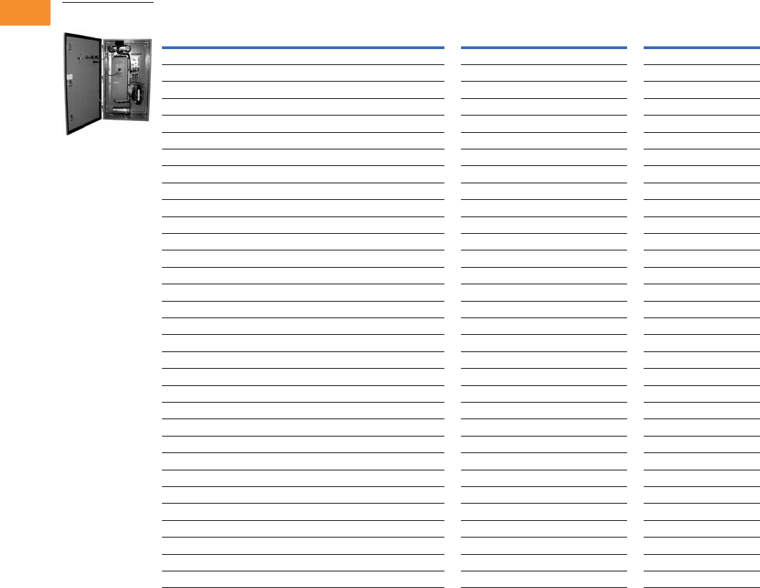
V6-T2-214 Volume 6—Solid-State Motor Control CA08100007E—May 2014 www.eaton.com
2
2
2
2
2
2
2
2
2
2
2
2
2
2
2
2
2
2
2
2
2
2
2
2
2
2
2
2
2
2
2.8
Adjustable Frequency Drives
Low Harmonic Drives
575V Drives
UL Type 1, UL Type 12, UL Type 3R and NEMA 12 Filtered
Notes
1 FR6–FR7 drives not available in UL Type 1.
2 Consult factory.
hp
NEC
Current (A)
Chassis
Frame
UL Type 1 UL Type 12 and NEMA 12 Filtered UL Type 3R
Base Catalog Number Base Catalog Number Base Catalog Number
Low Overload Drive
15 17 FR6 1CFX01525AA CFX01535AA
20 22 FR6 1CFX02025AA CFX02035AA
25 27 FR6 1CFX02525AA CFX02535AA
30 32 FR6 1CFX03025AA CFX03035AA
40 41 FR7 1CFX04025AA CFX04035AA
50 52 FR7 1CFX05025AA CFX05035AA
60 62 FR8 CFX06015AA CFX06065AA CFX06035AA
75 77 FR8 CFX07515AA CFX07565AA CFX07535AA
100 99 FR8 CFX10015AA CFX10065AA CFX10035AA
125 125 FR9 CFX12515AA CFX12565AA CFX12535AA
150 144 FR9 CFX15015AA CFX15065AA CFX15035AA
200 192 FR9 CFX20015AA CFX20065AA CFX20035AA
250 242 FR10 CFX25015AA CFX25065AA 2
300 289 FR10 CFX30015AA CFX30065AA 2
400 382 FR10 CFX40015AA CFX40065AA 2
High Overload Drive
10 14 FR6 1CFX01025DA CFX01035DA
15 17 FR6 1CFX01525DA CFX01535DA
20 22 FR6 1CFX02025DA CFX02035DA
25 27 FR6 1CFX02525DA CFX02535DA
30 32 FR7 1CFX03025DA CFX03035DA
40 41 FR7 1CFX04025DA CFX04035DA
50 52 FR8 CFX05015DA CFX05065DA CFX05035DA
60 62 FR8 CFX06015DA CFX06065DA CFX06035DA
75 77 FR8 CFX07515DA CFX07565DA CFX07535DA
100 99 FR9 CFX10015DA CFX10065DA CFX10035DA
125 125 FR9 CFX12515DA CFX12565DA CFX12535DA
150 144 FR9 CFX15015DA CFX15065DA CFX15035DA
200 192 FR10 CFX20015DA CFX20065DA 2
250 242 FR10 CFX25015DA CFX25065DA 2
300 289 FR10 CFX30015DA CFX30065DA 2
Enclosed Passive
Filtered Drive

Volume 6—Solid-State Motor Control CA08100007E—May 2014 www.eaton.com V6-T2-215
2
2
2
2
2
2
2
2
2
2
2
2
2
2
2
2
2
2
2
2
2
2
2
2
2
2
2
2
2
2
2.8
Adjustable Frequency Drives
Low Harmonic Drives
Enclosed Passive Filtered Drive Enclosure
Enclosure Dimension Drawings
Notes
1 Consult factory.
2 Enclosures 7 and 8 are NEMA 12 filtered.
3 Not available for UL Type 3R.
Chassis
Frame
UL Type 1 UL Type 12 UL Type 3R
Disconnect Only With Power Options Disconnect Only With Power Options Disconnect Only With Power Options
FR6 N/A N/A B C B C
FR7N/A7C7CD
FR87777FF
FR98888FF
FR1099 99 11
Enclosure
Size UL Type 1 and UL Type 12 UL Type 3R
BSee Page V6-T2-224 See Page V6-T2-226
CSee Page V6-T2-225 See Page V6-T2-227
DN/A See Page V6-T2-228
FN/A See Page V6-T2-229
7 2See Page V6-T2-230 3
8 2See Page V6-T2-231 3
9See Page V6-T2-232 3

V6-T2-216 Volume 6—Solid-State Motor Control CA08100007E—May 2014 www.eaton.com
2
2
2
2
2
2
2
2
2
2
2
2
2
2
2
2
2
2
2
2
2
2
2
2
2
2
2
2
2
2
2.8
Adjustable Frequency Drives
Low Harmonic Drives
Options
Enclosed Passive Filtered Drive Option Board Kits
The enclosed passive filtered drive series can accommodate a wide selection of expander and
adapter option boards to customize the drive for your application needs. The drive’s control unit is
designed to accept a total of five option boards.
The enclosed passive filtered drive series factory-installed standard board configuration includes an A9
I/O board and an A2 relay output board, which are installed in slots A and B.
Option Board Kits
Notes
1 AI = Analog Input; AO = Analog Output, DI = Digital Input, DO = Digital Output, RO = Relay Output
2 Option card must be installed in one of the slots listed for that card. Slot indicated in bold is the preferred location.
3 OPTC2 is a multi-protocol option card.
Option Kit Description 1
Allowed Slot
Locations 2
Field
Installed
Factory
Installed SVX Ready Programs
Catalog
Number
Option
Designator Basic
Local/
Remote Standard MSS PID Multi-P. PFC
Standard I/O Cards
2 RO (NC/NO) B OPTA2 — ■ ■ ■ ■■■ ■
6 DI, 1 DO, 2 AI, 1AO, 1 +10 Vdc ref,
2 ext +24 Vdc/ext +24 Vdc
AOPTA9 — ■ ■ ■ ■■■ ■
Extended I/O Cards
6 DI B, C, D, E OPTB1 B1 —— — ——
■■
1 RO (NC/NO), 1 RO (NO), 1 therm B, C, D, E OPTB2 B2 —— — ——
■■
1 AI (mA isolated), 2 AO (mA isolated) B, C, D, E OPTB4 B4 ■ ■ ■ ■■■ ■
3 RO (NO) B, C, D, E OPTB5 B5 —— — ——
■■
3 Pt100 RTD board B, C, D, E OPTB8 B8 —— — ——
■—
1 RO (NO), 5 DI 42–240 Vac input B, C, D, E OPTB9 B9 —— — ——
■■
Communication Cards 3
Modbus D, E OPTC2 C2 ■ ■ ■ ■■■ ■
Modbus TCP D, E OPTCI CI ■ ■ ■ ■■■ ■
BACnet D, E OPTCJ CJ ■ ■ ■ ■■■ ■
EtherNet/IP D, E OPTCQ CQ ■ ■ ■ ■■■ ■
Johnson Controls N2 D, E OPTC2 CA ■ ■ ■ ■■■ ■
PROFIBUS DP D, E OPTC3 C3 ■ ■ ■ ■■■ ■
LonWorks D, E OPTC4 C4 ■ ■ ■ ■■■ ■
PROFIBUS DP (D9 connector) D, E OPTC5 C5 ■ ■ ■ ■■■ ■
CANopen (slave) D, E OPTC6 C6 ■ ■ ■ ■■■ ■
DeviceNet D, E OPTC7 C7 ■ ■ ■ ■■■ ■
Modbus (D9 type connector) D, E OPTC8 C8 ■ ■ ■ ■■■ ■
RS-232 with D9 connection D, E OPTD3 D3 ■ ■ ■ ■■■ ■
Option Boards
ABCDE

Volume 6—Solid-State Motor Control CA08100007E—May 2014 www.eaton.com V6-T2-217
2
2
2
2
2
2
2
2
2
2
2
2
2
2
2
2
2
2
2
2
2
2
2
2
2
2
2
2
2
2
2.8
Adjustable Frequency Drives
Low Harmonic Drives
Modbus RTU Network
Communications
The Modbus Network Card
OPTC2 is used for connecting
the 9000X Drive as a slave
on a Modbus network. The
interface is connected by
a 9-pin DSUB connector
(female) and the baud rate
ranges from 300 to 19,200
baud. Other communication
parameters include an
address range from 1 to 247;
a parity of None, Odd or
Even; and the stop bit is 1.
PROFIBUS Network
Communications
The PROFIBUS Network Card
OPTC3 is used for connecting
the 9000X Drive as a slave
on a PROFIBUS-DP network.
The interface is connected
by a 9-pin DSUB connector
(female). The baud rates
range from 9.6K baud to 12M
baud, and the addresses
range from 1 to 127.
LonWorks Network
Communications
The LonWorks Network Card
OPTC4 is used for connecting
the 9000X Drive on a
LonWorks network. This
interface uses Standard
Network Variable Types
(SNVT) as data types. The
channel connection is
achieved using a FTT-10A
Free Topology transceiver
via a single twisted transfer
cable. The communication
speed with LonWorks is
78 kBits/s.
CANopen (Slave)
Communications
The CANopen (Slave)
Network Card OPTC6 is used
for connecting the 9000X
Drive to a host system.
According to ISO® 11898
standard cables to be chosen
for CAN bus should have
a nominal impedance of
120 ohms, and specific line
delay of nominal 5 as/m.
120 ohm line termination
resistors required for
installation.
DeviceNet Network
Communications
The DeviceNet Network Card
OPTC7 is used for connecting
the 9000X Drive on a
DeviceNet Network. It
includes a 5.08 mm pluggable
connector. Transfer method
is via CAN using a two-wire
twisted shielded cable with
two-wire bus power cable
and drain. The baud rates
used for communication
include 125K baud, 250K
baud and 500K baud.
Johnson Controls Metasys N2
Network Communications
The OPTC2 fieldbus board
provides communication
between the 9000X Drive
and a Johnson Controls
Metasys™ N2 network.
With this connection, the
drive can be controlled,
monitored and programmed
from the Metasys system.
The N2 fieldbus is available as
a factory-installed option and
as a field-installable kit.
Modbus/TCP Network
Communications
The Modbus/TCP Network
Card OPTCI is used for
connecting the 9000X Drive
to Ethernet networks using
Modbus protocol. It includes
an RJ-45 pluggable
connector. This interface
provides a selection of
standard and custom register
values to communicate drive
parameters. The board
supports 10 Mbps and
100 Mbps communication
speeds. The IP address of
the board is configurable over
Ethernet using a supplied
software tool.
BACnet Network
Communications
The BACnet Network Card
OPTCJ is used for connecting
the 9000X Drive to BACnet
networks. It includes a 5.08
mm pluggable connector.
Data transfer is Master-Slave/
Token Passing (MS/TP)
RS-485. This interface uses
a collection of 30 Binary
Value Objects (BVOs) and
35 Analog Value Objects
(AVOs) to communicate
drive parameters. The card
supports 9.6, 19.2 and 38.4
Kbaud communication
speeds and supports network
addresses 1 to 127.
Ethernet/IP Network
Communications
The Ethernet/IP Network
Card OPTCK is used for
connecting the 9000X Drive
to Ethernet/Industrial Protocol
networks. It includes an RJ-
45 pluggable connector. The
interface uses CIP objects to
communicate drive
parameters (CIP is
“Common Industrial
Protocol,” the same protocol
used by DeviceNet). The
board supports 10 Mbps and
100 Mbps communication
speeds. The IP address of
the board is configurable
by Static, BOOTP and
DHCP methods.

V6-T2-218 Volume 6—Solid-State Motor Control CA08100007E—May 2014 www.eaton.com
2
2
2
2
2
2
2
2
2
2
2
2
2
2
2
2
2
2
2
2
2
2
2
2
2
2
2
2
2
2
2.8
Adjustable Frequency Drives
Low Harmonic Drives
Control/Communication Option Descriptions
Available Control/Communications Options
Option Description Option Type
K1 Door-Mounted Speed Potentiometer—Provides the drive with the ability to adjust the frequency reference using a door-mounted potentiometer. This option uses the
10 Vdc reference to generate a 0–10V signal at the analog voltage input signal terminal. When the HOA bypass option is added, the speed is controlled when the HOA
switch is in the HAND position. Without the HOA bypass option, a two-position switch (labeled local/remote) is provided on the keypad to select speed reference from the speed
potentiometer or a remote speed signal.
Control
K2 Door-Mounted Speed Potentiometer with HOA Selector Switch—Provides the drive with the ability to start/stop and adjust the speed reference from door-
mounted control devices or remotely from customer supplied inputs. In HAND position, the drive will start and the speed is controlled by the door-mounted speed
potentiometer. The drive will be disabled in the OFF position. When AUTO is selected, the drive run and speed control commands are via user-supplied dry contact and
4–20 mA signal.
Control
K3 3–15 psig Follower—Provides a pneumatic transducer which converts a 3–15 psig pneumatic signal to either 0–8 Vdc or a 1–9 Vdc signal interface with the drive.
The circuit board is mounted on the inside of the front enclosure panel and connects to the user’s pneumatic control system via 6 ft (1.8m) of flexible tubing and a 1/4 in
(6.4 mm) brass tube union.
Control
K4 HAND/OFF/AUTO Switch for Non-Bypass Configurations—Provides a three-position selector switch that allows the user to select either a HAND or AUTO mode of
operation. HAND mode is defaulted to keypad operation, and AUTO mode is defaulted to control from an external terminal source. These modes of operation can be
configured via drive programming to allow for alternate combinations of start and speed sources. Start and speed sources include keypad, I/O and fieldbus.
Control
K5 MANUAL/AUTO Speed Reference Switch—Provides door-mounted selector switch for MANUAL/AUTO speed reference. Control
K6 START/STOP Pushbuttons—Provide door-mounted START and STOP pushbuttons for either bypass or non-bypass configurations. Control
KF Bypass Test Switch for RB and RA—Allows the user to energize the AF drive for testing while operating the motor on the bypass controller. The Test Switch is
mounted on the inside of the enclosure door.
Addl. bypass
KO Standard Elapsed Time Meter—Provides a door-mounted elapsed run time meter. Control
L1 Power On, Run and Fault Lights—Provide a white power on light that indicates power to the enclosed cabinets, a green run light and a red fault light that indicates a
drive fault has occurred.
Light
L2 Bypass Pilot Lights for RB, RA Bypass Options—A green light indicates when the motor is running in inverter mode and an amber light indicates when the motor is
running in bypass mode. The lights are mounted on the enclosure door, above the switches.
Addl. bypass
LE Red Run Pilot Light (22 mm)—Provides a red run pilot light that indicates the drive is running. Light
P1 Input Circuit Breaker—High interrupting circuit breaker that provides a means of short-circuit protection for the power cables between it and the enclosed 18-pulse
drive, and protection from high-level ground faults on the power cable. Allows a convenient means of disconnecting the enclosed 18-pulse drive from the line and the operating
mechanism can be padlocked in the OFF position. This is factory mounted in the enclosure. Standard rating is 65 kAIC at 208/480V. 100 kAIC is available as an option.
Input
P3 Input Line Fuses Rated to 200 kAIC—Provide high-level fault protection of the drive input power circuit from the load side of the fuses to the input side of the power
transistors. This option consists of three 200 kA fuses, which are factory mounted in the enclosure.
Input
P7 MOV Surge Suppressor—Provides a Metal Oxide Varistor (MOV) connected to the line side terminals and is designed to clip line side transients. Input
P8 TVSS Surge Protective Device with 50 kA Rating—Provides transient voltage protection eliminating surges and spikes which can damage the diode bridge
of the drive.
Input
PC Capacitor Contactor—This option provides a contactor between the tuned reactor and capacitor to disconnect the capacitor from the circuit when desired, typically at
light or no load conditions. This contactor is wired to a programmable relay output.
Input
PE Output Contactor—Provides a means for positive disconnection of the drive output from the motor terminals. The contactor coil is controlled by the drive’s run or
permissive logic. NO auxiliary contacts rated at 10A, 600 Vac are provided for customer use. Bypass options RB and RA include an output contactor as standard.
This option includes a low VA 115 Vac fused control power transformer and is factory mounted in the enclosure.
Output
PF Output Filter—Used to reduce the transient voltage (DV/DT) at the motor terminals. The output filter is recommended for cable lengths exceeding 100 ft (30m) or for a
drive rated at 525–690V. This option is mounted in the enclosure, and may be used in conjunction with a brake chopper circuit.
Output
PG MotoRx (300–600 ft) 1000 V/μS DV/DT Filter—Used to reduce transient voltage (DV/DT) and peak voltages at the motor terminals. This option is comprised of a 0.5%
line reactor, followed by capacitive filtering and an energy recovery/clamping circuit. Unlike the output filter (see option PF), the MotoRx recovers most of the energy from the
voltage peaks, resulting in a lower voltage drop to the motor, and therefore conserving power. This option is used when the distance between a single motor and the drive
is 300–600 ft (91–183m). This option cannot be used with the brake chopper circuit. The output filter (option PF) should be investigated as an alternative.
Output
PH Single Overload Relay—Uses a bimetallic overload relay to provide additional overload current protection to the motor on configurations without bypass options. It is
included with the bypass configurations for overload current protection in the bypass mode. The overload relay is mounted within the enclosure, and is manually
resettable. Heater pack included.
Output
PI Dual Overload Relays—This option is recommended when a single drive is operating two motors and overload current protection is needed for each of the motors. The
standard configuration includes two bimetallic overload relays, each sized to protect a motor with 50% of the drive hp rating. For example, a 100 hp drive would include
two overload relays sized to protect two 50 hp motors. The relays are mounted within the enclosure, and are manually resettable. Heater packs not included.
Output
PN Dual Overloads for Bypass—This option is recommended when a single drive is operating two motors in the bypass mode and overload current protection is needed
for each of the motors. The standard configuration includes two bimetallic overload relays, each sized to protect a motor with 50% of the drive hp rating. For example, a
100 hp drive would include two overload relays sized to protect two 50 hp motors. The relays are mounted within the enclosure, and are manually resettable.
Addl. bypass
Volume 6—Solid-State Motor Control CA08100007E—May 2014 www.eaton.com V6-T2-219
2
2
2
2
2
2
2
2
2
2
2
2
2
2
2
2
2
2
2
2
2
2
2
2
2
2
2
2
2
2
2.8
Adjustable Frequency Drives
Low Harmonic Drives
Available Control/Communications Options, continued
Enclosed Drive Options
Conformal (Varnished) Coating 1
Light Options
Control Options
Note
1See catalog number description to order.
Option Description Option Type
RA Manual HOA Bypass Controller—The manual HAND/OFF/AUTO (HOA)—three-contactor—bypass option provides a means of bypassing the enclosed passive
filtered drive, allowing the AC motor to be operated at full speed directly from the AC supply line. This option consists of an input HMCP, a fused control power
transformer, and a full voltage bypass starter with a door-mounted HOA selector switch and an INVERTER/BYPASS switch. The HOA switch provides the ability to start
and stop the drive in the inverter mode. IEC type input, bypass and input contactors are provided. The contactors are mechanically and electrically interlocked (see wiring
diagram on Page V6-T2-223).
Bypass
RB Manual IOB Bypass Controller—The manual INVERTER/OFF/BYPASS (IOB)—three-contactor—bypass option provides a means of bypassing the enclosed passive
filtered drive, allowing the AC motor to be operated at full speed directly from the AC supply line. This option consists of an input HMCP, a fused control power
transformer, and a full voltage bypass starter with a door-mounted IOB selector switch. IEC type input, bypass and input contactors are provided. The contactors are
mechanically and electrically interlocked (see wiring diagram on Page V6-T2-223).
Bypass
RC Auto Transfer HOA Bypass Controller —The manual HAND/OFF/AUTO (HOA)—three-contactor—bypass option provides a means of bypassing the enclosed passive
filtered drive, allowing the AC motor to be operated at full speed directly from the AC supply line. The circuitry provides an automatic transfer of the load to “across the
line” operation after a drive trip. This option consists of an input HMCP, a fused control power transformer, and a full voltage bypass starter with a door-mounted HOA
selector switch and an INVERTER/BYPASS switch. The HOA switch provides the ability to start and stop the drive in either mode. IEC type input, bypass and input
contactors are provided. The contactors are mechanically and electrically interlocked (see wiring diagram on Page V6-T2-223). Door-mounted pilot lights are provided
that indicate bypass or inverter operation. A green light indicates when the motor is running in inverter mode and an amber light indicates when the motor is running in
bypass mode.
WARNING: The motor may restart when the overcurrent relay is reset when operating in bypass, unless the IOB selector switch is turned to the OFF position.
Bypass
RD Auto Transfer IOB Bypass Controller—The auto INVERTER/OFF/BYPASS (IOB)—three-contactor—bypass option provides a means of bypassing the enclosed passive
filtered drive, allowing the AC motor to be operated at full speed directly from the AC supply line. The circuitry provides an automatic transfer of the load to “across the
line” operation after a drive trip. This option consists of an input HMCP, a fused control power transformer, and a full voltage bypass starter with a door-mounted IOB
selector switch. IEC type input, bypass and input contactors are provided. The contactors are mechanically and electrically interlocked (see wiring diagram on Page
V6-T2-223). Door-mounted pilot lights are provided that indicate bypass or inverter operation. A green light indicates when the motor is running in inverter mode and an
amber light indicates when the motor is running in bypass mode.
WARNING: The motor may restart when the overcurrent relay is reset when operating in bypass, unless the IOB selector switch is turned to the OFF position.
Bypass
RG Reduced Voltage Starter for Bypass—Used in conjunction with bypass option RA, RB, RC or RD. This option adds IT. Series reduced voltage soft starter to bypass
assembly for soft starting in bypass mode.
Bypass
S4 Floor Stand 6 in—Raises “F” box off the ground 6 in (152.4 mm). Recommended when box is not installed on an appropriate concrete pad. Enclosure
S5 Floor Stand 22 in—Converts a Size B or C, normally wall mounted enclosure to a floor standing enclosure with a height of 22 in (558.8 mm). Enclosure
S6 Floor Stand 12 in—Converts a Size C or D, normally wall mounted enclosure to a floor standing enclosure with a height of 12 in (304.8 mm). Enclosure
S9 Space Heater—Prevents condensation from forming in the enclosure when the drive is inactive or in storage. Includes a thermostat for variable temperature control.
Heater requires a customer supplied 115V remote supply source.
Enclosure
Chassis
Frame
Delivery
Code
Chassis
Frame
Delivery
Code
FR6 FP FR9 FP
FR7 FP FR10 FP
FR8 FP FR11 FP
— — FR12 FP
Description
Catalog
Number Suffix
Power on, run, fault LED lights (22 mm) L1
Power on, fault LED lights (22 mm) L3
Green LED run light (22 mm) LA
Green LED stop light (22 mm) LD
Red LED run light (22 mm) LE
Red LED stop light (22 mm) LF
Red LED fault light (22 mm) LG
Power on white LED light (22 mm) LJ
Miscellaneous LED light (22 mm) LU
Description
Catalog
Number Suffix
Door-mounted speed potentiometer K1
Door-mounted speed potentiometer with HOA selector switch K2
3–15 psig follower K3
HOA selector switch K4
MANUAL/AUTO reference switch K5
START-STOP pushbuttons K6
Type D2 control relay SD
On-delay relay SE
Off-delay relay SF
Additional terminal blocks per 4 points SD
V6-T2-220 Volume 6—Solid-State Motor Control CA08100007E—May 2014 www.eaton.com
2
2
2
2
2
2
2
2
2
2
2
2
2
2
2
2
2
2
2
2
2
2
2
2
2
2
2
2
2
2
2.8
Adjustable Frequency Drives
Low Harmonic Drives
Bypass Control Options
Meter Options
Enclosure Options
208V Power Options, 7-1/2–100 hp
230V Power Options, 7-1/2–125 hp
480 and 575V Power Options, 7-1/2–400 hp
208V Bypass Options, 7-1/2–100 hp
230V Bypass Options, 7-1/2–125 hp
480 and 575V Bypass Options, 7-1/2–400 hp
Note
1Requires customer-supplied 115 Vac supply.
Description
Catalog
Number Suffix
Bypass test switch used with RA and RB KF
Inverter/bypass pilot lights L2
Description
Catalog
Number Suffix
Standard elapsed time meter KO
Frequency meter KS
MP-3000 relay with URTD KV
MP-3000 relay with URTD and CTs KU
Enclosure
Size
Catalog
Number Suffix
Space Heater 1
7S9
8S9
9S9
BS9
CS9
DS9
FS9
Plastic Nameplate
All SN
Floor Stand/Enclosure Size
6 in floor stand, size F S4
22 in floor stand, size B and C S5
12 in floor stand, size C and D S6
Description
Catalog
Number Suffix
Input breaker P1
Input line fusing P2
Input line fuses 200 kAIC P3
Output contactor PE
Single overload relay PH
Dual overload relays PI
MOV P7
50 kA surge protective device P8
100 kA surge protective device P9
Description
Catalog
Number Suffix
Input breaker P1
Input line fusing P2
Input line fuses 200 kAIC P3
Output contactor PE
Single overload relay PH
Dual overload relays PI
MOV P7
50 kA surge protective device P8
100 kA surge protective device P9
Description
Catalog
Number Suffix
Input breaker P1
Input line fusing P2
Input line fuses 200 kAIC P3
Output contactor PE
Output filter PF
MotoRx (300–600 ft) DV/DT filter PG
Single overload relay PH
Dual overload relays PI
Input MOV P7
50 kA surge protective device P8
100 kA surge protective device P9
Description
Catalog
Number Suffix
Manual HOA bypass controller RA
IOB bypass controller RB
Auto transfer HOA bypass controller RC
Auto transfer IOB bypass controller RD
Reduced voltage starter for bypass RG
Dual overloads for bypass PN
Description
Catalog
Number Suffix
Manual HOA bypass controller RA
IOB bypass controller RB
Auto transfer HOA bypass controller RC
Auto transfer IOB bypass controller RD
Reduced voltage starter for bypass RG
Dual overloads for bypass PN
Description
Catalog
Number Suffix
Manual HOA bypass controller RA
IOB bypass controller RB
Auto transfer HOA bypass controller RC
Auto transfer IOB bypass controller RD
Reduced voltage starter for bypass RG
Dual overloads for bypass PN

Volume 6—Solid-State Motor Control CA08100007E—May 2014 www.eaton.com V6-T2-221
2
2
2
2
2
2
2
2
2
2
2
2
2
2
2
2
2
2
2
2
2
2
2
2
2
2
2
2
2
2
2.8
Adjustable Frequency Drives
Low Harmonic Drives
Technical Data and Specifications
Enclosed Passive Filtered Drives
Note
1The EMI filter is optional in FR10.
Description Specification
Primary Design Features
45–66 Hz input frequency Standard
Output: AC volts maximum Input Voltage Base
Output frequency range 0–320 Hz
Initial output current (IH) 250% for 2 seconds
Overload (1 minute [IH/IL]) 150%/110%
Enclosure space heater Optional
Oversize enclosure Standard
Output contactor Optional
Bypass motor starter Optional
Listings UL, cUL, 508C
Protection Features
Incoming line fuses Optional
AC input circuit disconnect Optional
Phase rotation insensitive Standard
EMI filter Standard—FR6 thru FR9 1
Input phase loss protection Standard
Input overvoltage protection Standard
Line surge protection Standard
Output short-circuit protection Standard
Output ground fault protection Standard
Output phase protection Standard
Overtemperature protection Standard
DC overvoltage protection Standard
Drive overload protection Standard
Motor overload protection Standard
Programmer software Optional
Local/remote keypad Standard
Keypad lockout Standard
Fault alarm output Standard
Built-in diagnostics Standard
Surge protective device Optional
Description Specification
Input/Output Interface Features
Setup adjustment provisions
Remote keypad/display Standard
Personal computer Standard
Operator control provisions
Drive mounted keypad/display Standard
Remote keypad/display Standard
Conventional control elements Standard
Serial communications Optional
115 Vac control circuit Optional
Speed setting inputs
Keypad Standard
0–10 Vdc potentiometer/voltage signal Standard
4–20 mA isolated Configurable
4–20 mA differential Configurable
3–15 psig Optional
Analog outputs
Speed/frequency Standard
Torque/load/current Programmable
Motor voltage Programmable
Kilowatts Programmable
0–10 Vdc signals Configurable w/jumpers
4–20 mA DC signals Standard
Isolated signals Optional
Discrete outputs
Fault alarm Standard
Drive running Standard
Drive at set speed Programmable
Optional parameters 14
Dry contacts 2 relays Form C
Open collector outputs 1
Additional discrete outputs Optional
Communications
RS-232 Standard
RS-422/485 Optional
DeviceNet™ Optional
Modbus RTU Optional
CANopen (slave) Optional
PROFIBUS-DP Optional
Lonworks®Optional
Johnson Controls Metasys™ N2 Optional
EtherNet/IP/Modbus TCP Optional
BACnet Optional

V6-T2-222 Volume 6—Solid-State Motor Control CA08100007E—May 2014 www.eaton.com
2
2
2
2
2
2
2
2
2
2
2
2
2
2
2
2
2
2
2
2
2
2
2
2
2
2
2
2
2
2
2.8
Adjustable Frequency Drives
Low Harmonic Drives
Enclosed Passive Filtered Drives, continued Standard I/O Specifications
I/O Specifications for Control/Communication Options
Notes
1Units FR10 rated 40°C.
2For applications above 3A consult instruction manual.
Description Specification
Performance Features
Sensorless vector control Standard
Volts/hertz control Standard
IR and slip compensation Standard
Electronic reversing Standard
Dynamic braking Optional
DC braking Standard
PID setpoint controller Programmable
Critical speed lockout Standard
Current (torque) limit Standard
Adjustable acceleration/deceleration Standard
Linear or S curve accel/decel Standard
Jog at preset speed Standard
Thread/preset speeds 7
Automatic restart Selectable
Coasting motor start Standard
Coast or ramp stop selection Standard
Elapsed time meter Optional
Standard Conditions for Application and Service
Maximum operating ambient temperature 0 to 40°C, contact factory for 50°C 1
Storage temperature –40 to 60°C
Humidity (maximum), non-condensing 95%
Altitude 100% load capacity (no derating) up to
3280 ft (1000m);
1% derating for each 328 ft (100m) above
3280 ft (1000m); max. 9842 ft (3000m)
Line voltage variation +10/–15%
Line frequency variation 45–66 Hz
Efficiency >96%
Power factor (displacement) 0.99
Description Specification
Six–digital input programmable 24V: “0” <10V, “1” >18V,Ri >5 kohms
Two–analog input configurable w/
jumpers
Voltage: 0–±10V, Ri >200 kohms
Current: 0 (4)–20 mA, Ri = 250 kohms
Two–digital output programmable Form C relays 250 Vac or 30 Vdc 2 Amp resistive
One–digital output programmable Open collector 48 Vdc 50 mA
One–analog output programmable
configurable w/jumper
0–20 mA, RL max. 500 ohms 10 bits ±2%
Description Specification
Analog voltage, input 0–±10V, Ri >200 kilohms
Analog current, input 0 (4)–20 mA, Ri = 250 ohms
Digital input 24V: “0” <10V, “1” >18V, Ri >5 kilohms
Auxiliary voltage 24V (±20%), max. 50 mA
Reference voltage 10V ±3%, max. 10 mA
Analog current, output 0 (4)–20 mA, RL = 500 kilohms, resolution
10 bit, accuracy <±2%
Analog voltage, output 0 (2)–10V, RL >1 kohm, resolution
10 bit, accuracy <±2%
Relay output max. switching voltage 300 Vdc, 250 Vac
Relay output max. switching load 3A/24 Vdc, 300 Vdc, 250 Vac 2
Relay output max. continuous load 2A rms
Thermistor input Rtrip = 4.7 kohms
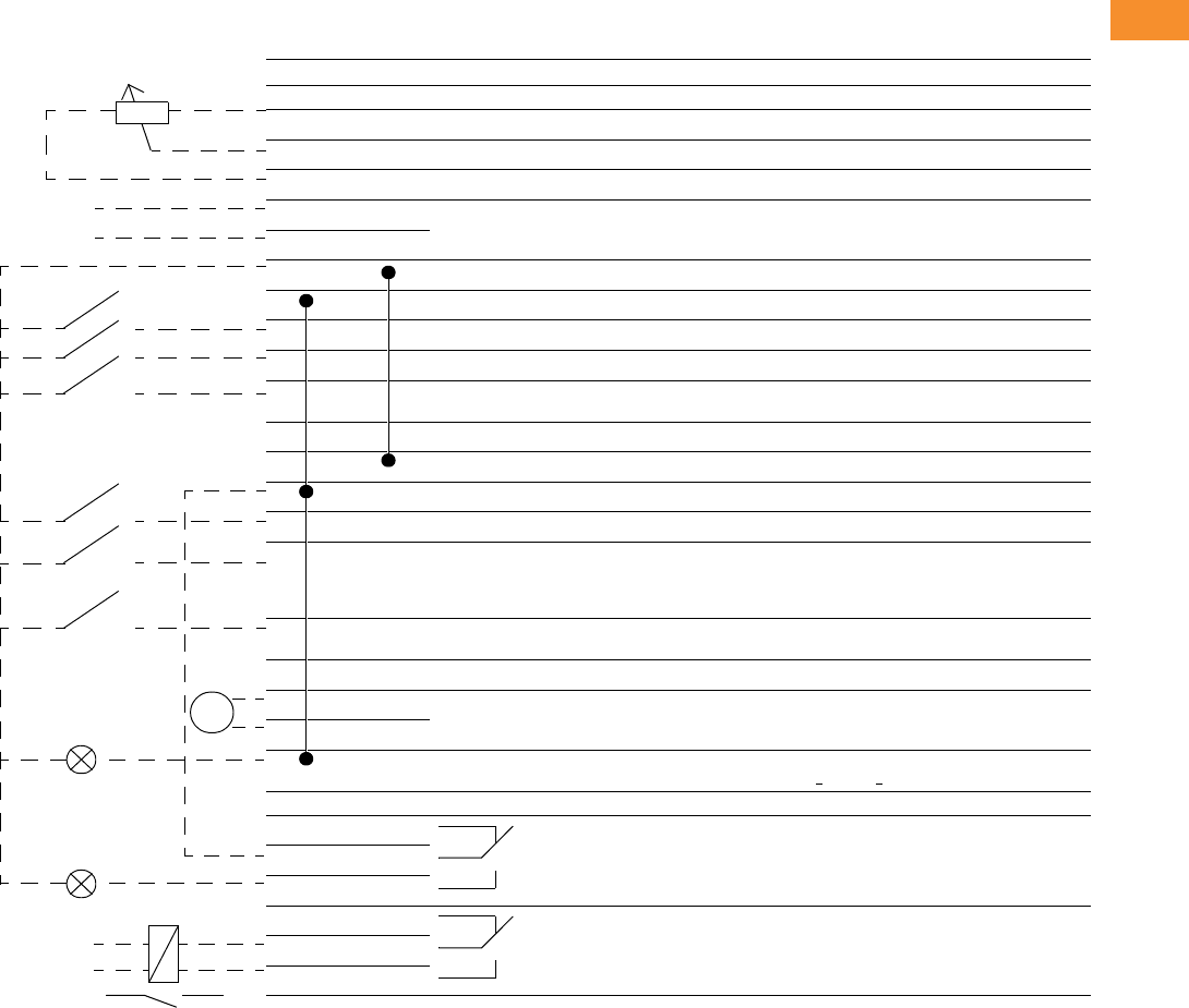
Volume 6—Solid-State Motor Control CA08100007E—May 2014 www.eaton.com V6-T2-223
2
2
2
2
2
2
2
2
2
2
2
2
2
2
2
2
2
2
2
2
2
2
2
2
2
2
2
2
2
2
2.8
Adjustable Frequency Drives
Low Harmonic Drives
Wiring Diagram
Control Input/Output
Basic Application Default I/O Configuration
Terminal Signal Description
OPTA9
1 +10Vref Reference output Voltage for potentiometer, etc.
2 AI1+ Analog input, voltage range 0–10 Vdc Voltage input frequency reference
3 AI1– I/O Ground Ground for reference and controls
4 AI2+ Analog input, current range 0–20 mA Current input frequency reference
5AI2–
6 +24V Control voltage output Voltage for switches, etc. max 0.1A
7 GND I/O ground Ground for reference and controls
8 DIN1 Start forward Contact closed = start forward
9 DIN2 Start reverse Contact closed = start reverse
10 DIN3 External fault input (programmable) Contact open = no fault
Contact closed = fault
11 CMA Common for DIN 1–DIN 3 Connect to GND or +24V
12 +24V Control voltage output Voltage for switches (see terminal 6)
13 GND I/O ground Ground for reference and controls
14 DIN4 Multi-step speed select 1 DIN4 DIN5 Frequency Ref.
15 DIN5 Multi-step speed select 2 Open
Closed
Open
Closed
Open
Open
Closed
Closed
Ref.Vin
Multi-step ref.1
Multi-step ref.2
RefMax
16 DIN6 Fault reset Contact open = no action
Contact closed = fault reset
17 CMB Common for DIN4–DIN6 Connect to GND or +24V
18 AO1+ Output frequency
Analog output
Programmable
Range 0–20 mA, RL max. 500 ohms
19 AO1–
20 DO1 Digital output
READY
Programmable
Open collector, I <50 mA, V <48 Vdc
OPTA2
21 RO1 Relay output 1
RUN
22 RO1
23 RO1
24 RO2 Relay output 2
FAULT
25 RO2
26 RO2
Remote reference
0(4)–20 mA
mA
READY
RUN
Reference potentiometer
1–10 kohms
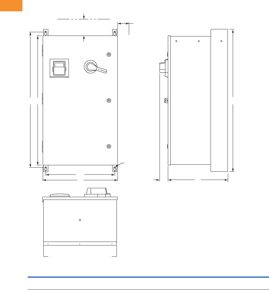
V6-T2-224 Volume 6—Solid-State Motor Control CA08100007E—May 2014 www.eaton.com
2
2
2
2
2
2
2
2
2
2
2
2
2
2
2
2
2
2
2
2
2
2
2
2
2
2
2
2
2
2
2.8
Adjustable Frequency Drives
Low Harmonic Drives
Dimensions
Approximate Dimensions in Inches (mm)
Enclosure Size B—UL Type 12
H H1H2W W1D D1
Approximate
Weight
Lbs (kg)
Approximate
Shipping Weight
Lbs (kg)
40.00
(1016.0)
38.00
(965.2)
36.35
(923.3)
20.92
(531.4)
19.30
(490.2)
16.76
(425.7)
2.34
(59.4)
185 (84) 229 (104)
4.00 (101.6)
Minimum Free Air
Space Required
H2H1 H
3.00 (76.2)
Minimum Air
Space
Required
Both Sides
DD1
W1
W
0.44 (11.2)
Mounting
Holes
(4 Places)
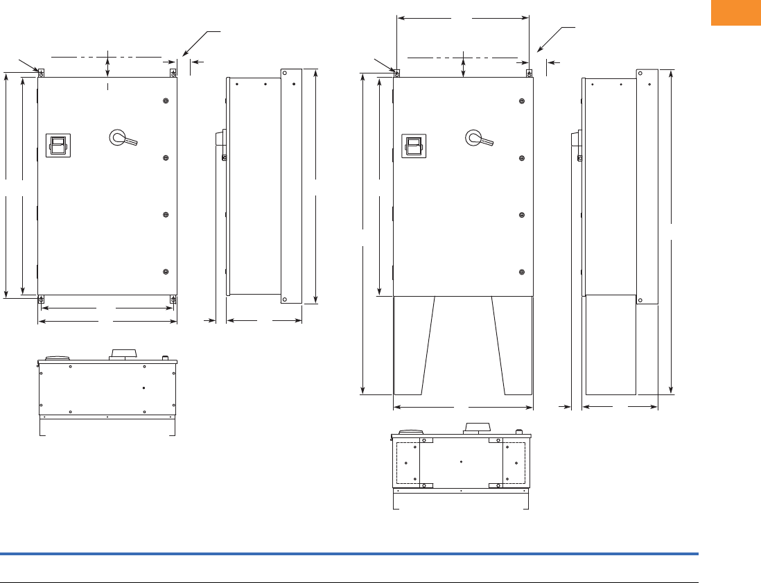
Volume 6—Solid-State Motor Control CA08100007E—May 2014 www.eaton.com V6-T2-225
2
2
2
2
2
2
2
2
2
2
2
2
2
2
2
2
2
2
2
2
2
2
2
2
2
2
2
2
2
2
2.8
Adjustable Frequency Drives
Low Harmonic Drives
Approximate Dimensions in Inches (mm)
Enclosure Size C—UL Type 12
H H1H2H3H4W W1D D1
Approximate
Weight
Lbs (kg)
Approximate
Shipping Weight
Lbs (kg)
52.00
(1320.8)
50.00
(1270.0)
48.35
(1228.1)
72.00
(1828.8)
71.19
(1808.2)
30.92
(785.4)
29.30
(744.2)
16.78
(426.2)
2.34
(59.4)
320 (145) 435 (197)
3.00 (76.2)
Minimum Air Space
Required Both Sides
4.00 (101.6) Minimum
Free Air Space Required
H3
H2
H4
WD1
W1
D
0.44 (11.2)
Mounting
Holes
(4 Places)
3.00 (76.2)
Minimum Air Space
Required Both Sides
4.00 (101.6) Minimum
Free Air Space Required
H
H2H1
D1
W
W1
D
0.44 (11.2)
Mounting
Holes
(4 Places)
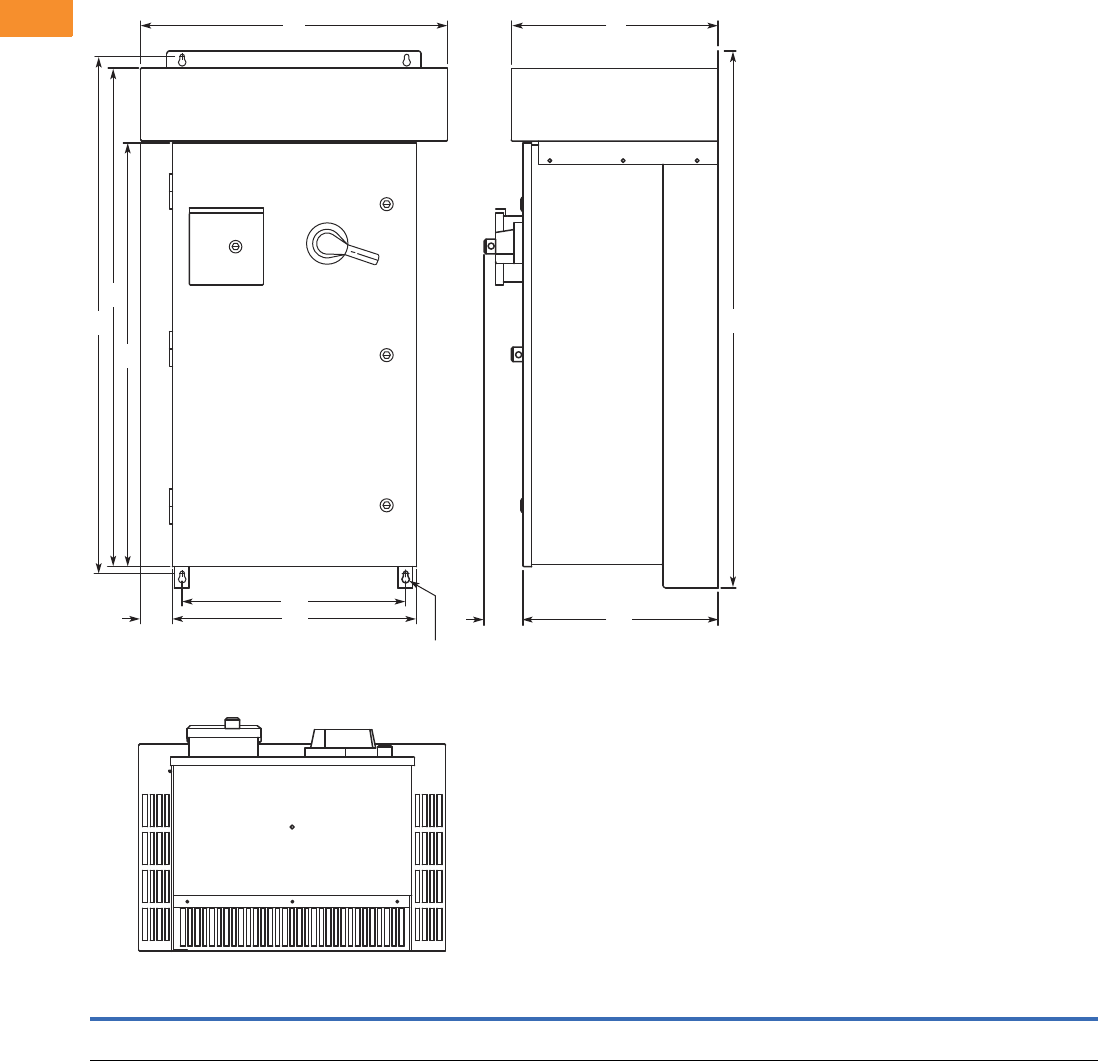
V6-T2-226 Volume 6—Solid-State Motor Control CA08100007E—May 2014 www.eaton.com
2
2
2
2
2
2
2
2
2
2
2
2
2
2
2
2
2
2
2
2
2
2
2
2
2
2
2
2
2
2
2.8
Adjustable Frequency Drives
Low Harmonic Drives
Approximate Dimensions in Inches (mm)
Enclosure Size B—UL Type 3R
H H1H2H3WW1W2W3DD1D2
Approximate
Weight
Lbs (kg)
Approximate
Shipping Weight
Lbs (kg)
46.09
(1170.7)
44.45
(1129.0)
42.77
(1086.4)
36.35
(923.3)
26.31
(668.3)
20.92
(531.4)
19.30
(490.2)
2.69
(68.3)
17.74
(450.6)
16.76
(425.7)
3.31
(84.1)
235 (107) 290 (132)
H3
H2
H1 H
W2
W1 D2
W
3D1
DW
0.44 (11.2)
Mounting
Holes
(4 Places)
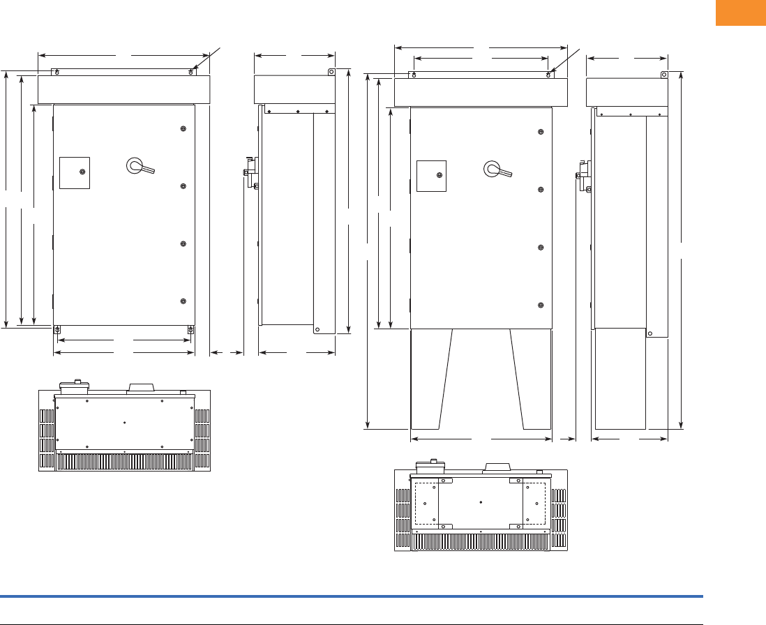
Volume 6—Solid-State Motor Control CA08100007E—May 2014 www.eaton.com V6-T2-227
2
2
2
2
2
2
2
2
2
2
2
2
2
2
2
2
2
2
2
2
2
2
2
2
2
2
2
2
2
2
2.8
Adjustable Frequency Drives
Low Harmonic Drives
Approximate Dimensions in Inches (mm)
Enclosure Size C—UL Type 3R
H H1H2H3H4H5WW1W2W3D D1D2
Approximate
Weight
Lbs (kg)
Approximate
Shipping Weight
Lbs (kg)
58.09
(1475.5)
56.45
(1433.8)
54.77
(1391.2)
48.35
(1228.1)
78.09
(1983.5)
77.64
(1972.1)
37.73
(958.3)
30.92
(785.4)
29.30
(744.2)
3.34
(84.8)
17.74
(450.6)
16.77
(426.0)
3.31
(84.1)
370 (168) 485 (220)
0.44 (11.2)
Mounting Holes
(4 Places)
H3 H
H2
H1
W2
W1 W3 D2 D1
WD
H3
H2
H5
D2 D1
W1
W2
W
D
H4
0.44 (11.2)
Mounting Holes
(4 Places)
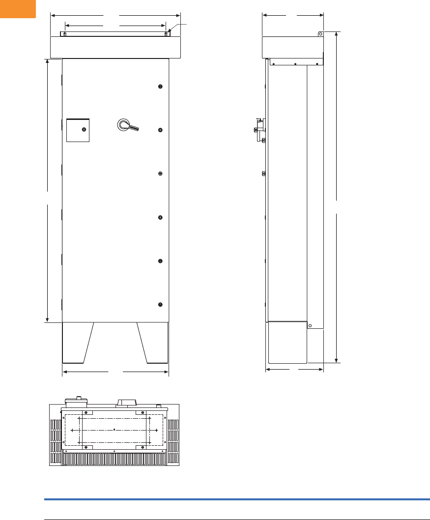
V6-T2-228 Volume 6—Solid-State Motor Control CA08100007E—May 2014 www.eaton.com
2
2
2
2
2
2
2
2
2
2
2
2
2
2
2
2
2
2
2
2
2
2
2
2
2
2
2
2
2
2
2.8
Adjustable Frequency Drives
Low Harmonic Drives
Approximate Dimensions in Inches (mm)
Enclosure Size D—UL Type 3R
Note
Shown with optional floor stands.
H H1 W W1 W2 D D1
Approximate
Shipping Weight
Lbs (kg)
76.27
(1937.3)
96.00
(2438.4)
30.92
(784.4)
37.73
(958.3)
29.30
(744.2)
16.76
(424.7)
17.74
(450.6)
1000 (454)
H1
D1
Ø0.44 (11.2)
Mounting Holes
(two places)
W1
WD
H
W2
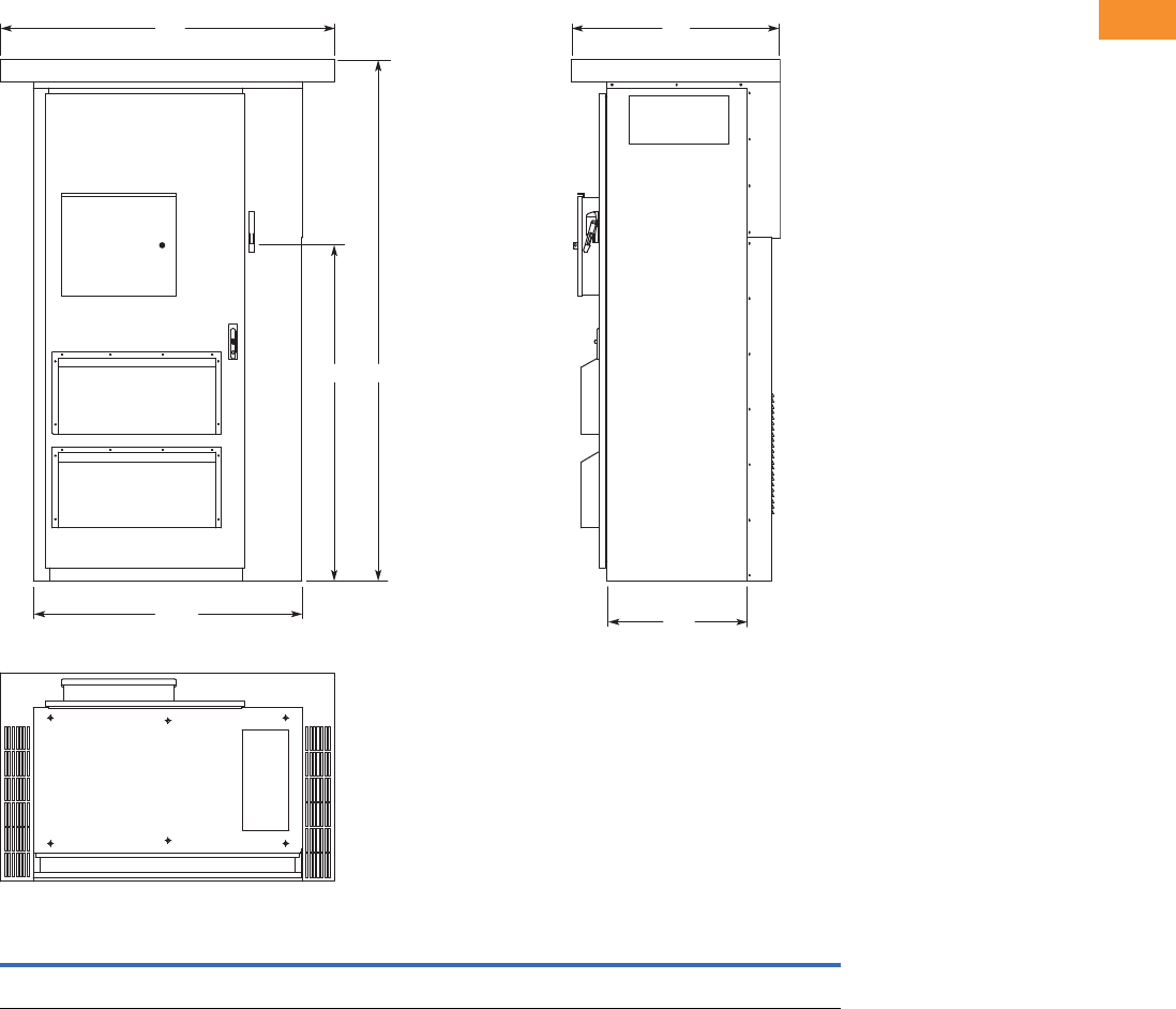
Volume 6—Solid-State Motor Control CA08100007E—May 2014 www.eaton.com V6-T2-229
2
2
2
2
2
2
2
2
2
2
2
2
2
2
2
2
2
2
2
2
2
2
2
2
2
2
2
2
2
2
2.8
Adjustable Frequency Drives
Low Harmonic Drives
Approximate Dimensions in Inches (mm)
Enclosure Size F
HH1WW1DD1
Approximate
Weight
Lbs (kg)
Approximate
Shipping Weight
Lbs (kg)
93.58
(2376.9)
69.51
(1765.60)
60.00
(1524.0)
48.00
(1219.2)
37.50
(952.5)
26.00
(660.4)
1700 (771) 1850 (839)
D
D1
HH1
W
W1
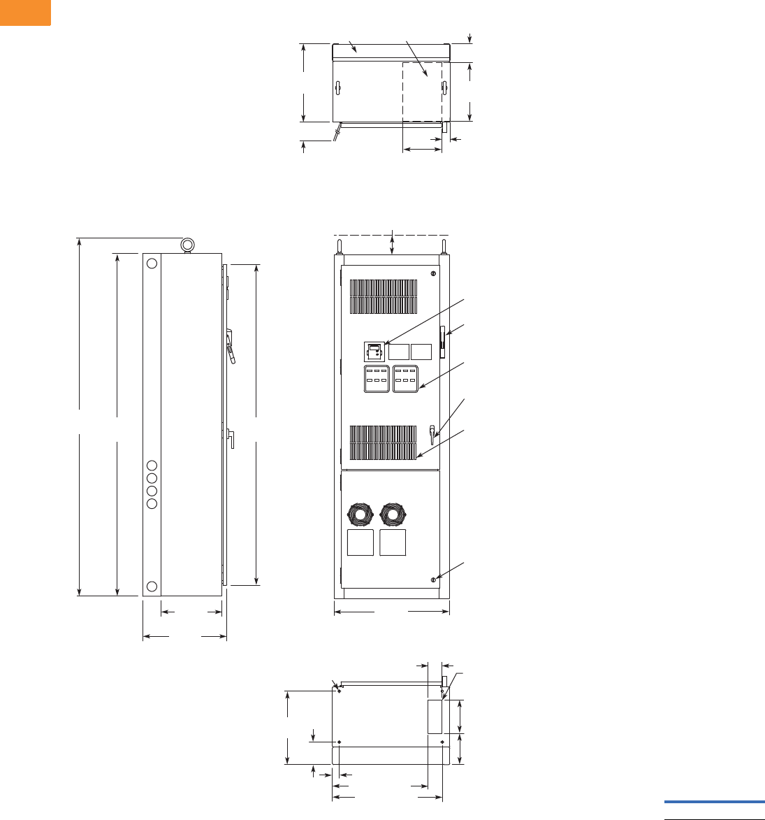
V6-T2-230 Volume 6—Solid-State Motor Control CA08100007E—May 2014 www.eaton.com
2
2
2
2
2
2
2
2
2
2
2
2
2
2
2
2
2
2
2
2
2
2
2
2
2
2
2
2
2
2
2.8
Adjustable Frequency Drives
Low Harmonic Drives
Approximate Dimensions in Inches (mm)
Enclosure Size 7
Construction: UL Type 1 Oversize
Finish: Enclosure – ANSI 61 Gray (Light)
15.50
(393.7)
21.50
(546.1)
Side View
15.00
(381.0)
8.00
(203.2)
8.50
(215.9)
18.75
(476.3)
5.75
(146.1)
1.75 (44.5) Typ.
24.45 (621.0)
28.05 (712.5)
20.00
(508.0)
26.25
(666.8)
4.79
(121.7)
Top View
Bottom View
10.00
(254.0)
Hinged Side
Door Clearance
at 90°
2.00
(50.8)
3.50
(88.9)
90.00
(2286.0)
93.92
(2385.6) 84.37
(2143.0)
4.00 (101.6) Minimum
Free Air Space Required
Exhaust
Air For
Cable Entry
Opening for
Bottom Cable Entry
.56 (14.2) Dia.
Mounting Holes
(4 Places)
30.00
(762.0)
Keypad
Operator Elements
When Specied, Mounted
on These Panels
Intake Ventilating Slots
(Filtered on NEMA 12)
Door Handle
(key-lock optional)
Quarter Turn Latch
(two places)
Flanged Disconnect Supplied
with Circuit Breaker
When Specied
Front View
Approximate
Shipping Weight
Lbs (kg)
1000 (454)
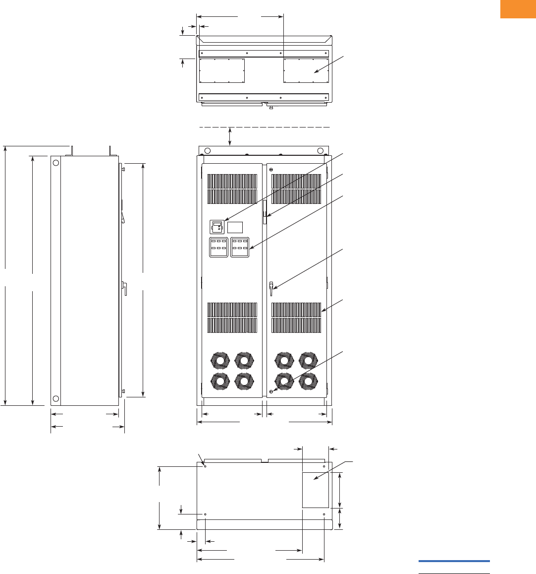
Volume 6—Solid-State Motor Control CA08100007E—May 2014 www.eaton.com V6-T2-231
2
2
2
2
2
2
2
2
2
2
2
2
2
2
2
2
2
2
2
2
2
2
2
2
2
2
2
2
2
2
2.8
Adjustable Frequency Drives
Low Harmonic Drives
Approximate Dimensions in Inches (mm)
Enclosure Size 8
Construction: UL Type 1 Oversize
Finish: Enclosure – ANSI 61 Gray (Light)
24.00 (609.6)
25.14 (639)
Side View 9.50
(241.3)
22.47
(570.74)
5.48
(139.19)
7. 7 3
(196.34)
12.50
(317.5)
45.22 (1148.59)
37.47 (951.74)
3.01 (76.45)
8.25
(209.6)
1.25
(31.8)
31.00
(787.4)
21.45 (544.8) 21.31 (541.3)
48.00 (1219.2)
Front View
Top View
90.00
(2286.0)
93.50
(2374.9) 84.37
(2143.0)
Opening for Top Cable Entry
(2 Places)
Keypad
Operator Elements When Specied,
Mounted on These Panels
Intake Ventilating Slots
(Filtered on NEMA 12)
Door Handle
(key-lock optional)
Quarter Turn Latch
(2 Places)
Bottom View
.56 (14.2) Dia.
Mounting Holes
(4 Places) Opening for
Bottom Cable Entry
Flanged Disconnect Supplied
with Circuit Breaker When Specied
4.00 (101.6) Minimum
Free Air Space Required
Approximate
Shipping Weight
Lbs (kg)
1400 (636)
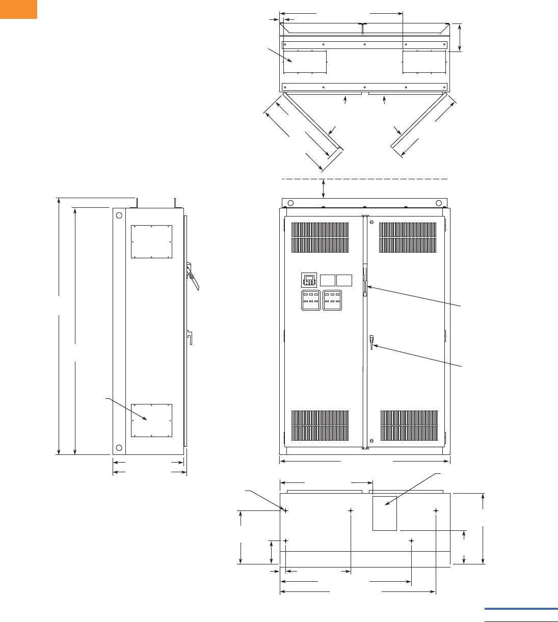
V6-T2-232 Volume 6—Solid-State Motor Control CA08100007E—May 2014 www.eaton.com
2
2
2
2
2
2
2
2
2
2
2
2
2
2
2
2
2
2
2
2
2
2
2
2
2
2
2
2
2
2
2.8
Adjustable Frequency Drives
Low Harmonic Drives
Approximate Dimensions in Inches (mm)
Enclosure Size 9
24.00 (609.6)
25.14 (638.6)
8.75
(222.3)
Top View
1.50 (38.1) 43.50 (1104.9)
90.00
(2286.0)
93.50
(2374.9)
4.00 (101.6) Minimum
Free Air Space Required
60.00 (1524.0)
Front View
Bottom View
Side View
7.46 x 15.00
(189.5 x 381.0)
Access in Top
(two places)
8.50 x 12.00 (215.9 x 304.8)
Bottom Access
ø0.56 (ø14.2) Dia.
Mounting Hole
(ve places)
27.06
(687.3)
27.36
(694.9)
90 Max.
Door
Opening
29.05
(737.9)
11.93
(303.0)
25.00
(635.0)
18.84
(478.5)
8.20
(208.3)
2.00 (50.8) 22.90 (581.7)
32.72 (831.1)
46.30 (1176.0)
54.90 (1394.5)
Door Handle
(key-lock optional)
Access
Plate
(4 places)
90 Max.
Door
Opening
Finish: Enclosure—ANSI 61 Gray (light)
Material: Enclosure and Backplate—
12 ga. = 0.1046 Cold Rolled Steel
Drive
Circuit Breaker
Approximate
Shipping Weight
Lbs (kg)
1800 (817)
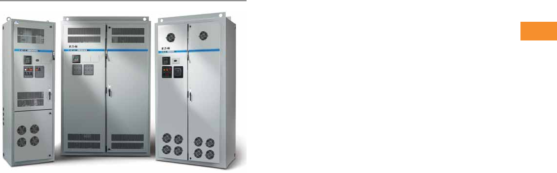
Volume 6—Solid-State Motor Control CA08100007E—May 2014 www.eaton.com V6-T2-233
2
2
2
2
2
2
2
2
2
2
2
2
2
2
2
2
2
2
2
2
2
2
2
2
2
2
2
2
2
2
2.8
Adjustable Frequency Drives
Low Harmonic Drives
Enclosed 18-Pulse Drives
Contents
Description Page
Enclosed Passive Filtered Drives . . . . . . . . . . . . . . V6-T2-200
Enclosed 18-Pulse Drives
Application Description . . . . . . . . . . . . . . . . . . . V6-T2-234
Features and Benefits . . . . . . . . . . . . . . . . . . . V6-T2-239
Catalog Number Selection . . . . . . . . . . . . . . . . V6-T2-240
Product Selection . . . . . . . . . . . . . . . . . . . . . . . V6-T2-241
Options . . . . . . . . . . . . . . . . . . . . . . . . . . . . . . . V6-T2-249
Technical Data and Specifications . . . . . . . . . . V6-T2-255
Wiring Diagrams . . . . . . . . . . . . . . . . . . . . . . . . V6-T2-257
Dimensions . . . . . . . . . . . . . . . . . . . . . . . . . . . V6-T2-258
Enclosed 18-Pulse Drives
Product Description
Eaton’s enclosed 18-pulse
clean power drives use
advanced 18-pulse clean
power technology that
significantly reduces line
harmonics at the drive input
terminals, resulting in one of
the purest sinusoidal
waveforms available.
The enclosed 18-pulse drive
also delivers True Power
Factor—in addition to
reducing harmonic distortion,
the enclosed 18-pulse drive
prevents upstream
transformer overheating and
overloading of breakers and
feeders, enabling the
application of adjustable
frequency drives on
generators and other high
impedance power systems.
All 9000X Series drives are
constant torque rated and
rated for either high overload
(IH) or low overload (IL). IH
indicates 150% overload
capacity for 1 minute out of
10 minutes. IL indicates
110% overload capacity for
1 minute out of 10 minutes.
Enclosed 18-Pulse Drive
Products
●Standard Enclosed—
covers a wide range of the
most commonly ordered
options. Pre-engineering
eliminates the lead time
normally associated with
customer specific options.
Available configurations
are listed on Pages
V6-T2-240 and
V6-T2-249 to V6-T2-254.
●Modified Standard
Enclosed—applies to
specific customer
requirements that vary
from the Standard
Enclosed offering, such as
the need for an additional
indicating light or minor
modifications to drawings.
Contact your local sales
office for assistance in
pricing and lead time.
●Custom Engineered—
for those applications with
more unique or complex
requirements, these are
individually engineered
to the customer’s needs.
Contact your local sales
office for assistance in
pricing and lead time.
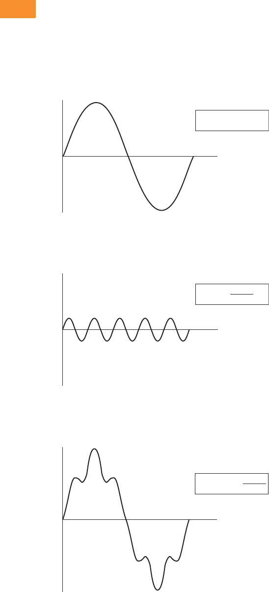
V6-T2-234 Volume 6—Solid-State Motor Control CA08100007E—May 2014 www.eaton.com
2
2
2
2
2
2
2
2
2
2
2
2
2
2
2
2
2
2
2
2
2
2
2
2
2
2
2
2
2
2
2.8
Adjustable Frequency Drives
Low Harmonic Drives
Application Description
Designed to exceed the
I
EEE
®
519-1992 requirements for
harmonic distortion, the
enclosed 18-pulse drive is the
clear choice for applications in
the water, wastewater,
HVAC, industrial and process
industries where harmonics
are a concern.
What Are Harmonics?
Take a perfect wave with a fundamental frequency of 60 Hz,
which is close to what is supplied by the power company.
Perfect Wave
Add a second wave that is five times the fundamental frequency—
300 Hz (typical of frequency added to the line by a fluorescent light).
Second Wave
Combine the two waves. The result is a 60 Hz supply rich in
fifth harmonics.
Resulting Supply
f(x) = sin(x)
Volts
(v)
Time
(t)
f(x) = sin(5x)
5
Volts
(v)
Time
(t)
f(x) = sin(x) +
Volts
(v)
Time
(t)
sin(5x)
5
What Causes Harmonics?
Harmonics are the result of
nonlinear loads that convert
AC line voltage to DC.
Examples of equipment that
are non-linear loads are listed
below:
●AC variable frequency
drives
●DC drives
●Fluorescence lighting,
computers, UPS systems
●Industrial washing
machines, punch presses,
welders, etc.
How Can Harmonics Due to
VFDs Be Diminished?
By purchasing Eaton’s
enclosed 18-pulse drive
that is guaranteed to meet
IEEE Std. 519-1992 Harmonic
Distortion Limits.
What Are Linear Loads?
Linear loads are primarily
devices that run across the
line and do not add
harmonics. Motors are prime
examples. The downside to
having large motor linear
loads is that they draw more
energy than a VFD, because
of their inability to control
motor speed. In most
applications, there is a turn
down valve used with the
motor that will reduce the
flow of the material, without
significantly reducing the load
to the motor. While this
provides some measure of
speed control, it is extremely
inefficient.
Why Be Concerned
About Harmonics?
1. Installation and utility
costs increase.
Harmonics cause
damage to transformers
and lower efficiencies
due to the IR loss. These
losses can become
significant and can have a
dramatic effect on the
HVAC systems that are
controlling the
temperatures of the
building where the
transformer and drive
equipment reside.
2. Downtime and loss of
productivity. Telephones
and data transmissions
links may not be
guaranteed to work on
the same power grids
polluted with harmonics.
3. Downtime and
nuisance trips of drives
and other equipment.
Emergency generators
have up to three times
the impedance that is
found in a conventional
utility source. Thus the
harmonic voltage
distortion can be up
to three times as large,
causing risk of operation
problems.
4. Larger motors must be
used. Motors running
across the line that are
connected on polluted
power distribution grids
can overheat or operate
at lower efficiency due
to harmonics.
5. Higher installation
costs. Transformers and
power equipment must
be oversized to
accommodate the loss of
efficiencies. This is due
to the harmonic currents
circulating through the
distribution without
performing useful work.
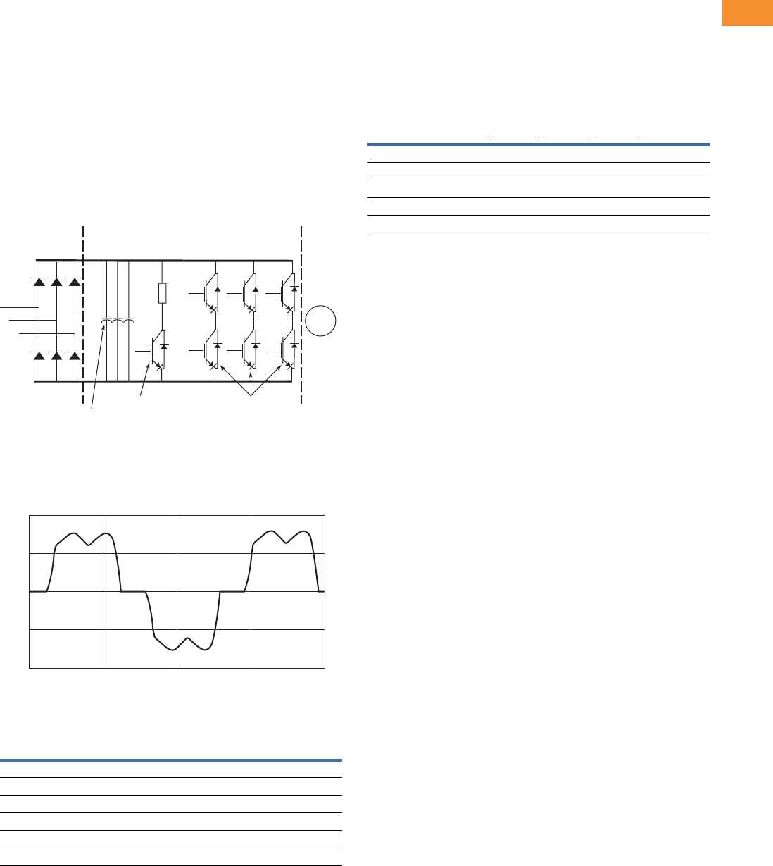
Volume 6—Solid-State Motor Control CA08100007E—May 2014 www.eaton.com V6-T2-235
2
2
2
2
2
2
2
2
2
2
2
2
2
2
2
2
2
2
2
2
2
2
2
2
2
2
2
2
2
2
2.8
Adjustable Frequency Drives
Low Harmonic Drives
How Does a VFD Convert Three-Phase AC to a
Variable Output Voltage and Frequency?
The six-pulse VFD: The
majority of all conventional
drives that are built consist
of a six-pulse configuration.
The figure below
represents
a six-diode rectifier design that
converts three-phase utility
power to DC. The inverter
section uses IGBTs to convert
DC power to a simulated AC
sine wave that can vary in
frequency from 0–320 Hz.
The six-pulse VFD drive
creates harmonic current
distortion. The harmonic
current that is created is
energy that can not be used
by customers and causes
external heat and losses to all
components including other
drives that are on the same
power distribution. See the
curve below showing a
500 hp drive with 167A of
damaging harmonic current.
Six-Diode Rectifier Design
500 hp Six-Pulse Nonproductive Harmonic Current
500 hp Six-Pulse Nonproductive Harmonic Current
Six-Pulse Circuit
Current harmonics
I1 = 100% I11 = 6.10% I19 = 1.77%
I5 = 22.5% I13 = 4.06% I23 = 1.12%
I7 = 9.38% I17 = 2.26% I25 = 0.86%
Power = 500 hp
Harmonic current = 167 amps
L2A
L1A
L3A
Output Transistors
IGBT Section
Dynamic Braking
Transistor
Six-Pulse Diode
Bridge Rectier
Converter Section
Inverter Section
(–) DC
(+) DC
Bus
Capacitors
AC
Motor
1000
Current
Amps
500
0
–500
–1000
0.100 0.10625 0.1125
Time in Seconds
0.11875 0.125
Guidelines of Meeting IEEE Std. 519-1992
Harmonic Distortion Limits
The IEEE 519-1992
Specification is a standard
that provides guidelines for
commercial and industrial
users that are implementing
medium and low voltage
equipment.
Maximum Harmonic Current Distortion in % of the
Fundamental (120V through 69,000V)
The ratio Isc/IL is the ratio of the short-circuit current available at the
point of common coupling (PCC), to the maximum fundamental load
current. Consequently, as the size of the user load decreases with
respect to the size of the system, the percentage of harmonic current
that the user is allowed to inject into the utility system increases.
Notes
TDD = Total demand distortion is the harmonic current distortion in percent of the maximum
demand load current (15 or 30 minute demand).
ISC = Maximum short-circuit current at the PCC not counting motor contribution.
IL = Maximum demand load current for all of the connected loads (fundamental frequency
component) at the PCC. All of the limits are measured at a point of common coupling.
Harmonic Order (Odd Harmonics)
Isc/ILh<11 11<h<17 17<h<23 23<h<35 35<hTDD
<20 4.0 2.0 1.5 0.6 0.3 5.0
20<50 7.0 3.5 2.5 1.0 0.5 8.0
50<100 10.0 4.5 4.0 1.5 0.7 12.0
100<1000 12.0 5.5 5.0 2.0 1.0 15.0
>1000 15.0 7.0 6.0 2.5 1.4 20.0
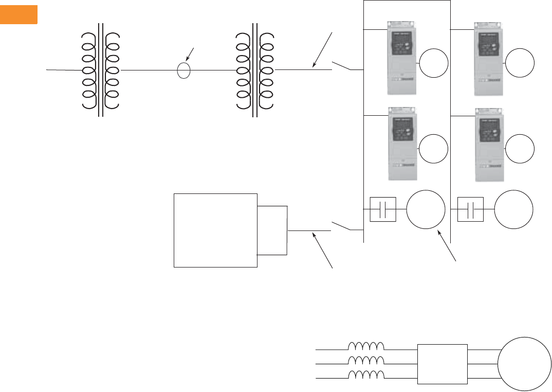
V6-T2-236 Volume 6—Solid-State Motor Control CA08100007E—May 2014 www.eaton.com
2
2
2
2
2
2
2
2
2
2
2
2
2
2
2
2
2
2
2
2
2
2
2
2
2
2
2
2
2
2
2.8
Adjustable Frequency Drives
Low Harmonic Drives
One-Line Diagram for Harmonic Analysis
Terms
●PCC (Point of Common
Coupling) is defined as the
electrical connecting point
between the utility and
multiple customers per the
specifications in IEEE 519
●POA (Point of Analysis)
is defined as where the
harmonic calculations
are taken
An oscilloscope can make
all measurements at the
PCC or POA do an on-site
harmonic evaluation.
Harmonic Reduction
Methods to Meet IEEE 519
1. Line Reactor
A line reactor is a three-phase
series inductance on the line
side of an AFD. If a line
reactor is applied on all AFDs,
it is possible to meet IEEE
guidelines where 10–25% of
system loads are AFDs,
depending on the stiffness of
the line and the value of line
reactance. Line reactors are
available in various values of
impedance, most typically
1–1.5%, 3% and 5%.
____Volts ____Volts
____Volts
____kVA
____Isc
____Impedance
PCC
Utility Side
Utility Side
Transformer
____Volts ____Volts
____Volts
____kVA
____Isc
____Impedance
Customer
Transformer
Customer
Generator
____Volts
____kVA
____Isc
____Impedance
Source A
Source B
Generator
Set
AC
Motor
AC
Motor
AC
Motor
Total Linear Motor Loads
Total Non-Linear Drive Loads
____AMPS
____AMPS
AC
Motor
AC
Motor
AC
Motor
The best way to estimate AFD harmonic contribution to an electrical system is to perform a harmonic analysis based on known system
characteristics. The one-line in this figure would provide the data to complete the calculations.
Line Reactor
Advantages
●Low cost
●Can provide moderate
reduction in voltage and
current harmonics
●Available in various values
of impedance
●Provides increased input
protection for AFD and its
semiconductors from line
transients
Disadvantages
●May not reduce harmonic
levels to below IEEE 519-
1992 guidelines
●Voltage drop due to IR loss
AFD Motor
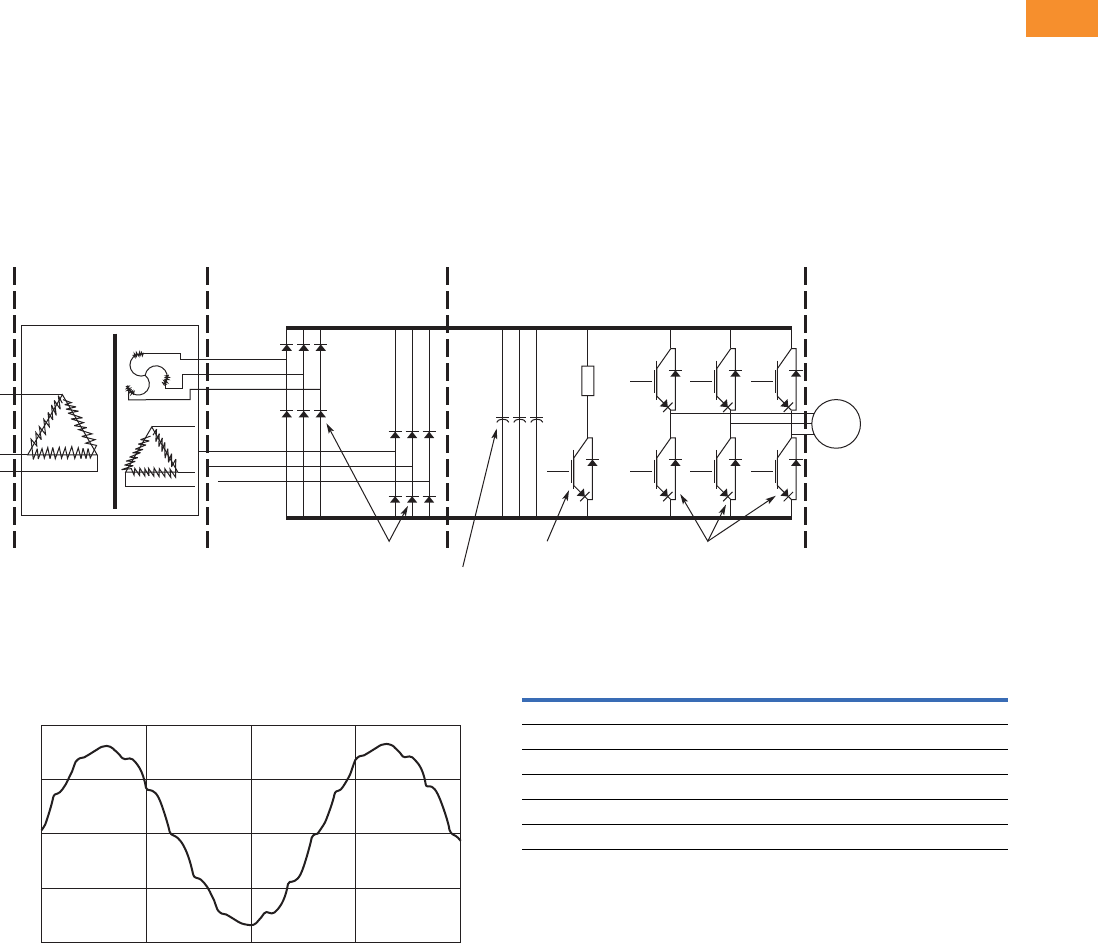
Volume 6—Solid-State Motor Control CA08100007E—May 2014 www.eaton.com V6-T2-237
2
2
2
2
2
2
2
2
2
2
2
2
2
2
2
2
2
2
2
2
2
2
2
2
2
2
2
2
2
2
2.8
Adjustable Frequency Drives
Low Harmonic Drives
2. 12-Pulse Converters
A 12-pulse converter
incorporates two separate
AFD input semiconductor
bridges, which are fed from
30º phase shifted power
sources with identical
impedance. The sources
may be two isolation
transformers, where one is
a delta/wye design (which
provides the phase shift)
and the second a delta/delta
design (which does not phase
shift). The 12-pulse
arrangement allows the
harmonics from the first
converter to cancel the
harmonics of the second.
Up to approximately 85%
reduction of harmonic current
and voltage distortion may
be achieved (over standard
Basic 12-Pulse Rectifier with “Phase Shifting” Transformer
500 hp 480V Drive with 12-Pulse Rectifier
12-Pulse Diode
Bridge Rectier
Converter Section
Inverter Section
(+) DC
L1A
L2A
L3A
L1B
L2B
L3B
(-) DC
Dynamic Braking
Transistor
Output Transistors
IGBT Section
AC
Motor
12-Pulse Diode
Bridge Rectier
Converter Section
12-Pulse
Phase-Shifting
Transformer
Bus
Capacitors
1000
Current
Amps
500
0
–500
–1000
0.126 0.13225 0.1385
Time in Seconds
0.14475 0.151
six-pulse converter). This
permits a facility to use a
larger percentage of AFD
loads under IEEE 519-1992
guidelines than allowable
using line reactors or DC
chokes. A harmonic analysis
is required to guarantee
compliance with guidelines.
500 hp 480V Drive with 12-Pulse Rectifier
Advantages
●Moderate cost, although
significantly more than
reactors or chokes
●Substantial reduction (up
to approx. 85%) in voltage
and current harmonics
●Provides increased input
protection for AFD and its
semiconductors from line
transients
Disadvantages
●Impedance matching of
phase shifted sources is
critical to performance
●Transformers often require
separate mounting or
larger AFD enclosures
●May not reduce
distribution harmonic levels
to below
IEEE 519-1992 guidelines
●Cannot retrofit for most
AFDs
12-Pulse Circuit
Current harmonics
I1 = 100% I11 = 4.19% I19 = 0.06%
I5 = 1.25% I13 = 2.95% I23 = 0.87%
I7 = 0.48% I17 = 0.21% I25 = 0.73%
Power = 500 hp
Hc = 66.2 amps
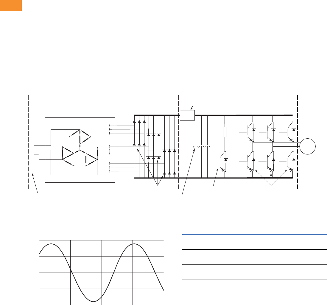
V6-T2-238 Volume 6—Solid-State Motor Control CA08100007E—May 2014 www.eaton.com
2
2
2
2
2
2
2
2
2
2
2
2
2
2
2
2
2
2
2
2
2
2
2
2
2
2
2
2
2
2
2.8
Adjustable Frequency Drives
Low Harmonic Drives
3. Clean Power Drives
When the total load is of non-
linear, the greatest harmonic
mitigation is required. Under
these conditions, the currents
drawn from the supply need
to be sinusoidal and “clean”
such that system
interference and additional
losses are negligible. Eaton’s
enclosed 18-pulse clean
power drive uses a phase-
shifting auto-transformer with
delta-connected winding.
Three of the output phases
are advanced and three are
retarded. The remaining three
phases of this nine-phase
supply are in phase with the
incoming line. This results in
nine separate phases. In this
type of configuration, the
total required kVA rating of
the transformer is only 48%
of a drive rate isolation
transformer. A traditional
isolated transformer system,
with multipulse windings,
would require the full kVA
Basic 18-Pulse Rectifier with Phase Shifting Transformer
500 hp 480V Drive with 18-Pulse Rectifiers
1
12
23
34
4
5
5
6
67
7
8
8
9
9
A
C
N
Output Transistors
IGBT Section
Dynamic Braking
Transistor
Pre-charge
Circuit
18-Pulse SCR
Bridge Rectier
Converter Section
18-Pulse
Phase-Shifting
Auto-Transformer
Inverter Section
(–) DC
(+) DC
Diode Rectiers
Bus
Capacitors
3-Phase
AC Input
1
2
3
AC
Motor
1000
Current
Amps
500
0
–500
–1000
0.126 0.13225 0.1385
Time in Seconds
0.14475 0.151
rating to be supported, which
is more common in an MV
step-down transformer.
The integrated 18-pulse
clean power drive, with
near sine wave input current
and low harmonics will meet
the requirements of IEEE
519-1992 under all practical
operating conditions. The
comparisons with six-pulse
and 12-pulse systems
are shown, see Pages
V6-T2-235, V6-T2-237
and V6-T2-238.
500 hp 480V Drive with 18-Pulse Rectifiers
Advantages
●Virtually guarantees
compliance with
IEEE 519-1992
●Provides increased input
protection for AFD and its
semiconductors from line
transients
●Up to four times the
harmonic reduction of
12-pulse methods
●Smaller transformer than
isolation transformer used
in 12-pulse converter
Disadvantages
●Not as cost-effective as
some other methods at
small (<50) horsepower
18-Pulse Clean Power
Current harmonics
I1 = 100% I11 = 0.24% I19 = 1.00%
I5 = 0.16% I13 = 0.10% I23 = 0.01%
I7 = 0.03% I17 = 0.86% I25 = 0.01%
Power = 500 hp
Hc = 24 amps
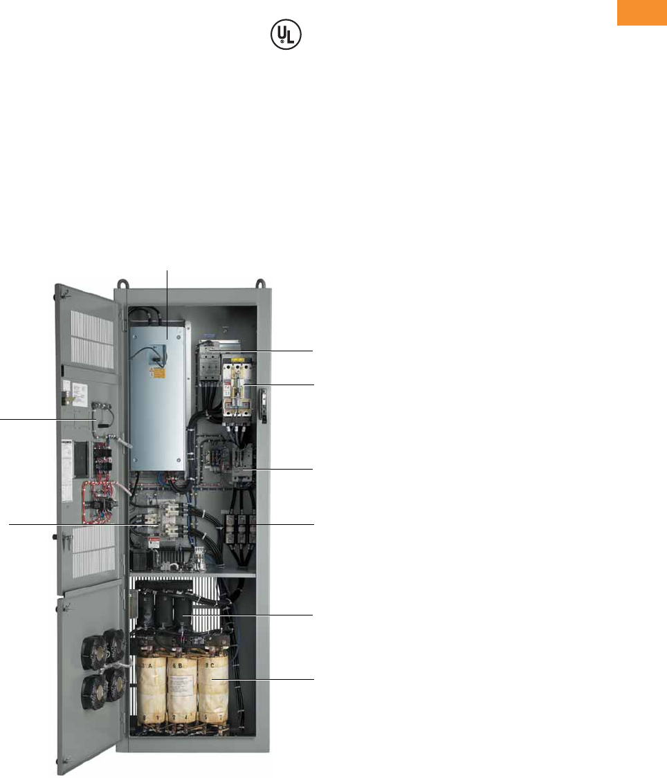
Volume 6—Solid-State Motor Control CA08100007E—May 2014 www.eaton.com V6-T2-239
2
2
2
2
2
2
2
2
2
2
2
2
2
2
2
2
2
2
2
2
2
2
2
2
2
2
2
2
2
2
2.8
Adjustable Frequency Drives
Low Harmonic Drives
Features and Benefits
Enclosed 18-pulse clean power
drive features include:
●Space optimized enclosure
●Simple layout for power
options
●Type 1, NEMA 12 with
gaskets and filters,
Type 3R
●Input voltage: 480V, 208V,
575V
●Complete range of control,
network and power options
●Horsepower range:
●480V, 25–800 hp (consult
factory for larger sizes)
●208/230V, 25–200 hp
●575V, 25–800 hp (consult
factory for larger sizes)
●Over 15 years of 18-pulse
clean power experience
●65 kAIC Standard at 480V
and 208V
●100 kAIC optional
Standards and Certifications
UL 508C tested, listed and
approved.
Product Identification
Type 1, 25–150 hp (30 x 90 x 21.50)
SVX9000 Drive
Door Mounted Keypad
18-Pulse Auto-Transformer
Motor Circuit Protector
(standard with bypass options)
Pre-Charge Input Contactor
18-Pulse Diode Rectifier Input Line Fuses
Input Choke
Bypass Starter Assembly
(option)
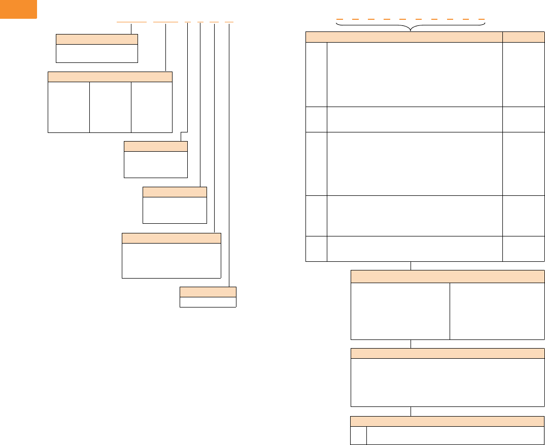
V6-T2-240 Volume 6—Solid-State Motor Control CA08100007E—May 2014 www.eaton.com
2
2
2
2
2
2
2
2
2
2
2
2
2
2
2
2
2
2
2
2
2
2
2
2
2
2
2
2
2
2
2.8
Adjustable Frequency Drives
Low Harmonic Drives
Catalog Number Selection
Enclosed 18-Pulse Drive
Notes
1Brake chopper is standard in drives up to 30 hp IH or 40 hp IL at 480V. It is optional in larger drives.
2Local/remote keypad is included as the standard control panel.
3Some options are voltage and/or horsepower specific. Consult your Eaton representative for details.
4See Pages V6-T2-251 and V6-T2-252 for complete descriptions.
5Includes local/remote speed reference switch.
6See Pages V6-T2-249 and V6-T2-250 for complete descriptions.
7Consult Eaton for availability.
C P X 1 0 0 1 4 A A
Voltage Rating
2 = 230V (208–240V)
4 = 480V
5 = 575V (575–600V)
Product Family
CPX = Clean power 18-pulse
enclosed drives
Horsepower Rating
025 = 25 hp
030 = 30 hp
040 = 40 hp
050 = 50 hp
060 = 60 hp
075 = 75 hp
100 = 100 hp
125 = 125 hp
150 = 150 hp
200 = 200 hp
250 = 250 hp
300 = 300 hp
350 = 350 hp
400 = 400 hp
500 = 500 hp
600 = 600 hp
700 = 700 hp
800 = 800 hp
Enclosure Rating
1 = Type 1
3 = Type 3R
6 = Type 12 filtered
Application—Torque/Braking 1
A = IL/no brake chopper
B = IL/internal brake chopper
D = IH/no brake chopper
E = IH/internal brake chopper
Enclosed Style
A = Enclosed drive
Engineered Options
HT
VB
High temperature rating for 50°C (FR10 and above) 7
Varnished boards
Communication Options 6
C2 = Modbus®
C3 = PROFIBUS® DP
C4 = LonWorks®
C5 = PROFIBUS DP (D9 connector)
C6 = CANopen (slave)
C7 = DeviceNet™
C8 = Modbus (D9 Type connector)
CA = Johnson Controls N2
CI = Modbus TCP
CJ = BACnet
CQ = EtherNet/IP
D3 = RS-232 with D9 connection
Control Options
B1 = 6 DI, 1 ext +24 Vdc/ext +24 Vdc
B2 = 1 RO (NC/NO), 1 RO (NO), 1 therm
B4 = 1 AI (mA isolated), 2 AO (mA isolated), 1 ext +24 Vdc/EXT +24 Vdc
B5 = 3 RO (NO)
B8 = 1 ext +24 Vdc/ext +24 Vdc, 3 Pt100
B9 = 1 RO (NO), 5 DI 42–240 Vac input
Enclosed Options 234 Type
K1
K2
K3
K4
K5
K6
KF
KO
Door-mounted speed potentiometer 5
Door-mounted speed potentiometer with HOA selector switch 5
3–15 psig follower
HAND/OFF/AUTO switch 0.87-inch (22 mm)
MANUAL/AUTO reference switch 0.87-inch (22 mm)
START/STOP pushbuttons 0.87-inch (22 mm)
Bypass test switch for RA and RB
Standard elapsed time meter
Control
Control
Control
Control
Control
Control
Addl. bypass
Control
L1
L2
LE
Power, RUN and fault pilot lights
Bypass pilot lights for RA, RB, bypass options
Red RUN light
Light
Addl. bypass
Light
P1
P8
PE
PF
PG
PH
PI
PN
Input disconnect
Surge protective device
Output contactor
Output filter
MotoRx (up to 600 ft [182.9m]) 1000 V/μS DV/DT filter
Single overload relay
Dual overload relays
Dual overloads for bypass
Input
Input
Output
Output
Output
Output
Output
Addl. bypass
RA
RB
RC
RD
RG
Manual HOA bypass controller
Manual IOB bypass controller
Auto transfer HOA bypass controller
Auto transfer IOB bypass controller
Reduced voltage starter for bypass
Bypass
Bypass
Bypass
Bypass
Bypass
S7
S8
S9
10.00-inch (254.0 mm) expansion
20.00-inch (508.0 mm) expansion
Space heater
Enclosure
Enclosure
Enclosure
Build options alphabetically and numerically.
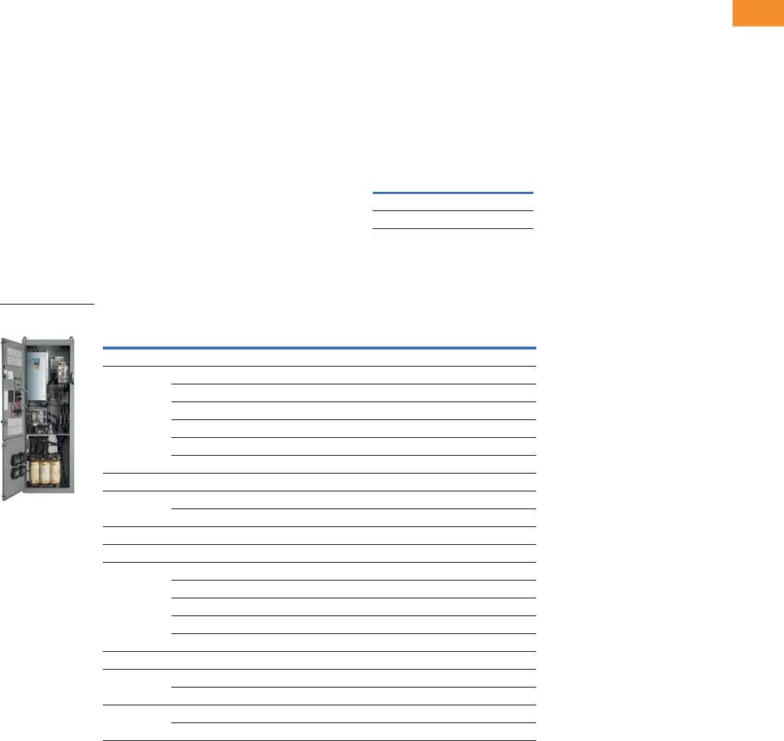
Volume 6—Solid-State Motor Control CA08100007E—May 2014 www.eaton.com V6-T2-241
2
2
2
2
2
2
2
2
2
2
2
2
2
2
2
2
2
2
2
2
2
2
2
2
2
2
2
2
2
2
2.8
Adjustable Frequency Drives
Low Harmonic Drives
Product Selection
When Ordering
●Select a base catalog
number that meets the
application requirements—
nominal horsepower,
voltage and enclosure
rating. (The enclosed
drive’s continuous output
amp rating should be equal
to or greater than the
motor’s full load amp
rating.) The base-enclosed
package includes a
standard drive, door-
mounted alphanumeric
panel and enclosure.
●The enclosed 18-pulse
drive product uses the
term High Overload (IH) in
place of the term Constant
Torque (CT). Likewise, Low
Overload (IL) is used in
place of the term Variable
Torque (VT). The new
terms are a more precise
description of the rating.
The older terms included
ambient temperature
ratings in addition to
overload ratings. In order to
minimize enclosure size
and offer the highest
ambient temperature
rating, overload and
temperature ratings are
now treated separately.
Ambient temperature
ratings are shown in the
table below. Consult the
factory for 50°C ratings of
FR10 and above.
Ambient Temperature
Ratings
●If dynamic brake chopper
or control/communication
option is desired, change
the appropriate code in the
base catalog number.
●All of the programming is
exactly the same as the
standard SVX9000 drive.
●Select enclosed options.
Add the codes as suffixes
to the base catalog number
in alphabetical and numeric
order.
208/230V Drives
Enclosed 18-Pulse Base Drive Type 1
Notes
1 See enclosure dimensions beginning on Page V6-T2-258.
2 hp ratings are provided as a guideline. Drives should be sized per motor nameplate FLA.
3 The 18-pulse clean power assembly includes a standard drive, door-mounted local/remote keypad and enclosure.
Frame
Size IHIL
FR4–FR9 50°C 50°C
FR10 and above 40°C 40°C
Enclosure
Size 1hp 2
Current
(A)
Chassis
Frame
Base Catalog
Number 3
Low Overload Drive
72575 FR7 CPX02512AA
30 88 FR7 CPX03012AA
40 114 FR7 CPX04012AA
50 140 FR8 CPX05012AA
60 170 FR8 CPX06012AA
75 205 FR8 CPX07512AA
8100300 FR9 CPX10012AA
9 125 340 FR8T CPX12512AA
150 410 FR8T CPX15012AA
10 200 522 FR9T CPX20012AA
High Overload Drive
72575 FR7 CPX02512DA
30 88 FR7 CPX03012DA
40 114 FR8 CPX04012DA
50 140 FR8 CPX05012DA
60 170 FR8 CPX06012DA
875205 FR9 CPX07512DA
9 100 300 FR8T CPX10012DA
125 340 FR8T CPX12512DA
10 150 410 FR9T CPX15012DA
200 522 FR9T CPX20012DA
Enclosed 18-Pulse
Drive
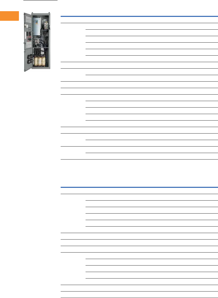
V6-T2-242 Volume 6—Solid-State Motor Control CA08100007E—May 2014 www.eaton.com
2
2
2
2
2
2
2
2
2
2
2
2
2
2
2
2
2
2
2
2
2
2
2
2
2
2
2
2
2
2
2.8
Adjustable Frequency Drives
Low Harmonic Drives
Enclosed 18-Pulse Base Drive NEMA 12 Filtered
Enclosed 18-Pulse Base Drive Type 3R 4
Notes
1 See enclosure dimensions beginning on Page V6-T2-258.
2 hp ratings are provided as a guideline. Drives should be sized per motor nameplate FLA.
3 The 18-pulse clean power assembly includes a standard drive, door-mounted local/remote keypad and enclosure.
4 All Type 3R drives use the Size F enclosure.
Enclosure
Size 1hp 2
Current
(A)
Chassis
Frame
Base Catalog
Number 3
Low Overload Drive
72575 FR7 CPX02562AA
30 88 FR7 CPX03062AA
40 114 FR7 CPX04062AA
50 140 FR8 CPX05062AA
60 170 FR8 CPX06062AA
75 205 FR8 CPX07562AA
8100300 FR9 CPX10062AA
9 125 340 FR8T CPX12562AA
150 410 FR8T CPX15052AA
10 200 522 FR9T CPX20062AA
High Overload Drive
72575 FR7 CPX02562DA
30 88 FR7 CPX03062DA
40 114 FR8 CPX04062DA
50 140 FR8 CPX05062DA
60 170 FR8 CPX06062DA
875205 FR9 CPX07562DA
9 100 300 FR8T CPX10062DA
125 340 FR8T CPX12562DA
10 150 410 FR9T CPX15062DA
200 522 FR9T CPX20062DA
Enclosure
Size 1hp 2
Current
(A)
Chassis
Frame
Base Catalog
Number 3
Low Overload Drive
72575 FR7 CPX02532AA
30 88 FR7 CPX03032AA
40 114 FR7 CPX04032AA
50 140 FR8 CPX05032AA
60 170 FR8 CPX06032AA
75 205 FR8 CPX07532AA
8100300 FR9 CPX10032AA
9 125 340 FR8T CPX12532AA
High Overload Drive
72575 FR7 CPX02532DA
30 88 FR7 CPX03032DA
40 114 FR8 CPX04032DA
50 140 FR8 CPX05032DA
60 170 FR8 CPX06032DA
875205 FR9 CPX07532DA
9 100 300 FR8T CPX10032DA
Enclosed 18-Pulse
Drive
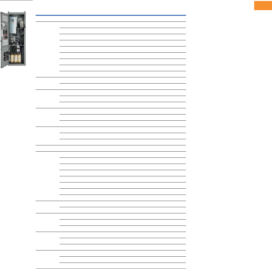
Volume 6—Solid-State Motor Control CA08100007E—May 2014 www.eaton.com V6-T2-243
2
2
2
2
2
2
2
2
2
2
2
2
2
2
2
2
2
2
2
2
2
2
2
2
2
2
2
2
2
2
2.8
Adjustable Frequency Drives
Low Harmonic Drives
480V Drives
Enclosed 18-Pulse Base Drive Type 1
Notes
1 See enclosure dimensions beginning on Page V6-T2-258.
2 hp ratings are provided as a guideline. Drives should be sized per motor nameplate FLA.
3 The 18-pulse clean power assembly includes a standard drive, door-mounted local/remote keypad and enclosure.
Enclosure
Size 1hp 2
Current
(A)
Chassis
Frame
Base Catalog
Number 3
Low Overload Drive
72538 FR6 CPX02514BA
30 46 FR6 CPX03014BA
40 61 FR6 CPX04014BA
50 72 FR7 CPX05014AA
60 87 FR7 CPX06014AA
75 105 FR7 CPX07514AA
100 140 FR8 CPX10014AA
125 170 FR8 CPX12514AA
150 205 FR8 CPX15014AA
8200261 FR9 CPX20014AA
250 300 FR9 CPX25014AA
9 300 385 FR10 CPX30014AA
350 460 FR10 CPX35014AA
400 520 FR10 CPX40014AA
10 500 590 FR11 CPX50014AA
550 650 FR11 CPX55014AA
600 730 FR11 CPX60014AA
11 650 820 FR11 CPX65014AA
700 920 FR12 CPX70014AA
800 1030 FR12 CPX80014AA
High Overload Drive
72538 FR6 CPX02514EA
30 46 FR6 CPX03014EA
40 61 FR7 CPX04014DA
50 72 FR7 CPX05014DA
60 87 FR7 CPX06014DA
75 105 FR8 CPX07514DA
100 140 FR8 CPX10014DA
125 170 FR8 CPX12514DA
8150205 FR9 CPX15014DA
200 245 FR9 CPX20014DA
9 250 300 FR10 CPX25014DA
300 385 FR10 CPX30014DA
350 460 FR10 CPX35014DA
10 400 520 FR11 CPX40014DA
500 590 FR11 CPX50014DA
550 650 FR11 CPX55014DA
11 600 720 FR12 CPX60014DA
650 820 FR12 CPX65014DA
700 840 FR12 CPX70014DA
Enclosed 18-Pulse
Drive
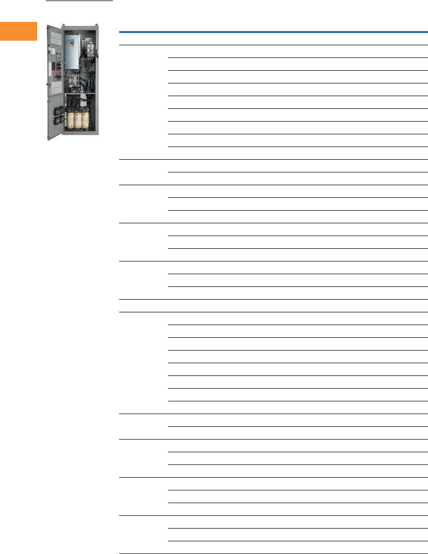
V6-T2-244 Volume 6—Solid-State Motor Control CA08100007E—May 2014 www.eaton.com
2
2
2
2
2
2
2
2
2
2
2
2
2
2
2
2
2
2
2
2
2
2
2
2
2
2
2
2
2
2
2.8
Adjustable Frequency Drives
Low Harmonic Drives
Enclosed 18-Pulse Base Drive NEMA 12 Filtered
Notes
1 See enclosure dimensions beginning on Page V6-T2-258.
2 hp ratings are provided as a guideline. Drives should be sized per motor nameplate FLA.
3 The 18-pulse clean power assembly includes a standard drive, door-mounted local/remote keypad and enclosure.
Enclosure
Size 1hp 2
Current
(A)
Chassis
Frame
Base Catalog
Number 3
Low Overload Drive
72538 FR6 CPX02564BA
30 46 FR6 CPX03064BA
40 61 FR6 CPX04064BA
50 72 FR7 CPX05064AA
60 87 FR7 CPX06064AA
75 105 FR7 CPX07564AA
100 140 FR8 CPX10064AA
125 170 FR8 CPX12564AA
150 205 FR8 CPX15064AA
8200261 FR9 CPX20064AA
250 300 FR9 CPX25064AA
9 300 385 FR10 CPX30064AA
350 460 FR10 CPX35064AA
400 520 FR10 CPX40064AA
10 500 590 FR11 CPX50064AA
550 650 FR11 CPX55064AA
600 730 FR11 CPX60064AA
11 650 820 FR11 CPX65064AA
700 920 FR12 CPX70064AA
800 1030 FR12 CPX80064AA
High Overload Drive
72538 FR6 CPX02564EA
30 46 FR6 CPX03064EA
40 61 FR7 CPX04064DA
50 72 FR7 CPX05064DA
60 87 FR7 CPX06064DA
75 105 FR8 CPX07564DA
100 140 FR8 CPX10064DA
125 170 FR8 CPX12564DA
8150205 FR9 CPX15064DA
200 245 FR9 CPX20064DA
9 250 300 FR10 CPX25064DA
300 385 FR10 CPX30064DA
350 460 FR10 CPX35014DA
10 400 520 FR11 CPX40064DA
500 590 FR11 CPX50064DA
550 650 FR11 CPX55064DA
11 600 720 FR12 CPX60064DA
650 820 FR12 CPX65064DA
700 840 FR12 CPX70064DA
Enclosed 18-Pulse
Drive
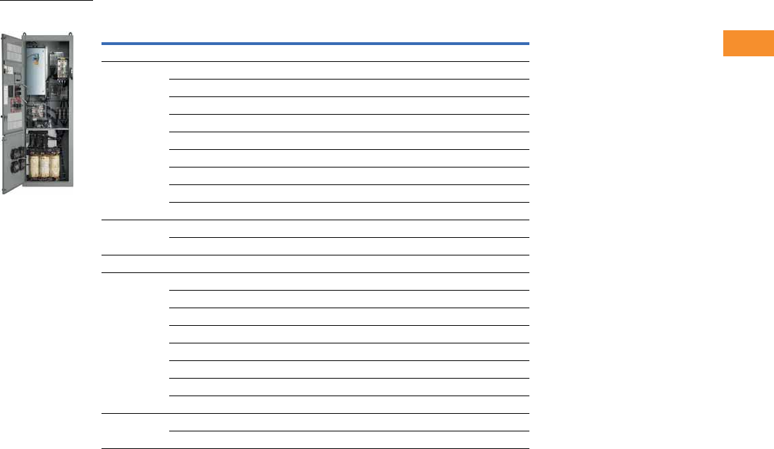
Volume 6—Solid-State Motor Control CA08100007E—May 2014 www.eaton.com V6-T2-245
2
2
2
2
2
2
2
2
2
2
2
2
2
2
2
2
2
2
2
2
2
2
2
2
2
2
2
2
2
2
2.8
Adjustable Frequency Drives
Low Harmonic Drives
Enclosed 18-Pulse Base Drive Type 3R 1
Notes
1 All Type 3R drives use the Size F enclosure.
2 See enclosure dimensions beginning on Page V6-T2-258.
3 hp ratings are provided as a guideline. Drives should be sized per motor nameplate FLA.
4 The 18-pulse clean power assembly includes a standard drive, door-mounted local/remote keypad and enclosure.
Enclosure
Size 2hp 3
Current
(A)
Chassis
Frame
Base Catalog
Number 4
Low Overload Drive
72538 FR6 CPX02534AA
30 46 FR6 CPX03034AA
40 61 FR6 CPX04034AA
50 72 FR7 CPX05034AA
60 87 FR7 CPX06034AA
75 105 FR7 CPX07534AA
100 140 FR8 CPX10034AA
125 170 FR8 CPX12534AA
150 205 FR8 CPX15034AA
8200261 FR9 CPX20034AA
250 300 FR9 CPX25034AA
High Overload Drive
72538 FR6 CPX02534DA
30 46 FR6 CPX03034DA
40 61 FR7 CPX04034DA
50 72 FR7 CPX05034DA
60 87 FR7 CPX06034DA
75 105 FR8 CPX07534DA
100 140 FR8 CPX10034DA
125 170 FR8 CPX12534DA
8150205 FR9 CPX15034DA
200 245 FR9 CPX20034DA
Enclosed 18-Pulse
Drive
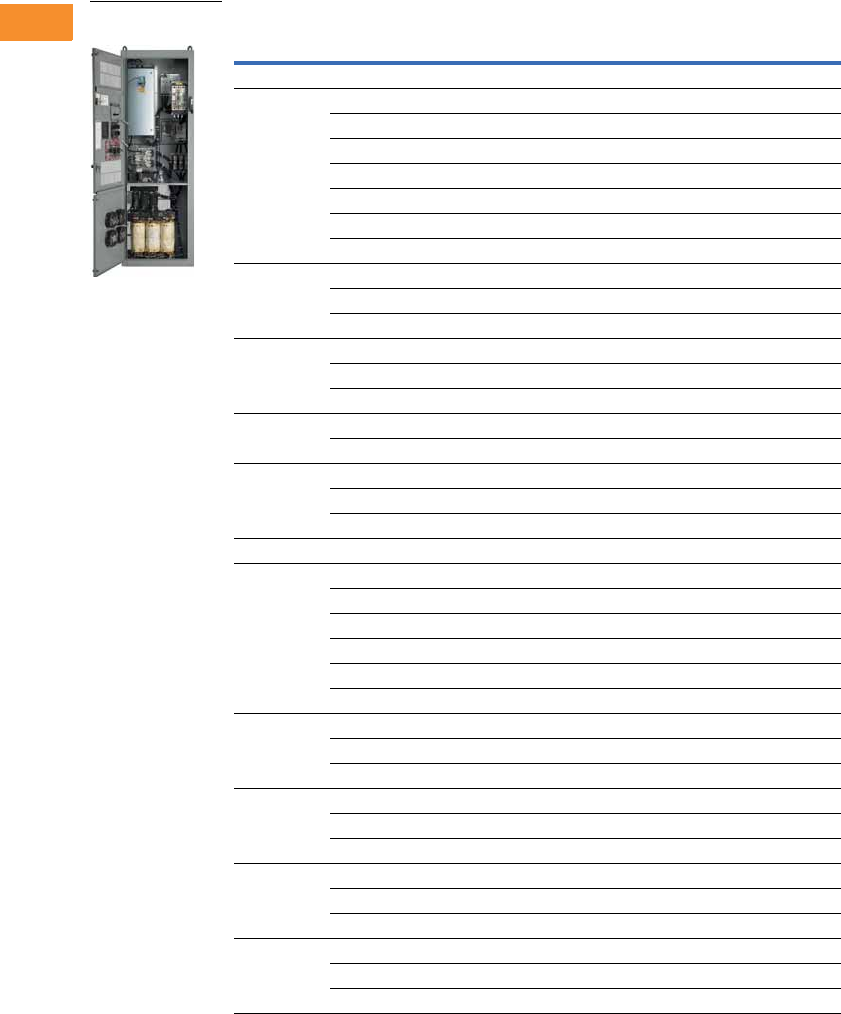
V6-T2-246 Volume 6—Solid-State Motor Control CA08100007E—May 2014 www.eaton.com
2
2
2
2
2
2
2
2
2
2
2
2
2
2
2
2
2
2
2
2
2
2
2
2
2
2
2
2
2
2
2.8
Adjustable Frequency Drives
Low Harmonic Drives
575V Drives
Enclosed 18-Pulse Base Drive Type 1
Notes
1 See enclosure dimensions beginning on Page V6-T2-258.
2 hp ratings are provided as a guideline. Drives should be sized per motor nameplate FLA.
3 The 18-pulse clean power assembly includes a standard drive, door-mounted local/remote keypad and enclosure.
Enclosure
Size 1hp 2
Current
(A)
Chassis
Frame
Base Catalog
Number 3
Low Overload Drive
72527 FR6 CPX02515AA
30 34 FR6 CPX03015AA
40 41 FR7 CPX04015AA
50 52 FR7 CPX05015AA
60 62 FR8 CPX06015AA
75 80 FR8 CPX07515AA
100 100 FR8 CPX10015AA
8125125 FR9 CPX12515AA
150 144 FR9 CPX15015AA
200 208 FR9 CPX20015AA
9 250 261 FR10 CPX25015AA
300 325 FR10 CPX30015AA
400 385 FR10 CPX40015AA
10 500 502 FR11 CPX50015AA
600 590 FR11 CPX60015AA
11 650 650 FR12 CPX65015AA
700 750 FR12 CPX70015AA
800 820 FR12 CPX80015AA
High Overload Drive
72527 FR6 CPX02515DA
30 34 FR7 CPX03015DA
40 41 FR7 CPX04015DA
50 52 FR8 CPX05015DA
60 62 FR8 CPX06015DA
75 80 FR8 CPX07515DA
8100100 FR9 CPX10015DA
125 125 FR9 CPX12515DA
150 144 FR9 CPX15015DA
9 200 208 FR10 CPX20015DA
250 261 FR10 CPX25015DA
300 325 FR10 CPX30015DA
10 400 385 FR11 CPX40015DA
450 460 FR11 CPX45015DA
500 502 FR11 CPX50015DA
11 600 590 FR12 CPX60015DA
650 650 FR12 CPX65015DA
700 750 FR12 CPX70015DA
Enclosed 18-Pulse
Drive
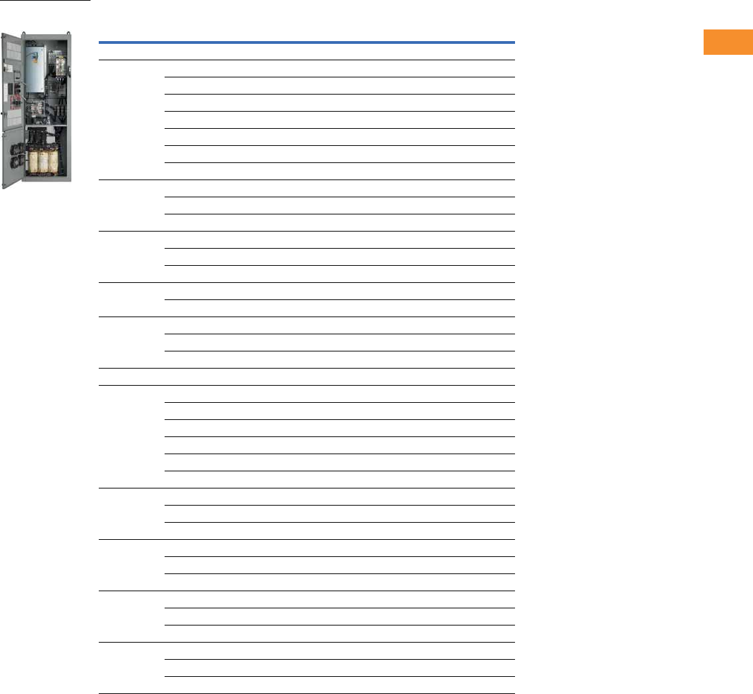
Volume 6—Solid-State Motor Control CA08100007E—May 2014 www.eaton.com V6-T2-247
2
2
2
2
2
2
2
2
2
2
2
2
2
2
2
2
2
2
2
2
2
2
2
2
2
2
2
2
2
2
2.8
Adjustable Frequency Drives
Low Harmonic Drives
Enclosed 18-Pulse Base Drive NEMA 12 Filtered
Notes
1 See enclosure dimensions beginning on Page V6-T2-258.
2 hp ratings are provided as a guideline. Drives should be sized per motor nameplate FLA.
3 The 18-pulse clean power assembly includes a standard drive, door-mounted local/remote keypad and enclosure.
Enclosure
Size 1hp 2
Current
(A)
Chassis
Frame
Base Catalog
Number 3
Low Overload Drive
72527 FR6 CPX02565AA
30 34 FR6 CPX03065AA
40 41 FR7 CPX04065AA
50 52 FR7 CPX05065AA
60 62 FR8 CPX06065AA
75 80 FR8 CPX07565AA
100 100 FR8 CPX10065AA
8125125 FR9 CPX12565AA
150 144 FR9 CPX15065AA
200 208 FR9 CPX20065AA
9 250 261 FR10 CPX25065AA
300 325 FR10 CPX30065AA
400 385 FR10 CPX40065AA
10 500 502 FR11 CPX50065AA
600 590 FR11 CPX60065AA
11 650 650 FR12 CPX65065AA
700 750 FR12 CPX70065AA
800 820 FR12 CPX80065AA
High Overload Drive
72527 FR6 CPX02565DA
30 34 FR7 CPX03065DA
40 41 FR7 CPX04065DA
50 52 FR8 CPX05065DA
60 62 FR8 CPX06065DA
75 80 FR8 CPX07565DA
8100100 FR9 CPX10065DA
125 125 FR9 CPX12565DA
150 144 FR9 CPX15065DA
9 200 208 FR10 CPX20065DA
250 261 FR10 CPX25065DA
300 325 FR10 CPX30065DA
10 400 385 FR11 CPX40065DA
450 460 FR11 CPX45065DA
500 502 FR11 CPX50065DA
11 600 590 FR12 CPX60065DA
650 650 FR12 CPX65065DA
700 750 FR12 CPX70065DA
Enclosed 18-Pulse
Drive
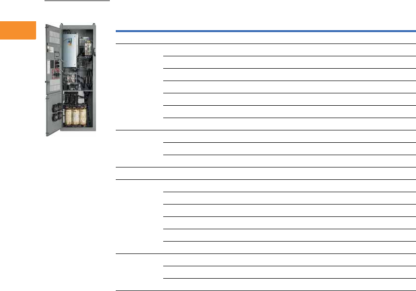
V6-T2-248 Volume 6—Solid-State Motor Control CA08100007E—May 2014 www.eaton.com
2
2
2
2
2
2
2
2
2
2
2
2
2
2
2
2
2
2
2
2
2
2
2
2
2
2
2
2
2
2
2.8
Adjustable Frequency Drives
Low Harmonic Drives
Enclosed 18-Pulse Base Drive Type 3R 1
Notes
1 All Type 3R drives use the Size F enclosure.
2 See enclosure dimensions beginning on Page V6-T2-258.
3 hp ratings are provided as a guideline. Drives should be sized per motor nameplate FLA.
4 The 18-pulse clean power assembly includes a standard drive, door-mounted local/remote keypad and enclosure.
Enclosure
Size 2hp 3
Current
(A)
Chassis
Frame
Base Catalog
Number 4
Low Overload Drive
72527 FR6 CPX02535AA
30 34 FR6 CPX03035AA
40 41 FR7 CPX04035AA
50 52 FR7 CPX05035AA
60 62 FR8 CPX06035AA
75 80 FR8 CPX07535AA
100 100 FR8 CPX10035AA
8125125 FR9 CPX12535AA
150 144 FR9 CPX15035AA
200 208 FR9 CPX20035AA
High Overload Drive
72527 FR6 CPX02535DA
30 34 FR7 CPX03035DA
40 41 FR7 CPX04035DA
50 52 FR8 CPX05035DA
60 62 FR8 CPX06035DA
75 80 FR8 CPX07535DA
8100100 FR9 CPX10035DA
125 125 FR9 CPX12535DA
150 144 FR9 CPX15035DA
Enclosed 18-Pulse
Drive
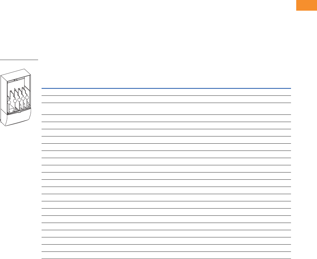
Volume 6—Solid-State Motor Control CA08100007E—May 2014 www.eaton.com V6-T2-249
2
2
2
2
2
2
2
2
2
2
2
2
2
2
2
2
2
2
2
2
2
2
2
2
2
2
2
2
2
2
2.8
Adjustable Frequency Drives
Low Harmonic Drives
Options
Enclosed 18-Pulse Drive Option Board Kits
The enclosed 18-pulse drives can accommodate a wide selection of expander and adapter option
boards to customize the drive for your application needs. The drive’s control unit is designed to accept
a total of five option boards (see figure below).
The enclosed 18-pulse drives factory-installed standard board configuration includes an A9 I/O board
and an A2 relay output board, which are installed in slots A and B.
9000X Series Option Board Kits
Option Board Kits
Notes
1 AI = Analog Input; AO = Analog Output, DI = Digital Input, DO = Digital Output, RO = Relay Output
2 Option card must be installed in one of the slots listed for that card. Slot indicated in bold is the preferred location.
3 OPTC2 is a multi-protocol option card.
Option Kit Description 1
Allowed Slot
Locations 2
Field
Installed
Factory
Installed SVX Ready Programs
Catalog
Number
Option
Designator Basic
Local/
Remote Standard MSS PID Multi-P. PFC
Standard I/O Cards
2 RO (NC/NO) B OPTA2 — ■ ■ ■ ■■■ ■
6 DI, 1 DO, 2 AI, 1AO, 1 +10 Vdc ref,
2 ext +24 Vdc/ext +24 Vdc
AOPTA9 — ■ ■ ■ ■■■ ■
Extended I/O Cards
6 DI B, C, D, E OPTB1 B1 —— — ——
■■
1 RO (NC/NO), 1 RO (NO), 1 therm B, C, D, E OPTB2 B2 —— — ——
■■
1 AI (mA isolated), 2 AO (mA isolated) B, C, D, E OPTB4 B4 ■ ■ ■ ■■■ ■
3 RO (NO) B, C, D, E OPTB5 B5 —— — ——
■■
3 Pt100 RTD board B, C, D, E OPTB8 B8 —— — ——
■—
1 RO (NO), 5 DI 42–240 Vac input B, C, D, E OPTB9 B9 —— — ——
■■
Communication Cards 3
Modbus D, E OPTC2 C2 ■ ■ ■ ■■■ ■
Modbus TCP D, E OPTCI CI ■ ■ ■ ■■■ ■
BACnet D, E OPTCJ CJ ■ ■ ■ ■■■ ■
EtherNet/IP D, E OPTCQ CQ ■ ■ ■ ■■■ ■
Johnson Controls N2 D, E OPTC2 CA ■ ■ ■ ■■■ ■
PROFIBUS DP D, E OPTC3 C3 ■ ■ ■ ■■■ ■
LonWorks D, E OPTC4 C4 ■ ■ ■ ■■■ ■
PROFIBUS DP (D9 connector) D, E OPTC5 C5 ■ ■ ■ ■■■ ■
CANopen (slave) D, E OPTC6 C6 ■ ■ ■ ■■■ ■
DeviceNet D, E OPTC7 C7 ■ ■ ■ ■■■ ■
Modbus (D9 type connector) D, E OPTC8 C8 ■ ■ ■ ■■■ ■
RS-232 with D9 connection D, E OPTD3 D3 ■ ■ ■ ■■■ ■
Option Boards
ABCDE

V6-T2-250 Volume 6—Solid-State Motor Control CA08100007E—May 2014 www.eaton.com
2
2
2
2
2
2
2
2
2
2
2
2
2
2
2
2
2
2
2
2
2
2
2
2
2
2
2
2
2
2
2.8
Adjustable Frequency Drives
Low Harmonic Drives
Modbus RTU Network
Communications
The Modbus Network Card
OPTC2 is used for connecting
the 9000X Drive as a slave
on a Modbus network. The
interface is connected by
a 9-pin DSUB connector
(female) and the baud rate
ranges from 300 to 19,200
baud. Other communication
parameters include an
address range from 1 to 247;
a parity of None, Odd or
Even; and the stop bit is 1.
PROFIBUS Network
Communications
The PROFIBUS Network Card
OPTC3 is used for connecting
the 9000X Drive as a slave
on a PROFIBUS-DP network.
The interface is connected
by a 9-pin DSUB connector
(female). The baud rates
range from 9.6K baud to 12M
baud, and the addresses
range from 1 to 127.
LonWorks Network
Communications
The LonWorks Network Card
OPTC4 is used for connecting
the 9000X Drive on a
LonWorks network. This
interface uses Standard
Network Variable Types
(SNVT) as data types. The
channel connection is
achieved using a FTT-10A
Free Topology transceiver
via a single twisted transfer
cable. The communication
speed with LonWorks is
78 kBits/s.
CANopen (Slave)
Communications
The CANopen (Slave)
Network Card OPTC6 is used
for connecting the 9000X
Drive to a host system.
According to ISO® 11898
standard cables to be chosen
for CAN bus should have
a nominal impedance of
120 ohms, and specific line
delay of nominal 5 nS/m.
120 ohm line termination
resistors required for
installation.
DeviceNet Network
Communications
The DeviceNet Network Card
OPTC7 is used for connecting
the 9000X Drive on a
DeviceNet Network. It
includes a 5.08 mm pluggable
connector. Transfer method
is via CAN using a two-wire
twisted shielded cable with
two-wire bus power cable
and drain. The baud rates
used for communication
include 125K baud, 250K
baud and 500K baud.
Johnson Controls Metasys N2
Network Communications
The OPTC2 fieldbus board
provides communication
between the 9000X Drive
and a Johnson Controls
Metasys™ N2 network.
With this connection, the
drive can be controlled,
monitored and programmed
from the Metasys system.
The N2 fieldbus is available as
a factory-installed option and
as a field-installable kit.
Modbus/TCP Network
Communications
The Modbus/TCP Network
Card OPTCI is used for
connecting the 9000X Drive
to Ethernet networks using
Modbus protocol. It includes
an RJ-45 pluggable
connector. This interface
provides a selection of
standard and custom register
values to communicate drive
parameters. The board
supports 10 Mbps and
100 Mbps communication
speeds. The IP address of
the board is configurable over
Ethernet using a supplied
software tool.
BACnet Network
Communications
The BACnet Network Card
OPTCJ is used for connecting
the 9000X Drive to BACnet
networks. It includes a 5.08
mm pluggable connector.
Data transfer is Master-Slave/
Token Passing (MS/TP)
RS-485. This interface uses
a collection of 30 Binary
Value Objects (BVOs) and
35 Analog Value Objects
(AVOs) to communicate
drive parameters. The card
supports 9.6, 19.2 and 38.4
Kbaud communication
speeds and supports network
addresses 1 to 127.
Ethernet/IP Network
Communications
The Ethernet/IP Network
Card OPTCK is used for
connecting the 9000X Drive
to Ethernet/Industrial Protocol
networks. It includes an RJ-
45 pluggable connector. The
interface uses CIP objects to
communicate drive
parameters (CIP is
“Common Industrial
Protocol,” the same protocol
used by DeviceNet). The
board supports 10 Mbps and
100 Mbps communication
speeds. The IP address of
the board is configurable
by Static, BOOTP and
DHCP methods.

Volume 6—Solid-State Motor Control CA08100007E—May 2014 www.eaton.com V6-T2-251
2
2
2
2
2
2
2
2
2
2
2
2
2
2
2
2
2
2
2
2
2
2
2
2
2
2
2
2
2
2
2.8
Adjustable Frequency Drives
Low Harmonic Drives
Control/Communication Option Descriptions
For availability, see Product Selection for base drive voltage required.
Available Control/Communications Options
Option Description
Option
Type
K1 Door-Mounted Speed Potentiometer—Provides the enclosed 18-pulse drive with the ability to adjust the frequency reference using a door-mounted potentiometer.
This option uses the 10 Vdc reference to generate a 0–10V signal at the analog voltage input signal terminal. When the HOA bypass option is added, the speed is
controlled when the HOA switch is in the HAND position. Without the HOA bypass option, a two-position switch (labeled local/remote) is provided on the keypad to select
speed reference from the speed potentiometer or a remote speed signal.
Control
K2 Door-Mounted Speed Potentiometer with HOA Selector Switch—Provides the enclosed 18-pulse drive with the ability to start/stop and adjust the speed
reference from door-mounted control devices or remotely from customer-supplied inputs. In HAND position, the drive will start and the speed is controlled by the door-
mounted speed potentiometer. The drive will be disabled in the OFF position. When AUTO is selected, the drive run and speed control commands are via user-supplied dry
contact and 4–20 mA signal.
Control
K3 3–15 psig Follower—Provides a pneumatic transducer that converts a 3–15 psig pneumatic signal to either 0–8 Vdc or a 1–9 Vdc signal interface with the enclosed
18-pulse drive. The circuit board is mounted on the inside of the front enclosure panel and connects to the user’s pneumatic control system via 6 ft (1.8m) of flexible
tubing and a 1/4 inch (6.4 mm) brass tube union.
Control
K4 HAND/OFF/AUTO Switch for Non-Bypass Configurations—Provides a three-position selector switch that allows the user to select either a HAND or AUTO mode
of operation. HAND mode is defaulted to keypad operation, and AUTO mode is defaulted to control from an external terminal source. These modes of operation can be
configured via drive programming to allow for alternate combinations of start and speed sources. Start and speed sources include Keypad, I/O and fieldbus.
Control
K5 MANUAL/AUTO Speed Reference Switch—Provides door-mounted selector switch for MANUAL/AUTO speed reference. Control
K6 START/STOP Pushbuttons—Provide door-mounted START and STOP pushbuttons for either bypass or non-bypass configurations. Control
KF Bypass Test Switch for RB and RA—Allows the user to energize the AF drive for testing while operating the motor on the bypass controller. The Test Switch is
mounted on the inside of the enclosure door.
Addl. bypass
KO Standard Elapsed Time Meter—Provides a door-mounted elapsed run-time meter. Control
L1 Power On and Fault Power Lights—Provide a white Power On light that indicates power to the enclosed cabinet and a red fault light that indicates a drive fault
has occurred.
Light
L2 Bypass Pilot Lights for RB, RA Bypass Options—A green light indicates when the motor is running in Inverter mode and an amber light indicates when the motor is
running in Bypass mode. The lights are mounted on the enclosure door, above the switches.
Addl. bypass
LE Red Run Pilot Light 0.87-Inch (22 mm)—Provides a red Run pilot light that indicates the drive is running. Light
P1 Input Circuit Breaker—High interrupting circuit breaker that provides a means of short-circuit protection for the power cables between it and the enclosed 18-pulse
drive, and protection from high-level ground faults on the power cable. Allows a convenient means of disconnecting the enclosed 18-pulse drive from the line and the operating
mechanism can be padlocked in the OFF position. This is factory mounted in the enclosure. Standard rating is 65 kAIC at 208/480V. 100 kAIC is available as an option.
Input
PE Output Contactor—Provides a means for positive disconnection of the drive output from the motor terminals. The contactor coil is controlled by the drive’s run or
permissive logic. NC and NO auxiliary contacts rated at 10A, 600 Vac are provided for customer use. Bypass options RB and RA include an output contactor as standard.
This option includes a low VA 115 Vac fused control power transformer and is factory mounted in the enclosure.
Output
PF Output Filter—Used to reduce the transient voltage (DV/DT) at the motor terminals. The output filter is recommended for cable lengths exceeding 100 ft (30.5m) with a
drive of 3 hp and above, for cable lengths of 33 ft (10.1m) with a drive of 2 hp and below, or for a drive rated at 525–690V. This option is mounted in the enclosure.
Output
PG MotoRx (300–600 Ft) 1000 V/μS DV/DT Filter—Used to reduce transient voltage (DV/DT) and peak voltages at the motor terminals. This option is comprised of a 0.5%
line reactor, followed by capacitive filtering and an energy recovery/clamping circuit. Unlike the output filter (see option PF), the MotoRx recovers most of the energy from the
voltage peaks, resulting in a lower voltage drop to the motor, and therefore conserving power. This option is used when the distance between a single motor and the drive
is 300–600 ft (91.4–182.9m).
Output
PH Single Overload Relay—Uses a bimetallic overload relay to provide additional overload current protection to the motor on configurations without bypass options.
It is included with the bypass configurations for overload current protection in the bypass mode. The overload relay is mounted within the enclosure, and is manually
resettable. Heater pack included.
Output
PI Dual Overload Relays—This option is recommended when a single drive is operating two motors and overload current protection is needed for each of the motors.
The standard configuration includes two bimetallic overload relays, each sized to protect a motor with 50% of the drive hp rating. For example, a 100 hp drive would
include two overload relays sized to protect two 50 hp motors. The relays are mounted within the enclosure, and are manually resettable. Heater packs not included.
Output
PN Dual Overloads for Bypass—This option is recommended when a single drive is operating two motors in the Bypass mode and overload current protection is needed
for each of the motors. The standard configuration includes two bimetallic overload relays, each sized to protect a motor with 50% of the drive hp rating. For example,
a 100 hp drive would include two overload relays sized to protect two 50 hp motors. The relays are mounted within the enclosure, and are manually resettable.
Addl. bypass
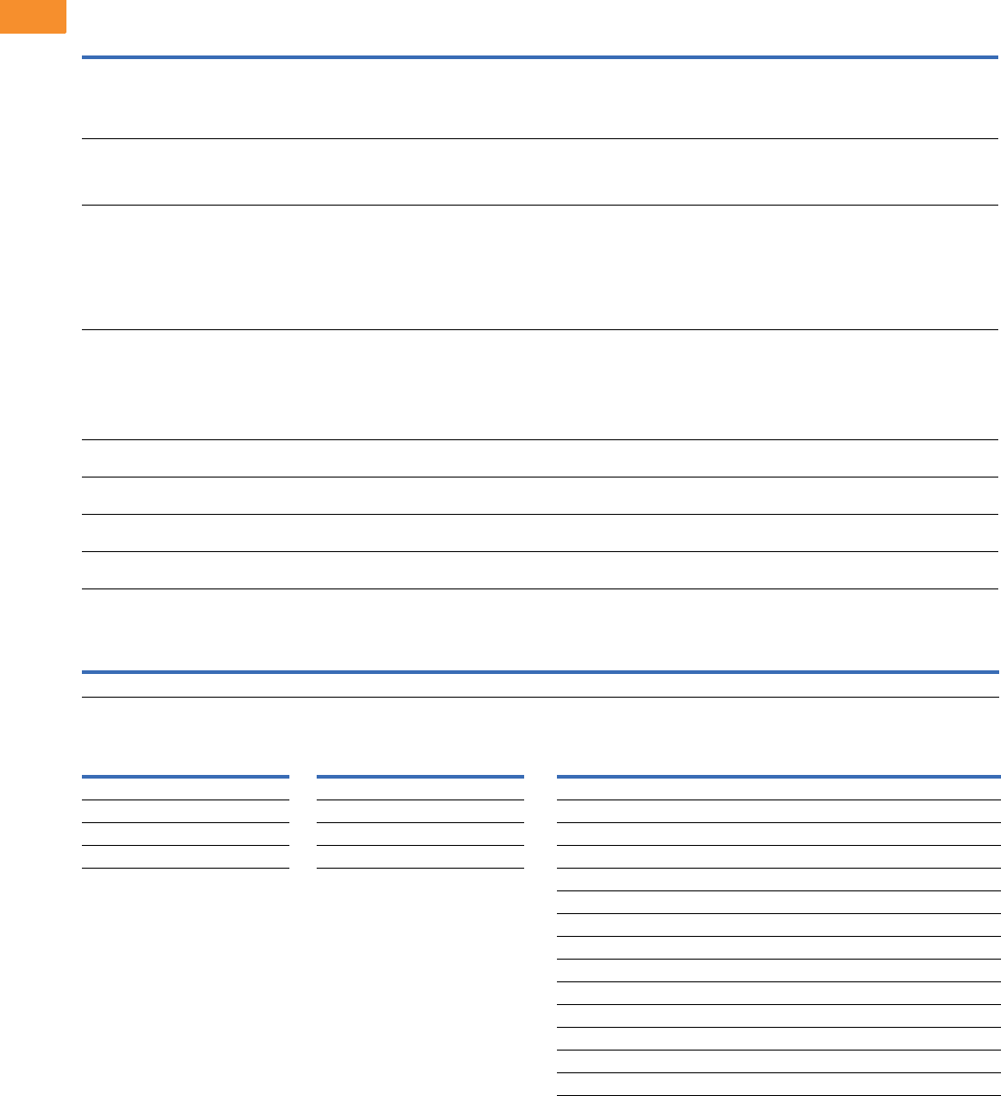
V6-T2-252 Volume 6—Solid-State Motor Control CA08100007E—May 2014 www.eaton.com
2
2
2
2
2
2
2
2
2
2
2
2
2
2
2
2
2
2
2
2
2
2
2
2
2
2
2
2
2
2
2.8
Adjustable Frequency Drives
Low Harmonic Drives
For availability, see Product Selection for base drive voltage required.
Available Control/Communications Options, continued
Dissipated Watt Losses
Conformal (Varnished) Coating 1
Notes
1See catalog number description to order.
2Contact factory for 208V and 575V applications.
3Contact factory.
480V Input Disconnect Selection 2
Option Description
Option
Type
RA Manual HOA Bypass Controller—The manual HAND/OFF/AUTO (HOA)—three-contactor—bypass option provides a means of bypassing the enclosed 18-pulse drive,
allowing the AC motor to be operated at full speed directly from the AC supply line. This option consists of an input HMCP, a fused control power transformer, and a
full voltage bypass starter with a door-mounted HOA selector switch and an INVERTER/BYPASS switch. The HOA switch provides the ability to start and stop the drive
in the inverter mode. IEC type input, bypass and input contactors are provided. The contactors are mechanically and electrically interlocked (see wiring diagram on
Page V6-T2-257).
Bypass
RB Manual IOB Bypass Controller—The manual INVERTER/OFF/BYPASS (IOB)—three-contactor—bypass option provides a means of bypassing the enclosed 18-pulse
drive, allowing the AC motor to be operated at full speed directly from the AC supply line. This option consists of an input HMCP, a fused control power transformer, and
a full voltage bypass starter with a door-mounted IOB selector switch. IEC type input, bypass and input contactors are provided. The contactors are mechanically and
electrically interlocked (see wiring diagram on Page V6-T2-257).
Bypass
RC Auto Transfer HOA Bypass Controller —The manual HAND/OFF/AUTO (HOA)—three-contactor—bypass option provides a means of bypassing the enclosed
18-pulse drive, allowing the AC motor to be operated at full speed directly from the AC supply line. The circuitry provides an automatic transfer of the load to “across the
line” operation after a drive trip. This option consists of an input HMCP, a fused control power transformer, and a full voltage bypass starter with a door-mounted HOA
selector switch and an INVERTER/BYPASS switch. The HOA switch provides the ability to start and stop the drive in either mode. IEC type input, bypass and input
contactors are provided. The contactors are mechanically and electrically interlocked (see wiring diagram on Page V6-T2-257). Door-mounted pilot lights are provided
that indicate bypass or inverter operation. A green light indicates when the motor is running in inverter mode and an amber light indicates when the motor is running in
bypass mode.
WARNING: The motor may restart when the overcurrent relay is reset when operating in bypass, unless the IOB selector switch is turned to the OFF position.
Bypass
RD Auto Transfer IOB Bypass Controller—The auto INVERTER/OFF/BYPASS (IOB)—three-contactor—bypass option provides a means of bypassing the enclosed
18-pulse drive, allowing the AC motor to be operated at full speed directly from the AC supply line. The circuitry provides an automatic transfer of the load to “across the
line” operation after a drive trip. This option consists of an input HMCP, a fused control power transformer, and a full voltage bypass starter with a door-mounted IOB
selector switch. IEC type input, bypass and input contactors are provided. The contactors are mechanically and electrically interlocked (see wiring diagram on Page
V6-T2-257). Door-mounted pilot lights are provided that indicate bypass or inverter operation. A green light indicates when the motor is running in inverter mode and an
amber light indicates when the motor is running in bypass mode.
WARNING: The motor may restart when the overcurrent relay is reset when operating in bypass, unless the IOB selector switch is turned to the OFF position.
Bypass
RG Reduced Voltage Starter for Bypass—Used in conjunction with bypass option RA, RB, RC or RD. This option adds reduced voltage soft starter to bypass assembly for
soft starting in bypass mode.
Bypass
S7 10.00-Inch (254.0 mm) Expansion—Expansion cabinet allows for special components, customer-supplied components or oversized cables.
NOTE: Enclosure expansion rated Type 1 only.
Enclosure
S8 20.00-Inch (508.0 mm) Expansion—Expansion cabinet allows for special components, customer-supplied components or oversized cables.
NOTE: Enclosure expansion rated Type 1 only.
Enclosure
S9 Space Heater—Prevents condensation from forming in the enclosure when the drive is inactive or in storage. Includes a thermostat for variable temperature control.
The heater requires a customer-supplied 115V remote supply source.
Enclosure
Horsepower 40 50 60 75 100 125 150 200 250 300 350 400 450 500 600 700 800
Watts 1844 2170 2540 3040 4011 4940 5730 8020 9383 11600 13600 15700 16250 17976 20393 27200 31400
Chassis
Frame
Delivery
Code
Chassis
Frame
Delivery
Code
FR6 FP FR9 FP
FR7 FP FR10 FP
FR8 FP FR11 FP
— — FR12 FP
Horsepower
P1 Input
Breaker
Bypass Motor Circuit Protector
(RA, RB, RC, RD)
25 HFD3050 HMCP050K2C
30 HFD3060 HMCP100R3C
40 HFD3080 HMCP100R3C
50 HFD3100 HMCP100R3C
60 HFD3100 HMCP150T4C
75 HFD3125 HMCP150T4C
100 HFD3150 HMCP150U4C
125 HFD3200 HMCP250W5C
150 HFD3225 HMCP250W5C
200 HKD3300 HMCP400X5C
250 HKD3400 HMCP400X5C
300–400 HLD3600 HMCP600L6W
500–600 HND3800 HMCP800X7W
650–800 HND312 3

Volume 6—Solid-State Motor Control CA08100007E—May 2014 www.eaton.com V6-T2-253
2
2
2
2
2
2
2
2
2
2
2
2
2
2
2
2
2
2
2
2
2
2
2
2
2
2
2
2
2
2
2.8
Adjustable Frequency Drives
Low Harmonic Drives
Enclosed Drive Options
Light Options
Control Options
Bypass Control Options
Meter Options
Enclosure Options
Note
1Requires customer-supplied 115 Vac supply.
Description
Catalog
Number Suffix
Power on, run, fault LED lights (22 mm) L1
Power on, fault LED lights (22 mm) L3
Green LED run light (22 mm) LA
Green LED stop light (22 mm) LD
Red LED run light (22 mm) LE
Red LED stop light (22 mm) LF
Red LED fault light (22 mm) LG
Power on white LED light (22 mm) LJ
Miscellaneous LED light (22 mm) LU
Description
Catalog
Number Suffix
Door-mounted speed potentiometer K1
Door-mounted speed potentiometer with HOA selector switch K2
3–15 psig follower K3
HOA selector switch K4
MANUAL/AUTO reference switch K5
START-STOP pushbuttons K6
Type D2 control relay SD
On-delay relay SE
Off-delay relay SF
Additional terminal blocks per 4 points SD
Description
Catalog
Number Suffix
Bypass test switch used with RA and RB KF
Inverter/bypass pilot lights L2
Description
Catalog
Number Suffix
Standard elapsed time meter KO
Frequency meter KS
MP-3000 relay with URTD KV
MP-3000 relay with URTD and CTs KU
Enclosure
Size
Catalog
Number Suffix
10.00 Inch (254.0 mm) Expansion
7S7
8S7
9S7
10 S7
11 S7
20.00 Inch (508.0 mm) Expansion
7S8
8S8
9S8
10 S8
11 S8
Space Heater 1
7S9
8S9
9S9
10 S9
11 S9
Plastic Nameplate
7SN
8SN
9SN
10 SN
11 SN

V6-T2-254 Volume 6—Solid-State Motor Control CA08100007E—May 2014 www.eaton.com
2
2
2
2
2
2
2
2
2
2
2
2
2
2
2
2
2
2
2
2
2
2
2
2
2
2
2
2
2
2
2.8
Adjustable Frequency Drives
Low Harmonic Drives
208V and 230V Power Options, 25–200 hp
480 and 575V Power Options, 25–800 hp
208V and 230V Bypass Options, 25–200 hp
480 and 575V Bypass Options, 25–800 hp
Description
Catalog
Number Suffix
Input breaker P1
Output contactor PE
Single overload relay PH
Dual overload relays PI
MOV P7
50 kA surge protective device P8
100 kA surge protective device P9
Description
Catalog
Number Suffix
Input breaker P1
Output contactor PE
Output filter PF
MotoRx (300–600 Ft) DV/DT filter PG
Single overload relay PH
Dual overload relays PI
Input MOV P7
50 kA surge protective device P8
100 kA surge protective device P8
Description
Catalog
Number Suffix
Manual HOA bypass controller RA
IOB bypass controller RB
Auto transfer HOA bypass controller RC
Auto transfer IOB bypass controller RD
Reduced voltage starter for bypass RG
Dual overloads for bypass PN
Description
Catalog
Number Suffix
Manual HOA bypass controller RA
IOB bypass controller RB
Auto transfer HOA bypass controller RC
Auto transfer IOB bypass controller RD
Reduced voltage starter for bypass RG
Dual overloads for bypass PN

Volume 6—Solid-State Motor Control CA08100007E—May 2014 www.eaton.com V6-T2-255
2
2
2
2
2
2
2
2
2
2
2
2
2
2
2
2
2
2
2
2
2
2
2
2
2
2
2
2
2
2
2.8
Adjustable Frequency Drives
Low Harmonic Drives
Technical Data and Specifications
Enclosed 18-Pulse Drives
Note
1The EMI filter is optional in FR10 and larger.
Description Specification
Primary Design Features
45–66 Hz input frequency Standard
Output: AC volts maximum Input voltage base
Output frequency range 0–320 Hz
Initial output current (IH) 250% for 2 seconds
Overload (1 minute [IH/IL]) 150%/110%
Enclosure space heater Optional
Oversize enclosure Standard
Output contactor Optional
Bypass motor starter Optional
Listings UL, cUL, 508C
Protection Features
Incoming line fuses Standard 200 kAIC rating
AC input circuit disconnect Optional
Phase rotation insensitive Standard
EMI filter Standard FR6 thru FR9 1
Input phase loss protection Standard
Input overvoltage protection Standard
Line surge protection Standard
Output short-circuit protection Standard
Output ground fault protection Standard
Output phase protection Standard
Overtemperature protection Standard
DC overvoltage protection Standard
Drive overload protection Standard
Motor overload protection Standard
Programmer software Optional
Local/remote keypad Standard
Keypad lockout Standard
Fault alarm output Standard
Built-in diagnostics Standard
Surge protective device Optional
Description Specification
Input/Output Interface Features
Setup adjustment provisions
Remote keypad/display Standard
Personal computer Standard
Operator control provisions
Drive mounted keypad/display Standard
Remote keypad/display Standard
Conventional control elements Standard
Serial communications Optional
115 Vac control circuit Optional
Speed setting inputs
Keypad Standard
0–10 Vdc potentiometer/voltage signal Standard
4–20 mA isolated Configurable
4–20 mA differential Configurable
3–15 psig Optional
Analog outputs
Speed/frequency Standard
Torque/load/current Programmable
Motor voltage Programmable
Kilowatts Programmable
0–10 Vdc signals Configurable w/jumpers
4–20 mA DC signals Standard
Isolated signals Standard
Discrete outputs
Fault alarm Standard
Drive running Standard
Drive at set speed Programmable
Optional parameters 14
Dry contacts
2 Form C contacts available
Additional discrete outputs Optional
Communications
RS-232 Standard
RS-422/485 Optional
DeviceNet™ Optional
Modbus RTU Optional
CANopen (slave) Optional
PROFIBUS-DP Optional
LonWorks Optional
Johnson Controls Metasys N2 Optional
EtherNet/IP/Modbus TCP Optional
BACnet Optional

V6-T2-256 Volume 6—Solid-State Motor Control CA08100007E—May 2014 www.eaton.com
2
2
2
2
2
2
2
2
2
2
2
2
2
2
2
2
2
2
2
2
2
2
2
2
2
2
2
2
2
2
2.8
Adjustable Frequency Drives
Low Harmonic Drives
Enclosed 18-Pulse Drives Standard I/O Specifications
I/O Specifications for Control/Communication Options
Note
1For applications above 3A consult instruction manual.
Description Specification
Performance Features
Sensorless vector control Standard
Volts/hertz control Standard
IR and slip compensation Standard
Electronic reversing Standard
Dynamic braking Optional
DC braking Standard
PID set point controller Programmable
Critical speed lockout Standard
Current (torque) limit Standard
Adjustable acceleration/deceleration Standard
Linear or S curve accel/decel Standard
Jog at preset speed Standard
Thread/preset speeds 7
Automatic restart Selectable
Coasting motor start Standard
Coast or ramp stop selection Standard
Elapsed time meter Optional
Carrier frequency adjustment 1–16 kHz
Standard Conditions for Application and Service
Maximum operating ambient temperature 0–50°C up to FR9
0–40°C FR10 and larger, consult factory for 50°C
rating above FR9
Storage temperature –40 to 60°C
Humidity (maximum), noncondensing 95%
Altitude (maximum without derate) 3300 ft (1000m)
Line voltage variation +10/–15%
Line frequency variation 45–66 Hz
Efficiency >95%
Power factor (displacement) 0.99+
Power factor (apparent) 0.99
Description Specification
Six–digital input programmable 24V: “0” <10V, “1” >18V,Ri >5 kohms
Two–analog input configurable
w/jumpers
Voltage: 0–±10V, Ri >200 kohms
Current: 0 (4)–20 mA, Ri = 250 ohms
Two–digital output programmable Form C relays 250 Vac
30 Vdc 2 amp resistive
One–analog output programmable
configurable w/jumper
0–20 mA, RL max. 500 ohms 10 bits ±2%
Description Specification
Analog voltage, input 0–±10V, Ri >200 kilohms
Analog current, input 0 (4)–20 mA, Ri = 250 ohms
Digital input 24V: “0” <10V, “1” >18V, Ri >5 kilohms
Auxiliary voltage 24V (±20%), max. 50 mA
Reference voltage 10V ±3%, max. 10 mA
Analog current, output 0 (4)–20 mA, RL = 500 kilohms, resolution
10 bit, accuracy <±2%
Analog voltage, output 0 (2)–10V, RL >1 kilohm, resolution
10 bit, accuracy <±2%
Relay output max. switching voltage 300 Vdc, 250 Vac
Relay output max. switching load 3A/24 Vdc, 300 Vdc, 250 Vac 1
Relay output max. continuous load 2A rms
Thermistor input Rtrip = 4.7 kohms
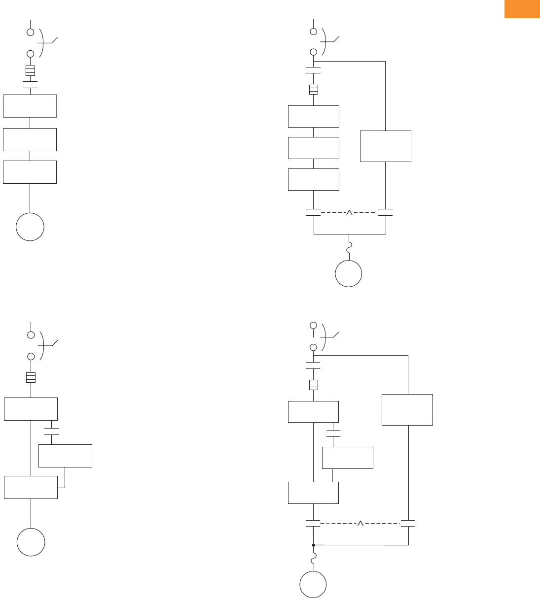
Volume 6—Solid-State Motor Control CA08100007E—May 2014 www.eaton.com V6-T2-257
2
2
2
2
2
2
2
2
2
2
2
2
2
2
2
2
2
2
2
2
2
2
2
2
2
2
2
2
2
2
2.8
Adjustable Frequency Drives
Low Harmonic Drives
Wiring Diagrams
Power Diagram Up to FR9
Power Diagram FR10 and Larger
Power Diagram Up to FR9 with Bypass
Power Diagram FR10 and Larger with Bypass
18-Pulse
Transformer
18-Pulse
Diode Bridge
9000X
Drive
Circuit
Breaker
Motor
Input
Fusing
IInverter Input
Contactor
18-Pulse
Transformer
6-Pulse
Diode Bridge
9000X
12-Pulse Drive
Circuit
Breaker
Motor
Input
Fusing
Pre-charge
Complete
Contactor
18-Pulse
Transformer
Optional
Reduced
Voltage Starter
18-Pulse
Diode Bridge
9000X
Drive
HMCP
Output
Contactor
Mechanical
Interlock
Motor
M
Inverter Input
Contactor I
Bypass
Contactor
L
(IT.)
Input
Fusing
Overload
18-Pulse
Transformer
Optional
Reduced
Voltage Starter
9000X
12-Pulse Drive
HMCP
Output
Contactor
Mechanical
Interlock
Motor
M
Inverter Input
Contactor I
Bypass
Contactor
L
Input
Fusing
Overload
6-Pulse
Diode Bridge
Pre-charge
Complete
Contactor
(IT.)
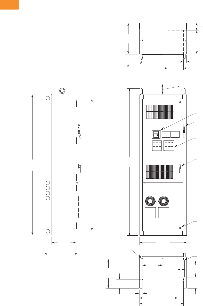
V6-T2-258 Volume 6—Solid-State Motor Control CA08100007E—May 2014 www.eaton.com
2
2
2
2
2
2
2
2
2
2
2
2
2
2
2
2
2
2
2
2
2
2
2
2
2
2
2
2
2
2
2.8
Adjustable Frequency Drives
Low Harmonic Drives
Dimensions
Approximate Dimensions in Inches (mm)
Enclosure Size 7
25–150 hp IL and 25–125 hp IH 480V—25–100 hp IL and 25–75 hp IH 575V
Side View
26.25
(666.8)
ø0.56 (ø14.2) Dia.
Mounting Holes
(ve places)
90.00
(2286.0)
84.37
(2143.0)
15.50
(393.7)
21.50
(546.1)
93.92
(2385.6)
30.00
(762.0)
4.00 (101.6) Minimum
Free Air Space Required
Keypad
Flanged Disconnect Supplied
With Circuit Breaker
When Specied
Operator Elements
When Specied, Mounted
On These Panels
Door Handle
(key-lock optional)
Quarter Turn Latch
(three places)
Bottom View
18.75
(476.3)
Opening For Bottom
Cable Entry
7. 0 0
(177.8)
5.75
(146.1)
14.90
(378.5)
1.75
(44.5) 24.45
(621.0) 28.05
(712.5)
10.50
(266.7)
4.25
(107.9)
Top View
Exhaust Air
For
Cable
Entry
Hinged
Side Door
Clearance at 90º
20.00
(508.0)
4.79
(121.7)
15.00
(381.0)
2.00
(50.8)
10.00
(254.0)
Finish: Enclosure—ANSI 61 Gray (light)
Material: Enclosure and Backplate—
12 ga. = 0.1046 Cold Rolled Steel
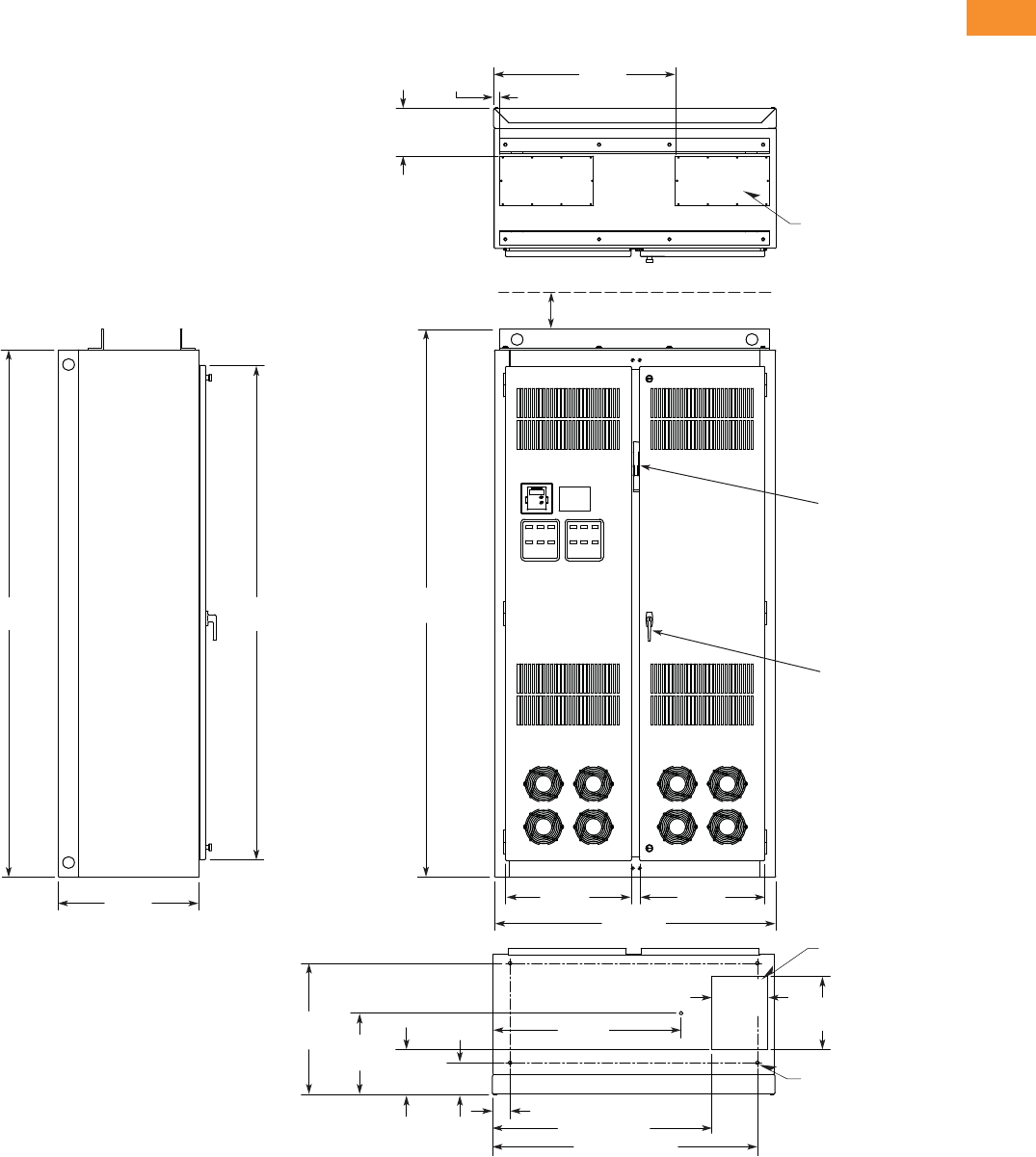
Volume 6—Solid-State Motor Control CA08100007E—May 2014 www.eaton.com V6-T2-259
2
2
2
2
2
2
2
2
2
2
2
2
2
2
2
2
2
2
2
2
2
2
2
2
2
2
2
2
2
2
2.8
Adjustable Frequency Drives
Low Harmonic Drives
Approximate Dimensions in Inches (mm)
Enclosure Size 8
200–250 hp IL and 150–200 hp IH 480V—125–200 hp IL and 100–150 hp IH 575V
Bottom View
For Bottom
Cable Entry
ø0.56
(ø14.2)
(ve places)
90.00
(2286.0)
84.37
(2143.0)
24.00
(609.6)
31.00
(787.4)
1.25
(31.8)
8.25
(209.6)
For Top
Cable Entry
(two places)
Top View
Side View
93.50
(2374.9)
3.01 (76.5)
32.20
(817.9)
37.47 (951.7)
45.22 (1148.6)
22.47
(570.7) 13.97
(354.8) 7.73
(196.3) 5.48
(139.2)
9.50
(241.3) 12.50
(317.5)
21.45
(544.8) 48.00
(1219.2)
21.31
(541.3)
Finish: Enclosure—ANSI 61 Gray (light)
Material: Enclosure and Backplate—
12 ga. = 0.1046 Cold Rolled Steel
4.00 (101.6) Minimum
Free Air Space Required
Door Handle
(key-lock optional)
Drive
Circuit Breaker
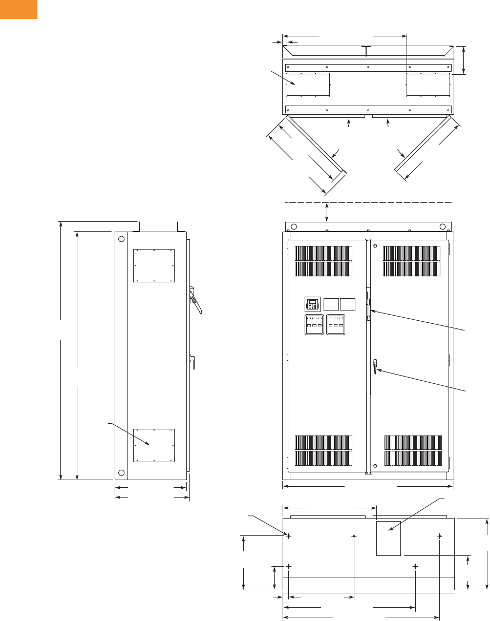
V6-T2-260 Volume 6—Solid-State Motor Control CA08100007E—May 2014 www.eaton.com
2
2
2
2
2
2
2
2
2
2
2
2
2
2
2
2
2
2
2
2
2
2
2
2
2
2
2
2
2
2
2.8
Adjustable Frequency Drives
Low Harmonic Drives
Approximate Dimensions in Inches (mm)
Enclosure Size 9
300–400 hp IL and 250–350 hp IH 480V—250–400 hp IL and 200–300 hp IH 575V
24.00 (609.6)
25.14 (638.6)
8.75
(222.3)
Top View
1.50 (38.1) 43.50 (1104.9)
90.00
(2286.0)
93.50
(2374.9)
4.00 (101.6) Minimum
Free Air Space Required
60.00 (1524.0)
Front View
Bottom View
Side View
7.46 x 15.00
(189.5 x 381.0)
Access in Top
(two places)
8.50 x 12.00 (215.9 x 304.8)
Bottom Access
ø0.56 (ø14.2) Dia.
Mounting Hole
(ve places)
27.06
(687.3)
27.36
(694.9)
90 Max.
Door
Opening
29.05
(737.9)
11.93
(303.0)
25.00
(635.0)
18.84
(478.5)
8.20
(208.3)
2.00 (50.8) 22.90 (581.7)
32.72 (831.1)
46.30 (1176.0)
54.90 (1394.5)
Door Handle
(key-lock optional)
Access
Plate
(4 places)
90 Max.
Door
Opening
Finish: Enclosure—ANSI 61 Gray (light)
Material: Enclosure and Backplate—
12 ga. = 0.1046 Cold Rolled Steel
Drive
Circuit Breaker
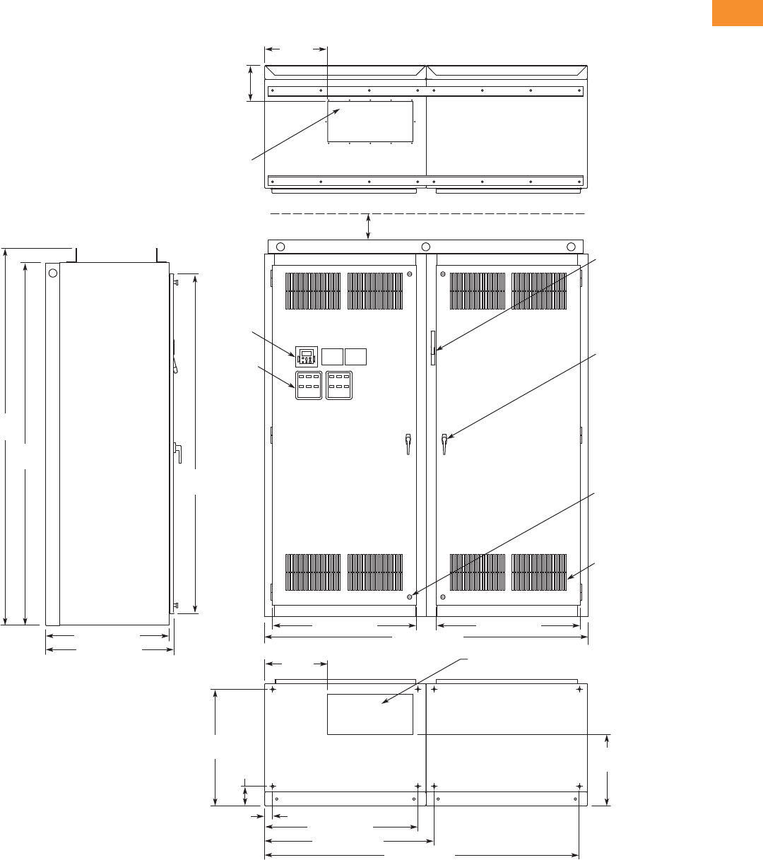
Volume 6—Solid-State Motor Control CA08100007E—May 2014 www.eaton.com V6-T2-261
2
2
2
2
2
2
2
2
2
2
2
2
2
2
2
2
2
2
2
2
2
2
2
2
2
2
2
2
2
2
2.8
Adjustable Frequency Drives
Low Harmonic Drives
Approximate Dimensions in Inches (mm)
Enclosure Size 10
500–600 hp IL and 400–500 hp IH 480V—500–600 hp IL and 400–500 hp IH 575V
30.50 (774.7)
31.75 (806.5)
9.03
(229.4)
Top View
15.63
(397.0)
90.00
(2286.0)
84.37
(2143.0)
93.50
(2374.9)
4.00 (101.6) Minimum
Free Air Space Required
35.75 (908.1) 35.75 (908.1)
80.00 (2032.0)
Front View
Side View
21.00 x 10.00
(533.4 x 254.0)
Access in Top
21.00 x 10.00 (533.4 x 254.0)
Bottom Access
17.79
(451.9)
29.04
(737.6)
4.87
(123.7)
2.00 (50.8)
15.64
(397.3)
38.00 (965.2)
42.02 (1067.3)
Bottom View
78.02 (1981.7)
Finish: Enclosure – ANSI 61 Gray (light)
Material: Enclosure and Backplate—
12 ga. = 0.1046 Cold Rolled Steel
Operator
Elements
When
Specied,
Mounted
on These
Panels
Keypad
Door Handle
(key-lock optional)
Intake Ventilating
Slots (ltered on
Type 12)
Quarter-Turn
Latch (four places)
Flanged
Disconnect
Supplied with
Circuit Breaker
When Specied
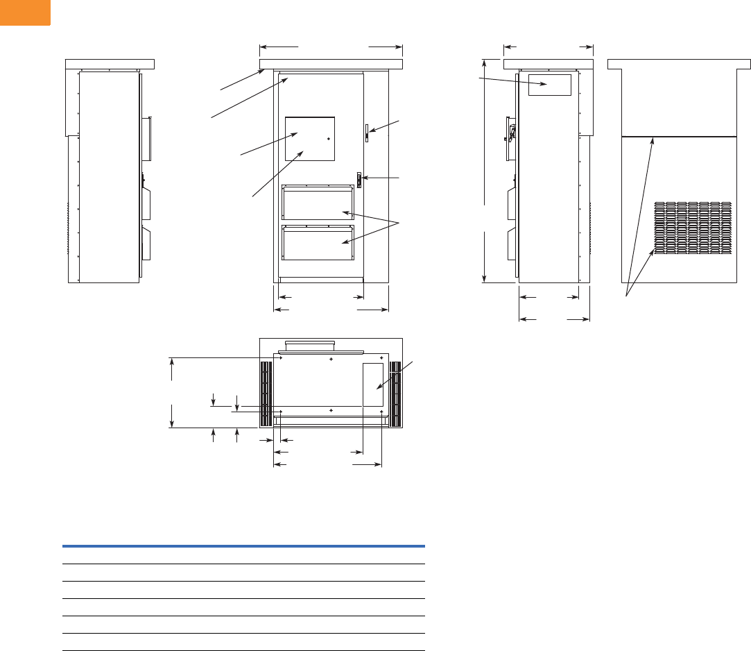
V6-T2-262 Volume 6—Solid-State Motor Control CA08100007E—May 2014 www.eaton.com
2
2
2
2
2
2
2
2
2
2
2
2
2
2
2
2
2
2
2
2
2
2
2
2
2
2
2
2
2
2
2.8
Adjustable Frequency Drives
Low Harmonic Drives
Approximate Dimensions in Inches (mm)
Enclosure Size F Type 3R Drives
25–250 hp IL and 25–200 hp IH 480V—25–200 hp IL and 25–150 hp IH 575V Type 3R Drives
Enclosed 18-Pulse Drive Enclosure Dimensions
Notes
1Enclosure sizes accommodate drive and options, including bypass and disconnect.
For other power options, consult your Eaton representative.
2Consult factory. Limited power options available.
3Enclosure size 11 consists of two of the enclosure size 9.
4All Type 3R drives use the Size F enclosure.
Enclosure
Size 1Width Height Depth
Approx. Shipping
Weight in Lbs (kg)
7 30.00 (762.0) 90.00 (2286.0) 21.50 (546.1) 1000 (454)
8 48.00 (1219.2) 90.00 (2286.0) 26.14 (664.0) 1400 (636)
9 60.00 (1524.0) 90.00 (2286.0) 25.74 (653.8) 1800 (817)
10 80.00 (2032.0) 90.00 (2286.0) 31.75 (806.5) 2100 (953)
11 23 120.00 (3048.0) 90.00 (2286.0) 25.74 (653.8) 2500 (1,135)
F 460.00 (1524.0) 93.50 (2374.9) 37.50 (952.5) 2500 (1,135)
37.50 (952.5)
60.00 (1524.0)
35.75 (908.0)
48.00 (1219.2)
Operator Elements
When Specied,
Mounted Inside
Locking Enclosure Door
Keypad Located
Inside Locking
Enclosure Door
Enclosure
Door Stop
Exhaust Air
Venting Slots
Filtered
Intake Air
Ventilating
Slots
Key Locking
Three-Position
Latch
Flanged
Disconnect
Supplied with
Circuit Breaker
When Specied
93.50
(2374.9)
18.00 x 8.50
(457.2 x 215.9)
Side Access
25.84
(656.2)
29.58
(751.2)
Exhaust Air
Venting Slots
9.08
(230.5)
29.32
(744.7)
6.82
(173.3)
3.11 (78.9)
18.00 x 8.50
(457.2 x 215.9)
Bottom Access
37.43 (950.7)
45.32 (1151.1)
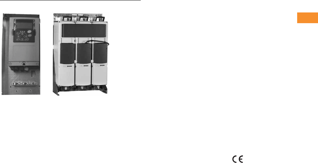
Volume 6—Solid-State Motor Control CA08100007E—May 2014 www.eaton.com V6-T2-263
2
2
2
2
2
2
2
2
2
2
2
2
2
2
2
2
2
2
2
2
2
2
2
2
2
2
2
2
2
2
2.9
Adjustable Frequency Drives
LCX9000 Liquid Cooled Drives
LCX9000 Liquid Cooled Adjustable Frequency Drives
Contents
Description Page
LCX9000 Drives
Catalog Number Selection . . . . . . . . . . . . . . . . V6-T2-264
Product Selection . . . . . . . . . . . . . . . . . . . . . . . V6-T2-265
Options . . . . . . . . . . . . . . . . . . . . . . . . . . . . . . . V6-T2-268
Technical Data and Specifications . . . . . . . . . . V6-T2-270
Wiring Diagrams . . . . . . . . . . . . . . . . . . . . . . . . V6-T2-271
Dimensions . . . . . . . . . . . . . . . . . . . . . . . . . . . V6-T2-273
Product Description
The LCX9000 Liquid Cooled
Drive family continues
Eaton’s tradition of providing
state-of-the-industry
products, by taking advantage
of liquid cooling technology in
lieu of air-cooling techniques.
The LCX9000 drives are
liquid-cooled products that
utilize potable water or a
water-glycol mixture as a
cooling medium.
Features and Benefits
●Compact size and low
heat transfer rates allow
enclosure size to be greatly
reduced, which is especially
beneficial in UL Type 4X
applications
●Design is modular, with
control and power modules
independent of each other.
Connection between
power and control modules
can be direct or extended
via a fiber optic cable
●Same reliable control
module and operating
system as the SPX9000
air-cooled drives
●CE mark ensures
compliance with the
Electromagnetic
Compatibility Directive
(EMC) and the Low Voltage
Directive (LVD)
●Reliable drive with over
500,000 hours MTBF
based on MIL 217
●Currently supports
DeviceNet, PROFIBUS-DP,
Modbus RTU and Modbus
TCP communication
protocols
●Separately mounted line
reactor included with AC
fed models
Standards and
Certifications
●CE
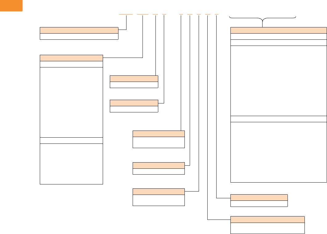
V6-T2-264 Volume 6—Solid-State Motor Control CA08100007E—May 2014 www.eaton.com
2
2
2
2
2
2
2
2
2
2
2
2
2
2
2
2
2
2
2
2
2
2
2
2
2
2
2
2
2
2
2.9
Adjustable Frequency Drives
LCX9000 Liquid Cooled Drives
Catalog Number Selection
LCX9000 Liquid Cooled Adjustable Frequency Drives
Note
1Brake chopper is only available in 480V CH3 drives.
LCX 016 A 0 –4A 3 B 2 __ __ __
Keypad
A = Alphanumeric
Software Series
A = Standard
Brake Chopper Options 1
N = No brake chopper circuit
B = Internal brake chopper
Input Options
3 = Three-phase, EMC T
7 = DC Input
Enclosure Rating
0 = Open chassis
Product Family
LCX = High performance, liquid-cooled drive
Board Modifications
2 = Varnished boards
Voltage Rating
4 = 380–500V
5 = 520–690V
Options
List options in alphabetical order.
Extended I/O Card Options
A3 = 2 RO, therm
A4 = Encoder low volt +5V/15V/24V
A5 = Encoder high volt +15V/24V
A7 = Dual encoder +15V/24V
A8 = 6 DI, 1 DO, 2 AI, 1AO
AE = Encoder with 2 DOs
B1 = 6 DI, 1 ext +24 Vdc/EXT +24 Vdc
B2 = 1 RO (NC-NO), 1 RO (NO), 1 therm
B4 = 1 AI (mA isolated), 2 AO (mA isolated),
1 ext +24 Vdc/EXT + 24 Vdc
B5 = 3 RO (NO)
B8 = 1 ext +24 Vdc/EXT +24 Vdc, 3 Pt100
B9 = 1 RO (NO), 5 DI 42–240 Vac input
BB = SPI, absolute encoder
Communication Cards
CA = Johnson Controls N2
CI = Modbus TCP
C2 = Modbus
C3 = PROFIBUS DP
C4 = LonWorks
C5 = PROFIBUS DP (D9 Connector)
C6 = CANopen (Slave)
C7 = DeviceNet
C8 = Modbus (D9 Type Connector)
D1 = Adapter
D2 = Adapter
D3 = RS-232 with D9 Connection
Current Rating
480V
016 = 16A
022 = 22A
031 = 31A
038 = 38A
045 = 45A
061 = 61A
072 = 72A
087 = 87A
105 = 105A
140 = 140A
168 = 168A
205 = 205A
261 = 261A
300 = 300A
385 = 385A
460 = 460A
520 = 520A
590 = 590A
650 = 650A
730 = 730A
820 = 820A
920 = 920A
H10 = 1030A
H11 = 1150A
H13 = 1370A
H16 = 1640A
H20 = 2060A
H23 = 2300A
690V
170 = 170A
208 = 208A
261 = 261A
325 = 325A
385 = 385A
416 = 416A
460 = 460A
502 = 502A
590 = 590A
650 = 650A
750 = 750A
820 = 820A
H10 = 1030A
H11 = 1180A
H13 = 1300A
H15 = 1500A
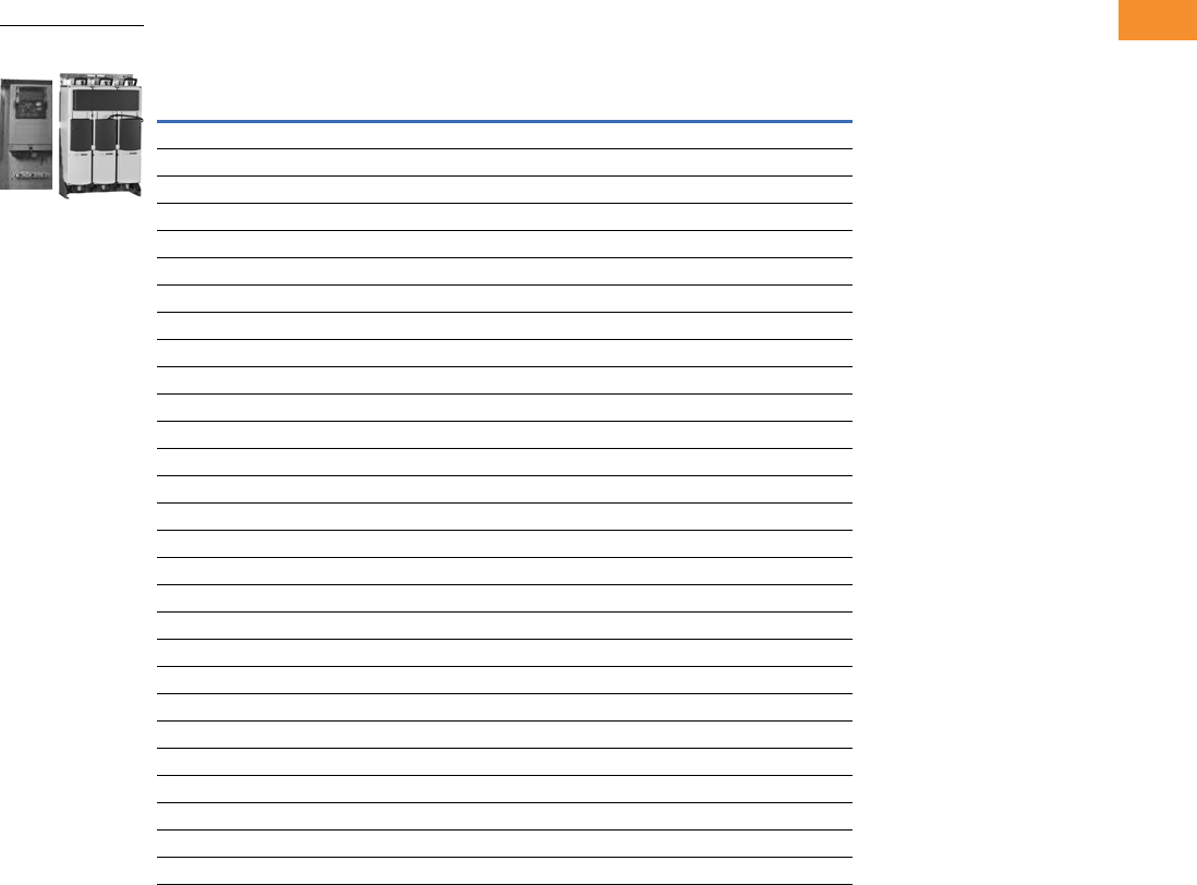
Volume 6—Solid-State Motor Control CA08100007E—May 2014 www.eaton.com V6-T2-265
2
2
2
2
2
2
2
2
2
2
2
2
2
2
2
2
2
2
2
2
2
2
2
2
2
2
2
2
2
2
2.9
Adjustable Frequency Drives
LCX9000 Liquid Cooled Drives
Product Selection
380–500 Vac Liquid Cooled Drives
Motor Output
Current
Thermal, Ith (A) IL (A) IH (A) kW Chassis Catalog Number
16 15 11 7.5 CH3 LCX016A0-4A3N2
22 20 15 11 CH3 LCX022A0-4A3N2
31 28 21 15 CH3 LCX031A0-4A3N2
38 35 25 18.5 CH3 LCX038A0-4A3N2
45 41 30 22 CH3 LCX045A0-4A3N2
61 55 41 30 CH3 LCX061A0-4A3N2
72 65 48 37 CH4 LCX072A0-4A3N2
87 79 58 45 CH4 LCX087A0-4A3N2
105 957055CH4LCX105A0-4A3N2
140 127 93 75 CH4 LCX140A0-4A3N2
168 153 112 90 CH5 LCX168A0-4A3N2
205 186 137 110 CH5 LCX205A0-4A3N2
261 237 174 132 CH5 LCX261A0-4A3N2
300 273 200 160 CH61 LCX300A0-4A3N2
385 350 257 200 CH61 LCX385A0-4A3N2
460 418 307 250 CH72 LCX460A0-4A3N2
520 473 347 250 CH72 LCX520A0-4A3N2
590 536 393 315 CH72 LCX590A0-4A3N2
650 591 433 355 CH72 LCX650A0-4A3N2
730 664 487 400 CH72 LCX730A0-4A3N2
820 745 547 450 CH63 LCX820A0-4A3N2
920 836 613 500 CH63 LCX920A0-4A3N2
1030 936 687 560 CH63 LCXH10A0-4A3N2
1150 1045 766 600 CH63 LCXH11A0-4A3N2
1370 1245 913 700 CH74 LCXH13A0-4A3N2
1640 1491 1093 900 CH74 LCXH16A0-4A3N2
2060 1873 1373 1100 CH74 LCXH20A0-4A3N2
2300 2091 1533 1200 CH74 LCXH23A0-4A3N2
LCX9000 Liquid Cooled
Drives
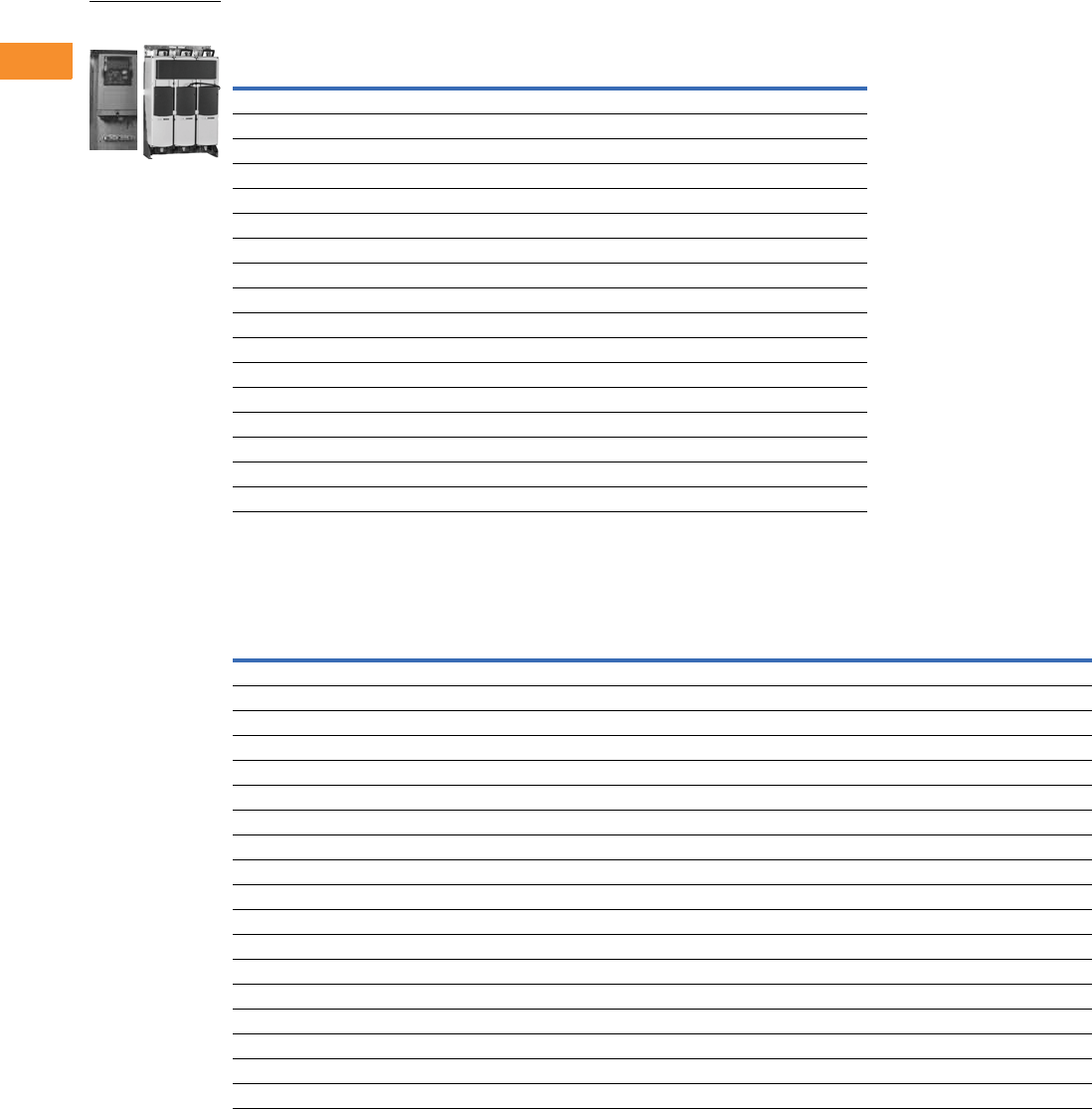
V6-T2-266 Volume 6—Solid-State Motor Control CA08100007E—May 2014 www.eaton.com
2
2
2
2
2
2
2
2
2
2
2
2
2
2
2
2
2
2
2
2
2
2
2
2
2
2
2
2
2
2
2.9
Adjustable Frequency Drives
LCX9000 Liquid Cooled Drives
525–690 Vac Liquid Cooled Drives
540–675 Vdc Liquid Cooled Inverter Units
Motor Output
Current
Thermal, Ith (A) IL (A) IH (A) kW Chassis Catalog Number
170 155 113 110 CH61 LCX170A0-5A3N2
208 189 139 132 CH61 LCX208A0-5A3N2
261 237 174 160 CH72 LCX261A0-5A3N2
325 295 217 200 CH72 LCX325A0-5A3N2
385 350 257 250 CH72 LCX385A0-5A3N2
416 378 277 250 CH72 LCX416A0-5A3N2
460 418 307 300 CH72 LCX460A0-5A3N2
502 456 335 355 CH72 LCX502A0-5A3N2
590 536 393 400 CH63 LCX590A0-5A3N2
650 591 433 450 CH63 LCX650A0-5A3N2
750 682 500 500 CH63 LCX750A0-5A3N2
820 745 547 560 CH74 LCX820A0-5A3N2
920 836 613 650 CH74 LCX920A0-5A3N2
1030 936 687 700 CH74 LCXH10A0-5A3N2
1180 1073 787 800 CH74 LCXH11A0-5A3N2
1300 1182 867 900 CH74 LCXH13A0-5A3N2
1500 1364 1000 1000 CH74 LCXH15A0-5A3N2
Drive Output
Power Loss
c/a/T
(kW)
Current Motor Output Power
Thermal
Ith (A)
Rated Cont.
IL (A)
Rated Cont.
IH (A)
Optimum Motor
at Ith 400V (kW)
Optimum Motor
at Ith 500V (kW) Chassis Catalog Number
16 15 11 7.5 11 0.4/0.2/0.6 CH3 LCX016A0-4A7B2
22 20 15 11 15 0.5/0.2/0.7 CH3 LCX022A0-4A7B2
31 28 21 15 18.5 0.7/0.2/0.9 CH3 LCX031A0-4A7B2
38 35 25 18.5 22 0.8/0.2/1.0 CH3 LCX038A0-4A7B2
45 41 30 22 30 1.0/0.3/1.3 CH3 LCX045A0-4A7B2
61 55 41 30 37 1.3/0.3/1.5 CH3 LCX061A0-4A7B2
72 65 48 37 45 1.2/0.3/1.5 CH4 LCX072A0-4A7N2
87 79 58 45 55 1.5/0.3/1.8 CH4 LCX087A0-4A7N2
105 95 70 55 75 1.8/0.3/2.1 CH4 LCX105A0-4A7N2
140 127 93 75 90 2.3/0.3/2.6 CH4 LCX140A0-4A7N2
168 153 112 90 110 2.5/0.3/2.8 CH5 LCX168A0-4A7N2
205 186 137 110 132 3.0/0.4/3.4 CH5 LCX205A0-4A7N2
261 237 174 132 160 4.0/0.4/4.4 CH5 LCX261A0-4A7N2
300 273 200 160 200 4.5/0.4/4.9 CH61 LCX300A0-4A7N2
385 350 257 200 250 5.5/0.5/6.0 CH61 LCX385A0-4A7N2
460 418 307 250 315 5.5/0.5/6.0 CH62 LCX460A0-4A7N2
520 473 347 250 355 6.5/0.5/7.0 CH62 LCX520A0-4A7N2
590 536 393 315 400 7.5/0.6/8.1 CH62 LCX590A0-4A7N2
LCX9000 Liquid Cooled
Drives
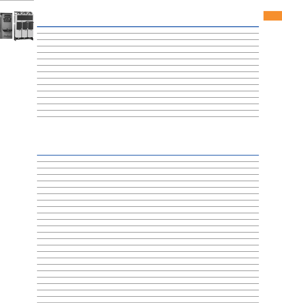
Volume 6—Solid-State Motor Control CA08100007E—May 2014 www.eaton.com V6-T2-267
2
2
2
2
2
2
2
2
2
2
2
2
2
2
2
2
2
2
2
2
2
2
2
2
2
2
2
2
2
2
2.9
Adjustable Frequency Drives
LCX9000 Liquid Cooled Drives
540–675 Vdc Liquid Cooled Inverter Units, continued
710–930 Vdc Liquid Cooled Inverter Unit
Drive Output
Power Loss
c/a/T
(kW)
Current Motor Output Power
Thermal
Ith (A)
Rated Cont.
IL (A)
Rated Cont.
IH (A)
Optimum Motor
at Ith 400V (kW)
Optimum Motor
at Ith 500V (kW) Chassis Catalog Number
650 591 433 355 450 8.5/0.6/9.1 CH62 LCX650A0-4A7N2
730 664 487 400 500 10.0/0.7/10.7 CH62 LCX730A0-4A7N2
820 745 547 450 560 12.5/0.8/13.3 CH63 LCX820A0-4A7N2
920 836 613 500 600 14.4/0.9/15.3 CH63 LCX920A0-4A7N2
1030 936 687 560 700 16.5/1.0/17.5 CH63 LCXH10A0-4A7N2
1150 1045 766 600 750 18.4/10.1/19.5 CH63 LCXH11A0-4A7N2
1370 1245 913 700 900 15.5/1.0/16.5 CH64 LCXH13A0-4A7N2
1640 1491 1093 900 1100 19.5/1.2/20.7 CH64 LCXH16A0-4A7N2
2060 1873 1373 1100 1400 26.5/1.5/28.0 CH64 LCXH20A0-4A7N2
2300 2091 1533 1250 1500 29.6/1.7/31.3 CH64 LCXH23A0-4A7N2
2470 2245 1647 1300 1600 36.0/2.0/38.0 2*CH64 LCXH24A0-4A7N2
2950 2681 1967 1550 1950 39.0/2.4/41.4 2*CH64 LCXH29A0-4A7N2
3710 3372 2473 1950 2450 48.0/2.7/50.7 2*CH64 LCXH37A0-4A7N2
4140 3763 2760 2150 2700 53.0/3.0/66.0 2*CH64 LCXH41A0-4A7N2
Drive Output
Power Loss
c/a/T
(kW)
Current Motor Output Power
Thermal
Ith (A)
Rated Cont.
IL (A)
Rated Cont.
IH (A)
Optimum Motor
at Ith 400V (kW)
Optimum Motor
at Ith 500V (kW) Chassis Catalog Number
170 155 113 110 160 4.5/0.2/4.7 CH61 LCX170A0-5A7N2
208 189 139 132 200 5.5/0.3/5.8 CH61 LCX208A0-5A7N2
261 237 174 160 250 5.5/0.3/5.8 CH61 LCX261A0-5A7N2
325 295 217 200 300 6.5/0.3/6.8 CH62 LCX325A0-5A7N2
385 350 257 250 355 7.5/0.4/7.9 CH62 LCX385A0-5A7N2
416 378 277 250 355 8.0/0.4/8.4 CH62 LCX416A0-5A7N2
460 418 307 300 400 8.5/0.4/8.9 CH62 LCX460A0-5A7N2
502 456 335 355 450 10.0/0.5/10.5 CH62 LCX502A0-5A7N2
590 536 393 400 560 10.0/0.5/10.5 CH63 LCX590A0-5A7N2
650 591 433 450 600 13.5/0.7/14.2 CH63 LCX650A0-5A7N2
750 682 500 500 700 16.0/0.8/16.8 CH63 LCX750A0-5A7N2
820 745 547 560 800 16.0/0.8/16.8 CH64 LCX820A0-5A7N2
920 836 613 650 850 18.0/0.9/18.9 CH64 LCX920A0-5A7N2
1030 936 687 700 1000 19.0/1.0/20.0 CH64 LCXH10A0-5A7N2
1180 1073 787 800 1100 21.0/10.1/20.1 CH64 LCXH11A0-5A7N2
1300 1182 867 900 1200 27.0/1.4/28.4 CH64 LCXH13A0-5A7N2
1500 1364 1000 1050 1400 32.0/1.6/33.6 CH64 LCXH15A0-5A7N2
1700 1545 1133 1150 1550 N/A CH64 LCXH17A0-5A7N2
1850 1682 1233 1250 1650 34.2/1.8/36.0 2*CH64 LCXH18A0-5A7N2
2120 1927 1413 1450 1900 37.8/2.0/39.8 2*CH64 LCXH21A0-5A7N2
2340 2127 1560 1600 2100 48.6/2.5/51.1 2*CH64 LCXH23A0-5A7N2
2700 2455 1800 1850 2450 57.6/3.0/60.6 2*CH64 LCXH27A0-5A7N2
3100 2818 2066 2150 2800 N/A 2*CH64 LCXH31A0-5A7N2
LCX9000 Liquid Cooled
Drives
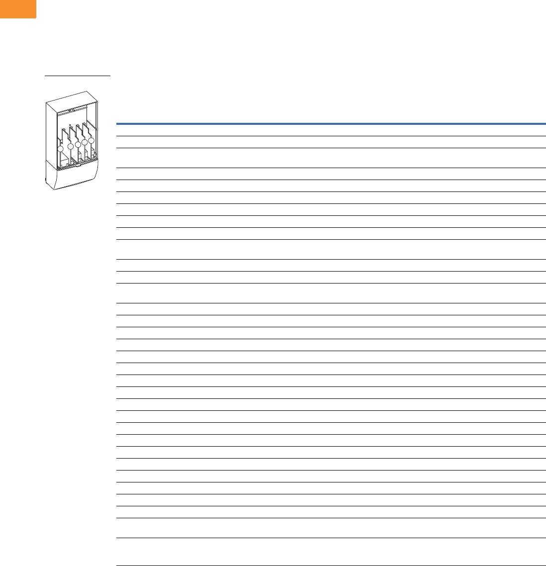
V6-T2-268 Volume 6—Solid-State Motor Control CA08100007E—May 2014 www.eaton.com
2
2
2
2
2
2
2
2
2
2
2
2
2
2
2
2
2
2
2
2
2
2
2
2
2
2
2
2
2
2
2.9
Adjustable Frequency Drives
LCX9000 Liquid Cooled Drives
Options
9000X Series Option Board Kits
The 9000X Series drives can accommodate a wide selection of expander and adapter option boards to
customize the drive for your application needs. The drive’s control unit is designed to accept a total of
five option boards.
The 9000X Series factory installed standard board configuration includes an A9 I/O board and an A2
relay output board, which are installed in slots A and B.
Option Board Kits
Notes
1 AI = Analog Input; AO = Analog Output, DI = Digital Input, DO = Digital Output, RO = Relay Output
2 Option card must be installed in one of the slots listed for that card. Slot indicated in bold is the preferred location.
3 OPTC2 is a multi-protocol option card.
Option Kit Description 1
Allowed Slot
Locations 2
Field
Installed
Factory
Installed SVX Ready Programs
Catalog
Number
Option
Designator Basic
Local/
Remote Standard MSS PID Multi-P. PFC
Standard I/O Cards
2 RO (NC-NO) B OPTA2 — ■ ■ ■ ■■■ ■
6 DI, 1 DO, 2 AI, 1AO, 1 +10 Vdc ref,
2 ext +24 Vdc/EXT +24 Vdc
AOPTA9 — ■ ■ ■ ■■■ ■
Extended I/O Cards
2 RO, therm B OPTA3 A3 —■ ■ ■■■ ■
Encoder low Volt +5V/15V/24V C OPTA4 A4 —■ ■ ■■■ ■
Encoder high Volt +15V/24V C OPTA5 A5 —■ ■ ■■■ ■
Dual encoder +15V/24V C OPTA7 A7 —■ ■ ■■■ ■
6 DI, 1 DO, 2 AI, 1 AO A OPTA8 A8 —■ ■ ■■■ ■
3 DI (encoder 10–24V), out +15V/+24V,
2 DO (pulse+direction)—SPX only
COPTAE AE ■ ■ ■ ■■■ ■
6 DI, 1 ext +24 Vdc/EXT +24 Vdc B, C, D, E OPTB1 B1 —— — ——
■■
1 RO (NC-NO), 1 RO (NO), 1 therm B, C, D, E OPTB2 B2 —— — ——
■■
1 AI (mA isolated), 2 AO (mA isolated),
1 ext +24 Vdc/EXT +24 Vdc
B, C, D, E OPTB4 B4 —■ ■ ■■■ ■
3 RO (NO) B, C, D, E OPTB5 B5 —— — ——
■■
1 ext +24 Vdc/EXT +24 Vdc, 3 Pt100 B, C, D, E OPTB8 B8 —— — ——— —
1 RO (NO), 5 DI 42–240 Vac input B, C, D, E OPTB9 B9 —— — ——
■■
SPI, absolute encoder C OPTBB BB —— — ——— —
Communication Cards 3
Modbus D, E OPTC2 C2 ■ ■ ■ ■■■ ■
Johnson Controls N2 D, E OPTC2 CA —— — ——— —
PROFIBUS DP D, E OPTC3 C3 ■ ■ ■ ■■■ ■
LonWorks D, E OPTC4 C4 ■ ■ ■ ■■■ ■
PROFIBUS DP (D9 connector) D, E OPTC5 C5 ■ ■ ■ ■■■ ■
CANopen (slave) D, E OPTC6 C6 ■ ■ ■ ■■■ ■
DeviceNet D, E OPTC7 C7 ■ ■ ■ ■■■ ■
Modbus (D9 Type connector) D, E OPTC8 C8 ■ ■ ■ ■■■ ■
Modbus TCP D, E OPTCI CI ■ ■ ■ ■■■ ■
Adapter—SPX only D, E OPTD1 D1 ■ ■ ■ ■■■ ■
Adapter—SPX only D, E OPTD2 D2 ■ ■ ■ ■■■ ■
RS-232 with D9 connection D, E OPTD3 D3 ■ ■ ■ ■■■ ■
Keypad
9000X Series standard keypad — KEYPAD-
STD
——— — ——— ■
9000X Series remote mount keypad unit
(keypad not included, includes 10 ft cable,
keypad holder, mounting hardware)
—OPTRMT-
KIT-9000X
——— — ——— —
Option Boards
ABCDE

Volume 6—Solid-State Motor Control CA08100007E—May 2014 www.eaton.com V6-T2-269
2
2
2
2
2
2
2
2
2
2
2
2
2
2
2
2
2
2
2
2
2
2
2
2
2
2
2
2
2
2
2.9
Adjustable Frequency Drives
LCX9000 Liquid Cooled Drives
Line Reactors
The line reactor carries out
several functions in the liquid
cooled drive. Connection of
the line reactor is necessary
except if you have a
component in your system
that performs the same tasks
(e.g. a transformer). The line
reactor is needed as an
essential component for
motor control, to protect the
input and DC-link component
s
against abrupt changes of
current and voltage as well as
to function as a protection
against harmonics. The line
reactors are included in the
standard delivery of liquid-
cooled drives (not inverters).
However, you can also order
your drive without a line
reactor.
Line Reactor Specifications
Notes
1Inductances for different supply voltages: A = 400–480 Vac; B = 500–690 Vac.
2Drives require three chokes of the designated catalog number with six-pulse supply.
Drive Rating
480V
Drive Rating
690V
Thermal
Current
(A)
Nominal
Inductance
(μH) A/B 1
Calculated
Loss
(W)
Choke
Catalog Number
(690 Vac)
16 to 22A 12 to 23A 23 1900 145 CHK0023N6A0
31 to 38A 31 to 38A 38 1100 170 CHK0038N6A0
45 to 61A 46 to 62A 62 700 210 CHK0062N6A0
72 to 87A 72 to 87A 87 480 250 CHK0087N6A0
105 to 140A 105 to 140A 145 290 380 CHK0145N6A0
168 to 261A 170 to 261A 261 139/187 460 CHK0261N6A0
300 to 385A 325 to 385A
820 to 1180A 2
400 90/126 570 CHK0400N6A0
460 to 520A
1370A 2
416 to 502A
1300 to 1500A 2
520 65/95 610 CHK0520N6A0
590 to 650A
1640A 2
590 to 650A 650 51/71 840 CHK0650N6A0
730A
2060A 2
— 730 45/61 850 CHK0730N6A0
820A
2300A 2
750A N/A N/A N/A CHK0820N6A0
920 to 1030A — 1000 30/41 950 CHK1030N6A0
1150A — 1150 26/36 1000 CHK1150N6A0
Dimensions, see Page V6-T2-273.

V6-T2-270 Volume 6—Solid-State Motor Control CA08100007E—May 2014 www.eaton.com
2
2
2
2
2
2
2
2
2
2
2
2
2
2
2
2
2
2
2
2
2
2
2
2
2
2
2
2
2
2
2.9
Adjustable Frequency Drives
LCX9000 Liquid Cooled Drives
Technical Data and Specifications
LCX9000 Products
Note
1Derating required if higher switching frequency than the default is used.
Description Specification
General Specifications
Line voltage 400 to 500 Vac; 525 to 690 Vac; (–10% to 10%)
465 to 800 Vdc; 640 to 1100 Vdc; (–0 to 0%)
Frequency 50/60 Hz
Line voltage variation –10% to 10%
Input frequency variation 45–66 Hz
Continuous output current Rated current at incoming cooling liquid
temperature of 30°C
Output frequency 0–320 Hz
Drive efficiency >95%
Power factor (displacement) 0.96
Liquid coolant pressure 87 psi (6 bar) maximum
Liquid coolant flow rate 1.3 to 7.9 gal./min. (5 to 30 liter/min.)
minimum depending on drive size
Liquid coolant fittings Standard quick connect, NPT
Operating ambient temperature –10/50°C
Storage temperature –40/70°C
Humidity 95% maximum (non-condensing)
Altitude 3300 ft (1000 m) maximum without derating
Enclosure IP00
Warranty Standard terms, 3 years with certified start-up
Mains Connection
Input voltage (Vin) 400–500 Vac; 525–690 Vac; (–10%–10%)
465–800 Vdc; 640–1100 Vdc; (–0–0%)
Input frequency (fin) 45–66Hz
Connection to mains Once per minute or less (normal case)
Motor Connection
Output voltage 0–Vin
Continuous output current Rated current at nominal inflow cooling water
temperature of 30°C; Overload 2 sec./20 sec.
Starting current Rated current at 2 sec./20 sec. if output frequency
<30 Hz and temperature of heatsink <149°F (65°C)
Output frequency 0–320 Hz (standard); 7200 Hz (special software)
Frequency resolution Application dependent
Control Characteristics
Control method Frequency control (V/f)
Open loop: Sensorless vector control
Closed loop: Frequency control
Closed loop: Vector control
Switching frequency Adjustable with parameter 2.6.9
480V 1Up to and including 61-Amp size:
1–16 kHz (factory default, 10 kHz)
From 72-Amp size:
1–12 kHz (factory default, 3.6 kHz)
575V 11–6kHz (factory default, 1.5kHz)
Frequency reference Analog input: resolution 0.1% (10 bits); accuracy ±1%
Panel reference: resolution 0.01 Hz
Field weakening point 30–320 Hz
Acceleration time 0.1–3000 seconds
Deceleration time 0.1–3000 seconds
Braking torque DC brake: 30% x Tn (without brake option)
Description Specification
Ambient Conditions
Ambient operating temperature 14°F (–10°C), no frost to 122°F (50°C) at Ith
122 to 158°F (50 to 70°C), derating required
Storage temperature –40°F to 158°F (–40 to 70°C)
No liquid in heatsink under 32°F (0°C)
Relative humidity 5–96% RH, noncondensing, no dripping water
Air quality Chemical vapors:
IEC 721-3-3, unit in operation, class 3C2
Mechanical particles:
IEC 721-3-3, unit in operation, class 3S2 (no conductive
dust allowed); No corrosive gases
Altitude Up to 1,000m: 100% load capacity (no derating)
Above 1,000m: Derating of 1% per each 100m required
Vibration EN 50178, EN 60068-2-6; 5–150 Hz
Displacement amplitude: 0.25 mm (peak) at 3–31 Hz
Max. acceleration amplitude: 1G at 31–150 Hz
Shock EN 50178, EN 60068-2-27, UPS drop test
(for applicable UPS weights)
Storage and shipping: Max. 15G, 11 ms (in package)
Enclosure class IP00 open frame standard in entire kW/hp range
EMC
Immunity Fulfils all EMC immunity requirements
Emissions EMC level N; EMC level T for IT networks
Safety
Approvals EN 50178, EN 60204-1, CE, UL, CUL, FI,
GOST R, IEC 61800-5
(See unit nameplate for more detailed approvals.)
Control Connections
Analog input voltage 0 to +10V, Ri = 200 kohm (–10V to +10V joystick control)
Resolution 0.1%; accuracy ±1%
Analog input current 0(4)–20 mA, Ri = 250 ohm differential
Digital inputs 6 positive or negative logic; 18–24 Vdc
Auxiliary voltage +24V, ±15%, max. 250 mA
Output reference voltage +10V, +3%, max. load 10 mA
Analog output 0(4)–20 mA, RL max. 500 ohm
Resolution 10 bits; accuracy ±2%
Digital outputs Open collector output, 50 mA/48V
Relay outputs Two programmable change-over relay outputs
Switching capacity: 24 Vdc/8A, 250 Vac/8A,
125 Vdc/0.4A
Min. switching load: 5V/10 mA
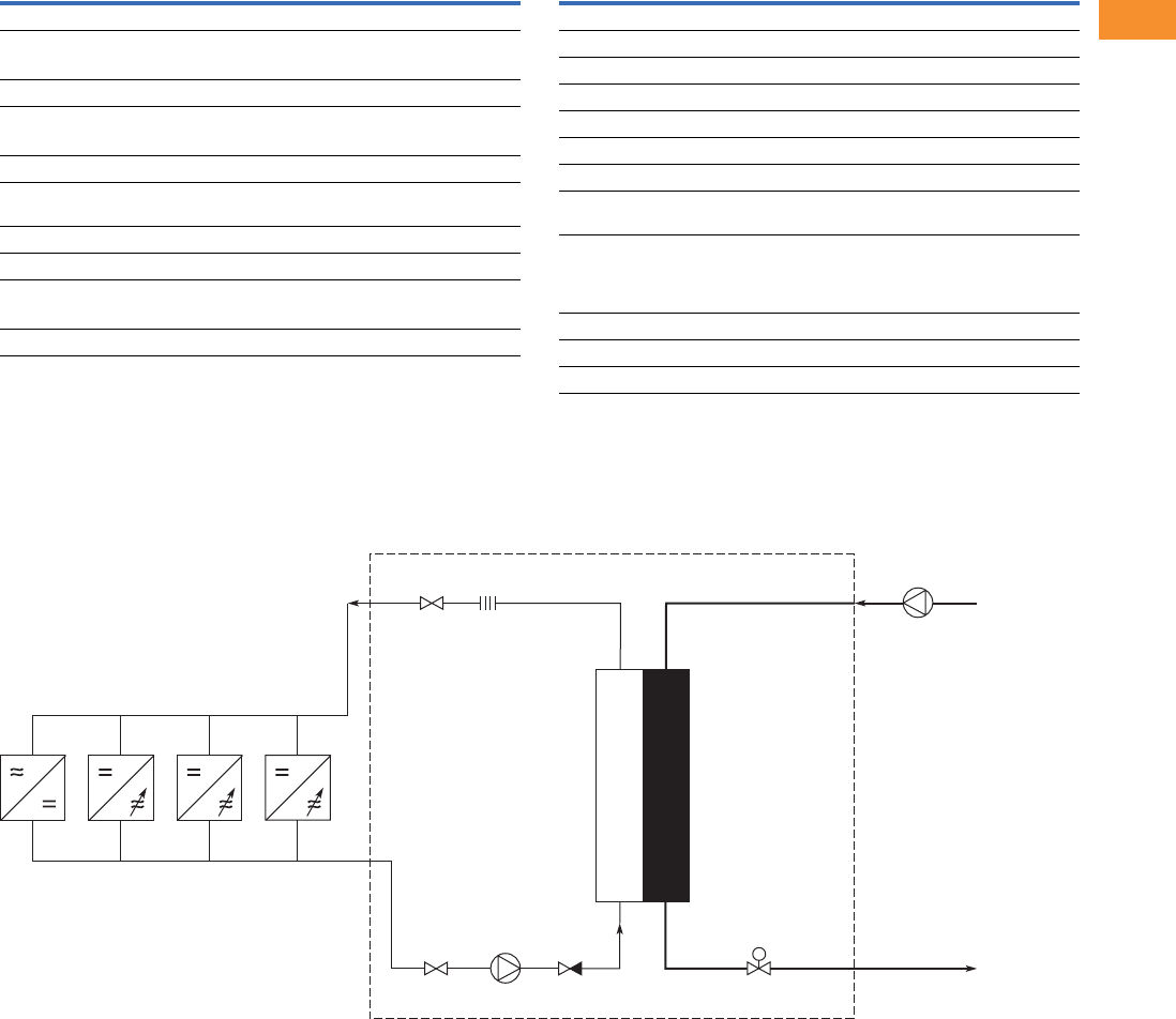
Volume 6—Solid-State Motor Control CA08100007E—May 2014 www.eaton.com V6-T2-271
2
2
2
2
2
2
2
2
2
2
2
2
2
2
2
2
2
2
2
2
2
2
2
2
2
2
2
2
2
2
2.9
Adjustable Frequency Drives
LCX9000 Liquid Cooled Drives
LCX9000 Products, continued
Wiring Diagrams
Cooling System Diagrams
Example of a Typical Cooling System
Description Specification
Protections
Overvoltage protection
480V 911V
575V 1200V
Undervoltage protection
480V 333V
575V 461V
Ground fault protection In case of ground fault in motor or motor cable,
only the drive is protected
Mains supervision Trips if any of the input phases are missing (drives only)
Motor phase supervision Trips if any of the output phases are missing
Unit overtemperature protection
Alarm limit 149°F (65°C) for heatsink, 158°F (70°C) for circuit boards
Trip limit 158°F (70°C) for heatsink, 185°F (85°C) for circuit boards
Description Specification
Protections, continued
Overcurrent protection Yes
Motor overload protection Yes
Motor stall protection Yes
Motor underload protection Yes
Short-circuit protection Yes (+24V and +10V reference voltages)
Liquid Cooling
Allowed cooling agents Drinking water
Water-glycol mixture
Temperature of cooling agent 32 to 86°F (0 to 30°C) at Ith for input;
86 to 149°F (30 to 65°C)
Max. temperature rise during circulation: 9°F (5°C), no
condensation allowed
System max. working pressure 87 psi (6 bar)
System max. peak pressure 580 psi (40 bar)
Pressure loss (at nominal flow) Varies according to size
Heat
Exchanger
18.0C30.0C
26.1C35.4C
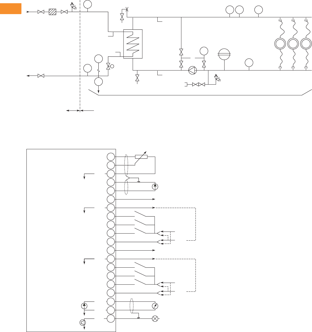
V6-T2-272 Volume 6—Solid-State Motor Control CA08100007E—May 2014 www.eaton.com
2
2
2
2
2
2
2
2
2
2
2
2
2
2
2
2
2
2
2
2
2
2
2
2
2
2
2
2
2
2
2.9
Adjustable Frequency Drives
LCX9000 Liquid Cooled Drives
Example PI-Diagram of a Typical Cooling System and Connections
I/O Board Diagrams
A9 Option Board Control Wiring
Cooling Water Inlet
Cooling Water Outlet
Customer Delivery
Frequency
Converters
9
8
7
6
5
4
3
1
+10 Vref
AI1+
GND
AI2+
Reference
(voltage)
Control Voltage Output
Reference
(current)
AI2-
24Vout
DIN1
AO1+
DO1
Dotted lines indicate the connections for inverted signals
DIN3
DIN2
CMA
10
11
24V
GND
+ V<+48V
0 (4)/20mA
RL<500W
I<50mA
Basic I/O Board A9
2
GND
AO1-
12
24Vout
15
14
13
DIN4
DIN6
DIN5
CMB
16
17
24V
GND
18
19
20
GND
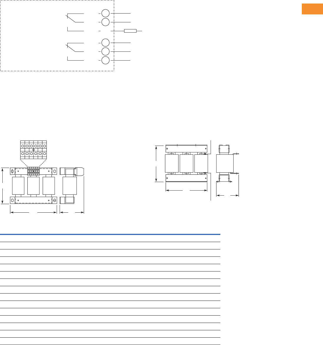
Volume 6—Solid-State Motor Control CA08100007E—May 2014 www.eaton.com V6-T2-273
2
2
2
2
2
2
2
2
2
2
2
2
2
2
2
2
2
2
2
2
2
2
2
2
2
2
2
2
2
2
2.9
Adjustable Frequency Drives
LCX9000 Liquid Cooled Drives
A2 Option Board Wiring
Dimensions
Approximate Dimensions in Inches (mm)
Line Reactors
Sizes Up To 61A Sizes Larger Than 61A
RO1/1
RO1/2
RO1/3 RL
Switching:
<8 A / 24 Vdc
<0.4 A / 125 Vdc
<8 A / 250 Vac
Continuous
<2 Arms
AC / DC
Basic Relay Board A2
21
22
23
RO2/1
RO2/2
RO2/3
24
25
26
ZWY VXU
H1
W1 D1
Mains
Converters
H1
W1
D1
Catalog Number H1 W1 D1
Weight
Lbs (kg)
CHK0023N6A0 7.01 (178) 9.06 (230) 4.76 (121) 22 (10)
CHK0038N6A0 8.23 (209) 10.63 (270) 5.71 (145) 33 (15)
CHK0062N6A0 8.39 (213) 11.81 (300) 6.30 (160) 44 (20)
CHK0087N6A0 9.13 (232) 11.81 (300) 6.69 (170) 57 (26)
CHK0145N6A0 11.50 (292) 11.81 (300) 7.28 (185) 82 (37)
CHK0220N6A0 12.05 (306) 13.86 (352) 7.28 (185) 119 (54)
CHK0325N6A0 13.66 (347) 13.86 (352) 7.28 (185) 132 (60)
CHK0460N6A0 16.54 (423) 13.70 (348) 9.41 (239) 203 (92)
CHK0520N6A0 17.60 (447) 15.51 (394) 10.71 (272) 231 (105)
CHK0590N6A0 20.43 (519) 15.51 (394) 10.71 (272) 276 (125)
CHK0650N6A0 20.51 (521) 15.51 (394) 10.71 (272) 276 (125)
CHK0750N6A0 24.72 (628) 15.51 (394) 11.10 (282) 331 (150)
CHK0820N6A0 24.72 (628) 15.51 (394) 11.10 (282) 331 (150)
CHK1000N6A0 22.68 (576) 19.57 (497) 11.85 (301) 441 (200)
CHK1150N6A0 22.83 (580) 19.57 (497) 11.85 (301) 441 (200)
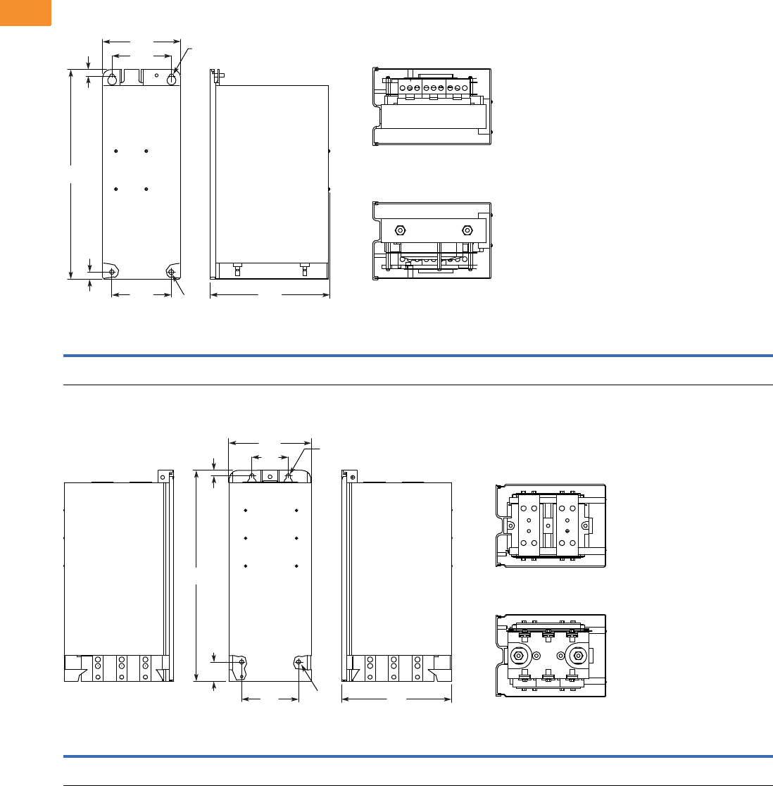
V6-T2-274 Volume 6—Solid-State Motor Control CA08100007E—May 2014 www.eaton.com
2
2
2
2
2
2
2
2
2
2
2
2
2
2
2
2
2
2
2
2
2
2
2
2
2
2
2
2
2
2
2.9
Adjustable Frequency Drives
LCX9000 Liquid Cooled Drives
Approximate Dimensions in Inches (mm)
LCX9000 Drives
Chassis Size, CH3
Chassis Size, CH4
VoltageAmpsH1H2H3D1W1W2W3R1 Dia.R2 Dia.
Weight
Lbs (kg)
380–500 Vac 16–61 16.97
(431.0)
0.53
(13.5)
0.59
(15.0)
9.69
(246.0)
6.30
(160.0)
4.80
(122.0)
4.80
(122.0)
0.39
(10.0)
0.35
(9.0)
66 (30)
VoltageAmpsH1H2H3D1W1W2W3R1 Dia.R2 Dia.
Weight
Lbs (kg)
380–500 Vac 72–140 19.41
(493.0)
0.49
(12.5)
1.77
(45.0)
10.14
(257.5)
7.60
(193.0)
3.35
(85.0)
5.24
(133.0)
0.39
(10.0)
— 77 (35)
W3 D1
Front Side
Bottom
To p
R1
W2
W1
H2 R2
H3
H1
W1
W2
W3 D1
FrontRight Side Left Side
H1
H2
H3
R1
R1
Bottom
To p
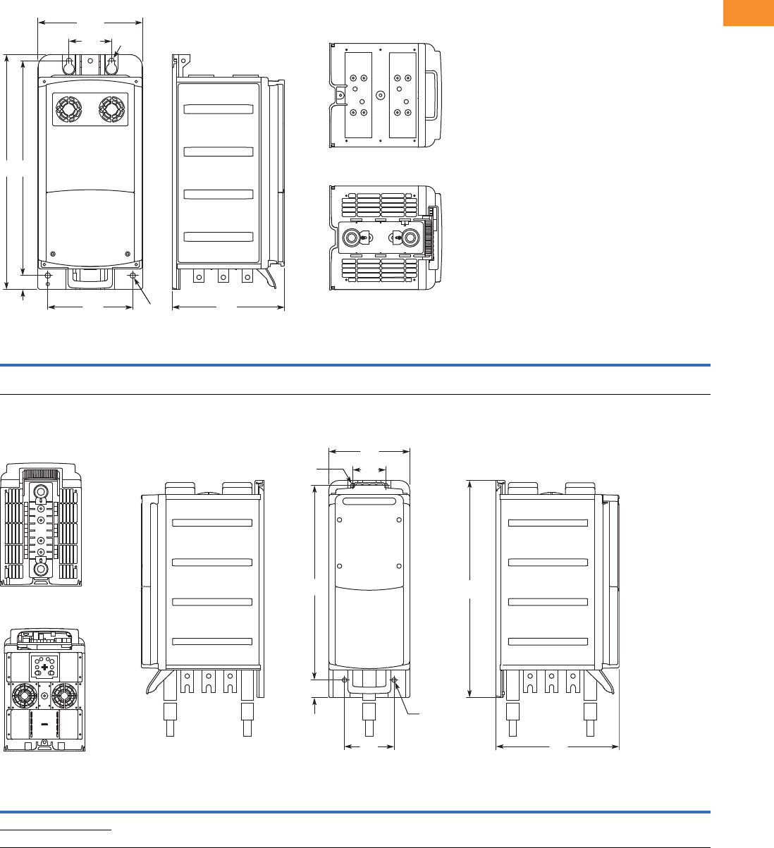
Volume 6—Solid-State Motor Control CA08100007E—May 2014 www.eaton.com V6-T2-275
2
2
2
2
2
2
2
2
2
2
2
2
2
2
2
2
2
2
2
2
2
2
2
2
2
2
2
2
2
2
2.9
Adjustable Frequency Drives
LCX9000 Liquid Cooled Drives
Approximate Dimensions in Inches (mm)
Chassis Size, CH5
Chassis Size, CH61
VoltageAmpsH1H2H3D1W1W2W3R1 Dia.R2 Dia.
Weight
Lbs (kg)
380–500 Vac 168–261 21.77
(553.0)
1.30
(33.0)
19.88
(505.0)
10.39
(264.0)
9.69
(246)
3.94
(100.0)
7.87
(200.0)
0.51
(13.0)
— 88 (40)
VoltageAmpsH1H2H3D1W1W2W3R1 Dia.R2 Dia.
Weight
Lbs (kg)
380–500 Vac 300–385 25.91
(658.0)
2.09
(53.0)
23.23
(590.0)
14.69
(373.0)
9.69
(246.0)
3.94
(100.0)
5.91
(150.0)
0.55
(14.0)
0.51
(13.0)
121 (55)
525–690 Vac 170–208
W3 D1
W1
Front Side
H2
W2 R1
H3H1
R1 Bottom
To p
D1W3
Left SideFrontRight Side
Bottom
Top
W2
W1
R2
H2
H3 H1
R1
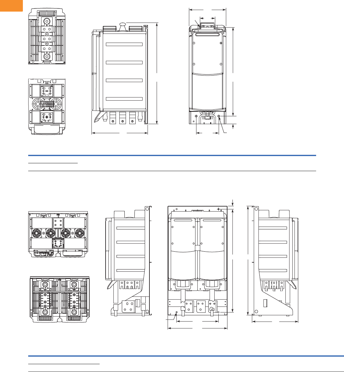
V6-T2-276 Volume 6—Solid-State Motor Control CA08100007E—May 2014 www.eaton.com
2
2
2
2
2
2
2
2
2
2
2
2
2
2
2
2
2
2
2
2
2
2
2
2
2
2
2
2
2
2
2.9
Adjustable Frequency Drives
LCX9000 Liquid Cooled Drives
Approximate Dimensions in Inches (mm)
Liquid-Cooled Inverter—Chassis Size, CH62
Chassis Size, CH63
VoltageAmpsH1H2H3D1W1W2W3R1 Dia.R2 Dia.
540–675 Vdc 460–730 26.50
(673)
2.0
(53)
23.23
(590)
14.69
(373)
9.69
(246)
3.94
(100)
5.91
(150)
0.55
(14)
0.51
(13)
710–930 Vdc 325–502
VoltageAmpsH1H2H3D1W1W2R1 Dia.
Weight
Lbs (kg)
380–500 Vac 820–1030 36.36
(923.5)
0.91
(23.0)
34.39
(873.5)
15.35
(390.0)
19.88
(505.0)
13.98
(355.0)
0.43
(11.0)
264 (120)
525–690 Vac 590–750
H1
H2
H3
R1
R2 W2
W3
W1
D1
FrontSideBottom
Top
H3
H2
W2
R1 D1
W1
Left SideRight Side Front
Bottom
Top
H1
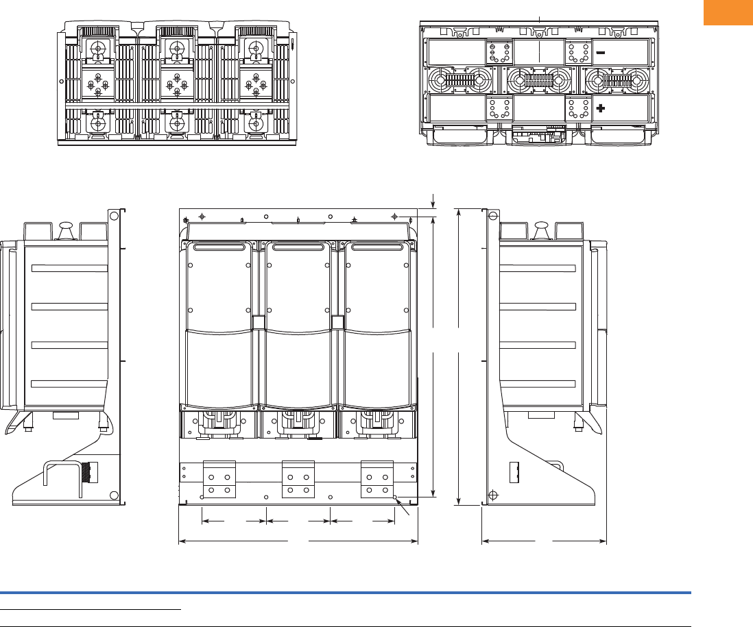
Volume 6—Solid-State Motor Control CA08100007E—May 2014 www.eaton.com V6-T2-277
2
2
2
2
2
2
2
2
2
2
2
2
2
2
2
2
2
2
2
2
2
2
2
2
2
2
2
2
2
2
2.9
Adjustable Frequency Drives
LCX9000 Liquid Cooled Drives
Approximate Dimensions in Inches (mm)
Liquid-Cooled Inverter with Mounting Bracket, Chassis Size CH64, IP90
Voltage Amps H1H2H3D1W1W2R1 Dia.
540–675 Vdc 1370–4140 36.38
(924)
1.03
(26)
34.37
(873)
15.35
(390)
29.37
(746)
7.87
(200)
0.43
(11)
710–930 Vdc 820–3100
Bottom
H1H3
H2
W1
W2 W2 W2
D1
FrontRight Side Left Side
R1
Top
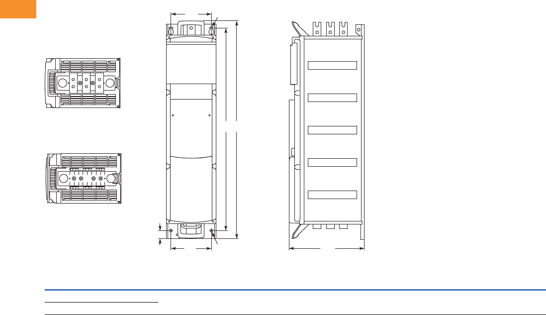
V6-T2-278 Volume 6—Solid-State Motor Control CA08100007E—May 2014 www.eaton.com
2
2
2
2
2
2
2
2
2
2
2
2
2
2
2
2
2
2
2
2
2
2
2
2
2
2
2
2
2
2
2.9
Adjustable Frequency Drives
LCX9000 Liquid Cooled Drives
Approximate Dimensions in Inches (mm)
Chassis Size, CH72
VoltageAmpsH1H2H3D1W1R1 Dia.R2 Dia.
Weight
Lbs (kg)
380–500 Vac 460–730 42.38
(1076.5)
1.57
(40.0)
39.37
(1000.0)
14.65
(372.0)
7.87
(200.0)
0.55
(14.0)
0.51
(13.0)
198 (90)
525–690 Vac 261–502
W1 R1
H1H3
H2 R2W1 D1
Front Side
Bottom
Top
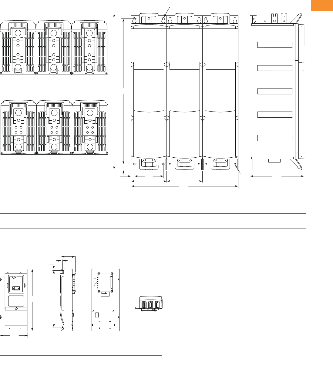
Volume 6—Solid-State Motor Control CA08100007E—May 2014 www.eaton.com V6-T2-279
2
2
2
2
2
2
2
2
2
2
2
2
2
2
2
2
2
2
2
2
2
2
2
2
2
2
2
2
2
2
2.9
Adjustable Frequency Drives
LCX9000 Liquid Cooled Drives
Approximate Dimensions in Inches (mm)
Chassis Size, CH74
Control Unit
VoltageAmpsH1H2 H3 D1 W1W2W3W4R1 Dia.R2 Dia.
Weight
Lbs (kg)
380–500 Vac 1370–2300 42.38
(1076.5)
1.57
(40.0)
39.37
(1000.0)
14.65
(372.0)
29.06
(738.0)
0.91
(23.0)
7.87
(200.0)
9.69
(246)
0.51
(13.0)
0.55
(14.0)
617 (280)
525–690 Vac 820–1500
H1 H2 H3 D1 D2 W1
12.93
(328.5)
0.33
(8.5)
11.81
(300.0)
2.95
(75.0)
0.33
(8.5)
5.75
(146.0)
W3
W4 W4
W2
W1
D1
ediStnorF
Bottom
Top
R1
R2
H2
H1 H3
D1
D2
H2
H3H1
W1
Side BackFront
Bottom
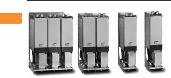
V6-T2-280 Volume 6—Solid-State Motor Control CA08100007E—May 2014 www.eaton.com
2
2
2
2
2
2
2
2
2
2
2
2
2
2
2
2
2
2
2
2
2
2
2
2
2
2
2
2
2
2
2.10
Adjustable Frequency Drives
SPA9000/SPN9000/SPI9000 Common DC Bus Drives
SPA9000/SPN9000/SPI9000 Common DC Bus Drive Products
Contents
Description Page
SPA9000/SPN9000/SPI9000 Common DC Bus Drives
Application Description . . . . . . . . . . . . . . . . . . V6-T2-281
Product Comparison . . . . . . . . . . . . . . . . . . . . V6-T2-281
Features . . . . . . . . . . . . . . . . . . . . . . . . . . . . . . V6-T2-282
Standards and Certifications . . . . . . . . . . . . . . V6-T2-282
Catalog Number Selection . . . . . . . . . . . . . . . . V6-T2-282
Product Selection . . . . . . . . . . . . . . . . . . . . . . . V6-T2-284
Options . . . . . . . . . . . . . . . . . . . . . . . . . . . . . . V6-T2-287
Technical Data and Specifications . . . . . . . . . . V6-T2-288
Wiring Diagrams . . . . . . . . . . . . . . . . . . . . . . . V6-T2-290
Dimensions . . . . . . . . . . . . . . . . . . . . . . . . . . . V6-T2-291
Product Description
Eaton offers a comprehensive
range of common DC bus
drive products. The product
family covers a number of
front-end units and inverter
units in the entire power
range from 1-1/2 to 2000
horsepower at 460V and
690V. The drive components
are built on the SPX9000
technology.
Front-End Units
The front-end units convert a
mains AC voltage and current
into a DC voltage and current.
The power is transferred from
the mains to a common DC
bus (and, in certain cases,
vice versa).
The SPA (active front-end)
unit is a bidirectional
(regenerative) power
converter for the front end
of a common DC bus drive
line up. An external LCL filter
is used at the input. This unit
is suitable in applications
where low mains harmonics
are required.
The SPN (non-regenerative
front-end) unit is a uni-
directional (motoring) power
converter for the front-end
of a common DC bus drive
line-up. The device operates
as a diode bridge using diode/
thyristor components. A
dedicated external choke is
used at the input. The unit
has the capacity to charge a
common DC bus. This unit is
suitable as a rectifying device
when a “normal” level of
harmonics is accepted and
no regeneration to the mains
is required.
Inverter Unit
The SPI9000 Inverter Unit is a
bidirectional DC-fed power
inverter for the supply and
control of AC motors. The
inverter is supplied from a
common DC bus drive line-
up. A charging circuit is
needed in case a connection
to a live DC bus is required.
The DC side charging circuit
is integrated up to 75 kW
(FR4–FR8) and external
for higher power ratings
(FI9–FI14).
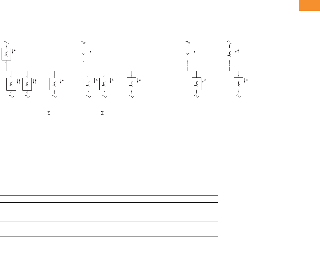
Volume 6—Solid-State Motor Control CA08100007E—May 2014 www.eaton.com V6-T2-281
2
2
2
2
2
2
2
2
2
2
2
2
2
2
2
2
2
2
2
2
2
2
2
2
2
2
2
2
2
2
2.10
Adjustable Frequency Drives
SPA9000/SPN9000/SPI9000 Common DC Bus Drives
Application Description
The common DC bus product portfolio fulfills all solution demands with a flexible architecture.
Front end units are selected according to the level of harmonics and power requirements. Typical
drive system configurations are illustrated the following figures.
SPA + Inverters SPN + Inverters Combination Configuration
●Low harmonics, -Pmains
+Pmains/Pmains < PINU
●Suitable for almost every
application
●Low total mains power,
Pmains < PINU
●Suitable e.g. for small
processing line with
un- and recoiler, em-stop
coasting
Common DC bus
components are used in a
multitude of combinations.
Drives which are braking can
transfer the energy directly to
the drives in motoring mode.
Product Comparison
Advantages over Conventional Front Ends
Eaton Front Ends vs. Conventional
Note
1Conventional regenerative front end (a.k.a. “anti-parallel thyristor bridge”) is not available from Eaton.
2
3
Inverter
2
3
Inverter
2
3
Inverter
Non-regenerative
Front End
(SPN)
3
2
3
2
2
3
Inverter
2
3
Inverter
2
3
Inverter
Active
Front End
(SPA)
2
3
Inverter
Common DC Bus 2
3
Inverter
3
2
3
2
Non-regenerative
Front End
(SPN) Alternative
Active
Front End
(SPA) Alternative
~
~
Non-Regenerative
Front End
Active
Front End
Conventional
Regenerative Front End 1
Input device Choke (L) Filter (LCL) Choke or auto-transformer (L)
Bridge type Diode/thyristor bridge IGBT bridge, two-level type Anti-parallel connected thyristor bridge
Type of operation Controlled half-bridge High frequency modulation
(1.5 to 3.6 kHz)
Firing angle controlled
Direction of power Motoring Motoring and regenerating Motoring and regenerating
Charging Constant current External required Usually internal
DC voltage Nominal (approx. 1.35
alternative UN)
Stable at +10% of nominal
(approx. 110% of 1.35
alternative UN)
Lowered DC voltage for commutation margin
(e.g. 17% fi approx. 83% of 1.35 alternative UN) or
autotransformer on regenerative bridge
THD Similar to six-pulse bridge
normal <40%
Very low Similar to six-pulse bridge or worse
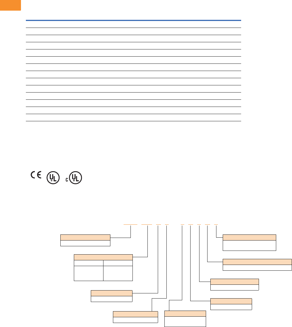
V6-T2-282 Volume 6—Solid-State Motor Control CA08100007E—May 2014 www.eaton.com
2
2
2
2
2
2
2
2
2
2
2
2
2
2
2
2
2
2
2
2
2
2
2
2
2
2
2
2
2
2
2.10
Adjustable Frequency Drives
SPA9000/SPN9000/SPI9000 Common DC Bus Drives
Features
Standard Features
Standards and Certifications
●CE
●UL
●cUL
●EN 61800-5-1 (2003)
Catalog Number Selection
Active Front End
SPI9000 SPA SPN
Feature FR4, 6, 7 FR8 FI9–FI14 FI9–FI14 FI9
IP00 — ■■■■
IP21 ■————
Air cooling ■■■■■
Standard board ■■■■
Varnished board —————
Alphanumeric keypad ■■■■—
EMC class T (EN 61800-3 for IT networks) ■■■■■
Safety CE/UL ■■■■■
Input choke ————■
LCL filter ———■—
No integrated charging — — ■■—
Integrated charging (DC side) ■■——■
Diode/thyristor rectifier ————■
IGBT ■■■■—
SPA 205 A 0 –4A 3 N 1
Keypad
A = Alphanumeric
Software Series
A = Standard
Brake Chopper Options
N = No brake chopper circuit
EMC Level
3 = IT network
Enclosure Rating
0 = Chassis
Product Family
SPA = Active Front End
Board Modifications
1 = Standard boards
2 = Varnished boards
Voltage Rating
4 = 480V
5 = 575V
Current Rating
480V 575V
205 = 205A
385 = 385A
H10 = 1150A
125 = 125A
325 = 325A
920 = 920A
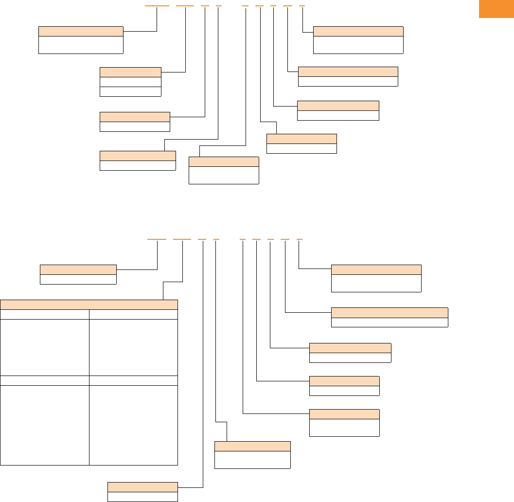
Volume 6—Solid-State Motor Control CA08100007E—May 2014 www.eaton.com V6-T2-283
2
2
2
2
2
2
2
2
2
2
2
2
2
2
2
2
2
2
2
2
2
2
2
2
2
2
2
2
2
2
2.10
Adjustable Frequency Drives
SPA9000/SPN9000/SPI9000 Common DC Bus Drives
Non-Regenerative Front End
SPI9000 Inverter Unit
SPN 510 A 0 –4A 3 N 1
Keypad
A = Alphanumeric
Software Series
A = Standard
Brake Chopper Options
N = No brake chopper circuit
EMC Level
3 = IT network
Enclosure Rating
0 = Chassis
Product Family
SPN = Non-regenerative
SPN = front end
Board Modifications
1 = Standard boards
2 = Varnished boards
Current Rating
480V/575V
510 = 510A
Voltage Rating
4 = 480V
5 = 575V
SPI 016 A 1 –4A 3 N 1
Keypad
A = Alphanumeric
Software Series
A = Standard
Brake Chopper Options
N = No brake chopper circuit
EMC Level
3 = IT network
Enclosure Rating
1 = NEMA Type 1/IP21
0 = Chassis
Product Family
SPI = Inverter unit
Board Modifications
1 = Standard boards
2 = Varnished boards
Voltage Rating
4 = 480V
5 = 575V
Current Rating
480V (FR4–FR8) 575V (FR6–FR8)
003 = 3.3A
007 = 7.6A
009 = 9A
012 = 12A
016 = 16A
023 = 23A
031 = 31A
038 = 38A
061 = 61A
071 = 72A
087 = 87A
105 = 105A
003 = 3.2A
004 = 4.5A
005 = 5.5A
007 = 7.5A
010 = 10A
013 = 13.5A
018 = 18A
022 = 22A
027 = 27A
034 = 34A
041 = 41A
052 = 52A
062 = 62A
080 = 80A
480V (FI9–FI13) 575V (FI9–FI14)
140 = 140A
170 = 170A
205 = 205A
245 = 245A
300 = 300A
385 = 385A
460 = 460A
520 = 520A
590 = 590A
650 = 650A
730 = 730A
820 = 820A
920 = 920A
H10 = 1030A
H11 = 1150A
H13 = 1300A
H16 = 1600A
H19 = 1940A
H23 = 2300A
100 = 100A
125 = 125A
144 = 144A
170 = 170A
208 = 207A
261 = 261A
325 = 325A
385 = 385A
460 = 460A
502 = 502A
590 = 590A
650 = 650A
820 = 820A
920 = 920A
H10 = 1030A
H13 = 1300A
H15 = 1500A
H19 = 1900A
V6-T2-284 Volume 6—Solid-State Motor Control CA08100007E—May 2014 www.eaton.com
2
2
2
2
2
2
2
2
2
2
2
2
2
2
2
2
2
2
2
2
2
2
2
2
2
2
2
2
2
2
2.10
Adjustable Frequency Drives
SPA9000/SPN9000/SPI9000 Common DC Bus Drives
Product Selection
SPA9000 Active Front End 480V
SPN9000 Non-Regenerative Front End 480V
SPI9000 Inverter Unit 480V
Note
For filter and line reactor information, see Page V6-T2-286.
Low Overload (AC Current) High Overload (AC Current) Imax
Frame IL-cont (A) I1min (A) IH-cont (A) I1min (A) I2s (A) Catalog Number
FI9 261 287 205 308 349 SPA205A0-4A3N1
FI10 460 506 385 578 693 SPA385A0-4A3N1
FI13 1300 1430 1150 1725 2070 SPAH11A0-4A3N1
Low Overload (AC Current) High Overload (AC Current) Imax
Frame IL-cont (A) I1min (A) IH-cont (A) I1min (A) I2s (A) Catalog Number
FI9 520 572 460 690 828 SPN460A0-4A3N1
Low Overload (AC Current) High Overload (AC Current) Imax
Frame IL-cont (A) I1min (A) IH-cont (A) I1min (A) I2s (A) Catalog Number
FR4 4.3 4.7 3.3 5 6.2 SPI003A1-4A3N1
99.9 7.611.4 14 SPI007A1-4A3N1
12 13.2 9 13.5 18 SPI009A1-4A3N1
FR61617.6 1218 24 SPI012A1-4A3N1
23 25.3 16 24 32 SPI016A1-4A3N1
31 34 23 35 46 SPI023A1-4A3N1
38 42 31 47 62 SPI031A1-4A3N1
46 51 38 57 76 SPI038A1-4A3N1
FR77279 6192 122 SPI061A1-4A3N1
87 96 72 108 144 SPI072A1-4A3N1
105 116 87 131 174 SPI087A1-4A3N1
FR8 140 154 105 158 210 SPI105A0-4A3N1
FI9 170 187 140 210 280 SPI140A0-4A3N1
205 226 170 255 336 SPI170A0-4A3N1
261 287 205 308 349 SPI205A0-4A3N1
300 330 245 379 444 SPI245A0-4A3N1
FI10 385 424 300 450 540 SPI300A0-4A3N1
460 506 385 578 693 SPI385A0-4A3N1
520 572 460 690 828 SPI460A0-4A3N1
FI12 590 649 520 780 936 SPI520A0-4A3N1
650 715 590 885 1062 SPI590A0-4A3N1
730 803 650 975 1170 SPI650A0-4A3N1
820 902 730 1095 1314 SPI730A0-4A3N1
920 1012 820 1230 1476 SPI820A0-4A3N1
1030 1133 920 1380 1656 SPI920A0-4A3N1
FI13 1150 1265 1030 1545 1854 SPIH10A0-4A3N1
1300 1430 1150 1720 2070 SPIH11A0-4A3N1
1450 1595 1300 1950 2340 SPIH13A0-4A3N1
FI14 1770 1947 1600 2400 2880 SPIH16A0-4A3N1
2150 2365 1940 2910 3492 SPIH19A0-4A3N1
Common DC Bus Drive
Products
Volume 6—Solid-State Motor Control CA08100007E—May 2014 www.eaton.com V6-T2-285
2
2
2
2
2
2
2
2
2
2
2
2
2
2
2
2
2
2
2
2
2
2
2
2
2
2
2
2
2
2
2.10
Adjustable Frequency Drives
SPA9000/SPN9000/SPI9000 Common DC Bus Drives
SPA9000 Active Front End 575V
SPN9000 Non-Regenerative Front End 575V
SPI9000 Inverter Unit 575V
Note
For filter and line reactor information, see Page V6-T2-286.
Low Overload (AC Current) High Overload (AC Current) Imax
Frame IL-cont (A) I1min (A) IH-cont (A) I1min (A) I2s (A) Catalog Number
FI9 144 158 125 188 213 SPA125A0-5A3N1
FI10 385 424 325 488 585 SPA325A0-5A3N1
FI13 1030 1133 920 1380 1656 SPA920A0-5A3N1
Low Overload (AC Current) High Overload (AC Current) Imax
Frame IL-cont (A) I1min (A) IH-cont (A) I1min (A) I2s (A) Catalog Number
FI9 600 660 510 732 888 SPN510A0-5A3N1
Low Overload (AC Current) High Overload (AC Current) Imax
Frame IL-cont (A) I1min (A) IH-cont (A) I1min (A) I2s (A) Catalog Number
FR6 4.5 5 3.2 5 6.4 SPI003A1-5A3N1
5.5 6 4.5 7 9 SPI004A1-5A3N1
7.5 8 5.5 8 11 SPI005A1-5A3N1
10 11 7.5 11 15 SPI007A1-5A3N1
13.5 15 10 15 20 SPI010A1-5A3N1
18 20 13.5 20 27 SPI013A1-5A3N1
22 24 18 27 36 SPI018A1-5A3N1
27 30 22 33 44 SPI022A1-5A3N1
34 37 27 41 54 SPI027A1-5A3N1
FR74145 3451 68 SPI034A1-5A3N1
52 57 41 62 82 SPI041A1-5A3N1
FR86268 5278 104 SPI052A0-5A3N1
80 88 62 93 124 SPI062A0-5A3N1
100 110 80 120 160 SPI080A0-5A3N1
FI9 125 138 100 150 200 SPI100A0-5A3N1
144 158 125 188 213 SPI125A0-5A3N1
170 187 144 216 245 SPI144A0-5A3N1
208 229 170 255 289 SPI170A0-5A3N1
FI10 261 287 208 312 375 SPI208A0-5A3N1
325 358 261 392 470 SPI261A0-5A3N1
385 424 325 488 585 SPI325A0-5A3N1
FI12 460 506 385 578 693 SPI385A0-5A3N1
502 552 460 690 828 SPI460A0-5A3N1
590 649 502 753 904 SPI502A0-5A3N1
650 715 590 885 1062 SPI590A0-5A3N1
750 825 650 975 1170 SPI650A0-5A3N1
FI13 920 1012 820 1230 1476 SPI820A0-5A3N1
1030 1133 920 1380 1656 SPI920A0-5A3N1
1180 1298 1030 1464 1755 SPIH10A0-5A3N1
FI14 1500 1650 1300 1950 2340 SPIH13A0-5A3N1
1900 2090 1500 2250 2700 SPIH15A0-5A3N1
2250 2475 1900 2782 3335 SPIH19A0-5A3N1
Common DC Bus Drive
Products

V6-T2-286 Volume 6—Solid-State Motor Control CA08100007E—May 2014 www.eaton.com
2
2
2
2
2
2
2
2
2
2
2
2
2
2
2
2
2
2
2
2
2
2
2
2
2
2
2
2
2
2
2.10
Adjustable Frequency Drives
SPA9000/SPN9000/SPI9000 Common DC Bus Drives
LCL Filters
LCL Filters for Active Front End (480V)
LCL Filters for Active Front End (690V)
Line Reactor
Line Reactor for
Non-Regenerative
Front End (480/575VV)
Amps Catalog Number Amps Catalog Number
10 REG 10 5 0 270 REG 270 5 0
18 REG 18 5 0 410 REG 410 5 0
32 REG 32 5 0 580 REG 580 5 0
48 REG 48 5 0 840 REG 840 5 0
75 REG 75 5 0 1160 REG 1160 5 0
110 REG 110 5 0 1480 REG 1480 5 0
180 REG 180 5 0
Amps Catalog Number Amps Catalog Number
14 REG 14 6 0 287 REG 287 6 0
23 REG 23 6 0 390 REG 390 6 0
35 REG 35 6 0 460 REG 460 6 0
52 REG 52 6 0 620 REG 620 6 0
85 REG 85 6 0 780 REG 780 6 0
122 REG 122 6 0 920 REG 920 6 0
185 REG 185 6 0 1180 REG 1180 6 0
Amps
Watts
Losses
Catalog
Number
600 493 CHK600
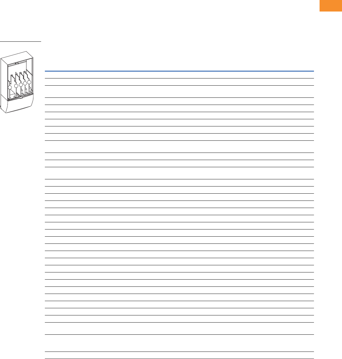
Volume 6—Solid-State Motor Control CA08100007E—May 2014 www.eaton.com V6-T2-287
2
2
2
2
2
2
2
2
2
2
2
2
2
2
2
2
2
2
2
2
2
2
2
2
2
2
2
2
2
2
2.10
Adjustable Frequency Drives
SPA9000/SPN9000/SPI9000 Common DC Bus Drives
Options
9000X Series Option Board Kits
The 9000X Series drives can accommodate a wide selection of expander and adapter option boards to
customize the drive for your application needs. The drive’s control unit is designed to accept a total of
five option boards.
The 9000X Series factory installed standard board configuration includes an A9 I/O board and an A2
relay output board, which are installed in slots A and B.
Option Board Kits
Notes
1 AI = Analog Input; AO = Analog Output, DI = Digital Input, DO = Digital Output, RO = Relay Output
2 Option card must be installed in one of the slots listed for that card. Slot indicated in bold is the preferred location.
3 OPTC2 is a multi-protocol option card.
Option Kit Description 1
Allowed Slot
Locations 2
Field
Installed
Factory
Installed SVX Ready Programs
Catalog
Number
Option
Designator Basic
Local/
Remote Standard MSS PID Multi-P. PFC
Standard I/O Cards
2 RO (NC-NO) B OPTA2 — ■ ■ ■ ■■■ ■
6 DI, 1 DO, 2 AI, 1AO, 1 +10 Vdc ref,
2 ext +24 Vdc/EXT +24 Vdc
AOPTA9 — ■ ■ ■ ■■■ ■
Extended I/O Cards
2 RO, therm B OPTA3 A3 —■ ■ ■■■ ■
Encoder low volt +5V/15V24V C OPTA4 A4 —■ ■ ■■■ ■
Encoder high volt +15V/24V C OPTA5 A5 —■ ■ ■■■ ■
Double encoder C OPTA7 A7 ■ ■ ■ ■■■ ■
6 DI, 1 DO, 2 AI, 1 AO A OPTA8 A8 —■ ■ ■■■ ■
3 DI (encoder 10–24V), out +15V/+24V,
2 DO (pulse+direction)
COPTAE AE ■ ■ ■ ■■■ ■
6 DI, 1 ext +24 Vdc/EXT +24 Vdc B, C, D, E OPTB1 B1 —— — ——
■■
1 RO (NC-NO), 1 RO (NO), 1 therm B, C, D, E OPTB2 B2 —— — ——
■■
1 AI (mA isolated), 2 AO (mA isolated),
1 ext +24 Vdc/EXT +24 Vdc
B, C, D, E OPTB4 B4 —■ ■ ■■■ ■
3 RO (NO) B, C, D, E OPTB5 B5 —— — ——
■■
1 ext +24 Vdc/EXT +24 Vdc, 3 Pt100 B, C, D, E OPTB8 B8 — — — ——— —
1 RO (NO), 5 DI 42–240 Vac input B, C, D, E OPTB9 B9 —— — ——
■■
SPI, absolute encoder C OPTBB BB — — — ——— —
Communication Cards 3
Modbus D, E OPTC2 C2 ■ ■ ■ ■■■ ■
Johnson Controls N2 D, E OPTC2 CA — — — ——— —
Modbus TCP D, E OPTCI CI ■ ■ ■ ■■■ ■
BACnet D, E OPTCJ CJ ■ ■ ■ ■■■ ■
EtherNet/IP D, E OPTCQ CQ ■ ■ ■ ■■■ ■
PROFIBUS DP D, E OPTC3 C3 ■ ■ ■ ■■■ ■
LonWorks D, E OPTC4 C4 ■ ■ ■ ■■■ ■
PROFIBUS DP (D9 connector) D, E OPTC5 C5 ■ ■ ■ ■■■ ■
CANopen (slave) D, E OPTC6 C6 ■ ■ ■ ■■■ ■
DeviceNet D, E OPTC7 C7 ■ ■ ■ ■■■ ■
Modbus (D9 type connector) D, E OPTC8 C8 ■ ■ ■ ■■■ ■
Adapter D, E OPTD1 D1 ■ ■ ■ ■■■ ■
Adapter D, E OPTD2 D2 ■ ■ ■ ■■■ ■
RS-232 with D9 connection D, E OPTD3 D3 ■ ■ ■ ■■■ ■
Keypad
9000X Series local/remote keypad
(replacement keypad)
—KEYPAD-
LOC/REM
—— — — ——— ■
9000X Series remote mount keypad unit
(keypad not included, includes 10 ft cable,
keypad holder, mounting hardware)
—OPTRMT-
KIT-9000X
—— — — ——— —
9000X Series RS-232 cable, 13 ft — PP00104 — — — — ——— —
Option Boards
ABCDE

V6-T2-288 Volume 6—Solid-State Motor Control CA08100007E—May 2014 www.eaton.com
2
2
2
2
2
2
2
2
2
2
2
2
2
2
2
2
2
2
2
2
2
2
2
2
2
2
2
2
2
2
2.10
Adjustable Frequency Drives
SPA9000/SPN9000/SPI9000 Common DC Bus Drives
Technical Data and Specifications
SPA9000/SPN9000/SPI9000
Description Specification
Supply Connection
Input voltage Uin (AC) front end modules 380–500 Vac/525–690 Vac –10% to 10%
Input voltage Uin (DC) inverter 465–800 Vdc/640–1100 Vdc –0% to 0%, the waviness of the inverter supply voltage,
formed in rectification of the electric network’s alternating voltage in basic frequency,
must be less than 50V peak-to-peak
Output voltage Uout (AC) inverter 3 ~ 0–Uin/1.4
Output voltage Uout (DC) active front end module 10.10 x 1.35 x Uin (factory default)
Output voltage Uout (DC) non-regenerative front end module 1.35 x Uin
Ambient Conditions
Ambient operating temperature 14 (no frost) to 122°F (–10 to 50°C): IH
14 (no frost) to 104°F (–10 to 40°C): IL
Storage temperature –40 to 158°F (–40 to 70°C)
Relative humidity 0 to 95% RH, non-condensing, non-corrosive, no dripping water
Air quality
Chemical vapors IEC 721-3-3, unit in operation, class 3C2
Mechanical particles IEC 721-3-3, unit in operation, class 3S2
Altitude 100% load capacity (no derating) up to 1000m
1% derating for each 100m above 1000m; max. 3000m
Vibration 5–150 Hz
EN50178/EN60068-2-6 Displacement amplitude 0.25 mm (peak) at 3–15.8 Hz
Max acceleration amplitude 1G at 15.8–150 Hz
Shock
EN50178, EN60068-2-27
UPS Drop Test (for applicable UPS weights)
Storage and shipping: max 15G, 11 ms (in package)
Cooling capacity required Approximately 2%
Cooling air required FR4 41 cfm, FR6 250 cfm, FR7 250 cfm, FR8 383 cfm
FI9 677 cfm, FI10 824 cfm, FI12 1648 cfm, FI13 2472 cfm
Unit enclosure class FR4–FR7 NEMA Type 1/IP21; FR8, FI9–FI14 chassis (IP00)
EMC (at fault settings)
Immunity Fulfill all EMC immunity requirements
Safety
Approvals CE, UL, cUL, EN 61800-5-1 (2003), see unit nameplate for more detailed approvals
Control Connections
Analog input voltage 0–10V, Ri = 200 kohms, (–10V to 10V joystick control)
Resolution 0.1%, accuracy ±1%
Analog input current 0(4)–20 mA, Ri = 250 ohms differential
Digital inputs 6, positive or negative logic; 18–30 Vdc
Auxiliary voltage +24V, ±15%, max. 250 mA
Output reference voltage +10V, +3%, max. load 10 mA
Analog output 0(4)–20 mA; RL max. 500 ohms; resolution 10 bits
Accuracy ±2%
Digital outputs Open collector output, 50 mA/48V
Relay outputs 2 programmable change-over relay outputs
Switching capacity: 24 Vdc/8A, 250 Vac/8A, 125 Vdc/0.4A
Min. switching load: 5V/10 mA

Volume 6—Solid-State Motor Control CA08100007E—May 2014 www.eaton.com V6-T2-289
2
2
2
2
2
2
2
2
2
2
2
2
2
2
2
2
2
2
2
2
2
2
2
2
2
2
2
2
2
2
2.10
Adjustable Frequency Drives
SPA9000/SPN9000/SPI9000 Common DC Bus Drives
SPA9000/SPN9000/SPI9000, continued
Input Fuses
SHT fuses can be assembled into same-size DIN fuse base.
SPA9000/SPN9000/SPI9000
Description Specification
Protections
Overvoltage protection 480V/911 Vdc, 575V/1200 Vdc
Undervoltage protection 480V/333 Vdc, 575V/460 Vdc
Ground fault protection In case of ground fault in motor or motor cable, only the inverter is protected
Motor phase supervision Trips if any of the output phases is missing
Overcurrent protection Yes
Unit overtemperature protection Yes
Motor overload protection Yes
Motor stall protection Yes
Motor underload protection Yes
Short-circuit protection of 24V and 10V reference voltages Yes
Module
Component Frame Bussman Fuse Type (aR) Size UN (V) IN (A) Qty.
Inverter Units
SPI003A1-4 FR4 170M1560 0 690 20 2
SPI007A1-4 FR4 170M1562 0 690 63 2
SPI009A1-4 FR4 170M1562 0 690 63 2
SPI012A1-4 FR6 170M1565 0 690 63 2
SPI016A1-4 FR6 170M1565 0 690 63 2
SPI023A1-4 FR6 170M1565 0 690 63 2
SPI031A1-4 FR6 170M1567 0 690 100 2
SPI038A1-4 FR6 170M1567 0 690 100 2
SPI061A1-4 FR7 170M1570 0 690 200 2
SPI072A1-4 FR7 170M1570 0 690 200 2
SPI087A1-4 FR7 170M1571 0 690 250 2
SPI105A0-4 FR8 170M3819 DIN1 690 400 2
SPI140A0-4 FR8 170M3819 DIN1 690 400 2
SPI170A0-4 FR8 170M3819 DIN1 690 400 2
SPI205A0-4 FI9 170M6812 DIN3 690 800 2
SPI245A0-4 FI9 170M6812 DIN3 690 800 2
SPI300A0-4 FI10 170M8547 3SHT 690 1250 2
SPI385A0-4 FI10 170M8547 3SHT 690 1250 2
SPI460A0-4 FI10 170M8547 3SHT 690 1250 2
SPI520A0-4 FI12 170M8547 3SHT 690 1250 2 x 2
SPI590A0-4 FI12 170M8547 3SHT 690 1250 2 x 2
SPI650A0-4 FI12 170M8547 3SHT 690 1250 2 x 2
SPI730A0-4 FI12 170M8547 3SHT 690 1250 2 x 2
SPI820A0-4 FI12 170M8547 3SHT 690 1250 2 x 2
SPI920A0-4 FI12 170M8547 3SHT 690 1250 2 x 2
SPIH10A0-4 FI13 170M8547 3SHT 690 1250 6
SPIH11A0-4 FI13 170M8547 3SHT 690 1250 6
SPIH13A0-4 FI13 170M8547 3SHT 690 1250 6
SPIH16A0-4 FI14 170M8547 3SHT 690 1250 2 x 6
SPIH19A0-4 FI14 170M8547 3SHT 690 1250 2 x 6
SPIH23A0-4 FI14 170M8547 3SHT 690 1250 2 x 6
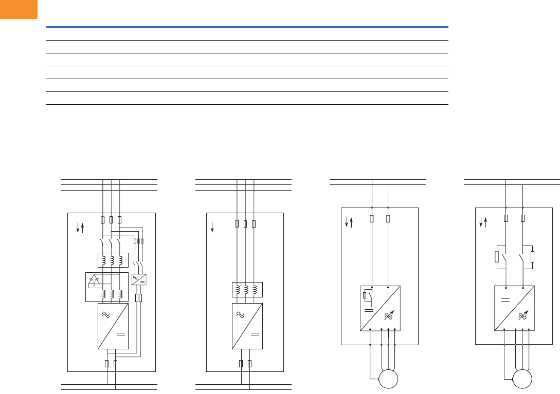
V6-T2-290 Volume 6—Solid-State Motor Control CA08100007E—May 2014 www.eaton.com
2
2
2
2
2
2
2
2
2
2
2
2
2
2
2
2
2
2
2
2
2
2
2
2
2
2
2
2
2
2
2.10
Adjustable Frequency Drives
SPA9000/SPN9000/SPI9000 Common DC Bus Drives
SHT fuses can be assembled into same-size DIN fuse base.
SPA9000/SPN9000/SPI9000, continued
Wiring Diagrams
SPA9000—
Active Front End
SPN9000—Non-
Regenerative Front End
SPI9000—Inverter Unit
(FR4–FR8)
SPI9000—Inverter Unit
(FI9–FI14)
Module
Component Frame Bussman Fuse Type (aR) Size UN (V) IN (A) Qty.
Active Front Ends
SPA205A0-4 FI9 170M6202 3SHT 1250 500 3
SPA385A0-4 FI10 170M6277 3SHT 1250 1000 3
SPAH10A0-4 FI13 170M6277 3SHT 1250 1000 3 x 3
Non-Regenerative Front Ends
SPN468A0-4 FI9 170M8547 3SHT 690 1250 3
-K4 -F4
-K5
-V4
-R4
425 – 600 Vdc
L2
L1
L3
DC+
DC-
-F1
-U1
-F2
380 – 500 Vac
AFE
-L1.1
-L1.2
425 – 800 Vdc
L2
L1
L3
DC+
DC-
-F1
-U1
-F2
380 – 500 Vac
NFE
-L1
DC+ DC-
VW
PE U
425 – 800 Vdc
DC+
DC-
M
INU -F1
VWU
PE
DC+
425 – 800 Vdc
DC+
DC-
DC-
INU -F1
M

Volume 6—Solid-State Motor Control CA08100007E—May 2014 www.eaton.com V6-T2-291
2
2
2
2
2
2
2
2
2
2
2
2
2
2
2
2
2
2
2
2
2
2
2
2
2
2
2
2
2
2
2.10
Adjustable Frequency Drives
SPA9000/SPN9000/SPI9000 Common DC Bus Drives
Dimensions
Approximate Dimensions in Inches (mm)
SPA9000/SPN9000/SPI9000
Frame Height Width Depth
Weight
Lbs (kg)
Active Front Ends
FI9 40.6 (1030) 9.4 (239) 14.6 (372) 148 (67)
FI10 40.6 (1032) 9.4 (239) 21.7 (552) 220 (100)
FI12 40.6 (1032) 2 x 9.4 (2 x 239) 21.7 (552) 441 (200)
FI13 40.6 (1032) 27.9 (708) 21.8 (553) 674 (306)
FI14 40.6 (1032) 2 x 27.9 (2 x 708) 21.8 (553) 1348 (612)
Non-Regenerative Front Ends
FI9 40.6 (1030) 9.4 (239) 14.6 (372) 148 (67)
Inverter Units
FR4 11.5 (292) 5.0 (128) 7.5 (190) 11 (5)
FR6 20.4 (519) 7.7 (195) 9.3 (237) 35 (16)
FR7 23.3 (591) 9.3 (237) 10.1 (257) 64 (29)
FR8 29.8 (758) 11.4 (289) 13.5 (344) 106 (48)
FI9 40.6 (1030) 9.4 (239) 14.6 (372) 148 (67)
FI10 40.6 (1032) 9.4 (239) 21.7 (552) 220 (100)
FI12 40.6 (1032) 2 x 9.4 (2 x 239) 21.7 (552) 441 (200)
FI13 40.6 (1032) 27.9 (708) 21.8 (553) 674 (306)
FI14 40.6 (1032) 2 x 27.9 (2 x 708) 21.8 (553) 1348 (612)
