Product Detail Manual
113610-Catalog 113610-Catalog 113610-Catalog 785901 Batch12 unilog cesco-content
2014-11-11
: Pdf 54531-Attachment 54531-Attachment 785901 Batch12 unilog
Open the PDF directly: View PDF ![]() .
.
Page Count: 24
3-1
© 2012 Schneider Electric
All Rights Reserved
3SAFETY SWITCHES
Table of Contents
Section 3
Safety Switches
Light Duty, p. 3-2
General Duty, p. 3-2
Heavy Duty, p. 3-4
Stainless Steel Heavy Duty, p. 3-7
Light Duty
Fusible 3-2
Application Data and Dimensions 3-3
Standards:
•UL 98 Enclosed and Dead Front Switches.
UL Listed under File E2875.
•NEMA Standards Publication KS1. Enclosed Switches.
General Duty
Fusible and Non-Fusible 3-2
Application Data and Dimensions 3-3
Standards:
•UL 98 Enclosed and Dead Front Switches.
UL Listed under File E2875.
•NEMA Standards Publication KS1. Enclosed Switches.
Heavy Duty
Fusible 3-4
Non-Fusible 3-6
Special Application Enclosures 3-7
Motor Disconnect and Receptacle Switches 3-8
Accessories 3-11
Application Data and Dimensions 3-13
Standards:
•UL 98 Enclosed and Dead Front Switches.
UL Listed under files E2875, E154828, E233505 and E317818.
•UL 508 Industrial Control Equipment, file E 164864.
•NEMA Standards Publication KS1 Enclosed Switches (UL98 Switches Only).
Double Throw
Fusible and Non-Fusible 3-15
Accessories 3-18
Standards:
•UL 98 Enclosed and Dead Front Switches.
UL Listed under files E2875 (unless otherwise noted).
•NEMA Standards Publication KS1 Enclosed Switches (applies to Type DT and
DTU series F only).
Application Data and Dimensions 3-19
1000 Vdc Photovoltaic Heavy Duty
Disconnect Switch
3-22
Standards:
•UL 98 Enclosed and Dead Front Switches
•UL Listed under file E343347
•IEC 60947 - 1 Electrical
•IEC 60947 - 3 Mechanical
•NEMA standard. Publication KS-1 Enclosed Switches
•IP 63 and NEMA 3 Enclosure
3-2 © 2012 Schneider Electric
All Rights Reserved
www.schneider-electric.us
3SAFETY SWITCHES
General Duty Safety Switches Light Duty
Class 3130 / Refer to Catalog 3100CT0901
Light Duty—Visible Blades 10 kA Short Circuit Current Rating
The Square D light duty enclosed switch is ideal for home applications in disconnecting power to workshops, hobby rooms,
furnaces, and garages.
aFor single phase hp rating, use two switching poles.
General Duty—Up To 100 kA Short Circuit Current Rating With Proper Current Limiting Fusing
General duty safety switches are designed for residential and commercial applications where durability and economy are
prime considerations. Typical loads are lighting, air conditioning, and appliances. They are suitable for use as service
equipment when equipped with a factory- or field-installed neutral assembly or a field-installed service grounding kit, (see
Table 3.6) as applicable.
General duty safety switches are UL Listed, File E2875, and meet or exceed the NEMA Standard KS1.
aBolt-on hubs—Refer to page 3-10.
bWhen installed, this kit rejects all but Class R fuses.
cFor corner grounded delta systems only. Use switching poles for ungrounded conductors. See data bulletin 2700DB0202 for additional information.
dIf corner grounded delta, use outer switching poles for ungrounded conductors.
eFor 200% neutral, order (1) additional neutral kit SN20A and (1) neutral jumper kit SN20NI.
fClass T 400–800 A general duty safety switches use 300 Vac Class T fuses and are UL Listed for use on systems with up to 100 kA available fault current.
gOrder Class J fuse kit: GDJK600 for Class J fuses.
hBolt-on hubs—Refer to page 3-10.
iEnclosed molded case switch—Refer to page 1-24.
jIncludes factory-installed grounding kit.
kNot service entrance rated—Refer to page 1-19 for more information.
lIf a neutral assembly is required, order and field-install SN0610.
mIf a neutral assembly is required, order and field install a SN20A Neutral Assembly Kit. For a 200% neutral application, order and field install (2) SN20A
Neutral Assembly Kits and (1) SN20NI Neutral Jumper Kit.
nIf a neutral assembly is required, order part number D600SN. Available for field-installation.
oFor single phase hp rating, use two switching poles.
pTo accept J class fuses, move fuse bases to the embossed guide inside of the switch.
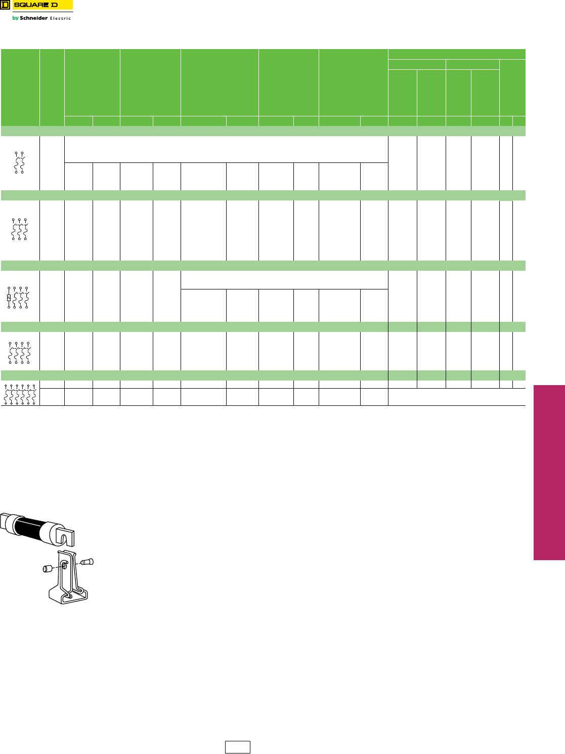
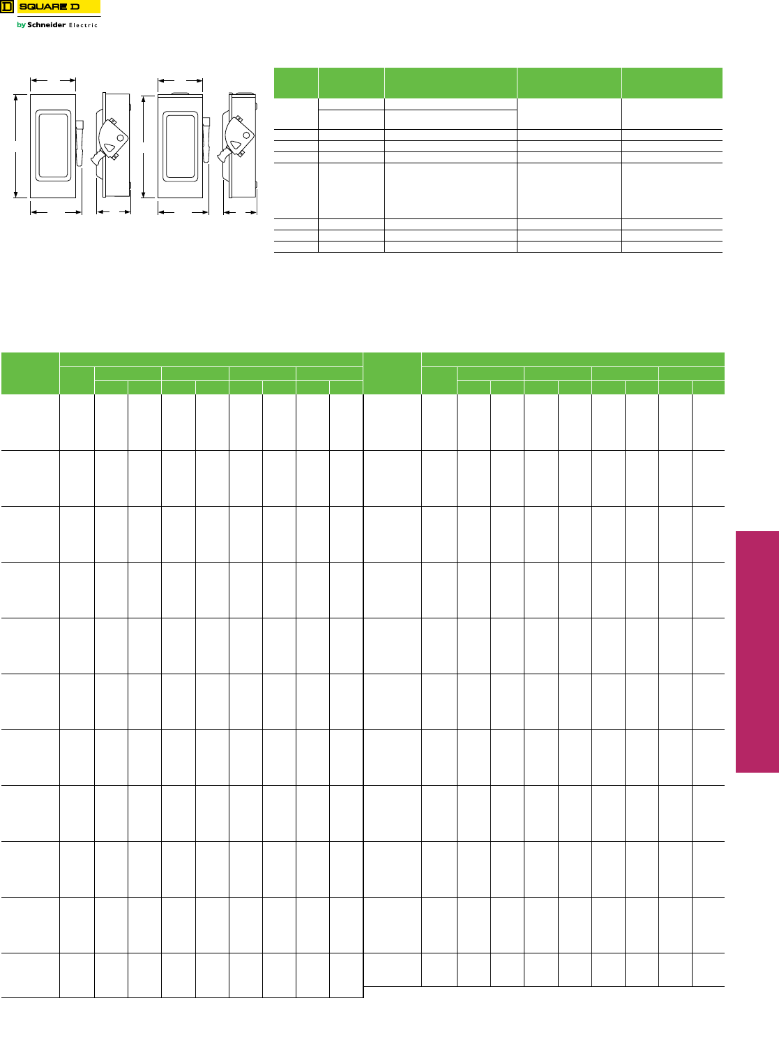
Table 3.1: Fusible
System Amperes Fuse NEMA 1 Indoor Horsepower Ratings System Amperes Fuse NEMA 1 Indoor Horsepower Ratings
Cat. No. $ Price Std. Max. Cat. No. $ Price Std. Max.
2 Wire (1 Blade and Fuseholder, 1 Neutral)—120 Vac 3 Wire (2 Blades and Fuseholders, 1 Neutral)—120/240 Vac
30 Plug L111N $54.00 1/2 2
30 Plug L211N 72.00 1-1/2a3a
30 Cart. L221N 98.00 1-1/2a3a
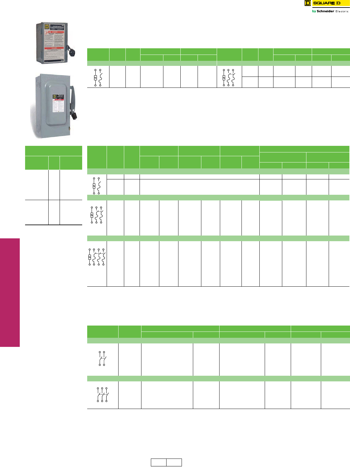
D223N
L221N
UL Listed Short Circuit
Withstand Rating
Switch
Type
Fuse
Class
Short
Circuit
Rating
Fusible
Plug 10 kA
H10 kA
K10 kA
J100 kA
R100 kA
T100 kA
Non-
Fusiblea
H10 kA
K10 kA
J100 kA
R100 kAb
T100 kA
aThe UL Listed short-circuit
current rating for
Square D general duty,
not fusible switches is
based on the switch being
used in conjunction with
fuses. Evaluation of non-
fusible switches in
conjunction with molded
case circuit breakers
above 10,000 amps has
not been performed. For
applications requiring
greater protection,
consider using a heavy
duty safety switch. Refer
to UL Listed Maximum
Short Circuit Current
Ratings—AC only—on
page 3-6. If a UL Listed
short-circuit current rating
is required, this non-
fusible switch must be
replaced with a Square D
general duty fusible safety
switch equipped with the
appropriate class and size
fusing. Consult the wiring
diagram of the switch to
verify the UL Listed short-
circuit current rating.
b50 kA for 60 A non-fusible
switch.
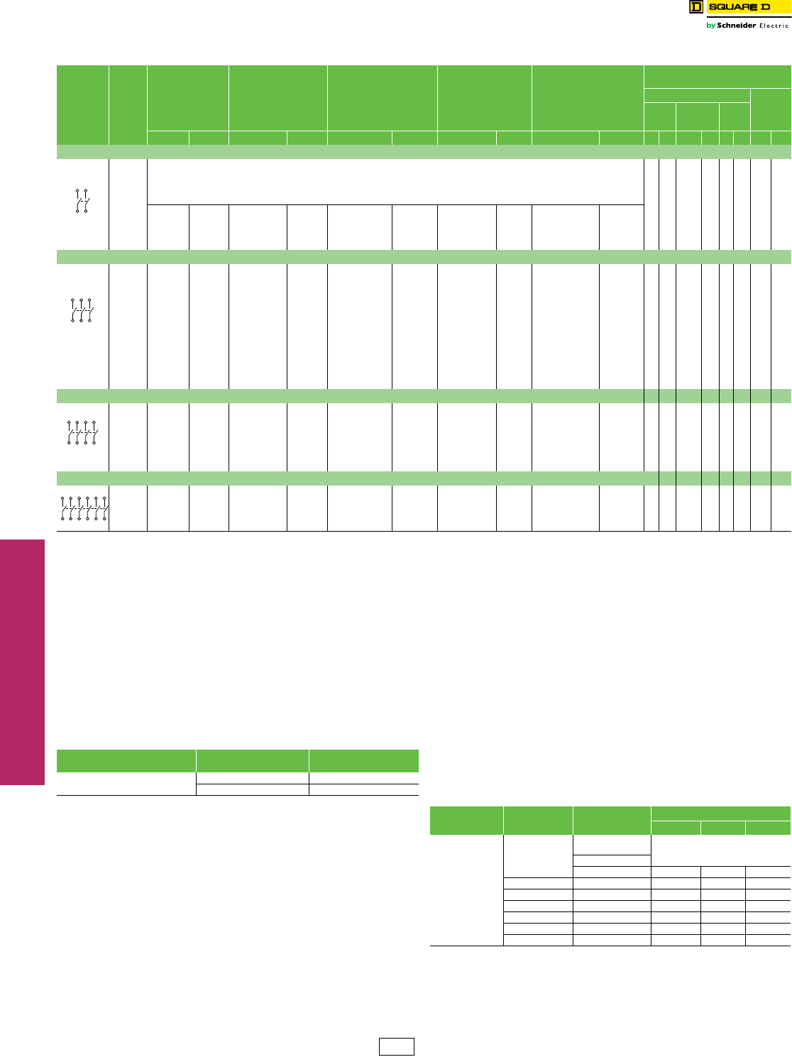
Table 3.2: Fusible
System Amperes Fuse
NEMA 1
Indoor
NEMA 3Ra
Rainproof
Class R Fuse Kits
Field-Installedb
Horsepower Ratings
Std. (Fast Acting
One-Time Fuses)
Max. (Dual Element
Time-Delay Fuses)
Cat. No. $ Price Cat. No. $ Price Cat. No. $ Price 1Ø 3Ø 1Ø 3Ø
2 Wire (1 Blade and Fuseholder, 1 Neutral)—120 Vac
30 Plug Use Light Duty Device for this Application (see below) — — — —
30 Cart. Use three-wire devices for this application. — — — —
3 Wire (2 Blades and Fuseholders, 1 Neutral)—120/240 Vac (Plug), 240 Vac (Cart.) Maximum
30 Plug D211N 90.00 D211NRB 177.00 ——1-1/2— 3 —
30 Cart. D221N 122.00 D221NRB 188.00 DRK30 25.65 1-1/2 3 c37-1/2c
60 Cart. D222N 206.00 D222NRB 326.00 RFK03H 25.50 37-1/2c10 15c
100 Cart. D223N 426.00 D223NRB 480.00 RFK10 47.70 7-1/2 15 c15 30c
200 Cart. D224Ne884.00 D224NRBe1200.00 HRK1020 47.70 15 25 c—60c
400 Cart. D225N 2555.00 D225NR 3459.00 DRK40 111.00 ————
600gCart. D226N 5109.00 D226NR 6569.00 DRK600 111.00 ————
4 Wire (3 Blades and Fuseholders, 1 Neutral)—240 Vac Maximum
30 Cart. D321N 188.00 D321NRB 293.00 DRK30 25.65 1-1/2 3 3 7-1/2
60 Cart. D322N 326.00 D322NRB 441.00 RFK03H 25.50 37-1/2d10 15d
100 Cart. D323N 564.00 D323NRB 816.00 RFK10 47.70 7-1/2 15d15 30d
200 Cart. D324Ne1202.00 D324NRBe1461.00 HRK1020 47.70 15 25d—60d
400 Cart. D325N 3113.00 D325NR 3893.00 DRK40 111.00 —50—125
400fClass T D325NT 2994.00 D325NTR 3741.00 ——— 50 — —
600gCart. D326N 5823.00 D326NR 7877.00 DRK600 111.00 —75—150
600fClass T D326NT 5598.00 D326NTR 7569.00 ——— 75 — —
800fClass T T327N 9722.00 T327NR 12438.00 ——— 100 — —
Table 3.3: Non-Fusible
System Amperes NEMA 1 Indoor NEMA 3R Rainproof hHorsepower Ratings (Max.)
Cat. No. $ Price Cat. No. $ Price 1Ø 3Ø
2 Wire (2 Blades)—240 Vac Maximum
30 — — DU221RB 177.00 3—
60 — — DU222RB 353.00 10 —
60 QO260NATSij 161.00 QO200TR ijk 161.00 10 —
100 QO2000NSij 276.00 QO2000NRBik 338.00 20 —
200 Use 3P Switch — Use 3P Switch — — —
400pUse 3P Switch — Use 3P Switch — — —
600 Use 3P Switch — Use 3P Switch — — —
3 Wire (3 Blades)—240 Vac Maximum
30 DU321 155.00 DU321RB 293.00 37-1/2
60 DU322 206.00 DU322RB 443.00 10 15
100 DU323l477.00 DU323RBl816.00 15 30
200 DU324m884.00 DU324RBm1461.00 15 60n
400pDU325 2198.00 ———125
600 DU326n4191.00 ———150
DE1A DE2A Discount
Schedule
www.schneider-electric.us
3SAFETY SWITCHES
© 2012 Schneider Electric
All Rights Reserved 3-3
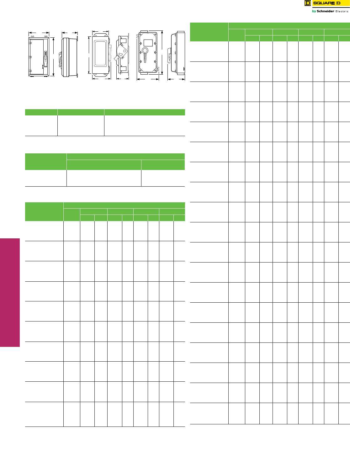
General Duty Safety Switches Accessories, Lug Data and Dimensions
Class 3130 / Refer to Catalog 3100CT0901
a30–100 A switches suitable for 60oC or 75oC conductors. 200–800 A switches suitable for
75oC conductors.
NOTE: Field-installed lug kits are located in the Supplemental
Digest page 2.2.
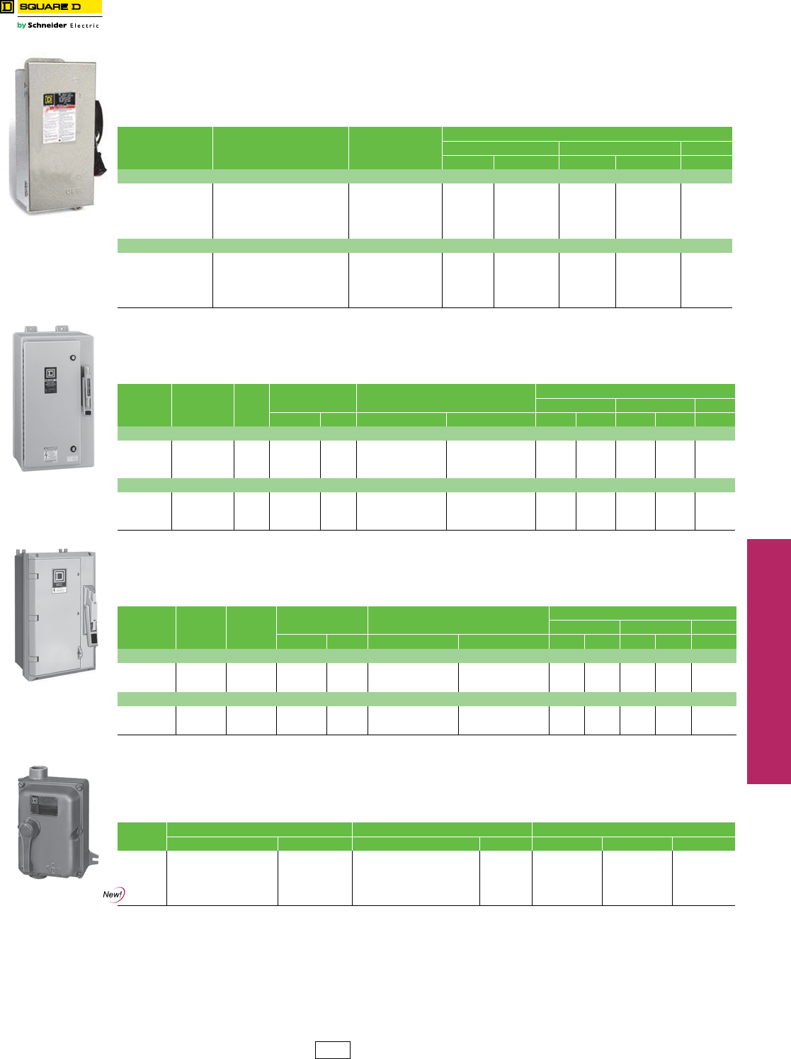
Field-Installed Fuse Puller Kits
Kit consists of three fuse pullers as required for a 3P, fusible, 60 and 100 A
general duty switch. Kits can be installed in 60 and 100 A Series F switches.
aSeries E switch only.
bSeries F switch only.
Field-Installed Electrical Interlock Kits
Electrical interlocks for Series F 100–200 A general duty safety switches
and Series F 60 A fusible general duty safety switches are available in
kit form for field installation. Each kit contains instructions for proper field
mounting. A pivot arm operates from switch mechanism, breaking the
control circuit before the main switch blades break. Switches with
electrical interlocks installed are UL Listed.
aElectrical interlock kit catalog numbers with -1 suffix indicates one normally open and one
normally closed contact; -2 indicates two normally open and two normally closed contacts.
Kits are UL Listed.
bFusible series.
c30–100 A switches suitable for 60oC or 75oC conductors. 200–800 A switches suitable for 75oC conductors.
Table 3.4: Terminal Lug Data a
Amperes Conductors
Per Phase
Wire Range
Wire Bending Space Per NEC Table 312.6
AWG/kcmil
Lug Wire Range
AWG/kcmil
30 1 12–6 (Al) or 14–6 (Cu) 12–6 (Al) or 14–6 (Cu)
60 1 10–3 (Al) or 14–3 (Cu) 10–2 (Al) or 14–2 (Cu)
100 1 12–1 (Al) or 14–1 (Cu) 12–1/0 (Al) or 14–1/0 (Cu)
200 1 6 –250 (Al/Cu) 6 –300 (Al/Cu)
400
NEMA 1
1
or
2
1/0 –600 (Al/Cu)
or
1/0 –300 (Al/Cu)
(1) 1/0 –750 (Al/Cu)
or
(2) 1/0 –300 (Al/Cu)
400
NEMA 3R 2 1/0–250 (Al/Cu)
(1) 1 –600 (Al/Cu)
or
(2) 1/0 –250 (Al/Cu)
600 2 4 –500 (Al/Cu) 4 –600 (Al/Cu)
800 3 3/0 –500 (Al/Cu) 3/0 –500 (Al/Cu)
Table 3.5: Fuse Puller Kits
Description Cat. No. $ Price
Series F 60 A Fuse Puller Kit FPK03 30.00
Series F 100 A Fuse Puller Kit FPK0610 42.60
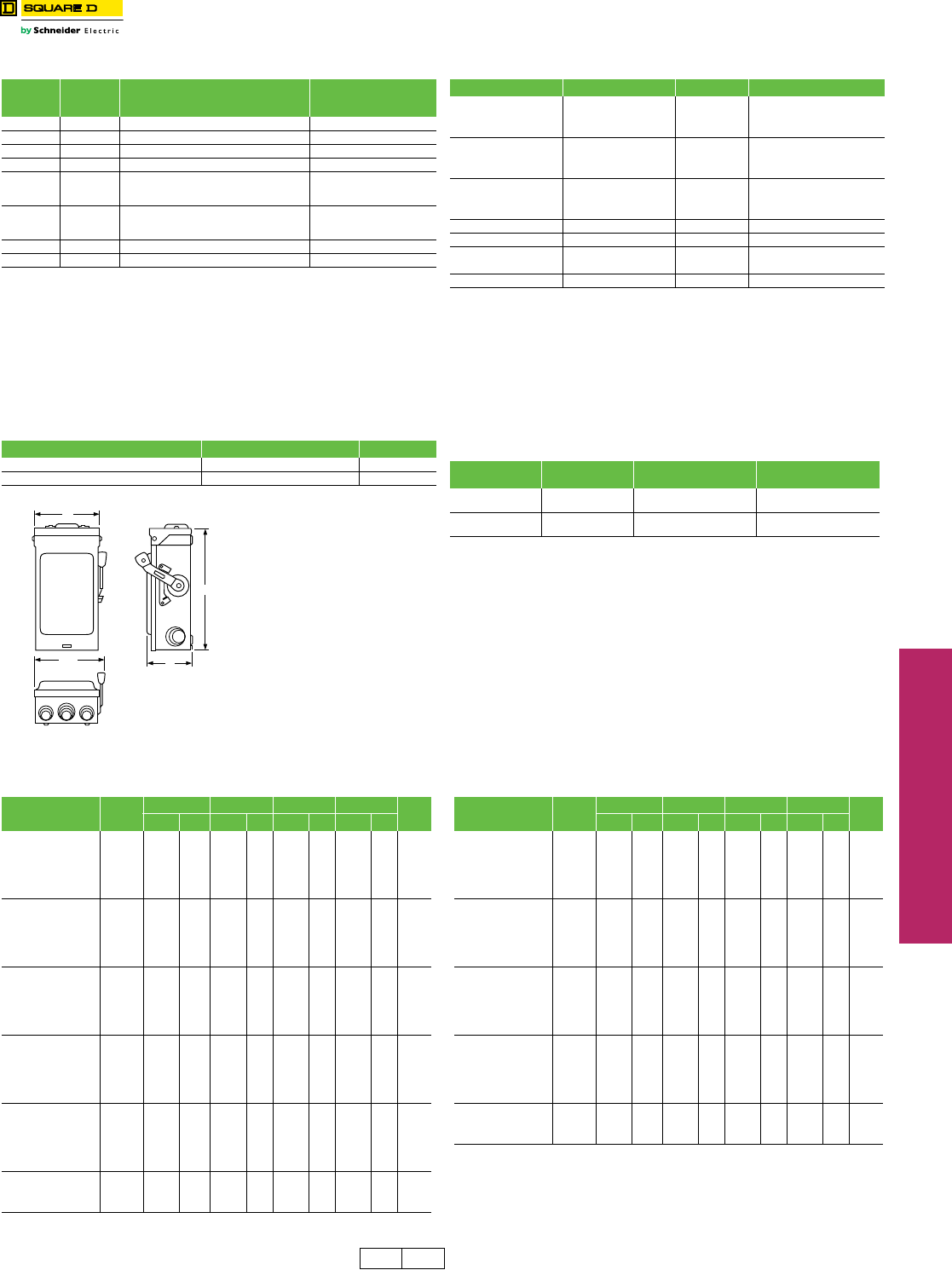
H
D
W/H
W
Table 3.6: Field-Installed Service Grounding Kits
Amperes Cat. No. $ Price Wire Size (AWG)
30 PK3GTA1 11.40
(2) 12 Cu or
(2) 10 Al or
(1) 4 Al/Cu Max.
60aPK3GTA1 11.40
(2) 12 Cu or
(2) 10 Al or
(1) 4 Al/Cu Max.
60bGTK03 11.40
(2) 12 Cu or
(2) 10 Al or
(1) 4 Al/Cu Max.
100 GTK0610 18.90 (2) 1/0 Al/Cu Max.
200 PKOGTA2 55.00 (2) 2/0 Al/Cu Max.
400 PKOGTA2 55.00 (2) 2/0 Al/Cu Max.
600 (Two Required) Per Lug
800 PKOGTA3 123.00 (6) 3/0 Al/Cu Max.
Table 3.7: Electrical Interlock Kit
Switch’s
Amperes Rating Series Electrical Interlock Kit
Cat. No.a$ Price
60 FbEIK031 or
EIK032 218.00
100–200 F EIK1 or
EIK2 311.00
Table 3.8: Approximate Dimensions
Cat. No. Series H W W/H DStd.
Pack Cat. No. Series H W W/H DStd.
Pack
in. mm in. mm in. mm in. mm in. mm in. mm in. mm in. mm
L111N E2 7.63 194 5.00 127 6.13 156 4.00 102 1 D325NTRcE1 30.63 778 21.38 543 22.25 565 10.13 257 1
L211N E2 7.63 194 5.00 127 6.13 156 4.00 102 1 D326NcE3 49.13 1248 24.00 610 24.88 632 8.88 226 1
L221N E2 7.63 194 5.00 127 6.13 156 4.00 102 1 D326NTcE3 49.13 1248 24.00 610 24.88 632 8.88 226 1
D211NcE3 9.25 235 6.75 171 7.25 184 3.63 92 5 D326NRcE1 49.13 1248 24.75 629 25.13 638 8.88 226 1
D211NRBcE2 9.63 245 7.25 184 7.75 197 3.75 95 5 D326NTRcE1 49.13 1246 24.75 629 25.13 638 8.88 226 1
D221NcE3 9.25 235 6.75 171 7.25 184 3.63 92 5 DU221RBcE2 9.63 245 7.25 184 7.75 197 3.75 95 5
D221NRBcE3 9.63 245 7.25 184 7.75 197 3.75 95 5 DU222RBcE1 9.63 245 7.25 184 7.75 197 3.75 95 5
D222N F1 14.63 372 6.50 165 7.45 189 4.88 124 1 DU321cE2 9.25 235 6.75 171 7.25 184 3.63 92 5
D222NRB F1 14.88 378 6.63 168 7.45 189 4.88 124 1 DU321RBcE2 9.63 245 7.25 184 7.75 197 3.75 95 5
D223N F3 17.50 445 8.50 216 10.50 267 6.50 165 1 DU322cE1 9.25 235 6.75 171 7.25 184 3.63 92 5
D223NRB F3 17.50 445 8.50 216 10.50 267 6.50 165 1 DU322RBcE1 9.63 245 7.25 184 7.75 197 3.75 95 5
D224N F1 29.00 737 17.25 438 19.00 483 8.25 210 1 DU323 F3 17.50 445 8.50 216 10.50 267 6.50 165 1
D224NRB F1 29.25 743 17.25 438 19.00 483 8.25 210 1 DU323RB F3 17.50 445 8.50 216 10.50 267 6.50 165 1
D225N E3 45.12 1146 24.00 610 24.88 632 8.88 226 1 DU324 F1 29.00 737 17.25 438 19.00 483 8.25 210 1
D225NR E1 30.63 778 21.38 543 22.25 565 10.13 257 1 DU324RB F1 29.25 743 17.25 438 19.00 483 8.25 210 1
D226NcE3 49.13 1248 24.00 610 24.88 632 8.88 226 1 DU325cE3 45.12 1146 24.00 610 24.88 632 8.88 226 1
D226NRcE1 49.13 1248 24.75 629 25.13 638 8.88 226 1 DU326cE3 49.13 1248 24.00 610 24.88 632 8.88 226 1
D321NcE3 9.25 235 6.75 171 7.25 184 3.63 92 5 QO200TRcG3 6.50 165 4.63 118 — — 3.88 99 5
D321NRBcE3 9.63 245 7.25 184 7.75 197 3.75 95 5 QO260NATScE2 9.25 235 4.88 124 — — 3.25 83 1
D322N F1 14.63 372 6.50 165 7.45 189 4.88 124 1 QO2000NRBcE1 14.00 356 7.75 197 — — 4.50 114 1
D322NRB F1 14.88 378 6.63 168 7.45 189 4.88 124 1 QO2000NScE1 13.38 340 6.13 156 — — 3.50 89 1
D323N F3 17.50 445 8.50 216 10.50 267 6.50 165 1 T327NcE1 49.13 1248 24.00 610 24.88 632 8.88 226 1
D323NRB F3 17.50 445 8.50 216 10.50 267 6.50 165 1 T327NRcE1 49.13 1248 24.75 629 25.13 638 8.88 226 1
D324N F1 29.00 737 17.25 438 19.00 483 8.25 210 1
D324NRB F1 29.25 743 17.25 438 19.00 483 8.25 210 1
D325NcE3 45.12 1146 24.00 610 24.88 632 8.88 226 1
D325NTcE3 45.12 1146 24.00 610 24.88 632 8.88 226 1
D325NRcE1 30.63 778 21.38 543 22.25 565 10.13 257 1
DE1 DE3A Discount
Schedule
www.schneider-electric.us
3SAFETY SWITCHES
3-4 © 2012 Schneider Electric
All Rights Reserved
Heavy Duty Safety Switches 240 Volt
Class 3110 / Refer to Catalog 3100CT0901
Visible blade heavy duty safety switches are designed for application where maximum
performance and continuity of service are required. All heavy duty safety switches
feature quick-make, quick-break operating mechanism, a dual cover interlock and a
color coded indicator handle. They are suitable for use as service equipment when
equipped with a field- or factory-installed neutral assembly or equipment grounding kit,
unless a 600Y/347 V or 480 Y/277 V, 1000 A or greater, solidly grounded WYE system
is used, per NEC 215-10. Heavy duty safety switches are UL Listed (except as noted),
File E2875 and 154828 and meet or exceed the NEMA Standard KS1. For UL Listed
short circuit current ratings, see page 3-6.
Accessories: . . . . . . . . . . . . . . . . . . . . . . . . . . . . . . . pages 3-10 through 3-12
Dimensions: NEMA 1 and 3R . . . . . . . . . . . . . . . . . . . . . . . . . . . . . page 3-13
Dimensions: NEMA 4, 4X and 5 Stainless and NEMA 12 . . . . . . . page 3-14
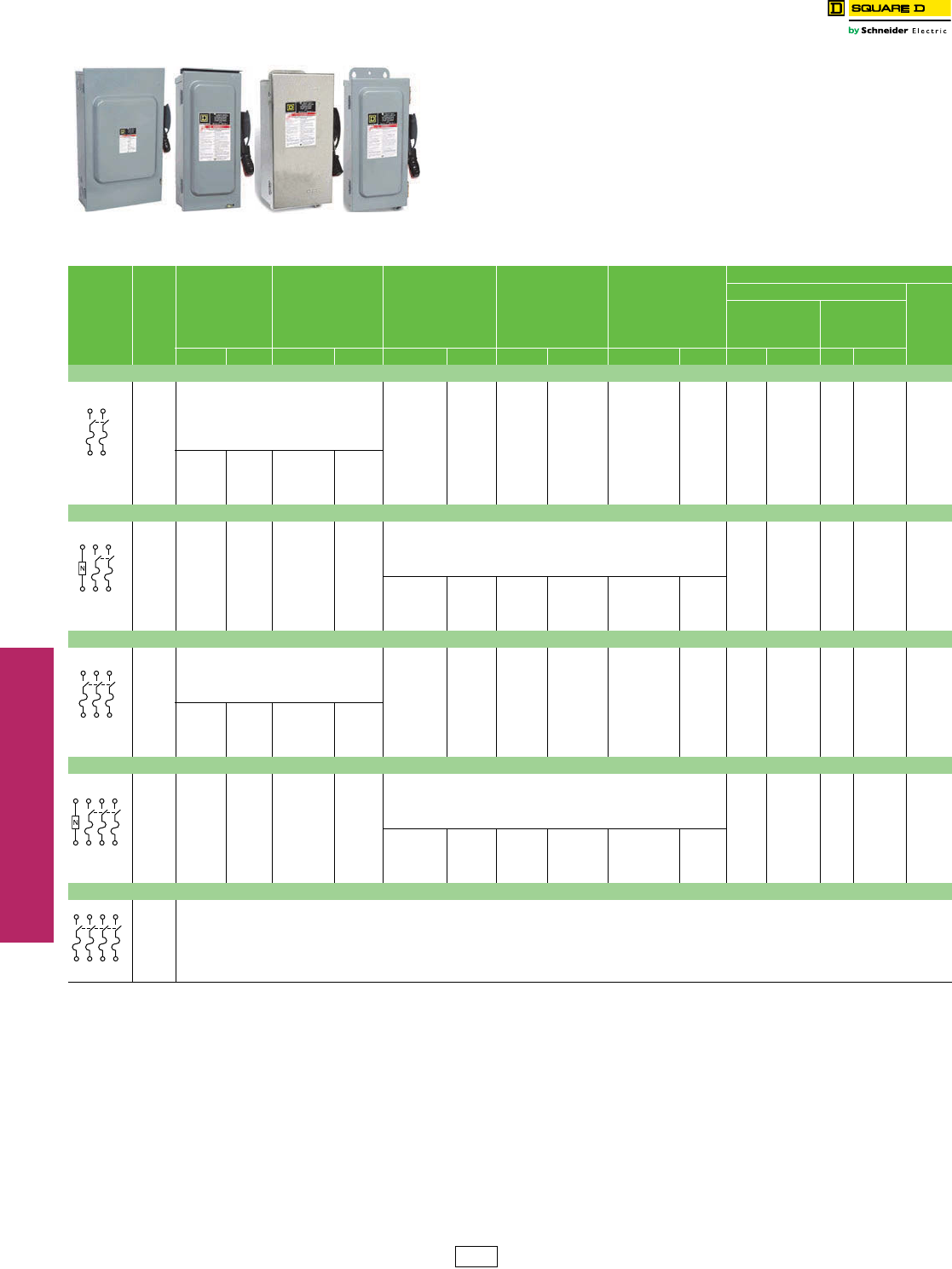
NEMA 1 NEMA 3R NEMA 4, 4X and 5
Stainless Steel
NEMA 12
Table 3.9: 240 Volt—Single Throw Fusible
System Amperes
NEMA 1
Indoor
NEMA 3R
Rainproof
(Bolt-on Hubs,
page 3-10)
NEMA 4, 4X, 5, a
304 Stainless Steel (for
316 stainless, see
page 3-7) Dust tight,
Watertight, Corrosion
Resistant (Watertight
Hubs, page 3-10)
NEMA 12K
With
Knockouts
(Watertight Hubs,
page 3-10)
NEMA
12, 3R b
Without
Knockouts
(Watertight Hubs,
page 3-10)
Horsepower Ratings
240 Vac
250 Vdcc
Std.
(Using Fast
Acting,
One Time Fuses)
Max.
(Using Dual
Element, Time
Delay Fuses)
Cat. No. $ Price Cat. No. $ Price Cat. No. $ Price Cat. No. $ Price Cat. No. $ Price 1Ø 3Ø 1Ø 3Ø
2-Wire (2 Blades and Fuseholders)—240 Vac, 250 Vdc
30
Use three-wire devices
For two-wire applications
H221DS 1947.00 H221A 504.00 H221AWK 473.00 1-1/2 3 d37-1/2d5
30 ————H2212AWKe588.00 1-1/2 —3—5
60 H222DS 2337.00 — — H222AWK 647.00 37-1/2d10 15 d10
100 H223DS 5094.00 H223A 1008.00 H223AWK 948.00 7-1/2 15 d15 30 d20
200 H224DS 6960.00 H224A 1737.00 H224AWK 1643.00 15 25 d—60 d40
400 H225 2729.00 H225R 3884.00 H225DS 14481.00 — — H225AWK 4163.00 — — — — 50
600 H226 5424.00 H226R 7281.00 H226DS 20772.00 — — H226AWK 6543.00 — 75 d—200 d50
800 H227 8459.00 H227Rf11483.00 — — — — H227AWK 10325.00 50 —50 —50
1200 H228 11682.00 H228Rf15486.00 — — — — H228AWK 15815.00 50 —50 —50
3-Wire (2 Blades and Fuseholders, 1 Neutral)—240 Vac, 250 Vdc
30 H221N 236.00 H221NRB 447.00
Use two-wire devices,
Field-installed solid neutral assemblies
Order separately See page 3-11.
1-1/2 3 d37-1/2 d5
60 H222N 471.00 H222NRB 842.00 37-1/2d10 15 d10
100 H223N 716.00 H223NRB 1086.00 7-1/2 15 d15 30 d20
200 H224N 1289.00 H224NRB 1562.00 15 25 d—60 d40
400 H225N 3092.00 H225NR 4245.00 H225NDS 14787.00 — — H225NAWK 4304.00 — 50 d—125 d50
600 H226N 5819.00 H226NR 7677.00 H226NDS 21081.00 — — H226NAWK 6936.00 — 75 d—200 d50
800 H227N 10067.00 H227NRf12216.00 — — — — H227NAWK 12338.00 50 —50 —50
1200 H228N 12422.00 H228NRf16665.00 — — — — H228NAWK 17184.00 50 —50 —50
3-Wire (3 Blades and Fuseholders)—240 Vac, 250 Vdc
30
Use four-wire devices
For three-wire applications
H321DS 2049.00 H321A 639.00 H321AWK 639.00 1-1/2 3 3 7-1/2 5
60 H322DS 2532.00 H322A 914.00 H322AWK 864.00 3 7-1/2 10 15 10
100 H323DS 5346.00 H323A 1412.00 H323AWK 1331.00 7-1/2 15 15 30 20
200 H324DS 7496.00 H324A 2040.00 H324AWK 1926.00 15 25 —60 40
400 H325 3425.00 H325R 3975.00 H325DS 14961.00 — — H325AWK 4253.00 — 50 —125 50
600 H326 6170.00 H326R 8286.00 H326DS 21399.00 — — H326AWK 7365.00 — 75 —200 50
800 H327 11456.00 H327Rf14849.00 — — — — H327AWK 14528.00 50 100 50 250 50
1200 H328 14517.00 H328Rf18728.00 — — — — H328AWK 17450.00 50 100 50 250 50
4-Wire (3 Blades and Fuseholders, 1 Neutral)—240 Vac, 250 Vdc
30 H321N 314.00 H321NRB 555.00
Use three-wire devices,
Field-installed solid neutral assemblies
Order separately. See page 3-11
1-1/2 3 3 7-1/2 5
60 H322N 528.00 H322NRB 891.00 3 7-1/2 10 15 10
100 H323N 842.00 H323NRB 1278.00 7-1/2 15 15 30 20
200 H324N 1451.00 H324NRB 1748.00 15 25 —60 40
400 H325N 3788.00 H325NR 4322.00 H325NDS 15321.00 — — H325NAWK 4635.00 — 50 —125 50
600 H326N 6519.00 H326NR 8622.00 H326NDS 21759.00 — — H326NAWK 7757.00 — 75 —200 50
800 H327N 12189.00 H327NRf15563.00 — — — — H327NAWK 15879.00 50 100 50 250 50
1200 H328N 15314.00 H328NRf19709.00 — — — — H328NAWK 20015.00 50 100 50 250 50
4-Wire (4 Blades and Fuseholders)
30
Use 600 Vac devices. See page 3-5.
60
100
200
400
600
aComplete rating is NEMA 3, 3R, 4, 4X, 5 and 12. For NEMA 3R applications, remove drain screw from bottom endwall.
bAlso suitable for NEMA 3R application by removing drain screw from bottom endwall.
cFor switching dc, use two outside switching poles.
dFor corner grounded delta systems only and with neutral assembly installed. Use switching poles for ungrounded conductors.
e60 ampere switch with 30 ampere fuse spacing and clips. Must use 60 A enclosure accessories including electrical interlocks.
fSuitable for NEMA 5 applications with drain screw installed.
DE1 Discount
Schedule
www.schneider-electric.us
3SAFETY SWITCHES
© 2012 Schneider Electric
All Rights Reserved 3-5
Heavy Duty Safety Switches 600 Volt
Class 3110 / Refer to Catalog 3100CT0901
Class H Fuse Provisions:
Fusible Square D 30 through 600 A heavy duty safety switches accept Class H fuses as standard. With Class H fuses
installed, the switch is UL Listed for use on systems with up to 10 kA available fault current.
Class R Fuse Provisions:
Fusible Square D 30–600 A heavy duty safety switches will accept Class R fuses as standard. A field-installed rejection
kit is available which, when installed, rejects all but Class R fuses. With the installation of the rejection kit and Class R
fuses, the switch is UL Listed for use on systems with up to 200 kA available fault current. See Class R fuse kits on
page 3-10.
Class J Fuse Provisions:
Provisions for installing Class J fuses are included in 30 through 400 A 600 Volt, and 100 through 400 A 240 Volt,
fusible heavy duty safety switches. Conversion to Class J fuse spacing requires relocating the load side fuse base
assembly from the standard Class H fuse location to an alternate position as marked in the enclosure. With Class J
fuses installed, the switch is UL Listed for use on systems with up to 200 kA available fault current. Switches rated
600 A, 240 or 600 Volt, require the addition of an adapter kit, H600J at $456. One kit per 3P switch.
Class L Fuse Provisions:
Fusible 800 A and 1200 A safety switches use Class L bolt-in fuses and are rated for use on systems with up to 200 kA
at 600 Vac maximum. 1200 A switches accept class L fuses from 601–1200 A, 800 A switches accept class L fuses
from 601–800 A.
Accessories: . . . . . . . . . . . . . . . . . . . . . . . . . . . . . . .pages 3-10 through 3-12
Dimensions: NEMA 1 and 3R . . . . . . . . . . . . . . . . . . . . . . . . . . . . .page 3-13
Dimensions: NEMA 4, 4X and 5 . . . . . . . . . . . . . . . . . . . . . . . . . . .page 3-14
Table 3.10: 600 Volts—Single Throw Fusible
System Amperes
NEMA 1
Indoor
NEMA 3R
Rainproof
(Bolt-on Hubs,
page 3-10)
NEMA 4, 4X, 5a
304 Stainless Steel
(for 316 stainless, see
page 3-7) Dust tight,
Watertight, Corrosion
Resistant
(Watertight Hubs, page 3-10)
NEMA 12K
With Knockouts
(Watertight Hubs,
page 3-10)
NEMA 12, 3Rb
Without Knockouts
(Watertight Hubs,
page 3-10)
Horsepower Ratings
480 Vac 600 Vac
dcd
Std.
(Using
Fast
Acting,
One Time
Fuses)
Max.
(Using
Dual
Element,
Time
Delay
Fuses)
Std.
(Using
Fast
Acting,
One
Time
Fuses)
Max.
(Using
Dual
Element,
Time
Delay
Fuses)
Cat. No. $ Price Cat. No. $ Price Cat. No. $ Price Cat. No. $ Price Cat. No. $ Price 3Ø 3Ø 3Ø 3Ø 250 600
2-Wire (2 Blades and Fuseholders)—600 Vac, 600 Vdc
30
Use three-wire devices
for two-wire applications
— —————
60 — —————
100 — —————
200 — —————
400 H265 4206.00 H265R 5424.00 H265DS 14961.00 — — H265AWK 5025.00 100c250 c——50 50
600 H266 6653.00 H266R 10686.00 H266DS 21399.00 — — H266AWK 7341.00 150c400 c——50 50
800 H267 10365.00 H267Rf16385.00 — — — — H267AWK 15276.00 — — — — 50 50
1200 H268 14570.00 H268Rf17991.00 — — — — H268AWK 18044.00 — — — — 50 50
3-Wire (3 Blades and Fuseholders)—600 Vac, 600 Vdc d
30 H361 528.00 H361RB 899.00 H361DS 2520.00 H361A 1014.00 H361AWK 956.00 5157-1/220515
30 H361-2f617.00 H3612RBe1049.00 — — H361-2Ae1035.00 H3612AWKe977.00 5157-1/220—15
60 H362 638.00 H362RB 1055.00 H362DS 2771.00 H362A 1047.00 H362AWK 984.00 15 30 15 50 —30
100 H363 1188.00 H363RB 1644.00 H363DS 5493.00 H363A 1626.00 H363AWK 1539.00 25 60 30 75 —50
200 H364 1707.00 H364RB 2259.00 H364DS 7685.00 H364A 2544.00 H364AWK 2400.00 50 125 60 150 40 50
400 H365 4551.00 H365R 5532.00 H365DS 15321.00 — — H365AWK 5462.00 100 250 125 350 50 50
600 H366 7649.00 H366R 10899.00 H366DS 21084.00 — — H366AWK 9203.00 150 400 200 500 50 50
800 H367 13319.00 H367R f16500.00 — — — — H367AWK 16352.00 200 500 250 500 50 50
1200 H368 17507.00 H368Rf20009.00 — — — — H368AWK 19706.00 200 500 250 500 50 50
4-Wire (3 Blades and Fuseholders, 1 Neutral)—600 Vac, 600 Vdcd
30 H361N 617.00 H361NRB 986.00 Use three-wire devices field-installed solid neutral
assemblies. Order separately. See page 3-11.
5157-1/220—15
60 H362N 710.00 H362NRB 1134.00 15 30 15 50 —30
100 H363N 1278.00 H363NRB 1737.00 25 60 30 75 —50
200 H364N 1869.00 H364NRB 2408.00 H364NDS 7871.00 H364NA 2715.00 H364NAWK 2558.00 50 125 60 150 40 50
400 H365N 4898.00 H365NR 5765.00 H365NDS 15668.00 — — H365NAWK 5823.00 100 250 125 350 50 50
600 H366N 8019.00 H366NR 11054.00 H366NDS 22122.00 — — H366NAWK 9600.00 150 400 200 500 50 50
800 H367N 14043.00 H367NRf17205.00 — — — — H367NAWK 17253.00 200 500 250 500 50 50
1200 H368N 18114.00 H368NRf20993.00 — — — — H368NAWK 20820.00 200 500 250 500 50 50
4-Wire (4 Blades and Fuseholders)—600 Vac, 600 Vdcg2Ø 2Ø 2Ø 2Ø
30 H461 914.00 — — H461DS 2937.00 — — H461AWK 1115.00 7-1/2 20 10 25 5 15
60 H462 1065.00 — — H462DS 3069.00 — — H462AWK 1257.00 15 40 20 50 10 30
100 H463 1778.00 — — H463DS 8345.00 — — H463AWK 1932.00 25 50 30 75 20 30
200 H464 2957.00 — — H464DS 12596.00 — — H464AWK 3222.00 50 —50 —40 50
400 H465 6210.00 — — — — — — H465AWK 6807.00 100 250 125 350 50 50
600 H466 10104.00 — — — — — — — — 150 400 200 500 50 50
6-Wire (6 Blades and Fuseholders)—600 Vac g3Ø 3Ø 3Ø 3Ø
100 —— — —H663DS 25964.00 — — H663AWK 5112.00 25 60 30 75 ——
200 —— — —H664DS 35393.00 — — H664AWK 12222.00 For applications requiring motor disconnect
capability, use electrical interlock. Refer to page 3-10.
aComplete rating is NEMA 3, 3R, 4, 4X, 5 and 12.
bAlso suitable for NEMA 3R application by removing drain screw from bottom endwall.
cFor corner grounded delta systems only and with neutral assembly installed. Use switching poles for ungrounded conductors.
dFor switching dc use two outside switching poles.
e60 A switch with 30 A fuse spacing and clips. Must use 60 A enclosure accessories including electrical interlocks.
fSuitable for NEMA 5 applications with drain screw installed.
gNot suitable for use as service equipment.
Class R Fuse
DE1 Discount
Schedule
www.schneider-electric.us
3SAFETY SWITCHES
3-6 © 2012 Schneider Electric
All Rights Reserved
Heavy Duty Safety Switches
Refer to Catalog 3100CT0901
UL Listed Maximum Short Circuit Current Ratings—AC only
NOTE: Consult the wiring diagram of the switch to verify the
UL Listed short circuit current rating.
lOn 600 V, 200 A switches, 100,000 A max. on corner grounded delta when protected by
Class J or R fuses.
Non-Fusible Safety Switches
Any brand of circuit breaker or fuse not exceeding the ampere rating of the
switch may be used in conjunction with an non-fusible safety switch when
there is up to 10 kA short circuit current available (see table below).
Above 10 kA—When applied on systems with greater than 10 kA short
circuit current available, the UL Listed short circuit current rating for
Square D non-fusible switches is based upon the switch being used in
conjunction with fuses or Square D circuit breakers or Mag-Gard motor
circuit protectors.
Table 3.11: 600 Volt—Single Throw Non-Fusible
System Amperes
NEMA 1
Indoor
NEMA 3R
Rainproof
(Bolt-on Hubs, page 3-10)
NEMA 4, 4X, 5 a
304 Stainless Steel
(for 316 stainless, see
page 3-7)
Dust tight, Watertight
Corrosion Resistant
(Watertight Hubs, page 3-10)
NEMA 12K
With
Knockouts
(Watertight Hubs,
page 3-10)
NEMA 12, 3Rb
Without
Knockouts
(Watertight Hubs,
page 3-10)
Horsepower Ratings
(Max.)
Volts ac
dcc
240 480 600
Cat. No. $ Price Cat. No. $ Price Cat. No. $ Price Cat. No. $ Price Cat. No. $ Price 1Ø 3Ø 1Ø 3Ø 1Ø 3Ø 250 600
2-Wire (2 Blades)—600 Vac, 600 Vdc
30
Use three-wire devices
for two-wire applications.
————————
60 ————————
100 ————————
200 ————————
400 HU265 2750.00 HU265R 3764.00 HU265DS 12812.00 — — HU265AWK 3212.00 — — — — — — 50 50
600 HU266 4896.00 HU266R 7533.00 HU266DS 18455.00 — — HU266AWK 5408.00 — — — — — — 50 50
800 HU267 7467.00 HU267Rd12884.00 — — — — HU267AWK 12957.00 50 —50 —50 —— 50
1200 HU268 10226.00 HU268Rd17393.00 — — — — HU268AWK 17522.00 50 —50 ——— 50 50
3-Wire (3 Blades)—600 Vac, 600 Vdc
30 HU361 279.00 HU361RB 488.00 HU361DS 2120.00 HU361A 689.00 HU361AWK 647.00 5 10 7-1/2 20 10 30 5 15
30 HU361EIe638.00 HU361RBEIe846.00 HU361DSEIe2480.00 HU361AEIe1047.00 HU361AWKEIe1007.00 5 10 7-1/2 20 10 30 5 15
30 HU3612f369.00 HU3612RBf638.00 — — HU3612Af710.00 HU3612AWKf666.00 5 10 7-1/2 20 10 30 5 15
60 HU362 488.00 HU362RB 876.00 HU362DS 2520.00 HU362A 875.00 HU362AWK 833.00 10 20 25 50 30 60 10 30
60 —— — —HU362DSEIe2972.00 — — — — 10 20 25 50 30 60 10 30
100 HU363 783.00 HU363RB 1226.00 HU363DS 5102.00 HU363A 1265.00 HU363AWK 1194.00 20 40 40 75 40 100 20 50
200 HU364 1209.00 HU364RB 1485.00 HU364DS 6960.00 HU364A 1697.00 HU364AWK 1604.00 15 60 50 125 50 150 40 50
400 HU365 2804.00 HU365R 3840.00 HU365DS 14294.00 — — HU365AWK 4023.00 — 125 —250 —350 50 50
600 HU366 4992.00 HU366R 7683.00 HU366DS 19062.00 — — HU366AWK 6711.00 — 200 —400 —500 50 50
800 HU367 9978.00 HU367R d13050.00 — — — — HU367AWK 13097.00 50 250 50 500 50 500 50 50
1200 HU368 13421.00 HU368R d17867.00 — — — — HU368AWK 17940.00 50 250 50 500 50 500 50 50
4-Wire (4 Blades)—600 Vac, 600 Vdc j2Ø 3Ø 2Ø 3Ø 2Ø 3Ø
30 HU461g827.00 — — HU461DS 2586.00 — — HU461AWKh915.00 10 10 20 20 25 30 10i15i
60 HU462g914.00 — — HU462DS 3027.00 — — HU462AWK 1008.00 20 20 40 50 50 60 10 30
100 HU463g1647.00 — — HU463DS 7401.00 — — HU463AWK 1791.00 30 40 50 75 50 75 20 30
200 HU464g2399.00 — — HU464DS 11244.00 — — HU464AWK 2832.00 50 60 50 125 50 150 40 50
400 HU465 5201.00 — — — — — — HU465AWK 5672.00 — 125 — 250 — 350 50 50
600 HU466 9072.00 — — — — — — — — — 200 — 400 — 500 50 50
6-Wire (6 Blades)—600 Vacj3Ø 3Ø 3Ø
30 —— — —HU661DS 11903.00 — — HU661AWKk3357.00 — 10 —20 —30 ——
60 —— — —HU662DS 13254.00 — — HU662AWKk3884.00 — 20 —50 —60 ——
100 —— — —HU663DS 20643.00 — — HU663AWKk4793.00 — 40 —75 —75 ——
200 —— — —HU664DS 28316.00 — — HU664AWKk10538.00 — 60 —125 —150 ——
aComplete rating is NEMA 3, 3R, 4, 4X, 5 and 12.
bAlso suitable for NEMA 3R application by removing drain screw from bottom endwall.
cFor switching dc, use two outside switching poles.
dSuitable for NEMA 5 applications with drain screw installed.
eSwitches with EI suffix are stocked with factory-installed electrical interlocks with one normally-open and one normally-closed contact.
fUse 60 A enclosure accessories, including electrical interlocks.
gNo knockouts are provided.
hRequires 60 A accessories. See page 3-14 for series rating..
iHU461AWK (Series F6) is rated 5 hp@250 Vdc, 10 hp@600 Vdc.
jNot suitable for use as service equipment.
kOne enclosure for NEMA 1, 3, 3R or 12 applications. UL Listed.
Table 3.12: Fusible Safety Switches
For the short circuit current rating, refer to the table below.
Heavy Duty
Safety Switch Type
UL Listed
Fuse Class
UL Listed Short Circuit
Current Ratings
Fusible H, K 10 kA
R, J, L 200 kAlTable 3.13: Non-Fusible Safety Switches
Heavy Duty
Safety Switch Type
Switch Rating
(A) m
Fuse or Circuit
Breaker Typen
3-Phase
240 Vac 480 Vac 600 Vac
Non-Fusible
Switches
All
Any brand circuit
breaker Up to 10 kA
H, K
R,T,J.L 200 kA 200 kA 200 kA
30–100 H o65 kA 35 kA 35 kA
30–100 FA 14 kA 14 kA 14 kA
30–100 FH 18 kA 18 kA 18 kA
200 H, J o65 kA 35 kA 35 kA
400 LA 22 kA 22 kA 22 kA
400 LH 25 kA 25 kA 25 kA
mApplies to NEMA 1, 3R, 4X stainless, 12 switches.
nAmpere rating of fuse or circuit breaker not to exceed switch ampere rating.
oAll H and J circuit breakers are acceptable, but will only support the noted Short Circuit
Current Ratings.
DE1 Discount
Schedule
www.schneider-electric.us
3SAFETY SWITCHES
© 2012 Schneider Electric
All Rights Reserved 3-7
Heavy Duty Safety
Switches
Special Applications
Class 3110 / Refer to Catalog 3100CT0901
316 Grade Stainless Steel—NEMA 3, 3R, 4, 4X, 5, 12
Type 316 stainless steel enclosure safety switches offer superior corrosion resistance to a wider range of chemicals than
Type 304 stainless switches. Type 316 better resists chloride and is often used in marine, waste treatment and transportation
applications. Use watertight hubs from page 3-10. Equipment grounding lugs are supplied as standard.
(For Type 304 stainless switches see pages 3-4–3-6.)
Fiberglass Reinforced Polyester Enclosures—NEMA 4X
Fiberglass reinforced polyester enclosures are watertight, corrosion resistant, and impervious to windblown dust, rain, and
splashing liquid. The molded fiberglass is extremely stable in a wide range of operating temperatures and can withstand
heavy impact. Switches are furnished with hubs (page 3-14) and equipment grounding lugs. UL Listed.
Krydon™ Enclosures—NEMA 4X
Krydon enclosures are compression molded of fiberglass reinforced polyester, specially formulated to withstand attack from
almost any corrosive atmosphere found in the toughest industrial application. Switches are furnished with hubs
(page 3-14) and equipment grounding lugs. UL Listed.
NEMA 7 and 9
An enclosed automatic molded case switch for use in Divisions 1 and 2 of the following: Class I, Groups C and D; Class II,
Groups E, F and G; or Class III, Hazardous Locations as defined in NEC™ Article 500. Furnished with threaded conduit
openings in both top and bottom endwall (page 3-14). Suitable for use as service equipment and listed as “Raintight’’ for
outdoor applications. cULus Listed. Equipment grounding lugs supplied as standard.
aStd.—Using fast acting one time fuses. Max.—Using dual element time delay fuses.
bFor switching dc use two switching poles.
cIncludes PKDB1, breather and drain kit, required for rainproof application—NEMA 7 only.
dIncludes auxiliary contacts.
eFor available options, contact customer service prior to placing an order.
fNot UL listed or CSA Certified due to wire bending space.
Table 3.14: 3P 600 Vac, 600 Vdc
Amperes Cat. No $ Price
Horsepower Ratings– 3Øa
480 Vac 600 Vac 600 Vdcb
Std. Max. Std. Max. Max.
Fusible
30 H361SS 3444.00 5157-1/22015
60 H362SS 3792.00 15 30 15 50 30
100 H363SS 7562.00 25 60 30 75 50
200 H364SS 10592.00 50 125 60 150 50
400 H365SS 21622.00 100 250 125 350 50
600 H366SS 30528.00 150 400 200 500 50
Non-Fusible
30 HU361SS 2898.00 —20— 3015
60 HU362SS 3444.00 —50— 6030
100 HU363SS 7029.00 —75—10050
200 HU364SS 9623.00 — 125 — 150 50
400 HU365SS 17758.00 — 250 — 350 50
600 HU366SS 26306.00 — 400 — 500 50
Table 3.15: 3P 600 Vac, 600 Vdc
Amperes Cat. No. $ Price Class R Fuse Kits Electrical Interlock Kits
Field-Installed Cat. No.
Horsepower Ratings– 3Øa
480 Vac 600 Vac 600 Vdcb
Cat. No. $ Price 1 NO/1 NC Contacts 2 NO/2 NC Contacts Std. Max. Std. Max. Max.
Fusible
30 H361DF 3570.00 RFK06 25.50 9999TC10 9999TC20 5 15 7-1/2 20 15
60 H362DF 3968.00 RFK06H 25.50 9999TC10 9999TC20 15 30 15 50 30
100 H363DF 7613.00 RFK10 47.70 9999TC10 9999TC20 25 60 30 75 50
200 H364DF 9729.00 HRK1020 47.70 9999R8 9999R9 50 125 60 150 50
Non-Fusible
30 HU361DF 3402.00 — — 9999TC10 9999TC20 — 20 — 30 15
60 HU362DF 3782.00 — — 9999TC10 9999TC20 — 50 — 60 30
100 HU363DF 7241.00 — — 9999TC10 9999TC20 — 75 — 100 50
200 HU364DF 9695.00 — — 9999R8 9999R9 — 125 — — 50
Table 3.16: 3P, 600 Vac, 600 Vdc
Amperes Cat. No. $ Price Class R Fuse Kits Electrical Interlock Kits
Field-Installed Cat. No.
Horsepower Ratings– 3Øa
480 Vac 600 Vac 600 Vdcb
Cat. No. $ Price 1 NO/1 NC Contact 2 NO/2 NC Contacts Std. Max. Std. Max. Max.
Fusible
30 H361DX 4161.00 RFK06 25.50 9999TC10 9999TC20 5 15 7-1/2 20 15
60 H362DX 4626.00 RFK06H 25.50 9999TC10 9999TC20 15 30 15 50 30
100 H363DX 8858.00 RFK10 47.70 9999TC10 9999TC20 25 60 30 75 50
Non-Fusible
30 HU361DX 3960.00 — — 9999TC10 9999TC20 — 20 — 30 15
60 HU362DX 4406.00 — — 9999TC10 9999TC20 — 50 — 60 30
100 HU363DX 8438.00 — — 9999TC10 9999TC20 — 75 — 100 50
Table 3.17: 3 Pole Molded Case Switch, 600 Vac, 250 Vdc Maximum, Short Circuit Current Rating 10 kA AIR
Amperes Enclosed Molded Case SwitchcSolid Neutral Assembly Horsepower Ratings—3Ø
Cat. No. $ Price Cat. No. $ Price 240 Vac 480 Vac 600 Vacb
60 H60XFA 2571.00 100SNA 143.00 15 30 50
60 H60XFA1212d2886.00 100SNA 143.00 15 30 50
100 H100XFA 3045.00 100SNA 143.00 30 60 75
100 H100XFA1212d3287.00 100SNA 143.00 30 60 75
225 H225XJGf6387.00 225SNA 189.00 60 125 150
225 H225XJGAAdf 6701.00 225SNA 189.00 60 125 150
H361SS
H363DF
H361DX
H60XFA
DE1 Discount
Schedule
www.schneider-electric.us
3SAFETY SWITCHES
3-8 © 2012 Schneider Electric
All Rights Reserved
UL508 Motor Disconnect
Switches
MD Motor Disconnect Switches
Class 3110 / Refer to Catalog 3100CT0901
The MD motor disconnect switch is listed UL508 Suitable For Motor Control (UL File
E164864). It is in a compact NEMA 4X enclosure suitable for use in NEMA Type 1, 3, 3R, 4,
4X and 12 applications. The MD's key benefits are an extremely small footprint, a more
economically efficient NEMA 4X solution and a handle interlock preventing cover removal
when the switch is in the ON position.
aSee table 8.9 for accessories.
bComplies with OSHA lockout/tagout requirements—accepts up to three 8 mm padlocks.
cSuitable for NEMA 1, 3R, 4, 4X and 12 enclosure applications.
D
H
W
MD Motor Disconnect Switches
Table 3.18: MD Motor Disconnect Switch—Non Metallic NEMA 1, 3, 3R, 4, 4X and
12 Enclosureabc
Amperes Cat. No.
Maximum Horse Power Ratings
$ Price Height
(in.)
Width
(in.)
Depth
(in.)
Three Phase Vac
220–240 440–480 600
30 MD3304X 7.5 20 25 121.00 6.38 3.9 4.37
60 MD3604X 20 40 40 161.00 8.27 4.94 4.37
Table 3.19: MD Motor Disconnect Accessories
Cat. No. Description $ Price
MDSAN20 2 Normally open auxiliary contact module 57.00
MDSAN11 1 normally open and 1 normally closed auxiliary contact module 27.00
MDS30P 30 Amp Add on power pole 35.00
DE1 Discount
Schedule
www.schneider-electric.us
3SAFETY SWITCHES
© 2012 Schneider Electric
All Rights Reserved 3-9
Heavy Duty Safety Switches Receptacle Switches
Class 3110 / Refer to Catalog 3100CT0901
Interlocked Receptacle Switches
Interlocked Receptacle Switches are furnished with a factory-installed three-phase four-wire Appleton
Powertite™, Crouse-Hinds Style 2 Arktite™, or Hubbellock™ receptacle. The fourth wire is connected to the switch
equipment grounding terminal and is not a neutral termination. Interlocking linkage between the receptacle and
switch mechanism prevents insertion or removal of the plug while the switch is in the “ON’’ position or insertion of
any plug other than specified. Grounding lugs are included.
Appleton Powertite Receptacle
•Devices are UL Listed and CSA Certified, suitable for use as service equipment.
•Receptacles are epoxy powder coated over copper-free cast aluminum and NEMA 3, 3R, 4, 4X and 12 rated. Appleton receptacles
are UL Classified for use with the Crouse-Hinds plugs listed below.
•Short circuit rating: 10 kA when used in conjunction with Class H or K fuses; 200 kA when used in conjunction with Class R or J fuses.
aReceptacle UL Listed for use with “Appleton ACP or CPH” plugs; UL Classified for use with Crouse-Hinds “APJ” Arktite plugs listed on this page.
bStd.—Using fast acting one time fuses. Max.—Using dual element time delay fuses.
cFor switching dc, use two switching poles.
Crouse-Hinds Arktite Receptacle
•UL Listed, suitable for use as service equipment.
•Short circuit ratings: 10 kA when used in conjunction with Class H or K fuses; 200 kA when used in conjunction with Class R or J fuses.
dStd.—Using fast acting one time fuses. Max.—Using dual element time delay fuses.
Hubbellock Receptacle
•UL Listed, suitable for use as service equipment.
•Short circuit rating: 10 kA.
Note: The Hubbellock receptacle switch utilizes the Square D interlocked plug SD12781 available only from Square D.
eStd.—Using fast acting one time fuses. Max.—Using dual element time delay fuses.
fHubbell plug is furnished with a Kellems grip for 1-1/2 in. to 1-21/64 in. cable diameter.
Accessories . . . . . . . . . . . . . . . . . . . . . . . . . . . . . . . pages 3-10 through 3-12.
Amperes
NEMA 1
NEMA
3, 3R, 4, 4X, 5, 12
304 Stainless Steel
Enclosure
NEMA 12, 3R Use with Plug aHorsepower
Ratings–3Øb
Cat. No. $ Price Cat. No. $ Price Cat. No. $ Price Cat. No. $ Price 480 Vac 600 Vac 250 Vdcc
Std. Max. Std. Max. Std. Max.
Fusible—3P, 600 Vac, 250 Vdc
30 H361WA 2076.00 H361DSWA 4401.00 H361AWA 2289.00 ACP3034BC 1235.00 5157-1/220 5—
60 H362WA 2412.00 H362DSWA 4668.00 H362AWA 2508.00 ACP6034BC 1295.00 15 30 15 50 10 —
100 H363WA 3689.00 H363DSWA 8468.00 H363AWA 3758.00 ACP1034CD 1928.00 25 60 30 75 20 —
Non-Fusible—3P, 600 Vac, 250 Vdc
30 HU361WA 1893.00 HU361DSWA 4001.00 HU361AWA 2076.00 ACP3034BC 1235.00 — 20 —30 —5
60 HU362WA 2306.00 HU362DSWA 4412.00 HU362AWA 2357.00 ACP6034BC 1295.00 — 50 —60 —10
100 HU363WA 3153.00 HU363DSWA 8010.00 HU363AWA 3347.00 ACP1034CD 1928.00 — 75 —100 —20
Table 3.20:
Amperes
NEMA 1
NEMA 3, 3R, 4, 4X, 5, 12
304 Stainless Steel
Enclosure
NEMA 12, 3R Use with Plug Horsepower
Ratings–3Ød
Cat. No. $ Price Cat. No. $ Price Cat. No. $ Price Cat. No. $ Price 480 Vac 600 Vac
Std. Max. Std. Max.
Fusible—3P, 600 Vac Maximum
30 H361WC 2139.00 H361DSWC 6377.00 H361AWC 2355.00 APJ3485 1235.00 5157-1/220
60 H362WC 2751.00 H362DSWC 7749.00 H362AWC 2846.00 APJ6485 1295.00 15 30 15 50
100 H363WC 6005.00 H363DSWC 14826.00 H363AWC 6087.00 APJ10487 1928.00 — 60 —75
Non-Fusible—3P, 600 Vac Maximum
30 HU361WC 1952.00 HU361DSWC 5888.00 HU361AWC 2136.00 APJ3485 1235.00 — 20 —30
60 HU362WC 2634.00 HU362DSWC 7374.00 HU362AWC 2678.00 APJ6485 1295.00 — 50 —60
100 HU363WC 5249.00 HU363DSWC 14025.00 HU363AWC 5444.00 APJ10487 1928.00 — 60 —100
Table 3.21:
Amperes
NEMA 1 NEMA 12 Use with Plug Horsepower Ratings—3Øe
Cat. No. $ Price Cat. No. $ Price Cat. No. $ Price 480 Vac 600 Vac
Std. Max. Std. Max.
Fusible—3P, 600 Vac Maximum
60 H362WH 2351.00 H362AWH 2459.00 SD12781f609.00 15 30 15 50
Non-Fusible—3P, 600 Vac Maximum
60 HU362WH 2237.00 HU362AWH 2310.00 SD12781f609.00 — 50 —60
H362AWA
Interlocked Receptacle
Switch with Appleton
Powertite Receptacle
H362AWC
Interlocked Receptacle
Switch with Crouse-Hinds
Arktite Receptacle
H362AWH
Interlocked Receptacle
Switch with Hubbell™
Hubbellock Receptacle
DE1 Discount
Schedule
www.schneider-electric.us
3SAFETY SWITCHES
3-10 © 2012 Schneider Electric
All Rights Reserved
Electrical Interlock Kits
Electrical interlocks for heavy duty 30–1200 A safety switches are
available factory-installed or in kit form for field installation. Each kit
contains instructions for proper field mounting. A pivot arm operates
from switch mechanism, breaking the control circuit before the main
switch blades break. Switches with electrical interlocks installed are UL
Listed. For factory-installed electrical interlocks add EI (for one contact)
or EI2 (for two contacts) suffix to catalog number. See Supplemental
Digest page 2-3 for electrical interlock contact ratings.
aSee page 3-7 for electrical interlocks on NEMA 4X fiberglass reinforced polyester and
Krydon™.
bElectrical interlock kit catalog numbers with 1 suffix indicates one normally open and one
normally closed contact; 2 indicates two normally open and two normally closed contacts.
Kits are UL Listed.
cHU461AWK uses EK3061 or EK3062.
dThe following Series F5–F7 devices use EIK-1, 2: H3612, H3612A, H3612AWK,
H3612RB, H461, H461DS, H461AWK, HU461, HU461DS, HU661DS, HU661AWK,
H361AWA, H361AWC, HU361AWA and HU361AWC.
eH362WA, HU362WA, H362WC, H362AWA, HU362AWA, H362AWC, HU362AWC, and
H2212AWK use EIK1 or EIK2 electric interlock.
fSingle-pole single-throw interlock kits are rated 1/2 hp @ 110 and 220 Vac.
Class R Fuse Kits
When installed, this kit rejects all but Class R fuses. Kits are available for
field installation. For factory installation, add “CLR’’ suffix to catalog
number.
gH221-2AWK uses RFK06 Class R fuse kit.
Internal Barrier Kits
Internal Barrier Kits provide an additional barrier that helps prevent
accidental contact with live parts. Field-installed transparent barriers do
not restrict visual inspection of the switch. Barriers provide IEC529 IP2X
“finger safe” protection when door of enclosed disconnect switch is
open. Convenient door allows use of test probes without accessing
fuses and replacement of fuses without removing barrier. Barrier can
also be used with the skirt kit to enclose a panel mounted Type 9422
disconnect.
jRequires arc shield on 240 V switches be changed to 600 V arc suppressor.
Fuse Puller Kits
Kit consists of three fuse pullers as required for a 3-pole fusible 240 V or
600 V heavy duty switch. Kits can be installed in switches manufactured
after February, 1980. Fuse pullers supplied as standard equipment on
NEMA 12, 12K, NEMA 4, 4X, 5 stainless steel, NEMA 4X fiberglass
reinforced polyester and KRYDON switches through 100 A.
k30 A 4- and 6-pole, H361-2 and H361-2RB Series F5 use FPK0610.
lH362WA, H362WC, H362AWA, H362AWC, H362WH and H362AWH use FPK0610 fuse
puller kit.
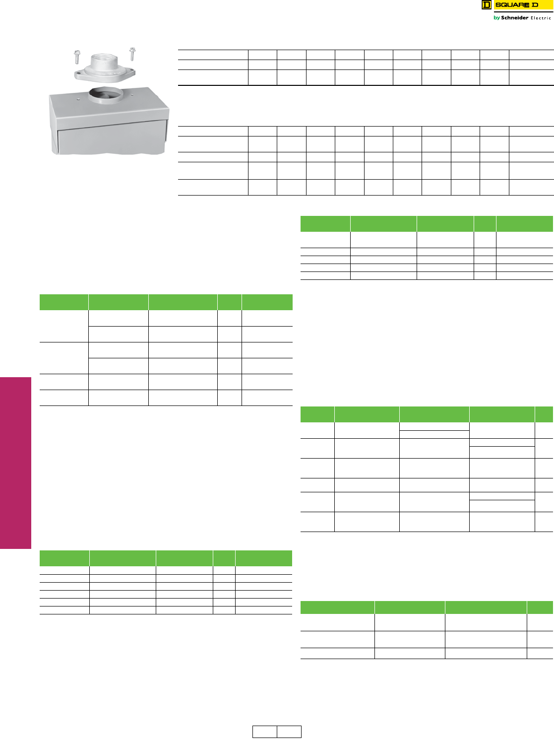
Rainproof Bolt-On Hubs—for use on NEMA 3R Enclosure
Conduit Size 3/4 11-1/41-1/222-1/233-1/24Closing Cap
Hub Cat. No. B075 B100 B125 B150 B200 B250 B300 B350 B400 BCAP
$ Price Each 33.30 33.30 33.30 33.30 61.00 102.00 186.00 300.00 368.00 3.80
(DE1A)
Note: NEMA 3R rainproof enclosures with Cat. No. ending in RB have a bolt-on closing cap factory-installed. Order bolt-on hubs separately
from table above. For more details see page 1-13. Hubs through size 2-1•
2 can be directly installed on RB devices. Devices requiring three-
inch or larger hubs must have holes cut in the field. Gaskets are provided on three-inch and larger hubs.
Note: All hubs are UL Listed for indoor and rainproof applications and suitable for use with conduit having ANSI standard taper pipe thread.
Watertight Hubs—for use on NEMA 4, 4X and 5 Stainless Steel and NEMA 12 Enclosures
Conduit Trade Size 1/23/4 11-1/41-1/222-1/233-1/2 4
Standard-Zinc
Hub Cat. No. H050 H075 H100 H125 H150 H200 H250 H300 H350 H400
Zinc $ Price Each 31.10 45.00 47.10 54.00 83.00 120.00 138.00 177.00 282.00 381.00
Chrome Plated
Hub Cat. No. H050CP H075CP H100CP H125CP H150CP H200CP ——— —
Chrome Plated $ Price
Each 40.70 56.00 64.00 67.00 96.00 137.00 — — — —
RB Hub
Table 3.22: Electrical Interlock Kit a
Switch’s
Amperes Rating
Series Number
(See pages 3-13, 3-14)
Electrical Interlock Kit
Cat. No.b$ Price Factory-Installed
$ Price
30
F1, F5–F7 EIK031c d218.00 359.00
EIK032c d
F3 EIK1 311.00 452.00
EIK2
60
F1-F3
F5–F7 (600 V)
EIK1 311.00 452.00
EIK2
F4
F5–F6 (240 V)
EIK031e218.00 359.00
EIK032e
100–200 F2–F7 EIK1 311.00 452.00
EIK2
400–1200 E1–E4 EIK40601 533.00 674.00
EIK40602
Table 3.23: Class R Fuse Kits—240 V (one kit per 3P switch)
Amperes Series Number
(See pages 3-13, 3-14)
Class R Fuse Kit
Cat. No. $ Price Factory-Installed
$ Price
30 F5–F7 RFK03Lg25.50 195.00
60 F1, F2, F3 RFK06 25.50 195.00
60 F4–F7 RFK03H 25.50 195.00
100 F2–F7 RFK10 47.70 231.00
200 F5–F6 HRK1020 47.70 231.00
400–600 E HRK4060 111.00 360.00
Table 3.24: Class R Fuse Kits—600 V (one kit per 3P switch)
Amperes Series Number
(See pages 3-13, 3-14)
Class R Fuse Kit
Cat. No. $ Price Factory-Installed
$ Price
30hF1, F5–F7 RFK03Hi25.50 293.00
30 hF3 RFK06 25.50 293.00
60 hF1–F7 RFK06H i25.50 293.00
100 hF2–F7 RFK10 47.70 231.00
200 F5–F6 HRK1020 47.70 231.00
400–600 E2–E4 HRK4060 111.00 360.00
hSee page 3-7 for Class R Fuse Kits in NEMA 4X Fiberglass Reinforced Polyester and
Krydon switches.
iThe following Series F5–F7 devices use RFK06: H3612, H3612A, H3612AWK, H3612RB,
H461, H461DS, H461AWK, H361AWA and H361AWC.
Cat. No. Description Safety Switch Application
(F Series Only)
9422 Type T
Disconnect Application $ Price
SS03 Interior Barrier for 30 A
Safety Switchj
240 / 600 Vac – 30 A NA 150.
240 Vac – 60 A
SS06
Interior Barrier for 60 A
Safety Switch, 30 or
60 A 9422 Switch
600 Vac – 60 A
600 Vac – 30 A
165.
600 Vac – 60 A
SS10
Interior Barrier for 100 A
Safety Switch or
100 A 9422 Switch
240 / 600 Vac – 100 A 600 Vac – 100 A 195.
SS20 Interior Barrier for 200 A
Safety Switch 240 / 600 Vac – 200 A NA 225.
SS0306SK
Skirt Kit to Enclose 30 or
60 A 9422 Switch
(requires SS06)
NA
600 Vac – 30 A
225.
600 Vac – 60 A
SS10SK
Skirt Kit to Enclose 100 A
9422 Switch
(requires SS10)
NA 600 Vac – 100 A 255.
Amperes Series Number Fuse Puller Kit Cat. No. $ Price
30
30
F1, F5–F7
F3
FPK03 k
FPK0610
30.00
42.60
60
60 l
F1, F2, F3, F5–F7 (600 V)
F4 l, F5–F7 (240 V)
FPK0610
FPK03 l
42.60
30.00
100 F2–F7 FPK0610 42.60
DE1 DE1A Discount
Schedule
Heavy Duty Safety Switches Accessories
Class 3110 / Refer to Catalog 3100CT0901
www.schneider-electric.us
3SAFETY SWITCHES
© 2012 Schneider Electric
All Rights Reserved 3-11
Note: Neutrals cannot be installed in 4P, 6P, or 200 A NEMA 4X fiberglass reinforced polyester
safety switches.
aThe following Series F5–F6 devices use SN0610(C): H-361-2, H-361-2RB, H-361-2A and
H-361-2AWK.
bFor 200% neutral, order (2) neutral kits and (1) SN20NI neutral jumper kit.
(2) 350 Max. Al/Cu.
Equipment Grounding Kitsg
Equipment grounding kits are field-installed and UL Listed in 30–1200 A
heavy duty switches. For factory installation of equipment grounding kit, add
suffix GL to standard Cat. No. (Example: H361GL).
Price = Switch + Kit Price.
Note: Shipped in quantities of 6.
Special Paint
UL Listed heavy duty switches are available painted with special safety
colors. To order safety colored switches add suffixes as noted in
Table 3.26 to the standard switch commercial reference number.
All colors comply with OSHA Standard 1910.144 and ANSI Specification
Z535.1 for marking physical hazards.
aStandard Square D ANSI 49 grey paint, when selecting this suffix, switches will receive
additional coat of paint.
A minimum quantity of 10 is required. Not available for NEMA Type 7/9
or stainless steel products.
Lock-Off Guard Kitsd
Neutral Assemblies—Field-Installed Neutral Assemblies for Fusible and Non-Fusible 240 and 600 Volt Safety Switches
Amperes Series Number
(See pages 3-13, 3-14)
Standard
Neutral Kit
Cat. No.
Terminal Data
AWG/kcmil $ Price Optional Copper Only
Neutral Kit Cat. No.
Terminal Data
AWG/kcmil $ Price
30 F1, F5–F6 SN03a(3) 2 Max. Al/Cu 83.00 SN03C a(3) 6 Max. Cu 102.00
60
F1–F3,
F5–F6 (600 V) SN0610 (2) 1/0 Max. Al/Cu 107.00 SN0610C (2) 1/0 Max. Cu 114.00
(2) 6 Max. Al/Cu (2) 6 Max. Cu
F4,
F5–F6 (240 V) SN03a(3) 2 Max. Al/Cu 83.00 SN03Ca(3) 6 Max. Cu 102.00
100 F2–F6 SN0610 (2) 1/0 Max. Al/Cu 107.00 SN0610C (2) 1/0 Max. Cu 114.00
(2) 6 Max. Al/Cu (2) 6 Max. Cu
200bF5–F6 SN20A (2) 250 Max. Al/Cu
(1) 1/0 Max. Al/Cu 200.00 SN20C (2) 250 Max. Cu
(1) 1/0 Max. Cu 246.00
400 and
600 E1–E4 H600SN (4) 750 Max. Al/Cu
(1) 300 Max. Al/Cu 327.00 H600SNC
(2) 600 Max. Cu
452.00(2) 350 Max. Cu
(1) 250 Max. Cu
800 E2–E4 H800SNE4 (6) 750 Max. Al/Cu 753.00 — — —
(2) 350 Max. Al/Cu
1200 E2–E4 H1200SNE4 (8) 750 Max. Al/Cu 1034.00 — — —
(2) 350 Max. Al/Cu
Equipment Grounding Kits—Field- or Factory-Installed Equipment Grounding Kits–240 and 600 V
Amperes Series Number
(See pages 3-13, 3-14)
Standard
Cat. No.
Terminal Data
AWG/kcmil $ Price Optional Copper Only
Cat. No.
Terminal Data
AWG/kcmil $ Price
30 F1, F5–F7 GTK03 c(2) 12 Cu or (2) 10 Al or (1) 4 Max. Al/Cu 11.40 GTK03Cc(1) 6 Max. Cu 13.40
60dF1–F3d,
F5–F7 (600 V) GTK0610 d(2) 1/0 Max. Al/Cu 18.90 GTK0610Cd(2) 4 Max. Cu 22.70
60 F4,
F5–F6 (240 V) GTK03 (2) 12 Cu or (2) 10 Al or (1) 4 Max. Al/Cu 11.40 GTK03C (1) 6 Max. Cu 13.40
100 F2–F7 GTK0610 (2) 1/0 Max. Al/Cu 18.90 GTK0610C (2) 4 Max. Cu 22.70
200 F5–F7 PKOGTA2 (2) 2/0 Max. Al/Cu 55.00 PKOGTC2 (2) 4 Max. Cu 58.00
400 and 600 E2–E4 PKOGTA2e(2) 2/0 Max. Al/Cu 55.00 PKOGTC3 (3) 1/0 Max. Cu 107.00f
(2 Required)
800 E2–E4 PKOGTA7 (4) 350 Max. Al/Cu 198.00f———
1200 E2–E4 PKOGTA8 (8) 350 Max. Al/Cu 203.00f———
cThe following Series F5–F6 devices use GTK0610(C): H-361-2 and H-361-2RB.
d4- and 6-pole 30 A F Series.
eTwo required if grounding conductors are run in parallel.
fPE1A Discount Schedule
gEquipment Ground Kits are factory-installed standard in 30–200 A series F NEMA 4-4X-5 (stainless) and 12. Equipment Ground Kits are standard on all NEMA Types, Series F 30–200 A
4 and 6 pole switches.
Table 3.25: Square D Gray Paint
Description Cat. No. $ Price
16 oz. Aerosol Paint Can, Square D Gray Paint PK49SP 39.00 ea.
Table 3.26: Safety Colors
Safety Color Suffix
Black SP0
Red SP2
Orange SP3
Yellow SP4
Green SP5
Blue SP6
Purple SP7
Gray SP8
Gray ANSI 61 SP861a
White SP9
Price Adder Each Switch
Quantity $ Price
30 A 60 A 100 A 200 A 400 A 600 A 800 A 1200 A
10 242.00 278.00 434.00 479.00 1137.00 2801.00 3501.00 4376.00
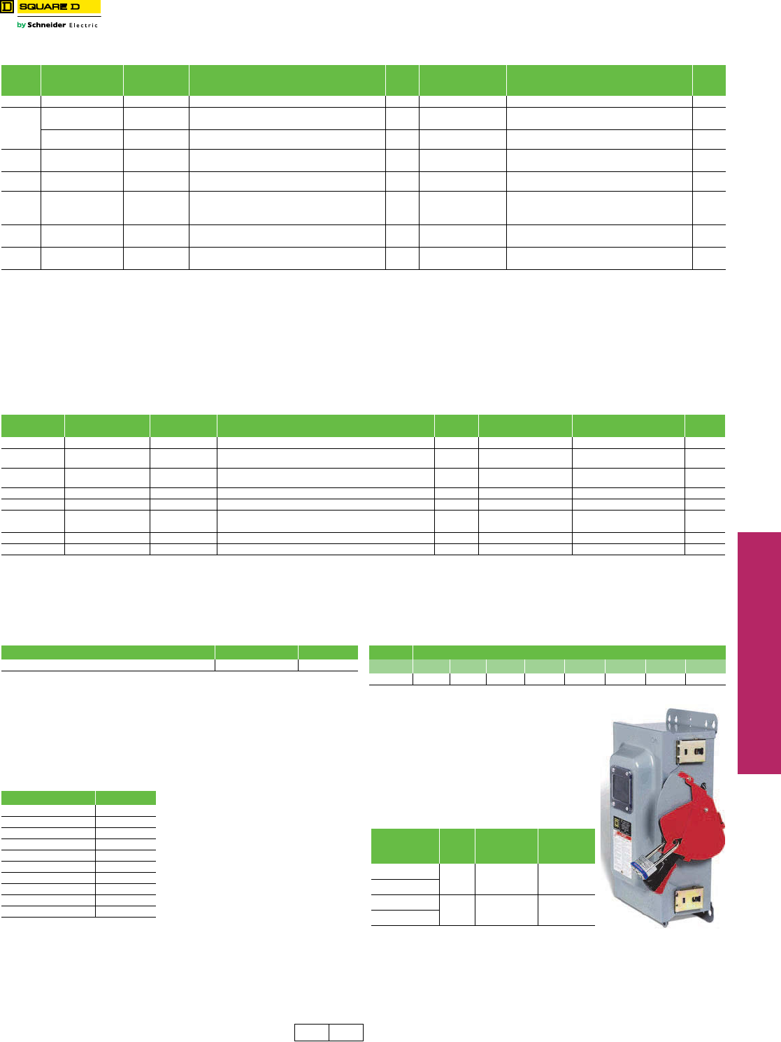
Available factory- or field-installed the
lock-off guard works by covering the
lockout/tagout opening whenever the switch
is in the ON position. This prevents a
padlock from being inadvertantly inserted
into the switch lockplate. The device is
designed to help prevent accidental
misapplication of a lockout device. These
kits are marked cURus (UL Component
Recognized) for field or factory installation.
bFor factory installation, add suffix “LOG” to the switch
catalog number.
cFor use with 30–200 Ampere Series F NEMA 1, 3R,
12 and 12K switches only.
dFactory install and kits are available for NEMA 1, 3R,
12 and 12K switch enclosures only.
AmperescKit Cat.
No.
Field-Installed
$ Price
Factory-
Installed
$ Price
30 A LOGK1 44.30 146.00
60 A 240 V
60 A 600 V LOGK2 45.00 177.00
100 and 200 A
DE1 PE1A Discount
Schedule
Heavy Duty Safety Switches Accessories and Special Features
Class 3110 / Refer to Catalog 3100CT0901
www.schneider-electric.us
3SAFETY SWITCHES
3-12 © 2012 Schneider Electric
All Rights Reserved
Heavy Duty Safety Switches Accessories and Special Features
Class 3110 / Refer to Catalog 3100CT0901
Key Interlock Systems
Factory-installed only on heavy duty safety
switches and double throw safety switches.
Interlocks are used to prevent the authorized
operator from making an unauthorized operation.
Not available on hazardous location devices
(NEMA 7/9) or fiberglass reinforced polyester
(NEMA 4X).
The key interlock system is a simple and easy
method of applying individual key interlock units
and assemblies to the above equipment so as to
require operation in a predetermined sequence.
UL Listed.
Quoting:
Contact Schneider Electric for catalog number, availability, and pricing prior
to quoting a job.
Detailed information is required before an order can be processed.
Please see Supplemental Digest Section 2 for further information.
Use these suffixes on switch catalog numbers:
•KI = 1 lock per switch
•KI2 = 1 lock with 2 cylinders (2 keys) per switch
•KIKI = 2 separate locks per switch
aPrices do not apply when more than three devices are interlocked, as these schemes
normally require more than one key assembly per device.
Lock-On Provisions
Lock-off provisions are standard on all heavy duty safety switches.
Provision for one 3•
8-inch hasp padlock is available factory-installed on
NEMA 1, 3R, 4-4X-5 stainless steel and 12 switches. This modification
will allow the switch to be locked in the “ON’’ position. UL Listed.
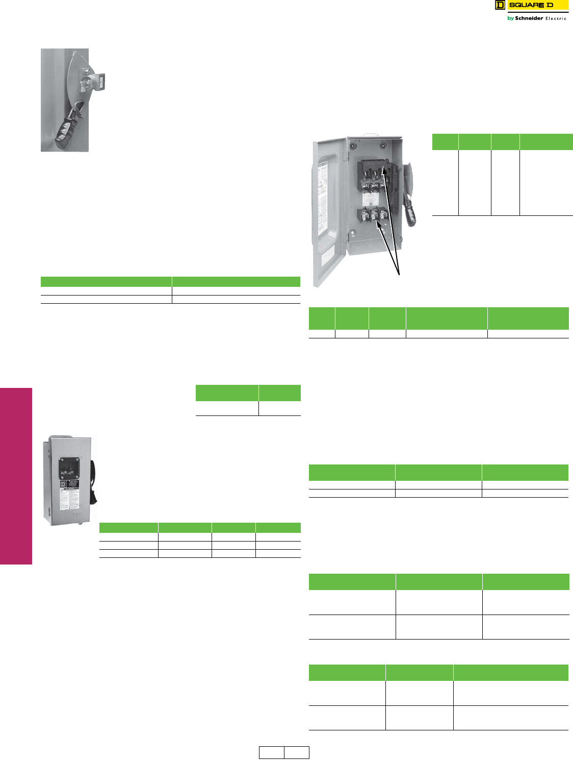
Cover Viewing Window
Optional cover viewing window is positioned over the
blades to allow visual verification of “ON-OFF’’ status.
Available on 30 through 1200 A heavy duty switches, all
NEMA Types. (Not available on NEMA 4X fiberglass
reinforced polyester, Krydon™ enclosures, or NEMA 7
and 9 devices.)
Factory-installed only: add “VW’’ suffix to the Cat. No.
See table below for price adder.
Switch Lubricant
Field maintenance lubricant is available for servicing blade and jaw
components in switches 600 V and below. Catalog number SWLUB (list
price $24.14) consists of one tube of BG20 High Performance Synthetic
Grease manufactured by Dow Corning®. SWLUB is available in
warehouse stock, shipped individually or in multiples of 12 units per
carton.
Copper Only Lug Kits
Heavy duty safety switches are supplied standard with Al lugs, which
accept both Cu and Al wires. For field installation of copper-only lug kits,
order kits below. For factory installation of copper only lugs, add suffix
SLC to standard Cat. No. Note: 30 through 200 Amperes NEMA 12, 12K
and stainless steel switches with factory-installed lugs bear the UL
Marine Listed manifest for use on vessels over 65 feet long. 30 through
200 Amperes NEMA 12, 12K and stainless steel switches using field-
installed copper only lug kits are UL Marine Listed, but do not bear the
marine manifest.
bOne kit includes all phase line/load lugs for a 3-
pole switch.
Double Lug Kits
200 A heavy duty F-series switches
are supplied standard with lugs listed
on page 3-13 (one wire per phase).
For lugs that accept two wires per
phase and neutral, order the following
kit:
cNot UL Listed.
dKit contains 3 lugs. For double lugs for line and load, order 2 kits.
Table 3.31: 800 and 1200 A Compression Lug Kits–
Field- Installed (See page 3-13 for 100–600 A Switches)
Series E4 800 and 1200 A safety switches are equipped as standard
with mechanical lugs. Alternate compression lug kits are available for
field installation and are UL Listed. Each kit consists of VCEL07512H1
Versa-Crimp™ Compression Lugs and lug landing connectors capable
of converting line and load side of one switch pole or neutral.
Order one field-installed kit per pole or neutral per table below.
Example: Three-pole three-wire requires three kits; three-pole, four-wire
requires four kits.
Note: For terminal lug data, refer to table below.
Table 3.32: Factory-Installed
Series E4 800 and 1200 A safety switches are available with factory-
installed VCEL-075-12H1 Versa-Crimp compression lug kits (above).
For factory installation, add suffix LK to standard Cat. No. (Example:
H367LK) and use price adder from table below based on system type.
Note: For terminal Lug data refer to table below.
Table 3.27: Price Adder Per Lock a
Switch Type $ Price
30–1200 A Heavy Duty 2055.00
30–600 A Double Throw 1988.00
Table 3.28: Price Adder Per Each Switch
Safety Switch
Rating $ Price
To order, add suffix SPLO to standard
catalog number. Example: H364-SPLO 30–1200 A 155.00
Table 3.29: Price Adder Per Switch—UL Listed
Class Amperes 2- and 3-Pole 4- and 6-Pole
Heavy Duty 30–100 A 38.00 75.00
Heavy Duty 400–1200 A 2297.00 —
Double Throw 30–100 A 255.00 510.00
Table 3.30: Kits–Wire size (pp 3-13)
Amperes Lug Kit
Cat. No.b
Kit
$ Price
Factory-Installed
Adder per Switch
30 CL0306F 69.00 224.00
60 CL0306F 69.00 224.00
100 CL10F 159.00 431.00
200 CL20F 264.00 717.00
400 CL40F 549.00 1490.00
600 CL60F 893.00 2426.00
800 — — —
1200 — — —
Amperes Lug Kitc
Cat. No. Kit $ Priced
Lug wire range
per phase and neutral
AWG/kcmil
Switch wire range
per phase and neutral
AWG/kcmil
200 AL20DTF 159.00 (2) 6 –300 Cu/Al (2) 6 –250 Cu/Al
Amperes Lug Kit
Cat. No.
$ Price Per
Pole or Neutral
800 H8LKE2 893.00
1200 H12LKE2 1109.00
Amperes System Factory-Installed
$ Price Adder Per Switch
800
2 Wire 2106.00
3 Wire 2972.00
4 Wire 3839.00
1200
2 Wire 2591.00
3 Wire 3696.00
4 Wire 4806.00
Table 3.33: Terminal Lug Data—800 and 1200 A Compression Lugs
Amperes Conductors
Per Phase
Compression Lug (VCEL-075-12H1)
Wire Range
800
(3) Line 500–750 kcmil (Al)
and or
(3) Load 500 kcmil (Cu)
1200
(4) Line 500–750 kcmil (Al)
and or
(4) Load 500 kcmil (Cu)
Al/Cu to Cu Only
DE1 DE5 Discount
Schedule
www.schneider-electric.us
3SAFETY SWITCHES
© 2012 Schneider Electric
All Rights Reserved 3-13
Heavy Duty Safety Switches NEMA Type 1 and 3R—Dimensions, Lug Data
Class 3110 / Refer to Catalog 3100CT0901
a30–100 A switches suitable for 60°C or 75°C conductors. 200–1200 A switches suitable for 75oC conductors.
bFor NEMA 1 and 3R only.
cHU461AWK— 14–3 AWG (Al or Cu).
dH60XFA— 14–6 AWG (Cu).
eH225XKA— 4 AWG–300 kcmil (Cu).
fMax. wire range is (1) 600 kcmil or (2) 300 kcmil Al/Cu on NEMA 4X Stainless and NEMA 12.
gOrder two PK516KN mounting kits when installing VCEL030516H1 lugs.
Only one kit is required on 2-Pole switches.
hSee page 3-12, 800 and 1200 A compression lug kits for additional information.
Table 3.34: Terminal Lug Data (NEMA 1, 3R, 4, 4X, 5, 7, 9, 12)a
Rating
(A)
Conductors
Per Phase
and Neutral
Wire Range Wire Bending Space
Per NEC Table 312.6
AWG/kcmil
Lug Wire Range
AWG/kcmil
Optional Versa-Crimp™
Compression Lug
Field-Installedb
30c
1 12–6 (Al) or 14–6 (Cu) 12–2 (Al)
or
14–2 (Cu)
—
2 14–10 (Cu) solid or 14–10 (Cu)
stranded
60d1 14–3 (Al) or 14–3 (Cu) 12–2 (Al) or 14–2 (Cu) —
100 1 12–1/0 (Al) or 14–1/0 (Cu) 12–1/0 (Al) or 14–1/0 (Cu) VCEL02114S1
200e1 6–250 (Al/Cu) 6–300 (Al/Cu) VCEL030516H1
400
VCEL07512H1
1 1/0–750 (Al/Cu)f 1/0–750 (Al/Cu) or
or or and VCEL030516H1g
2 1/0–300 (Al/Cu) 1/0–300 (Al/Cu) and
VCEL05012H1
600 2 3/0–500 (Al/Cu) 3/0–500 (Al/Cu) VCEL05012H1
800 3 3/0–750 (Al/Cu) 3/0–750 (Al/Cu) H8LKE2h
1200 4 3/0–750 (Al/Cu) 3/0–750 (Al/Cu) H12LKE2h
H
W/H D
W
H
W/H D
W
Typical NEMA 1 Typical NEMA 3R
Cat. No.
Approximate Dimensions
Cat. No.
Approximate Dimensions
Series H W D W/H Series H W D W/H
in. mm in. mm in. mm in. mm in. mm in. mm in. mm in. mm
H221N F5 14.60 371 6.50 165 4.88 124 7.55 192 H364, N F5 29.00 737 17.13 435 8.25 210 18.50 470
H221NRB F5 14.88 378 6.63 168 4.88 124 7.55 192 H364RB, NRB F5 29.25 743 17.25 438 8.50 216 18.63 473
H222N F5 14.60 371 6.50 165 4.88 124 7.55 192 H365, N E4 50.25 1276 27.63 702 10.13 257 27.63 702
H222NRB F5 14.88 378 6.63 168 4.88 124 7.55 192 H365R, NR E5 50.31 1278 27.76 705 9.53 242 27.88 708
H223N F5 21.25 540 8.50 216 6.38 162 10.50 267 H366, N E4 50.25 1276 27.63 702 10.13 257 27.63 702
H223NRB F5 21.25 540 8.50 216 6.38 162 10.50 267 H366NR, R E5 50.31 1278 27.76 705 9.53 242 27.88 708
H224N F5 29.00 737 17.13 435 8.25 210 18.50 470 H367, N E4 69.13 1756 36.62 930 17.75 451 36.62 930
H224NRB F5 29.25 743 17.25 438 8.50 216 18.63 473 H367NR, R E4 69.13 1756 36.62 930 17.75 451 36.62 930
H225, N E4 50.25 1276 27.63 702 10.13 257 27.63 702 H368, N E4 69.13 1756 36.62 930 17.75 451 36.62 930
H225NR, R E5 50.31 1278 27.76 705 9.53 242 27.88 708 H368NR, R E4 69.13 1756 36.62 930 17.75 451 36.62 930
H226, N E4 50.25 1276 27.63 702 10.13 257 27.63 702 H461 F5 20.50 521 14.75 375 6.85 174 16.13 410
H226NR, R E5 50.31 1278 27.76 705 9.53 242 27.88 708 H462 F5 20.50 521 14.75 375 6.85 174 16.13 410
H227, N E4 69.13 1756 36.62 930 17.75 451 36.62 930 H463 F5 20.50 521 14.75 375 6.85 174 16.13 410
H227NR, R E4 69.13 1756 36.62 930 17.75 451 36.62 930 H464 F5 29.00 737 23.25 591 8.75 222 24.88 632
H228, N E4 69.13 1756 36.62 930 17.75 451 36.62 930 H465 E4 50.25 1276 33.88 861 10.13 257 33.88 861
H228NR, R E4 69.13 1756 36.62 930 17.75 451 36.62 930 H466 E4 50.25 1276 33.88 861 10.13 257 33.88 861
H265 E4 50.25 1276 27.63 702 10.13 257 27.63 702 HU265 E4 50.25 1276 27.63 702 10.13 257 27.63 702
H265R E5 50.31 1278 27.76 705 9.53 242 27.88 708 HU265R E5 50.31 1278 27.76 705 9.53 242 27.88 708
H266 E4 50.25 1276 27.63 702 10.13 257 27.63 702 HU266 E4 50.25 1276 27.63 702 10.13 257 27.63 702
H266R E5 50.31 1278 27.76 705 9.53 242 27.88 708 HU266R E5 50.31 1278 27.76 705 9.53 242 27.88 708
H267 E4 69.13 1756 36.62 930 17.75 451 36.62 930 HU267 E4 69.13 1756 36.62 930 17.75 451 36.62 930
H267R E4 69.13 1756 36.62 930 17.75 451 36.62 930 HU267R E4 69.13 1756 36.62 930 17.75 451 36.62 930
H268 E4 69.13 1756 36.62 930 17.75 451 36.62 930 HU268 E4 69.13 1756 36.62 930 17.75 451 36.62 930
H268R E4 69.13 1756 36.62 930 17.75 451 36.62 930 HU268R E4 69.13 1756 36.62 930 17.75 451 36.62 930
H321N F5 14.60 371 6.50 165 4.88 124 7.55 192 HU361 F5 14.60 371 6.50 165 4.88 124 7.55 192
H321NRB F5 14.88 378 6.63 168 4.88 124 7.55 192 HU361RB F5 14.88 378 6.63 168 4.88 124 7.55 192
H322N F5 14.60 371 6.50 165 4.88 124 7.55 192 HU361WA F6 18.19 462 9.00 229 6.81 173 10.50 267
H322NRB F5 14.88 378 6.63 168 4.88 124 7.55 192 HU361WC F6 18.19 462 9.00 229 6.81 173 10.50 267
H323N F5 21.25 540 8.50 216 6.38 162 10.50 267 HU362 F5 17.50 445 9.00 229 6.38 162 10.50 267
H323NRB F5 21.25 540 8.50 216 6.38 162 10.50 267 HU362RB F5 17.50 445 9.00 229 6.38 162 10.50 267
H324N F5 29.00 737 17.13 435 8.25 210 18.50 470 HU362WA F6 18.19 462 9.00 229 6.81 173 10.50 267
H324NRB F5 29.25 743 17.25 438 8.50 216 18.63 473 HU362WC F6 16.75 425 9.00 229 7.00 178 10.50 267
H325, N E4 50.25 1276 27.88 708 10.13 257 27.88 708 HU362WH F5 18.19 462 9.00 229 6.81 173 10.50 267
H325R, NR E5 50.31 1278 27.76 705 9.53 242 27.88 708 HU363 F5 21.25 540 8.50 216 6.38 162 10.50 267
H326, N E4 50.25 1276 27.63 702 10.13 257 27.63 702 HU363RB F5 21.25 540 8.50 216 6.38 162 10.50 267
H326R, NR E5 50.31 1278 27.76 705 9.53 242 27.88 708 HU363WA F6 21.85 462 9.00 229 6.81 173 10.50 267
H327, N E4 69.13 1756 36.62 930 17.75 451 36.62 930 HU363WC F6 21.85 555 9.00 229 6.81 173 10.50 267
H327R, NR E4 69.13 1756 36.62 930 17.75 451 36.62 930 HU364 F5 29.00 737 17.13 435 8.25 210 18.50 470
H328, N E4 69.13 1756 36.62 930 17.75 451 36.62 930 HU364RB F5 29.25 743 17.25 438 8.50 216 18.63 473
H328R, NR E4 69.13 1756 36.62 930 17.75 451 36.62 930 HU365 E4 50.25 1276 27.63 702 10.13 257 27.63 702
H361, N F5 14.60 371 6.50 165 4.88 124 7.55 192 HU365R E5 50.31 1278 27.76 705 9.53 242 27.88 708
H361-2 F5 17.50 445 9.00 229 6.38 162 10.50 267 HU366 E4 50.25 1276 27.63 702 10.13 257 27.63 702
H361NRB, RB F5 14.88 378 6.63 168 4.88 124 7.55 192 HU366R E5 50.31 1278 27.76 705 9.53 242 27.88 708
H361WA F6 18.19 462 9.00 229 6.81 173 10.50 267 HU367 E4 69.13 1756 36.62 930 17.75 451 36.62 930
H361WC F6 18.19 462 9.00 229 6.81 173 10.50 267 HU367R E4 69.13 1756 36.62 930 17.75 451 36.62 930
H362, N F5 17.50 445 9.00 229 6.38 162 10.50 267 HU368 E4 69.13 1756 36.62 930 17.75 451 36.62 930
H362NRB, RB F5 17.50 445 9.00 229 6.38 162 10.50 267 HU368R E4 69.13 1756 36.62 930 17.75 451 36.62 930
H362WA F6 18.19 462 9.00 229 6.81 173 10.50 267 HU461 F5 20.50 521 14.75 375 6.85 174 16.13 410
H362WC F6 16.75 425 9.00 229 7.00 178 10.50 267 HU462 F5 20.50 521 14.75 375 6.85 174 16.13 410
H362WH F5 18.19 462 9.00 229 6.81 173 10.50 267 HU463 F5 20.50 521 14.75 375 6.85 174 16.13 410
H363, N F5 21.25 540 8.50 216 6.38 162 10.50 267 HU464 F5 29.00 737 23.25 591 8.75 222 24.88 632
H363NRB, RB F5 21.25 540 8.50 216 6.38 162 10.50 267 HU465 E4 50.25 1276 33.88 861 10.13 257 33.88 861
H363WA F6 21.85 462 9.00 229 6.81 173 10.50 267 HU466 E4 50.25 1276 33.88 861 10.13 257 33.88 861
H363WC F6 21.85 555 9.00 229 6.81 173 10.50 267
www.schneider-electric.us
3SAFETY SWITCHES
3-14 © 2012 Schneider Electric
All Rights Reserved
Heavy Duty Safety Switches NEMA Types 4, 4X, 5, 7, 9, 12 and 12K Dimensions
Class 3110 / Refer to Catalog 3100CT0901
NEMA Type 4, 4X, 5, 7, 9 and 12
Table 3.35: Optional Copper Only Lug Kits
(See page 3-12 for pricing. See page 3-13 for terminal lug data for the series switches listed in the
dimension table below.)
Amperes Optional Lug Kit Cat. No.aLug Wire Range Per Phase AWG/kcmil
30–60 CL0306F (1) 14–8 Cu solid or 14–4 Cu strand
100 CL10F (1) 14–8 Cu solid or 14–1/0 Cu strand
200 CL20F (1) 6–250 Cu
400 CL40F (1) 1–600 Cu plus (1) 6–250 Cu
600 CL60F (2) 4–350 Cu
aOne kit includes all phase line/load lugs for a 3-pole switch.
Table 3.36: Conduit Provisions
(NEMA 4X Fiberglass Reinforced Polyester and Krydon, NEMA 7 and 9.)
Amperes
Top and Bottom Endwall
NEMA 4X Fiberglass
Reinforced Polyester and KrydonbNEMA 7 and 9c
30 3/4 in. —
60 1-1/4 in. 3/4 in.
100 2 in. 1-1/4 in.
200 2-1/2 in. 2-1/2 in.
bHubs and hub drilling templates are provided for field-installation.
cThreaded conduit opening.
Cat. No.
Approximate Dimensions
Series H W D W/H
in. mm in. mm in. mm in. mm
H60XFA E1 15.93 405 9.87 251 6.96 177 9.87 251
H100XFA E1 15.93 405 9.87 251 6.96 177 9.87 251
H221AWK, A F6 14.60 371 6.63 168 4.96 125 7.55 192
H221DS F6 14.93 379 7.22 183 5.11 130 8.67 220
H221-2AWK F6 16.50 419 9.00 229 7.00 178 10.50 267
H222AWK, A F6 14.60 371 6.63 168 4.96 125 7.55 192
H222DS F6 14.93 379 7.22 183 5.11 130 8.67 220
H223AWK, A F6 20.50 521 9.00 229 7.00 178 10.50 267
H223DS F6 20.82 529 9.36 238 6.97 177 11.25 286
H224A,AWK F6 29.00 737 17.25 438 8.75 216 18.63 473
H224DS F6 29.00 737 17.75 451 8.88 226 19.25 489
H225AWK, DS E4 46.25 1175 26.25 667 10.13 259 26.25 667
H225NAWK, NDS E4 46.25 1175 26.25 667 10.13 259 26.25 667
H225XJG C2 22.56 573 10.88 276 7.75 197 10.88 276
H226AWK, DS E4 46.25 1175 26.25 667 10.13 259 26.25 667
H226NAWK, NDS E4 46.25 1175 26.25 667 10.13 259 26.25 667
H227AWK, NAWK E4 69.13 1756 36.62 930 17.75 451 36.62 930
H228AWK, NAWK E4 69.13 1756 36.62 930 17.75 451 36.62 930
H265AWK, DS E4 46.25 1175 26.25 667 10.13 259 26.25 667
H266AWK, A, DS E4 46.25 1175 26.25 667 10.13 259 26.25 667
H267AWK, NAWK E4 69.13 1756 36.62 930 17.75 451 36.62 930
H268AWK, NAWK E4 69.13 1756 36.62 930 17.75 451 36.62 930
H321AWK, A F6 14.60 371 6.63 168 4.96 125 7.55 192
H321DS F6 14.93 379 7.22 183 5.11 130 8.67 220
H322AWK, A F6 14.60 371 6.63 168 4.96 125 7.55 192
H322DS F6 14.93 379 7.22 183 5.11 130 8.67 220
H323AWK, A F6 20.50 521 9.00 229 7.00 178 10.50 267
H323DS F6 20.82 529 9.36 238 6.97 177 11.25 286
H324A,AWK F6 29.00 737 17.25 438 8.75 216 18.63 473
H324DS F6 29.00 737 17.75 451 8.88 226 19.25 489
H325AWK, DS E4 46.25 1175 26.25 667 10.13 259 26.25 667
H325NAWK, NDS E4 46.25 1175 26.25 667 10.13 259 26.25 667
H326AWK, DS E4 46.25 1175 26.25 667 10.13 259 26.25 667
H326NAWK, NDS E4 46.25 1175 26.25 667 10.13 259 26.25 667
H327AWK, NAWK E4 69.13 1756 36.62 930 17.75 451 36.62 930
H328AWK, NAWK E4 69.13 1756 36.62 930 17.75 451 36.62 930
H361AWA F7 16.50 419 9.00 229 7.00 178 10.50 267
H361AWC F7 16.50 419 9.00 229 7.00 178 10.50 267
H361AWK, A F6 14.60 371 6.63 168 4.96 125 7.55 192
H361DS F6 14.93 379 7.22 183 5.11 130 8.67 220
H361DSWA F7 16.87 428 8.92 227 5.11 130 10.81 275
H361DSWC F7 16.87 428 8.92 227 5.11 130 10.79 274
H361DF F1 16.50 419 11.00 279 8.80 224 11.00 279
H361DX F1 19.40 493 11.40 290 8.60 218 11.40 290
H361SS F6 14.93 379 7.22 183 5.11 130 8.67 220
H361-2AWK, A F6 16.50 419 9.00 229 7.00 178 10.50 267
H362AWA F7 16.50 419 9.00 229 7.00 178 10.50 267
H362AWC F7 16.50 419 9.00 229 7.00 178 10.50 267
H362AWH F6 16.50 419 9.00 229 7.00 178 10.50 267
H362AWK, A F6 16.50 419 9.00 229 7.00 178 10.50 267
H362DS F6 16.87 428 8.92 227 6.97 177 10.81 275
H
WD
Typical NEMA 4X
Fiberglass Reinforced
Polyester and Krydon™
H
W/H D
W
Typical NEMA 4, 4X, 5, 12,
12K (Stainless has flat front)
H
WD
Typical NEMA 7, 9
H362DSWA F7 16.87 428 8.92 227 5.11 130 10.81 275
H362DSWC F7 16.87 428 8.92 227 5.11 130 10.79 274
H362DF F1 16.50 419 11.00 279 8.80 224 11.00 279
H362DX F1 19.40 493 11.40 290 8.60 218 11.40 290
H362SS F6 16.87 428 8.92 227 6.97 177 10.81 275
H363AWA F7 20.50 521 9.00 229 7.00 178 10.50 267
H363AWC F7 20.50 521 9.00 229 7.00 178 10.50 267
H363AWK, A F6 20.50 521 9.00 229 7.00 178 10.50 267
H363DS F6 20.82 529 9.36 238 6.97 177 11.25 286
H363DSWA F7 20.82 529 9.36 238 6.97 177 11.25 286
H363DSWC F7 20.82 529 9.36 238 6.97 177 11.25 286
H363DF F1 24.80 630 13.70 348 12.00 305 13.70 348
H363DX F1 25.25 641 11.40 290 8.60 218 11.40 290
H363SS F6 20.82 529 9.36 238 6.97 177 11.25 286
H364A,AWK F6 29.00 737 17.25 438 8.75 216 18.63 473
H364DS,NDS F6 29.00 737 17.75 451 8.88 226 19.25 489
H364NA,NAWK F6 29.00 737 17.25 438 8.75 216 18.63 473
H364DF E1 31.30 795 26.30 668 11.80 300 26.30 668
H364SS F6 29.00 737 17.75 451 8.88 226 19.25 489
H365AWK, DS, SS E4 46.25 1175 26.25 667 10.13 259 26.25 667
H365NAWK, NDS E4 46.25 1175 26.25 667 10.13 259 26.25 667
H366AWK, DS E4 46.25 1175 26.25 667 10.13 259 26.25 667
H366NAWK, NDS, SS E4 46.25 1175 26.25 667 10.13 259 26.25 667
H367AWK, NAWK E4 69.13 1756 36.62 930 17.75 451 36.62 930
H368AWK, NAWK E4 69.13 1756 36.62 930 17.75 451 36.62 930
H461AWK F6 20.50 521 14.75 375 6.80 173 16.13 410
H461DS F6 20.82 529 15.08 383 6.97 177 16.85 428
H462AWK F6 20.50 521 14.75 375 6.80 173 16.13 410
H462DS F6 20.82 529 15.08 383 6.97 177 16.85 428
H463AWK F6 20.50 521 14.75 375 6.80 173 16.13 410
H463 DS F6 20.82 529 15.08 383 6.97 177 16.85 428
H464AWK F6 29.00 737 23.25 591 8.75 222 24.88 632
H464DS F6 29.00 737 23.75 603 8.88 226 25.25 641
H465AWK E4 46.25 1175 32.50 826 10.13 259 32.50 826
H663AWK F6 20.50 521 14.75 375 6.80 173 16.13 410
H663DS F6 20.82 529 15.08 383 6.97 177 16.85 428
H664AWK F6 29.00 737 23.25 591 8.75 222 24.88 632
H664DS F6 29.00 737 23.75 603 8.88 226 25.25 641
HU265AWK, DS E4 46.25 1175 26.25 667 10.13 259 26.25 667
HU266AWK, DS E4 46.25 1175 26.25 667 10.13 259 26.25 667
HU267AWK E4 69.13 1756 36.62 930 17.75 451 36.62 930
HU268AWK E4 69.13 1756 36.62 930 17.75 451 36.62 930
HU361AWA F7 16.50 419 9.00 229 7.00 178 10.50 267
HU361AWC F7 16.50 419 9.00 229 7.00 178 10.50 267
HU361AWK, A F6 14.60 371 6.63 168 4.96 125 7.55 192
HU361DS F6 14.93 379 7.22 183 5.11 130 8.67 220
HU361DSWA F7 16.87 428 8.92 227 5.11 130 10.81 275
HU361DSWC F7 16.87 428 8.92 227 5.11 130 10.79 274
HU361DF F1 16.50 419 11.00 279 8.80 224 11.00 279
HU361DX F1 19.40 493 11.40 290 8.60 218 11.40 290
HU361SS F6 14.93 379 7.22 183 5.11 130 8.67 220
HU362AWA F7 16.50 419 9.00 229 7.00 178 10.50 267
HU362AWC F7 16.50 419 9.00 229 7.00 178 10.50 267
HU362AWH F6 16.50 419 9.00 229 7.00 178 10.50 267
HU362AWK, A F6 16.50 419 9.00 229 7.00 178 10.50 267
HU362DS F6 16.87 428 8.92 227 6.97 177 10.81 275
HU362DSWA F7 16.87 428 8.92 227 5.11 130 10.81 275
HU362DSWC F7 16.87 428 8.92 227 5.11 130 10.79 274
HU362DF F1 16.50 419 11.00 279 8.80 224 11.00 279
HU362DX F1 19.40 493 11.40 290 8.60 218 11.40 290
HU362SS F6 16.87 428 8.92 227 6.97 177 10.81 275
HU363AWA F7 20.50 521 9.00 229 7.00 178 10.50 267
HU363AWC F7 20.50 521 9.00 229 7.00 178 10.50 267
HU363AWK, A F6 20.50 521 9.00 229 7.00 178 10.50 267
HU363DS F6 20.82 529 9.36 238 6.97 177 11.25 286
HU363DSWA F7 20.82 529 9.36 238 6.97 177 11.25 286
HU363DSWC F7 20.82 529 9.36 238 6.97 177 11.25 286
HU363DF F1 24.80 630 13.70 348 12.00 305 13.70 348
HU363DX F1 25.25 641 11.40 290 8.60 218 11.40 290
HU363SS F6 20.82 529 9.36 238 6.97 177 11.25 286
HU364A,AWK F6 29.00 737 17.25 438 8.75 216 18.63 473
HU364DF E1 31.30 795 26.30 668 11.80 300 26.30 668
HU364DS F6 29.00 737 17.75 451 8.88 226 19.25 489
HU364SS F6 29.00 737 17.75 451 8.88 226 19.25 489
HU365AWK, DS, SS E4 46.25 1175 26.25 667 10.13 259 26.25 667
HU366AWK, DS, SS E4 46.25 1175 26.25 667 10.13 259 26.25 667
HU367AWK E4 69.13 1756 36.62 930 17.75 451 36.62 930
HU368AWK E4 69.13 1756 36.62 930 17.75 451 36.62 930
HU461AWK F6 20.50 521 14.75 375 6.80 173 16.13 411
HU461DS F6 20.82 529 15.08 383 6.97 177 16.85 428
HU462AWK F6 21.25 540 16.13 410 6.80 173 16.13 410
HU462DS F6 20.82 529 15.08 383 6.97 177 16.85 428
HU463AWK F6 20.50 521 14.75 375 6.80 173 16.13 410
HU463DS F6 20.82 529 15.08 383 6.97 177 16.85 428
HU464AWK F6 29.00 737 23.25 591 8.75 222 24.88 632
HU464DS F6 29.00 737 23.75 603 8.88 226 25.25 641
HU465AWK E4 46.25 1175 32.50 826 10.13 259 32.50 826
HU661AWK F6 20.50 521 14.75 375 6.80 173 16.13 410
HU661DS F6 20.82 529 15.08 383 6.97 177 16.85 428
HU662AWK F6 20.50 521 14.75 375 6.80 173 16.13 410
HU662DS F6 20.82 529 15.08 383 6.97 177 16.85 428
HU663AWK F6 20.50 521 14.75 375 6.80 173 16.13 410
HU663DS F6 20.82 529 15.08 383 6.97 177 16.85 428
HU664AWK F6 29.00 737 23.25 591 8.75 222 24.88 632
HU664DS F6 29.00 737 23.75 603 8.88 226 25.25 641
Cat. No.
Approximate Dimensions
Series H W D W/H
in. mm in. mm in. mm in. mm
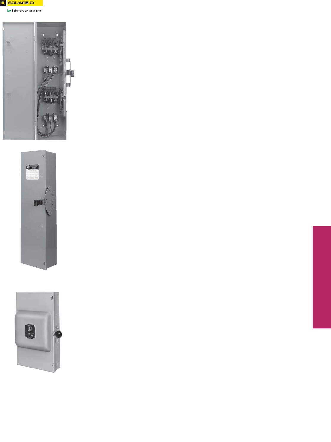
www.schneider-electric.us
3SAFETY SWITCHES
© 2012 Schneider Electric
All Rights Reserved 3-15
Double Throw Safety Switches Fusible and Non-Fusible
Class 3140 / Refer to Catalog 3100CT0901
30–100 A Types DT, DTU (Series F)
•Fusible (DT) and non-fusible (DTU) switches available
•Manually-operated switch suitable for use in accordance with article 702 of the NEC, ANSI/NFPA 70
•Standards: UL 98, NEMA KS1, CSA, and NOM
•Modular design—switch handle, lock-plate, switch mechanism; line and load bases are field replaceable
•UL Listed short circuit current ratings up to 200 kA (using Class R, J, or T fuses—see table for rating)
•Load make/break rated
•Meets NEMA hp ratings
•Dual cover interlock
•May be padlocked ON (I) or OFF (O)
•Lock-off accepts up to three padlocks
•Side-opening door
•Quick make / quick break mechanism
•Meets NEMA requirements as heavy duty switch
•Field-installed electrical interlock kits
•Field-installed neutral assembly kits (2P and 3P switches)
•UL Listed as suitable for use as service equipment
•Supplied as standard for switching one load between two power sources, and may be field-converted to switch on power
source between two loads.
30 (Series T4), 200–600 A Types 82,000 and 200 A DTU (Series E, A)
•Non-fusible
•Designed for manual transfer of loads from one supply to another
•UL Listed switches are suitable for use in accordance with Article 702 of the National Electrical Code, ANSI / NFPA 70
•All 82,000 and DTU double throw switches are continuous duty rated for their nameplate ampere rating
•The 82,000 and DTU (Series E, A) switches are load make/break rated
•UL Listed as suitable for use as service equipment
•Horsepower rated only as footnoted.
Field-Installed Accessories:
—Neutral
—Electrical Interlock
—Grounding Terminals
30–100 A DT, DTU (Series F)
NEMA 1
82,000 Line
NEMA 1
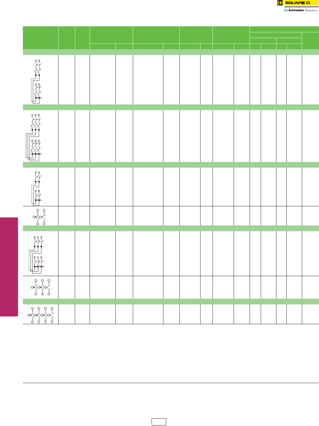
www.schneider-electric.us
3SAFETY SWITCHES
3-16 © 2012 Schneider Electric
All Rights Reserved
Double Throw Safety
Switches
240 Volt
Class 3140 / Refer to Catalog 3100CT0901
600 V Double Throw . . . . . . . . . . . . . . . . . . . . . . . . . . . . . . . . . . . . page 3-17
Accessories . . . . . . . . . . . . . . . . . . . . . . . . . . . . . . . . . . . . . . . . . . . page 3-18
Application Data . . . . . . . . . . . . . . . . . . . . . . . . . . . . . . . page 3-19
Dimensions: 30–100 A (Series F) . . . . . . . . . . . . . . . . . . . . . . . . . page 3-20
Dimensions: 30, 200–600 A (Series E, T4, A) . . . . . . . . . . . . . . . . page 3-21
Table 3.37: 240 V Double Throw Safety Switches
System Amperes Current
Series
NEMA 1 NEMA 3R NEMA 4,4X,5
304 Stainless Steel
NEMA 12
Gasketed
Horsepower Ratings ab
240 Vac
250 VdccStd. Max.
Cat. No. $ Price Cat. No. $ Price Cat. No. $ Price Cat. No. $ Price 1Ø 3Ø 1Ø 3Ø
Fusible—2P, 240 Vac—250 Vdc
100 F DT223 2379.00 DT223RB 3056.00 — — — — 7.5 15 d15 30 d20
Fusible—3P, 240 Vac—250 Vdc
30 F DT321 1646.00 DT321RB 2216.00 ————1.5 e3 d3 e7.5 d5
60 F DT322 1970.00 DT322RB 2612.00 ————3 e7.5 d10 e15 d10
100 F DT323 3104.00 DT323RB 3725.00 ——— —7.5 e15 d15 e30 d20
Non-Fusible—2P, 240 Vac—250 Vdc
60 F DTU222 962.00 ————————10—10 f
100 F DTU223 1371.00 DTU223RB 1347.00 ——— ———15—20 f
30 T4 92251 g585.00 ———————————
200 E 82254 k1815.00 DTU224NRB ghk 2177.00 ——H82254 4671.00 15 — — — —
—— — — — — — — — —15——— —
400 A 82255 g5850.00 82255R g8715.00 ——H82255 g10335.00 ———— —
Non-Fusible—3P, 240 Vac—250 Vdc
30 F DTU321 804.00 ———————3 d5 e10 d5 f
60 F DTU322 1119.00 ————————10 e15 d10 f
100 F DTU323 1764.00 DTU323RB 1953.00 ——— ———15 e30 d20 f
30 T4 92351 g687.00 ———————————
200 E 82354 g2564.00 DTU324NRB gh 3005.00 ——H82354 gi 5408.00 —15—— —
200 E DTU324N gh 2798.00 ———————15———
400 A 82355 g8040.00 82355R g13038.00 ——H82355 g11715.00 ———— —
600 A DTU326 12555.00 DTU326R 13890.00 — — — — — 125 — — 50
Non-Fusible—4P, 240 Vac
30 T4 92451 953.00 ———————————
200 E 82454 k5184.00 82454Rk7517.00 ——H82454j6779.00 —15j—— —
400 A 82455 11505.00 82455R 16200.00 ——H82455 15975.00 ———— —
600 A DTU426 20355.00 DTU426R 20595.00 — — — — — 125 — — 50
aRefer to page 7-31 for additional motor application data. The starting current of motors or more than standard horsepower may require the use of fuses with appropriate time delay
characteristics.
bStd.—Using fast acting one time fuses. Max.—Using dual element time delay fuses.
cFor switching dc, use two switching poles.
dIf used on corner grounded delta systems, install neutral and use outer switching pole for ungrounded conductors.
eUse outer switching poles.
fMaximum rating.
g240 Vac only.
hNeutral included with device.
iSuitable for use as service equipment.
jHp rating applies only to H82454.
k250 V dc rated.
Line
Line
Load
Line
Line
Load
Line
Line
Load
Line
Line
Load
DE1 Discount
Schedule
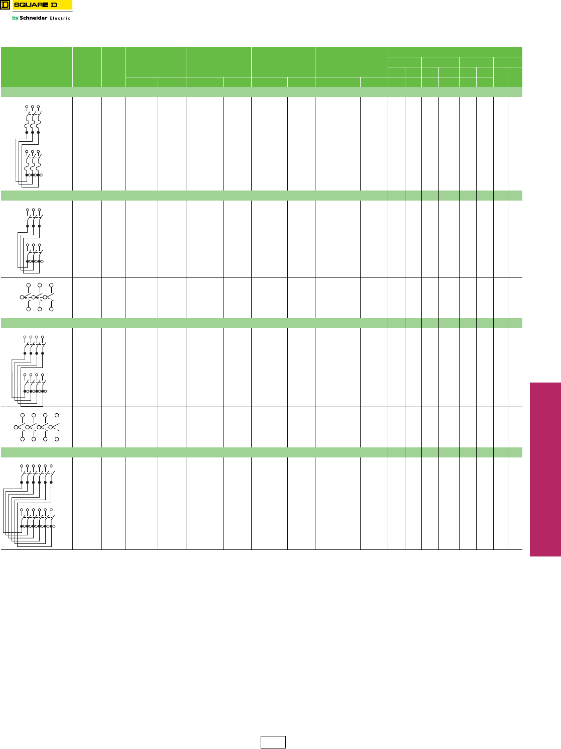
www.schneider-electric.us
3SAFETY SWITCHES
© 2012 Schneider Electric
All Rights Reserved 3-17
Double Throw Safety Switches 600 Volt
Class 3140 / Refer to Catalog 3100CT0901
240 V Double Throw . . . . . . . . . . . . . . . . . . . . . . . . . . . . . . . . . . . . . page 3-16
Accessories. . . . . . . . . . . . . . . . . . . . . . . . . . . . . . . . . . . . . . . . . . . . page 3-18
Application Data . . . . . . . . . . . . . . . . . . . . . . . . . . . . . . . . . . . . . . . .page 3-19
Dimensions: 30–100 A (Series F) . . . . . . . . . . . . . . . . . . . . . . . . . page 3-20
Dimensions: 30, 200–600 A (Series E, T4, A). . . . . . . . . . . . . . . . page 3-21
Table 3.38: 600 V Double Throw Safety Switches
System Amperes Current
Series
NEMA 1 NEMA 3R NEMA 4,4X,5
304 Stainless Steel
NEMA 12
Gasketed
Horsepower Ratings ao
240 Vac 480 Vac 600 Vac Vdcb
std max std max std max 250 600
Cat. No. $ Price Cat. No. $ Price Cat. No. $ Price Cat. No. $ Price 3Ø 3Ø 3Ø b3Øb3Ø 3Ø
Fusible 3P, 600 Vac—600 Vdc
30 F DT361 2016.00 DT361RB 2678.00 —— — ———5157.520515
60 F DT362 2111.00 DT362RB 3135.00 — — — — — — 15 30 15 50 — 30
100 F DT363 3686.00 DT363RB 4427.00 — — — — — — 25 60 30 75 — 50
Non-Fusible 3P, 600 Vac—600 Vdc 1Ø d3Ø b1Ø d3Ø b1Ø d3Ø
30 F DTU361 879.00 DTU361RB 1544.00 — — — — 5 10 7.5 20 10 30 5 15
60 F DTU362 1254.00 DTU362RB 2045.00 DTU362DS 6306.00 DTU362AWK p3635.00 10 20e25 50 g30 60 g10 30
100 F DTU363 2036.00 DTU363RB 3425.00 DTU363DS 9414.00 DTU363AWK p3894.00 20 40h40 75 hi 40 75 h20 50
200 E 82344jn 2783.00 82344RB jn 5868.00 82344DSjr 11415.00 H82344ljq 7503.00 ———15 k————
400 A 82345 n8213.00 82345R n13140.00 82345DS n15675.00 H82345 n12105.00 ——— — ————
600 A DTU366 ns 13890.00 DTU366R ns 19800.00 ——DTU366AWKns 21675.00 — 125 — 250 — 350 50 —
Non-Fusible 4P, 600 Vac—600 Vdc 2Ø 3Ø 2Ø 3Ø 2Ø 3Ø
60 F DTU462 3035.00 Use NEMA 12 —DTU462DS 6683.00 DTU462AWK p4184.00 20 20 40 50 50 60 10 30
100 F DTU463 3851.00 —DTU463DS 9978.00 DTU463AWK p6123.00 30 40 50 75 50 75 20 30
200 E 82444 n6143.00 82444R n8130.00 82444DS n15105.00 H82444 ljn 7143.00 ——— — ————
400 A 82445 n12578.00 82445Rn16800.00 ——H82445n16845.00 ——— — ————
600 A DTU466 n20355.00 DTU466R n23475.00 — — — — — 125 — 250 — 350 50 —
Non-Fusible 6P, 600 Vac—600 Vdc 1Ø 3Ø 1Ø 3Ø 1Ø 3Ø
60 F — — — — — — DTU662AWK p8474.00 —20— 50 —601030
100 F — — — — — — DTU663AWK p12735.00 —40— 75 —752050
aRefer to page 7-31 for additional motor application data. The starting current of motors or more than
standard horsepower may require the use of fuses with appropriate time delay characteristics.
bIf used on corner grounded delta systems, install neutral and use outer switching pole for ungrounded
conductors.
cFor switching dc, use two switching poles.
dUse outer switching poles.
eMaximum Hp is 15 for corner grounded delta systems.
fMaximum Hp is 30 for corner grounded delta systems.
gUse 75oC #4 Cu or #2 Al conductors only.
hUse 75oC #1 Cu conductors only.
iMaximum Hp is 60 for corner grounded delta systems.
j480 Vac maximum only, 250Vdc.
kStandard Hp rating.
lNot suitable for use as service equipment.
m600 Vac max.
n250 V dc rated.
oStd.—Using fast acting one time fuses. Max.—Using dual element time delay
fuses.
(Non-fusible switches have max rating unless noted.)
pComplete rating on switch is NEMA 3R or 12.
For 3R applications, remove drain screw from bottom endwall.
qH82 ... and H92 ... devices are NEMA 12 only, intended for use indoors only.
rNot UL Listed.
sCopper lugs not listed or available.
Line
Line
Load
Line
Line
Load
Line
Line
Load
Line
Line
Load
DE1 Discount
Schedule
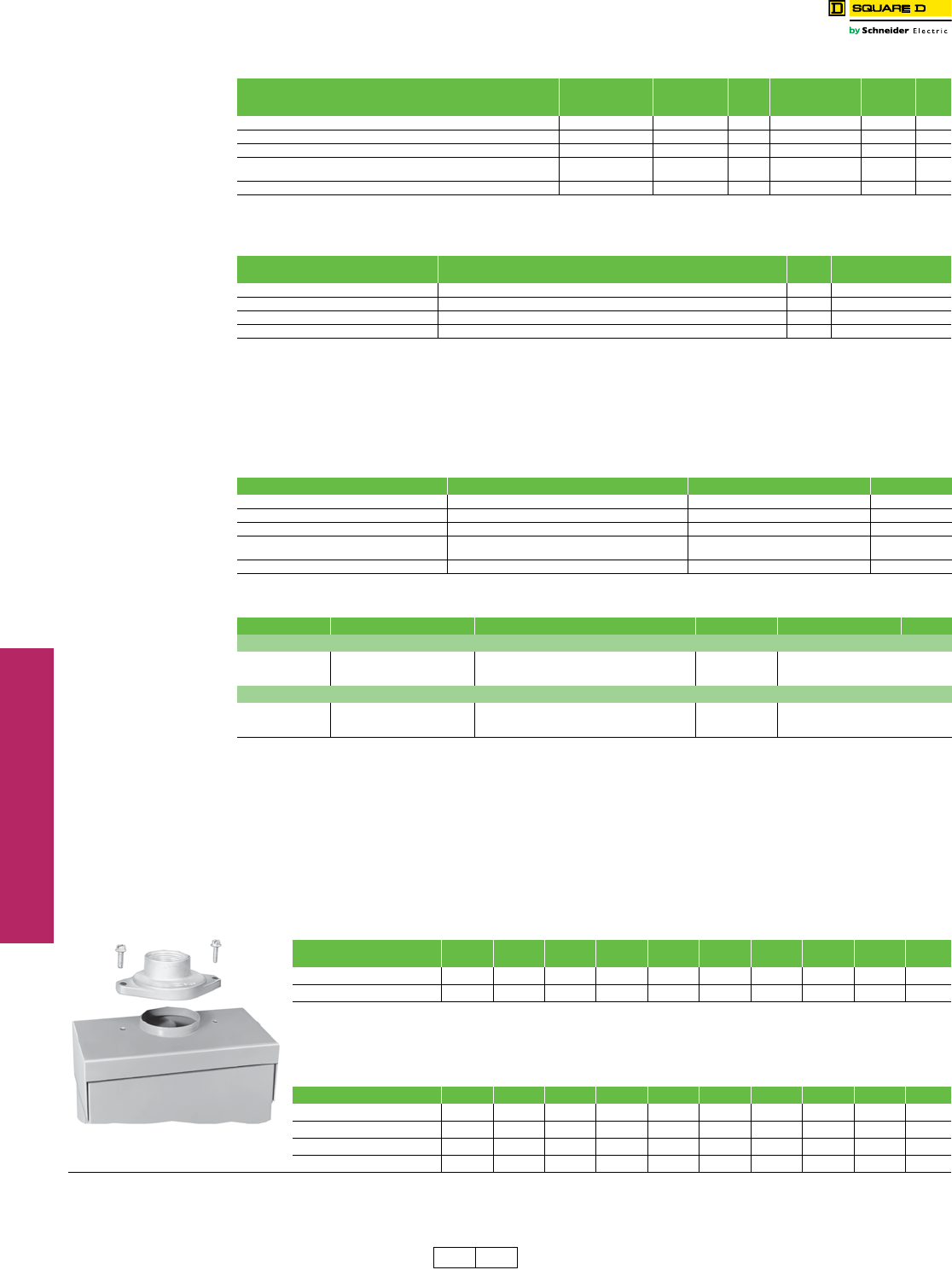
www.schneider-electric.us
3SAFETY SWITCHES
3-18 © 2012 Schneider Electric
All Rights Reserved
Double Throw Safety Switches Accessories
Class 3140 / Refer to Catalog 3100CT0901
aFor Type 82,000 switches, neutral is available factory-installed on 2P and 3P double throw switches. Not UL Listed. To order, add suffix N to the standard
catalog number and add the above price to the list price of the switch. For DTU switches, neutral is factory-installed in standard device and is UL Listed.
bNeutral assembly catalog number DT200N can be added to 4P Type 82000 switches in the field.
cElectrical interlock kit catalog numbers with “1” suffix indicate one normally open and normally closed contact; “2” indicates two normally open and two
normally closed contacts. See page 3-10 for electrical interlock ratings.
d30–100 A Type DT, DTU (Series F) switches contain (2) separate switching mechanisms. Each mechanism will accept an electrical interlock. Some
applications may therefore require (2) electrical interlocks.
e30–100 A Type DT, DTU (Series F) switches with factory-installed electrical interlocks installed are UL Listed and interlocks are furnished with 2 N.O. /2
N.C. contacts installed in both “ON” positions. To order, add suffix EI to standard catalog number.
fElectrical interlock EK400DTU2 can be added to 4-pole Type 82000 switches in the field.
gType 82000 and DTU switches are available with electrical interlock factory-installed only. Not UL listed. Electrical interlocks are furnished with 2
N.O./N.C. contacts and are installed in both “ON” positions. To order, add suffix EI to standard switch catalog number.
hDouble throw switches 92251, 92351, and 92451 are not available with factory or field installed electrical interlocks.
Viewing Windows
See Table 3.29 for list price. Accessory available on 30–100 A DTU switches only.
Key Interlock Systems
For factory-installed key interlocks, refer to page 3-12.
Phenolic Legend Plate
For factory-installed phenolic legend plates, refer to Supplemental Digest page 2.3.
Lock-On Provisions—UL Listed
Standard and feature on 30–100 A type DT and DTU (Series F), 82,000 (400 A only) and type 92,000 switches.
Feature available as facatory installed option for Type 82,000 (200 A only) and 200 A DTU (Series E) switches. Add the
suffix SPLO to the catalog number and add $410. to the switches list price.
240 V Double Throw . . . . . . . . . . . . . . . . . . . . . . . . . . . . . . . . . . . . page 3-16
600 V Double Throw . . . . . . . . . . . . . . . . . . . . . . . . . . . . . . . . . . . . page 3-17
Application Data . . . . . . . . . . . . . . . . . . . . . . . . . . . . . . . . . . . . . . . . page 3-19
Dimensions: 30–100 A (Series F) . . . . . . . . . . . . . . . . . . . . . . . . . . page 3-20
Dimensions: 30, 200–600 A (Series E, T4, A) . . . . . . . . . . . . . . . . page 3-21
Table 3.38: Neutral Assembly
Switch
Field-Installed
Standard Neutral Kit
Cat. No.
Terminal
Data
AWG/kcmil
$ Price
Field-Installed
Copper only
Neutral Kit Cat. No.
Terminal
Data
AWG/kcmil
$ Price
30–100 A Type DT, DTU (Series F) (2- and 3-pole switches only) SN0310 14–1/0 Al/Cu 114.00 SN0310C 14–1/0 Cu 120.00
30 A (Series T4) (2- and 3-pole switches only) aa908.00 ———
200 A Type 82000 and DTU (Series E) baa1110.00 ———
400 A Type 82000 DT400N (1) 4–600kcmil or
(2) 1/0–250kcmil 105.00 ———
600 A Type DTU (Series A) DT600NKD 250–500kcmil 452.00 ———
Table 3.39: Electrical Interlocks (For Electrical Interlock Contact Ratings, see Supplemental Digest page 2-4.)
Switch Field-Installed Electrical Interlock Kit Cat. No. c$ Price Factory-Installed
$ Price Adder Per Switch
30–100 A Type DT, DTU (Series F) EIK1, EIK2 dh 311.00 905.00e
200 A Type 82000 and DTU (Series E) fg—1113.00e
400 A Type 82000 EK400DTU2 260.00 1533.00
600 A Type DTU (Series A) DS200EK2D 438.00 —
Table 3.40: Service Grounding Kit (Required for service equipment use.)
Switch Field-Installed Service Grounding Lug Kit Cat. No. Terminal Data AWG/kcmil $ Price
30–100 A Type DT, DTU (Series F) Included Included std.
30 A Type 92,000 DT30SG (4) 14–4 Cu/Al 29.40
200 A Type 82000 and DTU (Series E) DT100SG (3) 14–1/0 Cu/Al 30.00
400 A Type 82000 PKOGTA2
(2 required)
(4) 10–2/0 Cu or
(4) 6–2/0 Al 55.00
600 A Type 82000 (Series A) DS468GKD 6–250kcmil 309.00
Table 3.41: Class R Fuse Kits
When installed, this kit rejects all but Class R fuses. Kits are available for field installation. For factory installation, add “CLR” suffix to catalog number.
Switch Series Number Class R Fuse Kit Cat. No. $ Price Factory-Installed $ Price
Class R Fuse Kits—240 V (two kits per 3P switch)
30 A F5 RFK03 24.50 390.00
60 A F5 RFK06 25.50 390.00
100 A F5 RFK10 47.70 390.00
Class R Fuse Kits—600 V (two kits per 3P switch)
30 A F5 RFK06 25.50 390.00
60 A F5 RFK06H 25.50 390.00
100 A F5 RFK10 47.70 390.00
Table 3.42: Rainproof Bolt-On Hubs—for use on NEMA 3R Enclosures
Conduit Size 3/4 11-1/4 1-1/2 22-1/2 33-1/2 4Closing
Cap
Hub Cat. No. B075 B100 B125 B150 B200 B250 B300 B350 B400 BCAP
$ Price Eachi33.30 33.30 33.30 33.30 61.00 102.00 186.00 300.00 368.00 3.80
Note: NEMA 3R rainproof enclosures with catalog number ending in RB have a bolt-on closing cap factory-installed. Order bolt-on hubs separately
from table above. For more details see page 1-13. Hubs through size 2-1/2 in. can be directly installed on RB devices. Devices requiring 3
in. or larger hubs must have holes cut in the field. Gaskets are provided on 3 in. and larger hubs.
Note: All hubs are UL Listed for indoor and rainproof applications and suitable for use with conduit having ANSI standard taper pipe thread.
iSee Discount Schedule.
Table 3.43: Watertight Hubs—for use on NEMA 4, 4X and 5 Stainless Steel and NEMA 12 Enclosures
Conduit Trade Size 1/2 3/4 11-1/4 1-1/2 22-1/2 33-1/2 4
Standard-Zinc Hub Cat. No. H050 H075 H100 H125 H150 H200 H250 H300 H350 H400
Zinc $ Price Each 31.10 45.00 47.10 54.00 83.00 120.00 138.00 177.00 282.00 381.00
Chrome Plated Hub Cat. No. H050CP H075CP H100CP H125CP H150CP H200CP ————
Chrome Plated $ Price Each 40.70 56.00 64.00 67.00 96.00 137.00 ————
“RB Hub”
DE1 DE1A Discount
Schedule
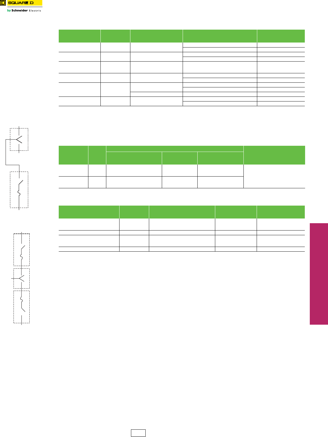
www.schneider-electric.us
3SAFETY SWITCHES
© 2012 Schneider Electric
All Rights Reserved 3-19
Double Throw Safety Switches Application Data
Class 3140 / Refer to Catalog 3100CT0901
aRating applies to AC only. The UL Listed short circuit current rating for non-fusible switches is based on the switch being used in conjunction with the
corresponding fuse type. Evaluation of non-fusible switches in conjunction with molded case circuit breakers has not been performed.
bThe DTU361 and DTU361RB are also suitable for use on a circuit capable of delivering not more than
(A) 18 kA, 600 Vac maximum when protected by Type FH circuit breaker rated 30 A maximum or
(B) 14 kA, 600 Vac maximum when protected by Type FA circuit breaker rated 30 A maximum.
cAny brand of circuit breaker or fuse not exceeding the ampere rating of the switch may be used ahead of a non-fusible safety switch when there is up to
10 kA short circuit current available.
d400 A 82,000 switch is only 10 kA.
eThomas and Betts catalog numbers.
fHubbell Versa-Crimp™ catalog numbers.
g200–600 A switches suitable for 75oC conductors.
h30 A switches suitable for 60oC or 75oC conductors.
iHubbell Versa-Crimp™ catalog numbers.
240 V Double Throw . . . . . . . . . . . . . . . . . . . . . . . . . . . . . . . . . . . . .page 3-16
600 V Double Throw . . . . . . . . . . . . . . . . . . . . . . . . . . . . . . . . . . . . page 3-17
Accessories . . . . . . . . . . . . . . . . . . . . . . . . . . . . . . . . . . . . . . . . . . . .page 3-18
Dimensions: 30–100 A (Series F) . . . . . . . . . . . . . . . . . . . . . . . . . .page 3-20
Dimensions: 30, 200–600 A (Series E, T4, A). . . . . . . . . . . . . . . . .page 3-21
Situations Requiring
Fuses
30–100 A Type DT
(Series F):
Select DT switches from
pages 3-16, 3-17, which
have provisions for
accepting fuses.
30 A, 200–600 A Type
82,000 (Series E, T4, A),
all DTU devices:
Use the non-fusible
double throw switches
from pages 3-16, 3-17 in
conjunction with standard
fusible devices, and
install them according to
diagram 1 or 2, below.
Diagram 1
Diagram 2
Line
Line
Non-Fusible
Double Throw
Switch
Load
Fusible Single
Throw Switch
or Circuit
Breaker
Line
Line
Load
Fusible
Single Throw
Switch or
Circuit
Breaker
Fusible
Single Throw
Switch or
Circuit
Breaker
Non-Fusible
Double
Throw
Switch
Table 3.44: UL Listed Short Circuit Current Ratings
Switch Type Amperes Voltage
Rating
UL Listed
Fuse Class
Short Circuit
Current Rating a
(A)
Typ e D T
(Series F) 30–100 A 240 V or
600 V
H, K 10,000
R, J 200,000
Type DTU b
(Series F) 30–100 A 240 V or
600 V
H or K 10,000 c
R, J or T 200,000
DTU224NRB and
DTU324NRB
(Series E)
200 A 240 V H, K 10,000 c
DTU324N
(Series E) 200 A 240 V H, K 10,000 c
R, J 100,000
Type 82,000 all 240 V H, K 10,000 c
R, J 100,000 d
600 V H, K 10,000 c
Type DTU (A series) 600 A 240 V or 600 V H, K 10,000
R, J, T 100,000
Table 3.45: Terminal Lug Data for Type DT, DTU (Series F) Double Throw Safety Switches
Switch Type
Wires
per
Phase
NEMA 1, 3R, 4, 4X, 12
Optional Copper Only Lug
Wire Range Wire Bending Space
Per NEC Table 373-6
AWG/kcmil
Standard Lug
Wire Range
AWG/kcmil
Optional
Compression Lug
Field-Installed
30–60 A
Type DT, DTU
(Series F)
1
12–2 Al
or
14–2 Cu
12–2 Al
or
14–2 Cu
C10-14,
D8-14,
or E6-14 eSee pages 3-12 and 3-14 for appropriate
kit.
Order two kits per switch.
100 A
Type DT, DTU
(Series F)
1
12–1/0 Al
or
14–1/0 Cu
12–1/0 Al
or
14–1/0 Cu
VCEL02114S1 f
Table 3.46: Terminal Lug Data for Types 82,000 and for A and E-Series DTU devices g
Amperes Wires per
Phase
Wire Range Wire Bending Space
Per NEC Table 373-6
AWG/kcmil
Lug Wire Range
AWG/kcmil
Optional Compression Lugs
Field-Installed
30 A (Series T4) h1 14–8 Al/Cu
12–2 Al
or
14–2 Cu
—
200 1 6–300 Al/Cu 6–300 Al/Cu VCEL030516H1 i
400
1
or
2
1/0–600 Al/Cu
or
1/0–300 Al/Cu
1/0–600 Al/Cu —
600 2 250–500 Al/Cu 250–500 Al/Cu —
DE1 Discount
Schedule
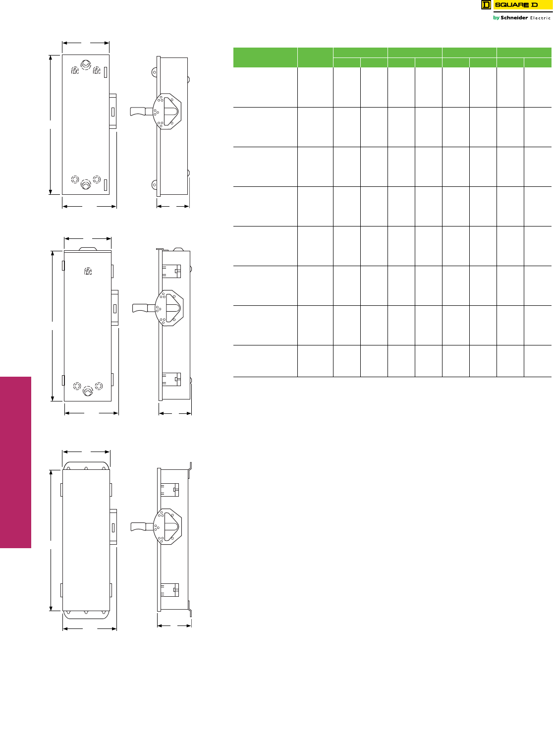
www.schneider-electric.us
3SAFETY SWITCHES
3-20 © 2012 Schneider Electric
All Rights Reserved
Double Throw Safety Switches Dimensions—Series F Devices
Class 3140 / Refer to Catalog 3100CT0901
240 V Double Throw . . . . . . . . . . . . . . . . . . . . . . . . . . . . . . . . . page 3-16
600 V Double Throw . . . . . . . . . . . . . . . . . . . . . . . . . . . . . . . . . . . . page 3-17
Accessories . . . . . . . . . . . . . . . . . . . . . . . . . . . . . . . . . . . . . . . . . . . page 3-18
Application Data . . . . . . . . . . . . . . . . . . . . . . . . . . . . . . . . . . . . . page 3-19
Dimensions: 30, 200–600 A (Series E, T4, A) . . . . . . . . . . . . . . . . page 3-21
Table 3.47: 30–100 A Type DT, DTU (Series F)—Approximate Dimensions
Cat. No. Series H W W/H D
in. mm in. mm in. mm in. mm
DT223 F5 38.00 965 9.88 251 11.13 283 6.75 171
DT223RB F5 38.00 965 6.87 174 8.12 206 6.60 168
DT321 F5 38.00 965 10.25 260 11.50 292 6.75 171
DT321RB F5 38.00 965 10.25 260 11.80 300 6.60 168
DT322 F5 38.00 965 10.25 260 11.50 292 6.75 171
DT322RB F5 38.00 965 10.25 260 11.80 300 6.60 168
DT323 F5 38.00 965 9.88 251 11.13 283 6.75 171
DT323RB F5 38.00 965 6.87 174 8.12 206 6.60 168
DT361 F5 38.00 965 10.25 260 11.50 292 6.75 171
DT361RB F5 38.00 965 10.25 260 11.80 300 6.60 168
DT362 F5 38.00 965 10.25 260 11.50 292 6.75 171
DT362RB F5 38.00 965 10.25 260 11.80 300 6.60 168
DT363 F5 38.00 965 9.88 251 11.13 283 6.75 171
DT363RB F5 38.00 965 6.87 174 8.12 206 6.60 168
DTU222 F5 29.94 760 10.25 260 11.96 304 6.93 176
DTU223 F5 29.94 760 10.25 260 11.96 304 6.93 176
DTU223RB F5 30.50 775 10.25 260 11.96 304 6.93 176
DTU321 F5 29.94 760 10.25 260 11.96 304 6.93 176
DTU322 F5 29.94 760 10.25 260 11.96 304 6.93 176
DTU323 F5 29.94 760 10.25 260 11.96 304 6.93 176
DTU323RB F5 30.50 775 10.25 260 11.96 304 6.93 176
DTU361 F5 29.94 760 10.25 260 11.96 304 6.93 176
DTU361RB F5 30.50 775 10.25 260 11.96 304 6.93 176
DTU362 F5 29.94 760 10.25 260 11.96 304 6.93 176
DTU362AWK F6 29.94 760 10.25 260 11.96 304 6.93 176
DTU362DS F6 30.26 769 10.25 260 11.50 292 7.12 181
DTU362RB F5 30.50 775 10.25 260 11.96 304 6.93 176
DTU363 F5 29.94 760 10.25 260 11.96 304 6.93 176
DTU363AWK F6 29.94 760 10.25 260 11.96 304 6.93 176
DTU363DS F6 30.26 769 10.25 260 11.50 292 7.12 181
DTU363RB F5 30.50 775 10.25 260 11.96 304 6.93 176
DTU462 F5 29.94 760 10.25 260 11.96 304 6.93 176
DTU462AWK F6 30.26 769 15.50 394 16.75 425 7.12 181
DTU462DS F6 30.26 769 15.50 394 16.75 425 7.12 181
DTU463 F5 29.94 760 10.25 260 11.96 304 6.93 176
DTU463AWK F6 30.26 769 15.50 394 16.75 425 7.12 181
DTU463DS F6 30.26 769 15.50 394 16.75 425 7.12 181
DTU662AWK F6 30.26 769 15.50 394 16.75 425 7.12 181
DTU663AWK F6 30.26 769 15.50 394 16.75 425 7.12 181
W
W/H D
H
NEMA 1
W
W/H D
H
NEMA 3R
W
W/H D
H
NEMA 4, 4X, 5 and 12
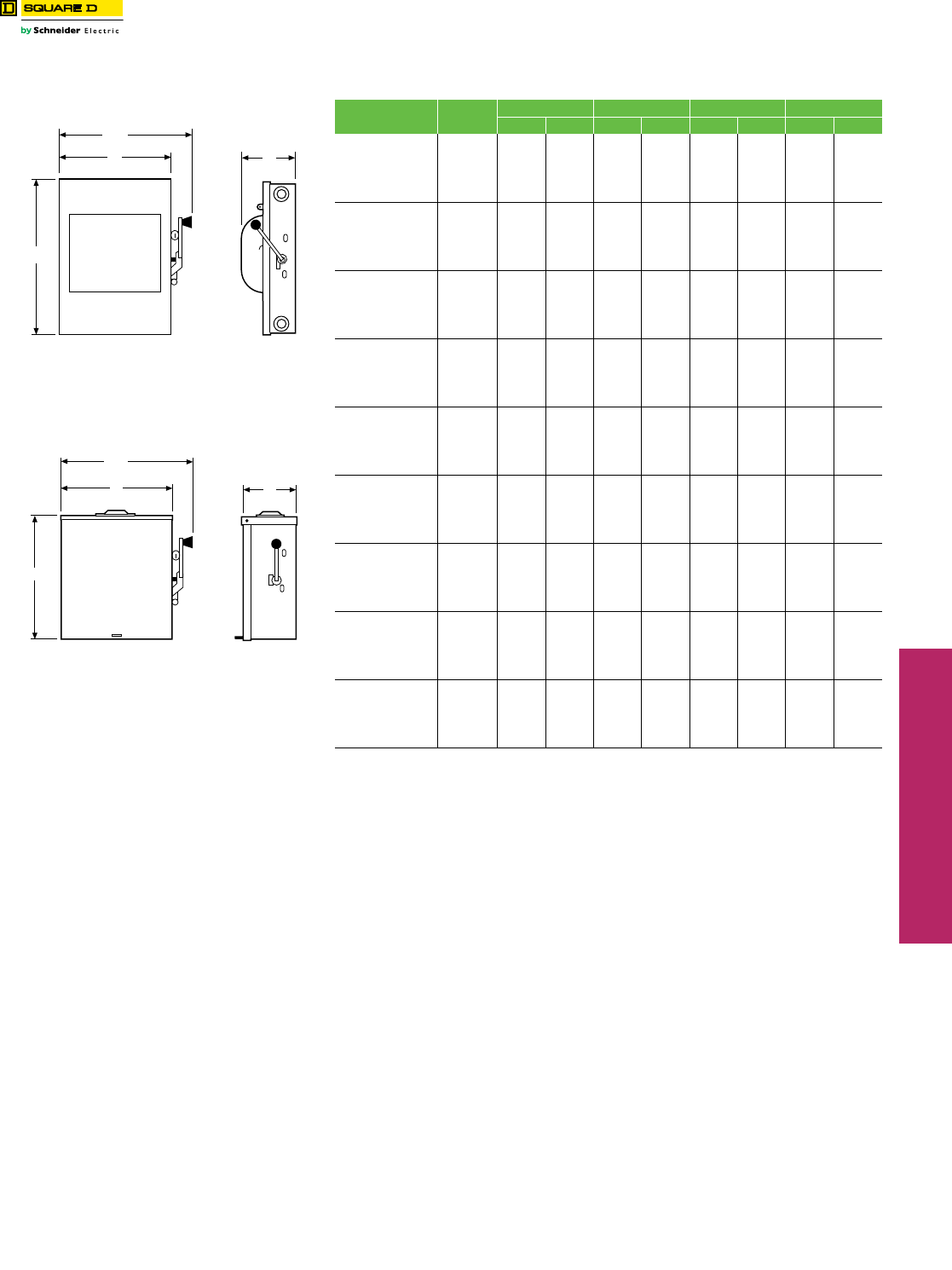
www.schneider-electric.us
3SAFETY SWITCHES
© 2012 Schneider Electric
All Rights Reserved 3-21
Double Throw Safety Switches Dimensions—Series A, E, and T4 Devices
Class 3140 / Refer to Catalog 3100CT0901
a250 V dc rated.
240 V Double Throw . . . . . . . . . . . . . . . . . . . . . . . . . . . . . . . . . . . . page 3-16
600 V Double Throw . . . . . . . . . . . . . . . . . . . . . . . . . . . . . . . . . . . . page 3-17
Accessories. . . . . . . . . . . . . . . . . . . . . . . . . . . . . . . . . . . . . . . . . . . . page 3-18
Application Data . . . . . . . . . . . . . . . . . . . . . . . . . . . . . . . . . . . . . . . .page 3-20
Dimensions: 30–100 A (Series F) . . . . . . . . . . . . . . . . . . . . . . . . . .page 3-20
Table 3.48: 30, 200–600 A Types 82,000 and E-Series DTU devices, NEMA 1 and
3R—Approximate Dimensions
Cat. No. Series H W W/H D
in. mm in. mm in. mm in. mm
DTU224NRB aE1 32.50 826 20.63 524 24.00 610 10.63 270
82254 aE1 30.88 784 15.75 400 19.63 499 9.75 248
82254NW aE1 30.88 784 20.00 508 23.88 607 11.75 298
82344 aE2 30.88 784 20.00 508 23.88 607 11.75 298
82344RB aE1 32.50 826 20.63 524 24.00 610 10.63 270
82354 E1 30.88 784 20.00 508 23.88 607 11.75 298
92251 T4 10.00 254 8.00 203 9.75 248 4.75 121
82344DS E1 30.88 784 20.00 508 23.88 607 11.75 298
DTU324N E1 32.50 826 24.50 622 26.25 667 10.63 270
DTU324NRB E1 32.50 826 24.50 622 26.25 667 10.63 270
H82344 E2 32.50 826 24.50 622 26.25 667 10.63 270
H82444 aE2 32.50 826 30.21 767 33.61 854 10.63 270
H82454 E3 32.50 826 30.21 767 33.61 854 10.63 270
82454 E3 38.00 965 29.62 753 33.02 839 10.63 270
82444 E3 38.00 965 29.62 753 33.02 839 10.63 270
82454R aE3 38.00 965 29.62 753 33.02 839 10.63 270
82444R E3 38.00 965 29.62 753 33.02 839 10.63 270
H82254 E3 32.50 826 24.50 622 26.25 667 10.63 270
H82354 E3 32.50 826 24.50 622 26.25 667 10.63 270
82444DS aE3 38.00 965 29.62 753 33.02 839 10.63 270
82255 aA1 38.50 978 26.10 663 29.51 750 10.63 270
82255R A1 39.00 991 26.62 676 30.02 763 10.63 270
82345aA1 38.50 978 26.10 663 29.51 750 10.63 270
82345DSaA1 39.00 991 26.62 676 30.02 763 10.63 270
82345RaA1 39.00 991 26.62 676 30.02 763 10.63 270
82355 aA1 38.50 978 26.10 663 29.51 750 10.63 270
82355R aA1 39.00 991 26.62 676 30.02 763 10.63 270
82445 A1 38.50 978 30.10 765 33.50 851 10.63 270
82445R A1 39.00 991 30.21 767 33.61 854 10.63 270
82455 aA1 38.50 978 30.10 765 33.50 851 10.63 270
82455R A1 39.00 991 30.21 767 33.61 854 10.63 270
H82255 A1 39.00 991 26.62 676 30.02 763 10.63 270
H82345 A1 39.00 991 26.62 676 30.02 763 10.63 270
H82355 A1 39.00 991 26.62 676 30.02 763 10.63 270
H82445 A1 39.00 991 30.21 767 33.61 854 10.63 270
H82455 A1 39.00 991 30.21 767 33.61 854 10.63 270
DTU326 A1 63.31 1608 23.66 601 24.46 621 8.88 226
DTU426 A1 63.31 1608 27.00 686 27.80 706 8.88 226
DTU366 A1 63.31 1608 23.66 601 24.46 621 8.88 226
DTU466 A1 63.31 1608 27.00 686 27.80 706 8.88 226
DTU326R A1 63.76 1619 23.66 601 24.46 621 8.88 226
DTU426R A1 63.76 1619 27.00 686 27.80 706 8.88 226
DTU366R A1 63.76 1619 23.66 601 24.46 621 8.88 226
DTU466R A1 63.76 1619 27.00 686 27.80 706 8.88 226
DTU366AWK A1 63.76 1619 23.66 601 24.46 621 8.88 226
W
W/H
D
H
NEMA 1
W
H
D
W/H
DTU—200 A
NEMA 3R
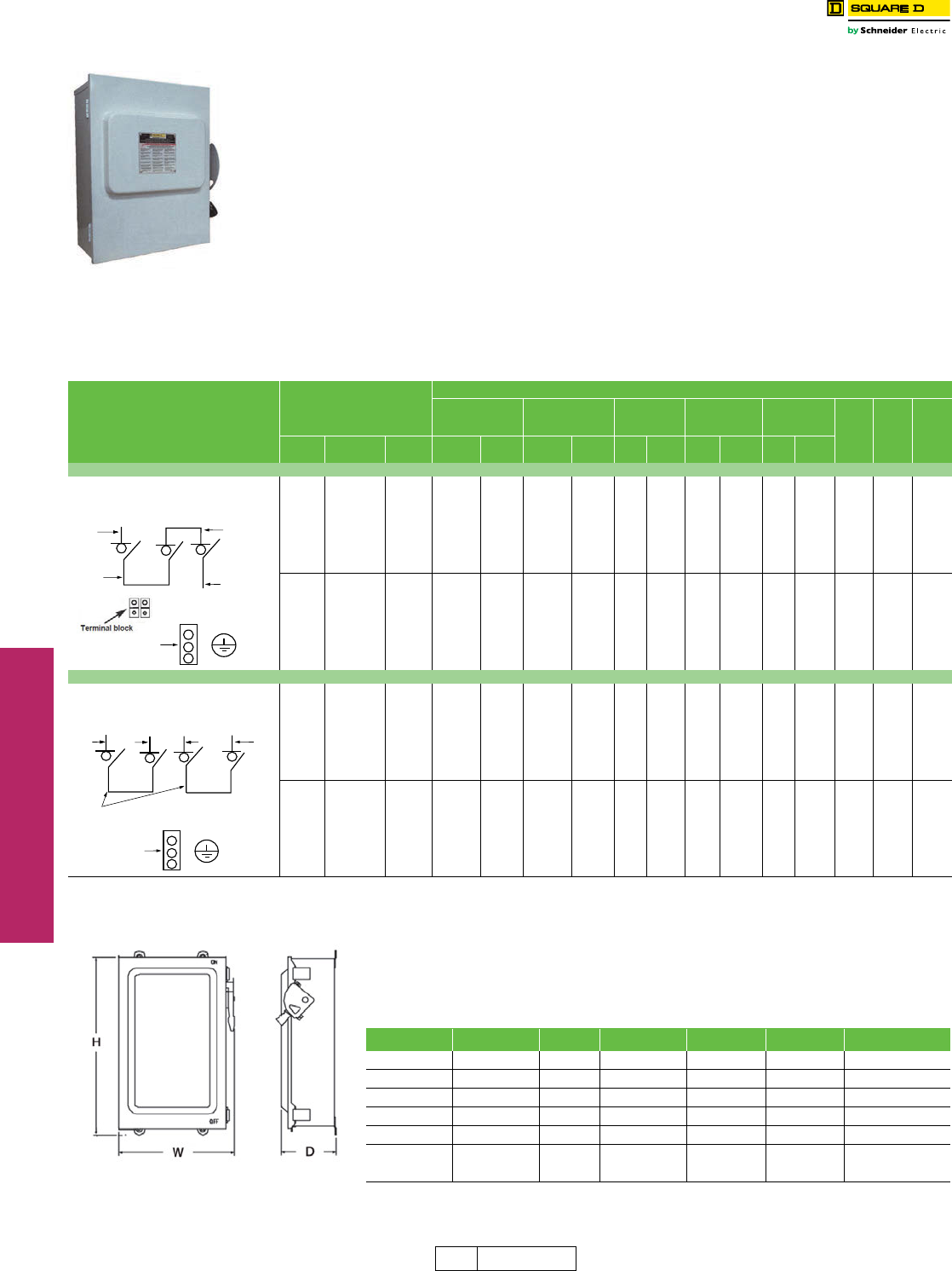
www.schneider-electric.us
3SAFETY SWITCHES
3-22 © 2012 Schneider Electric
All Rights Reserved
Put over 100 years of Schneider Electric’s experience as
a global specialist in energy management to work on your
photovoltaic (PV) project. The Square D™ 1000 Vdc
disconnect switch is the perfect solution for your 1000 Vdc
PV disconnect applications. It is compact and available in
both a 100 and 200 amp non-fusible versions. IEC 60947-
1 and 3 certified (file 136861) and UL 98 certified (file
E343341).
aOrder EIK1PV for single contact field-installed kit $311.00.
bOrder EIK2PV for double contact field-installed kit $355.00.
cAccommodates (2) 250 max Cu or (1) 1/0 max Cu wiring; Order
SN20CPV for field-installed kit $246.00.
dOrder REHGND KIT for field installable kit $100.00.
eTerminal blocks standard with 3 pole switches; accommodates (2) 1/0
max Al/Cu or (2) 6 max Al/Cu wiring.
For internal 600 Vdc PV combiner box switches please see our offering of 9422
switches 600 Vdc UL98 listed in digest pages 8-14.
For our 600 Vdc PV switch offering please see digest pages 3-5–3-6.
Extended Life Expectancy
Exceeds IEC 60947-3 mechanical endurance
requirements by factor of 18
Exceeds IEC 60947-1 electrical endurance requirements
by factor of 10
Exceeds NEMA KS-1 mechanical endurance
requirements by factor of 3.
Easy to Install
Preconfigured solar solution
Familiar enclosed safety switch design
Suitable for both grounded and ungrounded PV
Designed for Harsh PV Environments
NEMA Type 3 and IP63 enclosure
•Resists windblown dirt/dust
•Exceeds NEMA Type 1, 3R and 12
Operating range of -37°C to 50°C
Specially designed PV paint reduces solar gain up to 35%
over standard grey enclosures
Table 3.49: 1000 Vdc Photovoltaic Heavy Duty Disconnect Switch Pricing and Accessories
System
NEMA 1, 3R, 12, 3
and IP63
Factory Installed Accessories
Electrical Interlock
Single Contacta
Electrical Interlock
Two Contactsb
Viewing
Windows
Terminal Blocks
(Copper)c
3 Wire
Ground
LugdHeight
(in.)
Width
(in.)
Depth
(in.)
Amperes Cat. No. $ Price No. Suffix $ Price
Adder No. Suffix $ Price
Adder
No.
Suffix
$ Price
Adder
No.
Suffix
$ Price
Adder
No.
Suffix
$ Price
Adder
3 Pole Groundede
100 REHU393IP 1672.00 EI 452.00 EI2 496.00 VW 150.00 TBC 409.00 GL 263.00 22.13 18.63 8.75
200 REHU394IP 2246.00 EI 452.00 EI2 496.00 VW 175.00 TBC 409.00 GL 263.00 22.13 18.63 8.75
4 Pole Ungrounded
100 REHU493IP 2507.00 EI 452.00 EI2 496.00 VW 150.00 ——GL 263.00 29.00 18.63 8.75
200 REHU494IP 3965.00 EI 452.00 EI2 496.00 VW 175.00 ——GL 263.00 29.00 18.63 8.75
PE
Line
Connector
Connector
Load
Protective earth terminal
Three-Pole (Grounded System)
PE
Line
Connector
Line
Protective earth terminal
Four-Pole (Ungrounded System)
Load
Load
Schneider Electric gives the Photovoltaic market place the most comprehensive one stop shop
for Residential and Light Commercial Photovoltaic Balance of System components. Schneider
Electric's Inverters, and Square D brand DC and AC disconnect switches and Load Centers are
ideal solutions to your Balance of Systems requirements. See the Balance of System solution
chart below for your single phase PV system.
Table 3.50: PV Balance of System Solution Package—Grid Tie
System Voltage Kilowatts Amps DC Disconnect Inverter AC Disconnect Load Center Product
250 Vdc 2.8 30 HU361RB 878-2801 D221NRB QO130M200
250 Vdc 3.3 60 HU362RB 878-3301 D222NRB QO140M225
250 Vdc 3.3 100 HU363RB 878-3301 D223NRB QONQ42MS400
600 Vdc 3.8 30 HU361RB 878-3801 D221NRB QO130M200
600 Vdc 5.0 60 HU362RB 878-5001 D222NRB QO140M225
600 Vdc 5.0 100 HU363RB 878-5001 D223NRB QONQ42MS400
200 A Enclosed Switch Dimensions (inches)
DE1 Discount
Schedule
1000 Vdc Photovoltaic Heavy Duty
Disconnect Switch
Dimensions
Class 3110
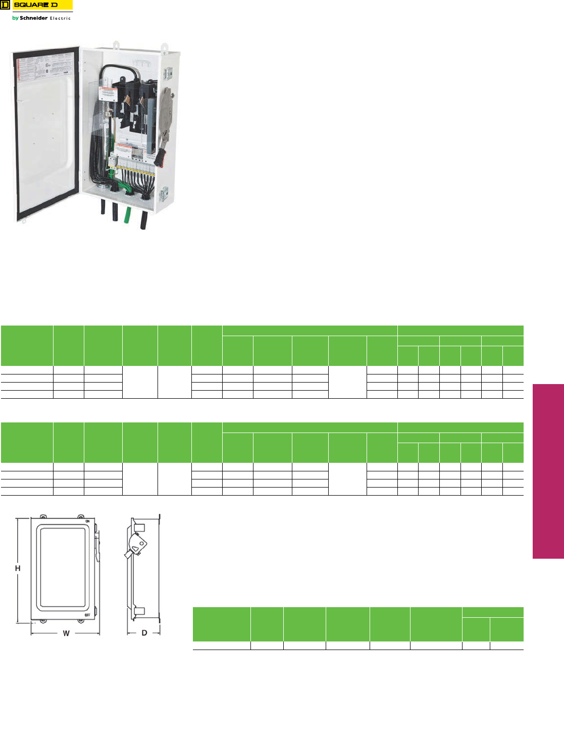
www.schneider-electric.us
3SAFETY SWITCHES
© 2012 Schneider Electric
All Rights Reserved 3-23
String Combiner Boxes Dimensions
Class 3140 / Refer to Catalog 3100CT0901
Square D PV string combiner boxes are used to integrate multiple PV strings into one output
circuit. Its tough exterior and safety features protect wiring from weather and overcurrent. The
exterior coating ensures low operating temperatures and longer life of internal components.
The specially engineered enclosure is designed to provide dust tight and rain tight protection;
it meets or exceeds NEMA® 3R, 12, and 4 requirements. Traditional Square D visible blade
switch architecture confirms disconnection, while touch-safe interior shielding protects
against accidental contact with live components.
Features
Flexible
•Vertical, horizontal, and angled mounting options
•Flexible installation with top, bottom, and side entry
•Substantial wire-bending space
Robust
•Dust tight and rain tight engineered enclosure for outdoor use
•UV-resistant white exterior coating to reduce solar gain by 35%
•Meets or exceeds NEMA 3R, 12, and 4 requirements
Safe
•Square D traditional visible blade switch architecture for confirmation of disconnect
•Touch-safe interior shielding guards against accidental contact with current-carrying components
•Seismic-certified 100–400 amp string combiner boxes for earthquake safety
•Optional integrated 2.5 kV surge arrestor to protect PV electronics from lightning strikes
Listings
•UL 1741
•Switches tested to UL98B
•CSA C22.2 Spec 107.1
Surge Protection Device
The 600 Vdc Type 2 Surge Protection Device (SPD) is for medium risk PV applications. The
SPD when installed in a Square D combiner box protects solar modules, power tracking and
blocking diodes from physical damage resulting from lightning induced transients. The SPD
device uses Metal Oxide Varistor (MOV)/Gas-Filled Spark Gap (GSP) protection circuits for
longer life and no current leakage. The devices are UL1449 ed 2 compliant Low Voltage
TVSS. The SP are available as factory installed by adding the suffix “S” to the combiner box
catalog number or as kits a kit: REHTYPE2SP.
Table 3.51: 600 Vdc Photovoltaic Combiner Boxes
Catalog
Numbera
Number
Input
Circuits
(Max.)
Continuous
DC Output
Current
(Max.)
Maximum
PV Module
Isc Rating
(Amps)
Maximum
Continuous
Input
Current
Per String
(Amps)
List
Price $
Wire Range (AWG/kcmil—Copper Only) Outside Dimmensions
Input
Circuit
(+ and -)
Output Circuit
(+ and -)
Output
Number of
Conductors
(+ or -)
Ground
In
Ground
Out
Height Width Depth
in. mm in. mm in. mm
REHSC126100 12 100
10.4 13
838.00 #12–#6 #6–1/0 1
#14–4 Or
2X #14–#12
#6–2/0 20.78 528 14.50 368 6.13 156
REHSC166200 16 200 1067.00 #12–#6 #6–300 MCM 1 #6–2/0 27.78 706 20.25 514 6.13 156
REHSC246300 24 300 1378.00 #12–#6 1/0–300 2 #6–2/0 35.78 909 20.25 514 6.13 156
REHSC326400 32 400 2226.00 #12–#6 1/0–300 2 #6–2/0 35.78 909 20.25 514 6.13 156
aFor factory installed surge protection device add the suffix “S” to the catalog number.
Table 3.52: 600 Vdc Photovoltaic Combiner Boxes With Disconnects
Catalog
Numbera
Number
Input
Circuits
(Max.)
Continuous
DC Output
Current
(Max.)
Maximum
PV Module
Isc Rating
(Amps)
Maximum
Continuous
Input
Current
Per String
(Amps)
List
Price $
Wire Range (AWG/kcmil—Copper Only) Outside Dimmensions
Input
Circuit
(+ and -)
Output Circuit
(+ and -)
Output
Number of
Conductors
(+ or -)
Ground
In
Ground
Out
Height Width Depth
in. mm in. mm in. mm
REHSC126100DU 12 100
10.4 13
1438.00 #12–#6 #6–1/0 1
#14–4 Or
2X #14–#12
#6–2/0 31.00 787 19.00 483 9.00 229
REHSC166200DU 16 200 1899.00 #12–#6 #6–300 MCM 1 #6–2/0 31.00 787 25.00 635 9.00 229
REHSC246300DU 24 300 3035.00 #12–#6 1/0–300 2 #6–2/0 41.00 1041 25.00 635 10.50 267
REHSC326400DU 32 400 3883.00 #12–#6 1/0–300 2 #6–2/0 41.00 1041 25.00 635 10.50 267
aFor factory installed surge protection device add the suffix “S” to the catalog number.
Typical String Combination Box Dimensions
Table 3.53: 600 Vdc Type 2 Surge Protection Device
Catalog
Number
Network
Vol tage
Nominal
Discharge
Current
per 20
micro sec
Maximum
Discharge
Current
per 20
micro sec
Operating
Current
Operating
Temperature;
Celsius
List Price $
Kit Factory
Installed
REHTYPE2SP 600 Vdc 20kA 40kA <0.1nA -40 to +85 337.00 490.00

www.schneider-electric.us
3SAFETY SWITCHES
3-24 © 2012 Schneider Electric
All Rights Reserved
