Omron F3SJ Safety Light Curtain Datasheet
2014-11-11
: Pdf 552406-Attachment 552406-Attachment 006085 Batch12 unilog
Open the PDF directly: View PDF ![]() .
.
Page Count: 88
- F3SJ v2 Safety Light Curtain (Type 4) Datasheet
- Continuing advances in the F3SJ help to create even safer production systems.
- New functions respond to a variety of safety needs.
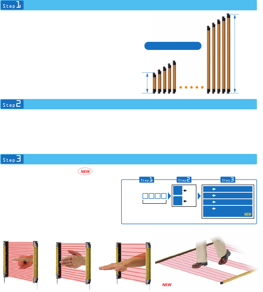
- Selecting a device is as easy as 1-2-3
- Easier to install, easier to use.
- Select the configuration that best meets your safety needs
- A variety of features are provided for easier use
- New functions for extra reliability
- Ordering Information
- Safety Light Curtains
- Ratings and Performance
- I/O Circuit
- Nomenclature
- Safety-related Functions
- Selecting the System Configuration
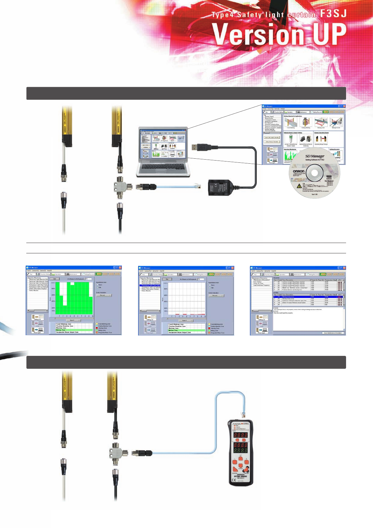
- System Configuration and Connection (Basic system)
- System Configuration and Connection (Muting system)
- Safety Precautions
- Using Setting Tools
- Two Kinds of Setting Tools
- Applications Supported by the Setting Tools
- Indicator and I/O Settings
- Changing the Detection Distance
- Monitoring Operation
- Other Functions
- Dimensions
- READ AND UNDERSTAND THIS CATALOG
New Models for Body
Protection or Presence
Detection
F3SJ Ver. 2
Safety Light Curtain (Type 4)
Cat. No. F074-E1-06
Authorized Distributor:
Note: Specifications subject to change without notice.
OMRON Corporation
Industrial Automation Company
Safety Devices Division
Shiokoji Horikawa, Shimogyo-ku,
Kyoto, 600-8530 Japan
Tel: (81)75-344-7093/Fax: (81)75-344-8197
Regional Headquarters
OMRON EUROPE B.V.
Wegalaan 67-69, NL-2132 JD Hoofddorp
The Netherlands
Tel: (31)2356-81-300/Fax: (31)2356-81-388
OMRON SCIENTIFIC TECHNOLOGIES INC.
6550 Dumbarton Circle Fremont,
CA 94555-3605 U.S.A.
Tel: (1)510-608-3400/Fax: (1)510-744-1442
OMRON ASIA PACIFIC PTE. LTD.
83 Clemenceau Avenue,
#11-01, UE Square,
239920 Singapore
Tel: (65)6835-3011/Fax: (65)6835-2711
OMRON (CHINA) CO., LTD.
Room 2211, Bank of China Tower,
200 Yin Cheng Road (M),
Shanghai, 200120 China
Tel: (86)21-5037-2222/Fax: (86)21-5037-2200
Printed in Japan
0207-1M (0605) (H)
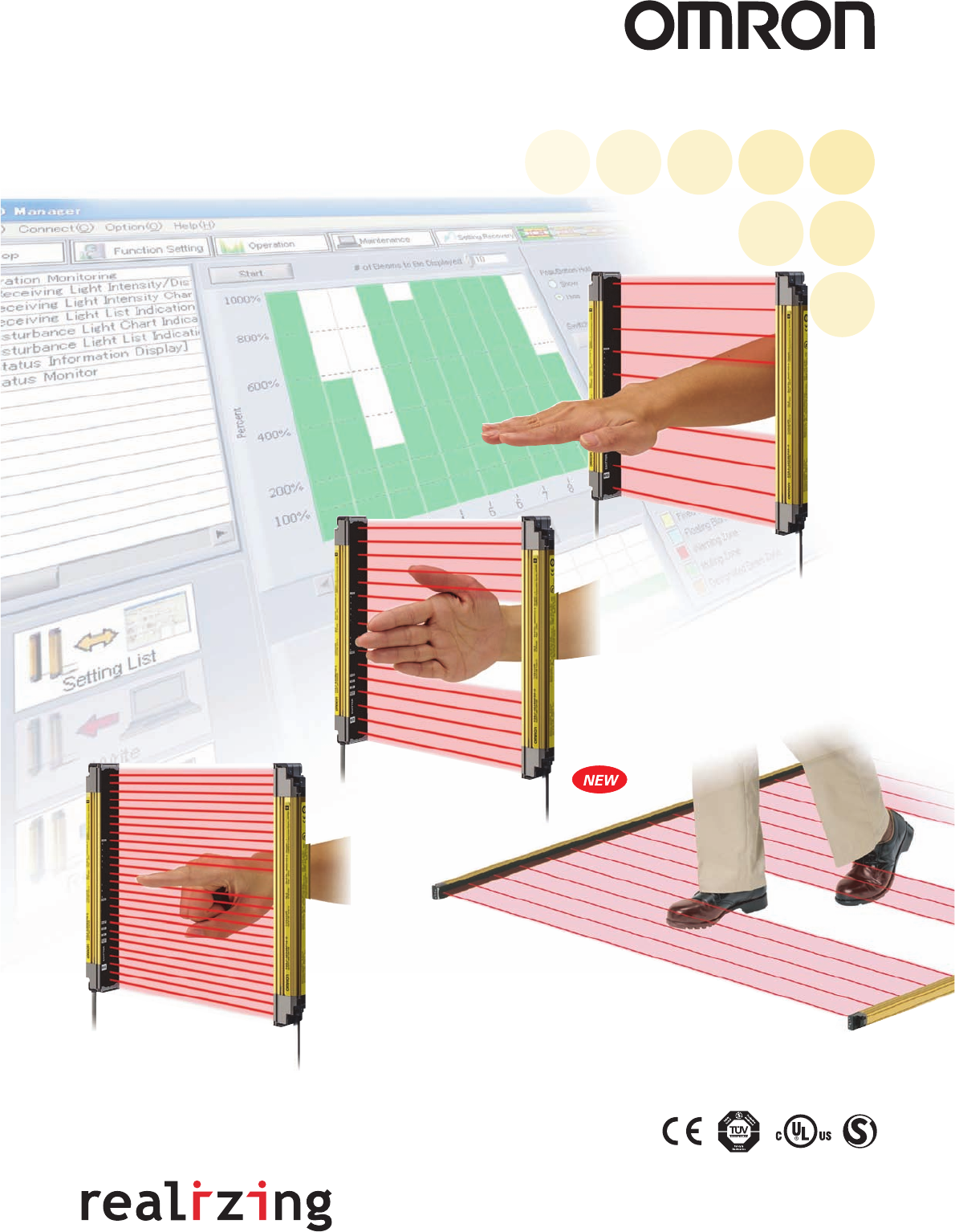
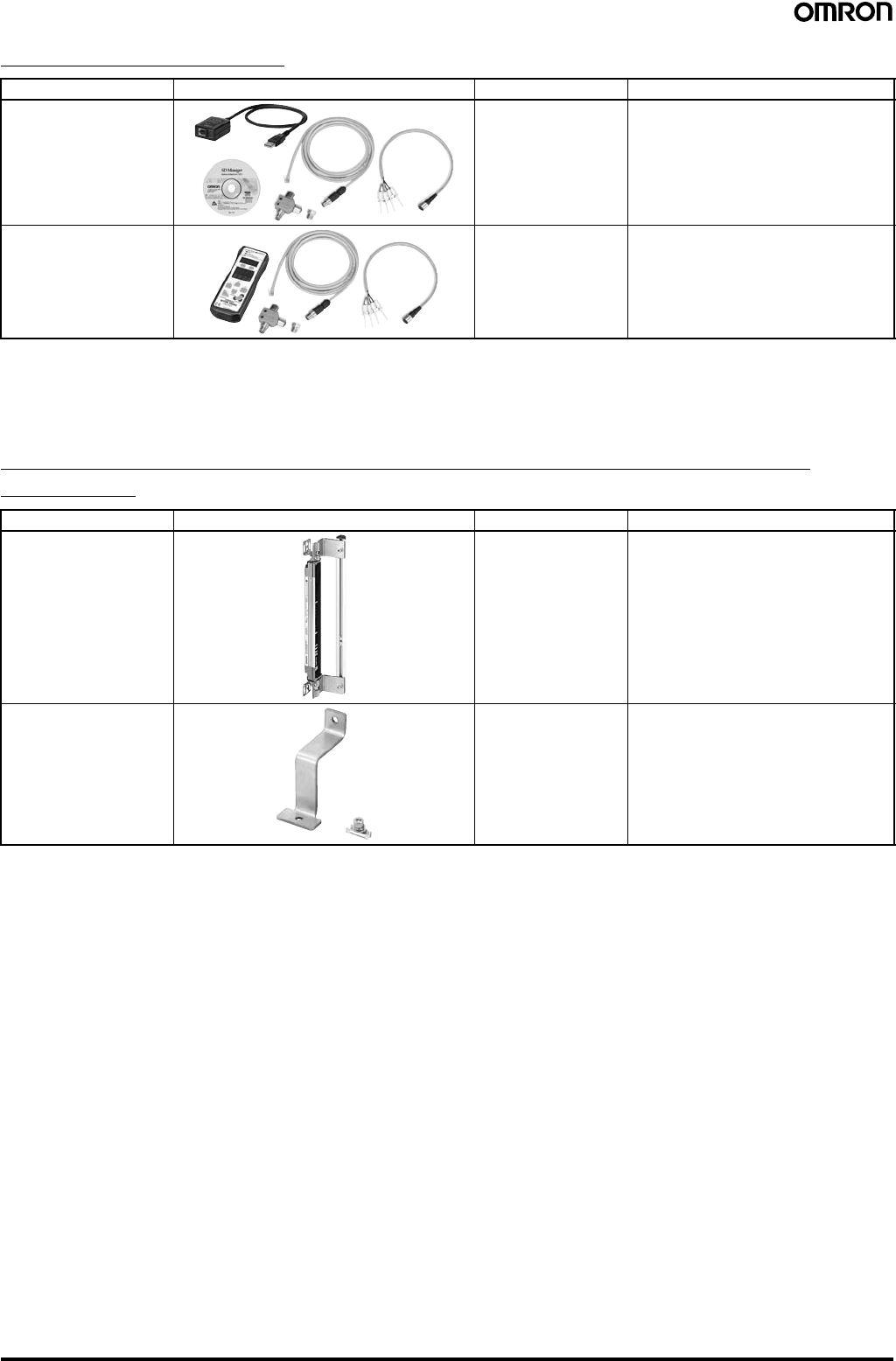
Setting Console
"SD Manager" PC Setting Support Software
● Beam alignment is easier.
● Ver. 2 Label Color
●
The ambient incident light intensity can be checked.
● The error log can be displayed.
The "SD Manager" PC Setting Support Software helps reduce the time required for installing and troubleshooting the Safety Light Curtain.
Continuing advances in the F3SJ help to
create even safer production systems.
The new F3SJ will satisfy your safety needs. Two new
tools make this Safety Light Curtain easier to set up and
use. The first is a newly developed setting support
software that allows all parameters to be set and the
system status to be checked with a personal computer.
The second is a Setting Console that lets you easily set
parameters and check the system status without having
to bring a personal computer to the worksite.
A number of new functions have also been provided to
ensure that you can use the Safety Light Curtain without
lowering productivity.
As a result, you can boost the safety of applications that
previously did not lend themselves to the use of a Safety
Light Curtain.
Choose from two new tools for setting parameters
Choose from two new tools for setting parameters
and checking the system status.
and checking the system status.
Choose from two new tools for setting parameters
and checking the system status.
All parameters can be set and the system status
can be checked with a personal computer. In
addition to making it easy to monitor the beam
alignment, the ambient incident light intensity
can be displayed in bar graph form for an easy
check of the system status.
F39-GWUM "SD
Manager" PC Setting
Support Software
The incident light level can be displayed
in a bar graph for each beam. The incident light level when the light
emission of the Safety Light Curtain is
stopped is displayed in a bar graph.
The cause of the errors and
countermeasures are both displayed.
When you don't want to carry a
personal computer onto the
worksite, the Setting Console is a
handy way to set parameters and
check the system status.
Note: The range of parameter setting and system status
checking capabilities is different for the PC Setting
Support Software and the Setting Console.
23
Connection Cable
To a USB terminal
F39-MC21
Setting Console for the F3SJ
Branch
Connector
F3SJ
Branch
Connector
F3SJ
Ver. 2 models have a yellow label. Models
with a white label are a previous version.
F39-JC@A Single-
end Connector Ca-
ble or F39-JC@B
Double-end Con-
nector Cable
F39-JC@A Single-
end Connector Ca-
ble or F39-JC@B
Double-end Con-
nector Cable
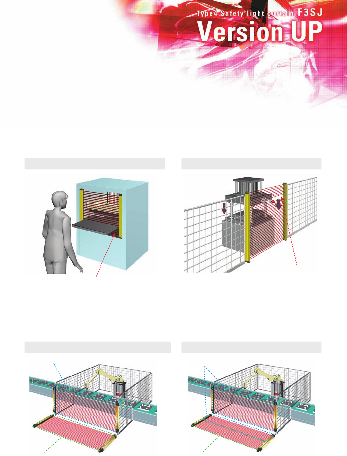
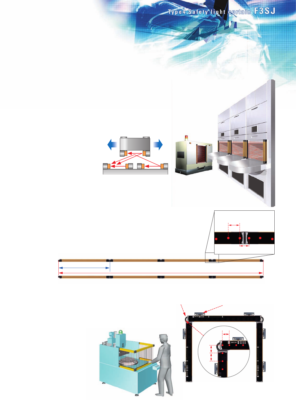
New functions respond to
a variety of safety needs.
● Partial muting
Warning zone
Detection zone
Warning zone
Detection zone
A number of new functions have been provided to ensure that you can use the Safety
Light Curtain without lowering productivity. This lets you boost the safety of applications
that previously did not lend themselves to the use of a Safety Light Curtain.
Note: The new functions on this page require the use of a setting tool. For details, see page 63 Using Setting Tools.
Two new functions have been added to the muting function.
The muting function temporarily disables the Safety Light Curtain when an object must pass through the detection zone, such
as when supplying a workpiece to your equipment. "Partial muting," which further heightens the level of safety, and "position
detection muting," which allows muting when the safety status can be determined by the position of a machine (such as a
robot), have been newly added to the muting function.
Partial muting raises safety by muting only the beams of the Safety
Light Curtain in the area where the workpiece passes through,
while preventing muting in all other areas. The Safety Light Curtain
beams in all areas other than
where the workpiece passes
through are constantly
ON.
Only the beams of the Safety Light Curtain that
would be interrupted by the workpiece are muted.
● Position detection muting
This is used in applications where the workpiece is set in position each time by an
operator, and then a turntable or positioning robot moves the workpiece to the area
where the work is done. A limit switch or other means is used to detect when the
robot is in a safe position, and muting is then applied.
● Fixed blanking
The blanking function disables specific beams of the Safety Light Curtain.
When a part of a machine is located inside the detection zone of the Safety Light Curtain,
the safety output will normally remain OFF and the machine cannot operate. The blanking
function makes it possible to disable specific beams for applications such as this.
● Floating blanking
●
Dividing the zone between series-connected sensors
A warning zone can be set to alert people before they enter a danger zone.
For example, you can set the F3SJ to generate only an alarm when someone approaches the danger zone, and to turn OFF
the control output when someone actually enters the danger zone. You can also divide the detection zone for a single F3SJ
into two zones, or set a warning zone for multiple, series-connected F3SJ Units. Plus, the auxiliary output can be used to
activate a flashing lamp as a warning to alert the person before turning OFF the machinery.
●
A single sensor can also be divided
The beam that would otherwise be
constantly interrupted by the
workbench is disabled.
In this case, 2-beam floating
blanking is set. If three or more
beams are interrupted, the
output goes OFF.
45
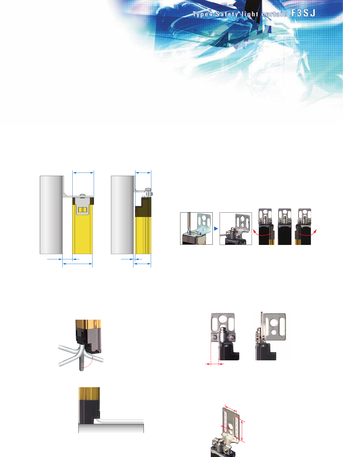
Easier to install,
easier to use.
Selecting a device is as easy as 1-2-3.
30 mm
15 mm
24 mm
45 mm 26 mm
2 mm
Previous model F3SJ
10 mm
37 mm
Can be used with a pitch of 18 to 20 mm
6 mm
245 mm
Minimum
2500 mm
Maximum
Sensor length = Protective height
Hand-protection Detection
67
Select the required sensor length.
The F3SJ incorporates the "perfect fit" concept that is a
feature of OMRON's other Safety Light Curtains. With a line-
up of products in 1-beam increments, you can find the
sensor that fits your setup perfectly. Refer to the list of
sensor models on pages 13 and 15 to select the minimum
sensor length required to cover the area you want to protect.
Note: We can also manufacture sensors with lengths not included in the list
of models. For details, please consult your OMRON sales
representative.
Select the output transistor.
Choose the PNP type when installing in safety system
configurations that comply with the Machinery Directive or
when using with a dedicated controller (F3SP-B1P or F3SX).
NPN types are also available as standard products when
replacing existing area sensors.
Select the application.
In addition to finger protection, hand protection, and
hand/arm protection models, new models have been added
that detects a leg or the presence of a person.
For areas where there is only a short distance to the source
of danger, select a finger protection model. For areas
where there is some distance to the hazardous point and
where the machinery stops with sufficient time to spare,
choose an economical hand/arm/body protection model.
Note: After selecting the type of device, calculate the safety distance
described on page 60 and change your selection if necessary.
Capability: 20 mm
diameter (Beam gap: 15
mm)
Capability: 30 mm
diameter (Beam gap: 25
mm)
The thin sensor saves valuable space.
The sensor is 6 mm thinner than our previous models. When
you include the newly designed mounting brackets, which
also enable beams to be aligned after the sensor is mounted,
the total thickness is 26 mm - a reduction of 19 mm compared
to previous models. The low profile means the sensor will not
get in the way when adding safety applications to existing
equipment.
Flexible cable with a 5 mm bending
radius makes wiring a snap.
The F3SJ cables (0.3 m) have M12 connectors and can be
routed in any direction. Problems with connector
compatibility have been eliminated.
The included standard mounting
brackets are easier than ever to use.
The included mounting brackets, which are suitable for
general use, have been redesigned with ease of use in mind.
The new design allows easy screwdriver access, even when
mounting in tight spaces.
Also, after aligning the beams, screws can be tightened
while oriented perpendicular to the lens surface, just like the
panel mounting screws. On previous models, the carefully
adjusted beam angles would sometimes come out of
alignment when tightening the final screws. This problem has
been solved with the F3SJ, because the screw-tightening
direction is different from the angle adjustment direction. The
result is reduced installation time.
Free-directional cables can be
routed down, back, left or right.
Flexible cables with 5 mm
bending radius can be
adhesively mounted to the
floor.
The sensor can be rotated along
its axis. Beam alignment can be
fine-tuned, even when mounted
side by side on a surface.
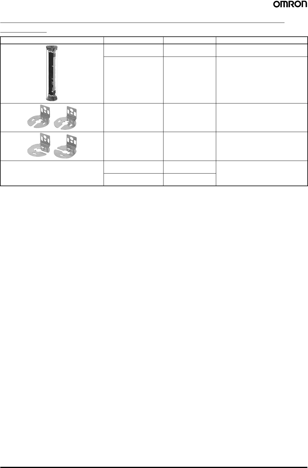
Side-mounting in tight spaces is simple.
When using standard mounting brackets to mount a sensor
on its side, the bracket protrudes outward in front of the lens
surface. When this protrusion is of concern, use the F39-LJ2
side-mounting brackets (sold separately).
Easy to change from previous models.
When replacing your previous standard multiple-beam area
sensor, use the F39-LJ4 top / bottom mounting bracket B
(sold separately), which features enlarged mounting holes.
Leg/body-protection and
Presence Detection
F3SJ-A
Protective height
(0245 to 2495 mm) Output type
Detection type
14 Finger
20
Hand
55
P
N
30
Hand/arm
PNP
output
NPN
output
Finger-protection
Detection
Capability: 14 mm diameter
(Beam gap: 9 mm)
Hand-protection
Detection
Capability: 20 mm diameter
(Beam gap: 15 mm)
Hand/arm-protection
Detection
Capability: 30 mm diameter
(Beam gap: 25 mm) Capability: 55 mm diameter
(Beam gap: 50 mm)
The direction of all screws can be
oriented perpendicular to the lens
surface. Easy screwdriver access.
F3SJ
Previous model
Leg/body-protection and
Presence Detection
Easier to install,
easier to use.
Selecting a device is as easy as 1-2-3.
30 mm
15 mm
24 mm
45 mm 26 mm
2 mm
Previous model F3SJ
10 mm
37 mm
Can be used with a pitch of 18 to 20 mm
6 mm
245 mm
Minimum
2500 mm
Maximum
Sensor length = Protective height
Hand-protection Detection
67
Select the required sensor length.
The F3SJ incorporates the "perfect fit" concept that is a
feature of OMRON's other Safety Light Curtains. With a line-
up of products in 1-beam increments, you can find the
sensor that fits your setup perfectly. Refer to the list of
sensor models on pages 13 and 15 to select the minimum
sensor length required to cover the area you want to protect.
Note: We can also manufacture sensors with lengths not included in the list
of models. For details, please consult your OMRON sales
representative.
Select the output transistor.
Choose the PNP type when installing in safety system
configurations that comply with the Machinery Directive or
when using with a dedicated controller (F3SP-B1P or F3SX).
NPN types are also available as standard products when
replacing existing area sensors.
Select the application.
In addition to finger protection, hand protection, and
hand/arm protection models, new models have been added
that detects a leg or the presence of a person.
For areas where there is only a short distance to the source
of danger, select a finger protection model. For areas
where there is some distance to the hazardous point and
where the machinery stops with sufficient time to spare,
choose an economical hand/arm/body protection model.
Note: After selecting the type of device, calculate the safety distance
described on page 60 and change your selection if necessary.
Capability: 20 mm
diameter (Beam gap: 15
mm)
Capability: 30 mm
diameter (Beam gap: 25
mm)
The thin sensor saves valuable space.
The sensor is 6 mm thinner than our previous models. When
you include the newly designed mounting brackets, which
also enable beams to be aligned after the sensor is mounted,
the total thickness is 26 mm - a reduction of 19 mm compared
to previous models. The low profile means the sensor will not
get in the way when adding safety applications to existing
equipment.
Flexible cable with a 5 mm bending
radius makes wiring a snap.
The F3SJ cables (0.3 m) have M12 connectors and can be
routed in any direction. Problems with connector
compatibility have been eliminated.
The included standard mounting
brackets are easier than ever to use.
The included mounting brackets, which are suitable for
general use, have been redesigned with ease of use in mind.
The new design allows easy screwdriver access, even when
mounting in tight spaces.
Also, after aligning the beams, screws can be tightened
while oriented perpendicular to the lens surface, just like the
panel mounting screws. On previous models, the carefully
adjusted beam angles would sometimes come out of
alignment when tightening the final screws. This problem has
been solved with the F3SJ, because the screw-tightening
direction is different from the angle adjustment direction. The
result is reduced installation time.
Free-directional cables can be
routed down, back, left or right.
Flexible cables with 5 mm
bending radius can be
adhesively mounted to the
floor.
The sensor can be rotated along
its axis. Beam alignment can be
fine-tuned, even when mounted
side by side on a surface.
Side-mounting in tight spaces is simple.
When using standard mounting brackets to mount a sensor
on its side, the bracket protrudes outward in front of the lens
surface. When this protrusion is of concern, use the F39-LJ2
side-mounting brackets (sold separately).
Easy to change from previous models.
When replacing your previous standard multiple-beam area
sensor, use the F39-LJ4 top / bottom mounting bracket B
(sold separately), which features enlarged mounting holes.
Leg/body-protection and
Presence Detection
F3SJ-A
Protective height
(0245 to 2495 mm) Output type
Detection type
14 Finger
20
Hand
55
P
N
30
Hand/arm
PNP
output
NPN
output
Finger-protection
Detection
Capability: 14 mm diameter
(Beam gap: 9 mm)
Hand-protection
Detection
Capability: 20 mm diameter
(Beam gap: 15 mm)
Hand/arm-protection
Detection
Capability: 30 mm diameter
(Beam gap: 25 mm) Capability: 55 mm diameter
(Beam gap: 50 mm)
The direction of all screws can be
oriented perpendicular to the lens
surface. Easy screwdriver access.
F3SJ
Previous model
Leg/body-protection and
Presence Detection
Select the configuration that best
meets your safety needs.
A G V
■ Application example
U-shaped configuration
F39-LJ3 free-location mounting
brackets can be mounted in any
location, without getting in the
way of the adjacent sensor.
Total length: Approx. 10 m (400 beams)
Approx. 2.5 m (100 beams)
20 mm gap between end beams when
connected side by side
25 mm
Series connection cable up to 15 m long
25 mm
25 mm
25 mm
A variety of features
are provided for easier use.
89
Emergency Stop
Switch
F39-JC@B Connector
Cable for F3SJ use
Branch Connector
F39-CN5
F39-JC@T
Connector Cable
for F3SX use
F3SX
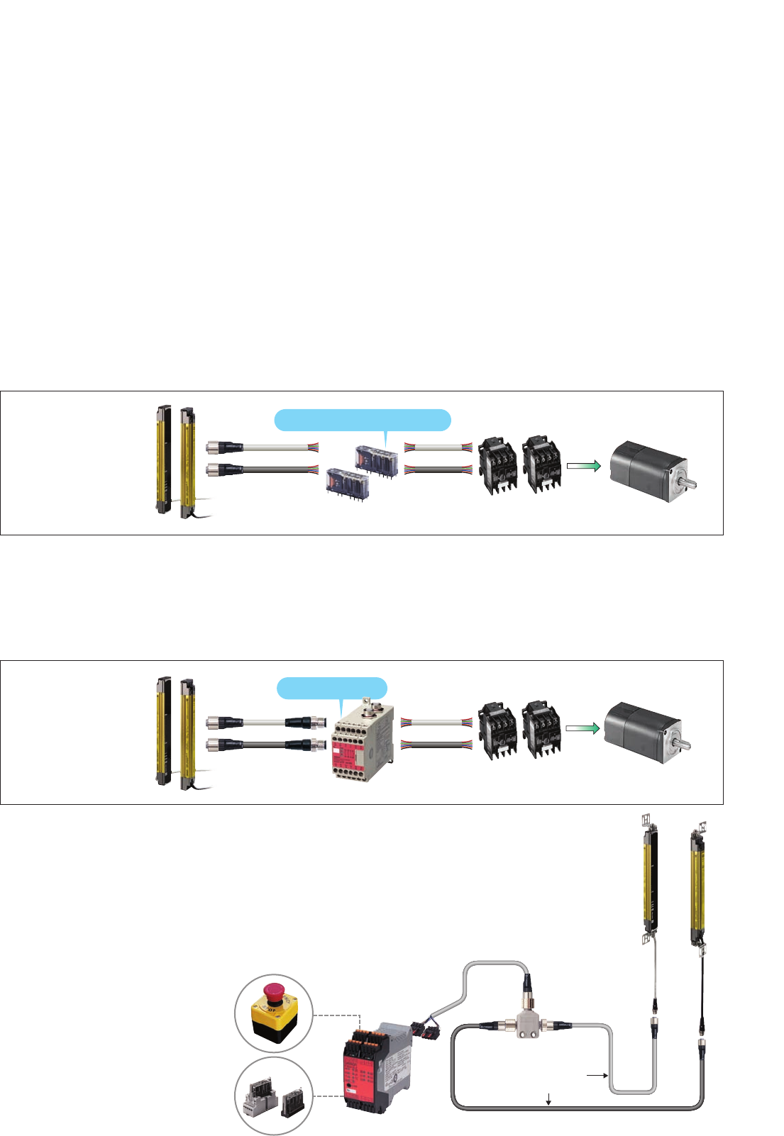
Relays with Forcibly Guided Contacts
This configuration, which only OMRON can provide, features a sensor unit with
an output feedback function required for Safety Category 4. Simply by using a
pair G7SA or G7S-E Safety Relays, you can easily and economically configure
a Category 4 safety circuit.
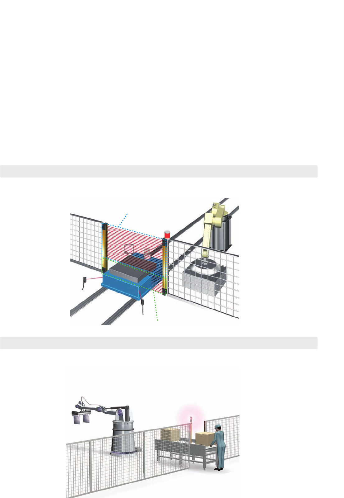
The F3SJ-A Safety Light Curtain is a Type 4 safety sensor that can be used to configure a Category 4
safety circuit. Several suggested configurations that are ideal for a variety of safety needs are outlined
below.
F39-JC@A
G7SA Contactor Motor
No Safety Relay Unit
F3SP-B1P
Dedicated Controller
Connector type
F39-JC@BContactor Motor
Space-efficient and low-cost system
● Low-cost and
space-efficient
The built-in external device
monitoring function
eliminates the need for a
Safety Relay Unit. A welded contact
detection circuit can
be created using two
Safety Relays.
Using single Safety Relays requires a lot of labor for wiring. To simplify the connection process, use
F39-JC@B Double-end Connector Cable and an F3SP-B1P Dedicated Controller. (Use a PNP type
for this configuration. NPN types cannot be connected when using an F3SP-B1P Relay.)
Wire-saving configuration
● Reduced wiring and
easy maintenance
Cables with connectors on
both ends simplify
connection, and prevent
wiring errors.
When an emergency stop switch or door switch is used with the F3SJ-A Safety
Light Curtain, the safety circuit may become complex, making circuit design
difficult. For this, we recommend using the F3SX Safety Controller. Select the
model that best matches the required input combination. Use an F39-CN5
Branch Connector (sold separately) to significantly reduce the amount of labor
required for wiring to the terminal block.
Multi-input safety circuit configuration
OMRON has developed a unique interference light prevention algorithm that
automatically prevents malfunction, even when light is received from three sets.
This feature is ideal for applications
where it is not possible to perform wiring
with an interference sensor, such as
between an AGV and installed equipment.
Also, the Setting Tool can be used to
adjust the emitted light intensity to
minimize the effect of light on other
devices.
(Updated function)
Resistant to mutual interference. No wiring between
sensors and no interference for up to three sets.
Sensors with protective heights of up to nearly 2.5 meters are available for
applications that involve large-sized workpieces. And if you happen to make changes
in the future, you can always extend the protective height with series connections. Up
to four sets, or 400 beams, can be series-connected, and with series connection
cables up to 15 meters in length, applications can cover a wide area.
Maximum protective height of 2,500 mm.
Series connection is more convenient than ever.
To create "perfect fit" installations with no dead zones or extra space when
making series connections in L- or U-shaped configurations, use the F39-
LJ3 free-location mounting brackets (sold separately) and F39-JJR06L or
F39-JJR15L Side-by-side Series Connection Cable.
No bottlenecks in workflow. Free-location brackets
make vertical installation easy. Side-by-side Series
Connection Cable
(F39-JJR06L)
■ Keep a 25-mm beam gap in L-shaped installations.
The cable (F39-JJR06L) does not get in the way
when used in series connections.
Select the configuration that best
meets your safety needs.
A G V
■ Application example
U-shaped configuration
F39-LJ3 free-location mounting
brackets can be mounted in any
location, without getting in the
way of the adjacent sensor.
Total length: Approx. 10 m (400 beams)
Approx. 2.5 m (100 beams)
20 mm gap between end beams when
connected side by side
25 mm
Series connection cable up to 15 m long
25 mm
25 mm
25 mm
A variety of features
are provided for easier use.
89
Emergency Stop
Switch
F39-JC@B Connector
Cable for F3SJ use
Branch Connector
F39-CN5
F39-JC@T
Connector Cable
for F3SX use
F3SX
Relays with Forcibly Guided Contacts
This configuration, which only OMRON can provide, features a sensor unit with
an output feedback function required for Safety Category 4. Simply by using a
pair G7SA or G7S-E Safety Relays, you can easily and economically configure
a Category 4 safety circuit.
The F3SJ-A Safety Light Curtain is a Type 4 safety sensor that can be used to configure a Category 4
safety circuit. Several suggested configurations that are ideal for a variety of safety needs are outlined
below.
F39-JC@A
G7SA Contactor Motor
No Safety Relay Unit
F3SP-B1P
Dedicated Controller
Connector type
F39-JC@BContactor Motor
Space-efficient and low-cost system
● Low-cost and
space-efficient
The built-in external device
monitoring function
eliminates the need for a
Safety Relay Unit. A welded contact
detection circuit can
be created using two
Safety Relays.
Using single Safety Relays requires a lot of labor for wiring. To simplify the connection process, use
F39-JC@B Double-end Connector Cable and an F3SP-B1P Dedicated Controller. (Use a PNP type
for this configuration. NPN types cannot be connected when using an F3SP-B1P Relay.)
Wire-saving configuration
● Reduced wiring and
easy maintenance
Cables with connectors on
both ends simplify
connection, and prevent
wiring errors.
When an emergency stop switch or door switch is used with the F3SJ-A Safety
Light Curtain, the safety circuit may become complex, making circuit design
difficult. For this, we recommend using the F3SX Safety Controller. Select the
model that best matches the required input combination. Use an F39-CN5
Branch Connector (sold separately) to significantly reduce the amount of labor
required for wiring to the terminal block.
Multi-input safety circuit configuration
OMRON has developed a unique interference light prevention algorithm that
automatically prevents malfunction, even when light is received from three sets.
This feature is ideal for applications
where it is not possible to perform wiring
with an interference sensor, such as
between an AGV and installed equipment.
Also, the Setting Tool can be used to
adjust the emitted light intensity to
minimize the effect of light on other
devices.
(Updated function)
Resistant to mutual interference. No wiring between
sensors and no interference for up to three sets.
Sensors with protective heights of up to nearly 2.5 meters are available for
applications that involve large-sized workpieces. And if you happen to make changes
in the future, you can always extend the protective height with series connections. Up
to four sets, or 400 beams, can be series-connected, and with series connection
cables up to 15 meters in length, applications can cover a wide area.
Maximum protective height of 2,500 mm.
Series connection is more convenient than ever.
To create "perfect fit" installations with no dead zones or extra space when
making series connections in L- or U-shaped configurations, use the F39-
LJ3 free-location mounting brackets (sold separately) and F39-JJR06L or
F39-JJR15L Side-by-side Series Connection Cable.
No bottlenecks in workflow. Free-location brackets
make vertical installation easy. Side-by-side Series
Connection Cable
(F39-JJR06L)
■ Keep a 25-mm beam gap in L-shaped installations.
The cable (F39-JJR06L) does not get in the way
when used in series connections.
The newly developed board-free "1-
bit module" is freely mounted on flat
cable.
In addition to our standard products, we
are now able to manufacture devices with a
different number of beams, or with a variety of
beam gaps. For details about these special
products, consult your OMRON sales representative.
Lens
Holder cap
Holder
Shield plate
IC package
Can also be used with equipment subject to US OSHA standards (29 CFR 1910.212).
Satisfies the requirements of the ANSI/RIA R15.06-1999 standards for industrial robots.
International standards
EU legislation EN standards
JIS standards
North American standards
IEC61496-1, IEC61496-2, IEC61508 1998 (SIL3)
Machinery Directive, EMC Directive, EN61496-1, prEN61496-2, EN61508 2001 (SIL3)
JIS B9704-1, B9704-2
UL61496-1, UL61496-2, UL508, UL1998, CAN/CSA22.2 NO.14, CAN/CSA22.2 NO.0.8
cUL
Built-in muting function
■ No controller required. Simply attach the Key Cap (sold separately) to
the sensor.
F39-CN6
Key Cap for Muting
The muting function temporarily disables the light curtain
when an object must pass through the detection zone, such
as when supplying a workpiece to your equipment.
In the past, this function required a dedicated muting
controller, but now it is built into the F3SJ. To use the muting
function, purchase the F39-CN6 Key Cap for Muting (sold
separately). The muting function is enabled simply by
replacing the Unit's cap with this Key Cap. In addition, a
muting sensor that determines the muting timing, as well as
a muting lamp that communicates the muting status to other
operators, should be connected to the F3SJ.
1 234 5 Incident light level
170% or higher of control output ON level
From 130 to 170% of control output ON level
From 100 to 130% of control output ON level
From 75 to 100% of control output ON level
From 50 to 75% of control output ON level
Less than 50% of control output ON level
A B C Cause of error
OFF Blinking ON
OFF ON
● Error Mode Indication Patterns and Causes of Errors
● Indication Patterns and Light Levels of the Incident Light Level Indicator
ERR
O
R-
C
ERR
O
R-B
ERR
O
R-A
LEVEL
-
1
LEVEL
-2
LEVEL-
3
LEVEL
-4
LEVEL-
5
Emitter Receiver
Mutual interference or ambient incident light.
Power supply voltage of F3SJ is out of the rated range.
Insufficient current capacity of power supply.
Incident light to blanking beams.
Failure in communication line.
Emitter and receiver have different F3SJ type
names or number of series connections.
Outside the effective range of parameters set by setting tool.
Cap is not attached.
External device monitor failure.
Failure in interlock selection input line or reset input line.
Muting wiring failure.
Failure in control output wiring.
Failure in series connection cable wiring.
Broken series connection cable.
Influence of electrical noise, or failure in a series-connected F3SJ.
Wiring error or broken communications wire.
Failure in wiring of external display lamp output.
Failure in wiring of auxiliary output.
10 11
New functions for extra reliability.
Combine safety and productivity with a
controller-less muting function.
The incident light level indicator uses orange LED lights for
levels 1 to 3, and green LED lights for levels 4 to 5. The
green LED lights indicate that a stable amount of light is
being received. The error indicator uses a variety of
illumination and blinking patterns, enabling more detailed
diagnosis results to be communicated via the display.
A new and improved LED indicator.
The Safety Light Curtain can be disabled when
an AGV carrying a workpiece passes through.
The connectors for series connection feature an intelligent
design. To connect a series connection cable to the F3SJ,
remove the Key Cap that is required when the sensor is used by
itself. If you should happen to forget to connect the series
connection cable, the sensor will not operate by itself without the
Key Cap. This solves the problem of sensors operating
independently when a series connection cable is accidentally left
unconnected, such as when equipment is moved.
A measure to prevent you from forgetting
to connect a series connection cable.
Like previous Type 4 Safety Light Curtains, the F3SJ conforms to the latest
required safety standards and regulations. Since the F3SJ also complies with
IEC61508, the international standard for functional safety, safety is ensured
regardless of where it is used.
Complies with the latest international safety standards and regulations.
Operates as a single
sensor when the Key
Cap is attached.
Does not operate
without the Key Cap.
The quality of Safety Light Curtain performance is determined
by the quality of the emitter/receiver elements. With previous
models, one faulty beam resulted in the malfunction of the
entire sensor. However, the F3SJ features a newly developed
"1-bit module" that integrates the lens and other optical parts
with the emitter IC and receiver IC, which are key devices.
With characteristic inspection performed on each beam, as
well as a thorough quality traceability system using 2D codes,
performance is assured.
New core technology that supports reliability and customizability.
30 dia. 30 dia.
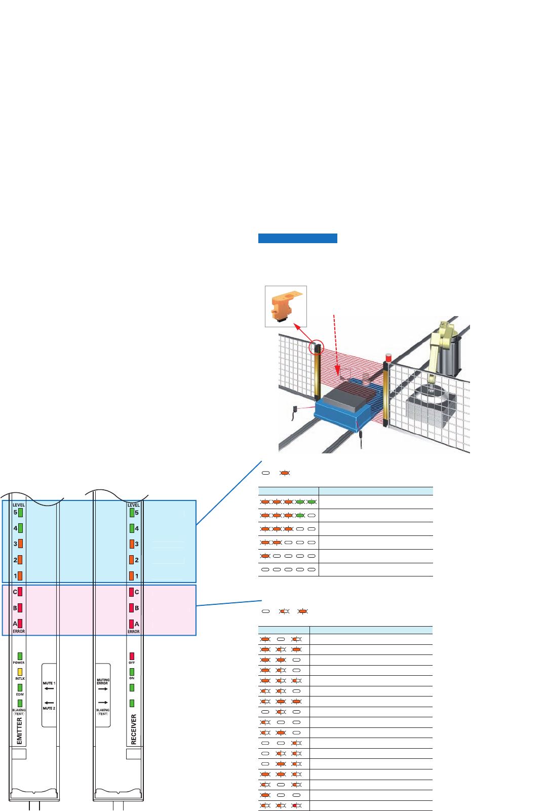
12 Safety Light Curtain (Type 4) F3SJ Ver. 2
Ordering Information
■Main Units
Safety Light Curtain F3SJ-A (Type 4)
Note: 1. Models with S-mark certification have an "-S" at the end of the model number. Example: F3SJ-A0245P14-S
2. Models with fixed auto reset (-TS). Parameters cannot be set using the F39-MC21 Setting Console or F39-GWUM "SD Manager" Setting
Support Software for F3SJ. See the Ratings and Performance data for other differences between this and standard models.
3. Models with NPN output can also be manufactured. Consult your OMRON representative for details.
4. Connection cables are not included with the products and are to be purchased separately, as needed. You must purchase optional
connector cable.
Application Detection
capability Beam
gap Appearance Operating range Number of
beams Protective height Model
PNP Output NPN Output
Finger
protection 14-mm-dia. 9 mm 26 to 180 245 to 1,631 mm F3SJ-
A@@@@P14
(See note 1.)
F3SJ-
A@@@@N14
Hand
protection 20-mm-dia. 15 mm 16 to 100 245 to 1,505 mm F3SJ-
A@@@@P20
(See note 1.)
F3SJ-
A@@@@N20
110 to 166 1,655 to 2,495 mm
16 to 100 245 to 1,505 mm F3SJ-
A@@@@P20
-TS
(See note 2.)
---
110 to 166 1,655 to 2,495 mm
25 mm-dia. 20 mm 13 to 82 260 to 1640 mm F3SJ-
A@@@@P25
-TS
(See note 2.)
---
83 to 125 1660 to 2500 mm
Hand/arm
protection 30-mm-dia. 25 mm 10 to 65 245 to 1,620 mm F3SJ-
A@@@@P30
(See note 1.)
F3SJ-
A@@@@N30
70 to 100 1,745 to 2,495 mm
Leg/body
protection,
Presence
Detection
55 mm-dia. 50 mm 6 to 33 270 to 1620 mm F3SJ-
A@@@@P55
(See note 1.)
---
(See note 3.)
34 to 50 1670 to 2470 mm
Infrared li
g
ht
0.2 to 9 m
0.2 to 9 m
0.2 to 7 m
0.2 to 9 m
0.2 to 7 m
0.2 to 9 m0.2 to 9 m
0.2 to 7 m
0.2 to 9 m
0.2 to 7 m
0.2 to 9 m
0.2 to 7 m

Safety Light Curtain (Type 4) F3SJ Ver. 2 13
Safety Light Curtains
■Safety Light Curtain Model List
Products other than those listed below are also available. Please contact your OMRON sales representative for details.
F3SJ-A14 Series (9 mm gap)
Note: Protective Height (mm) = Total sensor length
F3SJ-A20 Series (15-mm gap), F3SJ-A20-TS
Series (15-mm gap) (See note 1.)
Note: 1. The suffix "-TS" is attached to the model number of models
with fixed auto reset.
2. Protective Height (mm) = Total sensor length
Model No. of
Beams Protective Height
(mm) (See note.)
PNP Output NPN Output
F3SJ-A0245P14 F3SJ-A0245N14 26 245
F3SJ-A0263P14 F3SJ-A0263N14 28 263
F3SJ-A0281P14 F3SJ-A0281N14 30 281
F3SJ-A0299P14 F3SJ-A0299N14 32 299
F3SJ-A0317P14 F3SJ-A0317N14 34 317
F3SJ-A0335P14 F3SJ-A0335N14 36 335
F3SJ-A0353P14 F3SJ-A0353N14 38 353
F3SJ-A0371P14 F3SJ-A0371N14 40 371
F3SJ-A0389P14 F3SJ-A0389N14 42 389
F3SJ-A0407P14 F3SJ-A0407N14 44 407
F3SJ-A0425P14 F3SJ-A0425N14 46 425
F3SJ-A0443P14 F3SJ-A0443N14 48 443
F3SJ-A0461P14 F3SJ-A0461N14 50 461
F3SJ-A0479P14 F3SJ-A0479N14 52 479
F3SJ-A0497P14 F3SJ-A0497N14 54 497
F3SJ-A0515P14 F3SJ-A0515N14 56 515
F3SJ-A0533P14 F3SJ-A0533N14 58 533
F3SJ-A0551P14 F3SJ-A0551N14 60 551
F3SJ-A0569P14 F3SJ-A0569N14 62 569
F3SJ-A0587P14 F3SJ-A0587N14 64 587
F3SJ-A0605P14 F3SJ-A0605N14 66 605
F3SJ-A0623P14 F3SJ-A0623N14 68 623
F3SJ-A0659P14 F3SJ-A0659N14 72 659
F3SJ-A0695P14 F3SJ-A0695N14 76 695
F3SJ-A0731P14 F3SJ-A0731N14 80 731
F3SJ-A0767P14 F3SJ-A0767N14 84 767
F3SJ-A0803P14 F3SJ-A0803N14 88 803
F3SJ-A0839P14 F3SJ-A0839N14 92 839
F3SJ-A0875P14 F3SJ-A0875N14 96 875
F3SJ-A0911P14 F3SJ-A0911N14 100 911
F3SJ-A0983P14 F3SJ-A0983N14 108 983
F3SJ-A1055P14 F3SJ-A1055N14 116 1055
F3SJ-A1127P14 F3SJ-A1127N14 124 1127
F3SJ-A1199P14 F3SJ-A1199N14 132 1199
F3SJ-A1271P14 F3SJ-A1271N14 140 1271
F3SJ-A1343P14 F3SJ-A1343N14 148 1343
F3SJ-A1415P14 F3SJ-A1415N14 156 1415
F3SJ-A1487P14 F3SJ-A1487N14 164 1487
F3SJ-A1559P14 F3SJ-A1559N14 172 1559
F3SJ-A1631P14 F3SJ-A1631N14 180 1631
Model No. of
Beams Protective Height
(mm) (See note 2.)
PNP Output
(See note 1.) NPN Output
F3SJ-A0245P20 F3SJ-A0245N20 16 245
F3SJ-A0275P20 F3SJ-A0275N20 18 275
F3SJ-A0305P20 F3SJ-A0305N20 20 305
F3SJ-A0335P20 F3SJ-A0335N20 22 335
F3SJ-A0365P20 F3SJ-A0365N20 24 365
F3SJ-A0395P20 F3SJ-A0395N20 26 395
F3SJ-A0425P20 F3SJ-A0425N20 28 425
F3SJ-A0455P20 F3SJ-A0455N20 30 455
F3SJ-A0485P20 F3SJ-A0485N20 32 485
F3SJ-A0515P20 F3SJ-A0515N20 34 515
F3SJ-A0545P20 F3SJ-A0545N20 36 545
F3SJ-A0575P20 F3SJ-A0575N20 38 575
F3SJ-A0605P20 F3SJ-A0605N20 40 605
F3SJ-A0635P20 F3SJ-A0635N20 42 635
F3SJ-A0665P20 F3SJ-A0665N20 44 665
F3SJ-A0695P20 F3SJ-A0695N20 46 695
F3SJ-A0725P20 F3SJ-A0725N20 48 725
F3SJ-A0755P20 F3SJ-A0755N20 50 755
F3SJ-A0785P20 F3SJ-A0785N20 52 785
F3SJ-A0815P20 F3SJ-A0815N20 54 815
F3SJ-A0845P20 F3SJ-A0845N20 56 845
F3SJ-A0875P20 F3SJ-A0875N20 58 875
F3SJ-A0905P20 F3SJ-A0905N20 60 905
F3SJ-A0935P20 F3SJ-A0935N20 62 935
F3SJ-A0965P20 F3SJ-A0965N20 64 965
F3SJ-A0995P20 F3SJ-A0995N20 66 995
F3SJ-A1025P20 F3SJ-A1025N20 68 1025
F3SJ-A1055P20 F3SJ-A1055N20 70 1055
F3SJ-A1085P20 F3SJ-A1085N20 72 1085
F3SJ-A1115P20 F3SJ-A1115N20 74 1115
F3SJ-A1145P20 F3SJ-A1145N20 76 1145
F3SJ-A1175P20 F3SJ-A1175N20 78 1175
F3SJ-A1205P20 F3SJ-A1205N20 80 1205
F3SJ-A1235P20 F3SJ-A1235N20 82 1235
F3SJ-A1265P20 F3SJ-A1265N20 84 1265
F3SJ-A1325P20 F3SJ-A1325N20 88 1325
F3SJ-A1385P20 F3SJ-A1385N20 92 1385
F3SJ-A1445P20 F3SJ-A1445N20 96 1445
F3SJ-A1505P20 F3SJ-A1505N20 100 1505
F3SJ-A1655P20 F3SJ-A1655N20 110 1655
F3SJ-A1805P20 F3SJ-A1805N20 120 1805
F3SJ-A1955P20 F3SJ-A1955N20 130 1955
F3SJ-A2105P20 F3SJ-A2105N20 140 2105
F3SJ-A2255P20 F3SJ-A2255N20 150 2255
F3SJ-A2405P20 F3SJ-A2405N20 160 2405
F3SJ-A2495P20 F3SJ-A2495N20 166 2495

14 Safety Light Curtain (Type 4) F3SJ Ver. 2
F3SJ-A25-TS Series (20-mm gap) (See note 1.)
Note: 1. The models in the F3SJ-A25-TS Series have only an auto reset.
2. Protective Height (mm)= Total sensor length
F3SJ-A30 Series (25-mm gap)
Note: Protective Height (mm)= Total sensor length
Model No. of
Beams Protective Height
(mm) (See note 2.)
PNP output
F3SJ-A0260P25-TS 13 260
F3SJ-A0300P25-TS 15 300
F3SJ-A0340P25-TS 17 340
F3SJ-A0380P25-TS 19 380
F3SJ-A0420P25-TS 21 420
F3SJ-A0460P25-TS 23 460
F3SJ-A0500P25-TS 25 500
F3SJ-A0540P25-TS 27 540
F3SJ-A0580P25-TS 29 580
F3SJ-A0620P25-TS 31 620
F3SJ-A0660P25-TS 33 660
F3SJ-A0700P25-TS 35 700
F3SJ-A0740P25-TS 37 740
F3SJ-A0780P25-TS 39 780
F3SJ-A0820P25-TS 41 820
F3SJ-A0860P25-TS 43 860
F3SJ-A0900P25-TS 45 900
F3SJ-A0940P25-TS 47 940
F3SJ-A0980P25-TS 49 980
F3SJ-A1020P25-TS 51 1020
F3SJ-A1060P25-TS 53 1060
F3SJ-A1100P25-TS 55 1100
F3SJ-A1140P25-TS 57 1140
F3SJ-A1180P25-TS 59 1180
F3SJ-A1220P25-TS 61 1220
F3SJ-A1260P25-TS 63 1260
F3SJ-A1300P25-TS 65 1300
F3SJ-A1340P25-TS 67 1340
F3SJ-A1380P25-TS 69 1380
F3SJ-A1420P25-TS 71 1420
F3SJ-A1460P25-TS 73 1460
F3SJ-A1500P25-TS 75 1500
F3SJ-A1540P25-TS 77 1540
F3SJ-A1580P25-TS 79 1580
F3SJ-A1620P25-TS 81 1620
F3SJ-A1660P25-TS 83 1660
F3SJ-A1700P25-TS 85 1700
F3SJ-A1740P25-TS 87 1740
F3SJ-A1780P25-TS 89 1780
F3SJ-A1820P25-TS 91 1820
F3SJ-A1860P25-TS 93 1860
F3SJ-A1900P25-TS 95 1900
F3SJ-A1940P25-TS 97 1940
F3SJ-A1980P25-TS 99 1980
F3SJ-A2020P25-TS 101 2020
F3SJ-A2060P25-TS 103 2060
F3SJ-A2100P25-TS 105 2100
F3SJ-A2140P25-TS 107 2140
F3SJ-A2180P25-TS 109 2180
F3SJ-A2220P25-TS 111 2220
F3SJ-A2260P25-TS 113 2260
F3SJ-A2300P25-TS 115 2300
F3SJ-A2340P25-TS 117 2340
F3SJ-A2380P25-TS 119 2380
F3SJ-A2420P25-TS 121 2420
F3SJ-A2460P25-TS 123 2460
F3SJ-A2500P25-TS 125 2500
Model No. of
Beams Protective Height
(mm) (See note.)
PNP Output NPN Output
F3SJ-A0245P30 F3SJ-A0245N30 10 245
F3SJ-A0270P30 F3SJ-A0270N30 11 270
F3SJ-A0295P30 F3SJ-A0295N30 12 295
F3SJ-A0320P30 F3SJ-A0320N30 13 320
F3SJ-A0345P30 F3SJ-A0345N30 14 345
F3SJ-A0370P30 F3SJ-A0370N30 15 370
F3SJ-A0395P30 F3SJ-A0395N30 16 395
F3SJ-A0420P30 F3SJ-A0420N30 17 420
F3SJ-A0445P30 F3SJ-A0445N30 18 445
F3SJ-A0470P30 F3SJ-A0470N30 19 470
F3SJ-A0495P30 F3SJ-A0495N30 20 495
F3SJ-A0520P30 F3SJ-A0520N30 21 520
F3SJ-A0545P30 F3SJ-A0545N30 22 545
F3SJ-A0570P30 F3SJ-A0570N30 23 570
F3SJ-A0595P30 F3SJ-A0595N30 24 595
F3SJ-A0620P30 F3SJ-A0620N30 25 620
F3SJ-A0645P30 F3SJ-A0645N30 26 645
F3SJ-A0670P30 F3SJ-A0670N30 27 670
F3SJ-A0695P30 F3SJ-A0695N30 28 695
F3SJ-A0720P30 F3SJ-A0720N30 29 720
F3SJ-A0745P30 F3SJ-A0745N30 30 745
F3SJ-A0770P30 F3SJ-A0770N30 31 770
F3SJ-A0795P30 F3SJ-A0795N30 32 795
F3SJ-A0820P30 F3SJ-A0820N30 33 820
F3SJ-A0845P30 F3SJ-A0845N30 34 845
F3SJ-A0870P30 F3SJ-A0870N30 35 870
F3SJ-A0895P30 F3SJ-A0895N30 36 895
F3SJ-A0920P30 F3SJ-A0920N30 37 920
F3SJ-A0945P30 F3SJ-A0945N30 38 945
F3SJ-A0970P30 F3SJ-A0970N30 39 970
F3SJ-A0995P30 F3SJ-A0995N30 40 995
F3SJ-A1020P30 F3SJ-A1020N30 41 1020
F3SJ-A1045P30 F3SJ-A1045N30 42 1045
F3SJ-A1070P30 F3SJ-A1070N30 43 1070
F3SJ-A1095P30 F3SJ-A1095N30 44 1095
F3SJ-A1120P30 F3SJ-A1120N30 45 1120
F3SJ-A1145P30 F3SJ-A1145N30 46 1145
F3SJ-A1170P30 F3SJ-A1170N30 47 1170
F3SJ-A1195P30 F3SJ-A1195N30 48 1195
F3SJ-A1220P30 F3SJ-A1220N30 49 1220
F3SJ-A1245P30 F3SJ-A1245N30 50 1245
F3SJ-A1270P30 F3SJ-A1270N30 51 1270
F3SJ-A1295P30 F3SJ-A1295N30 52 1295
F3SJ-A1395P30 F3SJ-A1395N30 56 1395
F3SJ-A1495P30 F3SJ-A1495N30 60 1495
F3SJ-A1620P30 F3SJ-A1620N30 65 1620
F3SJ-A1745P30 F3SJ-A1745N30 70 1745
F3SJ-A1870P30 F3SJ-A1870N30 75 1870
F3SJ-A1995P30 F3SJ-A1995N30 80 1995
F3SJ-A2120P30 F3SJ-A2120N30 85 2120
F3SJ-A2245P30 F3SJ-A2245N30 90 2245
F3SJ-A2370P30 F3SJ-A2370N30 95 2370
F3SJ-A2495P30 F3SJ-A2495N30 100 2495

Safety Light Curtain (Type 4) F3SJ Ver. 2 15
F3SJ-A55 Series (50-mm gap)
Note: 1. Models with NPN output can also be manufactured.
2. Protective Height (mm)= Total sensor length
Model No. of
Beams Protective Height
(mm) (See note 2.)
PNP Output NPN Output
(See note 1.)
F3SJ-A0270P55 --- 6 270
F3SJ-A0320P55 7 320
F3SJ-A0370P55 8 370
F3SJ-A0420P55 9 420
F3SJ-A0470P55 10 470
F3SJ-A0520P55 11 520
F3SJ-A0570P55 12 570
F3SJ-A0620P55 13 620
F3SJ-A0670P55 14 670
F3SJ-A0720P55 15 720
F3SJ-A0770P55 16 770
F3SJ-A0820P55 17 820
F3SJ-A0870P55 18 870
F3SJ-A0920P55 19 920
F3SJ-A0970P55 20 970
F3SJ-A1020P55 21 1020
F3SJ-A1070P55 22 1070
F3SJ-A1120P55 23 1120
F3SJ-A1170P55 24 1170
F3SJ-A1220P55 25 1220
F3SJ-A1270P55 26 1270
F3SJ-A1320P55 27 1320
F3SJ-A1370P55 28 1370
F3SJ-A1420P55 29 1420
F3SJ-A1470P55 30 1470
F3SJ-A1520P55 31 1520
F3SJ-A1570P55 32 1570
F3SJ-A1620P55 33 1620
F3SJ-A1670P55 34 1670
F3SJ-A1720P55 35 1720
F3SJ-A1770P55 36 1770
F3SJ-A1820P55 37 1820
F3SJ-A1870P55 38 1870
F3SJ-A1920P55 39 1920
F3SJ-A1970P55 40 1970
F3SJ-A2020P55 41 2020
F3SJ-A2070P55 42 2070
F3SJ-A2120P55 43 2120
F3SJ-A2170P55 44 2170
F3SJ-A2220P55 45 2220
F3SJ-A2270P55 46 2270
F3SJ-A2320P55 47 2320
F3SJ-A2370P55 48 2370
F3SJ-A2420P55 49 2420
F3SJ-A2470P55 50 2470
16 Safety Light Curtain (Type 4) F3SJ Ver. 2
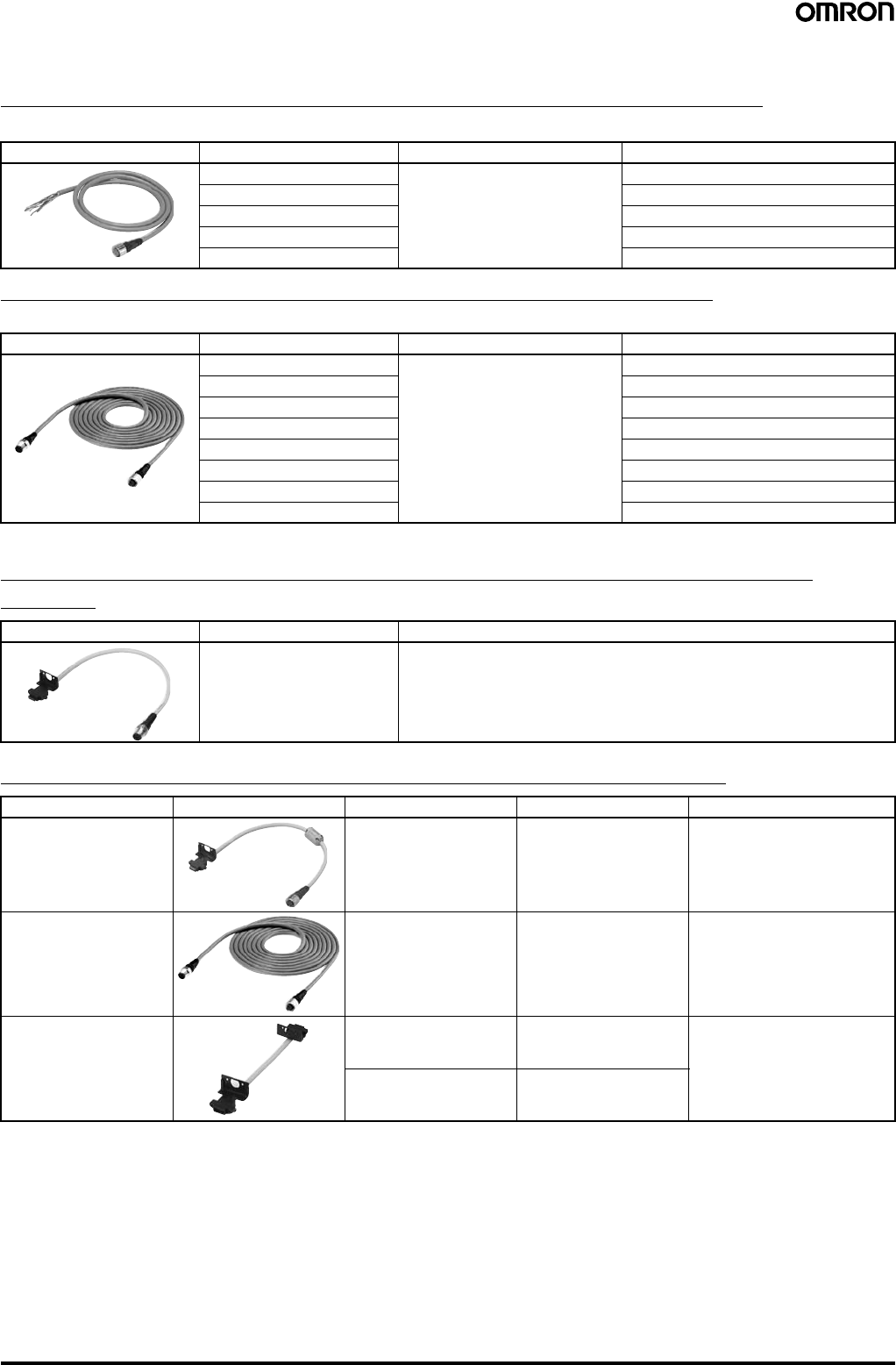
■Accessories (Optional)
Single-end Connector Cable (2 cables per set, for emitter and receiver)
For wiring with safety circuit such as single safety relay, safety relay unit, and safety controller
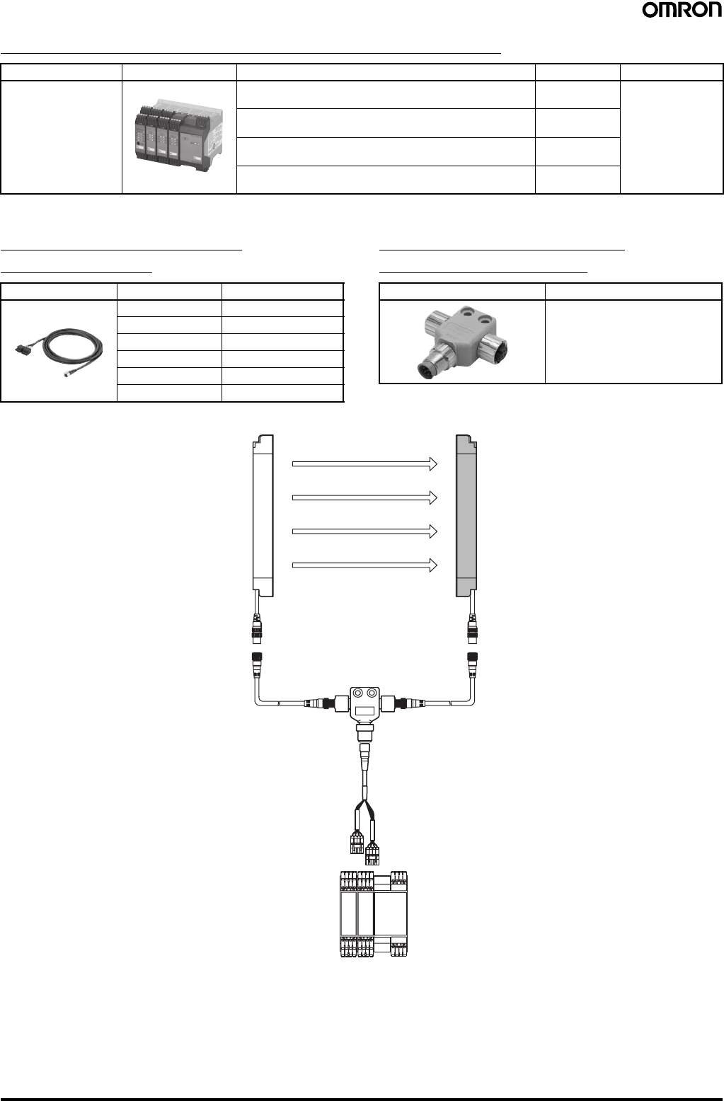
Double-end Connector Cable (2 cables per set, for emitter and receiver)
For connection with F3SP-B1P control unit, and for extension when series-connected (See note.)
Note: To extend the cable length under series connection, use F39-JJR3W and F39-JC@B in combination.
Power Cable (Included with the main unit) (2 cables per set, for emitter and
receiver)
Series Connection Cable (2 cables per set, for emitter and receiver)
Note: 1. Total cable length of series connection is 0.6 m to connect to connector cable of the main sensor unit.
For series connection with minimum length, use the F39-JJR06L or F39-JJR15L.
2. When using the F39-EJ@@@@-L/D Water-resistant Case in series connection configurations, use the special series connection cables
for the Water-resistant Case. Refer to page 21 for details.
Appearance Cable length Specifications Model
3 m M12 connector (8-pin) F39-JC3A
7 m F39-JC7A
10 m F39-JC10A
15 m F39-JC15A
20 m F39-JC20A
Appearance Cable length Specifications Model
0.5 m M12 connector (8-pin) F39-JCR5B
1 m F39-JC1B
3 m F39-JC3B
5 m F39-JC5B
7 m F39-JC7B
10 m F39-JC10B
15 m F39-JC15B
20 m F39-JC20B
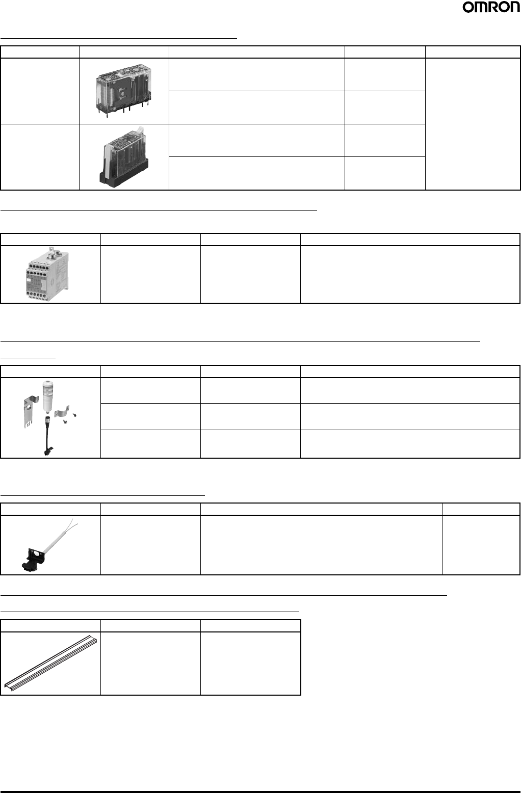
Appearance Cable length Model
0.3 m F39-JJR3K
Type Appearance Cable length Model Application
Series connection cable 0.3 m F39-JJR3W For series connection (See note
1.)
When using the Water-resistant
Case. (See note 2.)
Extension cable 0.5 to 15 m F39-JC@BTo change series connection
length in combination with F39-
JJR3W
Side-by-side Series
connection cable 0.06 m F39-JJR06L Dedicated series connection
cable with minimum length, used
in place of the sensor's cable
with connector
0.15 m F39-JJR15L
Safety Light Curtain (Type 4) F3SJ Ver. 2 17
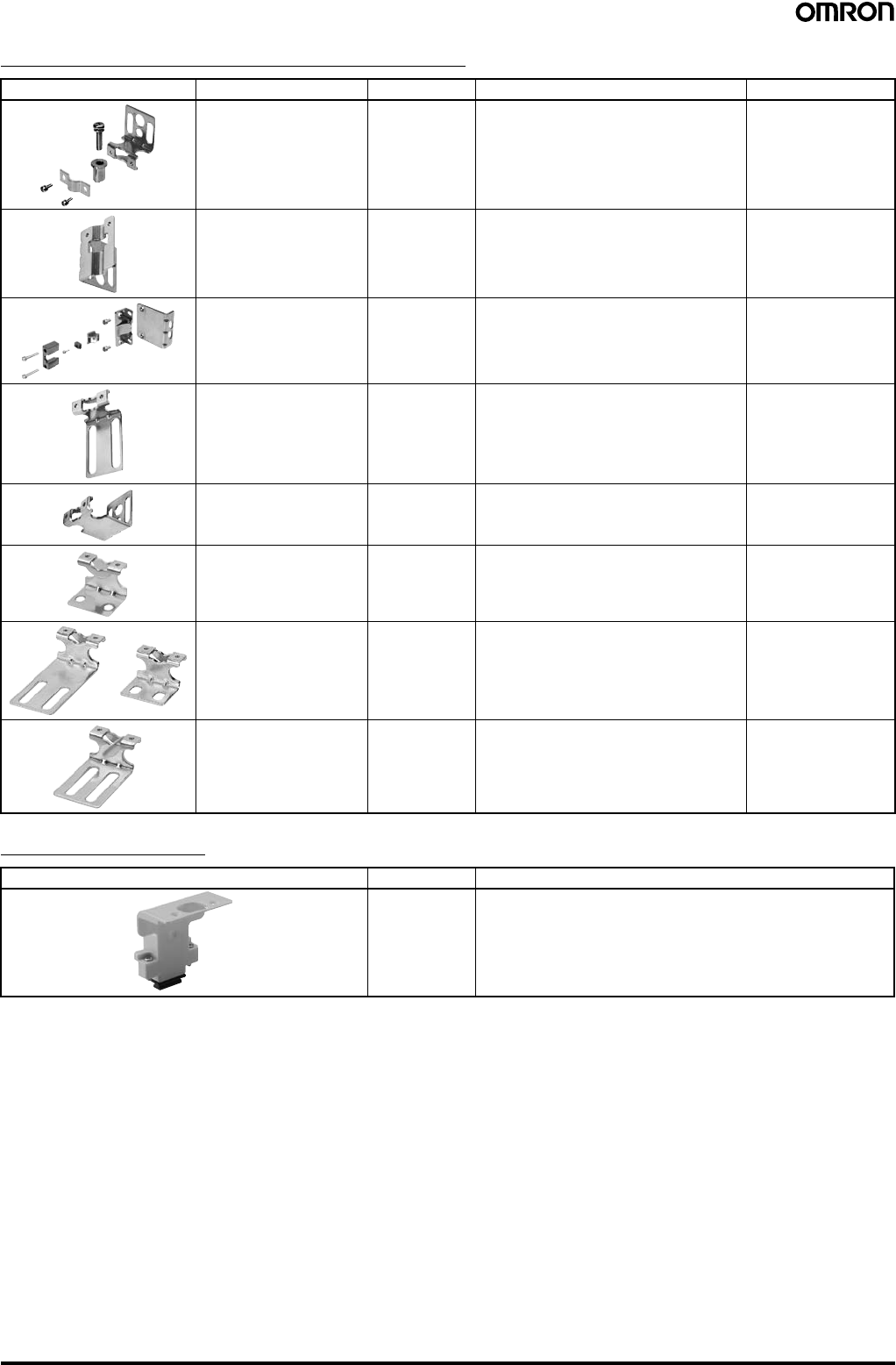
Safety Controller (Dedicated PNP output type) (See note.)
Note: F3SJ for NPN output type cannot be connected.
Connection Cable for F3SX
(F3SX↔F39-CN5) Branch Connector for F3SX
(F39-JC@T↔F39-JC@B)
Accessory connection example
Type Appearance Specifications Model Remarks
F3SX Safety Controller
(See note.) • Can connect 2 sets of F3SJs and emergency stop switch
• DC semiconductor safety output F3SX-EL2 For other models
and functions, refer
to the Safety
Components
Series (Cat. No.
Y106).
• Can connect 4 sets of F3SJs and emergency stop switch
• DC semiconductor safety output F3SX-E-L2L2
• Can connect 2 sets of F3SJs and emergency stop switch
• Relay output (2NO+1NC) F3SX-N-L2R
• Can connect 4 sets of F3SJs and emergency stop switch
• Relay output (2NO+1NC) F3SX-N-L2L2R
Appearance Cable length Model
1 m F39-JC1T
3 m F39-JC3T
5 m F39-JC5T
7 m F39-JC7T
10 m F39-JC10T
15 m F39-JC15T
Appearance Model
F39-CN5
F3SJ
Emitter
Branch connector for
safety light curtains
F39-CN5
Double-end connector cable:
F39-JC@B-L (gray)
Wire color:
Gray Wire color:
Black
Double-end connector cabl
e
F39-JC@B-D (black)
Connection cable for F3SX
F39-JC@T
F3SX
F3SJ
Receiver
Gray Black
18 Safety Light Curtain (Type 4) F3SJ Ver. 2
Relays with Forcibly Guided Contacts
Control unit (Can not be used as a muting system)
(Dedicated PNP output type) (See note.)
Note: F3SJ for NPN output type cannot be connected.
Dedicated External Indicator Set (Can be connected to either an emitter or a
receiver)
Note: For indication timing (operation mode) see "Ratings and Performance" on page 22.
General External Indicator Cable
Spatter Protection Cover (Includes two pieces for emitter and receiver)
(Each unit reduces the operating range by 10%)
Note: The same 4-digit numbers as the protective heights (@@@@ in the light curtain type names) are substituted by @@@@ in the model names.
Type Appearance Specifications Model Remarks
G7SA Relays with
Forcibly Guided
Contacts
• No. of contacts: 4
• Contact type: 2NO+2NC
• Rated switch load: 250 VAC 6 A, 30 VDC 6 A
G7SA-2A2B For other models and
functions, refer to For
other models and Socket
models, refer to the
Safety Components
Series (Cat. No. Y106).
• No. of contacts: 4
• Contact type: 3NO+1NC
• Rated switch load: 250 VAC 6 A, 30 VDC 6 A
G7SA-3A1B
G7S@-E Relays with
Forcibly Guided
Contacts
• No. of contacts: 6
• Contact type: 4NO+2NC
• Rated switch load: 250 VAC 10 A, 30 VDC 10 A
G7S-4A2B-E
• No. of contacts: 6
• Contact type: 3NO+3NC
• Rated switch load: 250 VAC 10 A, 30 VDC 10 A
G7S-3A3B-E
Appearance Output Model Remarks
Relay, 3NO+1NC F3SP-B1P (See note.) For connection with F3SJ-A, use an F39-JC@B double-end
connector cable
Appearance Color Model Remarks
Red F39-A01PR-PAC Indicator (red), mounting bracket (1 set), and dedicated
connection cable (0.1 m)
Green F39-A01PG-PAC Indicator (green), mounting bracket (1 set), and dedicated
connection cable (0.1 m)
Yellow F39-A01PY-PAC Indicator (yellow), mounting bracket (1 set), and dedicated
connection cable (0.1 m)
Appearance Cable length Specifications Model
3 m Cable to connect top of the main unit and an off-the shelf external
indicator (2-wire) F39-JJ3N
Appearance Applicable sensor Model
F3SJ-A series F39-HJ@@@@ (See note.)
Safety Light Curtain (Type 4) F3SJ Ver. 2 19
Sensor Mounting Bracket (Sold separately)
Key cap for muting
Appearance Specifications Model Application Remarks
Standard mounting
bracket (for top/bottom) F39-LJ1 (included in the main unit) 2 for emitter,
2 for receiver
(total of 4 per set)
Flat side mounting bracket F39-LJ2 Use these small-sized brackets when
performing side mounting with standard
mounting brackets, so that they do not
protrude from the detection surface.
2 for emitter,
2 for receiver
(total of 4 per set)
Free-location mounting
bracket (also used as
standard intermediate
bracket)
F39-LJ3 Use these brackets for mounting on any
place without using standard bracket. 1 set with 2 pieces
Top/bottom mounting
bracket B (mounting hole
pitch 19 mm)
F39-LJ4 Mounting bracket used when replacing
existing area sensors (other than F3SN or
F3WN) with the F3SJ.
For front mounting.
Suitable for mounting hole pitch of 18 to
20 mm.
2 for emitter,
2 for receiver
(total of 4 per set)
Bracket for replacing short-
length F3SN F39-LJ5 Mounting bracket used when an F3SN with
protective height of 300 mm or less is
replaced by an F3SJ.
2 for emitter,
2 for receiver
(total of 4 per set)
Space-saving mounting
bracket F39-LJ8 Use these brackets to mount facing inward.
Length is 12 mm shorter than the standard
F39-LJ1 bracket.
2 for emitter,
2 for receiver
(total of 4 per set)
Mounting bracket used
when replacing an F3W-C. F39-LJ9 Mounting bracket used when replacing
existing F3W-C series area sensors with
the F3SJ.
For front mounting or side mounting.
Mounting hole pitch 16 mm.
2 for emitter,
2 for receiver
(total of 4 per set)
Top/bottom mounting
bracket C (mounting hole
pitch 13 mm)
F39-LJ11 Mounting bracket used when replacing
existing area sensors having a mounting
pitch of 13 mm with the F3SJ.
2 for emitter,
2 for receiver
(total of 4 per set)
Appearance Model Remarks
F39-CN6 Cap attaches to the main unit to enable muting function.
Attach it to either an emitter or a receiver. (Case: orange)
20 Safety Light Curtain (Type 4) F3SJ Ver. 2
Setting Tools (See note 1.)
Note: 1. The setting tools described above can be connected only to F3SJ-A models with built-in software of Ver. 2 or later.
Note that the setting tools cannot be used with products shipped prior to December 2005. The setting tools cannot be used for setting
parameters on the F3SJ-A@-TS series, but the monitoring function can be used.
2. This product is for use only with the F3SJ-A. It cannot be connected to conventional models of the F3SN-A series.
Similarly, the F39-MC11 and F39-MT11 Dedicated Consoles for the F3SN-A cannot be connected to the F3SJ-A series.
Protector (Main unit mounting bracket (1) and a rear mounting bracket set)
(See note 1.)
Note: 1. When using for both emitter and receiver, order two sets.
2. The same four digits indicating protective height that are used in the Sensor model number (@@@@) are used in the @@@@ part of the
Protector model number.
Type Appearance Model Remarks
"SD Manager" Setting
Support Software for the
F3SJ
F39-GWUM Accessories: SD Manager CD-ROM (1),
F39-CN1 Branch Connector (1),
Connector Cap (1), 2-m Dedicated Cable
(1), 0.3-m Dedicated Cable with Plug (1),
Instruction Manual
Setting Console F39-MC21 (See note
2.) Accessories: F39-CN1 Branch Connector
(1), Connector Cap (1), 2-m Dedicated
Cable (1), 0.3-m Dedicated Cable with
Plug (1), Instruction Manual
Type Appearance Model Remarks
Protector Set F39-PJ@@@@-S (See
note 2.) Rear Mounting Brackets (2), including
intermediate brackets to match protective
height (0 to 2).
Intermediate brackets for
side mounting F39-PJ-MS For side mounting, order to suit the desired
protective height.
Protective height of up to 1,000 mm: 0
intermediate brackets
Protective height of 1,001 to 2,000 mm: 1
intermediate bracket
Protective height of 2,001 mm or more: 2
intermediate brackets
Safety Light Curtain (Type 4) F3SJ Ver. 2 21
Water-resistant Case (Set of 1 tube, packing, and dedicated connector cable)
(See note 1.)
Note: 1. When using for both emitter and receiver, order two sets.
2. The same four digits indicating protective height that are used in the Sensor model number (@@@@) are used in the @@@@ part of the
Case model number.
3. Be sure to purchase brackets with the Case to match the mounting direction (rear or side).
Appearance Specifications Model Remarks
For emitter F39-EJ@@@@-L (See
note 2.) Includes gray cable for emitter.
For receiver F39-EJ@@@@-D (See
note 2.) Includes black cable for receiver.
Rear Mounting Brackets F39-EJ-R (See note 3.) Top/bottom 1 each, total of 2
Side Mounting Brackets F39-EJ-S (See note 3.) Top/bottom 1 each, total of 2
---
Series connection cable
(for emitter) F39-JJR3WE-L Purchase additionally for series
connection when using the Water-
resistant Case.
Series connection cable
(for receiver) F39-JJR3WE-D

22 Safety Light Curtain (Type 4) F3SJ Ver. 2
Ratings and Performance (For details, refer to the instruction manual.)
■Main Units
F3SJ-A@@@@P14/P20/P30/P55/N14/N20/N30
Model PNP
outputs F3SJ-A@@@@P14 F3SJ-A@@@@P20 F3SJ-A@@@@P30 F3SJ-A@@@@P55
NPN
outputs F3SJ-A@@@@N14 F3SJ-A@@@@N20 F3SJ-A@@@@N30 ---
Sensor type Type 4 safety light curtain
Software version Ver. 2
Setting tool connection Connectable
Applicable safety category Category 4, 3, 2, 1, or B
Detection capability Opaque objects
14 mm in diameter Opaque objects
20 mm in diameter Opaque objects
30 mm in diameter Opaque objects
55 mm in diameter
Beam gap (P) 9 mm 15 mm 25 mm 50 mm
Number of beams (n) 26 to 180 16 to 166 10 to 100 6 to 50
Protective height (PH) 245 to 1,631 mm 245 to 2,495 mm 270 to 2,470 mm
Lens diameter Diameter 5 mm
Operating range 0.2 to 9 m (protective height 1,640 mm max.),
0.2 to 7 m (protective height 1,655 mm max.)
(Depending on the setting tool, the detection distance can be shortened to 0.5 m.)
Response time
(For details, see
"Response Time"
on page 27.)
ON to
OFF 1 set, 0245 to 983: 11 ms to
17.5 ms max.
1,055 or higher: 20 ms to 25 ms
max.
1 set, 0245 to 1,205: 10 ms to
15 ms max.
1,235 or higher: 17.5 ms to 22.5
ms max.
1 set: 10 ms to 17.5 ms max. 1 set: 10 ms to 13 ms max.
OFF to
ON 1 set, 0245 to 983: 44 ms to 70
ms max.
1,055 or higher: 80 ms to 100
ms max.
1 set, 0245 to 1,205: 40 ms to
60 ms max.
1,235 or higher: 70 ms to 90 ms
max.
1 set: 40 ms to 70 ms max. 1 set: 40 ms to 52 ms max.
Startup waiting time 2 s max. (2.2 s max. for series connection)
Power supply voltage (Vs) 24 VDC ±20% (ripple p-p10% max.)
Current
consumption (no
load)
Emitter Up to 50 beams: 76 mA max., 51 to 100 beams: 106 mA max., 101 to 150 beams: 130 mA max.,
151 to 180 beams: 153 mA max., 201 to 234 beams: 165 mA max.
Receiver Up to 50 beams: 68 mA max., 51 to 100 beams: 90 mA max., 101 to 150 beams: 111 mA max.,
151 to 180 beams: 128 mA max.
Light source (emitted
wavelength) Infrared LED (870 nm)
Effective aperture angle
(EAA) Based on IEC61496-2. Within ±2.5° for both emitter and receiver when the detection distance is 3 m or over
Control outputs
(OSSD) PNP
outputs Two PNP transistor outputs, load current 300 mA max., residual voltage 2 V max. (except for voltage drop due to cable extension),
allowable capacity load 2.2 µF, leak current 1 mA max.
(This can be different from traditional logic (ON/OFF) because safety circuit is used.)
NPN
outputs Two NPN transistor outputs, load current 300 mA max., residual voltage 2 V max. (except for voltage
drop due to cable extension), allowable capacity load 2.2 µF, leak current 2 mA max.
(This can be different from traditional logic (ON/OFF) because safety circuit is used.)
---
Auxiliary output 1
(non-safety
output)
PNP
output One PNP transistor output, load current 300 mA max., residual voltage 2 V max. (except for voltage drop due to cable extension), leak
current 1 mA max.
NPN
output One NPN transistor output, load current 300 mA max., residual voltage 2 V max. (except for voltage
drop due to cable extension), leak current 1 mA max. ---
Auxiliary output 2
(non-safety
output, basic
system functions)
PNP
output One PNP transistor output, load current 50 mA max., residual voltage 2 V max. (except for voltage drop due to cable extension), leak
current 1 mA max.
NPN
output One NPN transistor output, load current 50 mA max., residual voltage 2 V max. (except for voltage
drop due to cable extension), leak current 1 mA max. ---
External indicator output
(non-safety output) Available indicators
•Incandescent lamp: 24 VDC, 3 to 7 W
•LED lamp: Load current 10 mA to 300 mA max., leak current 1 mA max.
(To use an external indicator, an F39-JJ3N universal indicator cable or an F39-A01P@-PAC dedicated external indicator kit is re-
quired.)
Output operation
mode Receiver Control outputs 1, 2: ON when receiving light
Auxiliary output 1: Inverse of control output signals (Operating mode can be changed with the setting tool.)
External indicator output 1:Inverse of control output signals for a basic system (Operating mode can be changed with the setting tool.)
ON when muting/override for a muting system (Operating mode can be changed with the setting tool.)
Emitter Auxiliary output 2: Turns ON when the point of 30,000 operating hours is reached
(Operating mode can be changed with the setting tool.)
External indicator output 2:ON when lock-out for a basic system (Operating mode can be changed with the setting tool.)
ON when muting/override for a muting system (Operating mode can be changed with the setting tool.)

Safety Light Curtain (Type 4) F3SJ Ver. 2 23
Input voltage PNP
output Test input, interlock selection input, reset input, and muting input are all
ON voltage: 9 to 24 V (Vs) (sink current: 3 mA max.)
OFF voltage:0 to 1.5 V, or open
External device monitoring input
ON voltage: 9 to 24 V (Vs) (sink current: 5 mA max.)
OFF voltage:0 to 1.5 V, or open
NPN
output Test input, interlock selection input, reset input, and muting input are all
ON voltage: 0 to 1.5 V (short-circuit current 3 mA max.)
OFF voltage:9 to 24 V, or open
External device monitoring input
ON voltage: 0 to 1.5 V (short-circuit current 5 mA max.)
OFF voltage:9 to 24 V, or open
---
Internal indicators Emitter Light intensity level indicators (green LED × 2, orange LED × 3): ON based on the light intensity
Error mode indicators (red LED × 3): Blink to indicate error details
Power indicator (green LED × 1): ON while power is on
Interlock indicator (yellow LED × 1): ON while under interlock, ON while under interlock, blinks at lockout.
External device monitoring indicator (muting input 1 indicator), Blanking/test indicator (muting input 2 indicator) (green LED × 2):
ON/flash according to function
Receiver Light intensity level indicators (green LED × 2, orange LED × 3): ON based on the light intensity
Error mode indicators (red LED × 3): Blink to indicate error details
OFF output indicator (red LED × 1): ON when safety output is OFF, blinks at lockout.
ON output indicator (green LED × 1): ON while safety output is ON muting error indicator, Blanking /test indicator (green LED × 2):
ON/flash according to function
Mutual interference
prevention function Interference light prevention algorithm, detection distance change function
Series connection Time division emission by series connection
•Number of connections: up to 4 sets
•Total number of beams: up to 400 beams
•Maximum cable length for 2 sets: no longer than 15 m
•Response time under connection: See page 27
Test functions •Self test (when power is turned ON and while power is supplied)
•External test (emission stop function by test input)
Safety functions •Start interlock, restart interlock (Must be set with a setting tool when the muting function is used.)
•External device monitor
•Muting (Lamp burnout detection, override function included. F39-CN6 key cap for muting is required.)
•Fixed blanking (must be set by a setting tool)
•Floating blanking (must be set by a setting tool)
Connection type Connectors (M12, 8-pin)
Protective circuits Output short-circuit protection, and power supply reverse polarity protection
Ambient temperature Operating: −10 to 55°C (no icing), Storage: −30 to 70°C
Ambient humidity Operating: 35% to 85% (no condensation), Storage: 35% to 95%
Ambient operating light
intensity Incandescent lamp: 3,000 lx max. (light intensity on the receiver surface), Sunlight: 10,000 lx max. (light intensity on the receiver
surface)
Insulation resistance 20 MΩ min. (at 500 VDC)
Model PNP
outputs F3SJ-A@@@@P14 F3SJ-A@@@@P20 F3SJ-A@@@@P30 F3SJ-A@@@@P55
NPN
outputs F3SJ-A@@@@N14 F3SJ-A@@@@N20 F3SJ-A@@@@N30 ---

24 Safety Light Curtain (Type 4) F3SJ Ver. 2
Dielectric strength 1,000 VAC 50/60 Hz, 1 min
Degree of protection IP65 (IEC60529)
Vibration resistance Malfunction: 10 to 55 Hz, 0.7-mm double amplitude, 20 sweeps in X, Y, and Z directions
Shock resistance Malfunction: 100 m/s2, 1,000 times each in X, Y, and Z directions
Connection cable,
Series connection cable
(F39-JJR@L, F39-JJR3W)
6-mm-dia., 8-wire cable (0.15 mm2 × 8) with braided shield, allowable bending radius R5 mm
Extension cable
(F39-JC@A, F39-JC@B) 6.6-mm-dia., 8-wire cable (0.3 mm2 × 4P, resistance 0.058 Ω/m), with braided shield, allowable bending radius R36 mm
(To extend a cable length, use an equivalent or higher-performance cable. Do not place it in the same duct as high-voltage cables or
power cables.)
For available length for extension (cable extension length), see page 28.
Materials Casing (including metal parts on both ends): Aluminum, zinc die-cast
Cap: ABS resin
Optical cover: PMMA resin (acrylic)
Cable: Oil resistant PVC
Weight (packed state) Calculate using the following equations:
(1) For F3SJ-A@@@@P14, weight (g)=(protective height) × 1.7 + α
(2) For F3SJ-A@@@@P20/F3SJ-A@@@@P30, weight (g)=(protective height) × 1.5 + α
(3) For F3SJ-A@@@@P55, weight (g)=(protective height) × 1.4 + α
The values for α are as follows:
Protected height 245 to 596 mm: α = 1,100 protected height 1667 to 2180 mm: α = 2,400
Protected height 605 to 1,130 mm: α = 1,500 protected height 2195 to 2495 mm: α = 2,600
Protected height 1,136 to 1,658 mm: α = 2,000
Accessories Test rod (See note 1.), instruction manual, mounting brackets (top and bottom), mounting brackets (intermediate) (See note 2.), error
mode label, User's Manual (CD-ROM)
Note: 1. The F3SJ-A@@@@P55 is not included.
2. Number of intermediate mounting brackets depends on protective height of F3SJ.
•For protective height from 605 to 1,130 mm: 1 set for each of the emitter and receiver is included
•For protective height from 1,136 to 1,658 mm: 2 sets for each of the emitter and receiver are included
•For protective height from 1,667 to 2,180 mm: 3 sets for each of the emitter and receiver are included
•For protective height from 2,195 to 2,495 mm: 4 sets for each of the emitter and receiver are included
Applicable standards IEC61496-1, EN61496-1 UL61496-1, Type 4 ESPE (Electro-Sensitive Protective Equipment)
IEC61496-2, prEN61496-2, UL61496-2, Type 4 AOPD (Active Opto-electronic Protective Devices)
IEC61508, EN61508 SIL3
Model PNP
outputs F3SJ-A@@@@P14 F3SJ-A@@@@P20 F3SJ-A@@@@P30 F3SJ-A@@@@P55
NPN
outputs F3SJ-A@@@@N14 F3SJ-A@@@@N20 F3SJ-A@@@@N30 ---

Safety Light Curtain (Type 4) F3SJ Ver. 2 25
F3SJ-A@@@@P20-TS/P25-TS
Model F3SJ-A@@@@P20-TS F3SJ-A@@@@P25-TS
Sensor type Type 4 safety light curtain
Software version Ver. 2
Setting tool connection Parameter setting: Not possible
Monitoring: Possible
Applicable safety category Category 4, 3, 2, 1, or B
Detection capability Opaque objects
20 mm in diameter Opaque objects
25 mm in diameter
Beam gap (P) 15 mm 20 mm
Number of beams (n) 16 to 166 13 to 125
Protective height (PH) 245 to 2,495 mm 260 to 2,500 mm
Lens diameter Diameter 5 mm
Operating range 0.2 to 9 m (protective height 1,640 mm max.), 0.2 to 7 m (protective height 1,655 mm max.)
Response time
(For details, see
"Response Time"
on page 27.)
ON to OFF 1 set, 0245 to 1,205: 10 ms to 15 ms max.
1,220 or higher: 17.5 ms to 22.5 ms max.
3 sets (240 beams): 45.5 ms
1 set, 0260 to 1,600: 10 ms to 15 ms max.
1,620 or higher: 17.5 ms to 20.0 ms max.
3 sets (240 beams): 45.5 ms
OFF to ON 1 set, 0245 to 1,205: 40 ms to 60 ms max.
1,220 or higher: 70 ms to 90 ms max.
3 sets (240 beams): 200 ms
1 set, 0260 to 1,600: 40 ms to 60 ms max.
1,620 or higher: 70 ms to 80 ms max.
3 sets (240 beams): 200 ms
Startup waiting time 2 s max. (2.2 s max. for series connection)
Power supply voltage (Vs) 24 VDC ±20% (ripple p-p10% max.)
Current
consumption (no
load)
Emitter Up to 50 beams: 76 mA max., 51 to 100 beams: 106 mA max., 101 to 150 beams: 130 mA max.,
151 to 166 beams: 153 mA max
Receiver Up to 50 beams: 68 mA max., 51 to 100 beams: 90 mA max., 101 to 150 beams: 111 mA max.,
151 to 166 beams: 128 mA max.
Light source (emitted
wavelength) Infrared LED (870 nm)
Effective aperture angle (EAA) Based on IEC61496-2. Within ±2.5° for both emitter and receiver when the detection distance is 3 m or over
Control outputs (OSSD) Two PNP transistor outputs, load current 300 mA max., residual voltage 2 V max. (except for voltage drop due to cable extension),
allowable capacity load 2.2 µF, leak current 1 mA max.
(This can be different from traditional logic (ON/OFF) because safety circuit is used.)
Auxiliary output 1
(non-safety output) One PNP transistor output, load current 300 mA max., residual voltage 2 V max. (except for voltage drop due to cable extension),
leak current 1 mA max.
External indicator output
(non-safety output) Available indicators
•Incandescent lamp: 24 VDC, 3 to 7 W
•LED lamp: Load current 10 mA to 300 mA max., leak current 1 mA max.
(To use an external indicator, an F39-JJ3N universal indicator cable or an F39-A01P@-PAC dedicated external indicator kit is re-
quired.)
Output operation
mode Receiver Control outputs 1, 2: ON when receiving light
Auxiliary output 1: Inverse of control output signals (Operating mode can be changed with the setting tool.)
External indicator output 1:Inverse of control output signals for a basic system (Operating mode can be changed with the setting
tool.)
ON when muting/override for a muting system (Operating mode can be changed with the setting tool.)
Emitter External indicator output 2:ON when lock-out for a basic system (Operating mode can be changed with the setting tool.)
ON when muting/override for a muting system (Operating mode can be changed with the setting tool.)
Input voltage Test input, reset input, and muting input are all
ON voltage: 9 to 24 V (Vs) (sink current: 3 mA max.)
OFF voltage:0 to 1.5 V, or open
External device monitoring input
ON voltage: 9 to 24 V (Vs) (sink current: 5 mA max.)
OFF voltage:0 to 1.5 V, or open
Internal indicators Emitter Light intensity level indicators (green LED × 2, orange LED × 3): ON based on the light intensity
Error mode indicators (red LED × 3): Blink to indicate error details
Power indicator (green LED × 1): ON while power is on
Lockout indicator (yellow LED × 1): Blinks to indicate lockout.
External device monitoring indicator (muting input 1 indicator), Test indicator (muting input 2 indicator) (green LED × 2):
ON/flash according to function
Receiver Light intensity level indicators (green LED × 2, orange LED × 3): ON based on the light intensity
Error mode indicators (red LED × 3): Blink to indicate error details
OFF output indicator (red LED × 1): ON when safety output is OFF, blinks at lockout.
ON output indicator (green LED × 1): ON while safety output is ON muting error indicator, Test indicator (green LED × 2): ON/flash
according to function
Mutual interference prevention
function Interference light prevention algorithm
Series connection Time division emission by series connection
•Number of connections: up to 3 sets
•Total number of beams: up to 240 beams
•Maximum cable length for 2 sets: no longer than 15 m
•Response time under connection: See page 27
Test functions •Self test (when power is turned ON and while power is supplied)
•External test (emission stop function by test input)

26 Safety Light Curtain (Type 4) F3SJ Ver. 2
Safety functions •External device monitor
•Muting (Override function included. F39-CN6 Key Cap for muting is required.)
Lockout occurs under either of the following conditions:
•When more than 3 Units are connected in series.
•When the total number of beams connected in series exceeds 240.
•When any model other than a "-TS" model is included in a series connection.
Connection type Connectors (M12, 8-pin)
Protective circuits Output short-circuit protection, and power supply reverse polarity protection
Ambient temperature Operating: −10 to 55°C (no icing), Storage: −30 to 70°C
Ambient humidity Operating: 35% to 85% (no condensation), Storage: 35% to 95%
Ambient operating light
intensity Incandescent lamp: 3,000 lx max. (light intensity on the receiver surface), Sunlight: 10,000 lx max. (light intensity on the receiver
surface)
Insulation resistance 20 MΩ min. (at 500 VDC)
Dielectric strength 1,000 VAC 50/60 Hz, 1 min
Degree of protection IP65 (IEC60529)
Vibration resistance Malfunction: 10 to 55 Hz, 0.7-mm double amplitude, 20 sweeps in X, Y, and Z directions
Shock resistance Malfunction: 100 m/s2, 1,000 times each in X, Y, and Z directions
Connection cable, Series
connection cable (F39-JJR@L,
F39-JJR3W)
6-mm-dia., 8-wire cable (0.15 mm2 × 8) with braided shield, allowable bending radius R5 mm
Extension cable (F39-JC@A,
F39-JC@B) 6.6-mm-dia., 8-wire cable (0.3 mm2 × 4P, resistance 0.058 Ω/m), allowable bending radius R36 mm
(To extend a cable length, use an equivalent or higher-performance cable. Do not place it in the same duct as high-voltage cables
or power cables.)
For available length for extension (cable extension length), see page 28.
Materials Casing (including metal parts on both ends): Aluminum, zinc die-cast
Cap: ABS resin
Optical cover: PMMA resin (acrylic)
Cable: Oil resistant PVC
Weight (packed state) Calculate using the following equations:
For F3SJ-A@@@@P@@-TS, weight (g)=(protective height) × 1.5 + α
The values for α are as follows:
Protected height 245 to 580 mm: α = 1,100 protected height 1,700 to 2,180 mm: α = 2,400
Protected height 605 to 1,115 mm: α = 1,500 protected height 2,200 to 2,500 mm: α = 2,600
Protected height 1,140 to 1,660 mm: α = 2,000
Accessories Test rod, instruction manual, mounting brackets (top and bottom), mounting brackets (intermediate) (See note.), error mode label,
User's Manual (CD-ROM)
Note: Number of intermediate mounting brackets depends on protective height of F3SJ.
•For protective height from 605 to 1,115 mm: 1 set for each of the emitter and receiver is included
•For protective height from 1,140 to 1,660 mm: 2 sets for each of the emitter and receiver are included
•For protective height from 1,700 to 2,180 mm: 3 sets for each of the emitter and receiver are included
•For protective height from 2,220 to 2,500 mm: 4 sets for each of the emitter and receiver are included
Applicable standards IEC61496-1, EN61496-1 UL61496-1, Type 4 ESPE (Electro-Sensitive Protective Equipment)
IEC61496-2, prEN61496-2, UL61496-2, Type 4 AOPD (Active Opto-electronic Protective Devices)
IEC61508, EN61508 SIL3
Model F3SJ-A@@@@P20-TS F3SJ-A@@@@P25-TS

Safety Light Curtain (Type 4) F3SJ Ver. 2 27
■Response Time
Note: Use the following expressions for series connection.
For 2-set series connection:
Response time (ON to OFF): Response time of the 1st unit + Response time of the 2nd unit - 1 (ms)
Response time (OFF to ON): Response time calculated by the above x 4 (ms)
For 3-set series connection:
Response time (ON to OFF): Response time of the 1st unit + Response time of the 2nd unit + Response time of 3rd unit - 5 (ms)
Response time (OFF to ON): Response time calculated by the above x 5 (ms)
(For models with the "-TS" suffix, multiply the response time obtained by the above x 5 (ms),
or use 200 ms, whichever is less.)
For 4-set series connection:
Response time (ON to OFF): Response time of the 1st unit + Response time of the 2nd unit + Response time of the 3rd unit +
Response time of the 4th unit - 8 (ms)
Response time (OFF to ON): Response time calculated by the above x 5 (ms)
Model Protective Height (mm) Number of Beams Response time ms (ON to OFF) Response time ms (OFF to ON)
F3SJ-A@14
series 245 to 263 26 to 28 11 44
281 to 389 30 to 42 12 48
407 to 497 44 to 54 13 52
515 to 605 56 to 66 14 56
623 to 731 68 to 80 15 60
767 to 983 84 to 108 17.5 70
1,055 to 1,271 116 to 140 20 80
1,343 to 1,559 148 to 172 22.5 90
1,631 180 25 100
F3SJ-A@20
series
F3SJ-A@P20-TS
series
245 16 10 40
275 to 425 18 to 28 11 44
455 to 635 30 to 42 12 48
665 to 815 44 to 54 13 52
845 to 995 56 to 66 14 56
1,025 to 1,205 68 to 80 15 60
1,235 to 1,655 82 to 110 17.5 70
1,805 to 2,105 120 to 140 20 80
2,255 to 2,495 150 to 166 22.5 90
F3SJ-A@P25-TS
series 260 to 320 13 to 16 10 40
340 to 580 17 to 29 11 44
600 to 840 30 to 42 12 48
860 to 1100 43 to 55 13 52
1120 to 1340 56 to 67 14 56
1360 to 1600 68 to 80 15 60
1620 to 2240 81 to 112 17.5 70
2260 to 2500 113 to 125 20.0 80
F3SJ-A@30
series 245 to 395 10 to 16 10 40
420 to 720 17 to 29 11 44
745 to 1,045 30 to 42 12 48
1,070 to 1,295 43 to 52 13 52
1,395 to 1,620 56 to 65 14 56
1,745 to 1,995 70 to 80 15 60
2,120 to 2,495 85 to 100 17.5 70
F3SJ-A@55
series 270 to 770 6 to 16 10 40
820 to 1420 17 to 29 11 44
1470 to 2070 30 to 42 12 48
2120 to 2470 43 to 50 13 52
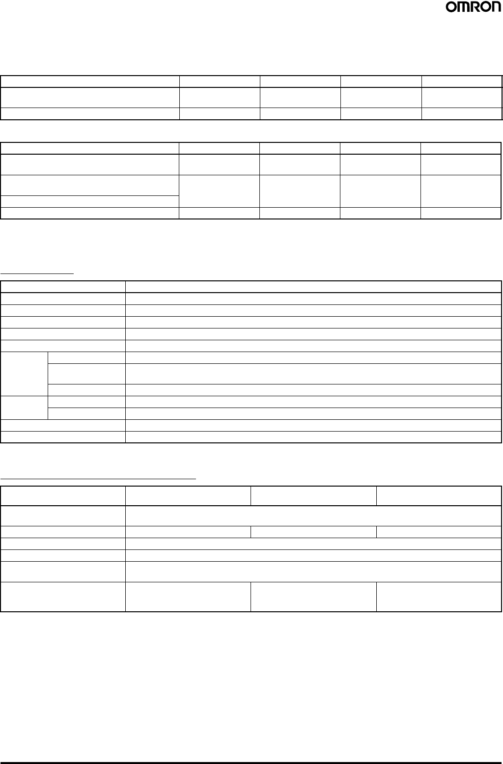
28 Safety Light Curtain (Type 4) F3SJ Ver. 2
■Cable Extension Length
Total cable extension length must be no greater than the lengths described below.
When the F3SJ and an external power supply are directly connected, or when the F3SJ is connected to a G9SA-300-SC.
When connected to the F3SP-B1P.
Note: Keep the cable length within the rated length. Failure to do so is dangerous as it may prevent safety functions from operating normally.
■Accessories
Control Unit
Note: NPN output type cannot be connected. Also, the system cannot be used as a muting system.
Dedicated External Indicator Set
Condition 1 set 2 sets 3 sets 4 sets
Using incandescent lamp for auxiliary output
and external indicator output 45 m 40 m 30 m 20 m
Not using incandescent lamp 100 m 60 m 45 m 30 m
Condition 1 set 2 sets 3 sets 4 sets
Using incandescent lamp for external indicator
output 2 40 m 30 m 25 m 20 m
Using incandescent lamp for external indicator
output 1 60 m 45 m 30 m 20 m
Using incandescent lamp for auxiliary output 1
Not using incandescent lamp 100 m 60 m 45 m 30 m
Item Model F3SP-B1P
Applicable sensor F3SJ-A (Only for PNP output type) (See note.)
Power supply voltage 24 VDC±10%
Power consumption DC1.7 W max. (not including sensor’s current consumption)
Operation time 100 ms max. (not including sensor’s response time)
Response time 10 ms max. (not including sensor’s response time)
Relay
output Number of contacts 3NO+1NC
Rated load 25 VAC 5 A (cosφ= 1),
30 VDC 5 A L/R = 0 ms
Rated current 5 A
Connection
type Between sensors M12 connector (8-pin)
Others Terminal block
Weight (packed state) Approx. 280 g
Accessories Instruction manual
Model
Item F39-A01PR-PAC F39-A01PG-PAC F39-A01PY-PAC
Applicable sensor F3SJ-A
(Common for PNP/NPN output type. Can be attached to emitters and/or receivers)
Light source Red LED Green LED Yellow LED
Power supply voltage 24 VDC±10% (supplied by sensor)
Consumption current 50 mA max. (supplied by sensor)
Connection type Dedicated accessory connector cable
(Sensor side: Dedicated 10-pin connector, Indicator side: M12 8-pin connector)
Set contents Indicator (red), Dedicated
connector cable (0.1 m), Dedicated
mounting brackets (1 for each)
Indicator (green), Dedicated
connector cable (0.1 m), Dedicated
mounting brackets (1 for each)
Indicator (yellow), Dedicated
connector cable (0.1 m), Dedicated
mounting brackets (1 for each)
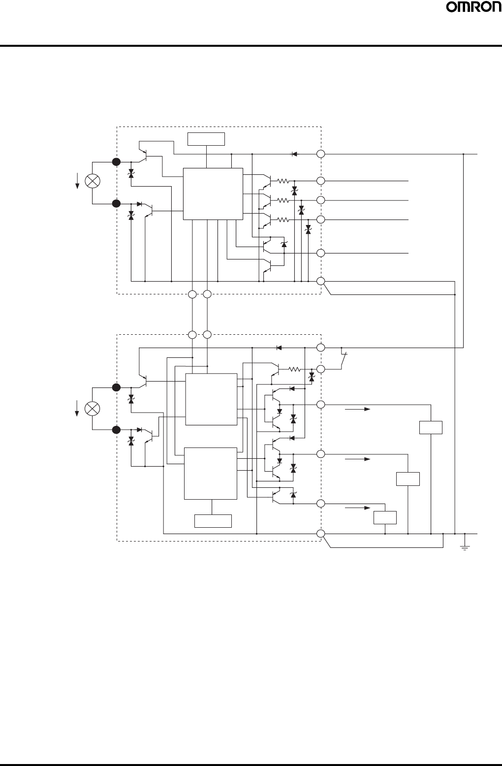
Safety Light Curtain (Type 4) F3SJ Ver. 2 29
I/O Circuit
■PNP Output Type
The numbers in white circles indicate the connector's pin numbers.
The black circles indicate connectors for series connection.
The words in brackets ([ ]) indicate the signal name for muting system.
Note: 1. Open or muting input 1 for models with the "-TS" suffix.
2. Open or muting input 2 for models with the "-TS" suffix.
Shield
Shield
Emitter
Main Circuit
Indication
Indication
Receiver
Main Circuit 2
Receiver
Main Circuit 1
+24 VDC
Brown
Brown
Green Test input
White Interlock selection input
[Muting input 1] (See note 1.)
Red Auxiliary output 2
[Muting input 2] (See note 2.)
Reset input
Yellow
Blue
Blue
Brown
Blue
Brown
Auxiliary output 1
Yellow
Green Control output 1
Red External device
monitoring input
White Control output 2
Blue
Load
Load
0 V
Communication line (−)
Pink
Gray
Gray Pink
Communication line (+)
Load
External indicator output 1
External indicator output 2
5
10
5
10
2
8
1
2
3
1
4
7
8
5
56
6
3
4
7
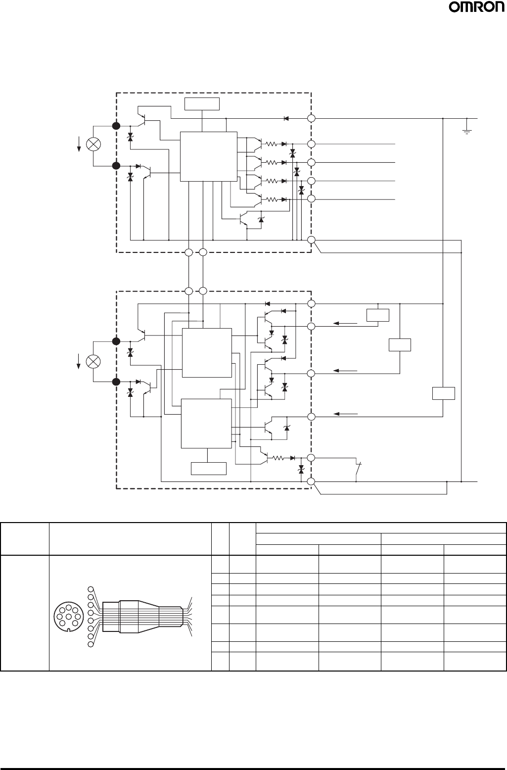
30 Safety Light Curtain (Type 4) F3SJ Ver. 2
■NPN Output Type
The numbers in white circles indicate the connector's pin numbers.
The black circles indicate connectors for series connection.
The words in brackets ([ ]) indicate the signal name for muting system.
■Single-end Connector Cable
Note: 1. Basic system indicates a system with default factory settings.
Muting system indicates a system attached with a muting keycap (F39-CN6) to enable muting function.
2. N.C. for models with the "-TS" suffix.
5
10
5
10
2
1
8
1
2
3
1
4
7
8
5
56
6
3
4
7Shield
Shield
Emitter
Main Circuit
Indication
Indication
Receiver
Main Circuit 2
Receiver
Main Circuit 1
+24 VDC
Brown
Brown
Green Test input
White Interlock selection input
[Muting input 1]
Red Auxiliary output 2
[Muting input 2]
Reset input
Yellow
Blue
Blue
Brown
Blue
Brown
Auxiliary output 1
Yellow
Green
Control output 1
Red External device
monitoring input
White
Control output 2
Blue
Load
Load
0 V
Communication line (−)
Pink
Gray
Gray Pink
Communication line (+)
Load
External indicator output 1
External indicator output 2
Model Internal wiring Pin
No. Wire
color Signal Name
Basic system (See note 1.) Muting system (See note 1.)
Receiver Emitter Receiver Emitter
F39-
JC3A (3 m)
F39-
JC7A (7 m)
F39-
JC10A (10 m)
F39-
JC15A (15 m)
(1) White Safety output 2 Interlock selection
input (See note 2.) Safety output 2 Muting input 1
(2) Brown +24 VDC +24 VDC +24 VDC +24 VDC
(3) Green Control output 1 Test Input Control output 1 Test Input
(4) Yellow Auxiliary output 1 Reset input Auxiliary output 1 Reset input
(5) Gray Communication
line (+) Communication
line (+) Communication
line (+) Communication
line (+)
(6) Pink Communication
line (-) Communication
line (-) Communication
line (-) Communication
line (-)
(7) Blue 0 V 0 V 0 V 0 V
(8) Red External device
monitoring input Auxiliary output 2
(See note 2.) External device
monitoring input Muting input 2
4
87
5
32
46
15
6
7
3
2
1
8
Wire color
White
Brown
Green
Yello
w
Gray
Pink
Blue
Red
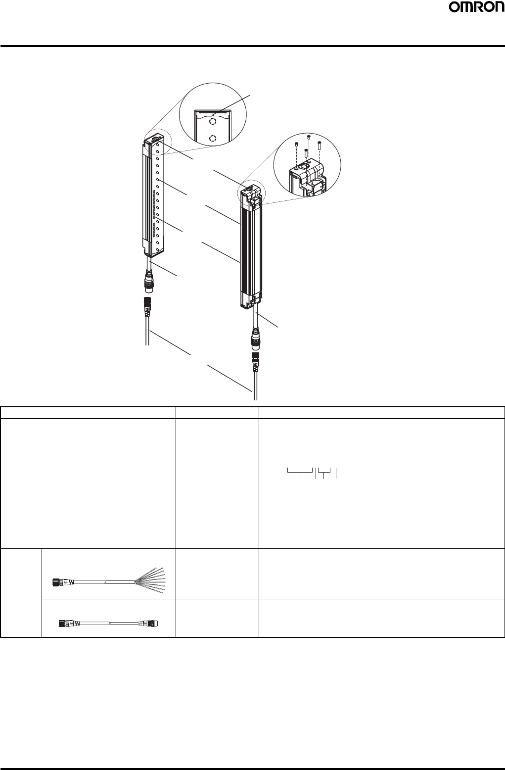
Safety Light Curtain (Type 4) F3SJ Ver. 2 31
Nomenclature
■Main Unit and Cables
Component Model Description
Emitter, receiver F3SJ-A@@@@P@@
or
F3SJ-A@@@@N@@
Select a type name based on the required protective height and
detection capability.
(Cap and power cable are included)
The type name can be understood as follows:
F3SJ-A@@@@P@@-@
1: Protective height (mm)
2: Output type (P=PNP output type, N=NPN output type)
3: Diameter of detection capability (mm)
4: L is emitter, D is receiver, and a blank is emitter/receiver set.
For models with fixed auto reset, the suffix "-L-TS" is an emitter,
"-D-TS" is a receiver, and "-TS" is an emitter/receiver set.
Extension
cable Single-end connector cable F39-JC@A This extension cable is used to connect to a terminal block controller
(e.g. F3SX, G9SA, G9SB, G9SX) or to a safety processing system
(e.g. DeviceNet safety).
Double-end connector cable F39-JC@B This extension cable is used when the length of the connection cable
is insufficient, or when connecting to an F3SP-B1P controller. The
length can be specified.
Emitter
Receiver
Cap
Indicator
Beam
Extension cable
Power cable
(Gray)
Power cable (Black)
Beam center-line mark
(A line indicates where the beam is
aligned. This line indicates the
reference line used to measure the
safety distance.)
To attach or detach the ca
p
and power cable, remove
the 4 screws shown above.
12
34
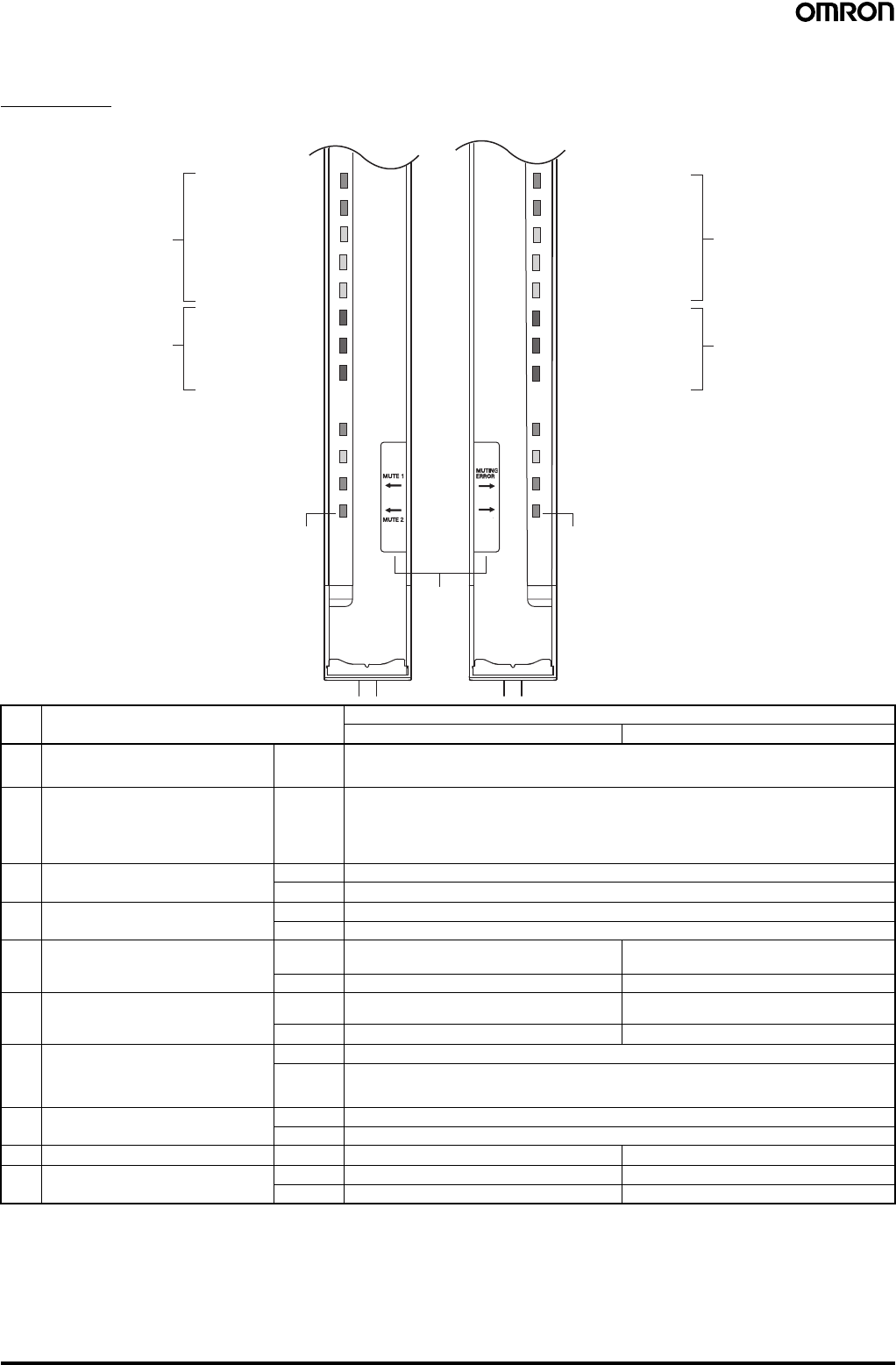
32 Safety Light Curtain (Type 4) F3SJ Ver. 2
■Internal Indicators
Total View
Note: 1. Lockout indicator (LOCKOUT) for models with the "-TS" suffix.
2. In the TS model, this is a test indicator labeled TEST.
3. This label is included with the F39-CN6 key cap for muting. Affix the label when the muting function is used.
No. Internal Indicators Description
For basic system For muting system
1 Light intensity level indicators (LEVEL-1 to
5)
(refer to page 33.)
ON Indication status of LEVEL-1 to 5 shows the light intensity level status of the F3SJ.
2 Error mode indicators (ERROR-A to C)
(refer to page 33.) ON/
Blinking Turns ON or blinks only on the sensor where the error occurred when the F3SJ enters lockout. The
error mode indicators turn OFF on sensors (emitters or receivers) where an error did not occur, or on
other series-connected sensors. The indication status of ERROR-A to C shows the cause of the
error. Affix the error mode label (included) near the F3SJ to allow for quick troubleshooting when
errors occur.
3 Power indicator (POWER) ON Turns ON while the power is ON.
Blinking Blinks when in maintenance mode.
4 Interlock indicator (INTLK) (See note 1.) ON Turns ON when F3SJ is in interlock state.
Blinking Blinks when under lockout.
5 External device monitoring indicator
(EDM)
Muting input 1 indicator (MUTE1)
ON Turns ON when an input is given to external device
monitoring input. Turns ON when an input is given to muting input
1.
Blinking Not used Blinks during muting override.
6 Blanking/Test indicator (BLANKING/
TEST) (See note 2.)
Muting input 2 indicator (MUTE2)
ON Turns ON when the blanking function and warning
zone function are enabled. Turns ON when an input is given to muting input 2.
Blinking Blinks when external test is being performed. Blinks during muting override.
7 OFF output indicator (OFF) ON Turns ON when control output is OFF.
Blinking Blinks in the following states:
• Lockout state
• One or more beams are blocked in maintenance mode
8 ON output indicator (ON) ON Turns ON when safety output is ON.
Blinking Blinks when no beams are blocked in maintenance mode
9 Muting error indicator (MUTING ERROR) ON Not used Turns ON when a muting error occurs.
10 Blanking/Test indicator (BLANKING/
TEST) (See note 2.) ON Not used Turns ON when the blanking function is enabled.
Blinking Not used Blinks when external test is being performed.
5. External device monitoring
indicator (Green)
[Muting input 1 indicator]
6. Blanking/Test indicator (Green)
[Muting input 2 indicator]
(See note 2.)
4. Interlock indicator (Yellow) (See note 1.)
3. Power indicator (Green)
ERROR-C (Red)
ERROR-B (Red)
ERROR-A (Red)
LEVEL-1 (Orange)
2. Error mode indicators 2. Error mode indicators
LEVEL-2 (Orange)
LEVEL-3 (Orange)
LEVEL-4 (Green)
LEVEL-5 (Green)
1. Light intensity
level indicators
10. Not used (Green)
[Blanking/Test indicator]
(See note 2.)
9. Not used (Green)
[Muting error indicator]
8. ON-state indicator (Green)
7. OFF-state indicator (Red)
ERROR-C (Red)
ERROR-B (Red)
ERROR-A (Red)
LEVEL-1 (Orange)
LEVEL-2 (Orange)
LEVEL-3 (Orange)
LEVEL-4 (Green)
LEVEL-5 (Green)
Emitter Receiver
EMITTER
LEVEL
POWER
INTLK
EDM
BLANKING
(TEST)
5
4
3
2
1
C
B
A
5
4
3
2
1
C
B
A
RECEIVER
LEVEL
ERROR ERROR
OFF
ON
(See
note 3.)
The words in brackets ([ ]) represent
the indicator name for the muting.
1. Light intensity
level indicators
BLANKING
(TEST)
30 dia. 30 dia.
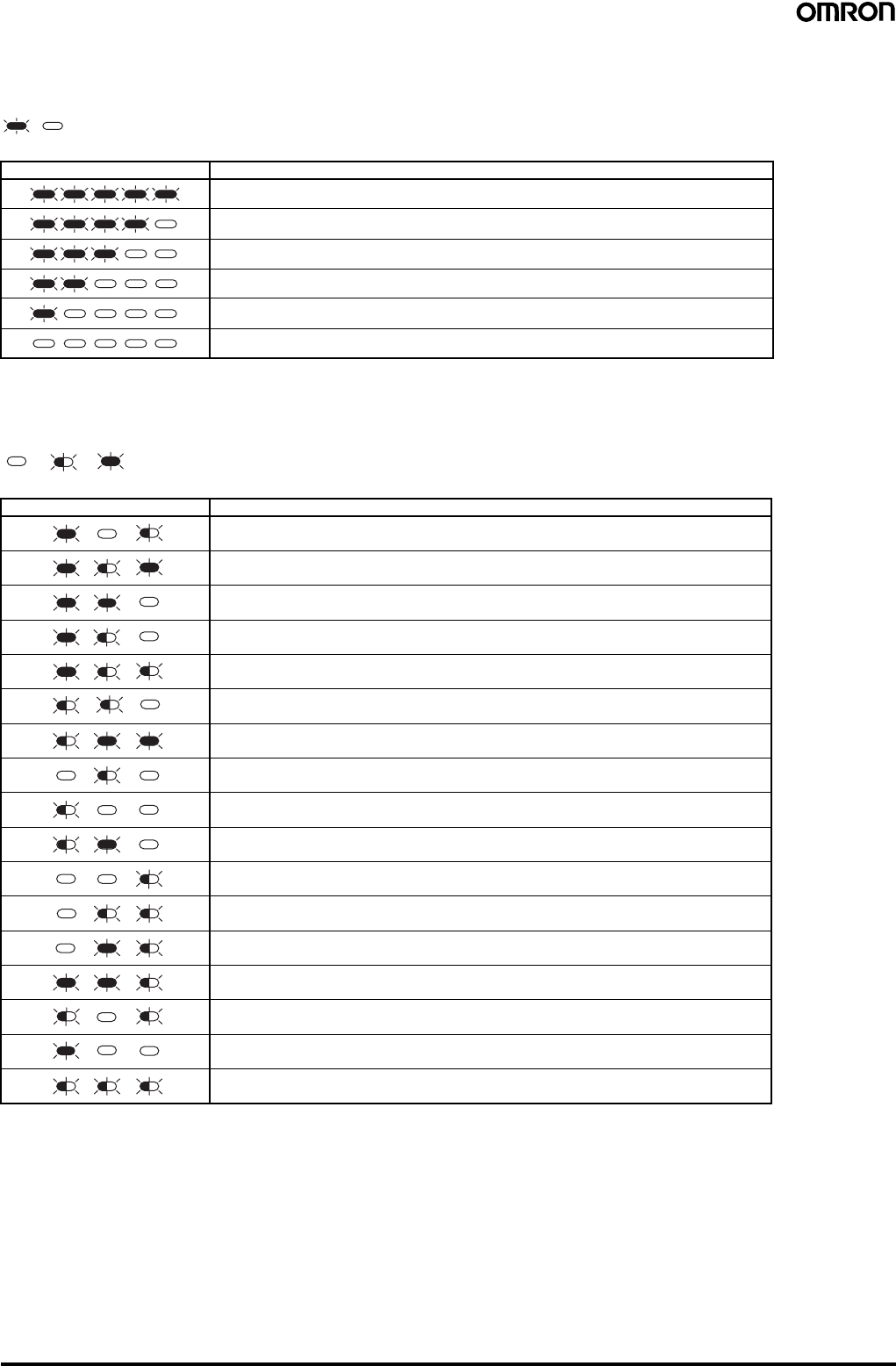
Safety Light Curtain (Type 4) F3SJ Ver. 2 33
■Indication Patterns and Intensity Levels of the Light Intensity Level
Indicators (LEVEL-1 to 5)
Note: Operation is possible with light intensity level of 100% or more, but to ensure stability, operate when at least 5 of the
indication lamps are ON.
■Error Mode Indication Patterns and Cause of Errors (ERROR-A to C)
ON OFF
1 2 3 4 5 Light intensity level
170% or higher of control output ON level
From 130 to 170% of control output ON level
From 100 to 130% of control output ON level
From 75 to 100% of control output ON level
From 50 to 75% of control output ON level
Less than 50% of control output ON level
OFF Blinking ON
A B C Cause of error
Mutual interference or ambient incident light.
Power supply voltage of F3SJ is out of the rated range. Insufficient current capacity of
power supply.
Incident light to blanking beams.
Failure in communication line.
Emitter and receiver have different F3SJ type names or number of series connections.
Outside the effective range of parameters set by setting tool.
Cap is not attached.
External device monitor failure.
Failure in interlock selection input line or reset input line.
Muting wiring failure.
Failure in control output wiring.
Failure in series connection cable wiring.
Failure in wiring of external display lamp output.
Failure in wiring of auxiliary output.
Broken series connection cable.
Wiring error or broken communications wire.
Influence of electrical noise, or failure in a series-connected F3SJ.
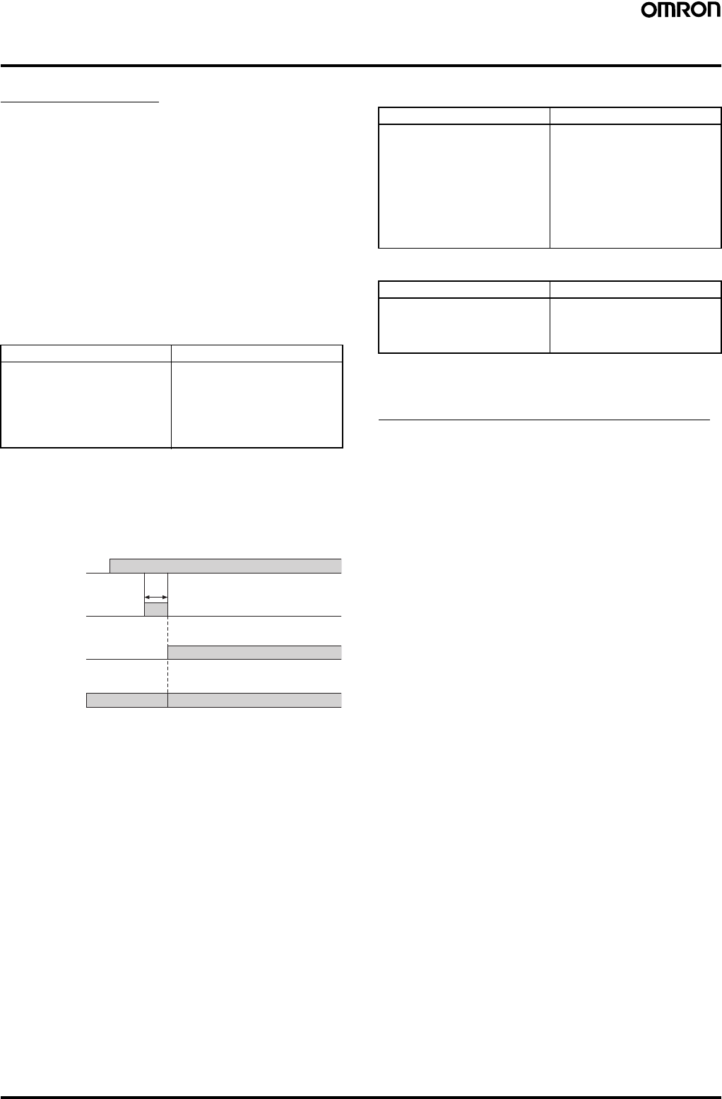
34 Safety Light Curtain (Type 4) F3SJ Ver. 2
Safety-related Functions
Interlock Function
The F3SJ turns the safety outputs OFF when the power is turned ON
or when a beam is interrupted, and maintains this state until a reset
signal is applied. This state is called "interlock".
You can reset this interlock by 2 methods; “auto reset that
automatically turns safety output ON when an interrupting object is
removed” and “manual reset mode that keeps safety output OFF until
a reset signal is provided if the interrupting object is removed”.
Auto Reset Mode
When an interrupting object is removed, safety output automatically
turns ON. Auto reset is used on machines where a worker is not able
to enter the area between the detection zone and the hazardous part
of the machine.
Note: Auto reset is always used in the F3SJ-A@-TS series.
Auto reset wiring procedure:
Manual Reset Mode
When a reset input is given while no interrupting object exists in a
detection zone, the safety outputs turn ON. This allows the machine
to be manually reset using a reset switch after ensuring safety,
preventing unexpected startup.
A sensor enters interlock state when:
•The power is turned ON (start interlock). This is useful if you want
to keep the machine stopped until start inspection is completed
after the power is turned ON.
•F3SJ is interrupted (restart interlock). After F3SJ is interrupted and
the machine stops, the machine can be restarted after safety is
ensured.
Manual Reset Wiring Procedure:
To reset:
Note: Install the reset switch outside the hazardous area, where the
operator can clearly see the hazardous area.
Interlock Function in a Muting System
Because the interlock selection input line is used as muting input 1
when using the muting function, the default setting is auto reset. Use
a setting tool for manual reset.
For PNP output For NPN output
1. Open the interlock selection
input line, or short-circuit it to 0
to 1.5 V (pin 1/white).
2. Short-circuit the reset input
line to 9 to 24 V (pin 4/yellow).
3. Turn ON the power of F3SJ.
1. Open the interlock selection
input line, or short-circuit it to 9
to 24 V (pin 1/white).
2. Short-circuit the reset input
line to 0 to 1.5 V (pin 4/yellow).
3. Turn ON the power of F3SJ.
Control output ON
OFF
Light incident/
Light interrupted
Light
incident
Light
interrupted
Sensor status Normal operationInterlock state
Reset Input ON
OFF
250 ms min.
For PNP output For NPN output
1. Connect the interlock
selection input line to 9 to 24 V
(pin 1/white).
2. Connect the reset input line to
9 to 24 V via the reset switch
(NO-contact) (pin 4/yellow).
3. Keep the reset switch contact
open, and turn the power of
F3SJ ON.
1. Connect the interlock selection
input line to 0 to 1.5 V (pin 1/
white).
2. Connect the reset input line to
0 to 1.5 V via the reset switch
(NO-contact) (pin 4/yellow).
3. Keep the reset switch contact
open, and turn the power of
F3SJ ON.
For PNP output For NPN output
Apply voltage of 9 to 24 V for
250 ms or longer to the reset
input line, and set it open or to 0
to 1.5 V.
Apply voltage of 0 to 1.5 V for
250 ms or longer to the reset
input line, and set it open or to
9 to 24 V.
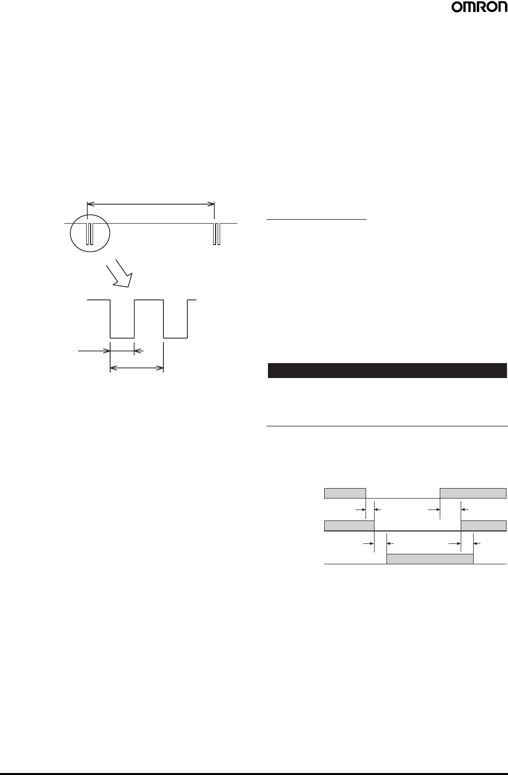
Safety Light Curtain (Type 4) F3SJ Ver. 2 35
■Diagnostic Functions
Self-test
A self-test is performed to check for errors when the power is turned
ON (within 2 seconds / within 2.2 seconds when series connected).
Also, the self-test is regularly performed (within the response time)
while operating.
Waveform of Control Outputs
When the F3SJ is receiving light, the control outputs cyclically turn
OFF as shown below to test the output circuit. When this OFF signal
is fed back, the output circuit is diagnosed as normal. If the output
signal does not include an OFF pulse signal, the receiver determines
that a failure has occurred with the output circuit or wiring, and enters
lockout state. (Refer to the following illustration.)
External Test
This function performs a test to ensure that the safety system stops
properly when the F3SJ is interrupted, by using an external signal to
forcibly stop emission.
To stop emission, apply 9 to 24 V for PNP output types or 0 to 1.5 V
for NPN output types to the test input line of the emitter. Apply the
voltage for a minimum of 4 x the safety output response time.
Lockout
If an error is found in the self-test, the sensor enters lockout state,
keeps the safety output in the OFF state, and indicates the error at
the same time.
Resetting Lockout
When a cause of lockout is removed, you can release the lockout by
using either of the following methods.
•Cycle the power back ON
•Reset input
[For PNP output]
After manual reset, apply voltage of 9 to 24 V for 100 ms or longer to
the reset input line, and set it open or apply 0 to 1.5 V.
After auto reset, apply voltage of 0 to 1.5 V for 100 ms or longer to
the reset input line, and set it open or apply 9 to 24 V.
[For NPN output]
After manual reset, apply voltage of 0 to 1.5 V for 100 ms or longer to
the reset input line, and set it open or apply 9 to 24 V.
After auto reset, apply voltage of 9 to 24 V for 100 ms or longer to the
reset input line, and set it open or apply 0 to 1.5 V.
External Device Monitoring Function
This function detects malfunctions, such as welded contacts in
external relays (or contactors) that control the hazardous area of a
machine.
This function constantly monitors that a specified voltage is applied
to the receiver's external device monitoring input line, and enters
lockout state when an error occurs. The relay's operational delay can
be up to 300 ms without being evaluated as an error.
For example, if a specified voltage is not applied to the external
device monitoring line because the normally closed (NC) contact is
not closed within 300 ms after the control outputs turn from ON to
OFF, it is evaluated as an error and enters a lockout state.
To utilize this function properly, use safety relays and contactors that
have forcibly guided or mechanically linked contact structure.
Other Functions
Auxiliary Output (Non-safety output)
The auxiliary output is used to monitor the status of the F3SJ.
This output can be connected to a device such as a relay, indication
lamp, programmable controller, etc.
There are two auxiliary outputs: Auxiliary output 1 and auxiliary
output 2.
•Auxiliary output 1: Control output inversion signal
•Auxiliary output 2: Turns ON when the point of 30,000 operating
hours is reached
The auxiliary output modes can be changed with a setting tool. See
the User's Manual for details on the modes that can be set.
!WARNING
Do not use the auxiliary output or external indicator output for safety
applications.
Failure of these outputs may prevent detection of people and result in
serious injury.
Note: 1. Auxiliary output 1 has a load current of 300 mA max., and
auxiliary output 2 has a load current of 50 mA.
2. The timing when auxiliary output 1 is set as a control output
inversion signal is shown in the diagram below.
Toff: Response time of control output's ON to OFF, Ton: Response
time of control output's OFF to ON
Note: When auxiliary output 2 is set as a control output inversion
signal, the response delay for control output becomes Toff x 3
max.
ON
OFF
Control output 1,2
Approx. 15 ms
Approx. 65 µs
OFF signal
Approx. 140 µs
Light incident/
Light interrupted
Light
incident
Light
interrupted
Auxiliary
output 1
Control
output
ON
OFF
Toff × 2 or less
(See note.) (See note.)
Toff × 2 or less
ON
OFF
Toff Ton
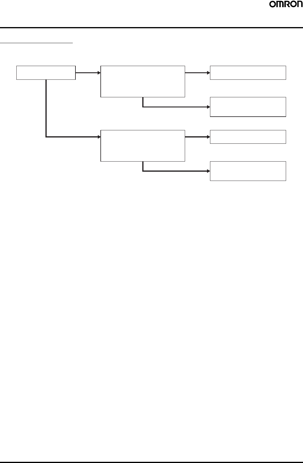
36 Safety Light Curtain (Type 4) F3SJ Ver. 2
Selecting the System Configuration
Selection Flowchart
The necessary system configuration varies depending on the functions to be used. Use the following flowchart to decide what kind of system is
required.
Note: Refer to the User's Manual to determine whether the functions can be used in combination or not.
NO Basic system
Will the fixed blanking function be used?
Will the floating blanking function be used?
Will the detection distance be changed?
Will other functions be used or changed?
NO
YES Basic system plus a setting tool
for setting or changing parameters
Muting system*
Will the fixed blanking function be used?
Will the floating blanking function be used?
Will the detection distance be changed?
Will other functions be used or changed?
NO
YES Muting system*
plus a setting tool for setting or
changing parameters
YES
*F39-CN6 Ke
y
Cap for mutin
g
is required.
Will the muting function be
used?
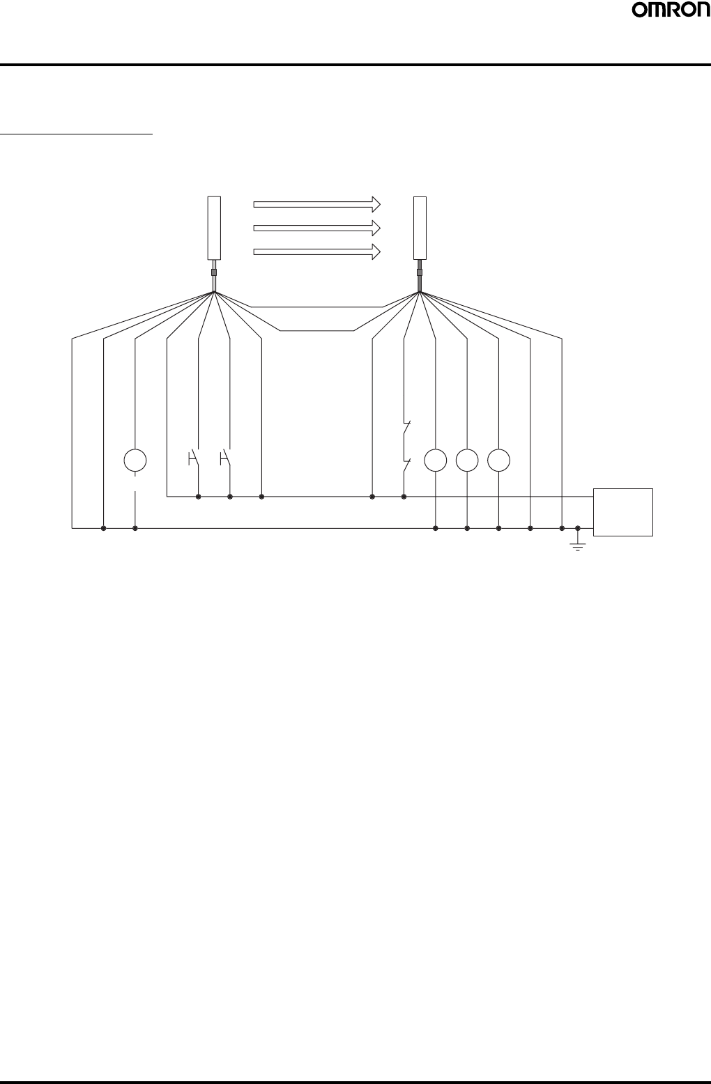
Safety Light Curtain (Type 4) F3SJ Ver. 2 37
System Configuration and Connection (Basic system)
"Basic system" refers to the F3SJ with its default factory settings. The basic system provides basic safety light curtain functions.
Most functions can be used without performing additional configuration.
Basic Connection
For PNP output (See page 39 for NPN output wiring.)
Wiring when using manual reset mode, external device monitoring
S1 S2
K4 K3
K2
K1
K1 K2
0 V
24 VDC
Power
supply
(Gray) Communication line (+)
Emitter
Receiver
(Pink)
Communication
line (−)
Shield
0 V (Blue)
Auxiliary output 2 (Red)
Interlock selection input (White)
Test input (Green)
Reset input (Yellow)
24 V (Brown)
24 V (Brown)
External device monitoring input (Red)
Auxiliary output 1 (Yellow)
Control output 1 (Green)
Control output 2 (White)
0 V (Blue)
Shield
(See
note 2.)
(See
note 1.) (See
note 1.) (See
note 2.)
S1: External test switch (connect to 0 V if the switch is not necessary.)
S2: Interlock/lockout reset switch
K1, K2: Relay or other device that controls hazardous parts of the machine
K3, K4: Load or PLC, etc. (for monitoring)
Note: 1. Use a switch for micro loads (Input specifications: 24 V, 1.8 mA).
2. F3SJ operates even when K3 and K4 are not connected.
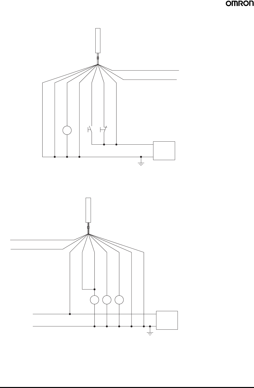
38 Safety Light Curtain (Type 4) F3SJ Ver. 2
Wiring for auto reset mode
The auto reset mode will be enabled when the emitter is wired as shown below.
Wiring when the external device monitoring function will not be used
•Use a setting tool to set the external device monitoring function to "Disabled."
•When using an auxiliary output 1 that has not been changed (output operation mode is "control output data," and inverse of control output
signals is "Enabled), the external device monitoring function will be disabled when auxiliary output 1 and the external device monitoring input are
connected as shown below.
S1 S3
K4
Communication line (+) (Gray)
Communication line (−) (Pink)
0 V
24 VDC
Power
supply
Emitter
Shield
0 V (Blue)
Auxiliary output 2 (Red)
Interlock selection input (White)
Test input (Green)
Reset input (Yellow)
24 V (Brown)
(See
note 2.) (See
note 1.) (See
note 1.)
S1: External test switch (connect to 0 V if the switch
is not necessary.)
S3: Lockout reset switch (connect to 24 V if the
switch is not necessary)
K4: Load or PLC, etc. (for monitoring)
Note: 1. Use a switch for micro loads (Input specifications:
24 V, 1.8 mA).
2. F3SJ operates even when K4 is not connected.
K1 K2K3
0 V
24 VDC
Power
supply
(Gray) Communication line (+)
Receiver
(Pink) Communication line (−)
24 V (Brown)
External device monitoring input (Red)
Auxiliary output 1
(Yellow)
Control output 1 (Green)
Control output 2 (White)
0 V (Blue)
Shield
(See
note.)
K1, K2: Relay or other device that controls
hazardous parts of the machine
K3: Load or PLC, etc. (for monitoring)
Note: The F3SJ operates even when K3 is not connected.
When K3 is not necessary, connect auxiliary output
1 only to the external device monitoring input.
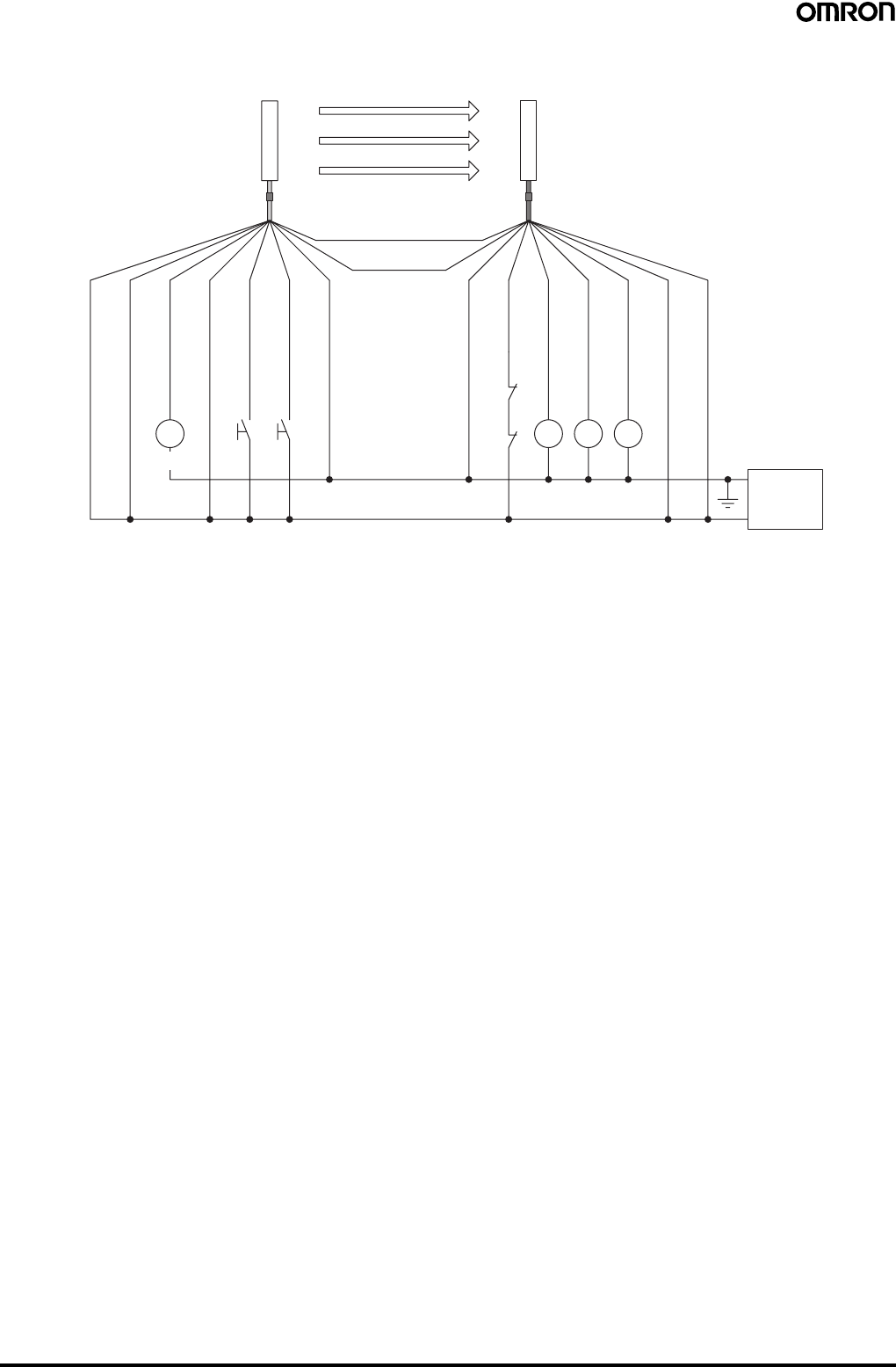
Safety Light Curtain (Type 4) F3SJ Ver. 2 39
For NPN output (See page 37 for PNP output wiring.)
Wiring when using manual reset mode, external device monitoring
S1 S2
K4 K3
K2
K1
K1 K2
0 V
24 VDC
Power
supply
(Gray) Communication line (+)
Emitter
Receiver
(Pink)
Communication
line (−)
Shield
0 V (Blue)
Auxiliary output 2 (Red)
Interlock selection input (White)
Test input (Green)
Reset input (Yellow)
24 V (Brown)
24 V (Brown)
External device monitoring input (Red)
Auxiliary output 1 (Yellow)
Control output 1 (Green)
Control output 2 (White)
0 V (Blue)
Shield
(See
note 2.)
(See
note 1.) (See
note 1.) (See
note 2.)
S1: External test switch (connect to 24 V if the switch is not necessary.)
S2: Interlock/lockout reset switch
K1, K2: Relay or other device that controls hazardous parts of the machine
K3, K4: Load or PLC, etc. (for monitoring)
Note: 1. Use a switch for micro loads (Input specifications: 5 V, 1 mA).
2. F3SJ operates even when K3 and K4 are not connected.
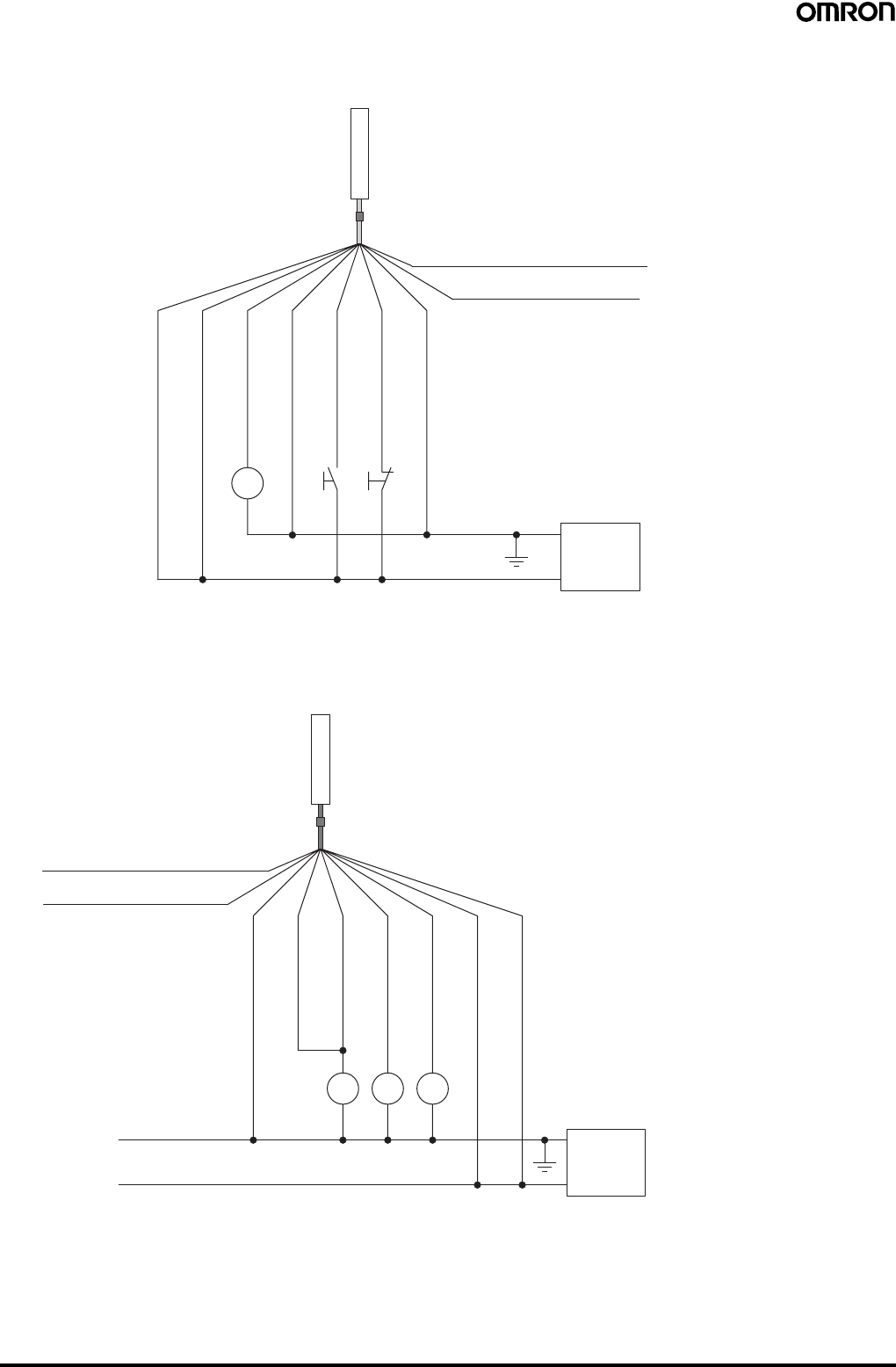
40 Safety Light Curtain (Type 4) F3SJ Ver. 2
Wiring for auto reset mode
The auto reset mode will be enabled when the emitter is wired as shown below.
Wiring when the external device monitoring function will not be used
•Use a setting tool to set the external device monitoring function to "Disabled."
•When using an auxiliary output 1 that has not been changed (output operation mode is "control output data," and inverse of control output
signals is "Enabled), the external device monitoring function will be disabled when auxiliary output 1 and the external device monitoring input are
connected as shown below.
S1 S3
K4
Communication line (+) (Gray)
Communication line (−) (Pink)
0 V
24 VDC
Power
supply
Emitter
Shield
0 V (Blue)
Auxiliary output 2 (Red)
Interlock selection input (White)
Test input (Green)
Reset input (Yellow)
24 V (Brown)
(See
note 2.)
(See
note 1.) (See
note 1.)
S1: External test switch (connect to 0 V if the switch
is not necessary.)
S3: Lockout reset switch (connect to 24 V if the
switch is not necessary)
K4: Load or PLC, etc. (for monitoring)
Note: 1. Use a switch for micro loads (Input specifications:
5 V, 1 mA).
2. F3SJ operates even when K4 is not connected.
K1 K2K3
0 V
24 VDC
Power
supply
(Gray) Communication line (+)
Receiver
(Pink) Communication line (−)
24 V (Brown)
External device monitoring input (Red)
Auxiliary output 1
(Yellow)
Control output 1 (Green)
Control output 2 (White)
0 V (Blue)
Shield
(See
note.)
K1, K2: Relay or other device that controls
hazardous parts of the machine
K3: Load or PLC, etc. (for monitoring)
Note: The F3SJ operates even when K3 is not connected.
When K3 is not necessary, connect auxiliary output
1 only to the external device monitoring input.
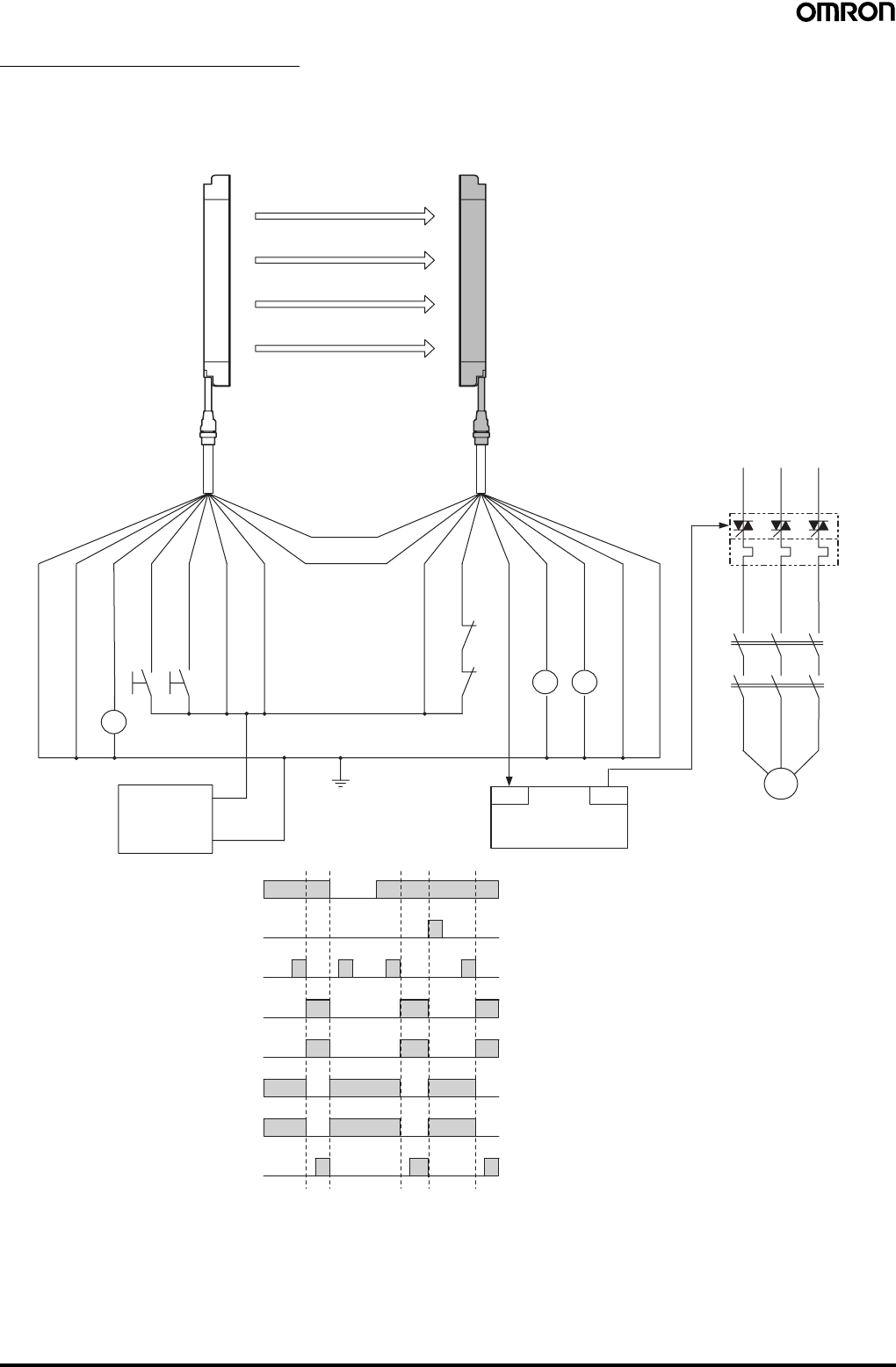
Safety Light Curtain (Type 4) F3SJ Ver. 2 41
Examples of Safety Circuits
For PNP output (See page 46 for NPN output wiring.)
Wiring for single F3SJ application (category 4)
•Use of welded relay contact detection and interlock is possible without a controller or relay unit.
Emitter
F39-JC@A-L F39-JC@A-D
Receiver
OUT
PLC
IN
Communication
line (+) (Gray)
Communication
line (−) (Pink)
Shield
0 V (Blue)
Auxiliary output 2 (Red)
S1
S2 Test input (Green)
Reset input (Yellow)
Interlock selection input (White)
+24 V (Brown)
+24 V (Brown)
External device monitoring input (Red)
KM1
KM2
Auxiliary output 1 (Yellow)
Control output 1 (Green)
Control output 2 (White)
0 V (Blue)
Shield
E1 +24 VDC
0 V
M
KM2
KM1
KM4
Light incident
Light interrupted
External test switch (S1)
Reset switch (S2)
Control output
KM1,KM2 N.O. contact
KM1,KM2 N.C. contact
PLC input (See note.)
PLC output
KM2KM1
KM3
S1: External test switch (connect to 0 V if the
switch is not necessary.)
S2: Interlock/lockout reset switch
KM1, KM2:Safety relay with forcibly-guided contacts
(G7SA) or magnetic contactor
KM3: Load, PLC (for monitor)
KM4: Solid state contactor (G3J)
M: 3-phase motor
E1: 24 VDC power supply (S82K)
PLC: Programmable controller
(Used for monitoring -- not related to safety
system)
Timing Chart
•Manual reset mode
•Using external device monitoring
function
Note: The output operation mode for auxiliary output 1 is control
output data/inverse of control output signals enabled
(default setting).
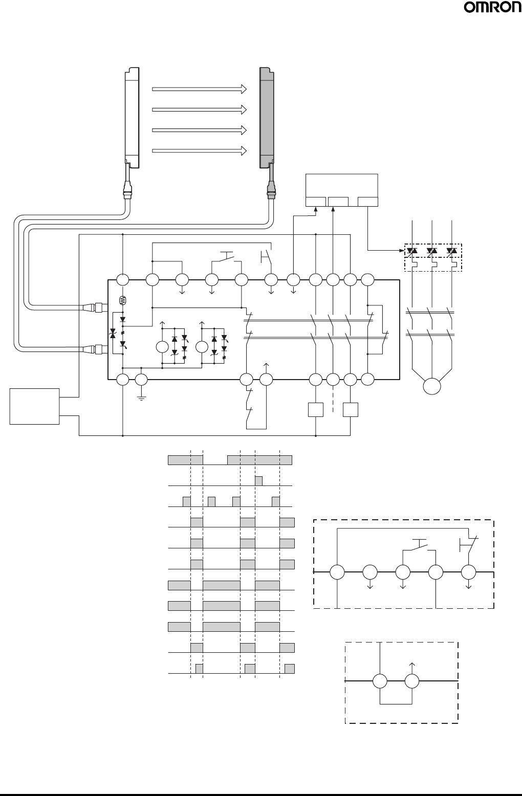
42 Safety Light Curtain (Type 4) F3SJ Ver. 2
Wiring for connection with a controller F3SP-B1P (category 4) (PNP models only)
•Reduced wiring due to connector connection
•Safety relay included
Emitter Receiver
PLC
IN1 IN2 OUT
S1 S2
A1 H1 L1 J1 H1 X1 P1 13 23 33 41
KM3
KM1
KM2
Interlock
selection Test Reset Auxiliary
output 1
OSSD1 OSSD2 K1
K2
K1 K2
A2 PE T31 T32
External device
monitoring
14 24 34 42
KM1 KM2
KM1
KM2
F3SP-B1P
F39-JC@B-L F39-JC@B-D
E1 +24 VDC
0 V
Light incident
Light interrupted
External test switch (S1)
Reset switch (S2)
Control output
K1,K2 N.O. contact
KM1,KM2 N.O. contact
K1,K2 N.C. contact
KM1,KM2 N.C. contact
PLC input 1 (See note 1.)
PLC input 2
PLC output
M
Wiring for auto reset mode
T32T31
Wiring when the external device
monitoring function will not be used
External device
monitoring
Included short bar
S1 S2
Reset
Test
Interlock
selection
X1H1J1L1H1
S1: External test switch
S2: Interlock/lockout reset switch
KM1, KM2:Magnetic contactor
KM3: Solid state contactor (G3J)
M: 3-phase motor
E1: 24 VDC power supply (S82K)
PLC: Programmable controller
(Used for monitoring -- not related
to safety system)
Timing Chart
•Manual reset mode
•Using external device monitoring
function
Note: 1. The output operation mode for auxiliary output 1 is control
output data/inverse of control output signals enabled (default
setting).
2. When the F3SP-B1P is used, the system cannot be used as
a muting system.
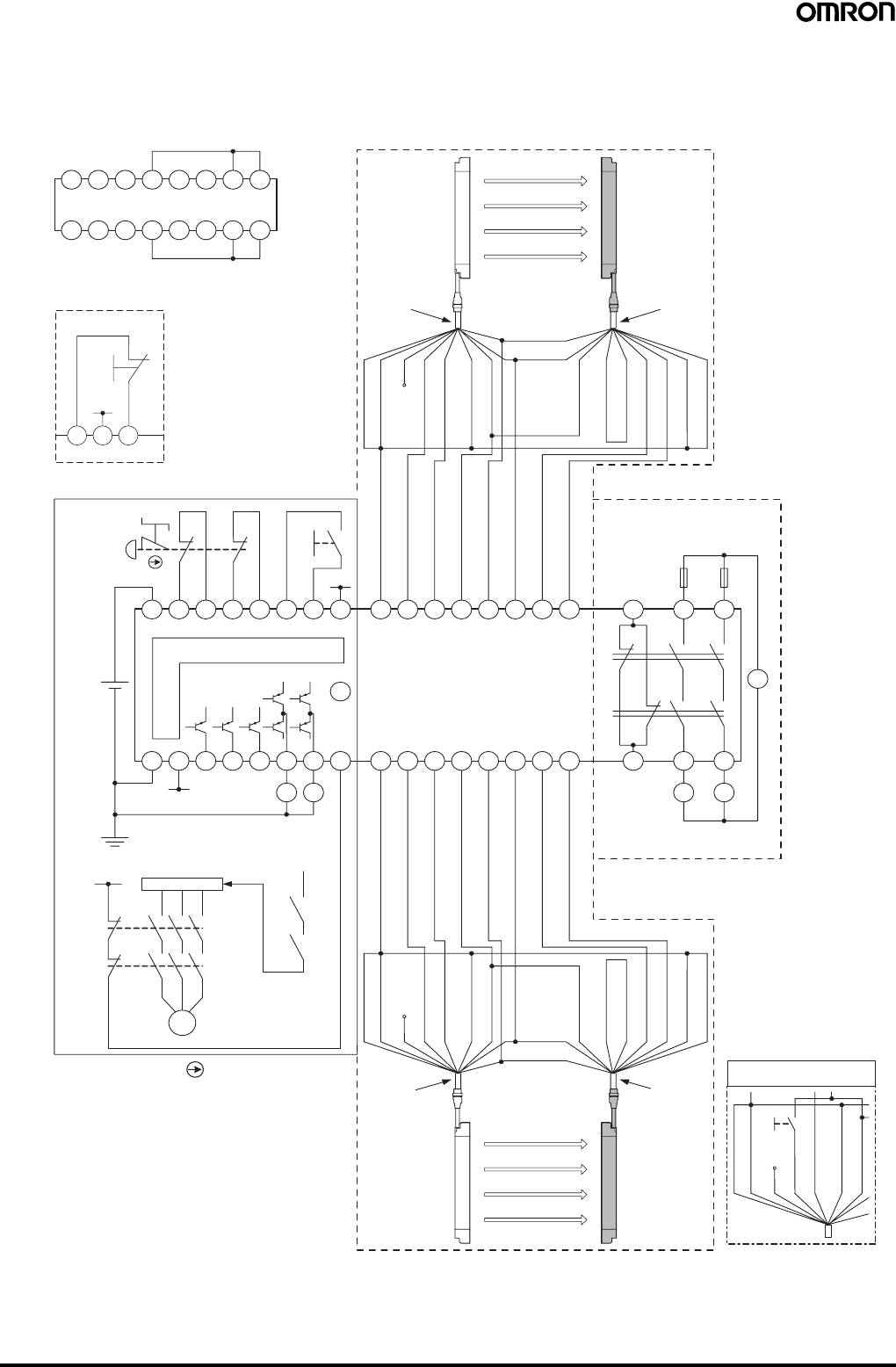
Safety Light Curtain (Type 4) F3SJ Ver. 2 43
Wiring for connection with a controller F3SX-E-L2R (category 4) (PNP models only)
•Emergency stop switch can be connected.
•Door switch, two hand control, single beam, or relay unit can be used in combination with F3SX.
•Various settings can be changed and input/output terminals can be monitored using the setting support software for F3SX.
Wiring when safety light curtain
F3SJ is not used
L2 Module
Emitter Receiver
F3SJ (1st unit)
Model F39-JC@A-L
cable for emitter Model F39-JC@A-D
cable for receiver
Communication
line (+) (Gray)
Communication
line (−) (Pink)
Shield 0 V (Blue)
27543186
15 1012131416911
Auxiliary output 2 (Red)
Open
Test input (Green)
Reset input (Yellow)
Interlock selection input (White)
24 VDC (Brown)
24 VDC (Brown)
External device
monitoring input (Red)
Auxiliary output 1 (Yellow)
Control output 1 (Green)
Control output 1 (White)
0 V (Blue)
Shield
Main Module
S1
S2
11
12 22
21
24 VDC
E1
A1 T11 T12 T21 T22 Y1 Y2 Y3
Control Circuit
24 VDC
E1
A2
24 VDC
24 VDC
COM
0 V
SSC AS3 AS2 AS1 SS1 SS2 FB
E1
24 VDC RY1 RY2
24 VDC
E1
KM1
KM2
M
Motor controller (operation command)
RY1
RY2
15 1012131416911
27
543186
Relay Output Module
(R Module)
Fuse
12 3424
3311 23
AC
K1
K2
KM1 KM2
Emitter Receiver
Shield
0 V (Blue)
Open
Auxiliary output 2 (Red)
Test input (Green)
Reset input (Yellow)
Interlock selection input
(White)
24 VDC (Brown)
Communication
line (−) (Pink)
Communication
line (+) (Gray)
24 VDC (Brown)
External device monitoring
input (Red)
Auxiliary output 1 (Yellow)
Control output 1 (Green)
Control output 2 (White)
0 V (Blue)
Shield
Model F39-JC@A-L
cable for emitter Model F39-JC@A-D
cable for receiver
F3SJ (2nd unit)
Wiring when F3SJ's
testing function is used
Shield
Test SW
0 V (Blue)
Open (Red)
Test input (Green)
Reset input (Yellow)
Interlock selection input (White)
24 VDC (Brown)
(See note 2.)
(See note 2.)
(See note 2.)
Wiring for auto reset mode
S 2
Y 1 Y 2 Y 3
24 VDC
E 1
S1: Emergency stop switch
(direct opening contacts)(A165E, A22E)
S2: Reset switch
KM1, KM2: Magnetic contactor (LC1D)
RY1, RY2: Relay
M: 3-phase motor
E1: 24 VDC power supply (S82K)
F3SJ settings
•Auto reset mode
•External device monitoring
function disabled
F3SX-E-L2R settings
•Manual reset mode
•Using feedback time monitor-
ing function
Note: 1. This wiring example is for category 4.
2. This example shows the connection when auxiliary output
1 is in the standard setting (ON when light is interrupted).
3. When the F3SJ is series-connected, or 5 or more sets are
connected to the total system of F3SX, power must be
supplied to F3SJ from external source.
For details, see instruction manual of F3SX.
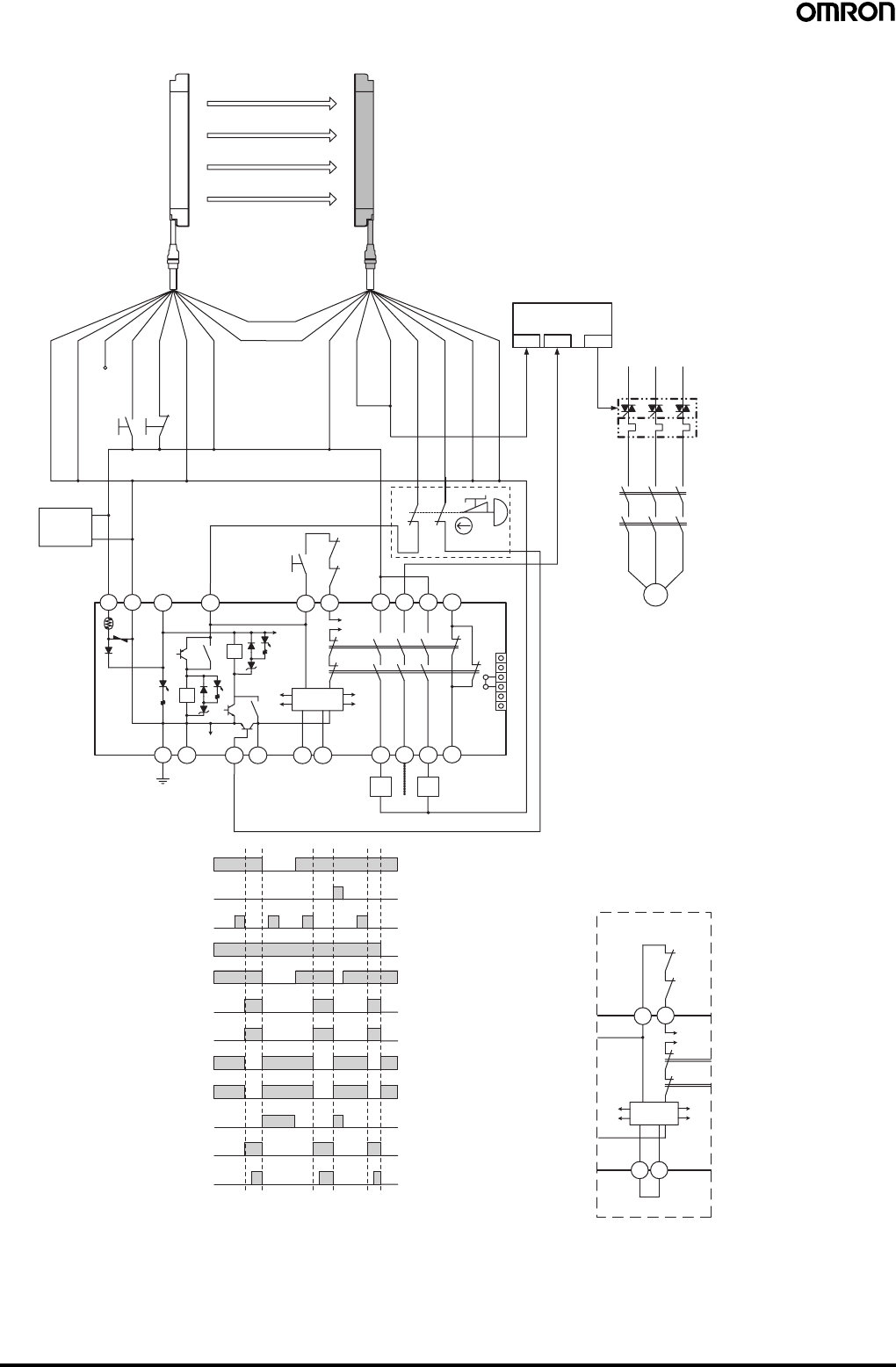
44 Safety Light Curtain (Type 4) F3SJ Ver. 2
Wiring for connection with a controller G9SA-301 (category 4) (PNP models only)
F39-JC@A-DF39-JC@A-L
Emitter Receiver
Shield
0 V (Blue)
S1
Auxiliary output 2 (Red)
Open
Test input (Green)
Reset input (Yellow)
Interlock selection input (White)
+24 V (Brown)
Communication
line (+) (Gray)
Communication
line (−) (Pink)
+24 V (Brown)
External device monitoring
input (Red)
Auxiliary output 1
(Yellow)
Control output 1 (Green)
Control output 2 (White)
0 V (Blue)
Shield
IN1 IN2 OUT
PLC
KM3
Light incident
Light interrupted
(S1)
Interlock reset switch
(S2)
Emergency stop switch
(S3)
Control output
K1,K2 N.O. contact
KM1,KM2 N.O. contact
K1,K2 N.C. contact
KM1,KM2 N.C. contact
PLC input 1 (See note 2.)
PLC input 2
PLC output
M
KM1
KM2
E1
+24 VDC
0 V
A1 A2 T11 T12
S2
KM1
KM2
T31
K1
3
4
K2
1
a
b2
5
T32 41
33
23
13
1
2
3
4
5
6
JP
6
N.O.
N.C.
K1 K2
K1 K2
PE T21 T23 T22 AB14 24 34 42
Control
Circuit
KM1 KM2
G9SA-301
(See
note 1.)
11
12
21
22
S3
External test switch
S4
Wiring for auto reset mod
e
T32
T31
KM1
KM2
K1
K2
A B
Control
Circuit
S1: External test switch (connect to 0 V if the switch is
not necessary.)
S2: Interlock reset switch
S3: Emergency stop switch (direct opening contacts)
(A165E, A22E)
S4: Lockout reset switch (connect to 24 V if the switch
is not necessary.)
KM1, KM2:Magnetic contactor
KM3: Solid state contactor (G3J)
M: 3-phase motor
E1: 24 VDC power supply (S82K)
PLC: Programmable controller
(Used for monitoring -- not related to safety system)
Timing Chart
F3SJ settings
•Auto reset mode
•External device monitoring function disabled
G9SA-301 settings
•Manual reset mode
•Using feedback loop
Using emergency stop switch
Note: 1. If an emergency stop switch is not used,
connect control output 1 to T12 terminal and
control output 2 to T23 directly.
Note: 2. The output operation mode for auxiliary output 1 is control output
data/inverse of control output signals enabled (default setting).
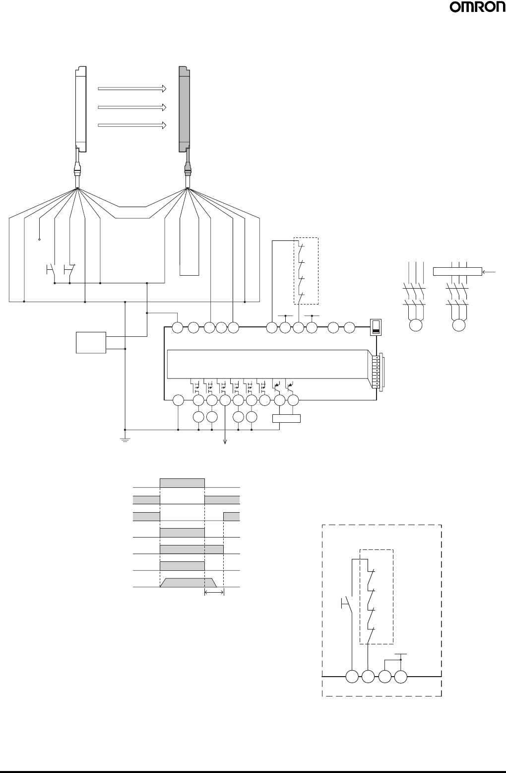
Safety Light Curtain (Type 4) F3SJ Ver. 2 45
Wiring for connection with a controller G9SX-AD322-T15 (category 4) (PNP models only)
•Can be configured for partial control and total control.
•Can be extended to connect a door switch or a relay unit.
A1
A2
S14 S24
KM1 KM2
S34 S44 S54
KM3 KM4
L1 X1 X2
T11
KM1
KM2
KM3
KM4
+24 V +24 V
T12 T21 T22 T31 T32 T33 Y1 T41 T42 M1 M2
PLC, etc.
Motor controller
Motor controller
(operation command)
Feedback loop
Open
G9SX-AD322-T15
Open Open Open OFF
AND
KM1
KM2
KM3
S3
4
KM4
Control circuit
Control output
KM1,KM2 N.C. contact
KM3,KM4 N.C. contact
KM1,KM2 N.O. contact
KM3,KM4 N.O. contact
Motor operation command
Motor rotation
OFF-delay time
+24 V (Brown)
0 V (Blue)
Control output 1 (Green)
Control output 2 (White)
Auxiliary output 1 (Yellow)
S1
S2
Emitter Receiver
Shield
0 V (Blue)
Open
Test input (Green)
Reset input (Yellow)
Interlock selection input (White)
+24 V (Brown)
Communication
line (+) (Gray)
Communication
line (−) (Pink)
External device monitoring
input (Red)
Shield
F39-JC@A-DF39-JC@A-L
+24 VDC
0 V
E1
Auxiliary output 2 (Red)
+24 V
T32 T33 Y1
KM3
KM4
T31
KM1
KM2
S3
Wiring for manual reset mode
Feedback loop
S3: Reset switch
S1: External test switch (connect to 0 V if the switch is
not necessary.)
S2: Lockout reset switch (connect to 24 V if the switch
is not necessary.)
KM1 to KM4:Magnetic contactor
M1, M2: 3-phase motor
E1: 24 VDC power supply (S82K)
PLC: Programmable controller
(Used for monitoring -- not related to safety
system)
Timing Chart
F3SJ settings
•Auto reset mode
•External device monitoring function disabled
G9SX-AD322-T15 settings
•Auto reset mode
•Using feedback loop
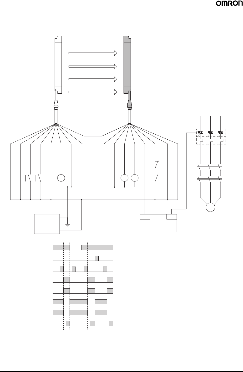
46 Safety Light Curtain (Type 4) F3SJ Ver. 2
For NPN output (See page 41 for PNP output wiring.)
Wiring for single F3SJ application (category 4)
•Use of relay welded relay contact detection and interlock is possible without a controller or relay unit.
KM1,KM2 N.C.contact
Light incident
Light interrupted
External test switch (S1)
Reset switch (S2)
Control output
KM1,KM2 N.O. contact
PLC input (See note.)
PLC output
+24 V (Brown)
+24 V (Brown)
0 V (Blue)
0 V (Blue)
Control output 1 (Green)
Control output 2 (White)
Auxiliary output 1 (Yellow)
Interlock selection input (White)
Reset input (Yellow)
Test input (Green)
Auxiliary output 2 (Red)
Emitter Receiver
Shield
Shield
Communication
line (−) (Pink)
Communication
line (+) (Gray)
M
External device monitoring
input (Red)
F39-JC@A-DF39-JC@A-L
S1
S2
M
KM1
KM2
OUT
PLC
IN
KM4
KM1
KM2
24 VDC
0 V
E1
KM1KM3
KM2
S1: External test switch (connect to 24 V if the
switch is not necessary.)
S2: Interlock/lockout reset switch
KM1, KM2: Safety relay with forcibly-guided contacts
(G7SA) or magnetic contactor
KM3: Load, PLC (for monitor)
KM4: Solid state contactor (G3J)
M: 3-phase motor
E1: 24 VDC power supply (S82K)
PLC: Programmable controller
(Used for monitoring -- not related to safety
system)
Timing Chart
•Manual reset mode
•Using external device monitoring
function
Note: The output operation mode for auxiliary output 1 is control output
data/inverse of control output signals enabled (default setting).
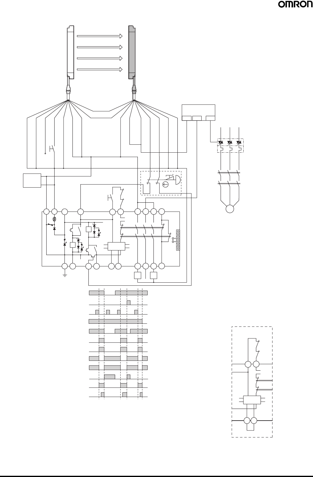
Safety Light Curtain (Type 4) F3SJ Ver. 2 47
Wiring for connection with a controller G9SA-301-P (category 4) (NPN models only)
M
OUT
PLC
KM1
KM2
KM1,KM2 N.C. contact
IN1 IN2
PLC input 1 (See note 2.)
Light incident
Light interrupted
External test switch
(S1)
Interlock reset switch
(S2)
Control output
K1,K2 N.O. contact
KM1,KM2 N.O. contact
K1,K2 N.C. contact
PLC input 2
PLC output
KM3
T23
PE 14 24 34 42
41332313
T32
T31
T11
KM1 KM2
G9SA-301-P
KM1
KM2
T12
K1 K1
K2
K1
T21
S2
+24 V (Brown)
+24 V (Brown)
0 V (Blue)
0 V (Blue)
Control output 1 (Green)
Control output 2 (White)
Auxiliary output 1
(Yellow)
External device monitoring
input (Red)
Interlock selection input (White)
Reset input (Yellow)
Test input (Green)
Auxiliary output 2 (Red)
S1
Emitter Receiver
Shield
Shield
1
aK2
K2
b
Control
Circuit
T22 A B
a
b2
5
63
4
1
2
3
4
5
6
JP
A2A1
+24 VDC
0 V
E1
Open
Emergency stop switch
(S3)
Communication
line (−) (Pink)
Communication
line (+) (Gray)
(See
note 1.)
11
12
21
22
S3
F39-JC@A-DF39-JC@A-L
A B
Wiring for auto reset mod
e
Control
Circuit
KM2
KM1
K1
K2
T32T31
S1: External test switch (connect to 24 V if the switch
is not necessary.)
S2: Interlock reset switch
S3: Emergency stop switch (direct opening contacts)
(A165E, A22E)
S4: Lockout reset switch (connect to 0 V if the switch
is not necessary.)
KM1, KM2: Magnetic contactor
KM3: Solid state contactor (G3J)
M: 3-phase motor
E1: 24 VDC power supply (S82K)
PLC: Programmable controller
(Used for monitoring -- not related to safety
system)
Timing Chart
F3SJ settings
•Auto reset mode
•External device monitoring function disabled
G9SA-301-P settings
•Manual reset mode
•Using feedback loop
Using emergency stop switch
Note: 1. If an emergency stop switch is not used,
connect control output 1 to T12 terminal and
control output 2 to T23 directly.
Note: 2. The output operation mode for auxiliary output 1 is control
output data/inverse of control output signals enabled
(default setting).
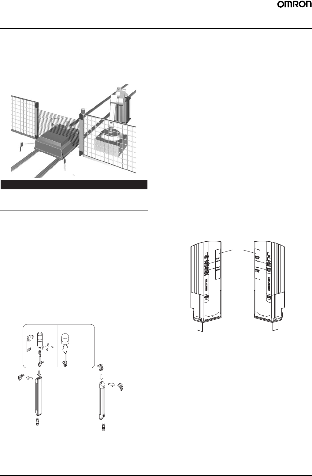
48 Safety Light Curtain (Type 4) F3SJ Ver. 2
System Configuration and Connection (Muting system)
Muting System
The muting function temporarily disables the safety function of the
F3SJ, keeping the control outputs ON even if beams are interrupted.
This makes it possible to install safety light curtains for AGV
passage, enabling both safety and productivity.
When muting, the muting lamp (external indicator) blinks to notify
people in the surrounding area that the safety functions are disabled.
!WARNING
The muting and override functions disable the safety functions of the
device. Additional safety measures must be taken to ensure safety
while these functions are working.
Install muting sensors so that they can distinguish between the
object that is being allowed to be pass through the detection zone
and a person.
If the muting function is activated by the detection of a person, it may
result in serious injury.
Muting lamps (external indicators) that indicate the state of the
muting and override functions must be installed where they are
clearly visible to workers from all the operating positions.
Upgrading F3SJ for Muting System
1. Remove the caps of the emitter and receiver.
(A screwdriver is included with the key cap for muting.)
2. Install a muting lamp (external indicator) on either the emitter or
receiver.
3. Attach the key cap for muting to the emitter/receiver on which the
muting lamp (external indicator) was not installed.
Muting Sensor
The muting sensor is the sensor that is the trigger for temporarily
disabling the safety functions of F3SJ. You can use a photoelectric
switch of through-beam or retro-reflective types, proximity sensor, or
limit switch. (OMRON's E3Z series, E2E series, and D4N series
sensors are recommended.) For the PNP type F3SJ, use a sensor
with PNP transistor outputs or N.O type contacts. For the NPN type
F3SJ, use a sensor with NPN transistor outputs or N.O type
contacts. For NPN type F3SJ, use a sensor with NPN transistor
outputs or N.O type contacts.
Muting Lamp (External indicator)
To notify workers that the muting function is working, external lamp(s)
must be installed. Use the F39-A01P@-PAC external indicator set or
an F39-JJ3N universal indicator cable with a commercially available
external indicator.
F3SJ Internal Indicators
•The muting input 1 indicator turns ON when input is applied to
muting input 1.
•The muting input 2 indicator turns ON when input is applied to
muting input 2.
•The muting input 1 indicator and muting input 2 indicator blink
under muting override.
•The muting error indicator on the receiver side turns ON when
there is a muting error.
Attachment Positions for Included Labels
Internal indicator labels are included with the F39-CN6 Key Cap for
Muting. When using a muting system, attach the internal indicator
labels so the arrows will be in line with the positions of the indicators,
as shown by the shading below.
Key Cap for Muting
F39-CN6
(Case: orange)
External indicator set
Model F39-A01P@-PAC
Commercially
available
external
indicator
Universal indicator
cable
Model F39-JJ3N
Brown: +, Blue: −
M
u
ti
ng
l
amp
(
ex
t
erna
l
i
n
di
ca
t
or
)
Cap
(Case: black)
Cap
(Case: black)
1.
1.
2.
3.
Emitter Receiver
Internal
indicator labels
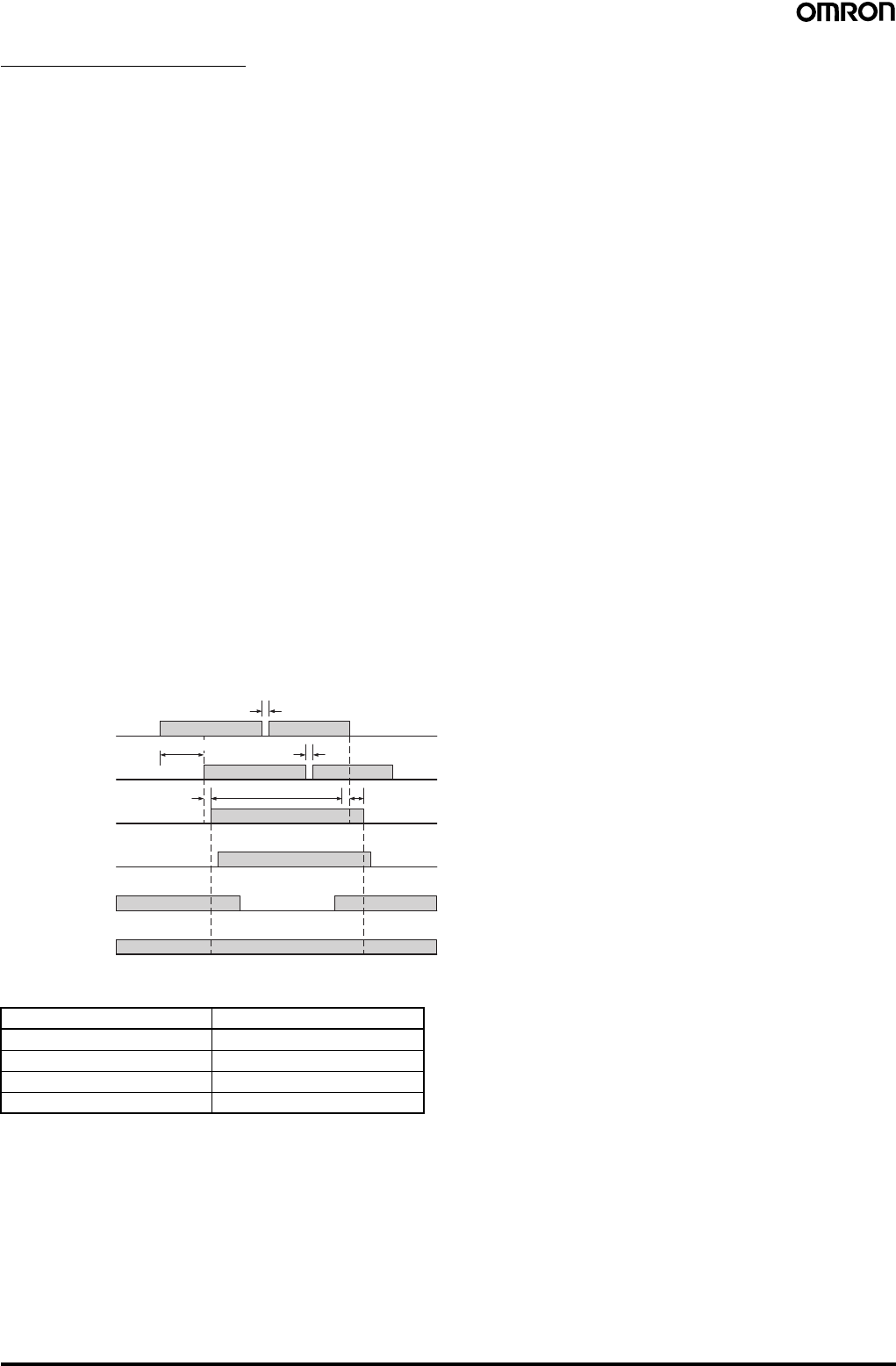
Safety Light Curtain (Type 4) F3SJ Ver. 2 49
Standard Muting Mode
The F3SJ is set to this operation mode when it is shipped from the
factory. The muting function is enabled by providing a time lag
between muting inputs 1 and 2. Use a separately purchased setting
tool to change parameters related to muting time, or to select other
muting operation modes.
Start Conditions
If both of the following 2 conditions are present, muting is activated.
1. No interrupting object is found in the F3SJ's detection zone, and
control output is ON.
2. After muting input 1 is turned ON (connected to 9 to 24 V for PNP
types, or to 0 to 1.5 V for NPN types), muting input 2 is turned ON
(connected to 9 to 24 V for PNP types, or to 0 to 1.5 V for NPN
types) within the muting input time limit T1 min. to T1 max. (0.03
to 3 s).
Once the conditions in item 2 above are met, the muting function will
be enabled in 0.15 s max.
When condition 1 is satisfied but time condition of 2 is not, a muting
sequence error occurs and receiver’s muting error indicator turns
ON.
However, the F3SJ safety functions will continue operating and the
F3SJ will operate normally even during a muting error.
A muting error is released when either of the following occurs:
•When muting is started using a proper procedure
•When power is turned on while muting inputs 1 and 2 are OFF
End Conditions
If either of the following conditions are satisfied, the muting state is
released.
1. Muting input 1 or 2 turns OFF for T3 (0.1 s) or longer.
2. When the muting continuation time exceeds the muting time limit
of T2 (60 s) (a setting tool can be used to change the limit in the
range of 1 to 600 s, or to eliminate the time limit)
∗: This value is the time when the F3SJ is used singly. When used in
a series, this time is as shown in the table below.
•T1 min: Muting input time limit (min.)
This is the minimum input time lag between muting inputs 1 and 2,
and is set to 0.03 s. If the time lag between muting inputs 1 and 2
are shorter than this value, a muting error is generated.
•T1 max: Muting input time limit (max.)
This is the maximum input time lag between muting inputs 1 and 2,
and is set to 3 s. The minimum value must be less than the
maximum value (min. < max.).
•T2: Muting time limit
This is the continuous time of the muting function, and is set to
60 s. If the muting status exceeds this time, muting is cancelled.
•T3: Allowable pulse-change time for muting input signals
This is the maximum time allowed for a change in the waveform
pulse of muting inputs 1 and 2 while in the muting status.
Note: The muting status can be released even when the system
enters lockout.
The following values can be changed using the Setting Support
Software for the F3SJ:
•T1 min: Muting input time limit (min.)
•T1 max: Muting input time limit (max.)
•T2: Muting time limit
The following values can be changed using the Setting Console:
•T2: Muting time limit
Installation Standard for Muting Sensors
•Set the muting sensors so that they can detect all of the passing
detection objects (palettes, automobiles, etc.). Do not install in a
position so that only the front or rear end of the detection object is
detected.
•Set the muting sensors so that they detect the objects even when
they are loaded on palettes or other transport devices.
•Install the F3SJ and muting sensors so that each object passes
through all muting sensors before the next object arrives at the first
muting sensor. Also, install all F3SJ and muting sensors so that no
person is able to accidentally enter the hazardous area while the
muting function is enabled.
•When objects pass through the muting area at different speeds,
consider limiting the muting time.
•For a muting sensor installation example, see the instruction
manual.
•For details about the override function, see the instruction manual.
Number of Connected Units ∗ Time (s)
10.15
Series of 2 0.26
Series of 3 0.29
Series of 4 0.32
Muting input 1
Muting input 2
Muting status
ON
OFF
Enabled
Disabled
F3SJ
Light incident/
Light interrupted
Control output
ON
OFF
Light
incident
Light
interrupted
ON
OFF
Muting lamp
(external
indicator)
Blink
OFF
0.25 s max.
T2 max.
T3 (0.1 s) max.
T3 (0.1 s) max.
T1 min. to T1 max.
0.15 s max.∗
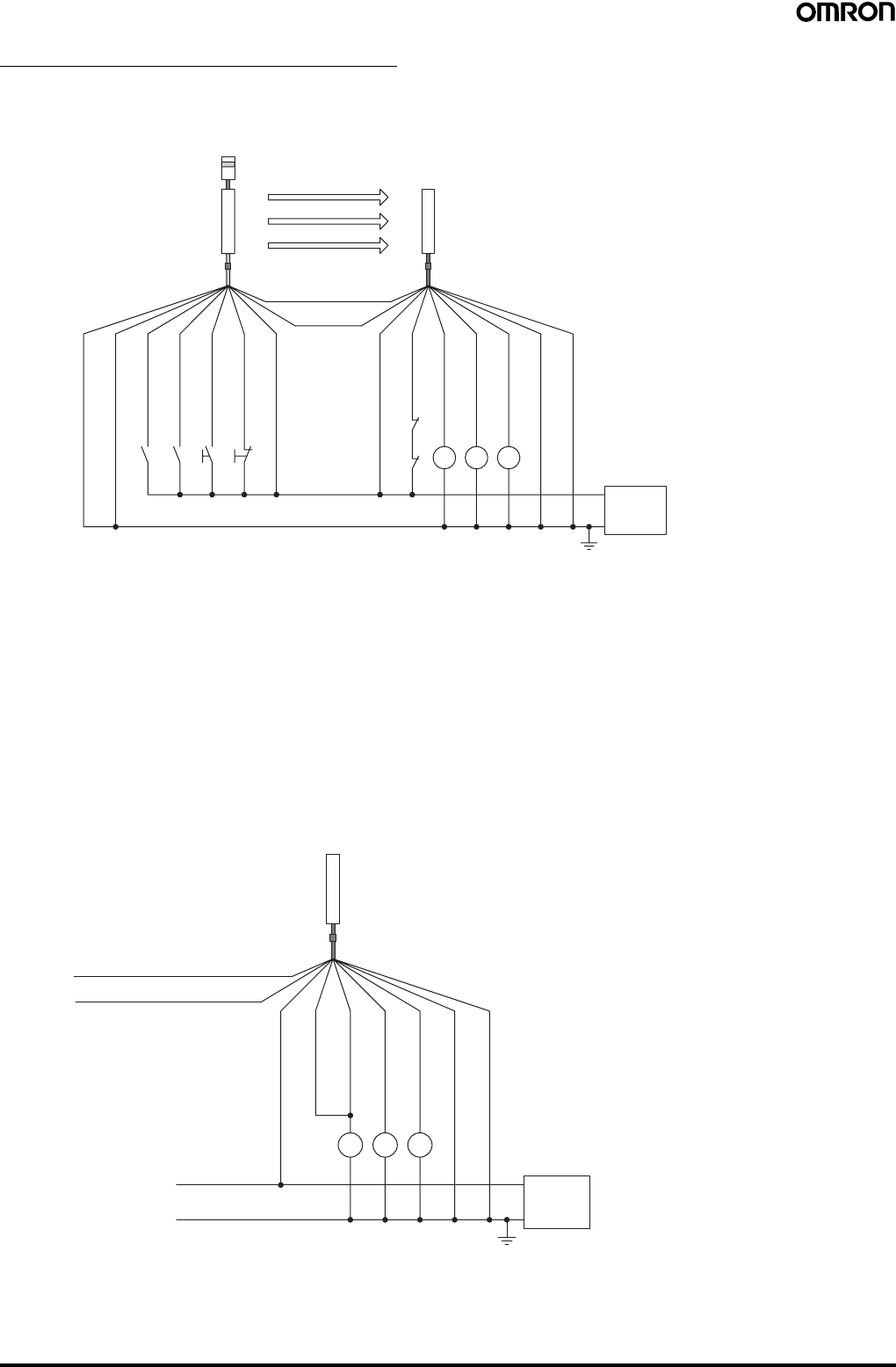
50 Safety Light Curtain (Type 4) F3SJ Ver. 2
Basic Connection for Muting System
For PNP output (See page 51 for NPN output wiring.)
Wiring when using muting and external device monitoring functions
Wiring when the external device monitoring function will not be used
•Use a setting tool to set the external device monitoring function to "Disabled."
•When using an auxiliary output 1 that has not been changed (output operation mode is "control output data," and inverse of control output
signals is "Enabled), the external device monitoring function will be disabled when auxiliary output 1 and the external device monitoring input are
connected as shown below.
K2K1K3
K1
K2
B1 A1 S1 S2
0 V
24 VDC
Power
supply
Emitter
Receiver
(Pink)
Communica-
tion line (−)
Shield
0 V (Blue)
Muting input 2
(Red)
Muting input 1
(White)
Test input (Green)
Reset input (Yellow)
24 V (Brown)
24 V (Brown)
External device
monitoring input (Red)
Auxiliary output 1
(Yellow)
Control output 1
(Green)
Control output 2
(White)
0 V (Blue)
Shield
(See
note 4.)
(See
note 1.) (See
note 1.)
(See
note 3.)
(See
note 4.)
(Gray)
Communication line (+)
(See
note 2.)
(See
note 4.)
S1: External test switch (connect to 0 V if the switch is not necessary.)
S2: Lockout reset switch (connect to 24 V if the switch is not necessary.)
A1: Contact by muting sensor A1
B1: Contact by muting sensor B1
K1, K2: Relay or other device that controls hazardous parts of the machine
K3: Load or PLC, etc. (for monitoring)
M1: Muting lamp
Note: 1. Use a switch for small loads (input specifications: 24 V, 1.8 mA)
2. When using the interlock function, this also functions as an interlock reset switch. (Must be set with a setting tool.)
3. The F3SJ will operate even if K3 is not connected.
4. Connect the muting lamp to either the external indicator output or auxiliary output 1 for the emitter or the receiver. When
connecting the muting lamp to auxiliary output 1, the parameter must be changed with a setting tool.
K3 K1 K2
0 V
24 VDC
Power
supply
Receiver
(Pink) Communication line (−)
External device
monitoring input (Red)
Control output 1
(Green)
Control output 2
(White)
0 V (Blue)
Shield
(See
note.)
(Gray) Communication line (+)
24 V (Brown)
Auxiliary
output 1 (Yellow)
K1, K2: Relay or other device that controls
hazardous parts of the machine
K3: Load, PLC, etc. (for monitoring)
Note: The F3SJ operates even when K3 is not connected.
When K3 is not necessary, connect auxiliary output 1
only to the external device monitoring input.
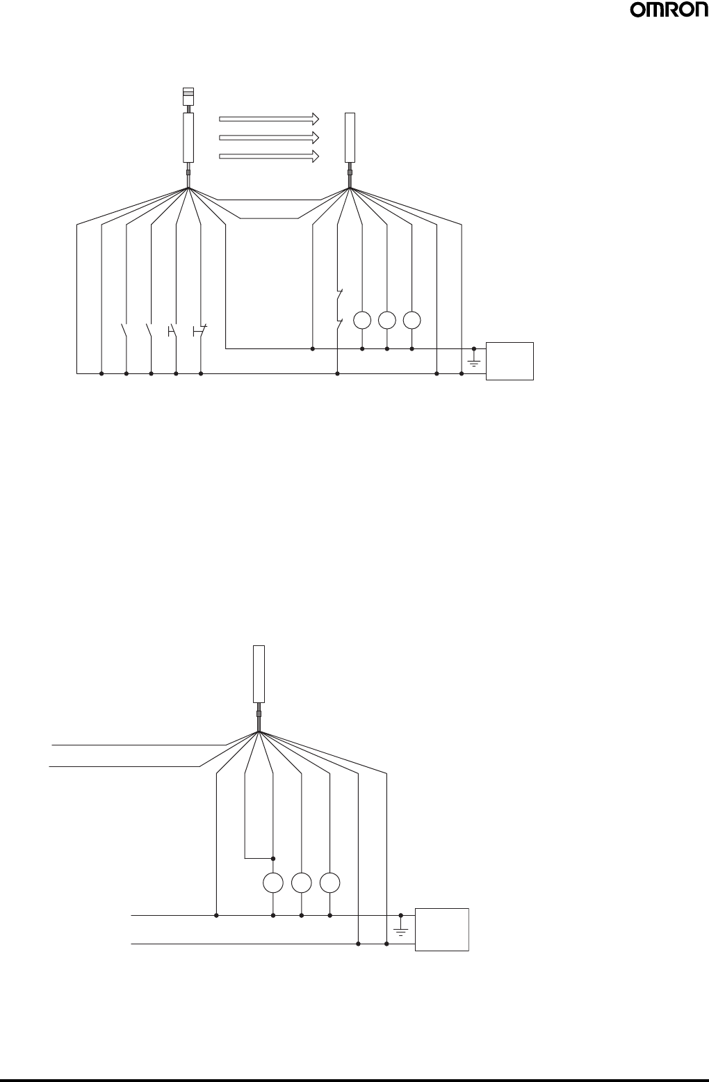
Safety Light Curtain (Type 4) F3SJ Ver. 2 51
For NPN output (See page 50 for PNP output wiring.)
Wiring when using muting and external device monitoring functions
Wiring when the external device monitoring function will not be used
•Use a setting tool to set the external device monitoring function to "Disabled."
•When using an auxiliary output 1 that has not been changed (output operation mode is "control output data," and inverse of control output
signals is "Enabled), the external device monitoring function will be disabled when auxiliary output 1 and the external device monitoring input are
connected as shown below.
K2K1K3
K1
K2
B1 A1 S1 S2
0 V
24 VDC
Power
supply
Emitter
Receiver
(Pink)
Communica-
tion line (−)
Shield
0 V (Blue)
Muting input 2
(Red)
Muting input 1
(White)
Test input (Green)
Reset input (Yellow)
24 V (Brown)
24 V (Brown)
External device
monitoring input (Red)
Auxiliary output 1
(Yellow)
Control output 1
(Green)
Control output 2
(White)
0 V (Blue)
Shield
(See
note 1.)
(See
note 3.)
(See
note 4.)
(Gray)
Communication line (+)
(See
notes 1
and 2.)
(See
note 4.)
(See
note 4.)
S1: External test switch (connect to 24 V if the switch is not necessary.)
S2: Lockout reset switch (connect to 0 V if the switch is not necessary.)
A1: Contact by muting sensor A1
B1: Contact by muting sensor B1
K1, K2: Relay or other device that controls hazardous parts of the machine
K3: Load or PLC, etc. (for monitoring)
M1: Muting lamp
Note: 1. Use a switch for small loads (input specifications: 5 V, 1 mA).
2. When using the interlock function, this also functions as an interlock reset switch. (Must be set with a setting tool.)
3. The F3SJ operates even when K3 is not connected.
4. Connect the muting lamp to either the external indicator output or auxiliary output 1 for the emitter or the receiver. When
connecting the muting lamp to auxiliary output 1, the parameter must be changed with a setting tool.
K3 K1 K2
0 V
24 VDC
Power
supply
Receiver
(Pink) Communication line (−)
External device
monitoring input (Red)
Control output 1
(Green)
Control output 2
(White)
0 V (Blue)
Shield
(See
note.)
(Gray) Communication line (+)
24 V (Brown)
Auxiliary
output 1 (Yellow)
K1, K2: Relay or other device that controls
hazardous parts of the machine
K3: Load, PLC, etc. (for monitoring)
Note: The F3SJ operates even when K3 is not connected.
When K3 is not necessary, connect auxiliary output 1
only to the external device monitoring input.
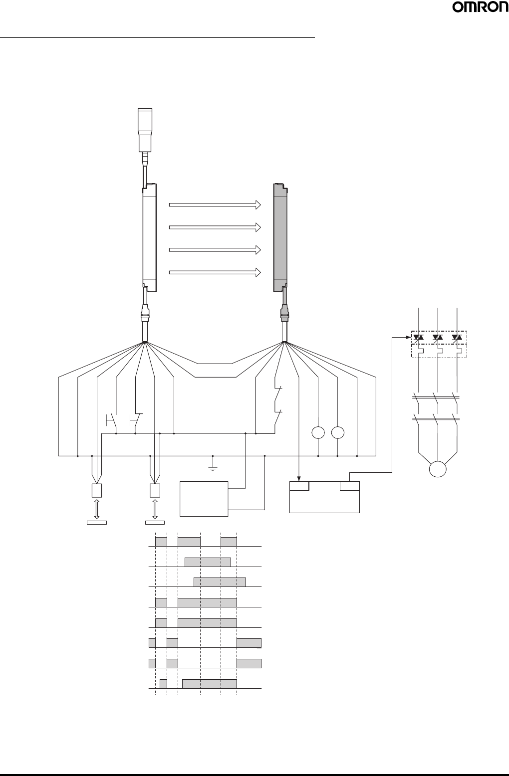
52 Safety Light Curtain (Type 4) F3SJ Ver. 2
Example of a Safety Circuit with the Muting System
For PNP output
Wiring for muting function with single F3SJ application (category 4)
When two muting sensors are connected
•Attaching a keycap for muting (F39-CN6) enables the muting function to be used.
Emitter Receiver
OUT
PLC
IN
S1
S2
E1 24 VDC
0 V
M
KM2
KM1
KM3
Reflector
Light incident
Muting lamp
(external indicator)
F39-JC@A-DF39-JC@A-L
KM1 KM2
KM2
KM1
Muting sensor
(PNP output)
Light interrupted
Control output
Muting input 1
Muting input 2
KM1, KM2 N.O. contact
KM1, KM2 N.C. contact
PLC input (See note 1.)
PLC output
Shield
0 V (Blue)
Muting input 2
(Red)
Test input
(Green)
Reset input
(Yellow)
Muting input 1
(White)
24 V (Brown)
24 V (Brown)
External device
monitoring input (Red)
Auxiliary output 1 (Yellow)
Control output 1 (Green)
Control output 2 (White)
0 V (Blue)
Shield
(Pink)
Communica-
tion line (−)
(Gray)
Communication line (+)
Note: 1. The output operation mode for auxiliary output 1 is control output data/inverse of control output signals enabled (default setting).
2. Start interlock and restart interlock can be used with a setting tool.
S1: External test switch (connect to 0 V if the switch is not
necessary.)
S2: Lockout reset switch (connect to 24 V if the switch is not
necessary.)
KM1, KM2: Safety relay with forcibly-guided contacts (G7SA) or
magnetic contactor
KM3: Solid state contactor (G3J)
M: 3-phase motor
E1: 24 VDC power supply (S82K)
PLC: Programmable controller (Used for monitoring -- not
related to safety system)
Muting sensor: Retro-reflective photoelectric sensor (E3Z-R81)
•Auto reset mode
•Using external device monitoring
function
Timing Chart

Safety Light Curtain (Type 4) F3SJ Ver. 2 53
When four muting sensors are connected
•The muting function can be used by attaching the F39-CN6 Key Cap.
F3SJ
+DC24V
0V E1
A1
B1 A2
B2
F3SJ
Control output
B2 Control output
A2 Control output
B1 Control output
A1 Control output
Workpiece
S1
S2
OUT
PLC
IN
M
KM1
KM2
KM3
KM1
KM2
KM1 KM2
Emitter Receiver
Muting lamp
(external indicator)
F39-JC@A-D
F39-JC@A-L
Shield
0 V (Blue)
Muting input 2
(Red)
Test input
(Green)
Reset input
(Yellow)
Muting input 1
(White)
24 V (Brown)
24 V (Brown)
External device
monitoring input (Red)
Auxiliary
output 1
(Yellow)
Control
output 1 (Green)
Control output
2 (White)
0 V (Blue)
Shield
(Pink)
Communica-
tion line (−)
(Gray)
Communication
line (+)
Reflector
Muting sensor
(PNP output)
Light incident
Light interrupted
Muting input 1
Muting input 2
KM1, KM2 N.O. contact
KM1, KM2 N.C. contact
PLC input (See note 1.)
PLC output
Note: 1. The output operation mode for auxiliary output 1 is control output data/inverse of control output signals enabled (default setting).
2. Start interlock and restart interlock can be used with a setting tool.
•Auto reset mode
•Using external device monitoring function
S1: External test switch (connect to 0 V if the
switch is not necessary.)
S2: Lockout reset switch (connect to 24 V if the
switch is not necessary.)
KM1, KM2: Safety relay with forcibly-guided contacts
(G7SA) or magnetic contactor
KM3: Solid state contactor (G3J)
M: 3-phase motor
E1: 24 VDC power supply (S82K)
PLC: Programmable controller
(Used for monitoring -- not related to safety
system)
A1, B1, A2, B2, Muting sensor: Retro-reflective
photoelectric sensor (E3Z-R81)
Timing Chart
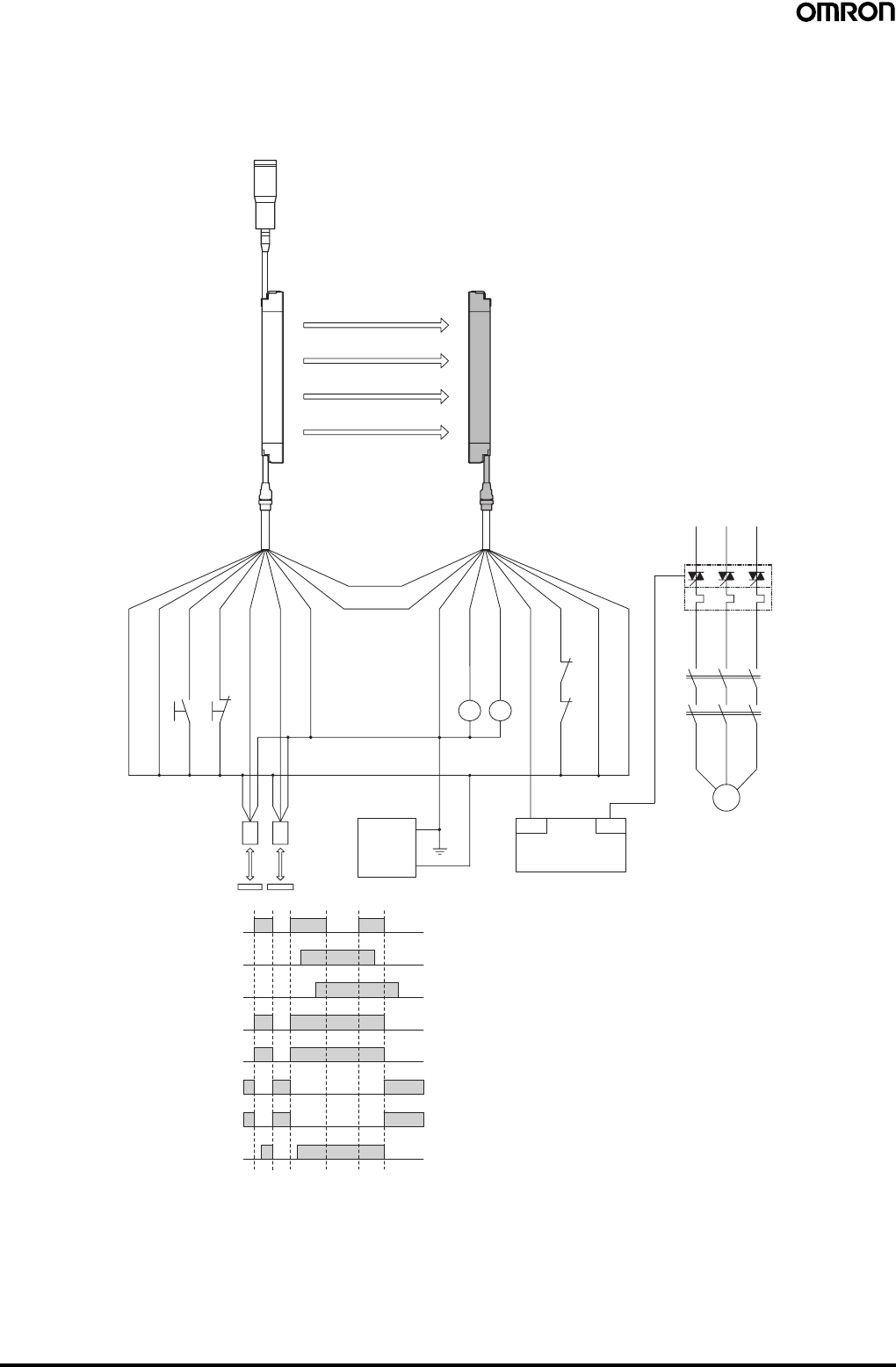
54 Safety Light Curtain (Type 4) F3SJ Ver. 2
For NPN output
Wiring for muting function with single F3SJ application (category 4)
When two muting sensors are connected
•Attaching a keycap for muting (F39-CN6) enables the muting function to be used.
Emitter Receiver
Communication
line (+) (Gray)
Communication
line (−) (Pink)
Shield
0 V (Blue)
Muting input 2 (Red)
Test input (Green)
Reset input (Yellow)
Muting input 1 (White)
+24 V (Brown)
+24 V (Brown)
Control output 1 (Green)
Control output 2 (White)
0 V (Blue)
Shield
+24 VDC
Reflector
Muting sensor
(NPN output)
Auxiliary output 1 (Yellow)
External device
monitoring input (Red)
KM1,KM2 N.C. contact
Light incident
Light interrupted
Muting input 1
Muting input 2
Control output
KM1,KM2 N.O. contact
PLC input (See note 1.)
PLC output
Muting lamp
(external indicator)
F39-JC@A-L
F39-JC@A-D
S1
S2
M
KM1
KM2
OUT
PLC
IN
KM
3
KM1
KM2
0V
E1
KM1
KM2
Timing Chart
•Auto reset mode
•Using external device monitoring
function
Note: 1. The output operation mode for auxiliary output 1 is control output data/
inverse of control output signals enabled (default setting).
2. Start interlock and restart interlock can be used with a setting tool.
S1: External test switch (connect to 24 V if the switch is not
necessary.)
S2: Lockout reset switch (connect to 0 V if the switch is not
necessary.)
KM1, KM2: Safety relay with forcibly-guided contacts (G7SA) or
magnetic contactor
KM3: Solid state contactor (G3J)
M: 3-phase motor
E1: 24 VDC power supply (S82K)
PLC: Programmable controller
(Used for monitoring -- not related to safety system)
Muting sensor: Retro-reflective photoelectric sensor (E3Z-R61)
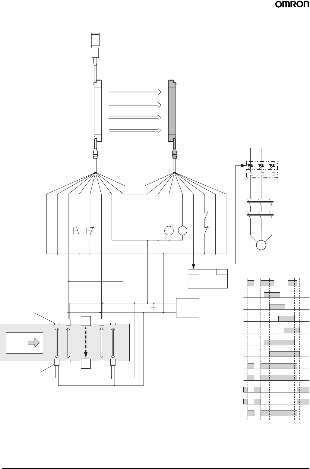
Safety Light Curtain (Type 4) F3SJ Ver. 2 55
When four muting sensors are connected
•The muting function can be used by attaching the F39-CN6 Key Cap.
F3SJ
F3SJ
Control output
B2 Control output
A2 Control output
B1 Control output
A1 Control output
Workpiece
S1
S2
OUT
IN
M
KM1
KM2
KM3
KM1
KM2
Emitter Receiver
Muting lamp
(external indicator)
F39-JC@A-D
F39-JC@A-L
Shield
0 V (Blue)
Muting input 2
(Red)
Test input
(Green)
Reset input
(Yellow)
Muting input 1
(White)
24 V (Brown)
24 V (Brown)
External device
monitoring input (Red)
Auxiliary output 1
(Yellow)
Control
output 1 (Green)
Control
output 2
(White)
0 V (Blue)
Shield
(Pink)
Communica-
tion line (−)
(Gray)
Communication
line (+)
Reflector
Muting sensor
(NPN output)
Light
incident
Light
interrupted
Muting input 1
Muting input 2
KM1, KM2 N.O. contact
KM1, KM2 N.C. contact
PLC input (See note 1.)
PLC output
A1
B1 A2
B2
Workpiece
OUT
PLC
IN
KM1 KM2
+DC24V
0V E1
Note: 1. The output operation mode for auxiliary output 1 is control output data/inverse of control output signals enabled (default setting).
2. Start interlock and restart interlock can be used with a setting tool.
•Auto reset mode
•Using external device monitoring function
S1: External test switch (connect to 24 V if the
switch is not necessary.)
S2: Lockout reset switch (connect to 0 V if the switch
is not necessary.)
KM1, KM2:Safety relay with forcibly-guided contacts
(G7SA) or magnetic contactor
KM3: Solid state contactor (G3J)
M: 3-phase motor
E1: 24 VDC power supply (S82K)
PLC: Programmable controller
(Used for monitoring -- not related to safety
system)
A1, B1, A2, B2, Muting sensor: Retro-reflective
photoelectric sensor (E3Z-R61)
Timing Chart
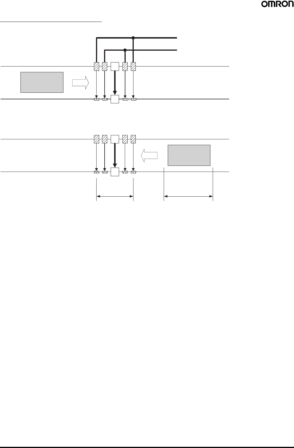
56 Safety Light Curtain (Type 4) F3SJ Ver. 2
Setting Bi-directional Muting
Connect the outer muting sensors A1 and A2 to muting input 1 and the inner muting sensors B1 and B2 to muting input 2.
Muting from the opposite direction is also possible.
Note: 1. This example arrangement uses E3Z-R@@ Retro-reflective Photoelectric Sensors as the muting sensors. Mutual interference must be
taken into account when installing these Sensors.
2. The muting sensors must be installed so that distance D between muting sensors A1 and A2 is smaller than workpiece length L.
3. Through-beam or Retro-reflective Photoelectric Sensors, Proximity Sensors, or Limit Switches can be used as the muting sensors.
Workpiece V
F3SJ
A1 B1 B2 A2
A1, A2, B1, B2: Retro-reflective Photoelectric Sensors
Connected to muting input 1
Connected to muting input 2
When muting sensors A1 and then B1 (or A2 and then B2)
turn ON in that order, the F3SJ will enter the muting state.
WorkpieceV
D L
A1 B1 B2 A2
F3SJ
Safety Light Curtain (Type 4) F3SJ Ver. 2 57
Safety Precautions
This catalog is intended as a guide for product selection. Be sure to use the instruction manual provided with the product for actual operation.
■Regulations and Standards
1. Application of an F3SJ-A sensor alone cannot receive type
certification provided by Article 44-2 of the Labour Safety and
Health Law of Japan. It is necessary to apply it in a system.
Therefore, when using the F3SJ-A in Japan as a "safety system
for pressing or shearing machines" prescribed in Article 42 of that
law, the system must receive type certification.
2. The F3SJ-A is electro-sensitive protective equipment (ESPE) in
accordance with European Union (EU) Machinery Directive Index
Annex IV, B, Safety Components, Item 1.
3. The F3SJ-A complies with the following legislation and standards:
1. EU Regulations
•Machinery Directive: Directive 98/37/EC
•EMC Directive: Directive 89/336/EEC
2. European standards:
EN61496-1 (TYPE 4 ESPE),
prEN61496-2 (TYPE 4 AOPD),
EN61508-1 to -7 (SIL3)
3. International standards:
IEC61496-1 (TYPE 4 ESPE),
IEC61496-2 (TYPE 4 AOPD),
EN61508-1 to -7 (SIL3)
4. JIS standards:
JIS B9704-1 (TYPE 4 ESPE),
JIS B9704-2 (TYPE 4 AOPD)
4. The F3SJ-A received the following certification from the EU-
accredited body, TÜV SÜD Product Service GmbH:
•EC type test based on machinery directive
Type 4 ESPE (EN61496-1),
Type 4 AOPD(prEN61496-2)
•EMC Competent Body Certificate (Test power supply:
OMRON's S82K)
•TÜV SÜD Product Service Type Certification
Type 4 ESPE (EN61496-1),
Type 4 AOPD (prEN61496-2),
SIL1, 2, 3 (EN61508-1 to -7)
Application: EN954-1 categories B, 1, 2, 3, 4
5. The F3SJ-A has received certificates of UL listing for US and
Canadian safety standards from the Third Party Assessment
Body UL.
•Type 4 ESPE (UL61496-1),
Type 4 AOPD (UL61496-2)
6. The F3SJ-A is designed according to the standards listed below.
To make sure that the final system complies with the following
standards and regulations, you are asked to design and use it in
accordance with all other related standards, laws, and
regulations. If you have any questions, consult with specialized
organizations such as the body responsible for prescribing and/or
enforcing machinery safety regulations in the location where the
equipment is to be used.
•European Standards: EN415-4, EN692, EN693
•US Occupational Safety and Health Administration: OSHA 29
CFR 1910.212
•US Occupational Safety and Health Administration: OSHA 29
CFR 1910.217
•American National Standard Institute: ANSI B11.1 to B11.19
•American National Standard Institute ANSI/RIA 15.06
•Canadian Standards Association CSA Z142, Z432, Z434
•SEMI standard SEMI S2
•Japanese Ministry of Health, Labour and Welfare
Announcement: "Guidelines for Comprehensive Safety
Standards of Machinery" Announcement No.501, June 1, 2001
■Precautions for Safe Use
Indication and meaning for safe use
Meanings of Signal Words
To ensure safe use of the F3SJ-A, signal words and an alert symbol
are used in this catalog to indicate safety-related instructions.
Because these instructions describe details very important to your
safety, it is extremely important that you understand and follow the
instructions. The signal words and alert symbol used in this catalog
are shown below.
!WARNING
Indicates a potentially hazardous situation which, if not avoided, will
result in minor or moderate injury, or may result in serious injury or
death. Additionally, there may by significant property damage.
!CAUTION
Indicates a potentially hazardous situation which, if not avoided, may
result in minor or moderate injury or in property damage.
Definition of Symbol
Warning Labels
For users
!WARNING
The FS3J must be installed, set, and integrated into the mechanical
control system by a qualified technician who has received the
appropriate training. Failure to make correct settings may prevent
detection of people and result in serious injury.
When changing parameters with a setting tool (F39-GWUM or F39-
MC21), the change must be made and the contents of the change
must be managed by the person in charge of the system.
Unintentional or mistaken parameter changes may prevent detection
of people and result in serious injury.
For machines
!WARNING
Do not use this sensor for machines that cannot possibly be stopped
by electrical control. For example, do not use it for a pressing machine
that uses full-rotation clutch. Otherwise, the machine may not stop
before a person reaches the hazardous part, resulting in serious
injury.
Do not use the auxiliary output or external indicator output for safety
applications. Failure of the F3SJ may cause a person to go
undetected, resulting in serious injury.
Prohibited
Indicates a prohibited action.
58 Safety Light Curtain (Type 4) F3SJ Ver. 2
For mounting
!WARNING
Make sure to test the operation of the F3SJ after installation to verify
that the F3SJ operates as intended. Do not operate the machine until
the test has been completed and F3SJ operation has been verified.
Unintended function settings may cause a person to go undetected,
resulting in serious injury.
Make sure to secure the safety distance between the F3SJ and the
hazardous parts. Otherwise, the machine may not stop before a
person reaches the hazardous part, resulting in serious injury.
Install a protective structure so that the hazardous part of a machine
can only be reached by passing through the sensor's detection zone.
Install the sensors so that part of the person is always present in the
detection zone when working in a machine's hazardous areas. If a
person is able to step into the hazardous area of a machine and
remain behind the F3SJ's detection zone, configure the system with
an interlock function that prevents the machine from being restarted.
Otherwise it may result in heavy injury.
Install the interlock reset switch in a location that provides a clear view
of the entire hazardous area and where it cannot be activated from
within the hazardous area.
The F3SJ cannot protect a person from an object flying from a
hazardous area. Install protective cover(s) or fence(s).
When detection of an area has been disabled by the fixed blanking
function, provide a protective structure around the entire area that will
prevent a person from passing through it and reaching the hazardous
part of the machinery. Failure to do so may prevent detection of
people and result in serious injury.
After setting the fixed blanking function, be sure to confirm that a test
rod is detected within all areas that require detection. Failure to do so
may prevent detection of people and result in serious injury.
When the fixed blanking function or the floating blanking function is
used, the diameter for the smallest detectable object becomes larger.
Be sure to use the diameter for the smallest detectable object for the
fixed blanking function or the floating blanking function when
calculating the safety distance. Failure to do so may prevent the
machinery from stopping before a person reaches the hazardous part
of the machinery, and result in serious injury.
The muting and override functions disable the safety functions of the
device. Additional safety measures must be taken to ensure safety
while these functions are working.
Install muting sensors so that they can distinguish between the object
that is being allowed to be pass through the detection zone and a
person. If the muting function is activated by the detection of a person,
it may result in serious injury.
Muting lamps (external indicators) that indicate the state of the muting
and override functions must be installed where they are clearly visible
to workers from all the operating positions.
Muting times must be precisely set according to the application by
qualified personnel who have received appropriate training. In
particular, if the muting time limit is to be set to infinity, the person who
makes the setting must bear responsibility.
Use two independent input devices for the muting inputs.
Install the F3SJ, Muting Sensors, or a protective wall so that workers
cannot enter hazardous areas while muting is in effect, and set muting
times.
Position the switch that is used to activate the override function in a
location where the entire hazardous area can be seen, and where the
switch cannot be operated from inside the hazardous area. Make sure
that nobody is in the hazardous area before activating the override
function.
Install the sensor system so that it is not affected by reflective
surfaces. Failure to do so may hinder detection, resulting in serious
injury.
When using more than 1 set of F3SJ, install them so that mutual
interference does not occur, such as by configuring series
connections or using physical barriers between adjacent sets.
Make sure that the F3SJ is securely mounted and its cables and
connectors are properly connected.
Make sure that no foreign material, such as water, oil or dust, enters
the inside of the F3SJ while the cap is removed.
Do not use the sensor system with mirrors in as retro-reflective
configuration. Doing so may hinder detection. It is possible to use
mirrors to "bend" the detection zone to a 90-degree angle.
When using series connections, perform inspection of all connected
F3SJs as instructed in the User's Manual.
For wiring
!WARNING
For PNP output, connect the load between the output and 0 V line.
For NPN output, connect the load between the output and +24 V line.
Connecting the load between the +24 V and 0 V lines results in a
dangerous condition because the operation mode is reversed to "ON
when light is interrupted".
[For PNP output]
Do not short-circuit an output line to +24 V line. Otherwise, the output
is always ON, creating a dangerous situation. Also, 0 V of the power
supply must be grounded so that output should not turn ON due to
grounding of the output line.
[For NPN output]
Do not short-circuit an output line to 0 V line. Otherwise, the output is
always ON, creating a dangerous situation. Also, the +24 V line of the
power supply must be grounded so that output does not turn ON due
to grounding of the output line.
Reflector
Position with retro-reflection
Position with detection
zone bent at 90°
Reflector
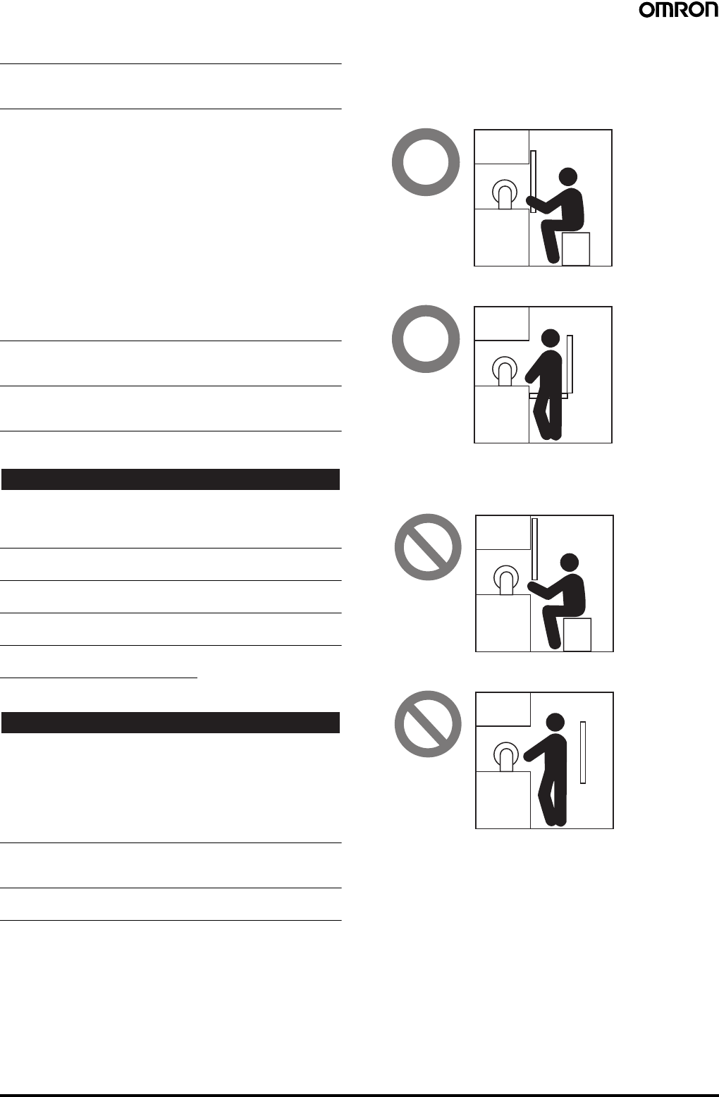
Safety Light Curtain (Type 4) F3SJ Ver. 2 59
Configure the system by using the optimal number of control outputs
that satisfy the requirements of the necessary safety category.
Do not connect each line of F3SJ to a DC power supply higher than
24 V+20%. Also, do not connect to an AC power supply.
Failure to do so may result in electric shock.
For F3SJ to comply with IEC 61496-1 and UL 508, the DC power
supply unit must satisfy all of the following conditions:
• Must be within rated power voltage (24 VDC±20%).
• Must have tolerance against the total rated current of devices if it is
connected to multiple devices.
• Must comply with EMC directives (industrial environment)
• Double or enhanced insulation must be applied between the primary
and secondary circuits.
• Automatic recovery of overcurrent protection characteristics
(reversed L sagging)
• Output holding time must be 20 ms or longer.
• Must satisfy output characteristic requirements for class 2 circuit or
limited voltage current circuit defined by UL508.
• Must comply with EMC, laws, and regulations of a country or a
region where F3SJ is used. (Ex: In EU, the power supply must
comply with EMC Low Voltage Directive.)
Double or enhanced insulation from hazardous voltage must be
applied to all input and output lines. Failure to do so may result in
electric shock.
The cable extension length must be no greater than the specified
length. Otherwise, the safety functions may fail to work properly,
resulting in danger.
Others
!WARNING
To use the F3SJ in PSDI mode (restart of cycle operation by the
sensor), you must configure an appropriate circuit between the F3SJ
and the machine. For details about PSDI, refer to OSHA1910.217,
IEC61496-1, and other relevant standards and regulations.
Do not try to disassemble, repair, or modify this product. Doing so may
cause the safety functions to stop working properly.
Do not use the F3SJ in environments where flammable or explosive
gases are present. Doing so may result in explosion.
Perform daily and 6-month inspections for the F3SJ. Otherwise, the
system may fail to work properly, resulting in serious injury.
Installation Conditions
Operating Range and Approach
!WARNING
Install a protective structure so that the hazardous part of a machine
can only be reached by passing through the sensor's detection zone.
Install the sensors so that part of the person is always present in the
detection zone when working in a machine's hazardous areas.
If a person is able to step into the hazardous area of a machine and
remain behind the F3SJ's detection zone, configure the system with
an interlock function that prevents the machine from being restarted.
Otherwise it may result in heavy injury.
Install the interlock reset switch in a location that provides a clear view
of the entire hazardous area and where it cannot be activated from
within the hazardous area.
The F3SJ cannot protect a person from an object flying from a
hazardous area. Install protective cover(s) or fence(s).
Correct position
The hazardous area of a machine can be reached only by passing
through the sensor's detection zone.
Incorrect positions
A person can only reach the hazardous part of the
machinery by passing through the sensor's detection zone.
A person enters the detection zone during operation.
A person can reach the hazardous part of the machinery
without passing through the sensor's detection zone.
A person is between the sensor's detection zone and the
hazardous part of the machinery.
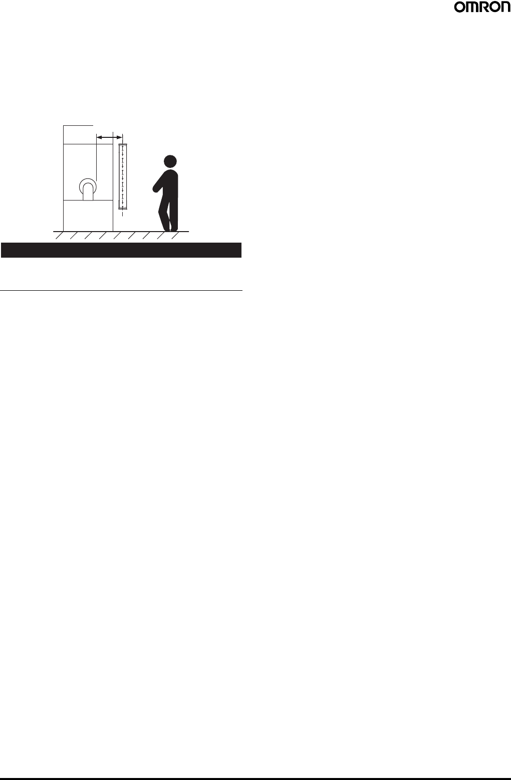
60 Safety Light Curtain (Type 4) F3SJ Ver. 2
Safety Distance
The safety distance is the distance that must be set between the
F3SJ and a machine's hazardous part to stop the hazardous part
before a person or object reaches it. The safety distance varies
according to the standards of each country and the individual
specifications of each machine. In addition, the calculation of the
safety distance differs if the direction of approach is not
perpendicular to the detection zone of the F3SJ. Always refer to
relevant standards.
!WARNING
Make sure to secure the safety distance (S) between the F3SJ and
the hazardous part. Otherwise, the machine may not stop before a
person reaches the hazardous part, resulting in serious injury.
Note: The response time of a machine is the time period from when
the machine receives a stop signal to when the machine's
hazardous part stops.
Measure the response time on the actual system. Also,
periodically check that the response time of the machine has
not changed.
How to calculate the safety distance specified by International
standard ISO13855-2002 (European standard EN999-1999)
(reference)
If a person approaches the detection zone of the F3SJ
perpendicularly, calculate the safety distance as shown below.
S = K x T + C . . . Eq. (1)
•S: Safety distance
•K: Approach speed to the detection zone
•T: Total response time of the machine and F3SJ
•C: Additional distance calculated by the detection capability of the
F3SJ
System that has detection capability of 40 mm max.
Use K = 2,000 mm/s and C = 8 x (d - 14 mm) in equation (1) for the
calculation.
S = 2,000 mm/s x (Tm + Ts) + 8 x (d - 14 mm)
•S = Safety distance (mm)
•Tm = Machine's response time (s)
•Ts = Response time of the F3SJ from ON to OFF (s)
•d = Size of F3SJ‘s detection capability (mm)
[Calculation example]
When Tm = 0.05 s, Ts = 0.01 s, and d = 14 mm:
S = 2,000 mm/s x (0.05 s + 0.01 s) + 8 x (14 mm - 14 mm)
= 120 mm . . . Eq. (2)
If the result is less than 100 mm, use S = 100 mm.
If the result exceeds 500 mm, use the following equation
where K = 1,600 mm/s.
S = 1,600 mm/s x (Tm + Ts) + 8 x (d - 14 mm) . . . Eq. (3)
If the result of this Eq. (3) is less than 500 mm,
use S = 500 mm.
Systems with a Smallest Detectable Object Size (Diameter) Greater
than 40 mm
Assuming K = 1,600 mm/s and C = 850 mm, the following calculation
is made using Eq. (1).
S = 1,600 mm/s x (Tm + Ts) + 850 … Eq. 4,
•S = Safety distance (mm)
•Tm = Machine's response time (s)
•Ts = Response time of the F3SJ from ON to OFF (s)
Calculation example:
When Tm = 0.05 s and Ts = 0.01 s,
S = 1,600 mm/s x (0.05 s + 0.01 s) + 850 mm = 946 mm
How to calculate the safety distance specified by American
standard ANSI B11.19
(Ref.)
If a person approaches the detection zone of the F3SJ
perpendicularly, calculate the safety distance as shown below.
S = K x (Ts + Tc + Tr + Tbm) + Dpf
•S: Safety distance
•K: Approach speed to the detection zone (the value recommended
by OSHA standard is 1,600 mm/s)
Approach speed K is not specified in the ANSI B.11.19 standard. To
determine the value of K to apply, consider all factors, including the
operator's physical ability.
•Ts = Machine's stop time (s)
•Tr = Response time of the F3SJ from ON to OFF (s)
•Tc = Machine control circuit's maximum response time required to
activate its brake (s)
•Tbm = Additional time (s)
If a machine has a brake monitor, "Tbm = Brake monitor setting time
- (Ts + Tc)". If it has no brake monitor, we recommend using 20% or
more of (Ts + Tc) as additional time.
•Dpf = Additional distance
According to ANSI's formula, Dpf is calculated as shown below:
Dpf = 3.4 x (d - 7.0): Where d is the detection capability of the F3SJ
(unit: mm)
[Calculation example]
When K = 1,600 mm/s, Ts + Tc = 0.06 s, brake monitor setting time =
0.1 s, Tr = 0.01 s, d = 14 mm:
Tbm = 0.1 - 0.06 = 0.04 s
Dpf = 3.4 x (14 - 7.0) = 23.8 mm
S = 1,600 x (0.06 + 0.01 + 0.04) + 23.8 = 199.8 mm
Hazardous
area
Safety distance (S)
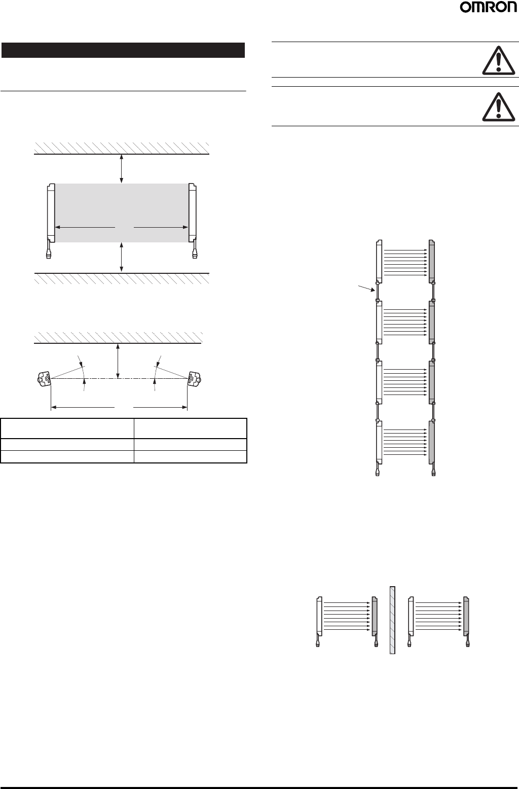
Safety Light Curtain (Type 4) F3SJ Ver. 2 61
Distance from Glossy Surface
!WARNING
Install the sensor system so that it is not affected by reflection from a
glossy surface. Failure to do so may hinder detection, resulting in
serious injury.
Install the sensor system at distance D or further from highly
reflective surfaces such as metallic walls, floors, ceilings, or
workpieces, as shown below.
Prevention of Mutual Interference
Mutual interference from other F3SJ is prevented in up to 3 sets
without series connection.
For series connection
Series connections can prevent mutual interference when multiple
sensors are used. Up to 4 sets, 400 beams, can be connected
(except for the F3SJ-A@-TS Series, for which up to 3 sets,
240 beams, can be connected). The emission of series-connected
F3SJ is time-divided, so mutual interference does not occur and
safety is ensured.
For no series connection
An interference light prevention algorithm prevents mutual
interference in up to 3 unconnected sets. If 4 or more sets of F3SJ
are installed and are not connected to each other, arrange them so
that mutual interference does not occur. If 2 sets are installed near
each other, reflection from the surface of the F3SJ may cause mutual
interference. When mutual interference occurs, the F3SJ enters
lockout. Combining countermeasures 1 to 3 below is effective.
1. Install a physical barrier
Distance between emitter and
receiver (Detection Distance L) Allowable installation
distance D
For 0.2 to 3 m 0.13 m
For 3 m or more L/2 x tan5° = L x 0.044 (m)
L
D
Detection zone
D
Emitter Receiver
Reflective ceiling
Reflective floor
L
D
Emitter Receiver
5°
Reflective surface
5°
Do not use a sensor system in a reflective configuration.
Doing so may hinder detection.
Mirrors can be used change the optical route.
When using more than 1 set of F3SJ, install them so that
mutual interference does not occur, such as by
configuring series connections or using physical barriers
between adjacent sets.
Emitter 1 Receiver 1
Emitter 2 Receiver
2
Emitter 3 Receiver
3
Emitter 4 Receiver
4
F39-JJR3W,
F39-JJR15L, or
F39-JJR06L
Connecting
Cable
Emitter 1 Receiver 1 Emitter 2 Receiver 2
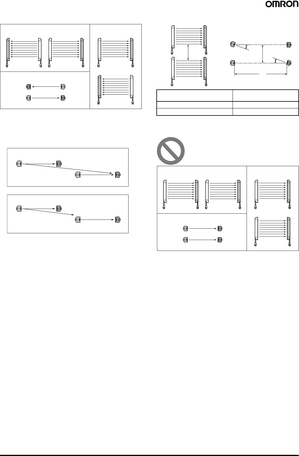
62 Safety Light Curtain (Type 4) F3SJ Ver. 2
2. Alternate the direction of emission (alternation)
If sensors of 2 sets are installed too close to each other, mutual
interference may occur due to reflection by the surface.
This can be resolved by using a setting tool to shorten the detection
distance.
3. Shorten the detection distance (Must be set with a setting tool).
4. Keep sufficient distance between them
The installations shown below may cause mutual interference.
When mutual interference occurs, the F3SJ enters lockout.
Aligned horizontally
Aligned fore and aft
Aligned vertically
Emitter 1
Receiver 1 Emitter 2 Receiver 2
Emitter 1 Receiver 1
Receiver 2 Emitter 2
Receiver 1 Emitter 1
Emitter 2 Receiver 2
Emitter Receiver
Emitter Receiver
Ambient light
Emitter Receiver
Emitter Receiver
Ambient light
Before changing
After changing
Distance between emitter and
receiver (Detection Distance L) Allowable installation
distance D
For 0.2 to 3 m 0.26 m
For 3 m or more L x tan5° = L x 0.088 (m)
Emitter Receiver
Emitter Receiver
Emitter Receiver
Emitter Receiver
D
L
D
5°
5°
Aligned horizontally
Aligned fore and aft
Aligned vertically
Emitter 1
Receiver 1 Emitter 2 Receiver 2
Emitter 1 Receiver 1
Receiver 2Emitter 2
Receiver 1
Emitter 1
Emitter 2 Receiver 2
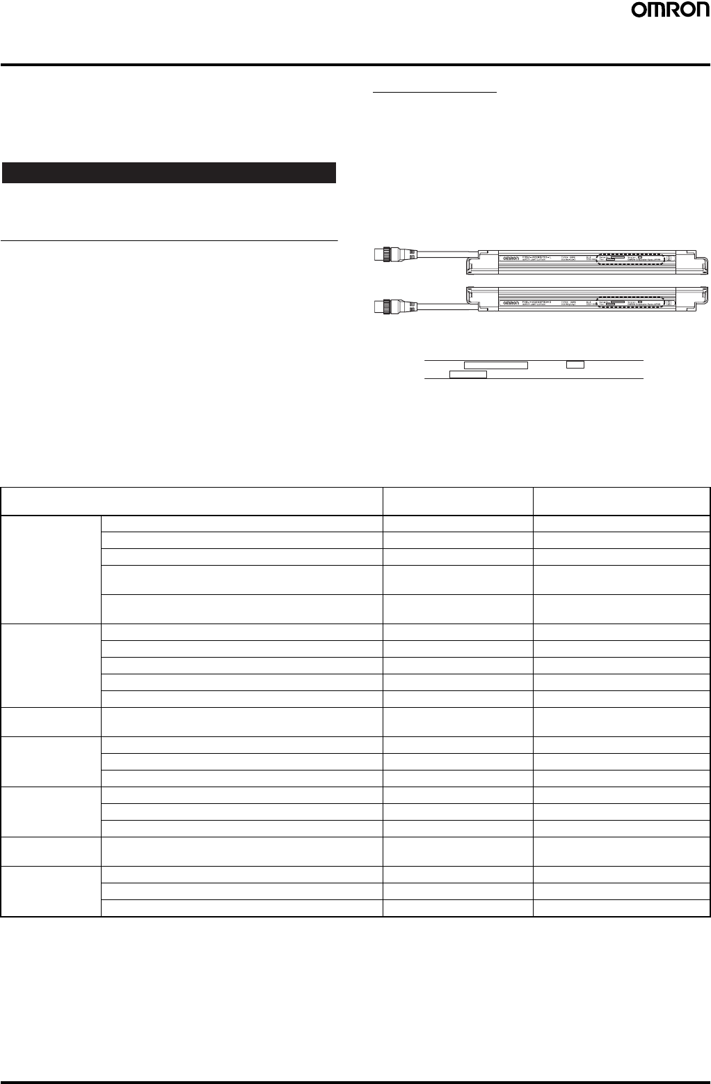
Safety Light Curtain (Type 4) F3SJ Ver. 2 63
Using Setting Tools
The following setting tools (sold separately) can be purchased in
order to change or confirm various F3SJ-series parameters.
•F39-MC21 Setting Console
•F39-GWUM SD Manager Setting Support Software for the F3SJ
The Setting Console cannot be used with the F3SJ-A@-TS Series.
!WARNING
The FS3J must be installed, set, and integrated into the mechanical
control system by a qualified technician who has received the
appropriate training. Failure to make correct settings may prevent
detection of people and result in serious injury.
F3SJ Versions
Setting tools can be used with Version 2 and later versions of the
F3SJ. The setting tools cannot be used with Version 1.
The setting tools cannot be used even if a Version 1 F3SJ is
combined in series with compatible F3SJ Units. (A communications
error lockout will occur.)
Unfortunately, the F3SJ's version cannot be upgraded.
The F3SJ's version number appears on its label, as shown in the
following diagram.
Functions Editable with Setting Tools
❍: Can be used.
×: Cannot be used.
Note: 1. These functions were newly added in Version 2. A setting tool can be used to enable these functions or read the function settings.
2. These functions can be used even without a setting tool. A setting tool can be used to make more detailed settings.
A
B
C
Close-up View of Dashed-line Box
Receiver
Emitter
Location of the F3SJ's Version Number (Within Dashed-line Box)
Serial No. :
Year : Version :
OMRON Corporation Kyoto, JAPAN
A: Serial number
B: Year of manufacture
C: F3SJ's version number (Verify that the version is Version 2 or later.)
Function or monitored item F39-MC21 Setting Console F39-GWUM SD Manager Setting
Support Software for the F3SJ
Settings for
individual
applications
Fixed blanking function (See note 1.) ❍❍
Floating braking function (See note 1.) ❍❍
Warning zone function (See note 1.) ❍❍
Muting function (See note 2.)
(when using the muting system) ❍❍
Override function (See note 2.)
(when using the muting system) ❍❍
Indicator and I/O
settings Auxiliary output (See note 2.) ❍❍
Specified light beam output function (See note 1.) ×❍
External indicator output (See note 2.) ❍❍
Interlock function (See note 2.) ❍❍
External device monitoring function (See note 2.) ❍❍
Changing detection
distance Change detection distance function (See note 1.) ❍❍
Monitoring
operation Light intensity indicators (See note 1.) ❍❍
Ambient light intensity indicators (See note 1.) ❍❍
Status indicators (See note 1.) ×❍
Maintenance
information Error log (See note 1.) ❍❍
Power ON time (See note 1.) ❍❍
Number of load switching operations (See note 1.) ❍❍
Recovering
settings Recover settings function (See note 1.) ❍❍
Other functions Safety distance calculation function (See note 1.) ×❍
Power cable length calculation Function (See note 1.) ×❍
Rated response time check (See note 1.) ❍❍
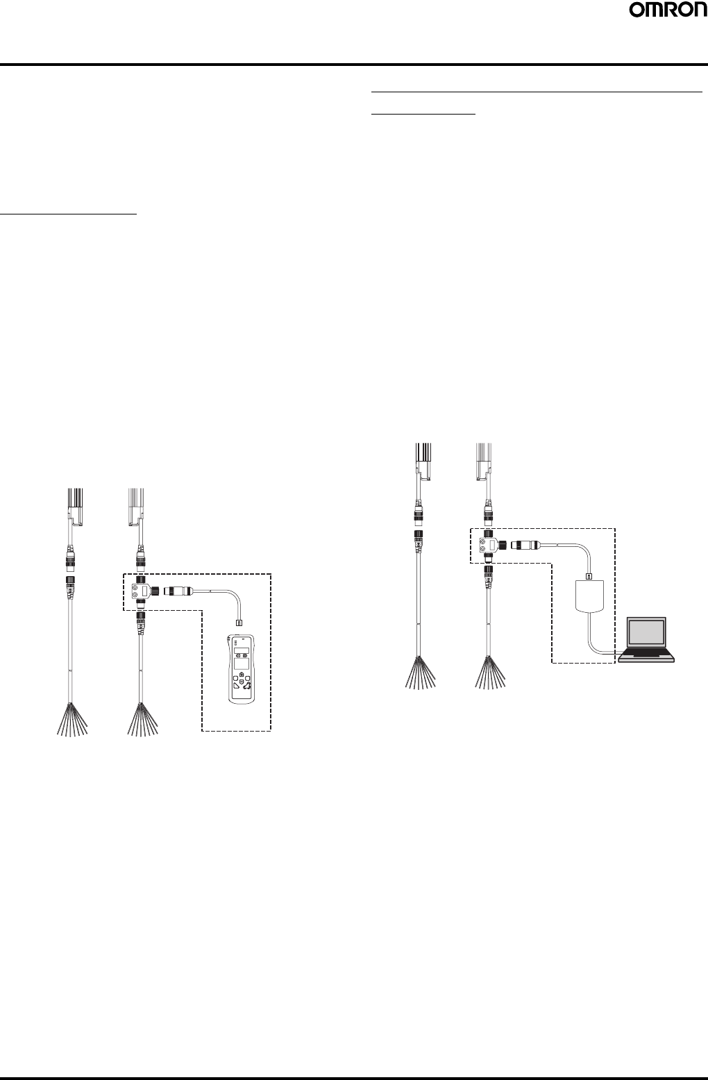
64 Safety Light Curtain (Type 4) F3SJ Ver. 2
Two Kinds of Setting Tools
The following accessories (sold separately) can be purchased in
order to use various F3SJ-series functions and change settings.
•F39-MC21 Setting Console
A Setting Console can easily make settings onsite.
•F39-GWUM SD Manager Setting Support Software for the F3SJ
With this software, a personal computer can be connected to make
settings. The SD Manager Setting Support Software for the F3SJ
can make more detailed settings than the Setting Console.
Setting Console
The following items are included with the F39-MC21 Setting
Console.
•Setting Console
•Branch Connector (with Connector Cap)
•Special Cable
•Special Cable with Plug
•Error Mode Label
•Instruction Manual
Connecting the Setting Console
Connect the F3SJ to the Setting Console as shown in the following
diagram. The Branch Connector can be used on either the emitter
side or receiver side. After the F3SJ has been wired, turn ON the
power and change parameters as required. If it is not possible to
connect a branch connector because the connector is concealed by
equipment or otherwise inaccessible, use the Special Cable with
Plug to connect to the + and − communications lines. For details,
refer to the F39-MC21 Instruction Manual.
SD Manager Setting Support Software
for the F3SJ
The following items are included with the F39-GWUM SD Manager
Setting Support Software for the F3SJ.
•CD-ROM (SD Manager Setting Support Software for the F3SJ,
Communications Unit Driver)
•Communications Unit
•Branch Connector (with Connector Cap)
•Special Cable
•Instruction Manual (Installation Guide)
•Special Cable with Plug
The F3SJ's operating status can be checked and its parameters can
be changed in the SD Manager Setting Support Software for the
F3SJ.
Connecting the SD Manager Setting Support Software
Connect the F3SJ, Communications Unit, and personal computer as
shown in the following diagram. The branch connector can be used
on either the emitter side or receiver side. After the F3SJ has been
wired, turn ON the power and start the Setting Support Software. If it
is not possible to connect a branch connector because the connector
is concealed by equipment or otherwise inaccessible, use the
Special Cable with Plug to connect to the + and - communications
lines. For details, refer to the SD Manager's Help function.
F39-MC21 Setting Console
(Accessory, sold separately)
F39-GWUM SD Manager Setting
Support Software for the F3SJ
(Accessory, sold separately)
PC
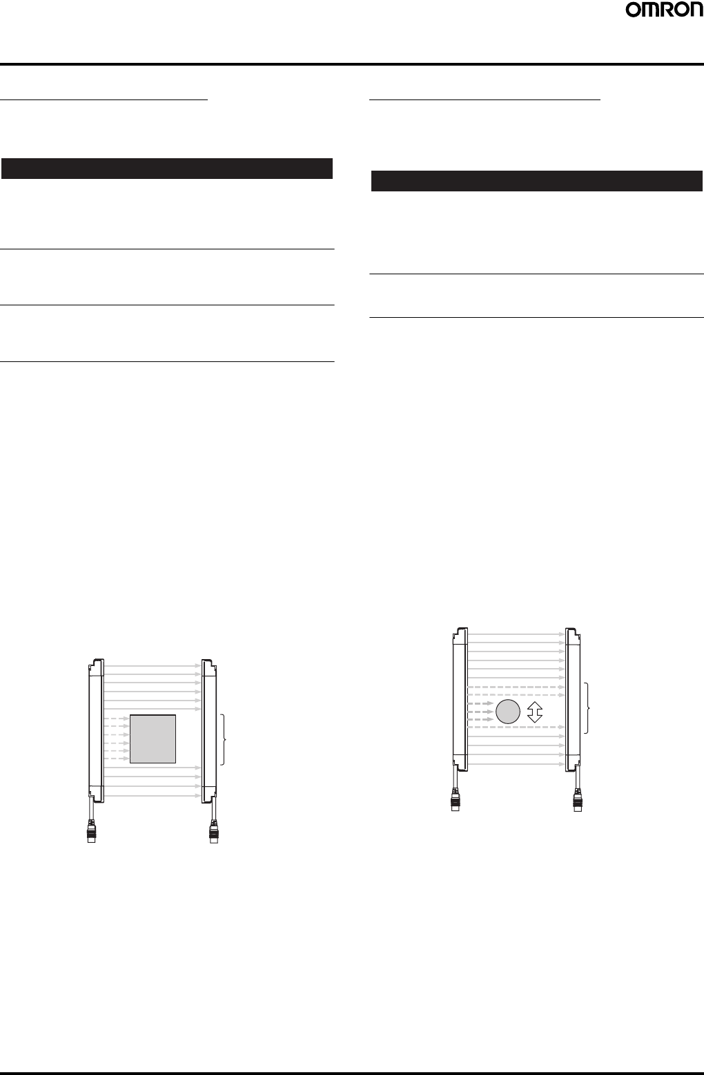
Safety Light Curtain (Type 4) F3SJ Ver. 2 65
Applications Supported by the Setting Tools
Fixed Blanking Function
Summary
Disables specific F3SJ light beams.
!WARNING
When the fixed blanking function is used to disable detection in an
area, install blocking structures or shielding to prevent passage into
the entire hazardous area where detection has been disabled.
Failure to do so may prevent detection of people and result in serious
injury.
When an allowable range of light beams has been set for fixed
blanking, the size of the smallest detectable object will be larger in the
vicinity of interrupting objects. Calculate the safety distance to match
the settings.
After setting the fixed blanking function, you must verify that the F3SJ
detects a test rod at any position in the entire area where intrusion
must be detected. Failure to do so may prevent detection of people
and result in serious injury.
Example Application
In this example, there is always an object such as a conveyor belt in
the detection area, and we want to ignore the conveyor belt.
Description of Functions
Fixed Blanking Function
This function disables part of the F3SJ's detection area and
maintains the control output's ON status even if there is an object in
the disabled area.
The light beams set for fixed blanking must be one area of
consecutive light beams and up to five areas can be set (areas 1 to
5). Fixed blanking cannot be set for all of the light beams.
Setting the Fixed Blanking Area
Set the area that will be subject to fixed blanking.
An interrupting object can be placed in the detection area to perform
teaching and specify light beams for manual settings.
Note: 1. When the Setting Console is being used, only one area can
be set as a fixed blanking area.
2. When the SD Manager Setting Support Software is being
used, up to five areas can be set as fixed blanking areas.
Floating Blanking Function
Summary
Increases the diameter of the F3SJ's smallest detectable object and
turns OFF the control output when multiple objects are detected.
!WARNING
When the floating blanking function is used, it increases the diameter
of the F3SJ's smallest detectable object. Always use the larger
diameter when calculating the safety distance. If the incorrect
diameter is used in the calculation, the machinery may fail to stop
before an operator reaches the hazardous area, resulting in serious
injury.
After setting the floating blanking function, always verify that the F3SJ
system operates as expected. Serious injury may result if an
individual is not detected.
Example Application
When there is a moving object with a fixed width in the detection area
that we do not want to detect, the detection function can be disabled.
Description of Functions
Floating Blanking Function
This function increases the diameter of the smallest detectable
object to allow passage of objects of a certain size or allow
interrupting objects in multiple locations.
Setting the Floating Blanking Area
When the Setting Console is being used, all of the light beams are
set as the floating blanking area. When the SD Manager Setting
Support Software is being used, just one area can be set but the
range of the area can be specified. In the following example, the
floating blanking area is set from the 5th light beam to the 10th light
beam (counting from the bottom). An interrupting object can be
placed in the detection area to perform teaching and specify light
beams for manual settings.
Floating Light Beams
The following charts show the relationship between the number of
floating light beams and the safety output operation (safety output
not going OFF). Measure the size of the interrupting object
(maximum diameter) and set the number of floating light beams so
that the object's size is less than the corresponding dimension shown
in the chart.
Higher Higher
Lower Lower
Fixed blanking area
Light beam #10
Light beam #5
Floating blanking are
a
Higher Higher
Lower Lower
Light beam #10
Light beam #5
66 Safety Light Curtain (Type 4) F3SJ Ver. 2
Example Setting
When an F3SJ-A@14 is being used with an interrupting object that is
20 mm in diameter, set three light beams as floating light beams.
With this setting, the F3SJ's safety output will not turn OFF even if
there is an interrupting object up to 22-mm wide in the floating
blanking area.
Effective Range vs. Number of Floating Light Beams
F3SJ-A@14 Series
F3SJ-A@20 Series
F3SJ-A@30 Series
F3SJ-A@55 series
Floating Blanking Mode
The floating blanking function has two operation modes.
1. Continuous Light Beam Mode
The safety output will not go OFF if the interrupting object is
smaller than the set size, although the safety output will go OFF if
objects pass through several areas in the detection area.
The floating blanking monitor function can be set in this mode.
Refer to the User's Manual for details.
2. Discontinuous Light Beam Mode
A light blockage is detected when the number of light beams
blocked in the area is equal to or greater than the preset number
of light beams.
Permitted Floating Range
010203040
Settable Range
4
13
22
31
Example Setting Size
With 1 floating light beam
With 2 floating light beams
With 3 floating light beams
With 4 floating light beams
Size of Interrupting Object (mm)
0102030405060
10
40
25
55
Permitted Floating Range
Settable Range
With 1 floating light beam
With 2 floating light beams
With 3 floating light beams
With 4 floating light beams
Size of Interrupting Object (mm)
0 20406080100
20
45
70
95
Permitted Floating Range
Settable Range
With 1 floating light beam
With 2 floating light beams
With 3 floating light beams
With 4 floating light beams
Size of Interrupting Object (mm)
Permitted Floating Range
Size of Interrupting Object (mm)
0 40 80 120 160 200
Settable Range
45
95
145
195
With 1 floating light beam
With 2 floating light beams
With 3 floating light beams
With 4 floating light beams
Safety Light Curtain (Type 4) F3SJ Ver. 2 67
Warning Zone Function
Summary
The detection zone can be divided into the detection zone and a
warning zone.
!WARNING
The warning zone output is not a safety output. Do not include this
area in the safety distance calculation. Shortening the safety distance
may result in serious injury.
The warning zone cannot be used for safety purposes. Always install
the system so that the hazard is reached by passing through the
detection zone.
The warning zone function can be
used only when the F3SJ is
installed horizontally. This function
cannot be used when the F3SJ is
installed vertically.
Example Application
When an individual enters, a warning lamp lights or buzzer sounds
without stopping the equipment.
Description of Function
Warning Zone Function
Use teaching to set the light beams that you want to set as the
warning zone or manually specify the light beams from the lowest or
highest beam. (See figures 1 and 2.)
To indicate that the warning zone is blocked, allocate the auxiliary
output or external indicator output as the warning zone information.
The following settings cannot be made:
•Setting all light beams as the warning zone (figure 4)
•Setting a warning zone that does not include one of the outer light
beams (figure 5)
If Safety Light Curtains are connected in series, and at least one of
an F3SJ's light beams is a normal light beam, all of a Light Curtain's
light beams can be set as a warning zone (figure 3).
Example Warning Zone Settings (Figures 1 to 3)
Examples of Unacceptable Warning Zone Settings
(Figures 4 and 5)
Warning Zone Display Label
When the warning zone is set, affix this label to indicate which areas
belong to the normal detection zone and the warning zone.
Hazardous
area Detection zone
Warning zone
Lower
Warning zone
6 upper light beams Detection zone
Upper
LowerU
pp
er
Warning zone
4 lower light beams
Detection zone
Figure 1
Figure 2
Lower
Upper
2CH
LowerUpper 1CH
Detection
zone
All light
beams
Warning zone
All light beams
Figure 3
LowerUpper
All light beams
Warning zone
Figure 4
Figure 5
Upper Lower
Detection zone Warning zone Detection zone
Normal light beam Warning light beam
Warning zoneDetection zone
DETECTION
ZONE WARNING
ZONE

68 Safety Light Curtain (Type 4) F3SJ Ver. 2
Muting Function
Summary
Makes settings related to the muting function.
!WARNING
The muting function disables the safety functions of the device.
Additional safety measures must be taken to ensure safety while this
function is working.
Install muting sensors so that they can distinguish between the object
that is being allowed to be pass through the detection zone and a
person.
Muting lamps (external indicators) that indicate the status of the
muting function must be installed where they are clearly visible to
workers from all the operating positions.
Muting times must be precisely set according to the application by
qualified personnel who have received appropriate training. In
particular, if the muting time limit is to be set to infinity, the person who
makes the setting must bear responsibility.
Use two independent input devices for the muting inputs. (For the
PNP output-type F3SJ, use a sensor with a PNP transistor output or
N.O. contact. For the NPN output-type F3SJ, use a sensor with an
NPN transistor output or N.O. type contact.)
To prevent a worker from entering the hazardous area while the
muting function is engaged, install the F3SJ, muting sensor, and then
a protective barrier and set a limited muting time.
Example Applications
•Allowing only work pieces to pass into the conveyor entrance
•Operating the muting function in a specific area only
•Setting a different muting mode when standard muting is not
appropriate for the application
Description of Functions (See User's Manual for details.)
Operation Modes
When the SD Manager Setting Support Software is being used, any
one of the following three operation modes can be selected for the
muting function.
1. Standard Muting Mode
This is the default operation mode, which is set when the F3SJ is
shipped from the factory.
The muting function is enabled by turning ON muting inputs 1 and
2 with a time lag.
Note: Settings such as the muting time limit value can be changed.
2. Specialized Exit Muting Mode (Can be set with the SD Manager
Setting Support Software only.)
The muting function is enabled by turning ON muting inputs 1 and
2 with a time lag.
Installation of the muting input sensors is simpler than standard
mode because the Safety Light Curtain's blocked light status is
used to end muting.
3. Position Detection Muting Mode (Can be set with the SD Manager
Setting Support Software only.)
Sensors such as limit switches are used for the muting inputs and
the muting function is enabled by turning muting input from OFF
to ON and then turning muting input 2 from ON to OFF within time
difference T1 max. Use hybrid redundant inputs such as a
combination of an N.O. contact input and an N.C. contact input.
(When using a PNP-output photoelectric switch, use L/ON
operation on one side and D/ON operation on the other side.)
This mode is useful when you want to disable the F3SJ
temporarily, such as when a person is placing an object at the
conveyor entrance.
Partial Muting (Muting area) Settings
The light beams controlled by the muting function can be specified
with a setting tool. (When the F3SJ is shipped, all light beams are
set.)
The light beams can be specified by teaching/recording the blocked
light beams as muting light beams or manually specifying the desired
light beams.

Safety Light Curtain (Type 4) F3SJ Ver. 2 69
Indicator and I/O Settings
Auxiliary Output (Non-safety) and External Indicator Output (Non-safety)
Summary
A setting tool can be used to change the allocation of auxiliary
outputs 1 and 2, and external indicator outputs 1 and 2.
!WARNING
Do not use the auxiliary outputs or external indicator outputs for
safety purposes. Serious injury may result if an output fails and a
person is not detected.
Example Applications
•Allocating a lockout output or warning zone output to an auxiliary
output
•Connecting an external indicator to an auxiliary output and making
it flash
An auxiliary output or external indicator output can be connected to
an incandescent light to function as a broken-wire or short-circuit
detector. Refer to the User's Manual for details.
Output Operation Modes (when allocated to an auxiliary output or external indicator output)
Note: 1. A light blockage was detected even though the output is not turned OFF because the blockage occurred at a light beam subject to fixed
blanking, floating blanking, or muting. Blockages are also not processed during overrides.
2. The fixed blanking light beams or floating blanking light beams must be set.
3. The specified light beam must be set.
4. The warning zone light beams must be set.
5. When "specified light beam output" is allocated as the output operation mode for auxiliary output 1 or 2 or external indicator output 1 or
2, that mode cannot be allocated to the other output operations.
Output operation mode Description of operation
(Output will go ON in the following situation.) Setting Console SD Manager Setting
Support Software
Control output The control output is ON ❍❍
Light intensity diagnosis (See note 1.) The F3SJ is ON and the received light intensity
is 100% to 130% of the threshold value for more
than 10 seconds.
❍❍
Error/Lockout The F3SJ is in error or lockout status. ❍❍
Muting/Override The F3SJ is in muting or override status. ❍❍
Blanking/Warning Zone (See note 2.) The fixed blanking, floating blanking, or warning
zone function is enabled. ❍❍
Specified light beam output (See note 3.) A specified light beam is blocked. ×❍
Power ON time The power ON time has exceeded the threshold
value. ❍❍
Warning zone (See note 4.) Light is blocked in the warning zone. ❍❍
Test input ON The test input went ON. ❍❍
Blanking light beam incident light A fixed or floating light beam is receiving incident
light. ❍❍
Interlock The F3SJ is in interlock status. ❍❍
Muting error The F3SJ is in muting error status. ❍❍
Number of load switching operations
exceeded The number of load switching operations
exceeded the threshold value. ❍❍
Information trigger An interlock, lockout, or muting error has
occurred. ×❍
Individual linked sensor output (channel
1) Channel 1 control output is ON when Units are
linked in series. ❍ (Auxiliary output 1 only) ❍ (Auxiliary output 1 only)
Individual linked sensor output (channel
2) Channel 2 control output is ON when Units are
linked in series. ❍ (Auxiliary output 1 only) ❍ (Auxiliary output 1 only)
Individual linked sensor output (channel
3) Channel 3 control output is ON when Units are
linked in series. ❍ (Auxiliary output 1 only) ❍ (Auxiliary output 1 only)
Individual linked sensor output (channel
4) Channel 4 control output is ON when Units are
linked in series. ❍ (Auxiliary output 1 only) ❍ (Auxiliary output 1 only)

70 Safety Light Curtain (Type 4) F3SJ Ver. 2
Changing the Detection Distance
Change detection distance function
Summary
The F3SJ's detection distance can be shortened.
Example Application
The F3SJ's detection distance can be shortened to avoid affecting
other photoelectric sensors.
When devices are installed close together, shortening the detection
distance can reduce mutual interference.
Description of Function
The detection distance can be set to 0.5 m, 1 m, 2 m, 3 m, 5 m, or
MAX (either 7 m or 9 m).
The most suitable detection distance can be set to match the
installation distance.
Note: MAX represents the rated detection distance.
Monitoring Operation
Received Light Intensity Indicator
Summary
It is possible to read the F3SJ's received light intensity.
Example Application
Adjust the light beams while checking the F3SJ's received light
intensity.
Description of Function
Indicates the F3SJ's received light intensity.
The F3SJ's received light intensity level can be checked with a
setting tool.
Ambient Light Intensity Indicator
Summary
It is possible to read the intensity of the light received by the F3SJ
from ambient sources, such as other photoelectric sensors.
Example Application
Display the ambient light level while taking steps to reduce light
interference form sources such as photoelectric switches in the area
and neighboring F3SJ Units.
Description of Function
Indicates the ambient light level at the F3SJ from other light sources
such as photoelectric sensors.
This function can help identify the photoelectric sensors that are the
source of the light interference and identify the light beams being
affected by the ambient light.
Other Functions
The F3SJ is also equipped with the following functions.
Refer to the User's Manual for details on using these functions.
•Status indicators
•Error log
•Power ON time
•Number of load switching operations
•Safety distance calculation function
•Power cable length calculation function
•Rated response time check function
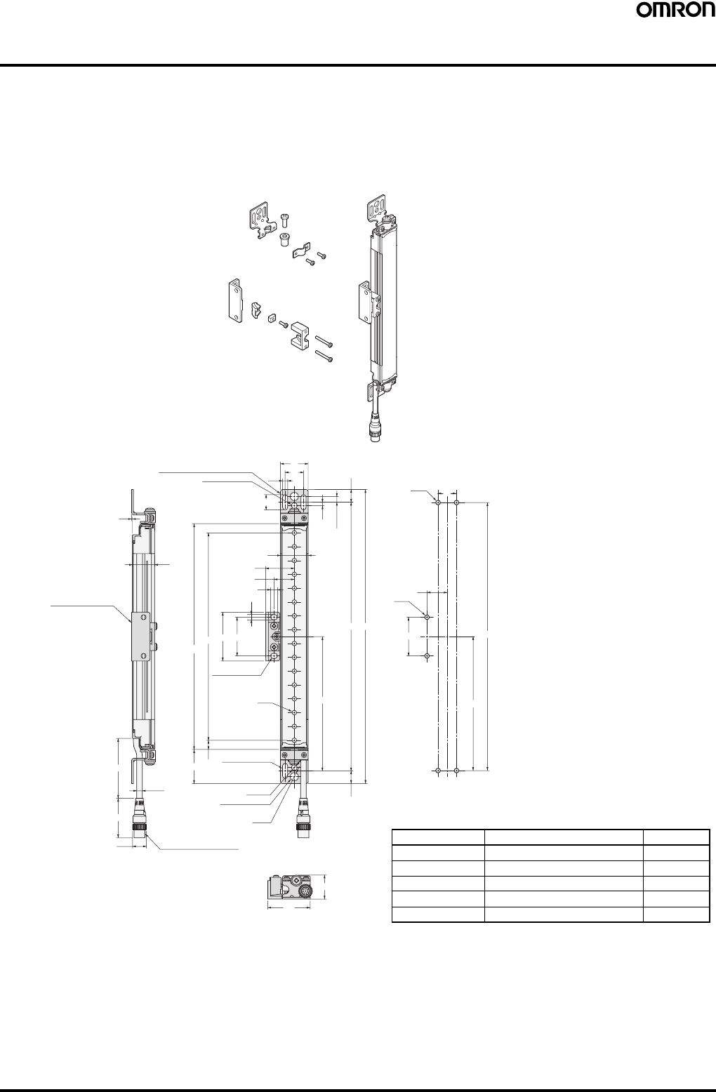
Safety Light Curtain (Type 4) F3SJ Ver. 2 71
Dimensions
Note: All units are in millimeters unless otherwise indicated.
■Main Units
When Using Standard Mounting Brackets
Backside mounting
Top/bottom mounting bracket
Intermediate mounting bracket
1
24
Intermediate mounting
bracket
300
43
6 dia.
15 dia. M12 Waterproof connector
9 dia.
13.75
2-Mounting holes
6.5 dia.
4-Mounting holes
37
10
Beam E
2-Mounting holes
C (Protective
height)
D53 42
5.5
7
22
31
30
16.5
2-Mounting holes
2-Top/bottom mounting brackets 5.5 20
20
30
3.75 6.25
(13.75)
BA
4-M5
22
2-M5
42
E
B
46
26
C (protective height): 4-digit number in the table
A = C + 74, B = C + 46.5
D = C - 20, E = See table below.
Note: Use E = 530 or less when none of the E values shown
above are used.
Protective height Number of intermediate brackets E (See note.)
0245 to 0596 0 ---
0600 to 1130 1 E = B / 2
1136 to 1658 2 E = B / 3
1660 to 2180 3 E = B / 4
2195 to 2500 4 E = B / 5
Mounting screw holes
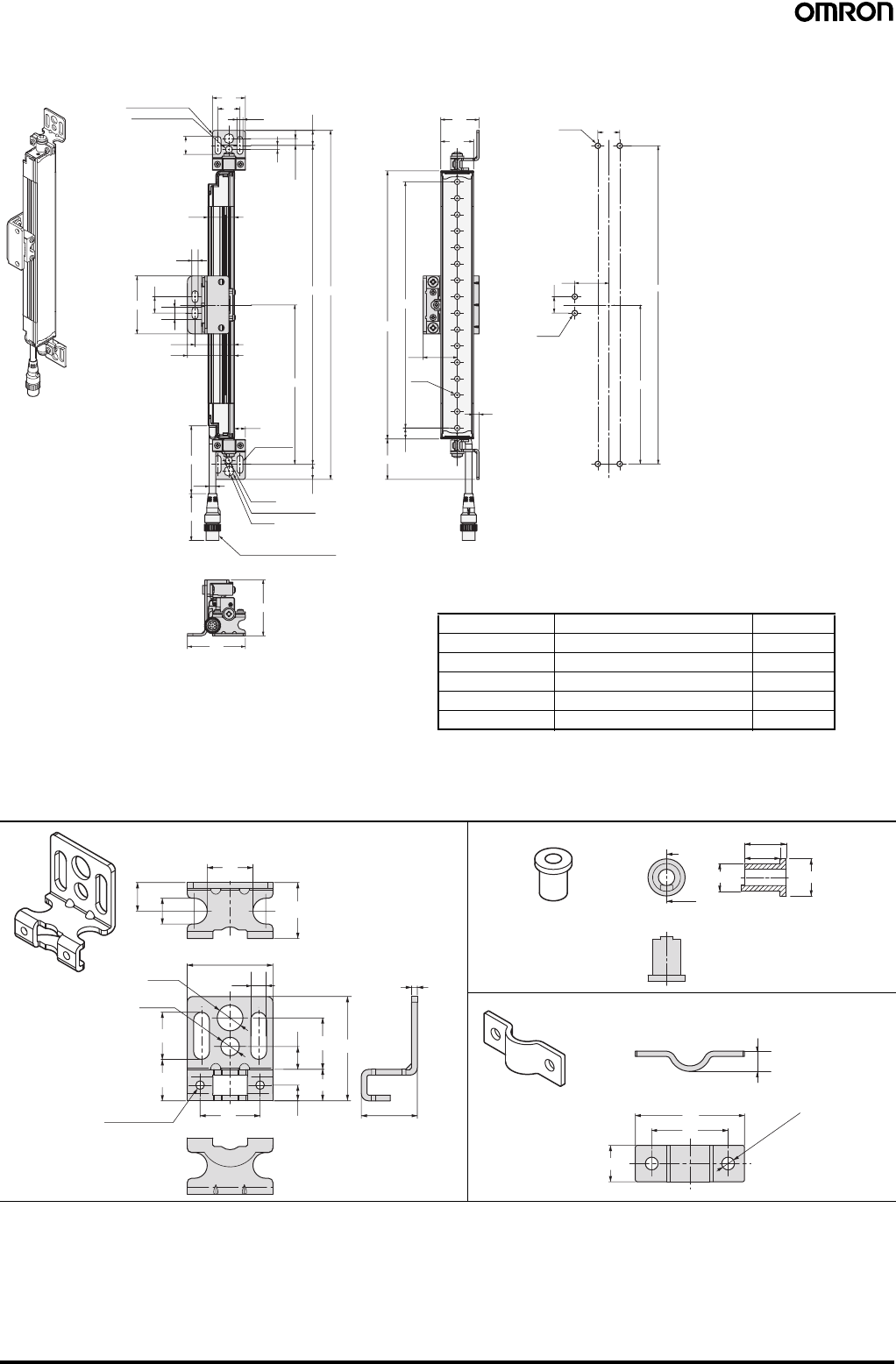
72 Safety Light Curtain (Type 4) F3SJ Ver. 2
Side mounting
F39-LJ1 Detailed Dimensions of Bracket
51
53
5.5
3.75
6.25
(13.75)
24
16.5
2-Mounting holes
2-Top/bottom
mounting brackets 30
20
10
43
36
53
15
M12 Waterproof connector
9 dia.
2-Mounting holes
6.5 dia.
6 dia.
43
300
13.75
4-Mounting
holes
E
BA
C (Protective height)
D
37
10
5
Beam
31
35
30
2-M5
15 31
E
B
4-M5 20
5.5
11
C (protective height): 4-digit number in the table
A = C + 74, B = C + 46.5
D = C - 20, E = See table below.
Note: Use E = 530 or less when none of the E values shown
above are used.
Protective height Number of intermediate brackets E (See note.)
0245 to 0596 0 ---
0600 to 1130 1 E = B / 2
1136 to 1658 2 E = B / 3
1660 to 2180 3 E = B / 4
2195 to 2500 4 E = B / 5
Mounting screw holes
16
2
30
9 dia.
6.5 dia.
2-M3
Through holes 19.6
21
10 919.6
818
11
5.5
36.5
16.5
14.5
5.5
Material: Stainless stee
l
13.5
A-A
A
A
9 dia. 12 dia.
11.5
Material: Brass
30
21
10
2 - 3.5 dia.
5.6
Material: Stainless steel
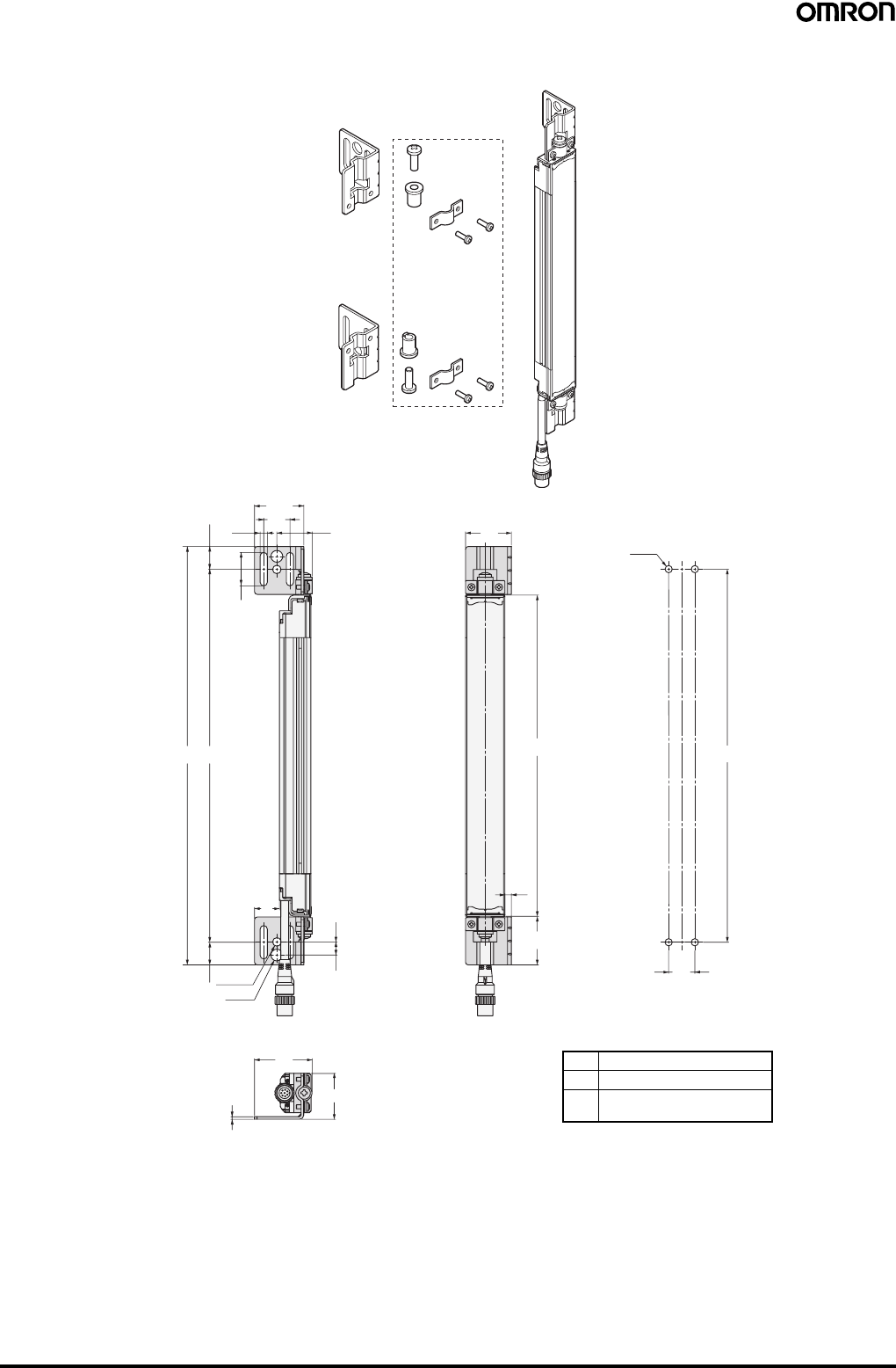
Safety Light Curtain (Type 4) F3SJ Ver. 2 73
Using Side Flat Mounting Bracket (F39-LJ2)
F39-LJ2
Material: Stainless steel
Use standard brackets
275.5 20
37.6
25.5
(17.25)
AB
19
6.5 dia.
17.25 9 dia.
0.3
9.7
44
35
2
35
C (Protective height)
37
5
20
4-M5
B
Dimensions A to C
AC + 74
B C + 39.5
C 4-digit number of the model
name (protective height)
Mounting screw holes
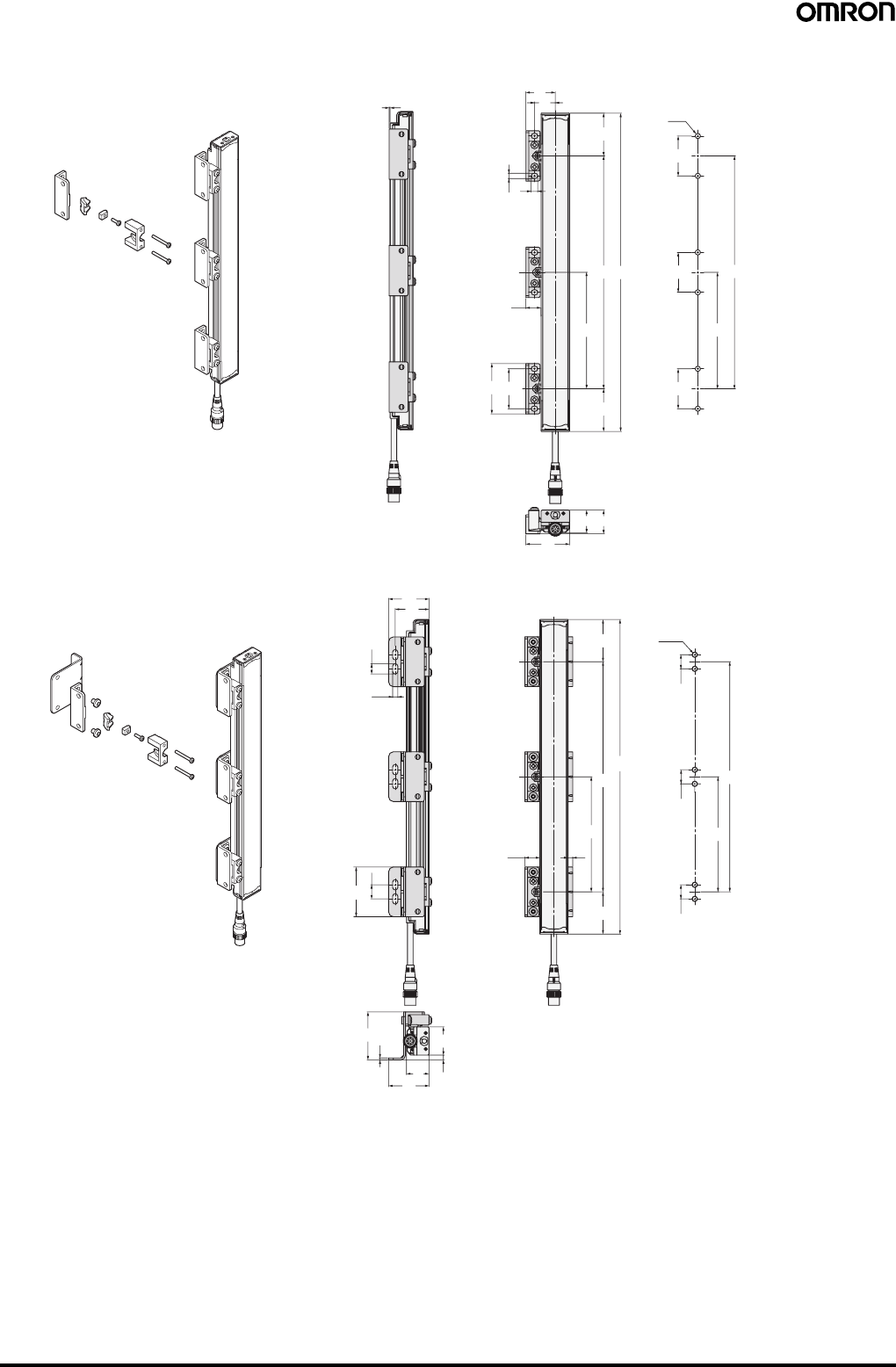
74 Safety Light Curtain (Type 4) F3SJ Ver. 2
Using Free Location Mounting Bracket (F39-LJ3)
131
22
5.5 7
45
C (Protective
height)
B
F
16
42
53
45
25
24
46
F
B
42
6-M5
42
42
36
43
11
5.5
15
53
2
51
4324 5
30
45
C (Protective
height)
516
45
B
F
B
F
15
6-M5
15
15
Material: Zinc die-cast
F39-LJ3
Material: Zinc die-cast/stainless
F39-LJ3
Backside mounting
Side mounting
Mounting screw holes
Mounting screw holes
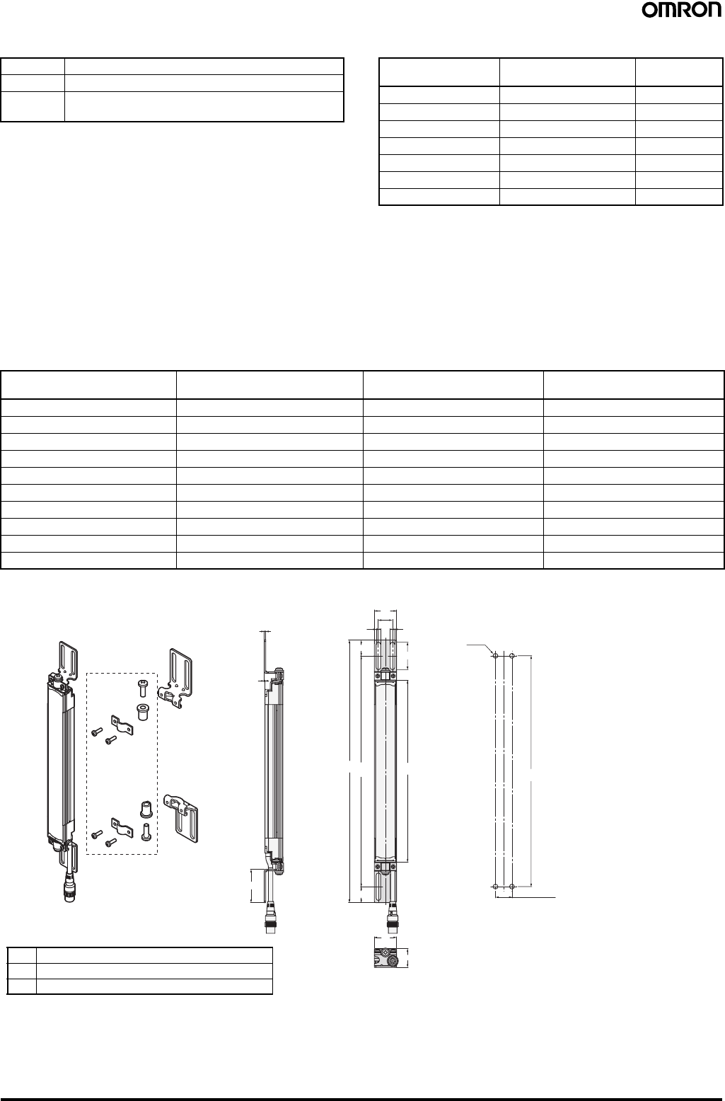
Safety Light Curtain (Type 4) F3SJ Ver. 2 75
Dimensions B, C, and F Dimension F
Note: Use F = 350 or less when none of the F values shown above
are used.
When only F39-LJ3 free-location mounting brackets are used without standard brackets, allow a space of at least 350 mm between the brackets.
The number of brackets required varies according to the protective height. For details about the number of required brackets, refer to the table
below.
The standard included intermediate mounting brackets are the same as the F39-LJ3 free-location mounting brackets. Purchase brackets as
necessary if there are fewer intermediate mounting brackets than required. When intermediate mounting brackets are included, they can be used
as free-location mounting brackets.
Required number of F39-LJ3 free-location mounting brackets for 1 F3SJ set (emitter/receiver) (2 pieces are included with
F39-LJ3)
Using Top/Bottom Mounting Bracket B (F39-LJ4)
BC - 90
C 4-digit number of the model name (protective height)
F Depends on the protective height. See the table on the
right.
Protective height Number of intermediate
mounting brackets F
(See note.)
0245 to 0440 2 ---
0443 to 0785 3 B / 2
0794 to 1140 4 B / 3
1145 to 1490 5 B / 4
1495 to 1840 6 B / 5
1845 to 2180 7 B / 6
2195 to 2500 8 B / 7
Protective height Number of included free location
brackets as intermediate brackets Number of free location
brackets to mount F3SJ Number of free location
brackets to be purchased
0245 to 0440 0 4 2 sets
0443 to 0596 0 6 3 sets
0600 to 0785 2 6 2 sets
0794 to 1130 2 8 3 sets
1136 to 1140 4 8 2 sets
1145 to 1490 4 10 3 sets
1495 to 1658 4 12 4 sets
1660 to 1840 6 12 3 sets
1845 to 2180 6 14 4 sets
2195 to 2500 8 16 4 sets
F39-LJ4
Use standard
brackets
2
1
45
37
66
19
30
AB
(21.5)
21.5
C (Protective height)
26
30
19 (See note.)
B
4-M5
Material: Stainless steel
Backside mounting
Dimensions A to C
Note: Refer to the User's Manual (Cat. No. SCHG-718 and SCHG-719) for the dimensions for side mounting.
AC + 109
BC + 66
C 4-digit number of the model name (protective height)
Note: Using M5 bolt, available range for
mounting is 18 to 20.
Mounting screw holes
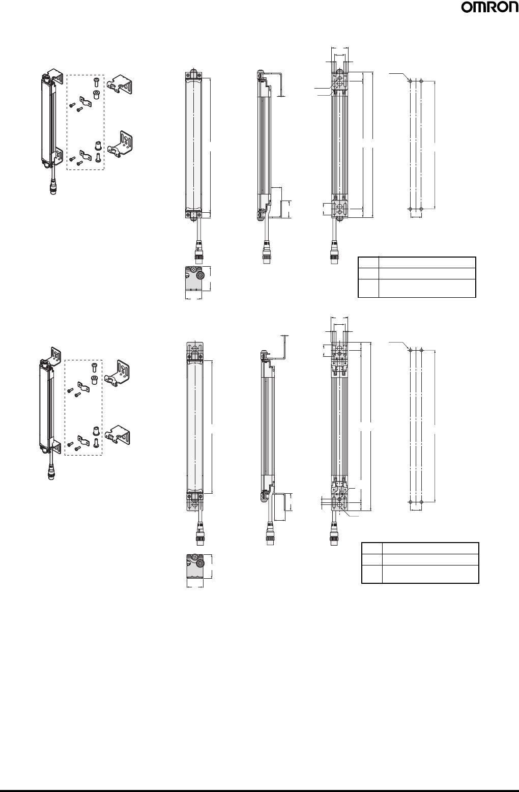
76 Safety Light Curtain (Type 4) F3SJ Ver. 2
Using Mounting Bracket for Short-length F3SN (F39-LJ5)
F39-LJ5
Use standard
brackets
F39-LJ5
Use standard
brackets
5.5 5.5
20
30
5.5 5.5
20
30
BA
15.5
(15.5)
20
20
B
B
4-M5
4-M5
BA
16.5
(16.5)
6.5 dia.
9 dia.
21
9 dia.
6.5 dia.
C (Protective height)
44.9
30
44
30
11.5
C (Protective height)
2
32
21
4.2
5.8
19.9
2
32
19.9
Material: Stainless steel
Material: Stainless steel
Inward-facing mounting
Outward-facing mounting
Dimensions A to C
AC + 65
BC + 34
C 4-digit number of the model
name (protective height)
Dimensions A to C
AC + 23
BC
− 10
C 4-digit number of the model
name (protective height)
Mounting screw holes
Mounting screw holes
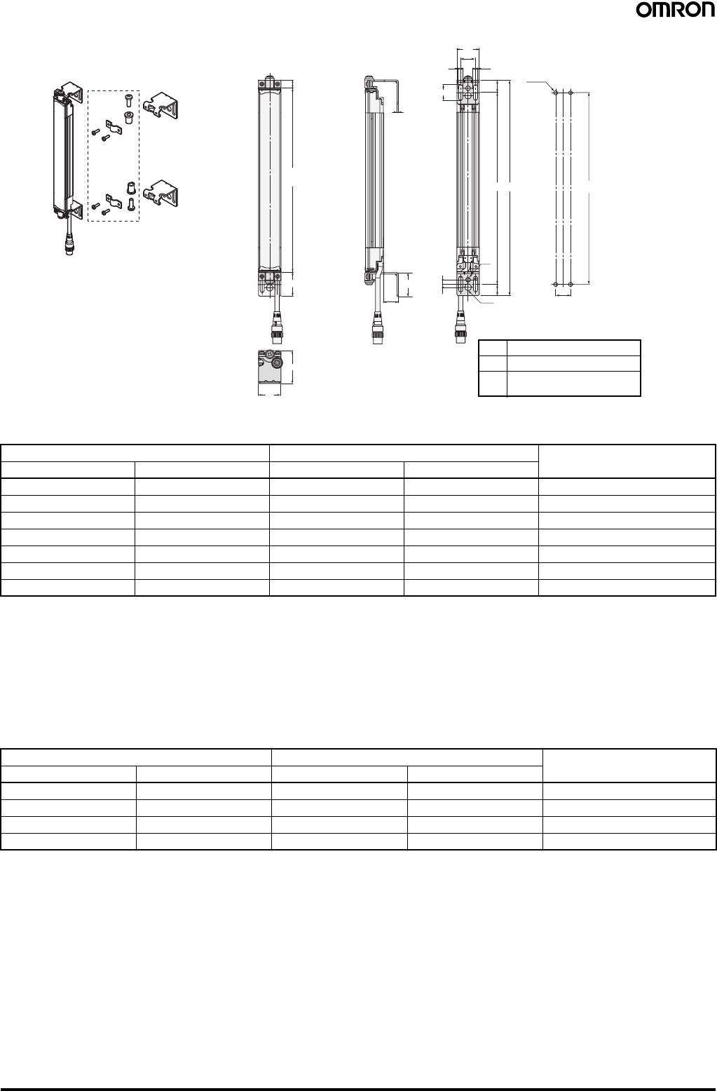
Safety Light Curtain (Type 4) F3SJ Ver. 2 77
F3SN replacement correspondence table (F3SN mounting holes can be used without modification)
When replacing F3SN-@@@@P(N)14 with F3SJ-A@@@@P(N)14
For length greater than F3SN-@0234P(N)14:
Add 11 to the F3SN's 4-digit number and apply it as the F3SJ's 4-digit number, and then replace with the standard brackets included with the
product.
[Selection example] F3SN-A0315P(N)14 becomes F3SJ-A0326P(N)14 (replace with standard brackets)
Note: 1. The protective height becomes 11 mm longer.
2. Replace with outward-facing mounting of F39-LJ5 when you want to set the detection surface height to be same as the F3SN.
However, the F39-LJ5 and intermediate mounting brackets cannot be mounted simultaneously, so set the protective height to 600 mm or
less.
When replacing F3SN-@@@@P (N)25 with F3SJ-A@@@@P (N)20
For length greater than F3SN-@0262P(N)25:
Subtract 17 from the F3SN's 4-digit number and apply it as the F3SJ's 4-digit number, and then replace with the standard brackets included with
the product.
[Selection example] F3SN-A0322P(N)25 becomes F3SJ-A0305P(N)20 (replace with standard brackets)
Note: 1. The protective height gets 17 mm shorter.
2. Replace with outward-facing mounting of F39-LJ5 when you want to set the detection surface height to be same as the F3SN.
However, the F39-LJ5 and intermediate mounting brackets cannot be mounted simultaneously, so set the protective height to 600 mm or
less.
F3SN Replacement F3SJ Replacement method using
F39-LJ5
Model Protective height Model Protective height
F3SN-@0153P(N)14 153 --- --- ---
F3SN-@0180P(N)14 180 F3SJ-A0245P(N)14 245 Inward-facing mounting
F3SN-@0189P(N)14 189 F3SJ-A0245P(N)14 245 Inward-facing mounting
F3SN-@0198P(N)14 198 F3SJ-A0245P(N)14 245 Inward + outward-facing mounting
F3SN-@0207P(N)14 207 F3SJ-A0245P(N)14 245 Inward + outward-facing mounting
F3SN-@0216P(N)14 216 F3SJ-A0245P(N)14 245 Outward-facing mounting
F3SN-@0225P(N)14 225 F3SJ-A0245P(N)14 245 Outward-facing mounting
F3SN Replacement F3SJ Replacement method using
F39-LJ5
Model Protective height Model Protective height
F3SN-@0187P(N)25 187 --- --- ---
F3SN-@0217P(N)25 217 F3SJ-A0260P(N)20 260 Inward-facing mounting
F3SN-@0232P(N)25 232 F3SJ-A0260P(N)20 260 Inward + outward-facing mounting
F3SN-@0247P(N)25 247 F3SJ-A0245P(N)20 245 Outward-facing mounting
F39-LJ5
Use standard
brackets
5.5 5.5
20
30
20
BA
15.5
(16.5)
6.5 dia.
9 dia.
44
30
(11.5)
C (Protective height)
32.5
221
4.2
5.8
32
19.9
B
4-M5
Material: Stainless steel
Inward + outward-facing mounting
Dimensions A to C
AC + 44
BC + 12
C 4-digit number of the model
name (protective height)
Mounting screw holes
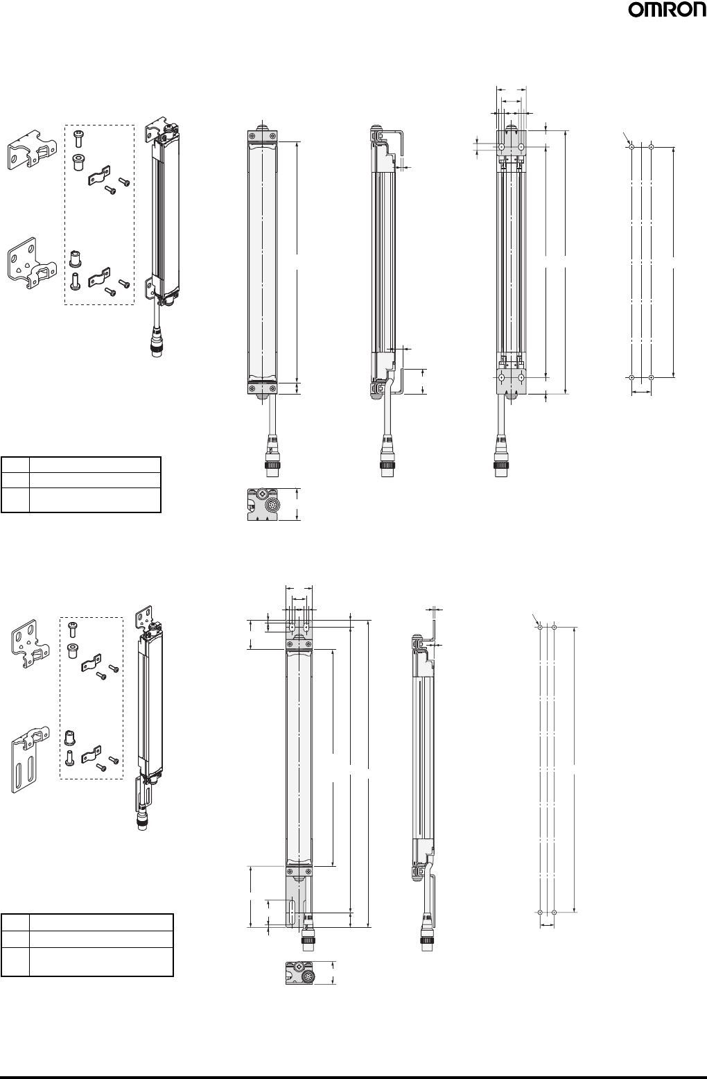
78 Safety Light Curtain (Type 4) F3SJ Ver. 2
Using Space-saving Mounting Bracket (F39-LJ8)
Backside mounting
Mounting Bracket (F39-LJ9) Used when Replacing an F3W-C.
Backside mounting
Use standard brackets
F39-LJ8
Material: Stainless steel
2
B
30
20
20
5.5 5.5
7
A
4-M5
B
25.65
8
16.65
11.5
33
C (Protective height)
(16.65)
Mounting screw holes
Note: Because the F39-LJ8 cannot be mounted together with an
intermediate bracket, keep the protective height at 600 mm max.
Dimensions A to C
AC + 23
BC
− 10.3
C 4-digit number of the model
name (protective height)
Use standard brackets
F39-LJ9
Material: Stainless steel
8
1
26
B
16
4-M5
C
(Protective
height) BA
(17)
3
28
69.3
3
10
33
30
66
16
2
Mounting screw holes
Note: Refer to the User's Manual (Cat. No. SCHG-718 and SCHG-
719) for the dimensions for side mounting.
Dimensions A to C
AC + 102.3
BC + 77.3
C 4-digit number of the model
name (protective height)
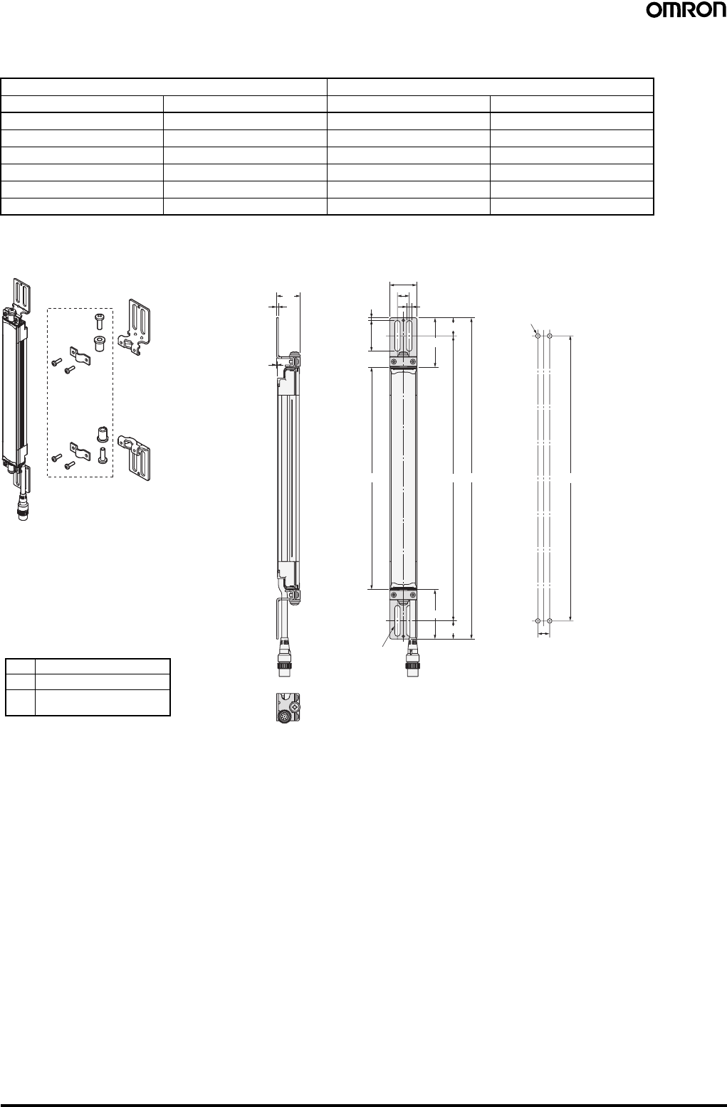
Safety Light Curtain (Type 4) F3SJ Ver. 2 79
F3W-C replacement correspondence table (F3W-C mounting holes can be used without modification)
When replacing F3W-C@@@ with F3SJ-A@@@@@30
Note: New holes must be drilled for the intermediate bracket.
Using Top/Bottom Mounting Bracket C (F39-LJ11)
F3W-C Replacement F3SJ
Model Protective height Model Protective height
F3W-C044 120 --- ---
F3W-C084 280 F3SJ-A0320@30 320
F3W-C124 440 F3SJ-A0470@30 470
F3W-C164 600 F3SJ-A0620@30 (See note.) 620
F3W-C204 760 F3SJ-A0795@30 (See note.) 795
F3W-C244 920 F3SJ-A0945@30 (See note.) 945
Use standard brackets
F39-LJ11
Material: Stainless steel 26
(20)
13
(54.5)
34
3
13
30
6
20
54.5
ABB
C (Protective height)
2
1
4-Mounting holes
4-M5
Dimensions A to C
AC + 109
BC + 69
C 4-digit number of the model
name (protective height)
Mounting screw holes
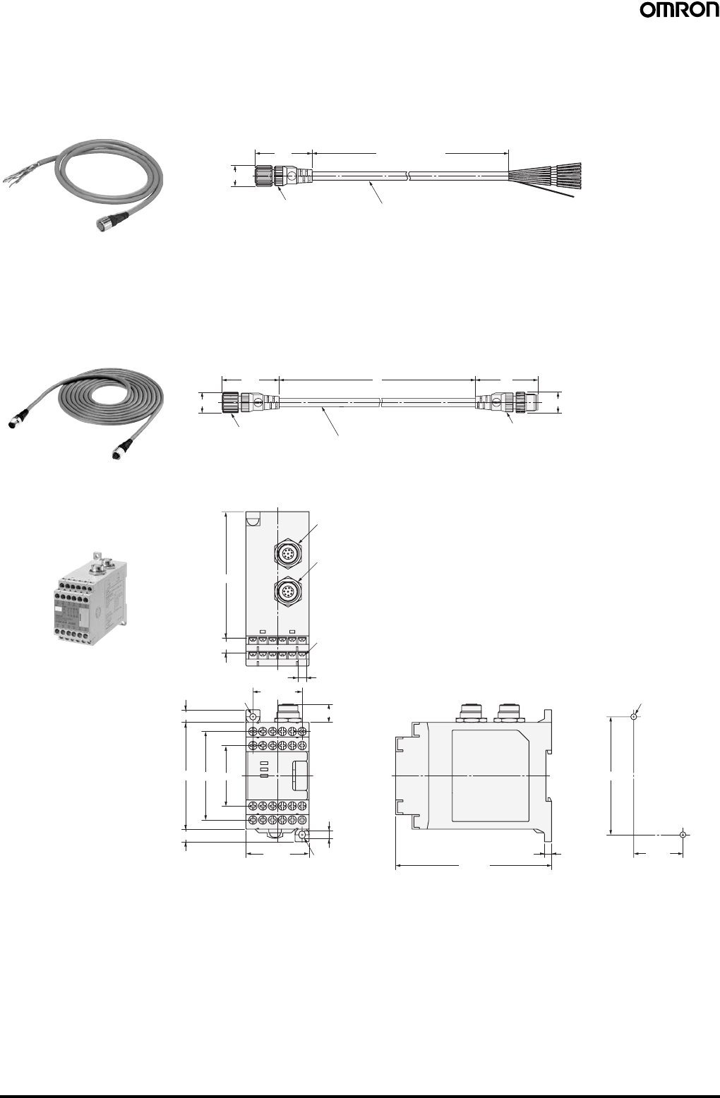
80 Safety Light Curtain (Type 4) F3SJ Ver. 2
■Accessories
Single-end Connector Cable
Cables with Connectors on Both Ends
Insulated vinyl round cable 6.6 dia. with braided shield
8-wire (4-pair) (Cross section of conductor: 0.3 mm2/insulator diameter: 1.15 mm)
Standard len
g
th L
39.5
15 dia.
L (See note.)
Waterproof connector
F39-JC3A (L = 3 m)
F39-JC7A (L = 7 m) F39-JC10A (L = 10 m)
F39-JC15A (L = 15 m)
F39-JC20A (L = 20 m)
Color: Emitter (gray)
Receiver (black) Note: Cables with L=3, 7, 10, 15, and 20 m are available.
15 dia. 15 dia.
39.5
Waterproof connector Waterproof connector
43L
Vinyl-insulated round cable: 6.6 dia. with braided shield
8-wire (4-pair) (Cross section of conductor: 0.3 mm2/ Insulator diameter: 1.15 mm)
Standard len
g
th L
F39-JCR5B (L = 0.5 m)
F39-JC1B (L = 1 m)
F39-JC3B (L = 3 m)
F39-JC5B (L = 5 m)
F39-JC7B (L = 7 m)
F39-JC10B (L = 10 m)
F39-JC15B (L = 15 m)
F39-JC20B (L = 20 m)
Color: Emitter (gray)
Receiver (black)
63
45 max.
43
5.6
111 max.
4.6 dia.
35±0.3
2-4.2 dia. or M4
5
84±0.3
R2.3
10.5
9
9
76 max.
13 max.
7×5=35
5.9
24-M3
Receiver
Emitter
91
Control Unit
F3SP-B1P
Mounting screw holes
Safety Light Curtain (Type 4) F3SJ Ver. 2 81
54
30 dia.
9 dia.
6.5 dia.
16
619
34
6
18
90
173
20
2
32 Material: Stainless steel
Dedicated External Indicator Set
F39-A01@-PAC
32
32
29.5
Four digits in the model number (protective height) − 10
Material: polycarbonate (for the protective cover)
Assembled dimension
s
10
Spatter Protection Cover
F39-HJ@@@@
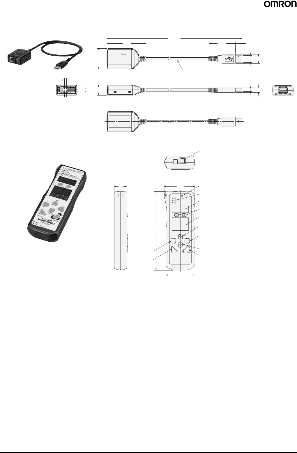
82 Safety Light Curtain (Type 4) F3SJ Ver. 2
67.9
35.8
17.8
3.6
0.7 (8)
(16)(12)
(4.5)
(625.7) (46)
Insulated vinyl round cable 4.6 dia.
Standard length: 0.5 m
(11.8)
Setting Support Software for the F3SJ
F39-GWUM
22
Communications jack
Channel key
Channel indicator
Function selection indicator
Connection indicator
52.8
136
50
Mode indicator
Up cursor key
Right cursor key
Down cursor key
Enter key
Delete key
Left cursor key
Setting Console
F39-MC21
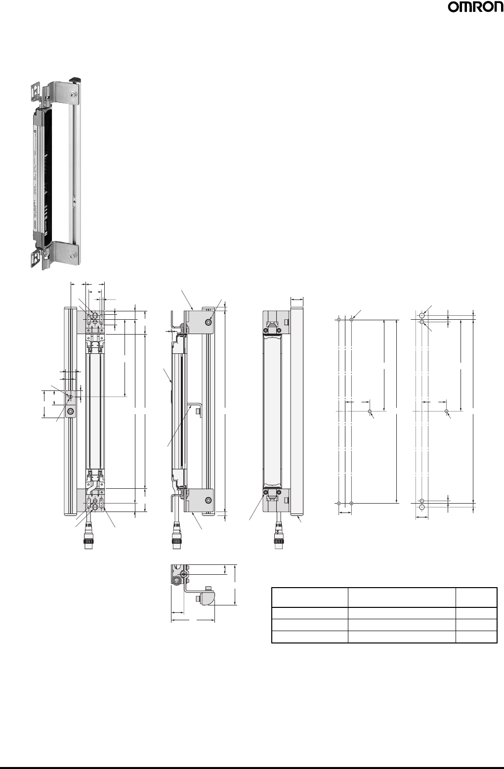
Safety Light Curtain (Type 4) F3SJ Ver. 2 83
16.5
5.5
(37)
1
(13.75)
(13.75)
C (Protective
height) AB
D
69
64
15
(6)
(6)
Mounting bracket (2)
Mounting
bracket (1)
Sensor
20
43 23
10
20
3024
9 dia.
5.5 dia.
16
8
Mounting hole
6.5 dia.
(37)
B
M5
39
D
6.25
20
2-M8
2-M6
3.75
3.75 6.25
B
M5
39
D
20
4-M5
2-Mounting holes
2-Mounting holes 4-Mounting holes Protective support
20
3-M5 bolts with
hexagonal holes and
attached washers
4-M3 bolts with
hexagonal holes
and attached
washers
Inter-
mediate
brackets
(3)
Protective Bar
F39-PJ@@@@-S
Backside mounting
C (protective height): 4-digit number in the table
A = C + 74, B = C + 46.5
Note: For reference, D is the dimension that will not interfere with
the intermediate bracket on the Safety Light Curtain body.
Protective height Number of intermediate
brackets used (3) D
0245 to 0995 0 ---
1001 to 2000 1 B/2
2009 to 2500 2 B/3
When using M5 When using M6, M8
Mounting screw holes
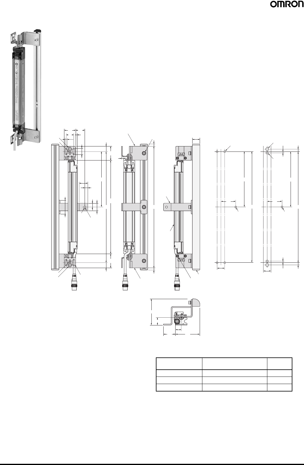
84 Safety Light Curtain (Type 4) F3SJ Ver. 2
16.5
4
5.5
(37)
(37)
(13.75)
(13.75)
AB
10 20
5.5 dia.
36
D
69
6432 15
(6)
(6)
20
20
20
30 24
9 dia.
8
23
6.5 dia.
5
B
M5
39
D
6.25
20
2-M8
2-M6
3.75
3.75 6.25
B
M5
39
D
20
4-M5
C (Protective
height)
Mounting bracket (2)
Mounting bracket (1)
Sensor
Mounting hole
2-Mounting holes
2-Mounting holes 4-Mounting holes Protective support
3-M5 bolts with
hexagonal holes and
attached washers
4-M3 bolts with
hexagonal holes
and attached
washers
Intermediate
brackets (4)
for side
mounting
(See note.)
Side mounting
C (protective height): 4-digit number in the table
A = C + 74, B = C + 46.5
Note: 1. For reference, D is the dimension that will not interfere
with the intermediate bracket on the Safety Light Curtain
body.
Protective height Number of protective
brackets used (4) D
0245 to 0995 0 ---
1001 to 2000 1 B/2
2009 to 2500 2 B/3
When using M5 When using M6, M8
Mounting screw holes
Note: 2. The four intermediate brackets (F39-PJ-MS)
for side mounting are not provided.
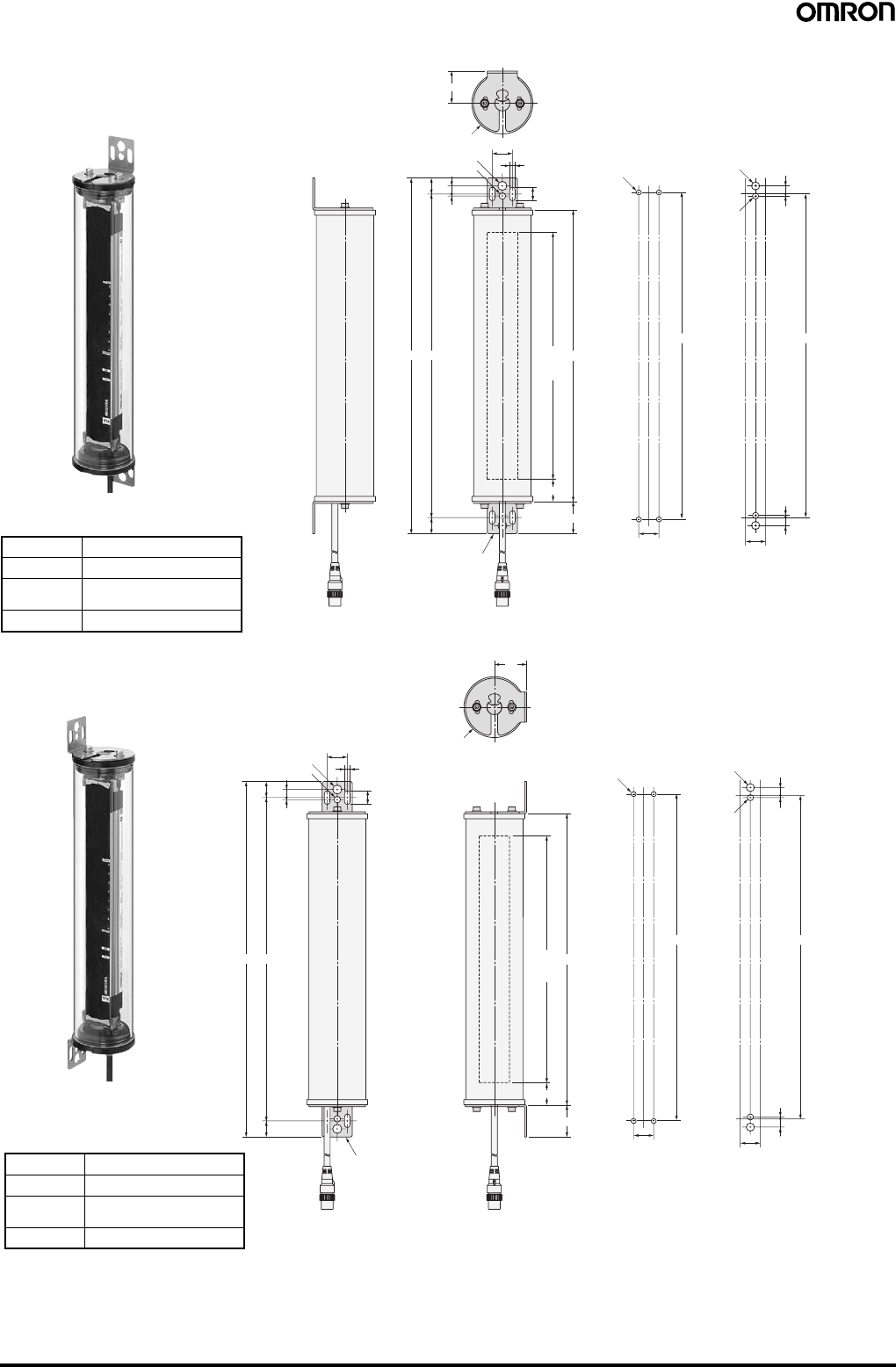
Safety Light Curtain (Type 4) F3SJ Ver. 2 85
13.5
5.5
20
32
6.5 dia.
(16)
16
2-Mounting Brackets
(See note.)
2
8
9 dia.
60.5 dia.
AB D
C
(Protective
height)
32
22
8
2
2-M8
2-M6
BB
20 20 8
2
4-M5
Water-resistant Case
F39-EJ@@@@-L(D)
Backside mounting
Dimensions A to D
AC + 108
BC + 76
C4-digit number of the model
name (protective height)
DC + 44
When using M5 When using M6, M8
Mounting screw holes
Note: The Mounting Brackets (F39-EJ-R)
are sold separately.
2-Mounting Brackets
(See note.)
13.5
5.5
20
6.5 dia.
(16)
16
2
8
9 dia.
AB D
C
(Protective
height)
32
22
32
60.5 dia.
8
2
2-M8
2-M6
BB
20 20 8
2
4-M5
Side mounting
Dimensions A to D
AC + 108
BC + 76
C4-digit number of the model
name (protective height)
DC + 44
When using M5 When using M6, M8
Mounting screw holes
Note: The Mounting Brackets (F39-EJ-S)
are sold separately.

86 Safety Light Curtain (Type 4) F3SJ Ver. 2

READ AND UNDERSTAND THIS CATALOG
Please read and understand this catalog before purchasing the products. Please consult your OMRON representative if you have any questions
or comments.
Warranty and Limitations of Liability
WARRANTY
OMRON’s exclusive warranty is that the products are free from defects in materials and workmanship for a period of one year (or other period if
specified) from date of sale by OMRON.
OMRON MAKES NO WARRANTY OR REPRESENTATION, EXPRESS OR IMPLIED, REGARDING NON-INFRINGEMENT,
MERCHANTABILITY, OR FITNESS FOR PARTICULAR PURPOSE OF THE PRODUCTS. ANY BUYER OR USER ACKNOWLEDGES THAT
THE BUYER OR USER ALONE HAS DETERMINED THAT THE PRODUCTS WILL SUITABLY MEET THE REQUIREMENTS OF THEIR
INTENDED USE. OMRON DISCLAIMS ALL OTHER WARRANTIES, EXPRESS OR IMPLIED.
LIMITATIONS OF LIABILITY
OMRON SHALL NOT BE RESPONSIBLE FOR SPECIAL, INDIRECT, OR CONSEQUENTIAL DAMAGES, LOSS OF PROFITS OR
COMMERCIAL LOSS IN ANY WAY CONNECTED WITH THE PRODUCTS, WHETHER SUCH CLAIM IS BASED ON CONTRACT, WARRANTY,
NEGLIGENCE, OR STRICT LIABILITY.
In no event shall responsibility of OMRON for any act exceed the individual price of the product on which liability is asserted.
IN NO EVENT SHALL OMRON BE RESPONSIBLE FOR WARRANTY, REPAIR, OR OTHER CLAIMS REGARDING THE PRODUCTS UNLESS
OMRON’S ANALYSIS CONFIRMS THAT THE PRODUCTS WERE PROPERLY HANDLED, STORED, INSTALLED, AND MAINTAINED AND
NOT SUBJECT TO CONTAMINATION, ABUSE, MISUSE, OR INAPPROPRIATE MODIFICATION OR REPAIR.
Application Considerations
SUITABILITY FOR USE
OMRON shall not be responsible for conformity with any standards, codes, or regulations that apply to the combination of products in the
customer’s application or use of the product.
At the customer’s request, OMRON will provide applicable third party certification documents identifying ratings and limitations of use that apply
to the products. This information by itself is not sufficient for a complete determination of the suitability of the products in combination with the end
product, machine, system, or other application or use.
The following are some examples of applications for which particular attention must be given. This is not intended to be an exhaustive list of all
possible uses of the products, nor is it intended to imply that the uses listed may be suitable for the products:
• Outdoor use, uses involving potential chemical contamination or electrical interference, or conditions or uses not described in this document.
• Nuclear energy control systems, combustion systems, railroad systems, aviation systems, medical equipment, amusement machines, vehicles,
safety equipment, and installations subject to separate industry or government regulations.
• Systems, machines, and equipment that could present a risk to life or property.
Please know and observe all prohibitions of use applicable to the products.
NEVER USE THE PRODUCTS FOR AN APPLICATION INVOLVING SERIOUS RISK TO LIFE OR PROPERTY WITHOUT ENSURING THAT
THE SYSTEM AS A WHOLE HAS BEEN DESIGNED TO ADDRESS THE RISKS, AND THAT THE OMRON PRODUCT IS PROPERLY RATED
AND INSTALLED FOR THE INTENDED USE WITHIN THE OVERALL EQUIPMENT OR SYSTEM.
Disclaimers
CHANGE IN SPECIFICATIONS
Product specifications and accessories may be changed at any time based on improvements and other reasons.
It is our practice to change model numbers when published ratings or features are changed, or when significant construction changes are made.
However, some specifications of the product may be changed without any notice. When in doubt, special model numbers may be assigned to fix
or establish key specifications for your application on your request. Please consult with your OMRON representative at any time to confirm actual
specifications of purchased products.
DIMENSIONS AND WEIGHTS
Dimensions and weights are nominal and are not to be used for manufacturing purposes, even when tolerances are shown.
ERRORS AND OMISSIONS
The information in this document has been carefully checked and is believed to be accurate; however, no responsibility is assumed for clerical,
typographical, or proofreading errors, or omissions.
PERFORMANCE DATA
Performance data given in this catalog is provided as a guide for the user in determining suitability and does not constitute a warranty. It may
represent the result of OMRON’s test conditions, and the users must correlate it to actual application requirements. Actual performance is subject
to the OMRON Warranty and Limitations of Liability.
PROGRAMMABLE PRODUCTS
OMRON shall not be responsible for the user’s programming of a programmable product, or any consequence thereof.
Copyright and Copy Permission
COPYRIGHT AND COPY PERMISSION
This document shall not be copied for sales or promotions without permission.
This document is protected by copyright and is intended solely for use in conjunction with the product. Please notify us before copying or
reproducing this document in any manner, for any other purpose. If copying or transmitting this document to another, please copy or transmit it in
its entirety.

New Models for Body
Protection or Presence
Detection
F3SJ Ver. 2
Safety Light Curtain (Type 4)
Cat. No. F074-E1-06
Authorized Distributor:
Note: Specifications subject to change without notice.
OMRON Corporation
Industrial Automation Company
Safety Devices Division
Shiokoji Horikawa, Shimogyo-ku,
Kyoto, 600-8530 Japan
Tel: (81)75-344-7093/Fax: (81)75-344-8197
Regional Headquarters
OMRON EUROPE B.V.
Wegalaan 67-69, NL-2132 JD Hoofddorp
The Netherlands
Tel: (31)2356-81-300/Fax: (31)2356-81-388
OMRON SCIENTIFIC TECHNOLOGIES INC.
6550 Dumbarton Circle Fremont,
CA 94555-3605 U.S.A.
Tel: (1)510-608-3400/Fax: (1)510-744-1442
OMRON ASIA PACIFIC PTE. LTD.
83 Clemenceau Avenue,
#11-01, UE Square,
239920 Singapore
Tel: (65)6835-3011/Fax: (65)6835-2711
OMRON (CHINA) CO., LTD.
Room 2211, Bank of China Tower,
200 Yin Cheng Road (M),
Shanghai, 200120 China
Tel: (86)21-5037-2222/Fax: (86)21-5037-2200
Printed in Japan
0207-1M (0605) (H)
