557101 Catalog
2014-09-04
: Pdf 557101-Catalog 557101-Catalog 662037 Batch7 unilog
Open the PDF directly: View PDF ![]() .
.
Page Count: 100
Q
U
A
Z
I
T
E
P
R
O
D
U
C
T
S
C
A
T
A
L
O
G
QUAZITE
3621 Industrial Park Drive
Lenoir City, TN 37771
Phone: 800-346-3062 or 865-986-9726
Fax: 865-986-0585
e-mail: hpsliterature@hps.hubbell.com
© Copyright 2006 Quazite • 3621 Industrial Park Drive • Lenoir City, TN
NOTE: Because Hubbell has a policy of continuous product improvement, we reserve the right to change design and specifications without notice.
UNDERGROUND ENCLOSURES AND PADS
Complete Product Representation and
Stocking Distributors Throughout North America
Web: http://www.quazite.com
E-mail: hpsliterature@hps.hubbell.com
QZ-1
DECEMBER 2006 Printed in USA SUTH 10M

2
Underground Enclosure Performance Specications
Enclosures, boxes and covers are required to conform to all test provisions of the most current ANSI/SCTE 77 “Specification For Underground
Enclosure Integrity” for Tier_____ (specify Tier 5, 8, 15 and/or 22) applications. When multiple “Tiers” are specified the boxes must physically
accommodate and structurally support compatible covers while possessing the highest Tier rating. All covers are required to have the Tier level
rating embossed on the surface. In no assembly can the cover design load exceed the design load of the box. All components in an assembly
(box & cover) are manufactured using matched surface tooling. Independent third party verification or test reports stamped by a registered
Professional Engineer certifying that all test provisions of this specification have been met are required with each submittal.

3
SEPTEMBER 2007
®
Table of Contents
........................ 2
Introduction to QUAZITE® .................................................................4 - 7
Engineering ................................................................................................ 4
Quality Assurance ...................................................................................... 4
What is Polymer Concrete? ........................................................................5
Why Use Polymer Concrete? ..................................................................... 5
Design Possibilities .....................................................................................5
Enclosures (ANSI Compliant) ..................................................................... 6
Electrical Equipment Pads and Telecommunications Cabinet Pads ............. 6
Box Pads and Traffic Signal Cabinet Bases ................................................ 6
Importance of the 2005 NEC, ANSI/SCTE 77 2007 and UL Listing ..............7
QUAZITE® Enclosures UL Listed to ANSI/SCTE 77 2007 .......................... 7
Testing Requirements for ANSI/SCTE 77 2007 .......................................... 7
Enclosure Selection ........................................................................8 - 14
Using the Selection Guide .......................................................................... 8
UL Listed Enclosures ..................................................................................8
Load Ratings .............................................................................................. 9
Handhole Opening Sizes .......................................................................... 10
Cover Series and Styles ........................................................................... 11
Other Cover Styles ................................................................................... 12
Box Styles ..........................................................................................13 - 14
Enclosure Drawings .....................................................................15 - 46
Index of Enclosure Drawings .................................................................... 15
6” x 8” ........................................................................................................ 16
8” x 8” ........................................................................................................ 17
8” x 18” ...................................................................................................... 18
10” x 15” .................................................................................................... 19
11” x 18” .............................................................................................20 - 21
12” x 12” .............................................................................................22 - 23
13” x 24” .............................................................................................24 - 27
17” x 30” .............................................................................................28 - 31
24” x 24” .................................................................................................... 32
24” x 36” .............................................................................................33 - 34
30” x 48” .............................................................................................35 - 36
30” x 60” .................................................................................................... 37
36” x 36” .................................................................................................... 38
36” x 60” .................................................................................................... 39
36” x 72” .................................................................................................... 40
48” x 48” .................................................................................................... 41
48” x 72” .................................................................................................... 42
48” x 96” .................................................................................................... 43
Grade Adjustable Extensions ................................................................... 44
27” Round ................................................................................................. 45
39” Round ................................................................................................. 46
Cover Drawings .............................................................................47 - 50
Replacement Cover Drawings ...........................................................47 - 49
Meter Reading Covers and Lids ............................................................... 50
Hardware and Options .................................................................51 - 56
Hardware .................................................................................................. 51
Enclosure Options .............................................................................52 - 53
Standard Cable Rack Insert, Terminator, Knockout, & Hole Locations ............... 54
Divided Boxes ...........................................................................................55
Logos ........................................................................................................ 55
Pad Options .............................................................................................. 55
Color Options ............................................................................................56
Electrical Equipment Pads ..........................................................57 - 64
Electrical Equipment Pad Selection Guide ........................................57 - 60
Switchgear Box Pad Cross Reference Guide ...........................................58
Box Pad Drawings .............................................................................61 - 62
Electrical Equipment Pad Drawings ...................................................63 - 64
Telecommunications Cabinet Pads ...........................................65 - 73
Telecommunications Cabinet Pad Selection Guide ...........................65 - 70
Telecommunications Cabinet Pad Cross Reference Guide ...............66 - 68
Telecommunications Cabinet Pad Dimensions & Weights .................71- 72
Cell Site Enclosure ................................................................................... 73
Transportation Industry Products ..............................................74 - 84
Traffic Signal Cabinet Base Selection Guide .....................................74 - 78
Traffic Signal Cabinet Base Cross Reference Guide .........................75 - 76
Traffic Signal Cabinet Base Drawings................................................79 - 80
Work Pad Drawing ....................................................................................81
Jersey Style Median Barrier Enclosure Drawing ...............................82 - 83
Installation .....................................................................................84 - 95
“ANSI Tier” Selection and Placement ................................................84 - 85
Small Enclosure Installation ..................................................................... 86
Hole Cutting Instructions .......................................................................... 87
EZ-Nut and Self-Aligning Nut Replacement Instructions .......................... 88
Large Enclosure Installation ..................................................................... 89
Internal Bracing Installation ...................................................................... 90
Concrete Collar Applications .................................................................... 91
Telecommunications Cabinet Pad Installation .......................................... 92
Traffic Signal Cabinet Base Installation ....................................................93
Electrical Equipment Pad Installation ....................................................... 94
Switchgear Box Pad Installation ............................................................... 95
Company Information ...................................................................96 - 99
INTRODUCTION
INTRODUCTION
4
SEPTEMBER 2007
®
INTRODUCTION
INTRODUCTION
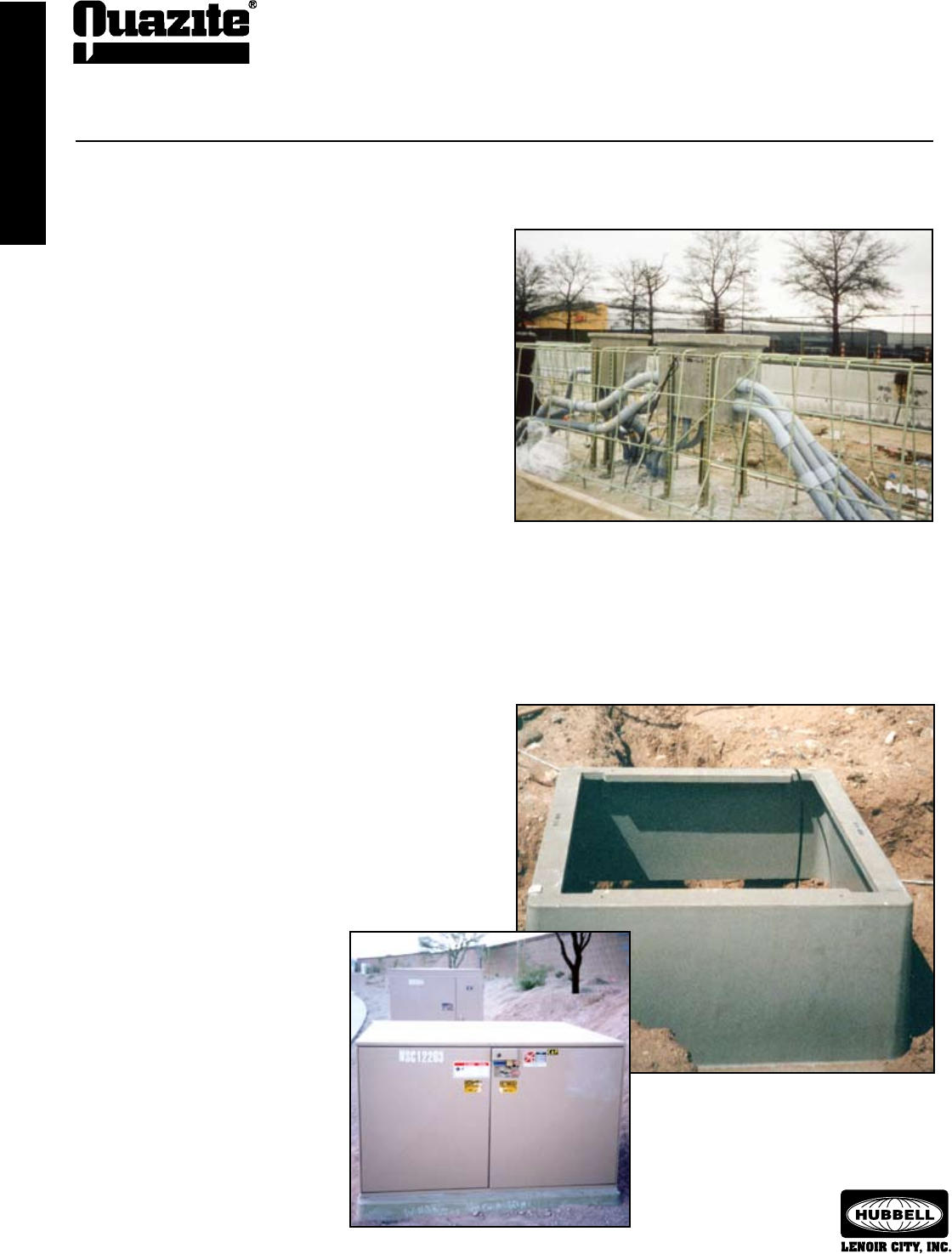
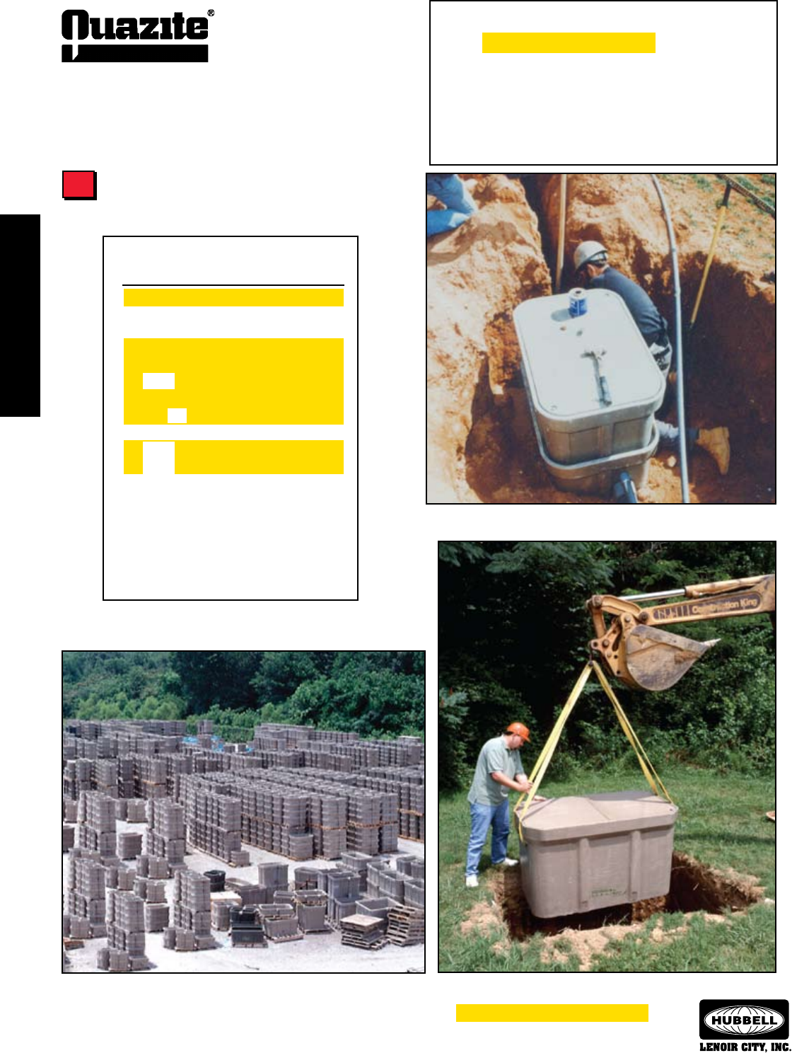
QUAZITE® switchgear box pads are used for easier,
quicker and less expensive installations.
Introduction
Since 1971, QUAZITE® precast polymer concrete products have
been used by utilities and contractors for durable, cost-effective applica-
tions. QUAZITE® encompasses a broad range of underground utility
products including: service boxes and handholes, electrical equipment
pads, telephone cabinet pads, CATV enclosures, water meter boxes,
box pads and traffic signal cabinet bases.
QUAZITE® manufacturing/distribution centers are in Lenoir City,
Tennessee and San Jose, California providing nationwide service and
prompt delivery.
Engineering
Registered professional engineers are on hand to assist with
design, specification development and review. Full CAD capabilities are
available and can be used to electronically transmit drawings and files
to you. Product drawings can be accessed from our website:
www.quazite.com
Quality Assurance
The Quality Assurance staff at each QUAZITE® manufacturing
facility assures product consistency and conformance to customer spec-
ifications. The test labs and manufacturing processes at all QUAZITE®
facilities are accepted by Underwriters Laboratories, Inc. (UL).
QUAZITE® underground products solve problems in thousands of
specific applications in many industries. If one or more of the products
described here could be the right solution for you, please contact your
local QUAZITE® representative for more information.
QUAZITE® enclosures are embedded in concrete highway median barriers.
QUAZITE® Products for Underground Construction
INTRODUCTION
INTRODUCTION
5
INTRODUCTION
INTRODUCTION
®
SEPTEMBER 2007
What Is Polymer Concrete?
Polymer concrete is made from selectively-graded aggregates
in combination with a polymer resin system. When combined through
a process of mixing, molding and curing, an extremely powerful cross-
linked bond is formed. Precast polymer concrete is reinforced with
fiberglass for exceptional strength and rigidity.
Why Use Polymer Concrete?
• Lightweight — 1/10 to 1/3 the weight of concrete
• High Strength — compressive, flexural and tensile strengths
three to five times higher than traditional concrete
• Reduced Installation Costs — easy to handle, no special
equipment required
• Stable Under Freeze/Thaw Conditions
• Impact Resistant — tested per ASTM D-2444
• Low Water Absorption — less than 1% per ASTM D-570
• Corrosion Resistant — resistant to alkalines, acids, weathering
and other forms of deterioration
• Cost Effective — outperforms conventional materials for longer
service and lower life cycle costs
• Nonammable — will not support combustion
• Nonconductive — no grounding required for the box or cover
Design Possibilities
Precast polymer concrete offers a variety of design
possibilities.
• Development of New Parts — Years of experience enable
QUAZITE® engineers to produce custom designed parts to your
specifications.
• Size — Monolithic boxes are being made up to 4’ x 8’ x 4’. Pads
for cabinets or equipment enclosures are currently being made
as small as 25” x 38” and as large as 93” x 93” and even larger
when bolted together. If other sizes are required, contact your
local QUAZITE® representative.
• Composite Design — An experienced staff is available to assist
in the development of specifications and design of products.
• Custom Accessories — Many options are available for
QUAZITE® products, including racking and struts, knockouts,
holes, logos, terminators, gaskets, pulling eyes, and numerous
other options. Please see pages 52 - 56 for a complete listing of
options.
Mechanical Properties
Modulus of elasticity 1 to 2.4 x 10⁶ psi
Compressive strength 9,000-15,000 psi
Flexural strength 3,000-6,000 psi
Impact energy 30-72 ft.-lbs.
Tensile strength 800-1,100 psi
Tested according to the requirements of ASTM Method D-543,
Section 7, Procedure 1 for chemical resistance, using the following
chemicals in the concentrations noted:
CHEMICAL CONCENTRATION
Sodium Chloride 5%
Sulfuric Acid 0.1N
Hydrochloric Acid 0.2N
Sodium Hydroxide 0.1N
Freeze/thaw resistance (2,500 cycles) No significant change
Density 85-150 lbs./cu. ft.
Barcol hardness 45
Coefficient of friction (covers) Greater than 0.5
Water absorption Less than 1%
Typical Properties of Polymer Concrete
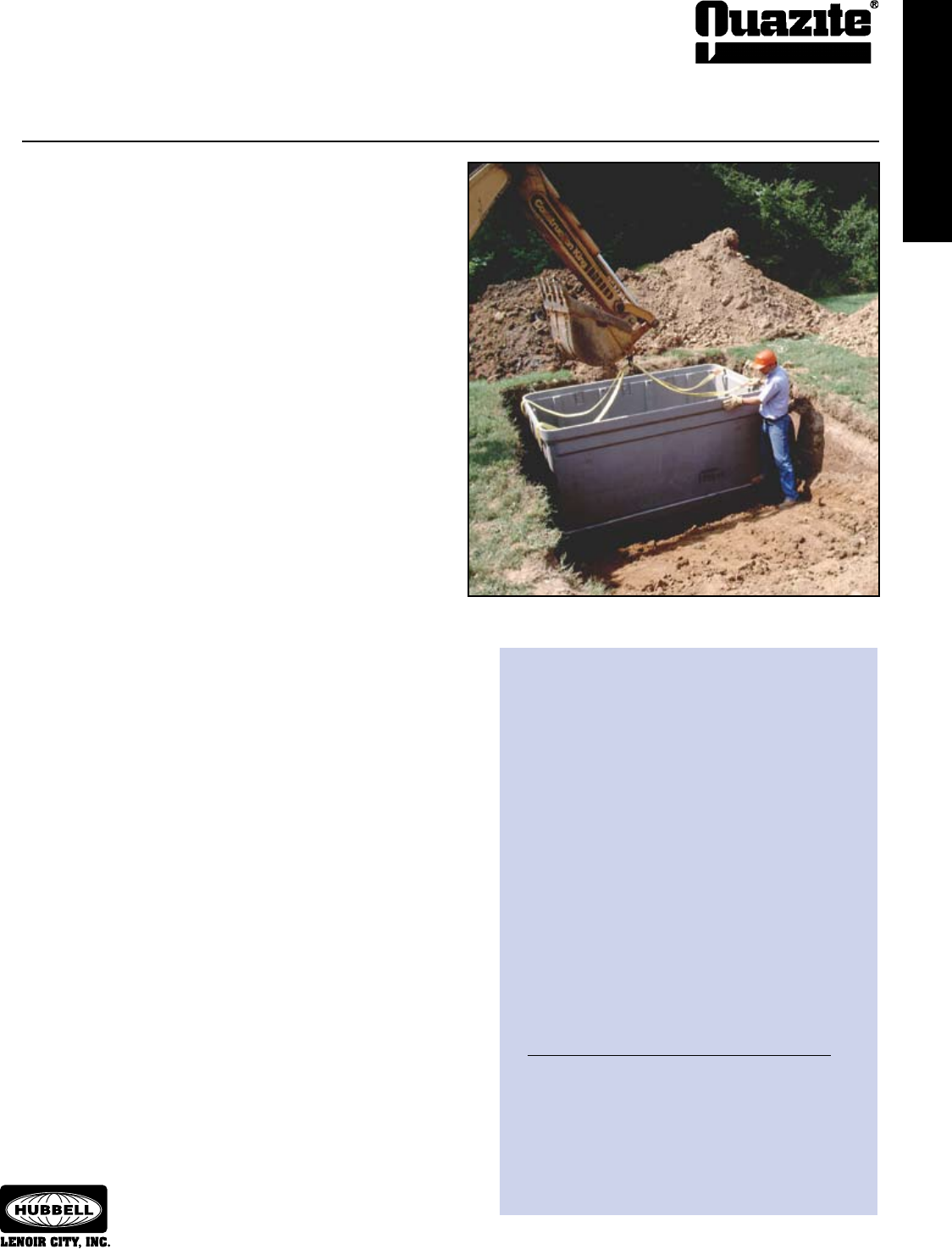
The strong polymer concrete construction allows QUAZITE® enclosures to
be stacked for even greater depths.
Precast Polymer Concrete
INTRODUCTION
INTRODUCTION
6
SEPTEMBER 2007
®
INTRODUCTION
INTRODUCTION
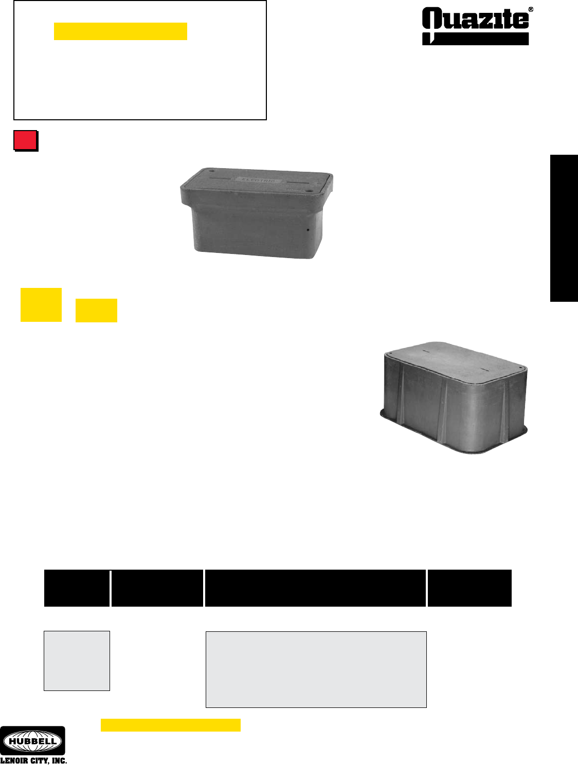
For use as splice boxes, pull boxes or equipment enclosures for any
application requiring easy access to an underground service (i.e. electrical,
telephone, fiber optics, CATV, water, gas, etc.). Available in a large variety
of sizes and styles with either standard, heavy duty or optional overlapping
covers. No grounding is required for the box or cover. Fits flush with sidewalk
or grass area. Covers are skid resistant. Replacement covers and meter lids,
hardware, inserts and grade adjustable extensions are available options. Boxes
and covers are ANSI/SCTE 77 compliant for intended applications.
Enclosures
Box Pads and Trafc
Signal Cabinet Bases
Precast polymer concrete
box pads and traffic signal cabinet
bases eliminate forming and pouring
and are lightweight, resulting in easy
handling and a lower installed cost.
Excavation and installation of the
entire unit can be done in one day.
Can be reused in other locations.
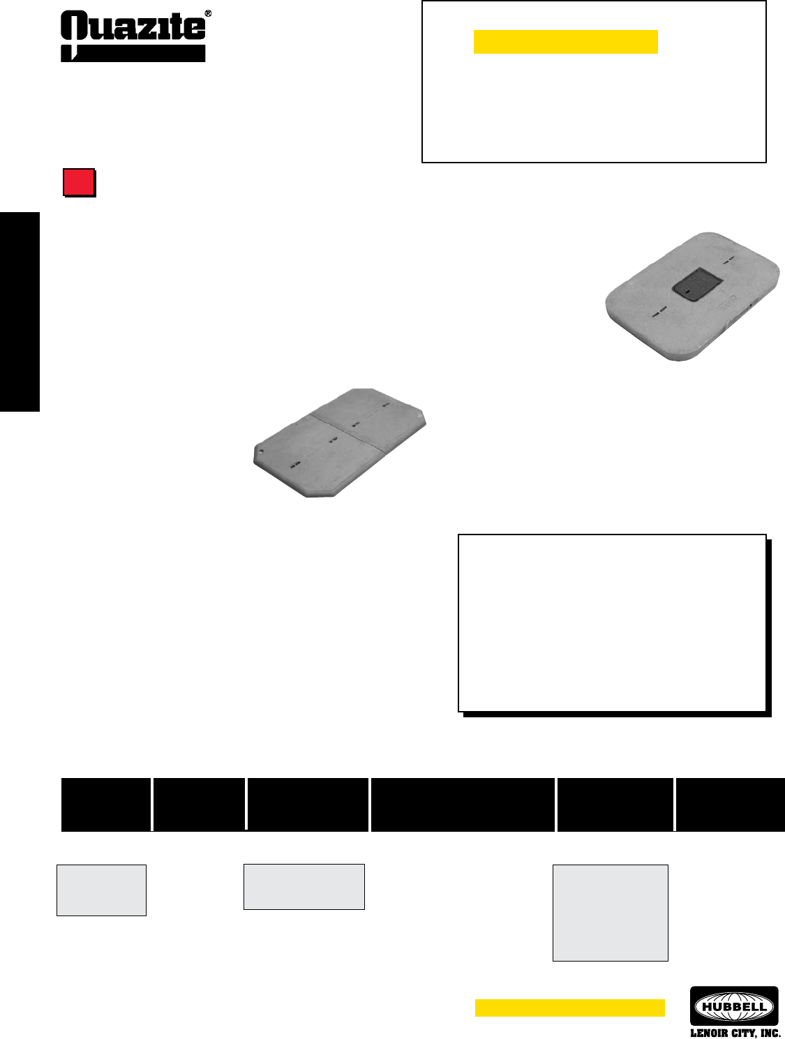
Electrical Equipment
and Telecommunications
Cabinet Pads
Used under transformers and
telephone cabinets to add stability,
prevent corrosion of metal cabinets,
provide a fire break, and protect
cabinets from damage caused by
mowing equipment. Available as
a solid pad or as a Splitt-Pad® for
easy retrofits.
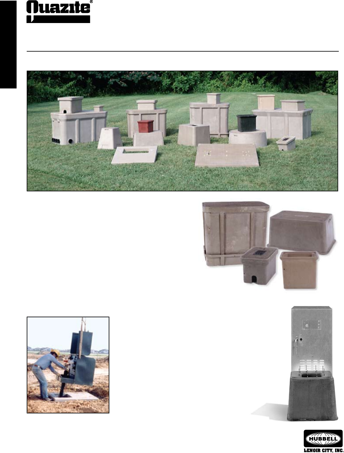
QUAZITE® has a broad product line for the underground construction industry.
The Product Line
INTRODUCTION
INTRODUCTION
7
INTRODUCTION
INTRODUCTION
®
SEPTEMBER 2007
The Importance of the 2005 NEC, ANSI/SCTE 77 2007 and UL Listing
UL Listing Card
BGHL
Boxes, Enclosures, Handholes and Vaults, Underground, Utility Specication
HUBBELL - LENOIR CITY E190048
3621 INDUSTRIAL PARK DR, LENOIR CITY TN 37771
Underground boxes investigated in accordance with Western Underground Committee
Guide 3.6, the Society of Cable Telecommunication Engineers Recommended Practices for
Coaxial Cable Construction and Testing, Issue 1, Section 5 and the American National Stan-
dards Institute/Society of Cable Telecommunication Engineers Standard ANSI/SCTE 77 2002.
LOOK FOR LISTING MARK ON PRODUCT
Underwriters Laboratories Inc. Card 1 of 1
2005 NEC and Underground Enclosures
The 2005 edition of the National Electric Code addresses
underground enclosures for the first time in its history. The NEC
now states in article 314.30 that enclosures “shall be designed and
installed to withstand all loads likely to be imposed,” 1 and addresses
issues related to enclosure size, wiring entries, enclosures without
bottoms, and bonding requirements for covers.
The Code references the ANSI/SCTE 77 20022 “Specification
for Underground Enclosure Integrity” National Standard 3, which out-
lines various tests that enclosures must pass to meet the standard.
ANSI/SCTE 77 2002 also provides load charts with Tier ratings to help
end users determine the appropriate enclosure to select depending
on the loadings expected in the application.
QUAZITE® Enclosures UL Listed to ANSI Standard
All QUAZITE® enclosures meet or exceed the test provisions of
ANSI/SCTE 77 2007 and most enclosures sized 30” x 48” and smaller
are even UL Listed to the ANSI National Standard as referenced in the
2005 NEC. This means that QUAZITE® enclosures have undergone
rigorous physical, environmental and internal equipment protection
tests and have been found by UL, a neutral third party, to meet the
test requirements of the ANSI National Standard.
No one wants to be responsible for an accidental electrocution
from a collapsed enclosure or energized cover. By using the 2005
NEC, ANSI/SCTE 77 2007 and UL Listing requirements in the en-
closure selection process, end-users will help ensure long service
life, increased safety and reduced potential liability associated with
failed underground enclosures.
Testing Requirements for ANSI/SCTE 77 2007
Underground enclosures must successfully pass numerous
material and product performance tests before they can meet ANSI/
SCTE 77 2007. These tests include:
• Three Position Load Testing to Simulate Actual Application
• UV Degradation per ASTM G-154
• Fire Resistance per RUS 7CFR 1755.910 (PE-91) and WUC 3.6
Section 5.2.7
• Chemical Resistance per ASTM D-543
• Water Absorption per ASTM D-570
• Impact Resistance per ASTM D-2444
• Accelerated Service per ASTM D-756, Procedure E
NOTE: Quazite recommends testing by third party organiza-
tions such as UL to verify that enclosures meet all test provisions
of ANSI/SCTE 77 2007.
1 National Fire Protection Agency, 2005 National
Electric Code.
2 Subsequent to the issuance of the 2005 NEC,
ANSI approved an updated version of the
standard, ANSI/SCTE 77 2007.
3 The latest copy of the standard may be purchased
from ANSI. It may also be viewed in PDF form on
SCTE’s website at www.scte.org/documents/pdf/
ANSISCTE%2077%202007.pdf.
8
ENCLOSURE SELECTION
ENCLOSURE SELECTION
SEPTEMBER 2007
®
ENCLOSURE SELECTION
ENCLOSURE SELECTION
Enclosure Selection Guide
To Select the Enclosure You Need for Your Application:
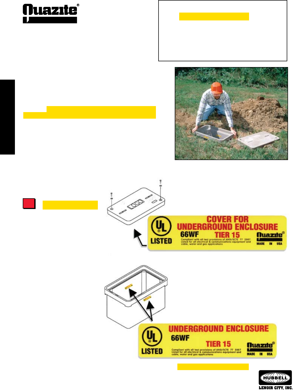
UL Listed Enclosures
Determine if a UL Listed enclosure
is required for your installation. Federally
funded electrical and telecom projects,
as well as many state and municipal
projects, generally require the use of
a UL Listed product whenever one is
available.
Most QUAZITE® underground
handhole enclosures in sizes through
30” x 48” are UL Listed. These products
are clearly marked with the UL label
on both the box and underneath the
cover. Special order boxes with holes
and mouseholes may also qualify for
UL Listing as long as the holes do
not exceed 25% of the area of each
sidewall.
Using The Selection Guide
Follow the steps outlined in this guide to select the enclosure for
your application. These steps will take you through the typical decisions
necessary to determine the proper size and style enclosure for your
application. The UL Listed enclosures are highlighted throughout this
selection guide to help in identifying them.
A detailed product information listing follows the selection guide.
All QUAZITE® products are listed here by size and style with dimensions
and ordering information.
For more information or for answers to any questions you might
have, call your local QUAZITE® representative. Detailed product draw-
ings can be viewed from our website:
www.quazite.com
1 .... Determine UL Requirements
2 .....Determine Load Ratings
3 .....Determine Handhole Opening Size
4 .....Select Cover Series & Style
5 .....Select Box Style
6 .....Determine Options & Hardware
Highlighted areas indicate UL Listing
Most QUAZITE® underground enclosures in sizes through
30” x 48” are UL Listed.
1
ENCLOSURE SELECTION
ENCLOSURE SELECTION
9
ENCLOSURE SELECTION
ENCLOSURE SELECTION
®
SEPTEMBER 2007
Enclosure Selection Guide
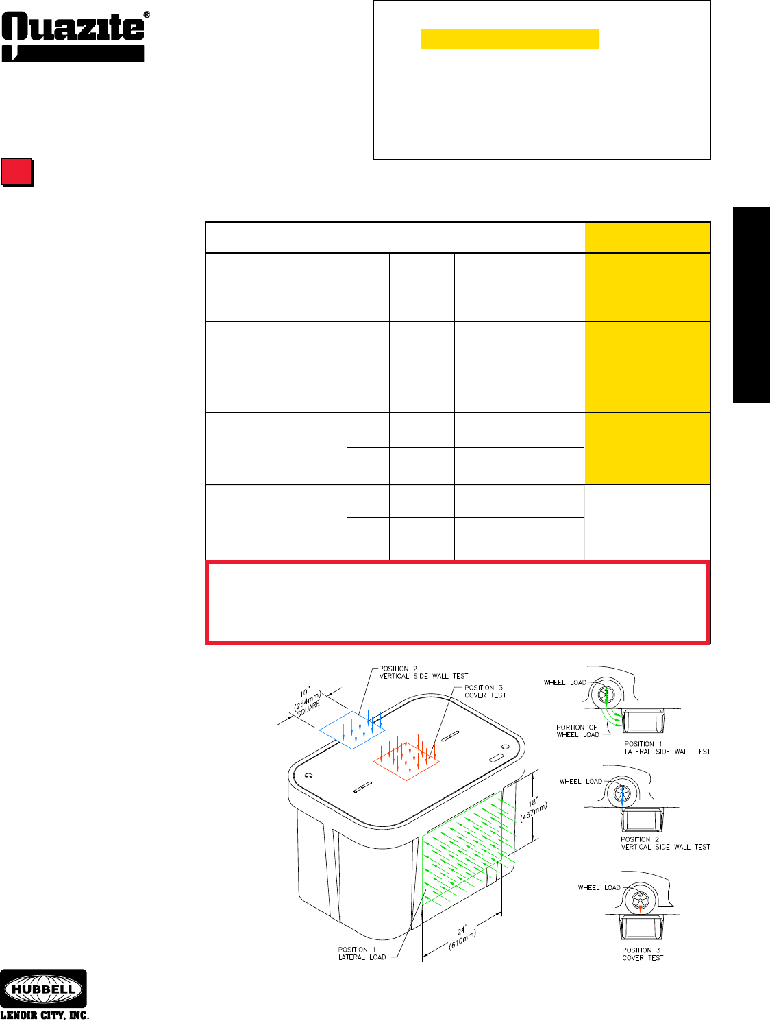
Three Position Testing
A key requirement outlined in ANSI/SCTE 77
2007 is three position testing for enclosures. Three
position testing is required to determine how a product
will perform in actual use.
In order to qualify a product’s performance, test
loading should be performed at the lateral center of the
longest sidewall, at the vertical center of the longest
sidewall, and at the vertical in the center of the cover.
QUAZITE® products have been tested to each of the
three positions as required by ANSI and all have met
or exceeded the requirements.
To Select the Enclosure You Need for Your Application:
1 ......Determine UL Requirements
2 ..... Determine Load Ratings
3 ......Determine Handhole Opening Size
4 ......Select Cover Series & Style
5 ......Select Box Style
6 ......Determine Options & Hardware
Load Ratings
QUAZITE® underground
handhole enclosures are designed
to meet or exceed the tier loadings
set forth in the American National
Standards Institute’s ANSI/SCTE 77
2007 “Specification for Underground
Enclosure Integrity”1. ANSI tier des-
ignations are minimum specifications
used by the industry to ensure the
safe and reliable performance of un-
derground handhole enclosures.
The ANSI application tier num-
ber relates to a nominal design load
times 1,000 pounds (i.e.: Tier 8 = 8
x 1,000 lbs. = 8,000 lbs.). All ANSI
tier loadings will have a correspond-
ing test load which is 50% greater
than the design load. The maximum
deflection at the indicated design
load shall be 1/2 inch for vertical
tests and 1/4 inch per foot of length
for lateral tests.
2Application Tiers & Static Vertical Wheel Load Ratings per
ANSI/SCTE 77 2007 “Specication for Underground Enclosure Integrity”
NOTE - QUAZITE® products are not intended for use in deliberate traffic areas.
Figure 4.1 from ANSI/SCTE 77 2007
1 Electronic file available at www.scte.org/documents/pdf/ANSIS-
CTE%2077%202007.pdf.
2 ANSI/SCTE 77 requires that the Tier 5, 8 and 15 tests are
performed using a 10” x 10” plate, and the Tier 22 tests are
performed using a 10” x 20” plate.
3 Some QUAZITE® products are currently not UL Listed. Refer to
pg. 15 for a complete listing of products.
Loading Requirements
PG and PT style enclosure and
cover assemblies up to 30” x
48” and PC style in sizes 6”x8”,
8”x18”, 11”x18” and 12”x12”
with standard covers (CA) and
standard covers w/o bolts (WA).
PG, PT and PC style enclo-
sure and cover assemblies up
to 30”x48” with heavy duty
covers (HA).
PC 13”x24” or PC 17”x30”
style enclosure and cover
assemblies with standard
covers (CA) and standard
covers w/o bolts (WA).
Application Tiers
TIER 51
Sidewalk applications with a
safety factor for occasional non-
deliberate vehicular traffic
TIER 81
Sidewalk applications with a
safety factor for non-deliberate
vehicular traffic
TIER 151
Driveway, parking lot, and off-
roadway applications subject to
occasional non-deliberate heavy
vehicular traffic
Tier 222
Driveway, parking lot, and off-
roadway applications subject
to occasional non-deliberate
heavy vehicular traffic
UL Listed to meet ANSI 77
2007 Requirements3
22.2 kN 5,000 lbs.
33.3 kN 7,500 lbs.
28.7 kPa 600 lbs./sq. ft.
43.1 kPa 900 lbs./sq. ft.
35.6 kN 8,000 lbs.
53.4 kN 12,000 lbs.
28.7 kPa 600 lbs./sq. ft.
43.1 kPa 900 lbs./sq. ft.
66.7 kN 15,000 lbs.
100.1 kN 22,500 lbs.
38.3 kPa 800 lbs./sq. ft.
57.5 kPa 1,200 lbs./sq. ft.
100.1 kN 22,500 lbs.
150.1 kN 33,750 lbs.
38.3 kPa 800 lbs./sq. ft.
57.5 kPa 1,200 lbs./sq. ft.
Certified precast concrete, cast iron or other AASHTO recognized materials.*
AASHTO H-20
Deliberate vehicular traffic
applications
*There are no AASHTO design or test provisions for polymer composites.
Therefore there is no recognized method of testing for qualification. Applying
other material testing methods to polymer composites is not recognized by
AASHTO. BUYER BEWARE !
See page 15.
10
ENCLOSURE SELECTION
ENCLOSURE SELECTION
SEPTEMBER 2007
®
ENCLOSURE SELECTION
ENCLOSURE SELECTION
Enclosure Selection Guide
Handhole Opening Sizes
To Select the Enclosure You Need for Your Application:
QUAZITE® enclosures are lightweight for easy installation.
QUAZITE® enclosures are used for underground fiber optics and electric
cable.
Quazite keeps a large inventory of QUAZITE® enclosures to ensure immediate
availability.
Box & Cover
Style Available Size
1 .....Determine UL Requirements
2 .....Determine Load Ratings
3 .... Determine Handhole Opening Size
4 .....Select Cover Series & Style
5 .....Select Box Style
6 .....Determine Options & Hardware
3
Highlighted areas indicate UL Listing
PC 6” x 8”
PC 8” x 8”
PC 8” x 18”
PT 10” x 15”
PG & PC 11” x 18”
PC & LX 12” x 12”
PG, PC, & PT 13” x 24”
PG, PC, PD & PT 17” x 30”
PG 24” x 24”
PG & PD 24” x 36”
PG & PD 30” x 48”
PG 30” x 60”
PG 36” x 36”
PG 36” x 60”
PG 36” x 72”
PG 48” x 48”
PG 48” x 72”
PG 48” x 96”
ENCLOSURE SELECTION
ENCLOSURE SELECTION
11
ENCLOSURE SELECTION
ENCLOSURE SELECTION
®
SEPTEMBER 2007
Cover Series & Styles
To Select the Enclosure You Need for Your Application:
1 .....Determine UL Requirements
2 .....Determine Load Ratings
3 .....Determine Handhole Opening Size
4 .... Select Cover Series & Style
5 .....Select Box Style
6 .....Determine Options & Hardware
Enclosure Selection Guide
HH Series Covers
Extra heavy duty HH covers are designed for driveways, parking
lots and off-roadway applications where subject to occasional non-
deliberate traffic by heavy vehicles. Contact your local QUAZITE®
representative for availability of sizes.
• Loadings for HH covers comply with all test provisions of ANSI/
SCTE 77 except that the vertical design load is 22,500 lbs. with
a test load of 33,750 lbs. over a 10” x 20” plate.
HA/HG Series Covers
Heavy duty covers (available for PG, PD, PC and PR box
styles) are designed for driveways, parking lots and off-road-
way applications where subject to occasional non-deliberate
vehicular traffic. HG covers feature a grommet package to
reduce incoming fluids into the enclosure. HG covers must
be used with gasketed boxes.
• Design Load: 15,000 lbs. over a 10” square with a
minimum test load of 22,500 lbs. (ANSI Tier 15)
CA/WA/CG Series Covers
CA covers are designed to bolt down. WA covers do not have
provisions to bolt the covers in place. CG covers feature a
grommet package to reduce incoming fluids into the enclosure.
CG covers must be used with gasketed boxes.
• Design Load: 8,000 lbs. over a 10” square with a minimum
test load of 12,000 lbs. (ANSI Tier 8)
(For PG, PT, PR and smaller PC styles)
• Design Load: 5,000 lbs. over a 10” square with a minimum
test load of 7,500 lbs. (ANSI Tier 5)
(For PC 13” x 24” and PC 17” x 30” styles and all LG
styles)
Cover Cover Size Cover Series Cover Variation Cover Logo # Bolt Option
Style
CA-standard cover
HA-heavy duty cover
WA-standard/no bolts
CG-standard cover w/gasket
HG-heavy duty cover w/gasket
CS-split cover
HS-heavy duty split cover
CT-torsion assist cover
HH-extra heavy duty
CC-overlapping cover
HC-heavy duty
overlapping cover
09 - Blank
(See chart on next
page for a listing of
commonly used cover
logos)
(width x length) example:
17” x 30”
Cover Numbering System
PC
PG
PR
PT
LG
Standard Cover -
No Variation
Contact your local QUAZITE®
representative
for more information
on cover variations.
PC 1730 CA 00 09 P
Penta-head
(Hex head bolts stan-
dard, no designation
needed)
4
Cover Load Rating
QUAZITE® Cover Performance Chart (Wheel Loads)*
LG CA/WA 5,000 7,500 10” x 10” 5
PC1324 & PC1730 CA/WA 5,000 7,500 10” x 10” 5
PC all other sizes CA/WA 8,000 12,000 10” x 10” 8
PG/PT CA/WA 8,000 12,000 10” x 10” 8
PC HA 15,000 22,500 10” x 10” 15
PG/PT HA 15,000 22,500 10” x 10” 15
PG HH 22,500 33,750 10” x 20” 22
PR CA/WA 8,000 12,000 10” x 10” 8
PR HA 15,000 22,500 10” x 10” 15
Design Test Load Test ANSI
(lbs.) (lbs.) Area Tier
Cover
Style Series
* Not all products are UL Listed. For specific UL Listed products, please refer to individual drawings.
Highlighted areas indicate UL Listing
12
ENCLOSURE SELECTION
ENCLOSURE SELECTION
SEPTEMBER 2007
®
ENCLOSURE SELECTION
ENCLOSURE SELECTION
To Select the Enclosure You Need for Your Application:
1 .....Determine UL Requirements
2 .....Determine Load Ratings
3 .....Determine Handhole Opening Size
4 .... Select Cover Series & Style
5 .....Select Box Style
6 .....Determine Options & Hardware
Other Cover Styles
LG Style Covers
32% lighter in weight as compared to the PG covers.
• Design Load: 5,000 lbs. over a 10” square with a
minimum test load of 7,500 lbs. (ANSI Tier 5)
Replacement Covers
Covers that are interchangeable with several manufacturers’ prod-
ucts include: PG1324, PG1730, PG2436, and PG3048. Other styles
and sizes are also available.
• Design Load: Load Ratings will vary.
Contact your local QUAZITE® representative for more
information.
09 Blank
10 C.A.T.V.
12 Communications
14 Controls
17 Electric
21 Fiber Optics
24 Ground
26 High Voltage
29 Lighting
41 Street Lighting
43 Telephone
44 Traffic
46 Traffic Signal
50 Water
Commonly Used Cover Logos
(See pg. 55 for additional logos)
Meter Reading Lid Numbering System
PG 1730 CA L 0 50
Cover Cover Cover Series Cover Variation Lid Position Cover
Style Size Logo #
(Meter reading
lids available only
in PG style)
CA - bolt down cover
WA - standard/no bolts
2 - Opens under 90o
0 - Used with drop-in lid
(As standard, all meter lids
are centered on the cover)
(width x length)
example:
17” x 30”
R - Cast iron 4 1/2” x 7 1/2” lid
P - Cast iron 6” x 9” lid
Q - Cast iron 9” x 12” lid
K - Polymer concrete 6” x 9”
drop-in lid
L - Polymer concrete 7” x 13”
drop-in lid
S - Through slot (no meter lid)
50 - Water
(See chart above
for a listing of commonly
used cover logos)
4
Overlapping Covers
Available in sizes 30” x 48”, 30” x
60”, and 36” x 60”.
Eliminates soil
infiltration and allows for easy
cover removal.
Not recommend-
ed for sidewalks.
• Design Load: Available in
either CA or HA ratings.
(ANSI Tier 5, 8 or 15)
Meter Reading Lids
Available in PG style covers.
• Design Load: 5,000
lbs. over a 10” square
with a minimum test load
of 7,500 lbs. (ANSI Tier 5)
Highlighted areas indicate UL Listing
ENCLOSURE SELECTION
ENCLOSURE SELECTION
13
ENCLOSURE SELECTION
ENCLOSURE SELECTION
®
SEPTEMBER 2007
To Select the Enclosure You Need for Your Application:
1 .....Determine UL Requirements
2 .....Determine Load Ratings
3 .....Determine Handhole Opening Size
4 .....Select Cover Series & Style
5 .... Select Box Style
6 .....Determine Options & Hardware
Enclosure Selection Guide
Box Styles
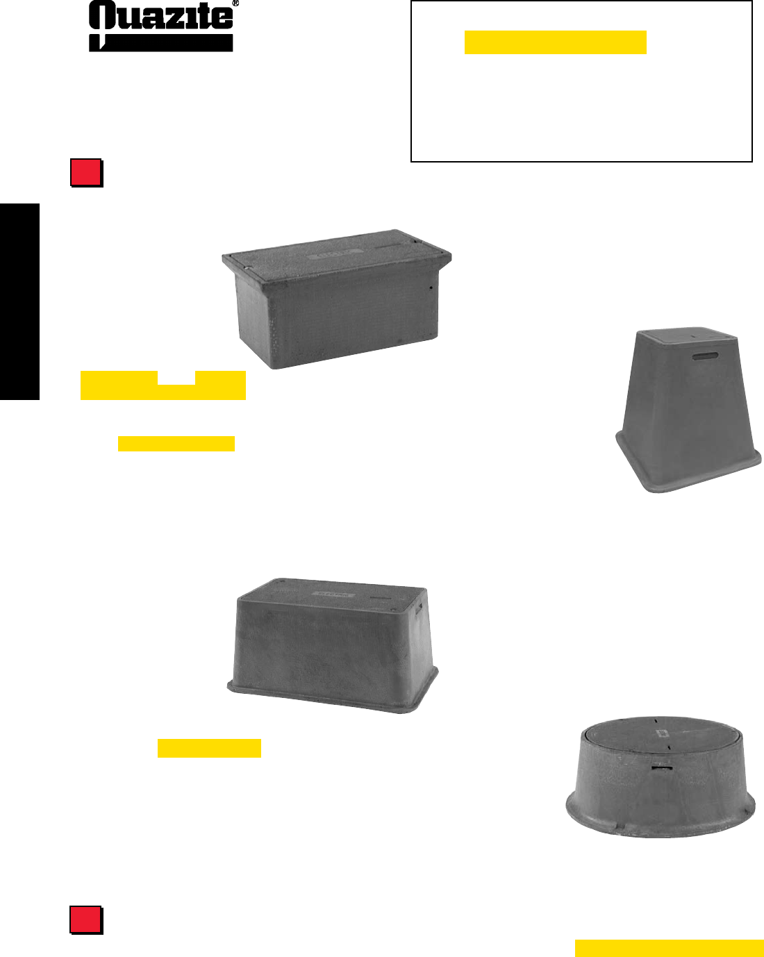
PD/LD Style
Enclosures with 1o (degree) flare
for maximum strength. Flared
design optimizes internal volume and
prevents frost heave.
• Availableinsizes:
17” x 30” x 18”, 17” x 30” x 26”, 24” x 36” x 18”, 24” x 36” x 26”,
24” x 36” x 48”, 30” x 48” x 24”, 30” x 48” x 48”
• Designload:15,000lbs.Testload:22,500lbs.(ANSITier15)
Box Numbering System
QUAZITE® products are referred to by an identifying part number. An example of the numbering system is shown below to help you understand
how to identify the product you need for your application. Contact your local QUAZITE® representative if you have any questions.
PC 1730 BA 12
Box Nominal Size Box Variation Box Depth
Style
(width x length)
example:
17” x 30”
12” deep
PC
PG
PR
PD
PT
LX
LR
BA-box w/open bottom
BB-box w/mouse holes
BC-divided box
BG-gasketed box w/open bot-
tom
DA-box w/solid bottom
DG- gasketed box w/solid bot-
tom
JA-footed box
EA-extension
RA-solid base extension
5
PG/LG Style
For use as a splice box, pull box,
equipment enclosure or for any
application requiring easy access to
an underground service. Stackable for
increased depth. Straight sides for easy
adjustment of box to grade.
• Availableinsizes:
11” x 18” 24” x 24” 30” x 60” 36” x 72” 48” x 96”
13” x 24” 24” x 36” 36” x 36” 48” x 48”
17” x 30” 30” x 48” 36” x 60” 48” x 72”
• LoadingscomplywithANSI/SCTE77.Theseboxes,withadesign
load of 22,500 lbs. and a test load of 33,750 lbs., meet and exceed
ANSI Tier 15 test provisions.
• 12”-48”depths
• LGstyleis32%lighterinweightascomparedtothePGbox.
Highlighted areas indicate UL Listing
14
ENCLOSURE SELECTION
Quazite® • Lenoir City, TN SEPTEMBER 2007
ENCLOSURE DRAWINGS
ENCLOSURE DRAWINGS
To Select the Enclosure You Need for Your Application:
1 .....Determine UL Requirements
2 .....Determine Load Ratings
3 .....Determine Handhole Opening Size
4 .....Select Cover Series & Style
5 .... Select Box Style
6 .... Determine Options & Hardware
See Hardware and Options Section, pages 51 - 56.
Hardware and Options
LX Style
Service box assemblies with flared
sides. Nestable for compact storage.
• Size:12”x12”x24”
Design load: 15,000 lbs.
Test load: 22,500 lbs. (ANSI Tier 15)
• TheLXstyleutilizesalighterweightmix(32%lighter).
PT/LT Style
(previously called
PE style)
Flared design prevents
frost heave. Covers are
interchangeable with many
precast concrete parts. Nestable for compact storage.
• Sizes:10”x15”,13”x24”,17”x30”
• Designload:15,000lbs.Testload:22,500lbs.
(ANSI Tier 15)
• 18”deep
• TheLTstyleutilizesalighterweightmix(32%lighter).
PR/LR Style
Round enclosures. Cover
cannot fall into the box.
• Availableinsizes:
27” dia. x 36” deep
39” dia. x 18”, 24”, 36” & 48” depths.
• Designload:15,000lbs. Testload:22,500lbs.(ANSITier15)
PC Style
Straight sides permit easy
movement of box should grade
level change. Gasketing also
available. All sizes are stackable.
• Sizes:6”x8”,8”x8”,8”x18”,
11” x 18” and 12” x 12”
Design load: 15,000 lbs. Test load: 22,500 lbs.
(ANSI Tier 15)
• Sizes:13”x24”and17”x30”
Design load: 5,000 lbs. Test load: 7,500 lbs.
(ANSI Tier 5)
• 6”-18”depths
Box Styles
5
6
Highlighted areas indicate UL Listing

15
ENCLOSURE DRAWINGS
ENCLOSURE DRAWINGS
SEPTEMBER 2007
®
Index of Enclosure Drawings
Box ANSI/SCTE Box Vertical CA Cover HA Cover HH Cover Box Cover Page
Size Tier Design/Test Design/Test Design/Test Design/Test Style Style No.
(for Box) Load # Load # Load # Load#
SMALL ENCLOSURES
6 x 8 15 15,000 / 22,500 8,000 / 12,000 — — PC PC 16
8 x 8 15 15,000 / 22,500 8,000 / 12,000 15,000 / 22,500 — PC PC 17
8 x 18 15 15,000 / 22,500 8,000 / 12,000 15,000 / 22,500 — PC PC 18
10 x 15 15 15,000 / 22,500 8,000 / 12,000 15,000 / 22,500 — LT PG 19
11 x 18 22 22,500 / 33,750 8,000 / 12,000 15,000 / 22,500 22,500 / 33,750 PG PG 20
11 x 18 15 15,000 / 22,500 8,000 / 12,000 15,000 / 22,500 — PC PC 21
12 x 12 15 15,000 / 22,500 8,000 / 12,000 15,000 / 22,500 — PC PC 22
12 x 12 15 15,000 / 22,500 8,000 / 12,000 15,000 / 22,500 — LX PC 23
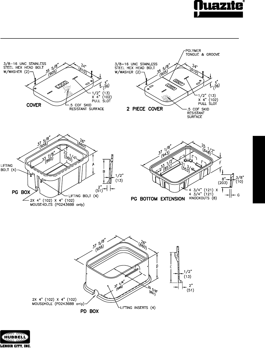
13 x 24 22 22,500 / 33,750 8,000 / 12,000 15,000 / 22,500 22,500 / 33,750 PG PG 24 - 25
13 x 24 5 5,000 / 7,500 5,000 / 7,500 15,000 / 22,500 22,500 / 33,750 PD PG 24 - 25
13 x 24 5 5,000 / 7,500 5,000 / 7,500 — — PC PC 26
13 x 24 15 15,000 / 22,500 8,000 / 12,000 15,000 / 22,500 — PT PG 27
17 x 30 22 22,500 / 33,750 8,000 / 12,000 15,000 / 22,500 22,500 / 33,750 PD PG 29 - 30
17 x 30 22 22,500 / 33,750 8,000 / 12,000 15,000 / 22,500 22,500 / 33,750 PG PG 29 - 30
17 x 30 5 5,000 / 7,500 5,000 / 7,500 — — PC PC 28
17 x 30 15 15,000 / 22,500 8,000 / 12,000 15,000 / 22,500 — PT PG 31
LARGE ENCLOSURES
24 x 24 15 15,000 / 22,500 8,000 / 12,000 15,000 / 22,500 — PG PG 32
24 x 36 22 22,500 / 33,750 8,000 / 12,000 15,000 / 22,500 22,500 / 33,750 PG PG 33 - 34
24 x 36 22 22,500 / 33,750 8,000 / 12,000 15,000 / 22,500 22,500 / 33,750 PD PG 33 - 34
30 x 48 22 22,500 / 33,750 8,000 / 12,000 15,000 / 22,500 22,500 / 33,750 PG PG 35 - 36
30 x 48 22 22,500 / 33,750 8,000 / 12,000 15,000 / 22,500 22,500 / 33,750 PD PG 35 - 36
30 x 60 22 22,500 / 33,750 5,000 / 7,500 15,000 / 22,500 22,500 / 33,750 PG LG / PG 37
36 x 36 22 22,500 / 33,750 8,000 / 12,000 15,000 / 22,500 22,500 / 33,750 PG PG 38
36 x 60 22 22,500 / 33,750 5,000 / 7,500 15,000 / 22,500 22,500 / 33,750 PG LG / PG 39
36 x 72 22 22,500 / 33,750 5,000 / 7,500 15,000 / 22,500 22,500 / 33,750 PG LG / PG 40
48 x 48 22 22,500 / 33,750 5,000 / 7,500 15,000 / 22,500 22,500 / 33,750 PG LG / PG 41
48 x 72 22 22,500 / 33,750 5,000 / 7,500 15,000 / 22,500 22,500 / 33,750 PG LG / PG 42
48 x 96 22 22,500 / 33,750 5,000 / 7,500 15,000 / 22,500 22,500 / 33,750 PG LG / PG 43
ROUND ENCLOSURES
27” Dia. 22 22,500 / 33,750 8,000 / 12,000 15,000 / 22,500 22,500/33,750 PR PR 45
39” Dia. 22 22,500 / 33,750 5,000 / 7,500 15,000 / 22,500 — LR PR 46
EXTENSIONS REPLACEMENT COVERS METER READING COVERS & LIDS
PG1324 Pg. 24 - 25 Pgs. 47 - 49 Pg. 50
PG1730 Pg. 29 - 30
PG2424 Pg. 32
PG2436 Pg. 33 - 34
PG3048 Pg. 35 - 36
PD3048 Pg. 35 - 36
PG3636 Pg. 38
PG4872 Pg. 42
PG4896 Pg. 43
Grade adjustable
extensions Pg. 44
16
ENCLOSURE DRAWINGS
ENCLOSURE DRAWINGS
SEPTEMBER 2007
®
ENCLOSURE DRAWINGS
ENCLOSURE DRAWINGS
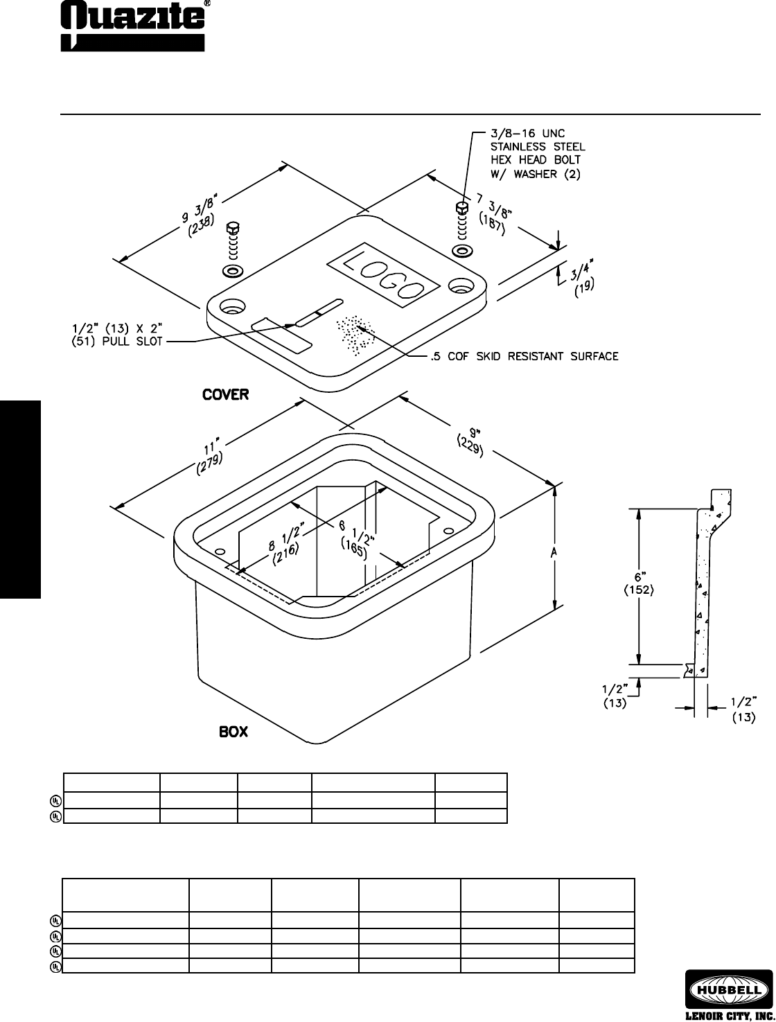
SPECIFICATIONS/DATA 6” x 8” PC Style (Stackable) Assembly
DESCRIPTION PART NO. WEIGHT # DESIGN/TEST LOAD # ANSI TIER
W/2 Bolts PC0608HA00 4 (1.8 kg) 15,000 / 22,500 15
Gasketed w/4 Bolts PC0608HG00 4 (1.8 kg) 15,000 / 22,500 15
Covers (Blank unless logo is specied)
• Gasketed covers and bolt grommets must be used with a gasketed box. Gaskets reduce the inow
of uids but do not make the enclosure water tight.
Dimensions & weights in parentheses are metric equivalent.
Boxes (Stackable with self-aligning, replaceable EZ-Nut)
DIMENSION DESIGN/TEST
DESCRIPTION PART NO. WEIGHT # A LOAD # ANSI TIER
Open Bottom PC0608BA06 14 (6.4 kg) 6 3/4” (171 mm) 15,000 / 22,500 15
Open Bottom w/Gasket PC0608BG06 14 (6.4 kg) 6 3/4” (171 mm) 15,000 / 22,500 15
Solid Bottom PC0608DA06 15 (6.8 kg) 7 1/4” (184 mm) 15,000 / 22,500 15
Solid Bottom w/Gasket PC0608DG06 15 (6.8 kg) 7 1/4” (184 mm) 15,000 / 22,500 15
ENCLOSURE DRAWINGS
ENCLOSURE DRAWINGS
17
ENCLOSURE DRAWINGS
ENCLOSURE DRAWINGS
SEPTEMBER 2007
®
Covers (Blank unless logo is specied)
Dimensions & weights in parentheses are metric equivalent.
For gasketed enclosure, see Options Section.
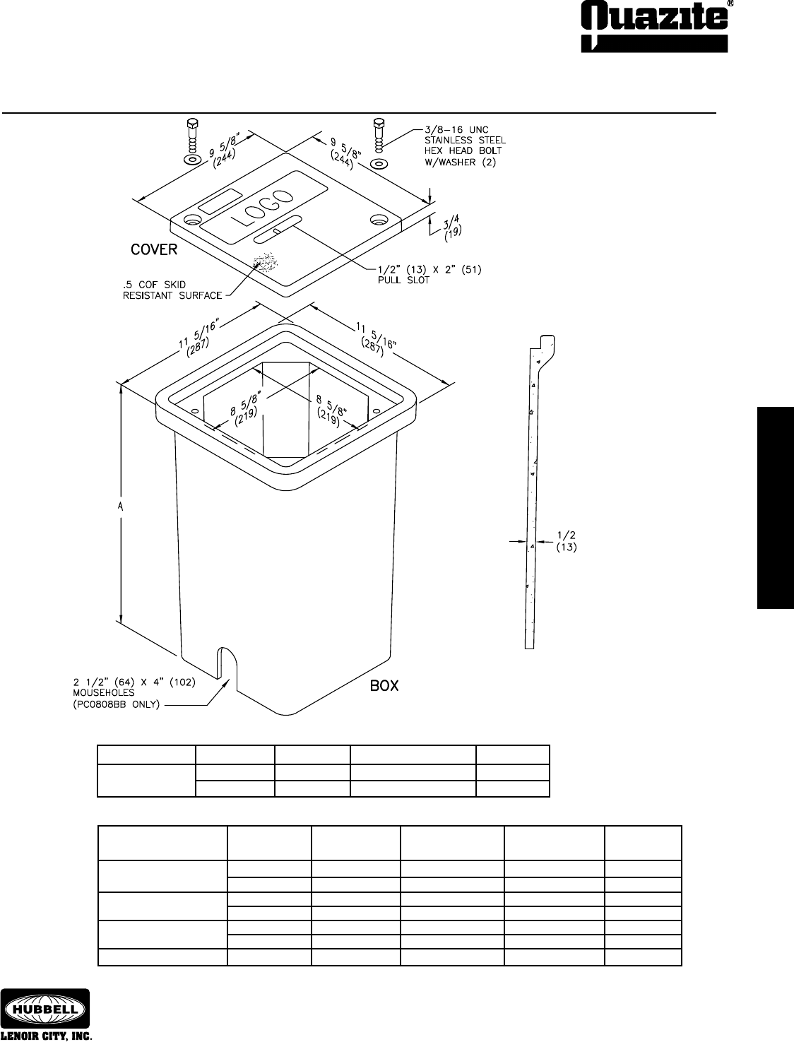
Boxes (With self-aligning, replaceable EZ-Nut)
DIMENSION DESIGN/TEST
DESCRIPTION PART NO. WEIGHT # A LOAD # ANSI TIER
Open Bottom PC0808BA12 25 (11 kg) 12” (304 mm) 15,000 / 22,500 22
PC0808BA18 36 (16 kg) 18” (457 mm) 15,000 / 22,500 22
Open Bottom PC0808BB12 23 (10 kg) 12” (304 mm) 15,000 / 22,500 22
w/2 Mouseholes PC0808BB18 34 (15 kg) 18” (457 mm) 15,000 / 22,500 22
Open Bottom w/Gasket PC0808BG12 25 (11 kg) 12” (304 mm) 15,000 / 22,500 22
PC0808BG18 34 (15 kg) 18” (457 mm) 15,000 / 22,500 22
Closed Bottom PC0808DA18 42 (19 kg) 18 1/2” (470 mm) 15,000 / 22,500 22
DESCRIPTION PART NO. WEIGHT # DESIGN/TEST LOAD # ANSI TIER
W/2 Bolts PC0808HA00 6 (3 kg) 15,000 / 22,500 15
PC0808HH00 6 (3 kg) 22,500 / 33,750 22
SPECIFICATIONS/DATA 8” x 8” PC Style (Stackable) Assembly
18
ENCLOSURE DRAWINGS
ENCLOSURE DRAWINGS
SEPTEMBER 2007
®
ENCLOSURE DRAWINGS
ENCLOSURE DRAWINGS
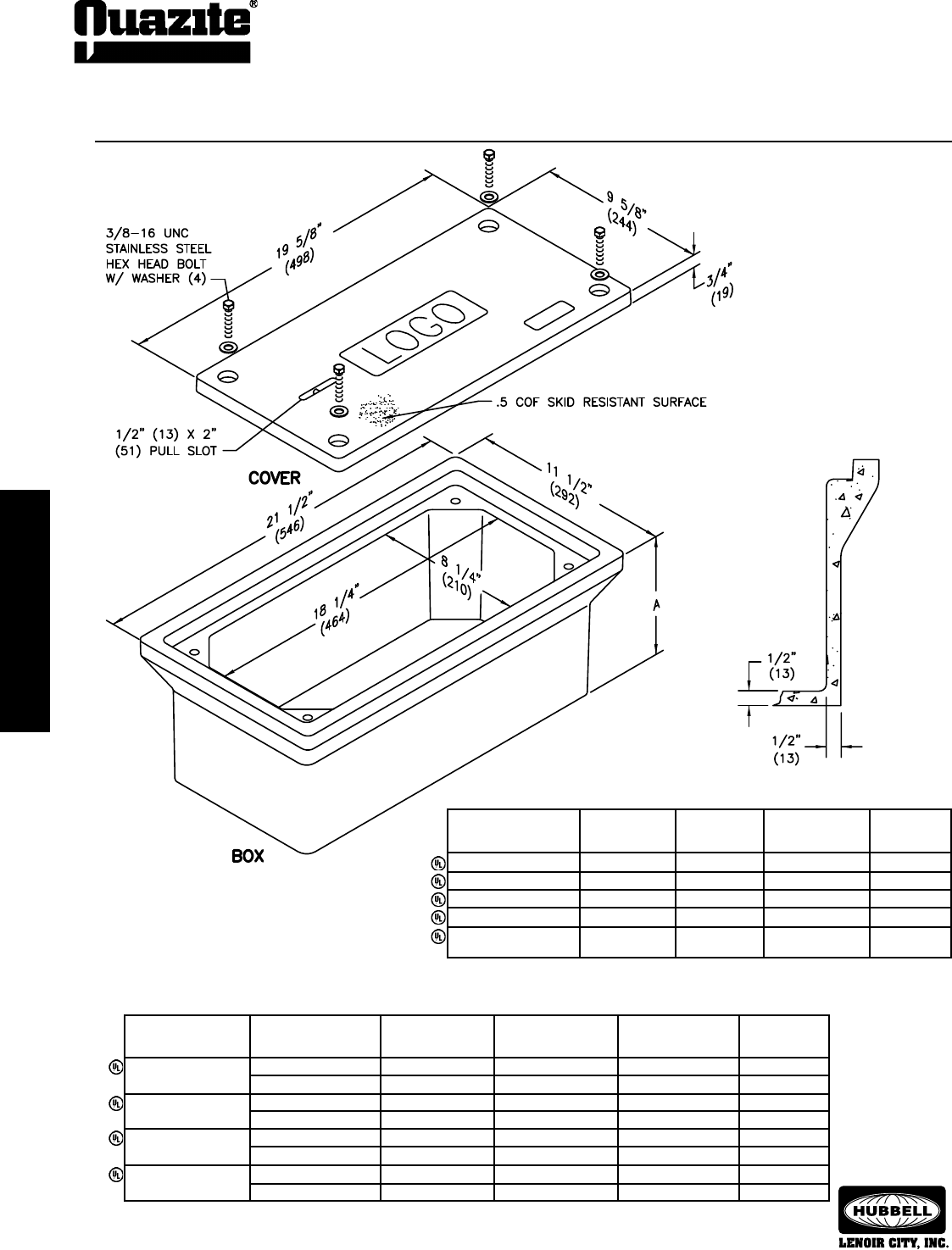
SPECIFICATIONS/DATA 8” x 18” PC Style (Stackable) Assembly
Covers (Blank unless logo is specied)
DESIGN/TEST
DESCRIPTION PART NO. WEIGHT # LOAD # ANSI TIER
W/4 Bolts PC0818CA00 11 (5.0 kg) 8,000 / 12,000 8
Gasketed w/4 Bolts PC0818CG00 11 (5.0 kg) 8,000 / 12,000 8
No Bolts PC0818WA00 11 (5.0 kg) 8,000 / 12,000 8
Heavy Duty w/4 Bolts PC0818HA00 11 (5.0 kg) 15,000 / 22,500 15
Gasketed Heavy Duty PC0818HG00 11 (5.0 kg) 15,000 / 22,500 15
w/4 Bolts
• Gasketed covers and bolt grommets must be used with a gasketed box. Gaskets reduce
the inow of uids but do not make the enclosure water tight.
Dimensions & weights in parentheses are metric equivalent.
Boxes (Stackable with self-aligning, replaceable EZ-Nut)
DIMENSION DESIGN/TEST
DESCRIPTION PART NO. WEIGHT # A LOAD # ANSI TIER
Open Bottom PC0818BA07 25 (11 kg) 7” (178 mm) 15,000 / 22,500 15
PC0818BA08 27 (12.2 kg) 8” (203 mm) 15,000 / 22,500 15
Open Bottom w/ PC0818BG07 25 (11 kg) 7” (178 mm) 15,000 / 22,500 15
Gasket PC0818BG08 27 (12.2 kg) 8” (203 mm) 15,000 / 22,500 15
Solid Bottom PC0818DA07 32 (14.5 kg) 7 1/2” (191 mm) 15,000 / 22,500 15
PC0818DA08 35 (15.9 kg) 8 1/2” (216 mm) 15,000 / 22,500 15
Solid Bottom w/ PC0818DG07 32 (14.5 kg) 7 1/2” (191 mm) 15,000 / 22,500 15
Gasket PC0818DG08 35 (15.9 kg) 8 1/2” (216 mm) 15,000 / 22,500 15
ENCLOSURE DRAWINGS
ENCLOSURE DRAWINGS
19
ENCLOSURE DRAWINGS
ENCLOSURE DRAWINGS
SEPTEMBER 2007
®
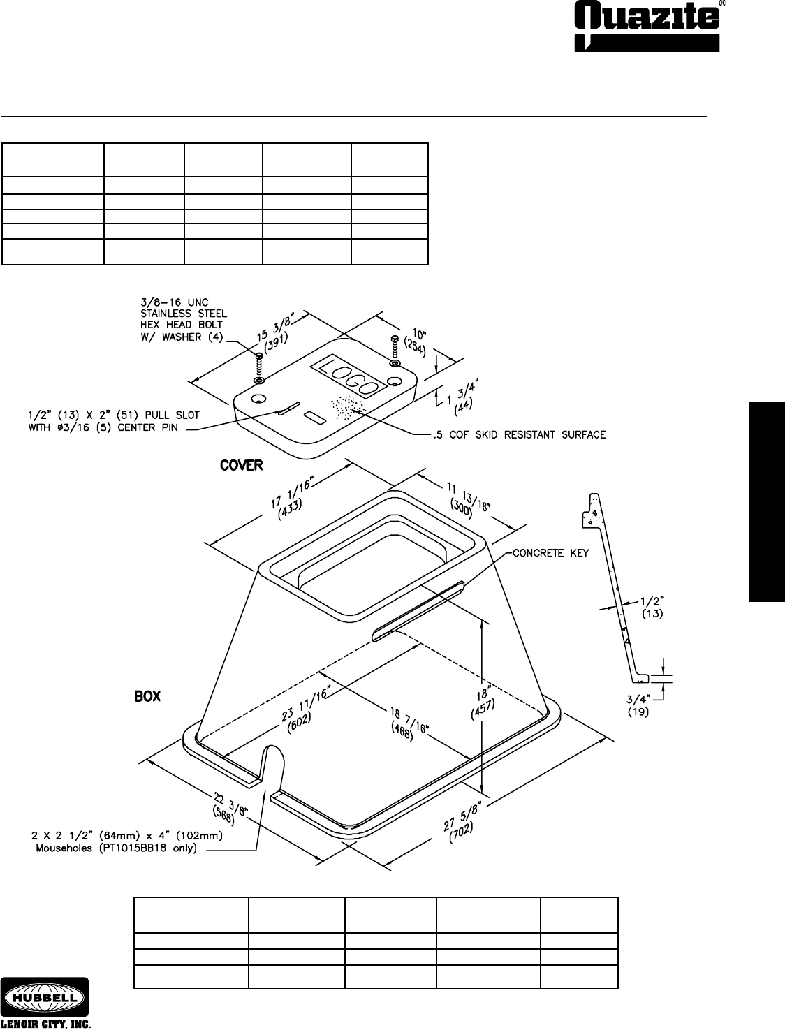
SPECIFICATIONS/DATA 10” x 15” LT Style (Nestable) Assembly
Dimensions & weights in parentheses are metric equivalent.
Boxes (Nestable with self-aligning, replaceable EZ-Nut)
DESIGN/TEST
DESCRIPTION PART NO. WEIGHT # LOAD # ANSI TIER
Open Bottom LT1015BA18 47 (21.0 kg) 15,000 / 22,500 15
Open Bottom w/Gasket LT1015BG18 47 (21.0 kg) 15,000 / 22,500 15
Open Bottom w/2 LT1015BB18 46 (21.0 kg) 15,000 / 22,500 15
Mouseholes
DESIGN/
DESCRIPTION PART NO. WEIGHT # TEST LOAD # ANSI TIER
W/2 Bolts PG1015CA00 20 (9.0 kg) 8,000 / 12,000 8
Gasketed w/2 Bolts PG1015CG00 20 (9.0 kg) 8,000 / 12,000 8
No Bolts PG1015WA00 20 (9.0 kg) 8,000 / 12,000 8
Heavy Duty w/2 Bolts PG1015HA00 20 (9.0 kg) 15,000 / 22,500 15
Gasketed Heavy Duty PG1015HG00 20 (9.0 kg) 15,000 / 22,500 15
w/2 Bolts
Covers (Blank unless logo is specied)
• Gasketed covers and bolt grommets must be used with a gasketed box. Gaskets reduce the
inow of uids but do not make the enclosure water tight.
20
ENCLOSURE DRAWINGS
ENCLOSURE DRAWINGS
SEPTEMBER 2007
®
ENCLOSURE DRAWINGS
ENCLOSURE DRAWINGS
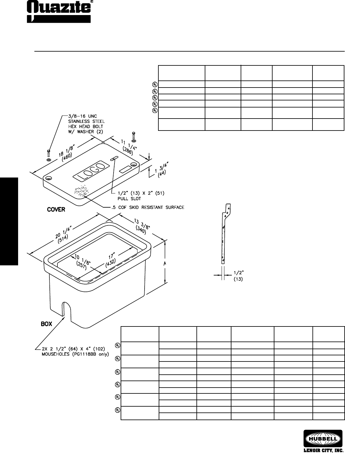
SPECIFICATIONS/DATA 11” x 18” PG Style (Stackable) Assembly
Covers (Blank unless logo is specied)
• Covers with meter lids available upon request.
• Gasketed covers and bolt grommets must be used with a gasketed box. Gaskets reduce the
inow of uids but do not make the enclosure water tight.
Dimensions & weights in parentheses are metric equivalent.
Boxes (Stackable with self-aligning, replaceable EZ-Nut)
DESIGN/TEST ANSI
DESCRIPTION PART NO. WEIGHT # LOAD # TIER
W/2 Bolts PG1118CA00 27 (12.2 kg) 8,000 / 12,000 8
Gasketed w/2 Bolts PG1118CG00 27 (12.2 kg) 8,000 / 12,000 8
No Bolts PG1118WA00 27 (12.2 kg) 8,000 / 12,000 8
Heavy Duty w/2 Bolts PG1118HA00 27 (12.2 kg) 15,000 / 22,500 15
Gasketed Heavy Duty PG1118HG00 27 (12.2 kg) 15,000 / 22,500 15
w/2 Bolts
Extra Heavy Duty PG1118HH00 27 (12.2 kg) 22,500 / 33,750 22
w/2 Bolts
DIMENSION DESIGN/TEST
DESCRIPTION PART NO. WEIGHT # A LOAD # ANSI TIER
Open Bottom PG1118BA12 40 (18 kg) 12” (305 mm) 22,500 / 33,750 22
PG1118BA18 53 (24 kg) 18” (457 mm) 22,500 / 33,750 22
Open Bottom w/ PG1118BG12 40 (18 kg) 12” (305 mm) 22,500 / 33,750 22
Gasket PG1118BG18 53 (24 kg) 18” (457 mm) 22,500 / 33,750 22
Open Bottom w/ PG1118BB12 40 (18 kg) 12” (305 mm) 22,500 / 33,750 22
2 Mouseholes PG1118BB18 53 (24 kg) 18” (457 mm) 22,500 / 33,750 22
Solid Bottom PG1118DA12 43 (19.5 kg) 12 1/2” (318 mm) 22,500 / 33,750 22
PG1118DA18 60 (27 kg) 18 1/2” (470 mm) 22,500 / 33,750 22
Solid Bottom w/ PG1118DG12 43 (19.5 kg) 12 1/2” (318 mm) 22,500 / 33,750 22
Gasket PG1118DG18 60 (27 kg) 18 1/2” (470 mm) 22,500 / 33,750 22
Footed Box PG1118JA12 41 (19 kg) 12 1/2” (318 mm) 22,500 / 33,750 22
PG1118JA18 55 (25 kg) 18 1/2” (470 mm) 22,500 / 33,750 22
ENCLOSURE DRAWINGS
ENCLOSURE DRAWINGS
21
ENCLOSURE DRAWINGS
ENCLOSURE DRAWINGS
SEPTEMBER 2007
®
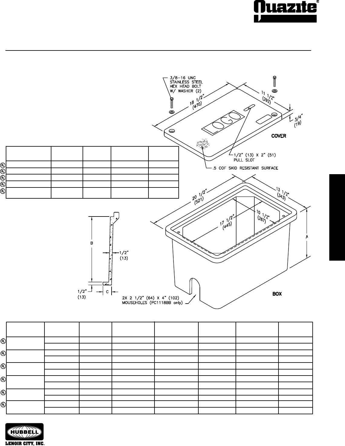
SPECIFICATIONS/DATA 11” x 18” PC Style (Stackable) Assembly
Covers (Blank unless logo is specied)
DESIGN/TEST
DESCRIPTION PART NO. WEIGHT # LOAD # ANSI TIER
W/2 Bolts PC1118CA00 13 (5.9 kg) 8,000 / 12,000 8
Gasketed w/4 Bolts PC1118CG00 13 (5.9 kg) 8,000 / 12,000 8
No Bolts PC1118WA00 13 (5.9 kg) 8,000 / 12,000 8
Heavy Duty w/2 Bolts PC1118HA00 13 (5.9 kg) 15,000 / 22,500 15
Gasketed Heavy Duty PC1118HG00 13 (5.9 kg) 15,000 / 22,500 15
w/4 Bolts
• Gasketed covers and bolt grommets must be used with a gasketed box. Gaskets
reduce the inow of uids but do not make the enclosure water tight.
Boxes (Stackable with self-aligning, replaceable EZ-Nut)
DIMENSION DIMENSION DIMENSION DESIGN/TEST
DESCRIPTION PART NO. WEIGHT # A B C LOAD # ANSI TIER
Open Bottom PC1118BA12 37 (16.8 kg) 12” (304.8 mm) 11 1/4” (286 mm) N/A 15,000 / 22,500 15
PC1118BA18 53 (24.0 kg) 18” (457 mm) 17 1/4” (438 mm) N/A 15,000 / 22,500 15
Open Bottom w/ PC1118BG12 37 (16.8 kg) 12” (304.8 mm) 11 1/4” (286 mm) N/A 15,000 / 22,500 15
Gasket PC1118BG18 53 (24.0 kg) 18” (457 mm) 17 1/4” (438 mm) N/A 15,000 / 22,500 15
Open Bottom w/ PC1118BB12 36 (16.3 kg) 12” (304.8 mm) 11 1/4” (286 mm) N/A 15,000 / 22,500 15
2 Mouseholes PC1118BB18 52 (23.6 kg) 18” (457 mm) 17 1/4” (438 mm) N/A 15,000 / 22,500 15
Solid Bottom PC1118DA12 45 (20.4 kg) 12 1/2” (317.5 mm) 11 1/4” (286 mm) N/A 15,000 / 22,500 15
PC1118DA18 60 (27.2 kg) 18 1/2” (470 mm) 17 1/4” (438 mm) N/A 15,000 / 22,500 15
Solid Bottom w/ PC1118DG12 45 (20.4 kg) 12 1/2” (317.5 mm) 11 1/4” (286 mm) N/A 15,000 / 22,500 15
Gasket PC1118DG18 60 (27.2 kg) 18 1/2” (470 mm) 17 1/4” (438 mm) N/A 15,000 / 22,500 15
Footed Box PC1118JA12 37 (16.8 kg) 12 1/2” (317.5 mm) 11 1/4” (286 mm) 1 1/2” (38 mm) 15,000 / 22,500 15
PC1118JA18 56 (25.4 kg) 18 1/2” (470 mm) 17 1/4” (438 mm) 1 1/2” (38 mm) 15,000 / 22,500 15
Dimensions & weights in parentheses are metric equivalent.
22
ENCLOSURE DRAWINGS
ENCLOSURE DRAWINGS
SEPTEMBER 2007
®
ENCLOSURE DRAWINGS
ENCLOSURE DRAWINGS
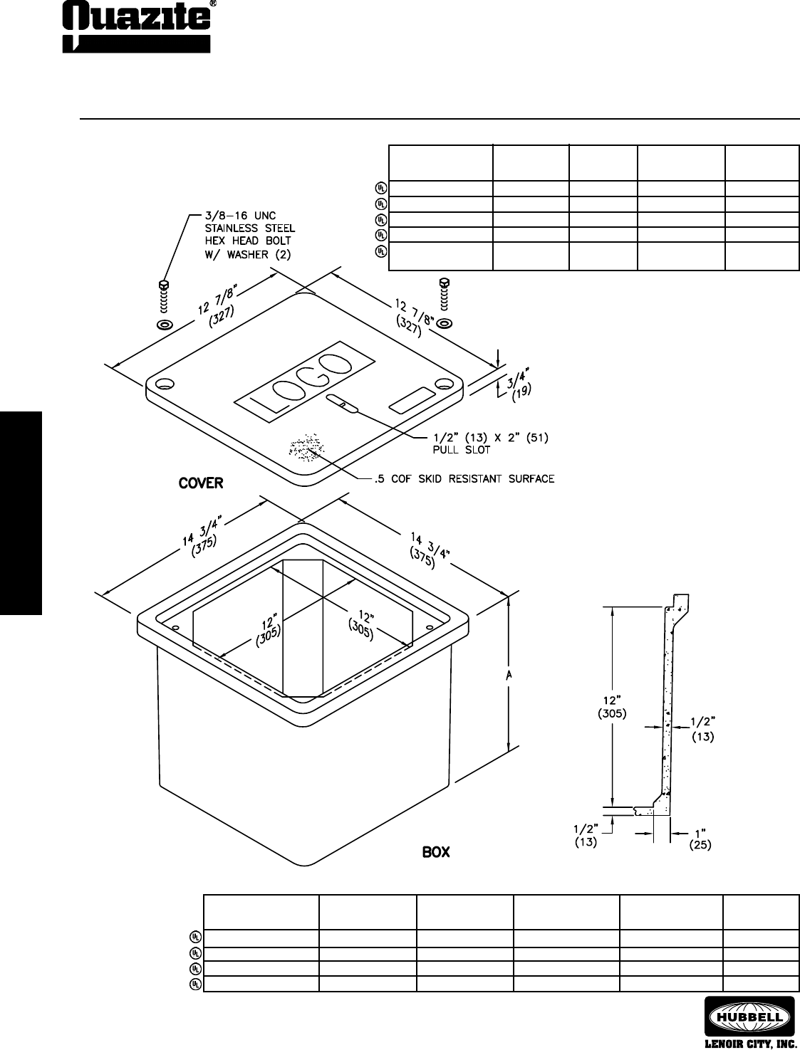
SPECIFICATIONS/DATA 12” x 12” PC Style (Stackable) Assembly
• Gasketed covers and bolt grommets must be used with a gasketed
box. Gaskets reduce the inow of uids but do not make the
enclosure water tight.
Covers (Blank unless logo is specied)
Dimensions & weights in parentheses are metric equivalent.
Boxes (Stackable with self-aligning, replaceable EZ-Nut)
DIMENSION DESIGN/TEST
DESCRIPTION PART NO. WEIGHT # A LOAD # ANSI TIER
Open Bottom PC1212BA12 36 (16 kg) 12 3/4” (324 mm) 15,000 / 22,500 15
Open Bottom w/Gasket PC1212BG12 36 (16 kg) 12 3/4” (324 mm) 15,000 / 22,500 15
Solid Bottom PC1212DA12 41 (19 kg) 13 1/4” (337 mm) 15,000 / 22,500 15
Solid Bottom w/Gasket PC1212DG12 41 (19 kg) 13 1/4” (337 mm) 15,000 / 22,500 15
DESIGN/TEST
DESCRIPTION PART NO. WEIGHT # LOAD # ANSI TIER
W/2 Bolts PC1212CA00 12 (5.4 kg) 8,000 / 12,000 8
Gasketed w/4 Bolts PC1212CG00 12 (5.4 kg) 8,000 / 12,000 8
No Bolts PC1212WA00 12 (5.4 kg) 8,000 / 12,000 8
Heavy Duty w/2 Bolts PC1212HA00 12 (5.4 kg) 15,000 / 22,500 15
Gasketed Heavy PC1212HG00 12 (5.4 kg) 15,000 / 22,500 15
Duty w/4 Bolts
ENCLOSURE DRAWINGS
ENCLOSURE DRAWINGS
23
ENCLOSURE DRAWINGS
ENCLOSURE DRAWINGS
SEPTEMBER 2007
®
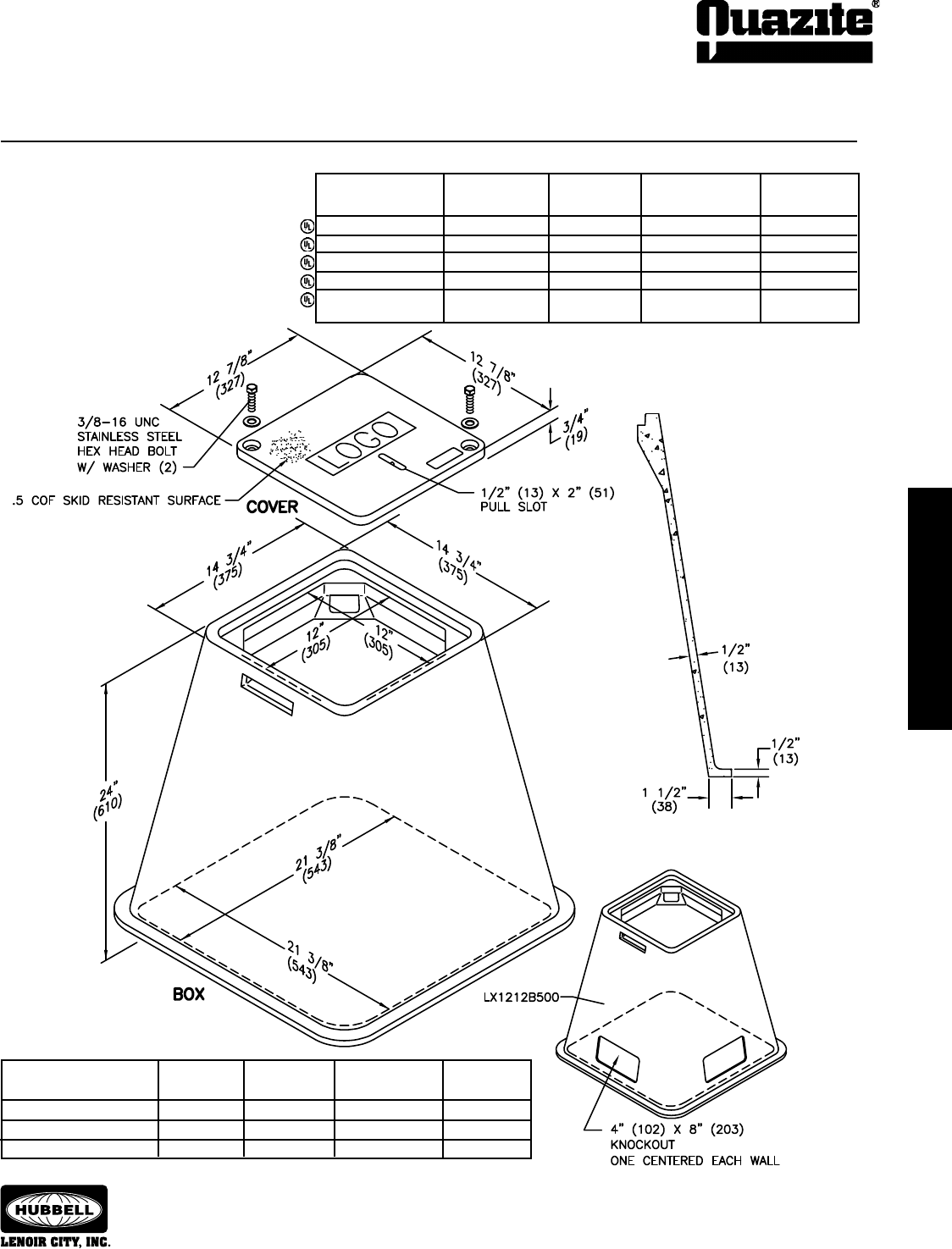
SPECIFICATIONS/DATA 12” x 12” LX Style (Nestable) Assembly
• Gasketed covers and bolt grommets must be used
with a gasketed box. Gaskets reduce the inow of
uids but do not make the enclosure water tight.
Covers (Blank unless logo is specied)
Boxes (Nestable)
DESIGN/TEST
DESCRIPTION PART NO. WEIGHT # LOAD # ANSI TIER
Open Bottom LX1212BA24 65 (29.5 kg) 15,000 / 22,500 15
Open Bottom w/Gasket LX1212BG24 65 (29.5 kg) 15,000 / 22,500 15
Open Bottom w/Knockouts LX1212B500 65 (29.5 kg) 15,000 / 22,500 15
Dimensions & weights in parentheses are metric equivalent.
DESIGN/TEST
DESCRIPTION PART NO. WEIGHT # LOAD # ANSI TIER
W/2 Bolts PC1212CA00 12 (5.4 kg) 8,000 / 12,000 8
Gasketed w/4 Bolts PC1212CG00 12 (5.4 kg) 8,000 / 12,000 8
No Bolts PC1212WA00 12 (5.4 kg) 8,000 / 12,000 8
Heavy Duty w/2 Bolts PC1212HA00 12 (5.4 kg) 15,000 / 22,500 15
Gasketed Heavy PC1212HG00 12 (5.4 kg) 15,000 / 22,500 15
Duty w/4 Bolts
24
ENCLOSURE DRAWINGS
ENCLOSURE DRAWINGS
SEPTEMBER 2007
®
ENCLOSURE DRAWINGS
ENCLOSURE DRAWINGS
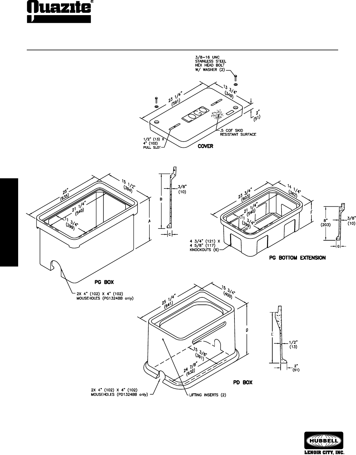
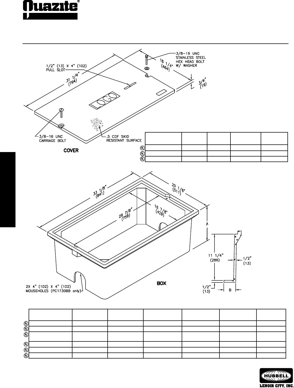
SPECIFICATIONS/DATA 13” x 24” PG Style (Stackable) Assembly
and 13” x 24” PD Style Assembly
ENCLOSURE DRAWINGS
ENCLOSURE DRAWINGS
25
ENCLOSURE DRAWINGS
ENCLOSURE DRAWINGS
SEPTEMBER 2007
®
SPECIFICATIONS/DATA 13” x 24” PG Style (Stackable) Assembly
and 13” x 24” PD Style Assembly
Extensions (For use under box only, one per box.)
DIMENSION DIMENSION DESIGN/TEST
DESCRIPTION PART NO. WEIGHT # F G LOAD # ANSI TIER
Open Bottom PG1324EA08 25 (11.3 kg) 8 3/4” (222 mm) 1” (25 mm) 22,500 / 33,750 22
Solid Bottom PG1324RA08 35 (15.9 kg) 9 1/4” (235 mm) N/A 22,500 / 33,750 22
Dimensions & weights in parentheses are metric equivalent.
PG Boxes (Stackable with self-aligning, replaceable EZ Nut)
DIMENSION DIMENSION DIMENSION DESIGN/TEST
DESCRIPTION PART NO. WEIGHT # A B C LOAD # ANSI TIER
Open Bottom PG1324BA12 53 (24 kg) 12” (305 mm) 10” (254 mm) 1 1/4” (32 mm) 22,500 / 33,750 22
PG1324BA18 72 (33 kg) 18” (457 mm) 16” (406 mm) 1 1/4” (32 mm) 22,500 / 33,750 22
Open Bottom PG1324BB12 49 (22.2 kg) 12” (305 mm) 10” (254 mm) 1 1/4” (32 mm) 22,500 / 33,750 22
w/2 Mouseholes PG1324BB18 68 (31 kg) 18” (457 mm) 16” (406 mm) 1 1/4” (32 mm) 22,500 / 33,750 22
Solid Bottom PG1324DA12 63 (28.6 kg) 12 1/2” (318 mm) 10” (254 mm) N/A 22,500 / 33,750 22
PG1324DA18 85 (39 kg) 18 1/2” (470 mm) 16” (406 mm) N/A 22,500 / 33,750 22
• Covers with meter lids available upon request.
• Gasketed covers and bolt grommets must be
used with a gasketed box. Gaskets reduce the
inow of uids but do not make the enclosure
water tight.
Covers (Blank unless logo is specied)
DESIGN/TEST
DESCRIPTION PART NO. WEIGHT # LOAD # ANSI TIER
W/2 Bolts PG1324CA00 33 (15 kg) 8,000 / 12,000 8
Gasketed w/2 Bolts PG1324CG00 33 (15 kg) 8,000 / 12,000 8
No Bolts PG1324WA00 33 (15 kg) 8,000 / 12,000 8
Heavy Duty w/2 Bolts PG1324HA00 51 (23 kg) 15,000 / 22,500 15
Gasketed Heavy Duty PG1324HG00 51 (23 kg) 15,000 / 22,500 15
w/2 Bolts
Extra Heavy Duty PG1324HH00 54 (24 kg) 22,500 / 33,750 22
w/2 Bolts
PD Boxes
DIMENSION DIMENSION DESIGN/TEST
DESCRIPTION PART NO. WEIGHT # D E LOAD # ANSI TIER
Open Bottom PD1324BA18 104 (47 kg) 18” (457 mm) 16” (406 mm) 22,500 / 33,750 22
PD1324BA26 133 (60 kg) 26” (660 mm) 24” (610 mm) 22,500 / 33,750 22
Open Bottom PD1324BB18 102 (46 kg) 18” (457 mm) 16” (406 mm) 22,500 / 33,750 22
w/2 Mouseholes PD1324BB26 131 (59 kg) 26” (660 mm) 24” (610 mm) 22,500 / 33,750 22
Open Bottom PD1324BG18 104 (47 kg) 18” (457 mm) 16” (406 mm) 22,500 / 33,750 22
w/Gasket PD1324BG26 133 (60 kg) 26” (660 mm) 24” (610 mm) 22,500 / 33,750 22
26
ENCLOSURE DRAWINGS
ENCLOSURE DRAWINGS
SEPTEMBER 2007
®
ENCLOSURE DRAWINGS
ENCLOSURE DRAWINGS
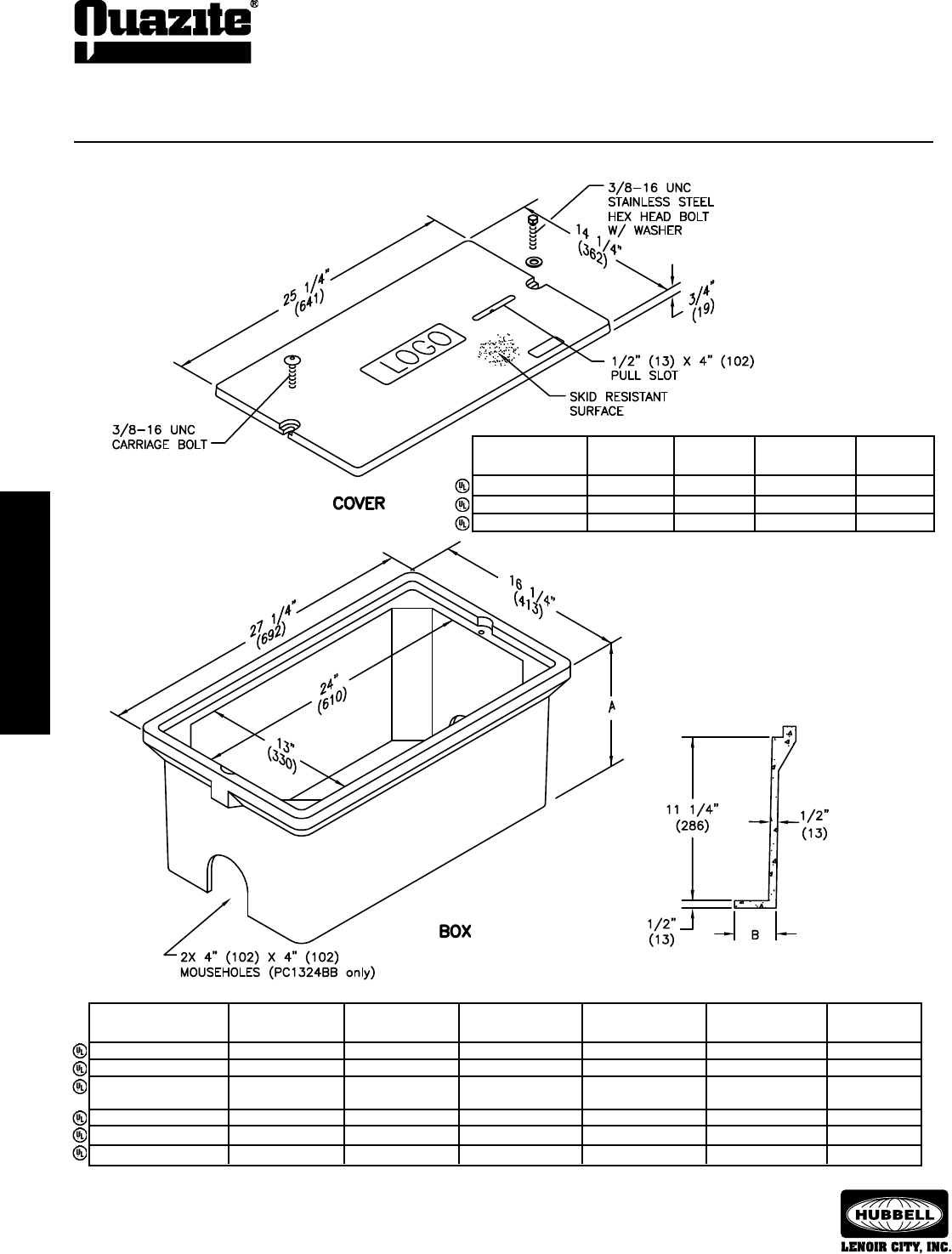
SPECIFICATIONS/DATA 13” x 24” PC Style (Stackable) Assembly
• Gasketed covers and bolt grommets must be used with a gasketed box.
Gaskets reduce the inow of uids but do not make the enclosure water tight.
Covers (Blank unless logo is specied)
DESIGN/
DESCRIPTION PART NO. WEIGHT # TEST LOAD # ANSI TIER
W/2 Bolts PC1324CA00 23 (10.4 kg) 5,000 / 7,500 5
Gasketed w/2 Bolts PC1324CG00 23 (10.4 kg) 5,000 / 7,500 5
No Bolts PC1324WA00 23 (10.4 kg) 5,000 / 7,500 5
Dimensions & weights in parentheses are metric equivalent.
Boxes (Stackable with self-aligning, replaceable EZ-Nut)
DIMENSION DIMENSION DESIGN/TEST
DESCRIPTION PART NO. WEIGHT # A B LOAD # ANSI TIER
Open Bottom PC1324BA12 50 (22.7 kg) 12” (305 mm) N/A 5,000 / 7,500 5
Open Bottom w/Gasket PC1324BG12 50 (22.7 kg) 12” (305 mm) N/A 5,000 / 7,500 5
Open Bottom w/2 PC1324BB12 50 (22.7 kg) 12” (305 mm) N/A 5,000 / 7,500 5
Mouseholes
Solid Bottom PC1324DA12 60 (27.2 kg) 12 1/2” (318 mm) N/A 5,000 / 7,500 5
Solid Bottom w/Gasket PC1324DG12 60 (27.2 kg) 12 1/2” (318 mm) N/A 5,000 / 7,500 5
Footed Box PC1324JA12 57 (25.9 kg) 12 1/2” (318 mm) 2 7/8” (73 mm) 5,000 / 7,500 5
ENCLOSURE DRAWINGS
ENCLOSURE DRAWINGS
27
ENCLOSURE DRAWINGS
ENCLOSURE DRAWINGS
SEPTEMBER 2007
®
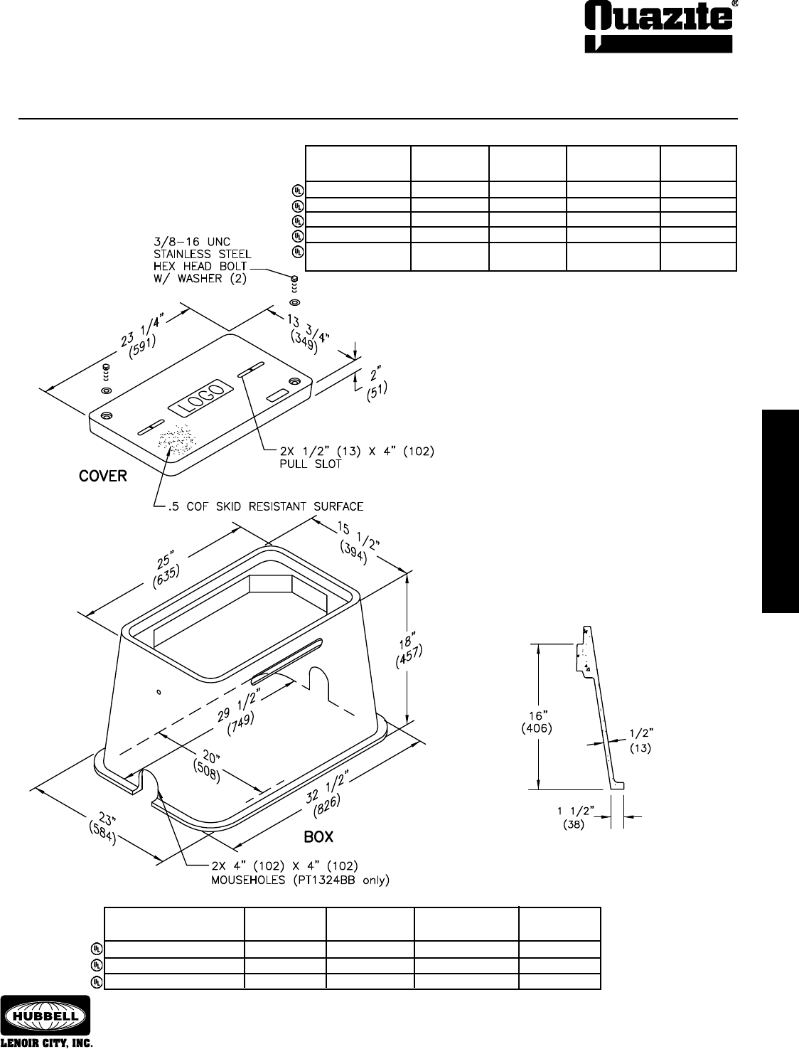
SPECIFICATIONS/DATA 13” x 24” PT Style (Nestable) Assembly
Covers (Blank unless logo is specied)
DESIGN/TEST
DESCRIPTION PART NO. WEIGHT # LOAD # ANSI TIER
W/2 Bolts PT1324CA00 32 (14.5 kg) 8,000 / 12,000 8
Gasketed w/2 Bolts PT1324CG00 32 (14.5 kg) 8,000 / 12,000 8
No Bolts PT1324WA00 32 (14.5 kg) 8,000 / 12,000 8
Heavy Duty w/2 Bolts PT1324HA00 49 (22.2 kg) 15,000 / 22,500 15
Gasketed Heavy PT1324HG00 49 (22.2 kg) 15,000 / 22,500 15
Duty w/2 Bolts
• Covers with meter lids available upon request.
• PT covers are PG covers with shorter bolts.
• Gasketed covers and bolt grommets must be used with a gasketed box. Gaskets
reduce the inow of uids but do not make the enclosure water tight.
Boxes (Nestable)
DESIGN/TEST
DESCRIPTION PART NO. WEIGHT # LOAD # ANSI TIER
Open Bottom PT1324BA18 97 (44.0 kg) 15,000 / 22,500 15
Open Bottom w/Gasket PT1324BG18 97 (44.0 kg) 15,000 / 22,500 15
Open Bottom w/2 Mouseholes PT1324BB18 96 (43.5 kg) 15,000 / 22,500 15
Dimensions & weights in parentheses are metric equivalent.
28
ENCLOSURE DRAWINGS
ENCLOSURE DRAWINGS
SEPTEMBER 2007
®
ENCLOSURE DRAWINGS
ENCLOSURE DRAWINGS
SPECIFICATIONS/DATA 17” x 30” PC Style (Stackable) Assembly
Dimensions & weights in parentheses are metric equivalent.
Boxes (Stackable with self-aligning, replaceable EZ-Nut)
DIMENSION DIMENSION DESIGN/TEST
DESCRIPTION PART NO. WEIGHT # A B LOAD # ANSI TIER
Open Bottom PC1730BA12 58 (26.3 kg) 12” (305 mm) N/A 5,000 / 7,500 5
Open Bottom w/Gasket PC1730BG12 58 (26.3 kg) 12” (305 mm) N/A 5,000 / 7,500 5
Open Bottom w/2 PC1730BB12 58 (26.3 kg) 12” (305 mm) N/A 5,000 / 7,500 5
Mouseholes
Solid Bottom PC1730DA12 83 (37.6 kg) 12 1/2” (318 mm) N/A 5,000 / 7,500 5
Solid Bottom w/Gasket PC1730DG12 83 (37.6 kg) 12 1/2” (318 mm) N/A 5,000 / 7,500 5
Footed Box PC1730JA12 67 (30.4 kg) 12 1/2” (318 mm) 2 7/8” (73 mm) 5,000 / 7,500 5
DESIGN/TEST
DESCRIPTION PART NO. WEIGHT # LOAD # ANSI TIER
W/2 Bolts PC1730CA00 33 (15.0 kg) 5,000 / 7,500 5
Gasketed w/2 Bolts PC1730CG00 33 (15.0 kg) 5,000 / 7,500 5
No Bolts PC1730WA00 33 (15.0 kg) 5,000 / 7,500 5
Covers (Blank unless logo is specied)
• Gasketed covers and bolt grommets must be used with a gasketed
box. Gaskets reduce the inow of uids but do not make the enclosure
water tight.
ENCLOSURE DRAWINGS
ENCLOSURE DRAWINGS
29
ENCLOSURE DRAWINGS
ENCLOSURE DRAWINGS
SEPTEMBER 2007
®
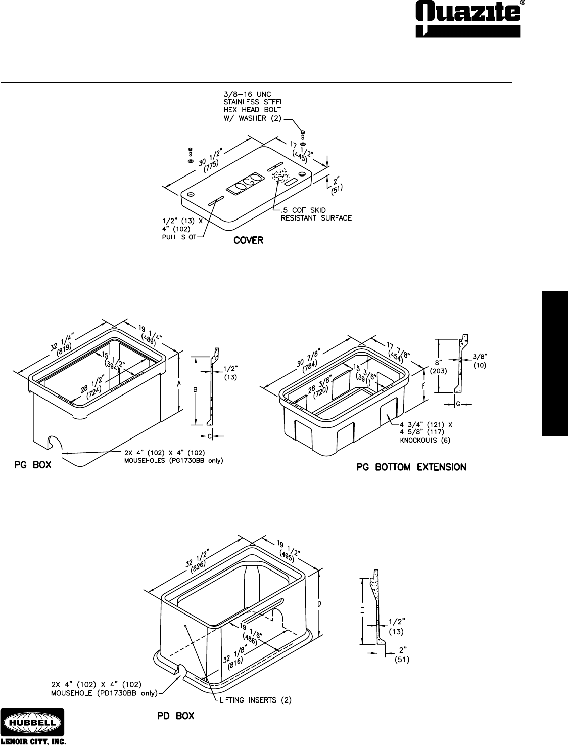
SPECIFICATIONS/DATA
17” x 30” PG Style (Stackable) Assembly
and 17” x 30” PD Style Assembly

30
ENCLOSURE DRAWINGS
ENCLOSURE DRAWINGS
SEPTEMBER 2007
®
ENCLOSURE DRAWINGS
ENCLOSURE DRAWINGS
SPECIFICATIONS/DATA
17” x 30” PG Style (Stackable) Assembly
and 17” x 30 PD Style Assembly
Extensions (For use under 12” and 18” boxes only, one per box.)
DIMENSION DIMENSION DESIGN/TEST
DESCRIPTION PART NO. WEIGHT # F G LOAD # ANSI TIER
Open Bottom PG1730EA08 36 (16.3 kg) 8 3/4” (222 mm) 1” (25 mm) 22,500 / 33,750 22
Solid Bottom PG1730RA08 55 (24.9 kg) 9 1/4” (235 mm) N/A 22,500 / 33,750 22
Dimensions & weights in parentheses are metric equivalent.
PG Boxes (Stackable with self-aligning, replaceable EZ Nut) **22” - 30” Deep boxes must be used as bottom of any stack.)
DIMENSION DIMENSION DIMENSION DESIGN/TEST
DESCRIPTION PART NO. WEIGHT # A B C LOAD # ANSI TIER
PG1730BA12 67 (30.4 kg) 12” (305 mm) 10” (254 mm) 1 1/4” (32 mm) 22,500 / 33,750 22
PG1730BA18 94 (42.6 kg) 18” (457 mm) 16” (406 mm) 1 1/4” (32 mm) 22,500 / 33,750 22
Open Bottom PG1730BA22 106 (48.1 kg) 22” (559 mm) 20” (508 mm) 1 1/4” (32 mm) 22,500 / 33,750 22
PG1730BA24 122 (55.3 kg) 24” (610 mm) 22” (559 mm) 1 1/4” (32 mm) 22,500 / 33,750 22
PG1730BA28 126 (57.2 kg) 28” (711 mm) 26” (660 mm) 1/2” (13 mm) 22,500 / 33,750 22
PG1730BA30 144 (65.3 kg) 30” (762 mm) 28” (711 mm) 1/2” (13 mm) 22,500 / 33,750 22
PG1730BB12 65 (29.5 kg) 12” (305 mm) 10” (254 mm) 1 1/4” (32 mm) 22,500 / 33,750 22
PG1730BB18 92 (41.7 kg) 18” (457 mm) 16” (406 mm) 1 1/4” (32 mm) 22,500 / 33,750 22
Open Bottom PG1730BB22 104 (47.2 kg) 22” (559 mm) 20” (508 mm) 1 1/4” (32 mm) 22,500 / 33,750 22
w/2 Mouseholes PG1730BB24 120 (54.4 kg) 24” (610 mm) 22” (559 mm) 1 1/4” (32 mm) 22,500 / 33,750 22
PG1730BB28 124 (56.2 kg) 28” (711 mm) 26” (660 mm) 1/2” (13 mm) 22,500 / 33,750 22
PG1730BB30 142 (64.4 kg) 30” (762 mm) 28” (711 mm) 1/2” (13 mm) 22,500 / 33,750 22
PG1730DA12 85 (38.5 kg) 12 1/2” (318 mm) 10” (254 mm) N/A 22,500 / 33,750 22
PG1730DA18 112 (50.8 kg) 18 1/2” (470 mm) 16” (406 mm) N/A 22,500 / 33,750 22
Solid Bottom PG1730DA22 124 (56.2 kg) 22 1/2” (572 mm) 20” (508 mm) N/A 22,500 / 33,750 22
PG1730DA24 137 (62.0 kg) 24 1/2” (622 mm) 22” (559 mm) N/A 22,500 / 33,750 22
PG1730DA28 143 (64.9 kg) 28 1/2” (724 mm) 26” (660 mm) N/A 22,500 / 33,750 22
PG1730DA30 150 (68.0 kg) 30 1/2” (775 mm) 28” (711 mm) N/A 22,500 / 33,750 22
PD Boxes
DIMENSION DIMENSION DESIGN/TEST
DESCRIPTION PART NO. WEIGHT # D E LOAD # ANSI TIER
Open Bottom PD1730BA18 129 (59 kg) 18” (457 mm) 16” (406 mm) 22,500 / 33,750 22
PD1730BA26 166 (75 kg) 26” (660 mm) 24” (610 mm) 22,500 / 33,750 22
Open Bottom PD1730BB18 127 (58 kg) 18” (457 mm) 16” (406 mm) 22,500 / 33,750 22
w/2 Mouseholes PD1730BB26 164 (74 kg) 26” (660 mm) 24” (610 mm) 22,500 / 33,750 22
Open Bottom PD1730BG18 129 (59 kg) 18” (457 mm) 16” (406 mm) 22,500 / 33,750 22
w/Gasket PD1730BG26 166 (75 kg) 26” (660 mm) 24” (610 mm) 22,500 / 33,750 22
• Covers with meter lids available upon request.
• Gasketed covers and bolt grommets must be
used with a gasketed box. Gaskets reduce the
inow of uids but do not make the enclosure
water tight.
Covers (Blank unless logo is specied)
DESIGN/TEST
DESCRIPTION PART NO. WEIGHT # LOAD # ANSI TIER
W/2 Bolts PG1730CA00 52 (23.6 kg) 8,000 / 12,000 8
Gasketed w/2 Bolts PG1730CG00 52 (23.6 kg) 8,000 / 12,000 8
No Bolts PG1730WA00 52 (23.6 kg) 8,000 / 12,000 8
Heavy Duty w/2 Bolts PG1730HA00 83 (37.6 kg) 15,000 / 22,500 15
Gasketed Heavy Duty PG1730HG00 83 (37.6 kg) 15,000 / 22,500 15
w/2 Bolts
Extra Heavy Duty PG1730HH00 83 (37.6 kg) 22,500 / 33,750 22
w/2 Bolts
Covers with meter lids available upon request.
ENCLOSURE DRAWINGS
ENCLOSURE DRAWINGS
31
ENCLOSURE DRAWINGS
ENCLOSURE DRAWINGS
SEPTEMBER 2007
®
SPECIFICATIONS/DATA 17” x 30” PT Style (Nestable) Assembly
• Covers with meter lids available upon request.
• PT covers are PG covers with shorter bolts
• Gasketed covers and bolt grommets must be used
with a gasketed box. Gaskets reduce the inow of
uids but do not make the enclosure water tight.
Covers (Blank unless logo is specied)
DESIGN/TEST
DESCRIPTION PART NO. WEIGHT # LOAD # ANSI TIER
W/2 Bolts PT1730CA00 52 (23.6 kg) 8,000 / 12,000 8
Gasketed w/2 Bolts PT1730CG00 52 (23.6 kg) 8,000 / 12,000 8
No Bolts PT1730WA00 52 (23.6 kg) 8,000 / 12,000 8
Heavy Duty w/2 Bolts PT1730HA00 83 (37.6 kg) 15,000 / 22,500 15
Gasketed Heavy Duty PT1730HG00 83 (37.6 kg) 15,000 / 22,500 15
w/2 Bolts
Boxes (Nestable)
DESIGN/TEST
DESCRIPTION PART NO. WEIGHT # LOAD # ANSI TIER
Open Bottom PT1730BA18 126 (57.2 kg) 15,000 / 22,500 15
Open Bottom w/Gasket PT1730BG18 126 (57.2 kg) 15,000 / 22,500 15
Open Bottom w/2 Mouseholes PT1730BB18 125 (56.7 kg) 15,000 / 22,500 15
Dimensions & weights in parentheses are metric equivalent.
32
ENCLOSURE DRAWINGS
ENCLOSURE DRAWINGS
SEPTEMBER 2007
®
ENCLOSURE DRAWINGS
ENCLOSURE DRAWINGS
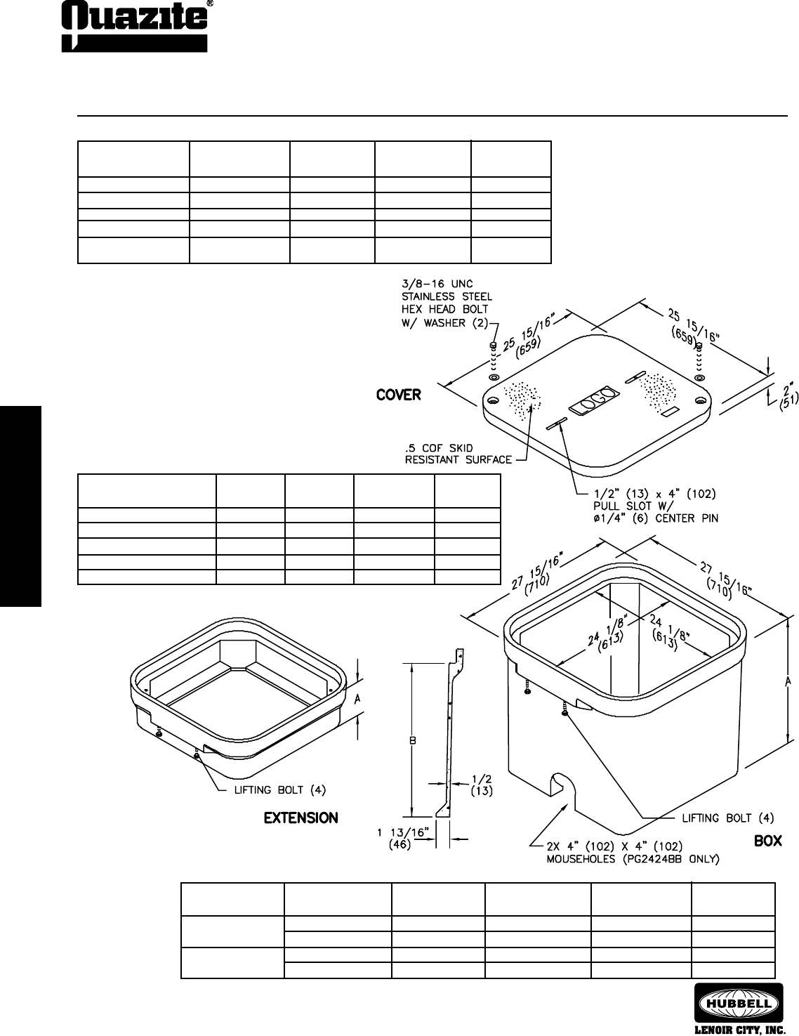
SPECIFICATIONS/DATA 24” x 24” PG Style (Stackable) Assembly
• Covers with meter lids available upon request.
• Gasketed covers and bolt grommets must be used with a
gasketed box. Gaskets reduce the inow of uids but do not
make the enclosure water tight.
Covers (Blank unless logo is specied)
DESIGN/TEST
DESCRIPTION PART NO. WEIGHT # LOAD # ANSI TIER
W/2 Bolts PG2424CA00 70 (32.0 kg) 8,000 / 12,000 8
Gasketed w/2 Bolts PG2424CG00 70 (32.0 kg) 8,000 / 12,000 8
No Bolts PG2424WA00 70 (32.0 kg) 8,000 / 12,000 8
Heavy Duty w/2 Bolts PG2424HA00 100 (45.4 kg) 15,000 / 22,500 15
Gasketed Heavy Duty PG2424HG00 100 (45.4 kg) 15,000 / 22,500 15
w/2 Bolts
Boxes (Stackable with self-aligning, replaceable EZ Nut)
DESIGN/TEST
DESCRIPTION PART NO. WEIGHT # LOAD # ANSI TIER
Open Bottom PG2424BA24 165 (75.0 kg) 15,000 / 22,500 15
Open Bottom w/Gasket PG2424BG24 165 (75.0 kg) 15,000 / 22,500 15
Open Bottom w/2 Mouseholes PG2424BB24 165 (75.0 kg) 15,000 / 22,500 15
Solid Bottom PG2424DA24 185 (83.0 kg) 15,000 / 22,500 15
Solid Bottom w/Gasket PG2424DG24 185 (83.0 kg) 15,000 / 22,500 15
Extensions (Stackable - can be used as a top or bottom extension)
Dimensions & weights in parentheses are metric equivalent.
DIMENSION DESIGN/TEST
DESCRIPTION PART NO. WEIGHT # A LOAD # ANSI TIER
Open Bottom PG2424EA06 71 (32.0 kg) 8” (203 mm) 15,000 / 22,500 15
PG2424EA12 112 (51.0 kg) 14” (356 mm) 15,000 / 22,500 15
Solid Bottom PG2424RA06 96 (44.0 kg) 8 1/2” (216 mm) 15,000 / 22,500 15
PG2424RA12 130 (59.0 kg) 14 1/2” (368 mm) 15,000 / 22,500 15
ENCLOSURE DRAWINGS
ENCLOSURE DRAWINGS
33
ENCLOSURE DRAWINGS
ENCLOSURE DRAWINGS
SEPTEMBER 2007
®
SPECIFICATIONS/DATA
24” x 36” PG Style (Stackable) Assembly
and 24” x 36” PD Style Assembly
34
ENCLOSURE DRAWINGS
ENCLOSURE DRAWINGS
SEPTEMBER 2007
®
ENCLOSURE DRAWINGS
ENCLOSURE DRAWINGS
SPECIFICATIONS/DATA
24” x 36” PG Style (Stackable) Assembly
and 24” x 36” PD Style Assembly
Extensions (For use under 18” deep box only, one per box.)
DIMENSION DIMENSION DESIGN/TEST
DESCRIPTION PART NO. WEIGHT # F G LOAD # ANSI TIER
Open Bottom PG2436EA08 81 (37 kg) 8 3/4” (222 mm) 1” (25 mm) 22,500 / 33,750 22
Solid Bottom PG2436RA08 95 (43.1 kg) 9 1/4” (235 mm) N/A 22,500 / 33,750 22
Dimensions & weights in parentheses are metric equivalent.
PD Boxes
DIMENSION DIMENSION DESIGN/TEST
DESCRIPTION PART NO. WEIGHT # D E LOAD # ANSI TIER
PD2436BA18 159 (72 kg) 18” (457 mm) 15” (381 mm) 22,500 / 33,750 22
Open Bottom PD2436BA26 199 (90 kg) 26” (660 mm) 23” (584 mm) 22,500 / 33,750 22
PD2436BA48 313 (142 kg) 48” (1219 mm) 45” (1143 mm) 22,500 / 33,750 22
Open Bottom PD2436BB18 157 (71 kg) 18” (457 mm) 15” (381 mm) 22,500 / 33,750 22
w/2 Mouseholes PD2436BB26 197 (89 kg) 26” (660 mm) 23” (584 mm) 22,500 / 33,750 22
PD2436BB48 311 (141 kg) 48” (1219 mm) 45” (1143 mm) 22,500 / 33,750 22
Open Bottom PD2436BG18 159 (72 kg) 18” (457 mm) 15” (381 mm) 22,500 / 33,750 22
w/Gasket PD2436BG26 199 (90 kg) 26” (660 mm) 23” (584 mm) 22,500 / 33,750 22
PD2436BG48 313 (142 kg) 48” (1219 mm) 45” (1143 mm) 22,500 / 33,750 22
PG Boxes (Stackable with self-aligning, replaceable EZ Nut) **24” - 42” Deep boxes must be used as bottom of any stack.)
DIMENSION DIMENSION DESIGN/TEST
DESCRIPTION PART NO. WEIGHT # A B LOAD # ANSI TIER
PG2436BA18 141 (64 kg) 18” (457 mm) 15” (381 mm) 22,500 / 33,750 22
PG2436BA24 180 (81.6 kg) 24” (610 mm) 21” (533 mm) 22,500 / 33,750 22
Open Bottom PG2436BA30 196 (88.9 kg) 30” (762 mm) 27” (686 mm) 22,500 / 33,750 22
PG2436BA36 254 (115 kg) 36” (914 mm) 33” (838 mm) 22,500 / 33,750 22
PG2436BA42 293 (133 kg) 42” (1067 mm) 39” (991 mm) 22,500 / 33,750 22
PG2436BB18 139 (63.1 kg) 18” (457 mm) 15” (381 mm) 22,500 / 33,750 22
Open Bottom PG2436BB24 178 (80.7 kg) 24” (610 mm) 21” (533 mm) 22,500 / 33,750 22
w/2 Mouseholes PG2436BB30 194 (88.0 kg) 30” (762 mm) 27” (686 mm) 22,500 / 33,750 22
PG2436BB36 252 (114 kg) 36” (914 mm) 33” (838 mm) 22,500 / 33,750 22
PG2436BB42 293 (133 kg) 42” (1067 mm) 39” (991 mm) 22,500 / 33,750 22
PG2436DA18 171 (78 kg) 18 1/2” (470 mm) 15” (381 mm) 22,500 / 33,750 22
PG2436DA24 228 (103.4 kg) 24 1/2” (622 mm) 21” (533 mm) 22,500 / 33,750 22
Solid Bottom PG2436DA30 238 (107.0 kg) 30 1/2” (775 mm) 27” (686 mm) 22,500 / 33,750 22
PG2436DA36 282 (128 kg) 36 1/2” (927 mm) 33” (838 mm) 22,500 / 33,750 22
PG2436DA42 321 (146 kg) 42 1/2” (1080 mm) 39” (991 mm) 22,500 / 33,750 22
• Covers with meter lids available upon request.
• Gasketed covers and bolt grommets must be
used with a gasketed box. Gaskets reduce the
inow of uids but do not make the enclosure
water tight.
Covers (Blank unless logo is specied)
DESIGN/TEST
DESCRIPTION PART NO. WEIGHT # LOAD # ANSI TIER
W/2 Bolts PG2436CA00 100 (45 kg) 8,000 / 12,000 8
Gasketed w/2 Bolts PG2436CG00 100 (45 kg) 8,000 / 12,000 8
2-Piece w/2 Bolts PG2436CS00 122 (55 kg) 8,000 / 12,000 8
No Bolts PG2436WA00 100 (45 kg) 8,000 / 12,000 8
Heavy Duty w/2 Bolts PG2436HA00 115 (52 kg) 15,000 / 22,500 15
Gasketed Heavy Duty PG2436HG00 115 (52 kg) 15,000 / 22,500 15
w/2 Bolts
Heavy Duty 2-Piece PG2436HS00 122 (55 kg) 15,000 / 22,500 15
w/2 Bolts
Heavy Duty w/2 Bolts PG2436HH00 122 (55 kg) 22,500 / 33,750 22
ENCLOSURE DRAWINGS
ENCLOSURE DRAWINGS
35
ENCLOSURE DRAWINGS
ENCLOSURE DRAWINGS
SEPTEMBER 2007
®
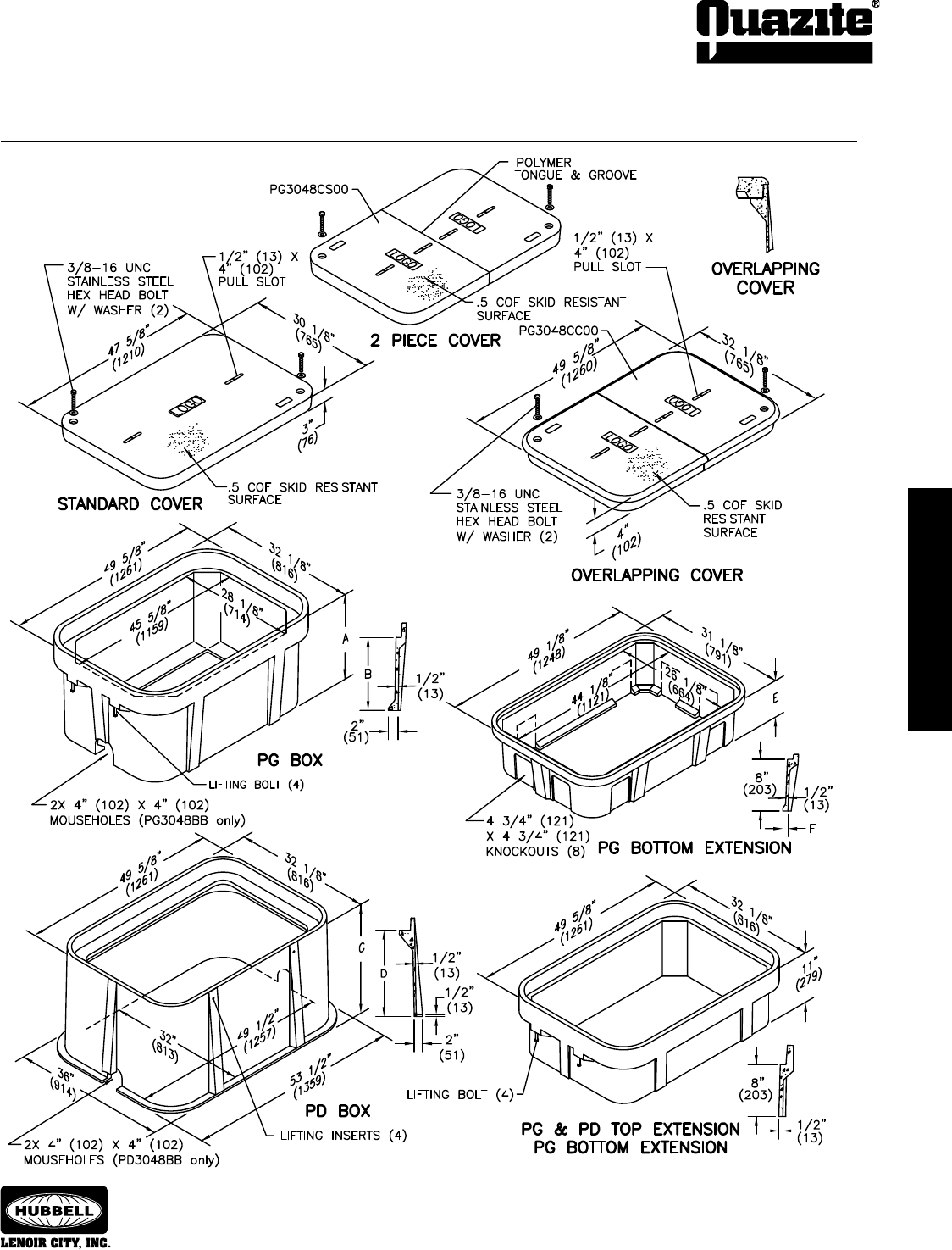
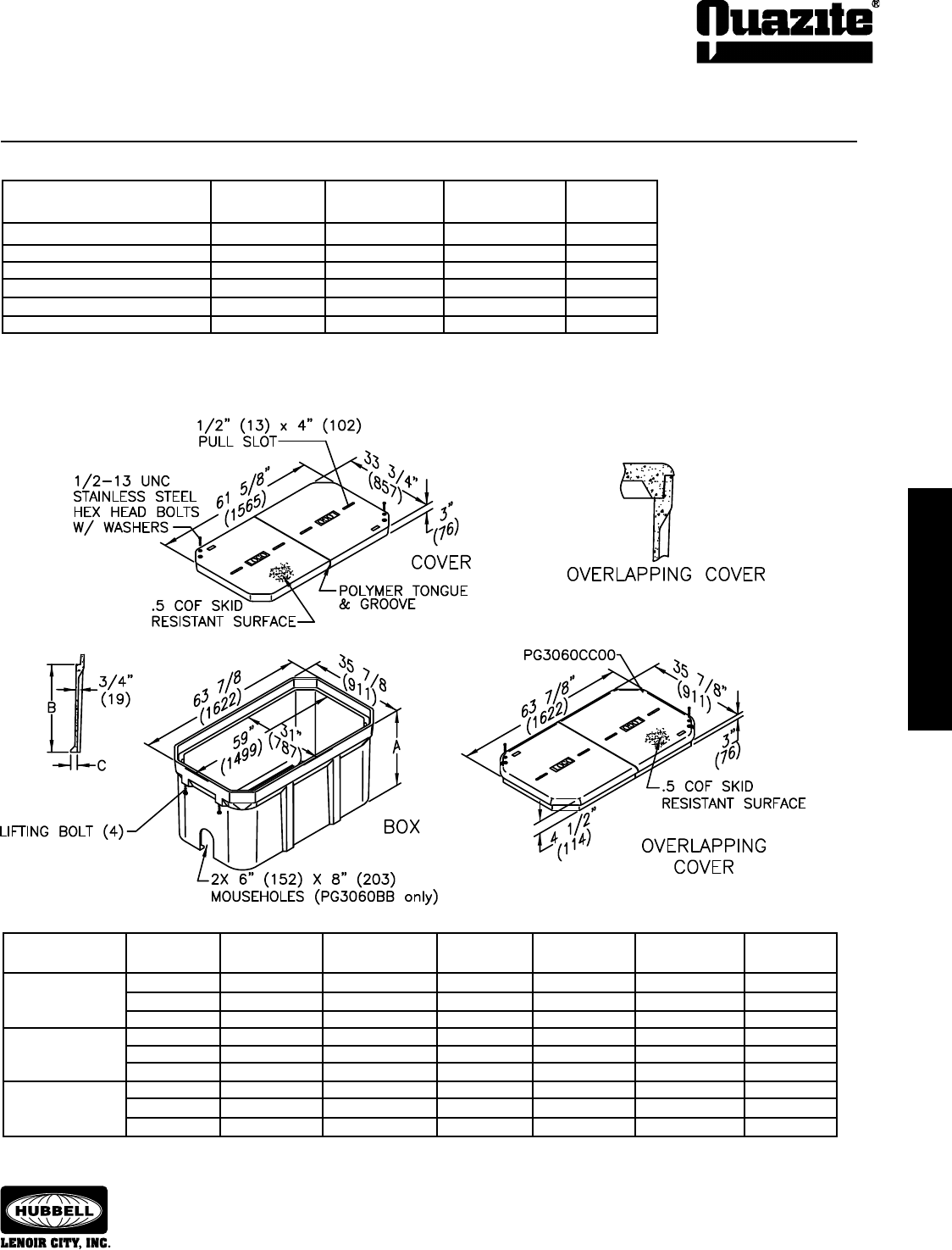
SPECIFICATIONS/DATA 30” x 48” PG Style (Stackable) Assembly
30” x 48” PD Style (Nestable) Assembly
36
ENCLOSURE DRAWINGS
ENCLOSURE DRAWINGS
SEPTEMBER 2007
®
ENCLOSURE DRAWINGS
ENCLOSURE DRAWINGS
SPECIFICATIONS/DATA 30” x 48” PG Style (Stackable) Assembly
30” x 48” PD Style (Nestable) Assembly
Covers (Blank unless logo is specied)
DESIGN/TEST
DESCRIPTION PART NO. WEIGHT # LOAD ANSI TIER
W/2 Bolts PG3048CA00 159 (72.1 kg) 8,000 / 12,000 8
Gasketed w/2 Bolts PG3048CG00 159 (72.1 kg) 8,000 / 12,000 8
No Bolts PG3048WA00 159 (72.1 kg) 8,000 / 12,000 8
Heavy Duty w/2 Bolts PG3048HA00 206 (93.4 kg) 15,000 / 22,500 15
Gasketed Heavy Duty w/2 Bolts PG3048HG00 206 (93.4 kg) 15,000 / 22,500 15
Extra Heavy Duty w/2 Bolts PG3048HH00 220 (99.7 kg) 22,500 / 33,750 22
2-piece w/2 Bolts PG3048CS00 181 (82.1 kg) 8,000 / 12,000 8
Heavy Duty 2-piece w/2 Bolts PG3048HS00 206 (93.4 kg) 15,000 / 22,500 15
2-piece Overlapping PG3048CC00 248 (112.0 kg) 8,000 / 12,000 8
Heavy Duty 2-piece Overlapping PG3048HC00 248 (112.0 kg) 15,000 / 22,500 15
PD Boxes (Nestable)
DIMENSION DIMENSION DESIGN/TEST
DESCRIPTION PART NO. WEIGHT # C D LOAD # ANSI TIER
Open Bottom PD3048BA24 286 (130 kg) 24” (610 mm) 21” (533 mm) 22,500 / 33,750 22
PD3048BA48 614 (278.5 kg) 48” (1219 mm) 45” (1143 mm) 22,500 / 33,750 22
Open Bottom w/ PD3048BG24 286 (130 kg) 24” (610 mm) 21” (533 mm) 22,500 / 33,750 22
Gasket PD3048BG48 614 (278.5 kg) 48” (1219 mm) 45” (1143 mm) 22,500 / 33,750 22
Open Bottom w/ PD3048BB24 286 (130 kg) 24” (610 mm) 21” (533 mm) 22,500 / 33,750 22
2 Mouseholes PD3048BB48 614 (278.5 kg) 48” (1219 mm) 45” (1143 mm) 22,500 / 33,750 22
Dimensions & weights in parentheses are metric equivalent.
DIMENSION DIMENSION DESIGN/TEST
DESCRIPTION PART NO. WEIGHT # E F LOAD # ANSI TIER
Open Bottom PG3048EA08 102 (46.3 kg) 8 3/4” (222 mm) 1” (25 mm) 22,500 / 33,750 22
Solid Bottom PG3048RA08 151 (58.0 kg) 9 1/4” (235 mm) N/A 22,500 / 33,750 22
Bottom Extensions (For use under 18” deep PG style box only, one per box)
• Covers with meter lids
available upon request.
• Gasketed covers and bolt
grommets must be used with
a gasketed box. Gaskets
reduce the inow of
uids but do not make the
enclosure water tight.
* In addition, this extension can be used as a bottom extension for 18” deep PG boxes.
Top Extension (For use on top of PG and PD boxes of any depth)
DESCRIPTION PART NO. WEIGHT # DESIGN/TEST LOAD # ANSI TIER
Open Bottom* PG3048EA11 100 (45.4 kg) 22,500 / 33,750 22
PG Boxes (Stackable with self-aligning, replaceable EZ-Nut) *24” & 36” deep boxes must be used as bottom of any stack
DIMENSION DIMENSION DESIGN/TEST
DESCRIPTION PART NO. WEIGHT # A B LOAD # ANSI TIER
Open Bottom PG3048BA18 185 (83.9 kg) 18” (457 mm) 15” (381 mm) 22,500 / 33,750 22
* PG3048BA24 236 (107.0 kg) 24” (609 mm) 21” (533 mm) 22,500 / 33,750 22
* PG3048BA36 343 (155.6 kg) 36” (914 mm) 33” (838 mm) 22,500 / 33,750 22
Open Bottom w/ PG3048BG18 185 (83.9 kg) 18” (457 mm) 15” (381 mm) 22,500 / 33,750 22
Gasket * PG3048BG24 236 (107.0 kg) 24” (609 mm) 21” (533 mm) 22,500 / 33,750 22
* PG3048BG36 343 (155.6 kg) 36” (914 mm) 33” (838 mm) 22,500 / 33,750 22
Open Bottom w/ PG3048BB18 185 (83.9 kg) 18” (457 mm) 15” (381 mm) 22,500 / 33,750 22
2 Mouseholes * PG3048BB24 236 (107.0 kg) 24” (610 mm) 21” (533 mm) 22,500 / 33,750 22
* PG3048BB36 343 (155.6 kg) 36” (914 mm) 33” (838 mm) 22,500 / 33,750 22
Solid Bottom PG3048DA18 220 (99.8 kg) 18 1/2” (470 mm) 15” (381 mm) 22,500 / 33,750 22
* PG3048DA24 287 (130.2 kg) 24 1/2” (622 mm) 21” (533 mm) 22,500 / 33,750 22
* PG3048DA36 394 (178.7 kg) 36 1/2” (927 mm) 33” (838 mm) 22,500 / 33,750 22
Solid Bottom w/ PG3048DG18 220 (99.8 kg) 18 1/2” (470 mm) 15” (381 mm) 22,500 / 33,750 22
Gasket * PG3048DG24 287 (130.2 kg) 24 1/2” (622 mm) 21” (533 mm) 22,500 / 33,750 22
* PG3048DG36 394 (178.7 kg) 36 1/2” (927 mm) 33” (838 mm) 22,500 / 33,750 22
ENCLOSURE DRAWINGS
ENCLOSURE DRAWINGS
37
ENCLOSURE DRAWINGS
ENCLOSURE DRAWINGS
SEPTEMBER 2007
®
SPECIFICATIONS/DATA 30” x 60” PG Style (Stackable) Assembly
2-Piece Covers (Blank unless logo is specied)
DESIGN/TEST
DESCRIPTION PART NO. WEIGHT # LOAD ANSI TIER
Lightweight w/2 Bolts LG3060CA00 228 (103.4 kg) 5,000 / 7,500 5
Lightweight w/No Bolts LG3060WA00 228 (103.4 kg) 5,000 / 7,500 5
Heavy Duty w/2 Bolts PG3060HA00 346 (156.9 kg) 15,000 / 22,500 15
Extra Heavy Duty w/2 Bolts PG3060HH00 368 (166.9 kg) 22,500 / 33,750 22
Lightweight Overlapping LG3060CC00 308 (139.7 kg) 5,000 / 7,500 5
Heavy Duty Overlapping PG3060HC00 404 (183.3 kg) 15,000 / 22,500 15
• Covers with meter lids available upon request.
• Gasketed covers and bolt grommets must be used with a gasketed box. Gaskets reduce the inow of uids but do not
make the enclosure water tight.
Dimensions & weights in parentheses are metric equivalent.
Boxes (Stackable with self-aligning, replaceable EZ-Nut) *30” & 36” deep boxes must be used as bottom of any stack
DIMENSION DIMENSION DIMENSION DESIGN/TEST
DESCRIPTION PART NO. WEIGHT # A B C LOAD # ANSI TIER
Open Bottom PG3060BA21 350 (159.0 kg) 21” (533 mm) 18” (457 mm) 2” (51 mm) 22,500 / 33,750 22
* PG3060BA30 492 (223.2 kg) 30” (762 mm) 27” (686 mm) 2 1/8” (54 mm) 22,500 / 33,750 22
* PG3060BA36 565 (256.3 kg) 36” (914 mm) 33” (838 mm) 2 1/8” (54 mm) 22,500 / 33,750 22
Open Bottom w/ PG3060BB21 350 (159.0 kg) 21” (533 mm) 18” (457 mm) 2” (51 mm) 22,500 / 33,750 22
2 Mouseholes * PG3060BB30 490 (222.3 kg) 30” (762 mm) 27” (686 mm) 2 1/8” (54 mm) 22,500 / 33,750 22
* PG3060BB36 563 (255.4 kg) 36” (914 mm) 33” (838 mm) 2 1/8” (54 mm) 22,500 / 33,750 22
Solid Bottom PG3060DA21 420 (190.5 kg) 21 1/2” (546 mm) 18” (457 mm) N/A 22,500 / 33,750 22
* PG3060DA30 532 (241.3 kg) 30 1/2” (775 mm) 27” (686 mm) N/A 22,500 / 33,750 22
* PG3060DA36 601 (272.6 kg) 36 1/2” (927 mm) 33” (838 mm) N/A 22,500 / 33,750 22
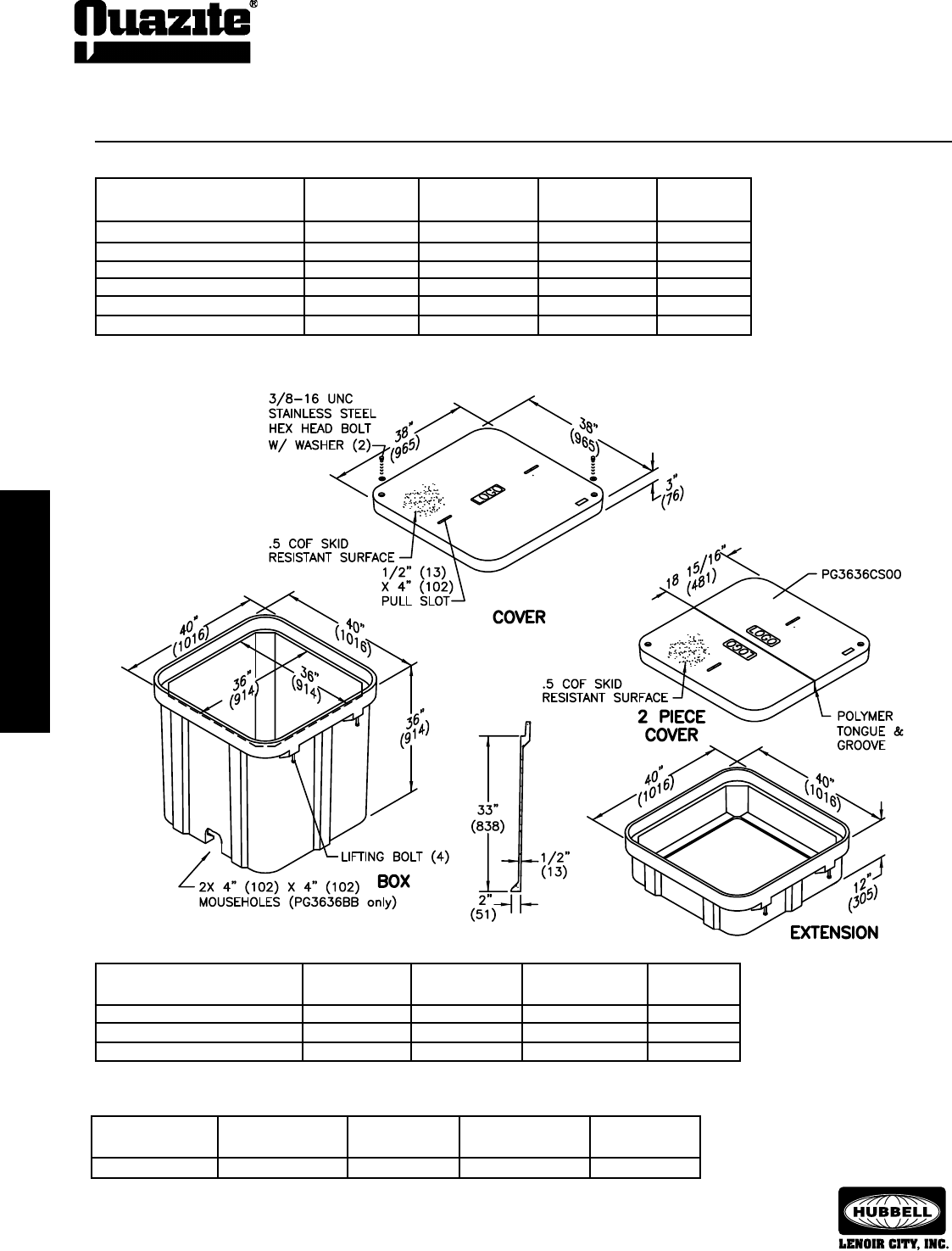
38
ENCLOSURE DRAWINGS
ENCLOSURE DRAWINGS
SEPTEMBER 2007
®
ENCLOSURE DRAWINGS
ENCLOSURE DRAWINGS
SPECIFICATIONS/DATA 36” x 36” PG Style (Stackable) Assembly
Covers (Blank unless logo is specied)
DESIGN/TEST
DESCRIPTION PART NO. WEIGHT # LOAD # ANSI TIER
W/2 Bolts PG3636CA00 201 (91 kg) 8,000 / 12,000 8
No Bolts PG3636WA00 201 (91 kg) 8,000 / 12,000 8
Heavy Duty w/2 Bolts PG3636HA00 220 (100 kg) 15,000 / 22,500 15
2-piece w/2 Bolts PG3636CS00 220 (100 kg) 8,000 / 12,000 8
Heavy Duty 2-piece w/2 Bolts PG3636HS00 220 (100 kg) 15,000 / 22,500 15
Extra Heavy Duty w/2 Bolts PG3636HH00 330 (150 kg) 22,500 / 33,750 22
• Covers with meter lids available upon request.
Extensions (For use on top of box only)
DESIGN/TEST
DESCRIPTION PART NO. WEIGHT # LOAD # ANSI TIER
Open Bottom PG3636EA12 129 (59 kg) 22,500 / 33,750 22
Dimensions & weights in parentheses are metric equivalent.
Boxes (Stackable with self-aligning, replaceable EZ-Nut)
DESIGN/TEST
DESCRIPTION PART NO. WEIGHT # LOAD # ANSI TIER
Open Bottom PG3636BA36 367 (166 kg) 22,500 / 33,750 22
Open Bottom w/2 Mouseholes PG3636BB36 367 (166 kg) 22,500 / 33,750 22
Solid Bottom PG3636DA36 407 (185 kg) 22,500 / 33,750 22
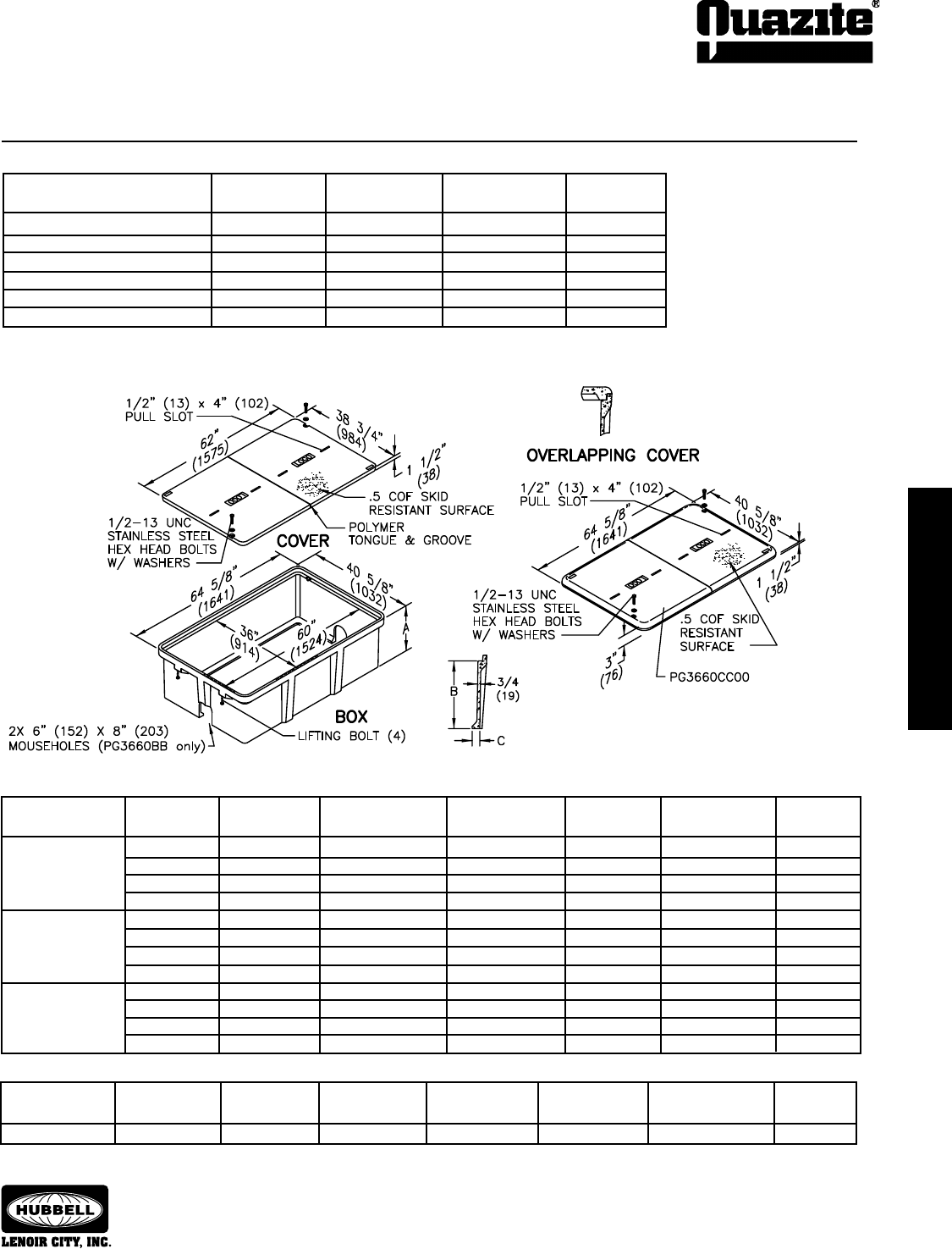
ENCLOSURE DRAWINGS
ENCLOSURE DRAWINGS
39
ENCLOSURE DRAWINGS
ENCLOSURE DRAWINGS
SEPTEMBER 2007
®
SPECIFICATIONS/DATA 36” x 60” PG Style (Stackable) Assembly
3” Grade Adjustable extension
available. See page 44.
Covers (Blank unless logo is specied)
DESIGN/TEST
DESCRIPTION PART NO. WEIGHT # LOAD # ANSI TIER
Lightweight w/2 Bolts LG3660CA00 222 (100.7 kg) 5,000 / 7,500 5
Lightweight w/No Bolts LG3660WA00 222 (100.7 kg) 5,000 / 7,500 5
Heavy Duty w/2 Bolts PG3660HA00 384 (174.0 kg) 15,000 / 22,500 15
Extra Heavy Duty w/2 Bolts PG3660HH00 470 (213.2 kg) 22,500 / 33,750 22
Lightweight Overlapping LG3660CC00 307 (139.3 kg) 5,000 / 7,500 5
Heavy Duty 2 pc. Overlapping PG3660HC00 436 (197.8 kg) 15,000 / 22,500 15
• Covers with meter lids available upon request.
Boxes (Stackable with self-aligning, replaceable nut) *31” & 36” deep boxes must be used as bottom of any stack
DIMENSION DIMENSION DIMENSION DESIGN/TEST
DESCRIPTION PART NO. WEIGHT # A B C LOAD # ANSI TIER
Open Bottom PG3660BA19 381 (172.8 kg) 19 1/2” (495 mm) 18” (457 mm) 2” (51 mm) 22,500 / 33,750 22
PG3660BA24 397 (180.0 kg) 24” (610 mm) 22 1/2” (572 mm) 2” (51 mm) 22,500 / 33,750 22
* PG3660BA31 481 (218.2 kg) 31” (787 mm) 29 1/2” (749 mm) 2” (51 mm) 22,500 / 33,750 22
* PG3660BA36 647 (293.0 kg) 36” (914 mm) 34 1/2” (876 mm) 2” (51 mm) 22,500 / 33,750 22
Open Bottom w/ PG3660BB19 379 (171.9 kg) 19 1/2” (495.0 mm) 18” (457 mm) 2” (51 mm) 22,500 / 33,750 22
2 Mouseholes PG3660BB24 397 (180.0 kg) 24” (610 mm) 22 1/2” (572 mm) 2” (51 mm) 22,500 / 33,750 22
* PG3660BB31 479 (217.3 kg) 31” (787 mm) 29 1/2” (749 mm) 2” (51 mm) 22,500 / 33,750 22
* PG3660BB36 647 (293.0 kg) 36” (914 mm) 34 1/2” (876 mm) 2” (51 mm) 22,500 / 33,750 22
Solid Bottom PG3660DA19 479 (217.0 kg) 20” (508 mm) 18 1/2” (470 mm) N/A 22,500 / 33,750 22
PG3660DA24 495 (224.5 kg) 24 1/2” (622 mm) 23” (584 mm) N/A 22,500 / 33,750 22
* PG3660DA31 590 (268.0 kg) 31 1/2” (800.1 mm) 30” (762 mm) N/A 22,500 / 33,750 22
* PG3660DA36 738 (334.8 kg) 36 1/2” (927 mm) 35” (889 mm) N/A 22,500 / 33,750 22
Dimensions & weights in parentheses are metric equivalent.
Extensions (For use on top of box only)
DIMENSION DIMENSION DIMENSION DESIGN/TEST
DESCRIPTION PART NO. WEIGHT # A B C LOAD # ANSI TIER
Open Bottom PG3660EA12 200 (90.7 kg) 11 1/2” 10” 2” 22,500 / 33,750 22
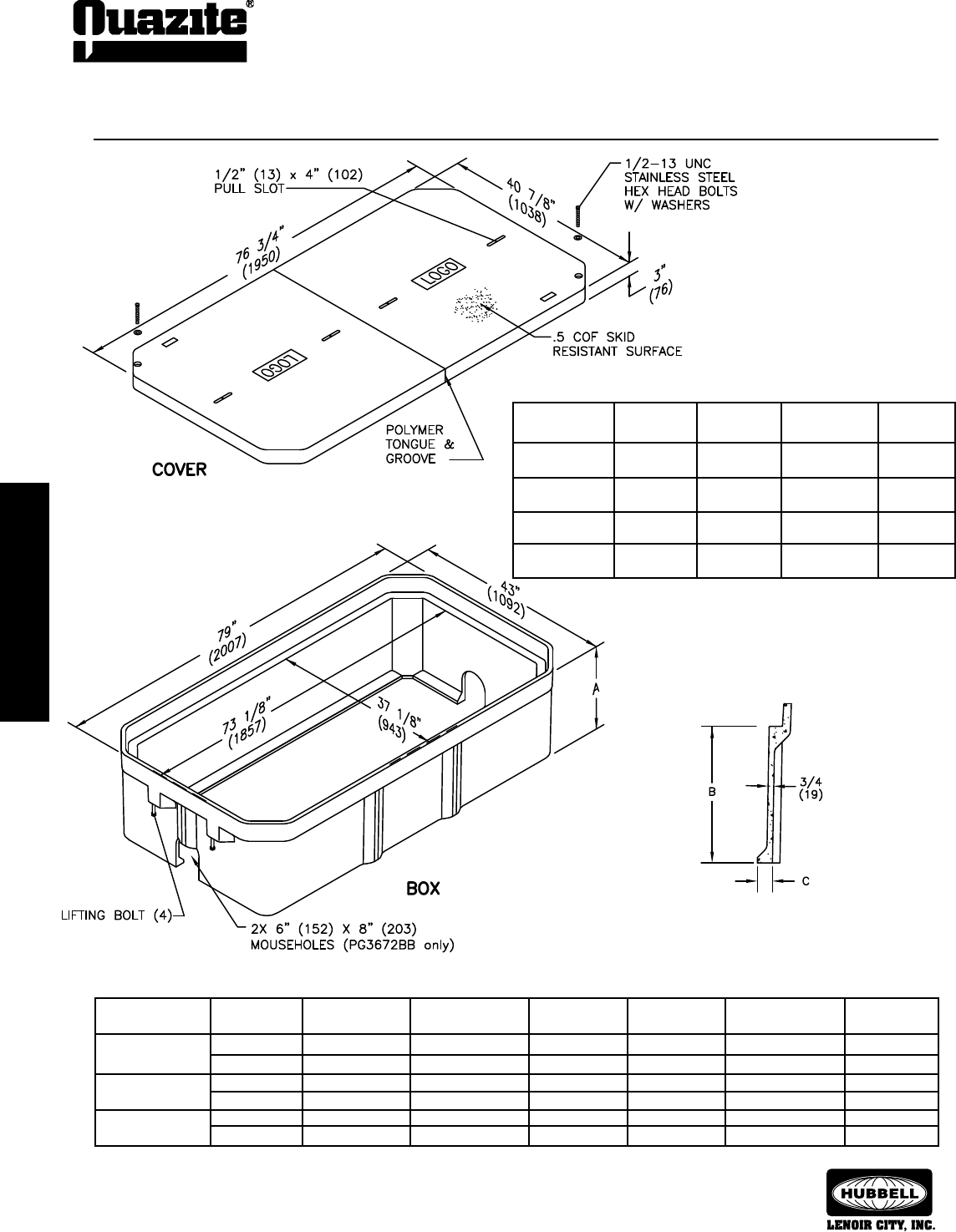
40
ENCLOSURE DRAWINGS
ENCLOSURE DRAWINGS
SEPTEMBER 2007
®
ENCLOSURE DRAWINGS
ENCLOSURE DRAWINGS
SPECIFICATIONS/DATA 36” x 72” PG Style (Stackable) Assembly
• Covers with meter lids available upon request.
2-Piece Covers (Blank unless logo is specied)
DESIGN/TEST
DESCRIPTION PART NO. WEIGHT # LOAD # ANSI TIER
Lightweight w/ LG3672CA00 310 (140.6 kg) 5,000 / 7,500 5
2 Bolts
Lightweight w/ LG3672WA00 310 (140.6 kg) 5,000 / 7,500 5
No Bolts
Heavy Duty w/ PG3672HA00 488 (221.0 kg) 15,000 / 22,500 15
2 Bolts
Extra Heavy Duty PG3672HH00 544 (246.8 kg) 22,500 / 33,750 22
w/2 Bolts
Dimensions & weights in parentheses are metric equivalent.
Boxes (Stackable with self-aligning, replaceable EZ-Nut) *36” deep box must be used as bottom of any stack
DIMENSION DIMENSION DIMENSION DESIGN/TEST
DESCRIPTION PART NO. WEIGHT # A B C LOAD # ANSI TIER
Open Bottom PG3672BA21 448 (203.2 kg) 21” (533 mm) 18” (457 mm) 2” (51 mm) 22,500 / 33,750 22
* PG3672BA36 768 (348.0 kg) 36” (914 mm) 33” (838 mm) 2” (51 mm) 22,500 / 33,750 22
Open Bottom w/ PG3672BB21 445 (201.9 kg) 21” (533 mm) 18” (457 mm) 2” (51 mm) 22,500 / 33,750 22
2 Mouseholes * PG3672BB36 768 (348.0 kg) 36” (914 mm) 33” (838 mm) 2” (51 mm) 22,500 / 33,750 22
Solid Bottom PG3672DA21 569 (258.1 kg) 21 1/2” (546 mm) 18” (457 mm) N/A 22,500 / 33,750 22
* PG3672DA36 822 (373.0 kg) 36 1/2” (927 mm) 33” (838 mm) N/A 22,500 / 33,750 22
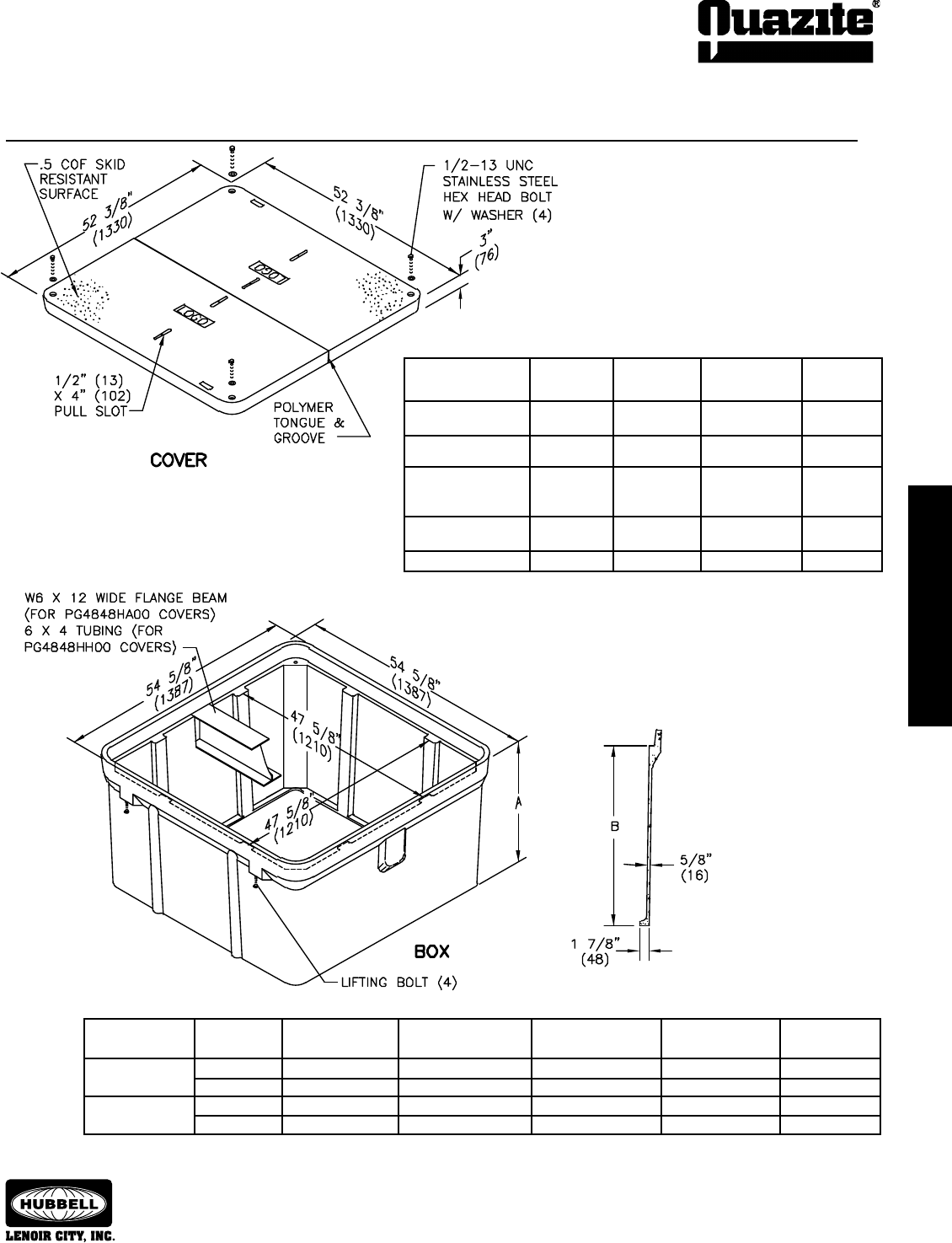
ENCLOSURE DRAWINGS
ENCLOSURE DRAWINGS
41
ENCLOSURE DRAWINGS
ENCLOSURE DRAWINGS
SEPTEMBER 2007
®
SPECIFICATIONS/DATA 48” x 48” PG Style (Stackable) Assembly
Dimensions & weights in parentheses are metric equivalent.
Boxes (Stackable with self-aligning, replaceable EZ-Nut)
DIMENSION DIMENSION DESIGN/TEST
DESCRIPTION PART NO. WEIGHT # A B LOAD # ANSI TIER
Open bottom PG4848BA36 629 (285.0 kg) 36” (914 mm) 33” (838 mm) 22,500 / 33,750 22
PG4848BA48 866 (393.0 kg) 48” (1219 mm) 45” (1143 mm) 22,500 / 33,750 22
Solid Bottom PG4848DA36 663 (301.0 kg) 36 1/2” (927 mm) 33” (838 mm) 22,500 / 33,750 22
PG4848DA48 940 (426.0 kg) 48 1/2” (1232 mm) 45” (1143 mm) 22,500 / 33,750 22
• Covers with meter lids available upon request.
*
Total weight for 48” x 48” HA beam is 51 lbs (23 kg). Total weight for 48” x 48” HH tubing
is 95 lbs (43 kg).
Covers (Blank unless logo is specied)
DESIGN/TEST
DESCRIPTION PART NO. WEIGHT # LOAD # ANSI TIER
Lightweight w/ LG4848CA00 286 (130.0 kg) 5,000 / 7,500 5
4 Bolts
Lightweight w/ LG4848WA00 286 (130.0 kg) 5,000 / 7,500 5
No Bolts
Heavy Duty w/W6 x PG4848HA00 364 (165.1 kg) 15,000 / 22,500 15
12 Wide Flange
Beam w/4 Bolts*
Extra Heavy Duty w/ PG4848HH00 596 (270.0 kg) 22,500 / 33,750 22
6 x 4 Tubing w/ 4 Bolts*
Round 39” Opening PG4848C500 377 (171 kg) 5,000 / 7,500 5
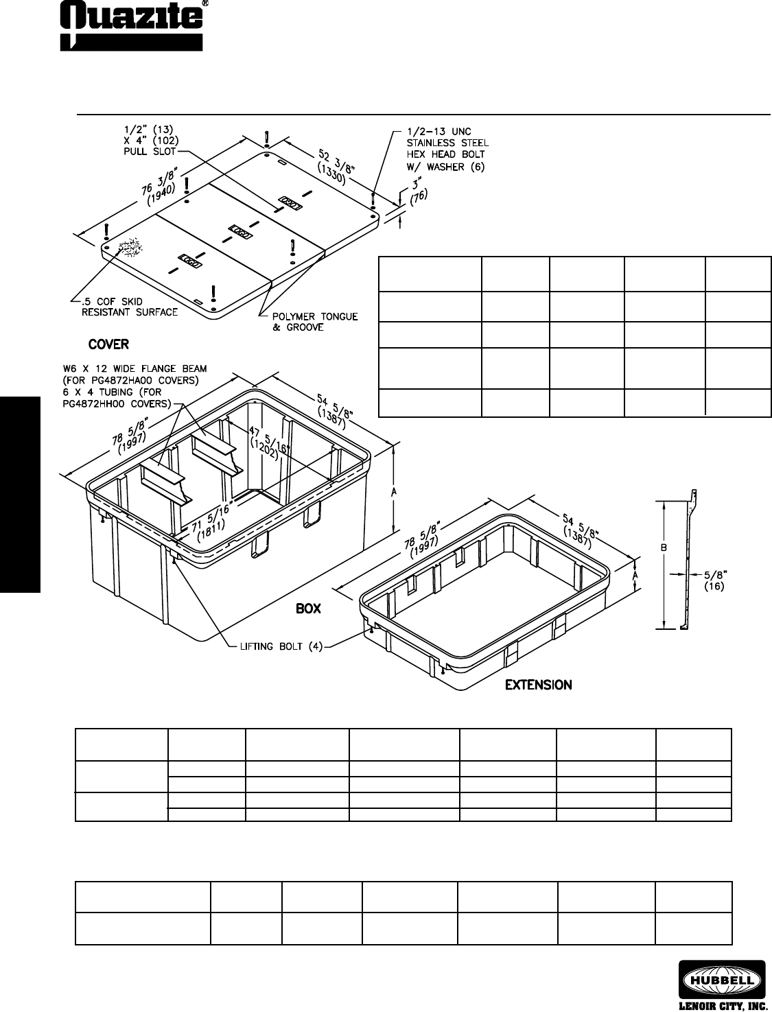
42
ENCLOSURE DRAWINGS
ENCLOSURE DRAWINGS
SEPTEMBER 2007
®
ENCLOSURE DRAWINGS
ENCLOSURE DRAWINGS
SPECIFICATIONS/DATA 48” x 72” PG Style (Stackable) Assembly
Covers (Blank unless logo is specied)
Extension (Stackable with self-aligning, replaceable EZ-Nut; for use on top of box only)
DIMENSION DIMENSION DESIGN/TEST
DESCRIPTION PART NO. WEIGHT # A B LOAD # ANSI TIER
Open Bottom, Beam Pocket, PG4872EA12 359 (162.8 kg) 15” (381 mm) 12” (305 mm) 22,500 / 33,750 22
No Beam Provided
Top extensions are available to give extra depth.
Dimensions & weights in parentheses are metric equivalent.
Boxes (Stackable with self-aligning, replaceable EZ-Nut)
DIMENSION DIMENSION DESIGN/TEST
DESCRIPTION PART NO. WEIGHT # A B LOAD # ANSI TIER
Open Bottom PG4872BA36 810 (367.0 kg) 37 1/2” (953 mm) 33” (838 mm) 22,500 / 33,750 22
PG4872BA48 1050 (476.0 kg) 49 1/2” (1257 mm) 45” (1143 mm) 22,500 / 33,750 22
Solid Bottom PG4872DA36 1065 (483.0 kg) 36 1/2” (927 mm) 33” (838 mm) 22,500 / 33,750 22
PG4872DA48 1245 (565.0 kg) 48 1/2” (1232 mm) 45” (1143 mm) 22,500 / 33,750 22
DESIGN/TEST
DESCRIPTION PART NO. WEIGHT # LOAD # ANSI TIER
Lightweight w/ LG4872CA00 447 (203.0 kg) 5,000 / 7,500 5
6 Bolts
Lightweight w/ LG4872WA00 447 (203.0 kg) 5,000 / 7,500 5
No Bolts
Heavy Duty w/W6 x PG4872HA00 573 (260.0 kg) 15,000 / 22,500 15
12 Wide Flange Beam
w/6 Bolts*
Extra Heavy Duty w/ PG4872HH00 891 (404.0 kg) 22,500 / 33,750 22
6 x 4 Tubing w/6 Bolts*
*Total weight for 48” x 72” HA beam is 102 lbs (46 kg). Total weight
for 48” x 72” HH tubing is 190 lbs (86 kg).
** Loadings for HH covers comply with all test provisions of ANSI/
SCTE 77 except that the vertical design load is 22,500 lbs. with
a test load of 33,750 lbs. over a 10” x 20” plate.
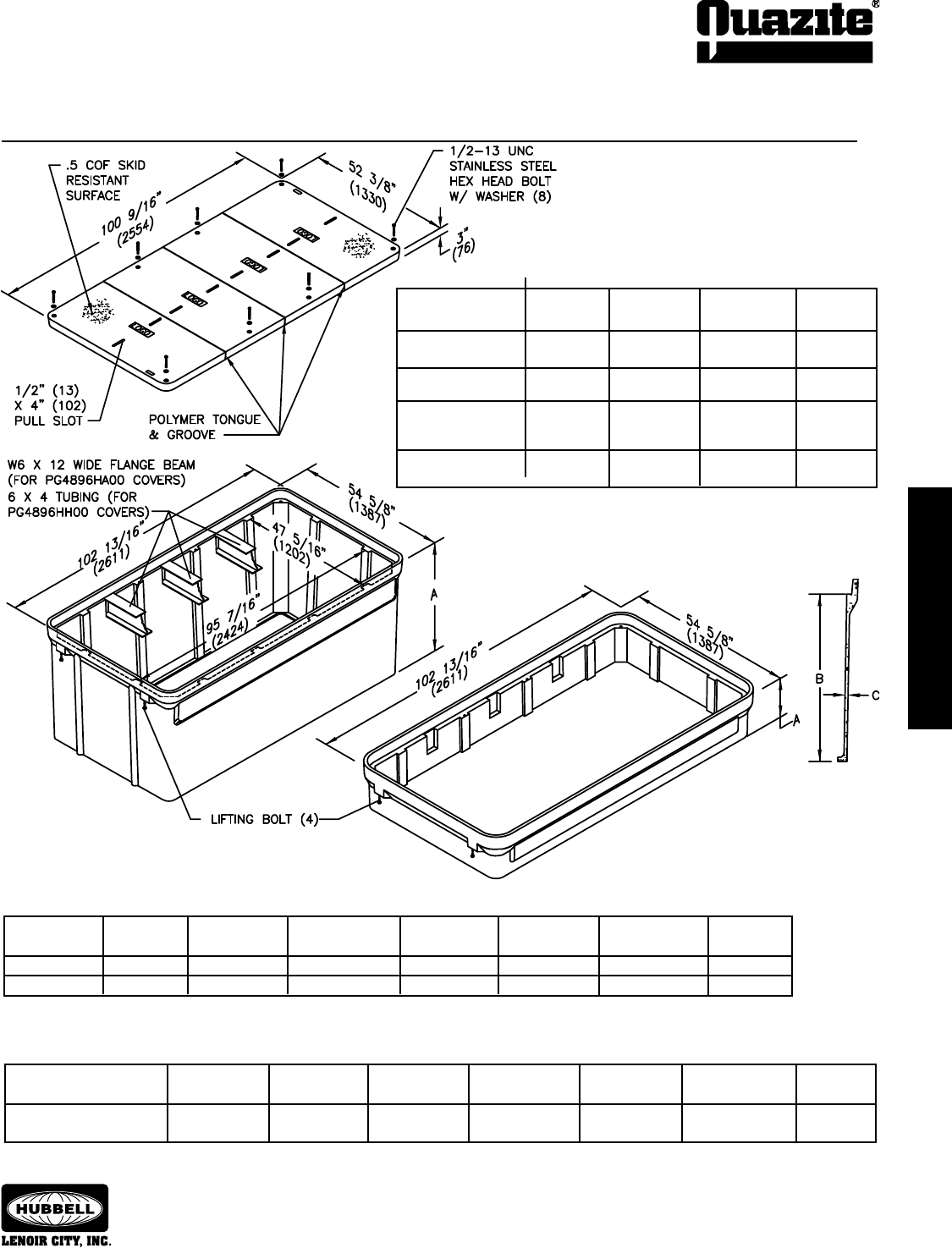
ENCLOSURE DRAWINGS
ENCLOSURE DRAWINGS
43
ENCLOSURE DRAWINGS
ENCLOSURE DRAWINGS
SEPTEMBER 2007
®
SPECIFICATIONS/DATA 48” x 96” PG Style (Stackable) Assembly
*Total weight for 48” x 96” HA beam is 153 lbs (69 kg). Total weight for
48” x 96” HH tubing is 285 lbs (129 kg).
Covers (Blank unless logo is specied)
DESIGN/TEST
DESCRIPTION PART NO. WEIGHT # LOAD # ANSI TIER
Lightweight w/ LG4896CA00 608 (276.0 kg) 5,000 / 7,500 5
8 Bolts
Lightweight w/ LG4896WA00 608 (276.0 kg) 5,000 / 7,500 5
No Bolts
Heavy Duty w/W6 x PG4896HA00 794 (360.0 kg) 15,000 / 22,500 15
12 Wide Flange Beam
w/8 Bolts*
Extra Heavy Duty w/ PG4896HH00 1186 (538.0 kg) 22,500 / 33,750 22
6 x 4 Tubing w/8 Bolts*
Extension (Stackable with self-aligning, replaceable EZ-Nut; for use on top of box only)
DIMENSION DIMENSION DIMENSION DESIGN/TEST
DESCRIPTION PART NO. WEIGHT # A B C LOAD # ANSI TIER
Open Bottom, Beam Pocket, PG4896EA12 485 (220.0 kg) 15” (381 mm) 12” (305 mm) 1 1/16” (27 mm) 22,500 / 33,750 22
No Beam Provided
Top extensions are available to give extra depth.
Dimensions & weights in parentheses are metric equivalent.
Boxes (Stackable with self-aligning, replaceable EZ-Nut)
DIMENSION DIMENSION DIMENSION DESIGN/TEST
DESCRIPTION PART NO. WEIGHT # A B C LOAD # ANSI TIER
Open Bottom PG4896BA48 1384 (628 kg) 49 3/4” (1264 mm) 45” (1143 mm) 5/8” (16 mm) 22,500 / 33,750 22
Solid Bottom PG4896DA48 1537 (697 kg) 48 3/4” (1238 mm) 45” (1143 mm) 5/8” (16 mm) 22,500 / 33,750 22
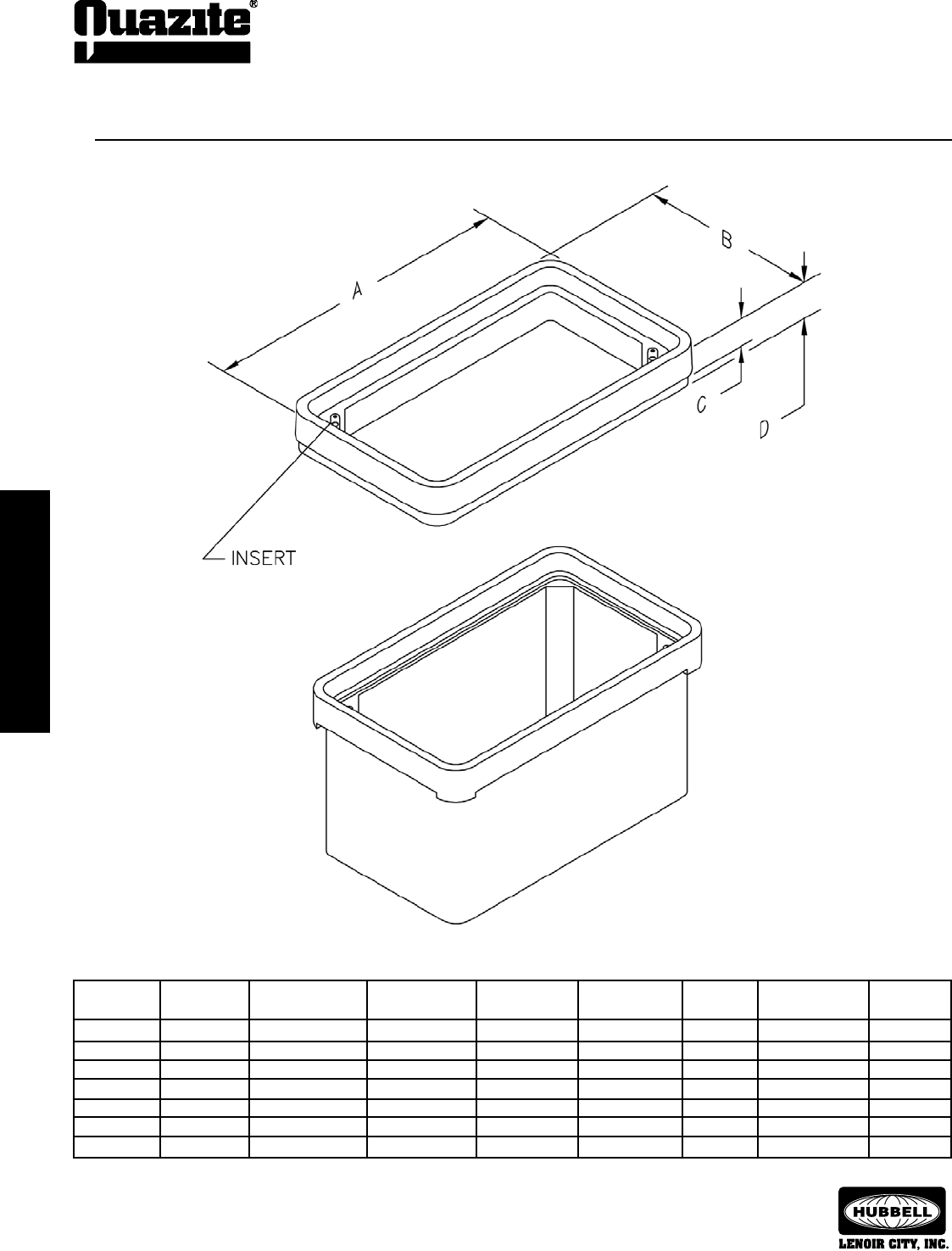
44
ENCLOSURE DRAWINGS
ENCLOSURE DRAWINGS
SEPTEMBER 2007
®
ENCLOSURE DRAWINGS
ENCLOSURE DRAWINGS
SPECIFICATIONS/DATA Grade Adjustable Extensions
Dimensions & weights in parentheses are metric equivalent.
Grade Adjustable Extensions
DIMENSION DIMENSION DIMENSION DIMENSION INSERT DESIGN/TEST
PART NO. WEIGHT # A B C D SIZE LOAD # ANSI TIER
PG1324ED03 37 (16.8 kg) 25 1/2” (648 mm) 16” (406 mm) 3” (76 mm) 5 1/8” (130 mm) 1/2” 22,500 / 33,750 22
PG1324E502 37 (16.8 kg) 25 1/2” (648 mm) 16” (406 mm) 3” (76 mm) 5 1/8” (130 mm) 3/8” 22,500 / 33,750 22
PG1730ED03 48 (21.8 kg) 32 3/4” (832 mm) 19 3/4” (502 mm) 3” (76 mm) 5 1/8” (130 mm) 1/2” 22,500 / 33,750 22
PG1730E505 48 (21.8 kg) 32 3/4” (832 mm) 19 3/4” (502 mm) 3” (76 mm) 5 1/8” (130 mm) 3/8” 22,500 / 33,750 22
PG2436ED04 80 (36.3 kg) 37 7/8” (962 mm) 26 1/4” (667 mm) 4” (102 mm) 7 1/8” (181 mm) 1/2” 22,500 / 33,750 22
PG2436E503 80 (36.3 kg) 37 7/8” (962 mm) 26 1/4” (667 mm) 4” (102 mm) 7 1/8” (181 mm) 3/8” 22,500 / 33,750 22
PG3660ED03 110 (49.9 kg) 65 1/2” (1664 mm) 41 3/4” (1060 mm) 2 1/2” (64 mm) 4” (102 mm) 1/2” 22,500 / 33,750 22
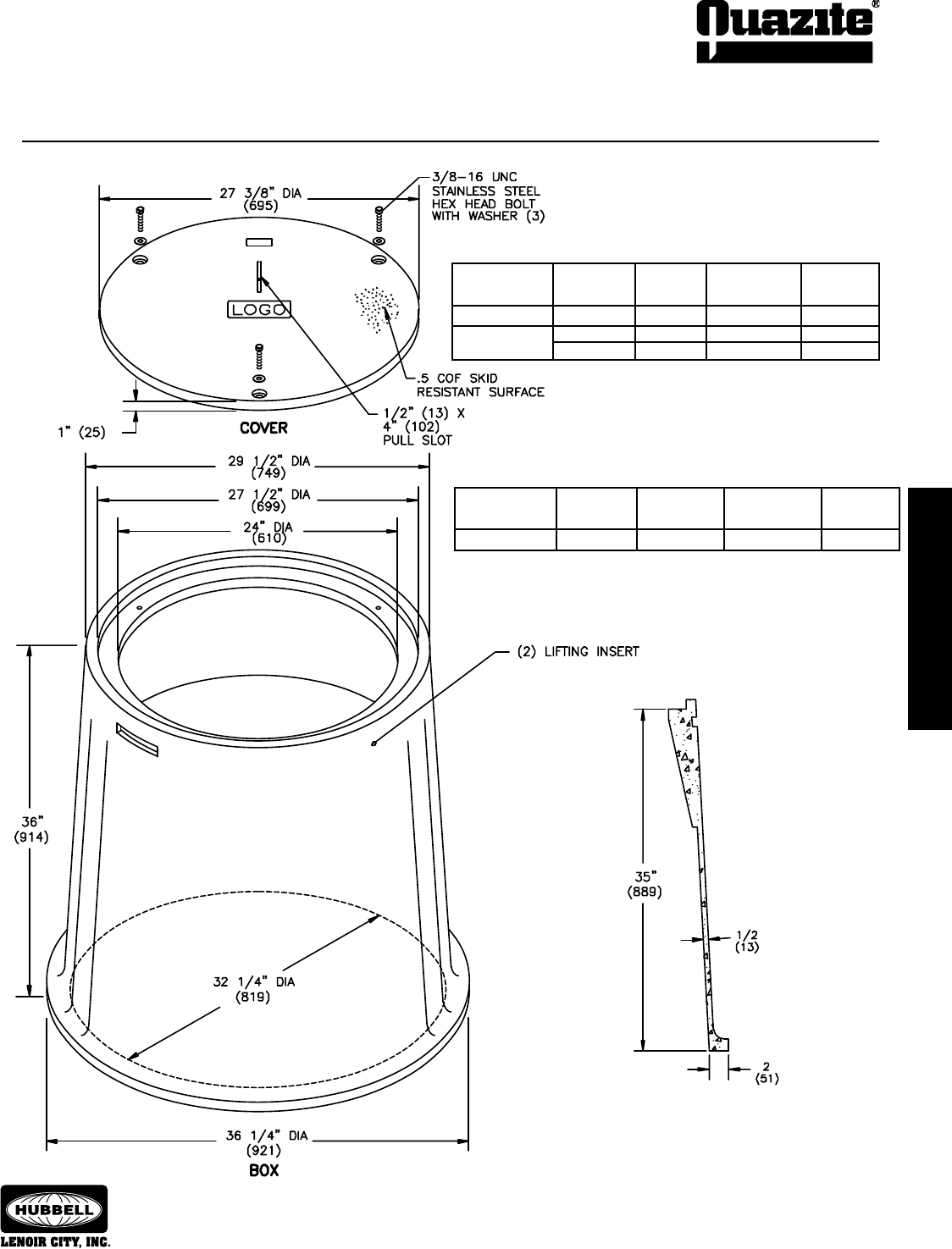
ENCLOSURE DRAWINGS
ENCLOSURE DRAWINGS
45
ENCLOSURE DRAWINGS
ENCLOSURE DRAWINGS
SEPTEMBER 2007
®
SPECIFICATIONS/DATA 27” Round Style (Nestable) Assembly
DESIGN/
DESCRIPTION PART NO. WEIGHT # TEST LOAD # ANSI TIER
W/3 Bolts PR2700CA00 53 (24.0 kg) 8,000 / 12,000 8
Heavy Duty w/ PR2700HA00 75 (34.0 kg) 15,000 / 22,500 15
3 Bolts PR2700HH00 75 (34.0 kg) 22,500 / 33,750 22
Covers (Blank unless logo is specied)
Dimensions & weights in parentheses are metric equivalent.
Boxes (Nestable)
DESIGN/TEST
DESCRIPTION PART NO. WEIGHT # LOAD # ANSI TIER
Open Bottom PR2732BA36 278 (126.0 kg) 15,000 / 22,500 15
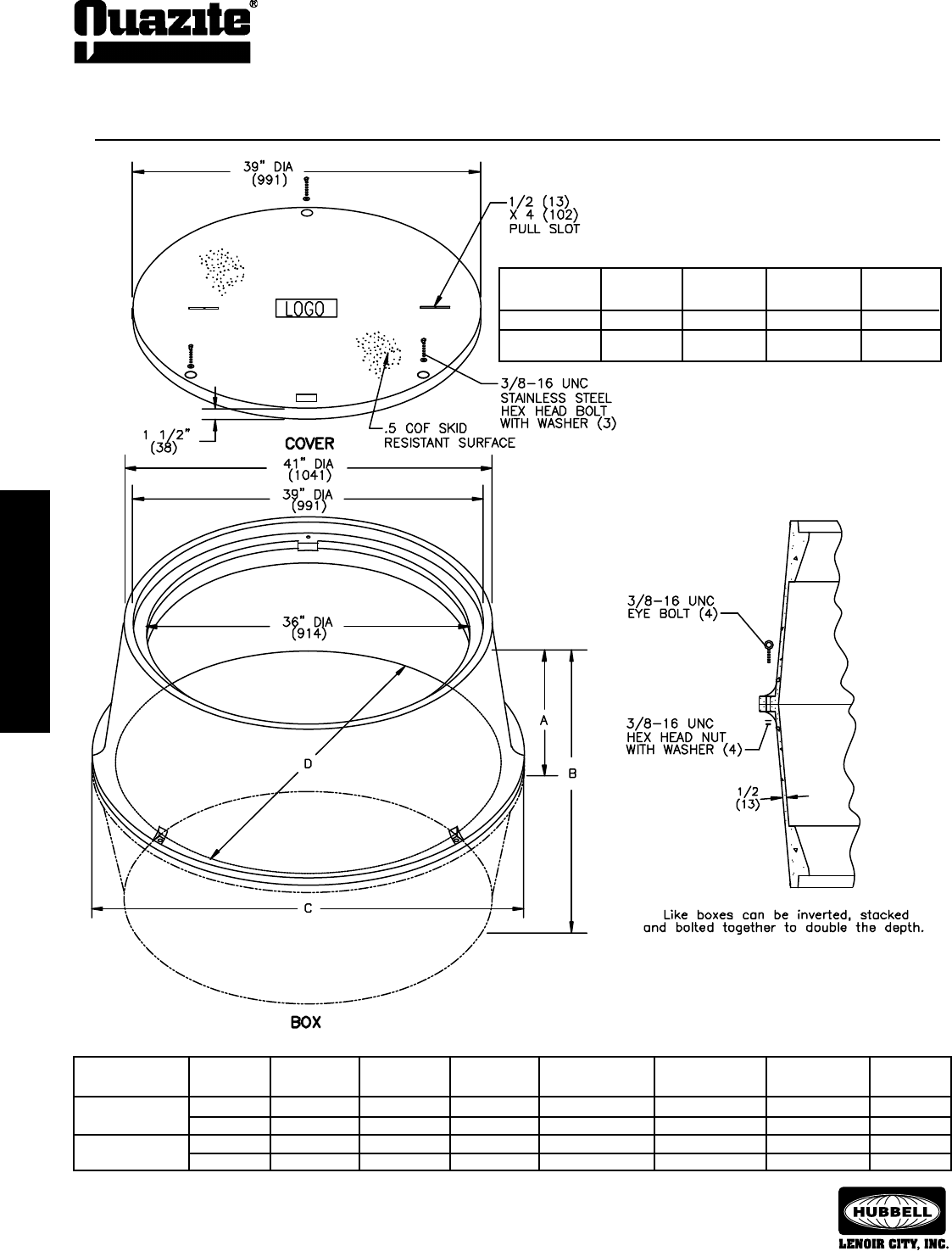
46
ENCLOSURE DRAWINGS
ENCLOSURE DRAWINGS
SEPTEMBER 2007
®
COVER DRAWINGS
COVER DRAWINGS
SPECIFICATIONS/DATA 39” Round Style (Nestable) Assembly
DESIGN/
DESCRIPTION PART NO. WEIGHT # TEST LOAD # ANSI TIER
W/3 Bolts PR3900CA00 141 (64.0 kg) 8,000 / 12,000 8
Heavy Duty w/ PR3900HA00 180 (81.6 kg) 15,000 / 22,500 15
3 Bolts
Covers (Blank unless logo is specied)
Dimensions & weights in parentheses are metric equivalent.
Boxes (Nestable)
DIMENSION DIMENSION DIMENSION DIMENSION DESIGN/TEST
DESCRIPTION PART NO. WEIGHT # A B C D LOAD # ANSI TIER
Open Bottom PR3943BA18 244 (111.0 kg) 18” (457 mm) - 48 1/8” (1222 mm) 43 1/8” (1095 mm) 22,500 / 33,750 22
PR3944BA24 326 (147.9 kg) 24” (610 mm) - 49 3/16” (1249 mm) 44 3/16” (1122 mm) 22,500 / 33,750 22
Open Bottom PR3943BA36 488 (221.0 kg) - 36” (914 mm) 48 1/8” (1222 mm) 43 1/8” (1095 mm) 22,500 / 33,750 22
Stacked w/Hardware PR3944BA48 660 (299.0 kg) - 48” (1219 mm) 49 3/16” (1249 mm) 44 3/16” (1122 mm) 22,500 / 33,750 22
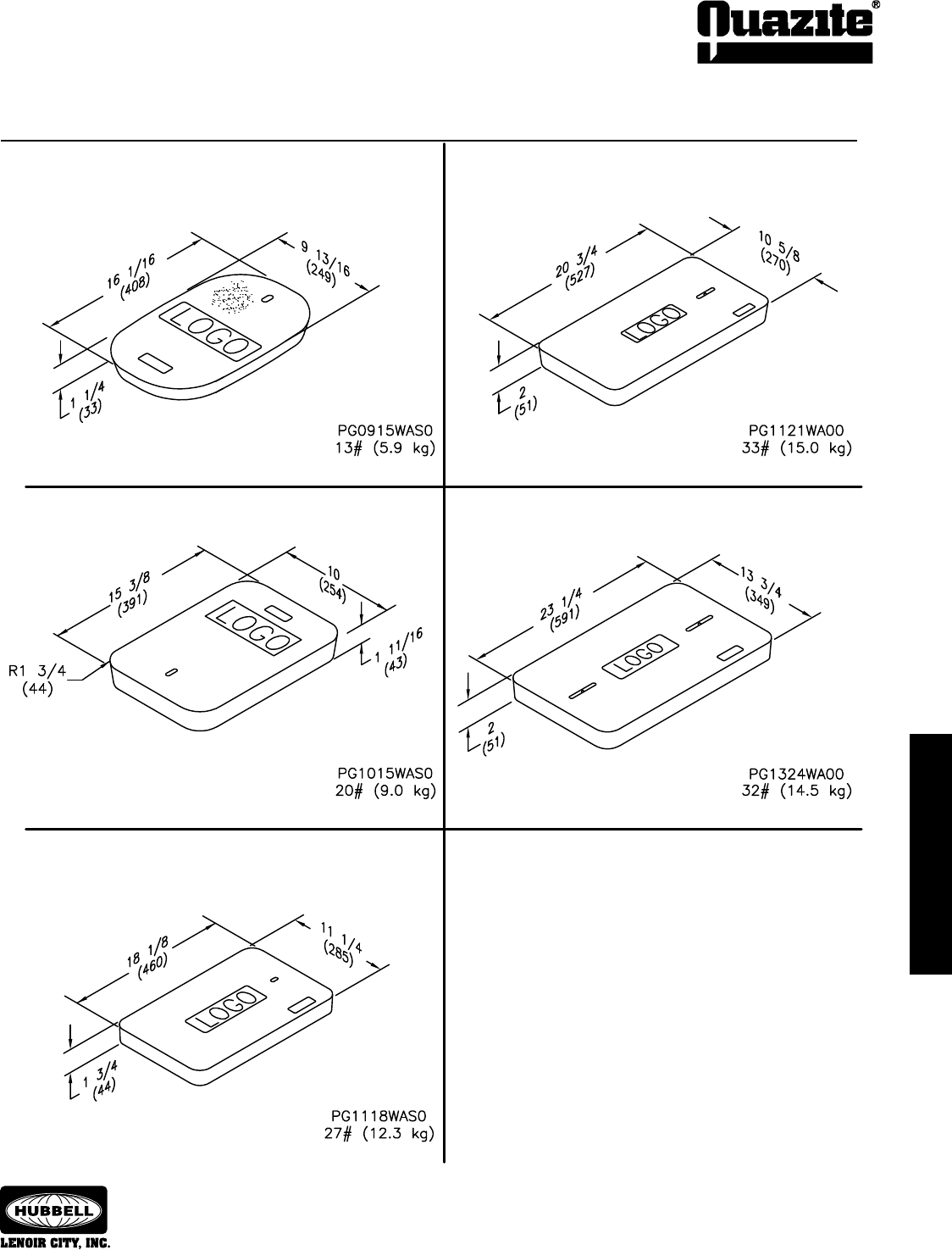
ENCLOSURE DRAWINGS
ENCLOSURE DRAWINGS
47
COVER DRAWINGS
COVER DRAWINGS
SEPTEMBER 2007
®
SPECIFICATIONS/DATA Replacement Covers
All covers have a .5 COF skid resistant surface.
Dimensions & weights in parentheses are metric equivalent.
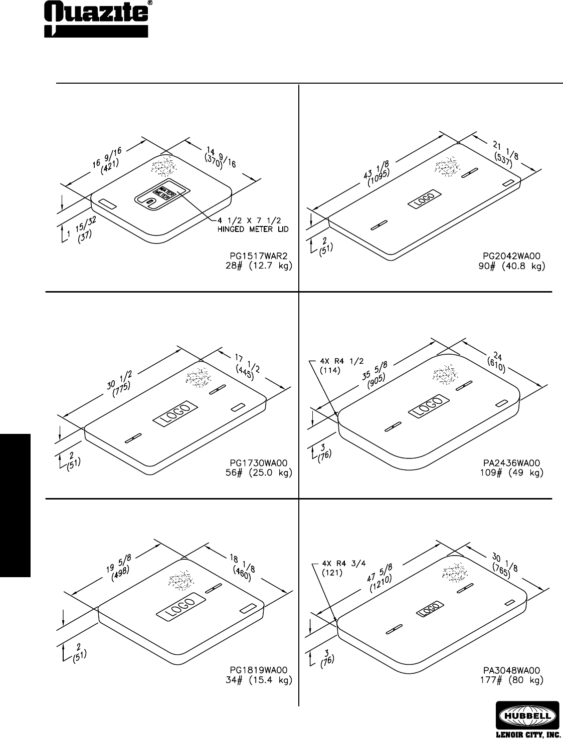
48
COVER DRAWINGS
COVER DRAWINGS
SEPTEMBER 2007
®
COVER DRAWINGS
COVER DRAWINGS
All covers have a .5 COF skid resistant surface.
Dimensions & weights in parentheses are metric equivalent.
SPECIFICATIONS/DATA Replacement Covers
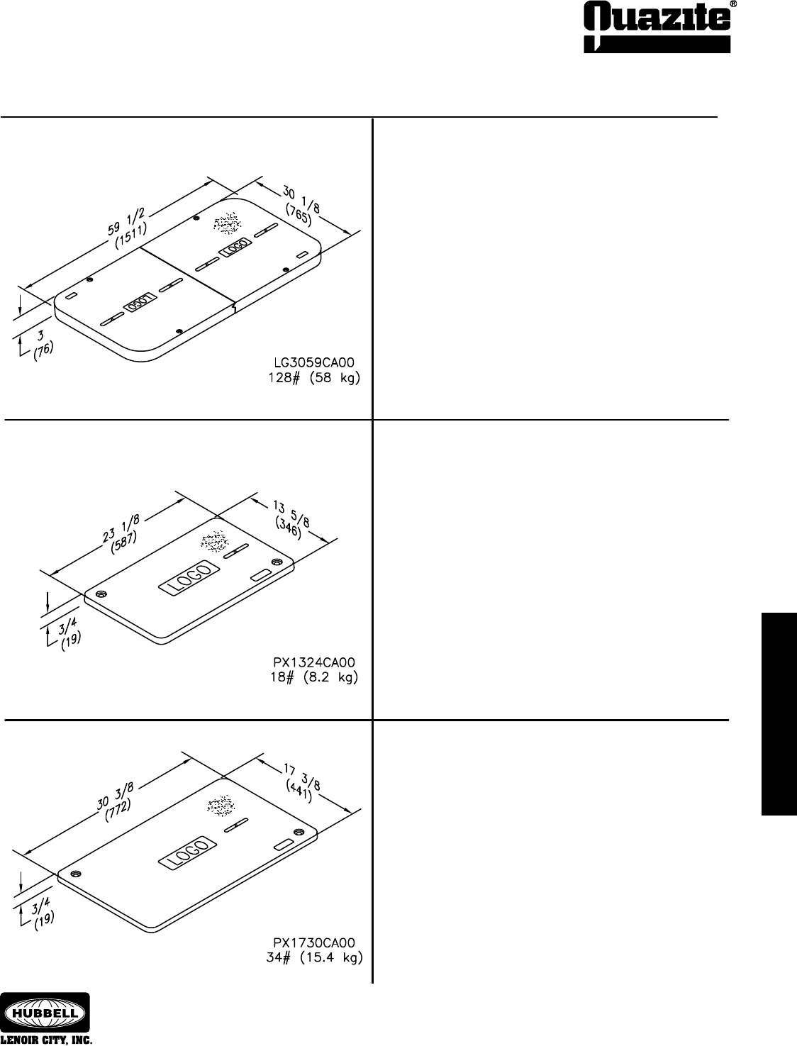
COVER DRAWINGS
COVER DRAWINGS
49
COVER DRAWINGS
COVER DRAWINGS
SEPTEMBER 2007
®
SPECIFICATIONS/DATA Replacement Covers
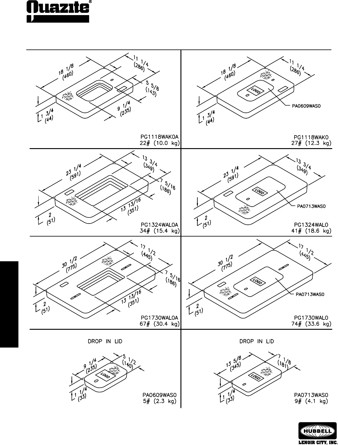
50
COVER DRAWINGS
COVER DRAWINGS
SEPTEMBER 2007
®
SPECIFICATIONS/DATA Meter Reading Covers and Lids
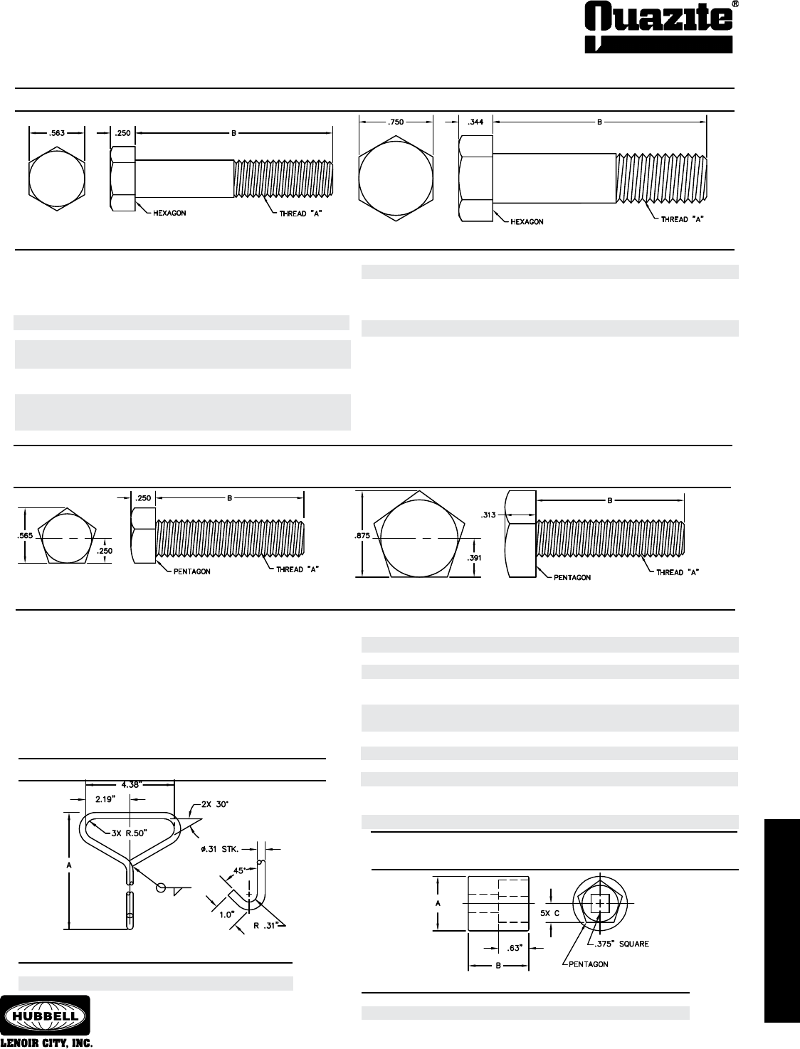
cover drawings
cover drawings
51
hardware & options
JANUARY 2008
®
3/8-16 UNC 1.50” 80024 12996 PC0608, PC0818,
PC1012, PC1118,
PC1212, LX1212
Thread UPC #
(A) (B) Part No. 66-237 Cover Application
Cover Hook - Electroplated Steel
Tamper Resistant Standard Penta-Head Socket
- Alloy Steel
Tamper Resistant Standard Penta-Head Bolt - Stainless Steel
(For use with penta-head socket #82922) (For use with penta-head socket #82920)
Standard Hex-Head Bolt - Stainless Steel
SPECIFICATIONS/DATA Hardware
Thread UPC #
(A) (B) Part No. 66-237 Cover Application
UPC #
Part No. 66-237 (A) (B) (C)
82920 11844 1.13” 2.00” .391”
82922 11845 .88” 1.50” .250”
82924 11846 .50”F to .375”M Adapter
Short Cover Hook 82905 11842 7.0”
Long Cover Hook 82908 11843 27.0”
UPC#
Description Part No. 66-237 (A)
3/8-16 UNC 1.50” 80023 12994 PC1324, PC1730, PX1324
PX1730
3/8-16 UNC 1.75” 80022 12940 PR2700, PR3900
3/8-16 UNC 2.50” 80026 13008 PG1015, PG1118
3/8-16 UNC 2.75” 80027 11837 PG2424, PT1324, PT1730
3/8-16 UNC 3.00” 80028 13009 PD1324, PD1730, PG1324,
PG1730
3/8-16 UNC 4.00” 80032 12995 PD2436, PD3048, PG2436,
PG3048, PG3636
3/8-16 UNC 4.50” 80031 13006 PG3048 (Overlapping)
1/2-13 UNC 1.75” 80122 13177 LG3660
1/2-13 UNC 2.25” 80124 12941 PR2200
1/2-13 UNC 3.50” 80129 11840 PG3660 (Overlapping)
1/2-13 UNC 4.00” 80131 13161 PG3060, PG3672, PG4848
PG4872, PG4896
1/2-13 UNC 5.00” 80132 13178 PG3060 (Overlapping)
3/8-16 UNC 1.50” 80008 13162 PC0608, PC0818
PC1012, PC1118
PC1212, PC1324
PC1730, PX1324
PX1730
3/8-16 UNC 1.75” 80009 13163 PR2700, PR3900
3/8-16 UNC 2.50” 80012 13411 PG1015, PG1118
3/8-16 UNC 2.75” 80013 13165 PG2424, PT1324
PT1730
3/8-16 UNC 3.00” 80036 13174 PD1324, PD1730
PG1324, PG1730
3/8-16 UNC 4.00” 80018 13166 PD2436, PD3048,
PG2436, PG3048
PG3636
3/8-16 UNC 4.50” 80017 13421 PG3048 (Overlapping)
Thread UPC #
(A) (B) Part No. 66-237 Cover Application
Thread UPC #
(A) (B) Part No. 66-237 Cover Application
1/2-13 UNC 1.75” 80107 13167 LG3660
1/2-13 UNC 3.50” 80114 13169 PG3660 (Overlapping)
1/2-13 UNC 4.00” 80119 13176 PG3060, PG3672
PG4848, PG4872
PG4896
1/2-13 UNC 5.00” 80108 13175 PG3060 (Overlapping)
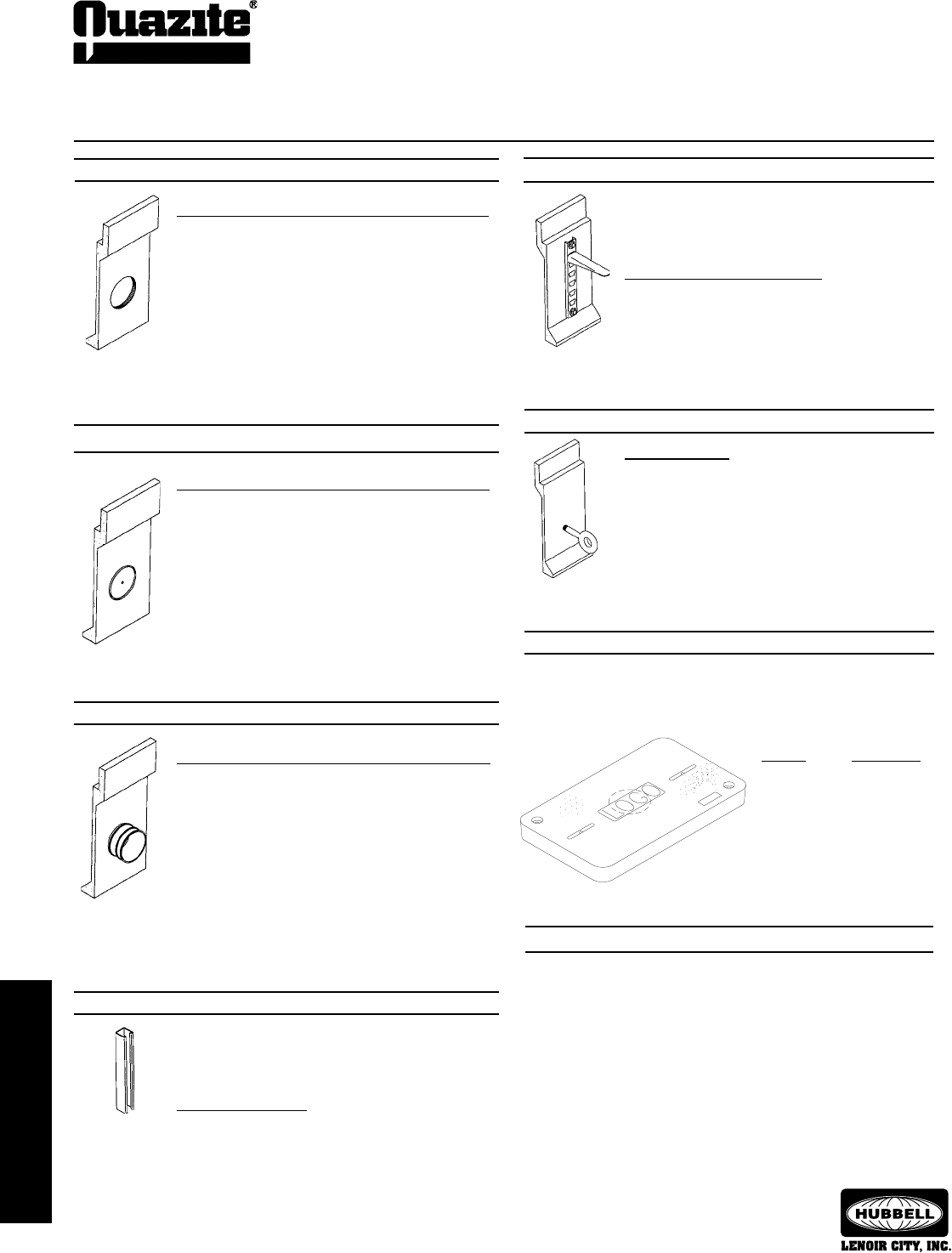
52
hArdWArE & optIonS
SEPTEMBER 2007
®
SPECIFICATIONS/DATA Options
Marker Frequency
Telephone 101.4 kHz
Power 169.8 kHz
Gas 83.0 kHz
Water 145.7 kHz
Sanitary 121.6 kHz
Conduit Sizes
(For actual hole sizes and locations see page 54.)
2”
3”
4” Electrical
4” Telephone
5”
6”
Other knockout sizes available. Contact your local
QUAZITE® representative for additional sizes.
Knockouts
Strut Racks
Box and cover struts available. Contact your local
QUAZITE® representative for sizes.
Inserts must be located in ribs. See page 54 for rib
locations.
Width x Depth
1-5/8” x 1-5/8”
Holes
Conduit Sizes
(For actual hole sizes and locations see page 54.)
2”
3”
4” Electrical
4” Telephone
5”
6”
Other hole sizes available. Contact your local
QUAZITE® representative for additional sizes.
Terminators
Conduit Sizes
(For actual hole sizes and locations see page 54.)
2”
3”
4” Electrical
4” Telephone
5”
6”
Other terminator sizes available. Contact your local
QUAZITE® representative for additional sizes.
Cable Racks & Rack Hooks - Galvanized Steel
Cable Racks available in the following lengths:
12”, 18”, 24”, 30”, 36” & 48”
See page 54 for cable rack locations.
Cable Rack Hooks Part No.
7-1/2” length 80905
10” length 80907
Pulling Eyes
Available Ratings
1,500 lbs.
3,000 lbs.
10,000 lbs.
Electronic Markers (cast in cover)
Full Range Electronic Markers are encased in the polymer
concrete cover for protection. Specify power, gas, sanitary water
or telephone as each type of utility has a different signal for
identication.
Special order boxes with holes (or mouseholes, etc.)
may qualify for UL Listing as long as the holes do not
exceed more than 25% of the area of each sidewall
and as long as the holes do not cut into a structural
reinforcing rib, corner, or box lip.
Special order boxes with knockouts may qualify for
UL Listing as long as the holes do not exceed more
than 25% of the area of each sidewall.
Special order boxes with terminators may qualify for
UL Listing as long as the holes do not exceed more
than 25% of the area of each sidewall.
Captive Bolts
Captive bolts are available for PG, LG, PT, LT and PR style covers.
Captive bolts prevent the bolt from falling out of the cover when the
cover is removed.
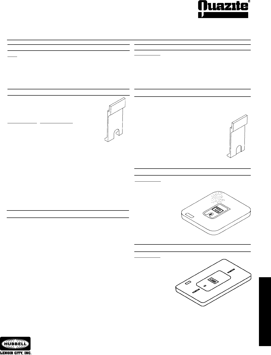
53
HARDWARE & OPTIONS
SEPTEMBER 2007
®
SPECIFICATIONS/DATA Options
Bolt Holes
Sizes
3/8”
1/4”
1/2”
Mouseholes
There is no additional charge for mouseholes in
the standard size and location for their respective
enclosures. PC0608, PC0818 and PC1212 boxes
usually do not have mouseholes. See pg. 54 for
locations.
Mousehole Sizes Standard on Boxes
2-1/2” x 4” LT1015, PC1118, PG1118
4” x 4” PC1324, PT1324, PC1730,
PT1730, PG1324, PG2424,
PG1730, PD1730, PG2436,
PG3048, PD3048, PG3636
6” x 8” PG3060, PG3660, PG3672, PG4848, PG4872,
PG4896
Special order boxes with mouseholes may qualify for UL Listing as long
as the mouseholes do not exceed more than 25% of the area of each
sidewall.
Other sizes available. Contact your local QUAZITE® representative for
information.
Pull Slots
The standard cover pull slot measures 1/2” x 4”. Bell cover pull slots
measuring 1” x 4” are available upon request.
Drop-in Meter Lids
Available Sizes
K - Polymer concrete 6” x 9” drop-in lid
L - Polymer concrete 7” x 13” drop-in lid
Hinged Meter Lids
Available Sizes
R - Cast iron 4 1/2” x 7 1/2” lid
P - Cast iron 6” x 9” lid
Q - Cast iron 9” x 12” lid with frame
Mousehole Knockouts
There is no additional charge for mousehole knockouts in the
standard size and location for their respective enclosures. Contact
your local QUAZITE® representative for size options. See pg. 54 for
locations.
Available Sizes
3/8” or 1/2”
Inserts - 18-8 Stainless Steel
Inserts must be located in ribs. See page 54 for rib locations.
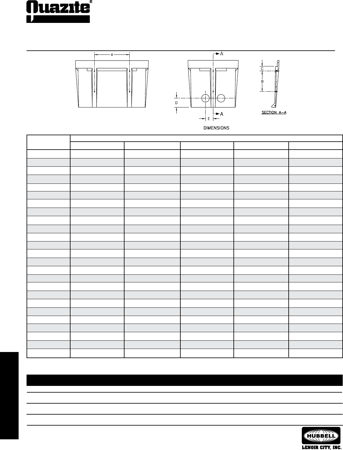
54
HARDWARE & OPTIONS
SEPTEMBER 2007
®
Quazite recommends that holes be punched 1/8” to 1/4” larger than the actual outside diameter of the conduit duct. If more precise holes
are required, contact your local QUAZITE® representative.
HOLE SIZING FOR NON-METALLIC CONDUIT / DUCT
NOMINAL SIZE 1/2” 3/4” 1” 1 1/4” 1 1/2” 2” 3” 4” (elec.) 4” (tele.) 5” 6”
CONDUIT O.D. .840 1.050 1.315 1.660 1.900 2.375 3.500 4.500 4.350 5.563 6.625
HOLE SIZE 1” 1 1/4” 1 3/8” 1 3/4” 2” 2 1/2” 3 3/4” 4 3/4” 4 3/4” 5 3/4” 6 3/4”
SPECIFICATIONS/DATA Standard Cable Rack Insert, Terminator, Knockout & Hole Locations
NOTE - Holes should be located only in the walls of an enclosure. Do not cut holes in ribs or corners. Hole locations are ± 1” (25mm).
Dimensions & weights in parentheses are metric equivalent.
PART NO.
BOXES
DIMENSIONS
AB C D
PG2424BA24 12” (305 mm) 10 1/2” (267mm) 4” (102 mm) 5 1/2” (140mm) 4” (102mm)
PG2436BA18 18” (457mm) 9” (229mm) 2 1/2” (64 mm) 5 1/2” (140mm) 4” (102mm)
PG2436BA24 18” (457mm) 13 1/2” (343mm) 2 1/2” (64 mm) 5 1/2” (140mm) 4” (102mm)
PG2436BA30 18” (457mm) 13 1/2” (343mm) 2 1/2” (64 mm) 5 1/2” (140mm) 4” (102mm)
PG2436BA42 18” (457mm) 13 1/2” (343mm) 2 1/2” (64 mm) 5 1/2” (140mm) 4” (102mm)
PD3048BA24 22” (559mm) 10 1/2” (267mm) 6” (152 mm) 5 1/2” (140mm) 5 1/2” (140mm)
PD3048BA48 22” (559mm) 13 1/2” (343 mm) 6” (152 mm) 5 1/2” (140mm) 5 1/2” (140mm)
PG3048BA18 22” (559mm) 9” (229mm) 2 1/2” (64 mm) 5 1/2” (140mm) 5 1/2” (140mm)
PG3048BA24 22” (559mm) 10 1/2” (267mm) 2 1/2” (64 mm) 5 1/2” (140mm) 5 1/2” (140mm)
PG3048BA36 22” (559mm) 13 1/2” (343mm) 2 1/2” (64 mm) 5 1/2” (140mm) 5 1/2” (140mm)
PG3060BA21 20 3/4” (527mm) 10 1/2” (267mm) 2 1/2” (64 mm) 5 1/2” (140mm) 7” (178mm)
PG3060BA30 24” (610mm) 10 1/2” (267mm) 2 1/2” (64 mm) 5 1/2” (140mm) 7” (178mm)
PG3060BA36 20 3/4” (527mm) 10 1/2” (267mm) 2 1/2” (64 mm) 5 1/2” (140mm) 7” (178mm)
PG3636BA36 18” (457mm) 13 1/2” (343mm) 2 1/2” (64 mm) 5 1/2” (140mm) 7” (178mm)
PG3660BA19 22” (559mm) 10 1/2” (267mm) 4” (102 mm) 5 1/2” (140mm) 9” (229mm)
PG3660BA24 22” (559mm) 10 1/2” (267mm) 4” (102 mm) 5 1/2” (140mm) 9” (229mm)
PG3660BA31 22” (559mm) 10 1/2” (267mm) 4” (102 mm) 5 1/2” (140mm) 9” (229mm)
PG3660BA36 22” (559mm) 10 1/2” (267mm) 4” (102 mm) 5 1/2” (140mm) 9” (229mm)
PG3672BA21 20” (508mm) 10 1/2” (267mm) 3” (76 mm) 5 1/2” (140mm) 9” (229mm)
PG3672BA36 20” (508mm) 10 1/2” (267mm) 3” (76 mm) 5 1/2” (140mm) 9” (229mm)
PG4848BA36 22” (559mm) 10 1/2” (267mm) 5 1/2” (140 mm) 7” (178mm) 5 1/2” (140mm)
PG4848BA48 22” (559mm) 10 1/2” (267mm) 5 1/2” (140 mm) 7” (178mm) 5 1/2” (140mm)
PG4872BA36 46” (1168mm) 13 1/2” (343mm) 5 1/2” (140 mm) 7” (178mm) 5 1/2” (140mm)
PG4872BA48 46” (1168mm) 13 1/2” (343mm) 5 1/2” (140 mm) 7” (178mm) 5 1/2” (140mm)
PG4896BA48 24 3/16” (614mm) 13 1/2” (343mm) 5 1/2” (140 mm) 7” (178mm) 5 1/2” (140mm)
E
Mouseholes (not illustrated) - The standard location for mouseholes
is in the center of the end walls of the enclosure.
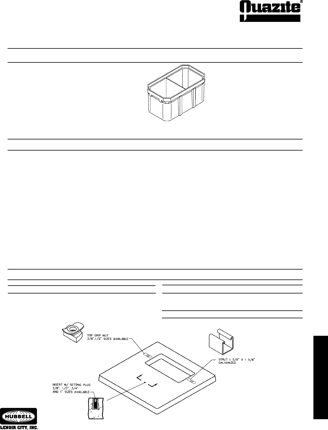
55
HARDWARE & OPTIONS
SEPTEMBER 2007
®
Dividers are available for the following size enclosures:
24” x 36” x 18”
24” x 36” x 30”
24” x 36” x 42”
30” x 48” x 18”
30” x 48” x 36”
30” x 60” x 21”
30” x 60” x 36”
36” x 36” x 36”
36” x 60” x 36”
SPECIFICATIONS/DATA Divided Boxes, Logos, Pad Options
Divided Boxes
All covers are supplied without a logo unless specied. Most Commonly Used Logos may be ordered without an extra charge. Other available
logos may be ordered with a set-up charge. New logos require a one time charge. (The PC0608 can accommodate only 13 letters and spaces.)
Most Commonly Used Cover Logos
17 Electric
09 Blank
46 Trafc Signal
41 Street Lighting
12 Communications
10 CATV
79 Electric 20K Static Load
50 Water
21 Fiber Optics
44 Trafc
29 Lighting
43 Telephone
24 Ground
7Z Telephone 20K Static Load
84 Power
22 Fire Alarm
65 Illumination
26 High Voltage
38 Signal
92 Telecommunications
14 Controls
ZA Irrigation
36 Security
81 Danger High Voltage
45 Trafc Control
Logos
Pad Options
Struts - Galvanized Steel Top-Grip Nuts - Zinc Plated
Typical strut lengths are 3” and 5”. Contact your local QUAZITE®
representative for additional lengths.
Available in 3/8” or 1/2” sizes.
Inserts - Zinc Alloy
Available in 3/8”, 1/2”, 3/4” and 1” sizes.
Dividers are typically located at the center of the box. Multiple dividers are also available. Additional dividers not listed may be available upon
request. Contact your local QUAZITE® representative.
36” x 72” x 21”
36” x 72” x 36”
48” x 48” x 36”
48” x 48” x 48”
48” x 72” x 36”
48” x 72” x 48”
48” x 96” x 36”
48” x 96” x 48”
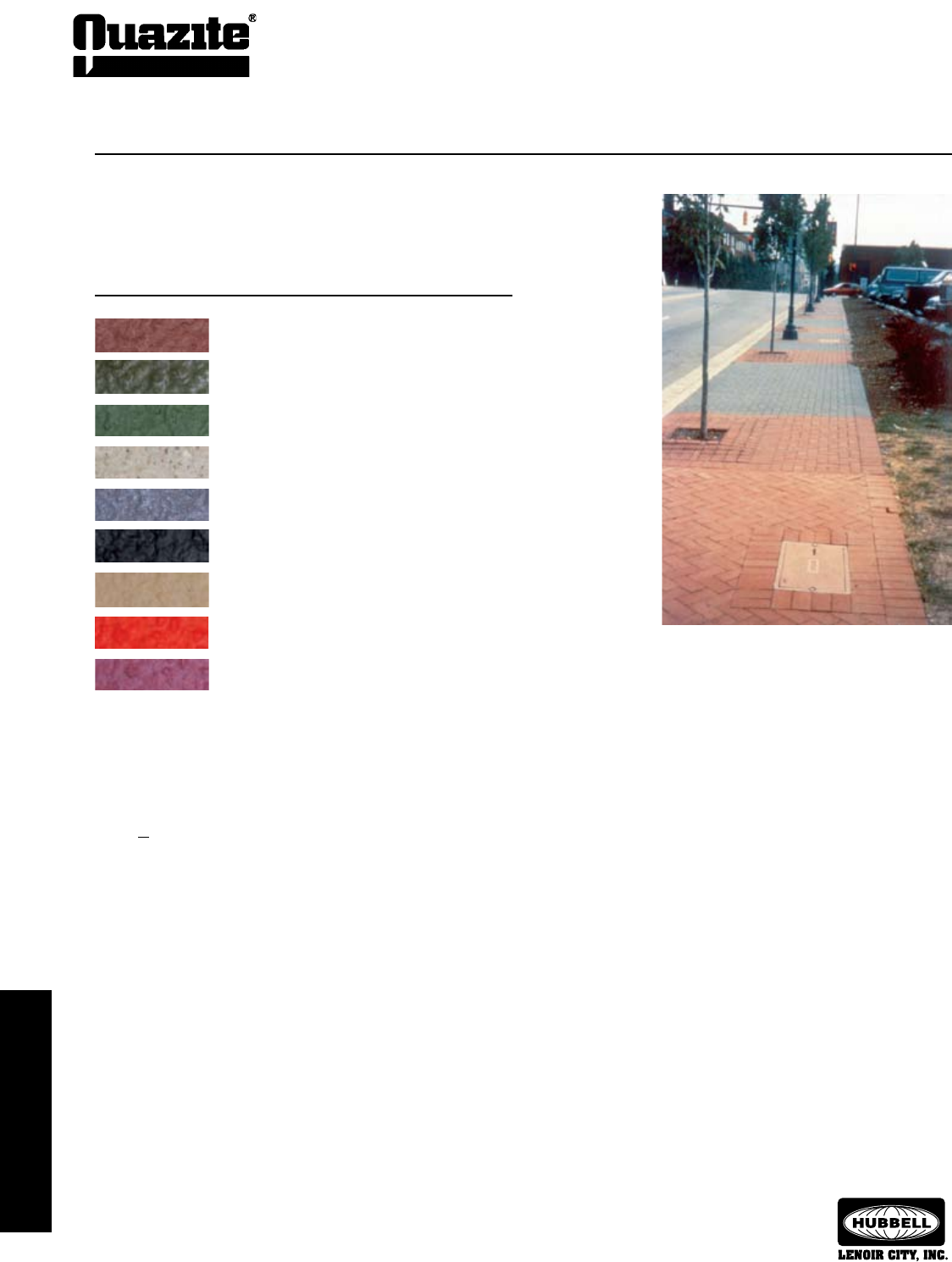
56
HARDWARE & OPTIONS
SEPTEMBER 2007
®
ELECTRICAL
EQUIPMENT PADS
ELECTRICAL
EQUIPMENT PADS
SPECIFICATIONS/DATA Color Options
Color options seen above at the Tennessee State
Aquarium in Chattanooga, Tennessee.
The standard color for QUAZITE® products is concrete gray. Various color options allow
for matching adjacent materials or special identification of enclosures. Some commonly
requested colors include:
Color Sample Description Part No. Code
Brick Red R
Forest Green G
Light Green F
Cement Gray C
Charcoal Gray D
Black B
Pecan P
International Orange A
Purple N
(non-potable water)
Note: Printed colors do not exactly represent product colors.
Contact your local QUAZITE® representative for other special colors.
When ordering, the color of the box and cover should be designated in the 6th digit of the
part number. For example, a forest green PG1730BA18 box or cover would be ordered as
PG173GBA18.
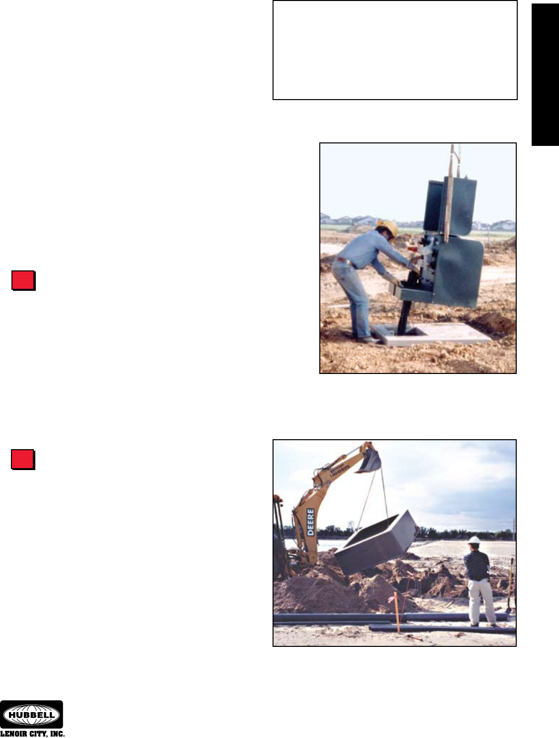
57
ELECTRICAL
EQUIPMENT PADS
ELECTRICAL
EQUIPMENT PADS
SEPTEMBER 2007
®
Information shown in catalog is a partial listing. If pad or throat
size desired is not listed, contact Quazite eld sales ofce.
Determine Pad Type
QUAZITE® offers two types of pads to choose from: flat pads
and box pads.
Flat pads and box pads offer different advantages. Flat pads
are light weight and require only a small amount of digging to set. Flat
pads can be installed on hillsides by using a hill holder. The optional
SPLITT-PAD® design may be preferred for retrofit installations requiring
the use of a flat pad. Box pads offer the advantage of providing room to
train and coil extra cable underneath the equipment if needed.
Quazite’s engineering staff will be happy to assist you in de-
termining the proper pad for your application. Throat sizes and insert
locations on both pads and box pads can be tailored to meet your
requirements.
Electrical Equipment Pad
Selection Guide
Using The Selection Guide
Follow the steps outlined in this guide to select the appropriate
pad for your application. For more information or for answers to any
questions you might have, call your local QUAZITE® representative.
Detailed product drawings can be found in this section and also can
be viewed on our website:
www.quazite.com
Determine Type of Equipment
QUAZITE® offers a variety of pads and box pads that work with
most transformers and switchgear manufactured today.
QUAZITE® pads are available for most Single-phase transformers
rated 10 kVA - 167 kVA and Three-phase transformers rated up to 2,500
kVA. Larger sizes can be made to suit your application.
QUAZITE® switchgear box pads are designed to fit most manu-
facturers’ switchgear rated 15 kV, 25 kV and 35 kV. Please see the
Switchgear Cross Reference Guide on page 58 for more information.
Quazite offers QUAZITE® single-phase transformer pads that
work with most transformers on the market today.
Lightweight QUAZITE® switchgear box pads (seen above) can be set in place
with the backhoe used to dig the hole (precast concrete pads this size would
require a crane to lift and install). The switchgear box pad also provides a large
underground area with room to “train” cable into the switchgear.
To Select the Pad You Need for Your Application:
1 .... Determine Type of Equipment
2 .... Determine Pad Type
3 .....Determine Pad Dimensions
4 .....Determine Performance Requirements
5 .....Determine Installation Requirements
1
2

ELECTRICAL
EQUIPMENT PADS
ELECTRICAL
EQUIPMENT PADS
58
SEPTEMBER 2007
®
ELECTRICAL
EQUIPMENT PADS
ELECTRICAL
EQUIPMENT PADS
Information shown in catalog is a partial listing. If pad or throat
size desired is not listed, contact Quazite eld sales ofce.
Switchgear Box Pad
Cross Reference Guide
To Select the Pad You Need for Your Application:
1 .....Determine Type of Equipment
2 .... Determine Pad Type
3 .....Determine Pad Dimensions
4 .....Determine Performance Requirements
5 .....Determine Installation Requirements
Cooper Power (Kyle Type)
Contact your local QUAZITE® representative for details.
Federal Pacific
Model kV Cabinet Size Throat Size Insert Location Part No.
PSE-SC-9 15 75 x 69 3/4 62 x 67 49 1/2 x 69 1/2 PB74766267B36
PSE-SC-11 15 75 x 72 3/4 62 x 67 55 1/2 x 69 1/2 PB74766267B36
PSE-SC-Deadfront 25 84 x 88 1/4 72 x 77 58 1/2 x 78 1/2 PB93937277B36
PSE-SC-Deadfront 25 81 3/4 x 84 72 x 77 52 x 78 1/2 PB93937277B36
PSI/II-5 25 74 1/2 x 43 43 x 60 66 1/2 x 35 PB74764360B36
PSI/II-61 15 67 x 72 62 x 67 49 1/2 x 69 1/2 PB74766267B36
PSI/II-9 15 58 1/2 x 67 50 x 62 53 x 49 PB74765062B36
PSI/II-9 25 74 1/2 x 82 66 x 72 69 x 64 PB93936672B36
G & W Electric
Contact your local QUAZITE® representative for details.
AB Chance
Model kV Cabinet Size Throat Size Insert Location Part No.
AIS-1 15-95 36 7/8 x 30 30 x 22 (2) 25 (Center) PB44443022B32
AIS-1A 15-95 31 7/8 x 41 31 x 31 (2) 36 (Center) PB44443131B32
AIS-6 15-95 64 1/2 x 75 57 x 67 49 1/2 x 70 PB74765767B36
AIS-9 15-95 64 1/2 x 75 57 x 67 49 1/2 x 70 PB74765767B36
AIS-10 15-95 70 1/2 x 75 57 x 67 55 1/2 x 70 PB74765767B36
AIS-11 15-95 70 1/2 x 75 57 x 67 55 1/2 x 70 PB74765767B36
AIS-12 15-95 64 1/2 x 75 57 x 67 49 1/2 x 70 PB74765767B36
AIS-13A 15-95 70 1/2 x 75 57 x 67 55 1/2 x 70 PB74765767B36
AIS-1 25-125 49 3/4 x 35 1/4 30 x 22 (2) 30 1/4 (Center) PB40583022B24
AIS-1A 25-125 49 3/4 x 46 1/2 15 x 37 (2) 41 1/2 (Center) PB52501537B18
AIS-6 25-125 79 1/2 x 84 74 x 76 64 1/2 x 79 PB93937476B36
AIS-9 25-125 79 1/2 x 84 74 x 76 64 1/2 x 79 PB93937476B36
AIS-10 25-125 86 x 84 74 x 76 71 x 79 PB93937476B36
AIS-11 25-125 86 x 84 74 x 76 71 x 79 PB93937476B36
AIS-12 25-125 79 1/2 x 84 74 x 76 64 1/2 x 79 PB93937476B36
AIS-13A 25-125 86 x 84 74 x 76 71 x 79 PB93937476B36
S&C Electric
Model kV Cabinet Size Throat Size Insert Location Part No.
PMH-6 14.4 60 3/4 x 67 50 x 62 53 x 49 PB74765062B36
PMH-9 14.4 60 3/4 x 67 50 x 62 53 x 49 PB74765062B36
PMH-10 14.4 60 3/4 x 67 50 x 62 53 x 49 PB74765062B36
PMH-11 14.4 60 3/4 x 67 50 x 62 53 x 49 PB74765062B36
PME-6 14.4 66 3/4 x 75 62 x 67 49 1/2 x 69 1/2 PB74766267B36
PME-9 14.4 66 3/4 x 75 62 x 67 49 1/2 x 69 1/2 PB74766267B36
PME-10 14.4 72 3/4 x 75 62 x 67 55 1/2 x 69 1/2 PB74766267B36
PME-11 14.4 72 3/4 x 75 62 x 67 55 1/2 x 69 1/2 PB74766267B36
PME-12 14.4 66 3/4 x 75 62 x 67 49 1/2 x 69 1/2 PB74766267B36
PMH-6 25 76 3/4 x 82 66 x 72 1/2 69 x 64 PB93936672B36
PMH-9 25 76 3/4 x 82 66 x 72 1/2 69 x 64 PB93936672B36
PMH-10 25 76 3/4 x 82 66 x 72 1/2 69 x 64 PB93936672B36
PMH-11 25 76 3/4 x 82 66 x 72 1/2 69 x 64 PB93936672B36
PME-6 25 81 3/4 x 84 72 1/2 x 77 52 x 78 1/2 PB93937277B36
PME-9 25 81 3/4 x 84 72 1/2 x 77 52 x 78 1/2 PB93937277B36
PME-10 25 88 1/4 x 84 72 1/2 x 77 58 1/2 x 78 1/2 PB93937277B36
PME-11 25 88 1/4 x 84 72 1/2 x 77 58 1/2 x 78 1/2 PB93937277B36
PME-12 25 81 3/4 x 84 72 1/2 x 77 52 x 78 1/2 PB93937277B36
320,321,330 15.5 61 x 72 43 x 43 37 x 45 3/8, (2) 57 PB74764343B36
413,422,431,440 15.5 61 x 72 43 x 60 5/8 37 x 63, (2) 57 PB74764360B36
320,321,330 29 65 x 72 43 x 43 37 x 45 3/8, (2) 57 PB74764343B36
413,422,431,440 29 65 x 72 43 x 60 5/8 37 x 63, (2) 57 PB74764360B36
320,321,330 38 65 x 79 49 x 49 37 x 53 1/8, (2) 64 PB74764949B36
413,422,431,440 38 65 x 79 50 x 67 37 x 70 3/8,(2) 64 PB93935067B36
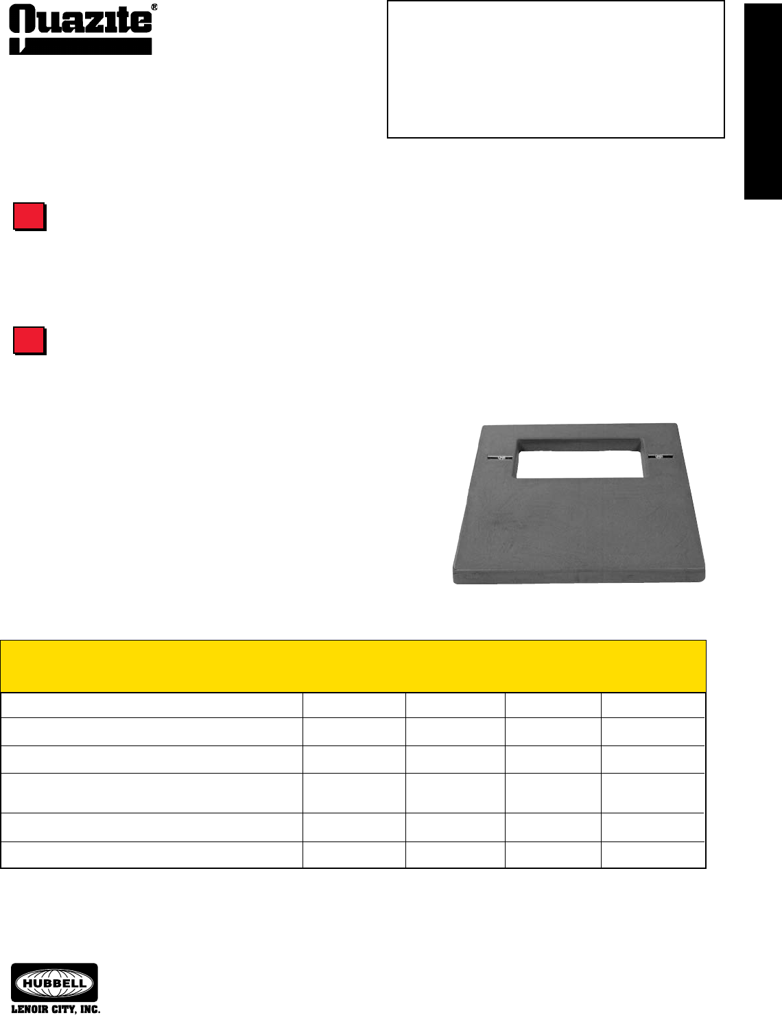
ELECTRICAL
EQUIPMENT PADS
ELECTRICAL
EQUIPMENT PADS
59
ELECTRICAL
EQUIPMENT PADS
ELECTRICAL
EQUIPMENT PADS
SEPTEMBER 2007
®
Information shown in catalog is a partial listing. If pad or throat
size desired is not listed, contact Quazite eld sales ofce.
Electrical Equipment Pad
Selection Guide
QUAZITE® pads are constructed of strong polymer concrete and reinforced with a heavy-weave fiberglass. Unlike fiberglass or plastic
pads, QUAZITE®’s strength assures that the pad will support the weight of the equipment mounted to it without bending or cracking. QUAZITE®
pads are tested for structural integrity by applying a 1,000 lb. load to the surface distributed by a 5” x 7” steel plate. Each corner is tested
separately by applying a 1,500 lb. load over the same plate positioned one inch from the edge.
No damage occurs and deflection is less than 0.15”.
QUAZITE® polymer concrete pads also resist UV rays, chemicals and water absorp-
tion. Plastic and fiberglass pads can become brittle and eventually crack when exposed
to the weather. The durability that QUAZITE® provides means lower maintenance and life
cycle costs.
Stable under loading during high temperatures (won’t flex or warp) X X X
Stable under loading during cold temperatures (won’t crack) X
Not susceptible to damage caused by freeze/thaw cycles X X
Resistant to corrosion caused by weathering, road chemicals, X X
and equipment lubricants
Provides long-term durability (fatigue or creep resistant) X X X
Withstands impacts and other damage caused by lawn equipment X X X
Pad Performance
QUAZITE®
Determine Pad Dimensions
Determine Performance Requirements
To determine the proper pad dimensions for your application, calculate the size of the equipment and the amount of workspace desired
and then specify the size and location of the throat. The electrical equipment footprint must match the pad/box pad dimensions and insert
locations to ensure transformers and switchgear will properly mount to the pad or box pad. The pad/box pad also must have a throat opening
that provides adequate space for cable and/or conduit to come through.
To Select the Pad You Need for Your Application:
1 .....Determine Type of Equipment
2 .....Determine Pad Type
3 .... Determine Pad Dimensions
4 .... Determine Performance Requirements
5 .....Determine Installation Requirements
3
4
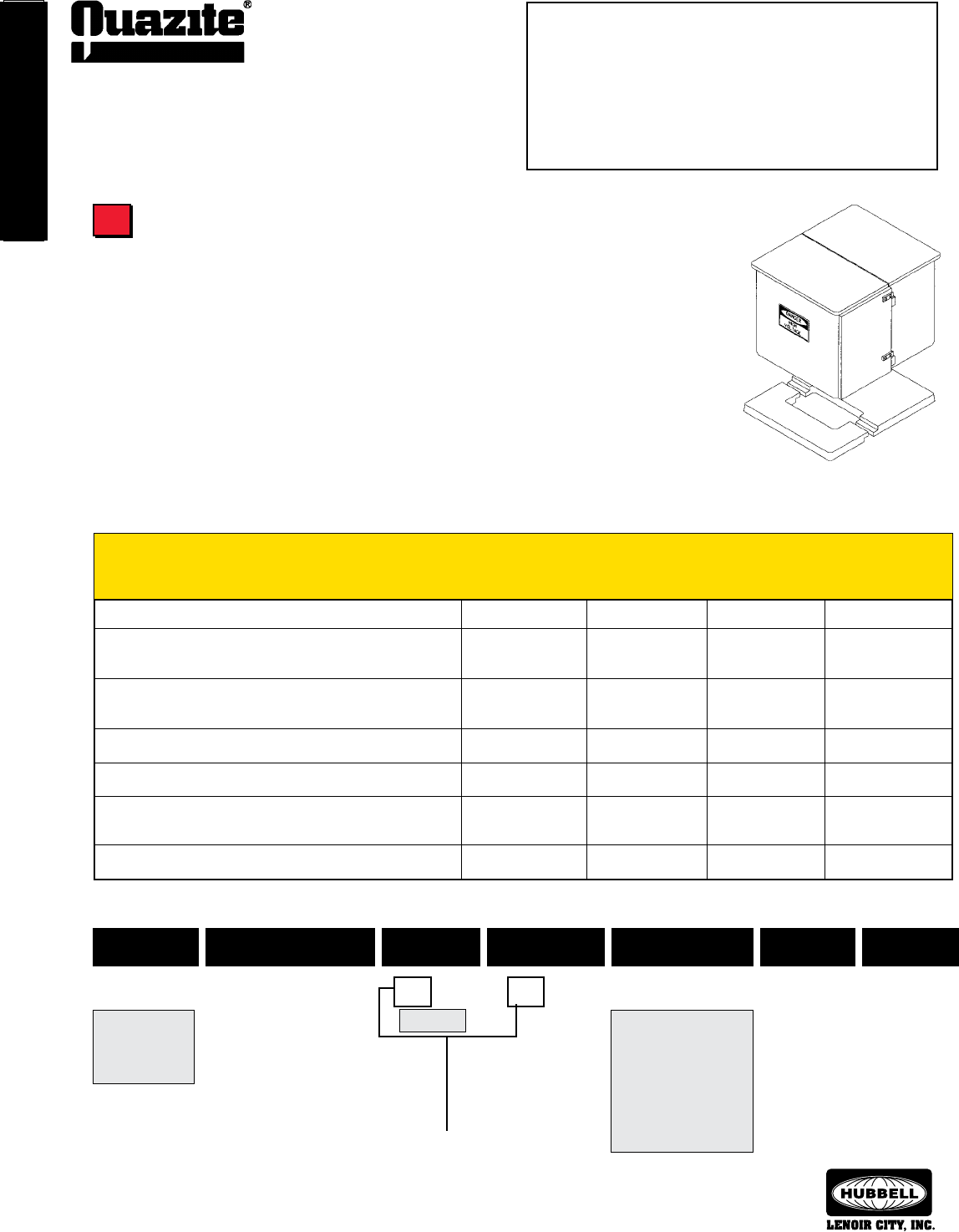
ELECTRICAL
EQUIPMENT PADS
ELECTRICAL
EQUIPMENT PADS
60
SEPTEMBER 2007
®
ELECTRICAL
EQUIPMENT PADS
ELECTRICAL
EQUIPMENT PADS
Information shown in catalog is a partial listing. If pad or throat
size desired is not listed, contact Quazite eld sales ofce.
Installing QUAZITE® pads is easy and cost effective because it requires no special equipment to set
the pad. A backhoe is all that is necessary to lift the pad in place. QUAZITE® pads also save time during
installation. Unlike poured-in-place pads that can take hours or days to form, pour, set, and remove the
forms, QUAZITE® pads can be installed in a matter of minutes and installation of electrical equipment can
begin immediately after the pad is set.
The optional SPLITT-PAD® design makes retrofit installations easy and eliminates the need to
disconnect service during installation. Simply break away the old concrete or other material underneath
the equipment cabinet and slip the SPLITT-PAD® underneath. Complete the installation by bolting the two-
piece pad together at the throat. For more detailed instructions on how to install the SPLITT-PAD® and other
QUAZITE® pads, see page 94.
Determine Installation Requirements
Electrical Equipment Pad
Selection Guide
SPLITT-PAD®
To Select the Pad You Need for Your Application:
1 .....Determine Type of Equipment
2 .....Determine Pad Type
3 .....Determine Pad Dimensions
4 .....Determine Performance Requirements
5 .... Determine Installation Requirements
Pad Installation
QUAZITE®
5
Weight Style Size Throat Size Item Depth Surface
P L 4846 0817 A 3 T
L - Lightweight
mix
P - Standard
mix
Pad Numbering System
8” x 17” 3” thick
(Indicates surface
thickness if flat pad;
indicates depth if
box pad.)
B - Box pad
H - Electrical equipment pad
J - Split electrical equipment pad
K - Split telecommunications equip-
ment pad
L - Telecommunications equipment
pad
S - Smooth
T - Skid resistant
48” x 46”
Dimensions run parallel to
each other.
A - 3/8-16 UNC inserts
B - 1/2-13 UNC inserts
C - 5/8-11 UNC inserts
E - 5/8 thru hole
F - Struts w/ 3/8” inserts
G - Struts w/ 1/2” inserts
H - Struts w/ 5/8” inserts
Easily installed in areas with limited accessibility X X
Minimal planning and scheduling of crews required for X X
installation
No special equipment (such as a boom truck or crane) needed X X
for installation
Easily installed by no more than two crew members (lightweight) X X
Equipment and pad can be easily installed in the same day X X X
Available as a two-piece pad so that service does not have to be X X
disconnected when retrofitting
Flat surface allows equipment to fit flush with the pad X
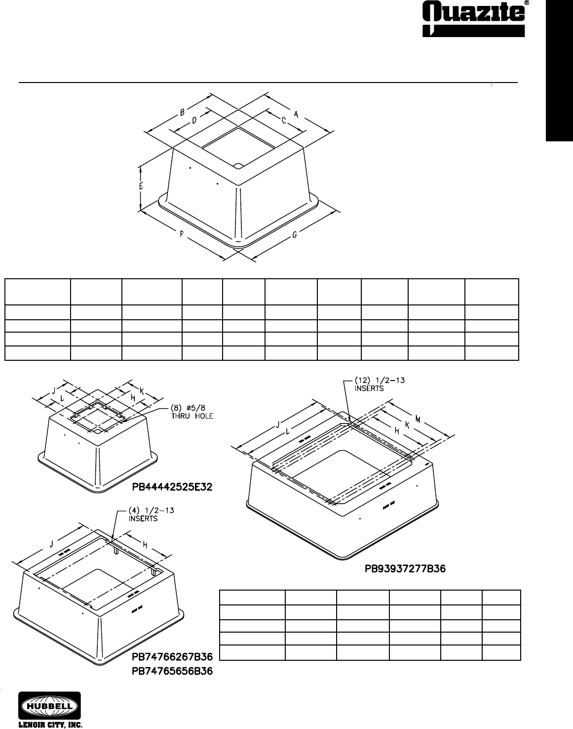
ELECTRICAL
EQUIPMENT PADS
ELECTRICAL
EQUIPMENT PADS
61
ELECTRICAL
EQUIPMENT PADS
ELECTRICAL
EQUIPMENT PADS
SEPTEMBER 2007
®
Information shown in catalog is a partial listing. If pad or throat
size desired is not listed, contact Quazite eld sales ofce.
Additional throat sizes and insert locations are available.
Dimensions in parentheses are metric equivalent.
SPECIFICATIONS/DATA Box Pads
Insert Locations
Refer to Switchgear Box Pad Cross Reference Guide on page 58.
NEW OLD WEIGHT
PART NO. PART NO. # A B C D E F G
PB44442525E32 PB4444BA32 500 (226.8 kg) 44” (1118) 44” (1118) 25” (635) 25” (635) 32” (812.8) 57” (1448) 57” (1448)
PB74766267B36 PB7476BA36 841 (381.5 kg) 74” (1880) 76” (1930) 62” (1575) 67” (1702) 36” (914.4) 87 1/4” (2216) 89 1/4” (2267)
PB74765656B36 PB7476B500 880 (399.2 kg) 74” (1880) 76” (1930) 56” (1422) 56” (1422) 36” (914.4) 87 1/4” (2216) 89 1/4” (2267)
*PB93937277B36 PB9393BA36 1238 (561.5 kg) 93” (2362) 93” (2362) 72 1/2” (1842) 77” (1956) 36” (914.4) 101” (2565) 101” (2565)
* Contact factory. Special order and freight terms apply.
* Contact factory. Special order and freight terms apply.
NEW PART NO. H J K L M
PB44442525E32 13” (330.2) 28” (711.2) 28” (711.2) 13” (330.2) —
PB74766267B36 46” (1168) 70” (1778) — — —
PB74765656B36 50 1/2” (1283) 61 1/2” (1562) — — —
*PB93937277B36 52” (1321) 78 1/2” (1994) 58 1/2” (1486) 76” (1930) 65” (1651)
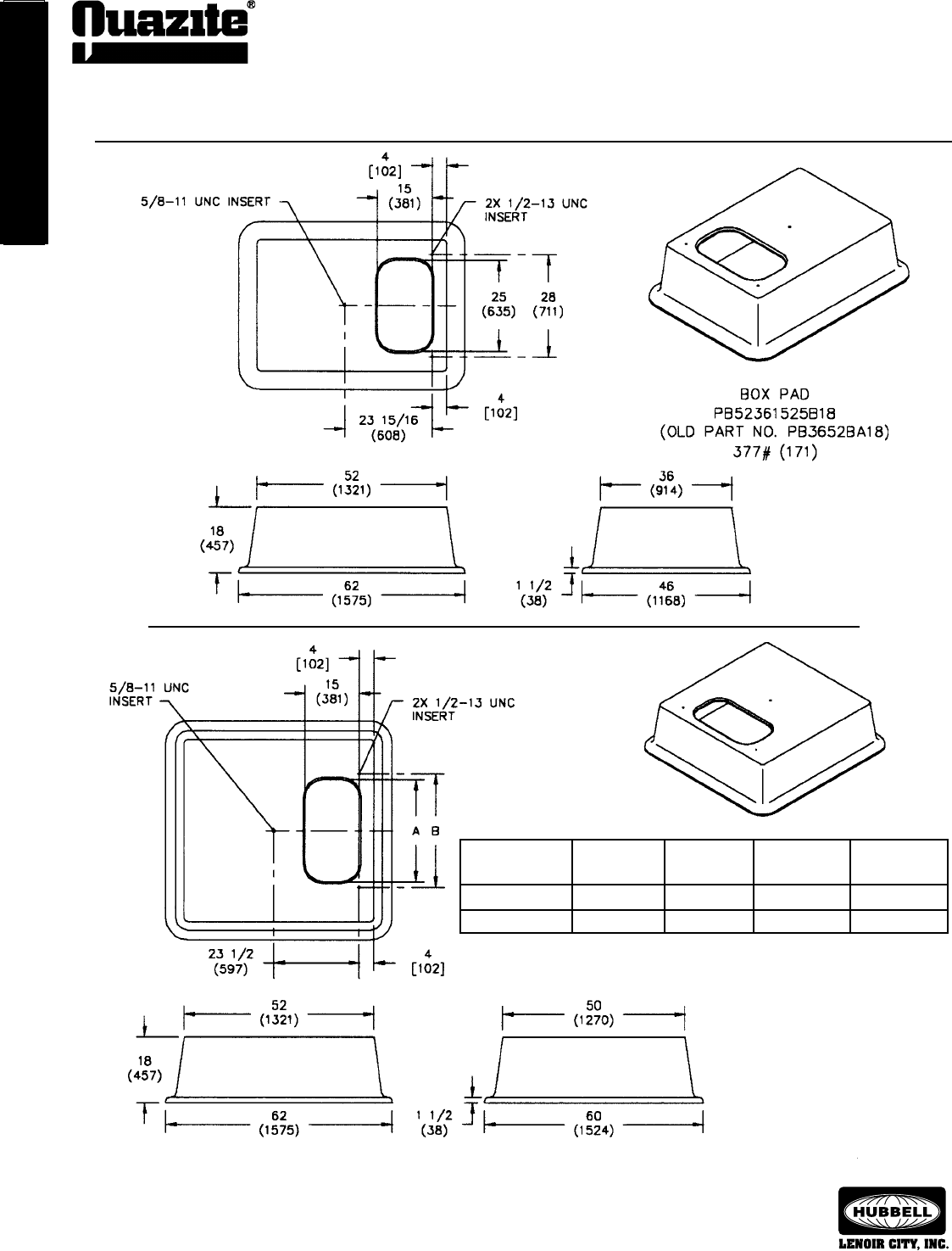
ELECTRICAL
EQUIPMENT PADS
ELECTRICAL
EQUIPMENT PADS
62
SEPTEMBER 2007
®
ELECTRICAL
EQUIPMENT PADS
ELECTRICAL
EQUIPMENT PADS
Information shown in catalog is a partial listing. If pad or throat
size desired is not listed, contact Quazite eld sales ofce.
SPECIFICATIONS/DATA Box Pads
Dimensions in parentheses are metric equivalent.
NEW OLD WEIGHT
PART NO. PART NO. # A B
PB52501528B18 PB5052BA18 491 (223 kg) 28” (711 mm) 31” (787 mm)
PB52501537B18 PB5052B500 485 (220 kg) 37” (940 mm) 40” (1016 mm)
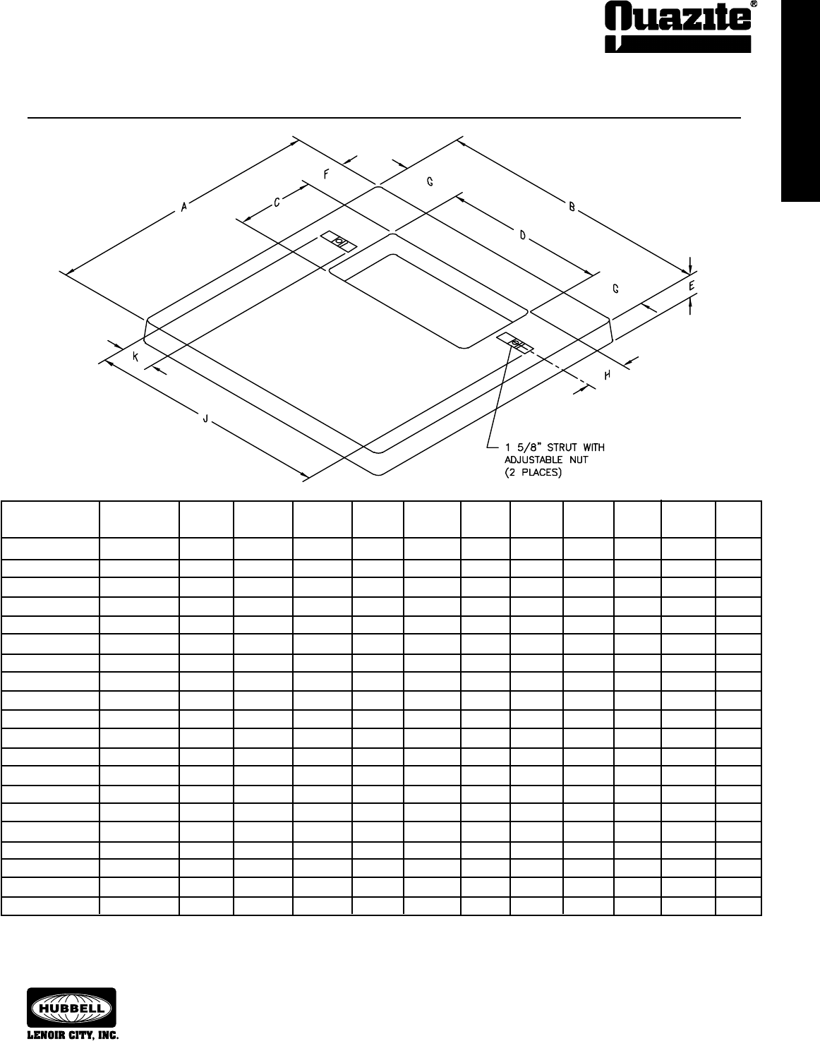
ELECTRICAL
EQUIPMENT PADS
ELECTRICAL
EQUIPMENT PADS
63
ELECTRICAL
EQUIPMENT PADS
ELECTRICAL
EQUIPMENT PADS
SEPTEMBER 2007
®
Information shown in catalog is a partial listing. If pad or throat
size desired is not listed, contact Quazite eld sales ofce.
* Skid resistant surface
Note: Individual detail drawings are available upon request.
Additional sizes are available to meet your specic requirements.
Contact your local QUAZITE® representative for more information.
SPECIFICATIONS/DATA Electric Equipment Pads
NEW OLD WEIGHT
PART NO. PART NO. # A B C D E F G H J K
PH40401225F3S PH4040BA 136 39 1/2” 39 1/2” 12” 25” 3 1/8” 5 3/4” 7 1/4” 6” 36 1/2” 5”
PH42421225F3S PH4242BA 150 41 7/16” 41 7/16” 12 9/16” 25 9/16” 3 1/4” 5 7/16” 7 15/16” 6 5/16” 36 1/2” 5”
PH42421227G3S PH4242B500 154 41 7/16” 41 7/16” 12 9/16” 27 9/16” 3 1/4” 5 7/16” 6 15/16” 6 5/16” 32” 2”
PH42421225G3T PH4242B501* 150 41 7/16” 41 7/16” 12 9/16” 25 9/16” 3 1/4” 5 7/16” 7 15/16” 6 5/16” 30 9/16” 2 1/2”
PH42421225G3S PH4242B503 150 41 7/16” 41 7/16” 12 9/16” 25 9/16” 3 1/4” 5 7/16” 7 15/16” 6 5/16” 39” 6”
PH42421227507 PH4242B507 154 41 7/16” 41 7/16” 12 9/16” 27 9/16” 3 1/4” 5 7/8” 6 15/16” 6 5/16” 32” 2”
PH42421225513 PH4242B513 100 41 7/16” 41 7/16” 12 9/16” 25 9/16” 3 1/4” 5 7/16” 7 15/16” 6 5/16” 36 1/2” 5”
PH42421424G3S PH4242B515 100 41 7/16” 41 7/16” 14 9/16” 24 9/16” 3 1/4” 4 7/16” 8 7/16” 7 5/16” 33” 3”
PH42421225A3S PH4242B518 150 41 7/16” 41 7/16” 12 9/16” 25 9/16” 3 1/4” 5 7/16” 7 15/16” — — —
PH42421225512 PH4242D512 150 41 7/16” 41 7/16” 12 9/16” 25 9/16” 3 1/4” 5 7/16” 7 15/16” 6 5/16” 32 1/2” 3”
PH42421225520 PH4242DW 142 41 7/16” 41 7/16” 12 9/16” 25 9/16” 3 1/4” 5 7/16” 7 15/16” 6 5/16” 36 1/2” 5”
PH56441326G3S PH4456B500 210 56” 44” 13 3/4” 26 3/4” 3 1/4” 6 1/4” 8 5/8” 6 13/16” 31 1/2” 2”
PH4842122603S PH4842B500 165 48” 42” 12” 26” 3 1/4” 6” 8” 6” 32 1/4” 3”
PH48421227G4S PH4842TB 170 48” 42” 12 3/4” 27 3/4” 4” 4 5/8” 7 1/8” 6 3/8” 38” 5”
PH48461826G3S PH4846BA 161 48” 46” 18 9/16” 26 9/16” 3 1/4” 5 1/2” 9 11/16” 9 5/16” 37 1/2” 5”
PH54481826F4S PH5448BA 220 54” 48” 18 3/4” 26 3/4” 4” 6 5/8” 10 5/8” 9 3/8” 37 3/4” 5”
PH66721842F4S PH6672BA 454 66” 72” 18 3/4” 42 3/4” 4” 4 3/4” 14 5/8” 9 3/8” 53 3/4” 5”
PH75521728B4T PH5275AD 290 75” 52” 17 11/16” 28 11/16” 4” 5 5/8” 11 5/8” — — —
PH84960000500 PH9684AA 779 84” 96” — — 4” — — — — —
PH84962269B4T PH9684AD 887 84” 96” 22 3/4” 69 3/4” 4” 9” 13 1/8” — — —
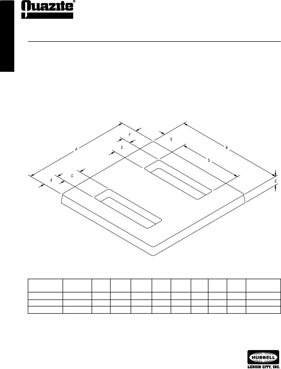
ELECTRICAL
EQUIPMENT PADS
ELECTRICAL
EQUIPMENT PADS
64
SEPTEMBER 2007
®
TELECOMMUNICATIONS
CABINET PADS
TELECOMMUNICATIONS
CABINET PADS
Information shown in catalog is a partial listing. If pad or throat
size desired is not listed, contact Quazite eld sales ofce.
SPECIFICATIONS/DATA Electric Equipment Pads
* Skid resistant surface
** See individual detail drawings for strut and insert locations.
Note: Individual detail drawings are available upon request.
Additional sizes are available to meet your specic requirements.
Contact your local QUAZITE® representative for more information.
NEW OLD WEIGHT STRUTS/
PART NO. PART NO. # A B C D E F G INSERTS**
PH64640650F4S PH6464AA 388 64” 64” 6 3/4” 50 3/4” 4” 11 1/4” 6 1/4” (4) 6” struts
PH90482412F4S PH9048AA 349 90” 48” 24 11/16” 12 3/4” 4” 8 1/8” 6” (4) 5” struts
PH96802165B4T PH8096AA* 494 96” 80” 21 3/4” 65 3/4” 4” 7” 7 1/8” (4) 1/2-13 UNC
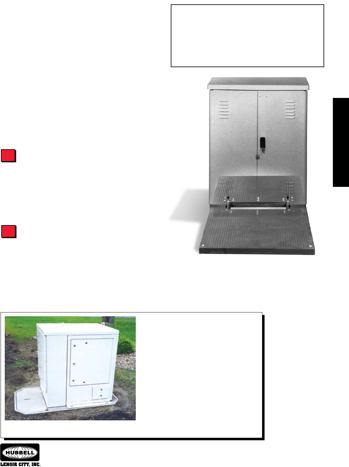
ELECTRICAL
EQUIPMENT PADS
ELECTRICAL
EQUIPMENT PADS
65
TELECOMMUNICATIONS
CABINET PADS
TELECOMMUNICATIONS
CABINET PADS
SEPTEMBER 2007
®
Information shown in catalog is a partial listing. If pad or throat
size desired is not listed, contact Quazite eld sales ofce.
Telecommunications Cabinet
Pad Selection Guide
Using The Selection Guide
Follow the steps outlined in this guide to select the appropriate
pad for your application. For more information or for answers to any
questions you might have, call your local QUAZITE® representative.
Detailed product drawings can be found in this section and also can
be accessed from our website:
www.quazite.com
QUAZITE® pads are made to accommodate most of the telephone
cabinets manufactured today. Please see the Telecommunications
Cabinet Pad Cross Reference Guide on pages 66 - 68 to determine
which standard QUAZITE® pad works best with the cabinet of your
choice. If you do not see your cabinet listed, please contact your local
QUAZITE® representative. Throat sizes and insert locations can be
designed to meet your requirements.
Determine Cabinet to be Installed
Determine Pad Type
QUAZITE® offers two types of pads to choose from: flat pads
and handhole cabinet pads. Determine the type of pad that will best
suit your needs.
Flat pads and handhole cabinet pads offer different advantages.
Flat pads are light weight and require only a small amount of site
preparation. Handhole cabinet pads offer the advantage of providing
room to coil extra cable underneath the equipment if needed. The
multiple-piece cover serves as an access panel to the cables underneath
Rather than using a traditional flat pad for mounting
telephone cabinets, some telecommunications companies
are now opting to use a standard QUAZITE® handhole with
a modified cover to fit the cabinet footprint. This design
provides some distinct advantages over traditional pads.
The space underneath the cover provides room to store
extra cable. Also, the split in the two-piece cover lies at the
edge of the cabinet and acts as an access panel to the
cables underneath the cabinet.
Telecom companies with future plans to offer high-speed
DSL, CATV or other telecommunications or broadband
services in addition to telephone service should find
the QUAZITE® handhole cabinet pad attractive. The
access panel and additional space make it easy to add
the necessary equipment and connections to existing
telephone cabinets rather than installing new infrastructure
to add services.
To Select the Pad You Need for Your Application:
1 .... Determine Cabinet to be Installed
2 .... Determine Pad Type
3 .....Determine Pad Dimensions
4 .....Determine Performance Requirements
5 .....Determine Installation Requirements
1
2
the cabinet and allows easy addition of more equipment and service
connections to the cabinet.
Quazite’s engineering staff is available to assist you in
determining the proper pad for your application. Throat sizes and
insert locations on both pads and handhole cabinet pads can be
tailored to meet your requirements.

TELECOMMUNICATIONS
CABINET PADS
TELECOMMUNICATIONS
CABINET PADS
66
SEPTEMBER 2007
®
TELECOMMUNICATIONS
CABINET PADS
TELECOMMUNICATIONS
CABINET PADS
Information shown in catalog is a partial listing. If pad or throat
size desired is not listed, contact Quazite eld sales ofce.
Telecommunications Cabinet Pad
Cross Reference Guide
To Select the Pad You Need for Your Application:
1 .....Determine Cabinet to be Installed
2 .... Determine Pad Type
3 .....Determine Pad Dimensions
4 .....Determine Performance Requirements
5 .....Determine Installation Requirements
3M
Cabinet Bolt Pattern New Pad No. Old Pad No.
Emerson, cont. (Marconi)
Cabinet Bolt Pattern New Pad No. Old Pad No.
Double Access
1800 - 5400 pr. 37 7/8” x 8 1/2” PL72600635500 PL6072SK
5400 Low Prole 37 7/8” x 8 1/2” PL76840735500 PL8476RA
5500 - 8100 Long Base 37 7/8” x 8 1/2” PL76840735500 PL8476RA
RLS / CQF
Sing. Acc. 600 - 2700 pr. 18 1/2” x 43” PL72600635500 PL6072SK
Dble. Acc. 1200 - 5400 pr. 18 1/2” x 43” PL72600635500 PL6072SK
UPCQF
200 - 800 pr. 11” x 13 7/16” PL42420808501 PL4242RA
600 - 2700 pr. 37 7/8” x 8 1/2” PL72600635500 PL6072SK
UNIVERSAL SERIES
Single Access
1200 - 5400 pr. 37 7/8” x 8 1/2” PL72600635500 PL6072SK
Double Access
4065 6” x 12 1/4” PL60420925500 PL6042MB
4082 6” x 12 1/4” PL60420925500 PL6042MB
4084 30” x 6” PL60420925500 PL6042MB
PL60420925B3T PL6042MC
PL60420720B3T PL6042MM
PL57600926B4T PL6057MA
PL78600926B4T PL6078MA
4086 30” x 6” PL60420925500 PL6042MB
PL60420925B3T PL6042MC
PL60420720B3T PL6042MM
PL57600926B4T PL6057MA
PL78600926B4T PL6078MA
4220 D PL60420720B3T PL6042MM
4220 DD PL60420720B3T PL6042MM
4220 E 38 3/8” x 13” PL60420720B3T PL6042MM
4220 EE 38 3/8” x 13” PL60420720B3T PL6042MM
4220 F 59 3/8” x 13” PL72640935B4T PL6472AA
4220 G 59 3/8” x 13” PL72640935B4T PL6472AA
4220 K 59 3/8” x 13” PL72640935B4T PL6472AA
4220 KF 59 3/8” x 13” PL72640935B4T PL6472AA
4220 ER 38 3/8” x 13” PL72640935B4T PL6472AA
4220 FR 59 3/8” x 13” PL72640935B4T PL6472AA
4220 ER-A 38 3/8” x 13” PL72640935B4T PL6472AA
4220 FR-A 59 3/8” x 13” PL72640935B4T PL6472AA
4365 6” x 12 1/4” PL60420925500 PL6042MB
4382 6” x 12 1/4” PL60420925500 PL6042MB
4384 30” x 6” PL60420925500 PL6042MB
PL60420925B3T PL6042MC
PL60420720B3T PL6042MM
PL57600926B4T PL6057MA
PL78600926B4T PL6078MA
4386 30” x 6” PL60420925500 PL6042MB
PL60420925B3T PL6042MC
PL60420720B3T PL6042MM
PL57600926B4T PL6057MA
PL78600926B4T PL6078MA
4918 51 3/4” x 17”, PL57600926B4T PL6057MA
46 3/4” x 21 5/16”, PL78600926B4T PL6078MA
CLX 44 13/16”
4927 51 3/4” x 17”, PL57600926B4T PL6057MA
46 3/4” x 21 5/16”, PL78600926B4T PL6078MA
CLX 44 13/16”
4954 51 3/4” x 17”, PL57600926B4T PL6057MA
46 3/4” x 21 5/16”, PL78600926B4T PL6078MA
CLX 44 13/16”
4981 51 3/4” x 17”, PL57600926B4T PL6057MA
46 3/4” x 21 5/16”, PL78600926B4T PL6078MA
CLX 44 13/16”
4900P 51 3/4” x 17”, PL57600926B4T PL6057MA
46 3/4” x 21 5/16”, PL78600926B4T PL6078MA
CLX 44 13/16”
Emerson (Marconi)
Cross Connect Cabinets
Cabinet Bolt Pattern New Pad No. Old Pad No.
ERLS / ECQF
UltraCab Series
100 - 900 pr. 11” x 13 7/16” PL42420808501 PL4242RA
Single Access
700 - 2700 pr. 37 7/8” x 8 1/2” PL72600635500 PL6072SK
2700 Low Prole 37 7/8” x 8 1/2” PL76840735500 PL8476RA
2800 - 4000 Long 37 7/8” x 8 1/2” PL76840735500 PL8476RA
Base
SC SERIES
SC 6000D 32” x 13 1/2” PL72600635500 PL6072SK
SC 8000D 43” x 16 1/2” PL72600635500 PL6072SK
SC10000D 43” x 16 1/2” PL72600635500 PL6072SK
BDS100 4” x 12 1/4” PL42420808501 PL4242RA
BDS200 11” x 12 1/4” PL42420808501 PL4242RA
BDS300 11” x 12 1/4” PL42420808501 PL4242RA
UPCBDS SERIES
UPC SERIES
BD7 11” x 12 1/4” PL42420808501 PL4242RA
Multipurpose Cabinets
1000 4” x 12 1/4” PL42420808501 PL4242RA
1248 11” x 12 1/4” PL42420808501 PL4242RA
1252S 11” x 12 1/4” PL42420808501 PL4242RA
1278 11” x 12 1/4” PL42420808501 PL4242RA
Lift Off Covers
1000LOC 4” x 12 1/4” PL42420808501 PL4242RA
1248LOC 11” x 12 1/4” PL42420808501 PL4242RA
Cross Connect Housings
600X 4” x 12 1/4” PL42420808501 PL4242RA
1254 11” x 12 1/4” PL42420808501 PL4242RA
1284 11” x 12 1/4” PL42420808501 PL4242RA
1294 11” x 12 1/4” PL42420808501 PL4242RA
Splice Housing Outdoor Terminal (SHOT)
1850 15 3/16” x 15 1/4” PL72600635500 PL6072SK
BD8000 15 5/16” x 15 1/4” PL42420822B3T PL4242SA
Repeater Housing
BT1200V 11” x 12 1/4” PL42420808501 PL4242RA
DRLS / DCQF
1800 - 5400 pr. 8 1/2” x 37 7/8” PL72600635500 PL6072SK
5400 pr. - LP 8 1/2” x 37 7/8” PL72600635500 PL6072SK
Single Access
100 - 600 pr. 18 1/2” x 13” PL72600635500 PL6072SK
700 - 2700 pr. 8 1/2” x 37 7/8” PL72600635500 PL6072SK
2700 pr. - LP 8 1/2” x 37 7/8” PL72600635500 PL6072SK
Double Access
Information shown in catalog is a partial listing. If pad or throat size desired is not listed, contact Quazite eld sales ofce.

TELECOMMUNICATIONS
CABINET PADS
TELECOMMUNICATIONS
CABINET PADS
67
TELECOMMUNICATIONS
CABINET PADS
TELECOMMUNICATIONS
CABINET PADS
SEPTEMBER 2007
®
Information shown in catalog is a partial listing. If pad or throat
size desired is not listed, contact Quazite eld sales ofce.
Cabinet Bolt Pattern New Pad No. Old Pad No.
Hub (Tyco)
200 - 400 pr. 13” x 8 1/2” PL42420808A3T PL4242WA
BTS-A
Single Faced
600 - 1200 pr. 30 7/8” x 8 1/2” PL48460827500 PL4846WA
BTS-C & D
Single Faced
1200 - 2400 pr. 30 7/8” x 8 1/2” PL48460827500 PL4846WA
Double Faced
Lucent Technologies
Cabinet Bolt Pattern New Pad No. Old Pad No.
40 A 13” x 8 1/2” PL42420808A3T PL4242WA
40 B 21 5/8” x 8 1/2” PL48460817A3T PL4846YA
40 C 30 7/8” x 8 1/2” PL48460827500 PL4846WA
PL54480928501 PL5448WD
40 D 30 7/8” x 8 1/2” PL48460827500 PL4846WA
PL54480928501 PL5448WD
40 DD 30 7/8” x 16 1/8” PL48460827500 PL4846WA
40 E 37 7/8” x 8 1/2” PL54483408A4T PL5448WA
PL54480928501 PL5448WD
PL72600832A4T PL6072EA
40 CE 37 7/8” x 8 1/2” PL54483408A4T PL5448WA
PL54480928501 PL5448WD
PL72600832A4T PL6072EA
40 EE 37 7/8” x 8 1/2” PL54483408A4T PL5448WA
PL54480928501 PL5448WD
PL72600832A4T PL6072EA
40 FE 37 7/8” x 8 1/2” PL54483408A4T PL5448WA
PL54480928501 PL5448WD
PL72600832A4T PL6072EA
40 F 36 1/2” x 13” PL54483408A4T PL5448WA
PL54480928501 PL5448WD
PL72600832A4T PL6072EA
40 H 30 7/8” x 8 1/2” PL48460827500 PL4846WA
PL54480928501 PL5448WD
42 EPI 37 7/8” x 8 1/2” PL54483408A4T PL5448WA
PL54480928501 PL5448WD
PL72600832A4T PL6072EA
841 A 13” x 8 1/2” PL42420808A3T PL4242WA
841 B 21 5/8” x 8 1/2” PL48460817A3T PL4846YA
841 C 30 7/8” x 8 1/2” PL48460827500 PL4846WA
BROADBAND CLOSURES
TV1600 4” x 12 1/4” PL42420808501 PL4242RA
TV2400 11” x 12 1/4” PL42420808501 PL4242RA
TV2500 11” x 12 1/4” PL42420808501 PL4242RA
BROADBAND CABINETS - FIBER NODE (OPFOTV)
OPFOTV 7 11” x 12 1/4” PL42420808501 PL4242RA
OPFOTV 8 11” x 12 1/4” PL42420808501 PL4242RA
OPFOTV 11 11” x 12 1/4” PL42420808501 PL4242RA
FIBER OPTIC CABINETS
OPFOBD 7 11” x 12 1/4” PL42420808501 PL4242RA
Emerson, cont.
Cabinet Bolt Pattern New Pad No. Old Pad No.
Hub, cont. (Tyco)
Cabinet Bolt Pattern New Pad No. Old Pad No.
200 - 1200 pr. 37 7/8” x 8 1/2” PL54480420A4T PL5448HA
1500 - 2700 pr. 37 7/8” x 8 1/2” PL64860435A4T PL6486HA
BNS
Single Faced
1600 - 2400 pr. 37 7/8” x 8 1/2” PL54480420A4T PL5448HA
2100 - 5400 pr. 37 7/8” x 8 1/2” PL96840435A4T PL9684HA
42 EPI 37 7/8” x 8 1/2” PL54483408A4T PL5448WA
PL72600832A4T PL6072EA
Double Faced
1500 - 3000 pr. 37 7/8” x 8 1/2” PL54483408A4T PL5448WA
BTS-E
Single Faced
2700 - 3600 pr. 37 7/8” x 8 1/2” PL72600832A4T PL6072EA
Double Faced
200 - 400 pr. 8 1/2” x 13” PL54481109B4T PL5448HA
600 pr. 37 7/8” x 8 1/2” PL48460827500 PL4846WA
900 - 1800 pr. 37 7/8” x 8 1/2” PL48460735B3T PL4846HA
PL72600735B4T PL6072HA
2100 - 3000 pr. 37 7/8” x 8 1/2” PL76840735B4T PL8476HA
3300 - 3600 pr. 37 7/8” x 8 1/2” PL96840435A4T PL9684HA
BTS-LP
Single Faced
1200 - 1600 pr. 37 7/8” x 8 1/2” PL54480420A4T PL5448HA
2700 - 3600 pr. 37 7/8” x 8 1/2” PL72600735B4T PL6072HA
5400 - 9000 pr. 37 7/8” x 8 1/2” PL76840735B4T PL8476HA
Double Faced
Erpel (EDC)
Cabinet Bolt Pattern New Pad No. Old Pad No.
DBL363213 27” x 8” PL42420822B3T PL4242SA
DBL483615 31” x 10” PL48460827A3T PL4846WX
DBL604415 39” x 10” PL48460735B3T PL4846HA
DBL604830 43” x 25” PL54482308B4T PL5448CA
DBL666015 55” x 10” PL72601032A4T PL6072AA
DBL724818 43” x 13” PL54483408A4T PL5448WA
DBL724824 43” x 19” PL54483408A4T PL5448WA
DBL727215 67” x 10” PL76840735B4T PL8476HA
DBL727224 67” x 19” PL76840735B4T PL8476HA
DBL727236 67” x 31” PL76840735B4T PL8476HA
DBL917224 67” x 19” PL76840735B4T PL8476HA
DOUBLE DOOR
FD503119 39” x 13 4/5” PL42420822B3T PL4242SA
FD553826 34 1/2” x 22 1/2” PL48460827A3T PL4846WX
FD554426 40 1/2” x 22 1/2” PL48460827A3T PL4846WX
FD773826 34 1/2” x 22 1/2” PL48460827A3T PL4846WX
FD774426 40 1/2” x 22 1/2” PL48460827A3T PL4846WX
FD727224 68 1/2” x 20 1/2” PL76840735B4T PL8476HA
FLUSH DOOR
Telecommunications Cabinet Pad
Cross Reference Guide
To Select the Pad You Need for Your Application:
1 .....Determine Cabinet to be Installed
2 .... Determine Pad Type
3 .....Determine Pad Dimensions
4 .....Determine Performance Requirements
5 .....Determine Installation Requirements
If your cabinet is not listed here, please contact your local QUAZITE®
representative for additional sizes and insert configurations.
Information shown in catalog is a partial listing. If pad or throat
size desired is not listed, contact Quazite eld sales ofce.

TELECOMMUNICATIONS
CABINET PADS
TELECOMMUNICATIONS
CABINET PADS
68
SEPTEMBER 2007
®
TELECOMMUNICATIONS
CABINET PADS
TELECOMMUNICATIONS
CABINET PADS
Information shown in catalog is a partial listing. If pad or throat
size desired is not listed, contact Quazite eld sales ofce.
Erpel (EDC), cont.
Cabinet Bolt Pattern New Pad No. Old Pad No.
Flextronics Enclosure Systems
(Chatham Technologies)
Cabinet Bolt Pattern New Pad No. Old Pad No.
RACK MOUNT
RM392420 15” x 15” PL42420808A3T PL4242WA
RM462420 15” x 15” PL42420808A3T PL4242WA
RM672430 21” x 21” PL42420808A3T PL4242WA
RM672438 21” x 21” PL42420808A3T PL4242WA
RM463026 15” x 25” PL42420808A3T PL4242WA
RM553026 15” x 33” PL42420808A3T PL4242WA
UCN
UCN 100 20” x 25” PL78600926B4T PL6078MA
UCN 200 46” x 25” PL76840735B4T PL8476HA
Telecommunications Cabinet Pad
Cross Reference Guide
To Select the Pad You Need for Your Application:
1 .....Determine Cabinet to be Installed
2 .... Determine Pad Type
3 .....Determine Pad Dimensions
4 .....Determine Performance Requirements
5 .....Determine Installation Requirements
If your cabinet is not listed here, please contact your local QUAZITE®
representative for additional sizes and insert configurations.
Multilink
Cabinet Bolt Pattern New Pad No. Old Pad No.
FNC 2000 11 3/4” x 23” PL42420822501 PL4242ML
FNC 3000 23 3/16” x 29 1/8” PL54482308B4T PL5448CA
FNC 3000 - 5016 12 1/8” x 24 3/16” PL42420822501 PL4242ML
LSD301815 CL x 12 1/2” PL42420808A3T PL4242WA
LSD362015 CL x 12 1/2” PL42420808A3T PL4242WA
LSD412516 CL x 12 1/2” PL42420808A3T PL4242WA
LSD512516 CL x 12 1/2” PL42420808A3T PL4242WA
LSD503017 26 1/2” x 13 1/2” PL42420822B3T PL4242SA
LSD503617 32 1/2” x 13 1/2” PL42420822B3T PL4242SA
LSD583017 26 1/2” x 13 1/2” PL42420822B3T PL4242SA
LSD763017 26 1/2” x 13 1/2” PL42420822B3T PL4242SA
LSD723617 32 1/2” x 13 1/2” PL42420822B3T PL4242SA
LSD363624 32 1/2” x 16 1/2” PL42420822B3T PL4242SA
LSD443624 32 1/2” x 16 1/2” PL42420822B3T PL4242SA
LSD553826 34 1/2” x 18 1/2” PL42420822B3T PL4242SA
LSD554426 40 1/2” x 18 1/2” PL42420822B3T PL4242SA
LSD773826 34 1/2” x 18 1/2” PL42420822B3T PL4242SA
LSD774426 40 1/2” x 18 1/2” PL42420822B3T PL4242SA
LARGE SINGLE DOOR
LQD484836 43” x 31” PL48460735B3T PL4846HA
LQD587430 69”, CL x 25” PL76840735B4T PL8476HA
LQD605036 45” x 31” PL54482308B4T PL5448CA
LQD605636 51” x 31” PL72601032A4T PL6072AA
LQD727224 67”, CL x 19” PL76840735B4T PL8476HA
LQD774826 43” x 21” PL48460735B3T PL4846HA
QUAD DOOR
ERM392421 15” x 15” PL42420808A3T PL4242WA
ERM462421 15” x 15” PL42420808A3T PL4242WA
ERM463027 21” x 21” PL42420808A3T PL4242WA
ERM553027 21” x 21” PL42420808A3T PL4242WA
ERM672430 15” x 25” PL42420808A3T PL4242WA
ERM672438 15” x 33” PL42420808A3T PL4242WA
RACK MOUNT
ETD666016 46 1/4” x 12” PL78600926B4T PL6078MA
ETD727216 58 1/4” x 12” PL78600926B4T PL6078MA
TWO DOOR
CE-1000 24 1/2” x 27 1/10”, PL78600926B4T PL6078MA
39” x 35 2/5”
CE-2000 53” x 27 1/10”, PL76840735B4T PL8476HA
67 1/2” x 35 2/5”
COMMUNICATIONS ENCLOSURES
FDR363624 32 1/2” x 20 1/2” PL42420822B3T PL4242SA
FDR443624 32 1/2” x 20 1/2” PL42420822B3T PL4242SA
FDR773826 34 1/2” x 22 1/2” PL48460827A3T PL4846WX
FDR774426 40 1/2” x 22 1/2” PL48460827A3T PL4846WX
FRONT AND REAR DOOR
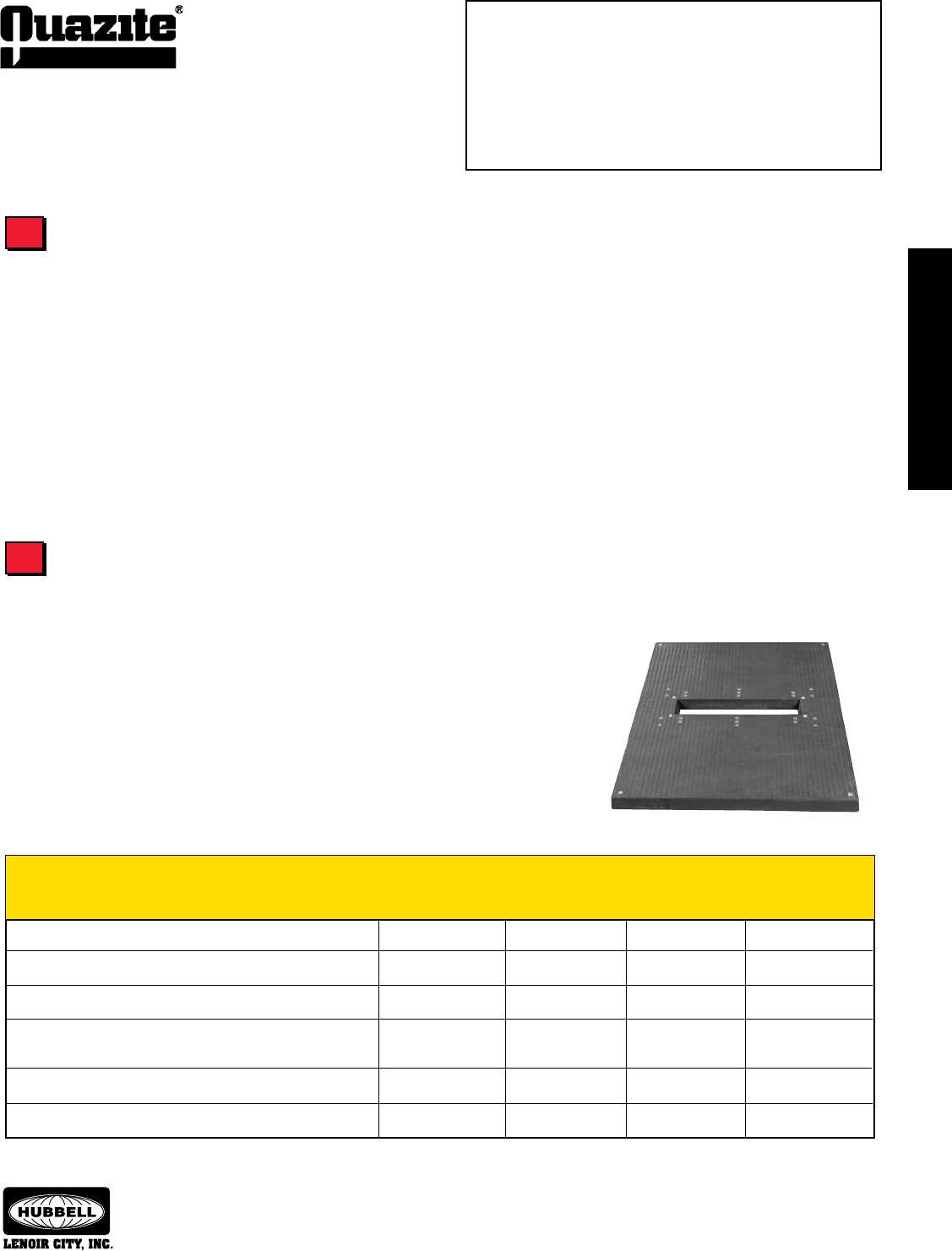
TELECOMMUNICATIONS
CABINET PADS
TELECOMMUNICATIONS
CABINET PADS
69
TELECOMMUNICATIONS
CABINET PADS
TELECOMMUNICATIONS
CABINET PADS
SEPTEMBER 2007
®
Information shown in catalog is a partial listing. If pad or throat
size desired is not listed, contact Quazite eld sales ofce.
To Select the Pad You Need for Your Application:
1 .....Determine Type of Cabinet to be Installed
2 .....Determine Pad Type
3 .... Determine Pad Dimensions
4 .... Determine Performance Requirements
5 .....Determine Installation Requirements
Determine Pad Dimensions
To ensure telephone cabinets will properly mount to the pad, the cabinet footprint must match the pad dimensions and insert locations.
The pad also must have a throat opening that provides adequate space for cable and/or conduit to come through.
How much work space you need around the cabinet also will affect the dimensions of the pad. Determine how far the pad should extend
beyond the cabinet to allow for adequate work space and cabinet entry and select the pad accordingly.
The Telecommunications Cabinet Pad Cross Reference Guide in this section lists the appropriate QUAZITE® pads for the most common
cabinets manufactured today. If you need assistance determining which pad has the appropriate throat size and insert locations to work with
your cabinet, please contact your local QUAZITE® representative.
QUAZITE® pads are constructed of strong polymer concrete and reinforced with a heavy-weave fiberglass mat. Unlike fiberglass or plastic
pads, QUAZITE®’s strength assures that the pad will support the weight of the equipment mounted to it without bending or cracking. QUAZITE®
pads have been tested for structural integrity by applying a 1,000 lb. load to the surface distributed by a
5” x 7” steel plate. Each corner was tested separately by applying a 1,500 lb. load over the same plate
positioned one inch from the edge. No damage occurred and deflection was less than 0.15”.
QUAZITE® polymer concrete pads also resist UV rays, chemicals, and water absorption. Plastic
and fiberglass pads can become brittle and eventually crack when exposed to the weather. The durability
that QUAZITE® provides means lower maintenance and life cycle costs.
Determine Performance Requirements
Pad Performance
QUAZITE®
Precast Polymer Precast Poured-in-Place Thermoplastic /
Performance Criteria Concrete Pads Concrete Pads Concrete Pads Fiberglass Pads
Telecommunications Cabinet
Pad Selection Guide
3
4
Stable under loading during high temperatures (won’t flex or warp) X X X
Stable under loading during cold temperatures (won’t crack) X X
Not susceptible to damage caused by freeze/thaw cycles X X
Resistant to corrosion caused by weathering, road chemicals, X X
and equipment lubricants
Provides long-term durability (fatigue or creep resistant) X X X
Withstands impacts and other damage caused by lawn equipment X X X
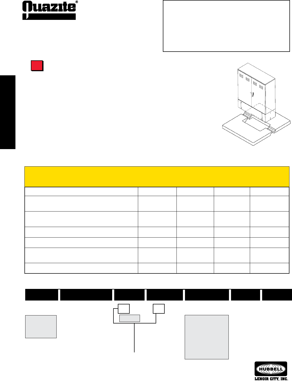
TELECOMMUNICATIONS
CABINET PADS
TELECOMMUNICATIONS
CABINET PADS
70
SEPTEMBER 2007
®
TELECOMMUNICATIONS
CABINET PADS
TELECOMMUNICATIONS
CABINET PADS
Information shown in catalog is a partial listing. If pad or throat
size desired is not listed, contact Quazite eld sales ofce.
Installing QUAZITE® pads is easy and cost effective because it requires no special equipment to set
the pad. A backhoe is all that is necessary to lift the pad into place. QUAZITE® pads also save time during
installation. Unlike poured-in-place pads that can take hours or days to form, pour, set and remove the forms,
QUAZITE® pads can be installed in a matter of minutes and installation of electrical equipment can begin
immediately after the pad is set.
The optional SPLITT-PAD® design makes retrofit installations easy and eliminates the need
to disconnect service during installation. Simply break away the old concrete or other material
underneath the equipment cabinet and slip the SPLITT-PAD® underneath. Complete the
installation by bolting the two-piece pad together at the throat. For more detailed instructions on
how to install the SPLITT-PAD® and other QUAZITE® pads, see page 92.
Telecommunications Cabinet
Pad Selection Guide
Determine Installation Requirements
SPLITT-PAD®
To Select the Pad You Need for Your Application:
1 .....Determine Type of Cabinet to be Installed
2 .....Determine Pad Type
3 .....Determine Pad Dimensions
4 .....Determine Performance Requirements
5 .... Determine Installation Requirements
Pad Installation
QUAZITE®
Precast Polymer Precast Poured-in-Place Thermoplastic /
Installation Criteria Concrete Pads Concrete Pads Concrete Pads Fiberglass Pads
5
Weight Style Size Throat Size Item Depth Surface
P L 4846 0817 A 3 T
L - Lightweight
mix
P - Standard
mix
Pad Numbering System
8” x 17” 3” thick
(Indicates surface
thickness if flat pad;
indicates depth if
box pad.)
B - Box pad
H - Electrical equipment pad
J - Split electrical equipment pad
K - Split telecommunications equip-
ment pad
L - Telecommunications equipment
pad
S - Smooth
T - Skid resistant
48” x 46”
Dimensions run parallel to
each other.
A - 3/8-16 UNC inserts
B - 1/2-13 UNC inserts
C - 5/8-11 UNC inserts
E - 5/8 thru hole
F - Struts w/ 3/8” inserts
G - Struts w/ 1/2” inserts
H - Struts w/ 5/8” inserts
Easily installed in areas with limited accessibility X X
Minimal planning and scheduling of crews required for X X
installation
No special equipment (such as a boom truck or crane) needed X X
for installation
Easily installed by no more than two crew members (light weight) X X
Equipment and pad can be easily installed in the same day X X X
Available as a two-piece pad so that service does not have to be X X
disconnected when retrofitting
Flat surface allows cabinet to fit flush with the pad X

TELECOMMUNICATIONS
CABINET PADS
TELECOMMUNICATIONS
CABINET PADS
71
TELECOMMUNICATIONS
CABINET PADS
TELECOMMUNICATIONS
CABINET PADS
SEPTEMBER 2007
®
Information shown in catalog is a partial listing. If pad or throat
size desired is not listed, contact Quazite eld sales ofce.
SPECIFICATIONS/DATA Telecommunications Cabinet Pads
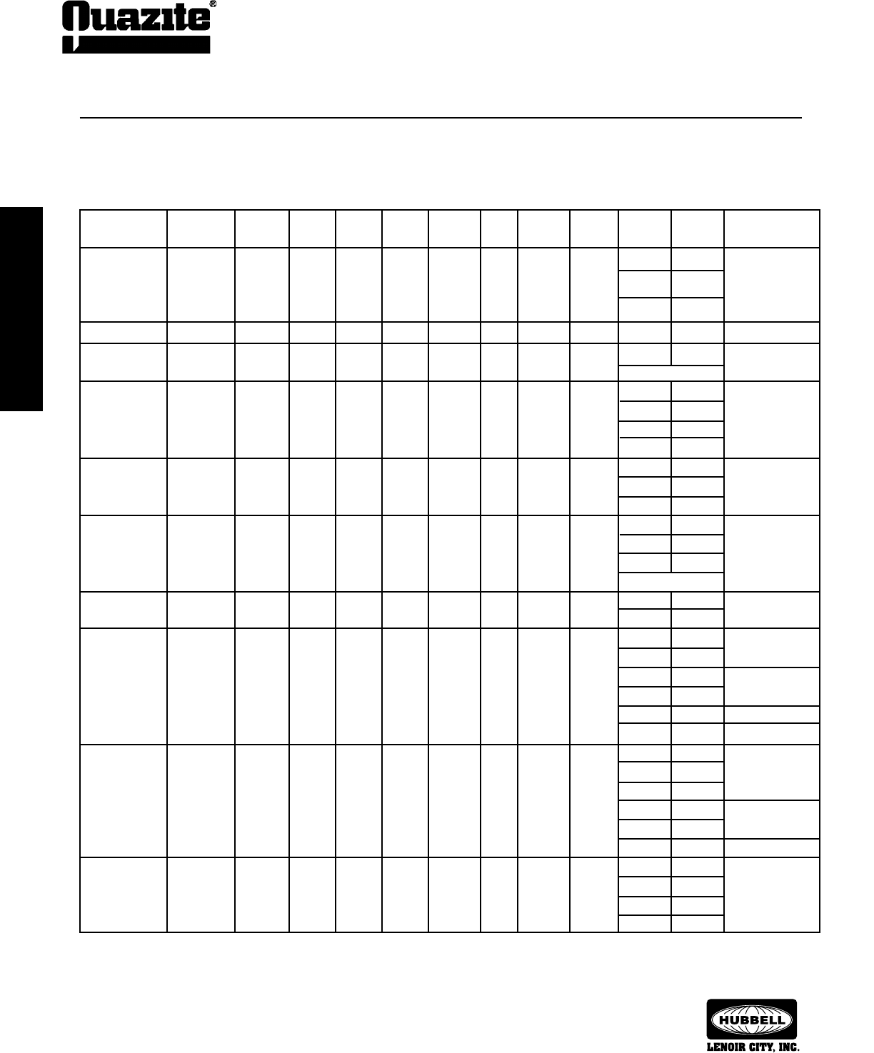
TELECOMMUNICATIONS
CABINET PADS
TELECOMMUNICATIONS
CABINET PADS
72
SEPTEMBER 2007
®
TELECOMMUNICATIONS
CABINET PADS
TELECOMMUNICATIONS
CABINET PADS
Information shown in catalog is a partial listing. If pad or throat
size desired is not listed, contact Quazite eld sales ofce.
SPECIFICATIONS/DATA Telecommunications Cabinet Pads
Note: Individual detail drawings are available upon request.
Additional sizes are available to meet your specic requirements.
Contact your local QUAZITE® representative for more information.
NEW OLD WEIGHT
PART NO. PART NO. # A B C D E F G H J INSERTS
PL42420822500 PL4242ML 136 41 7/16” 41 7/16” 8 9/16” 22 1/16” 3 1/4” 16 7/16” 9 11/16” 11 3/4” 23” (12) 1/2-13 UNC
18 5/8” 27 13/16”
29 1/8” 23 3/16”
PL48460817A3T PL4846YA 139 47 1/2” 45 1/2” 8 9/16” 17 13/16” 3 1/4” 14 11/16” 13 13/16” 8 1/2” 21 5/8” (4) 3/8-16 UNC
PL48460827500 PL4846WA 172 47” 45” 8 9/16” 27 1/16” 3 1/4” 14 1/2” 10” 8 1/2” 30 7/8” (6) 3/8-16 UNC
See sales drawing
PL54483408A4T PL5448WA 213 47 1/4” 53 1/4” 8 3/4” 34 1/8” 4” 14 3/8” 9 9/16” C-LINE 13” (14) 3/8-16 UNC
36 1/2” 13”
37 7/8” 8 1/2”
37 7/8” 17 3/8”
PL60420720B3T PL6042MM 240 60” 42” 7 9/16” 20 9/16” 3 1/4” 26 3/16” 10 3/4” 10” 16” (12) 1/2-13 UNC
13” 24”
13” 38 1/2”
PL60420925500 PL6042MB 192 57 1/2” 39 1/2” 9 1/8” 25 5/8” 3 5/16” 24 3/16” 6 15/16” 6” 30” (16) 3/8-16 UNC
10” 30 3/4”
12 1/4” 6”
See sales drawing
PL60420925B3T PL6042MC 189 57 7/16” 39 7/16” 9 5/16” 25 15/16” 3 1/4” 24 1/16” 6 3/4” 6” 30” (8) 1/2-13 UNC
10” 30 3/4”
PL57600926B4T PL6057MA 362 57 1/16” 60 1/16” 9 11/16” 26 3/16” 4” 2 3/16” 16 15/16” 30” 6” (4) 1/2-13 UNC
30 3/4” 10”
46 3/4” 21 5/16” (2) 1/2-13 UNC
51 3/4” 17”
52” 10” (4) 1/2-13 UNC
C-LINE 23 13/16” (1) 1/2-13 UNC
PL72640935B4T PL6472AA 473 72” 64” 9 11/16” 35 11/16” 4” 31 1/8” 14 1/8” 13” 59 3/8” (4) 1/2-13 UNC
21 1/2” 41 1/2”
25 1/4” 34 1/2”
30 3/4” 46 3/4” (2) 1/2-13 UNC
35 5/16” 51 3/4”
19 11/16” C-LINE (1) 1/2-13 UNC
PL76840735B4T PL8476HA 616 76” 84” 7 3/4” 35 7/8” 4” 34 1/4” 24 1/16” 33 3/4” 10” (16) 1/2-13 UNC
37 7/8” 6”
37 7/8” 11”
59 3/8” 13”
Refer to Telecommunications Cabinet Pad Cross Reference Guide on pages 65 - 67.
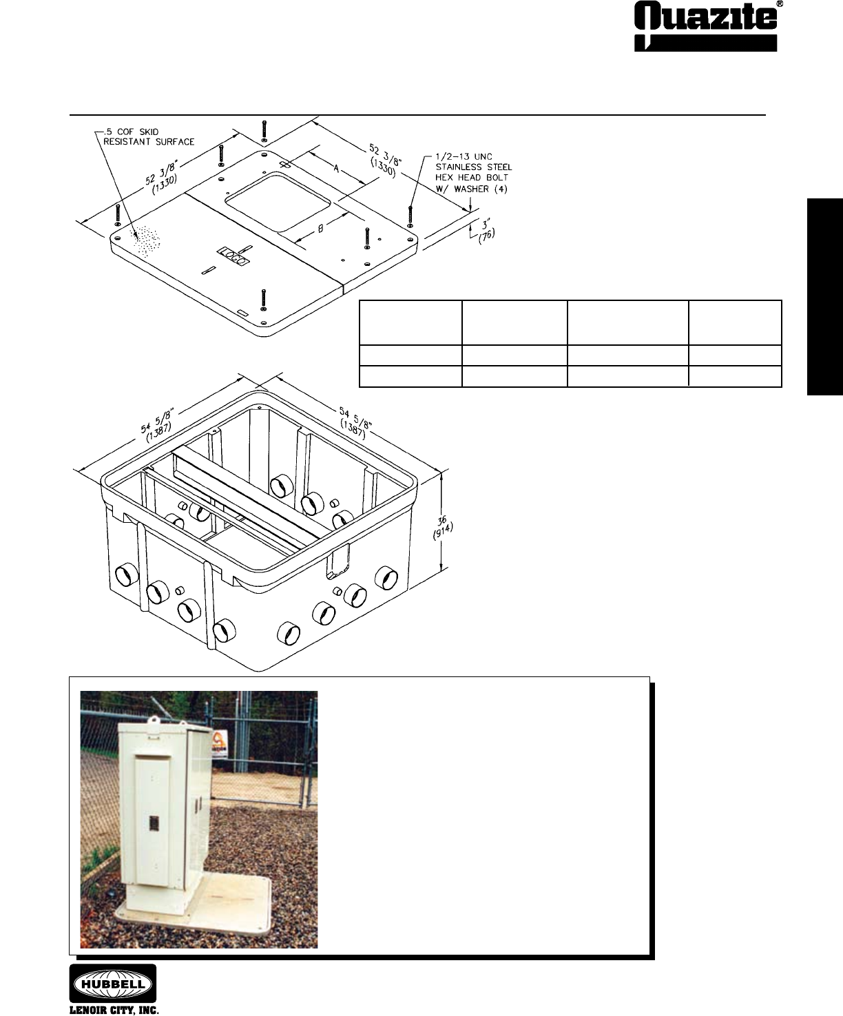
TELECOMMUNICATIONS
CABINET PADS
TELECOMMUNICATIONS
CABINET PADS
73
TELECOMMUNICATIONS
CABINET PADS
TELECOMMUNICATIONS
CABINET PADS
SEPTEMBER 2007
®
Information shown in catalog is a partial listing. If pad or throat
size desired is not listed, contact Quazite eld sales ofce.
SPECIFICATIONS/DATA Cell Site Enclosure
QUAZITE® cell site enclosures allow cellular providers easy access
to their cable lines and provide plenty of room for the addition of
new lines. Sixteen 4” terminators enable providers to easily add new
feeder cables to existing sites. The terminators also reduce the risk of
disturbing existing service when adding new cables because installers
can clearly see where other cables are entering the box.
QUAZITE® cell site enclosures also make equipment changes and
upgrades easy and cost effective. Poured-in-place pads must be
completely replaced if changes and upgrades became necessary, but
QUAZITE® cell site enclosures feature replaceable covers and an open
area inside the enclosure. As a result, new cable lines can easily be
added without replacing the pad. Also, providers only need to replace
the covers if cabinets with new bolt patterns are installed.
Dimensions & weights in parentheses are metric equivalent.
BOX DIMENSION DIMENSION Hub
ASSEMBLY NO. A B Cabinet
PG4848Z511 19” (483 mm) 18 1/8” (460 mm) CSC
PG4848Z505 10” (254 mm) 18 1/4” (464 mm) CFL
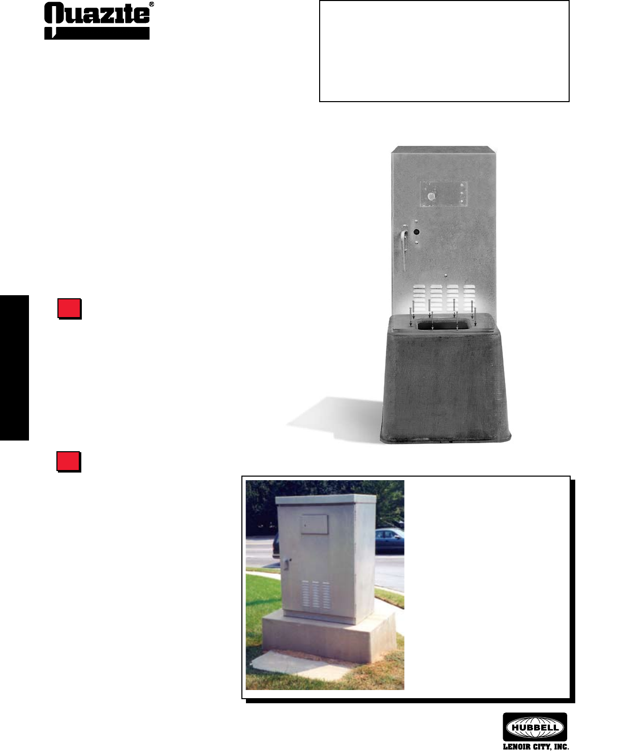
74
TRANSPORTATION INDUSTRY
PRODUCTS
TRANSPORTATION INDUSTRY
PRODUCTS
SEPTEMBER 2007
®
TRANSPORTATION INDUSTRY
PRODUCTS
TRANSPORTATION INDUSTRY
PRODUCTS
Information shown in catalog is a partial listing. If pad or throat
size desired is not listed, contact Quazite eld sales ofce.
Determine Work Pad
Requirements
Quazite offers work pads to accompany all
of the traffic signal cabinet bases. If the cabinet is
to be installed on a surface other than a sidewalk,
a work pad may be necessary to provide stable,
dry footing.
An alternative option to using a flat work
pad in front of the traffic signal cabinet base is to
use an enclosure instead. An enclosure serves as
a splice box and the work pad also provides a skid
resistant walking surface. Quazite offers a wide
variety of enclosure sizes and depths to choose
from. Your local QUAZITE® representative is
available to assist you in selecting the appropriate
enclosure and options to suit your application.
Trafc Signal Cabinet Base
Selection Guide
Using This Selection Guide
Follow the steps outlined in this guide to select the appropriate
traffic signal cabinet base for your application. For more information or
for answers to any questions you might have, call your local QUAZITE®
representative. Detailed product drawings are included in this section
and also can be accessed from our website:
www.quazite.com
Determine Type of Cabinet
QUAZITE® offers a variety of traffic signal cabinet bases that work
with every NEMA and 170E cabinet manufactured today.
The footprint of the cabinet will determine which base to install.
Please see the Traffic Signal Cabinet Base Cross Reference Guide on
pages 75 - 76 to choose the proper base for your application. If your
cabinet is not listed, please feel free to contact your local QUAZITE®
representative. Throat sizes and insert locations can be tailored to meet
your requirements.
Many Departments of Transportation choose
QUAZITE® traffic signal cabinet bases when
they have projects requiring new and retrofit
installations of traffic control cabinets. QUAZITE®
traffic signal cabinet bases are less expensive
than concrete to install, can be quickly installed
by employees, can be relocated and can
reduce potential injury and/or liability if struck
by a vehicle.
In this particular application, the DOT had
previously poured concrete in place at an
approximate cost of $1,000 for each traffic
signal foundation. The installation process
using concrete could take up to a week or more
depending on weather and involved having to
schedule around other work crews. The cost
of the QUAZITE® base was $500 (1/2 the cost
of the alternative method) and installation time
was reduced to one-half day.
To Select the Traffic Signal Cabinet Base You Need for Your
Application:
1 .... Determine Type of Cabinet
2 .... Determine Work Pad Requirements
3 .....Determine Performance Requirements
4 .....Determine Installation Requirements
1
2

TRANSPORTATION INDUSTRY
PRODUCTS
TRANSPORTATION INDUSTRY
PRODUCTS
75
TRANSPORTATION INDUSTRY
PRODUCTS
TRANSPORTATION INDUSTRY
PRODUCTS
SEPTEMBER 2007
®
Information shown in catalog is a partial listing. If pad or throat
size desired is not listed, contact Quazite eld sales ofce.
Trafc Signal Cabinet Base
Cross Reference Guide
NEMA Cabinets
M CL x 12 PB24360612B18 PB2436BA18
P 40 3/4” x 18 1/2” PB40440608B15 PB4044BA15
PB40440608B24 PB4044BA24
PB40580616B24 PB4058BA24
P-38 34 1/2” x 18 1/2” PB40440608B15 PB4044BA15
PB40440608B24 PB4044BA24
PB40580616B24 PB4058BA24
P-44 40 3/4” x 18 1/2” PB40440608B15 PB4044BA15
PB40440608B24 PB4044BA24
PB40580616B24 PB4058BA24
R 40 3/4” x 18 1/2” PB40440608B15 PB4044BA15
PB40440608B24 PB4044BA24
PB40580616B24 PB4058BA24
R-38 34 1/2” x 18 1/2” PB40440608B15 PB4044BA15
PB40440608B24 PB4044BA24
PB40580616B24 PB4058BA24
R-44 40 3/4” x 18 1/2” PB40440608B15 PB4044BA15
PB40440608B24 PB4044BA24
PB40580616B24 PB4058BA24
Southern Cabinets
Type Bolt Pattern New Part. No. Old Part. No.
IV 26 1/2” x 13 1/2” PB24360612B18 PB2436BA18
V 30” x 18” PB40580616B24 PB4058BA24
V-44 40 3/4” x 18 1/2” PB40440608B15 PB4044BA15
PB40440608B24 PB4044BA24
PB40580616B24 PB4058BA24
VI 30” x 18” PB40580616B24 PB4058BA24
332 25” x 15” PB25251212B24 PB2525BA24
25” x 15” PB40580616B24 PB4058BA24
336S 15” x 15” PB25251212B24 PB2525BA24
336 15” x 15” PB25251212B24 PB2525BA24
NEMA/ New Old
Cabinet Part No. 170 Ref. Part No. Part No.
Double DD363213 — PB40440608B15 PB4044BA15
Door PB40440608B24 PB4044BA24
DD483615 — PB40440608B15 PB4044BA15
PB40440608B24 PB4044BA24
DD604415 — PB40580616B24 PB4058BA24
DD724818 — PB40580616B24 PB4058BA24
DD604830 — PB40580616B24 PB4058BA24
Front & FR363624 — PB40440608B15 PB4044BA15
Rear PB40440608B24 PB4044BA24
Door FR773826 P-38, R-38 PB40580616B24 PB4058BA24
FR774426 R or P PB40440608B15 PB4044BA15
PB40440608B24 PB4044BA24
PB40580616B24 PB4058BA24
Rack RM392420 336 PB25251212B24 PB2525BA24
Mount RM462420 336 PB25251212B24 PB2525BA24
RM672438 — PB40440608B15 PB4044BA15
PB40440608B24 PB4044BA24
RM463026 — PB40440608B15 PB4044BA15
PB40440608B24 PB4044BA24
RM553026 — PB40440608B15 PB4044BA15
PB40440608B24 PB4044BA24
Pedestal PE401615 — PB40440608B15 PB4044BA15
PB40440608B24 PB4044BA24
Large LS301815 2B PB24360612B18 PB2436BA18
Single LS362015 3B PB24360612B18 PB2436BA18
Door LS412516 G PB24360612B18 PB2436BA18
LS503017 M PB24360612B18 PB2436BA18
LS583017 MSX PB24360612B18 PB2436BA18
LS763017 MXX PB24360612B18 PB2436BA18
LS503617 M36 PB40440608B15 PB4044BA15
PB40440608B24 PB4044BA24
LS723618 — PB40440608B15 PB4044BA15
PB40440608B24 PB4044BA24
LS363624 — PB40440608B15 PB4044BA15
PB40440608B24 PB4044BA24
LS443624 — PB40440608B15 PB4044BA15
PB40440608B24 PB4044BA24
LS553826 P-38 PB40580616B24 PB4058BA24
LS773826 R-38 PB40580616B24 PB4058BA24
LS554426 P-44 PB40440608B15 PB4044BA15
PB40440608B24 PB4044BA24
PB40580616B24 PB4058BA24
LS774426 R-44 PB40440608B15 PB4044BA15
PB40440608B24 PB4044BA24
PB40580616B24 PB4058BA24
Quad QD774826 — PB40580616B24 PB4058BA24
Door QD484836 — PB40580616B24 PB4058BA24
QD605036 — PB40580616B24 PB4058BA24
QD605636 — PB40580616B24 PB4058BA24
Type Bolt Pattern New Part. No. Old Part. No.
170 Controllers
330 17” x 12 1/2” PB24360612B18 PB2436BA18
332 25” x 15” PB40440608B15 PB4044BA15
PB40440608B24 PB4044BA24
PB40580616B24 PB4058BA24
334 25” x 15” PB40440608B15 PB4044BA15
PB40440608B24 PB4044BA24
PB40580616B24 PB4058BA24
336 15” x 6” PB25251212B24 PB2525BA24
336 (A & S) 15” x 6” PB25251212B24 PB2525BA24
Type Bolt Pattern New Part. No. Old Part. No.
To Select the Traffic Signal Cabinet Base You Need for Your
Application:
1 .... Determine Type of Cabinet
2 .....Determine Work Pad Requirements
3 .....Determine Performance Requirements
4 .....Determine Installation Requirements
Signal Control
336/332 15” x 6” PB25251212B24 PB2525BA24
Type Bolt Pattern New Part. No. Old Part. No.
Safetran #170
334C 15” x 6” PB25251212B24 PB2525BA24
Type Bolt Pattern New Part. No. Old Part. No.
If your cabinet is not listed here, please contact your local QUAZITE®
representative for additional sizes and insert configurations.
Flextronics Enclosure Systems
(Chatham Technologies)

76
TRANSPORTATION INDUSTRY
PRODUCTS
TRANSPORTATION INDUSTRY
PRODUCTS
SEPTEMBER 2007
®
TRANSPORTATION INDUSTRY
PRODUCTS
TRANSPORTATION INDUSTRY
PRODUCTS
Information shown in catalog is a partial listing. If pad or throat
size desired is not listed, contact Quazite eld sales ofce.
Erpel (EDC)
NEMA/ New Old
Cabinet Part No. 170 Ref. Part No. Part No.
Double DBL363213 — PB40440608B15 PB4044BA15
Door PB40440608B24 PB4044BA24
DBL483615 — PB40440608B15 PB4044BA15
PB40440608B24 PB4044BA24
DBL604415 — PB40580616B24 PB4058BA24
DBL724818 — PB40580616B24 PB4058BA24
DBL724824 — PB40580616B24 PB4058BA24
DD604830 — PB40580616B24 PB4058BA24
Flush FD503119 — PB40440608B15 PB4044BA15
Door PB40440608B24 PB4044BA24
FD553826 — PB40440608B15 PB4044BA15
PB40440608B24 PB4044BA24
FD773826 — PB40440608B15 PB4044BA15
PB40440608B24 PB4044BA24
FD554426 — PB40580616B24 PB4058BA24
FD774426 — PB40580616B24 PB4058BA24
Front & FDR363624 — PB40440608B15 PB4044BA15
Rear PB40440608B24 PB4044BA24
Door FDR443624 — PB40440608B15 PB4044BA15
PB40440608B24 PB4044BA24
FDR773826 — PB40440608B15 PB4044BA15
PB40440608B24 PB4044BA24
FDR774426 — PB40580616B24 PB4058BA24
Quad LQD774826 — PB40580616B24 PB4058BA24
Door LQD484836 — PB40580616B24 PB4058BA24
LQD605036 — PB40580616B24 PB4058BA24
LQD605636 — PB40580616B24 PB4058BA24
Pedestal TPE401608 — PB24360612B18 PB2436BA18
Enclosure TPE401615 — PB25251212B24 PB2525BA18
Large LSD301815 2B PB24360612B18 PB2436BA18
Single LSD362015 3B PB24360612B18 PB2436BA18
Door LSD412516 G PB24360612B18 PB2436BA18
LSD512516 K PB24360612B18 PB2436BA18
LSD503017 M PB24360612B18 PB2436BA18
LSD583017 MSX PB24360612B18 PB2436BA18
LSD763017 MXX PB24360612B18 PB2436BA18
LSD503617 M36 PB40440608B15 PB4044BA15
PB40440608B24 PB4044BA24
LSD723617 — PB40440608B15 PB4044BA15
PB40440608B24 PB4044BA24
LSD363624 — PB40440608B15 PB4044BA15
PB40440608B24 PB4044BA24
LSD443624 — PB40440608B15 PB4044BA15
PB40440608B24 PB4044BA24
LSD553826 P-38 PB40580616B24 PB4058BA24
LSD773826 R-38 PB40580616B24 PB4058BA24
LSD554426 P-44, R-44 PB40440608B15 PB4044BA15
PB40440608B24 PB4044BA24
LSD774426 R-44 PB40440608B15 PB4044BA15
PB40440608B24 PB4044BA24
Rack ERM392421 336 PB25251212B24 PB2525BA24
Mount ERM462421 336 PB25251212B24 PB2525BA24
ERM463027 — PB40440608B15 PB4044BA15
PB40440608B24 PB4044BA24
ERM553027 — PB40440608B15 PB4044BA15
PB40440608B24 PB4044BA24
ERM672430 332 PB40440608B15 PB4044BA15
PB40440608B24 PB4044BA24
332 PB40580616B24 PB4058BA24
ERM672438 — PB40440608B15 PB4044BA15
PB40440608B24 PB4044BA24
To Select the Traffic Signal Cabinet Base You Need for Your
Application:
1 .... Determine Type of Cabinet
2 .....Determine Work Pad Requirements
3 .....Determine Performance Requirements
4 .....Determine Installation Requirements
Trafc Signal Cabinet Base
Cross Reference Guide
If your cabinet is not listed here, please contact your local QUAZITE®
representative for additional sizes and insert configurations.
TRANSPORTATION INDUSTRY
PRODUCTS
TRANSPORTATION INDUSTRY
PRODUCTS
77
TRANSPORTATION INDUSTRY
PRODUCTS
TRANSPORTATION INDUSTRY
PRODUCTS
SEPTEMBER 2007
®
Information shown in catalog is a partial listing. If pad or throat
size desired is not listed, contact Quazite eld sales ofce.
Trafc Signal Cabinet Base
Selection Guide
To Select the Traffic Signal Cabinet Base You Need for
Your Application:
1 .....Determine Type of Cabinet
2 .....Determine Work Pad Requirements
3 .... Determine Performance Requirements
4 .....Determine Installation Requirements
Determine Performance Requirements
QUAZITE® traffic signal cabinet bases are constructed of strong polymer concrete and reinforced with a heavy-weave fiberglass. Unlike
concrete bases, polymer concrete bases are frangible and will break away when subjected to severe impact. This feature helps reduce the
risk of serious injury or fatalities resulting from these incidents.
QUAZITE® polymer concrete traffic signal cabinet bases also resist UV rays, chemicals and water absorption. Concrete bases are
susceptible to damage caused by freeze/thaw cycles. Thermoplastic fiberglass bases can become brittle and eventually crack when exposed
to the weather. The durability that QUAZITE® provides means lower maintenance and life cycle costs.
Stable under loading during high
temperatures (won’t flex or warp) X X X X
Stable under loading during cold
temperatures (won’t crack) X X
Not susceptible to damage caused
by freeze/thaw cycles X X X
Resistant to corrosion caused by
weathering, road chemicals X X
and equipment lubricants
Provides long-term durability
(fatigue or creep resistant) X X X X
Frangible base will break away when
cabinet is struck by a vehicle X X
Trafc Signal Cabinet Base Performance
QUAZITE®
3
78
TRANSPORTATION INDUSTRY
PRODUCTS
TRANSPORTATION INDUSTRY
PRODUCTS
SEPTEMBER 2007
®
TRANSPORTATION INDUSTRY
PRODUCTS
TRANSPORTATION INDUSTRY
PRODUCTS
Information shown in catalog is a partial listing. If pad or throat
size desired is not listed, contact Quazite eld sales ofce.
Trafc Signal Cabinet Base
Selection Guide
Installing QUAZITE® traffic signal cabinet bases is easy and cost effective because it requires no special equipment to set the base.
A backhoe is all that is necessary to lift the base in place. QUAZITE® traffic signal cabinet bases also save time during installation. Unlike
poured-in-place bases that take days to form, pour, set and remove the forms, QUAZITE® traffic signal cabinet bases can be installed
quickly, allowing the cabinet and equipment installation to begin immediately after setting the base. For detailed instructions on how to
install QUAZITE® traffic signal cabinet bases, see page 93.
Determine Installation Requirements
To Select the Traffic Signal Cabinet Base You Need for Your
Application:
1 .....Determine Type of Cabinet
2 .....Determine Work Pad Requirements
3 .....Determine Performance Requirements
4 .... Determine Installation Requirements
Easily installed in areas with limited
accessibility X X X
Minimal planning and scheduling of
crews required for installation X X X
No special equipment (such as a
boom truck or crane) needed for
installation X X X
Easily installed by no more than two
crew members (light weight) X X X
Cabinet and base can be easily
installed in the same day X X X X
Trafc Signal Cabinet Base Installation
QUAZITE®
4
Weight Style Size Throat Size Item Depth Surface
P L 48 46 0817 A 3 T
L - Lightweight
mix
P - Standard
mix
Pad Numbering System
8” x 17” 3” thick
(Indicates surface
thickness if flat pad;
indicates depth if
box pad.)
B - Box pad
H - Electrical equipment pad
J - Split electrical equipment pad
K - Split telecommunications equip-
ment pad
L - Telecommunications equipment
pad
S - Smooth
T - Skid resistant
48” x 46”
Dimensions run parallel to
each other.
A - 3/8-16 UNC inserts
B - 1/2-13 UNC inserts
C - 5/8-11 UNC inserts
E - 5/8 thru hole
F - Struts w/ 3/8” inserts
G - Struts w/ 1/2” inserts
H - Struts w/ 5/8” inserts
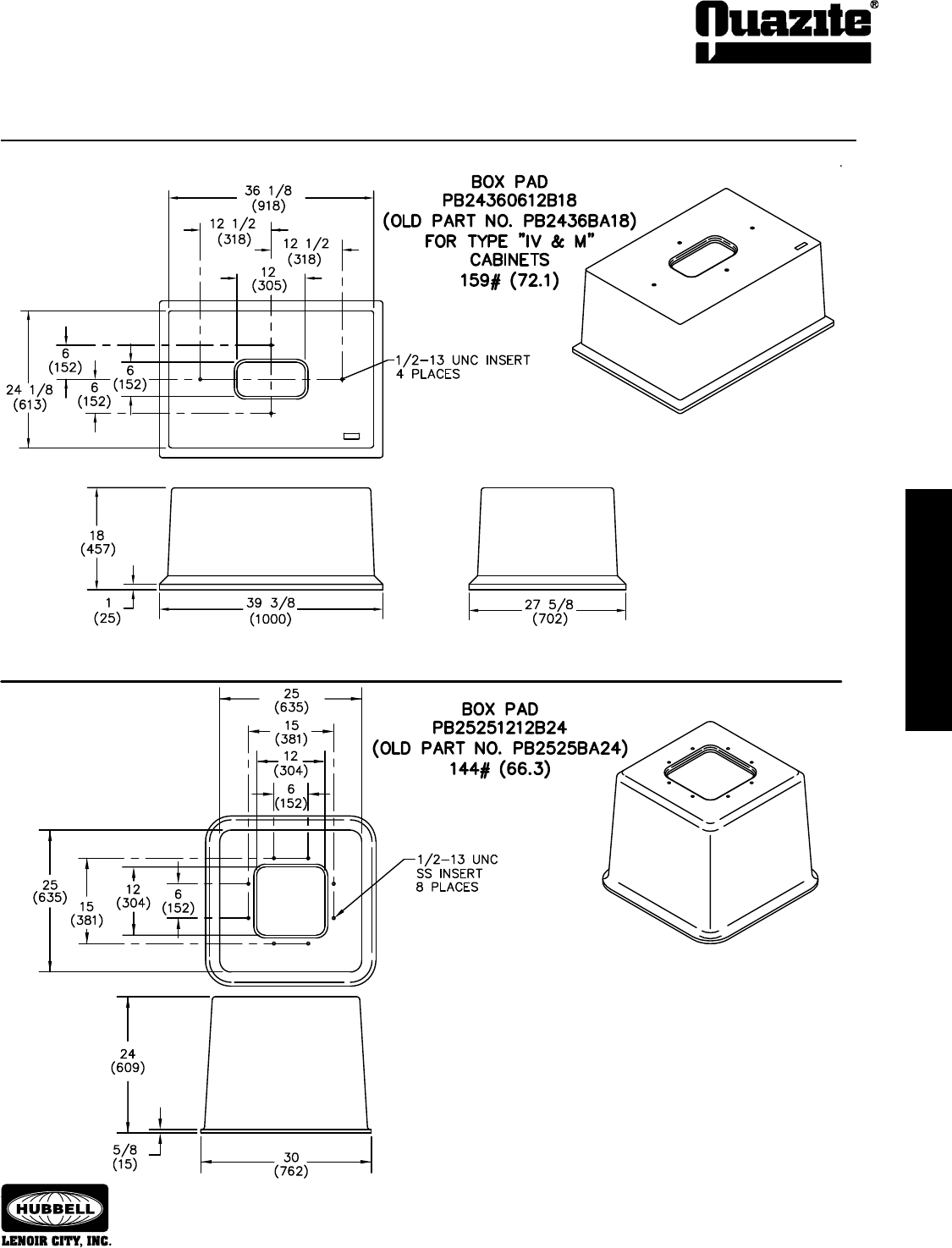
TRANSPORTATION INDUSTRY
PRODUCTS
TRANSPORTATION INDUSTRY
PRODUCTS
79
TRANSPORTATION INDUSTRY
PRODUCTS
TRANSPORTATION INDUSTRY
PRODUCTS
SEPTEMBER 2007
®
Information shown in catalog is a partial listing. If pad or throat
size desired is not listed, contact Quazite eld sales ofce.
SPECIFICATIONS/DATA Trafc Signal Cabinet Bases
Dimensions and weights in parentheses are metric equivalent.
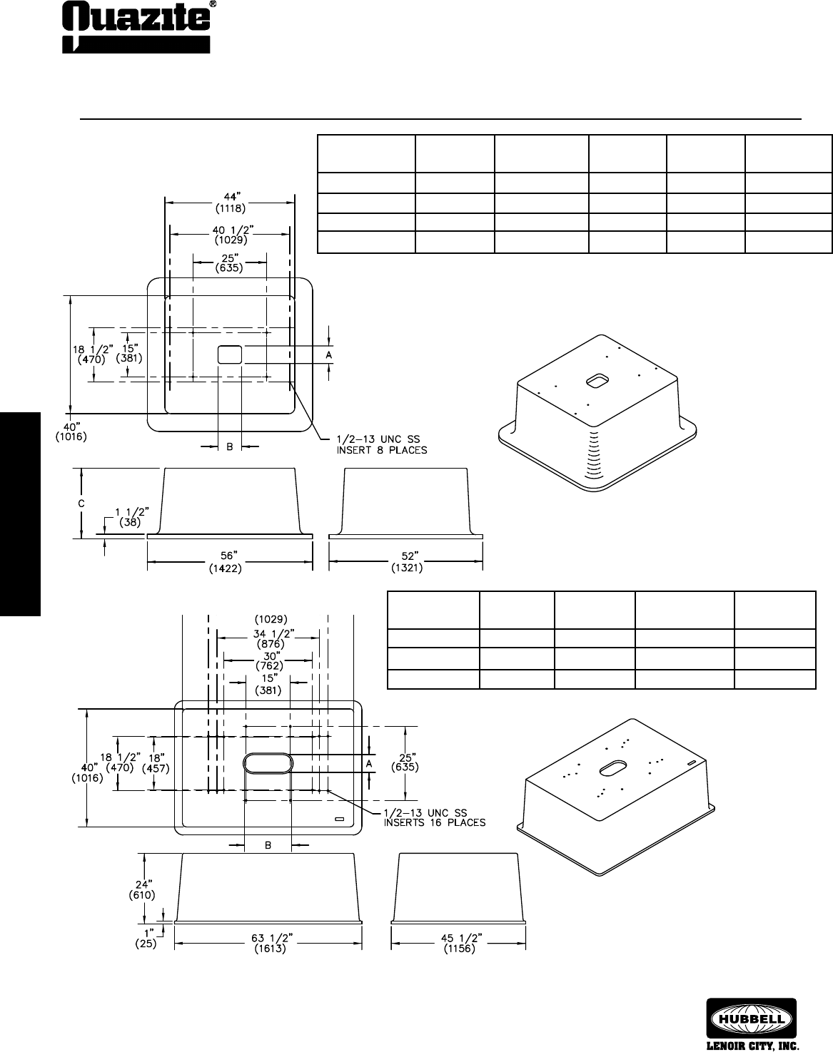
80
TRANSPORTATION INDUSTRY
PRODUCTS
TRANSPORTATION INDUSTRY
PRODUCTS
SEPTEMBER 2007
®
TRANSPORTATION INDUSTRY
PRODUCTS
TRANSPORTATION INDUSTRY
PRODUCTS
Information shown in catalog is a partial listing. If pad or throat
size desired is not listed, contact Quazite eld sales ofce.
SPECIFICATIONS/DATA Trafc Signal Cabinet Bases
Dimensions and weights in parentheses are
metric equivalent.
NEW OLD WEIGHT DIM. DIM.
PART NO. PART NO. # A B
PB40580616B24 PB4058BA24 450 (204.1 kg) 6” (152 mm) 16” (406 mm)
PB40581224B24 PB4058B502 435 (197.3 kg) 12” (305 mm) 24” (610 mm)
PB40581024B24 PB4058B504 440 (199.6 kg) 10” (254 mm) 24” (610 mm)
Refer to Trafc Signal Cabinet Base Cross Reference Guide on pages 75 - 76.
NEW OLD WEIGHT DIM. DIM. DIM.
PART NO. PART NO. # A B C
PB40440608B15 PB4044BA15 281 (127.0 kg) 6” (152 mm) 8” (203 mm) 15” (381 mm)
PB40440608B24 PB4044BA24 378 (171.0 kg) 6” (152 mm) 8” (203 mm) 24” (610 mm)
PB40440928B24 PB4044B503 385 (174.6 kg) 9” (229 mm) 28” (711 mm) 24” (610 mm)
PB40441218B24 PB4044B501 366 (166 kg) 12” (305 mm) 18” (457 mm) 24” (610 mm)
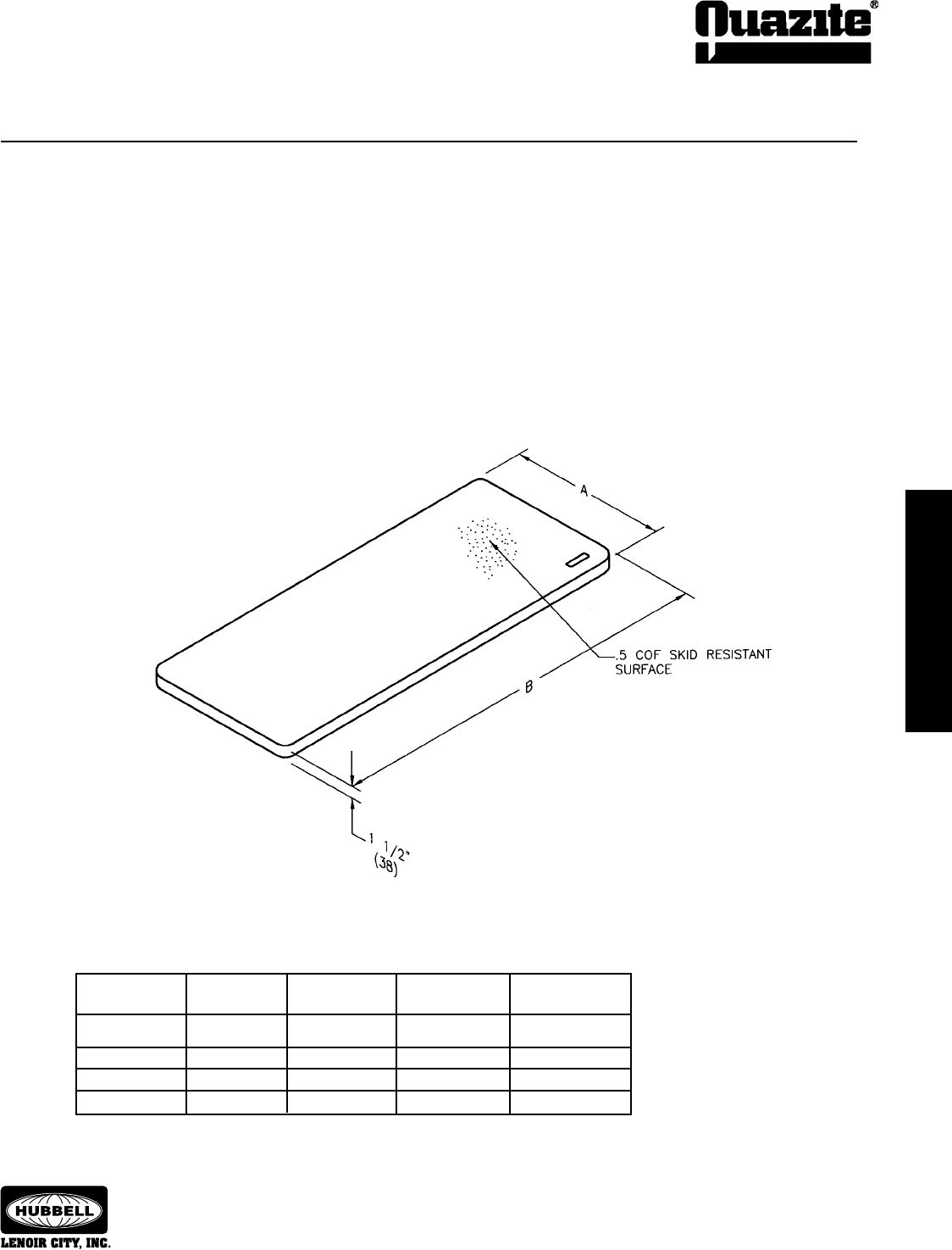
TRANSPORTATION INDUSTRY
PRODUCTS
TRANSPORTATION INDUSTRY
PRODUCTS
81
TRANSPORTATION INDUSTRY
PRODUCTS
TRANSPORTATION INDUSTRY
PRODUCTS
SEPTEMBER 2007
®
Information shown in catalog is a partial listing. If pad or throat
size desired is not listed, contact Quazite eld sales ofce.
NEW OLD WEIGHT DIM. DIM. DIM.
PART NO. PART NO. # A B C
PB40440608B15 PB4044BA15 281 (127.0 kg) 6” (152 mm) 8” (203 mm) 15” (381 mm)
PB40440608B24 PB4044BA24 378 (171.0 kg) 6” (152 mm) 8” (203 mm) 24” (610 mm)
PB40440928B24 PB4044B503 385 (174.6 kg) 9” (229 mm) 28” (711 mm) 24” (610 mm)
PB40441218B24 PB4044B501 366 (166 kg) 12” (305 mm) 18” (457 mm) 24” (610 mm)
SPECIFICATIONS/DATA Work Pad
Dimensions & weights in parentheses are metric equivalent.
OLD DIMENSION DIMENSION
PART NO. PART NO. WEIGHT # A B
PH242500002T PH2425AA 70 (30.8 kg) 24” (610 mm) 25” (635 mm)
PH243600002T PH2436AA 95 (43.1 kg) 24” (610 mm) 36” (914 mm)
PH244400002T PH2444AA 120 (54.4 kg) 24” (610 mm) 44” (1118 mm)
PH245800002T PH2458AA 160 (72.6 kg) 24” (610 mm) 58” (1473 mm)
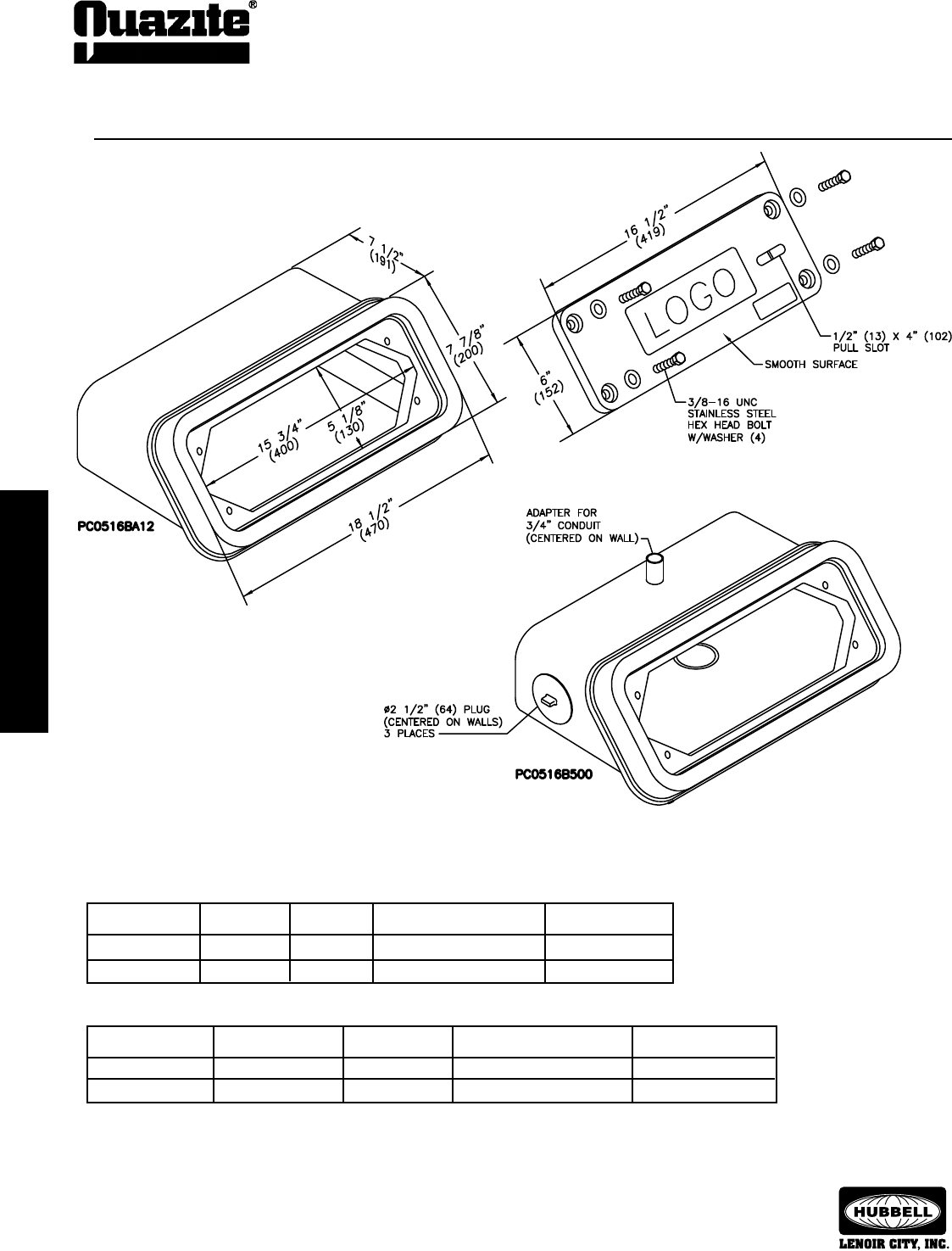
82
TRANSPORTATION INDUSTRY
PRODUCTS
TRANSPORTATION INDUSTRY
PRODUCTS
SEPTEMBER 2007
®
TRANSPORTATION INDUSTRY
PRODUCTS
TRANSPORTATION INDUSTRY
PRODUCTS
Information shown in catalog is a partial listing. If pad or throat
size desired is not listed, contact Quazite eld sales ofce.
Cover (Blank unless logo is specied)
Box
Dimensions and weights in parentheses are metric equivalent.
DESCRIPTION PART NO. WEIGHT # DESIGN/TEST LOAD # ANSI TIER
Closed Bottom PC0516BA12 25 (11 kg) 15,000 / 22,500 15
Closed Bottom PC0516B500 25 (11 kg) 15,000 / 22,500 15
DESCRIPTION PART NO. WEIGHT # DESIGN/TEST LOAD # ANSI TIER
W/4 Bolts PC0516CA00 6 (2.7 kg) 8,000 / 12,000 8
W/2 Bolts PC0516C500 6 (2.7 kg) 8,000 / 12,000 8
SPECIFICATIONS/DATA Median Barrier Enclosure
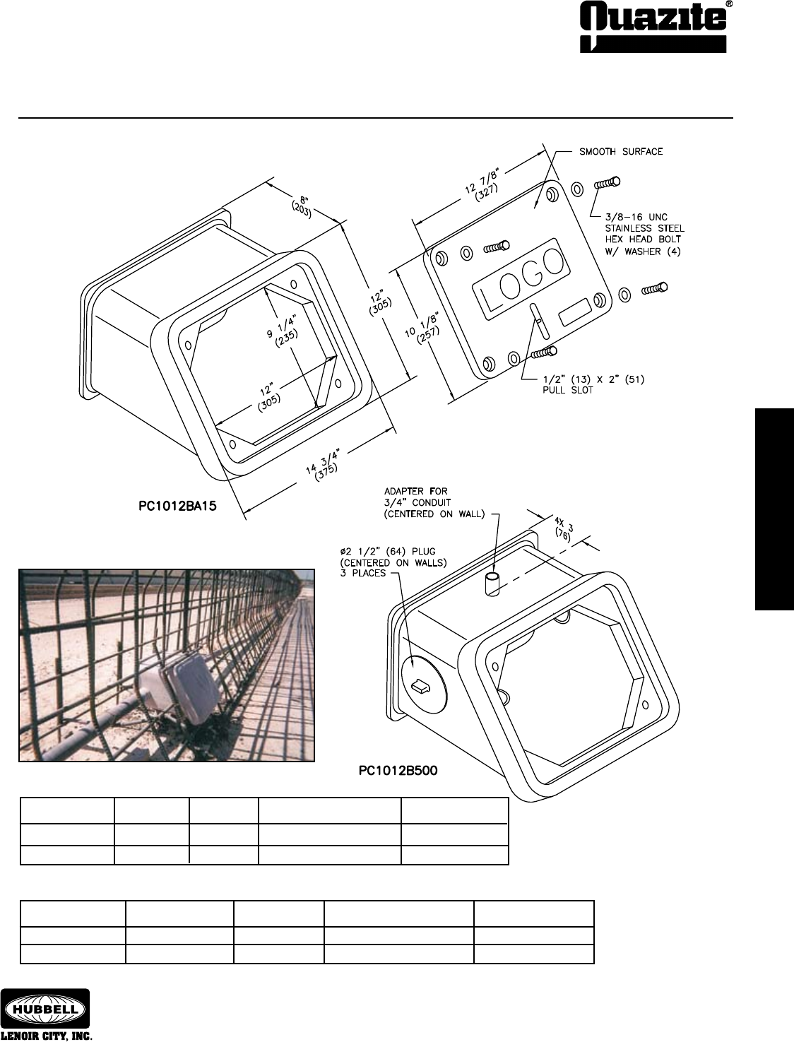
TRANSPORTATION INDUSTRY
PRODUCTS
TRANSPORTATION INDUSTRY
PRODUCTS
83
TRANSPORTATION INDUSTRY
PRODUCTS
TRANSPORTATION INDUSTRY
PRODUCTS
SEPTEMBER 2007
®
Information shown in catalog is a partial listing. If pad or throat
size desired is not listed, contact Quazite eld sales ofce.
SPECIFICATIONS/DATA Jersey Style Median Barrier Enclosure
DESCRIPTION PART NO. WEIGHT # DESIGN/TEST LOAD # ANSI TIER
W/4 Bolts PC1012CA00 8 (3.6 kg) 8,000 / 12,000 8
W/2 Bolts PC1012C500 8 (3.6 kg) 8,000 / 12,000 8
Cover (Blank unless logo is specied)
Box
Dimensions and weights in parentheses are metric equivalent.
DESCRIPTION PART NO. WEIGHT # DESIGN/TEST LOAD # ANSI TIER
Solid Bottom PC1012BA15 23 (10.4 kg) 15,000 / 22,500 15
Solid Bottom PC1012B500 23 (10.4 kg) 15,000 / 22,500 15
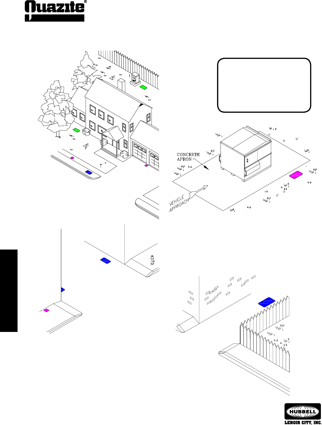
84
INSTALLATION
INSTALLATION
SEPTEMBER 2007
®
INSTALLATION
INSTALLATION
“ANSI TIER” SELECTION AND PLACEMENT IN NON-DELIBERATE
VEHICULAR TRAFFIC APPLICATIONS
RESIDENTIAL
(NON-DELIBERATE TRAFFIC)
Enclosures can be placed in grassy areas or
sidewalks. They may also be placed in areas
next to the structures or poles where it is
unlikely a vehicle will run over the enclosure.
Enclosures should not be placed in the
street or driveway where deliberate traffic is
anticipated.
TRASH RECEPTACLE APPLICATION
(NON-DELIBERATE TRAFFIC)
In an area where a trash receptacle is placed, the enclosure should be
placed away from the concrete that the receptacle is set on so that the
receptacle will not be placed on the enclosure or the wheels of the truck
will not roll over the enclosure. Even though the traffic expected on the
concrete apron or in front of the receptacle is occasional, it is deliberate
because the traffic is both intentional and heavy in nature.
DUAL LANE ALLEY
(NON-DELIBERATE TRAFFIC)
In a single lane alleyway (at right), the enclosure should be
placed in the center of the alleyway. The placement minimizes the
possibility of the enclosure being run over. In a dual lane alleyway,
the enclosure should be placed as close to the building as possible.
Most of the time, two vehicles will not be in the alleyway at the
same time, so the chances of the enclosure getting run over will be
minimal. Knowledge of the location and expected traffic patterns
should be used to determine if traffic would be deliberate or non-
deliberate as defined previously.
The enclosures shown in these
sketches have been color coded
to indicate the proper Tier level
required for the application.
Green = Pedestrian/Tier 5
Magenta = Tier 8
Blue = Tier 15
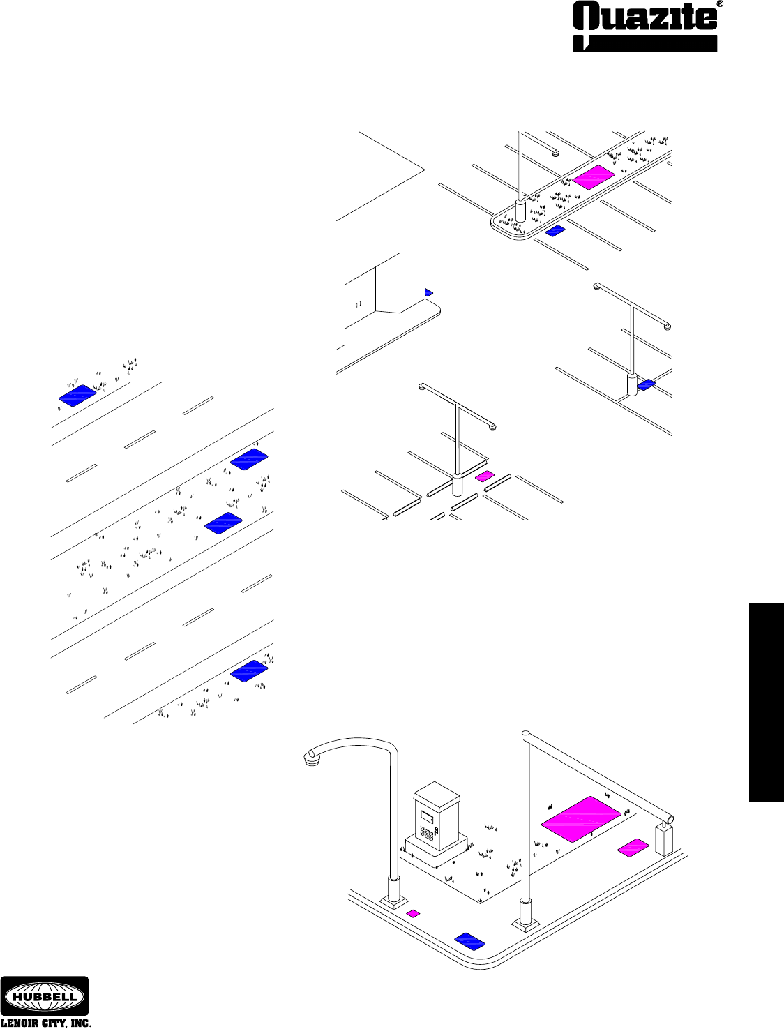
INSTALLATION
INSTALLATION
85
INSTALLATION
INSTALLATION
SEPTEMBER 2007
®
“ANSI TIER” SELECTION AND PLACEMENT IN NON-DELIBERATE
VEHICULAR TRAFFIC APPLICATIONS
SIDEWAY & GRASSY AREA
(NON-DELIBERATE TRAFFIC)
An enclosure can be placed in any grassy
area and in most sidewalks. However,
an enclosure should not be placed in a
sidewalk where a driveway crosses over
the sidewalk.
PARKING LOTS
(NON-DELIBERATE TRAFFIC)
Enclosure applications:
• Inthefront center of aparking space withtheenclosure
placed so that the tires of the vehicle will straddle the
enclosure.
• Inthegrassyareawheretheparkinglotends.
• Placedalongsideandclosetothelightingpole.
• Placedbetweentheparkingcurbswherethepossibilityof
running over the enclosure is remote. This enclosure could
be placed anywhere between the parking curbs.
• Alongthebuildingbutnotinfrontofadoororpickuparea
where vehicular traffic would be expected.
DIVIDED HIGHWAY
(NON-DELIBERATE TRAFFIC)
On a divided highway, the enclosure should be placed in any area that
is not paved and where deliberate traffic is not expected. They can be
placed in the grassy median or off the shoulder of the highway.
NOTE: The paved shoulder of the highway is normally considered a
deliberate traffic location because it may be used as a breakdown lane or
may be used as a lane in heavy traffic periods or in times of construction.
Therefore, an enclosure should never be placed in the paved shoulder
of a road or in the road itself. The enclosure should be placed off the
shoulder, in the grassy areas.
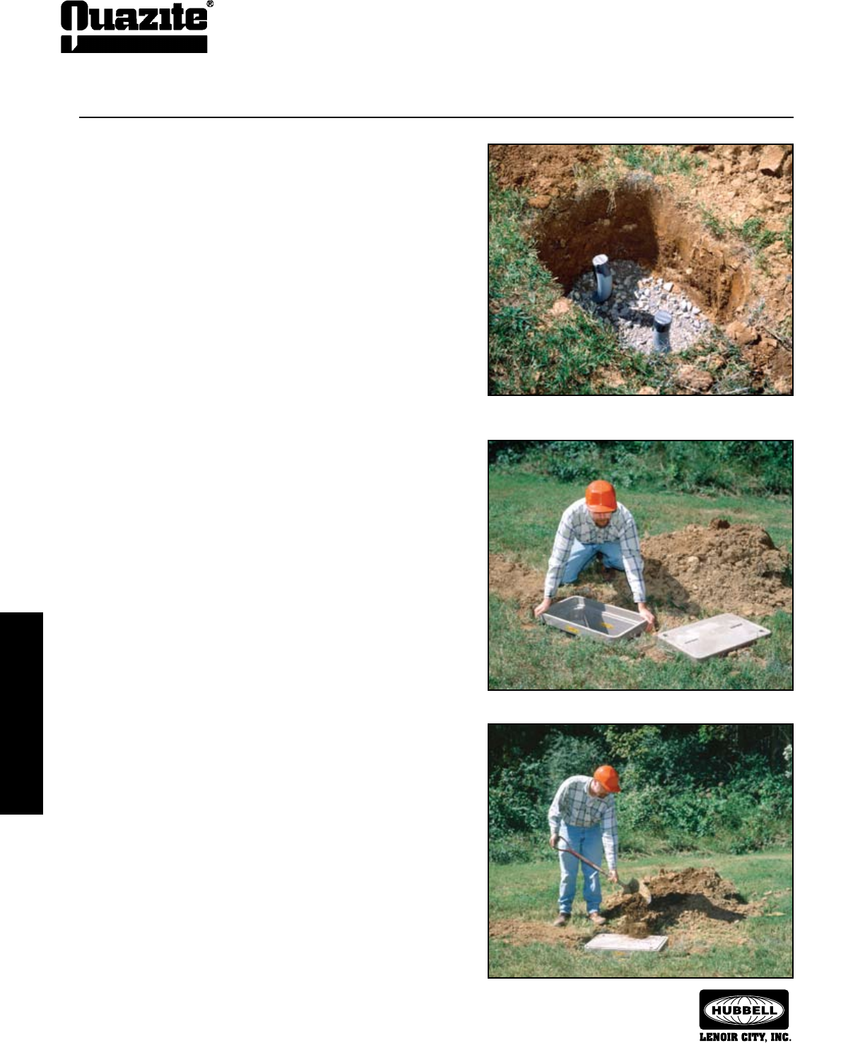
86
INSTALLATION
INSTALLATION
SEPTEMBER 2007
®
INSTALLATION
INSTALLATION
Installation Guidelines for
Enclosures Sized 17” x 30” and Smaller:
1.01 Excavate approximately 6 inches deeper than
depth of the enclosure.
1.02 Add 6 inches of gravel or crushed rock for
drainage.
2.01 Top of enclosure should be at grade level.
3.01 Fill to grade level with cover in enclosure.
4.01 If grade level is raised later, a straight sided
enclosure can be pulled up and bricked at the
bottom on one or four sides to conform to the
landscape.
Excavate 6 inches deeper than the depth of the enclosure and add
6 to 8 inches of gravel or crushed rock (1.02).
Make sure the cover is on when filling around
the enclosure (3.01).
The top of the enclosure should be level with the grade (2.01).
Standard Small Enclosure Installation
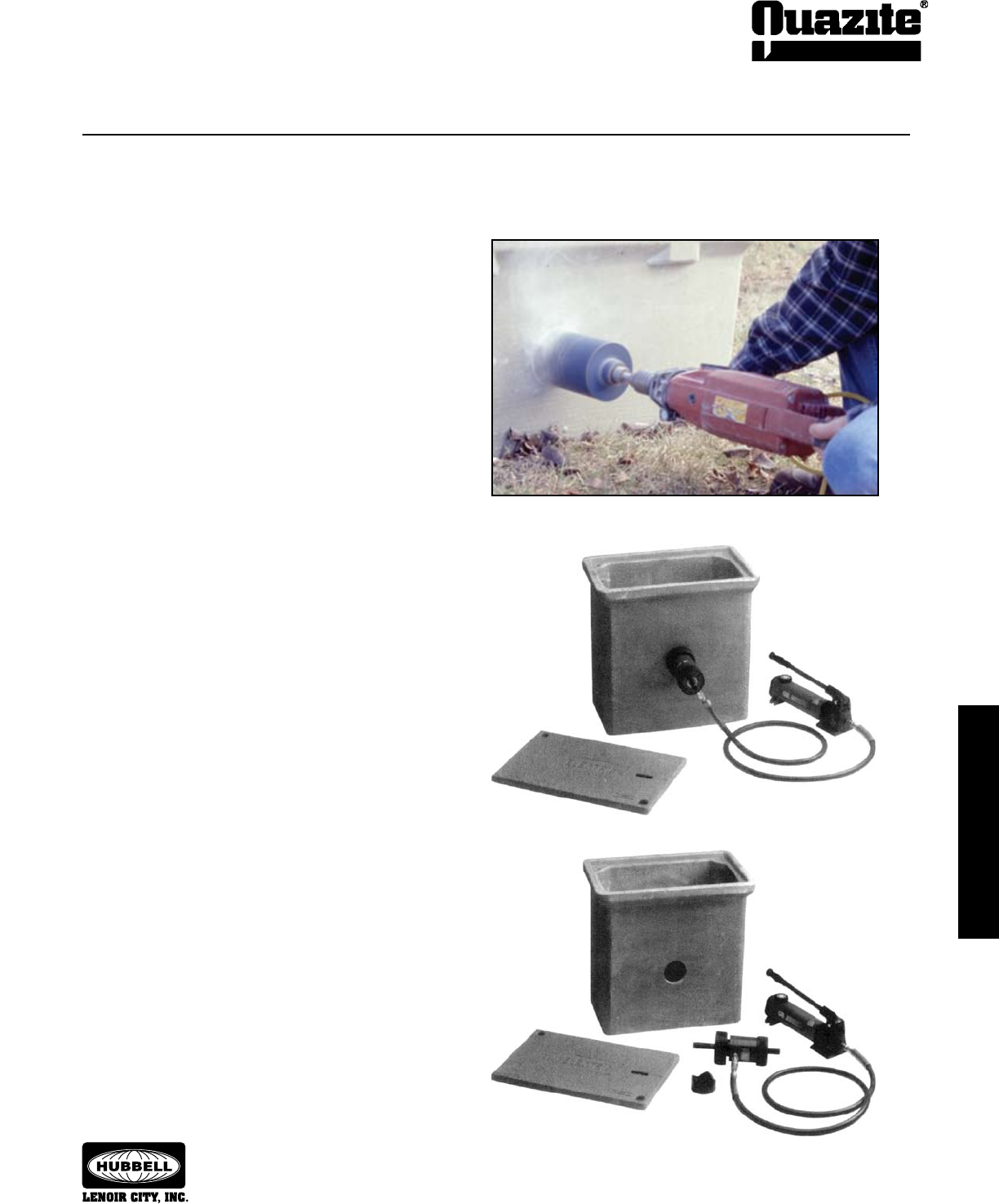
installation
installation
87
installation
installation
SEPTEMBER 2007
®
Methods for Cutting Holes in QUAZITE®
Enclosures:
Masonry Hole Saw
1. Drill a 7/8” pilot hole with a carbide tipped masonry drill.
2. Drill hole using a diamond tipped masonry hole saw.
• This is the preferred method from engineering.
• Estimated drilling time is 1 - 1.5 minutes.
Knockout Punch Driver
1. Set up the punch
1.01 Slide the die over the pull rod.
1.02 Insert pull rod into pilot hole.
1.03 Thread the punch onto the pull rod.
2. Punch hole and remove
2.01 Operate hand pump until the punch
penetrates the surface.
2.02 Open pump release valve.
2.03 Remove the slug.
NOTE: UL Listed enclosures with holes drilled in the field
may qualify for UL Listing as long as the holes do not
exceed more than 25% of the area of each sidewall
and as long as the holes do not cut into a structural
reinfocing rib, corner, or box lip. Contact the factory if
there is any question.
1.
2.
Hole Cutting Instructions
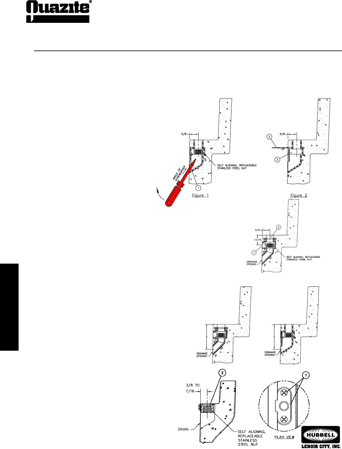
88
INSTALLATION
INSTALLATION
SEPTEMBER 2007
®
INSTALLATION
INSTALLATION
EZ-Nut and Self-Aligning Nut Cleaning & Replacement Instructions
EZ-Nut Cleanout Procedure
1. Make certain drain hole is clear. If it is not, scrape off material
with a flat edge and remove any visible obstruction(s). The drain
hole is located approximately 2” below the bearing ledge.
2. Insert flat head screw driver into insert. Scrape dirt off of
threads and clean out any excess dirt.
3. (Optional) Spray WD-40® or equivalent lubricant into insert to
lubricate the threads and help loosen any remaining debris.
4. Replace cover and secure bolts into insert.
Self-Aligning Nut Replacement:
1. Remove screws using a phillips screwdriver. Then remove the
retainer clip.
2. Remove 1/2-13 UNC square nut and replace it with a new 1/2-
13 UNC square nut.
3. Replace the retainer clip and screws.
Quazite has redesigned the EZ-Nut assembly (Style “B”) to provide a 40% greater drainage opening area and enable quicker and easier nut
replacement. This Style “B” design will be included in new production, but existing inventories may have the older Style “A” EZ-Nut assembly.
These instructions are provided in the event it is necessary to replace an existing nut.
*To determine which EZ-Nut design is in any box, insert a screwdriver into the drainage opening and pull upward. If the door does not pop
open, the Style “A” EZ-Nut is in the box. Follow the instructions for the Style “A” design. If the door pops open, follow the instructions for the
Style “B” EZ-Nut design.
Style “B” EZ-Nut replacement procedure*
1. Locate the drainage opening in the area containing
the insert. Insert a screwdriver into the opening at
approximately the angle shown in Figure 1.
2. After inserting the screwdriver into the drainage
opening, pull upward on the handle of the screw-
driver in order to pry open the door of the insert as
shown in Figure 2.
3. If necessary, remove any remaining debris from the
opening. After the opening is clear, remove existing
nut and replace with a nut of the required size.
Style “A” EZ-Nut replacement procedure*
1. Measure 13/16” down from bearing ledge of the enclosure. Using a screwdriver and
hammer, punch a hole into the cavity of the insert. Clear excess material out of the open-
ing.
2. Insert a screwdriver into the top opening and push the 3/18-16 UNC square nut out of
the opening just created. Replace with a new 3/8-16 UNC square nut and plug the cavity
in the sidewall if necessary.
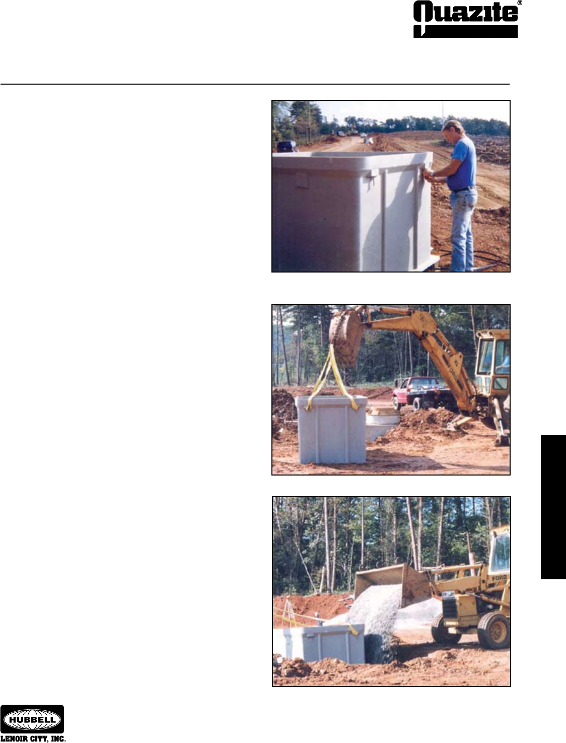
INSTALLATION
INSTALLATION
89
INSTALLATION
INSTALLATION
SEPTEMBER 2007
®
Installation Guidelines for
Enclosures Sized 24” x 36” and Larger:
enclosure
1.01 Utility easements
1.02 Streets
1.03 Parking lots
1.04 Parking lot entrances
1.05 Shipping & delivery docks
1.06 Waste removal (dumpsters)
2.01 Trenching or plowing of conduit
2.02 Boring under road crossings & railroads
2.03 Mark depth of conduit (marker tape)
3.01 Make hole 1-2’ longer and wider than the box and 6”-
8” deeper than the enclosure (add a rodent barrier if
called for).
4.01 Unpalletize the enclosure.
4.02 Place nylon straps or chains around the lifting bolts
and secure to the backhoe bucket. The angle between
the strap and the enclosure should not be less than 45
degrees.
4.03 Lift the enclosure and place it into the hole.
4.04 Place gravel in the enclosure and around the side if
necessary.
4.05 Lift the enclosure to the proper elevation allowing the
gravel to run out under the enclosure.
4.06 Check the elevation of the enclosure with a level and
range pole.
4.07 Make the necessary elevation adjustments with the
bucket and recheck the elevation.
4.08 Once the enclosure is set to the proper elevation,
remove the lifting bolts, reinstall the covers and back fill.
4.09 If 95% compaction is required, internal bracing
should be used on all manufacturer’s enclosures to
prevent deflection and premature failure.
Attach nylon straps or chains to the lifting bolts (4.02).
Place gravel in the enclosure and around the side. Lift enclosure to let
gravel run underneath (4.04, 4.05).
Lift and position enclosure with backhoe (4.03).
Standard Large Enclosure Installation
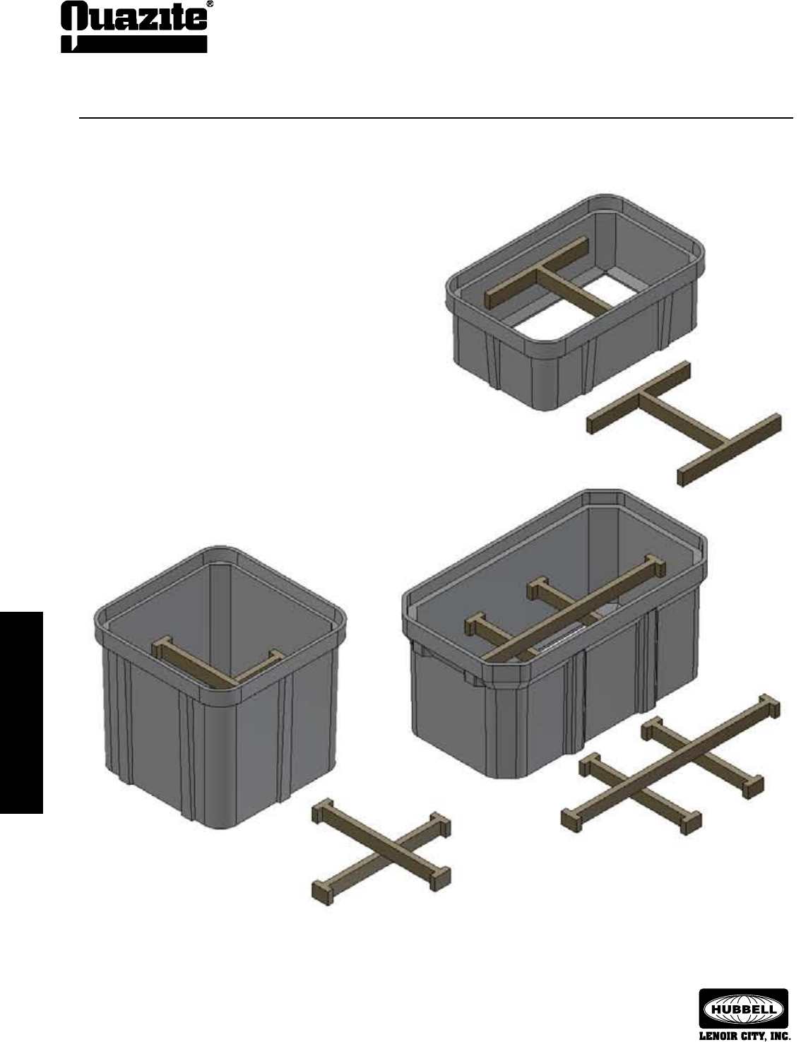
90
installation
installation
SEPTEMBER 2007
®
installation
installation
36 x 36
48 x 48
30 x 48
30 x 60
36 x 60
36 x 72
48 x 72
48 x 96
Internal Bracing Installation
Installation Guidelines for Internal Bracing:
Internal bracing may be warranted for any manufacturer’s
underground enclosure. If 95% compaction is required or if heavy
vehicles are going to be present during construction and/or
throughout the life of the enclosure, internal bracing during back-
filling operations will ensure minimal box sidewall deflections.
This installation practice applies to enclosures made from any
material to maintain the original sidewall geometry.
Supports should be 2 x 4s or similar material sized to hold at
mid-depth.
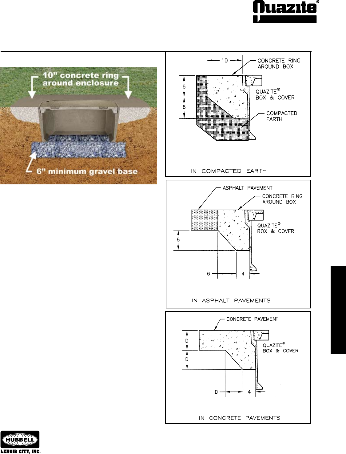
INSTALLATION
INSTALLATION
91
INSTALLATION
INSTALLATION
SEPTEMBER 2007
®
Concrete collars may be desired for installations in driveways, parking lots
and off-roadway applications where subject to occasional non-deliberate
traffic. This applies to boxes made from any material to provide added
protection for the top lip. This is not necessary in grassy areas or areas
subject to pedestrian traffic.
1. Concrete encasement to be 3,000 psi minimum.
2. Concrete encasement collar dimension, D, to be equal to
design pavement depth.
3. Pavement and subgrade to be as shown on the
engineering plans.
Concrete Collar Applications
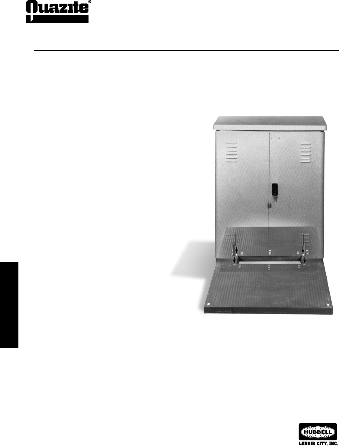
92
INSTALLATION
INSTALLATION
SEPTEMBER 2007
®
INSTALLATION
INSTALLATION
1.01 This section covers the description, installation and use
of support pads for cross connect cabinets and other
pedestal type cabinets.
1.02 The foundation base is designed for use with most
cabinets now being used in the field.
2.01 The foundation pad is constructed of polymer concrete
and reinforced with a heavy-weave fiberglass. All pads
have a non-skid surface.
2.02 Various types and sizes of pads are available for use
depending on the size of the cabinet to be installed.
2.03 3/8” or 1/2” inserts (anchors) or struts are molded into
the pad and must align with the base of the cabinet base
lugs, or support leg sets.
3.01 The following installation procedure is the same for all
sizes of foundation pads.
3.02 Determine cable/conduit entry position.
3.03 Dig recess for pad so that top surface of pad will be level
with surrounding area.
3.04 Level dirt around cable opening.
3.05 Level and tamp down dirt in the area to be occupied by
the foundation pad.
3.06 Backfill and tamp in trench area leading to cable opening.
3.07 Place pad in prepared, level area with opening in pad
(throat) directly over cable entry position.
3.08 Remove yellow plastic protective covers from inserts by
turning counterclockwise. Discard.
3.09 Attach cabinet to the foundation pad with bolts, brackets,
and/or lugs provided by cabinet manufacturer.
3.10 Backfill and tamp earth around pad so it is level with
surrounding landscape.
Installation Instructions
Telecommunications Cabinet Pad Installation
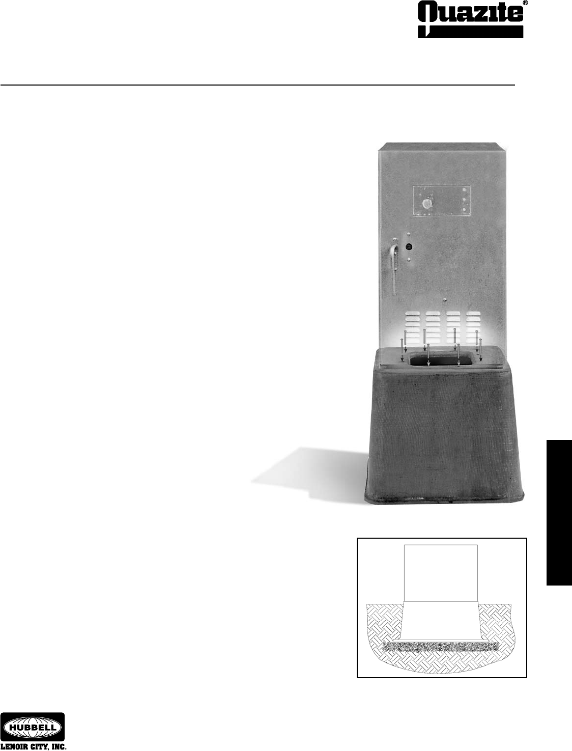
INSTALLATION
INSTALLATION
93
INSTALLATION
INSTALLATION
SEPTEMBER 2007
®
1.01 This section covers the description, installation and use of traffic signal
cabinet bases for traffic signal cabinets.
1.02 The foundation base is designed for most cabinets now being used in
the field.
2.01 The foundation base is constructed of polymer concrete and reinforced
by a heavy-weave fiberglass mat.
2.02 The types and sizes of the bases vary depending on the size of the
cabinet to be installed.
2.03 Inserts (1/2” anchors) are molded into the base and must align with
the cabinet footprint.
2.04 Base is resistant to most chemicals.
3.01 The following installation procedure is the same for all sizes of
foundation pads.
3.02 Determine cable/conduit entry position.
3.03 Excavate to the proper depth for traffic cabinet signal base. (The base
should extend no more than 50% above grade level.)
3.04 Excavate the site to the proper depth as determined by the final grade.
The work pad may be installed directly on undisturbed soil. (If the soil
compaction is substandard, or if you wish to provide drainage, you
need to lower the excavation 4” to 6” to accommodate pea gravel.)
3.05 Install conduit, 90o bends, to extend at least 2” above final grade of the
base.
3.06 Compact the soil or pea gravel base.
3.07 Install the traffic signal cabinet base. When lowering the base in place,
be sure the conduit is straight in line with the opening on the top
surface of the base. After setting the base, check for alignment and
plumb.
3.08 Backfill evenly around the base to maintain alignment and plumb.
Tamp backfill after each 4” fill. Fill 1” to 2” above grade and tamp to grade.
3.09 Set the cabinet.
Installation Instructions
Trafc Signal Cabinet Base Installation
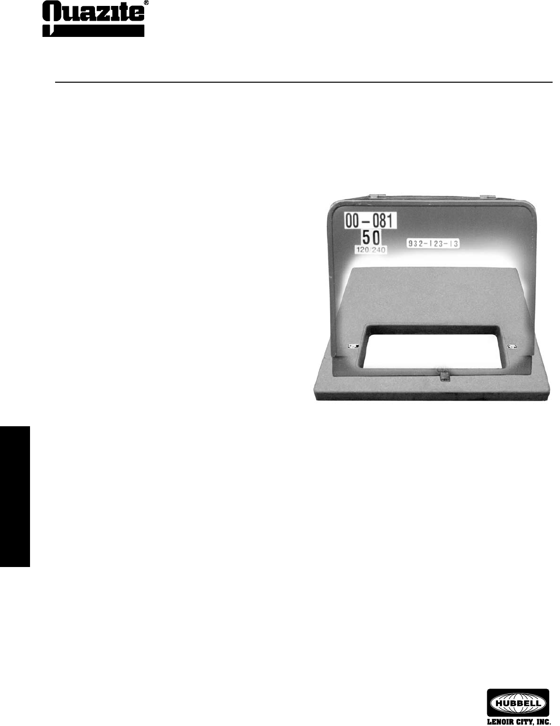
94
INSTALLATION
INSTALLATION
SEPTEMBER 2007
®
INSTALLATION
INSTALLATION
1.01 This section covers the description, installation and use of
support pads for transformers and switchgear.
1.02 The foundation base is designed for use with most
transformers and switchgear now being used in the field.
2.01 The foundation pad is constructed of polymer concrete and
reinforced with a heavy-weave fiberglass mat.
2.02 Various types and sizes of pads are available for use
depending on the size of the equipment to be installed.
2.03 Inserts (3/8” or 1/2” anchors) or struts are molded into the
pad and must align with the base of the equipment base
lugs, or support leg sets.
3.01 The following installation procedure is the same for all
sizes of foundation pads.
3.02 Determine cable/conduit entry position.
3.03 Dig recess for pad so that top surface of pad will be level
with surrounding area.
3.04 Level dirt around cable opening.
3.05 Level and tamp down dirt in the area to be occupied by the
foundation pad.
3.06 Backfill and tamp in trench area leading to cable opening.
3.07 Place pad in prepared, level area with opening in pad
(throat) directly over cable entry position.
3.08 Attach equipment to the foundation pad with bolts,
brackets, and/or lugs provided by equipment manufacturer.
3.09 Backfill and tamp earth around pad so it is level with
surrounding landscape.
Installation Instructions
Electrical Equipment Pad Installation
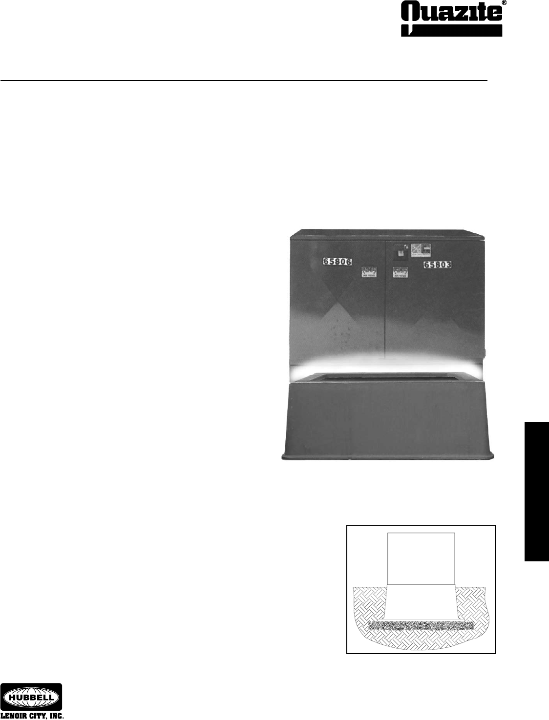
INSTALLATION
INSTALLATION
95
INSTALLATION
INSTALLATION
SEPTEMBER 2007
®
1.01 This section covers the description, installation and use
of box pads for switchgear.
1.02 The foundation base is designed for use with most
switchgear now being used in the field.
2.01 The foundation box pad is constructed of polymer concrete
and reinforced with a heavy-weave fiberglass mat.
2.02 Various types and sizes of pads are available for use
depending on the size of the equipment to be installed.
2.03 3/8” or 1/2” inserts (anchors) or struts are molded into the
pad and must align with the base of the cabinet base lugs,
or support leg sets.
3.01 The following installation procedure is the same for all sizes
of foundation box pads.
3.02 Determine cable/conduit entry position.
3.03 Excavate hole for the box pad. Make hole 1’ - 2’ longer and
wider and approximately 6” deeper than the box pad.
3.04 Put bolts into lifting inserts on sides of the box pad (4 bolts
are shipped with the box pad).
3.05 Attach lifting chain or straps to bolts.
3.06 Lift and position box pad into hole using a backhoe. Check
plan for proper orientation of box pad.
3.07 Place gravel in the box pad to a depth of approximately
6” to 8”.
3.08 Lift box pad to proper elevation, allowing gravel to run out
under the box pad.
3.09 Check the elevation of the box pad.
3.10 Make necessary elevation adjustments with the bucket and
recheck the elevation.
3.11 Remove the bolts once the box pad is set to proper
elevation.
Installation Instructions
Switchgear Box Pad Installation

96
SEPTEMBER 2007
®
Corporate Divisions
Hubbell Lenoir City, Inc. - Lenoir City, Tennessee Hubbell Lenoir City, Inc. - San Jose, California
HUBBELL - LENOIR CITY, INC.
(Lenoir City, Tennessee; San Jose, California)
Hubbell Lenoir City, with manufacturing plants in Lenoir City, Tennessee and San Jose, California, is the nation’s largest precaster
of polymer concrete products. Polymer concrete, which uses polymer resin instead of Portland Cement, is a strong, lightweight, highly
impermeable material.
Though both manufacturing plants produce precast polymer concrete products, the plants differ somewhat from each other. The 75,000
square foot San Jose location is the older of the two. “It’s really the cornerstone of our business,” explains John Downing, Vice President and
General Manager of Hubbell Lenoir City. In operation since the early 1970s, this plant boasts many employees with 15+ years of experience.
The San Jose plant manufactures all products in the QUAZITE® utility enclosure and POLYCAST® drain system product lines.
The 78,000 square foot Lenoir City facility was built in 1987 to replace smaller plants operating in Houston, Norfolk and Detroit. Down-
ing says an East Tennessee site was chosen for several reasons: the availability of motor freight (the plant is conveniently located near both
Interstates 40 and 75, a geographically central location that allows it to serve the entire east coast) and the availability of a good work force.
Each facility, unique in its own right, complements the other, allowing Quazite and Polycast to serve both the East and West coasts.
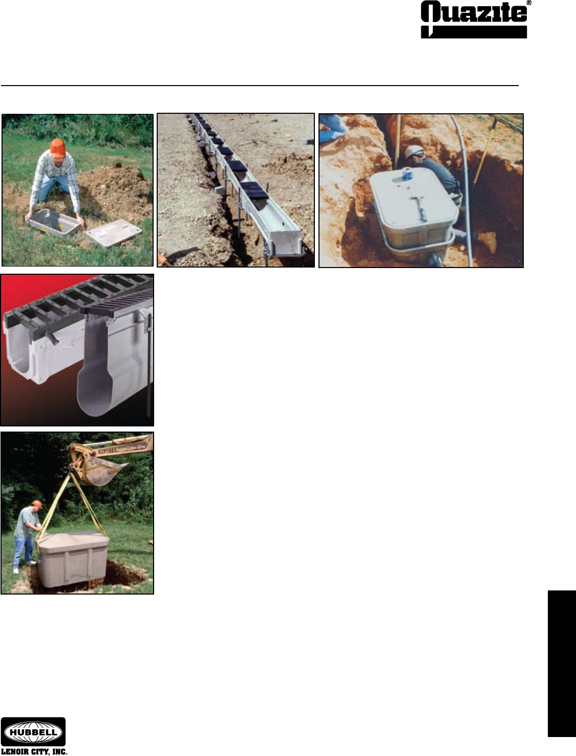
97
SEPTEMBER 2007
®
The division has two main product lines:
QUAZITE® utility products, which make up the oldest and largest group, are products engi-
neered for the electrical, water and gas utilities, telecommunications and transportation industries.
Underground pull/splice boxes, service boxes, handholes, box pads, and telephone and electric
equipment pads are included in the QUAZITE® line. These lightweight products are easier, and
therefore less expensive, to install. QUAZITE®’s strength, durability and corrosion resistance
means that it will last longer, reducing life cycle costs.
POLYCAST® presloped trench drain is used in a wide variety of applications from airports
to major highway systems to light duty residential to industrial plants. POLYCAST® offers easy to
install, low-cost channels, catch basins and a variety of gratings which are resistant to chemicals
and water erosion.
Polymer concrete products are manufactured at the Lenoir City Division plants in Lenoir City, TN and San Jose, CA.
Polymer Concrete Products
98
SEPTEMBER 2007
®
People and Capabilities
Engineering
Registered Professional Engineers are on hand to assist with design,
specification development and review. Full CAD capabilities are available and
can be used to electronically transmit drawings and files to you.
Sales and Customer Service
Quazite precast polymer concrete products are sold by a network of
stocking distributors throughout the country. In support of the distributors
are Sales Representatives knowledgeable in the products and applications.
Regional Sales Managers, as well as Product Managers, work to provide
customer service and satisfaction.
Competent, friendly, customer service personnel are on staff to respond
quickly to customer questions and concerns.
Special care is given by order receipt through plant scheduling, quality
control and shipping to meet all needs.
Website
QUAZITE® literature and product drawings are now conveniently avail-
able through the Quazite website at www.quazite.com. For the latest revisions
and additions to our product line, visit us online at:
www.quazite.com
Research and Development
Quazite is involved in continuous research and development pro-
grams. Products are reviewed, updated and improved as changes occur
in the market place.
As engineers become aware of the features and benefits of polymer
concrete, the range of applications for this unique material continues to
grow.
Precast polymer concrete may be the engineering solution for prob-
lems associated with traditional materials.
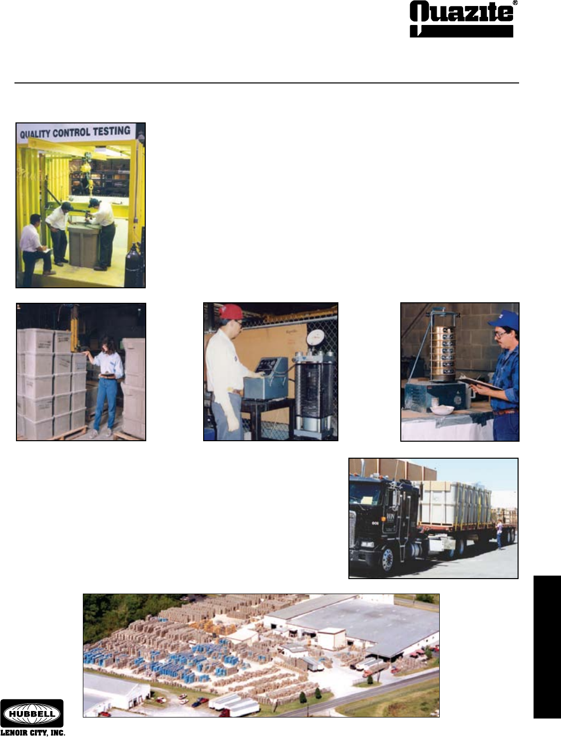
99
SEPTEMBER 2007
®
Quazite is committed to quality assurance, product improvement and research into new materials
and applications. Highly specialized Quality Assurance staff at each manufacturing facility ensure
product consistency and conformance to customer specifications.
Standard testing is performed to assure the highest quality products. In addition, other custom
tests are performed on a routine basis as required for the application.
Standard physical testing is performed for compressive strength, tensile strength, and flexural
strength. The material is tested according to the requirements of ASTM Method D-543, Section 7 for
chemical resistance.
As seen from the examples of test procedures shown here, product development and quality
have always been emphasized. That emphasis is more prevalent today than ever before and will
continue to grow in the future.
Shipping & Inventory
Many different types of products are shipped daily - drain, and utility service
boxes.
An extensive inventory is maintained on each product to assure that customers
receive a quick delivery.
Quality Assurance

Q
U
A
Z
I
T
E
P
R
O
D
U
C
T
S
C
A
T
A
L
O
G
QUAZITE
3621 Industrial Park Drive
Lenoir City, TN 37771
Phone: 800-346-3062 or 865-986-9726
Fax: 865-986-0585
e-mail: hpsliterature@hps.hubbell.com
© Copyright 2006 Quazite • 3621 Industrial Park Drive • Lenoir City, TN
NOTE: Because Hubbell has a policy of continuous product improvement, we reserve the right to change design and specifications without notice.
UNDERGROUND ENCLOSURES AND PADS
Complete Product Representation and
Stocking Distributors Throughout North America
Web: http://www.quazite.com
E-mail: hpsliterature@hps.hubbell.com
QZ-1
DECEMBER 2006 Printed in USA SUTH 10M
