56178 Catalog
10205-Catalog 10205-Catalog 10205-Catalog 782520 Batch5 unilog cesco-content
56178-Catalog 56178-Catalog 56178-Catalog 782520 Batch12 unilog cesco-content
2014-11-11
: Pdf 56178-Catalog 56178-Catalog Batch12 unilog
Open the PDF directly: View PDF ![]() .
.
Page Count: 112 [warning: Documents this large are best viewed by clicking the View PDF Link!]
About Our Products
All our latest products began with nationwide customer interviews to find out what you want and need...and
what you think. We then took this product-shaping feedback, factored in our own high standards for quality,
and developed products by which others are now measured. As you review our product offerings, you’ll see that
this strong tradition of excellence continues today with exit signs and emergency lighting that include the latest
advances and the highest level of performance.
About Our Quality
Quality is the key reason why Dual-Lite remains the industry’s most asked-for brand. You’ll see it in our construc-
tion, components, design and engineering, all of which combine to deliver the highest level of customer satisfac-
tion, and the industry’s best safety record.
Number One Brand
It’s our unique “listen-to-learn” business philosophy that’s made Dual-Lite the industry’s Number One brand ...and
why our name still remains synonymous with life safety excellence after more than 65 years.
Innovation doesn’t happen by
chance. Yes, it takes experience...
dedication to quality... and a
willingness to think “outside the box.”
But if you’re going to continually
set industry standards, that thinking
had better reflect what your
customers expect.
Which is why at Dual-Lite,
innovation begins with listening
carefully to our customers.
2
To be an
innovator,
first you have to
listen
to what
your
customers
say.
To be an
innovator,
first you have to
listen
to what
your
customers
say.
3
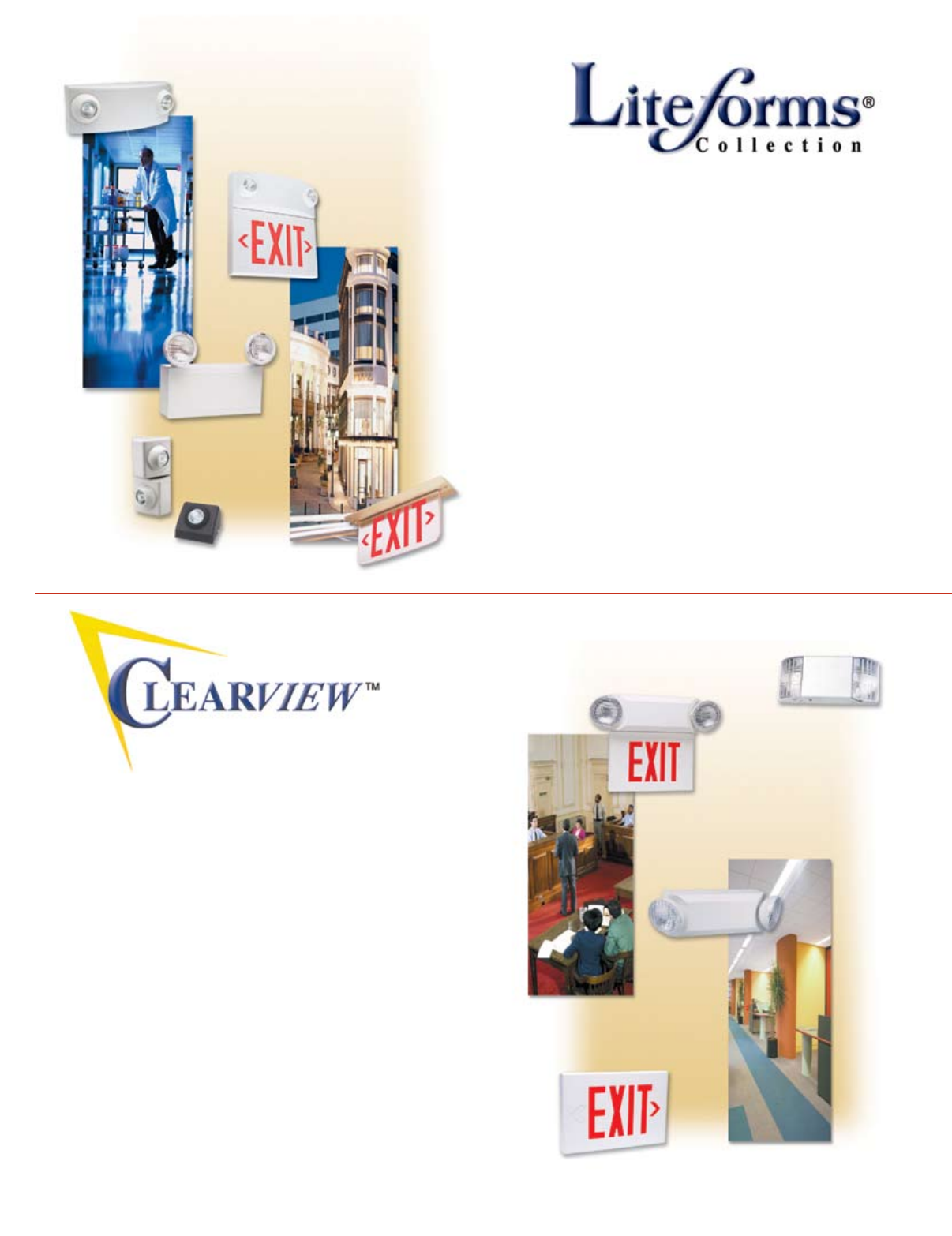
Sleek lines... low-profile silhouette... innovative design...
Only one line of life safety equipment fits this description
—the Liteforms® Collection by Dual-Lite.
Our unique styling is backed up by the substance of
high-quality, high-performance components and sturdy
construction features that helps ensure long-life, worry-
free operation and lower maintenance expense. Plus,
with our extensive product offering, you’ll find a
Liteforms exit sign or emergency lighting unit for nearly
every commercial, industrial or institutional application.
That’s the LiteForms tradition of excellence
LiteForms, delivering the perfect solutions to all your life
safety product needs.
For many, value equates to cost-effective products that
perform reliably.
For others, value means lowering transaction costs and
minimizing returns.
For everyone, value is simply having your expectations met
or exceeded every time.
Everything about Dual-Lite’s Clearview Collection is
focused on delivering the type of value and high output
performance that our customers have come to expect.
Additionally, Clearview Collection products share a “family”
style that results in a unified designer look when they are
installed together. With Clearview products, you can create
life safety lighting systems with eye appeal.
Value... Performance... Style...
That’s the Clearview difference.
A Tradition Of Excellence
Focused On Value
Collection
Inside Front Cover
4
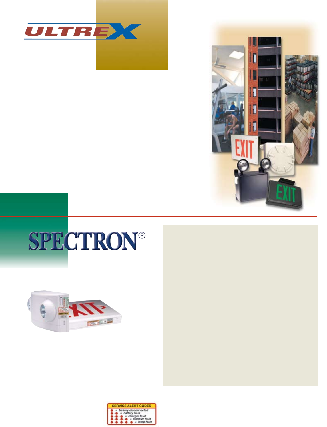
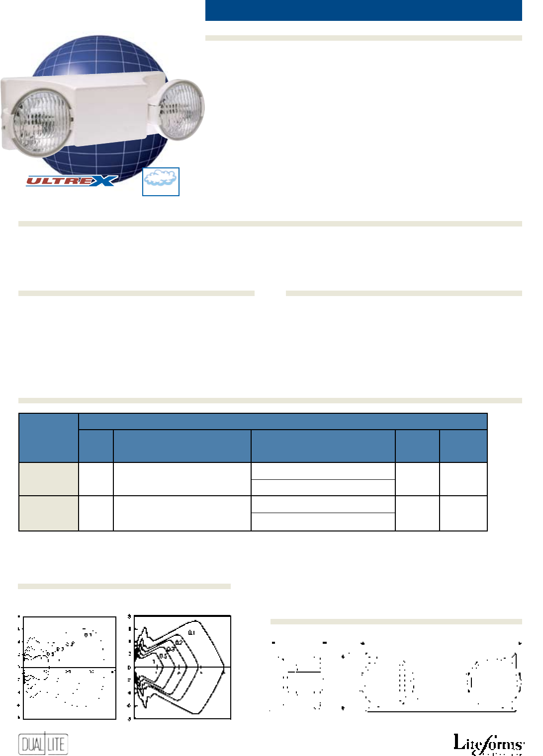
Whether your need is a vandal-
resistant exit sign, explosion-proof
emergency lighting, or units that can
withstand damp, exposed or hazardous
conditions, the solution is the Ultrex
line, from Dual-Lite.
Ultrex features products for almost
every severe condition you’ll
encounter.
Each Ultrex unit is designed to provide
unsurpassed, worry-free performance
and lower maintenance —
also lowering costs.
Ultrex Choices
Dual-Lite offers a broad choice
of products for severe condition
applications, including:
Emergency Lighting Units
• EZ-2 Damp Series
• LZ Damp Series
• LM Damp Series
• N4X Series
• IPS Series
• XPB Series
• Lampak Series
Exit Signs
• LX Series
• LT Series
• LN4X Series
• Sempra SC Series
• Sempra SC WL Series
• Freedom LED Series
• LEDS Series
Remote Lighting Heads
• GNX Series
• OMS Series
Protection From Severe
Conditions
Self-Testing/Self-Diagnostic
Electronics System
Technologically advanced self-testing, self-diagnostic
electronics provide increased reliability and decreased
maintenance.
All Dual-Lite models ordered with the Spectron
option provide:
• Visual indication of AC power status
• Visual Indication of all self-diagnostic test cycles
• Visual indication of unit malfunctions including:
• Battery disconnected
• Battery fault
• Charger fault
• Transfer fault
• Lamp fault
Features
• Meets UL 924 standards for self-testing/self diagnostic
models.
• Provides automatic self-diagnostic monitoring and
testing of unit operation.
• Automatically performs routine maintenance and
assures operational readiness at all times.
• Monitors charger and lamp operation.
• Routine discharge cycles insure optimum battery
performance and maximum useful life.
• Automatic self-test every 28 days and extended
operation self-test every 6 months.
• Automatic low voltage disconnect.
• Automatic unit transfer in brownout conditions.
• Automatic 15-minute retransfer delay (units).
• Automatic AC lockout circuit.
• Flashing LED indication of unit malfunction.
• All detected malfunctions retained in memory until
corrected and retested.
• Test switch allows a system check at any time.
• Supports exit sign flashing options
Test Intervals
The Spectron self-testing/self-diagnostic system conducts
tests to verify proper operation continuously and on
monthly, and semiannual intervals. Manual tests may also
be performed at any time. A malfunction during any self
test will be indicated by the external status indicators .
5
LiteScape Series Guaranteed Code Compliant Emergency Lights .................................................14, 15
EZ-2 Series Commercial Emergency Lights .................................................................................16
LZ Series Designer Emergency Lights ................................................................................................. 17
LZ (HC) Series High Capacity Designer Emergency Lights .........................................................18, 19
LM Series High Capacity Emergency Lights .......................................................................20, 21
EZ-2R Series Recessed Emergency Lights ................................................................................................. 22
T-Grid Series Recessed T-Grid Emergency Lights ............................................................................23
EXT Series Recessed Gimbal Emergency Light ...........................................................................24
Lite2 Series Emergency Lighting Square Units ................................................................... 25
Delite Series Emergency Lighting Cylinder Units ..........................................................................26
N4X Series Harsh Environment Emergency Lights ......................................................................27
AS Series Industrial Emergency Lights ..............................................................................28, 29
IPS Series Wet Location Emergency Lights ........................................................................30, 31
XPB Series Explosion-Proof Emergency Lights ....................................................................32, 33
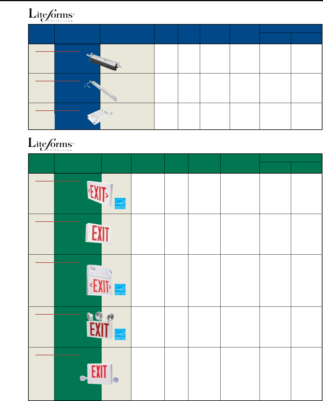
Lampak Series Fluorescent Power Packs ......................................................................34 to 38
LX Series Designer LED Exit Signs ....................................................................................................... 40
DK Series AC Incandescent Exit Signs .................................................................................................. 41
LT Series Designer Tandem Units ....................................................................................42, 43
NYXC Series New York Tandem Units ..........................................................................................44
SMC Series Tandem Units with Side Mounted Heads ..................................................................45
Sempra Series Diecast LED Exit Signs ...................................................................................................46, 47
Sempra MR Series Master/Remote Diecast LED Exit Signs ........................................................................48, 49
Sempra SC Series Severe Conditions Diecast LED Exit Signs ....................................................................50, 51
Sempra SCWL Series Wet Location Diecast LED Exit Signs ................................................................................... 52
Sempra SERS Series Recessed Diecast LED Exit Signs .......................................................................................... 53
NYDC Series New York Diecast LED Exit Signs......................................................................................... 54
LN4X Series Wet Location LED Exit Signs ....................................................................................55
Freedom LED Series Aluminum LED Exit Signs .................................................................................................... 56
LEDS Series Low-Profile Aluminum LED Exit Signs .......................................................................57
NYX Series New York LED Exit Signs..........................................................................................58
CMX Series Chicago Exit Signs ..................................................................................................59
LE Series Recessed Mounting Edge-Lit LED Exit Signs ...............................................................60, 61
LES Series Surface Mounting AC Edge-Lit LED Exit Signs ............................................................62, 63
NYE Series New York Recessed Mounting Edge-Lit LED Exit Signs ..................................................... 64
NYES Series New York Surface Mounting Edge-Lit LED Exit Signs ........................................................ 65
DEX Series Special Wording Incandescent Exit Signs ..................................................................66
SlimLite Series Fixed Lens Emergency Lights ..................................................................................68
CV Series Emergency Lights ...................................................................................................69
CVEC Series High Capacity Emergency Lights ..............................................................................70
CV3 Series LED Exit Signs ....................................................................................................................... 71
CVT Series Tandem Units .........................................................................................................72
CVD Series Diecast LED Exit Signs .......................................................................................................... 73
CVER Series Recessed Mounting Edge-Lit LED Exit Signs ...................................................................... 74
Remote Heads and Fixtures ..................................................................................................76 to 78
Lamp Selector Guide ...................................................................................................................... 79
Voltage Drop Tables ...................................................................................................................... 80
Unit Accessories ..............................................................................................................................................81
National Electric Code ............................................................................................................................82, 83
NFPA 101 Life Safety Code ....................................................................................................................84, 85
Limited Warranty ........................................................................................................................... 86
Synchron Series Single-Phase Inverters ........................................................................................88 to 91
Spectron LSN Series Single-Phase Inverters ...............................................................................92 to 101
Trident Series Three-Phase Inverters .....................................................................................................103 to 106
Auxiliary Transfer Switching Device .....................................................................................................................107
LiteForms Emergency Lighting Units
LiteForms Exit Signs
Remote Fixtures, Accessories & General Information
Inverter Power Systems
Clearview Emergency Lighting Products
Emergency
Lighting Units
Exit
Signs
Emergency
Lighting
Emergency
Lighting
Remote Heads,
Fixtures and
Accessories
Inverter Power
Systems
6
The following guide provides a fast, easy method of selecting
products for most applications. Refer to catalog pages for
additional product and ordering information.
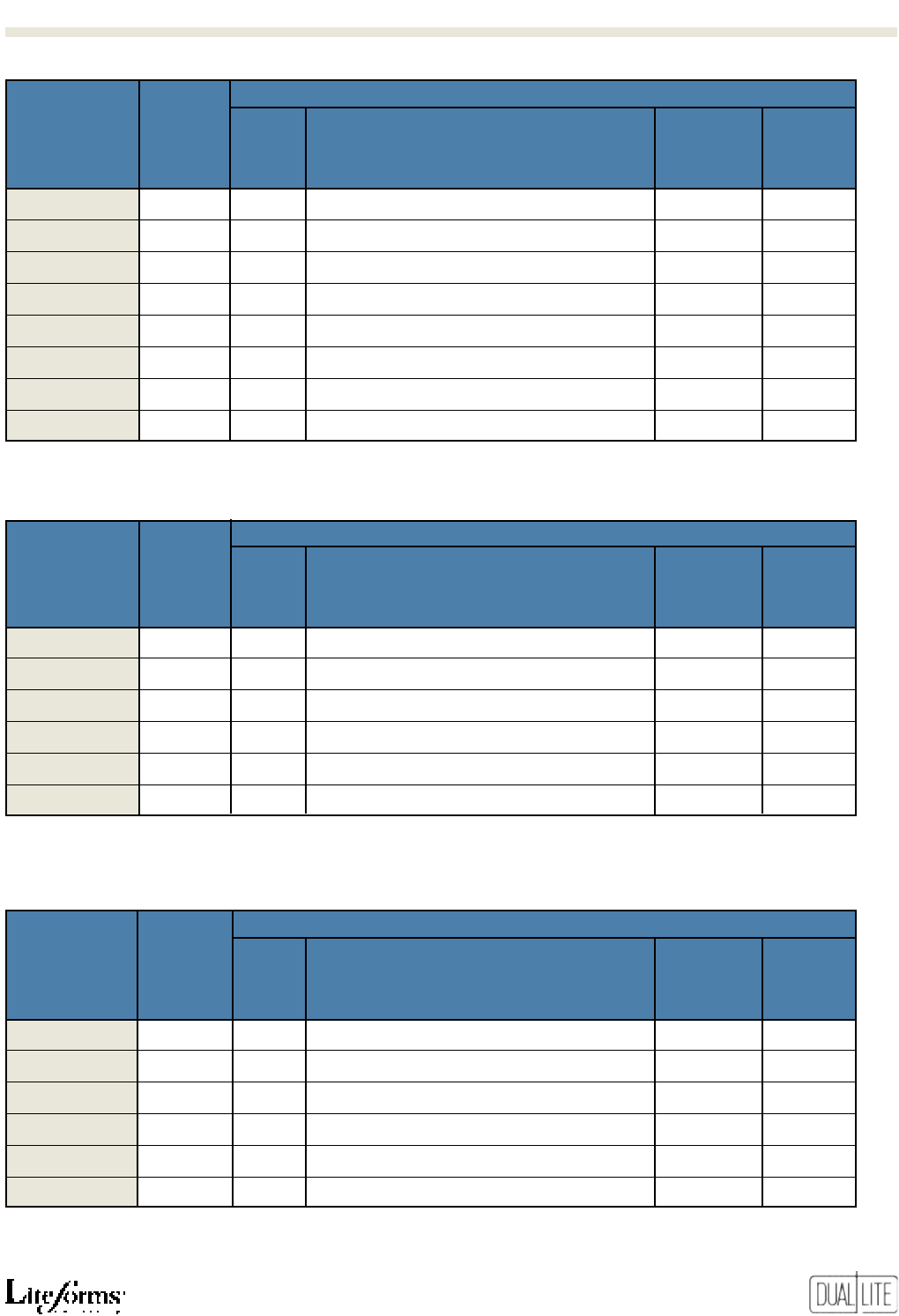
Catalog Watts PoWer Warranty
Page Model Unit For Battery ConsUMPtion Battery
nUMBer(s) ProdUCt series nUMBer Voltage 11/2 Hrs. tyPe (Max.)(1) eqUiPMent FUll/Pro-rata
14, 15 LiteScape™ Series LSC 6 20 Lead-Calcium 2 Watts 1 Years 1/5 Years
LSCN 6 20
Nickel-Cadmium
2 Watts 1 Years 1/9 Years
LSCI 6 20 Lead-Calcium 2 Watts 5 Years 2/4 Years
LSCNI 6 20
Nickel-Cadmium
2 Watts 5 Years 2/4 Years
16 EZ-2™ Series EZ-2 4 10.8 Lead-Calcium 15 Watts 3 Years 3/3 Years
EZ-2V 4 10.8 “ 15 Watts 3 Years 3/3 Years
EZ-2I 6 14.4 “ 15 Watts 5 Years 5/5 Years
Damp Location Model
EZ-2D 4 10.8 Lead-Calcium 15 Watts 3 Years 3/3 Year
17 LZ Series LZ2, LZ2D 6 10 Lead-Calcium 3.5 Watts 1 Year 1/5 Years
LZ15 6 15 ” ” ” ”
18, 19 LZ Series Standard Models
LZ30 6 30 Lead-Calcium 14 Watts 1 Year 1/5 Years
LZ35-12V 12 35 ” ” ” ”
LZ65 6 65 ” ” ” ”
LZ65-12V 12 65 ” ” ” ”
LZ20N 6 20
Nickel-Cadmium
11.2 Watts 3 Years 1/9
LZ25N-12V 12 25 ” ” ” ”
Damp Location Models
LZ25D 6 25 Lead-Calcium 14 Watts 1 Year 1/5 Years
LZ30D-12V 12 30 ” ” ” ”
LZ55D 6 55 ” ” ” ”
LZ55D-12V 12 55 ” ” ” ”
LZ15ND 6 15
Nickel-Cadmium
11.2 Watts 3 Years 1/9
LZ20ND-12V
12 20 ” ” ” ”
Remote Lighting Fixtures
Single Lamp Models 6, 12 — — — 1 Year —
Tandem Lamp Models 6, 12 — — — 1 Year —
20, 21 LM Series Standard Models
LM2 6 14.4 Lead-Calcium 15 Watts 1 Year 1/5 Years
LM16 6 16 “ “ “ “
LM33 6 33 “ “ “ “
LM40 6 40 “ “ “ “
LM66 6 66 “ “ “ “
LM80 6 80 “ “ “ “
LM130 6 130 “ “ “ “
LM40-12V 12 40 “ “ “ “
LM66-12V 12 66 “ “ “ “
LM80-12V 12 80 “ “ “ “
LM130-12V 12 130 “ “ “ “
Damp Location Models
LM28D 6 28 Lead-Calcium 15 Watts 1 Year 1/5 Years
LM34D 6 34 “ “ “ “
LM56D 6 56 “ “ “ “
LM68D 6 68 “ “ “ “
LM112D 6 112 “ “ “ “
LM34D-12V 12 34 “ “ “ “
LM56D-12V 12 56 “ “ “ “
LM68D-12V 12 68 “ “ “ “
LM112D-12V 12 112 “ “ “ “
(1) Maximum power consumption specification shown for circuit-sizing purposes only. Normal operating power requirements are significantly lower. Consult factory for normal operating power
consumption ratings on specific models.
Commercial
Units
Commercial
Units
Low-Profile
Halogen Lamp
Units
High Capacity
Halogen Lamp
Units
• Choice of battery types
• 6- and 12-volt models
• Capacities up to
65 watts
• Rugged metal housing
• 6- and 12-volt models
• Capacities up to 130
watts
• Lighting heads may be
top or side mounted
Compact,
Traditional
Design Units
GUARANTEED
CODE-COMPLIANCE
Emergency Lighting Units
7
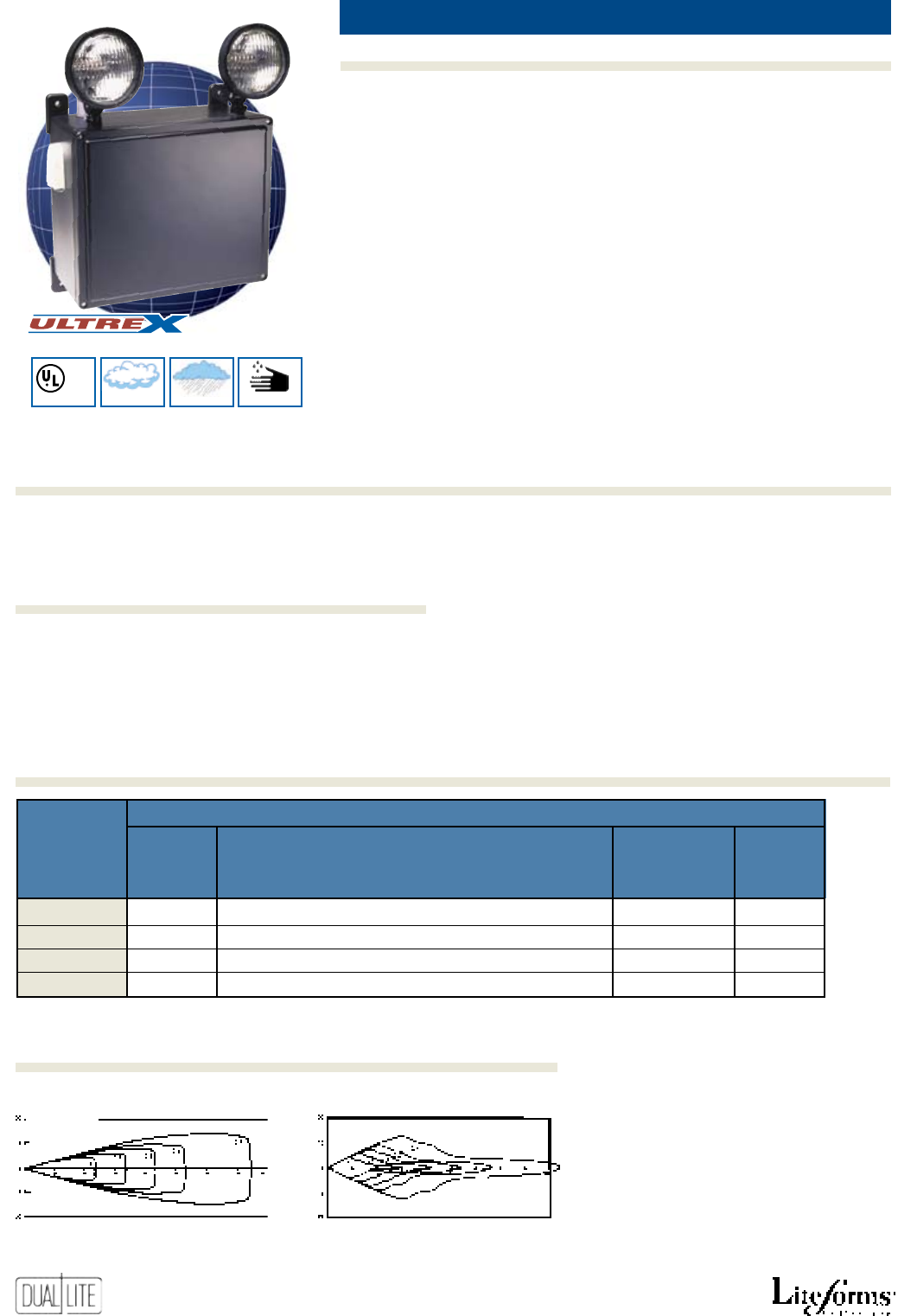
Catalog Watts PoWer Warranty
Page Model Unit For Battery ConsUMPtion Battery
nUMBer(s) ProdUCt series nUMBer Voltage 11/2 Hrs. tyPe (Max.)(1) eqUiPMent FUll/Pro-rata
20, 21 LM Series
NiCad Battery Models
LM15N 6 14.4
Nickel-Cadmium
15 Watts 3 Years 1/9 Years
LM30N 6 30 “ “ “ “
LM50N 6 50 “ “ “ “
LM50N-12V 12 50 “ “ “ “
LM100N-12V 12 100 “ “ “
City of Chicago Models
LM24CH 6 24 Lead-Calcium 15 Watts 1 Year 1/5 Years
LM36CH 6 36 “ “ “ “
LM36CH-12V 12 36 “ “ “ “
22 EZ-2R™ Series EZ-2R 6 10.8 Lead-Calcium 15 Watts 3 Years 3/3 Years
EZ-2RI 6 14.4 “ 15 Watts 5 Years 5/5 Years
23 T-Grid™ Series TG15 6 15 Lead-Calcium 15 Watts 3 Years 3/3 Years
TG30 6 30 ” 75 Watts ” ”
TG50-12V 12 50 ” ” ” ”
TG15N 6 15
Nickel-Cadmium
15 Watts 3 Years 1/9 Years
TG30N 6 30 ” 75 Watts ” ”
TG50N-12V 12 50 ” ” ” ”
24 EXT™ Series EXT-122-EM-K 6 8 Lead-Calcium 15 Watts 1 Year 1/5 Years
25 LITE2™ Series EDS 6 10 Lead-Calcium 12 Watts 3 Years 3/3 Years
EDS-2 6 14.4 ” ” ” ”
ERS 6 20 ” ” ” ”
ERS-3 6 30 ” ” ” ”
ERS-2-2 6 30 ” ” ” ”
ESS-I 6 10 Lead-Calcium 12 Watts 5 Years 5/5 Years
ESS-I-2 6 14.4 ” ” ” ”
ERS-I 6 20 ” ” ” ”
ERS-3I 6 30 ” ” ” ”
ERS-2I-2 6 30 ” ” ” ”
26 DELITE® Series ESC-2-0 6 12 Lead-Calcium 15 Watts 1 Years 1/5 Years
27 N4X Series N4X2 6 15.6 Lead-Calcium 75 Watts 3 Years 3/3 Years
N4X4 6 31.2 ” ” ” ”
N4X7 6 50.4 ” ” ” ”
N4X14 6 100 ” ” ” ”
N4X7-12V 12 50.4 ” ” ” ”
N4X14-12V 12 100 ” ” ” ”
(1) Maximum power consumption specification shown for circuit-sizing purposes only. Normal operating power requirements are significantly lower. Consult factory for normal operating power
consumption ratings on specific models.
Special
Application
Models
Recessed
Mounting
Units
• Rugged metal housing
• 6- and 12-volt models
• Capacities up to
100 watts
• Lighting heads may be
top or side mounted
• Chicago Models
Recessed
Troffer
Units
Recessed
Gimbal
Unit
Square
Units
Cylinder
Units
• Ceiling or wall mount
•
Suspended ceiling mount
•
Surface, semi-recessed
and fully-recessed models
Sealed, Harsh
Environment
Unit
• Dust-tight, moisture
and corrosion resistant
Quick Selector Guide
Emergency Lighting Units
8
Catalog Watts PoWer Warranty
Page Model Unit For Battery ConsUMPtion Battery
nUMBer(s) ProdUCt series nUMBer Voltage 11/2 Hrs. tyPe (Max.)(1) eqUiPMent FUll/Pro-rata
28, 29 AS Series AS-80 6 80 Lead-Calcium 75 Watts 1 Year 1/5 Years
AS-130 6 130 ” ” ” ”
AS-180-12V 12 180 ” ” ” ”
AS-270--12V 12 270 ” ” ” ”
AS-360-12V 12 360 ” ” ” ”
AS-180-24V 24 180 ” ” ” ”
AS-270-24V 24 270 ” ” ” ”
AS-360-24V 24 360 ” ” ” ”
28, 29 ALC-X/EDC-X Series ALC-X-30 6 78 Wet-Cell 75 Watts 1 Year 1/9 Years
ALC-X-60 6 144 Lead-Calcium ” ” ”
ALC-X-100 6 162 ” ” ” ”
12EDC-X-36S 12 200 ” ” ” ”
12EDC-X-60S 12 240 ” ” ” ”
12EDC-X-120S 12 350 ” ” ” ”
28, 29 AS/EDN Series AS-75 6 75 Wet-Cell 75 Watts 1 Year 1/14 Years
AS-145 6 110
Nickel-Cadmium
” ” ”
AS-210 6 145 ” ” ” ”
12EDN-10S 12 48 ” ” ” ”
12EDN-18S 12 100 ” ” ” ”
12EDN-30S 12 150 ” ” ” ”
30, 31 IPS Series C1D2-6V36 6 36 Pure-Lead 25 Watts 3 3/3
C1D2-6V72 6 72 “ “ “ “
C1D2-12V36 12 36 “ “ “ “
C1D2-12V72 12 72 “ “ “ “
32, 33 XPB Series XPB-75P 6 75 Pure-Lead 75 Watts 3 Years 3/3 Years
12XPB-75P 12 75 ” ” ” ”
(1) Maximum power consumption specification shown for circuit-sizing purposes only. Normal operating power requirements are significantly lower. Consult factory for normal operating power
consumption ratings on specific models.
Traditional
Units
• Maintenance-free
batteries
Traditional
Units
• Wet-cell
lead-calcium batteries
Traditional
Units
• Longest life,
wet-cell nickel-cadmium
batteries
NEC Class I,
Division 2
Units
• Suitable for
wet locations
Explosion-
Proof Units
• NEC Class I
and II operation
• Unit mounted and
remote fixtures
Fluorescent
Packs
Fluorescent
Packs
• Models
for standard
fluorescent lamps
Note: 12EDC-X models supplied
without lighting heads.
Note: 12EDN models supplied
without lighting heads.
• High lumen output
models
Emergency Lighting Units
Fluorescent Power Packs
Catalog oPerates rating nUMBer Warranty
Page Model laMP in Battery oF laMPs Battery
nUMBer(s) ProdUCt series nUMBer tyPe lUMens tyPe oPerated eqUiPMent FUll/Pro-rata
34 LAMPAK® Series UFO-3AW Std. Fluor. 350-450
Nickel-Cadmium
1 1 Year 1 Year
UFO-4W Std. Fluor. 500-600 ” 1 ” ”
UFO-5W Std. Fluor. 600-700 ” 1 ” ”
UFO-5AW Std. Fluor. 600-700 ” 1 or 2 ” ”
UFO-6W Std. Fluor. 1100-1400 ” 1 or 2 ” ”
UFO-6WI Std. Fluor. 1100-1400 ” 1 or 2 ” ”
UFO-6W-CLD Std. Fluor. 600-750 ” 1 or 2 ” ”
35 LAMPAK® Series UFO-7W Std. Fluor. 1450-3500
N
ickel-Cadmium
1 or 2 1 Year 1 Year
UFO-7WI Std. Fluor. 1800-3500 “ 1 or 2 “ “
9
Catalog PoWer Warranty
Page aC laMP aC laMP dC laMP Battery ConsUMPtion Battery
nUMBer(s) ProdUCt series tyPe Wattage tyPe tyPe (eMerg. Max.)(1) eqUiPMent FUll/Pro-rata
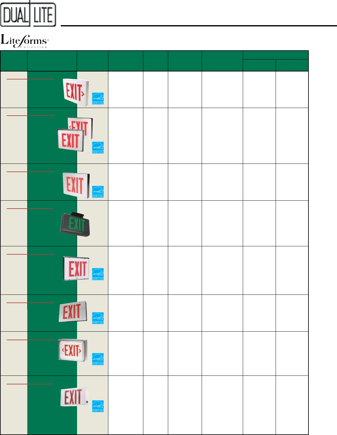
40 LX Series LED Red – 2.6W LED
Nickel-Cadmium
3.8 Watts 5 Years 1/9 Years
Green – 2.1W
41 DK Series Incandescent 15W (2) — — 30 Watts 3 Years —
Excluding
AC Lamps
42, 43 LT Series LED Red – 2.6W Halogen Lead-Calcium 5.0 Watts 5 Years 1/5 Years
Green – 2.1W and
LED
44 NYXC Series LED Red –3.5W LED Lead-Calcium 7.0 Watts 5 Years 1/5 Years
Green – 3.0W
45 SMC Series LED Red – 2.6W LED
Lead-Calcium
12 Watts 3 Years 1/5 Years
Green – 2.1W
(1) Maximum power consumption specification shown for circuit-sizing purposes only. Normal operating power requirements are significantly lower. Consult factory for normal operating power
consumption ratings on specific models.
Thermoplastic
LED Exit Signs
• All models
Damp Location Listed
• Damp Location
and Remote
Capacity models
Thermoplastic
Incandescent
Exit Signs
Combination
Emergency
Unit/LED Exit
Signs
Catalog oPerates rating nUMBer Warranty
Page Model laMP in Battery oF laMPs Battery
nUMBer(s) ProdUCt series nUMBer tyPe lUMens tyPe oPerated eqUiPMent FUll/Pro-rata
36 LAMPAK® Series UFO-12W 13 to 42W 300-750
Nickel-Cadmium
1 or 2 1 Year 1 Year
Compact
Fluor.
Lamps
37 LAMPAK® Series UFO-LP1 T5 and T8 390-700
Nickel-Cadmium
1 1 Year 1 Year
UFO-LP2 Fluor. 650-1325 “ 1 “ “
Lamps
38 LAMPAK® Series UFO-MH175 Metal- 20 to 30%
Nickel-Cadmium
1 1 Year 1 Year
UFO-MH250 Halide Normal “ 1 “ “
UFO-MH400 HID Lamps Output “ 1 “ “
Fluorescent
Packs
Fluorescent
Packs
• For compact
fluorescent lamps
• For low-profile
fluorescent fixtures
HID Back-up
Ballast
• For metal-
halide HID lamps
Quick Selector Guide
Combination
Emergency
Unit/LED Exit
Signs
Combination
Emergency
Unit/LED Exit
Signs
• Low-profile
side mounted
lighting heads
• Meets NY City
requirements
Fluorescent Power Packs
Exit Signs
10
• Lifetime warranty
on LED lamp strip
Cast Aluminum
LED Exit Signs
Severe Conditions
Cast Aluminum
LED Exit Signs
• Supplied as
2-sign sets
• Low-profile
Remote exit
• Lifetime warranty
on LED lamp strip
Master/Remote
Cast Aluminum
LED Exit Signs
Wet Location Cast
Aluminum LED
Exit Signs
• Lifetime warranty
on LED lamp strip
Cast Aluminum
LED Exit Signs
•
Suitable for damp, wet
and corrosive environ-
ments
Wet Location
LED Exit Signs
•
Up to 12 hours of
emergency operation
• All models
Damp Location Listed
Aluminum LED
Exit Signs
• Completely
sealed and
gasketed
• Lifetime warranty
on LED lamp strip
• Meets NY City
requirements
Catalog PoWer Warranty
Page aC laMP aC laMP dC laMP Battery ConsUMPtion Battery
nUMBer(s) ProdUCt series tyPe Wattage tyPe tyPe (eMerg. Max.)(1) eqUiPMent FUll/Pro-rata
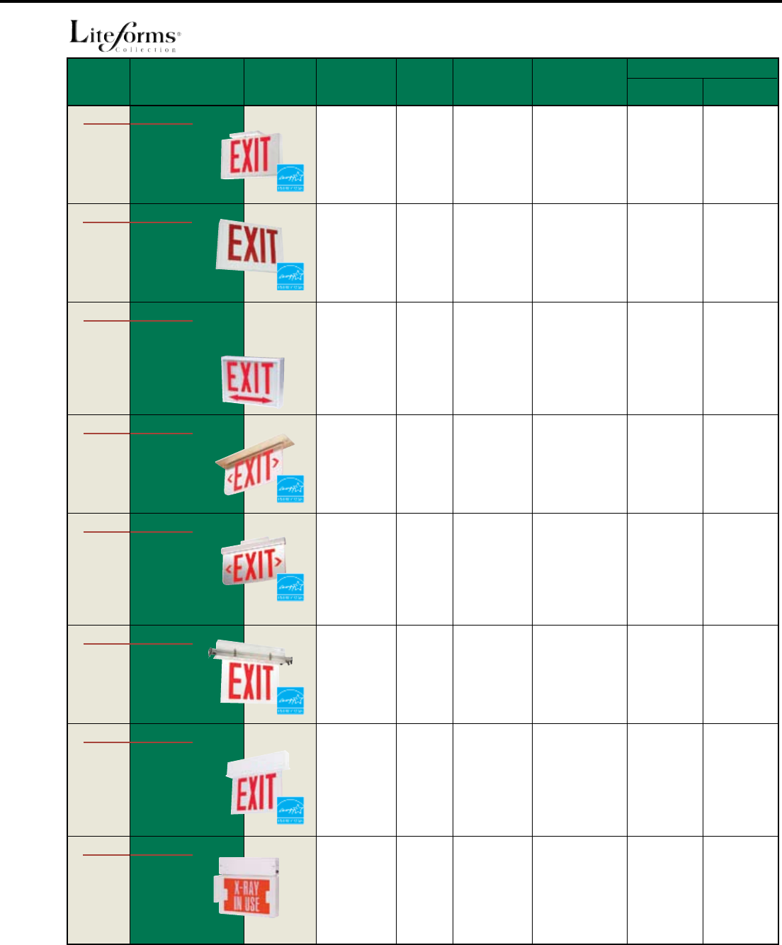
46, 47 Sempra® Series LED Red – 2.6W LED
Nickel-Cadmium
3.8 Watts 5 Years 1/9 Years
Green – 2.1W (Lifetime on
LED strip)
48, 49 Sempra® MR Series LED Red – 2.6W (2) LED
Nickel-Cadmium
3.8 Watts 5 Years 1/9 Years
Green – 2.1W (2)
(Lifetime on
LED strip)
50, 51 Sempra® SC Series LED Red – 2.6W LED
Nickel-Cadmium
3.8 Watts 5 Years 1/9 Years
Green – 2.1W (Lifetime on
LED strip)
52 Sempra® SCWL Series LED Red – 2.6W LED
Nickel-Cadmium
3.8 Watts 5 Years 1/9 Years
Green – 2.1W (Lifetime on
LED strip)
53 Sempra® SERS Series LED Red – 2.6W LED
Nickel-Cadmium
3.8 Watts 5 Years 1/9 Years
Green – 2.1W (Lifetime on
LED strip)
54 NYDC Series LED Red – 2.5W LED
Nickel-Cadmium
3.5 Watts 5 Years 1/9 Years
55
LN4X Series
LED Red – 2.6W LED
Nickel-Cadmium
3.8 Watts 5 Years 1/9 Years
Green – 2.1W
56 Freedom® LED Series LED LED Lead-Acid 7.7 Watts 5 Years 1/4 Years
(1) Maximum power consumption specification shown for circuit-sizing purposes only. Normal operating power requirements are significantly lower. Consult factory for normal operating power
consumption ratings on specific models.
Recessed Cast
Aluminum LED
Exit Signs
Single Face
Red – 4.5W
Green – 4.7W
Double Face
Red – 6.8W
Green – 6.7W
Exit Signs
•
Lifetime warranty
on LED lamp strip
11
Catalog PoWer Warranty
Page aC laMP aC laMP dC laMP Battery ConsUMPtion Battery
nUMBer(s) ProdUCt series tyPe Wattage tyPe tyPe (eMerg. Max.)(1) eqUiPMent FUll/Pro-rata
57 LEDS Series LED Red – 3.2W LED
Nickel-Cadmium
3.3 Watts 5 Years 1/9 Years
Green – 2.9W
58 NYX Series LED Red – 2.4W LED
Nickel-Cadmium
3.5 Watts 5 Years 1/9 Years
59 CMX Series Incandescent
Incand.– 20W (2
) 5W (2) Lead-Calcium Incand.– 50W 5 Years 1/9 Years
or Fluor.– 9W (2) Fluor.– 28W
Fluorescent
60, 61 LE Series LED LED
Nickel-Cadmium
3.8 Watts 5 Years 1/9 Years
62, 63 LES Series LED — — 4.0 Watts 5 Years 1/9 Years
64 NYE Series LED Red – 3.2W LED
Nickel-Cadmium
4.0 Watts 5 Years 1/9 Years
65 NYES Series LED Red – 3.2W —
Nickel-Cadmium
4.0 Watts 5 Years 1/9 Years
66 DEX Series Incandescent 15W (2) 3.7W (2) Lead-Calcium 35 Watts 3 Years 1/5 Years
Incandescent
Excluding
AC Lamps
(1) Maximum power consumption specification shown for circuit-sizing purposes only. Normal operating power requirements are significantly lower. Consult factory for normal operating power
consumption ratings on specific models.
• All models
Damp Location Listed
Low-Profile
Aluminum LED
Exit Signs
Recessed Edge-Lit
LED Exit Signs
Surface Mount
Edge-Lit LED
AC Exit Signs
• Universal recess
rough-in kit
• Choice of six
decorator finishes
• Wall-, ceiling- and
end-mount models
• Choice of six
decorator finishes
Special Wording
Incandescent
Exit Signs
Single Face
Red – 2.2W
Green – 2.5W
Double Face
Red – 3.4W
Green – 4.0W
Single Face
Red – 2.2W
Green – 2.5W
Double Face
Red – 3.4W
Green – 4.0W
• Ceiling or wall
recess installation
• Meets NY City re-
quirements
• Wall-, ceiling- and
end-mount models
• Meets NY City re-
quirements
• Meets NY City
requirements
• City of Chicago
approval No.
9823
NYC Recessed
Edge-Lit LED Exit
Signs
NYC Surface
Mount Edge-
Lit LED Exit
Signs
New York City
LED Exit Signs
Chicago
Exit Signs
Quick Selector Guide
Exit Signs
12
Catalog PoWer Warranty
Page aC laMP aC laMP dC laMP Battery ConsUMPtion Battery
nUMBer(s) ProdUCt series tyPe Wattage tyPe tyPe (eMerg. Max.)(1) eqUiPMent FUll/Pro-rata
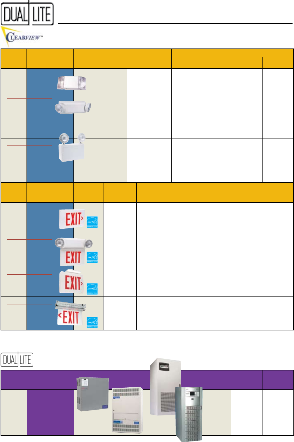
71 CV3 Series LED Red – 2.6W LED
Nickel-Cadmium
3.8 Watts 5 Years 1/9 Years
Green – 2.1W
72 CVT Series LED Red – 2.6W Halogen Lead-Calcium 5.0 Watts 5 Years 1/9 Years
Green – 2.1W and Excluding
LED AC Lamps
73 CVD Series LED Red – 2.6W LED
Nickel-Cadmium
3.8 Watts 5 Years 1/9 Years
Green – 2.1W
74 CVER Series LED Red –2.5W LED
Nickel-Cadmium
5.2 Watts 5 Years 1/9 Years
Green – 3.0W
(1) Maximum power consumption specification shown for circuit-sizing purposes only. Normal operating power requirements are significantly lower. Consult factory for normal operating power
consumption ratings on specific models.
Thermoplastic
LED Exit Signs
Combination
Emergency
Unit/LED Exit
Signs
Cast Aluminum
LED Exit Signs
Catalog Watts PoWer Warranty
Page Model Unit For Battery ConsUMPtion Battery
nUMBer(s) ProdUCt series nUMBer Voltage 11/2 Hrs. tyPe (Max.)(1) eqUiPMent FUll/Pro-rata
68 SlimLite Series SL1, SL1-V 6 12 Lead-Calcium 3.5 Watts 1 Year 1/5 Years
69 CV Series Standard Models
CV2 6 12 Lead-Calcium 4 Watts 1 Year 1/5 Years
CV3 6 18 ” ” ” ”
CV5 6 30
“
14 Watts “ “
Damp Location Models
CV2D 6 12 Lead-Calcium 4 Watts 1 Year 1/5 Years
CV3D 6 18 ” ” ” ”
CV5D 6 30
“
14 Watts “ “
70 CVEC Series CVEC15 6 15 Lead-Calcium 9 Watts 1 Year 1/5 Years
CVEC30 6 30 ” 9 Watts ” ”
CVEC50 6 50
“
20 Watts “ “
CVEC50-12V 6 50 ” 14 Watts ” ”
CVEC100-12V 6 100
“
39 Watts “ “
Contemporary
Unit
Designer
Units
• 6- and 12-volt
models
• Capacities up to 100
watts
• Lighting heads may be
top or side mounted
• Standard and damp
location models
Commercial
Units
Recessed
Mount Edge-
Lit LED Exit
Signs
Catalog systeM
Page systeM oUtPUt
nUMBer(s) ProdUCt series tyPe CaPaCities
88 to 91 Synchron Series Single Phase 400 to 2100VA
92 to 101 Spectron LSN Single Phase 1.0 to 17.5kVA
103 to 104 Trident TRX Series Three Phase 10 to 30kVA
105 to 106 Trident TRN Series Three Phase 30 to 130kVA
Emergency Lighting Products
Quick Selector Guide
Inverter Power Systems
13
LiteScape Series Guaranteed Code Compliant Emergency Lights ................ 14, 15
EZ-2 Series Commercial Emergency Lights ................................................ 16
LZ Series Designer Emergency Lights ............................................................17
LZ (HC) Series High Capacity Designer Emergency Lights ........................ 18, 19
LM Series High Capacity Emergency Lights ...................................... 20, 21
EZ-2R Series Recessed Emergency Lights ............................................................22
T-Grid Series Recessed T-Grid Emergency Lights...........................................23
EXT Series Recessed Gimbal Emergency Light ..........................................24
Lite2 Series Emergency Lighting Square Units ...................................... 25
Delite Series Emergency Lighting Cylinder Units ......................................... 26
N4X Series Harsh Environment Emergency Lights ..................................... 27
AS Series Industrial Emergency Lights ............................................ 28, 29
IPS Series Wet Location Emergency Lights ....................................... 30, 31
XPB Series Explosion-Proof Emergency Lights ................................... 32, 33
Lampak Series Fluorescent Power Packs ............................................. 34 to 38
Emergency Lighting Units
14
Features
Ordering Information
Options (add sUFFix to Model)Accessories (order seParately)
LiteScape CommerCial emergenCy light 20W
-24K 220/240VAC, 60Hz. operation
-AA Audible alarm (1)
(1) For use with LSCI and LSCNI self-testing/self-diagnostic
models only.
GUARANTEED CODE-
COMPLIANT ILLUMINATION
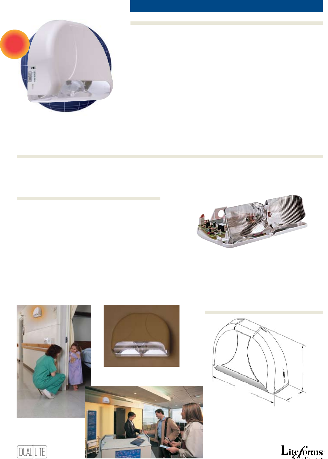
SurePathTM Technology
The heart of LiteScape’s SurePath technology is the patent pending reflector design created exclusively for Dual-Lite by
Breault Research Organization, the company selected to correct the optics for the Hubble space telescope. This unique
reflector design coupled with the unit’s two high-output, 10-watt halogen lamps provide an incredibly bright and
evenly distributed illumination pattern. Additionally, a user-selectable reflector adjustment allows a choice of the 3’ or
6’ wide SurePath illumination patterns. The long, broad and even nature of the SurePath illumination pattern makes it
the optimum method of lighting interior paths of egress during emergency conditions.
Patented reector design
produces bright, evenly illuminated
“SurePath™” egress lighting pattern
Housing is eld paintable
to match wall decor.
NEW
11”
81/2”
3
1
/
2
”
Dimensions
Nickel-Cadmium
Standard Model Nickel-Cadmium Model Spectron Self-Testing Model Spectron Self-Testing Model
LSC LSCN LSCI LSCNI
Ordering Information
Options (add sUFFix to Model)
• Universal 120/277VAC operation
• AC lockout
• Available with Spectron®
self-testing/self-diagnostic
electronics with time-delay relay
(TDR) standard
• Low-voltage battery disconnect
• Test switch and AC-On indicator
• Temperature range:
Lead-acid models = 20°C to 30°C
(68°F to 86°F)
Nickel-Cadmium models
= 0°C to 40°C
(32°F to 104°F)
• UL 924 Listed (Emergency Lighting)
• UL Damp Location Listed
(Nickel-Cadmium models only)
• Factory guaranteed NFPA-101
code-compliant illumination
• Field adjustable 3 ft. x 40 ft. or
6 ft. x 30 ft. egress illumination
patterns
• SurePath® technology delivers
bright, continuous illumination
• Low-profile silhouette
• Fast, easy installation
• High-output, 6 volt, 10-watt
halogen lamps
• Impact resistant, UV stable
polycarbonate construction
• Unit housing is paintable
• Lead-acid or nickel-cadmium
battery models
15
LiteScape
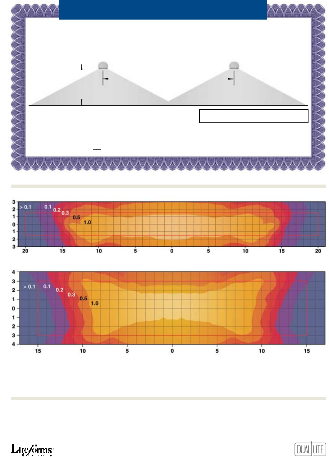
1) Photometric illustrations based on data provided by Independent Testing Laboratories (ITL), Boulder, Colorado.
2) Photometrics shown based on 7.5-foot mounting height and minimum 80-50-20 reflectance values.
3) The white rectangular area in photometric illustrations represents normal center to center SurePath egress illumination pattern provided.
Center to Center Mounting Information
Dual-Lite guarantees the LiteScape unit will fully meet the 2003 edition of the NFPA 101
Life Safety Code emergency lighting requirements by providing an average of one footcandle of
illumination along the path of egress as dened in the illustration below.
NOTE: The LiteScape unit must be installed per factory instructions provided
and properly maintained. In addition, the pathway to be illuminated
must meet the minimum surface reflectance values shown at right to
qualify for guaranteed illumination performance.
The LiteScape Performance Guarantee applies solely to units mounted 7.5 feet above the floor surface. For information on lighting performance
at other mounting heights, refer to LiteScape Series Mounting Guide on the LiteScape product page in the Dual-Lite web site’s on-line catalog.
The LiteScape Performance Guarantee is subject to all conditions as outlined in the Product Warranty Statement on the Dual-Lite public web site
(www.dual-lite.com) and applies only to the installation’s initial emergency lighting inspection by the authority having jurisdiction.
Minimum Reflectance Values Required:
Ceiling: 80% Walls: 50% Floor: 20%
The LiteScape Performance Guarantee
3-Foot Wide Standard Illumination Path Setting = 40 Foot Centers
6-Foot Wide Optional Illumination Path Setting = 30 Foot Centers
7.5 ft.
The photometric data shown above was generated and verified by Independent Testing Laboratories (ITL) of Boulder,
Colorado. LiteScape IES photometric files can be downloaded from the LiteScape product page at www.dual-lite.com.
LiteScape illumination data has also been incorporated into the Hubbell LitePro® lighting design application software.
3-Foot Standard Illumination Path Setting (40-Foot Mounting Centers)
6-Foot Optional Illumination Path Setting (30-Foot Mounting Centers)
Photometrics
Independent Verification
16
Features
Options (add sUFFix to Model)Accessories (order seParately)
Ordering Information
Product Selector Guide
EZ-2 CommerCial emergenCy lights 10.8W, 14.4W
(Damp Location Model EZ-2D)
Damp
An
Severe Conditions Product
• Easy to install
• Compact, low-profile design
• Flame-rated, UV-stable
thermoplastic housing
• Textured, bright white finish
• Universal mounting plate
• Glare-free, adjustable lampheads
• Maintenance-free battery
• Universal 120/277VAC operation
• Low power consumption
• Fully-automatic charger
• AC lockout
• Low-voltage battery disconnect
• Transformer isolation protection
• Test switch and AC-On light
• Available with Spectron® self-
testing/self-diagnostic electronics
with time-delay relay
(TDR) standard
• Damp location model available
• Temperature range: 20°C to 30°C
(68°F to 86°F)
Damp location EZ-2D: 0°C - 40°C
(32°F to 104°F)
• UL 924 Listed
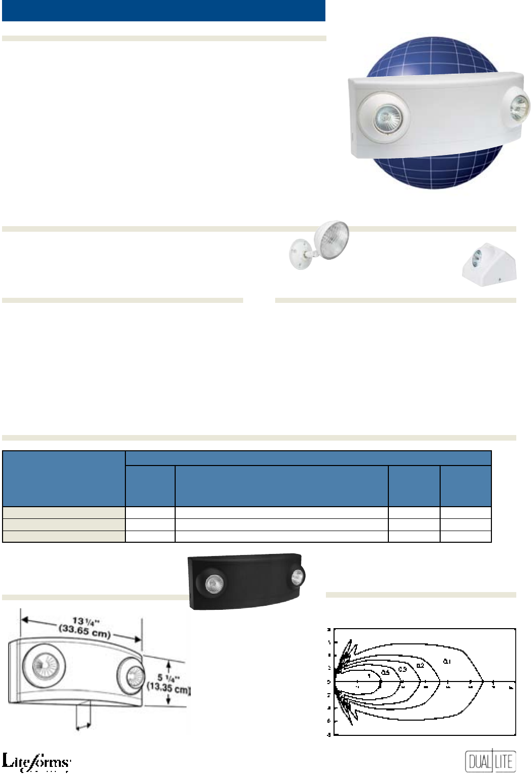
Standard Model Damp Location Model Voltmeter Model Spectron Self-Testing Model
EZ-2 EZ-2-D EZ-2-V EZ-2I
-A21 Auxiliary 2-conductor AC line cord (120V only) VRS Vandal resistant shield
WGEL Wire guard
Horizontal Isofootcandle Distribution
6 Volt, 5.4 Watt SBT Lamp 6 Volt, 7.2 Watt SBT Lamp
Dimensions
Photometrics
eleCtriCal
Base oUtPUt Watts aC inPUt
Catalog oUtPUt 1.5 2 3 4 standard reMote
nUMBer Volts HoUrs HoUrs HoUrs HoUrs Volts aMPs Watts laMP CaPaBility
EZ-2, EZ-2-D 6 10.8 -- -- --
120 .080 8.4
5.4W No
and EZ-2-V
277 .030 8.8
EZ-2I* 6 14.4 -- -- -- 120 .080 8.4 7.2W No
277 .030 8.8
*
Includes Spectron® self-testing/self-diagnostic electronics with time-delay relay (TDR) standard
5” (12.7 cm) 14” (35.5 cm)
5” (12.7 cm)
17
Features
Ordering Information
Options (add sUFFix to Model)Accessories (order seParately)
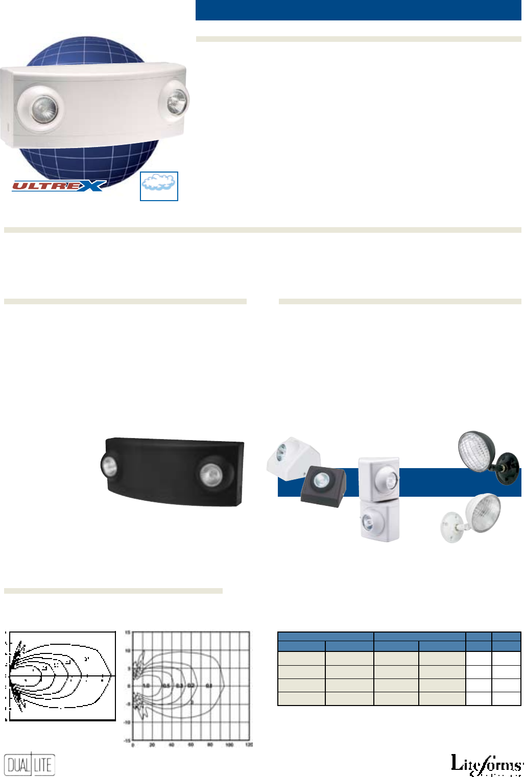
LZ
Designer emergenCy lights 10W
• Easy to install
• Flame-rated, UV-stable
thermoplastic housing
• White or black finishes
• Slim, low-profile snap-together
design
• Standard and damp location
models
• Low profile, adjustable lampheads
• High-output halogen lamps
• Clear glass protective lamp lens
• Matching remote fixtures
• 120/277VAC operation standard
• Fully-automatic charger
• Maintenance-free battery
• 90 minute operation
• Low-voltage battery disconnect
• Transformer isolation protection
• Test switch and AC-On light
• Available with Spectron® self-
testing/self-diagnostic electronics
with time-delay relay
(TDR) standard
• Temperature range: 20°C to 30°C
(68°F to 86°F)
Damp location model: 10°C to 40°C
(50°F to 104°F)
• UL 924 Listed
I
Spectron self-testing/self-diagnostic electronics (3)
-B Black finish
-V Voltmeter
-24K 220-240VAC, 60 Hz. operation
-A21 Auxiliary 2-conductor line cord (120V only) (1)
-A31 Auxiliary 3-conductor line cord (120V only) (2)
(1) Not for use with LZ15 model.
(2) For use with LZ15 model only.
(3) Not available with LZ2 model.
See Product Selector Guide below for available models
VRS Vandal resistant shield
WGLZ Wire guard
PMLZTW 121/2” Pendant mounting kit - white
PMLZTB 121/2” Pendant mounting kit - black
LZRSW0605 Matching remote lighting head - white
LZRSB0605 Matching remote lighting head - black
OMSSW0605 Outdoor lighting head - 6 Volt, 5 Watt
sealed beam type lamp - White finish
OMSSB0605 Outdoor lighting head - 6 Volt, 5 Watt
sealed beam type lamp - Black finish
Matching remote
lighting head
Outdoor lighting
head
35
/8” (9.2cm)
Also available in black finish
High-Output Halogen Lamp
Horizontal Isofootcandle Distribution
Product Selector Guide
Dimensions Photometrics
eleCtriCal
Base oUtPUt Watts
Catalog oUtPUt 1.5 2 3 4 standard reMote
nUMBers Volts HoUrs HoUrs HoUrs HoUrs laMP CaPaBility
LZ2 6 10 -- -- -- 5W Hal. No
LZ2D* 6 10 -- -- -- 5W Hal. No
LZ15 6 15 12 -- -- 5W Hal. Yes
18
Features
Ordering Information
Options (add sUFFix to Model)Accessories (order seParately)
High Capacity
See Product Selector Guide for available models
Designer emergenCy lights 15W to 65W
LZ
(Damp Location Models)
Damp
An
Severe Conditions Product Line
Matching Remote Fixtures
A complete line of 6- and 12-volt matching remote fixtures
in single and tandem lamp configurations is available for use
with LZ Series high-capacity units or any other 6- or 12-volt DC
emergency lighting remote power sources.
All remote fixtures are offered in black and white textured
finishes with a choice of 5- or 10-watt halogen lamps.
• Easy to install
• Capacities up to 65 watts
• 6- and 12-volt models
• Flame-rated, UV-stable
thermoplastic housing
• White or black finishes
• Snap-together design
• Standard and damp location
models
• Low profile lampheads
• High-output halogen lamps
• Clear glass protective lamp lens
• Matching remote fixtures
• 120/277VAC operation standard
Also available in black finish
• Fully automatic charger
• Choice of maintenance-free battery
types
• Low-voltage battery disconnect
• Transformer isolation protection
• Test switch and AC-On light
• Available with Spectron® self-
testing/self-diagnostic electronics
with time-delay relay
(TDR) standard
• Temperature range: 20°C to 30°C
(68°F to 86°F)
Damp location model: 10°C to 40°C
(50°F to 104°F)
• UL 924 Listed
I
Spectron self-testing/self-diagnostic electronics
-B Black finish
-V Voltmeter
-10W 10-watt halogen lamps (1)
-0 Unit supplied without lampheads
-24K 220-240VAC, 60 Hz. operation
-A31 Auxiliary 3-conductor line cord (120V only)
(1) Available on units with capacities of 20 watts or more.
VRS Vandal resistant shield
WGEL Wire guard
LZRSW0605 Matching remote lighting head - white
LZRDSB0605 Matching remote lighting head - black
OMSSW0605 Outdoor lighting head - 6 Volt, 5 Watt
sealed beam type lamp - White finish
OMSSB0605 Outdoor lighting head - 6 Volt, 5 Watt
sealed beam type lamp - Black finish
OMSSW1205 Outdoor lighting head - 12 Volt, 5 Watt
sealed beam type lamp - White finish
OMSSB1205 Outdoor lighting head - 12 Volt, 5 Watt
sealed beam type lamp - Black finish
High-Output Halogen Lamp
Horizontal Isofootcandle Distribution
Standard 5W MR-16 Lamp Optional 10W MR-16 Lamp
Matching
Remote Lighting
Heads
Outdoor
Lighting Heads
Photometrics
WHite BlaCk
single tandeM single tandeM Volts Watts
LZRSW0605 LZRDW0605 LZRSB0605 LZRDB0605 6 5
LZRSW0610 LZRDW0610 LZRSB0610 LZRDB0610 6 10
LZRSW1205 LZRDW1205 LZRSB1205 LZRDB1205 12 5
LZRSW1210 LZRDW1210 LZRSB1210 LZRDB1210 12 10
19
High Capacity
LZ
Product Selector Guide
Dimensions
Standard Models
eleCtriCal
oUtPUt Watts
oUtPUt Battery 1.5 2 3 4 standard reMote
Base Catalog nUMBers Volts tyPe HoUrs HoUrs HoUrs HoUrs laMP CaPaBility
LZ30 6 Lead-Calcium 30 24 15 12 5W Hal. Yes
LZ35-12V 12 Lead-Calcium 35 26 18 14 5W Hal. Yes
LZ65 6 Lead-Calcium 65 49 33 26 5W Hal. Yes
LZ65-12V 12 Lead-Calcium 65 49 33 26 5W Hal. Yes
LZ20N 6 Nickel-Cadmium 20 15 10 8 5W Hal. Yes
LZ25N-12V 12 Nickel-Cadmium 25 19 13 10 5W Hal. Yes
Damp Location Models
eleCtriCal
oUtPUt Watts
oUtPUt Battery 1.5 2 3 4 standard reMote
Base Catalog nUMBers Volts tyPe HoUrs HoUrs HoUrs HoUrs laMP CaPaBility
LZ25D 6 Lead-Calcium 25 19 13 10 5W Hal. Yes
LZ30D-12V 12 Lead-Calcium 30 24 15 12 5W Hal. Yes
LZ55D 6 Lead-Calcium 55 42 28 22 5W Hal. Yes
LZ55D-12V 12 Lead-Calcium 55 42 28 22 5W Hal. Yes
LZ15ND 6 Nickel-Cadmium 15 11 8 6 5W Hal. Yes
LZ20ND-12V 12 Nickel-Cadmium 20 15 10 8 5W Hal. Yes
51
/8” (13 cm)
20
Features
Ordering Information
Options (add sUFFix to Model)Accessories (order seParately)
LM
Example: LM130-3
high CapaCity emergenCy lights 14W to 130W
An
See Product Selector Guide for available models
Severe Conditions Product Line
Damp(1) Cold(2)
(1) Damp Location
Models Only
(2) NiCad Models Only
Horizontal Isofootcandle Distribution
6 Volt, 7.2 Watt SBT Lamp 12 Volt, 7.2 Watt SBT Lamp
I
Spectron self-testing/self-diagnostic electronics
( 1)(5)
-V Voltmeter
-3 Unit supplied with three lampheads (1)(2)
-4 Unit supplied with four lampheads (1)(2)
-0 Unit supplied without lampheads (1)(2)(3)
-
A31 Auxiliary 3-conductor AC line cord (120V)
-A32 Auxiliary 3-conductor AC line cord (277V)
-24K 220-240VAC, 60Hz. operation (4)
(1) Not available with LM2 model.
(2) Not available with LM16 model.
(3) NOTE: Spectron models with over 80 watts of capacity require a minimum
load of 35 watts for accurate lamp failure indications.
(4) Not available on units with capacities over 80 watts for 1.5 hours.
(5) Spectron not available with Nickel-Cadmium battery models.
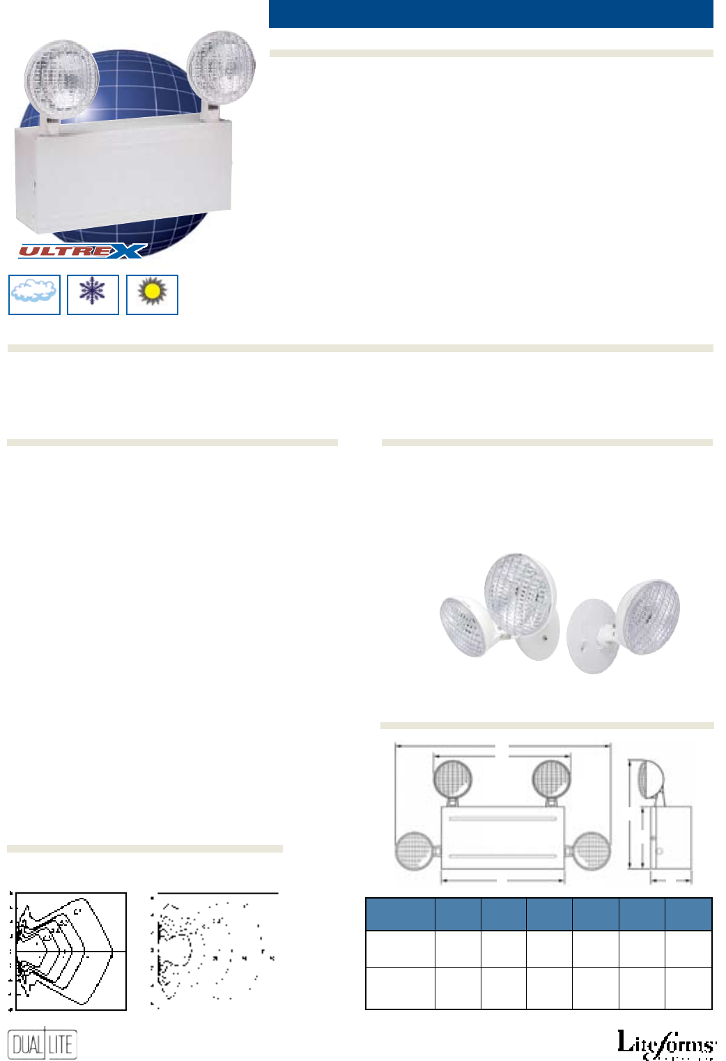
SRH Series Matching
Remote Lighting Heads
• Easy to install
• Universal wall mounting pattern
• White, corrosion-resistant metal
housing and front-loading cover
• Maintenance-free battery
• 6- & 12-volt models
• Damp location models available
• Glare-free lampheads
• Lampheads may be top or
side mounted
• Available with 3 or 4 lampheads
• Available without lampheads
• Matching remote fixtures
• 120/277VAC operation standard
(220-240VAC, 60 Hz. optional)
• Fully automatic, solid-state charger
• Low-voltage battery disconnect
• Transformer isolation protection
• Test switch and AC-On light
• Available with Spectron® self-
testing/self-diagnostic electronics
with time-delay relay
(TDR) standard
• 90 minute operation
• Temperature range: 20°C to 30°C
(68°F to 86°F)
NiCad models: 20°C - 30°C
(68°F to 86°F)
Damp location models: 10°C to 40°C
(50°F to 104°F)
• UL 924 Listed
40G Wire guard (Top mounted heads only)
SRHSW Single matching remote head - white *
SRHDW Twin matching remote head - white *
* Supplied with round mounting plate. Specify voltage and wattage when
ordering. Example: SRHDW1212. See “Remote Heads and Fixtures”
section for available lamps.
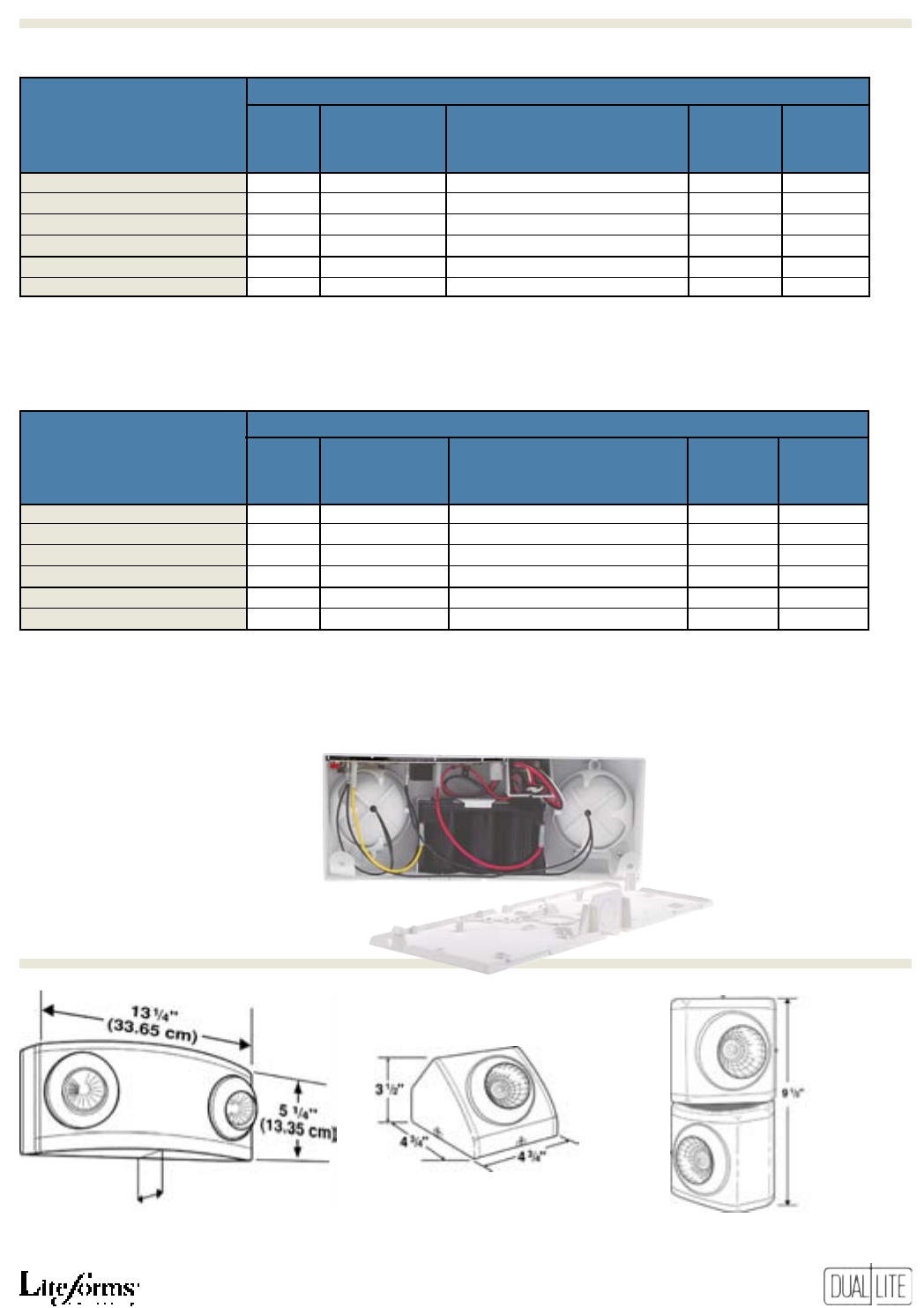
E
F
B
C
A
D
Ordering Information
Photometrics
Dimensions
Options (add sUFFix to Model)Accessories (order seParately)
Hot(2)
Optional Lamps
To order two nonstandard lamps on the fixture, suffix
catalog number. See “Remote Heads and Fixtures” sec-
tion for available lamps. Example: LM33-SRHSW0612.
enClosure
style a B C D e F
1 37/8” 53/4” 111/2” 131/2” 15 3/4” 25”
9.8 cm 14.6 cm 29.3 cm 34.3 cm 40.0 cm 63.5 cm
2 4 3/4” 73/4” 131/2” 15 3/4” 18” 271/4”
12.1 cm 19.7 cm 34.3 cm 40.0 cm 45.7 cm 69.2 cm
21
LM
Product Selector Guide
Standard Models (1)
eleCtriCal
oUtPUt Watts
Catalog enClosUre oUtPUt 1.5 2 3 4 standard reMote
nUMBers style Volts HoUrs HoUrs HoUrs HoUrs laMP CaPaBility
LM2 1 6 14.4 — — — 7.2W No
LM16 1 6 16 — — — 7.2W No
LM33 1 6 33 25 17 13 7.2W Yes
LM40 1 6 40 31 21 16 7.2W Yes
LM66 2 6 66 51 35 27 7.2W Yes
LM80 2 6 80 62 43 33 7.2W Yes
LM130 2 6 130 101 70 54 7.2W Yes
LM40-12V 1 12 40 31 21 16 7.2W Yes
LM66-12V 2 12 66 51 35 27 7.2W Yes
LM80-12V 2 12 80 62 43 33 7.2W Yes
LM130-12V 2 12 130 101 70 54 7.2W Yes
Nickel-Cadmium Models (1)
eleCtriCal
oUtPUt Watts
Catalog enClosUre oUtPUt 1.5 2 3 4 standard reMote
nUMBers style Volts HoUrs HoUrs HoUrs HoUrs laMP CaPaBility
LM15N 1 6 14.4 -- -- -- 7.2W No
LM30N 1 6 30 25 17 13 7.2W Yes
LM50N 1 6 50 42 29 22 7.2W Yes
LM50N-12V 1 12 50 42 29 22 7.2W Yes
LM100N-12V 1 12 100 85 59 46 7.2W Yes
Damp Location Models (1)
eleCtriCal
oUtPUt Watts
Catalog enClosUre oUtPUt 1.5 2 3 4 standard reMote
nUMBers style Volts HoUrs HoUrs HoUrs HoUrs laMP CaPaBility
LM28D 1 6 28 21 15 11 7.2W Yes
LM34D 1 6 34 26 18 14 7.2W Yes
LM56D 2 6 56 43 30 23 7.2W Yes
LM68D 2 6 68 53 36 28 7.2W Yes
LM112D 2 6 112 87 60 47 7.2W Yes
LM34D-12V 1 12 34 26 18 14 7.2W Yes
LM56D-12V 2 12 56 43 30 23 7.2W Yes
LM68D-12V 2 12 68 53 36 28 7.2W Yes
LM112D-12V 2 12 112 87 60 47 7.2W Yes
All Metal City Of Chicago Models (2)
eleCtriCal
oUtPUt Watts
Catalog enClosUre oUtPUt 1.5 2 3 4 standard reMote
nUMBers style Volts HoUrs HoUrs HoUrs HoUrs laMP CaPaBility
LM24CH 1 6 24 -- -- -- 12W No
LM36CH 1 6 36 26 -- -- 12W Yes
LM36CH-12V 1 12 36 26 -- -- 12W Yes
(2) 2000 Chicago Building Code compliant
(1) Meets New York City Requirements
(1) Meets New York City Requirements
(1) Meets New York City Requirements
22
Features
Options (add sUFFix to Model)Accessories (order seParately)
Ordering Information
Standard Model Spectron Self-Testing Model
EZ-2R EZ-2RI
EZ-2R
F-CBM Troffer mounting kit (suspended ceilings)
WGEL Wire guard
reCesseD emergenCy lights 10.8W, 14.4W
Horizontal Isofootcandle Distribution
6 Volt, 5.4 Watt SBT Lamp 6 Volt, 7.2 Watt SBT Lamp
Photometrics measured by independent testing laboratory
A
B
C
E G
D F
A
B
C
D
E
F
G
53/4”
(14.6 cm)
11”
(27.9 cm)
37
/8”
(9.8 cm)
73/4”
(19.7 cm)
91/8”
(23.2 cm)
5”
(12.7 cm)
61/8”
(15.6 cm)
EZ-2R suspended ceiling installation
using F-CBM accessory kit
Wall mounted EZ-2R unit
• Easy installation in wall or
ceiling
• Compact, low-profile design
• All metal recessed housing
• Flame-rated, thermoplastic
lamp housing and
mounting plate
• Maintenance-free battery
• Glare-free lampheads
• 120/277VAC operation standard
• Fully automatic, solid-state
charger
• Low-voltage battery disconnect
• Transformer isolation protection
• Test switch and AC-On light
• Available with Spectron®
self-testing/self-diagnostic
electronics with time-delay relay
(TDR) standard
• 90 minute operation
• Temperature range: 20°C to 30°C
(68°F to 86°F)
• UL 924 Listed
Accessories (order seParately)
Product Selector Guide
Photometrics
Dimensions
eleCtriCal
Base oUtPUt Watts
Catalog oUtPUt 1.5 2 3 4 standard reMote
nUMBer Volts HoUrs HoUrs HoUrs HoUrs laMP CaPaBility
EZ-2R 6 10.8 — — — 5.4W No
EZ-2RI* 6 14.4 — — — 7.2W No
*
Includes Spectron® self-testing/self-diagnostic electronics with time-delay relay (TDR) standard
23
Features
Ordering Information
Options (add sUFFix to Model)Accessories (order seParately)
T-Grid
reCesseD t-griD emergenCy lights 15W to 50W
* AC Input figures in parenthesis are for NiCad battery models.
Standard Models TG15 TG30 TG50-12V
NiCad Battery Models TG15N TG30N TG50N-12V
• Easy to install T-Grid lay-in
design
• Maintenance-free battery
• 6 and 12 volt models
• Heavy 20 gauge steel housing
• Standard white finish
• Standard with two glare-free
lampheads
• Dual voltage – 120V/277VAC
• Fully automatic, solid-state
charger
• Thermally compensated charger
• Regulated charge voltage
• Automatic low voltage disconnect
• Reverse polarity protection
• Filtered charger output
• Short circuit protection
• AC lockout
• Test switch and AC-On light
• Available with Spectron®
self-testing/self-diagnostic
electronics with time-delay relay
(TDR) standard
• Temperature range: 20°C to 30°C
(68°F to 86°F)
• UL 924 Listed
I Spectron self-testing electronics (1)
-V Voltmeter
-3 Unit supplied with three lighting heads (2)
-0 Unit supplied with no lighting heads
(1) Spectron not available with NiCad battery models.
(2) Not available on TG15 and TG15N models.
SRHSW Matching remote head - single *
SRHDW Matching remote head - twin *
* Supplied with round mounting plate. Specify voltage and wattage
when ordering.
Example: SRHSW1212. See “Remote Heads and Fixtures” section for
available lamps.
Optional Lamps
To order two nonstandard lamps on the fixture, suffix
catalog number. See “Remote Heads and Fixtures” sec-
tion for available lamps. Example: TG30-SRHSW0612.
51/4”
(13.3 cm)
(9.5 cm)
3
3/4
”
71/4”
(18.4 cm)
233/4”
(60.3 cm)
SRH Series
Matching Remote
Lighting Heads
Horizontal Isofootcandle Distribution
6 Volt, 7.2 Watt SBT Lamp 12 Volt, 7.2 Watt SBT Lamp
Product Selector Guide
Dimensions Photometrics
eleCtriCal
niCad oUtPUt Watts aC inPUt*
standard Battery oUtPUt 1.5 2 3 4 standard reMote
Models Models Volts HoUrs HoUrs HoUrs HoUrs Volts aMPs Watts laMP CaPaBility
TG15 TG15N 6 15 11 8 6 120 .064 (.070) 7.0 (7.6) 7.2W No
277 .029 (.032) 7.4 (8.0)
TG30 TG30N 6 30 22 15 12 120 .064 (.114) 7.0 (12.3) 7.2W Yes
277 .029 (.051) 7.4 (12.7)
TG50-12V TG50N-12V 12 50 38 25 20 120 .120 (.250) 12.6 (27.0) 7.2W Yes
277 .051 (.108) 12.9 (26.9)
24
Features
Options (add sUFFix to Model)Accessories (order seParately)
Ordering Information
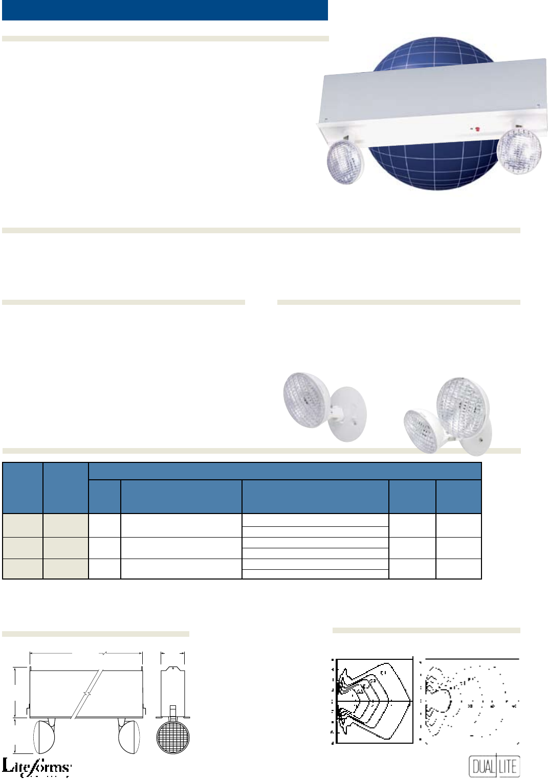
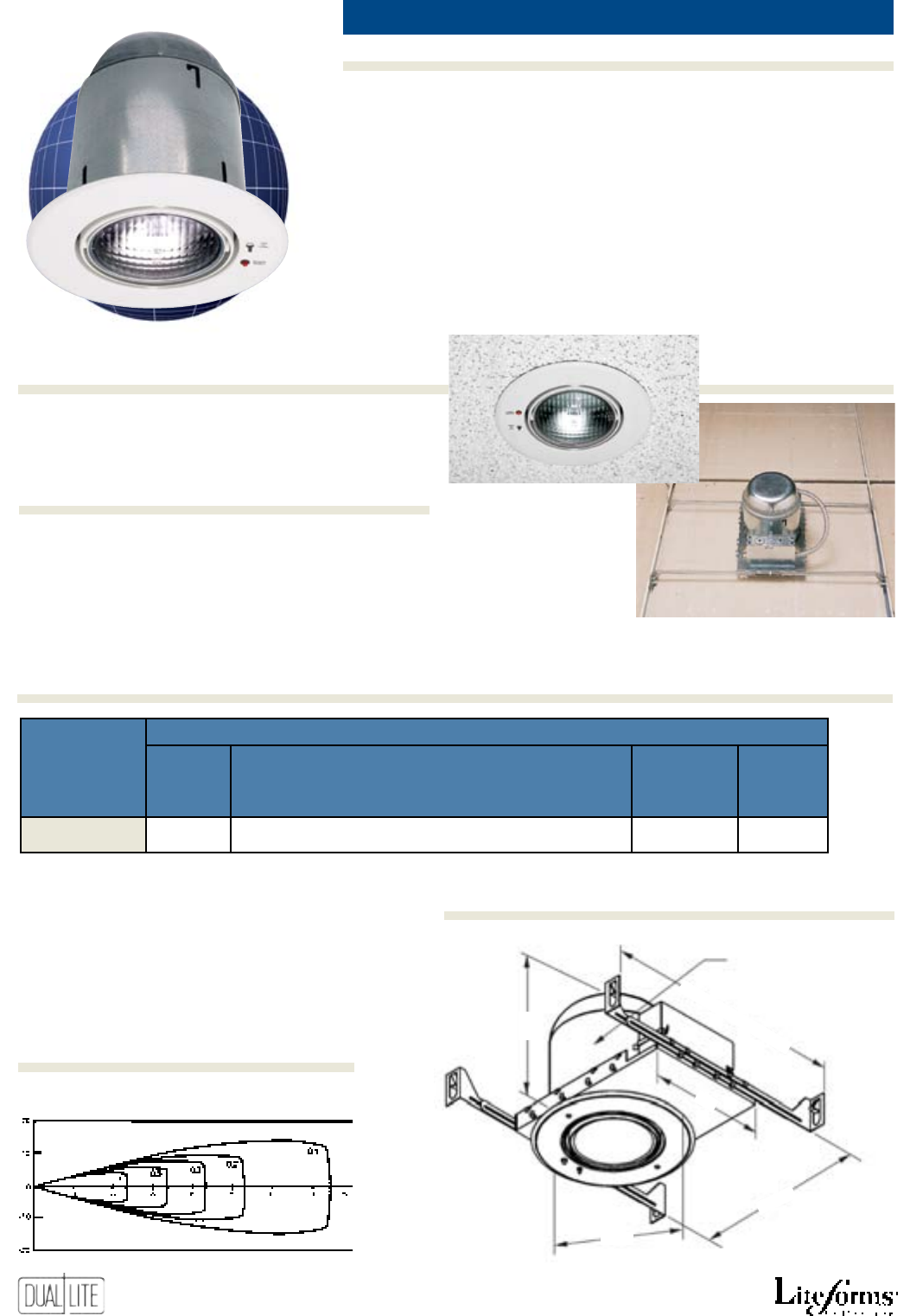
EXT
EXT-122-EM-K
WGLX Wire guard
reCesseD gimBal emergenCy light 8W
EXT-122-EM-K unit shown installed
using built-in hanger bars
• Easy recessed installation in
suspended ceilings
• Built-in hanger bar
• Compact, low-profile design
• All metal housing and
gimbal assembly
• Ceiling white trim ring
• Lamp adjusts in two planes to 26˚
• High-output, 8 watt halogen
lamphead
• Maintenance-free battery
• 120/277VAC operation standard
• Fully automatic, solid-state
charger
• Low-voltage battery disconnect
• Transformer isolation protection
• Test switch and AC-On light
• 90 minute operation
• Temperature range: 20°C to 30°C
(68°F to 86°F)
• UL 924 Listed
Horizontal Isofootcandle Distribution
6 Volt, 8 Watt Halogen SBT Lamp
71/2”
(19.0 cm)
61/8” (16.5 cm) Diameter
81
/2”
(21.6 cm)
14” (35.5 cm) (min.)
241
/2” (62.2 cm) (max.)
7”
(17.7 cm)
101
/2”
(26.6 cm)
Product Selector Guide
Photometrics
Accessories (order seParately)
Dimensions
eleCtriCal
Base oUtPUt Watts
Catalog oUtPUt 1.5 2 3 4 standard reMote
nUMBers Volts HoUrs HoUrs HoUrs HoUrs laMP CaPaBility
EXT-122-EM-K 6 8 — — — 8W Hal. No
25
Features
Ordering Information
Options (add sUFFix to Model)Accessories (order seParately)
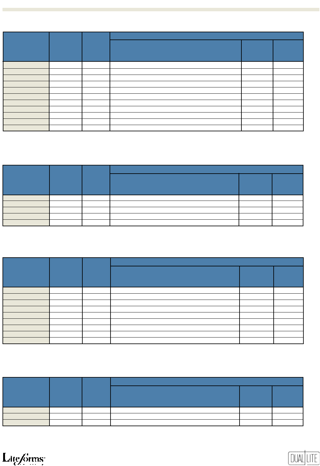
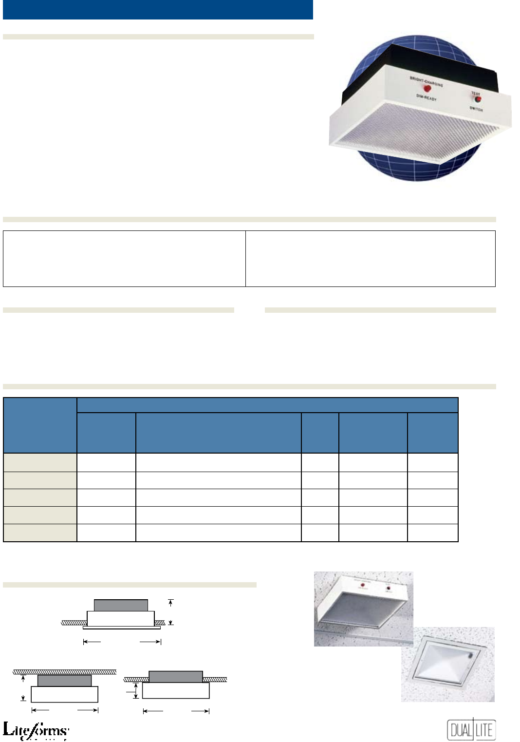
Lite2
emergenCy lighting square units 10W to 30W
sq.
sq. sq.
(Fully-Recessed)
(Semi-Recessed)
(Surface Mounted)
21/4”
(5.7 cm)
4”
(10.1 cm)
4”
(10.1 cm)
9”
(22.9 cm)
9”
(22.9 cm)
119/16”
(29.4 cm)
Semi-recessed model
Fully-recessed model
• Easy to install
• Matte-white frame and satin-
black housing
• Available in single and twin
lamp models
• Maintenance-free battery
• Prismatic lens for uniform
illumination
• Polished alzak reflector
• Remote capability (ERS models
only)
• Matching remote fixtures
• 120/277VAC operation standard
• Fully automatic, solid-state charger
• Low-voltage battery disconnect
• Transformer isolation protection
• Test switch and AC-On light
• Available with Spectron® self-testing/
self-diagnostic electronics with time-
delay relay (TDR) standard
• 90 minute operation
• Temperature range: 20°C to 30°C
(68°F to 86°F)
• UL 924 Listed
-V Voltmeter *
-FRM Fully recessed option
* Not available with fully recessed models.
F-SRM Semi-recessed mounting kit
WG-MLT Wire guard
RERS-1-0609 Matching remote fixture - single lamp
RERS-2-0607 Matching remote fixture - twin lamps
Product Selector Guide
Dimensions
Options (add sUFFix to Model)Accessories (order seParately)
Standard Models Spectron Self-Testing Models
EDS Single lamp unit EDS-2 Twin lamp unit ESS-I Single lamp unit ESS-I-2 Twin lamp unit
ERS Single lamp unit ERS-2-2 Twin lamp unit ERS-I Single lamp unit ERS-2I-2 Twin lamp unit
ERS-3 Single lamp unit ERS-3I Single lamp unit
eleCtriCal
oUtPUt Watts
Catalog oUtPUt 1.5 2 3 4 no. standard reMote
nUMBers Volts HoUrs HoUrs HoUrs HoUrs laMPs laMPs CaPaBility
EDS, ESS-I* 6 10 — — — 1 9W No
ERS, ERS-I* 6 20 10 — — 1 9W Yes
ERS-3, ERS-3I* 6 30 22 15 — 1 9W Yes
EDS-2, ESS-I-2* 6 14.4 — — — 2 7.2W No
ERS-2-2, ERS-2I-2* 6 30 22 15 — 2 7.2W Yes
*
Includes Spectron® self-testing/self-diagnostic electronics with time-delay relay (TDR) standard
26
Features
Options (add sUFFix to Model)Accessories (order seParately)
Ordering Information
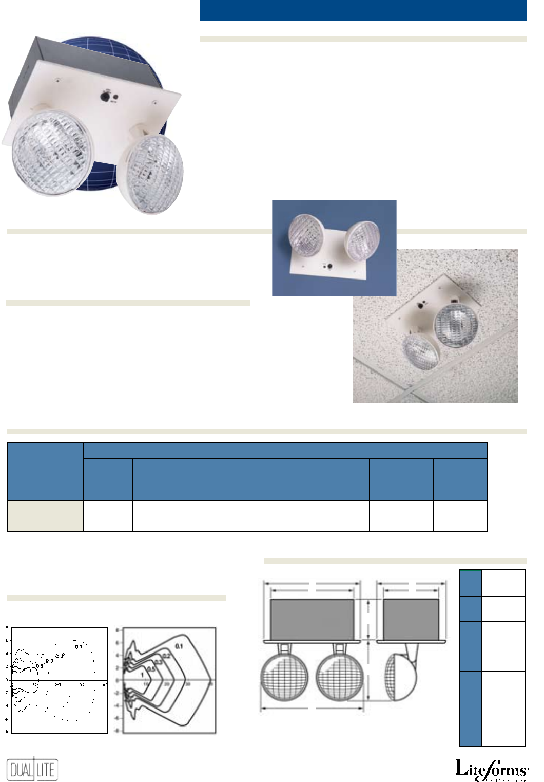
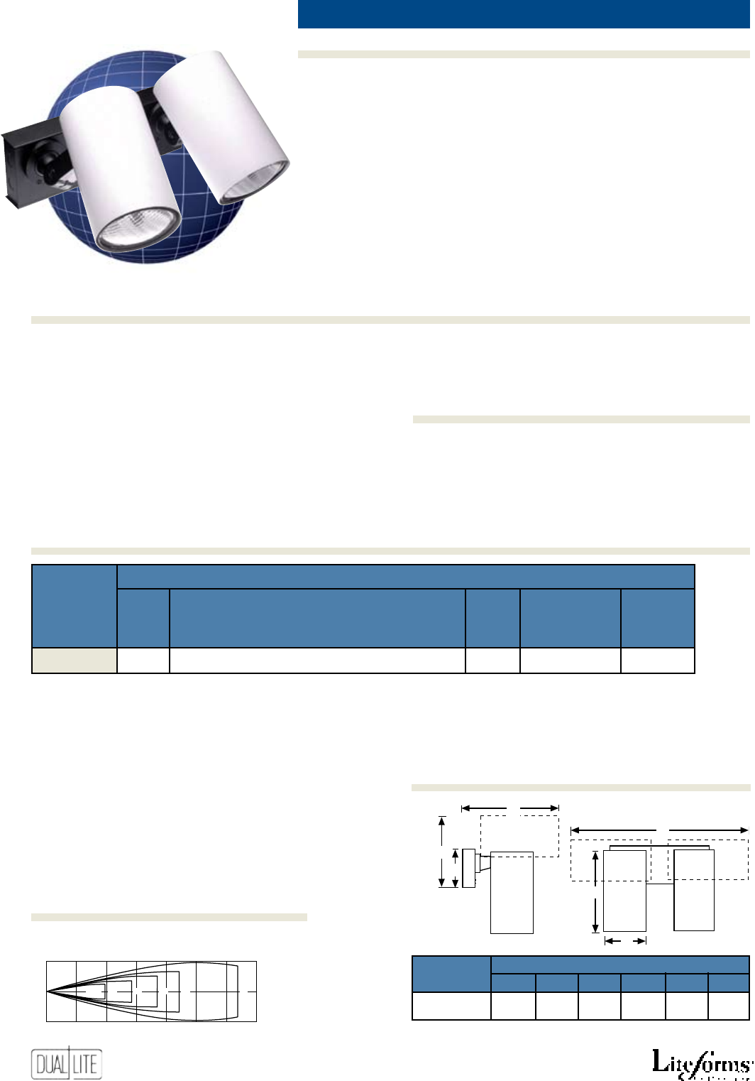
Delite emergenCy lighting CylinDer units 12W, 31W
• Easy to install
• Attractive matte-white cylinders
on contrasting black swivel
• Brushed aluminum base plate
• Multidirectional swivel lighting
heads
• Maintenance-free battery
• Matching remote fixture
• 120/277VAC operation standard
• Fully automatic solid-state
charger
• Low-voltage battery disconnect
• Transformer isolation protection
• Test switch and AC-On light
• 90 minute operation
• Temperature range: 20°C to 30°C
(68°F to 86°F)
• UL 924 Listed
F-TMK Ceiling recess mounting kit
41G Wire guard
A
B
C
D
E
F
Horizontal Isofootcandle Distribution
6 Volt, 6 Watt Halogen SBT Lamp
10
0
10
Feet
Right
Feet
Left
0 10 20 30 40 50 60 70
Feet From Lamp (measured on axis)
0.5
Horizontal Distribution
10
0
10
Feet
Right
Feet
Left
0 10 20 30 40 50 60 70
Feet From Lamp (measured on axis)
Vertical Distribution
LAMP
AXIS IFC 0.3 0.2 0.1 LAMP
AXIS IFC 0.5 0.3 0.2 0.1
Unit Model diMensions
nUMBer a B C d e F
ESC2-0 10” 43/4” 101/2” 8 1/2” 5” 22”
25.4 cm 12.0 cm 26.7 cm 21.6 cm 12.7 cm
55.9 cm
Dotted lines show heads in maximum horizontal position.
Product Selector Guide
Photometrics
Dimensions
ESC2-0
eleCtriCal
Base oUtPUt Watts
Catalog oUtPUt 1.5 2 3 4 no. standard reMote
nUMBers Volts HoUrs HoUrs HoUrs HoUrs Cyls. laMP(s) CaPaBility
ESC2-0 6 12 — — — 2 6W Halogen No
27
Features
Ordering Information
Options (add sUFFix to Model)Accessories (order seParately)
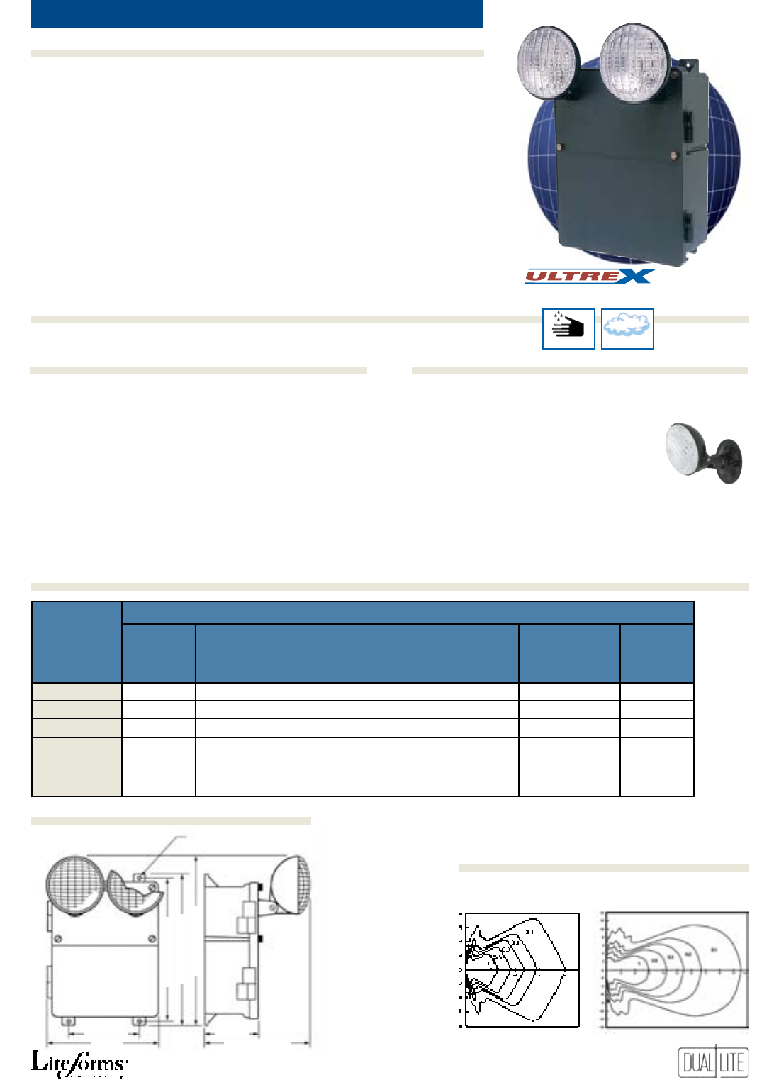
N4X
harsh environment emergenCy lights 15W to 100W
An
Severe Conditions Product Line
Corrosive Damp(1)
Diam.
5/8”
6”
10 1
/4”Max.
47
/8”
11”
135/8” (34.6 cm)
16 1/4” (41.3 cm)
12 3/4” (32.4 cm)
N4X2 N4X4 N4X7 N4X7-12V N4X14 N4X14-12V
• Gasketed construction
• Corrosion resistant hardware
• Charcoal grey thermoplastic case
• Available in 6- or 12-volt versions
• Fully adjustable lampheads
• Maintenance-free battery
• Capacities up to 100W
• Matching remote fixture
• 120/277VAC operation standard
• Fully automatic, solid-state
charger
• Low-voltage battery disconnect
• Transformer isolation protection
• Test switch and AC-On light
• Available with Spectron®
self-testing/self-diagnostic
electronics with time-delay relay
(TDR) standard
• 90 minute operation
• Temperature range: 10°C to 40°C
(50°F to 104°F)
• UL 924 Listed
• UL 924 Damp Location Listed
Horizontal Isofootcandle Distribution
6 Volt, 7.2 Watt SBT Lamp 12 Volt, 9 Watt SBT Lamp
Dimensions
Photometrics
Product Selector Guide
I
Spectron self-testing/self-diagnostic electronics
-0 Unit supplied without lighting heads (1)
-1 Unit supplied with one lighting head (1)
-A31 Auxiliary 3-conductor AC line cord (120V)
-A32 Auxiliary 3-conductor AC line cord (277V)
(1) Not available on N4X2 model.
40G Wire guard
GNXSB Matching remote head - single (a)
GNXDB Matching remote head - twin (a)
(a) Supplied with mounting plate.
Specify voltage and wattage when ordering.
Example: GNXSB0618.
See “Remote Heads and Fixtures” section for
available lamps.
Options (add sUFFix to Model)Accessories (order seParately)
eleCtriCal
Base oUtPUt Watts
Catalog oUtPUt 1.5 2 3 4 standard reMote
nUMBers Volts HoUrs HoUrs HoUrs HoUrs laMPs CaPaBility
N4X2 6 15 — — — 7.2W No
N4X4 6 31 22 15 — 7.2W Yes
N4X7 6 50 36 29 22 7.2W Yes
N4X7-12V 12 50 36 29 22 9W Yes
N4X14 6 100 79 61 44 7.2W Yes
N4X14-12V 12 100 79 61 44 9W Yes
Optional Lamps
To order two nonstandard lamps on the fixture,
suffix catalog number. See “Remote Heads and
Fixtures” section for available lamps. Example:
N4X4-GNXSB0612.
Lamps With Optional Shatter Containment Feature
Protective lamp cover safely contains glass lamp fragments in the
event of accidental breakage in sensitive areas such as food prepara-
tion or hospitals. To order N4X unit with shatter containment option,
suffix the catalog number. See “Remote Heads and Fixtures” section
for available lamps (1). Example: N4X4-GNXSB0608-L.
(1) Excludes 6V, 7.2W and 12V, 9W lamps.
28
Features
Ordering Information
Options (add sUFFix to Model)Accessories (order seParately)
See Product Selector Guide for available models
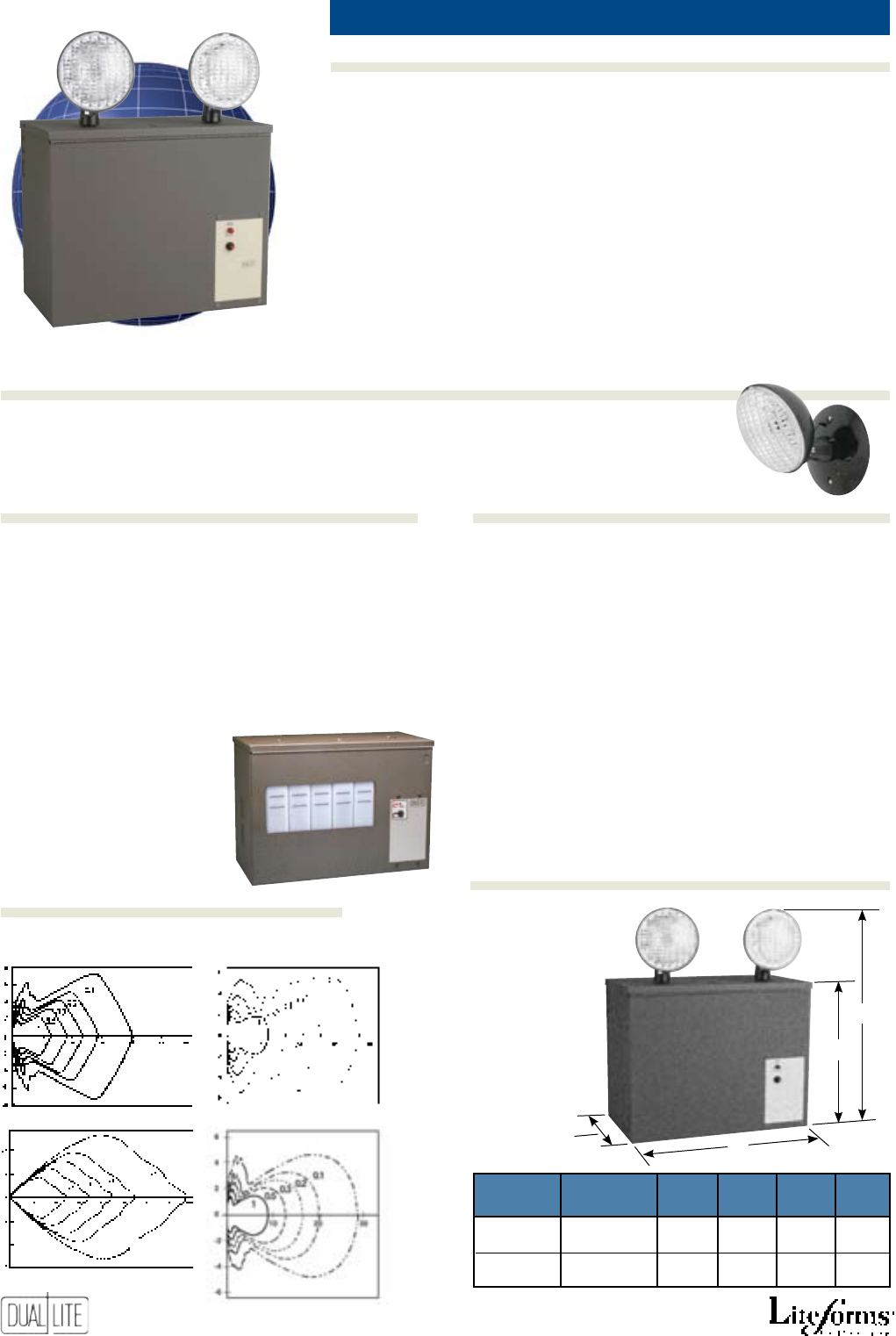
inDustrial emergenCy lights 75W to 360W
AS
• Easy to install
• NEMA 1 steel cabinet with dark
brown enamel finish
• 1/2” and 3/4” wiring KOs
provided
• Wet-cell and maintenance-free
battery models
• 6-, 12- and 24-volt models
• 12- and 24-volt models allow
longer wiring runs
• Glare-free lampheads
• Available with third lamphead
• Available without lampheads
• Matching remote fixtures
• 120/277VAC operation standard
• Fully automatic, solid-state charger
• Low-voltage battery disconnect
• Transformer isolation protection
• Test switch and AC-On light
• Available with Spectron®
self-testing/self-diagnostic
electronics with time-delay relay
(TDR) standard
• 90 minute operation
• Temperature range: 20°C to 30°C
(68°F to 86°F)
• UL 924 Listed
I
Spectron self-testing/self-diagnostic electronics (1)
-V Voltmeter
-C Ammeter (1)
-0 Unit supplied without lampheads
-1 Unit supplied with one lamphead
-2 Unit supplied with two lampheads (2)
-3 Unit supplied with three lampheads
-A31 Auxiliary 3-conductor AC line cord (120V)
-A32 Auxiliary 3-conductor AC line cord (277V)
(1) Not available with all models. Consult factory.
(2) Available for use with 12EDC
and 12EDN models only. All other
models are supplied standard with
two lampheads.
WB-6 Wall mounting hanger bracket (all models)
6000 Heavy-duty mounting shelf (Enclosure 1
models)
L-6 Mounting shelf (Enclosure 1 models)
L-12-S Mounting shelf (Enclosure 2 models)
40G Wire guard (Enclosure 1 models)
41G Wire guard (Enclosure 2 models)
SRHSB Matching remote lighting head - single *
SRHDB Matching remote lighting head - twin *
* Supplied with round mounting plate. Specify voltage and wattage
when ordering. Example: SRHSB0612. See “Remote Heads and
Fixtures” section for available lamps.
Optional Lamps
To order two nonstandard lamps on the fixture, suffix
catalog number. See “Remote Heads and Fixtures” sec-
tion for available lamps. Example: AS130-SRHSB0612.
Horizontal Isofootcandle Distribution
6 Volt, 7.2 Watt SBT Lamp 12 Volt, 7.2 Watt SBT Lamp
6 Volt, 25 Watt SB Lamp 24Volt, 7.2Watt SB Lamp
SRH Series
Matching Remote
Lighting Head
B
D
C
A
Photometrics
Dimensions
enClosUre enClosUre
style ga. a B C d
1 20 Ga. (.036”) 14” 8” 111/2” 18 3/4”
35.5 cm 20.3 cm 29.2 cm 47.6 cm
2 20 Ga. (.036”) 16” 8” 111/2” 18 3/4”
40.6 cm 20.3 cm 29.2 cm 47.6 cm
29
AS
Product Selector Guide
Wet-Cell Lead-Calcium Battery Models
eleCtriCal
Base oUtPUt Watts
Catalog enClosUre oUtPUt 1.5 2 3 4 standard reMote
nUMBers style Volts HoUrs HoUrs HoUrs HoUrs laMP CaPaBility
ALC-X-30 1 6 78 57 42 28 25W Yes
ALC-X-60 1 6 144 108 81 54 25W Yes
ALC-X-100 1 6 162 121 91 61 25W Yes
12EDC-X-36S 2 12 200 165 125 86 (*) Yes
12EDC-X-60S 2 12 240 192 153 115 (*) Yes
12EDC-X-120S 2 12 350 280 224 168 (*) Yes
(*) These models supplied standard without lampheads
Wet-Cell Nickel-Cadmium Battery Models
eleCtriCal
Base oUtPUt Watts
Catalog enClosUre oUtPUt 1.5 2 3 4 standard reMote
nUMBers style Volts HoUrs HoUrs HoUrs HoUrs laMP CaPaBility
AS75 1 6 75 57 42 28 25W Yes
AS145 1 6 110 85 59 46 25W Yes
AS210 1 6 145 112 84 54 25W Yes
12EDN-10S 2 12 48 38 25 20 (*) Yes
12EDN-18S 2 12 100 76 54 44 (*) Yes
12EDN-30S 2 12 150 115 86 57 (*) Yes
(*) These models supplied standard without lampheads
Maintenance-Free Battery Models
eleCtriCal
Base oUtPUt Watts
Catalog enClosUre oUtPUt 1.5 2 3 4 standard reMote
nUMBers style Volts HoUrs HoUrs HoUrs HoUrs laMP CaPaBility
AS80 1 6 80 62 43 33 7.2W Yes
AS130 1 6 130 101 70 54 7.2W Yes
AS180-12V 1 12 180 144 112 77 7.2W Yes
AS270-12V 1 12 270 227 168 116 7.2W Yes
AS360-12V 1 12 360 288 230 172 7.2W Yes
AS180-24V 1 24 180 144 112 77 9.0W Yes
AS270-24V 1 24 270 227 168 116 9.0W Yes
AS360-24V 1 24 360 288 230 172 9.0W Yes
NOTE: Batteries for all Wet-Cell Lead-Calcium models are shipped separately.
NOTE: Batteries for all Wet-Cell Nickel-Cadmium models are shipped separately.
NOTE: Batteries for all Maintenance-Free models are shipped with the units.
30
Features
Ordering Information
Options (add sUFFix to Model)Accessories (order seParately)
IPS
-0 Unit supplied without lampheads
-1 Unit supplied with one lamphead
-12 Unit supplied with 12 watt halogen lamps
Wet loCation emergenCy lights 36W, 72W
Horizontal Isofootcandle Dist.
6 Volt, 8 Watt Halogen SB Lamp
Photometrics measured by independent
testing laboratory
Hazardous
844 Damp Wet
An
Severe Conditions Product Line
Corrosive
12 Volt, 8 Watt Halogen SB Lamp
C1D2-6V36 C1D2-6V72 C1D2-12V36 C1D2-12V72
• 120/220/240/277VAC operation
standard
• Fully automatic, solid-state charger
• Automatic 15-minute retransfer
delay
• Low-voltage battery disconnect
• Transformer isolation protection
• Test switch and AC-On light
• T-6 100°C (212°F) lamphead rating
• 120 minute operation
• Temperature range: 0°C to 40°C
(32°F to 104°F)
• UL Listed to Standard 924 and
Standard 844 (Hazardous Locations)
• Suitable for wet or damp
applications
• Designed for Class I, Div 2 locations
• Compact, factory assembled system
• Sealed and gasketed NEMA 3R
construction
• Corrosion resistant hardware
• Black thermoplastic case with
battery vent
• Available in 6- or 12-volt versions
• Fully adjustable 8 watt halogen
sealed beam lampheads
• Maintenance-free battery
• Matching remote fixtures
NEMA 3R Enclosures (NEMA Standards 250)
Enclosures are intended for outdoor use primarily to provide a degree of
protection against falling rain and sleet, undamaged by the formation of
ice on the enclosure.
Ordering Information
Options (add sUFFix to Model)
Product Selector Guide
Photometrics
eleCtriCal
Base oUtPUt Watts
Catalog oUtPUt 2 3 4 standard reMote
nUMBers Volts HoUrs HoUrs HoUrs laMPs CaPaBility
C1D2-6V36 6 36 24 19 8W Hal. Yes
C1D2-6V72 6 72 50 39 8W Hal. Yes
C1D2-12V36 12 36 24 19 8W Hal. Yes
C1D2-12V72 12 72 50 39 8W Hal. Yes
31
Matching single and twin head
remote lighting fixtures
27/8”
12”
125/8”
3/4” Hub
Mounting
holes
1.9 cm
27/8”
(7.3 cm)
125/8”
(32.1 cm)
12”
(30.5 cm)
81/8”
71/2”
27/8”
3/4” Hub
95/8”
41/4”
45/8”
11/4”
Mounting holes
71/2”
(19 cm)
81/8”
(20.6 cm)
27/8”
(7.3 cm)
1.9 cm
11/
4
”
(3.2 cm)
45/8”
(14.3 cm)
41/4”
(10.8 cm)
95/8”
(24.4 cm)
12 1/2”
(31.7 cm)
111/4”
(28.6 cm)
12”
(30.5 cm)
13 1/4”
(33.7 cm)
63/4”
(17.1 cm)
17”
(43.1 cm)
11/2”
(3.8 cm)
1.9 cm
Wet loCation emergenCy lights 36W, 72W IPS
Accessories (order seParately)
Dimensions
Remote Lighting Heads
laMP single-Head Model nUMBers
Volts Watts HUB leFt side HUB rigHt side HUB BotH sides
6 8 C1D2R-6V8W C1D2R-6V8WR C1D2R-6V8WF
6 12 C1D2R-6V12W C1D2R-6V12WR C1D2R-6V12WF
12 8 C1D2R-12V8W C1D2R-12V8WR C1D2R-12V8WF
12 12 C1D2R-12V12W C1D2R-12V12WR C1D2R-12V12WF
laMPs tWin-Head Model nUMBers
Volts Watts HUB leFt side HUB rigHt side HUB BotH sides
6 8 C1D2TR-6V8W C1D2TR-6V8WR C1D2TR-6V8WF
6 12 C1D2TR-6V12W C1D2TR-6V12WR C1D2TR-6V12WF
12 8 C1D2TR-12V8W C1D2TR-12V8WR C1D2TR-12V8WF
12 12 C1D2TR-12V12W C1D2TR-12V12WR C1D2TR-12V12WF
* PAR 36 Halogen sealed beam lamps.
32
Features
Ordering Information
Options (add sUFFix to Model)Accessories (order seParately)
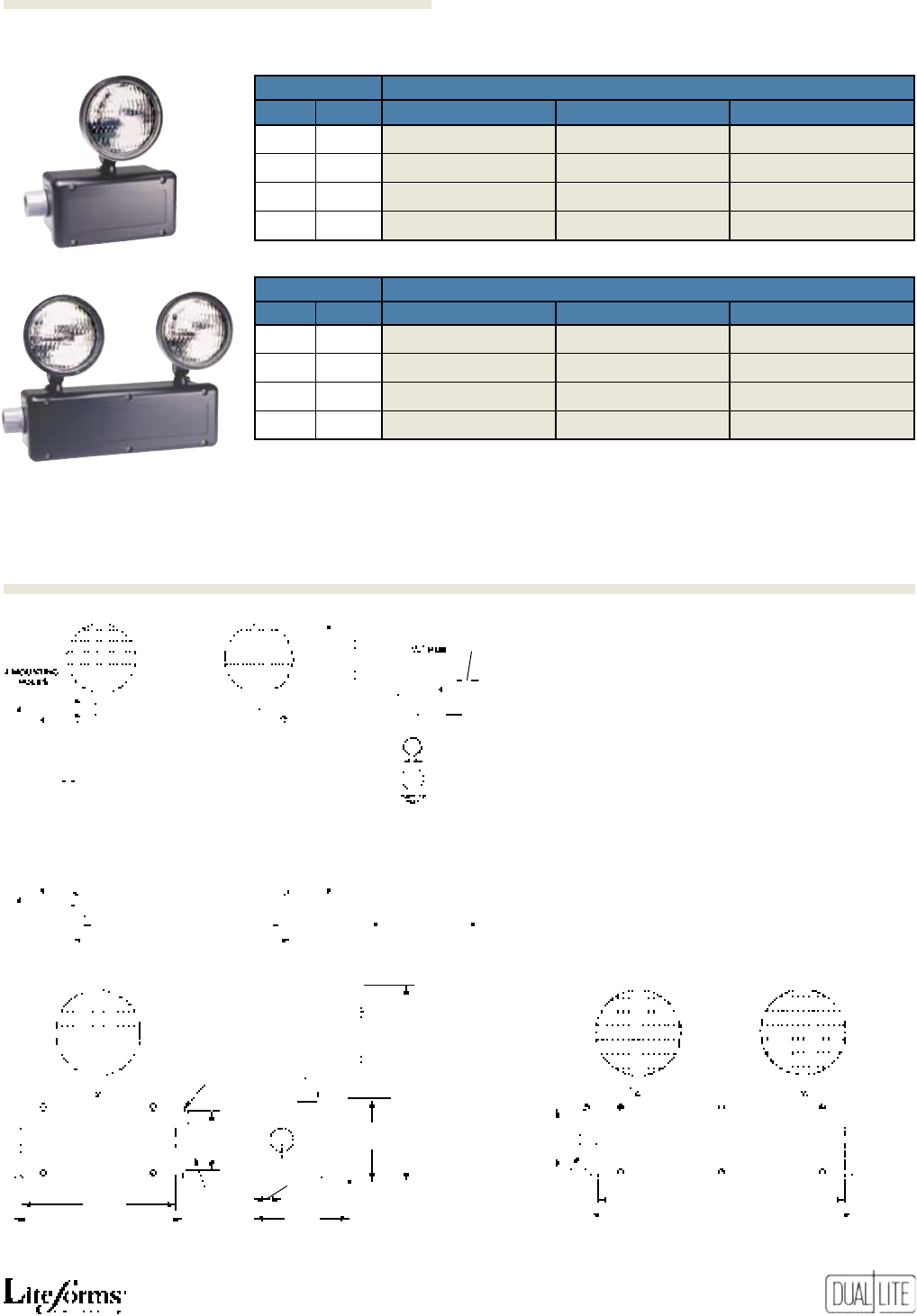
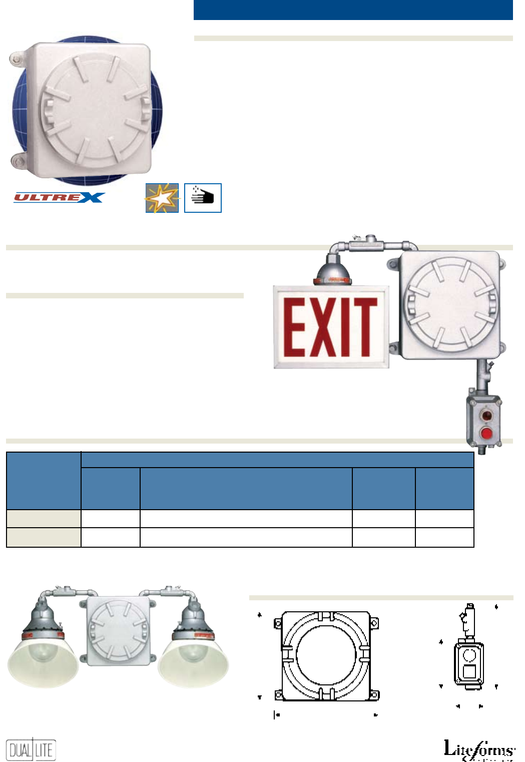
XPB
XPB-75P 12XPB-75P
• Suitable for Class I, Div. I & II
applications
• High-strength, copper-free
aluminum housing
• Quick access thread-on cover
• Test switch included
• AC-On indicator light
• Maintenance-free battery
• 6- and 12-volt models
• Capacity for remote fixtures
• 120/277VAC operation standard
• Fully automatic, solid-state charger
• Low-voltage battery disconnect
• Transformer isolation protection
• Optional fixtures available for
a wide range of hazardous
environments
• 90 minute operation
• Temperature range: 20°C to 30°C
(68°F to 86°F)
• UL Listed to Standard 924
and Standard 844 (Hazardous
Locations)
-TDR 15-minute retransfer delay (120VAC only)
explosion-prooF emergenCy lights 75W
Depth = 8” (20.3 cm) Depth = 5 9/16” (14.1 cm)
14 1/2”
(36.8 cm)
3”
(7.6 cm)
12”
(30.5 cm) 63/16”
(15.7 cm)
103/4”
(27.3 cm)
XPB-75P shown with EX-1CD
unit-mounted lighting fixtures
Product Selector Guide
Dimensions
Ordering Information
(Class I, Divisions I & II, Groups C through G)
Explosion-Proof
An
Severe Conditions Product Line Corrosive
Electrical
Base Output Watts
Catalog Output 1.5 2 3 4 Standard Remote
Numbers Volts Hours Hours Hours Hours Lamp Capability
XPB-75P 6 75 57 42 28 (*) Yes
12XPB-75P 12 75 57 42 28 (*) Yes
(*) Unit is supplied without lighting fixtures. Unit must operate at least one lighting fixture (unit mounted or remote)
to meet UL Standard 924 requirements. See following page for explosion-proof lighting fixtures and accessories.
33
Fixture Accessories
XWG Aluminum (copper-free) globe guard. Protects fixture lens from accidental impact damage. Two-coat, baked
epoxy, medium-gray enamel finish.
EX100CD Auxiliary housing with “EXIT” legend for “normally off” operation only. Housing constructed of 18-gauge
sheet metal; medium-gray enamel finish. Glass face with 6” high, 3/4” stroke red letters on white
background. (Lighting fixture not included).
REX-SDR Standard dome reflector. Steel, with white porcelain enamel finish.
REX-AR Angled (30°) reflector. Steel, with white porcelain enamel finish.
EX-1CD
REX1CDP
REX1CDC
REX1CDW
REX1CDA
XWG REX-SDR REX-AR
EX100CD
* Fixtures shown with optional “XWG” globe guards.
(1) When connected to XPB emergency units, lighting fixtures will operate in the
“normally-off” mode.
exPlosion-ProoF FixtUres (1)
Fixtures for direct mounting to XPB Series Unit
EX-1CD
All fittings required for unit mounting supplied standard. Up to three
fixtures may be connected (unit mounted and/or remote).
Catalog laMP laMP Catalog laMP laMP
nUMBer Voltage Wattage nUMBer Voltage Wattage
EX-1CD618 6 18 EX-1CD1218 12 18
EX-1CD628 6 28 EX-1CD1228 12 28
Fixtures for remote mounting
REX1CDP*
Fixture for pendant mounting; one 1/2” hub, rigid or flexible mounting.
Catalog laMP laMP Catalog laMP laMP
nUMBer Voltage Wattage nUMBer Voltage Wattage
REX1CDP618 6 18 REX1CDP1218 12 18
REX1CDP628 6 28 REX1CDP1228 12 28
REX1CDC*
Fixture for ceiling mounting; four 1/2” hubs, three close-up plugs.
Catalog laMP laMP Catalog laMP laMP
nUMBer Voltage Wattage nUMBer Voltage Wattage
REX1CDC618 6 18 REX1CDC1218 12 18
REX1CDC628 6 28 REX1CDC1228 12 28
REX1CDW*
Fixture for wall mounting; four 1/2” hubs, three close-up plugs.
Catalog laMP laMP Catalog laMP laMP
nUMBer Voltage Wattage nUMBer Voltage Wattage
REX1CDW618 6 18 REX1CDW1218 12 18
REX1CDW628 6 28 REX1CDW1228 12 28
REX1CDA*
Fixture for angled (15°) wall mounting; two 1/2” hubs, one close-up plug.
Catalog laMP laMP Catalog laMP laMP
nUMBer Voltage Wattage nUMBer Voltage Wattage
REX1CDA618 6 18 REX1CDA1218 12 18
REX1CDA628 6 28 REX1CDA1228 12 28
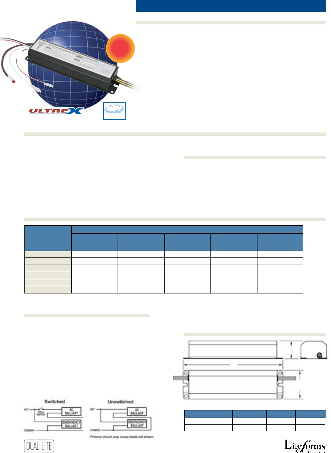
34
Features
Options (add sUFFix to Model)Accessories (order seParately)
Ordering Information
FluoresCent poWer paCks
Lampak
UFO-3, 4, 5, 6
• Battery case made of heavy 22-
gauge steel
• Reliable, high-frequency inverter
• Sealed nickel-cadmium battery
• Universal 120/277VAC operation
• Test switch and LED charge
indicator light supplied standard
• Provides 90 minutes of
emergency lighting
• Low power consumption
• Temperature range: 0°C to 50°C
(32°F to 122°F)
• UL 924 Listed (Emergency Lighting)
• UL 924 Damp Location Listed
Lampak UFO 3, 4, 5 and 6 emergency power
packs do not affect normal fixture operation and
may be used with either switched or unswitched
fixtures. UFO-3, 4, 5 and 6 packs may be installed
inside, on top of, or remote from the fixture. The
fluorescent pack may be remotely installed up to
half the distance from the lamp the AC
ballast manufacturer recommends, or up to 50
feet, whichever is less.
UFO-3, 4, 5 and 6 packs are
not suitable for installation in heated air outlet
fixtures and wet or hazardous location fixtures.
Installation is not recommended with fixtures where
the ambient temperature may fall below 0°C (32°F ).
A
C
B
Model a B C
UFO-3AW, 4W, 5W, 5AW
9 3/8” (23.8 cm) 11/2” (3.8 cm) 23/8” (6.0 cm)
UFO-6W, -6WI & -6-CLD
133/8” (33.9 cm) 11/2” (3.8 cm) 23/8” (6.0 cm)
NEW
• Compatible with electronic,
standard magnetic, energy
saving, and dimming AC ballasts
• Compatible with most standard
T8, T10 or T12, energy-saving or
rapid start, (4-pin) long compact
fluorescent lamp
• Easy installation with versatile
mounting capability inside of
ballast channel, on top of or
remote from fixture
• Operates one or two lamps in
emergency mode
• Can be used with switched or
unswitched lighting fixtures
F-WC Wire bundle cover (1)
SPRTS Remote test switch/charge indicator
module (2)
(1) Encloses exposed wiring harness when power pack is externally
mounted on the lighting fixture. One required per fixture.
(2) Fits single-gang box.
Standard Models
UFO-3AW, UFO-4W, UFO-5W, UFO-5AW, UFO-6W
Self-Testing Spectron Model
UFO-6WI
Extended Temperature Model*
UFO-6W-CLD
* Extends temperature range to
-20°C to 55°C (-4°F to 131°F)
Dimensions
Product Selector Guide
Accessories (order seParately)
Installation
Damp
An
Severe Conditions Product Line
eleCtriCal
Base nUMBer
Catalog oUtPUt initial oF laMPs laMP inPUt
nUMBer Wattage lUMens oPerated sizes Wattage
UFO-3AW 9.6 350-450 1 2’-4’ 3.5
UFO-4W 14.4 500-600 1 2’-4’ 3.5
UFO-5W 14.4 600-700 1 2’-8’ 3.5
UFO-5AW 14.4 600-700 1 or 2 2’-8’ 3.5
UFO-6W, UFO-6WI 24.0 1100-1400 1 or 2 2’-8’ 4.0
UFO-6W-CLD 24.0 Up to 1200 1 or 2 2’-8’ 4.0
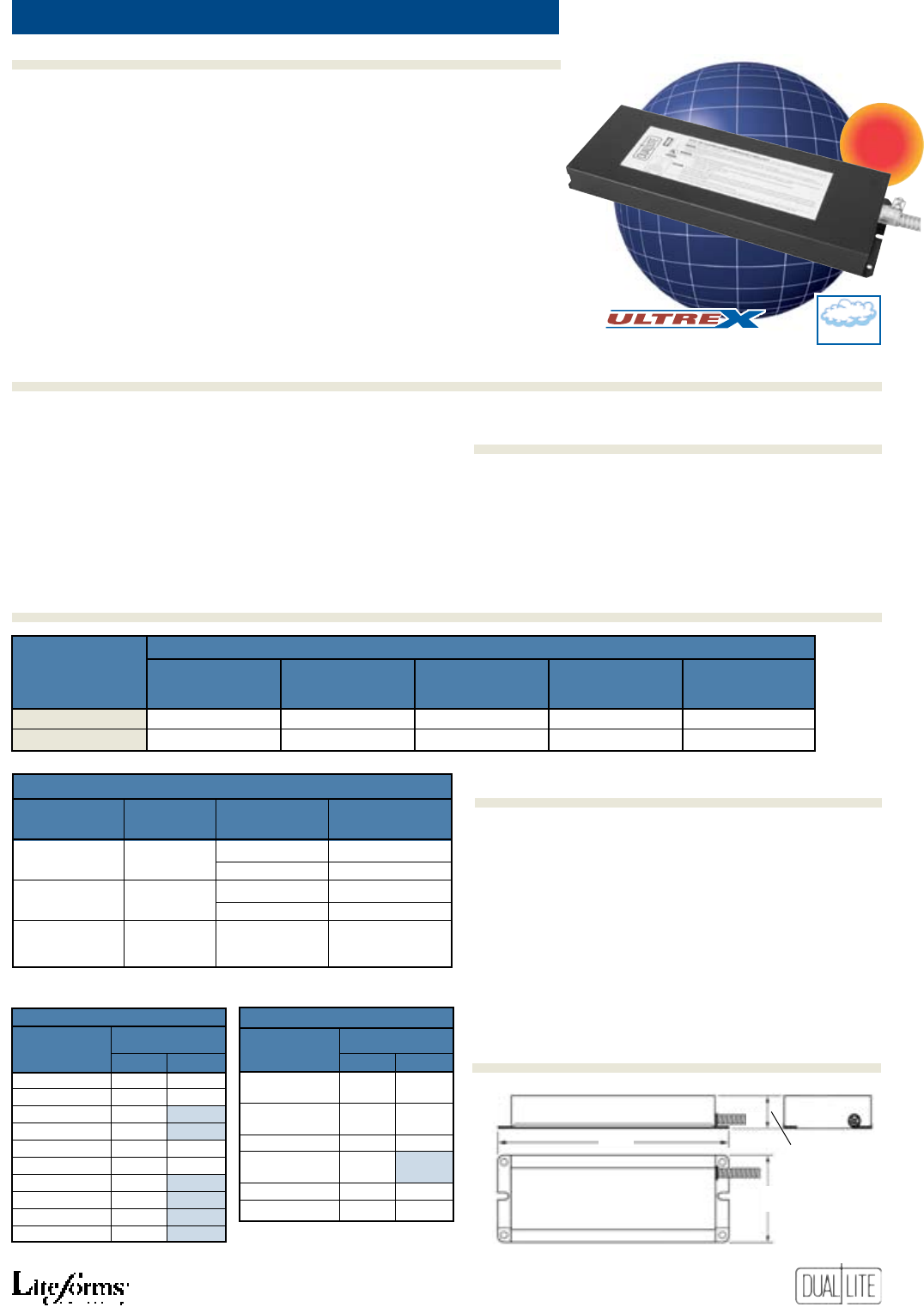
35
Features
Ordering Information
Options (add sUFFix to Model)Accessories (order seParately)
UFO-7W (Standard Model)
UFO-7WI (Self-Testing Model)
high lumen FluoresCent poWer paCks
•
Standard and Spectron self-testing/
self-diagnostic models offered.
• Compatible with electronic,
standard magnetic, energy
saving, and dimming AC ballasts
• Compatible with most standard
2 - 8 foot, T8, T9, T10 or T12 and
rapid-start (4-pin) long compact
fluorescent lamps
• Easy installation on top of or
remote from fixture
• Operates one or two lamps
depending on fixture
• Can be used with switched or
unswitched lighting fixtures
• Battery case made of 22-gauge steel
• Reliable, high-frequency inverter
• Premium sealed nickel-cadmium
battery
• Universal 120/277VAC operation
• Test switch and LED charge indicator
light supplied standard
• 90 minutes emergency operation
• Low power consumption
• Temperature range: 0°C to 40°C
(32°F to 104°F)
• UL 924 Listed (Emergency Lighting)
• UFO-7WI Model UL 924 Damp
Location Listed
F-WC Wire bundle cover (1)
SPRTS Remote test switch/charge indicator
module (2)
(1) Encloses exposed wiring harness when power pack is externally
mounted on the lighting fixture. One required per fixture.
(2) Fits single-gang box.
Table 1 (Models UFO-7W, UFO-7WI)*
Lamp Base Type Power No. of Lamps
Diameter (Length) Operated (Emerg.)
(1”, 11/8”,11/4”,11/2”)
Single or 17 - 40W (2’ to 4’) 1 or 2
T8, T9, T10, T12 Bipin
40 - 215W (5’ to 8’)
1
Long 4-Pin 18 - 39W 1 or 2
Compact (2G11) 40 - 55W 1
Compact 4-Pin 18 - 42W 1 or 2
(G24q, GX24q)
* Partial listing of lamps operated
Table 2*
Lamp Lumens
Type 1 Lamp 2 Lamps
FO25, FBO24 T8 2250 2600
FO32, FBO31 T8 3000 3000
FO40 T8 2400 --
FO96 T8 3000 --
F40 T12, F40/U 3000 3000
F40 T12ES (34W) 2700 2700
F48 T12/HO 3000 --
F96 T12 2800 --
F96 T12/HO 2900 --
F96 T12/VHO 3300 --
Table 2* (Continued)
Lamp Lumens
Type 1 Lamp 2 Lamps
PL-L 24W, F27/24BX
1800 2300
Dulux L 27W
PL-L 36W, F39/36BX
2900 3500
Dulux L 39W
PL-T 42W/4P 3200 3500
PL-L 40W, F40/30BX
1800 --
F50BX, Dulux L 55W
F28 2D/4P 2050 2800
F38 2D/4P 1450 2800
* Partial listing of lamps operated.
Initial lumen output measured at 25
°
C
ambient temperature.
LAMPAK UFO-7W Series emergency power packs do not
affect normal fixture operation and may be used with
either switched or unswitched fixtures. UFO-7W Series
models may be installed on top of, or remote from the
fixture. The emergency ballast may be remotely installed
up to half the distance from the lamp the AC ballast
manufacturer recommends, or up to 50 feet, whichever
is less.
UFO-7W Series emergency power packs are not suitable
for installation in heated air outlet fixtures and wet or
hazardous location fixtures. Installation is not recom-
mended with fixtures where the ambient temperature
may fall below 0°C (32°F ).
16.3”
41.4cm
5.5”
13.8cm
1.7”
4.4cm
* UFO-7WI Model Only
NEW
Accessories (order seParately)
Product Selector Guide
Installation
Dimensions
Lampak
UFO-7
Damp
An
Severe Conditions Product Line
eleCtriCal
Base nUMBer
Catalog oUtPUt initial oF laMPs laMP inPUt
nUMBer Wattage lUMens oPerated sizes Wattage
UFO-7W 57.6 1450-3500 1 or 2 2’-8’ 8.0
UFO-7WI 57.6 1800-3500 1 or 2 2’-8’ 8.0
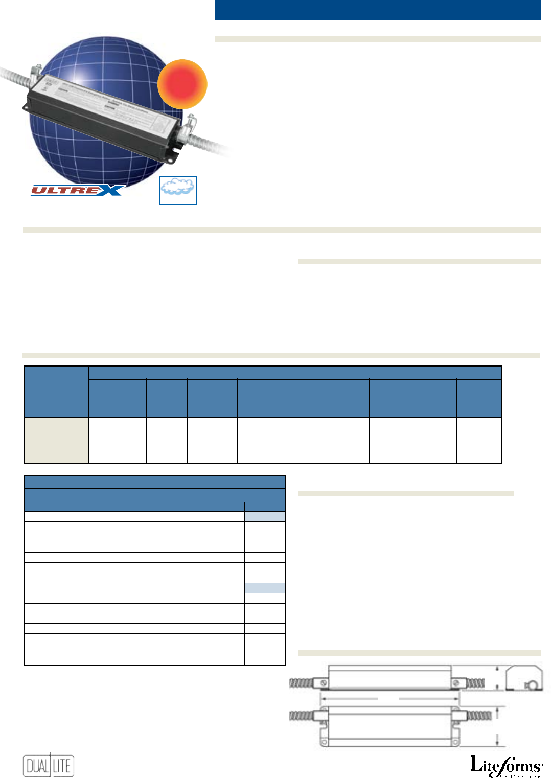
36
Features
Options (add sUFFix to Model)Accessories (order seParately)
Ordering Information
CompaCt FluoresCent poWer paCks
• Reliable, high-frequency
inverter
• Premium sealed nickel-cadmium
battery
• Universal 120/277VAC operation
• Test switch and LED charge
indicator light supplied standard
• 90 minute operation
• Low power consumption
• Temperature range: 0°C to 50°C
(32°F to 122°F)
• UL 924 Listed (Emergency Lighting)
• UL 924 Damp Location Listed
9.4”
23.8cm
2.4”
6.0cm
1.5”
3.8cm
LAMPAK Series UFO-12W emergency power pack does
not affect normal fixture operation and may be used
with either a switched or unswitched fixture. The UFO-
12W may be installed on top of, or remote from the
fixture. The emergency ballast may be remotely installed
up to half the distance from the lamp the AC ballast
manufacturer recommends, or up to 50 feet, whichever
is less. UFO-12W emergency power packs are not suit-
able for installation in heated air outlet fixtures and wet
or hazardous location fixtures. Installation is not recom-
mended with fixtures where the ambient temperature
may fall below 0°C (32°F ).
UFO-12W
F-WC Wire bundle cover (1)
SPRTS Remote test switch/charge indicator
module (2)
(1) Encloses exposed wiring harness when power pack is externally
mounted on the lighting fixture. One required per fixture.
(2) Fits single-gang box.
Table 1*
Lamp Lumens
Type (4-Pin) 1 Lamp 2 Lamps
PL-T 42W/4P
, Dulux T/E 42W 750 --
PL-T 32W/4P, Dulux T/E 32W 575 750
PL-T 26W/4P, Dulux T/E 26W, F26TBX/4P 450 725
PL-T 18W/4P, Dulux T/E 18W, F18TBX/4P 300 525
PL-C 26W/4P, Dulux D/E 26W, F26DBX/4P 600 700
PL-C 18W/4P, Dulux D/E 18W, F18DBX/4P 475 575
PL-C 13W/4P, Dulux D/E 13W, F13DBX/4P 350 425
PL-L 40W, Dulux L 40W, F40/30 BX/4P 650 --
PL-L 36W, Dulux L 39W, F39/36 BX/4P 575 750
PL-L 24W, Dulux L 27W, F27/24 BX/4P 475 550
PL-L 18W, Dulux L 18W, F18 BX 300 400
F3 82D/4P 525 650
FO25, FBO24 T8 525 700
FQL 28 600 700
FO17, FBO16 T8 425 500
* Partial listing of lamps operated
Initial lumen output measured at 25°C ambient temperature.
NEW
• Compatible with electronic,
standard magnetic, energy saving,
and dimming AC ballasts
• Compatible with most 13W to
42W rapid start, 4-pin compact
twin, quad or triple twin tube
fluorescent lamps
• Easy installation on top of or
remote from fixture
• Operates one or two lamps in
emergency mode
• Can be used with switched or
unswitched lighting fixtures
• Battery case made of heavy 22-
gauge steel
Dimensions
Product Selector Guide
Accessories (order seParately)
Application
Lampak
UFO-12
Damp
An
Severe Conditions Product Line
eleCtriCal
Base nUMBer
Catalog Ballast initial oF laMPs laMP Base inPUt
nUMBer CoMPat. lUMens oPerated tyPe tyPes Wattage
Magnetic, See See 13W through 42W quad and
UFO-12W Electronic, Table 1 Table 1 triple tube lamps without G24q-2, G24q-3 3.5
Energy Saving integral starters (4-pin lamps) GX24q-3, GX24q-2
& Dimming
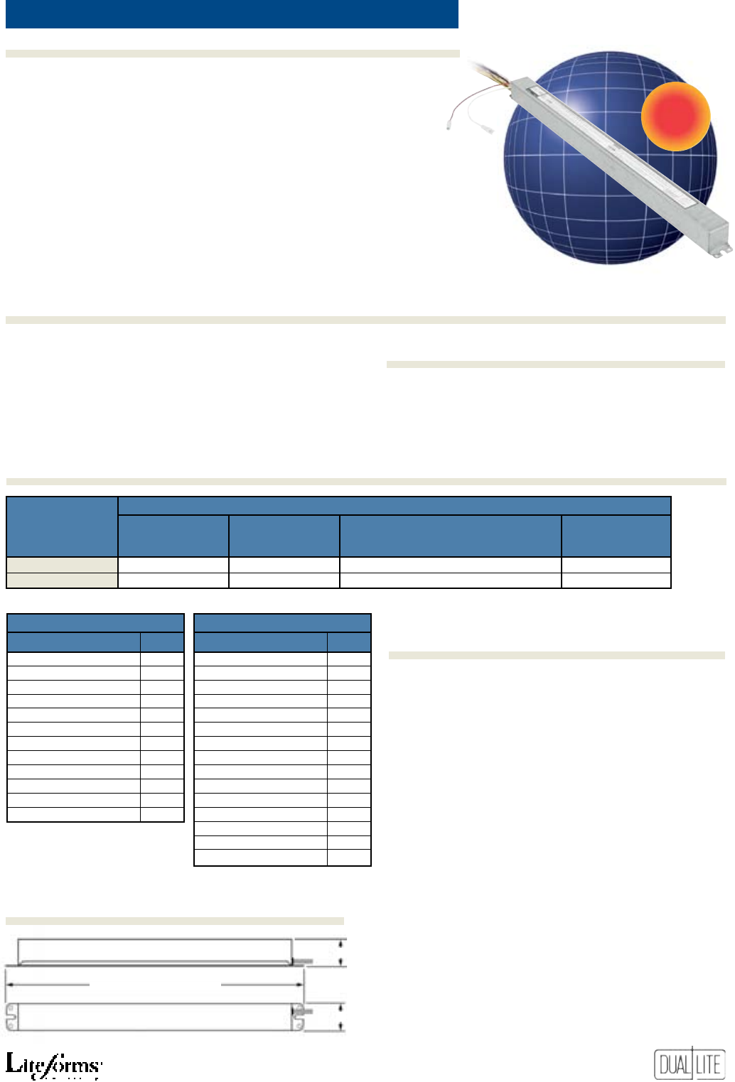
37
Features
Ordering Information
Options (add sUFFix to Model)Accessories (order seParately)
loW-proFile FluoresCent poWer paCks
• Low profile design
• Compatible with electronic
(including those containing
end-of-life shutdown circuits),
standard magnetic, energy saving,
and dimming AC ballasts
• Compatible with most standard
and HO T5 miniature bipin, T8
bipin and rapid-start (4-pin)
long compact lamps
• Easy ballast channel installation
• Operates one lamp
• Can be used with switched or
unswitched lighting fixtures
Table 1 (UFO-LP1)*
Lamp Type Lumens
FP54, F54 T5/HO 700
FP39, F39 T5/HO 620
FP24, F24 T5/HO 390
FP28, F28 T5 700
FP21, F21 T5 620
FP14, F14 T5 430
F32 T8 (4’) 635
F40 T8 (5’) 570
F48 T8/HO (4’) (44W) 470
PL-L 50W, F50BX/RS, Dulux L 55W 510
PL-L 40W, F40/30BX, Dulux L 55W 625
PL-L 36W, F39/36BX, Dulux L 55W 610
* Partial listing of lamps operated.
Initial lumen output measured at 25
°
C
ambient temperature.
Table 2 (UFO-LP2)*
Lamp Type Lumens
FP54, F54 T5/HO 1250
FP39, F39 T5/HO 1125
FP24, F24 T5/HO 725
FP28, F28 T5 1325
FP21, F21 T5 1025
FP14, F14 T5 750
F17 T8 650
F25 T8 750
F32 T8 (4’) 1100
F40 T8 (5’) 1325
F48 T8/HO (4’) (44W) 1100
F60 T8/HO (5’) (55W) 1275
PL-L 50W, F50BX/RS, FT55DL
1050
PL-L 40W/RS, F40/30BX, FT40DL/RS
925
PL-L 36W, F39/36BX, FT36DL
900
• Compact battery case
• Reliable, high-frequency inverter
• Premium sealed nickel-cadmium
battery
• Universal 120/277VAC operation
• Test switch and LED charge indicator
light supplied standard
• Provides 90 minutes of emergency
lighting
• Low power consumption
• Temperature range: 0°C to 50°C
(32°F to 122°F)
• UL 924 Listed (Emergency Lighting)
UFO-LP1 (Standard Output Model)
UFO-LP2 (High Output Model)
SPRTS Remote test switch/charge indicator
module (1)
(1) Fits single-gang box.
Dual-Lite Lampak UFO-LP Series low-profile fluorescent
emergency ballasts work in conjunction with a low-profile or
standard-size electronic AC ballast containing an end-of-life
shut down circuit to convert new or existing standard or high
output T5 fluorescent fixtures into unobtrusive emergency
lighting. Model UFO-LP1 can be used with one 14 - 28W
standard or 24 - 54W high output T5; one 32W (4’), 40W (5’)
and 44W H0 (4’) T8 fluorescent lamp; or one 36 - 55W (4-pin)
long compact fluorescent lamp (see Table 1). Model UFO-
LP2 can be used with one 14 - 54W (2’ - 4’) standard or high
output T5, 17 -55W (2’ - 5’) standard or high output T8, 36
- 55W (4-pin) long compact fluorescent lamp (see Table 2).
UFO-LP Series models are also compatible with most 1, 2, 3,
and 4-lamp electronic (including those containing end-of-life
shutdown circuits), standard, energy saving, and dimming AC
ballasts. If used in an emergency-only fixture, no AC ballast is
necessary. UFO-LP Series models are suitable for use in indoor-
dry locations except air handling heated air outlet fixtures,
and wet, damp, or hazardous location fixtures. For information
about specific lamp and ballast compatibility, please contact
the factory.
UFO-LP1 = 18.5” (41.4cm)
UFO-LP2 = 21.5” (54.6cm)
1.18” (3.0cm)
1.18” (3.0cm)
NEW
Lampak
UFO-LP
Accessories (order seParately)
Product Selector Guide
Application
Dimensions
eleCtriCal
Base nUMBer
Catalog lUMen oF laMPs laMP inPUt
nUMBer oUtPUt oPerated tyPes Wattage
UFO-LP1 See Table 1 1 T5 HO, T5, T8 HO, T8, 4-pin Compact 3.2
UFO-LP2 See table 2 1 T5 HO, T5, T8 HO, T8, 4-pin Compact 3.0
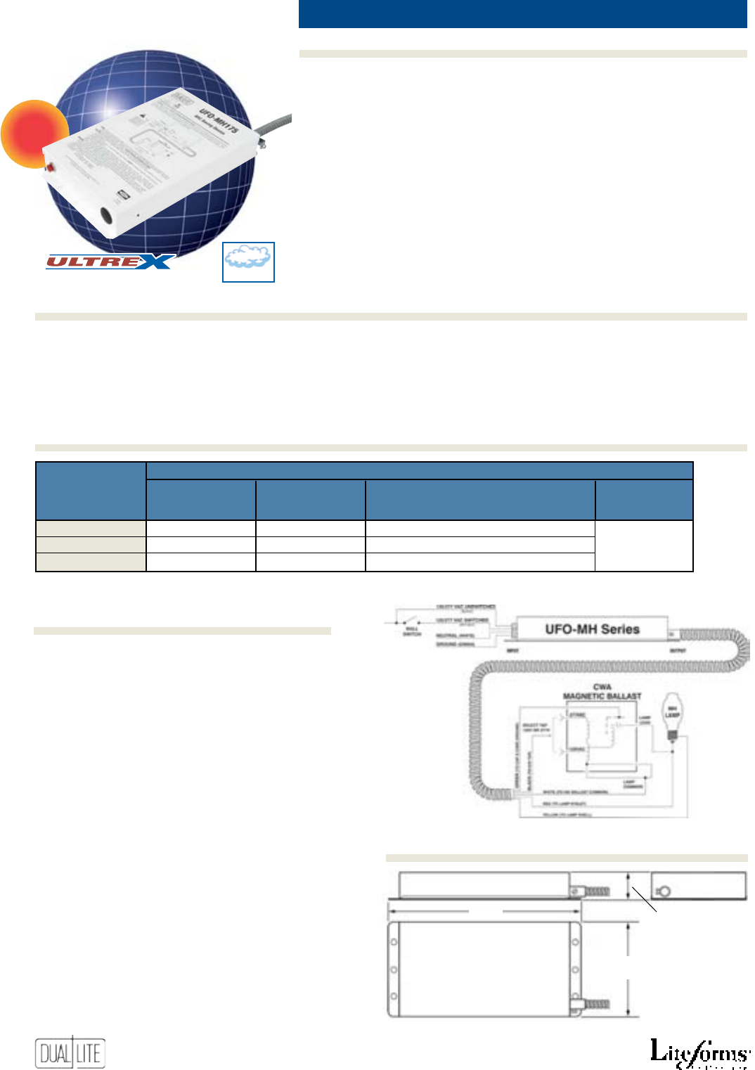
38
Features
Ordering Information
Options (add sUFFix to Model)Accessories (order seParately)
hiD BaCkup Ballast
• Catches and maintains the arc of
metal halide HID lamps
•
Provides two minutes of continuous
arc maintenance
• Maintains lamp at 20-30% normal
operating power
• Multiple catches from one
recharging
• Works with standard constant
wattage autotransformer (CWA)
magnetic ballasts
• Compatible with most standard
150 to 400 watt probe-start metal
halide M57, M58 and M59 HID
lamps
• Easy remote installation
• Battery case made of heavy 22-
gauge steel
• Reliable, high-frequency inverter
• Premium sealed nickel-cadmium
battery
• Universal 120/277VAC operation
• LED charge indicator light
• Low power consumption
• Temperature range: 0°C to 55°C
(32°F to 131°F)
• UL 924 Listed (Auxiliary Lighting)
• UL Damp Location Listed
The Dual-Lite Lampak UFO-MH Series devices are
battery-operated backup ballasts that catch and
maintain the arc of one metal halide HID lamp
during AC power sags, interruptions or failures.
The UFO-MH Series device works in conjunction
with standard constant wattage autotransformer
(CWA) magnetic ballasts. The UFO-MH device
detects AC power line disturbances and operates
the HID lamp with sufficient power to keep
the lamp arc from extinguishing during power
line disturbances. The lamp arc, in a typical HID
lamp, will extinguish if an AC power failure
persists for more than four milliseconds. The
UFO-MH unit detects AC power line disturbances,
then supplies supplemental power to the lamp
within approximately two milliseconds, thereby
maintaining the lamp arc. The UFO-MH Series is
suitable for damp location use. It is also for use
with listed indoor fixtures EXCEPT air handling
heated air outlets and wet or hazardous location
fixtures. The UFO-MH Series may be used with an
auxiliary generator or inverter power system and
the unit’s two-minute time limit allows more than
ample time for an auxiliary generator to pick up
and support the metal halide lamp for emergency
lighting purposes.
UFO-MH175
UFO-MH250
UFO-MH400
12.25”
31.1cm
7.25”
18.4cm
1.75”
4.4cm
NEW
Product Selector Guide
Application
Lampak
UFO-MH
Damp
An
Severe Conditions Product Line
Dimensions
eleCtriCal
Base MaxiMUM arC
Catalog distanCe FroM MaintenanCe laMP tyPes inPUt
nUMBer laMP Period oPerated Wattage
UFO-MH175 30 Feet 2 Minutes 175W or 150W energy saving MH (M57) 6W @ 120VAC
UFO-MH250 50 Feet 2 Minutes 250W or 225W energy saving MH (M58) 10W @ 277VAC
UFO-MH400 80 Feet 2 Minutes 400W or 360W energy saving MH (M59)
6W @ 120VAC
10W @ 277VAC
6W @ 120VAC
10W @ 277VAC
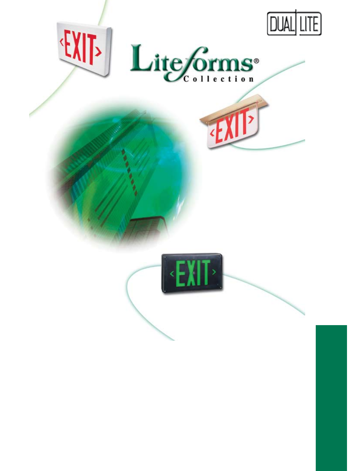
39
Exit Signs
LX Series Designer LED Exit Signs ..................................................................40
DK Series AC Incandescent Exit Signs .............................................................41
LT Series Designer Tandem Units ................................................... 42, 43
NYXC Series New York Tandem Units ......................................................... 44
SMC Series Tandem Units with Side Mounted Heads ................................. 45
Sempra Series Diecast LED Exit Signs ................................................................... 47
Sempra MR Master/Remote Diecast LED Exit Signs ...................................48, 49
Sempra SC Severe Conditions Diecast LED Exit Signs ..............................50, 51
Sempra SCWL Wet Location Diecast LED Exit Signs ..............................................52
Sempra SERS Recessed Diecast LED Exit Signs .....................................................53
NYDC Series New York Diecast LED Exit Signs ....................................................54
LN4X Series Wet Location LED Exit Signs ................................................... 55
Freedom LED Aluminum LED Exit Signs ................................................................56
LEDS Series Low-Profile Aluminum LED Exit Signs ...................................... 57
NYX Series New York LED Exit Signs ........................................................58
CMX Series Chicago Exit Signs .................................................................59
LE Series Recessed Mounting Edge-Lit LED Exit Signs ..........................60, 61
LES Series Surface Mounting AC Edge-Lit LED Exit Signs ......................62, 63
NYE Series New York Recess Mounted Edge-Lit LED Exit Signs ......................64
NYES Series New York Surface Mounted Edge-Lit LED Exit Signs ....................65
DEX Series Special Wording Incandescent Exit Signs .................................66
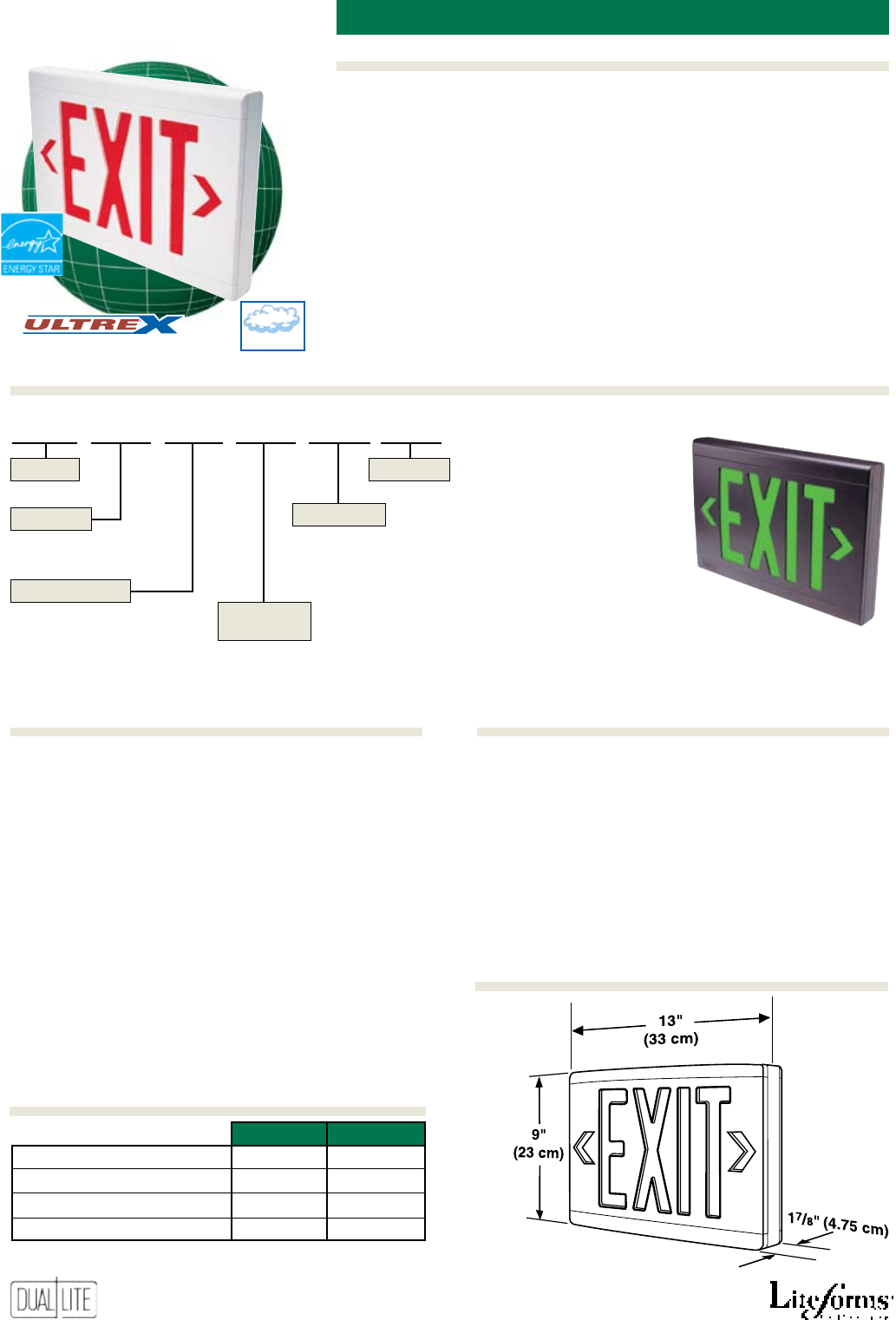
40
Features
Options (Add suffix to model)Accessories (order sepArAtely)
Ordering Information
Damp
An
Severe Conditions Product Line
LX Designer LeD exit signs
Also available in black finish
All Models
• UV-stable thermoplastic housing
• Compact, low-prole design
• Easy to install
• Long-life LED lamps
• Bright, even illumination
• Red and green letters
• Universal single/double face
• White and black models offered
• Push-in wiring connectors
• Universal end/ceiling/wall mount
• Universal snap-in, chevron
arrows
• Damp location listed
• 120/277VAC, 60 Hz operation
Emergency Models
• Solid-state charger with low
voltage disconnect
• Maintenance-free NiCad battery
• 2 hour emergency operation
• Test switch and AC-On light
• Available with Spectron®
self-testing/self-diagnostic
electronics with time-delay relay
(TDR) standard
• Temperature range: 10°C to 40°C
(50°F to 104°F)
• UL 924 Listed
FX2-E Emergency operation conversion module (red)
FX-E Emergency operation conversion module (green)
PMLXW 121/2” Pendant mounting kit (white)
PMLXB 121/2” Pendant mounting kit (black)
WGLX Wire guard (Wall mount)
WG-MLT
Wire guard (Wall mount)
WGLXC Wire guard (Ceiling mount)
WGLXE Wire guard (End mount)
VRS3 Vandal resistant shield
I
Spectron self-testing/self-diagnostic electronics
-2C 2-circuit operation (2)(6)
-FAP Fire alarm panel interface (3)(5)(6)
-FM Flasher module (1)(5)
-AF Audible/Flasher module (1)(5)
-DC Remote DC operation (2)(4)(5)
-24K 220-240VAC, 60 Hz. operation
-SA “SALIDA” stencil face
(1) For specification with emergency models only.
(2) For use with AC models only.
(3) Operates with 24-volt AC or DC fire alarm panels.
(4) For emergency illumination of sign from remote 6-24 VDC
power sources.
(5) -FAP, -FM, -AF or -DC options may not be specified together.
(6) -2C and -FAP options may be specified together.
120VAC 277VAC
Red AC Only Models 2.6 watts 2.6 watts
Green AC Only Models 2.1 watts 2.1 watts
Red Emergency Models 3.8 watts 3.8 watts
Green Emergency Models 3.5 watts 3.5 watts
Power factor, average: .8 (lagging)
LX U R W E -FAP
U - Universal Single/Double Face Blank - AC Only
E - Emergency
Series
Faces
Letter Color
Operation
Housing
Finish
R - Red
G - Green
W - White
B - Black
Options
Dimensions
Power Consumption

41
Features
Ordering Information
Options (Add suffix to model)Accessories (order sepArAtely)
DK
incanDescent exit sign
Damp
An
Severe Conditions Product Line
5”
(12.7 cm)
11” (27.9 cm)
111/2” (29.2 cm)
51/2”
(14.0 cm)
21/2”
(6.4 cm)
23/8”
(6.0 cm)
8”
(20.4 cm)
43/4”
(12.0 cm)
71/2”
(19.1 cm)
• High impact thermoplastic
housing with steel faceplate
• Universal directional chevron
arrow knockouts
• Tamper resistant screws supplied
• AC illumination provided by two
145V, 15T6 incandescent lamps
• May be wall, ceiling or end
mounted
• Universal single/double face
• White nish
• Red letter models
• 120V standard
• Suitable for damp locations
• Temperature range: 20°C to 30°C
(68°F to 86°F)
• UL 924 Listed
PMEXW 12” pendant stem and canopy kit – white
WG-MLT Wire guard (wall mount)
WGLXC Wire guard (ceiling or end mount)
VRS3 Vandal resistant shield
111/4”(28.6 cm) with power pack
Model Number Description
DKURW 120V, AC-Only, single or twin face – universal mount, white nish
DKURWE 120/277V, emergency, single or twin face – universal mount, white nish
Power Pack
31/4”
(8.3 cm)
11” (27.9 cm)
(DKURWE model)
Emergency model with power pack
Dimensions
CANOPY
1/2”
(1.3 cm) 1/2”
(1.3 cm)
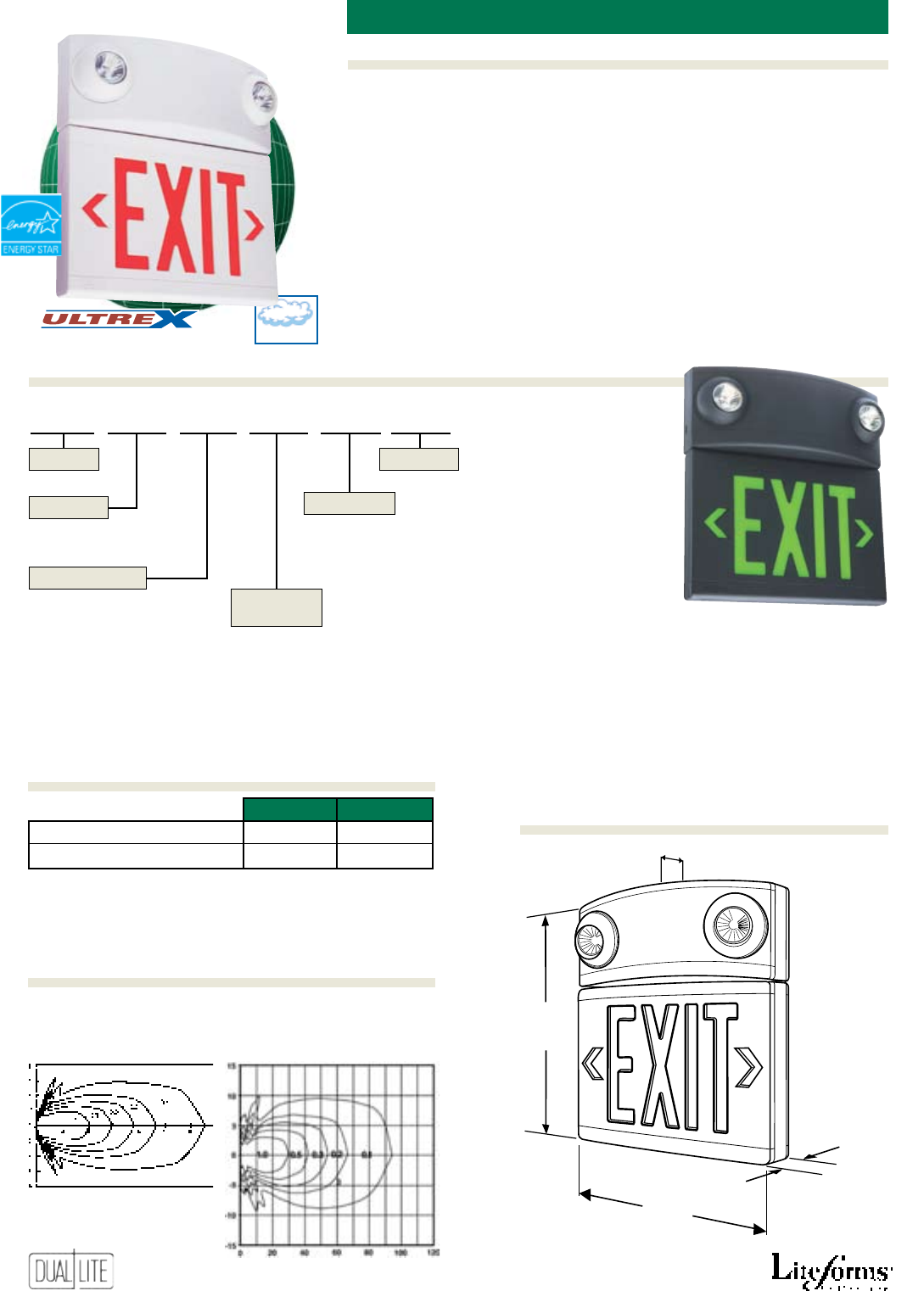
42
Features
Options (Add suffix to model)Accessories (order sepArAtely)
Ordering Information
Designer tanDem Units
Also available in black finish
An
Severe Conditions Product Line
• Factory assembled emergency
unit/LED exit sign
• UV-stable thermoplastic housing
• Eyeball style lighting heads
• High-output halogen lamps
• White or black nishes offered
• Remote capacity and damp
location listed models available
• 120/277VAC, 60 Hz operation
• Solid-state charger
• Maintenance-free battery
• Low-voltage disconnect
• Test switch and AC-On light
• Available with Spectron®
self-testing/self-diagnostic
electronics with time-delay relay
(TDR) standard
• Long-life LED lamps
• Bright, even illumination
• Universal single/double face
• Red and green letter models
• Snap-in, chevron arrows
• Ceiling or wall mount models
standard. Optional side mounting
requires accessory kit
• Temperature range: 20°C to 30°C
(68°F to 86°F)
(Damp location models:
10°C to 40°C
(50°F to 104°F)
• UL 924 Listed
High-Output Halogen Lamp
Horizontal Isofootcandle Distribution
5W MR-16 Lamp 10W MR-16 Lamp
• Standard Lamp for LT unit • 10W Lamp for
• 5W Lamp for LZR Remote Fixtures LZR Remote Fixtures
120VAC 277VAC
Red Emergency Models 5.0 watts 5.0 watts
Green Emergency Models 5.0 watts 5.0 watts
Power factor, average: .8 (lagging)
LT U R B D -AF
U - Universal Single/Double Face Blank - Standard model
3 - Remote capacity model
D - Damp location model
Series
Faces
Letter Color
Application
Housing
Finish
R - Red
G - Green
W - White
B - Black
Options
1
7
/
8
"
(4.75 cm)
14
1
/
4
"
(36.2 cm)
13"
(33 cm)
3
5
/
8
"
(9.2 cm)
Power Consumption
Photometrics
Dimensions
Damp
LT
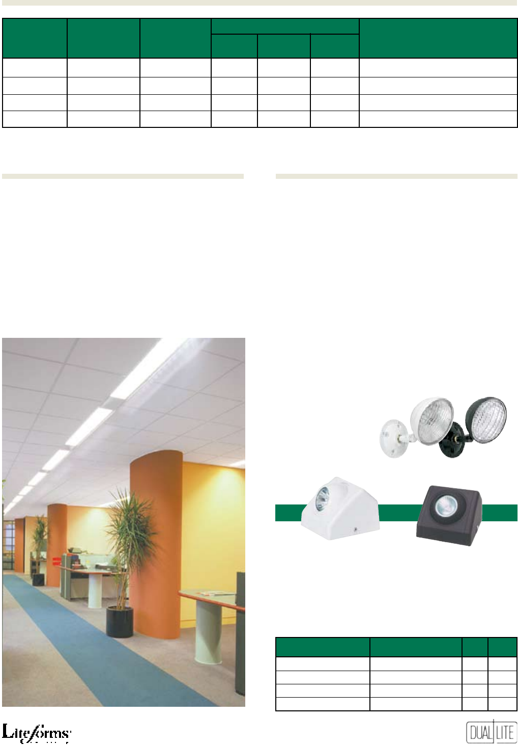
43
LT
remote dAmp Colors
stAndArd CApACity loCAtion exit stenCil
models models(1) models letters Housing fACe(s) desCription
LTURW LTURW3 LTURWD Red White White Single/double face tandem unit
LTURB LTURB3 LTURBD Red Black Black Single/double face tandem unit
LTUGW LTUGW3 LTUGWD Green White White Single/double face tandem unit
LTUGB LTUGB3 LTUGBD Green Black Black Single/double face tandem unit
(1) Operates the integral unit heads plus one additional 5 watt lighting fixture or exit sign.
FTSMKW Side mount eld kit (white) (a)
FTSMKB Side mount eld kit (black) (a)
PMLZTW 121/2” Pendant mounting kit (white)
PMLZTB 121/2” Pendant mounting kit (black)
WGTW Wire guard (Wall mount)
WGTCE Wire guard (Ceiling or end mount)
VRS2 Vandal resistant shield (b)
OMSSW0605 Outdoor remote lighting head -
6 Volt, 5 Watt sealed-beam type lamp -
White nish
OMSSB0605 Outdoor remote lighting head -
6 Volt, 5 Watt sealed-beam type lamp -
Black Finish
(a) FTSMKW and FTSMKB field kits are required for side mounting on all
models. Accommodates left side mounting only.
(b) For use with wall mounted units only.
I
Spectron self-testing/self-diagnostic electronics
(4)
-0 Unit supplied without lighting heads (3)
-FAP Fire alarm panel interface (1)(2)
-FM Flasher module (2)
-AF Audible/Flasher module (2)
-24K 220-240VAC, 60 Hz operation
-SA “SALIDA” stencil face
(1) Operates with 24-volt AC or DC fire alarm panels.
(2) -FAP, -FM, or -AF options may not be specified together.
(3) Available with remote capacity (LTXXX3) models only.
(4) Only available on remote capacity and damp location models.
Matching Remote Fixtures
A complete line of 6- and 12-volt matching remote xtures
in single and tandem lamp congurations is available for
use with LZ Series high-capacity units or any other 6- or 12-
volt DC emergency lighting remote power sources.
All remote xtures are offered in black and white
textured
nishes with a choice of 5- or 10-watt halogen lamps.
OMS Series outdoor lighting
heads
WHite BlACk
single single Volts WAtts
LZRSW0605 LZRSB0605 6 5
LZRSW0610 LZRSB0610 6 10
LZRSW1205 LZRSB1205 12 5
LZRSW1210 LZRSB1210 12 10
Options (Add suffix to model)Accessories (order sepArAtely)
Product Selector Guide
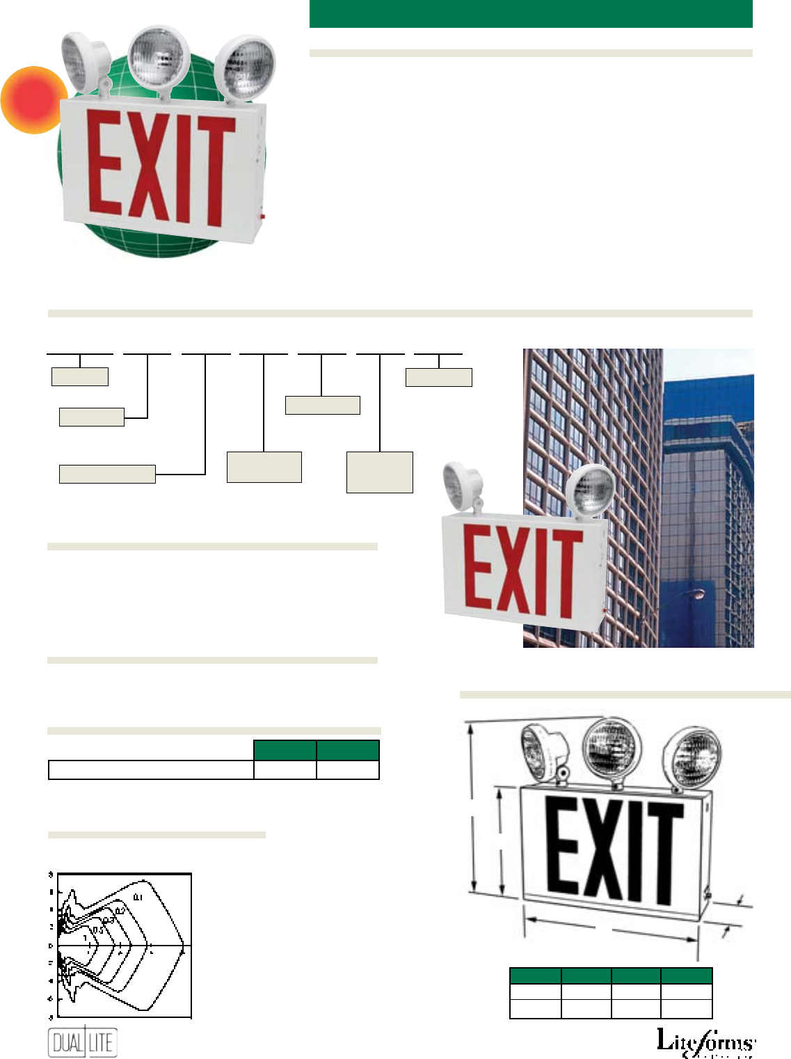
44
Features
Options (Add suffix to model)Accessories (order sepArAtely)
Ordering Information
•Designed to meet New York City
specications
•Heavy 20 gauge metal enclosure
with white or black nish
•Exit plaques secured by channels
•Single face eight inch high letters
•Knockout directional chevron
arrows
•Available with two or three fully
adjustable and lockable 7.2 watt
thermoplastic lighting heads
•High output LED lamps
•Universal 120/277VAC operation
•Wall mounting
•Completely self-contained
•90-Minute emergency operation
•Environmentally coated, fully
automatic solid state charger
•Automatic low voltage battery
disconnect
•Charge rate indicator and test
switch
•Maintenance free battery
• Temperature range: 0°C to 40°C
(32°F to 104°F)
• Listed to UL 924
Horizontal Isofootcandle Distribution
Standard 6V, 7.2W SBT Lamp
NEW
new York citY tanDem Unit
A
B
CD
A B C D
95/8” 151/2” 15” 41/4”
24.4 cm 39.4 cm 38.1 cm 10.8 cm
NYXC S R B E 2 -TR
S - Single
D - Double
E - Emergency
Series
Faces
Letter Color
Operation
Housing
Finish
R - Red W - White
B - Black
Number of
Lighting
Heads
Options
2 - Two
3 - Three
120VAC 277VAC
All Models 7.0W 7.2W
* Wattage figures include LED lamps, transformers and electronics
power requirements.
40G Wire guard (wall mount)
-0612 12 watt lamps (1)
-TR Tamper resistant option (2)
(1) 12 watt high-output lamps available on two-headed models only.
(2) Provides two stainless steel tamper resistant locking screws.
Power Consumption
Options (Add suffix to model)
Dimensions
Accessories (order sepArAtely)
Photometrics
NYXC
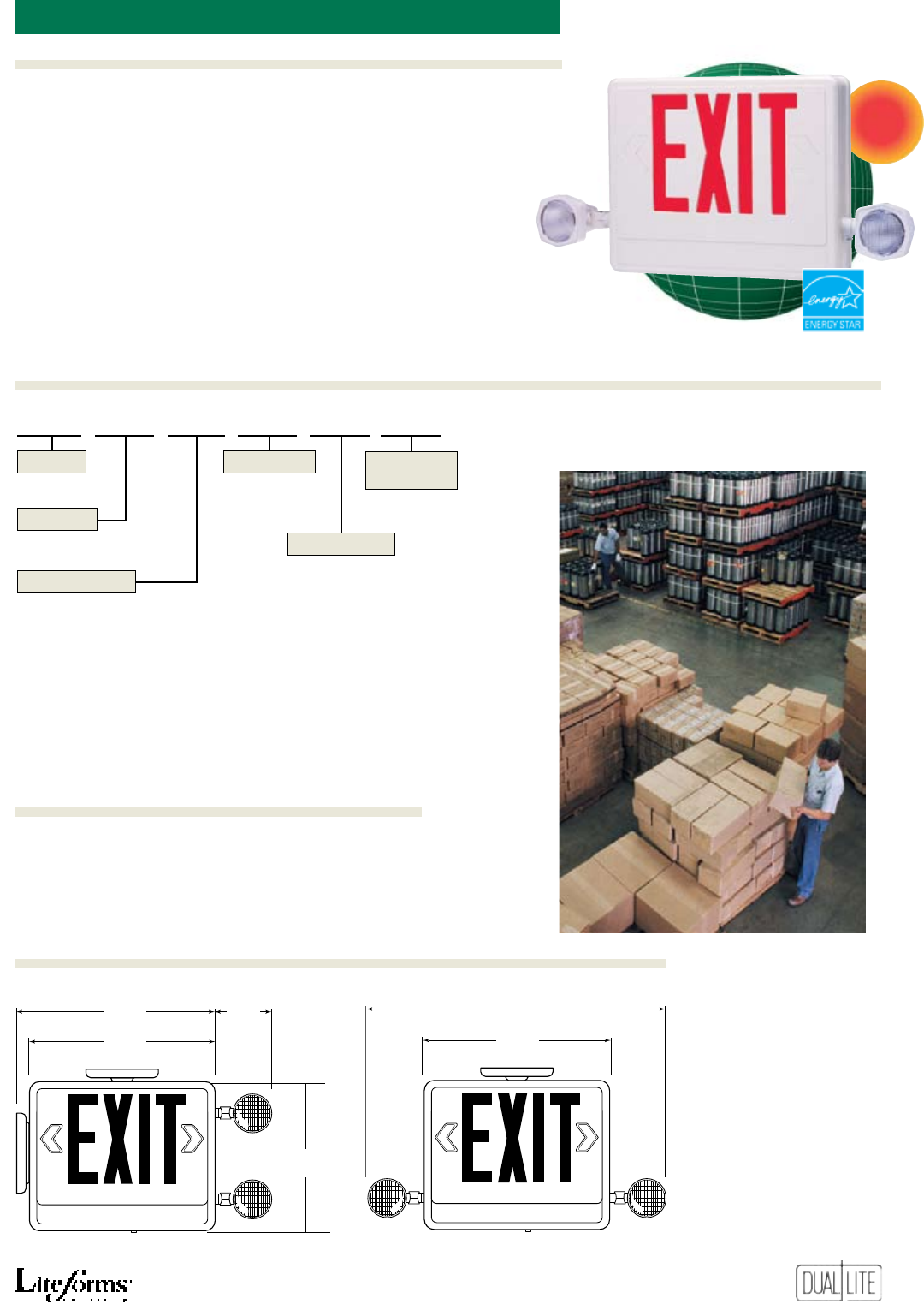
45
Features
Ordering Information
Options (Add suffix to model)Accessories (order sepArAtely)
NEW
SMC
• Combines emergency light with
energy saving LED exit
• Adjustable 5.4 watt incandescent
lampheads
• Maintenance-free battery
• Dual voltage – 120V/277VAC
• Fast, easy installation
• Snap together, modular
construction
• All components are integral
to the exit housing, including
battery
• Accessible compartments add to
ease of maintenance
• Consumes as little as 4 watts for
either a single or twin face sign
• Uniform illumination of
exit legend
• Snap-out directional chevrons
• Temperature range:
20°C to 30°C
(68°F to 86°F)
• UL 924 Listed
41G Wire guard (wall or ceiling mount)
combination LeD exit/emergencY Light
Ceiling or Back MountEnd Mount
max.
121/2”
(31.8 m)
41/2”
(11.4 cm)
133/8”
(34 cm)
121/2”
(31.8 cm)
211/2”
(54.6 cm)
101/8”
(13.3 cm)
max.
W - White
B - Black
SMC
3 R E CB W
3 - Universal Single or Double
E - Emergency
Series
Faces
Letter Color
Operation Housing
Finish
Mounting
R - Red
G - Green
CB - Ceiling/Back
E - End
Accessories (order sepArAtely)
Dimensions
Available March 1, 2006
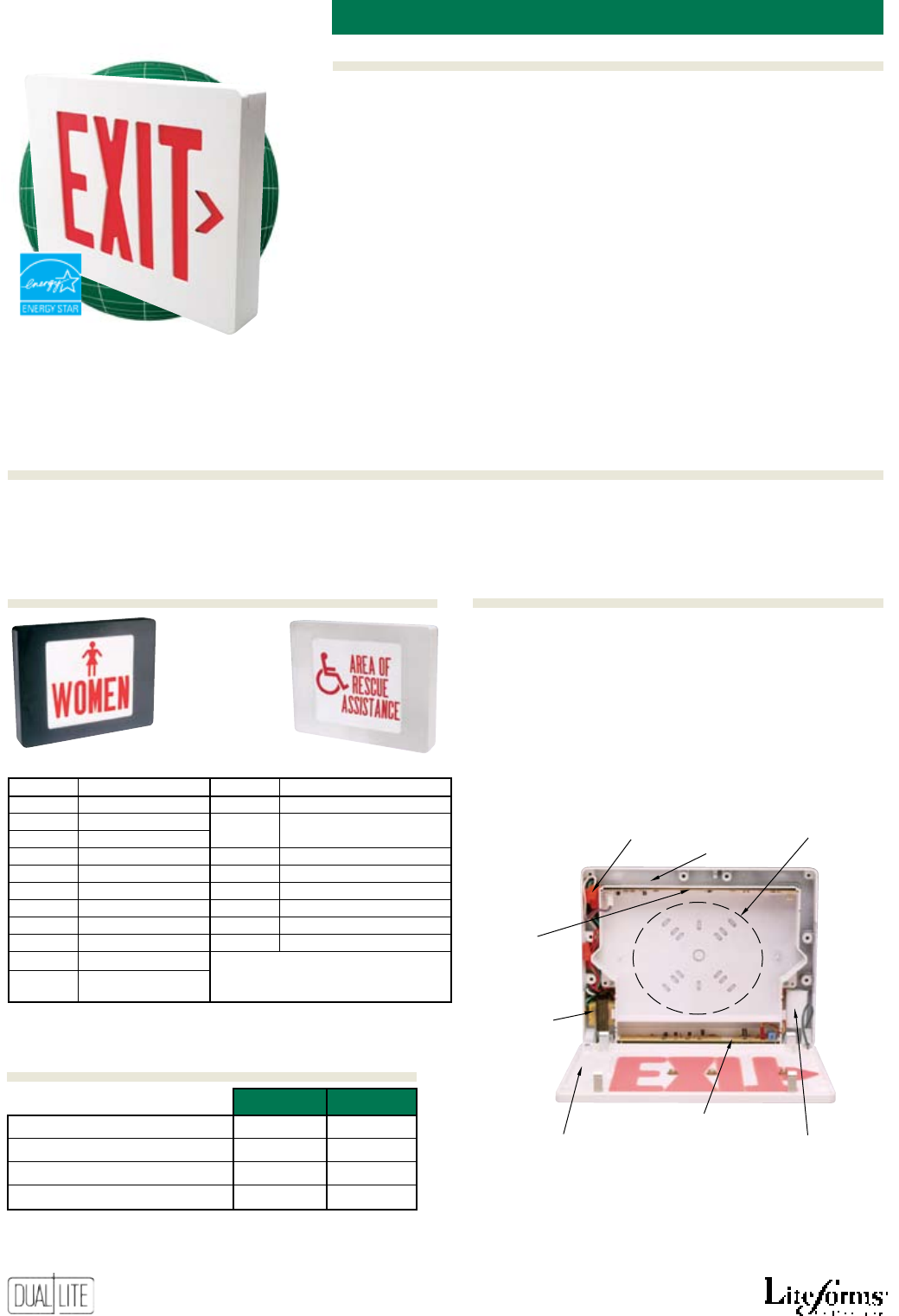
46
Features
Options (Add suffix to model)Accessories (order sepArAtely)
Ordering Information
Diecast LeD exit sign
Sempra
Push-in quick-connect
AC terminals
Isolated,
grounded
120/277VAC
transformer
Charger/transfer
module
Universal
wall mounting
KO pattern
Wiring
channel
Break-out
chevron-style
directional indi-
cators
Sealed
nickel-cadmium
battery
LED
illumination
strip
LIFETIME WARRANTY ON
ALL SPECTRON MODELS
See Product Selector Guide for available models
All Models
• High-strength cast aluminum
• Low-prole architectural styling
• 5-minute installation
• Long-life LED lamps
• Bright, even illumination
• Red and green letters
• Single and double face models
• White, black and black or white
with brushed face nishes
• Push-in wiring connectors
• Universal end/ceiling/wall mount
• Break-out, chevron arrows and
mounting KOs
• 120/277VAC, 60 Hz operation
Emergency Models
• Solid-state charger with low voltage
disconnect
• Maintenance-free NiCad battery
• 2-hour emergency operation
• Test switch and AC-On indicator
• Available with Spectron® self-
testing/self-diagnostic electronics
with time-delay relay
(TDR) standard
• Lifetime warranty on LED strip,
electronics and battery with
Spectron® self-testing/self-
diagnostic models
• Temperature range: 20°C to 30°C
(68°F to 86°F)
• UL 924 Listed
Special Wording Open Face Diffuser Table*
Option No. Description Option No. Description
-SW1 TO EXIT -SW12 AREA OF RESCUE ASSISTANCE
-SW2 NOT AN EXIT -SW13 AREA OF RESCUE ASSISTANCE
-SW3 IN USE (w/wheelchair symbol)
-SW4 XRAY IN USE -SW14 ELEVATOR
-SW5 DARKROOM IN USE -SW15 RESTROOMS
-SW6 CAUTION -SW16 MEN
-SW7 DO NOT ENTER -SW17 MEN (w/symbol)
-SW8 TEST IN PROGRESS -SW18 WOMEN
-SW9 ON AIR -SW19 WOMEN (w/symbol)
-SW10 AREA OF REFUGE
-SW11 AREA OF REFUGE
(w/wheelchair symbol)
Other special wording diffusers
available, consult factory.
120VAC 277VAC
Red AC Only Models: 2.6 watts 2.6 watts
Green AC Only Models: 2.1 watts 2.1 watts
Red Emergency Models: 3.8 watts 3.8 watts
Green Emergency Models: 3.5 watts 3.5 watts
*Wattage figures include LED lamps, transformer and electronics power
requirements. LED lamp assemblies (red or green) consume less than 1 watt.
Power factor, average: .8 (lagging)
Sempra cast-aluminum emergency exit signs with the
Spectron self-testing/self-diagnostic electronics system
are guaranteed by Dual-Lite under normal and proper
use, against defects in material and workmanship
for the life of the product. The warranty covers all
electronics, LED light strip and unit battery.
* To order special wording diffusers, add Option Number suffix to model number.
Ex: SEDRWE-SW(10)
Ordering Information
Power Consumption
Lifetime Warranty
Special Wording diffus-
47
15/8” (4.14 cm)
91/8”
(23 cm)
10”
(25.5 cm)
113/4” (30 cm)
125/8” (32 cm)
Sempra
I
Spectron self-testing/self-diagnostic electronics
-DC Remote DC operation (1)(4)(5)
-2C 2-circuit operation (1)(5)
-FAP Fire alarm panel interface (3)(5)
-FM Flasher module (2)(5)
-AF Audible/Flasher module (2)(5)
-24K 220/240VAC, 60 Hz. operation
(1) For use with AC models only.
(2) For use with emergency models only.
(3) Operates with 24-volt AC or DC fire alarm panels.
(4) For emergency illumination of sign from remote 6-24 VDC power sources.
(5) -DC, -2C, -FAP, -FM, -AF options may not be specified together.
SER-E Emergency operation module (red models) *
SEG-E
Emergency operation module (green models) *
PMCW 121/2” Pendant mounting kit (white)
PMCB 121/2” Pendant mounting kit (black)
WGLX Wire guard (Wall mount)
WG-MLT Wire guard (Wall mount)
WGLXC Wire guard (Ceiling mount)
WGLXE Wire guard (End mount)
*
For factory-equipped emergency models, see Product Selector Guide above.
Options (Add suffix to model)
Dimensions
Accessories (order sepArAtely)
Product Selector Guide
AC emergenCy numBer Colors
model model of exit stenCil
numBers numBers fACes letters Housing fACe(s)
SESRW SESRWE Single Red White White
SESGW SESGWE Single Green White White
SESRWN SESRWNE Single Red White Brushed
SESGWN SESGWNE Single Green White Brushed
SESRB SESRBE Single Red Black Black
SESGB SESGBE Single Green Black Black
SESRBN SESRBNE Single Red Black Brushed
SESGBN SESGBNE Single Green Black Brushed
SEDRW SEDRWE Double Red White White
SEDGW SEDGWE Double Green White White
SEDRWN SEDRWNE Double Red White Brushed
SEDGWN SEDGWNE Double Green White Brushed
SEDRB SEDRBE Double Red Black Black
SEDGB SEDGBE Double Green Black Black
SEDRBN SEDRBNE Double Red Black Brushed
SEDGBN SEDGBNE Double Green Black Brushed
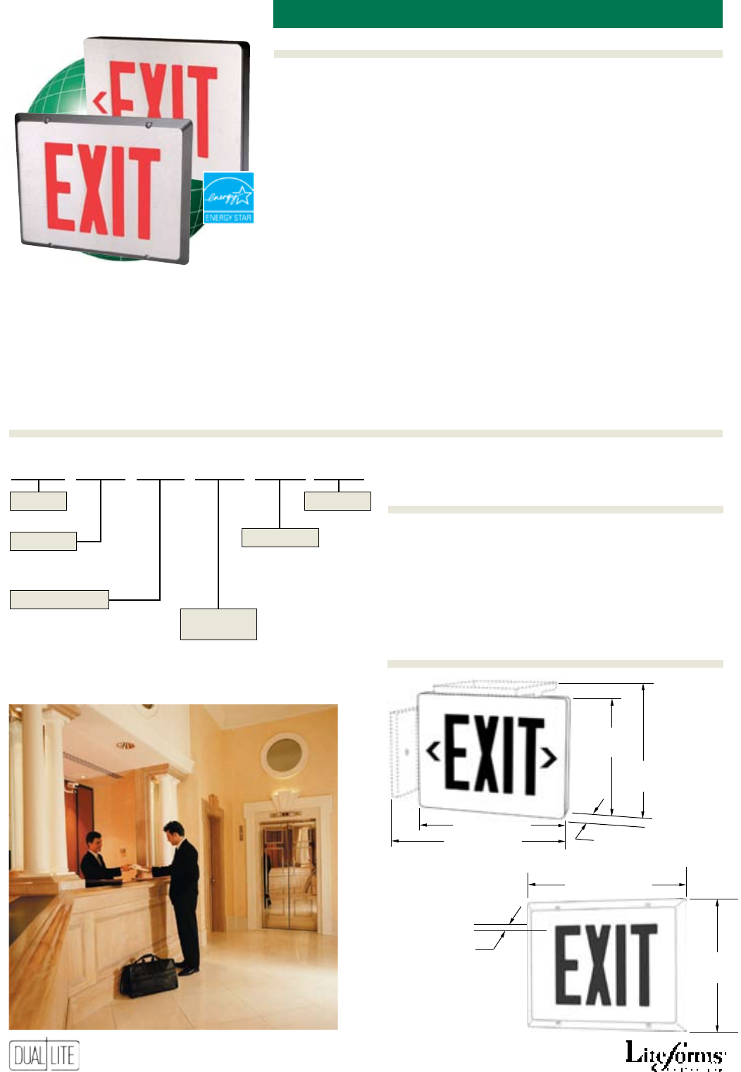
48
Features
Options (Add suffix to model)Accessories (order sepArAtely)
Ordering Information
master/remote Diecast LeD exit signs
15
/8”
(4.14 cm)
91/8”
(23 cm)
10”
(25.5 cm)
113
/4” (30 cm)
125/8” (32 cm)
95/8”
(24.4 cm)
123
/8” (31.4 cm)
5/8”
(1.6 cm)
Master
Signs
Remote Signs
LIFETIME WARRANTY ON
ALL SPECTRON MODELS
SempraMR
All Models
• High-strength, low-prole cast
aluminum housing
• Supplied as 2-sign,
Master/Remote sets
• 5-minute installation
• Long-life LED lamps
• Bright, even illumination
• Red or green letters
• Single and double face models
• White, black and black or white
with brushed face nishes
• Push-in wiring connectors
• Universal end/ceiling/wall mount
• Break-out, chevron arrows
• 120/277VAC, 60 Hz operation
Sempra cast-aluminum emergency exit signs with the
Spectron self-testing/self-diagnostic electronics system
are guaranteed by Dual-Lite under normal and proper
use, against defects in material and workmanship
for the life of the product. The warranty covers all
electronics, LED light strip and unit battery.
SEMR S R W E -FAP
S - Single
D - Double
Blank - AC Only
E - Emergency
Series
Faces
Letter Color
Operation
Housing
Finish
R - Red
G - Green
W - White
B - Black
WN - White with brushed face
BN - Black with brushed face
Options
Ordering Information
Dimensions
Lifetime Warranty
Master Signs
• Solid-state charger with low
voltage disconnect
• Maintenance-free NiCad battery
• 90 minute emergency operation
• Test switch and AC-On indicator
• Available with Spectron® self-
testing/self-diagnostic electronics
with time-delay relay
(TDR) standard
• Lifetime warranty on LED strip,
electronics and battery with
Spectron® self-testing/self-
diagnostic models
• Temperature range: 20°C to 30°C
(68°F to 86°F)
• UL 924 Listed
Remote Signs
• Surface mounts to standard
electrical boxes
• Connects to Master sign using
conventional wiring methods
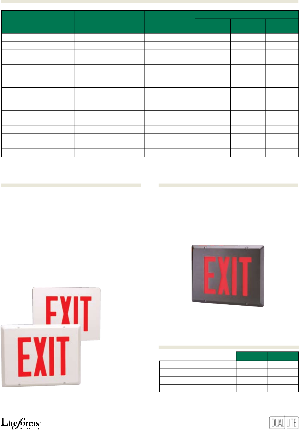
49
Beveled, low-profile design
on Remote signs meet ADA
requirements and UL Listing
requirements for floor
proximity use with -VTR option
SempraMR
I
Spectron self-testing/self-diagnostic electronics
-DC Remote DC operation (1)(4)(5)
-2C 2-circuit operation (1)(5)
-FAP Fire alarm panel interface (3)(5)
-FM Flasher module (2)(5)
-AF Audible/Flasher module (2)(5)
-24K 220/240VAC, 60 Hz. operation
-VTR Vandal/tamper resistant option (6)
(1) For use with AC models only.
(2) For use with emergency models only.
(3) Operates with 24-volt AC or DC fire alarm panels.
(4) For emergency illumination of sign from remote 6-24 VDC power sources.
(5) -DC, -2C, -FAP, -FM, -AF options may not be specified together.
(6) Provides polycarbonate face shield and tamper-proof screws. Meets UL listing
requirements for floor proximity use.
PMCW Pendant mounting kit (white) (a)
PMCB Pendant mounting kit (black) (a)
WGLX Wire guard (Wall mount) (a)
WG-MLT Wire guard (Wall mount) (a)
WGLXC Wire guard (Ceiling mount) (a)
WGLXE Wire guard (End mount) (a)
(a) For use with Master exit signs only.
AC emergenCy numBer Colors
model model of exit stenCil
numBers numBers fACes letters Housing fACe(s)
SEMRSRW SEMRSRWE Single Red White White
SEMRSGW SEMRSGWE Single Green White White
SEMRSRWN SEMRSRWNE Single Red White Brushed
SEMRSGWN SEMRSGWNE Single Green White Brushed
SEMRSRB SEMRSRBE Single Red Black Black
SEMRSGB SEMRSGBE Single Green Black Black
SEMRSRBN SEMRSRBNE Single Red Black Brushed
SEMRSGBN SEMRSGBNE Single Green Black Brushed
SEMRDRW SEMRDRWE Double Red White White
SEMRDGW SEMRDGWE Double Green White White
SEMRDRWN SEMRDRWNE Double Red White Brushed
SEMRDGWN SEMRDGWNE Double Green White Brushed
SEMRDRB SEMRDRBE Double Red Black Black
SEMRDGB SEMRDGBE Double Green Black Black
SEMRDRBN SEMRDRBNE Double Red Black Brushed
SEMRDGBN SEMRDGBNE Double Green Black Brushed
Power Consumption
Options (Add suffix to model)Accessories (order sepArAtely)
Product Selector Guide
Sempra MR signs equipped with -VTR
vandal/tamper resistant option shield
and hardware.
120VAC 277VAC
Red AC Only Models: 2.6 watts 2.6 watts
Green AC Only Models: 2.1 watts 2.1 watts
Red Emergency Models: 3.8 watts 3.8 watts
Green Emergency Models: 3.5 watts 3.5 watts
*Wattage figures include LED lamps, transformer and electronics power
requirements. LED lamp assemblies (red or green) consume less than 1 watt.
Power factor, average: .8 (lagging)
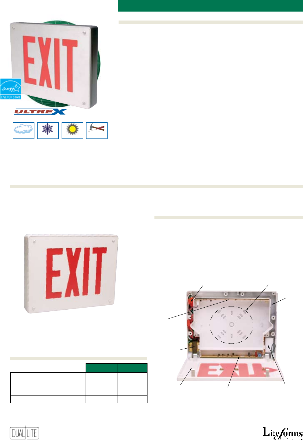
50
Features
Options (Add suffix to model)Accessories (order sepArAtely)
Ordering Information
severe conDitions Diecast LeD exit signs
All Models
• High-strength cast aluminum
• Low-prole architectural styling
• 5-minute installation
• Polycarbonate face shield
provides additional protection
against vandalism
• Tamper-resistent screws prevent
entry by unauthorized personnel
• Long-life LED lamps
• Bright, even illumination
• Red and green letters
• Single and double face models
• White, black and black or white
with brushed face nishes
• Push-in wiring connectors
• Universal end/ceiling/wall mount
• Break-out, chevron arrows and
mounting KOs
• UL Damp Location listed
• 120/277VAC, 60 Hz operation
Emergency Models
• Solid-state charger with low
voltage disconnect
• Maintenance-free NiCad battery
• 90 minute emergency operation
• Test switch and AC-On indicator
• Available with Spectron® self-
testing/self-diagnostic electronics
with time-delay relay
(TDR) standard
• Lifetime warranty on LED strip,
electronics and battery with
Spectron® self-testing/self-
diagnostic models
• Temperature ranges:
AC models: -20°C to 50°C
(-4°F to 122°F)
Emergency models: 0°C to 40°C
(32°F to 104°F)
Emergency models
with -XTR option: -20°C to 50°C
(-4°F to 122°F)
• UL 924 Listed
Push-in quick-connect
AC terminals
Isolated,
grounded
120/277VAC
transformer
Charger/transfer module
Universal wall mounting
KO pattern
Wiring
channel
Break-out
chevron-style
directional
indicators
Sealed
nickel-cadmium
battery
LED
illumination
strip
An
Severe Conditions Product Line
Damp Cold Hot
Vandal-
Tampering
LIFETIME WARRANTY ON
ALL SPECTRON MODELS
Sempra SC cast-aluminum emergency exit signs with the
Spectron self-testing/self-diagnostic electronics system are
guaranteed by Dual-Lite under normal and proper use,
against defects in material and workmanship for the life of
the product. The warranty covers all electronics, LED light
strip and unit battery.
See Product Selector Guide for available models
Polycarbonate face shield provided
standard on all Sempra SC models
SempraSC
Ordering Information
Power Consumption
Lifetime Warranty
120VAC 277VAC
Red AC Only Models: 2.6 watts 2.6 watts
Green AC Only Models: 2.1 watts 2.1 watts
Red Emergency Models: 3.8 watts 3.8 watts
Green Emergency Models: 3.5 watts 3.5 watts
*Wattage figures include LED lamps, transformer and electronics power
requirements. LED lamp assemblies (red or green) consume less than 1 watt.
Power factor, average: .8 (lagging)
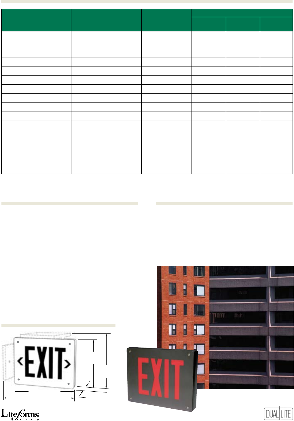
51
SempraSC
Options (Add suffix to model)
Dimensions
Accessories (order sepArAtely)
15
/8” (4.14 cm)
91/8”
(23 cm)
10”
(25.5 cm)
113/4” (30 cm)
125/8” (32 cm)
I
Spectron self-testing/self-diagnostic electronics
-DC Remote DC operation (1)(4)(5)
-2C 2-circuit operation (1)(5)
-FAP Fire alarm panel interface (3)(5)
-FM Flasher module (2)(5)
-AF Audible/Flasher module (2)(5)
-24K 220/240VAC, 60 Hz. operation
-XTR Extreme temperature operation (2)(6)
(1) For use with AC models only.
(2) For use with emergency models only.
(3) Operates with 24-volt AC or DC fire alarm panels.
(4) For emergency illumination of sign from remote 6-24 VDC power sources.
(5) -DC, -2C, -FAP, -FM, -AF options may not be specified together.
(6) For use with Sempra SC emergency models only (Spectron models excluded).
PMCW 121
/2” Pendant mounting kit (white)
PMCB 121
/2” Pendant mounting kit (black)
WGLX Wire guard (Wall mount)
WG-MLT
Wire guard (Wall mount)
WGLXC Wire guard (Ceiling mount)
WGLXE Wire guard (End mount)
Product Selector Guide
AC emergenCy numBer Colors
model model of exit stenCil
numBers numBers fACes letters Housing fACe(s)
SCSRW SCSRWE Single Red White White
SCSGW SCSGWE Single Green White White
SCSRWN SCSRWNE Single Red White Brushed
SCSGWN SCSGWNE Single Green White Brushed
SCSRB SCSRBE Single Red Black Black
SCSGB SCSGBE Single Green Black Black
SCSRBN SCSRBNE Single Red Black Brushed
SCSGBN SCSGBNE Single Green Black Brushed
SCDRW SCDRWE Double Red White White
SCDGW SCDGWE Double Green White White
SCDRWN SCDRWNE Double Red White Brushed
SCDGWN SCDGWNE Double Green White Brushed
SCDRB SCDRBE Double Red Black Black
SCDGB SCDGBE Double Green Black Black
SCDRBN SCDRBNE Double Red Black Brushed
SCDGBN SCDGBNE Double Green Black Brushed
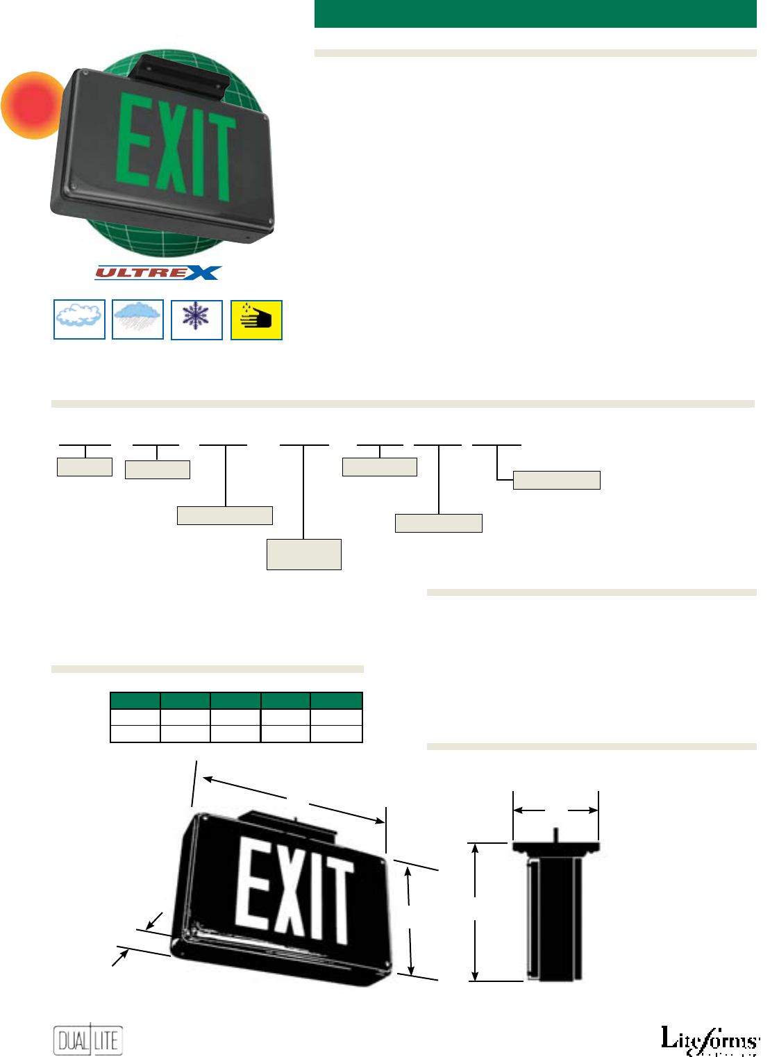
52
Features
Options (Add suffix to model)Accessories (order sepArAtely)
Ordering Information
wet Location environmentaL LeD exit sign
An
Severe Conditions Product Line
Damp Cold*
*With Heater
Option
Wet Corrosive
NEW
Emergency Models
• Completely self-contained
• Fully automatic, environmentally
coated charger
• Maintenance-free NiCad battery
• Low voltage disconnect
• Test switch and AC-On indicator
• 90 minute operation
• Optional 120 minute operation
• Temperature range: 0°C to 45°C
(32°F to 114°F)
• Temperature range with heater
option:
-40°C to 45°C
(-40°F to 114°F)
• Vandal-resistant housing with
tamper-resistant screws
• Listed to UL 924
SCWL
S R
B E U -AA
Series
Letter Color
Operation
Options
R - Red
G - Green
PMSWL 12” Pendant mounting kit
Mounting
U - Universal
S - Single
D - Double
Faces
Blank - AC Only
E - Emergency
-AA Audible alarm (1)(2)
-FM Flasher module (1)(2)
-AR120 120 minute emergency operation (2)
-HTR1 Internal heater - 120VAC (1)(2)
-HTR2 Internal heater - 277VAC (1)(2)
(1)
-AA, -FM, -HTR1, and -HTR2 options may not be specified together.
(2) For use with emergency models only.
Exit Housing
Color
B - Black
W - White
Ordering Information
Dimensions
Options (Add suffix to model)
Accessories (order sepArAtely)
SempraSC
WetLocation
Availability To Be Announced
All Models
• Designed for wet location and
high abuse applications
• Full neoprene gasket
• Durable cast aluminum housing in
black nish
• Polycarbonate face shields secured
with stainless hardware
• Universal ceiling, end or wall
surface mounting
• 120/277VAC operation standard
• Bright, even illumination
• Red and green letter models
• Snap-out chevron arrows
• High output, long-life LED lamps
• Temperature range: 0°C to 45°C
(32°F to 114°F)
A
B
D
EC
C D E
9” 9” 14”
22.9 cm 35.6 cm
A B C
4” 10” 6.2”
10.2 cm 25.4 cm 15.8 cm
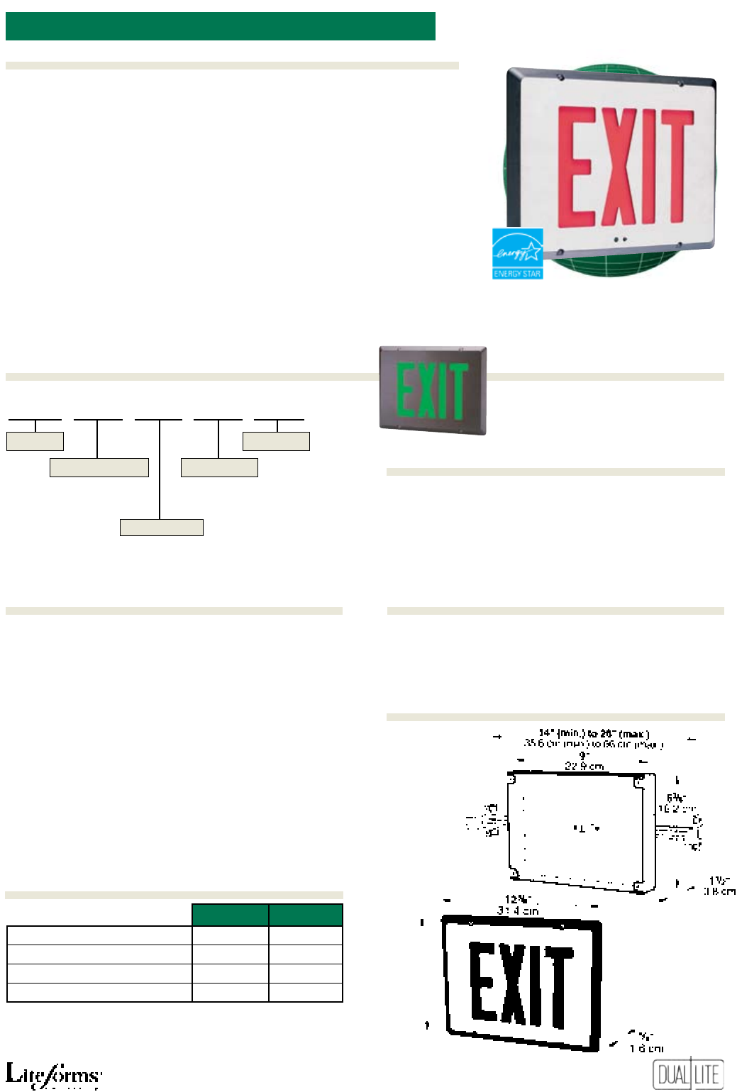
53
Features
Ordering Information
Options (Add suffix to model)Accessories (order sepArAtely)
recesseD cast aLUminUm LeD exit sign
All Models
• High-strength cast aluminum
• Compact, low-prole style
• Fast, easy installation
• Long-life LED lamps
• Bright, even illumination
• Red and green letters
• Rigid, high impact acrylic letter
panel
• White, black and black or white
with brushed face nishes
• Plug-together wiring connectors
• Break-out, chevron arrows and
mounting KOs
• 120/277VAC, 60 Hz operation
Emergency Models
• Solid-state charger with low
voltage disconnect
• Maintenance-free NiCad battery
• 2-hour emergency operation
• Test switch and AC-On indicator
• Available with Spectron® self-
testing/self-diagnostic electronics
with time-delay relay
(TDR) standard
• Lifetime warranty on LED strip,
electronics and battery with
Spectron® self-testing/self-
diagnostic models
• Temperature range: 20°C to 30°C
(68°F to 86°F)
• UL 924 Listed
LIFETIME WARRANTY ON
ALL SPECTRON MODELS
Sempra cast-aluminum emergency exit signs with the
Spectron self-testing/self-diagnostic electronics system
are guaranteed by Dual-Lite under normal and proper
use, against defects in material and workmanship
for the life of the product. The warranty covers all
electronics, LED light strip and unit battery.
I
Spectron self-testing/self-diagnostic electronics
-DC Remote DC operation (1)(4)(5)
-2C 2-circuit operation (1)(5)
-FAP Fire alarm panel interface (3)(5)
-FM Flasher module (2)(5)
-AF Audible/Flasher module (2)(5)
-VTR Vandal/tamper resistant option (6)
-LRBB Sign assembly less rough-in back box (7)
(1) For use with AC models only.
(2) For use with emergency models only.
(3) Operates with 24-volt AC or DC fire alarm panels.
(4) For emergency illumination of sign from remote 6-24 VDC power sources.
(5) -DC, -2C, -FAP, -FM, -AF options may not be specified together.
(6) Provides polycarbonate face shield and tamper-resistant screws. Meets UL
listing requirements for floor proximity use.
(7) Allows ordering of rough-in back box separately for installation prior to sign
shipment. Add “-LRBB” suffix to exit model number if RBB accessory kit is to
be ordered separately.
RBB Rough-in back box kit
WGLX Wire guard (Wall mount)
WG-MLT
Wire guard (Wall mount)
Rough-In
Back Box
SERS R WN E -AF
Blank - AC Only
E - Emergency
Series
Letter Color Operation
Housing Finish
R - Red
G - Green
W - White
B - Black
WN - White with brushed face
BN - Black with brushed face
Options
95/8”
(24.4 cm)
Power Consumption
Lifetime Warranty
Dimensions
Ordering Information
SempraSERS
wet Location environmentaL LeD exit sign
120VAC 277VAC
Red AC Only Models: 2.6 watts 2.6 watts
Green AC Only Models: 2.1 watts 2.1 watts
Red Emergency Models: 3.8 watts 3.8 watts
Green Emergency Models: 3.5 watts 3.5 watts
*Wattage figures include LED lamps, transformer and electronics power
requirements. LED lamp assemblies (red or green) consume less than 1 watt.
Power factor, average: .8 (lagging)
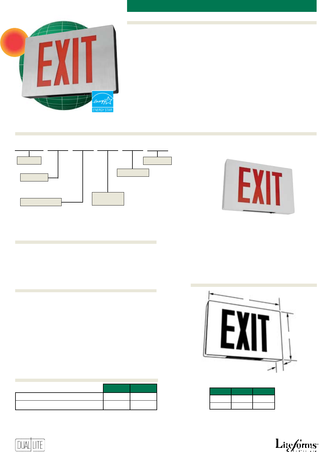
54
Features
Options (Add suffix to model)Accessories (order sepArAtely)
Ordering Information
AC Models
• Designed to meet New York City
specications
• All diecast aluminum construction
• White, black and black with
brushed face nishes
• Break-out directional chevrons
• Single and double face models
with eight inch letters
• Wall/ceiling/end mounting
• Dual voltage – 120/277VAC
• Bright and even illumination
• Long-life LED lamps
Emergency Models
• Long life NiCad battery
• 90 minute emergency operation
• Test switch and AC-On indicator
• Environmentally coated, fully
automatic charger
• Temperature range: 0°C to 45°C
(32°F to 113°F)
• Listed to UL 924
NEW
PMNYW Pendant mounting kit (white)
PMNYB Pendant mounting kit (black)
WGTW Wire guard (Wall mount)
WGTCE Wire guard (Ceiling mount)
new York citY cast aLUminUm LeD exit
NYDC
A B C
11” 161/4” 25/8”
27.9 cm 41.3 cm 6.7 cm
C
* Add 1“ (2.5 cm) for mounting
canopy on ceiling or end mounted models
B*
A*
Available in white, black and
black with brushed face finishes
120VAC 277VAC
AC Only Models 2.4W 2.4W
Emergency Models 3.4W 3.5W
* Wattage figures include LED lamps, transformers and electronics
power requirements.
-FM Flasher module (1)(2)
-AA Audible alarm module (1)(2)
(1) For use with emergency models only.
(2) -FM and -AA options may not be specified together.
NYDC S R B A -FM
S - Single
D - Double
A - AC Only
E - Emergency
Series
Faces
Letter Color
Operation
Housing
Finish
R - Red W - White
B - Black
BN - Black with brushed face
Options
Power Consumption
Options (Add suffix to model)
Dimensions
Accessories (order sepArAtely)
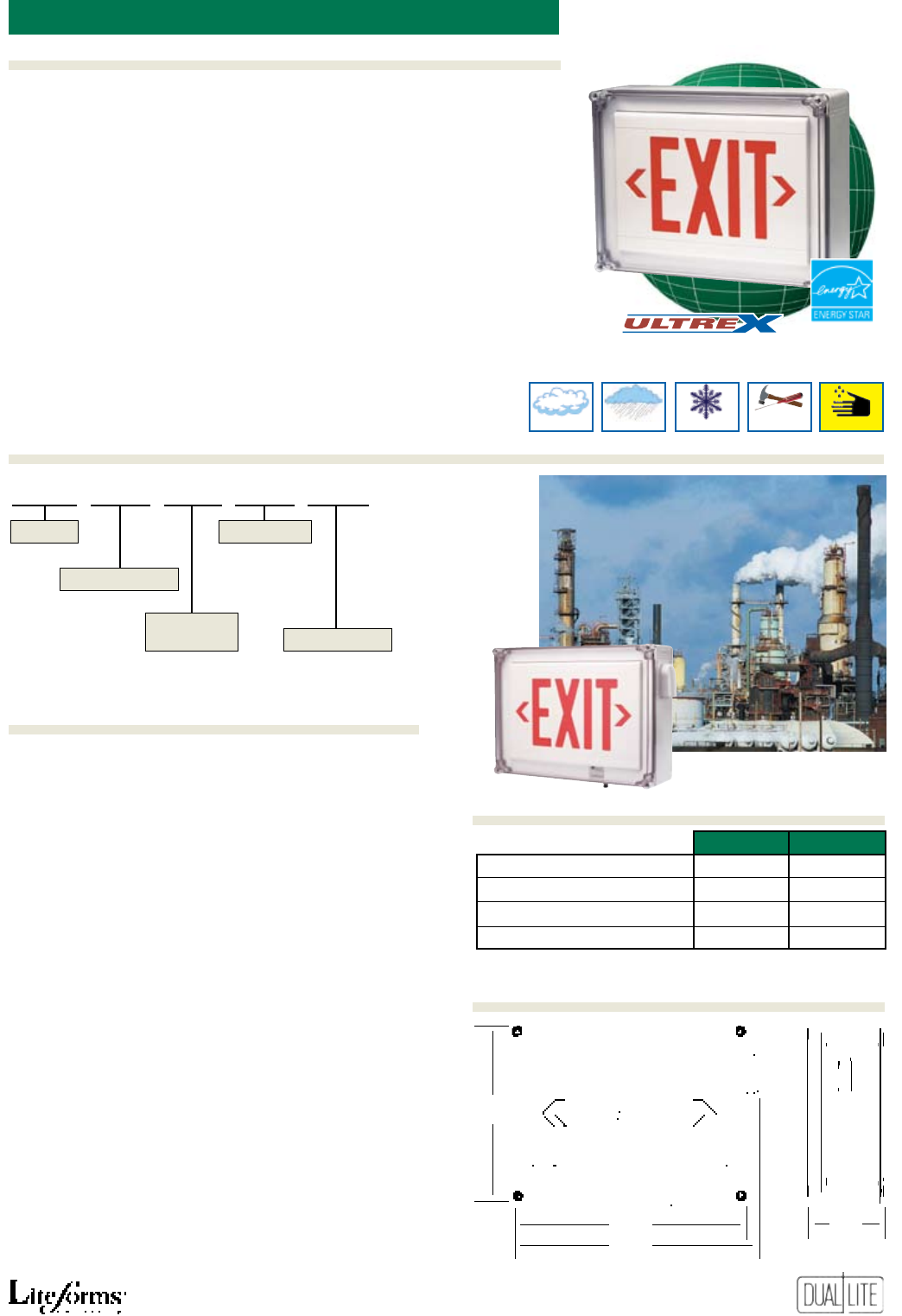
55
Features
Ordering Information
Options (Add suffix to model)Accessories (order sepArAtely)
wet Location LeD exit signs LN4X
I
Spectron self-testing/self-diagnostic electronics(1)(2)
-XTR Extreme temperature operation (2)(8)(9)
-2C 2-circuit operation (3)(7)
-FAP Fire alarm panel interface (4)(6)(7)
-XTRFAP Extreme temperature operation re alarm
panel interface (2)(4)(6)(7)(8)(9)
-FM Flasher module (2)(6)
-DC Remote DC operation (3)(5)(6)
-TR Tamper-proof cover screws (includes tool)
(1) Add “I” Spectron self-testing/self-diagnostic option suffix immediately after base
model number. Example: LN4XRWEI
(2) For specification with emergency models only.
(3) For use with AC models only.
(4) Operates with 24-volt AC or DC fire alarm panels.
(5) For emergency illumination of sign from remote 6-24 VDC power sources.
(6) -FAP, -XTRFAP, -FM or -DC options may not be specified together.
(7) -2C and -XTRFAP or -FAP options may be specified together.
(8) Not for use with self-testing Spectron models.
(9) Provides an operating temperature range of -20°C to 50°C (-4°F to 122°F)
120VAC 277VAC
Red AC Only Models 2.6 watts 2.6 watts
Green AC Only Models 2.1 watts 2.1 watts
Red Emergency Models 3.8 watts 3.8 watts
Green Emergency Models 3.5 watts 3.0 watts
Power factor, average: .8 (lagging)
An
Severe Conditions Product Line
LN4X
R W E -FAP
Blank - AC Only
E - Emergency
Series
Letter Color
Operation
Exit Face
Color Options
R - Red
G - Green
W - White
Emergency Models
• Suitable for use in damp, wet and
corrosive locations
• Completely self-contained
• Fully automatic, solid-state charger
• Maintenance-free NiCad battery
• Low voltage disconnect
• Test switch and AC-On light
• Available with Spectron® self-
testing/self-diagnostic electronics
with time-delay relay
(TDR) standard
• 120 minute operation
• Temperature range: 10°C to 40°C
(50°F to 104°F)
• UL 924 Listed
Damp
Vandal &
Tampering
Cold
Wet Corrosive
➤
➤➤
➤
➤
➤
➤
➤
113/4”
(29.8 cm)
153/4”
(40 cm)
165/8”
(42.2 cm)
51/4”
(13.3 cm)
AC Models
• UL type 4X enclosure for
indoor/outdoor use
• Easily installed to wall surfaces
• Suitable for use in damp, wet,
hose-down and corrosive locations
• Polycarbonate housing
• 120/277VAC operation standard
• Bright, even illumination
• Red and green letter models
• Snap-in chevron arrows
• Long-life LED lamps
• Temperature range: 0°C to 40°C
(32°F to 104°F)
Dimensions
Power Consumption
Ordering Information
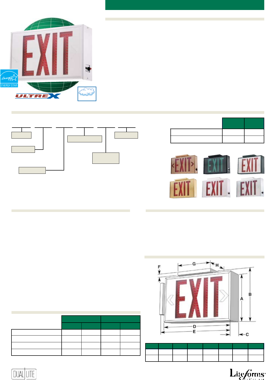
56
Features
Options (Add suffix to model)Accessories (order sepArAtely)
Ordering Information
Freedom
LED
All Models
• Vinyl-clad aluminum housing
• Polycarbonate face shield
standard
• Easy to install
• Long-life LED lamps
• Red and green letters
• Single and double face models
• Six decorator nishes offered
• End, ceiling or wall mount
• Snap-out, chevron arrows
• Damp location listed
• 120/277VAC, 60 Hz operation
aLUminUm LeD exit signs
Emergency Models
• Solid-state charger with low
voltage disconnect
• 6-volt, maintenance-free battery
• User-selectable constant on or
ashing emergency illumination
• Up to 12 hour operation
• Test switch, AC-On and charge
indicator lights
• Temperature range: 10°C to 40°C
(50°F to 104°F)
• Damp location listed
• UL 924 Listed
VRS3 Vandal resistant shield
WGTCE Wire guard (Ceiling/End mount)
WGTW Wire guard (Wall mount)
-DC Remote DC operation(2)(3)(5)
-TR Tamper resistent screws
-2C 2-circuit operation(2)(3)(6)
-FAP Fire alarm panel interface (asher)(4)(5)(6)
-BPR Beeper module(1)(6)
(1) For specification with emergency models only.
(2) For use with AC models only.
(3) For emergency illumination of sign from remote 12 through 48 VDC
power sources.
(4) Operates with 24-volt AC or DC fire alarm panels.
(5) -FAP, and -DC options may not be specified together.
(6) -2C, -BPR and -FAP options may be specified together.
A B C D E F G H
71/2” 8.0” 31/8” 121/8” 12 5/8” 1/2” 6.0” 41/4”
19 cm 20 cm 7.9 cm 30.8 cm 32.1 cm 1.3 cm 15.2 cm 10.8 cm
single fACe models
douBle fACe models
120VAC 277VAC 120VAC 277VAC
Red AC Only Models 4.47 watts 4.47 watts 6.80 watts 6.80 watts
Green AC Only Models 4.68 watts 4.64 watts 6.70 watts 6.70 watts
Red Emergency Models 4.99 watts 4.99 watts 7.27 watts 7.22 watts
Green Emergency Models 4.96 watts 4.93 watts 7.65 watts 7.67 watts
Power factor, average: .8 (lagging)
LED 2 EM R WW -TR
1 - Single Face
2 - Double Face
AC - AC Only
EM - Emergency
Series
Faces
Letter Color
Operation
Housing
Finish
R - Red
G - Green
WW - White
WA - White with Brushed Aluminum Face
BB - Black
BA - Black with Brushed Aluminum Face
TT - Brass
ZZ - Antique Brass
Options
Damp
An
Severe Conditions Product Line
Discharge Times single douBle
fACe fACe
Flashing Mode 12 Hours 8 Hours
Constant On Mode 6 Hours 4 Hours
Antique Brass Black Black/Brushed Face
Brass White White/Brushed Face
Available Colors
Power Consumption
Dimensions
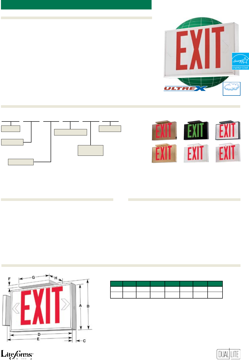
57
Features
Ordering Information
Options (Add suffix to model)Accessories (order sepArAtely)
LEDS
Low-ProfiLe aLUminUm LeD exit signs
-TR Tamper resistent screws VRS3 Vandal resistant shield
WGLX Wire guard (Wall mount)
WGLXC Wire guard (Ceiling mount)
WGLXE Wire guard (End mount)
LEDS U AC R BA -TR
1 - Single Face
2 - Double Face
U - Universal Single/Double Face
AC - AC Only
EM - Emergency
Series
Faces
Letter Color
Operation
Housing
Finish
R - Red
G - Green
WW - White
WA - White with Brushed Aluminum Face
BB - Black
BA - Black with Brushed Aluminum Face
TT - Brass
ZZ - Antique Brass
Options
A B C D E F G H
71/2” 8.0” 15/8” 121/8” 125/8” 1/2” 6.0” 41/4”
19 cm 20 cm 4.1 cm 30.8 cm 32.1 cm 1.3 cm 15.2 cm 10.8 cm
Damp
An
Severe Conditions Product Line
All Models
• Vinyl-clad aluminum housing
• Compact, low-prole style
• Easy to install
• Long-life LED lamps
• Red and green letters
• Single, double and universal
single/double face models
• Six decorator nishes offered
• End, ceiling or wall mount
• Snap-out, chevron arrows
• Damp location listed
• 120/277VAC, 60 Hz operation
Emergency Models
• Solid-state charger with low
voltage disconnect
• Maintenance-free Ni-Cad battery
• 90-minute emergency operation
• Test switch and AC-On indicator
light
• Temperature range: 10°C to 40°C
(50°F to 104°F)
• Damp location listed
• UL 924 Listed
Antique Brass Black Black/Brushed Face
Brass White White/Brushed Face
Available Colors
Dimensions
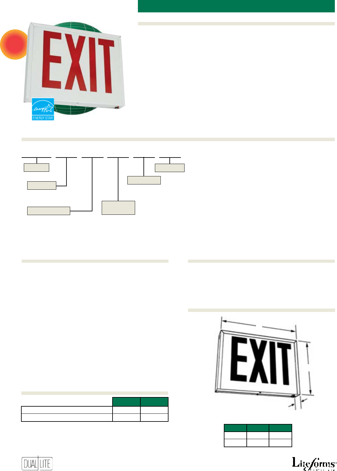
58
Features
Options (Add suffix to model)Accessories (order sepArAtely)
Ordering Information
NYX
new York citY LeD exit sign
NEW
AC Models
• Designed to meet New York City
specications
• 20 gauge metal enclosure
• White or black nish
• Break-out directional chevrons
• Universal single/double face
models with eight inch letters
• Wall/ceiling/end mounting
• Dual voltage – 120/277VAC
• Bright and even illumination
• Long-life LED lamps
Emergency Models
• Long life NiCad battery
• 90 minute emergency operation
• Test switch and AC-On indicator
• Environmentally coated, fully
automatic charger
• Temperature range: 0°C to 45°C
(32°F to 113°F)
• Listed to UL 924
NYX U R W E -FM
U - Universal single/double face A - AC Only
E - Emergency
Series
Faces
Letter Color
Operation
Housing
Finish
R - Red W - White
B - Black
Options
-FM Flasher module (1)(2)
-AA Audible alarm module (1)(2)
-TR Tamper resistant option (3)
(1) For use with emergency models only.
(2) -FM and -AA options may not be specified together.
(3) Provides two tamper-resistant locking screws.
PMNYW Pendant mounting kit (white)
PMNYB Pendant mounting kit (black)
WGTW Wire guard (Wall mount)
A*
B*
C
* Add 1“ (2.5 cm) for mounting
canopy on ceiling or end mounted models
A B C
101/2” 141/2” 23/8”
26.7 cm 36.8 cm 6.0 cm
120VAC 277VAC
AC Only Models 2.4W 2.4W
Emergency Models 3.4W 3.5W
* Wattage figures include LED lamps, transformers and electronics
power requirements.
Power Consumption
Dimensions
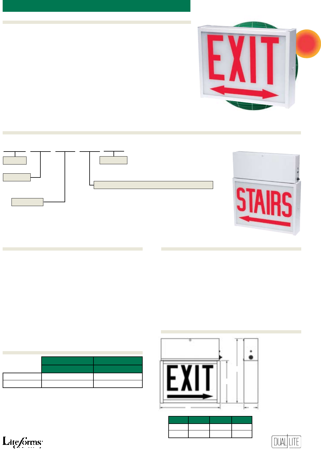
59
Features
Ordering Information
Options (Add suffix to model)Accessories (order sepArAtely)
CMX
chicago Low ProfiLe exit sign
-277V 277 VAC operation (1)
-DC6 6 VDC emergency socket and lamp (1)
-DC12 12 VDC emergency socket and lamp (1)
-B Black nish
-FL 7 watt uorescent AC lamps
-FAP Fire alarm panel interface (2)(3)(4)
-AF Audible asher alarm (3)(4)(5)
-PH Phosphorescent glass diffuser panel
(1) For use with AC models only.
(2) Operates with 24-volt AC or DC fire alarm panels.
(3) -FAP and -AF options may not be specified together.
(4) -FAP and -AF options not available with fluorescent lamp models.
(5) -AF option for use with emergency models only.
All Models
• City of Chicago approved
• 22-gauge metal enclosure with
white or black nish
• Translucent glass diffuser
• Six-inch letters
• Full length, silkscreened
directional arrows
• Standard, incandescent AC lamps
(Fluorescent lamps optional)
• Standard 120 VAC (277 VAC
optional on AC models)
• Wall, end or ceiling mounting
• Downlighting aperture
Emergency Models
• Completely self-contained
emergency power pack
• 120-minute operation
• Fully automatic, solid-state charger
• Automatic, low-voltage
battery disconnect
• AC-On indicator and test switch
• Maintenance-free long-life lead-
acid battery
• Universal 120/277VAC operation
• UL Listed
NEW
CKW Canopy mounting kit (white)
CKB Canopy mounting kit (black)
PMKW Pendant mounting kit (white)
PMKB Pendant mounting kit (black)
WGMLT Wire guard (wall mount - AC models)
WGTW Wire guard (wall mount - emergency models)
WGTCE Wire guard (ceiling/end mount - AC and
emergency models)
VRS2 Vandal resistant shield (ts all models)
A
B
C
D
A B C D
123/4” 91/2” 141/2” 21/2”
32.4 cm 24.1 cm 36.8 cm 6.4 cm
City of Chicago Approval No. 9823
inCAndesCent models fluoresCent models
120/277VAC 120/277VAC
AC Only Exits 40 watts 18 watts
Emergency Exits 50 watts 28 watts
CMX S E 6 -AF
S - Single Face
D - Double Face
Blank - AC Only
E - Emergency
Series
Faces
Exit Legend
Operation
Options
Single face models
3 - “EXIT” (no arrows)
6 - “EXIT” (right arrow)
9 - “EXIT” (left arrow)
12 - “EXIT” (double arrow)
2 - “STAIRS” (no arrows)
5 - “STAIRS” (right arrow)
8 - “STAIRS” (left arrow)
11 - “STAIRS” (double arrow)
Double face models
18 - “EXIT” (no arrows)
21 - “EXIT” (right/left arrow)
24 - “EXIT” (double arrow)
17 - “STAIRS” (no arrows)
20 - “STAIRS” (right/left arrow)
23 - “STAIRS” (double arrow)
Power Consumption
Dimensions
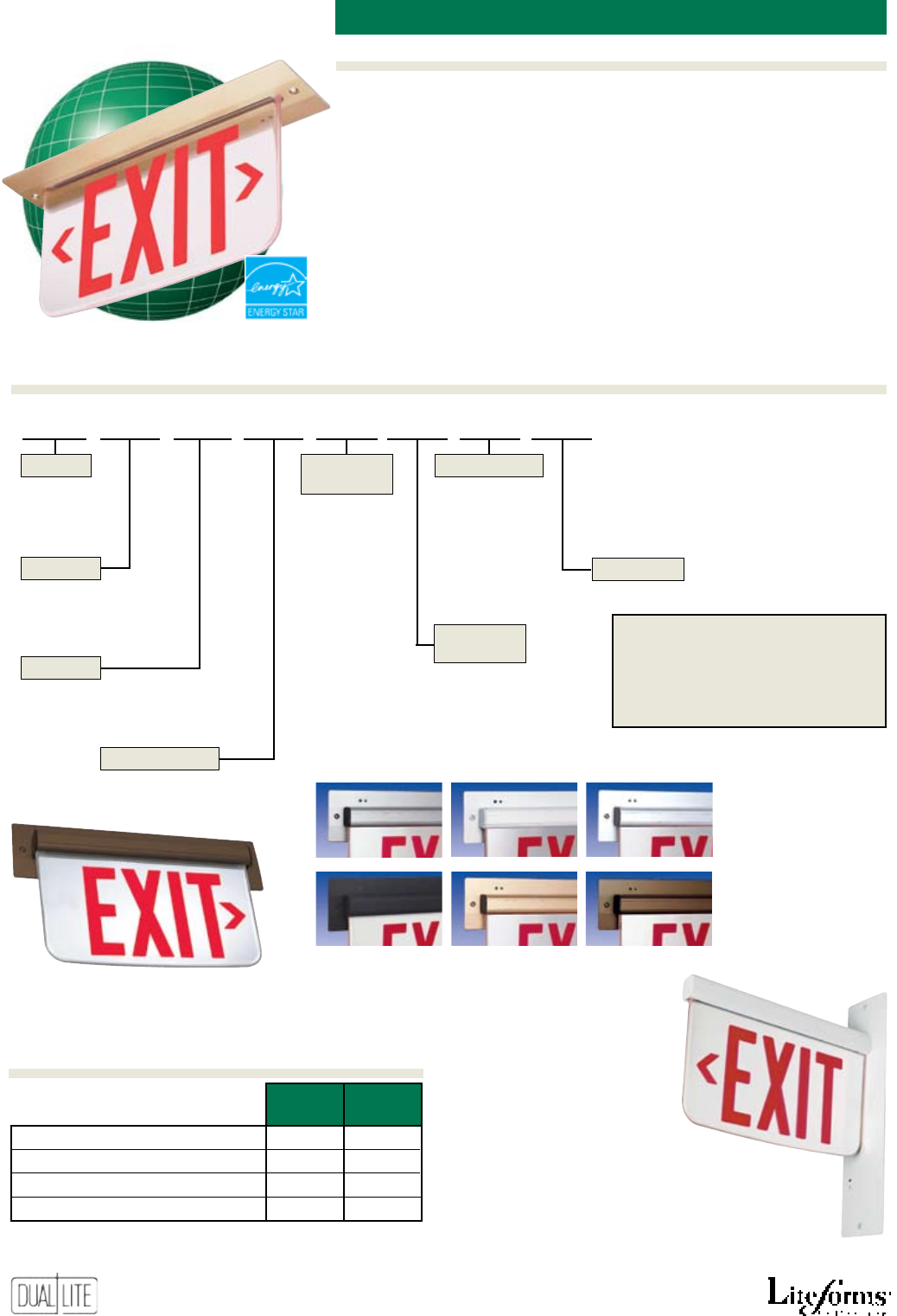
60
Features
Options (Add suffix to model)Accessories (order sepArAtely)
Ordering Information
LE recesseD moUnting eDge-Lit LeD exit signs
End mount model
Wall mount model
single douBle
fACe fACe
Red AC Only Models 2.2W 3.7W
Green AC Only Models 2.5W 4.4W
Red Emergency Models 3.3W 4.7W
Green Emergency Models 3.6W 5.2W
* Wattage figures include LED lamps, transformers and electronics
Satin Aluminum White Chrome
Black Satin Brass Dark Bronze
LE C D R C N E -FM
S - Single
D - Double*
* Not for use with wall mounted models
C - Ceiling mount
W - Wall mount
E - End mount
X - No arrows EXIT
R - Right arrow*
EXIT>
L - Left arrow* <EXIT
D - Double arrows
<EXIT>
C - L/R arrows**
<EXIT/EXIT>
* Not for use with double
face models. Use “C” L/R
arrow designator
** Double face models only.
Provides reversible right
or left arrow indicator
Series
Faces
Letter Color
Directional
Arrows
Trim/Housing
Finish
Operation
Options
R - Red
G - Green
A - AC only
E - Emergency
N - Satin Aluminum
W - White
C - Chrome
B - Black
S - Satin brass
Z - Dark Bronze
Mounting
LE - Recessed
mount
See “Options” section
Standard Plaque Backgrounds
Single face models = clear
Double face models = mirror
See “Options” for alternate
backgrounds.
Power Consumption
AC Models
• Ceiling, wall or end mounted
models for recessed installations
• Extruded aluminum construction
• Available in six color nishes
• Molded acrylic plaque
• Red and green letter models
• Clear, white or mirror
background
• Silkscreened chevron arrows
• Long life LED lamps
• Bright, even letter illumination
• Energy-saving operation
• Universal rough-in box
• Easy to install
• 120/277VAC, 60 Hz operation
Emergency Models
• Solid-state charger
• Maintenance-free NiCad battery
• Low voltage disconnect
• Test switch and AC-On light
• Available with Spectron® self-
testing/self-diagnostic electronics
with time-delay relay
(TDR) standard
• Temperature range: 20°C to 30°C
(68°F to 86°F)
• UL 924 Listed
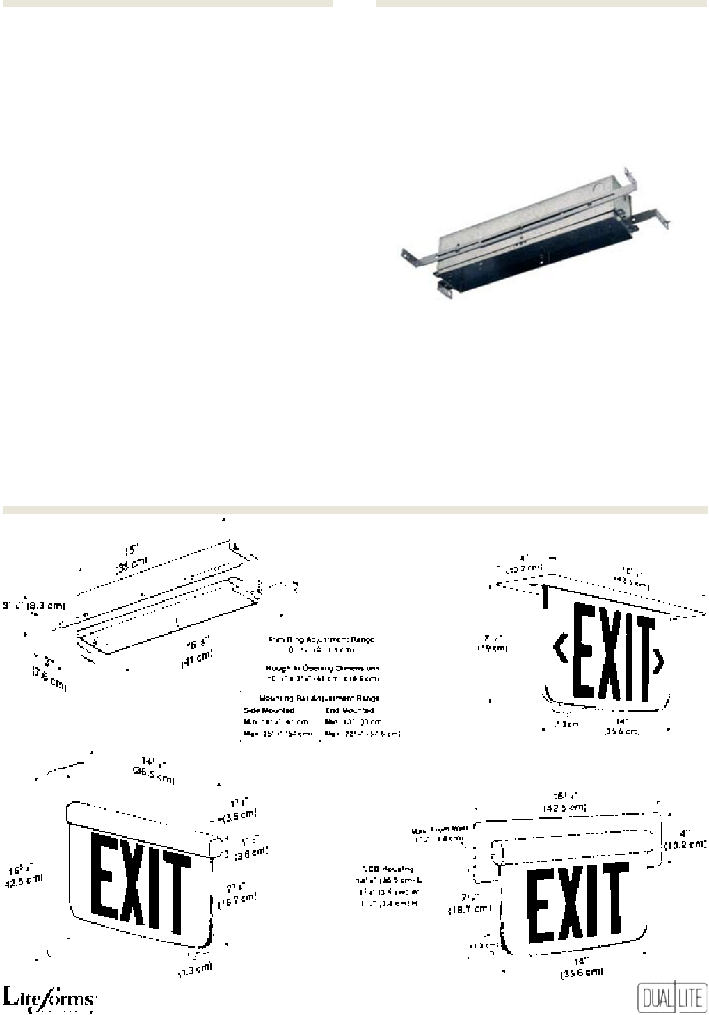
61
LE
Rough-In Kit
End Mount Application
Ceiling Mount Application
Wall Mount Application
Universal Rough-In Kit
Dimensions
Options (Add suffix to model)Accessories (order sepArAtely)
I
Spectron self-testing/self-diagnostic electronics
-XK Recessed mount exit sign less rough-in kit (1)
-W White plaque background
-M Mirror plaque background (2)
-8L 8 inch letter plaque (red letters only) (10)(11)
-2C 2-circuit operation (3)(8)
-FAP Fire alarm panel interface (5)(7)(8)
-FM Flasher module (4)(7)
-AF Audible/asher module (4)(7)
-DC Remote DC operation (3)(6)(7)
-24K 220/240VAC, 60 Hz operation (9)
(1) Allows ordering of rough-in kit separately for recessed mount (LE) models.
See “Accessories”.
(2) For use with single face models only. Standard on double face models.
(3) For use with AC models only.
(4) For specification with emergency models only.
(5) Operates with 24-volt AC or DC fire alarm panels.
(6) For emergency illumination of sign from remote 6-24 VDC power sources.
(7) -FAP, -FM, -AF or -DC options may not be specified together.
(8) -2C and -FAP options may be specified together.
(9) Rough-in kit may not be ordered separately on models specified with -24K
option.
(10) LE exit models with 8” plaques registered under NYC-BEC Calendar Number
42135 for use in New York City.
(11) Single face LE exit signs specified with the -8L option are supplied without
backgrounds. Double face models specified with the -8L option are supplied
with mirror backgrounds.
URK Universal rough-in kit (b)
URK2C Universal 2-circuit rough-in kit (a)(b)(c)
(a) For use with AC models only.
(b) Rough-in kit may not be ordered separately on models specified
with -24K option.
(c) Must be ordered in conjunction with -2C option on exit sign
To Order Rough-In Kit Separately
To order rough-in kit only for early installation, add
“-XK” option suffix to exit model number and order
“URK” or “URK2C” kit separately.
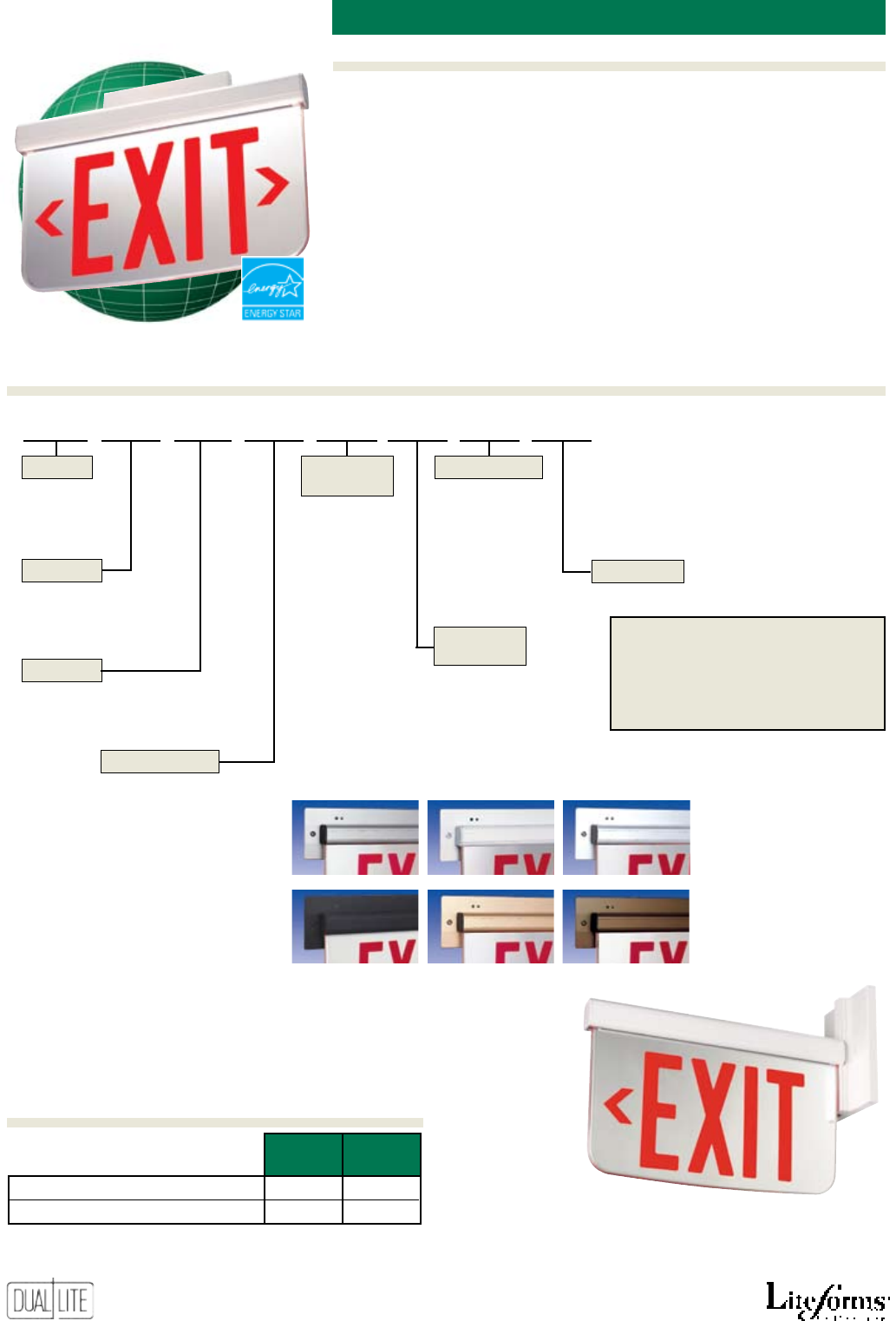
62
Features
Options (Add suffix to model)Accessories (order sepArAtely)
Ordering Information
LES sUrface moUnting ac eDge-Lit LeD exit signs
End mount model
single douBle
fACe fACe
Red AC Only Models 2.5W 4.0W
Green AC Only Models 2.6W 4.5W
* Wattage figures include LED lamps, transformers and electronics
power requirements.
LES C S R C N A -M
S - Single
D - Double*
* Not for use with wall mounted models
C - Ceiling mount
W - Wall mount
E - End mount
X - No arrows EXIT
R - Right arrow*
EXIT>
L - Left arrow* <EXIT
D - Double arrows
<EXIT>
C - L/R arrows**
<EXIT/EXIT>
* Not for use with double
face models. Use “C” L/R
arrow designator
** Double face models only.
Provides reversible right
or left arrow indicator
Series
Faces
Letter Color
Directional
Arrows
Trim/Housing
Finish
Operation
Options
R - Red
G - Green
A - AC only
N - Satin aluminum
W - White
C - Chrome
B - Black
S - Satin Brass
Z - Dark bronze
Mounting
LES - Surface
mount
See “Options” section
Standard Plaque Backgrounds
Single face models = clear
Double face models = mirror
See “Options” for alternate back-
grounds.
Satin Aluminum White Chrome
Black Satin Brass Dark Bronze
Power Consumption
AC Models
• Ceiling, wall or end mounted
models for surface installations
• Extruded aluminum construction
• Available in six color nishes
• Molded acrylic plaque
• Red and green letter models
• Clear, white or mirror
background
• Silkscreened chevron arrows
• Long life LED lamps
• Bright, even letter illumination
• Energy-saving operation
• Easy to install
• 120/277VAC, 60 Hz operation
• Temperature range: 20°C to 30°C
(68°F to 86°F)
• UL Listed
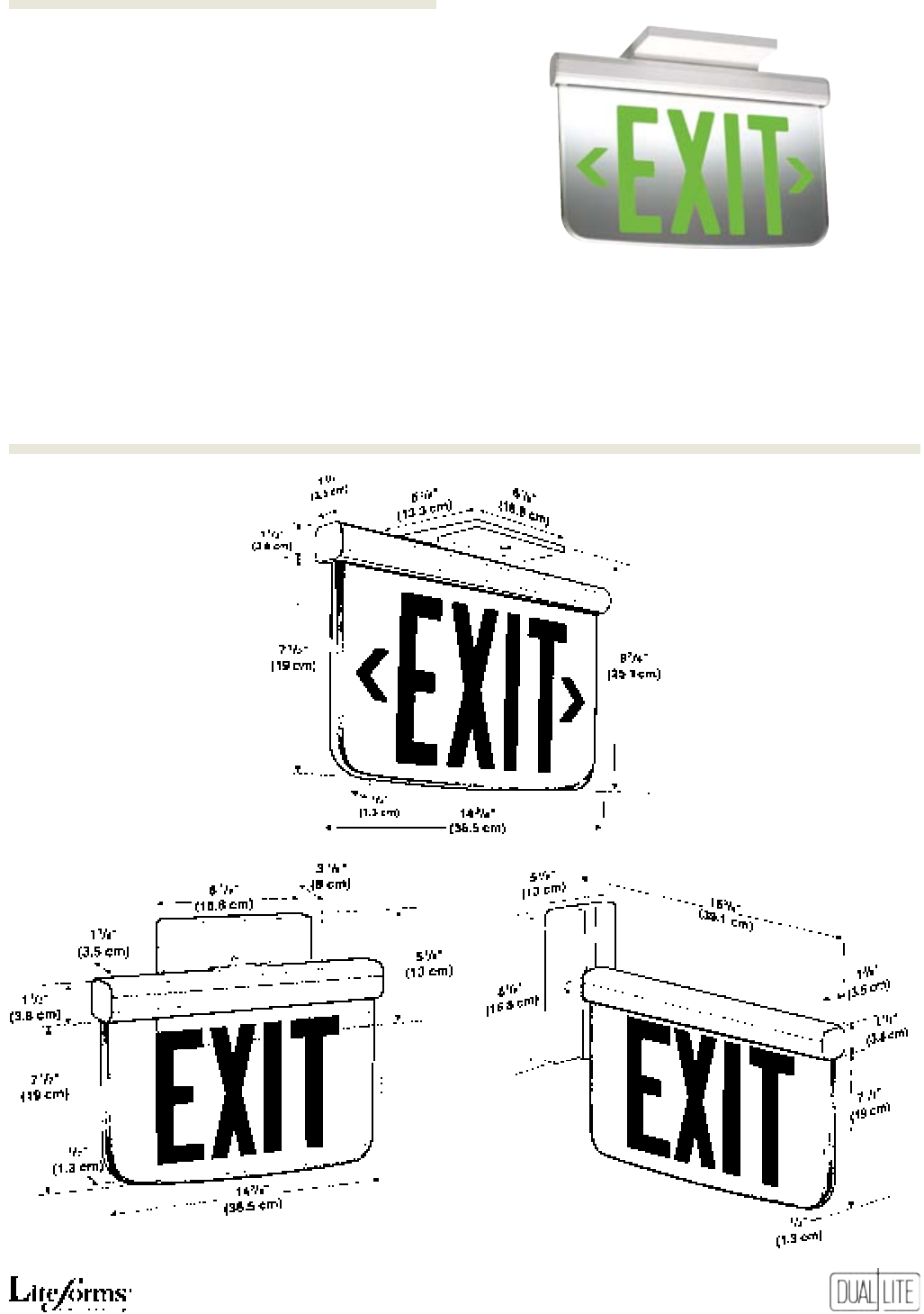
63
LES
End Mount Application
Ceiling Mount Applica-
tion
Wall Mount Application
Ceiling mount model
Dimensions
Options (Add suffix to model)
-W White plaque background
-M Mirror plaque background (1)
-8L 8 inch letter plaque (red letters only) (2)(3)
(1) For use with single face models only. Standard on double
face models.
(2) LES exit models with 8” plaques registered under NYC-BEC Calendar
Number 42135 for use in New York City.
(3) Single face LES exit signs specified with the -8L option are supplied
without backgrounds. Double face models specified with the -8L op-
tion are supplied with mirror backgrounds.
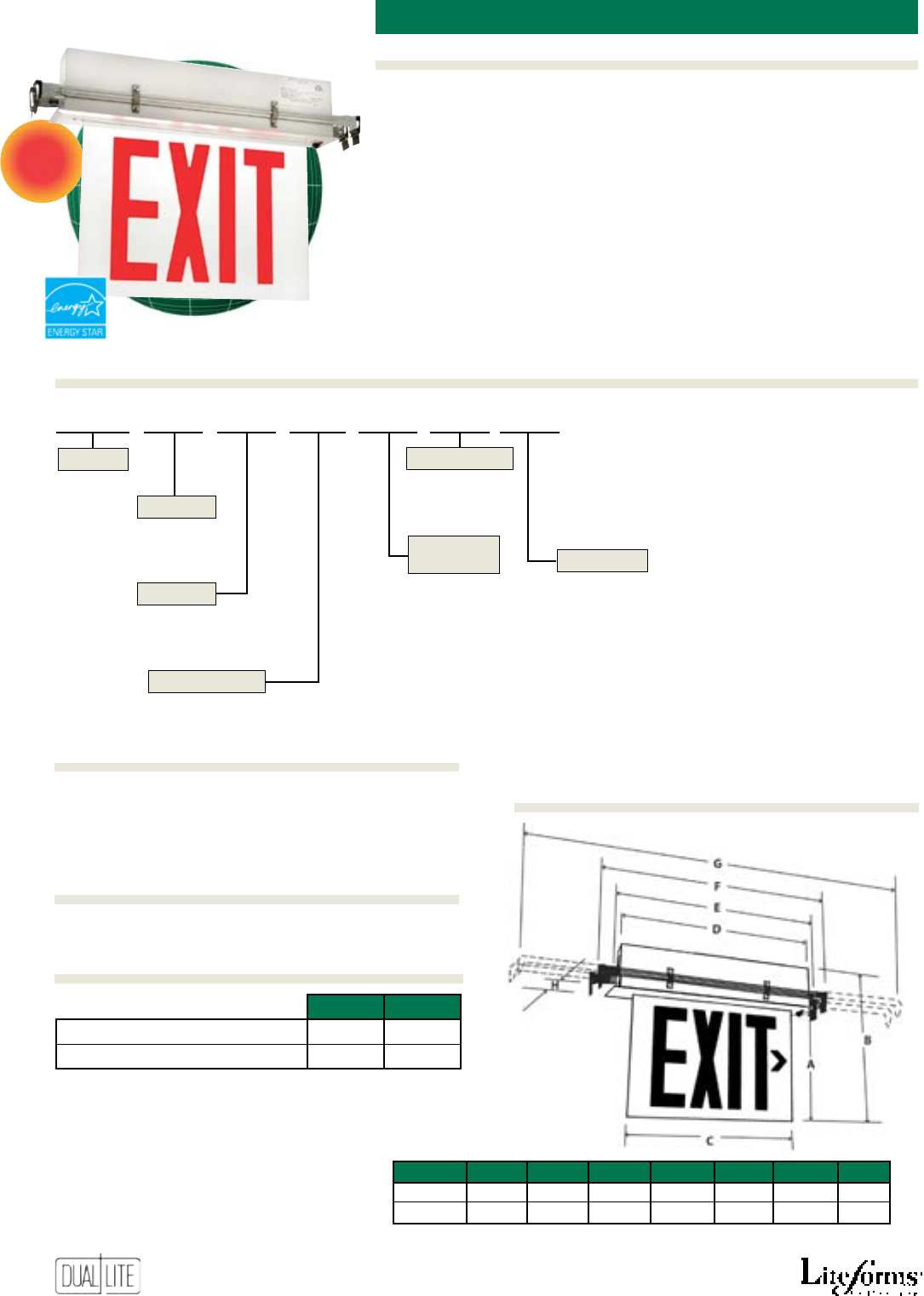
64
Features
Options (Add suffix to model)Accessories (order sepArAtely)
Ordering Information
-LRBB Recessed mount exit sign less rough-in backbox (1)
-W White exit face background
-M Mirrored exit face background
(1) Allows ordering of rough-in backbox separately. See “Accessories”.
AC Models
• Designed to meet New York City
specications
• Recessed ceiling or wall mount
models
• Extruded aluminum construction
• Available in two color nishes
• Acrylic plaque
• Eight-inch red letter models
• Clear, white or mirror
background
• Applique chevron arrows
• Long life LED lamps
• Bright, even letter illumination
• Energy-saving operation
• Easy to install
• 120/277VAC, 60 Hz operation
Emergency Models
• Environmentally coated, fully
automatic charger
• Maintenance-free NiCad battery
• Low voltage disconnect
• Test switch and AC-On indicator
• Temperature range: 0°C to 45°C
(32°F to 113°F)
• Listed to UL 924
NYE new York citY recesseD eDge-Lit exit
NEW
NYE C D R N E -W
S - Single
D - Double*
* Not for use with wall mounted models
Series
Faces
Letter Color
Trim/Housing
Finish
Operation
Options
R - Red
A - AC only
E - Emergency
N - Satin aluminum
W - White
See “Options” section
NYE - Recessed
mount
C - Ceiling
W - Wall
Mounting
C
120VAC 277VAC
AC Only Models 3.2W 3.2W
Emergency Models 4.0W 3.9W
* Wattage figures include LED lamps, transformers and electronics
NYC-RBB Rough-in backbox
Power Consumption
Options (Add suffix to model)
Dimensions
Accessories (order sepArAtely)
A
B
D
E
F
A B C D E F G H
93/4” 131/2” 14” 165/8” 173/8” 193/16” 305/8” 23/4”
24.8 cm 34.2 cm 35.6 cm 42.2 cm 44.1 cm
48.8 cm 77.8 cm 7.0 cm
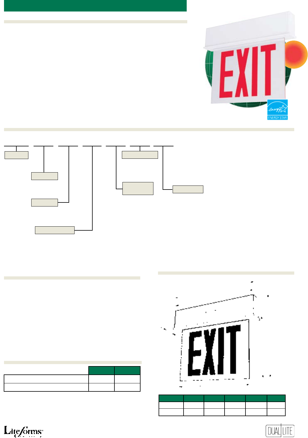
65
Features
Ordering Information
Options (Add suffix to model)Accessories (order sepArAtely)
NYES C D R N E -W
S - Single
D - Double*
* Not for use with wall mounted models
Series
Faces
Letter Color
Trim/Housing
Finish
Operation
Options
R - Red
A - AC only
E - Emergency
N - Satin aluminum
W - White
See “Options” section
NYES - Surface
mount
C - Ceiling
W - Wall
E - End
Mounting
-W White exit face background
-M Mirrored exit face background
AC Models
• Designed to meet New York
City specications
• Surface mount design
• Wall, ceiling or end
mounted models
• Extruded aluminum construction
• Available in two color nishes
• Acrylic plaque
• Eight-inch red letter models
• Clear, white or
mirror background
• Applique chevron arrows
• Long life LED lamps
• Bright, even letter illumination
• Energy-saving operation
• Easy to install
• 120/277VAC, 60 Hz operation
Emergency Models
• Environmentally coated, fully
automatic charger
• Maintenance-free NiCad battery
• Low voltage disconnect
• Test switch and AC-On indicator
• Temperature range: 0°C to 45°C
(32°F to 113°F)
• Listed to UL 924
new York citY sUrface eDge-Lit exit
NEW
A
B
C
D
E
F
A B C D E F
10” 131/2” 14” 17” 165/8” 21/4”
25.4 cm 34.3 cm 35.6 cm 43.2 cm 42.2 cm 5.7 cm
120VAC 277VAC
AC Only Models 3.2W 3.2W
Emergency Models 4.0W 3.9W
* Wattage figures include LED lamps, transformers and electronics
Power Consumption
Options (Add suffix to model)Dimensions
NYES
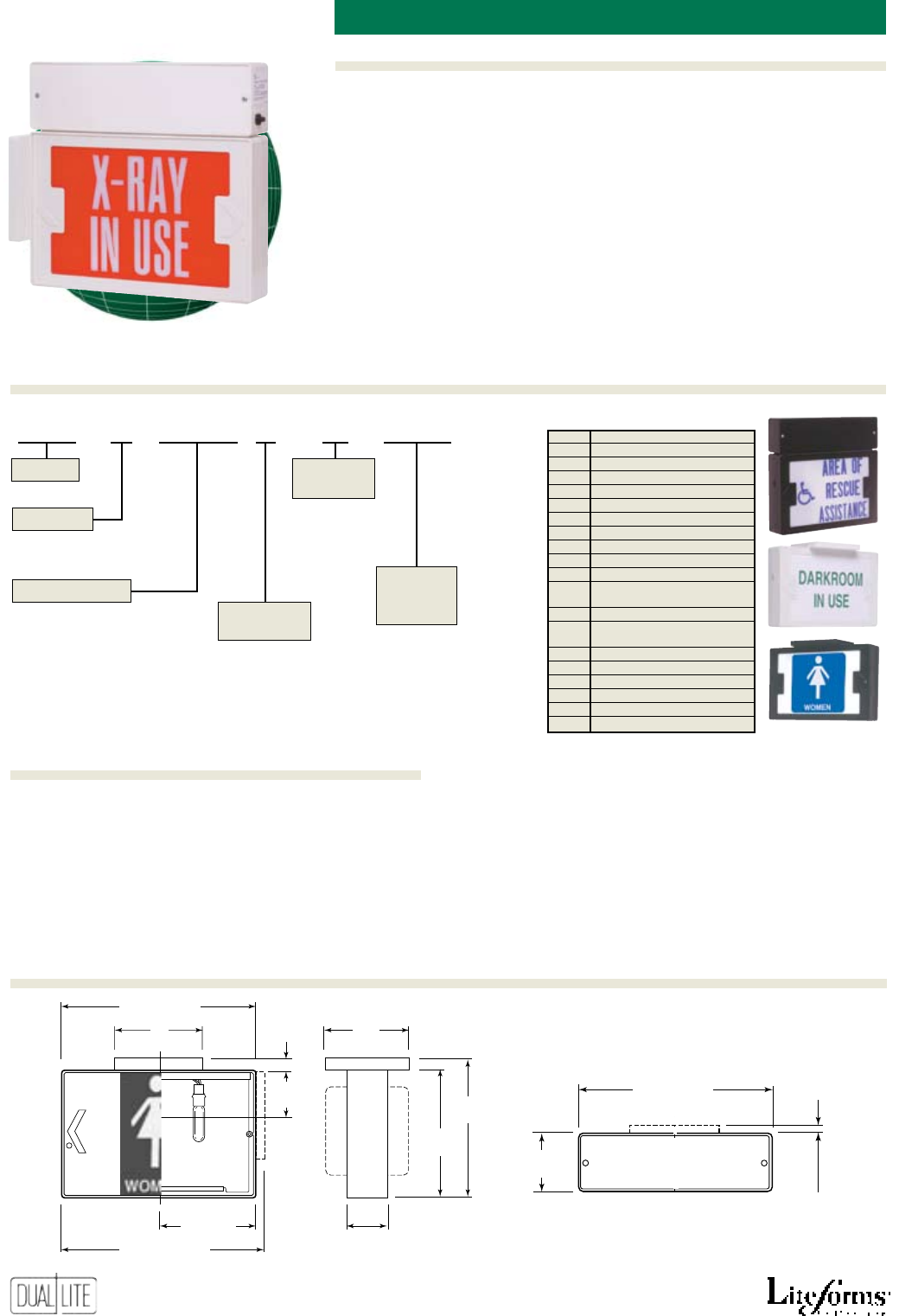
66
Features
Options (Add suffix to model)Accessories (order sepArAtely)
Ordering Information
sPeciaL worDing incanDescent signs
DEX
Power Pack
5”
(127 mm)
11” (279 mm)
111/2” (292 mm)
51/2”
(140 mm)
21/2”
(64 mm)
23/8”
(60 mm)
8”
(204 mm)
43/4”
(120 mm)
71/2”
(191 mm) 31/4”
(83 mm)
11” (279 mm)
(EMFA models)
AC Models
• Thermoplastic housing
• Steel faceplate
• Polyester berglass special
wording open face diffuser
• Acrylic downlight lens
• Canopy for ceiling or end mount
• Universal directional chevron
arrow knockouts
• Tamper resistant screws supplied
• 120V standard
• AC illumination provided by two
145V, 15T6 incandescent lamps
• Suitable for damp locations (AC
models only)
Emergency Models
• Maintenance-free battery
• High impact housing
• Dual voltage – 120V/277VAC
• Two 6V, 3.7W DC lamps for
emergency operation
• Temperature range: 20°C to 30°C
(68°F to 86°F)
WG-MLT Wire guard (wall mount - all models)
WGLXC Wire guard (ceiling mount - AC models only)
WGTCE Wire guard (end mount - all models)
PMEXW 12” pendant stem and canopy kit – white
PMEXB 12” pendant stem and canopy kit – black
VRS3 Vandal resistant shield
Other Special Wording models available. Consult Factory.
* To order special wording diffusers, add Option Number suffix
to model number. Ex: DEX1EMFARW-SW10
1 - Single
2 - Double
Series
Faces
Operation
Letter
Color
Blank – AC-Only 120VAC
EMFA – Emergency 120/277VAC
R – Red
G – Green
W – White
B – Blue
Background
Color
R – Red
G – Green
W – White
See table at
right
Special
Wording
Option No.
DEX 1 EMFA R W -SW3 Special Wording Table
Option
No.* Description
-SW1 TO EXIT
-SW2 NOT AN EXIT
-SW3 IN USE
-SW4 XRAY IN USE
-SW5 DARKROOM IN USE
-SW6 CAUTION
-SW7 DO NOT ENTER
-SW8 TEST IN PROGRESS
-SW9 ON AIR
-SW10 AREA OF REFUGE
-SW11 AREA OF REFUGE
(w/wheelchair symbol)
-SW12 AREA OF RESCUE ASSISTANCE
-SW13 AREA OF RESCUE ASSISTANCE
(w/wheelchair symbol)
-SW14 ELEVATOR
-SW15 RESTROOMS
-SW16 MEN
-SW17 MEN (w/symbol)
-SW18 WOMEN
-SW19 WOMEN (w/symbol)
Dimensions
Accessories (order sepArAtely)
CANOPY
1/2”
(13 mm)
1/2”
(13 mm)
67
SlimLite Series Fixed Lens Emergency Lights .................................................. 68
CV Series Emergency Lights ..................................................................69
CVEC Series High Capacity Emergency Lights .............................................70
CV3 Series LED Exit Signs .................................................................................71
CVT Series Tandem Units ........................................................................72
CVD Series Diecast LED Exit Signs .....................................................................73
CVER Series Recessed Mounting Edge-Lit LED Exit Signs ..................................74
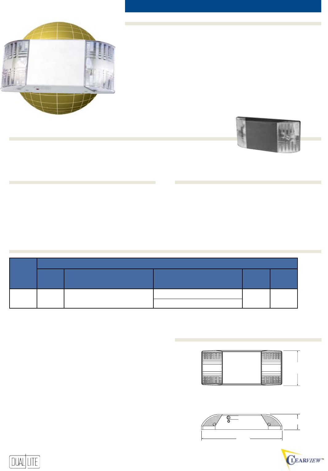
68
Features
Options (Add suffix to model)Accessories (order sepArAtely)
Ordering Information
contemPorarY emergencY Light 12w
Standard Model Voltmeter Model
SL1 SL1-V
• Easy to install
• Sleek, low prole design
• Flame rated, UV stable
thermoplastic housing
• Bright white nish
• 6 volt, T-5 incandescent lamps
• Acrylic fresnel lens provides a
focused beam pattern
• Adjustable lamp socket
• Maintenance-free battery
• Universal 120/277VAC operation
• Fully-automatic, temperature-
compensated, solid-state charger
• Reverse polarity and short circuit
protection
• AC lockout
• Low-voltage battery disconnect
• Test switch and AC-On light
• Temperature range: 20°C to 30°C
(68°F to 86°F)
• Meets ADA specications
• UL 924 Listed
VRS Vandal resistant shield
WGLZ Wire guard
TEST/ESSAI
CHARGE
21/4” (5.7cm)
113/4”
(30 cm)
51/8”
(13 cm)
SlimLite
Options (Add suffix to catalog number)
-B Black housing
-6H 6 watt halogen lamps
Also available in black finish
Dimensions
Options (Add suffix to model)Accessories (order sepArAtely)
eleCtriCAl
BAse output WAtts AC input
CAtAlog output 1.5 2 3 4 stAndArd remote
numBer Volts Hours Hours Hours Hours Volts Amps WAtts lAmp CApABility
SL1, SL1-V 6 12.0 -- -- -- 120 .050 6.0 5.4W No
277 .020 6.0
Product Selector
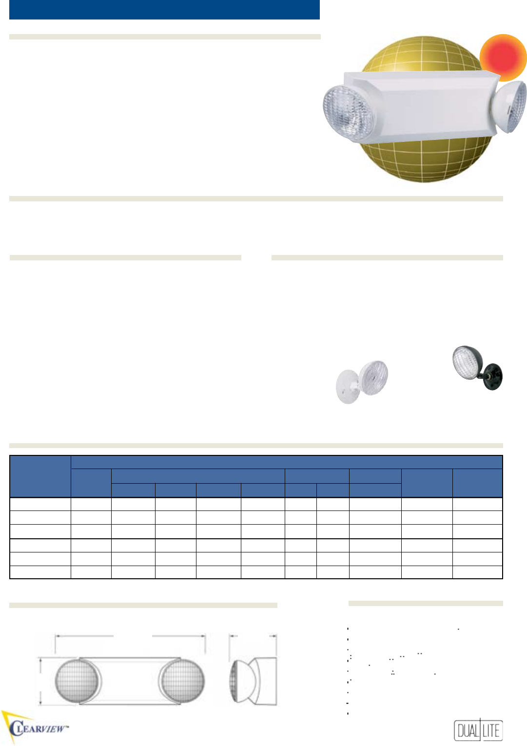
69
Features
Ordering Information
Options (Add suffix to model)Accessories (order sepArAtely)
• Fast, easy installation
• Snap-together design
• Compact, low-prole style
• Injection molded high impact, UV
stabilized thermoplastic
• White nish
• Standard and damp location
models
• Remote capacity models
• High output incandescent lamps
• Maintenance-free battery
• Dual voltage – 120/277VAC
• Fully automatic charger
• Automatic low-voltage battery
disconnect and transformer
isolation protection
• Universal mounting plate
• Test switch and LED AC-On light
• Temperature range: 20°C to 30°C
(68°F to 86°F)
Damp location models:
10°C to 40°C
(50°F to 104°F)
• UL 924 Listed
Example: EDS4-EV1
CV
Designer emergencY Light 11w to 30w
Standard Models: CV2 (6V, 12W) CV3 (6V, 18W) CV5 (6V, 30W)
Damp Location Models: CV2D (6V, 12W) CV3D (6V, 18W) CV5D (6V, 30W)
SRHSW0605 Matching remote head - single (white)
SRHDW0605 Matching remote head - twin (white)
OMSSB0605 Single outdoor lighting head (black)
OMSDB0605 Twin outdoor lighting head (black)
PMLZTW Pendant mounting kit (white) (a)
PMLZTB Pendant mounting kit (black) (a)
WGEL Wire guard
(a) Not available for use with CV5 and CV5D models.
-V Voltmeter
Outdoor
lighting headMatching
remote head
53/8”
(13.7 cm)
157/8”-Min.
193/4”-Max.
(40.3 cm)-Min.
(50.2 cm)-Max.
BAse eleCtriCAl
CAtAlog output output WAtts input Amps input WAtts stAndArd remote
numBer Volts 1.5 Hrs. 2 Hrs. 3 Hrs. 4 Hrs. 120V 277V 120/277V lAmp CApABility
CV2 6 12 -- -- -- .040 .020 4.0 5.4W No
CV3 6 18 13 -- -- .040 .020 4.0 5.4W Yes
CV5 6 30 22 15 12 .130 .060 14.0 5.4W Yes
CV2D 6 11 -- -- -- .040 .020 4.0 5.4W No
CV3D 6 17 12 -- -- .040 .020 4.0 5.4W Yes
CV5D 6 27 20 13 -- .130 .060 14.0 5.4W Yes
Horizontal Isofootcandle Distribution
6 Volt, 5.4 Watt SBT Lamp
NEW
Ordering Information
Product Selector
Options (Add suffix to model)Accessories (order sepArAtely)
Dimensions Photometrics
43/4”-Min.
63/4”-Max.
(12.1 cm)-Min.
(17.1 cm)-Max.
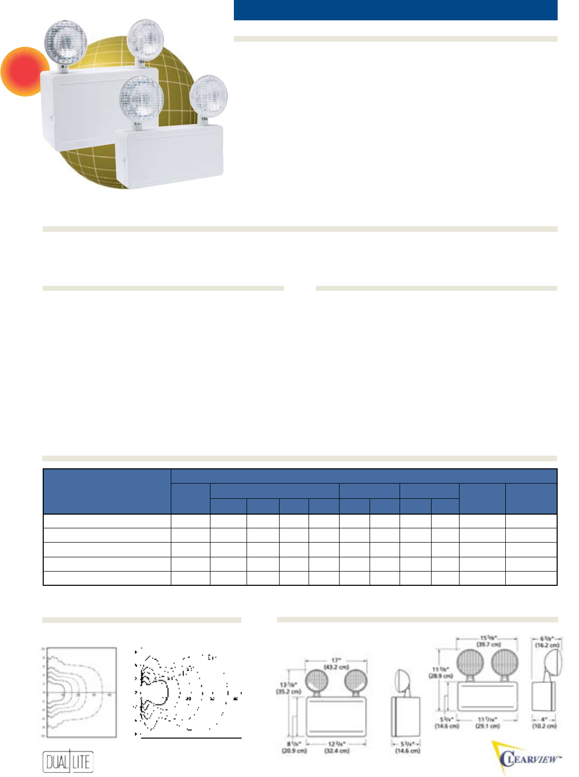
70
Features
Options (Add suffix to model)Accessories (order sepArAtely)
Ordering Information
• Injection molded high impact,
UV stabilized thermoplastic
• Standard white housing
• T-5 incandescent lamps
• Lampheads may be top or side
mounted
• Most models capable of powering
remote lampheads
• Maintenance-free battery
• Dual voltage – 120/277VAC
• Automatic low voltage disconnect
• Thermally compensated charger
• Regulated charge voltage
• Automatic low voltage disconnect
• Reverse polarity protection
• Filtered charger output
• Universal wall mounting plate
• Short circuit protection
• AC lockout
• Test switch and AC-On light
• Temperature range: 20°C to 30°C
(68°F to 86°F)
• UL 924 Listed
50 and 100W Models
15 and 30W Models
40G Wire guard (a)
41G Wire guard (b)
SRHSW0607 Matching 6-volt remote head - single
SRHDW0607 Matching 6-volt remote head - twin
SRHSW1207 Matching 12-volt remote head - single
SRHDW1207 Matching 12-volt remote head - twin
(a) For top mounted heads on CVEC 15 and 30 watt models
(b)
For top mounted heads on CVEC 50 and 100 watt models and side mounted
heads on CVEC
15 and 30 watt
models.
-V Voltmeter
eleCtriCAl
stAndArd output output WAtts input Amps input WAtts stAndArd remote
models Volts 1.5 Hrs. 2 Hrs. 3 Hrs. 4 Hrs. 120V 277V 120 277V lAmp CApABility
CVEC15 6 15 -- -- --
.07 .03 8.4 8.8
7.2W No
CVEC30 6 30 22 15 12
.07 .03 8.4 8.8
7.2W Yes
CVEC50 6 50 38 25 20
.17 .08 20 20
7.2W Yes
CVEC50-12V 12 50 38 25 20
.11 .05 13 14
9.0W Yes
CVEC100-12V 12 100 76 54 44
.32 .14 39 28
9.0W Yes
commerciaL emergencY Light 15w to 100w
CVEC
Standard Models: CVEC15 CVEC30 CVEC 50 CVEC50-12V CVEC100-12V
NEW
Product Selector
Dimensions
Photometrics
Options (Add suffix to model)Accessories (order sepArAtely)
Horizontal Isofootcandle Distribution
6 Volt, 7.2 Watt SBT Lamp 12 Volt, 7.2 Watt SBT Lamp
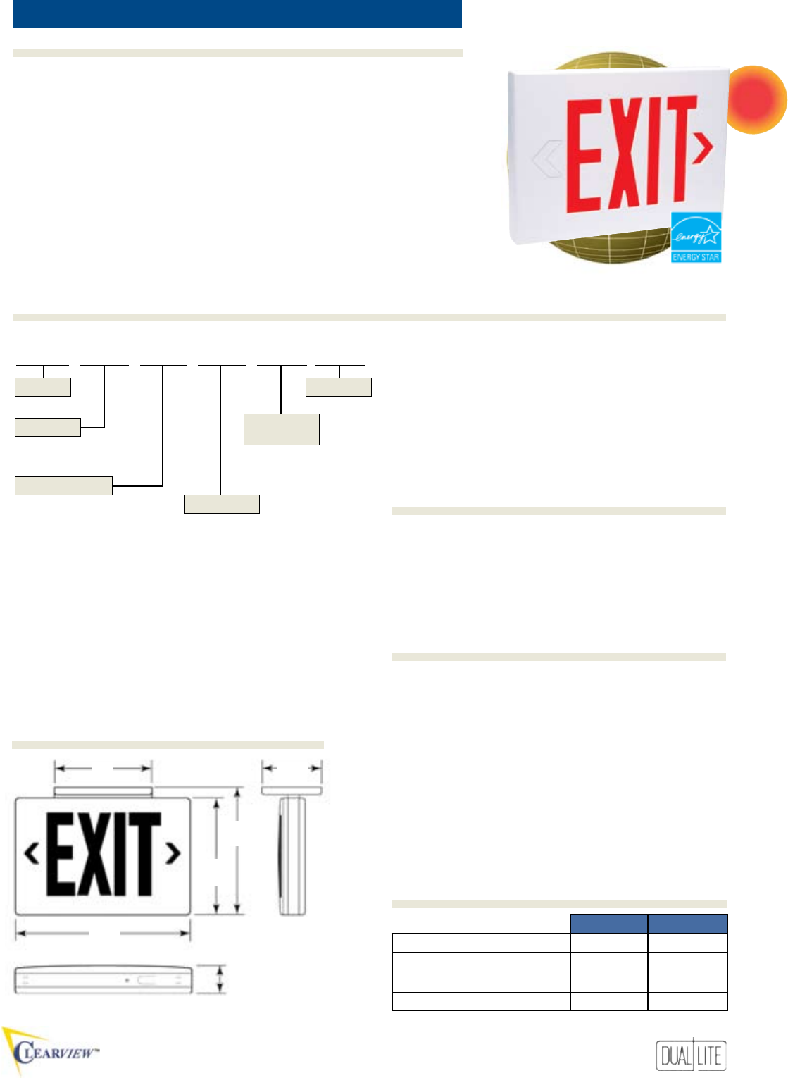
71
Features
Ordering Information
Options (Add suffix to model)Accessories (order sepArAtely)
All Models
• UV-stable thermoplastic housing
• Compact, low-prole design
• Easy to install
• Long-life LED lamps
• Bright, even illumination
• Red and green letters
• Universal single/double face
• White nish
• Push-in wiring connectors
• Universal end/ceiling/wall mount
• Universal snap-in,
chevron arrows
thermoPLastic LeD exit sign
• Damp location listed
• 120/277VAC, 60 Hz operation
Emergency Models
• Solid-state charger with low
voltage disconnect
• Maintenance-free NiCad battery
• 2 hour emergency operation
• Test switch and AC-On light
• Temperature range: 0°C to 40°C
(32°F to 104°F)
• UL 924 Listed
CV3
PMLXW Pendant mounting kit (white)
WGLX Wire guard (Wall mount)
WG-MLT Wire guard (Wall mount)
WGLXC Wire guard (Ceiling mount)
WGLXE Wire guard (End mount)
VRS3 Vandal resistant shield
120VAC 277VAC
Red AC Only Models 2.7 watts 2.7 watts
Green AC Only Models 2.3 watts 2.3 watts
Red Emergency Models 3.8 watts 3.8 watts
Green Emergency Models 3.5 watts 3.5 watts
Power factor, average: .8 (lagging)
7”
(17.8 cm)
9”
(22.8 cm)
93/4”
(24.8 cm)
13”
(33.0 cm)
53/16”
(13.2 cm)
13/4”
(4.4 cm)
-2C 2-circuit operation (1)(3)
-DC Remote DC operation (1)(2)(3)
(1) For use with AC models only.
(2) For emergency illumination of sign from remote 6-24 VDC
power sources.
(3) -2C and -DC options may not be specified together.
CV 3 R E W -2C
3 - Universal Single/Double Face
A - AC Only
E - Emergency
Series
Faces
Letter Color
Operation
Housing
Finish
R - Red
G - Green
W - White
Options
NEW
Options (Add suffix to model)
Accessories (order sepArAtely)
Dimensions
Power Consumption
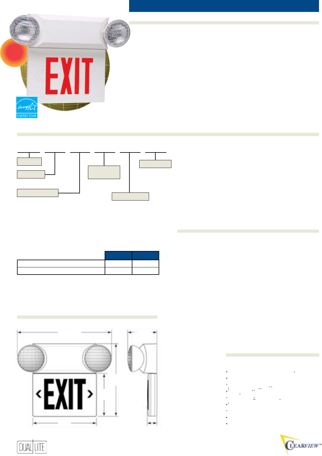
72
Features
Options (Add suffix to model)Accessories (order sepArAtely)
Ordering Information
• Factory assembled emergency
unit/LED exit sign
• UV-stable thermoplastic housing
• High-output lighting heads
• White nish
• Damp location listed
models available
• 120/277VAC, 60 Hz operation
• Solid-state charger with low-
voltage disconnect
• Maintenance-free battery
• Test switch and LED AC-On light
thermoPLastic tanDem Unit
• Long-life LED lamps
• Bright, even illumination
• Universal single/double face
• Red and green letter models
• Snap-in, chevron arrows
• Ceiling or wall mounting
• Temperature range: 20°C to 30°C
(68°F to 86°F)
Damp location models:
10°C to 40°C
(50°F to 104°F)
• UL 924 Listed
CVT
9”
(22.8 cm)
14 3/8”
(36.5 cm)
13”
(33.0 cm) 13/4”
(4.4 cm)
15 7
/8”-Min.
193
/4”-Max.
(40.3 cm)-Min.
(50.2 cm)-Max.
Horizontal Isofootcandle Distribution
6 Volt, 5.4 Watt SBT Lamp
SRHSW0605 Matching remote head - single (white)
SRHDW0605 Matching remote head - twin (white)
OMSSB0605 Single outdoor lighting head (black)
OMSDB0605 Twin outdoor lighting head (black)
PMLZTW Pendant mounting kit (white) (a)
WGTW Wire guard (Wall mount)
WGTCE Wire guard (Ceiling mount)
(a) Not available for use with 5-head models
NEW
CVT 3 R W 5 D
3 - Universal Single or Double
Blank - Standard model
D - Damp location model*
* Only available on 3-head models
Series
Faces
Letter Color
Application
Housing
Finish
R - Red
G - Green
W - White
Blank - No remote capability
3 - Operates one additional
5.4 watt remote head
5 - Operates up to three
additional 5.4 watt
remote heads
Remote Heads
Dimensions
Photometrics
Accessories (order sepArAtely)
120VAC 277VAC
Input Amps .05 .02
Input Watts 5.0 5.0
43/4”-Min.
63
/4”-Max.
(12.1 cm)-Min.
(17.1 cm)-Max.
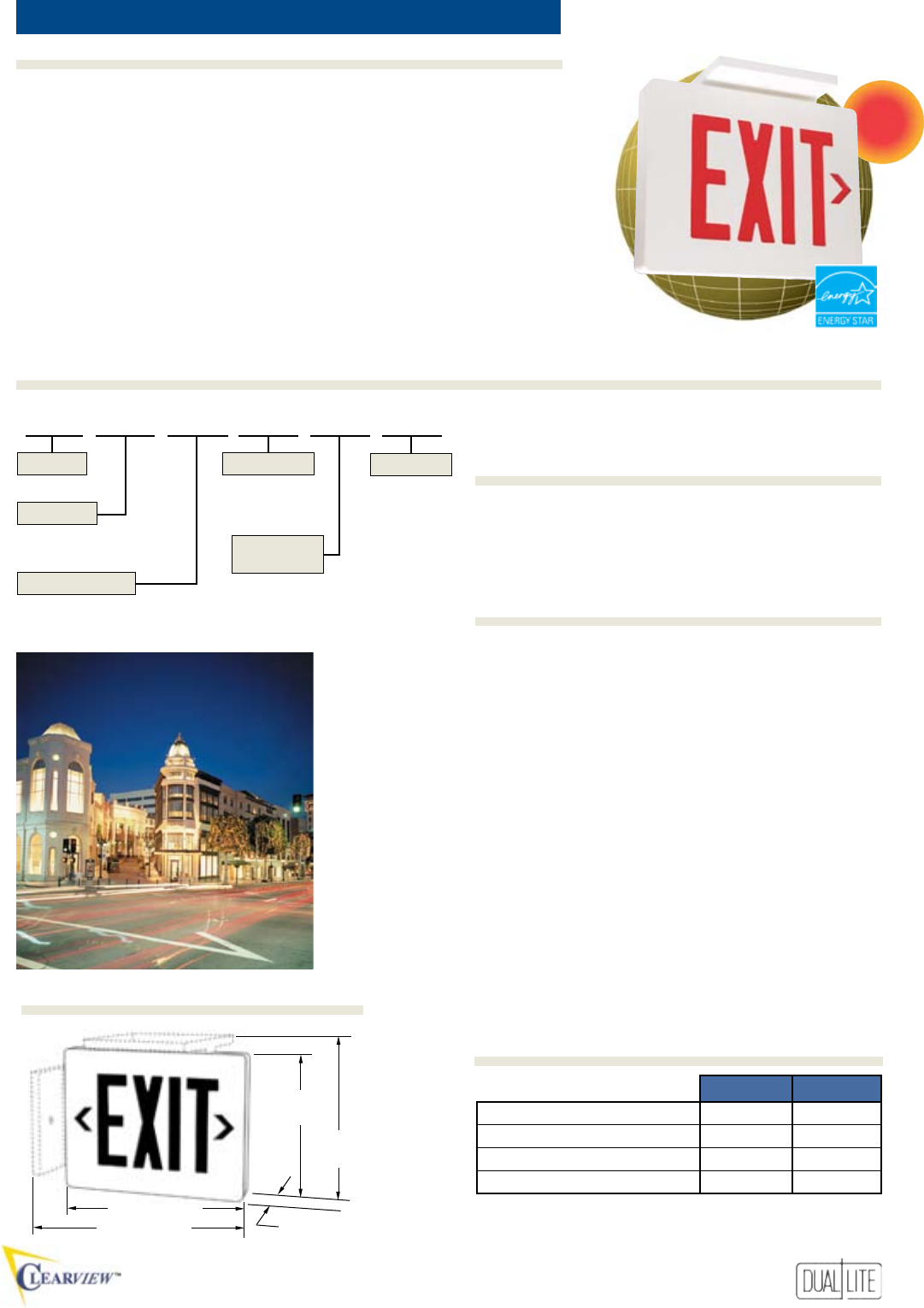
73
Features
Ordering Information
Options (Add suffix to model)Accessories (order sepArAtely)
AC Models
• All diecast aluminum construction
• Soft edges and corners
• White and black with brushed
face nishes
• Break-out directional chevrons
• Universal mounting KO pattern
• Back/ceiling/end mounting
• Dual voltage – 120/277VAC
• Bright and even illumination
• Long-life LED lamps
cast aLUminUm LeD exit sign
Emergency Models
• Long life NiCad battery
• 90 minute emergency operation
• Test switch and AC-On indicator
• Reverse polarity, short circuit and
brownout protection
• Thermally compensated charger
• AC lockout
• Temperature range: 20°C to 30°C
(68°F to 86°F)
• UL 924 Listed
CVD
-DC Remote DC operation (1)
-2C 2-circuit operation (1)
(1) For use with AC models only.
PMCW 121/2” Pendant mounting kit (white)
PMCB 121/2” Pendant mounting kit (black)
WGLX Wire guard (Wall mount)
WG-MLT Wire guard (Wall mount)
WGLXC Wire guard (Ceiling mount)
WGLXE Wire guard (End mount)
15/8” (4.14 cm)
91/8”
(23 cm)
10”
(25.5 cm)
113/4” (30 cm)
125/8” (32 cm)
CVD 1 R A BN -2C
1 - Single
2 - Double
A - AC Only
E - Emergency
Series
Faces
Letter Color
Operation
Housing
Finish
R - Red
G - Green
W - White
BN - Black with brushed face
Options
120VAC 277VAC
Red AC Only Models: 2.6 watts 2.6 watts
Green AC Only Models: 2.1 watts 2.1 watts
Red Emergency Models: 3.8 watts 3.8 watts
Green Emergency Models: 3.5 watts 3.5 watts
*Wattage figures include LED lamps, transformer and electronics power
requirements. LED lamp assemblies (red or green) consume less than 1 watt.
Power factor, average: .8 (lagging)
NEW
Options (Add suffix to model)
Accessories (order sepArAtely)
Dimensions
Power Consumption

74
Features
Options (Add suffix to model)Accessories (order sepArAtely)
Ordering Information
A B C D E F
77/8” 11” 125/8” 15” 14 3/8” 4 1/8”
20.0 cm 27.9 cm 32.1 cm 38.1 cm 36.5 cm 10.5 cm
A
B
C
D
E
F
CVER
AC Models
• Ceiling mounted models for
recessed installation
• Metal construction
• Available in two color nishes
• Clear acrylic plaque
• Red and green letter models
• Applique chevron arrows
• Long life LED lamps
• Bright, even letter illumination
• Energy-saving operation
recesseD moUnt eDge-Lit LeD exit sign
• Easy to install
• 120/277VAC, 60 Hz operation
Emergency Models
• Fully automatic charger
• Maintenance-free NiCad battery
• Low voltage disconnect
• Test switch and AC-On light
• Temperature range: 20°C to 30°C
(68°F to 86°F)
• ETL Listed
CVER 1 R N E
1 - Single
2 - Double*
* Provided standard with mirror
background.
Series
Faces
Letter Color
Trim/Housing
Finish
Operation
R - Red
G - Green
A - AC only
E - Emergency
N - Satin aluminum
W - White
CVER - Recessed
mount
Field installable chevrons provide for all possible
directional arrow requirements.
NEW
120VAC 277VAC
Red AC Only Models 2.2W 3.7W
Green AC Only Models 2.5W 4.4W
Red Emergency Models 3.3W 4.7W
Green Emergency Models 3.6W 5.2W
* Wattage figures include LED lamps, transformers and electronics
power requirements.
Dimensions
Power Consumption
Fully-adjustable universal mounting bar system
allows installations in standard construction
and suspended ceiling applications.
Availability To Be Announced
75
Features
Ordering Information
Options (Add suffix to model)Accessories (order sepArAtely)
Remote Heads and Fixtures ...........................................................76 to 78
Lamp Selector Guide ..........................................................................................79
Voltage Drop Tables ............................................................................... 80
Unit Accessories .................................................................................................. 81
National Electric Code ................................................................................ 82, 83
NFPA 101 Life Safety Code ........................................................................ 84, 85
Limited Warranty ................................................................................................ 86
76
SRH Series
Injection molded thermoplastic lamphead/round mounting
plate assemblies. Mounts to 31/2” octagonal or single gang
boxes. For use with most commercial or industrial emer-
gency xtures. Standard nish is available in white or black.
Single and twin lamp xtures with a choice of incandescent
or halogen PAR 36 lamps.
Lamp photometrics and IES files available on the web at www.dual-lite.com
RemoteHeadsandFixtures
OMS Series
Outdoor aluminum spot with sealed lamp and swivel
assembly. Furnished with round gasketed aluminum
mounting plate. Mounts to 31⁄2” octagonal boxes.
Outdoor Remote Lighting Heads
Lamp photometrics and IES files available on the web at www.dual-lite.com
Standard Remote
Lighting Heads
WHite BlACk
single HeAd WitH tWin HeAd WitH single HeAd WitH tWin HeAd WitH lAmp lAmp lAmp
mounting plAte mounting plAte mounting plAte mounting plAte VoltAge WAttAge pArt no.
SRHSW0605 SRHDW0605 SRHSB0605 SRHDB0605 6 5.4 0110258*
SRHSW0607 SRHDW0607 SRHSB0607 SRHDB0607 6 7.2 0110213*
SRHSW0618 SRHDW0618 SRHSB0618 SRHDB0618 6 18 0110127
SRHSW0625 SRHDW0625 SRHSB0625 SRHDB0625 6 25 0110041
SRHSW1207 SRHDW1207 SRHSB1207 SRHDB1207 12 7.2 0110289*
SRHSW1218 SRHDW1218 SRHSB1218 SRHDB1218 12 18 0110128
SRHSW1225 SRHDW1225 SRHSB1225 SRHDB1225 12 25 0110132
SRHSW1235 SRHDW1235 SRHSB1235 SRHDB1235 12 35 0110233
SRHSW2409 SRHDW2409 SRHSB2409 SRHDB2409 24 9 0110230*
SRHSW0608 SRHDW0608 SRHSB0608 SRHDB0608 6 8 0110162
SRHSW0612 SRHDW0612 SRHSB0612 SRHDB0612 6 12 0110159
SRHSW0620 SRHDW0620 SRHSB0620 SRHDB0620 6 20 0110157
SRHSW1208 SRHDW1208 SRHSB1208 SRHDB1208 12 8 0110189
SRHSW1212 SRHDW1212 SRHSB1212 SRHDB1212 12 12 0110190
* Sealed Beam type lamp
inCAndesCent pAr 36
seAled BeAm
HAlogen pAr 36
seAled BeAm
WHite BlACk
single HeAd WitH tWin HeAd WitH single HeAd WitH tWin HeAd WitH lAmp lAmp lAmp
mounting plAte mounting plAte mounting plAte mounting plAte VoltAge WAttAge pArt no.
OMSSW0605 OMSDW0605 OMSSB0605 OMSDB0605 6 5.4 0110258*
OMSSW0607 OMSDW0607 OMSSB0607 OMSDB0607 6 7.2 0110213*
OMSSW0618 OMSDW0618 OMSSB0618 OMSDB0618 6 18 0110127
OMSSW0625 OMSDW0625 OMSSB0625 OMSDB0625 6 25 0110041
OMSSW1207 OMSDW1207 OMSSB1207 OMSDB1207 12 7.2 0110289*
OMSSW1218 OMSDW1218 OMSSB1218 OMSDB1218 12 18 0110128
OMSSW1225 OMSDW1225 OMSSB1225 OMSDB1225 12 25 0110132
OMSSW1235 OMSDW1235 OMSSB1235 OMSDB1235 12 35 0110233
OMSSW0608 OMSDW0608 OMSSB0608 OMSDB0608 6 8 0110162
OMSSW0612 OMSDW0612 OMSSB0612 OMSDB0612 6 12 0110159
OMSSW0620 OMSDW0620 OMSSB0620 OMSDB0620 6 20 0110157
OMSSW1208 OMSDW1208 OMSSB1208 OMSDB1208 12 8 0110189
OMSSW1212 OMSDW1212 OMSSB1212 OMSDB1212 12 12 0110190
* Sealed Beam type lamp
inCAndesCent pAr 36
seAled BeAm
HAlogen pAr 36
seAled BeAm
77
RemoteHeadsandFixtures
Environmental
Lighting Head
GNX Series
Moisture resistant thermoplas-
tic head in black nish with
coated lamp terminals and
sealed swivel assembly. Fur-
nished with mounting plate.
Available with a choice of
incandescent or halogen PAR
36 lamps. Matches N4X series
units.
Available with shatter containment option.
Add “-L” to model number for Sealed Beam
Lamps PAR36 only. Example: GNXSB0625-L
AHD
Stamped aluminum housing with metal
swivel. Standard nish available in white
or black. Choice of incandescent or
halogen PAR 36 lamps.
All Metal Remote
Lighting Heads
Lamp photometrics and IES files available on the web at www.dual-lite.com
WHite BlACk
single HeAd WitH tWin HeAd WitH single HeAd WitH tWin HeAd WitH lAmp lAmp lAmp
mounting plAte mounting plAte mounting plAte mounting plAte VoltAge WAttAge pArt no.
AHDSW0605 AHDDW0605 AHDSB0605 AHDDB0605 6 5.4 0110258*
AHDSW0607 AHDDW0607 AHDSB0607 AHDDB0607 6 7.2 0110213*
AHDSW0618 AHDDW0618 AHDSB0618 AHDDB0618 6 18 0110127
AHDSW0625 AHDDW0625 AHDSB0625 AHDDB0625 6 25 0110041
AHDSW1207 AHDDW1207 AHDSB1207 AHDDB1207 12 7.2 0110289*
AHDSW1218 AHDDW1218 AHDSB1218 AHDDB1218 12 18 0110128
AHDSW1225 AHDDW1225 AHDSB1225 AHDDB1225 12 25 0110132
AHDSW1235 AHDDW1235 AHDSB1235 AHDDB1235 12 35 0110233
AHDSW2407 AHDDW2407 AHDSB2407 AHDDB2407 24 7.2 0110212*
AHDSW2413 AHDDW2413 AHDSB2413 AHDDB2413 24 13 0110009*
AHDSW2418 AHDDW2418 AHDSB2418 AHDDB2418 24 18 0110010*
AHDSW2428 AHDDW2428 AHDSB2428 AHDDB2428 24 28 0110011*
AHDSWLV30 AHDDWLV30 AHDSBLV30 AHDDBLV30 120 30 0110021*
AHDSW0608 AHDDW0608 AHDSB0608 AHDDB0608 6 8 0110162
AHDSW0612 (1) AHDDW0612 (1) AHDSB0612 AHDDB0612 6 12 0110159
AHDSW0620 AHDDW0620 AHDSB0620 AHDDB0620 6 20 0110157
AHDSW1208 AHDDW1208 AHDSB1208 AHDDB1208 12 8 0110189
AHDSW1212 (1) AHDDW1212 (1) AHDSB1212 AHDDB1212 12 12 0110190
* Sealed Beam type lamp
(1) Matches LM City of Chicago models.
n4x remote HeAd models lAmp lAmp lAmp
single tWin Volts WAtts pArt no.
GNXSB0605 GNXDB0605 6 5.4 0110258*
GNXSB0607 GNXDB0607 6 7.2 0110213*
GNXSB0618 GNXDB0618 6 18 0110127
GNXSB0625 GNXDB0625 6 25 0110041
GNXSB1209 GNXDB1209 12 9 0110202*
GNXSB1218 GNXDB1218 12 18 0110128
GNXSB1225 GNXDB1225 12 25 0110132
GNXSB1235 GNXDB1235 12 35 0110233
GNXSB0608 GNXDB0608 6 8 0110162
GNXSB0612 GNXDB0612 6 12 0110159
GNXSB0620 GNXDB0620 6 20 0110157
GNXSB1208 GNXDB1208 12 8 0110189
GNXSB1212 GNXDB1212 12 12 0110190
* Sealed Beam Type lamp
Lamp photometrics and IES files available on the web at www.dual-lite.com
inCAndesCent pAr 36
seAled BeAm
HAlogen pAr 36
seAled BeAm
inCAndesCent pAr 36
seAled BeAm
HAlogen pAr 36
seAled BeAm
78
RERS
Injection molded housing. Sur-
face mounted. Semi-recessed or
recessed mounting available with
kit. Black box, white trim. Single
(RERS-1) and twin (RERS-2) lamp
models. Dimensions and mounting
kits same as Lite2.
Catalog No. Lamp Part No.
RERS-1-0609 0110163
RERS-2-0607 0110213
F-SRM Semi-recessed mounting kit
-FRM Fully-recessed option
124R
Recessed mounted xture with
frosted lens. White trim.
Dimensions: 83⁄16” x 41⁄2” x 4”.
Catalog No. Lamp Part No.
124R-0628 0110003
124R-1228 0110007
122
Adjustable (60° max.) recessed
mounted xture. Matte white trim.
Dimensions: 81⁄2” dia. x 41⁄2”.
Incandescent PAR 36 Lamp Models
Catalog No. Lamp Part no.
122SB-0625 0110041
122SB-1225 0110132
Halogen PAR 36 Lamp Models
Catalog No Lamp Part No.
122SB-T-0608 0110162
122SB-T-0612 0110159
122SB-T-0620 0110157
122SB-T-1208 0110189
122SB-T-1212 0110190
Bayonet Base Lamp Models
Catalog No. Lamp Part No.
122-2407 0110212
122-2413 0110009
122-2418 0110010
122-2428 0110011
133
Adjustable to 42° and rotated
through 358°. White standard,
other nishes upon request.
Dimensions: Trim ring: 47⁄8” dia.
Back box: 43⁄16” deep x 4” dia.
Catalog No. Lamp Part No.
133-0618 0110002
133-1218 0110006
RemoteHeadsandFixtures
Square
Gimbal
Recessed
Rectangle
Recessed
Eyeball
Consult factory for additional voltage and wattage configurations for remote fixtures.
model numBers
lAmps * single HeAd tWin HeAd
Volts WAtts HuB left side(1)(2) HuB left side(1)(2)
6 8 C1D2R-6V8W C1D2TR-6V8W
6 12 C1D2R-6V12W C1D2TR-6V12W
12 8 C1D2R-12V8W C1D2TR-12V8W
12 12 C1D2R-12V12W C1D2TR-12V12W
* PAR 36 Halogen sealed beam lamps.
(1) Hub Right Side - add “R” to end of model number. Example C1D2R-6V8WR.
(2) Hubs Both Sides - add “F” to end of model number. Example C1D2R-
C1D2R/C1D2TR
Suitable for wet and damp location
applications. Rated for NEC Class I,
Division 2, Groups B, C and D as well
as Class I, Zone 2, Group IIB + H2
environments. Black housing and
head assemblies. Single (C1D2R)
and twin (C1D2TR) head models. 3R Listed
Lamp photometrics and IES files available on the web at www.dual-lite.com
LZR
Architectural/commercial
design. High performance MR-16
halogen lamps standard. Mounts to
standard electrical boxes using
universal mounting plate provided.
Fixture housing mounts to back plate
in a choice of four mounting
positions. Housings secured using
locking screws provided.
LZ Series Matching
Remote Lighting Heads
tWin remote tWin remote lAmp lAmp lAmp
HeAd -WHite HeAd - BlACk Volts WAtts pArt no.
LZRDW
0605
LZRDB
0605
6 5 0110256
LZRDW
0610
LZRDB
0610
6 10 0110261
LZRDW
1205
LZRDB
1205
12 5 0110263
LZRDW
1210
LZRDB
1210
12 10 0110264
single remote single remote lAmp lAmp lAmp
HeAd -WHite HeAd - BlACk Volts WAtts pArt no.
LZRSW
0605
LZRSB
0605
6 5 0110256
LZRSW
0610
LZRSB
0610
6 10 0110261
LZRSW
1205
LZRSB
1205
12 5 0110263
LZRSW
1210
LZRSB
1210
12 10 0110264
IPS Series Matching
Remote Lighting Heads
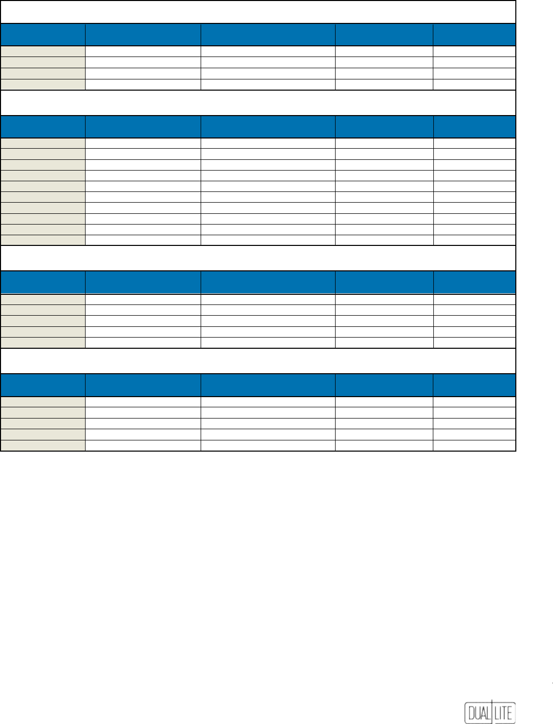
79
LampSelectorGuide
MR16 Lamps
duAl-lite
pArt numBer lAmp numBer lAmp type lAmp Volts lAmp WAtts
0110256 MR16 6V5W Halogen 6 5
0110261 MR16 6V10W Halogen 6 10
0110263 MR16 12V5W Halogen 12 5
0110264 MR16 12V10W Halogen 12 10
PAR 36 Sealed Beam Lamps
duAl-lite
pArt numBer lAmp numBer lAmp type lAmp Volts lAmp WAtts
0110127 4014 Incandescent 6 18
0110041 4510 Incandescent 6 25
0110128 4414 Incandescent 12 18
0110132 4446 Incandescent 12 25
0110233 4411 Incandescent 12 35
0110162 H7551 Halogen 6 8
0110159 H7553 Halogen 6 12
0110157 H7554 Halogen 6 20
0110189 H7555 Halogen 12 8
0110190 H7557 Halogen 12 12
Double Contact Bayonet Base Lamps
duAl-lite
pArt numBer lAmp numBer lAmp type lAmp Volts lAmp WAtts
0110212 304 Incandescent 24 7.2
0110009 1692 Incandescent 24 13
0110010 308 Incandescent 24 18
0110011 310 Incandescent 24 28
0110021 30S11/93 Incandescent 125 30
Wedge Base Lamps
duAl-lite
pArt numBer lAmp numBer lAmp type lAmp Volts lAmp WAtts
0110258 939 Incandescent 6 5.4
0110213 927 Incandescent 6 7.2
0110289 KB-AN Incandescent 12 7.2
0110202 915 Incandescent 12 9
0110230 - Incandescent 24 9
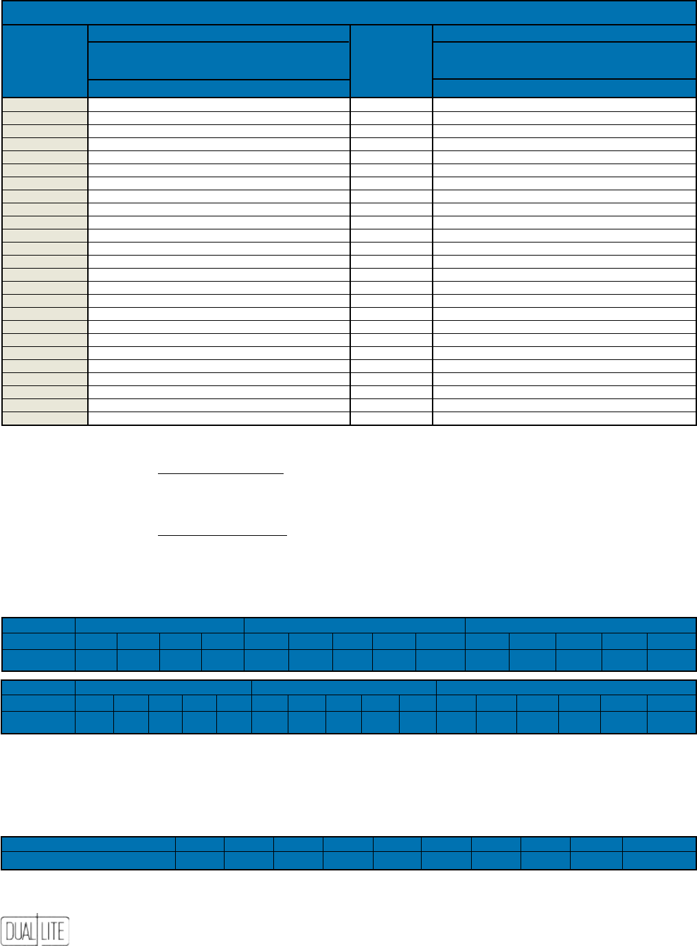
80
VoltageDropTables
Values not shown in Table A may be calculated using the following formulas:
Table B Constant Value
I. Maximum Length (Feet) = Maximum Load (Watts)
Example: Find the maximum circuit length for #8 wire on a 24 volt system with an 80 watt load.
Maximum Length (Feet) = 21613 ÷ 80 = 270 feet.
Table B Constant Value
II. Maximum Load (Watts) = Maximum Length (Feet)
Example: Find the maximum circuit load for 540 feet of #12 wire on a 32 volt system.
Maximum Load (Watts) = 15197 ÷ 540 = 28 watts.
Table B
Constant Values per Voltage System Wire Size (Maximum Voltage Drop 5%)
system 6 Volt 12 Volt 24 Volt
Wire size #12 #10 #8 #6 #12 #10 #8 #6 #4 #12 #10 #8 #6 #4
ConstAnt
534 849 350 2148 2137 3397 5403 8590 13660 8548 13588 21613 34363 54641
system 32 Volt 48 Volt 110 Volt
Wire size #12 #10 #8 #6 #4 #12 #10 #8 #6 #4 #12 #10 #8 #6 #4 #2
ConstAnt
15197 24157 38423 61090 97140 34193 54353 86452 137454 218565 179575 285450 454025 721875 1147850 1824900
Uniform Loads
The maximum circuit length data in Table A (and derived from Table B) assumes that 100% of the load is concentrated at the end of the run. If
equally sized loads can be equally spaced along the run, maximum circuit length can be increased by the multipliers shown in Table C.
Table C
Multipliers for Equally Sized, Equally Spaced Loads (Maximum Voltage Drop 5%)
numBer of fixtures 2 3 4 5 6 7 8 9 10 n
multiply distAnCe By 1.333 1.500 1.600 1.670 1.714 1.750 1.777 1.800 1.818 2n/(n+1)
The National Electrical Code limits voltage drop to a maximum of 5% of nominal. Circuit runs must be of sufcient
capacity to maintain operating voltage when remote xtures and/or exit signs are connected to the emergency lighting
tABle A - importAnt eleCtriCAl instAllAtion informAtion
12 Volt system 6 Volt system
Wire gAuge Wire gAuge
totAl WAtts #12 #10 #8 #6 totAl WAtts #12 #10 #8 #6
on Wire run mAx. lengtH of Wire run (feet) on Wire run mAx. lengtH of Wire run (feet)
6 378 600 955 1518 6 94 150 238 379
7 324 515 818 1301 7 81 129 204 325
8 283 450 716 1138 8 70 112 179 284
10 226 360 570 910 10 56 90 143 227
12 178 283 450 715 12 44 70 112 178
14 162 257 409 650 14 40 64 102 162
16 133 212 338 538 16 33 53 84 134
18 119 189 300 477 18 30 47 75 119
20 113 180 286 455 20 28 45 71 114
21 108 171 273 434 21 27 43 68 108
24 89 141 225 357 24 24 38 60 95
25 86 136 216 344 25 21 34 54 86
30 75 120 190 303 30 19 30 48 76
35 65 103 164 260 35 15 25 39 63
40 53 85 135 214 40 13 21 33 53
48 44 70 112 178 48 11 17 28 44
50 43 68 108 172 50 11 17 27 43
75 28 45 72 115 75 7 11 18 29
100 21 34 54 86 100 5 8 14 21
125 17 27 43 69 125 4 7 11 17
150 14 23 36 57 150 3 5 9 14
175 12 19 31 49 175 3 5 8 12
200 10 16 27 42 200 2 4 6 10
225 10 16 25 40 225 2 4 6 10
250 9 14 22 36 250 2 3 5 9
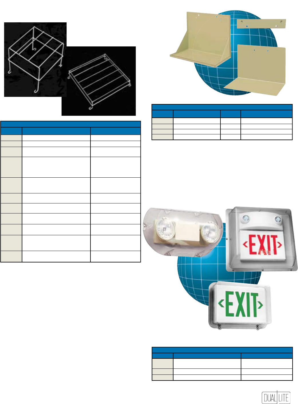
81
Vandal Resistant Shields
For protection against vandalism or accidental damage.
Prevents tampering with mountings and lamps.
Wire Guards
Offered for most Dual-Lite emergency lights and exits.
Constructed of heavy gauge steel, all wire guards are
standard with chrome plating. Order as separate line item.
UnitAccessories
Mounting Brackets and Shelves
For mounting of AS Series industrial emergency lighting
units.
WB-6
6000
L-6 & L-12-S
mounting BrACkets And sHelVes
CAt. no. for use WitH type dimensions
WB-6
All enclosure 1 & 2 models
Bracket --
6000
Enclosure 1 models only
Shelf 11” H x 14” L x 81⁄8” D
L-6
Enclosure 1 models only
Shelf 11” H x 14” L x 81⁄8” D
L-12-S
Enclosure 2 models only
Shelf 11” H x 16” L x 81⁄8” D
VAndAl sHields
CAt. no. for use WitH dimensions (outside)
VRS
EZ-2, LZ, LZ High Capacity, EXT-122-EM-K,
20” L x 101⁄2” H x 73⁄4” D
VRS-4X*
EZ-2R Series and CV Series
VRS2
Lite2 Series, LT Series exits
211⁄4” L x 193⁄4” H x 61⁄4” D
VRS3
LX, DK, Sempra and CV3 Series exits
151⁄2” L x 111⁄2” H x 41⁄2” D
* VRS-4X supplied with a neoprene wall gasket
Wire guArds
CAt. no. for use WitH dimensions (inside)
WGLZ
LZ Series (except High-Capacity models)
61⁄4” H x 14” L x 41⁄4” D
S6WG
Remote heads
8” H x 8” L x 8” D
WGEL
EZ-2, EZ-2R and LZ High-Capacity Series,
8” H x 20” L x 8” D
Remote heads, CV Series
40G
LM Series with top mounted heads,
181⁄2” H x 20” L x 12” D
AS Series (enclosure 1 models), N4X Series,
CVEC Series (15 and 30 watt models) and
NYXC tandem units
41G
AS Series (enclosure 2 models),
21” H x 23” L x 15” D
Delite Cylinder Series, SMC exits and
CVEC Series (50 and 100 watt models)
WGLX
EXT-122-EM-K, Wall mount LX, LED and
10” H x 14” L x 21⁄4” D
Sempra Series exits, Wall Mount CV3 Series
WGLXC
Ceiling mount LX, LED, Sempra and
101⁄4” H x 133⁄4” L x 31⁄2” D
CV3 Series exits
WGLXE
End mount LX, LED and Sempra, CV3 and
101⁄2” H x 141⁄2” L x 31⁄2” D
CVD Series exits
WGTW
Wall mount LT, Freedom LED,
CVT
16” H x 20” L x 77⁄8” D
NYDC and NYX Series exits
WGTCE
Ceiling or end mount LT, CVD, CVT
20” H x 167⁄8” L x 8” D
and
Freedom
LED
Series exits. Ceiling
mount NYDC and NYX Series exits
WG-MLT
Lite2 Series, Wall mount LX, DK, Sempra
115⁄8” H x 135⁄8” L x 7” D
DEX, CV3 and CVD Series exits
VRS/VRS-4X
VRS2
VRS3

82
NEC (NFPA 70) - 2005
NationalElectricCode
I. General
700.1 Scope. The provisions of this article apply to the electrical safety of the
installation, operation, and maintenance of emergency systems consisting of
circuits and equipment intended to supply, distribute, and control electricity for
illumination, power, or both, to required facilities when the normal electrical
supply or system is interrupted. Emergency systems are those systems legally
required and classed as emergency by municipal, state, federal, or other codes,
or by any governmental agency having jurisdiction. These systems are intended
to automatically supply illumination, power, or both, to designated areas and
equipment in the event of failure of the normal supply or in the event of accident
to elements of a system intended to supply, distribute, and control power and
illumination essential for safety to human life.
FPN No. 1: For further information regarding wiring and installation of
emergency systems in health care facilities, see Article 517.
FPN No. 2: For further information regarding performance and maintenance
of emergency systems in health care facilities, see NFPA 99-2002, Standard for
Health Care Facilities.
FPN No. 3: Emergency systems are generally installed in places of assembly
where articial illumination is required for safe exiting and for panic control
in buildings subject to occupancy by large numbers of persons, such as
hotels, theaters, sports arenas, health care facilities, and similar institutions.
Emergency systems may also provide power for such functions as ventilation
where essential to maintain life, re detection and alarm systems, elevators,
re pumps, public safety communications systems, industrial processes where
current interruption would produce serious life safety or health hazards, and
similar functions.
FPN No. 4: For specication of locations where emergency lighting is considered
essential to life safety, see NFPA 101®-2003, Life Safety Code®.
FPN No. 5: For further information regarding performance of emergency and
standby power systems, see NFPA 110®- 2002, Standard for Emergency and
Standby Power Systems.
700.2 Application of Other Articles. Except as modied by this article, all
applicable articles of this Code shall apply.
700.3 Equipment Approval. All equipment shall be approved for use on
emergency systems.
700.4 Tests and Maintenance.
(A) Conduct or Witness Test. The authority having jurisdiction shall conduct or
witness a test of the complete system upon installation and periodically afterward.
(B) Tested Periodically. Systems shall be tested periodically on a schedule
acceptable to the authority having jurisdiction to ensure the systems are
maintained in proper operating condition.
(C) Battery Systems Maintenance. Where battery systems or unit equipments
are involved, including batteries used for starting, control, or ignition in auxiliary
engines, the authority having jurisdiction shall require periodic maintenance.
(D) Written Record. A written record shall be kept of such tests and maintenance.
(E) Testing Under Load. Means for testing all emergency lighting and power
systems during maximum anticipated load conditions shall be provided.
FPN: For testing and maintenance procedures of emergency power supply
systems (EPSSs), see NFPA 110-2002, Standard for Emergency and Standby Power
Systems.
700.5 Capacity.
(A) Capacity and Rating. An emergency system shall have adequate capacity
and rating for all loads to be operated simultaneously. The emergency system
equipment shall be suitable for the maximum available fault current at its
terminals.
(B) Selective Load Pickup, Load Shedding, and Peak Load Shaving. The
alternate power source shall be permitted to supply emergency, legally required
standby, and optional standby system loads where the source has adequate
capacity or where automatic selective load pickup and load shedding is provided as
needed to ensure adequate power to
(1) the emergency circuits, (2) the legally required standby circuits, and (3) the
optional standby circuits, in that order of priority. The alternate power source shall
be permitted to be used for peak load shaving, provided these conditions are met.
Peak load-shaving operation shall be permitted for satisfying the test requirement
of 700.4(B), provided all other conditions of 700.4 are met. A portable or
temporary alternate source shall be available whenever the emergency generator
is out of service for major maintenance or repair.
700.6 Transfer Equipment.
(A) General. Transfer equipment, including automatic transfer switches, shall be
automatic, identied for emergency use, and approved by the authority having
jurisdiction. Transfer equipment shall be designed and installed to prevent the
inadvertent interconnection of normal and emergency sources of supply in any
operation of the transfer equipment. Transfer equipment and electric power
production systems installed to permit operation in parallel with the normal source
shall meet the requirements of Article 705.
(B) Bypass Isolation Switches. Means shall be permitted to bypass and isolate the
transfer equipment. Where bypass isolation switches are used, inadvertent parallel
operation shall be avoided.
(C) Automatic Transfer Switches. Automatic transfer switches shall be electrically
operated and mechanically held.
(D) Use. Transfer equipment shall supply only emergency loads.
700.7 Signals. Audible and visual signal devices shall be provided, where
practicable, for the purpose described in 700.7(A) through 700.7(D).
(A) Derangement. To indicate derangement of the emergency source.
(B) Carrying Load. To indicate that the battery is carrying load.
(C) Not Functioning. To indicate that the battery charger is not functioning.
(D) Ground Fault. To indicate a ground fault in solidly grounded wye emergency
systems of more than 150 volts to ground and circuit-protective devices rated 1000
amperes or more. The sensor for the ground-fault signal dewwwvices shall be
located at, or ahead of, the main system disconnecting means for the emergency
source, and the maximum setting of the signal devices shall be for a ground-fault
current of 1200 amperes. Instructions on the course of action to be taken in event
of indicated ground fault shall be located at or near the sensor location.
FPN: For signals for generator sets, see NFPA 110-2002,Standard for Emergency
and Standby Power Systems.
700.8 Signs.
(A) Emergency Sources. A sign shall be placed at the service entrance
equipment, indicating type and location of on-site emergency power sources.
Exception: A sign shall not be required for individual unit equipment as specied
in 700.12(F).
(B) Grounding. Where the grounded circuit conductor connected to the
emergency source is connected to a grounding electrode conductor at a location
remote from the emergency source, there shall be a sign at the grounding location
that shall identify all emergency and normal sources connected at that location.
II. Circuit Wiring
700.9 Wiring, Emergency System.
(A) Identification. All boxes and enclosures (including transfer switches,
generators, and power panels) for emergency circuits shall be permanently marked
so they will be readily identied as a component of an emergency circuit or system.
(B) Wiring. Wiring of two or more emergency circuits supplied from the same
source shall be permitted in the same raceway, cable, box, or cabinet. Wiring from
an emergency source or emergency source distribution overcurrent protection
to emergency loads shall be kept entirely independent of all other wiring and
equipment, unless otherwise permitted in (1) through (4):
(1) Wiring from the normal power source located in transfer equipment enclosures
(2) Wiring supplied from two sources in exit or emergency luminaires (lighting
xtures)
(3) Wiring from two sources in a common junction box, attached to exit or
emergency luminaires (lighting xtures)
(4) Wiring within a common junction box attached to unit equipment, containing
only the branch circuit supplying the unit equipment and the emergency circuit
supplied by the unit equipment
(C) Wiring Design and Location. Emergency wiring circuits shall be designed and
located so as to minimize the hazards that might cause failure due to ooding,
re, icing, vandalism, and other adverse conditions.
(D) Fire Protection. Emergency systems shall meet the additional requirements
in 700.9(D)(l) and (D)(2) assembly occupancies for not less than 1000 persons or
in buildings above 23 m (75 ft) in height with any of the following occupancy
classes: assembly, educational, residential, detention and correctional, business,
and mercantile.
(1) Feeder-Circuit Wiring. Feeder-circuit wiring shall meet one of the
following conditions:
(1) Be installed in spaces or areas that are fully protected by an approved
automatic re suppression system
(2) Be a listed electrical circuit protective system with a minimum l-hour re rating
(3) Be protected by a listed thermal barrier system for electrical system components
(4) Be protected by a re-rated assembly listed to achieve a minimum re rating
of 1 hour
(5) Be embedded in not less than 50 mm (2 in.) of concrete
(6) Be a cable listed to maintain circuit integrity for not less than 1 hour when
installed in accordance with the listing requirements
(2) Feeder-Circuit Equipment. Equipment for feeder circuits (including transfer
switches, transformers, and panel boards) shall be located either in spaces fully
protected by approved automatic re suppression systems (including sprinklers,
carbon dioxide systems) or in spaces with a 1-hour re resistance rating.
FPN: For the denition of occupancy classication, see Section 6.1 of NFPA 101-
2003, Life Safety Code.
III. Sources of Power
700.12 General Requirements. Current supply shall be such that, in the event
of failure of the normal supply to, or within, the building or group of buildings
concerned, emergency lighting, emergency power, or both shall be available
within the time required for the application but not to exceed 10 seconds. The
supply system for emergency purposes, in addition to the normal services to
the building and meeting the general requirements of this section, shall be one
or more of the types of systems described in 700.12(A) through 700.12(E). Unit
equipment in accordance with 700.12(F) shall satisfy the applicable requirements
of this article. In selecting an emergency source of power, consideration shall
be given to the occupancy and the type of service to be rendered, whether of
minimum duration, as for evacuation of a theater, or longer duration, as for
supplying emergency power and lighting due to an indenite period of current
failure from trouble either inside or outside the building. Equipment shall be
designed and located so as to minimize the hazards that might cause complete
failure due to ooding, res, icing, and vandalism. Equipment for sources of
power as described in 700.12(A) through 700.12(E) where located within assembly
occupancies for greater than 1000 persons or in buildings above 23 m (75 ft) in
height with any of the following occupancy classes — assembly, educational,
residential, detention and correctional, business, and mercantile — shall be
installed either in spaces fully protected by approved automatic re suppression
systems (sprinklers, carbon dioxide systems, and so forth) or in spaces with a 1-hour
re rating.

83
NEC (NFPA 70) - 2005
NationalElectricCode
FPN No. 1: For the denition of occupancy classication, see Section 6.1 of NFPA
101-2003, Life Safety Code.
FPN No. 2: Assignment of degree of reliability of the recognized emergency
supply system depends on the careful evaluation of the variables at each
particular installation.
(A) Storage Battery. Storage batteries used as a source of power for emergency
systems shall be of suitable rating and capacity to supply and maintain the total
load for a minimum period of 1 1/2 hours, without the voltage applied to the load
falling below 87-1/2 percent of normal. Batteries, whether of the acid or alkali
type, shall be designed and constructed to meet the requirements of emergency
service and shall be compatible with the charger for that particular installation.
For a sealed battery, the container shall not be required to be transparent.
However, for the lead acid battery that requires water additions, transparent or
translucent jars shall be furnished. Automotive-type batteries shall not be used.
An automatic battery charging means shall be provided.
(B) Generator Set.
(1) Prime Mover-Driven. For a generator set driven by a prime mover acceptable
to the authority having jurisdiction and sized in accordance with 700.5, means shall
be provided for automatically starting the prime mover on failure of the normal
service and for automatic transfer and operation of all required electrical circuits.
A time-delay feature permitting a 15-minute setting shall be provided to avoid
retransfer in case of short-time reestablishment of the normal source.
(2) Internal Combustion as Prime Movers. Where internal combustion engines
are used as the prime mover, an on-site fuel supply shall be provided with an on-
premise fuel supply sufcient for not less than 2 hours’ full-demand operation of
the system. Where power is needed for the operation of the fuel transfer pumps
to deliver fuel to a generator set day tank, this pump shall be connected to the
emergency power system.
(3) Dual Supplies. Prime movers shall not be solely dependent on a public utility
gas system for their fuel supply or municipal water supply for their cooling systems.
Means shall be provided for automatically transferring from one fuel supply to
another where dual fuel supplies are used.
Exception: Where acceptable to the authority having jurisdiction, the use of
other than on-site fuels shall be permitted where there is a low probability of a
simultaneous failure of both the off-site fuel delivery system and power from the
outside electrical utility company.
(4) Battery Power and Dampers. Where a storage battery is used for control
or signal power or as the means of starting the prime mover, it shall be suitable
for the purpose and shall be equipped with an automatic charging means
independent of the generator set. Where the battery charger is required for the
operation of the generator set, it shall be connected to the emergency system.
Where power is required for the operation of dampers used to ventilate the
generator set, the dampers shall be connected to the emergency system.
(5) Auxiliary Power Supply. Generator sets that require more than 10 seconds
to develop power shall be permitted if an auxiliary power supply energizes the
emergency system until the generator can pick up the load.
(6) Outdoor Generator Sets. Where an outdoor housed generator set is equipped
with a readily accessible disconnecting means located within sight of the building
or structure supplied, an additional disconnecting means shall not be required
where ungrounded conductors serve or pass through the building or structure.
(C) Uninterruptible Power Supplies. Uninterruptible power supplies used to
provide power for emergency systems shall comply with the applicable provisions
of 700.12(A) and 700. 12(B)
(D) Separate Service. Where acceptable to the authority having jurisdiction as
suitable for use as an emergency source of power, an additional service shall be
permitted. This service shall be in accordance with the applicable provisions of
Article 230 and the following additional requirements:
(1) Separate service drop or service lateral
(2) Service conductors sufciently remote electrically and physically from any other
service conductors to minimize the possibility of simultaneous interruption
of supply
(E) Fuel Cell System. Fuel cell systems used as a source of power for emergency
systems shall be of suitable rating and capacity to supply and maintain the total
load for not less than 2 hours of full-demand operation. Installation of a fuel cell
system shall meet the requirements of Parts II through VIII of Article 692. Where
a single fuel cell system serves as the normal supply for the building or group
of buildings concerned, it shall not serve as the sole source of power for the
emergency standby system.
(F) Unit Equipment. Individual unit equipment for emergency illumination shall
consist of the following:
(1) A rechargeable battery
(2) A battery charging means
(3) Provisions for one or more lamps mounted on the equipment, or shall be
permitted to have terminals for remote lamps, or both
(4) A relaying device arranged to energize the lamps automatically upon failure of
the supply to the unit equipment
The batteries shall be of suitable rating and capacity to supply and maintain at
not less than 87-1/2 percent of the nominal battery voltage for the total lamp load
associated with the unit for a period of at least l l/2 hours, or the unit equipment
shall supply and maintain not less than 60 per cent of the initial emergency
illumination for a period of at least 11/2 hours. Storage batteries, whether of the
acid or alkali type, shall be designed and constructed to meet the requirements of
emergency service. Unit equipment shall be permanently xed in place (i.e., not
portable) and shall have all wiring to each unit installed in accordance with the
requirements of any of the wiring methods in Chapter 3. Flexible cord-and-plug
connection shall be permitted, provided that the cord does not exceed 900 mm
(3 ft) in length. The branch circuit feeding the unit equipment shall be the same
branch circuit as that serving the normal lighting in the area and connected ahead
of any local switches. The branch circuit that feeds unit equipment shall be clearly
identied at the distribution panel. Emergency luminaires (illumination xtures)
that obtain power from a unit equipment and are not part of the unit equipment
shall be wired to the unit equipment as required by 700.9 and by one of the wiring
methods of Chapter 3.
Exception: In a separate and uninterrupted area supplied by a minimum of three
normal lighting circuits, a separate branch circuit for unit equipment shall be
permitted if it originates from the same panelboard as that of the normal lighting
circuits and is provided with a lock-on feature.
IV. Emergency System Circuits for Lighting
and Power
700.15 Loads on Emergency Branch Circuits. No appliances and no lamps, other
than those specied as required for emergency use, shall be supplied by emergency
lighting circuits.
700.16 Emergency Illumination. Emergency illumination shall include all required
means of egress lighting, illuminated exit signs, and all other lights specied as
necessary to provide required illumination. Emergency lighting systems shall be
designed and installed so that the failure of any individual lighting element, such
as the burning out of a light bulb, cannot leave in total darkness any space that
requires emergency illumination. Where high-intensity discharge lighting such as
high and low-pressure sodium, mercury vapor, and metal halide is used as the sole
source of normal illumination, the emergency lighting system shall be required to
operate until normal illumination has been restored.
Exception: Alternative means that ensure emergency lighting illumination level is
maintained shall be permitted.
700.17 Circuits for Emergency Lighting. Branch circuits that supply emergency
lighting shall be installed to provide service from a source complying with 700.12
when the normal supply for lighting is interrupted. Such installations shall provide
either of the following:
(l) An emergency lighting supply, independent of the general lighting supply, with
provisions for automatically transferring the emergency lights upon the event of
failure of the general lighting system supply
(2) Two or more separate and complete systems with independent power supply,
each system providing sufcient current for emergency lighting purposes unless
both systems are used for regular lighting purposes and are both kept lighted,
means shall be provided for automatically energizing either system upon failure
of the other. Either or both systems shall be permitted to be a part of the general
lighting system of the protected occupancy if circuits supplying lights for emergency
illumination are installed in accordance with other sections of this article.
700.18 Circuits for Emergency Power. For branch circuits that supply equipment
classed as emergency, there shall be an emergency supply source to which the load
will be transferred automatically upon the failure of the normal supply.
V. Control—Emergency Lighting Circuits
700.20 Switch Requirements. The switch or switches installed in emergency
lighting circuits shall be arranged so that only authorized persons have control of
emergency lighting.
Exception No. 1: Where two or more single-throw switches are connected in parallel
to control a single circuit, at least one of these switches shall be accessible only to
authorized persons.
Exception No. 2: Additional switches that act only to put emergency lights into
operation but not disconnect them shall be permissible.
Switches connected in series or 3- and 4-way switches shall not be used.
700.21 Switch Location. All manual switches for controlling emergency circuits
shall be in locations convenient to authorized persons responsible for their
actuation. In facilities covered by Articles 518 and 520, a switch for controlling
emergency lighting systems shall be located in the lobby or at a place conveniently
accessible thereto. In no case shall a control switch for emergency lighting to be
placed in a motion-picture projection booth or on a stage or platform.
Exception: Where multiple switches are provided, one such switch shall be permitted
in such locations where arranged so that it can only energize the circuit, but cannot
de-energize the circuit.
700.22 Exterior Lights. Those lights on the exterior of a building that are not
required for illumination when there is sufcient daylight shall be permitted to be
controlled by an automatic light-actuated device.
VI. Overcurrent Protection
700.25 Accessibility. The branch-circuit overcurrent devices in emergency circuits
shall be accessible to authorized persons only.
700.26 Ground-Fault Protection of Equipment. The alternate source for
emergency systems shall not be required to have ground-fault protection of
equipment with automatic disconnecting means. Ground-fault indication of the
emergency source shall be provided per 700.7(D).
700.27 Coordination. Emergency system(s) overcurrent devices shall be selectively
coordinated with all supply side overcurrent protective devices.

84
Section 4.6 General Requirements
4.6.13 Maintenance and Testing.
4.6.13.1 Whenever or wherever any device, equipment, system, condition,
arrangement, level of protection, or any other feature is required for compliance
with the provisions of this Code, such device, equipment, system, condition,
arrangement, level of protection, or other feature shall thereafter be continuously
maintained in accordance with applicable NFPA requirements or as directed by the
authority having jurisdiction.
4.6.13.2* Existing life safety features obvious to the public, if not required by the
Code, shall be either maintained or removed.
4.6.13.3 Equipment requiring periodic testing or operation to ensure its
maintenance shall be tested or operated as specied elsewhere in this Code or as
directed by the authority having jurisdiction.
4.6.13.4 Maintenance and testing shall be performed under the supervision of a
responsible person who shall ensure that testing and maintenance are made at
specied intervals in accordance with applicable NFPA standards or as directed by
the authority having jurisdiction.
7.8 Illumination of Means of Egress.
7.8.1 General
7.8.1.1* Illumination of means of egress shall be provided in accordance with
Section 7.8 for every building and structure where required in Chapter 11 through
Chapter 42. For the purposes of this requirement, exit access shall include only
designated stairs, aisles, corridors, ramps, escalators, and passageways leading
to an exit. For the purposes of this requirement, exit discharge shall include only
designated stairs, aisles, corridors, ramps, escalators, walkways, and exit passage
ways leading to a public way.
7.8.1.2 Illumination of means of egress shall be continuous during the time that the
conditions of occupancy require that the means of egress be available for use, unless
otherwise provided in 7.8.1.2.2.
7.8.1.2.1 Articial lighting shall be employed at such locations and for such periods
of time as are necessary to maintain the illumination to the minimum criteria values
herein specied.
7.8.1.2.2 Automatic, motion sensor-type lighting switches shall be permitted within
the means of egress, provided that the switch controllers are equipped for fail-safe
operation, the illumination timers are set for a minimum 15-minute duration, and
the motion sensor is activated by any occupant movement in the area served by the
lighting units.
7.8.1.3* The oors and other walking surfaces within an exit and within the
portions of the exit access and exit discharge designated in 7.8.1.1 shall be
illuminated as follows:
(1) During conditions of stair use, the minimum illumination for new stairs shall be
at least 108 lux (10 ft-candle), measured at the walking surfaces.
(2) The minimum illumination for oors and walking surfaces, other than new
stairs, shall be to values of at least 10.8 lux (1 ft-candle), measured at the oor.
(3) In assembly occupancies, the illumination of the oors of exit access shall be
at least 2.2 lux (0.2 ft-candle) during periods of performances or projections
involving directed light.
(4) * The minimum illumination requirements shall not apply where operations or
processes require low lighting levels.
7.8.1.4* Required illumination shall be arranged so that the failure of any single
lighting unit does not result in an illumination level of less than 2.2 lux (0.2 ft-
candle) in any designated area.
7.8.1.5 The equipment or units installed to meet the requirements of Section 7.10
also shall be permitted to serve the function of illumination of means of egress,
provided that all requirements of Section 7.8 for such illumination are met.
7.8.2 Sources of Illumination.
7.8.2.1* Illumination of means of egress shall be from a source considered reliable
by the authority having jurisdiction.
7.8.2.2 Battery-operated electric lights and other types of portable lamps or lanterns
shall not be used for primary illumination of means of egress. Battery-operated
electric lights shall be permitted to be used as an emergency source to the extent
permitted under Section 7.9.
7.9 Emergency Lighting.
7.9. 1 General.
7.9.1.1* Emergency lighting facilities for means of egress shall be provided in
accordance with Section 7.9 for the following:
(1) Buildings or structures where required in Chapter 11 through Chapter 42
(2) Underground and limited access structures as addressed in Section 11.7
(3) High-rise buildings as required by other sections of this Code
(4) Doors equipped with delayed-egress locks
(5) Stair shaft and vestibule of smokeproof enclosures, for which the following also
apply:
(a) The stair shaft and vestibule shall be permitted to include a standby
generator that is installed for the smokeproof enclosure mechanical
ventilation equipment.
(b) The standby generator shall be permitted to be used for the stair shaft
and vestibule emergency lighting power supply.
7.9.1.2 For the purposes of 7.9.1.1, exit access shall include only designated stairs,
aisles, corridors, ramps, escalators, and passageways leading to an exit. For the
purposes of 7.9.1.1, exit discharge shall include only designated stairs, ramps, aisles,
walkways, and escalators leading to a public way.
7.9.1.3 Where maintenance of illumination depends on changing from one energy
source to another, a delay of not more than 10 seconds shall be permitted.
7.9.2 Performance of System.
7.9.2.1* Emergency illumination shall be provided for not less than 1 1/2 hours
in the event of failure of normal lighting. Emergency lighting facilities shall be
arranged to provide initial illumination that is not less than an average of 10.8 lux
(1 ft-candle) and, at any point, not less than 1.1 lux (0.1 ft-candle), measured along
the path of egress at oor level. Illumination levels shall be permitted to decline to
not less than an average of 6.5 lux (0.6 ft candle) and, at any point, not less than
6.5 lux (0.06 ft-candle) at the end of the 1 1/2 hours. A maximum-to-minimum
illumination uniformity ratio of 40 to 1 shall not be exceeded.
7.9.2.2* The emergency lighting system shall be arranged to provide the required
illumination automatically in the event of any interruption of normal lighting due
to any of the following:
(1) Failure of a public utility or other outside electrical power supply
(2) Opening of a circuit breaker or fuse
(3) Manual act(s), including accidental opening of a switch controlling normal
lighting facilities
7.9.2.3 Emergency generators providing power to emergency lighting systems shall
be installed, tested, and maintained in accordance with NFPA 110,
Standard for Emergency and Standby Power Systems. Stored electrical energy
systems, where required in this Code, shall be installed and tested in accordance
with NFPA 111, Standard on Stored Electrical Energy Emergency and Standby
Power Systems.
7.9.2.4* Battery-operated emergency lights shall use only reliable types of
rechargeable batteries provided with suitable facilities for maintaining them in
properly charged condition.
Batteries used in such lights or units shall be approved for their intended use and
shall comply with NFPA 70, National Electrical Code®.
7.9.2.5 The emergency lighting system shall be either continuously in operation or
shall be capable of repeated automatic operation without manual intervention.
7.9.3 Periodic Testing of Emergency Lighting Equipment.
7.9.3.1 Required emergency lighting systems shall be tested in accordance with
one of the three options offered by 7.9.3.1.1, 7.9.3.1.2, or 7.9.3.1.3.
7.9.3.1.1 Testing of required emergency lighting systems | shall be permitted to
be conducted as follows:
(1) Functional testing shall be conducted at 30-day intervals for not less than 30
seconds.
(2) Functional testing shall be conducted annually for not less than 1 1/2 hours if
the emergency lighting system is battery powered.
(3) The emergency lighting equipment shall be fully operational for the duration
of the tests required by 7.9.3.1.1 ( 1 ) and 7.9.3.1.1 (2).
(4) Written records of visual inspections and tests shall be kept by the owner for
inspection by the authority having jurisdiction.
7.9.3.1.2 Testing of required emergency lighting systems shall be permitted to be
conducted as follows:
(1) Self-testing/self-diagnostic battery-operated emergency lighting equipment
shall be provided.
(2) Self-testing/self-diagnostic battery-operated emergency lighting equipment
shall automatically perform not less than once every 30 days a test for not less
than 30 seconds and a diagnostic routine.
(3) Self-testing/self-diagnostic battery-operated emergency lighting equipment
shall indicate failures by a status indicator.
(4) A visual inspection shall be performed at intervals not exceeding 30 days.
(5) Functional testing shall be conducted annually for not less than 1 1/2 hours.
(6) Self-testing/self-diagnostic battery-operated emergency lighting equipment
shall be fully operational for the duration of the 1 1/2 hour test.
(7) Written records of visual inspections and tests shall be kept by the owner for
inspection by the authority having jurisdiction.
7.9.3.1.3 Testing of required emergency lighting systems shall be permitted to be
conducted as follows:
(1) Computer-based, self-testing/self-diagnostic battery-operated emergency
lighting equipment shall be provided.
(2) The emergency lighting equipment shall automatically perform not less than
once every 30 days a test for not less than 30 seconds and a diagnostic routine.
(3) The emergency lighting equipment shall automatically perform annually a test
for not less than 11/2 hours.
(4) The emergency lighting equipment shall be fully operational for the duration
of the tests required by 7.9.3.1.3(2) and 7.9.3.1.3(3).
(5) The computer-based system shall be capable of providing a report of the
history of tests and failures at all times.
7.10 Marking of Means of Egress.
7.10.1 General.
7.10.1.1 Where Required. Means of egress shall be marked in accordance with
Section 7.10 where required in Chapter 11 through Chapter 42.
7.10.1.2* Exits. Exits, other than main exterior exit doors that obviously and clearly
are identiable as exits, shall be marked by an approved sign that is readily visible
from any direction of exit access.
7.10.1.3 Exit Stair Door Tactile Signage. Tactile signage shall be provided to meet
the following criteria, unless otherwise provided in 7.10.1.4:
(1) Tactile signage shall be located at each exit door requiring an exit sign.
(2) Tactile signage shall read as follows: EXIT
(3) Tactile signage shall comply with ICC/ANSI A117.1, American National Standard
for Accessible and Usable Buildings and Facilities.
7.10.1.4 Existing Exemption. The requirements of 7.10.1.3 shall not apply to
existing buildings, provided that the occupancy classication does not change.
7.10.1.5 Exit Access.
7.10.1.5.1 Access to exits shall be marked by approved, readily visible signs
in all cases where the exit or way to reach the exit is not readily apparent to
LIFE SAFETY CODE
(NFPA 101) - 2003
NationalFireProtectionAssn.

85
the occupants.
7.10.1.5.2* New sign placement shall be such that no point in an exit access
corridor is in excess of the rated viewing distance or 30 m (100 ft), whichever is less,
from the nearest sign.
7.10.1.6* Floor Proximity Exit Signs. Where oor proximity exit signs are required
in Chapter 11 through Chapter 42, such signs shall be located near the oor
level in addition to those signs required for doors or corridors. The signs shall be
illuminated in accordance with 7.10.5. Externally illuminated signs shall be sized
in accordance with 7.10.6.1. The bottom of the sign shall be not less than 150 mm
(6 in.) but not more than 455 mm (18 in. ) above the oor. For exit doors, the sign
shall be mounted on the door or adjacent to the door, with the nearest edge of
the sign within 100 mm (4 in.) of the door frame.
7.10.1.7* Floor Proximity Egress Path Marking. Where oor proximity egress path
marking is required in Chapter 11 through Chapter 42, a listed and approved
oor proximity egress path marking system that is internally illuminated shall be
installed within 455 mm (18 in.) of the oor. The system shall provide a visible
delineation of the path of travel along the designated exit access and shall be
essentially continuous, except as interrupted by doorways, hallways, corridors,
or other such architectural features. The system shall operate continuously or at
any time the building re alarm system is activated. The activation, duration, and
continuity of operation of the system shall be accordance with 7.9.2.
7.10.1.8* Visibility. Every sign required in Section 7.10 shall be located and of such
size, distinctive color, and design that it is readily visible and shall provide contrast
with decorations, interior nish, or other signs. No decorations, furnishings,
or equipment that impairs visibility of a sign shall be permitted. No brightly
illuminated sign (for other than exit purposes), display, or object in or near the line
of vision of the required exit sign that could detract attention from the exit sign
shall be permitted.
7.10.1.9 Mounting Location. The bottom of new egress markings shall be located
at a vertical distance of not more than 2030 mm (80 in.) above the top edge of the
egress opening intended for designation by that marking. Egress markings shall
be located at a horizontal distance of not more than the required width of the
egress opening, as measured from the edge of the egress opening intended for
designation by that marking to the nearest edge of the marking.
7.10.2* Directional Signs. A sign complying with 7.10.3 with a directional
indicator showing the direction of travel shall be placed in every location where
the direction of travel to reach the nearest exit is not apparent.
7.10.3* Sign Legend.
7.10.3.1 Signs required by 7.10.1 and 7.10.2 shall read as follows in plainly legible
letters, or other appropriate wording shall be used:
EXIT
7.10.3.2* Where approved by the authority having jurisdiction, pictograms shall be
permitted.
7.10.4* Power Source. Where emergency lighting facilities are required by the
applicable provisions of Chapter 11 through Chapter 42 for individual occupancies,
the signs, other than approved self luminous signs, shall be illuminated by the
emergency lighting facilities. The level of illumination of the signs shall be in
accordance with 7.10.6.3 or 7.10.7 for the required emergency lighting duration as
specied in 7.9.2.1. However, the level of illumination shall be permitted to decline
to 60 percent at the end of the emergency lighting duration.
7.10.5 Illumination of Signs.
7.10.5.1* General. Every sign required by 7.10.1.2 or 7.10.1.5, other than where
operations or processes require low lighting levels, shall be suitably illuminated by
a reliable light source. Externally and internally illuminated signs shall be legible in
both the normal and emergency lighting mode.
7.10.5.2* Continuous Illumination.
7.10.5.2.1 Every sign required to be illuminated by 7.10.6.3 and 7.10.7 shall be
continuously illuminated as required under the provisions of Section 7.8 unless
otherwise provided in 7.10.5.2.2.
7.10.5.2.2* Illumination for signs shall be permitted to ash on and off upon
activation of the re alarm system.
7.10.6 Externally Illuminated Signs.
7.10.6.1* Size of Signs.
7.10.6.1.1 Externally illuminated signs required by 7.10.1 and 7.10.2, other than
approved existing signs, unless otherwise provided in 7.10.6.1.2, shall read EXIT, or
other appropriate wording shall be used, in plainly legible letters sized as follows:
(1) For new signs, the letters shall be not less than 150 mm (6 in.) high, with the
principal strokes of letters not less than 19 mm (3/4 in.) wide.
(2) For existing signs, the required wording shall be permitted to be in plainly
legible letters not less than 100 mm (4 in.) high.
(3) The word EXIT shall be in letters of a width not less than 51 mm (2 in.), except
the letter I, and the minimum spacing between letters shall be not less than
9.5 mm ( /8 in. ) .
(4) Sign legend elements larger than the minimum established in 7.10.6.1.1(1)
through 7.10.6.1.1(3) shall use letter widths, strokes, and spacing in proportion
to their height.
7.10.6.1.2 The requirements of 7.10.6.1.1 shall not apply to marking required by
7.10.1.3 and 7.10.1.6.
7.10.6.2* Size and Location of Directional Indicator.
7.10.6.2.1 Directional indicators, unless otherwise provided in 7.10.6.2.2, shall
comply with the following:
(1) The directional indicator shall be located outside of the EXIT legend, not less
than 9.5 mm (3/8 in.) from any letter.
(2) The directional indicator shall be of a chevron type, as shown in Figure
7.10.6.2.1.
(3) The directional indicator shall be identiable as a directional indicator at a
distance of 12m (40 ft).
(4)
A directional indicator larger than the minimum established for compliance with
7.10.6.2.1(3) shall be proportionately increased in height, width and stroke.
(5) The directional indicator shall be located at the end of the sign for the direction
indicated.
FIGURE 7.10.6.2.1 Chevron-Type Indicator.
7.10.6.2.2 The requirements of 7.10.6.2.1 shall not apply to approved existing signs.
7.10.6.3* Level of Illumination. Externally illuminated signs shall be illuminated by
not less than 54 lux (5 ft-candles) at the illuminated surface and shall have a contrast
ratio of not less than 0.5.
7.10.7 Internally Illuminated Signs.
7.10.7.1 Listing. Internally illuminated signs shall be listed in accordance with UL 924,
Standard for Safety Emergency Lighting and Power Equipment, unless they meet one
of the following criteria:
(1) They are approved existing signs.
(2) They are existing signs having the required wording in legible letters not less
than 100mm (4 in.) high.
(3) They are signs that are in accordance with 7.10.1.3 and 7.10.1.6.
7.10.7.2* Photoluminescent Signs.
The face of a photoluminescent sign shall be continually illuminated while the
building is occupied. The illumination levels on the face of the photoluminescent
sign shall be in accordance with its listing. The charging illumination shall be a
reliable light source as determined by the authority having jurisdiction. The charging
light source shall be of a type specied in the product markings.
7.10.8 Special Signs.
7.10.8.1 Sign Illumination.
7.10.8.1.1 Where required by other provisions of this Code, special signs shall be
illuminated.
7.10.8.1.2 Where emergency lighting facilities are required by the applicable
provisions of Chapter 12 through Chapter 42, the required illumination of special
signs shall additionally be provided under emergency lighting conditions.
7.10.8.2 Characters. Special signs, where required by other provisions of this Code,
shall comply with the visual character requirements of ICC/ANSI A117. 1 American
National Standard | for Accessible and Usable Buildings and Facilities.
7.10.8.3* No Exit.
7.10.8.3.1 Any door, passage, or stairway that is neither an exit nor a way of exit
access and that is located or arranged so that it is likely to be mistaken for an exit
shall be identied by a sign that reads as follows:
NO
EXIT
7.10.8.3.2 The NO EXIT sign shall have the word NO in letters 51 mm (2 in.) high,
with a stroke width of 9.5 mm (3/8 in.), and the word EXIT in letters 25 mm (1 in.)
high, with the word EXIT below the word NO, unless such sign is an approved
existing sign.
7.10.8.4 Elevator Signs. Elevators that are a part of a means of egress (see 7.2.13.1)
shall have signs with a minimum letter height of 16 mm (5/8 in.) posted in every
elevator lobby as follows:
(1) *Signs that indicate that the elevator can be used for egress, including any
restrictions on use
(2) *Signs that indicate the operational status of elevators
7.10.9 Testing and Maintenance.
7.10.9.1 Inspection. Exit signs shall be visually inspected for operation of the
illumination sources at intervals not to exceed 30 days, or shall be periodically
monitored in accordance with 7.9.3.1.3.
7.10.9.2 Testing.
Exit signs connected to or provided with a battery-operated emergency illumination
source, where required in 7.10.4, shall be tested and maintained in accordance with
7.9.3.
LIFE SAFETY CODE
(NFPA 101) - 2003
NationalFireProtectionAssn.
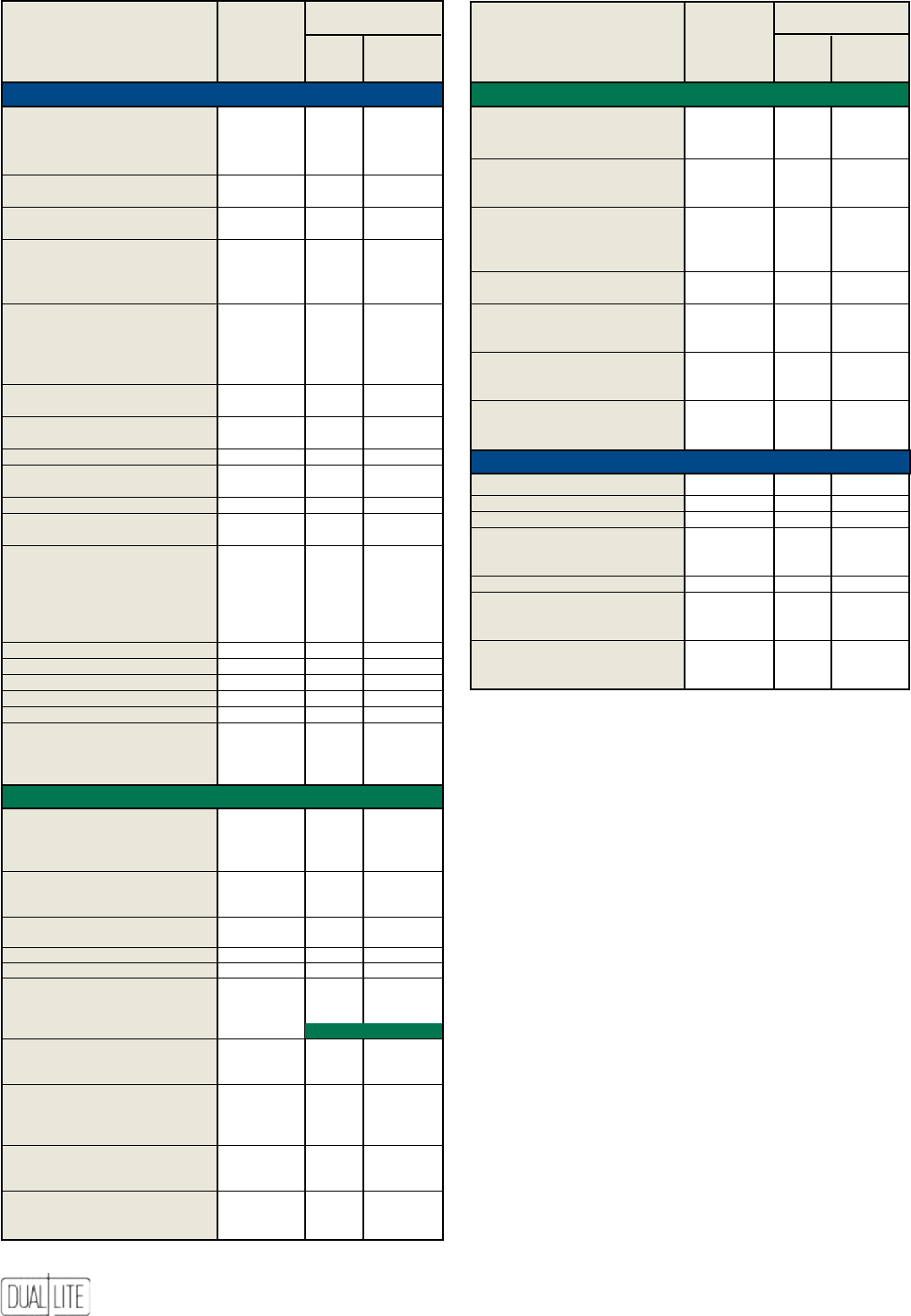
86
LimitedWarranty
Emergency Lighting Units and Batteries
Dual-Lite warrants to the purchaser that its products have been carefully manufactured and
inspected, and are warranted to be free from defect of workmanship and materials when used
as intended. See chart at left for duration of warranties for units and batteries (fuses and lamps
are excluded from all warranties).
Batteries must be placed in service or recharged within nine (9) months from invoice date or
ninety (90) days from recommended recharge date stamped on carton, whichever is longer
(NiCad batteries excluded).
The warranties are subject to proper installation and maintenance in accordance with the
instructions supplied. Any abuse or misuse contrary to normal operation shall void this
warranty.
This warranty does not cover damages caused by installation in areas with other than normal
temperatures and environmental conditions per application specifications. Dual-Lite assumes
no responsibility for any damage to people, property, apparatus or otherwise resulting from
improper installation or maintenance of its emergency lighting units.
Warranty coverage shall not apply to any equipment of another manufacturer used in conjunction
with Dual-Lite systems.
Warranty does not cover damages caused by abuse, fire or acts of God.
To obtain prior written approval to return defective items, please contact your local manufacturer’s
representative. After prior written notification has been given and approval obtained for the
return, merchandise may be returned, freight prepaid, to Dual-Lite.
Customer is responsible for secure packaging of returned materials to provide best possible
assurance against breakage in shipment.
If, upon inspection, the merchandise is found to be defective replacement or repair shall be
made. Dual-Lite’s sole obligation under this limited warranty is to repair or replace the defective
parts or products, at its discretion, providing such defective parts or products are brought to
its attention within the specified warranty time period, and does not include any other costs
such as removal of defective parts or product, installation, labor or consequential damages of
any kind, the exclusive remedy being to require such new parts or products to be furnished. All
other warranties, expressed or implied, including warranties of merchantability or warranties
of fitness for any particular purpose we hereby disclaim.
Dual-Lite Distributors and Representatives have no authority to change this warranty without
written permission from Dual-Lite.
Dual-Lite reserves the right to determine the best method of correcting warranty problems.
All specifications subject to change without notice.
Some states do not allow the exclusion of limitation of incidental or consequential damages, so
the above limitation or exclusion may not apply to you. This warranty gives you specific legal
rights, and you may also have other rights which vary from state to state.
Battery Warranty
Unit
Warranty Full Pro-Rata
Product (Years) (Years) (Years)
NYX LED exit
AC-Only models 5 – –
Emergency models 5 1 9
CMX exit
AC-Only models 5 – –
Emergency models 5 1 9
LE edge-lit LED exit
AC-Only models 5 – –
Emergency models 5 1 9
Emergency Spectron models 5 2 8
LES edge-lit LED exit
AC-Only models 5 – –
NYE edge-lit LED exit
AC-Only models 5 – –
Emergency models 5 1 9
NYES edge-lit LED exit
AC-Only models 5 – –
Emergency models 5 1 9
DEX special wording exit
AC-Only models 3 – –
Emergency models 3 1 5
SlimLite Series 1 1 5
CV Series 1 1 5
CVEC Series 1 1 5
CV3 LED exit
AC-Only models 5 – –
Emergency models 5 1 9
CVT Tandem LED exit 5 1 9
CVD cast LED exit
AC-Only models 5 – –
Emergency models 5 1 9
CVER edge-lit LED exit
AC-Only models 5 – –
Emergency models 5 1 9
Consult factory for warranties available with AC Inverter Systems.
Liteforms Exit Signs
Liteforms Emergency Lighting Units Liteforms Exit Signs
Clearview Life Safety Products
Battery Warranty
Unit
Warranty Full Pro-Rata
Product (Years) (Years) (Years)
LiteScape Series 1 1 5
with Spectron option 5 2 4
nicad battery models 1 1 9
nicad with Spectron option 5 2 4
EZ-2 Series 3 3 3
with Spectron option 5 5 5
LZ Series 1 1 5
with Spectron option 5 5 5
LZ High Capacity Series 1 1 5
with Spectron option 5 2 4
nicad battery models 3 1 9
nicad with Spectron option 5 2 8
LM Series
lead-calcium battery models 1 1 5
lead-calc. with Spectron option 5 2 4
nicad battery models 3 1 9
nicad with Spectron option 5 2 8
EZ-2R Series 3 3 3
with Spectron option 5 5 5
T-Grid Series 3 3 3
with Spectron option 5 5 5
EXT-122-EM Series 1 1 5
Lite2 Series 3 3 3
with Spectron option 5 5 5
Delite Series 1 1 5
N4X Series 3 3 3
with Spectron option 5 5 5
AS Series 1 1 5
with Spectron option 5 2 4
wet lead-acid battery models 1 1 9
wet lead-acid with Spectron option
5 2 8
wet nicad battery models 1 1 14
wet nicad with Spectron option 5 2 13
IPS Series 3 3 3
XPB Series 3 3 3
UFO-3AW, UFO-4W models 1 1 –
UFO-5W, UFO-12W models 2 2 –
UFO-5AW models 3 3 –
UFO-6W, UFO-6WI, 5 5 –
UFO-6W-CLD, UFO-7W, “ “ –
UFO-7WI, UFO-LP “ “ –
and UFO-MH models “ “ –
LX LED exit
AC-Only models 5 – –
Emergency models 5 1 9
Emergency Spectron models 5 2 8
DK incandescent exit
AC-Only models 3 – –
Emergency models 5 1 9
LT combo exit 5 1 5
Spectron models 5 2 4
NYXC combo exit 5 1 5
SMC combo exit 5 1 5
Sempra cast LED exit*
AC-Only models 5 – –
Emergency models 5 1 9
Emergency Spectron models 5 Lifetime
NYDC cast LED exit
AC-Only models 5 – –
Emergency models 5 1 9
LN4X wet location LED exit
AC-Only models 5 – –
Emergency models 5 1 9
Emergency Spectron models 5 2 8
Freedom LED aluminum exit
AC-Only models 5 – –
Emergency models 5 1 4
LEDS aluminum LED exit
AC-Only models 5 – –
Emergency models 5 1 9
* Includes Sempra, Sempra SC, SC-WL, MR and SERS Series exit signs.
87
Synchron Series Single-Phase Inverters ............................................ 88 to 91
Spectron LSN Series Single-Phase Inverters ...................................92 to 101
Trident Series Three-Phase Inverters ................................................... 103 to 106
Auxiliary Transfer Switching Device ...................................................................107
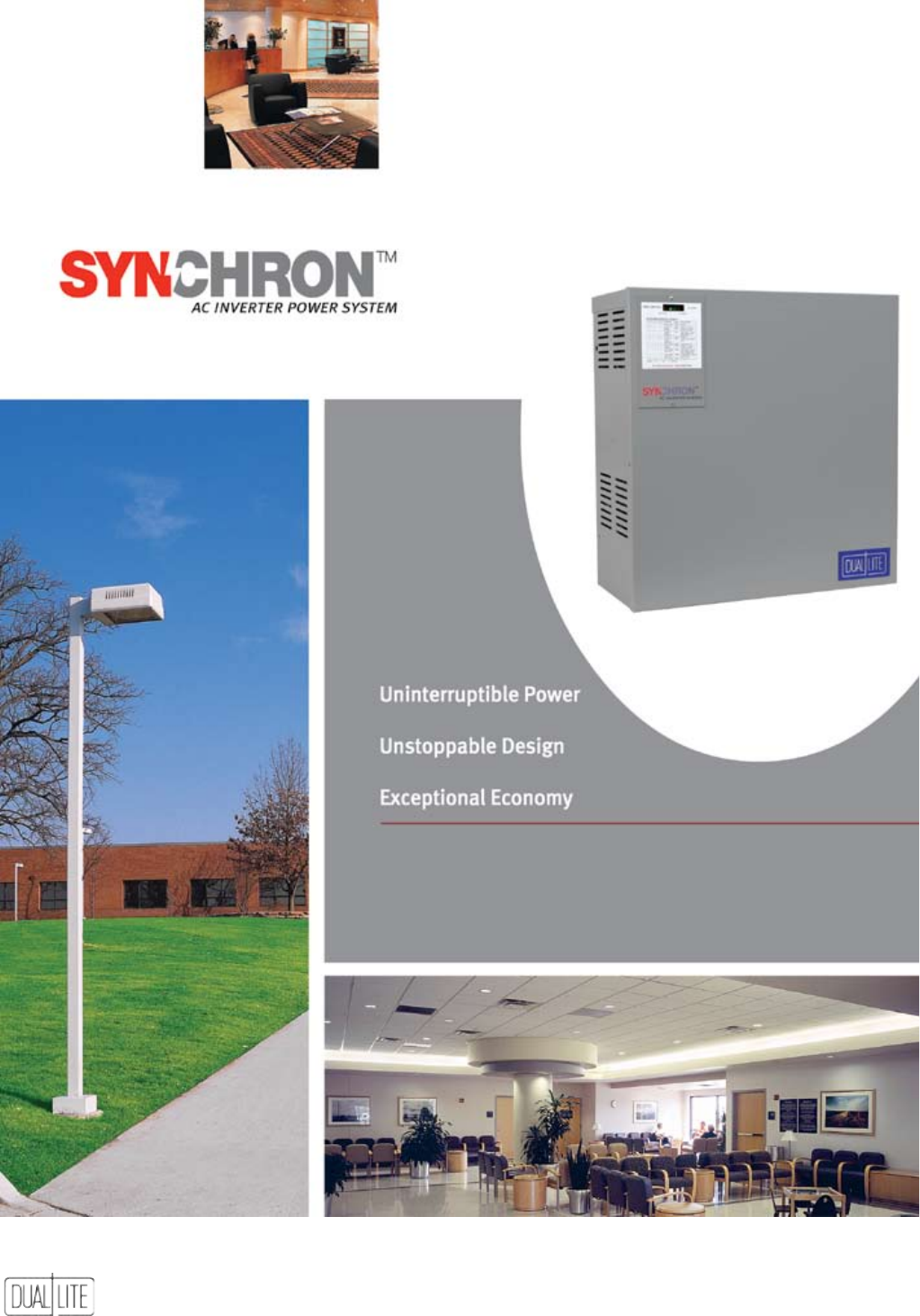
88
Single Phase Systems
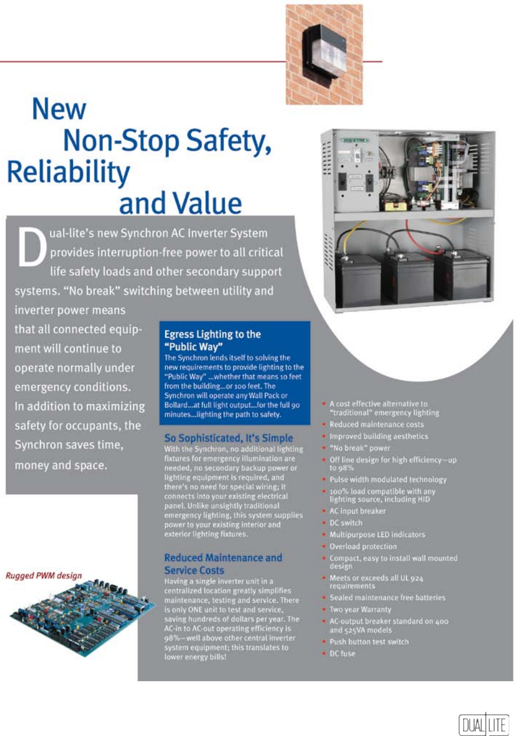
89
Single Phase Systems
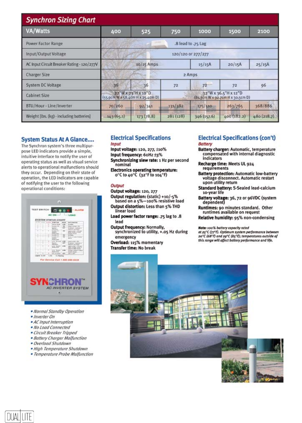
90
Single Phase Systems
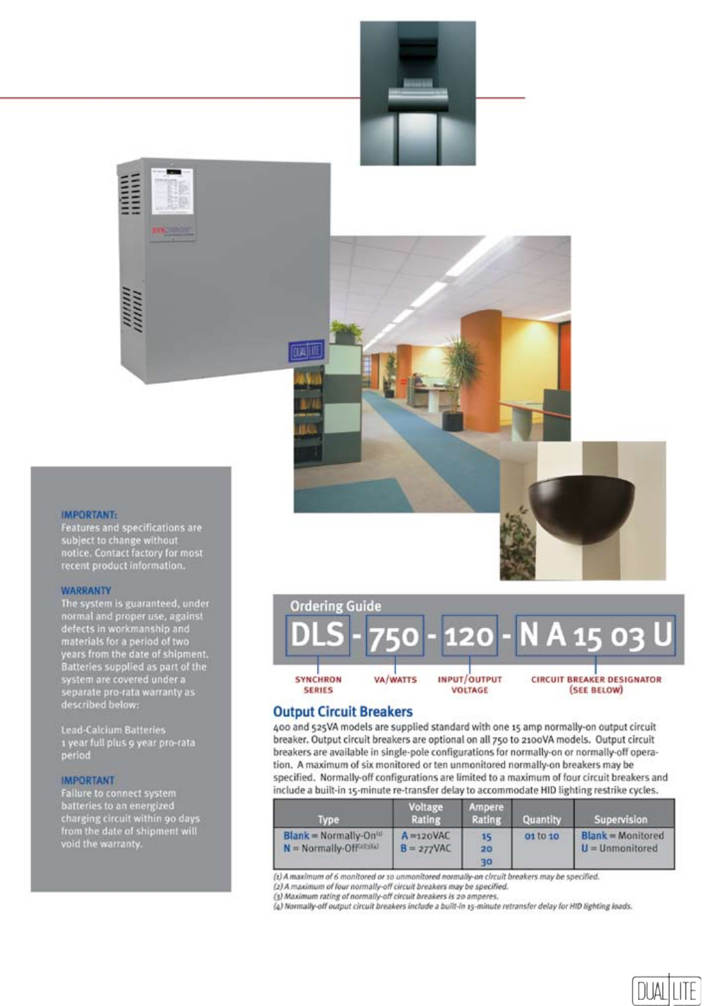
91
Single Phase Systems
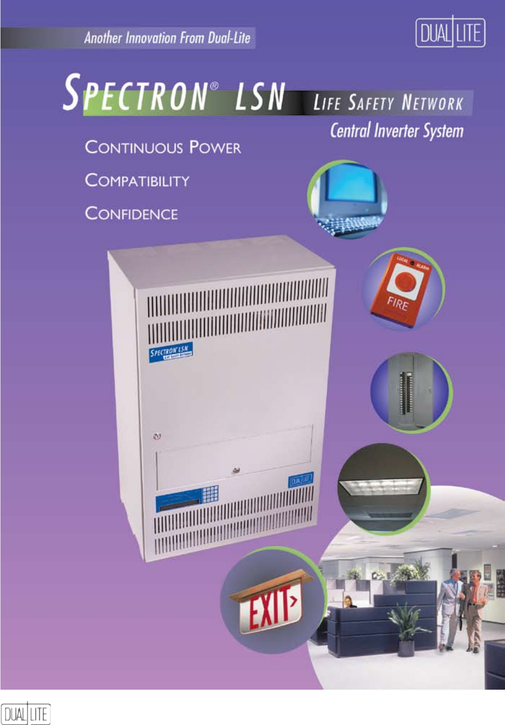
92
Single Phase Systems
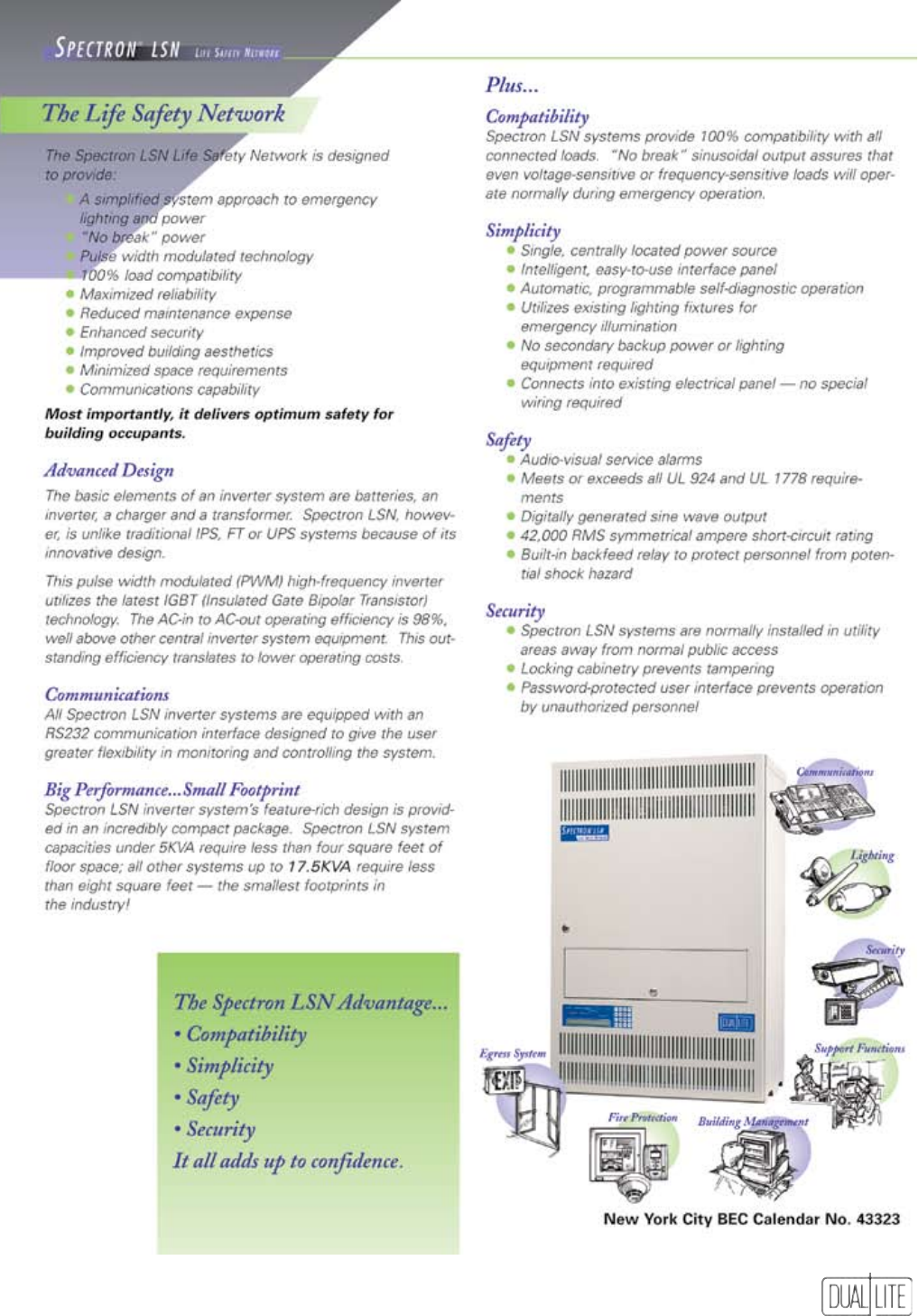
93
Single Phase Systems
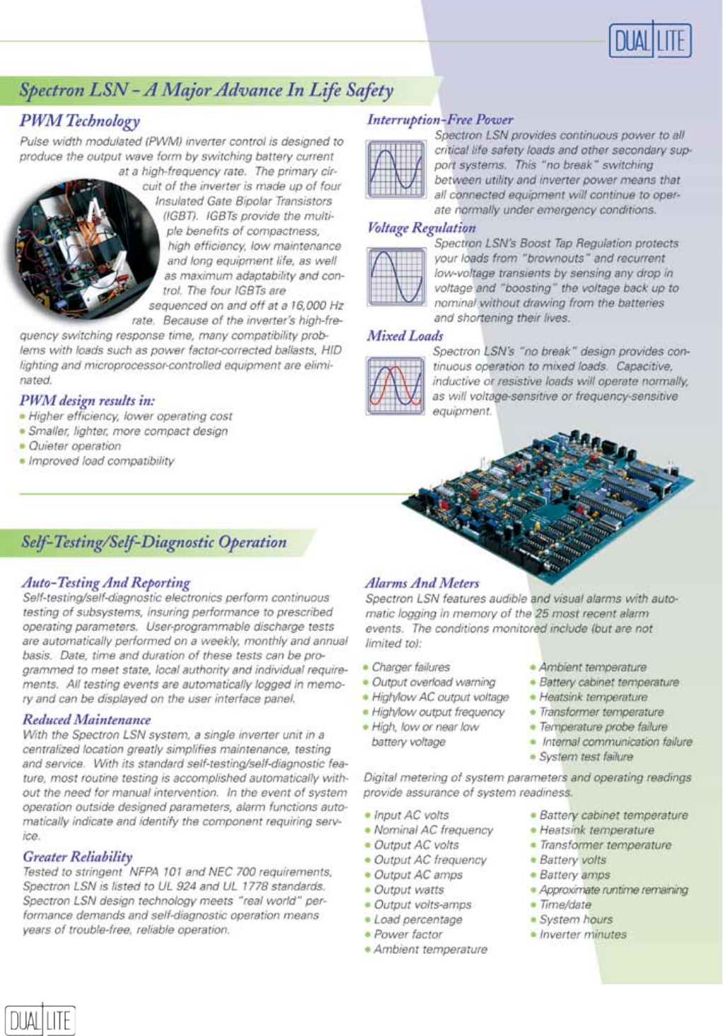
94
Single Phase Systems
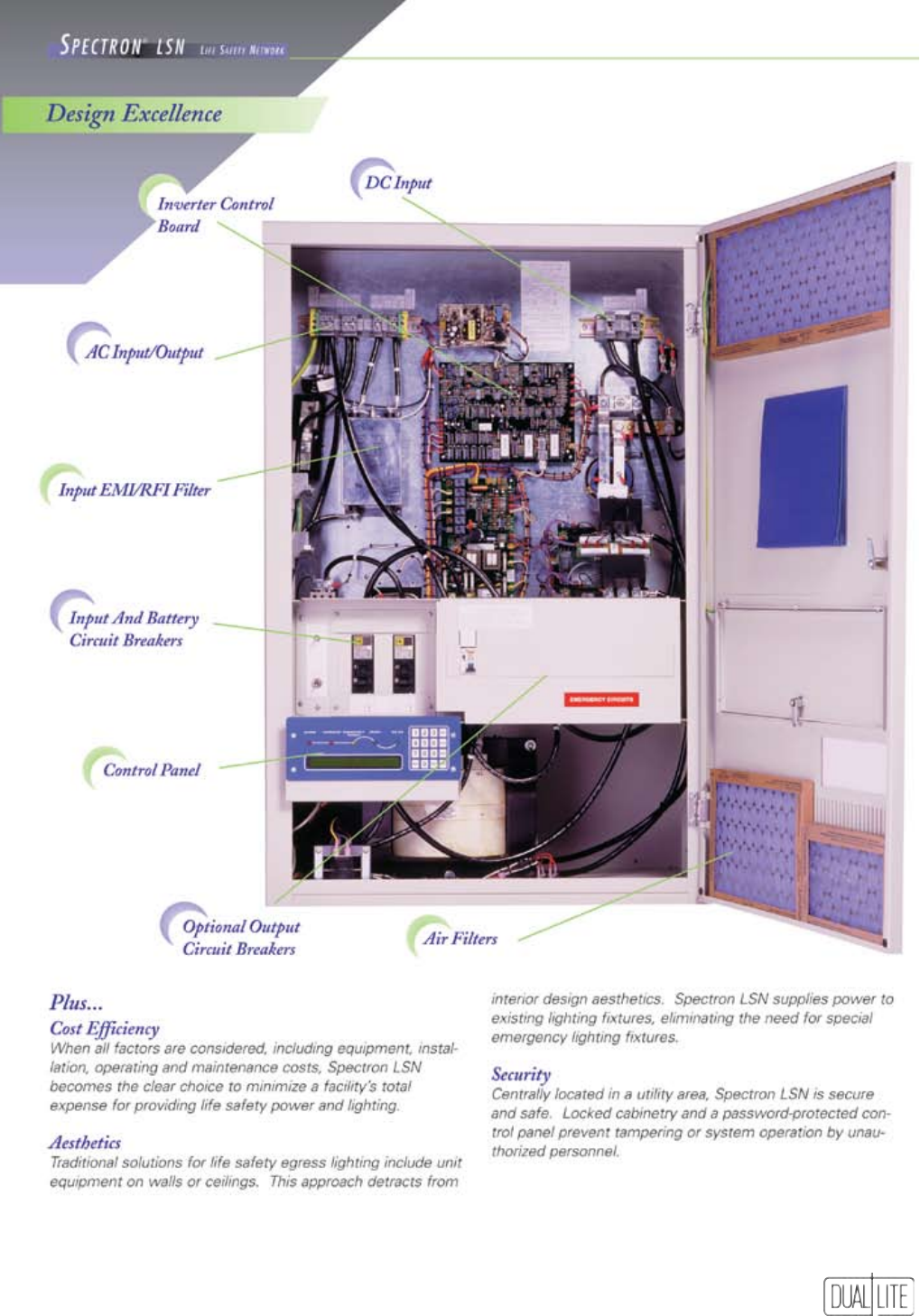
95
Single Phase Systems
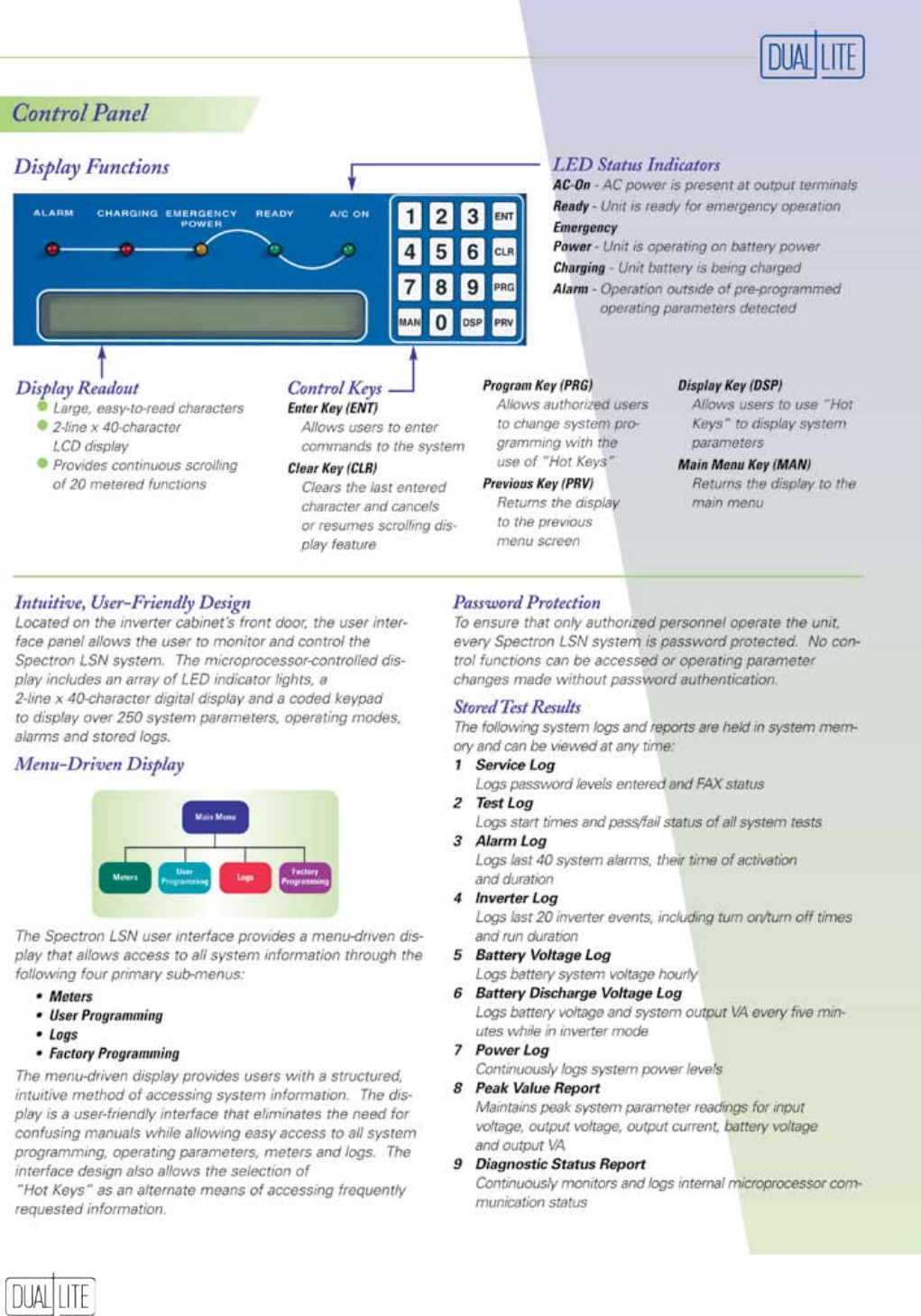
96
Single Phase Systems
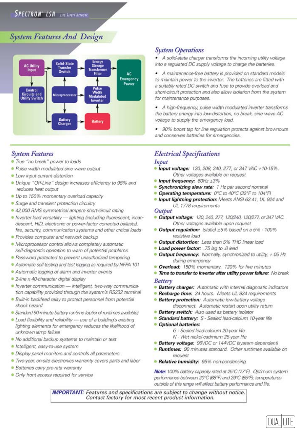
97
Single Phase Systems
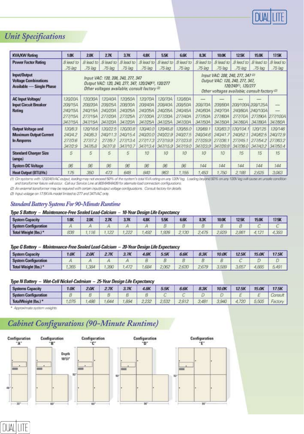
98
Single Phase Systems
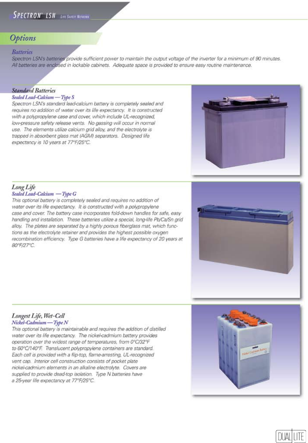
99
Note: Batteries for all Spectron LSN inverter
systems are shipped separately.
Batteries must be installed and energized within six
months of shipment or warranty is void.
Single Phase Systems
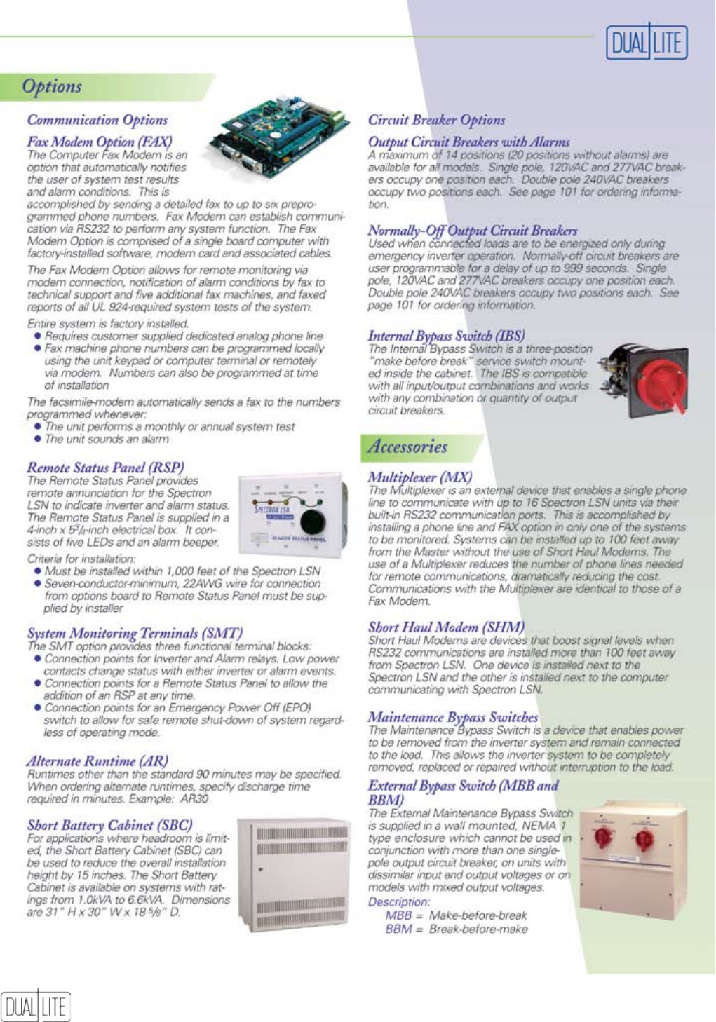
100
Single Phase Systems
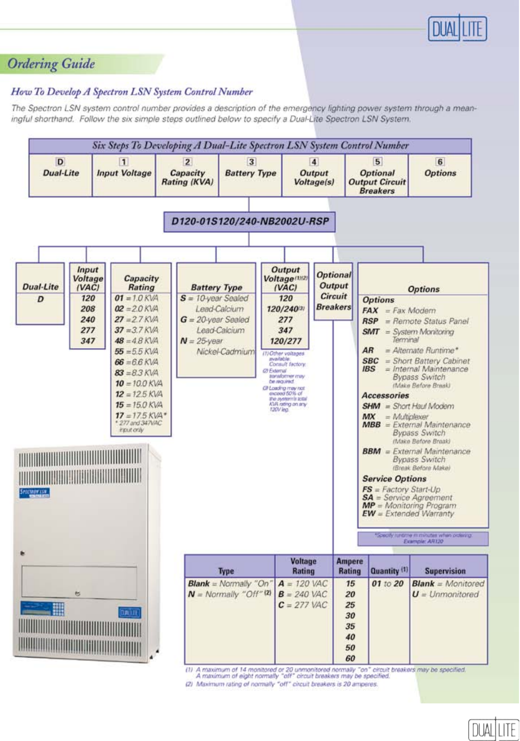
101
Single Phase Systems
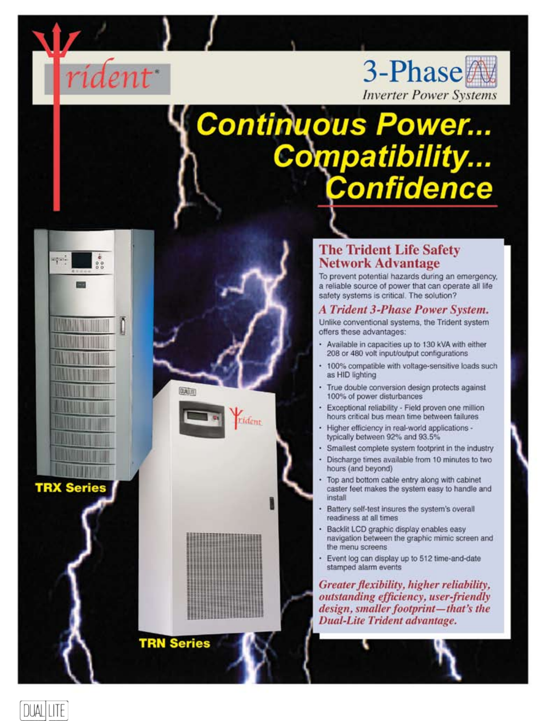
102
Three Phase Systems
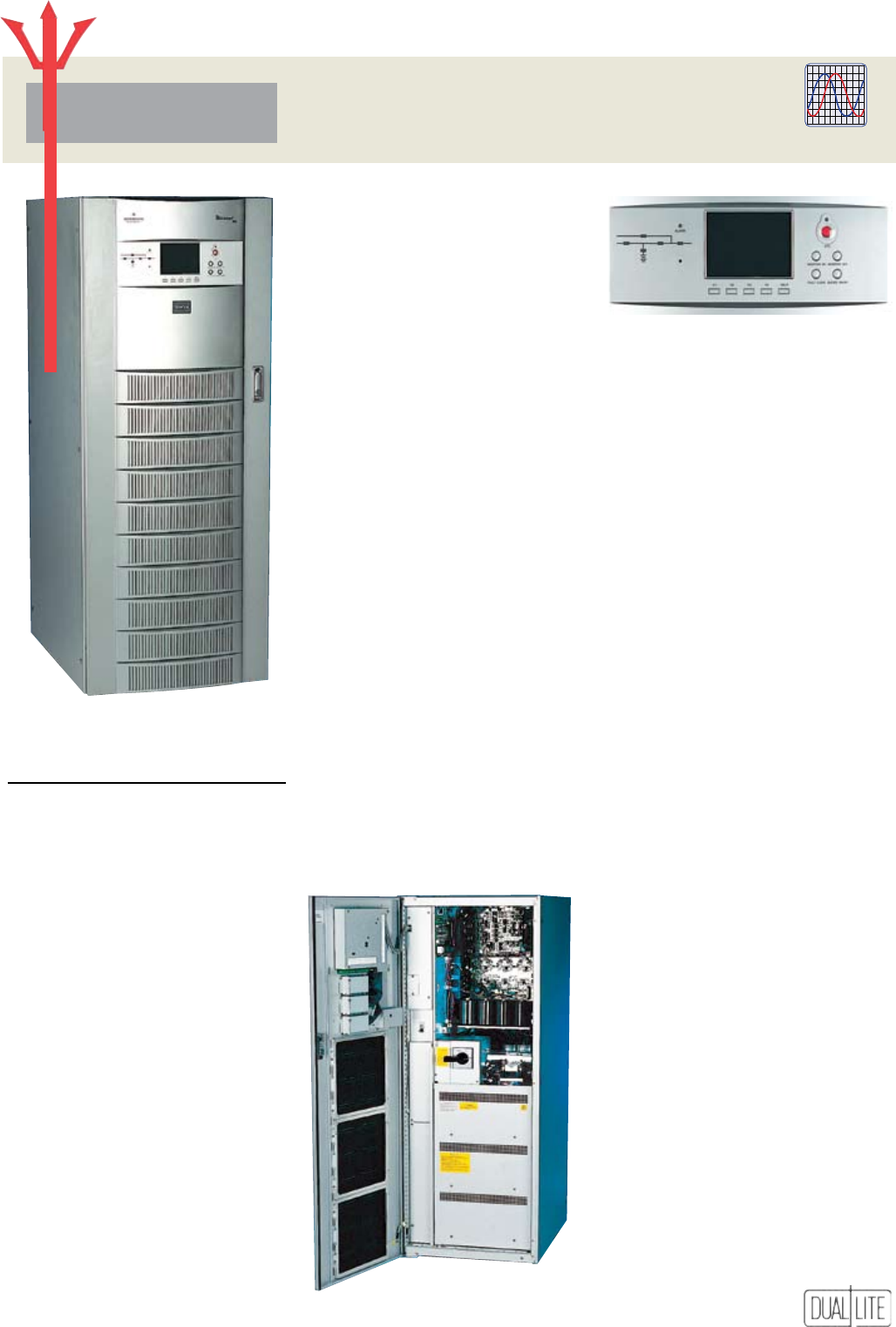
103
TRX Series
3-Phase
Inverter Power Systems
rident
TRX Three Phase Systems
10 to 30 kVA, 3-Phase UPS
Flexibility In Application
The Dual-Lite Trident TRX Series’
quiet operation, small footprint
and lightweight design is perfect
for installation in computer rooms,
yet the Trident TRX Series is
rugged enough for factory floors
or maintenance rooms. Precisely
controlled system output is suitable
for any lighting or critical life safety
loads up to the full rated output
capacity.
Outstanding Features
• Unmatched reliability
• Smallest system footprint
• Excellent efficiency with nonlinear
and partial loads
• Outstanding dynamic response
• All-digital ActiveStar controls and
graphical user interface
• Power factor corrected
• Harmonic current cancellation
GENERAL SPECIFICATIONS
INPUT
Voltage:
120/208VAC, 60Hz 3-phase, 4-wire
plus ground
Voltage Range: +10%, -20%
Frequency Range: 47-63Hz.
Current Distortion:
4% maximum reflected THD at
full load
Current Limit:
125% of full load input current
Walk-ln: 20 seconds to full load
Power Factor:
0.99 lagging minimum at full load
Surge Protection:
Sustains input surges without damage,
per criteria listed in IEC 1000-4-5
ENVIRONMENTAL
Operating Temperature:
UPS: 32°F to 104°F (0°C to 40°C)
Battery: 68°F to 86°F (20°C to 30°C)
Relative Humidity:
0-95% non-condensing
Operating Altitude:
Up to 3,300 ft. (1,000m)
without derating
Acoustical Noise:
Less than 54 dBA typical, measured 3.3
ft. (1 m) from the unit
OUTPUT
Voltage:
120/208VAC, 60Hz., 3-phase, 4-wire
plus ground
Voltage Adjustment Range: ±5%
Voltage Regulation:
1% for balanced load
2% for 100% unbalanced load
Dynamic Regulation:
±4% deviation for 100% load step
±1% for loss or return of AC input
Transient Response Time:
Recover to ±1% of steady state within
1 cycle
Voltage Distortion:
For linear loads, 1% THD. Less than
4% THD for 100% nonlinear loads
without kVA/kW derating
Phasing Balance:
120° ±0.5° for balanced load
120° ±1° for 100% unbalanced load
Frequency Regulation: ±0.1%
Load Power Factor Range:
0.70 lagging to 0.95 leading without
derating
Overload:
125% of full load for 10 minutes
150% for one minute, with true
sinusoidal waveform
Outstanding Support
Assistance is available from the
largest Customer service and Support
network in the country.
Standards
Complies with UL 1778 (UPS) and UL
924 (Emergency) standards, and is
CSA certified.
User Interface Panel
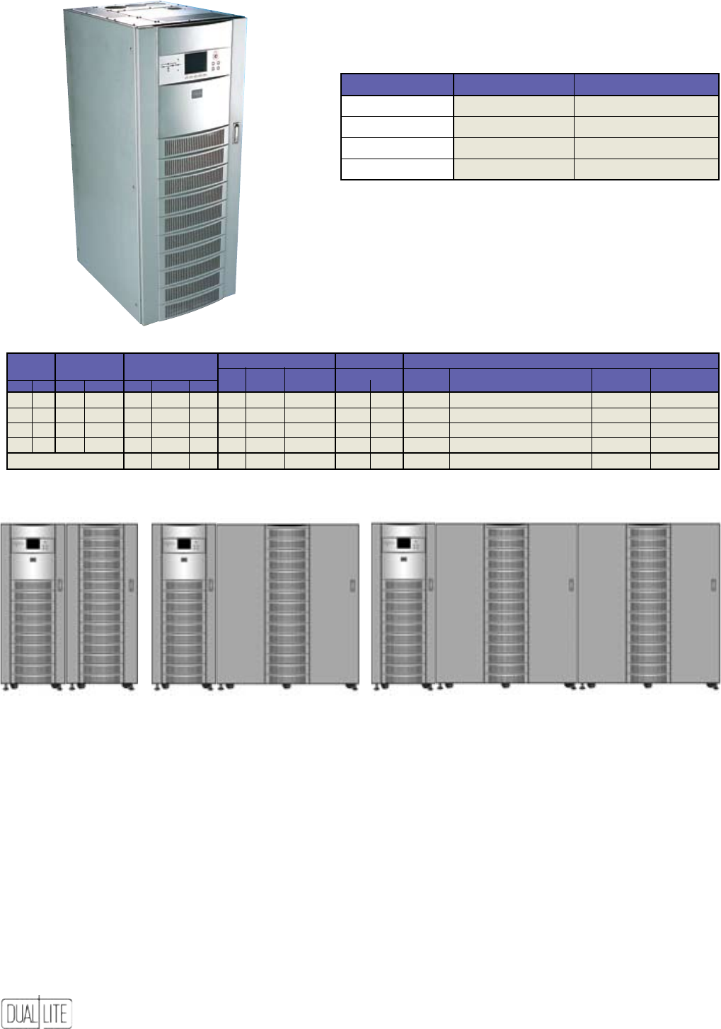
104
Site Planning Data Trident UPS - 90 Minute Operation 10-30 kVA, 3-Phase, 60 Hz.
SyStem AC AC Input BAttery AC Output meChAnICAl DAtA
rAtIng VOltAge Current nOm. BAttery mAx. Current nO. Of DImenSIOnS - WxDxh WeIght heAt DIS
kVA kW Input Output nOm. mAx. OCpD VDC kW DISChArge nOm. OCpD CABInetS InCheS (mm) IBS. (kg) Btu/hr (kWh)
10 8 208 208 28 35 50 288 9 37A 28 50 2 51x32.5x63 (1,295x826x1,600) 2,800 (1,275) 2,800 (0.82)
15 12 208 208 42 53 60 288 13 55A 42 60 2 51x32.5x63 (1,295x826x1,600) 3,350 (1,526) 4,200 (1.23)
20 16 208 208 56 70 80 288 18 73A 56 80 2 83x32.5x63 (2,057x826x1,600) 4,150 (1,890) 5,500 (1.61)
30 24 208 208 83 104 125 288 26 110A 83 125 3 142x32.5x63 (1,981x826x1,600) 6,650 (3,028) 8,300 (2.43)
See Notes For Table (Below):
-- 1,3,7 -- -- -- 1,3,7 1,3,7 6 -- -- -- --
10 and 15 kVA Models 20 kVA Models 30 kVA Models
(1)
(1) Contact factory for 480 VAC applications.
Product Selector
SIze kVA/kW upS CABInet nO. BAttery CABInet nO. (1)
10/8 TRXSAA10114 TRXBATAR141BNR
15/12 TRXSAB10114 TRXBATBR271BNR
20/16 TRXSAC10114 TRXBATCR371BNR
30/24 TRXSAD10114 TRXBATDR311BNR(2)
(1) 90 minute run time. Contact factory for other run times.
(2) Two battery cabinets required on 30 kVA models
Options
480 VAC Operation (Contact factory for proper configuration)
Intellislot Relay Board
Seismic Floor Kit
NOTES FOR TABLE:
1. UPS input and bypass cables must be run in separate conduit from output cables
2. Minimum-sized grounding conductors to be per NEC 250-122. Parity-sized ground conductors are recommended. Neutral conductors to be sized for full capacity per
NEC 310-15 (b)(4). References are per NEC 1999.
3. Wiring requirements:
AC Input: 3-phase, 4-wire, plus ground
AC Output: 3-phase, 3- or 4-wire, plus ground
4. All wiring is to be in accordance with national and local electric codes.
5. Minimum access clearance is 3 ft. (0.9m) front and 18 in. (457mm) above the UPS.
6. Top or bottom cable entry through removable access plates. Punch plate to suit conduit size, then replace.
7. Control wiring and power wiring must be run in separate conduit.
ADDITIONAL NOTES:
• If site configuration includes a backup emergency generator, it is recommended that the engine generator set be properly sized and equipped for a UPS application.
Generator options would typically include an isochronous governor (generator frequency regulation) and a UPS-compatible regulator (generator voltage regulation).
Consult generator manufacturer for required generator options and sizing.
• If site configuration includes an automatic transfer switch, refer to Power Line titled “Criteria for Application of Automatic Transfer Switches (ATS) With Uninterruptible
Power Supply (UPS) Systems,” publication 91K-PLT-48-02. It is also recommended that the transfer switch be equipped with auxiliary contacts for UPS “on generator”
current limit. Consult transfer switch manufacturer for required transfer switch options and sizing.
• If site configuration requires an external isolated maintenance bypass circuit, it should be noted that utility AC input might not be in phase with the UPS AC output.
Consult a Dual-Lite sales representative or applications engineer.
Cabinet Configurations
TRX Three Phase Systems
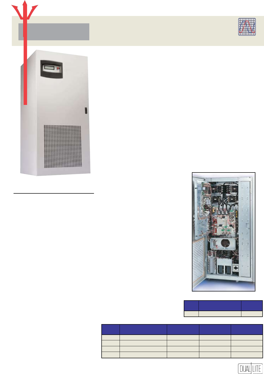
105
TRN Three Phase Systems
30 to 130 kVA, 3-Phase UPS
TRN Series
• Unmatched heritage of
reliability and availability
• Smallest system footprint
• Excellent efficiency with
nonlinear loads and partial loads
• Outstanding dynamic response
• All-digital controls and graphical
user interface
Dual-Lite has reinvented the dual-
conversion UPS. The TridentTM Series is
the result of an international design
collaboration and more than a decade of
advanced research.
Every aspect of the TridentTM Series shows
careful design and attention to detail.
The rugged power train and advanced
DSP controls were subjected to computer
simulations and thermal analysis to
ensure reliable performance in every
environment.
Even the physical packaging is uniquely
efficient, to make fully configured systems
more compact than our competitors.
Best of all, it’s a Dual-Lite product -
designed to deliver an impressive million-
hour critical bus MTBF.
Maintenance Bypass Cabinets
mODel DImenSIOnS (In.) WeIght (IB) WeIght (IB) WeIght (IB)
(WxDxh) 15-50 kVA 65-80 kVA 100-130 kVA
L 25 x 32.5 x 71 660 750 800
N 25 x 32.5 x 71 660 750 800
P 31.7 x 32.5 x 71 1,210 1,320 1,540
Q 31.7 x 32.5 x 71 1,210 1,320 1,540
Slim-Line Distribution Cabinet
kVA DImenSIOnS (In.) WeIght
(WxDxh) (IB)
All 10 x 32.5 x 71 250
GENERAL SPECIFICATIONS
INPUT
Voltage: 208 or 480 VAC, 60 Hz (3-phase,
3-or 4-wire plus ground)
Voltage Range: +10, -15% (no battery
discharge at-20%)
Frequency Range: 60 Hz, ± 5
Current Distortion: 10% maximum
reflected THD at full load with optional
input filter. 30% THD without filter
Current Limit: 115% of full load
input current
Current Walk-in: 20 seconds to full load
Power Factor: 0.80 lagging minimum at
full load. Up to 0.96 lagging at full load
with optional input filter
Surge Protection: Sustains input surges
without damage, per criteria
listed in ANSI C62.41-1980 (IEEE 587)
ENVIRONMENTAL
Operating Temperature: 0° to 40°C (UPS),
20° to 30°C (battery)
Non-Operating Temperature: -20°C
to 70°C
Relative Humidity: 0-95% non-condensing
Operating Altitude: Up to 6,600 feet
(2000 meters) without derating
Acoustical Noise: Less than 65 dBA 1
meter from unit (typical)
OUTPUT
Voltage: 208 or 480 VAC (3-phase, 4-wire
plus ground)
Voltage Adjustment Range: ±5%
Voltage Regulation:
±0.5% for balanced load
±1.0% for 100% unbalanced load
Dynamic Regulation: ±2.5% deviation for
100% load step.
±1% for loss or return of AC input
Transient Response: Recover to ±1% of
steady state within 1 cycle
Voltage Distortion: For linear loads,
1% THD. Less than 2.5% THD for 100%
nonlinear loads without kVA/kW derating
Phasing Balance: 120° ±0.5° for balanced
load. 120° ±1° for 100% unbalanced load
Frequency Regulation: ±0.1%
Load Power Factor Range: 1.0 to 0.7
lagging without derating
Overload: 125% of full load for ten
minutes. 150% for one minute, with true
sinusoidal waveform
STANDARDS
Complies with UL 1778 (UPS) and UL 924
(Emergency) standards, and is CSA certified.
3-Phase
Inverter Power Systems
rident
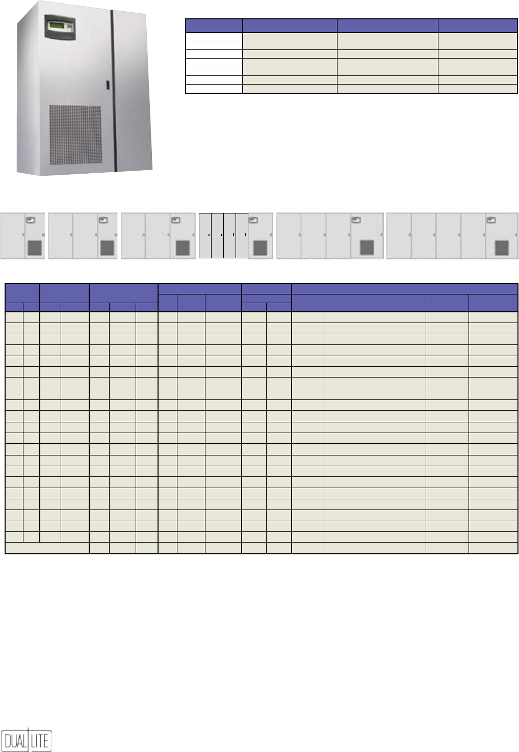
106
TRN Three Phase Systems
Site Planning Data Trident UPS - 90 Minute Operation 30-130 kVA, 3-Phase, 60 Hz.
SyStem AC AC Input BAttery AC Output meChAnICAl DAtA
rAtIng VOltAge Current nOm. BAttery mAx. Current nO. Of DImenSIOnS - WxDxh
WeIght heAt DIS
kVA kW Input Output nOm. mAx. OCpD VDC kW DISChArge nOm. OCpD CABInetS InCheS (mm) IBS. (kg) Btu/hr (kWh)
30 24 208 208 80 92 150 480 26 66A 83 125 2 80.7x32.5x71 (2,050x826x1,803) 7,250 (3,303) 8,500 (2.49)
30 24 480 208 33 38 60 480 26 66A 83 125 2 80.7x32.5x71 (2,050x826x1,803) 7,150 (3,257) 7,500 (2.19)
30 24 480 480 33 38 60 480 26 66A 36 50 2 80.7x32.5x71 (2,050x826x1,803) 6,950 (3,166) 11,000 (3.22)
40 32 208 208 106 122 175 480 34 88A 111 150 3 130x32.5x71 (3,294x826x1,803) 9,600 (4,373) 11,000 (3.22)
40 32 480 208 44 51 80 480 34 88A 111 150 3 130x32.5x71 (3,294x826x1,803) 9,500 (4,328) 10,000 (2.93)
40 32 480 480 44 51 80 480 34 88A 48 60 3 130x32.5x71 (3,294x826x1,803) 9,300 (4,237) 10,000 (2.93)
50 40 208 208 133 153 225 480 43 109A 139 175 3 130x32.5x71 (3,294x826x1,803) 10,200 (4647) 14,000 (4.10)
50 40 480 208 55 63 90 480 43 109A 139 175 3 130x32.5x71 (3,294x826x1,803) 10,100 (4601) 12,000 (3.51)
50 40 480 480 55 63 90 480 43 109A 60 80 3 130x32.5x71 (3,294x826x1,803) 9,900 (4510) 12,000 (3.51)
65 52 208 208 171 196 300 480 55 141A 180 25 3 137.4x32.5x71 (3,490x826x1,803) 12,800 (5831) 18,000 (5.27)
65 52 480 208 70 81 125 480 55 141A 180 225 3 137.4x32.5x71 (3,490x826x1,803) 12,600 (5740) 15,000 (4.39)
65 52 480 480 70 81 125 480 55 141A 78 100 3 137.4x32.5x71 (3,490x826x1,803) 12,400 (5649) 15,000 (4.39)
80 64 208 208 210 241 350 480 68 174A 222 300 5 139.4x32.5x71 (3,541x826x1,803) 14,700 (6697) 22,000 (6.44)
80 64 480 208 87 100 150 480 68 174A 222 300 5 139.4x32.5x71 (3,541x826x1,803) 14,500 (6606) 18,000 (5.27)
80 64 480 480 87 100 150 480 68 174A 96 125 5 139.4x32.5x71 (3,541x826x1,803) 14,300 (6515) 18,000 (5.27)
100 80 208 208 261 300 500 480 85 218A 278 350 4 196.2x32.5x71 (3,713x826x1,803) 18,950 (8633) 26,000 (7.61)
100 80 480 208 108 124 200 480 85 218A 278 350 4 196.2x32.5x71 (3,713x826x1,803) 18,750 (8542) 21,000 (6.14)
100 80 480 480 108 124 200 480 85 218A 120 150 4 196.2x32.5x71 (3,713x826x1,803) 18,550 (8451) 21,000 (6.14)
130 104 208 208 339 390 600 480 111 283A 361 450 5 245.2x32.5x71 (6,228x826x1,803)
24,000
(10934)
33,000 (9.66)
130 104 480 208 140 161 250 480 111 283A 361 450 5 245.2x32.5x71 (6,228x826x1,803)
23,800
(10843)
27,000 (7.90)
130 104 480 480 140 161 250 480 111 283A 156 200 5 245.2x32.5x71 (6,228x826x1,803)
23,600
(10751)
27,000 (7.90)
See Notes For Table (Below):
-- 1,3,7 -- -- -- 1,3,7 1,3,7 -- -- 8 8 --
Cabinet Configurations
ADDITIONAL NOTES:
• If site configuration includes a back-up emergency generator, it is recommended
that the engine generator set be properly sized and equipped for the unit’s
application. Generator options would typically include an isochronous governor
(generator frequency regulation) and a UPS-compatible regulator (generator
voltage regulation). Consult generator manufacturer for required generator
options and sizing.
• If site configuration includes an automatic transfer switch, refer to the Power
Line titled “Criteria for Application of Automatic Transfer Switches (ATS) with
Uninterruptible Power Supply (UPS) Systems” publication 91K-PLT-48-02. It is also
recommended that the transfer switch be equipped with auxiliary contacts for
the unit’s “on generator“ current limit. Consult transfer switch manufacturer for
required transfer switch options and sizing.
• If site configuration requires an external isolated maintenance bypass circuit,
it should be noted that utility AC input may not be in phase with the unit’s AC
output. Consult local sales representative or applications engineer.
Product Selector
SIze kVA/kW upS CABInet nO. (480/480) upS CABInet nO. (208/208) BAttery pACk nO.*
30/24 TRNSAD2026B TRNSAD1016B TRNBATDX471BNL
40/32 TRNSAE2026B TRNSAE1016B TRNBATEX312BNL
50/40 TRNSAF2026B TRNSAF1016B TRNBATFX372BNL
65/52 TRNSAG2026B TRNSAG1016B TRNBATGX472BNL
80/64 TRNSAH2026B TRNSAH1016B TRNBATHX274BNL
100/80 TRNSAI2026B TRNSAI1016B TRNBATIX473BNL
130/104 TRNSAJ2026B TRNSAJ1016B TRNBATJX474BNL
* 90 minute run time. Contact factory for other run times.
Options
Programmable Relay Board
Internal Modem
Network Interface Card
AS/400 Signal Cable
Remote Alarm Status Panel
80 kVA Models 130 kVA Models
100 kVA Models
30 kVA Models 65 kVA Models40 - 50 kVA Models
NOTES FOR TABLE:
1. The unit’s input and bypass cables must be run in separate conduit from
output cables.
2. Minimum-sized grounding conductors to be per NEC 250-122. Parity-sized
ground conductors are recommended. Neutral conductors to be sized for full
capacity per NEC 310-15(b)(4). References are per NEC 1999.
3. Wiring requirements:
AC Input: 3-phase, 3-wire plus ground or 3-phase, 4-wire plus ground
AC Output: 3-phase, 4-wire plus ground
DC Input: 2-wire (positive and negative), plus ground
4. All wiring is to be in accordance with national and local electrical codes.
5. Minimum access clearance is 3 feet front and 1 foot above the unit.
6. Top or bottom cable entry through removable access plates. Cut plate to suit
conduit size then replace.
7. Control wiring and power wiring must be run in separate conduit.
8. Weights and dimensions shown include battery cabinets.
9. OCPD-Overcurrent Protection Device.
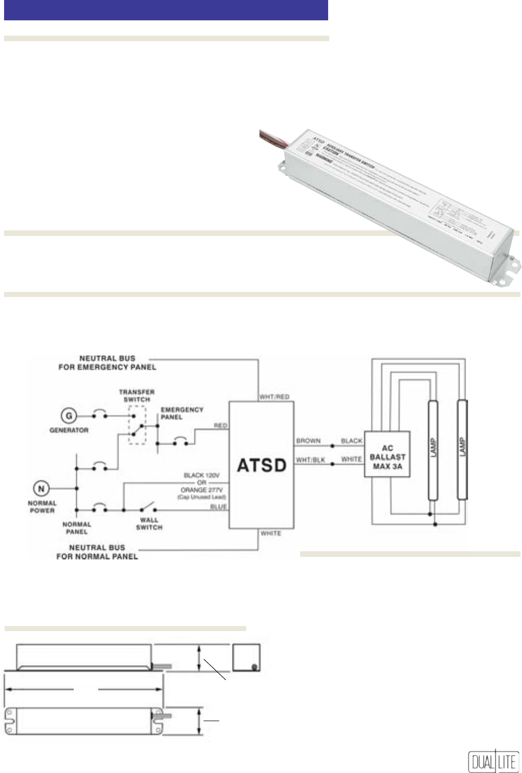
107
ATSD
1.18”
3.0cm
8.0”
20.4cm
1.18”
3.0cm
•
Device allows generator or inverter
supplied egress lighting fixtures to
be switched
• For factory or field installation
• Compatible with all
fluorescent fixtures
• Easy installation inside of
ballast channel
• For use with switched fluorescent
lighting fixtures
The ATSD auxiliary transfer device does not affect normal xture operation and comes fully assembled to mount in the xture
ballast channel. In addition to available wiring, the device requires a direct, unswitched connection to a generator- or inverter-
supplied emergency panel and an unswitched source on the same branch circuit as the switched supply (see diagram below).
• Battery case made of
galvanized steel
• Universal 120/277VAC operation
• Low power consumption
• Temperature range: 0°C to 50°C
(32°F to 122°F)
• UL Listed
ATSD
The ATSD auxiliary transfer switching device
works in conjunction with an auxiliary generator
or inverter power system to power existing
fluorescent fixtures for egress lighting regardless
of fixture wall switch position. The device consists
of relay switching circuitry and fusing in one
compact galvanized steel case. One auxiliary
transfer switch device per fixture can be used to
bypass fixture wall switch allowing the building’s
generator to bring on switchable fixtures and not
just those on “night-light” circuits. The auxiliary
transfer switch device is suitable for use in indoor-
dry or damp location fixtures. Recommended
applications include: auditoriums, classrooms, or
any other location with generator- or inverter-
supplied emergency lighting.
Features
Ordering Information
Installation
Dimensions
AuxiliAry TrAnsfer swiTching Device
Application

108
Notes

109
Notes

110
Notes

Dual-Lite • A Hubbell Lighting, Inc. Life Safety Products Brand • www.dual-lite.com
Copyright© Hubbell Lighting, Inc., All Rights Reserved • Specications subject to change without notice. • Printed in U.S.A. 0603254 3/06
