Installation Directions
2014-09-04
: Pdf 57757-Installationsheet 57757-InstallationSheet 006187 Batch7 unilog
Open the PDF directly: View PDF ![]() .
.
Page Count: 2
www.LEDtronics.com
PACKAGE INCLUDES: LED Tube(s) + Caution Label + Installation Instructions
READ AND FOLLOW ALL PRECAUTIONS AND INSTALLATION INSTRUCTIONS PRIOR TO INSTALLING LUMINAIRE
INSTR-LEDXXT8SM-0001-E / Rev. D 10/2013
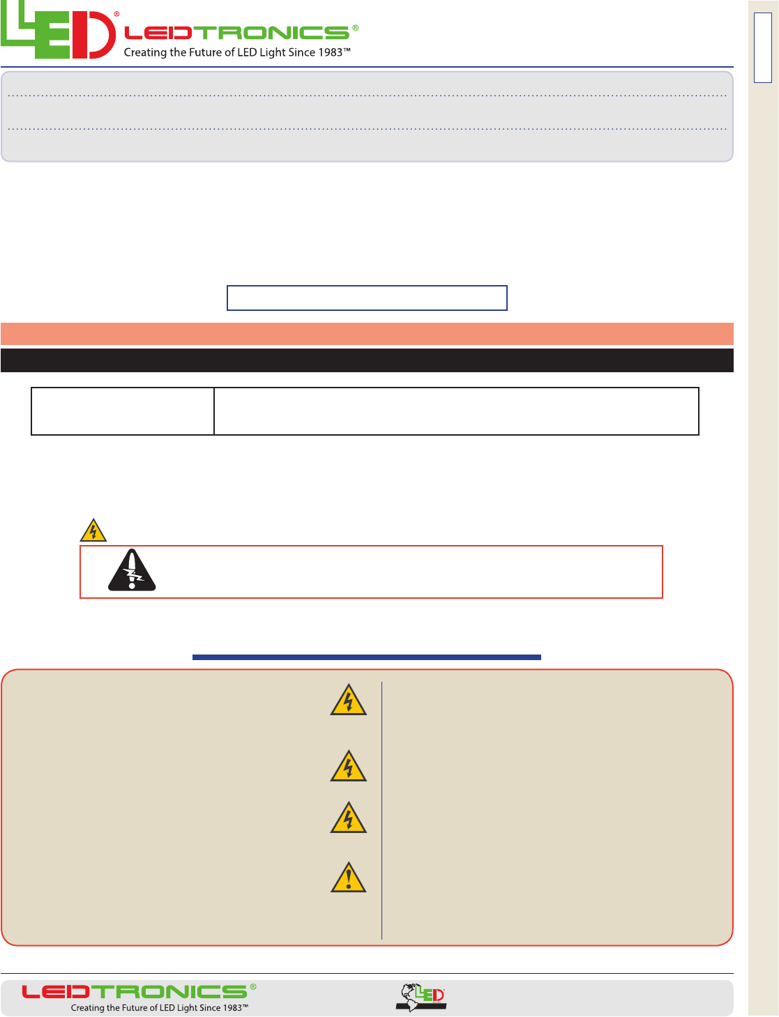
■THIS PRODUCT MUST BE INSTALLED IN ACCORDANCE WITH THE
APPLICABLE INSTALLATION CODE BY A PERSON FAMILIAR WITH
THE CONSTRUCTION AND OPERATION OF THE PRODUCT AND THE
HAZARDS INVOLVED.
■WARNING - Risk of re or electric shock. The electrical rating
of these products is 90-290 VAC; the installer must determine
whether they have 90-290 V at the luminaire before installation.
■WARNING - Risk of re or electric shock. Reector kit installation
requires knowledge of uorescent lighting luminaire electrical
systems. If not qualied, do not attempt installation–Contact a
qualied electrician.
■WARNING - Risk of re or electric shock. Install this kit only in
luminaires that have the construction features and dimensions
shown in the photographs and/or drawings.
■WARNING - To prevent wiring damage or abrasion, do not expose
wiring to edges of sheet metal or other sharp objects.
■Do not make or alter any open holes in an enclosure of wiring or
electrical components during kit installation.
■THE RETROFIT ASSEMBLY IS ACCEPTED AS A COMPONENT OF
A FLUORESCENT LUMINAIRE WHERE THE SUITABILITY OF THE
COMBINATION SHALL BE DETERMINED BY CSA OR AUTHORITIES
HAVING JURISDICTION.
■For lamp replacement, contact Ledtronics and use only LEDtronics
LED Tube lamps (G13 Base).
■Not for use with light dimmers.
■This device is not intended for use with emergency exit xtures or
emergency exit lights.
■LEDtronics suggests installing a luminaire disconnect for protection
when servicing uorescent lights.
Important Safety InStructIonS
DANGER – RISK OF SHOCK: Disconnect Power Before Installation
Installation Instructions
Use of the ETL-listed T8 lamps in conjunction with bypassing the ballast does not eect the overall
Certication status, since the xture is covered by the Listing of the lamp and its installation instructions.
ENSURE THAT POWER IS OFF WHEN INSTALLING, REMOVING OR CHANGING LEDT8 TUBE LAMPS.
DO NOT TOUCH/HANDLE TUBES WITH POWER APPLIED (ON).
UNPACKING
THE LEDTRONICS LED T8 LIGHT TUBE
After unpacking and saving packing materials, examine the Light Tube and check for any possible damage that
could have resulted from transport. If damaged, notify LEDtronics and return the tube(s) in the packaging.
The instructions in these guidelines cannot anticipate all conceivable wiring situations.
23105 Kashiwa Court, Torrance, CA 90505
Phone: (800) 579.4875 / (310) 534.1505
Fax: (310) 534.1424
E-mail: info@ledtronics.com
Website: ledtronics.com
SEE PAGE 2 FOR MORE INSTALLATION INSTRUCTIONS
(2-foot)
(latest
generation)
(previous
generation)
(3-foot) (4-foot) (5-foot)
© 2013 LEDtronics, Inc.
9001:2008ISO
CERTIFIED by DNV
LED Tube Lights, Two Pins at Each End (G13 Bipin Bases)
AC Line Voltage
LED24T8SM-96X2-xxx-x01Wxx
LED24T8SM-144-xxx-001Wxx
LED36T8SM-144X2-xxx-x01Wxx LED48T8SM-192X2-xxx-x01Wxx
LED48T8SM-276-xxx-001Wxx
LED60T8SM-240X2-xxx-x01Wxx
LED60T8SM-576-xxx-001Wxx
PAGE 1 of 2
www.LEDtronics.com
INSTR-LEDXXT8SM-0001-E / Rev. D 10/2013
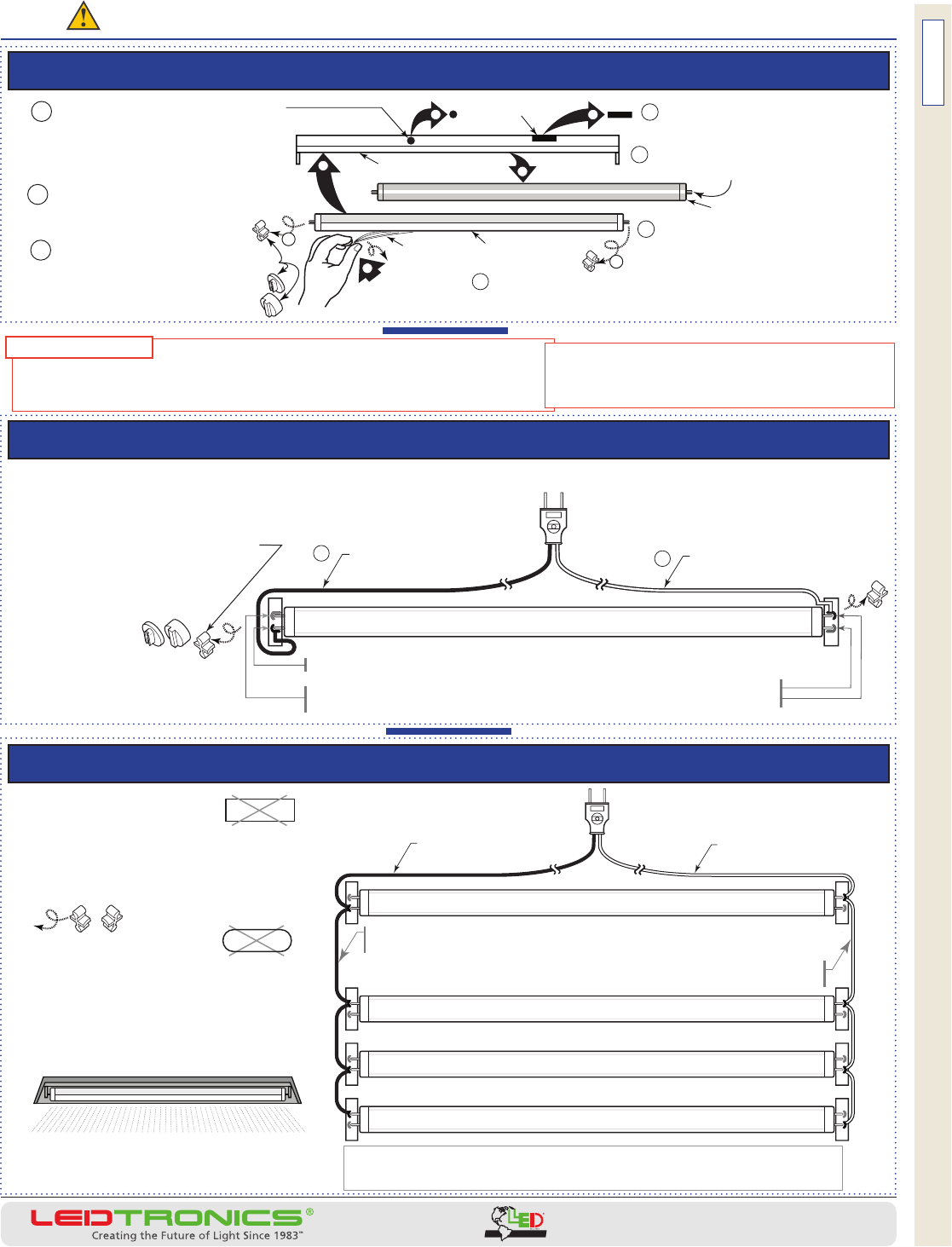
If the uorescent tube xture HAS A BALLAST (and starter, if separate)
If the uorescent tube xture has NO BALLAST
Wiring for xtures with MULTIPLE TUBES (2, 3 or 4-tube xtures)
DANGER – RISK OF SHOCK: Disconnect Power Before Installation
© 2013 LEDtronics, Inc.
9001:2008ISO
CERTIFIED by DNV
Ax the LEDtronics cautionary label to the xture if one is not present, and if the xture already uses LED tube lights,
or the installer knows the xture does not use a ballast.
Protective end
caps need to be
removed before
tube installation.
*
*
*
*
*
SIMPLIFIED
WIRING WILL
BYPASS
STARTER
(If present
on fixture)
STARTER
WIRING 90VAC to
290VAC
Input Cold Wire to any other pin
(Type with 1 hot wire, 1 cold wire,
with or without ground wire)
LEDTRONICS LED T8 TUBE WITH BI-PIN BASES
Hot Wire to an
The hot wire (line/black) can sequentially link by ANY ONE
of the pins on the LED tubes.
The cold wire (neutral/white) can sequentially link by
ANY OF THE OTHER THREE pins on the LED tube.
y pin
on one end.
Adhesive label included with LEDtronics tubes explains this fixture has been modified
for LED tube lights and no longer accepts fluorescent bulbs requiring a ballast.
> Place the provided label in a visible location inside the fixture.
WIRING WILL
BYPASS
BALLAST
(If present
on fixture)
BALLAST
The protective film
covering the tube lens
needs to be peeled off
before turning the
lamp on.
Be certain the tube lamp’s LEDs and their
light beams are directed outward
from the fixture.
LEDTRONICS LED T8 TUBE WITH BI-PIN BASES
LEDTRONICS LED T8 TUBE WITH BI-PIN BASES
LEDTRONICS LED T8 TUBE WITH BI-PIN BASES
. . . Then the xture should have a cautionary label identifying it as having
been rewired for LED lamps, and to never install uorescent lamps in it.
SIMPLIFIED WIRING 90VAC to
290VAC
Input Cold Wire to any other pin
(Type with 1 hot wire, 1 cold wire,
with or without ground wire)
Hot Wire to any pin
on one end.
The hot wire (line/black) can connect to ANY one of the pins at one end.
The cold wire (neutral/white) connects to ANY ONE of the other three
pins at either en
When installing, be
certain the tube lamp’s LEDs
and their light beams are
directed away from the fixture.
As illustrated above: Before installation,
remove the protective pin guards.
Before applying power, remove
the lens protector film from the
LEDtronics LED tube light.
d.
12
LEDTRONICS LED T8 TUBE WITH BI-PIN BASE
(The appearance of your
lamp’s pinguards may
vary from that pictured.)
PAGE 2 of 2
when bypassing a uorescent instant-on ballast:
If the fixture’s bipin sockets are shunted**, then connect a wire at each end.
(Connect hot wire to a pin of the socket at ONE END, and connect cold wire to a pin of the socket at the OTHER END.)
DO NOT connect both power wires at the same shunted bipin socket end.
Shunted sockets have a jumper wire connecting the bipins within
the socket, and are used in “instant-on” fluorescent fixtures. This
wiring exception pertains to converting instant-on ballasted
fluorescent fixtures to LED ballast-free fixtures.
**
WIRING EXCEPTION
*
FIXTURE
ballast
lens
protective
film
OLD TUBE
LEDTRONICS
TUBE
2 Remove the old T8 fluores-
cent tube from the fixture
6 Install LED tube with LEDs
directed to beam their light out
of the fixture.
6
3
2
3
7
Place cautionary label in a location inside the fixture
where the next bulb installer will see it.
4
4
4 Remove the protective
pin guard caps from the
LEDtronics tube, and. . .
5 Peel the lens protec-
tive plastic film from the
LEDtronics tube lens.
1
Make certain that the
fixture’s line voltage is
compatible with the
LEDtronics tube [90–290VAC].
(Pin guard caps
may vary in
appearance
from that
pictured.)
(electronic ballasts do not have a
separate starter)
5
LIGHTING
3 Remove or bypass ballast
(and starter, if present)
starter
