578440 Catalog 1
2014-05-16
: Pdf 578440-Catalog 1 578440-Catalog_1 782116 Batch3 unilog
Open the PDF directly: View PDF ![]() .
.
Page Count: 192 [warning: Documents this large are best viewed by clicking the View PDF Link!]

183
EATON CORPORATION New Zealand Product Guide
Power Control
Motor Control ......................................................................................................................185-229
XT/Xstart IEC Motor Control ..................................................................................................................................................... 186
XT/Xstart IEC Mini Contactors .................................................................................................................................................. 188
XT/Xstart IEC Contactors .......................................................................................................................................................... 190
Overload Relays ......................................................................................................................................................................... 196
IEC Manual Motor Protectors ................................................................................................................................................... 205
Electronic Motor-protective circuit-breaker PKE ........................................................................................................................ 208
IEC Manual Motor Protectors Accessories ............................................................................................................................... 209
IEC Motor Control Busbar Adapters ......................................................................................................................................... 212
Contacts for safety-relevant control functions .......................................................................................................................... 213
IEC Power Control, dimensions ................................................................................................................................................ 214
DOL Starters ............................................................................................................................................................................. 224
Contactor & Starter Assemblies ............................................................................................................................................... 225
1000V Mining Contactors .......................................................................................................................................................... 227
IT, IEC Contactors & Starters .................................................................................................................................................... 228
Accessories for IT Motor Control .............................................................................................................................................. 229
Drives & Soft Starters ........................................................................................................ 230-236
Soft starters............................................................................................................................................................................... 231
Variable Speed Drives ............................................................................................................................................................... 233
Control & Indication ...........................................................................................................237-285
22.5mm Pushbuttons ................................................................................................................................................................ 238
SL signal towers ........................................................................................................................................................................ 252
30.5mm Pushbuttons ................................................................................................................................................................ 256
30.5mm Pushbuttons Control Stations & Enclosures ............................................................................................................... 267
30.5mm Pushbuttons Accessories............................................................................................................................................ 268
30.5mm Pushbuttons, dimensions & technical data ................................................................................................................. 270
Cam switches ............................................................................................................................................................................ 273
Automation & Control ........................................................................................................ 286-362
Easy Relay controllers ............................................................................................................................................................... 287
XC100/200 Programmable logic controllers .............................................................................................................................. 293
Easy Control relays & accessories ............................................................................................................................................ 295
ELC Programmable logic controllers ......................................................................................................................................... 297
Panelmate Operator Interfaces ................................................................................................................................................. 299
ELC Graphic Touch Panels ......................................................................................................................................................... 300
HMi Operator Interfaces ........................................................................................................................................................... 300
LS - Titan Position Switches .......................................................................................................................................................301
E50 Heavy duty modular Limit Switches ...................................................................................................................................301
E49 metal body compact Limit Switches ................................................................................................................................. 307
E49 plastic modular DIN Limit Switches ....................................................................................................................................310
10316H series Rotating Shaft Limit Switches ........................................................................................................................... 312
ME40 single- & two-pedal Foot Switches ................................................................................................................................. 312
E2020 Heavy Duty Pull Wire Switches ..................................................................................................................................... 313
iProx Programmable Proximity Sensors .................................................................................................................................... 314
AccuProx Analogue output Proximity Sensors .......................................................................................................................... 315
SpeedSense Proximity Sensors ................................................................................................................................................ 315
General purpose Inductive Proximity Sensors .......................................................................................................................... 316
General purpose Capacitive Proximity Sensors ........................................................................................................................ 318
Cables for Plug-In Proximity Sensors ........................................................................................................................................ 326
Photoelectric Sensors ............................................................................................................................................................... 327
CurrentWatch Current Sensors & Switches .............................................................................................................................. 335
Plug In Relays - D2 Series ......................................................................................................................................................... 342
Plug In Relays - D3 series ......................................................................................................................................................... 343
Plug In Relays - D4 Series ......................................................................................................................................................... 344
Plug In Relays - D7 Series ......................................................................................................................................................... 345
Plug In Relays - D8 Series ......................................................................................................................................................... 346
Plug In Relays - D9 Series ......................................................................................................................................................... 346
Interface Relays – XR series ..................................................................................................................................................... 347
Rhomberg Monitoring Relays.................................................................................................................................................... 348
EMR4 measuring & monitoring relays ...................................................................................................................................... 349
Rhomberg Control Relays ......................................................................................................................................................... 351
Timers ....................................................................................................................................................................................... 351
Time Switches ........................................................................................................................................................................... 353
Counters .................................................................................................................................................................................... 354

184 EATON CORPORATION New Zealand Product Guide
Power Control
Automation & Control (cont.) ............................................................................................ 286-362
Ratemeters................................................................................................................................................................................ 355
Hour Meters .............................................................................................................................................................................. 356
Water Pump Pressure Switches ............................................................................................................................................... 357
Riko Float Switches ................................................................................................................................................................... 357
DC Power Supplies ................................................................................................................................................................... 358
Liquid Level Controllers ............................................................................................................................................................. 358
MCS Pressure Switches ........................................................................................................................................................... 359
SW Float switches .................................................................................................................................................................... 361
Temperature Controllers ............................................................................................................................................................ 362
Wiring Accessories ..............................................................................................................363-374
Feed-Through Terminals ............................................................................................................................................................ 363
Earth Terminals .......................................................................................................................................................................... 367
Double Deck/Duo Terminals ...................................................................................................................................................... 368
Disconnect Terminals ................................................................................................................................................................ 369
Fuse Terminals ........................................................................................................................................................................... 370
Marking Tags ............................................................................................................................................................................. 371
DIN Rail & Ducting .................................................................................................................................................................... 372
Cable Accessories ..................................................................................................................................................................... 373

185
EATON CORPORATION New Zealand Product Guide
Power Control
• Easy to Install
• Small Footprint
• Global Approvals
• Type 2 Coordination
• Full range of IEC Motor Control
IEC Motor Control
Motor Control
Motor Control

186
Power Control
EATON CORPORATION New Zealand Product Guide
Motor Control
Motor Control
XT/Xstart IEC Motor Control
The XT/XStart range of contactors, overloads & manual motor protectors is
a complete range of IEC motor control. XT/XStart is an efficient & effective
solution for applications from 7-2000A.
Eaton & Moeller Item Numbers
The XT/XStart range of IEC Motor Control was the result of a joint venture between Eaton
& Moeller. This pricebook lists these products side by side because the items are identical,
apart from branding. Accessories & components are interchangeable between the XT &
XStart ranges.
If you have always ordered these products from Moeller, you can continue to use the part
numbers you have always used. Likewise, if you have ordered parts from Eaton, you can
order the Eaton part numbers as before.
Key Features
Feature: AC & DC devices with the same dimensions achieved with an electronically
controlled coil system.
Benefit: Space savings, reduced engineering design time.
Feature: Twin terminals with separate sockets in contactors up to 400A.
Benefit: Offers installation & application flexibility when using different size wires. The
improved integrity of the connections reduces cabling faults.
Feature: Reduced sealing power consumption for DC contactors due to an electronic coil
controller that uses less power.
Benefit: With sealing wattage as low as 0.5W, XT/XStart contactors reduce power
consumption & generate less heat. This results in lower cooling requirements,
& the ability to mount more contactors per cabinet.
Feature: Integrated suppressors in DC controlled contactors from 7–1000A. Integrated
surge suppressors in all contactors from 115A & above.
Benefit: Offers reductions in total logistics & inventory costs by limiting the number of
products ordered & stocked. Increased installation & maintenance efficiency,
as wiring is not required.
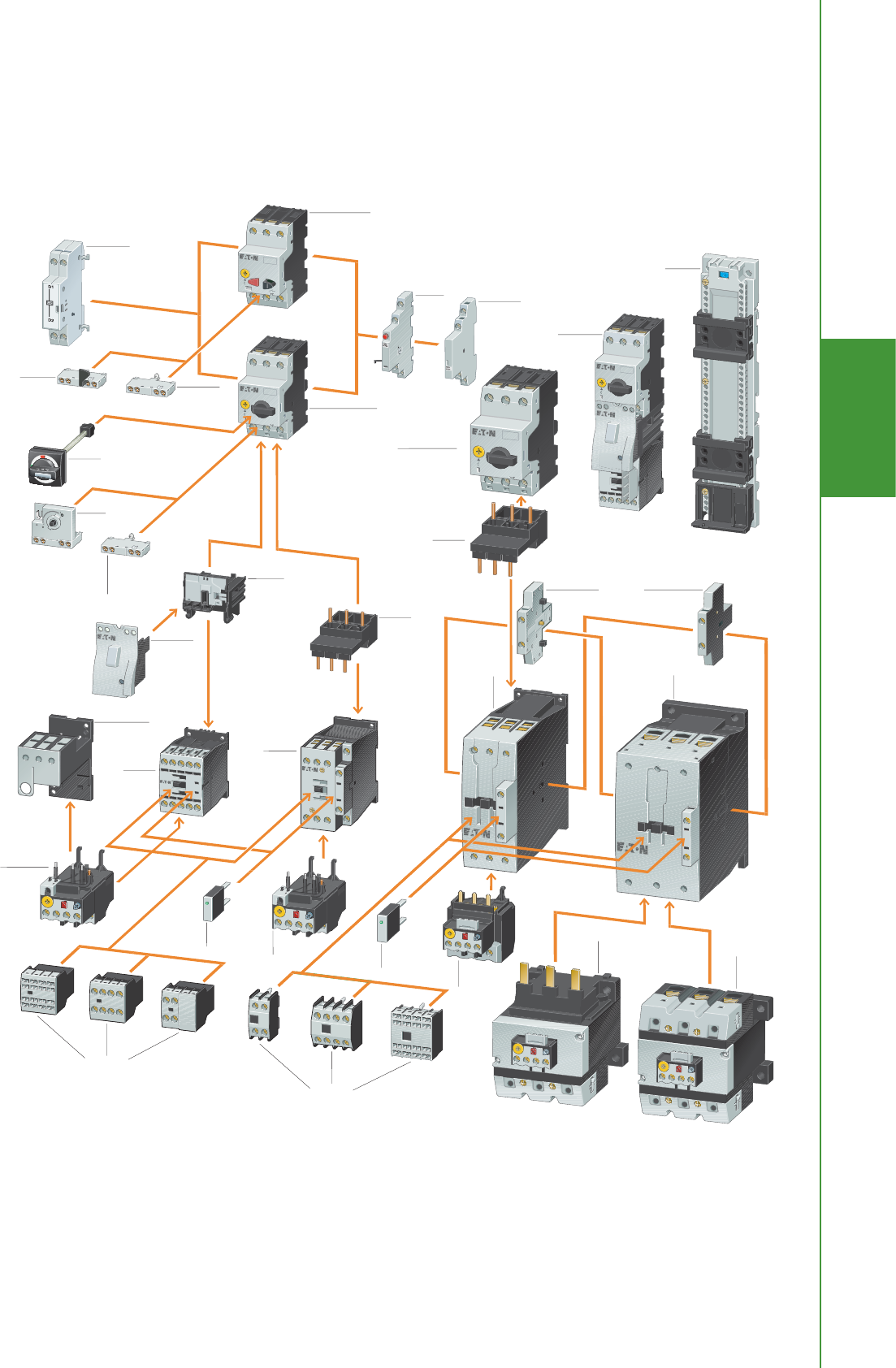
Manual Motor
Controller
Insulated
flush mount
enclosure
Current
limiter
Insulated surface
mount enclosure
with emergency-
stop actuator
Early-make
auxiliary contact
Top-hat
rail adapter
Door coupling rotary
handle and axis extension
Shunt and
undervoltage
release
Manual Motor
Protector with
pushbutton actuation
up to 25A
Manual Motor Protector
with rotary actuation
up to 32A
Trip-
indicating
auxiliary
contact
Side mounting
auxiliary contact
Mechanical
connector
up to 15A
Electrical
connector
Tool-less plug
connector
Front mounting
auxiliary contact
Early-make
auxiliary
contact
Side mounting
auxiliary contact
Contactor
up to 32 A
Top mounting
auxiliary contact
Contactor up to 150 A
Overload relay
up to 150 A,
separate mounting
Overload relay
up to 150 A
Contactor
up to 65 A
Overload relay
up to 65 A
Overload relay
up to 32 A
Suppressor
Suppressor
Front
mounting
auxiliary
contact
Contactor
up to 15 A
Overload relay
up to 15 A
Overload relay separate
mounting adapter
up to 65A
XT
IEC Power Control
Eaton Electrical
1000 Cherrington Parkway
Moon Township, PA 15108-4312
USA
tel: 1-800-525-2000
www.EatonElectrical.com
© 2005 Eaton Corporation
All Rights Reserved
Printed in USA
Publication No. PT03407002E
April 2005
Manual Motor Protector
with rotary actuation
up to 65A
Electrical
connector
Top mounting
auxiliary contact
Eaton's
PT03407002E XT IEC Power Control Poster.pdf 4/1/2010 12:14:13 PM
187
Power Control
EATON CORPORATION New Zealand Product Guide
Motor Control
Motor Control
Manual Motor
Controller
Insulated
flush mount
enclosure
Current
limiter
Insulated surface
mount enclosure
with emergency-
stop actuator
Early-make
auxiliary contact
Top-hat
rail adapter
Door coupling rotary
handle and axis extension
Shunt and
undervoltage
release
Manual Motor
Protector with
pushbutton actuation
up to 25A
Manual Motor Protector
with rotary actuation
up to 32A
Trip-
indicating
auxiliary
contact
Side mounting
auxiliary contact
Mechanical
connector
up to 15A
Electrical
connector
Tool-less plug
connector
Front mounting
auxiliary contact
Early-make
auxiliary
contact
Side mounting
auxiliary contact
Contactor
up to 32 A
Top mounting
auxiliary contact
Contactor up to 150 A
Overload relay
up to 150 A,
separate mounting
Overload relay
up to 150 A
Contactor
up to 65 A
Overload relay
up to 65 A
Overload relay
up to 32 A
Suppressor
Suppressor
Front
mounting
auxiliary
contact
Contactor
up to 15 A
Overload relay
up to 15 A
Overload relay separate
mounting adapter
up to 65A
XT
IEC Power Control
Eaton Electrical
1000 Cherrington Parkway
Moon Township, PA 15108-4312
USA
tel: 1-800-525-2000
www.EatonElectrical.com
© 2005 Eaton Corporation
All Rights Reserved
Printed in USA
Publication No. PT03407002E
April 2005
Manual Motor Protector
with rotary actuation
up to 65A
Electrical
connector
Top mounting
auxiliary contact
Eaton's
PT03407002E XT IEC Power Control Poster.pdf 4/1/2010 12:14:13 PM

188
Power Control
EATON CORPORATION New Zealand Product Guide
Motor Control
Motor Control
XT/Xstart IEC Mini Contactors
IEC Miniature Controls
Due to its compact size, the XT line of mini controls is best suited to be applied in light duty loads such as hoisting, packaging,
material handling, heating, lighting & automation systems. XT mini contactors are a particularly compact, economic &
environmentally friendly solution wherever control of small motors or loads is required.
Mini Contactors E9
Operational Current
AC-3 Amp Rating
Thermal Current
AC-1
Maximum kW Ratings AC-3, 3-Phase Motors,
50 – 60 Hz
No. of
Power Poles Aux. Contacts Eaton Item No.
Moeller
Item No.
240V 415V
6.6 20 1.5 33 1NO XTMC6A10_ -
6.6 20 1.5 33 1NC XTMC6A01_ -
8.8 20 2.2 43 1NO XTMC9A10_ DILEM-10(…)
8.8 20 2.2 43 1NC XTMC9A01_ DILEM-01(…)
8.8 20 2.2 44 - XTMF9A00_ DILEM4(…)
Underscore (_) indicates Magnetic Coil Suffix required. See Coil Selection Chart.
Coil Selection Chart
AC Coil Voltage (50Hz) Eaton Suffix Code Moeller Suffix Code DC Coil Voltage Eaton Suffix Code Moeller Suffix Code
415 C (415V50HZ,480V60HZ) 24 TD G(24VDC)
230-240 F (240V50HZ)
110 A (110V50/60HZ)
24 T (24V50HZ)
ote:N Mini Contactor Coils are not interchangeable. For additional coil voltages contact Eaton.
IEC Miniature Overload Relays
• Trip Class 10A
• Ambient temperature compensated -5° to 50°C
• Selectable manual / automatic reset
• 1NO-1NC auxiliary contact as standard
• Direct mount with XTMC contactors
Mini Overload Relays E9
Motor full load current (FLC) Trip Class Contact Configuration Eaton Item No. Moeller Item No.
0.1 – 0.16A
0.16 – 0.24A
0.24 – 0.4A
0.4 – 0.6A
10A 1NO-1NC XTOMP16AC1
XTOMP24AC1
XTOMP40AC1
XTOMP60AC1
ZE-0,16
ZE-0,24
ZE-0,4
ZE-0,6
0.6 – 1A
1 – 1.6A
1.6 – 2.4A
10A 1NO-1NC XTOM001AC1
XTOM1P6AC1
XTOM2P4AC1
ZE-1,0
ZE-1,6
ZE-2,4
2.4 – 4A
4 – 6A
6 – 9A
9 – 12A
10A 1NO-1NC XTOM004AC1
XTOM006AC1
XTOM009AC1
XTOM012AC1
ZE-4
ZE-6
ZE-9
ZE-12
When fitted directly to the contactor, a clearance of at least 5 mm is required between the overload relays.
W:45mm H:58mm D:52mm

189
Power Control
EATON CORPORATION New Zealand Product Guide
Motor Control
Motor Control
XT/Xstart IEC Mini Contactors
IEC Miniature Controls Accessories
XT IEC Miniature Controls Accessories (Auxiliary Contacts for Mini Contactors, Front (top) Mounted) E9
Contact Configuration Poles Eaton Item No. Moeller Item No.
1NO/1NC 2 XTMCXFA11 11DILE
2NO 2 XTMCXFA20 20DILE
2NC 2 XTMCXFA02 02DILE
2NO2NC 4 XTMCXFA22 22DILE
1NO/3NC 4 XTMCXFA13 13DILE
3NO1NC 4 XTMCXFA31 31DILE
4NO 4 XTMCXFA40 40DILE
4NC 4 XTMCXFA04 04DILE
1ECNO/1LONC 2 XTMCXFAL11 -
2ECNO/2LONC 2 XTMCXFAL22 22DDILE
ote:N Auxiliary contacts are rated for 10A AC-1.
Mechanical Interlock E9
Description Eaton Item No. Moeller Item No.
Mechanical Interlock XTMCXML MVDILE
ote:N For two contactors with AC or DC operated coils that are horizontally or vertically mounted, the distance between contactors is 0 mm.
Reversing Link Kit E9
Description Eaton Item No. Moeller Item No.
Main current wiring for reversing contactors
& starters.
XTMCXRL MVS-WB-EM
ote:N Reversing Link Kit does not include mechanical interlock. Order part No. XTMCXML for Mechanical Interlock.
Star-Delta Link Kit E9
Description Eaton Item No. Moeller Item No.
Main current wiring for
star-delta combinations. Includes the Star-Delta
Bridge.
XTMCXSDL MVS-SB-EM
Other Accessories E9
Description Eaton Item No. Moeller Item No.
Connector for mechanically arranging
contactors in combinations.
XTMCXCN V0DILE
Shroud IP40 Sealable Shroud, snap fit XTMCXSHROUD HDILE
ote:N 0 mm distance between contactors with connector.

190
Power Control
EATON CORPORATION New Zealand Product Guide
Motor Control
Motor Control
Full Voltage Non-Reversing 3-Pole Contactors, Frame B – Frame G E9
IEC Ratings
Aux.
Contacts
Screw
Terminals
Eaton Item No. Moeller Item No.
AC-3
Ie (A)
AC-1
(40°C)
Ie = Ith (A)
Maximum kW Ratings AC-3
3-Phase Motors 50 – 60 Hz
380/
400V 415V
660/
690V
Frame B
7
7
9
9
20
20
20
20
3
3
4
4
4
4
5.5
5.5
3.5
3.5
4.5
4.5
1NO
1NC
1NO
1NC
XTCE007B10_
XTCE007B01_
XTCE009B10_
XTCE009B01_
DILM7-10(…)
DILM7-01(…)
DILM9-10(…)
DILM9-01(…)
12
12
15.5
15.5
20
20
20
20
5.5
5.5
7.5
7.5
7
7
8
8
6.5
6.5
7
7
1NO
1NC
1NO
1NC
XTCE012B10_
XTCE012B01_
XTCE015B10_
XTCE015B01_
DILM12-10(…)
DILM12-01(…)
DILM15-10(…)
DILM15-01(…)
Frame C
18
18
25
25
32
32
35
35
40
40
40
40
7.5
7.5
11
11
15
15
10
10
14.5
14.5
18
18
11
11
14
14
17
17
1NO
1NC
1NO
1NC
1NO
1NC
XTCE018C10_
XTCE018C01_
XTCE025C10_
XTCE025C01_
XTCE032C10_
XTCE032C01_
DILM17-10(…)
DILM17-01(…)
DILM25-10(…)
DILM25-01(…)
DILM32-10(…)
DILM32-10(…)
Frame D
40
50
65
72
50
65
80
80
18.5
22
30
37
24
30
39
41
23
30
35
35
—
—
—
—
XTCE040D00_
XTCE050D00_
XTCE065D00_
XTCE072D00_
DILM40(…)
DILM50(…)
DILM65(…)
-
Frame F
80
95
90
110
37
45
48
57
63
75
—
—
XTCE080F00_
XTCE095F00_
DILM80(…)
DILM95(…)
Frame G
115
150
170
130
160
275 d
55
75
90
70
91
100
90
96
96
—
—
—
XTCE115G00_
XTCE150G00_
XTCE170G00_
DILM115(…)
DILM150(…)
-
Underscore (_) indicates magnet coil suffix required. See Page 230.
ote:N The 7 – 32A contactors have positively driven contacts between the integrated auxiliary contact & the auxiliary contact module as well as within the auxiliary contact modules.
The 40 – 65A contactors have positively driven contacts within the auxiliary contact module. 6 auxiliary contacts are possible with a combination of side mounted & front mount auxiliary contacts.
DC operated contactors (Frames B – G, 7 – 150A) have a built-in suppressor circuit. Frame B – C contactors with 1NC built-in auxiliary are mirror contacts (XTCE...B01_ – XTCE...C01_).
XT/Xstart IEC Contactors
IEC Contactors
• AC-3 contactor ratings to 1600A & AC-1 contactor ratings
to 2000A
• Panel or DIN-Rail mounting to 65A
• IP20 finger & back-of-hand proof
• Built-in NO or NC auxiliary contacts to 32A
• Built-in surge suppression on DC coils XTCE Frame B-G & AC
or DC coils on XTCE Frame L-R
• Can be used with XT or C396 Overload Relays
• Can be used with XTPR MMPs for Manual Motor Controllers

191
Power Control
EATON CORPORATION New Zealand Product Guide
Motor Control
Motor Control
XT/Xstart IEC Contactors
IEC Contactors
Full Voltage Non-Reversing 3-Pole Contactors, Frame L – Frame R E9
IEC Ratings
Aux.
Contacts Eaton Item No. Moeller Item No.
AC-3
Ie (A)
AC-1
(40°C)
Ie = Ith (A)
Maximum kW Ratings AC-3
3-Phase Motors 50 – 60 Hz
380/
400V 415V
660/
690V 1000V
Frame L — Standard Coil (110/120V, 230/240V ac Coil Only)
185
225
250
337
386
429
90
110
132
110
132
148
175
215
240
108
108
108
2NO-2NC
2NO-2NC
2NO-2NC
XTCS185L22_
XTCS225L22_
XTCS250L22_
DILM185-S/22(…)
DILM225-S/22(…)
DILM250-S/22(…)
Frame L — Electronic Coil
185
225
250
337
386
429
90
110
132
110
132
148
175
215
240
108
108
108
2NO-2NC
2NO-2NC
2NO-2NC
XTCE185L22_
XTCE225L22_
XTCE250L22_
DILM185/22(…)
DILM225/22(…)
DILM250/22(…)
Frame M — Standard Coil (110/120V, 230/240V ac Coil Only)
300
400
500
580
490
612
857
980
160
200
250
315
180
240
300
—
286
344
344
344
132
132
132
132
2NO-2NC
2NO-2NC
2NO-2NC
2NO-2NC
XTCS300M22_
XTCS400M22_
XTCS500M22_
XTCS570M22_
DILM300-S/22(…)
DILM400-S/22(…)
DILM500-S/22(…)
-
Frame M — Electronic Coil
300
400
500
580
490
612
857
980
160
200
250
315
180
240
300
350
286
344
344
344
132
132
132
132
2NO-2NC
2NO-2NC
2NO-2NC
2NO-2NC
XTCE300M22_
XTCE400M22_
XTCE500M22_
XTCE570M22_
DILM300/22(…)
-
DILM500/22(…)
-
Frame N — Electronic Coil
580
650
750
820
1000
980
1041
1102
1225
1225
315
355
400
450
560
348
390
455
500
610
560
630
720
750
1000
600
600
800
800
1000
2NO-2NC
2NO-2NC
2NO-2NC
2NO-2NC
2NO-2NC
XTCE580N22_
XTCE650N22_
XTCE750N22_
XTCE820N22_
XTCEC10N22_
DILM580/22(…)
DILM650/22(…)
DILM750/22(…)
DILM820/22(…)
DILM1000/22(…)
Frame P — Electronic Coil
— 1714 — —— — 2NO-2NC XTCEC14P22_ -
Frame R — Electronic Coil
1600
—
2200
2450
900
—
900
—
1600
—
1700
—
2NO-2NC
2NO-2NC
XTCEC16R22_
XTCEC20R22_
-
-
Contactors Frame L - R:
Standard Coil: Cost Saving, 110 & 240V AC Control Only, L & M Frames.
Electronic Coil: Wide range of control voltages, Can be controlled by a PLC output, Can be controlled by a low power command device, like a limit switch or sensor.
Underscore (_) indicates magnet coil suffix required. See Page 230.
Contactor Application Data
Item Prefix
Electrical Life (Operations) for 10 hp,
480V (14.2A) Applications
XTCE012B 1 million
XTCE015B 1.2 million
XTCE018C 2 million
ote:N AC & DC operated contactors have a built-in suppressor circuit.
(Frames L – R, 185 – 2000A).

192
Power Control
EATON CORPORATION New Zealand Product Guide
Motor Control
Motor Control
XT/Xstart IEC Contactors
Coil Suffix Tables
Magnet Coil Suffix
Coil Voltage Eaton Suffix Code Moeller Suffix Code
Frame B – F (DILM7 - DILM95)
24V 50/60 Hz T (RAC24)
110V 50 Hz, 120V 60 Hz A (110V50/60HZ)
230-240V 50 Hz F (240V50HZ)
415V 50 Hz, 480V 60 Hz C (415V50HZ,480V60HZ)
24V DC TD DILM7-DILM15 (24VDC)
DILM17-DILM95 (RDC24)
Frame G (DILM115 - 150)
100 – 120V 50/60 Hz A (RAC120)
190 – 240V 50/60 Hz B (RAC240)
24V 50/60 Hz T (RAC24)
24 – 27V dc TD (RDC24)
480 – 500V 50/60 Hz C (RAC440)
Magnet Coil Suffix (Continued)
Coil Voltage Eaton Suffix Code Moeller Suffix Code
Frame L – N, Electronic Coil (DILM185 - DILM250)
110 – 250V 40 – 60 Hz/DC A (RA250)
250 – 500V 40 – 60 Hz C (RAC500)
24 – 48V dc TD (RDC48)
Frame L – M, Standard Coil (DILM185-S - DILM250-S)
110 – 120V 50/60 Hz A N/A
220 – 240V 50/60 Hz B (220-240V50/60HZ)
Frame P – R
220 – 250V 50 – 60 Hz/DC B (RAW250)
Reversing Contactor Components
Qty Frame B C D F G
2 Contactor XTCE...B01_ XTCE...B01_ XTCE...D00_ XTCE...F00_ XTCE...G00_
2Auxiliary Contact XTCEXFAC20 XTCEXFAC20 XTCEXFBG11 XTCEXFBG11 XTCEXFBG11
1Mechanical Interlock XTCEXMLB XTCEXMLC XTCEXMLD XTCEXMLG XTCEXMLG
1Reversing Link Kit XTCEXRLB XTCEXRLC XTCEXRLD XTCEXRLG XTCEXRLG

193
Power Control
EATON CORPORATION New Zealand Product Guide
Motor Control
Motor Control
XT/Xstart IEC Contactors
IEC Four Pole & Capacitor Contactors
XTCF 4-Pole Contactors, Frame B – Frame G E9
Ie (A) Ie = Ith (A) Maximum kW Ratings AC-3 Item No. Moeller Item No.
AC-3 AC-1 3 Ph Motors 50 – 60 Hz
400V, kW 415V, kW
Frame B
12 20 5.5 7 XTCF020B00_ -
Frame C
18 32 7.5 10 XTCF032C10_ DILMP-32-10(…)
25 45 11 14.5 XTCF045C10_ DILMP-45-10(…)
Frame D
40 63 18.5 24 XTCF063D00_ DILMP63(…)
50 80 22 30 XTCF080D00_ DILMP80(…)
Frame G*
80 125 37 48 XTCF125G00_ DILMP125(…)
95 160 45 57 XTCF160G00_ DILMP160(…)
115 200 55 70 XTCF200G00_ DILMP200(…)
*See page 230 for G frame coil suffix. Contactors with 240Vac coils are stocked.
XTCC Capacitor Contactors, Frame C – Frame D E9
Switching duty in kvar - Group compensation, without reactor Item No. Moeller Item No.
230V 400V 525V 690V
Frame C
11 20 25 33.3 XTCC020C11_ DILK20-11
15 25 33.3 40 XTCC025C11_ DILK25-11
Frame D
20 33.3 40 55 XTCC033D10_ DILK33-10
25 50 65 85 XTCC050D10_ DILK50-10
Other coil voltages have a 1-day lead time.
Underscore [ _ ] indicates magnet coil suffix required. See Coil Selection Chart.
Magnet Coil Suffix E9
Coil Voltage Eaton Suffix Code Moeller Suffix Code
Frame B – F (DILM7 - DILM95)
24V 50/60 Hz T (RAC24)
110V 50 Hz, 120V 60 Hz A (110V50/60HZ)
230-240V 50 Hz F (240V50HZ)
415V 50 Hz, 480V 60 Hz C (415V50HZ,480V60HZ)
24V DC TD DILM7-DILM15 (24VDC)
DILM17-DILM95 (RDC24)
Frame G (DILM115 - 150)
100 – 120V 50/60 Hz A (RAC120)
190 – 240V 50/60 Hz B (RAC240)
24V 50/60 Hz T (RAC24)
24 – 27V dc TD (RDC24)
480 – 500V 50/60 Hz C (RAC440)

194
Power Control
EATON CORPORATION New Zealand Product Guide
Motor Control
Motor Control
XT/Xstart IEC Contactors
Accessories
Auxiliary Contacts E9
Conventional
Thermal Current,
Open at 60°C
Ith = Ie,
AC-1 in Amps Poles
Contact
Configuration
Screw Terminals
Eaton Item No. Moeller Item No.
Frame B – C — Front (Top) Mount
16 2 2NO XTCEXFAC20 DILA-XHI20
16 2 1NO-1NC XTCEXFAC11 DILA-XHI11
16 4 4NO XTCEXFAC40 DILA-XHI40
16 4 2NO-2NC XTCEXFAC22 DILA-XHI22
Frame B — Side Mount
16 1 1NO XTCEXSAB10 DILA-XHI10-S
16 1 1NC XTCEXSAB01 DILA-XHI01-S
Frame C — Side Mount
10 2 1NO-1NC XTCEXSCC11DILM32-XHI11-S
Frame D — G
16 2 2NO XTCEXFBG20 DILM150-XHI20
16 2 1NO-1NC XTCEXFBG11 DILM150-XHI11
16 4 4NO-0NC XTCEXFBG40 DILM150-XHI40
16 4 2NO-2NC XTCEXFBG22 DILM150-XHI22
Can be mounted to the left side of contactor only. Cannot be used in combination with front (top) mount auxiliary contacts or mechanical interlocks.
ote:N Interlocked opposing contacts, to IEC/EN 60947-5-1 Annex L (positively driven), within the auxiliary contact modules (not NO (early make) & NC (late break) contacts) & for the built-in auxiliary contacts of the XTCE007B... –
XTCE032C....Auxiliary break contact can be used as mirror contact to IEC/EN 60947-4-1 Annex F (not NC (late break) contact). No auxiliary contacts can be fitted between two contactors.

195
Power Control
EATON CORPORATION New Zealand Product Guide
Motor Control
Motor Control
XT/Xstart IEC Contactors
Accessories
Side Mount Auxiliary Contacts for Frame D – R, 40 – 2000A E9
Conventional Free Air Thermal
Current,
Ith = Ie, AC-1 in Amps Poles Contact Configuration
Screw Terminals
Eaton Item No. Moeller Item No.
Frame D – R
10 2 1NO-1NC XTCEXSBN11 DILM1000-XHI11-SI
ote:N For Frames B – C, cannot use both a side & a top mount auxiliary contact at the same time. For Frame D, 6 auxiliary contacts maximum (can be a combination of side & top mount units). For Frames F – R,
8 auxiliary contacts maximum (can be a combination of side & top mount units).
Accessories E9
For Use with... Pkg. Qty. Eaton Item No. Moeller Item No.
Mechanical Interlock
XTCE007B – XTCE015B,
XTCF020B
5XTCEXMLB DILM12-XMV
XTCE018C – XTCE032C
XTCF032C – XTCF045C
XTCE040D – XTCE072D
1XTCEXMLC DILM32-XMV
XTCF063D – XTCF080D 1XTCEXMLD DILM65-XMV
XTCE080F – XTCE170G
XTCF125G – XTCF200G
1XTCEXMLGDILM150-XMV
XTCE185L – XTCE570M 1XTCEXMLM DILM500-XMV
XTCE580N – XTCEC10N 1XTCEXMLNDILM820-XMV
Reversing Link Kits
XTCE007B – XTCE015B 1XTCEXRLBDILM12-XRL
XTCE018C – XTCE032C 1XTCEXRLC DILM32-XRL
XTCE040D – XTCE065D 1XTCEXRLD DILM65-XRL
XTCE080F – XTCE150G 1XTCEXRLG DILM150-XRL
XTCE185L – XTCE250L 1XTCEXRLL DILM250-XRL
XTCE300M – XTCE400M 1XTCEXRLM400 DILM400-XRL
For two contactors with AC or DC operated magnet system which are horizontally or vertically mounted. For B – G frames, mechanical lifespan is 2.5 x 10⁶ operations & the distance between contactors is 0 mm. For L – N
frames, mechanical lifespan is 5 x 10⁶ operations & no auxiliary contact can be mounted between the mechanical interlock & the contactor — the distance between contactors is 15 mm.
XTCEXMLG, XTCEXMLN & XTCEXMLNM & Moeller equivalents consist of an interlock element & mounting plate.
Also includes Interlocking Bridge (XTCEXLBB).

196
Power Control
EATON CORPORATION New Zealand Product Guide
Overload Relays
Product Overview
Description XTOB, XTOT Thermal Overload Relays
C396 Electronic
Overload Relays
Motor Insight Overload
and Monitoring Relays
Moeller Type ZB Not Available Not Available
Page Page 235 Page 237 Page 241
Relay Type Thermal Bi-Metallic Electronic Electronic
Direct Connect to XT Contactor Yes, XTCE (DILM) Yes, XTCE (DILM) —
Separate Mount Yes, Adapter Yes Yes
FLC Range 0.1 – 630A 0.1 – 1500A 1 – 540A (with CTs)
FLC Max.:Min. Ratio Approx. 1.5:1 5:1 —
Motor Overload Protection Yes Yes Yes
Underload Protection — — Yes
Supply Protection — — Yes
Enhanced Phase Loss Protection —Yes Yes
Enhanced Phase Imbalance Protection —Yes Yes
Trip Class 10A Selectable 5 / 10 / 20 / 30 5 – 30
Reset Type Selectable Manual / Automatic Selectable Manual / Automatic Selectable Manual / Automatic / Programmable / Remote
Communications with I/O — — Yes (Modbus, DeviceNet, PROFIBUS)
Remote Display — — Yes
Ground Fault — — Yes
Alarm No Trip — — Yes (voltage & ground faults)
Jam — Yes Yes
Programmable Reset Timers — — Yes
Progammable Reset Attempts — — Yes
Current Monitoring — — Yes
Voltage Monitoring — — Yes
Power Monitoring — — Yes
Thermal Capacity Monitoring — — Yes
Motor Run Hours Monitoring — — Yes
Motor Control
Motor Control

197
Power Control
EATON CORPORATION New Zealand Product Guide
Overload Relays E9
Overload Releases, IrContact Configuration
For Use with Contactor Ampere
Range Eaton Item No. Moeller Item No.
Frame B — Direct Mount to XTCE...B Contactor (DILM7-15)
0.1 – 0.16
0.16 – 0.24
0.24 – 0.4
0.4 – 0.6
1NO-1NC
1NO-1NC
1NO-1NC
1NO-1NC
7 – 15A
7 – 15A
7 – 15A
7 – 15A
XTOBP16BC1
XTOBP24BC1
XTOBP40BC1
XTOBP60BC1
ZB12-0,16
ZB12-0,24
ZB12-0,4
ZB12-0,6
0.6 – 1
1 – 1.6
1.6 – 2.4
2.4 – 4
1NO-1NC
1NO-1NC
1NO-1NC
1NO-1NC
7 – 15A
7 – 15A
7 – 15A
7 – 15A
XTOB001BC1
XTOB1P6BC1
XTOB2P4BC1
XTOB004BC1
ZB12-1
ZB12-1,6
ZB12-2,4
ZB12-4
4 – 6
6 – 10
9 – 12
12 – 16
1NO-1NC
1NO-1NC
1NO-1NC
1NO-1NC
7 – 15A
7 – 15A
9 – 15A
12 – 15A
XTOB006BC1
XTOB010BC1
XTOB012BC1
XTOB016BC1
ZB12-6
ZB12-10
ZB12-12
ZB12-16
Frame C — Direct Mount to XTCE...C Contactor (DILM17-32)
0.6 – 1
1 – 1.6
1.6 – 2.4
2.4 – 4
1NO-1NC
1NO-1NC
1NO-1NC
1NO-1NC
18 – 32A
18 – 32A
18 – 32A
18 – 32A
XTOB001CC1
XTOB1P6CC1
XTOB2P4CC1
XTOB004CC1
ZB32-1
ZB32-1,6
ZB32-2,4
ZB32-4
4 – 6
6 – 10
10 – 16
16 – 24
24 – 32
1NO-1NC
1NO-1NC
1NO-1NC
1NO-1NC
1NO-1NC
18 – 32A
18 – 32A
18 – 32A
18 – 32A
25 – 32A
XTOB006CC1
XTOB010CC1
XTOB016CC1
XTOB024CC1
XTOB032CC1
ZB32-6
ZB32-10
ZB32-16
ZB32-24
ZB32-32
Frame D — Direct Mount to XTCE...D Contactor (DILM40-65)
6 – 10
10 – 16
16 – 24
1NO-1NC
1NO-1NC
1NO-1NC
40 – 72A
40 – 72A
40 – 72A
XTOB010DC1
XTOB016DC1
XTOB024DC1
ZB65-10
ZB65-16
ZB65-24
24 – 40
40 – 57
50 – 65
65 – 75
1NO-1NC
1NO-1NC
1NO-1NC
1NO-1NC
40 – 72A
50 – 72A
65 – 72A
72A
XTOB040DC1
XTOB057DC1
XTOB065DC1
XTOB075DC1
ZB65-40
ZB65-57
ZB65-65
ZB65-75
Frame F – G — Direct Mount to XTCE...F or XTCE...G Contactor (DILM80-150)
35 – 50
50 – 70
70 – 100
1NO-1NC
1NO-1NC
1NO-1NC
80 – 170A
80 – 170A
80 – 170A
XTOB050GC1
XTOB070GC1
XTOB100GC1
ZB150-50
ZB150-70
ZB150-100
95 – 125
120 – 150
145 – 175
1NO-1NC
1NO-1NC
1NO-1NC
80 – 170A
80 – 170A
150 – 170A
XTOB125GC1
XTOB150GC1
XTOB175GC1
ZB150-125
ZB150-150
ZB150-175
Overload Relays
Bi-metallic Overload Relays
• Direct mount to XT & DILM contactors or separate mount
• Class 10A
• Up to 630A
• Ambient - compensated bi-metallic
Motor Control
Motor Control

198
Power Control
EATON CORPORATION New Zealand Product Guide
Overload Relays
Bi-metallic Overload Relays
Overload Relay (Continued) E9
Overload Releases, Ir Contact Configuration
For Use with Contactor Ampere
Range Eaton Item No. Moeller Item No.
Frame F – G — Separate Mount (DILM80-150)
35 – 50
50 – 70
70 – 100
1NO-1NC
1NO-1NC
1NO-1NC
80 – 170A
80 – 170A
80 – 170A
XTOB050GC1S
XTOB070GC1S
XTOB100GC1S
ZB150-50/KK
ZB150-70/KK
ZB150-100/KK
95 – 125
120 – 150
145 – 175
1NO-1NC
1NO-1NC
1NO-1NC
80 – 170A
80 – 170A
150 – 170A
XTOB125GC1S
XTOB150GC1S
XTOB175GC1S
ZB150-125/KK
ZB150-150/KK
ZB150-175/KK
Frame L — Direct Mount to XTC(E or S)...L or Separate Mount (DILM185-250)
50 – 70
70 – 100
95 – 125
1NO-1NC
1NO-1NC
1NO-1NC
185 - 250A
185 - 250A
185 - 250A
XTOB070LC1
XTOB100LC1
XTOB125LC1
Z5-70/FF250
Z5-100/FF250
Z5-125/FF250
120 – 160
160 – 220
200 – 250
1NO-1NC
1NO-1NC
1NO-1NC
185 - 250A
185 - 250A
225 - 250A
XTOB160LC1
XTOB220LC1
XTOB250LC1
Z5-160/FF250
Z5-220/FF250
Z5-250/FF250
ote:N Short circuit protection: Observe the maximum permissible fuse of the contactor with direct device mounting. See MN03402001E for more information on overload relays for Frame B – G.
Trip Class: 10A.
Suitable for protection of EEx e-motors. EC prototype test certificate available upon request.
Observe manuals MN03402001E & MN03407001E, See Documentation — Manuals for Overload Monitoring of EEx e-motors.
Current Transformer Operated Overload Relay E9
Overload Releases, IrContact Sequence Contact Configuration
For Use with Contactor
Ampere Range Eaton Item No. Moeller Item No.
Frame M – N — Separate Mount
160 – 240
190 – 290
270 – 400
360 – 540
420 – 630
1NO-1NC
1NO-1NC
1NO-1NC
1NO-1NC
1NO-1NC
300 – 500A
300 – 500A
300 – 500A
500A
630A
XTOT240C3S
XTOT290C3S
XTOT400C3S
XTOT540C3S
XTOT630C3S
ZW7-240
ZW7-290
ZW7-400
ZW7-540
ZW7-630
DIN-Rail or Panel-Mount Adapter, Frame C – D — Accessories E9
For Use with... Pkg. Qty. Eaton Item No. Moeller Item No.
XTOB...CC1 5 XTOBXDINC ZB32-XEZ
XTOB...DC1 2 XTOBXDIND ZB65-XEZ
Can be snap fitted on a top hat rail (DIN-Rail) or can be screw fitted.
Motor Control
Motor Control

199
Power Control
EATON CORPORATION New Zealand Product Guide
C396 Overload for Integrated Use with XT IEC Contactors & Moeller DILM Contactors E9
FLC Range (Amps) XT IEC Contactor Frame Size / Width Item No.
Direct Mount to XTCE...B Contactor (DILM7-15)
0.4 – 2.0
1 – 5
1.6 – 8
6.4 – 32
B / 45 mm
B / 45 mm
B / 45 mm
B / 45 mm
C396A2A002SELXB
C396A2A005SELXB
C396A2A008SELXB
C396A2A032SELXB
Direct Mount to XTCE...C Contactor (DILM17-32)
1.6 – 8
6.4 – 32
C / 45 mm
C / 45 mm
C396A2A008SELXC
C396A2A032SELXC
Direct Mount to XTCE...D Contactor (DILM40-65)
6.4 – 32
9 – 45
15 – 75
D / 55 mm
D / 55 mm
D / 55 mm
C396A2A032SELXD
C396A2A045SELXD
C396B2A075SELXD
Direct Mount to XTCE...F or XTCE...G Contactor (DILM80-150)
22 – 110 F – G / 90 mm C396B2A110SELXF
C396 Stand-Alone Overload Relay E9
FLC Range(Amps) Description Item No.
0.4 – 2.0
1 – 5
1.6 – 8
6.4 – 32
9 – 45
45 mm Frame Overload RelayC396A2A002SELAX
C396A2A005SELAX
C396A2A008SELAX
C396A2A032SELAX
C396A2A045SELAX
15 – 75
22 – 110
65 mm Frame Overload RelayC396B2A075SELAX
C396B2A110SELAX
30 – 150 110 mm Frame Overload RelayC396C2A150SELAX
Overload comes with a panel / DIN-Rail mounting adapter assembled. No separate mounting adapter accessory offered.
Panel-mount only! Overload comes with integrated pass-through holes for power wires. Bus Bar Kit (C396CBAR or C396CBARXT, and Lug Kit (C396CLUG) must be purchased separately
if customer prefers not to use pass-through capability.
Overload Relays
C396 Electronic Overload Relays
Item Numbering System C396 A 2 A P05 SEL AX
Device Type
C396 = C396 Electronic Overload Relay Frame Size
A = 45 mm
B = 65 mm
C = 110 mm
Reset Type
A = Auto
Feature Set
2 = Standard
Max. Amperes
Current Rating
Frame A (45 mm)
P05 = 0.1 – 0.5
002 = 0.4 – 2.0
005 = 1 – 5
008 = 1.6 – 8
032 = 6.4 – 32
045 = 9 – 45
Frame B (65 mm)
075 = 15 – 75
110 = 22 – 110
Frame C (110 mm)
150 = 30 – 150
Class
SEL = Selectable
Stand-Alone Overload Relay Suffix
AX = All Frame Sizes
XT IEC Adapter Suffix
Frame B
XB = 0.1 – 0.5A
0.4 – 2.0A
1 – 5A
1.6 – 8A
6.4 – 32A
Frame C
XC = 0.1 – 0.5A
0.4 – 2.0A
1 – 5A
1.6 – 8A
6.4 – 32A
Frame D
XD = 6.4 – 32A
9 – 45A
15 – 75A
Frame F – G
XF = 22 – 110A
• Direct mount to XT contactors & Moeller DILM Contactors
or separate mount
• Standard version: selectable trip class (5, 10, 20, 30) with selectable
manual or auto reset
• Broad 5:1 FLC range
• Self-powered design, will accept ac voltages from
12 – 690V 50/60 Hz
• Electrically isolated 1NO-1NC contacts (Push-to-Test)
• FLC range of 0.1 – 1500 amps
Motor Control
Motor Control

200
Power Control
EATON CORPORATION New Zealand Product Guide
Overload Relays
C396 Overload Relays
Current Transformer Kits for Use with Stand-Alone Overload Relay C396A2A005SELAX
FLC Range (Amps) Description Item No.
60 – 300 300: 5 Panel-mount CT kit with integrated, pass-through holes. Kit includes CT, bus bars, lugs & hardware to mount
C396A2A005SELAX(not included).
C396CTK300
120 – 600 600: 5 Panel-mount CT kit with integrated, pass-through holes. Kit includes CT, bus bars, lugs & hardware to mount
C396A2A005SELAX (not included).
C396CTK600
200 – 1000 1000: 5 Panel-mount CT kit with integrated, pass-through holes. Kit includes CT,
bus bars, lugs & hardware to mount C396A2A005SELAX (not included).
C396CTK1000
300 – 1500 1500: 5 Panel-mount CT kit with integrated, pass-through holes. Kit includes CT,
bus bars, lugs & hardware to mount C396A2A005SELAX (not included).
C396CTK1500
C396A2A005SELAX is not included in the current transformer kits. This item must be ordered separately.
Accessories E9
Description Item No.
Reset Bar Kit
assembles to the top of the overload to increase reset area
C396ARST
110 mm XT Bus Bar KitC396CBARXT
C396ARST +
C396RR_ _ _ _ _
Assembled to a C396
Overload Relay
Remote Reset 24V dcC396RR024DC
Remote Reset 24V acC396RR024AC
Remote Reset 120V acC396RR120AC
Remote Reset 240V acC396RR240AC
Bus bar kits do not include lugs. Order C396CLUG if lugs are needed (3 lugs per kit).
Reset Bar Kit (C396ARST) required to use the Remote Reset modules.
Motor Control
Motor Control

201
Power Control
EATON CORPORATION New Zealand Product Guide
Overload Relays
Electronic motor-protective relay ZEV
• Protection against unbalance
• Overload protection
• Tripping class between 5 & 40
• Earth leakage protection
• Integrated thermistor connection allows the relay to be expanded to provide a full motor protection system
• LCD display with fault indication
• 2 standard contacts 1 N/O, 1 N/C, 2 free programmable contacts for fault indication
• Phase failure protection
• PTB 01 ATEX 3233
E9
Length Diameter n mm
Setting range overload releases, Ir, A
Part. No.
– – 1 – 820 ZEV
Current sensors
– 6 1 – 25 ZEV-XSW-25
– 13 3 – 65 ZEV-XSW-65
– 21 10 – 145 ZEV-XSW-145
– 110 40 – 820 ZEV-XSW-820
Connecting cables
200 – – ZEV-XVK-20
400 – – ZEV-XVK-40
800 – – ZEV-XVK-80
SSW core-balance transformers, for earth-leakage monitoring
– 40 – SSW40-0,3
–SSW40-0,5
–SSW40-1
65 – SSW65-0,5
65 – SSW65-1
120 – SSW120-0,5
120 – SSW120-1
Motor Control
Motor Control

202
Power Control
EATON CORPORATION New Zealand Product Guide
Overload Relays
Thermal overload relay EMT6 for machine protection
Thermistor overload relays for machine protection
3 A rated operational current for
AC-15, 240 V
AC-14, 415 V
E9
Description Rated control voltage Us, V Item No.
Without automatic reset
Mains & fault LED display
24 – 240 V 50/60 Hz,
24 – 240 V DC
EMT6
Without automatic reset Mains & fault LED display
Trip with short-circuit in the sensor cable
24 – 240 V 50/60 Hz,
24 – 240 V DC
EMT6-K
Without automatic reset
Mains & fault LED display
230 V 50/60 Hz EMT6(230V)
Selector switch with/without automatic reset
For manual or remote resetting
Test button
Mains & fault LED display
24 – 240 V 50/60 Hz,
24 – 240 V DC
EMT6-DB
Selector switch with/without automatic reset
For manual or remote resetting
Test button
Mains & fault LED display
Trip with short-circuit in the sensor cable
24 – 240 V 50/60 Hz,
24 – 240 V DC
EMT6-KDB
Selector switch with/without automatic reset
For manual or remote resetting Test button
Mains & fault LED display
230 V 50/60 Hz EMT6-DB(230V)
Multifunction device
Selector switch with/without automatic reset
Trip with short-circuit in the sensor cable
Zero-voltage safe
For manual or remote resetting
Test button
Short-circuit recognition & zero-voltage safety can be
deactivated
Mains & fault LED display
24 – 240 V 50/60 Hz,
24 – 240 V DC
EMT6-DBK
Accessories, Screw adapter
For screw fixing – CS-TE
Motor Control
Motor Control

203
Power Control
EATON CORPORATION New Zealand Product Guide
Motor Insight Power Monitoring Relays
Item Numbering System C441 B A
Device Type
C441 = Motor Insight Overload Relay Overload Relay Voltage
B = 240V
C = 480V
D = 600V
Communications Module
K = DeviceNet Module 4IN/2OUT 120V ac
L = DeviceNet Module 4IN/2OUT 24V dc
M = Modbus Module
N = Modbus Module 4IN/2OUT 120V ac
P = Modbus Module 4IN/2OUT 24V dc
Q = PROFIBUS Module 4IN/2OUT 24V dc
Accessory Type
1 = Type 1 and 12 Remote-Mounted Display
3 = Type 3R Kit for Remote Display
CMP1 = Mounting Plate
Overload Relay Current Rating
A = 2 – 9A
B = 20 – 90A
Motor Insight™ Overload Power Monitoring Relays
• Power, voltage & current monitoring, ground fault,
flexible communications, motor, load & line protection
in a single package
• Enhanced surge / sag withstand capacity ensures
reliable operation
• Finger proof IP20 rated terminals provide extra safety by
reducing shock hazard
• Adjustments to overload settings can be made without
disconnecting power
• User Interface
• Bright LED display
• Intuitive & highly customisable parameter configuration
• Remote display allows for configuration without opening the panel,
providing additional operator safety
Motor Insight E9
Voltage Current Range Item No.
240V ac (170 – 264)
240V ac (170 – 264)
480V ac (323 – 528)
480V ac (323 – 528)
600V ac (489 – 660)
600V ac (489 – 660)
2 – 9 Amps
20 – 90 Amps
2 – 9 Amps
20 – 90 Amps
2 – 9 Amps
20 – 90 Amps
C441BA
C441BB
C441CA
C441CB
C441DA
C441DB
Motor Insight CT Multiplier and Wire Wrap Schedule E9
Motor FLC Number of Loops
Number of Conductors, Through CT
Primary CT Multiplier, Setting Item No.
Current Range: 20 – 90A
5 – 22.5
6.67 – 30
10 – 45
20 – 90
3
2
1
0
4
3
2
1
4
3
2
1
C441_B
Current Range: 2 – 9A
1 – 5
2 – 9
60 – 135
120 – 270
240 – 540
1
0
0
0
0
2
1
1
1
1
2
1
150 – (150:5)
300 – (300:5)
600 – (600:5)
C441_A
Underscore indicates operating voltage code required.
Operating Voltage Codes:
Code Voltage
B
C
D
240V ac
480V ac
600V ac
Motor Control
Motor Control
Overload Relays

204
Power Control
EATON CORPORATION New Zealand Product Guide
Overload Relays
Modbus Communication Module
Description I/O Item No.
Modbus Communication Module
Modbus Communication Module 4IN / 2OUT
Modbus Communication Module 4IN / 2OUT
None
120V ac
240V dc
C441M
C441N
C441P
DeviceNet Modules
Description I/O Item No.
DeviceNet Communication Module
DeviceNet Communication Module
120V ac
24V dc
C441K
C441L
Motor Insight — Accessories
Description Item No.
Remote Display Type 1 C4411
Type 3R Kit for Remote Display
(remote display not included)
C4413
Adaptive Mounting Plate C441CMP1
Motor Control
Motor Control

205
Power Control
EATON CORPORATION New Zealand Product Guide
IEC Manual Motor Protectors
Manual Motor Protectors Product Overview
Description XTPB Pushbutton Manual Motor Protector XTPR Rotary Manual Motor Protector
Moeller type PKZM01 PKZM0
Page Page 244 Page 245
Operator Style Pushbutton Rotary
Components Manual Motor Protector Manual Motor Protector
Branch Motor
Circuit Functions
Disconnect
Controller (manual)
Short Circuit Protection
Motor Overload Protection
Disconnect
Controller (manual)
Short Circuit Protection
Motor Overload Protection
FLC Range 0.1 – 25A 0.1 – 65A
Motor Control
Motor Control
Moeller SK0211-1158GB-AUS
Motor-protective circuit-breakers
8/2 System overview
Motor-protective circuit-breakers PKZM01, PKZM0, PKZM4
Motor protection, transformer protection, conductor and cable protection
Standard auxiliary
contact
PKZM0
PKZM01
Voltage
releases
Door coupling
rotary handle
Standard
auxiliary
contact
PKZM4
PKZM0
Current limiter
SK1158GB-INT.book Seite 2 Donnerstag, 2. Oktober 2008 2:27 14
PKZM01/XTPB
PKZMO/XTPR
PKZMO/XTPR
PKZM4/XTPR

206
Power Control
EATON CORPORATION New Zealand Product Guide
Pushbutton Manual Motor Protectors
Motor Protective Device with Thermal and Magnetic Trip E9
Rated
Uninterrupted
Current —
Iu = Ie (Amps)
FLC
Adjustment
Range /
Overload
Release —
Ir (Amps)
Short Circuit
Release —
Irm (Amps)
Maximum Motor Ratings
Screw Terminals
Eaton Item No. Moeller Item No.
Maximum kW Rating
AC-3 — P (kW)
3-Phase
220 –
240V
380 –
415V 440V 500V
660 –
690V
Frame B
0.16
0.25
0.4
0.63
0.1 – 0.16
0.16 – 0.25
0.25 – 0.4
0.4 – 0.63
2.2
3.5
5.6
8.8
—
—
0.06
0.09
—
0.06
0.09
0.12
—
0.06
0.12
0.18
—
0.06
0.12
0.25
0.06
0.12
0.18
0.25
XTPBP16BC1
XTPBP25BC1
XTPBP40BC1
XTPBP63BC1
PKZM01-0,16
PKZM01-0,25 PKZM01-0,4
PKZM01-0,63
1
1.6
2.5
4
0.63 – 1
1 – 1.6
1.6 – 2.5
2.5 – 4
14
22
35
56
0.12
0.25
0.37
0.75
0.25
0.55
0.75
1.5
0.25
0.55
1.1
1.5
0.37
0.75
1.1
2.2
0.55
1.1
1.5
3
XTPB001BC1
XTPB1P6BC1
XTPB2P5BC1
XTPB004BC1
PKZM01-1
PKZM01-1,6
PKZM01-2,5
PKZM01-4
6.3
10
12
4 – 6.3
6.3 – 10
8 – 12
88
140
168
1.1
2.2
3
2.2
4
5.5
3
4
5.5
3
4
5.5
4
7.5
11
XTPB6P3BC1
XTPB010BC1
XTPB012BC1
PKZM01-6,3
PKZM01-10
PKZM01-12
16
20
25
10 – 16
16 – 20
20 – 25
224
280
350
4
5.5
5.5
7.5
9
12.5
9
11
12.5
9
12.5
15
12.5
15
22
XTPB016BC1
XTPB020BC1
XTPB025BC1
PKZM01-16
PKZM01-20
PKZM01-25
Select manual motor protectors by full load amperes. Maximum motor ratings (kW) are for reference only.
ote:N Service Factor (SF) — Setting Ir of current scale in dependence of load factor:
SF = 1.15 -> Ir = 1 x In mot
SF = 1 -> Ir = 0.9 x In mot
IEC Manual Motor Protectors
• Class 10 overload protection
• Motor applications from 0.1A to 63A
• Built-in heater & magnetic trip elements to protect the motor
• Adjustment dial for setting motor FLC
Motor Control
Motor Control

207
Power Control
EATON CORPORATION New Zealand Product Guide
IEC Manual Motor Protectors
Rotary Manual Motor Protectors
Motor Protective Device with Thermal & Magnetic Trip E9
Rated
Uninterrupted
Current —
Iu = Ie (Amps)
FLC
Adjustment
Range /
Overload
Release —
Ir (Amps)
Short Circuit
Release —
Irm (Amps)
Maximum Motor Ratings
Eaton Item No. Moeller Item No.
Maximum kW Rating
AC-3 — P (kW)
3-Phase
220 –
240V
380 –
415V 440V 500V
660 –
690V
Frame B
0.16
0.25
0.4
0.63
0.1 – 0.16
0.16 – 0.25
0.25 – 0.4
0.4 – 0.63
2.2
3.5
5.6
8.8
—
—
0.06
0.09
—
0.06
0.09
0.12
—
0.06
0.12
0.18
—
0.06
0.12
0.25
0.06
0.12
0.18
0.25
XTPRP16BC1
XTPRP25BC1
XTPRP40BC1
XTPRP63BC1
PKZM0-0,16
PKZM0-0,25
PKZM0-0,4
PKZM0-0,63
1
1.6
2.5
4
0.63 – 1
1 – 1.6
1.6 – 2.5
2.5 – 4
14
22
35
56
0.12
0.25
0.37
0.75
0.25
0.55
0.75
1.5
0.25
0.55
1.1
1.5
0.37
0.75
1.1
2.2
0.55
1.1
1.5
3
XTPR001BC1
XTPR1P6BC1
XTPR2P5BC1
XTPR004BC1
PKZM0-1
PKZM0-1,6
PKZM0-2,5
PKZM0-4
6.3
10
12
16
4 – 6.3
6.3 – 10
8 – 12
10 – 16
88
140
168
224
1.1
2.2
3
4
2.2
4
5.5
7.5
3
4
5.5
9
3
4
5.5
9
4
7.5
11
12.5
XTPR6P3BC1
XTPR010BC1
XTPR012BC1
XTPR016BC1
PKZM0-6,3
PKZM0-10
PKZM0-12
PKZM0-16
20
25
32
16 – 20
20 – 25
25 – 32
280
350
448
5.5
5.5
7.5
9
12.5
15
11
12.5
15
12.5
15
22
15
22
30
XTPR020BC1
XTPR025BC1
XTPR032BC1
PKZM0-20
PKZM0-25
PKZM0-32
Frame D
16
25
32
40
10 – 16
16 – 25
25 – 32
32 – 40
224
350
448
560
4
5.5
7.5
11
7.5
12.5
15
20
9
12.5
17.5
22
9
15
22
24
12.5
22
22
30
XTPR016DC1
XTPR025DC1
XTPR032DC1
XTPR040DC1
PKZM4-16
PKZM4-25
PKZM4-32
PKZM4-40
50
58
65
40 – 50
50 – 58
55 – 65
700
812
882
14
17
18.5
25
30
34
30
37
37
30
37
45
45
55
55
XTPR050DC1
XTPR058DC1
XTPR063DC1
PKZM4-50
PKZM4-58
PKZM4-63
Select manual motor protectors by full load amperes. Maximum motor ratings (kW) are for reference only.
ote:N Service Factor (SF) — Setting Ir of current scale in dependence of load factor:
SF = 1.15 -> Ir = 1 x In mot
SF = 1 -> Ir = 0.9 x In mot.
Eaton Rotary Manual Motor Protectors include a padlockable handle. Moeller PKZM0 & PKZM4 handles are not padlockable. Order part no. AK-PKZ0 handle if a lockable handle is required.
Lockable Rotary Handle for Moeller MMPs E9
For use with Moeller Item No.
PKZM0 & PKZM4 AK-PKZ0
Motor Control
Motor Control

208
Power Control
EATON CORPORATION New Zealand Product Guide
Electronic Motor-protective circuit-breaker PKE
Switch & protect motors up to 65 A with electronic wide-range
overload protection. Modular design. Highest level of flexibility.
Highest level of performance.
The selection of a suitable motor-protective circuit-breaker is decisive for the functional
safety & service life of a motor. Motor-protective circuit-breakers PKE with electronic
overload protection offer an interesting alternative to the bimetal solution here &
complement the intelligent PKZ series from Moeller. The motor-protective circuit-breaker
PKE provides the highest level of flexibility featuring a compact & modular design with
plug-in control unit for motor currents up to 65 A.
The large current setting ranges decisively reduce the number of variants & minimise the
engineering work & costs accordingly.
PKE features & benefits:
• Autonomous supply via current transformer
• Large electronically controlled setting range
• Exchangeable control units
• Tripping classes greater than CLASS 10
• Precise & extremely long-time stable tripping characteristic curves
• Minimum heat losses
• Protection suited to individual starting conditions
• Motor starter design with standard components
• Common range of accessories from system PKZ0/XTPR
• Parameter data read out options
• Very service friendly
• Reduction of engineering time & costs
• Advanced control unit includes a COM interface for SmartWire
3 base units + 5 control units = current range up to 65A
PKE 12, 12A (45 mm) PKE 32, 32A (45 mm) PKE 65, 65A (55 mm)
0.3A 12A
0.09 - 5.5 kW (400 V)
3A 32A
1.5 - 15 kWa (400 V)
8A 65A
4 - 34 kW (400 V)
5 plug-in control units up to 65 A in 2 versions.
Standard Extended
0.3A 1.2A
1A 4A
3A 12A
8A 32A
16A 65A
Selection overview (available Q4 2010)
Motor
rating
Rated motor
current AC-3
Overload
release
setting range Base unit
Control unit
Standard
Control unit
Advanced
(with COM
interface)
240V 415V
kW A A
Motor-protective
circuit-breaker,
Coordination type
“1” & “2”
0.06 0.37 - 0.3 ... 1.2 A PKE12 PKE-XTU-1,2 PKE-XTUA-1,2
0.09 0.54 0.31
0.12 0.72 0.41
0.18 1.04 0.6
0.25 - 0.8
0.37 - 1.1
0.18 1.04 - 1 ... 4 A
PKE12 PKE-XTU-4 PKE-XTUA-4
0.25 1.4 -
0.37 2 1.1
0.55 2.7 1.5
0.75 3.2 1.9
1.1 - 2.6
1.5 - 3.6
0.75 3.2 - 3 ... 12 A PKE12 PKE-XTU-12 PKE-XTUA-12
1.1 4.6 -
1.5 6.3 3.6
2.2 8.7 5
3 11.5 6.6
4 - 8.5
5.5 - 11.3
2.2 8.7 - 8 ... 32 A PKE32 PKE-XTU-32 PKE-XTUA-32
3 11.5 -
4 14.8 8.5
5.5 19.6 11.3
7.5 26.4 15.2
11 - 21.7
15 - 29.3
Motor Control
Motor Control

209
Power Control
EATON CORPORATION New Zealand Product Guide
IEC Manual Motor Protectors Accessories
Auxiliary Contacts E9
Contact Configuration Eaton Item No. Moeller Item No.
Side-Mount
1NO-1NC XTPAXSA11 NHI11-PKZ0
Front-Mount
1NO-1NC XTPAXFA11 NHI-E-11-PKZ0
Trip indicating aux. contact XTPAXSATR20
XTPAXSATR02
AGM2-10-PKZ0
AGM2-01-PKZ0
IP65 Rotary Handle Mechanism E9
Description Eaton Item No. Moeller Item No.
Complete Kits — Includes Handle, Shaft & Required Hardware
Rotary Handle Mechanism IP65 Black — For use on main switches to IEC / EN 60204. XTPAXRHMB PKZ0-XH
Rotary Handle Mechanism IP65 Red / Yellow — For use on main switch with Emergency-Stop function to IEC / EN 60204. XTPAXRHMRY PKZ0-XRH
Rotary Handle Mechanism IP65 Black — For use on main switches to IEC / EN 60204 where XTPR is mounted 90° from
vertical.
XTPAXRHM90B PKZ0-XH-MCC
Rotary Handle Mechanism IP65 Red / Yellow — For use on main switch with Emergency-Stop function to IEC / EN 60204
where XTPR is mounted 90° from vertical.
XTPAXRHM90RY PKZ0-XRH-MCC
With ON/OFF switch position & “+” (tripped), lockable with 3 padlocks, 4 – 8 mm hasp. Can be locked in the OFF position, if required.
Rotary handle mechanisms ship with door interlock disabled. See instruction publication with product for how to enable door interlock.
Not for use with XTPAXFAEM20 early-make front-mount auxiliary contact.
Shunt Release E9
Voltage Eaton Item No. Moeller Item No.
120 vac
240 vac
480 vac
24 DC
XTPAXSR120V60H
XTPAXSR240V60H
XTPAXSR480V60H
XTPAXSR24VDC
-
A-PKZ0(230V50HZ)
-
A-PKZ0(24VDC)
Undervoltage Release E9
Voltage Eaton Item No. Moeller Item No.
120 vac
240 vac
480 vac
XTPAXUVR120V60H
XTPAXUVR240V60H
XTPAXUVR480V60H
-
U-PKZ0(240V50HZ)
-
Sealing facility E9
Description Eaton Item No. Moeller Item No.
To prevent tampering with the overload release & the test
function. For use with XTPB (PKZMO & PKZM4)
XTPAXSW PL-PKZ0
Motor Control
Motor Control

210
Power Control
EATON CORPORATION New Zealand Product Guide
IEC Manual Motor Protectors Accessories
Three-Phase Commoning Links E9
For Use with... Qty. MMP
Length of Link
(mm) Unit Width (mm) Eaton Item No. Moeller Item No.
Frame B
MMP With No Side-Mounted Auxiliaries or Voltage
Releases
2 90 45 XTPAXCLKA2 B3.0/2-PKZ0
3 135 45 XTPAXCLKA3 B3.0/3-PKZ0
4 180 45 XTPAXCLKA4 B3.0/4-PKZ0
5 225 45 XTPAXCLKA5 B3.0/5-PKZ0
For motor-protective circuit-breaker each with an auxiliary
contact or trip-indicating auxiliary contact fitted on the right
2--XTPAXCLKB2 B3.1/2-PKZ0
3--XTPAXCLKB3 B3.1/3-PKZ0
4--XTPAXCLKB4 B3.1/4-PKZ0
5--XTPAXCLKB5 B3.1/5-PKZ0
For PKZM0-... with one auxiliary contact each & a trip-
indicating auxiliary contact fitted on right or a voltage
release fitted on left
2--XTPAXCLKC2 B3.2/2-PKZ0
4--XTPAXCLKC4 B3.2/4-PKZ0
Shroud for unused terminals. Protection against direct contact.
For closing off non-used connections on the three phase commoning link. B3...-PKZ0
---XTPAXUTS H-B3-PKZ0
Frame D
MMP With No Side-Mounted Auxiliaries or Voltage
Releases
2 110 55 XTPAXCLKA2D B3.0/2-PKZ4
3 165 55 XTPAXCLKA3D B3.0/3-PKZ4
4 220 55 XTPAXCLKA4D B3.0/4-PKZ4
For motor-protective
circuit-breakers/starters each
with an auxiliary contact or
trip-indicating auxiliary contact fitted on the right & with
a DIL1(A)M contactor
2--XTPAXCLKB2D B3.1/2-PKZ4
3--XTPAXCLKB3D B3.1/3-PKZ4
4--XTPAXCLKB4D B3.1/4-PKZ4
For PKZM4 with one auxiliary contact each or trip-indicating
auxiliary contact fitted on right or
a voltage release fitted on left
2--XTPAXCLKB2D B3.2/2-PKZ4
4--XTPAXCLKB4D B3.2/4-PKZ4
Shroud for unused terminals. Protection against direct contact. To cover unused terminals on three-phase commoning link
- ---XTPAXUTSD H-B3-PKZ4
Protected against accidental contact. B-Frame short circuit proof Ue = 690V, Iu = 63A; D-Frame short circuit proof Ue = 690V, Iu = 128A. Frame B links can be combined by rotating mounting.
Frame D links cannot be combined.
+ MMP w/1 aux. (2, 3, 4, 5 module) + trip indicating etc. for frames B & D.
Incoming Terminal for Three-Phase Commoning Link E9
For Use with... Eaton Item No. Moeller Item No.
B-Frame XTPR, XTPB, PKZMO, PKZM01 XTPAXIT BK25/3-PKZ0
For three-phase commoning link, protected against accidental contact, Ue = 690V, Iu = 63A; for conductor cross-sections: 2.5 – 25 mm2 stranded; 2.5 – 16 mm2 flexible with ferrules, AWG 14-6.
Motor Control
Motor Control

211
Power Control
EATON CORPORATION New Zealand Product Guide
IEC Manual Motor Protectors Accessories
Combination Connection Kits for Connection of Rotary MMP with IEC Contactor E9
For Use with... Description Eaton Item No. Moeller Item No.
Non-Reversing Starters
XTPR...B + XTCE...B
PKZMO + DILM7-15
Comprised of:
• Mechanical connection element for XTPR...B
& contactor
• Main current wiring between XTPR...B & contactor
in tool-less plug connection
• Cable guidance
Use contactor auxiliary switch XTCEXFAT_.
Control cable guidance: max. 6 cables up to 2.5 mm2 external diameter or 4 cables
up to 3.5 mm2 external diameter.
XTPAXTPCB PKZM0-XDM12
XTPR...B + XTCE...C
PKZMO + DILM17-32
Comprised of:
• DIN-Rail adapter plate
• Main current wiring between XTPR & contactor
XTPAXTPCC PKZM0-XDM32
XTPR...D + XTCE...D
PKZM4 + DILM40-65
XTPAXTPCD PKZM4-XDM65
Reversing & Star-Delta connections are available. Contact your local sales office for more information.
Insulated Enclosures for Surface Mounting E9
Degree of
Protection For Use with... Description Eaton Item No. Moeller Item No.
XTPB Pushbutton Manual Motor Protectors
IP65
NEMA
3R, 4X, 12, 13
XTPB MMP Only or with: XTPAXFA...,
XTPBXFAEM20, XTPAXSA...,
XTPAXUVR..., XTPAXSR..., XTPAXCL
With actuating diaphragm XTPBXENAS65 CI-PKZ01-G
IP65
NEMA
3R, 4X, 12, 13
XTPB MMP Only or with: XTPAXFA...,
XTPBXFAEM20, XTPAXUVR...,
XTPAXSR..., XTPAXCL
With Emergency-Stop (E-Stop)
pushbutton actuator, Red-Yellow
XTPBXENASES65 CI-PKZ01-PVT
D-Frame (10 – 65A) XTPR Rotary Manual Motor Protectors
- - Black XTPAXENCSD65B CI-K4-PKZ4-G
IP65 B-Frame XTPR Only or with:
XTPAXFA…, XTPAXSA…,
XTPAXSATR…,
XTPAXUVR…, XTPAXSR…,
XTPAXCL
With black/grey rotary handle XTPAXENCS65B CI-K2-PKZ0-G
With red/yellow rotary handle for use
as Emergency-Stop switches to IEC/
EN 60204
XTPAXENCS65RY CI-K2-PKZ0-GR
IP65
NEMA 1, 12, 3R, 4X
D-Frame XTPR Only or with: XTPAXFA...,
XTPAXFAEM20, XTPAXSA...,
XTPAXSATR..., XTPAXUVR..., XTPAXSR...,
XTPAXCL
With red/yellow rotary handle for use as Emergency-Stop switches to
IEC / EN 60204
XTPAXENCSD65RY CI-K4PKZ4-GR
Integrated terminal for PE(N) connection.
% Metric knockouts: Top ÷ bottom: M25/M32. In backplate: M25/M32. Control cable entry: M20.
MMP Enclosure Accessories (Rotary Manual Motor Protector Enclosure Padlock Attachment) E9
For Use with... Description Pkg. Qty. Eaton Item No. Moeller Item No.
XTPAXENCS65B,
XTPAXENCS65RY,
Padlocking feature. Up to 3 padlocks with
3 – 6 mm hasp thickness. For use as main switch to IEC/EN 60204.
3XTPAXPL1 SVB-PKZ0-CI
XTPAXENCSD65B,
XTPAXENCSD65RY
1XTPAXPL2 SVB-PKZ4-CI
More enclosures are available. Contact your local sales office for more information.
Lockable in the 0-position of the XTPR manual motor protector.
Motor Control
Motor Control

212
Power Control
EATON CORPORATION New Zealand Product Guide
IEC Motor Control Busbar Adapters
Busbar adapter, 3 pole
Rated operational voltage Ue = 690 V. For mounting on CU flat busbars with 60 mm interval between busbar centres, suitable for 5 mm & 10 mm busbar thickness.
Busbar adapters E9
Rated operational
current, Ie, A Adapter width (mm) Adapter length (mm) For Use with... Item No.
For direct-on-line starters
25 45 200 PKZM0 + DILM7
PKZM0 + DILM9
PKZM0 + DILM12
PKZM0 + DILM15
MSC-D-0,25-M7... to
MSC-D-16-M15...
BBA0-25
32 45 200 PKZM0 + DILM17
PKZM0 + DILM25
PKZM0 + DILM32
MSC-D-16-M17... to
MSC-D-32-M32...
BBA0-32
63 55 260 PKZM4 + DILM17
PKZM4 + DILM25
PKZM4 + DILM32
PKZM4 + DILM40
PKZM4 + DILM50
PKZM4 + DILM65
BBA4L-63
63 72 260 PKZ2 + DILM7
PKZ2 + DILM9
PKZ2 + DILM12
PKZ2 + DILM15
PKZ2 + DILM17
PKZ2 + DILM25
PKZ2 + DILM32
PKZ2 + DILM40
BBA2L-63
For reversing starters
25 90 200 PKZM0 + 2 x DILM7-01
PKZM0 + 2 x DILM9-01
PKZM0 + 2 x DILM12-01
MSC-R-0,25-M7... to MSC-R-
12-M12...
BBA0R-25
32 90 200 PKZM0 + 2 x DILM17-01
PKZM0 + 2 x DILM25-01
PKZM0 + 2 x DILM32-01
MSC-R-16-M17... to MSC-R-
32-M32...
BBA0R-32
Empty module, without electrical contacts
– 45 200 – BBA0/2TS-L
– 54 200 – BBA4/2TS-L
Side mounted module, can be plugged into both sides
– 9 200 – BBA-XSM
Motor Control
Motor Control

213
Power Control
EATON CORPORATION New Zealand Product Guide
Motor Control
Motor Control
Contacts for safety-relevant control functions
Contacts for safety-relevant control functions
Positive opening operation of the contacts
to IEC/EN 60947-5-1, Annex L.
Mirror contacts
to IEC/EN 60947-4-1, Annex F
Auxiliary break contact in the
auxiliary contact module
to the main contacts Item No.
Integrated auxiliary switch in basic
unit to contacts in the auxiliary contact
module . Contactor with AC or DC operation,
with screw or cage clamp connections
Between the contacts within an
auxiliary contact module
Integrated auxiliary break
contact to the main
contacts. Contactor with AC or DC
operation, with screw or cage clamp
connections
Yes Yes No main contacts available No main contacts available DILA22(31)
Yes Yes No auxiliary break contact available Yes DILM7-10 to DILM32-10
Yes Yes Yes Yes DILM7-01 to DILM32-01
No auxiliary contact available Yes No auxiliary break contact available Yes DILM40 to DILM65
Not currently available Not currently available Not currently available Not currently available DILM80 to DILM150
Yes Yes No main contacts available No main contacts available DILER-22(31)
Yes Yes No auxiliary break contact available Yes DILE(E)M-10
Yes Yes Yes Yes DILE(E)M-01
Yes Yes No main contacts available No main contacts available DILR-22(31)
Yes Yes No auxiliary break contact available Yes DIL00(A)(B)M-10
Yes Yes Yes Yes DIL00(A)(B)M-01
No integrated auxiliary contact available Yes No integrated auxiliary contact
available
Yes DIL0(A)M to DIL3M85
Yes Connect 1 right & 1 left SI
auxiliary switch contact in series
DIL4M115 & DIL4M145
Yes Yes DILM185 to DILM1000
Yes Yes DILH1400 to DILH2000
Currently not tested Currently not tested DILP160 to DILP800
Generally does not apply for combinations with early-make contacts & late-break contacts.

214
Power Control
EATON CORPORATION New Zealand Product Guide
IEC Power Control, dimensions
August 2006
CA08102001E For more information visit: www.EatonElectrical.com
34-29
IEC Contactors & Starters
34
XT IEC Power Control
Miniature Controls
Dimensions
Figure 34-27. Non-reversing Mini Contactor
Figure 34-28. Star-Delta Starter Combinations
Figure 34-29. Reversing Mini Contactor
Figure 34-30. Non-reversing Mini Contactor with Overload Relay
Figure 34-31. XTMCXRSA, XTMCXVSA Mini Suppressors —
Approximate Dimensions in mm [in]
Figure 34-32. XTMCXTSA Mini Sealable Shroud — Approximate
Dimensions in mm [in]
Figure 34-33. XTMCXML Mechanical Interlock — Approximate
Dimensions in mm [in]
35
[1.38]
58
[2.28]
D1
D
50
[1.97]
M4
45
[1.77]
XTMC XTMCC
D 52 [2.05] 54 [2.13]
D1 83 [3.27] 86 [3.39]
61
[2.40]
108
[4.25]
180
[7.09]
83
[3.27]
90
[3.54]
94
[3.70]
61
[2.40]
108
[4.25]
5.5 [.22]
58
[2.28]
≥ 5 [.20]
45
[1.77]
32
[1.26]
49
[1.93]
106
[4.17]
52
[2.05]
45
[1.77]
62.5
[2.46]
43
[1.69]
45
[1.77]
58
[2.28]
69
[2.72]
45
[1.77]
90
[3.54]
94
[3.70]
63
[2.48]
90
[3.54]
58
[2.28]
58
[2.28]
Mini Contactor
Star-Delta Starter Combinations
Reversing Mini Contactor
Mini Contactor with Overload Relay
Motor Control
Motor Control

215
Power Control
EATON CORPORATION New Zealand Product Guide
IEC Power Control, dimensions
August 2006
34-82
For more information visit: www.EatonElectrical.com CA08102001E
IEC Contactors & Starters
34
XT IEC Power Control
Contactors and Starters
Dimensions
XTCE Contactors
Figure 34-44. Frame B, XTCE007B – XTCE015B Contactors with Screw Terminals (7 – 15A) — Approximate Dimensions in mm [in]
Figure 34-45. Frame B, XTCEC007B – XTCEC012B Contactors with Spring Cage Terminals (7 – 12A) — Approximate Dimensions in mm [in]
Figure 34-46. Frame C, XTCE018C – XTCE032C Contactors (18 – 32A) — Approximate Dimensions in mm [in]
18
[.71] 45
[1.77]
68
[2.68]
45 [1.77]
36 [1.42]
8.7 [.34]
Typ. 5.1 [.20] 6.5 [.26]
75 [2.95]
C
3.2 [.13]
Auxiliary
Type
XTCEXFAC_
XTCEXFCC_
XTCEXFATC_
C
117 [4.61]
117 [4.61]
125 [4.92]
35 [1.38]
4 x M4 Dia.
60 [2.36]
68
[2.68]
6.5 [.26]
3.2 [.13]
75 [2.95]
125.2 [4.93]
26.4
[1.04]
52.3
[2.06]
45 [1.77]
5.1 [.20]
1.8
[.07]
1.8
[.07]
8.7 [.34]
Typ.
35 [1.38]
4 x M4 Dia.
60 [2.36]
11.6
[.46] 11.6
[.46]
4.5 [.17]
17.7 [.70]
10.6
[.42]
6.4
[.25]
38
[1.50]
71
[2.80]
60.4
[2.38]
85
[3.46]
45 [1.77]
4.8 [.19]
138.7 [5.46]
6.5 [.26]
97.4 [3.83]
Note: Sideways distance to grounded parts: 6 mm [.39 in]
4.5 [.17]
35 [1.38]
2 x M4 Dia.
75 [2.95]
Frame B, XTCE007B - XTCE015B (DILM7-DILM15) Contactors (7 - 15A)
Frame C, XTCE018C - XTCE032C (DILM17-DILM32) Contactors (18 - 32A)
August 2006
CA08102001E For more information visit: www.EatonElectrical.com
34-83
IEC Contactors & Starters
34
XT IEC Power Control
Contactors and Starters
Figure 34-47. Frame D, XTCE040D – XTCE065D Contactors (40 – 65A) — Approximate Dimensions in mm [in]
Figure 34-48. Frame F – G, XTCE080F – XTCE150G Contactors (80 – 150A) — Approximate Dimensions in mm [in]
6.9 [.27]
4.7 [.19]
34.4 [1.35]
113.8 [4.48]
132.1 [5.20]
146.8 [5.78]
Note: Sideways distance to
grounded parts: 6 mm [.39 in]
55 [2.17]
57
[2.24]
86.4
[3.40]
104
[4.09]
45 [1.77]
4 x M4 Dia.
105 [4.13]
Note: Sideways distance to
grounded parts: 10 mm [.39 in]
90 [3.54]
111 [4.37]
82.5 [3.25]
85.5 [3.37]
142 [5.59]
160 [6.30]
76.5 [3.01]
57 [2.24]
170 [6.69]
156 [6.14]
4 x M6 Dia.
156 [6.14]
70 [2.79]
Frame D, XTCE040D - XTCE065D (DILM40-DILM65) Contactors (40 - 65A)
Frame F - G, XTCE080F - XTCE150G, (DILM80-DILM150) Contactors (80 - 150A)
Motor Control
Motor Control

216
Power Control
EATON CORPORATION New Zealand Product Guide
IEC Power Control, dimensions
June 2008
34-86
For more information visit: www.eaton.com CA08102001E
IEC Contactors & Starters
34
XT IEC Power Control
Contactors and Starters
Figure 34-49. Frame L – M, XTCE185L – XTCE500M Contactors (185 – 500A) — Approximate Dimensions in mm [in]
Figure 34-50. Frame N, XTCE580N – XTCEC10N Contactors (580 – 1000A) — Approximate Dimensions in mm [in]
D8 [.31]
140 [5.51]
H3
W2
M6 Dia.
D1
W3
H1 H
W4
W
11 [.43] Dia.
W1
H2
W W1 W2 W3 W4 H H1 H2 H3 D D1
Frame L
(185 – 250A)
140 [5.51] 160 [6.30] 120 [4.72] 20 [.79] 48 [1.89] 180 [7.09] 164 [6.46] 189 [7.44] 160 [6.30] 208 [8.19] 5 [.20]
Frame M
(300A – 400A)
160 [6.30] 180 [7.09] 130 [5.12] 25 [.98] 48 [1.89] 200 [7.87] 184 [7.24] 209 [8.23] 180 [7.09] 216 [8.50] 6 [.24]
Frame M
(500A)
160 [6.30] 180 [7.09] 130 [5.12] 38 [1.50] 57 [2.24] 200 [7.87] 189 [7.44] 219 [8.62] 180 [7.09] 216 [8.50] 6 [.24]
250 [9.84]
80
[3.15] W
A Dia.
232
[9.13]
232 [9.13]
H
140 [5.51]
256
[10.08]
270 [10.63]
D1
165 [6.50]
215
[8.46]
M6
Dia.
WH D1 A (Dia.)
XTCE580N 35 [1.38] 286 [11.26] 6 [.24] 11 [.43]
XTCE650N 35 [1.38] 286 [11.26] 6 [.24] 11 [.43]
XTCE750N 45 [1.77] 296 [11.65] 6 [.24] 13.5 [.53]
XTCE820N 45 [1.77] 296 [11.65] 6 [.24] 13.5 [.53]
XTCEC10N 45 [1.77] 296 [11.65] 10 [.40] 13.5 [.53]
Frame L - M, XTCS185L - XTCS570M (DILM185-DILM500) Contactors (185 - 500A)
August 2006
34-84
For more information visit: www.EatonElectrical.com CA08102001E
IEC Contactors & Starters
34
XT IEC Power Control
Contactors and Starters
Figure 34-49. Frame L – M, XTCE185L – XTCE500M Contactors (185 – 500A) — Approximate Dimensions in mm [in]
Figure 34-50. Frame N, XTCE580N – XTCEC10N Contactors (580 – 1000A) — Approximate Dimensions in mm [in]
D8 [.31]
140 [5.51]
H3
W2
M6 Dia.
D1
W3
H1 H
W4
W
11 [.43] Dia.
W1
H2
W W1 W2 W3 W4 H H1 H2 H3 D D1
Frame L
(185 – 250A)
140 [5.51] 160 [6.30] 120 [4.72] 20 [.79] 48 [1.89] 180 [7.09] 164 [6.46] 189 [7.44] 160 [6.30] 208 [8.19] 5 [.20]
250 [9.84]
80
[3.15] W
A Dia.
232
[9.13]
232 [9.13]
H
140 [5.51]
256
[10.08]
270 [10.63]
D1
165 [6.50]
215
[8.46]
M6
Dia.
W H D1 A (Dia.)
XTCE580N 35 [1.38] 286 [11.26] 6 [.24] 11 [.43]
XTCE650N 35 [1.38] 286 [11.26] 6 [.24] 11 [.43]
XTCE750N 45 [1.77] 296 [11.65] 6 [.24] 13.5 [.53]
XTCE820N 45 [1.77] 296 [11.65] 6 [.24] 13.5 [.53]
XTCEC10N 45 [1.77] 296 [11.65] 10 [.40] 13.5 [.53]
Frame N, XTCE580N - XTCEC10N (DILM580-DILM1000) Contactors (580 - 1000A)
Moeller Eaton W H D1 A (Dia.)
DILM580 XTCE580N 35 [1.38] 286 [11.26] 6 [.24] 11 [.43]
DILM650 XTCE650N 35 [1.38] 286 [11.26] 6 [.24] 11 [.43]
DILM750 XTCE750N 45 [1.77] 296 [11.65] 6 [.24] 13.5 [.53]
DILM820 XTCE820N 45 [1.77] 296 [11.65] 6 [.24] 13.5 [.53]
DILM1000 XTCEC10N 45 [1.77] 296 [11.65] 10 [.40] 13.5 [.53]
Motor Control
Motor Control

217
Power Control
EATON CORPORATION New Zealand Product Guide
IEC Power Control, dimensions
August 2006
CA08102001E For more information visit: www.EatonElectrical.com
34-85
IEC Contactors & Starters
34
XT IEC Power Control
Contactors and Starters
Figure 34-51. Frame P, XTCEC14P Contactor (1400A, AC-1) — Approximate Dimensions in mm [in]
Figure 34-52. Frame R, XTCEC16R, XTCEC20R Contactors — Approximate Dimensions in mm [in]
100
[3.94]
60
[2.36]
100
[3.94]
210
[8.27]
232
[9.13]
256
[10.08]
342
[13.46]
308
[12.13]
260 [10.24]
14 [.55]
Dia.
232 [9.13]
130 [5.12] 10
[.39]
165 [6.50]
215
[8.46]
M6 Dia.
125 [4.92]
172.5 [6.79]172.5 [6.79]
210
[8.27]
272
10.71]
352
[13.86]
392
[15.43]
14 [.55]
Dia.
300
[11.81]
252 [9.92]
150 [5.91] 10 [.39]
40
[1.57]
80 [3.15]
40
[1.57]
80 [3.15]
150 [5.90]
515 [20.28]
430 [16.93]
270
[10.63]
M6 Dia.
Frame P, XTCEC14P Contactor (1400A, AC-1)
Frame R, XTCEC16R, XTCEC20R Contactors
Motor Control
Motor Control

218
Power Control
EATON CORPORATION New Zealand Product Guide
IEC Power Control, dimensions
August 2006
CA08102001E For more information visit: www.EatonElectrical.com
34-99
IEC Contactors & Starters
34
XT IEC Power Control
Overload Relays — XTOB, XTOT
Dimensions
Figure 34-77. Frame B – C, XTOB…BC1 and XTOB…CC1 Overload Relays —
Approximate Dimensions in mm [in]
Figure 34-78. Frame D, XTOB…DC1 Overload Relay — Approximate Dimensions in mm [in]
Figure 34-79. Frame B – C, XTOBXDINC DIN Rail or Panel Mount Adapter and Frame D,
XTOBXDIND DIN Rail or Panel Mount Adapter — Approximate Dimensions in mm [in]
45 [1.77] 83 [3.27]
65 [2.56]
48
[1.89]
35.5
[1.40]
39.5
[1.56]
29.5
[1.16]
60 [2.36] 102 [4.02]
95.5 [3.76]
51.5
[2.03]
79.2
[3.12]
20.3
[.80]
5 [.20]
H
16.5 [.65]
D2
42.5
[1.67]
W
D
D1
H W D D1 D2
XTOB…CC1 85 [3.46] 45 [1.77] 90.5 [3.56] 58.3 [2.30] 3.8 [.15]
XTOB…DC1 86 [3.39] 60 [2.36] 112 [4.41] 80.5 [3.17] 4.7 [.19]
Frame B - C, XTOB...BC1 & XTOB...CC1 (ZB12-ZB32) Overload Relays
Frame D, XTOB...DC1 (ZB65) Overload Relays
Frame B - C, XTOBXDINC DIN Rail or Panel Mount Adapter & Frame D,
XTOBXDIND DIN Rail or Panel Mount Adapter
Moeller Eaton H W D D1 D2
ZB32-XEZ XTOB…CC1 85 [3.46] 45 [1.77] 90.5 [3.56] 58.3 [2.30] 3.8 [.15]
ZB65-XEZ XTOB…DC1 86 [3.39] 60 [2.36] 112 [4.41] 80.5 [3.17] 4.7 [.19]
August 2006
34-100
For more information visit: www.EatonElectrical.com CA08102001E
IEC Contactors & Starters
34
XT IEC Power Control
Overload Relays — XTOB, XTOT
Figure 34-80. Frame F – G, XTOB…GC1 Overload Relay — Approximate Dimensions in mm [in]
Figure 34-81. Frame F – G, XTOB…G1CS Overload Relay — Approximate Dimensions in mm [in]
138
[5.43]
63 [2.48]
129 [5.08]
100 [3.94]
134 [5.28]
74
[2.91]
118 [4.65]
99 [3.90]
80 [3.15]
95 [3.74]
73 [2.87]
63 [2.48]
129 [5.08]
134 [5.28]
121
[4.76]
74
[2.91]
100 [3.94]
99 [3.90]
118 [4.65]
95 [3.74]
Frame F – G, XTOB…GC1 (ZB150) Overload Relay
Frame F – G, XTOB…G1CS (ZB150-.../KK) separate mounted Overload Relay
Motor Control
Motor Control

219
Power Control
EATON CORPORATION New Zealand Product Guide
IEC Power Control, dimensions
August 2006
CA08102001E For more information visit: www.EatonElectrical.com
34-101
IEC Contactors & Starters
34
XT IEC Power Control
Overload Relays — XTOB, XTOT
Figure 34-82. Frame L, XTOB…LC1 Overload Relay — Approximate Dimensions in mm [in]
Current Transformer Operated Overload Relay
Figure 34-83. XTOT…C3S — Approximate Dimensions in mm [in]
110 [4.33]
121 [4.76]
96 [3.78]
128 [5.04]
74
[2.91]
144
[5.67]
169
[6.65]
48 [1.89]
25
[.98]
5
[.20] 16.5
[.65]
144 [5.67]
111 [4.37]
94
[3.70]
7 [.28]
7 [.28] Dia.
11 [.43] Dia.
*
**
*
** * = OFF
** = RESET/ON
7.5 [.30]
26
[1.02]
55
[2.17]
21 [.83]
85
[3.35]
185 [7.28]
71
[2.80] 44 [1.73] 33
[1.30]
8 [.31] 4.3 [.17] 185 [7.28]
M4
44
[1.73]
26 [1.02]
55
[2.17]
1.5 [.06]
159 [6.26]
172 – 250
[6.77 – 9.84]
*
*
* = RESET/ON
90°90°
200 [7.87]
65
[2.56]
65
[2.56]
71
[2.80]
27
[1.06]
90°
Frame L, XTOB…LC1 (Z5-.../FF250) Overload Relay
August 2006
CA08102001E For more information visit: www.EatonElectrical.com
34-105
IEC Contactors & Starters
34
XT IEC Power Control
Overload Relays — C396
Dimensions
Figure 34-84. 45 mm Stand-Alone C396 Electronic Overload Relay — Approximate Dimensions in mm [in]
Figure 34-85. 65 mm Stand-Alone C396 Electronic Overload Relay — Approximate Dimensions in mm [in]
40.0
[1.57]
49.0
[1.93]
86.5
[3.41]
91.5
[3.60]
4.5
[.18]
23.8
[.94]
59.5
[2.34]
82.0
[3.23]
39.1
[1.54]
Mounting Holes for
#6 or M4 Screws
(2 Qty.)
5.0
[.20]
63.5
[2.50]
114.0
[4.49]
41.9
[1.65]
4.1
[.16]
40.4
[1.59]
65.0
[2.56]
.8
[.03]
1.5
[.06]
108.7
[4.28]
119.9
[4.72]
Mounting Holes for
#10 or M5 Screws
(4 Qty.)
.8
[.03
6.1
[.24]
XTOT…C3S (ZW7)
45 mm Stand-Alone C396 Electronic Overload Relay
65 mm Stand-Alone C396 Electronic Overload Relay
Motor Control
Motor Control

220
Power Control
EATON CORPORATION New Zealand Product Guide
IEC Power Control, dimensions
August 2006
34-106
For more information visit: www.EatonElectrical.com CA08102001E
IEC Contactors & Starters
34
XT IEC Power Control
Overload Relays — C396
Figure 34-86. 110 mm Stand-Alone C396 Electronic Overload Relay — Approximate Dimensions in mm [in]
Figure 34-87. 45 mm C396 (0.1 – 8A) Direct Connect to XT Frame B
Contactor — Approximate Dimensions in mm [in]
Figure 34-88. 45 mm C396 (6.4 – 32A) Direct Connect to XT Frame B
Contactor — Approximate Dimensions in mm [in]
217.0
[8.54]
47.9
[1.89]
31.9
[1.25]
154.9
[6.10]
4.0
[.16]
6.4
[.25]
1.0
[.04]
153.7
[6.05]
110.0
[4.33]
96.5
[3.80]
96.5
[3.80]
94.0
[3.70]
94.0
[3.70]
Mounting
Holes for
#10 or M5
Screws
(4 Qty.)
1.5
[.06]
3.0
[.12]
85.3
[3.36]
77.5
[3.05]
20.0
[.79]
82.4
[3.24]
45.0
[1.77]
2.0
[.08]
8.7
[.34]
8.4
[.33]
85.8
[3.38]
77.5
[3.05]
20.0
[.79]
82.4
[3.24]
45.0
[1.77]
3.0
[.12]
8.7
[.34]
8.4
[.33]
110 mm Stand-Alone C396 Electronic Overload Relay
45 mm C396 (0.1 – 8A) Direct Connect to XT
Frame B Contactor
45 mm C396 (6.4 – 32A) Direct Connect to XT
Frame B Contactor
August 2006
CA08102001E For more information visit: www.EatonElectrical.com
34-107
IEC Contactors & Starters
34
XT IEC Power Control
Overload Relays — C396
Figure 34-89. 45 mm C396 (0.1 – 8A) Direct Connect to XT Frame C
Contactor — Approximate Dimensions in mm [in]
Figure 34-90. 45 mm C396 (6.4 – 32A) Direct Connect to XT Frame C
Contactor — Approximate Dimensions in mm [in]
Figure 34-91. 45 mm C396 (6.4 – 45A) Direct Connect to XT Frame D
Contactor — Approximate Dimensions in mm [in]
Figure 34-92. 65 mm C396 (15 – 75A) Direct Connect to XT Frame D
Contactor — Approximate Dimensions in mm [in]
89.7
[3.41]
77.5
[3.05]
20.0
[.79]
82.4
[3.24]
45.0
[1.77]
2.0
[.08]
12.5
[.49]
12.1
[.48]
87.2
[3.43]
77.5
[3.05]
20.0
[.79]
82.4
[3.24]
45.0
[1.77]
3.0
[.12]
12.5
[.49]
12.1
[.48]
85.8
[3.38]
73.8
[2.91] 70.0
[2.76]
20.0
[.79]
80.0
[3.15]
45.0
[1.77]
3.0
[.12]
15. 0
[.59]
14.6
[.57]
96.0
[3.78]
106.0
[4.17]
106.0
[4.17]
65.0
[2.56]
55.6
[2.19]
7.0
[.28]
3.0
[.12]
17.6
[.69]
17.6
[.69]
45 mm C396 (0.1 – 8A) Direct Connect to XT
Frame C Contactor
45 mm C396 (6.4 – 32A) Direct Connect to XT
Frame C Contactor
45 mm C396 (6.4 – 45A) Direct Connect to XT
Frame D Contactor
65 mm C396 (15 – 75A) Direct Connect to XT
Frame D Contactor
Motor Control
Motor Control

221
Power Control
EATON CORPORATION New Zealand Product Guide
IEC Power Control, dimensions
Manual Motor Protectors — XTPR...DC1 (PKZM4)
August 2006
34-108
For more information visit: www.EatonElectrical.com CA08102001E
IEC Contactors & Starters
34
XT IEC Power Control
Overload Relays — C396
Figure 34-93. 65 mm C396 (22 – 110A) Direct Connect to XT Frame F – G Contactor — Approximate Dimensions in mm [in]
Figure 34-94. 110 mm C396 (30 – 150A) + C396CBARXT Direct Connect to XT Frame G Contactor — Approximate Dimensions in mm [in]
103.4
[4.07]
74.3
[2.93]
73.8
[2.91]
108.0
[4.25]
65.0
[2.56]
3.0
[.12]
13.8
[.54]
201.0
[7.91]
93.0
[3.66]
226.3
[8.91]
151.7
[5.97]
49.0
[1.93]
128.0
[5.04]
49.0
[1.93]
77.8
[3.06]
29.9
[1.18]
29.9
[1.18]
98.0
[3.86]
110.0
[4.33]
4.0
[.16]
65 mm C396 (22 – 110A) Direct Connect to XT Frame F – G Contactor
110 mm C396 (30 – 150A) + C396CBARXT Direct Connect to XT Frame G Contactor
August 2006
34-166
For more information visit: www.EatonElectrical.com CA08102001E
IEC Contactors & Starters
34
XT IEC Power Control
Manual Motor Protectors
Dimensions
Figure 34-107. Manual Motor Protectors — XTPB (Approximate
Dimensions in mm [in]) Figure 34-108. Manual Motor Protectors, Manual Transformer
Protectors — XTPR…B, XTPT and XTPM (Approximate Dimensions in
mm [in])
Figure 34-109. Manual Motor Protector — XTPR…DC1 (Approximate Dimensions in mm [in])
Figure 34-110. Current Limiter — XTPAXCL (Approximate Dimensions
in mm [in])
Figure 34-111. MMPs with Early-Make Auxiliary Contacts —
XTPR…BC1 + XTPAXFAEM20 (Approximate Dimensions in mm [in])
5.5
[.22]
45
[1.77]
45
[1.77]
93
[3.66]
44
[1.73]
74 [2.91]
85 [3.35]
XTPAXFA _XTPAXFA _
45
[1.77]
93
[3.66] 45
[1.77]
50
[1.97]
88 [3.46]
94 [3.70]
XTPAXFA _
XTPAXFA _
30
[1.18] 7.5 [.30]
118 [4.65]
127 [5.00]
145 [5.71]
171 [6.73]
55 [2.17]
130
[5.12]
140
[5.57]
125
[4.92]
65
[2.56]
45
[1.77]
4 [.16]
XTPAXFA _
XTPAXFA _
*
93
[3.66]
28
[1.10]
45
[1.77]
* IEC/EN 60715 DIN Rail
90
[3.54]
73
[2.87]
7.5
[.30]
7.5
[.30]
44
[1.73]
70
[2.76]
49.5
[1.95]
XTPAXFAEM20
XTPAXFAEM20
45
[1.77]
45
[1.77] 55
[2.17]
93
[3.66]
50
[1.97]
68 [2.68]
86 [3.39]
80 [3.15]
Manual Motor Protectors, Manual Transformer
Protectors — XTPR…B, XTPT & XTPM (PKZM0)
Manual Motor Protectors — XTPB (PKZM01)
Motor Control
Motor Control

222
Power Control
EATON CORPORATION New Zealand Product Guide
IEC Power Control, dimensions
August 2006
CA08102001E For more information visit: www.EatonElectrical.com
34-167
IEC Contactors & Starters
34
XT IEC Power Control
Manual Motor Protectors
Figure 34-112. Standard Auxiliary Contact — XTPAXSA…
(Approximate Dimensions in mm [in])
Figure 34-113. Trip Indicating Auxiliary Contact — XTPAXSATR…
(Approximate Dimensions in mm [in])
Figure 34-114. Undervoltage / Shunt Release — XTPAXUVR…,
XTPAXSR…
(Approximate Dimensions in mm [in])
Figure 34-115. Three-Phase Commoning Link — XTPAXCLKA4,
XTPAXCLKA2 (Approximate Dimensions in mm [in])
Figure 34-116. Three-Phase Commoning Link — XTPAXCLKB5,
XTPAXCLKB4, XTPAXCLKB3, and XTPAXCLKB2 (Approximate
Dimensions in mm [in])
Figure 34-117. Three-Phase Commoning Link — XTPAXCLKC4,
XTPAXCLKC2 (Approximate Dimensions in mm [in])
Figure 34-118. Incoming Terminal, Line Side Adapter — XTPAXIT,
XTPAXLSA (Approximate Dimensions in mm [in])
45
[1.77]
36
[1.42] 90
[3.54]
26
[1.02]
68 [2.68]
9
[.35]
36
[1.42]
45
[1.77] 90
[3.54]
26
[1.02]
68 [2.68]
9
[.35]
36
[1.42]
45
[1.77] 90
[3.54]
18
[.71]
49
[1.93]
68 [2.68]
180 [7.09] (90 [3.54])
27
[1.06]
45
[1.77]
Overlapping Mounting
to Extend the Three-Phase
Commoning Link
261 [10.28] (207 [8.15],
153 [6.02], 99 [3.90])
27
[1.06]
54
[2.13]
234 [9.21] (108 [4.25])
27
[1.06]
63
[2.48]
XTPAXLSA
73
[2.87] 48
[1.89]
XTPAXIT
31
[1.22]
7.5
[.30]
41
[1.61]
≤
56
[2.20]
≤
August 2006
CA08102001E For more information visit: www.EatonElectrical.com
34-169
IEC Contactors & Starters
34
XT IEC Power Control
Manual Motor Protectors
Figure 34-122. Insulated Enclosures for Surface Mounting of XTPB Manual Motor Protectors (Approximate Dimensions in mm [in])
Figure 34-123. Insulated Enclosures for Flush Mounting of XTPB Manual Motor Protectors (Approximate Dimensions in mm [in])
158
[6.22]
80 [3.15] 116.5 [4.59]
158
[6.22]
80 [3.15] 116.5 [4.59]
177.2 [6.98]
158
[6.22]
80 [3.15] 116.5 [4.59]
129.5 [5.10]
XTPBXENCS40
XTPBXENCS65
XTPBXENAS41
XTPBXENAS65
XTPBXENCSEK65
XTPBXENCSES65
XTPBXENASEK65
XTPBXENASES65
XTPBXENCSLE65
XTPBXENCSLO65
XTPBXENASLE65
XTPBXENASO065
129
[5.08]
90.2
[3.55]
69
[2.72]
93 [3.66]
115.2 [4.54]
129
[5.08]
90.2
[3.55]
69
[2.72]
93 [3.66]
115.2 [4.54]
175.9 [6.93]
129
[5.08]
90.2
[3.55]
69
[2.72]
93 [3.66]
115.2 [4.54]
XTPBXENCF40
XTPBXENCF55 XTPBXENCFEK55
XTPBXENCFES55
XTPBXENCFLE55
XTPBXENCFLO55
Standard Auxiliary Contact — XTPAXSA…NHI11
Trip Indicating Auxiliary Contact — XTPAXSATR…
Undervoltage / Shunt Release — XTPAXUVR…, XTPAXSR…
(A-PKZ0, U-PKZ0)
Three-Phase Commoning Link — XTPAXCLKA4, XTPAXCLKA2 (B3.0/4 - PKZ0)
XTPBXENAS65 XTPBXENASES65
Three-Phase Commoning Link — XTPAXCLKB5,
XTPAXCLKB4, XTPAXCLKB3, and XTPAXCLKB2
Three-Phase Commoning Link — XTPAXCLKC4, XTPAXCLKC2
Incoming Terminal, Line Side Adapter — XTPAXIT, XTPAXLSA
Insulated Enclosures for Surface Mounting of XTPB Manual Motor Protectors
Motor Control
Motor Control

223
Power Control
EATON CORPORATION New Zealand Product Guide
IEC Power Control, dimensions
XTPR...B/MMP WITH XTCE...B contactor with XTPAXTPCB combination
connection kit
XTPR...B MMP with XTCE...C Contactor, with XTPAXTPCC Combination
Connection Kit
XTPR...D MMP with XTCE...D contactor, with XTPAXTPCD combination
connection kit
Rotary Handle Mechanism — XTPAXRHM…
August 2006
34-172
For more information visit: www.EatonElectrical.com CA08102001E
IEC Contactors & Starters
34
XT IEC Power Control
Manual Motor Protectors
Figure 34-126. Insulated Enclosures for Surface Mounting of XTPR...D Manual Motor Protectors (Approximate Dimensions in mm [in])
Figure 34-127. Rotary Handle Mechanism — XTPAXRHM…
(Approximate Dimensions in mm [in])
160 [6.30]
240
[9.45]
134 [5.28]
181 [7.13]
197 [7.76]
32 [1.26]
SVB-PKZ4-CI
98 [3.86]
72
[2.83]
3 [.12]
160 [6.30] 186 [7.32] 28 [1.10]
30
[1.18]
193
[7.60]
142 [5.60]
5.6 [.22]
Dia.
72
[2.83]
240
[9.45]
Drilling Dimensions
XTPAXENCSD65_ + XTPAXPL2
XTPAXENCSD65B
XTPAXENCSD65RY
XTPAXENCSD65
48
[1.89]
At least 100 [3.94]
up to Cover Hinge
Mounting Depth:
100 – 240 [3.94 – 9.45]
from the top edge of
the mounting rail to the
front edge of the panel
door/cover
48
[1.89]
43 [1.69] Dia.
64
[2.52]
64
[2.52]
19.5
[.77]
62
[2.44]
XTPAXENCSD65RY
August 2006
34-172
For more information visit: www.EatonElectrical.com CA08102001E
IEC Contactors & Starters
34
XT IEC Power Control
Manual Motor Protectors
Figure 34-126. Insulated Enclosures for Surface Mounting of XTPR...D Manual Motor Protectors (Approximate Dimensions in mm [in])
Figure 34-127. Rotary Handle Mechanism — XTPAXRHM…
(Approximate Dimensions in mm [in])
160 [6.30]
240
[9.45]
134 [5.28]
181 [7.13]
197 [7.76]
32 [1.26]
SVB-PKZ4-CI
98 [3.86]
72
[2.83]
3 [.12]
160 [6.30] 186 [7.32] 28 [1.10]
30
[1.18]
193
[7.60]
142 [5.60]
5.6 [.22]
Dia.
72
[2.83]
240
[9.45]
Drilling Dimensions
XTPAXENCSD65_ + XTPAXPL2
XTPAXENCSD65B
XTPAXENCSD65RY
XTPAXENCSD65
48
[1.89]
At least 100 [3.94]
up to Cover Hinge
Mounting Depth:
100 – 240 [3.94 – 9.45]
from the top edge of
the mounting rail to the
front edge of the panel
door/cover
48
[1.89]
43 [1.69] Dia.
64
[2.52]
64
[2.52]
19.5
[.77]
62
[2.44]
August 2006
CA08102001E For more information visit: www.EatonElectrical.com
34-187
IEC Contactors & Starters
34
XT IEC Power Control
Combination Motor Controllers
Figure 34-136. XTSC…DD_ — Approximate Dimensions in mm [in]
Figure 34-137. XTFC…BB_ — Approximate Dimensions in mm [in]
142.8
[5.62]
To Coil
Terminals
83.4 [3.28]
To Terminals
196 [7.72]
158.5
[6.24]
172.1 [6.78]
To Optional Aux. Contacts
Mounting Holes for
M5 Screws or #10 Screws
(4 Places)
55 [2.17]
43.4 [1.71]
Mounting
266 [10.47]
Mounting
9 [.35]
284
[11.18]
49.7 [1.96]
To Terminals
45 [1.77]
36.3 [1.43]
To Terminals
95.7 [3.77]
209.2
[8.24]
August 2006
34-186
For more information visit: www.EatonElectrical.com CA08102001E
IEC Contactors & Starters
34
XT IEC Power Control
Combination Motor Controllers
Figure 34-134. XTSC…BC_ — Approximate Dimensions in mm [in]
Figure 34-135. XTSR…BC_ — Approximate Dimensions in mm [in]
Mounting Holes
for M4 Screws
or #8 Screws
(4 Places)
34
[1.34]
210.8 [8.30]
Mounting
9 [.35]
86.8
[3.42]
To Terminals
45.2
[1.78]
57.5 [2.26]
To Terminals
124.3
[4.89]
228.8
[9.01]
235.7
[9.28]
86.8 [3.42]
To
Terminals
89.6
[3.53]
34
[1.34]
45
[1.77]
79
[3.11]
5.3
[.21]
210.8 [8.30]
Mounting
9 [.35]
124.3
[4.89]
228.8
[9.01]
235.4
[9.27]
Mounting Holes for
M4 Screws or #8 Screws
(4 Places)
57.5 [2.26]
To Terminals
Motor Control
Motor Control

224
Power Control
EATON CORPORATION New Zealand Product Guide
DOL Starters
IP65 Surface Mounting Starter, fitted with Start & Stop/Reset Pushbuttons.
DOL Starters C10
kW(400 - 415VAC) AC-3 Amps Coil Voltage Aux. Contacts Dimensions (W x H x D) mm Item No.
4 11 240 1NO 90 x 184 x 113 EDOL40NO240
5.5 12 240 1NO 90 x 184 x 113 EDOL55NO240
7.5 16 240 1NO 90 x 184 x 113 EDOL75NO240
11 22 240 1NO 100 x 194 x 123 EDOL11NO240
4 11 415 1NO 90 x 184 x 113 EDOL40NO415
5.5 12 415 1NO 90 x 184 x 113 EDOL55NO415
7.5 16 415 1NO 90 x 184 x 113 EDOL75NO415
11 22 415 1NO 100 x 194 x 123 EDOL11NO415
Order Overloads Separately.
Overload Relays C10
Full Load Current (A) Item No.
0.3 - 0.5 EDOL045TOL
0.5 - 0.7 EDOL067TOL
0.7 - 1.0 EDOL10TOL
1.0 - 1.5 EDOL15TOL
1.5 - 2.1 EDOL21TOL
2.1 - 2.7 EDOL27TOL
2.7 - 3.6 EDOL36TOL
3.5 - 5.0 EDOL50TOL
4.0 - 6.0 EDOL60TOL
5.5 - 8.5 EDOL85TOL
8.5 - 12.5 EDOL125TOL
13 - 18.0 EDOL18TOL
17.0 - 24.0 EDOL24TOL
22.0 - 30.0 EDOL30TOL
1NO/1NC Electrically Separated Auxiliary Contacts.
Single - phase sensitivity for phase imbalance & phase loss protection.
Temperature Compensated.
Spare Coils C10
Coil Voltage (AC) Item No.
24V EDOLCOIL24A
32V EDOLCOIL32A
110V EDOLCOIL110A
240V EDOLCOIL240A
415V EDOLCOIL415A
480V EDOLCOIL480A
12V EDOLCOIL12A
Coils suit all starter sizes.
Motor Control
Motor Control

225
Power Control
EATON CORPORATION New Zealand Product Guide
Contactor & Starter Assemblies
Reversing Contactors & Starters E9
Rated operational
current
Max. rating for three-phase
motors, 50 – 60 Hz Individual components of the combination AC operation Item No.
AC-3, 415 V
Ie, A
AC-3, 380/415 V
P, kW
AC-4, 380/415 V
P, kW Contactor Q11 Item No. Contactor Q12 Item No.
Open units
9 4 2.5 DILM9-01
+ DILA-XHI20
DILM9-01
+ DILA-XHI20
DOLRS4/U(...V50HZ)
12 5.5 3 DILM12-01
+ DILA-XHI20
DILM12-01
+ DILA-XHI20
DOLRS5.5/U(...V50HZ
18 7.5 4.5 DILM17-01
+ DILA-XHI20
DILM17-01
+ DILA-XHI20
DOLRS7.5/U(...V50HZ)
25 11 6 DILM25-01
+ DILA-XHI20
DILM25-01
+ DILA-XHI20
DOLRS11/U(...V50HZ)
32 15 7 DILM32-01
+ DILA-XHI20
DILM32-01
+ DILA-XHI20
DOLRS15/U(...V50HZ)
40 18.5 9 DILM40
+ DILM150-XHI11
DILM40
+ DILM150-XHI11
DOLRS18.5/U(...V50HZ)
50 22 10 - - DOLRS22/U(...V50HZ)
65 30 12 DILM65
+ DILM150-XHI11
DILM65
+ DILM150-XHI11
DOLRS30/U(...V50HZ)
Enclosed units
9 4 2.5 DILM9-01
+ DILA-XHI20
DILM9-01
+ DILA-XHI20
DOLRS4/I(...V50HZ)
12 5.5 3 DILM12-01
+ DILA-XHI20
DILM12-01
+ DILA-XHI20
DOLRS5.5/I(...V50HZ)
18 7.5 4.5 DILM17-01
+ DILA-XHI20
DILM17-01
+ DILA-XHI20
DOLRS7.5/I(...V50HZ)
25 11 6 DILM25-01
+ DILA-XHI20
DILM25-01
+ DILA-XHI20
DOLRS11/I(...V50HZ)
32 15 7 DILM32-01
+ DILA-XHI20
DILM32-01
+ DILA-XHI20
DOLRS15/I(...V50HZ)
40 18.5 9 DILM40
+ DILM150-XHI11
DILM40
+ DILM150-XHI11
DOLRS18.5/I(...V50HZ)
50 22 10 - - DOLRS22/I(...V50HZ)
65 30 12 DILM65
+ DILM150-XHI11
DILM65
+ DILM150-XHI11
DOLRS30/I(...V50HZ)
Specify voltage & frequency when ordering.
Standard voltages: V AC: 24 V, 110 V, 240 V, 415 V at 50 Hz.
Non-standard voltages: V AC: 12 – 600 V at 50 or 60 Hz. V DC: 12 – 250 V.
For DC voltage add suffix “-G” to Item No.
N.B. additional charge applies. Please enquire for non-standard configurations.
Moeller SK0211-1158GB-AUS
5/10
Moeller SK0211-1158GB-AUS
Contactors
Contactors
GST not included
Contactor combinations Contactor combinations
Reversing combinations Reversing combinations
AC operation
Rated
operational
current
Max. rating for three-phase
motors, 50 – 60 Hz
Part no. Price ($)
Product
group 0
Individual components of the combination Spare auxiliary contacts Notes Notes
AC-3 AC-3 AC-4 Contactor Q11 Contactor Q12 Q11 Q12 Mechanical
interlock
415 V 380/415 V 380/415 V
IePP Part no. Part no.
AkW kW
Reversing combinations
Open units 9 4 2.5 DOLRS4/U(...V50HZ)1) 500.90 DILM9-01
+ DILA-XHI20
DILM9-01
+ DILA-XHI20
12 5.5 3 DOLRS5.5/U(...V50HZ1) 578.80 DILM12-01
+ DILA-XHI20
DILM12-01
+ DILA-XHI20
+
18 7.5 4.5 DOLRS7.5/U(...V50HZ)1) 634.50 DILM17-01
+ DILA-XHI20
DILM17-01
+ DILA-XHI20
+
25 11 6 DOLRS11/U(...V50HZ)1) 768.00 DILM25-01
+ DILA-XHI20
DILM25-01
+ DILA-XHI20
+
32 15 7 DOLRS15/U(...V50HZ)1) 957.20 DILM32-01
+ DILA-XHI20
DILM32-01
+ DILA-XHI20
+
40 18.5 9 DOLRS18.5/U(...V50HZ)1) 1,035.10 DILM40
+ DILM150-XHI11
DILM40
+ DILM150-XHI11
––+
50 22 10 DOLRS22/U(...V50HZ)1) 1,246.60
65 30 12 DOLRS30/U(...V50HZ)1) 1,446.90 DILM65
+ DILM150-XHI11
DILM65
+ DILM150-XHI11
––+
Enclosed units 9 4 2.5 DOLRS4/I(...V50HZ)1) 656.70 DILM9-01
+ DILA-XHI20
DILM9-01
+ DILA-XHI20
+
12 5.5 3 DOLRS5.5/I(...V50HZ)1) 667.80 DILM12-01
+ DILA-XHI20
DILM12-01
+ DILA-XHI20
+
18 7.5 4.5 DOLRS7.5/I(...V50HZ)1) 857.10 DILM17-01
+ DILA-XHI20
DILM17-01
+ DILA-XHI20
+
25 11 6 DOLRS11/I(...V50HZ)1) 1,090.80 DILM25-01
+ DILA-XHI20
DILM25-01
+ DILA-XHI20
+
32 15 7 DOLRS15/I(...V50HZ)1) 1,357.90 DILM32-01
+ DILA-XHI20
DILM32-01
+ DILA-XHI20
40 18.5 9 DOLRS18.5/I(...V50HZ)1) 1,357.90 DILM40
+ DILM150-XHI11
DILM40
+ DILM150-XHI11
––+
50 22 10 DOLRS22/I(...V50HZ)1) 1,736.30
65 30 12 DOLRS30/I(...V50HZ)1) 1,903.30 DILM65
+ DILM150-XHI11
DILM65
+ DILM150-XHI11
––+
Notes 1) Specify voltage and frequency when ordering.
Standard voltages: V AC: 24 V, 110 V, 240 V, 415 V at 50 Hz
Non-standard voltages: V AC: 12 – 600 V at 50 or 60 Hz
V DC: 12 – 250 V
For DC voltage add suffix “-G” to part no.
N.B. additional charge applies.
Please enquire for non-standard configurations.
64
63
64
63
Q12
54
Q11
54
53 53
Q12
22
21
Q11
22
21
Q11
A1
A2
Q12
A1
A2
I
14
13
13
II
21
22
22
21
21
22
0
14
Reversing contactors
UVW
Q11
M
M1
Q12
135
64
2
13 5
6
4
2
3
64
63
64
63
64
63
64
63
64
63
64
63
64
63
64
63
Q12
14
Q11
14
13 13
Q12
22
21
Q11
22
21
Q11
A1
A2
Q12
A1
A2
(-)N
I
14
13
13
II
21
22
22
21
21
22
0
14
64
63
64
63
Q12
54
Q11
54
53 53
Q12
22
21
Q11
22
21
Q11
A1
A2
Q12
A1
A2
I
14
13
13
II
21
22
22
21
21
22
0
14
Reversing contactors
UVW
Q11
M
M1
Q12
135
64
2
13 5
6
4
2
3
64
63
64
63
64
63
64
63
64
63
64
63
64
63
64
63
Q12
14
Q11
14
13 13
Q12
22
21
Q11
22
21
Q11
A1
A2
Q12
A1
A2
(-)N
I
14
13
13
II
21
22
22
21
21
22
0
14
5/11
SK1158AUS_05_008-011.fm Seite 10 Donnerstag, 2. Oktober 2008 3:38 15
Moeller SK0211-1158GB-AUS
5/10
Moeller SK0211-1158GB-AUS
Contactors
Contactors
GST not included
Contactor combinations Contactor combinations
Reversing combinations Reversing combinations
AC operation
Rated
operational
current
Max. rating for three-phase
motors, 50 – 60 Hz
Part no. Price ($)
Product
group 0
Individual components of the combination Spare auxiliary contacts Notes Notes
AC-3 AC-3 AC-4 Contactor Q11 Contactor Q12 Q11 Q12 Mechanical
interlock
415 V 380/415 V 380/415 V
IePP Part no. Part no.
AkW kW
Reversing combinations
Open units 9 4 2.5 DOLRS4/U(...V50HZ)1) 500.90 DILM9-01
+ DILA-XHI20
DILM9-01
+ DILA-XHI20
12 5.5 3 DOLRS5.5/U(...V50HZ1) 578.80 DILM12-01
+ DILA-XHI20
DILM12-01
+ DILA-XHI20
+
18 7.5 4.5 DOLRS7.5/U(...V50HZ)1) 634.50 DILM17-01
+ DILA-XHI20
DILM17-01
+ DILA-XHI20
+
25 11 6 DOLRS11/U(...V50HZ)1) 768.00 DILM25-01
+ DILA-XHI20
DILM25-01
+ DILA-XHI20
+
32 15 7 DOLRS15/U(...V50HZ)1) 957.20 DILM32-01
+ DILA-XHI20
DILM32-01
+ DILA-XHI20
+
40 18.5 9 DOLRS18.5/U(...V50HZ)1) 1,035.10 DILM40
+ DILM150-XHI11
DILM40
+ DILM150-XHI11
––+
50 22 10 DOLRS22/U(...V50HZ)1) 1,246.60
65 30 12 DOLRS30/U(...V50HZ)1) 1,446.90 DILM65
+ DILM150-XHI11
DILM65
+ DILM150-XHI11
––+
Enclosed units 9 4 2.5 DOLRS4/I(...V50HZ)1) 656.70 DILM9-01
+ DILA-XHI20
DILM9-01
+ DILA-XHI20
+
12 5.5 3 DOLRS5.5/I(...V50HZ)1) 667.80 DILM12-01
+ DILA-XHI20
DILM12-01
+ DILA-XHI20
+
18 7.5 4.5 DOLRS7.5/I(...V50HZ)1) 857.10 DILM17-01
+ DILA-XHI20
DILM17-01
+ DILA-XHI20
+
25 11 6 DOLRS11/I(...V50HZ)1) 1,090.80 DILM25-01
+ DILA-XHI20
DILM25-01
+ DILA-XHI20
+
32 15 7 DOLRS15/I(...V50HZ)1) 1,357.90 DILM32-01
+ DILA-XHI20
DILM32-01
+ DILA-XHI20
40 18.5 9 DOLRS18.5/I(...V50HZ)1) 1,357.90 DILM40
+ DILM150-XHI11
DILM40
+ DILM150-XHI11
––+
50 22 10 DOLRS22/I(...V50HZ)1) 1,736.30
65 30 12 DOLRS30/I(...V50HZ)1) 1,903.30 DILM65
+ DILM150-XHI11
DILM65
+ DILM150-XHI11
––+
Notes 1) Specify voltage and frequency when ordering.
Standard voltages: V AC: 24 V, 110 V, 240 V, 415 V at 50 Hz
Non-standard voltages: V AC: 12 – 600 V at 50 or 60 Hz
V DC: 12 – 250 V
For DC voltage add suffix “-G” to part no.
N.B. additional charge applies.
Please enquire for non-standard configurations.
64
63
64
63
Q12
54
Q11
54
53 53
Q12
22
21
Q11
22
21
Q11
A1
A2
Q12
A1
A2
I
14
13
13
II
21
22
22
21
21
22
0
14
Reversing contactors
UVW
Q11
M
M1
Q12
135
64
2
13 5
6
4
2
3
64
63
64
63
64
63
64
63
64
63
64
63
64
63
64
63
Q12
14
Q11
14
13 13
Q12
22
21
Q11
22
21
Q11
A1
A2
Q12
A1
A2
(-)N
I
14
13
13
II
21
22
22
21
21
22
0
14
64
63
64
63
Q12
54
Q11
54
53 53
Q12
22
21
Q11
22
21
Q11
A1
A2
Q12
A1
A2
I
14
13
13
II
21
22
22
21
21
22
0
14
Reversing contactors
UVW
Q11
M
M1
Q12
135
64
2
13 5
6
4
2
3
64
63
64
63
64
63
64
63
64
63
64
63
64
63
64
63
Q12
14
Q11
14
13 13
Q12
22
21
Q11
22
21
Q11
A1
A2
Q12
A1
A2
(-)N
I
14
13
13
II
21
22
22
21
21
22
0
14
5/11
SK1158AUS_05_008-011.fm Seite 10 Donnerstag, 2. Oktober 2008 3:38 15
Motor Control
Motor Control

226
Power Control
EATON CORPORATION New Zealand Product Guide
Contactor & Starter Assemblies
Star-delta Contactors & Starters E9
Rated
operational
current
Max. rating
for
three-phase
motors,
50 – 60 Hz
Max.
changeover
time Individual components of the combination Item No.
AC-3,
380/415 V
Ie, A
AC-3,
380/415 V
P, kW S
Mains contactor
Q11 Item No.
Delta contactor
Q15 Item No.
Star contactor
Q13 Item No.
Star-delta starter combinations
Open units
• Timing relay K1T: ETR4-51
• Complete with overload
12 5.5 20 DILM7-10
+ DILA-XHI20
DILM7-01
+ DILA-XHI20
DILM7-01
+ DILA-XHI20
SDES5.5/U(...)
16 7.5 20 DILM9-10
+ DILA-XHI20
DILM9-01
+ DILA-XHI20
DILM7-01
+ DILA-XHI20
SDES7.5/U(...)
22 11 20 DILM12-10
+ DILA-XHI20
DILM12-01
+ DILA-XHI20
DILM7-01
+ DILA-XHI20
SDES11/U(...)
30 15 20 DILM17-10
+ DILA-XHI20
DILM17-01
+ DILA-XHI20
DILM17-01
+ DILA-XHI20
SDES15/U(...)
45 22 20 DILM25-10
+ DILA-XHI20
DILM25-01
+ DILA-XHI20
DILM17-01
+ DILA-XHI20
SDES22/U(...)
55 30 20 DILM32-10
+ DILA-XHI20
DILM32-01
+ DILA-XHI20
DILM25-01
+ DILA-XHI20
SDES30/U(...)
70 37 20 DILM40
+ DILM150-XHI11
DILM40
+ DILM150-XHI31
DILM40
+ DILM150-XHI11
SDES37/U(...)
90 45 20 DILM50
+ DILM150-XHI11
DILM50
+ DILM150-XHI31
DILM40
+ DILM150-XHI11
SDES45/U(...)
115 55 20 DILM65
+ DILM150-XHI11
DILM65
+ DILM150-XHI31
DILM40
+ DILM150-XHI11
SDES55/U(...)
140 75 20 DILM80
+ DILM150-XHI11
DILM80
+ DILM150-XHI31
DILM50
+ DILM150-XHI11
SDES75/U(...)
Enclosed units
• Complete with pushbutton & overload
• According to IEC 60947
12 5.5 20 DILM7-10
+ DILA-XHI20
DILM7-01
+ DILA-XHI20
DILM7-01
+ DILA-XHI20
SDES5.5/I(...)
16 7.5 20 DILM9-10
+ DILA-XHI20
DILM9-01
+ DILA-XHI20
DILM7-01
+ DILA-XHI20
SDES7.5/I(...)
22 11 20 DILM12-10
+ DILA-XHI20
DILM12-01
+ DILA-XHI20
DILM7-01
+ DILA-XHI20
SDES11/I(...)
30 15 20 DILM17-10
+ DILA-XHI20
DILM17-01
+ DILA-XHI20
DILM17-01
+ DILA-XHI20
SDES15/I(...)
45 22 20 DILM25-10
+ DILA-XHI20
DILM25-01
+ DILA-XHI20
DILM17-01
+ DILA-XHI20
SDES22/I(...)
55 30 20 DILM32-10
+ DILA-XHI20
DILM32-01
+ DILA-XHI20
DILM25-01
+ DILA-XHI20
SDES30/I(...)
70 37 20 DILM40
+ DILM150-XHI11
DILM40
+ DILM150-XHI31
DILM40
+ DILM150-XHI11
SDES37/I(...)
90 45 20 DILM50
+ DILM150-XHI11
DILM50
+ DILM150-XHI31
DILM40
+ DILM150-XHI11
SDES45/I(...)
115 55 20 DILM65
+ DILM150-XHI11
DILM65
+ DILM150-XHI31
DILM40
+ DILM150-XHI11
SDES55/I(...)
140 75 20 DILM80
+ DILM150-XHI11
DILM80
+ DILM150-XHI31
DILM50
+ DILM150-XHI11
SDES75/I(...)
Specify voltage & frequency when ordering.
Standard voltages: V AC: 24 V, 110 V, 240 V, 415 V at 50 Hz
Non-standard voltages: V AC: 12 – 600 V at 50 or 60 Hz, V DC: 12 – 250 V
For DC voltage add suffix “-G” to part no.
N.B. additional charge applies. Please enquire for non-standard configurations.
Moeller SK0211-1158GB-AUS
5/8
Moeller SK0211-1158GB-AUS
Contactors
Contactors
GST not included
Contactor combinations Contactor combinations
Star-delta combinations Star-delta combinations
Rated
operational
current
Max. rating for
three-phase
motors,
50 – 60 Hz
Max.
changeover
time
Part no. Price ($)
Product
group 0
Spare auxiliary
contacts
Individual components of the combination SDES5.5 – SDES30
AC-3 AC-3 Q11 Q13 Q15 Mains contactor
Q11
Delta contactor
Q15
Star contactor
Q13
380 V
415 V
380 V
415 V
IePPart no. Part no. Part no.
AkW s
Star-delta starter combinations
Open units
• Timing relay K1T: ETR4-51
• Complete with overload
12 5.51) 20 SDES5.5/U(...)1) 723.50 DILM7-10
+ DILA-XHI20
DILM7-01
+ DILA-XHI20
DILM7-01
+ DILA-XHI20
SDES37 – SDES75
16 7.5 20 SDES7.5/U(...)1) 723.50 DILM9-10
+ DILA-XHI20
DILM9-01
+ DILA-XHI20
DILM7-01
+ DILA-XHI20
22 11 20 SDES11/U(...)1) 768.00 DILM12-10
+ DILA-XHI20
DILM12-01
+ DILA-XHI20
DILM7-01
+ DILA-XHI20
30 15 20 SDES15/U(...)1) 946.10 DILM17-10
+ DILA-XHI20
DILM17-01
+ DILA-XHI20
DILM17-01
+ DILA-XHI20
45 22 20 SDES22/U(...)1) 968.40 DILM25-10
+ DILA-XHI20
DILM25-01
+ DILA-XHI20
DILM17-01
+ DILA-XHI20
55 30 20 SDES30/U(...)1) 1,101.90 DILM32-10
+ DILA-XHI20
DILM32-01
+ DILA-XHI20
DILM25-01
+ DILA-XHI20
70 37 20 SDES37/U(...)1) 1,335.60 –– DILM40
+ DILM150-XHI11
DILM40
+ DILM150-XHI31
DILM40
+ DILM150-XHI11
90 45 20 SDES45/U(...)1) 1,558.20 –– DILM50
+ DILM150-XHI11
DILM50
+ DILM150-XHI31
DILM40
+ DILM150-XHI11
115 55 20 SDES55/U(...)1) 1,669.50 –– DILM65
+ DILM150-XHI11
DILM65
+ DILM150-XHI31
DILM40
+ DILM150-XHI11
140 75 20 SDES75/U(...)1) 3,172.10 –– DILM80
+ DILM150-XHI11
DILM80
+ DILM150-XHI31
DILM50
+ DILM150-XHI11
Enclosed units
• Complete with pushbutton and overload
• According to IEC 60947
12 5.5 20 SDES5.5/I(...)1) 990.60 DILM7-10
+ DILA-XHI20
DILM7-01
+ DILA-XHI20
DILM7-01
+ DILA-XHI20
16 7.5 20 SDES7.5/I(...)1) 990.60 DILM9-10
+ DILA-XHI20
DILM9-01
+ DILA-XHI20
DILM7-01
+ DILA-XHI20
22 11 20 SDES11/I(...)1) 1,046.30 DILM12-10
+ DILA-XHI20
DILM12-01
+ DILA-XHI20
DILM7-01
+ DILA-XHI20
30 15 20 SDES15/I(...)1) 1,224.30 DILM17-10
+ DILA-XHI20
DILM17-01
+ DILA-XHI20
DILM17-01
+ DILA-XHI20
45 22 20 SDES22/I(...)1) 1,335.60 DILM25-10
+ DILA-XHI20
DILM25-01
+ DILA-XHI20
DILM17-01
+ DILA-XHI20
55 30 20 SDES30/I(...)1) 1,613.90 DILM32-10
+ DILA-XHI20
DILM32-01
+ DILA-XHI20
DILM25-01
+ DILA-XHI20
70 37 20 SDES37/I(...)1) 1,881.00 –– DILM40
+ DILM150-XHI11
DILM40
+ DILM150-XHI31
DILM40
+ DILM150-XHI11
90 45 20 SDES45/I(...)1) 2,181.50 –– DILM50
+ DILM150-XHI11
DILM50
+ DILM150-XHI31
DILM40
+ DILM150-XHI11
115 55 20 SDES55/I(...)1) 2,292.80 –– DILM65
+ DILM150-XHI11
DILM65
+ DILM150-XHI31
DILM40
+ DILM150-XHI11
140 75 20 SDES75/I(...)1) 3,661.80 –– DILM80
+ DILM150-XHI11
DILM80
+ DILM150-XHI31
DILM50
+ DILM150-XHI11
Notes 1) Specify voltage and frequency when ordering.
Standard voltages: V AC: 24 V, 110 V, 240 V, 415 V at 50 Hz
Non-standard voltages: V AC: 12 – 600 V at 50 or 60 Hz
V DC: 12 – 250 V
For DC voltage add suffix “-G” to part no.
N.B. additional charge applies.
Please enquire for non-standard configurations.
S11
0
(–)N
Q11
Q13
Q13
Q15
K1
I
Q11
Q11
Q15
Q13
K1
Q15
NY
K1
21
22
13
14
A2
A1
A2
A1
13
14
22
21
28
17
17
18
14
13
13
14
43
44
A2
A1
A2
A1
22
21
64
63
64
63
64
63
S11
0
(–)N
Q11
Q13
Q13
Q15
K1
I
Q11
Q11
Q15
Q13
K1
Q15
NY
K1
21
22
13
14
A2
A1
A2
A1
13
14
22
21
28
17
17
18
14
13
13
14
43
44
A2
A1
A2
A1
22
21
Overload relay settings Starting
A: IN x 0.58
Protection of the motor in Y- and d configuration
F 15 s
B: IN x 1
Only partial motor protection in star position
15 – 40 s
C: IN x 0.58
Motor not protected in star position
> 40 s
Timing relay set to approx. 10 s
Main circuit:
Depending on the coordination type required (i.e. Type “1” or Type “2”) it must be established
whether the fuse protection and the input wiring for the mains contactor and delta contactor are to
be common or separate.
L1 L2 L3
F1
M1
Q13
0.58 x I
n
0.58 x I
n
3~
M
C
A
Q15Q11
V1
U1
W1
U2
W2
V2
135
246
135
246
135
246
B1 x I
n
64
63
64
63
64
63
64
63
64
63
64
63
64
63
64
63
64
63
64
63
64
63
64
63
64
63
64
63
64
63
21
22
33
34
21
22
33
34
21
22
33
34
21
22
33
34
64
63
64
63
64
63
64
63
64
63
64
63
64
63
64
63
64
63
64
63
64
63
64
63
64
63
64
63
64
63
64
63
64
63
64
63
21
22
33
34
21
22
33
34
21
22
33
34
21
22
33
34
5/9
SK1158AUS_05_008-011.fm Seite 8 Donnerstag, 2. Oktober 2008 3:38 15
Moeller SK0211-1158GB-AUS
5/8
Moeller SK0211-1158GB-AUS
Contactors
Contactors
GST not included
Contactor combinations Contactor combinations
Star-delta combinations Star-delta combinations
Rated
operational
current
Max. rating for
three-phase
motors,
50 – 60 Hz
Max.
changeover
time
Part no. Price ($)
Product
group 0
Spare auxiliary
contacts
Individual components of the combination SDES5.5 – SDES30
AC-3 AC-3 Q11 Q13 Q15 Mains contactor
Q11
Delta contactor
Q15
Star contactor
Q13
380 V
415 V
380 V
415 V
IePPart no. Part no. Part no.
AkW s
Star-delta starter combinations
Open units
• Timing relay K1T: ETR4-51
• Complete with overload
12 5.51) 20 SDES5.5/U(...)1) 723.50 DILM7-10
+ DILA-XHI20
DILM7-01
+ DILA-XHI20
DILM7-01
+ DILA-XHI20
SDES37 – SDES75
16 7.5 20 SDES7.5/U(...)1) 723.50 DILM9-10
+ DILA-XHI20
DILM9-01
+ DILA-XHI20
DILM7-01
+ DILA-XHI20
22 11 20 SDES11/U(...)1) 768.00 DILM12-10
+ DILA-XHI20
DILM12-01
+ DILA-XHI20
DILM7-01
+ DILA-XHI20
30 15 20 SDES15/U(...)1) 946.10 DILM17-10
+ DILA-XHI20
DILM17-01
+ DILA-XHI20
DILM17-01
+ DILA-XHI20
45 22 20 SDES22/U(...)1) 968.40 DILM25-10
+ DILA-XHI20
DILM25-01
+ DILA-XHI20
DILM17-01
+ DILA-XHI20
55 30 20 SDES30/U(...)1) 1,101.90 DILM32-10
+ DILA-XHI20
DILM32-01
+ DILA-XHI20
DILM25-01
+ DILA-XHI20
70 37 20 SDES37/U(...)1) 1,335.60 –– DILM40
+ DILM150-XHI11
DILM40
+ DILM150-XHI31
DILM40
+ DILM150-XHI11
90 45 20 SDES45/U(...)1) 1,558.20 –– DILM50
+ DILM150-XHI11
DILM50
+ DILM150-XHI31
DILM40
+ DILM150-XHI11
115 55 20 SDES55/U(...)1) 1,669.50 –– DILM65
+ DILM150-XHI11
DILM65
+ DILM150-XHI31
DILM40
+ DILM150-XHI11
140 75 20 SDES75/U(...)1) 3,172.10 –– DILM80
+ DILM150-XHI11
DILM80
+ DILM150-XHI31
DILM50
+ DILM150-XHI11
Enclosed units
• Complete with pushbutton and overload
• According to IEC 60947
12 5.5 20 SDES5.5/I(...)1) 990.60 DILM7-10
+ DILA-XHI20
DILM7-01
+ DILA-XHI20
DILM7-01
+ DILA-XHI20
16 7.5 20 SDES7.5/I(...)1) 990.60 DILM9-10
+ DILA-XHI20
DILM9-01
+ DILA-XHI20
DILM7-01
+ DILA-XHI20
22 11 20 SDES11/I(...)1) 1,046.30 DILM12-10
+ DILA-XHI20
DILM12-01
+ DILA-XHI20
DILM7-01
+ DILA-XHI20
30 15 20 SDES15/I(...)1) 1,224.30 DILM17-10
+ DILA-XHI20
DILM17-01
+ DILA-XHI20
DILM17-01
+ DILA-XHI20
45 22 20 SDES22/I(...)1) 1,335.60 DILM25-10
+ DILA-XHI20
DILM25-01
+ DILA-XHI20
DILM17-01
+ DILA-XHI20
55 30 20 SDES30/I(...)1) 1,613.90 DILM32-10
+ DILA-XHI20
DILM32-01
+ DILA-XHI20
DILM25-01
+ DILA-XHI20
70 37 20 SDES37/I(...)1) 1,881.00 –– DILM40
+ DILM150-XHI11
DILM40
+ DILM150-XHI31
DILM40
+ DILM150-XHI11
90 45 20 SDES45/I(...)1) 2,181.50 –– DILM50
+ DILM150-XHI11
DILM50
+ DILM150-XHI31
DILM40
+ DILM150-XHI11
115 55 20 SDES55/I(...)1) 2,292.80 –– DILM65
+ DILM150-XHI11
DILM65
+ DILM150-XHI31
DILM40
+ DILM150-XHI11
140 75 20 SDES75/I(...)1) 3,661.80 –– DILM80
+ DILM150-XHI11
DILM80
+ DILM150-XHI31
DILM50
+ DILM150-XHI11
Notes 1) Specify voltage and frequency when ordering.
Standard voltages: V AC: 24 V, 110 V, 240 V, 415 V at 50 Hz
Non-standard voltages: V AC: 12 – 600 V at 50 or 60 Hz
V DC: 12 – 250 V
For DC voltage add suffix “-G” to part no.
N.B. additional charge applies.
Please enquire for non-standard configurations.
S11
0
(–)N
Q11
Q13
Q13
Q15
K1
I
Q11
Q11
Q15
Q13
K1
Q15
NY
K1
21
22
13
14
A2
A1
A2
A1
13
14
22
21
28
17
17
18
14
13
13
14
43
44
A2
A1
A2
A1
22
21
64
63
64
63
64
63
S11
0
(–)N
Q11
Q13
Q13
Q15
K1
I
Q11
Q11
Q15
Q13
K1
Q15
NY
K1
21
22
13
14
A2
A1
A2
A1
13
14
22
21
28
17
17
18
14
13
13
14
43
44
A2
A1
A2
A1
22
21
Overload relay settings Starting
A: IN x 0.58
Protection of the motor in Y- and d configuration
F 15 s
B: IN x 1
Only partial motor protection in star position
15 – 40 s
C: IN x 0.58
Motor not protected in star position
> 40 s
Timing relay set to approx. 10 s
Main circuit:
Depending on the coordination type required (i.e. Type “1” or Type “2”) it must be established
whether the fuse protection and the input wiring for the mains contactor and delta contactor are to
be common or separate.
L1 L2 L3
F1
M1
Q13
0.58 x I
n
0.58 x I
n
3~
M
C
A
Q15Q11
V1
U1
W1
U2
W2
V2
135
246
135
246
135
246
B1 x I
n
64
63
64
63
64
63
64
63
64
63
64
63
64
63
64
63
64
63
64
63
64
63
64
63
64
63
64
63
64
63
21
22
33
34
21
22
33
34
21
22
33
34
21
22
33
34
64
63
64
63
64
63
64
63
64
63
64
63
64
63
64
63
64
63
64
63
64
63
64
63
64
63
64
63
64
63
64
63
64
63
64
63
21
22
33
34
21
22
33
34
21
22
33
34
21
22
33
34
5/9
SK1158AUS_05_008-011.fm Seite 8 Donnerstag, 2. Oktober 2008 3:38 15
Overload relay settings Starting
A: IN x 0.58 15 s
Protection of the motor in Y- and d configuration
B: IN x 1 15 – 40 s
Only partial motor protection in star position
C: IN x 0.58 > 40 s
Motor not protected in star position.
Timing relay set to approx. 10 s.
Main circuit:
Depending on the coordination type required (i.e. Type “1” or
Type “2”) it must be established whether the fuse protection
and the input wiring for the mains contactor and delta contactor
are to be common or separate.
Motor Control
Motor Control

227
Power Control
EATON CORPORATION New Zealand Product Guide
1000V Mining Contactors
Eaton Westinghouse V201 Vacuum Contactor
Eaton’s Westinghouse V201 Vacuum Contactors are known for quality & proven
performance. They are ideally suited for heavy-duty applications in harsh environments.
These contactors are most commonly used for mining applications.
• Rated for up to 1500V
• Small physical size
• Long life
• Reduced maintenance
• No atmospheric contamination of the contacts
• No noise, no arc flash
• Derating is not required at higher voltages
• Mounting in any position
Vacuum Contactors NETT
Description Item No.
160A V201KRCJZ1
320A V201KTCJZ1
540A V201KVCJZ1
110V AC Coil as standard. Vacuum Contactor Amp Ratings are AC3. Vacuum switch tubes cannot be replaced.
Auxiliary Contacts for V201 Vacuum Contactors & DPCK Air Break Contactors C4
Description Item No.
1NO/1NC J-11
2NO J-20
2NC J-02
Accessories C4
Description Item No.
For mechanically interlocking two 160A Vacuum Contactors 180C113G04
For mechanically interlocking two 320A Vacuum Contactors 180C113G16
For mechanically interlocking two 540A Vacuum Contactors 180C113G17
Interphase barriers for 160A Vacuum contactor. Contains a set of two interphase barriers. IPB1
A set is suitable for line OR load side of the contactor. For line AND load side interphase barriers, order two sets.
Discount code is C5.
Air Break 1000V Mining Contactors, Air Break 1000V Contactors
DPCK Contactors C4
Description Poles Coil Voltage Item No.
35A 3 110V DPCK3035AW
35A 3 240V DPCK3035WW
35A 5 110V DPCK5035AW
100A 3 110V DPCK3100AW
250A 3 110V DPCK3250V
250A 3 240V DPCK3250W
Accessories C4
Description Item No.
Auxiliary contact 1NC/1NO J-11
Auxiliary contact 2NO J-20
Auxiliary contact 2NC J-02
Mechanical interlock for 35A contactor 180C113G09
Replacement contacts for 35A contactor (Kit of 3)* 180C180G02
Replacement contacts for 100A contactor (Kit of 3) 180C180G06
*For 5 pole 35A contactor, use 2 kits.
Motor Control
Motor Control

228
Power Control
EATON CORPORATION New Zealand Product Guide
IT, IEC Contactors & Starters
DC-Operated Full Voltage Non-Reversing 3-Pole
Open Type Contactors (A-F Frames)
• 24V DC Coil Control — safe, reliable
global standard
• No seal in auxiliary contacts required
— control wiring is not needed between
the contactor & overload relay
• Unique Pulse Width Modulated (PWM) coil
controller minimizes energy & coil
power consumption
• Microprocessor-based control
• High immunity to ESD, harmonics — minimal Total Harmonic
Distortion
• Built-in logic to provide either 2- or 3-wire control
• Easy field assembly of control wiring — plug & unplug lockable control
connector
• DIN rail mounting, 6 – 100A (A – D Frames)
• Common accessories
• IP20 Finger Protection
• Low wattage coils & minimal heat dissipation
• 24V DC power supply required with contactors, see page 271
DC-Operated Full Voltage Non-Reversing 3-Pole
Open Type Contactors (A-F Frames) C13
Max Amp. AC-3 Max Amp. AC-1 400/415V, Rating kW Item No.
Frame A (27 mm) - smallest contactor in the market
6 12 2.2 E111A06X3N
9 16 4 E111A09X3N
12 20 5.5 E111A12X3N
Frame B (45 mm)
18 25 9 E111B18X3N
25 40 12.5 E111B25X3N
32 50 15 E111B32X3N
Frame C (54 mm)
40 63 18.5 E111C40X3N
50 85 22 E111C50X3N
Frame D (76 mm)
65 100 33 E111D65X3N
85 115 45 E111D85X3N
100 130 55 E111D10X3N
Frame E (105 mm)
125 200 63 E111E12X3N
160 225 80 E111E16X3N
200 250 110 E111E20X3N
Frame F (140 mm)
250 300 140 E111F25X3N
315 375 160 E111F31X3N
420 450 220 E111F42X3N
All contactors must use a power supply page 271. 24V DC coil voltage. Accessories available page 267.
Integral solid-state auxiliary hold-in circuit.
Control inputs (P, F) are rated 24V DC (3 – 5 mA). For reversing contactors, contact Eaton.
Full Voltage Non-reversing DC-Operated, Open Type
Starters (A – F Frames), with 3-Pole Solid-State
Overload Protection
• 115V AC – 600V AC, 1/4 – 350 hp/3/4 – 250 kW,
50/60 Hz
• 24V DC Coil Control — safe, reliable
global standard
• Phase loss & current unbalance protection,
user selectable
• Unique Pulse Width Modulated (PWM) coil
controller minimizes energy & coil power consumption
• Microprocessor-based control
• Motor temperature & power-up protection with thermal memory
• LED status indication — trip, trip class, motor thermal state, reset,
overload state
• Lockable overload cover protects against unauthorised adjustment &
reset functions
• No control wiring needed between contactor & overload relay —
eliminates seal in auxiliary contacts
• Minimal heat — no full voltage coils
• Wide 3.2:1 current adjustment range
• High immunity to ESD, harmonics — minimal Total Harmonic
Distortion
• DIN rail mounting, 6A – 100A (A – D Frames)
• Communication Interface with Starter Network Adapter Product
(SNAP)
• 2- or 3-wire control
• 24V DC power supply required with contactors, see page 271
Full Voltage Non-reversing DC-Operated, Open Type
Starters (A – F Frames), with 3-Pole Solid-State
Overload Protection C13
Max Amp. AC-3 FLC 400/415V, Rating kW Item No.
Frame A (27 mm)
6.25 – .8 2.2 E101A06A3A
.59 – 1.9 E101A06B3A
1.4 – 4.4 E101A06C3A
2.8 – 9.0 E101A06D3A
3.8 – 12 E101A06E3A
9.25 – .8 4E101A09A3A
.59 – 1.9 E101A09B3A
1.4 – 4.4 E101A09C3A
2.8 – 9.0 E101A09D3A
3.8 – 12 E101A09E3A
12 .25 – .8 5.5 E101A12A3A
.59 – 1.9 E101A12B3A
1.4 – 4.4 E101A12C3A
2.8 – 9.0 E101A12D3A
3.8 – 12 E101A12E3A
Frame B (45 mm)
18 .25 – .8 9E101B18A3A
.59 – 1.9 E101B18B3A
1.4 – 4.4 E101B18C3A
25 .25 – .8 12.5 E101B25A3A
.59 – 1.9 E101B25B3A
1.4 – 4.4 E101B25C3A
2.8 – 9.0 E101B25D3A
6.3 – 20 E101B25G3A
10 – 32 E101B25J3A
32 .25 – .8 15 E101B32A3A
.59 – 1.9 E101B32B3A
1.4 – 4.4 E101B32C3A
2.8 – 9.0 E101B32D3A
6.3 – 20 E101B32G3A
10 – 32 E101B32J3A
Accessories available page 267. For reversing contactors, contact Eaton.
Motor Control
Motor Control

229
Power Control
EATON CORPORATION New Zealand Product Guide
IT, IEC Contactors & Starters
IT. IEC Starters C13
Max Amp. AC-3 400/415V, FLC 400/415V, Rating kW Item No.
Frame C (54 mm)
40 .25 – .8 22 E101C40A3A
.59 – 1.9 E101C40B3A
1.4 – 4.4 E101C40C3A
2.8 – 9.0 E101C40D3A
5.0 – 16 E101C40F3A
8.4 – 27 E101C40H3A
16 – 50 E101C40L3A
50 .25 – .8 25 E101C50A3A
.59 – 1.9 E101C50B3A
1.4 – 4.4 E101C50C3A
2.8 – 9.0 E101C50D3A
5.0 – 16 E101C50F3A
8.4 – 27 E101C50H3A
16 – 50 E101C50L3A
Frame D (76 mm)
65 5.0 – 16 33 E101D65F3A
8.4 – 27 E101D65H3A
14 – 45 E101D65K3A
31 – 100 E101D65N3A
85 5.0 – 16 45 E101D85F3A
8.4 – 27 E101D85H3A
14 – 45 E101D85K3A
31 – 100 E101D85N3A
100 5.0 – 16 55 E101D10F3A
8.4 – 27 E101D10H3A
14 – 45 E101D10K3A
31 – 100 E101D10N3A
Frame E (105 mm)
125 14 – 45 63 E101E12K3A
28 – 90 E101E12M3A
42 – 135 E101E12P3A
63 – 200 E101E12R3A
160 14 – 45 80 E101E16K3A
28 – 90 E101E16M3A
42 – 135 E101E16P3A
63 – 200 E101E16R3A
200 14 – 45 110 E101E20K3A
28 – 90 E101E20M3A
42 – 135 E101E20P3A
63 – 200 E101E20R3A
Frame F (140 mm)
250 42 – 135 140 E101F25P3A
84 – 270 E101F25S3A
131 – 420 E101F25T3A
315 42 – 135 160 E101F31P3A
84 – 270 E101F31S3A
131 – 420 E101F31T3A
420 42 – 135 220 E101F42P3A
84 – 270 E101F42S3A
131 – 420 E101F42T3A
For Reversing Contactors contact Eaton.
Accessories for IT Motor Control
IT IEC Contactors & Starters Accessories
IT Connect C13
Description Item No.
DeviceNet Starter Network Adapter Product
For IT Starters & S752 Soft Starters
D77B-DSNAP-X1
QCPort Starter Network Adapter Product For IT
Starters & S752 Soft Starters
D77B-QSNAP-X1
DeviceNet Adaptor - Concentrates all
data from IT devices into a single DeviceNet
node
D77D-DNA
Modbus Adaptor - Concentrates all data from
IT devices into a single Modbus node
D77D-EMA
EtherNet/IP Adaptor - Concentrates all date
from IT devices & I/O modules into a single
EtherNet/IP node
D77D-EIP
PROFIBUS Adaptor - Concentrates all IT
devices & I/O modules into a single node.
Supports Modbus as a slave device.
D77D-PNA
Motor Control
Motor Control

230 EATON CORPORATION New Zealand Product Guide
Power Control
Drives & Soft Starters
Drives & Soft Starters
• Eaton’s variable speed drives are
software driven solid-state devices
that enable the OEM, contractor or
end user to control the speed of
motors used in industrial, mining
& HVAC applications. Drives are
an alternative to direct-on-line or
star-delta starters as a method to
control the motor & offer greatly
enhanced control capability along
with energy savings.
• From advanced starting & stopping
control to integrated motor protection
& communications capabilities, Eaton’s
line of soft starters provide a unique
combination of soft starting & flexible
protective features. Communications
capabilities enable integration into
building management systems for
easy monitoring & troubleshooting
& the small size permits the use
of smaller panels & enclosures,
for significant cost savings.
Total motor control
solutions for every
industry & application

231
Power Control
EATON CORPORATION New Zealand Product Guide
Soft starters
DS4 soft starters M03
For use with
Rated operational voltage
at 50/60 Hz Rated operational current
Rated power for three-
phase motors at AC-3
400 V Item No.
Ue ` 10 %, V AC AC–-51, Ie, A AC–-53, Ie, A P, kW
DS4 soft starters
600 switching operations/h at 6 x In for 0.5 s, 300 switching operations/h at 6 x In for 0.1 s, 20 starts/h at 6 x In for 5 s
Soft starters for three-
phase motors
110 – 500 11 6 2.2 DS4-340-2K2-M
17 9 4 DS4-340-4K0-M
22 12 5.5 DS4-340-5K5-M
29 16 7.5 DS4-340-7K5-M
41 23 11 DS4-340-11K-M
for three-phase motors,
fast control inputs, DC
actuation only
11 6 2.2 DS4-340-2K2-M-DC
Soft starter with reversing
function for three-phase
motors
– 6 2.2 DS4-340-2K2-MR
–94DS4-340-4K0-MR
– 12 5.5 DS4-340-5K5-MR
– 16 7.5 DS4-340-7K5-MR
– 23 11 DS4-340-11K-MR
DS4 soft starters
10 starts/h at 3 x In for 5 s
Soft starters with built-in
bypass for three-phase
motors
110 – 500 – 16 7.5 DS4-340-7K5-MX
– 23 11 DS4-340-11K-MX
– 31 15 DS4-340-15K-MX
Soft starter with built-
in bypass & reversing
function for three-phase
motors
– 16 7.5 DS4-340-7K5-MXR
– 23 11 DS4-340-11K-MXR
– 31 15 DS4-340-15K-MXR
DS6 soft starters M03
Mains voltage at 50/60 Hz Rated operational current
Rated power for three-phase motors
at 3 AC 400 V Item No.
UL ` 10 %, V AC Ie, A P, kW
Soft starters for three-phase motors
with built-in bypass, 10 starts/h at 3 x In for 5 s
230 – 480 41 22 DS6-340-22K-MX
55 30 DS6-340-30K-MX
68 37 DS6-340-37K-MX
81 45 DS6-340-45K-MX
99 55 DS6-340-55K-MX
230 – 480 134 75 DS6-340-75K-MX
161 90 DS6-340-90K-MX
196 110 DS6-340-110K-MX
Drives & Soft Starters
Drives & Soft Starters

232
Power Control
EATON CORPORATION New Zealand Product Guide
Drives & Soft Starters
Drives & Soft Starters
Soft starters
DS7 Soft Starters
• Tool-less plug connection, ensuring easy connection & wiring with
other switching devices such as motor-protective circuit breakers
• Connection design, handling & the 45 mm device width match our
motor-protective circuit-breakers & contactors of the device series exactly
• The DS7 ensures a jerk-free increase in torque and effective current
reduction in the three-phase motor startup phase
• Nine device versions for motor ratings from 1.1kW to 15kW/ 400V or
3A to 32A/ 480V are available
• Furthermore, the DS7 is also
available with a 24 V AC/DC
or 110/230 V control voltage input
• Settings & status values can be remotely transferred via
SmartWire-Darwin gateway regardless of whether Profibus
DP or CANopen control commands are used
M03
Rated operational current
Rated power for three-phase motors at 3 AC
400 V Control supply Item No.
Ie, A P, kW
3 1.1 110/230V AC DS7-342SX003N0-N
4 1.5 110/230V AC DS7-342SX004N0-N
5 2.2 110/230V AC DS7-342SX005N0-N
73110/230V AC DS7-342SX007N0-N
94110/230V AC DS7-342SX009N0-N
12 5.5 110/230V AC DS7-342SX012N0-N
16 7.5 110/230V AC DS7-342SX016N0-N
24 11 110/230V AC DS7-342SX024N0-N
32 15 110/230V AC DS7-342SX032N0-N
36 18.5 110/230V AC DS7-342SX036N0-N
41 22 110/230V AC DS7-342SX041N0-N
55 30 110/230V AC DS7-342SX055N0-N
70 37 110/230V AC DS7-342SX070N0-N
81 45 110/230V AC DS7-342SX081N0-N
100 55 110/230V AC DS7-342SX100N0-N
135 75 110/230V AC DS7-342SX135N0-N
160 90 110/230V AC DS7-342SX160N0-N
200 110 110/230V AC DS7-342SX200N0-N
S811 Intelligent Technologies (IT) Soft Starters
• Built-in overload protection
• Built-in run bypass contactor
• Adjustable ramp times
• Adjustable torque control
• Adjustable kick start control
• Programmable overload settings, 31-100% of rated current
• Digital Interface Module (DIM) to safely configure, commission,
monitor and troubleshoot
• Soft start and Soft stop control
• Multiple trip class settings (5, 10, 20 and 30)
• Built-in comms. capability for
DeviceNet/Modbus/Ethernet/Profibus
(through the DIM or using CH Studio software)
• Six SCR control
• Ideal for pump protection and control
• 24V DC 55W power supply required
with soft starter see below
B57
Max current (amps) kW rating at 415V AC Item No.
Normal Duty Severe Duty Normal Duty* Severe Duty**
37 22 18.5 11 S811N37P3S
66 42 37 22 S811N66P3S
105 65 60 37 S811R10P3S
135 80 75 45 S811R13P3S
180 115 100 63 S811T18P3S
240 150 132 90 S811T24P3S
304 192 185 110 S811T30P3S
360 240 200 132 S811U36P3S
420 305 220 160 S811U42P3S
500 365 295 200 S811U50P3S
650 420 400 220 S811V65P3S
720 480 425 280 S811V72P3S
850 525 500 300 S811V85P3S
1000 600 600 375 S811V10P3S
Normal duty is 4 starts per hour at ramp current 300% of full load amps. Severe duty is 4 starts per hour at ramp current 450% of full load amps. For 6-wire inside-the-delta soft starters, please contact our sales office.
Accessories for S811 Soft Starters B57
Description Item No.
Lug Kits, 3-phase 2 cable connection, up to 2 x 240mm dia(S8X1TXXX) EML24
-2 cable connection, up to 2 x 240mm dia(S8X1VXXX) EML28
Control Interface Module Panel Mounting Kits Kit with 2m Cable EMA69C
Control Wire Connectors 12-Pin Connector for Control Wiring EMA75L

233
Power Control
EATON CORPORATION New Zealand Product Guide
Soft Starters
Power Supplies B57
Continuous Wattage (Sealed) Amperes Inrush (Peak) Wattage Input Voltage Amperes VAC Item No.
10 0.4 20 0.8 240 PSS10E
10 0.4 20 0.8 415 PSS10F
25 1 165 6.5 240 PSS25E
25 1 165 6.5 415 PSS25F
55 2.3 250 10.4 240 PSS55B
55 2.3 250 10.4 415 PSS55C
DIN Rail power supply mounting kit PSSDIN
IT Connect B57
Description Item No.
DeviceNet Adaptor - Concentrates all data from IT devices into a single DeviceNet node D77D-DNA
Modbus Adaptor - Concentrates all data from IT devices into a single Modbus node D77D-EMA
EtherNet/IP Adaptor - Concentrates all date from IT devices & I/O modules into a single EtherNet/IP node D77D-EIP
Profibus Adaptor - Concentrates all IT devices & I/O modules into a single Profibus node. Supports Modbus
as a slave device.
D77D-PNA
Variable Speed Drives
NFX9000 1-ph OEM drives
• Out-of-the-box: factory settings loaded for quick startup
• Serial communication port RS485
• Constant torque, 150% overload for 1 min. rated
• 2 preset speeds, 2 adjustable linear or S-curves
• 3 jump frequencies, with adjustable width
• Stop modes: decel, coast or DC injection
• DIN rail mountable or panel-mount
• 4 programmable digital inputs, 1 programmable relay output,
1 analogue input
• Earth fault, over & undervoltage
& current, over temperature protection
• Diagnostics: last 3 trips with cause
• Status LEDs & alphanumeric display,
plus rotary potentiometer
• Inbuilt RFI filter supplied as standard
1-ph in, 3-ph out, 240V AC B57
Description H x W x D (mm) High overload Low overload Item No.
P(kW) I(H) P(kW) I(L)
NFX9000 Drive 240V 0.185kW CT IP20 132 x 68 x 128 0.185 1.6 0.185 1.6 NFXF25A0-2
NFX9000 Drive 240V 0.37kW CT IP20 132 x 68 x 128 0.37 2.5 0.37 2.5 NFXF50A0-2
NFX9000 Drive 240V 0.75kW CT IP20 132 x 68 x 128 0.75 4.2 0.75 4.2 NFX001A0-2
MVX9000 1ph/3-ph OEM drives
• Sensorless vector drive with auto-tuning, built-in PID
• Serial communication port RS485
• Constant torque, 150% overload for 1 min rated
• 7 preset speeds, 2 adjustable linear or S-curves
• 3 jump frequencies, with adjustable width
• Stop modes: decel, coast or DC injection
• Auto Restart: 4 selectable retry restart modes
• 6 programmable digital inputs, 1 digital
and 1 relay output, 2 analogue inputs
• Earth fault, over and undervoltage and
current, overtemperature protection
• Diagnostics: last 3 trips with cause
• Status LEDs and alphanumeric display,
plus rotary potentiometer
1-ph in, 3-ph out, 240V AC B57
Description H x W x D (mm) High overload Low overload Item No.
P(kW) I(H) P(kW) I(L)
MVX9000 Drive 240V 0.37kW CT IP20 161 x 100 x 143 0.37 2.5 0.37 2.5 MVXF50A0-2
MVX9000 Drive 240V 0.75kW CT IP20 161 x 100 x 143 0.75 5 0.75 5 MVX001A0-2
MVX9000 Drive 240V 1.5kW CT IP20 161 x 100 x 143 1.5 7 1.5 7 MVX002A0-2
MVX9000 Drive 240V 2.2kW CT IP20 235 x 125 x 192 2.2 10 2.2 10 MVX003A0-2
Drives & Soft Starters
Drives & Soft Starters

234
Power Control
EATON CORPORATION New Zealand Product Guide
Drives & Soft Starters
Drives & Soft Starters
Variable Speed Drives
3-ph in, 3-ph out, 415V AC B57
Description H x W x D (mm) High overload Low overload Item No.
P(kW) I(H) P(kW) I(L)
MVX9000 Drive 415V 0.75kW CT IP20 161 x 100 x 143 0.75 3 0.75 3 MVX001A0-4
MVX9000 Drive 415V 1.5kW CT IP20 161 x 100 x 143 1.5 4 1.5 4 MVX002A0-4
MVX9000 Drive 415V 2.2kW CT IP20 161 x 100 x 143 2.2 5 2.2 5 MVX003A0-4
MVX9000 Drive 415V 3.7kW CT IP20 235 x 125 x 192 3.7 8.2 3.7 8.2 MVX005A0-4
MVX9000 Drive 415V 5.5kW CT IP20 235 x 125 x 192 5.5 13 5.5 13 MVX007A0-4
MVX9000 Drive 415V 7.5kW CT IP20 235 x 125 x 192 7.5 18 7.5 18 MVX010A0-4
Options & accessories B57
Description Item No.
MVX9000 Copy/Paste Keypad MVXCOPY
MVX9000 Standard Keypad MVXKPD
MVX9000 Keypad Remote Mount Kit MVXRM
MVX9000 Extension I/O MVXEIO
MVX9000 Devicenet Comms. Module MVXDN
MVX9000 IP21 Enclosure FR1 MVXENCS
MVX9000 IP21 Enclosure FR2 MVXENCL
Braking Resistors & Braking Units - 240V Series B57
App. Motor kW Resistor Qty. Resistance & Wattage Braking Torque Full Load Item No.
0.37 1 80W 200 ohm 220% .216 K13-000034-0821
0.75 1 80W 200 ohm 125% .427 K13-000034-0821
1.5 1 300W 20 ohm 125% .849 K13-000034-0824
2.2 1 300W 70 ohm 125% 1.262 K13-000034-0824
Braking Resistors & Braking Units - 415V Series B57
App. Motor kW Resistor Qty. Resistance & Wattage Braking Torque Full Load Item No.
0.75 1 80W 750 ohm 125% .427 K13-000034-0841
1.5 1 300W 250 ohm 125% .849 K13-000034-0843
2.2 1 300W 250 ohm 125% 1.262 K13-000034-0843
3.7 1 400W 150 ohm 125% 2.080 K13-000034-0844
5.5 2 in parallel 500W 100 ohm 125% 3.111 K13-000034-0845
7.5 3 in parallel 1000W 75 ohm 125% 4.148 K13-000034-0846
EMI Filters B57
Description Item No.
MVX9000 EMI Filter 1PH 240V 0.37KW 20DRT1W3S
MVX9000 EMI Filter 1PH 240V 0.75KW 20DRT1W3S
MVX9000 EMI Filter 1PH 240V 1.5KW 20DRT1W3S
MVX9000 EMI Filter 1PH 240V 2.2KW 32DRT1W3C
MVX9000 EMI Filter 3PH 415V 0.75KW 11TDT1W4S
MVX9000 EMI Filter 3PH 415V 1.5KW 11TDT1W4S
MVX9000 EMI Filter 3PH 415V 2.2KW 11TDT1W4S
MVX9000 EMI Filter 3PH 415V 3.7KW 17TDT1W44
MVX9000 EMI Filter 3PH 415V 5.5KW 17TDT1W44
MVX9000 EMI Filter 3PH 415V 7.5KW 26TDT1W4B4

235
Power Control
EATON CORPORATION New Zealand Product Guide
Variable Speed Drives
GVX9000 3-ph industrial drives
• Sensorless vector drive with auto-tuning, built-in PID
• Serial communication port RS485
• High overload Constant torque & Low overload Variable torque ratings
• 7 preset speeds, 2 adjustable linear or S-curves
• 3 jump frequencies, with adjustable width
• Stop modes: decel, coast or DC injection
• Auto Restart: 4 selectable retry restart modes
• 10 digital inputs, 2 digital & 2 relay outputs, 3 analogue inputs & 1 analogue output
• Earth fault, over & undervoltage & current, over temperature protection
• Diagnostics: last 3 trips with cause
• Status LEDs & Plain English text display, copy/paste keypad
3-ph in, 3-ph out, 415V AC B57
Description H x W x D (mm) High overload Low overload Item No.
P(kW) I(H) P(kW) I(L)
GVX9000 Drive 415V 0.75kW VT IP20 260 x 150 x 174 0.75 2.7 0.75 2.2 GVX001A1-4
GVX9000 Drive 415V 1.5kW VT IP20 260 x 150 x 174 1.5 4.2 1.5 4.2 GVX002A1-4
GVX9000 Drive 415V 2.2kW VT IP20 260 x 150 x 174 2.2 5.5 2.2 5.5 GVX003A1-4
GVX9000 Drive 415V 3.7kW VT IP20 260 x 150 x 174 3.7 8.5 3.7 8.5 GVX005A1-4
GVX9000 Drive 415V 7.5kW VT IP20 323 x 200 x 197 5.5 13 7.5 18 GVX007A1-4
GVX9000 Drive 415V 11kW VT IP20 323 x 200 x 197 7.5 18 11 24 GVX010A1-4
GVX9000 Drive 415V 15kW VT IP20 323 x 200 x 197 11 24 15 32 GVX015A1-4
GVX9000 Drive 415V 18.5kW VT IP20 404 x 250 x 220 15 32 18.5 38 GVX020A1-4
GVX9000 Drive 415V 22kW VT IP20 404 x 250 x 220 18.5 38 22 45 GVX025A1-4
GVX9000 Drive 415V 30kW VT IP20 404 x 250 x 220 22 45 30 60 GVX030A1-4
GVX9000 Drive 415V 37kW VT IP20 589 x 370 x 260 30 60 37 73 GVX040A1-4
GVX9000 Drive 415V 45kW VT IP20 589 x 370 x 260 37 73 45 91 GVX050A1-4
GVX9000 Drive 415V 55kW VT IP20 589 x 370 x 260 45 91 55 110 GVX060A1-4
GVX9000 Drive 415V 75kW VT IP20 589 x 370 x 260 55 110 75 150 GVX075A1-4
GVX9000 Drive 415V 90kW VT IP20 589 x 370 x 260 75 150 90 180 GVX100A1-4
Options & accessories B57
Description Item No.
GVX9000 Copy/Paste Keypad GVXKPD
GVX9000 Keypad Remote Mount Kit GVXRM
GVX9000 Encoder Feedback Card GVXPG
GVX9000 Devicenet Comms. Card GVXDN
GVX9000 Profibus Comms. Card GVXPB
GVX9000 Lonworks Comms. Card GVXLON
GVX9000 240V Braking Unit GBM2022
GVX9000 415V Braking Unit GBM4045
GVX EMI Filter 415V 9A 0.75-3.7KW GVXEMI-4A
GVX EMI Filter 415V 16A 5.5-7.5KW GVXEMI-4B
GVX EMI Filter 415V 32A 11-15KW GVXEMI-4C
GVX EMI Filter 415V 50A 18.5-22KW GVXEMI-4D
GVX EMI Filter 415V 60A 30KW GVXEMI-4E
GVX EMI Filter 415V 80A 37-45KW GVXEMI-4F
GVX EMI Filter 415V 112A 55KW GVXEMI-4G
GVX EMI Filter 415V 136A 75KW GVXEMI-4H
GVX EMI Filter 415V 160A 90KW GVXEMI-4I
Drives & Soft Starters
Drives & Soft Starters

236
Power Control
EATON CORPORATION New Zealand Product Guide
Drives & Soft Starters
Drives & Soft Starters
Variable Speed Drives
M-Max Machinery Drives
• Ease of use — plug & play, start-up wizard, advanced diagnostic capability,
copy/paste parameters without powering drive
• Compact, space-saving design
• Rugged & reliable — 50°C rating, 150% overload for 1 min., 200% starting current
for 2 secs. in every 20 sec. period, conformal coated boards, 2 year warranty
• RS485/Modbus & PI-controller inbuilt as standard
• Internal EMC filter complying with IEC61800-3
• RoHS compliance
1-ph in, 3-ph out, 240V AC B57
Description H x W x D (mm) High overload Low overload Item No.
P(kW) I(H) P(kW) I(L)
M-Max Drive 240V 0.25 kW CT IP20 157 x 66 x 102 0.25 1.7 0.25 1.7 MMX12AA1D7F0-0
M-Max Drive 240V 0.37 kW CT IP20 157 x 66 x 102 0.37 2.4 0.37 2.4 MMX12AA2D4F0-0
M-Max Drive 240V 0.55 kW CT IP20 157 x 66 x 102 0.55 2.8 0.55 2.8 MMX12AA2D8F0-0
M-Max Drive 240V 0.75 kW CT IP20 157 x 66 x 102 0.75 3.7 0.75 3.7 MMX12AA3D7F0-0
M-Max Drive 240V 1.1 kW CT IP20 195 x 90 x 105 1.1 4.8 1.1 4.8 MMX12AA4D8F0-0
M-Max Drive 240V 1.5 kW CT IP20 195 x 90 x 105 1.5 7 1.5 7 MMX12AA7D0F0-0
M-Max Drive 240V 2.2 kW CT IP20 263 x 100 x 112 2.2 9.6 2.2 9.6 MMX12AA9D6F0-0
3-ph in, 3-ph out, 415V AC B57
Description H x W x D (mm) High overload Low overload Item No.
P(kW) I(H) P(kW) I(L)
M-Max Drive 415V 0.37 kW CT IP20 157 x 66 x 102 0.37 1.3 0.37 1.3 MMX34AA1D3F0-0
M-Max Drive 415V 0.55 kW CT IP20 157 x 66 x 102 0.55 1.9 0.55 1.9 MMX34AA1D9F0-0
M-Max Drive 415V 0.75 kW CT IP20 157 x 66 x 102 0.75 2.4 0.75 2.4 MMX34AA2D4F0-0
M-Max Drive 415V 1.1 kW CT IP20 157 x 66 x 102 1.1 3.3 1.1 3.3 MMX34AA3D3F0-0
M-Max Drive 415V 1.5 kW CT IP20 195 x 90 x 105 1.5 4.3 1.5 4.3 MMX34AA4D3F0-0
M-Max Drive 415V 2.2 kW CT IP20 195 x 90 x 105 2.2 5.6 2.2 5.6 MMX34AA5D6F0-0
M-Max Drive 415V 3.0 kW CT IP20 263 x 100 x 112 3 7.6 3 7.6 MMX34AA7D6F0-0
M-Max Drive 415V 4.0 kW CT IP20 263 x 100 x 112 4949MMX34AA9D0F0-0
M-Max Drive 415V 5.5 kW CT IP20 263 x 100 x 112 5.5 12 5.5 12 MMX34AA012F0-0
M-Max Drive 415V 7.5 kW CT IP20 263 x 100 x 112 7.5 14 7.5 14 MMX34AA014F0-0
M-Max PC Comms. & Copy/Paste Adaptor -----MMX-COM-PC
The 9000X Family of Drives includes
SVX9000, SLX9000, SPX9000 &
LCX9000 drives. With the 9000X series
sensor-less vector control, Eaton’s expanded
drive offering now covers a complete line of
PWM adjustable frequency (speed) drives in
ratings from 0.75 to 1400 kW constant torque;
1.1 to 1600 kW variable torque at 415V AC.
The liquid-cooled LCX9000 drive is our
most space-saving AC drive, well suited for
locationswhereair-coolingwouldbedifcult
or expensive, or where the installation space is
at a premium.
As no air channels are required, the
LCX9000drives are extremely compact &
suitable for ships & in the offshore industry,
in mines or in heavy industry.
Equipped with high processing power, the
SPX9000 can use information from an encoder
or a resolver in order to provide very precise
motor control. Typical applications requiring
high performance are: master-slave drives,
positioning applications, winder tension control
& synchronization. The SPX9000 supports fast
drive-to-drive communication.
For further Information:
0508 328 6669
www.eaton.co.nz
Total drive solutions for every
industry & application.

237
EATON CORPORATION New Zealand Product Guide
Power Control
Control & Indication
Control & Indication
• Control at your fingertips
• Rugged, durable, reliable
• A wide range of operators to suit your application
• IP65 to IP67 rated pushbutton operators
• Cam switches can be custom made to suit your unique applications
Control
& Indication

238
Power Control
EATON CORPORATION New Zealand Product Guide
Control & Indication
Control & Indication
Moeller SK0211-1158GB-AUS
Control circuit devices
1/2 System overview
RMQ-Titan
Contact blocks
Contact blocks
Enclosure
Contact blocks
Contact block
Contact blocks
Top-hat rail
adaptor
Telescopic clip
Centring
adaptor
Fixing adaptor
Fixing adaptor
Complete
legend plate
Fixing adaptor
Key-operated
actuator
Selector switch
actuator
Pushbutton
actuator
Emergency-Stop
actuator
4-way joystick
4-way pushbutton
4-way
selector switch
Button plate/
button lens
Indicator
light
Buzzer
Acoustic
indicator
Acoustic indicator cap
Potentiometer
(Titanium appearance standard, black and gold options)
Front rings
SK1158GB-INT.book Seite 2 Donnerstag, 2. Oktober 2008 2:27 14
22.5mm Pushbuttons
RMQ - Titan, system overview

239
Power Control
EATON CORPORATION New Zealand Product Guide
22.5mm Pushbuttons
RMQ - Titan, system overview
Competitively priced, Moeller’s RMQ-Titan range comprises pushbuttons, selector switches, joysticks, Emergency-Stop &
key-operated actuators. The system includes a variety of indicator lights & illuminated pushbuttons in white, red, yellow,
blue & green. They are available in two voltage ranges 12 – 30 V AC/DC & 85 – 264 V AC covering all standard applications.
Meeting all relevant international standards, this attractive, co-ordinated product range will add significant value to any machine
or system.
Features & benefits:
• Ergonomic design ensuring ease of operation & bright illumination
• IP66 degree of protection as standard (many devices IP67, IP69K) for use in the harshest of industrial environments
• Vibration resistant LEDs giving a minimum life of 100,000 hours for improved reliability & high integrity
• Fitting in the standard 22.5 mm hole, the snap fitting modular system saves both assembly & fitting time
M00
Colour Description Contact Blocks LED Light Unit Legend Plate(s) VISTA Item No.
Pushbutton
Black Flush 1NO/1NC - Run, 1 M22-D-S-K11-P
Red Extended 1NO/1NC - Stop, Off M22-DH-R-K11-P
Green Flush 1NO/1NC -Start, On M22-D-G-K11-P
Illuminated Pushbutton
Red Extended 1NO/1NC 12-30V AC/DC Stop, Off M22-DLH-R-K11-R-P
Red Extended 1NO/1NC 85-264VAC Stop, Off M22-DLH-R-K11-230R-P
White Flush 1NO/1NC 12-30V AC/DC Run, 1 M22-DRL-W-K11-W-P
White Flush 1NO/1NC 85-264VAC Run, 1 M22-DRL-W-K11-230W-P
Indicating Light
Red --12-30V AC/DC Stop, Off, Fault M22-L-R-R-P
Green --12-30V AC/DC Start, On, Run M22-L-G-G-P
Red - - 85-264VAC Stop, Off, Fault M22-L-R-230R-P
Green - - 85-264VAC Start, On, Run M22-L-G-230G-P
Emergency Stop
Red Non-Illuminated Twist-to-
release
1NO/2NC - Emergency Stop M22-PVT-K12-P
Red Illuminated Push-Pull 1NO/2NC 12-30V AC/DC Emergency Stop M22-PVL-K12-R-P
Red Illuminated Push-Pull 1NO/2NC 85-264VAC Emergency Stop M22-PVL-K12-230R-P
Selector Switch
Black 2 Position Momentary 1NO/1NC - 0 I, Man Auto M22-WKV-K11-P
Black 3 Position Momentary 1NO/1NC - I 0 II, Hand 0 Auto M22-WK3-K22-P
Complete units M00
Description Button Plate Contacts Item No.
Complete units for front mounting
Pushbutton actuators Start Green 1NO M22-D-G-X1/K10
Stop Red 1NC M22-D-R-X0/K01
Double actuators With white LED element lens,
85 – 264 V AC
Green
White
Red
1NO/1NC M22-DDL-GR-X1/X0/K11/230-W
Emergency-Stop actuators Key-release mushroom button
with 1 key, MS1 individual lock
mechanism
Red 1NC M22-PVS/K01
Pull to release Red 1NC M22-PV/K01
Pull to release Red 1NO/1NC M22-PV/K11
Selector switch actuators Two positions, stay-put – 1NO M22-WRK/K10
Three positions, stay-put – 2NO M22-WRK3/K20
Key-operated actuators Two positions, stay-put, with
1 key
– 1NO/1NC M22-WRS/K11
Control & Indication
Control & Indication

240
Power Control
EATON CORPORATION New Zealand Product Guide
22.5mm Pushbuttons
RMQ - Titan
Enclosed units M00
Description Button Plate Contacts Item No.
Enclosed units for surface mounting
Pushbutton actuators Start 1NO/1NC M22-D-G-X1/KC11/I
Stop 1NO/1NC M22-D-R-X0/KC11/I
Emergency-Stop actuator Pull to release, yellow
enclosure
– 1NO/1NC M22-PV/KC11/IY
Emergency-Stop key-release
mushroom button
Red actuator with 1 key – 1NO/1NC M22-PVS/KC11/IY
Key-operated selector switch 2 positions, stay-put, with
1 key
– 1NO/1NC M22-WRS/KC11/I
Two-way pushbutton stations Without indicator light – - M22-I2-M1
With indicator light, white
LED element, 85 – 264 V AC
– - M22-I3-M2
Three-way pushbutton station Without indicator light – - M22-I3-M1
Four-way pushbutton station Without indicator light – - M22-I4-M1
Control & Indication
Control & Indication

241
Power Control
EATON CORPORATION New Zealand Product Guide
22.5mm Pushbuttons
RMQ - Titan
Pushbutton actuators, IP67
• Front ring titanium, also available in black
• Snap-fitting modular system
• Mounting diameter 22.3 mm
• Minimum grid dimensions 30 x 40 mm
• Up to six contacts per location
• Switching of different potentials
• Worldwide approval
Actuators M00
Description
Colour of button
plate/mushroom head Item No.
Flush design
Flush actuator Spring-return Green M22-D-G
Red M22-D-R
(I) Green M22-D-G-X1
(O) Red M22-D-R-X0
Black M22-D-S
Yellow M22-D-Y
White M22-D-W
Blue M22-D-B
Moeller SK0211-1158GB-AUS
Control circuit devices
1/2 System overview
RMQ-Titan
Contact blocks
Contact blocks
Enclosure
Contact blocks
Contact block
Contact blocks
Top-hat rail
adaptor
Telescopic clip
Centring
adaptor
Fixing adaptor
Fixing adaptor
Complete
legend plate
Fixing adaptor
Key-operated
actuator
Selector switch
actuator
Pushbutton
actuator
Emergency-Stop
actuator
4-way joystick
4-way pushbutton
4-way
selector switch
Button plate/
button lens
Indicator
light
Buzzer
Acoustic
indicator
Acoustic indicator cap
Potentiometer
(Titanium appearance standard, black and gold options)
Front rings
SK1158GB-INT.book Seite 2 Donnerstag, 2. Oktober 2008 2:27 14
Flush actuator Spring-return Without button plate M22-D-X
button plate for use with M22-D-X Black M22-XD-S
White M22-XD-W
Red M22-XD-R
Green M22-XD-G
Yellow M22-XD-Y
Blue M22-XD-B
Extended Design
Extended actuator Spring-return Black M22-DH-S
Red M22-DH-R
Green M22-DH-G
Spring-return, with guard ring Without M22-DG-X
Mushroom actuators, IP67
- Spring-return Green M22-DP-G
Red M22-DP-R
Black M22-DP-S
Yellow M22-DP-Y
Stay-put Black M22-DRP-S
Red M22-DRP-R
Green M22-DRP-G
Double actuator, IP66
Stop-start button plate. Optional
indicator light M22-LED230-W
see page 281 Spring return, with
indicator light, white lens
Green
White
Red
M22-DDL-GR-X1/X0
Control & Indication
Control & Indication

242
Power Control
EATON CORPORATION New Zealand Product Guide
22.5mm Pushbuttons
RMQ - Titan
Actuators M00
Description Colour of mushroom head Item No.
Emergency-Stop actuators, IP66. Snap-action & positive non-tease action, yellow base
Pull to release. After actuation, plunger remains in the actuated
position.
Red M22-PV
Twist to release. One or two contact blocks can be fitted. Red M22-PVT
Illuminated. Pull to release. After actuation, plunger remains in the
actuated position. One or two contact blocks can be fitted.
Red M22-PVL
Key-operated, with 1 key Red M22-PVS
Sealable shroud. Transparent with collapse point, reusable after
Emergency-Stop operation. Suitable for M22-PV & M22-PVL
Emergency-Stop actuators & M22-PVS key-release mushroom
actuator.
– M22-PL-PV
Foot & palm switches, IP67
Spring-return mushroom head Red FAK-R/KC11/I
Black FAK-S/KC11/I
Emergency-Stop actuators, IP67
Stay-put, pull to release Red FAK-R/V/KC01/IY
Stay-put, pull to release Red FAK-R/V/KC11/IY
Control & Indication
Control & Indication

243
Power Control
EATON CORPORATION New Zealand Product Guide
22.5mm Pushbuttons
RMQ - Titan
Fixing adapters, contact blocks M00
Description Contacts Item No.
Fixing adapters
Front fixing, for 3 M22-K... contact elements & M22-LED... LED elements. – M22-A
For 4 contact blocks – M22-A4
Contact blocks with screw terminals
Front fixing 1 NO M22-K10
1 NC M22-K01
Base fixing 1 NO M22-KC10
1 NC M22-KC01
Complete modules. Combination of contact elements with screw terminals & fixing adapter
Front fixing 1 NO, 1 NC M22-AK11
1 NO M22-AK10
1 NC M22-AK01
LED elements M00
Description
Rated operational
voltage, Ue, V Colour Item No.
LED elements with screw terminals
Front fixing 12 – 30 V AC/DC White M22-LED-W
Red M22-LED-R
Green M22-LED-G
Blue M22-LED-B
85 – 264 V AC, 50/60 Hz White M22-LED230-W
Red M22-LED230-R
Green M22-LED230-G
Blue M22-LED230-B
Base fixing 12 – 30 V AC/DC White M22-LEDC-W
Red M22-LEDC-R
Green M22-LEDC-G
Blue M22-LEDC-B
85 – 264 V AC, 50/60 Hz White M22-LEDC230-W
Red M22-LEDC230-R
Green M22-LEDC230-G
Blue M22-LEDC230-B
LED test elements
For non-interacting function test (lamp test) for connection to: 12 – 240 V AC/DC – M22-XLED-T
85 – 264 V AC – M22-XLED230-T
Control & Indication
Control & Indication

244
Power Control
EATON CORPORATION New Zealand Product Guide
A
Pilot Devices
TITAN-CAT-NA-0807 moellerNA.com A77 Discount Schedule C10
Accessories
Coding Adapters
Coding Adapters
Adapter Description For Use With… Catalog Number Price
Maintained to Momentary Operation
Supplied with standard
switches
Used to convert Main-
tained operation to
Momentary operation
•
•
M22(S)-WR(L)(K)(3)
M22(S)-WRS(3) M22-XC-Y 2.50
Bottom
aects Left
position (I)
Top
aects Right
position (II)
Insert for Momentary
Remove for Maintained
The same slots
on keyed selector
switches are shared
between these two
dierent sets of
coding adapters.
All possible
combinations and
their eects are
detailed in the
tables below.
Key Withdraw to Non-Key Withdraw
Used to convert
Key withdraw position
to non-key withdraw
position
M22(S)-WRS(3) M22-XC-R 2.50
Bottom
aects Left
position (I)
Top
aects Right
position (II)
Insert for no key withdraw
Remove for key withdraw
Two-position adapter congurations
(shading indicates standard switch conguration)
Two-Position
Adapter
Congurations
Switching Positions
O
I
maintained
O
I
maintained
O
I
momentary
Key Withdraw Positions
O I O I O I
Top Slot
(aects right position)
–
Bottom Slot
(not implemented with
2-position switches)
–––
Three-position adapter congurations
(shading indicates standard switch conguration)
Three-Position
Adapter
Congurations
Switching Positions
O
I II
maintained
O
I II
maintained
O
I II
maintained
O
I II
maintained
O
I II
momentary
O
I II
O
I II
O
I II
O
I II
Key Withdraw Positions
I O II I O II I O II I O II I O II I O II I O II I O II I O II
Top Slot
(aects right position)
– – –
Bottom Slot
(aects left position)
– – –
22.5mm Pushbuttons
RMQ - Titan
Illuminated pushbutton actuators, indicator lights M00
Description Colour Item No.
Illuminated pushbutton actuators, IP67
Flush design Spring-return White M22-DL-W
Green M22-DL-G
Red M22-DL-R
Yellow M22-DL-Y
Blue M22-DL-B
Stay-put, press again to release. White M22-DRL-W
Green M22-DRL-G
Red M22-DRL-R
Yellow M22-DRL-Y
Blue M22-DRL-B
Extended design Spring-return White M22-DLH-W
Green M22-DLH-G
Red M22-DLH-R
Yellow M22-DLH-Y
Blue M22-DLH-B
Indicator lights, IP67
Flush - White M22-L-W
Green M22-L-G
Red M22-L-R
Yellow M22-L-Y
Blue M22-L-B
Extended, conical - White M22-LH-W
Green M22-LH-G
Red M22-LH-R
Yellow M22-LH-Y
Blue M22-LH-B
Set of coding adapters for selector switches M00
Description Colour Item No.
For converting between stay-put,
spring-return & key release function
--M22-XC-R
For converting between stay-put &
spring-return function
--M22-XC-Y
Control & Indication
Control & Indication

245
Power Control
EATON CORPORATION New Zealand Product Guide
A
Pilot Devices
TITAN-CAT-NA-0807 moellerNA.com A77 Discount Schedule C10
Accessories
Coding Adapters
Coding Adapters
Adapter Description For Use With… Catalog Number
Price
Maintained to Momentary Operation
Supplied with standard
switches
Used to convert Main-
tained operation to
Momentary operation
•
•
M22(S)-WR(L)(K)(3)
M22(S)-WRS(3) M22-XC-Y
2.50
Bottom
aects Left
position (I)
Top
aects Right
position (II)
Insert for Momentary
Remove for Maintained
The same slots
on keyed selector
switches are shared
between these two
dierent sets of
coding adapters.
All possible
combinations and
their eects are
detailed in the
tables below.
Key Withdraw to Non-Key Withdraw
Used to convert
Key withdraw position
to non-key withdraw
position
M22(S)-WRS(3) M22-XC-R
2.50
Bottom
aects Left
position (I)
Top
aects Right
position (II)
Insert for no key withdraw
Remove for key withdraw
Two-position adapter congurations
(shading indicates standard switch conguration)
Two-Position
Adapter
Congurations
Switching Positions
O
I
maintained
O
I
maintained
O
I
momentary
Key Withdraw Positions
O I O I O I
Top Slot
(aects right position)
–
Bottom Slot
(not implemented with
2-position switches)
–––
Three-position adapter congurations
(shading indicates standard switch conguration)
Three-Position
Adapter
Congurations
Switching Positions
O
I II
maintained
O
I II
maintained
O
I II
maintained
O
I II
maintained
O
I II
momentary
O
I II
O
I II
O
I II
O
I II
Key Withdraw Positions
I O II I O II I O II I O II I O II I O II I O II I O II I O II
Top Slot
(aects right position)
– – –
Bottom Slot
(aects left position)
– – –
A
Pilot Devices
TITAN-CAT-NA-0807 moellerNA.com A77 Discount Schedule C10
Accessories
Coding Adapters
Coding Adapters
Adapter Description For Use With… Catalog Number Price
Maintained to Momentary Operation
Supplied with standard
switches
Used to convert Main-
tained operation to
Momentary operation
•
•
M22(S)-WR(L)(K)(3)
M22(S)-WRS(3) M22-XC-Y 2.50
Bottom
aects Left
position (I)
Top
aects Right
position (II)
Insert for Momentary
Remove for Maintained
The same slots
on keyed selector
switches are shared
between these two
dierent sets of
coding adapters.
All possible
combinations and
their eects are
detailed in the
tables below.
Key Withdraw to Non-Key Withdraw
Used to convert
Key withdraw position
to non-key withdraw
position
M22(S)-WRS(3) M22-XC-R 2.50
Bottom
aects Left
position (I)
Top
aects Right
position (II)
Insert for no key withdraw
Remove for key withdraw
Two-position adapter congurations
(shading indicates standard switch conguration)
Two-Position
Adapter
Congurations
Switching Positions
O
I
maintained
O
I
maintained
O
I
momentary
Key Withdraw Positions
O I O I O I
Top Slot
(aects right position)
–
Bottom Slot
(not implemented with
2-position switches)
–––
Three-position adapter congurations
(shading indicates standard switch conguration)
Three-Position
Adapter
Congurations
Switching Positions
O
I II
maintained
O
I II
maintained
O
I II
maintained
O
I II
maintained
O
I II
momentary
O
I II
O
I II
O
I II
O
I II
Key Withdraw Positions
I O II I O II I O II I O II I O II I O II I O II I O II I O II
Top Slot
(aects right position)
– – –
Bottom Slot
(aects left position)
– – –
22.5mm Pushbuttons
2, 3 & 4 positions
Selector switch actuators M00
Description
Function:
= Stay-put
= Spring-return
= V position Button plate
Front ring: titanium
Item No.
Selector switch actuators, 2 positions, IP66
Rotary button – 40° M22-W
– 60° M22-WR
Thumb-grip – 40° – M22-WK
– 60° – M22-WRK
Thumb-grip, V position – 60° – M22-WKV
Selector switch actuators, 3 positions, IP66
Rotary button 40° 40° M22-W3
60° 60° M22-WR3
Thumb-grip 40° 40° – M22-WK3
60° 60° – M22-WRK3
Selector switch actuators, 4 positions, IP66.
Rotary button 45° – M22-WR4
Thumb-grip 45° – M22-WRK4
Key-operated actuators, IP66, with 1 key
2 positions, 60° turn,
stay-put
– 60° –M22-WRS
3 positions, 60° turn,
stay-put
60° 60° –M22-WRS3
Key for MS1 individual
lock mechanism
––––M22-ES-MS1
Control & Indication
Control & Indication

246
Power Control
EATON CORPORATION New Zealand Product Guide
22.5mm Pushbuttons
RMQ - Titan
Illuminated selector switch actuators, key-operated actuators M00
Description
Function:
= Stay-put
= Spring-return Colour of thumb-grip Item No.
Illuminated selector switch actuators, IP66. Thumb grip handle
2 positions
– Spring-return – 40° White M22-WLK-W
– 40° Green M22-WLK-G
– 40° Red M22-WLK-R
– 40° Yellow M22-WLK-Y
– 40° Blue M22-WLK-B
Stay-put – 60° White M22-WRLK-W
– 60° Green M22-WRLK-G
– 60° Red M22-WRLK-R
– 60° Yellow M22-WRLK-Y
– 60° Blue M22-WRLK-B
3 positions
– Spring-return 40° 40° White M22-WLK3-W
40° 40° Green M22-WLK3-G
40° 40° Red M22-WLK3-R
40° 40° Yellow M22-WLK3-Y
40° 40° Blue M22-WLK3-B
Stay-put 60° 60° White M22-WRLK3-W
60° 60° Green M22-WRLK3-G
60° 60° Red M22-WRLK3-R
60° 60° Yellow M22-WRLK3-Y
60° 60° Blue M22-WRLK3-B
Control & Indication
Control & Indication
A
Pilot Devices
TITAN-CAT-NA-0807 moellerNA.com A77 Discount Schedule C10
Accessories
Coding Adapters
Coding Adapters
Adapter Description For Use With… Catalog Number Price
Maintained to Momentary Operation
Supplied with standard
switches
Used to convert Main-
tained operation to
Momentary operation
•
•
M22(S)-WR(L)(K)(3)
M22(S)-WRS(3) M22-XC-Y 2.50
Bottom
aects Left
position (I)
Top
aects Right
position (II)
Insert for Momentary
Remove for Maintained
The same slots
on keyed selector
switches are shared
between these two
dierent sets of
coding adapters.
All possible
combinations and
their eects are
detailed in the
tables below.
Key Withdraw to Non-Key Withdraw
Used to convert
Key withdraw position
to non-key withdraw
position
M22(S)-WRS(3) M22-XC-R 2.50
Bottom
aects Left
position (I)
Top
aects Right
position (II)
Insert for no key withdraw
Remove for key withdraw
Two-position adapter congurations
(shading indicates standard switch conguration)
Two-Position
Adapter
Congurations
Switching Positions
O
I
maintained
O
I
maintained
O
I
momentary
Key Withdraw Positions
O I O I O I
Top Slot
(aects right position)
–
Bottom Slot
(not implemented with
2-position switches)
–––
Three-position adapter congurations
(shading indicates standard switch conguration)
Three-Position
Adapter
Congurations
Switching Positions
O
I II
maintained
O
I II
maintained
O
I II
maintained
O
I II
maintained
O
I II
momentary
O
I II
O
I II
O
I II
O
I II
Key Withdraw Positions
I O II I O II I O II I O II I O II I O II I O II I O II I O II
Top Slot
(aects right position)
– – –
Bottom Slot
(aects left position)
– – –

247
Power Control
EATON CORPORATION New Zealand Product Guide
22.5mm Pushbuttons
4 positions
Four-way operators M00
Description Inscription
Function:
= Stay-put
= Spring-return For use with Front ring: titanium Item No.
Joysticks, IP66
2 positions – – M22-WJ2H
– – M22-WJ2V
4 positions – – M22-WRJ4
– – M22-WJ4
Pushbuttons, 4-way, IP66
–No inscription, actuator
colour black
– M22-D4-S
Inscription with direction
arrows, actuator colour: black
– M22-D4-S-X7
Inscription with direction
arrows, actuator colour:
black, opposing buttons
mechanically interlocked
– M22-DI4-S-X7
Labels
– Blank – Joystick 4-way selector
switch actuators
M22-XCK
Direction arrows –Joystick 4 positions M22-XCK1
Joystick 2 positions M22-XCK3
0-1-0-2-0-3-0-4 – 4-way selector switch
actuators
M22-XCK2
Control & Indication
Control & Indication

248
Power Control
EATON CORPORATION New Zealand Product Guide
22.5mm Pushbuttons
RMQ - Titan
Accessories M00
Description Number of ways Item No.
Shrouds, IP55
Plastic, light grey 1 M22-H1
Plastic, light grey 2 M22-H2
Blanking plugs, IP66. Round style, for blanking off reserve locations
Grey – M22-B
Black – M22S-B
Actuator diaphragms, IP67. Transparent diaphragms for severe environmental conditions & use in the food industry. Do not use with legend plates since degree of protection
is not guaranteed
For use with M22(S)-D(R)-... pushbutton actuators, M22(S)-DL-..., M22(S)-DRL-...,
illuminated pushbutton actuators, M22-D(C)-... flush indicator lights
– M22-T-D
For use with M22(S)-DD(L)-... double actuators – M22-T-DD
Telescopic clips. For adjusting depth of rear mounting devices in CI enclosures & panels with a mounting depth of 115 – 155 mm. Stepless adjustment, screw fixing & snap
fitting (top hat rails to IEC/EN 60715). Maximum of 10 x M22-TC per enclosure, 5 of which can hold stay-put actuators. Do not use with Emergency-Stop actuators
For 3 contacts/LED elements, base fixing, with centering adapter – M22-TC
Extension for telescopic clip; for mounting depths up to 205 mm – M22-TCV
Adapter rings. Set of adapter rings 30/22.3 mm, black, consists of adapter ring & lock nut
For fitting 22.3 mm diameter buttons into 30.5 mm diameter holes – M22S-R30
Threaded ring
M22 x 1.5 mm – M22-GR
Acoustic indicator housing IP40
Black front, without buzzer
- - M22-AMC
Buzzer - for use with M22-AMC
18 - 30 V AC/DC, 83 dB / 10 cm, 100 % DF, Positive pole connected to X1
Continuous tone -M22-XAM
Pulsed tone -M22-XAMP
NEMA/UL Type 1.
Control & Indication
Control & Indication

249
Power Control
EATON CORPORATION New Zealand Product Guide
22.5mm Pushbuttons
RMQ - Titan
Accessories M00
Description Item No.
Combination box spanner
For threaded ring M22-MS
Top-hat rail adapter
IEC/EN 60715 top-hat rail, for front fixing M22-IVS
Plunger bridge. For actuating the middle contact element of the M22-W...3 non-illuminated 3-position selector switch actuator
Middle contact of 3-position selector switch, non-illuminated, (1 off) black M22-XW
Guard ring, IP66. To protect against accidental operation
For pushbutton & selector switch actuators M22-XGWK
Front ring: gold (24 carat). Front ring not supplied individually: To order exclusively via Moeller Sales Offices as M22-Combination-* (customised complete units).
– M22-FR-AU
IP65 external reset button
–M22-DZ-B-GB14
Description Circuit symbol Resistance, R, kWItem No.
Potentiometers, IP66
3 individual screw terminals, Pmax =
0.5 W Accuracy of resistance value:
±10% (linear)
1 M22-R1K
4.7 M22-R4K7
10 M22-R10K
47 M22-R47K
100 M22-R100K
470 M22-R470K
Description Inscription Colour Item No.
Emergency-Stop labels, IP66
Lettering black, 30 X 50 mm Emergency-Stop Yellow M22-XZK-GB99
Blank Yellow M22-XZK
Diameter = 90 mm Emergency-Stop in 4 languages Yellow M22-XAK1
Legend holders without label, IP66. Round, black
For actuators, 30 x 50 mm – Black M22S-ST-X
For double actuators, 30 x 75 mm – Black M22S-STDD-X
Insert plate for legend holder Blank Aluminium M22-XST
Control & Indication
Control & Indication

250
Power Control
EATON CORPORATION New Zealand Product Guide
22.5mm Pushbuttons
RMQ - Titan
Surface mounting enclosures, flush mounting plates M00
Number of ways Qty. Colour Item No.
Surface mounting enclosures
1 White M22-I1
2M22-I2
3M22-I3
4M22-I4
6M22-I6
Description Number of ways Qty. Colour Item No.
Flush mounting plates: Legend plates cannot be used if pushbuttons are fitted in vertical column without apertures, if required.
Aluminium with yellow paint
finish for Emergency-Stop buttons
1 Yellow M22-EY1
Aluminium, light anodized 1 White M22-E1
2 M22-E2
3 M22-E3
4 M22-E4
5 M22-E5
6 M22-E6
Control & Indication
Control & Indication

For further Information:
0508 328 6669
www.eaton.co.nz
2
SmartWire-Darwin.
Cost-optimized communication for switchgear
Manufacturers of machines and systems strive to achieve a balance between
the maximum level of functionality and cost optimization. SmartWire-Darwin
is a communication system for industrial switchgear based on the concept of
continued development in the control panel and in the peripherals:
from control through to protection and switching, and extending to driving,
operation and monitoring.
A technology that benefi ts you, both now, and in the future.
Protecting Operation &
monitoring
Controlling
Switching Drives
SmartWire-Darwin: The easy way to connect.
SmartWire-Darwin reduces the wiring effort and expense with many switchgear systems by more than 60% and helps
along the entire value-added chain – from the design to the construction, to the commissioning up to system expansion –
in the reduction of costs. SmartWire-Darwin relies on the tried-and-tested Eaton Moeller industrial switchgear and grants
intelligent communication features.
Effi cient planning and
engineering
Comfortable
operation
Quick to commission
Simple to expand
Fault-free mounting
and wiring
Maintenance with
direct diagnostics
W0211-7601.indd 2 01.04.2010 14:23:36 Uhr
Darwin Technology
Darwin Technology
The easy way to connect.
SmartWire-Darwin
The cost-optimised communication system for switchgear

252
Power Control
EATON CORPORATION New Zealand Product Guide
Moeller SK0211-1158GB-AUS
Control circuit devices
1/18 System overview
SL signal towers
Gasket
Gasket
Caps with grooved lenses for enhanced light distribution
Gasket
Gasket
Gasket
Continuous
light module
Top cover
Flashing
light module
Strobe
light module
Acoustic
indicator
module
Base
module
Stand with
100 mm spacer
250 mm spacer option
90 metal fixing bracket
SK1158GB-INT.book Seite 18 Donnerstag, 2. Oktober 2008 2:27 14
SL signal towers
Control & Indication
Control & Indication

253
Power Control
EATON CORPORATION New Zealand Product Guide
SL signal towers
Signal tower modules
Mounted on top of a machine or control panel SL signal towers provide operating staff,
working near or at a distance, with information about a machine’s operation, stoppage,
interruption in material flow or, for example, fault alarms. Consequently any problems or
faults can be indicated & resolved quickly.
The user has the choice of four types of indicator: continuous, flashing, or strobe light
&/or an audible alarm. Choose between filament bulbs, or LEDs for more critical
applications – specially shaped lenses ensure excellent visibility from all directions.
Features & benefits:
• Individual modules can be combined as required, enabling users to
assemble their own combinations
• Modules are freely programmable by simply setting jumpers on the
module board
• Fitting modules together is quick & easy with no tools required
– simply plug on the bayonet fitting & turn slightly
• Rated as standard to IP54, with an IP65 option for use in harsher environments
M00
Description Colour Item No.
Base module, IP54
With screw terminals & top cover Black SL-B
Continuous light modules, IP54
Without filament lamp/LED Blue SL-L-B
Green SL-L-G
Red SL-L-R
White SL-L-W
Yellow SL-L-Y
Control & Indication
Control & Indication

254
Power Control
EATON CORPORATION New Zealand Product Guide
SL signal towers
M00
Description Colour Item No.
Flashing light modules, IP54
24 V AC/DC Without filament lamp/LED Blue SL-BL24-B
Green SL-BL24-G
Red SL-BL24-R
White SL-BL24-W
Yellow SL-BL24-Y
110 – 130 V AC Without filament lamp/LED Blue SL-BL130-B
Green SL-BL130-G
Red SL-BL130-R
White SL-BL130-W
Yellow SL-BL130-Y
240 V AC Without filament lamp/LED Blue SL-BL230-B
Green SL-BL230-G
Red SL-BL230-R
White SL-BL230-W
Yellow SL-BL230-Y
Strobe light modules, IP54
24 V AC/DC With flash tube Red SL-FL24-R
White SL-FL24-W
Yellow SL-FL24-Y
110 – 130 V AC With flash tube Red SL-FL130-R
White SL-FL130-W
Yellow SL-FL130-Y
240 V AC With flash tube Red SL-FL230-R
White SL-FL230-W
Yellow SL-FL230-Y
Acoustic indicator modules, IP20
Continuous tone
12 – 36 V AC/DC SL-A24
110 – 240 V AC/DC SL-A110-230
Pulsed tone
12 – 36 V AC/DC SL-AP24
110 – 240 V AC/DC SL-AP110-230
Control & Indication
Control & Indication

255
Power Control
EATON CORPORATION New Zealand Product Guide
SL signal towers
Accessories M00
Description Colour Item No.
Stand with spacer
100 mm Black SL-F100
250 mm Black SL-F250
Fixing brackets
90°, metal –SL-FW
Filament lamps, BA 15d, 5 – 7 W
24 V DC –SL-L24
110 – 130 V AC –SL-L130
240 V AC –SL-L230
Multiple LED, BA 15d
18 – 30 V AC/DC Blue SL-LED-B
Green SL-LED-G
Red SL-LED-R
White SL-LED-W
Yellow SL-LED-Y
Set of gaskets
For increasing the degree of protection to IP65
(not for the acoustic indicator), 4 gaskets for use
with 3 modules
–SL-IP65
Control & Indication
Control & Indication

256
Power Control
EATON CORPORATION New Zealand Product Guide
30.5mm Pushbuttons
Eaton’s 30.5mm pushbuttons are versatile, durable, rugged, & stand the test of time in
even the most hostile environments.
The range includes momentary, illuminated & mushroom head pushbuttons, selector
switches, indicating lights & push-pull units.
The T Series Chrome 30.5 mm pushbutton line features a zinc die cast construction with
chrome-plated housing & mounting nut. The same durable construction is also available with
the corrosive resistant E34 line of pushbuttons.
All operators are IP66 rated to protect against dirt & moisture. Additionally, most devices
come complete with grounding hardware to prevent electrical shock. Rugged metal
construction, handsome appearance, extra features, & competitive prices makes Eaton’s
30.5mm range of pushbuttons the logical choice for OEM’s & board builders looking for
value, durability, & reliability.
Features
• Die-cast metal housings create robust & heavy-duty devices that can
endure repetitive & heavy handed use in industrial environments.
• IP66 rated for protection against dirt & moisture.
• The corrosion resistant E34 range can with stand extremely harsh
environments.
• Contact blocks are colour coded (green for N.O. & red for N.C.) to
permit easy identification & troubleshooting.
• Up to 6 contact blocks can stack on each other, allowing for up to 12
circuits per operator.
• Heavy-duty zinc die cast construction
• Enclosed silver contacts with reliability nibs
• All normally closed contacts have positive opening operation, i.e.,
normally closed contacts are forced open in the event of contact weld
or spring breakage.
• Diaphragm seals with drainage holes
• Grounding nibs on the operator casing.
• Logic level contact blocks have palladium tipped contacts to ensure
circuit integrity down to 1mA @ 5V AC/DC.
• Bright, long-lasting & vibration-proof LED’s are available for illuminated
operators.
Standards
• CE EN60947-5-1
• UL 508 — File No. 131568
• CSA C22.2 No. 14 — File No. LR68551
Contact Blocks
Eaton’s contact blocks feature enclosed silver contacts with pointed “reliability nibs” for
reliable performance from logic level up to 600V. To ensure reliable switching, nibs bite
through oxide which can form on silver contacts, eliminating the need for expensive logic
level blocks for most applications. Reliability nibs improve performance in dry circuit,
corrosive, fine dust & other contaminated atmospheres. Under normal environmental
conditions, the minimum operational voltage is 5V & the minimum operational current is
1 mA, AC/DC. For operation under a wider range of environmental conditions, logic level
contact blocks with inert palladium tipped contacts are recommended. Diaphragm Seal with
Drainage Holes Eaton’s pushbutton operators offer front-of-panel drainage via holes in the
operator bushing. Hidden from view by the mounting nut, these holes prevent buildup of
liquid inside the operator, which can prevent operation in freezing environments. The holes
also provide a route for escaping liquid in high pressure washdowns, effectively relieving
pressure from the internal diaphragm seal, ensuring reliable sealing every time.
Grounding Nibs
Most operators have green earthing screws to prevent electrical shock. Operators also have
“grounding nibs” — four metal points on the operator casting designed to bite through
most paints & other coatings on metal panels to enhance the ground connection when the
operator is securely tightened.
Standard Pushbuttons
Chrome, T Series Pushbuttons
Chrome
The 30.5 mm pushbutton line features a zinc die cast construction with chrome-plated
housing & mounting nut.
Applications for the Chrome Operators:
Aggregate
Automotive
Construction Vehicles
Industrial Equipment
Material Handling
Metal Forming
Metal Stamping
Mining
Petrochemical
Pulp & Paper
Corrosion Resistant, E34 Pushbuttons
Corrosion Resistant
Eaton’s Corrosion Resistant E34 Range of 30.5 mm pushbuttons features the same rugged
die cast construction of our T Series with an additional two-layer 100% solid thermosetting
cathodic epoxy coating. This coating provides a smooth flat black smooth, flat back,
corrosion resistant surface that has passed a demanding 600 hour salt spray test.
Applications for Corrosion Resistant Operators:
Automotive
Chemical Plants
Food & Beverage
Food Service Equipment
Industrial Equipment
Mining
Pulp & Paper
Waste Water Treatment Plants
Ultraviolet Light
E34 cathodic coating is not recommended for use in applications where exposure to
ultraviolet light exists, use chrome operators.
Control & Indication
Control & Indication

257
Power Control
EATON CORPORATION New Zealand Product Guide
30.5mm Pushbuttons
Standard Pushbuttons, Flush, Extended & Half-Shrouded Buttons
Flush Button C11
Colour Chrome Corrosion Resistant
Black T101 E34PB1
Red T102 E34PB2
Green T103 E34PB3
Yellow T104 E34PB4
Grey T105 -
White T106 E34PB5
Brown T107 -
Blue T108 E34PB6
Extended Button C11
Colour Chrome Corrosion Resistant
Black T111 E34EB1
Red T112 E34EB2
Green T113 E34EB3
Yellow T120 E34EB4
White T116 -
Blue T118 E34EB6
Half-Shrouded C11
Colour Chrome Corrosion Resistant
Black T501 E34EVB1
Red T502 E34EVB2
Green T503 E34EVB3
Yellow T504 E34EVB4
Blue T508 E34EVB6
Step 2
Select Pushbutton
operator above.
Select contact block
from Page 295
Step 1
Contact Blocks
Standard Contact Blocks C11
Description Part. No.
1NO 1NC T1P
2NO T2P
2NC T3P
1NC T51P
1NO T53P
2NO 2NC T44
1LONC 1ECNO T55
1ECNO 1NO T57
1LONC T71
2LONC T45
Base Mounted Contact Blocks C11
Description Part. No.
1NO 1NC T6
2NO T7
2NC T8
1NC T52
1NO 1NC T54
1LONC 1ECNO T56
1LONC 1ECNO T58
Logic Level Contact Blocks C11
Description Part. No.
1NO 1NC T1E
2NO T2E
2NC T3E
1NC T51E
1NO T53E
NO = Normally Open, NC = Normally Closed, LONC = Late Open Normally Closed,
ECNO = Early Close Normally Open, Logic Level contact blocks have palladium contacts.
T1P T44 T57
Control & Indication
Control & Indication

258
Power Control
EATON CORPORATION New Zealand Product Guide
30.5mm Pushbuttons
Mushroom Operators Momentary
Mushroom Button 38.1mm C11
Colour Chrome Corrosion Resistant
Black T121 E34LB1
Red T122 E34LB2
Green T123 E34LB3
Yellow T124 E34LB4
Blue T129 E34LB6
Palm Head Button 63.5mm Zinc C11
Colour Chrome Corrosion Resistant
Black T171 E34JB1
Red T172 E34JB2
Red (Emergency Stop) T17213 E34JB2N
Green T173 E34JB3
Push-Pull Mushroom Operators Maintained
T129P T176P
Push-Pull Operators Complete Padlockable C11
Head Diameter Colour Material Chrome
Corrosion
Resistant
45mm Red Zinc T129P E34129P
63.5mm Red Zinc T176P E34176P
T129M E34129S
Push-Pull Operators Complete Non-Padlockable C11
Head Diameter Colour Material Chrome
Corrosion
Resistant
38mm Red Plastic T129S E34129S
45mm Red Zinc T129M E34129M
63.5mm Red Zinc T176M E34176M
Step 2
Select pushbutton
operator above.
Select contact block
from Page 295
Step 1
Standard Pushbuttons, Mushroom Operators Accessories
Accessories for Complete Push-Pull Operators* C11
Description Item No.
Padlock Assembly Kit 6-A474
Replacement Locking Tongue 6-A475
Padlock with Chain 52-A1617
Legend Plates C11
Engraving Material Item No.
STOP Pull to reset Metal D2179-53CP
STOP Pull to reset Plastic E34LP179
* For use with push-pull mushroom operators maintained.
Control & Indication
Control & Indication

259
Power Control
EATON CORPORATION New Zealand Product Guide
30.5mm Pushbuttons
Mushroom Operator Components
Bare Shaft Operator for Mushroom or Palm Pushbutton C11
Description Item No.
Momentary, Spring Return T100
Auto-Latch - Twist Base to Release T140
38.1 Mushroom Button for bare shaft operators C11
Colour Item No.
Black T281
Red T282
Green T283
Yellow T284
Blue T288
63.5mm Palm Button (Anodized Aluminium)
for bare shaft operators C11
Colour Item No.
Black T291
Red T292
Green T293
Step 1
Select bare
shaft operator
above
Step 2
Select
Mushroom
button from
above
Step 3
Select contact
block from
page 295
Push-Pull Operator Components
Push-Pull Operators C11
Description Position Chrome Corrosion Resistant
Maintained Push & Pull 2 T5 E34GDB
Momentary Push & Pull 3 T4 E34GEB
Maintained Push &
Momentary Pull
3 T9 E34GFB
38.1mm Mushroom Button for Push-Pull Operators C11
Description Colour Item No.
38.1mm Operator Head Black E34C1
38.1mm Operator Head Red E34C2
38.1mm Operator Head Red (Emergency Stop) 10250TB63
38.1mm Operator Head Green E34C3
63.5mm Palm Button (Anodized Aluminium)
for Push-Pull Operators C11
Description Colour Item No.
65mm Operator Head Red E34J2
65mm Operator Head Red (Emergency Stop) E34J2N8
Step 1
Select push-
pull operator
above
Step 2
Select
Mushroom
button from
above
Step 3
Select contact
block from
page 295
Control & Indication
Control & Indication

260
Power Control
EATON CORPORATION New Zealand Product Guide
30.5mm Pushbuttons
Illuminated Operators, Indicating Light Lenses
Plastic Lenses C11
Colour Plastic
Red E34H2
Green E34H3
Amber E34H9
Clear E34H0
Yellow E34H4
White E34H5
Blue E34H6
Glass Lenses (Chrome) C11
Colour Glass (Chrome)
Red TC7N
Green TC8N
Amber TC9N
Clear TC11N
White TC12N
Blue TC10N
Glass Lenses (Corrosion Resistant) C11
Colour Glass (Corrosion Resistant)
Red E34G2
Green E34G3
Amber E34G9
Clear E34G0
Yellow E34G4
White E34G5
Blue E34G6
Select lens from
this page
Step 1 Step 2
Select indicating
light from above
Select contact block
from page 295
Step 4
Select bulb if not
supplied with
indicating light
Step 3
Indicating Light Units
Direct Voltage Indicating Light Unit C11
Description Voltage Chrome Corrosion Resistant
Direct voltage - order
bulb separately
6 - 240V T197N E34FB197L*
See page 301 for bulbs. Can be used with LEDs.
*LED only 6-240V
Incandescent Bulb Indicating Light Units C11
Description Voltage Chrome Corrosion Resistant
With incandescent
bulb supplied
6T197N/2 E34FB06
12 T197N/3 E34FB12
24 T197N/4 E34FB24
48 T197N/5 E34FB48
110 T197N/7 E34FB110
240 T197N/8 E34FB240
Transformer Type Indicating Light Units C11
Description Voltage Chrome Corrosion Resistant
Transformer Type
6V Secondary
bulb supplied
110/120 T181N E34TB120
220/240 T182N E34TB240
380/415 T183N E34TB380
440/480 T184N E34TB480
550/600 T185N E34TB600
415 - E34TB415
Resistor Type Indicating Light Units C11
Description Voltage Chrome Corrosion Resistant
Resistor Type
120V bulb supplied
110/120 T201N E34RB120
220/240 T202N E34RB240
Control & Indication
Control & Indication

261
Power Control
EATON CORPORATION New Zealand Product Guide
30.5mm Pushbuttons
Illuminated Operators, Illuminated Pushbutton Lenses
Plastic Illuminated Lenses C11
Colour Plastic
Red E34V2
Green E34V3
Amber E34V9
Clear E34V0
Yellow E34V4
White E34V5
Blue E34V6
Glass Illuminated Lenses (Chrome) C11
Colour Glass (Chrome)
Red TC13N
Green TC14N
Amber TC15N
Clear TC17N
White TC18N
Blue TC16N
Glass Illuminated Lenses (Chrome)
(Corrosion Resistant) C11
Colour Glass (Chrome)
Red E34P2
Green E34P3
Amber E34P9
Clear E34P0
Yellow E34P4
White E34P5
Blue E34P6
Select lens from
this page
Step 1 Step 2
Select light from
this page
Select contact block
from page 295
Step 4
Select bulb if not
supplied with
indicating light
Step 3
Illuminated Pushbutton Light Units
Illuminated Pushbuttons - Direct Voltage C11
Description Supply Voltage Chrome Corrosion Resistant
Direct Voltage
Order bulb separately
6-240V T441 E34CB497L*
See page 301 for bulbs. Can be used with LEDs.
*LED only 6-240V.
Illuminated Pushbuttons - Transformer Type C11
Description Supply Voltage Chrome Corrosion Resistant
Transformer type
6V secondary
bulb supplied
110/120 T411 E34XB120
220/240 T412 E34XB1240
380/415 T413 E34XB380
440/480 T414 E34XB480
Press-To-Test Light Units
Press-To-Test Indicating Lights - Direct Voltage C11
Description Supply Voltage Chrome Corrosion Resistant
Direct voltage
order bulb separately
6-240V T230N E34FPB
380/415 T413 E34XB380
See page 301 for bulbs. Can be used with LEDs.
Press-To-Test Indicating Lights - Transformer Type C11
Description Supply Voltage Chrome Corrosion Resistant
Transformer Type
6V, 1W secondary
bulb supplied
110/120 T221N E34TPB120
220/240 T222N E34TPB240
380/415 T223N E34TPB380
Press-To-Test Indicating Lights -Resistor Type C11
Description Supply Voltage Chrome Corrosion Resistant
Resistor Type
120V, bulb supplied
110/120 T231N E34RPB120
220/240 T240N E34RPB240
Control & Indication
Control & Indication

262
Power Control
EATON CORPORATION New Zealand Product Guide
30.5mm Pushbuttons
Illuminated Operators, Push-Pull Mushroom Lenses
Standard Push-Pull Lenses C11
Colour Item No.
Red E34M2
Red (Emergency Stop) E34M2N8
Green E34M3
Amber E34M9
Clear E34M0
White E34M5
Blue E34M6
Side Lighted Anodised Aluminium Lenses C11
Colour Item No.
Red 10250TC57
Red (Emergency Stop) 10250TC63
Green 10250TC58
Amber 10250TC64
Clear 10250TC62
White 10250TC61
Blue 10250TC59
Illuminated Push-Pull Operators
Illuminated Push-Pull Operators C11
Description Supply Voltage Chrome
Corrosion
Resistant
Maintained Push & Pull 2T5 E34GDB
Momentary Push & Pull 3T4 E34GEB
Maintained Push & Momentary
Pull
3T9 E34GFB
Select lens from
this page
Step 1 Step 2
Select push-pull
operator from
this page
Select contact block
from page 295
Step 5
Select light unit
from above
Step 3
Select bulb if not
supplied with
light unit
Step 4
Light Units for Illuminated Push-Pull Operators
Direct Voltage Light Modules for Push-Pull Operators C11
Description Voltage Item No.
Direct Voltage 6-240V 10250T70
ote:N Order bulb separately. See page 301 for bulbs. Can be used with LEDs.
Transformer Type Light Modules
for Push-Pull Operators C11
Description Voltage Item No.
Transformer Type
6V secondary
bulb supplied
110/120 10250T63
220/240 10250T65
380/415 10250T66
440/480 10250T67
Resistor Type Light Modules for Push-Pull Operators C11
Description Voltage Item No.
Resistor Type
120V bulb
supplied
120 10250T80
240 10250T81
Control & Indication
Control & Indication

263
Power Control
EATON CORPORATION New Zealand Product Guide
30.5mm Pushbuttons
Illuminated Operators, Bulbs
Incandescent Bulbs C11
Supply Voltage Watts Item No.
6.3V 0.9W 28-2225-33
12V 1.2W 21BA9S12
24V 1.2W 28-2225-13
30V 1.2W 21BA9S30
130V 2.2W 28-2225-24
Bright LED Bulbs - Single Chip (AC/DC) C11
Colour 6V 12V 24V
Red BA9SL6R BA9SL12R BA9SL24R
Green BA9SL6V BA9SL12V BA9SL24V
Yellow BA9SL6G BA9SL12G BA9SL24G
White BA9SL6W BA9SL12W BA9SL24W
Bright LED Bulbs - Single Chip (AC/DC) C11
Colour 110V 240V
Red BA9SL110R BA9SL240R
Green BA9SL110V BA9SL240V
Yellow BA9SL110Y BA9SL240A
White BA9SL110W BA9SL240W
Super Bright LED Bulbs (Recognisable in outdoor
daylight applications - AC/DC) C11
Colour 6-12V 24V 120V
Red E22LED612RN E22LED024RN E22LED120RN
Green E22LED612GN E22LED024GN E22LED120GN
Yellow E22LED612YN E22LED024YN E22LED120YN
White - - E22LED120WN
Neon Bulbs C11
Supply Voltage Colour Item No.
110V Clear 21BA9S110N
240V Clear 21BA9S240N
240V Green 21BA9S240NG
240V Red 21BA9S240NR
Control & Indication
Control & Indication

264
Power Control
EATON CORPORATION New Zealand Product Guide
30.5mm Pushbuttons
Selector Switch Operators
2 Position Selector Switches C11
Description
(M = Maintained,
S = Spring Return) Chrome
Corrosion
Resistant
M M
M M
M
M S
M
M S
MS
M
S S
M
MM
MM
T4011 E34VFB
M M
M M
M
M S
M
M S
MS
M
S S
M
MM
MM
T4081 E34VEB
3 Position Selector Switches C11
Description
(M = Maintained,
S = Spring Return)
Cam
Code* Chrome
Corrosion
Resistant
M M
M M
M
M S
M
M S
MS
M
S S
M
MM
MM
2T4022 E34VGB
3T4023 E34VHB
4T4024 -
6T4026 -
M M
M M
M
M S
M
M S
MS
M
S S
M
MM
MM
2T4032 E34VJB
3T4033 E34VKB
M M
M M
M
M S
M
M S
MS
M
S S
M
MM
MM
2T4042 E34VLB
3T4043 E34VMB
M M
M M
M
M S
M
M S
MS
M
S S
M
MM
MM
2T4052 E34VNB
3T4053 E34VPB
4 Position Selector Switches C11
Description
(M = Maintained,
S = Spring Return)
Cam
Code* Chrome
Corrosion
Resistant
Maintained 7 T4067 E34VTB
* See Cam Selection Chart to determine cam code.
Selector Switch Knobs & Levers
Knobs & Levers C11
Description Material Image Item No.
Knob Plastic 1 E34K1
Metal 2 T341M
Lever Plastic 3 E34L1
Plastic 4 E34A1*
* For maintained operators only.
Selector Switches & Joystick Operators, Cam Selection Guide
Cam Selection Chart Showing Contact Sequence C 11
Item No. of
contact block Circuit
2 position
selector
switch 3 position selector switch
4 position
selector
switch
Cam
code
no. 1
Cam
code
no. 2
Cam
code
no. 3
Cam
code
no. 4
Cam
code
no.6
Cam
code
no.7
T1P A.N.C. XO OXO OXX XOO XOO XOOO
B.N.O. OX OOX OOX OXO OXO OXOO
T1P A.N.O. OX XOX XOO OXX OOX OOXO
B.N.C. XO XXO XXO XOX OOX OOOX
T2P A.N.O. OX XOX XOO OXX OOX OOXO
B.N.O. OX OOX OOX OXO OXO OXOO
T3P A.N.C. XO OXO OXX XOO XOO XOOO
B.N.C. XO XXO XXO XOX OOX OOOX
Switching angle 60o between each position. Rated for AC only. Refer to actual installation instructions given with
each switch for additional switching combinations. To determine the number of the cam you require & the correct
contact block, select the contact sequence desired from table above. O = contacts open, X = contacts closed. The
cam number is shown at top of column. The Item number of the appropriate contact block is shown in column 1.
at extreme left of table.
Each contact block contains two contact circuits. The top set of contacts is identified as ‘Circuit A’ & the lower
set as ‘Circuit B’ is indicated in the table. The chart shows the contact arrangements with the three contact
blocks available & in each operator position. Additional contacts are obtainable by stacking contact blocks up to a
maximum of 6 blocks (12 circuits). A maximum of 2 can be used with cam 6.
1 2 3 4
Step 2
Choose cam based on contact
sequence from cam selection
guide table above (applies to 3
position selector switches only)
Step 1
Choose selector
switch operator
from previous page
Select contact block
according to cam
selection guide
above
Step 4
Choose knob or lever
from above
Step 3
Control & Indication
Control & Indication

265
Power Control
EATON CORPORATION New Zealand Product Guide
30.5mm Pushbuttons
Key Operated Selector Switches
2 Position Key Operated Selector Switches
C11
2 Position Cam Key Removal Chrome
Corrosion
Resistant
M M
M M
M
M S
M
M S
MS
M
S S
M
MM
MM
-Right & Left T15113 E34KFB3
M M
M M
M
M S
M
M S
MS
M
S S
M
MM
MM
-Left Only T15712 E34KEB2
3 Position Key Operated Selector Switches
C11
3 Position Cam* Key Removal Chrome
Corrosion
Resistant
M M
M M
M
M S
M
M S
MS
M
S S
M
MM
MM
2Left Right &
Centre
T15227 E34KGB7
3Left Right &
Centre
T15237 E34KHB7
4Left Right &
Centre
T15247 -
6Left Right &
Centre
T15267 -
M M
M M
M
M S
M
M S
MS
M
S S
M
MM
MM
2Right & Centre T15325 E34KJB5
3Right & Centre T15335 E34KKB5
M M
M M
M
M S
M
M S
MS
M
S S
M
MM
MM
2Centre Only T15424 E34KLB4
3Centre Only T15434 E34KMB4
* See page 302 for cam selection guide.
Spare Key
C11
Description Item No.
Replacement Keys (2) TA152
ote:N Other key codes are available contact Eaton for more information.
Step 2
Choose cam based on contact
sequence from cam selection
guide table on page 302
(applies to 3 position selector
switches only)
Step 1
Choose key
selector switch
operator
from this page
Select contact block
according to cam
selection guide on
page 302
Step 3
Control & Indication
Control & Indication

266
Power Control
EATON CORPORATION New Zealand Product Guide
30.5mm Pushbuttons
Selector Switches & Joystick Operators, Joystick Operators
Two-Position Joystick Operators
The device mounts in the standard 30.5 mm mounting hole.
Four-Position Joystick Operators
The joystick operated control unit is intended for AC application only. The panel area required
for the 4-position operator is equivalent to two standard pushbutton operators.
Latched Joystick Operators
The latch holds the lever in the centre position. The trigger latch must be released before
lever can moved into any position.
2 position Operator
2 Position Joystick Operator C 11
Description Item No.
2 position Operator - Momentary Up & Down T452
Latched Operator
4 Position Joystick Operators (Spring Return ONLY) C11
Description Item No.
4 position - Without Latch T450
4 position - With Latch T460
4 position without latch
4 Position Joystick Operators (Maintained) C11
Description Item No.
4 position - Without Latch 10250T451_*
4 position - With Latch 10250T461_*
*Maintained Position
For maintained position (non-spring return), locate required maintained position or positions of operating lever in
the Maintained table below & add appropriate Suffix Number to the Item Number selected from the table above.
Maintained Positions C11
Up Down Left Right Suffix No.*
X — — — 1
— X — — 2
— — X — 3
— — — X 4
X X — — 5
X — X — 6
X — — X 7
— X X — 8
— X — X 9
— — X X 10
X X X — 11
X X — X 12
X — X X 13
— X X X 14
X X X X 15
Two-Position Joystick Operators - Contact Block Operation
Figure 47-97. A and B Mounting Location
Up
Center
Down
Locating Nib
Top
Contacts
Bottom
Contacts
Centre
All NC and NO
Contacts Are
Open (1/2 Way),
Late Opening
NC Is Closed
Down
NC Contact
at Bottom
Is Closed,
NO at Top
Is Closed
Up
NC Contact
at Top Is
Closed, NO
at Bottom
Is Closed
Figure 1, A and B Mounting Location
Contact Block Selection & Mounting
Handle Position Contact Block Mounting Location
Up Centre Down Item No. Type Top Bottom
A B
Left Centre Right
X O O T51P 1NC
O O X T51P 1NC
O X O T45 2LONC
X
O
O
O
O
X
T3P 1NC
1NC
X
O
X
X
O
X
T45 1LONC
1LONC
X
O
O
V
O
O
O
O
O
X
X
O
T44 1NC
1NO
1NC
1NO
X = closed circuit, O = open circuit.
NO = Normally Open, NC = Normally Closed, LONC = Late Opening Normally Closed.
Four circuits in single block depth — rated 300V max.
Four-Position Joystick Operators - Contact Block Operation
Contact blocks mount directly on the back of the operator. For reliable operation, the
maximum number of contact blocks that should be installed behind each operator lever is
2 (4 contacts total). Figure 2 identifies the circuits activated by each of the eight possible
lever positions. Contact block plungers 1, 2, 3, 4 are depressed (change state) when handle
is in the position indicated by arrows in Figure 2.
:tisiv noitamrofni erom roFE10020180AC www.eaton.com
1
2
3
4
Contact Blocks . . . . . . . . . . . . . . . . . . . Page 47-148
Discount Symbol . . . . . . . . . . . . . . . . . . 1CD1C
Figure 2, Circuit Activation
Application Caution
Joystick operators are not recommended on certain DC applications above 24V DC which
may involve lightly engaging the contacts (teasing) to achieve speed control, positioning,
jogging, etc. Excessive arcing & deterioration of the contacts will occur.
Control & Indication
Control & Indication

267
Power Control
EATON CORPORATION New Zealand Product Guide
30.5mm Pushbuttons Control Stations & Enclosures
Diecast Aluminium Enclosures
Standard C11
No. of Holes
Single - Depth
T Series Corrosion Resistant
1TN1 E34N1
2TN2 E34N2
3TN3 E34N3
4TN4 E34N4
Corrosion Resistant C11
No. of Holes
Double Depth
T Series Corrosion Resistant
1TN11 E34N11
2TN12 E34N12
3TN13 E34N13
4TN14 E34N14
6 TN15 -
1-2 hole: 3/4 inch conduit entry hole, 2-6 hole: 1 inch conduit bottom-entry hole, 1.5 inch UNF Thread IP66.
Stainless Steel Enclosures
Stainless Steel C11
No. of Holes 316 Stainless
1XBS130
2XBS230
3XBS330
4XBS430
316: 25mm non-threaded conduit bottom-entry hole, IP67. 304: 1-2 hole: 3/4 inch conduit entry hole, 2-4 hole: 1
inch conduit bottom-entry hole, 1.5 inch UNF Thread IP66.
Fibreglass Enclosures
Fibreglass C11
No. of Holes Item No.
1TFG11
2TFG12
3TFG13
20mm non-threaded conduit bottom-entry hole IP66, UV Stabilised.
Assembled Control Stations
Push-Pull Stop Stations (Non-Padlockable) C11
Operator Head Contacts Item No.
Metal mushroom
45mm
1LONC 10250T700M
1ECNO,1LONC 10250T701M
Metal palm
63.5mm
1LONC 10250T700P
1ECNO,1LONC 10250T701P
“Staylock” Push-Pull Stop Stations
(Non-Padlockable) C11
Operator Head Contacts Padlock Included Item No.
Metal Mushroom
45mm
1LONC NO ESM9/5
1LONC YES ESM9/5P
1ECNO,1LONC NO ESM9/6
1ECNO,1LONC YES ESM9/6P
Metal Palm
63.5mm
1LONC NO ESP6/5
1LONC YES ESP6/5P
1ECNO,1LONC NO ESP6/6
1ECNO,1LONC YES ESP6/6P
Stop Start Pushbutton Station C11
Description Item No.
Fibreglass Enclosure
Start: green pushbutton with boot
Stop: red padlockable
mushroom with boot
T3500
Control & Indication
Control & Indication

268
Power Control
EATON CORPORATION New Zealand Product Guide
30.5mm Pushbuttons Accessories
Padlock Attachments & Boots
Padlock Attachment Accessories C11
Padlock Attachments Description Cat. No
With hinged transparent flap. For flush or extended
pushbuttons, & knob-operated selector switches
Plastic
Cover
TA38
For flush stop button. Permits locking NC contacts
in open position with padlock. Prevents operation of
button. Will not lock NO contact
Chrome TA2
Corrosion
Resistant
E34TA2
For extended pushbutton. Permits locking NC
contacts in open position with padlock
Chrome TA26
For illuminated pushbuttons. Locks in down position
only
Chrome 10250TA64
Boots C11
Boots Colour Cat. No
Protective boot for flush pushbutton operators Clear TA46
Black TA47
Red TA48
Green TA49
Yellow TA50
Protective boot for extended pushbutton operators Black TA3
Red TA4
Green TA10
Clear TA85
Protective boot for illuminated pushbuttons. Clear TA25
Protective boot for momentary mushroom operators
on page 295. Not suitable for use with T140 operator.
Black TA88
Shrouds & Guards
C11
Title Description Item No.
Shroud for
Mushroom
Head
Operator
Prevents accidental operation. Not for push-pull
operators. Momentary operators only
10250TA6
E34TA6
Extended
Retaining
Nut
Replaces standard nut &
provides guard for flush head pushbutton
operators.
10250TA12
E34TA12
Guard for
Illuminated
Pushbutton
Guard for Illuminated Pushbutton 10250TA15
E34TA15*
Shroud For jumbo mushroom head
operator. Available in Grey & Yellow (Not for push-
pull operators, momentary operators only.)
TA56
10250TA56Y
Half Shroud
– Yellow
For jumbo mushroom head operator. 10250ED1241
Hardware & Kits
C11
Title Description Item No.
Fingerproof
Shroud
10 per Package Fits new style contact blocks &
light units.
10250TA101
Spacer Ring Used when legend plate is not required. Set of 5 TA8
Base
Mounting
Spacers
Equivalent to contact block in depth — Complete
with screws, washers, etc. For use in pushbutton
stations for base mounting contact blocks.
1 Block Deep
2 Blocks Deep
TA22
TA23
Control & Indication
Control & Indication

269
Power Control
EATON CORPORATION New Zealand Product Guide
30.5mm Pushbuttons Accessories
Special Operators & Attachments
Special Operators & Attachments C11
Title Description Item No.
Wobble
Stick
Complete with retaining nut —
fits standard button.
TA5
Maintained
Contact
Attachment
Mechanically interlocks two buttons &
provides position indication for one. Use with
two pushbutton operators & one or more
contact blocks.
TA1
Hole Plugs & Tools
Special Operators & Attachments C11
Title Description Item No.
Plug For unused holes — Steel, painted grey 10250TA7
Stainless
Steel Plug
For unused holes — Stainless Steel - Square E30KT5
Tools C11
Title Description Item No.
Octagonal
Tool
Octagonal notched to fit over selector switch
lever
10250TA95
Tool for
Tightening
Boots
Used to install boot TA96
Allen Key Used for removal of jumbo mushroom head. 10250TA102
Special Light Modules
Special Light Modules C11
Title Description Item No.
Flasher
Module
Changes any AC illuminated device to a
controlled flashing light.
24V s
120V
TFL2
TFL1
Legend Plates C11
Description Item No.
Aluminium T-Range, large size, black unless marked “red” TJ_ _
Custom Legends TJ36X*
Aluminium T-Range, medium size,
black unless marked “red”
TM_ _
Custom Legends TM36X*
Stainless steel T-Range, medium size, red, blank TM36S
Stainless steel T-Range, medium size, black, blank TM37S
Plastic E34 range universal size, black unless marked “red” E34SP_ _
*Specify text on order.
C11
Legend
T-Range Large
Item No.
T-Range Medium
Item No.
E34 Universal
Item No.
Blank TJ36 TM36 TSP76
Blank (red) TJ37 TM37 TSP77
Off (red) TJ24 TM24 E34SP24
On TJ25 TM25 E34SP25
Run TJ31 TM31 E34SP31
Start TJ33 TM33 E34SP33
Stop (red) TJ34 TM34 E34SP34
Control & Indication
Control & Indication

270
Power Control
EATON CORPORATION New Zealand Product Guide
30.5mm Pushbuttons, dimensions & technical data
47-161
47
Approximate Dimensions in mm
19.1 21.3 23.9
41.4
22.6
Adjustable
52.3
9.7
21.3
22.4
for Each
Additional
Contact
Block
27.2
24.6
38.1
6.4
26.9
35.1
28.7
35.1
28.7
35.1
28.7
A27.7 38.9
9.7
Long
Button
Only
49.8
47.8 40.4
33.840.4 41.4
44.5
52.3
95.3
63.5
main.
55.9
mom. 101.6
35.1
54.1
31.8
98.622.6
22.4
per Block
1.5 to 6.6
Panel Thickness
Key Operated
Selector Switch
2-Position Joystick Operator
Lever Operator
(For Use with Two Vertically
Mounted Flush Pushbuttons)
Catalog No. 10250TA14
Flexible Boot for
Protecting Flush or
Long Pushbutton
Catalog No. 10250TA3
Typical
Transparent Flexible Boot
for Illuminated Pushbutton
Catalog No. 10250TA25
Padlock Attachment
for Knob Selector Switch
Catalog No. 10250TA11
Maintained Pushbutton
Catalog No. 10250TA66 Typical
Padlock Attachment
for Flush Pushbutton
Catalog No. 10250TA2
Padlock Attachment
for Extended Pushbutton
Catalog No. 10250TA26
Maintained Contact
Attachment
Catalog No. 10250TA17 Typical
kcitS elbboWrotarepO kcitsyoJ noitisoP-4
Catalog No. 10250TA5
Illuminated Selector
Switch
Roto-Push
Lever
Knob
47.8 95.3
31.8
36.6
31
62
30.2
22.4
Per Unit
55.6 91.2
Cam
37.3
47.8 11.2
Contact
Block
23.1
41.4
Min.
58.7
Max.
41.1
Min.
63.5
Max.
21°
21°
28.7
Operator Dim. A
Knob 35.1
Lever 38.1
Diecast Aluminium Enclosure Dimensions
Wide High Single Depth Double Depth
1 98.6 101.6 57.2 76.3
2 98.6 149.4 57.2 76.3
3 98.6 196.9 57.2 76.3
4 98.6 244.6 57.2 76.3
Fibreglass Enclosure Dimensions
Wide High Deep
1 97 100 75
2 97 150 75
3 97 200 75
316 Stainless Steel Enclosure Dimensions
Wide High Deep
1 120 120 84
2 120 160 84
3 120 220 84
4 120 280 84
47
Approximate Dimensions in mm
Flush and Long Pushbutton
Half Shroud Is Same as Long Pushbutton
with Lower Half of Guard Ring Cut Back
46 27.7 26.9 9.7
35.1
28.7
22.4
for Each
Additional
Contact Block
44.5
66.8
41.9
45.26.4
41.4
38.1
63.5
45.2
Long
Button
Only
48.5
Pushbutton with
Cylinder Lock
Mushroom and
Jumbo Head Pushbutton
Flush Pushbutton Operator
with Padlock Attachment
Push-Pull Switch Mushroom Head Pushbutton Operator
with Padlock Attachment
Jumbo Mushroom Head Pushbutton Operator
with Padlock Attachment
Press-To-Test Indicating Light – Tr ansformer Type
Press-To-Test Indicating Light – Resistor Type
Indicating Light – Transformer Type
epyT noeN dna rotsiseR – thgiL gnitacidnI
Illuminated Pushbutton
45.7
46
47.8
47.8 39.6
A
27.9
A
28.7
27.7 27.7 17.5
28.7
35.1
35.1
1.5 to 6.4
Panel Thickness
1.5 to 6.4
Panel Thickness
51.6 50.8 38.127.7
22.4 22.4 28.7
45.2
45.2
27.9 55.6 49.3 39.6
63.5
58.7 60.5
45.2 35.1 45.2 35.1
35.1 35.1
44.5
45.2
41.4
63.5 50.8
44.5
28.7
Lens Dimension A
Plastic 35.1
Glass 39.6
47
Approximate Dimensions in mm
Flush and Long Pushbutton
Half Shroud Is Same as Long Pushbutton
with Lower Half of Guard Ring Cut Back
46 27.7 26.9 9.7
35.1
28.7
22.4
for Each
Additional
Contact Block
44.5
66.8
41.9
45.26.4
41.4
38.1
63.5
45.2
Long
Button
Only
48.5
Pushbutton with
Cylinder Lock
Mushroom and
Jumbo Head Pushbutton
Flush Pushbutton Operator
with Padlock Attachment
Push-Pull Switch Mushroom Head Pushbutton Operator
with Padlock Attachment
Jumbo Mushroom Head Pushbutton Operator
with Padlock Attachment
Press-To-Test Indicating Light – Transformer Ty pe
Press-To-Test Indicating Light – Resistor Type
Indicating Light – Transformer Type
epyT noeN dna rotsiseR – thgiL gnitacidnI
Illuminated Pushbutton
45.7
46
47.8
47.8 39.6
A
27.9
A
28.7
27.7 27.7 17.5
28.7
35.1
35.1
1.5 to 6.4
Panel Thickness
1.5 to 6.4
Panel Thickness
51.6 50.8 38.127.7
22.4 22.4 28.7
45.2
45.2
27.9
55.6 49.3 39.6
63.5
58.7 60.5
45.2 35.1 45.2 35.1
35.1
35.1
44.5
45.2
41.4
63.5 50.8
44.5
28.7
Lens Dimension A
Plastic 35.1
Glass 39.6
47
Approximate Dimensions in mm
Flush and Long Pushbutton
Half Shroud Is Same as Long Pushbutton
with Lower Half of Guard Ring Cut Back
46 27.7 26.9 9.7
35.1
28.7
22.4
for Each
Additional
Contact Block
44.5
66.8
41.9
45.26.4
41.4
38.1
63.5
45.2
Long
Button
Only
48.5
Pushbutton with
Cylinder Lock
Mushroom and
Jumbo Head Pushbutton
Flush Pushbutton Operator
with Padlock Attachment
Push-Pull Switch Mushroom Head Pushbutton Operator
with Padlock Attachment
Jumbo Mushroom Head Pushbutton Operator
with Padlock Attachment
Press-To-Test Indicating Light – Tr ansformer Type
Press-To-Test Indicating Light – Resistor Type
Indicating Light – Transformer Type
epyT noeN dna rotsiseR – thgiL gnitacidnI
Illuminated Pushbutton
45.7
46
47.8
47.8 39.6
A
27.9
A
28.7
27.7 27.7 17.5
28.7
35.1
35.1
1.5 to 6.4
Panel Thickness
1.5 to 6.4
Panel Thickness
51.6 50.8 38.127.7
22.4 22.4 28.7
45.2
45.2
27.9 55.6 49.3 39.6
63.5
58.7 60.5
45.2 35.1 45.2 35.1
35.1 35.1
44.5
45.2
41.4
63.5 50.8
44.5
28.7
Lens Dimension A
Plastic 35.1
Glass 39.6
47
Approximate Dimensions in mm
Flush and Long Pushbutton
Half Shroud Is Same as Long Pushbutton
with Lower Half of Guard Ring Cut Back
46 27.7 26.9 9.7
35.1
28.7
22.4
for Each
Additional
Contact Block
44.5
66.8
41.9
45.26.4
41.4
38.1
63.5
45.2
Long
Button
Only
48.5
Pushbutton with
Cylinder Lock
Mushroom and
Jumbo Head Pushbutton
Flush Pushbutton Operator
with Padlock Attachment
Push-Pull Switch Mushroom Head Pushbutton Operator
with Padlock Attachment
Jumbo Mushroom Head Pushbutton Operator
with Padlock Attachment
Press-To-Test Indicating Light – Transformer Ty pe
Press-To-Test Indicating Light – Resistor Type
Indicating Light – Transformer Type
epyT noeN dna rotsiseR – thgiL gnitacidnI
Illuminated Pushbutton
45.7
46
47.8
47.8 39.6
A
27.9
A
28.7
27.7 27.7 17.5
28.7
35.1
35.1
1.5 to 6.4
Panel Thickness
1.5 to 6.4
Panel Thickness
51.6 50.8 38.127.7
22.4 22.4 28.7
45.2
45.2
27.9 55.6 49.3 39.6
63.5
58.7 60.5
45.2 35.1 45.2 35.1
35.1 35.1
44.5
45.2
41.4
63.5 50.8
44.5
28.7
Lens Dimension A
Plastic 35.1
Glass 39.6
Control & Indication
Control & Indication

271
Power Control
EATON CORPORATION New Zealand Product Guide
30.5mm Pushbuttons, dimensions & technical data
47
Approximate Dimensions in mm
44.5
38.1
21.3
9.7
Protecting Shroud for
Illuminated Pushbutton
Catalog No. 10250TA15
Protecting Shroud for
Mushroom Head Button
Catalog No. 10250TA6
Padlock Cover Guard
for Flush Pushbutton
Catalog No. 10250TA36
Padlock Hasp or
Flip-Up Guard
Catalog No. TA38
Extended Retaining Nut
Catalog No. 10250TA12
38.9
38.1
29.5 25.4
44.5
42.9
48.5
35.1
55.6
33.3
19.1
41.9
Protecting Shroud for
Jumbo Mushroom Head Button
Catalog No. 10250TA56
82.6
23.1
Padlock Attachment
for Maintained Push-Pull Operator
Catalog No. 10250TA64
55.6
37.3 31.8
9.7
23.9
31.8
41.4
29
6 Mounting Holes
45.2 A
33.3
Master Test Module,
Flasher Module
Legend Plate
B
B
Min.
A
Min.
15.2
A
Min. 31
B
Min.
Horizontal Rows Vertical Rows
Terminals on Top
Terminals at
Side
54.9
33.3
47.8
19.1
Multiple Button Guard
A
A C
D
Chain Hook Bracket
BE
9.7
Dia. Hole
Panel Drilling and Minimum Spacing
If Jumbo plates are to be placed one
above the other vertically, add 3.3
to minimum dimensions listed.
Note: Locating nib hole or notch is
3.45 – 3.56 mm #29 drill.
Legend
Plate
Dim. in mm
A Min. B Min.
1 or 2 Circuit Contact Blocks
Small or None
Standard
Jumbo
Extra Large
41.4
44.5
57.2
63.5
57.2
57.2
57.2
66
4 Circuit Contact Block 10250T44
Small or None
Standard
Jumbo
Extra Large
47.8
47.8
57.2
63.5
57.2
57.2
57.2
66
Enclosure Size
(No. of
Elements)
Dimensions in Inches (mm)
Wide
A
High
B
Deep
C
Mounting
DE
For plastic legend plate, Dimension B is
28.4
Legend
Plate
Dim. in mm
AB
1/2 Round Legend Plates
Small
Standard
Jumbo
39.6
40.4
52.3
23.1
27.2
38.9
Square Legend Plates
Small
Standard
Jumbo
Extra Large
40.4 Sq.
44.5 Sq.
55.6 Sq.
62.0 Sq.
22.9
26.9
38.1
41.4
Number of
Elements
Dimension
A
2
3
4
7
101.6
149.4
200.2
339.9
mm
Control & Indication
Control & Indication

272
Power Control
EATON CORPORATION New Zealand Product Guide
30.5mm Pushbuttons, dimensions & technical data
Features
• Heavy-duty zinc die cast construction
• Enclosed silver contacts with reliability nibs
• Diaphragm seals with drainage holes
• Grounding nibs on the operator casing
Benefits
• Reliability nibs improve contact reliability even under dry circuit & fine
dust conditions
• Drainage holes prevent buildup of liquid inside the operator which can
prevent operation in freezing environments
• Grounding nibs bite through paint & other coatings to provide secure
ground
Contact Operation
Slow make & break. All normally closed contacts have positive opening operation, i.e.,
normally closed contacts are forced open in the event of contact weld or spring breakage.
Standards & Certifications
• CE EN60947-5-1
• UL 508 — File No. 131568
• CSA C22.2 No. 14 — File No. LR68551
Ingress Protection (When mounted in similarly rated enclosure):
• Standard Indicating Lights: UL (NEMA) Type 1, 2, 3, 3R, 3S, 4, 4X,
12, 13, IEC IP65
• All Other Operators: UL (NEMA) Type 1, 2, 3, 3R, 4, 4X, 12, 13,
IEC IP65
Technical Data & Specifications
Mechanical Ratings:
• Frequency of operation: All pushbuttons 6000 operations/hr, Key &
lever selector switches 3000 operations/hr, Auto-latch devices 1200
operations/hr.
• Life: Pushbuttons 10 x 106 operations, Contact blocks: 10 x 106
operations, PresTest units 10 x 106 operations, Lever & key selector
switches 0.25 x 10⁶ operations, Twist to release pushbuttons 0.3 x
106 operations,
• Shock resistance: Duration 20 mS 5g
Climate Conditions:
• Operating Temperature (-17° to 66°C), Storage Temperature (-40° to
80°C), Altitude 2,000m (6,562 ft.), Humidity Max. 95% RH @ 60°C
Terminals:
• Marking: NC-NO on the contact block to meet the NEMA
requirements. Dual marking system 1 – 2 for normally closed, 3 – 4
for normally open to meet BS5472 (Cenelec EN50 005)
• Clamps: Terminals are saddle clamp type for 1 x 22 AWG (0.34 mm2)
to 2 x 14 AWG (2.5 mm2) conductors
• Torque = 7 lb-in (0.8 Nm)
• Degree of protection against direct electrical contact: IP2X with
fingerproof shroud
Light Units:
• Transformers: will withstand short circuit for 1 hour per IEC 60997-5-1
• Bulbs — average life: Transformer type 20,000 hrs., Resistor/direct
voltage type 2500 hrs. minimum @ rated V, LED 60,000 to 100,000
hrs.
Electrical Ratings:
• Insulation: Ui = 660V AC or DC
• Thermal: lth = 10A
Short Circuit Coordination to IEC/EN 60947-5-1:
• Rated conditional short circuit current: 1 kA
• Fuse type: GE Power Controls TIA 10, Red Spot Type gG, 10A, 660V
AC, 460V DC, BS88-2, IEC 60269-2-1
• UL rating: A600, P600: AC load life duty cycle 1200 operations/hour
(– 10A: 110V pf 0.4 – 1 x 10⁶ operations, – 5A: 250V pf 0.4 – 1 x 10⁶
operations, – 2A: 660V pf 0.4 – 1 x 10⁶ operations)
• Switching capacity: AC15 rated make/break (11 x le at 1.1 x Ue),
(– 6A: 120V pf 0.3, – 4A: 240V pf 0.3, – 2A: 660V pf 0.3).
DC13 rated make/break (1.1 x le at 1.1 x Ue), (– 1.0A: 125V L/R 0.95
at 300 mS, – .55A: 250V L/R 0.95 at 300 mS, – .1A: 660V L/R 0.95 at
300 mS, – 10A: 110V pure resistive)
• Maximum ratings for logic level & hostile atmosphere application:
Maximum amperes: 0.5A
Maximum volts: 120V AC/DC
40
Technical Data
Technical Data
47
Features
Heavy-duty zinc die cast construction
Enclosed silver contacts with
reliability nibs
Diaphragm seals with drainage
holes
Grounding nibs on the operator
casing
Benefits
Reliability nibs improve contact
reliability even under dry circuit and
fine dust conditions
Drainage holes prevent buildup of
liquid inside the operator which
can prevent operation in freezing
environments
Grounding nibs bite through paint
and other coatings to provide
secure ground
Contact Operation
Slow make and break. All normally
closed contacts have positive opening
operation, i.e., normally closed contacts
are forced open in the event of contact
weld or spring breakage.
Standards and Certifications
CE EN60947-5-1
UL 508 — File No. 131568
CSA C22.2 No. 14 — File No. LR68551
Ingress Protection
When mounted in similarly rated
enclosure —
Standard Indicating Lights
UL (NEMA) Type 1, 2, 3, 3R, 3S, 4,
4X, 12, 13
IEC IP65
All Other Operators
UL (NEMA) Type 1, 2, 3, 3R, 4, 4X,
12, 13
IEC IP65
Technical Data and
Specifications
Mechanical Ratings
Frequency of operation
All pushbuttons:
6000 operations/hr.
Key and lever selector switches:
3000 operations/hr.
Auto-latch devices:
1200 operations/hr.
Life
Pushbuttons: 10 x 106 operations
Contact blocks: 10 x 106 operations
PresTest units: 10 x 106 operations
Lever and key selector switches:
0.25 x 10⁶ operations
Twist to release pushbuttons:
0.3 x 10⁶ operations
Shock resistance
Duration: 20 mS ≥ 5g
Climate Conditions
Operating Temperature:
(-17° to 66°C)
Storage Temperature:
(-40° to 80°C)
Altitude: 2,000m (6,562 ft.)
Humidity: Max. 95% RH @ 60°C
Terminals
Marking
NC-NO on the contact block to meet
the NEMA requirements. Dual
marking system 1 – 2 for normally
closed, 3 – 4 for normally open to
meet BS5472 (Cenelec EN50 005)
Clamps
Terminals are saddle clamp type
for 1 x 22 AWG (0.34 mm2) to 2 x 14
AWG (2.5 mm2) conductors
Torque = 7 lb-in (0.8 Nm)
Degree of protection against
direct electrical contact: IP2X
with fingerproof shroud
Light Units
Transformers: will withstand short
circuit for 1 hour per IEC 60997-5-1
Bulbs — average life
Transformer type: 20,000 hrs.
Resistor/direct voltage type:
2500 hrs. minimum @ rated V
LED: 60,000 to 100,000 hrs.
Electrical Ratings
Insulation: Ui = 660V AC or DC
Thermal: lth = 10A
Short Circuit Coordination to
IEC/EN 60947-5-1
Rated conditional short circuit cur-
rent: 1 kA
Fuse type: GE Power Controls TIA
10, Red Spot Type gG, 10A,
660V AC, 460V DC, BS88-2,
IEC 60269-2-1
UL rating: A600, P600
AC load life duty cycle
1200 operations/hour
– 10A: 110V pf 0.4 – 1 x 10⁶
operations
– 5A: 250V pf 0.4 – 1 x 10⁶
operations
– 2A: 660V pf 0.4 – 1 x 10⁶
operations
Switching capacity
AC15 rated make/break
(11 x le at 1.1 x Ue)
– 6A: 120V pf 0.3
– 4A: 240V pf 0.3
– 2A: 660V pf 0.3
DC13 rated make/break
(1.1 x le at 1.1 x Ue)
– 1.0A: 125V L/R ≥ 0.95 at 300 mS
– .55A: 250V L/R ≥ 0.95 at 300 mS
– .1A: 660V L/R ≥ 0.95 at 300 mS
– 10A: 110V pure resistive
Maximum ratings for logic level
and hostile atmosphere application
Maximum amperes: 0.5A
Maximum volts: 120V AC/DC
Contact Block
Fuse
Meet or Exceed NEMA Rating Designations A600, A300 and B300 for AC and P600 for DC
CD stloVzH 06 ro 05 CA stloVnoitpircseD
120240 48060 24
Make and Emerg. Interrupting Capacity (Amp)
Normal Load Break (Amp)
Thermal Current (Amp)
Voltamperes (VA):
Make and Emerg. Interrupting Capacity
Normal Load Break
60
6
10
7200
720
30
3
10
7200
720
15
1.5
10
7200
720
12
1.2
10
7200
720
5.7
5.7
5.0
138
138
1.1
1.1
5.0
138
138
0.55
0.55
5.0
138
138
125250
Control & Indication
Control & Indication

273
Power Control
EATON CORPORATION New Zealand Product Guide
Control & Indication
Control & Indication
Moeller SK0211-1158GB-AUS
Cam switches
7/2 System overview
T cam switches
Isolators: T0, T3, T5B, T5
Control switches: T0, T3, T5B, T5
Main switch (assembly kit)
Thumb-grip, for use as
Emergency-Stop device
Thumb-grip with front plate
Safety switch
Surface mounting
Door mounting
Rear mounting
Service distribution
board mounting
Coupling drive
Main switch (assembly kit),
for use as Emergency-Stop device
Rear mounting
Coupling drive
Thumb-grip with
front plate
Service distribution
board mounting
Door mounting
Surface mounting
SK1158GB-INT.book Seite 2 Donnerstag, 2. Oktober 2008 2:27 14
Cam switches

274
Power Control
EATON CORPORATION New Zealand Product Guide
Cam switches
The reliable and robust T&P isolators are quick and easy to install and, together with simple selection, offer savings in both time and cost.
Current ratings are from 20 A to 100 A with power ratings from 4 kW to 37 kW. They are suitable for main, maintenance and
Emergency-Stop switches, being available in their own enclosures or for mounting in control cabinets, either on the door or rear
of the panel with cover interlock.
The T0 range of control switches is suitable for many different switching and control functions, such as ON/OFF, Hand/Auto
and changeover. Manufactured in the UK, this highly flexible system satisfies a wide range of applications, and can be customised
to suit specific needs.
Features and benefits:
Isolators
• All switches to IEC/EN 60204 & IEC/EN 60947.
• Padlockable in the OFF position (using up to three padlocks) for safe, secure maintenance.
• Available in insulated enclosures to meet all applications.
• With a high protection standard of IP65, they can be used in most environments including the food industry.
Control switches
• Sharing the same design criteria as the RMQ-Titan range, T0 switches can be combined with this system to offer even greater functionality.
• A broad range of mounting and fitting options speeds assembly and meets every operational requirement.
On-off switches, main switches M00
Number of poles
AC-3
415 V
Rated
uninterrupted
current, IuItem No.
Flush mounting, Front
IP65,
Mounting form
Rear mounting, Front IP65,
Mounting form
kW A
Mounting forms I and I./SVB
1 1.3 20 T0-1-8200/... E Z
3.6 32 T3-1-8200/... E Z
7.3 63 T5B-1-8200/... E Z
12.3 100 T5-1-8200/... E Z
2 2.2 20 T0-1-102/... E Z
5.5 32 T3-1-102/... E Z
11 63 T5B-1-102/... E Z
18.5 100 T5-1-102/... E Z
All other mounting forms
2 2.2 20 T0-1-15108/... E Z
5.5 32 T3-1-15108/... E Z
22 63 T5B-1-15108/... E Z
18.5 100 T5-1-15108/... E Z
3 4 20 T0-2-1/... E Z
7.5 25 P1-25/... E Z
13 32 P1-32/... E Z
30 63 P3-63/... E Z
37 100 P3-100/... E Z
3 + N 4 20 T0-2-15042/... E Z
11 32 T3-2-15042/... E Z
4 4 20 T0-2-8324/... E Z
11 32 T3-2-8324/... E Z
Control & Indication
Control & Indication

275
Power Control
EATON CORPORATION New Zealand Product Guide
Cam switches
On-off switches, main switches M00
Surface mounting, IP65,
Mounting form
Centre mounting, Front IP65,
Mounting form
For use as emergency-stop
devices , Surface mounting, IP65,
(totally insulated)
Mounting form
For use as emergency-stop
devices , Flush mounting, Front
IP65,
Mounting form
For use as emergency-stop
devices , Rear mounting, Front IP65,
Mounting form
I1 EZ I1/SVB EA/SVB V/SVB
I2 EZ I2/SVB EA/SVB V/SVB
I4 – I4/SVB EA/SVB V/SVB
I5 – I5/SVB EA/SVB V/SVB
I1 EZ I1/SVB EA/SVB V/SVB
I2 EZ I2/SVB EA/SVB V/SVB
I4 – I4/SVB EA/SVB V/SVB
I5 – I5/SVB EA/SVB V/SVB
I1 EZ – – –
I2 EZ – – –
I4 – – – –
I5 – – – –
I1 EZ I1/SVB EA/SVB V/SVB
I2 EZ I2/SVB EA/SVB V/SVB
I2 EZ I2/SVB EA/SVB V/SVB
I4 – I4/SVB EA/SVB V/SVB
I5 – I5/SVB EA/SVB V/SVB
I1 EZ – – –
I2 EZ – – –
I1 EZ – – –
I2 EZ – – –
To IEC/EN 60204-1, VDE 0113, Part 1 with red rotary handle and yellow locking collar, lockable in the 0 position.
Control & Indication
Control & Indication

276
Power Control
EATON CORPORATION New Zealand Product Guide
Cam switches
M00
Number of poles AC-3, 415 V
Rated
uninterrupted
current, IuItem No.
Flush mounting, Front IP65,
Mounting form
kW A
Changeover switches with centre off position
Mounting forms I and I./SVB
1 1.3 20 T0-1-8210/... E
3.6 32 T3-1-8210/... E
7.3 63 T5B-1-8210/... E
2 2.2 20 T0-2-8211/... E
5.5 32 T3-2-8211/... E
11 63 T5B-2-8211/... E
All other mounting forms
3 4 20 T0-3-8212/... E
12 32 T3-3-8212/... E
22 63 T5B-3-8212/... E
30 100 T5-3-8212/... E
37 125 T6-3-8212/... E
55 315 T8-3-8212/... E
4 4 20 T0-4-8213/... E
12 32 T3-4-8213/... E
22 63 T5B-4-8213/... E
30 100 T5-4-8213/... E
Reversing switches with center off position
2 2.2 20 T0-2-8400/... E
5.5 32 T3-2-8400/... E
11 63 T5B-2-8400/... E
3 4 20 T0-3-8401/... E
11 32 T3-3-8401/... E
22 63 T5B-3-8401/... E
30 100 T5-3-8401/... E
Reversing switches for single phase motors 240 V
2 2.4 20 T0-3-8622/... E
4.4 32 T3-3-8622/... E
Control & Indication
Control & Indication

277
Power Control
EATON CORPORATION New Zealand Product Guide
Cam switches
M00
Rear mounting, Front IP65,
Mounting form
Surface mounting, IP65,
Mounting form
Centre mounting, Front IP65,
Mounting form
Z I1 EZ
Z I2 EZ
Z I4 –
Z I1 EZ
Z I2 EZ
Z I4 –
Z I1 EZ
Z I2 EZ
Z I4 –
Z I5 –
– – –
– – –
Z I1 EZ
Z I2 EZ
Z I4 –
Z I5 –
Z I1 EZ
Z I2 EZ
Z I4 –
Z I1 EZ
Z I2 EZ
Z I4 –
Z I5 –
Z I1 EZ
Z I2 EZ
Control & Indication
Control & Indication

278
Power Control
EATON CORPORATION New Zealand Product Guide
Cam switches
M00
Number of poles AC-3, 415 V
Rated
uninterrupted
current, IuItem No.
Flush mounting, Front IP65,
Mounting form
kW A
Star-delta switches
Mounting forms I and I./SVB
3 5.5 20 T0-4-8410/... E
18.5 32 T3-4-8410/... E
37 63 T5B-4-8410/... E
Reversing star-delta switches
3 5.5 20 T0-5-15876/... E
18.5 32 T3-5-15876/... E
30 63 T5B-5-15876/... E
3 with interlock
provision
5.5 20 T0-6-15877/... E
18.5 32 T3-6-15877/... E
22 63 T5B-7-15897/... E
Multi-speed switches
Two-speed, non-reversing, all other mounting forms
3, for two separate
windings
4 20 T0-3-8451/... E
12 32 T3-3-8451/... E
22 63 T5B-3-8451/... E
3, for one-tapped
winding
4 20 T0-4-8440/... E
12 32 T3-4-8440/... E
22 63 T5B-4-8440/... E
Reversing multi-speed switches
Two-speed, reversing
3 4 20 T0-5-8453/... E
12 32 T3-5-8453/... E
22 63 T5B-6-71/... E
3 4 20 T0-6-15866/... E
12 32 T3-6-15866/... E
Control & Indication
Control & Indication

279
Power Control
EATON CORPORATION New Zealand Product Guide
Cam switches
M00
Rear mounting, Front IP65,
Mounting form
Surface mounting, IP65,
Mounting form
Centre mounting, Front IP65,
Mounting form
Z I1 EZ
Z I2 EZ
Z I4 -
Z - EZ
Z I2 EZ
Z - -
Z - EZ
Z - EZ
Z - -
Z I1 EZ
Z I2 EZ
Z I4 -
Z I1 EZ
Z I2 EZ
Z I4 -
Z - EZ
Z - EZ
Z - -
Z - EZ
Z - EZ
Control & Indication
Control & Indication

280
Power Control
EATON CORPORATION New Zealand Product Guide
Cam switches
M00
Number of poles Steps AC-3, 415 V
Rated
uninterrupted
current, IuItem No.
Flush mounting, Front
IP65,
Mounting form
kW A
Starting switches
For single phase motor with auxiliary winding
Mounting forms I and I./SVB
2, non-reversing - 4 20 T0-2-15121/... E
5.5 32 T3-2-15121/... E
22 63 T5B-2-15121/... E
2, reversing 4 20 T0-3-8426/... E
5.5 32 T3-3-8426/... E
22 63 T5B-3-8426/... E
Step switches
All other mounting forms
1 2 - - T0-1-8240/... E
1 3 T0-2-8241/... E
1 4 T0-2-8242/... E
1 5 T0-3-8243/... E
1 6 T0-3-8244/... E
1 7 T0-4-8245/... E
1 8 T0-4-8246/... E
1 9 T0-5-8247/... E
3 2 T0-3-8280/... E
3 3 T0-5-8281/... E
3 4 T0-6-8282/... E
3 5 T0-8-8283/... E
Control & Indication
Control & Indication

281
Power Control
EATON CORPORATION New Zealand Product Guide
Cam switches
M00
Rear mounting, Front IP65,
Mounting form
Surface mounting, IP65,
Mounting form
Centre mounting, Front IP65,
Mounting form
Z I1 EZ
Z I2 EZ
Z I4 -
Z I1 EZ
Z I2 EZ
Z I4 -
Z I1 EZ
Z I1 EZ
Z I1 EZ
Z I1 EZ
Z I1 EZ
Z I1 EZ
Z I1 EZ
Z - EZ
Z I1 EZ
Z - EZ
Z - EZ
Z - EZ
Control & Indication
Control & Indication

282
Power Control
EATON CORPORATION New Zealand Product Guide
Cam switches
M00
Number of poles Item No. Stock Code
Flush mounting, Front
IP65,
Mounting form
Instrument selector switches
Voltmeter
Mounting forms I and II./SVB
3 x phase against phase with OFF position T0-2-15920/... Q E
3 x phase against phase without OFF position T0-2-15922/... Q E
3 x phase against neutral with OFF position T0-2-15921/... Q E
3 x phase against neutral without OFF position T0-2-15923/... Q E
3 x phase against phase plus 3 x phase against neutral with OFF position T0-3-8007/.. Q E
3 x phase against phase plus 3 x phase against neutral without OFF position T0-3-15924/... Q E
Ammeter
All other mounting forms
3-pole, measurement via current transformers T0-3-8048/... Q E
3-pole, direct measurement
3 main circuits, 12 A
T0-5-15925/... Q E
3-pole, direct measurement
3 main circuits, 25 A
T3-5-15925/... Q E
3-pole, direct measurement
3 main circuits, 63 A
T5B-6-183/... Q E
Accessories M00
Description For use with Item No.
Key operation
Front protected to IP 53 T0, T3 and P1-.../E, .../I..., .../Z S-T0
Padlockable handle
Red handle, yellow locking collar T0, T3 and P1-.../E, .../I..., .../Z SVB-T0
T5(B) and P3-.../E, .../I..., .../Z SVB-P3
Control & Indication
Control & Indication

283
Power Control
EATON CORPORATION New Zealand Product Guide
Cam switches
M00
Rear mounting, Front IP65,
Mounting form
Surface mounting, IP65,
Mounting form
Centre mounting, Front IP65,
Mounting form
Z I1 EZ
Z I1 EZ
Z I1 -
Z I1 EZ
Z I1 EZ
Z I1 -
Z I1 EZ
Z - EZ
Z - EZ
Z - -
Accessories M00
Description For use with Item No.
Neutral poles
Early-make, late-break, side mounting. Can be fitted to left and/or right of 3-pole. P switch-
disconnectors
P1-.../E, .../EA, .../EZ N-P1E
P1-.../Z, .../V, .../I2 N-P1Z
P3-.../E, .../EA N-P3E
P3-.../Z, .../V, .../I... N-P3Z
Auxiliary contacts
1 N/O, 1 N/C. Can be fitted to left and/or right of 3-pole. P switch-disconnectors P1-.../E, .../EA, .../EZ
P3-.../E, .../EA
HI11-P1/P3E
P1-.../Z, .../V, .../I2
P3-.../I, .../Z, .../V, .../I...
HI11-P1/P3Z
Control & Indication
Control & Indication

284
Power Control
EATON CORPORATION New Zealand Product Guide
Cam switches
Accessories M00
Description For use with Item No.
Thumb-grips
Black-handle T0, T3-.../E, .../EZ, .../IVS, ..../Z, .../I1 KNB-T0
Serviceman’s key
Includes hollow drive shaft tube plus black KNB
handle
P1, when door is open KNK-T0
P3, when door is open KNK-P3
Coupling drive
-T0 and T3 DE-T0
T5B and P3 DE-P3
Drive shaft
37 mm overall length P1-.../EA AE-T0
37 mm overall length P3-.../EA AE-P3
Interlocks with N and PE terminals
T0, T3 and P1-.../E, .../EZ UV-T0
T5(B) and P3-.../E UV-P3
Interlock extensions
Push-fit, up to 4 units, 25 mm UV-T0 ZVV-T0
UV-P3 ZVV-P3
Shaft extensions
Plug-in, 25 mm T0, T3 and P1-.../Z ZAV-T0
T5(B) and P3-.../Z ZAV-P3
Sleeves
For flush mounting switches, up to four contact
units
T0-..., T3-... and P1-.../E H3-T0
Insulated enclosures
-T0, up to 2 contact units CI-K1-T0-2
T0, up to 4 contact units CI-K1-T0-4
T3, P1 up to 2 contact units CI-K2-T3-2
T3, up to 5 contact units CI-K2-T3-5
T5B, P3 up to 2 contact units CI-K4-T5B-2
T5B, up to 4 contact units CI-K4-T5B-4
T5, P3 up to 2 contact units CI-K5-T5-2
T5, up to 4 contact units CI-K5-T5-4
Control & Indication
Control & Indication

Multi-Voltage, Hardwired Power Conditioners for Industrial Applications
Pushbutton Dimensions
Take Control
22.5mm Modular Pushbuttons
Eaton/Moeller’s M22 Titan 22.5mm industrial heavy-duty
pushbutton line offers a wide array of functional, attractive
& ergonomically designed illuminated & non-illuminated
pushbuttons, selector switches, push-pulls, alternate action
& twist-to-release operators.
The complete illuminated line is only offered in LED light units
to ensure high-quality brightness & up to 100,000 hours of LED
illumination. The space-saving modular construction of the
22.5mm line makes on-the-job assembly fast & simplifies the
stocking of both components & complete devices.
Rugged & Reliable
For further Information:
1300 332 866
www.eaton.co.nz

286 EATON CORPORATION New Zealand Product Guide
Power Control
• Today’s marketplace is all about
how you interface with customers,
suppliers & your machinery. Meeting
customers’ needs means creating
products that interface seamlessly.
That’s why Eaton’s complete line
of automation & control products
includes everything from sophisticated
logic controllers & operator interfaces
to monitoring relays, timers, limit
switches & terminal blocks, all the
latest in technology.
• With the ever present need to be
connected to your machinery &
processes, communications are
more important than ever. All our
controllers, touchscreens & drives
provide Ethernet connectivity to
stay in control of your processes
& machinery wherever you are.
Our new & expanded range, now
including Moeller’s industrial
automation products, provides a
one-stop shop for all your automation
& control requirements.
Control, Monitor,
Protect.
Automation & Control
Automation & Control

287
Power Control
EATON CORPORATION New Zealand Product Guide
Automation & Control
Automation & Control
Easy Relay controllers
System overview, easy relays, MFD-Titan multi-function display (See legend overleaf).
Moeller SK0211-1158GB-AUS
3/2
Control relays, displays
Compact and modular PLC
System overview
easy relays, MFD-Titan multi-function display
ESC
DEL
OK
ALT
ESC
POW
BUS
POWER
COM-ERR
ADR
ERR
MS
NS
2
2
13
5
6
6
4
45
78 9
8
10 11 12 13
System overview
1. Separately mounted display MFD(-AC)-CP4-500
2. Ethernet gateway EASY209-SE
3. Separately mounted display MFD(-AC)-CP4-800
4. Base units EASY500
5. Base units EASY700
6. Base units EASY800
7. Output expansion EASY202-RE
8. Input/output expansion EASY6...
9. Coupling unit EASY200-EASY
10. Bus modules EASY204-DP
11. Bus modules EASY205-ASI
12. Bus modules EASY221-CO
13. Bus modules EASY222-DN

288
Power Control
EATON CORPORATION New Zealand Product Guide
Easy Relay controllers
System overview, easy relays, MFD-Titan multi-function display
Specifications (refer previous page)
1. Separately mounted display: MFD(-AC)-CP4-500,
24 V DC, 100/240 V AC, serial interface, cage clamp terminals, programming port connection to easy500/
easy700 as display repeater with MFD-80-… (ASCII characters), CP8-… as display extension with MFD,
with integral extension cable (5m, can be cut to length)
2. Ethernet gateway: EASY209-SE,
24 V DC, serial interface, protocols (ARP, Auto-IP, DHCP, HTTP, ICMP, SNMP, TCP, Telnet, TFTP, UDP)
3. Separately mounted display: MFD(-AC)-CP4-800, 24 V DC, 100/240 V AC,
serial interface, cage clamp terminals, terminal connection to easy800/MFD-…, 80… (ASCII characters).
With integral extension cable (5m, can be cut to length)
4. Base unit: easy500,
stand alone, inputs/outputs & bus systems easy-NET on board, DA: 12 V DC, DC: 24 V DC, AB: 24 V AC,
AC: 100/240 V AC, 50/60 Hz, 8 digital inputs, 2 usable as analogue inputs (all AB, DA or DC versions),
4 relay outputs (max. 10 A) or 4 transistor outputs, LCD display, X versions without LCD, bolt-on & top-hat
rail mounting, screw terminals
5. Base unit: easy700,
expandable: Inputs/outputs & bus systems, DA: 12 V DC, DC: 24 V DC, AB: 24 V AC, 12 digital inputs, 4
usable as analogue inputs (all AB, DA & DC versions), 6 relay outputs (max. 10 A) or 8 transistor outputs,
LCD display, X versions without LCD, bolt-on & top-hat rail mounting, screw terminals
6. Base unit: easy 800,
expandable: Inputs/outputs & bus systems, DC: 24 V DC, AC: 100/240 V AC, 50/60 Hz, AC: 100/240 V AC,
50/60 Hz, 12 digital inputs, 4 usable as analogue inputs (all DC versions), 6 relay outputs (max. 10 A) or
8 transistor outputs, 1 analogue output (optional on DC versions), LCD display, X versions without LCD,
bolt-on & top-hat rail mounting, screw terminals
7. Output expansion: EASY202-RE, 2 relay outputs (max. 10 A), bolt-on & top-hat rail mounting, screw
terminals
8. Input/output expansion: EASY6…,
24 V DC, 100/240 V AC, 50/60 Hz, 12 digital inputs, 6 relay outputs (max. 10 A) or 8 transistor outputs,
bolt-on & top-hat rail mounting, screw terminals
9 Coupling unit: EASY200-EASY, for remote connection of an easy6... I/O expansion via 2-pole connection
cable (max. 30 m) e.g. NYM 3 x 1.5 mm²
10. Bus module: EASY204-DP,
Profibus DP connection as slave
11. Bus module: EASY205-ASI,
AS-Interface connection as slave
12. Bus modules: EASY221-CO,
CANopen interface
13. Bus modules: EASY222-DN,
DeviceNet interface
Base units easy500, easy700, easy800 M02
Inputs Outputs
Additional
features Supply voltage Item No.
Digital of which can
be used as
analogue
Relay 10 A (UL) Transistor Analog Display and
keypad
Real time
clock
easy500
8 2 4 – – 24 V AC EASY512-AB-RC
8 2 4 – – – 24 V AC EASY512-AB-RCX
8 – 4 – – –100/240 V AC EASY512-AC-R
8 – 4 – – 100/240 V AC EASY512-AC-RC
8 – 4 – – – 100/240 V AC EASY512-AC-RCX
8 2 4 – – 12 V DC EASY512-DA-RC
8 2 4 – – – 12 V DC EASY512-DA-RCX
8 2 4 – – –24 V DC EASY512-DC-R
8 2 4 – – 24 V DC EASY512-DC-RC
8 2 4 – – – 24 V DC EASY512-DC-RCX
8 2 – 4 – 24 V DC EASY512-DC-TC
8 2 – 4 – – 24 V DC EASY512-DC-TCX
easy700
Expandable: Inputs/outputs
and bus systems
12 4 6 – – 24 V AC EASY719-AB-RC
12 4 6 – – – 24 V AC EASY719-AB-RCX
12 – 6 – – 100/240 V AC EASY719-AC-RC
12–6–––100/240 V AC EASY719-AC-RCX
12 4 6 – – 12 V DC EASY719-DA-RC
12 4 6 – – – 12 V DC EASY719-DA-RCX
12 4 6 – – 24 V DC EASY719-DC-RC
12 4 6 – – – 24 V DC EASY719-DC-RCX
12 4 – 8 – 24 V DC EASY721-DC-TC
12 4 – 8 – – 24 V DC EASY721-DC-TCX
easy800
Expandable: Inputs/outputs
and bus systems
12 – 6 – – 100/240 V AC EASY819-AC-RC
12 – 6 – – – 100/240 V AC EASY819-AC-RCX
12 4 6 – – 24 V DC EASY819-DC-RC
12 4 6 – – – 24 V DC EASY819-DC-RCX
12 4 6 – 1 24 V DC EASY820-DC-RC
12 4 6 – 1 – 24 V DC EASY820-DC-RCX
12 4 – 8 – 24 V DC EASY821-DC-TC
12 4 – 8 – – 24 V DC EASY821-DC-TCX
12 4 – 8 124 V DC EASY822-DC-TC
12 4 – 8 1– 24 V DC EASY822-DC-TCX
Automation & Control
Automation & Control

289
Power Control
EATON CORPORATION New Zealand Product Guide
Easy Relay controllers
MFD-Titan display/keypad, CPU, I/O modules M03
Voltage Description Item No.
Display/operating unit
Graphics display: 132 x 64 pixels with switchable backlight, freely definable status LED, IP65, removable titanium
front frame
– With keypad & Moeller logotype NEMA 4x in connection with MFD-XM-80 protective membrane,
see accessories
MFD-80-B
– With keypad, without Moeller logotype, NEMA 4x in connection with MFD-XM-80 protective membrane,
see accessories
MFD-80-B-X
–Without keypad, with Moeller logotype, NEMA 4x MFD-80
–Without keypad, without Moeller logotype, NEMA 4x MFD-80-X
Power supply unit/CPU module
Expandable with MFD-80-.. & I/O module, easy expansions can be connected, Serial interface, IP20, cage clamp terminals
100/240 V AC Without easy-NET MFD-AC-CP8-ME
100/240 V AC With easy-NET MFD-AC-CP8-NT
24 V DC Without easy-NET MFD-CP8-ME
24 V DC With easy-NET MFD-CP8-NT
MFD-Titan display/keypad, CPU, I/O modules M03
Inputs Outputs
Range of
temperature Item No.
Digital of which can be
used as analog
Pt 100/
Ni 1000
Relay
10 A (UL)
Transistor Analog
I/O modules
IP20, cage clamp terminals 24 V DC for MFD-CP8..
12 4 – 4 – – – MFD-R16
12 4 – – 4 – – MFD-T16
12 4 – 4 – 1 – MFD-RA17
12 4 – – 4 1 – MFD-TA17
100/240 V AC for MFD-AC-CP8… 12 – – 4 – – – MFD-AC-R16
I/O modules with temperature measuring
IP20, cage clamp terminals, 24 V DC for MFD-CP8…, (from device version 08), temperature range can be set
6 2 2 – 4 – -40…+90 °C
0…+250 °C
0…+400 °C
MFD-TP12-PT-A
6 2 2 – 4 – -200…+200 °C
0…+850 °C
MFD-TP12-PT-B
6 2 2 – 4 – -40…+90 °C
0…+250 °C
MFD-TP12-NI-A
6 2 2 – 4 1 -40…+90 °C
0…+250 °C
0…+400 °C
MFD-TAP13-PT-A
6 2 2 – 4 1 -200…+200 °C
0…+850 °C
MFD-TAP13-PT-B
6 2 2 – 4 1 -40…+90 °C
0…+250 °C
MFD-TAP13-NI-A
Automation & Control
Automation & Control

290
Power Control
EATON CORPORATION New Zealand Product Guide
Easy Relay controllers
Expansions, bus modules, Ethernet gateway M02
Description Inputs Outputs
Supply
voltage For use with Item No.
Digital Relay 10 A
(UL)
Transistor
I/O expansions
– 12 6 – 100/240 V AC easy700
easy800
MFD-CP8..
EASY618-AC-RE
– 12 6 – 24 V DC EASY618-DC-RE
– 12 – 8 24 V DC EASY620-DC-TE
Not usable in combination with base units EASY719-DA-... – 2 – – EASY202-RE
Coupling unit
For the connection of remote I/O modules up to 30 m. – – – – easy700
easy800
MFD-CP8..
EASY200-EASY
Expansion units for networking
AS-Interface connection slave 4 inputs, 4 outputs, 4parameter
bits Addresses available: 0 to 31
– – – – easy700
easy800
MFD-CP8..
EASY205-ASI
Profibus DP slave addresses available: 1 to 126 – – – – EASY204-DP
CANopen interface addresses available: 1 to 127 – – – – EASY221-CO
DeviceNet interface addresses available: 0 to 63 – – – – EASY222-DN
Ethernet gateway
Serial interface easy to ethernet – – – – easy500
easy700
easy800
MFD-CP8..
EASY209-SE
Power supply unit/communication modules
24 V DC – – – – easy500
easy700
MFD-CP4-500
24 V DC – – – – easy800
MFD-CP8..
MFD-CP4-800
100/240 V AC – – – – easy500
easy700
MFD-AC-CP4-500
100/240 V AC – – – – easy800
MFD-CP8..
MFD-AC-CP4-800
Discount code M03.
Automation & Control
Automation & Control

291
Power Control
EATON CORPORATION New Zealand Product Guide
Easy Relay controllers
Easy relays, MFD-Titan multi-function display, accessories M02
Description For use with Item No.
Programming software
Menu selection in 13 languages. Operating systems: Windows 2000 SP4, Windows XP SP1 easy400/500/600/700 EASY-SOFT-BASIC
Menu selection in 13 languages. Operating systems: Windows 2000 SP4, Windows XP SP1 easy400/500/600/700/ 800/
MFD-..-CP8
EASY-SOFT-PRO
Programming cable
SUB-D 9-pole, serial, 2 m easy500
easy700
EASY-PC-CAB
SUB-D 9-pole, serial, 2 m easy800
MFD-..-CP8
EASY800-PC-CAB
Memory cards
32 kB module easy500
easy700
EASY-M-32K
256 kB module easy800
MFD-..-CP8
EASY-M-256K
Coupling piece
Spare link between base unit & expansion units easy700/800/
MFD-..-CP8
EASY-LINK-DS
Network connection cable (remote coupling)
Completely prepared for easy-NET
Length: 0.3 m easy800
MFD-..-CP8-NT
EASY-NT-30
Length: 0.8 m EASY-NT-80
Length: 1.5 m EASY-NT-150
Point-to-point connection cable
Serial interface for connecting MFD-..-CP8 to easy800 or MFD-..-CP8, can be configured as required with
separate plug, 5m can be cut as required
easy800
MFD-..-CP8
MFD-800-CAB5
Adapter for the connection between easy800 & MI4
Connection of MI4 operator panel to easy800 or MFD-..-CP8 in conjunction with programming cable EASY800-
PC-CAB
easy800
MFD-..-CP8
EASY800-PC-CAB
ZB4-03B-AD1
Reserve power supply/communications module
For MFD-80… separately mounted display (only ASCII characters) on easy500/700/800/MFD-…-CP8, without connection cable, serial interface.
24 V DC, IP20 MFD-80.. MFD-CP4
100/240 V AC, IP20 MFD-80.. MFD-AC-CP4
Spare connection cables
For the connection of MFD-CP4-500 to easy500/easy700, 5m, can be cut to length easy500
easy700
MFD-CP4-500-
CAB5
For the connection of MFD-CP4-800 to easy800/MFD-…-CP8, 5m, can be cut to length easy800
MFD-..-CP8
MFD-CP4-800-
CAB5
Discount code M03.
Automation & Control
Automation & Control

292
Power Control
EATON CORPORATION New Zealand Product Guide
Easy Relay controllers
Easy relays, MFD-Titan multi-function display, accessories M02
Description For use with Item No.
Switched-mode power supply unit
Primary-switched mode, stabilized
Rated input voltage: 50/60 HZ: 100/240 V AC
Rated output voltage (residual ripple): 24 V DC (g 3 %)
Rated output current: 1.25 A
easy500
easy700
easy800
MFD-CP8
EASY400-POW
Rated input voltage: 50/60 Hz: 100/240 V
Rated output voltage: 24 V/12 V DC
Rated output current: 0.35 A/20 mA
easy500
easy700
easy800
MFD-CP8
EASY200-POW
Upstream device
To increase the AC input current
6 channels, cable length up to 100m AC versions of easy/MFD EASY256-HCI
Mounting accessories
Top-hat rail adapter for hinged inspection window
12 mm x 66 mm x 82 mm Installation on hinged inspection window, for front fitting of
devices. Complete set, consisting of 2 brackets & 4 screws
easy200
easy500
easy700
easy800
MFD-CP8
SKF-HA
Hinged inspection window
94 mm x 77 mm x 25 mm (4 space units) easy500 SKF-FF4
130 mm x 77 mm x 25 mm (6 space units) easy700
easy800
SKF-FF6
Mounting rail to IEC/EN 60715
Mounting rail with cutout specifically for MFD-AC-CP8.../MFD CP8... for fixing easy
expansion units (2 space units) Length: 142.5 mm
easy200 MFD-TS-144
Protective cover
Transparent, protection against accidental actuation. Can be sealed. Application
without front frame
MFD-80.. MFD-XS-80
Protective membrane
Transparent version for harsh environmental conditions & application in the food
industry. Increased protection rating to NEMA 4x for MFD-80-B
MFD-80.. MFD-XM-80
Front frame
Gold frame for MFD-80… – MFD-FR-80-AU
Discount code M03.
Automation & Control
Automation & Control

293
Power Control
EATON CORPORATION New Zealand Product Guide
XC-CPU… M03
Description Std. Pack Item No.
XC100/XC200
• Controller with digital inputs/outputs, locally & remotely expandable
• CANopen interface, 24V power supply
• Locally expandable by up to 15 XI/OC modules
• The following accessory equipment is required: terminal clamps, module rack, battery
XC100
Controller with 8 digital inputs (4 interrupt inputs), 6 digital outputs, RS232 interface for programming & communication, CANopen interface; slot for memory card,
optional expansion with text display, RUN/STOP switch & LED indicators.
64 kByte user memory 1 off XC-CPU101-C64K-8DI-6DO
128 kByte user memory XC-CPU101-C128K-8DI-6DO
256 kByte user memory XC-CPU101-C256K-8DI-6DO
XC200
Controller with 8 digital inputs (2 counters, 2 interrupt inputs, 1 incremental input) & 6 digital outputs, Ethernet & RS232 interface for programming & communication,
CANopen interface, slot for memory card, USB interface, RUN/STOP switch & LED indicators.
256 kByte user memory 1 off XC-CPU201-EC256K-8DI-6DO
512 kByte user memory XC-CPU201-EC512K-8DI-6DO
256 kByte user memory
Integrated Web server
XC-CPU201-EC256K-8DI-6DO-XV
512 kByte user memory
built-in Web server
XC-CPU201-EC512K-8DI-6DO-XV
XC100/200 Programmable logic controllers
Automation & Control
Automation & Control
Moeller HPL0211-2007/2008
4/80
http://catalog.moeller.net
Modular PLC – XC100/XC200
System overview
XC-CPU101
0
4
0
4
1
5
1
5
2
6
2
14
3
7
3
15
2
6
4
5
3
3
1
8
2
8
7
1
DC INPUT
EH-XD16
0
4
8
12
1
5
9
13
2
6
10
14
3
7
11
15
DC INPUT
EH-XD16
0
4
8
12
1
5
9
13
2
6
10
14
3
7
11
15
XC-CPU201
0
4
0
4
1
5
1
5
2
6
2
14
3
7
3
15
DC INPUT
EH-XD16
0
4
8
12
1
5
9
13
2
6
10
14
3
7
11
15
DC INPUT
EH-XD16
0
4
8
12
1
5
9
13
2
6
10
14
3
7
11
15
DC INPUT
EH-XD16
0
4
8
12
1
5
9
13
2
6
10
14
3
7
11
15
2
5
8
F5
1
4
7
F4
0
,
+/-
F3
F15
F13
F11
F2
F14
F12
F10
F1
3ESC ENTERCLEAR
SHIFT
6
9
F6 F7 F8 F9
XC-CPU101
0
4
0
4
1
5
1
5
2
6
2
14
3
7
3
15
180°
System overview
2. XC100
3. XI/OC I/O modules
4. Battery
5. Memory card (multimedia card)
6. XC200
7. Module rack
8. XI/OC terminal block

294
Power Control
EATON CORPORATION New Zealand Product Guide
XC100/200 Programmable logic controllers
XIOC-… M03
Description Std. Pack Item No.
XI/OC
• Compact I/O system for connection to XC100/200 Modular PLCs
• XC100/200 expandable with up to 15 XI/OC modules
• Optionally, screw terminals or spring-loaded terminals for digital/analogue modules
Digital modules
-8 inputs, 24 V DC 1 off XIOC-8DI
-16 inputs, 24 V DC XIOC-16DI
-16 inputs, 240 V AC XIOC-16DI-AC
-32 inputs, 24 V DC XIOC-32DI
-8 outputs, 24 V DC, 0.3 A XIOC-8DO
-12 relay outputs XIOC-12DO-R
-16 outputs, 24 V DC, 0.3 A XIOC-16DO XIOC-16DO
-16 outputs, 24 V DC, 0.8 A, short-circuit proof XIOC-16DO-S
-32 outputs, 24 V DC, 0.2 A XIOC-32DO
-16 connections, 4 inputs, 12 freely parameterisable as
inputs/outputs, 24 V DC Outputs 0.5 A
XIOC-16DX
Analogue modules
Inputs 8 inputs, 4 – 20 mA 1 off XIOC-8AI-I2
8 voltage inputs, 0 – 10 V XIOC-8AI-U1
8 voltage inputs, g10 V XIOC-8AI-U2
4 inputs for temperature monitoring, Pt100/1000 XIOC-4T-PT
Outputs 4 inputs for thermocouples, Type K, J, L, B, N, E, R, S, T XIOC-4AI-T
2 outputs, g10 V XIOC-2AO-U2
2 outputs, 0 – 10 V, 2 outputs, 4 – 20 mA XIOC-2AO-U1-2AO-I2
4 outputs, 0 – 10 V XIOC-4AO-U1
Combination
modules
2 inputs & 1 output, 0 – 10 V
1 ms conversion time
XIOC-2AI-1AO-U1
2 inputs & 1 output, 0 – 10 V, 0 – 20 mA
1 ms conversion time, individual changeover
XIOC-2AI-1AO-U1-I1
4 inputs & 2 outputs, 0 – 10 V
1 ms conversion time
XIOC-4AI-2AO-U1
4 inputs & 2 outputs 0 – 10 V, 0 – 20 mA
1 ms conversion time, individual changeover
XIOC-4AI-2AO-U1-I1
Counter modules
-1 input up to 100 kHz, 24 V DC, 5 V DC, 2 digital
transistor outputs, opto-isolated, 24 V DC
30-pole connector required for counter module
1 off XIOC-1CNT-100KHZ
-2 inputs up to 100 kHz, (24 V DC or 5 V diff), 4 digital
transistor outputs, opto-coupled, 24 V DC
30-pole connector required for counter module
XIOC-2CNT-100KHZ
-2 incremental encoders up to 400 kHz, 5 V DC,
2 analog, outputs, +10 V
XIOC-2CNT-2AO-INC
Automation & Control
Automation & Control

295
Power Control
EATON CORPORATION New Zealand Product Guide
Easy Control relays & accessories
EC4P-… M02
Inputs Outputs
Additional features,
Display & keypad Supply voltage Std. Pack Item No.
Digital of which can be
used as analog
Relay 10 A (UL) Transistor Analog
easy Control
easy-NET/CANopen on board
12 4 - 8 - 24 V DC 1 off EC4P-221-MTXD1
12 4 - 8 - EC4P-221-MTXX1
12 4 6 - - EC4P-221-MRXD1
12 4 6 - - EC4P-221-MRXX1
12 4 - 8 1 EC4P-221-MTAD1
12 4 - 8 1 EC4P-221-MTAX1
12 4 6 - 1 EC4P-221-MRAD1
12 4 6 - 1 EC4P-221-MRAX1
easy-NET/CANopen & Ethernet on board
12 4 - 8 - 24 V DC 1 off EC4P-222-MTXD1
12 4 - 8 - EC4P-222-MTXX1
12 4 6 - - EC4P-222-MRXD1
12 4 6 - - EC4P-222-MRXX1
12 4 - 8 1 EC4P-222-MTAD1
12 4 - 8 1 EC4P-222-MTAX1
12 4 6 - 1 EC4P-222-MRAD1
12 4 6 - 1 EC4P-222-MRAX1
Accessories See page
1 Power supply unit/communication module 327
2 Display/keypad 327
3 Programming software 329
4 PC programming cable 329
5 Switched-mode power supply unit 330
6 Memory card 329
7 I/O expansion 328
8 output expansion, bus module, coupling module 328
Accessories XIOC-… M03
Description Std. Pack Item No.
Communication modules
-Profibus DP master module 1 off XIOC-NET-DP-M
-Profibus DP slave module XIOC-NET-DP-S
-Suconet K master module XIOC-NET-SK-M
-Serial interface RS 232C, RS 485, RS 422. Operating modes: Transparent mode,
Modbus master, slave, SUCOM A, Suconet-K slave
XIOC-SER
Accessories
Terminals
One 18-pole terminal plug is required for each digital & analogue module.
-18-pole plug with spring-loaded terminal 10 off XIOC-TERM-18T
-18-pole plug with screw terminal XIOC-TERM-18S
-30-pole connector for counter module, with 4 m cable
XIOC-1CNT-100KHZ, XIOC-2CNT-100KHZ
XIOC-TERM30-CNT4
-40-pole connector for digital module, with 4 m cable
XIOC-32DI, XIOC-32DO
XIOC-TERM32
Racks
Basic rack for mounting XC100/200
on top-hat rail, expandable
Width: 2 slots for controller 1 off XIOC-BP-XC
Basic rack for mounting XC100/200
on top-hat rail, expandable
Width: 3 slots for controller & one XI/OC
module
XIOC-BP-XC1
Expander rack for mounting XI/OC
modules on top-hat rail, expandable
Width: 2 slots for XI/OC modules XIOC-BP-2
Expander rack for mounting XI/OC
modules on top-hat rail, expandable
Width: 3 slots for XI/OC modules XIOC-BP-3
Expander rack for mounting XI/OC
modules on top-hat rail, expandable
Width: 3 slots for XI/OC modules
Note: module carriers for expansion to maximum 15 modules must be plugged into
the 5th slot (see also: XI/OC project engineering)
XIOC-BP-EXT
Automation & Control
Automation & Control

296
Power Control
EATON CORPORATION New Zealand Product Guide
Easy Control relays & accessories
Accessories XIOC-…, XTT… M03
Description Item No.
Multi-media card
For storage of programs, data, recipes
-32 MByte XT-MEM-MM32M
Battery
-For back-up of real-time clock & retentive data XT-CPU-BAT1
Programming cable RS232
2 m length XT-SUB-D/RJ45
2 m length Ethernet cross, 2 m XT-CAT5-X-2
5 m length Ethernet cross, 5 m XT-CAT5-X-5
Connection cable
Connecting cable for interface switch XC200 Length: 0.3 m EASY-NT-30*
Connecting cable for interface switch XC200 Length: 0.8 m EASY-NT-80*
Connecting cable for interface switch XC200 Length: 1.5 m EASY-NT-150*
CAN cable to ISO 11898
-Recommendation: UNITRONIC bus LD, Messrs. LAPPKABEL, 2 x 2 x 0.22 mm2
Surge impedance: 100 – 120 W
Effective capacitance: 800 Hz, max. 60 nF/km
-
Empty module
-Empty module to cover free XI/OC slots XIOC-NOP
Interface switch
-Interface adapter to split the combined
RS232/Ethernet interface of the XC200 into RJ45 sockets.
Connection cable EASY-NT-30/80/150 usable for connection to XC200.
XT-RJ45-ETH-RS232
Filter
-Interference suppression of the external 24 V DC, supply of the XC100/200,
Max. current drawn: 2.2 A
XT-FIL-1
Insert labels
-Insert labels for free user inscription
For 3 devices: XV-101-K42
For 3 devices: XV-101-K84
XT-BS1
Programming software
CoDeSys-Programming system, according to IEC 61131-1
with. Instruction list, ST, KOP, FBS, AS, CFC. Bus configuration
CANopen, Profibus DP, XI/OC, creation of visualisation for
simulation & WEB-visualisation OPC configurator, many
online- & help functions. Supports XC100, XC200, EC4-200
Documentation as PDF file
Menu selection in 3 languages
Operating systems: WIN NT 4.0 SP6, WIN 2000
SP3, WIN XP SP2
ECP-SOFT
* Discount code M02.
Automation & Control
Automation & Control

297
Power Control
EATON CORPORATION New Zealand Product Guide
ELC Programmable logic controllers
ELC Eaton Logic Controller
• Sophisticated PLC logic with an extensive set of I/O & communication capabilities, in packages as small as
25mm W x 610mm D x 89mm H
ELC Controllers (PB, PC, PH, PA, PV) B57
Description
Inputs Outputs Max. Current
Consumption
(at 24V dc) Item No.AC DC Analog Relay Transistor Analog
14 I/O PB Series
14 I/O PB Series
—
—
8
8
—
—
6
—
—
6
—
—
150 mA
150 mA
ELC-PB14NNDR
ELC-PB14NNDT
12 I/O PC Series
12 I/O PC Series
12 I/O PC Series
8
—
—
—
8
8
—
—
—
4
4
—
—
—
4
—
—
—
150 mA
150 mA
150 mA
ELC-PC12NNAR
ELC-PC12NNDR
ELC-PC12NNDT
12 I/O PH Series —8 ——4 —170 mA ELC-PH12NNDT
10 I/O PA Series
10 I/O PA Series
—
—
4
4
2
2
2
—
—
2
2
2
210 mA
210 mA
ELC-PA10AADR
ELC-PA10AADT
28 I/O PV Series
28 I/O PV Series
—
—
16
16
—
—
12
—
—
12
—
—
220 mA
220 mA
ELC-PV28NNDR
ELC-PV28NNDT
ELC - PA 10 A A D R
Device Types
PB = Processor w/o clock
PC = Processor w/ clock
PH = Processor w/ clock and high-speed I/O
PA = Processor w/ clock and embedded
analog
PV = Processor w/ clock, high-speed I/O
and high-speed CPU
AN = Analogue Expansion Module
EX = Digital Expansion Module
PT = Platinum RTD Expansion Module
TC = Thermocouple Expansion Module
I/O Count
xx = Total number of I/O
Digital Outputs
T = Transistor
R = Relay
I = High Current Relay
N = None
Digital Inputs
A = AC
D = DC
N = None
Analogue Inputs
A = Analog
N = None
Analogue Outputs
A = Analog
N = None
Automation & Control
Automation & Control

298
Power Control
EATON CORPORATION New Zealand Product Guide
ELC Programmable logic controllers
Right Side Digital Expansion Modules B57
Description
Inputs Outputs Max. Current
Consumption
(at 24V dc) Item No.AC DC Relay Transistor
6 Relay OUT (6 Amp) ——6 —70 mA ELC-EX06NNNI
AC IN
DC IN
Relay OUT
Transistor OUT
IN / OUT Combo
IN / OUT Combo
8
—
—
—
—
—
—
8
—
—
4
4
—
—
8
—
4
—
—
—
—
8
—
4
50 mA
50 mA
70 mA
70 mA
70 mA
70 mA
ELC-EX08NNAN
ELC-EX08NNDN
ELC-EX08NNNR
ELC-EX08NNNT
ELC-EX08NNDR
ELC-EX08NNDT
16 I/O Expansion — IN / OUT Combo
16 I/O Expansion — IN / OUT Combo
—
—
8
8
8
—
—
8
90 mA
90 mA
ELC-EX16NNDR
ELC-EX16NNDT
8 I/O Expansion — Switch Input —8 ——20 mA ELC-EX08NNSN
Right Side Analogue & Specialty Modules B57
Description Analogue In Analogue Out Mac. Current Consumption (at 24V dc) Item No.
Analogue In 4 — 90 mA ELC-AN04ANNN
Analogue Out — 2 125 mA ELC-AN02NANN
Analogue Out — 4 170 mA ELC-AN04NANN
Analogue In/Out 4290 mA ELC-AN06AANN
Thermocouple J, K, R, S, T 4 — 90 mA ELC-TC04ANNN
Platinum RTD, PT100 4 — 90 mA ELC-PT04ANNN
Other Right Side Specialty Expansion Modules B57
Description Item No.
Profibus-DP (Slave) ELC-COPBDP
DeviceNet (Slave) ELC-CODNET
RS-485 Easy Connect Adapter, DB9, RJ-12, 2-Pin Connections to RS-485 ELC-485APTR
Motion Control, 1 Axis Module (up to 8 modules per controller) ELC-MCO1
Left Side Specialty Expansion Modules (Require a PV Series Controller) B57
Description Item No.
Ethernet Modbus TCP (Master / Slave) ELC-COENETM
DeviceNet Scanner (Master / Slave) ELC-CODNETM
ELC Accessories & Software B57
Description Item No.
ELC Programming Software ELCSOFT
24 Watt, 1 Amp Power Supply ELC-PS01
48 Watt, 2 Amp Power Supply ELC-PS02
Hand-held Programmer (includes ELC-CBHHELC15) ELC-HHP
Cable to Connect a PC or a GP Unit to ELC, 3 Meters (DB9 pin female to 8-pin DIN) ELC-CBPCELC3
Cable to Connect a PC to a GP Unit, 3 Meters (DB9 pin female to DB9 pin female) ELC-CBPCGP3
Program Transfer Module for GP Units ELC-GPXFERMOD
Program Transfer Module for ELC Controllers ELC-ACPGMXFR
Plate Mount for Specialty Modules, Qty. 10 ELC-ACCOVER
ELC Starter Kit (includes ELC-PA10AADT, ELC-PS01, ELC-GP04, ELC-CBPCELC3, ELC-CBPCGP3,
ELCSoft, ELCSoft GP)
ELCSTARTKIT1
Automation & Control
Automation & Control

299
Power Control
EATON CORPORATION New Zealand Product Guide
Panelmate Operator Interfaces
Eaton PanelMate Power Pro & EPro
Operator interfaces offer up to 100-page, 5000 message capacity. All models use Windows-based configuration software
with built-in communication interfaces for all popular PLCs & networks, including Cutler-Hammer, Allen-Bradley, Square D,
GE Fanuc, Mitsubishi, Modicon, OMRON, PLC-Direct, Schneider, Siemens, Rockwell, Toshiba, as well as DH, DH+,
Remote I/O, GEnius I/O, DeviceNet, Modbus Plus, & Profibus. Multiple communication interfaces may be run
simultaneously on models PM1755T & above.
B57
Description Item No.
Flat Panel Power Pro Series Touchscreens
Panelmate 1100, 7.4" Greyscale LCD, Touchscreen, DC PM1155T
Panelmate 1100, 7.7" Colour DSTN, Touchscreen, DC PM1175T
Panelmate 1700, 7.4" Greyscale LCD, Touchscreen, DC PM1755T
Panelmate 1700, 8.0" Colour DSTN, Touchscreen, DC PM1775T
Panelmate 1700, 8.4" Colour TFT, Touchscreen, DC PM1785T
Panelmate 3000, 10.4" Colour TFT, Touchscreen, DC PM3985T
Panelmate 5000, 13" Colour TFT, Touchscreen, DC PM5785T
Flat Panel ePro Series Touchscreens
ePro ES, 5.7” Colour STN Display, Touchscreen, OPC, DC 7475T-6
ePro PS Classic, 8.4” Colour TFT Display, Touchscreen (Acrylic), OPC, DC 7685T-8C
ePro PS Classic, 10” Colour TFT Display, Touchscreen (Acrylic), OPC, DC 7685T-10C
ePro PS, 12.1” Colour TFT Display, Touchscreen (Glass), OPC, Painted Steel, DC 7685T-12
ePro PS, 15.0” Colour TFT Display, Touchscreen (Glass), OPC, Painted Steel, DC 7685T-15
ePro PS Classic, Blind Node (no display), OPC, DC 7600C
Flat Panel ePro Series Touchpanel
ePro PS 8.4” Colour TFT Display, Touchpanel OPC, DC c/w memrane keypad 7585K-8
ePro PS 10.4” Colour TFT Display, Touchpanel OPC, DC c/w memrane keypad 7585K-10
ePro 12” Colour TFT Display with ELO touchscreen 7585DT-12
ePro 15” Colour TFT Display with ELO touchscreen 7585DT-15
ePro 17” Colour TFT Display with ELO touchscreen 7585DT-17
Software, Accessories
PanelMate Power Pro software PMPROSW
ePro configuration software suite for use with ES & PS ePro, including OPC servers/drivers CANVASPRO
240Vac to 24VDC Power Supply, 160W PSS160E
ote:N For other PanelMate units, special communication, accessories, etc., contact your nearest Eaton branch.
PanelMate® Selection Guide B57
Family
Series
Display
Touchscreen*
Keypad
(TouchPanel)*
Stainless steel
front panel
options
Outdoor series
Classic - supports
PanelMate
Power Pro &
ePro Canvas
applications
Enterprise
Edition (extended
capabilities)
Ethernet
Power Pro
software
ePro Canvas
software
ePro PS 7685T-8 8.4" Colour TFT - - -
ePro PS 7685T-10 10.4" Colour TFT - -
ePro PS 7685T-12
7685T-15
12.1" Colour TFT
15.0" Colour TFT
- - -
ePro PS 7600 Display with TS or other input device purchased separately ----
ePro ES 7475T-6 5.7" Colour STN - - - - -
Power Pro 1155
1175
7.4" Greyscale LCD
7.7" Colour DSTN
-- - - - -
Power Pro 1755
1775
1785
7.4" Greyscale LCD
7.7" Colour DSTN
8.4" Colour TFT
- - - - --
Power Pro 3985 10.4" Colour TFT - - - - -
Power Pro 5485 13.0" Colour TFT - - - - -
Power Pro 5785 13.0" Colour TFT - - - - -
ePro 7585K-8 8.4" Colour TFT -- - - -
ePro 7585K-10 10.4" Colour TFT - - - - -
PanelMate Power Pro Series
®
PanelMate ePro PS, ES Series
®
Automation & Control
Automation & Control

300
Power Control
EATON CORPORATION New Zealand Product Guide
ELC Graphic Touch Panels
Eaton ELC Graphic Touch Panels
• High-end features in a low-cost operator interface
• Communication through 2 ports simultaneously: RS232 & RS485/422
• Connection to all major PLCs with drivers
• Process indication by graphs, alarms, etc
• 10 levels of password protection
B57
Description Item No.
Graphic Touch Panels
Touch Panel, 160 x 32 pixels, 10 function keys, monochrome ELC-GP02
Touch Panel, 128 x 64 pixels, 10 function keys, monochrome ELC-GP04
Programming Software
Programming Software for ELC graphic touch panels ELCSOFTGP
Power Supplies
Power Supply, 110-240V AC IN, 24V DC OUT, 24 watts, 1 A ELC-PS01
Power Supply, 110-240V AC IN, 24V DC OUT, 48 watts, 2 A ELC-PS02
Programming Cable
Cable PC to ELC (DB9 female to DB9 female) ELC-CBPCGP3
Cable PC or touch panel to PLC, 3 m (DB9 female to 8-pin DIN) ELC-CBPCELC3
Program Transfer Module
Program Transfer Module for ELC graphic touch panels ELC-GPXFERMOD
HMi Operator Interfaces
Eaton HMi Operator Interfaces
• High-end features in a low-cost operator interface
• Communication through 2 ports simultaneously: RS232 & RS485/422
• Connection to all major PLCs with drivers
• Process indication by graphs, alarms, etc
• 10 levels of password protection
B57
Description Item No.
HMi 4" Blue Mode Touchscreen HMI04BU
HMi 4" Grey Scale Touchscreen HMI04GU
HMi 6" Blue Mode with Expansion Slot HMI06BE
HMi 6" Grey Scale Mode with Expansion Slot HMI06GE
HMi 6" Colour Mode with Expansion Slot HMI06CE
HMi 8" Colour Mode with Expansion Slot HMI08CE
HMi 10" Colour Mode with Expansion Slot HMI10CE
HMi Programming Software HMISOFT
ote:N Please use a standard USB cable as a programing cable between HMI & PC.
Automation & Control
Automation & Control

301
Power Control
EATON CORPORATION New Zealand Product Guide
Moeller SK0211-1158GB-AUS
Position switches, proximity switches,
pressure switches, float switches
2/2 System overview
LS-Titan position switches
LS, LSM
New LS safety limit switches now available – please enquire.
• Positions reliably registered
• Screw terminals
• Metal or insulated
• Positively opening contacts
• Simple mounting of the various operating heads
Basic unit
Roller lever Angled
roller lever
Rotary lever Roller plunger
RMQ-Titan front elements
Adjustable
roller lever Actuating rod
Spring-rod
Fixing adaptor
for RMQ-Titan control
circuit devices
LS - Titan Position Switches
System Overview
Automation & Control
Automation & Control

302
Power Control
EATON CORPORATION New Zealand Product Guide
LS-Titan Position Switches
Basic units
LS-Titan position switches are quick & easy to install, highly flexible & safe. Rated to IP66, the LS-Titan range is available in two versions: For normal
operating conditions in corrosive environments, or in the food industry, the LS versions have a totally insulated housing, whereas the LSM versions
in their robust metal enclosures are suited to mechanically harsher environments.
All devices are actuated mechanically & with their positively opening & interlocked opposing contacts, are suitable for use in safety circuits. A unique
feature is the ability to combine LS-Titan with pushbutton actuators, selector switches or Emergency-Stop buttons from the RMQ-Titan range. These
can simply be snapped on to act as the operating head of the position switch.
The LSE (limit switch electronic) has a freely programmable operating point that can be easily set. Just move the plunger from the original position
to the new switching position & press the ‘teach-in’ button with a screwdriver for 1 second. Once the LED flashes at a higher rate, the new position
is accepted & is usable. The switching point is freely adjustable within a range of 0.5 to 5.5 mm.
Features & benefits:
• Conform to EN 50047, so ensuring interchangeability
• Modular range of basic units & operating heads are quickly & easily installed with a bayonet catch, offering flexibility
of application
• Maintenance free & vibration resistant cage clamp terminals
M00
Description Contacts Item No.
Insulated, enclosed units, IP66, rounded plunger
Basic units
Standard action contacts 1 N/O, 1 N/C LS-11
Make-before-break contacts 1 N/O, 1 N/C LS-11D
Snap-action contacts 1 N/O, 1 N/C LS-11S
Standard action contacts 2 N/O LS-20
Standard action contacts 2 N/C LS-02
Basic units with electronically adjustable operating point
Indicator light 1 N/O, 1 N/C LSE-11
2 N/C LSE-02
Metal, enclosed units, IP66, rounded plunger
Basic units
Standard action contacts 1 N/O, 1 N/C LSM-11
Make-before-break contacts 1 N/O, 1 N/C LSM-11D
Snap-action contacts 1 N/O, 1 N/C LSM-11S
Standard action contacts 2 N/O LSM-20
Standard action contacts 2 N/C LSM-02
Accessories
Fixing adapter
For operation by RMQ-Titan actuators -M22-LS
To show status (optical status display safety category 3, EN 954-1) adjustment see page 342.
Automation & Control
Automation & Control

303
Power Control
EATON CORPORATION New Zealand Product Guide
LS-Titan Position Switches
Operating heads
M00
Description Insulated version Item No. Metal version Item No.
Operating heads
The operating heads can be rotated in 90° stages to match the specified direction of operation.
Roller plunger
– LS-XP LSM-XP
Roller lever
– LS-XL LSM-XL
Angled roller lever
– LS-XLA LSM-XLA
Rotary lever
– LS-XRL LSM-XRL
Adjustable roller lever
D = 18 mm LS-XRLA LSM-XRLA
D = 30 mm LS-XRLA30 –
D = 40 mm LS-XRLA40 –
D = 40 mm (rubber) LS-XRLA40R –
Actuating rod
Plastic rod LS-XRR LSM-XRR
Metal rod LS-XRRM LSM-XRRM
Spring-rod
Not to be used as a safety position switch Use only in conjunction with snap-action contact.
– LS-XS LSM-XS
Automation & Control
Automation & Control

304
Power Control
EATON CORPORATION New Zealand Product Guide
Moeller SK0211-1158GB-AUS
Position switches, proximity switches,
pressure switches, float switches
2/12 Engineering
LS-Titan position switches
Individual operating point adjustment
Circuit examples
LSE-11 and LSE-02 can be used in safety-oriented circuits.
Parallel circuit
Series circuit
S1 is connected to 24 V DC
S2, S3, S4 each switch with a delay of 0.7 s
Set
LED 1 s
Set
fix
adjust
f
max
F 2 N
LSE-11
+ 24 V
0 V
M22-XLED-T
LSE-11 LS-..
S3
S2S1
K1
M22-XLED-T
Q1
Q2
0V
+Ue
Q1
Q2
0V
+Ue
+ 24 V
0 V
LS-..
K1
S5
LSE-11
S1
Q1
Q2
0V
+Ue
LSE-11
S2
Q1
Q2
0V
+Ue
LSE-11
S3
Q1
Q2
0V
+Ue
LSE-11
S4
Q1
Q2
0V
+Ue
LS-Titan Position Switches
LS-Titan position switches
Cross reference
Cross reference for new LS system New LS system Established system
Insulated version Metal version
Basic units
Limit switch basic unit LS-11… LSM-11… AT0-11…
Operating heads
Roller plunger LS-XP LSM-XP RS-AT0
Roller lever LS-XL LSM-XL AR-AT0
Angled roller lever LS-XLA LSM-XLA WR-AT0
Rotary lever LS-XRL LSM-XRL R-AT0
Adjustable roller lever LS-XRLA (D = 18 mm) LSM-XRLA (D = 18 mm) V-AT0
LS-XRLA30 (D = 30 mm) – –
LS-XRLA40 (D = 40 mm) – –
LS-XRLA40R (D = 18 mm, rubber) – –
Actuating rod – – H-AT0
Insulated rod LS-XRR LSM-XRR –
Metal rod LS-XRRM LSM-XRRM –
Spring rod LS-XS LSM-XS F-AT0
Fixing adaptor M22-LS M22-LS –
Roller plunger – – ZRS-AT0
Plunger – – ZS-AT0
Automation & Control
Automation & Control

305
Power Control
EATON CORPORATION New Zealand Product Guide
E50 Heavy duty modular Limit Switches
Eaton E50 Limit Switches are available with or without indicating LED, in single- or 2-pole versions.
Optional manifold mount & submersible versions available.
Complete switch = body + receptacle + Head
B51
Indicating light Switch body Item No. Receptacle Item No.
Assembled Switch
Switch body
None E50SA, 1N.O.-1N.C.
Single Pole
(5 Terminal)
E50RA
LED (24 - 120V AC/DC) E50SAL, 1N.O.-1N.C. -
Switch body
None E50SB, 2N.O.-2N.C.
Double Pole
(9 Terminal)
E50RB
LED (24 - 120V AC/DC) E50SBL, 2N.O.-2N.C. -
B51
Operating Head Type Item No.
Side Rotary
(Requires an operating Lever,
see next page)
Standard Spring Return E50DR1
Low Force Spring Return E50DL1
Maintained Two position E50DM1
Side Pushbutton,
Spring Return - E50DS1
E50DS1
Side Pushbutton,
Spring Return - E50DS2
E50DS2
Side Push Rolller,
Spring Return - E50DS3
E50DS3
For assembled Limit Switch pricing, contact your nearest Eaton branch.
B51
Operating Head Type Item No.
Side Pushbutton,
Maintained - E50DH1
E50DH1
Top Pushbutton,
Spring Return - E50DT1
E50DT1
Top Pushbutton,
Adjustable Spring Return - E50DT2
E50DT2
Top Push Roller,
Spring Return - E50DT3
E50DT3
Wobble Head Spring Return (requires a wobble
operator,
see next page)
Standard Duty E50DW1
Heavy-Duty High Strength Steel E50DW2
For assembled Limit Switch pricing, contact your nearest Eaton branch.
Automation & Control
Automation & Control

306
Power Control
EATON CORPORATION New Zealand Product Guide
E50 Heavy duty modular Limit Switches
Finalise Your Limit Switch Installation with the right operator for the job
Operating Levers - various operators are available, which suit standard E50 & special purpose E50 Limit switches.
B51
Operator Length (mm) Type Roller dia. (mm) Roller width (mm) Item No.
Stainless steel, adjustable 12.7-95.3 nylon 19.1 7.9 E50KL201
12.7-95.3 nylon 19.1 12.7 E50KL599
12.7-95.3 nylon 19.1 25.4 E50KL537
28.5-95.3 nylon 38.1 7.1 E50KL443
12.7-82.6 nylon 102 2.8 E50KL598
12.7-95.3 metal 19.1 7.9 E50KL538
12.7-95.3 ball bearing 17.5 6.4 E50KL539
76.2-127 no roller --E50KL31
Cast aluminium standard lever 22.2mm metal 19.1 7.9 E50KL39
34.9mm metal 19.1 7.9 E50KL40
38.1mm nylon 19.1 7.9 E50KL200
38.1mm nylon 19.1 25.4 E50KL377
38.1mm metal 19.1 7.9 E50KL355
38.1mm ball bearing 17.5 6.4 E50KL531
50.8mm no roller --E50KL32
50.8mm nylon 19.1 7.9 E50KL546
50.8mm nylon 19.1 25.4 E50KL572
50.8mm metal 19.1 7.9 E50KL549
63.5mm ball bearing 17.5 6.4 E50KL552
63.5mm nylon 19.1 7.9 E50KL547
63.5mm nylon 19.1 25.4 E50KL573
63.5mm nylon 38.1 7.1 E50KL575
63.5mm metal 19.1 7.9 E50KL550
63.5mm ball bearing 17.5 6.4 E50KL553
76.2mm nylon 19.1 7.9 E50KL548
76.2mm nylon 19.1 25.4 E50KL574
76.2mm nylon 38.1 7.1 E50KL576
76.2mm metal 19.1 7.9 E50KL551
76.2mm ball bearing 17.5 6.4 E50KL554
Fork lever, both rollers one side 38.1mm nylon 19.1 7.9 E50KL204
38.1mm nylon 19.1 25.4 E50KL543
38.1mm metal 19.1 7.9 E50KL544
38.1mm ball bearing 17.5 6.4 E50KL545
Fork lever, 1 roller out/1 inside 38.1mm nylon 19.1 7.9 E50KL203
38.1mm nylon 19.1 25.4 E50KL540
38.1mm metal 19.1 7.9 E50KL541
38.1mm ball bearing 17.5 6.4 E50KL542
Delrin rod for wobble head switch (82.6mm long), rod diameter 6.4mm E50KW2
Stainless steel rod for wobble head (305mm long), rod diameter 1.6mm E50KW3
Coil spring for wobble head switch (102mm long), spring diameter 8.7mm E50KW4
Nylon roller, adjustable E50KL37
Nylon roller, adjustable DIP E50KL37D1P
Stainless steel rod, adjustable E50KL220
Finalise Your Limit Switch Installation with
Right Operator for the Job
Automation & Control
Automation & Control

307
Power Control
EATON CORPORATION New Zealand Product Guide
E49 metal body compact Limit Switches
Eaton E49 Compact Metal Limit Switches
• Rigid die cast switch housing
• High mechanical strength
• Oil-tight, waterproof & dustproof construction
• Snap action 1NO/1NC contact provides flexibility in design
B51
Operating Head Type Specifications Item No.
Travel to Operate
Contacts
Travel to Reset Contacts Total Travel Force to Operate Contacts
(Maximum) (lb)
Minimum Return Force
(lb)
Assembled Units (Switch
Body & Head), 1N.O./1N.C.
Contacts
Roller Lever
20° 12° 50° 2.99 0.50 E49M11AP1
Top Push
0.067 in
(1.7mm)
0.04 in
(1.0mm)
- 6.02 2.01 E49M11BP1
Top Push Roller
- E49M11CP1
0.067 in
(1.7 mm)
0.04 in
(1.0 mm)
0.25 in
(6.5 mm)
6.02 2.01 E49M11CP1
E49M11CP2*
Rod Lever
20° 12° 50° 0.31 0.06 E49M11DP1
Adjustable Roller Lever
20° 12° 50° 2.99 0.50 E49M11UP1
Wobble
1.10 in (28mm) N/A N/A 0.33 N/A E49M11VP1
Cat Whisker
1.10 in (28mm) N/A N/A 0.064 N/A E49M11XM1
* Includes 90° Roller.
Automation & Control
Automation & Control

308
Power Control
EATON CORPORATION New Zealand Product Guide
E49 metal body compact Limit Switches
Eaton E49 Mini Metal Limit Switches
• Long life - rated for 10 million operations
• Pre-wired units with custom cable lengths available for high volume customers
• Fingerproof terminals protect against accidental contact
• Double-spring mechanism for contact reliability
• Grounding terminal included
• Captive screws on enclosure cover make wiring hassle-free
• SPDT double break
B51
Operating Head Type Specifications Item No.
Travel to Operate
Contacts
Travel to Reset Contacts Total Travel Force to Operate Contacts
(g)
Minimum Return Force (g) Assembled Units (Switch
Body & Head), 1N.O./1N.C.
Contacts
Side Rotary Lever
20° 12° 70° 750 100 E49G31AP3
Adjustable Side Rotary
Lever
20° 12° 70° 750 100 E49G31UP3
Top Pushbutton
0.06 in
(1.5 mm)
0.04 in
(1 mm)
0.22 in
(5.5 mm)
900 150 E49G31BP3
Top Push Roller
0.06 in
(1.5 mm)
0.04 in
(1 mm)
0.22 in
(5.5 mm)
900 150 E49G31CP3
Top Push Roller
0.06 in
(1.5 mm)
0.04 in
(1 mm)
0.22 in
(5.5 mm)
900 150 E49G31C1P3*
Adjustable Rod Lever
20° 12° 70° 750 100 E49G31DP3
* Includes 90° Roller.
Automation & Control
Automation & Control

309
Power Control
EATON CORPORATION New Zealand Product Guide
E49 metal body compact Limit Switches
B51
Operating Head Type Specifications Item No.
Travel to Operate Contacts Travel to Reset Contacts Total Travel Force to Operate Contacts
(g)
Minimum Return Force (g) Assembled Units (Switch
Body & Head), 1N.O./1N.C.
Contacts
Wobble Stick
(Nylon Coil)
1.18 in
(30 mm)
- - 150 - E49G31NP3
Wobble Stick
(Metal Coil)
1.18 in
(30 mm)
- - 150 - E49G31VP3
Wobble Stick
(Metal Rod)
1.18 in
(30 mm)
- - 150 - E49G31MP3
Wobble Stick
(Whisker)
1.18 in
(30 mm)
- - 150 - E49G31XM3
Automation & Control
Automation & Control

310
Power Control
EATON CORPORATION New Zealand Product Guide
E49 plastic modular DIN Limit Switches
Eaton E49 Miniature Plastic DIN Limit Switches
• Non-metallic housing is ideal for corrosive environments
• Fingerproof terminals & double insulated enclosures protect against accidental contact
• Generous wiring space speeds installation
• Electrically isolated contacts eliminate polarity restrictions for electrical loads
• Positive opening N.C. contacts improve reliability by positively breaking the N.C. contacts during operation,
eliminating light welding/sticking conditions
• Modular design allows flexibility to replace operating head when required
B51
Operating Head
Type Specifications Item No. Item No.
Travel to Operate
Contacts
Travel to
Operate Pos. Break
N.C Contacts
Travel to Reset
Contacts
Total Travel Force to Operate
Contacts
(Maximum)
Minimum Return
Force (lb)
Operating
Head Only
Assembled Units
(Switch Body &
Head)
1N.O.-1N.C.
Contacts
Side Rotary
35° 55° 15° 76° 1.16 in-lb 0.76 in-lb E49AP7 E49S71AP7
Top Push Plunger
0.12 in
(3.0 mm)
0.19 in
(4.8 mm)
0.05 in
(1.3 mm)
0.23 in
(5.8 mm)
1.79 lb 1.14 lb — E49S71
Top Push Roller
0.11 in
(2.8 mm)
0.19 in
(4.8 mm)
0.04 in
(1.0 mm)
0.23 in
(5.8 mm)
1.81 lb 0.95 lb E49CP7 E49S71CP7
Rod Lever
35° 55° 16° 76° 0.80 in-lb 0.49 in-lb E49DP7 E49S71DP7*
Offset Roller Lever
0.14 in
(3.6 mm)
0.12 in
(3.0 mm)
0.06 in (1.5 mm) 0.30 in
(7.6 mm)
1.7 lb 0.78 lb E49EP7 E49S71EP7
Adjustable Roller
Lever
35° 55° 16° 75° 0.88 in-lb 0.58 in-lb E49UP7 E49S71UP7
Automation & Control
Automation & Control

311
Power Control
EATON CORPORATION New Zealand Product Guide
E49 plastic modular DIN Limit Switches
Eaton E49 Miniature Plastic DIN Limit Switches (continued) B51
Operating Head
Type Specifications Item No. Item No.
Travel to Operate
Contacts
Travel to
Operate Pos. Break
N.C Contacts
Travel to Reset
Contacts
Total Travel Force to Operate
Contacts
(Maximum)
Minimum Return
Force (lb)
Assembled Units (Switch Body & Head)
2N.O. Contacts 2N.C. Contacts
Side Rotary
35° 55° 15° 76° 1.16 in-lb 0.76 in-lb E49S74AP7 E49S73AP7
Top Push Plunger
0.12 in
(3.0 mm)
0.19 in
(4.8 mm)
0.05 in
(1.3 mm)
0.23 in
(5.8 mm)
1.79 lb 1.14 lb E49S74 E49S73
Top Push Roller
0.11 in
(2.8 mm)
0.19 in
(4.8 mm)
0.04 in
(1.0 mm)
0.23 in
(5.8 mm)
1.81 lb 0.95 lb E49S74CP7 E49S73CP7
Rod Lever
35° 55° 16° 76° 0.80 in-lb 0.49 in-lb E49S74DP7 E49S73DP7
Offset Roller Lever
0.14 in
(3.6 mm)
0.12 in
(3.0 mm)
0.06 in
(1.5 mm)
0.30 in
(7.6 mm)
1.7 lb 0.78 lb E49S74EP7 E49S73EP7
Adjustable Roller
Lever
35° 55° 16° 75° 0.88 in-lb 0.58 in-lb E49S74UP7 E49S73UP7
Automation & Control
Automation & Control

312
Power Control
EATON CORPORATION New Zealand Product Guide
10316H series Rotating Shaft Limit Switches
Eaton 10316H Rotating Shaft Limit Switches - are a geared design for use in control circuits with AC or DC motors on garage doors,
windows, small hoists, etc. Comes in general purpose & heavy duty versions.
General Purpose Heavy Duty
Construction die cast zinc cast iron
Contacts 2 4
Protection IP54 IP66
B51
Description Contacts Item No.
General purpose limit switch 1N.O.-1N.C. 10316H77
General purpose limit switch 2N.C. 10316H50
Heavy duty limit switch 2N.O - 2N.C. 10316H54
Flexible coupling for these switches -93321H010
ote:N On general purpose switch, one contact can be independently adjusted to trip in the clockwise direction & the other contact can be independently adjusted to trip in the counter-clockwise direction. On the heavy duty switch,
two contacts can be independently adjusted to trip in the clockwise direction & the other two contacts can be independently adjusted to trip in the counter-clockwise direction. Heavy duty switch is convertible to 4N.O. or
4N.C contacts.
ME40 single- & two-pedal Foot Switches
Eaton ME40 Heavy Duty Foot Switches - in single & double pedal, guarded or unguarded. Guarded shown left.
All switches are IP65 rated & have anti-slip base plates which can be screwed into position. Triple pedal version also available on special order.
B51
Foot Switch Type Contacts Item No.
1-pedal unguarded spring return 1N.O.-1N.C. ME40BW03A
spring return 2N.O.-2N.C. ME40BW13A
2-stg operation 2N.O.-2N.C. ME40BW13D
maintained 1N.O.-1N.C. ME40BW03A1
2-pedal unguarded spring return 2N.O - 2N.C. ME40BW13B
2-stg operation 2N.O.-2N.C. ME40BW13E
1-pedal guarded spring return 1N.O.-1N.C. ME40BW03A2
spring return with emergency stop 1N.O.-1N.C. ME40BW03A21
spring return 2N.O.-2N.C. ME40BW13A2
2-stg operation 2N.O.-2N.C. ME40BW13D2
maintained 1N.0.-1N.C. ME40BW03A3
2-pedal guarded spring return 2N.O.-2N.C. ME40BW13B2
2-stg operation 2N.O.-2N.C. ME40BW13E2
contact block to suit ME40BW03A1 - 1N.O.-1N.C. 600.6101.060
contact block to suit ME40BW03A - 1N.O.-1N.C. 600.6351.039
contact block to suit ME40BW13A - 2N.0.-2N.C. 600.6451.117
contact block to suit ME40BW13D - 2N.O.-2N.C. 600.6451.130
Automation & Control
Automation & Control

313
Power Control
EATON CORPORATION New Zealand Product Guide
E2020 Heavy Duty Pull Wire Switches
Eaton 2020 Trip/Pull Wire Switches - are available in either cast iron, aluminium.
All feature failsafe design & IP65 protection.
B57
Construction Contacts Item No.
Aluminium 1 NO - 1NC E2020-A2P
Cast iron 1 NO - 1 NC E2020-C2P
Replacement suffix for aluminium.
Replacement suffix for cast iron.
Contact block options
Description Suffix
Aluminium 2N.0.-2N.C. contact block A4P
Aluminium 3N.O.-3N.C. contact block A6P
Aluminium 4N.O.-4N.C. contact block A8P
Cast iron 2N.0.-2N.C. contact block C4P
Cast iron 3N.O.-3N.C. contact block C6P
Cast iron 4N.O.-4N.C. contact block C8P
Contact block AC2, 5A; 250V 3A; 415V 10A thermal is standard (units with higher ratings supplied on special order).
Failsafe Trip maintains switch in tripped position until pull wires are connected & adjusted.
Replacement suffix for aluminium.
Replacement suffix for cast iron.
Optional Extras (to order, add suffix to end of Item No. of switch above)
Description Suffix
Top dome light (no globe) DL
Blinking feature for dome light B
Wire guard for dome light PG
Transparent safety window W
Flag indicator in front cover F
Single-ended operation, left SLH
Single-ended operation, right SRH
Extra 12-way terminal block TB
Plastic covered galvanised wire rope, 100m A1
Galvanised U bolts, 3/4” A2
Galvanised turnbuckle, 5/16” A3
Galvanised wire clamp A4
Galvanised wire rope thimble A5
End-of-line spring G1511-2
Automation & Control
Automation & Control

314
Power Control
EATON CORPORATION New Zealand Product Guide
iProx Programmable Proximity Sensors
Eaton iProx Clone Sensor
• Replace thousands of sensors with the click of a button using the new iProx programming software for Microsoft Windows or mobile devices
• Clone the iProx to match the characteristics of more than 4800 competitor models or custom configure the iProx to meet your specific
application needs
• Advanced programmable features such as dual outputs, output delay, speed detection, adjustable sensing range & more.
• Reliably senses metal targets at up to three times the range of conventional shielded or unshielded inductive proximity sensors
• Field programmability reduces inventory & costly downtime
• Auto Configuration output allows for automatic detection of NPN or PNP
• New Remote Programming Device allows for mobile programming - no need to remove the sensor from its application
• New Tray Programmer allows for “one touch” programming & batch programming of up to four iProx sensors at a time
• Resistant to extreme temperature (-400C) & high pressure washdown
• Withstands high electrical noise ( up to 20 V/m).
3-Wire sensors B51
Model selection Operating voltage Sensing range Shielding Connection type Output type Item No.
12 mm diameter end
sensing
6 – 48V DC 4 mm std range shielded Plug-In* NO Default Setting E59-M12A105D01-D1 #
6 – 48V DC 4 mm std range shielded Plug-In* NC Default Setting E59-M12A105D01-D2
6 – 48V DC 10 mm ext range unshielded Plug-In* NO Default Setting E59-M12C110D01-D1 #
6 – 48V DC 10 mm ext range unshielded Plug-In* NC Default Setting E59-M12C110D01-D2
18 mm diameter end
sensing
6 – 48V DC 8 mm std range shielded Plug-In* NO Default Setting E59-M18A108D01-D1 #
6 – 48V DC 8 mm std range shielded Plug-In* NC Default Setting E59-M18A108D01-D2
6 – 48V DC 18 mm ext range unshielded Plug-In* NO Default Setting E59-M18C116D01-D1 #
6 – 48V DC 18 mm ext range unshielded Plug-In* NC Default Setting E59-M18C116D01-D2
30 mm diameter end
sensing
6 – 48V DC 15 mm std range shielded Plug-In* NO Default Setting E59-M30A115D01-D1 #
6 – 48V DC 15 mm std range shielded Plug-In* NC Default Setting E59-M30A115D01-D2
6 – 48V DC 29 mm ext range unshielded Plug-In* NO Default Setting E59-M30C129D01-D1 #
6 – 48V DC 29 mm ext range unshielded Plug-In* NC Default Setting E59-M30C129D01-D2
* Order connector cable CSDS4A4CY2202 listed below for use with the above plug-in sensors.
# Dual outputs available on these models. Specify dual PNP or NPN by adding PP or NN to the end of the Item No. when asking for a quote.
Accessories B51
Description Item No.
4-pin 4-wire cable, 2 m long, with straight micro DC connector female CSDS4A4CY2202
Programmer to program iProx sensors one-at-a-time (through serial port on PC) E59RP1
Step-by-step programming software (compatible with Windows mobile devices) E59SW1
Remote Programming Device (PDA) for portable programming c/w software & cables E59RPD
Tray Programmer - programs up to 4 iProx Clone sensors at a time E59TP1
Field-applied iProx labels for iProx Clone sensors (100 pcs) E59LABEL
Automation & Control
Automation & Control

315
Power Control
EATON CORPORATION New Zealand Product Guide
AccuProx Analogue output Proximity Sensors
Eaton AccuProx Analogue Sensor
• Unmatched sensing range, linearity & resolution
• Outputs available in current (4-20mA/0-20mA) & voltage(0-10V)
• Stainless steel barrel, ideal for high temperature or washdown environments
• Detecting different metals, eccentricity or absolute angle detection
• Available in 12, 18 & 30 mm diameter tubular
• 10-30V DC supply, shielded or unshielded type
• 2 metre prewired cable or plug-in connector type
• Provide electrical signal that varies in proportion to the position of metal target
3-Wire sensors B51
Model selection Operating voltage Sensing range Shielding Connection type Item No.
12mm diameter
15 – 30V DC 0.5 - 4 mm Shielded Plug-in* E59-A12A104D01-CV
1 - 8 mm Unshielded Plug-in* E59-A12C108D01-CV
18mm diameter
15 – 30V DC 1 - 7 mm Shielded Plug-in* E59-A18A107D01-CV
1 - 15 mm Unshielded Plug-in* E59-A18C115D01-CV
30mm diameter 15 – 30V DC 1 - 12 mm Shielded Plug-in* E59-A30A112D01-CV
1 - 25 mm Unshielded Plug-in* E59-A30C125D01-CV
* Order connector cable CSDS4A4CY2202 listed below for use with the above plug-in sensors.
SpeedSense Proximity Sensors
Eaton SpeedSense Inductive Proximity Sensors
• Built-in speed detection technology activates the sensor when the target’s rotational or lateral speed slows
(output “closes” when motion stops)
• Outputs are N.O. by default, but N.C. models can be special ordered from the factory
• Reliably detects metal targets at up to three times range of conventional inductive proximity sensors
• No special programming necessary
• Auto-configure output allows for automatic NPN or PNP
• Resistant to extreme temperature (-40°C) & high pressure washdown
• High electrical noise immunity of 10 V/m
3-Wire sensors B51
Model selection Sensing range Shielding Maximum Rated Target Speed* Activation Point* Item No.
12mm diameter
4 mm Shielded 2175 rpm, 27.5 ms 50 rpm or 1200 ms E59-M12A105D01-D1S1
100 rpm or 600 ms E59-M12A105D01-D1S2
500 rpm or 120 ms E59-M12A105D01-D1S3
1500 rpm or 40 ms E59-M12A105D01-D1S4
10 mm Unshielded 1125 rpm, 53 ms 50 rpm or 1200 ms E59-M12C110D01-D1S1
100 rpm or 600 ms E59-M12C110D01-D1S2
500 rpm or 120 ms E59-M12C110D01-D1S3
18mm diameter
8 mm Shielded 1460 rpm, 41 ms
50 rpm or 1200 ms E59-M18A108D01-D1S1
100 rpm or 600 ms E59-M18A108D01-D1S2
500 rpm or 120 ms E59-M18A108D01-D1S3
30mm diameter
15 mm Shielded 900 rpm, 66 ms
50 rpm or 1200 ms E59-M30A115D01-D1S1
100 rpm or 600 ms E59-M30A115D01-D1S2
500 rpm or 120 ms E59-M30A115D01-D1S3
* Sensor will not perform reliably if (a) target speed rotation exceeds the max rated rpm or (b) the time between target detections is less than the rated milliseconds.
The sensor will activate when (a) target rotation drops below the rated rpm, or (b) when the time between two target detections exceeds the milliseconds indicated.
Order connector cable CSDS4A4CY2202 listed below for use with all the above plug-in sensors.
Connector Cable B51
Description Item No.
4-pin 4-wire cable, 2m long, with straight micro DC connector female CSDS4A4CY2202
Automation & Control
Automation & Control

316
Power Control
EATON CORPORATION New Zealand Product Guide
General purpose Inductive Proximity Sensors
Eaton Global Plus Inductive Proximity Sensors
• The Global Plus Proximity Line features solid performance & a basic
feature set for reliable, cost-effective sensing
• Available in a variety of sizes to fit in all of your applications: 8 mm, 12 mm,
18 mm & 30 mm diameters
• DC sensors operate on 10 – 30V DC in 2-wire & 3-wire (NPN or PNP) Configurations
• AC sensors operate on 20 – 250V AC in 2-wire configuration
• Shielded & unshielded versions available
• Terminations include 2-metre cable & plug-in connector
• Bright output LED indicator to show output status
• Optimal solution for high volume OEM customers
2-Wire sensors B51
Model selection Operating voltage Sensing range Shielding Connection type Output type Item No.
12 mm diameter 20 – 250V AC 2 mm Shielded 2-metre Cable N.O. E57-12PAS02-A
20 – 250V AC 2 mm Shielded 2-metre Cable N.C. E57-12PBS02-A
20 – 250V AC 4 mm Unshielded 2-metre Cable N.O. E57-12PAU04-A
20 – 250V AC 4 mm Unshielded 2-metre Cable N.C. E57-12PBU04-A
18 mm diameter 20 – 250V AC 5 mm Shielded 2-metre Cable N.O. E57-18PAS05-A
20 – 250V AC 5 mm Shielded 2-metre Cable N.C. E57-18PBS05-A
20 – 250V AC 8 mm Unshielded 2-metre Cable N.O. E57-18PAU08-A
20 – 250V AC 8 mm Unshielded 2-metre Cable N.C. E57-18PBU08-A
30 mm diameter 20 – 250V AC 10 mm Shielded 2-metre Cable N.O. E57-30PAS10-A
20 – 250V AC 10 mm Shielded 2-metre Cable N.C. E57-30PBS10-A
20 – 250V AC 15 mm Unshielded 2-metre Cable N.O. E57-30PAU15-A
20 – 250V AC 15 mm Unshielded 2-metre Cable N.C. E57-30PBU15-A
3-Wire sensors B51
Model selection Operating voltage Sensing range Shielding Connection type Output type Item No.
8 mm diameter 10 – 30V DC 1.5 mm Shielded 2-metre Cable N.O.(NPN) E57-08PAS15-C
10 – 30V DC 1.5 mm Shielded 2-metre Cable N.O.(PNP) E57-08PAS15-G
10 – 30V DC 2 mm Unshielded 2-metre Cable N.O.(NPN) E57-08PAU02-C
10 – 30V DC 2 mm Unshielded 2-metre Cable N.O.(PNP) E57-08PAU02-G
12 mm diameter
10 – 30V DC 2 mm Shielded 2-metre Cable N.O.(NPN) E57-12PAS02-C
10 – 30V DC 2 mm Shielded 2-metre Cable N.O.(PNP) E57-12PAS02-G
10 – 30V DC 4 mm Unshielded 2-metre Cable N.O.(NPN) E57-12PAU04-C
10 – 30V DC 4 mm Unshielded 2-metre Cable N.O.(PNP) E57-12PAU04-G
18 mm diameter
10 – 30V DC 5 mm Shielded 2-metre Cable N.O.(NPN) E57-18PAS05-C
10 – 30V DC 5 mm Shielded 2-metre Cable N.O.(PNP) E57-18PAS05-G
10 – 30V DC 8 mm Unshielded 2-metre Cable N.O.(NPN) E57-18PAU08-C
10 – 30V DC 8 mm Unshielded 2-metre Cable N.O.(PNP) E57-18PAU08-G
30 mm diameter
10 – 30V DC 10 mm Shielded 2-metre Cable N.O.(NPN) E57-30PAS10-C
10 – 30V DC 10 mm Shielded 2-metre Cable N.O.(PNP) E57-30PAS10-G
10 – 30V DC 15 mm Unshielded 2-metre Cable N.O.(NPN) E57-30PAU15-C
10 – 30V DC 15 mm Unshielded 2-metre Cable N.O.(PNP) E57-30PAU15-G
Automation & Control
Automation & Control

317
Power Control
EATON CORPORATION New Zealand Product Guide
General purpose Inductive Proximity Sensors
Eaton E57 Premium+ & Premium Series Inductive Proximity Sensors
• Premium+ are designed with stainless steel barrel & new potting compound for robust,
high temperature, high pressure washdown, as well as intense shock & vibration applications
• Premium+ has unmatched high noise immunity eliminates problems associated
with electrical noise (all models > 20V/metre)
• Premium+ has 360° output status indicator is visible from any angle & in any light condition
• Wide temperature range -13 to 158°F (-25 to 70°C)
• New expanded offering of 2-wire, 3-wire, AC, DC, & AC/DC multiple range sensor models
• Connector models available on request, connector cables are on page
• For cable lengths longer than 2 metres, add the number of the desired length in
metres to the end of the listed Item No.
2-Wire sensors B51
Model selection Operating voltage Sensing range Shielding Connection type N/O output Item No.
N/C output
Item No.
12 mm diameter end
sensing
20-250VAC 2 mm std range shielded 2-metre cable E57LAL12A2 E57LBL12A2
20-250VAC 4 mm std range unshielded 2-metre cable E57LAL12A2E E57LBL12A2E
20-250VAC 6 mm ext range semi-shielded 2-metre cable E57-12LE06-A E57-12LE06-A1
20-250VAC 10 mm ext range non-embeddable 2-metre cable E57-12LE10-A E57-12LE10-A1
20-250VAC/DC 2 mm std range shielded 2-metre cable E57SAL12A2 E57SBL12A2
20-250VAC/DC 4 mm std range unshielded 2-metre cable E57SAL12A2E E57SBL12A2E
18 mm diameter end
sensing
20-250VAC 5 mm std range shielded 2-metre cable E57LAL18A2 E57LBL18A2
20-250VAC 8 mm std range unshielded 2-metre cable E57LAL18A2E E57LBL18A2E
20-250VAC 12 mm ext range semi-shielded 2-metre cable E57-18LE12-A E57-18LE12-A1
20-250VAC 20 mm ext range non-embeddable 2-metre cable E57-18LE20-A E57-18LE20-A1
20-250VAC/DC 5 mm std range shielded 2-metre cable E57SAL18A2 E57SBL18A2
20-250VAC/DC 8 mm std range unshielded 2-metre cable E57SAL18A2E E57SBL18A2E
30 mm diameter end
sensing
20-250VAC 10 mm std range shielded 2-metre cable E57LAL30A2 E57LBL30A2
20-250VAC 15 mm std range unshielded 2-metre cable E57LAL30A2E E57LBL30A2E
20-250VAC 22 mm ext range semi-shielded 2-metre cable E57-30LE22-A E57-30LE22-A1
20-250VAC/DC 10 mm std range shielded 2-metre cable E57SAL30A2 E57SBL30A2
20-250VAC/DC 15 mm std range unshielded 2-metre cable E57SAL30A2E E57SBL30A2E
Automation & Control
Automation & Control
The iProx is a field programmable,
adaptable & configurable inductive
proximity sensor with an embedded
microprocessor, which allows for
unique sensing capabilities that solve
the unsolvable.
The iProx Clone adapts to your environment.
Set the sensing distance, operating modes,
teach it to ignore background metals, sense
in a narrow band & more. The iProx can be
pre-conguredatthefactorytohelpyousave
even more time. Yes. The iProx can do that.
In a nutshell, the iProx is the most versatile
inductive proximity sensor available today.
Using the iProx Programming Software, you
can literally replace thousands of sensors
with just a few clicks of the mouse. When
you need unmatched flexibility, adaptability &
sensing performance, look no further than the
iProx family of sensor products.
For further Information:
0508 328 6669
www.eaton.co.nz
iProx Clone...
Adaptability
Unmatched

318
Power Control
EATON CORPORATION New Zealand Product Guide
General purpose Inductive Proximity Sensors
3-Wire sensors B51
Model selection Operating voltage Sensing range Shielding Connection type
Item No.
N/O output
Item No.
N/C output
12 mm diameter end
sensing
6-48VDC 2 mm std range shielded (NPN) 2-metre cable E57LAL12T110 E57LBL12T110
6-48VDC 2 mm std range shielded (PNP) 2-metre cable E57LAL12T111 E57LBL12T111
6-48VDC 4 mm std range unshielded (NPN) 2-metre cable E57LAL12T110E E57LBL12T110E
6-48VDC 4 mm std range unshielded (PNP) 2-metre cable E57LAL12T111E E57LBL12T111E
6-48VDC 6 mm ext range semi-shielded (NPN) 2-metre cable E57-12LE06-C E57-12LE06-C1
6-48VDC 6 mm ext range semi-shielded (PNP) 2-metre cable E57-12LE06-B E57-12LE06-B1
6-48VDC 10 mm ext range non-embeddable (NPN) 2-metre cable E57-12LE10-C -
6-48VDC 10 mm ext range non-embeddable (PNP) 2-metre cable E57-12LE10-B E57-12LE10-B1
18 mm diameter end
sensing
6-48VDC 5 mm std range shielded (NPN) 2-metre cable E57LAL18T110 E57LBL18T110
6-48VDC 5 mm std range shielded (PNP) 2-metre cable E57LAL18T111 E57LBL18T111
6-48VDC 8 mm std range unshielded (NPN) 2-metre cable E57LAL18T110E E57LBL18T110E
6-48VDC 8 mm std range unshielded (PNP) 2-metre cable E57LAL18T111E E57LBL18T111E
6-48VDC 12 mm ext range semi-shielded (NPN) 2-metre cable E57-18LE12-C E57-18LE12-C1
6-48VDC 12 mm ext range semi-shielded (PNP) 2-metre cable E57-18LE12-B E57-18LE12-B1
6-48VDC 20 mm ext range non-embeddable (NPN) 2-metre cable E57-18LE20-C E57-18LE20-C1
6-48VDC 20 mm ext range non-embeddable (PNP) 2-metre cable E57-18LE20-B E57-18LE20-B1
30 mm diameter end
sensing
6-48VDC 10 mm std range shielded (NPN) 2-metre cable E57LAL30T110 E57LBL30T110
6-48VDC 10 mm std range shielded (PNP) 2-metre cable E57LAL30T111 E57LBL30T111
6-48VDC 15 mm std range unshielded (NPN) 2-metre cable E57LAL30T110E E57LBL30T110E
6-48VDC 15 mm std range unshielded (PNP) 2-metre cable E57LAL30T111E E57LBL30T111E
6-48VDC 22 mm ext range semi-shielded (NPN) 2-metre cable E57-30LE22-C E57-30LE22-C1
6-48VDC 22 mm ext range semi-shielded (PNP) 2-metre cable E57-30LE22-B E57-30LE22-B1
Accessories B51
Description Item No.
8mm mounting bracket E57KM8
12mm mounting bracket E57KM12
18mm mounting bracket E57KM18
30mm mounting bracket E57KM30
* For Plug-in cables, refer to page 364.
Automation & Control
Automation & Control

319
Power Control
EATON CORPORATION New Zealand Product Guide
General purpose Inductive Proximity Sensors
Eaton Premium+ Series Short Barrel Inductive Proximity Sensors
• Manufactured to take physical & environmental abuse
• Premium+ are designed with stainless steel barrel & impact-absorbing new potting compound
for robust, high temperature, high pressure washdown, as well as intense shock & vibration applications
• Premium+ unmatched high noise immunity eliminates problems associated with electrical noise
(all models > 20V/metre)
• Premium+ 360° output status indicator is visible from any angle & in any light condition
• Resettable short circuit protection in AC/DC & DC models
• Reverse polarity protection in 3-wire DC versions
• Small size to fit in tight spaces
• Choice of cable for low cost wiring, or micro-connector for quick installation and/or replacement
• Cable models include an extra long 5-metre cable as standard
2-Wire sensors B51
Model selection Operating voltage Sensing range Shielding Overall Length Connection type
Item No.
N/O output
Item No.
N/C output
12 mm diameter
end sensing
20 – 250V AC 2 mm Shielded 51.7 2-metre Cable E57SAL12A4 E57SBL12A4
20 – 250V AC 4 mm Unshielded 51.7 2-metre Cable E57SAL12A4E E57SBL12A4E
20 – 250V AC/DC 2 mm Shielded 62.4 2-metre Cable E57SAL12A2 E57SBL12A2
20 – 250V AC/DC 4 mm Unshielded 62.4 2-metre Cable E57SAL12A2E E57SBL12A2E
18 mm diameter
end sensing
20 – 250V AC 5 mm Shielded 35.4 2-metre Cable E57SAL18A4 E57SBL18A4
20 – 250V AC 8 mm Unshielded 35.4 2-metre Cable E57SAL18A4E -
20 – 250V AC/DC 5 mm Shielded 64.5 2-metre Cable E57SAL18A2 E57SBL18A2
20 – 250V AC/DC 8 mm Unshielded 64.5 2-metre Cable E57SAL18A2E E57SBL18A2E
30 mm diameter
end sensing
20 – 250V AC 10 mm Shielded 40.2 2-metre Cable E57SAL30A4 -
20 – 250V AC 15 mm Unshielded 44.9 2-metre Cable E57SAL30A4E -
20 – 250V AC/DC 10 mm Shielded 69.3 2-metre Cable E57SAL30A2 E57SBL30A2
20 – 250V AC/DC 15 mm Unshielded 69.3 2-metre Cable E57SAL30A2E E57SBL30A2E
3-Wire sensors B51
Model selection Operating voltage Sensing range Shielding Overall Length Connection type
Item No.
N/O output
Item No.
N/C output
12 mm diameter end
sensing
6 – 48V DC 2 mm Shielded (NPN) 35.2 2-metre Cable E57SAL12T110 -
6 – 48V DC 2 mm Shielded (PNP) 35.2 2-metre Cable E57SAL12T111 E57SBLT111
6 – 48V DC 4 mm Unshielded (NPN) 35.2 2-metre Cable E57SAL12T110E E57SBL12T110E
6 – 48V DC 4 mm Unshielded (PNP) 35.2 2-metre Cable E57SAL12T111E E57SBL12T111E
18 mm diameter end
sensing
6 – 48V DC 5 mm Shielded (NPN) 35.4 2-metre Cable E57SAL18T110 E57SBL18T110
6 – 48V DC 5 mm Shielded (PNP) 35.4 2-metre Cable E57SAL18T111 E57SBL18T111
6 – 48V DC 8 mm Unshielded (NPN) 35.4 2-metre Cable E57SAL18T110E E57SBL18T110E
6 – 48V DC 8 mm Unshielded (PNP) 35.4 2-metre Cable E57SAL18T111E E57SBL18T111E
30 mm diameter end
sensing
6 – 48V DC 10 mm Shielded (NPN) 40.2 2-metre Cable E57SAL30T110 -
6 – 48V DC 10 mm Shielded (PNP) 40.2 2-metre Cable E57SAL30T111 E57SBL30T111
6 – 48V DC 15 mm Unshielded (NPN) 44.9 2-metre Cable E57SAL30T110E E57SBL30T110E
6 – 48V DC 15 mm Unshielded (PNP) 44.9 2-metre Cable E57SAL30T111E -
Automation & Control
Automation & Control

320
Power Control
EATON CORPORATION New Zealand Product Guide
General purpose Inductive Proximity Sensors
Eaton High Current Output Inductive Proximity Sensors
• Solid-state output can handle up to 12A continuous
• Ideal for vehicle use to replace mechanical limit switches, typically required to handle high currents
• Wide voltage & temperature range covers most vehicle power supplies & operating environments
• Normally Open & Normally Closed isolated outputs
• SJO cable is available in custom lengths
4-Wire sensors B51
Model selection Operating voltage Sensing range Shielding Connection type Output type Output Rating Item No.
Continuous <100 mS Pulse
30 mm diameter
end sensing
10 – 55V DC 10 mm Shielded 2-Metre Cable N.O. & N.C. (PNP) 3.5A 20A E57-30JS10-H
6-Wire sensors B51
Model selection Operating voltage Sensing range Shielding Connection type Output type Output Rating Item No.
Continuous <100 mS Pulse
30 mm diameter
end sensing
10 – 30V DC 10 mm Shielded 2-Metre Cable N.O. & N.O.,
or N.C. & N.C.
(NPN or PNP)
8A 50A E57-30HS10-K
For additional cable length other than 2-metre, add desired length in metres to listed Item number. Example: For an E57-30JS10-H with a 5 metre cable, order E57-30JS10-H5.
Eaton Small Diameter Inductive Proximity Sensors
• Small 4, 5, 6.5 & 8 mm diameters for use in applications with limited space for mounting sensors
• Stainless steel housings
• All models include an LED indicator to show output status
• Short circuit & reverse polarity protection
• Rated NEMA 4, 4X, 6, 6P, 12 & 13 (IP67) for high resistance to environmental factors
3-Wire sensors B51
Model selection Operating voltage Sensing range Shielding Connection type
N/O output
Item No.
N/C output
Item No.
4 mm Diameter
(Unthreaded)
10 – 30V DC 0.8 mm Shielded (NPN) 2-metre Cable E57EAL4T110SP —
10 – 30V DC 0.8 mm Shielded (PNP) 2-metre Cable E57EAL4T111SP —
5 mm Diameter 10 – 30V DC 0.8 mm Shielded (NPN) 2-metre Cable E57EAL5T110SP —
10 – 30V DC 0.8 mm Shielded (PNP) 2-metre Cable E57EAL5T111SP —
6.5 mm Diameter
(Unthreaded)
10 – 30V DC 1 mm Shielded (NPN) 2-metre Cable E57EAL6T110SP —
10 – 30V DC 1 mm Shielded (PNP) 2-metre Cable E57EAL6T111SP —
10 – 30V DC 2 mm Unshielded (NPN) 2-metre Cable E57EAL6T110EP —
10 – 30V DC 2 mm Unshielded (PNP) 2-metre Cable E57EAL6T111EP —
8 mm Diameter 10 – 30V DC 1 mm Shielded (NPN) 2-metre Cable E57EAL8T110SP E57EBL8T110SP
10 – 30V DC 1 mm Shielded (PNP) 2-metre Cable E57EAL8T111SP E57EBL8T111SP
10 – 30V DC 2 mm Unshielded (NPN) 2-metre Cable E57EAL8T110EP E57EBL8T110EP
10 – 30V DC 2 mm Unshielded (PNP) 2-metre Cable E57EAL8T111EP E57EBL8T111EP
Automation & Control
Automation & Control

321
Power Control
EATON CORPORATION New Zealand Product Guide
General purpose Inductive Proximity Sensors
Eaton E52 Rectangular Inductive Proximity Sensors
• Small, low-profile design for use in space restrictive applications
• 3-wire DC operation
• Sensitivity adjustment
• Choose from a variety of sizes & side or end sensing configuration
• Output indicator included on all models
• Epoxy filled cavities stops fluids from contacting any electrical component
• Convenient mounting holes integrated into each sensor housing
3-Wire sensors B51
Model selection Operating voltage Sensing range Shielding Connection type
Item No.
N/O output
R12 Side Sensing 12 – 24V DC 3 mm Shielded (PNP) 1-metre cable E52RAL12T111
Q16 End Sensing 12 – 30V DC 5 mm Shielded (PNP) 2-metre cable E52-16QS04-B
R18 Side Sensing 10 – 30V DC 4 mm Unshielded (PNP) 2-metre cable E52-18RU04-B
Q25 End Sensing 10 – 30V DC 10 mm Shielded (PNP) 2-metre cable E52-25QS10-B
Rhomberg Proximity Switches - Inductive
• Inductive (Metal) Sensing
• Black Cap, Cables & LED Colour Coded For Type
• Moulded 2m Colour Coded Cable with Fishtail - Rated To IP67
• Normally Open (NO) Has Red LED, Normally Closed (NC) Has Green LED
• Interchangeable with other makes
Rhomberg Inductive Prox 2 Wire AC
• 20-250Vac, 50/60Hz
• Series & parallel connection compatible
• 400mA Max. Load Current
B57
Description Item No.
M12 Dia. 2mm Sensing Distance Shielded AC 2 Wire RI11202F**
M12 Dia. 4mm Sensing Distance Unshielded AC 2 Wire RI11204S**
M18 Dia. 5mm Sensing Distance Shielded AC 2 Wire RI11805F**
M18 Dia. 8mm Sensing Distance Unshielded AC 2 Wire RI11808S**
M30 Dia. 10mm Sensing Distance Shielded AC 2 Wire RI13010F**
M30 Dia. 15mm Sensing Distance Unshielded AC 2 Wire RI13015S**
M40 Dia. 20mm Sensing Distance Shielded AC 2 Wire RI14020F**
M40 Dia. 25mm Sensing Distance Unshielded AC 2 Wire RI14025S**
6M Lead, for plug-in sensor, straight type RRK44T6
6M Lead, for plug-in sensor, right angle type RRK44T6W
Add “MTP” for sensors with plug instead of 2m standard cable & request pricing.
** Specify NO or NC.
Tiny R12 Models Are
Available in Two Frequencies
for Use Close Together
Bright LED on All Sensors
Indicates Output Status
PBT Composite
Housings Withstand
Corrosive Solutions
Choose from
Cable or
Connector
Wiring on
R18 Models
Automation & Control
Automation & Control

322
Power Control
EATON CORPORATION New Zealand Product Guide
General purpose Inductive Proximity Sensors
Rhomberg Inductive Prox 3 or 4 Wire PNP & NPN DC
• PNP - 3 or 4 Wire Yellow Cable, NPN - 3 or 4 Wire Green Cable
• 10-60Vdc
• Reverse Polarity & Short Circuit Protected
• 400mA Max Load Current
B57
Description Item No.
M12 Dia.. 2mm Sensing Distance Shielded 3 Wire RI*1202F**
M12 Dia.. 4mm Sensing Distance Unshielded 3 Wire RI*1204S**
M18 Dia. 5mm Sensing Distance Shielded 3 Wire RI*1805F**
M18 Dia. 5mm Sensing Distance Shielded 4 Wire RI*1805FNX
M18 Dia. 8mm Sensing Distance Unshielded 3 Wire RI*1808S**
M18 Dia. 8mm Sensing Distance Unshielded 4 Wire RI*1808SNX
M30 Dia. 10mm Sensing Distance Shielded 3 Wire RI*3010F**
M30 Dia. 10mm Sensing Distance Shielded 4 Wire RI*3010FNX
M30 Dia. 15mm Sensing Distance Unshielded 3 Wire RI*3015S**
M30 Dia. 15mm Sensing Distance Unshielded 4 Wire RI*3015SNX
M40 Dia. 20mm Sensing Distance Shielded 3 Wire RI*4020F**
M40 Dia. 20mm Sensing Distance Shielded 4 Wire RI*4020FNX
M40 Dia. 25mm Sensing Distance Unshielded 3 Wire RI*4025S**
M40 Dia. 25mm Sensing Distance Unshielded 4 Wire RI*4025SNX
6M Lead, for plug-in sensor, straight type RRK44T6
6M Lead, for plug-in sensor, right angle type RRK44T6W
Add “MTP” for sensors with plug instead of 2m standard cable & request pricing.
* Specify 4 for PNP or 5 for NPN
** Specify NO or NC
NX = 4 wire NO & NC
Rhomberg Inductive Prox NAMUR 2 Wire
• 2 Wire (Blue Cable)
• Designed To DIN 19234
• Interfaces with Rhomberg SC320 or SC300 Relay
B57
Description Item No.
M12 Dia. 2mm Sensing Distance Shielded RI01202FNC
M12 Dia. 4mm Sensing Distance Unshielded RI01204SNC
M18 Dia. 5mm Sensing Distance Shielded RI01805FNC
M18 Dia. 8mm Sensing Distance Unshielded RI01808SNC
M30 Dia. 10mm Sensing Distance Shielded RI03010FNC
M30 Dia. 15mm Sensing Distance Unshielded RI03015SNC
M40 Dia. 20mm Sensing Distance Shielded RI04020FNC
M40 Dia. 25mm Sensing Distance Unshielded RI04025SNC
Switching Amplifier/Relay For NAMUR Sensors Plug In SC300/*-SP
Control Relay For Rhomberg Photo Electric Sensors Plug In SC410/*-SP
11 Pin DIN Rail Base S3B
Add “-MTP” for sensors with plug instead of cable & request pricing.
* Specify voltage: 12, 24Vdc & 24, 110, 240, 415Vac.
Automation & Control
Automation & Control

323
Power Control
EATON CORPORATION New Zealand Product Guide
General purpose Inductive Proximity Sensors
Rhomberg Inductive Prox Can-Line
• Plastic Rectangular Body
• DC PNP, NPN or NAMUR
• Can-Line Sensors
B57
Description Item No.
40 x 26 x 12mm 2mm Sensing Distance RI02602FNCPBC
40 x 26 x 12mm 4mm Sensing Distance RI02604SNCPBC
40 x 26 x 12mm 2mm Sensing Distance RI04002FNCPBC
40 x 26 x 12mm 4mm Sensing Distance RI04004SNCPBC
40 x 26 x 12mm 2mm Sensing Distance RI*2602F**PBC
40 x 26 x 12mm 4mm Sensing Distance RI*2604S**PBC
40 x 26 x 12mm 2mm Sensing Distance RI*4002F**PBC
40 x 26 x 12mm 4mm Sensing Distance RI*4004S**PBC
130 x 35 x 35mm 20mm Sensing Distance RI*9020FNOPBC
* Specify 4 for PNP or 5 for NPN.
** Specify NO or NC.
General purpose Capacitive Proximity Sensors
Eaton E53 Threaded Body Capacitive Proximity Sensors
• Detect liquids, powders & other materials that are difficult or impossible with other sensor types
• Plastic body is corrosion resistant
• Sensitivity adjustment
• Output indicator LED
2-Wire sensors B51
Model selection Operating voltage Sensing range Shielding Connection type
N/O output
Item No.
N/C output
Item No.
18 mm diameter
end sensing
20 – 250V AC 8 mm Shielded 2-metre Cable E53KAL18A2 E53KBL18A2
20 – 250V AC 15 mm Unshielded 2-metre Cable E53KAL18A2E E53KBL18A2E
30 mm diameter
end sensing
20 – 250V AC 20 mm Shielded 2-metre Cable E53KAL30A2 E53KBL30A2
20 – 250V AC 25 mm Unshielded 2-metre Cable E53KAL30A2E E53KBL30A2E
3-Wire sensors B51
Model selection Operating voltage Sensing range Shielding Connection type
N/O output
Item No.
N/C output
Item No.
18 mm diameter end
sensing
10 – 35V DC 8 mm Shielded (NPN) 2-metre Cable E53KAL18T110 E53KBL18T110
10 – 35V DC 8 mm Shielded (PNP) 2-metre Cable E53KAL18T111 E53KBL18T111
10 – 35V DC 15 mm Unshielded (NPN) 2-metre Cable E53KAL18T110E E53KBL18T110E
10 – 35V DC 15 mm Unshielded (PNP) 2-metre Cable E53KAL18T111E E53KBL18T111E
30 mm diameter end
sensing
10 – 35V DC 20 mm Shielded (NPN) 2-metre Cable E53KAL30T110 E53KBL30T110
10 – 35V DC 20 mm Shielded (PNP) 2-metre Cable E53KAL30T111 E53KBL30T111
10 – 35V DC 25 mm Unshielded (NPN) 2-metre Cable E53KAL30T110E E53KBL30T110E
10 – 35V DC 25 mm Unshielded (PNP) 2-metre Cable E53KAL30T111E E53KBL30T111E
Automation & Control
Automation & Control

324
Power Control
EATON CORPORATION New Zealand Product Guide
General purpose Capacitive Proximity Sensors
Rhomberg Proximity Switches - Capacitive
• Capacitive (Most Materials) Sensing
• Adjustable Sensitivity
• White Cap, Cables & LED Colour Coded For Type
• Moulded 2m Colour Coded Cable with Fishtail - Rated To IP67
• Normally Open (NO) Has Red LED, Normally Closed (Nc) Has Green LED
• Interchangeable with other makes
Rhomberg Capacitive Prox 2 Wire AC
• 20-250Vac, 50/60Hz
• Series & parallel connection compatible
• 400mA Max Load Current
B57
Description Item No.
M18 Dia. 5mm Sensing Distance Shielded AC 2 wire RC11805F**
M18 Dia. 10mm Sensing Distance Unshielded AC 2 wire RC11810S**
M30 Dia. 10mm Sensing Distance Shielded AC 2 wire RC13010F**
M30 Dia. 20mm Sensing Distance Unshielded AC 2 wire RC13020S**
6M Lead, for plug-in sensor, straight type. RRK44T6
6M Lead, for plug-in sensor, right angle type. RRK44T6W
Add “MTP” for sensors with plug instead of 2m standard cable & request pricing.
** Specify NO or NC.
Rhomberg Capacitive Prox 3 Wire PNP & NPN DC
• PNP - 3 Wire Yellow Cable, NPN - 3 Wire Green Cable
• 10-60Vdc
• Reverse Polarity & Short Circuit Protected
• 400mA Max Load Current
B57
Description Item No.
M18 Dia. 5mm Sensing Distance Shielded RC*1805F**
M18 Dia. 10mm Sensing Distance Unshielded RC*1810S**
M30 Dia. 10mm Sensing Distance Shielded RC*3010F**
M30 Dia. 20mm Sensing Distance Unshielded RC*3020S**
Add “MTP” for sensors with plug instead of 2m standard cable & request pricing.
* Specify 4 for PNP or 5 for NPN.
** Specify NO or NC.
Automation & Control
Automation & Control

325
Power Control
EATON CORPORATION New Zealand Product Guide
General purpose Capacitive Proximity Sensors
Rhomberg Capacitive Prox NAMUR 2 Wire
• 2 Wire (Blue Cable)
• Designed To DIN 19234
• Interfaces with SC320 or SC300 Relay
B57
Description Item No.
M30 Dia. 10mm Sensing Distance Shielded RC03010FNC
M30 Dia. 20mm Sensing Distance Unshielded RC03020SNC
Switching Amplifier/Relay For NAMUR Sensors Plug In SC300/*-SP
Control Relay For Rhomberg Photo Electric Sensors Plug In SC410/*-SP
11 Pin DIN Rail Base S3B
Add “-MTP” for sensors with plug instead of 2m standard cable & request pricing.
* Specify voltage: 12, 24Vdc & 24, 110, 240, 415Vac.
Rhomberg Capacitive Prox Plastic Body 1.5” BSP
B57
Description Item No.
1.5" BSP20mm Sensing Distance NAMUR Type RC04020SNCPBT
1.5" BSP20mm Sensing Distance AC/DC Type N/O RCE4020SNOPBT
1.5" BSP20mm Sensing Distance AC/DC Type N/C RCE4020SNCPBT
1.5" BSP20mm Sensing Distance DC Type NO RC44020SNOPBT
1.5" BSP20mm Sensing Distance DC Type NC RC44020SNCPBT
1.5" BSP20mm Sensing Distance DC Type NO RC54020SNOPBT
1.5" BSP20mm Sensing Distance DC Type NC RC54020SNCPBT
Automation & Control
Automation & Control

326
Power Control
EATON CORPORATION New Zealand Product Guide
Cables for Plug-In Proximity Sensors
Eaton Cable for Plug-In Sensors is available for AC & DC sensors.
Cable comes complete with micro connector fitted.
AC Micro Connector Cable B51
Connector Type Cable Length Item No.
.35mm2 3-pin straight female 2m CSAS3F3CY2202
.35mm23-pin straight female 5m CSAS3F3CY2205
.35mm2 3-pin straight female 10m CSAS3F3CY2210
.35mm23-pin 90o angle female 2m CSAR3F3CY2202
.35mm23-pin 90o angle female 5m CSAR3F3CY2205
.35mm23-pin 90o angle female 10m CSAR3F3CY2210
DC Micro Connector Cable* B51
Connector Type Cable Length Item No.
4-pin 3-wire straight female 2m CSDS4A3CY2202
4-pin 3-wire straight female 5m CSDS4A3CY2205
4-pin 3-wire straight female 10m CSDS4A3CY2210
4-pin 4-wire straight female 2m CSDS4A4CY2202
4-pin 4-wire straight female 5m CSDS4A4CY2205
4-pin 4-wire straight female 10m CSDS4A4CY2210
4-pin 3-wire right angle female 2m CSDR4A3CY2202
4-pin 3-wire right angle female 5m CSDR4A3CY2205
4-pin 3-wire right angle female 10m CSDR4A3CY2210
4-pin 4-wire right angle female 2m CSDR4A4CY2202
4-pin 4-wire right angle female 5m CSDR4A4CY2205
4-pin 4-wire right angle female 10m CSDR4A4CY2210
*For DC connector, NO (normally open) sensors require 4-pin 3-wire cable & NC (normally closed) sensors require 4-pin 4-wire cable.
Extensive Line of
Cost-Effective Products
Multi-Connector Blocks
OEM-Style Cables
Single-Connector
Cables
Double-Connector
Cables
Single-Connector
Micro-Connector
Cables
Automation & Control
Automation & Control

327
Power Control
EATON CORPORATION New Zealand Product Guide
Photoelectric Sensors
Eaton Prism Series Photoelectric Sensors
• Small size for use in a wide variety of applications & locations
• High sensing power for longer ranges & resistance to dust & dirt
• Adjustable gain control to ensure peak optical performance
• High noise immunity greatly reduces problems associated with electrical noise
• AC/DC models which allow you to order & stock one model for both voltages
• DC only models which offer lower cost options in all sensing modes
• Isolated outputs for wiring flexibility
• Short circuit protection
• Quick 3mS response time on all models
• Highly visible output status LED
3-Wire & 4-Wire sensors B51
Model selection Operating voltage Type Sensing range Field of view Through beam part Light Operate Item No. Dark Operate Item No.
Thru-Beam
Forward Viewing
20 – 132V AC
or 15 – 30V DC
- 6m 0.5 m diameter
at 3 metres
Source
Detector
11155AA14 11155AA14
12155AL10 12155AD10
10 – 30V DC - 6m 0.5 m diameter
at 3 metres
Source
Detector
11155AA17 11155AA17
12155AL10 12155AD10
Reflex-Forward
Viewing
Retroreflector
(not included)
20 – 132V AC Standard
Reflex
4.5m 76 mm diameter
at 3.6 metres
-14150AL14 14150AD14
20 – 132V AC
or 15 – 30V DC
Polarized
Reflex
3m 76 mm diameter
at 3.6 metres
-14151AL14 14151AD14
For complete system,
order Sensor and
Retroreflector
10 – 30V DC Standard
Reflex
4.5m 76 mm diameter
at 3.6 metres
-14150AL17 14150AD17
10 – 30V DC Polarized
Reflex
3m 76 mm diameter
at 3.6 metres
-14151AL17 14151AD17
Diffuse Reflective
Forward Viewing
20 – 132V AC
or 15 – 30V DC
-200 mm 15 mm diameter
at 127 mm
-13150AL14 13150AD14
10 – 30V DC -200 mm 15 mm diameter
at 127 mm
-13150AL17 13150AD17
Connection type : 2m Cable.
Automation & Control
Automation & Control

328
Power Control
EATON CORPORATION New Zealand Product Guide
Photoelectric Sensors
Eaton E58 Harsh Duty Series Photoelectric Sensors
• E58 Sensors are available in 18 mm & 30 mm diameters
• Highly refined optics for long sensing ranges & to see through high levels
of contamination — unmatched optical performance
• Perfect Prox® technology provides exceptional background rejection
& extremely high excess gain
• Resistant to the wide range of chemicals used in the automotive,
food processing & forest products industries
• Suitable for high temperature, high pressure washdown (1200 psi)
• Mechanical Viton seals hold up to extreme temperature variations
• Visible sensing beam on all models lets you see where the beam is aimed
for quick setup & alignment
• Output status indicator is the brightest available & is visible from any angle
& in any lighting condition
• The industry’s only background rejection sensors with a 2-wire circuit design
• Models available with both AC & DC operation in a single unit
• 4-wire DC sensors offer dual NPN & PNP outputs
3-Wire & 4-Wire sensors B51
Model selection Operating voltage Sensing range Field of view Through beam part
Item No.
Light Operate
Item No.
Dark Operate
30 mm Diameter 20 – 132V AC 250 m 830 mm diameter Source E58-30TS250-GA E58-30TS250-GA
Through-Beam or 15 – 30V DC -at 7.6 metres Detector E58-30TD250-GL E58-30TD250-GD
30 mm Diameter
Reflex
20 – 132V AC
or 15 – 30V DC
18 m 150 mm diameter
at 6 metres
-E58-30RS18-GL* E58-30RS18-GD*
30 mm Diameter
Polarized Reflex
20 – 132V AC
or 15 – 30V DC
10 m 150 mm diameter
at 6 metres
-E58-30RP10-GL* E58-30RP10-GD*
* Retroreflector not included.
Connection type: 2 metre Cable
2-Wire sensors B51
Model selection Operating voltage Sensing range Field of view Through beam part
Item No.
Light Operate
Item No.
Dark Operate
18 mm Diameter
Perfect Prox®
90 – 132V AC
or 18 – 50V DC
50 mm 6 mm diameter
at 50 mm
-E58-18DP50-EL E58-18DP50-ED
90 – 132V AC
or 18 – 50V DC
100 mm 10 mm diameter
at 100 mm
-E58-18DP100-EL E58-18DP100-ED
30 mm Diameter
Perfect Prox®
90 – 132V AC
or 18 – 50V DC
150 mm 19 mm diameter
at 150 mm
-E58-30DP150-EL E58-30DP150-ED
90 – 132V AC
or 18 – 50V DC
280 mm 26 mm diameter
at 280 mm
-E58-30DPS280-EL E58-30DPS280-ED
Connection type: 2 metre Cable
3-Wire & 4-Wire sensors B51
Model selection Operating voltage Sensing range Field of view Through beam part
Item No.
Light Operate
Item No.
Dark Operate
18 mm Diameter
Perfect Prox®
10 – 30V DC 50 mm 6 mm diameter
at 50 mm
-E58-18DP50-HL E58-18DP50-HD
10 – 30V DC 100 mm 10 mm diameter
at 100 mm
-E58-18DP100-HL E58-18DP100-HD
30 mm Diameter
Perfect Prox®
20 – 132V AC
or 15 – 30V DC
150 mm 19 mm diameter
at 150 mm
-E58-30DP150-GL E58-30DP150-GD
20 – 132V AC
or 15 – 30V DC
280 mm 26 mm diameter
at 280 mm
-E58-30DPS280-GL E58-30DPS280-GD
Connection type: 2 metre Cable
Automation & Control
Automation & Control

329
Power Control
EATON CORPORATION New Zealand Product Guide
Photoelectric Sensors
Eaton E64 Terminal Base Series Photoelectric Sensors
• Universal voltage operation — 16 to 240V AC or DC
• SPST relay output handles up to 1A AC & 2A DC
• Screw-terminal connections with 1/2 inch NPT conduit entry
• Output & stability indicators
• PLC compatible output
• Sensitivity adjustment
• Selectable light or dark operation
• Mounting brackets & retroreflector (for polarised reflex models) included
• Rugged ABS housing rated NEMA 1, 3, 4, 12 & 13 (IP66)
• Polarised reflex models allow reliable detection of shiny targets that could reflect light back to the sensor
& falsely trigger a non-polarised sensor
• Time delay models can be set for normal operation, on-delay, off-delay, on/off-delay, or one-shot delay,
with adjustable timing range from 0.6 to 16 sec.
3-Wire & 4-Wire sensors B51
Model selection Operating voltage Sensing range Field of view Light Source With time delay Item No.
Thru-Beam
Source
16-240VAC/DC 50 m 750 mm diameter
at 10 metres
Infrared - E64CAL4T
Thru-Beam
Detector
16-240VAC/DC 50 m 750 mm diameter
at 10 metres
-Yes E64CAT3T
Polarized Reflex 16-240VAC/DC 0.15 – 3.5 m 125 mm diameter at 0.5 m Visible Red Yes E64CAT5T
Diffuse Reflective 16-240VAC/DC 2 m 20 mm diameter
at 0.5 m
Infrared Yes E64CAT2T
For a complete system, order one Source & one Detector.
Retroreflector included in Polarized Reflex sensors.
Automation & Control
Automation & Control

330
Power Control
EATON CORPORATION New Zealand Product Guide
Photoelectric Sensors
Eaton E65 Miniature Series Photoelectric Sensors
• 10 – 30V DC operation
• Output & stability indicators
• NPN or PNP selectable by wiring
• Light or dark operation selectable by wiring
• Sensitivity adjustment for fine tuning the sensor in your application
• All sensors include an adjustable mounting bracket for easy installation & alignment
• All sensors built with 2 metre cable for ease of use
B51
Model selection Operating voltage Sensing range Sensing beam Forward viewing Item No. Right angle viewing Item No.
Thru-Beam Source 10 – 30V DC 5 m Infrared E65CBL4 E65VBL4
Thru-Beam Detector 10 – 30V DC 5 m -E65CBL3 E65VBL3
Polarised Reflex 10 – 30V DC 0.1 – 1.8 m Visible Red E65CBL5 E65VBL5
Clear Object Sensors 10 – 30V DC 0.2 – 0.6 m Infrared - E65VBL1C
Diffuse Reflective Short Range 10 – 30V DC 100 mm Infrared E65CBL2 E65VBL2
Diffuse Reflective Long Range 10 – 30V DC 500 mm Infrared E65CBL2N E65VBL2N
Diffuse Reflective Fixed Focus 10 – 30V DC 12 mm Visible Red E65CBL6 -
Fiber Optic 10 – 30V DC Thru-beam mode:
11 cm, diffuse reflective, mode:
3.3 cm
Visible Red E65CBL7R -
Connection type: 2 metre Cable.
For a complete system, order one Source & one Detector.
Retroreflector included in Polarised Reflex & Clear Object sensors.
Eaton SM Series Photoelectric Sensors
• Highly visible LED indicators for power, output & TargetLock™
• TargetLock™ simplifies setup & ensures the sensor operates at the highest level of reliability possible
• Perfect Prox® models sense different coloured targets at the same range & ignore objects in the background
• AC/DC models operate on either 18 – 264V AC or 18 – 50V DC
• DC-only models feature both NPN & PNP outputs
• Visible beam on all models let you see exactly where the sensor is pointing
• Reverse polarity, overload & short circuit protection
• Full family includes thru-beam, polarised reflex, diffuse reflective & Perfect Prox® background rejection
3-Wire & 4-Wire sensors B51
Model selection Operating voltage Sensing range Field of view Through beam part
Item No.
Light Operate
Item No.
Dark Operate
Thru-Beam 10 – 30V DC 15m 254 mm diameter Source E65-SMTS15-HA E65-SMTS15-HA
at 3 metres Detector E65-SMTD15-HL E65-SMTD15-HD
Polarised Reflex 18 – 264V AC,
or 18 – 50V DC
3m 25 mm diameter, at 1.3
metres
-E65-SMPR3-GL E65-SMPR3-GD
10 – 30V DC 3m 25 mm diameter, at 1.3
metres
-E65-SMPR3-HL E65-SMPR3-HD
Diffuse Reflective 18 – 264V AC, or 18 –
50V DC
200 mm 50 mm diameter, at
127 mm
-E65-SMSD200-GL E65-SMSD200-GD
10 – 30V DC 200 mm 50 mm diameter, at
127 mm
-E65-SMSD200-HL E65-SMSD200-HD
Perfect Prox® 18 – 264V AC, or 18 –
50V DC
50 mm 6 mm diameter, at 57 mm -E65-SMPP050-GL E65-SMPP050-GD
-100 mm 9 mm diameter, at 127 mm -E65-SMPP100-GL E65-SMPP100-GD
10 – 30V DC 50 mm 6 mm diameter, at 57 mm -E65-SMPP050-HL E65-SMPP050-HD
-100 mm 9 mm diameter, at 127 mm -E65-SMPP100-HL E65-SMPP100-HD
Connection type: 2 metre Cable.
Automation & Control
Automation & Control

331
Power Control
EATON CORPORATION New Zealand Product Guide
Photoelectric Sensors
Eaton E51 Assembled Photoelectric Sensors -
in reflex, diffuse reflective & thru-beam versions,
complete with head, body & receptacle. For complete thru-beam system, order one source & one detector.
B51
Description Max. Range Voltage Circuit Wires Item No.
Reflex standard P* 5.5m 20-264Vac/dc NO or NC 2E51ALP1
standard 5.5m 120Vac NO + NC 3E51CLP1
standard, logic** 5.5m 120Vac NO + NC 3E51CNP1
standard, NPN 5.5m 10-30Vdc NO + NC 3E51NLP1
standard, PNP 5.5m 10-30Vdc NO + NC 3E51PLP1
fast response 5.5m 120Vac NO + NC 3E51CLP11
fast resp, logic** 5.5m 120Vac NO + NC 3E51CNP11
fast response, NPN 5.5m 10-30Vdc NO + NC 3E51NLP11
fast response, PNP 5.5m 10-30Vdc NO + NC 3E51PLP11
extended range 10.7m 120Vac NO + NC 3E51CLP3
ext range, logic** 10.7m 120Vac NO + NC 3E51CNP3
ext range, NPN 10.7m 10-30Vdc NO + NC 3E51NLP3
ext range, PNP 10.7m 10-30Vdc NO + NC 3E51PLP3
polarised lens 4.6m 120Vac NO + NC 3E51CLP5
pol lens, logic** 4.6m 120Vac NO + NC 3E51CNP5
pol lens, NPN 4.6m 10-30Vdc NO + NC 3E51NLP5
pol lens, PNP 4.6m 10-30Vdc NO + NC 3E51PLP5
Diffuse Reflective std. P* 200mm 20-264Vac/dc NO or NC 2E51ALP2
standard 200mm 120Vac NO + NC 3E51CLP2
standard, logic** 200mm 120Vac NO + NC 3E51CNP2
standard, NPN 200mm 10-30Vdc NO + NC 3E51NLP2
standard,PNP 200mm 10-30Vdc NO + NC 3E51PLP2
fast response 200mm 120Vac NO + NC 3E51CLP22
fast resp, logic** 200mm 120Vac NO + NC 3E51CNP22
fast response, NPN 200mm 10-30Vdc NO + NC 3E51NLP22
fast response, PNP 200mm 10-30Vdc NO + NC 3E51PLP22
high gain 450mm 120Vac NO + NC 3E51CLP6
high gain, logic** 450mm 120Vac NO + NC 3E51CNP6
high gain, NPN 450mm 10-30Vdc NO + NC 3E51NLP6
high gain, PNP 450mm 10-30Vdc NO + NC 3E51PLP6
extended range 1m 120Vac NO + NC 3E51CLP4
ext range, logic** 1m 120Vac NO + NC 3E51CNP4
ext range , NPN 1m 10-30Vdc NO + NC 3E51NLP4
ext range, PNP 1m 10-30Vdc NO + NC 3E51PLP4
Detector for thru-beam P* 90m 20-264Vac/dc NO or NC 2E51ALC1
for thru-beam 90m 120Vac NO + NC 3E51CLC1
for thru-beam, logic** 90m 120Vac NO + NC 3E51CNC1
for thru-beam,NPN 90m 10-30Vdc NO + NC 3E51NLC1
for thru-beam,PNP 90m 10-30Vdc NO + NC 3E51PLC1
24Vac source for thru-beam -----E51ELA24
240Vac source for thru-beam -----E51ELA40
10-30Vdc source for thru beam -----E51EDN
*P = programmable.
**Will accept logic modules.
Automation & Control
Automation & Control

332
Power Control
EATON CORPORATION New Zealand Product Guide
Photoelectric Sensors
Eaton Comet Thru-Beam Photoelectric Sensors - are available in a variety of sources & detectors
to sense objects as small as 6.5mm diameter. For complete system, order 1 source & 1 detector.
Sensitivity adjustment 15:1
Light source for 6m range infrared LED
Light source for 24m range visible red LED
Sensor = source + detector
Source B51
Voltage Max. Range Optimum Range Viewing Connector Item No.
20-264Vac
50/60Hz
or 15-30Vdc
refer
detector
refer
detector
forward 2m cable 11100A6513
right angle 2m cable 11100R6513
forward micro 11100AQD03
right angle micro 11100RQD03
10-30Vdc refer
detector
refer
detector
forward 2m cable 11100A6517
right angle 2m cable 11100R6517
forward micro 11100AQD07
right angle micro 11100RQD07
Detector B51
Voltage Max. Range Optimum Range Viewing Connector Item No.
20-264Vac
50/60Hz
or 15-30Vdc (NPN)
6m 30mm - 3m forward 2m cable 12100A6513
6m 30mm - 3m right angle 2m cable 12100R6513
6m 30mm - 3m forward micro 12100AQD03
6m 30mm - 3m right angle micro 12100RQD03
24m 30mm - 12m forward 2m cable 12102A6513
24m 30mm - 12m forward micro 12102AQD03
10-30Vdc
(NPN, PNP)
6m 30mm - 3m forward 2m cable 12100A6517
6m 30mm - 3m right angle 2m cable 12100R6517
6m 30mm - 3m forward micro 12100AQD07
6m 30mm - 3m right angle micro 12100RQD07
24m 30mm - 12m forward 2m cable 12102A6517
24m 30mm - 12m forward micro 12102AQD07
* For Plug in Cables, refer to page 364.
Automation & Control
Automation & Control

333
Power Control
EATON CORPORATION New Zealand Product Guide
Photoelectric Sensors
Eaton Comet Reflex Photoelectric Sensors - High performance sensor housed in industry standard 18mm tubular body.
Comes with two mounting nuts for quick installation.
Sensitivity adjustment 15:1
Output indicator LED lights when output is “on”
Complete Unit = Sensor + Retroreflector
Sensor B51
Voltage Beam Max/Optimum Range Viewing Connect Item No.
20-264Vac
50/60Hz
or 15-30Vdc(NPN)
visible red 7.5m/30mm - 4.5m forward cable 14102A6513
visible red 4.5m/30mm - 3m right angle cable 14102R6513
visible red 7.5m/30mm - 4.5m forward micro 14102AQD03
visible red 4.5m/30mm - 3m right angle micro 14102RQD03
invisible/infrared 7.5m/30mm - 4.5m forward cable 14100A6513
invisible/infrared 7.5m/30mm - 4.5m forward micro 14100AQD03
polarised vis. red 4.5m/30mm - 3m forward cable 14101A6513
polarised vis. red 4.5m/30mm - 3m right angle cable 14101R6513
polarised vis. red 3m/30mm - 1.5m forward micro 14101AQD03
polarised vis. red 3m/30mm - 1.5m right angle micro 14101RQD03
10-30Vdc
(NPN, PNP)
visible red 7.5m/30mm - 4.5m forward cable 14102A6517
visible red 4.5m/30mm - 3m right angle cable 14102R6517
visible red 7.5m/30mm - 4.5m forward micro 14102AQD07
visible red 4.5m/30mm - 3m right angle micro 14102RQD07
invisible/infrared 7.5m/30mm - 4.5m forward cable 14100A6517
invisible/infrared 7.5m/30mm - 4.5m forward micro 14100AQD07
polarised vis. red 4.5m/30mm - 3m forward cable 14101A6517
polarised vis. red 3m/30mm - 1.5m right angle cable 14101R6517
polarised vis. red 4.5m/30mm - 1.5m forward micro 14101AQD07
polarised vis. red 3m/30mm - 1.5m right angle micro 14101RQD07
Retroreflectors B51
Description Item No.
75mm diameter with mounting hole (2 per package) 6200A-6501
75mm diameter with mounting hole (1 per package) E51KR84
75mm diameter, metal backed, with mounting hole (1 per package) 6200A-6506
75mm wide retro reflective tape, 1 piece 6303A-XXX**
Polarised visible beam red sensors may not operate with retro reflective tape. Test selected tape before installation.
* For Plug in Cables, refer to page 364.
**Replace XXXs in Item number with length in feet of tape required.
Automation & Control
Automation & Control

334
Power Control
EATON CORPORATION New Zealand Product Guide
Photoelectric Sensors
Eaton Comet Diffuse Reflective Photoelectric Sensors - High performance sensors housed in industry
standard 18mm tubular body. Come with two mounting nuts for quick installation.
Sensitivity adjustment 15:1
Light source for model 13102 visible red LED
Light source for all other models infrared LED
Output indicator LED lights when output is “on”
B51
Voltage Max. Range Optimum Range Viewing Connector Item No.
20-264Vac
50/60Hz
or 15-30Vdc(NPN)
200mm 30mm - 1.5m forward 2m cable 13106A6513
200mm 30mm - 1.5m right angle 2m cable 13106R6513
200mm 30mm - 1.5m forward micro 13106AQD03
200mm 30mm - 1.5m right angle micro 13106RQD03
600mm 30mm - 4.5m forward 2m cable 13100A6513
600mm 30mm - 4.5m right angle 2m cable 13100R6513
600mm 30mm - 4.5m forward micro 13100AQD03
600mm 30mm - 4.5m right angle micro 13100RQD03
10-30Vdc
(NPN, PNP)
200mm 30mm - 1.5m forward 2m cable 13106A6517
200mm 30mm - 1.5m right angle 2m cable 13106R6517
200mm 30mm - 1.5m forward micro 13106AQD07
200mm 30mm - 1.5m right angle micro 13106RQD07
600mm 30mm - 4.5m forward 2m cable 13100A6517
600mm 30mm - 4.5m right angle 2m cable 13100R6517
600mm 30mm - 4.5m forward micro 13100AQD07
600mm 30mm - 4.5m right angle micro 13100RQD07
* For Plug in Cables, refer to page 364.
Automation & Control
Automation & Control
With models measuring up to 2,000 amps
AC & 300 amps DC, CurrentWatch products
are perfect for providing improved reliability,
predictive diagnostics, feedback & monitoring
for all types of electrical equipment.
Simply run a conductor wire through the
sensing aperture, wire the outputs to your
controller & installation is complete. With
features such as split-core housings that
wrap around existing wires, industry standard
outputs & self-powered models available,
sensing current has never been easier.
For more information on Eaton’s full line of
Cutler-Hammer contact & non-contact sensing
solutions including CurrentWatch, just give
our experienced Sensor Application Engineers
a call at 1300 3 EATON.
For further Information:
0508 328 6669
www.eaton.co.nz
Sense Your
Power With
CurrentWatch™
High Performance AC & DC Current Sensors
Introducing CurrentWatch™, a complete line of Cutler-Hammer current sensors, switches & ground fault devices from
Eaton’s electrical business.

335
Power Control
EATON CORPORATION New Zealand Product Guide
CurrentWatch Current Sensors & Switches
Eaton EDC Series CurrentWatch Current Sensors
• Jumper-Selectable Ranges - Reduces inventory & eliminates zero or span pots
• Isolation output is magnetically isolated from the input for safety, also eliminating insertion loss (voltage drop)
• Internal Power Regulation. Cuts installation costs & works well, even with unregulated power
• Split Core Design & Built-In Mounting Brackets. Makes installation quick & easy
• UL & CE Approved, Applications - Battery banks, transportation, electrical heating elements
Top Terminal Current Sensors B51
Power Supply Aperture Size Output Signal Current Range Item No.
Split-Core Housings
24V AC/DC 0.85 in. (21.6 mm) 0 – 5V DC 50, 75 or 100A EDC205SP
100, 150 or 200A EDC305SP
150, 225 or 300A EDC405SP
0 – 5V DC 50, 75 or 100A EDC210SP
100, 150 or 200A EDC310SP
150, 225 or 300A EDC410SP
4 – 20 mA 50, 75 or 100A EDC2420SP
100, 150 or 200A EDC3420SP
150, 225 or 300A EDC4420SP
Solid-Core Housings
0.75 in. (19 mm) 4 – 20 mA 5, 10 or 20A EDC1420SC
Eaton ECSJ Series CurrentWatch Current Switches
• Choice of N.O. or N.C. Solid-State Outputs. 1A @ 240V AC, 0.15A @ 30V DC, 15A @ 120V AC,
3A @ 120V AC, 0.15A @ 30V DC, Dual Contact
• Self-Powered - Cuts installation & operating costs
• Easily Adjustable Setpoint - Speeds start-up & reduces inventory
• Solid or Split-Core Housings - Choose the appropriate version for your application
• LED Indication - Provides quick visual indication of output contact status
• Built-In Mounting Feet - Provide for a secure installation
• UL, C-UL & CE Approved, Applications - Electronic proof of flow, Conveyors, Lighting Circuits,
Fans, Pumps, Heating elements, Critical motors & Ancillary equipment
Front & Top Terminal Switches B51
Power Supply Aperture Size Output Type, Voltage & Rating Setpoint & LED Configuration Item No.
Solid-Core Housings with Front
Terminals
Self-Powered
(No External Power needed)
0.55 in. (14 mm) Normally Open,
1A @ 240V AC
Adjustable 1 – 6, 6 – 40 or
40 – 175A Setpoint with LED
ECSJ400SC
Normally Open,
15A @ 120V AC
Adjustable 1 – 6, 6 – 40 or
40 – 175A Setpoint with LED
ECSJ406SC
Normally Closed,
1A @ 240V AC
Adjustable 1 – 6, 6 – 40 or
40 – 175A Setpoint with LED
ECSJ401SC
Normally Closed,
15A @ 120V AC
Adjustable 1 – 6, 6 – 40 or
40 – 175A Setpoint with LED
ECSJ407SC
Dual Contact, N.O. & N.C.,
0.15A @ 30V DC
Adjustable 1 – 6, 6 – 40 or
40 – 175A Setpoint with LED
ECSJ430SC
Normally Open,
0.15A @ 30V DC
Adjustable 1 – 6, 6 – 40 or
40 – 175A Setpoint with LED
ECSJ420SC
Adjustable 1 – 6, 6 – 40 or
40 – 175A Setpoint with LED
ECSJ424SC
Normally Closed,
0.15A @ 30V DC
Adjustable 1 – 6, 6 – 40 or
40 – 175A Setpoint with LED
ECSJ421SC
Solid-
Core Housings with Top
Terminals
0.74 in. (19 mm) Normally Open,
3A @ 120V AC
Adjustable 1 – 6, 6 – 40 or
40 – 175A Setpoint with LED
ECSJ404SC
Normally Closed,
3A @ 120V AC
Adjustable 1 – 6, 6 – 40 or
40 – 175A Setpoint with LED
ECSJ405SC
Split-Core Housings
0.85 in. (21.6 mm) Normally Open,
1A @ 240V AC
Adjustable 1.75 – 6, 6 – 40 or
40 – 200A Setpoint with LED
ECSJ402SP
Normally Closed,
1A @ 240V AC
Adjustable 1.75 – 6, 6 – 40 or
40 – 200A Setpoint with LED
ECSJ403SP
Normally Open,
0.15A @ 30V DC
Adjustable 1.75 – 6, 6 – 40 or
40 – 200A Setpoint with LED
ECSJ422SP
Normally Closed,
0.15A @ 30V DC
Adjustable 1.75 – 6, 6 – 40 or
40 – 200A Setpoint with LED
ECSJ423SP
Automation & Control
Automation & Control

336
Power Control
EATON CORPORATION New Zealand Product Guide
CurrentWatch Current Sensors & Switches
Eaton EGF Series CurrentWatch Current Sensors
• Broad Range of Options to Meet Application Needs - N.O. or N.C., solidstate or mechanical relays,
normally energised or normally de-energised contacts
• Setpoint Options Maximize Ease-of-Use & Application
• Flexibility - Field selectable 5, 10 or 30 mA setpoints on the EGF “Tri-set” models make user
adjustments fast, sure & convenient
• Compatible with Standard Equipment - Application on single- & three phases systems, ideal for use
with shunt trip breakers, & magnetically isolated from monitored circuit & control power
• Agency Approved - UL & CE Certified, accepted worldwide
• Applications - Personnel Protection (Typically 5 mA), Equipment Protection (Typically 10 or 30 mA),
Regulatory requirements.
Solid-State Output Sensors B51
Power Supply Setpoint AC Solid-State Output DC Solid-State Output Contacts Item No.
Solid-Core Housings
120V AC Fixed, 50 mA Solid-State, N.O.,
1A @ 240V AC
—Normally Energised EGF1NOACNE050
Normally De-energised EGF1NOACDE050
Solid-State, N.C.,
1A @ 240V AC
—Normally Energised EGF1NCACNE050
Normally De-energised EGF1NCACDE050
—Solid-State, N.O.,
0.15A @ 30V DC
Normally Energised EGF1NODCNE050
Normally De-energised EGF1NODCDE050
—Solid-State, N.C.,
0.15A @ 30V DC
Normally Energised EGF1NCDCNE050
Normally De-energised EGF1NCDCDE050
Fixed, 100 mA Solid-State, N.O.,
1A @ 240V AC
—Normally Energised EGF1NOACNE100
Normally De-energised EGF1NOACDE100
Solid-State, N.C.,
1A @ 240V AC
—Normally Energised EGF1NCACNE100
Normally De-energised EGF1NCACDE100
—Solid-State, N.O.,
0.15A @ 30V DC
Normally Energised EGF1NODCNE100
Normally De-energised EGF1NODCDE100
—Solid-State, N.C.,
0.15A @ 30V DC
Normally Energised EGF1NCDCNE100
Normally De-energised EGF1NCDCDE100
Tri-Set Adjustable,
5, 10 or 30 mA
Solid-State, N.O.,
1A @ 240V AC
—Normally Energised EGF3NOACNET3
Normally De-energised EGF3NOACDET3
Solid-State, N.C.,
1A @ 240V AC
—Normally Energised EGF3NCACNET3
Normally De-energised EGF3NCACDET3
—Solid-State, N.O.,
0.15A @ 30V DC
Normally Energised EGF3NODCNET3
Normally De-energised EGF3NODCDET3
—Solid-State, N.C.,
0.15A @ 30V DC
Normally Energised EGF3NCDCNET3
Normally De-energised EGF3NCDCDET3
Automation & Control
Automation & Control

337
Power Control
EATON CORPORATION New Zealand Product Guide
CurrentWatch Current Sensors & Switches
Eaton EPRM Series CurrentWatch Current Sensors
• True RMS Output Models Available - True RMS technology is accurate on distorted waveforms
like VFD or SCR outputs
• Switch-Selectable Input & Output Ranges - Field selectable input accommodates multiple AC
current ranges, while voltage output models offer choice of 0-5V DC or 0-10V DC analogue outputs
• Application Versatility - Supports input ranges of up to 400A & standard 50/60 Hz or distorted
(VFD, SCR) loads
• Agency Approvals & Patented Technology - CE Approved & UL 508 Pending with a patented
technology that eliminate problems inherent with magnetic technology such as core saturation
• Applications - Motor Control Centres, Automation & Data Logging & VFD Controlled Loads.
B51
Power Supply Output Signal Current Selectable Range Item No.
AC Current Sensors
Split-Core Housings
24V DC ± 5% Auxiliary Power 0 – 5 or 0 – 10V DC 10, 25 or 50A EPRM0510ASP
50, 75 or 100A EPRM1510ASP
100, 150 or 200A EPRM2510ASP
200, 300 or 400A EPRM3510ASP
24V DC ± 5% Loop-Powered 4 – 20 mA 10, 25 or 50A EPRM0420LSP
50, 75 or 100A EPRM1420LSP
100, 150 or 200A EPRM2420LSP
200, 300 or 400A EPRM3420LSP
True RMS Sensors
Split-Core Housings
24V DC ± 5% Auxiliary Power 0 – 5 or 0 – 10V DC 10, 25 or 50A EPRMR0510ASP
50, 75 or 100A EPRMR1510ASP
100, 150 or 200A EPRMR2510ASP
200, 300 or 400A EPRMR3510ASP
24V DC ± 5% Loop-Powered 4 – 20 mA 10, 25 or 50A EPRMR0420LSP
50, 75 or 100A EPRMR1420LSP
100, 150 or 200A EPRMR2420LSP
200, 300 or 400A EPRMR3420LSP
Automation & Control
Automation & Control

338
Power Control
EATON CORPORATION New Zealand Product Guide
CurrentWatch Current Sensors & Switches
Eaton EAC Series CurrentWatch Current Sensors
• Highly Accurate - Factory matched & calibrated single-piece sensor is more accurate than traditional
two-piece, field-installed solutions
• Average Responding - “Average Responding” algorithm gives an RMS output on pure sine waves,
perfect for constant speed (linear) loads
• Jumper Selectable Ranges - The ability to change input ranges reduces inventory & eliminates
zero & span
• Isolation - Output is magnetically isolated from the input for safety & elimination of insertion loss
(voltage drop)
• UL, C-UL & CE Approved - Accepted worldwide. Typical Applications - Automation Equipment,
Data Loggers & Panel Meters
Top Terminal Current Sensors B51
Power Supply Aperture Size Output Signal Current Range Item No.
Solid-Core Housings
Self-Powered
(No External Power Needed)
0.74 in. (19 mm) 0 – 5V DC 10, 20 or 50A EAC105SC
100, 150 or 200A EAC205SC
0 – 10V DC 10, 20 or 50A EAC110SC
100, 150 or 200A EAC210SC
24V DC Loop-Powered 4 – 20 mA 2 or 5A EAC0420SC
10, 20 or 50A EAC1420SC
100, 150 or 200A EAC2420SC
Split-Core Housings
Self-Powered (No
External Power Needed)
0.85 in. (21.6 mm) 0 – 5V DC 10, 20 or 50A EAC105SP
100, 150 or 200A EAC205SP
0 – 10V DC 10, 20 or 50A EAC110SP
100, 150 or 200A EAC210SP
24V DC Loop-Powered 4 – 20 mA 2 or 5A EAC0420SP
10, 20 or 50A EAC1420SP
100, 150 or 200A EAC2420SP
Split-Core Housings
120V AC 4 – 20 mA 2 or 5A EACP0420120SP
10, 20 or 50A EACP1420120SP
100, 150 or 200A EACP2420120SP
24V AC/DC 4 – 20 mA 2 or 5A EACP042024USP
10, 20 or 50A EACP142024USP
100, 150 or 200A EACP242024USP
Automation & Control
Automation & Control

339
Power Control
EATON CORPORATION New Zealand Product Guide
CurrentWatch Current Sensors & Switches
Eaton EACR Series CurrentWatch Current Sensors
• True RMS Output - True RMS technology is accurate on distorted waveforms like VFD
or SCR outputs
• Jumper-Selectable Ranges - Reduces inventory & eliminates zero
& span isolation - Output is magnetically isolated from the input for safety
& elimination of insertion loss (voltage drop)
• UL, C-UL & CE Approved, Applications - VFD Controlled Loads, SCR Controlled Loads
& Switched mode Power Supplies & Electronic Ballasts
Top Terminal Current Sensors B51
Power Supply Aperture Size Output Signal Current Range Item No.
Solid-Core Housings
24V DC Loop-Powered 0.74 in. (19 mm) 4 – 20 mA 2 or 5A EACR0420SC
10, 20 or 50A EACR1420SC
100, 150 or 200A EACR2420SC
Split-Core Housings
24V DC Loop-Powered 0.85 in. (21.6 mm) 4 – 20 mA 2 or 5A EACR0420SP
10, 20 or 50A EACR1420SP
100, 150 or 200A EACR2420SP
ECS7 Series CurrentWatch Current Switches
• Self-Powered & Self-Calibrating. Reduces installation costs
• Status Monitoring, Overload & Operating Window Options
• Choose the operating style that matches your application
• Universal Output . AC or DC compatibility with any automation system
• UL, C-UL & CE Approved, Applications - Conveyors, Electronic Proof of Flow
& Pump Protection
Front & Top Terminal Switches B51
Power Supply Output Type Aperture Size Intelligent Logic Item No.
Solid-Core Housing
Self-Powered (No
External Power Needed)
Normally Open 0.74 in. (19 mm) Over/Underload, 1.5 – 150A
Self-Calibrating
ECS701SC
Overload Only, 1.5 – 150A Self-
Calibrating
ECS700SC
Underload Only, 1.5 – 150A
Self-Calibrating
ECS702SC
Split-Core Housing
0.85 in. (21.6 mm) Over/UnderLoad, 2.8 – 150A
Self-Calibrating
ECS711SP
Overload Only, 2.8 – 150A Self-
Calibrating
ECS710SP
Underload Only, 2.8 – 150A
Self-Calibrating
ECS712SP
Output is closed when current is within ± 15% window.
Automation & Control
Automation & Control

340
Power Control
EATON CORPORATION New Zealand Product Guide
CurrentWatch Current Sensors & Switches
Eaton ECSTD Series CurrentWatch Current Switches
• Adjustable Start-Up/Delay Timer - Field adjustable from 0-15 seconds to eliminate nuisance alarms due
to start-up inrush or temporary overcurrent conditions
• Choice of N.O./N.C. AC or Universal Outputs - Contact ratings of 1.0A @ 240V AC or universal outputs
of 0.15A @ 240V AC/DC (N.O. models) & 0.2A @ 135V AC/DC (N.C. models) for use with most standard
motor control systems
• Improved Ease of Installation & Use - Self-powered, split-core models simplify installation, 1.0A AC
rating eliminates need for time delay relay & status LED provides visual indication of setpoint trip
& contact status
• Industrial Grade Performance - Constant hysteresis & linear response characteristics enhance
setpoint accuracy
• Agency Approved - UL Listed, CE pending
• Applications - Motor Protection & High Inrush or Temporary Overload Current
B51
Power Supply Aperture Size Output Type Setpoint Options Item No.
AC Output Switches (N.O./N.C. 1A @ 240V AC)
Solid-Core Housings
Self Powered
(No External Power Needed)
0.75 in. (19 mm) Normally Open Adjustable Setpoints: 1.5 – 12,
12 – 55 or 50 – 175A
ECSTD401SC
Normally Closed Adjustable Setpoints: 1.5 – 12,
12 – 55 or 50 – 175A
ECSTD402SC
Split-Core Housings
0.85 in. (21.6 mm) Normally Open Adjustable Setpoints:
2 – 12, 12– 55 or
50 – 200A
ECSTD404SP
Normally Closed Adjustable Setpoints:
2 – 12, 12 – 55 or
50 – 200A
ECSTD405SP
AC/DC Output Switches (N.O. 0.15A @ 240V AC/DC, N.C. 0.2A @ 135V AC/DC)
Solid-Core Housings
Self Powered
(No External Power Needed)
0.75 in. (19 mm) Normally Open Adjustable Setpoints:
1.5 – 12, 12 – 55 or
50 – 175A
ECSTD406SC
Normally Closed Adjustable Setpoints:
1.5 – 12, 12 – 55 or
50 – 175A
ECSTD407SC
Split-Core Housings
0.85 in. (21.6 mm) Normally Open Adjustable Setpoints:
2 – 12, 12– 55 or
50 – 200A
ECSTD408SP
Normally Closed Adjustable Setpoints:
2 – 12, 12 – 55 or
50 – 200A
ECSTD409SP
Preferred for PLC inputs.
Automation & Control
Automation & Control

341
Power Control
EATON CORPORATION New Zealand Product Guide
CurrentWatch Current Sensors & Switches
Eaton ECS Series CurrentWatch Current Switches
• Universal Outputs N.O. or N.C. solid-state switch for control circuits up to 240V AC/DC
• Easily Adjustable Setpoint - Increases application flexibility & speeds start-up
• Solid- or Split-Core Housings
• LED Indication - Provides quick indication of contact status
• Built-In Mounting Feet - Simple, two-screw panel mount or attach with optional
DIN-rail mounting kit accessory
• Applications - Electronic proof of flow, Conveyors, Lighting Circuits, Fans, Pumps,
Heating elements, Critical motors & Ancillary equipment
Top Terminal Current Switch B51
Power Supply Aperture Size Output Signal Setpoint & LED Configuration Item No.
Solid-Core Housings
Self Powered
(No External Power Needed)
0.74 in. (19 mm) Normally Open Adjustable 1 – 150A Setpoint
with LED
ECSNOASC
Fixed 1.0A Setpoint No LED ECSNOFSC
Normally Closed Adjustable 1 – 150A Setpoint
with LED
ECSNCASC
Fixed 1.0A Setpoint No LED ECSNCFSC
Split-Core Housings
0.85 in. (21.6 mm) Normally Open Adjustable 1.75 – 150A
Setpoint with LED
ECSNOASP
Fixed 1.5A Setpoint
No LED
ECSNOFSP
Normally Closed Adjustable 1.75 – 150A Setpoint
with LED
ECSNCASP
Fixed 1.5A Setpoint No LED ECSNCFSP
DIN Rail Mounting Kit*
----EDINKIT
*Sensor pictured for reference & not included in kit.
Automation & Control
Automation & Control

342
Power Control
EATON CORPORATION New Zealand Product Guide
Plug In Relays - D2 Series
D2PF 2 A A
Type
D2PR = Standard Relay
D2PF = Full-Featured Relay
Contact Configuration
2 = DPDT
4 = 4PDT
5 = DPDT Latching
Coil Voltage
A = 120V ac
A1 = 110V dc
B = 240V ac
P = 6V ac
P1 = 6V dc
R = 12V ac
R1 = 12V dc
T = 24V ac
T1 = 24V dc
W1 = 48V dc
Options
A = LED, Test Button, Flag Indicator,
Flange Mounting, Lock-Down
Door, Finger-Grip Cover, I.D. Tag
3 = Indicating Light and Test Button
4 = Flange Mounting
Eaton D2PF2 2 Pole Relays
• Flag indicator shows relay status in manual or
powered condition
• Bi-polar LED status lamp allows for reverse
polarity applications
• LED status lamp shows coil “ON” or “OFF”
status — ideal for use in low light applications
• Shows coil ON or OFF status
• Colour coded pushbutton identifies AC coils
with red or DC coils with blue pushbuttons
• Allows for manual operation of relay without
the need for coil power
• Ideal for field service personnel to test control circuits
• Lock down door, when activated, holds pushbutton & contacts in the
operate position
• Excellent for analysing circuit problems
• Finger-grip cover allows operator to remove relays from sockets more
easily than conventional relays
• White plastic I.D. tag/write label used for identification of relays in
multi-relay circuits
Eaton D2PF2 2 Pole Relays B51
Description Voltage Item No.
Relay 8 Amps 48V DC 2 Pole 48V DC D2PF2AW1
Relay 8 Amps 24V DC 2 Pole 24V DC D2PF2AT1
Relay 8 Amps 24V AC 2 Pole 24V AC D2PF2AT
Relay 8 Amps 240V AC 2 Pole 240V AC D2PF2AB
Relay 8 Amps 12V DC 2 Pole 12V DC D2PF2AR1
Relay 8 Amps 12V AC 2 Pole 12V AC D2PF2AR
Relay 8 Amps 120V AC 2 Pole 120V AC D2PF2AA
Relay 8 Amps 110VDC 2 Pole 110V DC D2PF2AA1
2 OR 4 Pole DIN or Panel
Mount Base (Fingersafe)
-D2PA7-A2
Hold down clip -PQC-1782
Eaton D2PF4 4 Pole Relays
• Flag indicator shows relay status in manual
or powered condition
• LED status lamp shows coil “ON” or “OFF”
status — ideal for use in low light applications
• Push-to-test button allows for manual
operation of relay without the need for coil
power
• Lock-down door holds pushbutton & contacts
in the operate position when activated
• Finger-grip cover allows operator to remove relays from sockets easily
• I.D. tag/write label to identify relays in multiple-relay circuits
• Bi-polar LED allows for reverse polarity applications
Eaton D2PF4 4 Pole Relays B51
Description Voltage Item No.
Relay 3 Amps 48V DC 4 Pole 48V DC D2PF4AW1
Relay 3 Amps 24V DC 4 Pole 24V DC D2PF4AT1
Relay 3 Amps 24V AC 4 Pole 24V AC D2PF4AT
Relay 3 Amps 240V AC 4 Pole 240V AC D2PF4AB
Relay 3 Amps 12V DC 4 Pole 12V DC D2PF4AR1
Relay 3 Amps 12V AC 4 Pole 12V AC D2PF4AR
Relay 3 Amps 110V DC 4 Pole 110V DC D2PF4AA1
2 OR 4 Pole DIN or Panel
Mount Base (Fingersafe)
-D2PA7-A2
Hold down clip -PQC-1782
Automation & Control
Automation & Control
For deciphering Item Numbers. Do not use for ordering as not all combinations are readily available.

343
Power Control
EATON CORPORATION New Zealand Product Guide
D3PF 2 A A
Type
D3PR = Standard Relay
D3PF = Full Featured Relay
Contact Configuration
2 = DPDT (8-Pin)
3 = 3PDT (11-Pin)
5 = DPDT Latching (11-Pin)
Coil Voltage
A = 120V ac
A1 = 110V dc
B = 240V ac
P = 6V ac
P1 = 6V dc
R = 12V ac
R1 = 12V dc
T = 24V ac
T1 = 24V dc
W1 = 48V dc
Options
Blank = Relay with Test Button
A = LED, Test Button, Flag
Indicator, Lock-Down
Door, Finger-Grip Cover,
I.D. Tag
Plug In Relays – D3 series
Eaton D3PF2 8 Pin Round Pin Plug Relays
• Flag indicator shows relay status in manual or
powered condition
• LED status lamp shows coil “ON” or
“OFF” status
• Push-to-test button allows for manual operation
of relay
• Lock-down door holds pushbutton & contacts
in the operated position when activated
• Finger-grip cover allows operator to remove relays from sockets easily
• I.D. tag/write label to identify relays in multiple-relay circuits
• Bi-polar LED allows for reverse polarity applications
Eaton D3PF2 8 Pin Plug Relays B51
Description Voltage Item No.
Relay 12 Amps 24V DC 2 Pole 24V DC D3PF2AT1
Relay 12 Amps 24V AC 2 Pole 24V AC D3PF2AT
Relay 12 Amps 240V AC 2 Pole 240V AC D3PF2AB
Relay 12 Amps 12V DC 2 Pole 12V DC D3PF2AR1
Relay 12 Amps 120V AC 2 Pole 120V AC D3PF2AA
Relay 12 Amps 110V DC 2 Pole 110V DC D3PF2AA1
8 PIN Octal Base -D3PA6
Hold down clip for 2/3-pole -PQC-1332
Eaton D3PF3, D3PR5 11 Pin Round Pin
Plug Relays
• Flag indicator shows relay status in manual
or powered condition
• LED status lamp shows coil “ON”
or “OFF” status
• Push-to-test button allows for manual operation
of relay
• Lock-down door holds pushbutton & contacts
in the operated position when activated
• Finger-grip cover allows operator to remove relays
from sockets easily
• I.D. tag/write label to identify relays in multiple-relay circuits
• Bi-polar LED allows for reverse polarity applications
D3PF3 11 Pin Round Pin Plug Relays B51
Description Voltage Item No.
Relay 12 Amps 24V DC 3 Pole 24V DC D3PF3AT1
Relay 12 Amps 24V AC 3 Pole 24V AC D3PF3AT
Relay 12 Amps 240V AC 3 Pole 240V AC D3PF3AB
Relay 12 Amps 120V AC 3 Pole 120V AC D3PF3AA
Relay 12 Amps 110V DC 3 Pole 110V DC D3PF3AA1
11 PIN Octal Base -D3PA7-A2
D3PR5 11 PIN Latching Relays B51
Description Voltage Item No.
Relay 10 Amps 120V AC 2 Pole 120V AC D3PR5A
Relay 10 Amps 24V AC 2 Pole 24V AC D3PR5T
Automation & Control
Automation & Control
For deciphering Item Numbers. Do not use for ordering as not all combinations are readily available. D3PR only.

344
Power Control
EATON CORPORATION New Zealand Product Guide
Plug In Relays - D4 Series
D4PR1, D4PR2 Single & Double Pole Slimline Flat Pin Relay
• Slim-styled power relay
• Socket has built-in hold-down clip
• Panel or DIN rail mounting
Eaton D4PR1 Single Pole Slimline Flat Pin Relay B51
Description Voltage Item No.
Relay 10 Amps 12V DC 1 Pole 12V DC D4PR11R1
Relay 10 Amps 24V DC 1 Pole 24V DC D4PR11T1
Relay 10 Amps 24V AC 1 Pole 24V AC D4PR11T
Relay 10 Amps 240V AC 1 Pole 240V AC D4PR11B
Relay 10 Amps 120V AC 1 Pole 120V AC D4PR11A
Single Pole Base -D4PA1
D4PR2 Double Pole Slimline Flat Pin Relay B51
Description Voltage Item No.
Relay 5 Amps 24V DC 2 Pole 24V DC D4PR21T1
Relay 5 Amps 24V AC 2 Pole 24V AC D4PR21T
Relay 5 Amps 12V DC 2 Pole 12V DC D4PR21R1
Relay 5 Amps 120V AC 2 Pole 120V AC D4PR21A
Relay 5 Amps 240V AC 2 Pole 240V AC D4PR21B
Double Pole Base -D4PA2
Automation & Control
D4PR 1 1 A
Type
D4PR = D4PR Standard Relay Contact Configuration
1 = SPDT
2 = DPDT
Coil Voltage
A = 120V ac
A1 = 110V dc
B = 240V ac
P = 6V ac
P1 = 6V dc
R = 12V ac
R1 = 12V dc
T = 24V ac
T1 = 24V dc
W1 = 48V dc
Options
1 = Indicating Light
For deciphering Item Numbers. Do not use for ordering as not all combinations are readily available.
Automation & Control

345
Power Control
EATON CORPORATION New Zealand Product Guide
Plug In Relays - D7 Series
D7PF2 Double Pole Flat Pin Relay B51
Description Voltage Item No.
Relay 12 Amps 48V DC 2 Pole 48V DC D7PF2AW1
Relay 12 Amps 24V DC 2 Pole 24V DC D7PF2AT1
Relay 12 Amps 24V AC 2 Pole 24V AC D7PF2AT
Relay 12 Amps 240V AC 2 Pole 240V AC D7PF2AB
Relay 12 Amps 12V DC 2 Pole 12V DC D7PF2AR1
Relay 12 Amps 120V AC 2 Pole 120V AC D7PF2AA
Relay 12 Amps 110V DC 2 Pole 110V DC D7PF2AA1
D7 2 pole relay base -D7PAA-B1
Hold down clip -PQC-1349
D7PF4 Four Pole Flat Pin Relay B51
Description Voltage Item No.
Relay 12 Amps 48V DC 4 Pole 48V DC D7PF4AW1
Relay 12 Amps 24V DC 4 Pole 24V DC D7PF4AT1
Relay 12 Amps 24V AC 4 Pole 24V AC D7PF4AT
Relay 12 Amps 240V AC 4 Pole 240V AC D7PF4AB
Relay 12 Amps 12V DC 4 Pole 12V DC D7PF4AR1
Relay 12 Amps 12V AC 4 Pole 12V AC D7PF4AR
Relay 12 Amps 120V AC 4 Pole 120V AC D7PF4AA
D7 4 pole relay base -D7PAD
Hold down clip PQC-1351
Automation & Control
Automation & Control
For deciphering Item Numbers. Do not use for ordering as not all combinations are readily available.
D7PF 2 & 4 Pole Flat Pin Relays
• Flag indicator shows relay status in manual or powered condition
• Bi-polar LED status lamp allows for reverse polarity applications
• Shows coil ON or OFF status
• Ideal in low light conditions
• Colour coded pushbutton identifies AC coils with red or DC coils with blue pushbuttons
• Allows for manual operation of relay without the need for coil power
• Ideal for field service personnel to test control circuits
• Lock down door, when activated, holds pushbutton & contacts in the operated position
• Excellent for analysing circuit problems
• Finger-grip cover allows operator to remove relays from sockets more easily than conventional relays
• White plastic I.D. tag/write label used for identification
D7PF 2 A B
Type
D7PR = Standard Relay
D7PF = Full Featured Relay
Contact Configuration
1 = SPDT
2 = DPDT
3 = 3PDT
4 = 4PDT
Coil Voltage
A = 120V ac
A1 = 110V dc
B = 240V ac
P = 6V ac
P1 = 6V dc
R = 12V ac
R1 = 12V dc
T = 24V ac
T1 = 24V dc
W = 48V dc
W1 = 48V dc
Options
1 = Indicating Light
4 = Flange Mounting
A = LED, Test Button, Flag
Indicator, Lock-Down Door,
Finger-Grip Cover, I.D. Tag

346
Power Control
EATON CORPORATION New Zealand Product Guide
Plug In Relays - D8 Series
D8PR6, D8PR7 Single & Double Pole
High Current Power Relay
• Allows switching of 25A & 30A loads
• A high-capacity, high-withstand voltage relay
compatible with momentary voltage drops
• No contact chattering for momentary voltage
drops up to 50% of rated voltage
• UL Class B construction standard
• Wide-range AC-activated coil that handles
100 to 120V AC at either 50 or 60 Hz
• Panel, DIN rail & flange mounting
D8PR6 Single Pole High Current Power Relay B51
Description Voltage Item No.
Relay 30 Amps 24V DC 1 Pole 24V DC D8PR6TET1
Relay 30 Amps 12V DC 1 Pole 12V DC D8PR6TER1
Relay 30 Amps 24V AC 1 Pole 24V AC D8PR6TET
Relay 30 Amps 240V AC 1 Pole 240V AC D8PR6TEB
Screw terminal DIN adaptor -D8PA2
E-bracket mounting adaptor -D8PA5
D8PR7 Double Pole High Current Power Relay B51
Description Voltage Item No.
Relay 25Amps 24V AC 2 Pole 24V AC D8PR7TET
Relay 25Amps 240V AC 2 Pole 240V AC D8PR7TEB
Relay 25 Amps 24V DC 2 Pole 24V DC D8PR7TET1
Relay 25 Amps 12V DC 2 Pole 12V DC D8PR7TER1
Screw terminal DIN adaptor -D8PA2
E-bracket mounting adaptor -D8PA5
For deciphering Item Numbers. Do not use for ordering as not all combinations are readily available.
D9PR 8B A
Type
D9PR = Standard Relay Coil Voltage
A = 120V ac
A1 = 110V dc
B = 240V dc
R1 = 12V dc
T = 24V ac
T1 = 24V dc
Contact Configuration
8B = 4PST-NO
9B = 3PST-NO/SPST-NC
10B = DPST-NO/DPST-NC
General Purpose Plug-In Relays — D9 Series
• Ideal for 3-phase motor control applications
• No contact chattering for momentary voltage drops up to 50%
of rated voltage
• Push-to-test button is a standard feature to check contact operation
D9 Series B51
Coil Voltage Item No.
4PST-NO-Power Relay
24V ac D9PR8BT
120V ac D9PR8BA
240V ac D9PR8BB
24V dc D9PR8BT1
3PST-NO/SPST-NC Power Relay
120V ac D9PR9BA
DPST-NO/DPST-NC Power Relay
24V ac D9PR10BT
120V ac D9PR10BA
24V dc D9PR10BT1
Plug-In Relays - D9 Series
Automation & Control
Automation & Control
For deciphering Item Numbers. Do not use for ordering as not all combinations are readily available.
D8PR 6 TE A
Type
D8PR = Standard Relay Contact Configuration
6 = SPST-NO
7 = DPST-NO
Coil Voltage
A = 120V ac
B = 240V dc
R1 = 12V dc
T = 24V ac
T1 = 24V dc
Options
TE = E-Bracket
TF = Flange Mount

347
Power Control
EATON CORPORATION New Zealand Product Guide
Interface Relays – XR series
XR Terminal Block Interface Relays
• 6mm wide (1P), 14mm wide (2P) relay
screw connection or spring-cage
• Plug-in jumpers or bridges available
• SPDT or DPDT contacts rated 6A
• DIN rail mount, LED indication
• Field-replaceable pluggable miniature relay
• 12VDC to 110VDC/120VAC available
• 10A High current series in SPDT
B51
Description Item No.
XR Relay, 1P, 6A, 12VDC, screw conn XRU1D12
XR Relay, 1P, 6A, 120VAC/110VDC, screw conn XRU1D120U
XR Relay, 1P, 6A, 230VAC/220VDC, screw conn XRU1D230U
XR Relay, 1P, 6A, 24VDC, screw conn XRU1D24
XR Relay, 1P, 6A, 24VAC/DC, screw conn XRU1D24U
XR Relay, 2P, 6A, 12VDC, screw conn XRU2D12
XR Relay, 2P, 6A, 120VAC/110VDC, screw conn XRU2D120U
XR Relay, 2P, 6A, 230VAC/220VDC, screw conn XRU2D230U
XR Relay, 2P, 6A, 24VDC, screw conn XRU2D24
XR Relay, 2P, 6A, 24VAC/DC, screw conn XRU2D24U
XR Relay, 1P, 6A, 12VDC, spring-cage XRP1D12
XR Relay, 1P, 6A, 120VAC/110VDC, spring-cage XRP1D120U
XR Relay, 1P, 6A, 230VAC/220VDC, spring-cage XRP1D230U
XR Relay, 1P, 6A, 24VDC, spring-cage XRP1D24
XR Relay, 1P, 6A, 24VAC/DC, spring-cage XRP1D24U
XR Relay, 2P, 6A, 230VAC/220VDC, spring-cage XRP2D230U
XR Relay, 1P, 10A, 12VDC, screw conn XRU1H12
XR Relay, 1P, 10A, 120VAC/110VDC, screw conn XRU1H120U
XR Relay, 1P, 10A, 230VAC/220VDC, screw conn XRU1H230U
XR Relay, 1P, 10A, 24VDC, screw conn XRU1H24
XR Relay, 1P, 10A, 24VAC/DC, screw conn XRU1H24U
Accessories B51
Description Item No.
2-position snap-in Jumper, grey XRAFBST2GY
80-position snap-in Jumper, grey XRAFBST500GY
Power Terminal Block XRAPLCESK
End Cover XRAATPBK
Automation & Control
Automation & Control
Type
XR = XR Terminal Block Relay Connection Type
U = Screw
P = Spring-Cage
Number of Poles
1 = 1 PDT
2 = 2 PDT
Gold plated contacts
G = Yes
Blank = No
Coil Voltage
D12 = 12V dc
D120U = 120V ac / 110V dc
D24 = 24V dc
D230U = 24Vac / dc
XR U 1 D120 G

348
Power Control
EATON CORPORATION New Zealand Product Guide
Rhomberg Monitoring Relays
Rhomberg 3-Phase
Sequence/Failure/Asymmetry Relays
• Protects Against Phase Imbalance or
Asymmetry, Phase Loss or Phase Reversal
• Sensitivity (Nps) Adjustment
• Insensitive To Regenerated EMF
• Loss of Neutral Detection in SP431
B57
Description Item No.
Ph Fail, Ph Seq, Ph Asy Detection with 1 C/O
& LEDs
AP430/*S
Ph Fail, Ph Seq, Ph Asy Detection with 2 C/O
& LEDs
AP430/*D
Ph Fail, Ph Seq, Ph Asy Detection Plug In 1
C/O & LEDs
SP430/*-SP
Ph Fail, Ph Seq, Ph Asy Detection Plug In 2
C/O & LEDs
SP430/*-DP
Ph Fail, Ph Seq, Ph Asy Loss of Neutral
Detection Plug In
SP431/*-SP
Ph Fail, Ph Seq Detection Plug In with LEDs SP433/*-SP
11 Pin DIN Rail Base S3B
* Specify voltage: 110, 115, 220, 380, 400, 415 & 525Vac.
Rhomberg Current Relays/Monitors
(AC & DC) Single Phase
• 11 Pin Plug In or DIN Rail Mount Relay
(with Plug In Terminals)
• 250Vac/10A Relay
• Single Pole & 2 Pole Configuration
• Slimline & Slimline-D Series
B57
Description Item No.
Current Monitor 5 Amp AC/DC Selectable with
Time Delay
P100PD*S3
Current Monitor 5 Amp AC/DC Selectable with
Time Delay Plug In
SP103/*-SP
Current Monitor For DC Shunt Selectable with
Time Delay
P101PD*S3
Current Monitor For DC Shunt Selectable with
Time Delay Plug In
SP104/*-SP
Current Window Comparator AC Adjustable
with Time Delay
P120PD*S3
Current Window Comparator AC Adjustable
with Time Delay Plug In
SP123/*-SP
Single Phase Reverse Power Monitor For AC
Current
SP510/**-SP
11 Pin DIN Rail Base S3B
* Specify voltage: 12, 24Vdc & 24, 110, 240, 415Vac.
** Specify voltage: 24, 110, 240, 415Vac.
Rhomberg Voltage Monitors (AC & DC)
& Frequency Relays
• 11 Pin Plug In or DIN Rail Mount Relay
(with Plug In Terminals)
• 250Vac/10A Relay
• Slimline & Slimline-D Series
B57
Description Item No.
Voltage Comparator adj delay DPDT 415VAC AP231/400AD
Overvoltage & undervoltage monitoring relay,
24VDC
AP224/24VDCS
Overvoltage & undervoltage monitoring relay,
240VAC
AP224/240VACS
Voltage Monitor 1-Ph Selectable with Time
Delay
P200PD*S3
Voltage Monitor 1-Ph Selectable with Time
Delay Plug In
SP201/*-SP
Voltage Window Comparator 1-Ph Selectable
with Time Delay
P220PD*S3
Voltage Window Comparator 1-Ph Selectable
with Time Delay Plug In
SP221/*-SP
Voltage Window Comparator 3-Ph Selectable
with Time Delay
P230PD**S3
Voltage Window Comparator 3-Ph Selectable
with Time Delay Plug In
SP231/**-SP
Voltage Window Comparator 3-Ph + N Over
& Under
SP232/**-SP
Frequency Monitor Over & Under 50Hz SP320/**-SP
11 Pin DIN Rail Base S3B
* Specify voltage: 12, 24Vdc & 24, 110, 240, 415Vac
** Specify voltage: 24, 110, 240, 415Vac.
Rhomberg Bases For Monitoring Relays
• Shrouded terminals
B57
Description Item No.
11 Pin DIN Rail Socket / Base S3B
Rhomberg Motor/Pump Protection Relays
• Borehole Pump Protection
• Auto-Calibrating
• Overload (Blocking/Closed Valve)
Protection
• Underload (Running Dry) Protection
with Auto Restart Timer
• Max 4kW Without External CT
• Over & Under Voltage Protection
• Phase Sequence/Failure Monitoring
• Liquid Level Control
B57
Description Item No.
Motor/Pump Protection Relay 240Vac
Single Phase
MP820/240AS
Motor/Pump Protection Relay 400-415Vac
Three Phase
MP830/415AS
Automation & Control
Automation & Control

349
Power Control
EATON CORPORATION New Zealand Product Guide
EMR4 measuring & monitoring relays
Current, phase, sequence relays, phase imbalance monitoring M00
Description
Current measuring
range, I ~ /I = A Circuit symbol Supply voltage Item No.
Current monitoring relays, single-phase
• Switching hysteresis adjustable
from 5 – 30%
• Response delay 0.1 – 30 s
• EMR4...-A: monitors one upper or
lower limit
• EMR4...-B: monitors one upper
limit
• Extension of the measurement
range possible with current
transformers
3 – 30 mA
10 – 100 mA
0.1 – 1 A
24 – 240 V
AC/DC
EMR4-I1-2-A
0.3 – 1.5 A
1 – 5 A
3 – 15 A
24 – 240 V
AC/DC
EMR4-I15-2-A
0.3 – 1.5 A
1 – 5 A
3 – 15 A
220 – 240 V
AC
EMR4-I15-2-B
Description
Monitoring
voltage Circuit symbol Supply voltage Item No.
Phase sequence relay
• Monitors three-phase systems
for phase sequence & phase
failure (< 0.6 x Ue)
• Supply voltage = voltage being
monitored
200 – 500 V
AC
200 – 500 V
AC
EMR4-F500-2
Phase imbalance monitoring relay
• Monitors three-phase systems
for phase imbalance
• Detects phase failure even at
95% voltage feedback from the
motor
• Response delay: 0.5 s
• Phase imbalance response
threshold adjustable from 5 – 15 %
• Phase sequence detection
• Supply voltage = voltage being
monitored
380 – 415 V
50 Hz
380 – 415 V
50 Hz
EMR4-A400-1
Current, phase, sequence relays, phase imbalance monitoring M00
Description
Monitoring voltage
adjustable from Circuit symbol Supply voltage Item No.
Phase monitoring relays
• Monitors three-phase systems
for phase sequence, over- &
undervoltage & phase failure (<
0.6 x Ue)
• 3-phase voltage monitoring
within a range
• Selectable On-delay or Off-delay
(0.1 – 10 s)
Umin 300 – 380
V AC
160 – 330 V AC EMR4-W500-2-C
Umax 420 – 500
V AC
300 – 500 V AC EMR4-W500-2-D
Umin 350 – 430
V AC
Umax 500 – 580
V AC
300 – 500 V AC EMR4-W580-2-D
Automation & Control
Automation & Control

350
Power Control
EATON CORPORATION New Zealand Product Guide
EMR4 measuring & monitoring relays
Level monitoring relays, insulation monitoring relays, sealable shrouds M00
Description Response sensitivity Circuit symbol Supply voltage Item No.
Liquid level monitoring relays
• Monitors the level of conductive liquids
• Monitors the ratio of mixtures of conductive liquids
• Selectable: protection against running dry or overflowing
5 kW – 100 kW220 – 240 V AC EMR4-N100-1-B
• Monitors the level of conductive liquids
• Monitors the ratio of mixtures of conductive liquids
• Selectable On-delay or Off-delay between 0.5 – 10 s
250 W – 500 kW220 – 240 V AC EMR4-N500-2-B
• Monitors the level of conductive liquids
• Monitors the ratio of mixtures of conductive liquids
• Selectable On-delay or Off-delay between 0.5 – 10 s
250 W – 500 kW24 – 240 V AC/DC EMR4-N500-2-A
Description
Insulation
resistance
range Circuit symbol Supply voltage Item No.
Insulation monitoring relays
• Monitors the insulation resistance in nonearthed DC
supply systems
• Selector switch for open or closed-circuit principle
• With test & reset facilities
• Status indication via LEDs
10 – 110 kW24 – 240 V AC/DC EMR4-RDC-1-A
• Monitors the insulation resistance between non-earthed
AC supply systems & the protective conductor/earth
• Tripping function memory
• Insulation monitoring in 1- & 3-phase AC supply systems
• Test via local test button or remote
test operation
• Status indication via LEDs to
VDE 0413 / Part 2
10 – 110 kW24 – 240 V AC/DC EMR4-RAC-1-A
Mounting width (mm) Item No.
Sealable shrouds
22.5 EMR4-PH22
45 EMR4-PH45
Automation & Control
Automation & Control

351
Power Control
EATON CORPORATION New Zealand Product Guide
Rhomberg Control Relays
• Switching Amplifiers, Tacho Relays,
Thermistor Relays, Flip Flop Relays
• Power Supply Modules
B57
Description Item No.
Switching Amplifier/Relay For NAMUR Sensors
Plug In
SC300/*-SP
Switching Amplifier/Relay For Three Wire DC
Sensors Plug In
SC314/*-SP
Tacho Relay For NAMUR Sensors Pulse In
0-1mA Re-Transmit Plug In
SC320/*-SP
Control Relay For Rhomberg Photo Electric
Sensors Plug In
SC410/*-SP
Temperature Control Relay For PT-100/Rtd
Sensors Plug In
SC501/*-SP
Thermistor Motor Protection Relay Auto Reset
Plug In
SC510/*-SP
Thermistor Motor Protection Relay Auto Reset
Plug In
SC510/*-DP
Thermistor Motor Protection Relay Test & Reset
Buttons Plug In
SC511/*-SP
Flip Flop Relay No Memory Contact Input
Plug In
SC610/*-SP
Flip Flop Relay with Memory Contact Input or
Sensor Plug In
SC611/*-SP
Multi Function Preselect Counter Plug In SC700/*-SP
Preset Counter Panel Mount 48x48 CC701/*DSP
Power Supply 250Vac / 24Vac 150mA
Unregulated Plug In
SC900/240/24A
Power Supply 250Vac / 24Vdc 120mA
Unregulated Plug In
SC900/240/24D
Power Supply 250Vac / 24Vdc 100mA Regulated
Plug In
SC900/240/24R
Power Supply 240Vac / 12Vdc 150mA Regulated
Plug In
SC900/240/12R
11 Pin DIN Rail Base S3B
* Specify voltage: 12, 24Vdc & 24, 110, 240, 415Vac.
Timers
Rhomberg Multi-Function DIN Rail
& Plug In
• Delayed-ON, Interval, Recycling Functions
22.5mm Size
• 0.2 Sec. To 100 Hours
• DPDT Relay (5A Per Contact)
B57
Description Item No.
0.2 Sec - 100 Hrs 2 Timed Contacts DIN Rail AT100/**D
0.2 Sec - 120 Sec 2 Timed Contacts 11 Pin ST100/**DP
22 Sec - 240 Min 2 Timed Contacts 11 Pin ST101/**DP
0.2 Sec - 100 Hrs 1 Timed Contact DIN Rail AT110/*S
0.2 Sec - 120 Sec 2 Timed Contacts 11 Pin (Hold or Pulse Reset
NPN)
ST110/**DP
22 Sec - 240 Min 2 Timed Contacts 11 Pin (Hold or Pulse Reset
NPN)
ST111/**DP
11 Pin DIN Rail Base (Accepts Retainer Clip with Plug in Timers) S3B
* Specify voltage: 12, 24Vdc, 24, 110, 240, 415Vac.
** Specify voltage: 30Vdc, 250, 415Vac.
Rhomberg Asymmetrical Recycling
DIN Rail & Plug in
• Asymmetrical Recycling - ON or OFF
Cycle First
• DPDT Relay (5A Per Contact)
• DIN Rail & Plug in 22.5mm Size
B57
Description Item No.
0.2 Sec - 240 Min 2 Timed Contacts DIN Rail AT200/**D
T1 = 0 - 120s, T2 = 0 - 120s 2 Timed Contacts 11 Pin ST200/**DP
T1 = 0 - 120s, T2 = 22s - 240m 2 Timed Contacts 11 Pin ST201/**DP
T1 = 22s - 240m, T2 = 22s - 240m 2 Timed Contacts 11 Pin ST202/**DP
T1 = 22s - 240m, T2 = 0 - 120s 2 Timed Contacts 11 Pin ST203/**DP
Multi Function Type 0.2 Sec - 120 Sec 1 Timed Contact 11 Pin ST210/*SP
11 Pin DIN Rail Base (Accepts Retainer Clip with Plug in Timers) S3B
* Specify voltage: 12, 24Vdc & 24, 110, 240, 415Vac
** Specify voltage: 30Vdc & 250, 415Vac
Automation & Control
Automation & Control

352
Power Control
EATON CORPORATION New Zealand Product Guide
Timers
ETR4 M00
Description Rated operational current AC–15
Conventional
thermal current Time range Item No. Item No.
240 V, Ie, A 400 V, Ie, A Ith, A
ETR4 electronic timing relays, 22.5 mm wide
Actuating voltage:
Type suffix -A: 24 – 240 V DC & 24 – 240 V AC, 50/60 Hz
Type suffix -W: 400 V AC, 50/60 Hz
On-delayed 3 3 6 0.05 – 1 s
0.15 – 3 s
0.5 – 10 s
1.5 – 30 s
5 – 100 s
15 – 300 s
1.5 – 30 min
15 – 300 min
1.5 – 30 h
5 – 100 h
ETR4-11-A ETR4-11-W
Multi-function relay 3 3 6 ETR4-69-A ETR4-69-W
Multi-function relay with connection for potentiometer & two
changeover contacts that can be converted to two timed contacts
or one non-delayed contact & one timed contact.
3 3 6 ETR4-70-A -
Star-delta timing relays 3 3 6 3 – 60 s ETR4-51-A ETR4-51-W
ETR2 M00
Description Rated operational current AC–15
Conventional
thermal current Time range Item No.
240 V, Ie, A 400 V, Ie, A Ith , A
ETR2 electronic timing relays, 17.5 mm wide
Actuating voltage:
24 – 48 V DC & 24 – 240 V AC, 50/60 Hz
On-delayed 3 – 5 0.05 – 1 s
0.5 – 10 s
5 – 100 s
0.5 – 10 min
5 – 100 min
0.5 – 10 h
5 – 100 h
ETR2-11
Off-delayed 3 – 5 ETR2-12
Fleeting contact on energisation 3 – 5 ETR2-21
Flashing, pulse initiating 3 – 5 ETR2-42
Flashing, 2 speeds or pause initiating 3 – 5 ETR2-44
Multi-function relay (i.e. all of the above plus fleeting contact on
de-energisation
3 – 5 ETR2-69
Automation & Control
Automation & Control

353
Power Control
EATON CORPORATION New Zealand Product Guide
Timers
Rhomberg Special Function Timers
• No Power Delayed OFF Functions - ‘True OFF Delay’
• Multi start attempt timer for repeated
starting attempts of standby generator
sets with start failure alarm output
• Slim Housing (22.5mm)
B57
Description Item No.
0.2 Sec - 120 Sec No Power Delay OFF Timer 1 Timed Contact 11 Pin ST300/*SP
22 Sec - 240 Min No Power Delay OFF Timer 1 Timed Contact 11 Pin ST301/*SP
Multi Start Attempt Timer 1 C/O AT500/*S
11 Pin DIN Rail Base (Accepts Retainer Clip with Timer) S3B
* Specify voltage: 12, 24Vdc & 24, 110, 240, 415Vac.
Rhomberg Star Delta Timers
• Star Time Adjustable up to 60 Sec.
(30 Sec. Max Adjustment Available on Request)
• Pause Time 75msec (50msec Available On Request)
• Relay Rests in “Centre-Off” Position
During Pause & Power OFF State
• 5A Relay Output
B57
Description Item No.
Star Time Adjustable Pause Time 75msec Fixed 1 C/O DIN Rail AT130/*AS
Star Time Adjustable Pause Time 75msec Fixed 1 C/O Plug in ST130/*-SP
11 Pin DIN Rail Base (Accepts Retainer Clip with St310) S3B
* Specify voltage: 110, 240, 415Vac
Eaton TRL 18mm DIN Timers
• Slim 18mm DIN rail mount timers
• Timing range 50 msec to 100 hours
• Changeover output contact rated 8A,
240VAC
• Universal supply voltage
12V-240V AC/DC for TRL07 & TRLPG
24V-240V AC/DC for TRL04
Eaton TR series Plug-in Timers
• 20 time ranges & 10 timing functions
• Time delays from 0.1 sec. to 600 hrs
• 2 Form C DPDT delayed output contacts
Eaton E42A24M analogue panel-mount timer
• 11-pin plug-in multifunction timer
• ON delay, OFF delay, pulse output, etc.
B51
Description Item No.
18mm DIN Multifunction Timer - 4 modes TRL04
18mm DIN Multifunction Timer - 7 modes TRL07
18mm DIN Asymmetrical Pulse Generator - 2 modes TRLPG
Timer S1DXMA Power On Delay 0.20S to 30m 2 TRNB24AD
Timer On Delay 1s - 500h 2 Time 8 PIN 24V ac/dc TRNP24AD
Timer On Delay 1s - 500h 2 Time 8 PIN 240V ac TRNP240AC
Timer 8 Mode 1s-500h 2 time 11 PIN 24V ac/dc TRFP24AD
Timer 8 Mode 1s-500h 2 time 11 PIN 240V ac TRFP240AC
Timer Battery Powered LCD Time Control 48x48mm E5-248-C1420
Multifunction Timer 7 mode 48 x 48 mm Panel or DIN mount E42A24M
Time Switches
Eaton Time switches
• Analogue synchronous or digital types
• With or without battery backup
• Standard DIN rail mountable
• Daily/weekly/yearly time switches
• Daylight saving feature
• Easy to program, plain English menu
• 16A AC-1, 240V AC changeover contact
• 1, 2 or 4 channel models
• Pulse output option, for school bells
• Clock dial or 18mm wide, captive pins
• Replacement batteries available
B51
Description Item No.
Analogue timeswitches (day/week program)
Analogue timeswitch, clock dial, 24 hr, 1 ch, captive pins TAD1NC
Analogue timeswitch, slim 18mm module, 24 hr, 1 ch TAD1NCS
Analogue timeswitch, clock dial, 7 day, battery backup, 1ch, tappets TAW1
Analogue timeswitch, clock dial, 24 hr, battery backup, 1 ch, captive pins TAD1
Analogue timeswitch, slim 18mm module, 24 hr, battery backup, 1 ch TAD1S
Analogue timeswitch, slim 18mm module, 7 day, battery backup, 1 ch TAW1S
Analogue Timeswitch Dial, 24 Hr, 1 Ch TAD1NCQA
Analogue Timeswitch Dial, 24 Hr, 7 day, 1 Ch TADW1NCQA
Analogue Timeswitch Dial Quartz, 24Hr, 7 day 1ch TADW1QA
Digital Timeswitches (week program)
Digital timeswitch, 35mm wide, 7 day, 28 mem, battery backup, 1 ch TDW1
Digital timeswitch, 18mm wide, 7 day, 28 mem, battery backup, 1 ch TDW1S
Digital timeswitch, 35mm wide, 7 day, 42 mem, battery backup, 2 ch TDW2
Digital timeswitch, 35mm, 7 day, 42 mem, battery, pulse/cycle, 2 ch TDW2E
Digital Timeswitches (year program)
Digital timeswitch, 105mm, 365 day, 324 mem, pulse, battery, 2 ch TDY2
Same as TDY2 digital timeswitch, but with radio control capability TDY2E
Digital timeswitch, 105mm, 365 day, 324 mem, pulse, battery, 4 ch TDY4
Same as TDY4 digital timeswitch, but with radio control capability TDY4E
Twilight switches (DIN mount control unit
+ remote sensor)
Twilight switch, adjustable sensitivity 2-100 lux, 1 ch TSM1S
Twilight switch, adjustable sensitivity 2-200 lux, 1 ch TSM1
Twilight switch, adjustable sensitivity 2-2000 lux, 1 ch TSM1E
Twilight switch, adjustable sensitivity 2-7500 lux, 2 ch TSM2
Combined timeswitch & twilight switch (DIN mount + remote sensor)
Digital timeswitch, 7 day, sensor adjustable sensitivity 2-2000 lux TSMC1
Automation & Control
Automation & Control

354
Power Control
EATON CORPORATION New Zealand Product Guide
Time Switches
Eaton Time Switch Accessories B51
Description Item No.
Battery for TDY2, TDY2E, TDY4, TDY4E timeswitches TBAT1
Battery for TAD1, TAW1 timeswitches TBAT2
Battery for TDW1S timeswitches TBAT3
Battery for TDW1, TDW2, TDW2E timeswitches TBAT4
Battery for TAD1S, TAW1S timeswitches TBAT5
Power supply for DCF antenna (TDY2E & TDY4E) TDCFMU
Antenna for radio control DCF reception TDCFANT
Programming software & adapter cable TPROG
Memory card TMEMO
Light sensor, built-in type (TSM1S, TSM1, TSM1E, TSMC1) TSENS
Light sensor, surface-mount type (TSM1S, TSM1, TSM1E, TSMC1) TSENS1
Light sensor, surface-mount type (TSM2 only) TSENS2
Terminal cover, for all 18mm timeswitches & twilight switches TCV1
Terminal cover, for all 35mm timeswitches & twilight switches TCV2
Terminal cover, for all 54mm analogue clock dial timeswitches TCV3
Terminal cover, for all 54mm twilight switches TCV4
Terminal cover, for all 72mm twilight switches TCV5
Terminal cover, for all 105mm timeswitches & twilight switches TCV6
Staircase light timeswitches
Analogue staircase light timeswitch, 0.5-20 min, override function TE7
Analogue staircase light timeswitch, 0.5-20 min, multifunction TE1
Counters
E5 1 48 C 1 400
Type
E5 = E5 Series Counter Type
1 = Pulse Counter Display
C = LCD
Front Dimension
48 = 48 x 48 mm
Power
400 = Battery-Powered
421 = ac Power
422 = dc Power
Presets
1 = 1 Preset
2 = 2 Presets
1/16 DIN LCD Preset Counter
Battery-Powered
• 2-line displays count, preset and level of the output
• Replacement for electromechanical preset counters
• No power supply necessary (battery operated)
• Count and reset input electrically separated from counter
through optocoupler input range 12 – 250V AC/DC
AC/DC-Powered
• 2-line LCD display
• Programmable as impulse counter, frequency meter or time meter
with sign and zero blanking
• Batch mode
1/16 DIN LCD B57
Description Item No.
Battery-Powered 1 Preset LCD
Battery Power 1.89 x 1.89 Inch (48 x 48 mm) E5-148-C1400
AC/DC-Powered 1 Preset LCD
90 – 260V ac Power 1.89 x 1.89 Inch
(48 x 48 mm))
E5-148-C1421
10 – 30V dc Power 1.89 x 1.89 Inch
(48 x 48 mm)
E5-148-C1422
AC/DC-Powered 2 Preset LCD
90 – 260V ac Power 1.89 x 1.89 Inch
(48 x 48 mm)
E5-148-C2421
10 – 30V dc Power 1.89 x 1.89 Inch
(48 x 48 mm)
E5-148-C2422
Automation & Control
Automation & Control

355
Power Control
EATON CORPORATION New Zealand Product Guide
Eclipse Series 1/8 DIN LED Ratemeter 577 00 48 1
Type
577 = Eclipse Series Power
00 = dc Power
01 = ac Power
Function
48 = Counter
Outputs
1 = Dual Relay Out
2 = Analogue Output (4 – 20mA + 0 – 10V)
3 = Dual Relay + Analogue Output
4 = RS-485 Communications
5 = Dual Relay + RS-485 Communications
6 = Analogue Output + RS-485 Communications
7 = Dual Relay, RS-485 Communications + Analogue Output
Counters 577 00 48 1
Type
577 = Eclipse Series Power
00 = dc Power
01 = ac Power
Function
48 = Counter
Outputs
1 = Dual Relay Out
2 = Analogue Output (4 – 20mA + 0 – 10V)
3 = Dual Relay + Analogue Output
4 = RS-485 Communications
5 = Dual Relay + RS-485 Communications
6 = Analogue Output + RS-485 Communications
7 = Dual Relay, RS-485 Communications + Analogue Output
1/8 DIN Eclipse Series Preset Counter
• 1/8 DIN cutout
• Type 4X front panel protection
• 7-segment LED Display
LED Count Control, 6-Digit B57
Description Item No.
Relay Out, 9 – 30V dc Power 57700481
Relay Out, 85 – 265V ac Power 57701481
Relay & Analogue Out, 9 – 30V dc Power 57700483
Relay & Analogue Out, 85 – 265V ac Power 57701483
Relay & RS-485 Out, 9 – 30V dc Power 57700485
Relay & RS-485 Out, 85 – 265V ac Power 57701485
Relay, Analogue & RS-485 Out, 9 – 30V dc Power 57700487
Relay, Analogue & RS-485 Out, 85 – 265V ac Power 57701487
Ratemeters 533 0 0 404
Type
533 = Courier Series Power
0 = Batter- Powered
Counter
0 = No Option
1 = Extend Temperature Range
2 = Backlight Option (24V dc required)
Function
404 = Ratemeter
Courier Series Battery-Powered
Ratemeter
• 1/Tau ratemeter
• Scaling capabilities
• Type 4X protection
• Internal battery: 3V, Lithium
1/Tau LCD Ratemeter B57
Description Item No.
Battery-Powered 53300404
• 1/8 DIN cutout
• Type 4X front panel protection
• Front panel programming
B57
Description Item No.
9 – 30V dc
9 – 30V dc, Alarms
9 – 30V dc, Analogue Out
9 – 30V dc, Alarms,
Analogue Out
57700470
57700471
57700472
57700473
B57
Description Item No.
9 – 30V dc, RS-485
9 – 30V dc, Alarms, RS-485
9 – 30V dc, Analogue Out, RS-485
9 – 30V dc, Alarms, Analogue Out, RS-485
57700474
57700475
57700476
57700477
85 – 265V ac
85 – 265V ac, Alarms
85 – 265V ac, Analogue Out
85 – 265V ac, Alarms, Analogue Out
57701470
57701471
57701472
57701473
85 – 265V ac, RS-485
85 – 265V ac, Alarms, RS-485
85 – 265V ac, Analogue Out, RS-485
85 – 265V ac, Alarms, Analogue Out, RS-485
57701474
57701475
57701476
57701477
Automation & Control
Automation & Control

356
Power Control
EATON CORPORATION New Zealand Product Guide
Hour Meters
Number of Digits
6 = 6 Digits
7 = 7 Digits
8 = 8 Digits
Function
T = Time Meter
Voltage
402 = dc Voltage
406 = ac Voltage
6 T - 3H - 508R PM - 406
Option
65 = IP65 Seal
3H = 3-Hole Mount
Size
508R = 50.8 mm Round
4848 = 48 x 48 mm Square
Mounting
PM = Panel Mount
Electronic LCD Hour Meters
Battery-Powered
• Low price and high efficiency
• Large 8-digit LCD display, height of
the figures 0.31 inch (8 mm)
• Different time ranges from 0.1 second to 100,000 hours
• Lifetime of the battery is approximately 8 years
AC/DC-Powered
• Solid-state hour meters
• Record and display up to 99,999.9 hours, rollover and
continue timing
• EEPROM memory can retain data for 25+ years
• Time accumulation indicated by flashing hourglass icon
Electronic LCD Hour Meter B57
Description Item No.
Battery-Powered 1/32 DIN 8-digit LCD
Hours / Minutes, 0.94 x 1.89 Inch (24 x 48 mm) E5-224-C0440
Hours / Minutes, 10 – 260V Input, 0.94 x 1.89
Inch (24 x 48 mm)
E5-224-C0448
Minutes / Seconds, 0.94 x 1.89 Inch (24 x 48 mm) E5-224-C0450
Minutes / Seconds, 10 – 260V Input 0.94 x 1.89
Inch (24 x 48 mm)
E5-224-C0458
AC/DC-Powered Round LCD
Elapsed Hour Meter, 48 – 150V dc / 100 – 230V
ac
E42DIR48230
Elapsed Hour Meter w/ Reset, 48 – 150V dc /
100 – 230V ac
E42DIR48230R
Elapsed Hour Meter, 12 – 48V dc / 20 – 60V ac E42DIR1260
AC/DC-Powered Compact Rectangular LCD
Elapsed Hour Meter, 48 – 150V dc / 100 – 230V
ac
E42DI2448230
Elapsed Hour Meter, w/ Reset, 48 – 150V dc /
100 – 230V ac
E42DI2448230R
Elapsed Hour Meter, 12 – 48V dc / 20 – 60V ac E42DI241260
Electromechanical Hour Meters
1/16 DIN
• High shock-resistance
• Without reset
• Data retention if power is lost
71.1 mm Round
• 6-digit hour meter for round panel cut-out
• Low cost
• Waterproof
• Type 4X protection
Electromechanical Hour Meters B57
Description Item No.
1/16 DIN
10 – 30V dc, 1.89 x 1.89 Inch (48 x 48 mm) 8-T-65-4848PM-402
100 – 130V ac, 1.89 x 1.89 Inch (48 x 48 mm) 7-T-65-4848PM-406
187-264V ac, 1.89 x 1.89 Inch (48 x 48 mm) 7-T-65-4848PM-408
71.1 mm Round
115V ac, 2.80 Inch (71.1 mm) Round 6-T-3H-508RPM-406
10 – 80V dc, 2.80 Inch (71.1 mm) Round 6-T-3H-508RPM-402
DIN-Rail Adapter — Accessory B57
Description
DIN-Rail Adapter for DIN Electromechanical
Hour Meter
Automation & Control
Automation & Control

357
Power Control
EATON CORPORATION New Zealand Product Guide
Water Pump Pressure Switches
Eaton CHWPS water pump pressure switches
• Suitable for all water pumps: submersible, jet, reciprocating, etc.
• Available in 20-40, 30-50 & 40-60 psi models
• Diaphragm-actuated contacts
• Adjustable cut-in & cut-out pressures
• Easy wiring & corrosion resistant
• Ideal for pump OEM applications
• Rated 1-ph 230V, 2.0 HP, 12A
• Removable cover, ample wiring space
B51
Description Item No.
20-40 psi pressure switch CHWPS2040D
30-50 psi pressure switch CHWPS3050D
40-60 psi pressure switch CHWPS4060D
20-40 psi pressure switch c/w pulsation plug CHWPS2040DP
20-40 psi pressure switch c/w low pressure cut-off CHWPS2040DL
30-50 psi pressure switch c/w low pressure cut-off CHWPS3050DL
Riko Float Switches
• Stainless & Plastic Type Floats
• Horizontal & Vertical Types
• Multiple Level Switches
• Suitable For 240Vac
B51
Description Item No.
1/2" NPT Polypropylene Horizontal Float Switch, 90mm x 15mm Dia. 0.5 Amp MFS10N1
1/2" NPT Nylon-6 Horizontal Float Switch, 90mm Long x 15mm Dia. 0.5 Amp MFS10N2
PA/rubber Upright Float Switch, 44mm Long x 20mm Dia. 0.5 Amp MFS17A2
PA/rubber Upright Float Switch, 44mm Long x 20mm Dia. 0.5 Amp, PP clip MFS17A2PPC
PA/rubber Upright Float Switch, 44mm Long x 26.5mm Dia. 0.5 Amp MFS17B2
Polypropylene Upright Float Switch, 44mm Long x 25mm Dia. 0.5 Amp MFS17C2
Polypropylene Upright Float Switch, 44mm Long x 18mm Dia. 0.5 Amp MFS17D2
1/4” PF PA/rubber Horizontal Float Switch, 38mm x 31mm Dia. 0.5 Amp MFS21E2
Polypropylene Horizontal Float Switch, 73mm x 15mm Dia. 0.5 Amp MFS9N1
Nylon-6 Horizontal Float Switch, 73mm Long x 15mm Dia. 0.5 Amp MFS9N2
S/S Horizontal Float Switch, 73mm Long x 28mm Dia. 0.5 Amp RFS11A2
1/2" NPT S/S Horizontal Float Switch, 94mm Long x 17mm Dia. 0.5 Amp RFS122
S/S Upright Float Switch, 42mm Long x 28mm Dia. 0.5 Amp RFS22
S/S Elbow Float Switch, 83.5mm Long x 28mm Dia. 0.5 Amp RFS42
S/S Upright Float Switch, 75 Long x 50mm Dia. 0.5 Amp RFS62
S/S Upright Float Switch, 59mm Long x 43mm Dia. 0.5 Amp RFS8
S/S Elbow Float Switch, 99mm Long x 28mm Dia. 0.5 Amp RFS9
316S/S Float only, RFS22 FLOAT316SS
316S/S Float only, RFS62 FLOAT50MM316
MFS9N1
MFS
17A2
MFS
17B2
MFS
17C2
MFS
17D2
MFS
23F
MFS
25J RFS22 RFS62 RFS8
RFS42
RFS9
RFS11A2
Special Models
Float Switch Map RFS122
MFS9N2
MFS10N1
MFS10N2
MFS21E2
MFS21K
Automation & Control
Automation & Control

358
Power Control
EATON CORPORATION New Zealand Product Guide
DC Power Supplies
Eaton PSG range of DC Power Supplies
• DIN rail mountable, all mounting hardware supplied
• Industrial application, range includes 60 to 480 watts, 2.5 to 20A
• 1-phase Input 85 to 264V AC, 22-28V DC adj Output
• 3-phase Input 350 to 575V AC, 22-28V DC adj Output
• Wide operating temp -20 to +75 degrees Celsius
• Transient surge voltage protection
• Certified to IEC, CE, UL; RoHS compliant
• Green operation LED for DC OK
• MTBF in excess of 800,000 hours
• Screw terminal type connections
B57
Description Item No.
Single-phase AC input type
Power Supply 85-264VAC Input, 24VDC, 2.5A Output, 60 PSG60E
Power Supply 85-264VAC Input, 24VDC, 5A Output, 120W PSG120E
Power Supply 85-264VAC Input, 24VDC, 10A Output, 240W PSG240E
Power Supply 85-264VAC Input, 24VDC, 20A Output, 480W PSG480E
Three-phase AC input type
Power Supply 350-575VAC Input, 24VDC, 2.5A Output, 60W PSG60F
Power Supply 350-575VAC Input, 24VDC, 5A Output, 120W PSG120F
Power Supply 350-575VAC Input, 24VDC, 10A Output, 240W PSG240F
Power Supply 350-575VAC Input, 24VDC, 20A Output, 480W PSG480F
Liquid Level Controllers
• Level Control of Conductive Liquids - Relay & Probes
• Level Control of Non-Conductive Liquids or Granular Materials
• Relay For Use with Capacitive Proximity Switches
B57
Description Item No.
Level Relay For Resistive Sensors Single Point Control Plug In SC100/***ACS
Level Relay Single Pt High / Low C/W Drain Function 1 C/O AC130/***S
Level Relay Single Pt High / Low C/W Drain Function 2 C/O AC130/***D
Level Relay Single Pt High / Low C/W Drain Function 1 C/O Plug In SC130/***S
Level Relay Single Pt High / Low C/W Drain Function 2 C/O Plug In SC130/***D
Level Relay Non Conductive Type Single Pt High / Low 1 C/O Plug In SC230/*SP
11 Pin DIN Rail Base S3B
Accessories
Probe Holder with Screw Cap Incl 3 X 1 MTR Coated SS316 Rods CP3C
Probe Holder with Screw Cap Incl 2 X 1 MTR Coated SS316 Rods CP2C
Probe Holder with Screw Cap Incl 1 X 1 MTR Coated SS316 Rods CP1C
Extension Rods 1 MTR Male / Female EP1/CEXT
* Specify voltage: 12, 24Vdc & 24, 110, 240, 415Vac.
*** Specify voltage: 24, 110, 240, 415Vac.
Automation & Control
Automation & Control

359
Power Control
EATON CORPORATION New Zealand Product Guide
MCS Pressure Switches
With main contacts, R ½“ pressure pipe flange
M00
Preferred setting range
Max. operating
pressure
Make & break pressure: separately infinitely adjustable. Pressures can be
set to any point within the area of the pressure diagram for the appropriate
switch.
Variable switching
differential
Item No.
From Bar To Bar Bar
MCSN pressure switches, IP65, 3-pole
0.9 4 7
Min. switching differential: 0.6 bar
Example: Cut-out pressure 3.3 bar. Cut-in pressure 2.2 bar
MCSN4
2 10 15
Min. switching differential: 1.4 bar
Example: Cut-out pressure 8.5 bar. Cut-in pressure 4.5 bar
MCSN11
5 15 25
Min. switching differential: 2.4 bar
Example: Cut-out pressure 14.5 bar. Cut-in pressure 7.5 bar
MCSN16
8 22 25
Min. switching differential: 3.0 bar
Example: Cut-out pressure 17.5 bar. Cut-in pressure 7.8 bar
MCSN22
Automation & Control
Automation & Control

360
Power Control
EATON CORPORATION New Zealand Product Guide
MCS Pressure Switches
With auxiliary contacts, R ¼“ pressure pipe flange
M00
Contacts
Quantity Preferred setting range
Max.
operating
pressure
Make & break pressure: separately infinitely adjustable. Pressures can be
set to any point within the area of the pressure diagram for the appropriate
switch.
Variable
switching
differential
Item No.
From Bar To Bar Bar
MCS pressure switches, IP65
1 changeover
contact
0.3 4 7
Min. switching differential: 0.2 bar
Example: Cut-out pressure 3.3 bar. Cut-in pressure 2.2 bar
MCS4
1 changeover
contact
2 10 15
Min. switching differential: 0.3 bar
Example: Cut-out pressure 8.5 bar. Cut-in pressure 4.5 bar
MCS11
1 changeover
contact
8 22 25
Min. switching differential: 0.7 bar
Example: Cut-out pressure 17.5 bar. Cut-in pressure 7.8 bar
MCS22
Wall fixing bracket
For MCS & MCSN
----Wall mounting bracket can be rotated to right or left in 90° stages W-MCS
Automation & Control
Automation & Control

361
Power Control
EATON CORPORATION New Zealand Product Guide
SW Float switches
M00
Description Item No.
Float switch, IP65
Standard features
• Lever can be transposed to reverse contact operation
• One insulated earth terminal , one insulated N terminal
• Shroud: impact-resistant, grey
• Two cable entry knockouts for M20, without cable gland
• IP65 in conjunction with V-M20 cable gland
• Bracket for wall fixing
• Mounting position as required
SW
Moulded float
To be filled with sand or liquid SK-SW
Cable operation
Set of accessories, without float for cable operation, consists of:
• 1 cable eye bolt
• 2 guide pulleys
• 4 cable clamps incl. screws
• 10 m steel cable (plastic sheathed)
• 1 counterweight
SBO-SW
Rod operation
Set of accessories, without float for rod operation, consists of:
• 1 bracket
• 3 clamp rings
• 1 operating rod (plastic 1.20 m)
• 2 hexagonal nuts (plastic)
STO-SW
Metric cable gland, M20 to EN 50 262
With lock nut & built-in strain relief
IP68 up to 5 bar, halogen-free
External diameter of cable 6 – 13 mm
V-M20
Automation & Control
Automation & Control

362
Power Control
EATON CORPORATION New Zealand Product Guide
Temperature Controllers
Eaton TC Series Temperature Controllers
• TC series panel-mount: 24 x 48, 48 x 48 & 96 x 48 sizes
• Universal input: J, K, T, E, B, R, S, N, L thermocouples or Pt100 RTD
• Outputs available: relay, alarm, SSR, analog
• Supply options: 90-250V AC or 11-26V AC/DC
• Advanced fuzzy logic PID minimises overshoot/undershoot & allows quick accurate response
• Fast sampling rate up to 5 times per second ensures accuracy in fast processes
• Standard IP65 front panel (TC48) suitable for washdown environments
• Sensor break detection feature (thermocouple/RTD open, RTD short)
• Two bright easy-to-read 4-digit LED displays for process value & set value
• Heat/cool control, dwell timer function available
B57
Description Item No.
24 x 48 size
Temp Ctrl, 24 x 48mm, 2 Relay Out, 90 – 250V AC TC24411100
Temp Ctrl, 24 x 48mm, SSR Driver/Relay Out, 90 – 250V AC TC24412100
Temp Ctrl, 24 x 48mm, 2 Relay Out, 11 – 26V AC/DC TC24511100
Temp Ctrl, 24 x 48mm, Analogue Out, Relay Alarm, 90 – 250V AC TC24413100
Process Cntrl, 24 x 48mm, Analogue/Relay Out, 90 – 250V AC PC24463100
48 x 48 size
Temp Ctrl, 48 x 48mm, 1 Relay Out, Relay Alarm, 90 – 250V AC TC484110101
Temp Ctrl, 48 x 48mm, SSR Driver Out, 90 – 250V AC TC484120001
Temp Ctrl, 48 x 48mm, SSR Driver Out, Relay Alarm, 90 – 250V AC TC484120101
Temp Ctrl, 48 x 48mm, Analogue Out, Relay Alarm, 90 – 250V AC TC484130101
Temp Ctrl, 48 x 48mm, 1 Relay Out, Relay Alarm, 11 – 26V AC/DC TC485110101
96 x 48 size
Temp Ctrl, 96 x 48mm, 1 Relay Out, Relay Alarm, 90 – 250V AC TC964110100
Automation & Control
Automation & Control

363
Power Control
EATON CORPORATION New Zealand Product Guide
Feed-Through Terminals
Feed-Through Connection Terminals
(suitable for 35mm DIN Rail & 32mm G Rail)
Type 2.5mm 4mm
Current 26 amps - 750V / 24 amps - 800V 34 amps - 750V / 32 amps - 800V
Width / Strip Length /
Screw
5mm / 7mm / M2.5 6mm / 12mm / M3
Cable 0.2mm-2.5mm stranded /
0.2mm -4mm solid
0.2mm-4mm stranded /
0.2mm-6mm solid
B16
Description Reference
2.5mm
Item No. Description Reference
4mm
Item No.
2.5mm terminal beige 1296.0 RK2.5PA 4mm terminal beige 1001.2 RK2.5-4PA
2.5mm terminal beige 10P 1297.2 KBL2.5PA 4mm terminal beige 10P 1002.2 KBL2.5-4PA
End plate beige 2001.2 AP2.5-10PA End section beige 2001.2 AP2.5-10PA
Partition beige 2002.2 TW2.5-10PA Partition beige 2002.2 TW2.5-10PA
2.5mm terminal red 1296.9 RK2.5PAR 4mm terminal red 1001.9 RK2.5-4PAR
End plate red 2001.9 AP2.5-10PAR End plate red 2001.9 AP2.5-10PAR
2.5mm terminal white 1296.7 RK2.5PAW 4mm terminal white 1001.7 RK2.5-4PAW
End plate white 2001.7 AP2.5-10PAW End plate white 2001.7 AP2.5-10PAW
2.5mm terminal blue 1296.5 RK2.5PAB 4mm terminal blue 1001.5 RK2.5-4PAB
End plate Blue 2001.5 AP2.5-10PAB End plate Blue 2001.5 AP2.5-10PAB
Partition blue 2002.5 TW2.5-10PAB Partition blue 2002.5 TW2.5-10PAB
Cross Connection 2P bare 2567.0 Q.22.5 Cross Connection 2P insul. 2740.2 QI24
Cross Connection 3P bare 2568.0 Q.32.5 Cross Connection 3P insul. 2741.2 QI34
Cross Connection 10P bare 2570.0 Q.102.5 Cross Connection 10P insul. 2743.2 QI104
Cross Connection 100P bare 2152.0 Q.0.5m Cross Connection 83P bare 2153.0 Q.0.5m4
Cover (60mm) 2499.0 ADQ Cover (60mm) 2499.0 ADQ
External jumper insulated 10P 2029.0 AQI10/5/15 External jumper insulated 10P 2143.0 AQI10/6/17
- - -External jumper insulated 75P 2480.0 AQI75/6/17
Separator 2566.2 TRS3PA Separator 2003.2 TRS
Test Socket 2075.0 STB8.5/2.3 Test Socket 2006.0 STB14/2.3
Test Plug 2007.0 PS2.3 Test Plug 2007.0 PS2.3
End clamp Economy TS35 2005.2 ES35PA End clamp Economy TS35 2005.2 ES35PA
End clamp TS35 (9.5mm) 2828.0 ES35SKT End clamp TS35 (9.5mm) 2828.0 ES35SKT
End clamp metal TS35 (11mm) 2761.9 HES35ST End clamp metal TS35 (11mm) 2761.9 HES35ST
For marking systems, refer to page 409. For mounting rails, refer to page 410.
Profile Dimensions Profile Dimensions
Wiring Accessories
Wiring Accessories

364
Power Control
EATON CORPORATION New Zealand Product Guide
Feed-Through Terminals
Feed-Through Connection Terminals (suitable for 35mm DIN Rail
& 32mm G Rail)
Type 10mm 16mm
Current 61 amps - 750V / 57 amps - 800V 82 amps - 750V / 76 amps - 800V
Width / Strip Length /
Screw
8mm / 12mm / M4 12mm / 15mm / M5
Cable 0.2mm-10mm stranded /
0.2mm -10mm solid
2.5mm-16mm stranded /
2.5mm-25mm solid
B16
Description Reference
10mm
Item No. Description Reference
16mm
Item No.
10mm terminal beige * 1005.2 RK6-10PA 16mm terminal beige * 1050.2 RK16PA
10mm terminal beige 10P * 1006.2 KBL6-10PA ---
End plate beige * 2001.2 AP2.5-10PA End plate beige * 2104.2 AP16PA
Partition beige * 2002.2 TW2.5-10PA Partition beige * 2105.2 TW16PA
10mm terminal red * 1005.9 RK6-10PAR
End plate red * 2001.9 AP2.5-10PAW
10mm terminal white * 1005.7 RK6-10PAW
End plate white * 2001.7 AP2.5-10PAR
6mm terminal blue * 1005.5 RK6-10PAB 16mm terminal blue * 1050.5 RK16PAB
End plate Blue * 2001.5 AP2.5-10PAB End plate Blue * 2104.5 AP16PAB
Partition blue * 2002.5 TW2.5-10PAB Partition blue * 2105.5 TW16PAB
Cross Connection 2P insul. 2750.2 QI210 Cross Connection 2P bare 2112.0 Q.216
Cross Connection 3P insul. 2751.2 QI310 Cross Connection 3P bare 2113.0 Q.316
Cross Connection 10P insul. 2753.2 QI1010 Cross Connection 10P bare 2115.0 Q.1016
Cover s (60mm) 2499.0 ADQ Cover 1P 2819.0 AD1/12
External jumper insulated 2P 2067.0 AQI2/8/11
External jumper insulated 3P 2068.0 AQI3/8/11
Separator 2003.2 TRS
Test Socket 2050.0 STB14/4
Test Plug 2051.0 PS4
End clamp Economy TS35 2005.2 ES35PA End clamp Economy TS35 2005.2 ES35PA
End clamp TS35 (9.5mm) 2828.0 ES35KST End clamp TS35 (9.5mm) 2828.0 ES35KST
End clamp metal TS35 (11mm) 2761.9 HES35ST End clamp metal TS35 (11mm) 2761.9 HES35ST
For marking systems, refer to page 409. For mounting rails, refer to page 410.
* Other colours available on request.
Profile Dimensions Profile Dimensions
Wiring Accessories
Wiring Accessories

365
Power Control
EATON CORPORATION New Zealand Product Guide
Feed-Through Terminals
Feed-Through Connection Terminals (suitable for 35mm DIN Rail
& 32mm G Rail)
Type 35mm 50mm
Current 135 amps - 750V / 125 amps - 800V 168 amps - 1000V
Width / Strip Length /
Screw
16mm / 20mm / M5 all. 20mm / 27mm / M8 all.
Cable 2.5mm-35mm stranded /
2.5mm -50mm solid
25mm-50mm stranded /
16mm-50mm solid
B16
Description Reference
35mm
Item No. Description Reference
50mm
Item No.
35mm terminal beige 1494.2 RK35PA 50mm terminal beige 1120.2 RK50PA
End plate beige 2116.2 AP35PA End plate beige -Not Required
Partition beige 2117.2 TW35PA Partition grey -Not Required
35mm terminal blue 1494.5 RK35PAB 35mm terminal blue 1120.5 RK50PAB
End plate Blue 2116.5 AP35PAB End section Blue -Not Required
Partition blue 2117.5 TW35PAB ---
Cross Connection 2P bare 2164.0 Q.235 Cross Connection 2P insul. 2763.2 AQI250
Cross Connection 3P bare 2165.0 Q.335 Cross Connection 3P bare 2764.2 AQI350
Cross Connection 10P bare 2167.0 Q.1035
Cover 1P 2820.0 AD1/16
Test Socket 2127.0 STB16/4
Test Plug 2051.0 PS4
End clamp Economy TS35 2005.2 ES35PA End clamp Economy TS35 2005.2 ES35PA
End clamp TS35 (9.5mm) 2828.0 ES35KST End clamp TS35 (9.5mm) 2828.0 ES35KST
End clamp metal TS35 (11mm) 2761.9 HES35ST End clamp metal TS35 (11mm) 2761.9 HES35ST
For marking systems, refer to page 409. For mounting rails, refer to page 410.
Type 95mm 150mm
Current 250 amps - 1000V 355 amps - 1000V
Width / Strip Length /
Screw
25mm / 30mm / M8 all 31mm / 38mm / M10 all.
Cable 35mm-95mm stranded /
25mm -95mm solid
35mm-150mm stranded /
35mm-185mm solid
B16
Description Reference
95mm
Item No. Description Reference
150mm
Item No.
95mm terminal beige 1122.2 RK95PA 150mm terminal beige 1124.2 RK150PA
End plate -Not Required End plate -Not Required
Partition - Not Required Partion - Not Required
95mm terminal blue 1122.5 RK95PAB 150mm terminal blue 1124.5 RK150PAB
End plate -Not Required End Plate Not Required
Partition - Not Required ---
Cross Connection 2P insul. 2765.2 AQI295 Cross Connection 2P insul. 2767.2 AQI2150
Cross Connection 3P bare 2766.2 AQI395 Cross Connection 3P bare 2768.2 AQI3150
- - -Warning Tag 2806.0 AD1/150
End clamp Economy TS35 2005.2 ES35PA End clamp Economy TS35 2005.2 ES35PA
End clamp TS35 (9.5mm) 2828.0 ES35SKT End clamp TS35 (9.5mm) 2828.0 ES35SKT
End clamp metal TS35 (11mm) 2761.9 HES35ST End clamp metal TS35 (11mm) 2761.9 HES35ST
For marking systems, refer to page 409. For mounting rails, refer to page 410.
Profile Dimensions Profile Dimensions
Profile Dimensions Profile Dimensions
Wiring Accessories
Wiring Accessories

366
Power Control
EATON CORPORATION New Zealand Product Guide
Feed-Through Terminals
Feed-Through Connection Terminals (suitable for 35mm DIN Rail & 32mm G Rail)
Type 240mm HSK High Current Terminals
(available on request).
Current 453 amps - 1000V
Width / Strip Length / Screw 36mm / 38mm / M10 all.
Cable 70mm-240mm stranded / 70mm -240mm solid
B16
Description Reference 240mm Item No.
240mm terminal beige 1126.2 RK240PA
End plate -Not Required
Partition - Not Required
240mm terminal blue 1126.5 RK240PAB
End Plate -Not Required
Cross Connection 2P insul. 2769.2 AQI2240
Cross Connection 3P bare 2770.2 AQI3240
Warning Tag 2808.0 AD1/240
End clamp Economy TS35 2005.2 ES35PA
End clamp TS35 (9.5mm) 2828.0 ES35SKT
End clamp metal TS35 (11mm) 2761.9 HES35ST
For marking systems, refer to page 409. For mounting rails, refer to page 410.
Profile Dimensions
Wiring Accessories
Wiring Accessories

367
Power Control
EATON CORPORATION New Zealand Product Guide
Earth Terminals
Through-Type Earth Terminals (Yellow/Green) (suitable for 35mm DIN Rail)
Type 2.5mm 4mm
Width / Strip Length /
Screw
6mm / 10mm / M2.5 8mm / 12mm / M3
Cable 0.2mm-2.5mm stranded /
0.2mm -4mm solid
0.2mm-4mm stranded /
0.2mm-6mm solid
B16
Description Reference
2.5mm
Item No. Description Reference
4mm
Item No.
2.5mm Earth terminal 1056.2 SL2.535 4mm Earth terminal 1212.2 SL435
End section not required.
Type 10mm 16mm
Width / Strip Length /
Screw
10mm / 12mm / M4 12mm / 12mm / M5
Cable 0.2mm-10mm stranded /
0.2mm-10mm solid
2.5mm-16mm stranded /
2.5mm-25mm solid
B16
Description Reference
10mm
Item No. Description Reference
16mm
Item No.
10mm Earth terminal 1213.2 SL1035 16mm Earth terminal 1197.2 SL1635
For marking systems, refer to page 409. For mounting rails, refer to page 410.
Type 35mm
Width / Strip Length / Screw 16mm / 20mm / M6
Cable 2.5mm-35mm stranded / 2.5mm-50mm solid
B16
Description Reference
35mm
Item No.
35mm Earth terminal 1199.2 SL3535
For mounting rails, refer to page 410. End section not required.
Type 2.5mm, Duo Earth Double
Width / Strip Length / Screw 6mm / 10mm
Cable 0.2mm-2.5mm stranded / 0.2mm-0.4mm solid
B16
Description Reference
2.5mm
Item No. Description Reference
2.5mm
Item No.
2.5mm terminal 1060.2 SL2.535ZR 2.5mm terminal 1062.2 SL2.535ZR
End section 2575.1 AP2.5RLPA
For marking systems, refer to page 409. For mounting rails, refer to page 410.
Profile Dimensions Profile Dimensions
Profile Dimensions Profile Dimensions
Profile Dimensions
Profile Dimensions Profile Dimensions
Wiring Accessories
Wiring Accessories

368
Power Control
EATON CORPORATION New Zealand Product Guide
Double Deck/Duo Terminals
Double Deck Through-Type Terminals (suitable for 35mm DIN Rail
& 32mm G Rail)
Type 4mm without Bridge 4mm with Bridge
Current 34 amps - 500V 34 amps
Width / Strip Length /
Screw
6mm / 9mm / M3 6mm / 9mm / M3
Cable 0.2mm-4mm stranded /
0.2mm-4mm solid
0.2mm-4mm stranded /
0.2mm-4mm solid
B16
Description Reference
4mm
Item No. Description Reference
4mm
Item No.
4mm terminal beige 1020.2 RKD4PA 4mm terminal beige 1027.2 RKD4SVPA
End section beige 2101.2 AP4PA End section beige 2101.2 AP4PA
End clamp Economy TS35 2005.2 ES35PA End clamp Economy TS35 2005.2 ES35PA
End clamp TS35 (9.5mm) 2828.0 ES35SKT End clamp TS35 (9.5mm) 2828.0 ES35SKT
End clamp metal TS35 (11mm) 2761.9 HES35ST End clamp metal TS35 (11mm) 2761.9 HES35ST
For marking systems, refer to page 409. For mounting rails, refer to page 410.
Duo Through-Type Connection Terminals (suitable for 35mm DIN Rail
& 32mm G Rail)
Type 4mm 1in/2out Connection 4mm 2in/2out Connection
Current 26 amps - 500V 26 amps - 500V
Width / Strip Length 6mm / 12mm 6mm / 9mm
Cable 0.2mm-4mm stranded /
0.2mm -6mm solid
0.2mm-4mm stranded /
0.2mm -6mm solid
B16
Description Reference
4mm
Item No. Description Reference
4mm
Item No.
4mm terminal beige * 1210.2 RK2.5-4ZRPA 4mm terminal beige * 1211.2 RK2.5-4ZRLPA
End section beige * 2574.2 AP2.5RPA End section beige * 2575.2 AP2.5RLPA
Cross Connection 2P insul. 2740.2 QI24 Cross Connection 2P insul. 2740.2 QI24
Cross Connection 3P insul. 2741.2 QI34 Cross Connection 3P insul. 2741.2 QI34
Cross Connection 10P insul. 2743.2 QI104 Cross Connection 10P insul. 2743.2 QI104
Cross Connection 83P bare 2153.0 Q0.5m Cross Connection 83P bare 2153.0 Q.0.5m
Cover s (60mm) 2499.0 ADQ Cover s (60mm) 2499.0 ADQ
External jumper insulated 10P 2029.0 AQI10/5/15 External jumper insulated 10P 2143.0 AQI10/6/17
- - -External jumper insulated 75P 2480.0 AQI75/6/17
Separator 2566.2 TRS3PA Separator 2003.2 TRS
Test Socket 2075.0 STB8.5/2.3 Test Socket 2006.0 STB14/2.3
Test Plug 2007.0 PS2.3 Test Plug 2007.0 PS2.3
End clamp Economy TS35 2005.2 ES35PA End clamp Economy TS35 2005.2 ES35PA
End clamp TS35 (9.5mm) 2828.0 ES35SKT End clamp TS35 (9.5mm) 2828.0 ES35SKT
End clamp metal TS35 (11mm) 2761.9 HES35ST End clamp metal TS35 (11mm) 2761.9 HES35ST
For marking systems, refer to page 409. For mounting rails, refer to page 410.
*Blue on Request.
Profile Dimensions Profile Dimensions
Profile Dimensions Profile Dimensions
Wiring Accessories
Wiring Accessories

369
Power Control
EATON CORPORATION New Zealand Product Guide
Disconnect Terminals
Disconnect Terminals (suitable for 35mm DIN Rail & 32mm G Rail)
Type 4mm without test socket 4mm with LH & RH test sockets
Current 10 amps 35 amps
Width / Strip Length 6mm / 8mm 6mm
Cable 0.2mm-4mm stranded /
0.2mm -6mm solid
0.5mm-4mm stranded /
0.5mm-6mm solid
B16
Description Reference
4mm
Item No. Description Reference
4mm
Item No.
4mm terminal beige 1390.2 TRK1.5PA 4mm terminal beige 1391.2 TRK1.5STBPA
External Jumper 2p 2064.0 AQ2
External Jumper 3p 2065.0 AQ3
External Jumper 4p 2066.0 AQ4
Test Plug 2007.0 PS2.3
End clamp Economy TS35 2005.2 ES35PA End clamp Economy TS35 2005.2 ES35PA
End clamp TS35 (9.5mm) 2828.0 ES35SKT End clamp TS35 (9.5mm) 2828.0 ES35SKT
End clamp metal TS35 (11mm) 2761.9 HES35ST End clamp metal TS35 (11mm) 2761.9 HES35ST
For marking systems, refer to page 409. For mounting rails, refer to page 410.
Type 4mm without test sockets 4mm
Current 10 / 15 amps - 300 / 600V 34 / 15 amps - 300 / 600V
Width / Strip Length 6mm / 8mm 8mm / 9mm
Cable 0.2mm-4mm stranded /
0.2mm-4mm solid
0.2mm-4mm stranded /
0.2mm -4mm solid
B16
Description Reference
4mm
Item No. Description Reference
4mm
Item No.
4mm terminal beige 1394.2 TRK1.5DSPA 4mm terminal beige 2193.2 TRK2KPA
Plug (spare) 1403.2 DS1TRK1.5 End plate beige 2046.2 APSI1PA
Diode Plug 1A 1401.2 DS1TRK1.51A
Diode Plug with Bridge 1400.2 DS1TRK1.5B
External Jumper 2p 2064.0 AQ2 End clamp Economy TS35 2005.2 ES35PA
External Jumper 3p 2065.0 AQ3 End clamp TS35 (9.5mm) 2828.0 ES35SKT
External Jumper 4p 2066.0 AQ4 End clamp metal TS35 (11mm) 2761.9 HES35ST
Test Plug 2007.0 PS2.3
End clamp Economy TS35 2005.2 ES35PA End clamp Economy TS35 2005.2 ES35PA
End clamp TS35 (9.5mm) 2828.0 ES35SKT End clamp TS35 (9.5mm) 2828.0 ES35SKT
End clamp metal TS35 (11mm) 2761.9 HES35ST End clamp metal TS35 (11mm) 2761.9 HES35ST
For marking systems, refer to page 409. For mounting rails, refer to page 410.
Type 4mm with RH & LH test sockets
Current 10 / 15 amps - 300 / 600V
Width / Strip Length 6mm / 8mm
Cable 0.2mm-4mm stranded / 0.2mm-4mm solid
B16
Description Reference
4mm
Item No.
4mm terminal beige 1395.2 TRK1.5STBDSPA
Profile Dimensions Profile Dimensions
Profile Dimensions
Profile Dimensions
Wiring Accessories
Wiring Accessories

370
Power Control
EATON CORPORATION New Zealand Product Guide
Fuse Terminals
Fuse Terminals (suitable for 35mm DIN Rail & 32mm G Rail)
Type 10mm 5 x 20mm / 5 X 25mm 10mm 6.3mm x 32mm
Width / Strip Length 8mm / 9mm 6mm / 9mm
Cable 0.2mm-10mm stranded /
0.2mm-10mm solid
0.2mm-10mm stranded /
0.2mm-10mm solid
B16
Description Reference
10mm
Item No. Description Reference
10mm
Item No.
terminal beige 1101.2 SIK10PA terminal beige 1102.2 SIK10ZPA
LED - 12VDC / 24VAC 1113.2 SSTSIKLED12
LED - 30VDC / 60VAC 1114.2 SSTSIKLED30
LED - 60VDC / 120VAC 1115.2 SSTSIKLED60
LED - 115VDC / 230VAC 1116.2 SSTSIKLED115
End clamp Economy TS35 2005.2 ES35PA
End clamp TS35 (9.5mm) 2828.0 ES35SKT
End clamp metal TS35 (11mm) 2761.9 HES35ST
Fuses to suit:
5 x 25mm:
1A 2096.0 SIK251A
2A 2097.0 SIK252A
4A 2098.0 SIK254A
6.3A 2099.0 SIK256.3A
5 x 20mm:
1A 2406.0 SIK201A
2A 2407.0 SIK202A
4A 2408.0 SIK204A
6.3A 2409.0 SIK206.3A
For marking systems, refer to page 409. For mounting rails, refer to page 410.
Fuse Terminals (suitable for 35mm DIN Rail)
Type 4mm 5mm X 20mm/25mm 10mm 5mm X 20mm/25mm
Width / Strip Length 8mm / 9mm 12mm / 12mm
Cable 0.2mm-4mm stranded /
0.2mm-4mm solid
0.2mm-10mm stranded /
0.2mm-10mm solid
B16
Description Reference
4mm
Item No. Description Reference
10mm
Item No.
4mm terminal 2190.2 STK1PA 10mm terminal 1092.6 SK135
End section 2046.2 APSI1PA End section 2047.6 APSK1KRG
End clamp Economy TS35 2005.2 ES35PA End clamp Economy TS35 2005.2 ES35PA
End clamp TS35 (9.5mm) 2828.0 ES35SKT End clamp TS35 (9.5mm) 2828.0 ES35SKT
End clamp metal TS35 (11mm) 2761.9 HES35ST End clamp metal TS35 (11mm) 2761.9 HES35ST
For marking systems, refer to page 409. For mounting rails, refer to page 410.
For fuses see above.
Profile Dimensions Profile Dimensions
Profile Dimensions Profile Dimensions
Wiring Accessories
Wiring Accessories

371
Power Control
EATON CORPORATION New Zealand Product Guide
Marking Tags
Terminal SB Marking Tag Branches (each branch with 10 tags)
B16
Nos. Reference
5mm width,
Item No. * Reference
6mm width,
Item No. Reference
8mm width,
Item No.
1 - 10 2433.0/1-10 SB510FS1-10 2037.0/1-10 SB610FS1-10 2942.0/1-10 SB810FS1-10
11- 20 2433.0/11-20 SB510FS11-20 2037.0/11-20 SB610FS11-20 2942.0/11-20 SB810FS11-20
21 - 30 2433.0/21-30 SB510FS21-30 2037.0/21-30 SB610FS21-30 2942.0/21-30 SB810FS21-30
31 - 40 2433.0/31-40 SB510FS31-40 2037.0/31-40 SB610FS31-40 2942.0/31-40 SB810FS31-40
41 - 50 2433.0/41-50 SB510FS41-50 2037.0/41-50 SB610FS41-50 2942.0/41-50 SB810FS41-50
51 - 60 2433.0/51-60 SB510FS51-60 2037.0/51-60 SB610FS51-60 2942.0/51-60 SB810FS51-60
61 - 70 2433.0/61-70 SB510FS61-70 2037.0/61-70 SB610FS61-70 2942.0/61-70 SB810FS61-70
71 - 80 2433.0/71-80 SB510FS71-80 2037.0/71-80 SB610FS71-80 2942.0/71-80 SB810FS71-80
81 - 90 2433.0/81-90 SB510FS81-90 2037.0/81-90 SB610FS81-90 2942.0/81-90 SB810FS81-90
91 - 100 2433.0/91-100 SB510FS91-100 2037.0/91-100 SB610FS91-100 2942.0/91-100 SB810FS91-100
Blank 2430.0 SB510 2035.0 SB610 2940.0 SB810
* Tag quantity - price is for one strip of 10 tags.
Terminal AS Marking Tag Branches (each strip with 10 tags)
B16
Description Reference Item No. * Description Reference Item No.
Letter A 2573.0-A AS310G-A Letter O 2573.0-O AS310G-O
Letter B 2573.0-B AS310G-B Letter P 2573.0-P AS310G-P
Letter C 2573.0-C AS310G-C Letter Q 2573.0-Q AS310G-Q
Letter D 2573.0-D AS310G-D Letter R 2573.0-R AS310G-R
Letter E 2573.0-E AS310G-E Letter S 2573.0-S AS310G-S
Letter F 2573.0-F AS310G-F Letter T 2573.0-T AS310G-T
Letter G 2573.0-G AS310G-G Letter U 2573.0-U AS310G-U
Letter H 2573.0-H AS310G-H Letter V 2573.0-V AS310G-V
Letter I 2573.0-I AS310G-I Letter W 2573.0-W AS310G-W
Letter J 2573.0-J AS310G-J Letter X 2573.0-X AS310G-X
Letter K 2573.0-K AS310G-K Letter Y 2573.0-Y AS310G-Y
Letter L 2573.0-L AS310G-L Letter Z 2573.0-Z AS310G-Z
Letter M 2573.0-M AS310G-M Letter + 2573.0-PLUS AS310G-PLUS
Letter N 2573.0-N AS310G-N Letter - 2573.0-MINUS AS310G-MINUS
* Tag quantity - price is for one strip of 10 tags.
B16
Description Reference Item No. * Description Reference Item No.
Nos. Sequence 0…..9 2572.0 Tag Mounting Clip
No .1 2573.0-1 AS310G-1 3 way 9.5mm 2616.0 SCHT3
No .2 2573.0-2 AS310G-2 4 way 12.5mm 2617.0 SCHT4
No. 3 2573.0-3 AS310G-3 5 way 15.8mm 2618.0 SCHT5
No. 4 2573.0-4 AS310G-4 6 way 19mm 2619.0 SCHT6
No. 5 2573.0-5 AS310G-5
No. 6 2573.0-6 AS310G-6
No. 7 2573.0-7 AS310G-7
No. 8 2573.0-8 AS310G-8
No. 9 2573.0-9 AS310G-9
No. 0 2573.0-0 AS310G-0
Blank 2571.0 AS310
* Tag quantity - price is for one strip of 10 tags.
AS310 Marking branches white polyamide with Black print
(colours available on request).
Wiring Accessories
Wiring Accessories

372
Power Control
EATON CORPORATION New Zealand Product Guide
DIN Rail & Ducting
Terminal Accessories
B16
Description Reference Item No.
Mounting Rails (2 Metre length)
35mm DIN 7.5mm high 2026.00 TS357.5US
35mm DIN 7.5mm high slotted 2094.00 TS357.5S
End Clamps
End clamp Economy 2005.20 ES35PA
Type TS35 ( 35mm) 2828.0 ES35SKT
End clamp metal (11mm) 2761.9 HES35ST
Wiring Duct, Surface Mounting
Wiring duct available in slotted closed & open
or solid wall variations.
• High impact strength
• Self extinguishing 94V - 0 PVC
• Service temperature 850C
• Ducting comes with lids
Slotted - open (2m lengths) B23
Dimensions (W x H mm) Colour Item No.
25 x 30 Grey FBO2530G
25 x 40 Grey FBO2540G
25 x 60 Grey FBO2560G
40 x 40 Grey FBO4040G
40 x 60 Grey FBO4060G
40 x 80 Grey FBO4080G
60 x 40 Grey FBO6040G
60 x 60 Grey FBO6060G
60 x 80 Grey FBO6080G
80 x 60 Grey FBO8060G
80 x 80 Grey FBO8080G
100 x 100 Grey FBO100100G
25 x 30 Black FBO2530B
25 x 60 Black FBO2560B
40 x 40 Black FBO4040B
40 x 60 Black FBO4060B
40 x 80 Black FBO4080B
60 x 60 Black FBO6060B
60 x 80 Black FBO6080B
80 x 80 Black FBO8080B
100 x 100 Black FBO100100B
Slotted - closed (2m lengths) B23
Dimensions (W x H mm) Colour Item No.
25 x 60 Grey FBC2560G
40 x 40 Grey FBC4040G
40 x 60 Grey FBC4060G
40 x 80 Grey FBC4080G
60 x 60 Grey FBC6060G
60 x 80 Grey FBC6080G
80 x 80 Grey FBC8080G
100 x 100 Grey FBC100100G
25 x 30 Black FBC2530B
25 x 60 Black FBC2560B
40 x 40 Black FBC4040B
40 x 60 Black FBC4060B
40 x 80 Black FBC4080B
60 x 60 Black FBC6060B
60 x 80 Black FBC6080B
80 x 80 Black FBC8080B
100 x 100 Black FBC100100B
Spare Duct Lids B23
Dimensions (mm) Colour Item No.
25 Grey FBL25G
40 Grey FBL40G
60 Grey FBL60G
80 Grey FBL80G
100 Grey FBL100G
25 Black FBL25B
40 Black FBL40B
60 Black FBL60B
80 Black FBL80B
100 Black FBL100B
TS357.5 ES35SKT
HES35STES35PA
Wiring Accessories
Wiring Accessories

373
Power Control
EATON CORPORATION New Zealand Product Guide
Cable Accessories
Cable Ties
• UL approved nylon 66, 94V-2
• One piece design ensures strong locking
• Service temperature -400C to +1050C
• High temperature 1850C, 94V-0 available
on request
• Packed quantity 100
B23
Dimensions
(mm) Colour
Tensile strength
(kgs)
Bundle Diameter
(mm) Item No.
100 x 2.5 Clear 8 25 FBCT1002C
190 x 4.8 Clear 22 52 FBCT1904C
280 x 4.8 Clear 22 81 FBCT2804C
370 x 4.8 Clear 22 102 FBCT3704C
280 x 7.6 Clear 55 81 FBCT2807C
380 x 7.6 Clear 55 110 FBCT3807C
450 x 7.6 Clear 55 120 FBCT4507C
450 x 8.0 Clear 80 133 FBCT4508C
550 x 8.0 Clear 80 168 FBCT5508C
812 x 9.0 Clear 80 246 FBCT8129C
1168 x 9.0 Clear 80 360 FBCT11689C
100 x 2.5 Black 8 25 FBCT1002B
150 x 3.6 Black 18 39 FBCT1503B
190 x 4.8 Black 22 52 FBCT1904B
280 x 4.8 Black 22 81 FBCT2804B
370 x 4.8 Black 22 102 FBCT3704B
280 x 7.6 Black 55 81 FBCT2807B
380 x 7.6 Black 55 110 FBCT3807B
450 x 7.6 Black 55 120 FBCT4507B
450 x 8.0 Black 80 133 FBCT4508B
550 x 8.0 Black 80 168 FBCT5508B
1168 x 9.0 Black 80 360 FBCT11689B
Cable Tie Saddles
• Available in screw-in
or stick-on
• Colour - white
B23
Dimensions (mm) Mounting Item No.
19 x 9.5 Screw-on FBTM0
15 x 10 Screw-on FBTM1
23 x 16 Screw-on FBTM2
21 x 21 Stick-on only FBTM21214
28 x 28 Stick-on + screw-on FBTM28284
Cable Ties, Surface Mounting
Cable Tie Saddles
Wiring Accessories
Wiring Accessories

374
Power Control
EATON CORPORATION New Zealand Product Guide
Cable Accessories
Spiral Banding
• Manufactured from P.E.
• Binds cables & protects them
from damage
B23
Wrapping range
(mm) Band width Dia. (inner) Dia. (outer) Item No.
4 - 50 7.0 4.0 6.0 FBSW06
6 - 60 10.8 6.0 8.0 FBSW08
7.5 - 60 11.4 7.5 10 FBSW10
9 - 65 13.9 9.0 12 FBSW12
12 - 75 15 12 15 FBSW15
15 - 100 18.2 15 19 FBSW19
Flexible Bushing
• Cut to suit any shape hole
• Protects cables from
sharp edges
• Manufactured P.E. Natural
B23
Thickness Max. Thickness Item No.
1.0 1.0 FBMB10
1.6 1.0 - 1.6 FBMB16
2.4 1.6 - 2.4 FBMB24
3.2 2.4 - 3.2 FBMB32
4.5 3.2 - 4.5 FBMB45
Cable Glands
• Manufactured from UL approved
nylon 66 94V-2 black
• Temperature -400C to +1050C
• “Cable grab claw” stays on gland
body to reduce installation time
• IP68 rating
B23
Thread size,
metric, (mm)
Suits cable
outside dia. Item No.
16 5 - 10 FBAG16
20 6 - 13 FBAG20
25 10-18 FBAG25
32 16 - 22 FBAG32
40 20 - 27 FBAG40
50 30 - 41 FBAG50
63 40 - 53 FBAG63
Wiring Accessories
Wiring Accessories
