60333100A_3436_3437_Drum_Storage_Ctlr_Oct70 60333100A 3436 3437 Drum Storage Ctlr Oct70
User Manual: Pdf 60333100A_3436_3437_Drum_Storage_Ctlr_Oct70
Open the PDF directly: View PDF ![]() .
.
Page Count: 53
CONTROL DATA ®
3436-A,
3637
-AlBIC
CONTROL
DATA
CORPORATION
DRUM STORAGE CONTROLLERS
REFERENCE MANUAL
REVISION
A
(10-1-70)
Publication
No.
60333100
©
1970
REVISION
RECORD
DESCRIPTION
Manual
released;
this
publication
obsoletes
the
3436/3637
Drum
Storage
Controllers
section
of
the
3000
SERIES
PERIPHERAL
EQUIPMENT
Reference
Manual,
Pub.
No.
60108800.
Information
contained
herein
is
the
same
as
that
found
in
Rev.
U
of
the
obsolete
manual.
Address
comments
concerning
this
manual
to:
Control
Data
Corporation
Technical
Publications
Department
4201
North
Lexington
Avenue
Arden
Hills,
Minnesota
55112
by
Control
Data
Corporation
or
use
Comment
Sheet
in
the
back
of
this
manual.
Printed
in
the
United
States
of
America
PREFACE
This
publication
contains
reference
information
for
Control
Data®
3436-A,
3637-A/B/C
Drum
Storage
Controllers
which
may
be
used
in
conjunction
with
standard
Control
Data
3000
series
data
channels.
The
reader
should
be
familiar
with
characteristics
of
the
3000
series
data
channels.
60333100
A
iii

Functional
Description
Subsystem
Configuration
Drum
Units
Drum
Controllers
Storage
Data
Format
Address
Characteristics
Data
Transfer
Performance
Timing
Codes
Connect
Code
Function
Codes
Status
Codes
Subsystem
Errors
and
Performance
Lost
Data
Error
Parity
Errors
Not
Ready
Causes
1
Typical
Drum
Subsystem
2
Theoretical
Byte
Record-
ing
Format
3
Connect
Code
Format
4
Function
Code
Format
5
Write
Timing
6
Holding
Registers
During
Write
Operations
7
Read/Write
Check
Timing
1
Drum
Capacity
and
Transfer
Specifications
2
Interlace
Specifications
60333100
A
CONTENTS
1
Buffer
Timing
2
Addressing
3 863
Format
7 865
Format
8
Programming
Considerations
8
Program
Compatability
10 865
I/O
Operations
10
Simultaneous
Selection
12
Buffer
Restrictions
13
Master
Clear,
Release
and
14
Disconnect
15
Not
Ready
21
Interrupts
Write
Timing
24
Manual
Operations
24
Sample
Program
Routine
24
Program
Sequence
26
Program
FIGURES
2
9
14
15
28
28
29
TABLES
11
11
8
Holding
Register
During
Read/Write
Operation
9
863
Drum
Address
Format
10
865
Drum
Address
Format
11
Drum
Unit
Switches
and
Indicators
12
Controller
Interior
Switches
and
Indicators
3
Connect,
Function,
and
Status
Codes
4
Switches
and
Indicators
v
27
28
:30
31
32
32
33
33
33
33
34
34
34
36
40
40
41
29
30
31
37
38
13
38
DRUM
STORAGE
CONTROLLER
DRUM
STORAGE
UNIT
-
"
'"
3436-A,3637-A/B/C
DRUM
STORAGE CONTROLLERS
This
manual
describes
a
drum
storage
subsystem
consisting
of
the
CONTROL
DATA
®
3436/3637
Drum
Storage
Controllers"
CONTROL
DATA~'
3000
Series
Data
Channels"
and
the
following
peripheral
storage
devices:
CONTROL
DATA®
861/863
and
865
Drum
Storage
Units.
It
includes
relevant
system
specifications"
programming
procedures"
codes"
manual
operating
information
and
sample
program
routines.
It
is
assumed
the
reader
is
familiar
with
3000
Series
logic"
instructions"
and
procedures.
The
following
terms
are
used
throughout
this
section
and
are
defined
here
for
clarifi-
cation:
•
Drum:
The
physical
drum
assembly"
consisting
of
the
drum
drive
motor"
recording
surface"
drum
case
and
logic
mounted
thereon.
It
does
not
in-
clude
the
cabinet
which
houses
the
drum
assembly.
•
Drum
Unit:
The
drum
and
cabinet
in
which
it
is
housed
along
with
the
associated
drum
unit
logic
and
electronics.
•
Drum
Controller:
The
logic
interface
between
the
drum
unite
s)
and
the
data
channel(s)
and
the
cabinet
in
which
the
logic
is
housed.
FUNCTIONAL DESCRIPTION
The
controllers"
in
conjunction
with
the
drum
units
operate
as
a
drum
storage
sub-
system
having
medium
access
time"
nonvolatile"
mass-memory
facilities.
The
subsystem
provides
large-volume
data
storage
with
high-speed
transfer
capabilities.
The
subsystem
incorporates
features
which
permit:
1)
Byte
addressable
data
access
in
the
863
Drum
Units.
2)
Sector
addressable
data
access
in
the
865
Drum
Units.
3)
Continuous
addressing
throughout
each
drum
unit.
4)
Data
checking
on
completion
of
a
Write
operation
(Write
Check).
5)
The
ability
to
determine
the
approximate
drum
angular
position
for
maximum
programming
efficiency.
60333100
A 1
SUBSYSTEM
CONFIGURATION
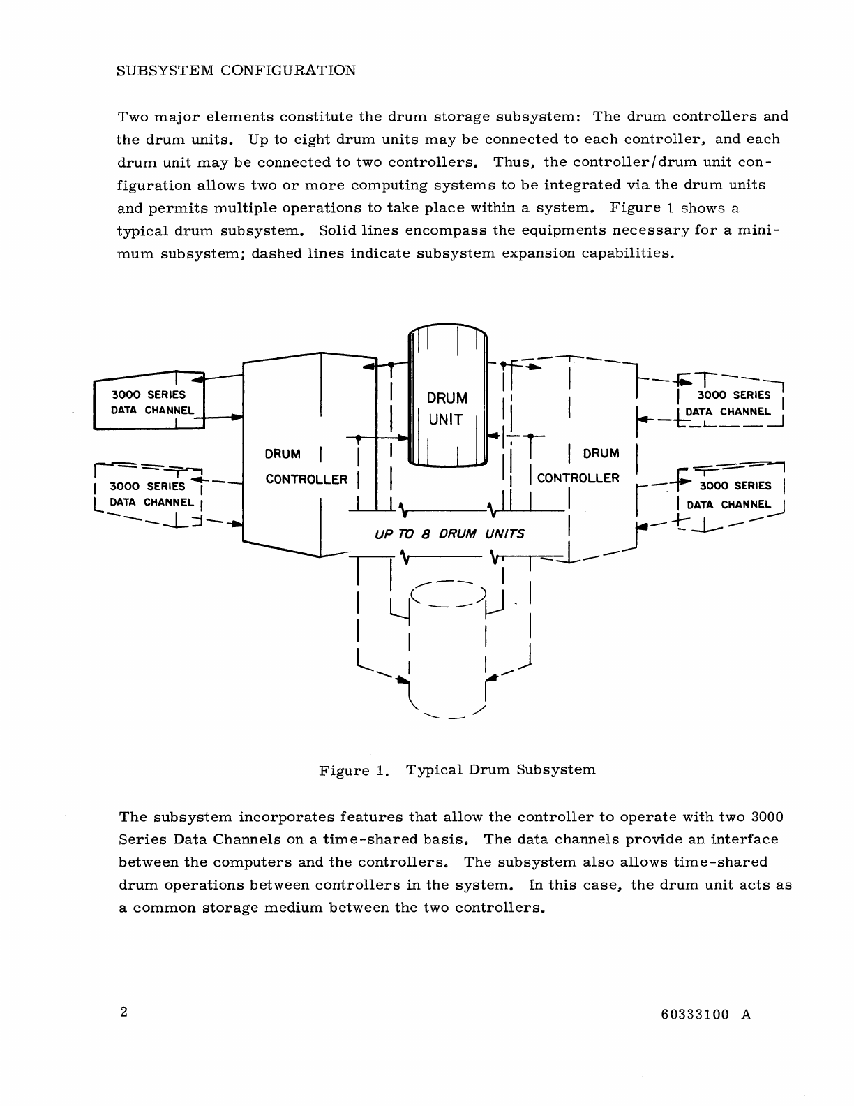
Two
major
elements
constitute
the
drum
storage
subsystem:
The
drum
controllers
and
the
drum
units.
Up
to
eight
drum
units
may
be
connected
to
each
controller,
and
each
drum
unit
may
be
connected
to
two
controllers.
Thus,
the
controller/drum
unit
con-
figuration
allows
two
or
more
computing
systems
to
be
integrated
via
the
drum
units
and
permits
multiple
operations
to
take
place
within
a
system.
Figure
1
shows
a
typical
drum
subsystem.
Solid
lines
encompass
the
equipments
necessary
for
a
mini-
mum
subsystem;
dashed
lines
indicate
subsystem
expansion
capabilities.
3000
SERIES
DATA
CHANNEL
-+--~
r-=~
I
3000
SERIES
,-
l
DATA
CHANNEL I
-----L:j-
DRUM
UNIT
---r--
If'"
"
-L-.T--
I I I
3000
SERIE~
II
I l.-_ I
DATA
CHANNEL !
1_
,-
1:"""_1-
__
---1
DRUM
liT
I
DRUM
I
~_.....,
CONTROLLER
I I
CONTROLLER
-i=-
3000
SERIES
,
.......I....-...&....-L\
___
\
II
I I r . I
DATA
CHANNE'::.J
I
~-
-t-
--1-
----
UP
TO
8 DRUM UNITS
~
n \
'v-I
~-::l----
,.--
-__
I
I
~(-~lJ-
I I I I
l I I J
--~
(--
'-_/
Figure
1.
Typical
Drum
Subsystem
The
subsystem
incorporates
features
that
allow
the
controller
to
operate
with
two
3000
Series
Data
Channels
on
a
time-shared
basis.
The
data
channels
provide
an
interface
between
the
computers
and
the
controllers.
The
subsystem
also
allows
time
-shared
drum
operations
between
controllers
in
the
system.
In
this
case,
the
drum
unit
acts
as
a
common
storage
medium
between
the
two
controllers.
2
60333100
A
A
description
of
equipment
which
may
be
incorporated
into
the
drum
storage
subsystem~
and
its
capabi1ities~
is
shown
below.
3436
-A
Drum
Storage
Controller
-
Provides
a
single
data
channel
interface
to
any
of
the
861/863
Drum
Units.
3637
-A
Drum
Storage
Controller
-
Provides
a
dual
data
channel
interface
to
any
of
the
861/863
Drum
Units.
3637
-B
Drum
Storage
Controller
-
Provides
dual
data
channel
interface
to
any
of
the
861/863/865
Drum
Units.
861-B
Drum
Unit
-
Provides
byte
addressable
data
storage
(2~
097~
152
data
bytes)
with
variable
transfer
rate
capabilities.
863-B/C
Drum
Unit
-
Provides
byte
addressable
data
storage
(2~
097~
152
data
bytes)
with
variable
transfer
rate
capabilities.
865-A/B
Drum
Unit
-
Provides
sector
addressable
data
storage
(128
data
bytes/
sector;
4~
194~
304
bytes
total
capacity)
at
a
fixed
transfer
rate.
Most
of
the
information
in
this
section
is
common
to
all
of
the
equipment.
Information
that
is
unique
to
a
particular
controller
or
drum
unit
is
so
stated.
The
861-
Band
863
-B
Drum
Units
are
similar.
For
simplicity~
only
the
863
is
referenced
throughout
this
section;
however~
all
references
and
information
applicable
to
the
863
also
apply
to
the
861.
DRUM
UNITS
The
basic
purpose
of
the
drum
unit
(which
houses
the
drum
and
associated
electronics)
is
to
provide
recording
surfaces
for
storage
of
data.
The
drum~
which
is
mounted
on
a
vertical
axis,
is
plated
with
a
metallic
recording
medium.
Each
863
drum
contains
832
recording
tracks;
each
865
drum
contains
768
recording
tracks.
Six
other
tracks
are
used
to
make
up
three
sets
of
control
timing
tracks.
One
track
of
each
set
provides
timing
(Clock
pulses);
the
other
track
of
each
set
provides
reference
(indexing)
in-
formation.
One
of
the
three
sets
of
control
tracks
is
designated
as
a
master
set;
the
other
two
sets
are
designated
as
working
sets.
Provision
is
made
within
each
drum
unit
for
rewriting
the
working
tracks
from
the
master
set
while
the
master
set
may
be
written
or
rewritten
via
an
external
oscillator
(one
megacycle
for
the
863
Drum
Unit;
two
megacycles
for
the
865
Drum
Unit).
60333100
A 3
The
drum
unit
also
contains
the
drum
drive
motor
l
the
R/W
heads
l
and
the
associated
drum
electronics.
Provision
is
made
within
the
861/863
drum
units
for
manual
selec-
tion
of
the
interface
transfer
rates
and
drum
size.
All
drum
units
provide
for
setting
of
the
unit
designation
(unit
number)
1
and
various
maintenance
switch
functions.
The
exchange
of
the
following
signals
between
the
controller
and
drum
units
is
neces-
sary
to
control
drum
operation:
(C
- D)
indicates
the
signal
originates
in
the
controller
and
is
sent
to
the
drum;
(D
-C)
indicates
the
signal
originates
in
the
drum
and
is
sent
to
the
controller.
Select
(C
- D)
This
signal
is
sent
to
a1l
drum
units
attached
to
the
controller.
The
signal
indicates
that
the
unit
code
is
on
the
line
and
causes
the
drum
unit
to
examine
the
code.
Select
Reply
(D -C)
This
signal
is
sent
in
response
to
the
Select
signal
and
indicates
that
the
designated
drum
unit
has
been
selected.
Absence
of
the
signal
indicates
that
the
desired
drum
was
un-
available
(either
no
such
drum
exists
or
the
drum
is
reserved
by
another
controller).
Head
Group
Address
(C
-D)
These
signals
carry
the
8
-bit
head
group
code
(and
Head
Subgroup
in
the
865)
from
the
controller
Address
register.
The
signals
are
decoded
by
the
drum
unit
to
select
the
appropriate
head
group
(and
head
subgroup
in
the
865).
Angular
Address
(C
-D)
These
signals
carry
the
15
-bit
(14
-bit
in
the
865)
angular
address
to
the
drum
unit
from
the
controller
Address
register.
For
the
863
1
the
signals
are
decoded
according
to
the
interlace
to
determine
the
angular
position
of
the
data
to
be
read
or
written.
For
the
865
1
the
signals
are
decoded
to
determine
the
starting
sector
address
of
the
data
to
be
read
or
written.
Read
Angular
Count
(D -
C)
These
12
signals
carry:
1)
from
the
863
1
the
upper
12
bits
of
the
15
-bit
Angular
Count.
This
indicates
within
8
byte
locations
the
present
position
of
the
drum;
2)
from
the
865
1
(in
the
lower
order
positions)
the
7
-bit
sector
address
portion
of
the
Angular
Count.
This
indicates
the
sector
presently
being
referenced
by
the
drum.
4
60333100
A
Write
(C -D)
This
signal
indicates
the
data
is
on
the
lines
and
directs
the
drum
unit
to
record
the
data
at
the
addressed
location
or
sector.
Read
(C -
D)
This
signal
directs
the
drum
unit
to
read
data
from
the
addressed
byte
or
sector.
Data
Ready
(D
-
C)
This
signal
(sent
in
response
to
the
Read
signal)
indicates
that
the
requested
byte
(in
the
case
of
the
863)
is
on
the
lines
to
the
controller.
For
the
865,
the
signal
indicates
that
a
data
byte
(from
the
requested
sector)
is
on
the
lines
to
the
controller.
Compare
(D
-C)
This
signal
indicates
that
the
drum
unit
is
presently
accessing
the
byte
(for
the
863)
or
the
sector
(for
the
865)
location
indicated
by
the
controller
Address
register.
In
the
case
of
the
863"
the
signal
initiates
the
Read
operation
within
the
controller
if
in
the
Read
mode.
In
the
case
of
the
865"
this
signal
comes
up
only
at
the
beginning
of
the
ad-
dressed
sector.
For
both
the
863
and
865"
the
signal
activates
the
Address
Compare
interrupt
if
selected.
Write
Reply
(D
-C)
This
signal
is
sent
in
response
to
a
Write
signal.
It
indicates
that
the
Write
operation
has
been
accepted
by
the
drum
unit
and
will
commence
upon
determination
of
a
suc-
cessful
Write
Compare.
Write
Compare
(D -C)
This
signal
is
sent
in
response
to
a
Write
signal.
It
indicates
that
the
angular
address
sent
by
the
controller
and
the
angular
position
of
the
drum
compare
and
that
the
pre-
viously
selected
Write
operation
is
being
initiated
at
that
location.
Index
(D -C)
This
is
the
Stop
Index
signal
from
the
index
control
track.
The
signal
indicates
the
end
of
the
clock
and
the
beginning
of
the
dead
zone
and
head
switching
time
for
each
revolu-
tion
of
the
drum.
60333100
A 5
Drum
Ready
(D
--
C)
This
signal
indicates
that
the
unit
code
and
the
designation
switch
setting
agree,
the
drum
is
up
to
speed,
and
no
timing
errors
exist.
Clock
(D
--
C)
Two
clock
signals
(Clock
1
and
Clock
2)
are
sent
by
the
selected
drum
unit.
The
signals
come
from
the
control
timing
tracks
and
provide
the
two
phases
of
the
1-MHz
clock.
(The
865
drum
2
-MHz
clock
is
broken
down
to
1
MHz
for
controller
use.
)
Release
(C
--
D)
This
signal
removes
all
operating
modes
and
reserves
in
the
drum
units;
however,
it
does
not
affect
any
drum
unit
reserved
by
another
controller.
MC
(C
--
D)
This
signal
clears
most
logic
conditions,
selections,
and
reserves
within
the
drum
units;
however,
it
does
not
affect
any
drum
unit
reserved
by
another
controller.
Manually
initiated
Master
Clear
removes
all
error
conditions
and
the
Drum
Ready
condition,
causing
the
drum
to
recheck
all
timing
and
synchronization
before
becoming
Ready
again.
(This
requires
approximately
70
ms.
)
Drum
Type
(D
--
C)
When
a
logical
1 ,
this
signal
indicates
that
the
selected
drum
unit
contains
an
863
Drum
with
32K
byte
storage
per
head
group;
when
a
logical
0 ,
this
signal
indicates
that
the
selected
drum
unit
contains
an
865
Drum
with
65K
byte
storage
per
head
group.
Data
Error
(D
--
C)*
The
presence
of
this
signal
indicates
that
either
a
Transmission
Parity
Error
has
been
detected
during
a
Write
operation,
or
that
a
Checkword
Error
has
been
detected
during
a
Read
operation.
*These
signals
are
only
applicable
to
and
returned
only
by
the
865
Drum
Units.
6
60333100
A
Busy
(D-
C)*
The
presence
of
this
signal
indicates
that
the
drum
unit
is
busy
with
a
data
handling
operation.
Note
that
even
if
a
Write
or
Read
operation
terminates
prior
to
the
end
of
the
sector,
the
drum
unit
remains
busy
until
the
checkword
is
read
or
written
at
the
end
of
that
sector.
Lost
Data
(D
--
C)*
The
presence
of
this
signal
indicates
that
1)
the
data
channel
has
failed
to
maintain
the
proper
transfer
rate
while
writing,
(the
controller
checks
for
Lost
Data
during
Read
operations),
or
2)
the
byte
address
portion
does
not
contain
all
zeros
when
a
new
110
initiation
is
attempted.
(All
110
operations
must
commence
at
the
beginning
of
a
sector.
At
that
point
the
byte
address
portion
equals
all
zeros).
In
addition
to
the
signals,
13
bidirectional
lines
carry
the
data
and
parity
information
and
Connect
codes
between
the
controller
Transfer
register
and
the
drum
unit.
DRUM
CONTROLLERS
The
standard
3000
Series
signals
are
exchanged
between
the
controller
and
the
data
channel.
The
controller
provides
an
interface
between
the
drum
units
and
the
com-
puter
via
the
data
channels.
The
controller
translates
the
Connect
and
function
codes
issued
by
the
computer
to
control
drum
operation.
The
controller
synchronizes
and
transfers
data
between
the
druIps
and
the
computers
in
a
parallel
13
-bit
byte
format.
The
computers
control
the
drum
(and
controller)
operations
through
the
use
of
12
-bit
function
codes
and
a
21-or
22-bit
address
word**
(dependent
upon
the
type
of
drum
unit
in
use).
Issuing
of
a
function
code
specifying
a
mode
of
operation
prepares
the
con-
troller
and
drum
unit
for
an
110
operation.
The
drum
seeks
the
specified
head
group
and
the
sector
or
angular
address
position
specified
by
the
contents
of
the
Address
register
in
the
controller.
The
specific
operation
commences
upon
initiation
of
an
110
at
the
location
specified
by
the
address.
*These
signals
are
applicable
to
the
865
Drum
Units.
**For
specific
format
and
address
word
information,
refer
to
ADDRESSING.
60333100
A 7
Subsequent
to
the
initiation
of
an
I/O
to/from
the
drum,
the
computer
may
issue
a
Load
Address
code
followed
by
2
bytes
which
form
the
address
word.
If
an
address
word
is
issued,
it
is
loaded
into
the
controller
Address
register,
and
the
next
operation
com-
mences
at
this
new
address
location.
If
no
new
address
is
received
by
the
controller
prior
to
the
initiation
of
an
I/O,
operation
commences
at
the
address
presently
held
in
the
Address
register*.
STORAGE
The
types
of
drum
units
are
similar
in
that
they
are
all
mounted
in
identical
cabinets,
they
all
utilize
a
metallic
magnetic
recording
medium,
and
all
have
the
same
number
of
data
recording
tracks
per
unit.
The
drums
differ
in
their
physical
appearance,
bit
and
track
arrangement,
and
logically
in
their
recording
and
addressing
techniques
and
total
storage
capacities.
863
Drum
Units
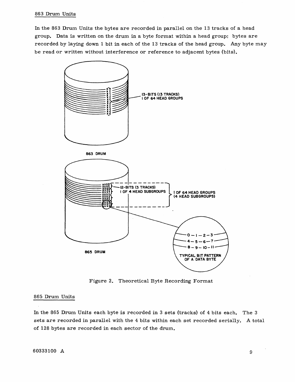
These
drums
have
768
data
tracks
and
64
parity
tracks.
The
tracks
are
divided
into
64
groups
of
13
tracks
each
(12
data
and
one
parity
track
per
group).
The
groups
are
organized
vertically
on
the
drum
and
are
referred
to
as
head
groups.
Each
bit
of
a
byte
is
written
on
a
separate
track
of
the
group
(see
Figure
2).
Each
track
provides
32,768
bits
of
storage
with
a
total
capacity
of
25,165,824
data
bits
(4,194"
304
6-bit
characters)
per
drum
unit.
865
Drum
Units
These
drums
have
768
data
tracks
divided
into
64
head
groups
of
12
tracks
each.
Each
head
group
is
further
sub
-divided
into
four
subgroups
of
3
tracks
each.
Four
bits
of
each
byte
are
written
serially
on
each
of
the
three
tracks
of
the
subgroup.
The
bytes
are
written
serially
and
in
parallel
as
three
groups
of
4
bits
each.
(See
Figure
2.
)
DATA
FORMAT
Each
12
-bit
byte
plus
an
associated
parity
hit
is
transferred
in
parallel
between
the
data
channels
and
the
controller,
and
between
the
controller
and
selected
drum
units.
*With
the
865
Drum,
the
byte
portion
of
the
address
must
equal
zero
or
a
Lost
Data
Error
will
occur
upon
initiation
of
the
operation.
8
60333100
A
863
Drum
Units
In
the
863
Drum
Units
the
bytes
are
recorded
in
parallel
on
the
13
tracks
of
a
head
group.
Data
is
written
on
the
drum
in
a
byte
format
within
a
head
group:
bytes
are
recorded
by
laying
down
1
bit
in
each
of
the
13
tracks
of
the
head
group.
Any
byte
may
be
read
or
written
without
interference
or
reference
to
adjacent
bytes
(bits).
13-BIT$
(\3
TRACKS)
I
OF
64
HEAD
GROUPS
863
DRUM
.:::----mif-=~~~I!S:~~~~~::S}
I
OF
64
HEAD
GROUPS
:::::::::::===nn
(4
HEAD SUBGROUPS)
~:::==fllll
.
_
:~Il
__________
_
865
DRUM
Figure
2.
Theoretical
Byte
Recording
Format
865
Drum
Units
In
the
865
Drum
Units
each
byte
is
recorded
in
3
sets
(tracks)
of
4
bits
each.
The
3
sets
are
recorded
in
parallel
with
the
4
bits
within
each
set
recorded
serially.
A
total
of
128
bytes
are
recorded
in
each
sector
of
the
drum.
60333100
A 9
ADDRESS
CHARACTERISTICS
Data
is
referenced
by
means
of
a
21-or
22
-bit
address.
*
The
address
is
assembled
in
the
controller
from
two
12
-bit
bytes
sent
via
the
data
channel
to
the
controller.
In
the
863
a
21-bit
address
designates
the
specific
head
group
and
angular
position
of
the
byte
on
the
drum;
in
the
865,
a
22
-bit
address
specifies
the
head
group,
the
head
subgroup
and
the
starting
sector
address.
Addresses
are
continuous
throughout
the
drum.
For
multiple-byte
(or
sector)
transfers
the
address
is
automatically
augmented
to
select
the
next
sequential
byte
(or
sector)
without
the
necessity
of
readdressing
from
the
computer.
Address
sequencing
is
continuous
from
the
starting
address
to
the
end
of
the
drum;
however,
operation
is
not
end-:around
within
a
drum
unit.
863
Drum
Units
The
data
is
byte
addressable.
Each
21-bit
address
references
the
head
group
and
angular
position
of
one
of
the
32,
768
bytes
within
that
head
group.
865
Drum
Unit
Data
is
sector
addressable.
The
sectors
are
referenced
by
means
of
a
22
-bit
address.
Each
address
references
a
head
group,
a
head
subg!'oup,
and
a
sector
within
the
head
group.
DATA
TRANSFER
The
minimum
data
transfer
is
1
bytet
;
the
maximum
data
transfer
is
an
entire
drum.
Table
1
lists
the
drum
unit
capacities
and
transfer
information.
In
the
865
Drum
Unit
data
is
transferred
at
a
set
rate
of
1
byte
every
2
microseconds.
In
the
863
Drum
Unit
data
is
transferred
at
a
maximum
rate
of
1
byte
per
microsecond.
*Dependent
upon
the
type
of
drum
used
in
the
subsystem.
For
specific
format
and
address
word
information,
refer
to
Addressing.
t
Although
as
little
as
1
byte
may
be
read
or
written
in
the
865,
the
smallest
address-
able
quantity
is
a
sector
(128
bytes)
10
60333100
A
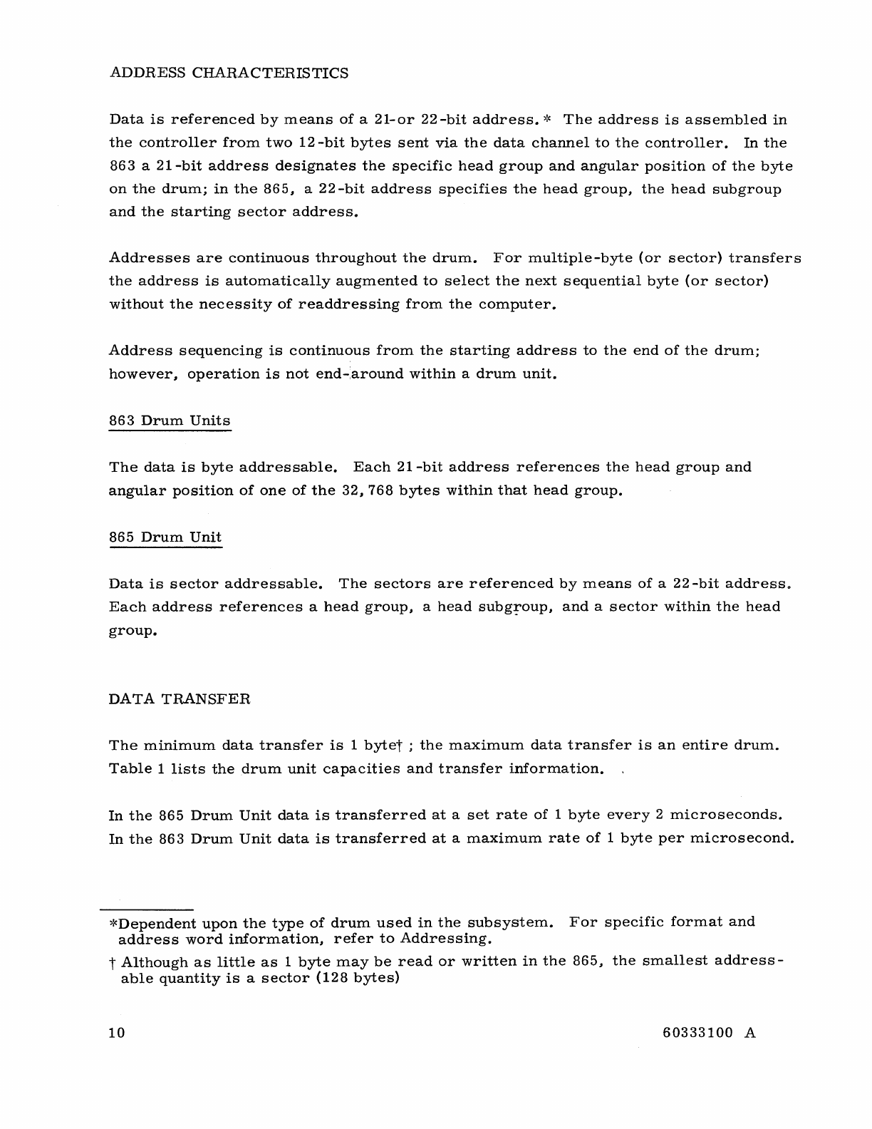
The
transfer
rate
is
variable
in
the
863
Drum
Unit,
and
can
be
reduced
in
binary
incre-
ments
by
a
logic
interlace
built
into
the
drum
unit.
Table
2
indicates
the
interlaces
available
along
with
the
various
byte
transfer
timing.
The
interlace
is
selected
man-
uallyat
each
drum
unit.
Therefore,
various
863
Drum
Units
in
a
subsystem
may
have
independent
data
transfer
rates.
TABLE
1
..
DRUM
CAPACITY
AND
TRANSFER
SPECIFICATIONS
863
Drum
865
Drum
C~pacity
Data
Bits
25,165,824
50,331,648
6
-bit
Characters
4,194,304
8,
388,
604
Tracks
(data)
768
768
Bits/Track
32,768
65,536
Transfer
Minimum
Quantity
1
byte
1
byte*
Maximum
Quantity
2,097,
152
bytes
4,
194,
304
bytes
Maximum
Rate
2,000,000
Characters/
1,000,000
Characters/
second
second
(IXl
interlace)
TABLE
2.
INTERLACE
SPEC-IFICATIONS
Ratio
Transfer
Rate
f.J,sec/
Byte,
Minimum
Byte/Sec~
(Maximum)
1:
1 1
1,000,000
2:
1 2
500,000
4:1
4
250,000
8:1
8
125,000
16:1
16
62,500
32:1
32
31,250
Registers
within
the
controller
and
drum
unit
are
used
for
synchronization
and
buffering.
Buffering
limitations
are
explained
under
Buffer
Timing.
*
Although
as
little
as
1
byte
may
be
read
or
written
in
the
865,
the
smallest
address-
able
quantity
is
a
sector
(128
bytes).
60333100
A 11
In
the
865
Drum
Unit
the
data
channel
must
maintain
the
specified
transfer
rate
or
a
Lost
Data
condition
will
occur.
In
the
863~
data
is
never
missed
due
to
the
failure
of
the
data
channel
to
maintain
the
selected
interlace
rate.
If
a
byte
is
missed
(either
not
received
by
the
controller
in
time
to
be
written
on
the
drum
or
the
last
byte
is
not
accepted
from
the
controller
when
the
next
byte
is
ready
to
be
read).
the
controller
automatically
enters
a
Readdress
state
during
which
the
drum
readdresses
the
location
of
the
missed
byte
(the
Address
register
is
decremented
and
the
address
relocated).
Accordingly~
the
drum
must
make
one
full
revolution
in
order
to
relocate
the
desired
position.
(The
863
Drum
Unit
requires
34
ms
per
revolution.)
PERFORMANCE
TIMING
The
access
and
total
operating
time
involved
in
a
data
transfer
is
equal
to
the
sum
of
the
times
involved
in
addressing
the
drum~
locating
the
address
byte
or
sector
(865),
and
performing
the
transfer.
Head
Switching
Head
switching
time
is
defined
as
the
interval
necessary
to
electronically
switch
from
one
head
group
to
another
(or
to
the
specified
head
group
on
an
initial
address
operation).
This
is
a
constant~
and
is
equal
to
100
usec.
Latency
Time
Latency
time
is
defined
as
the
interval
between
the
end
of
head
switching
time
and
the
point
at
which
the
addressed
byte
or
sector
(865)
arrives
under
the
R/W
heads.
This
is
a
maximum
of
one
revolution
of
the
drum
(33.4
ms);
the
average
time
is
one-half
revolution.
Access
Time
Access
time
is
defined
as
the
time
necessary
to
electronically
switch
to
the
desired
head
group
plus
the
latency
time
necessary
to
locate
the
specified
sector
(865)
or
angular
address
(863);
bring
the
desired
data
under
the
selected
head
group.
During
multiple
byte
transfers
which
encompass
more
than
one
head
group~
the
head
switching
takes
place
during
the
drum
index
time.
Thus~
additional
access
time
is
not
required
to
reference
the
next
sequential
head
group;
however,
the
transfer
time
is
increased
by
the
100
usec
index
time
(see
Programming
Considerations;
Write
Timing).
12
60333100
A
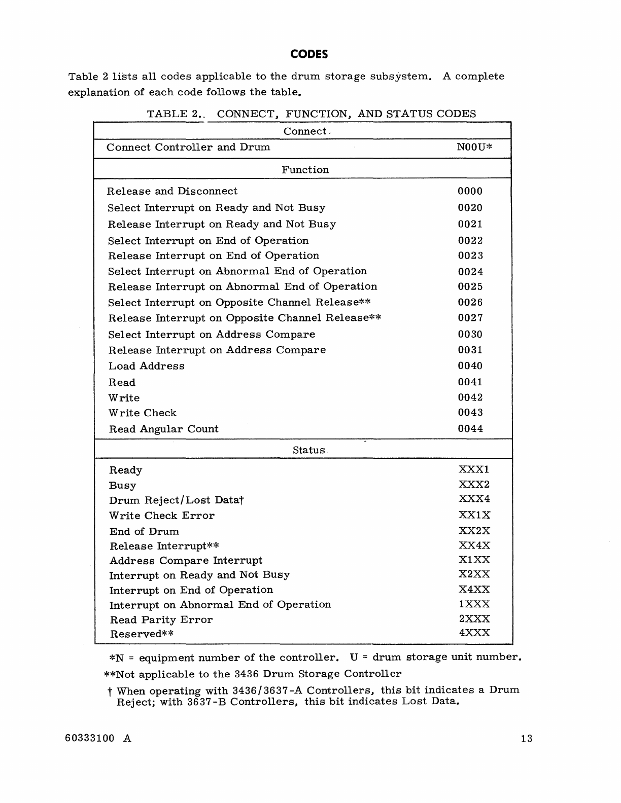
CODES
Table
2
lists
all
codes
applicable
to
the
drum
storage
subsystem.
A
complete
explanation
of
each
code
follows
the
table.
TABLE
2..
CONNECT
1
FUNCTION
1 AND
STATUS
CODES
Connect
..
Connect
Controller
and
Drum
NOOU':C
Function
Release
and
Disconnect
0000
Select
Interrupt
on
Ready
and
Not
Busy
0020
Release
Interrupt
on
Ready
and
Not
Busy
0021
Select
Interrupt
on
End
of
Operation
0022
Release
Interrupt
on
End
of
Operation
0023
Select
Interrupt
on
Abnormal
End
of
Operation
0024
Release
Interrupt
on
Abnormal
End
of
Operation
0025
Select
Interrupt
on
Opposite
Channel
Release**
0026
Release
Interrupt
on
Opposite
Channel
Release**
0027
Select
Interrupt
on
Address
Compare
0030
Release
Interrupt
on
Address
Compare
0031
Load
Address
0040
Read
0041
Write
0042
Write
Check
0043
Read
Angular
Count
0044
-
Status
Ready
XXXI
Busy
XXX
2
Drum
Reject/
Lost
Datat
XXX
4
W
rite
Check
Error
XXIX
End
of
Drum
XX2X
Release
Interrupt**
XX4X
Address
Compare
Interrupt
XIXX
Interrupt
on
Ready
and
Not
Busy
X2XX
Interrupt
on
End
of
Operation
X4XX
Interrupt
on
Abnormal
End
of
Operation
1
XXX
Read
Parity
Error
2
XXX
Reserved**
4XXX
*N
=
equipment
number
of
the
controller.
U =
drum
storage
unit
number.
**Not
applicable
to
the
3436
Drum
Storage
Controller
t
When
operating
with
3436/3637
-A
Controllers
l
this
bit
indicates
a
Drum
Reject;
with
3637
-B
Controllers
l
this
bit
indicates
Lost
Data.
60333100
A 13
CONNECT
CODE
Connect
Controller
and
Drum
(NOOU)
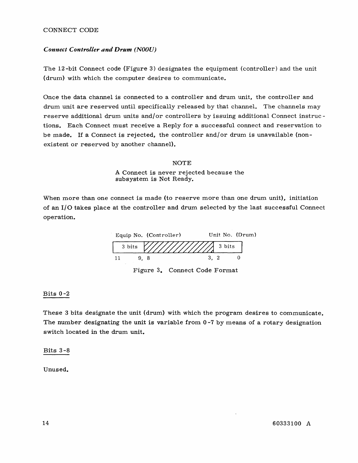
The
12-bit
Connect
code
(Figure
3)
designates
the
equipment
(controller)
and
the
unit
(drum)
with
which
the
computer
desires
to
communicate.
Once
the
data
channel
is
connected
to
a
controller
and
drum
unit,
the
controller
and
drum
unit
are
reserved
until
specifically
released
by
that
channel.
The
channels
may
reserve
additional
drum
units
andlor
controllers
by
issuing
additional
Connect
instruc-
tions.
Each
Connect
must
receive
a
Reply
for
a
successful
connect
and
reservation
to
be
made.
If
a
Connect
is
rejected,
the
controller
and/or
drum
is
unavailable
(non-
existent
or
reserved
by
another
channel).
NOTE
A
Connect
is
never
rejected
because
the
subsystem
is
Not
Ready.
When
more
than
one
connect
is
made
(to
reserve
more
than
one
drum
unit)
I
initiation
of
an
IIO
takes
place
at
the
controller
and
drum
selected
by
the
last
successful
Connect
operation.
Equip
No.
(Controller)
Unit
No.
(Drum)
3
bits
3
bits
11
9,
8
3,
2 0
Figure
3.
Connect
Code
Format
Bits
0
-2
These
3
bits
designate
the
unit
(drum)
with
which
the
program
desires
to
communicate.
The
number
designating
the
unit
is
variable
from
0
-7
by
means
of
a
rotary
designation
switch
located
in
the
drum
unit.
Bits
3-8
Unused.
14
60333100
A
Bits
9-11
These
3
bits
designate
the
equipment
with
which
the
program
desires
to
communicate
..
The
number
designating
the
drum
controller
is
variable
by
means
of
a
rotary
desig-
nation
switch
located
in
the
controller
cabinet.
Upon
receipt
of
the
Connect
code
by
the
controller
~
a
Reply
or
Rej
ect
is
returned
to
the
data
channel.
If
the
desired
controller
and
drum
are
available~
a
Reply
is
returned
immediately..
If
the
controller
is
unable
to
accept
the
code
and
perform
the
connect~
a
Reject
is
returned.
Upon
receipt
of
a
Reject~
the
computer
must
request
a
status
response
and
interrogate
the
status
bits
in
order
to
determine
whether
the
Rej
ect
was
a
result
of
the
controller
being
reserved
or
the
drum
unit
being
unavailable.
(Refer
to
explanation
of
status
response
bits
Drum
Reject
(XXX4)
and
Reserved
(4XXX).
)
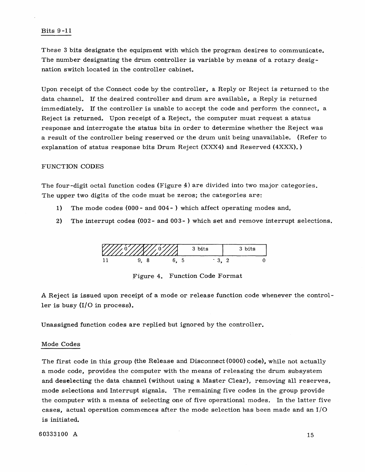
FUNCTION
CODES
The
four-digit
octal
function
codes
(Figure
4)
are
divided
into
two
major
categories.
The
upper
two
digits
of
the
code
must
be
zeros;
the
categories
are:
1)
The
mode
codes
(000
-
and
004
- )
which
affect
operating
modes
and,
2)
The
interrupt
codes
(002
-
and
003
- )
which
set
and
remove
interrupt
selections.
3
bits
3
bits
11
9,
8 6, 5 -
3,
2 o
;Figure
4.
Function
Code
Format
A
Rej
ect
is
issued
upon
receipt
of
a
mode
or
release
function
code
whenever
the
control-
ler
is
busy
(I/O
in
process).
Unassigned
function
codes
are
replied
but
ignored
by
the
controller.
Mode
Codes
The
first
code
in
this
group
(the
Release
and
Disconnect
(0000)
code)~
while
not
actually
a
mode
code,
provides
the
computer
with
the
means
of
releasing
the
drum
subsystem
and
deselecting
the
data
channel
(without
using
a
Master
Clear),
removing
all
reserves,
mode
selections
and
Interrupt
signals.
The
remaining
five
codes
in
the
group
provide
the
computer
with
a
means
of
selecting
one
of
five
operational
modes.
In
the
latter
five
cases,
actual
operation
commences
after
the
mode
selection
has
been
made
and
an
I/O
is
initiated.
60333100
A
15
Transmission
of
a
new
select
code
prior
to
initiation
of
an
I/O
removes
the
present
selection
and
replaces
it
with
a
new
selection.
In
all
cases#
the
select
code
is
cleared
upon
completion
of
the
mode
of
operation
(end
of
I/O).
Therefore#
each
individual
buffer
must
be
preceded
by
an
operating
mode
code.
Release
and
Disconnect (0000)
This
code
releases
the
subsystem
from
the
data
channel.
It
causes
all
reserves
to
be
removed#
clears
all
Interrupt
signals#
removes
all
mode
selections#
clears
the
Read
Parity
and
Write
Check
Error
conditions,
and
drops
the
status
response
lines.
(See
Programming
Consideration;
Master
Clear#
Release
and
Disconnect.)
Load
Address (0040)
This
mode,
in
conjunction
with
an
output
buffer,
causes
the
controller
to
load
the
next
output
buffer
into
the
controller
Address
register.
Read
(0041)
This
mode,
in
conjunction
with
an
input
buffer,
causes
the
controller
to
initiate
a
Read
operation
from
the
drum
at
the
address
specified
by
the
content
of
the
Address
register.
The
operation
will
continue
until
halted
by
one
of
the
conditions
listed
under
Interrupt
on
End
of
Operation.
Write
(0042)
This
mode,
in
conjunction
with
an
output
buffer,
causes
the
controller
to
initiate
a
Write
operation
to
the
drum
at
the
address
specified
by
the
content
of
the
controller
Address
register.
The
operation
continues
until
halted
by
one
of
the
conditions
listed
under
the
Interrupt
on
End
of
Operation.
Write
Check (0043)
This
mode#
in
conjunction
with
an
output
buffer,
causes
the
controller
to
initiate
a
Read
froln
the
drum
at
the
address
specified
by
the
content
of
the
controller
Address
register.
The
output
buffer
transmits
data
to
the
controller
which
is
compared
on
a
bit
-by-bit
basis
with
the
data
read
from
the
drum.
16
60333100
A
Upon
occurrence
of
a
miscompare
(compare
error),
the
Write
Check
Error
status
bit
is
set.
The
occurrence
of
a
write
check
error
causes
the
Abnormal
End
of
Operation
interrupt
to
be
set
(if
selected).
Read
Angular
Count
(0044)
NOTE
The
operation
ends
before
the
byte
in
error
is
replied;
thus,
in
this
case,
the
Address
register
contains
the
address
of
the
byte
in
error.
This
mode,
in
conjunction
with
an
input
buffer,
causes
the
controller
to
return
to
the
data
channel
a
portion
of
the
drum
angular
count.
The
count
held
in
the
Angular
Counter
is
advanced
by
the
drum
unit
Clock
pulses
and
is
synchronized
with
the
rota-
tion
of
the
drum.
Thus,
the
count
(at
any
particular
instant)
represents
the
angular
position
of
the
drum
in
relation
to
the
various
address
locations.
NOTE
The
count
returned
is
from
the
drum
unit
Angular
Counter
and
is
NOT
the
contents
of
the
Address
register.
The
count
returned
to
the
data
channel
by
the
controller
is
dependent
upon
the
type
of
drum
unit
selected.
•
865
Drum
Unit:
The
controller
returns
the-
7
-bit
sector
address
portion
of
the
count
presently
associated
with
the
data
block
being
referenced.
The
Angular
Count
is
not
timed
with
the
beginning
of
the
sector,
and
therefore
the
programmer
cannot
expect
to
operate
on
the
next
sector
of
the
drum
con-
sistently.
The
programs
next
operation
should
be
initiated
on
the
returned
address
+
2.
(See
Address
Compare
Interrupt
..
)
•
861/863
Drum
Unit:
The
controller
returns
the
upper
12
bits
of
the
15-bit
angular
count.
These
12
bits
are
sufficient
to
indicate
within
eight
address
positions
(approximately
8 f.,lsec)
the
present
position
of
the
drum.
If
the
input
buffer
is
more
than
1
byte
in
length,
the
count
presently
held
in
the
continuously
incrementing
Angular
Counter
is
returned
on
each
byte
trans-
mitted.
The
lower
15
bits
of
the
21-bit
address
indicate
the
angular
address
of
a
par-
ticular
byte.
The
actual
angular
position
of
the
byte
on
the
drum
depends
upon
60333100
A
17
the
interlace
selected.
To
determine
the
physical
location
(angular
position)
of
a
particular
byte
address,
the
angular
address
portion
of
the
byte
address
is
left
shifted,
end
-around,
by
the
number
of
bits
equal
to
the
log2
of
the
interlace.
An
example
follows:
Drum
Interlace
=
8-1
Byte
Address
~~8
Head
Address
j J
Angular
Address
Log
2 8=3
Angular
Address
31465
8
Angular
Address
=
011
001 100 110 1012
Physical
Location
= 001 100
110
101
011
2
Interrupt
Codes
These
codes
establish
and
remove
the
interrupt
selections
which
determine
what
condi-
tions
send
an
interrupt
to
the
data
channel.
The
codes
are
never
rejected
by
the
control-
ler.
A
manual
Master
Clear
or
channel
Master
Clear
removes
all
interrupt
selections.
Interrupt
indications
(interrupt
active)
are
removed
whenever
a
manual
Master
Clear,
channel
Master
Clear,
release,
or
any
interrupt
function
(select
or
release)
is
per-
formed.
The
indication
(but
not
the
selection)
is
also
removed
whenever
a
new
mode
of
operation
is
selected.
Select Interrupt
on
Ready
and
Not
Busy (0020)
Selection
of
this
code
causes
the
interrupt
line
to
be
activated
and
the
associated
status
bit
set
the
next
time
the
subsystem
becomes
Ready
and
Not
Busy
(at
the
end
of
the
next
operation).
(For
an
explanation
of
Ready
and
Not
Busy
conditions,
refer
to
the
asso-
ciated
status
response
bit
description.
)
Release Interrupt
on
Ready
and
Not
Busy (0021)
This
code
removes
the
associated
interrupt
selection
set
up
by
the
0020
code.
No
interrupt
notification
of
Ready
and
Not
Busy
will
be
sent
until
the
condition
is
reselected.
Select Interrupt
on
End
of
Operation
(0022)
This
code
causes
the
interrupt
line
to
be
activated
and
the
associated
status
bit
to
be
sent
upon
completion
of
the
next
operation
whether
the
end
of
operation
is
normal
or
abnormal.
18
60333100
A
Normally,
operation
ends
upon
completion
of
a
buffer;
however,
during
Write
operation,
the
End
of
Operation
signal
is
delayed
until
completion
of
writing
of
the
last
byte
on
the
drum.
Although
this
is
a
fixed
delay
for
the
operation,
the
length
of
the
delay
is
inher-
ently
dependent
on
the
interlace
being
used,
on
the
last
address
of
the
drum,
and
on
whether
a
single
byte
is
being
written.
(For
specific
times,
refer
to
Program
Consider-
ations;
Write
Timing.)
Release Interrupt on
End
oj
Operation (0023)
This
code
removes
the
associated
interrupt
selections
set
up
by
the
0022
code.
No
interrupt
indication
of
end
of
operation
will
be
sent
until
the
condition
is
res
elected.
Select Interrupt on
Abnormal
End
oj
Operation (0024)
This
code
causes
the
interrupt
line
to
be
activated
and
the
associated
status
bit
set
upon
the
stopping
of
an
operation
due
to
any
abnormal
condition
within
the
controller
or
drum
unit.
The
following
conditions
are
considered
abnormal:
1)
The
drum
unit
becomes
Not
Ready.
2)
Any
110
attempt
to
reference
an
address
exceeding
the
last
address
of
the
drum.
3)
Occurrence
of
a
read
parity
error
(parity
error
in
the
data
read
from
the
drum).
4)
Occurrence
of
a
write
check
error
(lack
of
a
comparison
during
a
Write
Check
operation)
•
Conditions
1
and
2
cause
operations
to
cease
immediately
whether
the
interrupt
is
se-
lected
or
not.
If
the
interrupt
is
not
selected,
operation
ends
in
a
normal
manner
even
though
conditions
3
or
4
or
both
have
occurred.
Release Interrupt on
Abnormal
End
oj
Operation (0025)
This
code
removes
the
associated
interrupt
selection
set
up
by
the
0024
code.
No
interrupt
indication
of
abnormal
end
of
operation
will
be
sent
until
the
condition
is
re-
selected.
Select Interrupt on Opposite Channel Release (0026)
This
code
causes
an
Interrupt
signal
to
be
sent
and
the
associated
status
bit
set
when-
ever
the
opposite
data
channel
(the
channel
presently
maintaining
a
Reserve
state
of
the
controller)
releases
its
reservation
of
the
controller
and
drum
units.
60333100
A
19
NOTE
If
only
one
data
channel
is
connected
to
the
controller
(as
in
the
3436)
this
code
is
not
applicable
and
should
not
be
used.
NOTE
The
interrupt
is
conditioned
upon
the
drop-
ping
of
the
reserve.
Therefore,
a
Master
Clear
causes
the
interrupt
only
if
the
data
channel
executing
the
Master
Clear
has
the
drum
sUb-system
reserved.
Release
Interrupt
on
Opposite
Channel
Release (0027)*
This
code
removes
the
associated
interrupt
selection
set
by
the
0026
code.
No
interrupt
indication
of
a
release
by
the
other
channel
will
be
set
until
the
condition
is
reselected.
Select
Interrupt
on Address Compare (0030)
This
code
causes
the
interrupt
line
to
be
activated
and
the
associated
status
bit
set
upon
occurrence
(locating)
of
an
address
comparison
between
contents
of
the
drum
Angular
Counter
and
the
contents
of
the
controller
Address
register.
When
operating
with
an
863
Drum
Unit,
this
interrupt
operates
in
either
of
the
following
modes:
1)
Upon
detection
of
a
specified
address:
if
none
of
the
0041
through
0044
codes
have
been
selected
prior
to
location
of
the
address,
the
interrupt
occurs
immediately.
2)
Upon
location
of
the
specified
address:
if
a
mode
is
selected
prior
to
location
of
the
address,
the
interrupt
is
sent
upon
initiation
of
data
transfer
(I/O)
at
that
address.
When
operating
with
an
865
Drum
Unit,
this
interrupt
is
conditioned
only
on
the
sector
portion
of
the
address.
The
interrupt
occurs
when
the
beginning
of
the
specified
sector
is
detected,
and
accordingly
does
not
permit
enough
time
for
an
operation
to
be
ini-
tiated
to
that
sector.
Release
Interrupt
on Address Compare (0031)
This
code
removes
the
associated
interrupt
selection
set
up
by
the
0030
code.
No
in-
terrupt
indication
of
an
address
comparison
will
be
sent
until
the
condition
is
reselected.
20
60333100
A
STATUS
CODES
In
order
for
the
computer
to
determine
the
state
of
the
controller
and
drums~
a 12
-bit
status
response
is
available
to
the
data
channel.
The
computer
initiates
a
Copy
Status
instruction
and
samples
the
status
response
on
the
lines
from
the
controller.
The
com-
puter
may
sample
a
status
response
anytime
it
is
connected~
or
after
a
connect
attempt
is
rej
ected~
even
if
the
controller
andlor
drum
unit
are
under
control
or
reservation
by
a
different
data
channel.
The
Copy
Status
response
bits
(Table
3)
indicate
the
state
of
the
controller
and!
or
drums
to
which
the
data
channel
is
connected
or
last
attempted
to
connect.
A
"1"
in
the
bit
position
indicates
the
condition
is
present
(or
has
occurred);
a
"0"
indicates
the
condition
is
not
present
(or
has
not
occurred).
It
should
be
noted
that
the
interrupts
must
have
been
selected
or
the
associated
interrupt
status
bit
will
be
a
"0"
even
though
a
condition
that
would
normally
set
the
interrupt
has
occurred
(e.
g.,
a
copy
status
will
not
indicate
that
an
abnormal
end
of
operation
has
occurred
unless
the
Abnormal
End
of
Operation
interrupt
is
selected).
If
the
Abnormal
End
of
Operation
interrupt
is
selected~
the
operation
ends~
the
Interrupt
and
Error
status
bits
are
set,
and
the
interrupt
is
sent
to
the
data
channel
immediately
upon
occurrence
of
the
error
condition.
However,
if
the
Abnormal
End
of
Operation
interrupt
is
not
selected,
the
Error
status
bits
are
set
immediately
upon
occurrence
of
the
error
condition
even
though
the
operation
may
not
end
until
the
buffer
is
completed
(end
of
1/0).
Ready
(XXXl)-Bit
0
The
presence
of
this
bit
indicates
that
the
drum
unit
that
last
connected
is
in
an
oper-
able
condition
and
ready
for
use.
The
drum
is
considered
Ready
when
it
is
up
to
oper-
ating
speed,
all
voltages
are
at
proper
operating
levels,
and
no
timing
fault
conditions
exist.
The
bit
will
remain
a
"I"
until
the
unit
becomes
inoperable
or
certain
fault
conditions
occur
(see
Not
Ready
Causes).
Busy
(XXX2)-Bit
1
The
presence
of
this
bit
indicates
that
the
drum
unit
specified
by
the
Connect
code
is
currently
performing
an
operation
(data
transfer)
and
is
unable
to
initiate
any
new
action
at
this
time.
The
bit
will
become
a
"0"
at
the
end
of
operation.
The
Busy
status
normally
follows
the
Channel
Busy
signal;
however,
in
a
Write
mode,
the
Busy
status
remains
until
the
last
byte
has
been
written
on
the
drum,
or
in
the
case
of
the
865,
until
a
checkword
has
been
written
or
read.
Any
abnormal
condition
which
causes
an
end
of
operation
to
occur
causes
the
Busy
status
to
drop.
60333100
A 21
The
Busy
status
does
not
respond
to
buffers
attempted
on
a
unit
which
is
Not
Ready
or
to
buffers
which
are
inconsistent
with
the
selected
mode
of
operation
or
for
which
no
mode
of
operation
has
been
selected
(e.
g.
~
attempting
to
initiate
an
output
buffer
when
a
Read
mode
is
selected).
Drum
Reject/Lost
Data
(XXX4)-Bit
2
Dependent
upon
the
controller
model
used
in
the
subsystem"
this
bit
indicates:
•
3436/3637
-A
Controllers
-
Drum
Reject
The
presence
of
this
bit
indicates
that
the
instruction
has
been
rejected
because
the
specified
drum
unit
was
unavailable.
This
bit
will
be
a "1"
whether
another
controller
is
actually
using
the
unit
or
simply
has
it
reserved.
The
bit
will
also
become
a
"1"
if
the
unit
specified
by
the
code
does
not
exist
(no
drum
unit
has
that
unit
designation
switch
setting).
•
3637
-B
Controller
-
Lost
Data
The
presence
of
this
bit
indicates
that
data
has
been
lost
due
to
the
data
channel's
failure
to
maintain
the
specified
transfer
rate
to
the
865
Drum
Unit"
or
that
the
starting
byte
address
was
unequal
to
zero
upon
initiation
of
an
I/O
operation.
(this
bit
is
not
used
when
861/863
Drum
Units
are
attached
to
this
controller).
Write
Check Error
(XXIXJ-Bit
3
The
presence
of
this
bit
indicates
that
a
miscompare
has
occurred
during
a
Write
Check
operation.
The
bit
is
a
"0"
from
initiation
of
the
operation
until
the
completion
of
the
operation"
providing
the
record
compares
for
the
entire
buffer.
If
a
miscompare
is
detected"
the
bit
becomes
a
"1"
immediately"
and
operation
ceases
if
the
Abnormal
End
of
Operation
interrupt
is
selected.
End
of
Drum
(XX2X)-Bit
4
The
presence
of
this
bit
indicates
that:
1)
with
3436/3637
-A
Controllers"
the
drum
unit
has
addressed
and
used
the
final
address
on
the
drum.
The
bit
remains
a
"1"
until
the
subsystem
is
readdressed
or
master
cleared
(a
Me
clears
the
Address
register
to
00000)
or~
2)
with
3637
-B
Controllers"
that
the
operation
being
initiated
on
the
drum
is
attempting
to
go
end-around
on
the
drum.
(Refer
to
section
on
Addressing).
Release
Interrupt
(XX4X)-Bit
5
The
presence
of
this
bit
indicates
that
the
interrupt
was
caused
by
the
other
data
channel
releasing
its
reserve
of
the
controller
and/
or
drum
u:r{its.
22
60333100
A
Address Compare Interrupt
(XIXX)-Bit
6
The
presence
of
this
bit
indicates
that
the
interrupt
was
caused
by
an
existing
compar-
ison
between
the
content
of
the
controller
Address
register
and
the
drum
angular
position
(see
0030
Interrupt
on
Address
Compare).
Interrupt
on
Ready
and
Not Busy
(X2XX)-Bit
7
The
presence
of
this
bit
indicates
that
the
interrupt
was
caused
by
the
specified
condi-
tion"
i.
e."
the
drum
unit
is
in
the
Ready
state
and
is
not
currently
Busy.
Interrupt
on
End
of Operation
(X4XX)-Bit
8*
The
presence
of
this
bit
indicates
that
the
interrupt
was
caused
by
an
End
of
Operation.
Interrupt
on
Abnormal
End
oj Operation
(lXXX)-Bit
9 *
The
presence
of
this
bit
indicates
that
the
interrupt
was
caused
by
an
Abnormal
End
of
Operation.
Read
Parity Error
(2XXX)-Bit
10
The
presence
of
this
bit
indicates
that
either
a
parity
or
checkword
error
has
been
detected
in
the
data
read
from
the
drum
during
a
Read
or
Write
Check
operation.
When
an
865
Drum
is
selected,
the
occurrence
of
a
transmission
parity
error
between
the
controller
and
drum
unit
also
causes
this
bit
to
set.
Reserved
(4XXX)-
Bit
11
Dependent
upon
the
controller
model
used
in
the
subsystem"
this
bit
indicates:
•
For
3436/3637
-A
Controller:
The
presence
of
this
bit
indicates
that
the
in-
struction
has
been
rej
ected
because
of
the
Reserved
condition.
If
the
status
occurs
without
the
Drum
Reject
status
bit
set,
it
indicates
that
the
controller
is
reserved
by
the
other
data
channel.
If
the
status
occurs
with
the
Drum
Reject
bit
set"
it
indicates
that
the
controller
is
not
reserved
by
the
other
channel
but
that
the
desired
drum
unit
was
reserved
or
unavailable.
*For
an
explanation
of
an
End
of
Operation
and
an
Abnormal
End
of
Operation,
see
interrupt
function
codes
0022
and
0024.
60333100
A 23
•
For
3637
-B
Controllers:
The
presence
of
this
bit
indicates
that
the
instruction
has
been
rejected
because
the
controller
is
reserved
by
the
other
data
channel.
If
the
bit
is
a
zero
after
a
connect
is
rejected,
it
indicates
that
the
controller
is
not
reserved
by
the
other
channel
but
that
the
desired
drum
unit
was
re-
served
or
unavailable.
SUBSYSTEM
ERRORS
AND
PERFORMANCE
The
controller
is
designed
to
recognize
lost
data,
parity,
and
write
check
errors.
Other
internal
drum
errors
cause
the
subsystem
to
go
to
the
Not
Ready
state.
The
write
check,
lost
data,
and
read
parity
errors
may
be
detected
through
the
use
of
interrupts
and
the
Copy
Status
instruction.
LOST
DATA
ERROR
This
error
and
associated
status
bit
is
applicable
only
when
operating
with
an
865
Drum
Unit.
The
error
occurs
(and
the
associated
status
bit
sets)
whenever:
• A
data
transfer
is
initiated
anywhere
other
than
at
the
start
of
a
sector.
•
The
data
channel
fails
to
maintain
the
required
transfer
rate
between
the
channel
and
controller
I
drum
unit.
Upon
occurrence
of
a
Lost
Data
error
condition,
all
further
data
transfer
(within
the
operation)
ceases
and
an
Abnormal
End
of
Operation
occurs.
If
selected,
the
Abnormal
End
of
Operation
Interrupt
sets.
PARITY
ERRORS
The
controller
is
designed
to
recognize
two
distinct
types
of
parity
errors:
1) A
parity
error
associated
with
the
byte
received
from
the
data
channel,
called
a
Transmission
Parity
Error.
2) A
parity
error
associated
with
the
data
read
from
the
drum,
called
a
Read
Parity
Error.
The
Read
Parity
Error
and
Transmission
Parity
Error
circuits
are
independent
of
one
another.
The
data
transfer
circuits
within
the
controller
are
designed
so
that
the
24
60333100
A
occurrence
of
one
type
of
error
does
not
cause
the
occurrence
of
the
other
II
0.
e.
,
occurrence
of
either
type
of
error
causes
the
controller
to
correct
(toggle)
the
parity
bit
prior
to
transferring
the
byte).
Read
Parity
Error
During
Read
or
Write
Check
(special
type
of
Read)
operation,
a
check
is
made
on
the
data
read
from
the
drum.
If
an
error
is
detected
ll
the
Read
Parity
Error
FF
sets
ll
causing
the
associated
parity
error
indicator
to
light
and
status
bit
to
set.
If
selected,
the
Abnormal
End
of
Operation
Interrupt
occurs
and
that
status
bit
is
set.
In
the
case
of
the
861/863
drums
it
indicates
that
a
parity
error
was
deleted
in
the
data
byte
read
from
the
drum.
In
the
case
of
the
865
it
indicates
that
either
a
checkword
error
was
detected
in
association
with
the
sector
read
from
the
drum
or
a
parity
error
was
de-
tected
in
the
data
transferred
between
the
drum
and
the
controller.
NOTE
The
Read
Parity
Error
FF
and
status
bit
remain
set
until
a
new
operation
is
initiated.
Transmission
Parity
Error
The
Transmission
(XMSN)
Parity
circuits
examine
each
byte
transmitted
tol
from
the
controller
ll
generate
a
new
parity
bit
for
that
byte
ll
and
compare
the
parity
bit
generated
with
the
parity
bit
accompanying
the
byte.
If
the
bits
do
not
agree,
the
Transmission
Parity
Error
indicator
lights
up.
Transmission
of
the
error
indication
to
the
data
channel
is
dependent
upon
the
code
or
data
causing
the
error
as
follows:
XMSN
Parity
Error
on
Connect:
If
the
error
is
detected
in
conjunction
with
a
Connect
code
II
the
connect
and
status
droPIl
no
action
is
taken
by
the
controller
upon
the
code
in
error
ll
the
TRANSMISSION
PIE
indicator.
(XMSN)
lights
up;
however,
no
Reply,
Rejectll
or
Transmission
Parity
Error
signals
are
sent
to
the
data
channe1.
XMSN
Parity
Error
on
Function:
If
a
Transmission
Parity
Error
occurs
in
conjunction
with
a
function
code,
the
XMSN
Parity
Error
signal
is
enabled
to
the
data
channel
and
the
error
indicator
lights
up;
however,
the
function
code
is
ignored
by
the
controller.
(No
Reply
or
Reject
is
sent).
60333100
A
25
XMSN
Parity
Error
on
Data
Transfer:
If
a
Transmission
Parity
Error
is
detected
on
a
data
byte
received
from
or
transmitted
to
the
data
channel,
the
XMSN
Parity
Error
signal
is
enabled
and
the
error
indicator
lights
up.
Transfer
of
the
byte
in
error
con-
tinues
in
the
normal
manner.
The
865
Drum
Unit
also
checks
and
generates
parity
for
each
byte
transmitted
to
or
received
from
the
controller.
(Parity
bits
are
not
written
on
or
read
from
the
865
drum;
only
the
checkword
is
used
for
data
error
detection.
)
In
the
863,
if
a
Transmission
Parity
Error
occurs
during
a
Write
operation,
the
parity
bit
of
the
byte
in
error
is
toggled
and
the
byte
in
error
along
with
the
toggled
parity
bit
is
transferred
to
and
written
on
the
drum.
If
a
Read
Parity
Error
occurs
during
a
Read
operation,
the
parity
bit
in
error
is
toggled
and
the
byte
in
error,
along
with
the
cor-
rected
parity
bit
is
transferred
to
the
data
channel.
(Toggling
of
the
parity
bit
has
the
effect
of
correcting
the
parity
error,
not
the
byte,
so
that
the
byte
in
error
does
not
cause
a
parity
error
to
be
detected
in
the
opposite
parity
circuit
as
the
byte
in
error
is
transferred.
)
NOTE
Once
the
parity
bit
is
toggled
and
the
byte
transferred,
all
indication
of
the
byte
in
error
is
removed
(except
as
noted
under
Read
Parity
Error).
Thus
it
becomes
the
responsibility
of
the
programmer
to
maintain
the
knowledge
and
indication
of
the
byte
in
error
and
its
location
on
the
drum
(in
the
case
of
a
Write)
or
in
the
computer
(in
the
case
of
a
Read)
in
order
to
avoid
inadvertent
use
of
the
data
in
error.
Only
a
master
clear
clears
a
Transmission
Parity
Error
in
the
3436/3637-A
Control-
lers;
any
MC
or
new
Connect
operation
clears
the
Transmission
Parity
Error
in
the
3637-B
Controller.
NOT
READY
CAUSES
The
drum
subsystem
becomes
Not
Ready
only
when
the
associated
drum
unit
is
Not
Ready.
The
drum
is
Not
Ready
when
any
of
the
following
conditions
exist:
•
•
•
26
The
drum
is
not
up
to
operating
speed.
Any
abnormal
voltage
levels
exist
in
the
dc
circuits.
A
timing
error
exists
or
has
been
detected.
60333100
A
If
the
system
becomes
Not
Ready
during
a
data
transfer"
an
abnormal
end
of
operation
is
generated
(the
End
of
Operation
and/
or
the
Abnormal
End
of
Operation
interrupts
are
set
if
selected).
The
Not
Ready
status
is
removed
by
a
manual
master
clear
only.
BUFFER
TIMING*
The
following
indicates
the
buffer
timing**
available
to
the
data
channel
when
operating
with
863
Drum
Units.
If
the
channel
fails
to
operate
within
these
times
the
controller
automatically
enters
a
Readdress
state
during
which
the
drum
readdresses
the
location
of
the
missed
byte
(the
Address
register
is
decremented
and
the
address
relocated).
Accordingly"
the
drum
must
make
one
full
revolution
in
order
to
relocate
the
desired
position.
(The
861/863
Drum
Unit
requires
34
ms
per
revolution.)
Timing
of
transfers
within
the
drum
subsystem
is
determined
by
the
drum
unit
timing.
The
timing
is
referenced
at
the
start
of
a
Write
cycle
(for
Write
operations)
or
the
start
of
a
Read
cycle
(for
Read
and
Write
Check
operations).
1)
Minimum
data
signal
to
Reply
time
is
0.1
microseconds
for
Read
and
Write
operations
and
O. 16
microseconds
for
Write
Check
operations.
2)
The
time
from
the
dropping
of
the
data
signal
to
the
dropping
of
the
Reply
is
constant
at
0.04
microseconds.
3)
Byte
timing
is
dependent
on
the
interlace
selected.
The
time
between
bytes
is
equal
to
the
interlace
rate
in
microseconds
..
Write
Timing
1)
The
data
signal
must
occur
no
later
than
O.
08
microseconds
before
the
start
of
the
associated
Write
cycle.
2)
The
earliest
a
Reply
can
occur
for
the
data
signal
of
a
given
byte
is
1.1
micro-
seconds
following
the
start
of
the
Write
cycle
of
the
preceeding
byte
plus
one
H.
e ...
the
earliest
a
Reply
can
occur
for
Byte
C
is
1. 1
microseconds
after
the
start
of
the
Write
cycle
for
Byte
A).
Refer
to
Figure
5.
3)
Figure.6
shows
holding
registers
during
Write
operations.
*Not
applicable
to
865
Drum
Units.
**All
times
are
taken
from
the
controller
cable
interface.
60333100
A
27
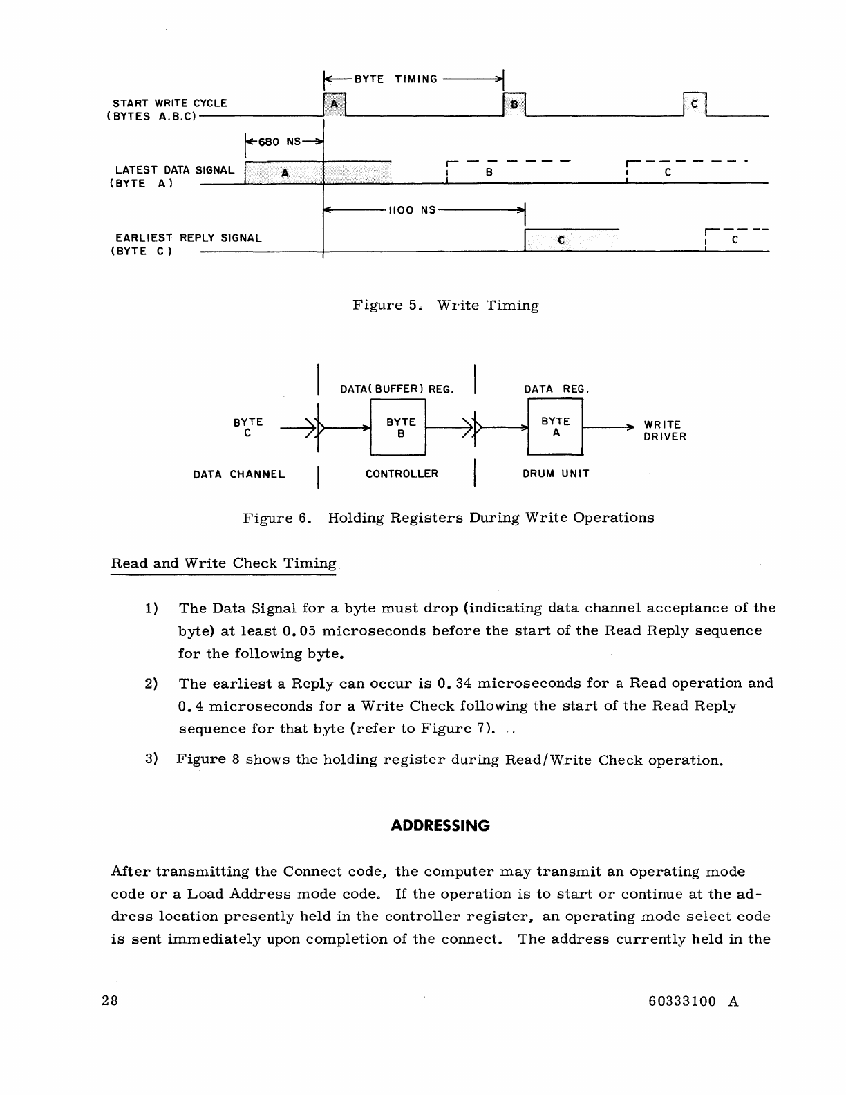
r--BYTE
TIMING
~I
(~~~~~
~~~~;_Y_CL_E
__________
~~~
________________
~p;q~
________________
~fCl~
____
__
r-680
NS~
.------
r----
LATEST
DATA
SIGNAL I A I B I C
(BYTE
A)
____
~L~~
__
~~~
.•.
__
.~.~
.•
·
______
~
____________________
~'~
______________
_
I'E~----"OO
NS-----~~I
EARLIEST
REPLY SIGNAL
(BYTE
C)
,
.------
c
r----
! C
Figure
5
,;
Write
Timing
I DATA( BUFFER}
REG.
I DATA REG.
BYTE
-7}
~I
eYe
TE I
)~
~I
BYTE I "
WR
ITE
C A DRIVER
DATA
CHANNEL
CONTROLLER I DRUM
UNIT
Figure
6.
Holding
Registers
During
Write
Operations
Read
and
Write
Check
Timing
1)
The
Data
Signal
for
a
byte
must
drop
(indicating
data
channel
acceptance
of
the
byte)
at
least
0.05
microseconds
before
the
start
of
the
Read
Reply
sequence
for
the
following
byte.
2)
The
earliest
a
Reply
can
occur
is
O.
34
microseconds
for
a
Read
operation
and
0.4
microseconds
for
a
Write
Check
following
the
start
of
the
Read
Reply
sequence
for
that
byte
(refer
to
Figure
7).
:.
3)
Figure
8
shows
the
holding
register
during
Read/Write
Check
operation.
ADDRESSING
After
transmitting
the
Connect
code,
the
computer
may
transmit
an
operating
mode
code
or
a
Load
Address
mode
code.
If
the
operation
is
to
start
or
continue
at
the
ad-
dress
location
presently
held
in
the
controller
register,
an
operating
mode
select
code
is
sent
immediately
upon
completion
of
the
connect.
The
address
currently
held
in
the
28
60333100
A
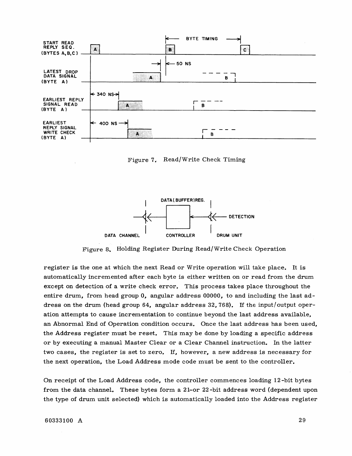
~
BYTE
TIMING ----::J
START READ
1-
'1
(~~~~~:,~~C)
__
~~~\A~)~1
__________________
~~~?B~j~~
__________________
~f§J_<C~.··
•.
·L·.
________________
___
-----,-1
r
50
NS
LATEST
DROP
DATA
SIGNAL
(BYTE
A)
EARLIEST REPLY
SIGNAL
READ
(BYTE
A)
EARLIEST
REPLY SIGNAL
WRITE CHECK
(BYTE
A)
Figure
7
<I
I
---1<
I
DATA CHANNEL
------,
B
r
----
I B
Ie
Read/Write
Check
Timing
DATA ( eUFFER)REG.
1<
{~
DETECTION
CONTROLLER
DRUM
UNIT
Figure
8..
Holding
Register
During
Read/Write
Check
Operation
register
is
the
one
at
which
the
next
Read
or
Write
operation
will
take
place.
It
is
automatically
incremented
after
each
byte
is
either
written
on
or
read
from
the
drum
except
on
detection
of
a
write
check
error.
This
process
takes
place
throughout
the
entire
drum,
from
head
group
0,
angular
address
00000,
to
and
including
the
last
ad-
dress
on
the
drum
(head
group
64,
angular
address
32,
768).
If
the
input/
output
oper-
ation
attempts
to
cause
incrementation
to
continue
beyond
the
last
address
available,
an
Abnormal
End
of
Operation
condition
occurs.
Once
the
last
address
has
been
used,
the
Address
register
must
be
reset.
This
may
be
done
by
loading
a
specific
address
or
by
executing
a
manual
Master
Clear
or
a
Clear
Channel
instruction.
In
the
latter
two
cases,
the
register
is
set
to
zero.
If,
however,
a
new
address
is
necessary
for
the
next
operation,
the
Load
Address
mode
code
must
be
sent
to
the
controller.
On
receipt
of
the
Load
Address
code,
the
controller
commences
loading
12
-bit
bytes
from
the
data
channel.
These
bytes
form
a
21-or
22
-bit
address
word
(dependent
upon
the
type
of
drum
unit
selected)
which
is
automatically
loaded
into
the
Address
register
60333100
A
29
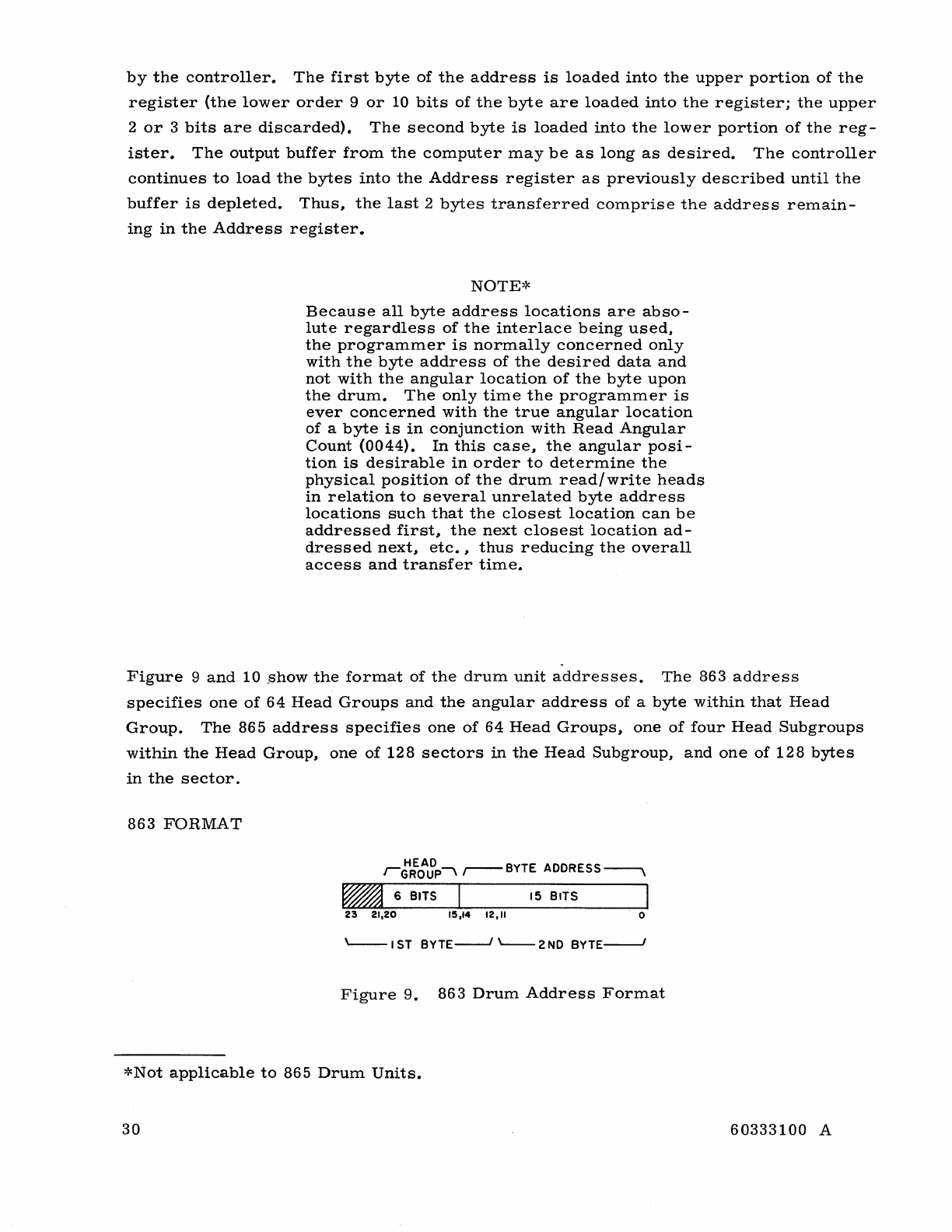
by
the
controller.
The
first
byte
of
the
address
is
loaded
into
the
upper
portion
of
the
register
(the
lower
order
9
or
10
bits
of
the
byte
are
loaded
into
the
register;
the
upper
2
or
3
bits
are
discarded).
The
second
byte
is
loaded
into
the
lower
portion
of
the
reg-
ister.
The
output
buffer
from
the
computer
may
be
as
long
as
desired.
The
controller
continues
to
load
the
bytes
into
the
Address
register
as
previously
described
until
the
buffer
is
depleted.
Thus~
the
last
2
bytes
transferred
comprise
the
address
remain-
ing
in
the
Address
register.
NOTE*
Because
all
byte
address
locations
are
abso-
lute
regardless
of
the
interlace
being
used,
the
programmer
is
normally
concerned
only
with
the
byte
address
of
the
desired
data
and
not
with
the
angular
location
of
the
byte
upon
the
drum.
The
only
time
the
programmer
is
ever
concerned
with
the
true
angular
location
of
a
byte
is
in
conjunction
with
Read
Angular
Count
(0044).
In
this
case~
the
angular
posi-
tion
is
desirable
in
order
to
determine
the
physical
position
of
the
drum
read/
write
heads
in
relation
to
several
unrelated
byte
address
locations
such
that
the
closest
location
can
be
addressed
first~
the
next
closest
location
ad-
dressed
next~
etc.
~
thus
reducing
the
overall
access
and
transfer
time.
Figure
9
and
10
.show
the
format
of
the
drum
unit
addresses.
The
863
address
specifies
one
of
64
Head
Groups
and
the
angular
address
of
a
byte
within
that
Head
Group.
The
865
address
specifies
one
of
64
Head
Groups~
one
of
four
Head
Subgroups
within
the
Head
Group~
one
of
128
sectors
in
the
Head
Subgroup,
and
one
of
128
bytes
in
the
sector.
863
FORMAT
HEAD
IGROUP'
,----
BYTE ADDRESS
~
• 6 BITS
15
BITS
23
21.20
15.14
12."
o
'---I
ST
BYTE----1
'---
2
NO
BYTE----1
Figure
9.
863
Drum
Address
Format
*Not
applicable
to
865
Drum
Units.
30
60333100
A
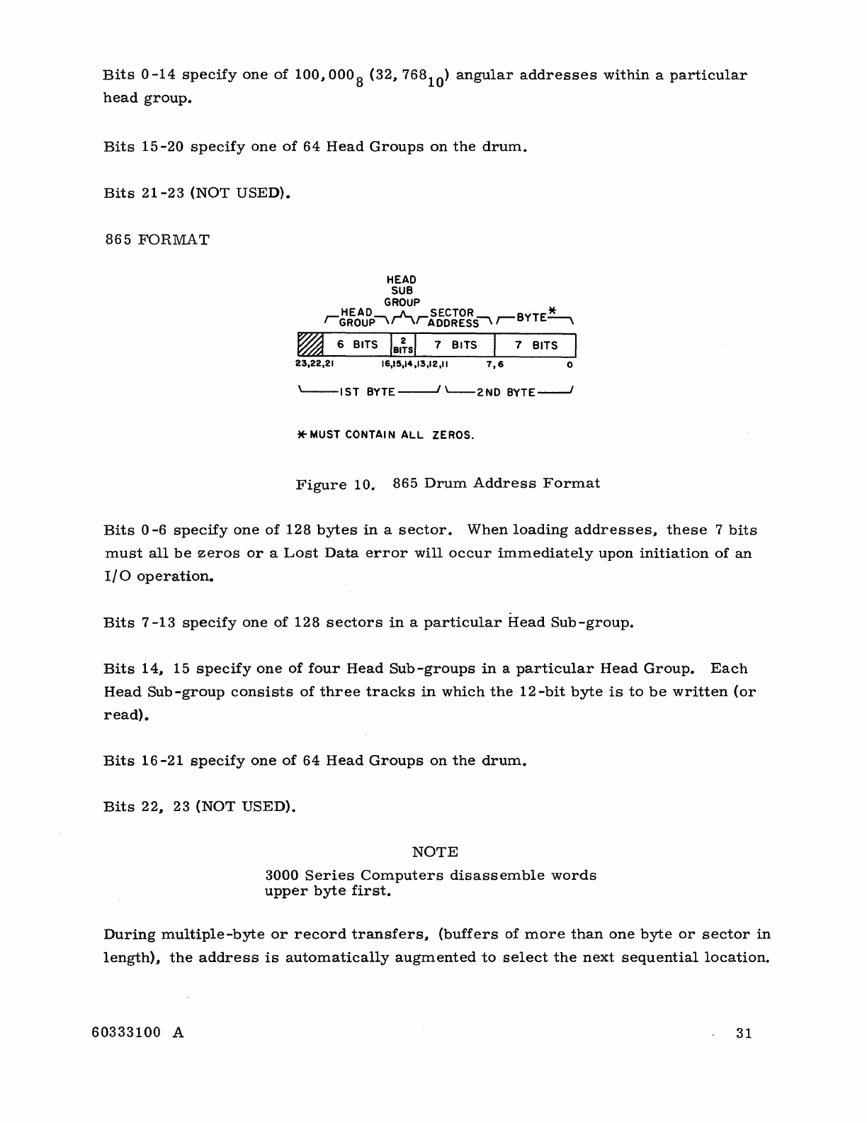
Bits
0
-14
specify
one
of
100"
000
8 (32" 768
10
)
angular
addresses
within
a
particular
head
group.
Bits
15
-20
specify
one
of
64
Head
Groups
on
the
drum.
Bits
21-23
(NOT
USED).
865
FORMAT
HEAD
SUB
GROUP
HEAD
.JL
SECTOR
*'
'GROUP\'\/ADDRESS'
,--BYTE~
~
6 BITS
IBI~sl
7 BITS 7 BITS
23,22,21
16,15,14,13,12,11
7,6
0
L--IST
BYTE---''---2ND
BYTE---'
*
MUST
CONTAI N
ALL
ZEROS.
Figure
10.
865
Drum
Address
Format
Bits
0
-6
specify
one
of
128
bytes
in
a
sector.
When
loading
addresses"
these
7
bits
must
all
be
zeros
or
a
Lost
Data
error
will
occur
immediately
upon
initiation
of
an
I/O
operation.
Bits
7
-13
specify
one
of
128
sectors
in
a
particular
Head
Sub-group.
Bits
14" 15
specify
one
of
four
Head
Sub
-groups
in
a
particular
Head
Group.
Each
Head
Sub-group
consists
of
three
tracks
in
which
the
12-bit
byte
is
to
be
written
(or
read).
Bits
16
-21
specify
one
of
64
Head
Groups
on
the
drum.
Bits
22" 23
(NOT
USED).
NOTE
3000
Series
Computers
disassemble
words
upper
byte
first.
During
multiple-byte
or
record
transfers,
(buffers
of
more
than
one
byte
or
sector
in
length),
the
address
is
automatically
augmented
to
select
the
next
sequential
location.
60333100
A 31
This
process
takes
place
throughout
the
entire
drum,
up
to
and
including
(but
not
beyond)
the
last
address
of
the
drum.
(Operation
is
not
end-around
within
a
drum.)
Auto-loading/End
of
Record
In
order
to
accommodate
auto-loading,
the
drum
subsystem
is
equipped
to
indicate
an
End
of
Record
upon
completion
of
the
autoload
sequence.
Auto-loading
causes
the
drum
subsystem
to
send
to
the
data
channel
512
bytes
of
data,
commencing
at
address
zero
of
the
specified
drum
unit.
Upon
completion
of
the
data
transfer,
the
subsystem
transmits
an
End
of
Record
signal
in
response
to
the
513th
byte.
NOTE
Because
the
863
drum
is
byte
addressable,
there
is
no
specific
record
length
for
the
subsystem.
The
End
of
Record
signal
is
provided
only
to
facilitate
auto-loading
and
is
issued
in
response
to
an
Autoload
Request
(see
below).
The
subsystem
is
designed
to
recognize
the
following
sequence
as
the
Auto-load
Request
and
responds
accordingly:
1)
Master
Clear.
2)
Connect.
3)
Issuance
of
a
0041
(Read)
function
code.
4)
Initiation
of
a
buffer
equal
to
or
greater
than
513
bytes.
PROGRAMMING CONSIDERATIONS
The
following
information
will
help
in
making
the
programmer
and
the
engineer
aware
of
critical
problems
and
procedures
unique
to
drum
subsystems.
Most
of
the
proce-
dures
are
common
to
all
computers;
those
that
are
unique
to
a
particular
computer
are
so
stated.
PROGRAM
COMPATABILITY
Program
compatability
exists
between
programs
written
for
the
3436/3637
-A
control-
lers
and
the
3637
-B
controllers
with
only
minor
variations
necessary
to
the
original
program.
These
changes
are
limited
to
the
differences
in
the
Drum
Reject/Lost
Data
32
60333100
A
and
Reserved
status
bits
and
addressing.
Thus
any
program
written
for
a
3436/3637-A
controller
will
operate
with
a
3637
-B
controller
by
altering
all
references
in
the
orig-
inal
program
to
these
two
status
bits
so
that
they
reflect
the
new
meaning
as
defined
for
the
3637
-B
controller
and
(when
operating
with
an
865)
by
ensuring
that
all
addresses
reference
the
beginning
of
a
sector.
The
converse
is
also
true,
except
that
any
program
written
for
a 3637
-B
controller
and
operating
with
an
865
Drum
Unit
cannot
be
modified
to
operate
with
a
3436/3637
-A
controller.
865
INPUT/OUTPUT
OPERATIONS
When
any
I/O
operation
to
an
865
Drum
Unit
is
terminated
anywhere
other
than
at
the
end
of
the
sector
(less
than
128
bytes
have
been
read
or
written),
the
byte
count
portion
of
the
Address
register
will
not
contain
all
zeros.
Accordingly,
the
register
must
be
reloaded
with
an
address
whose
byte
count
portion
equals
zero
before
any
new
1/0
operation
may
commence.
SIMULTANEOUS
SELECTION
If
the
two
data
channels
attached
to
the
same
controller
simultaneously
attempt
to
connect
to
the
controller,
neither
channel
is
given
preference;
the
controller
connects
to
the
data
channel
recognized
first.
Initiation
of
the
110
need
not
take
place
immediately
after
the
connect
is
made;
once
the
connect
is
made,
the
channel
has
the
controller
reserved
until
specifically
released
by
the
channel.
BUFFER
RESTRICTIONS
Each
buffer
must
be
preceded
by
an
EF
instruction
which
specifies
a
mode
of
operation.
Completion
of
a
buffer
(end
of
operation)
with
or
without
chaining
clears
the
previous
mode
selection.
Buffers
which
are
inconsistent
with
the
mode
selected
cause
the
com-
puter
to
hang
up
(i.
e.,
initiation
of
an
output
(write)
buffer
when
a
Read
mode
is
selected).
MASTER
CLEAR,
RELEASE
AND
DISCONNECT
A
manual
or
programmed
(channel)
Master
Clear
causes
the
Address
register
to
be
cleared
to
zero
and
removes
all
interrupt
selections.
A
Release
and
Disconnect
has
no
effect
on
the
content
of
the
Address
register
or
interrupt
selections.
60333100
A 33
NOT
READY
A
manual
Master
Clear
is
necessary
to
remove
a
Not
Ready
condition.
INTERRUPTS
Once
an
interrupt
occurs
(if
selected)~
it
is
removed
by
any
Master
Clear"
the
Release
and
Disconnect
function
code"
or
any
002-"
003-
function
code.
The
interrupt
selections
are
independent
for
each
data
channel
interface
and
are
not
affected
by
the
actions
of
the
other
data
channel.
NOTE
An
interrupt
selections
are
saved
(remain)
within
the
interface
when
a
release
and
dis-
connect
is
performed.
Only
a
Master
Clear
and
associated
002
-
or
003
-
codes
remove
interrupt
selections.
A
data
channel
which
has
the
subsystem
reserved
receives
an
interrupts
selected.
The
channel
not
in
control
(reservation)
of
the
controller
and/
or
drums
can
be
interrupted
by
a
release
interrupt
only.
All
other
interrupts
from
the
controller
to
the
data
channel
not
in
control
are
inhibited
even
though
the
interrupt
is
selected.
WRITE
TIMING
During
Write
operations"
the
End
of
Operation
signal
is
delayed
until
completion
of
writing
of
the
last
byte
of
the
buffer
or
record.
In
the
863
Drum
Units
the
length
of
this
delay
depends
on
three
factors:
1)
the
interlace
ratio"
2)
whether
the
last
byte
of
the
buffer
requires
a
different
head
group"
and
3)
whether
a
single
byte
is
being
written
(1-byte
buffer).
Write
Timing
Interlace
Delay
(863
Drum
Units)
This
delay
time
is
equal
to
the
transfer
time
per
byte"
and
is
directly
proportional
to
the
interlace
ratio:
34
Ratio
1:1
2:1
4:1
8:1
16:1
32:1
Transfer
Time
(t-lsec/byte)
1
2
4
8
16
32
60333100
A
Last
Byte
Write
Timing
If
the
last
byte
of
the
buffer
requires
a
head
group
on
the
drum
different
than
the
group
used
for
the
preceding
byte"
the
end
of
operation
is
delayed
by
the
100
-Ilsec
head
group
switching
time
plus
the
interlace
time
mentioned
above.
Single
Byte
Write
Timing
If
only
a
single
byte
is
to
be
written
on
the
drum
(one-byte
buffer),
the
end
of
operation
is
not
sent
until
the
byte
has
been
written.
Since
the
desired
address
position
must
be
located
prior
to
initiating
the
Write
operation,
the
delay
may
be
equal
to
an
entire
revo-
lution
of
the
drum
(35
ms).
60333100
A 35
MANUAL
OPERATIONS
Operation
of
the
drum
subsystem
is
under
program
control
from
the
computers
through
the
use
of
the
EF
Connect
and
function
codes.
Only
those
manual
operations
necessary
to
bring
up
power
to
the
controller
and
drums,
set
the
equipment
and
unit
designation
switches,
and
load
and
initiate
the
computer
program
are
necessary
for
subsystem
operation.
To
bring
the
subsystem
up
from
dead
start
(no
power
applied
to
drums
or
controller),
one
of
the
following
procedures
should
be
followed.
Refer
to
Figure
11
for
switch
locations.
REMOTE
STARTING
1)
Ensure
that
the
REMOTE
-
LOCAL
power
switch
at
each
drum
unit
is
in
the
REMOTE
position.'~
2)
Turn
the
main
power
circuit
break-
er
(located
near
the
bottom
of
the
power
panel
at
the
rear
of
the
con-
troller)
on.
(The
drum
units
will
automatically
be
sequenced
to
avoid
circuit
overloading
by
starting
current
surges.
)
NOTE
LOCAL
STARTING
1)
Ensure
that
the
REMOTE-LOCAL
switch
at
the
drum
unit
is
in
the
LOCAL
position.
2)
Press
the
power
ON
switch
located
immediately
above
the
REMOTE-
LOCAL
switch.
Wait
approximately
10
minutes
(to
allow
starting
current
surge
to
die
down)
and
then
repeat
steps
1
and
2
for
the
next
drum
unit.
During
remote
starting,
the
sequencing
automatically
bypasses
any
unit
in
the
subsystem
whose
selection
switch
is
in
the
LOCAL
posi-
tion.
Any
combination
of
REMOTE
and
LOCAL
settings
is
permis-
sible
in
a
subsystem.
NOTE
In
the
REMOTE
position,
the
presence
of
dc
power
at
the
controller
is
the
determining
factor
in
sequencing
of
power
on
at
the
drum
units.
When
dc
power
becomes
available
at
the
controller,
the
drum
units
selected
for
remote
power
on
starting
automatically
commence
se-
quencing.
Thus,
it
is
possible
to
wire
the
system
for
automatic
remote
starting
from
the
computer
(or
other
desired
source)
rather
than
the
controller
by
supplying
controller
power
from
a
switch
at
the
desired
remote
location.
*When
the
switch
is
in
the
REMOTE
position,
pressing
the
POWER
ON
or
POWER
OFF
switch
on
the
drum
unit
maintenance
panel
has
no
effect
on
the
drum
unit.
When
the
switch
is
in
the
LOCAL
position,
the
drum
unit
is
not
affected
by
the
controller
main
power
source.
36
60333100
A
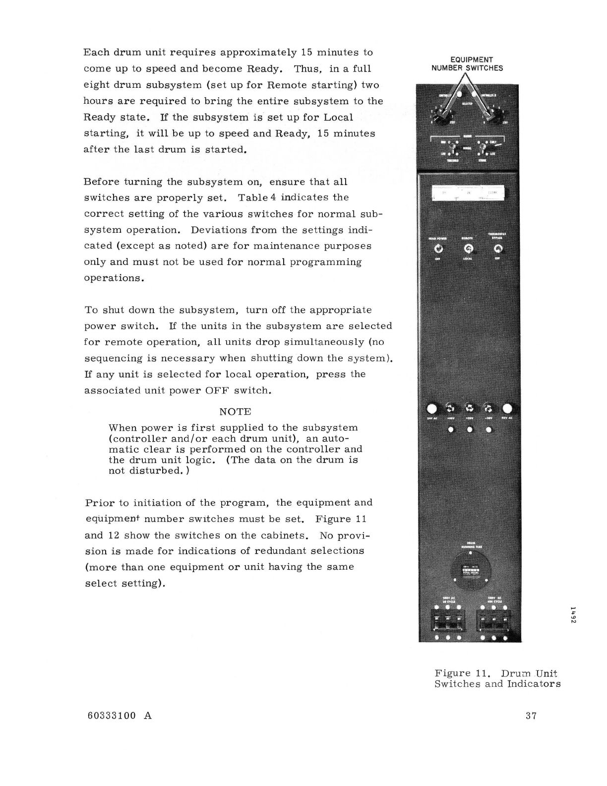
Each
drum
unit
requires
approximately
15
minutes
to
come
up
to
speed
and
become
Ready.
Thus, in
a
full
eight
drum
subsystem
(set
up
for
Remote
starting)
two
hours
are
required
to
bring
the
entire
subsystem
to
the
Ready
state.
If
the
subsystem
is
set
up
for
Local
starting,
it
will
be
up
to
speed
and
Ready,
15
minutes
after
the
last
drum
is
started.
Before
turning
the
subsystem
on,
ensure
that
all
switches
are
properly
set.
Table
4
indicates
the
correct
setting
of
the
various
switches
for
normal
sub-
system
operation.
Deviations
from
the
settings
indi-
cated
(except
as
noted)
are
for
maintenance
purposes
only
and
must
not
be
used
for
normal
programming
operations.
To
shut
down
the
subsystem,
turn
off
the
appropriate
power
switch.
If
the
units
in
the
subsystem
are
selected
for
remote
operation,
all
units
drop
simultaneously
(no
sequencing
is
necessary
when
shutting
down
the
system).
If
any
unit
is
selected
for
local
operation,
press
the
associated
unit
power
OFF
switch.
NOTE
When
power
is
first
supplied
to
the
subsystem
(controller
and/
or
each
drum
unit),
an
auto-
matic
clear
is
performed
on
the
controller
and
the
drum
unit
logic.
(The
data
on
the
drum
is
not
disturbed.
)
Prior
to
initiation
of
the
program,
the
equipment
and
equipment
number
switches
must
be
set.
Figure
11
and
12
show
the
switches
on
the
cabinets.
No
provi-
sion
is
made
for
indications
of
redundant
selections
(more
than
one
equipment
or
unit
having
the
same
select
setting).
60333100
A
EQUIPMENT
NUMBER SWITCHES
Figure
11.
DrumUnit
Switches
and
Indicators
37
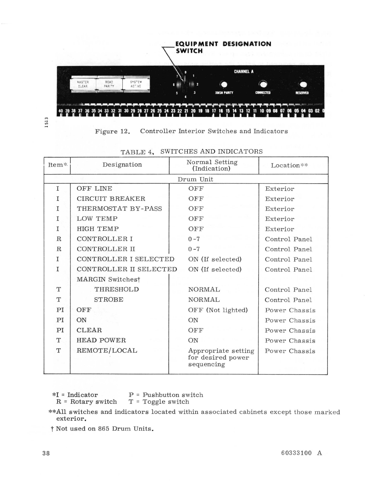
EQUIPMENT
DESt'
GNATION
SWITCH
Figure
12.
Controller
Interior
Switches
and
Indicators
TABLE
4.
SWITCHES
AND
INDICATORS
I
Item
':' I
DeSignation
Normal
Betting
Location
':":
'
(Indi
cat
ion)
Drum
Unit
I
OFF
LINE
OFF
I
CIRCUIT
BREAKER
OFF
I
THERMOSTAT
BY-PASS
OFF
I
LOW
TEMP
OFF
I
HIGH
TEMP
OFF
R
CONTROLLER
I
0-7
R
CONTROLLER
II
0-7
I
CONTROLLER
I
SELECTED
ON
(If
selected)
I
CONTROLLER
II
SELECTED
ON
(If
selected)
MARGIN
Switchest
T
THRESHOLD
NORMAL
T
STROBE
NORMAL
PI
OFF OFF
(N
ot
light
ed
)
PI
ON
ON
PI
CLEAR
OFF
T
HEAD
POWER
ON
T
REMOTE
/
LOCAL
Appropriate
setting
for
desired
power
sequencing
'~I
=
Indicator
R =
Rotary
switch
P =
Pushbutton
switch
T =
Toggl
e
switch
Exterior
Exterior
Exterior
Exterior
Exterior
Control
Panel
Control
Pane
l
Cont
rol
Panel
Control
Panel
Control
Panel
Control
Panel
Power
Chassis
Power
Chassis
Power
Chas
sis
Power
Chassis
Power
Chassis
**All
switches
and
indicators
located
within
asso
c
iated
cabi
n
ets
except
those
marked
exterior.
t
Not
used
on
865
Drum
Units.
38
60333100
A
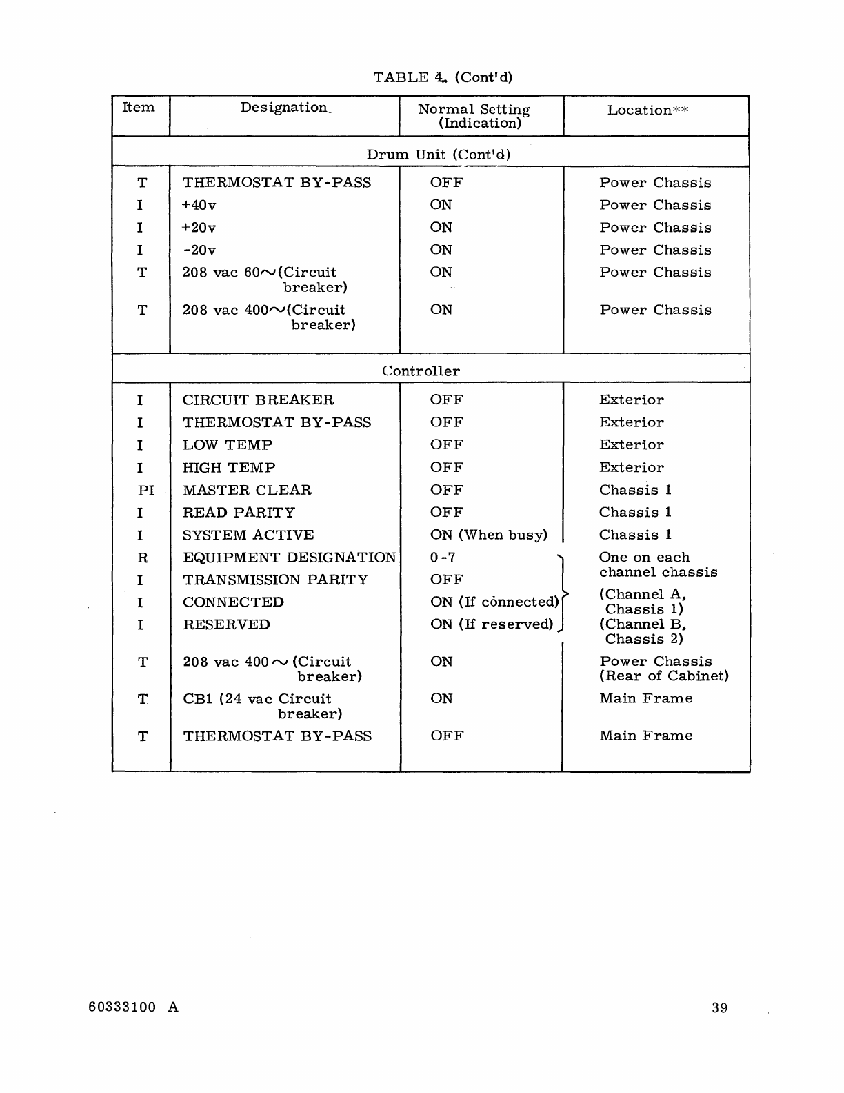
TABLE
4..
(Cont'd)
Item
Designation_
Normal
Setting
Location
~o:~
(Indication)
Drum
Unit
(Cont'd)
T
THERMOSTAT
BY-PASS
OFF
Power
Chassis
I
+40v
ON
Power
Chassis
I
+20v
ON
Power
Chassis
I
-20v
ON
Power
Chassis
T
208
vac
60rv(Circuit
ON
Power
Chassis
breaker)
T
208
vac
400""(Circuit
ON
Power
Chassis
breaker)
Controller
I
CIRCUIT
BREAKER
OFF
Exterior
I
THERMOSTAT
BY-PASS
OFF
Exterior
I
LOW
TEMP
OFF
Exterior
I
HIGH
TEMP
OFF
Exterior
PI
MASTER
CLEAR
OFF
Chassis
1
I
READ
PARITY
OFF
Chassis
1
I
SYSTEM
ACTIVE
ON
(When
busy)
Chassis
1
R
EQUIPMENT
DESIGNATION
0-7
}
One
on
each
I
TRANSMISSION
PARITY
OFF
channel
chassis
I
CONNECTED
ON
(If
connected)
(Channel
AI
Chassis
1)
I
RESERVED
ON
(If
reserved)
(Channel
BI
Chassis
2)
T
208
vac
400"",
(Circuit
ON
Power
Chassis
breaker)
(Rear
of
Cabinet)
T
CB1
(24
vac
Circuit
ON
Main
Frame
breaker)
T
THERMOSTAT
BY-PASS
OFF
Main
Frame
60333100
A
39
SAMPLE
PROGRAM ROUTINE
To
help
in
understanding
the
drum
subsystem,
a
sample
program
is
included
preceded
by
a
flow
chart
of
the
program.
The
routine
is
designed
for
a
3600
Computer
System
operating
with
an
863
Drum
Unit.
PROGRAM
SEQUENCE
The
basic
programming
sequence
is:
SEQUENCE
1.
Connect
Connect
Response
2.
Select
Interrupts
3.
Load
Address
4.
Select
Operating
Mode
5.
Initiate
Operation
40
COMMENT
Connect
code
selects
controller
and
drum
unit
(if
available).
If
the
Connect
operation
is
successful,
a
Reply
is
returned;
if
the
connect
is
not
made
(controller
or
drum
unavailable)
a
Reject
is
returned;
return
to
step
1
after
determining
the
cause
of
the
reject.
Any
desired
interrupting
conditions
should
be
selected
at
this
point.
If
a
new
address
location
(other
than
the
one
presently
held
in
the
controller
Address
register)
is
desired,
it
should
be
sent
prior
to
the
execution
of
an
EF
operating
mode
selection.
EF
code
selects
the
desired
mode
of
oper-
ation.
(Operating
modes
must
be
selected
for
each
individual
buffer.)
Initiation
of
a
read
or
write
IIO
initiates
operation
within
the
drum.
Completion
of
the
IIO
may
be
detected
through
use
of
the
End
of
Operation
interrupt
or
dropping
of
the
Busy
status
bit.
60333100
A
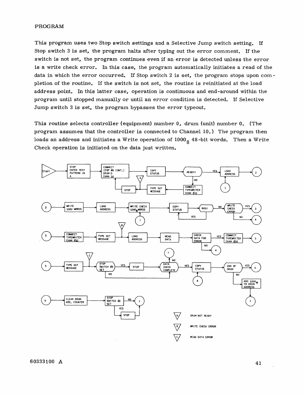
PROGRAM
This
program
uses
two
Stop
switch
settings
and
a
Selective
Jump
switch
setting.
If
Stop
switch
3
is
set,
the
program
halts
after
typing
out
the
error
comment.
If
the
switch
is
not
set,
the
program
continues
even
if
an
error
is
detected
unless
the
error
is
a
write
check
error.
In
this
case,
the
program
automatically
initiates
a
read
of
the
data
in
which
the
error
occurred.
If
Stop
switch
2
is
set"
the
program
stops
upon
com-
pletion
of
the
routine.
If
the
switch
is
not
set"
the
routine
is
reinitiated
at
the
load
address
point.
In
this
latter
case,
operation
is
continuous
and
end-around
within
the
program
until
stopped
manually
or
until
an
error
condition
is
detected.
If
Selective
Jump
switch
3
is
set"
the
program
bypasses
the
error
typeout.
This
routine
selects
controller
(equipment)
number
0"
drum
(unit)
number
O.
(The
program
assumes
that
the
controller
is
connected
to
Channel
10.)
The
program
then
loads
an
address
and
initiates
a
Write
operation
of
1000
S
4S-bit
words.
Then
a
Write
Check
operation
is
initiated
on
the
data
just
written.
DRUM
NOT
READY
WR
[IT
CHECK
ERROR
READ
DATA
ERROR
60333100
A
41
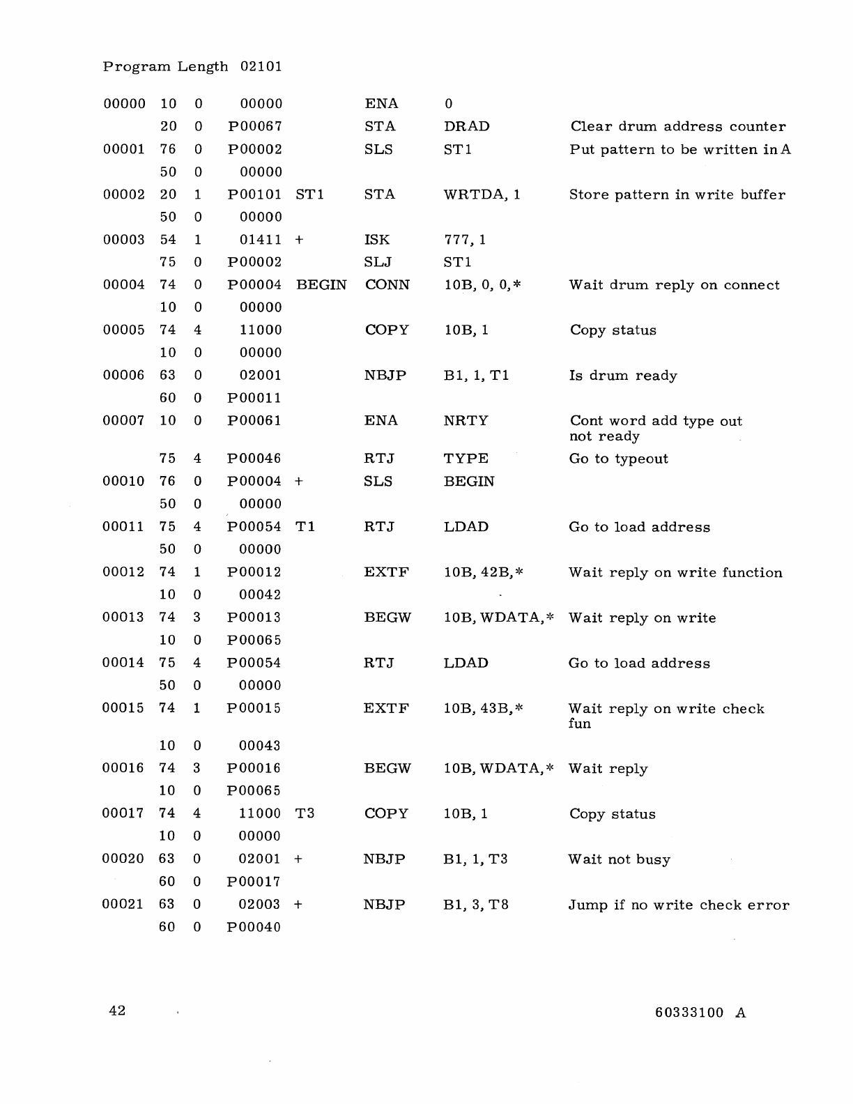
Program
Length
02101
00000
10
0
00000
ENA
0
20
0
POO067
STA
DRAD
Clear
drum
address
counter
00001
76
0 POOO02
SLS
ST1
Put
pattern
to
be
written
in
A
50
0
00000
00002
20
1
P00101
ST1
STA
WRTDA,l
Store
pattern
in
write
buffer
50
0
00000
00003
54
1
01411
+
ISK
777,
1
75
0 POOO02
SLJ
ST1
00004
74
0 POOO04
BEGIN
CONN
lOB,
0, 0, *
Wait
drum
reply
on
connect
10
0
00000
00005
74
4
11000
COpy
lOB,
1
Copy
status
10
0
00000
00006
63
0
02001
NBJP
B1,
1,
T1
Is
drum
ready
60
0 POO011
00007
10
0 POO061
ENA
NRTY
Cont
word
add
type
out
not
ready
75
4
POO046
RTJ
TYPE
Go
to
typeout
00010
76
0 POOO04 +
SLS
BEGIN
50
0
00000
00011
75
4
POO054
T1
RTJ
LDAD
Go
to
load
address
50
0
00000
00012
74
1 POOO12
EXTF
lOB,
42B,*
Wait
reply
on
write
function
10
0
00042
00013
74
3 POOO13
BEGW
lOB,
WDATA,~~
Wait
reply
on
write
10
0
POO065
00014
75
4
POO054
RTJ
LDAD
Go
to
load
address
50
0
00000
00015
74
1 POOO15
EXTF
lOB,
43B,*
Wait
reply
on
write
check
fun
10
0
00043
00016
74
3 POOO16
BEGW
lOB,
WDATA,*
Wait
reply
10
0
POO065
00017
74
4
11000
T3
COpy
lOB,
1
Copy
status
10
0
00000
00020
63
0
02001
+
NBJP
B1,
1,
T3
Wait
not
busy
60
0 POOO17
00021
63 0
02003
+
NBJP
B1,
3,
T8
Jump
if
no
write
check
error
60
0
POO040
42
60333100
A
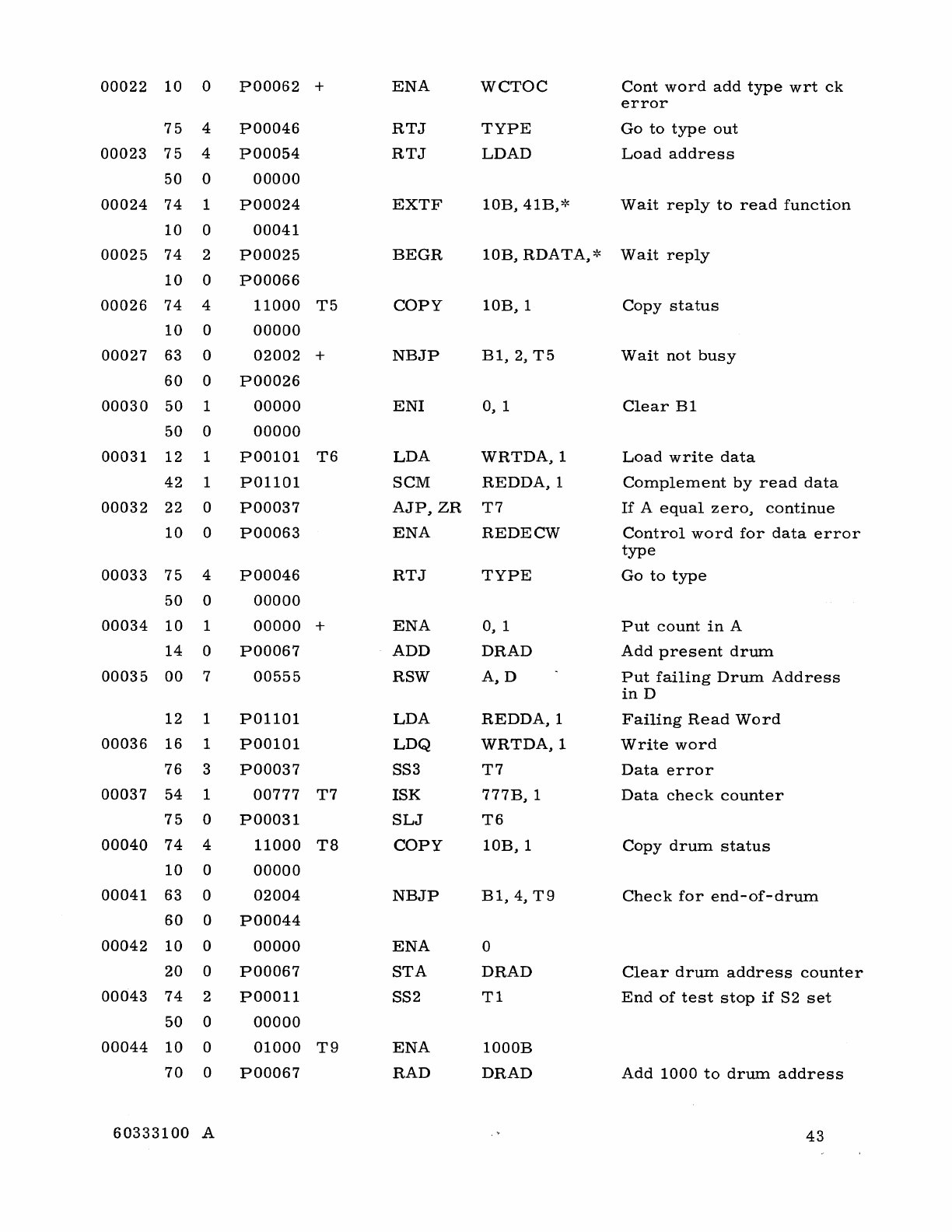
00022
10
0
POO062
+
ENA
WCTOC
Cont
word
add
type
wrt
ck
error
75
4
POO046
RTJ
TYPE
Go
to
type
out
00023
75
4
POO054
RTJ
LOAD
Load
address
50
0
00000
00024
74
1
POO024
EXTF
lOB,
41B,*
Wait
reply
to
read
function
10
0
00041
00025
74
2
POO025
BEGR
lOB,
RDATA,*
Wait
reply
10
0
POO066
00026
74
4
11000
T5
COpy
lOB,
1
Copy
status
10
0
00000
00027
63 0
02002
+
NBJP
B1,
2,
T5
Wait
not
busy
60
0
POO026
00030
50
1
00000
EN1
0, 1
Clear
B1
50
0
00000
00031
12
1
P00101
T6
LDA
WRTDA,l
Load
write
data
42
1
P01101
SCM
REDDA,l
Complement
by
read
data
00032
22
0
POO037
AJP,ZR
T7
If
A
equal
zero,
continue
10
0
POO063
ENA
REDECW
Control
word
for
data
error
type
00033
75
4
POO046
RTJ
TYPE
Go
to
type
50
0
00000
00034
10
1
00000
+
ENA
0, 1
Put
count
in
A
14
0
POO067
ADD
DRAD
Add
present
drum
00035
00
7
00555
RSW
A,D
Put
failing
Drum
Address
in
D
12
1
P01101
LDA
REDDA,l
Failing
Read
Word
00036
16
1
P00101
LDQ
WRTDA,l
Write
word
76
3
POO037
SS3
T7
Data
error
00037
54
1
00777
T7
1SK
777B,
1
Data
check
counter
75
0
POO031
SLJ
T6
00040
74
4
11000
T8
COpy
lOB,
1
Copy
drum
status
10
0
00000
00041
63
0
02004
NBJP
B1,4,T9
Check
for
end-of-drum
60
0
POO044
00042
10
0
00000
ENA
0
20
0
POO067
STA
DRAD
Clear
drum
address
counter
00043
74
2
POOOl1
SS2
T1
End
of
test
stop
if
S2
set
50
0
00000
00044
10
0
01000
T9
ENA
1000B
70
0
POO067
RAD
DRAD
Add
1000
to
drum
address
60333100
A
43
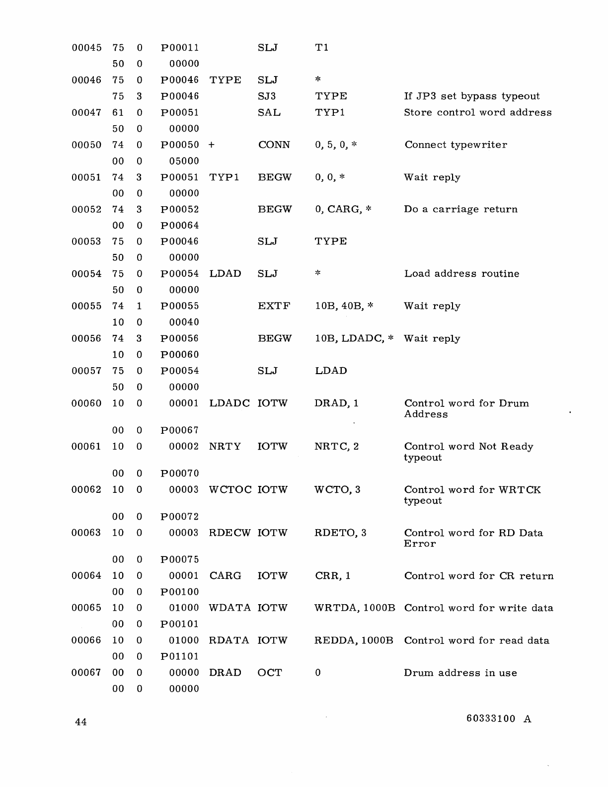
00045
75
0
POO01l
SLJ
Tl
50
0
00000
00046
75
0 POO046
TYPE
SLJ
*
75
3 POO046
SJ3
TYPE
If
.JP3
set
bypass
typeout
00047
61
0
POO05l
SAL
TYPI
Store
control
word
address
50
0
00000
00050
74
0
POO050
+
CONN
0,
5,
0,
,~
Connect
typewriter
00
0
05000
00051
74
3
POO05l
TYP1
BEGW
0, 0, *
Wait
reply
00
0
00000
00052
74
3 POO052
BEGW
0,
CARG,
,~
Do
a
carriage
return
00
0
POO064
00053
75
0 POO046
SLJ
TYPE
50
0
00000
00054
75
0
POO054
LDAD
SLJ
*
Load
addres
s
routine
50
0
00000
00055
74
1
POO055
EXTF
lOB,
40B,
*
Wait
reply
10
0
00040
00056
74
3 POO056
BEGW
lOB,
LDADC,
*
Wait
reply
10
0
POO060
00057
75
0
POO054
SLJ
LDAD
50
0
00000
00060
10
0
00001
LDADC
IOTW
DR
AD,
1
Control
word
for
Drum
Address
00
0 POO067
00061
10
0
00002
NRTY
IOTW
NRTC,2
Control
word
Not
Ready
typeout
00
0
POO070
00062
10
0
00003
WCTOC
IOTW
WCTO,3
Control
word
for
WRTCK
typeout
00
0
POO072
00063
10
0
00003
RDECW
IOTW
RDETO,3
Control
word
for
RD
Data
Error
00
0
POO075
00064
10
0
00001
CARG
IOTW
CRR,l
Control
word
for
CR
return
00
0
P00100
00065
10
0
01000
WDATA
IOTW
WRTDA,1000B
Control
word
for
write
data
00
0
P00101
00066
10
0
01000
RDATA
IOTW
REDDA,1000B
Control
word
for
read
data
00
0
POllOI
00067
00
0
00000
DRAD
OCT
0
Drum
address
in
use
00
0
00000
44
60333100
A
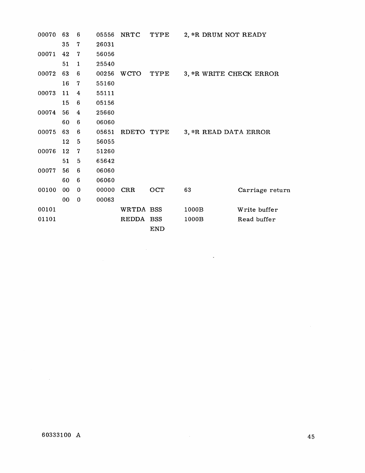
00070
63 6
05556
NRTC
TYPE
2,
*R
DRUM
NOT
READY
35
7
26031
00071
42
7
56056
51 1
25540
00072
63 6
00256
WCTO
TYPE
3,
*R
WRITE
CHECK
ERROR
16 7
55160
00073
11 4
55111
15 6
05156
00074
56 4
25660
60
6
06060
00075
63 6
05651
RDETO
TYPE
3,
*R
READ
DATA
ERROR
12 5
56055
00076
12 7
51260
51 5
65642
00077
56 6
06060
60
6
06060
00100
00
0
00000
CRR
OCT
63
Carriage
return
00
0
00063
00101
WRTDA
BSS
1000B
Write
buffer
01101
REDDA
BSS
1000B
Read
buffer
END
60333100
A
45
COMMENT
SHEET
MANUAL
TITLE
__
3_4_3_6_-_A...;;,.,_3_6_3_7_-_A_I_B_I_C_D_R_U_M
__
S_T_O_R_A
_G_E_C_O_N_T_R_O_L_L_E_R_S_
Reference
Manual
PUBLICATION
NO.
_6_0_3_3_3_1_0_0
____
_
REVISION
___
A
_"
---
FROM:
NAME:
______________________________________________________
__
BUSINESS
ADDRESS:
__________________________________________________
___
COMMENTS:
This
form
is
not
intended
to
be
used
as
an
order
blank.
Your
evaluation
of
this
manual
will
be
welcomed
by
Control
Data
Corporation.
Any
errors,
suggested
additions
or
deletions,
or
general
comments
may
be
made
below.
Please
include
page
number
references
and
fill
in
publication
revision
level
as
shown
by
the
last
entry
on
the
Record
of
Revision
page
at
the
front
of
the
manual.
Customer
engineers
are
urged
to
use
the
TAR.
NO
POSTAGE
STAMP
NECESSARY
IF
MAILED
IN
U.
S.
A.
FOLD
ON
DOTTED
LINES
AND
STAPLE
STAPLE
STAPLE
FOLD FOLD
-------------------------------------------~
FOLD
BUSINESS
REPLY
MAIL
NO
POSTAGE
STAMP
NECESSARY
IF
MAILED
IN
U.S.A.
POSTAGE WILL
BE
PAID
BY
CONTROL DATA CORPORATION
Technical
Publications
Department
4201
North
Lexington
Avenue
Arden
Hills,
Minnesota
55112
FIRST
CLASS
PERMIT
NO.
8241
MINNEAPOLIS,
MINN.
FOLD
w
Z >
:::::i
