Product Detail Manual
100098-Catalog 100098-Catalog 100098-Catalog 785901 Batch7 unilog cesco-content
90546-Catalog 90546-Catalog 90546-Catalog 785901 Batch12 unilog cesco-content
2014-11-11
: Pdf 61079-Attachment 61079-Attachment 785901 Batch12 unilog
Open the PDF directly: View PDF ![]() .
.
Page Count: 42
23-1
© 2012 Schneider Electric
All Rights Reserved
23 RELAYS AND TIMERS
Table of Contents
Section 23
Relays and Timers
s
RXM, p. 23-8 RSL, p. 23-2 /RSB, p. 23-3
SSR, p. 23-25 8501X, p. 23-22
CAD32, p. 23-16 9050JCK, p. 23-30
RE7, p. 23-28 ABL8, p. 23-37
REG24, REG48, REG96
p. 23-31
CA2SKE, p. 23-21
SR2, SR3, p. 23-39 RM17, RM35 p. 23-32
General Purpose Relays
Zelio™ Interface Relays RSL, RSB 23-2
Zelio™ Plug-in Relays, Sockets & Access. RXM, RPM, RUM, RPF 23-4
Square D™ Plug-in Class 8501 Type K 23-10
Square D™ Alternating Plug-in Class 8501 Type KA 23-11
Square D™ Miniature Plug-in Class 8501 Type R 23-12
Square D™ Sockets Class 8501 Type N 23-14
Square D™ Power Class 8501 Type C 23-15
Industrial Relays
TeSys™ IEC Style Relays TeSys D 23-16
TeSys K 23-19
TeSys SK 23-21
TeSys™ IEC Style - Alternating Relays CA2SKE 23-21
Square D™ NEMA Style Relays Class 8501 Type X™ 23-22
Solid State Relays
Panel Mount SSRP 23-25
DIN Mount SSRD 23-25
SSR Accessories SSRAH1, SSRAT1 23-25
Timers
Zelio™ IEC Style—17.9 mm RE11 23-26
Zelio™ Panel Mounting RE48 23-26
Zelio™ Miniature Plug-in REXL 23-26
Zelio™ IEC Style—22.5 mm RE7, RE8, and RE9 23-27
Square D™ General Purpose Plug-in Class 9050 Type JCK 23-30
Control and Measurement Relays
Zelio™ Temperature Controllers—24x48 REG24 23-31
Zelio™ Temperature Controllers—48x48 REG48 23-31
Zelio™ Temperature Controllers—48x96 REG96 23-31
Zelio™Current Measurement Relays RM17JC andRM35JA 23-32
Zelio™ Phase Measurement Relays RM17T and RM35T 23-33
Zelio™ Voltage Measurement Relays RM17U and RM35U 23-34
Zelio™ Level Control Relays RM35L 23-35
Zelio™ Pump Control Relays RM35BA 23-35
Zelio™ Speed Control Relays RM35S 23-36
Zelio™ Frequency Control Relays RM35HZ 23-36
Zelio™ Temperature Control Relays RM35AT 23-36
Other Products
Phaseo™ DC Power Supplies ABL1, ABL7, and ABL8 23-37
Zelio™ Analog Interface Modules RM 23-38
Zelio™ Logic 2 Smart Relays SR2, SR3 23-39
Zelio™ Solid-State Interface Modules ABS 23-41
Zelio™ Electromechanical Interface ABR 23-42
www.schneider-electric.us
23 RELAYS AND TIMERS
23-2 © 2012 Schneider Electric
All Rights Reserved
General Purpose Relays RSL
Refer to Catalog DIA3ED2090304EN-US
Zelio™ Interface Relays
Zelio RSL slim interface relays save valuable panel space with a 6 mm width and have a 6 Amp general purpose load
rating. Features include:
•Pre-assembled option: relay and socket are combined into one catalog number.
•Universal AC/DC sockets have built-in protection from transients and reverse polarity voltages (see catalog
DIA3ED2090304EN-US for more detailed information).
•Accessories, which include isolators, ID tags, and bus jumper save valuable installation time.
aRelays are mounted on sockets equipped with LED and protection circuit.
Approvals for RSL relays:
Approvals for RSLZ sockets:
Table 23.1: Zelio RSL Slim Interface: Pre-assembled Relay + Socket (sold in lots of 10)
Socket Supply Voltage
(Vac/Vdc)
Socket Type Replacement Relays
Screw Connector Spring Terminal
Catalog No.
Catalog Numbera$ Price ea. Catalog Numbera$ Price ea.
12 RSL1PVJU 12.00 RSL1PRJU 12.00 RSL1AB4JD
24 RSL1PVBU 14.60 RSL1PRBU 15.70 RSL1AB4BD
48 RSL1PVEU 14.90 RSL1PREU 16.10 RSL1AB4ED
110 RSL1PVFU 14.90 RSL1PRFU 16.10 RSL1AB4ND
230 RSL1PVPU 14.90 RSL1PRPU 16.10 RSL1AB4ND
Table 23.2: Zelio RSL Slim Interface: Relay Only (sold in lots of 10)
Relay Coil Voltage (Vdc) Catalog Number $ Price ea.
12 RSL1AB4JD 6.20
24 RSL1AB4BD 7.70
48 RSL1AB4ED 7.90
60 RSL1AB4ND 7.90
Table 23.3: Zelio RSL Slim Interface: Socket Only (sold in lots of 10)
Socket
Supply Voltage
(Vac/Vdc)
Socket Type
For use with relays:Screw Connector Spring Terminal
Catalog Number $ Price ea. Catalog Number $ Price ea.
12 RSLZVA1 7.20 RSLZRA1 8.30 RSL1AB4JD
24 RSL1AB4BD
48 RSLZVA2 7.20 RSLZRA2 8.30 RSL1AB4ED
60 RSL1AB4ND
110 RSLZVA3 7.40 RSLZRA3 8.60 RSL1AB4ND
230 RSLZVA4 7.40 RSLZRA4 8.60 RSL1AB4ND
Table 23.4: Socket Accessories
Description Compatibility Catalog Number $ Price ea.
ID tags (2 sheets of 64 tags) With all sockets RSLZ5 4.60
Bus jumper (10 x 20-pole jumpers) With all sockets RSLZ2 3.80
Butterfly isolator (10 isolators) With all sockets RSLZ3 3.70
File
CCN
E173076
NRNT2,
NRNT8
File
Class 240278
3211 04 IEC
61810-1 RoHS
Compliant
File
CCN
E172326S
SWIV2
SWIV8
File
Class 247510
3211 07 IEC
61810-1 RoHS
Compliant
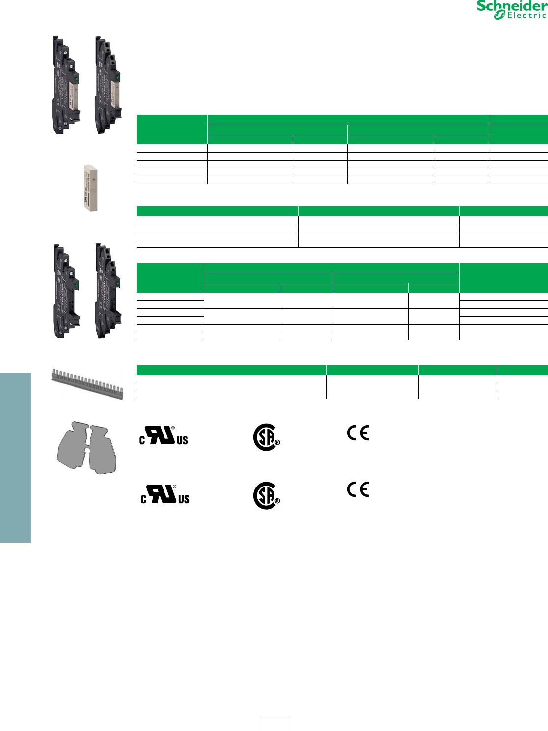
RSL 1PV•• RSL 1PR••
RSL 1AB••
RSL ZVA• RSL ZRA•
RSL Z2
RSL Z3
CP2 Discount
Schedule
www.schneider-electric.us
23 RELAYS AND TIMERS
© 2012 Schneider Electric
All Rights Reserved 23-3
General Purpose Relays RSB
Refer to Catalog DIA3ED2090304EN-US
Zelio™ Plug-In Interface Relays
Zelio RSB interface relays and sockets provide the optimum combination of robust performance and space saving for
the most demanding applications. Relays are rated at 8 A, 12 A, and 16 A (250 Vac / 28 Vdc). Features include:
•Optional protection modules for protection against electrical spikes
•Optional plastic hold-down ejector clips
•Socket or printed circuit board installation options
aTo order a relay complete with socket (sold in lots of 20): add suffix S to the catalog numbers selected above.
Example: RSB 2A080RD + RSZ E1S48M becomes RSB 2A080RDS.
bWhen using the relay with socket RSZ E1S48M, terminals must be jumpered.
Approvals for RSB relays:
Approvals for RSB sockets:
RZM modules are RoHS compliant as of date code 0610.
For mounting track, see page 24-16.
Table 23.5: Relays (sold in lots of 10)
Coil Voltage
Number and type of contacts - Thermal current (Ith)
1 C/O -12 A Res. 1 C/O -16 A Res. 2 C/O -8 A Res.
Catalog Numbera$ Price ea. Catalog Numbera$ Price ea. Catalog Numbera$ Price ea.
6 Vdc RSB1A120RD 3.50 RSB1A160RD 4.20 RSB2A080RD 4.20
12 Vdc RSB1A120JD 3.50 RSB1A160JD 4.20 RSB2A080JD 4.20
24 Vdc RSB1A120BD 3.50 RSB1A160BD 4.20 RSB2A080BD 4.20
48 Vdc RSB1A120ED 3.50 RSB1A160ED 4.20 RSB2A080ED 4.20
60 Vdc RSB1A120ND 3.50 RSB1A160ND 4.20 RSB2A080ND 4.20
110 Vdc RSB1A120FD 3.50 RSB1A160FD 4.20 RSB2A080FD 4.20
24 Vac RSB1A120B7 3.50 RSB1A160B7 4.20 RSB2A080B7 4.20
48 Vac RSB1A120E7 3.50 RSB1A160E7 4.20 RSB2A080E7 4.20
120 Vac RSB1A120F7 3.50 RSB1A160F7 4.20 RSB2A080F7 4.20
220 Vac RSB1A120M7 3.50 RSB1A160M7 4.20 RSB2A080M7 4.20
230 Vac RSB1A120P7 3.50 RSB1A160P7 4.20 RSB2A080P7 4.20
240 Vac RSB1A120U7 3.50 RSB1A160U7 4.20 RSB2A080U7 4.20
Table 23.6: Sockets – 12 A, 300 Vac
(sold in lots of 10)
Contact terminal arrangement Connection Relay type Catalog Number $ Price ea.
Separate Box lug connector
RSB1A120•• RSZE1S35M 4.80
RSB1A160••b
RSB2A080•• RSZE1S48M 5.30
Table 23.7: Protection modules (sold in lots of 10)
Description For use with Voltage Catalog Number $ Price ea.
Diode All sockets 6–230 Vdc RZM040W 2.40
RC circuit All sockets 24–60 Vac RZM041BN7 4.80
110–240 Vac RZM041FU7 4.80
Diode + green LED All sockets
6–24 Vdc RZM031RB 4.20
24–60 Vdc RZM031BN 4.20
110–230 Vdc RZM031FPD 6.00
Varistor + green LED All sockets
6–24 Vac/Vdc RZM021RB 6.00
24–60 Vac/Vdc RZM021BN 6.00
110–230 Vac/Vdc RZM021FP 6.00
Table 23.8: Accessories (sold in lots of 10)
Description For use with Catalog Number $ Price ea.
Plastic hold-down ejector clip All sockets RSZR215 .42
ID tags All sockets RSZL300 .30
File
CCN
E173076
NRNT2,
NRNT8
File
Class 215736
3211 07 IEC
61810-1 RoHS
Compliant as of date
code 0401
File
CCN SWIV2
E172326 File
Class 212916
3211 07 IEC 61984 RoHS
Compliant as of date
code 0501
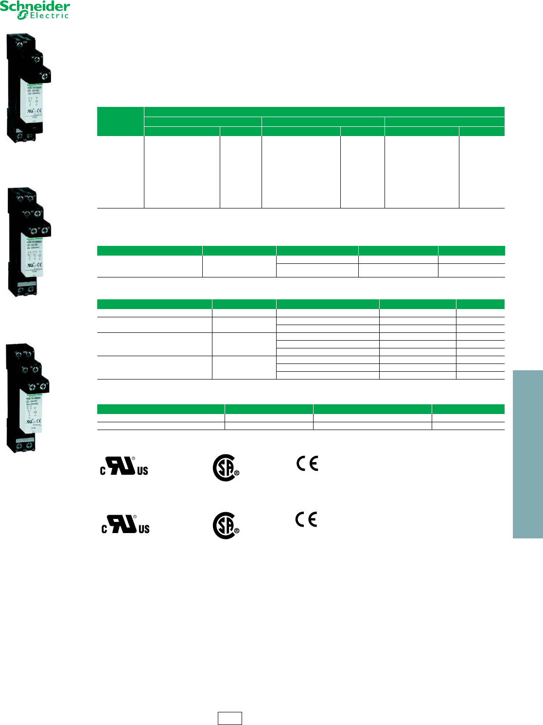
RSB1A120JD Relay
+ RZM031FPD Socket
+ RSZE1S35M Module
RSB2A080BD Relay
+ RSZE1S48M Socket
RSB1A160BD Relay
+ RSZE1S48M Socket
CP2 Discount
Schedule
www.schneider-electric.us
23 RELAYS AND TIMERS
23-4 © 2012 Schneider Electric
All Rights Reserved
General Purpose Relays RXM
Refer to Catalog DIA3ED2090304EN-US
Zelio™ Plug-In Relays
Zelio RXM miniature plug-in relays and sockets provide a
complete system solution in response to the most
demanding applications ranging from 3A to 12A. Some of
the features include:
•Test button with removable lock-down door for testing
the contacts (depending on model)
•Green LED indication of relay status (depending on
model)
•Mechanical indication of relay status (standard)
•Optional protection modules to protect against
electrical spikes
•Bus jumpers for connecting multiple terminals reduce
installation time
IO
For sockets and accessories, see page 23-5.
Approvals for Relays:
aWhen used with the appropriate socket.
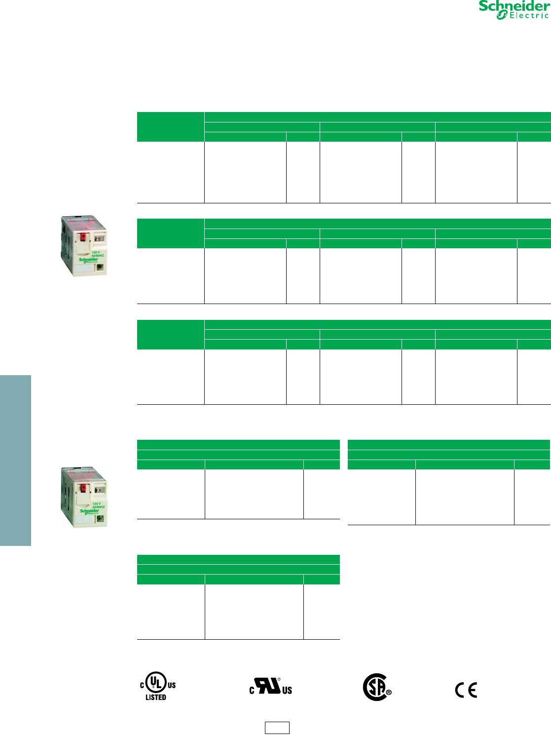
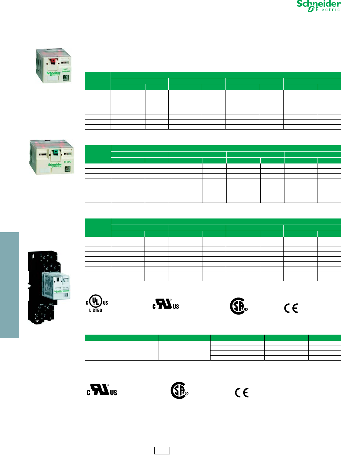
RXM2AB2F7
RXM4GB2F7
Table 23.9: Miniature relays without LED, with Test Button and Lock-Down Door (sold in lots of 10)
Number and type of contacts - Thermal current (Ith)
2 C/O -12 A Res. 3 C/O - 10 A Res. 4 C/O - 8 A Res.
Coil Voltage Catalog Number $ Price ea. Catalog Number $ Price ea. Catalog Number $ Price ea.
12 Vdc RXM2AB1JD 5.30 RXM3AB1JD 5.70 RXM4AB1JD 6.00
24 Vdc RXM2AB1BD 5.30 RXM3AB1BD 5.70 RXM4AB1BD 6.00
48 Vdc RXM2AB1ED 5.30 RXM3AB1ED 5.70 RXM4AB1ED 6.00
110 Vdc RXM2AB1FD 5.30 RXM3AB1FD 5.70 RXM4AB1FD 6.00
220 Vdc ————RXM4AB1MD 6.00
24 Vac RXM2AB1B7 5.30 RXM3AB1B7 5.70 RXM4AB1B7 6.00
48 Vac RXM2AB1E7 5.30 RXM3AB1E7 5.70 RXM4AB1E7 6.00
120 Vac RXM2AB1F7 5.30 RXM3AB1F7 5.70 RXM4AB1F7 6.00
230 Vac RXM2AB1P7 5.30 RXM3AB1P7 5.70 RXM4AB1P7 6.00
240 Vac ————RXM4AB1U7 6.00
Table 23.10: Miniature relays with LED, Test Button, and Lock-Down Door (sold in lots of 10)
Number and type of contacts - Thermal current (Ith)
2 C/O -12 A Res. 3 C/O - 10 A Res. 4 C/O - 8 A Res.
Coil Voltage Catalog Number $ Price ea. Catalog Number $ Price ea. Catalog Number $ Price ea.
12 Vdc RXM2AB2JD 6.20 RXM3AB2JD 6.60 RXM4AB2JD 6.80
24 Vdc RXM2AB2BD 6.20 RXM3AB2BD 6.60 RXM4AB2BD 6.80
48 Vdc RXM2AB2ED 6.20 RXM3AB2ED 6.60 RXM4AB2ED 6.80
110 Vdc RXM2AB2FD 6.20 RXM3AB2FD 6.60 RXM4AB2FD 6.80
125 Vdc ————RXM4AB2GD 6.80
24 Vac RXM2AB2B7 6.20 RXM3AB2B7 6.60 RXM4AB2B7 6.80
48 Vac RXM2AB2E7 6.20 RXM3AB2E7 6.60 RXM4AB2E7 6.80
120 Vac RXM2AB2F7 6.20 RXM3AB2F7 6.60 RXM4AB2F7 6.80
230 Vac RXM2AB2P7 6.20 RXM3AB2P7 6.60 RXM4AB2P7 6.80
Table 23.11: Miniature relays with LED, without Test Button and Lock-Down Door (sold in lots of 10)
Number and type of contacts - Thermal current (Ith)
2 C/O -12 A Res. 3 C/O - 10 A Res. 4 C/O - 8 A Res.
Coil Voltage Catalog Number $ Price ea. Catalog Number $ Price ea. Catalog Number $ Price ea.
12 Vdc RXM2AB3JD 5.70 ——RXM4AB3JD 6.30
24 Vdc RXM2AB3BD 5.70 ——RXM4AB3BD 6.30
48 Vdc RXM2AB3ED 5.70 ——RXM4AB3ED 6.30
110 Vdc RXM2AB3FD 5.70 ——RXM4AB3FD 6.30
125 Vdc ————RXM4AB3GD 6.30
24 Vac RXM2AB3B7 5.70 ——RXM4AB3B7 6.30
48 Vac RXM2AB3E7 5.70 ——RXM4AB3E7 6.30
120 Vac RXM2AB3F7 5.70 ——RXM4AB3F7 6.30
230 Vac RXM2AB3P7 5.70 ——RXM4AB3P7 6.30
Table 23.12: Miniature relays with low level contacts,
without LED, with Test Button and
Lock-Down Door (sold in lots of 10)
Number and type of contacts - Thermal current (Ith)
4 C/O -3 A Res.
Coil Voltage Catalog Number $ Price ea.
12 Vdc RXM4GB1JD 6.00
24 Vdc RXM4GB1BD 6.00
48 Vdc RXM4GB1ED 6.00
110 Vdc RXM4GB1FD 6.00
24 Vac RXM4GB1B7 6.00
48 Vac RXM4GB1E7 6.00
120 Vac RXM4GB1F7 6.00
230 Vac RXM4GB1P7 6.00
Table 23.13: Miniature relays with low level contacts,
with LED, Test Button and Lock-Down
Door (sold in lots of 10)
Number and type of contacts - Thermal current (Ith)
4 C/O -3 A Res.
Coil Voltage Catalog Number $ Price ea.
12 Vdc RXM4GB2JD 6.80
24 Vdc RXM4GB2BD 6.80
48 Vdc RXM4GB2ED 6.80
110 Vdc RXM4GB2FD 6.80
24 Vac RXM4GB2B7 6.80
48 Vac RXM4GB2E7 6.80
120 Vac RXM4GB2F7 6.80
230 Vac RXM4GB2P7 6.80
240 Vac RXM4GB2U7 6.80
Table 23.14: Miniature relays with low level contacts,
with LED, without Test Button and
Lock-Down Door (sold in lots of 10)
Number and type of contacts - Thermal current (Ith)
4 C/O -3 A Res.
Coil Voltage Catalog Number $ Price ea.
12 Vdc RXM4GB3JD 6.30
24 Vdc RXM4GB3BD 6.30
48 Vdc RXM4GB3ED 6.30
110 Vdc RXM4GB3FD 6.30
125 Vdc ——
24 Vac RXM4GB3B7 6.30
48 Vac RXM4GB3E7 6.30
120 Vac RXM4GB3F7 6.30
230 Vac RXM4GB3P7 6.30
File
CCN a
E164862
NLDX, NLDX7 File
CCN
E164862
NLDX2,
NLDX8
File 230765
Class 3211 07 IEC 61810-1 RoHS
Compliant
CP2 Discount
Schedule
www.schneider-electric.us
23 RELAYS AND TIMERS
© 2012 Schneider Electric
All Rights Reserved 23-5
General Purpose Relays RXM
Refer to Catalog DIA3ED2090304EN-US
aWhen mounting relay RXM2••••• on socket RXZE2M••••, the thermal current must not exceed 10 A.
bThermal current Ith: 10 A
cThermal current lth: 12 A
Approvals for Sockets:
Table 23.15: Miniature relays (sold in lots of 100)
Number and type of contacts - Thermal current (Ith)
2 C/O - 12 A Res. 4 C/O - 8 A Res.
Coil Voltage Catalog Number $ Price
ea. Catalog Number $ Price ea.
Without LED, with Test Button, and Lock-Down Door
12 Vdc — — RXM4AB1JDTQ 6.00
24 Vdc RXM2AB1BDTQ 5.30 RXM4AB1BDTQ 6.00
48 Vdc — — RXM4AB1EDTQ 6.00
110 Vdc — — RXM4AB1FDTQ 6.00
220 Vdc — — RXM4AB1MDTQ 6.00
24 Vac RXM2AB1B7TQ 5.30 RXM4AB1B7TQ 6.00
48 Vac — — RXM4AB1E7TQ 6.00
120 Vac RXM2AB1F7TQ 5.30 RXM4AB1F7TQ 6.00
230 Vac RXM2AB1P7TQ 5.30 RXM4AB1P7TQ 6.00
With LED, Test Button, and Lock-Down Door
24 Vdc — — RXM4AB2BDTQ 6.80
24 Vac RXM2AB2B7TQ 6.20 RXM4AB2B7TQ 6.80
230 Vac RXM2AB2P7TQ 6.20 RXM4AB2P7TQ 6.80
Table 23.16: Miniature relays with LED without Test Button and Lock-Down Door (sold in lots of 100)
Number and type of contacts - Thermal current (Ith)
Coil Voltage 2 C/O - 12 A Res. 4 C/O - 8 A Res.
Catalog Number $ Price ea. Catalog Number $ Price
ea.
24 Vdc RXM2AB3BDTQ 5.70 RXM4AB3BDTQ 6.30
24 Vac RXM2AB3B7TQ 5.70 RXM4AB3B7TQ 6.30
230 Vac RXM2AB3P7TQ 5.70 RXM4AB3P7TQ 6.30
Table 23.17: Sockets (sold in lots of 10)
Contact terminal arrangement Connection Relay type Catalog Number $ Price
ea.
Mixed
Screw clamp terminals RXM2•••••a
RXM4•••••aRXZE2M114b5.00
Box lug connector RXM2•••••
RXM4••••• RXZE2M114Mb5.00
Separate Box lug connector
RXM2••••• RXZE2S108Mc5.00
RXM3••••• RXZE2S111Mb5.00
RXM4••••• RXZE2S114Mb5.00
Table 23.18: Protection modules (sold in lots of 10)
Description Voltage For use with Catalog Number $ Price
ea.
Diode 6–250 Vdc All sockets RXM040W 1.90
RC circuit 24–60 Vac All sockets RXM041BN7 1.90
110–240 Vac All sockets RXM041FU7 1.90
Varistor
6–24 Vac/Vdc All sockets RXM021RB 1.90
24–60 Vac/Vdc All sockets RXM021BN 1.90
110–240 Vac/Vdc All sockets RXM021FP 1.90
Table 23.19: Accessories (sold in lots of 10)
Description For use with Catalog Number $ Price
ea.
Metal hold-down clip All sockets RXZ400 .50
Plastic hold-down ejector clip All sockets RXZR335 .50
Bus jumper, 2-pole (Ith: 5 A) All sockets with separate contacts RXZS2 .70
DIN rail mounting adapter All relays RXZE2DA .70
Panel mounting adapter All relays RXZE2FA .50
ID tags All relays (sheet of 108 tags) RXZL520 .10
All sockets except RXZE2M114 RXZL420 .10
File
CCN E172326
SWIV2, SWIV8 File 230765
Class 3211 07 IEC 61984 RoHS
Compliant
RXZE2M114M Socket +
RXM4AB2P7 Relay
RXZE2S114M Socket +
RXM4AB2F7 Relay
RXM041BN7
RXZ400
CP2 Discount
Schedule
www.schneider-electric.us
23 RELAYS AND TIMERS
23-6 © 2012 Schneider Electric
All Rights Reserved
General Purpose Relays RPM
Refer to Catalog DIA3ED2090304EN-US
Zelio™ Plug-In Relays
Zelio RPM plug-in relays and sockets provide a complete system solution in response to the most demanding
applications up to 15 A. Some of the features include:
•Test button with removable lock-down door for testing the contacts (depending on model)
•Green LED indication of relay status (depending on model)
•Mechanical indication of relay status (standard)
•Optional modules to protect against electrical spikes
Approvals for relays:
Approvals for Sockets:
Table 23.20: Power relays without LED, with Test Button and Lock-Down Door (sold in lots of 10)
Number and type of contacts - Thermal current (Ith)
1 C/O - 15 A Res. 2 C/O - 15 A Res. 3 C/O - 15 A Res. 4 C/O - 15 A Res.
Coil Voltage Catalog Number $ Price ea. Catalog Number $ Price ea. Catalog Number $ Price ea. Catalog Number $ Price ea.
12 Vdc RPM11JD 4.50 RPM21JD 6.00 RPM31JD 8.10 RPM41JD 10.00
24 Vdc RPM11BD 4.50 RPM21BD 6.00 RPM31BD 8.10 RPM41BD 10.00
48 Vdc RPM11ED 4.50 RPM21ED 6.00 RPM31ED 8.10 RPM41ED 10.00
110 Vdc RPM11FD 4.50 RPM21FD 6.00 RPM31FD 8.10 RPM41FD 10.00
24 Vac RPM11B7 4.50 RPM21B7 6.00 RPM31B7 8.10 RPM41B7 10.00
48 Vac RPM11E7 4.50 RPM21E7 6.00 RPM31E7 8.10 RPM41E7 10.00
120 Vac RPM11F7 4.50 RPM21F7 6.00 RPM31F7 8.10 RPM41F7 10.00
230 Vac RPM11P7 4.50 RPM21P7 6.00 RPM31P7 8.10 RPM41P7 10.00
Table 23.21: Power relays with LED, Test Button and Lock-Down Door (sold in lots of 10)
Number and type of contacts - Thermal current (Ith)
1 C/O - 15 A Res. 2 C/O - 15 A Res. 3 C/O - 15 A Res. 4 C/O - 15 A Res.
Coil Voltage Catalog Number $ Price ea. Catalog Number $ Price ea. Catalog Number $ Price ea. Catalog Number $ Price ea.
12 Vdc RPM12JD 5.30 RPM22JD 6.80 RPM32JD 9.00 RPM42JD 10.90
24 Vdc RPM12BD 5.30 RPM22BD 6.80 RPM32BD 9.00 RPM42BD 10.90
48 Vdc RPM12ED 5.30 RPM22ED 6.80 RPM32ED 9.00 RPM42ED 10.90
110 Vdc RPM12FD 5.30 RPM22FD 6.80 RPM32FD 9.00 RPM42FD 10.90
24 Vac RPM12B7 5.30 RPM22B7 6.80 RPM32B7 9.00 RPM42B7 10.90
48 Vac RPM12E7 5.30 RPM22E7 6.80 RPM32E7 9.00 RPM42E7 10.90
120 Vac RPM12F7 5.30 RPM22F7 6.80 RPM32F7 9.00 RPM42F7 10.90
230 Vac RPM12P7 5.30 RPM22P7 6.80 RPM32P7 9.00 RPM42P7 10.90
Table 23.22: Power relays with LED, without Test Button and Lock-Down Door (sold in lots of 10)
Number and type of contacts - Thermal current (Ith)
1 C/O - 15 A Res. 2 C/O - 15 A Res. 3 C/O - 15 A Res. 4 C/O - 15 A Res.
Coil Voltage Catalog Number $ Price ea. Catalog Number $ Price ea. Catalog Number $ Price ea. Catalog Number $ Price ea.
12 Vdc RPM13JD 5.00 RPM23JD 6.30 RPM33JD 8.30 RPM43JD 10.10
24 Vdc RPM13BD 5.00 RPM23BD 6.30 RPM33BD 8.30 RPM43BD 10.10
48 Vdc RPM13ED 5.00 RPM23ED 6.30 RPM33ED 8.30 RPM43ED 10.10
110 Vdc RPM13FD 5.00 RPM23FD 6.30 RPM33FD 8.30 RPM43FD 10.10
125 Vdc — — — — — — — —
24 Vac RPM13B7 5.00 RPM23B7 6.30 RPM33B7 8.30 RPM43B7 10.10
48 Vac RPM13E7 5.00 RPM23E7 6.30 RPM33E7 8.30 RPM43E7 10.10
120 Vac RPM13F7 5.00 RPM23F7 6.30 RPM33F7 8.30 RPM43F7 10.10
230 Vac RPM13P7 5.00 RPM23P7 6.30 RPM33P7 8.30 RPM43P7 10.10
File
CCN a
E164862
NLDX, NLDX7 File
CCN E164862
NLDX2, NLDX8 File 230765
Class 3211 07 IEC 61810-1 RoHS
Compliant
aWhen used with the appropriate socket
Table 23.23: Sockets (sold in lots of 10)
Contact terminal arrangement Connection Relay type Catalog Number $ Price ea.
Mixed Screw terminals
RPM1••• RPZF1 4.30
RPM2••• RPZF2 5.50
RPM3••• RPZF3 6.30
RPM4••• RPZF4 7.30
File
CCN E172326
SWIV2, SWIV8 File 230765
Class 3211 07 IEC 61984 RoHS
Compliant
RPM22F7
RPM42BD
RPZF2 Socket +
RPM22F7 Relay
CP2 Discount
Schedule
www.schneider-electric.us
23 RELAYS AND TIMERS
© 2012 Schneider Electric
All Rights Reserved 23-7
General Purpose Relays RPM
Refer to Catalog DIA3ED2090304EN-US
aSee timer module description (selection of functions and time delays) in catalog DIA3ED2090304EN-US.
bTest button and lock-down door become inaccessible
Table 23.24: Protection modules (sold in lots of 10)
Description Vol tage For use with Catalog Number $ Price ea.
Diode 6–250 Vdc
RPZF1
RPZF2 RXM040W 1.90
RPZF3
RPZF4 RUW240BD 2.60
RC circuit
24–60 Vac RPZF1
RPZF2 RXM041BN7 1.90
110–240 Vac
RPZF1
RPZF2 RXM041FU7 2.20
RPZF3
RPZF4 RUW241P7 2.20
Varistor
6–24 Vac/Vdc RPZF1
RPZF2 RXM021RB 1.90
24–60 Vac/Vdc RPZF1
RPZF2 RXM021BN 1.90
110–240 Vac/Vdc RPZF1
RPZF2 RXM021FP 1.90
24 Vac/Vdc RPZF3
RPZF4 RUW242B7 2.70
240 Vac/Vdc RPZF3
RPZF4 RUW242P7 2.70
Table 23.25: Timer modulea (sold in lots of 1)
Description Vol tage For Use With Catalog Number $ Price
On-delay timer, interval timer,
repeat cycle timer/starting on-delay,
repeat cycle timer/starting off-delay,
off-delay timer, one-shot timer,
timing on de-energization, on-delay timer
24–240 Vac/Vdc RPZF3
RPZF4 RUW101MW 47.10
Table 23.26: Accessories (sold in lots of 10)
Description For use with Catalog Number $ Price ea.
Metal hold-down clip (for single-pole relays) RPZF1 RPZR235 0.50
DIN rail mounting adapter b
RPM1••• RPZ1DA 0.70
RPM2••• RXZE2DA 0.70
RPM3••• RPZ3DA 0.70
RPM4••• RPZ4DA 0.70
Panel mounting adapter
RPM1••• RPZ1FA 0.50
RPM2••• RXZE2FA 0.50
RPM3••• RPZ3FA 0.50
RPM4••• RPZ4FA 0.50
ID tags (sheet of 108 tags) All relays RXZL520 0.10
RXM041BN7
RPZ1DA
RPZ3FA
CP2 Discount
Schedule
www.schneider-electric.us
23 RELAYS AND TIMERS
23-8 © 2012 Schneider Electric
All Rights Reserved
General Purpose Relays RUM
Refer to Catalog DIA3ED2090304EN-US
Zelio™ Plug-In Relays
Zelio RUM plug-in relays and sockets provide a complete system solution in response to the most demanding
applications up to 16 A. Some of the features include:
•Test button with lock-down door for testing the contacts (depending on model)
•Green LED indication of relay status (depending on model)
•Mechanical indication of relay status (standard)
•Optional protection modules to protect against electrical spikes
•Bus jumpers for connecting multiple terminals reduce installation time
Approvals for Relays:
Table 23.27: Relays for standard applications without LED, with Test Button and Lock-Down Door
(sold in lots of 10)
Pins Coil Voltage
Number and type of contacts - Thermal current (Ith)
2 C/O -16 A Res. 3 C/O -16 A Res.
Catalog Number $ Price ea. Catalog Number $ Price ea.
Cylindrical
12 Vdc RUMC2AB1JD 10.10 RUMC3AB1JD 11.30
24 Vdc RUMC2AB1BD 10.10 RUMC3AB1BD 11.30
48 Vdc RUMC2AB1ED 10.10 RUMC3AB1ED 11.30
60 Vdc — — RUMC3AB1ND 11.30
110 Vdc RUMC2AB1FD 10.10 RUMC3AB1FD 11.30
125 Vdc — — RUMC3AB1GD 11.30
220 Vdc — — RUMC3AB1MD 11.30
24 Vac RUMC2AB1B7 10.10 RUMC3AB1B7 11.30
48 Vac RUMC2AB1E7 10.10 RUMC3AB1E7 11.30
120 Vac RUMC2AB1F7 10.10 RUMC3AB1F7 11.30
230 Vac RUMC2AB1P7 10.10 RUMC3AB1P7 11.30
Flat
12 Vdc RUMF2AB1JD 10.10 RUMF3AB1JD 11.30
24 Vdc RUMF2AB1BD 10.10 RUMF3AB1BD 11.30
48 Vdc RUMF2AB1ED 10.10 RUMF3AB1ED 11.30
110 Vdc RUMF2AB1FD 10.10 RUMF3AB1FD 11.30
24 Vac RUMF2AB1B7 10.10 RUMF3AB1B7 11.30
48 Vac RUMF2AB1E7 10.10 RUMF3AB1E7 11.30
120 Vac RUMF2AB1F7 10.10 RUMF3AB1F7 11.30
230 Vac RUMF2AB1P7 10.10 RUMF3AB1P7 11.30
Table 23.28: Relays for standard applications, with LED, Test Button, and Lock-Down Door
(sold in lots of 10)
Pins Coil Voltage
Number and type of contacts - Thermal current (Ith)
2 C/O -16 A Res. 3 C/O -16 A Res.
Catalog Number $ Price ea. Catalog Number $ Price ea.
Cylindrical
12 Vdc RUMC2AB2JD 11.30 RUMC3AB2JD 12.50
24 Vdc RUMC2AB2BD 11.30 RUMC3AB2BD 12.50
48 Vdc RUMC2AB2ED 11.30 RUMC3AB2ED 12.50
60 Vdc — — RUMC3AB2ND 12.50
110 Vdc RUMC2AB2FD 11.30 RUMC3AB2FD 12.50
125 Vdc — — RUMC3AB2GD 12.50
24 Vac RUMC2AB2B7 11.30 RUMC3AB2B7 12.50
48 Vac RUMC2AB2E7 11.30 RUMC3AB2E7 12.50
120 Vac RUMC2AB2F7 11.30 RUMC3AB2F7 12.50
230 Vac RUMC2AB2P7 11.30 RUMC3AB2P7 12.50
Flat
12 Vdc RUMF2AB2JD 11.30 RUMF3AB2JD 12.50
24 Vdc RUMF2AB2BD 11.30 RUMF3AB2BD 12.50
48 Vdc RUMF2AB2ED 11.30 RUMF3AB2ED 12.50
110 Vdc RUMF2AB2FD 11.30 RUMF3AB2FD 12.50
24 Vac RUMF2AB2B7 11.30 RUMF3AB2B7 12.50
48 Vac RUMF2AB2E7 11.30 RUMF3AB2E7 12.50
120 Vac RUMF2AB2F7 11.30 RUMF3AB2F7 12.50
230 Vac RUMF2AB2P7 11.30 RUMF3AB2P7 12.50
Table 23.29: Relays for standard applications with LED, without Push Button, and Lock-Down Door
(sold in lots of 10)
Pins Coil Voltage
Number and type of contacts - Thermal current (Ith)
2 C/O -16 A Res. 3 C/O -16 A Res.
Catalog Number $ Price ea. Catalog Number $ Price ea.
Cylindrical
12 Vdc RUMC2AB3JD 10.40 RUMC3AB3JD 11.60
24 Vdc RUMC2AB3BD 10.40 RUMC3AB3BD 11.60
48 Vdc RUMC2AB3ED 10.40 RUMC3AB3ED 11.60
60 Vdc — — RUMC3AB3ND 11.60
110 Vdc RUMC2AB3FD 10.40 RUMC3AB3FD 11.60
125 Vdc — — RUMC3AB3GD 11.60
24 Vac RUMC2AB3B7 10.40 RUMC3AB3B7 11.60
48 Vac RUMC2AB3E7 10.40 RUMC3AB3E7 11.60
120 Vac RUMC2AB3F7 10.40 RUMC3AB3F7 11.60
230 Vac RUMC2AB3P7 10.40 RUMC3AB3P7 11.60
Flat
12 Vdc RUMF2AB3JD 10.40 RUMF3AB3JD 11.60
24 Vdc RUMF2AB3BD 10.40 RUMF3AB3BD 11.60
48 Vdc RUMF2AB3ED 10.40 RUMF3AB3ED 11.60
110 Vdc RUMF2AB3FD 10.40 RUMF3AB3FD 11.60
125 Vdc — — RUMF3AB3GD 11.60
24 Vac RUMF2AB3B7 10.40 RUMF3AB3B7 11.60
48 Vac RUMF2AB3E7 10.40 RUMF3AB3E7 11.60
120 Vac RUMF2AB3F7 10.40 RUMF3AB3F7 11.60
230 Vac RUMF2AB3P7 10.40 RUMF3AB3P7 11.60
File
CCN a
E164862
NLDX,
NLDX7
File
CCN
E164862
NLDX2,
NLDX8
File 230765
Class 3211 07 IEC 61810-1 RoHS
Compliant
aWhen used with appropriate socket
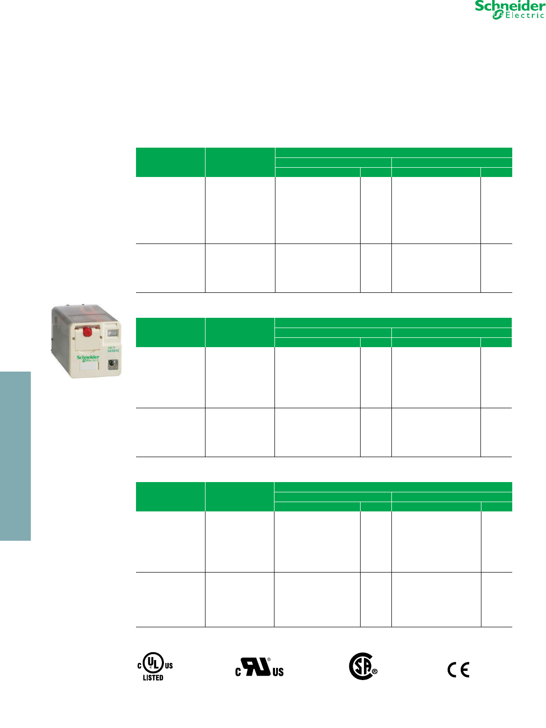
RUMF3AB2P7
Universal Relay
For sockets and accessories, see
page 23-9
www.schneider-electric.us
23 RELAYS AND TIMERS
© 2012 Schneider Electric
All Rights Reserved 23-9
General Purpose Relays RUM
Refer to Catalog DIA3ED2090304EN-US
aThe inputs are mixed with the relay coil terminals, with the outputs located on the opposite side of the socket.
bThe inputs and outputs are separated from the relay coil terminals.
cSee timer module description (selection of functions and time delays) in catalog 8501CT0601.
Approvals for Sockets:
Zelio™ RPF Power Relays
RPF Zelio power relays respond to the most demanding applications up to 30 A. Features include:
•UL Listed
•Sealed construction
•Motor load ratings: 1hp @ 120 Vac / 3hp @ 240 Vac (N/O contacts only)
•Dual DIN rail and panel mounting capability
•Short circuit rating of 5,000 A @ 240 Vac (N/O contacts only)
a30 A when mounted with 13 mm gap between two relays.
25 A when mounted side by side without a gap.
Approvals for Relays:
For mounting track, see page 24-16
Table 23.30: Sockets (sold in lots of 10)
Contact terminal arrangement Connection Relay type Catalog Number $ Price ea.
Mixed a
Box lug connector
(screw terminals)
RUMC2••••• RUZC2M 3.50
RUMC3••••• RUZC3M 4.20
Separate b
RUMC2••••• RUZSC2M 4.50
RUMC3••••• RUZSC3M 5.00
RUMF2••••• RUZSF3M 5.60
RUMF3•••••
Table 23.31: Protection modules (sold in lots of 10)
Description For use with Voltage Catalog Number $ Price ea.
Diode
All sockets
6–250 Vdc RUW240BD 2.20
RC circuit 110–240 Vac RUW241P7 2.20
Varistor 24 Vac/Vdc RUW242B7 2.70
240 Vac/Vdc RUW242P7 2.70
Table 23.32: Timer modulec (sold in lots of 1)
Description For use with Voltage Catalog Number $ Price
On-delay timer, interval timer,
repeat cycle timer/starting on-delay,
repeat cycle timer/starting off-delay,
off-delay timer, one-shot timer,
timing on de-energization, on-delay timer.
All sockets 24–240 Vac/Vdc RUW101MW 47.10
Table 23.33: Accessories (sold in lots of 10)
Description For use with Catalog Number $ Price ea.
Metal hold-down clip All sockets RUZC200 1.20
Bus jumper, 2-pole (Ith: 5 A) All sockets with separate contacts RUZS2 0.70
ID tags All relays (sheet of 108 tags) RXZL520 0.10
All sockets with separate contacts RUZ420 0.10
File
CCN E172326
SWIV2, SWIV8 File
Class 230765
3211 07 IEC 61810-1 RoHS
Compliant
Table 23.34: Power relays (sold in lots of 10)
Coil Voltage
Number and type of contacts - Thermal current (Ith)
2 N/O - 30 Aa Res. 2 C/O - 30 A on N.O. / 3 A on N.C. a Res.
Catalog Number $ Price ea. Catalog Number $ Price ea.
12 Vdc RPF2AJD 10.40 RPF2BJD 10.90
24 Vdc RPF2ABD 10.40 RPF2BBD 10.90
110 Vdc RPF2AFD 10.40 RPF2BFD 10.90
24 Vac RPF2AB7 10.40 RPF2BB7 10.90
120 Vac RPF2AF7 10.40 RPF2BF7 10.90
230 Vac RPF2AP7 10.40 RPF2BP7 10.90
File
CCN E43641
NLDX, NLDX7 File 040787
Class 3211-07 IEC 61810-1 RoHS
Compliant
RUZ C3M Socket+
RUMC3ppppp Relay
RUW241P7
RUW101MW
RUZS2
RUZC200
RPF2BJD
CP2 Discount
Schedule

www.schneider-electric.us
23 RELAYS AND TIMERS
23-10 © 2012 Schneider Electric
All Rights Reserved
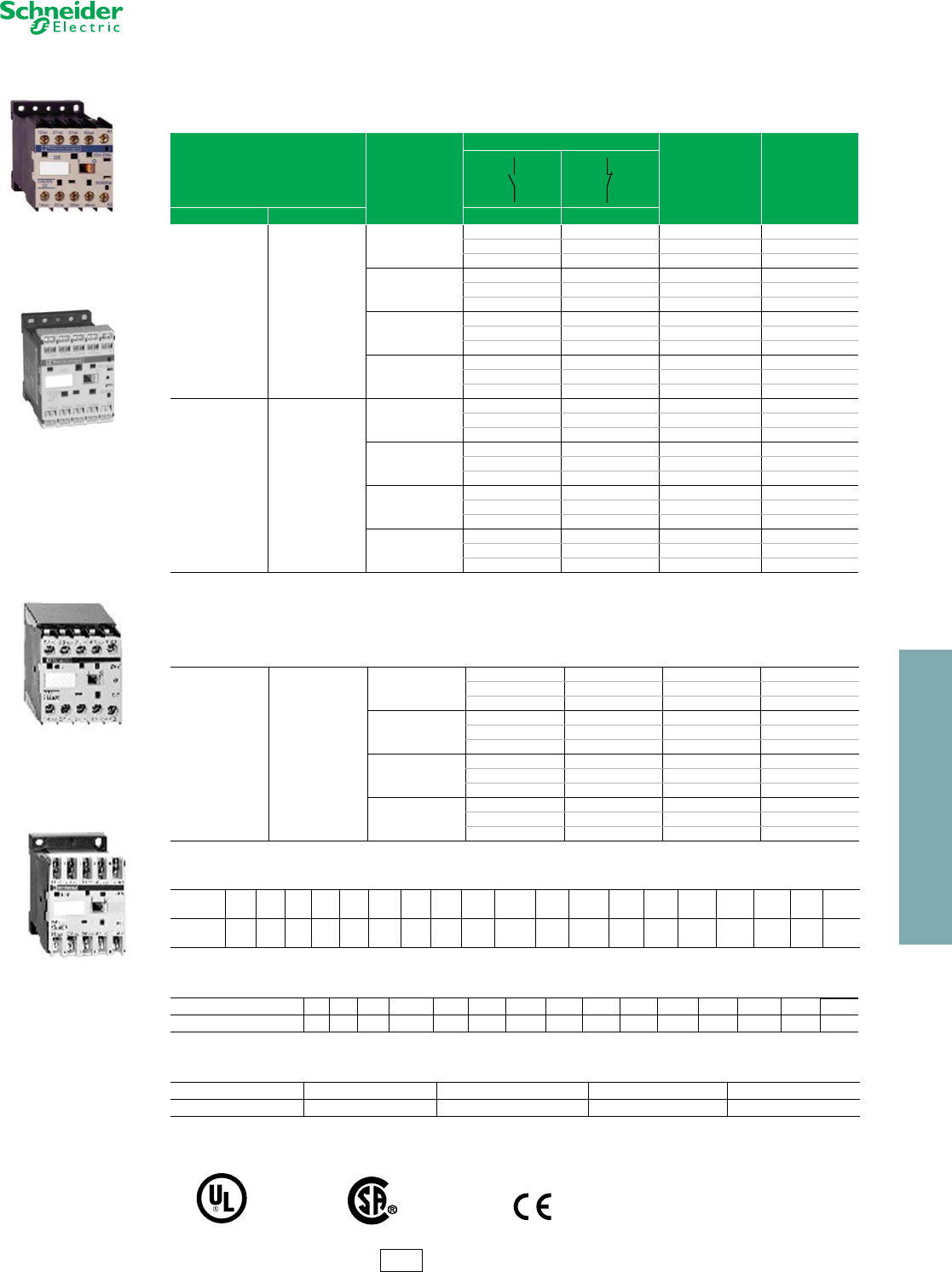
Square D™ Plug-In Relays
8501K relays are designed for multipole switching applications at
240 Vac or lower. These relays have industry standard wiring and pin
terminal arrangements which allow for their use as replacements for
many competitive relays without wiring or hardware modifications.
Note: S = Stocked.
Factory order items require a minimum order quantity of 25 and have a lead time of 12
weeks.
Pilot Light Option—Available on Types KP and KU. Internal pilot lights
are available in both AC and DC versions for positive indication of power
to the coil. The pilot light is a green LED.
Manual Operator Option—Available on Type KU only. To facilitate
speed circuit testing, a manual operator (test button) can be provided.
Coil VAC—3.0 VA
Coil VDC—1.4 Watts
Note: All 8501 K relays have a B300 rating.
aSocket is not required with Type KF relays.
b3 pole devices have a 20 A max. total (sum of currents in all 3 poles), continuous rating.
c3 pole devices have a 30 A max. total (sum of currents in all 3 poles), continuous rating.
dVoltage code must be specified to order this product. Refer to standard voltage codes
listed in Table 23.37 and insert as shown in Table 23.41: How to Order.
For sockets and accessories, see page 23-14.
For track, see page 24-16.
•12 A relays
•DPDT or 3PDT
•Manual operator/
green pilot light options
•Motor load (hp) ratings
•DPDT latching models
available
•AC or DC operation
•RoHS Compliant
Table 23.35: Type KF —Flange Mounted—Spade Terminals
Input
Voltage
Contact
Arrangement Options Type $ Price
AC
50/60 Hz
DPDT
None Available
KF12d24.60
3PDT KF13d26.70
DC
DPDT
None Available
KFD12d24.60
3PDT KFD13d26.70
Table 23.36: Type KL—Latching Relay—Spade Terminals
Input
Voltage
Contact
Arrangement Options Type $ Price
AC
50/60 Hz DPDT None Available KL12d45.00
DC DPDT None Available KLD12d45.00
Table 23.37: Voltage Codes and Stocked Relays
Type AC Voltage 50/60 Hz Type DC Voltage
612 24 120 240 612 24 48 110 125
Voltag e
Codes V35 V36 V14 V20 V24 Voltage Codes V50 V51 V53 V56 V60 V63
KP12 SSSS SKPD12 SSSS S
KP12P14 S S S S KPD12P14 S S S S
KP13 S S S S KPD13 S S S S S
KP13P14 S S S KPD13P14 S
KU12 S S S S KUD12 S
KU12M1 KUD12M1 S
KU12P14 S S KUD12P14 S
KU12M1P14 S S KUD12M1P14 S
KU13 S S S S KUD13 S S S
KU13M1 KUD13M1
KU13P14 S S KUD13P14
KU13M1P14 S S S KUD13M1P14 S S
KF12 S S S KFD12 S S
KF13 S S KFD13 S
KL12 S S KLD12 S S
For 8501 KP, KU, and KF:
File
CCN
E78351
NLDX2
NLDX8
File
Class 211269
3211 04
For 8501 KP, KU, and KL:
File
CCN
E78351
NLDX
NLDX7 When used with the appropriate 8501NR socket.
For 8501 KL:
File
CCN
E78351
NLDX2
NLDX8
File
Class 211268
3211 04
Table 23.38: Type KP—Tubular Terminals
Input
Vol tage
Contact
Arrangement Options Type $ Price
AC
50/60
Hz
DPDT None KP12d39.00
DPDT Pilot Light KP12P14d45.00
3PDT None KP13d47.30
3PDT Pilot Light KP13P14d53.30
DC
DPDT None KPD12d39.00
DPDT Pilot Light KPD12P14d45.00
3PDT None KPD13d47.30
3PDT Pilot Light KPD13P14d53.30
Table 23.39: Type KU—Spade Terminals
Input
Voltage
Contact
Arrangement Options Type $ Price
AC
50/60 Hz
DPDT None KU12d22.70
DPDT Manual
Operator KU12M1d26.70
DPDT Pilot Light KU12P14d28.70
DPDT Manual
Operator and
Pilot Light KU12M1P14d30.80
3PDT None KU13d24.60
3PDT Manual
Operator KU13M1d28.70
3PDT Pilot Light KU13P14d30.80
3PDT Manual
Operator and
Pilot Light KU13M1P14d35.00
DC
DPDT None KUD12d22.70
DPDT Manual
Operator KUD12M1d26.70
DPDT Pilot Light KUD12P14d28.70
DPDT Manual
Operator and
Pilot Light KUD12M1P14d30.80
3PDT None KUD13d24.60
3PDT Manual
Operator KUD13M1d28.70
3PDT Pilot Light KUD13P14d30.80
3PDT Manual
Operator and
Pilot Light KUD13M1P14d35.00
Table 23.40: Contact Ratings (Contacts are Silver Tin Oxide)
AC DC
Type AC
Vol ts
Resistive 75% PF
Continuous
Amperes
Hp DC
Vol ts
Resistive
Amperes
KP 120 10 c1/3 28 12
240 6.5 b1/2
KU
KFd
120 12 1/3 28 12
240 12 1/2
KL 120 10 1/3 28 10
240 10 1/2
Table 23.41: How to Order
To Order Specify: Catalog Number
•Class Number
•Type Number
•Voltage Code
(See Stocked Relay Table above)
Class Type Voltag e
Code
8501 KP12 V20
CP2 Discount
Schedule
General Purpose Relays Type K
Class 8501 / Refer to Catalog 8501CT0301
23 RELAYS AND TIMERS
© 2012 Schneider Electric
All Rights Reserved 23-11
www.schneider-electric.us
General Purpose Relays 8501KA
Refer to Catalog 8501CT9401
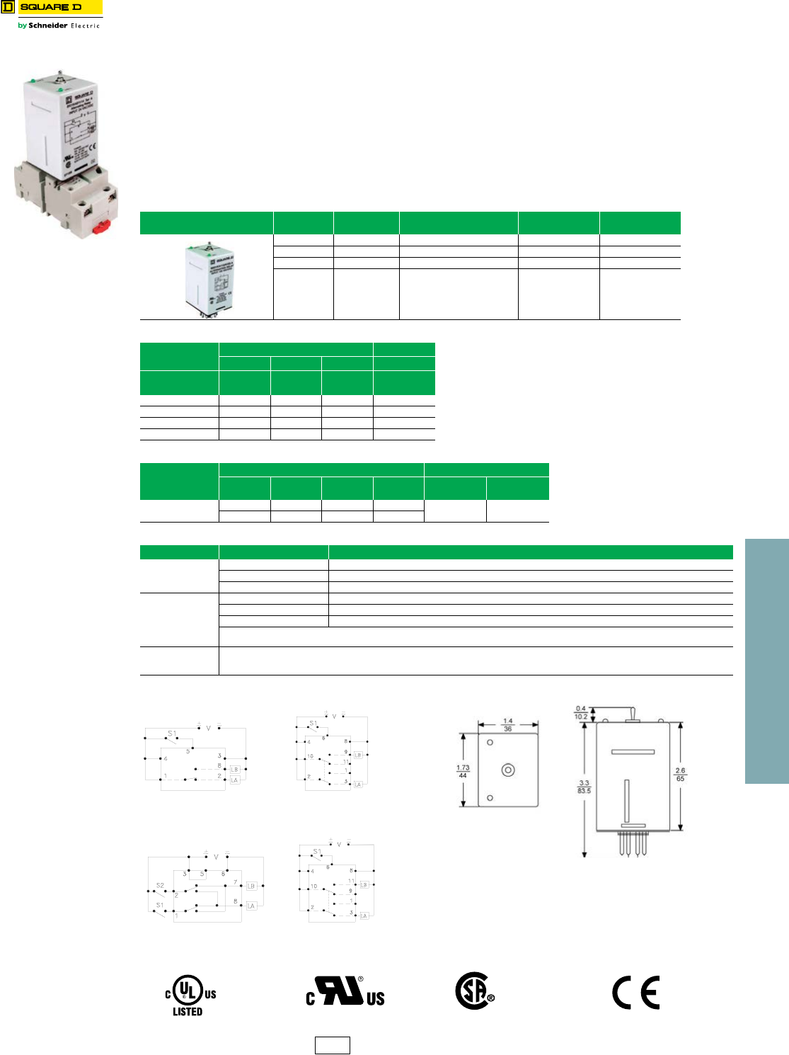
Square D™ Alternating Plug-In Relays
8501KA alternating relay is designed to minimize pump and motor wear by equalizing run time between parallel
components in a multi-pump system.
The relay is controlled by an external control switch. The switch may be any type of contact closure; for example the
contacts of a timing relay or the closure of a float switch. The 8501KA relay also has a toggle switch that allows the
operator to lock one side of the duplex system in the “on” position.
Wiring Diagrams and Dimensions
•12 A Resistive Rating
•SPDT or DPDT
•Toggle switch for load control
•LED Load Indicators
•Horsepower Rated
•AC and DC Control
•UL Listed w/ Square D Socket
•Rohs Compliant
Table 23.42: Type KA — Alternating Relay
Input Voltage Contact
Arrangement Options Type $ Price
AC & DC SPDT LED + Toggle 8501KA81••• 93.00
AC & DC DPDT LED + Toggle + Cross Wired 8501KA82••• 95.00
AC & DC DPDT (N.C.) LED + Toggle 8501KA112••• 94.00
AC & DC DPDT (N.O.) LED + Toggle 8501KA112A••• 94.00
Table 23.43: Relay Availability
Type AC & DC Voltage AC Voltage Notes:
•AC Voltage is 50/60 Hz
•S = Stocked. “S” items have a 2 week lead time and
nominimum order requirement.
12 24 120 240
Voltage Code V36 V14 V20 V24
8501KA81••• S •All other part numbers are considered factory order
(FO) and require a minimum order quantity of 25 and
have a lead-time of 18 weeks
8501KA82••• S
8501KA112••• S
8501KA112A••• S
Table 23.44: Contact Ratings
Type
AC DC
AC Volts Resistive
Amperes HP Pilot Duty DC Volts Resistive
Amperes
8501KA81••• 120 12 1/3 — 30 12
240 12 1/2 B300
Table 23.45: Alternating Functions
Diagram Toggle Switch Position Detail S1 = Control Switch 1 S2 = Control Switch 2 LA = Load 1 LB = Load 2
A, C & D
Alternate Closing S1 alternates the loads between LA and LB.
Lock 1 LA is ON and LB is OFF. S1 is not used in this mode.
Lock 2 LA is OFF and LB is ON. S1 is not used in this mode.
B
Alternate Closing S1 alternates the loads between LA an dLB. S2 will only control LA.
Lock 1 S1 will control LA and S2 will control LB
Lock 2 S1 will control LB and S2 will control LA.
The cross wired option allows extra system load capacity through simultaneous operation of both motors when needed (LA and LB energize
simultaneously when both S1 and S2 are closed–relay contacts are not isolated)
ALL Input voltage must applied at all times for proper alternation. Use of a solid state control switch for S1 or S2 may not initiate alternation corredtly.
S1 or S2 voltage must be from the same supply as the unit’s input voltage (see wiring diagrams). Loss of input voltage resets the unit; LA becomes
the lead load for the next operation.
8501KA81···
Socket = 8501NR51 or NR52
8501KA112···
Socket = 8501NR61 or NR62
8501KA82···
Socket = 8501NR51 or NR52
8501KA112A···
Socket = 8501NR61 or NR62
.C.A
.D.B
CP2 Discount
Schedule
Approvals
File
Class E78351
NLDX E78351
NLDX2 File
Class 242675
3211-07 IEC 61810-1
23 RELAYS AND TIMERS
23-12 © 2012 Schneider Electric
All Rights Reserved
www.schneider-electric.us
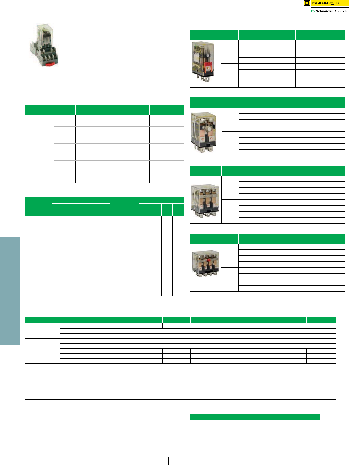
Square D™ Miniature Plug-in Relays
8501R miniature plug-in relays have a 10 A resistive
rating, the same as the Type K plug-in relays, but
are much smaller. The compact size of these relays
makes them ideal for downsizing equipment and
applications where space is at a premium.
aRelays have a B300 rating with UL.
bVoltage code must be specified to order this product. Refer to standard voltage codes
listed in Table 23.47 and insert as shown in Table 23.53: How to Order.
cWhen used with the appropriate 8501NR socket.
For sockets and accessories, see page 23-14.
For track, see page 24-16.
•SPDT through 4PDT
•AC or DC operated
•Horsepower rated
•Socket compatible
•Manual operator/
green LED pilot
light options
•Silver tin oxide
contacts
Table 23.46: Contact Ratings
(Contact material is Silver Tin Oxide)
Type Vo lt age Resistive
Rating Voltag e General Use
Rating
Horsepower
Rating
8501RS41 a120 Vac 15 120 Vac 10 1/3 @120 Vac
240 Vac 12 240 Vac 10 1/3 @240 Vac
8501RSD41a28 Vdc 15 28 Vdc 15 —
8501RS42a120 Vac 10 120 Vac 10 1/3 @120 Vac
240 Vac 10 240 Vac 10 1/2 @240 Vac
8501RSD42a30 Vdc 10 28 Vdc 10 —
8501RS43a120 Vac 10 150 Vac 10 —
277 Vac 10 250 Vac 6.6 —
8501RSD43a28 Vdc 10 28 Vdc 10 —
8501RS44a120 Vac 10 150 Vac 7.5 —
277 Vac 10 250 Vac 5 —
8501RSD44a28 Vdc 10 28 Vdc 10 —
Table 23.47: Voltage Codes and Stocked Relays
Type AC Voltage 50/60 Hz Type DC Voltage
612 24 120 240 612 24 110
Voltage Code V35 V36 V14 V20 V24 Voltage Code V50 V51 V53 V60
RS41 S S RSD41 S S
RS41M1 RSD41M1
RS41P14 S S RSD41P14 S
RS41M1P14 S S RSD41M1P14 S
RS42 S S S S RSD42 S S
RS42M1 RSD42M1
RS42P14 S S RSD42P14 S S
RS42M1P14 S RSD42M1P14 S
RS43 S S RSD43 S
RS43M1 RSD43M1
RS43P14 S RSD43P14
RS43M1P14 S RSD43M1P14
RS44 S S S RSD44 S S
RS44M1 RSD44M1
RS44P14 S RSD44P14 S
RS44M1P14 S RSD44M1P14
Note: S = Stocked.
Factory order items require a minimum order quantity of 25 and have a lead time of 12
weeks.
Table 23.48: SPDT with Silver Tin Oxide Contacts
Input
Vol tage Options Type $ Price
AC
50/60
Hz
None RS41b29.60
Manual Operator RS41M1b31.70
Pilot Light RS41P14b37.20
Manual Operator and Pilot Light RS41M1P14b39.30
DC
None RSD41b29.60
Manual Operator RSD41M1b31.70
Pilot Light RSD41P14b37.20
Manual Operator and Pilot Light RSD41M1P14b29.60
Table 23.49: DPDT with Silver Tin Oxide Contacts
Input
Vol tage Options Type $ Price
AC
50/60
Hz
None RS42b35.00
Manual Operator RS42M1b37.10
Pilot Light RS42P14b43.10
Manual Operator and Pilot Light RS42M1P14b45.20
DC
None RSD42b35.00
Manual Operator RSD42M1b37.10
Pilot Light RSD42P14b43.10
Manual Operator and Pilot Light RSD42M1P14b45.20
Table 23.50: 3PDT with Silver Tin Oxide Contacts
Input
Voltage Options Type $ Price
AC
50/60
Hz
None RS43b39.30
Manual Operator RS43M1b41.40
Pilot Light RS43P14b47.60
Manual Operator and Pilot Light RS43M1P14b49.90
DC
None RSD43b39.30
Manual Operator RSD43M1b41.40
Pilot Light RSD43P14b47.60
Manual Operator and Pilot Light RSD43M1P14b49.90
Table 23.51: 4PDT with Silver Tin Oxide Contacts
Input
Vol tage Options Type $ Price
AC
50/60
Hz
None RS44b44.30
Manual Operator RS44M1b46.20
Pilot Light RS44P14b52.30
Manual Operator and Pilot Light RS44M1P14b54.50
DC
None RSD44b44.30
Manual Operator RSD44M1b46.20
Pilot Light RSD44P14b52.30
Manual Operator and Pilot Light RSD44M1P14b54.50
Table 23.52: Application Data
Class 8501 Type RS41 RSD41 RS42 RSD42 RS43 RSD43 RS44 RSD44
Operating Data
Pick-Up Time 20 ms Maximum 25 ms Maximum 20 ms Maximum
Drop-Out Time 20 ms Maximum
Operating Temperature -40oC to +70oC (-40oF to +158oF)
Coil
Duty Cycle Continuous
Voltage Range AC coils +10%, -15% of nominal DC coils +10%, -20% of nominal
AC Coils–Inrush 9 VA — 6.2 VA — 10.3 VA — 11.9 VA —
AC Coils–Sealed 1.5 VA — 1.2 VA — 1.7 VA — 2.1 VA —
DC Coils — 0.9 watts — 0.9 watts — 1.4 watts — 1.5 watts
UR File
CCN E78351
NLDX2, NLDX8
CSA File
Class 211268
3218 07
CE marked yes
RoHS Compliant yes
UL Listed File
CCN E78351c
NLDX, NLDX7
Table 23.53: How to Order
To Order Specify: Catalog Number
•Class Number
•Type Number
•Voltage Code (see Table 23.47)
Class Type Vo ltage
Code
8501 RS42 V20
CP2 Discount
Schedule
General Purpose Relays Type R
Class 8501 / Refer to Catalog 8501CT0301
23 RELAYS AND TIMERS
© 2012 Schneider Electric
All Rights Reserved 23-13
www.schneider-electric.us
General Purpose Relays Type R
Class 8501 / Refer to Catalog 8501CT0301
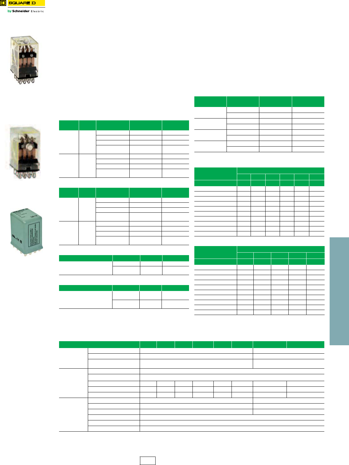
Square D™ Miniature Plug-in Relays
8501R relays are suited for use as logic elements and
power switching output devices. The short stroke motion of
the armature provides long mechanical life required for
high speed operation of control systems. Different contact
compositions allow these relays to be used in a variety of
applications. Fine silver (gold flashed) and bifurcated
crossbar (gold overlay silver) are suitable for high contact
reliability and low level switching requirements. Silver tin
oxide is best suited for inductive loads. Class I Division II
sealed relays can be used in specified hazardous
locations.
aVoltage code must be specified to order this product. Refer to standard
voltage codes shown in Table 23.59.
bDo not ground the frame.
Pilot Light Option
An internal green pilot light is available in both AC and DC
versions for positive indication of power to the coil.
Manual Operation Option
To speed circuit testing, a manual operator (test button)
can be provided. The relay can be manually switched to
simulate normal operation.
NOTE: All Type R relays with a manual operator must
be used on circuits of the same polarity.
cRS4/RSD4, RS14/RSD14 have NEMA C300 pilot duty rating.
Note: S = Stocked.
Factory Order items require a minimum order quantity of 25 and have
a lead time of 12 weeks.
For sockets and accessories, see page 23-14. For track, see page 24-16.
•1, 3, or 5 A versions
•4PDT
•Complete socket line
•Horsepower rated
•AC or DC operation
•Manual operator/pilot
light options
Table 23.54: 5 A Version
5 A Input
Voltage Options Type $ Price
For
switching
inductive
loads
AC
50/60
Hz
None RS14a32.70
Manual Operator RS14M1a35.00
Pilot Light RS14P14a40.90
Manual Operator
and Pilot Light RS14M1P14a43.10
Contacts:
Silver Tin
Oxide DC
None RSD14a27.70
Manual Operator RSD14M1a30.80
Pilot Light RSD14P14a36.80
Manual Operator
and Pilot Light RSD14M1P14a39.00
Table 23.55: 3 A Version
3 A Input
Voltage Options Type $ Price
For low level
switching
AC
50/60
Hz
None RS4a32.70
Manual Operator RS4M1a35.00
Pilot Light RS4P14a40.90
Manual Operator
and Pilot Light RS4M1P14a43.10
Contacts:
Fine Silver
(Gold
Flashed)
DC
None RSD4a28.70
Manual Operator RSD4M1a30.80
Pilot Light RSD4P14a36.80
Manual Operator
and Pilot Light RSD4M1P14a39.00
Table 23.56: 1 A Version
1 A Input Voltage Type $ Price
Best for Low Level Switching AC 50/60 Hz RS24a53.00
Bifurcated Silver Gold-Plated
Contacts DC RSD24a53.00
Table 23.57: 5 A Version, Class I Division II
5 A, Hermetically Sealed Input Voltage Type $ Price
5 Ampere Resistiveb
Silver Tin Oxide Contacts AC 50/60 Hz RS34a53.00
Suitable for Class I
Division 2 Locations DC RSD34a53.00
8501RSD14P14V53
Table 23.58: Contact Ratings
(Contact material is Silver Tin Oxide)
Type Vo l t age Continuous
Current Rating
Horsepower
Rating
RS4 c
RSD4c
120/240 Vac 3 1/10
30 Vdc 3 —
RS14c
RSD14c
120/240 Vac 5 1/6
28 Vdc 5 —
RS24
RSD24
120/240 Vac 1 1/16 (2.8 FLA)
30 Vdc 1 —
RS34
RSD34
120/240 Vac 5 —
30 Vdc 5 —
Table 23.59: AC Voltage Codes and Stocked Relays
Type AC Voltage 50/60 Hz
612 24 48 120 240
Voltage Code V35 V36 V14 V17 V20 V24
RS4 S S
RS4M1 S
RS4P14 S
RS4M1P14 S
RS14 S S S
RS14M1 S
RS14P14 S
RS14M1P14 S S
RS24 S
RS34 S
Table 23.60: DC Voltage Codes and Stocked Relays
Type DC Voltage
612 24 48 110
Voltage Code V50 V51 V53 V56 V60
RSD4 S S
RSD4M1
RSD4P14 S
RSD4M1P14 S
RSD14 S S S
RSD14M1 S
RSD14P14 S S S
RSD14M1P14 S S
RSD24 S
RSD34 S S
8501RS14M1V14
8501RSD34V51
Table 23.61: Application Data
Class 8501 Type RS4 RSD4 RS14 RSD14 RS24 RSD24 RS34 RSD34
Operating
Data
Pick-Up Time 20 ms Maximum 13 ms Max.
Drop-Out Time 20 ms Maximum 6 ms Max.
Operating Temperature
Range -40oC to +70oC (-40oF to +158oF) -40oC to +70oC (-40oF to +158oF)
Coil
Duty Cycle Continuous
Voltage Range AC coils +10%, -15% of nominal and DC coils +10%, -20% of nominal
AC Coils—Sealed 1.2 VA — 1.2 VA — 1.2 VA — 1.2 VA —
AC Coils—Inrush 6.2 VA — 6.2 VA — 6.2 VA — 6.0 VA —
DC Coils — 0.9 watt — 0.9 watt — 0.9 watt — 0.9 watt
Approvals
UR File: E197072 CCN: NRNT2 N/A
C UR US File: E197072 CCN: NRNT8 (Approved but not marked) File: E196809 CCN: NQMJ2, NQMJ8
CSA File: 211268 Class: 3218 07 File: 211268 Class: 3218 06
CE marked Ye s
RoHS Compliant Yes
UL Listed File E78351 CCN NLDX, NLDX7d
dWhen used with the appropriate 8501 NR Socket.
CP2 Discount
Schedule
23 RELAYS AND TIMERS
23-14 © 2012 Schneider Electric
All Rights Reserved
www.schneider-electric.us
General Purpose Relays Type N
Class 8501 / Refer to Catalog 8501CT0301
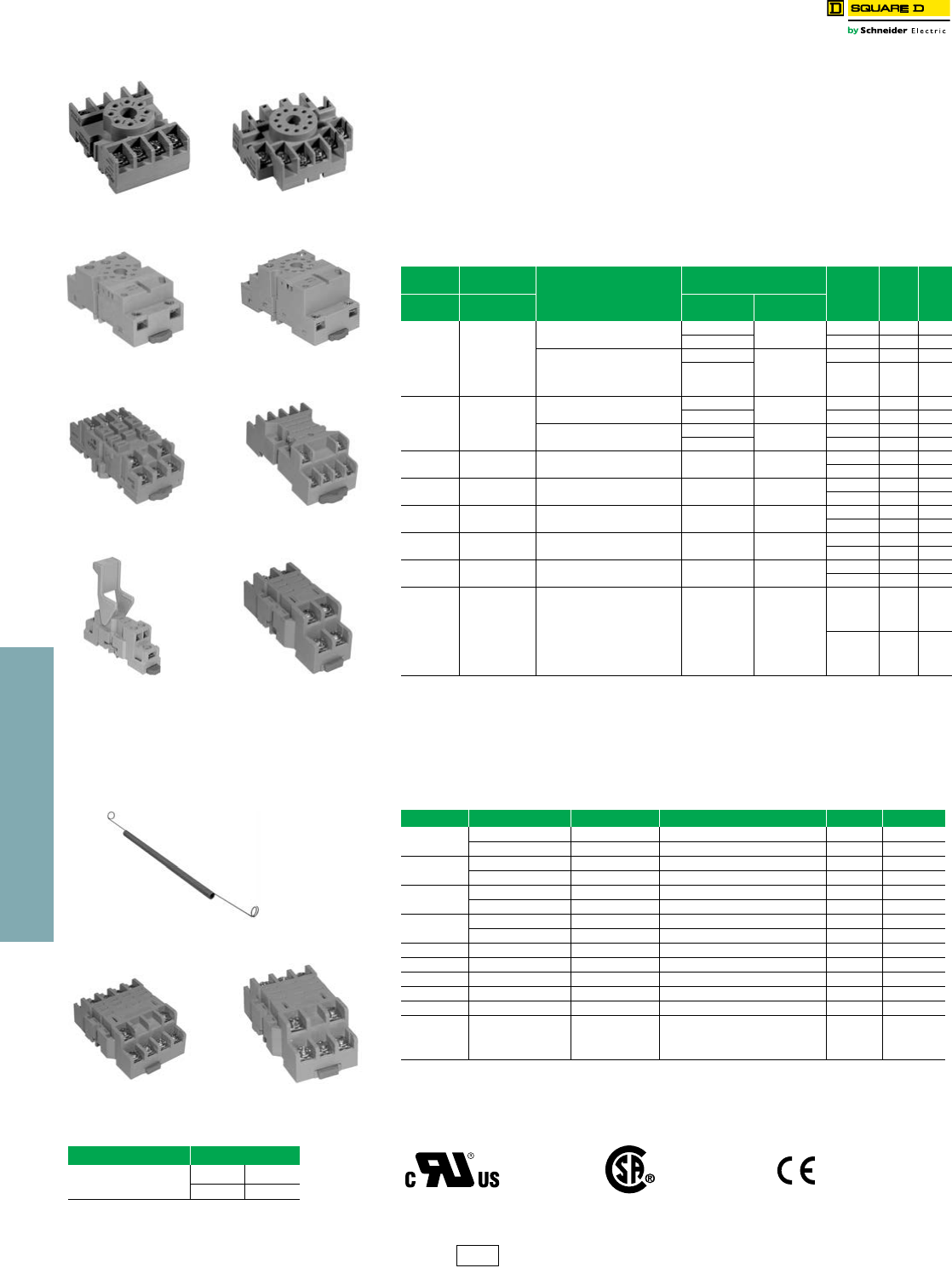
Square D™ Sockets
8501NR sockets are designed for use with plug-in Class 8501 Type K, KA, and R relays,
and 9050JCK timers. The 8501NR45 screw terminal sockets have pressure wire clamps
that accept 1 or 2 #16–22 wires. All other sockets have pressure clamps that will accept 1
or 2 #12–22 wires.
The recommended tightening torque for all terminals is 7-8 lb-in.
•All devices stocked in central warehouse
•DIN track mount or direct panel mount
•Tubular sockets available in easy-to-wire single tier or double tier versions
•RoHS compliant
aMust be ordered in multiples of the quantity listed. Units provided in standard quantity of one are individually
packaged; devices with B suffix have a standard quantity of 10 per bulk pack.
bFinger Safe
For DIN 3 mounting track and end clamps, see page 24-16, or refer to:
•NEMA Style terminal block section of catalog 9080CT9601
•IEC Style terminal block section of catalog 9080CT9901
cMust be ordered in multiples of the quantity listed.
Table 23.62: Snapmount Sockets
For Use
With Class: Description
Socket Rating
Type $ Price
ea.
Std.
Qty.a
8501
Type
9050
Type UL CSA
KP12
KPD12
KA81
KA82
JCK11–19
JCK31–39
JCK51–59
JCK60
JCK1 F
JCK3 F
JCK5 F
8 Pin Tubular
Single Tier Screw Terminal
600 V, 10 A 300 V, 10 A NR51 12.30 1
300 V, 15 A NR51B 10.20 10
8 Pin Tubular
Double Tier Screw Terminal
600 V, 5 A
300 V, 10 A
NR52b12.30 1
300 V, 16 A NR52Bb10.20 10
KP13
KPD13
KA112
JCK21–29
JCK41–49
JCK70
JCK2F
JCK4F
11 Pin Tubular
Single Tier Screw Terminal
600 V, 5 A 300 V, 10 A NR61 18.50 1
300 V, 15 A NR61B 16.50 10
11 Pin Tubular
Double Tier Screw Terminal
600 V, 5 A 300 V, 10 A NR62b 18.50 1
300 V, 16 A NR62Bb16.50 10
KL
KU —11 Pin Spade
Double Tier Screw Terminal 300 V, 15 A 300 V, 15 A NR82 20.60 1
NR82B 18.50 10
RS41
RSD41 —5 Pin Spade
Double Tier Screw Terminal 300 V, 15 A 300 V, 15 A NR41b28.70 1
NR41Bb26.70 10
RS42
RSD42 —8 Pin Spade
Double Tier Screw Terminal 300 V, 10 A 300 V, 10 A NR42 28.70 1
NR42B 26.70 10
RS43
RSD43 —11 Pin Spade
Double Tier Screw Terminal 300 V, 10 A 300 V, 10 A NR43 26.70 1
NR43B 26.70 10
RS44
RSD44 —14 Pin Spade
Double Tier Screw Terminal 300 V, 10 A 300 V, 10 A NR34 28.70 1
NR34B 26.70 10
RS4
RSD4
RS14
RSD14
RS24
RSD24
RS34
RSD34
—14 Pin Spade
Double Tier Screw Terminal 300 V, 10 A 300 V, 10 A
NR45 28.70 1
NR45B 26.70 10
Table 23.63: Socket Accessories
Socket For Use With Description Type $ Price ea. Std. Pack c
8501NR51 8501KP12, KPD12 Hold Down Clip NH51 1.00 10
9050JCK Hold Down Spring NH7 8.30 1
8501NR52 8501KP12, KPD12 Hold Down Clip NH52 1.00 10
9050JCK Hold Down Spring NH7 8.30 1
8501NR61 8501KP13, KPD13 Hold Down Clip NH61 1.00 10
9050JCK Hold Down Spring NH7 8.30 1
8501NR62 8501KP13, KPD13 Hold Down Clip NH52 1.00 10
9050JCK Hold Down Spring NH7 8.30 1
8501NR82 8501KU and KL Hold Down Clip NH82 1.00 10
8501NR41 8501RS41, RSD41 Hold Down Clip Supplied with socket as standard ——
8501NR42 8501RS42, RSD42 Hold Down Clip 8501NH42 1.00 10
8501NR43 8501RS43, RSD43 Hold Down Clip 8501NH42 1.00 10
8501NR34 8501RS44, RSD44 Hold Down Clip 8501NH42 1.00 10
8501NR45
8501RS4, RSD4
8501RS14, RSD14
8501RS24, RSD24
8501RS34, RSD34
Hold Down Clip 8501NH45 1.00 10
8501NR51
8501NR61
8501NR52
8501NR62
8501NR82
8501NR45
8501NR41
8501NR42
8501NR43
8501NH7
8501NR34
How to Order
To Order Specify: Catalog Number
•Class Number
•Type Number
Class Type
8501 NR51B
Approvals:
File
CCN E66924
SW1V2 File
Class 211268
3211 07
IEC 61984
RoHS
Compliant as of date
code 0639
CP2 Discount
Schedule

23 RELAYS AND TIMERS
© 2012 Schneider Electric
All Rights Reserved 23-15
www.schneider-electric.us
Note: S = Stocked.
Factory order items require a minimum order quantity of 25 and have a lead time of
12 weeks.
Approximate Dimensions and Wiring Diagrams
Square D™ Power Relays
8501C relays are ideally suited for controlling single-phase motors, electric heaters, pumps, conveyors, material
handling equipment, and other applications.
•40 A contact rating •UL listed •CE approved
•Motor load (hp) ratings •CSA certified •RoHS compliant
•Durable open-frame construction
Table 23.64: Selection Table and Application Data
Selection Table Application Data
Contact
Arrangement
Number
of Fixed
Contacts
AC Operated Coil
Open Type
DC Operated Coil
Open Type Maximum
Contact
Voltage
Resistive Ampere
Rating 75% Power Factor
Maximum
Single Phase
Horsepower
Maximum
Coil Power
Consumption
N.O. N.C. Type $ Price Type $ Price 277 Vac 600 V 120 V 230 V 600 V AC Coil DC Coil
AC Rated Contacts
SPST 1 0 CO6a32.70 CDO6a32.70 600 40 10 2 2 2 10 VA 4 W
DPST 2 0 CO7a51.30 CDO7a51.30 600 40 5 1.5 1.5 1.5 10 VA 4 W
SPST 0 1 CO8a32.70 CDO8a32.70 600 40 10 2 2 2 10 VA 4 W
SPDT 1 1 CO15a57.30 CDO15a57.30 600 40 5 1.5 1.5 1.5 10 VA 4 W
DPDT 2 2 CO16a69.60 CDO16a69.60 600 40 5 1.5 1.5 1.5 10 VA 4 W
DC Rated Contacts 110 V 220 V
SPST 1 0 CO21a71.70 CDO21a71.70 500 20 8 N.A. 10 VA 4 W
DPDT 2 2 CO22a84.00 CDO22a84.00 325 10 4 10 VA 4 W
aVoltage codes must be specified to order this product. Refer to standard voltage codes listed in Table 23.66 and insert as shown in Table 23.68: How to Order.
8501CDO6V51
Table 23.65: Operating Data
Operating Voltages/
Voltage Range
AC coils – 6 through 480 volts, + 10/-15% of nominal at 25 oC
DC coils – 6 through 110 volts, + 10/-20% of nominal at 25 oC
Coil Duty Continuous duty rated coils. (Non-replaceable)
Operating Temp. Range AC: -67 oF to +131 oF (-55 oC to +55 oC)
DC: -67 oF to +131 oF (-55 oC to +55 oC)
Storage Temp. Range -67 oF to +212 oF (-55 oC to +100 oC)
Approvals:
File
CCN E78351
NLDX File
Class 218139
3211 04 IEC 60947-4-1
Table 23.66: Voltage Codes and Stocked Relays
Class
8501
Type
AC Voltage—50/60 Hz Class
8501
Type
DC Voltage
612 24 120 208 240 277 480 612 24 110
Voltag e
Code V35 V36 V14 V20 V08 V24 V04 V29 Vol tage
Code V50 V51 V53 V60
CO6 SSSSSSSCDO6 SS
CO7 SSSSSSSCDO7 SS
CO8 S S S S S CDO8
CO15 SSSSSSCDO15 S
CO16 SSSSSSSCDO16 SSS
CO21 S CDO21 S S
CO22 S CDO22 S S
2.49
(63.2)
1.98
(50.3)
2.5
(63.6)
1.874
(47.60)
1.874
(47.60)
2.5
(63.6)
0.374
(9.50)
0.19
(4.8)
3.13
(79.4)
2.31
(58.8)
2.5
(63.6)
2.06
(52.4)
2.49
(63.2)
1.874
(47.60) 0.374
(9.50)
0.31
(8.0)
0.81
(20.7)
0.19
(4.8)
8501CO15, 8501CDO15 (SPDT)
2.49
(63.2)
1.95
(49.6)
2.5
(63.6)
1.874
(47.60)
8501CO7, 8501CDO7 (DPST)
8501CO6, 8501CDO6, 8501CO8, 8501CDO8, 8501CO21, 8501CDO21 (SPST)
8501CO16, 8501CDO16, 8501CO22, 8501CDO22 (DPDT)
14
12
A1
A2 11
A1
A2
14
13
A1
A2 11
2124
14
22
12
A1
A2 11
21
24
14
Table 23.67: Class 9991 Enclosure
Type Description $ Price
UE1 NEMA 1 sheet steel enclosure 29.60
Table 23.68: How to Order
To Order Specify: Catalog Number
•Class Number
•Type Number
•Voltage Code
(See Stocked Relay Table above)
Class Type Voltage
Code
8501 CO6 V20
CP2 Discount
Schedule
General Purpose Relays Type C
Class 8501 / Refer to Catalog 8501CT1003
23-16 © 2012 Schneider Electric
All Rights Reserved
www.schneider-electric.us
23 RELAYS AND TIMERS
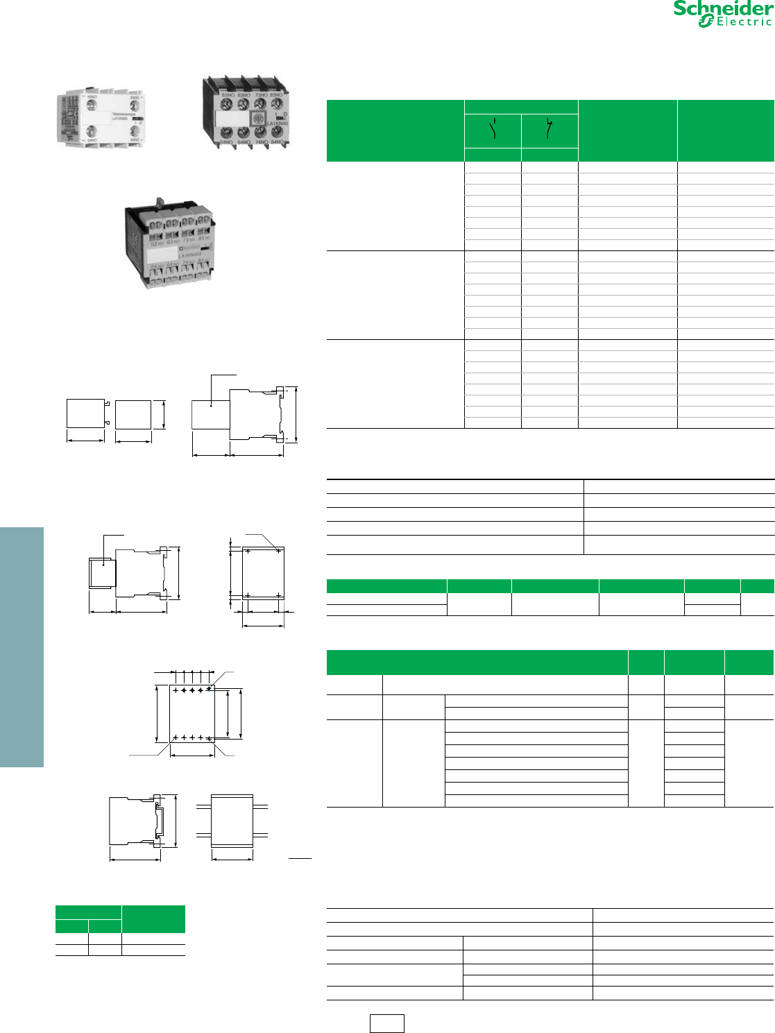
Industrial Relays CAD
Refer to Catalog 8501CT0101
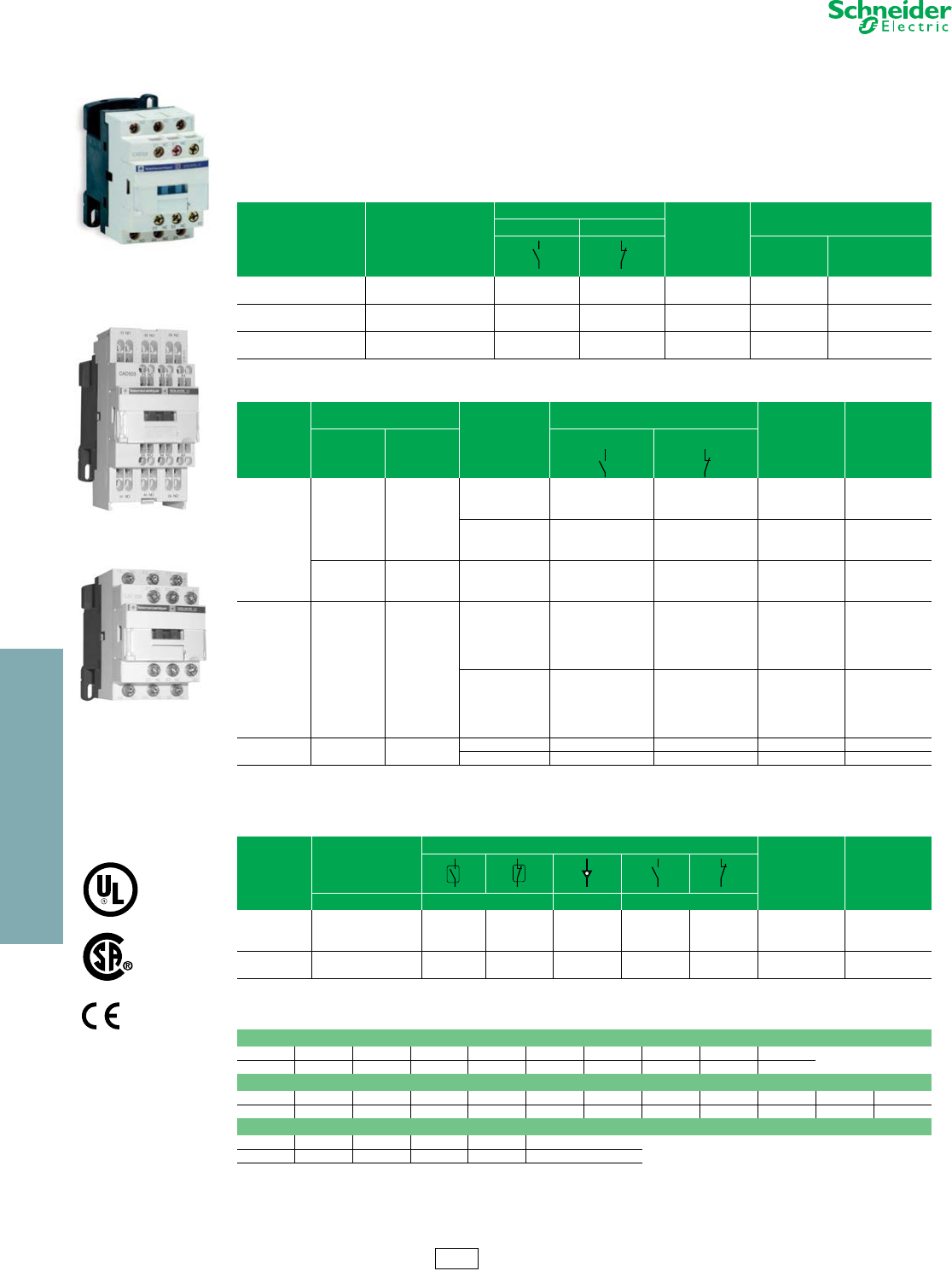
TeSys™ D IEC Style Relays
These 600 volt relays are approved for use around the world. TeSys D relays are usually mounted on 35 mm DIN 3
track, but can also be mounted directly to a panel. The fixed contacts in these relays have a NEMA A600 and Q600
ratings, in addition to the standard IEC ratings, making them suitable for use in most any control circuit. Low
consumption versions of this relay are available for use with low level DC signals from a computer or a PLC. Adder
decks can be added to a basic five pole relay to make it up to an 11 pole relay. The serrated silver-nickel contacts with
wiping action provide excellent reliability in 12 or 24 volt control circuits. Special auxiliary contacts are available for
switching low power down to 5 volts at 10 mA. Timer and mechanical latch attachments are available.
aAdd the proper voltage code from Table 23.72 to the end of catalog number (for example, CAD50B7).
bAuxiliary contact blocks with four contacts cannot be used on relays with low consumption coils.
cIncludes 1 N.O. and 1 N.C. overlapping contact.
dGrounding terminal points (2 terminals jumpered together; see diagram on page 8 of Catalog 8501CT0101).
eAuxiliary contact blocks with four contacts cannot be used on relays with low consumption coils.
fAdd the proper voltage code to the end of catalog number.
For replacement AC coils, see page 18-16. DC coils are not replaceable.
Table 23.69: Instantaneous Control Relays
Terminal Type Number of Contacts
Contact Composition
Catalog Number
$ Price
Normally Open Normally Closed
AC Coil DC or Low
Consumption Coil
Screw Clamp 55 0 CAD50a62.00 110.00
3 2 CAD32a62.00 110.00
Spring Terminal 550CAD503a62.00 110.00
32CAD323a62.00 110.00
Ring Tongue 550CAD506a62.00 110.00
532CAD326a62.00 110.00
Table 23.70: Instantaneous Auxiliary Contact Blocks (for use in normal operation environments)
Number of
Contacts
Maximum Number per Device
Clip-on Mounting
Termination Type
Contact Composition
Catalog Number $ Price
Front Left Side Only
Normally Open Normally Closed
2
1—
Screw Clamp
20LADN20 20.70
11LADN11 20.70
02LADN02 20.70
Spring Terminal
20LADN203 20.70
11LADN113 20.70
02LADN023 20.70
—1
Not for
DC devices Screw Clamp
20LAD8N20 20.70
11LAD8N11 20.70
02LAD8N02 20.70
4 b1—
Screw Clamp
40LADN40 41.50
31LADN31 41.50
22LADN22 41.50
13LADN13 41.50
04LADN04 41.50
Spring Terminal
40LADN403 41.50
31LADN313 41.50
22LADN223 41.50
13LADN133 41.50
04LADN043 41.50
4 b1—
Screw Clamp 2 c2 cLADC22 41.50
Spring Terminal 2 c2 cLADC223 41.50
Table 23.71: Instantaneous Auxiliary Contacts with Dust and Damp Protected Contacts
(for use in particularly harsh industrial environments)
Number
of Contacts
Maximum Number
per Device
Contact Composition
Catalog Number $ Price
Front Mounting Sealed dNormal
21
2————LA1DX20 65.00
—2 ———LA1DX02 65.00
2— 2 ——LA1DY20 77.00
4 e12—— 2 —LA1DZ40 82.00
2—— 1 1LA1DZ31 82.00
Table 23.72: Coil Voltage Codes f
AC 50/60 Hz Coil (for additional voltage code options see page 7 of Catalog 8501CT0101).
Volts 12 24 48 120 208 240 277 480 600
Code J7 B7 E7 G7 LE7 U7 W7 T7 X7
DC Coil (coils have built in suppression as standard)
Volts 12 24 36 48 60 72 110 125 220 250 440
Code JD BD CD ED ND SD FD GD MD UD RD
DC Low Consumption Coil (coils have built in suppression as standard)
Volts 5122448 72
Code AL JL BL EL SL
CAD32
CAD503
CAD323
I12 Discount
Schedule
Approvals:
File
CCN E164353
NKCR
File
Class LR43364
3211 03
www.schneider-electric.us
23 RELAYS AND TIMERS
© 2012 Schneider Electric
All Rights Reserved 23-17
Industrial Relays CAD
Refer to Catalog 8501CT0101
TeSys™ D IEC Style
aWith extended scale from 0.1 to 0.6 s.
bWith switching time of 40 ms ± 15 ms between opening of the N.C. contact and closing of the N.O. contact.
cPower should not be simultaneously applied or maintained to the mechanical latching block and the CAD relay. The duration of the control signal to the
mechanical latching block and the CAD relay should be Š 100 ms.
dRepair part for the preceeding version (non-TeSys) of this product. Not for use on CAD devices.
eComplete the catalog number by adding coil voltage code from Table 23.76. (for example, LA6DK10B)
Table 23.73: Time Delay Auxiliary Contact Blocks
Number and Type
of Contacts
Maximum Number
per Device Time Delay Type Termination Type Range Catalog Number $ Price
Front Mounting
1 N.C. and 1 N.O. 1
On-Delay
Screw Clamp
0.1–3 s aLADT0 131.00
0.1–30 s LADT2 131.00
10–180 s LADT4 131.00
1–30 s bLADS2 131.00
Spring Terminal
0.1–3 s aLADT03 131.00
0.1–30 s LADT23 131.00
10–180 s LADT43 131.00
1–30 s bLADS23 131.00
Off-Delay
Screw Clamp
0.1–3 s aLADR0 131.00
0.1–30 s LADR2 131.00
10–180 s LADR4 131.00
Spring Terminal
0.1–3 s aLADR03 131.00
(Lockout Cover,
See page 7 of Catalog 8501CT0101.)
0.1–30 s LADR23 131.00
10–180 s LADR43 131.00
Table 23.74: Mechanical Latch Blocks c
Unlatching Control Maximum Number per Device Catalog Number $ Price
Front mounting
Manual or electrical 1 LA6DK10 ed 77.00
LAD6K10 e77.00
Table 23.75: Coil Suppressor Modules
These modules clip onto the right hand side of the control relay and the electrical connection is instantly made. Adding an input
module is still possible.
RC Circuits (Resistor-Capacitor)
•Effective protection for circuits highly sensitive to “high frequency” interference.
•Voltage limited to 3 Uc maximum and oscillating frequency limited to 400 Hz maximum.
•Slight increase in drop-out time (1.2 to 2 times the normal time).
For Mounting On: Operational Voltage Catalog Number $ Price
CAD (Vac) 24 to 48 Vac LAD4RCE 26.20
110 to 240 Vac LAD4RCU 26.20
Varistors (Peak Limiting)
•Protection provided by limiting the transient voltage value to 2 Uc maximum.
•Maximum reduction of transient voltage peaks.
•Slight increase in drop-out time (1.1 to 1.5 times the normal time).
CAD (Vac)
24 to 48 Vac LAD4VE 26.20
50 to 127 Vac LAD4VG 26.20
110 to 250 Vac LAD4VU 26.20
Bidirectional Peak Limiting Diode
•Protection provided by limiting the transient voltage value to 2 Uc maximum.
•Maximum reduction of transient voltage peaks.
CAD (Vac) 24 Vac LAD4TB 26.20
72 Vac LAD4TS 26.20
Table 23.76: Coil Voltage Codes
Voltage 24
Vac/Vdc 32/36
Vac/Vdc 42/48
Vac/Vdc 60/72
Vac/Vdc 100
Vac/Vdc 110/127
Vac/Vdc 220/240
Vac/Vdc 256/277
Vac/Vdc 380/415
Vac/Vdc
Voltage Code BCEENKFMUQ
CAD (Vac Coil) CAD (Vdc Coil) or (Low Consumption Vdc Coil)
in. (mm) in. (mm)
CAD 32
50
323
503 CAD 32
50
323
503
b3.03 (77) 3.90 (99) b3.03 (77) 3.90 (99)
cWithout cover or add-on blocks 3.31 (84) 3.31 (84) cWithout cover or add-on blocks 3.66 (93) 3.66 (93)
With cover, without add-on blocks 3.39 (86) 3.39 (86) With cover, without add-on blocks 3.74 (95) 3.74 (95)
LADT
LA6DK
LAD4
b
c
c1
c2
c3
1.770.49
(LAD-8) 45
12.5
b
c
c1
c2
c3
1.77
45
I12 Discount
Schedule
www.schneider-electric.us
23 RELAYS AND TIMERS
23-18 © 2012 Schneider Electric
All Rights Reserved
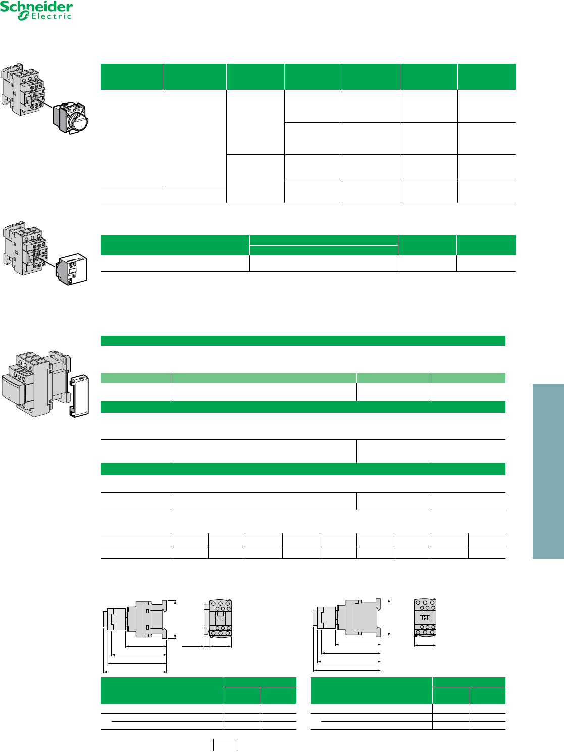
Industrial Relays CAD
Refer to Catalog 8501CT0101
TeSys™ D IEC Style Relays
aFor 24 V operation, the relay must be fitted with a 21 V coil (code Z7).
Table 23.77: Cabling Accessory
Description Catalog Number $ Price
Mounting Adapter
For adapting existing wiring
to a new product
Without coil suppression LAD4BB 23.00
With coil suppression
24 to 48 Vac LAD4BBVE 23.00
50 to 127 Vac LAD4BBVG 23.00
110 to 250 Vac LAD4BBVU 23.00
Table 23.78: Electronic Serial Timer Modules a
•Mounted using adaptor LAD4BB, to be ordered separately, see listing above.
On-delay Type
Operational Voltage Time Delay Catalog Number $ Price
24 to 250 Vac
0.1 to 2 s LA4DT0U 82.00
1.5 to 30 s LA4DT2U 82.00
25 to 500 s LA4DT4U 82.00
Table 23.79: Auto-Man-Stop Control Modules
For local override operation tests with two-position “Auto-Man” switch and “O-I” switch
•Mounted using adaptor LAD4BB, to be ordered separately, see listing above.
Operational Voltage Catalog Number $ Price
24 to 100 Vac LA4DMK 35.00
Table 23.80: Accessories (ordered separately)
For Connection
Description For Mounting On: Must be Ordered in
Multiples of: Catalog Number $ Price ea.
For Marking
Sheet of 64 self-adhesive blank labels 8 x 33 CAD, LAD (4 contacts), LA6DK 10 LAD21 5.20
Sheet of 112 self-adhesive blank labels 8 x 12 LAD (2 contacts), LADT 10 LAD22 5.20
For Protection
Lockout cover LADT, LADR 1 LA9D901 5.50
Relay cover preventing access to the moving contact carrier CAD 1 LAD9ET1 5.20
Table 23.81: Application Data
Type CAD (Vac) CAD (Vdc) CAD (Vdc)
Low Consumption
Rated Insulation Voltage (Ui)
Conforming to IEC 60947-1-1
Overvoltage category III and degree of pollution 3 690 V 690 V 690 V
Conforming to UL, CSA 600 V 600 V 600 V
Rated Impulse Withstand Voltage
(Uimp) Conforming to IEC 60947-1-1 6 kV 6 kV 6 kV
Separation of Electrical Circuits To IEC 536 and VDE 0106 Reinforced insulation up to 400 V
Conforming to Standards IEC 60947-1-1, N-F C 63-140, VDE 0660, BS 4794.
EN 60947-5-15
Approvals
UL: File:
E164353
CSA: File:
LR43364 CE
CCN: NKCR
Class: 3211 03
Protective Treatment Conforming to IEC 68 “TH” (Tropical Finish). See page 23 of Catalog 8501CT0101 for details.
Degree of Protection Conforming to VDE 0106 Front face protected against direct finger
contact IP 2X Protection against direct
finger contact
I12 Discount
Schedule
www.schneider-electric.us
23 RELAYS AND TIMERS
© 2012 Schneider Electric
All Rights Reserved 23-19
Industrial Relays CA2K and CA3K
Refer to Catalog 8501CT0101
TeSys™ K IEC Style Relays
aComplete catalog number by adding proper voltage code from Table 23.84 or Table 23.85 (for example, CA2KN40G7).
aComplete catalog number by adding proper voltage code from Table 23.86 (for example, CA4KN40BW3).
Approvals:
Table 23.82: Control Relays
•Mounting on 35 mm DIN 3 track or 4 screw direct mounting.
•Screws in open “ready-to-tighten” position. •NEMA A600, Q600
•IEC AC15, DC13
Control Circuit Type of
Termination
Contact Configuration
Catalog Number a$ Price
Supply Consumption N.O. N.C.
AC 4.5 VA
Screw clamp
4 0 CA2KN40 • • 35.50
3 1 CA2KN31• • 35.50
2 2 CA2KN22• • 35.50
Spring Termination
4 0 CA2KN403•• 35.50
3 1 CA2KN313•• 35.50
2 2 CA2KN223•• 35.50
Faston
1 x 6.35
or 2 x 2.8
4 0 CA2KN407 • • 35.50
3 1 CA2KN317• • 35.50
2 2 CA2KN227• • 35.50
Solder pins for
printed circuit
board
4 0 CA2KN405 • • 35.50
3 1 CA2KN315• • 35.50
2 2 CA2KN225• • 35.50
DC 3 W
Screw clamp
4 0 CA3KN40 • • 49.20
3 1 CA3KN31• • 49.20
2 2 CA3KN22• • 49.20
Spring Termination
4 0 CA3KN403•• 49.20
3 1 CA3KN313•• 49.20
2 2 CA3KN223•• 49.20
Faston
1 x 6.35
or 2 x 2.8
4 0 CA3KN407 • • 49.20
3 1 CA3KN317• • 49.20
2 2 CA3KN227• • 49.20
Solder pins for
printed circuit
board
4 0 CA3KN405 • • 49.20
3 1 CA3KN315• • 49.20
2 2 CA3KN225• • 49.20
Table 23.83: Low Consumption Control Relays
Compatible with programmable controller outputs.
•LED indicator incorporated.
•Wide range coil (70 to 130% Uc), suppressor fitted as standard.
•Mounting on 35 mm DIN 3 track or 4 screw direct mounting.
•Screws in open “ready-to-tighten” position.
DC 1.8 W
Screw clamp
4 0 CA4KN40• •• 64.00
3 1 CA4KN31•• • 64.00
2 2 CA4KN22•• • 64.00
Spring Termination
4 0 CA4KN403••• 64.00
3 1 CA4KN313••• 64.00
2 2 CA4KN223••• 64.00
Faston
1 x 6.35
or 2 x 2.8
4 0 CA4KN407••• 64.00
3 1 CA4KN317••• 64.00
2 2 CA4KN227•• • 64.00
Solder pins for
printed circuit board
4 0 CA4KN405••• 64.00
3 1 CA4KN315•• • 64.00
2 2 CA4KN225•• • 64.00
Table 23.84: Coil Voltage Codes for CA2K Control Relays (0.8–1.15 Uc) (0.85–1.1 Uc)
Vac
50/60 Hz 12 24 36 42 48 110 120 127 208 220/
230 230 230/
240 380/
400 400 400/
415 440 480 500
660/
690
Voltage
Code J7 B7 C7 D7 E7 F7 G7 FC7 L7 M7 P7 U7 Q7 V7 N7 R7 T7 S7 Y7
Note: Up to and including 240 V, coil with integral suppression device available: add 2 to the code required. Example: J72. (Price Adder 9.50)
Table 23.85: Coil Voltage Codes for CA3K Control Relays (0.8–1.15 Uc)
Vdc 12 20 24 36 48 60 72 100 110 125 200 220 230 240 250
Voltage Code JD ZD BD CD ED ND SD KD FD GD LD MD MPD MUD UD
Note: Coil with integral suppression device available: add 3 to the code required. Example: JD3. (Price Adder 9.50)
Table 23.86: Coil Voltage Codes for CA4K, Low Consumption Control Relays (Wide Range Coil: 0.7–1.3 Uc)
Vdc 12 24 48 72
Voltage Code JW3 BW3 EW3 SW3
File
CCN 164353
NKCR File
Class LR43364
3211 03
CA2KN22 • •
CA3KN407 • •
CA2KN403 • •
CA4KN405 • • •
I12 Discount
Schedule
www.schneider-electric.us
23 RELAYS AND TIMERS
23-20 © 2012 Schneider Electric
All Rights Reserved
Industrial Relays CA2K and CA3K
Refer to Catalog 8501CT0101
TeSys™ K IEC Style Relays
aNot to be used on CA4KN relays.
bClip-on front mounting, 1 block per control relay.
cAuxiliary contact module not suitable for safety circuits.
Note: For other electronic timers see Type RE7 and 9050 Type JCK, pages 23-28 and 23-30.
dProtection by the limitation of the transient voltage to 2 Uc maximum. Maximum reduction of the transient voltage
peaks. Slight time delay on drop-out (1.1 to 1.5 times normal).
eNo overvoltage or oscillation frequency. Polarized component. Slight time delay on drop-out (1.1 to 1.5 times
normal).
fProtection by limitation of the transient voltage to 3 Uc max. and limitation of the oscillation frequency. Slight time
delay on drop-out (1.2 times to twice normal).
gSee “Clip-in Marker Strips” in Catalog 8501CT0101 for information on completing the catalog number.
Table 23.87: Instantaneous Auxiliary Contact Blocks bc
Clip-on Front Mounting, 1 Block Per Control Relay
Type of Connection
Contact Configuration
Catalog Number $ Price
N.O. N.C.
Screw Clamp
20 LA1KN20 14.20
0 2 LA1KN02 14.20
1 1 LA1KN11 14.20
40 LA1KN40a27.30
3 1 LA1KN31a27.30
2 2 LA1KN22a27.30
1 3 LA1KN13a27.30
04 LA1KN04a27.30
Spring Termination
20 LA1KN203 14.20
11 LA1KN113 14.20
02 LA1KN023 14.20
40LA1KN403a27.30
31LA1KN313a27.30
22LA1KN223a27.30
13LA1KN133a27.30
04LA1KN043a27.30
Faston
1 x 6.35
or 2 x 2.8
2 0 LA1KN207 14.20
0 2 LA1KN027 14.20
1 1 LA1KN117 14.20
4 0 LA1KN407a27.30
3 1 LA1KN317a27.30
2 2 LA1KN227a27.30
1 3 LA1KN137a27.30
04 LA1KN047a27.30
Table 23.88: Electronic Time Delay Contact Blocks
Relay output, with common point changeover contact 240 Vac/Vdc, 2 A maximum
Control voltage 0.85–1.1 Uc
Maximum switching capacity 250 VA or 150 W
Operating temperature –10 to + 60oC (+14o F to 140o F)
Reset time 1.5 s during the time delay period,
0.5 s after the time delay.
Table 23.89: Clip-on front mounting, 1 block per control Relay
Voltage (V) Type Timing Range, s Composition C.O. Catalog No. $ Price
AC or DC / 24 to 48 On-delay 1 to 30 1 LA2KT2E 32.80
AC / 110 to 240 LA2KT2U
Table 23.90: Accessories (supplied separately)
Description Sold in
lots of Catalog No. $ Price ea.
Marker
holdergClips on front of relay 100 LA9D90 0.06
Clip-on
markersg
4 maximum per
device
Strip of 10 identical numbers, 0 to 9 25 AB1R•g0.70
Strip of 10 identical capital letters A to Z AB1G•g
Suppressor
modules with
incorporated
LED indicator
Clips onto front
of relay with
locating device.
No tools
required for
connection.
For AC and DC voltages 12 to 24 V (varistor)
5
LA4KE1Bd
9.80
For AC and DC voltages 32 to 48 V (varistor) LA4KE1Ed
For AC and DC voltages 50 to 129 V (varistor) LA4KE1FCd
For AC and DC voltages 130 to 250 V (varistor) LA4KE1UG d
For DC voltages 12 to 24 V (diode + Zener diode) LA4KC1Be
For DC voltages 32 to 48 V (diode + Zener diode) LA4KC1Ee
For AC voltages 220 to 250 V (RC) LA4KA1Uf
LA1KN20
LA1KN40
LA1KN403
38
27
1.45
1.06
57
LA2KT
58
34
1.34 2.24
2.28
34
1.34
LA2KT electronic time delay contact blocks
57
31
LA1-K
58
50
==
35
45
==
4xØ4
2.28
1.22 2.24 1.38
1.77
1.97
On panel
Approximate dimensions
for CA2, CA3, CA4K control relays
C Product
in. mm
2.22 59 AM1DP200
2.60 66 AM1DE200
50
53
45
58
8.65 ===
10xØ1.3
A1
A2
2.28
2.05
1.97
1.77
0.34
58
45
C1.77
2.28
On printed circuit board
n AM1DP200 or AM1DE200 mounting rail—35 mm DIN rail
(see page 22-16 for additional DIN rail)
in.
mm
Table 23.91: Environment
Conforming to Standards IEC 947, NF C 63-140, VDE 0660, BS 5424, CE
Approvals UL, CSA, DEMKO, NEMKO, SEMKO, FI
Protective treatment Conforming to IEC 68 (DIN 50016) “TC” (Climateproof)
Degree of protection Conforming to VDE 0106 Protection against direct finger contact
Ambient air temperature Storage -58 to 176 oF (-50 to 80oC)
Operation -13 to 122 oF (-25 to 50oC)
Maximum operating altitude Without derating 6562 ft (2000 m)
I12 Discount
Schedule
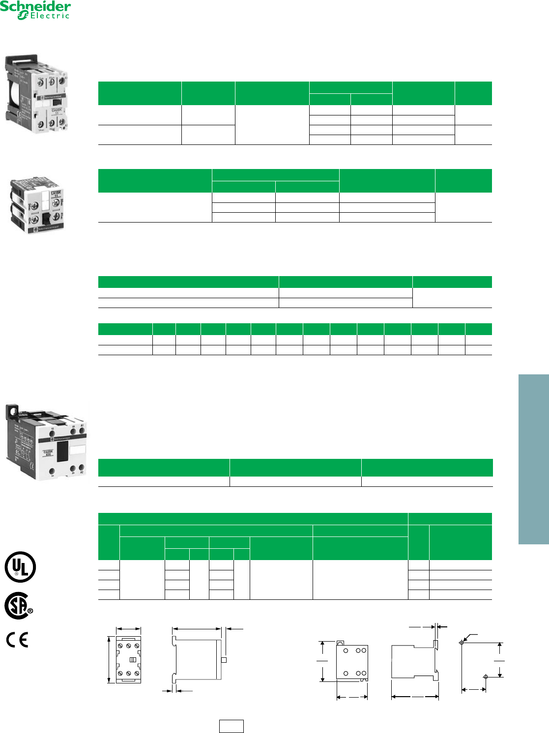
www.schneider-electric.us
23 RELAYS AND TIMERS
© 2012 Schneider Electric
All Rights Reserved 23-21
Industrial Relays CA2SK and CA3SK
Refer to Catalog 8501CT0101
TeSys™ SK IEC Style Relays
aUse the appropriate voltage code to complete the catalog number (for example: CA2SK11G7)
Transient Suppressor Module
Dampens the voltage spike that may occur when the relay coil is de-energized. The spike may adversely affect solid
state equipment near the relay. The transient suppressor module snaps into a cavity located in the side of the relay.
These modules can be used with CA2SK and CA3SK relays.
bAlternating relays CA2SKE available in these voltages only. No other voltages are available.
Alternating Relays, CA2SKE
Refer to Catalog 8501CT9701
These alternating relays are used to alternate the use of 2 motor circuits. When the coil is energized the first time, one
contact closes and will open when the coil is de-energized. When the coil is energized again, the other contact will
close and will open when the coil is de-energized. The contacts from these alternators are to be used in the control
circuit of the starters that are controlling pump or compressor motors.
Approvals: UL File: E164353 CCN: NKCR; CSA File: LR43364 Class: 3211 03.
aUse the appropriate voltage code to complete the catalog number (for example, CAZSK11G7). Only available with voltages indicated above.
Table 23.92: IEC Style Industrial Control Relays
•Miniature size saves space.
•Mounts on 35 mm DIN 3 track
•Up to 4 poles.
Control Circuit Supply Consumption Type of Termination
Contact Configuration
Catalog Number $ Price
N.O. N.C.
AC 4.2 VA
Screw clamp
11CA2SK11•• a
43.70
20CA2SK20•• a
DC 2.2 W 11CA3SK11•• a
51.00
20CA3SK20•• a
Table 23.93: Contact Adder Decks (for CA2SK20 only)
Type of Termination
Contact Configuration
Catalog Number $ Price
N.O. N.C.
Screw clamp
20 LA1SK20
16.9011 LA1SK11
02 LA1SK02
Table 23.94: Transient Suppressor Module
Control Circuit Voltage Catalog Number $ Price
24–48 Vac 50/60 Hz, 24–48 Vdc LA4SKEIE 21.80
110–250 Vac 50/60 Hz, 110–250 Vdc LA4SKEIU
Table 23.95: Coil Voltage Codes for Control Relays
Vol tage 12 24 36 48 72 110 120 220 230 240 380 400 480
50/60 Hz — B7 b—E7 b—F7G7 bM7 bP7 U7 bQ7 V7 T7 b
DC JDBDCDEDSD————————
Table 23.96: Alternating Relays
Coil Voltage
(Voltage-Hz) Type $ Price
24–50/60 CA2SKE20••a120.00
Table 23.97: Contact Ratings for CA2SK, CA3SK, AND CA2SKE20 Relays
AC DC
Vol ts
Inductive 35% PF Resistive 75% PF
Volts Continuous
Amperes
NEMA Rating
Make Break Continuous
Amperes
Make, Break and
Continuos Amperes
AVA AVA
120
A600
60
7200
6
720 10 10
24 3
240 30 3 60 2
480 15 1.5 110 0.8
600 12 1.2 240 0.2
Approximate Dimensions for CA2SKE Relay
CA2SK11G7
LA1SK11
CA2SKE20
2.20
56
1.06
27
2.19
56
.20
5
.14
4
Dual Dimensions: INCHES
Millimeters
#8
or
(49)
1.93
(34.5)
1.36
(68)
2.68
(45)
1.77
(58)
2.28
(4)
.16
4mm
I12 Discount
Schedule
Approvals:
File
CCN E164353
NKCR
File
Class LR43364
3211 03
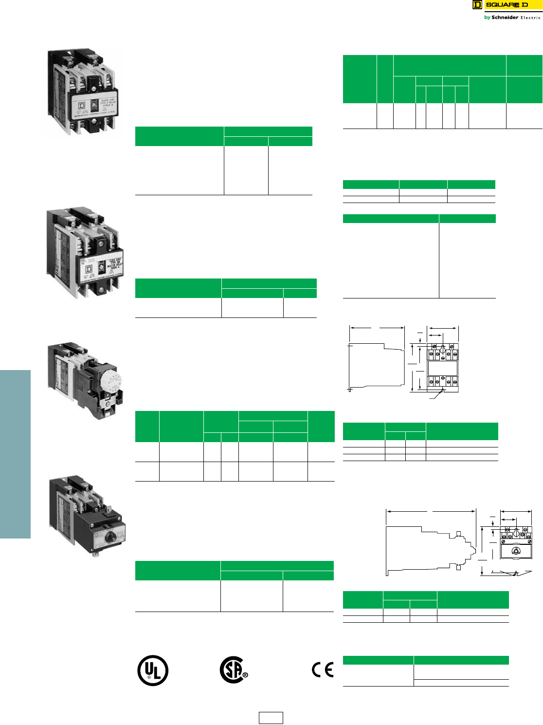
23 RELAYS AND TIMERS
23-22 © 2012 Schneider Electric
All Rights Reserved
www.schneider-electric.us
Industrial Relays
Square D™ NEMA Style
Type X
Class 8501 / Refer to Catalog 8501CT9601
AC Control Relays
•Straight-through wiring
•Plug-in contact cartridges for easy contact conversion and
replacement
•Contact conversion without removing terminal screws or wires
•Self-lifting pressure wire connectors
•Replaceable coil
aA maximum of 8 N.C. contacts is allowed on 9–12 pole relays.
AC Master Relays
•20 ampere contact rating due to use of master contact
cartridges. d
•Provisions for standard cartridges to be used in contact
cavities not occupied by master cartridges in 2-8 pole AC
relay.
bAttachments not permitted on this relay.
AC Timing Relays
•Easily convertible On Delay or Off Delay
•Two adjustable timing ranges
•Repeat accuracy well above ±10%
•Convertible 1 N.O. and 1 N.C. timed contacts
•Large knob for easy adjustment of time delay
•Off Delay mode times out even after loss of power.
AC Latching Relays
•Mechanical latch holds all contacts switched even after
removal of power from replaceable latching coil.
•Provides sequence memory in the event of power loss. Ideal
for press control, process control and punch presses.
•Replaceable unlatch coil to switch contacts back to original
state.
cVoltage Code must be specified to order these products. Refer to Table
23.104 and insert the code as shown in Table 23.107: How to Order.
Approvals:
dMaximum of six 8501 Type XC4 Master Cartridges may be used on
only 7 and 8 pole AC Devices
AC Control Relays and AC Master Relays
AC Latching Relay Dimensions
For replacement coils, see page 23-24.
Table 23.98: AC Control Relays
Normally Open Convertible
Instantaneous Contacts
Control Relay a
Typec $ Price
0
2
3
4
6
8
10
12
XO00
XO20
XO30
XO40
XO60
XO80
XO1000
XO1200
98.00
144.00
169.00
192.00
242.00
288.00
336.00
385.00
Table 23.99: AC Master Relays
Number of N.O. 20 Ampere
Convertible Contacts
Open Typeb
Typec $ Price
2
4
6
XMO20
XMO40
XMO60
204.00
336.00
457.00
Table 23.100: AC Timing Relays
Timing
Mode
N.O.
Convertible
Instantaneous
Contacts
Timed
Convertible
Contacts
Timing Relay
$ Price0.2–60 s 5–180 s
N.O. N.C. Typ e c Ty pe c
On
Delay
0
2
4
1
1
1
1
1
1
XO00XTE1
XO20XTE1
XO40XTE1
XO00XTE2
XO20XTE2
XO40XTE2
432.00
480.00
529.00
Off
Delay
0
2
4
1
1
1
1
1
1
XO00XTD1
XO20XTD1
XO40XTD1
XO00XTD2
XO20XTD2
XO40XTD2
432.00
480.00
529.00
Table 23.101: AC Latching Relays
N.O. Convertible Instantaneous
Contacts
Latching Relay
Type c $ Price
2
3
4
6
8
XO20XL
XO30XL
XO40XL
XO60XL
XO80XL
313.00
336.00
360.00
408.00
457.00
File
CCN E78403
NKCR File
Class 060905
3211 03
IEC 60947-1
Type XMO40
Control Relay
Type XMO40
Master Relay
Type XO40XTE1
Timing Relay
Type XO40XL
Latching Relay
Table 23.102: AC Contact Ratings
(for DC ratings, see page 23-23)
Type of
Cartridge V
Inductive
35% Power Factor
Resistive
75% Power
Factor
NEMA
Rating
Make Break
Continuous
Amperes
Make, Break
and
Continuous
Amperes
AVA AVA
Standard
or
Overlapping
120
240
480
600
A600
60
30
15
12
7200
6
3
1.5
1.2
720 10 10
Masterd—A600
Same as standard cartridge above except
substitute 20 A for the continuous ampere rating
Logic Reed — — 150 Vac, 150 mA, 8 W Maximum
Table 23.103: Average Operating Time (ms)
Device Pick-Up Drop-Out
AC Relay 15 16
AC Latching Relay 15 13
Table 23.104: Voltage Codes
AC Voltages - Hz Code
12–60
24–60
24–50
48–60
48–50
120–60/110–50
208–60
240–60/220–50
277–60
480–60/440–50
600–60/550–50
V11
V01
V12
V18
V16
V02
V08
V03
V04
V06
V07
Table 23.105: Dimensions and Weight
No. of Poles Dim. A Shipping Weight, lb
in. mm
0–4 3.95 100 2.0
6–8 5.16 131 2.3
10–12 6.36 162 2.7
Table 23.106: Dimensions and Weight
No. ofPoles Dim. A Shipping Weight, lb
in. mm
2–4 6.54 166 2.8
6–8 7.74 197 3.1
Table 23.107: How to Order
To Order Specify: Catalog Number
•Class Number
•Type Number
•Voltage Code
Class Type Vol tage
Code
8501 XO40 V02
.19
5
2.23
57
1.12
28
3.50
893.12
79
Prov. for
(2) #8/#10 Mtg. Screws
B30080-064
A
Dual Dimensions: INCHES
Millimeters
A.19
5
2.23
57
1.12
28
3.12
79
3.50
89
Dual Dimensions: INCHES
Millimeters
CP2 Discount
Schedule
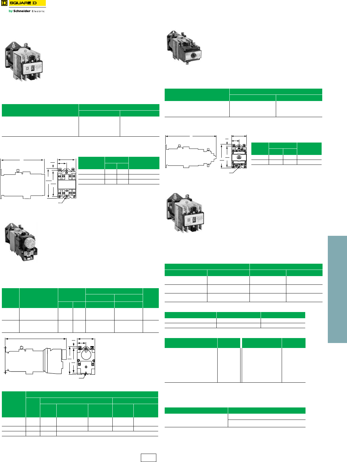
23 RELAYS AND TIMERS
© 2012 Schneider Electric
All Rights Reserved 23-23
www.schneider-electric.us
DC Control Relays
DC Control Relay Utility Auxiliary Relay
DC Timing Relays
DC Latching Relays
Note: Unlatch coil is rated for intermittent duty and should be connected through a N.O. contact
of the relay if the input signal is maintained. Order one more N.O. contact than the
application requires to use as a coil clearing contact.
DC Utility Relays
eVoltage code must be specified to order these products. Refer to Table 23.116 and insert
the appropriate code as shown in Table 23.117: How to Order.
For Replacement coils, see page 23-24
For UL and CSA approvals, see page 23-22
•Replaceable, highly reliable pure DC power plant: no
economizing resistors, overlapping contacts or dual-
wound coil.
•Utilizes the same Type XB adder decks and
attachments as the AC version.
•Offers all the features of the AC relay.
•Available in up to 8 poles.
•All contact poles are usable since no overlapping
contacts are needed.
Table 23.108: DC Control Relays
Normally Open Convertible
Instantaneous Contacts
Control Relay
Type $ Price
0
2
4
6
8
XDO00e
XDO20e
XDO40e
XDO60e
XDO80e
216.00
264.00
313.00
360.00
408.00
Table 23.109: Dimensions
No. of Poles Dim. A Shipping Weight
lb.
in. mm
0–4 5.17 131 3.1
6–8 6.37 162 3.4
10–12 7.60 193 3.8
•Easily convertible On Delay or Off Delay.
•Two adjustable timing ranges.
•Repeat accuracy well above ±10%.
•Convertible 1 N.O. and 1 N.C. timed contacts.
•Large knob for easy adjustment of time delay.
•Off Delay mode times out even after loss of power.
Table 23.110: DC Timing Relays
Timing
Mode
Normally
Open Convertible
Instantaneous
Contacts
Timed
Convertible
Contacts
Timing Relay
$ Price0.2–60 s 5–180 s
N.O. N.C. Type Type
On
Delay
0
2
4
1
1
1
1
1
1
XDO00XTE1e
XDO20XTE1e
XDO40XTE1e
XDO00XTE2e
XDO20XTE2e
XDO40XTE2e
522.00
601.00
648.00
Off
Delay
0
2
4
1
1
1
1
1
1
XDO00XTD1e
XDO20XTD1e
XDO40XTD1e
XDO00XTD2e
XDO20XTD2e
XDO40XTD2e
522.00
601.00
648.00
Table 23.111: DC Contact Ratings (for AC ratings, see page 23-22)
Type of
Cartridge
DC Ratings
Volts
Inductive Resistive
NEMA
Rating
Make and Break
Amperes
138 VA Max.
Continuous
Amperes
Make and
Break
Amperes
Continuous
Amperes
Standard 125
250 P600 1.1
0.55 5
54
0.8 5
5
Overlapping 125 P150 1.1 5 4 5
Logic Reed — — 30 Vdc, 60 ma
Note: Do not use any 8501 Type XC4 Master Cartridges on any DC-operated device.
Type XDO40
Control Relay
A.25
6
2.23
57
1.12
28
3.56
903.12
79
Prov. for
(2) #8/#10 Mtg. Screws
B30080-066
Type XDO40XTE2
Timing Relay
7.77
197.25
6
2.23
57
1.12
28
3.56
903.12
79
Prov. for
(2) #8/#10 Mtg. Screws
B30080-075 A
•Mechanical latch holds all contacts switched even
after removal of power from replaceable latching coil.
•Provides sequence memory in the event of power
loss.
•Ideal for sequencing applications such as press
control, process control and punch presses.
•Replaceable unlatch coil to switch contacts back to
original state.
Table 23.112: DC Latching Relays
Normally Open Convertible
Instantaneous Contacts
Latching Relay
Type $ Price
2
4
6
8
XDO20XDLe
XDO40XDLe
XDO60XDLe
XDO80XDLe
485.00
534.00
582.00
629.00
Table 23.113: Dimensions
No. of
Poles
Dim. A Shipping
Weight, lb.
in. mm
2–4 7.76 197 3.9
6–8 8.98 228 4.2
Ideal for utility plant applications where reliable
performance and a pure DC power plant is required. In
addition to the Type XDO relay features, the Type
XUDO provides:
•Up to 12 poles N.O. or N.C.
•Nominal 125 Vdc coil, capable of handling 140 Vdc
continuously and picking up at 105 Vdc after having
been operated at 140 Vdc continuously. Other voltages
with comparable operating characteristics are
available.
•Enclosed device capable of operating in 145°F
ambient.
Table 23.114: DC Utility Relays
Number of Convertible Contacts Open Type
N.O. N.C. Type $ Price
4
00
4XUDO40e
XUDO04e390.00
8
00
8XUDO80e
XUDO08e510.00
12
00
12 XUDO1200e
XUDO0012e629.00
Table 23.115: Average Operating Times (in ms)
Device Pick-Up Drop-Out
DC Relay 37 21
DC Latching Relay 37 45
Table 23.116: Voltage Codes—8501 XUDO and XDO Relays
DC Voltages for
8501 XUDO Relays ONLY Code DC Voltages for
8501 XDO Relays Code
6
12
24
48
125
250
V50
V51
V53
V56
V63
V67
6
12
24
32
48
72
90
115/125
230/250
V50
V51
V53
V54
V56
V58
V59
V62
V66
Table 23.117: How to Order
To Order Specify: Catalog Number
•Class Number
•Type Number
•Voltage Code
Class Type Voltage Code
8501 XDO40 V53
Type XDO40XDL
Latching Relay
A.25
6
2.23
57
1.12
28
3.56
90
3.12
79
Prov. for
(2) #8/#10 Mtg. Screws
B30080-159
Type XUDO40
Utility Relay
CP2 Discount
Schedule
Industrial Relays
Square D™ NEMA Style
Type X™ Relays
Class 8501 / Refer to Catalog 8501CT9601
23 RELAYS AND TIMERS
23-24 © 2012 Schneider Electric
All Rights Reserved
www.schneider-electric.us
aSee Mechanical Latch Attachment Voltage Codes table below:
bTo order an unlatch coil add the letter “L” to the type number and the letter “B” to the suffix number. Example: for a 120 V 60 Hz unlatch coil order a Class 9998 Type XL44B.
cNot dual rated—250 Vdc only
d125 Vdc only
Table 23.118: Type X™ Relays
Description Type $ Price
Mechanical Latch Attachment—Mounts on any 2 through 8-pole relay (except XMO master relay). The Type XL and XDL latch
attachments are identical in size and mounting provisions. The Type XLAC latch attachment has a continuous-duty-rated coil which is
replaceable. The Type XDLDC latch attachment has an intermittent–rated coil (replaceable) and should be connected
through a N.O. contact of the basic relay if the input signal is maintained to the unlatch coil.
AC Latch Attachment
DC Latch Attachment XLa
XDLa
169.00
222.00
Pneumatic Timer Attachment—Mounts only on any 0 through 4-pole AC or DC relays (except XMO master relay). It provides 1
N.O. and 1 N.C. convertible timed contacts, which are the same Type XC1 cartridges used on the basic relay. Two timing ranges are
available, and conversion from On Delay to Off Delay or vice versa is easy.
Off Delay
0.2–60 seconds
5–180 seconds
On Delay
0.2–60 seconds
5–180 seconds
XTD1
XTD2
XTE1
XTE2
336.00
336.00
336.00
336.00
Timer Lockout Cover—Fits over the time delay adjustment knob of any Type XT timing attachment. The Lockout Cover is designed
to protect the time setting against accidental adjustment. It mounts directly to the timing attachment with two included screws.XJ1 9.00
Adder Decks—Adder decks are used to expand the number of poles on a relay. The basic 4-pole relay can be easily converted to an
8-pole or 12-pole relay by installing one or two adder decks. The Class 8501 Type XB20 comes with 2 convertible contact cartridges
and will accept 2 additional convertible contact cartridges. The Class 8501 Type XB40 comes with 4 convertible contact cartridges.
The same Type XB adder deck is used for both the middle and upper decks of the AC or DC relay.
With 2 N.O. contact cartridges XB20 48.00
With 4 N.O. contact cartridges XB40 98.00
Contact Cartridges—The Type X relay offers 4 Types of contact cartridges. All are color–coded for visual identification of each Type.
Standard Cartridge—The standard cartridge, used for most applications, has a black case. XC1 24.20
Overlapping Cartridge—Same NEMA Type A600 AC rating as standard cartridge and a NEMA Type P150 DC rating. When it is
used in the N.O. mode it will close early and when used in the N.C. mode it will open late. If two or more are used together, the N.O.
contacts will close before the N.C. contacts open as the relay picks up. Overlap also occurs during dropout. Overlapping cartridge
has a red case.
XC2 24.20
May be ordered factory installed:
•Substitute 1 N.O. and 1 N.C. overlapping cartridges for 2 standard cartridges.
•Substitute 2 N.O. and 2 N.C. overlapping cartridges for 4 standard cartridges.
•Substitute 3 N.O. and 3 N.C. overlapping cartridges for 6 standard cartridges.
•Substitute 4 N.O. and 4 N.C. overlapping cartridges for 8 standard cartridges.
Form
Y1591
Y1592
Y1593
Y1594
Add 24.20
Add 24.20
Add 24.20
Add 24.20
Master Cartridge—Features the same contact ratings as the Type XC1 standard cartridge except it has a 20 ampere continuous
current rating instead of 10 amperes. It can be used in circuits where a master relay is required. Master cartridge has a blue case.
Maximum of 6 master cartridges may be used on any 7 and 8-pole AC relays. Do not use any master cartridges on 9-12-pole
AC or any DC-operated devices. Note: If master cartridges are added to a standard relay, attachments (latch mechanism,
timers, etc.) cannot be used. XC4 60.00
Logic Reed Cartridge—See logic reed adder deck above.
Mounting Track—The mounting track has pre-punched mounting holes to simplify mounting the track on the control panel. The relay
mounting screws are factory installed on the track so that the relays can be hung prior to tightening the screws.
9 in. long for 4 relays
18 in. long for 8 relays
27 in. long for 12 relays
36 in. long for 16 relays
XM4
XM8
XM12
XM16
19.70
29.80
36.40
42.90
Manual Test Tool—Provides a means of manually switching the contacts of a basic relay or timing relay and holding all contacts in
their switched state until the tool is removed. This simplifies the checking of control circuits without power on the coil or contacts. XA1 6.10
Transient Suppressor—Consists of an R-C circuit designed to suppress coil generated transients to approximately 200 percent of
peak voltage. It is particularly useful when switching the Type X relay near solid state equipment. It is designed for use on coils up to
120 Vac. XS1 48.00
NEMA 1 Enclosure—Formed from sheet steel to provide strength and rigidity. Two conduit knockouts are located in both the top and
bottom of the enclosure. The enclosure is furnished with self tapping screws for mounting the relay inside the enclosure.
Accommodates a single 4 or 8-pole AC or DC relay, 12-pole AC relay, 4-pole AC latching relay, and 4-pole AC timing relay.
Note: The 4-pole DC latching relay, 4-pole DC timing relay, 8-pole AC and DC latching relays and 12-pole utility auxiliary relay will not fit.
Class 9991
Ty p e
UE7 29.60
Table 23.119: Mechanical Latch Attachment Voltage Codes Table 23.120: How to Order
AC Voltage Code DC Voltage Code
24–60
24–50
120–60/110–50
208–60
240–60/220–50
277–60
480–60/440–50
600–60/550–50
V01
V12
V02
V08
V03
V04
V06
V07
6
12
18
24
48
72
90
115/125
230/250
V50
V51
V99
V53
V56
V58
V59
V62
V66
Table 23.121: Relay Coil Selection and Pricing
Device
Type
Equipment To Be Serviced Coil Prefix,
or Class
and Type
Hz
SUFFIX
(The complete coil number consists of prefix or the Class and Type, followed by suffix.) Coil
Burden
Watts
$ Price
Class Type 6 V 12 V 18 V 24 V 32 V 48 V 64 V 72 V 90 V 110 V 115/125 V 220 V 230/250 V
DC 8501
XD 9998XD—192834374046495255—58—67 18 168.00
XDL 9998 XDL — 19 28 34B 37B 40B 46B 49B 52B 55B — 58B — 67B 50 216.00
XUD 9998 XUD — 19 28 — 37 — 46 — — — — 58d—67c16 168.00
Device
Type
Equipment To Be Serviced Coil Prefix
or Class
and Type
Coil Volt-Amperes $ Price
Class Type —24 V 110-115
V120 V 208 V 220 V 240 V 277 V 380 V 440 V 480 V 550 V 600 V In-rush Sealed
AC 8501 XO,
XMO 9998 X b60 23 — 44 51 52 53 55 — — 62 — 65 148 23 69.00
50 24 44 — 52 53 — — — 62 — 65 — 143 25
To Order Specify: Catalog Number
•Class Number
•Type Number
•Voltage Code for mechanical latch attachment
•Form for factory installed overlapping contacts
Class Type
8501 XTE1
CP2 Discount
Schedule
Industrial Relays
Square D™ NEMA Style
Type X™ Relays
Class 8501 / Refer to Catalog 8501CT9601
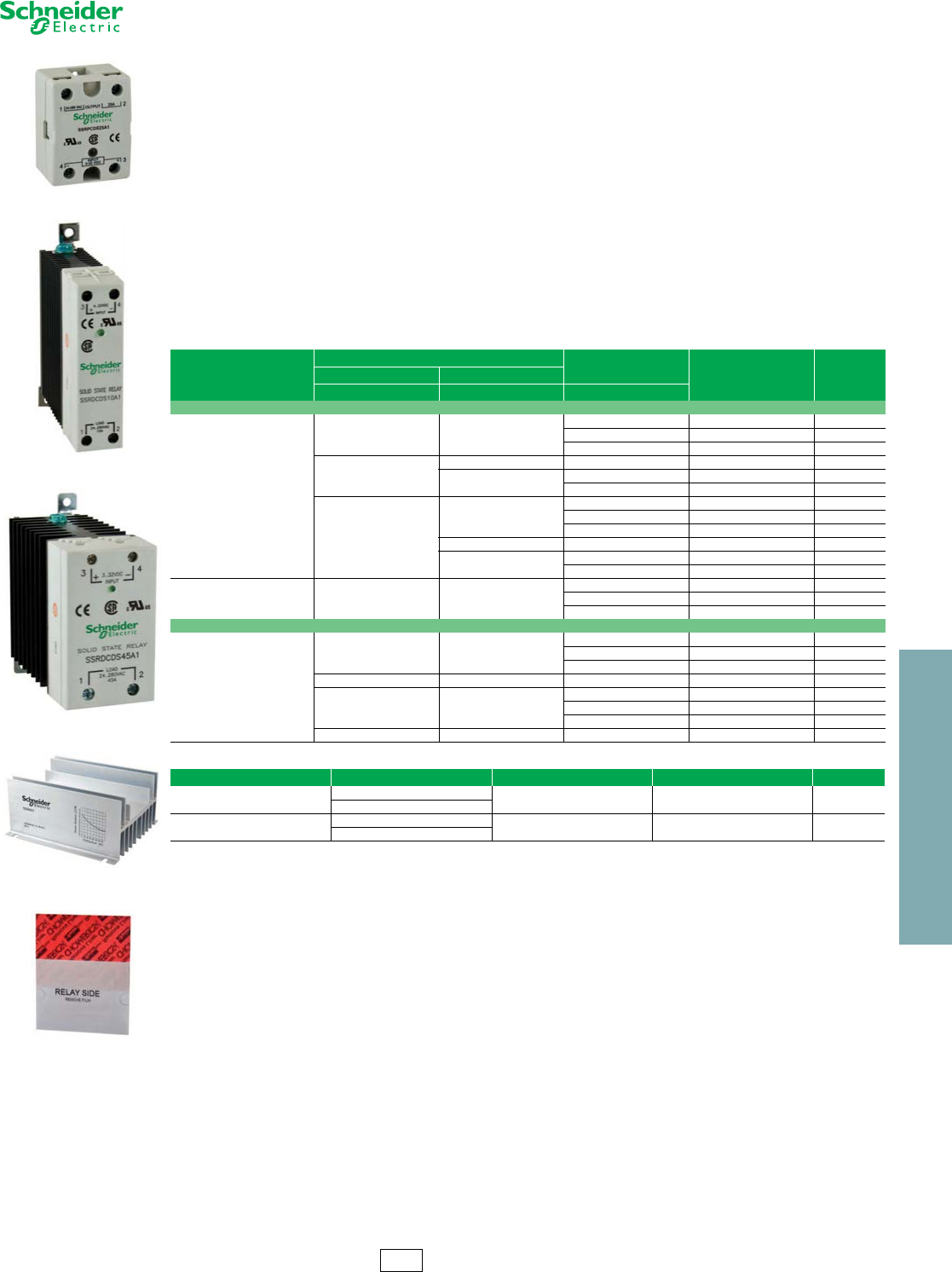
www.schneider-electric.us
23 RELAYS AND TIMERS
© 2012 Schneider Electric
All Rights Reserved 23-25
Solid State Relays Type SSR
Refer to Catalog DIA3ED2090304EN-US
Schneider Electric Solid State Relays
Solid state relays do not have any moving parts to wear out. Combined with vibration resistance, arc-less switching and
the lack of acoustical noise, you have the ideal product for switching applications that demand reliable execution. For
added reliability the Zelio™ SSRP and SSRD solid state relays utilize Direct Copper Bonding (DCB) technology to
decrease internal temperatures and improve the overall quality of the product.
Key features include:
•Input voltage range 3 to 32 Vdc, 90 to 280 Vac
•Breaking capacities up to 125 A
•Zero voltage turn on, low EMI / RFI
•No moving parts
•Shock and Vibration resistant
•No acoustical noise
•Fast response
•Arc-less switching
•Long life (>109 operations)
Table 23.122: Solid State Relays
Switching
Voltage Range Load Current
Range Catalog
Number $ Price ea.Input Output
V V A
Panel Mounted
SCR Output
Zero voltage switching
3•••32 DC 24•••280 AC
10 SSRPCDS10A1 40.60
25 SSRPCDS25A1 41.90
50 SSRPCDS50A1 59.00
4•••32 DC
48•••530 AC 75 SSRPCDS75A2 100.00
48•••660 AC 90 SSRPCDS90A3 114.00
125 SSRPCDS125A3 144.00
90•••280 AC
24•••280 AC
10 SSRPP8S10A1 43.10
25 SSRPP8S25A1 45.70
50 SSRPP8S50A1 53.00
48•••530 AC 75 SSRPP8S75A2 114.00
48•••660 AC 90 SSRPP8S90A3 117.00
125 SSRPP8S125A3 134.00
MOSFET Output
Instant switching 3.5•••32 DC 0•••100 DC
12 SSRPCDM12D5 66.00
25 SSRPCDM25D5 82.00
40 SSRPCDM40D5 114.00
DIN Rail Mounted
SCR Output
Zero voltage switching
4•••32 DC 24•••280 AC
10 SSRDCDS10A1 58.00
20 SSRDCDS20A1 81.00
30 SSRDCDS30A1 85.00
3•••32 DC 24•••280 AC 45 SSRDCDS45A1 100.00
90•••280 AC 24•••280 AC
10 SSRDP8S10A1 61.00
20 SSRDP8S20A1 70.00
30 SSRDP8S30A1 78.00
90•••140 AC 24•••280 AC 45 SSRDF8S45A1 106.00
Table 23.123: Accessories For Panel Mount Solid State Relays
Description For Use With Relays Load Current Range Catalog Number $ Price ea.
Heat Sink SSRPP8S••• • up to 50 A SSRAH1 26.00
SSRPCDS••• •
Pre-Cut Thermal Transfer Pad
(sold in pack sof 10)
SSRPP8S•••• up to 125 A SSRAT1 2.30
SSRPCDS••• •
SSRPCDS25A1
SSRDCDS10A1
SSRDCDS45A1
SSRAH1
SSRAT1
CP2 Discount
Schedule

www.schneider-electric.us
23 RELAYS AND TIMERS
23-26 © 2012 Schneider Electric
All Rights Reserved
Timers RE11/RE48/REXL
Refer to Catalog 9050CT0001
Zelio ™ IEC Style—17.9 mm wide
Table 23.124: RE11 Modular Timers—17.9 mm wide (Multi-range timers offering 7 selectable ranges)
Output 1 C/O contact
Functions Supply Voltages Rated Current Catalog Number $ Price
On delay 24 Vdc, 24–240 Vac 8A RE11RAMU 42.90
Interval 24 Vdc, 24–240 Vac 8A RE11RHMU 42.90
Asymmetrical repeat cycle 24 Vdc, 24–240 Vac 8A RE11RLMU 53.00
Asymmetrical repeat cycle 12 Vac/Vdc 8A RE11RLJU 75.00
One shot 24 Vdc, 24–240 Vac 8A RE11RBMU 52.00
Off delay with control start 24 Vdc, 24–240 Vac 8A RE11RCMU 52.00
Multi-function a24 Vdc, 24–240 Vac 8A RE11RMMU 62.00
Multi-function a12–240 Vac/Vdc 8A RE11RMMW 75.00
Multi-function a12–240 Vac/Vdc 8A RE11RMMWS 75.00
Multi-function a12 Vac/Vdc 8A RE11RMJU 75.00
Multi-function b24 Vdc, 24–240 Vac 8A RE11RMEMU 75.00
Multi-function a24 Vdc, 24–240 Vac 8A RE11RMXMU 75.00
aTiming ranges: 0.1–1 s, 1–10 s, 0.1–10 min, 1–10 min, 0.1–1 hr, 1–10 hr, 10–100 hr
bTiming ranges: 0.1–1 s, 1–10 s, 0.1–10 min, 1–10 min, 0.1–1 hr, 1–10 hr
Conforming to standards IEC 61812-1, EN 50081-1/2, EN 50082-1/2, LV directives (73/23/EEC + 93/68/EEC (CE marking) +
EMC directive (89/336/EEC + IEC 60669-2-3)
Approvals
cULus File: E173076 CNN: NRNT
File: E173076 CNN: NRNT7
CSA File: 217698 Class 3211 07
CE
GL except RE11 RMX MU and RE11 RME MU
Ambient air temperature around the
device
Storage oF (oC) –22 to +140 (–30 to +60)
Operation oF (oC) –4 to +140 (–20 to +60)
Table 23.125: RE11 Modular Timers—17.9 mm wide (Multi-function, dual function or single function)
Functions Supply Voltages Rated Current Catalog Number $ Price
Solid state output
On delay 24–240 Vac/Vdc 0.7A RE11LAMW 45.40
Interval 24–240 Vac 0.7A RE11LHBM 42.90
Off delay with control contact 24–240 Vac 0.7A RE11LCBM 52.00
Asymmetrical repeat cycle 24–240 Vac 0.7A RE11LLBM 75.00
Multi-function 24–240 Vac 0.7A RE11LMBM 62.00
Timing ranges: 0.1–1 s, 1–10 s, 0.1–10 min, 1–10 min, 0.1–1 hr, 1–10 hr, 10–100 hr
Conforming to standards IEC 61812-1, EN 50081-1/2, EN 50082-1/2, LV directives (73/23/EEC + 93/68/EEC (CE marking) +
EMC directive (89/336/EEC + IEC 60669-2-3)
Approvals
cULus File: E173076 CNN: NRNT
File: E173076 CNN: NRNT7
CSA File: 217698 Class: 3211 07
CE
Ambient air temperature around the
device
Storage oF (oC) –22 to 140 (–30 to +60
Operation oF (oC) –4 to 140 (–20 to +60)
Table 23.126: RE48 Panel Mount Timers (For required socket, refer to the catalog section)
Functions Supply Voltages Rated Current Catalog Number $ Price
Single function: on delay, two relay outputs 24–240 Vac/Vdc 2 x 5 A RE48ATM12MW 73.00
Repeat cycle: two relay outputs 24–240 Vac/Vdc 2 x 5 A RE48ACV12MW 88.00
Multi-function: on delay, one shot, off delay, repeat cycle 24–240 Vac/Vdc 2 x 5 A RE48AML12MW 86.00
Multi-function: on delay and interval, two relay outputs,
of which one selectable and instantaneous 24–240 Vac/Vdc 2 x 5A RE48AMH13MW 86.00
Conforming to standards IEC 61812-1, EN 50081-1/2, EM 50082-1/2, LV directives (73/23/EEC +
93/68/EEC (CE marking) + ENC directive (89/336/EEC + IEC 60669-2-3)
Approvals
cURus File: E173076 CNN: NRNT2
File: E173076 CNN: NRNT8
CSA File: 217698 Class: 3211 070
CE, C-Tick, GL
RoHS compliant as of date code 0625
Ambient air temperature around the device Storage oF (oC) –40 to 158 (–40 to +70)
Operation oF (oC) –4 to 122 (–20 to +50)
Table 23.127: REXL Miniature Plug-in Timers (For required socket, refer to the catalog section)
4 pole 2 pole
Function Supply Voltages Rated
Current Catalog Number $ Price Rated
Current Catalog Number $ Price
Single function (On-Delay
12 Vdc 3A REXL4TMJD 56.00 5A REXL2TMJD 53.00
24 Vdc c3A REXL4TMBD 56.00 5A REXL2TMBD 53.00
24 Vac 50/60 Hz c3A REXL4TMB7 56.00 5A REXL2TMB7 53.00
120 Vac 50/60 Hz 3A REXL4TMF7 56.00 5A REXL2TMF7 53.00
230 Vac 50/60 Hz 3A REXL4TMP7 56.00 5A REXL2TMP7 53.00
Timing Ranges 0.1–1 s, 1–10 s, 0.1–1 min, 1–10 min, 0.1–1 hr, 1–10 hr, 10–100 hr
For 48 Vac supply, additional resistor 390 ohm 4 W / 24 V
cFor 48 Vac supply, additional resistor 560 ohm 2 W / 24 V
Approvals: File
CCN
File
CCN
E173076
NRNT2
E173076
NRNT8
File
Class 217698
321107 IEC 61812-1 RoHS
Compliant as of date
code 0625
RE11RLMU
RE11LHBM
REXL2TMJD
RE48A TM12MW
CP2 Discount
Schedule
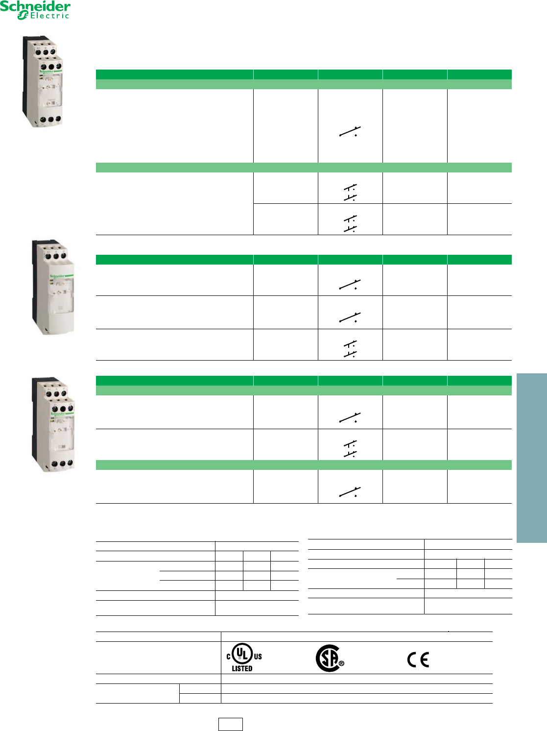
www.schneider-electric.us
23 RELAYS AND TIMERS
© 2012 Schneider Electric
All Rights Reserved 23-27
Timers RE7
Refer to Catalog 9050CT0001
Zelio ™ IEC Style—22.5 mm
aExcept control of partial stop of time delay for RE7MY13BU.
RE7ML
These timers offer multi range timing from 0.05 to 300 hours, in 10 timing ranges.
Table 23.128: RE7M 6 Function and 8 Function Timers
Function Supply Voltages Relay Output Catalog Number $ Price
6 Function Timer
On-Delay Timer
Off-Delay Timer
Interval Timer
•start on energization
•start on opening of remote control contact
Repeat Cycle Timer with start during the OFF period.
Repeat Cycle Timer with start during the ON period
External control possible for:
•start of time delay
•partial stop of time delay
•adjustment of time delay
24 Vdc or Vac
42–48 Vdc or Vac
110–240 Vac
1 C/O, SPDT
RE7ML11BU 226.00
8 Function Timer
Same as 6 Function Timer a plus
Timer for star-delta starting
•with double On-Delay timing
•with changeover contact to star connection
24 Vdc or Vac
110–240 Vac
2 C/O, DPDT
RE7MY13BU 252.00
24–240 Vdc or Vac
2 C/O, DPDT
RE7MY13MW 277.00
RE7T
RE7M
Table 23.129: RE7T On-Delay Timers
Functions Supply Voltages Relay Output Catalog Number $ Price
On-Delay Timer 24 Vdc or Vac
110–240 Vac
1 C/O, SPDT
RE7TL11BU 138.00
On-Delay Timer
External control possible for:
•start of time delay
•partial stop of time delay
•adjustment of time delay b
24 Vdc or Vac
42–48 Vdc or Vac
110-240 Vac
1 C/O, SPDT
RE7TM11BU 177.00
On-Delay Timer
Remote control possible for:
adjustment of time delay b
24 Vdc or Vac
42–48 Vdc or Vac
110–240 Vac
2 C/Oc, DPDT
RE7TP13BU 189.00
Table 23.130: RE7M Symmetrical and Asymmetrical Timers
Functions Supply Voltages Relay Output Catalog Number $ Price
Symmetrical Timers: On and Off delay times are equal.
On-Delay and Off-Delay Timer
External control possible for:
•partial stop of time delay
•adjustment of time delay b
Start control via external contact only
24 Vdc or Vac
42–48 Vdc or Vac
110–240 Vac
1 C/O, SPDT
RE7MA11BU 194.00
On-Delay and Off-Delay Timer
Start control via external contact only
24 Vdc or Vac
42–48 Vdc or Vac
110–240 Vac
2 C/O c, DPDT
RE7MA13BU 208.00
Asymmetrical Timers: On and Off delay times are adjusted separately.
On-Delay and Off-Delay Timer
External control possible for:
•partial stop of time delay
•adjustment of time delay b
Start control via external contact only
24 Vdc or Vac
42–48 Vdc or Vac
110–240 Vac
1 C/O, SPDT
RE7MV11BU 214.00
bBy external potentiometer, to be ordered separately (see page 3 of Catalog 9050CT0001 for specifications). If external potentiometer is used, the internal
potentiometer is automatically disconnected.
cA switch on the front face of the timer allows the second contact to be used in instantaneous mode.
Table 23.131: Output Circuit Specifications for RE7
Current Limit, Ith 8 A
Rated Operational Limits at 70oC24 V 115 V 250 V
Conforming to
IEC60947-5-1/1991 and
VDE 060
AC-15 N.C. contact 3 A 3 A 3 A
AC-15 N.O. contact 5 A 5 A 5 A
DC-13 N.O. contact 2 A 0.2 A 0.1A
UL and CSA Current Resistive Rating 5A
NEMA / UL B300 Inductive Rating 3600 VA Make, 360 VA Break,
5 A Carry
Table 23.132: Output Circuit Specifications for RE8
Maximum Switching Voltage 250 Vac/Vdc
Current Limit Ith 8 A
Rated Operational Limits at 150oF (70oC) 24 V 115 V 250 V
Conforming to IEC 60947-5-
1/1991 and VDE 0660
AC-15 3 A 3 A 3 A
DC-13 2 A 0.2 A 0.1 A
UL and CSA Current Ratings (Resistive) 5 A
NEMA / UL B300 Ratings (Inductive) 3600 VA Make, 360 VA Break.
5 A Carry
RE7, RE8, and RE9 Timers comply to the following:
Conforming to Standards IEC 61812-1, EN 61812-1
Product Approvals File E164353
NKCR File 089150
Class 3211-07 IEC 61812-1
CE Marking RE7, RE8, and RE9 Timers conform to European regulations relating to CE Marking
Ambient Air Temperature Storage -40oF to +185oF (-40oC to +85oC)
Operation -4oF to +140oF (-20oC to +60oC)
CP2 Discount
Schedule
www.schneider-electric.us
23 RELAYS AND TIMERS
23-28 © 2012 Schneider Electric
All Rights Reserved
Timers RE7
Refer to Catalog 9050CT0001
Zelio ™ IEC Style—22.5 mm
aIf the device has been stored de-energized for more than a month, it must be energized for about 15 seconds to activate it.
Subsequently, a time of > 1 s is enough to activate the time delay.
Note: If this time is not complied with, the relay will remain energized indefinitely.
bBy external potentiometer, to be ordered separately (see page 3 of Catalog 9050CT0001 for specifications). If external potentiometer is used, the internal
potentiometer is automatically disconnected.
cA switch on the front face of the timer allows the second contact to be used in instantaneous mode.
For conformance to standards, see page 23-32
RoHS Compliant as of date code 0626
Table 23.133: RE7R Timers Off-Delay Timers
Functions Supply Voltages Relay Output Catalog Number $ Price
On De-energization, Adjustable from 0.05 s to 10 min, in 7 Ranges
Off-Delay Timer
(Times without power) 24–240 Vdc or Vac
1 C/O
SPDT
RE7RB11MWa189.00
Off-Delay Timer
Remote control possible for:
•adjustment of time delayb
24–240 Vdc or Vac
2 C/O
DPDT
RE7RB13MWa214.00
On Opening of External Control Contact, Adjustable from 0.05 s to 300 h, in 10 Ranges
Off-Delay Timer
External control possible for:
•partial stop of time delay
•adjustment of time delay b
24 Vdc or Vac
42–48 Vdc or Vac
110–240 Vac
1 C/O
SPDT
RE7RA11BU 164.00
On opening of Low Level External Control Contact, Adjustable from 0.05 s to 300 h, in 10 Ranges
Off-Delay Timer
External control possible for:
•partial stop of time delay
•adjustment of time delay b
24 Vdc or Vac
42–48 Vdc or Vac
110–240 Vac
1 C/O
SPDT
RE7RM11BU 177.00
Off-Delay Timer 24 Vdc or Vac
42–48 Vdc or Vac
110–240 Vac
2 C/Oc, DPDT
RE7RL13BU 189.00
Table 23.134: RE7P Interval Timers
Functions Supply Voltages Relay Output Catalog Number $ Price
Start on Energization
Interval Timer 24 Vdc or Vac
110–240 Vac
1 C/O
SPDT
RE7PE11BU 151.00
Interval Timer
External control possible for:
•adjustment of time delay b
24 Vdc or Vac
42–48 Vdc or Vac
110–240 Vac
2 C/O c
DPDT
RE7PP13BU 189.00
Start on Opening of External Control Contact
Interval Timer
External control possible for:
•partial stop of time delay
•adjustment of time delay b
24 Vdc or Vac
42–48 Vdc or Vac
110–240 Vac
1 C/O
SPDT
RE7PM11BU 151.00
Interval Timer 24 Vdc or Vac
42–48 Vdc or Vac
110–240 Vac
2 C/O c
DPDT
RE7PD13BU 189.00
Table 23.135: RE7C Timers Symmetrical and Asymmetrical Relays
Functions Supply Voltages Relay Output Catalog Number $ Price
Symmetrical Relays with Start during Off Period
Repeat Cycle Timer 24 Vdc or Vac
110–240 Vac
1 C/O
SPDT
RE7CL11BU 164.00
Repeat Cycle Timer
External control possible for:
•adjustment of time delay b
24 Vdc or Vac
42–48 Vdc or Vac
110–240 Vac
2 C/O c
DPDT
RE7CP13BU 202.00
Asymmetrical, with Separate Adjustment of On-Delay and Off-Delay
Repeat Cycle Timer
External control possible for:
•start period
•adjustment of time delays b
•partial stop
24 Vdc or Vac
42–48 Vdc or Vac
110–240 Vac
1 C/O
SPDT
RE7CV11BU 214.00
RE7R
RE7P
RE7C
CP2 Discount
Schedule
www.schneider-electric.us
23 RELAYS AND TIMERS
© 2012 Schneider Electric
All Rights Reserved 23-29
Timers RE8/RE9
Refer to Catalog 9050CT0001
Zelio™ IEC Style—22.5 mm
dAlso available in pack of one; delete TQ from the end of the catalog number. Example: RE8TA11BU.
aFor easier adjustment, it is preferable to set the time delay between the maximum value in the range and one tenth of this value. Example: RE8TA11BUTQ
timing range 0.1–10 s, recommended use 1–10 s.
bOrders must specify standard pack quantity or multiples of that quantity.
For technical information, refer to . . . . . . . . . . . . . . . . . . . . . . . . page 23-32.
cFor easier adjustment, it is preferable to set the time delay between the maximum value in the range and one tenth of this value. Example: RE9TA11MW
timing range 0.1-10 s, recommended use 1-10 s.
RoHS Compliant as of date code 0626
For technical information, refer to catalog 9050CT0001.
Table 23.136: On-Delay (timing starts on energization), TDE
Relay Output Supply Voltages Timing Range aCatalog Number Standard Pack Quantity b$ Price
1 C/O
SPDT
24 Vdc or Vac
110–240 Vac
0.1–3 s RE8TA61BUTQ 10 75.00
0.1–10 s RE8TA11BUTQ d10 75.00
0.3–30 s RE8TA31BUTQ d10 75.00
3–300 s RE8TA21BUTQ d10 75.00
20 s–30 min RE8TA41BUTQ 10 75.00
Table 23.137: Off-Delay (timing starts on de-energization), TDD
Control Contact
1 C/O
SPDT
24 Vdc or Vac
0.1–10 s RE8RA11BTQ d10 95.00
0.3–30 s RE8RA31BTQ 10 95.00
3–300 s RE8RA21BTQ d10 95.00
110–240 Vac
0.1–10 s RE8RA11FUTQ d10 95.00
0.3–30 s RE8RA31FUTQ 10 95.00
3–300 s RE8RA21FUTQ d10 95.00
20 s–30 min RE8RA41FUTQ 10 95.00
Self-Powered (Times without power)
1 C/O
SPDT
24 Vdc or Vac
110–240 Vac
0.05–0.5 s RE8RB51BUTQ 10 105.00
0.1–10 s RE8RB11BUTQ 10 105.00
0.3–30 s RE8RB31BUTQ 10 105.00
Table 23.138: Repeat Cycle Timer
Relay Output Supply Voltages Timing Range aCatalog Number Standard Pack Quantity b$ Price
1 C/O
SPDT
24 Vdc or Vac
110–240 Vac 0.1–10 s RE8CL11BUTQ 10 105.00
Table 23.139: Interval Timer
On Energization
1 C/O
SPDT
24 Vdc or Vac
110–240 Vac
0.1–10 s RE8PE11BUTQ 10 87.00
0.3–30 s RE8PE31BUTQ 10 87.00
3–300 s RE8PE21BUTQ 10 87.00
By Control Contact
1 C/O
SPDT
24 Vdc or Vac
0.1–10 s RE8PD11BTQ 10 101.00
0.3–30 s RE8PD31BTQ 10 101.00
3–300 s RE8PD21BTQ 10 101.00
110–240 Vac
0.1–10 s RE8PD11FUTQ 10 101.00
0.3–30 s RE8PD31FUTQ 10 101.00
3–300 s RE8PD21FUTQ 10 101.00
On De-Energization
1 C/O
SPDT
24 Vdc or Vac
110–240 Vac 0.05–1 s RE8PT01BUTQ 10 107.00
Table 23.140: On-Delay Timer (Solid State Output)
Power Supply Circuit Function Timing Range cCatalog Number $ Price
24–240 Vac or Vdc On-Delay
0.1–10 s RE9TA11MW 87.00
0.3–30 s RE9TA31MW 87.00
3–300 s RE9TA21MW 87.00
40 s–60 min RE9TA51MW 87.00
Table 23.141: Off-Delay Timer (Solid State Output)
24–240 Vac Off-Delay
0.1–10 s RE9RA11MW7 126.00
0.3–30 s RE9RA31MW7 126.00
3–300 s RE9RA21MW7 126.00
40 s–60 min RE9RA51MW7 126.00
RE8TA
RE8PE
RE9TA
CP2 Discount
Schedule
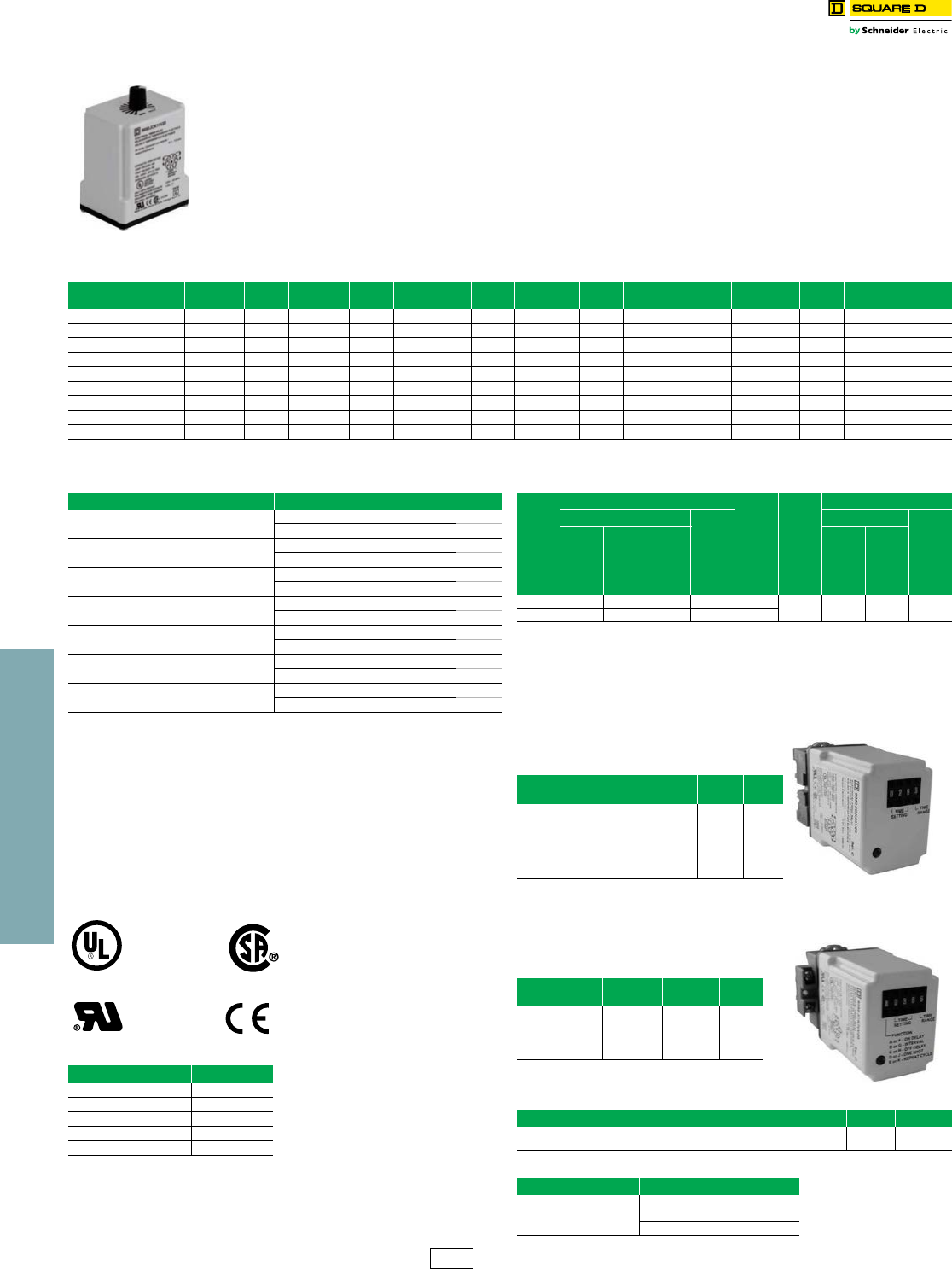
23 RELAYS AND TIMERS
23-30 © 2012 Schneider Electric
All Rights Reserved
www.schneider-electric.us
Square D™ General Purpose Plug-In
c(XXXX) denotes the timing period in seconds.
Example: Class 9050 Type JCK1F60 is an On Delay timer fixed at 60 seconds.
dFixed repeat cycle timers can be supplied with the same or different On-Time and
Off-Time.
eInitiating contact can be up to 50 feet from the timer.
fVoltage code must be specified to order this product. Refer to standard voltage codes
listed below and insert as shown in How To Order.
Class 8501 Sockets
For sockets, see page 23-14
For DIN rail, see page 24-16
For all 9050JCK timers:
AC15 / B300 (NO/NC)
DC13 / R300 (NO)
Type JCK60
This On Delay timer uses a 5 position rotary switch to select the timing
range. The three pushbutton thumbwheels are used to select the time
value.
Type JCK70
Two 5 position rotary switches are used to select the timing mode and
timing range. The three pushbutton thumbwheels are used to select the
time value.
gThe repeat cycle mode utilizes the same
on-time and off-time.
9050JCK timing relays are designed to provide low-cost timing
in a plug-in housing. The Types JCK11 thru 59 provide ±1%
repeat accuracy. The Types JCK60 and 70 offer ±0.1% repeat
accuracy. These timers are directly interchangeable with many
other 8 and 11 pin tube base timers.
•Up to ±0.1% repeat accuracy
•Timing from 0.05 seconds to 999 hours
•Available in 5 timing modes
•DPDT contacts (2 N.O. and 2 N.C.)
•10 A contact rating
•Transient protected
•Hold down spring available
•Variable or fixed time delay
•Horsepower rated
•RoHS compliant
9050JCK46V20
Table 23.142: Variable Time Delay
Knob Adjustable
Timing Range
On
Delay $ Price Off
Delayb$ Price Off Delay
Power Trigger $ Price Interval $ Price One Shotb$ Price One Shot
Power Trigger $ Price Repeat
Cyclea$ Price
0.1–10 seconds JCK11f78.00 JCK21f98.00 JCK21PTf98.00 JCK31f78.00 JCK41f98.00 JCK41PTf98.00 JCK51f140.00
0.3–30 seconds JCK12f78.00 JCK22f98.00 JCK22PTf98.00 JCK32f78.00 JCK42f98.00 JCK42PTf98.00 JCK52f140.00
0.6–60 seconds JCK13f78.00 JCK23f98.00 JCK23PTf98.00 JCK33f78.00 JCK43f98.00 JCK43PTf98.00 JCK53f140.00
1.2–120 seconds JCK14f78.00 JCK24f98.00 JCK24PTf98.00 JCK34f78.00 JCK44f98.00 JCK44PTf98.00 JCK54f140.00
1.8–180 seconds JCK15f78.00 JCK25f98.00 JCK25PTf98.00 JCK35f78.00 JCK45f98.00 JCK45PTf98.00 JCK55f140.00
0.1–10 minutes JCK16f87.00 JCK26f107.00 JCK26PTf107.00 JCK36f87.00 JCK46f107.00 JCK46PTf107.00 JCK56f147.00
0.3–30 minutes JCK17f87.00 JCK27f107.00 JCK27PTf107.00 JCK37f87.00 JCK47f107.00 JCK47PTf107.00 JCK57f98.00
0.6–60 minutes JCK18f87.00 JCK28f107.00 JCK28PTf107.00 JCK38f87.00 JCK48f107.00 JCK48PTf107.00 JCK58f98.00
1.2–120 minutes JCK19f87.00 JCK29f107.00 JCK29PTf107.00 JCK39f87.00 JCK49f107.00 JCK49PTf107.00 JCK59f98.00
aTwo dials are provided for independently adjustable repeat cycle timing ranges.
bInitiating contact can be up to 50 feet from the timer.
Table 23.143: Fixed Time Delay
Timing Mode Type Timing Range (seconds) $ Price
On Delay JCK1F(XXXX)cf 0.1 to 180 78.00
181 to 3600 87.00
Off Delay eJCK2F(XXXX)cf 0.1 to 180 98.00
181 to 3600 107.00
Off Delay with
Power Trigger JCK2F(XXXX)PTcf 0.1 to 180 98.00
181 to 3600 107.00
Interval JCK3F(XXXX)cf 0.1 to 180 78.00
181 to 3600 87.00
One ShoteJCK4F(XXXX)cf 0.1 to 180 98.00
181 to 3600 107.00
One Shot with
Power Trigger JCK4F(XXXX)PTcf 0.1 to 180 98.00
181 to 3600 107.00
Repeat Cycle JCK5F(XXXX)cdf 0.1 to 180 140.00
181 to 3600 147.00
With appropriate 8501NR Socket:
File
CCN E78351
NLDX File
Class 214768
3211 07
Without Socket
File
CCN E78351
NLDX2 IEC
60947-1
RoHS
Compliant
as of date code
9050JCK1-5 = 0627
9050JCK6070=0648
Table 23.144: Voltage Codes
Voltage Code
12 Vdc V36
24 Vac/Vdc V14
48 Vac/Vdc V17
120 Vac/110 Vdc V20
240–50/60 Vac V24
Table 23.145: Contact Ratings
AC
Vol ts
AC Amperes
hp DC
Vol ts
DC Amperes
Inductive 35% P.F.
Res. 75% P.F.
Make Break and
Continuous
Inductive
Res. Make Break
and Continuous
Make
Break
Continuous
Make
Break
120 30 3 10 10 1/3 28 3 3 10
240 15 1.5 10 10 1/2
Table 23.146: Selection and Pricing
Timing
Modes Timing Ranges Type $ Price
On Delay
.01s
0.1s
S
0.1m
M
0.1h
H
0.05–9.99 seconds
00.1–99.9 seconds
001–999 seconds
00.1–99.9 minutes
001–999 minutes
00.1–99.9 hours
001–999 hours
JCK60f152.00
Table 23.147: Selection and Pricing
Timing
Modes
Timing
Range Type $ Price
On Delay
Off Delay
Interval
One Shot
Repeat Cycleg
Same as
JCK60 JCK70f173.00
Table 23.148: Class 8501 Hold Down Spring
For use on Class 9050 Type JCK Timers Class Type $ Price ea.
Hold down spring holds timer in socket during heavy vibration.
(See 9050JCK with 8501NH7 photo at the top of this page.) 8501 NH7 8.30
Table 23.149: How to Order
To Order Specify: Catalog Number
•Class Number
•Type Number
•Voltage Code
Class Type Voltage
Code
9050 JCK11 V20
CP2 Discount
Schedule
Timers Type JCK
Class 9050 / Refer to Catalog 9050CT9601
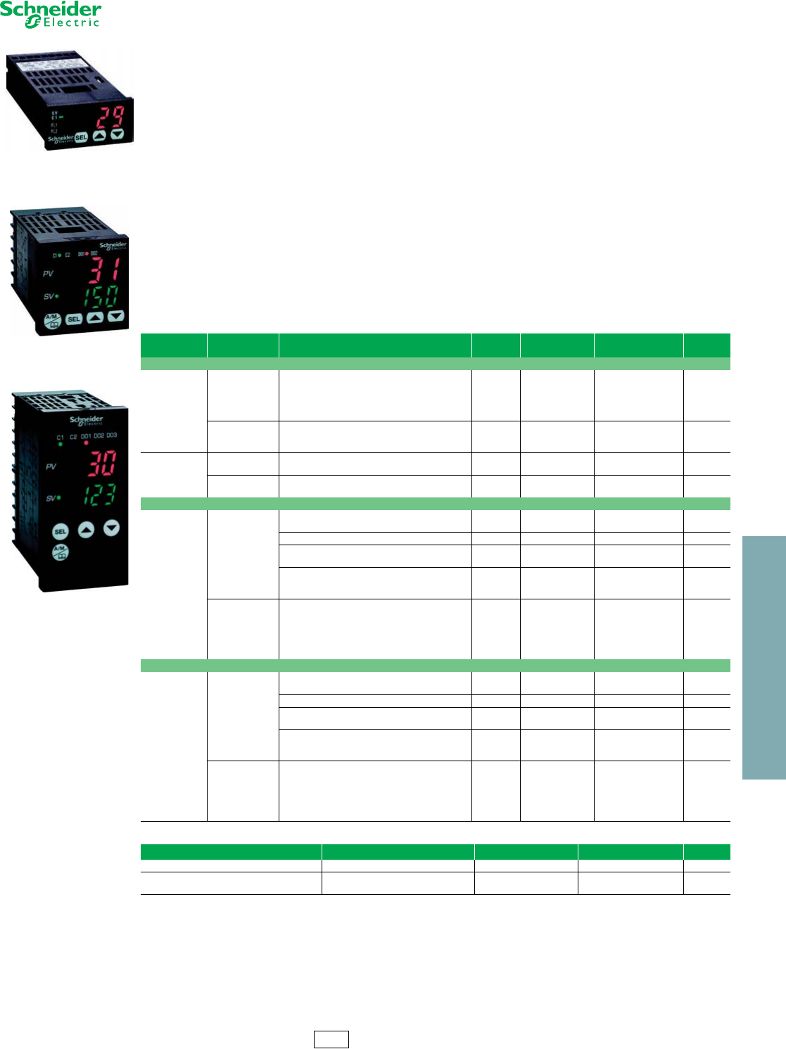
www.schneider-electric.us
23 RELAYS AND TIMERS
© 2012 Schneider Electric
All Rights Reserved 23-31
Control and Measurement
Relays
Type REG
Refer to Catalog 8430CT0601
Zelio™ Temperature Controllers
The new Zelio REG temperature controllers offer seamless interfacing with solid state relays, electromechanical relays,
PLCs, variable speed drives and HMI displays make them a key component to controlling the temperature in your
process.
Offer includes 3 versions:
•A 24x48 mm (1/32 DIN) cost effective solution for basic temperature control needs.
•A 48x48 mm (1/16 DIN) balanced version for optimal price and functionality.
•A 96x48 mm (1/8 DIN) full-featured version for complete performance and function.
Key features include:
•Modbus communication for easy data exchange with other automation products
•Simple parameter settings
•IP66 certification enables dust resistance
•Flash memory (saves configurations)
•Compatible with a wide range of sensors
•Advanced Functions (standard): PID, fuzzy logic, auto-tuning, soft start
•Optimized programming
— Common software for all products in the temperature relay range (freely downloadable from www.schneider-electric.us).
— A single cable enables connection to both a computer and PLCs.
— Simple adjustment of parameters.
— Saving of configurations.
Table 23.150: Zelio Temperature Controllers
Input Type Supply Voltage Number and
Type of Outputs Alarms Communication
on Modbus Catalog Number $ Price
28 x 48 Size — 1/32 DIN Standard
Thermocouple
PT100 Probe
100/240 Vac
1 electromechanical relay No Yes REG24PTP1RHU 209.00
1 electromechanical relay 1 Yes REG24PTP1ARHU 186.00
1 solid state relay No Yes REG24PTP1LHU 216.00
1 solid state relay 1 No REG24PTP1ALHU 192.00
1 analog interface (4–20 mA) No Yes REG24PTP1JHU 219.00
24 Vac/Vdc 1 electromechanical relay No Yes REG24PTP1RLU 209.00
1 solid state relay No Yes REG24PTP1LLU 216.00
1 analog interface (4–20 mA) No Yes REG24PTP1JLU 219.00
Voltage/current
100/240 Vac 1 electromechanical relay No Yes REG24PUJ1RHU 209.00
1 solid state relay No Yes REG24PUJ1LHU 216.00
24 Vac/Vdc 1 electromechanical relay No Yes REG24PUJ1RLU 219.00
1 solid state relay No Yes REG24PUJ1LLU 216.00
48 x 48 Size — 1/16 DIN Standard
Universal
100/240 Vac
1 electromechanical relay 2 Yes REG48PUN1RHU 252.00
No REG48PUNL1RHU 226.00
2 electromechanical relays 2 Yes REG48PUN2RHU 292.00
1 solid state relay 2 Yes REG48PUN1LHU 258.00
No REG48PUNL1LHU 234.00
1 solid state relay + 1 electromechanical relay 2 Yes REG48PUN2LRHU 295.00
1 analog interface (4–20 mA) 2 Yes REG48PUN1JHU 260.00
1 solid state relay + 1 analog interface (4–20 mA) 2 Yes REG48PUN2LJHU 298.00
24 Vac/Vdc
1 electromechanical relay 2 Yes REG48PUN1RLU 252.00
2 electromechanical relays 2 Yes REG48PUN2RLU 292.00
1 solid state relay 2 Yes REG48PUN1LLU 258.00
1 solid state relay + 1 electromechanical relay 2 Yes REG48PUN2LRLU 295.00
1 analog interface (4–20 mA) 2 Yes REG48PUN1JLU 260.00
1 solid state relay + 1 analog interface (4–20 mA) 2 Yes REG48PUN2LJLU 298.00
98 x 48 Size — 1/8 DIN Standard
Universal
100/240 Vac
1 electromechanical relay 3 Yes REG96PUN1RHU 336.00
No REG96PUNL1RHU 311.00
2 electromechanical relays 3 Yes REG96PUN2RHU 381.00
1 solid state relay 3 Yes REG96PUN1LHU 343.00
No REG96PUNL1LHU 317.00
1 solid state relay + 1 electromechanical relay 3 Yes REG96PUN2LRHU 383.00
1 analog interface (4–20 mA) 3 Yes REG96PUN1JHU 345.00
1 solid state relay + 1 analog interface (4–20 mA) 3 Yes REG96PUN2LJHU 385.00
24 Vac/Vdc
1 electromechanical relay 3 Yes REG96PUN1RLU 336.00
2 electromechanical relays 3 Yes REG96PUN2RLU 381.00
1 solid state relay 3 Yes REG96PUN1LLU 343.00
1 solid state relay + 1 electromechanical relay 3 Yes REG96PUN2LRLU 384.00
1 analog interface (4–20 mA) 3 Yes REG96PUN1JLU 345.00
1 solid state relay + 1 analog interface (4–20 mA) 3 Yes REG96PUN2LJLU 385.00
Table 23.151: Temperature Controller Accessories
Description For Use With Relays Sold In Lots Of Catalog Number $ Price
Bracket for mounting on DIN rail 24 x 48 mm (1/32 DIN) 4 REG24PSOC 21.90
Terminal block cover 48 x 48 mm (1/16 DIN) 2 REG48PCOV 30.30
96 x 48 mm (1/8 DIN) 2 REG96COV 37.10
REG24PTP1RHU
REG48PUN1RHU
REG96PUN1RHU
CP2 Discount
Schedule

www.schneider-electric.us
23 RELAYS AND TIMERS
23-32 © 2012 Schneider Electric
All Rights Reserved
Control and Measurement
Relays
RM17JC & RM35JA
Refer to Catalog 8430CT0601
Zelio™ Current Measurement Relays
Zelio Current Measurement Relays are designed to measure under and overcurrent, without external sensors. Current
measurement relays enable continuous monitoring of the operation of electrical and mechanical loads such as motors
and resistors. They are DIN rail mountable and the control status is indicated by an LED.
aAbove 15A, a current transformer can be connected (for RM35JA3•MW). See page 57 of the catalog for suggested wiring.
Approvals:
Approximate Dimensions
Table 23.152:
Supply Voltage Measurement Range Output
5Amps
Width Catalog Number $ Price
RangeaTerminals Inches mm
24–240 Vac/dc
2–20 A N/A 1 C/O 0.69 17.50 RM17JC00MW 130.00
2–20 mA E1-M
2 C/O 1.38 35.00
RM35JA31MW
148.0010–100 mA E2-M
50–500 mA E3-M
0.15–1.5 A E1-M RM35JA32MW
177.000.5–5 A E2-M
1.5–15 A E3-M
Table 23.153: Output Characteristics and Measurement Circuit Characteristics
Type of Relay RM17JC00MW RM35JA31MW RM35JA32MW
Setting accuracy Plus or minus 10% of the full scale value
Repeat accuracy (with constant parameters) Plus or minus 0.5%
Hysteresis 15% of the threshold setting, fixed 5 to 50% of the threshold setting, adjustable
Time delay accuracy (with constant parameters) N/A plus or minus 2%
Time delay on pick-up 500ms 300ms
Conforming to standards NF EN 60255-6
Ambient air temperature around the
device
Storage -40 to 158 degrees F (-40 to +70°C)
Operational -4 to 122 degrees F (-20 to +50°C)
File
CNN E173076
NRNT File
Class 217698
3211 07 CE: 73/23/EEC and
EMC 89/336/EEC GL, C-Tick, GOST,
RoHS
RM17JC00MW
RM35JA31MW
1 C/O =
2 C/O =
RM35JA32MW
RM17JC Current Control Relay
•Monitors a.c. currents
•Designed to monitor overcurrent
•Equipped with an integrated current transfmormer
RM35JA Current Control Relays
•Selection between overcurrent or undercurrent
•Automatic d.c. or a.c. recognition
•Selectable memory function
72/2.83
2.8
0.11
76/2.99
72.5/2.85
90/3.54
35/1.38
A1
12 22 21 241411
A2
E3
E2 E1 M
97/3.82 17.5
0.69
90/3.54
2.8
0.11
101/3.98
97.5/3.84
10/0.39
RM35JA3•MW RM17JC00MW
Dual Dimensions: INCHES
Millimeters
CP2 Discount
Schedule
www.schneider-electric.us
23 RELAYS AND TIMERS
© 2012 Schneider Electric
All Rights Reserved 23-33
Control and Measurement
Relays
RM17T•00
Refer to Catalog 8430CT0601
Zelio™ Phase Measurement Relays
Zelio Phase Measurement Relays monitor their own power supply. Relay status is indicated by an LED and they are
DIN rail mountable.
RM17TG•0 measurement and control relays are for monitoring of 3-phase supplies for the correct sequencing of
phases L1, L2, and L3, as well as the total loss of one or more phases.
RM35TF30 measurement and control relay is for monitoring of phase sequence, phase failure, asymmetry,
undervoltage and overvoltage in window mode.
Approvals:
Approximate Dimensions
Table 23.154: 3-Phase supply control relays
Supply
Voltage
Detection
Threshold
Output
5 Amps
Width Catalog Number $ Price
inches mm
208–480 Vac <100 Vac 1 C/O 0.69 17.50 RM17TG00 114.00
208–440 Vac 2 C/O RM17TG20 125.00
Table 23.155: Multifunction 3-phase supply control relays
Supply
Voltage
Vol tage
Range
Output
5 Amps
Width Catalog
Number $ Price
inch mm
208–480 Vac Selectable voltages:
208, 220, 380, 400,
415, 440, 480 1 C/O 0.69 17.50
RM17TT00 136.00
RM17TA00 177.00
RM17TU00 131.00
RM17TE00 217.00
Table 23.156: RM17TT, RM17TA, RM17TU, and RM17TE multifunction control relays monitor the following on
3-phase supplies:
Function RM17TT RM17TA RM17TU RM17TE
Sequence of phases L1, L2 and L3 Yes Yes Yes Yes
Phase failure with regeneration (0.7 x selected voltage range) Yes Yes Yes Yes
Asymmetry (phase imbalance) No Yes No Yes
Undervoltage No No Yes No
Overvoltage and undervoltage No No No Yes
Table 23.157: 3-phase supply and motor temperature control relays
Supply
Voltage
Measurement
Range
Output
5 Amps
Width Catalog
Number $ Price
inch mm
220–480 Vac 208–480 Vac 2 N.O. 1.38 35.00 RM35TM50MW 221.00
RM35TM250MW 231.00
Table 23.158: RM35TM control relays monitor the following on 3-phase supplies:
Function RM35TM50MW RM35TM250MW
Sequence of phases L1, L2 and L3 Yes Yes
Phase failure Yes Yes
Motor temperature via PTC probe Yes Yes
Selection (with or without memory) No Yes
Test-reset button No Yes
Table 23.159: Multifunction 3-phase supply control relays
Supply
Voltage
Measurement
Range
Output
5 Amps
Width Catalog
Number $ Price
inch mm
220–480 Vac 194–528 Vac 2 C/O 1.38 35.00 RM35TF30 273.00
File
CNN E173076
NRNT File
Class 217698
3211 07 CE: 73/23/EEC and
EMC 89/336/EEC GL, C-Tick, GOST,
RoHS
RM17TG•0
RM17TA00
1 C/O =
2 C/O =
2 N/O =
RM17TE00
RM35TM••MW
RM35TF30
RM35• RM17•
2.8
0.11
76/2.99
72.5/2.85
72/2.83
90/3.54
35/1.38
2.8
0.11
76/
2.99
72.5/
2.85
72/
2.83
17.5
0.69
90/3.54
Dual Dimensions: INCHES
Millimeters
CP2 Discount
Schedule
www.schneider-electric.us
23 RELAYS AND TIMERS
23-34 © 2012 Schneider Electric
All Rights Reserved
Control and Measurement
Relays
RM17UB, RM35UB, RM17UAS, RM17UBE, RM35UA1•MW
Refer to Catalog 8430CT0601
Zelio™ Voltage Measurement Relays
Zelio Voltage Measurement Relays are DIN rail mountable and relay status is indicated by an LED.
Single phase and d.c. voltage measurement and control relays RM17UAS•• and RM17UBE•• monitor:
•Overvoltage
•Undervoltage
•Overvoltage and undervoltage (window mode)
•Nominal voltages
aProvides overvoltage or undervoltage protection.
bProvides overvoltage and undervoltage protection in window mode.
Multifunction voltage control relays RM35UA1•MW monitor both a.c. and d.c. voltages.
•Automatic Vdc or Vac recognition
•Selection between overvoltage and undervoltage
3-phase voltage control relays monitor:
•Failure of one or more phases
•Voltage between phases
•Absence of neutral
•Voltage between phases and neutral
•Overvoltage and undervoltage
cProvides overvoltage and undervoltage protection between phases.
dProvides overvoltage and undervoltage protection between phases and neutral and absence of neutral.
Approvals:
Approximate Dimensions
Table 23.160: Single-phase and d.c. voltage control relays
Supply Voltage Ranges Controlled Output 5 A Width Catalog Number $ Price
in. mm
12 Vdc 9–15 Vdc
1 C/O 0.69 17.50
RM17UAS14a138.00
24–48 Vac/Vdc 20–80 Vac/Vdc RM17UAS16a138.00
110–240 Vac/Vdc 65–260 Vac/Vdc RM17UAS15a138.00
24–48 Vac/Vdc 20–80 Vac/Vdc RM17UBE16b146.00
110–240 Vac/Vdc 65–260 Vac/Vdc RM17UBE15b146.00
Table 23.161: Multifunction voltage control relays
Supply Voltage Measurement Range Output
5 A
Width Catalog
Number $ Price
RangedTerminals in. mm
24–240 Vac/Vdc
0.05–0.5 V E1-M
2 C/O 1.38 35.00
RM35UA11MW
157.000.3–3 V E2-M
0.5–5 E3-M
1–10 E1-M RM35UA12MW
157.005–50 E2-M
10–100 E3-M
15–150 E1-M RM35UA13MW
157.0030–300 E2-M
60–600 E3-M
Table 23.162: Three-phase voltage control relays
Rated 3-Phase
Supply Voltage Vac Measurement Range Output
5 A
Width Catalog
Number $ Price
in. mm
220–480 phase-phase 195–528 Vac 1 C/O + 1 C/O 1 per threshold 1.38 35.00 RM35UB330c229.00
120–277 phase-neutral 183–528 Vac 1 C/O 0.69 17.50 RM17UB310c189.00
120–277 phase-neutral 114–329 Vac 1 C/O + 1 C/O 1 per threshold 1.38 35.00 RM35UB3N30d254.00
File
CNN E173076
NRNT File
Class 217698
3211 07 CE: 73/23/EEC and
EMC 89/336/EEC GL, C-Tick,
GOST, RoHS
RM17UB310
RM35UB3•••
1 C/O =
2 C/O =
RM17UAS••
RM35UA1•MW
2.8
0.11
76/2.99
72.5/2.85
72/2.83
90/3.54
35/1.38
2.8
0.11
76/
2.99
72.5/
2.85
72/
2.83
17.5
0.69
90/3.54
Dual Dimensions: INCHES
Millimeters
RM35• RM17•
CP2 Discount
Schedule
www.schneider-electric.us
23 RELAYS AND TIMERS
© 2012 Schneider Electric
All Rights Reserved 23-35
Control and
Measurement Relays
RM35L•••MW, RM35BA10
Refer to Catalog 8430CT0601
Zelio™ Level Control Relays and Zelio™ Pump Control Relays
Zelio level control relays control one or two levels with fill or empty function. The settings are protected by a sealable
cover, control status is indicated by an LED, and they are DIN rail mountable. RM35LM is designed to control levels of
conductive liquid, and RM35LV is designed to control levels of other materials.
a3/8” BSP mounting thread with hexagonal head. Use a 24mm spanner for tightening.
b3/8” BSP mounting head.
Pump control relay RM35BA10 can operate on a single-phase or 3-phase supply. It incorporates three functions in a
signal unit:
It has two operating modes which are designed to control a pump via two external signal inputs (Y1 Y2). These two
signals are controlled by volt-free contacts. Control inputs Y1 and Y2 can be connected to:
Approvals:
Approximate Dimensions
Table 23.163: Level Control Relays
Time Delay on
Crossing the
Threshold
Function Output Relay Supply Voltage
50/60 Hz
Measurement
Ranges Catalog Number $ Price
0.1–5 seconds,
0 + 10%
Detection by resistive
probes 2 C/O, 5A 24–240 Vac/Vdc
250 –5 k RM35LM33MW
115.005 k –100 k
50 k –1 M
Detection by discrete
sensors 1 C/O, 5A — RM35LV14MW 146.00
Table 23.164: Probes
Application No. of
probes
Operating temperature Maximum
pressure
kg/cm2
Catalog
Number $ Price
°F °C
Recommended for drink vending machines and where
installation space is limited (stainless steel)a3 176 80 2 RM79696044 78.00
Suitable for boilers, pressure vessels, and under high
temperature conditions (1) (304 stainless steel)a1 392 25 200 RM79696014 95.00
Table 23.165: Probes
Description Catalog
Number $ Price
Protected probe for mounting by suspension, protective shell PUC (S7) Electrode: stainless steel RM79696043 57.00
Liquid level control probe, suspended by cable, maximum operating temperature 212°F/100°CbLA9RM201 83.00
Table 23.166: Electrode Holders
Description Material Catalog
Number $ Price
Electrode for use up to 662°F (350°C) Stainless steel isolated by ceramic RM79696006 62.00
•Over and under current measurement •Phase presence control •Single or three phase
•Level sensor •Level relay •Pressure sensor •Push button
Table 23.167: Pump Control Relay
Description Current Range Controlled Supply Voltage Output Catalog Number $ Price
Pump Control Relay 1–10 A 208–480 Vac, 3 phase 1 C/O 5 A RM35BA10 284.00
230, single-phase
File
CNN E173076
NRNT File
Class 217698
3211 07 CE: 73/23/EEC and
EMC 89/336/EEC GL, C-Tick, GOST,
RoHS
RM35LM33MW
RM35LV14MW
1 C/O =
2 C/O =
RM79696043
Application examples for RM35LM:
•Detecting pump seal failures
•Spring, town, industrial and sea water
•Metallic salt, acid or base solutions
•Liquid fertilizers
•Non-concentrated alcohol (<40%)
•Liquids in the food-processing industry: milk, beer, coffee, etc.
Application examples for RM35LV:
•Chemically pure water
•Fuels, liquid gasses (inflammable)
•Oil, concentrated alcohol (>40%)
•Ethylene, glycol, paraffin, varnish and paints
Ω
Ω
Ω
Ω
Ω
Ω
LA9RM201
RM79696006
RM35BA10
/09 54.3
35/1.38
2.8
0.11
76/2.99
72.5/2.85
72/2.83
2.8
0.11
76/2.99
72.5/2.85
72/2.83
90/3.54
35/1.38
E1
Y1 12 11 14Y2
L2 L3L1
Def.
Un
R
> I
< I
Dual Dimensions: INCHES
Millimeters
RM35LM33MW, RM35LV14MW RM35BA10
CP2 Discount
Schedule

www.schneider-electric.us
23 RELAYS AND TIMERS
23-36 © 2012 Schneider Electric
All Rights Reserved
Control and Measurement
Relays
RM35S, RM35HZ, RM35AT
Refer to Catalog 8430CT0601
Zelio™ Speed Control Relays, Zelio™ Frequency Control Relays, and
Zelio™ Temperature Control Relays
Zelio speed control relay RM35SOMW monitors underspeed and overspeed, with or without memory, with inhibition by
an external contact. It operates with either N.O. or N.C. sensors. Adjustable time between impulses is 0.05s to 10m.
Power-on inhibition time is adjustable from 0.6 to 60s. Inhibition is controlled by an external contact. Settings are
protected by a sealable cover, control status is indicated by an LED, and it is DIN rail mountable.
Zelio frequency control relay RM35HZ monitors its own supply voltage. Settings are protected by a sealable cover,
control status is indicated by an LED, and it is DIN rail mountable.
Zelio temperature control relays are designed for monitoring the temperature in elevator (lift) pully rooms, in compliance
with directive EN81. For use with PT100 input (customer supplied). Features adjustable control, control status is
indicated by an LED, and it is DIN rail mountable.
Approvals:
Approximate Dimensions
Table 23.168: Speed Control Relay
Function Time Delay Measurement Input Supply Output Catalog
Number $ Price
Underspeed 0.05s–10min 3-wire PNP or NPN proximity sensor 24–240 Vac/Vdc 1 C/O
5A RM35S0MW 217.00
Overspeed Namur proximity sensor 0–30 V voltage Volt-free contact
Table 23.169: Frequency Control Relay
Function Controlled Supply Voltage Output Catalog
Number $ Price
Over frequency and under frequency (50 or 60 Hz) 40–60 Hz (50 Hz) /
50–70 Hz (60 Hz) 120–277 Vac 1 C/O + 1 C/O
5A RM35HZ21FM 222.00
Table 23.170: Temperature Control Relays
Function Supply Voltage Vac Output Catalog
Number $ Price
Over temperature 93 to 114°F (34 to 46°C)
24–240 Vac/Vdc
—1 C/O 5ARM35ATL0MW 141.00
Under temperature 30 to 51°F (-1 to 11°C) — 2 N.O. 5A RM35ATR5MW 151.00
Over temperature 93 to 114 °F (34 to 46°C) 208–480 Vac 2 N.O. 5A RM35ATW5MW
237.00
Under temperature 30 to 51°F (-1 to 11°C)
Phase sequence
Phase failure
File
CNN E173076
NRNT File
Class 217698
3211 07 CE: 73/23/EEC and
EMC 89/336/EEC GL, C-Tick, GOST,
RoHS
RM35S0MW
RM35HZ21FM
1 C/O =
2 N/O =
RM35AT•0MW
2.8
0.11
76/2.99
72.5/2.85
72/2.83
90/3.54
35/1.38
A1
12 2214 21 2411
A2
90/3.54
35/1.38
2.8
0.11
76/2.99
72.5/2.85
72/2.83
2.8
0.11
76/2.99
72.5/2.85
72/2.83
90/3.54
35/1.38
Dual Dimensions: INCHES
Millimeters
RM35S0MW RM35HZ21FM
RM35AT••MW
CP2 Discount
Schedule
www.schneider-electric.us
23 RELAYS AND TIMERS
© 2012 Schneider Electric
All Rights Reserved 23-37
Other Products ABL8, ABL7 and ABL1
Refer to Catalog 8440CT0001
Phaseo™ DC Power Supply
Phaseo switch mode power supplies are totally electronic and their output voltage is regulated. They offer:
•Compact size
•High degree of output voltage stability
For use with Universal power supplies, see optional function modules in catalog 8440CT0601/08, which offer a set of
solutions to meet the needs for continuity of service such as:
•Immunity to microbreaks
•Voltage holding during power outages
•Voltage holding during power supply equipment failure
Table 23.175: Dedicated, Single Phase
Designed for integration into repetitive equipment with power ratings from 60 to 240 W and an output voltage of 12 Vdc
or 24 Vdc.
.
aCompatible input voltage 120-370 Vdc not indicated on the product.
bCompatible input voltage 180-370 Vdc not indicated on the product.
Approvals:
See www.Schneider-Electric.us for UL and CSA compliances.
For additional information, refer to Catalog #8440CT0601R1/08.
Table 23.171: Modular, Single Phase
Meets all the needs of simple automation systems with power ratings from 7 to 60 W and an output voltage of 5 Vdc, 12
Vdc, or 24 Vdc.
Input
Voltage (Vac)
Output
Vol tage (Vdc)
Nominal
Current (I) Protection Reset Catalog Number $ Price
100–240
54
Auto
ABL8MEM05040 128.
12 2 ABL8MEM12020 132.
24
0.3 ABL8MEM24003 71.
0.6 ABL8MEM24006 105.
1.2 ABL8MEM24012 141.
2.5 ABL7RM24025 180.
Table 23.172: Optimum, Single Phase
The low-cost solution for applications supplied at 12 Vdc, 24 Vdc, or 48 Vdc and requiring currents between 3 and 5 A.
Input Voltage (Vac) Output Voltage (Vdc) Nominal Current (I) Protection Reset Catalog Number $ Price
100–240
12 5
Auto
ABL7RP1205 360.
24 3ABL8REM24030 195.
5ABL8REM24050 300.
48 3 ABL7RP4803 225.
Table 23.173: Universal, Single Phase
Adapts to the majority of power distribution systems with power ratings from 72 to 480 W at 24 Vdc. The same power
supply can be connected phase-to-neutral (N-L1) or phase-to-phase (L1-L2) for line supplies ranging from 100 to 500
Vac. Energy reserve, diagnostics, and choice of manual or auto reset are integrated into these units.
Input
Voltage (Vac)
Output
Voltage (Vdc) Nominal Current (I) Auto-Protection Reset Catalog Number $ Price
100–120 /
200–500 24
3
Auto/Manual
ABL8RPS24030 270.
5ABL8RPS24050 360.
10 ABL8RPS24100 525.
100–120 /
200–240 20 ABL8RPM24200 716.
Table 23.174: Universal, Three Phase
This three-phase, 480 to 960 W, 24 Vdc output offering is particularly suited for complex machines and processes.
Energy reserve, diagnostics and choice of manual or auto reset are integrated into these units.
Input Voltage (Vac) Output Voltage (Vdc) Nominal Current (I) Auto-Protection Reset Catalog Number $ Price
380–500 24 20 Auto/Manual ABL8WPS24200 735.
40 ABL8WPS24400 1173.
Input Voltage (Vac) Output Voltage
(Vdc)
Nominal Current
(I)
Protection
Reset Catalog Number $ Price
100–240a
12 5
Auto
ABL1REM12050 113.
24 2.5 ABL1REM24025 93.
4.2 ABL1REM24042 132.
100–120 / 200–240b24 6.2 ABL1REM24062 143.
10 ABL1REM24100 206.
100–240a12 8.3
Auto
ABL1RPM12083 150.
24 4.2 ABL1RPM24042 158.
100–120 / 200–240b24 6.2 ABL1RPM24062 173.
10 ABL1RPM24100 270.
File
CCN E164867,
NMTR, NMTR7 File
CCN E164867,
NMTR2, NMTR8
File
Class
Class
238438
5311-87
5311-07
RoHS
Compliant
SEMI F47
Compliant
for most
units
ABL8MEM12020
ABL8REM24030
ABL8RPS24100
ABL8WPS24200
ABL1RPM24042
ABL1RPM24100
CP12 Discount
Schedule
www.schneider-electric.us
23 RELAYS AND TIMERS
23-38 © 2012 Schneider Electric
All Rights Reserved
Interface Modules RM
Refer to Catalog 8501CT0502
Zelio™ Analog Interface Modules
The Zelio Analog range of converters is designed to convert signals emitted by sensors or electrical measurement
devices, into standard electrical signals that are compatible with automation platforms and controllers. They also allow
the connection distance between a sensor and a measurement device to be increased, for example, between a
thermocouple and a programmable controller
aConverters dedicated to Zelio Logic smart relays.
Approvals:
Table 23.176: Converters for Type J and K type thermocouples—supply voltage 24 Vdc ± 20%, non-isolated
Type Temperature Range Switchable Output Signals Catalog Number $ Price
°F °C
Type J
32–302 0–150 0–10 V, 0–20 mA, 4–20 mA RMTJ40BD 141.00
32–572 0–300 0–10 V, 0–20 mA, 4–20 mA RMTJ60BD 141.00
32–1112 0–600 0–10 V, 0–20 mA, 4–20 mA RMTJ80BD 141.00
Type K 32–1112 0–600 0–10 V, 0–20 mA, 4–20 mA RMTK80BD 141.00
32–2192 0–1200 0–10 V, 0–20 mA, 4–20 mA RMTK90BD 141.00
Table 23.177: Converters for Universal Pt100 probes—supply voltage 24 Vdc ± 20%, non-isolated
Type Temperature Range Switchable Output Signals Catalog Number $ Price
°F °C
Pt100
2-wire, 3-wire, and
4-wire
- 40–104 - 40–40 0–10 V, 0–20 mA, 4–20 mA RMPT10BD 141.00
- 148–212 - 100–100 0–10 V, 0–20 mA, 4–20 mA RMPT20BD 141.00
32–212 0–100 0–10 V, 0–20 mA, 4–20 mA RMPT30BD 141.00
32–482 0–250 0–10 V, 0–20 mA, 4–20 mA RMPT50BD 141.00
32–932 0–500 0–10 V, 0–20 mA, 4–20 mA RMPT70BD 141.00
Table 23.178: Converters for Optimum Pt100 probesa—supply voltage 24 Vdc ± 20%, non-isolated
Type Temperature Range Switchable Output Signals Catalog Number $ Price
°F °C
Pt100
2-wire, 3-wire, and
4-wire
- 40–104 - 40–40 0–10 V or 4–20 mA RMPT13BD 113.00
- 148–212 - 100–100 0–10 V or 4–20 mA RMPT23BD 113.00
32–212 0–100 0–10 V or 4–20 mA RMPT33BD 113.00
32–482 0–250 0–10 V or 4–20 mA RMPT53BD 113.00
32–932 0–500 0–10 V or 4–20 mA RMPT73BD 113.00
Table 23.179: Universal Voltage/Current Converters
Type Input signal Output signal Catalog Number $ Price
Supply voltage 24 Vdc ±
20%, non-isolated 0–10 V or 4–20 mA 0–10 V or 4–20 mA RMCN22BD 95.00
Supply voltage 24 Vdc ±
20%, isolated
0–10 V, ± 10 V,
0–20 mA, 4–20 mA
Switchable:
0–10 V, ± 10 V,
0–20 mA, 4–20 mA RMCL55BD 141.00
0–50 V, 0–300 V, 0–500 V
DC or AC, 50/60 Hz Switchable:
0–10 V, 0–20 mA, 4–20 mA RMCV60BD 154.00
0–1.5 A, 0–5 A, 0–15 A
DC or AC, 50/60 Hz 0–10 V, 0–20 mA, 4–20 mA RMCA61BD 154.00
File
CCN E164353
NKCR File
Class 089150_S_000
3211 07 IEC 60947-1 RoHS
Compliant
Table 23.180: How to Order
To Order Specify: Catalog Number
•Catalog Number RMCN22BD
RMTJ40BD
RMTK90BD
RMPT70BD
RMPT13BD
RMCN22BD
CP2 Discount
Schedule
www.schneider-electric.us
23 RELAYS AND TIMERS
© 2012 Schneider Electric
All Rights Reserved 23-39
Other Products SR2 Compact and SR3 Modular
Refer to Catalog DIA3ED2051002EN-US
Zelio™ Logic 2 Smart Relays
Zelio Logic 2 smart relays meet the demands of applications that require more flexibility than a simple relay, timer, or counter, but are too small or
simple for the smallest Nano PLC. The Zelio Logic SR2 range is an exact replacement for the obsolete SR1 range, but with an expanded feature set.
Designed to accept control outputs just like a relay, Zelio Logic 2 features dual language capability, using either Function Block Diagramming (FBD)
or Ladder Logic Programming (LL), and can be programmed easily by using either the front panel or by using ZelioSoft software.
Table 23.181: Compact Smart Relays with Display, DC Power Supply
Supply voltage 12 Vdc 24 Vdc
Number of inputs/outputs 12 20 10 12 12 20 20 20
Number of
inputs
Discrete inputs 8 12 6 8 8 12 12 12
Including 0-10 V analog inputs 4 6 — 4 4 2 6 6
Number of outputs 4 relay 8 relay 4 relay 4 relay 4 transistor 8 relay 8 relay 8 transistor
Dimensions, W x D x H (mm) 71.2x59.5x107.6 124.6x59.5x107.6 71.2x59.5x107.6 124.6x59.5x107.6
Clock yes yes no yes yes no yes yes
Catalog Number SR2B121JD SR2B201JD SR2A101BD cSR2B121BD SR2B122BD SR2A201BD cSR2B201BD SR2B202BD
$ Price 282.00 398.00 232.00 282.00 276.00 358.00 398.00 392.00
aProgramming of smart relay in LADDER language only.
bPlease consult Schneider Electric representative for list prices.
Table 23.182: Compact Smart Relays with Display, AC Power Supply
Supply voltage 24 Vac 100–240 Vac
Number of inputs/outputs 12 20 10 12 20 20
Number of inputs Discrete inputs 8 12 6 8 12 12
Number of outputs 4 relay8 relay4 relay4 relay8 relay8 relay
Dimensions, W x D x H (mm) 71.2x59.5x107.6 124.6x59.5x107.6 71.2 x 59.5 x 107.6 124.6 x 59.5 x 107.6
Clock yes yes no yes no yes
Catalog Number SR2B121B SR2B201B SR2A101FU aSR2B121FU SR2A201FU aSR2B201FU
$ Price 282.00 398.00 258.00 288.00 374.00 408.00
cProgramming of smart relay in LADDER language only.
Table 23.183: Compact Smart Relays without Display and without Buttons, DC and AC Power Supply
Supply voltage 24 Vdc 100–240 Vac
Number of inputs/outputs 12 20 20 10 12 20
Number of inputs Discrete inputs 6 8 12 6 8 12
Including 0-10 V analog inputs — 4 6 — — —
Number of outputs 4 relay4 relay8 relay4 relay4 relay8 relay
Dimensions, W x D x H (mm) 71.2 x 59.5 x 107.6 124.6x59.5x107.6 71.2 x 59.5 x 107.6 124.6x59.5x107.6
Clock no yes yes no yes yes
Catalog Number SR2D101BD dSR2E121BD b SR2E201BD bc SR2D101FU dSR2E121FU SR2E201FUc
$ Price 214.00 222.00 338.00 218.00 226.00 344.00
dProgramming of smart relay in LADDER language only.
eTo order a smart relay for a 24 Vac supply (no analog inputs), delete the letter D from the end of the catalog number (SR2E121B and SR2E201B).
fTo order a smart relay without a clock, replace the letter E with the letter D (Example: SR2D201BD and SR2D201FU (these units can only be programmed in LADDER language.
IDiscount
Schedule
www.schneider-electric.us
23 RELAYS AND TIMERS
23-40 © 2012 Schneider Electric
All Rights Reserved
Other Products SR2 Compact and SR3 Modular
Refer to Catalog DIA3ED2051002EN-US
Zelio™ Logic 2 Smart Relays
aThe modular base can be fitted with one I/O extension module. The 24 Vdc modular base can be fitted with one communication module and/or one I/O
extension module.
bReplace the p by the number 1 to order a smart relay with relay output or by 2 for a smart relay with transistor output (Example: SR3B101BD).
cPlease consult local Schneider Electric representative for list prices.
aThe power supply of the extension modules is provided via the Zelio Logic 2 modular relays.
bmax. 1 PT 100 input
aCD-ROM includes Zelio Soft software, application library, self-training manual, installation instructions and user’s manual
aModems to be supplied by user.
Approvals:
Table 23.184: Modular Smart Relays a with Display, DC and AC Power Supply
Supply voltage 12 Vdc 24 Vdc 24Vac 100-240 Vac
Number of inputs/outputs 26 10 26 10 26 10 26
Number of inputs Discrete inputs 16616616616
Including 0-10 V analog inputs 6 4 6 ————
Number of outputs 10 relay 4 relay 10 relay 4 relay 10 relay 4 relay 10 relay
Dimensions, W x D x H (mm) 124.6x59.5x107.6 71.2x59.5x107.6 24.6x59.5x107.6 71.2x59.5x107.6 124.6x59.5x107.6 71.2x59.5x107.6 124.6x59.5x107.6
Clock yes yes yes yes yes yes yes
Catalog Number SR3B261JD SR3B10pBD bc SR3B26pBD bc SR3B101B SR3B261B SR3B101FU SR3B261FU
$ Price 380.00 ——282.00 476.00 292.00 486.00
Table 23.185: Extension Modules for Zelio Logic 2 SR3B•••••a
Communication Discrete Inputs/Outputs Analog Inputs/Outputs
Application MODBUS network — —
Number of inputs/outputs —610144
Number of inputs Discrete inputs —4 6 8—
Analog (0–10 V, 0–20 mA, PT100) ————2b
Number of outputs Relay — 2relay 4 relay 6 relay —
Analog (0-10 V) ————2
Dimensions, W x D x H (mm) 35.5x59.5x107.6 35.5x59.5x107.6 72x59.5x107.6 72x59.5x107.6 35.5x59.5x107.6
Cat. No. $ Price Cat. No. $ Price Cat. No. $ Price Cat. No. $ Price Cat. No. $ Price
Voltage
12 Vdc — — SR3XT61JD 80.00 SR3XT101JD 100.00 SR3XT141JD 140.00 ——
24 Vdc SR3MBU01BD 200.00 SR3XT61BD 106.00 SR3XT101BD 126.00 SR3XT141BD 164.00 SR3XT43BD 220.00
24 Vac — — SR3XT61B 106.00 SR3XT101B 126.00 SR3XT141B 164.00 ——
100-240 Vac — — SR3XT61FU 106.00 SR3XT101FU 126.00 SR3XT141FU 164.00 ——
Table 23.186: Zelio Soft Software and Memory for SR2/SR3
Multilingual Programming Software Connecting Cables Back-up Memory
PCCD-ROM
(Windows 98, NT, 2000, XP, ME) aPC Serial to Relay PC USB to SR2CBL01 PC USB to Relay EEPROM
(< V3.0 ZelioSoft software
and firmware)
EEPROM
(≥V3.0 ZelioSoft software
and firmware)
Cat. No. $ Price Cat. No. $ Price Cat. No. $ Price Cat. No. $ Price Cat. No. $ Price Cat. No. $ Price
SR2SFT01 74.00 SR2CBL01 136.00 SR2CBL06 156.00 SR2USB01 160.00 SR2MEM01 38.00 SR2MEM02 30.00
Table 23.187: Communication interface for SR2/SR3
Interface, Zelio Logic 2 Alarm Software Communication Interface aAlarm Management Software Zelio Logic GSM Modem
Supply voltage 12-24 Vdc — 24 Vdc
Description — PC CD-ROM (Windows 98, NT, 2000, XP) GSM modem
Dimensions, W x D x H 72x59.5x107.6 mm —
Catalog Number SR2COM01 SR2SFT02 SR2MOD02
$ Price 230.00 60.00 545.00
File
CCN E164866
NRAQ File
Class LR217698
2252 01
IDiscount
Schedule
www.schneider-electric.us
23 RELAYS AND TIMERS
© 2012 Schneider Electric
All Rights Reserved 23-41
Other Products ABS
Refer to Catalog DIA3ED2090304EN-US
Solid State Interface Modules
aDimensions mounted on DIN 3 (7.5 mm high) track.
For Mounting Track, see page 24-16.
ABS solid state relay interface modules are for discrete digital input or output control signals exchanged in automated
equipment. Features include:
•High operating rate
•5 separate character places for marking
•Silent operation
•LED indication of the control signal state
•35 mm DIN 3 or 32 mm DIN 1 track mountable
Table 23.188: Solid State Interface Input Modules
Input Module Catalog Number $ Price ea.
Input Module Catalog No. ABS2EC01EA ABS2EC01EB ABS2EC01EE ABS2EA02EF ABS2EA02EM 70.00
Dimensions (WxDxH)aInches: 0.37 x 2.78 x 2.91 mm: 9.5 x 70.5 x 74
Control Circuit Characteristics
Rated Voltage US 5 Vdc 24 Vdc 48 Vdc 120/127 60Hz 230/240 60Hz
Maximum Voltage 6 (TTL) 28.8 Vdc 57.6 Vdc 140 Vac 264 Vac
Maximum Current at Us 13.6 mA 12 mA 10.5 mA 17 mA 15 mA
Internal Protection Against Reverse Polarity Yes Yes Yes N/A N/A
Output Circuit Characteristics
Rated Operational Voltage Ve 5 to 48 Vdc 5 to 48 Vdc 5 to 48 Vdc 5 to 48 Vdc 5 to 48 Vdc
Min./Max. Voltage 2/60 Vdc 2/60 Vdc 2/60 Vdc 2/60 Vdc 2/60 Vdc
Min./Max. Switching Current 1/50 mA 1/50 mA 1/50 mA 1/50 mA 1/50 mA
Rated Insulation Voltage Conforming to IEC 60947-1: 300 V
Conforming to IEC 0110: 250 V group C
Approvals UL E164353, CSA 081630, IEC 60947-1
Table 23.189: Solid State Interface Output Modules
Output Module Catalog No. $ Price
ABS2SC01EB
—
—
—
—
ABS2SC02EB
—
—
—
—
ABS2SA01MB
—
—
—
—
ABS2SA02MB
80.00
80.00
90.00
101.00
Dimensions (W x D x H)aInches: 0.69 x 2.78 x 2.91 mm: 17.5 x 70.5 x 74
Control Circuit Characteristics
Rated Voltage Us 24 Vdc 24 Vdc 24 Vdc 24 Vdc
Maximum Voltage 28.8 Vdc 28.8 Vdc 28.8 Vdc 28.8 Vdc
Maximum Current at Us 12 mA 12 mA 13.6 mA 13.6 mA
Internal Protection
against reverse polarity Ye s Yes Ye s Ye s
Output Circuit Characteristics
Rated Operational Voltage Ve 5 to 48 Vdc 5 to 48 Vdc 24 to 240 Vac 24 to 240 Vac
Maximum Voltage 57.6 Vdc 57.6 Vdc 264 Vac 264 Vac
Internal Protection against reverse polarity Yes Yes Yes Yes
External Protection Against short-circuits for 1k, 1k (Ac) and <100 A (DC)
Quick-blow fuse with very high breaking capacity: 3.15 A
Rated insulation voltage Conforming to IEC 60947-1: 300 V
Conforming to VDE 0110: 250 V group C
Approvals UL E164353, CSA 081630, IEC 60947-1
Table 23.190: How to Order
To Order Specify: Catalog Number
•Catalog Number ABS2EC01EA
ABS2EA01EM
ABS2SA01MB
CP2 Discount
Schedule
www.schneider-electric.us
23 RELAYS AND TIMERS
23-42 © 2012 Schneider Electric
All Rights Reserved
Other Products ABR
Refer to Catalog DIA3ED2090304EN-US
Electromechanical Interface Modules
ABR electromechanical relay modules are for discrete digital input or output control signals exchanged in automated
equipment. Features include:
•High contact reliability
•LED indication of the control signal state
•5 separate character places for marking
•35 mm DIN 3 or 32 mm DIN 1 track mountable
aRoHS Compliant
bRoHS Compliant
cDimensions mounted on DIN 3 track (7.5 mm high).
ABR1 relays are RoHS compliant as of date code 0610.
For Mounting Track, see page 24-16
Table 23.191: Input Modules
Coil Voltage Options 1 N.O. Contact 1 C.O. Contact 2 N.O. Contacts $ Price
Catalog Number Catalog Number Catalog Number
24 Vac/Vdc
Manual Operator and LED Indication
ABR1E118BaABR1E318BaABR1E418Ba
68.00
48 Vac/Vdc ABR1E118EaABR1E318EaABR1E418Ea
110–125 Vdc ABR1E112FaABR1E312FaABR1E412Fa
110–127 Vac 50/60 Hz ABR1E111FaABR1E311FaABR1E411Fa
230–240 Vac 50/60 Hz ABR1E111MaABR1E311MaABR1E411Ma
230–240 Vac 50/60 Hz Manual Operator ABR1E101MaABR1E301Ma—
24 Vdc
LED Indication
ABR2E112B ——
52.00
48 Vdc ABR2E112E ——
120–127 Vac 60 Hz ABR2E116F ——
60.00
230–240 Vac 50/60 Hz ABR2E111M ——
24 Vdc —ABR2EB312B —76.00
Table 23.192: Output Modules
Coil Voltage Options 1 N.O. Contact 1 C.O. Contact 2 N.O. Contacts 1 N.C. & 1 N.O. Contact $ Price
Catalog Number Catalog Number Catalog Number Catalog Number
24 Vdc Manual Operator ABR1S102BbABR1S302BbABR1S402BbABR1S602Bb52.00
24 Vac/Vdc Manual Operator and
LED Indication
ABR1S118BbABR1S318BbABR1S418BbABR1S618Bb
70.0048 Vac/Vdc ABR1S118EbABR1S318EbABR1S418EbABR1S618Eb
110–127 Vac 50/60 Hz ABR1S111FbABR1S311FbABR1S411FbABR1S611Fb
24 Vdc LED Indication ABR2S112B —— —40.10
48 Vdc —ABR2SB312B ——80.00
24 Vdc —ABR2S102B —— —26.00
Table 23.193: Coil Data
Relay ABR1E ABR2E ABR2EB ABR1S ABR2S ABR2SB
Coil Voltage Ue V24
Vac/Vdc 48
Vac/Vdc 127
Vdc 127
Vac 240
Vac 24
Vdc 48 Vdc 127
Vac 240
Vac 24 Vdc 24
Vdc 24
Vdc 48
Vac/Vdc 127
Vac 24 24 24
Maximum
Voltage V 30 53 137 140 255 28.8 56 140 264 28.8 30 30 53 140 28.8 28.8 28.8
Pick-up
Voltage V 17 38 97 93 195 16.9 37.3 97 186 16.9 17 17 38 83 16.9 16.9 16.9
Minimum
Sealed Current mA 5.2 5.4 1.5 2.4 2 2 2 2.5 2.5 2 6.6 6.2 5.4 2.4 2 2 2
Maximum
Sealed Current mA 62 36 15 8 7 19.5 11 16 15 29 62 62 36 8 28 17 29
Table 23.194: Contact Ratings
Relay ABR1E ABR2E ABR2EB ABR1S ABR2S ABR2SB
Rated Voltage Ue Vac 250 115 48 250 230 48
Rated Voltage Ue Vdc 125 100 48 125 120 48
Thermal Current Ith A210.055 50.05
Break Rating (AC14) A10.5 1 1 1 —
Break Rating (DC13) A1 1 1 1 1.5 —
Table 23.195: Dimensions
Modules Approximate Dimensions (WxDxH)c
In. mm
ABR1E, ABR2EB, ABR2SB 0.69 x 2.91 x 2.78 17.5 x 74 x 70.5
ABR2E 0.37 x 2.91 x 2.78 9.5 x 74 x 70.5
ABR2S1 0.47 x 2.91 x 2.78 12 x 74 x 70.5
Table 23.196: Approvals
ABR1E, ABR2E UL E164353, CSA 081630, IEC 60947-1
ABR1S, ABR2S UL E164353, CSA 081630, IEC 60947-1
ABR1E411F
ABR2E112E
ABR1S111F
ABR2S102B
CP2 Discount
Schedule
