XW2R Series Connector Terminal Block Conversion Units Brochure
2014-10-17
: Pdf 612185-Attachment 612185-Attachment 007343 Batch10 unilog
Open the PDF directly: View PDF ![]() .
.
Page Count: 20
» Slim design
» Simple connection to controllers
» Variety of models for various controller types
XW2R Series Connector-Terminal Block
Conversion Units
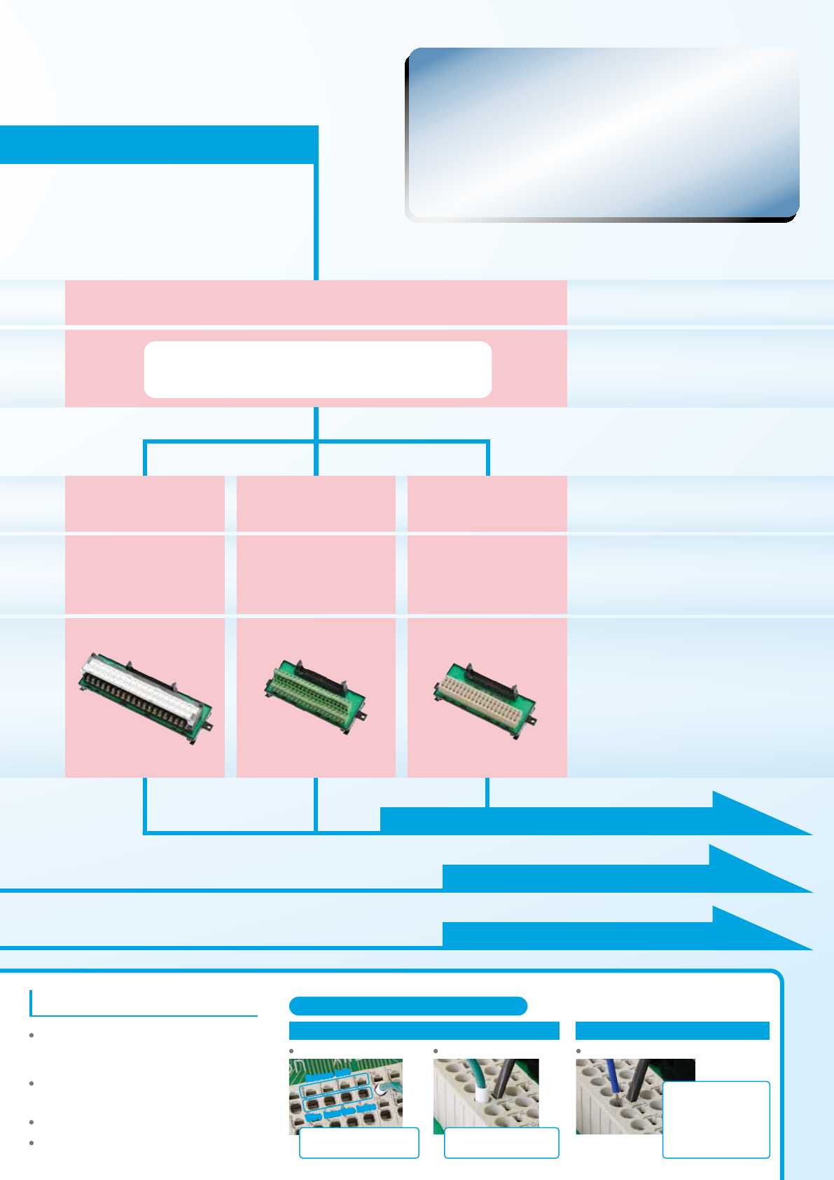
• Specialized wiring pattern for
OMRON and Mitsubishi PLCs
• Minimized size with required number
of poles
• Wide variation of poles
General-purpose
devices
Connecting Spring Clamp Terminals
To insert a wire, insert a
screwdriver into the release hole
and then insert the stripped wire.
To remove a wire, insert a
screwdriver into the release hole
and then pull out the stripped wire.
Release holeRelease hole
Wire insertion holes
Insert the screwdriver into the
release hole and pull out the ferrule.
Using Ferrules
How to insert wire How to release wire Inserting and Removing Wires
Using Stripped Wires
Insert wire into the terminal
block.
Type
General-purpose devices
Features
Terminal Type
XW2R-J
-T
XW2R-E
-T
XW2R-P
-T
Appearance
Model
M3 Screw Clamp Spring Clamp
M3 Screw Clamp Spring Clamp
XW2R-J34G-MXW2R-E34G-MXW2R-P34G-M
XW2R-J34G-C
For Mitsubishi
PLC
For OMRON
PLC
For PLCs from
Mitsubishi
For PLCs from
OMRON
XW2R-E34G-CXW2R-P34G-C
PLCs
XW2R
New Series
Product Lineup
Wide variation of poles
Minimized size with
required number of poles
Specialized wiring pattern
for PLC
Smart Features
PLC Connecting type General-purpose devices
Wiring patterns that are specifically
designed for PLCs reduce the work
required to check signal layout.
More model variations are scheduled for
future development, such as models with
FCN, MR, or MDR connectors in addition to
the current models with MIL connectors.
Spring Clamp terminals simplify wiring and
make the terminal blocks even easier to
use.(In comparison to the OMRON XW2F.)
The terminal arrangement enables
smoother wiring work.
Mount to DIN Rail or with screws.
Common design that can also be customized.
Terminal block signal labels give the PLC
addresses.
To page 13 for details on models for general-purpose devices
To page 4 for details on models for OMRON PLCs
To page 9 for details on models for Mitsubishi PLCs
All Models
3

General-purpose
devices
Connecting Spring clamp Terminals
To insert a wire, insert a
screwdriver into the release hole
and then insert the stripped wire.
To remove a wire, insert a
screwdriver into the release hole
and then pull out the stripped wire.
Release holeRelease hole
Wire insertion holes
Insert the screwdriver into the
release hole and pull out the ferrule.
Using Ferrules
How to insert wire How to release wire Inserting and Removing Wires
Using Stripped Wires
Insert wire into the terminal
block.
Type
General-purpose devices
Features
Terminal Type
XW2R-J
-T
XW2R-E
-T
XW2R-P
-T
Appearance
Model
M3 Screw Clamp Spring Clamp
M3 Screw Clamp Spring Clamp
XW2R-J34G-MXW2R-E34G-MXW2R-P34G-M
XW2R-J34G-C
For Mitsubishi
PLC
For OMRON
PLC
For PLCs from
Mitsubishi
For PLCs from
OMRON
XW2R-E34G-CXW2R-P34G-C
PLCs
XW2R
New Series
Product Lineup
Wide variation of poles
Minimized size with
required number of poles
Specialized wiring pattern
for PLC
Smart Features
PLC Connecting type General-purpose devices
Wiring patterns that are specifically
designed for PLCs reduce the work
required to check signal layout.
More model variations are scheduled for
future development, such as models with
FCN, MR, or MDR connectors in addition to
the current models with MIL connectors.
Spring Clamp terminals simplify wiring and
make the terminal blocks even easier to
use.(In comparison to the OMRON XW2F.)
The terminal arrangement enables
smoother wiring work.
Mount to DIN Rail or with screws.
Common design that can also be customized.
Terminal block signal labels give the PLC
addresses.
To page 13 for details on models for general-purpose devices
To page 4 for details on models for OMRON PLCs
To page 9 for details on models for Mitsubishi PLCs
Specialized
wiring pattern for
OMRON PLCs and
Mitsubishi PLCs
Minimized size
with required
number of poles
Wide variation
of poles
All Models
2
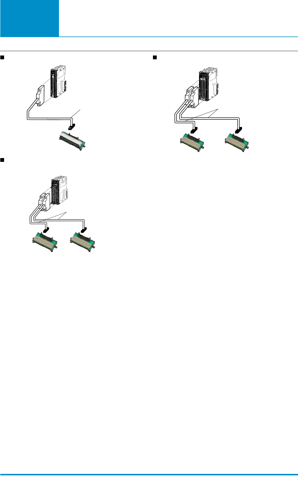
Models for
Connection to
OMRON PLCs
XW2Z-B
Connection to 32 pts unit
(Without branch)
XW2Z-B
Connection to 64 pts unit
(Without branch)
XW2Z-K
inputsoutputs
Connection to 64 pts unit
(Without branch)
Connection Examples
CJ1W-ID231 32-point
CJ1W-MD563 IN 32 Points,OUT 32 Points
CJ1W-ID261 64-point
32-point Input Unit or Output Unit
64-point Output Unit
64-point Input Unit or Output Unit
5
Models for
Connection to
OMRON PLCs
PLC Type I/O
I/O Points I/O Unit Model Connecting cables
C1
Input
32
CJ1W-ID231
XW2Z-000B
32-point Unit: 1 Cable
64-point Unit: 2 Cables
CS1W-ID231
C200H-ID216
C200H-ID218
CQM1-ID112
CQM1-ID213
CQM1-ID214
64
CJ1W-ID261
CS1W-ID261
C200H-ID217
C200H-ID219
C200H-ID111
C500-ID114
C500-ID219
I/O 32
CJ1W-MD261 (inputs)
CS1W-MD261 (inputs)
CS1W-MD262 (inputs)
CS1W-MD561 (inputs)
C2
Input 32 CJ1W-ID232
XW2Z-000K
32-point Unit: 1 Cable
64-point Unit: 2 Cables
CJ1W-ID233
64 CJ1W-ID262
I/O 32
CJ1W-MD263 (inputs)
CJ1W-MD563 (inputs)
C3
Output
32
CJ1W-OD231
XW2Z-000B
32-point Unit: 1 Cable
64-point Unit: 2 Cables
CS1W-OD231
CS1W-OD232
C200H-OD218
CQM1-OD213
64
CJ1W-OD261
CS1W-OD261
CS1W-OD262
C200H-OD219
C500-OD213
I/O 32
CJ1W-MD261 (outputs)
CS1W-MD261 (outputs)
CS1W-MD262 (outputs)
CS1W-MD561 (outputs)
C4
Output
32
CJ1W-OD232
XW2Z-000K
32-point Unit: 1 Cable
64-point Unit: 2 Cables
CJ1W-OD233
CJ1W-OD234
64
CJ1W-OD262
CJ1W-OD263
I/O 32
CJ1W-MD263 (outputs)
CJ1W-MD563 (outputs)
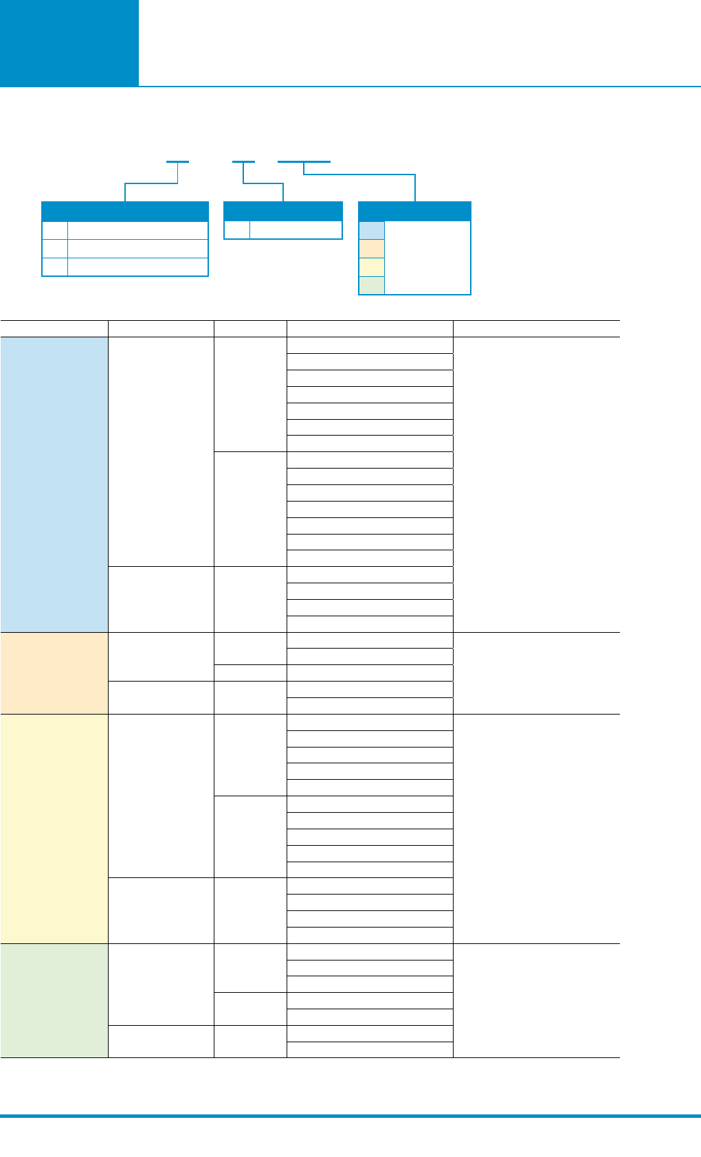
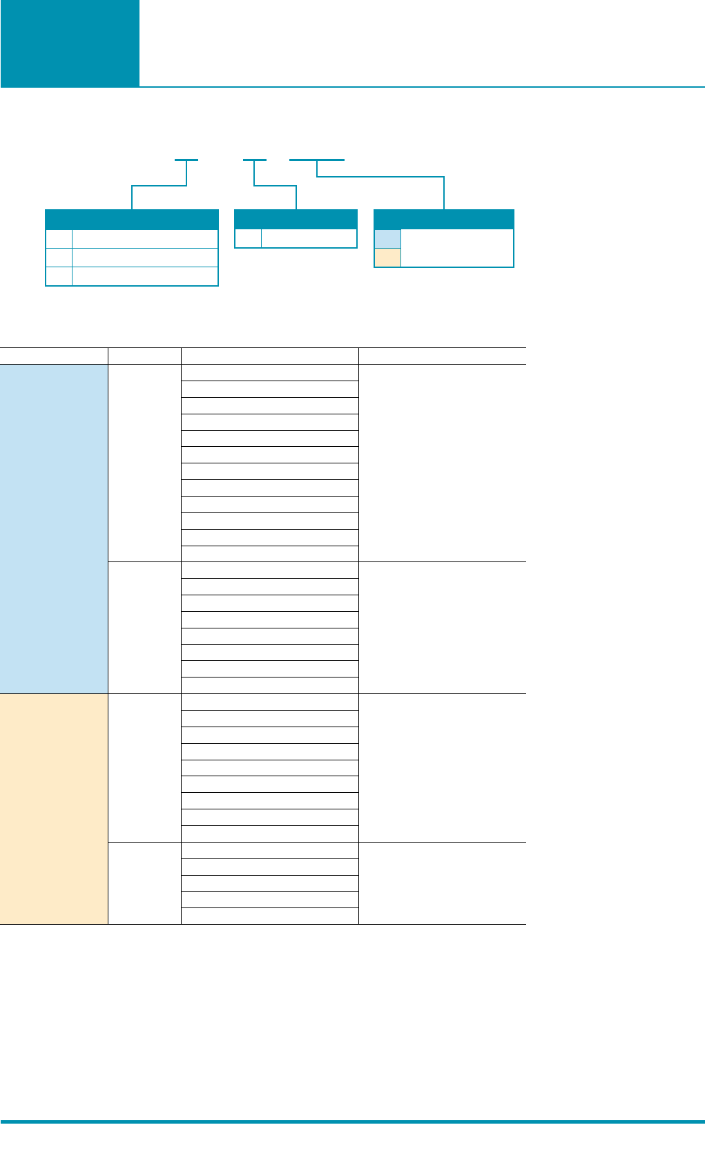
J
E
P
M3 Screw
Clamp
Spring Clamp
MIL (XG4A) C1
C2
C3
C4
Refer to the
following table
for details.
G
Wiring method
Mounted Connector type
PLC type
XW2R-3 4 G-
4
*Connection is not possible to all OMRON PLC Units.
*000
is replaced by the cable length.
*There is one common for each 32 points.
*Refer to page 16-17 for information on Connecting Cables.
Model List
Models for OMRON PLCs
Models for
Connection to
OMRON PLCs
Dimensions Wiring Diagram
Label Contents
C1
C2
C3
C4
MIL Connector
Terminal Block
MIL Connector
MIL Connector
Terminal Block
Terminal Block
MIL Connector
Terminal Block
403836343230282624222018161412108642
3634323028262422
19/20
17/18
161412108642
39373533312927252321191715131197531
39/40
37/38 353331292725232115131197531
4038363432302826
40 38 36 34 32 30 28 26
242220
20
18
18
16
16
14
14
12
12
10
10
8
8
6
6
42
39
39
37
37
35
35
33
33
31
31
29
29
27
27
25
25
232119
19
17
17
15
15
13
13
11
11
9
9
7
7
5
5
31
1/2
21/22
3/4
23/24
4038363432302826
40 38 36 34 32 30 28 26
242220
20
18
18
16
16
14
14
12
12
10
10
8
8
6
6
42
39
39
37
37
35
35
33
33
31
31
29
29
27
27
25
25
232119
19
17
17
15
15
13
13
11
11
9
9
7
7
5
5
31
1/2
21/22
3/4
23/24
40
39
38
37
36
35
34
33
32
31
30
29
28
27
26
25
24
23
22
21
20
19
18
17
16
15
14
13
12
11
10
9
8
7
6
5
4
3
2
3432302826242220161412108642
1
35/36
3331292725232119
17/18 15131197531
Appearance I/O Points
(number of poles) Model Dimension A(mm) Dimension B(mm)
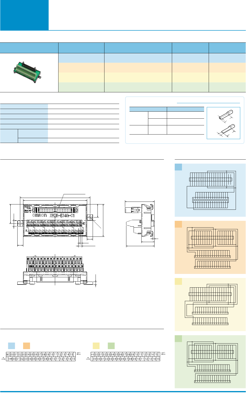
32 (34) XW2R-E34G-C1 98.5 108
32 (34) XW2R-E34G-C2 98.5 108
32 (34) XW2R-E34G-C3 98.5 108
32 (34) XW2R-E34G-C4 98.5 108
Rated current
0.5A/signal,4A/common
Rated voltage
24VDC
Insuration resistance
100MΩ min.(at 500VDC)
Dielectric strength
500VAC for 1 min (leakage current: 1 mA max.)
Ambient operating temperature
0 to 55℃
Applicable
wires
Applicable wire sizes
AWG 22 to 16 (rod terminals)
AWG 26 to 16 (twisted or solid wires)
Stripped length
7 mm
9
9
2.5
5(Pitch)
8.5
29.75
A
B
2- Ø 4.5
20.25
50
MIL Plug:XG4A-4031
4.5
2
20
(43.3)
(45.11)
Rod
Blade
Note: Round rod and blade crimp terminals are made by Nichifu.
BT1.25-9-1
BT1.25-10-1
W = 2.2
TC-05
Dia. = 1
AWG22 to AWG16
(0.30 to 1.25 mm2)
AWG22 to AWG16
(0.30 to 1.25 mm2)
AWG22 to AWG18
(0.30 to 0.75 mm2)
Applicable crimp terminals Applicable wires
TC-1.25S
Dia. = 1.5
Details on Crimp Terminals
Round rod
Blade
Dia.
8-10mm
W
t=0.75
8-10mm
7
(Unit:mm)
Ratings and Specifications
Clamp
For C1 and C2 For C3 and C4
Models for
Connection to
OMRON PLCs
Dimensions Wiring Diagram
Label Contents
C1
C2
C3
C4
MIL Connector
Terminal Block
MIL Connector
MIL Connector
Terminal Block
Terminal Block
MIL Connector
Terminal Block
403836343230282624222018161412108642
3634323028262422
19/20
17/18
161412108642
39373533312927252321191715131197531
39/40
37/38 353331292725232115131197531
4038363432302826
40 38 36 34 32 30 28 26
242220
20
18
18
16
16
14
14
12
12
10
10
8
8
6
6
42
39
39
37
37
35
35
33
33
31
31
29
29
27
27
25
25
232119
19
17
17
15
15
13
13
11
11
9
9
7
7
5
5
31
1/2
21/22
3/4
23/24
4038363432302826
40 38 36 34 32 30 28 26
242220
20
18
18
16
16
14
14
12
12
10
10
8
8
6
6
42
39
39
37
37
35
35
33
33
31
31
29
29
27
27
25
25
232119
19
17
17
15
15
13
13
11
11
9
9
7
7
5
5
31
1/2
21/22
3/4
23/24
40
39
38
37
36
35
34
33
32
31
30
29
28
27
26
25
24
23
22
21
20
19
18
17
16
15
14
13
12
11
10
9
8
7
6
5
4
3
2
3432302826242220161412108642
1
35/36
3331292725232119
17/18 15131197531
Appearance I/O Points
(number of poles) Model Dimension A(mm) Dimension B(mm)
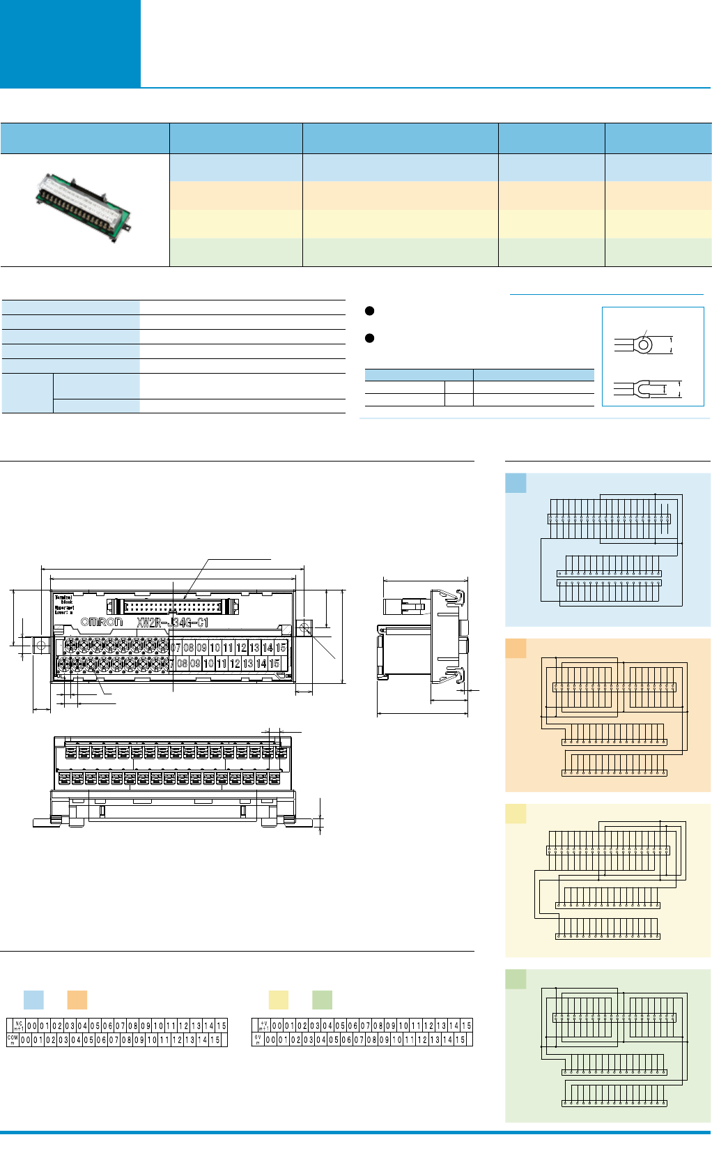
32 (34) XW2R-J34G-C1 130.7 140.2
32 (34) XW2R-J34G-C2 130.7 140.2
32 (34) XW2R-J34G-C3 130.7 140.2
32 (34) XW2R-J34G-C4 130.7 140.2
Rated current
0.5A/signal,4A/common
Rated voltage
24VDC
Insuration resistance
100MΩ min.(at 500VDC)
Dielectric strength
500VAC for 1 min (leakage current: 1 mA max.)
Ambient operating temperature
0 to 55℃
Applicable
wires
Applicable wire sizes
AWG 22 to 16 (round or forked crimp terminals)
AWG 26 to 16 (twisted or solid wires)
Stripped length
9 mm
3.5
7(Pitch)
9
8.5
29.75
9
2-Ø4.5
20.25
50
A
B
M3
MIL Plug:XG4A-4031
4.5
5.8
2
20
(48.35)
(45.11)
Wiring Terminal Blocks
Use crimp terminals on terminal blocks with M3 screws.
Terminal Screw Tightening Torque
Use a tightening torque of 0.5 N·m when connecting wires or
crimp terminals to the terminal block.
Details on Crimp Terminals
Forked crimp terminals
Round crimp terminals
AWG 22 to 16(0.30 to 1.25 mm
2
)
AWG 22 to 16(0.30 to 1.25 mm
2
)
1.25-3
1.25Y-3
Applicable wiresApplicable crimp terminals
Round crimp terminals
Forked crimp terminals
5.8 mm max.
3.2 mm
5.8 mm max.
3.2 mm dia.
6
(Unit:mm)
Ratings and Specifications
M3 Screw
For C1 and C2 For C3 and C4
Models for
Connection to
Mitsubishi PLCs
PLC Type I/O Points Mitsubishi PLC Module model
Connecting cables
M1
32
LX41C4
XW2Z-000B: 1 cable
QX41
QX41-S1
QX41-S2
QX71
QH42P (input)
QX41Y41P (input)
A1SX41-S1
A1SX41-S2
A1SX71
A1SH42 (input)
A1SH42-S1 (input)
64
LX42C4
XW2Z-000B: 2 cables
QX42
QX42-S1
QX82
QX82-S1
A1SX42-S1
A1SX42-S2
A1SX82-S
M2
32
LY41NT1P
XW2Z-000B: 1 cable
QY41P
QY71
QH42P (output)
QY41Y41P (output)
A1SY41-S1
A1SY41P
A1SY42P
A1SY71
64
A1SH42 (output)
XW2Z-000B: 2 cables
A1SH42-S1 (output)
LY42NT1P
QY42P
A1SY42
J
E
P
M3 Screw
Clamp
Spring Clamp
MIL (XG4A)
G
Wiring method
Mounted Connector type
XW2R-3 4 G-
M1
M2
Refer to the following
table for details.
PLC type
9
Model List
Models for Connection to Mitsubishi PLCs
*000
is replaced by the cable length.
*Refer to page 16 for information on Connecting Cables.
Models for
Connection to
OMRON PLCs
Dimensions Wiring Diagram
Label Contents
C1
C2
C3
C4
MIL Connector
Terminal Block
MIL Connector
MIL Connector
Terminal Block
Terminal Block
MIL Connector
Terminal Block
403836343230282624222018161412108642
3634323028262422
19/20
17/18
161412108642
39373533312927252321191715131197531
39/40
37/38 353331292725232115131197531
4038363432302826
40 38 36 34 32 30 28 26
242220
20
18
18
16
16
14
14
12
12
10
10
8
8
6
6
42
39
39
37
37
35
35
33
33
31
31
29
29
27
27
25
25
232119
19
17
17
15
15
13
13
11
11
9
9
7
7
5
5
31
1/2
21/22
3/4
23/24
4038363432302826
40 38 36 34 32 30 28 26
242220
20
18
18
16
16
14
14
12
12
10
10
8
8
6
6
42
39
39
37
37
35
35
33
33
31
31
29
29
27
27
25
25
232119
19
17
17
15
15
13
13
11
11
9
9
7
7
5
5
31
1/2
21/22
3/4
23/24
40
39
38
37
36
35
34
33
32
31
30
29
28
27
26
25
24
23
22
21
20
19
18
17
16
15
14
13
12
11
10
9
8
7
6
5
4
3
2
3432302826242220161412108642
1
35/36
3331292725232119
17/18 15131197531
Appearance I/O Points
(number of poles) Model Dimension A(mm) Dimension B(mm)
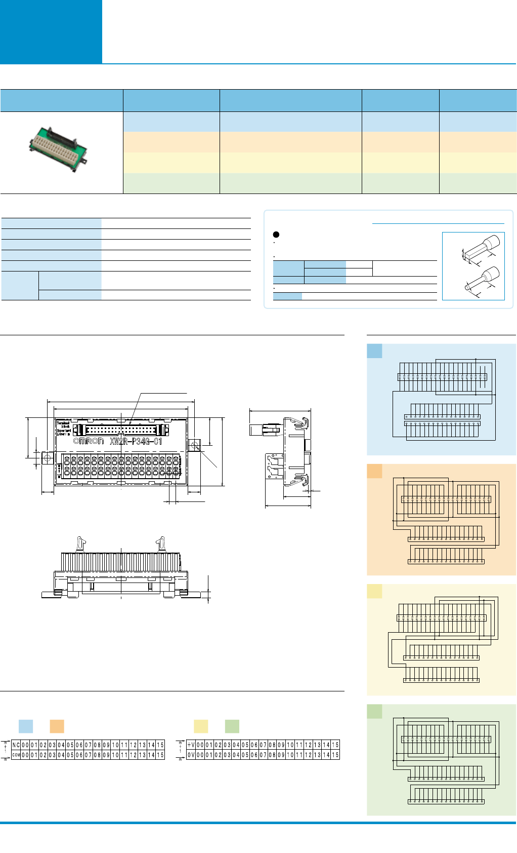
32 (34) XW2R-P34G-C1 98.5 108
32 (34) XW2R-P34G-C2 98.5 108
32 (34) XW2R-P34G-C3 98.5 108
32 (34) XW2R-P34G-C4 98.5 108
Rated current
0.5A/signal,4A/common
Rated voltage
24VDC
Insuration resistance
100MΩ min.(at 500VDC)
Dielectric strength
500VAC for 1 min
Ambient operating temperature
0 to 55℃
Applicable
wires
Applicable wire sizes
AWG 24 to 14 (rod terminals),AWG 28 to 14 (twisted or solid
wires)(Outer diameter of insulation must be 4 mm max)
Stripped length
AWG28-16: 8 to 10 mm, AWG14: 9 to 10 mm
9 9
5(Pitch)
8.5
29.75
20.25
2- Ø 4.5
50
A
B
MIL Plug:XG4A-4031
2
20
(33.4)
(45.11)
4.5
Round ferrules
Square ferrules
Dimension C (Diameter)
Dimension B (Height)
Dimension A (Width)
Model XW4Z-00B
2 mm dia. max. (after crimping)
2 mm max.
2.7mm max.
The cross-sectional area after
crimping must be 4.8 mm
2
or less
Applicable Ferrules
Use ferrules of the lengths and thicknesses specified below.If other lengths or thicknesses are
used, connection may not be possible or it may not be possible to insert or remove the posts.
Ferrule Dimensions
Special Tools
Details on Crimp Terminals
B
Square ferrules
A
Dia. C
Round ferrules
8-10mm
8-10mm
8
(Unit:mm)
Spring Clamp
Ratings and Specifications
For C1 and C2 For C3 and C4
Models for
Connection to
Mitsubishi PLCs
Dimensions Wiring Diagram
Label Contents
MIL Connector
Terminal Block
MIL Connector
Terminal Block
403836343230282624222018161412108642
40 38 36 34 32 30 28 26 24 22 20 18 16 14 12 10
4
2
39
39
37
37
35
35
33
33
31
31
29
29
27
27
25
25
23
23
21
21
19
19
17
17
15
15
13
13
11
11
9
9
7531
3
1
403836343230282624222018161412108642
40 38 36 34 32 30 28 26 24 22 20 18 16 14 12 10
4
2
39
39
37
37
35
35
33
33
31
31
29
29
27
27
25
25
23
23
21
21
19
19
17
17
15
15
13
13
11
11
9
9
7531
3
1
M1
M2
Appearance I/O Points
(number of poles) Model Dimension A(mm) Dimension B(mm)
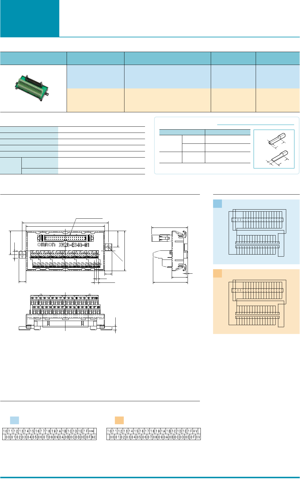
32 (34) XW2R-E34G-M1 98.5 108
32 (34) XW2R-E34G-M2 98.5 108
Rated current
0.5A/signal,2A/common
Rated voltage
24VDC
Insuration resistance
100MΩ min.(at 500VDC)
Dielectric strength
500VAC for 1 min (leakage current: 1 mA max.)
Ambient operating temperature
0 to 55℃
Applicable
wires
Applicable wire sizes
AWG 22 to 16 (rod terminals)
AWG 26 to 16 (twisted or solid wires)
Stripped length
7 mm
Rod
Blade
Note: Round rod and blade crimp terminals are made by Nichifu.
BT1.25-9-1
BT1.25-10-1
W = 2.2
TC-05
Dia. = 1
AWG22 to AWG16
(0.30 to 1.25 mm2)
AWG22 to AWG16
(0.30 to 1.25 mm2)
AWG22 to AWG18
(0.30 to 0.75 mm2)
Applicable crimp terminals Applicable wires
TC-1.25S
Dia. = 1.5
Details on Crimp Terminals
Round rod
Blade
Dia.
8-10mm
W
t=0.75
8-10mm
9
9
2.5
5(Pitch)
8.5
29.75
A
B
2- Ø 4.5
20.25
50
MIL Plug:XG4A-4031
4.5
2
20
(43.3)
(45.11)
11
(Unit:mm)
Ratings and Specifications
Clamp
For M1 For M2
Models for
Connection to
Mitsubishi PLCs
Dimensions Wiring Diagram
Label Contents
MIL Connector
Terminal Block
MIL Connector
Terminal Block
403836343230282624222018161412108642
40 38 36 34 32 30 28 26 24 22 20 18 16 14 12 10
4
2
39
39
37
37
35
35
33
33
31
31
29
29
27
27
25
25
23
23
21
21
19
19
17
17
15
15
13
13
11
11
9
9
7531
3
1
403836343230282624222018161412108642
40 38 36 34 32 30 28 26 24 22 20 18 16 14 12 10
4
2
39
39
37
37
35
35
33
33
31
31
29
29
27
27
25
25
23
23
21
21
19
19
17
17
15
15
13
13
11
11
9
9
7531
3
1
M1
M2
Appearance I/O Points
(number of poles) Model Dimension A(mm) Dimension B(mm)
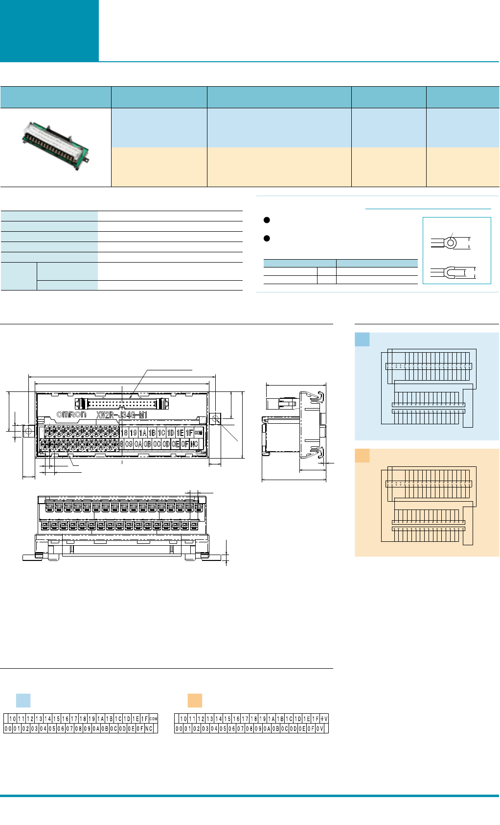
32 (34) XW2R-J34G-M1 130.7 140.2
32 (34) XW2R-J34G-M2 130.7 140.2
Rated current
0.5A/signal,2A/common
Rated voltage
24VDC
Insuration resistance
100MΩ min.(at 500VDC)
Dielectric strength
500VAC for 1 min (leakage current: 1 mA max.)
Ambient operating temperature
0 to 55℃
Applicable
wires
Applicable wire sizes
AWG 22 to 16 (round or forked crimp terminals)
AWG 26 to 16 (twisted or solid wires)
Stripped length
9 mm
Wiring Terminal Blocks
Use crimp terminals on terminal blocks with M3 screws.
Terminal Screw Tightening Torque
Use a tightening torque of 0.5 N·m when connecting wires or
crimp terminals to the terminal block.
Details on Crimp Terminals
Forked crimp terminals
Round crimp terminals
AWG 22 to 16(0.30 to 1.25 mm
2
)
AWG 22 to 16(0.30 to 1.25 mm
2
)
1.25-3
1.25Y-3
Applicable wiresApplicable crimp terminals
Round crimp terminals
Forked crimp terminals
5.8 mm max.
3.2 mm
5.8 mm max.
3.2 mm dia.
3.5
7(Pitch)
9
8.5
29.75
9
2-Ø4.5
20.25
50
A
B
M3
MIL Plug:XG4A-4031
4.5
5.8
2
20
(48.35)
(45.11)
10
(Unit:mm)
Ratings and Specifications
M3 Screw
For M1 For M2
General-
purpose
devices
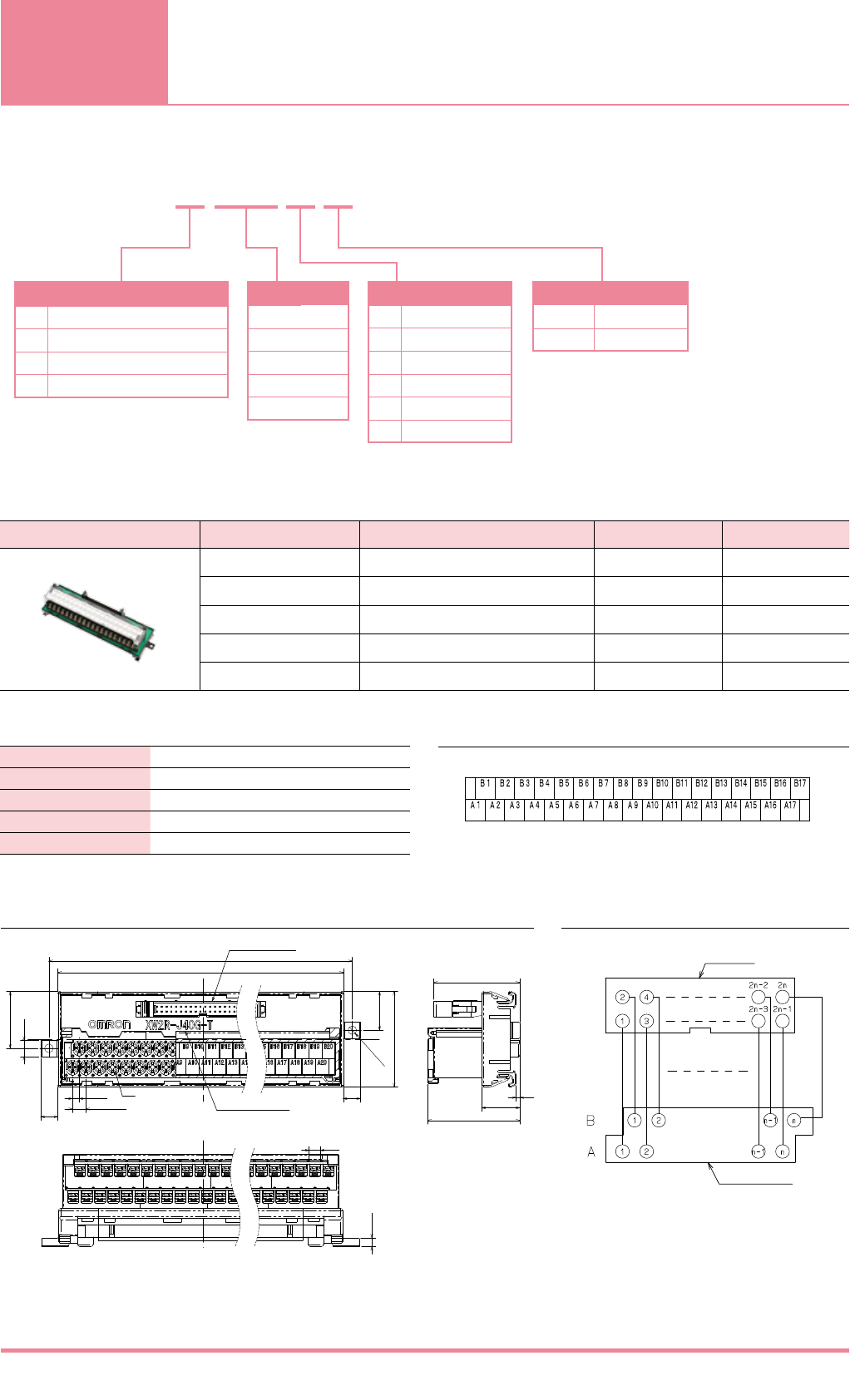
Appearance number of poles Model Dimension A(mm) Dimension B(mm)
20 XW2R-J20G-T 81.7 91.2
34 XW2R-J34G-T 130.7 140.2
40 XW2R-J40G-T 151.7 161.2
50 XW2R-J50G-T 186.7 196.2
60 XW2R-J60G-T 221.7 231.2
Rated current 1A
Rated voltage 125VAC 24VDC
Insuration resistance 100MΩ min.(at 500VDC)
Dielectric strength 500VAC for 1 min (leakage current: 1 mA max.)
Ambient operating temperature
0 to 55℃
A
B
8.5
29.75
9
9
20.25
50
2-Ø4.5
3.5
7(Pitch)
MIL Plug:XG4A-
31
M3
Depending on the poles
2
20
(48.35)
(45.11)
4.5
5.8
XW2R-- T
J
E
P
N
M3 Screw
Clamp
Spring Clamp
e-CON*
*
Scheduled for release soon.
20
34
40
50
60
G
C
F
D
R
M
MIL (XG4A)
MIL (XG4C)*
FCN*
D-sub*
MR*
MDR*
Wiring method
Number of poles
Mounted Connector type
Blank
R
Plug (male)
Socket (female)*
Plug/Socket
Connector
Terminal Block
13
Model List
Dimensions
Ratings and Specifications
Wiring Diagram
Label Contents
M3 Screw
*The details on crimp terminals are the same for the XW2R-J34G on page 6.
*The label contents for a Terminal Block with 34 poles are shown.
(Unit:mm)
Models for
Connection to
Mitsubishi PLCs
Dimensions Wiring Diagram
Label Contents
MIL Connector
Terminal Block
MIL Connector
Terminal Block
403836343230282624222018161412108642
40 38 36 34 32 30 28 26 24 22 20 18 16 14 12 10
4
2
39
39
37
37
35
35
33
33
31
31
29
29
27
27
25
25
23
23
21
21
19
19
17
17
15
15
13
13
11
11
9
9
7531
3
1
403836343230282624222018161412108642
40 38 36 34 32 30 28 26 24 22 20 18 16 14 12 10
4
2
39
39
37
37
35
35
33
33
31
31
29
29
27
27
25
25
23
23
21
21
19
19
17
17
15
15
13
13
11
11
9
9
7531
3
1
M1
M2
Appearance I/O Points
(number of poles) Model Dimension A(mm) Dimension B(mm)
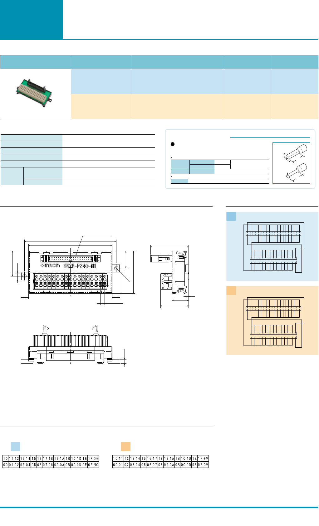
32 (34) XW2R-P34G-M1 98.5 108
32 (34) XW2R-P34G-M2 98.5 108
Rated current
0.5A/signal,2A/common
Rated voltage
24VDC
Insuration resistance
100MΩ min.(at 500VDC)
Dielectric strength
500VAC for 1 min
Ambient operating temperature
0 to 55℃
Applicable
wires
Applicable wire sizes
AWG 24 to 14 (rod terminals),AWG 28 to 14 (twisted or solid
wires)(Outer diameter of insulation must be 4 mm max)
Stripped length
AWG28-16: 8 to 10 mm, AWG14: 9 to 10 mm
9 9
5(Pitch)
8.5
29.75
20.25
2- Ø 4.5
50
A
B
MIL Plug:XG4A-4031
2
20
(33.4)
(45.11)
4.5
Round ferrules
Square ferrules
Dimension C (Diameter)
Dimension B (Height)
Dimension A (Width)
Model XW4Z-00B
2 mm dia. max. (after crimping)
2 mm max.
2.7mm max.
The cross-sectional area after
crimping must be 4.8 mm
2
or less
Applicable Ferrules
Use ferrules of the lengths and thicknesses specified below.If other lengths or thicknesses are
used, connection may not be possible or it may not be possible to insert or remove the posts.
Ferrule Dimensions
Special Tools
Details on Crimp Terminals
B
Square ferrules
A
Dia. C
Round ferrules
8-10mm
8-10mm
12
(Unit:mm)
Ratings and Specifications
Spring Clamp
For M1 For M2
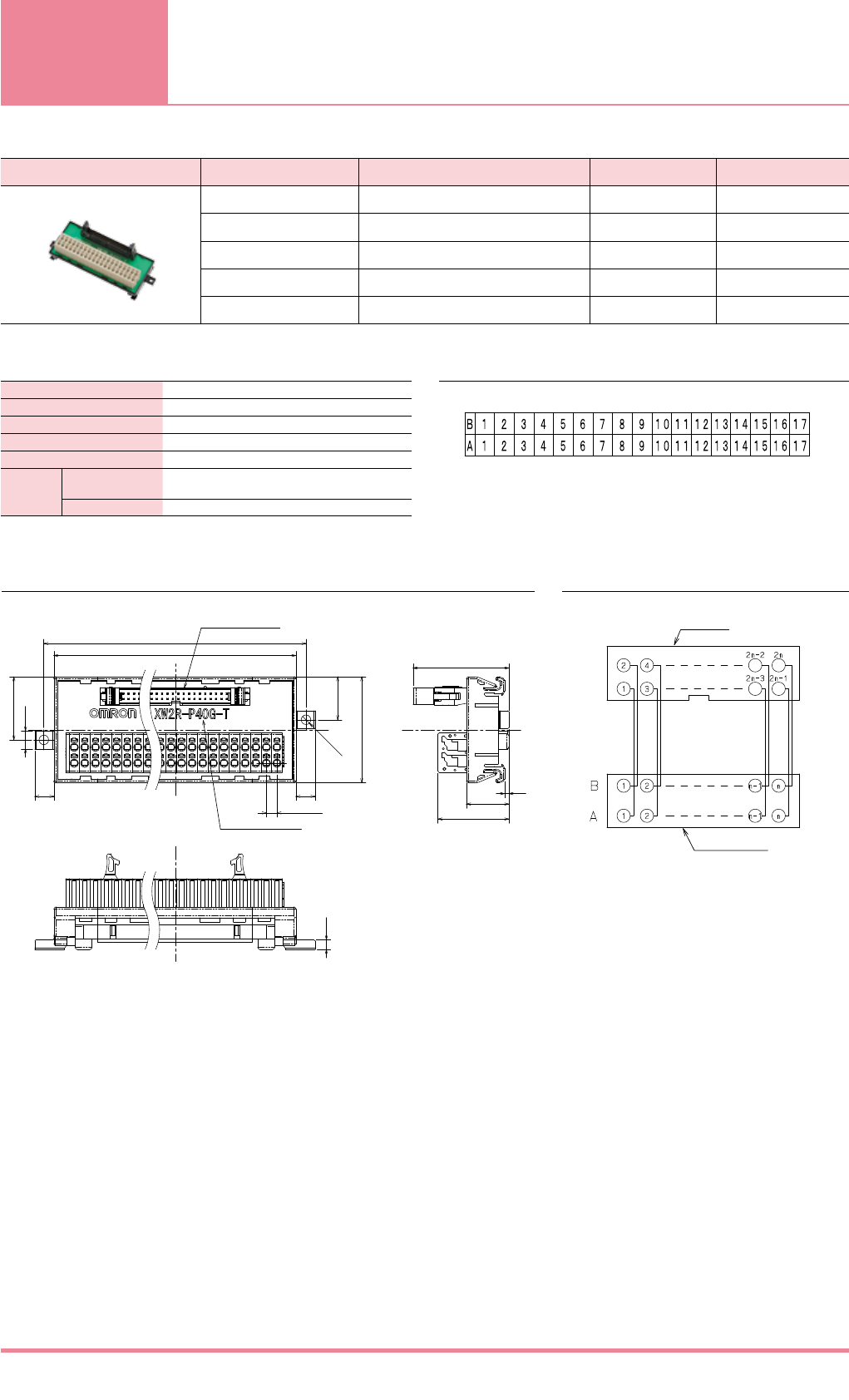
General-
purpose
devices
Appearance number of poles Model Dimension A(mm) Dimension B(mm)
20 XW2R-P20G-T 64.4 73.9
34 XW2R-P34G-T 98.5 108
40 XW2R-P40G-T 113.5 123
50 XW2R-P50G-T 138.5 148
60 XW2R-P60G-T 163.5 173
Rated current
1A
Rated voltage
125VAC 24VDC
Insuration resistance
100MΩ min.(at 500VDC)
Dielectric strength
500VAC for 1 min (leakage current: 1 mA max.)
Ambient operating temperature
0 to 55℃
Applicable
wires
Applicable wire sizes
AWG 24 to 14 (rod terminals),AWG 28 to 14 (twisted or solid
wires)(Outer diameter of insulation must be 4 mm max)
Stripped length
AWG28-16: 8 to 10 mm, AWG14: 9 to 10 mm
A
5(Pitch)
29.75
20.25
50
99
8.5
2-Ø4.5
B
MIL Plug:XG4A-31
Depending on the poles
4.5
2
20
(33.4)
(45.11)
Connector
Terminal Block
15
Dimensions Wiring Diagram
Ratings and Specifications Label Contents
*The details on crimp terminals are the same for the XW2R-P34G on page 8.
*The label contents for a Terminal Block with 34 poles are shown.
(Unit:mm)
Spring Clamp
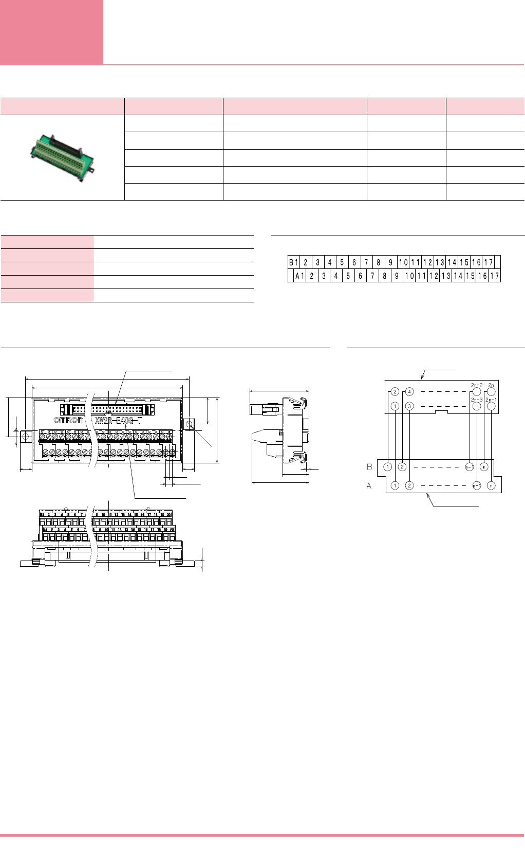
General-
purpose
devices
Appearance number of poles Model Dimension A(mm) Dimension B(mm)
20 XW2R-E20G-T 64.4 73.9
34 XW2R-E34G-T 98.5 108
40 XW2R-E40G-T 113.5 123
50 XW2R-E50G-T 138.5 148
60 XW2R-E60G-T 163.5 173
Rated current 1A
Rated voltage 125VAC 24VDC
Insuration resistance 100MΩ min.(at 500VDC)
Dielectric strength 500VAC for 1 min (leakage current: 1 mA max.)
Ambient operating temperature
0 to 55℃
(43.3)
A
29.75
20.25
50
2-Ø4.5
B
9
9
8.5
2.5
5(Pitch)
MIL Plug:XG4A-31
Depending on the poles
4.5
2
20
(45.11)
Connector
Terminal Block
14
Dimensions
Ratings and Specifications
Wiring Diagram
Label Contents
Clamp
*The details on crimp terminals are the same for the XW2R-E34G on page 7.
*The label contents for a Terminal Block with 34 poles are shown.
(Unit:mm)
Connecting
Cables
Appearance Model Cable length L (m)
A B
XW2Z-100D 1 0.75
XW2Z-150D 1.5 1.25
XW2Z-200D 2 1.75
XW2Z-300D 3 2.75
XW2Z-500D 5 4.75
XW2Z-010D 10 9.75
XW2Z-15MD 15 14.75
XW2Z-20MD 20 19.75
Appearance Model Cable length L (m)
XW2Z-100F 1
XW2Z-150F 1.5
XW2Z-200F 2
XW2Z-300F 3
XW2Z-500F 5
XW2Z-010F 10
XW2Z-15MF 15
XW2Z-20MF 20
Appearance Model Cable length L (m)
XW2Z-C25K 0.25
XW2Z-C50K 0.5
XW2Z-100K 1
XW2Z-150K 1.5
XW2Z-200K 2
XW2Z-300K 3
XW2Z-500K 5
XW2Z-010K 10
Forked
terminal
No. of
cores
Insulation
color
Dot
marks Dot color
Connector
pin No.
11 Blue
0
Red 1
2 Black 2
32 Pink Red 3
4 Black 4
53 Green Red 5
6 Black 6
74 Orange Red 7
8 Black 8
95 Gray Red 9
10 Black 10
11 6 Blue
00
Red 11
12 Black 12
13 7 Pink Red 13
14 Black 14
15 8 Green Red 15
16 Black 16
17 9 Orange Red 17
18 Black 18
19 10 Gray Red 19
20 Black 20
A
B
Yellow
Black
CN3
(250 mm)
CN2
(500 mm)
CN1
L
Forked terminals
(M3.5)
XG4M-2030-T
Devices
300 (mm)
L
B20
B19
B18
B17
B16
B15
B14
B13
B12
B11
B10
B9
B8
B7
B6
B5
B4
B3
B2
B1
20
19
18
17
16
15
14
13
12
11
10
9
8
7
6
5
4
3
2
1
20
19
18
17
16
15
14
13
12
11
10
9
8
7
6
5
4
3
2
1
A20
A19
A18
A17
A16
A15
A14
A13
A12
A11
A10
A9
A8
A7
A6
A5
A4
A3
A2
A1
FCN367J040-AU/F
CN1
XG4M-2030-T
CN3
XG4M-2030-T
CN2
1 1
17 17
18 18
20 19
18 17
16 15
4 3
2 1
19 19
20 20
2 2
8 8
9 9
10 10
11 11
20 19
18 17
16 15
4 3
2 1
B A
Triangular mark
Triangular
mark
XG4M-2030-T
CN3
(mating side)
XG4M-2030-T
CN2
(mating side)
FCN367J040-AU/F
CN1
(mating side)
NC
NC
NC
19 20
17 18
3 4
1 2
20
19
18
17
4
3
2
1
XG4M-2030-T
(mating side)
Forked
terminals
(M3.5)
Triangular
mark
21 22
19 20
39 40
37 38
1 2
3 4
20 19
22 21
2 1
4 3
40 39
38 37
XG4M-4030-T
(mating side)
XG4M-4030-T
(mating side)
Triangular mark
Triangular mark
17
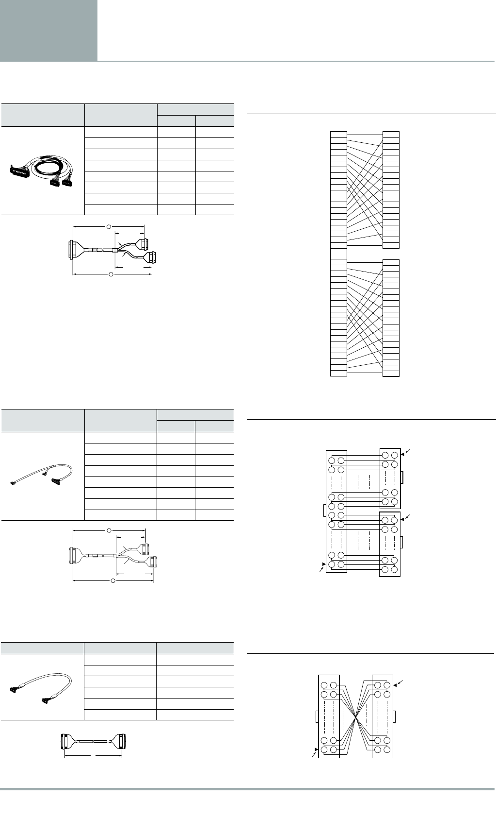
XW2Z-000D
Connectors: One 40-pin Connector Made by Fujitsu Component, Ltd. to Two 20-pin MIL Connectors
XW2Z-000F
Connectors: One 20-pin MIL Connector to 20 Loose Wires with Crimp Terminals Attached
XW2Z-000K
Connectors: One 40-pin MIL Connector to One 40-pin MIL Connector
Cable length L (m)
Cable length L (m)
Cable length L (m)
Wiring Diagram
Wiring Diagram
Wiring Diagram
Connector Pin No. Table
Note: Connector pins are connected 1-to-1 so
that pin numbers correspond.
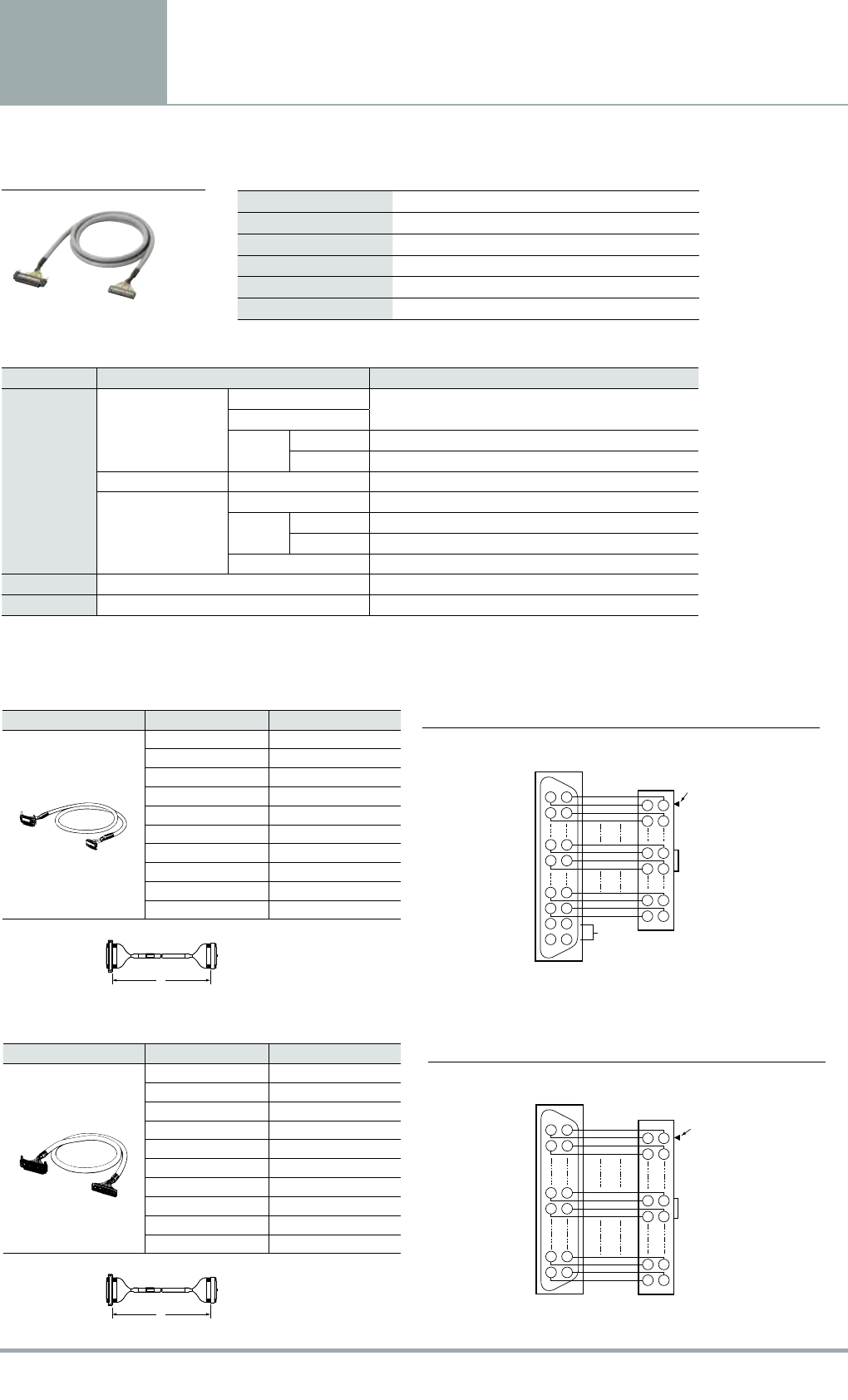
Connecting
Cables
Appearance Model Cable length L (m)
XW2Z-050A 0.5
XW2Z-100A 1
XW2Z-150A 1.5
XW2Z-200A 2
XW2Z-300A 3
XW2Z-500A 5
XW2Z-700A 7
XW2Z-010A 10
XW2Z-15MA 15
XW2Z-20MA 20
Appearance Model Cable length L (m)
XW2Z-050B 0.5
XW2Z-100B 1
XW2Z-150B 1.5
XW2Z-200B 2
XW2Z-300B 3
XW2Z-500B 5
XW2Z-700B 7
XW2Z-010B 10
XW2Z-15MB 15
XW2Z-20MB 20
Rated current 1A
Rated voltage 125 VAC 24 VDC
Contact resistance 20 mΩ max. (at 20 mV, 100 mA max.) *1
Insulation resistance 100 MΩ min. (at 500 VDC)
Dielectric strength 500 VAC for 1 min (leakage current: 1 mA max.) *2
Ambient operating temperature
−25 to 80℃
Item Part name Materials and Finish
Connectors
XG4M-2030
XG4M-4030
Housing Fiber-glass reinforced PBT resin (UL94V-0)/black
Cover
Contacts Mating end Phosphor bronze/nickel base, 0.15-μm gold plating
Press-fit end Phosphor bronze/nickel base, 2.0-μm tin plating
XG4T-2004/4004 Strain Relief Fiber-glass reinforced PBT resin (UL94V-0)/black
FCN-367J024-AU/F *
FCN-367J040-AU/F
Housing Polyester resin (UL94V-0)/black
Contacts Mating end Copper alloy/gold plated
Press-fit end Copper alloy/tin plated
Connecting screw Steel/nickel plated
Cable UL2464 Interface Cable AWG28
Crimp terminal Forked crimp terminal 1.25 YAS 3.5 or the equivalent
L
L
1 1
2 2
6 6
7 7
10 10
9 9
12 12
11 11
12 11
14 13
2 1
4 3
20 19
18 17
B A
FCN367J024-AU/F
(mating side)
XG4M-2030-T
(mating side) Triangular
mark
NC
1 1
2 2
10 10
11 11
20 20
19 19
20 19
22 21
2 1
4 3
40 39
38 37
B A
FCN367J040-AU/F
(mating side) XG4M-4030-T
(mating side)
Triangular
mark
16
XW2Z-000A
Connectors: One 24-pin Connector Made by Fujitsu Component, Ltd. to One 20-pin MIL Connector
XW2Z-000B
Connectors: One 40-pin Connector Made by Fujitsu Component, Ltd. to One 40-pin MIL Connector
Cable length L (m)
Wiring Diagram
Wiring Diagram
XW2Z
Ratings and SpecificationsAppearance
Materials and Finish
* These housings, contacts, and connecting screws are made by Fujitsu Component, Ltd.
Cable length L (m)
*1. Contact resistance for the Connector. *2. Dielectric strength for the Connector.

Safety Precautions
Precautions for Correct Use
• Do not perform wiring work, remove connectors, or connect connectors while power is being supplied.
Electric shock or damage to the device may result.
• Double-check all wiring before turning ON the power supply.
• After wiring, route the cable so that force is not applied directly to the connections.
• Do not damage the cores when stripping the insulation from them.
• Always twist stranded wires together before connecting them.
• Do not presolder wires. It may not be possible to connect them or remove them.
Wiring Precautions
Wires for Terminal Blocks
Mounting Units to and Removing Units from DIN Track
Connecting Spring cramp Terminals
Use tool
Bending Radius of Connecting Cables
• Select a use tool from following table.
• To prevent damaging the Connecting Cables, use the following minimum bending radii as guidelines.
1.Hook the Unit on the DIN Track.
2.Press the Unit onto the DIN Track to secure it.
1.Insert a flat-blade screwdriver into the DIN Track lock.
2.Move the screwdriver like a lever to free the lock.
Using Ferrules
Mounting Procedure Removal Procedure
How to insert wire How to release wire Inserting and Removing Wires
Using Stripped Wires
Model Use tool
XW2R-J
XW2R-E
XW2R-P
Phillips screwdriver
Flat-blade screwdriver
JIS#2
Model XW4Z-00B
Head of screwdriver Is 0.4 × 2.5mm max.
Specialized tool and dimension
A, F, or X
B, D, K, L, or N
67.2 mm
88 mm
End of model number Minimum bending radius
XW2Z-
Hook.Hook.
1
Press.
Press.
2
To insert a wire, insert a
screwdriver into the release hole
and then insert the stripped wire.
To remove a wire, insert a
screwdriver into the release hole
and then pull out the stripped wire.
Wire insertion holes
Release holeRelease hole
Wire insertion holes
Insert the screwdriver into the
release hole and pull out the ferrule.
The wire should be pushed into
the terminal block till stopping.
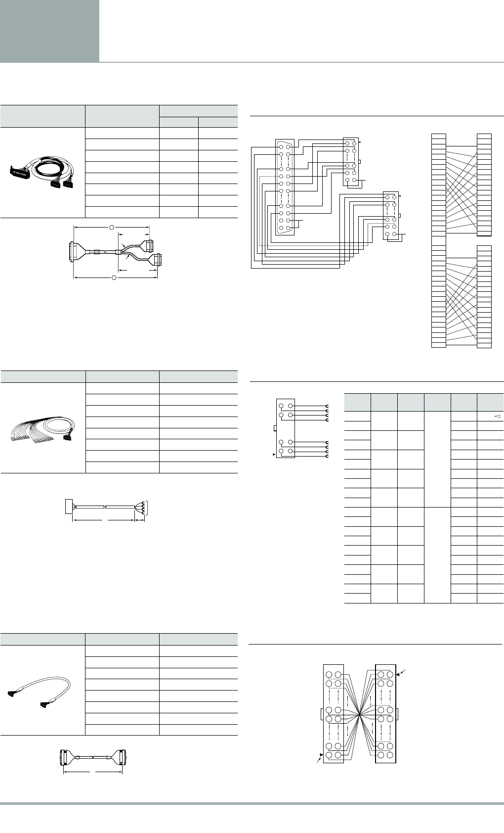
19
Connecting
Cables
Appearance Model Cable length L (m)
A B
XW2Z-100L 1 0.75
XW2Z-150L 1.5 1.25
XW2Z-200L 2 1.75
XW2Z-300L 3 2.75
XW2Z-500L 5 4.75
XW2Z-010L 10 9.75
XW2Z-15ML 15 14.75
XW2Z-20ML 20 19.75
Appearance Model Cable length L (m)
A B
XW2Z-100N 1 0.75
XW2Z-150N 1.5 1.25
XW2Z-200N 2 1.75
XW2Z-300N 3 2.75
XW2Z-500N 5 4.75
XW2Z-010N 10 9.75
XW2Z-15MN 15 14.75
XW2Z-20MN 20 19.75
Appearance Model Cable length L (m)
XW2Z-C50X 0.5
XW2Z-100X 1
XW2Z-200X 2
XW2Z-300X 3
XW2Z-500X 5
XW2Z-010X 10
A
B
Green
White
CN3
CN1
CN2
(250 mm)
(500 mm)
L
B20
B19
B18
B17
B16
B15
B14
B13
B12
B11
B10
B9
B8
B7
B6
B5
B4
B3
B2
B1
20
19
18
17
16
15
14
13
12
11
10
9
8
7
6
5
4
3
2
1
20
19
18
17
16
15
14
13
12
11
10
9
8
7
6
5
4
3
2
1
A20
A19
A18
A17
A16
A15
A14
A13
A12
A11
A10
A9
A8
A7
A6
A5
A4
A3
A2
A1
FCN367J040-AU/F
CN1
XG4M-2030-T
CN3
XG4M-2030-T
CN2
23 24
21 22
19 20
17 18
39 40
37 38
1 2
3 4
18 17
20 19
2 1
4 3
18 17
20 19
2 1
4 3
XG4M-2030-T
CN2
(mating side)
XG4M-2030-T
CN3
(mating side)
Triangular mark
XG4M-4030-T
(mating side) Triangular mark
Triangular mark
19 20
17 18
1 2
3 4
21
43
20 19
18 17
XG4M-2030-T
(mating side)
XG4M-2030-T
(mating side)
Triangular mark
Triangular mark
Linear lengths (not including bends)
CN1
CN2
CN3
(500 mm)
(250 mm)
Green
Black
B
A
18
Note: Connector pins are connected 1-to-1 so
that pin numbers correspond.
XW2Z-000L
Connectors: One 40-pin Connector Made by Fujitsu Component, Ltd. to Two 20-pin MIL Connectors
XW2Z-000N
Connectors: One 40-pin MIL Connector to Two 20-pin MIL Connectors
XW2Z-000X
Connectors: One 20-pin MIL Connector to One 20-pin MIL Connector
Cable length L (m)
Cable length L (m)
Cable length L (m)
Wiring Diagram
Wiring Diagram
Wiring Diagram

Printed on recycled paper.
R26I-E-01 Note: Specifications are subject to change. © 2013 Omron Electronics LLC Printed in U.S.A.
Authorized Distributor:
Toronto, ON, Canada • 416.286.6465 • 866.986.6766 • www.omron247.com
México DF • 52.
55.59.01.43.00
• 001.800.556.6766 • mela@omron.com
Apodaca, N.L. • 52.81.11.56.99.20 • 001.800.556.6766 • mela@omron.com
São Paulo, SP, Brasil • 55.11.2101.6300 • www.omron.com.br
Cono Sur • 54.11.4783.5300
Santiago • 56.9.9917.3920
54.11.4783.5300
• Schaumburg, IL USA • 847.843.7900 • 800.556.6766 • www.omron247.com
Wegalaan 67-69, NL-2132 JD, Hoofddorp, The Netherlands.
•
Tel: +31 (0) 23 568 13 00
•
Fax: +31 (0) 23 568 13 88
•
www.industrial.omron.eu
• Machine Automation Controllers (MAC) • Programmable Controllers (PLC)
• Operator interfaces (HMI) • Distributed I/O • Software
• Servo & AC Drives • Motion Controllers & Encoders
• Single and Multi-loop Controllers
• Proximity Sensors • Photoelectric Sensors • Fiber-Optic Sensors
• Amplified Photomicrosensors • Measurement Sensors
• Ultrasonic Sensors • Vision Sensors • RFID/Code Readers
• Relays • Pushbuttons & Indicators • Limit and Basic Switches • Timers
• Counters • Metering Devices • Power Supplies
• Laser Scanners • Safety Mats • Edges and Bumpers
• Programmable Safety Controllers • Light Curtains • Safety Relays
• Safety Interlock Switches
