Product Detail Manual
61305-Attachment 61305-Attachment 61305-Attachment 095969 Batch5 unilog cesco-content
2014-09-08
: Pdf 61305-Attachment 61305-Attachment 095969 Batch3 unilog
Open the PDF directly: View PDF ![]() .
.
Page Count: 72

Test Tools Catalog
Volume one, 2007
Find it. Fix it. Fast.
Fluke 975
AirMeter™
Fluke 1587
Insulation Multimeter
Fluke 199C
Color ScopeMeter®
Fluke Ti20
Thermal Imager

2
Test Tools Catalog
Volume 37, 2007
Contents
Fluke tools for:
Commercial Electricians ...................................... 3
Industrial Electricians .......................................... 4
HVAC/IAQ Technicians ........................................ 5
Online resource centers .................................. 6
Fluke test tool information ............................. 7
Safety and its importance ............................... 8
Service, repair, and calibration .................... 9
Digital Multimeters
Multimeter Selection Guide .............................. 10
Faster, Safer Multimeters .................................. 11
189 Logging Multimeter .................................... 12
FlukeView Forms® Software ............................ 13
87V Industrial Multimeter ................................. 14
179 Digital Multimeter ....................................... 15
Family of True-rms Digital Multimeters .......... 16
117 and 115 True-rms Digital Multimeters ......17
116 and 114 True-rms Digital Multimeters ..... 18
77-IV and 73-III Digital Multimeters ............... 19
27 Waterproof Multimeter ................................ 19
88V Automotive Multimeter .............................20
8845A/8846A 6.5 Digit Precision
Multimeters ......................................................... 21
Electrical Testers
T3 and T5 Electrical Testers, VoltAlert™ .........22
9040 Rotary Field Indicator .............................22
Earth Ground Testers
1625 and 1623 Geo Earth Ground Testers .....23
1630 Earth Ground Clamp Meter,
Handy Geo Earth Ground Tester ......................24
Power Quality Analyzers
430 Series Power Quality Analyzers ...............25
43B Power Quality Analyzer ............................26
1760 Power Quality Recorder, 1650 RPM
Power Recorder ..................................................27
1740 Series Three-Phase PQ Loggers,
VR101S Voltage Event Recorder System ........28
1735 Three-Phase Power Logger,
Norma 4/5000 Power Analyzers .....................29
Clamp Meters
Fluke 345 and LH1050, LH1060
Power Clamp Meters .........................................30
Fluke 360 and LH41 Current Clamp Meters,
LH2015 True-rms Clamp Meter ........................ 31
Better Clamp Meters from Fluke ......................32
330 and 320 Series Clamp Meters ..................33
902 True-rms HVAC Clamp Meter ...................54
Insulation Testers and MegOhmMeters
1550B and 1520 Megohmmeters ....................34
1587 and 1577 Insulation Multimeters ...........35
1507 and 1503 Insulation Testers ...................36
Process Calibration Tools
Process Tools Selection Guide .......................... 37
744, 743B, 741B Documenting Process
Calibrators ...........................................................38
726, 725 Precision Multifunction Process
Calibrators ...........................................................39
724, 714, 712 Temperature Calibrators ...........40
718, 717 Pressure Calibrator, 700 Series
Pressure Modules ............................................... 41
715, 707, 705 Loop Calibrators ........................42
789, 787 Process Meters ...................................43
771 Milliamp Process Clamp Meter .................44
9102S, 9100S Handheld Drywell
Temperature Calibrators....................................44
Intrinsically Safe Products
707Ex, 718Ex, 725Ex, 700PEx, 574-NI,
68IS, 87V Ex .......................................................45
Thermal Imagers
Ti40/Ti50 Series IR FlexCam®
Thermal Imagers ..........................................46-47
Ti20 Thermal Imager .........................................48
Ti30™ Thermal Imager ......................................49
TiR4, TiR3, TiR2 IR FlexCam™
Thermal Imagers and IR InSight XS,
XST Thermal Imagers ........................................50
Thermometers
570 Series Infrared Thermometers .................. 51
54 Series II Contact Thermometers .................52
561 HVACPro Thermometer ..............................52
60 Series Infrared Thermometers ....................53
HVAC/Indoor Air Quality Tools
975 AirMeter,™ 902 True-rms
HVAC Clamp Meter ............................................54
971 Temperature Humidity Meter,
983 Particle Counter ..........................................55
ScopeMeter® Test Tools
ScopeMeter Test Tools Selection Guide ..........56
124 Industrial ScopeMeter Test Tools .............57
190 Series Color ScopeMeter Test Tools .........58
Fluke ScopeMeter Accessories .........................59
Accessories
Accessory Selection Guide ................................60
Accessory Sets and Kits .................................... 61
SureGrip™ Accessories .......................................62
Accessories for Electronic and Automotive
Applications and High Voltage Probes ............63
Lights, Software and Specialty
Accessories .................................................. 64-65
Current Clamps .............................................66-67
Temperature Accessories ........................... 68-69
Cases, Holsters and Fuses ........................... 70-71
What’s new from Fluke ....................back cover
Contact us:
United States
General product and sales
information: 1-888-44-FLUKE
Fluke Thermal Imagers:
1-800-760-4620 (U.S. only) all
other regions 1-425-446-4620
Service and calibration:
1-800-993-5853
Parts: 1-800-526-4731
Canada
General product and sales
information: 1-800-36-FLUKE
Service, parts and calibration:
1-800-36-FLUKE
canada@fluke.com
Australia
General product and sales
information: (2) 8850-3333
Parts: (2) 8850-3333
Service and calibration:
(2) 9771-9300
Singapore
General product and sales
information: 6738-5655
info.asean@fluke.com
Service, parts and calibration:
6737-2922
service.asean@fluke.com
Japan
General product and sales
information: +81-3-3434-0180
Service, parts and calibration:
+81-3-3434-0188
Other countries: 1+(425) 446-5500
Application
segment key
To help you better identify the
right product for your job, you
will find the applicable icons
located on the outside edge of
each product page.
••••••
••••• •
3
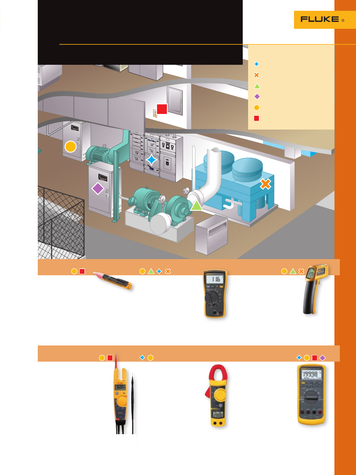
Fluke 1AC II VoltAlert Voltage
Detector
Best suited for:
• Non-contact voltage
detection on electrical circuits
• Detecting voltage before work begins
See page 22 for details
Fluke 116 Digital Multimeter
Best suited for:
• Measures volts, ohms,
capacitance and
temperature
• Resistance and continuity
• 600 V ac and dc
measurement range
See page 18 for details
Fluke 62 Mini IR
Thermometer
Best suited for:
• Surface temperature
readings
• Finding heating and
ventilation problems
• Non-contact monitoring
of electrical motors and
panels
See page 53 for details
Fluke T5 Voltage, Continuity
and Current Tester
Best suited for:
• Measure loads on a branch
circuit at a service level
• Measure the load side
voltage of a circuit breaker
or fuse
• Map outlets to breakers
• Check individual voltages
(either ac or dc)
• Determine resistances up to
1000 ohms
• Check circuit continuity
See page 22 for details
Fluke 322 Clamp Meter
Best suited for:
• Verify the presence of
load current, ac/dc voltage
and continuity
• Current measurements up to
400 A in tight cable
compartments
• Higher resolution for
loads below 40 A
See page 33 for details
Fluke 87V Industrial True-rms
Multimeter w/temp
Best suited for:
• VSD motor drive
installation and
troubleshooting
• Accurate frequency and
voltage measurements
on motor drives and
in electrically noisy
environments
• Built-in thermometer
for temperature
measurements
• CAT III 1000 V rated to protect against
high voltage transients up to 8 kV
See page 14 for details
Legend
Power Distribution Center
Heat Exchanger
HVAC Blower
Drive Control
Motor and Motor Control Center
Electrical
Fluke test tools to
help you get the job done
Fluke tools for commercial electricians
••••••
••••••
4
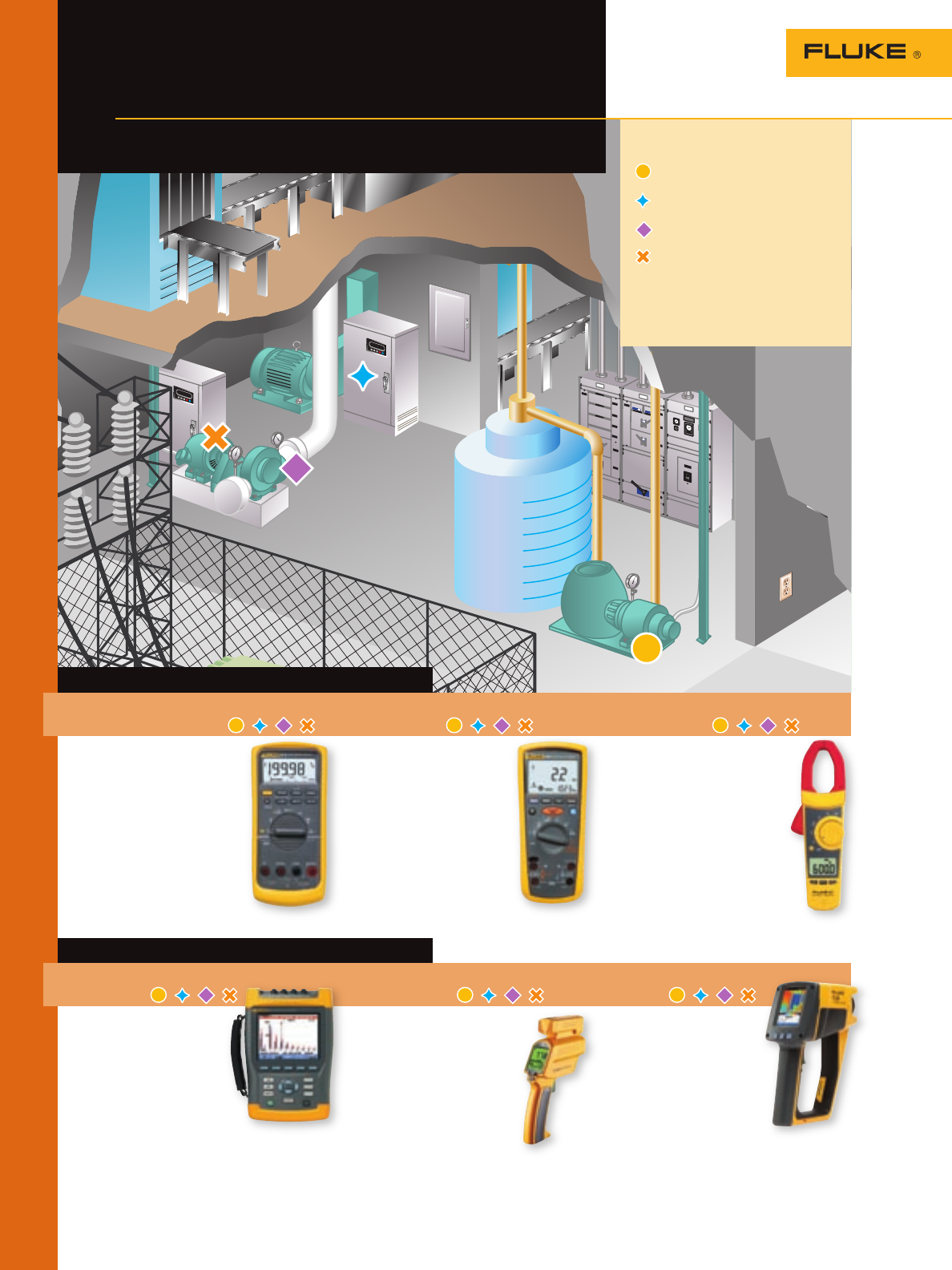
Legend
Pumps
Drive Control
Blowers
Motors
Fluke test tools to
help you get the job done
Fluke tools for industrial electricians
Front line troubleshooting tools
Fluke 87V Industrial True-rms
Multimeter w/temp
Best suited for: VSD motor
drive installation and
troubleshooting.
Features:
• Accurate frequency and
voltage measurements
on motor drives and
in electrically noisy
environments
• Built-in thermometer for
temperature measurements
See page 13 for details
Fluke 1587 Insulation
Multimeters
Best suited for: Work on
motors, generators, cables or
switch-gear.
Features:
• Measuring insulation test
voltages to 1000 V
• Prevents insulation test if
voltage > 30 V is detected
for added user protection
• Filter for motor drive
measurements
See page 35 for details
Fluke 337 AC/DC True-rms
Clamp Meter
Best suited for: Measure inrush
current on electric motor startup
and electric motor testing and
troubleshooting
Features:
• Inrush current measurements
to measure start up current
on electric motors
• Frequency measurements to
help track down power
quality problems
See page 33 for details
Preventive and predictive maintenance
Fluke 434 Three-Phase PQ
Analyzer
Best suited for: Trouble-
shooting and preventing
problems in power distri-
bution systems.
Features:
• Simultaneously measure
voltage and current on all
three phases and neutral
• High-resolution color screen simplifies
operation
• Tough enough for industrial environments,
easy to carry, works for seven hours per
battery charge
See page 25 for details
Fluke 576 Photographic IR
Thermometer
Best suited for: Measuring
surface temperatures, quickly
locating lubrication problems,
overloads, short-circuits or
misaligned and overheated
equipment.
Features:
• Last ten temperature
readings displayed on
bar graph for easy reference
• Customizable log names, alarms and
emissivity values for more efficient, less
error-prone predictive maintenance
routes
See page 51 for details
Fluke Ti20 Thermal
Imager
Best suited for: Displaying
a visual image of surface
temperatures to easily and
safely identify potential
problems.
For use on:
• Electrical power distribu-
tion systems
• Electro-mechanical equipment
• Process instrumentation
• Facility maintenance
See page 48 for details
000124
5
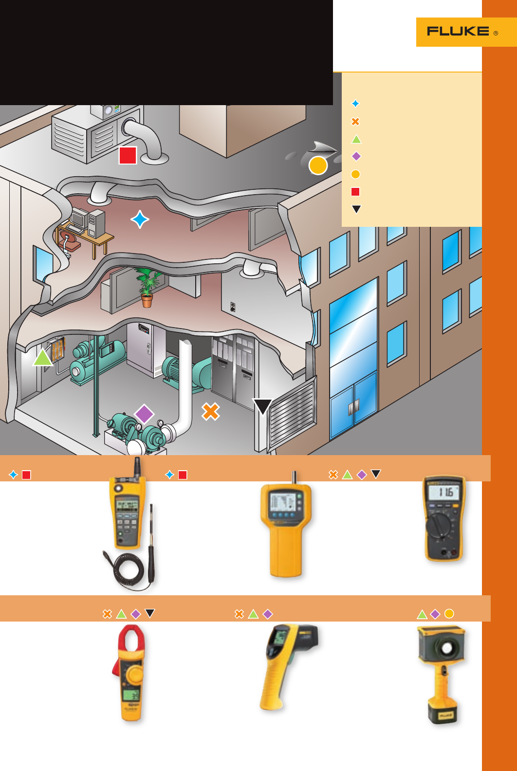
Fluke test tools to
help you get the job done
Fluke tools for HVAC/IAQ technicians
Fluke 975 AirMeter™
Best suited for:
Optimizing HVAC ventilation
settings for ASHRAE 62
recommendations
• Simultaneously measures,
logs and displays tempera-
ture, humidity, velocity,
CO2 and CO
See page 54 for details
Fluke 983 Particle Counter
Best suited for:
Troubleshooting and
maintaining indoor
air quality
• Measures particle size,
temperature, and relative
humidity
• Data logging and six-
channel particle size
display
See page 55 for details
Fluke 116 Digital Multimeter
Best suited for:
Troubleshooting HVAC
equipment and flame
sensors
• Thermometer and
microamps
• Volts ac/dc, resistance,
diode, continuity, and
Min/Max/Avg
See page 18 for details
Fluke 902 True-rms
HVAC Clamp Meter
Best suited for: HVAC
system diagnosis and repair
• Capacitance and true-rms
• DC current to 200 µA
• Contact temperature
See page 54 for details
Fluke 561 HVACPro IR
Thermometer
Best suited for: Measuring
hot, moving, electrical
energized objects
• Contact and non-contact
measurement
• Compatible with
standard type-K
thermocouple
• Includes Velcro® pipe
probe
See page 52 for details
Fluke IR Insight XS/XST
Thermal Imagers
Best suited for:
Quick, accurate building
diagnostic surveys
• High resolution
images and display
• Industry -leading
thermal sensitivity
• Simple, one-button
operation
See page 50 for details
Legend
Indoor Air Comfort
Superheat and Subcooling
Electrical
Motors/Pumps/Compressors
Building Diagnostics
Filtration and Ventilation
Furnace
6Online Resource Centers
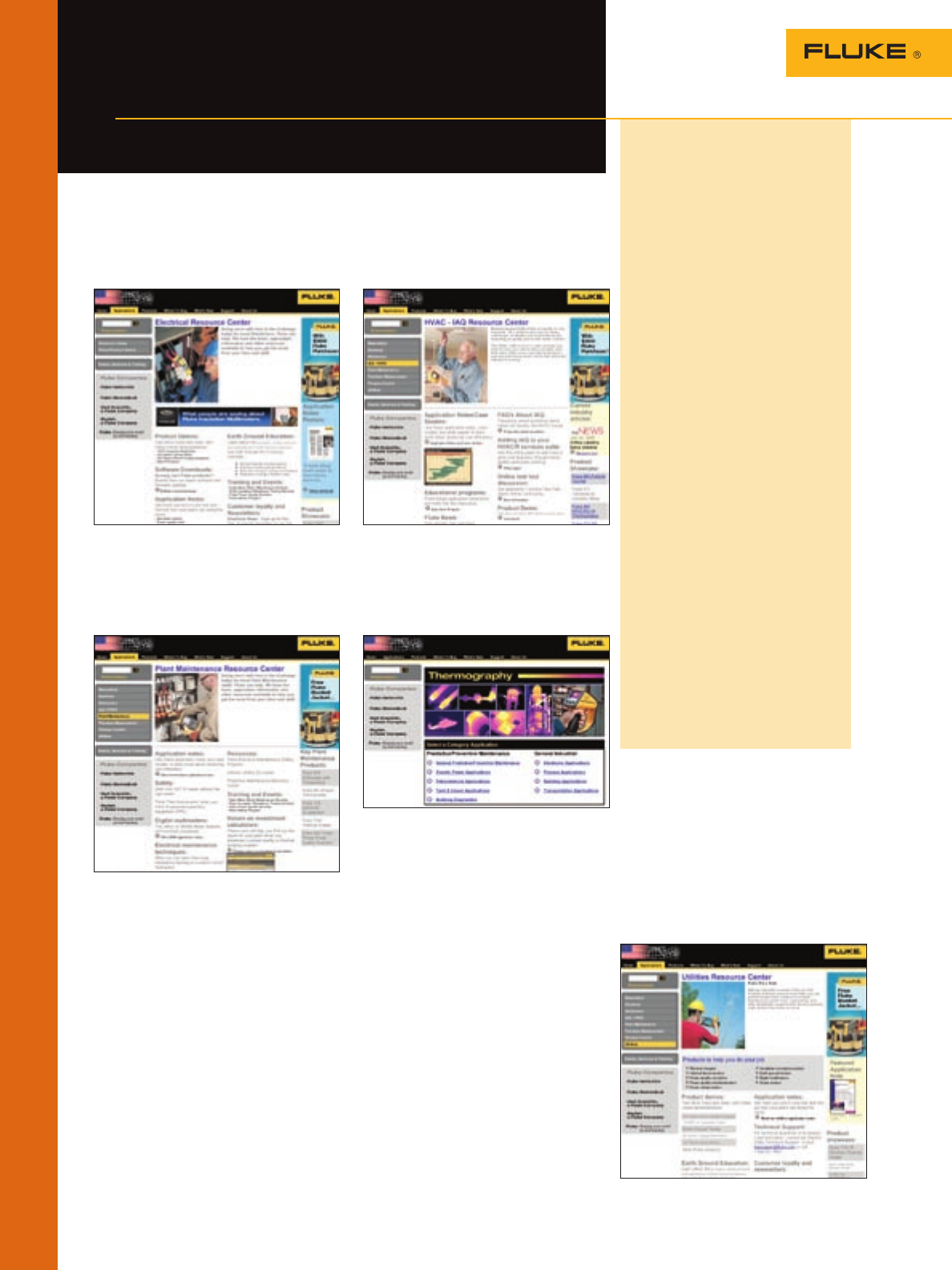
Online resource centers
Test tool applications
Electrical Resource Center
www.fluke.com/electrical_resource_ctr
Product demos, software downloads, earth
ground education, application notes, train-
ing and events information.
Plant Maintenance
Resource Center
www.fluke.com/plant_resource_ctr
ROI calculator, PDM program, maintenance
techniques, tool profiles, common culprits.
HVAC/IAQ Resource Center
www.fluke.com/IAQ
FAQs, white papers, case studies and
application notes, downloads, and
product demos.
Thermal Imaging
Resource Center
www.fluke.com/thermal_resource
Online product selection guide, product
information, application notes, software
Biomedical Resource Center
www.fluke.com/biomed_resource_ctr
Product news and information, catalog,
trade-up program, and tradeshow
schedule.
Electronics Resource Center
www.fluke.com/electronics_resource_ctr
Tips from the field, product demos, applica-
tion notes, and product showcase.
Intrinsic Safety Resource Center
www.fluke.com/ex
Standards explanations, industry applica-
tions, guidelines, and product information.
Building Diagnostics
Resource Center
www.fluke.com/buildings
Image gallery, application notes, and
expert tips on using thermography to
identify structural, thermal, moisture, and
air leakage problems in buildings.
Precision Measurement and
Calibration Resource Center
www.fluke.com/precision_resource_ctr
New product information, e-news bulletins,
total solutions newsletter, industry links,
users community, used certified equipment,
technical papers and application notes.
Process Control
Resource Center
www.fluke.com/process_resource_ctr
Process calibration glossary, industry infor-
mation, ROI calculator, application notes,
and product demos.
Solve more
problems with
Fluke Tools
Fluke is more than digital
multimeters. These days, Fluke
offers the ultimate go-everywhere
DMM as well as specialized tools
for electrical, industrial, HVAC, and
electronic applications.
Increasingly, technicians are
using their Fluke tools together,
in a one-two troubleshooting
combination.
Use a thermal imager to find a
problem, then use a DMM, clamp
meter, or power quality analyzer to
fix it.
Use a power logger to check
power usage, use an AirMeter to
optimize the HVAC system, and then
log power again to see the impact of
your adjustments.
The online resource centers on
this page can help you find the right
tools for your applications, learn
how to use them, and get to work.
Your site-specific knowledge plus
Fluke tools makes for an impressive
troubleshooting team.
Plus, the new generation of Fluke
tools is smaller, lighter, and easier
to use than ever. They meet higher
safety standards. They download to
reports. And they’re as reliable and
tough as ever.
By offering a system of tools that
work together, Fluke aims to help
you solve more problems, faster and
better, no matter where you work.
Utilities Resource Center
www.fluke.com/utilities_resource_ctr
Training and events information, product
demos, specialized technical support,
application notes, and power quality,
thermography and earth ground infor-
mation for utilities.
7
Application Notes
www.fluke.com/appnotes
Fluke has a
complete library
of applica-
tion notes and
white papers on
topics ranging
from predictive
maintenance to
maintaining
motors and
drives to
automotive
troubleshooting
and more.
FlukePlus
Tool Info Online
www.fluke.com/flukeplus
FlukePlus is a website for test tool users
who want to learn more. Sign up and get:
• Product tips and “how to” articles
• Previews of the newest Fluke tools
• Special offers and promotions
• Direct connection to Fluke technical
support
Fluke News
www.fluke.com/flukenews
Fluke News is published two times
a year with new tips, tools and
articles in each issue.
Fluke Electrical News
For electrical
contractors or
electricians
working in
residential,
commercial,
or industrial
environments.
Fluke Plant News
For electricians,
electrical
supervisors,
field service
technicians,
plant
technicians
and process
engineers
maintaining
industrial
equipment in
the field or
plant.
Fluke Electronics News
For electronics
or electrical
engineers who
use DMMs,
benchtop
meters, and
oscilloscopes
in prototyping,
design and
field evaluation
situations.
Fluke HVAC/IAQ News
All-new articles
about tools,
measuring
practices,
and business
opportunities
for HVAC and
Indoor Air
Quality (IAQ)
professionals.
Fluke...
more than just tools
Test tool information
Since 1949 the Fluke Corporation has been dedicated to the design
and manufacturing of innovative test and measurement instruments.
Fluke also leads the way in providing programs, training and
resources that help you stay at the forefront of your profession.
Fluke Education
Partnership Program
www.fluke.com/education
We’ve teamed up with colleges, trade,
technical, vocational schools, and appren-
ticeship programs to bring the latest
application information and tools into the
classroom. Currently available in USA,
Canada, Brunei, Burma, India, Indonesia,
Laos, Malaysia, Philippines, Singapore,
Taiwan, Thailand and Vietnam.
Electrical Measure-
ment Safety Program
www.fluke.com/safety
Get a free safety video, a summary of
safety standards and helpful articles on
safe electrical measurement practices.
(Available only in the U.S.)
Fluke Test Tool Information
Test Tool Users
Online Community
www.fluke.com/community
See what other test tool users are saying
and get your questions answered, fast!
The Test Tool Community online bulletin
board is free and open to everyone.
8Safety
Safety and You
Why is safety important?
Why should you care?
Between five and ten times on any given
day, arc flash explosions, sufficient to send
a victim to a special burn center, take place
in the U.S. These incidents and other less
serious electrical accidents result in injury
—sometimes death—lost work time, medical
costs and insurance claims, downtime, the
list goes on.
The cost to both the victim, the victim’s
family and the company involved, are
high. Yet many of these accidents can be
prevented. The combination of training,
good measurement technique, and the use
of proper tools can significantly reduce the
chance of an accident occurring.
What are the Standards?
To provide improved protection for users,
industry standards organizations have
taken steps to clarify the hazards present
in electrical supply environments. The
American National Standards Institute
(ANSI), the Canadian Standards Association
(CSA), and the International Electro-
Technical Commission (IEC), have created
more stringent standards for voltage test
equipment used in environments of up to 1000 volts.
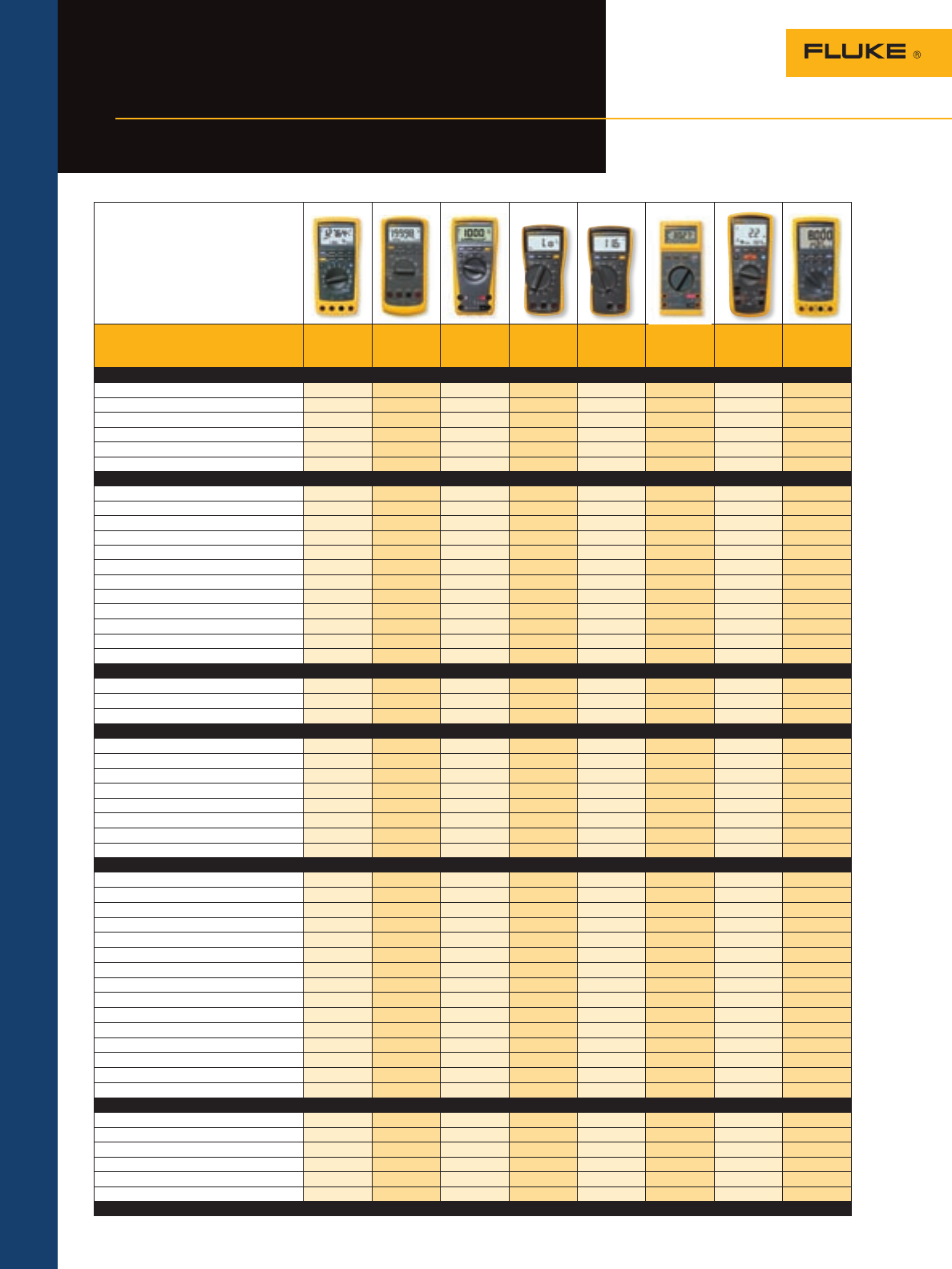
ANSI, CSA and IEC define four measurement categories of over-voltage transient
impulses. The rule of thumb is that the closer the technician is working to the power
source, the greater the danger and the higher the measurement category number. Lower
category installations usually have greater impedance, which dampens transients and
helps limit the fault current that can feed an arc.
• CAT (Category) IV is associated
with the origin of installation.
This refers to power lines at
the utility connection, but also
includes any overhead and
underground outside cable runs,
since both may be affected by
lightning.
• CAT III covers distribution level
wiring. This includes 480-volt
and 600-volt circuits such as
3-phase bus and feeder circuits,
motor control centers, load
centers and distribution panels.
Permanently installed loads are
also classed as CAT III. CAT III
includes large loads that can
generate their own transients. At this level, the trend to using higher voltage levels in
modern buildings has changed the picture and increased the potential hazards.
• CAT II covers the receptacle circuit level and plug-in loads.
• CAT I refers to protected electronic circuits.
Some installed equipment may include multiple categories. A motor drive panel, for
example, may be CAT III on the 480-volt power side, and CAT I on the control side.
Independent testing labs help ensure safety compliance
You want your tools and equipment to help you work safely. But how do you know that
a tool designed to meet a safety standard will actually deliver the performance you are
paying for?
Unfortunately it’s not enough to just look on the box. The IEC (International
Electrotechnical Commission) develops and proposes standards, but it is not responsible
for enforcing the standards. Wording like “Designed to meet specification...” may not mean
a test tool actually performs up to spec. Designer’s plans are never a substitute for an
actual independent test.
TUV and VDE
(German standards
organizations) are
approval/listing
agencies
Canadian Standards
Association (CSA)
For more information, go to www.fluke.com/safety
That’s why independent testing is
so important. To be confident, check
the product for the symbol and listing
number of Underwriters Laboratories
(UL), the Canadian Standards Associa-
tion (CSA), TÜV or another recognized
testing organization. Those symbols can
only be used if the product successfully
completed testing to the agency’s
standard, which is based on national/
international standards. That is the
closest you can come to ensuring that
the test tool you choose was actually
tested for safety.
What does the CE symbol indicate?
A product is marked CE (Conformité
Européenne) to show it conforms
to health, safety, environment and
consumer protection requirements
established by the European Commis-
sion. Products from outside the Euro-
pean Union cannot be sold there unless
they comply with applicable directives.
But manufacturers are permitted to
self-certify that they have met the
standards, issue their own Declaration
of Conformity, and mark the product
“CE.” The CE mark is not, therefore, a
guarantee of independent testing.
Why are Fluke products different?
Don’t be confused by “Listed” vs.
“Designed to” in your test tools.
IEC sets the standards but does not
test or inspect for compliance. So a
manufacturer can claim to “design
to” a standard with no independent
verification. To be UL-Listed, CSA or
TUV-Certified, a manufacturer must
employ the listing agency to TEST
the product’s compliance with the
standard. Look for the listing agency’s
emblem on the meter.
Go to www.fluke.com/safety to view The
Fluke Electrical Measurement Safety Program
and order your free copy of the Fluke Safety
video. This video makes the standards easy
to understand and can be used as part of
your own internal safety program.
Underwriters
Laboratories (UL)
United States
Department of
Labor Mine Safety
and Health
Administration

9
Service
Technical service at your fingertips
We know Fluke tool users put their tools through the paces, so we’re ready to answer
your questions and help keep your tools in top shape. No matter what application, in
what industry. And we’ll do it through real technical service professionals in Everett,
Washington.
When you need questions answered, call Sales and Application Support at
1-888-44-Fluke or email fluke-info@fluke.com
The Fluke experts answering your call can help with just about any test tool question.
They specialize in:
• Advice on what to buy, from problem analysis to tool compatibility and configuration
“If I’m working with three phase motors, what’s the best tool to use?”
• Help on how to use your tools in any application, from automotive to industrial
“How come I’m not getting a reading?”
“How do I transfer my test results?” “How do I measure harmonics?”
When your Fluke tools need repair or calibration, call Customer Support Services
at 1-888-99-Fluke or email service.status@fluke.com. Customers outside the U.S.
email service.international@fluke.com or visit www.fluke.com/service to find your
nearest location.
If your tool isn’t working correctly, or if you dropped it, ran over it, or dunked it in the pool,
call Fluke. If it’s not under warranty, we’ll give you a cost estimate over the phone. Once
you send it in, we’ll verify the problem, fix it, test it and put it back in the mail often in
less than five working days.
Fluke recommends having your DMMs, Calibrators and ScopeMeter test tools calibrated
once a year—especially if you use them often or need accurate measurements to meet
regulations requirements. Calibration compares your tool’s measurements to the accuracy
standard—sort of like setting your watch to match an atomic clock. Some test tools live a
pretty rough life. If you calibrate them, you know they’re accurate—even after what you
put them through.
For more information on servicing your Fluke tools outside of the U.S., see page 2 for contact information.
Fluke customer support is ready to help
Service Information
Think of Fluke first for technical
service, repair and calibration
Calibrating a thermometer.
Application note, literature code
2153519:
Why calibrate test
equipment?
Why would
a digital test
tool need to be
calibrated? It’s
not as though
any analog
parts will go
out of balance.
Well, have any
events occurred
that would
render your
instruments
less accurate or
unsafe? Is accu-
rate measurement essential to your
operations? Are you trending data?
Read this application note to find out
what causes calibration problems
and whether you should consider
calibrating your test instruments.
Visit www.fluke.com/why-calibrate
Application note, literature code
2138394:
Shocking treatment
Because of
our commit-
ment to safety,
all Fluke
equipment
is designed
to provide as
much protec-
tion as pos-
sible from
the inherent
dangers of
working in the
unsettled sea
of electricity.
Fluke products are dropped, shocked,
short circuited, injected with thou-
sands of volts of electricity and
forced to endure extreme tempera-
ture, just to get out the door.
To learn more about our product tests,
visit www.fluke.com/shocking
Digital Multimeters
Pick the right digital
multimeter for you
Digital Multimeter Selection Guide
Models
Highest
accuracy with
data logging
189
Industrial
troubleshooting
87V
True-rms and
built-in
thermometer
179
Designed
for building
maintenance
117
Designed
for HVAC/R
technicians
116
Waterproof
and chemical
resistant
27
Two powerful
tools in one
1587
4-20 mA loop
diagnostics
789
Basic features •
True-rms readings AC+DC AC AC AC AC AC AC
Basic dc accuracy 0.025 % 0.05 % 0.09 % 0.5 % 0.5 % 0.1 % 0.09 % 0.1 %
Wide bandwidth 100 kHz 20 kHz 30 kHz
Auto/manual ranging ••••••••
Digits 4-1⁄2 4-1⁄2 3-1⁄2 3-1⁄2 3-1⁄2 3-1⁄2 3-1⁄2
Counts 50000 20000 6000 6000 6000 3200 6000 4000
Measurements
Voltage ac/dc 1000 V 1000 V 1000 V 600 V 600 V 1000 V 1000 V 1000 V
Current ac/dc 10 A 10 A 10 A 10 A 600 µA 10 A 400 mA 1 A
Resistance 500 MW50 MW50 MW40 MW40 MW32 MW50 MW40 MW
Frequency 1 MHz 200 kHz 100 kHz 50 kHz 50 kHz 100 kHz 20 kHz
Capacitance 50 mF 10 mF 10 mF 10 mF 10 mF 10 mF
Temperature +1350 °C +1090 °C +400 °C +400 °C +500 °C
dB 60 dB
Conductance 50 nS 50 nS 32 nS
Duty cycle/pulse width • •
Motor drive measurements/low pass filter • •
Continuity with beeper ••••••••
Diode test ••••••••
Display
Dual display • •
Analog bargraph •••••• •
Backlight ••••• ••
Data storage and exchange
Min/Max recording •••••••
Min/Max recording/with time stamp • •
Fast Min/Max 250 µs 250 µs
Display Hold/Auto (Touch) Hold •••••• •
Relative reference • • • •
PC interface • •
Data logging •with PC
Readings memories 100
Other features
Automatic selection, LoZ •
Insulation test range 0.01 MW to 2 GW
VoltAlert, non-contact ac voltage detector) •
Real time clock •
Overmolded case, integrated holster • • •
Removable holster • • • •
ToolPak Magnetic Hangar compatibility ••••• •
Closed case calibration ••••• ••
Separate battery door ••••••••
Completely sealed/watertight •
Automatic power off ••••• ••
Low battery indication ••••••••
Operating temperature range –20 °C, +55 °C –20 °C, +55 °C –10 °C, +50 °C –10 °C, +50 °C –10 °C, +50 °C –40 °C, +55 °C –20 °C, +55 °C
4-20 mA •
24 V loop supply •
Warranty and electrical safety
Limited lifetime warranty • • • •
Warranty (years) 3 3 3 3
Input alert • •
Dangerous voltage indication ••••• ••
CAT III measurements 1000 V 1000 V 1000 V 600 V 600 V 1000 V 1000 V 1000 V
CAT IV measurements 600 V 600 V 600 V 600 V 600 V
See page 12 14 15 17 18 19 35 43
More comprehensive information is available at www.fluke.com/dmm
10
Digital Multimeters 11
Test faster and safer
with a new Fluke
Move up to more measurement
performance and safety
Get accurate voltage and frequency
measurements on adjustable speed
motor drives with the 87V.
87
Use the built-in data logging fea-
ture of the 189 to record readings
and the time they occurred to catch
intermittent problems.
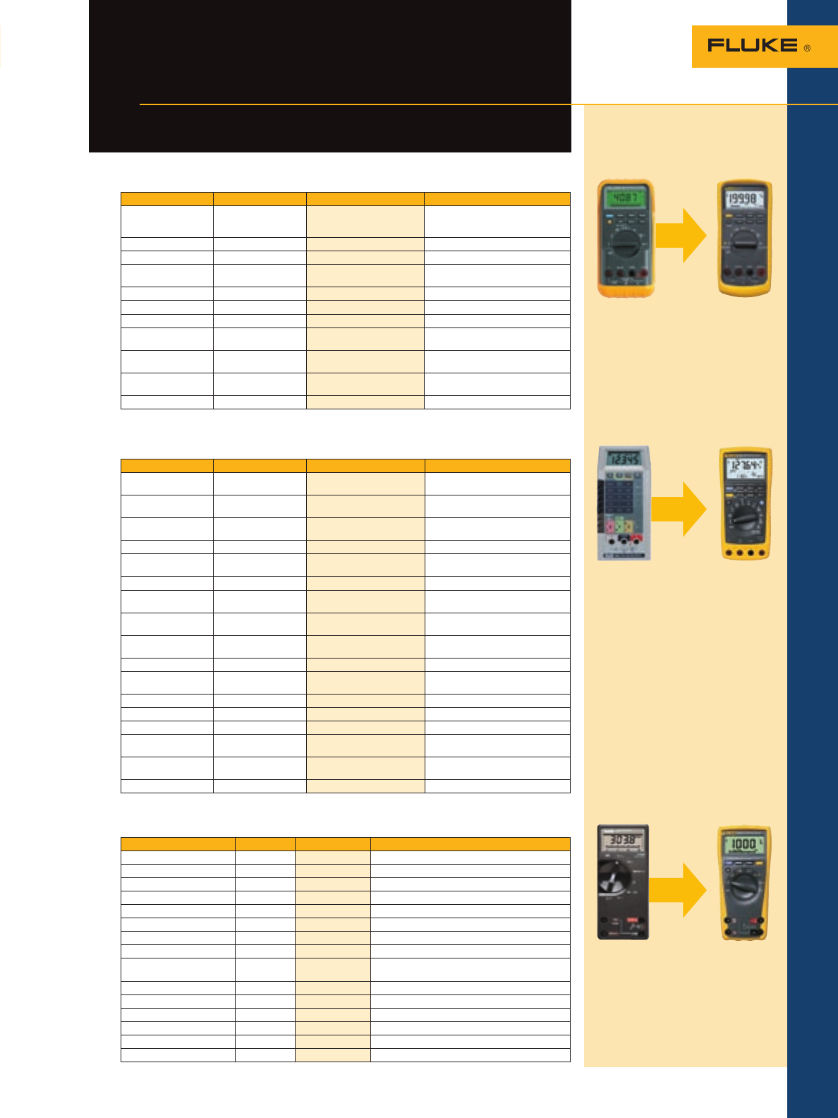
Move up from your old 87 and benefit from more than a dozen improvements
Function Original 87 87V Benefit
Selectable filter for
motor drives No Yes Accurate voltage and frequency
measurements on pulse width
modulated signals
Built-in thermometer No Yes No separate thermometer required
Capacitance 5 nf to 5 µF 5 nf to 10,000 µF Measure more capacitors
V dc accuracy and
resolution 0.1 %, 10 µV 0.05 %, 10 µV Precise measurements in a
handheld tool
Display digits 13.5 mm x 7 mm 15.25 mm x 8.5 mm 30 % larger makes it easy to read
Backlight Green 2-level, bright white Easier to read in dark locations
Magnetic hanger No Optional (included with kit) Position meter for easy viewing
Peak capture 1 ms 250 µS Record intermittent problems four
times faster
CAT electrical safety
rating No Yes, 2nd edition ANSI and
IEC 61010
Increased protection from 8 kV
spikes that can cause arc flash
Battery door No Yes Change battery quickly without
breaking cal seal
Warranty Expired Limited lifetime Lower cost of ownership
Move up from your old 8060 or 8062 and benefit from more than 20 improvements
Function 8060 189 Benefit
Built-in recorder with
time stamp No Yes Record and view intermittent
problems without a chart recorder
PC interface No Yes, software optional Transfer readings to a PC for
analysis and documentation
Built-in thermometer No Yes, probe optional No need to carry a separate
thermometer
Capacitance No 5 nf to 50,000 µF Measure capacitors with one tool
V dc and V ac
resolution 10 µV 1 µV Precise measurements in a
handheld tool
dBv and dBm Yes Yes Measure communication circuits
Duty cycle and pulse
width No Yes Measure control circuits
In-line current 2 A 10 A, 1000 V fuse Safely measure five times more
current
Relative offset No Yes Remove test lead resistance
See small signal variations
Range selection Manual, 8 switches Auto/Manual range Simpler to use, more durable
Peak capture,
MIN/MAX No 250 µS Record intermittent problems
Backlight No 2-level, bright white Easier to read in dark locations
Holster No Integrated overmold Stands up to accidental drops
Magnetic hanger No optional TPAK Position meter for easy viewing
CAT electrical
safety rating No Yes, 2nd edition
ANSI and IEC
Increased protection from 8 kV
spikes that can cause arc flash
Battery door No Yes Change battery quickly without
breaking cal seal
Warranty Expired Limited lifetime Lower cost of ownership
Move up from your old 70 or 20 series and benefit from more than 15 improvements
Feature Original 77 179 Benefit
True-rms No Yes Accurate on non-linear signals
Accuracy, basic dc 0.3 % 0.09 % Three times more accurate
Temperature No Yes No need for a separate thermometer
Min/Max/Average No Yes Capture intermittent problems
Display size Small 20 % larger Large, easy to read
Display backlight No Yes Easy to read in dark locations
Simple to use Yes Yes No retraining required
Probe holders Yes Improved One-hand operation
Latest electrical measure-
ment safety standards Not rated 1000 V CAT III,
600 V CAT IV
Designed to withstand 8,000 volt peak transient
impulses and protect against arc flash
Optional magnetic hanger No Yes Position meter in best location
Warranty Expired Limited lifetime Lower cost of ownership
Frequency No Yes Built in frequency counter
Capacitance No Yes Measure motor capacitors and components
Max. ac voltage 750 1000 Wider measurement range
Battery door No Yes Change battery quickly without breaking cal seal
87V
8060 189
77 179
The ultimate multi-purpose meter,
the 179 combines precision, safety
and reliability to help you get any
job done.
Test Tools Catalog
Volume 36
Contents
12 Digital Multimeters
Specifications – 189 and 187 DMMs
Recommended accessories – 189 and 187 DMMs
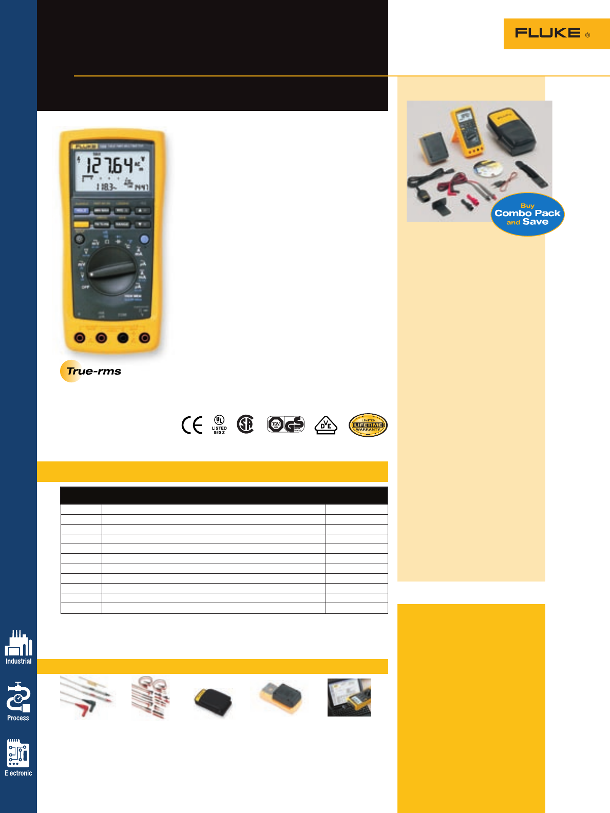
Fluke 189 Logging
Multimeter
Solve complex problems for electronic
and industrial applications
Included accessories
Every 180 series meter comes pack-
aged with TL71 Silicone Test Leads,
probe holders, two AC72 Alligator
Clips, four AA batteries (installed),
CD-ROM (users manual and techni-
cal notes) and operator’s guide.
Ordering information
Fluke-189/FVF2 Logging Multimeter
and Software
Combo Pack
Fluke-189 Logging Multimeter
Fluke-187 Digital Multimeter
FVF-SC2 FlukeView Forms
Software w/cable
The Fluke 189 is the most advanced meter with features,
precision and accuracy to troubleshoot industrial and
electronic equipment in the field or on the bench. The
Fluke 189 has a built-in data logger to record measure-
ments unattended. Recorded data can be viewed on
the 189 or transferred to a PC with optional FlukeView®
Forms software.
• Built in data logger (Fluke 189) records reading and
time to catch intermittent problems
• True-rms, 100 KHz bandwidth for precise
measurement of non linear signals
• 0.025 % dc accuracy and 1 microvolt resolution for
bench meter performance in a handheld package
• Measure 20 A for up to 30 seconds, 10 A continuous
• Temperature, capacitance, dB, frequency, pulse width
and duty cycle to find more problems with one tool
• Large bright white display with dual parameter
readout to view multiple readings at once
• Min/Max with timestamp to record signal fluctuations
• Peak capture to measure transients as short as 250 µS
• Isolated IR communication port to send data to a PC
(with optional FVF pack)
• Premium test leads and alligator clips (AC72) included
• New! Optional USB data cable with FlukeView Forms
• New! Optional battery pack (BP189) extends battery
life to over 400 hours
Electrical safety
All inputs are protected to measurement CAT III 1000 V
and CAT IV 600 V.
Available in non-logging version as Fluke 187
*10 A continuous, 20 A for up to 30 seconds and not specified.
Battery life: 72 hours typical (alkaline), 450 hours typical with Battery Extender (BP189)
Size (LxWxD): 203 mm x 100 mm x 50 mm (8.00 in x 3.94 in x 1.97 in)
Weight: 0.545 kg (19.2 oz)
Best accuracy
Function Range and resolution 180 Series
V dc 50.000 mV, 500.00 mV, 3000.0 mV, 5.0000 V, 50.000 V, 500.00 V, 1000.0 V ± 0.025 %
V ac 50.000 mV, 500.00 mV, 3000.0 mV, 5.0000 V, 50.000 V, 500.00 V, 1000.0 V ± 0.4 %
A dc 500.00 µA, 5,000 µA, 50.000 mA, 400.00 mA, 5.0000 A, 10.000 A* ± 0.15 %
A ac 500.00 µA, 5,000 µA, 50.000 mA, 400.00 mA, 5.0000 A, 10.000 A* ± 0.75 %
Resistance 500.00 W to 500.0 MW ± 0.05 %
Capacitance 1.000 nF to 50.00 mF ± 1.00 %
Frequency 500.00 Hz, 5.0000 kHz, 50.000 kHz, 999.99 kHz ± 0.005 %
Temperature -200 ºC to 1350 ºC (-328 ºF to 2462 ºF) ± 1 % of reading
Duty cycle 10 % to 90 %, resolution 0.01 % —
Pulse width 2 ranges, 499.99 ms and 999.9 ms, best resolution 0.01 ms 3 %
dBm, dBv -62 to +60, resolution 0.01dB 0.1 dB
TL910 TL81A C125 BP189 FVF-SC2
Electronic Test Probes Test Lead Kit Meter Case High Capacity Battery Pack FlukeView Forms Software
See page 63 See page 63 See page 70 See page 65 See page 65
For more information and detailed specifications, go to www.fluke.com/dmm
NEW! The 189/FVF2
Data Logging Multimeter
and Software Combo Pack
gives you a practical,
affordable approach to
predictive maintenance.
• With built-in data logger, the
189 helps you track down
elusive, intermittent problems,
monitoring equipment with
any of its functions, while you
do other jobs
• Overlay data from six meters
or six time periods to find
cause and effect relationships
or for condition monitoring
applications
• With break-through accuracy
and precision, catch events as
brief as 50 ms
• Designed for harsh environ-
ments that would ruin most
data loggers or multimeters
• Log up to 450 hours of data
using the extended battery pack
• Turn data into meaningful
graphs and tables using
FlukeView Forms software
• TPAK™ Magnetic Hanger
allows you to securely hang
your meter for monitoring or
hands-free use
• Soft carrying case to protect
your investment
• USB cable included with kit
Log and document
13
Digital Multimeters
Compatible with
FVF-SC2 Fluke 187 and 189
Digital Multimeters,
Fluke 1550B
MegOhmMeter,
Fluke 789
ProcessMeter™
FVF-SC1 Fluke 53-II and 54-II
Thermometers
FVF-SC3 Fluke 45 Bench Meter
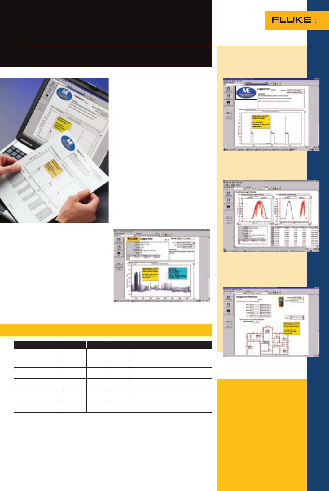
FlukeView® Forms
Software
Utilize this powerful tool to
analyze your measurements
Customize reports using your
specific data or company logo,
spot trends and document
interruptions or spikes.
A single graph overlaying two time
periods makes analysis easier.
Use the FlukeView designer to turn
simple time and event data into
fully customized reports.
Fluke 189, 189/FVF2 Kit and 187 capabilities
189/FVF2 189 187 Benefit
Fluke 180 Series Multimeter
and premium test leads •••Fluke’s top-of-the-line multimeter with maximum
feature set to troubleshoot any situation.
PC connectable •••Use to download and document test results.
Logging capabilities • • Reduce man-hours by using logging to find
problems and intermittent glitches.
FlukeView Forms software •Document and print measurement data in a clear
and organized format.
Overlay and graph data from
up to six meters • • Find elusive cause/effective relationships.
Compatible with FlukeView
Forms Demo Reader •••Allow data to be distributed and shared with
individuals throughout a company for free.
Harness the power of the data logging
function on your Fluke Digital Multimeter.
FlukeView Forms offers an easy-to-use,
customizable solution to help you document
logged data. Easy-to-use wizards allow you
to download readings from your Fluke tool
and display individual readings or a series of
measurements.
• Graph data to help you detect trends,
analyze, predict and prevent problems
• Print, save and share logged data
• Log live readings while connected to a PC,
or leave your Fluke 189 in place to capture
up to 1,000 readings for download to a PC
• Display readings from up to six different
meters on the same graph to show links
between multiple processes, events and
locations
• Record and display any function the
meter measures: volts, ohms, frequency,
capacitance, temperature, diode testing
and more
• Free demo-reader download allows
co-workers or clients to open your report
and interact with captured data
• Export data into Microsoft® Excel
To take a test drive of the power
of FlukeView Forms, download
demonstration software for free at
www.fluke.com/flukeviewforms
You can share reports and add notes to draw
attention to and explain anomalies.
For more information and detailed specifications, go to www.fluke.com/flukeviewforms
Digital Multimeters
14
Function Range and resolution
Basic accuracy
87V 83V
DC volts 600.0 mV, 6.000 V, 60.00 V, 600.0 V, 1000 V 0.05 % 0.1 %
AC volts 600.0 mV, 6.000 V, 60.00 V, 600.0 V, 1000 V 0.7 % (true-rms) 0.5 %
DC current 600.0 µA, 6000 µA, 60.00 µA, 600.O mA, 6.000 A, 10.00 A 0.2 % 0.4 %
AC current 600.0 µA, 6000 µA, 60.00 µA, 600.O mA, 6.000 A, 10.00 A 1.0 % (true-rms) 1.2 %
Temperature (excl. probe) -200 °C to 1090 °C (-328 °F to 1994 °F) 1.0 % —
80BK Temperature Probe -40 °C to 260 °C (-40 °F to 500 °F) 2.2 °C or 2 % —
Resistance 600.0 W, 6.000 kW, 60.00 kW, 600.0 kW, 6.000 MW, 50.00 MW0.2 % 0.4 %
Capacitance 10.00 nF, 100.0 nF, 1.000 µF, 10.00 µF, 100.0 µF, 9,999 µF 1.0 % 1.0 %
Frequency 199.99 Hz, 1.9999 kHz, 19.999 kHz, 199.99 kHz 0.005 % 0.005 %
Diagnostic functions for
maximum industrial productivity
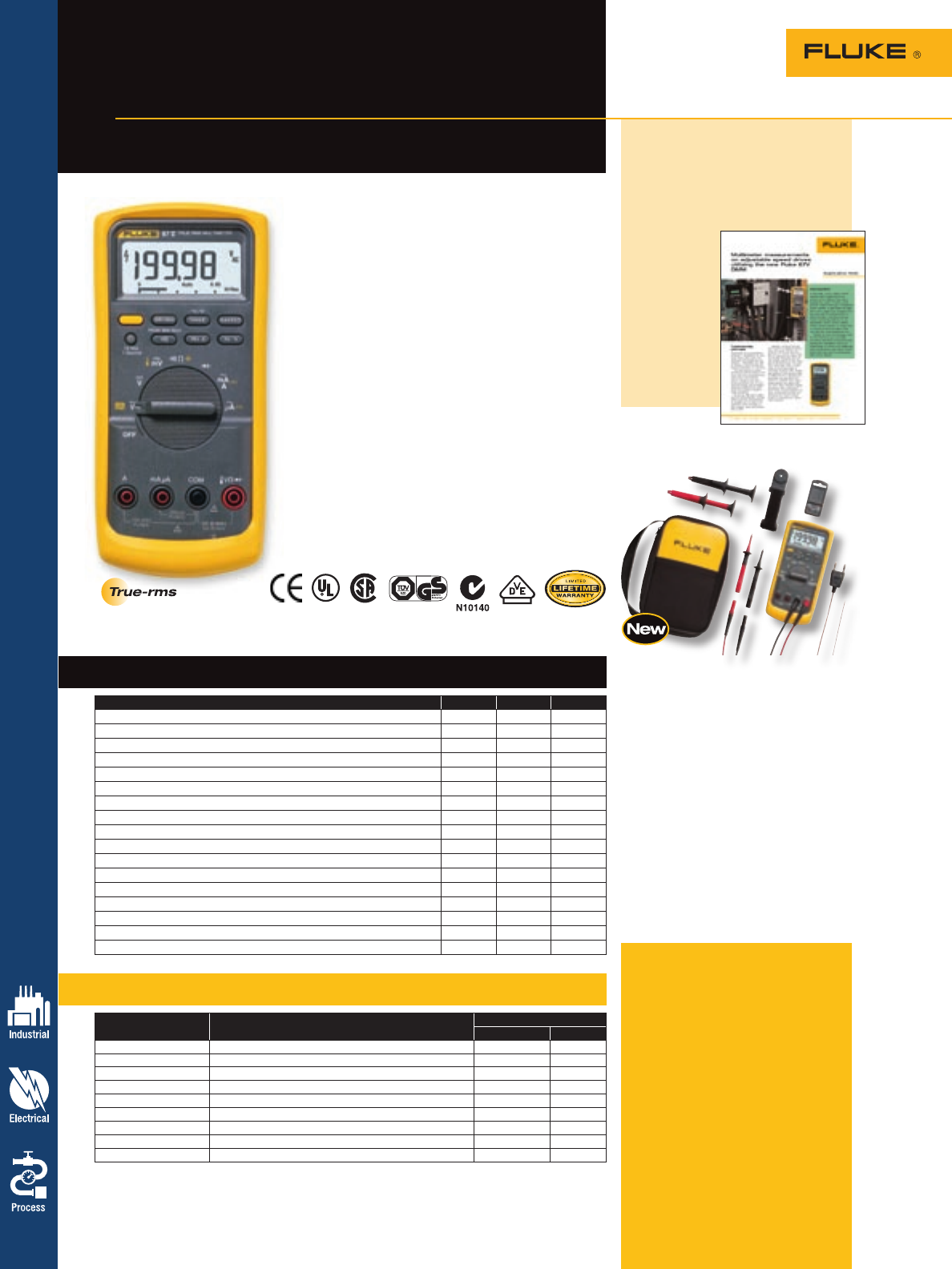
Fluke 87V
Industrial Multimeter
The Fluke 87V has measurement functions, trouble-
shooting features, resolution and accuracy to solve more
problems on motor drives, in-plant automation, power
distribution and electro-mechanical equipment.
New features for maximum productivity
• Unique function for accurate voltage and frequency
measurements on adjustable speed motor drives and
electrically noisy equipment (87V and 87V Ex)
• Large digit display with bright two level backlight
makes the 87V significantly easier to read
• Measure 20 A for up to 30 sec, 10 A continuously
• Optional magnetic hanger for easy setup and viewing
while freeing your hands for other tasks (TPAK)
• Expanded capacitance range to 10,000 µF
• Built-in thermometer (87V)
Electrical safety
All inputs are protected to CAT III 1000 V and CAT IV
600 V. They can withstand impulses in excess of 8,000 V
to help protect you from arc blast resulting from surges
and spikes.
Available in intrinsically safe version as the
Fluke 87V Ex.
Also available as 83V average responding
multimeter, see below for specifications
Fluke 87V/E2 Industrial
Electrician’s Combo Kit
Make industrial troubleshooting even
more productive with accessories.
• 87V Industrial Multimeter
• New! C35 lightweight soft case
to provide optimal protection
and storage
• TL224 1.5 m silicone leads
resist heat
• TP238 removable probes with
4 mm of exposed metal for use
on industrial circuits
• AC220 retractable long reach
alligator clips
• ToolPak™ meter hanging accessory
to hold meter to steel surfaces
• 80BK K-type temperature probe
For more information and detailed specifications, go to www.fluke.com/dmm
Specifications – 87V and 83V DMMs
Features – 87V and 83V DMMs
Application note, literature code
2155830:
Multimeter measurements
on adjustable speed drives
utilizing the Fluke 87V DMM
How do I
troubleshoot
an adjustable
speed drive
with a digital
multimeter?
Read this and
other applica-
tion notes at
www.fluke.
com/library
Battery life: 400 hours typical with backlight off. Size (LxWxD): 201 mm x 98 mm x 52 mm (7.9 in x 3.8 in x 2 in).
Weight: 355 g (22 oz)
Included accessories
Every Fluke 83V and 87V meter
comes packaged with TL75 Test
Leads, AC72 Alligator Clips,
holster, 9 V battery (installed),
80BK Temperature Probe (87V only)
CD-ROM (users manual and techni-
cal notes) and operator’s guide.
Ordering information
Fluke-87-5 Industrial True-rms
Multimeter with
Temperature
Fluke-87-5/E2 Industrial
Electrician’s
Combo Kit
Fluke-83-5 Industrial Multimeter
Feature 87V Ex 87V 83V
ATEX II 2G EEx ia IICT4 safety rating for use in Zone 1 and Zone 2 •
True-rms ac voltage and current for accurate measurements on non linear signals • •
Selectable filter for accurate voltage and frequency measurements on motor drives • •
0.05 % dc accuracy • •
4-1/2 digit mode for precise measurements • •
Built-in thermometer lets you carry one less tool • •
Large display digits and two level bright white backlight for increased visibility •••
10,000 µF capacitance range for components and motor caps •••
Peak capture to record transients as fast as 250 µs • •
Measure up to 1000 V ac and dc •••
Measure up to 10 A, 20 A for up to 30 seconds •••
Auto and manual ranging for maximum flexibility •••
Analog bargraph •••
Frequency to 200 kHz and % duty cycle •••
Min/Max and average recording to capture variations automatically •• •
Relative mode to remove test lead resistance from low ohms measurements •••
Access door for fast battery changes without breaking the calibration seal •••
15
15
Digital Multimeters
For more information and detailed specifications, go to www.fluke.com/dmm
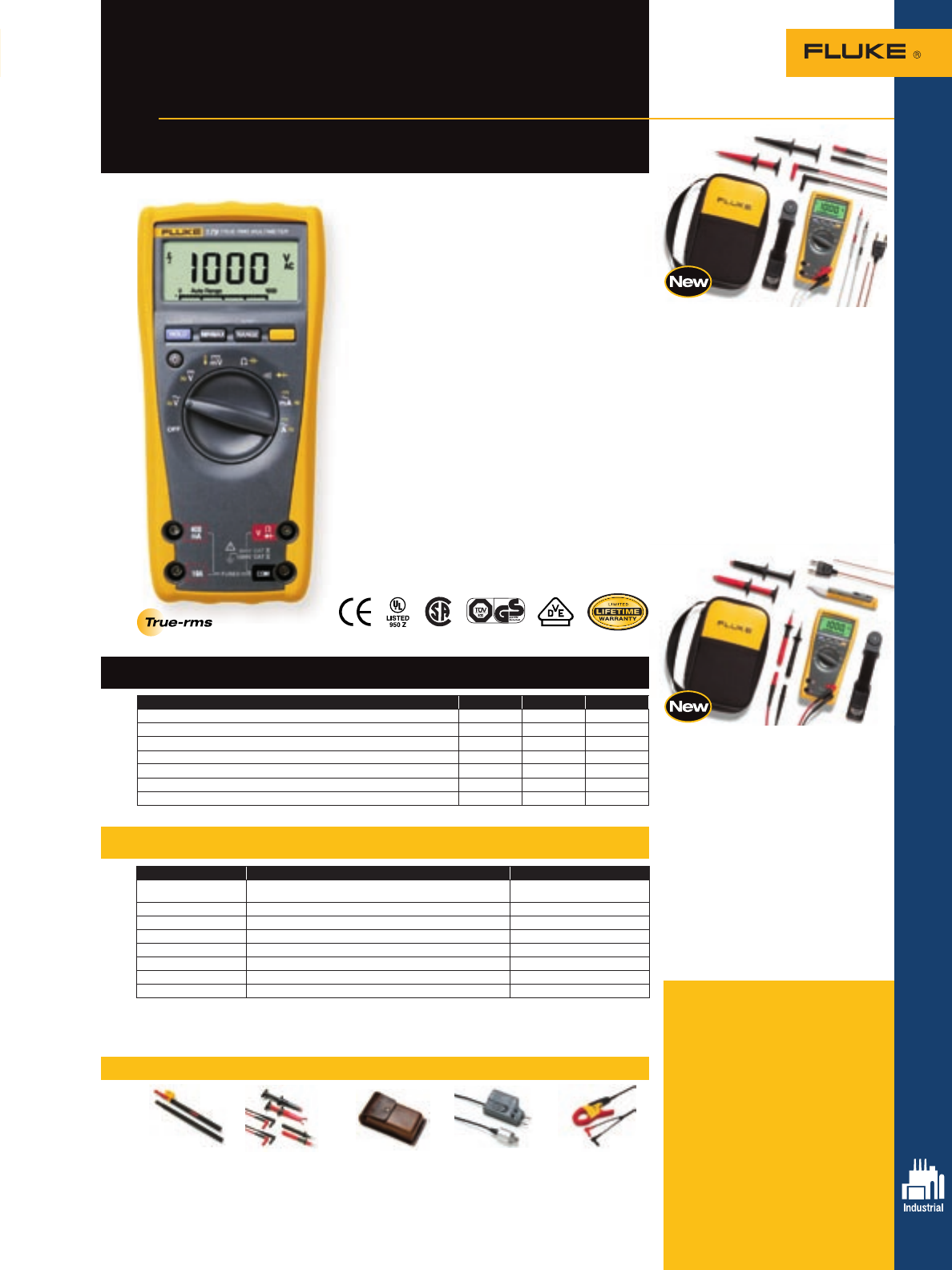
Fluke 179 Digital
Multimeter
Versatile meters for maintenance
and field service
179/EDA2 Electronics
Multimeter and Deluxe
Accessory Combo Kit
• 179 True-rms Digital Multimeter
• New! C35 lightweight soft case
to provide optimal protection
and storage
• TL910 Electronic Test Probes
• TL224 SureGrip™ Silicone Test
Leads resist heat
• AC280 SureGrip™ Heavy Duty
Hook Clips
• 80BK Type-K temperature probe
• ToolPak™ meter hanging accessory
to hold meter to steel surfaces
Specifications – 179, 177 and 175 DMMs
Features – 175, 177 and 179 DMMs
Recommended accessories – 179, 177 and 175 DMMs
The 179 true-rms Multimeter has the features needed
to find most electrical and HVAC problems. Simple
to use with significant improvements over the original
Fluke 70 Series like true-rms, the 179 has more
measurement functions, conformance to the latest
safety standards and a much larger display that’s
easier to view.
Features include:
• Wide 1000 V measurement range
• True-rms for precise measurement of non
linear signals
• Capacitance, resistance, continuity and frequency
• Built-in thermometer (Fluke 179 only)
• Large, easy-to-read display
• Backlight for work in dimly lit areas
(Fluke 177 and179 only)
• Min/Max/Avg to record signal fluctuations
• Free your hands with the optional TPAK magnetic
hanger (Fluke TPAK)
Electrical safety
All inputs are protected to measurement CAT III 1000 V
and CAT IV 600 V. This meter can withstand transient
impulses in excess of 8000 V to help protect you from
arc blasts resulting from surges and spikes.
Feature 179 177 175
Max voltage 1000 1000 1000
True-rms • • •
Temperature •
Basic dc accuracy 0.09 % 0.09 % 0.15 %
Backlight • •
Min/Max/Avg •• •
ToolPak meter hanging kit with magnet Opt Opt Opt
1All ac voltage and ac current ranges are specified from 5 % of range to 100 % of range.
210 A continuous, 20 A for up to 30 seconds.
3Voltage frequency is specified from 2 Hz to 100 kHz. Current Frequency is specified from 2 Hz to 30 kHz.
Battery life: 200 hours typical for alkaline. Size (HxWxL): 4.3 cm x 9.0 cm x 18.5 cm (1.7 in x 3.5 in x 7.3 in)
Function Range and resolution Best accuracy
DC voltage 600.0 mV, 6.000 V, 60.00 V, 600.0 V, 1000 V ± 0.09 % (Models 177 and 179)
± 0.15 % (Model 175)
AC voltage1600.0 mV, 6.000 V, 60.00 V, 600.0 V, 1000 V ± 1.0 % of reading
DC current 60.00 mA, 400.0 mA, 6.000 A, 10.00 A2± 1.0 % of reading
AC current2 60.00 mA, 400.0 mA, 6.000 A, 10.00 A2± 1.5 % of reading
Resistance 600.0 W, 6.000 kW, 60.00 kW, 600.0 kW, 6.000 MW, 50.00 MW± 0.9 % of reading
Capacitance 1000 nF, 10.00 µF, 100.0 µF, 9999 µF ± 1.2 % of reading
Frequency399.99 Hz, 999.9 Hz, 9.999 Hz, 99.99 kHz ± 0.1 % of reading
Temperature (Model 179) -40 ºC to +400 ºC (-40 ºF to +752 ºF) 1.0 % of reading
L210 TL220 C510 PV350 i400s
Probe Extender SureGrip Industrial Carrying Case Pressure-Vacuum AC Current Clamp
with light Test Lead Set See page 70 Module See page 66
See page 64 See page 61 See page 65
Included accessories
Every Fluke 170 Series meter
comes packaged with TL75 test
leads, 9 V battery (installed) and
manual. The Fluke 179 comes with
an 80BK Temperature Probe.
Ordering information
Fluke-179 Digital Multimeter
Fluke-179/1AC-II Electricians
Combo Kit
Fluke-179/EDA2 Electronics
Combo Kit
Fluke-175 Digital Multimeter
Fluke-177 Digital Multimeter
179/1AC-II Electrician’s
Multimeter and Voltage
Tester Combo Kit
• 179 True-rms Digital Multimeter
• 1AC-II VoltAlert™ Non-Contact
Voltage Detector
• New! C35 lightweight soft case to
provide optimal protection and storage
• AC220 retractable long reach
alligator clips
• TP220 sharp 12 mm stainless steel
tip provides reliable contact
• TL224 1.5 m silicone leads resist heat
• ToolPak™ meter hanging accessory
to hold meter to steel surfaces
• 80BK K-type temperature probe
Digital Multimeters
For more information and detailed specifications, go to www.fluke.com/dmm
Commercial electricians HVAC/R technicians
Field service technicians Basic electrical
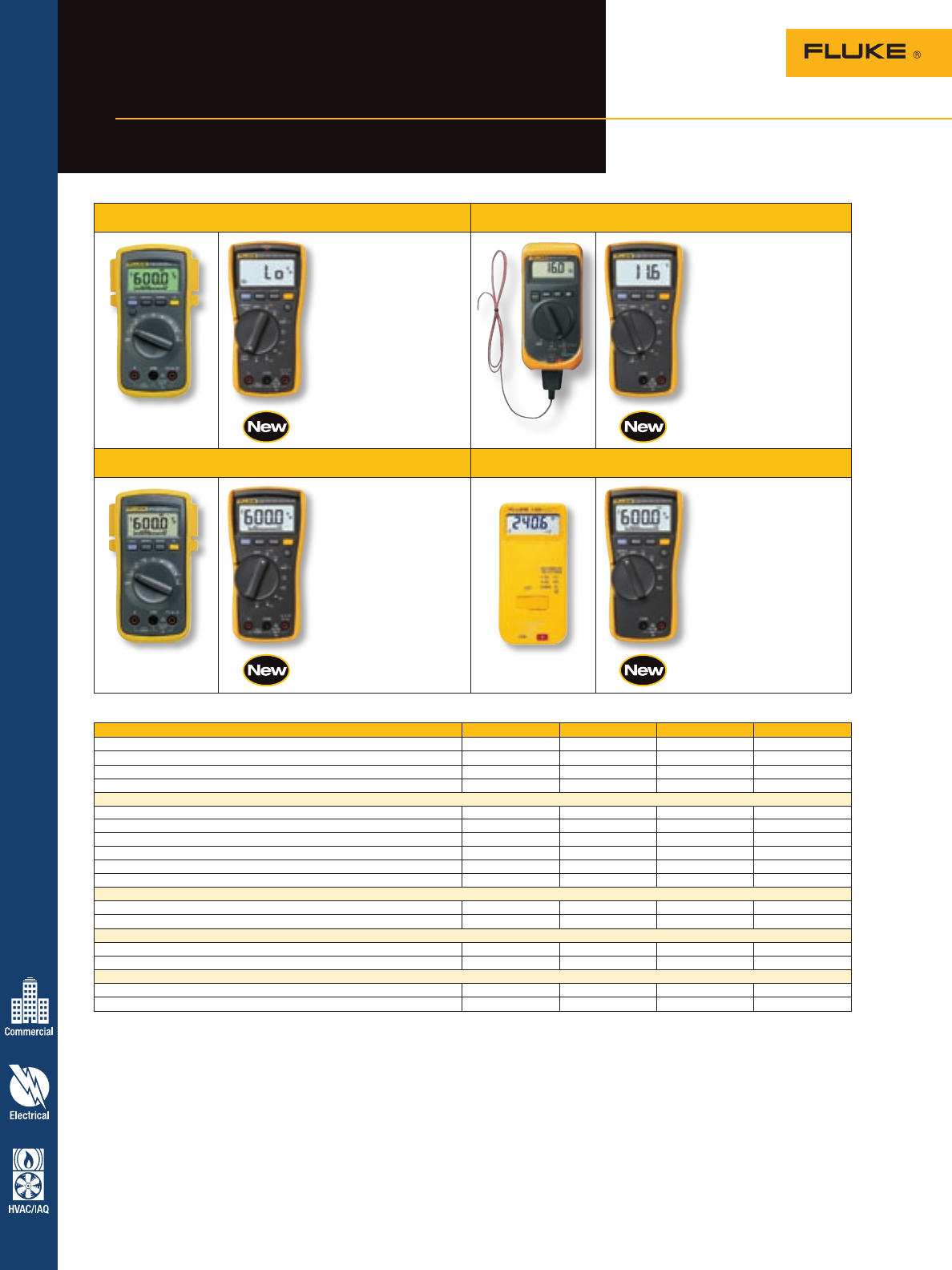
Fluke 116
• Temperature to 400 °C
• Resistance, continuity,
frequency and
capacitance
• LoZ low impedance
input for safer
troubleshooting
• AC/DC voltage to 600 V,
ac/dc current to 600 µA
Fluke 117
• VoltAlert™ non-contact
voltage detection
• LoZ low impedance
input for safer
troubleshooting
• Resistance, continuity,
frequency and
capacitance
• AC/DC voltage to 600 V,
ac/dc current to 10 A
Fluke 112
Fluke 115
• Resistance, continuity,
frequency and
capacitance
• AC/DC voltage to 600 V
• AC/DC current to 10 A
Fluke 114
• LoZ low impedance
input for safer
troubleshooting
• Resistance and
continuity
• AC/DC voltage to 600 V
Basic features 114 115 116 117
True-rms readings ac ac ac ac
Basic dc accuracy 0.5 % 0.5 % 0.5 % 0.5 %
Digits 3-1⁄2 3-1⁄2 3-1⁄2 3-1⁄2
Counts 6000 6000 6000 6000
Measurements
Voltage ac/dc 600 V 600 V 600 V 600 V
Current ac/dc — 10 A 600 µA 10 A
Resistance 40 MW40 MW40 MW40 MW
Frequency — 50 kHz 50 kHz 50 kHz
Capacitance — 10 mF 10 mF 10 mF
Temperature — — +400 °C —
Display
Analog bargraph • • • •
Large backlit display • • • •
Data storage and exchange
Min/Max recording • • • •
Display hold/auto touch hold • • • •
Other features
Automatic selection, LoZ • • •
VoltAlert, non-contact ac voltage detector •
Fluke 12, 16
Fluke 110, 111 Fluke 7-600
16
Engineered by Fluke for
working professionals
Fluke Family of True-rms
Digital Multimeters
17
17
Digital Multimeters
Recommended accessories – 117 and 115 DMMs
Specifications – 117 and 115 DMMs
Features – 117 and 115 DMMs
For more information and detailed specifications, go to www.fluke.com/dmm
ToolPak™ TL220 C50
Meter Hanger SureGrip Industrial Carrying Case
See page 71 Test Lead Set See page 70
See page 61
Included accessories
TL75 Test leads, holster, users
manual and 9 V battery (installed).
Ordering information
Fluke-117 Multimeter with
Non-Contact Voltage
Fluke-117/322 Electrician’s
Combo Kit
Fluke-115 Multimeter
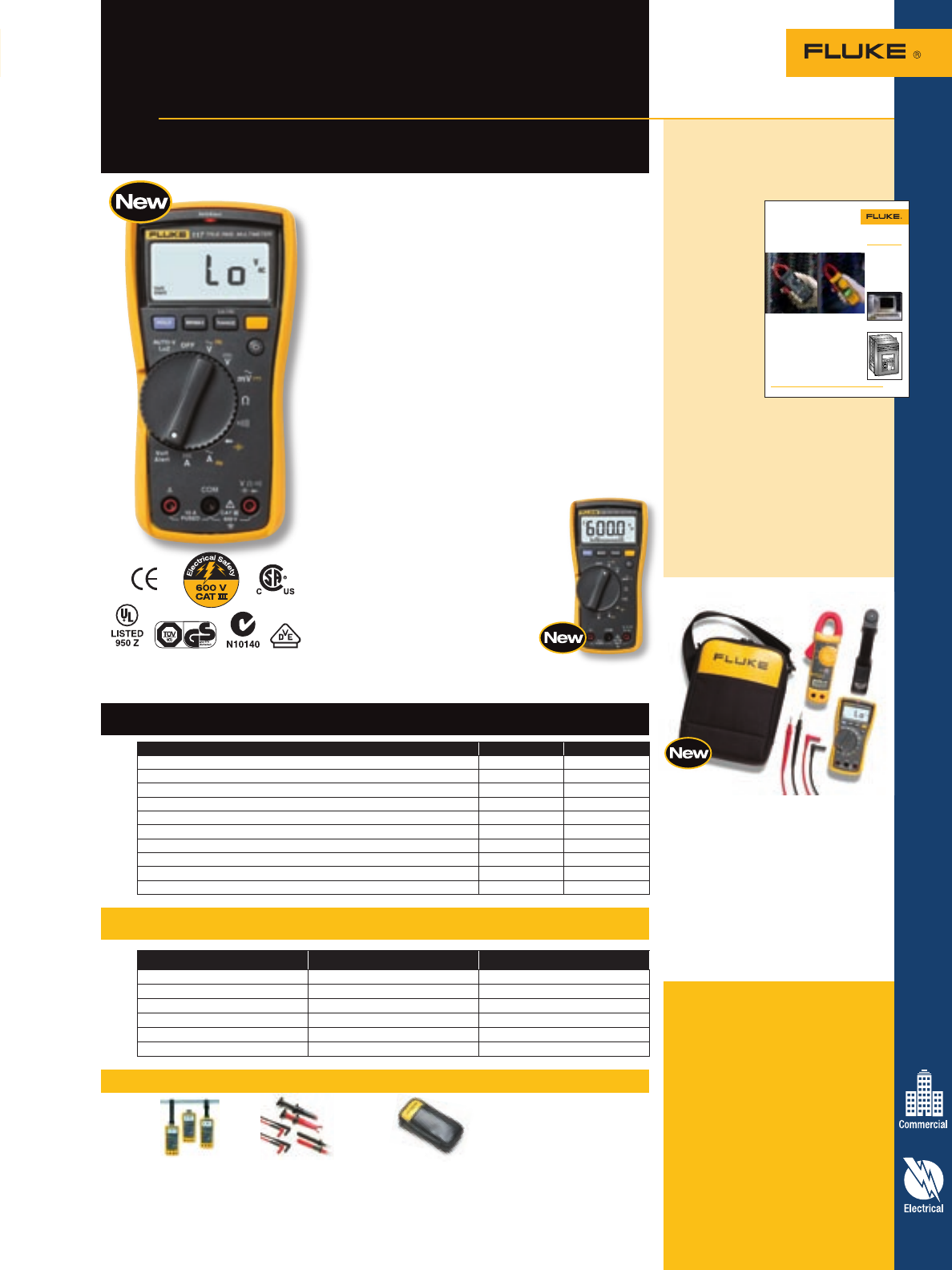
Fluke 117
The Fluke 117 is the ideal meter for demanding settings
like commercial buildings, hospitals and schools. The 117
includes integrated non-contact voltage detection to help
get the job done faster.
The 117 features include:
• VoltAlert™ Technology for integrated non-contact
voltage detection
• AutoVolt feature for automatic ac/dc voltage selection
• LoZ: low input impedance prevents false readings due
to “ghost voltage”
• Large display and white LED backlight to work in
poorly lit areas more effectively
• Compact design for one-handed operation
• Min/Max/Average to record signal fluctuations
• Compatible with optional magnetic hanger (ToolPak™)
for hands free operation
• Current measurement 20 A (30 seconds momentary;
10 A continuous)
• Resistance, continuity, frequency and capacitance
Fluke 115
The new Fluke 115 is the solution for a wide variety of
electrical and electronic testing applications.
The 115 features include:
• Large display and white LED backlight to work in poor-
ly lit areas more effectively
• Compact ergonomic design for
one-handed operation
• Min/Max/Average to record signal
fluctuations
• Resistance, continuity, frequency and capacitance
Feature 117 115
VoltAlert™•
AutoVolt/LoZ •
Analog bargraph • •
Large backlit digital display • •
True-rms for accurate measurements on non-linear loads • •
Min/Max recording • •
Display hold • •
3-1⁄2 digits • •
6000 counts • •
CAT III 600 V safety rated • •
Function Range and resolution Best accuracy
Volts ac/dc 600 V 0.5 % + 2
Current ac/dc 10 A 1.0 % + 3
Resistance 40 MW0.9 % + 2
Capacitance 1 nF to 9,999 µF 1.9 % + 2
Frequency 5 Hz to 50 kHz 0.1 % + 2
Diode 2 V 0.9 % + 2
Designed for commercial electricians
and field service technicians
Fluke 117 and 115 True-rms
Digital Multimeters
Application note, literature code
1260729:
Why true-rms?
If you’re
measuring
non-linear
loads like
variable
frequency
drives, solid
state heater
drives, or
electronics,
you need a
true-rms tool
to get accurate
readings.
Average
responding meters will read low,
up to 30 or 40 percent low in some
cases. This application note explains
what true-rms is and when you need
it in your test tool.
Want to read more? Download this
and other application notes at
www.fluke.com/library
Application Note
Introduction
Troubleshooting the electrical
service feeding adjustable
speed motor loads can be diffi-
cult if you don’t have the right
tools. New solid state motor
drives and heating controls
often conduct non-sinusoidal
(distorted) current. In other
words, the current occurs in
short pulses rather than the
smooth sine wave drawn
by a standard induction motor.
The current wave shape can
have a drastic effect on a
current clamp reading.
Basically, there are two
types of current clamps
commonly available: “average
responding” and “true-rms.”
The average responding units
are widely used and are usually
Why true-rms?
Non-linear loads need a true-rms
current clamp for accurate readings
From the Fluke Digital Library @ www.fluke.com/library
can usually be separated into
one of three categories:
1. Too much current.
2. Too much heat in the
electrical enclosure.
3. Faulty circuit breaker
(or fuse).
Your first instinct will probably
be to measure the current with
a current clamp while the load
is on. If the current is within
the circuit rating, you may be
tempted to replace the circuit
breaker.
Figure 1. One current—two readings. Which do you trust? The branch circuit above feeds a
non-linear load with distorted current. The true-rms clamp reads correctly but the average
responding clamp reads low by 32 percent.
Figure 2. A computer load.
Figure 3. An adjustable speed motor load.
Non-linear loads that cause
measurement errors.
lower cost. They give correct
readings for linear loads such
as standard induction motors,
resistance heaters, and incan-
descent lights. But when loads
are non-linear, containing
semiconductors, the average
responding meters typically
read low. Worst case non-
linear loads include small
adjustable speed drives (5 hp
or less) connected line to line
across two phases of a 480 V,
three-phase system, solid state
heater controls connected
single phase to 240 V, or
computers connected to 120 V.
When troubleshooting a branch
circuit that suffers from circuit
breaker tripping (or fuse blow-
ing), the cause of the trouble
117/322 Electrician’s
Combo Kit
• 117 True-rms digital multimeter
with non-contact voltage detection
• New! C115 Deluxe carrying case
with shoulder strap
• 322 Compact clamp meter
• TL75 Hard Point Test Lead Set
• ToolPak Magnetic Meter Hanging
Strap
Digital Multimeters
18
Recommended accessories – 116 Digital Multimeter
Specifications – 116 and 114 DMMs
Features – 116 and 114 DMMs
80AK 80PK-24 80PK-8 80BK
DMM Adapter SureGrip Air Temperature Probe Pipe Clamp Temperature Probe Integrated DMM Temperature Probe
See page 69 See page 68 See page 68 ships with 116
See page 68
Included accessories
TL75 Test Leads, 80BK Integrated
Temperature Probe (116 only),
holster, users manual and 9 V
battery (installed).
Ordering information
Fluke-116 HVAC Multimeter
with Temperature
and Microamps
Fluke-116/62 HVAC Combo Kit
Fluke-114 Electrical Multimeter
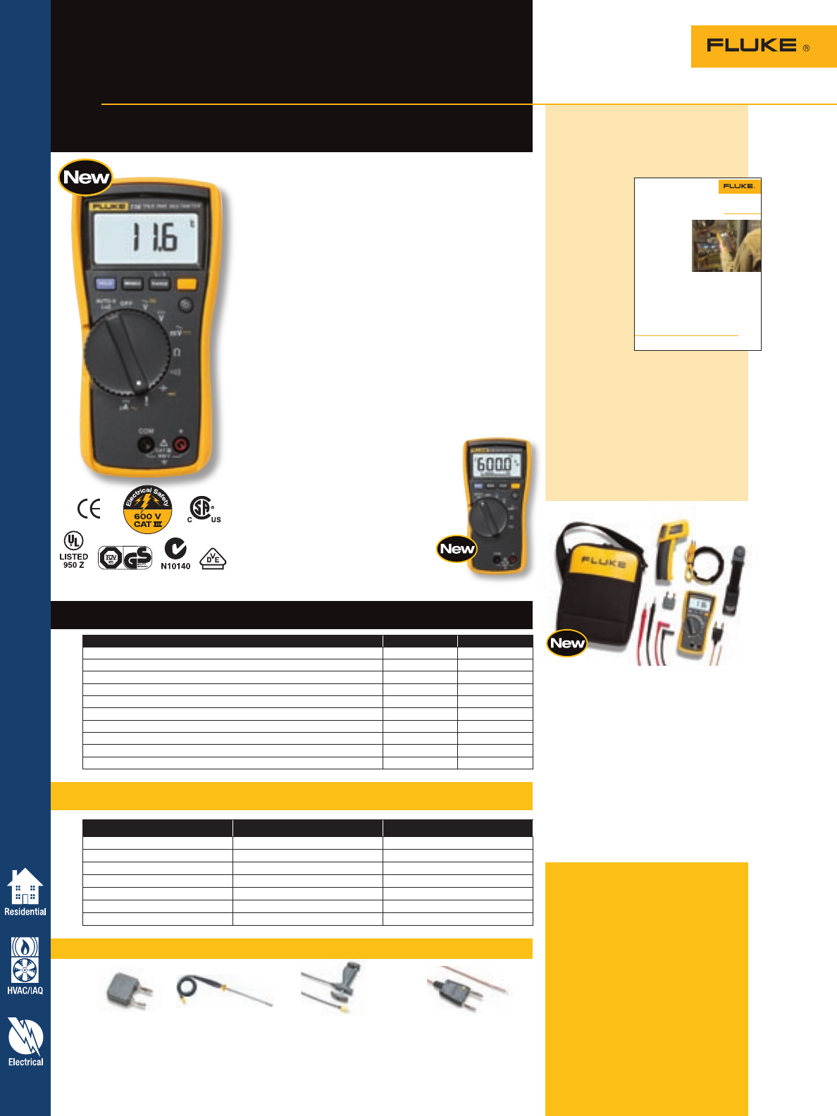
Fluke 116
The Fluke 116 was specifically designed for the HVAC
professional. It has everything needed in an HVAC meter
including temperature and microamp measurements to
quickly troubleshoot problems with HVAC equipment and
flame sensors.
The 116 features include:
• Built in thermometer for HVAC applications
• Microamps to test flame sensors
• Min/Max/Average to record signal fluctuations
• Large white LED backlight to work in poorly lit areas
• Compact ergonomic design for one-handed operation
• Min/Max/Average to record signal fluctuations
• Compatible with optional magnetic hanger (ToolPak™)
• Resistance, continuity, frequency and capacitance
Fluke 114
The new Fluke 114 is the troubleshooting tool for “go/
no-go” testing. It includes a feature to prevent false
readings caused by ghost voltage.
The 114 features include:
• AutoVolt: Automatic ac/dc voltage
selection
• LoZ: Helps prevent false readings due to ghost voltage
• Large white LED backlight to work in poorly lit areas
• Compact ergonomic design for
one-handed operation
• Resistance, continuity, frequency and capacitance
Feature 116 114
Temperature measurements •
AutoVolt/LoZ • •
Analog bargraph • •
Large backlit digital display • •
True-rms for accurate measurements on non-linear loads • •
Min/Max recording • •
Display hold • •
3-1⁄2 digits • •
6000 counts • •
CAT III 600 V safety rated • •
Function Range and resolution Best accuracy
Volts ac/dc 600 V 0.5 % + 2
Current ac/dc 10 A 1.0 % + 3
Temperature (116 only) +400 °C 1.0 % + 18
Resistance 50 kHz 0.9 % + 2
Capacitance (116 only) 1 nF to 9,999 µF 1.9 % + 2
Frequency (116 only) 5 Hz to 50 kHz 0.1 % + 2
Diode (116 only) 2 V 0.9 % + 2
Designed for HVAC/R technicians
and electrical troubleshooting
Fluke 116 and 114
Digital Multimeters
Application note, literature code
2434064:
Fossil fuel heating
equipment
This
application
note explains
the basic
principles
of fossil fuel
heating
systems
(gas and oil)
and how to
troubleshoot
them using
thermometers,
DMMs,
clamp meters, pressure/vacuum
modules, and other accessories. The
instructions cover the thermostat
controls, fan controls, flame
verification controls, and cad cell
testing.
Want to read more? Download this
and other application notes at
www.fluke.com/library
This application note was written
to provide you with an understand-
ing of the basic principles of fossil
fuel heating systems and how to
troubleshoot these systems using
thermometers, digital multimeters
(DMMs), clamp meters, pressure/
vacuum modules and other acces-
sories. Heat pumps and forced air
electric heat furnaces are discussed
in other application notes available
from Fluke.
• A heat exchanger
• A flue gas exhaust chamber
• A forced air circulating fan
and,
• A controller section.
Newer units often include a
secondary heat exchanger to
increase efficiency and an auxil-
iary fan for combustion gases.
Since the newer units substan-
tially cool the combustion gases,
removing water vapor from the
combustion gases, they often are
called condensing high-efficiency
furnaces. Additionally, they
will have plastic flue gas piping
instead of older more traditional
metal flue pipe since the gas
temperatures are much lower
than less efficient older units.
Older standard gas furnaces
were 65 % to 78 % efficient,
Application Note
From the Fluke Digital Library @ www.fluke.com/library
Fossil fuel heating
equipment
principles and troubleshooting
techniques
DMM with microamps capability testing the flame rectification circuit.
Heating systems
principles
Forced-air heat is generated at
a central furnace and is then
distributed and delivered to the
conditioned space via a duct
system. A properly designed
heating system will generate
quiet, filtered, and comfortable
air into the conditioned zone.
Modern systems have been
recently designed that will also
filter the air electronically, modu-
late airflow as zone temperatures
change, and bring in fresh outside
air based on occupied time.
There are three types of fossil
fuel heating systems predomi-
nantly available on the market
today. These include natural gas,
liquefied petroleum (LP) and fuel
oil forced-air furnaces.
Fossil fuel forced-air
heating
Forced-air fossil fuel furnaces are
factory manufactured, packaged
heating units that include:
• A combustion chamber
designed for gas or oil
while newer high efficiency
furnaces are 78 % to 85 %
efficient when used with induced
draft fans. Modern condensing
furnaces, however, are 90-95 %
efficient.
Modern fossil fuel furnaces also
come equipped with electronic
controls for ignition, fan speed
control, electronic thermostats,
and safety controls. The typical
operating pressure of the natural
gas furnaces at the burner is
3.5 inches of water column.
Natural gas is predominantly
used as the preferred fuel in
larger cities and communities
where main gas lines are
available. Fuel oil and Liquid
Petroleum (LP) heating furnaces
are more popular in rural
communities.
116/62 HVAC Combo Kit
• Fluke 116 HVAC Multimeter with
Temperature and Microamps
• Fluke 62 Infrared Thermometer
• TL75 Hard Point Test Lead Set
• ToolPak™ Magnetic Meter
Hanging Strap
• New! C115 Deluxe carrying case
with shoulder strap
• New! 80PK-11 Pipe Wrap
Thermocouple
• Fluke 80AK Thermocouple Adapter
• Fluke 80BK B-Type Integrated
Temperature Probe
For more information and detailed specifications, go to www.fluke.com/dmm
19
19
Digital Multimeters
Feature Old 77 New 77-IV Benefit
Accuracy 0.3 % 0.3 % Same great accuracy
True-rms No No Same familiar readings
Frequency No Yes Built in frequency counter
Capacitance No Yes Test components
Maximum ac voltage 750 1000 Wider measurement range
Min/Max/Average No Yes Capture transients automatically
Display backlight No Yes Usable in dim areas
Battery door No Yes Fast battery changes
Probe holders No Yes One-hand operation
Overvoltage category safety rating Not rated 600 V CAT IV Higher level of protection
Optional magnet hanger No Yes Position meter in best location
For more information and detailed specifications, go to www.fluke.com/dmm
Fluke 77-IV
included accessories
TL75 test leads, 9 V battery
(installed) and manual.
Fluke 27
included accessories
TL75 test leads, alligator clips, 9 V
battery (installed) and manual.
Ordering information
Fluke-77-4 Digital Multimeter
Fluke-73-3 Digital Multimeter
Fluke-27-YEL Multimeter
Versatile meters for field service
or bench repair
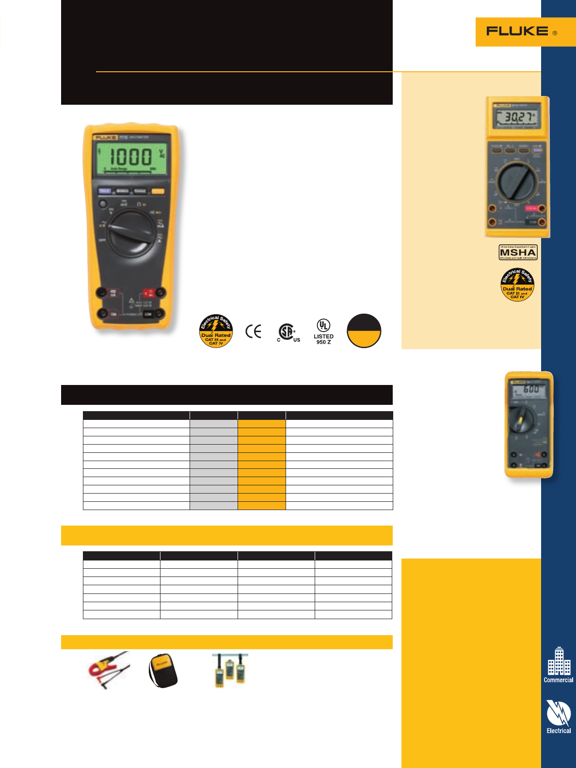
Fluke 77-IV
Digital Multimeter
Specifications – 77-IV Digital Multimeter
Features – 77-IV Digital Multimeter
Recommended accessories – 77-IV Digital Multimeter
The new 77-4 digital multimeter has the features needed
to repair most electrical and electronic problems. This
meter is simple to use and has significant improvements
over Fluke’s original 70 Series with more measurement
functions, conformance to the latest safety standards, and
a much larger display that’s easier to view.
Measures
• Wide 1000 V measurement range
• Average responding ac measurements
• 0.3 % accuracy
• 10 Amps continuous
• Frequency and capacitance
• Resistance and continuity
Features
• Large display
• Backlight for work in dim areas
• Min / Max to record signal fluctuations
• Integral holster with probe holders
• Free your hands with the optional TPAK magnetic
hanger
• Auto and Manual ranging
i400s C35 ToolPak™
AC Current Clamp Meter Case Meter Hanger
See page 66 See page 71
Fluke 27 waterproof
multimeter
Completely
sealed for extreme
conditions
Designed for U.S.
military, mining and
other extreme appli-
cations. A special
case with o-rings
prevents water from
entering the input
jacks, switches and
fuse door. Meets
military specifica-
tions for vibration,
shock and water
resistance.
• Waterproof design
with rugged, o-ring
sealer case protects
rotary switch, input
jacks, battery and
fuse door
• Operates from -15 °C
to +55 °C (5 °F to
131 °F) and 95 %
relative humidity
Fluke 73-III
The Fluke 73-III product
represents one of the best
selling multimeter designs
of all time. It’s classic
simplicity combined with
attractive feature set make
this meter the perfect
choice for electronic and
automotive applications.
The 73-III features
include:
• Average responding
• Measures both amps and milliamps
• Removable high impact holster
• Manual or autoranging
Function Range Best accuracy Best resolution
V dc 600.0 mV to 1000 V ± (0.3 % + 1) 0.1 mV
V ac 6.000 V to 1000 V ± (2.0 % + 2) 1.0 mV
A dc 60.00 mA to 10 A ± (1.5 % + 2) 0.01mA
A ac 60.00 mA to 10 A ± (2.5 % + 2) 0.01 mA
Resistance 600.0 W to 50 MW± (0.5 % + 1) 0.1 W
Capacitance 1 nF to 9,999 µF ± (1.2 % + 2) 1 nF
Frequency 99.99 Hz to 99.99 kHz ± (0.1 % + 1) 0.01 Hz
U.S.A.
Made
in the
Digital Multimeters
Application note, literature code
1547394:
Beat the book
This amazing reference covers test
procedures commonly used by
experienced automotive technicians.
Covers basic troubleshooting
techniques and measurements using
a DMM and
describes
tests for the
charging
system,
starting
system, fuel
and air system,
ignition
system, and
the body
electric/engine
management/
cooling system.
Want to read more? Download this
and other application notes at
www.fluke.com/library
Application Note
Work safely
This application note is intended
as a guide for the professional
mechanic. It describes some of
the test procedures commonly
used by experienced technicians.
However, some of the procedures
require you to take certain pre-
cautions to avoid personal injury
and/or damage to equipment or
vehicles. Fluke cannot anticipate
all possible precautions that you
must take on all the different
vehicles for which this guide is
applicable. For this reason, you
should thoroughly familiarize
yourself with proper safety
habits and take all precautions
described in the vehicle’s
repair manuals to avoid injury
or damage.
Testing automotive
systems with an
analog/digital multimeter
Perhaps the most important tool
you’ll use in troubleshooting auto
electrical systems is the multime-
ter. The basic multimeter
measures voltage, current and
resistance, while more elaborate
multimeters, such as the new
Fluke 88-V, have features that
can check things such as
frequency, duty cycle, pulse
width, make diode tests, and
even measure temperature.
In this application note you
will find troubleshooting tech-
niques using the high quality,
affordable and popular line of
Fluke analog/digital multimeters
and automotive troubleshooting
accessories. Fluke’s analog/
digital combination has distinct
advantages over either digital
or analog meters alone, and
the accessories are designed to
make your job easier and more
profitable.
Beat the Book
Automotive electrical diagnosis.
Better diagnosis, faster repair.
From the Fluke Digital Library @ www.fluke.com/library
Although automotive multime-
ters with various capabilities
have been around for years,
many of them didn’t have the
scales and functions required for
todays’ automotive applications.
Hybrid, electric and fuel cell
powered vehicles have special
requirements, ones met with the
new 88-V. Now that computers
and their sensors are a part of
everyday automobile trou-
bleshooting, you need a true
multimeter to do the job.
The common analog type mul-
timeter is not only inadequate, it
can damage delicate computer
circuitry. Both analog meters and
test lights, due to their low inter-
nal resistance (input impedance),
draw too much power from the
device they’re testing to be used
on computers. What’s more,
many analog meters use 9V to
power the resistance test, which
is enough to destroy sensitive
digital components.
For more information and detailed specifications, go to www.fluke.com/dmm
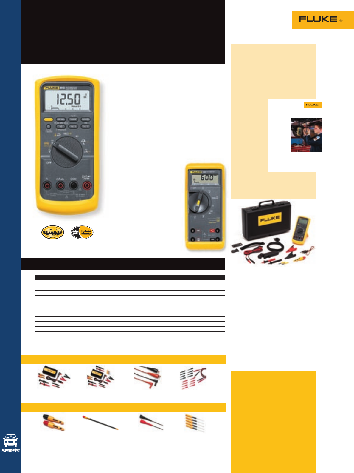
Fluke 88V
included accessories
Test leads, 9 V battery (installed),
RPM pickup, carrying case and
users manual.
Ordering information
Fluke-88-5 Automotive
Multimeter
Fluke-88-5/A KIT Automotive
Multimeter
Combo Kit
Fluke-73-3 Digital Multimeter
TP81 or TP82 TP84 TP88 TP40
Insulation Oxygen Sensor Insulation Rigid Backprobe Automotive Back
Piercing Probes Piercing Probe Pin Set Probe Pin Set
See page 63 See page 63 See page 63 See page 63
Fluke 88V Automotive Multimeter
The Fluke 88V Automotive Multimeter is designed
to help automotive professionals beat the book.
This DMM has more measurement functions, trou-
bleshooting features and accuracy to solve virtually
any problems on conventional and hybrid vehicles.
• Automotive test functions include dc and ac volt-
age, resistance and current
• Min/Max recording for logging the highest and
lowest readings over time
• Frequency measurements for magnetic sensors
and ac/dc frequency signals
• Duty Cycle for variable duty cycle signals with
selectable trigger slope and level
• Pulse width for fuel injector on time measurements
• Conductance testing for secondary ignition coils
• RPM measurements for DIS and
conventional ignition systems
• Built-in thermometer
Fluke 73-III (see pg 19 for details)
• Simple interface for
one-handed operation
• Current measurement (A and mA)
• Auto or manual ranging
Buy accessory kits and save
TLK281 TLK282 TL28A TL82
Automotive Test Lead Kit Deluxe Automotive Test Lead Kit Automotive Test Lead Set Automotive Pin & Socket Adapter Set
See page 61 See page 61 See page 62 See page 63
Features – 88V and 73 DMMs
Feature 88V 73
Digital display with analog bargraph • •
Continuity for detecting opens and shorts • •
Diode test for alternator testing • •
Peak Min/Max captures intermittence as fast as 250 microseconds •
Min/Max average to monitor trends in oxygen sensor values for fuel trim •
Pulse width for fuel injector on time measurements •
Milliamp ranges to find low current parasitic drains •
Lo-Ohms (.01 W) for low resistance sensor and coil measurements •
Duty cycle for pulse width modulated signals •
RPM for ignition systems •
Temperature for coolant and air temperature sensors •
Dwell for points and feedback carburetors
Limited lifetime warranty • •
Recommended automotive accessories – 88V DMM
For the complete diagnostics
package and maximum value,
pick up the 88V/A combo kit.
• Includes Fluke 88 Series V
Automotive Multimeter
• TL224 Heat Resistant Silicone
Test Leads
• TP220 Removable Sharp Point
Test Probes
• AC285 Large Jaw Alligator Clips
• TPAK Magnetic Hanger
• 80BK Temperature Probe
• RPM80 Inductive Pick-up
• Automotive Backprobe Pins
• Insulation Piercing Probe
• Packaged in a durable carrying case
(C800)
20
Complete automotive
diagnostic tools
Tools designed to help
you beat the book
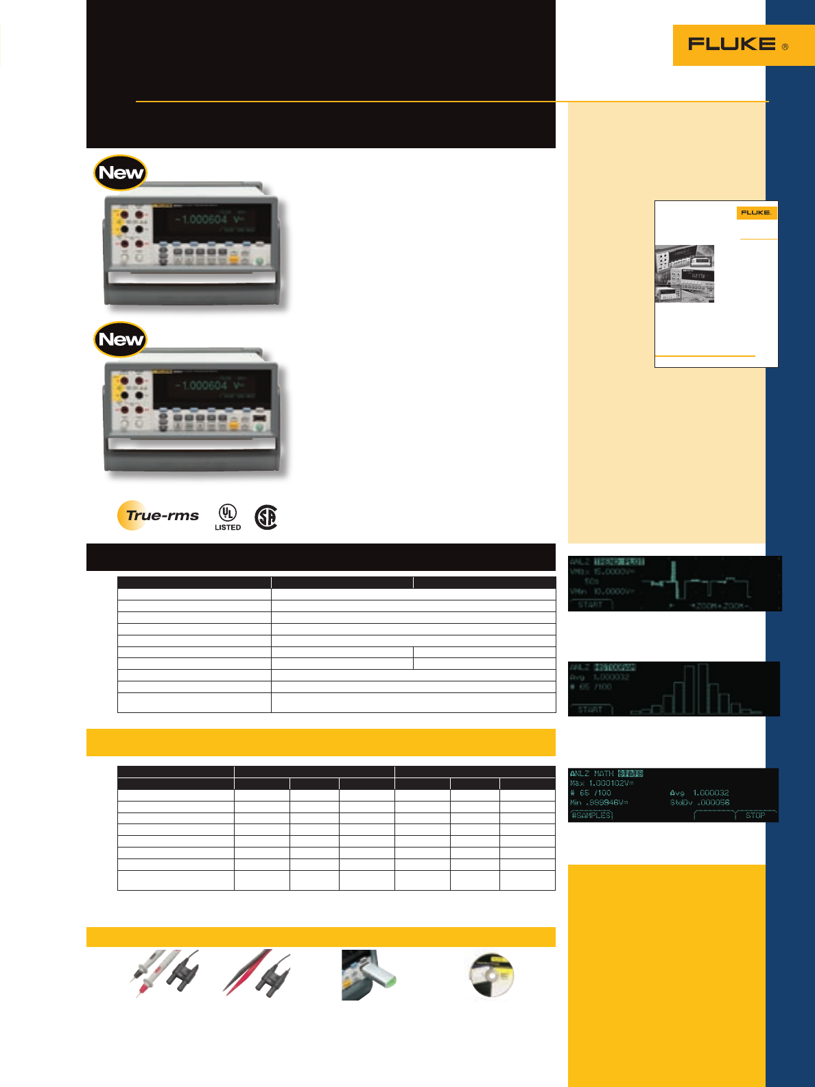
21
21
Digital Multimeters
Recommended accessories – 8845A and 8846A Precision Multimeters
TL2X4W-PT TL2X4W-TWE 884X-512M FVF-UG
2x4 Wire Ohms Test Lead 2x4 Wire Ohms USB Memory 512M FlukeView Forms
2 mm probe tip Tweezer Software Upgrade
Included accessories
LCI Line Power Cord, TL71 Test
Lead Set, Spare Line Power fuse,
Programmers Manual/User Manual
on CD-ROM, FVF-BASIC FlukeView
Forms Software Basic Version.
Ordering information
Fluke-8845A 6.5 Digit Precision
Multimeter, 35 ppm
Fluke-8846A 6.5 Digit Precision
Multimeter, 24 ppm
Specifications – 8845A and 8846A
Features – 8845A and 8846A
Precision and versatility for
bench or systems applications
Fluke 8845A and 8846A
6.5 Digit Precision Multimeters
Fluke 8846A
8845A 8846A
Function* Range Resolution Accuracy* (%) Range Resolution Accuracy* (%)
Voltage dc 1000 V 100 nV 0.0035 1000 V 100 nV 0.0024
Voltage ac (freq. 300 Hz) 750 V 100 nV 0.06 1000 V 100 nV 0.06
Resistance (2x4 wire) 100 MW100 µW0.01 1 GW10 µW0.01
Current dc 10 A 100 pA 0.05 10 A 100 pA 0.05
Current ac (freq. 3 Hz to 10 kHz) 10 A 1 µA 0.10 10 A 10 nA 0.10
Freq/period 300 kHz 1 µHz 0.01 1 MHz 1 µHz 0.01
Capacitance — — — 1 nF to 0.1 F 1 pF 1
Temperature RTD ———-200 °C to
+600 °C 0.001° 0.06°
*Accuracy = ± (% of reading)
Size (HxWxD): 88 mm x 217 mm x 297 mm (3.45 in x 8.54 in x 11.69 in) Weight: 3.6 kg (7.9 lb) One-year warranty
Use the built-in TrendPlot paperless chart recorder
to graphically identify the extent of drift and inter-
mittent events in analog circuits.
View results in Histogram mode to reveal stability
or noise problems in analog circuits.
Handle even the most demanding measurements
with high accuracy and 6.5 digit resolution.
Fluke 8845A
The Fluke 8845A and 8846A, 6.5 digit precision
multimeters have the precision and versatility to
handle your most demanding measurements on the
bench or in a system.
Dual display offers versatile graphical
capabilities: The 8845A and 8846A feature a unique
graphical display that can reveal signal quality
issues like drift, intermittent and stability by viewing
the measurement data as a real time TrendPlot,™
Histogram or Statistics using the unique analyze
mode.
Wide measurement ranges: Resistance or
current has been extended to cover the widest range
possible.
Perform 4-wire measurements easily with
two leads: Patented split terminal jacks for 2x4
ohms function allow you to perform precise 4-wire
measurements with only two leads instead of four.
Optional Kelvin leads accessories are available to
enable you to establish a 4-wire connection even in
tight spaces.
Systems capabilities: Both instruments include
an RS-232, IEEE-488 and Ethernet interface as
standard, with popular DMM emulation modes that
make systems integration a simple task.
Software: Transfer data points from your meter to
your PC with the free copy of FlukeView Forms Basic.
To customize your forms, upgrade with FVF-UG.
Application note, literature code
2547797:
Understanding specifications
for precision multimeters
A solid understanding of
specifications
is critical
when you’re
evaluating the
suitability of
DMMs for an
application,
or when
you must be
confident that
your readings
accurately
reflect
reality. This
application
note discusses some of the thinking
behind DMM specifications and
spec sheets. It defines the various
elements of DMM specs and gives
tips on how to apply them.
Want to read more? Go to www.
fluke.com/library to download this
and other application notes, or get
info specific to your industry and
sign up for Fluke News publications
at www.fluke.com/subscribe.
!PPLICATION.OTE
ÀÊÌiÊÕiÊ}Ì>ÊLÀ>ÀÞÊJÊÜÜÜ°vÕi°VÉLÀ>ÀÞ
5NDERSTANDINGSPECIlCATIONS
FORPRECISIONMULTIMETERS
$IGITALMULTIMETERSARETHEWORKHORSESOFTHE
ELECTRONICSINDUSTRY!LMOSTALLOFTHEELECTRONIC
PRODUCTSWEUSEINOURPERSONALANDPROFESSIONAL
LIVESAREBUILTORSERVICEDUSINGMULTIMETERS
$IFFERENT$--APPLICATIONSREQUIREDIFFER
ENTDEGREESOFATTENTIONTOSPECS!TECHNICIAN
CHECKINGALOGICPOWERSUPPLYCANUSEHISTRUSTY
BENCH$--CONlDENTLYTOVERIFYTHATTHESUPPLY
ISWITHINAFEWPERCENTOF6(OWEVERWHEN
THEJOBREQUIRESTESTINGCRITICALCIRCUITSCHECKING
PRECISIONCOMPONENTSMAKINGlNEADJUSTMENTS
INPRODUCTIONVERIFYINGCOMPLIANCEWITHINDUSTRY
STANDARDSORTAKINGMEASUREMENTSOUTSIDETHE
CONTROLLEDENVIRONMENTOFTHELABTHENYOULLNEED
TOEVALUATESPECIlCATIONSCAREFULLY
!SOLIDUNDERSTANDINGOFSPECIlCATIONSISCRITICAL
WHENYOUREEVALUATINGTHESUITABILITYOF$--S
FORANAPPLICATIONORWHENYOUMUSTBECONlDENT
THATYOURREADINGSACCURATELYREmECTREALITY4HIS
APPLICATIONNOTEDISCUSSESSOMEOFTHETHINKING
BEHIND$--SPECIlCATIONSANDSPECSHEETS)T
DElNESTHEVARIOUSELEMENTSOF$--SPECSAND
GIVESTIPSONHOWTOAPPLYTHEM
3PECIlCATIONSANDTHE
SPECSHEET
7HENEVERWETAKEAMEASURE
MENTWITHANYMETERWERE
GAMBLING7EREGAMBLINGTHAT
THEINSTRUMENTISGOINGTOGIVEUS
THEhREALvREADING&ORTUNATELY
ITSAVERYSAFEBETTHATAQUALITY
MULTIMETERWILLDELIVERREADINGS
THATCOINCIDEWITHREALITY3PECIl
CATIONSQUANTIFYTHECONlDENCEOF
GETTINGACCURATEREADINGSANDTHE
RISKOFSEEINGINACCURATEREADINGS
!SPECIlCATIONSDOCUMENTIS
ACLEARLYWRITTENDESCRIPTIONOF
ANINSTRUMENTSPERFORMANCE
)TSHOULDQUANTIFYANINSTRU
MENTSCAPABILITIESOBJECTIVELY
UNDERWELLDElNEDOPERATING
CONDITIONS
&ROMTHISFORMALDElNITIONWE
CANDRAWTHECHARACTERISTICSOF
GOODSPECIlCATIONS
s #OMPLETENESSnANYFACTOR
THATIMPACTSUNCERTAINTYIS
COVEREDINCLUDINGOPERAT
INGLIMITSSUCHASHUMIDITY
ALTITUDEORVIBRATION
s #LARITYnALLEFFORTSSHOULDBE
MADETOMAKETHESPECIlCA
TIONSSTRAIGHTFORWARD
s /BJECTIVITYnDOESNOTATTEMPT
TOMISLEADFORTHESAKEOF
PROMOTION
!WELLWRITTENSPECIlCATION
SHOULDMAINTAINTHESAMELEVEL
OFINTEGRITYASAMEDICALCHARTOR
BANKSTATEMENT-ANUFACTURERS
MUSTSTANDlRMLYBEHINDTHEIR
SPECSANDYOUSHOULDFULLYEXPECT
THATTHEINFORMATIONYOUARE
GETTINGISACCURATEANDCOMPLETE
/NTHESPECSHEETYOUSHOULD
SEEMEASUREMENTUNCERTAINTY
SPECSANDMODIlERSTHATAFFECT
THEUNCERTAINTY9OUWILLALSOSEE
OPERATINGLIMITSTHATCONSTRAIN
THEENVIRONMENTINWHICHTHE
UNCERTAINTYSPECIlCATIONSWILL
HOLDTRUE4HESEARESTATEDIN
NUMERICALVALUESEGHUMIDITY
ORWITHREFERENCETOINTERNATIONAL
STANDARDSSHOCKANDVIBRATION
&IRSTLETSTAKEACLOSERLOOKAT
HOWWEQUANTIFYMEASUREMENT
UNCERTAINTY
Feature 8845A 8846A
Display Dual VFD Dot Matrix
Resolution 6.5 Digits
Continuity / Diode Test Yes
Analytical Functions Statistics, Histogram, TrendPlot™, Limit Test
Math Functions Zero, Min/Max/Average, Std Dev; mx + b, dB/dBm
USB Device Port — USB memory drive port
Real Time Clock — Yes
Interfaces RS-232, IEEE-488.2, Ethernet, USB (with optional adapter)
Programming Languages/Emulation Modes SCPI (IEEE-488.2), Agilent 34401A, Fluke 45
Safety Designed to comply with IEC 61010-2000-1, ANSI / ISA-S82.01-1994,
CAN / CSA-C22.2 No.1010.1-92 1000 V CAT I / 600 V CATII
For more information and detailed specifications, go to www.fluke.com/884X
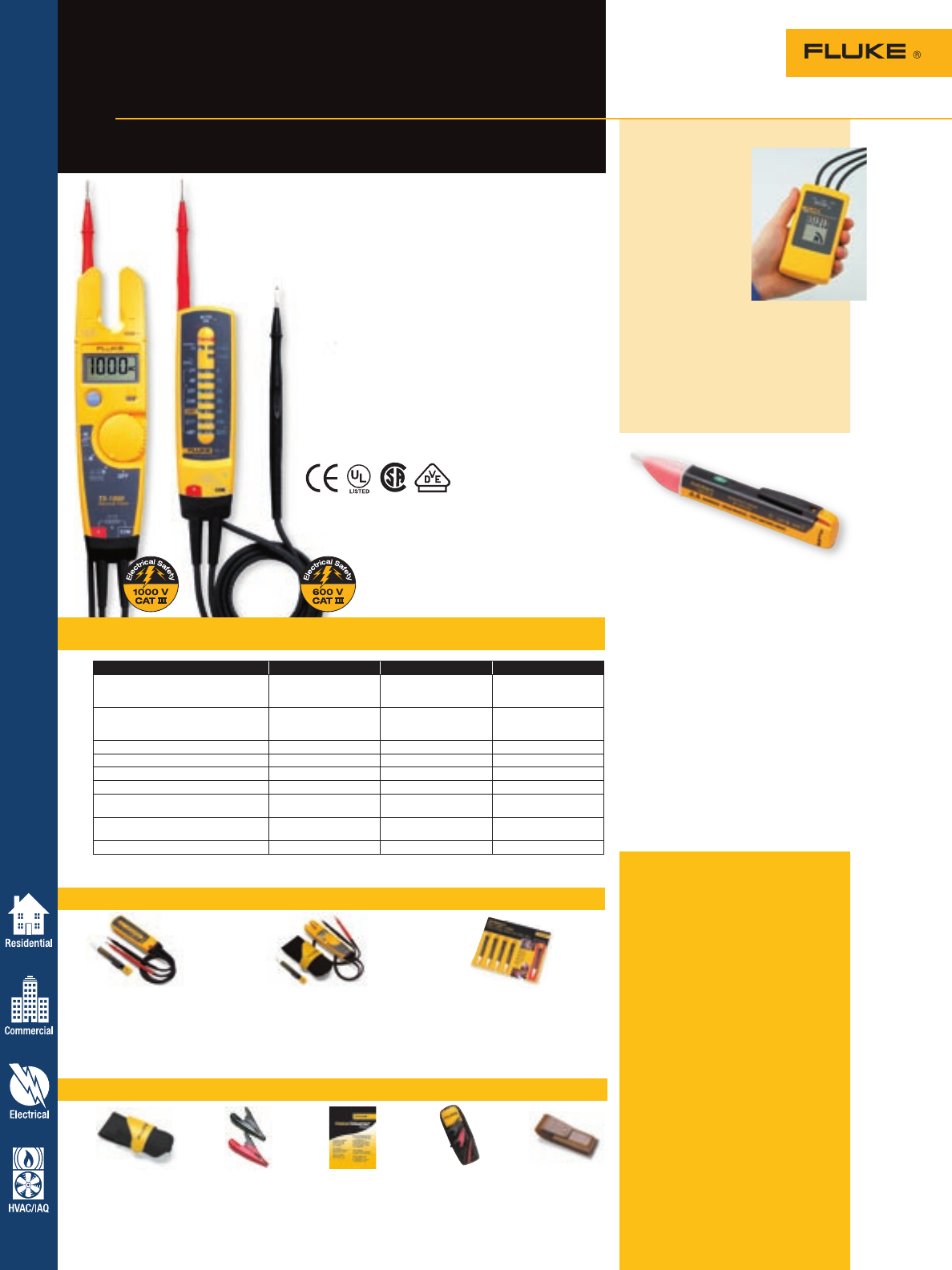
Buy Electrical Tester Kits and Save
Specifications – T5 and T3 Testers
Recommended accessories – Electrical Testers
Fluke T5 Voltage, Continuity and
Current Tester
• Excellent front-line troubleshooting and
measurement tool
• Available in 600 V and 1000 V models
• Digital display
• OpenJaw™ current measurement
• Rotary switch selects volts, amps and ohms
functions
• Heavy-duty test leads
Fluke T3 Voltage and Continuity Tester
• LED voltage indicators
• Seven key voltage levels
• Automatically switches to continuity beeper or
ac/dc voltage
• Heavy-duty test leads
Alternatives to traditional
solenoid testers
T5-1000 T5-600 T3
Measure dc voltage 1000 V 600 V Preset 6 V, 12 V, 24 V,
36 V, 48 V, 110 V and
220 V*
Measure ac voltage 1000 V 600 V Preset 24 V, 48 V, 120
V, 208 V, 240 V, 277 V
and 480 V*
Measure ac current (average) 100 A 100 A N/A
Measure continuity < 25 W< 25 W < 20,000 W
Measure resistance 1000 W1000 W N/A
DC polarity indicator Yes Yes Yes
Detachable probe tips with
optional probe tips styles Yes Yes N/A
Safety rating 1000 V Overvoltage
CAT III 600 V Overvoltage
CAT III 1000 V Overvoltage
CAT III
Warranty Two-years Two-years One-year
* Voltage levels will vary depending on country of intended use.
22
Fluke 9040
Rotary Field
Indicator
The Fluke 9040 is
a premium phase
rotation tester with
a CAT III, 600 V rat-
ing. The frequency
range is from 15 Hz
to 400 Hz for
demanding appli-
cations. The clear
liquid crystal display and the holster
make it suitable for rough outdoor
applications. This instrument is sup-
plied with three unique, expandable,
test probes which fit most sockets.
For more information, visit
www.fluke.com/9040
H5 AC285 (T5) Meter Cleaner T5 Kit C520A
Electrical Tester Holster SureGrip™ Alligator Clips Cleaning Wipes Starter Kit Leather Tool Case
See page 70 See page 62 See page 71 See page 61 See page 70
T3 Tester Kit
Combo kit includes:
• Fluke T3 Voltage and
Continuity Tester
• Fluke VoltAlert™
T5-1000 Tester Kit
Combo kit includes:
• Fluke T5-1000 Voltage
Electrical Tester
• Fluke VoltAlert™
• Fluke H5 Holster
VoltAlert™ Multi Pack
Includes five Fluke VoltAlerts.
The special kit pricing gets you
the fifth VoltAlert™ free. Outfit
your entire staff.
Fluke
1AC-II/1LAC-II
VoltAlert
The pocket-sized voltage detector
The next generation VoltAlert™ ac
non-contact voltage testers from
Fluke are easy to use—just touch
the tip to a terminal strip, outlet, or
supply cord. When the tip glows
red and the unit beeps, you know
there is voltage present. Electricians,
maintenance, service, safety personnel
and homeowners can quickly test for
energized circuits in the workplace or
at home. Certified up to CAT IV 1000 V.
Two models to choose from:
• 1AC-II – detects voltage from
90 V ac to 1000 V ac
• 1LAC-II – detects voltage from
20 V ac to 90 V ac
Fluke T5 and T3
Electrical Testers
For more information and detailed specifications, go to www.fluke.com/tseries
Included accessories
The T5-1000 and T5-600 come with
detachable probes and instruction
sheet. The T3 has fixed test leads
and probes.
Ordering information
T5-1000 1000 V Voltage,
Continuity and
Current Tester
T5-600 600 V Voltage,
Continuity and
Current Tester
T3 Voltage and Continuity
Tester
T3-1AC Kit Voltage and Continuity
Tester Kit
T5-H5-1AC Voltage, Continuity
Kit and Current Tester Kit
1AC-II 5PK VoltAlert 5 Pack
1AC-II Voltage Detector
1LAC-II Voltage Detector
9040 Rotary Field Indicator
Electrical Testers
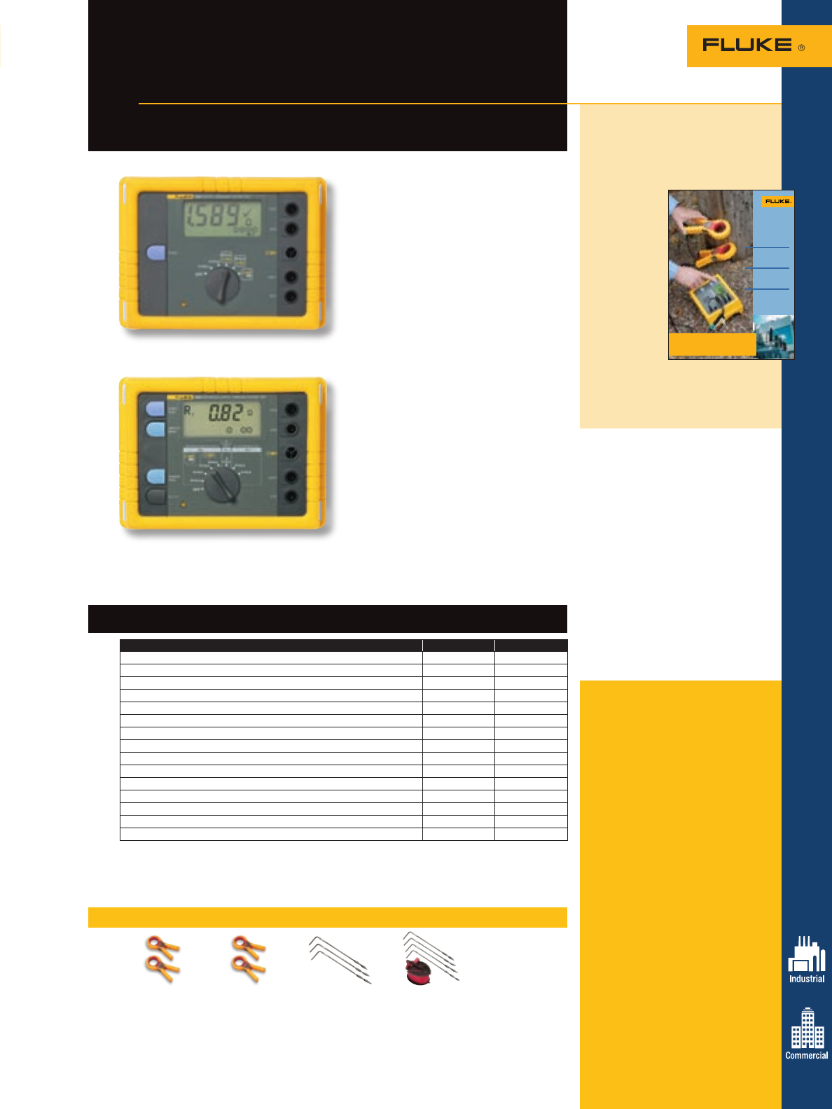
23
Earth Ground Testers
Fluke 1625 and 1623
Geo Earth Ground Testers
Advanced technology for all your earth
ground testing applications
Included accessories
Fluke 1625 Tester: 2 test leads,
2 alligator clips, and users manual.
Fluke 1625 Kit: Same as above
plus stake/reel set 4 pole, selective/
stakeless clamp set, and rugged
carrying case.
Fluke 1623 Tester: 2 test leads,
2 alligator clips, and users manual.
Fluke 1623 Kit: Same as above
plus stake/reel set 4 pole, selective/
stakeless clamp set, and rugged
carrying case.
Ordering information
Fluke-1625 Advanced GEO
Earth Ground Tester
Fluke-1625 Kit Advanced GEO
Earth Ground
Tester Kit
Fluke-1623 Basic GEO Earth
Ground Tester
Fluke-1623 Kit Basic GEO Earth
Ground Tester Kit
These products are for unpowered
installations measuring grounding
connections.
For more information and detailed specifications, go to www.fluke.com/egt
Brochure, literature code 2633834:
Earth Ground Resistance:
Principles, testing methods
and applications
This brochure
is a highly
informative
collection of
information
about Earth
Ground
Systems,
testing
methods and
applications.
Want to
read more?
Download
this and other application notes at
www.fluke.com/library
Principles,
testing methods
and applications
Earth Ground
Resistance
Diagnose intermittent
electrical problems
Avoid unnecessary
downtime
Learn earth g round
safety principles
The new Fluke 1620 Series Earth Ground
Testers not only measure ground resistance
using the classic ‘fall of potential test’
but also enable time saving testing using
the ‘selective’ and ‘stakeless’ methods.
‘Selective’ testing does not require the
electrode under test to be disconnected
during the measurement, thus increasing
safety. The simple ‘stakeless’ method
quickly checks ground connections using
two current transformers (probes) clamped
around the ground conductor under test.
Offering ‘one-button’ simplicity, the 1623
is an all-in-one earth ground tester, while
the 1625 has extra versatility for more
demanding applications.
Earth ground resistance and soil
resistivity should be measured when:
• Designing earth ground systems
• Installing new ground system and
electrical equipment
• Periodically testing ground and lightning
protection systems
• Installing large electrical equipment
such as transformers, switchgears,
machines, etc.
The 1623 is perfect for performing
predictive maintenance checks of
commercial and industrial applications.
The 1625 is intended for electrical utility or
other high frequency environments.
Features – 1625/1623 Earth Ground Testers
Feature 1625 1623
One-button measurement concept •
3- and 4-pole earth ground measurement • •
4-Pole soil resistivity testing • •
2-Pole resistance measurement ac • •
2-and 4-pole resistance measurement dc •
Selective testing, no disconnection of ground conductor (1 clamp) • •
Stakeless testing, quick ground loop testing (2 clamps) • •
Measuring frequency 128 Hz •
Earth impedance measurement at 55 Hz •
Automatic frequency control (AFC) (94 Hz to 128 Hz) •
Measuring voltage switchable 20/48V •
Programmable limits, settings •
Continuity with buzzer •
Dust/water resistance IP56 IP56
Safety rating CAT II 300 V CAT II 300 V
Recommended accessories – 1625 and 1623 Earth Ground Testers
Battery type: 6 x AA alkaline cells
Size (HxWxD): 110 mm x 180 mm x 240 mm (4.33 in x 7.08 in x 9.45 in)
Weight (including batteries): 1623 Geo: 1.1 kg (2.42 lb); 1625 Geo: 1.5 kg (3.31 lb)
Two-year warranty
EI-1623 EI-1625 ES-162P3 ES-162P4
Selective/stakeless Selective/stakeless Stake/reel set Stake/reel set
clamp set clamp set for 3 pole for 4 pole
for 1623 for 1625 measurements measurements
Fluke 1623
Fluke 1625
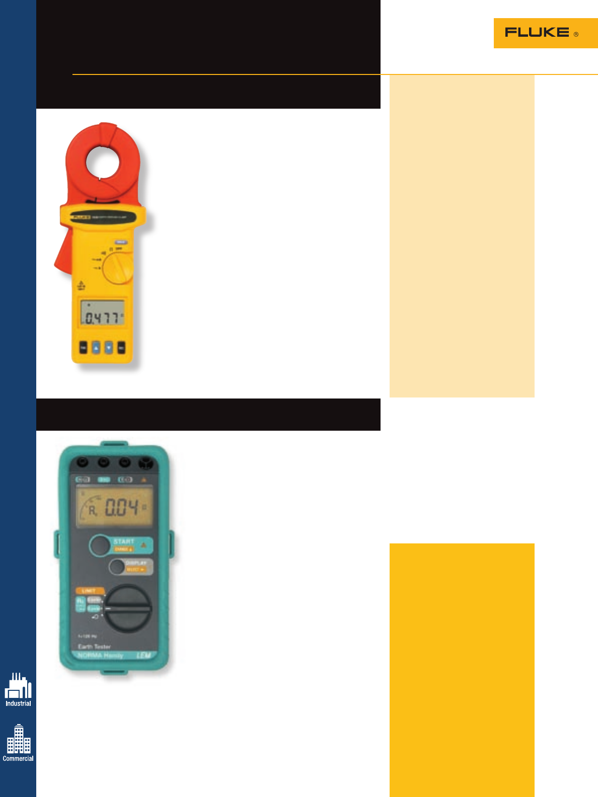
Handy GEO Earth Ground Tester
Earth ground tester for resistance measurement
Included accessories
Fluke 1630 Clamp Meter: Rugged
carrying case with belt, resistance
test loop, 9 V battery and users
manual.
Handy GEO Tester: Rugged rubber
holster with carrying belt, battery,
and operating instructions.
Ordering information
Fluke-1630 Earth Ground
Clamp Meter
Handy GEO Earth Ground Tester
Handy GEO Kit Earth Ground Tester
Kit with 25 m and
50 m cable reel
and two earth
ground stakes
These products are for unpowered
installations measuring grounding
connections.
24
The Handy GEO Earth Ground Tester is a rugged,
easy-to-use tester for three-pole ground resistance
measurements and two-pole ac resistance
measurements.
Earth ground resistance is measured by installing
earth ground test electrodes and testing with the
Handy GEO. Earth ground resistance measurements
are used to ensure safe operation and reduce power
quality problems. The Handy GEO is extremely
lightweight making it ideal to test for lightning
protection levels and periodic check-ups during
routine maintenance.
Two-pole ac resistance is measured to confirm low
resistance between electrical joints:
• Fuse-to-fuse holder (to ensure there is no
overheating)
• Bonding of ground earth connections
• Additional bonding
• Cable to terminal connections
AC current can be used to confirm the low resistance
path in two directions simultaneously.
The gold standard for measuring ground resistance
using classic fall of potential as well as selective and
stakeless methods.
Fluke 1630 Earth
Ground Clamp Meter
Measure earth ground loop resistance
anywhere. Quickly and easily.
Earth Ground Testers
For more information and detailed specifications, go to www.fluke.com/egt
The Fluke 1630 Earth Ground Clamp is able to measure
ground loop resistances—using the Stakeless testing method.
This test technique eliminates the dangerous, and time
consuming activity of disconnecting parallel grounds, as
well as the process of finding suitable locations for auxiliary
ground stakes. You can also perform earth ground tests in
places you have not considered before: inside buildings, on
power pylons or anywhere you don’t have access to soil.
With the Stakeless testing method, the Fluke 1630 Earth
Ground clamp is placed around the earth ground rod or
the connecting cable. No earth ground stakes are used at
all. A known voltage is induced by one half of the clamp
and the current is measured by the other half. The tester
automatically determines the ground loop resistance at this
grounding connection. Gone are the days of spending time
placing and connecting stakes for each earth ground rod on
your system—a major time saver.
• Quick and easy use—no earth ground stakes are
necessary
• Large, 35 mm (1.35 in) jaw opening
• Measures ground resistance from 0.025 W to 1500 W
• Measures ground leakage current from 0.2 mA to 30 mA
• High and Low alarming
• Automatic self calibration
• Rugged carrying case and resistance check loop included
What is ground, and what
does it do?
The NEC, National Electrical Code,
defines a ground as a “conducting
connection, whether intentional or
accidental between an electrical
circuit or equipment and the earth, or
to some conducting body that serves
in place of the earth.”
When talking about grounding
it is actually two different subjects,
earth grounding and equipment
grounding. Earth grounding is an
intentional connection from a circuit
conductor usually the neutral to a
ground electrode placed in the earth.
Equipment grounding is to ensure
that operating equipment within a
structure is properly grounded.
These two grounding systems
are required to be separate except
for a connection between the two
systems to prevent differences in
potential from a possible flashover
from a lightning strike. The purpose
of a ground besides the protection
of people, plants and equipment
is to provide a safe path for the
dissipation of fault currents, lightning
strikes, static discharges, EMI and
RFI signals and interference.
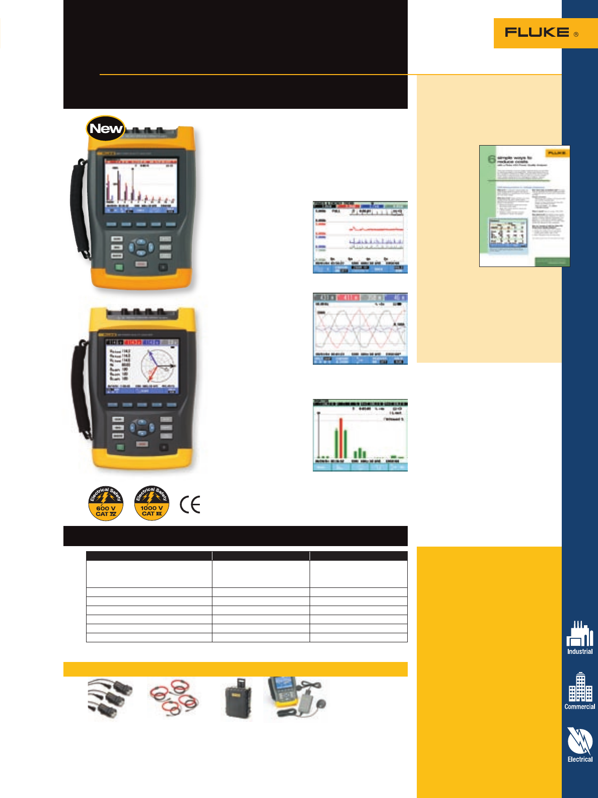
Power Quality Analyzers 25
Recommended accessories – 435 and 434 PQ Analyzers
I5sPQ3 i430-flex-4pk C435 GPS430
3 pack of 5 A 4 pack of 3000 A Water-tight hard GPS time
precision current flexible current case with rollers synchronization
clamps probes module
Fluke 430 Series Three-Phase
Power Quality Analyzers
Pinpoint power problems faster,
safer and in greater detail
Features – 435 and 434 PQ Analyzers
The Fluke 435 and 434 Three-Phase Power Quality
Analyzers help you locate, predict, prevent and trouble-
shoot problems in three- and single-phase power distri-
bution systems. Troubleshooting is faster with on-screen
display of trends and captured events, even while back-
ground recording continues. The new IEC standards for
flicker, harmonics, and power quality are built right in to
take the guess work out of power quality.
• Troubleshoot real-time:
Analyze the trends
using the cursors and
zoom tools—even while
background recording
continues
• AutoTrend: Every
measurement you see
is always automatically
recorded, without any setup
• Automatic Transient
Mode: Capture 200 kHz
waveform data on all
phases simultaneously
up to 6 kV
• Measure all three
phases and neutral:
With included four
current probes
• Fully Class-A compliant: Conduct tests according to
the stringent international IEC 61000-4-30 Class-A
standard
• System-Monitor: Up
to ten power quality
parameters on one screen
according to EN50160
power quality standard
• Inrush mode: For
troubleshooting nuisance
circuit breaker tripping
• Logger function:
Configure for any test condition with memory for over
400 parameters at user defined intervals
For more information and detailed specifications, go to www.fluke.com/pq
Included accessories
Fluke 435 Analyzer: Hard carry-
ing case with rollers, four flexible
current probes (i430-flex), five test
leads and clips, battery charger,
FlukeView software, Power Log soft-
ware, optical USB cable, color local-
ization set, getting started manual,
users manual on CD-ROM.
Fluke 434 Analyzer: Hard carrying
case, four current probes (i400s),
five test leads and clips, battery
charger, FlukeView software, opti-
cal USB cable, color localization set,
getting started manual, users manual
on CD-ROM.
Ordering information
Fluke-435 Three-Phase Power
Quality Analyzer
Fluke-434 Three-Phase Power
Quality Analyzer
Application note, literature code
2435490:
Six simple ways to reduce
costs with a Fluke 434
Power Quality Analyzer
There are
hundreds of
power quality
measurements
you can take
on electrical
systems and
equipment.
These
instructions
focus on four
predictive
maintenance
(PdM)
measurements and two power
consumption measurements that
can help you uncover hidden costs,
protect equipment from damaging
conditions, reduce unscheduled
downtime, and improve system
performance.
Features 435 434*
Measures voltage, current, dips, swells,
interruptions, harmonics, inter-harmonics,
flicker, power, energy, transients, frequency,
unbalance, inrush, EN50160 overview
• •
Logger function with multi-parameter logging •optional*
Mains signaling •optional*
Memory size 16 MB 8 MB
Current probes 3000 A flexible (4) 40 A/400 A clamp (4)
Carrying case water-tight hard case with rollers rugged hard case
Software Fluke Power Log and FlukeView®FlukeView®
*Optional functionality can be added with upgrade kit.
Fluke 435
Fluke 434
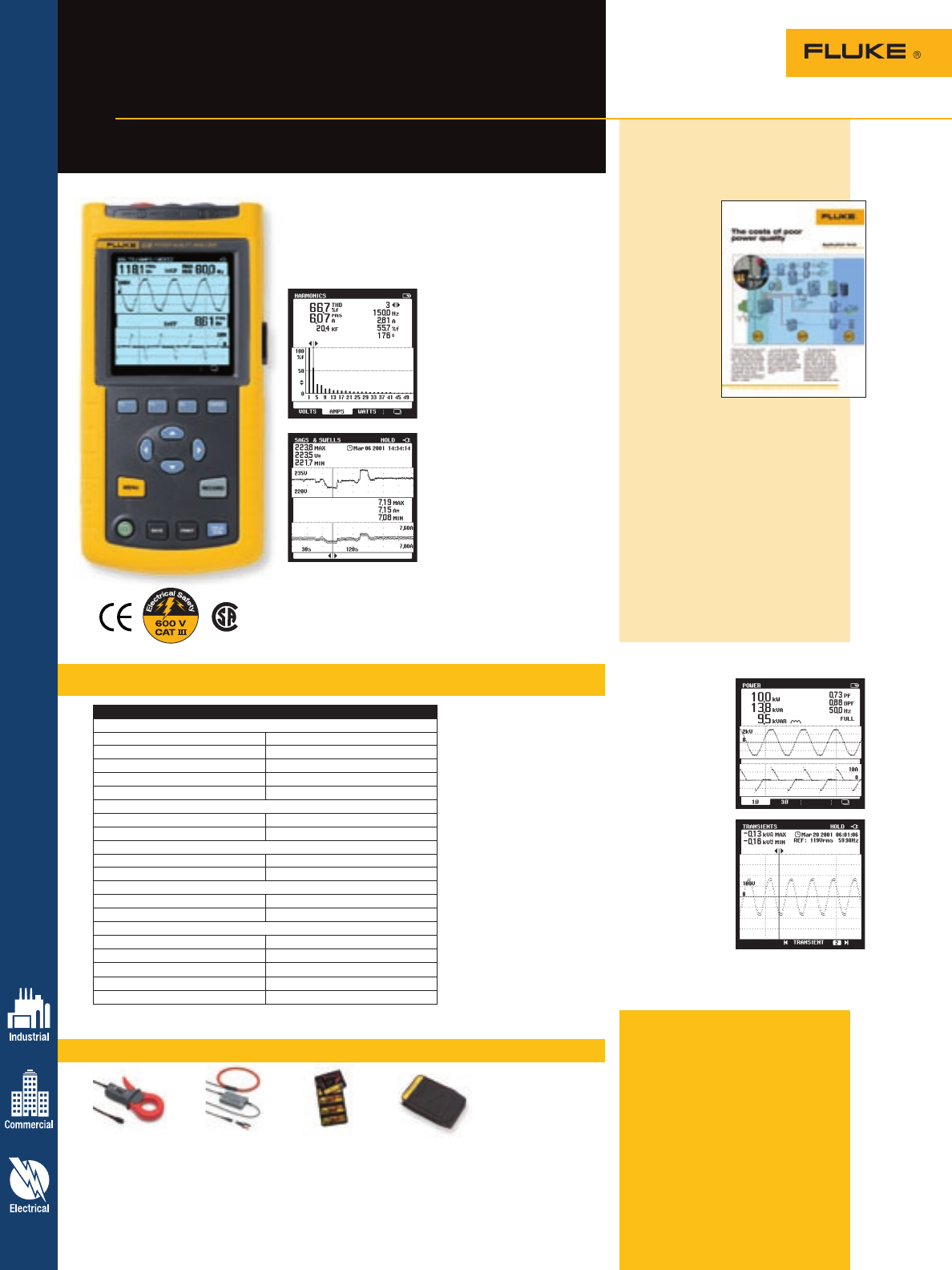
Specifications – 43B Analyzer
Recommended accessories – 43B Analyzer
26 Power Quality Analyzers
Power quality analysis plus a
scope and a meter
Fluke 43B Power
Quality Analyzer
Battery life: Rechargeable NiMH pack
(charger included), 6.5 hours typical
(continuous)
Shock and vibration: Mil 28800E,
Type 3, Class III, Style B
Operating temperature: 0 ºC to 50 ºC
(32 ºF to 122 ºF)
Case: IP51 (dust, drip waterproof)
Size (HxWxD): 232 mm x 115 mm x
50 mm (9.1 in x 4.5 in x 2 in)
Weight: 1.1 kg (2.5 lbs)
Safety: IEC 1010-1, CAT III 600 V.
Tested and approved to UL 3111-1,
CSA C.22.2 No. 1010.1-92.
Warranty: Three-years on Fluke 43B,
one-year on accessories
• NiMH battery provides
extended operating time of
6.5 hours
• Voltage, current and power
harmonics up to 51st
• Total harmonic distortion
(THD)
• Phase angle of individual
harmonics
• FlukeView® software with
enhanced analysis and
documentation capabilities
• Continuously measure volts
and amps cycle-by-cycle for
up to 16 days
• Cursors give time and date
of sags and swells
• Watts, power
factor, displace-
ment power
factor, VA and
VAR
• Voltage
and current
waveforms
• Calculates three-
phase power
on balanced
loads from a
single-phase
measurement
• Catch up to
40 voltage
transients and
waveform
distortions
The Fluke 43B Power Quality Analyzer performs the
measurements you need to maintain power systems,
troubleshoot power problems, and diagnose equipment
failures. The 43B has 20 storage locations and can store
data as well as screens.
i1000s i2000flex TLK225 C43
AC Current Probe AC Current Clamp SureGrip Master Carrying Case
See page 66 See page 66 Accessory Kit See page 70
See page 61
Application note, literature code
2391563:
The costs of poor power
quality
Productivity
is the key to
survival in
today’s global
competitive
environment.
Power quality
problems
can cause
processes and
equipment to
malfunction
or shut down.
And the consequences can range
from excessive energy costs to
complete work stoppage. Obviously,
power quality is critical.
To reduce your power bill, you
need to record consumption patterns
and adjust the system and load
timing to reduce one or more of the
following:
1. Actual power (kWh) usage
2. Power factor penalties
3. A peak demand charge structure
Want to read more? Download this
and other application notes at
www.fluke.com/library
For more information and detailed specifications, go to www.fluke.com/pq
Included accessories
The Fluke 43B includes a hard
case, voltage and current probes,
FlukeView® software, power quality
instructional CD, USB interface cable,
line voltage adapter/battery charger
and users manuals.
Ordering information
Fluke-43B Power Quality Analyzer
Function Fluke 43B*
Volts/Amps/Hz
Volts rms ± (1 % + 10 counts)
Amps rms ± (1 % + 10 counts)
Frequency (Hz) ± (0.5 % + 2 counts)
Crest Factor (CF) ± (5 % + 1 count)
Sags and swells ± (2 % +10 counts)
Power
W, VAR, VA ± (2 % + 6 counts)
PF, Cos ( (DPF) ± 0.04
Harmonics and THD
Harmonics ± 3 %
THD ± 3%
Transient display
Minimum transient detection 40 ns
Inrush current ± 5 % of full scale
Additional capabilities
AutoTrend •
Real time scope •
Ohms, diode, continuity, capacitance •
Memory (screens/data) 20 (screens, settings, data)
FlukeView software and interface cable Standard
*Not including current probe specifications
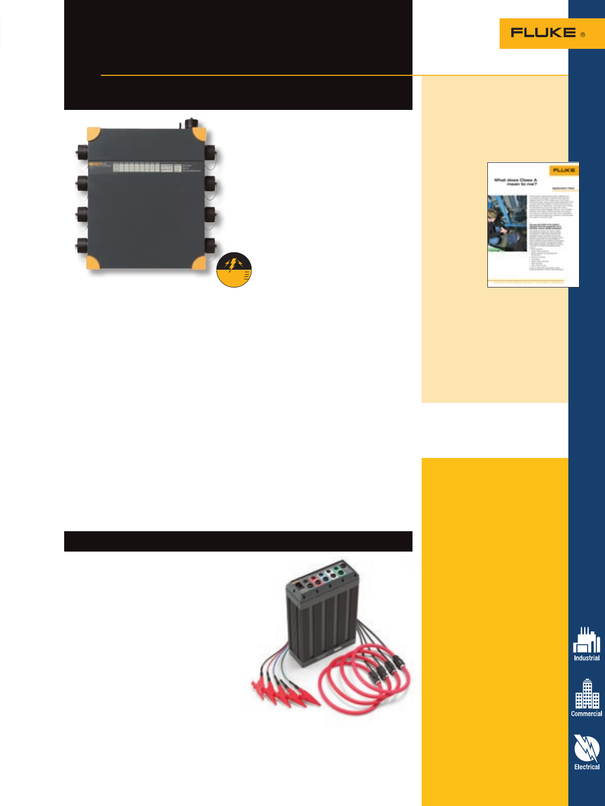
Power Quality Analyzers 27
Fluke 1760 Power Quality
Recorder Topas
Class-A compliance for the most
demanding power quality tests
The Fluke 1760 Three-Phase Power
Quality Recorder is the ideal portable
instrument for power quality experts. It is
fully compliant to IEC 61000-4-30 Class-A,
for advanced power quality analysis and
consistent compliance testing. Designed
for analysis of utility and industrial power
distribution systems, in medium- and low-
voltage networks, the Fluke 1760 provides
the flexibility to customize thresholds,
algorithms, and measurement selections.
It captures the most comprehensive details
on user-selected parameters and allows for
later analysis and reporting.
• Fully Class-A compliant: Conduct tests
according to the stringent international
IEC 61000-4-30 Class-A standard
• GPS time synchronization: Correlate
data with events or datasets from other
instruments, with precision
• Flexible and fully configurable
thresholds and scale factors: Allows
user to pinpoint specific issues by
defining the detailed criteria for detection
and recording of disturbances.
• Highest safety rating in the industry:
600 V CAT IV/1000 V CAT III rated for
use at the service entrance
• Uninterrupted power supply
(40 minutes): Never miss important
events—even record the beginning and
end of interruptions and outages, to help
determine the cause
• 10 MHz, 6000 Vpk waveform capture:
Get a detailed picture of even the
shortest event
• 2 GB data memory: Enables detailed,
simultaneous recording of numerous
power parameters for long periods of
time
• Comprehensive software included:
Provides trend diagrams for root cause
analysis, statistical summaries, report
writing, and real-time data monitoring
in the online mode
• Plug and play: Allows quick setup with
automatic sensor detection; sensors are
instrument powered, eliminating the
need for batteries
• Rugged field design: Insulated housing
and a solid state design with no rotating
components, enable reliable testing
under nearly any conditions
E
l
e
c
t
r
i
c
a
l
S
a
f
e
t
y
1000 V CAT III
600 V CAT IV
For more information and detailed specifications, go to www.fluke.com/pq
Included accessories
Fluke 1760 Recorder: Voltage
probes (4), current probes (4),
ethernet cable for network connec-
tion (1), crosslink ethernet cable for
direct PC connection (1), mains cable
(1), GPS time sync receiver, PC soft-
ware on CD-ROM, operators manuals
and carrying case.
Fluke 1650 Recorder: Five flexible
current probes (four 1000 A and one
100 A), PAS software with report
writer, ethernet cable and manual.
Ordering information
Fluke-1760 Without fast
transient, voltage
or current option
Fluke-1760TR With fast transient
option
1695-Flexi Pack Power Recorder
These power quality recorders are
sold exclusively through power
quality representatives. To request
a demonstration, or to order, call
1-888-257-9897 or email questions
to fpqsupport@fluke.com.
Many configurations and accessories
are available for these recorders,
go to www.fluke.com/pq for more
information.
For more information and detailed specifications, go to www.fluke.com/pq
Fluke 1650 RPM Power Recorder
Power recorder
Fewer connections, shorter set up, less mistakes.
Patented Full-Disclosure technology captures every
measurement, every event, on every cycle, all the
time—without thresholds. From simple set-ups to
finished reports, the Fluke 1650 is the complete
solution to your portable power recording needs.
The Power Recorder is all you need to record, analyze,
and document:
• Loading and load interaction
• Power consumption and demand
• Sags, swells, harmonics or transient events
• Ground currents
• Phase relationships, including phase
imbalance
Multipoint
For permanent installations, select Multipoint to get the same
performance as the portable Power Recorder—simultaneously measuring all power quality
parameters, as well as power consumption and harmonics.
Application note, literature code
2555030:
What does Class A
mean to me?
The new IEC 61000-4-30 Class A
standard takes the guesswork out
of selecting a
power quality
instrument.
The standard
IEC 61000-
4-30 Class A
defines the
measure-
ment meth-
ods for each
power quality
parameter to
obtain reli-
able, repeat-
able and
comparable
results. It also defines the accuracy,
bandwidth, and minimum set of
parameters. Going forward, manu-
facturers can begin designing to
Class A standards, giving technicians
a level playing field to choose from
and increasing their measurement
accuracy, reliability, and efficiency
on the job.
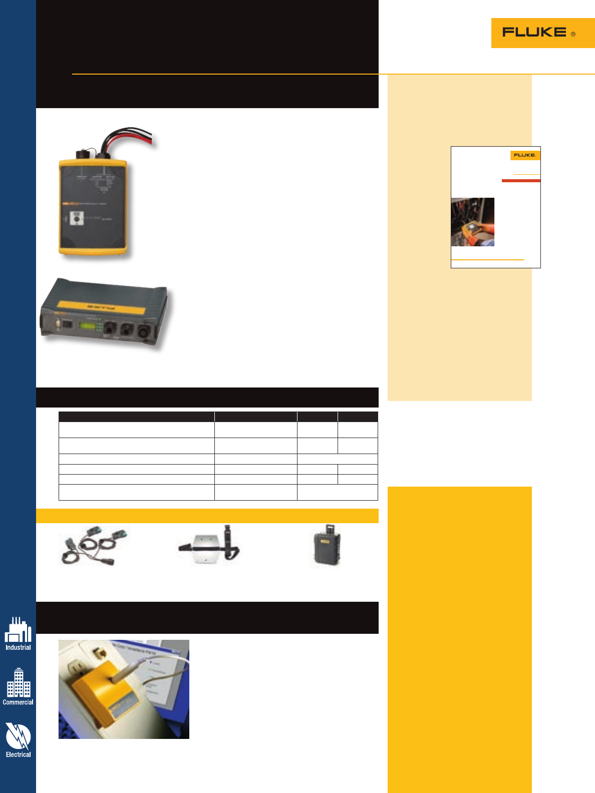
Included accessories
Fluke 1740 Series: 4 Flexible
probes 15/150/1500/3000 A with
2 m cable, PQ Log software, RS-232
interface cable and RS-232-USB
adapter, 4 black dolphin clips, test
leads for voltages and power supply,
color localization kit, carrying bag,
test certificate with measurement
values, printed English manual and
multi-language manual CD.
VR101S: VR101, optical interface
cable, and EventView software on CD.
VR101: Instruction sheet.
Ordering information
Fluke-1743 Power Quality
Logger – Memobox
Fluke-1744 Power Quality
Logger – Memobox
Fluke-1745 Power Quality
Logger – Memobox
VR101S Voltage Event
Recorder System
VR101 Voltage Event
Recorder
Note: At least one VR101S is required for
proper operation.
For more information and detailed specifications, go to www.fluke.com/pq
Fluke 1740 Series Three-
Phase PQ Loggers Memobox
Assess power quality and
conduct long-term studies with ease
Fluke VR101S Voltage Event Recorder System
Power tools for power quality
For more information and detailed specifications, go to www.fluke.com/vr101
The VR101S is the perfect system for catching
sags, swells, transients, outages, and frequency
variations on line voltage at receptacles.
The VR101S is a starter system that includes a
compact VR101 event recorder, an optical inter-
face cable, and EventView® software that turns
your PC into a power quality reporting tool. The
VR101S is covered by a one-year warranty.
Application note, literature code
2646555:
Power quality recording and
analysis: Techniques and
applications
Hooking up a
power quality
recorder and
taking days’
worth of
data can give
you a rich
picture of your
power. In this
article we’ll
talk about
the various
recording
techniques
available in power loggers and
recorders-understanding the tools
and techniques you have available
will be key to your strategy. What
should you be looking for? And
when does recording make sense?
Want to read more? Go to www.
fluke.com/library to download this
and other application notes, or get
info specific to your industry and
sign up for Fluke News publications
at www.fluke.com/subscribe.
Application Note
From the Fluke Digital Library @ www.fluke.com/library
Power quality recording
and analysis: Techniques
and applications
Hooking up a power quality recorder and taking
days’ worth of data can give you a rich picture
of your power. In this article we’ll talk about the
various recording techniques available in power
loggers and recorders—understanding the tools
and techniques you have available will be key to
your strategy. What should you be looking for?
And when does recording make sense?
To really know your power, ideally,
you’d want to look at every line
cycle to see even the smallest
changes. However, since our power
swings through more than four
million cycles per day, it’s impracti-
cal to look at tiny changes—and
often unnecessary. Few loads even
notice occasional voltage dips of
one or two cycles.
How long you record depends
somewhat on the rhythm of your
building. If you are working on a
typical commercial or light indus-
trial building, then a week is long
enough for a building to go through
its normal cycle. If you are work-
ing in a plant that runs special
equipment only periodically (say
a furnace that runs only monthly),
you’ll need to be sensitive to the
timing of these loads.
Different recording techniques
have been developed to look at
small changes over relatively long
time periods. Many instruments
combine several techniques to
improve their coverage. We’ll
describe the common techniques
and some of their pros and cons.
By understanding the different
techniques. you’ll be better able to
choose an appropriate tool for the
job at hand.
Setting up a Fluke 1735 Power Logger at the service entrance for a
30-day load study.
Recording techniques
Fluke 1744/1743
Features 1745 1744 1743
Measurement of common power parameters: V, A, W, VA,
VAR, PF, energy, flicker, voltage events, and THD • • •
Measurement of voltage and current harmonics to the
50th, unbalance, and mains signaling • •
Dust/water resistance IP50 IP65 water proof
Display LED + LCD LED LED
UPS ride-through 5 hours 3 s 3 s
Dimensions (HxWxD) 282 mm x 216 mm x 74 mm
(11.5 in x 8.8 in x 3 in) 170 mm x 125 mm x 55 mm
(6.9 in x 5.1 in x 2.2 in)
Features – 1740 Series PQ Loggers
Fluke 1745
Compact and rugged, the Fluke 1740 Series Three-Phase
Power Quality Loggers are everyday instruments for tech-
nicians who troubleshoot and analyze power distribution
systems. Capable of simultaneously logging up to 500
parameters for up to 85 days and capturing events, the
Fluke 1740 Series helps uncover intermittent and hard-
to-find power quality issues. The included PQ Log soft-
ware quickly assesses the quality of power at the service
entrance, substation, or at the load, according to the latest
EN50160 standard.
• Plug and play: Setup in minutes with automatic current
probe detection and powering
• Installs inside the cabinet: Compact, fully-insulated
housing and accessories fit easily in tight spaces, next
to live power
• Determines the root cause: Included PQ Log software
quickly analyzes trends, creates statistical summaries,
and generates detailed graphs and tables
• Monitors power for the long-term: Data can be
downloaded during recording without interruption
• Measure voltage with premium accuracy: IEC61000-
4-30 Class-A compliant voltage accuracy (0.1 %)
• Quickly validate quality of power: Assess power
quality according to EN50160 power quality standard,
with statistical overview
• Rugged and reliable: Designed for everyday field use,
with no moving parts and durable, insulated case, with
two-year warranty
Recommended accessories – 1740 Series PQ Loggers
MBX CLAMP 1 A/10 A + N MBX 300 POLESET C435
3-phase+N current clamps Pole mounting kit for 1743 and 1744 Water-tight hard case with rollers
2 m cable
28 Power Quality Analyzers
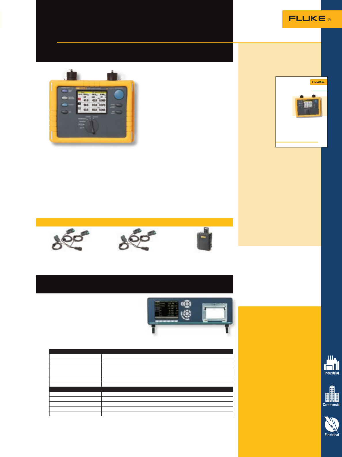
Power Quality Analyzers 29
Recommended accessories – 1735 Three-Phase Power Logger
MBX Clamp 1 A/10 A MBX Clamp 5 A/50 A +N C435
3 precision dual range 4 precision dual range Water-tight hard case with rollers
current clamps (1 A/10 A) current clamps (5 A/50 A)
Fluke 1735 Three-Phase
Power Logger
Electrical load studies, energy consumption
testing, and general power quality logging
The Fluke 1735 Three-Phase Power
Logger is the ideal electrician or
technician’s tool for conducting energy
studies and basic power quality logging.
Set up the 1735 in seconds, with the
included flexible current probes and
color display. The 1735 logs most
electrical power parameters, harmonics
and captures voltage events.
Included accessories
Fluke 1735 Logger: Four flexible
current probes (15 A/150 A/3000 A),
Power Log software, voltage leads
and clips, color localization set, PC
interface cable, international ac
adapter (115/230 V, 50/60 Hz), soft
carrying case, printed English manu-
al and multi-language manual CD.
Norma 4000/5000 Analyzers:
Test certificate with calibration
values, user manual, power supply
cable and are completely customiz-
able with a variety of accessories.
Ordering information
Fluke-1735 Three-Phase
Power Analyzer
Norma 4000 BU43 High Precision
Power Analyzer
Norma 5000 BU56 High Precision
Power Analyzer
The Norma High Precision Power Analyzers
deliver precise measurements of single or
three-phase current and voltage as well
as calculation of power and other derived
values. They provides class-leading
accuracy for any waveform, frequency or
phase shift. Its 144 mm (5.7 in) color display
makes it easy to use both in the field and as
a table unit in labs and on test benches.
For more information and detailed specifications, go to www.fluke.com/pq
Application Note
The NEC specifies that:
• The highest demand is the
highest demand among all
feeders.
• Take the measurements when
the building is occupied.
• Include heating or cooling
loads, whichever is larger, or
correct to account for these
loads.
• Add in any other periodic
loads.
As always, local authorities
are responsible for interpreting
the Code and measurements.
Local regulations determine
when a load study must be per-
formed, exactly what information
is required, and the review pro-
cess. Make sure you understand
your local requirements before
you start a load study.
30 Day Load
Studies with the
Fluke 1735
Power Logger
When a building owner wants
you to add new loads to an exist-
ing service or set of feeders, the
first thing you have to is deter-
mine whether the existing sys-
tem will support the new loads.
If you have a 600 amp service
installed in a facility, can you add
another 100 amps of load?
To answer this question you
have to ask another one: What is
the highest load the system car-
ries now?
Often, local electrical authori-
ties will need to know these
answers before they issue per-
mits. You’ll also need a compre-
hensive understanding of today’s
loading to evaluate the new sys-
tem, once installed.
To determine the existing
equipment’s capacity, factor in
the incoming conductor size, the
ratings of the equipment, and
space for new circuits. To deter-
mine present loading, you’ll need
to either precisely calculate the
existing loads, or measure them.
Article 220 of the 2005
National Electrical Code offers
two measurement methods for
determining existing loads and
the maximum demand the system
is likely to handle.
The NEC defines demand as
the power consumption of the
loads averaged over 15-minute
intervals.
The primary NEC method is to
find the maximum demand dur-
ing a one-year period. This only
works if you have a year’s worth
of demand data.
The alternate method is to
record the demand over a 30-day
period and find the maximum
demand. This article describes
the 30-day recording method,
known as a load study.
From the Fluke Digital Library @ www.fluke.com/library
Recording Current
and Power with the
Fluke 1735
The compact, rugged Fluke 1735
Power Logger is an excellent tool
for performing load studies.
• It includes flexible current
probes for connecting around
multiple conductorsor bus bars.
• It has a PC interface and
software for downloading
measurements to a Win-
dows-based PC and creating
professional reports for your
electrical plans.
• It measures voltage on three
phases and current on three
phases and neutral.
• It records multiple parameters
that can help determinesystem
load, including voltage, current,
frequency, real power (kW),
Application note, literature code
2584800:
30 Day Load Studies with
the Fluke 1735 Power
Logger
When a build-
ing owner
wants you to
add new loads
to an existing
service or set
of feeders,
the first thing
you have to
is determine
whether
the existing
system will
support the new loads. If you have a
600 amp service installed in a facil-
ity, can you add another 100 amps
of load?
To answer this question you
have to ask another one: What is
the highest load the system car-
ries now? Often, local electrical
authorities will need to know these
answers before they issue permits.
Want to read more? Go to www.
fluke.com/library to download this
and other application notes, or get
info specific to your industry and
sign up for Fluke News publications
at www.fluke.com/subscribe
Norma 4000 and 5000
High Precision Power Analyzers
Configurations
Number of channels NORMA 4000: 1 phase or 3 phase; NORMA 5000 and 2x3 phases
Basic accuracy 0.05 % to 0.3 % ± rdg depending on options
Sample rate 1 MHz, 1/3 MHz or 0.1 MHz depending on options
Ranges Up to 100 V and 10 A or 20 A direct inputs, depending on model. With shunts, transducer
or clamp accessories – up to 300 A.
Mechanical power Optional process interface 4 x speed/torque/Pmech
Interfaces RS-232, optional IEEE 488.2/1, Ethernet, USB
Functions
RMS values V/A/P/Q/S and derived values like Fundamental, THD ...
Oscilloscope Simultaneous display of up to three values on sample level
FFT Up to H40 or half of sampling rate
Recorder Display of three average values over time for trend determination
Vector Display of Fundamental of all channels
• Record power and associated parameters
for up to 45 days
• Monitor maximum power demand over
user-defined averaging periods
• Prove the benefit of efficiency
improvements with energy consumption
tests
• Measure harmonic distortion caused by
electronic loads
• Improve reliability by capturing voltage
dips and swells from load switching
• Easily confirm instrument setup with
color display of waveforms and trends
• Measure all three phases and neutral
with included 4 flexible current probes
• View graphs and generate reports with
included Power Log software
• Compact, rugged design with IP65 case,
600 V CAT III and two-year warranty
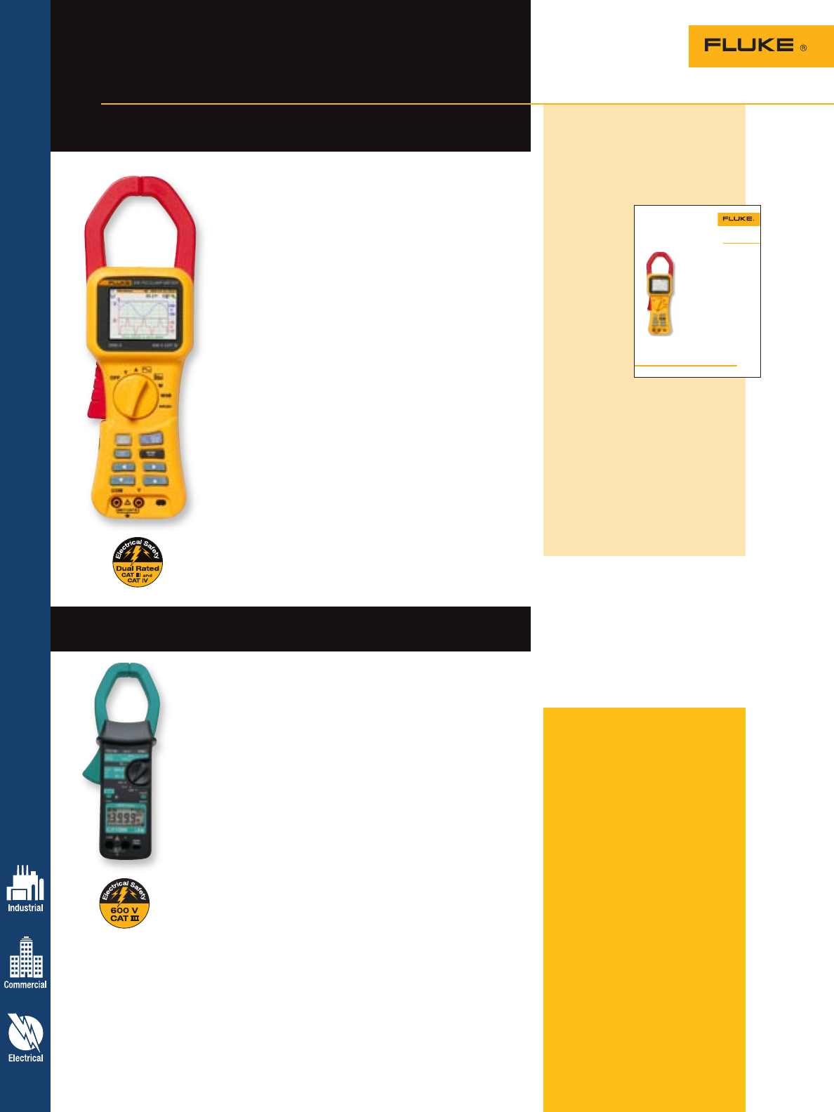
LH1050 and LH1060 Power Clamp Meters
Ideal combination of a clamp and power meter
Included accessories
Fluke 345 Clamp Meter: Batteries,
pair of measuring leads, alligator
clips, operating instructions, Power
Log software, interface cable pouch,
and calibration certificate.
LH1050/LH1060 Clamp Meters:
Battery, pair of measuring leads,
operating instructions, and pouch.
Recommended
accessories
WINLOG S/W WinLOG software for
LH 1050/1060,
Analyst 2050/2060
Ordering information
LH1050 AC/DC Power
Clamp Meter
LH1060 AC/DC Power
Clamp Meter
Fluke-345 AC/DC Power
Quality Clamp Meter
The LH1050 and LH1060 are not
available in Canada.
Fluke 345 Power Quality
Clamp Meter
The ideal meter for commissioning and
troubleshooting modern electrical loads
With a bright color display to analyze the harmonic spectrum,
a low-pass filter to remove high frequency noise, and a high
EMC immunity design, the Fluke 345 is ideal for measurements
on switching loads such as variable speed drives, electronic
lighting and UPS systems. Additionally, the Hall Effect
measurement system makes measurement of dc current
possible without the need to break the circuit, and the internal
memory enables long-term logging for analysis of trends or
intermittent problems.
• AC/DC current: Clamp-on measurement of ac peak and dc
current up to 2000 A without breaking the circuit
• Highest safety rating: 600 V CAT IV/1000 V CAT III rated for
use at the service entrance
• Accurate measurement of parameters: Even with distorted
waveforms present on electronic loads with low-pass filter
• Data logging: Identify intermittent faults by logging
any power parameters for minutes or months, including
harmonics
• Verify batteries: Direct measurement of dc ripple (%) for
battery and dc systems
• Troubleshoot harmonics: Analyze and log harmonics
digitally or graphically
• Inrush current: Capture and analysis from 3 seconds to
300 seconds
• Easy-to-use: Easily confirm instrument setup with large
backlit color display of waveforms and trends
• Three-Phase power: Built in capability for balanced loads.
• View graphs and generate reports: with included Power
Log software
The LH1050/1060 ac/dc meters are essential tools for power
measurement and diagnostics on switching loads such as drives and
high efficiency lighting. They combine the functionality of a current
clamp, power meter and harmonics meter in a single handheld
instrument that has been designed to a CAT III 600 V rating. Common
applications include:
• Installing and testing of dc power systems
• Measurement of harmonics voltage and current on industrial systems
• Power and energy optimization
LH1050 and LH1060 features:
• Wide range of measuring tasks possible with V, A, Hz, W, VAR, VA and
PF in one easy to use clamp
• True-rms ensures correct, accurate measurement of ac+dc and
distorted signals
• Clear presentation of results with bargraph for dual display of V/Hz,
A/Hz and PF/W
• Flexible applications with three-phase power capability for
balanced loads
• Easy data evaluation with ‘Smart Hold’ saving up to 7 parameters
• Capture trends with record mode storing Min Max and Average values
• EL backlight visible in varying light levels
• Two-year warranty
Additional LH1060 features:
• Check startup characteristics with measurement of peak voltage and
current values
• Harmonic trouble shooting with measurement of Total Harmonic
Distortion (THD), Distortion Factor (DF) and Crest Factor (CF)
• Monitor the effects of loads with dc ripple measurement
For more information and detailed specifications, go to www.fluke.com/clamps
30 Clamp Meters
Application Note
Basic power quality
measurements on the
go with the Fluke 345
From the Fluke Digital Library @ www.fluke.com/library
During your day-to-day
measurement activities,
there may be situations
where you need to know
more than what voltage or
current is present. When
that happens, the standard
clamp meter isn’t going to
get the job done. The solu-
tion may be a power quality
clamp meter such as the
Fluke 345.
A power quality clamp
meter like the Fluke 345
combines a clamp meter,
power quality meter, oscil-
loscope and data logger
in one. This combination
of functions coupled with
high quality digital filtering
makes it ideal for working
with variable speed motor
drives, high efficiency light-
ing, and other loads using
switching electronics.
The basics
Of course, the Fluke 345 will make the basic mea-
surements of voltage and current to determine if
there is something seriously wrong with the circuit
under test. It’s rated for use at the service entrance
with a 600 Volt CAT IV rating.
Measuring voltage is as simple as using a clamp
meter: Connect the test leads up to the voltage
inputs, select voltage, and then read the rms volt-
age. Current measurement is just as easy. Select
current, open the jaw, clamp around the wire and
measure. With the 2000A range and large jaw
opening, you can evaluate most of the circuits in
the building.
The Fluke 345 can also measure both ac and dc
voltage and current simultaneously, and identify
the magnitude of each separately and combined as
ac+dc true-rms. That’s helpful for checking a UPS,
battery, and output, to make sure that the circuits
are working correctly and the batteries are in good
condition. A dc voltage component on the output
of a UPS or even an adjustable speed motor drive
may even be a quick indicator of a developing
problem. For example, waveform non-symmetry
will cause an apparent dc voltage component and
may indicate impending failure of system output
electronics.
Application note, literature code
2722823:
Basic power quality
measurements on the go
with the Fluke 345
A great
introduction to
power quality,
this short
application
note teaches
the basics of
simple voltage,
current,
waveform,
harmonics,
power, inrush,
and logging
measurements
using the
Fluke 345. Learn how to read
waveforms and how and where
to use them, and then learn about
harmonics and how they distort
voltage and current.
Download this and other
application notes at www.fluke.
com/library or sign up for Fluke
News to get pertinent information on
your industry at www.fluke.com/
subscribe
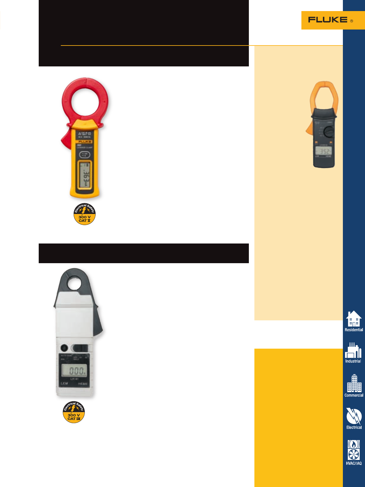
31
Clamp Meters
The compact size of the LH41 makes it ideal for making
general measurements on small conductors. With excellent
accuracy and resolution of 1 mA, the LH41 offers exceptional
performance for automotive and other low current
applications.
Features
• Easy use autoranging ac/dc leakage current
measurements from 10 mA to 40 A
• High 1 mA current resolution for quick circuit comparison
on sensor and control circuits
• Patented jaw design for high accuracy, low dc current
measurement ensures no interference from other circuits
• Push button dc Auto Zero for correct measurement
every time
• Battery saving auto power off function
• ‘Carry everywhere’ pocket size, lightweight design
• Convenient display hold for capturing measurement in
inaccessible spots
• CAT III 300 V
• Two-year warranty
Fluke 360 AC Leakage
Current Clamp Meter
1 μA resolution leakage current measure-
ments with a tough, pocket sized clamp
For more information and detailed specifications, go to www.fluke.com/clamps
LH41 AC/DC Low Current Clamp Meter
AC/DC current clamp for low current applications
LH2015 AC/DC
True-rms Clamp Meter
High current, large jaw clamp for
industrial and utility applications
The LH2015’s
large jaw is
suitable for current
measurements
up to 2000 A
ac/dc on large
conductors or bus
bars. The LH2015’s
measurement
accuracy is
unaffected by
external magnetic
fields or off-
center conductor
positioning due to
its advanced jaw
design. Its Display-
Hold feature freezes
the measurement for
viewing after measuring and the
Max-Hold captures the maximum
measured current.
Current clamp measurement can be
used when:
• it’s not possible to power down
equipment and break the circuit.
• checking the current on large
loads to avoid overheating of
conductors.
• measuring large dc currents in
industrial drives.
Features:
• 2000 ac and dc current
measurement
• Accurate true-rms measurement
for distorted waveforms
• Large 50 mm (2 in) jaw capacity
• Autoranging and Auto-zero
• Display-Hold and Max-Hold
(surge)
• Two-year warranty
Included accessories
Fluke 360 Clamp Meter: Soft
carrying pouch and users manual.
LH41 Clamp Meter: Battery and
operating instructions.
LH2015 Clamp Meter: Soft case and
users manual.
Ordering information
Fluke-360 AC Leakage Current
Clamp Meter
LH41 AC and DC Current
Clamp Meter
LH2015 AC/DC True-rms
Clamp Meter
These products are not available
in Canada.
The unique jaw design of the Fluke 360 eliminates
the influence of adjacent current conductors
and measures leakage current down to 1 µA for
monitoring of insulation. The ergonomic design
of the Fluke 360 ensures easy measuring. The
measuring clamp fits into tight spaces and the
wide display angle clearly shows the measurement
result. The data hold button keeps the measured
value on the display after removing the clamp for
the measured conductor.
The light Fluke 360 offers the widest range
of current measurement for maintenance
professionals and contractors. Use the light and
rugged Fluke 360 when it’s not possible to power
down and break the circuit.
Current measurement
• Automatic ranging within the manually selected
mA or A range
• Ranges 3/30 mA and 30/60 A
• Current resolution 1 µA/0.01 mA and
0.01 A/0.1 A
• Frequency range 50 and 60 Hz
• Jaw size: 40 mm (1.55 in) maximum conductor
diameter
• Auto power off
• One-year warranty
Move up to better design and
performance with Fluke clamp meters
Get more done with the
latest Fluke tools
It’s never been more important to be
efficient, fast, and accurate at your job.
Today, you need a tool that can keep up
with the demanding needs of residential,
commercial, and industrial electricians. The
Fluke 337 Clamp Meter provides you the
ability to work quickly and easily in narrow
and dark locations, and makes it possible to
keep track of your measurements for further
analysis.
The Fluke 337 is a significant
improvement from the Fluke 30 Series
clamps that were built in the mid 1990’s.
While the 30 Series was a leader in its day,
the 337 offers a design that is compact and
lightweight, and functionality that allows
you to take measurements that are more
precise.
Fluke 330 Series clamps are designed
more ergonomically with capabilities not
found in their predecessors, the Fluke 30, 31,
32, 33 and 36.
Specialty clamp meters
See page 54 for information on the NEW!
902 True-rms HVAC Clamp Meter.
See page 44 for information on the NEW!
771 Milliamp Process Clamp Meter.
Function Fluke 30 Series Clamps Fluke 337 Benefit
Three-year warranty Out of warranty Three-year warranty Lower cost of ownership
Small body and jaws fit
perfectly in your hand and
into tight places —•
Fits into tight areas for
maximum usability
Frequency measurement —•Built-in frequency counter
Meter controls are positioned
so current measurements
can be done with one hand
(index finger on clamp
opening lever and thumb on
rotary switch)
—•
Easier to use, efficient
measurements
Large, backlit display is
easy-to-see —•Use in dark areas
Inrush current function for
measuring starting current for
motors, lighting, etc. —•
Easily measure inrush
current on motors, switches,
and circuit protectors to
determine if equipment can
work with high current levels
Improved low current
measurement accuracy
from new microprocessor
technology
—•
More precise measurements
Min/Max capability Max only Min/Max Easily track your
measurements
Fluke 337 Premium
Clamp Meter
• Rugged
• CAT III 600 V
• Inrush
• Compact
32 Clamp Meters
For more information and detailed specifications, go to www.fluke.com/clamps
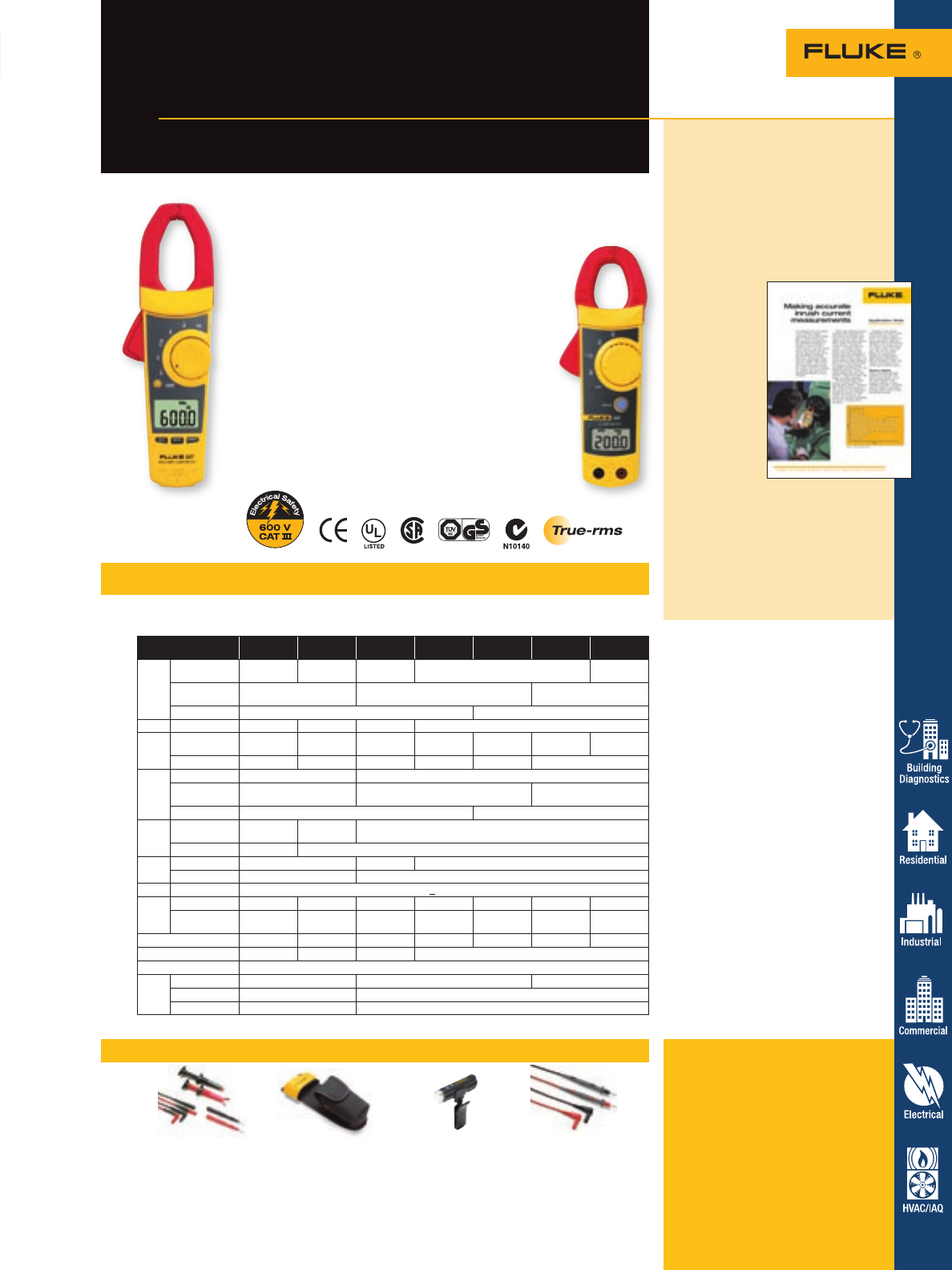
Clamp Meters 33
Recommended accessories – 320 and 330 Series
Specifications – 320 and 330 Series
Models 333, 334, 335, 336
and 337
Operating temperature: -10 °C to 50 °C
(-14 °F to 122 °F)
Altitude: 2,500 meters
Battery life: (2) AA alkaline approximately
150 hours continuous, automatic low battery
indicator
Safety rating: IEC 1010-2-031, CAT III 600 V
Temperature de-rating: Add 0.1 x specified
accuracy for each ºC above 28 ºC or below
18 ºC
Storage temperature: -40 ºC to 60 ºC
(-40 ºF to 140 ºF)
Models 321 and 322
Operating temperature: -10 °C to 50 °C
(-14 °F to 122 °F)
Altitude: 2,000 meters
Battery life: (2) AAA carbon zinc
approximately 100 hours continuous,
automatic low battery indicator
Safety rating: IEC 1010-2-031, CAT III 600 V
Temperature de-rating: < 18 °C, > 28 °C add
0.1 x specified accuracy /°C
Storage temperature: -30 °C to 60 °C
(-22 °F to 140 °F)
See page 54 for information on the
NEW! 902 True-rms HVAC Clamp Meter
• Inrush current feature (selected models)
• Small body and jaws fit perfectly in your hand
and into tight places
• Controls positioned for one hand operation
• Accurate low current measurements
• Backlight available on most models
• Auto shut-off
• Display hold
• Safety rating: IEC 1010-2-031, CAT III 600 V
• Three-year warranty on 330 Series
Fluke 322 Clamp Meter
• Precise measurements with 1.8 % basic accuracy
• Resolution up to 0.01 A and 0.1 V
• Measures ac current 40.00 A/400.0 A
• Measures ac and dc volts to 600 V
• Resistance measurement to 400 W
• Continuity for quick checking of shorts
(@23 °C ± 5 °C RH
0 to 90 %) Fluke 321 Fluke 322 Fluke 333 Fluke 334 Fluke 335 Fluke 336 Fluke 337
AC
current
Range to 400.0 A 40.00 A/
400.0 A to 400.0 A to 600.0 A to 999.9 A
Accuracy 1.8 % + 5 counts
(50 to 60 Hz) 2 % + 5 counts
(50 to 60 Hz) 2 % + 5 counts
(10 to 100 Hz)
AC response Averaging True-rms
Inrush
Integration time
— — — 100 mS
DC
current
Range — — — — — 0 to
600.0 A 0 to
999.9 A
Accuracy — — — — — 2 % + 3 counts
AC
volts
Range 400.0 V/600.0 V to 600.0 V
Accuracy 1.2 % + 5 counts
(50 to 400 Hz) 1 % + 5 counts
(50/60 Hz) 1 % + 5 counts
(20 to 100 Hz)
AC response Averaging True-rms
DC
volts
Range — 400.0 V/
600 V to 600.0 V
Accuracy — 1 % + 5 counts
Ohms Range to 400.0 Wto 600.0 W600.0 W/6000 W
Accuracy 1 % + 5 counts 1.5 % + 5 counts
Continuity < 30 W
Hz
Range — — — — — — to 400 Hz
Accuracy — — — — — — 0.5 % + 5
counts
MIN/MAX — — — — — — Yes
Backlight — — — Yes
Display hold Yes
Size
H x W x D 7.5 in x 2.5 in x 1.4 in 9.4 in x 3.1 in x 1.6 in 9.9 in x 3.1 in x 1.6 in
Max wire dia. 1 in 1.2 in
Weight 8 oz 11 oz
Fluke 320 and 330 Series Clamp Meters offer an impressive array of innovative features with
current ranges up to 1000 A. Choose the model that matches the jobs you do.
TL223 H3 LVD1 TL71
SureGrip™ Electrical Test Lead Set Clamp Meter Holster Volt Light Premium Test Lead Set
See page 61 See page 70 See page 64 See page 62
Fluke 337 and 322
Clamp Meters
Measure inrush motor starting current
the way a circuit breaker sees it
For more information and detailed specifications, go to www.fluke.com/clamps
Included accessories
Soft carrying case, test leads,
(2) batteries, instruction card and
safety information.
Ordering information
Fluke 321 Fluke 335
Fluke 322 Fluke 336
Fluke 333 Fluke 337
Fluke 334
Application note, literature code
2041766:
Making accurate inrush
current measurements
New high-efficiency motors require
better tools to evaluate and fix the
consequences of their high inrush
current. The Fluke 335, 336 and
337 Clamp
Meters are
designed
to capture
inrush current
accurately
and, most
importantly,
synchronously
and provide
readings that
accurately
depict what
the circuit
protector
experiences.
This application note covers
practices to help you accurately
and safely measure and interpret
inrush current measurements.
Want to read more? Download
this and other application notes at
www.fluke.com/library
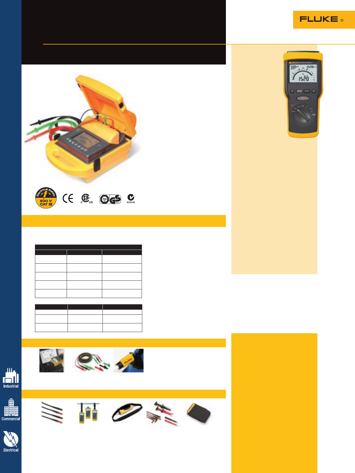
Specifications – 1550B MegOhmMeter
Recommended accessories – 1520 MegOhmMeter
Recommended accessories – 1550B MegOhmMeter Included accessories
Fluke 1550B MegOhmMeter: Test
leads, 5000 V-rated probes, alligator
clips, interface adapter and cable,
FlukeView Forms software, line cord,
soft carrying case, and users manual.
Fluke 1520 MegOhmMeter: TL27
Heavy Duty Test Leads, TP74
Lantern Tip Test Probes, AC285
Large Jaw Alligator Clips, protective
holster with hand strap, carrying
case with accessory storage, four
C-cell alkaline batteries, instruction
manual, and instruction manual on
CD-ROM.
Ordering information
Fluke-1520 MegOhmMeter
Fluke-1550B MegOhmMeter
34 Insulation Resistance Testing
Fluke 1550B and 1520
MegOhmMeters
Powerful troubleshooting and
predictive maintenance tools
The 1550B automatically calculates
polarization index and dielectric absorp-
tion ratios. The 1550B features:
• Standard test voltages of 250 V,
500 V, 1000 V, 2500 V and 5000 V
for a wide range of equipment testing
• Programmable test voltages
available in 50-volt steps from 250 V
to 1000 V and 100-volt steps from
1000 V to 5000 V
• Automatic calculation of Dielectric
Absorption Ratio (DAR) and Polarization
Index (PI) with no additional setup
• Easy setup saves time and effort when
conducting “timed” and “ramp” test of
insulation breakdown
• Improved ramp function (0 V dc to
5000 V dc) for breakdown testing
• Autodischarge of capacitive voltage
• Measures resistances up to one
teraohm
• Includes improved FlukeView®
Forms Software and Optical Interface
cable for easier downloading to a
Windows® PC
Insulation resistance measurement
Test Voltage (dc) Range Accuracy (± reading)
250 V 200 kW to 5 GW
5 GW to 50 GW
5 %
20 %
500 V 200 kW to 10 GW
10 GW to 100 GW
5 %
20 %
1000 V 200 kW to 20 GW
20 GW to 200 GW
5 %
20 %
2500 V 200 kW to 50 GW
50 GW to 500 GW
5 %
20 %
5000 V 200 kW to 100 GW
100 GW to 1 TW
5 %
20 %
Function Range Accuracy (± reading)
Leakage current 1 nA to 2 mA ± (5 % + 2 nA)
Capacitance
measurement 0.01 uF to 15.00 µF ± (15 % rdg + 0.03 µF)
Live circuit
indicator 30 V to 600 V ac/dc,
50/60 Hz ± (5 % + 2 V)
The meter’s accuracy is specified for one year after calibration at oper-
ating temperatures of 0 °C to 35 °C. For operating temperatures outside
the range (-20 °C to 0 °C and 35 °C to 50 °C), add ± .25 % per °C,
except on the 20 % bands add ± 1 % per °C.
Short circuit current: greater than 1 mA and less
than 2 mA
Bargraph range: 0 to 1 TW
Insulation test voltage accuracy: -0 % to +10 % at
1 mA load current
Induced ac mains current rejection: 2 mA maximum
Charging rate for capacitive load: 5 seconds per µF
Timer: 0 to 99 minutes; settable in 1 minute incre-
ments; indicated to within 1 second
Ramp: 0 % to 100 % of selected test voltage, or until
breakdown
Dimensions (HxWxL): 330 mm x 242 mm x 170 mm
(13 in x 9.5 in x 6.7 in)
Weight (with battery): 4 kg (8.8 lb)
Battery type: 12 V, lead-acid, rechargeable
Charger input (ac): 85 to 250 V ac, 50/60 Hz, 50 VA
Operating temperature: -20 ºC to 50 ºC
(-4 ºF to 122 ºF)
Storage temperature: -20 ºC to 65 ºC (-4 ºF to 149 ºF)
Relative humidity: 80 % at 31 °C decreasing linearly
to 50 % at 50 °C
Operating altitude: 0 to 2000 meters
Enclosure sealing: IP 40
Safety conformance: EN 61010-1, CAT III, 600 V,
EN61557, Parts 1 & 2
Input overload protection: 600 V ac continuous
Warranty: Two-years
Software: FlukeView® Forms Basic Software requires a
PC running Windows® 95, 98, Me, 2000, NT4.0
Fluke 1520
MegOhmMeter
A proven workhorse,
the 1520 can make
up to 5,000 insula-
tion resistance tests,
more than any other
Fluke insulation
tester, without chang-
ing batteries. A dual
analog/digital display
makes it easy to use.
A lo-ohms function
measures voltage and
checks connections.
Thanks to superb accu-
racy, endurance, and handheld size,
the 1520 is a long-standing tool
of choice for demanding plant and
utilities work.
• Large, backlit LCD with analog
bar graph and digital display
• Three output voltages for insula-
tion resistance testing: 250 V,
500 V and 1000 V
• Perform up to 5,000 insulation
resistance tests without changing
batteries
• Insulation resistance testing up to
4000 MW; switches automatically
to voltage measurement when
voltage is greater than
30 V ac or 30 V dc
• Auto-discharge of capacitive
voltage
• AC/DC voltage measurement up
to 600 V
• Lo-Ohms function for testing
connections
• Last reading memory display
TL27 ToolPak™ SH100 TL223 C43
Heavy-Duty Meter Hanger Shoulder harness SureGrip™ Electrical Soft Carrying Case
Test Lead Set See page 71 for 1520 Test Lead Set See page 70
See page 62 See page 61
FVF-UG TL1550EXT L206
FlukeView Forms 25 Foot Extension Deluxe LED Hat Light
Software Upgrade Test Lead Set See page 64
See page 65
For more information and detailed specifications, go to www.fluke.com/1550
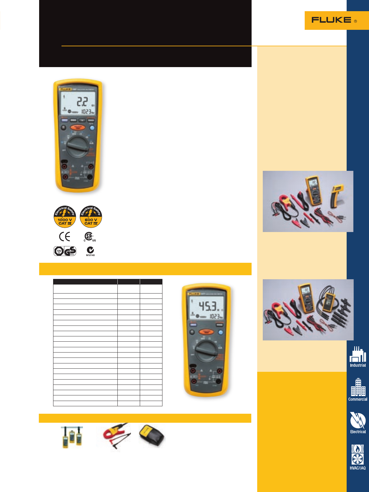
Insulation Resistance Testing 35
Fluke 1587 and 1577
Insulation Multimeters
Two powerful tools in one
For more information and detailed specifications, go to www.fluke.com/1587
Specifications
The Fluke 1587 and 1577 Insulation Multimeters combine a
digital 1 kV insulation tester with a full-featured, true-rms
digital multimeter in a single compact, handheld unit, which
provides maximum versatility for both troubleshooting and
preventative maintenance. Whether you work on motors,
generators, cables, or switchgear, the Fluke 1587 and 1577
Insulation Multimeters are ideally suited to help you with
your tasks.
• Insulation test (1587: 0.01 MW to 2 GW)
(1577: 0.1 MW to 600 MW)
• Insulation test voltages (1587: 50 V, 100 V, 250 V, 500 V,
1000 V), (1577: 500 V, 1000 V) for many applications
• Live circuit detection prevents insulation test if voltage
> 30 V is detected for added user protection
• Auto-discharge of capacitive voltage for added
user protection
• Filter for motor drive measurements (1587 only)
• AC/DC voltage, dc milliVolts, ac/dc milliamps,
resistance (W), and continuity
• Capacitance, diode test, temperature, Min/Max, and
frequency (Hz) (1587 only)
• Auto power off to save battery power
• Large display with backlight and large digits
• Included accessories: Remote probe, test leads and probes,
alligator clips, (K-type thermocouple, 1587 only)
• Accepts optional Fluke TPAK™ magnetic hanging system to
free your hands for other work
• Rugged, utility hard case allows you to bring everything
you need for the job
• Three-year warranty
1587 1577
Insulation test voltages 50 V, 100 V,
250 V, 500 V, 1000 V •
Insulation test voltages 500 V, 1000 V •
Insulation test: 0.01 MW to 2.0 GW•
Insulation test: 0.1 MW to 600 MW•
Auto-discharge of capacitive voltage • •
Insulation test smoothing reading •
Frequency •
Capacitance •
Diode test •
Temperature •
Min/Max •
Low-pass filter (for work on VSDs) •
AC/DC Voltage • •
DC Millivolts • •
AC/DC milliAmps • •
Resistance (0.1 W to 50 MW)• •
Continuity • •
Three-year warranty • •
Remote probe, test leads, alligator clips • •
K-type thermocouple •
Rugged, utility hard case • •
Auto power off • •
Recommended accessories
ToolPak™ i400s C25
Meter Hanger AC Current Clamp Meter Case
See page 71 See page 66 See page 70
Get the most value and
productivity from Fluke kits
Establishing a preventive mainten-
ance program is becoming critical to
maintaining the uptime of electrical
equipment and can significantly
reduce both planned and unplanned
downtime. Unplanned downtime
costs are difficult to calculate, but are
often significant. For some industries,
it can represent 1 % to 3 % of
revenue (potentially 30 % to 40 % of
profits) annually.
These kits can help you be
proactive and efficient with your
maintenance and can save you up
to 10 % off the individual price of
the tools.
Fluke 1587/ET Advanced Electrical
Troubleshooting Kit includes:
• Fluke 1587 Insulation Multimeter
• Fluke i400 Current Clamp
• Fluke 62 Mini Infrared
Themometer
Fluke 1587/MDT Advanced Motor
and Drive Troubleshooting Kit
includes:
• Fluke 1587 Insulation Multimeter
• Fluke i400 Current Clamp
• Fluke 9040 Phase Rotation
Indicator
Included accessories
Remote probe, test leads,
alligator clips, K-type thermocouple
(1587 only), hard case and user
documentation.
Ordering information
Fluke-1577 Insulation
Multimeter
Fluke-1587 Insulation
Multimeter
Fluke-1587/ET Advanced
Electrical
Troubleshooting Kit
Fluke-1587/MDT Advanced Motor
and Drive
Troubleshooting Kit
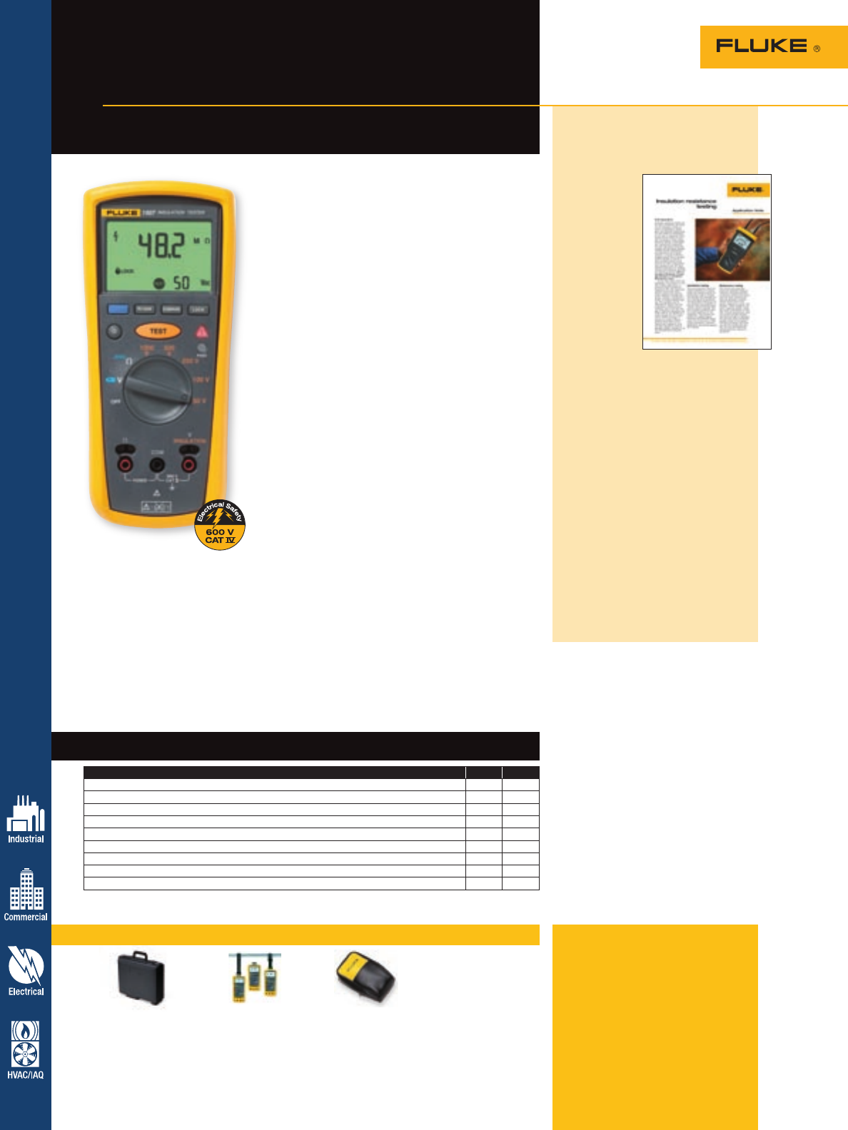
Recommended accessories – 1507 and 1503 Testers
Features – 1507 and 1503 Testers
Insulation Resistance Testing
36
For more information and detailed specifications, go to www.fluke.com/1507
Fluke 1507 and 1503
Insulation Testers
Insulation resistance testing
in the palm of your hand
The Fluke 1507 and 1503 Insulation Testers are
compact, rugged, reliable, and easy to use. With
their multiple test voltages, they are ideal for many
troubleshooting, commissioning, and preventive
maintenance applications. Additional features, like the
remote probe on these tools save both time and money
when performing tests.
Insulation test ranges:
• 1507: 0.01 MW to 10 GW
• 1503: 0.1 MW to 2 GW
Insulation test voltages:
• 1507: 50 V, 100 V, 250 V, 500 V, 1000 V
• 1503: 500 V, 1000 V
• Save both time and money with automatic calculation
of Polarization Index and Dielectric Absorption Ratio
(1507 only)
• Make repetitive tests simple and easy with the
1507’s compare (Pass/Fail) function (only available on
the 1507)
• Repetitive or hard-to-reach testing is easy with the
remote test probe
• Live circuit detection prevents insulation test if
voltage > 30 V is detected for added user protection
• Auto-discharge of capacitive voltage for added user
protection
• AC/DC voltage: 0.1 V to 600 V
• Lo-Ohms/Earth bond continuity (200 mA)
• Resistance: 0.01 W to 20.00 KW
• Save battery power with auto-power off
• Read measurements easily with large, backlit display
• CAT IV 600 V overvoltage category rating for added
user protection
• Remote probe, test leads, probes, and alligator clips
included with each tester
• Accepts optional Fluke ToolPak™ magnetic hanging
system to free your hands for other work
• Four AA alkaline batteries (NEDA 15 A or IEC LR6) for
at least 1000 insulation tests
• One-year warranty
Included accessories
Remote probe, test leads, test
probes, alligator clips, holster and
user documentation.
Ordering information
Fluke-1507 Insulation Tester
Fluke-1503 Insulation Tester
Application note, literature code
1579160:
Insulation resistance testing
Insulation
resistance
testers can
be used to
determine
the integrity
of windings
or cables
in motors,
transformers,
switchgear,
and electrical
installations.
The test
method is determined by the type
of equipment being tested and the
reason for testing. For instance,
when testing electrical cabling
or switchgear (low-capacitance
equipment) the time-dependent
capacitive leakage and absorption
leakage currents become insignifi-
cant and decrease to zero almost
instantly. A steady conductive
leakage current flow is reached
almost instantly (a minute or less)
providing perfect conditions for the
spot-reading/short time resistance
test.
Want to read more? Download this
and other application notes at
www.fluke.com/library, or sign
up for Fluke News for pertinent
information on your industry at
www.fluke.com/subscribe
C101 ToolPak™ C25
Meter Hard Case Meter Hanger Meter Case
See page 70 See page 71 See page 70
Feature 1507 1503
Insulation test voltages 50 V, 100 V, 250 V, 500 V, 1000 V •
Insulation test voltages 500 V and 1000 V •
Insulation test: 0.01 MW to 10 GW•
Insulation test: 0.01 MW to 2 GW•
PI/DAR •
Auto discharge of capacitive voltage • •
Remote test probe, test leads, alligator clips • •
Rugged utility hard case • •
Auto power off • •
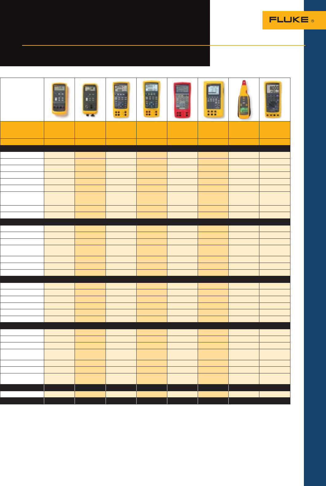
Loop Calibrator Pressure
Calibrator
Temperature
Calibrator
Precision
Multifunction
Process
Calibrator
Intrinsically
Safe
Calibrator
Documenting
Process
Calibrator
Process mA
Clamp Meter
ProcessMeter®
Test Tool
Model 715 718 724 726 725Ex 744 771 789
Measure
V dc 25 V 30 V 30 V 30 V 300 V 1000 V
V ac (true-rms) 300 V 1000 V
Resistance 3200 W4000 W3200 W11 kW40 MW
A dc 24 mA 24 mA 24 mA 24 mA 24 mA 110 mA 20.99, 99.9 mA 30 mA, 1 A
A ac •
Frequency 15 kHz 10 kHz 50 kHz 20 kHz
Pressure 1 psi, 30 psi,
100 psi and
300 psi •1•5•1
Temperature: RTDs 7 types 8 types 7 types 8 types
Temperature: TCs 12 types 13 types 12 types 13 types
Source/Simulate
V dc 20 V 10 V 20 V 10 V 15 V
Resistance 3200 W4000 W3200 W11 kW
mA dc/% scale 24 mA 24 mA 24 mA 22 mA 24 mA
mA source; auto step,
auto ramp • • • • •
Frequency 15 kHz 10 kHz 50 kHz
Temperature: RTDs 7 types 8 types 7 types 8 types
Temperature: TCs 12 types 13 types 12 types 13 types
Record
Min/Max • • •
Hold • • • •
As Found/As Left results •
Log data •
Upload data to PC •
Remote operation • •
Features
24 V loop supply • • • • 12 V • •
Non-contact measurement •
Hart communication •
Integrated hand pressure
pump •
Intrinsically safe (ATEX) •
Warranty 3 years 1 year 3 years 3 years 1 year 3 years 1 year 3 years
NIST traceable
certification • • • • • •
Accessories3A/B C A/B A/B A/B
Pressure enabled4• • • •
See page 42 41 40 39 45 38 44 43
Process Calibration Tools 37
Pick the right
process tool for you
Process Tools Selection Guide
1Fluke 700 Pressure Modules required.
2Either the internal sensor or a Fluke 700 Pressure Module may be used.
3Accessories: A. Compatible with LockPak B. Compatible with ToolPak C. Accepts hanging straps from ToolPak D. Optional accessories
4Fluke Process Calibrators in this guide displaying the Pressure Enabled symbol display readings from the 700 Series Pressure Modules.
5Fluke 700PEx Pressure Module required.
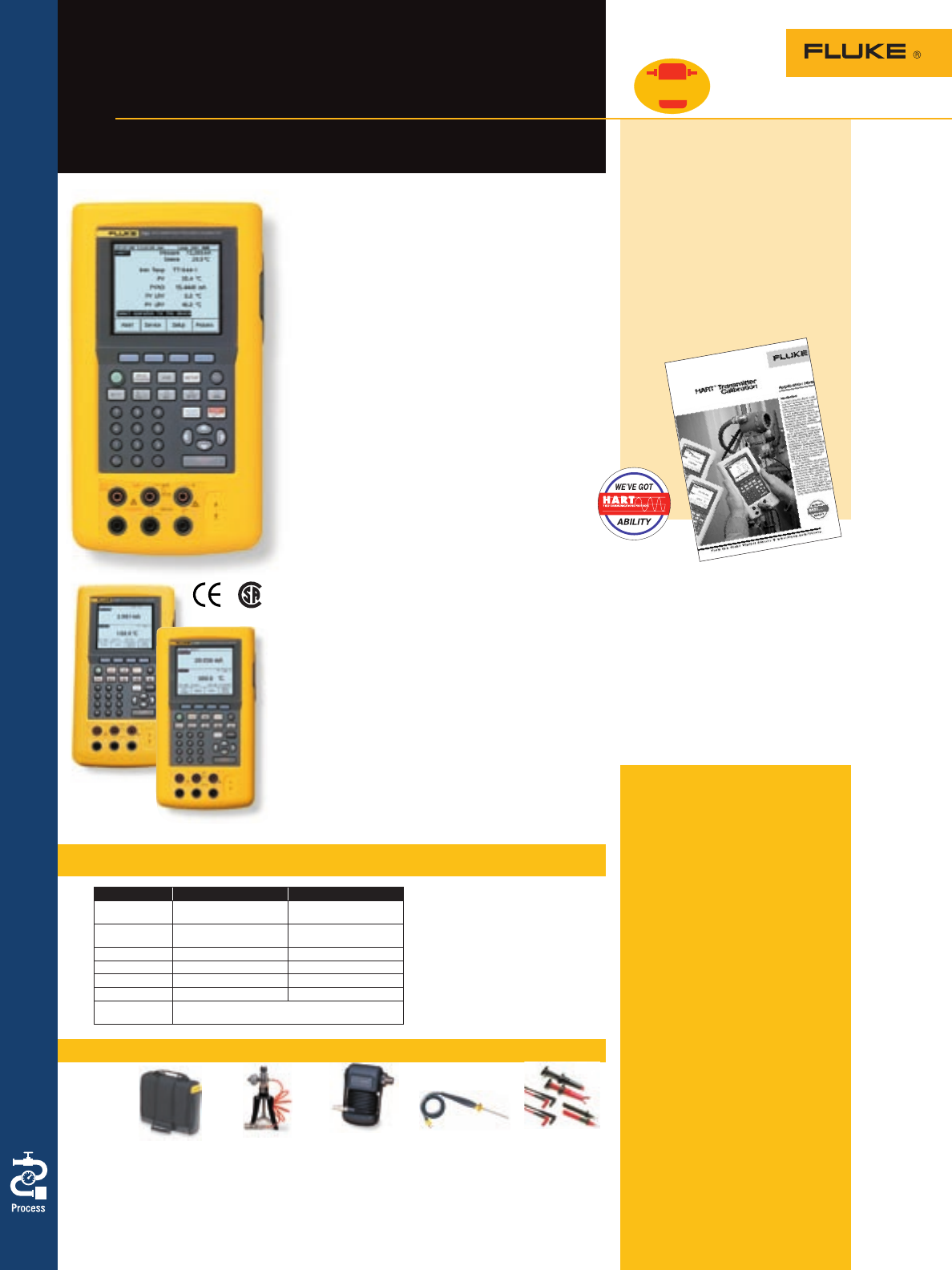
Recommended accessories – 741B, 743B and 744
Specifications – 741B, 743B and 744
Included accessories
TL224 Industrial Test Leads (2 sets),
AC220 Test Clips (2 sets), TP220
Test Probes, BP7217 Battery Pack,
BC7217 Battery Charger, instruction
manual, NIST Traceable calibration
certificate and data, serial port cable
(743B and 744 only), DPC/TRACK
sample version with free PC commu-
nication utility software (743B and
744 only).
Additional 744 accessories
BP7235 NiMH Battery Pack, HART
communications cable, HART user’s
manual and NIST Traceable calibra-
tion certificate and data.
Ordering information
Fluke-741B Documenting Process
Calibrator
Fluke-743B Documenting Process
Calibrator
Fluke-744 Documenting Process
Calibrator
Fluke-700S DPC/Track
Software
38 Process Calibration Tools
Fluke 741B, 743B and
744 Calibrators
For the calibration and troubleshooting
of process control instrumentation
Function Measure Sourcing
DC voltage 0.025 % reading +
0.005 % full scale 0.01 % output +
0.005 % full scale
DC current 0.01 % reading +
0.015 % full scale 0.01 % output +
0.015 % full scale
Resistance 0.05 % reading + 50 mW0.01 % output + 40 mW
Frequency 0.05 % 0.01 %
Thermocouples 0.3 °C 0.2 °C
RTDs 0.3 °C 0.1 °C
Pressure To 0.25 % of full scale, per pressure
module specifications.
• Calibrate temperature, pressure, voltage, current,
resistance and frequency instruments
• Built-in procedures for transmitters, square root
transmitters, pressure and temperature switches
• Simultaneously measure and source
• Automatically capture calibration results
• Document procedures and results to meet ISO 9000,
EPA, FDA, OSHA, and other government requirements
• Measure/simulate 13 types of thermocouples and
eight RTDs
• Store up to 8,000 readings in data logging mode
(743B and 744 only)
• Protected against dirt, dust and moisture; unaffected
by vibration
• Includes a PC interface (743B and 744 only)
• Operate in English, French, German, Italian and Spanish
• Offer one- and two-year calibration cycles and a
three-year warranty (one-year for pressure modules)
744: Get HART-ability
The Fluke 744 offers all of the capabilities of the 743B, plus
the ability to calibrate, maintain, and troubleshoot HART
instrumentation. Integrated HART communication functions
permit you to monitor, control, and calibrate HART instru-
mentation. It handles fast pulsed instruments such as RTD
transmitters and PLCs, with pulses as short as 1 ms.
See www.fluke.com/744upgrade for the latest list of
HART instruments.
741B: A complete documenting calibrator
The 741B is the economical choice for plants that don’t use
PCs or that require traditional paper forms. It has storage
capacity for a day’s calibration and measurement data. When
you’re back at the shop, recall the data on-screen to fill out
calibration forms.
743B: More memory, plus a PC interface
and data logging
The 743B has all the capabilities of the 741B plus a PC
interface that lets you load procedures, lists, and instructions
created with software—or unload data for printing, archiving,
and analysis. With its expanded memory, the 743B can hold
a full week of calibrations and procedures.
Summary specifications: best case,
midrange, one-year.
Battery life: Typically over eight hours
Internal battery pack: NiCd, 7.2 V,
1700 mAh, NiMH 3500 mAh on 744.
Battery replacement: Via snap-shut
door without opening calibrator; no
tools required
Weight: 1.4 kg (3 lb 1 oz)
Size (HxWxD): 236 mm x 130 mm x
61 mm (9.3 in x 5.1 in x 2.4 in)
Instrumentation
management software
The Fluke 743B and 744 are compatible
with Fluke 700SW DPC/TRACK software
and with software from Beamex,
Cornerstone, Emerson, Honeywell,
On Time Support, Prime Technologies,
Yokogowa, Intools and Meridium.
For more information, visit
www.fluke.com/software
C789 Fluke-700PTP Fluke-700Pxx 80PK-25 TL220
Meter and Pneumatic Pressure Modules SureGrip Piercing SureGrip Industrial
Accessory Case Test Pump See page 41 Temperature Probe Test Lead Set
See page 70 See page 69 See page 68 See page 61
Application note, literature code
1262439:
HART® transmitter
calibration
The need for calibration of HART
smart transmitters is often misun-
derstood. What do you calibrate and
when? Here is a step-by-step
procedure showing how to use the
Fluke 744 to perform calibration and
digital adjustments of Rosemount
3051 and 3144 transmitters and
other HART devices.
Pressure
Enabled
For more information and detailed specifications, go to www.fluke.com/740
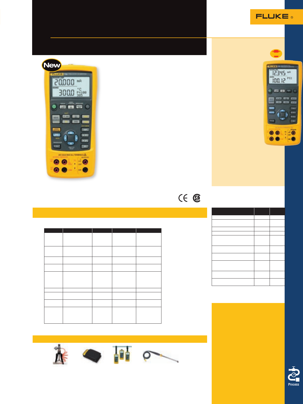
Process Calibration Tools 39
Recommended accessories – 726 and 725 Calibrators
Specifications – 726 and 725 Calibrators
Step up to unmatched accuracy in
process measurement and calibration
Fluke 726 and 725 Multi-
function Process Calibrators
Fluke 726 Precision Multifunction
Process Calibrator
The Fluke 726 Precision Multifunction Process Calibrator
is designed specifically for the Process industry with
broad workload coverage, calibration power and
unsurpassed accuracy in mind. The 726 measures and
sources almost all process parameters and can calibrate
almost anything. The 726 will also interpret results
without the help of a calculator and store measurement
data for later analysis.
• Precise measurement and calibration source
performance, accuracies of 0.01 %
• Transmitter error% calculation, interpret calibration
results without a calculator
• Memory storage for up to 8 calibration results, return
stored calibration data from the field for later analysis
• Frequency totalizer and frequency pulse train source
mode for enhanced flowmeter testing
• HART mode inserts 250 ohm resistor in mA
measure and source for compatibility with HART
instrumentation
• Integrated pressure switch test allows you to capture
the set, reset and deadband of a switch
• Custom RTD curves, add calibration constants for
certified RTD probes for enhanced temperature
measurement
• New voltage input protection design for improved
reliability
• Three-year warranty
Fluke-700PTP C125 ToolPak 80PK-27
Pneumatic Meter Case Meter Hanging Kit SureGrip Industrial
Test Pump See page 70 See page 71 Surface Temperature Probe
See page 69 See page 68
Measure and source
Function Range or type Resolution Accuracy Notes
Voltage 0 to 100 mV
0 to 10 V (source)
0 to 20 V (source)
0 to 30 V (measure)
0.01 mV
0.01 V
0.01 V
0.01 V
0.01 %,
0.02 %
Rdg + 2 LSD
Max load, 1 mA
mA 0 to 24 0.001 mA 0.01 %,
0.02 %
Rdg + 2 LSD
Max load, 1000 W
mV (TC
terminals) -10.00 mV to
+75.00 mV .01 mV 0.01 %, 0.02 %
of range + 1 LSD
Ohms 15 W to 3,200 W
5 W to 4,000 W
0.01 W
to 0.1 W
0.10 W to 1.0 W
0.015 %
Hz - CPM 2.0 to 1,000 CPM
1 to 1000 Hz
1.0 to 10.0 kHz
10.0 to 15.0 kHz
0.1 CPM
1 Hz
0.1 kHz
0.1 kHz
± 0.05 %
± 0.05 %
± 0.25 %
± 0.05 %
Source;
5 V p-p
1 V to 20 V p-p
squarewave,
-0.1 V offset
Loop supply 24 V dc N/A 10 %
T/C J, K, T, E, L, N, U, XK 0.1 °C, 0.1 °F to 0.7 °C
to 0.2 °C
T/C B, R, S, BP 1 °C, 1 °F to 1.7 °C
to 1.2 °C
RTDs Cu (10), Ni120 (672)
Pt 100, 200, 500,
1000 (385)
Pt 100 (3916),
Pt 100 (3926)
0.01 °C,
0.01 °F
0.1 °C, 0.1 °F
to 0.15 °C
to 0.2 °C
Unique 726 specifications are bolded
Simultaneous function
capability
Channel
A
Channel
B
24.000 mA dc M M or S
24.000 mA dc with 24 V
loop supply M
100.00 mV dc M or S
30.000 V dc measure M
20.000 V dc measure
10.000 V dc source
20.000 V dc source
M or S
15 to 3200 Ohms
5 to 4000 Ohms M or S
Thermocouple J, K, T, E, R, S,
B, M, L, U, N, XK, BP M or S
RTD Cu 10, Ni120; Pt100 (392);
Pt100 (JIS); Pt100, 200, 500,
1000 (385), XK and BP
M or S
Pressure (requires Fluke
700PXX Modules) M M used
as S
Frequency; 10 kHz;
(15 KHz 726) M or S
M = Measure, S = Source/Simulate
General specifications
Storage temperature:
-20 °C to 71 °C
Operating temperature:
-10 °C to 55 °C
Relative humidity:
90 % (10 °C to 30 °C);
75 % (30 °C to 40 °C);
45 % (40 °C to 50 °C);
35 % (50 °C to 55 °C)
Shock: 1 meter drop test
Safety: CSA C22.2
No. 1010.1:1992
EMC: EN50082-1:1992 and
EN55022:1994 Class B
Size (HxWxD): 200 mm x
96 mm x 47 mm (7.9 in x
3.8 in x 1.9 in)
Weight: 650 g (23 oz)
Battery: Four AA alkaline
batteries
Battery life: 25 hours
typical
Fluke 725 Multifunction
Process Calibrator
• Measure volts, mA, RTDs,
thermocouples,
frequency and ohms
to test sensors and
transmitters
• Source/simulate volts,
mA, thermocouples,
RTDs, frequency,
ohms and pressure to
calibrate transmitters
• Measure/source
pressure using any
of 29 Fluke 700Pxx
Pressure Modules
• Source mA with
simultaneous pressure
measurement to
conduct valve and
I/P tests
• Support flow meter
testing with frequency
and counts per minute (CPM)
functions
• Perform fast linearity tests with
auto step and auto ramp features
Intrinsically safe version available
(see page 45)
Pressure
Enabled
Included accessories
TL75 Test Leads, AC72 Test Clips,
one pair of stackable test leads,
product overview manual (print)
and users manual in 14 languages
on CD-ROM.
Ordering information
Fluke-726 Precision Multifunction
Process Calibrator
Fluke-725 Multifunction Process
Calibrator
Fluke-724 Temperature Calibrator
(also see page 40)
For more information and detailed specifications, go to www.fluke.com/726
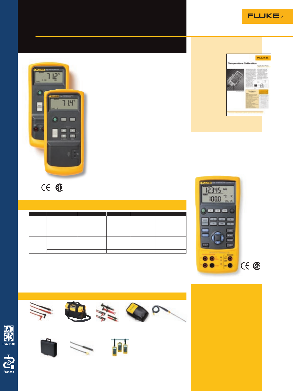
Recommended accessories – 712, 714 and 724 Calibrators
Included accessories
Each 71X calibrator includes:
Protective yellow holster with test
lead storage, test leads and alligator
clips (excluding model 714), single
9 V alkaline battery and instruction
sheet (14 languages).
Fluke 724: TL75 Test Leads, AC72
Test Clips, one pair of stackable test
leads, product overview manual
(print) and users manual in 14
languages on CD-ROM.
Ordering information
Fluke-712 RTD Calibrator
Fluke-714
Themocouple Calibrator
Fluke-724 Temperature Calibrator
Model Function Range Resolution Accuracy Notes
Fluke-712 Measure/simulate RTD -200 °C to 800 °C
(Pt 100-385) 0.1 °C, 0.1 °F 0.2 °C, 0.4 °F
(Pt 100-385) Pt; 100 200 500
1000 (385); Pt 100
(392); Pt 100 (392) JIS;
Ni 120 (672)
Measure/simulate
resistance 5 W to 4000 W0.1 W0.025 %
Fluke-714 Measure/simulate
thermocouple -200 °C to 1800 °C,
depending on type
(K, -200 °C to
1370 °C)
0.1 °C or °F
(1 °C or °F; BRS) 0.5 °C, 0.8 °F
(Type K) 9 TC types; J K T E R
S B per NIST 175 and
ITS-90 L U per DIN
43710 and PTS-68
Measure/simulate mV -10 mV to 75 mV 0.01 mV 0.015 % +10 µV
40 Process Calibration Tools
Accurate and rugged,
temperature calibration tools
Fluke 712, 714 and 724
Temperature Calibrators
Specifications – 712 and 714 Calibrators
The Fluke 710 Series temperature calibrators deliver
outstanding performance, durability and reliability. And
with a push-button interface, similar to the multifunc-
tion Fluke 740 Series Documenting Process Calibrators,
the 710s are easy to use. Each calibrator is EMI tolerant,
dust- and splash-resistant, and features a removable
battery door for quick battery changes.
Fluke 712 RTD Calibrator
• Compatible with pulsed current transmitters
• Measure temperature from an RTD probe
• Simulate RTD output
• Operates with seven types of RTD
• Measure additional RTDs using Ohms measurement
function
• Simulate additional RTDs using Ohms source function
• °F or °C selectable
• 25 % stepping, auto-step and auto-ramp
• Ramp and Step Ramp output functions
Fluke 714 Thermocouple Calibrator
• Measure temperature from TC probes
• Simulate TC output
• Operable with nine types of thermocouples
•
Calibrate linear TC transmitter with mV source function
• Selectable °F or °C
• 25 % stepping, auto-step and auto-ramp
• Available as accessories: Fluke 700TC1 and TC2
Thermocouple Mini-plug Kits
• Ramp and Step Ramp output functions
General specifications for all Fluke 712 through 718 calibrators
Maximum voltage: 30 V Non-operating temperature: -40 °C to 60 °C Operating temperature: -10 °C to 55 °C
Relative humidity: 95 % (10 °C to 30 °C); 75 % (30 °C to 40 °C); 45 % (40 °C to 50 °C); 35 % (50 °C to 55 °C)
Operating altitude: 3,000 m max Shock: 1 m drop test Vibration: Random, 2 g, 5-500 Hz
Safety: CSA C22.2 No. 1010.1:1992 EMC: EN50082-1:1992 and EN55022:1994 Class B
Size/weight (HxWxD) (712-717): 187 mm x 87 mm x 32 mm (7.35 in x 3.41 in x 1.25 in) 330 g (12 oz)
Size/weight (HxWxD) (712-717 with holster): 201 mm x 98 mm x 52 mm (7.93 in x 3.86 in x 2.06 in) 600 g (21 oz)
Size/weight (HxWxD) (718): 210 mm x 83 mm x 62 mm (8.25 in x 3.27 in x 2.44 in) 737 g (26 oz)
Size/weight (HxWxD) (718 with holster): 216 mm x 94 mm x 66 mm (8.50 in x 3.72 in x 2.60 in) 992 g (35 oz)
Power: 9 V battery ANSI/NEDA 1604A or IEC 6LR619V alkaline; two batteries in 718
Battery life: 4 to 20 hours, typical, depending on functions used
Warranty: Three-years (one-year on pressure pump in Fluke 718)
TL75 (712 and 724) C550 TL220 (712 and 724) C25 (712 and 714) 80PK-24 (714)
Hard Point Tool Bag SureGrip Industrial Large Soft Case SureGrip Air
Test Lead Set See page 70 Test Lead Set See page 70 Temperature Probe
See page 62 See page 61 See page 68
C101 (724) 80PK-3A (714, 724) ToolPak
Meter Hard Case Surface Probe Meter Hanging Kit
See page 70 See page 68 See page 71
Fluke 724 Temperature
Calibrator
• Source/measure TCs, RTDs,
volts and ohms
• Measure mA while supplying
loop power
• 25 % and 100 % stepping,
auto-step and auto ramp
Data Sheet, literature code
1560369:
Temperature
calibration
See how Fluke
can help you
calibrate,
troubleshoot
and verify the
most common
temperature
devices, faster
and easier.
Want to read
more? Download
this and other
application notes at
www.fluke.com/library
For more information and detailed specifications, go to www.fluke.com/tempcal
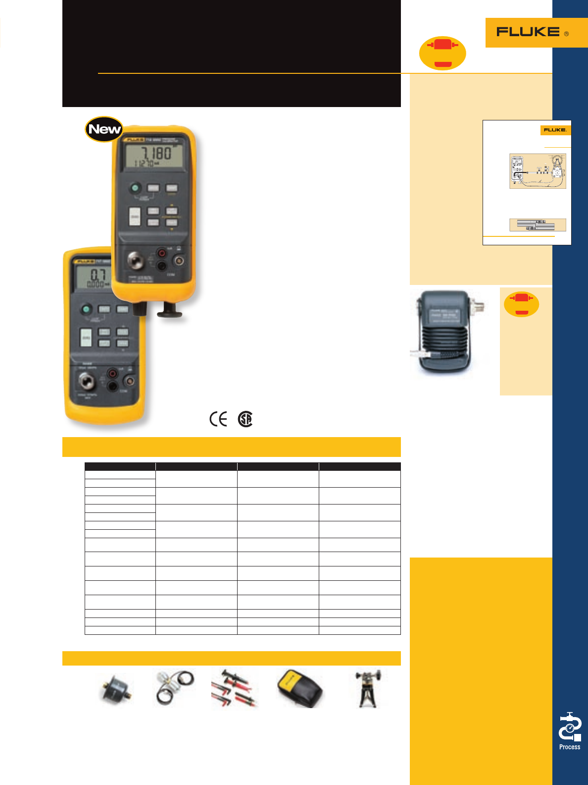
41
Process Calibration Tools
Recommended accessories – 717 and 718 Calibrators
700ILF 700LTP TL220 C25 (717 only) 700HTP
In-Line Filter Low Pressure SureGrip Industrial Large Soft Case Hydraulic Test Pump
See page 69 Test Pump Test Lead Set See page 70 See page 69
See page 69 See page 61
Fluke 718 Pressure Calibrators
New! 1 psi and 300 psi models in addition to the
30 and 100 psi models previously available
• Compact size, lightweight
•
New built-in pressure switch test feature
• Built-in pressure/vacuum hand pump, with vernier
and bleed valve
• Pressure and vacuum measurement to 0.05 % of full
span, using an internal pressure sensor (dry air only)
• Pressure measurement to 10,000 psi/700 bar using
any of 29 Fluke 700Pxx Pressure Modules
• Measure mA with 0.015 % accuracy and 0.001 mA
resolution, while providing 24 volt loop power supply
• 1⁄8 inch NPT female pressure fitting
• Min/Max/Hold functions
Intrinsically safe 718 version available (see page 45)
Fluke 717 Pressure Calibrators
Now with 9 ranges: 1, 30, 100, 300, 500, 1000,
1500, 3000 and 5000 psi
• Measure pressure and vacuum to 0.05 % of full scale
with internal 30 or 100 psig sensor
– 1/8 NPT pressure fitting
– Compatible with non-corrosive gasses and liquids
• Measure pressure to 10,000 psi/69 mPa using one of
29 Fluke 70Pxx Pressure Modules
• Measure mA with 0.015 % accuracy and 0.001 mA
resolution, while providing 24 V loop power
•
New built-in pressure switch test feature
• Min/Max/Hold functions
Fluke 718 and 717
Pressure Calibrators
Compact, professional,
pressure calibration tools
Specifications – 717 and 718 Calibrators
Fluke 700 Series
Pressure Modules
• 29 pressure modules
• 8 intrinsically safe pressure modules*
• Ranges from 1.000 in H20
(0.2491 kPa) to 10,000 psi
(68.948 MPa)
• Gage, differential, dual (compound),
absolute, and vacuum modules
• Rugged cases protect the modules
from harsh environments
• Full-accuracy performance from
0 °C to 50 °C
• Pressure readings update twice per
second, and may be displayed in
up to 11 different units
• One-year warranty
*for use with 718Ex and 725Ex only
(see page 45 for more information)
Application note, literature code
2577485:
Pressure calibration with the
Fluke 718
New design pro-
tects on-board
pump from fluid
damage. This
application note
explains how
to drain pres-
sure lines safely
before calibra-
tion, and how to
clean the pres-
sure pump on the
new Fluke 718.
Want to read more? Download
this and other application notes
at www.fluke.com/library
!PPLICATION.OTE
THECOMPLEXITYANDCOSTOFREPAIR
OFAPUMPFOULEDBYPROCESS
MEDIAISNORMALLYHIGHERTHANA
STANDALONEPUMP
5SINGTHEUPDATED
#ALIBRATORPUMP
4HENEW&LUKEISA UNIQUELY
PROTECTEDPNEUMATICPRESSURE
CALIBRATORANDPUMP4HENEW
PUMPDESIGNUSESPROTECTIVE
CHECKVALVESTHATALLOWAIRTO
PASSTHROUGHTHEPUMPFORCALI
BRATIONBUTINHIBITSFLUIDSFROM
0RESSURECALIBRATION
WITHTHE&LUKE
.EWDESIGNPROTECTSONBOARD
PUMPFROMFLUIDDAMAGE
ÀÊÌiÊÕiÊ}Ì>ÊLÀ>ÀÞÊ JÊÜÜÜ°vÕi°VÉLÀ>ÀÞ
ENTERINGTHEPUMPANDCAUSING
DAMAGE4HESETWOCHECKVALVES
ALLOWTHEBIDIRECTIONALFLOWOF
AIRINTOOROUTOFTHE
%VENAFTERDRAININGTHEPRO
CESSFLUIDFROMTHECALIBRATION
PORTOFTHEDEVICEUNDERTEST
MINUTEAMOUNTSOFPROCESS
FLUIDSMAYOFTENSTILLBELURKING
BEHIND)NTHEEVENTTHESEFLUIDS
ENTERTHEPUMPCAVITIESTHE
NEWPUMPDESIGNENABLESQUICK
CLEANINGANDMAINTENANCEEVEN
INTHEFIELD
0ROTECTYOURTOOLS
0RESSURECALIBRATIONTYPICALLY
INVOLVESAPNEUMATICCALIBRATION
PUMPANDAPRESSURECALIBRA
TIONTOOLORREFERENCEGAUGE4HE
PUMPAPPLIESPRESSURETOBOTH
THEDEVICEUNDERTEST$54AND
THECALIBRATIONTOOLSEEFIGURE
4HETRICKISTHATBEFOREYOU
CANAPPLYPRESSUREWITHAPNEU
MATICHANDPUMPYOUABSOLUTELY
MUSTFIRSTDRAINALLCONDENSATE
ANDOILFROMTHELINES7HY )F
THERESOILORWATERTRAPPEDIN
THELINEWHENTHEPUMPIS CON
NECTEDTHATFLUIDCANBEPULLED
BACKINTOTHEPUMPWHENTHE
PRESSUREISRELEASED4HATCAN
EITHERCAUSECOSTLYDAMAGETOTHE
PUMPORATTHEVERYLEAST FORCE
YOUTODISASSEMBLEANDCLEANTHE
PUMPBEFOREREUSE
&ORTHISREASONTHEUPDATED
&LUKE0RESSURE#ALIBRA
TORNOWCONTAINSANINNOVATIVE
NEWPUMPDESIGNTHATISEASILY
CLEANEDINTHEFIELDANDINHIBITS
DAMAGEFROMPROCESSFLUIDS
0NEUMATICPRESSURE
CALIBRATORSWITH
INTEGRATEDTESTPUMPS
)NSTEADOFTHEPUMPPLUS
CALIBRATORMETHODDESCRIBED
ABOVEMANYTECHNICIANSNOW
USEAHANDHELDPNEUMATICPRES
SURECALIBRATORTHATINCLUDESAN
ONBOARDPNEUMATICPUMPMAR
RYINGTWODEVICESINTOONEHANDY
INTEGRATEDTOOL7HILETHEINTE
GRATEDPUMPISMORECONVENIENT
ANDEASIERTOUSEITIS DOUBLY
IMPORTANTTOMAKESUREPROCESS
FLUIDSAREPROPERLYDRAINEDBEFORE
MAKINGACONNECTION"ECAUSE
THEPUMPITSELFNORMALLYNEEDS
TOBEREMOVEDFROMTHECALIBRA
TORBEFORECLEANINGREBUILDINGOR
REPLACEMENTCANBEPERFORMED
2ED
6
6
"LACK
&IGURE
4ODRAINPROCESSmUIDSCLOSE6ANDOPEN6BEFORECONNECTINGTHE#ALIBRATOR
!IRFLOWTO
INPUT
CONNECTOR
ANDVERNIER
ADJUSTMENT 4OPUMP
)NLET
/UTLET
&IGURE
4HE&LUKEISDESIGNEDTOPROTECTTHEHANDPUMPANDSIMPLIFYMAINTENANCE
For more information and detailed specifications, go to www.fluke.com/pressure
Pressure
Enabled
Included accessories
Fluke 718 and 717: Protective
yellow holster, test leads and
alligator clips, single 9 V alkaline
battery (two 9 V batteries in 718)
and instructions.
Ordering information
Fluke-718 30US Pressure Calibrator
Fluke-718 100US Pressure Calibrator
Fluke-718 1G Pressure Calibrator
Fluke-718 300G Pressure Calibrator
Fluke-717 30G Pressure Calibrator
Fluke-717 100G Pressure Calibrator
Fluke-717 1G Pressure Calibrator
Fluke-717 300G Pressure Calibrator
Fluke-717 500G Pressure Calibrator
Fluke-717 1000G Pressure Calibrator
Fluke-717 1500G Pressure Calibrator
Fluke-717 3000G Pressure Calibrator
Fluke-717 5000G Pressure Calibrator
Pressure
Enabled
Fluke Process
Calibrators in
this catalog
displaying
the Pressure
Enabled symbol
display readings
from the 700
Series Pressure
Modules.
Range Resolution Comment
717-1 +/- 1 psi, 27.5 in H20,
(-7 - +7 kPa) +0.0001 psi, 0.0001 kPa,
0.0001 in H20Fluke-718 dry air only and
includes on board pump
718-1G
717-30G -12 to + 30 psi,
(-83 to 207 kPa) 0.001 psi, 0.001 kPa, 0.001
in H20Fluke-718 dry air only and
includes on board pump
718-30G
717-100G -12 to + 100 psi,
(-83 to 690 kPa) 0.01 psi, 0.01 kPa, 0.01 in H20 Fluke-718 dry air only and
includes on board pump
718-100G
717-300G -12 to +300 psi,
(-83 to +2070 kPa) 0.01 psi, 0.01 kPa, 0.01 in H20 Fluke-718 dry air only and
includes on board pump
718-300G
717-500G 0-500 psi, 0-3450 kPa 0.01 psi, 0.1 kPa Compatible with non-corrosive
gases and fluids
717-1000G 0-1000 psi, 0-6900 kPa 0.01 psi, 0.1 kPa Compatible with non-corrosive
gases and fluids
717-1500G 0-1500 psi, 0-10342 kPa 0.1 psi, 1 kPa Compatible with non-corrosive
gases and fluids
717-3000G 0-3000 psi, 0-20700 kPa 0.1 psi, 1 kPa Compatible with non-corrosive
gases and fluids
717-5000G 0-5000 psi, 0-34500 kPa 0.1 psi, 1 kPa Compatible with non-corrosive
gases and fluids
Pressure accuracy 0.05 % of range
mA measurement 0-24 mA range 0.001 mA resolution Accuracy: ± 0.015 % + 1 count
Loop power 24 V dc Accuracy: ± 10 %
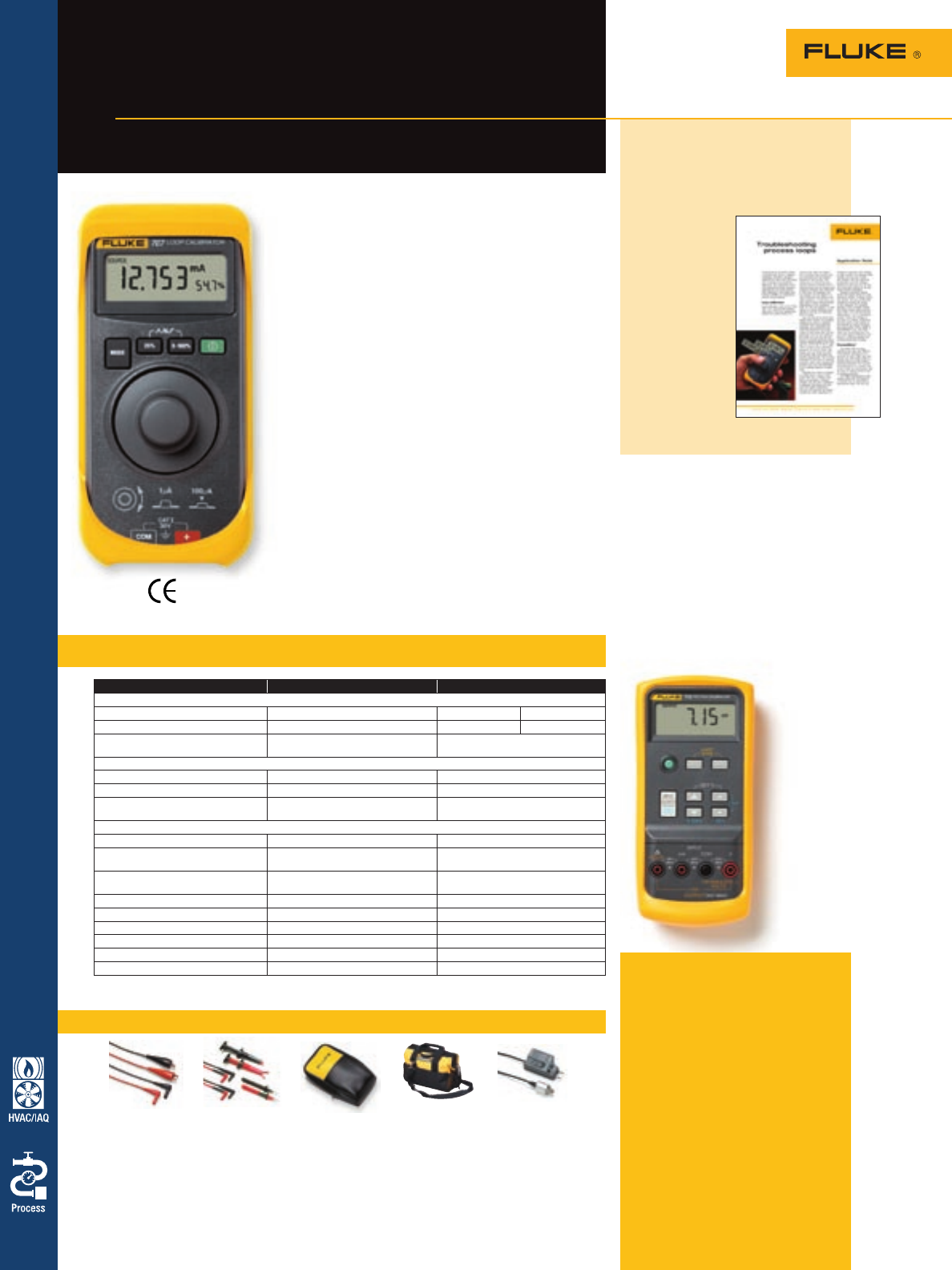
Specifications – 715, 707 and 705
Recommended accessories – 715, 707, 707Ex and 705 Calibrators
Included accessories
Fluke 715: Protective yellow hol-
ster, test leads and alligator clips,
single 9 V alkaline battery and
instruction sheet (14 languages).
Fluke 705, 707 and 707Ex:
Protective holster, TL75 Test Leads,
AC72 Test Clips and instruction
sheet (14 languages).
Ordering information
Fluke-715 Volt/mA Calibrator
Fluke-707 Loop Calibrator
Fluke-707Ex IS Loop Calibrator
Fluke-705 Loop Calibrator
42 Process Calibration Tools
Application note, literature
code 1989137:
Troubleshooting
process loops
In process
systems, prob-
lems with
the loop can
bring things to
a screeching
halt. In this
application
note, find out
how to use
Fluke test tools
to identify
current loop
prolems such
as noise,
ripple and drift.
Fluke 707 and 705
Two powerful models to choose from
• Innovative output adjustment dial on 707 provides
1 µA and 100 µA resolution and one-hand operation
• Large display and simple interface for ease of use
• Simultaneous mA and % readout for quick, easy
interpretation of readings
• mA accuracy of 0.015 % on the Fluke 707 and 0.02 %
on the 705
• HART™ mode on 707 connects 250 ohm resistor in
series with 24 V loop for compatibility with HART
communicators
• Push button 25 % steps for fast, easy linearity checks
• “Span Check” for fast confirmation of zero and span
• Selectable slow and fast linear step ramp provide
ramping outputs for valve slewing, remote testing
and loop functional tests
•
24 V internal loop supply, so you can power and read
a transmitter at the same time without carrying a DMM
• 0 mA to 20 mA or 4 mA to 20 mA default start
up modes
Intrinsically safe 707 version available (see page 45)
TL28A TL220 C25 C550 PV350
Heavy Duty SureGrip Industrial Large Soft Case Tool Bag Pressure Vacuum
Test Lead Set Test Lead Set See page 70 See page 70 Module
See page 62 See page 61 See page 65
Fluke 715 Volt/mA Calibrator
• Source voltage to 200 mV or 20 V
• Measure loop current (0 to 20 mA,
4 to 20 mA) signals with 0.01 %
accuracy and 1 µA resolution
• Measure voltage output process
signals from PLCs, transmitters
• Source or simulate 24 mA
loop current
• 24 V loop supply with simultaneous
current measurement
• Ramp and Step Ramp output functions
1Will over-range to 24 mA
Functions Fluke 705 and 707 Fluke 715
Voltage measurement
Range 0 to 28 V 0 to 200 mV 0 to 25 V
Resolution 1 mV 10 µV 1 mV
Accuracy 705: 0.025 % Rdg + 1 LSD 707,
707Ex: 0.015 % Rdg + 2 LSD 0.01 % Rdg + 2 LSD
Current measurement
Range 0 to 24 mA 0 to 24 mA
Resolution 0.001 mA 0.001 mA
Accuracy 705: 0.02 % Rdg + 2 LSD 707,
707Ex: 0.015 % Rdg + 2 LSD 0.01 % + 2 LSD
Current sourcing
Range 0 to 20 mA or 4 to 20 mA10 to 20 mA or 4 to 20 mA1
Accuracy 705: 0.025 % Rdg + 2 LSD 707,
707Ex: 0.015 % Rdg + 2 LSD 0.01 % Rdg + 2 LSD
Drive capability 705: 1000 W @ 24 mA 707: 1200 W @
24 mA 707Ex: 700 W @ 20 mA 1000 W @ 24 mA
Loop power while measuring mA 24 V 24 V
Voltage sourcing N/A 0 to 200 mV or 0 to 20 V
Display current and % of span Yes mA or %
Auto step, auto ramp Yes Yes
Span Check Yes Yes
Battery life 18 hours typical, at 12 mA 18 hours typical, at 12 mA
For more information and detailed specifications, go to www.fluke.com/loop
Fluke 715, 707 and
705 Loop Calibrators
Complete family of volt/mA calibrators
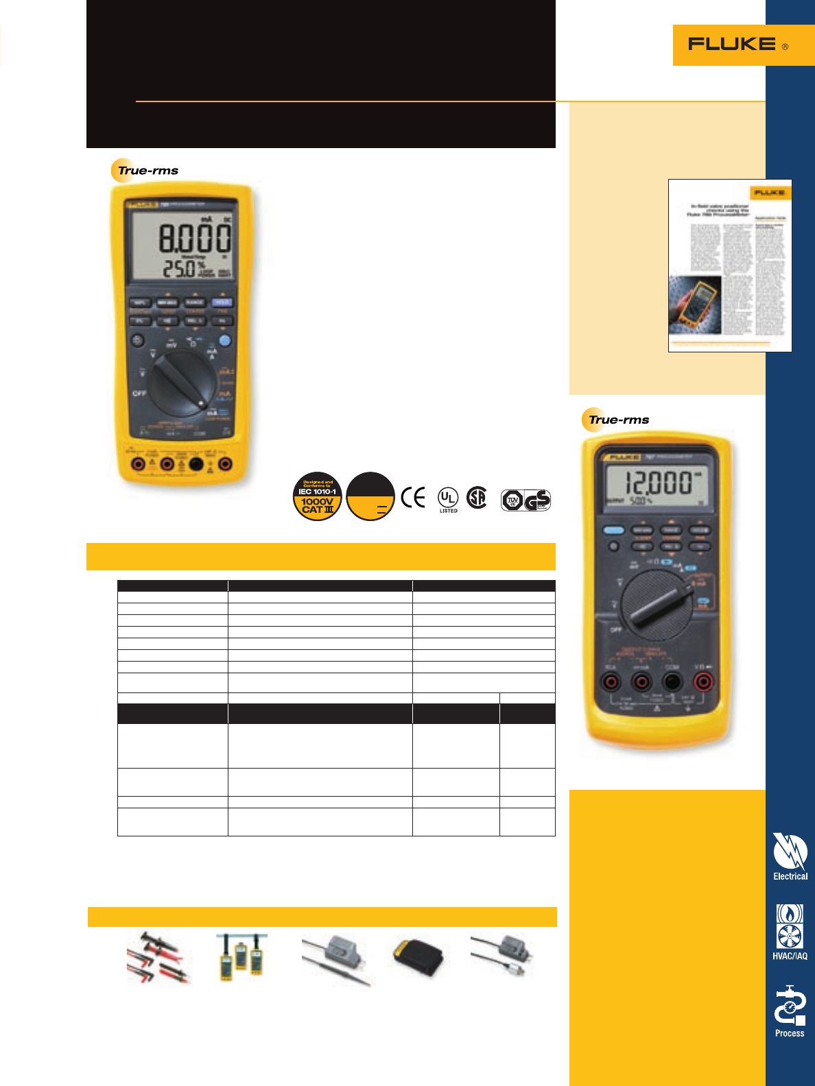
43
Process Calibration Tools
Measurement function Best accuracy range and resolution (% of reading + LSD)
V dc 400.0 mV, 4.000 V, 40.00 V, 400.0 V, 1000 V 0.1 % + 1
V dc (true-rms) 400.0 mV, 4.000 V, 40.00 V, 400.0 V, 1000 V 0.7 % + 2
mA dc 30.000 mA .05 % + 2
A dc 1.000 A (0.440 A continuous) 0.2 % + 2
A ac 1.000 A (0.440 A continuous) 1 % + 2
Resistance 400.0 W, 4.000 k, 40.00 k, 400.0 k, 4.0 M, 40 M 0.2 % + 1
Frequency (0.5 Hz to 20 kHz) 199.99 Hz, 1999.9 Hz, 19.999 kHz .005 % + 1
Diode Test 789: 2.000 V (shows diode voltage drop) 787:
2.400 V (shows diode voltage drop) 2 % + 1 2 % + 1
Continuity Beeps for resistance < approx. 100 ohms
Output function Range and resolution Drive capability Accuracy
(% of span)
DC current output (Internal
battery operation) 0.000 mA to 20.000 mA or 4.000 mA to 20.000 mA
(selectable at power-up) Over-range to 24.000 mA 789: 24 V compliance
or, 1,200 Ohms,
@ 20 mA 787: 12 V
compliance or,
500 Ohms, @ 20 mA
.05 %
DC current simulate
(Ext. 24 Volt loop supply,
up to 48 V on 789 only)
0.000 mA to 20.000 mA or 4.000 mA to 20.000 mA,
(selectable at power-up) Over-range to 24.000 mA 1000 Ohms, @ 20 mA .05 %
24 V loop supply 789: Minimum 24 V 787: not available 250 Ohms @ 20 mA > 24 V
Current adjustment modes Manual: Coarse, Fine, 25 % and 100 % step
(100 % step 789 only) Automatic: slow ramp,
fast ramp, 25 % step
Temperature range of 18 °C to 28 °C, for one year after calibration
Maximum voltage applied between any jack and earth ground:1000 V rms Storage temperature: -40 °C to 60 °C
Operating temperature: -20 °C to 55 °C Relative humidity: 95 % up to 30 °C; 75 % up to 40 °C; 45 % up to 50 °C; 35 % up to 55 °C
Safety: Designed in accordance with EN61010, ANSI/ISA S82.01-1994 and CAN/CSA C22.2 No. 1010.1-92 Over-voltage CAT III
Size (HxWxL)/weight (787 with holster): 52 mm x 98 mm x 201 mm (2.06 in x 3.86 in x 7.93 in)/638 g (1.4 lb)
Size (HxWxL)/weight (789): 50 mm x 100 mm x 203 mm (1.97 in x 3.94 in x 8.00 in)/600 g (1.3 lb)
Safety rated multimeters with mA source
Fluke 789 and 787
ProcessMeter™ Test Tools
Specifications – 789 and 787 ProcessMeter
Recommended accessories – 787 and 789 ProcessMeter
Application note, literature code
2041342:
In-field valve positioner
checks
Valve positioners
open and close
with a 4 to
20 mA signal
applied. This
application note
explains how to
adjust these
valves so they
open and close
correctly.
Want to read
more? Download
this and other
application notes
at www.fluke.com/library
Fluke 789 ProcessMeter
With the Fluke 789 ProcessMeter, process technicians
can do a lot more while carrying a lot less.
Key Fluke 789 features:
• 24 V loop power supply
• HART mode setting with loop power
(adds 250 ohm resistor)
• Double-sized, dual display
• 20 mA drive into 1200 ohms
• Backlight with two brightness settings
• 0 to 100 % mA Span Check buttons to toggle between
4 mA and 20 mA
• Infrared I/O serial port compatible with FlukeView®
Forms Software
• Improved battery power with four AA batteries
• Plus all the proven 787 features
Fluke 787 ProcessMeter
• Simultaneous mA and % of scale readout on mA output
• 25 % Manual Step plus Auto Step and Auto Ramp on
mA output
• Min/Max/Average/Hold/Relative modes
• Externally accessible battery for easy changes
TL220 ToolPak 80T-150U C125 PV350
SureGrip Industrial Meter Hanging Kit Universal Meter Case Pressure Vacuum Module
Test Lead Set See page 71 Temperature Probe See page 70 See page 65
See page 61 See page 69
600V
CAT IV
Designed and
Conforms to
IEC 1010-1
(Fluke 789 only)
For more information and detailed specifications, go to www.fluke.com/processmeters
Included accessories
Fluke-789 ProcessMeter: TL71
Premium Safety-Designed Test Lead
Set plus alligator clips, 4 AA alkaline
batteries (installed), product overview
and users manual (CD-ROM) in
14 languages.
Fluke-787 ProcessMeter: Protective
yellow holster with test lead storage,
TL75 Safety-Designed Test Lead Set
plus alligator clips, one 9 V alkaline
battery (installed), product overview
and users manual (CD-ROM) in
14 languages.
Ordering information
Fluke-789 ProcessMeter
Fluke-787 ProcessMeter
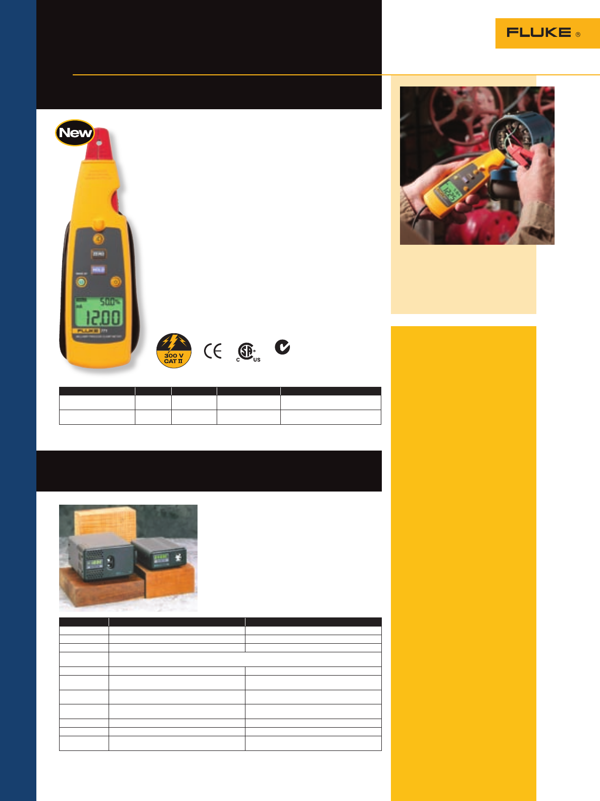
44 Process Calibration Tools
For more information and detailed specifications, go to www.fluke.com/processmeters
Fluke 771
included accessories
Carrying case, and instruction
manual.
Ordering information
Fluke-771 Milliamp Process
Clamp Meter
9102S and 9100S
ordering information
9100S-A-156 Dry-Well, Block A (1)
9100S-A-256 Dry-Well, Block A (2)
9100S-B-156 Dry-Well, Block B (1)
9100S-B-256 Dry-Well, Block B (2)
9100S-D-156 Dry-Well, Block D (1)
9100S-D-256 Dry-Well, Block D (2)
9300 Rugged Carrying
Case, 9100
9102S-156 Dry-Well, -10 to 122
(2 Wells) (1) (3)
9102S-256 Dry-Well, -10 to 122
(2 Wells) (2) (3)
9320-156 Battery Pack, 9102 (1)
9320-256 Battery Pack, 9102 (2)
9102S and 9009
inserts
3102-1 Insert, AL 1/16 in
(1.6 mm)
3102-2 Insert, AL 1/8 in
(3.2 mm)
3102-3 Insert, AL 3/16 in
(4.8 mm)
3102-4 Insert, AL 1/4 in
(6.4 mm) (Standard)
3102-6 Insert, AL 3/8 in
(9.5 mm) (Standard)
3102-7 Insert, AL 7/16 in
(11.1 mm) (Standard)
3102-8 Insert, AL 5/32 in
(4 mm) (Standard)
9308 Hard Carrying Case,
9102/9132
(1) 156 Blocks are 115 V 50/60 Hz
(2) 256 Blocks are 220 V 50/60 Hz
(3) Specify two 3102 inserts
Save time and money troubleshooting
process control loops
Fluke 771 Milliamp
Process Clamp Meter
The innovative new Fluke 771 mA Process Clamp Meter is
designed to measure, test, and troubleshoot 4-20 mA control sig-
nals without breaking the mA loop. Make mA measurements in
active control systems without disrupting process control.
Features:
• Best in class 0.2 % accuracy
• Resolution and sensitivity to 0.01 mA
• Hold function captures and displays changing measurements
• Dual display with both mA measurement and 0 % to 100 % of
4 mA to 20 mA span
• Measurement spotlight illumination hard to see wires in dark
enclosures
• Detachable clamp with extension cable for measurements in
tight locations
• Includes carrying case that can be used as a belt mounted
holster
Key uses:
• Measure mA signals for PLC and control system analog I/O
• Measure 4 mA to 20 mA output signals from transmitters
• Measure 10 mA to 50 mA signals in older control systems
using the 99.9 mA range
Detachable clamp used to measure 4 mA
to 20 mA signals on transmitters without
breaking the loop.
N10140
Range Resolution Accuracy Features Notes
-20.99 mA to +20.99 mA 0.01 mA 0.2 % or reading
+ 5 counts Zero, Hold, backlight,
measurement spotlight Use for measuring and troubleshooting
4 mA to 20 mA signals
-21.0 mA to -99.9 mA
+21.0 mA to +99.9 mA 0.1 mA 1 % reading
+ 5 counts Zero, Hold, backlight,
measurement spotlight Use for measuring and troubleshooting
10 mA to 50 mA signals
9102S and 9100S Handheld Drywell
Temperature Calibrators
Fluke Corporation, Hart Scientific Division
The smallest, lightest and most
portable dry-wells in the world
• 9100 model weighs only 2 pounds, 3 ounces
(1 kilogram)
• Temperature ranges from -10 °C to 375 °C
• Stability during calibrations to ± 0.05 °C
• Fast and easy calibrations of RTDs and
thermocouples
• Includes RS-232 interface, instrument
control software
• Direct interface to the Fluke 744
9100S 9102S
Range 35 °C to 375 °C (95 °F to 707 °F) -10 °C to 122 °C (14 °F to 252 °F) at 23 °C ambient
Accuracy ± 0.5 °C ± 0.25 °C
Stability ± 0.1 °C at 100 °C ± 0.3 °C at 375 °C ± 0.05 °C at 0 °C
Well-to-well
uniformity ± 0.2 °C with sensors of similar size at equal depths within wells
Stabilization 5 minutes 7 minutes
Well depth 102 mm (4 in); 1.6 mm (1/16 in) hole is 89 mm (3.5
in) deep 102 mm (4 in)
Removable inserts N/A 1/4 in, 3/16 in (Standard) 1/16 in, 1/8 in, 3/8 in
(optional)
Power
115 V ac (± 10 %), 1.5 A or
230 V ac (± 10 %, 0.8 A,
specify, 50/60 Hz, 175 W 94 V ac to 234 V ac (± 10 %), 50/60 Hz, 60 W; or
12 V dc
Size (H x W x D) 57 mm x 125 mm x 150 mm (2.25 in x 4.9 in x 5.9 in) 99 mm x 140 mm x 175 mm (3.9 in x 5.5 in x 6.9 in)
Weight 1 kg (2 lb, 3 oz) 1.8 kg (4 lb)
NIST-traceable
calibration Data at 50 °C, 150 °C, 200 °C, 250 °C, 300 °C and
350 °C Data at -10 °C, 24 °C, 50 °C, 55 °C, 100 °C and 122 °C
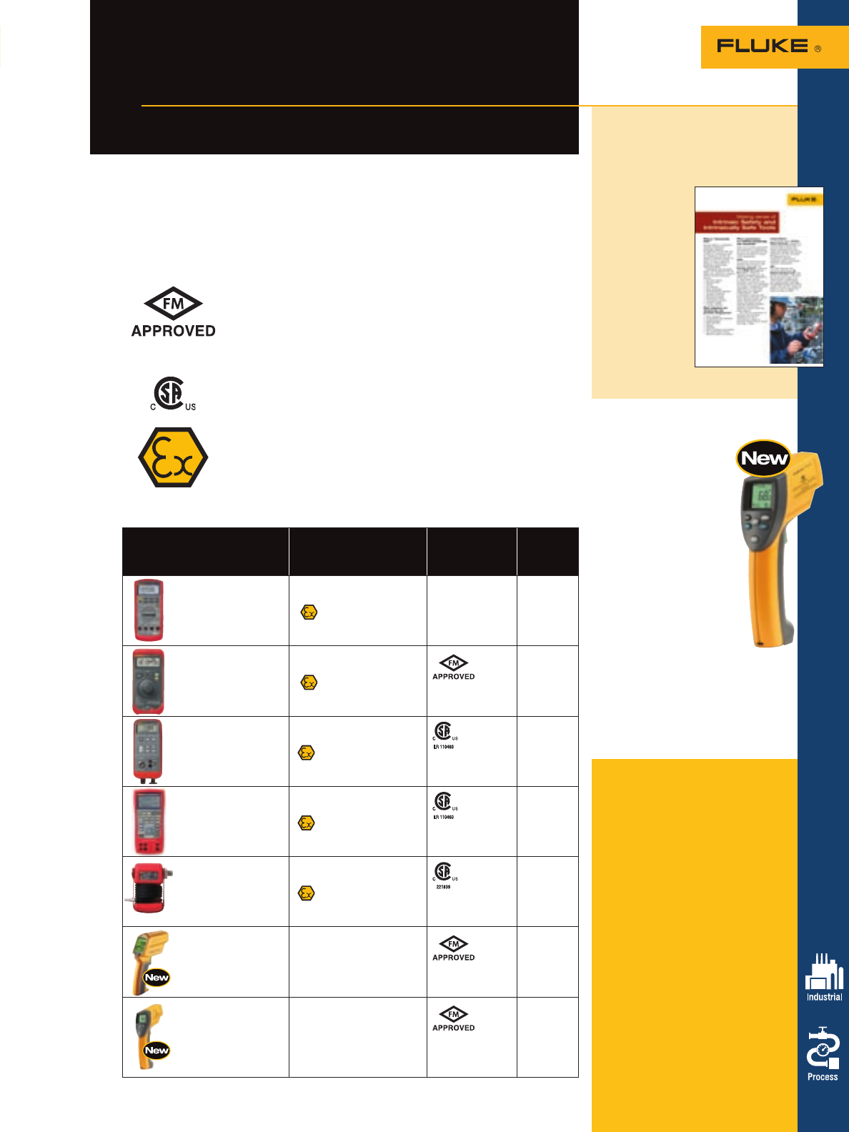
Ordering information
Fluke-87V Ex IS True-rms
Multimeter
Fluke-707Ex IS Loop
Calibrator
Fluke-718Ex IS Pressure
Calibrator
Fluke-725Ex IS Multifuction
Process Calibrator
Fluke-700PEx Pressure Modules
(700P01Ex,
700P05Ex,
700P06Ex,
700P09Ex,
700P24Ex,
700P27Ex,
700P29Ex and
700PA4Ex)
Fluke-574-NI Precision Infrared
Thermometer w/
Logging SW
Nonincendive
Fluke-68IS Infrared
Thermometer
Intrinsically Safe
Intrinsically Safe
Products
Calibrators, thermometers and multimeters
designed to intrinsic safety standards
45
Intrinsically Safe Products
What is “Intrinsically Safe”?
Intrinsic safety is a protection method employed in potentially explosive atmospheres.
Devices that are certified as “intrinsically safe” are designed to be unable to release
sufficient energy, by either thermal or electrical means, to cause ignition of flammable
material (gas or dust/particulates).
There are no global intrinsically safe standards or certifications, but there are
organizations that influence directives in certain world geographies.
Factory Mutual
In The United States, Factory Mutual Research, managed by
Factory Mutual (FM) Global, is a not-for-profit scientific and testing
organization that has tested and certified over 40,000 products in
the last 165 years. FM Research has set certification guidelines for
equipment used in potentially explosive atmospheres.
Canadian Standards Association (CSA)
Accreditation body for North American regulations based in
Toronto, Canada.
ATEX
The primary intrinsically safe standard which has been set in the
European Union with the Directive 94/9/EC, commonly called ATEX
(“Atmosphères Explosibles,”) French for explosive atmospheres.
For more information and detailed specifications, turn to the
corresponding non-intrinsically safe product pages (Fluke 707, 718,
725, 574, 68) or go to www.fluke.com/ex
Fluke products ATEX certified
North American
Certification
For
additional
product
detail
87V Ex: Intrinsically
Safe True-rms Multimeter
II 2 G EEx ia IIC T4 See page 14
707Ex: Intrinsically
Safe mA Calibrator
II 2 G EEx ia IIC T4
N.I. Class I, Div 2,
Groups A-D T4
See page 42
718Ex: Intrinsically
Safe Pressure Calibrator
II 1 G EEx ia IIC T4
I.S. Class I, Div 1,
Groups A-D T4
See page 41
725Ex: Intrinsically Safe
Multifunction Calibrator
II 1 G EEx ia IIB 171 °C
I.S. Class I, Div 1,
Groups B-D, 171 °C
See page 39
700PEx: Intrinsically
Safe Pressure Modules
II 1 G EEx ia IIC T4
I.S. Class I, Div 1,
Groups A-D T4
See page 41
Fluke 574-NI Nonincendive
Infrared Thermometer
Class I, Division 2,
Groups A, B, C, D;
Class I, Zone 2 IIC
See page 51
Fluke 68IS Intrinsically Safe
Infrared Thermometer
Class I, Division 1,
Groups A, B, C, D
Class I, Zone 0 AEx
ia IIC
See page 53
Fluke 68IS Intrinsically Safe
Infrared Thermometer
• Laser guided sighting
system for easy targeting
with 1 % accuracy
• 12-point data logging
• Advanced optics to
measure smaller targets
at greater distances
• Adjustable emissivity for
more accurate temperature
measurements
• Selectable MAX, MIN, DIF
and AVG functions that
display values instantly
with Hi/Lo Alarm
• Expanded measurement
range up to 760 °C (1400 °F)
• RTD probe accessory included
for dual contact and non-contact
temperature measurements
• Class I, Division 1, Groups A, B, C,
D Class I, Zone 0, AEx ia IIC, T4 at
50 °C when used with 9 V alkaline
battery
Not available for purchase in Europe.
Application note, literature code
2096400:
Making sense of intrinsic
safety and intrinsically
safe tools
Want to know
what industries
Intrinsically Safe
products are
designed for?
Want to know
why intrinsic
safety is so
important? Want
to make sense
of the product
ratings and
classifications?
Go to www.fluke.com/ex
For more information and detailed specifications, turn to the corresponding non-intrinsically
safe product pages (Fluke 87V, 707, 718, 725, 574, 68) or go to www.fluke.com/ex.
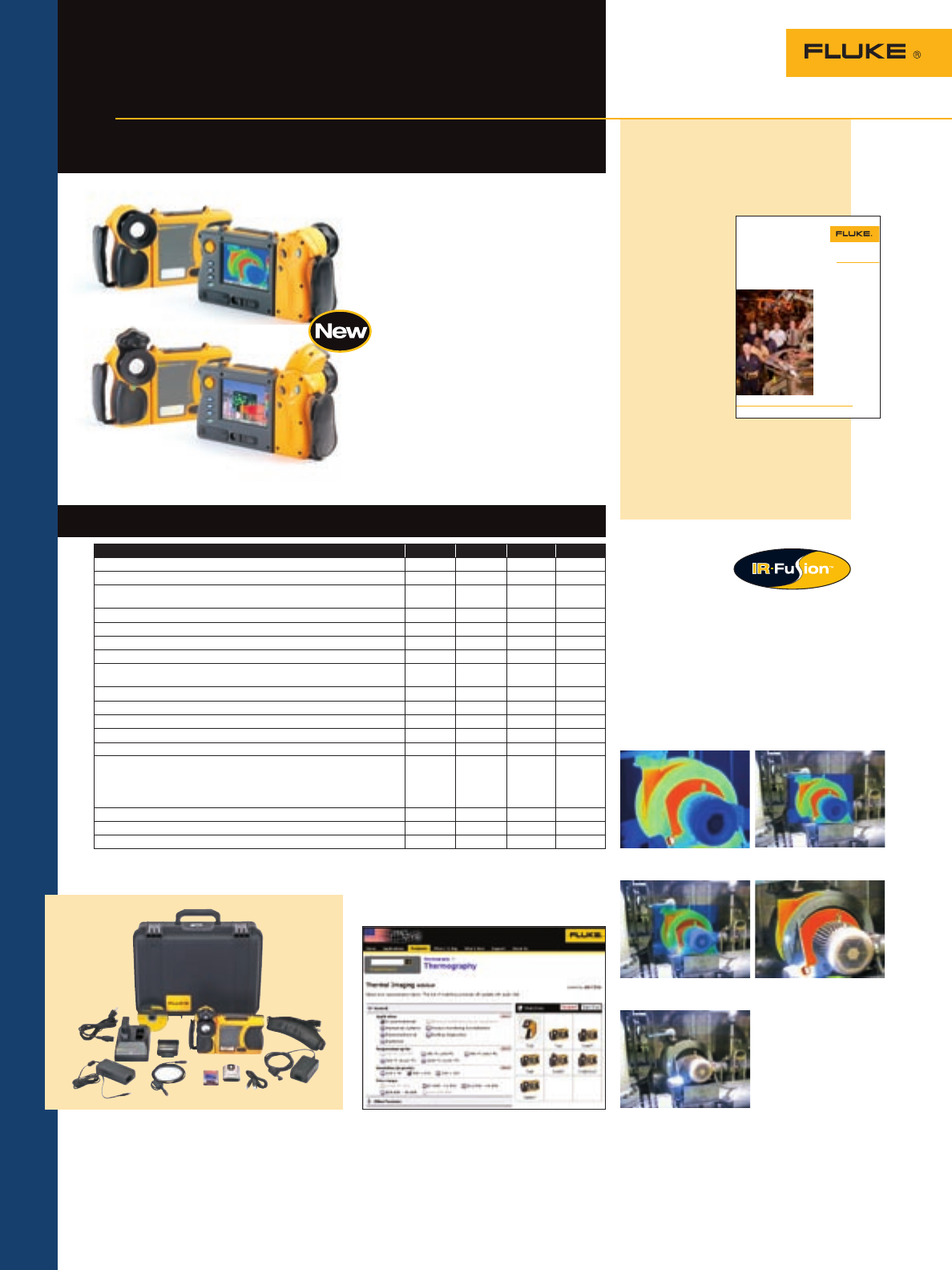
46
The thermal imagers for
professionals demanding the best
Ti40 and Ti50 Series IR
FlexCam® Thermal Imagers
Thermal Imaging
Alpha Blending IR/Visible Alarm
Full Visible Light
Full IR Picture-in-Picture
Features Ti40 Ti45 Ti50 Ti55
180° articulating flexible lens to view images in every situation • • • •
Choice of 3 interchangeable lenses to cover every application • • • •
Large 5” high contrast color LCD for a clear picture independent of
lighting conditions • • • •
Fully radiometric for detailed temperature analysis and tracking • • • •
SmartFocus for best image quality and accurate temperature measurements • • • •
Windows® CE based menu structure for ease of use • • • •
Personalized instrument set-up for multiple use • • • •
CompactFlash memory cards to store over 1000 IR images plus fully
radiometric temperature data • • • •
SmartView reporting and analysis software included • • • •
AutoCapture for making intermittent problems visible • •
On-board analysis functions • •
User defined text annotations for simplified reporting • •
Built-in visible light (digital) camera FT model FT model FT model FT model
IR-Fusion blending thermal and visible light images to easily pinpoint
suspect components FT model
Picture-
in-
picture
only
FT model FT model FT model
IR/Visible Alarm FT model FT model FT model
Laser pointer for easy targeting FT model FT model FT model FT model
Flash and torch light for high quality images in dark environments FT model FT model FT model FT model
Application note, literature code
2764017:
Thermography at Ford’s
Dearborn Stamping Plant
The Dearborn
Stamping Plant
has had thermal
cameras on site
in the past, but
has not met
the objectives
of a successful
thermography
program. Today,
DSP’s thermog-
raphy program
is a model for
the rest of Ford,
and the program
came on line in a matter of weeks.
Want to read more? Download
this and other application notes
at www.fluke.com/library
Application Note
Thermography at Ford’s
Dearborn Stamping Plant:
From start to best-in-Ford in
30 days—and still accelerating
From the Fluke Digital Library @ www.fluke.com/library
The Dearborn Stamping Plant has had thermal cameras
on site in the past, but has not met the objectives of a
successful thermography program. Today, DSP’s ther-
mography program is a model for the rest of Ford, and
the program came on line in a matter of weeks.
Lately, there has been a stream
of visitors to the Dearborn
Stamping Plant (DSP) housed in
the historic Ford Rouge Center
in Dearborn, Michigan. What’s
the attraction? The DSP opera-
tion, which manufactures sub-
assembly doors and hoods for
the popular Ford F-150 pickup
truck, achieved a perfect score in
a recent independent audit of its
weld effectiveness. That makes
the plant best in company—
perhaps the best period—when
it comes to the precision with
which it forms and welds sub-
assemblies. Executives from Ford
Motor Company corporate offices
and management from other Ford
operations want to know how
they do it.
A significant factor is a condi-
tion-monitoring program using
thermography or thermal imag-
ing. Thermography itself isn’t
new to DSP or new to Ford
operations, but the DSP thermog-
raphy program is unique. After
only 30 days, the program scored
higher in an insurance audit
than any other Ford thermogra-
phy program had ever scored. It
continued to work even when
new thermography team mem-
bers came on board. In the best
tradition of Ford’s commitment to
continuous improvement, DSP’s
thermography program keeps
getting better. And possibly the
most distinctive aspect: the pro-
gram is designed around a sys-
tems approach and supported by
a systems solution. That means
it has the potential to be quickly
and easily replicated and the
possibility of being deployed
with equal success and equiva-
lent return on investment in any
Ford operation.
caption
FIND problems faster with
Fluke thermal imagers.
Reduce costs and maximize uptime
with our complete range of imaging
solutions. They combine the largest,
sharpest images in the industry with
innovative, easy-to-use features. Fluke
Ti40 and Ti50 Series reveal more
with IR Fusion® Technology—merging
infrared and visible light images in
one display. Fluke puts powerful
technology within your reach.
Fluke Ti40, Ti45,
Ti50, Ti55
Features – Ti40 and Ti50 Series Imagers
Complete package
The IR FlexCam thermal imagers are
delivered as a complete package.
To find the best thermal imaging solution
for your application go to our Thermal
Imaging Web Selection Guide at
www.fluke.com/thermal_imaging
IR-Fusion™ Technology
IR-Fusion technology simultaneously
captures pixel-for-pixel infrared and vis-
ible light images and allows full image
optimization with 5 different on-camera
as well as software viewing modes. With
the integrated laser pointer visible on
the images, precise and accurate (faulty)
component identification is very easy.
Fluke Ti40FT, Ti45FT,
Ti50FT, Ti55FT
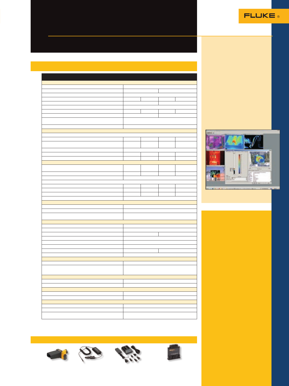
Included accessories
AC adapter (for Ti45 and Ti55 only),
video cable, 512 MB compact flash
card, compact flash card reader and
USB cable, PCMCIA compact flash
card adapter, SmartView report-
ing and analysis software on CD, 2
rechargeable battery packs, battery
charger, neck strap, heavy duty car-
rying case and user manual on CD.
Ordering information
Fluke-Ti40-20 IR FlexCam
Thermal Imager
Fluke-Ti40FT-20 IR FlexCam
Thermal Imager
with IR-Fusion
Fluke-Ti45-20 IR FlexCam
Thermal Imager
Fluke-Ti45FT-20 IR FlexCam
Thermal Imager
with IR-Fusion
Fluke-Ti50-20 IR FlexCam
Thermal Imager
Fluke-Ti50FT-20 IR FlexCam
Thermal Imager
with IR-Fusion
Fluke-Ti55-20 IR FlexCam
Thermal Imager
Fluke-Ti55FT-20 IR FlexCam
Thermal Imager
with IR-Fusion
*For ordering information of optional
lenses check the Fluke web.
47
The thermal imagers for
professionals demanding the best
Ti40 and Ti50 Series IR
FlexCam® Thermal Imagers
Thermal Imaging
Fluke SmartView™ IR
analysis and reporting
software for Fluke IR
cameras.
Included with each Fluke IR
thermal imager, Fluke SmartView
software is a modular suite of
tools that annotates, views, edits
and analyzes IR images. It also
generates fully customizable and
professional-looking reports in
a few easy steps. The IR-Fusion
technology is full supported.
The software is easy to use for
the technician, yet delivers the
performance specialized ther-
mographers require for advanced
analysis.
Fluke
Ti40
Fluke Ti45 Fluke
Ti50
Fluke Ti55
Thermal imaging performance
Field of view (FOV)* 23° horizontal x 17° vertical
Spatial resolution (IFOV)* 2.60 mrad 1.30 mrad
Min focus distance* 0.15 m
Thermal sensitivity (NETD) at 30 °C ≤0.09 °C ≤0.08 °C ≤0.07 °C ≤0.05 °C
Detector data acquisition/image frequency 30 Hz/30 Hz 60 Hz/60 Hz
Focus SmartFocus; single finger continuous focus
IR digital zoom 2x 2x 2x, 4x. 8x
Detector size 160 x 120 320 x 240
Detector type Focal Plane Array, Vanadium Oxide (VOx) Uncooled
Microbolometer
Spectral band 8 µm to 14 µm
Visual Imaging performance (Fusion models only)
On-camera operating modes
Picture-in-Picture • • • •
Full thermal, full visual light or merged thermal-visual images Smartview
only • • •
Visible light camera 1280 x 1024 pixels, full color (1.3 megapixels)
Visible light digital zoom 2x 2x 2x, 4x
Visible color alarm above and below • • •
Temperature measurement
Calibrated temperature range -20 °C to
350 °C -20 °C to
600 °C -20 °C to
350 °C -20 °C to
600 °C
1200 °C High temperature option •
Accuracy ± 2 °C or 2 % (whichever is greater)
Measurement modes
Centerpoint, center box (area min/max, average) • • • •
Moveable spots/boxes • •
Isotherms, automatic hot and cold point detection • •
Emissivity correction 0.1 to 1.0 (0.01 increments)
Image presentation
Digital display 5” large high-resolution backlight LCD
Video output RS170 EIA/NTSC or CCIR/PAL composite video
Palettes Grayscale, grayscale inverted, blue red, high contrast, hot
metal, ironbow, amber, amber inverted
Optional lenses
54 mm Telephoto lens High precision Germanium lens
Field of view (FOV) 9° horizontal x 6° vertical
Spatial resolution (IFOV) 0.94 mrad 0.47 mrad
Min focus distance 0.6 m
10.5 mm wide angle lens High precision Germanium lens
Field of view (FOV) 42° horizontal x 32° vertical
Spatial resolution (IFOV) 4.9 mrad 2.45 mrad
Min focus distance 0.3 m
Image and data storage
Storage medium Compact flash card (512Mb) stores over 1000 IR images
File formats supported 14 bit measurement data included.
Images: bmp, gif, jpg, png, tiff;
Data formats: comma separated (csv), tab separated (txt)
Interfaces and software
Interface Compact flash card reader included
Included software SmartView; Full analysis and reporting software
Laser (IR-Fusion models only)
Classification Class II
Laser targeting Laser dot visible on blended and visual image
Controls and adjustments
Set-up controls Date/time, °C/°F, language, scale, LCD intensity
Image controls Level, span, auto adjust (continuous/manual)
On-screen indicators Battery status, emissivity, background temperature and
real time clock
Battery life: 3 hours continuous operation (2 hours on FT models)
Water and dust resistant: IP54
Size (HxWxD): 162 mm x 262 mm x 101 mm (6.378 in x 10.315 in x 3.9764 in)
Weight: 1.85 kg (4.07 lb)
Two-year warranty
Recommended accessories – Ti40 and Ti50 Series Imagers
103232 104543 Ti-SBC Ti-SBP
Anti-glare Hood Car Charger Battery Charger Rechargeable Battery Pack
Specifications – Ti40 and Ti50 Series
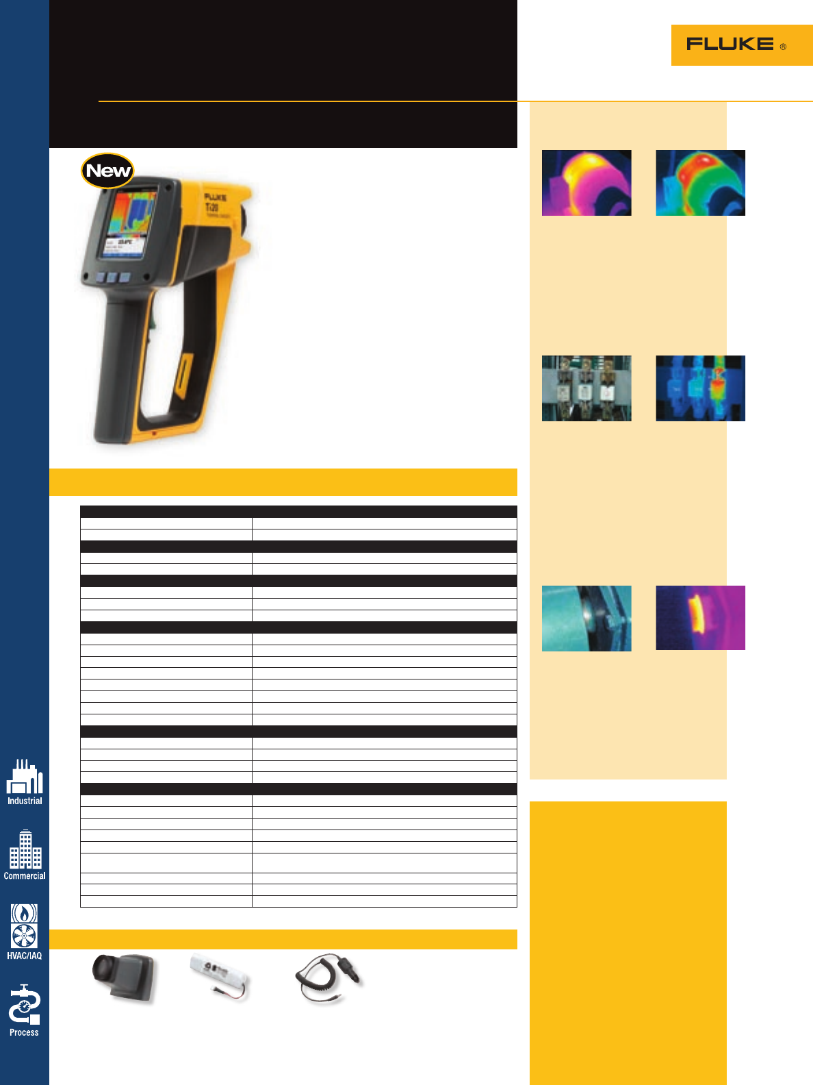
Recommended accessories – Ti20 Thermal Imager
The Fluke Ti20 Thermal Imager is an unbeatable
solution for predictive maintenance and
troubleshooting.
• Complete imaging solution. The Ti20
Thermal Imager is packaged with all necessary
accessories including unlimited-use InsideIR™
companion software and professional training
materials.
• Lowest cost of ownership. An exceptional
value for a high performance imager, the Ti20
also offers affordable instrument service and
calibrations.
• Designed for industrial use. Rugged Fluke
construction; IP54-rated for use in dust and
moisture filled environments.
• Fast and easy inspection routing. Plan your
equipment inspection route, load it once into
the imager, and then follow the easy, on-
camera instructions each time you perform
inspections (simply point, focus and pull the
trigger).
Typical thermal imaging
applications
Electric motors and pumps
Hot spots may be an early indicator
of motor winding problems. Elevated
temperatures can damage winding
insulation, resulting in operational
inefficiencies and premature motor
failure. An overheated motor may be
an indication of an underrated motor
in the application, insufficient cooling
or electrical power problems.
Bus bars and fuse boxes
Temperature differences between
phases may indicate unbalanced
loads, harmonics, component
problems, bad connections or
bad wiring. These conditions can
result in increased energy cost and
can damage cables or machines
or possibly cause fire. Even small
temperature differences between
phases should be investigated to
determine the root cause.
Rotating machinery
Ball bearings showing an increased
temperature are an indication that
either the quality of the lubricant
is deteriorating or there is poor
alignment between the motor and
shaft. These problems can cause the
bearings to fail, or a motor or pump
to overheat.
Specifications – Ti20 Thermal Imager
Detector
Detector type 128 x 96 thermal element focal plane array (FPA) uncooled microbolometer
NETD (thermal sensitivity) ≤ 0.2 °C at 30 °C
Thermal
Temperature range -10 °C to 350 °C (14 °F to 662 °F)
Accuracy ± 2 °C or 2 % (whichever is greater)
Optical
Field of View (FOV) 20° horizontal by 15° vertical
Optical resolution (D:S) 75:1 or better
Target sighting Single laser dot (Meets IEC Class 2 and FDA Class II requirements)
Controls and adjustments
Focus Manual
Minimum focus distance 0.15 m (6 in)
Temperature scale ºC or ºF selectable
Palettes Grayscale, reverse grayscale, rainbow, ironbow
Measurement modes Auto and manual
LCD backlight On/off selectable
Adjustable emissivity 0.10 to 1.00 in 0.01 increments
Adjustable reflected background temperature -50 °C to 460 °C (-58 °F to 860 °F)
Environmental
Ambient operating temperature 0 °C to 50 °C (32 °F to 122 °F)
Relative humidity 10 % to 95 % non-condensing
Storage temperature -25 °C to 70 °C (-13 °F to 158 °F)
Water and dust resistant IP54
Other
Display Large color LCD
Storage capacity 50 images stored internally
Power Rechargeable battery pack or six AA batteries
Battery life Three hours continuous use
Image frame rate 30 Hz*, 9 Hz
Thermal analysis software InsideIR™ (included) full-featured analysis and reporting software
(unlimited use; no per user license fees)
Size (HxWxD) 40.64 x 20.32 x 30.48 cm (16 in x 8 in x 12 in)
Weight 1.2 kg or (2.65 lbs)
Warranty One-year
Included accessories
Unlimited-use InsideIR PC software
for data storage, analysis and
reporting, ac/dc power adapter,
USB communication cable, hard
carrying case, soft-sided carrying
case, wrist strap, two (2) recharge-
able battery packs, one (1) AA
battery carrier, training materials
and getting started guide.
Ordering information
Fluke-TI20 US Thermal Imager
North America
Fluke-TI20 INT Thermal Imager
Ampac
Fluke-TI20 INT 9 Thermal Imager
Ampac 9 Hz
*Subject to U.S. export license compliance. Applicable outside the U.S. and Canada.
Thermal Imaging
48
For more information and detailed specifications, go to www.fluke.com/thermal_imaging
Everything needed for
everyday imaging
Fluke Ti20
Thermal Imager
Ti20-Visor Ti30-TBP Ti20-CC
Sun Visor Rechargeable Battery Pack Car Charger
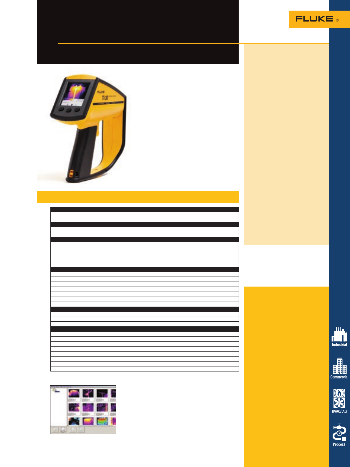
Thermal imaging for the
industrial technician
Fluke Ti30™
Thermal Imager
The affordable Fluke Ti30™ Thermal Imager is an
unbeatable solution for predictive maintenance:
Complete imaging solution – The Ti30 Thermal
Imager is packaged with all necessary accessories,
unlimited-use InsideIR™ companion software, and
two days of professional thermography training.*
Low cost of ownership – An exceptional value
for a high performance imager, the Ti30 also offers
affordable instrument service and calibrations.
Designed for industrial use – Over five hours
of continuous-use battery life and the capacity to
store up to 100 images, allows for a full day of
uninterrupted inspections.
Fast and easy inspection routing – Plan your
equipment inspection route, load it once into
the imager, and then follow the easy, on-camera
instructions each time you perform inspections.
*U.S. and Canada only. Training package varies by country.
Does not include travel expenses.
Understanding
maintenance routing
Predictive maintenance (PdM)
programs rely on periodic
inspections of the critical assets
comprising a plant or facility. These
inspections range from visual
inspections to nondestructive
testing performed using a variety
of technologies. To optimize a
PdM program, one must develop a
series of routes, determining the
equipment to be inspected, the
frequency of those inspections,
and the sequence or physical
course for each.
With the Fluke Ti30™ Thermal
Imager, images taken on a
planned inspection route can be
combined with location names
and temperature data and
uploaded to the camera for use
as a “routing guide.” The user is
prompted to go to each location
on the route to take images during
subsequent inspections—improving
accuracy. New images can easily
be compared to previous scans
using InsideIR software (included),
helping to identify potential
problems before they cause failure.
To learn more about predictive
maintenance with the Fluke
Ti30™ Thermal Imager, go to
www.fluke.com/thermal_imaging
Specifications – Ti30™ Thermal Imager
Detector
Detector type 120 x160 thermal element uncooled focal plane array microbolometer
NETD (Noise equivalent temp. difference) 200 mK
Thermal
Temperature range -10 °C to 250 °C (14 °F to 482 °F)
Accuracy ±2 % or ±2 ºC (± 3 % or 3 °C from -10 to 0 °C)
Optical
Optical resolution 90:1
Slit response optical resolution 225:1
Minimum diameter measurement spot 7 mm (0.27 in) at 61cm (24 in)
Field of view (FOV) 17 º horizontal x 12.8 º vertical
Target sighting Single laser dot (Meets IEC Class 2 & FDA Class II requirements)
Controls and adjustments
Focus Focusable, 61cm (24 in) to infinity
Temperature scale ºC or ºF selectable
Palettes Gray, ironbow or rainbow
Measurement modes Automatic, semi-automatic or manual
LCD backlight Bright, dim, off-selectable
Adjustable emissivity 0.10 to 1.00 by 0.01
Reflected background temperature -50 ºC to 460 ºC (-58 ºF to 860 ºF)
Environmental
Ambient operating temperature -10 ºC to 50 ºC (14 ºF to 122 ºF)
Relative humidity 10 to 90 % non-condensing
Storage temperature -25 ºC to 70 ºC (-13 ºF to158 ºF) [without batteries]
Other
Storage capacity 100 images
Power Rechargable battery pack or 6AAs (not included)
Battery life Minimum 5 hours continuous use
Image frame rate 20 Hz*, 9 Hz
Thermal analysis software InsideIR (included)
PC software operating systems Microsoft® Windows® 2000® or XP®
Weight (includes batteries) 1 kg (2.2 lb)
Warranty 1 year (U.S. only)
Store infrared images
in InsideIR software
Included accessories
Unlimited-use InsideIR PC software
for data storage, analysis and report-
ing, docking station with universal
power adapter and USB connection,
hardshell carrying case, USB field
cable, rechargeable battery pack,
sun visor, interactive CD, training
presentation CD, carrying pouch,
wrist strap, and quick reference card.
Optional
NIST Calibration Certificate
Ordering information
Fluke-Ti30 US Thermal Imager/
North America
Fluke-Ti30 EL Thermal Imager/
Latin America
Fluke-Ti30 EL/9 Thermal Imager/
Latin America,
9 Hz Version
To request a demonstration, call
1-800-44-Fluke (1+425-446-5500
outside the U.S.) or visit
www.fluke.com/demo
*Subject to U.S. export license compliance. Applicable outside the U.S. and Canada.
49
For more information and detailed specifications, go to www.fluke.com/thermal_imaging
Thermal Imaging
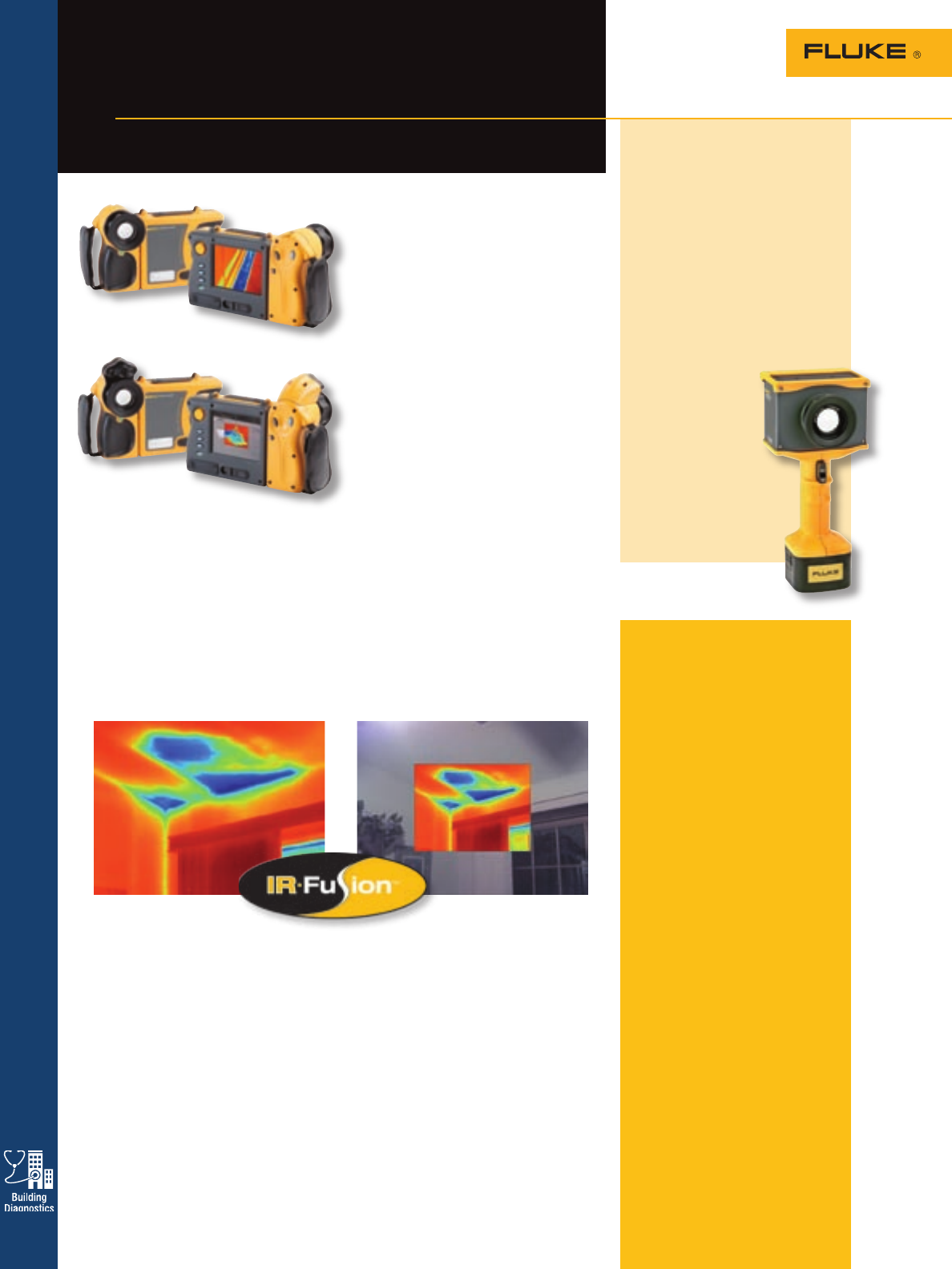
50
The expert’s choice for
building diagnostics
FlexCam™ TiR4, TiR3, and
TiR2 IR Thermal Imagers
Thermal Imaging
The new Fluke TiR2, TiR3 and TiR4 thermal
imagers are for professionals demanding the
best and most thorough solutions in building
diagnostics applications. The Fluke TiR-Series
provides the industry’s largest LCD to view
on-camera images, augmented with the
innovative IR-Fusion™ technology to better
pinpoint building problems. IR-Fusion is the
overlay of IR and visible images, allowing one
to clearly identify critical points within the
thermal image.
• Industry leading thermal sensitivity
(≤ 0.050 °C NETD on TiR4) (0.07 °C
NETD on TiR2 and TiR3) provides solid
resolution, and ultra high-quality images.
• IR-Fusion technology automatically merges
visual and thermal images pinpointing
trouble areas quicker by automatically
relating thermal images with the real
world. (included with Flk-TiR/FT series,
optional with Flk-TiR series)
TiR2, TiR3 and TiR4
Included accessories
AC adapter (for TiR2 and TiR4 only),
video cable, 512 MB compact flash
card, compact flash card reader and
USB cable, PCMCIA compact flash
card adapter, SmartView reporting
and analysis software on CD, 2
rechargeable battery packs, battery
charger, neck strap, heavy duty car-
rying case and user manual on CD.
InSight XS and XST
Included accessories
Serial/USB download adapter kit/
cable, SmartView reporting software
on CD, 2 rechargeable battery
packs, battery charger, neck strap,
heavy-duty carrying case, user
manual on CD.
Ordering information
Flk-TIR2-20 IR Flexcam BD
Thermal Imager
Flk-TIR2/FT-20 IR Flexcam BD
Thermal Imager
with IR-Fusion
Flk-TIR3-20 IR Flexcam BD
Thermal Imager
Flk-TIR3/FT-20 IR Flexcam BD
Thermal Imager
with IR-Fusion
Flk-TIR4-20 IR Flexcam BD
Thermal Imager
Flk-TIR4/FT-20 IR Flexcam BD
Thermal Imager
with IR-Fusion
Flk-INSXT-20 IR InSight, 20MM,
XST
Flk-INSXS-20 IR InSight, 20MM,
XS
IR InSight XS & XST
Thermal Imagers
The New Fluke IR InSight XS &
XST portable infrared imagers
combine outstanding image quality
and thermal sensitivity. They are
optimized for low contrast ther-
mal applications encountered in
building sciences applications and
show problems that other infrared
cameras cannot. These easy to use
cameras include SmartView™ soft-
ware to customize and prepare pro-
fessional infrared survey reports.
• 160x120 focal
plane array
• 0.07 °C (Industry
leading thermal
sensitivity (≤ NETD)
• Simple robust
one-button
operation
• 3.5-inch, 30 bit color,
high resolution,
high-contrast display
• SmartView professional
report writing software
IR-Fusion™ Technology
Infrared and visible light images fused
together on one display.
IR-Fusion Technology captures a visible
light image in addition to the infrared
image and takes the mystery out of IR
image analysis. It helps to better identify
and report suspect areas and enable the
repair to be done right the first time.
• Full IR – for analyzing very high reso-
lution IR imaging. Detect the smallest
temperature variations to track down the
origin of problems and fully document
the extent of remediation. Full IR images
are automatically linked to full visible
light images.
• Picture-in-Picture – for creating an IR
“window” surrounded by a visible light
frame to easily identify thermal anoma-
lies, while maintaining a frame of refer-
ence with surroundings.
• Alpha blending – for combining visible
and infrared images together in any ratio
to create a single image with enhanced
detail that will help in precisely locating
problems.
• IR/visible alarm – for displaying only
temperatures that fall above, below, or in
between a specified range as IR image,
leaving the rest of the scene as a fully
visible light image.
• Full visible light – a bright, detailed
pixel-for-pixel reference image of subject
areas for documentation and reporting.
Fluke TiR2/FT, TiR3/FT, TiR4/FT
Fluke TiR2, TiR3, TiR4
• The 180° articulating lens is great for viewing around obstructions.
• The 5” high resolution, high contrast display is the biggest display in the industry.
• 320 x 240 focal plane array and 20 mm high quality Germanium lens with
continuous single finger focus provide exceptional image resolution (Model TiR2
available with 160 x 120 only).
• SmartView™ professional report writing software generates fast, easy customizable
reports including rich image analysis.
• The intuitive operation with on-camera Windows CE interface makes it easy to use.
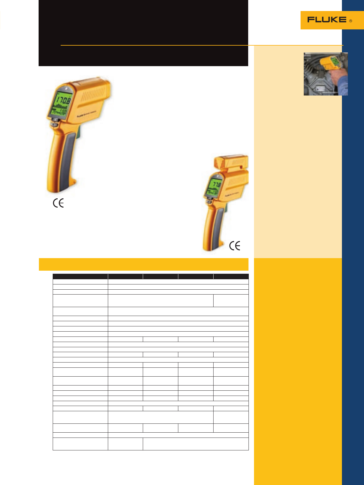
51
Thermometers
The predictive maintenance
professional’s precision diagnostic tool
Fluke 570 Series
Infrared Thermometers
574-NI
Nonincendive
Thermometer
When safety is a
concern and data
logging and
downloading are
required, the Fluke
574 Nonincendive (NI) model
thermometer is the product to
choose. It has the same great fea-
tures as the standard 574 model
thermometers with the extra confi-
dence of a Factory Mutual approval
for use in hazardous environments.
Class I, Division 2, Groups A, B, C, D: Class I,
Zone 2 IIC; T4 Ta=50 °C when used with 1.5 V
alkaline batteries.
The Fluke 572, 574 and 576 non-contact thermometers
are ideal professional diagnostic tools for maintenance
professionals requiring the most accurate temperature read-
ings at all distances. Predictive maintenance professionals
requiring analysis and documentation use the 574 or 576
models, with 100-point data logging and digital photographs
(576 only) with the included software for graphing and
analysis for follow-up reporting and documentation.
• Backlit display for poorly lit areas
• Displays last ten temperature readings on bar graph for easy reference
• Enhanced optics (distance to spot ratio up to 60:1) allow measurements
of smaller objects from farther away
• Coaxial three-dot laser sighting system highlights the true diameter of
measurement spots at all distances
• Adjustable emissivity setting (all models) and 30 pre-set
common material values (574, 576) for more accurate
measurements
• 100-data point logging for documentation (574, 576)
• Customizable log names, alarms, and emissivity
values for personalized measurements (574, 576)
• Software to log, graph, and analyze temperature
data via RS-232 (574) connection or USB
connection (576, includes photo viewing feature)
• Instantly captures photographs of measurement
locations along with temperature and date-time
information for improved documentation and
maintenance follow-up (576)
• Close-focus option available for specialized
applications
• Durable hard plastic storage case
Fluke 576 Photographic
Non-contact Thermometer
The Fluke 576 thermometer mea-
sures temperature while digitally
photographing the measured area
and its surroundings. The 576
allows you to:
• Ensure consistency of repeated
measurements by using prior
photos as a reference.
• Position the laser sighting to
assure the measurement area is
the same.
• Create customized company
reports with the software, data
and photos, using standard
Windows programs.
Specifications – 572, 574 and 576 IRTs
Models Fluke-572 Fluke-574 Fluke-574-NI Fluke-576
Temperature range -30 °C to 900 °C (-25 °F to 1600 °F)
D:S (Distance to Spot size) 60:1 [50:1 with close focus option (close focus not available with NI model)]
Laser sighting 3-dot, coaxial, extra-bright
Emissivity Adjustable Adjustable, plus
table of 30 preset
values
Accuracy ± 0.75 % of reading or (± 0.75 °C (± 1.5 °F) whichever is greater
(assumes ambient operating temperature of 23 °C [73 °F])
Response time 250 mSec
Display hold (7 seconds) Yes
LCD backlit Yes
MAX, MIN temperatures Yes
DIF, AVG temperatures No Yes Yes Yes
Recall last reading Yes
Audible/visible HI alarm Yes
Audible/visible LO alarm No Yes Yes Yes
Bar graph display Yes
100 points data logging No Yes Yes Yes
Data graphing software
(Windows 2000, XP compatible) No Yes Yes Yes
Photo viewing software (Windows
2000, XP, NT compatible) No No No Yes
26 images (640 x 480 pixel) No No No Yes
100 images (320 x 240 pixel) No No No Yes
Image file format (.jpg) No No No Yes
Protective hard case Yes
Weight 472 g (1 lb, 1 oz) 480 g (1 lb, 1 oz) 480 g (1 lb, 1 oz) 580 g (1 lb, 1 oz)
Dimensions 16.7 cm x 5 cm x 19.8 cm (6.58 in x 1.97 in x 7.80 in) 16.7 cm x 5 cm x
23.8 cm (6.58 in x
1.97 in x 9.57 in)
Power 2 AA batteries 2 AA batteries/
AC adapter 2 AA batteries/
AC adapter 2 AA batteries/
USB
Warranty Two-years, conditional
Additional options/accessories Nylon holster, NIST
Traceable Calibration
Certificate
Nylon holster,
NIST Traceable Calibration Certificate,
Analog cable
For more information and detailed specifications, go to www.fluke.com/thermometers
Included accessories
2 AA batteries, operator’s guide
(on CD), durable hard case.
thermocouple K probe (574, 576),
power supply (574), RS-232 data
cable (574), USB 1.1 cable (576),
data graphing, storage and analysis
software on CD (574, 576)
Ordering information
Fluke-572 Precision Infrared
Thermometer
Fluke-572-CF Precision Infrared
Thermometer with
Close Focus Option
Fluke-574 Precision Infrared
Thermometer
w/Logging SW
Fluke-574-NI Precision Infrared
Thermometer
w/Logging SW
Nonincendive
Fluke-574-CF Precision Infrared
Thermometer
w/Logging SW
Close Focus
Fluke-576 Precision,
Photographic
Infrared
Thermometer
w/Logging SW
Fluke-576-CF Precision,
Photographic
Infrared
Thermometer
w/Logging SW
Close Focus
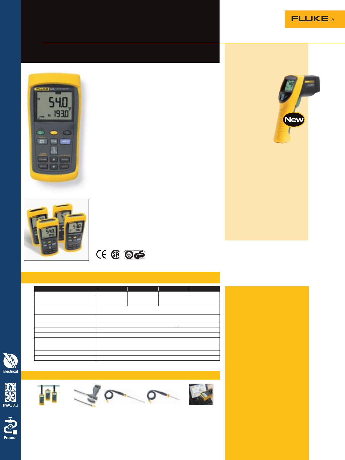
Thermometers
Included accessories
Fluke 50 Series II includes:
80PK-1 Bead Thermocouple(s),
batteries, overview manual and
instructional guide on CD-ROM.
Fluke 561HVACPro includes:
Infrared thermometer with contact
thermometer capabilities, thermo-
couple K-type Velcro® pipe probe,
hand-carrying case and user manual
with HVAC measurement guide.
Ordering information
Fluke-51-2 Digital Thermometer,
Single Input
Fluke-52-2 Digital Thermometer,
Dual Input
Fluke-53-2 Datalogging
Thermometer,
Single Input
Fluke-54-2 Datalogging
Thermometer,
Dual Input
Fluke-561 HVACPro Thermometer
Fluke 54 Series II
Thermometer
Lab accuracy in a field thermometer
Specifications – 51, 52, 53 and 54 Series II
Recommended accessories – 51, 52, 53 and 54 Series II Thermometers
Feature 51 52 53 54
Thermocouple types K,J,T,E K,J,T,E K,J,T,E,N,R,S K,J,T,E,N,R,S
Number of inputs Single Dual Single Dual
Time stamp Relative time Relative time Time of day Time of day
Temperature measurement accuracy
(for temperatures above -100 °C) Type J,K,T,E,N: ± [0.05 % + 0.3 °C (0.5 °F)] Type R,S: ± [0.05 % + 0.4 °C (0.7 °F)]
Measurement range
(depending on thermocouple type) -250 °C (-418 °F) to 1767 °C (3212 °F)
Display resolution 0.1 °C /°F/K < 100° 1° °C/°F/K > 1000°
Operating temperature -10 °C to 50 °C (14 °F to 122 °F)
Storage temperature -40 °C to 60 °C (-40 °F to 140 °F)
Humidity 0 % to 90 %; 0 °C to 35 °C (32 °F to 95 °F), 0 % to 70 %;
0 °C to 50 °C (32 °F to 122 °F)
Weight 400 g (14 oz)
Size (HxWxD) 17.3 cm x 8.6 cm x 3.8 cm (6.8 in x 3.4 in x 1.5 in)
Battery 3 AA batteries; typical 1000-hour life
Fluke 561 HVACPro
Two-in-one infrared and
contact thermometer for
HVAC/R professionals
The Fluke 561 HVACPro
combines the tempera-
ture measurement
functions that profes-
sionals need for most
HVAC jobs, all in one
tool. It measures
both IR and contact
temperature, replacing
several hundred
dollars worth
of equipment.
• IR thermometer
for measurements
up close or at a
distance, without a ladder
• Contact thermometry capability,
compatible with all standard
mini-connector K-type thermo-
couples, preserves your invest-
ment in thermocouples
• Velcro® pipe probe for superheat
and sub-cooling and other con-
tact and ambient measurements
• MIN, MAX and DIF functions help
you quickly identify problems
• Scan large areas or small objects
quickly and efficiently
TPak 80PK-8 80PK-22 80PK-25 FVF-SC1
ToolPak Meter Pipe Clamp SureGrip™ Immersion SureGrip™ Piercing FlukeView Forms
Hanging Kit Temperature Probe Temperature Prove Temperature Probe Software
See page 71 See page 68 See page 68 See page 68 See page 65
The Fluke 51, 52, 53 and 54 Series II Thermometers offer
high accuracy with fast response times to quickly capture
your measurement and show trends. Choose from four models
to get the functionality, thermocouple support and data logging
you need.
All models offer:
• Laboratory accuracy: ± (0.05 % + 0.3 °C)
• Large backlit dual display presents all the information
you need at a glance
• MIN, MAX, and AVG—with time references—captures
major events
• Electronic Offset function maximizes overall accuracy by
allowing you to compensate for thermocouple errors
• Supports a wide range of thermocouple types
• Temperatures displayed in °C, °F, or Kelvin (K)
• Splash and dust resistant case
• Sleep mode to increase battery life
(typical 1000-hour life)
• Battery door allows easy battery replacement without
breaking the calibration seal
Powerful data logging capabilities
The Fluke 53 and 54 Series II can log up to 500 points of
data to internal memory.
• User-adjustable recording intervals
• Real-time clock captures the exact time of day
of events
• Recall function allows logged data to be easily reviewed
on the meter display
• For further analysis and graphing, data can be
exported to optional FlukeView® PC software using
the thermometer’s IR communication port
For more information and detailed specifications, go to www.fluke.com/thermometers
52
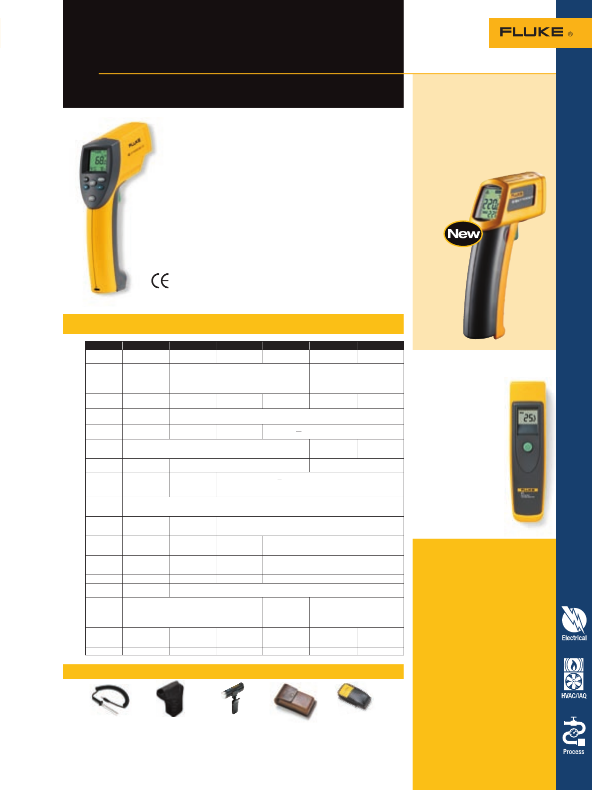
Recommended accessories – 60 Series Thermometers
80PR-60 H6 LVD1 C510 C90
Temperature Probe Meter Case Volt Light Meter Case Meter Case
(66/68 only) (63/66/68 only) (all models) (61 only) (61 only)
See page 69 See page 70 See page 64 See page 70 See page 70
Specifications – 561, 61, 62, 63, 66, 68
561 61 62 63 66 68
Temperature
range -40 °C to 550 °C
(-40 °F to 1022 °F) -18 °C to 275 °C
(0 °F to 525 °F) -30 °C to 500 °C
(-20 °F to 932 °F) -32 °C to 535 °C
(-25 °F to 995 °F) -32 °C to 600 °C
(-25 °F to 1100 °F) -32 °C to 760 °C
(-25 °F to 1400 °F)
Emissivity Adjustable with
three settings:
Low (0.3),
Medium (0.7),
High (0.95)
Fixed at 0.95 Digitally adjustable
(from 0.1 to 1.0 by 0.01)
Optical reso-
lution (D:S) 12:1 8:1 10:1 at 80 %
energy 12:1 30:1 50:1
Laser sight-
ing (class II) Single point laser Offset single point laser
Response
time 500 mSec (95 %
of reading) < 500 mSec < 500 mSec < 0.5 second (95 % of reading)
Minimum
usable spot
size 25 mm (1 in) 24 mm (0.9 in) 18 mm (0.7 in)
Resolution 0.1 °C (0.1 °F)
of reading 0.2 °C (0.5 °F) 0.1 °C (0.1 °F)
Repeatability ± 0.5 % of
reading or ± 1 °C
(± 2 °F), which-
ever is greater
± 2 °C or
± 2 %, whichever
is greater
± 0.5 % or < ± 1 °C (± 2 °F), whichever is greater
Ambient
operating
temperature 0 °C to 50 °C (32 °F to 120 °F)
Relative
humidity 10 to 90 % RH
non-condensing,
at < 30 °C (86 °F)
10 to 90 % RH
noncondensing, at
< 50 °C (120 °F)
10 to 90 % RH non-condensing, at < 30 °C (86 °F) ambient
Storage
temperature -20 °C to 65 °C
(-25 °F to 150 °F) -20 °C to 60 °C
(-4 °F to 140 °F)
without battery
-20 °C to 65 °C
(-4 °F to 150 °F)
without battery
-20 °C to 60 °C (-13 °F to 158 °F) without battery
Dimensions 17. 8 cm x 16.5
cm x 5.1 cm (7 in
x 6.5 in x 2 in)
190 mm x 51 mm
x 41 mm (7.5 in x
2 in x 1.6 in)
152 mm x 101 mm
x 38 mm (6 in x
4 in x 1.5 in)
200 mm x 160 mm x 55 mm (8 in x 6 in x 2 in)
Weight 330 g (11.6 oz) 341 g (0.75 lb) 200 g (7 oz) 320 g (11 oz)
Power 2 AA batteries
(alkaline or NiCD) 9 V alkaline or customer supplied NiCd battery
Battery life
(alkaline) 12 hours 10 hours with
laser and back-
light on, 40 hours
with laser and
backlight off
20 hours with laser and backlight
on 50 % 40 hours with laser and
backlight off
Typical
distance to
target Up to 2 m (6 ft) 1 m (3 ft) Up to 2 m (6 ft) Up to 2 m (6 ft) Up to 5 m (15 ft) Up to 8 m (25 ft)
Warranty Two-year limited One-year Two-year limited Two-year limited Two-year limited Two-year limited
Measuring temperature in hard-to-reach,
hot, rotating or dangerous situations
Fluke 68 Infrared
Thermometer
For more information and detailed specifications, go to www.fluke.com/thermometers
Included accessories
Fluke 61 includes: instruction sheet
and 9 V battery.
Fluke 62 includes: storage pouch
and instruction sheet.
Fluke 63, 66, 68 includes: carrying
case, hand strap, instruction manual
and 9 V battery.
Ordering information
Fluke-61 Infrared Thermometer
Fluke-62 Mini Infrared
Thermometer
Fluke-63 Infrared Thermometer
Fluke-66 Infrared Thermometer
Fluke-68 Infrared Thermometer
Fluke-68IS Intrinsically Safe
Infrared Thermometer
Reach for a rugged Fluke IR thermometer. You get easy and
safe temperature readings in less than a second.
These handheld portable tools enable professionals to
research heating and ventilation problems, monitor the
status of electrical motors and electrical panels and diagnose
car malfunctions with ease.
Fluke 63, 66 and 68 pistol grip
infrared thermometers
The new Fluke 63, 66 and 68 pistol grip thermometers offer
an easy to use solution for temperature measurement in
hard-to-reach, hot, rotating or dangerous situations.
• Wide temperature range and quick response time
• Superb optics for measuring temperature of surfaces from
a distance
• Laser sighting
• Adjustable emissivity (66/68 only) for more
accurate temperature measurement
Intrinsically safe Fluke 68 version available (see page 45)
New! Fluke 62 Mini
Infrared Thermometer
• Temperature measurement range
up to 500 ºC (932 ºF)
• 10:1 optics
• Accurate to within ± 1.5 %
of reading or ± 1.5 °C
• MAX temperature display
• Laser sighting
• Backlit display
Fluke 61 Infrared
Thermometers
• Easy to use one
button operation
• Easy targeting with
bright laser
• Shock-absorbing
molding increases
ruggedness
Thermometers 53
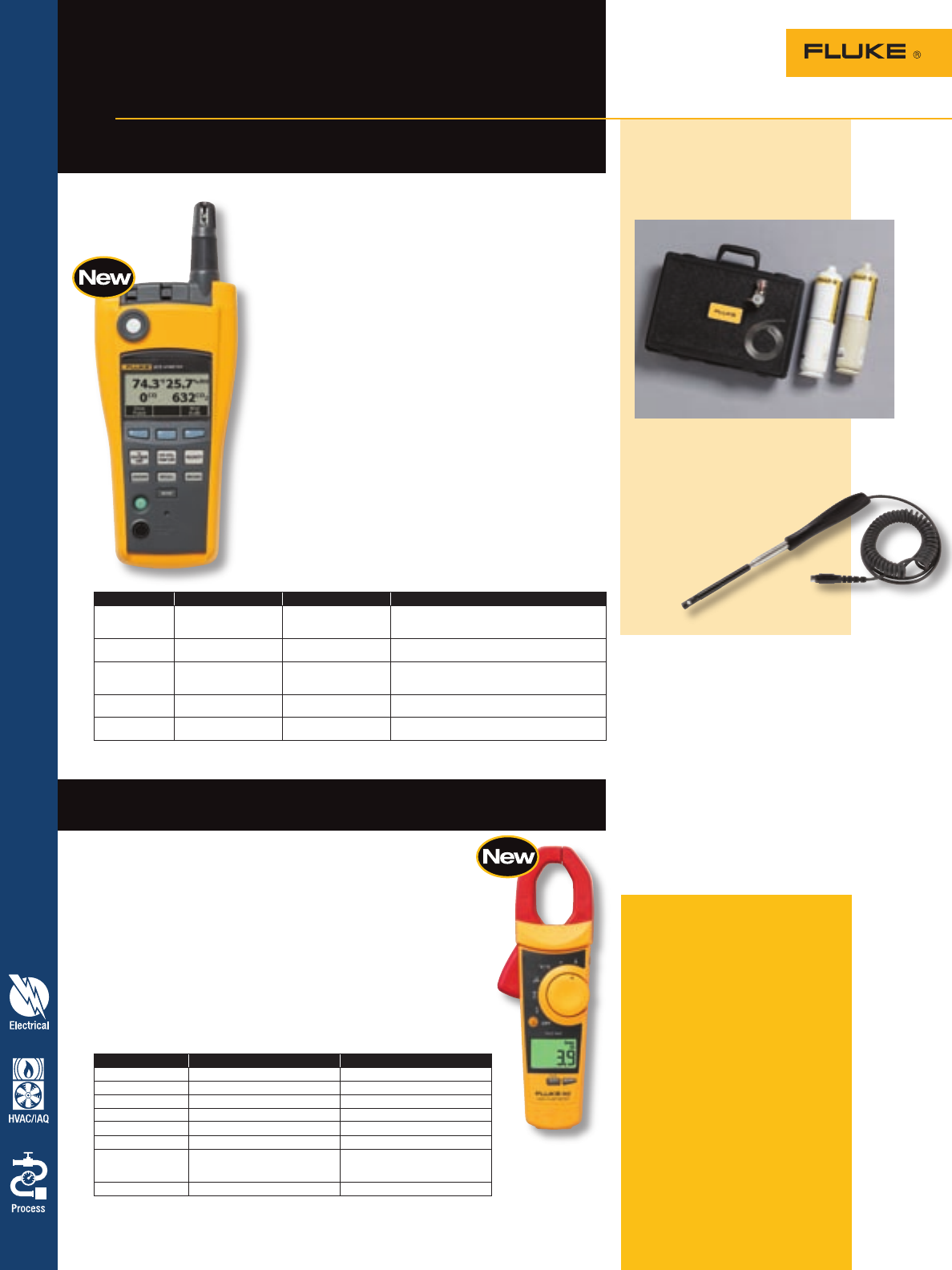
Also available:
Fluke-975CK AirMeter Calibration
Kit includes the gases and tools
necessary to keep your Fluke 975
AirMeter calibrated.
54 Indoor Air Quality
Fluke 975 AirMeter™
Five powerful tools in one, with
simple one-touch air velocity
The Fluke 975 test tool combines five powerful air
quality tools into one. Identify and diagnose indoor
air quality issues quickly and easily with one rugged,
handheld device. The Fluke 975 measures and simul-
taneously displays temperature, humidity, CO2 and CO.
At the press of a button, it quickly measures air flow
and percentage of outside air.
• Simultaneously measures, logs, and displays
temperature, humidity, CO2, and CO on a bright,
backlit LCD display
• One-touch air flow and velocity with available probe*
• Wet bulb and dew point temperature
• % of outside air calculation
• CO2 and CO field calibration feature
• Automatically compensates for barometric pressure
changes
• Min/Max/Average on all measured and calculated
readings
• Audible and visual threshold alarms
• Extensive discrete or continuous data logging
capacity, downloadable to PC via USB interface
*Included with Fluke 975V, optional with Fluke 975
Fluke 902 True-rms HVAC Clamp Meter
Get more done
Included accessories
Fluke 975 includes: AA alkaline
batteries (3), Users manual (with
safety information), calibration cap,
hard carrying case, FlukeView®
Forms software, power adapter, inter-
national power plugs, air velocity
probe (Fluke 975V only).
Fluke 902 includes: AA alkaline
batteries (2), Users manual (with
safety information), soft carrying
case, Tl75 Test Leads (1 pair), 80BK
Integrated Temperature Probe (1).
Ordering information
Fluke-975 AirMeter™
Fluke-975V AirMeter™ with
Velocity
Fluke-902 HVAC Clamp Meter
Range Display Resolution Accuracy
Temperature -20 °C to 50 °C
(-5 °F to 122 °F) 0.1 °C (0.1 °F) ± 0.9 °C/± 1.62°F from 40 °C to 60 °C ± 0.5 °C/±
1.00°F from 5 °C to 40 °C ± 1.1 °C/± 1.98 °F from
-20 °C to 5 °C
Relative humidity 10 % to 90 % RH
non-condensing 1 % ± 2 % RH (10 % RH to 90 % RH)
Air velocity 50.0 fpm to 3000 fpm
0.25 m/sec to 15 m/sec 1 fpm (0.005m/sec) ±4 % or 4 fpm* ±4 % or 0.02 m/sec* whichever is
greater *Accuracy specification only valid for velocity
readings above 50 fpm.
CO20 to 5000 ppm 1 ppm Warm up time 1 min (5 minutes for full specification)
2.75 % + 75 ppm
CO 0 to 500 ppm 1 ppm ± 5 % or ± 3 ppm, whichever is greater, @ 20 °C
and 50 % RH
Heating, ventilation, air conditioning (HVAC) technicians require a
service tool that can consistently keep up with their demands. The
Fluke 902 expands the existing line of quality Fluke clamp meters by
delivering the features necessary to diagnose and repair HVAC systems.
Combined with True-rms technology and a CAT III 600 V rating, the
Fluke 902 helps technicians do their jobs safely and accurately.
• Designed for HVAC applications with capacitance, dc current (µA), and
temperature measurements
• Small body and jaws fit perfectly in your hand and into tight places
• Handy ‘Display Hold’ button keeps measurements on the display
• Meter controls are positioned so current measurements can be done
with one hand (index finger on clamp opening lever and thumb on
rotary switch)
Range Accuracy
Voltage dc 0 - 600 V 1 % ± 5 counts
Voltage ac (True-rms) 0 - 600 V 1 % ± 5 counts (50/60 Hz)
Current ac (True-rms) 0 - 600 A 2.0 % ± 5 counts (50/60 Hz)
Current dc 0 - 200 µA 1.0 % ± 5 counts
Resistance 0 - 9999 W1.5 % ± 5 counts
Continuity <= 30 W—
Temperature Range -10 °C to 400 °C (-14 °F to 752 °F)
-40 °C to -10 °C (-40 °F to -14 °F) +/-1.0 % + 0.8 °C (+/-1.0 % +
1.5 °F) typical +/-5.0 % + 1.5 °C
(+/-5.0 % + 3.3 % °F) typical
Capacitance 1-1000 µF 1.9 % ± 2 counts
Fluke-975AP AirMeter
Velocity Probe for use
with Fluke 975 AirMeter.
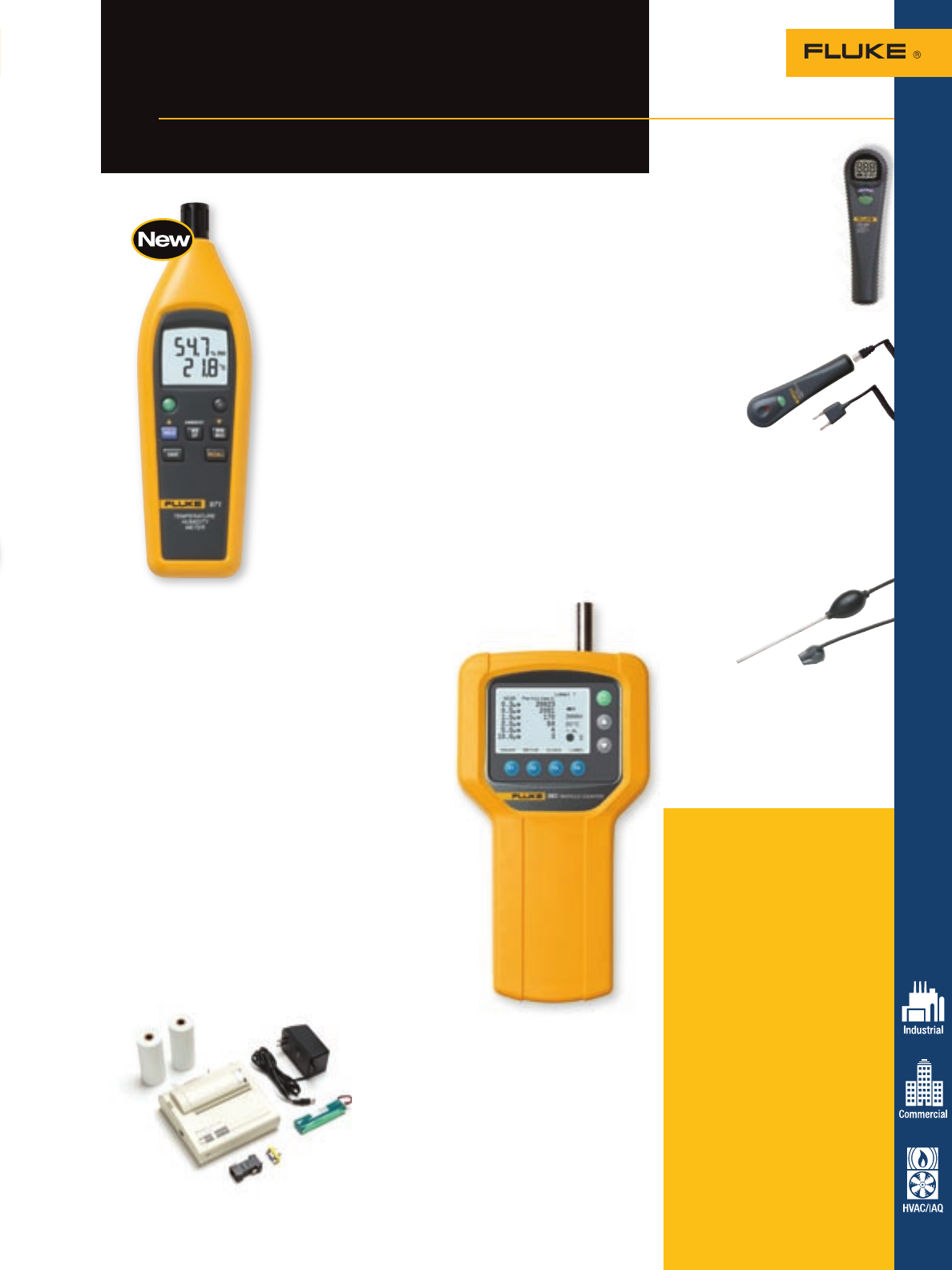
Fluke 983 Particle Counter
The Fluke 983 Particle Counter measures and displays six channels
of particle size distribution. The Fluke 983 holds 5000
logged samples including date, time, counts, sample
volume, temperature and relative humidity. Data
is easily downloaded using the included windows
compatible utility software. The Fluke 983 is
invaluable for IAQ investigations, allowing you to
determine size distribution of airborne particles or
track down a particle source.
Features:
• Compact and easy to operate
• Graphic liquid crystal display with backlight
• Simple connection to computer or printer
• Selectable sample time, count data and
programmable delay
• Set sample size to cubic feet or liters, set
temperature measurements to °C or °F
• Data displayed in totalize or concentration modes
• Automatic turn-off when battery voltage drops
below safe operating level
• Meets JISB9921:1997 and CE standards
• Battery or ac operation with internal rechargeable
battery
• Protective holster
• Rugged, hard shell carrying case
Included accessories
Fluke 971 includes: operation
manual, four AAA alkaline batteries.
Fluke 983 includes: Certificate of
Calibration (NIST), Windows com-
patible software download utility,
DB9 to RS-232 adapter and cable,
isokinetic probe, high purity tubing,
1/8 in. hose barb adapter, power
supply, operation manual, zero count
filter, protective holster and hard
molded plastic case.
Ordering information
Fluke-971 Temperature
Humidity Meter
Fluke-983 Particle Counter
Fluke-983TPK 220 Thermal Printer
Kit, 220 V
Fluke-983TPK 120 Thermal Printer
Kit, 120 V
Fluke-CO-205 Aspirator Kit
Fluke-CO-210 Carbon
Monoxide Probe
Fluke-CO-220 Carbon
Monoxide Meter
Indoor Air Quality Tools
Easy-to-use tools to help you
maintain good IAQ
55
Indoor Air Quality
Fluke 971 Temperature Humidity Meter
Temperature and humidity are two important factors in
maintaining optimal comfort levels and good indoor air quality.
Quickly and conveniently take accurate humidity and temperature
readings with the Fluke 971. The Fluke 971 is invaluable for
facility maintenance and utility technicians, HVAC-service
contractors, and specialists who assess indoor air quality (IAQ).
Lightweight and easy to hold, the Fluke 971 is the perfect tool for
monitoring problem areas. With a rugged holster and twist-open
protective sensor cover, the Fluke 971 is built to perform and
made to last.
Features:
• Backlit dual display of humidity and temperature
• Measures dew point and wet bulb temperatures
• 99 record storage capacity
• Ergonomic design with belt clip and protective holster
• Quick-response capacitance sensor with twist-open
protective cover
• Compact and lightweight at 188 g (6.6 oz)
• Temperature range from -20 °C to 60 °C (-4 °F to 140 °F)
• Relative humidity from 5 % to 95 %
• Min/Max/Avg Data hold
• Low battery indicator
CO-220 Carbon
Monoxide Meter
• Standalone CO meter that
does not require a digital
multimeter
• Large backlit LCD displays
CO levels from 0 to 1000 ppm
• Beeper triggers with
increasing frequency as CO
levels rise
• MAX hold function stores
and displays the maximum
CO level
• Automatic sensor zeroing and
self-test upon startup
CO-210 Carbon
Monoxide Probe
• Use as an accessory to a digital
multimeter with DC millivolt inputs
• Displays CO level readings from 0 to
999 ppm, with a resolution of
1 ppm and accuracy of ± 5 %
• Also used as a standalone device
with an LED indicator and beeper
that triggers with increasing
frequency as CO levels rise
CO-205
Aspirator Kit
The CO-205 flue gas sampling
accessory kit includes:
• Stainless steel sampling tube
• Aspirator to draw flue sample
• Replaceable particulate filter
• Nose cap for connection to the
Fluke CO-210/CO-220
Also available:
Fluke 983TPK Thermal Printer Kits
Print the results of a single sample or an entire
data logging session with the new Fluke 983
Thermal Printer Kit accessory. Available in
220 V and 120 V models and includes two
rolls of thermal printer paper, battery pack,
power adapter and serial adapter.
For more information and detailed specifications, go to www.fluke.com/IAQ
56 ScopeMeter Test Tools
Fluke ScopeMeter®
Test Tools
Handheld oscilloscopes for professionals
with challenging troubleshooting situations
Specifications – ScopeMeter® Test Tools
Recommended accessories – ScopeMeter Test Tools
The ScopeMeter 192, 196 and 199 high-performance
oscilloscopes have bandwidth of 60, 100 and 200 MHz
and sample rates up to 2.5 GS/s. The C models add a
high-resolution color display that has a fast update rate,
waveform pass/fail testing and a digital persistence
mode—making the analysis of complex and dynamic sig-
nals that much easier.
For industrial, electronic or electro mechanical appli-
cations, the 123 and 124 Industrial ScopeMeters feature
20 MHz bandwidth, Connect-and-View™ software for
quick measurements and a dual DMM and paperless
recorder to get virtually any job done.
Model Description 192, 196, 199 123, 124
SCC 120 Software, cable and carrying case package •
SCC 190 Software, cable and carrying case package •
C125 Compact soft case •
C195 Universal soft carrying case •
PAC91 Optical to parallel printer adapter cable • •
Fluke 199C Fluke 196C Fluke 199B Fluke 196B Fluke 192B Fluke 124 Fluke 123
Bandwidth 200 MHz 100 MHz 200 MHz 100 MHz 60 MHz 40 MHz 20 MHz
Max real time sample rate 2.5 GS/s 1.0 GS/s 2.5 GS/s 1.0 GS/s 0.5 GS/s 25 MS/s 25 MS/s
Max record length (per input) 3000 Points 512 Points (min/max pairs)
Number of Inputs 2 Scope and 1 DMM (Isolated) 2 Scope Or DMM
Input sensitivity 2 mV/div. to 100 V/div. 5 mV/div. to 100 V/div. 5 mV/div. to 500 V/div.
Independently isolated floating inputs •
Display and display modes
Display Color Monochrome Monochrome
Persistence Digital with variable decay On/Off —
Envelope mode • •
Waveform compare •
FFT •
Pass/fail testing •
Triggering
Connect-and-View™ trigger • •
Edge, single, free run • •
Video • •
Video lines • •
Pulse width •
External •With ITP 120 Option
Advanced functions
Cursors • •
Zoom •
Dual input Trendplot™•
ScopeRecord™ mode •
Automatic capture and replay last 100 screens •
Waveform mathematics •
Save setups and screens 10 20 10
True-rms multimeter 5000 Counts Volts, Amps, Ohms, Continuity, Diode, Temp
Safety, power and warranty
Safety (EN61010-1) CAT II 1000 V/CAT III 600 V CAT III 600 V1
Battery 4-hour Ni-MH 7-hour NiMH 7-hour NiMH
Line power Adapter/battery charger included
PC printer interface Yes, using optional optically isolated cable
Warranty Three-year on main instrument/one-year on standard accessories
1Max input voltage CAT II 1000 V with VPS40, 40 MHz 10:1 voltage probe.
TM
For more information and detailed specifications, go to www.fluke.com/scopemeter
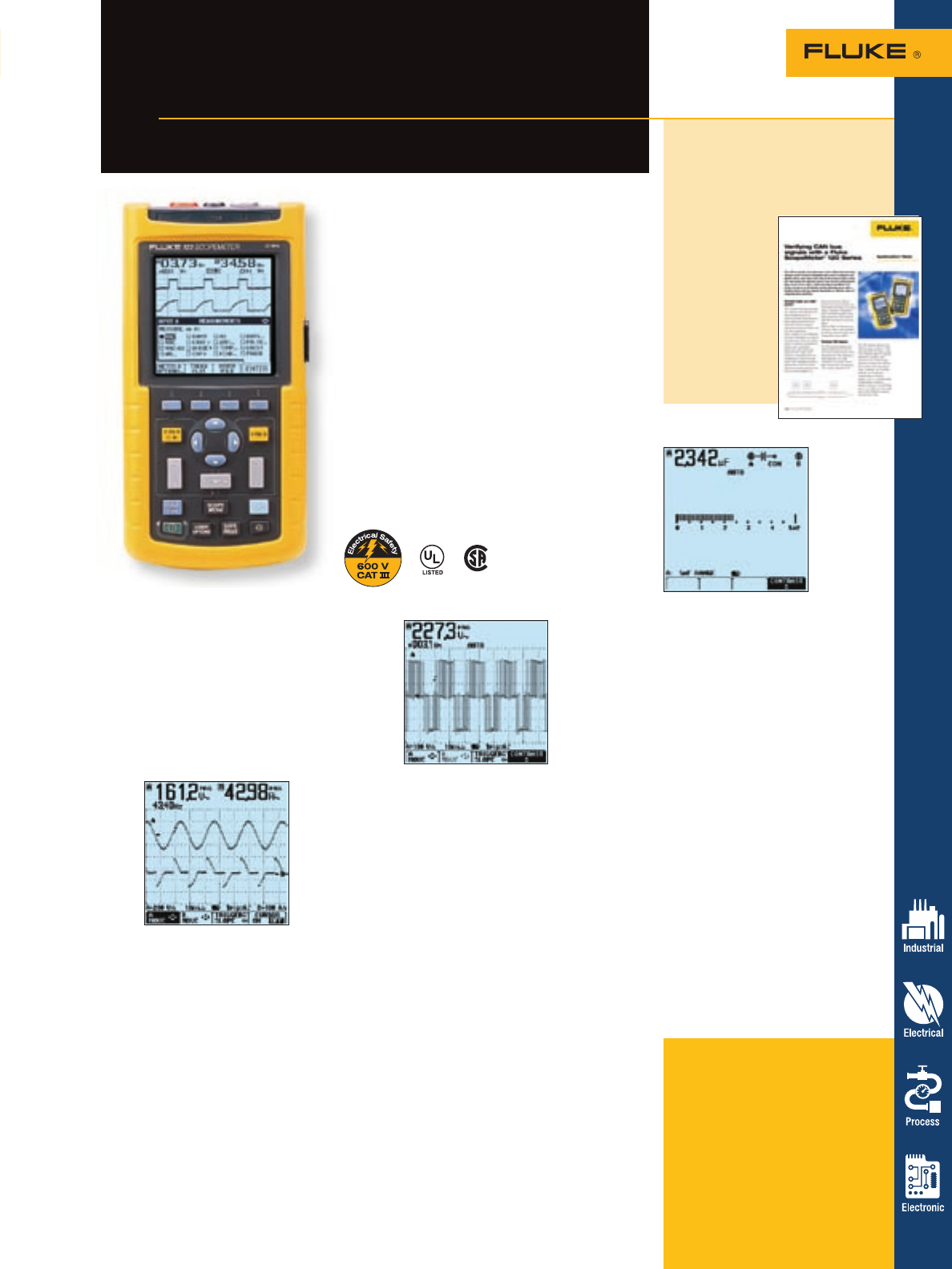
Ordering information
FLUKE-124/003 Industrial ScopeMeter
40 MHz
FLUKE-124/003S Industrial ScopeMeter
40 MHz with SCC Kit
FLUKE-123/003 Industrial ScopeMeter
20 MHz
FLUKE-123/003S Industrial ScopeMeter
20 MHz with SCC Kit
57
ScopeMeter Test Tools
Fluke 124 and 123 Industrial
ScopeMeter® Test Tools
Three-in-one simplicity for
fast answers wherever you work
A three-in-one tool
The ScopeMeter 123 and 124 combine
a 40 MHz or 20 MHz dual input digital
storage oscilloscope, two true-rms
digital multimeters and a dual input
TrendPlot™ recorder all in a compact,
battery powered instrument. Leave all
other test tools behind because the
ScopeMeter 123 and 124 Test Tools are
the only one you’ll need.
Dual-input mea-
surement shows
both meter read-
ing and wave-
form at the same
time (124, incl.
cursors)
Connect-and-View™ triggering
for an instant, stable display
Scope users know how difficult triggering
can be. Incorrect settings show unstable
and sometimes incorrect results. Fluke’s
unique Connect-and-View recognizes
signal patterns, and automatically sets
up correct triggering. It provides a sta-
ble, reliable and repeatable display of
virtually any signal including motordrive
and control signals—without touching
a button. Signal changes are instantly
recognized and settings adjusted for
once again a stable display.
The compact ScopeMeter 123 and 124 are the rugged
solution for industrial troubleshooting and installation
applications. These are truly integrated test tools, with
oscilloscope, multimeter and “paperless” recorder in one
affordable, easy-to-use instrument. Find fast answers
to problems in machinery, instrumentation, control and
power systems.
• A dual input 40 MHz or 20 MHz digital oscilloscope
• Two 5,000-count true-rms digital multimeters
• Cursor measurements (Fluke 124 only)
• A dual input TrendPlot recorder
• Connect-and-View trigger simplicity for hands-off
operation
• Shielded test leads for oscilloscope, resistance,
continuity and capacitance measurements
• Full bandwidth, heavy duty 10:1 probe
(Included standard with Fluke 124)
• Up to seven hours battery operation with
standard battery
• CAT III 600 V safety certified
• Optically isolated RS-232 interface
• Rugged, compact case
simply broken wiring or connectors.
Other factors, like line outages and
sags, or the starting and stopping of
a motor can also cause a machine to
stop. You may not be around to see
it—your Fluke ScopeMeter will. In this
“paperless recorder” mode, you can
plot the min, max, peak and average
values over time, up to 16 days. The
two inputs can plot any combination
of volts, amps, temperature, frequency
and phase, with time and date stamp-
to help lead you to the cause of those
faults quickly.
Safety certified
The 123 and 124 ScopeMeter Test
Tools and the included shielded test
leads are safety certified for measure-
ments on CAT III 600 V industrial
power systems. Via the optically
isolated OC4USB interface, the 123
and 124 can be safely connected to a
printer for direct print-out or to a PC
for later analysis and documentation
using FlukeView software. And using
the VPS40 probe, measurement up to
CAT II 1000 V are fully supported.
Connect-and-
View captures
even the most
complex motor
drive signals
One test lead measures all
High-frequency waveform, meter,
capacitance and resistance measure-
ments and continuity checks are all cov-
ered by the shielded test leads. No time
wasted finding or swapping leads. The
included accessories allow hook-up at
test objects of every dimension.
Battery powered mobility
Up to seven hours of battery operation
frees you from mains outlets for true
on-the-move working. The handheld
format and the weight of just 1.2 kg,
make the instrument easy to carry and
to fit comfortably in your hand. The rug-
ged, drip proof case assures long life
and reliable operation in the harshest
industrial environments.
Use TrendPlot,
™ dual
channel recorder, to help
find intermittents, fast
The toughest faults to find are those
that happen only once in a while—
intermittents. They can be caused by
bad connections, dust, dirt, corrosion or
Application note, literature code
2126072:
Verifying CAN bus signals
with a Fluke ScopeMeter
120 Series
Verifying the
physical layer
signals of two-
wire differential
serial bus sys-
tem. Read
a detailed
application
note on www.
fluke.com/
scopemeter
Check the
starting
capacitor of a
motor with the
ScopeMeter 124
For more information and detailed specifications, go to www.fluke.com/scopemeter
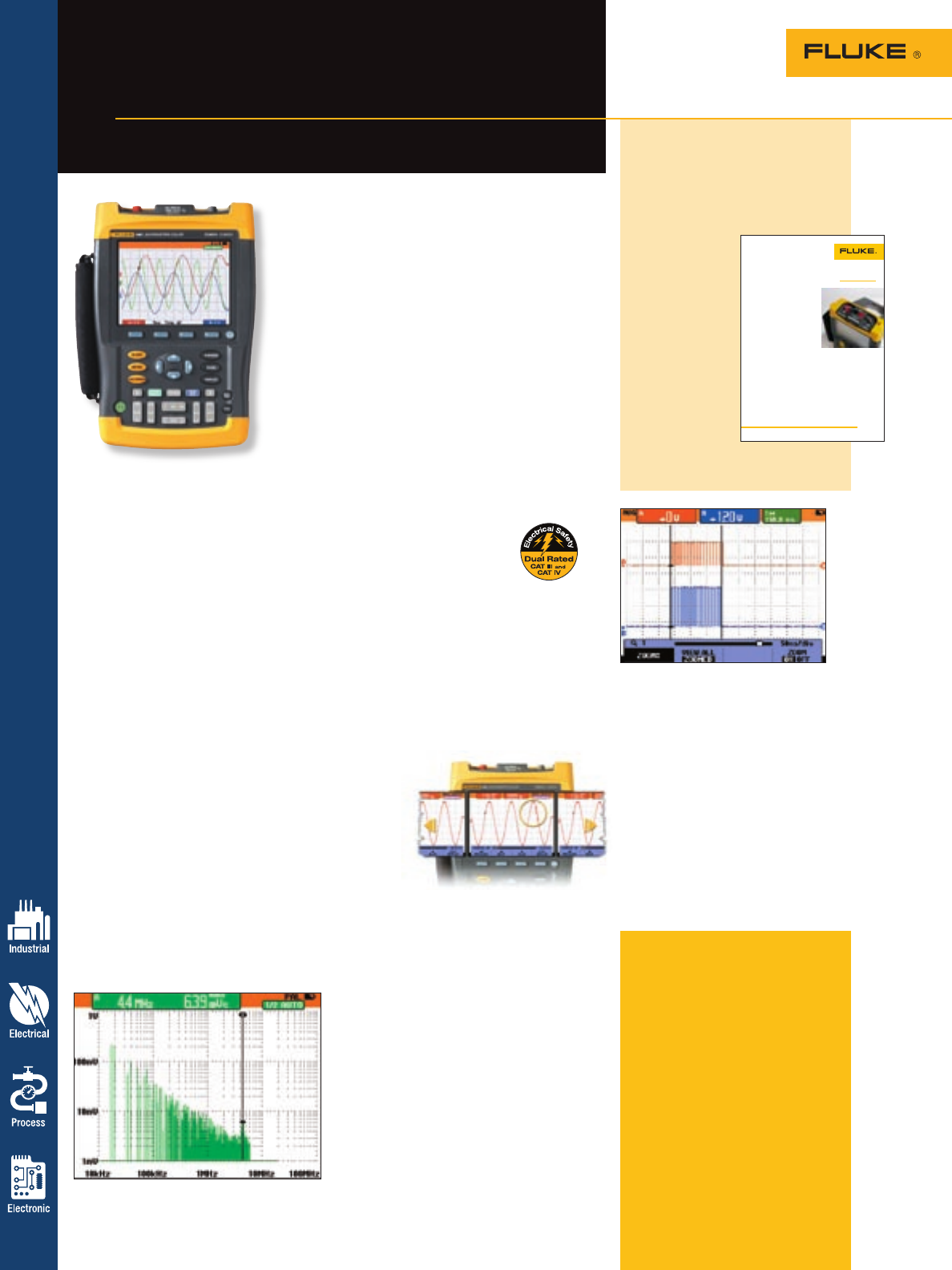
58 ScopeMeter Test Tools
Fluke 192, 196 and 199
ScopeMeter® Test Tools
Speed, performance and analysis power.
See more, fix more with color.
See what’s really happening
With a maximum real-time sampling rate of
2.5 GS/s per input, you can see what really
happens, with 400 ps resolution. Both inputs
have their own digitizer, so you can simulta-
neously acquire two waveforms and analyze
them with the highest resolution and detail.
If an anomaly flashes by on the screen, just
press the Replay button to see it again.
Frequency Spectrum Analysis
All C models now include Frequency
Spectrum Analysis functionality based on
Fast Fourier Transformation (FFT) analysis
as a standard feature. This makes it possible
for you to identify the individual frequency
components contained in a signal. The spec-
trum analysis function is also handy to reveal
the effects of vibration, signal interference
or crosstalk. An automatic window function
assures optimal windowing, although you
may manually select your preferred time
window.
Automatic capture and
replay of 100 screens
Scope users know how frustrating it is to
see a one-time anomaly flash by—never to
be seen again. Not with the ScopeMeter 190
Series. Now you can look back in time with
a touch of the replay button. In normal use,
the instrument continuously memorizes the
last 100 screens. Each time a new screen is
acquired, the
oldest is discard-
ed. At any
moment
you can
“freeze” the
last 100
screens
and scroll
through
picture-by-picture or replay as a “live” anima-
tion. Cursors can be used for further analysis.
Deep memory for high-
resolution ScopeRecord™
and Trendplot™
The ScopeRecord memory stores 27,500
points per input, for high-resolution record-
ing of waveform events up to 48 hours, and
captures fast intermittents and glitches as
short as 50 ns. This continuous roll mode
also stores events like motion profiles, UPS,
power supply and motor start-ups.
In Trendplot or “paperless recorder”
mode, you can plot the minimum, maximum
peak and average measurement (DMM or
Automatic Scope) values over time—up to
22 days. The two inputs can plot any combi-
nation of volts, amps, temperature, frequency
Whether you are performing routine maintenance and
calibration, or troubleshooting the hardest to solve prob-
lems like intermittent failures or sources of unwanted
noise—the Fluke ScopeMeter 192, 196 and 199 include
all the tools needed to get the job done. With 200 MHz
bandwidth, up to 2.5 GSa/s real-time sampling rate,
27500 points memory for high resolution waveform
ScopeRecord™, measurement TrendPlot™ and FFT
analysis, analyzing signal details, finding random
glitches and sources of unwanted noise or interference
become routine tasks.
• Dual-input—200, 100 or 60 MHz bandwidth
• Up to 2.5 GS/s real-time sampling and 3 k points
memory per input
• Automatic and advanced triggering functions—
Connect&View, pulse width, dual slope and n-cycle
for synchronizing on specific waveform details
and phase with time and date stamp
to help lead you to the cause of those
faults quickly.
Waveform Pass/Fail testing
Waveform reference allows an acquired
trace to be stored and designated
reference trace for visual comparisons,
or it can be used as the reference for
automatic Pass/Fail testing (C models
only). Up to 100 individually matching
(Pass) or non-matching (Fail) waveforms
can be stored in the replay memory
(C models only), allowing you to moni-
tor your system’s behavior over a long
period of time, without the need for you
to attend!
For more information and detailed specifications, go to www.fluke.com/scopemeter
• Fast Fourier Transform (FFT) for frequency domain, spectrum display of signal harmonics or
fidelity. (C models)
• Digital persistence for analyzing complex dynamic waveforms like on an analog scope (C models)
• Automatic capture and replay of 100 screens
• 27,500 points per input record length using ScopeRecord mode
• TrendPlot paperless chart recorder for trend analysis up to 22 days
• Waveform reference for visual comparisons and automatic pass/fail
testing (C models) of waveforms
• Five hours rechargeable Ni-MH battery pack
Application Note
The ability to display informa-
tion from multiple information
sources – “channels” – at once
is critical to troubleshooting and
maintaining today’s complex
equipment. Virtually all modern
power control systems have
circuitry designs that require
different reference measure-
ments. Control circuits based on
micro-controllers, for example,
are likely to run at the 3 or 5 V
levels of today’s logic systems,
whereas the power electronics
could well be driven by the 380
V three-phase mains supply. To
complicate matters even more,
such systems may be designed
with one or more floating
sections so even their grounds
are not the same
voltage.
In the past, technicians and
engineers have juggled the
need to track such divergent
system components by using
multiple test instruments at
once. A more accurate and
efficient method is to employ
a handheld Fluke Corporation
ScopeMeter® 190 Series. Unlike
standard dual-input oscillo-
scopes in which the inputs are
connected to a common ground,
ScopeMeter 190’s three inputs
are independently isolated,
which means they can be
connected to signals of widely
differing voltage reference
levels with complete accuracy
and safety. And the standard
probes cover a wide application
range from mV to kV, making
the ScopeMeter 190C ideal for
micro electronics to electrical
power applications.
Beware. A few other dual-
input oscilloscopes say they
have isolated channels, but
the isolation is limited, suit-
able for use only to about 30 V,
which is severely inadequate
for industrial environments. By
contrast, the isolation on the
Fluke ScopeMeter 190 Series
is certified up to a 1000 V CAT
II safety rating and 600 V CAT
III. That level of isolation makes
the 190 an extremely safe
instrument for professional and
industrial applications.
Those differences are critical,
for both accuracy and safety.
The need to measure and
capture waveforms from differ-
ent test points in sources is
such a common requirement
that it is easy to forget that
incorrectly attaching a dual-
input oscilloscope without
adequately isolated channels
can be a safety hazard. It’s not
uncommon for oscilloscopes
without industrial-strength
isolated channels to encounter
unexpected or unknown diver-
gent grounds, which can cause
the instrument to short out or
in extreme cases explode. Even
if users encounter no system
unknowns, the drive for speed
and efficiency can encourage
unsafe work habits. Too often,
bench-top oscilloscopes are
operated ungrounded to make
their inputs floating, greatly
increasing the danger of physi-
cal injury or even electrocution.
The level of channel isolation
engineered into the ScopeMe-
ter 190 protects the unit, the
equipment you’re troubleshoot-
ing, your test tool investment,
and your eyebrows.
The heavy-duty strength of
the 190 Series’ isolated chan-
nel capabilities are allowing
technicians to easily, accurately
and safely troubleshoot and
maintain systems from ac motor
All DSO isolated
channels are not
the same
From the Fluke Digital Library @ www.fluke.com/library
drives to switched-mode power
supplies and all manner of
high-energy industrial systems.
Fluke relied on the advice of
its most valuable design team,
its customers, as it developed
the extended isolated channel
capacity, said Hilton Hammond,
Fluke’s ScopeMeter U.S. product
manager.
“Our customers were asking
for it,” he said. “They need to
be able to safely and accurately
look at two different signals
with two different ground
potentials. The 190, with its
isolated channel architecture,
IEC safety rating of 1000 V
CAT II and 600 V CAT III, does
exactly that!”
Ordering information
Fluke-192B/003 ScopeMeter 60 MHz
B/W
Fluke-192B/003S ScopeMeter 60 MHz
B/W with SCC kit
Fluke-196B/003 ScopeMeter 100 MHz
B/W
Fluke-196B/003S ScopeMeter 100 MHz
B/W with SCC kit
Fluke-199B/003 ScopeMeter 200 MHz
B/W
Fluke-199B/003S ScopeMeter 200 MHz
B/W with SCC kit
Fluke-196C/003 ScopeMeter 100 MHz
color
Fluke-196C/003S ScopeMeter 100 MHz
color with SCC kit
Fluke-199C/003 ScopeMeter 200 MHz
color
Fluke-199C/003S ScopeMeter 200 MHz
color with SCC kit
Application note, literature code
2043253:
All DSO isolated channels
are not the same
Displaying information from multiple
information sourc-
es—“channels” at
once is critical to
troubleshooting
and maintaining
today’s complex
equipment and
most modern
power control
systems’ circuitry
require different
reference mea-
surements. Now
one tool will do
it all.
Go to www.fluke.com/scopemeter
for more information.
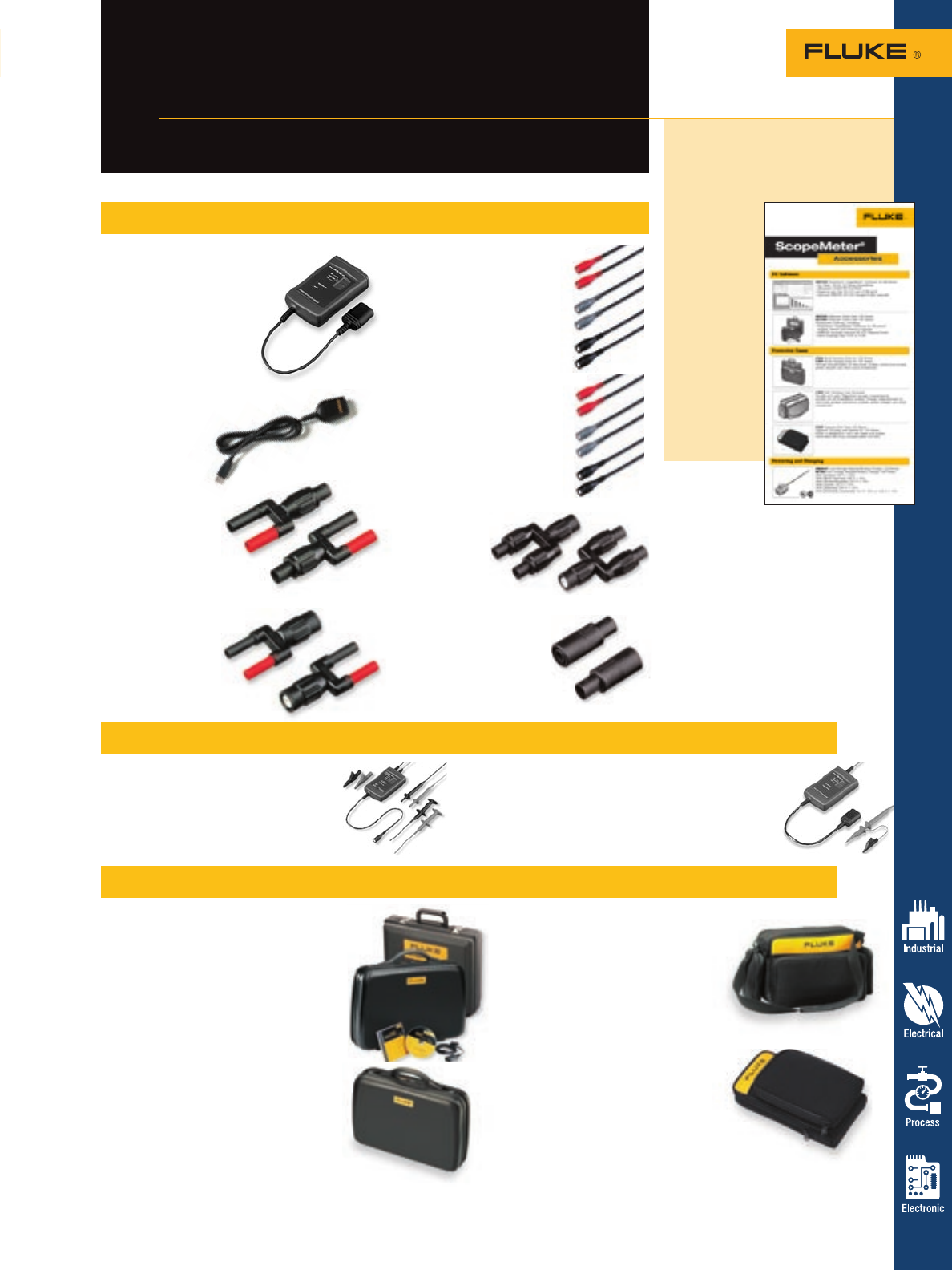
Measurements made easier
Fluke ScopeMeter®
Test Tool accessories
ScopeMeter Test Tools 59
Cable and adapters
SCC120 Software Cable Case for
123, 124
SCC190 Software Cable Case for
192, 196, 199
Accessories package, including:
• FlukeView® ScopeMeter® Software for
Windows® English, French and
German language
• OC4USB Optically Isolated RS-232
Adapter/Cable
• Hard Carrying Case C120 or C190
C120 Hard Carrying Case for
123, 124
C190 Hard Carrying Case for
192, 196, 199
• Storage compartments for test leads, probes,
instruction manual, power adapter and other small accessories
C195 Soft Carrying Case Universal
• Durable soft case. Adjustable storage
compartments suitable for all
ScopeMeter models. Storage
compartments for test leads, probes,
instruction manual, power adapter
and other accessories
C125 Compact Soft Case for 123, 124
• Zippered carrying case (black) for
123, 124
• Pouch is designed to carry test leads
and probes
• Convenient belt loop accommodates
tool belt
Software, carrying cases and kits
Data Sheet, literature code
1629076:
ScopeMeter accessories
Fluke acces-
sories can
enhance or
expand the
measurement
capabilities
of your
ScopeMeter.
Go to www.
fluke.com/
scopemeter
for your copy
of the
ScopeMeter
accessories
data sheet.
DP120 Differential Probe
• 1.5 m with shrouded banana probe tips
(red and black)
• CAT III 600 V/CAT II 1000 V rated
ITP120 Optically Isolated Trigger Probes
• 1.2 m, for ScopeMeter 123
• Included hookclip with ground lead
• Max. signal voltage and voltage to ground:
CAT II 600 V rms
Trigger and differential probes
For more information and detailed specifications, go to www.fluke.com/scopemeter
PAC91
• Printer Adapter Cable 0.25 m
• Safety designed optical to
parallel printer adapter cable
• See instrument manual for
compatible printers
OC4USB
• Optically-isolated
serial to USB
adapter
PM9081
• Dual Banana Plug
4 mm male to
female BNC Adapter
• The set consists of two
adapters
PM9082
• Dual Banana Jack
4 mm female to
male BNC Adapter
• The set consists of two
adapters easy identification
PM9091
• 50 Ohm Coaxial BNC cable set,
3 x 1.5 m
• Three colored BNC male
connectors (red, gray and
black) for easy identification
PM9092
• 50 Ohm Coaxial BNC cable set,
3 x 0.5 m
• Three colored BNC male
connectors (red, gray and
black) for easy identification
PM9093
• Male BNC to
dual female
BNC T-piece
• Set consists of
two adapters
BB120
• Two shielded Banana-
to-BNC Adapters
• Adapting Probes and BNC
adapters to 123 and 124
ScopeMeter Test Tools
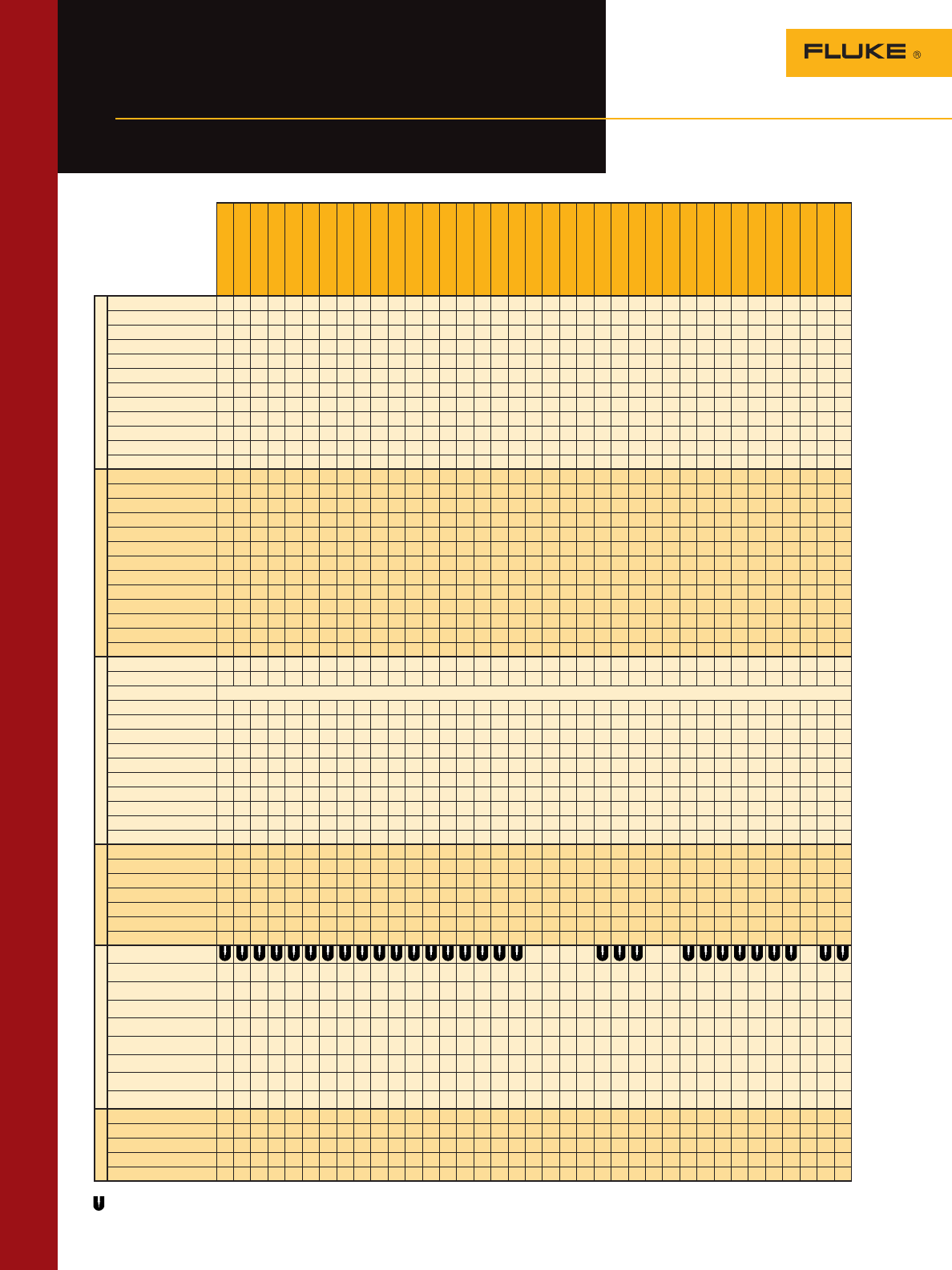
10/11/12/12B
110/111/112
114/115/116/117
21/23/26/75/77/79
27
70/73 III
175/177
179
83/85/87 III/83V
87/89 IV
87V
187/189
45
39/41B
43B
90 Series
120 Series
190 Series
50S/50D
51/52/53/54 II
61/65
63/66/68
321/322
333/334/335/336/337
705/707
712/713
714
715
716/717
718
725/726
741/743
744
787/789
T3/T5
1587
1577
Current
i200 • • 73 3 • •
i200s •••••••••••••••••• • ••
i400 • • 73 ••••••• 3• •
i400s 44444444444444• • • • 3 4 4
80i-600A • • 73 • • • • • • • • • •
i1000s 44444444444444•••• • 4 4
i2000 flex •••••••••••••••••• 3 3 • • •
i3000 flex 4 4 • • • • • 4 4
i3000s •••••••••••••••••• 3 3 • • •
i410 • ••••••••••• 5 5 5 5 3 3 • • •
i1010 • ••••••••••• 5 5 5 5 3 3 • • •
i30/i30s • • • • • • • • •
Temperature
80AK • • • • • •
80BK • • • • • •
All 80PK Probes 1121111212221 1111• • • 1• • • 1 2
80PJ-1/80PJ-9 • • • • • • 2
80PT-25 • • • • • 2
80TK • • • • • • • • • • • • • •
80T-150U •• •••• ••••• •••• • • 2
80PJ-EXT • • • • • • 2
80PK-EXT 1121111212221 1111• • • 1•••1 2
80PT-EXT • • • • • 2
80CK-M 1121111212221 1111• • 1•••1 2
80CJM • • • • • • 2
80PR-60 2
Cases
C50 •••• •••• • ••65 787
C520 •
C550/C1600
C12A • • • •
C23 ••• 61
C25 ••••••••• ••61 • • • • • • • •
C33 • • • •
C43 • • • • • • • • • •
C90 ••• ••• ••65
C125 • • • • • • • • • • • • • •
C789 • • • • • • •
C20 • • • • • • 789
C101 ••••••••••• • •• ••••••• • • ••
Holsters
C10 •* •* • •
C70Y • •
H80M ••• •••• 787
H3 •
H5 • •
H6 •
ToolPak Meter Hanger • • • 83V • • • • • 787 •
Test Leads
Standard Test Lead Input
TL220 •••••••••••• ••••• ••• ••••••• •
TL223 •••••••••••• ••••• ••• ••••••• •
TL225 •••••••••••• ••••• ••• ••••••• •
TL238 •••••••••••• ••••• ••• ••••••• •
TL80A ••••••• •••
TL81A ••••••• •••
TL71 ••••••••••••• ••• ••• ••••••• •
TL76 •••••••••••• ••• ••• ••••••• •
Specialty
FlukeView Forms Software • • • •** 789
PV350 (pressure) ••••••••••••• •••• • • •••
FOM (fiber optic) ••••••••••••• •••• • • •••
CO-210 ••••••••••••• •••• • • •••
80K-6, 80K-15, 80K-40 dc dc dc •••••••••dc •
60 Accessories
Fluke accessory
selection guide
Find the right accessories to
make your meter work for you
For more information and detailed specifications, go to www.fluke.com/accessories
(1) Requires 80TK (2) Requires 80AK (3) Limited low level ac capability – see page 40 (4) Requires PM9081/001 Adapter (5) Requires PM9082/001 adapter
A universal accessory. Works with most brands of meters. For detailed Current Clamp specifications see pages 58 and 59. *included with the 12B and 16 ** 53, 54 only
66/
68
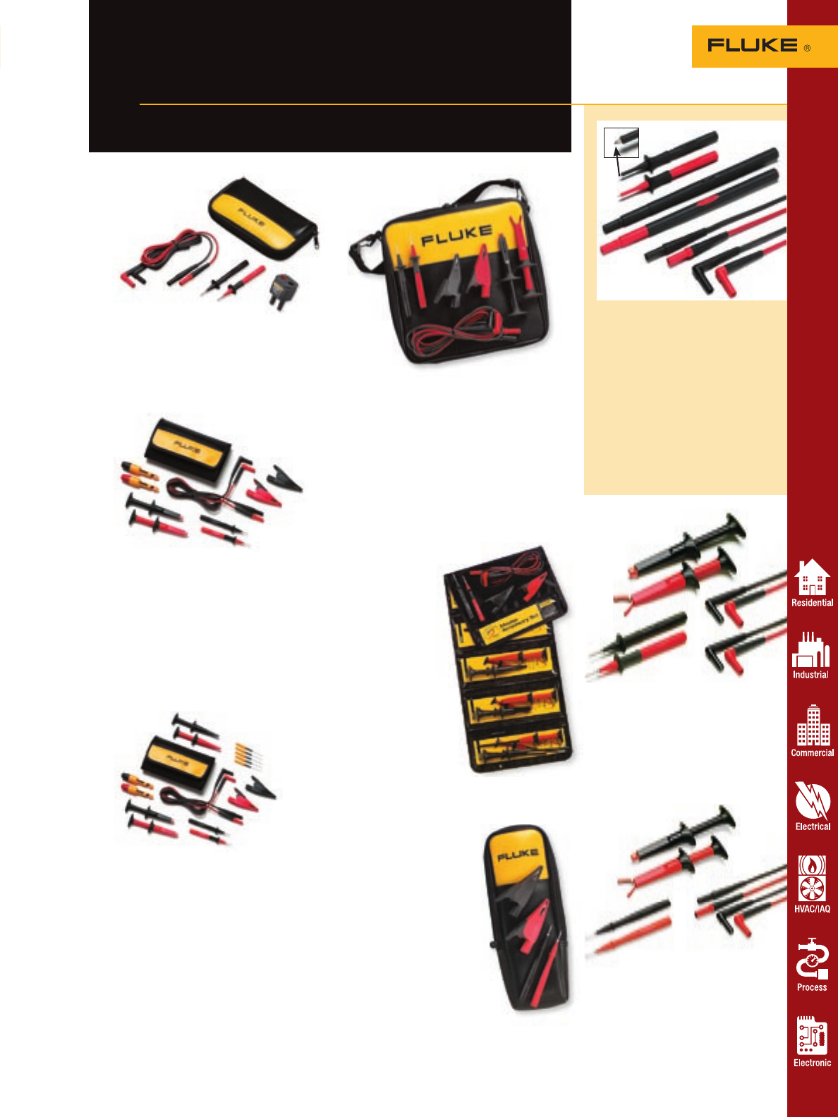
TLK-225 SureGrip™
Master Accessory Kit
• AC220 Plunger Style
Alligator Clips
• AC280
Plunger Style
Hook Clips
• AC283 Plunger
Style Pincer
Clips
• AC285 Large
Jaw Alligator
Clips
• TP220 Sharp
Test Probes
• TL224 Right to
Straight Test Leads
• 6-pocket storage
pouch, keeps the
entire set together
Combines our most popular accessories
into a convenient money saving package
Fluke accessory
sets and kits
61
Accessories
TLK-220 SureGrip™ Accessory
Kit with Meter Carry Case
• AC220 Plunger Style Alligator Clips
• AC285 Large Jaw Alligator Clips
• TP220 Sharp Test Probes
• TL224 Right to Straight Test Leads
• Zippered vinyl carry case with moveable
divider
• Holds large DMMs
New! TL225 SureGrip™ Stray
Voltage Adapter Test Lead Kit
• Stray Voltage Adapter
• TL224 Suregrip Silicone Test Leads
• TP220 Suregrip Test Probes
• C75 Soft Accessory Case
T5 Tester Starter Kit
Getting started kit for
electricians who already
own a Fluke T5 Tester.
• TP220 Test Probes
• AC285 Large Jaw
Alligator Clips
• C33 Zippered Soft
Case
TL238 SureGrip™ Test
Lead Set for high energy
environments
• Insulated tip probes help lessen
risk of arc flash explosion
• Probe extenders keep hands
away from live current
• Includes one pair each, insulated
test tip probes, probe extenders
and TL224 test leads
• Probes and leads CAT III 1000 V,
CAT IV 600 V, 10 A, extenders
CAT III 1000 V 10 A
TL220 Industrial
Test Lead Set
• Starter kit for industrial applications
• TP220 has round, stainless steel tip
• Includes 1 pair: AC220, TP220,
TL222
• CAT III 1000 V, CAT IV 600 V, 10 A
TL223 Electrical
Test Lead Set
• Starter kit for electrical applications
• TP1 has flat blades for wall sockets
• Includes 1 pair: AC220, TP1, TL224
• CAT III 1000 V, CAT IV 600 V, 10 A
TLK282 Deluxe Automotive
Test Lead Kit
• TP81 Insulation Piercing Probes
• Set of five TP40 Automotive Back
Probe Pins
• TL224 Suregrip Silicone Test Leads
• TP220 Suregrip Test Probes
• AC220 Suregrip Plunger
Style Alligator Clips
• AC285 Suregrip Alligator Clips
• C280 Suregrip Hook Clips
• Handy Fluke carrying case
• TP81 and TP40 rated to 60 V dc;
all others rated to CAT III 1000 V,
CAT IV 600 V
TLK281 Automotive Test
Lead Kit
• TP81 Insulation Piercing Probes
• TL224 Suregrip Silicone Test Leads
• TP220 Suregrip Test Probes
• AC220 Suregrip Plunger Style Alligator
Clips
• AC285 Suregrip Alligator Clips
• Handy Fluke carrying case
• TP81 rated to 60 V dc; all others rated
to CAT III 1000 V, CAT IV 600 V
For more information and detailed specifications, go to www.fluke.com/accessories
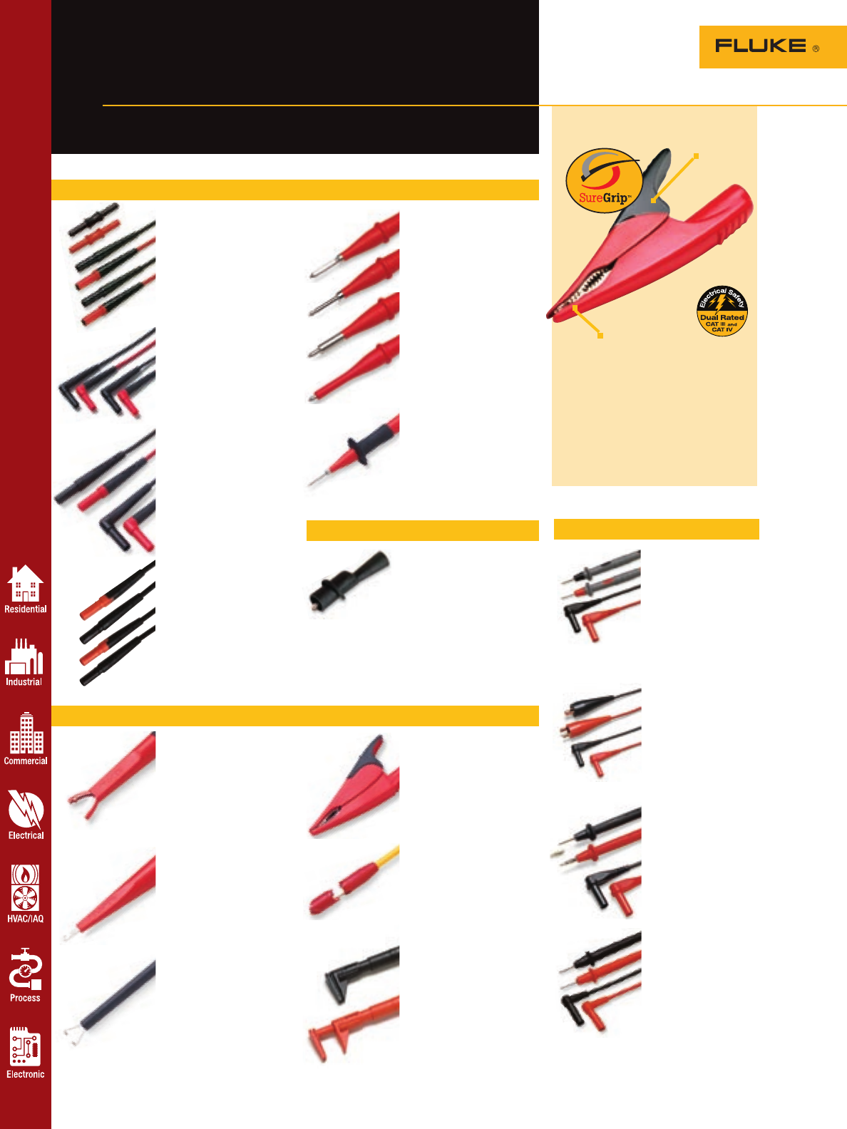
For more information and detailed specifications, go to www.fluke.com/accessories
62 Accessories
A complete set of
probes, leads and clips
Fluke SureGrip™
accessories
Test lead and probe in one
Modular clips (for use with test leads)
Modular test leads and test probes (use test probes with test leads)
TP1, TP2, TP4 and
TP38 Slim Reach™
Test Probes
• Slender probe bodies for
probing closely spaced or
recessed points
• TP1 has a flat blade
• TP2 has 2 mm diameter tip
• TP4 has 4 mm diameter tip
• TP38 has stainless steel
insulated probe to help
lessen the risk of arc flash
explosion
• CAT III 1000 V, 10 A,
CAT IV 600 V, 10 A
TP220 SureGrip™
Industrial Test Probes
• Sharp, 1/2 in. stainless
steel tip provides reliable
contact
• Flexible finger barrier
improves grip
• CAT III 1000 V, 10 A,
CAT IV 600 V, 10 A
TL221 SureGrip™
Silicone Test Lead
Extension Kit
• Superior strain relief
• Includes two adapters to
extend leads 1.5 m
• CAT III 1000 V, 10 A,
CAT IV 600 V, 10 A
TL222 SureGrip™
Silicone Insulated
Test Leads
• Recommended for use
with AC220, AC280,
AC283 test clips
• Superior strain relief
• CAT III 1000 V, 10 A,
CAT IV 600 V, 10 A
TL224 SureGrip™
Silicone Insulated
Test Leads
• 1.5 m silicone-insulated
wire resists heat
and cold
• Superior strain relief
• CAT III 1000 V, 10 A,
CAT IV 600 V, 10 A
TL27 Heavy Duty
Test Leads
• Rugged EPDM insulation
• 1.5 m long with shrouded,
straight connectors and
excellent strain reliefs
on each end
• CAT III 1000 V, 10 A,
CAT IV 600 V, 10 A
AC220 SureGrip™
Alligator Clips
• Insulated, nickel plated
jaws grip objects up to
3/8 in.
• Blunt tip grabs round screw
heads
• CAT III 1000 V,
CAT IV 600 V, 10 A
AC280 SureGrip™
Hook Clips
• Profile narrows to .22 in.
at tip
• Hook opening .20 in. at
front, .08 in. at base
• CAT III 1000 V,
CAT IV 600 V, 3 A
AC283 SureGrip™
Pincer Clips
• 4.5 in. flexible, insulated
shaft
• Nickel plated pincers open
to .20 in.
• CAT III 1000 V,
CAT IV 600 V, 1 A
SureGrip accessories provide a
reliable grip in slippery hands.
Rubber-overmolded surfaces and
finger-hugging curves give the
user a comfortable, steady hold on
the accessory so they can focus on
making an accurate measurement.
New design makes
clips, hooks and
probes more versatile
AC285 SureGrip™
Alligator Clips
• Multi-purpose tooth pattern
grips anything from fine
gauge wire to a 3/4 in. nut
• Nickel-plated steel jaws
• CAT III 1000 V,
CAT IV 600 V, 10 A
AC89 Heavy Duty
Insulation Piercing Clip
• Plunger style, safety grip
operation with insulated
jaws
• Small pin pierces 30 to
14 AWG insulated wire
• CAT III 1000 V, 5 A,
CAT IV 600 V, 5 A
AC87 Heavy Duty
Bus Bar Clip Set
• One pair (red, black) of flat,
right angle design for
connecting to bus bars
• Adjustable collar provides
two ranges of jaw openings
up to 30 mm
• CAT III 1000 V, 5 A rating
AC72 Alligator Clips
• Slide-on style for test
probes
• Jaws open to 8 mm
• For use with TL71 and
TL75 test lead and probe
sets
• CAT III 1000 V, 10 A,
CAT IV 600 V, 10 A
Push-on clips
TL71 Premium
DMM Test Lead Set
• Flexible silicone
insulated leads are
heat and cold resistant
• Distinctive comfort
grip probes
• Recommended for µV
measurements
• CAT III 1000 V, 10 A,
CAT IV 600 V, 10 A
TL28A Automotive
Test Lead Set
• Large, solid copper
alligator clips with
0.5 in. opening
• Flexible silicone
insulated lead are
heat and cold resistant
• CAT I 30 V, 10 A
TL76 2 mm/4 mm
Test Lead Set
• 2 mm threaded probes
with removable 4 mm
banana-style spring
contacts
• Flexible 1.5 m
silicone leads
• CAT III 1000 V,
CAT IV 600 V, 10 A
TL75 Hard Point
Test Lead Set
• Extremely hard alloy
tips resist wear
• Distinctive comfort
grip probes
• CAT III 1000 V, 10 A,
CAT IV 600 V, 10 A
• 1.5 m PVC leads
Superior gripping
surface made from
thermoplastic rubber
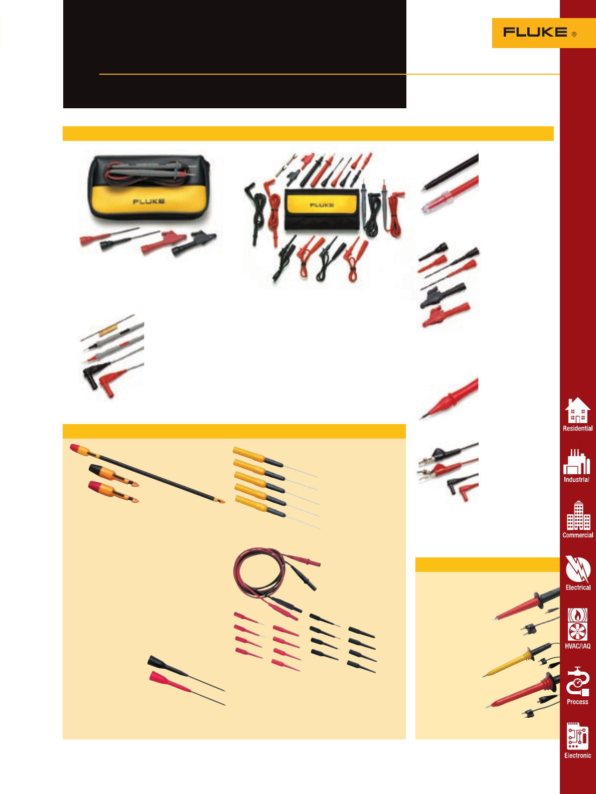
80K-6, 80K-15, 80K-40
High Voltage Probes
• Allows a digital multimeter
to measure up to
6,000 volts peak,
15,000 volts peak
and 40,000 volts peak
respectively
• 1000:1 division ratio output
when connected to
10 MW multimeter
• Ground clip
included
• Intended for low
energy applica-
tions that are
referenced to ground
• 80K-15 (not available
in Europe)
High-voltage probes
TP80 Electronic
Test Probes
• Tapered tip ideal for
probing electronic
components or
boards
• Removable guard for
IC probing
• CAT III 1000 V, 10 A
TP920 Test Probe
Adapter Kit
• IC test tip adapters,
extended tips,
medium alligator
clips fit over
TL71 and TL75
test lead sets
• IC test tip
Adapter, 3 A
• Extended probe tip,
3 A
• Med. alligator
clip, 5 A
• CAT II 300 V
TL40 Retractable
Probe Assembly
• Retractable,
insulated sharp
probe tip
• CAT II 300 V, 2 A
TL26A Telecom
Test Lead Set
• 5-way multipoint
test clips for
telecommunications
applications
• Flexible silicone
insulated leads are
heat and cold
resistant
• CAT I 30 V, 8 A
Accessories 63
Fluke test leads,
probes and clips
Test leads for all your
measurement needs
For electronic applications
TL81A Deluxe Electronic Test Lead Set
• 22 piece set with quadfold pouch
• Includes mini alligator clips, hooks and pincers
for virtually every electronic need
• Slide-on lC probe tip adapter and test lead
couplers
• Both modular test leads and lead-probe
combinations
• CAT II 300 V
TL80A Basic Electronic Test Lead Set
• 6 piece set with zippered case
• Probes, alligator clips and tip extenders for
electronic applications
• CAT II 300 V
TL910 Electronic
Test Probes with
Replacement Tips
• Small profile provides
accessibility
• Comes with 5 sets of
replaceable tips
•
Replacement tips:
TP912
• CAT III 1000 V, 3 A
New! TL82 Automotive
Pin & Socket Adapter Set
• Collection of male and female adapters allows you to
make firm connection to pin and socket connectors
• Adapters with flexible tips come in the following
sizes: 22, 20, 16 and 12
• Rated to 60 V dc
New! TP40
Automotive Back
Probe Pin Set
• Set of five 1.5 inch
pins Rated to 60 V dc
• Provide an easy
connection past
weather pack seals to
connector conductors
• Use with Fluke TL71
or TL75 test lead sets
New! TP81, TP82 and TP84
New piercing probes for Automotive
applications. Control the depth as you
pierce insulation.
• Stainless steel probe pierces insulation
on 14, 16 and 18 gauge wire
• Design provides complete insulation while
working on fuel injectors or sensors
• TP81 for use with modular test leads
(Fluke TL224)
• TP82 slips over probe tips (Fluke TL71)
• TP84 is 12 inches long to reach farther
into engine compartments.
• Rated to 60 V dc
New! TP88 Rigid Backprobe
Pin Set
• 2 inch long pins
pass between
the weather pack
seal and wire
• Use with Fluke TL71 or
TL75 test lead sets
• Rated to 60 V dc
For automotive applications
For more information and detailed specifications, go to www.fluke.com/accessories

Accessories
64
Fluke illuminates
the task at hand
Get all the light you need and
keep your hands free
L200 Probe Light
• Small, rugged light easily attaches to
any Fluke test probe
• Bright white LED never burns out
• 120-hours of battery life
• Two 3 V watch batteries included
L205 Mini Hat Light
Rugged, high-intensity Xenon worklight
• Attaches to a baseball cap
• Includes a hat clip
• Includes two AAA batteries
• Waterproof
L206 Deluxe LED
Hat Light (hard hat not included)
Attach it to a hard hat, a baseball cap,
or even a panel door for all the light
you need
• Three super bright white LEDs—never
burn out
• Special hard-hat attachment included
• 40-hour battery life
• Includes three AAA batteries
L207 High-Intensity Light with
Limited Edition Fluke Cap
• Includes L205 Mini Xenon worklight
• Black baseball-style cap with
Fluke logo
• Light is waterproof
• Includes two AAA batteries
LVD1 Volt Light
Non-contact ac voltage detector and LED
flashlight combined in one convenient,
compact design. Exclusive dual-sensitivity.
• Detects voltages from 40 V ac to
300 V ac
• Voltage detector glows blue at
50 Hz to 60 Hz or 2.5 cm to 38 cm
(1 in to 5 in) away from source
• Ultra-bright white LED with
100,000 hour bulb life
• AAA battery included
L211 Probe Light Kit
• L200 probe light
• TL71 premium DMM test lead set
• C75 zippered case
L215 SureGrip™ Kit with Probe
Light and Probe Extenders
• L200 probe light
• TP220 SureGrip test probes
• TL224 SureGrip test leads
• TP280 test probe extenders
• Soft foldable pouch, keeps the entire
set together
Shed light on the point of contact
L210 Probe Light and
Probe Extenders
• 8 in. probe extenders fit modular
test probes
• Probe and extender length complies
with NFPA recommendations
• Bright white LED illuminates
contact area
• Probe light fits on extender or
test probe
For more information and detailed specifications, go to www.fluke.com/accessories
For more information and detailed specifications, go to www.fluke.com/accessories
Accessories
Fluke specialty
accessories and software
Extend the utility of your multimeter
Fiber optics
PV350 Pressure Vacuum Module
• Digital pressure and vacuum measure-
ments in a single module
• Measures HVAC/R, hydraulic and
pneumatic pressures to 350 psig/
2413 kPa (usable to 500 psig)
• Measures to 76 cm Hg (29.9 in Hg)
vacuum (not intended for measuring
microns of vacuum)
• Compatible with most popular digital
multimeters
FOM Fiber Optic Meter
The Fluke Fiber Optic Meter (FOM)
helps you test and maintain fiber optic
cable without having to buy a whole
new meter. Plug the FOM directly into
any DMM with a mV dc funtion and a
10 mW input impedance, and quickly
and accurately verify fiber optic cable
system loss. Light sources and patch
cords sold separately.
Logging software
FlukeView® Forms
Harness the power of the data logging
function on your Fluke Digital Multimeter,
Thermometer or ProcessMeter. Log live
readings while connected to a PC, or leave
your Fluke 189, 789 or 54-II in place to
capture up to 1,000 readings for download
to a PC. FlukeView® Forms easy-to-use
wizards allow you to download read-
ings from your Fluke tool and store and
display individual readings or a series
of measurements. Spot trends and docu-
ment interruptions or spikes. Use standard
forms or the FlukeView® Designer feature
to customize reports using your specific
data or company logo. Free demo-reader
download allows co-workers or clients to
open your report and interact with cap-
tured data.
Choose the model that’s right for you:
• FVF-SC1: Includes software and cable
used with 53-II and 54-II Thermometers
and 87IV and 89IV DMMs
• FVF-SC2: Includes software and cable
used with 180 Series DMMs and 789
ProcessMeters
• FVF-SC3: Includes software and cable
used with 45 Bench Meters
Go to www.fluke.com/flukeviewforms to
download the demo.
New! FlukeView® Forms Basic
An abridged version of FlukeView Forms.
Analyze and share data with the provided
standard forms. Available for use with 180
Series DMMs and 789 ProcessMeters, only.
Upgrade to the full FlukeView Forms with
FVF-UG.
Make extended logging easier
New! BP189 High Capacity
Battery Pack for Fluke 180
Series Multimeters
• Expands battery life up to 450 hours
• Accepts four C batteries
• Allows you to use your Fluke 189 to
continually log data for up to two weeks
FOS 850 and FOS 850/1300
Fiber Optic Light Sources
A variety of LED light sources allow you
to test different cables.
H900 Test Lead Holder
• Heavy duty construction with
mounting holes
• Holder has 10 slots for wires up to
8 mm in diameter
• Over-all dimensions: 27.9 cm L x
8.9 cm W x 3.2 cm H
• One-year warranty
Pressure and vacuum
New! SV225/10PAK
• Pack of 10 stray voltage adapters
• Adapter makes sure meter has low input
impedence that eliminates stray voltage
Stray voltage
65
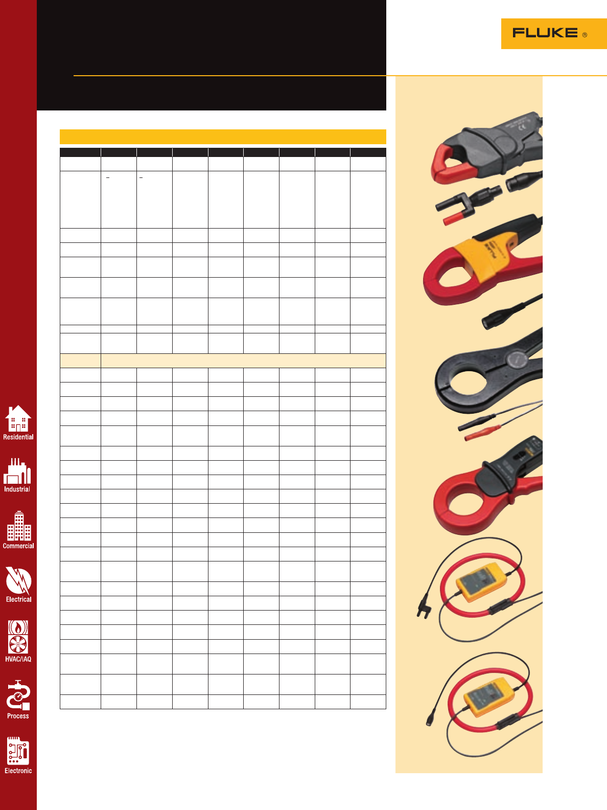
Accessories
66
Fluke current clamps
For use with DMMs, scopeMeters
and power quality analyzers
AC current clamp specifications
AC only models
i200s
i400s
80i-600A
i1000s
i2000 flex
1 Current and watt readings will be multiples of 10 higher or lower than actual.
* Requires PM9081/001 or BP880 Adapters
i200 i200s i400 i400s 80i-600A i1000s i2000 flex i3000s flex
AC current
range
1 A to 200 A 1 A to 200 A 1 A to 400 A 0.5 A to
400 A
1 A to 600 A 0.2 A to
1000 A
2 A to 2000 A
ac rms
1 A to 3000 A
Accuracy < 3 % +0.5
A48 to 65 Hz
< 1 % +0.5 A
48 Hz to
65 Hz
2 % + 0.06 A
45 Hz to
400 Hz
.5 A to 40 A,
2 % +
.015 A, 5 A to
400 A, 2 % +
.04 A, 45 to
400 Hz
2 % 50 Hz to
1 kHz 10 A to
100 A:
2 %+0.5 A
100 A to
1000 A:
1 %+1 A
48 to 65 Hz
0.2 to 10 A:
3 %+0.1 A
10 A to
100 A:
2 %+0.5 A
100 A to
1000 A:
1 %+1 A
48 to 65 Hz
± 1 % of
range
45 to 65 Hz
Ranges: 20
A, 200 A,
2000 A*
1 to 30 A:
2 % + 0.1 A
1 to 300 A:
2 % + 0.5 A
1 to 3000 A:
2 % + 2 A
48 to 65 Hz
Bandwidth
(-3 dB)
40 Hz to
40 kHz
40 Hz to
40 kHz
5 kHz to
20 kHz
5 Hz to
10 kHz
10 Hz to
50 kHz
5 Hz to
100 kHz
10 Hz to
20 kHz
10 Hz to
100 kHz
Maximum con-
ductor diameter
20 mm
(0.8 in)
20 mm
(0.8 in)
32 mm
(1.25 in)
32 mm
(1.25 in)
50 mm
(1.98 in)
54 mm
(2.13 in)
177 mm
(7 in)
64 x 100 mm
(2.52 x 3.94 in)
Maximum
conductor size
300 MCM 300 MCM 750 MCM 750 MCM 2-500 MCM
or 1-1000
MCM
2-500 MCM
or 1-1000
MCM
60 mm (24
in) circumfer-
ence
610 mm or
915 mm
Output levels 1 mA/A 10 mV/A
100 mV/A
1 mA/A 10 mV/A
1 mV/A
1 mA/A
10 mV/A
1 mV/A
10 mV/A
100 mV/A
100 mV/A
10 mV/A
1 mV/A
10 mV/A
1 mV/A
0.1 mV/A
Output cable 1.5 m
shrouded
banana plugs
2 m to BNC
termination
1.5 m
shrouded
banana plugs
2.5 m to BNC
termination
1.2 m
shrouded
banana plugs
1.6 m to BNC
termination
2 m with
double
shrouded
banana plugs
2.1 m to BNC
termination
Warranty One-year One-year One-year One-year One-year One-year One-year One-year
Safety rating CAT III 600 V CAT III 600 V CAT III
1000 V
CAT IV 600 V
CAT III
1000 V
CAT IV 600 V
CAT III 600 V CAT III 600 V CAT III 600 V CAT III 600 V
Meter
compatability AC range
10/11/12/
12B/16/18
1 A to 200 A 1 A to 400 A 0.1 A to
1000 A*
4 A to
2000 A
1 A to
3000 A
110/111/112 3 A to 200 A 30 A to 400 A 3 A to 1000 A* 30 A to
2000 A
30 A to
3000 A
114/115/116/
117
60 A to 200 A
(115, 117 only)
1 A to
200 A ac
60 A to 400 A
(115, 117 only)
0.6 A to 400
A ac*
60 A to 600A 0.2 A to 1000
A ac*
4 A to
2000 A ac
1 A to
3000 A ac
21/23/73/75/77
Series III
1 A to 200 A 1 A to 200 A 1 A to 400 A 1 A to 400 A 1 A to 600 A 0.1 A to
1000 A*
4 A to
2000 A
1 A to
3000 A
26/79 Series III 1 A to 40 A 1 A to 200 A 1 A to 40 A
and 200 A to
400 A
1 A to 400 A 1 A to 40 A
and 200 A to
600 A
0.2 A to
1000 A*
4 A to
2000 A
2 A to
3000 A
27 1 A to 200 A 1 A to 200 A 1 A to 400 A 1 A to 400 A 1A to 600 A 0.1 A to
1000 A*
4 A to
2000 A
1 A to
3000 A
70 Series III 1 A to 200 A 1 A to 400 A 0.1 A to
1000 s*
4 A to
2000 A
1 A to
3000 A
175/177/179 3 A to 200 A 1 A to 200 A 3 A to 400 A 3 A to 400 A* 3 A to 600 A 0.3 A to
1000 A*
4 A to
2000 A
3 A to
3000 A
1577/1587
Insulation Meter
3 A to 200 A 1 A to 200 A 3 A to 400 A 3 A to 400 A* 3 A to 600 A 0.3 A to
1000 A*
4 A to
2000 A
3 A to
3000 A
83-III, 83-V,
88V
1 A to 200 A 1 A to 200 A 1 A to 400 A 1 A to 400 A 1 A to 600 A 0.1 A to
1000 A*
4 A to
2000 A
1 A to
3000 A
85/87 Series III
87 Series V
1 A to 200 A 1 A to 200 A 1 A to 400 A 1 A to 400 A 1 A to 600 A 0.2 A to
1000 A*
4 A to
2000 A
2 A to
3000 A
87/89 Series IV
187/189
1 A to 200 A 1 A to 200 A 1 A to 400 A 1 A to 400 A 1 A to 600 A 0.1 A to
1000 A*
4 A to
2000 A
1 A to
3000 A
8060A/8062A
DMMs
1 A to 200 A 1 A to 200 A 1 A to 400 A 1 A to 400 A 1 A to 600 A 0.2 A to
1000 A*
4 A to
2000 A
2 A to
3000 A
860 Series
Graphical
Multimeter
1 A to 200 A 1 A to 200 A 1 A to 400 A 1 A to 400 A 1 A to 600 A 0.3 A to
1000 A*
4 A to
2000 A
3 A to
3000 A
43B Power
Meter
1 A to 200 A10.35 A to
400 A
0.1 A to
1000 A1
4 A to
2000 A1
1 A to
3000 A1
433/434 Power
Quality
1 A to 200 A 1 A to 400 A 0.3 A to
1000 A
5 A to
2000 A
1.2 A to
3000 A
9X ScopeMeter 1 A to 200 A 1 A to 400 A 0.1 A to
1000 A
4 A to
2000 A
1 A to
3000 A
123/124
ScopeMeter
1 A to 200 A 1 A to 400 A 0.25 A to
1000 A
4.5 A to
2000 A
2.5 A to
3000 A
190 Series
ScopeMeter
1 A to 200 A 1 A to 400 A 0.1 A to
1000 A
4 A to
2000 A
1 A to
3000 A
45 DMM 1.5 A to
100 A
1 A to 200 A 1.5 A to
100 A
1 A to 400 A 1.5 A to 100
A and 500 A
to 600 A
0.15 A to
1000 A*
4 A to
2000 A
1.5 A to
3000 A
74X Series
Process
Calibrators
1.1 A to
200 A
1.1 A to
400 A
1.1 A to
1000 A*
11 A to
2000 A
11 A to
3000 A
787/789
ProcessMeter
50 A to 200 A 1 A to 200 A 50 A to 400 A 1 A to 400 A 50 A to 440 A 0.2 A to
1000 A*
4 A to
2000 A
2 A to
3000 A
For more information and detailed specifications, go to www.fluke.com/accessories
i3000s flex
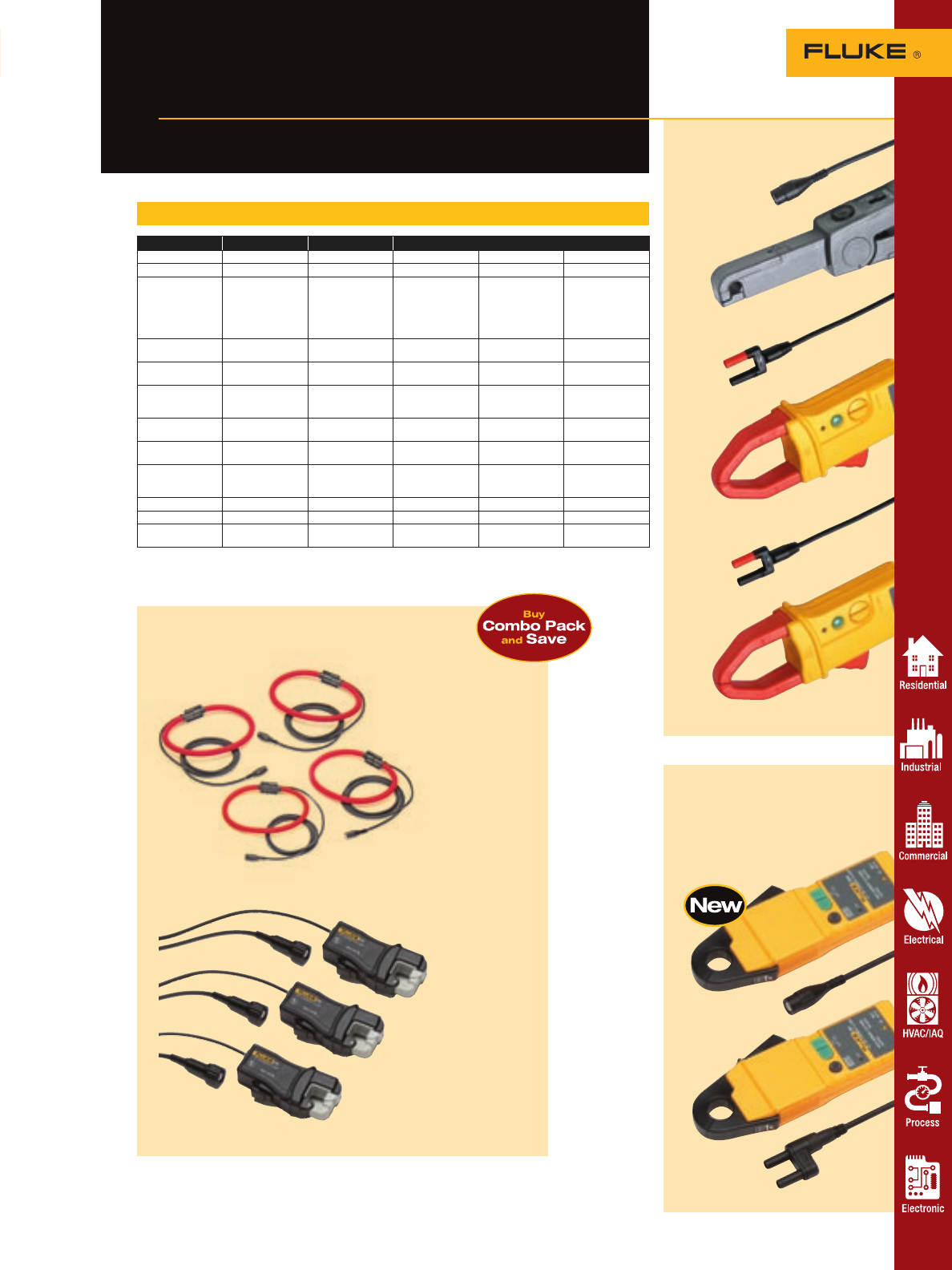
i30s and i30 Hall Effect
AC/DC Current Clamps
• Use with multimeters or
recorders for non-intrusive
current measurements
For more information and detailed specifications, go to www.fluke.com/accessories
Fluke current clamps
For use with DMMs, ScopeMeters
and Power Quality Analyzers
67
Accessories
AC/DC current clamp specifications
80i-110s i410 i1010 i30 i30s
DC range 0.1 A to 100 A 1 to 400 A 1 to 1000 A 4 mA to 20 A 4 mA to 20 A
AC range 0.1 A to 70 A 1 A to 400 A 1 A to 600 A 4 mA to 20 A rms 4 mA to 20 A rms
Accuracy 0.1 A to 10 A; dc
to 1 kHz: ± 3 % +
50 mA; up to
100 A add 15 %;
up to
20 kHz add 12 %
3.5 % + 0.5 A for
dc or ac
(45 to 400 Hz)
2 % + 0.5 A for
dc or ac
(45 to 400 Hz)
± 1 % ± 2 mA ± 1 % ± 2 mA
Bandwidth (-3 dB) 100 kHZ 3 kHz 10 kHz dc to 20 kHz
(-0.5 dB) dc to 100 kHz
(-0.5 dB)
Zero error
adjustment Yes Yes Yes Yes Yes
Maximum
conductor
diameter
11.8 mm (0.46 in) 30 mm (1.18 in) 30 mm (1.18 in) 19 mm (0.75 in) 19 mm (0.75 in)
Maximum
conductor size 1 AWG 750 MCM or 2-
500 MCM 750 MCM or 2-
500 MCM 250 MCM 250 MCM
Output levels 10 mV/A, 100
mV/A 1 mV/A 1 mV/A 100 mV/A 100 mV/A
Output cable 1.6 meter with
BNC
termination
1.2 meter with
shrouded banana
plugs
1.2 meter with
shrouded banana
plugs
1.5 meter with
shrouded dual
banana plue
2 meter with BNC
termination
Battery life 40 hours 60 hours 60 hours 30 hours 30 hours
Warranty One-year One-year One-year One-year One-year
Safety CAT II 600 V; CAT
III 300 V CAT III 600 V CAT III 600 V CAT III 300 V CAT III 300 V
* Requires PM9081/001 Adapter
** Requires PM9082/001 Adapter
AC/DC models
i410
i1010
80i-110s
Power quality ac combo packs
for 4-phase current measurements
i5sPQ3
i30s
i30
i430flex 4-pack
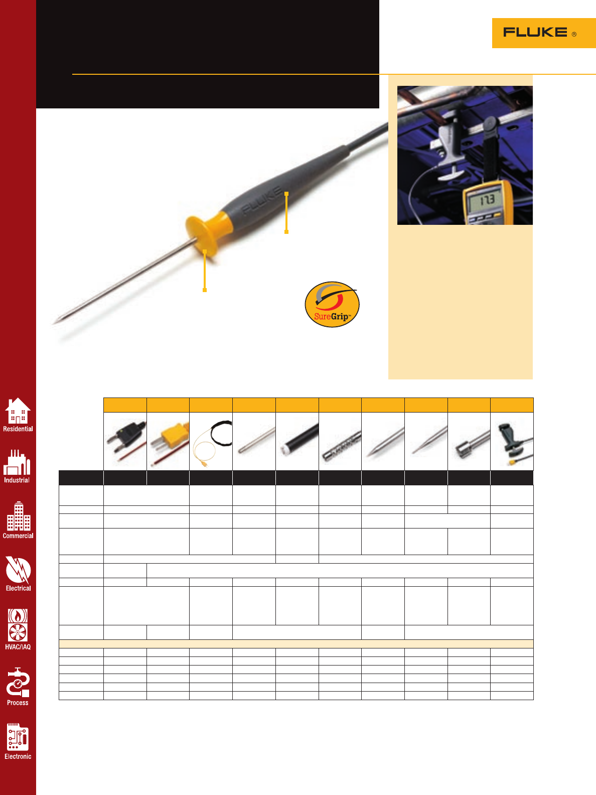
For more information and detailed specifications, go to www.fluke.com/accessories
Accessories
68
Fluke temperature
accessories
Hot probes with cool designs
Use an 80AK adapter with meters with temperature function such as the 16, 78, 83V, 87V, 88V, 179, 187 and 189
The 80TK enables your meter to read temperature using mV (see the Accessory selection guide on page 60 for meters)
For the Fluke Thermometer, 51, 52, 53, and 54 III, no adaper is necessary for thermocouple types K, J, T and E
Cleans up with
soap and water
Soft rubber
handle provides
a secure grip
SureGrip™ temperature
accessories
The innovative SureGrip™ design
from Fluke is now available in select
temperature probes. The soft rubber
handle combined with a new ergo-
nomic shape is so comfortable
to hold that you’ll forget about
the probe and focus on the
measurement. All SureGrip
probes have an improved,
more flexible strain relief
for a long life. The right tool for the job
Make better temperature measurements
with a probe designed for your application.
The 80PK-8 pipe clamp probe (shown) is
specifically designed for measuring pipe
temperatures, calculating superheat and
sub-cooling for refrigeration troubleshoot-
ing. Other special purpose probes shown
are designed for making quick surface,
fluid and air temperature measurements.
The piercing probe makes it possible to
make temperature measurements below
the surface of a soft object. To enable your
Fluke DMM or 50 Series II thermometer
to make its’ best possible measurements,
chose the correct probe from the selection
guide below.
Bead Bead HVAC Immersion Surface Air Piercing General
purpose
Industrial
surface Pipe clamp
80BK 80PK-1
80PJ-1 80PK-11 80PK-22 80PK-3A 80PK-24 80PK-25
80PT-25 80PK-26 80PK-27 80PK-8
Lowest temp -40 °C (-40 °F) -30 °C (-22 °F) -40 °C (-40 °F) 0 °C (32 °F) -40 °C (-40 °F) K Type: -40 °C
(-40 °F) T Type:
-196 °C (-321 °F) -40 °C (-40 °F) -127 °C (-196 °F) -29 °C (-20 °F)
Highest temp 260 °C (500 °F) 105 °C (221 °F) 1090 °C (1994 °F) 260 °C (500 °F) 816 °C (1500 °F) 350 °C (662 °F) 816 °C (1500 °F) 600 °C (1112 °F) 149 °C (300 °F)
Probe material K type wire with
teflon insulation Velcro Inconel 600 K type sensor
with teflon body Inconel 316 Stainless
Steel 304 Stainless Steel K type sensor
with pvc body
Probe length 1 m Lead Wire 19 m Velcro cuff 21.27 cm
(8.375 in) 9.525 cm
(3.75 in) 21.59 cm
(8.5 in) 10.16 cm
(4 in) 21.57 cm
(8.5 in) 20.32 cm
(8 in)
for pipes from
6.4 mm (.25 in)
to 34.9 mm
(1.375 in)
Cable length 1 m (39 in) 1.3 m (4 ft) 1 m (39 in)
Connection Standard
Banana Jack Molded Thermocouple Plug
SureGrip handle No No No Yes No Yes Yes Yes Yes No
Key feature Ideal for initial troubleshooting.
Can be secured in place with a
magnet.
Velcro probe
allows
hands free
temperature
measurement.
For use in
liquids or in
gels.
Exposed junc-
tion for direct
contact with
flat or slightly
convex surfaces.
Perforated baffle
for air and
non-caustic gas
measurements
Probe material
safe for use in
foods. Sharp tip
pierces solid
surfaces..
Use for general
purpose air or
surface mea-
surements
Low conductiv-
ity stainless
steel minimizes
thermal shunt-
ing. Extra
rugged.
Clamps securely
to pipe.
Measurements
are repeat-
able to 0.56 °C
(1 °F).
Thermocouple
types K K, J K K K, T K
Typical use
General purpose ••••••••••
HVAC ••••• •••
Food service • •
Industrial ••• ••
Residential • • • • • •
Commercial ••••••••••
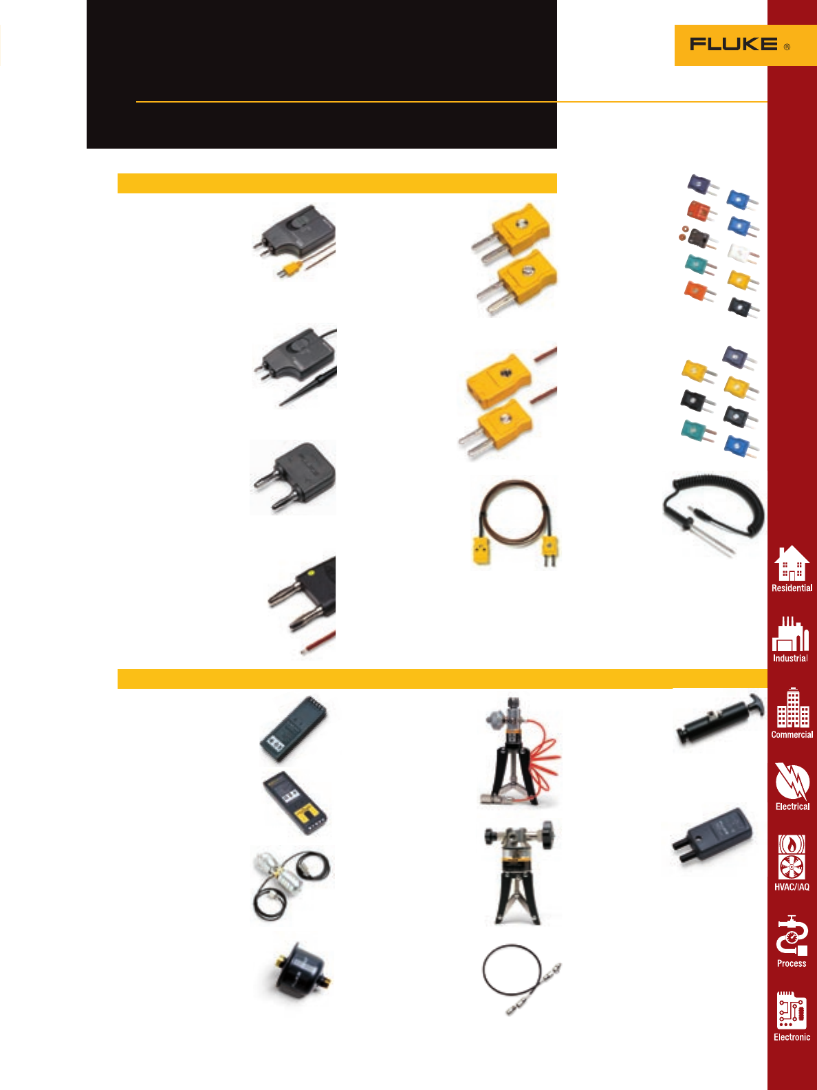
80TK Thermocouple Module
• Converts K-Type thermocouple
signals into mV output
• Connects to DMM via
standard banana plugs
• Switch selectable °C or °F
• Range: -50 °C to 1000 °C
(-58 °F to 1832 °F)
• Includes 80PK-1 probe
80T-150U Universal Solid State
Temperature Probe
• For measurement of air, surface
and non-corrosive materials
• Measurement range:
-50 °C to 150 °C
(-58 °F to 302 °F)
• Output: 1 mV/°C or 1 mV/°F
(switch selectable)
• Connects to DMM via standard banana plugs
80AK DMM Adapter
• Adapts K-type thermocouple
mini-connector to dual banana
plug inputs
• Compatible with all Fluke
DMMs with temperature
measurement functions
• Measurement range and accuracy
is not affected by the 80AK adapter
80BK Integrated DMM
Temperature Probe
• Compatible with all Fluke DMMs
with temperature measurement
functions
• K-Type thermocouple with
standard banana jack
• Convenient one-piece construction
• Measurement range: -40 °C to 260 °C
(-40 °F to 500 °F)
For more information and detailed specifications, go to www.fluke.com/accessories
Accessories
Fluke Temperature
accessories
Turn your digital multimeter
into a thermometer
80CK-M and 80CJ-M
Type K and J Male
Mini-Connectors
• Isothermal screw terminal
for K or J wire
• Suitable for up to 20
gauge thermocouple wire
• Color coded to industry
standards (K-yellow,
J-black)
• Two per package
80PJ-EXT, 80PK-
EXT, 80PT-EXT
Thermocouple Wire
Extension Kits
For extending and
repairing J, K or T-type
thermocouple wires.
• Kit includes 3 m (approx.
9 ft.) of thermocouple
wire and 1 pair of
male/female
mini-connectors
• Maximum continuous
exposure temperature:
260 °C (500 °F)
• 80PK-EXT is compatible
with K-type thermometers;
80PJ-EXT is designed for
J-Type thermometers, and
80PT-EXT is designed for
T-type thermometers
BP7217
• NiCd rechargeable battery;
nominal 7.2 volt, 1700 mA hr
• Use in 867B meters or 700
and 740 Series Calibrators
BP7235
• NiMH rechargeable battery;
nominal 7.2 Volt, 3500 mA hr
• Use in 700 and 740 Series
Calibrators
700LTP Low Pressure
Test Pump
The Fluke 700LTP is designed
to generate either vacuum to
-12 psi/-.85 bar or pressures to
30 psi/2000 mbar. The Fluke
700 LTP is primarily intended
for low pressure applications.
700ILF In-line Filter
The Fluke 700ILF can be used
to isolate the calibrator from
incidental contact with fluids.
Particularly useful with the 718
calibrator to help keep moisture
or oils from contaminating the
on-board pump.
Other temperature accessories Thermocouple
Plug Kits
700TC1
A kit of 10 mini-plug
connectors. One each
of the following:
Type J (black)
Type K (yellow)
Type T (blue)
Type E (purple)
Type R/S (green)
Type B or Cu (white)
Type L (J-DIN) (blue)
Type U (T-DIN) (brown)
Type C (red)
Type N (orange)
700TC2
A kit of 7 mini-plug
connectors.
Type J (black), two
Type K (yellow), two
Type E (purple), one
Type T (blue), one
Type R/S (green), one
Process tools accessories
700PTP Pneumatic
Test Pump
The 700PTP is a handheld
pressure pump designed to
generate either vacuum to
-11.6 psi/-0.8 bar or pressure
to 600 psi/25 bar.
700HTP Hydraulic
Test Pump
The 700HTP is designed to
generate pressures up to
10,000 psi/700 bar. Use the
Fluke-700PRV adjustable
relief valves to limit pressures
to 1360 psi and 5450 psi.
700HTH Hydraulic
Test Hose
The 700HTH is a 10,000
psi, 700 bar test hose that
connects to a calibration
unit under test from a Fluke
700HTP hydraulic test pump.
700PMP Pressure
Pump
The 700PMP is a hand-
operated pressure pump
to provide pressures up to
150 psi/1000 kPa. Output
fitting is 1/8 FNPT.
Fluke 700-IV Current
Shunt
Conversion factor:
10 mV = 1 mA
Accuracy (% of input,
1 year): 0.025 %
Input current:
0 to 55 mA
Input resistance:
250 W nominal
Output resistance:
10 W nominal
Accuracy specification
applies from +18 °C and
28 °C to 50 °C
Maximum input voltage:
30 V dc
New!
80PR-60 RTD
Temperature
Probe
• Resistance
temperature
detector probe
designed to
add contact measurements to your
Fluke 66 and 68 Non-Contact Infrared
Thermometers
• Measurement range: -40 °C to 260 °C
(-40 °F to 500 °F)
• 3.5 mm phono type jack is only
appropriate for Fluke 66 and 68
Thermometers
69
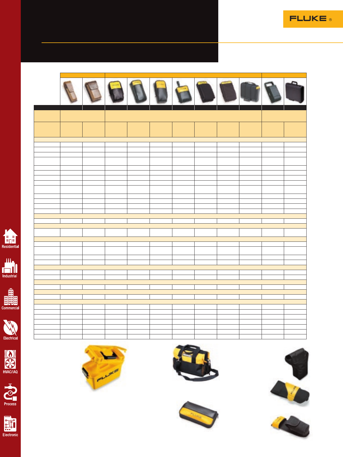
For more information and detailed specifications, go to www.fluke.com/accessories
Accessories
70
Fluke cases and holsters
A premium meter deserves a
premium case
C1600 Meter and
Accessories Gear Box
This rugged, molded
plastic case will
carry Fluke digital
multimeters, process
calibrators and most
Fluke accessories used
for these meters.
• Deep interior large enough
to hold and protect your gear
• Rubber gasket in lid seals out
dust and keeps contents dry
• Lift out tray keeps everything
organized
H6 Infrared Thermometer Holster
• Durable nylon construction
protects your thermometer
while keeping it within reach
• For Fluke 63, 66 and 68 Infrared
Thermometers
H5 Electrical Tester Holster
• Rugged fabric holster
includes flap for lead
storage and built-in
belt loop
• Fits Fluke T3 and T5 testers
H3 Clamp Meter Holster
• Rugged fabric holster includes
flap for lead storage and
built-in belt loop
• For Fluke 320 and
330 Series Clamp Meters
C550 Tool Bag
• Steel reinforced
frame
• Rugged ballistic
cloth with heavy
duty hardware
• Large zippered
storage compartment
with 25 pockets
• Weather resistant
• Carry all your tools to the job
C75 Accessory Case
• Zippered carrying case with
two inside pockets
• Carry test lead sets or probes
Premium cases Soft cases Hard cases
C520A C510 C25 C50 C90 C12A C125 C43 C789 C20 C101
Genuine top grade leather
cowhide. Zippered carrying cases protect your meter; most cases come with
belt loops so your meter is stored conveniently on your tool belt.
Tough polyprophylene cases
hold and protect meters and
accessories.
Dimensions 22.5 cm x 7.0
cm x 4.8 cm
(10 in x 3.125
in x 2.125 in)
20.3 cm x 11.3
cm x 5.1 cm
(9 in x 5 in x
2.25 in)
19.2 cm x 11
cm x 5.6 cm
(8.5 in x 4.9 in
x 2.5 in)
16.9 cm x 8.5
cm x 3.4 cm
(7.5 in x 3.75
in x 1.5 in)
19.2 cm x 7.9
cm x 5.6 cm
(8 in x 3.5 in
x 2.5 in)
15.1 cm x 11.3
cm x 3.4 cm
(6.7 in x 5 in
x 1.5 in)
23.7 cm x 13.5
cm x 5.6 cm
(10.5 in x 6 in
x 2.5 in)
30.4 cm x 19.7
cm x 6.7 cm
(13.5 in x 8.75
in x 3 in)
27.0 cm x 22.5
cm x 6.7 cm
(12 in x 10 in
x 3 in)
22.5 cm x 13.5
cm x 9.0 cm
(10 in x 6 in x
4 in)
30.5 cm x 36
cm x 10.5 cm
(12 in x 14.2 in
x 4.1 in)
DMMs
10/11/12/12B • • •
110/111/112 • • • • • •
16 • • • • • •
21/23/26/
75/77/79 • • • • •
27 • • •
70/73 III • • • • •
175/177 • • • • •
179 • • • • •
83/85/87
Series III • • • • •
87/89 IV • • • • •
83/87 Series V • • • • •
187/189 • • • • •
867B •
Clamp meters
321/322 •
Insulation testers
1503/1507
1577/1587 • •
Thermometers
50S/50D • • • • •
51/52/53/54
Series II • • • • •
61 •
65 • • •
Electrical testers
T3/T5 •
7-600/7-300 • • •
ScopeMeters
123/124 • • • •
Power quality
39/41B • •
Process tools
705/707 •
712/713 • •
714/715/716/717 • •
725 • • • •
741/743/744 • •
787 • • • • •
789 • • • • • •
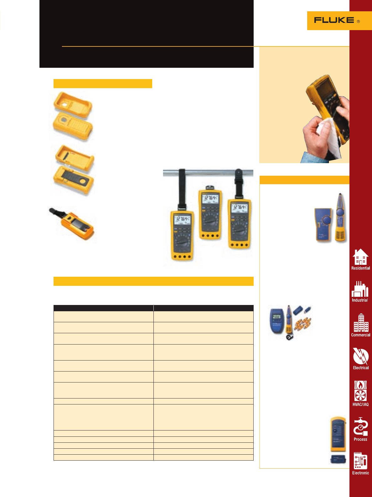
Verification tools
For more information and detailed specifications, go to www.fluke.com/accessories
Accessories 71
Take care of your test tools—
inside and out
Fluke holsters and fuses
New! MeterCleaner Wipes
• Industrial strength cleaning
formula removes surface dirt,
oil and grease
• Safe on rubber
• Safe to the
environment
• Comes in
two sizes:
6-pack (MC6)
and 50-pack
(MC50)
Protective meter holsters
C10 Meter Holster
• Snap on yellow holster
absorbs shocks and pro-
tects meter from rough
handling
• Fits Fluke 10 Series DMMs
C70Y Meter Holster
• Snap on yellow holster
absorbs shocks and pro-
tects meter from rough
handling
• Flex-Stand™ allows meter
to hang, lean or stand
for convenience and best
viewing
• For Fluke 70 and 73
Meters
H80M Protective
Holster with
magnetic strap
• Snap on holster absorbs
shocks and protects meter
from rough handling
• Magnetic strap solution
makes it easy to hang your
meter for hands free work
• For Fluke 80 Series
DMMs, 710 Series and
787 calibration tools
Model Fuse requirements
21/23/75/77-II P/N 871173; 630 mA 250V fuse
P/N 892583; 15 A 600 V fuse
21-III/75-III 73-III P/N 871173; 630 mA 250 V fuse
P/N 803293 11 A 1000 V fuse
76/29/79-II
83/85/87/88 (S/N < 65650001)
P/N 871207; 1 A 600 V fuse
P/N 892583; 15 A 600 V fuse
25/27 (S/N < 7247001) P/N 871173; 630 mA 250 V fuse
P/N 871202; 3A 600 V fuse
P/N 892583; 15A 600 V fuse
27 (S/N >7247001) P/N 943121; 440 mA 1000 V fuse
P/N 803293; 11A 1000 V fuse
45 (S/N < 7211001) P/N 871181; 500 mA 250 V fuse
P/N 892583; 15 A 600 V fuse
45 (S/N > 7211001) P/N 871181; 500 mA 250 V fuse
P/N 943121; 440 mA 1000 V fuse
P/N 803293; 11 A 1000 V fuse
73 and 73-II P/N 892583; 15 A 600 V fuse
863/865/867/867B
83/85/87 (S/N > 65650001)
87-IV/89-IV/187/189/
83-III/85-III/87-III/87E-III/83V/87V
23-III/77-III/26-III/79-III/175/177/179
P/N 943121; 440 mA 1000 V fuse
P/N 803293; 11 A 1000 V fuse
111/112 P/N 803293; 11 A 1000 V fuse
712/713/714/715/716/717/718 P/N 686527; 125 mA 250 V fuse
724/725 P/N 2002234 (qty. 1); 50 mA 250 V fuse
1577/1587 P/N 943121; 440 mA 1000 V fuse
1503/1507 P/N 2279339; 315 mA, 1000 V fuse
Fuse selection guide
IntelliTone 200 Kit
• IntelliTone digital processing
eliminates noise and
false signals
• New SmartTone™
analog toning pre-
cisely isolates indi-
vidual wire pairs
• Locates cables safely
and effectively on
active networks
• Verifies twisted-pair
installation with visual end-to-end
continuity test
• Identifies, diagnoses, and trouble-
shoots datacom/telecom services
Test the integrity of UTP, Coax,
phone and security cabling
using known standards.
MicroScanner Pro
• The essential cable verification tester
• Measures length and distance to
fault via true TDR (Time Domain
Reflectometry)
• Pinpoints opens, shorts, reversed,
crossed and split pairs
• Tests UTP, STP and coax cables
• Flashes hub and switch port lights
• Identifies active networking hubs and
detects speed/duplex settings
• Analog tone generator with four song
selections
MicroMapper
• The fast, comprehensive
LAN wiremap checker
• Tests twisted-pair cables for
opens, shorts, crossed pairs,
split pairs, or any miswires
• Verifies correct pin outs,
wiremap
ToolPak™ Magnetic Meter
Hanging Solution
• Free both hands to make measurements
• Hang your meter from metallic surfaces
like panels and pipes
• Kit includes universal hanger clips
(two), hook and loop straps (two
lengths), adapter and strong magnet
• Attaches to back of many Fluke meters,
including 110, 170, 180 Series, 87V
and 83V DMMs, 724, 725 and 789
Process Calibrators, 70 Series III DMMs,
1503, 1507, 1577 and 1587 Insulation
Multimeters and 50 Series II Digital
Thermometers
Replacement fuses for Fluke DMMs are available from your distributor in 440 mA, 500 mA, 630 mA,
1 A, 2 A, 3 A, 11 A, and 15 A values. To order direct from Fluke call 1-888-99-FLUKE (U.S.) or
contact your distributor.
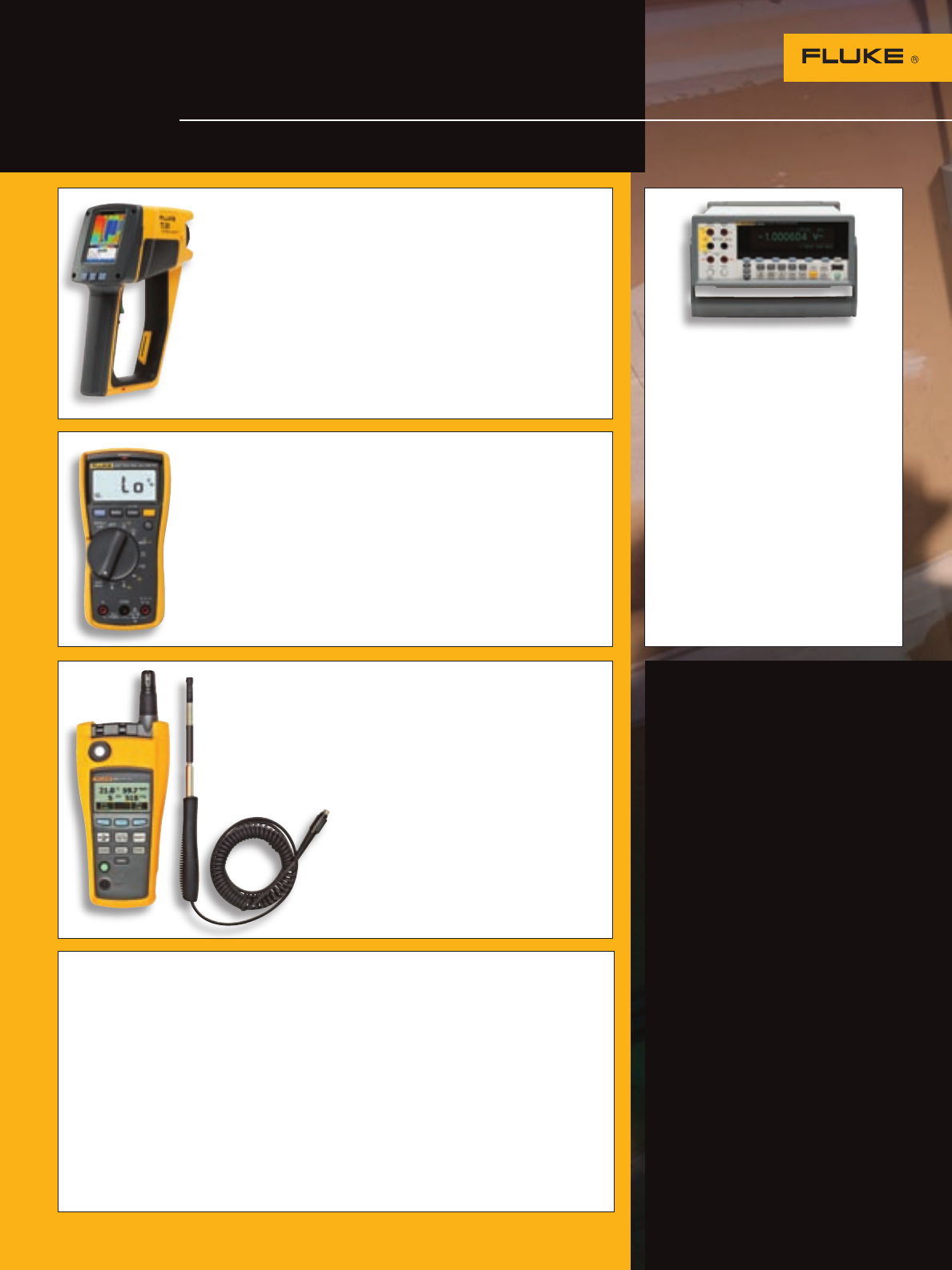
What’s New from Fluke
The new products to help keep
you up and running
Fluke. Keeping your world
up and running.™
Your authorized Fluke distributor
Fluke Ti20 Thermal Imager
The Fluke Ti20 Thermal Imager is an unbeatable solution for
predictive maintenance and troubleshooting.
• Includes unlimited-use InsideIR™ companion software
and professional training materials.
• Designed for industrial use. IP54-rated for use in dust
and moisture filled environments.
• Follow easy, on-camera instructions each time you perform
inspections (simply point, focus and pull the trigger) for fast
and easy inspection routing.
For more information, see page 48.
Fluke 8845A and 8846A 6.5
Digit Precision Multimeters
• 6.5 digit resolution
• Graphical display
• Basic V dc accuracy of up to 0.0024 %
• 100 uA to 10 A Current
• 10 ohm to 1 Gohm resistance
• 2x4 Wire ohms measurement technique
• Frequency, period, capacitance and
RTD temperature measurements
• Analytical modes; TrendPlot,™
Histogram and Statistics
• USB device port, for memory storage
devices
• RS-232, IEEE-488 and LAN interfaces
For more information, see page 21.
Fluke 117 Electrician’s Digital Multimeter
The Fluke 117 is one of four new compact digital multimeters.
Choose from models specifically designed for Commercial Electricians,
HVAC/R Technicians and Field Service Technicians. Engineered by
you, designed by Fluke.
• VoltAlert™ Technology for integrated non-contact voltage detection.
• AutoVolt feature for automatic ac/dc voltage selection.
• LoZ: low input impedance prevents false readings due to
“ghost voltage”.
For more information, see page 17.
Fluke 975 AirMeter™
The Fluke 975 AirMeter test tool raises
indoor air monitoring to the next level by
combining five powerful tools in one, rugged
and easy-to-use handheld device.
The Fluke 975 measures:
• Temperature
• Relative Humidity
• Air Velocity
• CO2
• CO
For more information see page 54.
Fluke Corporation
PO Box 9090,
Everett, WA USA 98206
Fluke Europe B.V.
PO Box 1186, 5602 BD
Eindhoven, The Netherlands
For more information call:
In the U.S.A. (800) 443-5853 or
Fax (425) 446-5116
In Europe/M-East/Africa
(31 40) 2 675 200 or
Fax (31 40) 2 675 222
In Canada (800) 36-FLUKE or
Fax (905) 890-6866
From other countries
+1 (425) 446-5500 or
Fax +1 (425) 446-5116
Web access: http://www.fluke.com
©2006 Fluke Corporation.
All rights reserved. Specifications
subject to change without notice.
LEM is a trademark of LEM Holding S.A.
Corporation. Microsoft is a registered
trademark of Microsoft Corporation.
Printed in U.S.A. 11/2006
1274458 C-US-N Rev O
Volume 37
