XStart 1
2014-09-08
: Pdf 618755-Attachment 618755-Attachment 015082 Batch5 unilog
Open the PDF directly: View PDF ![]() .
.
Page Count: 309 [warning: Documents this large are best viewed by clicking the View PDF Link!]
xStart series contactors
xStart series overload relays
Motor protective circuit breaker PKZ
Motor-starter combinations
Contactors and starters
1.1
1.2
1.3
1.4
xStart series contactors
Mini contactor relays, contactor relay . . . . . . . . . . . . . . . . . . . . . . . . . . . . . . . . . . . . . . . .
Contactors DIL . . . . . . . . . . . . . . . . . . . . . . . . . . . . . . . . . . . . . . . . . . . . . . . . . . . . . . . . . .
xStart series overload relays
Bimetal relay ZE, ZB, Z5 . . . . . . . . . . . . . . . . . . . . . . . . . . . . . . . . . . . . . . . . . . . . . . . . . . .
Overload relay ZW7 . . . . . . . . . . . . . . . . . . . . . . . . . . . . . . . . . . . . . . . . . . . . . . . . . . . . . .
Electronic overload relays ZEB . . . . . . . . . . . . . . . . . . . . . . . . . . . . . . . . . . . . . . . . . . . . . .
EMT6 thermistor overload relay for machine protection . . . . . . . . . . . . . . . . . . . . . . . . . .
C441 overload and monitoring relay . . . . . . . . . . . . . . . . . . . . . . . . . . . . . . . . . . . . . . . .
xStart series motor-protective circuit-breakers
Motor-protective circuit-breakers PKZ . . . . . . . . . . . . . . . . . . . . . . . . . . . . . . . . . . . . . . . .
Motor-protective circuit-breakers PKE . . . . . . . . . . . . . . . . . . . . . . . . . . . . . . . . . . . . . . . .
DC string circuit-breaker PKZ-SOL . . . . . . . . . . . . . . . . . . . . . . . . . . . . . . . . . . . . . . . . . . .
DC switch-disconnectors P-SOL, SOL . . . . . . . . . . . . . . . . . . . . . . . . . . . . . . . . . . . . . . . .
Motor-starter combinations
Motor-starter combinations . . . . . . . . . . . . . . . . . . . . . . . . . . . . . . . . . . . . . . . . . . . . . . . .
1
1
2
2
4
4
37
3
8
47
47
1
1
2
xStart series
2.1
2.2
E Line contactors
Control relays XTRG . . . . . . . . . . . . . . . . . . . . . . . . . . . . . . . . . . . . . . . . . . . . . . . . . . . . . .
Contactors XTCG . . . . . . . . . . . . . . . . . . . . . . . . . . . . . . . . . . . . . . . . . . . . . . . . . . . . . . . .
E Line thermal overload relay
Thermal overload relays XTOD . . . . . . . . . . . . . . . . . . . . . . . . . . . . . . . . . . . . . . . . . . . . . .
2
5
2
E Line series
E Line contactors
E Line thermal overload relay
AUTOMATION AND CONTROL www.eaton.com/seasia-electrical
1
Continual operation requires high operational reliability in the components used. The
DILM contactor achieves the best lifespan values in AC-3 applications and is ideal for
heavy AC-4 jogging.
Mini contactor relays,
contactor relay, contactors
Eaton after sales service
Testing switching devices in
compliance with regulations
applicable to this technology
See catalog
Mini contactor relay DILE…,contactor relays, contactors up to 12 A AC-3 at 400 V
Compact dimensions for the highest packing densities
Extended performance range up to 5.5 kW at 400 V
•
•
AC and DC contactor system DILM…, contactor relays, 3 pole contactors up to 170 A AC-3
at 400 V, 4 pole contactors up to 200 A AC-1
Easier engineering through identical construction sizes for AC- and DC-operated contactors
Energy savings and higher packing density in control panel due to minimized heat dissipation
High wiring security through doubled box terminals
Less coupler relays: direct actuation from the PLC for contactors up to 32 A
Easy engineering through integrated suppressor circuits for DC
Uniform accessories for 3- and 4-pole contactors
Mechanical interlock double conductor run mountable without additional separation gap
Direct fieldbus connection through the communication system SmartWire-DT®, through
plug-in type protective module
•
•
•
•
•
•
•
•
High rated contactors - contactors up to 1600 A AC-3 at 400 V, contactors up to 2600 A AC-1
Compact dimensions with high switching power
Direct actuation from the PLC saves coupler relays
Easy engineering through wide range coils
Cost and energy savings for control panel ventilation due to reduced heat dissipation
Long lifespan through vacuum technology from 580 A
•
•
•
•
•
SmartWire-DT®
The DIL product range offers contact elements which can be connected to the SmartWire-DT®
communication system. Protective modules, Page 62
Mini contactors, relays, contactors
Contents
1AUTOMATION AND CONTROL www.eaton.com/seasia-electrical
1
Ordering
Mini contactor relays DILER, DILEEM, DILEM
Mini contactor relays, contactors . . . . . . . . . . . . . . . .
Auxiliary contact modules . . . . . . . . . . . . . . . . . . . . .
Accessories . . . . . . . . . . . . . . . . . . . . . . . . . . . . . . . .
Actuating voltages . . . . . . . . . . . . . . . . . . . . . . . . . . .
DILA contactor relays
Contactor relays . . . . . . . . . . . . . . . . . . . . . . . . . . . . .
Auxiliary contact modules . . . . . . . . . . . . . . . . . . . . .
Actuating voltages . . . . . . . . . . . . . . . . . . . . . . . . . . .
Technical overview
Contactors DILM, DILH . . . . . . . . . . . . . . . . . . . . . . .
System overview
Contactors DILM, DILH . . . . . . . . . . . . . . . . . . . . . . .
Ordering
Contactors DILM, DILH
Basic devices up to 170 A . . . . . . . . . . . . . . . . . . . . .
Complete units up to 170 A . . . . . . . . . . . . . . . . . . . .
Standard devices greater than 170 A . . . . . . . . . . . . .
Comfort devices greater than 170 A . . . . . . . . . . . . .
Basic devices up to 200 A, 4 pole . . . . . . . . . . . . . . .
Auxiliary contact modules . . . . . . . . . . . . . . . . . . . . .
Engineering
Auxiliary contact modules . . . . . . . . . . . . . . . . . . . . .
Ordering
DILK contactors for capacitors . . . . . . . . . . . . . . . . . .
Engineering
Contactors for power factor correction . . . . . . . . . . .
Ordering
Star-delta combinations SDAINL . . . . . . . . . . . . . . . .
Engineering
Star-delta combinations SDAINL . . . . . . . . . . . . . . . .
Ordering
DIUL reversing combinations . . . . . . . . . . . . . . . . . . .
Description
CMD contactor monitoring device . . . . . . . . . . . . . . .
Ordering
CMD contactor monitoring device . . . . . . . . . . . . . . .
2
6
8
66
10
12
68
14
16
18
24
28
30
34
36
40
41
42
44
46
48
64
64
Ordering
DILM contactor relays, DILM, DILH contactors
suppressor circuit . . . . . . . . . . . . . . . . . . . . . . . . . . .
Accessories . . . . . . . . . . . . . . . . . . . . . . . . . . . . . . .
Ordering
Actuating voltages contactors DILM, DILH
Basic devices up to 170 A . . . . . . . . . . . . . . . . . . . .
Basic devices up to 200 A, 4 pole . . . . . . . . . . . . . .
Contactors up to 150 A
with electronic actuation . . . . . . . . . . . . . . . . . . . . .
Replacement coils . . . . . . . . . . . . . . . . . . . . . . . . . .
Comfort devices greater than 170 A . . . . . . . . . . . .
Standard devices greater than 170 A . . . . . . . . . . . .
Electronic modules including coil . . . . . . . . . . . . . . .
Contactors for capacitors . . . . . . . . . . . . . . . . . . . . .
Engineering
Contact travel diagrams . . . . . . . . . . . . . . . . . . . . . .
Enclosure . . . . . . . . . . . . . . . . . . . . . . . . . . . . . . . . .
UL/CSA-approved rating data . . . . . . . . . . . . . . . . . .
UL/CSA special purpose ratings . . . . . . . . . . . . . . .
UL/CSA short circuit current rating . . . . . . . . . . . .
Contactors for resistive loads . . . . . . . . . . . . . . . . . .
Electrical life span . . . . . . . . . . . . . . . . . . . . . . . . . . .
Short-time loading . . . . . . . . . . . . . . . . . . . . . . . . . .
Operating frequency . . . . . . . . . . . . . . . . . . . . . . . . .
Switching of DC current . . . . . . . . . . . . . . . . . . . . . .
Technical data
Mini contactor relays, contactor relays . . . . . . . . . . .
Contactor monitoring device . . . . . . . . . . . . . . . . . .
Basic devices up to 170 A . . . . . . . . . . . . . . . . . . . .
Basic devices up to 200 A, 4 pole . . . . . . . . . . . . . .
Comfort devices greater than 170 A . . . . . . . . . . . .
Standard devices greater than 170 A . . . . . . . . . . . .
Contactors for capacitors . . . . . . . . . . . . . . . . . . . . .
Contactors up to 150 A
with electronic actuation . . . . . . . . . . . . . . . . . . . . .
Lighting contactors . . . . . . . . . . . . . . . . . . . . . . . . . .
Auxiliary contact modules . . . . . . . . . . . . . . . . . . . .
Accessories . . . . . . . . . . . . . . . . . . . . . . . . . . . . . . .
Dimensions
Mini contactor relays . . . . . . . . . . . . . . . . . . . . . . . .
Contactor relays . . . . . . . . . . . . . . . . . . . . . . . . . . . .
Basic devices up to 170 A . . . . . . . . . . . . . . . . . . . .
Basic devices up to 200 A, 4 pole . . . . . . . . . . . . . .
Contactors larger than 170 A . . . . . . . . . . . . . . . . . .
Contactors for capacitors . . . . . . . . . . . . . . . . . . . . .
Lighting contactors . . . . . . . . . . . . . . . . . . . . . . . . . .
Contactor combinations . . . . . . . . . . . . . . . . . . . . . .
Accessories . . . . . . . . . . . . . . . . . . . . . . . . . . . . . . .
50
52
69
74
76
71
77
77
77
77
78
79
80
81
82
84
86
90
91
92
93
96
104
120
112
112
123
126
125
128
128
130
131
131
133
134
136
136
137
138
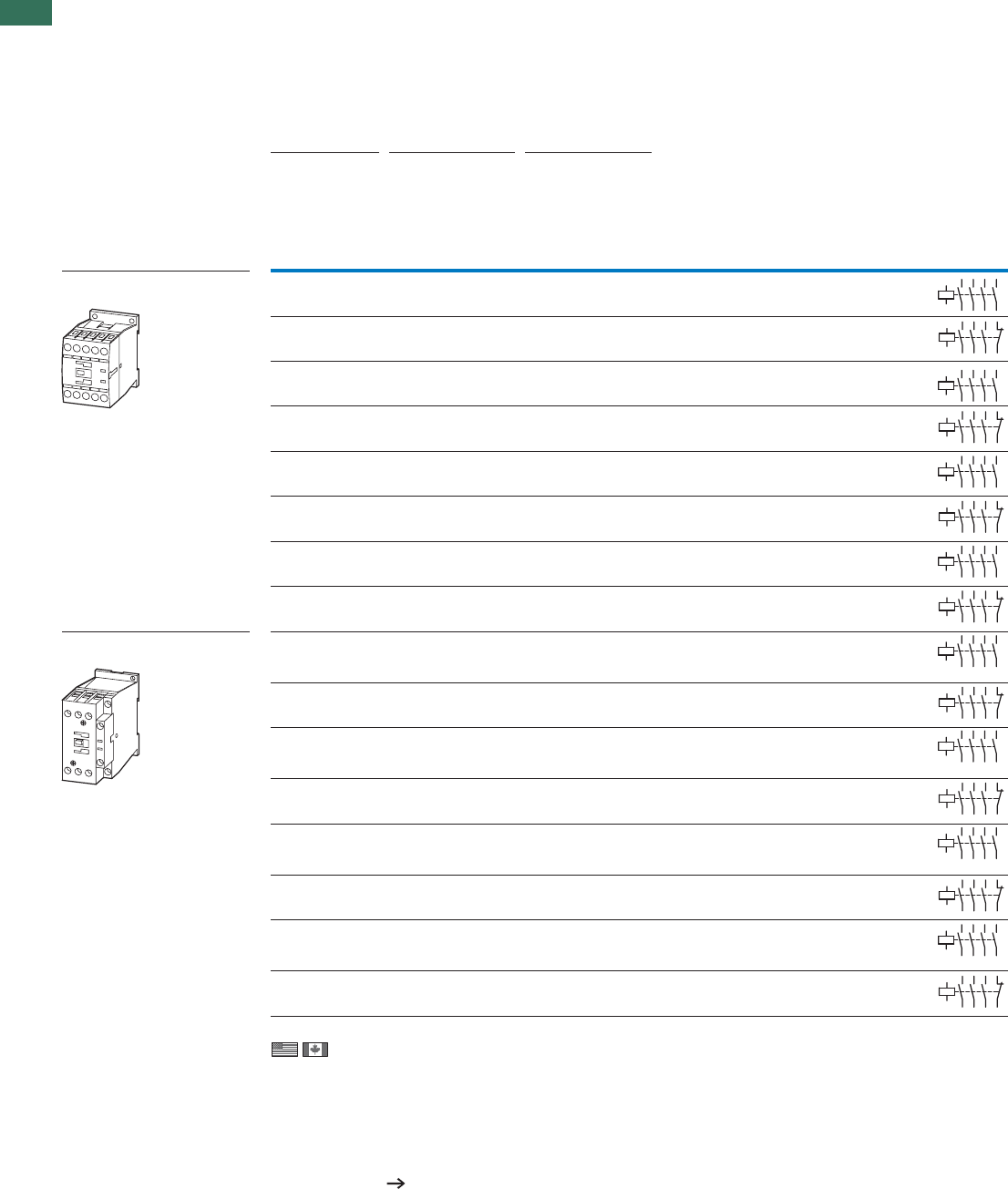
1.1 Contactors
Mini contactors, relays
2 AUTOMATION AND CONTROL www.eaton.com/seasia-electrical
1Ordering
Rated operational current Conventional free
air thermal current
Contact Distinctive
number
Circuit symbol For use with
AC-15
N/O = normally open contact
NC = normally closed contact
220 V
230 V
240 V
380 V
400 V
415 V
IeIeIth
AAA
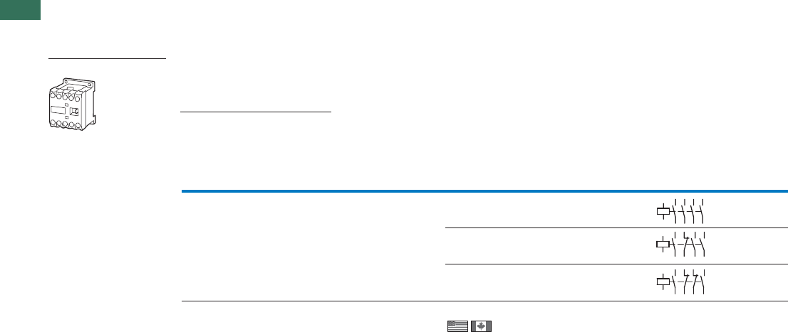
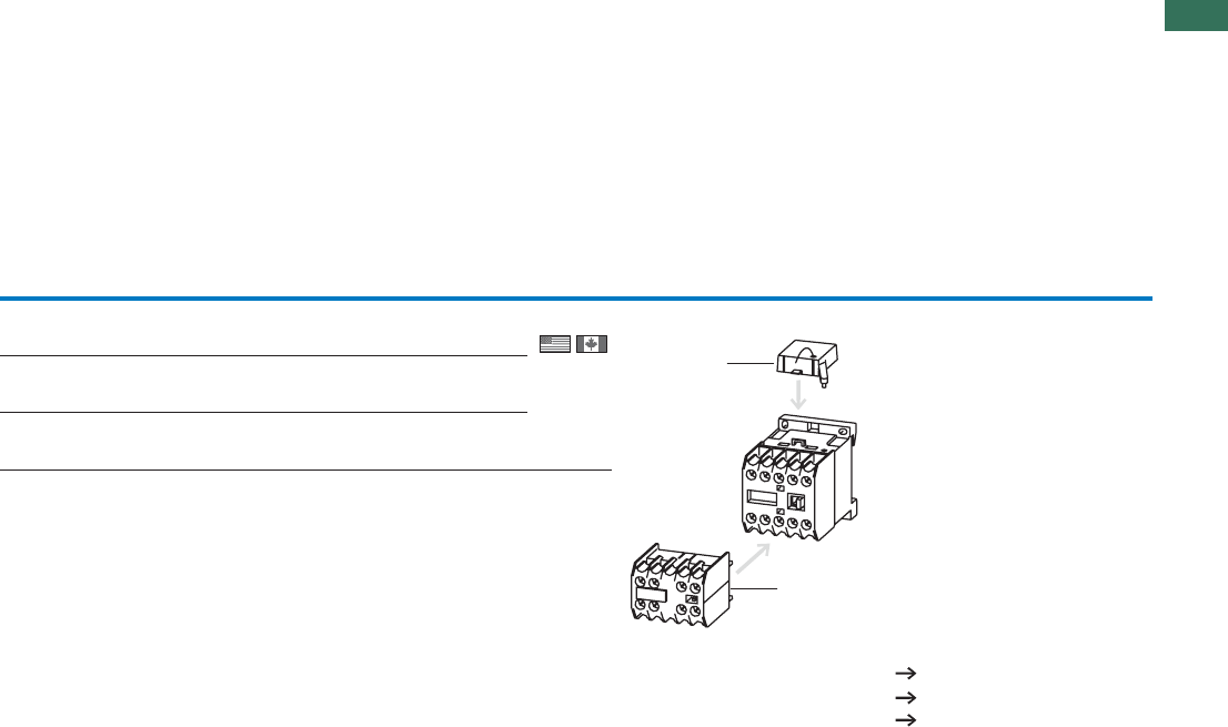
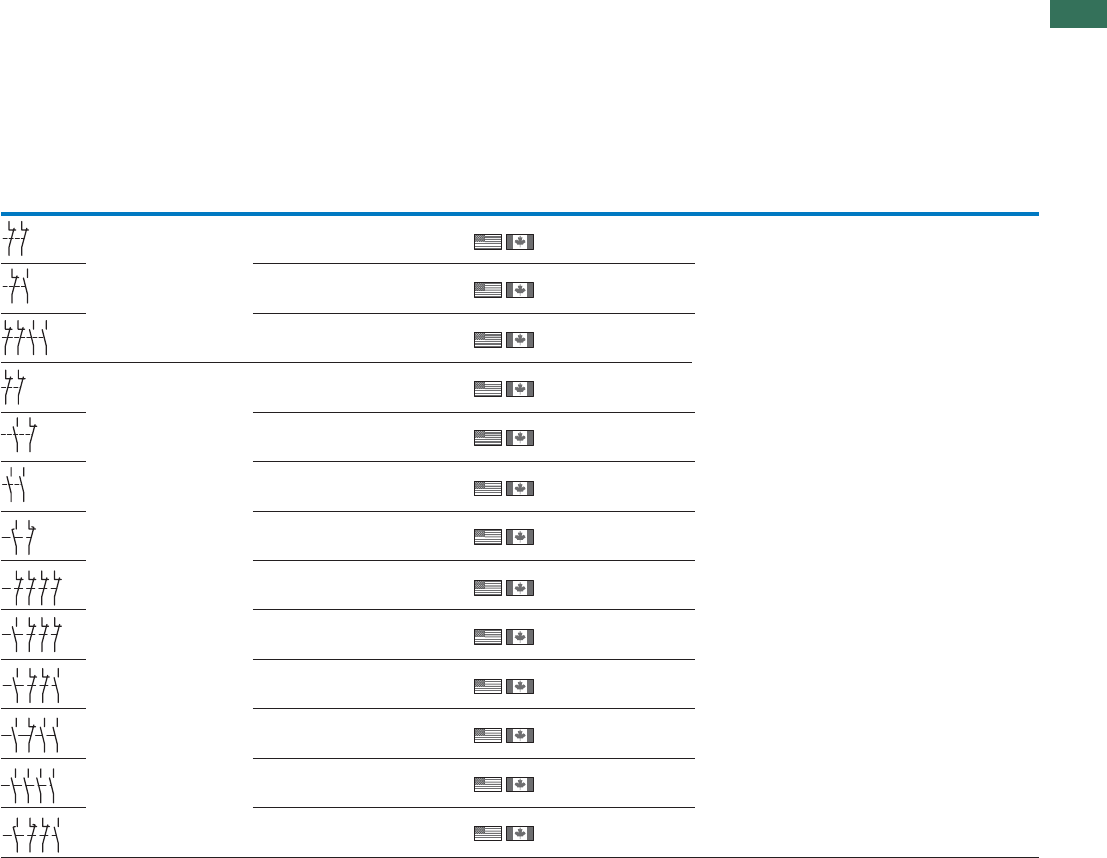
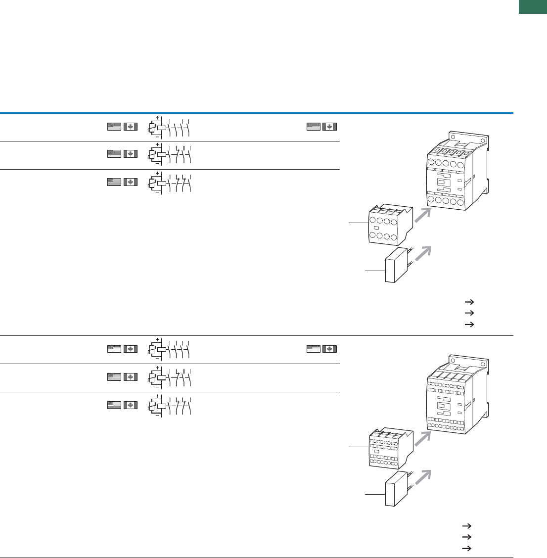
DILER mini contactor relays
Screw terminals
DILE…40E–4 N/O
DILE…31E1 NC3 N/O
DILE…22E2 NC2 N/O
1036
Notes
Coil terminal marking as specified in EN 50005
Contact numbers to EN 50011
The following applies to DC-operated contactors:
• Integrated diode-resistor combination
• Coil rating 2.6 W
Information relevant for export to North America
Product Standards
UL File No.
UL CCN
CSA File No.
CSA Class No.
NA Certification
14
13 33
34
43
44
A1
A2
23
24
14
13 21
22
33
34
43
44
A1
A2
14
13 21
22
31
32
43
44
A1
A2
IEC/EN 60947-4-1; UL508; CSA-C22.2 No.14-05;
CE marking
E29184
NKCR
012528
3211-03
UL Listed,
CSA certified
1.1
Contactors
Mini contactors, relays
3AUTOMATION AND CONTROL www.eaton.com/seasia-electrical
1
AC operation DC operation
Part no.
Article no. Price
See price list Part no.
Article no. Price
See price list
Std. pack Notes
DILER-40(230V50Hz)
051759 DILER-40-G(24VDC)
010223 5 off
DILER-31(230V50Hz)
051768 DILER-31-G(24VDC)
010157
DILER-22(230V50Hz)
051777 DILER-22-G(24VDC)
010042
With screw terminals:
egaPseirosseccA
1 Suppressor 8
2 Auxiliary contact modules 6
Further actuating voltages 66
1
2
1.1 Contactors
Mini contactors, relays
4 AUTOMATION AND CONTROL www.eaton.com/seasia-electrical
1
Rated
operational
current
Max. motor rating for
three-phase motors, 50 - 60 Hz
Conventional thermal
current Ith = Ie
AC-1 at 50 °C
Contact Circuit symbol For use with
AC-3 AC-3 AC-4
380 V
400 V
220 V
230 V 380 V
400 V
660 V
690 V
220 V
230 V 380 V
400 V
660 V
690 V
Open Enclosed N/O = normally open
contact
NC = normally
closed contact
IePPP P PP Ith = IeIth = Ie
AkW kW kW kW kW kW A A
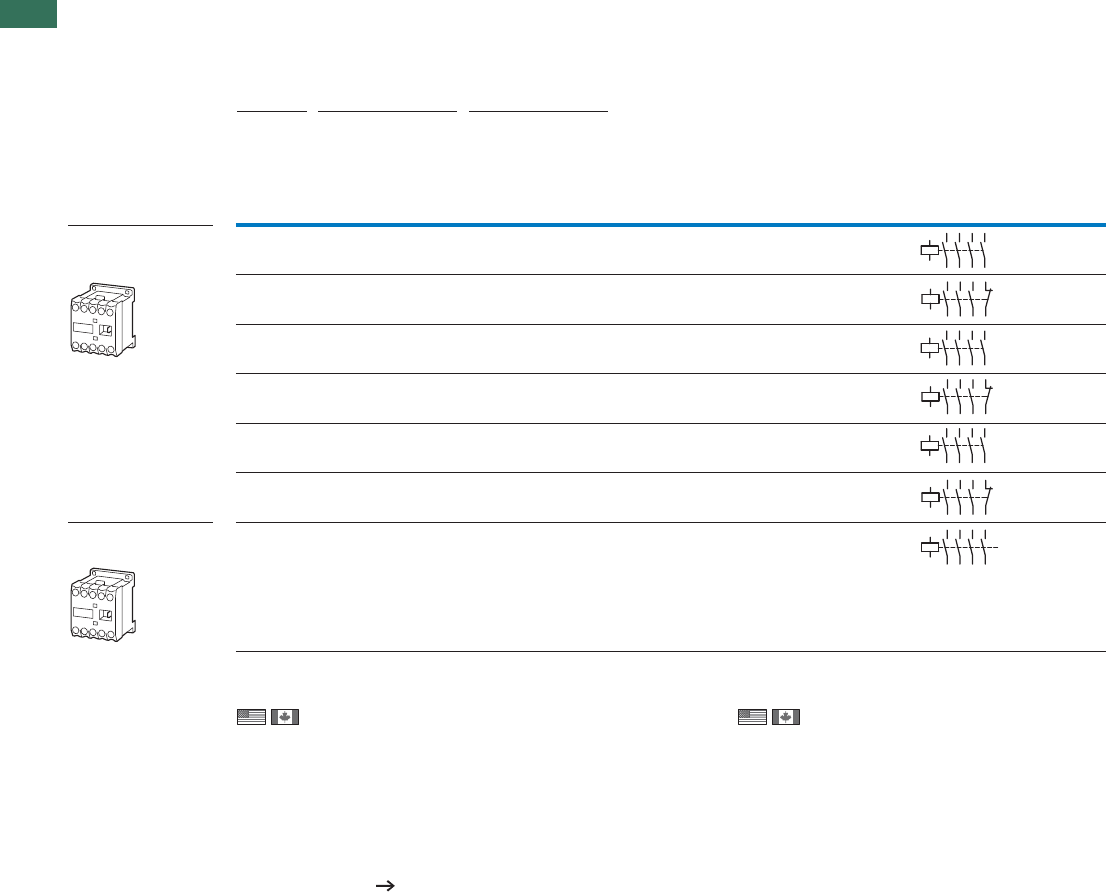
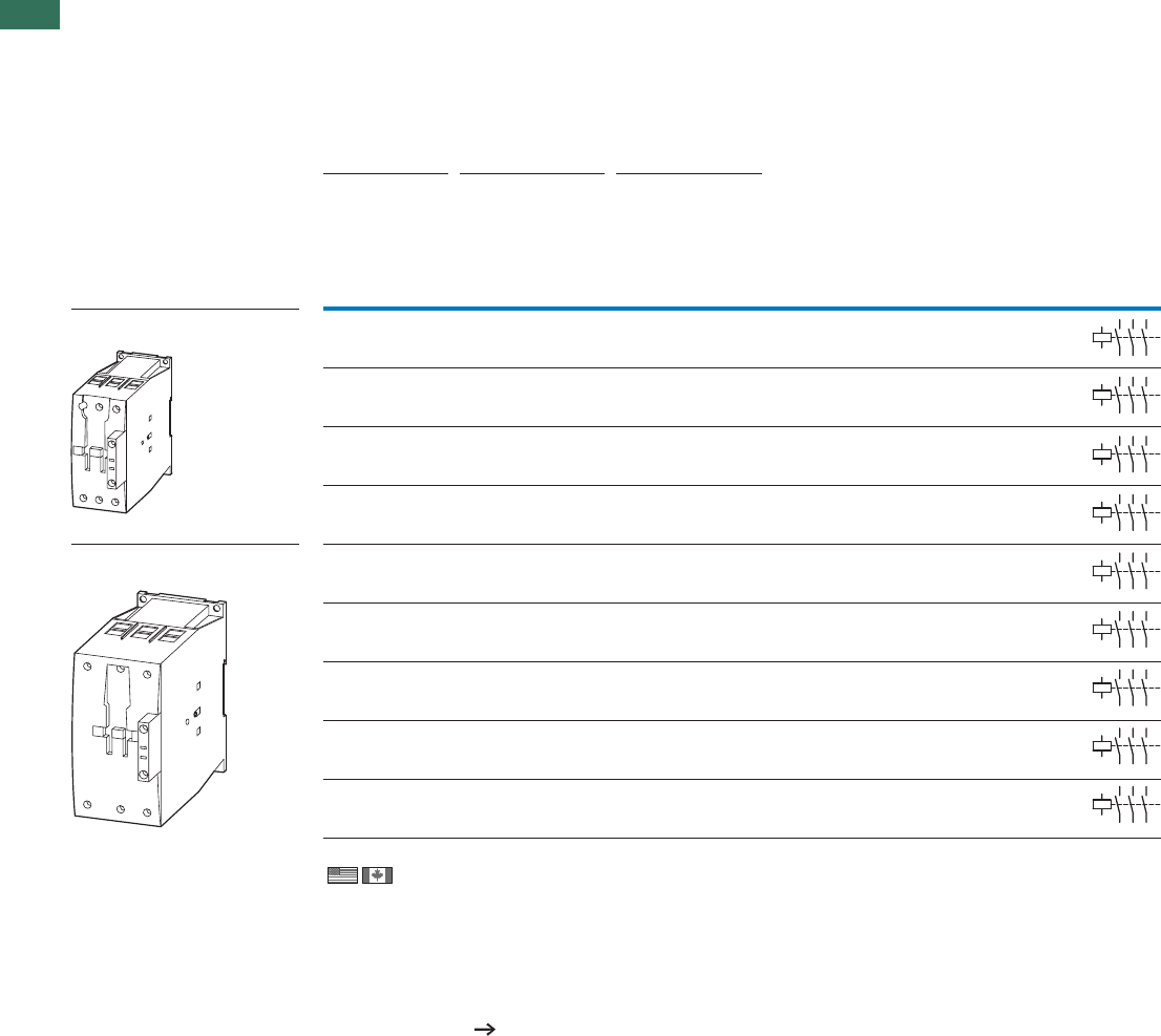
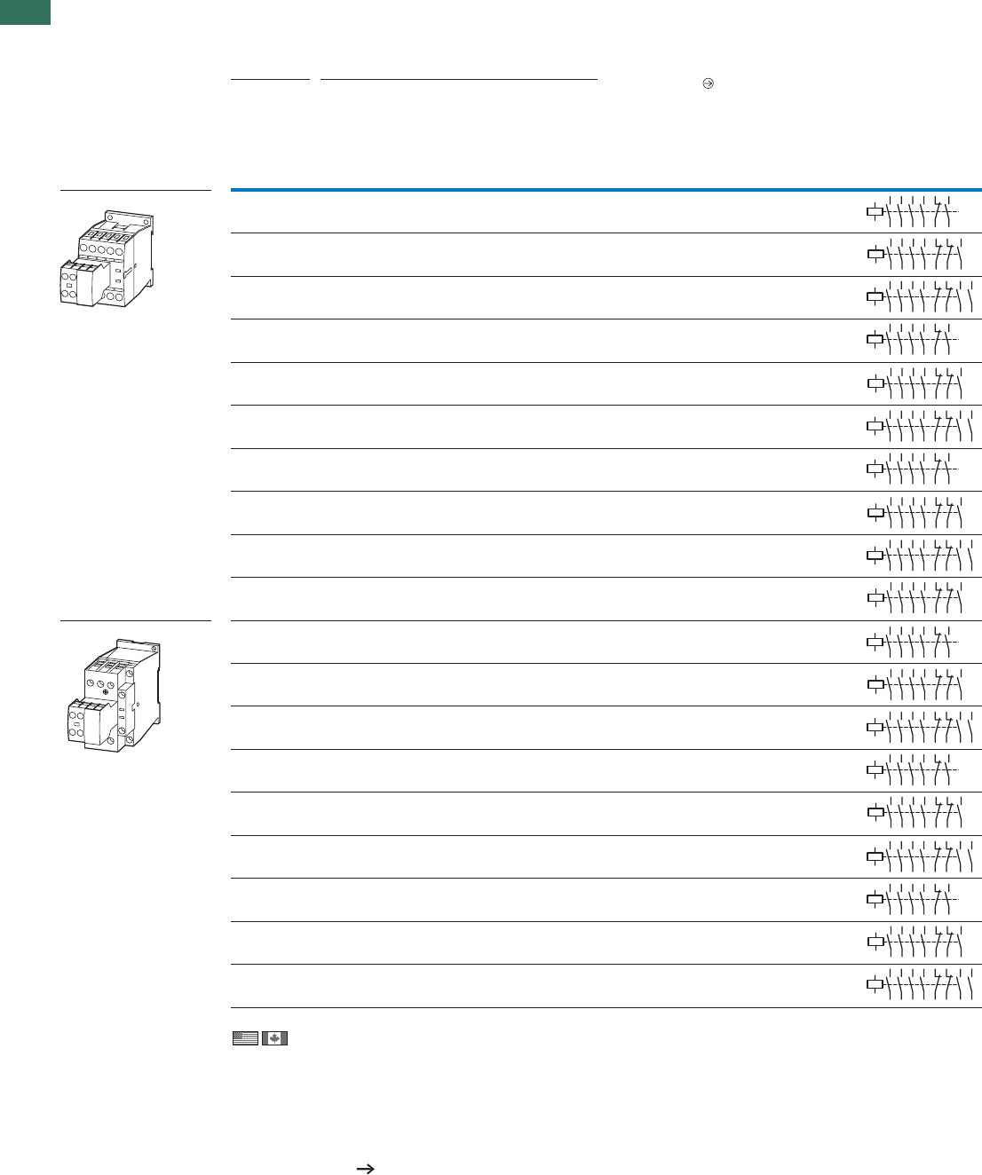
DILEM contactors
3 pole with auxiliary
contact
Screw terminals
6.6 1.5 331.12.2 2.2 20 16 1 N/O – …DILEM
DILE…
6.6 1.5 331.12.2 2.2 20 16 – 1 NC DILE…
92.2 441.533 20 16 1 N/O – …DILEM
DILE…
92.2 441.53320 16 – 1 NC DILE…
12 3.5 5.5 6.5 2 32.2 20 16 1 N/O – …DILEM
DILE…
12 3.5 5.5 6.5 2 32.2 20 16 – 1 NC DILE…
4 pole
Screw terminals
92.2 441.533 20 16 – – …DILEM
DILE…
1) 2)
aciremAhtroNottropxeroftnavelernoitamrofnIaciremAhtroNottropxeroftnavelernoitamrofnI
Product Standards
UL File No.
UL CC
CSA File No.
CSA Class No.
NA Certification
See also
Product Standards
UL File No.
UL CCN
CSA File No.
CSA Class No.
NA Certification
2
35
46
A1
A2
113
14
2
35
46
A1
A2
121
22
2
35
46
A1
A2
113
14
2
35
46
A1
A2
121
22
2
35
46
A1
A2
113
14
2
35
46
A1
A2
121
22
2
35
46
A1
A2
17
8
IEC/EN 60947-4-1;
UL 508; CSA-C22.2 No.14-05; CE marking
E29096
NLDX
012528
2411-03,3211-04
UL Listed, request filed for CSA
IEC/EN 60947-4-1;
UL 508; CSA-C22.2
No.14-05; CE marking
E29096
NLDX
012528
3211-04
UL Listed, CSA certified
Page 80
1.1
Contactors
Mini contactors, relays
5AUTOMATION AND CONTROL www.eaton.com/seasia-electrical
1
AC operation DC operation
Part no.
Article no. Price
See price
list
Part no.
Article no. Price
See price
list
Std. pack Notes
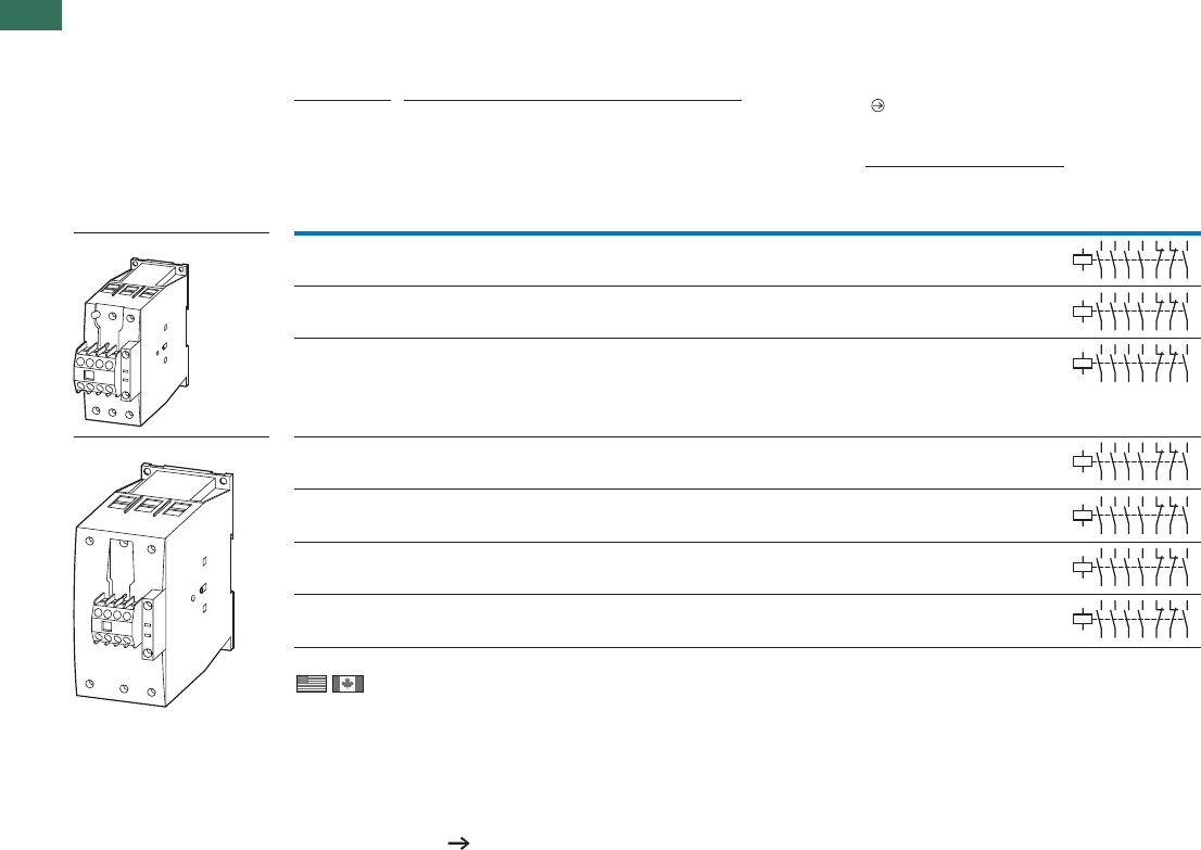
DILEEM-10(230V50Hz) 1)
051608 DILEEM-10-G(24VDC)1)
051643
5 off
DILEEM-01(230V50Hz) 1)
051633 DILEEM-01-G(24VDC)1)
051650
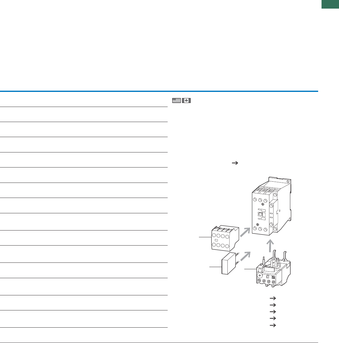
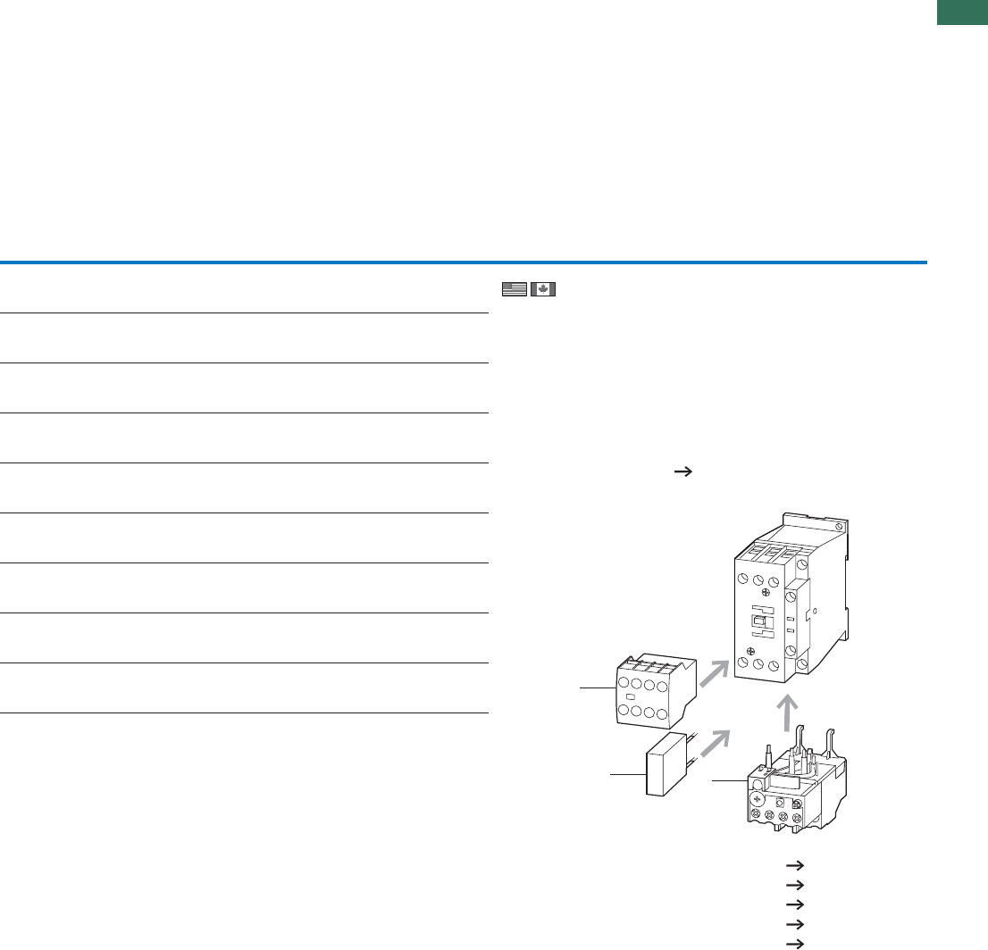
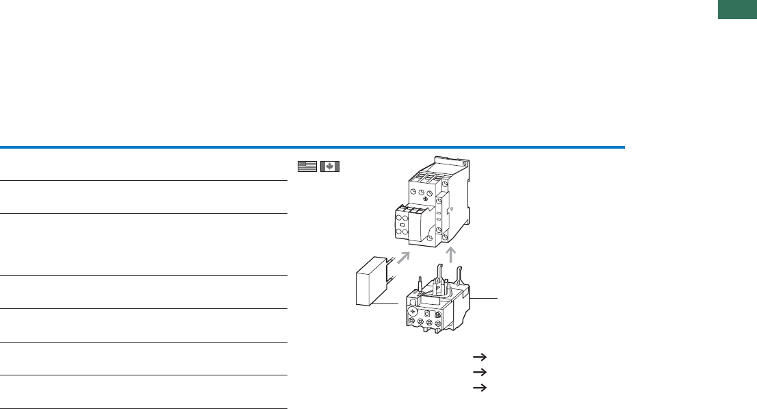
DILEM-10(230V50Hz) 1)
051786 DILEM-10-G(24VDC)1)
010213
DILEM-01(230V50Hz) 1)
051795 DILEM-01-G(24VDC)1)
010343
DILEM12-10(230V50Hz) 2)
127075 DILEM12-10-G(24VDC)2)
127132
DILEM12-01(230V50Hz) 2)
127091 DILEM12-01-G(24VDC)2)
127137
DILEM4(230V50Hz) 1)
051804 DILEM4-G(24VDC)1)
012701
5 off
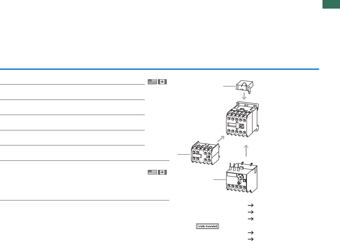
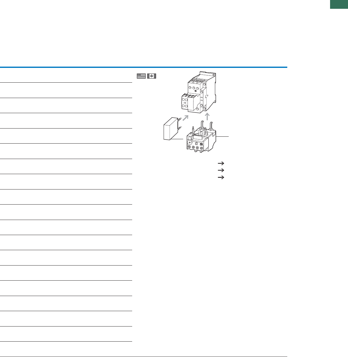
With screw terminals:
PageAccessories
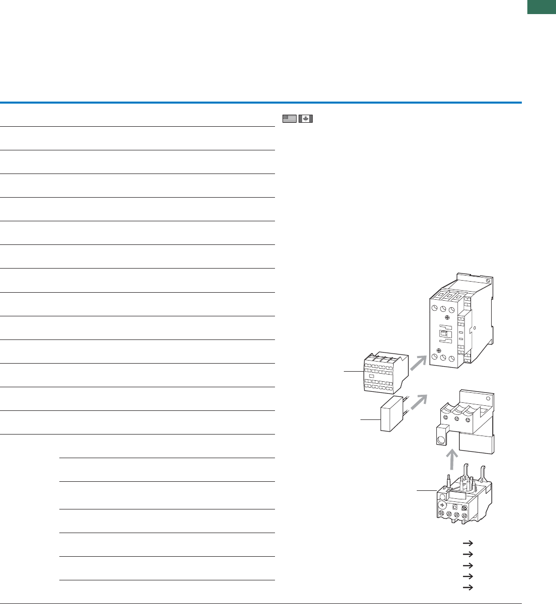
1 Overload relay Chapter 1.2
2 Suppressor 8
3 Auxiliary contact module 6
Enclosures
Further actuating voltages 66
Accessories 8
1
3
2
1.1 Mini contactor relays
Auxiliary contact modules
6 AUTOMATION AND CONTROL www.eaton.com/seasia-electrical
1DILE
ConventionalRated operational currentContact
thermal current
Distinctive number/type of combinations
with basic device
N/O = normally open
contact
SF = NO early-make
NC = normally closed
contact
ÖS = NC late-break
AC-15 Ith DILER-40(-G) DILER-31(-G) DILER-22
220 V
230 V
240 V
380 V
400 V
415 V
A
IeIe
AA
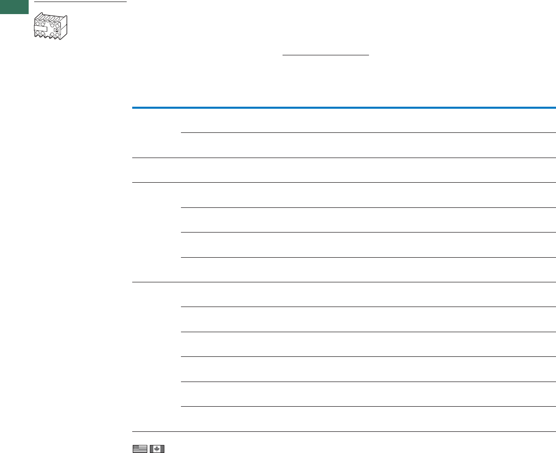
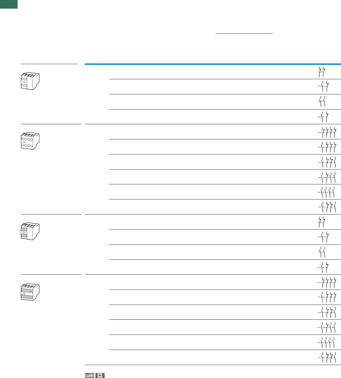
Auxiliary contact modules
Screw terminals
Information relevant for export to North America
Product Standards
UL File No.
UL CCN
CSA File No.
CSA Class No.
NA Certification
IEC/EN 60947-4-1; UL 508; CSA-C22.2 No.14-05;
CE marking
E29184
NKCR
012528
3211-03
UL Listed,
CSA certified
2 pole – –2 NC – 4 210 – – –
4 pole 2 N/O –2 NC – 4210 –––
2 pole – –2 NC – 4 210 42E 33 24
1 N/O – 1 NC – 4 2 10 – – –
1 N/O – 1 NC – 4 2 10 51E 42 33
1 N/O – 3 NC – 4 2 10 53E 44 35
2 N/O – 2 NC – 4 2 10 62E 53 44
3 N/O – 1 NC – 4210 71E 62 53
4 N/O – – – 4 210 80E 71 62
2 N/O – – – 4 210 60E 51 42
–1 S–1 Ö 4210 51 42 33
FS
1 N/O 1 S 1 NC 1 Ö 4 2 10 62 53 44
FS
4 pole – –4 NC – 4 210 44E 35 26
1.1
Mini contactor relays
Auxiliary contact modules
7AUTOMATION AND CONTROL www.eaton.com/seasia-electrical
1
Circuit symbol Can be combined with
contactor Part no.
Article no. Price
See price
list
Std. pack Notes
DILEM-10(-G)(…)
DILEM-4(-G)(…)
DILEEM-10(-G)(…)
DILEM12-10(-G)(…)
02DILEM
010064
5 off With interlocked
opposing contacts
5 off
5 off
5 off
With interlocked
opposing contacts
5 off With interlocked
opposing contacts
5 off With interlocked
opposing contacts
5 off With interlocked
opposing contacts
5 off With interlocked
opposing contacts
The following applies to ...DILEM auxiliary
contacts:
• Contacts to EN 50012
The following applies to ...DILE auxiliary contacts:
• Contacts to EN 50005
Contacts according to EN50012 are to be prefered.
Type E combinations compy with EN 50011 and are
to be given preference.
No interlocked opposing contacts in NO early-
makes and NC late-breaks.
11DILEM
010080
22DILEM
010112
DILEM-10(-G)(…)
DILEM-01(-G)(…)
DILEM-4(-G)(…)
DILER40(-G)
DILER31(-G)
DILER22
DILEEM-10(-G)(…)
DILEEM-01(-G)(…)
DILEM12-10(-G)(…)
DILEM12-01(-G)(…)
02DILE
010240
11DILE
010224
20DILE
010208
11DDILE
049824
–
04DILE
010256
With interlocked
opposing contacts
5 off With interlocked
opposing contacts
5 off With interlocked
opposing contacts
5 off With interlocked
opposing contacts
5 off With interlocked
opposing contacts
5 off
13DILE
002397
22DILE
010288
31DILE
048912
40DILE
010304
22DDILE
049823
–
21
22
31
32
21
22
33
34
21
22
31
32
43
44
53
54
51
52
61
62
54
53 61
62
54
63
64
53
58
57 65
66
51
52
61
62
71
72 82
81
53 61 71 81
82
72
62
54
54
53 61
62
71
72
83
84
54
53 61
62
73
74
83
84
54
63 73
64 74
53 83
84
58
57 65
66
71
72
83
84
1.1 Mini contactor relays
Accessories
8 AUTOMATION AND CONTROL www.eaton.com/seasia-electrical
1
IEC/EN 60947-4-1; UL 508;
CSA-C22.2 No.14-05;
CE marking
E29096
NLDX
012528
3211-03
UL Listed, CSA certified
IEC/EN 60947-4-1; UL 508;
CSA-C22.2 No.14-05;
CE marking
E29184
NKCR2
-
UL Recognized
IEC/EN 60947-4-1; UL 508;
CSA-C22.2 No.14-05;
CE marking
E29184
NKCR2
012528
3211-07
UL Recognized, CSA certified
IEC/EN 60947-4-1; UL 508;
CSA-C22.2 No.14-05;
CE marking
E29096
NLDX
012528
3211-07
UL Listed, CSA certified
Actuating
voltage
Circuit
symbol
For use with Part no.
Article no. Price
See price
list
Std. pack Information relevant for export to North America
Us
V AC
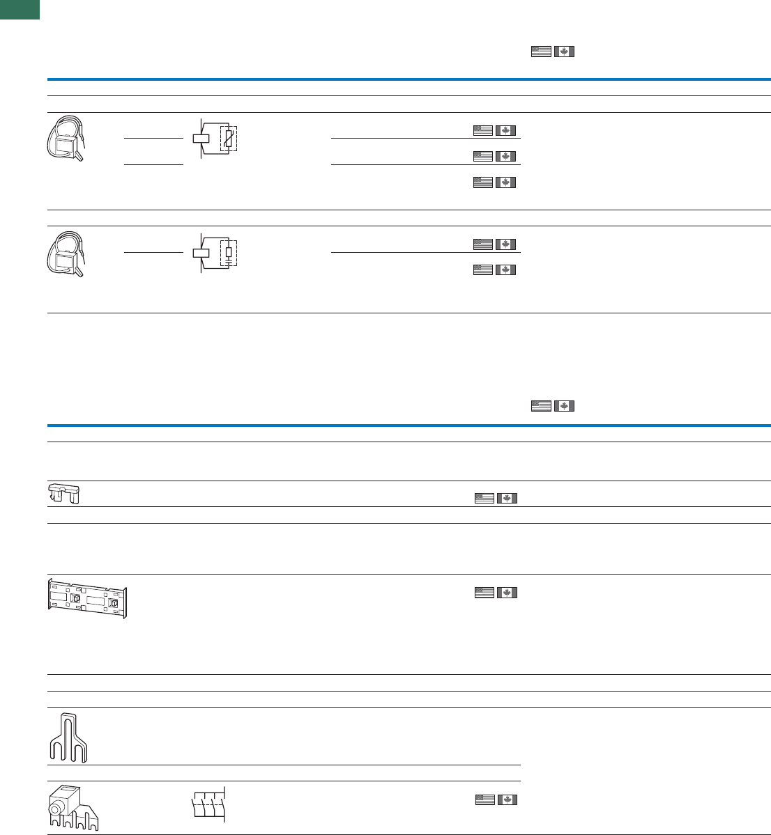
Suppressor circuits
Varistor suppressor
24 - 48 AC DILE... VGDILE48
010320
10 off
10 off
10 off
UL File No.
UL CCN
CSA File No.
CSA Class No.
NA Certification
110 - 250 AC VGDILE250
010336
380 - 415 AC VGDILE415
010463
RC-Suppressor
24 - 48 AC DILE... RCDILE48
044264
10 off Product Standards
UL File No.
UL CCN
CSA File No.
NA Certification
110 - 250 AC RCDILE250
046320
10 off
Notes For AC operated contactors 50 - 60 Hz.
DC operated contactor relays have an integrated suppressor.
Note drop-out delay.
For use with Part no.
Article no. Price
See price
list
Std. pack Information relevant for export to North America
Mechanical interlocks
For mechanical connection of contactor and timing relays in
combinations.
0 mm distance between contactors.
DILE…
DILET… V0DILE
026634
50 off UL/CSA certification not required
Mechanical interlock
For contactors with the same or different magnet system.
0 mm distance between contactors.
Mechanical lifespan 2.5 x 10 operations.
6
Additional auxiliary contact modules possible.
–DILE…MVDILE
010113
5 off Product Standards
Product Standards
UL File No.
UL CCN
CSA File No.
CSA Class No.
NA Certification
Paralleling link
For parallel connection of contacts
– DILE…
DILE… BT4801)
052785
100 off
UL File No.
UL CCN
CSA File No.
CSA Class No.
NA Certification
Consisting of two four-pole paralleling links.
DILEEM
DILEM12
DILEM
P1DILEM2)
019095
5 off
Notes 1) Not protected against accidental contact as specified in VDE 0106 Part 100.
2) 4th pole can be broken off
4 pole: Ith = 60 A open
3 pole: Ith = 50 A open
AC-1 current carrying capacity of the open contactor increases by a factor of 2.5
Protected against accidental contact in accordance with VDE 0106 Part 100
Product Standards
A2
A1
A1
A2
VGDILE..., RCDILE..., MVDILE, BT480, P1DILEM
VGDILE..., RCDILE..., MVDILE, BT480, P1DILEM
1.1
Mini contactor relays
Accessories
9AUTOMATION AND CONTROL www.eaton.com/seasia-electrical
1
IEC/EN 60947-4-1; UL 508;
CSA-C22.2 No.14-05;
CE marking
E36332
NLRV7
012528
3211-06
UL Listed, CSA certified
IEC/EN 60947-4-1; UL 508;
CSA-C22.2 No.14-05;
CE marking
E36332
NLRV7
012528
3211-06
UL Listed, CSA certified
Contact
sequence
For use with Part no.
Article no. Price
See price
list
Std. pack Information relevant for export to North America
Sealable shrouds
Transparent
Snap-fitting on contactor.
Can be used with open installation or on service distribution board.
Protection type: IP40 front
Can be drilled to accommodate timing relay setting dials.
DILE…
DILET… HDILE
010482
1 off UL/CSA certification not required
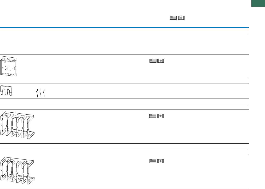
Start-point bridge
DILEEM
DILEM12
DILEM
S1DILEM1)
220218
20 off
Reversing starter wiring kit
Main current wiring for reversing combinations
DILEEM (+MVDILEM)
DILEM12 (+MVDILEM)
DILEM (+MVDILEM)
MVS-WB-EM2)
220209
1 off Product Standards
UL File No.
UL CCN
CSA File No.
CSA Class No.
NA Certification
Star-delta wiring kit
Main current wiring for star-delta combination incl. star-point bridge
DILE(E)M (+MVDILEM)
DILE(E)M12 (+MVDILEM)
DILE(E)M star contactor
MVS-SB-EM3)
220213
1 off Product Standards
UL File No.
UL CCN
CSA File No.
CSA Class No.
NA Certification
Notes 1) Protected against accidental contact in accordance with VDE 0106 Part 100
2) The following control cables are integrated in addition to electrical interlock:
•Q11: A1 -Q12: 21
•Q11: 21 - Q12: A1
•Q11: A2 - Q12: A2
For use with overload relay separate mounting.
3) The following control cables are integrated in addition to electrical interlock:
•Q13: A1 -Q15: 21
•Q13: 21 - Q15: A1
•Q13: A2 - Q15: A2
For use with overload relay separate mounting.
HDILE, ...DILEM, MVS
1.1 Contactor relays
Basic devices
10 AUTOMATION AND CONTROL www.eaton.com/seasia-electrical
1
ConventionalRated operational currentContact
thermal current
Distinctive
number
Can be combined
with auxiliary contact
Circuit symbol
N/O = normally
open contact
NC = normally
closed contact
I51-CA th
220 V
230 V
240 V
380 V
400 V
415 V
A
IeIe
AA
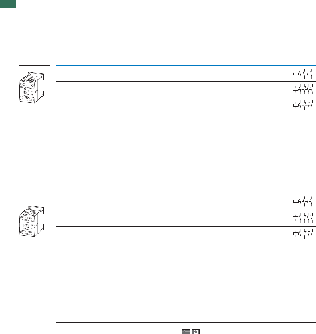
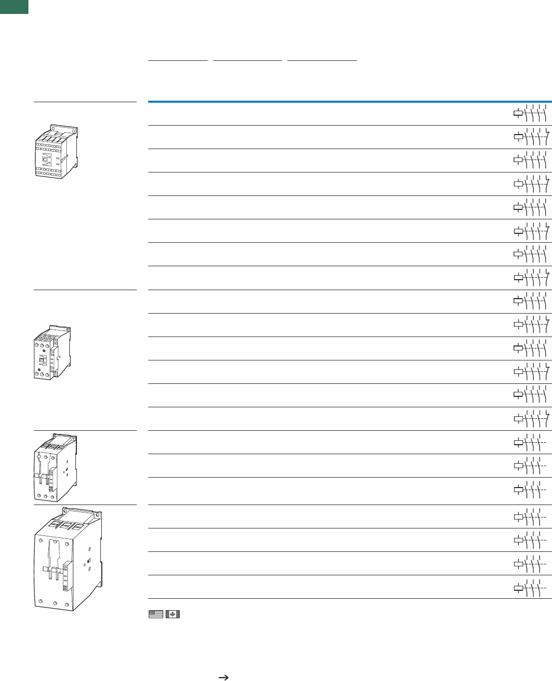
Basic devices with positively driven contacts
Screw terminals 4 N/O – 4 4 16 40E DILA-XHI(V)…
4416
4416
4416
4416
DILA-XHI(V)…31E1 NC3 N/O
DILA-XHI(V)…22E2 NC2 N/O
Spring-loaded
terminals
4 N/O – 4 4 16 40E DILA-XHIC(V)…
DILA-XHIC(V)…31E1 NC3 N/O
DILA-XHIC(V)…22E2 NC2 N/O
Contact numbers to EN 50011
Coil terminal markings to EN 50005
The following applies to DC-operated contactors:
• Integrated suppressor circuit
Information relevant for export to North America
Product Standards
UL File No.
UL CCN
CSA File No.
CSA Class No.
NA Certification
14
13 33
34
43
44
A1
A2
23
24
14
13 21
22
33
34
43
44
A1
A2
14
13 21
22
31
32
43
44
A1
A2
14
13 33
34
43
44
A1
A2
23
24
14
13 21
22
33
34
43
44
A1
A2
14
13 21
22
31
32
43
44
A1
A2
Notes
DILA
IEC/EN 60947-4-1; UL 508; CSA-C22.2 No.14-05; CE marking
E29184
NKCR
012528
3211-03
UL Listed, CSA certified
1.1
Contactor relays
Basic devices
11AUTOMATION AND CONTROL www.eaton.com/seasia-electrical
1
AC operation DC operation
Part no.
Article no. Price
See price
list
Std. pack Circuit symbol Part no.
Article no. Price
See price
list
Std. pack Notes
DILA-40(230V50Hz)
276329
1 off
1 off
1 off
DILA-40(24VDC)
276344
1 off
DILA-31(230V50Hz)
276364 DILA-31(24VDC)
276379
DILA-22(230V50Hz)
276399 DILA-22(24VDC)
276414
DILAC-40(230V50Hz)
276441
1 off
1 off
1 off
DILAC-40(24VDC)
276456
1 off
DILAC-31(230V50Hz)
276473 DILAC-31(24VDC)
276488
DILAC-22(230V50Hz)
276505 DILAC-22(24VDC)
276520
14
13 33
34
43
44
A1
A2
23
24
With screw terminals:
Accessories Page
1 Suppressor 50
2 Auxiliary contact modules 36
Further actuating voltages 68
2
1
14
13A1
A2
21
22
33
34
43
44
14
13A1
A2
21
22
31
32
43
44
14
13 33
34
43
44
A1
A2
23
24
With spring-loaded terminals:
Accessories Page
1 Suppressor 50
2 Auxiliary contact modules 36
Further actuating voltages 68
2
1
14
13A1
A2
21
22
33
34
43
44
14
13A1
A2
21
22
31
32
43
44
1.1 Contactor relays
Auxiliary contact modules
12 AUTOMATION AND CONTROL www.eaton.com/seasia-electrical
1
ConventionalRated operational currentContact
thermal current
Circuit symbol
N/O = normally open contact
S
F
= NO early-make
NC = normally closed contact
Ö
S
= NC late-break
AC-15
220 V
230 V
240 V
380 V
400 V
415 V
Ith
IeIe
A A A
DILA auxiliary contact modules
Screw terminals
Screw terminals
Spring-loaded terminals
Spring-loaded terminals
Information relevant for export to North America
Product Standards
UL File No.
UL CCN
CSA File No.
CSA Class No.
NA Certification
51
52
61
62
54
53 61
62
54
63
64
53
58
57 65
66
51
52
61
62
71
72 82
81
53 61 71 81
82
72
62
54
54
53 61
62
71
72
83
84
54
53 61
62
73
74
83
84
54
63 73
64 74
53 83
84
58
57 65
66
71
72
83
84
51
52
61
62
54
53 61
62
54
63
64
53
58
57 65
66
51
52
61
62
71
72 82
81
53 61 71 81
82
72
62
54
54
53 61
62
71
72
83
84
54
53 61
62
73
74
83
84
54
63 73
64 74
53 83
84
58
57 65
66
71
72
83
84
DILA...XHI...
2 pole – –2 NC – 4 416
4 pole – –4 NC – 4 416
4 pole – –4 NC – 4 4 16
2 pole – –2 NC – 4 416
1 N/O –1 NC – 4 416
1 N/O – 3 NC – 4 4 16
1 N/O –3 NC – 4 416
2 N/O –2 NC – 4 416
2 N/O – 2 NC – 4 4 16
3 N/O – 1 NC – 4 4 16
3 N/O – 1 NC – 4 4 16
1 N/O – 1 NC – 4 416
4 N/O –––4 416
2 N/O – – – 4 4 16
2 N/O –––4 416
–1 S
F–1 Ö
S44 16
1 N/O 1 SF1 NC 1 ÖS4416
4 N/O –––
4416
1 N/O 1 SF1 NC 1 ÖS44 16
–1 SF–1 Ö
S44 16
IEC/EN 60947-4-1; UL 508; CSA-C22.2 No.14-05; CE marking
E29184
NKCR
012528
3211-03
UL Listed, CSA certified
1.1
Contactor relays
Auxiliary contact modules
13AUTOMATION AND CONTROL www.eaton.com/seasia-electrical
1
Distinctive number/type
of combinations Part no.
Article no. Price
See price list
Std. pack Description Notes
DILA(C)-40 DILA(C)-31 DILA(C)-22
42E 33 24
51E 42 33
60E 51 42
51 42 33
44E 35 26
53E 44 35
62E 53 44
71E 62 53
80E 71 62
62 53 44
42E 33 24
51E 42 33
60E 51 42
51 42 33
44E 35 26
53E 44 35
62E 53 44
71E 62 53
80E 71 62
62 53 44
DILA-XHI02
276420
5 off With interlocked
opposing contacts
5 off With interlocked
opposing contacts
5 off
5 off
5 off
With interlocked
opposing contacts
Type E combinations comply with
EN 50011 and must be given preference.
The other combinations comply with
EN 50005
The DC operated contactor DILA(C)-22 must only
be combined with 2 pole auxiliary contacts.
DILA-XHI11
276421
DILA-XHI20
276422
DILA-XHIV11
276423
–
DILA-XHI04
276424
With interlocked
opposing contacts
5 off With interlocked
opposing contacts
5 off With interlocked
opposing contacts
5 off With interlocked
opposing contacts
5 off
5 off
With interlocked
opposing contacts
DILA-XHI13
276425
DILA-XHI22
276426
DILA-XHI31
276427
DILA-XHI40
276428
DILA-XHIV22
276429
–
DILA-XHIC02
276526
5 off With interlocked
opposing contacts
5 off With interlocked
opposing contacts
5 off
5 off
5 off
With interlocked
opposing contacts
Type E combinations comply with
EN 50011 and must be given preference.
The other combinations comply with
EN 50005
The DC operated contactor DILA(C)-22 must only
be combined with 2 pole auxiliary contacts.
DILA-XHIC11
276527
DILA-XHIC20
276528
DILA-XHICV11
276529
–
DILA-XHIC04
276530
With interlocked
opposing contacts
5 off With interlocked
opposing contacts
5 off With interlocked
opposing contacts
5 off With interlocked
opposing contacts
5 off
5 off
With interlocked
opposing contacts
DILA-XHIC13
276531
DILA-XHIC22
276532
DILA-XHIC31
276533
DILA-XHIC40
276534
DILA-XHICV22
276535
–
1.1 Contactors
14 AUTOMATION AND CONTROL www.eaton.com/seasia-electrical
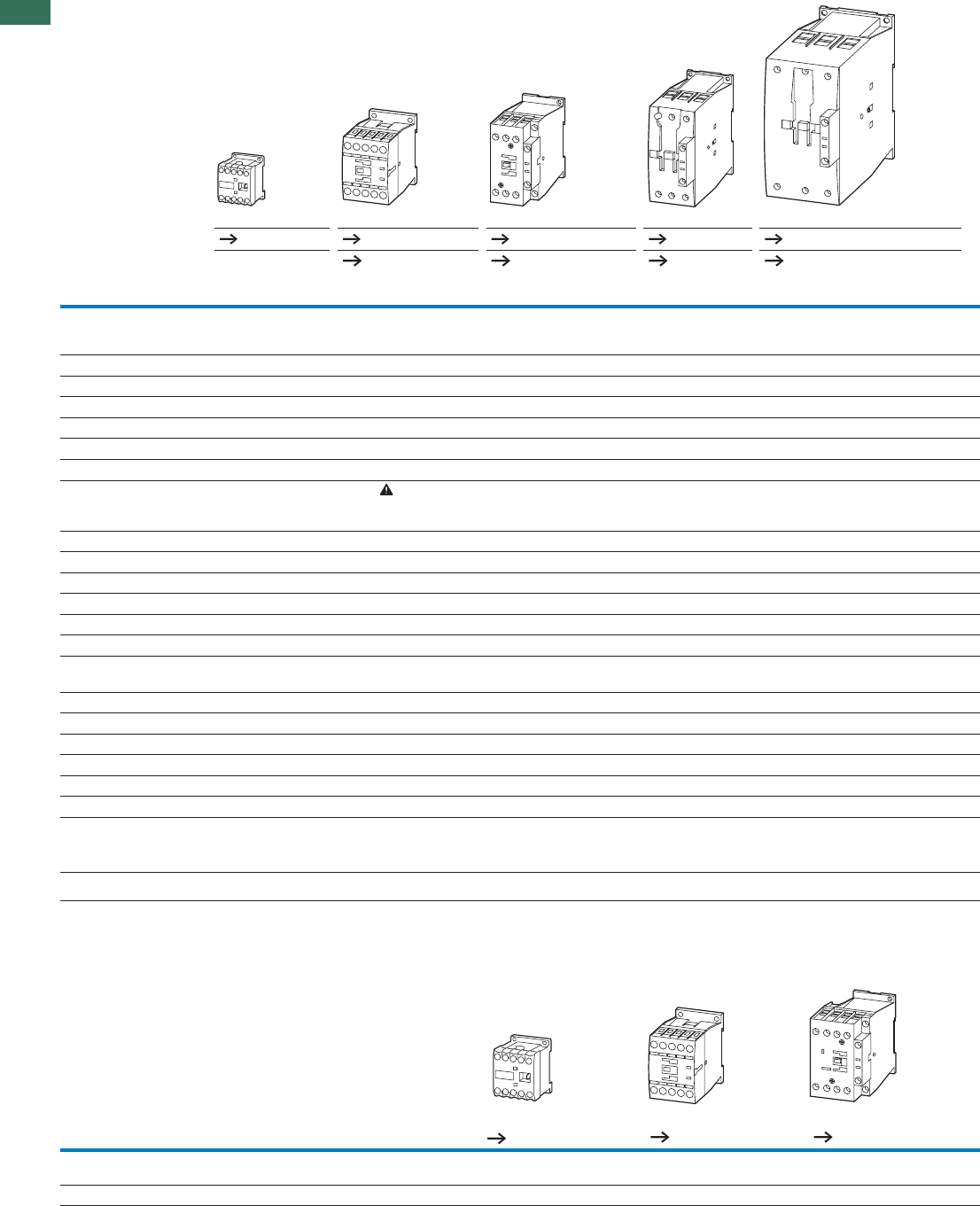
1Technical overview
Contactors
3 pole
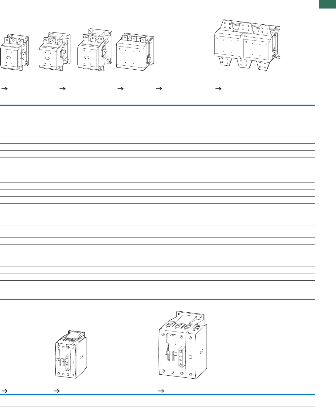
DIL EEM EM EM12 M7 M9 M12 M15 M17 M25 M32 M38 M40 M50 M65 M80 M95 M115 M150 M170
Basic devices Page 4 18 18 20 46
Complete units Page – Page 24 – Page 24 Page 26 Page 26
Rated-operational voltage kW kW kW kW kW kW kW kW kW kW kW kW kW kW kW kW kW kW kW
AC-3
Rated operational power
for 3-phase motors 50 –60 Hz
220 V – 230 V 1.5 2.2 3 2.2 2.5 3.5 4 5 7.5 10 11 12.5 15.5 20 25 30 37 48 52
380 V – 400 V 3 4 5.5 3 4 5.5 7.5 7.5 11 15 18.5 18.5 22 30 37 45 55 75 90
440 V 3.3 4.6 5.5 4.5 5.5 7.5 8.4 10.5 15.5 20 21 25 32 41 51 60 75 95 105
500 V 3 4 5.5 3.5 4.5 7 7.5 12 17.5 23 24 28 36 47 58 70 85 110 120
660 V/690 V 3 4 4 3.5 4.5 6.5 7 11 14 17 21 23 30 35 63 75 90 96 140
1000 V – – – – – – – – – – – – – – – – – – –
AC-4
Rated operational power
for 3-phase motors 50 –60 Hz
Increase in life span for DILM7 – DILM150 to 200000 operations
220 V – 230 V 1.1 1.5 1.5 1 1.5 2 2 2.5 3.5 4 4 5 6 7 12 16 17 20 20
380 V – 400 V 2.2 3 3 2.2 2.5 3 3 4.5 6 7 7 9 10 12 20 26 28 33 33
440 V 2.4 3.3 3.3 2.4 3 3.6 3.6 5.5 7 8 8 10 12 14 25 32 35 41 41
500 V 2.2 3 3 2.5 2.8 3.5 3.5 6 8 9 9 11 13 16 29 36 40 47 47
660 V/690 V 2.2 3 3 2.9 3.6 4.4 4.4 6.5 8.5 10 10 12 14 17 26 35 43 48 48
1000 V – – – – – – – – – – – – – – – – – – –
1000 V – – – – – – – – – – – – – – – – – – –
22 22 22 22 22 22 22 40 45 45 45 60 80 98 110 130 160 190 225
220 V – 230 V 8 8 8 8 8 8 8 15 17 17 17 22 30 37 42 49 61 72 85
380 V – 400 V 13 13 13 14 14 14 14 26 29 29 29 39 53 65 72 85 105 125 150
400 V 15 15 15 16 16 16 16 30 34 34 34 45 58 71 80 94 116 138 170
500 V 18 18 18 19 19 19 19 34 38 38 38 51 66 81 90 107 132 156 194
660 V/690 V 23 23 23 25 25 25 25 45 51 51 51 68 91 111 125 148 182 216 268
AC-1
Rated operational power under resistive load, 40 °C
Conventional thermal
Current
Ith = Ie open at 40 °C
A AA AAAAAAA AAAAAAA A A
Contactors
4 pole
MP32MP20EM4DIL
Rated operational voltage Page 4 Page 34 Page 34
AC-1
Conventional free air thermal current I = I open, at 40 °C
th e AAA
322222up to 690 V
DILM, DILE(E)M, DILMP
DILM, DILE(E)M, DILMP
1.1
Contactors
15AUTOMATION AND CONTROL www.eaton.com/seasia-electrical
1
Contactors
4 pole
DILM, DILE(E)M, DILMP
Contactors
3 pole
M185A M225A M250A M300A M400 M500 M580 M650 M750 M820 M1000 M1600 M1400 H2000 H2200 H2600
––––––––––––––––
Page 30 Page 30 Page 30 Page 30 Page 32
kW kW kW kW kW kW kW kW kW kW kW kW kW kW kW kW
55 70 75 90 125 155 185 205 240 260 315 500 – – – –
90 110 132 160 200 250 315 355 400 450 560 900 ––––
115 142 157 190 255 345 370 420 480 525 650 1000 – – – –
132 160 180 215 290 360 420 470 550 600 730 1180 – – – –
175 215 240 286 344 344 560 630 720 750 1000 1600 – – – –
108 108 108 132 132 132 600 600 800 800 1000 1770 – – – –
41 51 62 75 92 112 143 161 181 209 260 430 – – – –
75 90 110 132 160 200 250 280 315 355 450 750 ––––
85 102 125 140 186 229 290 326 367 418 520 830 – – – –
96 116 143 172 214 260 330 370 417 474 590 940 – – – –
127 155 189 229 283 344 440 494 556 633 780 1300 – – – –
108 108 108 132 132 132 509 509 678 678 1000 1650 – – – –
121 139 155 177 221 310 354 376 398 443 443 717 620 886 1075 1269
210 241 268 306 382 535 612 650 689 766 766 1247 1071 1531 1870 2207
243 279 310 354 443 620 709 753 797 886 886 1371 1240 1773 2058 2427
277 317 352 403 503 705 806 856 906 1007 1007 1558 1410 2015 2338 2758
365 419 465 532 664 930 1064 1130 1196 1330 1330 2151 1861 2660 3227 3806
554 635 705 806 1007 1410 1612 1712 1813 2015 2015 2420 2417 3223 4676 5516
337 356 400 430 612 857 980 1041 1102 1225 1225 2200 1714 2450 2700 3185
AAAAAAAAAAAAAAAA
MP45 MP63 MP80 MP125 MP160 MP200
Page 34 Page 34 Page 34
AAAAAA
200160125806345
DILM, DILH, DILMP
1.1 Contactors
16 AUTOMATION AND CONTROL www.eaton.com/seasia-electrical
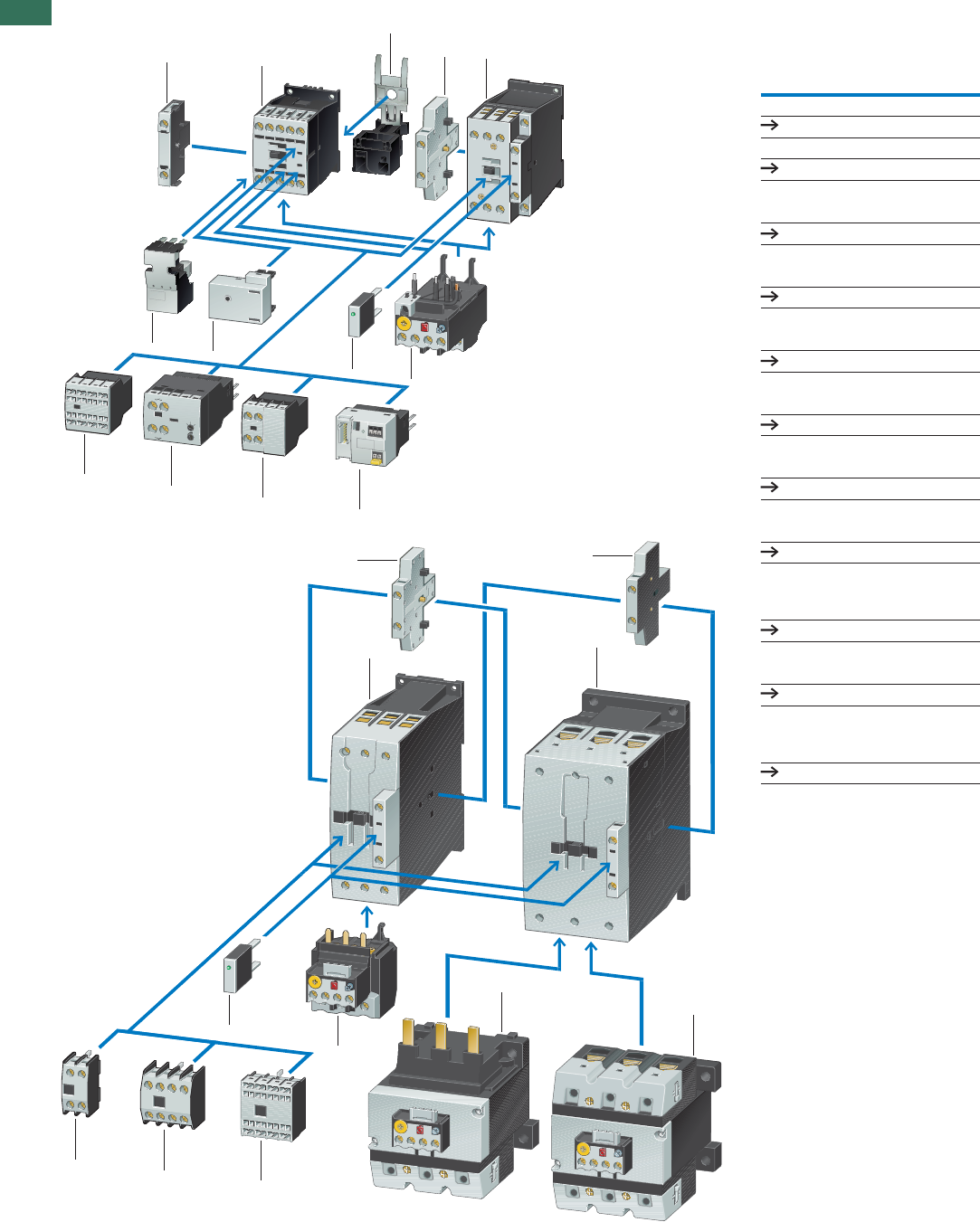
1System overview
Contactors up to 90 kW
(AC-3/400V)
1
2
3
4
5
6
7
9
3 pole
Page 18
4 pole
Page 34
Suppressor circuits
Page 50
Overload relays
Chapter 1.2 (Page 8)
Auxiliary contact modules
Page 36
Auxiliary contact modules
Page 36
Auxiliary contact modules
Motor feeder plug
Page 39
Page 58
PE module with contact
plate
8
Page 58
Motor suppressor module
Page 59
SmartWire-DT®
contactor module
10
Page 58
Range (s)
66
10
T
im
e
1100
58
65
57
NC
NO
2T1 4 T2 6
T3
54
1
1
8
6
23
5
6
9
7
10
66
455
1
3
3
1
3
2
DILM7...DILM170
1.1
Contactors
17AUTOMATION AND CONTROL www.eaton.com/seasia-electrical
1
1
2
3
5
4
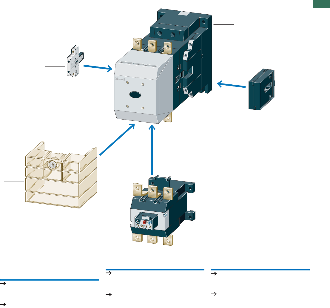
Contactors 90 – 900 kW
(AC-3/400 V)
Comfort series
Standard range 90–250kW
1
1
Page 30
Page 28
2Mechanical interlock
Page 52
3Overload relays
Chapter 1.2 (Page 12)
4Terminal shroud
Auxiliary contact modules 5
Page 61
Page 39
DILM185... DILH2600
1.1 Contactors
Basic devices up to 170 A
18 AUTOMATION AND CONTROL www.eaton.com/seasia-electrical
1
Rated operational
current
Max. motor rating for
three-phase motors 50 - 60 Hz
Conventional thermal
current Ith = IeAC-1
at 60 °C
Contact configuration Circuit symbol
N/O = normally openAC-4AC-3AC-3
contact
NC = normally closed
contact
380 V
400 V
220 V
230 V 380 V
400 V
660 V
690 V
220 V
230 V 380 V
400 V
660 V
690 V
Open
IePPPPPth = Ie
AkW kW kW
P
kW kW kW
I
A
Basic device
Screw terminals
3 pole
72.2 33.5 1 2.2 2.9 20 1 N/O –
72.2 33.5 1 2.2 2.9 20 – 1 NC
92.5 44.5 1.5 2.5 3.6 20 1 N/O –
92.5 44.5 1.5 2.5 3.6 20 – 1 NC
12 3.5 5.5 6.5 2 34.4 20 1 N/O –
12 3.5 5.5 6.5 2 34.4 20 – 1 NC
15.5 47.5 7234.4 20 1 N/O –
15.5 47.5 7234.4 20 – 1 NC
18 57.5 11 2.5 4.5 6.5 35 1 N/O –
18 57.5 11 2.5 4.5 6.5 35 – 1 NC
25 7.5 11 14 3.5 68.5 40 1 N/O –
25 7.5 11 14 3.5 68.5 40 – 1 NC
32 10 15 17 4 710 40 1 N/O –
32 10 15 17 4 710 40 – 1 NC
38 11 18.5 21 4 710 40 1 N/O –
38 11 18.5 21 4 710 40 – 1 NC
Information relevant for export to North America
Product Standards
UL File No.
UL CCN
CSA File No.
CSA Class No.
NA Certification
See also Page 80
2
35
46
A1
A2
113
14
2
35
46
A1
A2
121
22
2
35
46
A1
A2
113
14
2
35
46
A1
A2
121
22
2
35
46
A1
A2
113
14
2
35
46
A1
A2
121
22
2
35
46
A1
A2
113
14
2
35
46
A1
A2
121
22
2
35
46
A1
A2
113
14
2
35
46
A1
A2
121
22
2
35
46
A1
A2
113
14
2
35
46
A1
A2
121
22
2
35
46
A1
A2
113
14
2
35
46
A1
A2
121
22
2
35
46
A1
A2
113
14
2
35
46
A1
A2
121
22
DILM
Screw terminals
3 pole
IEC/EN 60947-4-1; UL 508; CSA-C22.2 No.14-05; CE marking
E29096
NLDX
012528
2411-03, 3211-04
UL Listed,
CSA certified
1.1
Contactors
Basic devices up to 170 A
19AUTOMATION AND CONTROL www.eaton.com/seasia-electrical
1
AC operation DC operation
Can be combined
with auxiliary
contact
Part no.
Article no. Price
See
price list
Part no.
Article no. Price
See
price list
Std. pack Notes
DILM32-XHI..
DILA-XHI(V).. DILM7-10(230V50Hz)
276550 DILM7-10(24VDC)
276565 1 off Contacts to EN 50 012.
For all DC operated contactors DILM7 - DILM15 the following
applies:
• Integrated varistor-suppressor circuit.
For DC operated contactors DILM17 - DILM170 the following
applies:
• Integrated suppressor circuit in actuating electronics
For AC operated contactors DILM115 - DILM170 the following
applies:
• Integrated suppressor circuit in actuating electronics
For DILM7-01 – DILM38-01 the following applies:
• With mirror contact.
1) Electrical lifespan 87
DILA-XHI(V).. DILM7-01(230V50Hz)
276585 DILM7-01(24VDC)
276600
DILM32-XHI..
DILA-XHI(V).. DILM9-10(230V50Hz)
276690 DILM9-10(24VDC)
276705
DILA-XHI(V).. DILM9-01(230V50Hz)
276725 DILM9-01(24VDC)
276740
DILM32-XHI..
DILA-XHI(V).. DILM12-10(230V50Hz)
276830 DILM12-10(24VDC)
276845
DILA-XHI(V).. DILM12-01(230V50Hz)
276865 DILM12-01(24VDC)
276880
DILM32-XHI..
DILA-XHI(V).. DILM15-10(230V50Hz) 1)
290058 DILM15-10(24VDC)1)
290073
DILA-XHI(V).. DILM15-01(230V50Hz) 1)
290093 DILM15-01(24VDC)1)
290108
DILM32-XHI..
DILA-XHI(V)..
DILM32-XHI11-S
DILM17-10(230V50Hz)
277004 DILM17-10(RDC24)
277018
DILA-XHI(V)..
DILM32-XHI11-S DILM17-01(230V50Hz)
277036 DILM17-01(RDC24)
277050
DILM32-XHI..
DILA-XHI(V)..
DILM32-XHI11-S
DILM25-10(230V50Hz)
277132 DILM25-10(RDC24)
277146
DILA-XHI(V)..
DILM32-XHI11-S DILM25-01(230V50Hz)
277164 DILM25-01(RDC24)
277178
DILM32-XHI..
DILA-XHI(V)..
DILM32-XHI11-S
DILM32-10(230V50Hz)
277260 DILM32-10(RDC24)
277274
DILA-XHI(V)..
DILM32-XHI11-S DILM32-01(230V50Hz)
277292 DILM32-01(RDC24)
277306
DILM32-XHI..
DILA-XHI(V)..
DILM32-XHI11-S
DILM38-10(230V50Hz) 1)
112428 DILM38-10(RDC24)1)
112442
DILA-XHI(V)..
DILM32-XHI11-S DILM38-01(230V50Hz)1)
112456 DILM38-01(RDC24)1)
112470
PageAccessories
1 Overload relay Chapter 1.2
2 Suppressor 50
3 Auxiliary contact module 36
Further actuating voltages 69
Accessories 52
3
21
1.1 Contactors
Basic devices up to 170 A
20 AUTOMATION AND CONTROL www.eaton.com/seasia-electrical
1
40 12.5 18.5 23 5 912 50 – –
50 15.5 22 30 6 10 14 65 – –
65 20 30 35 7 12 17 80 – –
72 25 37 35 7 12 17 80 – –
80 25 37 63 12 20 26 90 – –
95 30 45 75 16 26 35 110 – –
115 37 55 90 17 28 43 130 – –
150 48 75 96 20 33 48 160 – –
170 52 90 140 20 33 48 185 – –
Information relevant for export to North America
Product Standards
UL File No.
UL CCN
CSA File No.
CSA Class No.
NA Certification
See also Page 80
Rated operational
current
Max. motor rating for
three-phase motors 50 - 60 Hz
Conventional thermal
current Ith = Ie AC-1
at 60 °C
Contact configuration Circuit
symbol
N/O = normally openAC-4AC-3AC-3
contact
NC = normally closed
contact
380 V
400 V
220 V
230 V 380 V
400 V
660 V
690 V
220 V
230 V 380 V
400 V
660 V
690 V
Open
IePPPPPth = Ie
AkW kW kW
P
kW kW kW
I
A
2
35
46
A1
A2
1
2
35
46
A1
A2
1
2
35
46
A1
A2
1
2
35
46
A1
A2
1
2
35
46
A1
A2
1
2
35
46
A1
A2
1
2
35
46
A1
A2
1
2
35
46
A1
A2
1
2
35
46
A1
A2
1
Screw terminals
3 pole
Screw terminals
3 pole
IEC/EN 60947-4-1; UL 508; CSA-C22.2 No.14-05; CE marking
E29096
NLDX
012528
2411-03, 3211-04
UL Listed,
CSA certified
Basic device
DILM
1.1
Contactors
Basic devices up to 170 A
21AUTOMATION AND CONTROL www.eaton.com/seasia-electrical
1
DILM150-XHI(V)..
DILM1000-
XHI(V)..
DILM40(230V50Hz)
277766 DILM40(RDC24)
277780 1 off Contacts to EN 50012.
For all DC operated contactors DILM7 - DILM15 the following
applies:
• Integrated varistor-suppressor circuit.
For DC operated contactors DILM17 - DILM170 the following
applies:
• Integrated suppressor circuit in actuating electronics
For AC operated contactors DILM115 - DILM170 the following
applies:
• Integrated suppressor circuit in actuating electronics
For DILM7-01 – DILM38-01 the following applies:
• With mirror contact.
1) Electrical lifespan 87
DILM150-XHI(V)..
DILM1000-
XHI(V)..
DILM50(230V50Hz)
277830 DILM50(RDC24)
277844
DILM150-XHI(V)..
DILM1000-
XHI(V)..
DILM65(230V50Hz)
277894 DILM65(RDC24)
277908
DILM150-XHI(V)..
DILM1000-
XHI(V)..
DILM72(230V50Hz)1)
107670 DILM72(RDC24)1)
107671
DILM150-XHI(V)..
DILM1000-
XHI(V)..
DILM80(230V50Hz)
239402 DILM80(RDC24)
239416
DILM150-XHI(V)..
DILM1000-
XHI(V)..
DILM95(230V50Hz)
239480 DILM95(RDC24)
239510
DILM150-XHI(V)..
DILM1000-
XHI(V)..
DILM115(RAC240)
239548 DILM115(RDC24)
239555
DILM150-XHI(V)..
DILM1000-
XHI(V)..
DILM150(RAC240)
239588 DILM150(RDC24)
239591
DILM150-XHI(V)..
DILM1000-
XHI(V)..
DILM170(RAC240)1)
107013 DILM170(RDC24)1)
107016
AC operation DC operation
Can be combined
with auxiliary
contact
Part no.
Article no. Price
See
price list
Part no.
Article no. Price
See
price list
Std. pack Notes
PageAccessories
1 Overload relay Chapter 1.2
2 Suppressor 50
3 Auxiliary contact module 36
Further actuating voltages 71
Accessories 52
3
21
1.1 Contactors
Basic devices up to 170 A
22 AUTOMATION AND CONTROL www.eaton.com/seasia-electrical
1
Rated operational
current
Max. motor rating for
three-phase motors 50 - 60 Hz
Conventional thermal
current Ith = Ie AC-1
at 60 °C
Contact configuration Circuit symbol
N/O = normally openAC-4AC-3AC-3
contact
NC = normally closed
contact
380 V
400 V
220 V
230 V 380 V
400 V
660 V
690 V
220 V
230 V 380 V
400 V
660 V
690 V
Open
IePPPPPth = Ie
AkW kW kW
P
kW kW kW
I
A
Spring-loaded terminals
3 pole
72.2 33.5 1 2.2 2.9 20 1 N/O –
72.2 33.5 1 2.2 2.9 20 – 1 NC
92.5 44.5 1.5 2.5 3.6 20 1 N/O –
92.5 44.5 1.5 2.5 3.6 20 – 1 NC
12 3.5 5.5 6.5 2 34.4 20 1 N/O –
12 3.5 5.5 6.5 2 34.4 20 – 1 NC
15.5 47.5 7234.4 20 1 N/O –
15.5 47.5 7234.4 20 – 1 NC
Spring-loaded terminals on
auxiliary and control circuit
terminals
3 pole
18 57.5 11 2.5 4.5 6.5 35 1 N/O –
18 57.5 11 2.5 4.5 6.5 35 – 1 NC
25 7.5 11 14 3.5 68.5 40 1 N/O –
25 7.5 11 14 3.5 68.5 40 – 1 NC
32 10 15 7 10 40 1 N/O –
32 10 15 7 10 40 – 1 NC
40 12.5 18.5 9 12 50 – –
50 15.5 22 10 14 65 – –
65 20 30 12 17 80 – –
80 25 37 63 12 20 26 90 – –
95 30 45 75 16 26 35 110 – –
115 37 55 90 17 28 43 130 – –
150 48 75 96 20 33 48 160 – –
2
35
46
A1
A2
113
14
2
35
46
A1
A2
121
22
2
35
46
A1
A2
113
14
2
35
46
A1
A2
121
22
2
35
46
A1
A2
113
14
2
35
46
A1
A2
121
22
2
35
46
A1
A2
113
14
2
35
46
A1
A2
121
22
2
35
46
A1
A2
113
14
2
35
46
A1
A2
121
22
2
35
46
A1
A2
113
14
2
35
46
A1
A2
121
22
2
35
46
A1
A2
113
14
2
35
46
A1
A2
121
22
2
35
46
A1
A2
1
2
35
46
A1
A2
1
2
35
46
A1
A2
1
2
35
46
A1
A2
1
2
35
46
A1
A2
1
2
35
46
A1
A2
1
2
35
46
A1
A2
1
Information relevant for export to North America
Product Standards
UL File No.
UL CCN
CSA File No.
CSA Class No.
NA Certification
See also Page 80
IEC/EN 60947-4-1; UL 508; CSA-C22.2 No.14-05; CE marking
E29096
NLDX
012528
2411-03, 3211-04
UL Listed, CSA certified
Basic device
DILM
1.1
Contactors
Basic devices up to 170 A
23AUTOMATION AND CONTROL www.eaton.com/seasia-electrical
1
Can be combined
with auxiliary
contact
AC operation DC operation Std. pack Notes
Part no.
Article no. Price
See
price list
Part no.
Article no. Price
See
price list
DILM32-XHIC..
DILA-XHIC(V).. DILMC7-10(230V50Hz)
277389 DILMC7-10(24VDC)
277404 1 off Contacts to EN 50 012.
For DILMC7 – DILMC15 the following applies:
• Auxiliary coil, and main current terminals with spring-loaded
terminals.
For DILMC17 – DILMC150 the following applies:
• Auxiliary connections, coil connections with spring-loaded
connection terminals.
• Main current connections with screw terminals.
For DC operated contactors DILMC7 - DILMC15 the following
applies:
• Integrated varistor-suppressor circuit.
For DC operated contactors DILMC17 - DILMC150 the following
applies:
• Integrated suppressor circuit in actuating electronics
For AC operated contactors DILMC115 - DILMC150 the
following applies:
• Integrated suppressor circuit in actuating electronics
For DILMC7-01 – DILMC32-01 the following applies:
• With mirror contact.
DILA-XHIC(V).. DILMC7-01(230V50Hz)
277421 DILMC7-01(24VDC)
277436
DILM32-XHIC..
DILA-XHIC(V).. DILMC9-10(230V50Hz)
277453 DILMC9-10(24VDC)
277468
DILA-XHIC(V).. DILMC9-01(230V50Hz)
277485 DILMC9-01(24VDC)
277500
DILM32-XHIC..
DILA-XHIC(V).. DILMC12-10(230V50Hz)
277517 DILMC12-10(24VDC)
277532
DILA-XHIC(V).. DILMC12-01(230V50Hz)
277549 DILMC12-01(24VDC)
277564
DILM32-XHIC…
DILA-XHIC(V)… DILMC15-10(230V50Hz)
293911 DILMC15-10(24VDC)
293926
DILA-XHIC(V)… DILMC15-01(230V50Hz)
293946 DILMC15-01(24VDC)
293961
DILM32-XHIC..
DILA-XHIC(V).. DILMC17-10(230V50Hz)
277581 DILMC17-10(RDC24)
277595
DILA-XHIC(V).. DILMC17-01(230V50Hz)
277611 DILMC17-01(RDC24)
277625
DILM32-XHIC..
DILA-XHIC(V).. DILMC25-10(230V50Hz)
277641 DILMC25-10(RDC24)
277655
DILA-XHIC(V).. DILMC25-01(230V50Hz)
277671 DILMC25-01(RDC24)
277685
DILM32-XHIC..
DILA-XHIC(V).. DILMC32-10(230V50Hz)
277701 DILMC32-10(RDC24)
277715
DILA-XHIC(V).. DILMC32-01(230V50Hz)
277731 DILMC32-01(RDC24)
277745
DILM150-
XHIC(V)..
DILM1000-XHIC..
DILMC40(230V50Hz)
277965 DILMC40(RDC24)
277979
DILMC50(230V50Hz)
277995 DILMC50(RDC24)
278009
DILMC65(230V50Hz)
278025 DILMC65(RDC24)
278039
DILMC80(230V50Hz)
239618 DILMC80(RDC24)
239652
DILMC95(230V50Hz)
239685 DILMC95(RDC24)
239715
DILMC115(RAC240)
239736 DILMC115(RDC24)
239741
DILMC150(RAC240)
239751 DILMC150(RDC24)
239765
egaPseirosseccA
1 Overload relay Chapter 1.2
2 Suppressor 50
3 Auxiliary contact module 36
Further actuating voltages 73
Accessories 52
3
2
1
1.1 Contactors
Complete device up to 170 A
24 AUTOMATION AND CONTROL www.eaton.com/seasia-electrical
1
Rated opera-
tional current
Max. motor rating for
three-phase motors 50 - 60 Hz
Conventional
free air
thermal
current Ith = Ie
AC-1 at 60 °C
Open
Contact Circuit symbol
Contact configuration:AC-4AC-3AC-3
= Safety function by
positive opening according
to IEC/EN 60947-5-1
380 V
400 V
220 V
230 V 380 V
400 V
660 V
690 V
220 V
230 V 380 V
400 V
660 V
690 V
IePPPPPth = Ie
N/O = normally
open contact
NC = normally
closed contact
AkW kW kW
P
kW kW kW
I
A
DILM complete device
Screw terminals 72.2 33.5 1 2.2 2.9 20 2 N/O 1 NC
72.2 33.5 1 2.2 2.9 20 2 N/O 1 NC
72.2 33.5 1 2.2 2.9 20 3 N/O 2 NC
92.5 44.5 1.5 2.5 3.6 20 2 N/O 1 NC
92.5 44.5 1.5 2.5 3.6 20 2 N/O 1 NC
92.5 44.5 1.5 2.5 3.6 20 3 N/O 2 NC
12 3.5 5.5 6.5 2 34.4 20 2 N/O 1 NC
12 3.5 5.5 6.5 2 34.4 20 2 N/O 1 NC
12 3.5 5.5 6.5 2 34.4 20 3 N/O 2 NC
15.5 47.5 7234.4 20 2 N/O 2 NC
18 57.5 11 2.5 4.5 6.5 35 2 N/O 1 NC
18 57.5 11 2.5 4.5 6.5 35 2 N/O 1 NC
18 57.5 11 2.5 4.5 6.5 35 3 N/O 2 NC
25 7.5 11 14 3.5 68.5 40 2 N/O 1 NC
25 7.5 11 14 3.5 68.5 40 2 N/O 1 NC
25 7.5 11 14 3.5 68.5 40 3 N/O 2 NC
32 10 15 17 4 710 40 2 N/O 1 NC
32 10 15 17 4 710 40 2 N/O 1 NC
32 10 15 17 4 710 40 3 N/O 2 NC
2
3513 21 33
46
14 22 34
A1
A2
1
2
3513 21 31
46
14 22 32
43
44
A1
A2
1
2
3513 21 31
46
14
53
54
22 32
43
44
A1
A2
1
2
3513 21 33
46
14 22 34
A1
A2
1
2
3513 21 31
46
14 22 32
43
44
A1
A2
1
2
3513 21 31
46
14
53
54
22 32
43
44
A1
A2
1
2
3513 21 33
46
14 22 34
A1
A2
1
2
3513 21 31
46
14 22 32
43
44
A1
A2
1
2
3513 21 31
46
14
53
54
22 32
43
44
A1
A2
1
2
3513 21 31
46
14 22 32
43
44
A1
A2
1
2
3513 21 33
46
14 22 34
A1
A2
1
2
3513 21 31
46
14 22 32
43
44
A1
A2
1
2
3513 21 31
46
14
53
54
22 32
43
44
A1
A2
1
2
3513 21 33
46
14 22 34
A1
A2
1
2
3513 21 31
46
14 22 32
43
44
A1
A2
1
2
3513 21 31
46
14
53
54
22 32
43
44
A1
A2
1
2
3513 21 33
46
14 22 34
A1
A2
1
2
3513 21 31
46
14 22 32
43
44
A1
A2
1
2
3513 21 31
46
14
53
54
22 32
43
44
A1
A2
1
Information relevant for export to North America
Product Standards
UL File No.
UL CCN
CSA File No.
CSA Class No.
NA Certification
See also Page 80
IEC/EN 60947-4-1; UL 508; CSA-C22.2 No.14-05; CE marking
E29096
NLDX
012528
2411-03, 3211-04
UL Listed,
CSA certified
Screw terminals
1.1
Contactors
Complete device up to 170 A
25AUTOMATION AND CONTROL www.eaton.com/seasia-electrical
1
AC operation DC operation
Part no.
Article no. Price
See
price list
Part no.
Article no. Price
See
price list
Std. pack Notes
DILM7-21(230V50Hz)
276620 DILM7-21(24VDC)
276635 1 off
DILM7-22(230V50Hz)
106360 DILM7-22(24VDC)
106367
DILM7-32(230V50Hz)
276655 DILM7-32(24VDC)
276670
DILM9-21(230V50Hz)
276760 DILM9-21(24VDC)
276775
DILM9-22(230V50Hz)
106361 DILM9-22(24VDC)
106368
DILM9-32(230V50Hz)
276795 DILM9-32(24VDC)
276810
DILM12-21(230V50Hz)
276900 DILM12-21(24VDC)
276915
DILM12-22(230V50Hz)
106362 DILM12-22(24VDC)
106369
DILM12-32(230V50Hz)
276935 DILM12-32(24VDC)
276950
DILM15-22(230V50Hz)
106363 DILM15-22(24VDC)
106370 For all DC operated contactors DILM7 - DILM15 the following applies:
• Integrated varistor suppressor circuit.
For DC operated contactors DILM17 - DILM170 the following applies:
• Integrated suppressor circuit in actuating electronics
For AC operated contactors DILM115 - DILM170 the following applies:
• Integrated suppressor circuit in actuating electronics
For DILM7 - DILM150 the following applies:
• With mirror contact.
Contacts to EN 50012
DILM17-21(230V50Hz)
277068 DILM17-21(RDC24)
277082
DILM17-22(230V50Hz)
106364 DILM17-22(RDC24)
106371
DILM17-32(230V50Hz)
277100 DILM17-32(RDC24)
277114
DILM25-21(230V50Hz)
277196 DILM25-21(RDC24)
277210
DILM25-22(230V50Hz)
106365 DILM25-22(RDC24)
106372
DILM25-32(230V50Hz)
277228 DILM25-32(RDC24)
277242
DILM32-21(230V50Hz)
277324 DILM32-21(RDC24)
277338
DILM32-22(230V50Hz)
106366 DILM32-22(RDC24)
106373
DILM32-32(230V50Hz)
277356 DILM32-32(RDC24)
277370
Accessories
1 Overload relay Chapter 1.2
2 Suppressor 50
Accessories 52
1
2
Page
1.1 Contactors
Complete device up to 170 A
26 AUTOMATION AND CONTROL www.eaton.com/seasia-electrical
1DILM complete device
Screw terminals 40 12.5 18.5 23 5 912 50 2 N/O 2 NC
50 15.5 22 30 6 10 14 65 2 N/O 2 NC
65 20 30 35 7 12 17 80 2 N/O 2 NC
80 25 37 63 12 20 26 90 2 N/O 2 NC
95 30 45 75 16 26 35 110 2 N/O 2 NC
115 37 55 90 17 28 43 130 2 N/O 2 NC
150 48 75 96 20 34 48 160 2 N/O 2 NC
Rated opera-
tional current
Max. motor rating for
three-phase motors 50 - 60 Hz
Conventional
free air
thermal
current Ith = Ie
AC-1 at 60 °C
Open
Contact Circuit symbol
Contact configuration:AC-4AC-3AC-3
= Safety function by
positive opening according
to IEC/EN 60947-5-1
380 V
400 V
220 V
230 V 380 V
400 V
660 V
690 V
220 V
230 V 380 V
400 V
660 V
690 V
IePPPPPth = Ie
N/O = normally
open contact
NC = normally
closed contact
AkW kW kW
P
kW kW kW
I
A
2
3513 21 31
46
14 22 32
43
44
A1
A2
1
2
3513 21 31
46
14 22 32
43
44
A1
A2
1
2
3513 21 31
46
14 22 32
43
44
A1
A2
1
2
3513 21 31
46
14 22 32
43
44
A1
A2
1
2
3513 21 31
46
14 22 32
43
44
A1
A2
1
2
3513 21 31
46
14 22 32
43
44
A1
A2
1
2
3513 21 31
46
14 22 32
43
44
A1
A2
1
Screw terminals
Information relevant for export to North America
Product Standards
UL File No.
UL CCN
CSA File No.
CSA Class No.
NA Certification
See also Page 80
IEC/EN 60947-4-1; UL 508; CSA-C22.2 No.14-05; CE marking
E29096
NLDX
012528
2411-03, 3211-04
UL Listed,
CSA certified
1.1
Contactors
Complete device up to 170 A
27AUTOMATION AND CONTROL www.eaton.com/seasia-electrical
1
DILM40-22(230V50Hz)
277798 DILM40-22(RDC24)
277812
1 off
For DC operated contactors DILM17 - DILM170 the following applies:
• Integrated suppressor circuit in actuating electronics
For AC operated contactors DILM115 - DILM170 the following applies:
• Integrated suppressor circuit in actuating electronics
For DILM7 - DILM150 the following applies:
• With mirror contact.
Contacts to EN 50012
DILM50-22(230V50Hz)
277862 DILM50-22(RDC24)
277876
DILM65-22(230V50Hz)
277926 DILM65-22(RDC24)
277940
DILM80-22(230V50Hz)
239449 DILM80-22(RDC24)
239463
DILM95-22(230V50Hz)
239527 DILM95-22(RDC24)
239541
DILM115-22(RAC240)
239578 DILM115-22(RDC24)
239581
DILM150-22(RAC240)
239598 DILM150-22(RDC24)
239601
AC operation DC operation
Part no.
Article no. Price
See
price list
Part no.
Article no. Price
See
price list
Std. pack Notes
Accessories
1 Overload relay Chapter 1.2
2 Suppressor 50
Accessories 52
1
2
Page
1.1 Contactors DILM, DILH
Standard devices greater than 150 A
28 AUTOMATION AND CONTROL www.eaton.com/seasia-electrical
1
Rated
operational
current
Max. motor rating for
three-phase motors 50 - 60 Hz
Conventional
thermal current
Ith = Ie
AC-1 at 40 °C
Circuit symbol For use with
AC-3 OpenAC-4AC-3
380 V
400 V
220 V
230 V 380 V
400 V
660 V
690 V
220 V
230 V 380 V
400 V
660 V
690 V
Ith = Ie
IePPPPP
AkW kW kW
P
kW kW kW A
Standard device for currents greater than 150 A
DILM complete device
DILM complete device
250 75 132 240 62 110 DILM820-XHI…400189
DILM820-XHI…430160
DILM820-XHI…612283
DILM820-XHI…857344
DILM820-XHI…920344
300 90 160 195 75 132
400 125 200 344 92 160
500 155 250 344 112 200
580 185 315 344 112 200
Notes 1) Availability from August 2010.
Previous DILM300/22, see Online Catalog at http://www.eaton.com/seasia-electrical
For all contactors the following applies:
• 660 V, 690 V or 1000 V: do not reverse directly
• Integrated suppressor circuit in actuating electronics.
2
3513 21 31
46
14 22 32
43
44
A1
A2
1
2
3513 21 31
46
14 22 32
43
44
A1
A2
1
2
3513 21 31
46
14 22 32
43
44
A1
A2
1
2
3513 21 31
46
14 22 32
43
44
A1
A2
1
2
3513 21 31
46
14 22 32
43
44
A1
A2
1
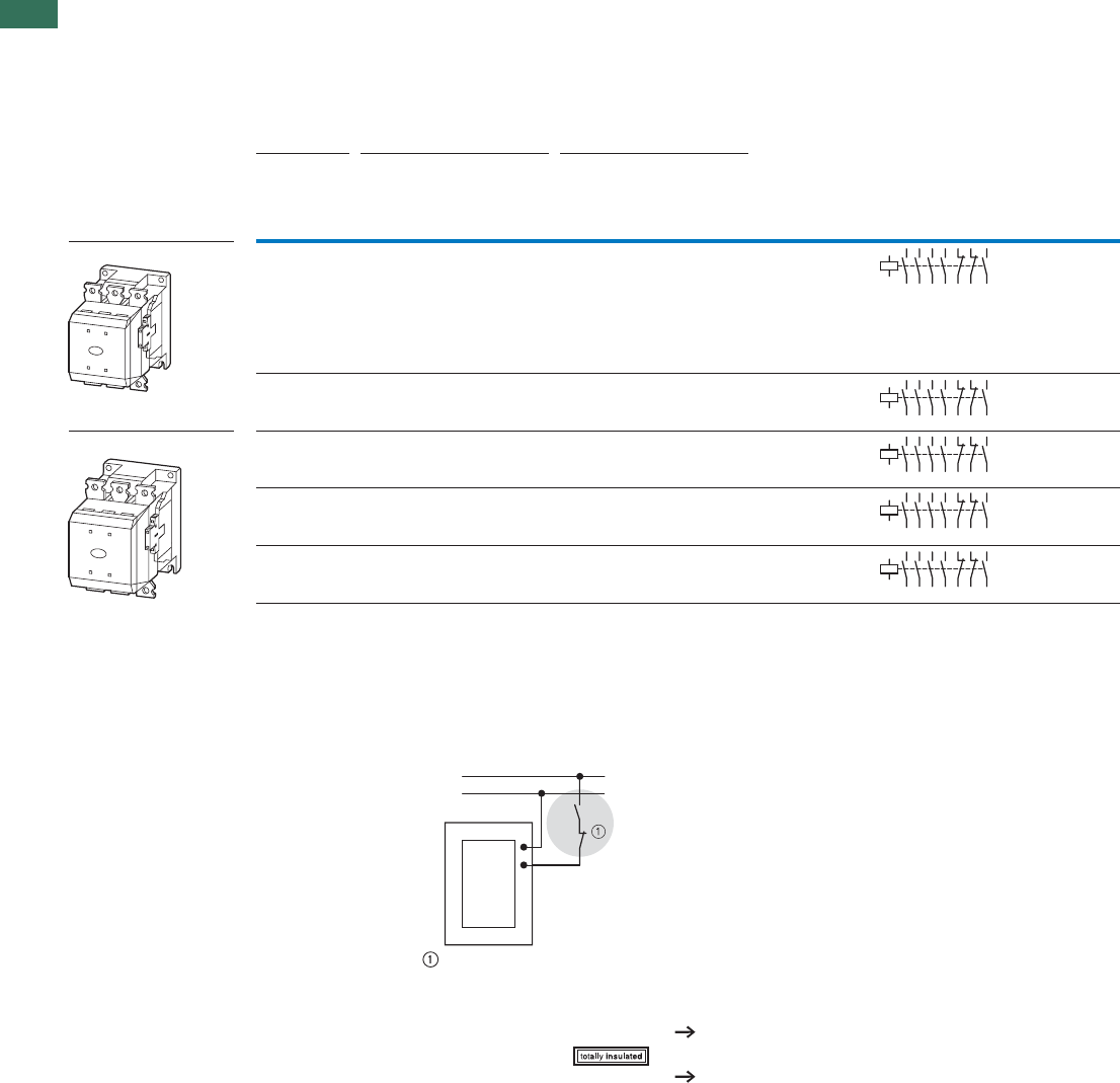
DILM…-S contactors are actuated conventionally
Stopping in the event of an emergency (emergency switching off)
A2
A1
(+) L1
(–) N
PageAccessories
Auxiliary contact modules 38
Enclosures
Further actuating voltages 77
DILM...S/22...
1.1
Contactors DILM, DILH
Standard devices greater than 150 A
29AUTOMATION AND CONTROL www.eaton.com/seasia-electrical
1
Part no.
Article no. Price
See price
list
Std. pack Information relevant for export to North America
DILM250-S/22(220-240V50/60Hz)
274190 1 off
DILM300A-S/22(220-240V50/60Hz)1)
139559
1 off Request filed for UL and CSA
DILM400-S/22(220-240V50/60Hz)
274196
1 off
1 off
1 off
DILM500-S/22(220-240V50/60Hz)
274199
DILM570-S/22(220-240V50/60Hz)
110744
Product Standards
UL File No.
UL CCN
CSA File No.
CSA Class No.
NA Certification
See also
IEC/EN 60947-4-1; UL 508; CSA-C22.2 No.14-05; CE marking
E29096
NLDX
012528
3211-04
UL Listed, CSA certified
Additional approvals, Page 82
Product Standards
UL File No.
UL CCN
CSA File No.
CSA Class No.
NA Certification
IEC/EN 60947-4-1; UL 508; CSA-C22.2 No.14-05; CE marking
E29096
NLDX
1017510
3211-04
UL Listed, CSA certified
1.1 Contactors DILM, DILH
Comfort devices greater than 150 A
30 AUTOMATION AND CONTROL www.eaton.com/seasia-electrical
1
Rated
operational
current
Max. motor rating for
three-phase motors 50 - 60 Hz
Conventional
thermal
current I
th
= I
e
AC-1 at 60 °C
Circuit symbol
OpenAC-4AC-3AC-3
380 V
400 V
220 V
230 V 380 V
400 V
660 V
690 V
1000 V 220 V
230 V 380 V
400 V
660 V
690 V
1000 V Ith = Ie
e
IPPPPPPA
AkW kW kW
P
kW
P
kW kW kW kW
Contactors, comfort DILM 185 55 90 140 108 41 75 102 77 275
225 70 110 150 108 51 90 110 77 315
250 75 132 195 108 62 110 160 109 330
300 90 160 195 132 75 132 160 109 350
400 125 200 344 132 92 160 283 132 500
500 155 250 344 132 112 200 344 132 700
580 185 315 560 600 143 250 440 509 800
650 205 355 630 600 161 280 494 509 850
750 240 400 720 800 181 315 556 678 900
820 260 450 750 800 209 355 633 678 1000
1000 315 560 1000 1100 260 450 780 1000 1000
1600 500 900 1600 1770 430 750 1300 1650 1800
Notes 1) Availability from August 2010.
Previous DILM185/22 to DILM300/22, see Online Catalog at http://www.eaton.com/seasia-electrical
For all contactors the following applies:
• 660 V, 690 V or 1000 V: do not reverse directly
• Integrated suppressor circuit in actuating electronics.
2
3513 21 31
46
14 22 32
43
44
A1
A2
1
2
3513 21 31
46
14 22 32
43
44
A1
A2
1
2
3513 21 31
46
14 22 32
43
44
A1
A2
1
2
3513 21 31
46
14 22 32
43
44
A1
A2
1
2
3513 21 31
46
14 22 32
43
44
A1
A2
1
2
3513 21 31
46
14 22 32
43
44
A1
A2
1
2
3513 21 31
46
14 22 32
43
44
A1
A2
1
2
3513 21 31
46
14 22 32
43
44
A1
A2
1
2
3513 21 31
46
14 22 32
43
44
A1
A2
1
2
3513 21 31
46
14 22 32
43
44
A1
A2
1
2
3513 21 31
46
14 22 32
43
44
A1
A2
1
2
3513 21 31
46
14 22 32
43
44
A1
A2
1
When operating contactors DILM580 to DILM1600 behind a frequency inverter or mains with
strong harmonic loads, the suppressor circuit on the load side must be removed.
During high-voltage tests, the suppressor circuit on the load-side for DILM580 to DILH2600 contactors
must be disconnected (see instructional leaflet).
Control voltages
RA250 110 V - 250 V AC/DC
RAW250 230 V - 250 V AC/DC
PageAccessories
Auxiliary contact modules 38
Suppressor circuits on load side 61
Enclosures
Further actuating voltages 72
DILM, DILH
1.1
Contactors DILM, DILH
Comfort devices greater than 150 A
31AUTOMATION AND CONTROL www.eaton.com/seasia-electrical
1
Part no.
Article no.
Price
See price
list
Std. pack
DILM185A/22(RAC240)1)
139537
1 off
DILM225A/22(RAC240)1)
139547
DILM250/22(RA250)2)
208201
DILM300A/22(RA250)1) 2)
139556
DILM400/22(RA250)3)
208209
DILM500/22(RA250)3)
208213
DILM580/22(RA250)3)
208216
DILM650/22(RA250)3)
208219
DILM750/22(RA250)3)
208222
DILM820/22(RA250)3)
208225
DILM1000/22(RA250)3)
267214
DILM1600/22(RAW250)3)
106727
Information relevant for export to North America
1)
NA Certification Request filed for UL and CSA
2)
3)
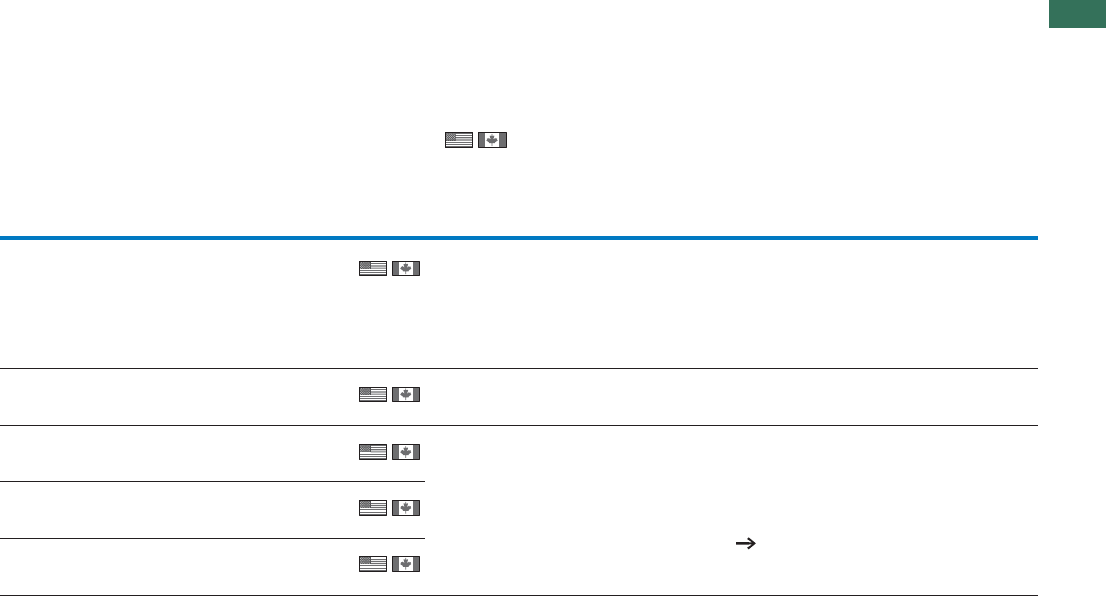
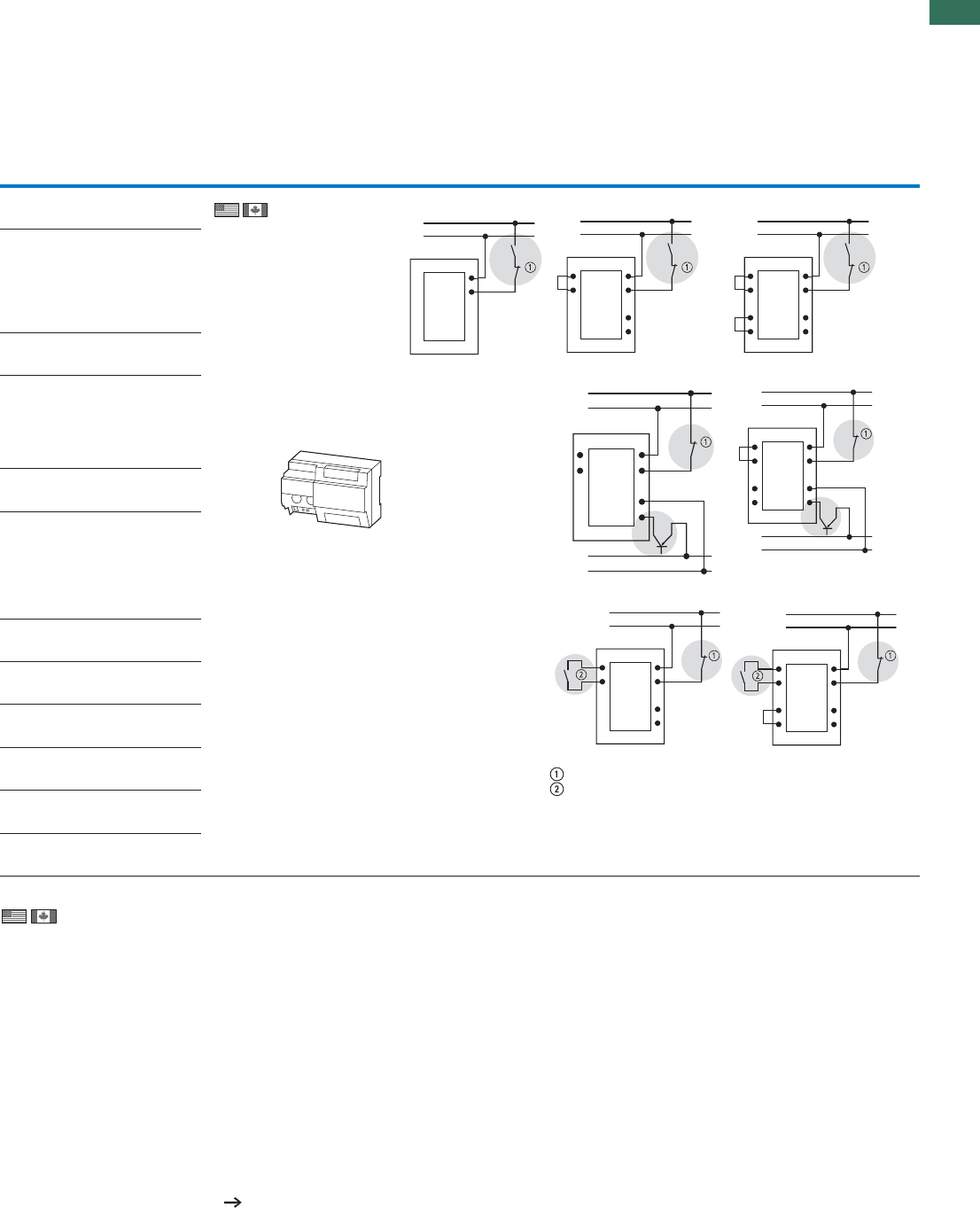
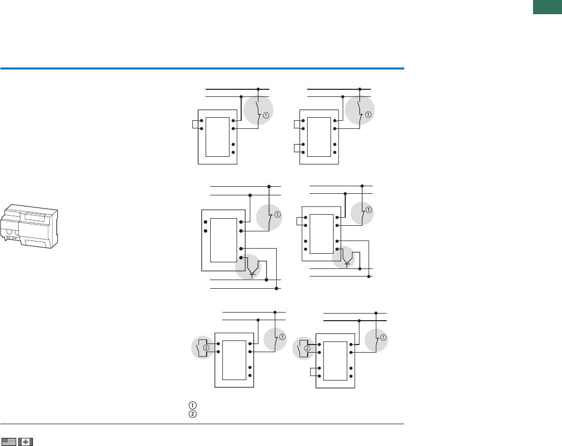
Conventional DILM 185 A, DILM 225 A DILM250 to DILM1000, DILH1400 DILM1600 to DILH 2600
A1/A2 are attached
to power supply as
normal
Directly from the PLC
A 24 V output from
the PLC can be
directly connected
to the terminals A4/
A24.
From a low-power command device
Low-power
actuating devices
such as PCB relays,
pilot devices or
position switches
can be directly
connected to A10/
A11.
Stopping in the event of an emergency (emergency switching off)
Max. cable capacitance 6 nF
A2
A1
(+) L1
(–) N
A10
A11
A2
A1
A3
A4
(+) L1
(–) N
A10
A11
A2
A1
A3
A4
TY
TX
(+) L1
(–) N
A10
A11
A2
A1
A3
A4
24 V
GND
(+) L1
(–) N
A2
A1
A3
A4
24 V
GND
(+) L1
(–) N
A10
A11
TY
TX
A10
A11
A2
A1
A3
A4
(+) L1
(–) N
A10
A11
A2
A1
A3
A4
(+) L1
(–) N
TY
TX
Notes
Product Standards
UL File No.
UL CCN
CSA File No.
CSA Class No.
NA Certification
See also
IEC/EN 60947-4-1; UL 508; CSA-C22.2 No.14-05; CE marking
E29096
NLDX
012528
3211-04
UL Listed, CSA certified
Additional approvals, Page 82
Product Standards
UL File No.
UL CCN
CSA File No.
CSA Class No.
NA Certification
IEC/EN 60947-4-1; UL 508; CSA-C22.2 No.14-05; CE marking
E29096
NLDX
1017510
3211-04
UL Listed, CSA certified
1.1 Contactors DILM, DILH
Comfort devices greater than 150 A
32 AUTOMATION AND CONTROL www.eaton.com/seasia-electrical
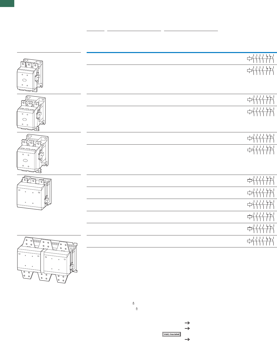
1DILM, DILH
Conventional thermal current Ith = Ie
AC-1 at 60 °C
Circuit symbol Part no.
Article no.
Price
See price
list
Std. pack
Open
Ith = Ie
A
DILH comfort devices AC-1 1400 DILH1400/22(RAW250)1)
272441
1 off
1 off
1 off
1 off
2000 DILH2000/22(RAW250)1)
272442
2200 DILH2200/22(RAW250)1)
111793
2600 DILH2600/22(RAW250)2)
125945
Notes For all contactors the following applies:
• 660 V, 690 V or 1000 V: do not reverse directly
• Integrated suppressor circuit in actuating electronics.
2
3513 21 31
46
14 22 32
43
44
A1
A2
1
2
3513 21 31
46
14 22 32
43
44
A1
A2
1
2
3513 21 31
46
14 22 32
43
44
A1
A2
1
2
3513 21 31
46
14 22 32
43
44
A1
A2
1
When operating contactors DILM580 to DILM1600 behind a frequency inverter or mains with
strong harmonic loads, the suppressor circuit on the load side must be removed.
During high-voltage tests, the suppressor circuit on the load-side for DILM580 to DILH2600 contactors
must be disconnected (see instructional leaflet).
Control voltages
RAW250 230 V - 250 V AC/DC
PageAccessories
Auxiliary contact modules 38
Suppressor circuits on load side 61
Enclosures
1.1
Contactors DILM, DILH
Comfort devices greater than 150 A
33AUTOMATION AND CONTROL www.eaton.com/seasia-electrical
1
Notes
Information relevant for export to North America
1)
Product Standards
UL File No.
UL CCN
CSA File No.
CSA Class No.
NA Certification
2)
NA Certification Request filed for UL and CSA
Conventional DILH1400 DILM1600 to DILH 2600
A1/A2 are attached to power
supply as normal
Directly from the PLC
A 24 V output from the PLC can
be directly connected to the
terminals A4/A24.
From a low-power command device
Low-power actuating devices
such as PCB relays, pilot
devices or position switches
can be directly connected to
A10/A11.
Stopping in case of emergency (Emergency-stop)
Max. cable capacitance 6 nF
A10
A11
A2
A1
A3
A4
(+) L1
(–) N
A10
A11
A2
A1
A3
A4
TY
TX
(+) L1
(–) N
A10
A11
A2
A1
A3
A4
24 V
GND
(+) L1
(–) N
A2
A1
A3
A4
24 V
GND
(+) L1
(–) N
A10
A11
TY
TX
A10
A11
A2
A1
A3
A4
(+) L1
(–) N
A10
A11
A2
A1
A3
A4
(+) L1
(–) N
TY
TX
IEC/EN 60947-4-1; UL 508; CSA-C22.2 No.14-05; CE marking
E29096
NLDX
012528
3211-04
UL Listed, CSA certified
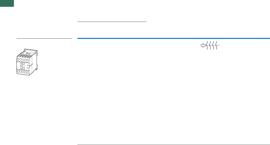
1.1 Leistungsschütze
Basic devices up to 200 A
34 AUTOMATION AND CONTROL www.eaton.com/seasia-electrical
1
Rated operational current open Conventional thermal current
Ith = Ie AC-1 at 50 °C
Circuit symbol For use with
OpenAC-1
40 °C 55 °C 70 °C
Ith = Ie
AAA A
Contactors up to 200 A
4 pole
DILM32-XHI(C)…20302122
DILA-XHI(V)(C)…
Notes 1) DILM1000-XHI…can only be fitted on the left of DILMP.
Contacts to EN 50012.
For DC operated contactors DILMP20 the following applies:
• Integrated varistor suppressor circuit.
For DC operated contactors DILMP32 - DILMP200 the following applies:
• Integrated suppressor circuit in actuating electronics.
For AC operated contactors DILMP125 - DILMP200 the following applies:
• Integrated suppressor circuit in actuating electronics.
For DILMP32-01 and DILMP45-01 the following applies:
• With mirror contact.
2
35
46
A1
A2
17
8
DILMP 4 pole
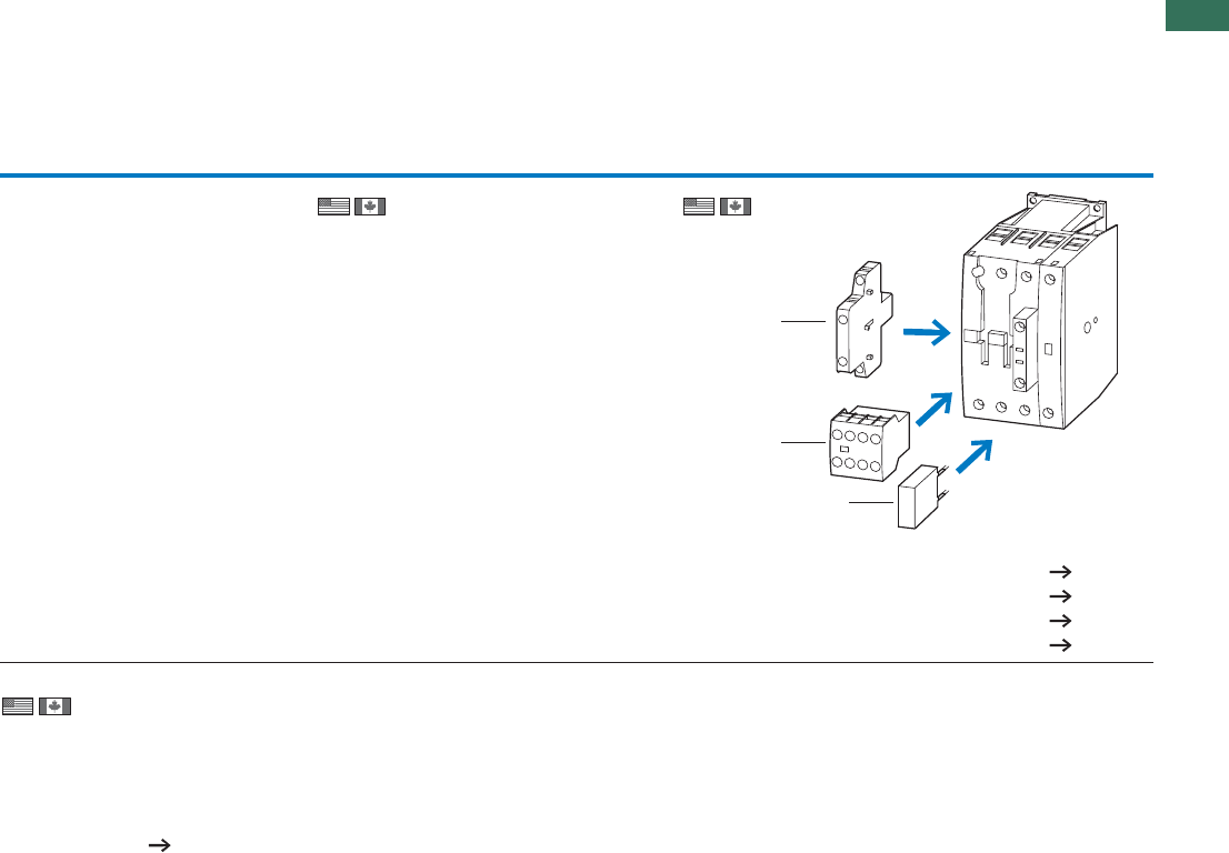
1.1
Leistungsschütze
Basic devices up to 200 A
35AUTOMATION AND CONTROL www.eaton.com/seasia-electrical
1
AC operation DC operation
Part no.
Article no. Price
See
price
list
Std. pack Part no.
Article no. Price
See
price list
Std. pack Notes
DILMP20(230V50Hz,240V60Hz)
276970
1 off DILMP20(24VDC)
276985
1 off
Information relevant for export to North America
PageAccessories
1 Auxiliary contact module 36
2 Suppressor 50
Further actuating voltages 74
Accessories 52
1
2
1
Product Standards
UL File No.
UL CCN
CSA File No.
CSA Class No.
NA Certification
See also
IEC/EN 60947-4-1; UL 508; CSA-C22.2 No.14-05; CE marking
E29096
NLDX
012528
2411-03, 3211-04
UL Listed, CSA certified
Page 81
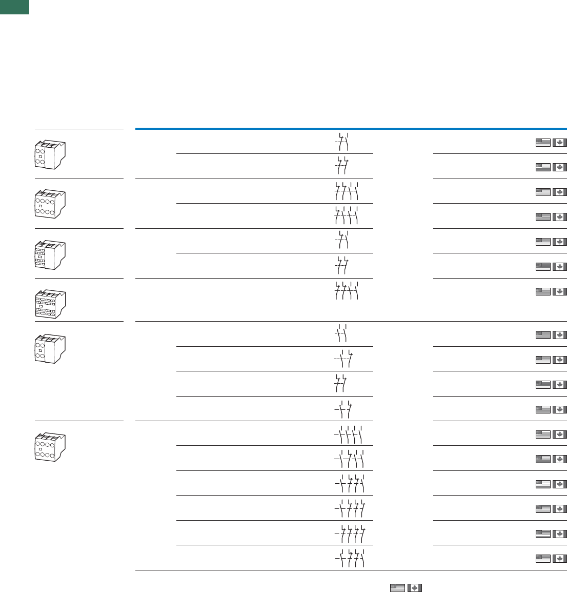
1.1 Contactors
Auxiliary contact modules
36 AUTOMATION AND CONTROL www.eaton.com/seasia-electrical
1
Terminal
type
Pole Conventional
thermal current
Ith = Ie
AC-1 at 60 °C
Contact
configuration
N/O = normally open
contact
S
F
= N/O early-make
NC = normally closed
contact
Ö
S
= NC late-break
Circuit
symbol
For use with Part no.
Article no.
Price
See price
list
Std. pack
Open
Ith = Ie
A
Auxiliary contact modules
With interlocked opposing contacts, except ...XHI(C)V
Top mounting auxiliary contacts Screw
terminals
Screw
terminals
2 pole 16 1 N/O 1 NC
2 pole 16 1 N/O 1 NC
2 pole 16 1 N/O –
4 pole 16 2 N/O 2 NC
4 pole 16 2 N/O 2 NC
4 pole 16 4 N/O –
2 pole 16 – 1 NC
4 pole 16 3 N/O 1 NC
2 pole 16 1 N/O 1 NC
4 pole 16 3 N/O 1 NC
4 pole 16 2 N/O 2 NC
4 pole 16 1 N/O 3 NC
4 pole 16 1 N/O 1 NC
2 pole 16 – 2 NC
2 pole 16 – 2 NC
4 pole 16 – 4 NC
DILM(C)9-10…
DILM(C)7-10…
DILM(C)12-10…
DILM(C)15-10…
DILM(C)17-10…
DILM(C)25-10…
DILM(C)32-10…
DILM38-…10
DILMP20…
DILMP32-10…
DILMP45-10…
DILL…
DILM32-XHI11
277376
5 off
5 off
5 off
5 off
5 off
5 off
5 off
5 off
5 off
5 off
5 off
5 off
5 off
5 off
5 off
5 off
5 off
DILM32-XHI02
277375
DILM32-XHI22
277377
DILM32-XHI31
106112
Spring-
loaded
terminals
Spring-
loaded
terminals
DILM32-XHIC11
277751
DILM32-XHIC02
277750
DILM32-XHIC22
277752
Screw
terminals
Screw
terminals
DILM(C)9…
DILM(C)9…
DILM(C)12…
DILM(C)15…
DILM(C)17…
DILM(C)25…
DILM(C)32…
DILM38…
DILMP20…
DILMP32…
DILMP45…
DILL…
DILA-XHI20
276422
DILA-XHI11
276421
DILA-XHI02
276420
2 pole 16 1 SF1 ÖS
1 SF1 ÖS
DILA-XHIV11
276423
DILA-XHI40
276428
DILA-XHI31
276427
DILA-XHI22
276426
DILA-XHI13
276425
DILA-XHI04
276424
DILA-XHIV22
276429
Notes
• Auxiliary NC usable as mirror contact according to IEC/EN 60947-4-1,
Annex F
• Interlocked opposing contacts according to IEC/EN 60947-5-1 Annex L,
inside the auxiliary contact modules, also for the
integrated auxiliary contacts of the DILM 7 - DILM32
Information relevant for export to North America
Product Standards
UL File No.
UL CCN
CSA File No.
CSA Class No.
NA Certification
21
22
33
34
21
22
31
32
21
22
31
32
43
44
53
54
21
22
33
34
53
54
43
44
21
22
33
34
21
22
31
32
21
22
31
32
43
44
53
54
54
63
64
53
54
53 61
62
51
52
61
62
58
57 65
66
54
63 73
64 74
53 83
84
54
53 61
62
73
74
83
84
54
53 61
62
71
72
83
84
53 61 71 81
82
72
62
54
51
52
61
62
71
72 82
81
58
57 65
66
71
72
83
84
DILM, DILA
Top mounting auxiliary contacts
Top mounting auxiliary contacts
Top mounting auxiliary contacts
Top mounting auxiliary contacts
Top mounting auxiliary contacts
IEC/EN 60947-4-1; UL 508;
CSA-C22.2 No.14-05; CE marking
E29184
NKCR
012528
3211-03
UL Listed, CSA certified
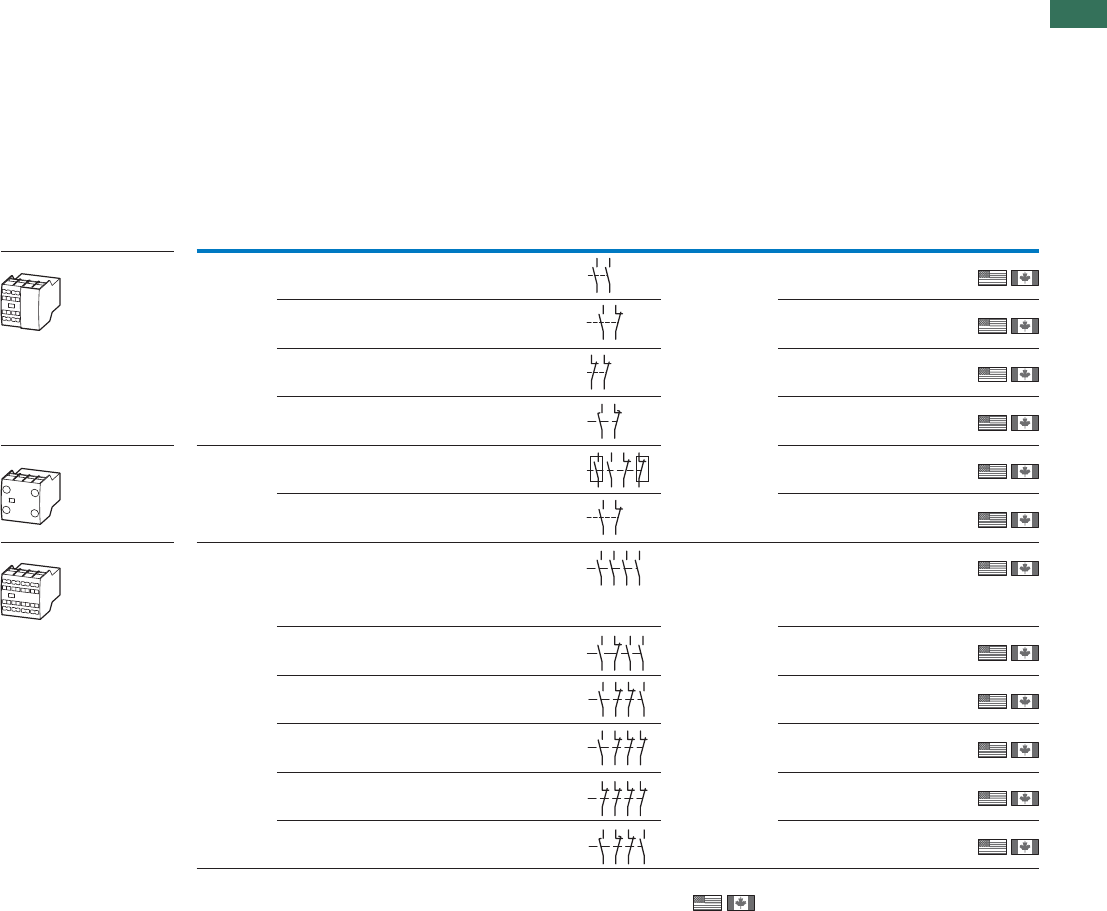
1.1
Contactors
Auxiliary contact modules
37AUTOMATION AND CONTROL www.eaton.com/seasia-electrical
1
16 2 N/O –2 pole
2 pole 16 2 N/O 2 NC
2 pole 16 – 2 NC
4 pole 16 4 N/O –
2 pole 16 1 N/O 1 NC
2 pole 16 1 N/O 1 NC
2 pole 16 1 SF1 ÖS
4 pole 16 3 N/O 1 NC
4 pole 16 2 N/O 2 NC
4 pole 16 1 N/O 3 NC
4 pole 16 1 N/O 1 NC
4 pole 16 – 4 NC
1 SF1 ÖS
Notes
• Auxiliary NC usable as mirror contact according to IEC/EN 60947-4-1,
Annex F
• Interlocked opposing contacts according to IEC/EN 60947-5-1 Annex L,
inside the auxiliary contact modules, also for the
integrated auxiliary contacts of the DILM 7 - DILM32
Auxiliary contact modules
With interlocked opposing contacts, except ...XHI(C)V
DILM, DILA
Spring-
loaded
terminals
DILM(C)9…
DILM(C)7…
DILM(C)12…
DILM(C)15…
DILM(C)17…
DILM(C)25…
DILM(C)32…
DILM38…
DILMP20…
DILMP32…
DILMP45…
DILL…
DILA-XHIC20
276528
DILA-XHIC11
276527
DILA-XHIC02
276526
DILA-XHICV11
276529
Screw
terminals DILA-XHIR221)
139580
DILA-XHIR11
110140
Spring-
loaded
terminals DILM(C)9…
DILM(C)9…
DILM(C)12…
DILM(C)15…
DILM(C)17…
DILM(C)25…
DILM(C)32…
DILA-XHIC40
276534
DILA-XHIC31
276533
DILA-XHIC22
276532
DILA-XHIC13
276531
DILA-XHIC04
276530
DILA-XHICV22
276535
1)
NA Certification Request filed for UL and CSA
1) 1 N/C + 1 N/O above microswitch for electronic applications
Terminal
type
Pole Conventional
thermal current
Ith = Ie
AC-1 at 60 °C
Contact
configuration
N/O = normally open
contact
S
F
= N/O early-make
NC = normally closed
contact
Ö
S
= NC late-break
Circuit
symbol
For use with Part no.
Article no.
Price
See price
list
Std. pack
Open
Ith = Ie
A
54
63
64
53
54
53 61
62
51
52
61
62
58
57 65
66
54
53 63
64
71
72
81
82
54
53 61
62
54
63 73
64 74
53 83
84
54
53 61
62
73
74
83
84
54
53 61
62
71
72
83
84
53 61 71 81
82
72
62
54
51
52
61
62
71
72 82
81
58
57 65
66
71
72
83
84
5 off
5 off
5 off
5 off
5 off
5 off
5 off
5 off
5 off
5 off
5 off
5 off
Top mounting auxiliary contacts
Top mounting auxiliary contacts
Top mounting auxiliary contacts
Information relevant for export to North America
Product Standards
UL File No.
UL CCN
CSA File No.
CSA Class No.
NA Certification
IEC/EN 60947-4-1; UL 508;
CSA-C22.2 No.14-05; CE marking
E29184
NKCR
012528
3211-03
UL Listed, CSA certified
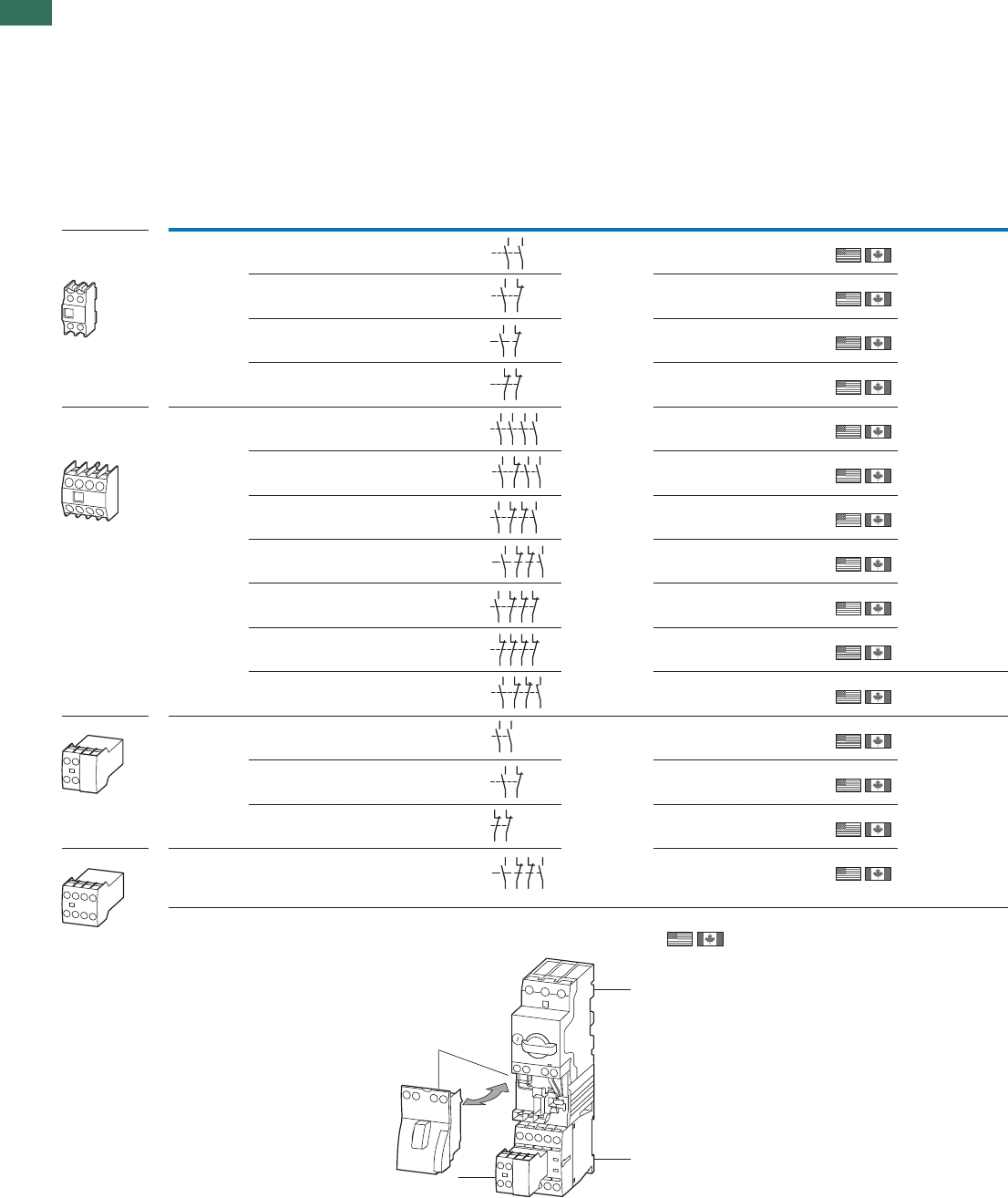
1.1 Contactors
Auxiliary contact modules
38 AUTOMATION AND CONTROL www.eaton.com/seasia-electrical
1
Auxiliary contact modules
With interlocked opposing contacts
Top mounting
auxiliary
contacts
Information relevant for export to North America
Product Standards
UL File No.
UL CCN
CSA File No.
CSA Class No.
NA Certification
DILM
Top mounting
auxiliary
contacts
IEC/EN 60947-4-1; UL 508;
CSA-C22.2 No.14-05; CE marking
E29184
NKCR
012528
3211-03
UL Listed, CSA certified
Connection
type
Pole conventional
thermal
current
Ith = Ie
AC-1 at 60 °C
Contact
configuration
N/O = normally
open contact
SF = N/O early
make
NC = normally
closed contact
ÖS = NC late-
break
Circuit
symbol
For use with Part no.
Article no. Price
See
price
list
Std. pack
Open
Ith = Ie
A
Screw
terminals DILM50…
DILM40…
DILM65…
DILM72…
DILM80…
DILM95…
DILM115…
DILM150…
DILM170…
DILMP63…
DILMP80…
DILMP125…
DILMP160…
DILMP200…
DILM150-XHI20
277945
5 off
5 off
5 off
5 off
5 off
5 off
5 off
5 off
5 off
5 off
5 off
5 off
5 off
5 off
5 off
Interlocked
opposing contacts
according to
IEC/EN 60947-5-1
Annex L, inside the
auxiliary contact
modules
Auxiliary NC
usable as mirror
contact according
to IEC/EN 60947-4-1,
Annex F
DILM150-XHI11
277946
DILM150-XHIA11
283463
DILM150-XHI02
277947
Screw
terminals DILM150-XHI40
277948
DILM150-XHI31
277949
DILM150-XHI22
277950
DILM150-XHIA22
283464
DILM150-XHI13
277951
DILM150-XHI04
277952
DILM150-XHIV22
277953
–
High version1)
High version1)
Screw
terminals
Screw
terminals
DILM9…
DILM7…
DILM12…
DILM15…
DILL…
DILA-XHIT20
101042
Interlocked
opposing contacts
according to
IEC/EN 60947-5-1
Annex L, inside the
auxiliary contact
modules
Auxiliary NC
usable as mirror
contact according
to IEC/EN 60947-4-1,
Annex F
DILA-XHIT11
101043
DILA-XHIT02
101041
DILA-XHIT22
101044
Notes 1) Suitable for the combination with electrical wiringlinks
in tool-less plug connection usable with:
DILM12-XSL
DILM12-XRL
DILM12-XS1
PKZM0-XDM12
PKZM0-XRM12
PKZM0-XSM12
1 PKZM0
2 DILM7 - DILM15
3 DILA-XHIT
4 PKZM0-XDM12
14 24
13 23
14
13 21
22
54
53 61
62
12
11 21
22
14
13 23
24
33
34
43
44
14
13 21
22
33
34
43
44
14
13 21
22
31
32
43
44
54
53 61
62
71
72
83
84
14
13 21
22
31
32
41
42
12
11 21
22
31
32
41
42
14
13 21
22
35
36
47
48
54
63
64
53
54
53 61
62
51
52
61
62
54
53 61
62
71
72
83
84
1
2
3
4
2 pole 16 2 N/O –
4 pole 16 4 N/O –
2 pole 16 1 N/O 1 NC
4 pole 16 2 N/O 2 NC
2 pole 16 1 N/O 1 NC
2 pole 16 – 2 NC
4 pole 16 3 N/O 1 NC
2 pole 16 2 N/O –
4 pole 16 2 N/O 2 NC
2 pole 16 – 2 NC
2 pole 16 1 N/O 1 NC
4 pole 16 2 N/O 2 NC
4 pole 16 1 N/O 3 NC
4 pole 16 1 N/O 1 NC
4 pole 16 – 4 NC
1 SF1 ÖS
Notes
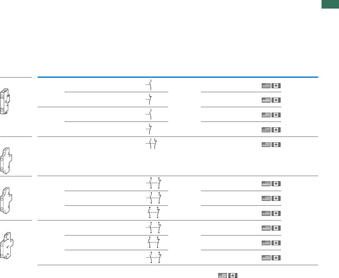
1.1
Contactors
Auxiliary contact modules
39AUTOMATION AND CONTROL www.eaton.com/seasia-electrical
1
DILM, DILA
Information relevant for export to North America
Product Standards
UL File No.
UL CCN
CSA File No.
CSA Class No.
NA Certification
IEC/EN 60947-4-1; UL 508;
CSA-C22.2 No.14-05; CE marking
E29184
NKCR
012528
3211-03,3211-04
UL Listed, CSA certified
Side-mounting
auxiliary contacts Screw
terminals DILM(C)9…
DILM(C)7…
DILM(C)12…
DILM(C)15…
DILMP20…
DILA(C)…
DILA-XHI10-S
115948
1 off
1 off
1 off
1 off
1 off
1 off
1 off
1 off
1 off
1 off
1 off
1)
DILA-XHI01-S
115949
Spring-
loaded
terminals
DILA-XHIC10-S
115950
DILA-XHIC01-S
115951
Screw
terminals DILM25…
DILM17…
DILM32…
DILM38…
DILM32-XHI11-S
101371
Can only be left on
the contactor.
Cannot be
combined with
mechanical
interlock
Screw
terminals
Screw
terminals
DILH2600
DILM250 - DILM820-XHI11-SI
208281
1)
DILM820-XHI11-SA
208282
DILM820-XHI11V-SI
208283
DILM225A
DILM40 -
DILMP63 -
DILMP200
DILM1000-XHI11-SI
278425
DILM1000-XHIV11-SI
278426
DILM1000-XHI11-SA
278427
Notes 1)
• Interlocked opposing contacts according to IEC/EN 60947-5-1
Annex L, inside the auxiliary contact module, also for the inte-
grated auxiliary contacts of the DILM7 – DILM32 (not NO early-
make and NC late-break)
• Auxiliary NC usable as mirror contact according to IEC/EN 60947-
4-1, Annex F (no NC late-breaks)
• No auxiliary contact is possible between 2 contactors with
mechanical interlock.
2)
Connection
type
Pole conventional
thermal
current
Ith = Ie
AC-1 at 60 °C
Contact
configuration
N/O = normally
open contact
SF = N/O early
make
NC = normally
closed contact
ÖS = NC late-
break
Circuit
symbol
For use with Part no.
Article no. Price
See
price
list
Std. pack
Open
Ith = Ie
A
53
54
61
62
53
54
61
62
54
53 61
62
13
44
14
43
21
32
31
22
53
84
54 62
61
72
71 83
17
48
18
47
25
36
26
35
13
44
14
43
21
32
31
22
17
48
18
47
25
36
26
35
53
84
54 62
61
72
71 83
1 pole 10 1 N/O –
2 pole 10 1 N/O 1 NC
1 pole 10 1 N/O –
2 pole 10 1 N/O 1 NC
1 pole 10 – 1 NC
1 pole 10 – 1 NC
2 pole 10 1 N/O 1 NC
2 pole 10 1 N/O 1 NC
2 pole 10 1 N/O 1 NC
2 pole 10 1 SF1 ÖS
2 pole 10 1 SF1 ÖS
Notes
Side-mounting
auxiliary contacts
Side-mounting
auxiliary contacts
Side-mounting
auxiliary contacts
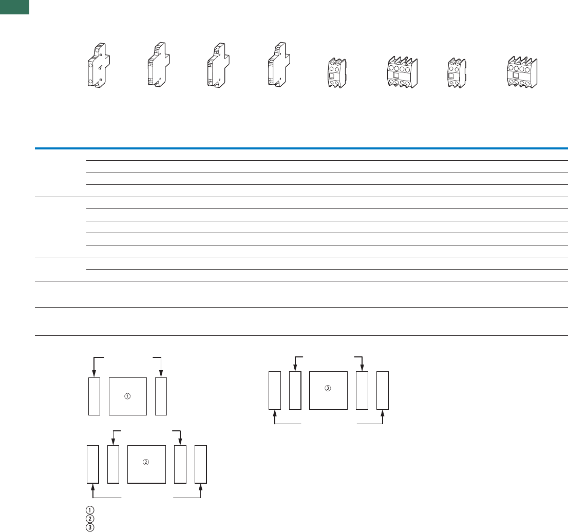
1.1 Contactors
Auxiliary contact modules
40 AUTOMATION AND CONTROL www.eaton.com/seasia-electrical
1Engineering
DILM1000-
XHI(V)11-SI DILM820-
XHI(V)11-SI DILM1000-
XHI(V)11-SA DILM820-
XHI(V)11-SA DILM150-XHI20
DILM150-XHI11
DILM150-XHI02
DILM150-XHI40
DILM150-XHI31
DILM150-
XHI(V)22
DILM150-XHI13
DILM150-XHI04
DILM150-
XHIA11 DILM150-
XHIA22
DILM40
...
DILM72
2 x – – – – – 1 x –
– – 2 x – 1 x – – –
1 x – – – – – – 1 x
––1 x––1 x––
DILM80
...
DILM170
2 x – 2 x – – – – –
2 x – – – – – – 1 x
2 x – – – – – 1 x –
––2 x––1 x––
– – 2 x – 1 x – – –
DILM185A 2 x – 2 x – – – – –
DILM222A 2 x – – – – – – –
DILM250
DILM1600 – 2 x– 2 x– – – –
DILH1400
...
DILH2600
– 2 x– 2 x– – – –
Notes Side mounting auxiliary contacts
DILM40 – DILM72
DILM250 – DILH2600
DILM80-DILM225A
• Interlocked opposing contacts according to IEC/EN 60947-5-1 Annex L, inside the auxiliary contact module (not N/O early close and N/C late open)
• Auxiliary contacts can be used as mirror contacts according to IEC/EN 60947-4-1, Annex F (not N/C late open)
• No auxiliary contact is possible between two contactors with mechanical interlock.
• 2 auxiliary contacts DILM820-XHI11-SI are already built into the contactors DILM250 to DILH2600/22.
• 2 DILM1000-XHI11-SI auxiliary contacts are already installed in DILM185A and DILH225A contactors.
DILM1000-XHI(C)..
+ +
DILM1000-XHI(C)..-SI
DILM1000-XHI(C)..-SA
+++
+
DILM820-XHI(C)..-SI
DILM820-XHI(C)..-SA
+++
+
DILM, DILH
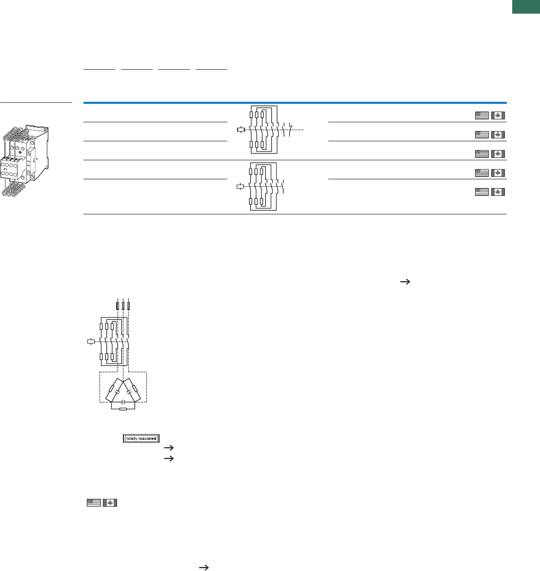
1.1
Contactors
Contactor for capacitors
41AUTOMATION AND CONTROL www.eaton.com/seasia-electrical
1
Ordering
Three-phase capacitors
50 – 60 Hz
Circuit symbol Part no.
Article no. Price
See price
list
Std. pack
Open
230 V 400 V 525 V 690 V
kvar kvar kvar kvar
With series resistors
Basic Units
7.5 12.5 16.7 20 DILK12-11(230V50Hz,240V60Hz)
293988
11 20 25 33.3 DILK20-11(230V50Hz,240V60Hz)
294010
15 25 33.3 40 DILK25-11(230V50Hz,240V60Hz)
294032
20 33.3 40 55 DILK33-10(230V50Hz,240V60Hz)
294054
25 50 65 85 DILK50-10(230V50Hz,240V60Hz)
294076
Notes Weld-resistant for capacitors with inrush current peaks up to 180 x IN
With group compensation multi-stage capacitor banks are connected to the mains as required. This can cause, transient currents of up to 180 x Ie
to flow between the capacitors.
The capacitors are pre-charged via the early-make auxiliary contacts and the fitted wire resistors, thereby reducing the inrush current. The main
contacts then close after a time lag and carry the continuous current.
The contactors for capacitors are weld-resistant with inrush current peaks up to 180 x le due to their special contacts.
DILK… cannot be combined with other auxiliary contacts.
For the switching of reactive-power compensation equipment please see Engineering notes on power factor correction page 33.
Information relevant for export to North America
135
246
13 21
14 22
A1
A2
13
5
246
13
14
A1
A2
R11 R11
R11
C1
L1 L2 L3
135
64
2
A2
A1
Accessories Page
Enclosures
Accessories 52
Further actuating
voltages 76
DILK
1 off
1 off
1 off
1 off
1 off
Product Standards
UL File No.
UL CCN
CSA File No.
CSA Class No.
NA Certification
See also
IEC/EN 60947-4-1; UL 508; CSA-C22.2 No.14-05; CE marking
E29096
NLDX
012528
3211-04
UL Listed, CSA certified
Further approvals Page 66

1.1 Contactors
Contactors for power factor correction
42 AUTOMATION AND CONTROL www.eaton.com/seasia-electrical
1Engineering
Ordering data Switching power
230 V 420 V
400 V
440 V
525 V 690 V
Part no. Page kvar kvar kvar kvar
Individual compensation, open version
DILM7-…(…) 1.5 3 3.5 5
18
18
18
18
18
18
18
20
20
20
20
20
20
20
30
30
30
18
18
18
18
18
18
18
20
20
20
20
20
20
20
30
30
30
30
30
30
41
41
41
41
41
30
30
30
DILM9-…(…) 2 4 4.5 6
DILM12-…(…) 2.5 4.5 5.5 7
DILM15-…(…) 2.5 4.5 5.5 7
DILM17-…(…) 6.5 12 14.5 19
DILM25-…(…) 7 13.5 16 21
DILM32-…(…) 7.5 14.5 17 22.5
DILM40(…) 11 20.5 24.5 32
DILM50(…) 11.5 22 26 34.5
DILM65(…) 12.5 23.5 28 37
DILM80(…) 16 30.5 36.5 48
DILM95(…) 18 34 41 54
DILM115(…) 24 46 54.5 72
DILM150(…) 28 53 63.5 83.5
DILM185A(…) 87 150 190 150
DILM300A(…) 115 200 265 200
DILM580(…) 175 300 400 300
Group compensation, with choke, open version
DILM7-…(…) 4 7 7.5 12
DILM9-…(…) 5 8 10 14
DILM12-…(…) 5.5 10 12 16
DILM15-…(…) 5.5 10 12 16
DILM17-…(…) 7.5 18 20 28
DILM25-…(…) 10 20 23 30
DILM32-…(…) 12.5 25 25 32
DILM40(…) 15 30 30 40
DILM50(…) 20 40 40 48
DILM65(…) 25 50 50 57
DILM80(…) 30 60 70 90
DILM95(…) 35 70 80 104
DILM115(…) 50 95 100 125
DILM150(…) 55 115 115 152
DILM185A(…) 80 150 200 260
DILM225A(…) 100 175 230 300
DILM250(…) 110 190 260 340
DILM300A(…) 130 225 290 390
DILM400(…) 160 280 370 480
DILM500(…) 220 390 500 680
Group compensation, without choke, open version
DILK12-…(…) 7.5 12.5 16.7 20
DILK20-…(…) 11 20 25 33.3
DILK25-…(…) 15 25 33.3 40
DILK33-…(…) 20 33.3 40 55
DILK50-…(…) 25 50 65 85
DILM185A(…) 66 115 145 115
DILM300A(…) 85 150 195 150
DILM580(…) 145 250 333 250
Use of the contactors DILM without series resistor for group compensationNotes When using the contactors for group compensation in a system without chokes each capacitor must have a minimum
induction of approx. 6 μH to limit the peak inrush current. This corresponds to an air-cored coil with 5 windings and a coil
diameter of approximately Ø 140 mm. The conductor cross section must correspond to the rated operational current.
DILM, DILK
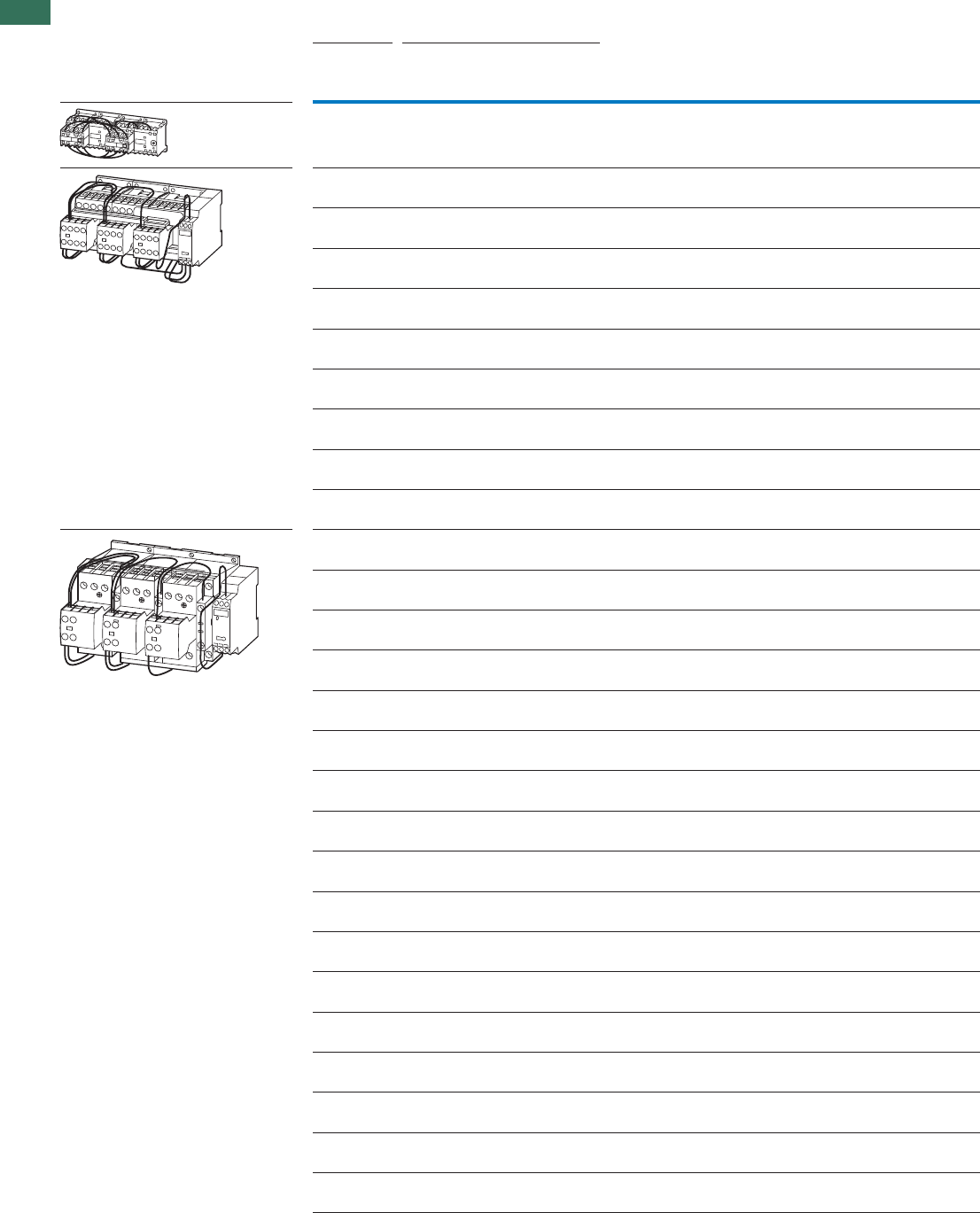
1.1 Contactor combinations
Star-delta combinations
44 AUTOMATION AND CONTROL www.eaton.com/seasia-electrical
1
Ordering
Rated opera-
tional current
Max. rated operational power for
three-phase motors, 50 - 60 Hz
Max.
change-
over time
s
Part no.
Article no. Price
See price
list
Std.
pack
AC-3 AC-3
400 V 230 V 400 V 500 V 690 V
IePPPP
AkWkWkWkW
Star-delta combinations SDAINL
Operating frequency: maximum 30 starts per hour
12 4 5.5 5.5 – < 30 SDAINLEM(230V50Hz)
051840
12 3 5.5 5.5 5.5 < 20 SDAINLM12(230V50Hz)
278286
12 3 5.5 5.5 5.5 < 20 SDAINLM12(400V50Hz)
101380
12 3 5.5 5.5 5.5 < 20 SDAINLM12(24VDC)
100416
16 4 7.5 7.5 7.5 < 20 SDAINLM16(230V50Hz)
278311
16 4 7.5 7.5 7.5 < 20 SDAINLM16(400V50Hz)
101381
16 4 7.5 7.5 7.5 < 20 SDAINLM16(24VDC)
100417
22 5.5 11 11 11 < 20 SDAINLM22(230V50Hz)
278336
22 5.5 11 11 11 < 20 SDAINLM22(400V50Hz)
101382
22 5.5 11 11 11 < 20 SDAINLM22(24VDC)
100418
30 7.5 15 18.5 18.5 < 20 SDAINLM30(230V50Hz)
278361
30 7.5 15 18.5 18.5 < 20 SDAINLM30(400V50Hz)
101383
30 7.5 15 18.5 18.5 < 20 SDAINLM30(RDC24)
100419
45 11 22 30 22 < 20 SDAINLM45(230V50Hz)
278386
45 11 22 30 22 < 20 SDAINLM45(400V50Hz)
101384
45 11 22 30 22 < 20 SDAINLM45(RDC24)
100420
55 15 30 37 30 < 20 SDAINLM55(230V50Hz)
278411
55 15 30 37 30 < 20 SDAINLM55(400V50Hz)
101385
55 15 30 37 30 < 20 SDAINLM55(RDC24)
100421
70 18.5 37 45 37 < 20 SDAINLM70(230V50Hz)
239895
70 18.5 37 45 37 < 20 SDAINLM70(400V50Hz)
101386
90 22 45 55 45 < 20 SDAINLM90(230V50Hz)
239937
115 30 55 75 55 < 20 SDAINLM115(230V50Hz)
239963
140 37 75 90 90 < 20 SDAINLM140(230V50Hz)
240009
165 45 90 110 132 < 20 SDAINLM165(230V50Hz)
240035
200 55 110 132 160 < 20 SDAINLM200(230V50Hz)
101010
260 75 132 160 160 < 20 SDAINLM260(230V50Hz)
101031
1 off
1 off
1 off
1 off
1 off
1 off
1 off
1 off
1 off
1 off
1 off
1 off
1 off
1 off
1 off
1 off
1 off
1 off
1 off
1 off
1 off
1 off
1 off
1 off
1 off
1 off
1 off
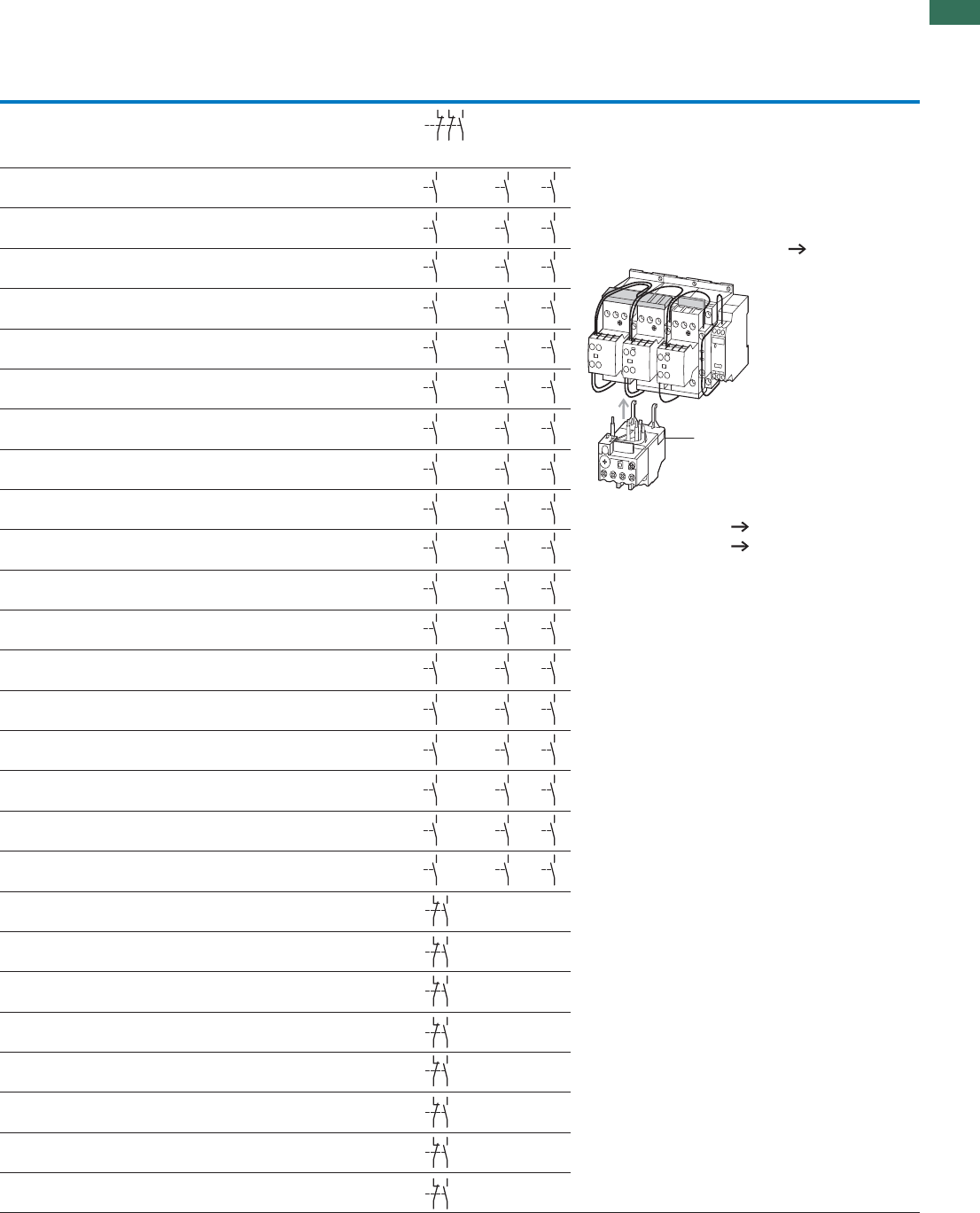
1.1
Contactor combinations
Star-delta combinations
45AUTOMATION AND CONTROL www.eaton.com/seasia-electrical
1
stcatnocyrailixuaerapSnoitanibmocehtfostnenopmoclaudividnI Notes
Mains contactor
Q11
Delta contactor
Q15
Star contactor
Q13
Timing relays
K1
Q11 Q13 Q15
Part no. Part no. Part no. Part no.
DILEM-10
+ 22DILEM
DILEM-01 DILEM-10 +
02DILEM
Main circuit:––DILET
Depending on the type of coordination required (i.e. Type
“1” or Type “2”) it must be established whether the fuse
protection and the input wiring for the mains contactor and
delta contactor are to be common or separate.
The following applies for SDAINLM 140 – SDAINLM 260:
• On the mounting plate.
Circuit diagrams, Star-delta combinations page 46
DILM7-10
+ DILA-XHI20
DILM7-01
+ DILA-XHI20
DILM7-01
+ DILA-XHI20
ETR4-51
DILM7-10
+ DILA-XHI20
DILM7-01
+ DILA-XHI20
DILM7-01
+ DILA-XHI20
ETR4-51
DILM7-10
+ DILA-XHI20
DILM7-01
+ DILA-XHI20
DILM7-01
+ DILA-XHI20
ETR4-51
DILM9-10
+ DILA-XHI20
DILM9-01
+ DILA-XHI20
DILM7-01
+ DILA-XHI20
ETR4-51
DILM9-10
+ DILA-XHI20
DILM9-01
+ DILA-XHI20
DILM7-01
+ DILA-XHI20
ETR4-51
DILM9-10
+ DILA-XHI20
DILM9-01
+ DILA-XHI20
DILM7-01
+ DILA-XHI20
ETR4-51
DILM12-10
+ DILA-XHI20
DILM12-01
+ DILA-XHI20
DILM7-01
+ DILA-XHI20
ETR4-51
DILM12-10
+ DILA-XHI20
DILM12-01
+ DILA-XHI20
DILM7-01
+ DILA-XHI20
ETR4-51
DILM12-10
+ DILA-XHI20
DILM12-01
+ DILA-XHI20
DILM7-01
+ DILA-XHI20
ETR4-51
DILM17-10
+ DILA-XHI20
DILM17-01
+ DILA-XHI20
DILM17-01
+ DILA-XHI20
ETR4-51
DILM17-10
+ DILA-XHI20
DILM17-01
+ DILA-XHI20
DILM17-01
+ DILA-XHI20
ETR4-51
DILM17-10
+ DILA-XHI20
DILM17-01
+ DILA-XHI20
DILM17-01
+ DILA-XHI20
ETR4-51
DILM25-10
+ DILA-XHI20
DILM25-01
+ DILA-XHI20
DILM17-01
+ DILA-XHI20
ETR4-51
DILM25-10
+ DILA-XHI20
DILM25-01
+ DILA-XHI20
DILM17-01
+ DILA-XHI20
ETR4-51
DILM25-10
+ DILA-XHI20
DILM25-01
+ DILA-XHI20
DILM17-01
+ DILA-XHI20
ETR4-51
DILM32-10
+ DILA-XHI20
DILM32-01
+ DILA-XHI20
DILM25-01
+ DILA-XHI20
ETR4-51
DILM32-10
+ DILA-XHI20
DILM32-01
+ DILA-XHI20
DILM25-01
+ DILA-XHI20
ETR4-51
DILM32-10
+ DILA-XHI20
DILM32-01
+ DILA-XHI20
DILM25-01
+ DILA-XHI20
ETR4-51
DILM40
+ DILM150-XHI31
DILM40
+ DILM150-XHI11
DILM40
+ DILM150-XHI11
DILM40
+ DILM150-XHI31
DILM40
+ DILM150-XHI11
DILM40
+ DILM150-XHI11
DILM50
+ DILM150-XHI31
DILM50
+ DILM150-XHI11
DILM40
+ DILM150-XHI11
ETR4-51 – –
ETR4-51 – –
ETR4-51 – –
DILM65
+ DILM150-XHI31
DILM65
+ DILM150-XHI11
DILM40
+ DILM150-XHI11
ETR4-51 – –
DILM80
+ DILM150-XHI31
DILM80
+ DILM150-XHI11
DILM50
+ DILM150-XHI11
ETR4-51 – –
DILM95
+ DILM150-XHI31
DILM95
+ DILM150-XHI11
DILM65
+ DILM150-XHI11
ETR4-51 – –
DILM115
+ DILM150-XHI31
DILM115
+ DILM150-XHI11
DILM80
+ DILM150-XHI11
ETR4-51 – –
DILM150
+ DILM150-XHI31
DILM150
+ DILM150-XHI11
DILM95
+ DILM150-XHI11
ETR4-51 – –
21
22
31
32
53
54
Accessories Page
1 Overload relay Chapter 1.2
Accessories 52
1
64
63
64
63
64
63
64
63
64
63
64
63
64
63
64
63
64
63
64
63
64
63
64
63
64
63
64
63
64
63
64
63
64
63
64
63
64
63
64
63
64
63
64
63
64
63
64
63
64
63
64
63
64
63
64
63
64
63
64
63
64
63
64
63
64
63
64
63
64
63
64
63
64
63
64
63
64
63
64
63
64
63
64
63
64
63
64
63
64
63
64
63
64
63
64
63
64
63
64
63
64
63
64
63
64
63
64
63
21
22
33
34
21
22
33
34
21
22
33
34
21
22
33
34
21
22
33
34
21
22
33
34
21
22
33
34
21
22
33
34
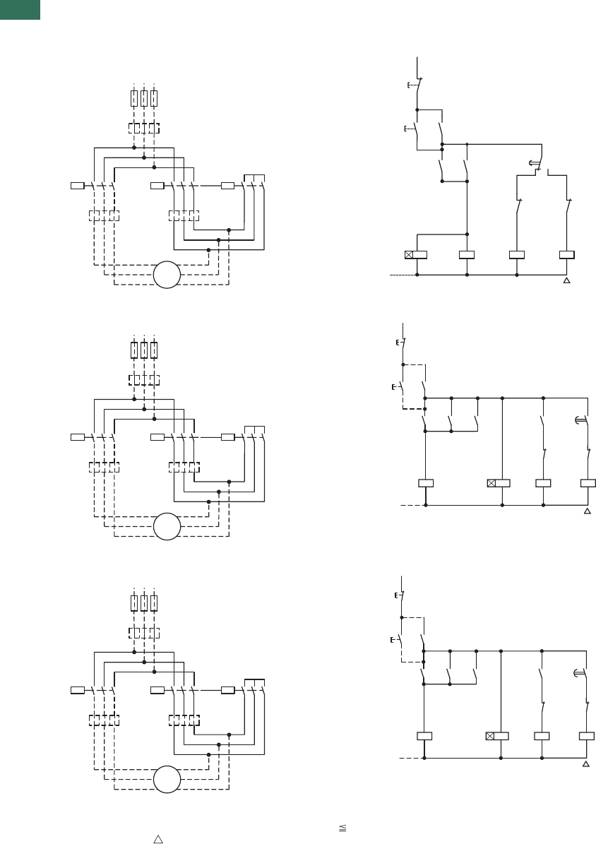
1.1 Contactor combinations
Star-delta combinations
46 AUTOMATION AND CONTROL www.eaton.com/seasia-electrical
1Engineering
Circuit diagrams, Star-delta combinations
SDAINLEM
SDAINLM12…SDAINLM55
SDAINLM70…SDAINLM260
StartingOverload relay settings
A: IN x 0.58
Motor protected in Y and - positions 15 s
B: IN x 1
Only partial motor protection in Y position 15 – 40 s
C: IN x 0.58
Motor not protected in Y position > 40 s
Timing relay set to approx. 10 s
Main circuit:
Depending on the type of coordination required (i.e. Type “1” or Type “2”) it must be established whether the fuse protection and the input wiring for the mains
contactor and delta contactor are to be common or separate.
L1L2 L3
F1
M1
Q13
0.58 xIn0.58 xIn
3~
M
C
A
Q15Q11
V1
U1
W1
W2
V2
U2
135
24
6
135
24
6
135
24
6
B1xIn
0
21
22
I13
Q11
14
14
13
44
Q11
Q13
43
14
13
15
K1
Q15
22
21 Q13
22
21
NN
16 18
Q11 Q15
Y
A2
A1
A2
A1
K1 A2
A1 Q13 A2
A1
L1L2 L3
F1
M1
Q13
0.58 xIn0.58 xIn
3~
M
C
A
Q15Q11
V1
U1
W1
W2
V2
U2
135
24
6
135
24
6
135
24
6
B1xIn
S11
0
(–)N
Q11
Q13
Q13
Q15
K1
I
Q11
Q11
Q15
Q13
K1
Q15
NY
K1
21
22
13
14
A2
A1
A2
A1
53
54
22
21
28
17
17
18
14
13
53
54
53
54
A2
A1
A2
A1
22
21
L1L2 L3
F1
M1
Q13
0.58 xIn0.58 xIn
3~
M
C
A
Q15Q11
V1
U1
W1
W2
V2
U2
135
24
6
135
24
6
135
24
6
B1xIn
S11
0
(–)N
Q11
Q13
Q13
Q15
K1
I
Q11
Q11
Q15
Q13
K1
Q15
NY
K1
21
22
13
14
A2
A1
A2
A1
13
14
22
21
28
17
17
18
14
13
13
14
43
44
A2
A1
A2
A1
22
21
SDAINL
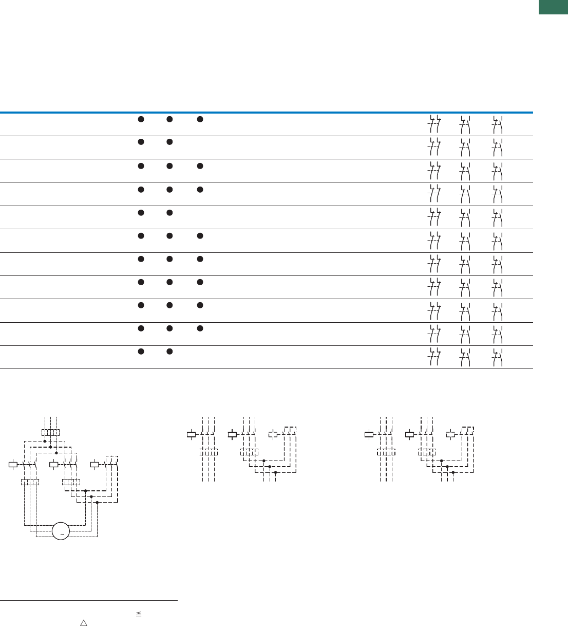
1.1
Contactor combinations
Star-delta combinations
47AUTOMATION AND CONTROL www.eaton.com/seasia-electrical
1
Components for self-assembly of star-delta combinations
Maximum operational rating of AC
motors 50 - 60 Hz Individual components of the combination Spare auxiliary contacts
AC-3 Changeover time
1) Coil to EN 50005
Switching element to EN 50005 and EN 50012
230 V 400 V 500 V 690 V 1000 V Mains
contactor
Q11
Delta
contactor
Q15
Star
contactor
Q13
Timing
relay
K1 Q11 Q15 Q13
kW kW kW kW kW up to
12 s up to
20 s up to
30 s Part no. DIL Part no. DIL Part no. DIL Part no.
90 160 200 250 132 M185A/22 M185A/22 M115/22 ETR4-51
110 200 250 315 160 – M225A/22 M225A/22 M150/22 ETR4-51
132 250 315 400 200 M250/22 M250/22 M185A/22 ETR4-51
160 300 355 450 200 M300A/22 M300A/22 M185A/22 ETR4-51
200 355 450 560 220 – M400/22 M400/22 M250/22 ETR4-51
250 450 560 600 220 M500/22 M500/22 M300A/22 ETR4-51
300 560 710 900 355 M580/22 M580/22 M400/22 ETR4-51
350 630 750 950 355 M650/22 M650/22 M400/22 ETR4-51
400 710 900 1200 1400 M750/22 M750/22 M580/22 ETR4-51
450 800 950 1300 1400 M820/22 M820/22 M580/22 ETR4-51
560 1000 1200 1700 1700 – M1000/22 M1000/22 M650/22 ETR4-51
Notes 1) Longer changeover times please enquire
Components for se setoNylbmessa-fl
Overload relay settings Timing relay set to approx. 10 s
Main circuit:
IN
Starting Depending on the coordination type required (i.e.
Type “1” or Type “2”) it must be established whether
the fuse protection and the input wiring for the
mains contactor and delta contactor are to be
common or separate.
A x 0.58
Motor protection in Y and positions 15 s
B x 1
In Y position only limited motor protec-
tion
15 – 40 s Control circuit:
If the combinations are to be used within the scope
of IEC/EN 60 204 Part 1, VDE 0113 Part 1, then Point
9.1.1 regarding the supply of control circuits, must
be observed.
C x 0.58
Motor not protected in Y position > 40 s
21
22
31
32
31
32
43
44
31
32
43
44
21
22
31
32
31
32
43
44
31
32
43
44
21
22
31
32
31
32
43
44
31
32
43
44
21
22
31
32
31
32
43
44
31
32
43
44
21
22
31
32
31
32
43
44
31
32
43
44
21
22
31
32
31
32
43
44
31
32
43
44
21
22
31
32
31
32
43
44
31
32
43
44
21
22
31
32
31
32
43
44
31
32
43
44
21
22
31
32
31
32
43
44
31
32
43
44
21
22
31
32
31
32
43
44
31
32
43
44
21
22
31
32
31
32
43
44
31
32
43
44
Q11
135
642
Q15
135
642
Q13 135
642
U1
V1
W1
M1
3
M1
V2
W2
U2
AC
BQ11 1
2
3
4
5
6Q15
1
2
3
4
5
6Q13
135
642
C
A
Q11 1
2
3
4
5
6Q15
1
2
3
4
5
6Q13
135
642
C
A
SDAINL
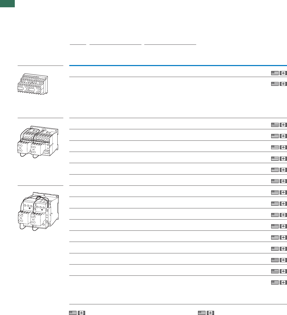
1.1 Contactor combinations
Reversing combinations
48 AUTOMATION AND CONTROL www.eaton.com/seasia-electrical
1Ordering
Rated
operational
current
Max. motor rating for
three-phase motors 50 - 60 Hz Part no.
Article no.
Price
See
price list
Std. pack
AC-4AC-3AC-3
400 V 220 V
230 V
380 V
400 V
660 V
690 V
220 V
230 V
380 V
400 V
660 V
690 V
IeP
AkW
P
kW
P
kW
P
kW
P
kW
P
kW
DIUL reversing combinations
AC operation 92.2441.533DIULEM/21/MV(230V50Hz)1)
051849
1 Off
1 Off
1 Off
1 Off
1 Off
1 Off
1 Off
1 Off
1 Off
1 Off
1 Off
1 Off
1 Off
1 Off
1 Off
1 Off
1 Off
92.2441.533DIULEM/21/MV-G(24VDC)2)
214655
7 2.233.512.22.9DIULM7/21(230V50Hz)2)
278061
7 2.233.512.22.9DIULM7/21(24VDC)2)
107021
9 2.5 4 4.5 1.5 2.5 3.6 DIULM9/21(230V50Hz) 2)
278086
9 2.5 4 4.5 1.5 2.5 3.6 DIULM9/21(24VDC)2)
107022
12 3.5 5.5 6.5 2 3 4.4 DIULM12/21(230V50Hz)2)
278111
12 3.5 5.5 6.5 2 3 4.4 DIULM12/21(24VDC)2)
107023
18 5 7.5 11 2.5 4.5 6.5 DIULM17/21(230V50Hz)2)
278136
18 5 7.5 11 2.5 4.5 6.5 DIULM17/21(RDC24)2)
107024
25 7.5 11 14 3.5 6 8.5 DIULM25/21(230V50Hz)2)
278161
25 7.5 11 14 3.5 6 8.5 DIULM25/21(RDC24)2)
107025
321015174710DIULM32/21(230V50Hz)2)
278186
321015174710DIULM32/21(RDC24)2)
107026
40 12.5 18.5 23 5 9 12 DIULM40/11(230V50Hz)2)
278211
50 15.5 22 30 6 10 14 DIULM50/11(230V50Hz)2)
278236
65 20 30 35 7 12 17 DIULM65/11(230V50Hz)2)
278261
1)
Information relevant for export to North America
Product Standards
UL File No.
UL CCN
CSA File No.
CSA Class No.
NA Certification
IEC/EN 60947-4-1; UL 508;
CSA-C22.2 No.14-05; CE marking
E29096
NLDX
012528
3211-04
UL Listed, CSA certified
2)
Information relevant for export to North America
Product Standards
UL File No.
UL CCN
CSA File No.
CSA Class No.
NA Certification
IEC/EN 60947-4-1; UL 508;
CSA-C22.2 No.14-05; CE marking
E29096
NLDX
012528
2411-03, 3211-04
UL Listed, CSA certified
AC operation
AC operation
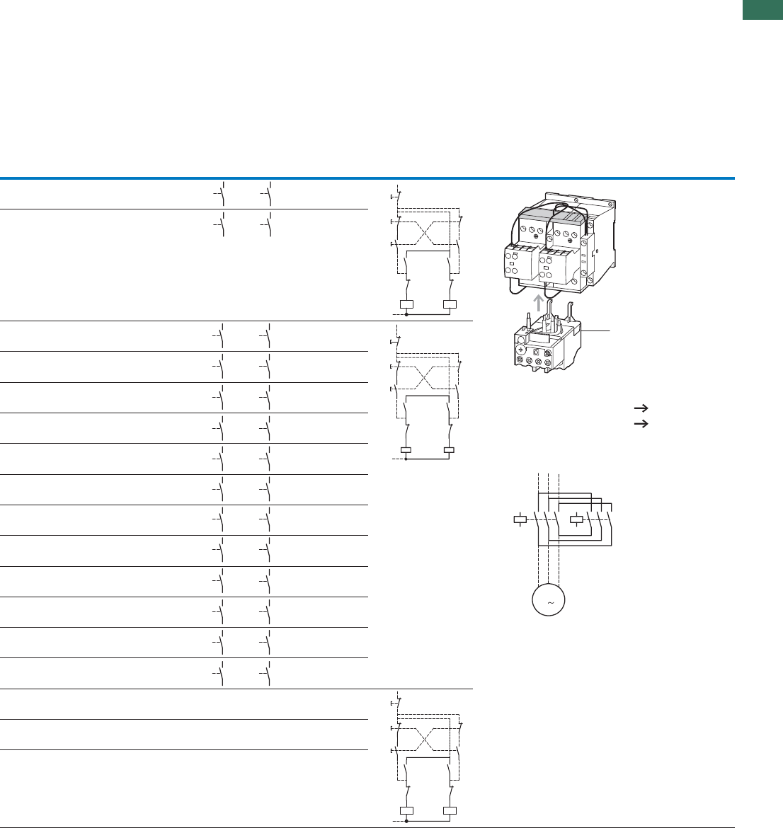
1.1
Contactor combinations
Reversing combinations
49AUTOMATION AND CONTROL www.eaton.com/seasia-electrical
1
Individual components of the combination Spare auxiliary contacts Circuit diagram Notes
Contactor Q11 Contactor Q12 Q11 Q12 Mechanical
interlock
Part no. Part no.
DILEM-10
+ 11DILEM
DILEM-10
+ 11DILEM
+
DILEM-10-G
+ 11DILEM
DILEM-10-G
+ 11DILEM
+
DILM7-01
+ DILA-XHI20
DILM7-01
+ DILA-XHI20
+
DILM7-01
+ DILA-XHI20
DILM7-01
+ DILA-XHI20
+
DILM9-01
+ DILA-XHI20
DILM9-01
+ DILA-XHI20
+
DILM9-01
+ DILA-XHI20
DILM9-01
+ DILA-XHI20
+
DILM12-01
+ DILA-XHI20
DILM12-01
+ DILA-XHI20
+
DILM12-01
+ DILA-XHI20
DILM12-01
+ DILA-XHI20
+
DILM17-01
+ DILA-XHI20
DILM17-01
+ DILA-XHI20
+
DILM17-01
+ DILA-XHI20
DILM17-01
+ DILA-XHI20
+
DILM25-01
+ DILA-XHI20
DILM25-01
+ DILA-XHI20
+
DILM25-01
+ DILA-XHI20
DILM25-01
+ DILA-XHI20
+
DILM32-01
+ DILA-XHI20
DILM32-01
+ DILA-XHI20
+
DILM32-01
+ DILA-XHI20
DILM32-01
+ DILA-XHI20
+
DILM40
+ DILM150-XHI11
DILM40
+ DILM150-XHI11
––+
DILM50
+ DILM150-XHI11
DILM50
+ DILM150-XHI11
––+
DILM65
+ DILM150-XHI11
DILM65
+ DILM150-XHI11
––+
34
33
34
33
Q12 14
Q11 14
13 13
Q12 22
21
Q11 22
21
Q11 A1
A2
Q12 A1
A2
(-)N
I14
13
13
II 21
22
22
21
21
22
0
14
Accessories Page
1 Overload relay Chapter 1.2
Accessories 52
Reversing contactors
DIULM7/21 to DIULM65/11 with mechanical
interlock
1
UVW
Q11
M
M1
Q12
135
64
2
135
6
4
2
3
34
33
34
33
64
63
64
63
Q12
54
Q11 54
53 53
Q12
22
21 Q11
22
21
Q11 A1
A2 Q12 A1
A2
I14
13
13
II 21
22
22
21
21
22
0
14
64
63
64
63
64
63
64
63
64
63
64
63
64
63
64
63
64
63
64
63
64
63
64
63
64
63
64
63
64
63
64
63
64
63
64
63
64
63
64
63
64
63
64
63
Q12 14
Q11 14
13 13
Q12 22
21
Q11 22
21
Q11 A1
A2
Q12 A1
A2
(-)N
I14
13
13
II 21
22
22
21
21
22
0
14
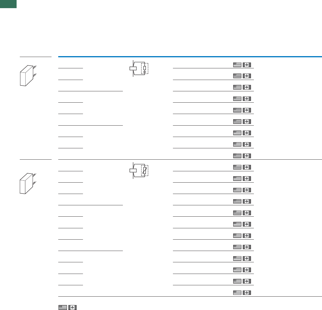
1.1 Contactor relays, contactors
Suppressor circuit
50 AUTOMATION AND CONTROL www.eaton.com/seasia-electrical
1Ordering
Information relevant for export to North America
Product Standards
UL File No.
UL CCN
CSA File No.
CSA Class No.
NA Certification
IEC/EN 60947-4-1; UL 508; CSA-C22.2 No.14-05; CE marking
E29096
NLDX
227038
3211-07
UL Listed, CSA certified
Voltage For use with Circuit symbol Part no.
Article no. Price
See price
list
Std. pack Notes
Us
V
Suppressor circuits
RC suppressors 24 - 48 AC DILM7 - DILM15
DILMP20
DILA
DILM12-XSPR48
281199
10 Off
10 Off
10 Off
10 Off
10 Off
10 Off
10 Off
10 Off
10 Off
10 Off
10 Off
10 Off
10 Off
10 Off
10 Off
10 Off
10 Off
10 Off
10 Off
10 Off
10 Off
For AC operated contactors 50 - 60 Hz.
DC operated contactors and DILM115 and
DILM150 have an integrated suppressor.
Note drop-out delay.
110 - 240 AC DILM12-XSPR240
281200
240 - 500 AC DILM12-XSPR500
281201
24 - 48 AC DILM17 - DILM32
DILK12 - DILK25
DILL…
DILMP32 - DILMP45
DILM32-XSPR48
281202
110 - 240 AC DILM32-XSPR240
281203
240 - 500 AC DILM32-XSPR500
281204
24 - 48 AC DILM40 - DILM95
DILK33 - DILK50
DILMP63 - DILMP200
DILM95-XSPR48
281205
110 - 240 AC DILM95-XSPR240
281206
240 - 500 AC DILM95-XSPR500
281207
Varistor
suppressors
24 - 48 AC DILM7 - DILM15
DILMP20
DILA
DILM12-XSPV48
281208
For AC operated contactors 50 - 60 Hz.
DC operated contactors and DILM115 and
DILM150 have an integrated suppressor.
Note drop-out delay.
48 - 130 AC DILM12-XSPV130
281209
130 - 240 AC DILM12-XSPV240
281210
240 - 500 AC DILM12-XSPV500
281211
24 - 48 AC DILM17 - DILM32
DILK12 - DILK25
DILL…
DILMP32 - DILMP45
DILM32-XSPV48
281212
48 - 130 AC DILM32-XSPV130
281213
130 - 240 AC DILM32-XSPV240
281214
240 - 500 AC DILM32-XSPV500
281215
24 - 48 AC DILM40 - DILM95
DILK33 - DILK50
DILMP63 - DILMP200
DILM95-XSPV48
281216
48 - 130 AC DILM95-XSPV130
281217
130 - 240 AC DILM95-XSPV240
281218
240 - 500 AC DILM95-XSPV500
281219
A1
A2
A2
A1
DILM...-XSP...
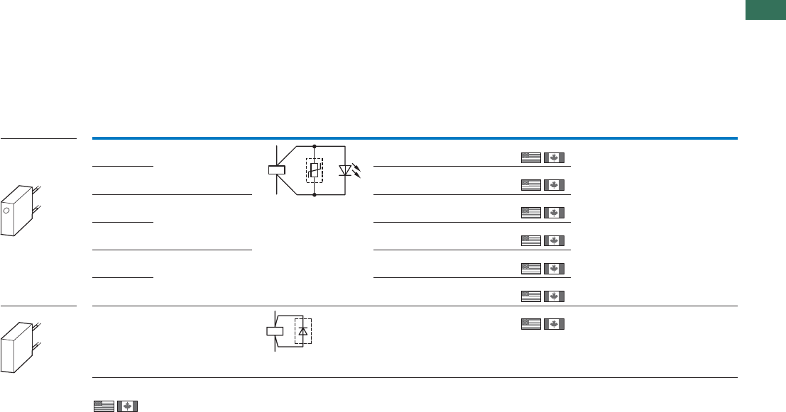
1.1
Contactor relays, contactors
Suppressor circuit
51AUTOMATION AND CONTROL www.eaton.com/seasia-electrical
1
Ordering
Information relevant for export to North America
Product Standards
UL File No.
UL CCN
CSA File No.
CSA Class No.
NA Certification
IEC/EN 60947-4-1; UL 508; CSA-C22.2 No.14-05; CE marking
E29096
NLDX
227038
3211-07
UL Listed, CSA certified
Notes
Suppressor circuits
DILM...-XSP...
Varistor
suppressors
with integrated
LED
24 - 48 AC DILM7 - DILM15
DILMP20
DILA
DILM12-XSPVL48
281220
10 Off
10 Off
10 Off
10 Off
10 Off
10 Off
10 Off
For AC operated contactors 50 - 60 Hz.
DC operated contactors and DILM115 and
DILM150 have an integrated suppressor.
Note drop-out delay.
130 - 240 AC DILM12-XSPVL240
281221
24 - 48 AC DILM17 - DILM32
DILK12 - DILK25
DILL…
DILMP32 - DILMP45
DILM32-XSPVL48
281222
130 - 240 AC DILM32-XSPVL240
281223
24 - 48 AC DILM40 - DILM95
DILK33 - DILK50
DILMP63 - DILMP200
DILM95-XSPVL48
281224
130 - 240 AC DILM95-XSPVL240
281225
Diode suppressor 12 - 250 DC DILM7 - DILM15
DILMP20
DILA
DILM12-XSPD
101672
DC operated contactors.
Prevention of negative switch-off voltage
when the contactor is used together with
a safety PLC.
Voltage For use with Circuit symbol Part no.
Article no. Price
See price
list
Std. pack
Us
V
A1
A2
A1
A2
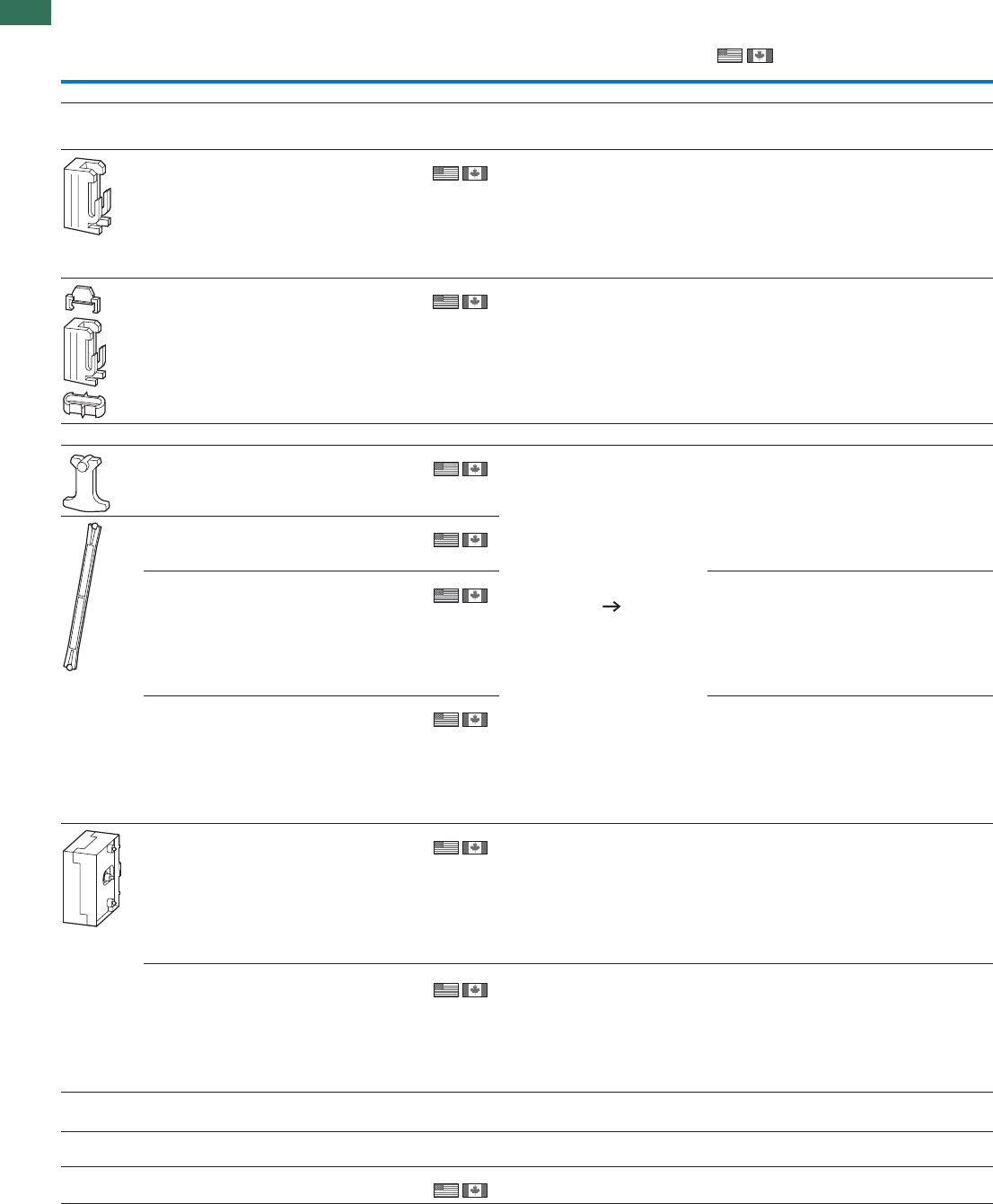
1.1 Contactor relays, contactors
Accessories
52 AUTOMATION AND CONTROL www.eaton.com/seasia-electrical
1
For use with Part no.
Article no.
Price
See price
list
Std. pack Information relevant for export to North AmericaNotes
Mechanical interlocks
For mechanically linking contactors
in combinations
0 mm distance between contactors.
DILM7 - DILM72
DILA DILM32-XVB
281227
50 Off –
DILM80 - DILM170 DILM150-XVB
281226
10 Off –
Mechanical interlocks
DILM7 - DILM15
DILMP20
DILA
DILM12-XMV
281196
1 Off
1 Off
1 Off
1 Off
1 Off
1 Off
1 Off
For two contactors with AC or DC
operation arranged vertically or
horizontally.
Distance between contactors 0 mm,
including contactor connector
Mechanical lifespan 2.5 x 10⁶
operations.
DILM 150-XMV including mounting
plate for contactors.
Additional auxiliary contact
modules possible. 36
DILM17 - DILM38 DILM32-XMV
281197
DILM40 - DILM72 DILM65-XMV
281198
DILM80 - DILM170 DILM150-XMV
240081
DILM185A,
DILM225A,
DILM250,
DILM300A,
DILM400,
DILM500,
DILM570
DILM500-XMV
208289
For contactors with the same or
different magnet systems mounted
horizontally or vertically, mechanical
lifespan 5 x 10 operations.
No
6
auxiliary contact permitted between
mechanical interlock and contactor.
Combination only with consecutive
installation sizes or DILM185A -
DILM570.
DILM580,
DILM650
DILM750,
DILM820
DILM1000
DILM820-XMV
208288
For contactors with the same or
different magnet systems mounted
horizontally or vertically, mechanical
lifespan 5 x 10 operations.
No
6
auxiliary contact permitted between
mechanical interlock and contactor.
DILM820-XMV consists of interlock
element and mounting plate.
Set of spare parts for
mechanical interlock
Ball for mechanical interlock, incl.
contactor connector.
– DILM80 - DILM170 DILM150-XMVE
107020
UL/CSA certification not required
DILM...-XDILM..-XVB, DILM..-XMV
IEC/EN 60947-4-1; UL 508;
CSA-C22.2 No.14-05;
CE marking
E36332
NLRV
012528
3211-05
UL Listed, CSA certified
UL File No.
UL CCN
CSA File No.
CSA Class No.
NA Certification
Product Standards
IEC/EN 60947-4-1; UL 508;
CSA-C22.2 No.14-05;
CE marking
E29184
NKCR
012528
3211-03
UL Listed, CSA certified
UL File No.
UL CCN
CSA File No.
CSA Class No.
NA Certification
Product Standards
IEC/EN 60947-4-1; UL 508;
CSA-C22.2 No.14-05;
CE marking
E29096
NLDX
012528
2411-03
UL Listed, CSA certified
UL File No.
UL CCN
CSA File No.
CSA Class No.
NA Certification
Product Standards
IEC/EN 60947-4-1; UL 508;
CSA-C22.2 No.14-05;
CE marking
E29096
NLDX
012528
2411-03,3211-04
UL Listed, CSA certified
UL File No.
UL CCN
CSA File No.
CSA Class No.
NA Certification
Product Standards
IEC/EN 60947-4-1; UL 508;
CSA-C22.2 No.14-05;
CE marking
E29096
NLDX
012528
2411-03
UL Listed, CSA certified
UL File No.
UL CCN
CSA File No.
CSA Class No.
NA Certification
Product Standards
IEC/EN 60947-4-1; UL 508;
CSA-C22.2 No.14-05;
CE marking
E29184
NKCR
012528
3211-04
UL Listed, CSA certified
UL File No.
UL CCN
CSA File No.
CSA Class No.
NA Certification
Product Standards
IEC/EN 60947-4-1; UL 508;
CSA-C22.2 No.14-05;
CE marking
E29184
NKCR
012528
3211-04
UL Listed, CSA certified
UL File No.
UL CCN
CSA File No.
CSA Class No.
NA Certification
Product Standards
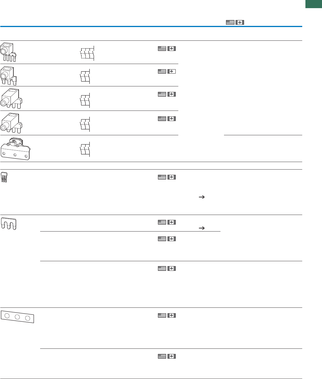
1.1
Contactor relays, contactors
Accessories
53AUTOMATION AND CONTROL www.eaton.com/seasia-electrical
1
For use with Circuit
symbol Part no.
Article no.
Price
See price
list
Std. pack Notes Information relevant for export to North
America
Paralleling links for main contacts
Consisting of 2 paralleling links
DILM7 - DILM15 DILM12-XP1
281193 5 Off
5 Off
4th pole can be
broken off
AC-1 current carrying
capacity of the open
contactor increases
by a factor of 2.5
Protected against
accidental contact in
accordance with VDE
0106 Part 100
A cover is included
with DILM185-XP1 for
protection against
accidental contact.
Connection cross
section for DILM..-
XP1 Technical data
DILM17 - DILM32 DILM32-XP1
281194
DILM40 - DILM72 DILM65-XP1
281195
1 Off
1 Off
DILM80 - DILM170 DILM150-XP1
284769
DILM185A DILM185-XP1
208292
–ffO1
Star-point bridges
DILM7 - DILM15 DILM12-XS1
281190
20 Off
20 Off
• Designed as tool-
less plug
connection
• Use as DILA-XHIT...
contactor auxiliary
contact 38
DILM17 - DILM32 DILM32-XS1
281191
• Use as DILA-XHIT...
contactor auxiliary
contact 38
DILM40 - DILM72 DILM65-XS1
281192
10 Off –
–DILM80 - DILM170 DILM150-XS1
284768
5 Off
DILM185A - DILM400 DILM400-XS1
208291 1 Off
1 Off
A cover is included
for protection against
accidental contact.
DILM500 DILM500-XS1
208290
A cover is included
for protection against
accidental contact.
DILM...-XP1, DILM...-XS1
IEC/EN 60947-4-1;
UL 508; CSA-C22.2
No.14-05; CE marking
E29096
NLDX
012528
3211-03
UL Listed, CSA
certified
UL File No.
UL CCN
CSA File No.
CSA Class No.
Product Standards
NA Certification
IEC/EN 60947-4-1;
UL 508; CSA-C22.2
No.14-05; CE marking
E36332
NLRV
012528
3211-05
UL Listed,
CSA certified
UL File No.
UL CCN
CSA File No.
CSA Class No.
Product Standards
NA Certification
IEC/EN 60947-4-1;
UL 508; CSA-C22.2
No.14-05; CE marking
E36332
NLRV
012528
3211-04
UL Listed,
CSA certified
UL File No.
UL CCN
Product Standards
CSA File No.
CSA Class No.
NA Certification
IEC/EN 60947-4-1;
UL 508; CSA-C22.2
No.14-05; CE marking
E36332
NLRV
012528
3211-03
UL Listed,
CSA certified
UL File No.
UL CCN
CSA File No.
CSA Class No.
Product Standards
NA Certification
IEC/EN 60947-4-1;
UL 508; CSA-C22.2
No.14-05; CE marking
E36332
NLRV
012528
3211-03
UL Listed,
UL File No.
UL CCN
CSA File No.
CSA Class No.
Product Standards
NA Certification
IEC/EN 60947-4-1;
UL 508; CSA-C22.2
No.14-05; CE marking
E29096
NLDX
UL Listed
UL File No.
UL CCN
Product Standards
NA Certification
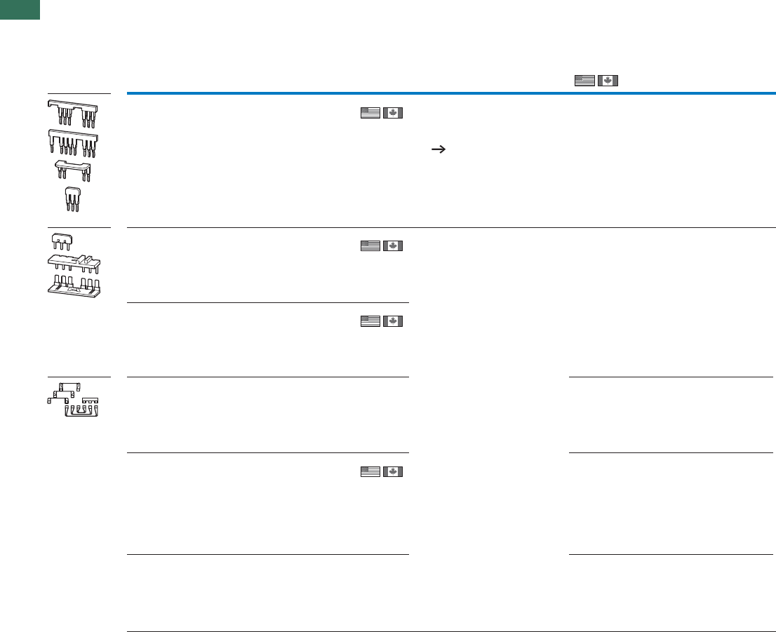
1.1 Contactor relays, contactors
Accessories
54 AUTOMATION AND CONTROL www.eaton.com/seasia-electrical
1
For use with Part no.
Article no.
Price
See price
list
Std. pack Information relevant for export to NorthNotes
America
Star-delta wiring kit
Main current wiring for star-delta combination Including star-point bridge
DILM7/9/12/15
mains contactors
DILM7/9/12/15 delta
contactors
DILM7/9/12/15
star contactors
DILM12-XSL
283130
1 Off
1 Off
1 Off
• Designed for tool-less plug
connection
• Use as DILA-XHIT...
contactor auxiliary contact
38
The following control cables are
integrated in addition to electrical
interlock:
• Q13: A1 - Q15: 21
• Q13: 21 - Q15: A1
• Q13: A2 - Q15: A2
DILM17/25/32
mains contactors
DILM17/25/32 delta
contactors
DILM17/25/32 star
contactors
DILM32-XSL
283131
Consists of the following
connection bridges:
• Mains - delta contactors
• Delta - star contactors
• Star-point bridge
DILM40/50/65
mains contactors
DILM40/50/65 delta
contactors
DILM40/50/65 star
contactors
DILM65-XSL
101058
DILM 80/95 mains
contactors
DILM80/95 delta
contactors
DILM50/65 star
contactors
DILM95-XSL
101486
–ffO1
DILM 115/150 mains
contactors
DILM115/150 delta
contactors
DILM80/95/115 star
contactors
DILM150-XSL
101487 1 Off
DILM 185/225 mains
contactors
DILM185/225 delta
contactors
DILM115/150 star
contactors
DILM225-XSL
101488
–ffO1
DILM...-XSL
IEC/EN 60947-4-1; UL 508;
CSA-C22.2 No.14-05;
CE marking
012528
3211-05
UL Listed, CSA certified
CSA File No.
CSA Class No.
NA Certification
Product Standards
IEC/EN 60947-4-1; UL 508;
CSA-C22.2 No.14-05;
CE marking
E36332
NLRV
012528
3211-04
UL Listed, CSA certified
UL File No.
UL CCN
CSA File No.
CSA Class No.
NA Certification
Product Standards
IEC/EN 60947-4-1; UL 508;
CSA-C22.2 No.14-05;
CE marking
E36332
NLRV
012528
2411-03,3211-04
UL Listed, CSA certified
UL File No.
UL CCN
CSA File No.
CSA Class No.
NA Certification
Product Standards
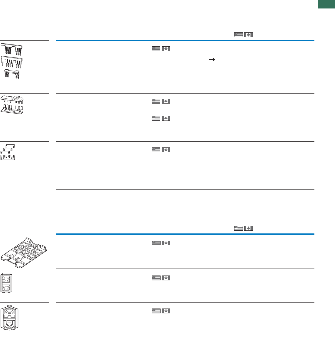
1.1
Contactor relays, contactors
Accessories
55AUTOMATION AND CONTROL www.eaton.com/seasia-electrical
1
For use with Part no.
Article no.
Price
See price
list
Std. pack Notes Information relevant for export to North
America
Reversing starter wiring kits
Main current wiring for reversing combinations
DILM7
DILM9
DILM12
DILM12-XRL
283108
1 Off
1 Off
1 Off
1 Off
• Designed for tool-less
plug connection
• As auxiliary contact
DILA-XHIT...use 38
The following control cables
are integrated in addition to
electrical interlock:
• Q11: A1 - Q12: 21
• Q11: 21 - Q12: A1
• Q11: A2 - Q12: A2
DILM17
DILM25
DILM32
DILM32-XRL
283109
–
DILM40
DILM50
DILM65
DILM65-XRL
101057
–
DILM80
DILM95
DILM115
DILM150
DILM150-XRL
101681
–
DILM17
DILM25
DILM32
DILM38
DILMP32
DILMP45
DILM32-XIP2X
118855 1 Off Each cover set consists of
two three-pole and two
single-pole covers.
UL/CSA certification not required
DILM40
DILM50
DILM65
DILM72
DILMP63
DILMP80
DILM65-XIP2X
106491
8 Off
8 Off
2 covers are required per
phase
The cover set consists of
8covers
UL/CSA certification not required
DILM80
DILM95
DILM115
DILM150
DILM170
DILMP125
DILMP160
DILMP200
ZB150
DILM150-XIP2X
106492
UL/CSA certification not required
For use with Part no.
Article no.
Price
See price
list
Std. pack Notes Information relevant for export to North
America
DILM...-XRL, DILM...XIP2X
IP2X cover set
DILM...-XRL, DILM...XIP2X
IEC/EN 60947-4-1;
UL 508; CSA-C22.2
No.14-05;CE marking
E36332
NLRV
012528
3211-05
UL Listed, CSA
certified
UL File No.
UL CCN
CSA File No.
CSA Class No.
NA Certification
Product Standards
IEC/EN 60947-4-1;
UL 508; CSA-C22.2
No.14-05; CE marking
E36332
NLRV
012528
3211-04
UL Listed, CSA
certified
UL File No.
UL CCN
CSA File No.
CSA Class No.
NA Certification
Product Standards
IEC/EN 60947-4-1;
UL 508; CSA-C22.2
No.14-05; CE marking
E36332
NLRV
012528
2411-03, 3211-04
UL Listed, CSA
certified
UL File No.
UL CCN
CSA File No.
CSA Class No.
NA Certification
Product Standards
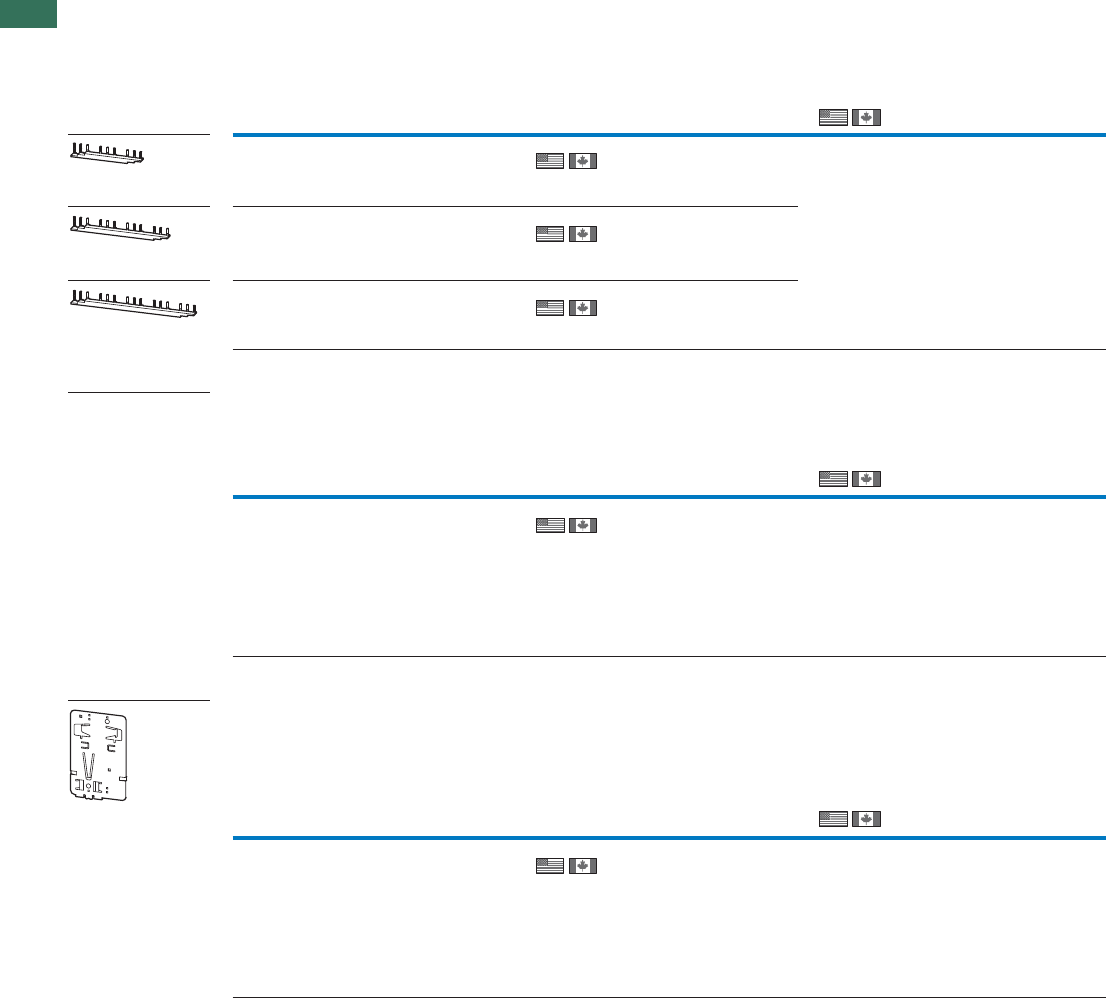
1.1 Contactor relays, contactors
Accessories
56 AUTOMATION AND CONTROL www.eaton.com/seasia-electrical
1
For use with Part no.
Article no.
Price
See price
list
Std. pack Information relevant for export to NorthNotes
America
Three-phase commoning links
DILM7
DILM9
DILM12
DILM15
DILM12-XDSB0/3
240084
5 Off
5 Off
5 Off
Suitable for 3 contactors.
Length 112 mm
DILM7
DILM9
DILM12
DILM15
DILM12-XDSB0/4
240085
Suitable for 4 contactors.
Length 157 mm
DILM7
DILM9
DILM12
DILM15
DILM12-XDSB0/5
240086
Suitable for 5 contactors.
Length 202 mm
–
DILM7
DILM9
DILM12
DILM15
DILM12-XEK
240083
5 Off For three-phase commoning
link, protected against
accidental contact,
Ue=690V, Iu=35A.
Terminal capacities:
Stranded 2.5…16 mm2
Flexible with ferrule
2.5…16 mm2
AWG14…8
Enables clipping on of switches on to DIN rails
DILM80
DILM95
DILM115
DILM150
DILM170
NZM2-XC75
260215
1 Off For top-hat rail 75 mm
For use with Part no.
Article no.
Price
See price
list
Std. pack Information relevant for export to NorthNotes
America
For use with Part no.
Article no.
Price
See price
list
Std. pack Information relevant for export to NorthNotes
America
Protected against accidental contact, short-circuit proof, Ue = 690 V, Iu = 35 ACan be extended by rotating by mounting
DILM12-XDSBS
Incoming connection block
DILM12-XDSBS
Adapter plate
DILM12-XDSBS
IEC/EN 60947-4-1; UL 508;
CSA-C22.2 No.14-05;
CE marking
E36332
NLRV
012528
2411-03
UL Listed, CSA certified
UL File No.
UL CCN
CSA File No.
CSA Class No.
NA Certification
Product Standards
IEC/EN 60947-4-1; UL 508;
CSA-C22.2 No.14-05;
CE marking
E36332
NLRV
012528
2411-03
UL Listed, CSA certified
UL File No.
UL CCN
CSA File No.
CSA Class No.
NA Certification
Product Standards
IEC/EN 60947-4-1; UL 489;
CSA-C22.2 No.14-05;
CE marking
E140305
DIHS
022086
1437-01
UL Listed, CSA certified
UL File No.
UL CCN
CSA File No.
CSA Class No.
NA Certification
Product Standards
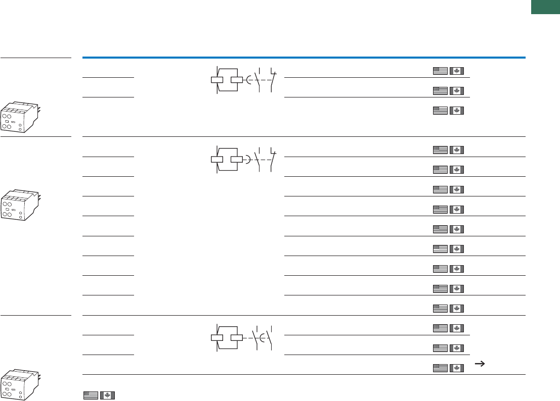
1.1
Contactor relays, contactors
Electronic timer modules
57AUTOMATION AND CONTROL www.eaton.com/seasia-electrical
1
For use with Circuit symbol Part no.
Article no. Price
See price
Std. pack Notes
On-delayed, Cannot be
combined with top
mounting auxiliary
contacts Incl.
suppressor circuits
24 V AC/DC
DILMP20
DILM7 - DILM32
DILMP32-DILMP45
DILA
DILM32-XTEE11(RA24)
101440
1 Off
1 Off
1 Off
Time range can be
selected
0.05 s...1 s
0.5 s...10 s
5 s...100 s
100 … 130 V AC DILM32-XTEE11(RAC130)
101441
200 … 240 V AC DILM32-XTEE11(RAC240)
101442
Off-delayed, auxiliary
voltage-free Cannot be
combined with top
mounting auxiliary
contactsIncl.
suppressor circuits
24 V AC/DC
24 V AC/DC
24 V AC/DC
DILMP20
DILM7 - DILM32
DILMP32-DILMP45
DILA
DILM32-XTED11-1(RA24)
105210
1 Off
1 Off
1 Off
1 Off
1 Off
1 Off
1 Off
1 Off
1 Off
Time range
0.05 s...1 s
DILM32-XTED11-10(RA24)
104943
Time range
0.5 s...10 s
DILM32-XTED11-100(RA24)
104946
Time range
5 s...100 s
100 … 130 V AC
100 … 130 V AC
100 … 130 V AC
DILM32-XTED11-1(RAC130)
105211
Time range
0.05 s...1 s
DILM32-XTED11-10(RAC130)
104944
Time range
0.5 s...10 s
DILM32-XTED11-100(RAC130)
104947
Time range
5 s...100 s
200 … 240 V AC
200 … 240 V AC
200 … 240 V AC
DILM32-XTED11-1(RAC240)
105212
Time range
0.05 s...1 s
DILM32-XTED11-10(RAC240)
104945
Time range
0.5 s...10 s
DILM32-XTED11-100(RAC240)
104948 Time range
5 s...100 s
For star-delta
applications Cannot be
combined with top
mounting auxiliary
contactsIncl.
suppressor circuits
24 V AC/DC
DILMP20
DILM7 - DILM32
DILMP32-DILMP45
DILA
DILM32-XTEY20(RA24)
101446
1 Off
1 Off
1 Off
Changeover time
1...30 s
50 ms changeover
delay
Sample circuit
Page 92
100 … 130 V AC DILM32-XTEY20(RAC130)
101447
200 … 240 V AC DILM32-XTEY20(RAC240)
101448
57
58
65
66
A1
A2
57
58
65
66
A1
A2
57
58
67
68
A1
A2
Electronic timer modules
DILM32-XTE
list
Information relevant for export to North America
Product Standards
UL File No.
UL CCN
CSA File No.
CSA Class No.
NA Certification
IEC/EN 60947-4-1; UL 508; CSA-C22.2 No.14-05; CE marking
E29184
NKCR
012528
3211-03
UL Listed, CSA certified
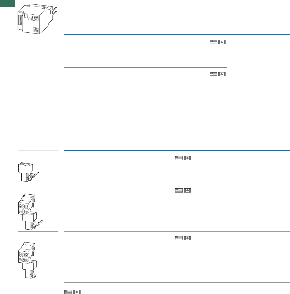
1.1 Contactor relays, contactors
Accessories
58 AUTOMATION AND CONTROL www.eaton.com/seasia-electrical
1
SWD contactor modules
SmartWire-DT® module for installation on contactors. One module per contactor
DIL-SWD..., DILM12-XMC
Wiring set for motor feeder plug
DIL-SWD..., DILM12-XMC
For use with Part no.
Article no. Price
See price
list
Std. pack Notes
Two digital inputs for potential-free
contacts.
1 electrical interlock for the surface
mounting of reversing starters.
Messages: Contactor switch status,
status of the digital inputs 1 and 2.
Commands: Contactor actuation
DILM(C)7… -
DILM(C)32
DILM38
DILA
DIL-SWD-32-0011)
118560
5 Off • Take into account the max.
current consumption of the
contactor coils per SmartWire-DT®
line.
• A2 terminals must not be
bridged.
• Wiring sets DILM 12-XRL and
PKZM0-XRM12 cannot be used.
• Connection terminals for
electrical interlocking are not
suitable for safety technology.
Two digital inputs for potential-free
contacts.
1 electrical interlock for the surface
mounting of reversing starters.
1-0-A switch for manual or automatic
operation.
Messages: contactor switching
position, status of the digital inputs 1
and 2, 1-0-A switch position.
Commands: Contactor actuation
DILM(C)7… -
DILM(C)32
DILM38
DILA
DIL-SWD-32-0021)
118561
5 Off
For use with Part no.
Article no. Price
See price
list
Std. pack Notes
PE module with contact
plate DILM(C)9
DILM(C)7
DILM(C)12
DILM(C)15
DILM12-XMCE2)
121764
5 Off 35x7.5 (15) mm mounting rail (as per
DIN EN 60715) with PE function required.
For connection of:
PE 0.75 – 4 mm²
Motor plate with PE
module and contact plate
DILM(C)7
DILM(C)9
DILM(C)12
DILM(C)15
DILM12-XMCP/E2)
121769
1 Off 35x7.5 (15) mm mounting rail (as per
DIN EN 60715) with PE function required.
For connection of:
L1, L2, L3, PE 0.75 – 2.5 mm²
PKZM0/PKE + DILM(C)7
PKZM0/PKE + DILM(C)9
PKZM0/PKE + DILM(C)12
PKZM0/PKE + DILM(C)15
MSC-D(E)-…-M7…
MSC-D(E)-…-M9…
MSC-D(E)-…-M15…
DILM12-XMCP/T2)
121770
1 Off For connection of:
L1, L2, L3, PE 0.75 – 2.5 mm²
Information relevant for export to North America
1) NA Certification Request filed for UL and CSA
2) Product Standards IEC/EN 60947-4-1; UL 508; CSA-C22.2 No. 14-05; CE marking
NA Certification Request filed for UL and CSA
Motor plate with PE
module and contact plate
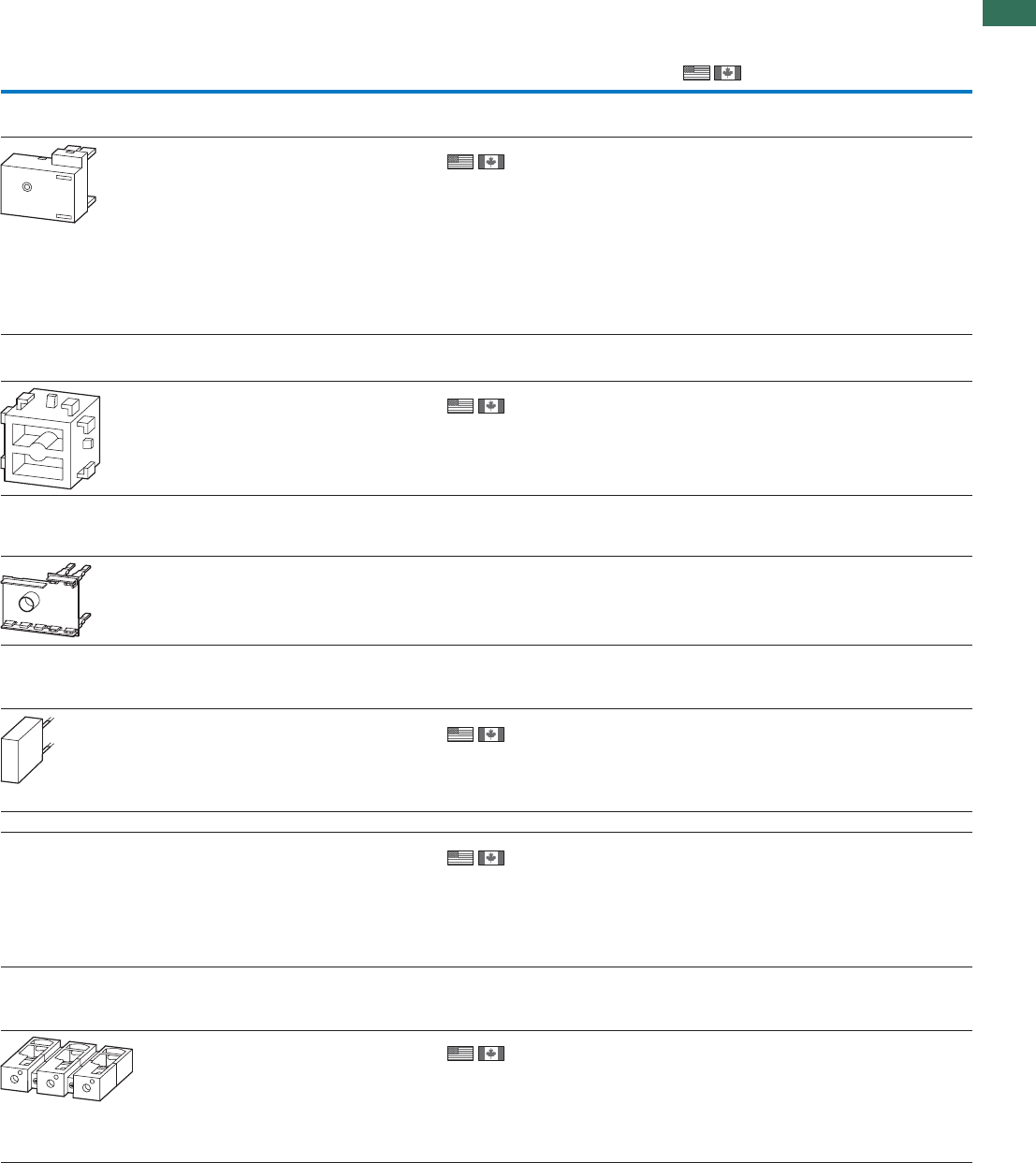
1.1
Contactor relays, contactors
Accessories
59AUTOMATION AND CONTROL www.eaton.com/seasia-electrical
1
DILM...-X...
For use
with Part no.
Article no. Price
See price
Std. pack Notes Information relevant for export to
North America
Motor suppressor module
Can be used at 380…575 V 50/60 Hz.
DILM7 -
DILM15 DILM12-XMSM
109399
4 Off • Tool-less version using
tool-less plug
connection
• RC suppressor
• Ambient temperature
-25…+60 °C, open.
• Insulated material,
difficult to ignite
according to UL 94.
• Weight = 0.05 kg.
• UL/CSA approval
applied for
Test block
Suitable for switching on contactor off-load
DILM7 -
DILM38
DILA
DILM32-XMAN
110955
1 Off deriuqertonnoitacifitrecASC/LU–
Printed board contact
For the adaption of a control circuit on a
printed-circuit board
DILM7 -
DILM15
DILA
DILM12-XPBC
109400
––ffO4
Load resistor
For DC contactors in order to increase
power consumption
DILM17
DILM25
DILM32
DILM38
DILMP32
DILMP45
DILM32-XSPLW24
112419
1 Off Installed in a suppressor
circuit enclosure.
Required when using
special PLC outputs for
actuation, e.g.: Beckhoff
safety controllers.
Extension terminals
DILM80
DILM95
DILM115
DILM150
DILM170
DILM150-XZK
104486
10 Off Can be fitted on every
main terminal of the con-
tactor.
Connection options:
maximum 2 x 4 mm² solid
maximum 2 x 2.5 mm²
flexible with ferrule
Cable terminal block
With control circuit terminal
Consisting of three flat ribbon terminals
DILM250
DILM300A
DILM400
DILM400-XKU-S
208293
1 Off Connection options:
round conductors,
flexible and stranded,
ribbon cables.
IEC/EN 60947-4-1;
UL 508; CE marking
E300273
NMTR2
UL Listed
UL File No.
UL CCN
NA Certification
Product Standards
IEC/EN 60947-4-1;
CSA-C22.2 No.14-05;
CE marking
225135
3211-07
CSA certified
CSA File No.
CSA Class No.
NA Certification
Product Standards
IEC/EN 60947-4-1;
UL 508; CSA-C22.2
No.14-05;CE marking
E29184
NKCR
012528
2411-03, 2411-04
UL Listed, CSA certified
UL File No.
UL CCN
CSA File No.
CSA Class No.
NA Certification
Product Standards
IEC/EN 60947-4-1;
UL 508; CSA-C22.2
No.14-05;CE marking
E29184
NKCR
012528
3211-04
UL Listed, CSA certified
UL File No.
UL CCN
CSA File No.
CSA Class No.
NA Certification
Product Standards
list
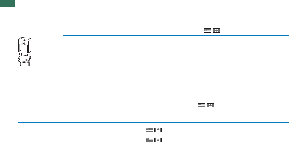
1.1 Contactor relays, contactors
Accessories
60 AUTOMATION AND CONTROL www.eaton.com/seasia-electrical
1
Flat strip conductor terminal kit
With control cable connection
DILM...-XK...
Connection terminal sets for North America
Consist of three individual terminals
DILM...-XK...
DILM580
DILM650
DILM750
DILM820
DILM820-XKB-S
208295
1 Off Connection options:
ribbon cables
Conductor
material
Cross-section X
number of
cores
For use
with Part no.
Article no. Price
See
price list
Std. pack Notes Information relevant for export to North America
mm²
Copper,
aluminum
2 x (AWG4 …
MCM500)
DILM500/22 DILM500-XK-CNA
232192
1 Off
1 Off
Including cover
With control
cable connec-
tion
Copper,
aluminum
4 x (AWG2 …
MCM500)
DILM580/22
DILM650/22
DILM750/22
DILM820/22
DILM820-XK-CNA
232194
For use
with Part no.
Article no. Price
See price
list
Std. pack Notes Information relevant for export to
North America
IEC/EN 60947-4-1; UL 508;
CSA-C22.2 No.14-05;
CE marking
E29184
NKCR
012528
3211-04
UL Listed, CSA certified
UL File No.
UL CCN
CSA File No.
CSA Class No.
NA Certification
Product Standards
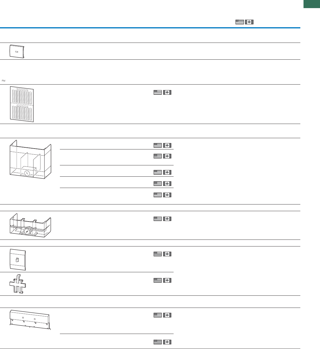
1.1
Contactor relays, contactors
Accessories
61AUTOMATION AND CONTROL www.eaton.com/seasia-electrical
1
Description For use with Part no.
Article no. Price
See price
list
Std. pack Information relevant for export toNotes
North America
Sealable shrouds
Transparent
DILM32-XTE… DILM32-XTEPLH
101449
––ffO1
Device labelling, label sheet
7.5 x 17 mm
Colour: yellow HKS 3
(RAL 1018)
Labelling with
laser printer,
plotter, film
plotter, copier
XGKE-GE
207517
25 Off 1 off = 1 sheet
240 labels per sheet
1 sheet = DIN A4,
Can be split into two DIN A5
sheets
UL/CSA certification not required
Covers
Terminal cover
DILM185A
DILM225A DILM225A-XHB
139560
1 Off
1 Off
1 Off
1 Off
1 Off
To provide terminals with
protection against accidental
contact vertical from the front
UL/CSA certification not required
DILM250
DILM300A
DILM400
DILM400-XHB
208287
DILM500 DILM500-XHB
208286
DILM580
DILM650 DILM650-XHB
208285
DILM750
DILM820,
DILM1000
DILM820-XHB
208284
Shroud for star-point bridge
DILM400-XS1 DILM400-XHBS1
101687
1 Off Can be combined with star-
delta wiring kits DILM250-XSL
and DILM400-XSL.
UL/CSA certification not required
Auxiliary contact seat cover
DILM7 - DILM38
DILMP32
DILMP45
DILA
DILL
DILM32-XAB
129538
10 Off
10 Off
For preventing manual
actuation. Cannot be
combined with additional
surface mounting accessories
.
UL/CSA certification not required
DILM40 -
DILM170
DILMP63 -
DILMP200
DILM150-XAB
121712
Suppressor circuits for vacuum contactors
(on load side)
DILM580
DILM650
DILM750
DILM820
DILM1000
DILM1000-XSM
125947
1 Off
1 Off
For damping the cutout
overvoltage when switching
off inductive loads.
NA Certification Request filed
for UL and CSA
DILH2000
DILH2200
DILH2600
DILH2600-XSM
125946
DILM...-XHB, DILM...-XAB
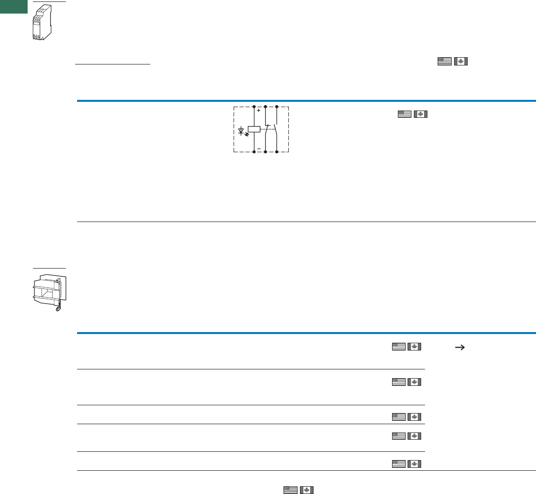
1.1 Contactor relays, contactors
Accessories
62 AUTOMATION AND CONTROL www.eaton.com/seasia-electrical
1
Amplifier module for separate mounting
Input with integrated suppressor circuit for overvoltage limitation
DILM...-XSP...
Individual coils
DILM...-XSP...
Rated operational current
Actuating
voltage
Actuating
current
Circuit symbol For use
with Part no.
Article no.
Price
See
price
list
Std. pack Information relevant for export to
North America
AC-15 DC
230 V 400 V 220 V
IeIeIeUsI
A A A V DC mA
MLID...524230.022
DIMLP...
DILL...
DILK...
ETS4-VS3
083094
1 Off Product Standards
UL File No.
UL CCN
CSA File No.
CSA Class No.
NA Certification
Notes Contactor coils with rated operational current > 2 A must be actuated via the DILER-G mini contactor relay.
Rated operational current DC:
Making and breaking conditions DC-13, time L/R 300ms
DC voltage AC voltage
For use with Part no.
Article no. Prices
See price
list
Part no.
Article no. Price
See price
list
Std. pack Notes
DILM17
DILM25
DILM32
DILM38
DILM32-XSP(RDC24)1)
281155 DILM32-XSP(230V50Hz,240V60Hz)
281141
1 Off
1 Off
1 Off
1 Off
1 Off
For additional actuating
voltages Page 75
DILM40
DILM50
DILM65
DILM72
DILM65-XSP(RDC24)1)
281185 DILM65-XSP(230V50Hz,240V60Hz)
281171
DILM80
DILM95 DILM95-XSP(RDC24)1)
230080 DILM95-XSP(230V50Hz,240V60Hz)
230062
DILM115
DILM150
DILM170
DILM150-XSP(RDC24)1)
230115 DILM150-XSP(RAC240)1)
230112
DILM185A
DILM225A DILM225A-XSP(RDC24)1)
139568 DILM225A-XSP(RAC240)1)
139565
Notes 1) Incl. electronic module
13
14
21
22
IEC/EN
60947-4-1;
UL 508;
CSA-C22.2
No.14-05;
CE marking
E36332
NLRV
012528
2411-03,
3211-04
UL Listed,
CSA certi-
fied
Information relevant for export to North America
Product Standards
UL File No.
UL CCN
CSA File No.
CSA Class No.
NA Certification
IEC/EN 60947-4-1; UL 508; CSA-C22.2 No.14-05; CE marking
E29096
NLDX
012528
2411-03, 3211-04
UL Listed, CSA certified
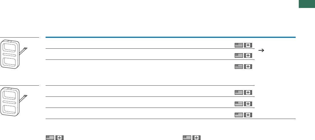
1.1
Contactor relays, contactors
Accessories
63AUTOMATION AND CONTROL www.eaton.com/seasia-electrical
1
Electronic modules including coils
DILM...-XSP/E...
DC voltage AC voltage
For use with Part no.
Article no. Price
See price
list
Part no.
Article no. Price
See price
list
Std. pack Notes
DILM250
DILM300A DILM250-XSP/E(RA250)1)
208252 DILM250-XSP/E(RA250)1)
208252
1 Off
1 Off
1 Off
1 Off
1 Off
1 Off
For additional actuating
voltages
Page 77
DILM400
DILM500 DILM500-XSP/E(RA250)1)
208256 DILM500-XSP/E(RA250)1)
208256
DILM580
DILM650
DILM750
DILM820
DILM1000
DILM1000-XSP/E(RA250)1)
289145 DILM1000-XSP/E(RA250)1)
289145
DILH1400 – DILH1400-XSP/E(RAW250)2)
289161
DILM250-S
DILM300A-S
–DILM250-S-XSP/E(220-240V50/60Hz)2)
274202
DILM400-S
DILM500-S –DILM500-S-XSP/E(220-240V50/60Hz) 2)
274205
1) 2)
Information relevant for export to North America
Product Standards
UL File No.
UL CCN
CSA File No.
CSA Class No.
NA Certification
IEC/EN 60947-4-1; UL 508; CSA-C22.2
No.14-05; CE marking
E29096
NLDX
1017510
3211-04
UL Listed, CSA certified
Information relevant for export to North America
Product Standards
UL File No.
UL CCN
CSA File No.
CSA Class No.
NA Certification
IEC/EN 60947-4-1; UL 508; CSA-C22.2
No.14-05; CE marking
E29096
NLDX
012528
3211-04
UL Listed, CSA certified
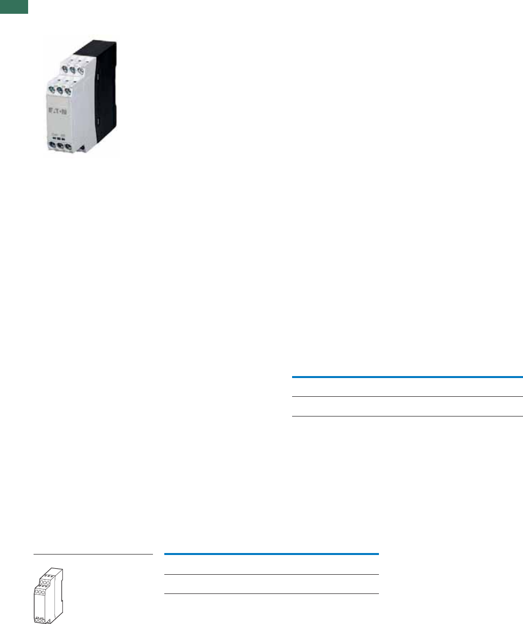
1.1 Contactor monitoring devices
64 AUTOMATION AND CONTROL www.eaton.com/seasia-electrical
1Description, ordering
General
For safety-related off switching to safety
category 3 and 4 according to EN 954-1,
at present two contactors must be used
in series. Especially with larger
contactors this is an expensive solution.
Application
This is where the CMD can be used. The
function of the CMD is to monitor the
main contacts of a contactor against
welding. For this the control voltage of
the contactor is compared with the state
of the main contacts which is reliably
monitored using a mirror contact (IEC EN
60947-4-1 Annex F). If the coil is de-
energized and the contactor does not
drop out the CMD trips the upstream
circuit-breaker/motor protective circuit
breaker/switch-disconnector via a shunt
release.
Safety
The CMD has a safety-compliant design
so that in safety combinations with a
circuit-breaker/motor protective circuit
breaker/switch disconnector the reliable
switch off in the case of a "welded
contactor" can be guaranteed. In this
application it replaces the series
connection of a second contactor. As a
component it conforms to safety
category 3 according to EN 954-1 and
EN ISO 13849.
Mounting
The CMD can be combined with the
following Eaton components:
• Contactors:
– DILEM
– DILM7 to DILM150
– DILM185(-S) to DILM500(-S):
– DILM580 to DILM1600
– DILH1400 … DILH2000
– SE-1A-PKZ2 and S-PKZ2
For the wiring of the CMD the auxiliary N/C
contact, mirror contact must be according
to IEC/EN 60947-4-1 and the auxiliary N/O
contact must be interlocked and opposing
according to IEC/EN 60947-5-1. Also the
auxiliary N/C contact for the feedback
circuit must have a mirror contact function
according to IEC/EN 60947-4-1.
• Motor-protective circuit-breakers/
circuit-breakers:
– PKZ2 + U-PKZ2(18VDC)
– NZM1 + NZM1-XUVL
– NZM2 + NZM2/3-XUV
– NZM3 + NZM2/3-XUV
– NZM4 + NZM4-XUV
– N1 + NZM1-XUVL
– N2 + NZM2/3-XUV
– N3 + NZM2/3-XUV
– N4 + NZM4-XUV
Ordering
Part no.
Article no. Price
See Price List
Std. pack
CMD contactor monitoring device CMD(24VDC)
106170 1 Off
CMD(220-240VAC)
106172
1 Off
Auxiliary contact requirements per contactor:
CMD Self
maintaining Feedback
circuit Electrical
interlock
DOL starter 1 N/C 1S 1 B
Reversing
starter 1 N/O +
1 N/O +
1 N/C 1S 1 B 1 B
CMD
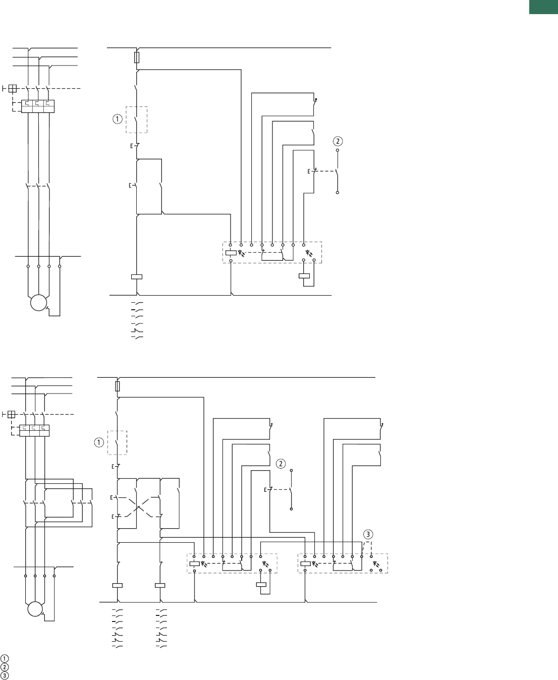
1.1
Contactor monitoring devices
65AUTOMATION AND CONTROL www.eaton.com/seasia-electrical
1
Engineering
DOL starter
Reversing starter
Switching by safety relay of safety PLC
Signal contact to PLC evaluation
CMD (24VDC)
I > I > I >
U <
M
3˜
-Q1
-Q1
-K
-S1
-F1
-Q11
-X1
-M1
L1 L2 L3 1.13
21
22
1.14
-Q11
13
14
-Q11
33
34
-Q11
21
22
-F2
CMD
-Q1 D1
D2
D2
A1
A2
L S21 S22 S13 S14 S31 S32
-Q11A1
12
A2
T1
135
246
T2 T3
10L10L1L
20L20L
L2
PE UVWPE PE
L3
L1
L2
L3
-S213
14
-S321
22
13
14
TEST
34
56
13 14
21 22
33 34
L1
L2
L3
L1
L2
L3
-Q1
-Q1
-K
-S1
-F1
-Q11
-X1
-M1
-Q12
-Q11 -Q12
-Q11
-Q11
-Q12 -Q11
-F2
CMD
1Q-Q12--Q11
L01 L01
L02 L02
PE PE
-F3
CMD
-S2
-S3
-S4
TEST
12
34
56
13 14
21 22
31 32
43 44
-Q12
-Q12
12
34
56
13 14
21 22
31 32
43 44
I > I > I >
U <
M
3˜
L1 L2 L3 1.13
21
22
1.14
13
14 13
14
21
22
13
14
43
44
21
22
31
32
31
32
A1
A2
D1
D2
D2 D1 D2
1A1A
A2
LL S21 S22 S13 S14 S31 S32
A1
A2
T1
135
246
135
246
T2 T3
UVWPE
A2
13
14
21
22
21
22
13
14
43
44
21
22
S21 S22 S13 S14 S31 S32

1.1 Mini contactor relays, contactor relays
Actuating voltages
66 AUTOMATION AND CONTROL www.eaton.com/seasia-electrical
1Ordering
AC DILER-40(...) DILER-31(...) DILER-22(...) DILEEM-10(...) DILEEM-01(...)
Article no.1) Article no.1) Article no.1) Article no.1) Article no.1)
Standard voltages See price list See price list See price list See price list See price list
24V 50Hz 010094 010251 010344 051604 051629
48V 50Hz 010190 010044 010201 051603 051628
240V 50Hz 010478 010300 010138 051602 051627
115V 60Hz 010270 010204 010211 051598 051624
42V 50Hz,
48V 60Hz
– – – 051612 051637
110V 50Hz,
120V 60Hz
051756 051765 051774 051611 051636
190V 50Hz,
220V 60Hz
051757 051766 051775 051610 051635
220V 50Hz,
240V 60Hz
051758 051767 051776 051609 051634
230V 50Hz,
240V 60Hz
051759 051768 051777 051608 051633
380V 50Hz,
440V 60Hz
051760 051769 051778 051607 051632
400V 50Hz,
440V 60Hz
051761 051770 051779 051606 051631
415V 50Hz,
480V 60Hz
051762 051771 051780 051605 051630
24V 50/60Hz 021924 021594 021704 051596 051621
42V 50/60Hz 033459 029869 029433 051595 051620
110V 50/60Hz 021961 021624 021871 051592 051618
230V 50/60Hz 052725 052509 052508 056674 058771
DC DILER-40-G(...) DILER-31-G(...) DILER-22-G(...) DILEEM-10-G(...) DILEEM-01-G(...)
Article no.1) Article no.1) Article no.1) Article no.1) Article no.1)
Standard voltages See price list See price list See price list See price list See price list
12V DC 079711 079761 080728 051644 051649
24V DC 010223 010157 010042 051643 051650
48V DC 010255 010205 010346 051642 051648
110V DC 010287 010253 010043 051640 051646
220V DC 010303 010269 010091 051639 051645
Notes 1) To obtain the article number for ordering, read under selected part number and actuating voltage from the table.
Devices with dual-voltage coils are to be ordered under a single article number.
DILER, DILEEM
DILER, DILEEM

1.1
Mini contactor relays, contactor relays
Actuating voltages
67AUTOMATION AND CONTROL www.eaton.com/seasia-electrical
1
AC DILEM-10(...) DILEM-01(...) DILEM12-10(...) DILEM12-01(...) DILEM4(...)
Article no.1) Article no. 1) Article no.1) Article no.1) Article no.1)
Standard voltages See price list See price list See price list See price list See price list
24V 50Hz 010005 010086 127067 127083 014754
48V 50Hz 010020 010294 – – –
240V 50Hz 010032 010151 – – 014305
115V 60Hz 010024 010470 – – –
42V 50Hz,
48V 60Hz
051782 051791 – – –
110V 50Hz,
120V 60Hz
051783 051792 127072 127088 051801
190V 50Hz,
220V 60Hz
051784 051793 – – –
220V 50Hz,
240V 60Hz
051785 051794 – – 051803
230V 50Hz,
240V 60Hz
051786 051795 – – 051804
380V 50Hz,
440V 60Hz
051787 051796 – – –
400V 50Hz,
440V 60Hz
051788 051797 – – 051806
415V 50Hz,
480V 60Hz
051789 – – – –
24V 50/60Hz 021417 020402 127079 127095 022044
42V 50/60Hz 032174 033233 – – –
110V 50/60Hz 021455 020436 127081 127097 –
230V 50/60Hz 052302 051114 127082 127098 052506
DC DILEM-10-G(...) DILEM-01-G(...) DILEM12-10-G(...) DILEEM12-01-G(...) DILEM4-G(...)
Article no.1) Article no. 1) Article no.1) Article no.1) Article no.1)
Standard voltages See price list See price list See price list See price list See price list
12V DC 079594 079642 – – 079680
24V DC 010213 010343 127132 127137 012701
48V DC 010245 010496 – – –
110V DC 010309 010136 – – –
220V DC 010325 010168 – – –
Notes 1) To obtain the article number for ordering, read under selected part number and actuating voltage from the table.
Devices with dual-voltage coils are to be ordered under a single article number.
DILEM
DILEM

1.1 Contactor relays
Actuating voltages
68 AUTOMATION AND CONTROL www.eaton.com/seasia-electrical
1
AC With screw terminals With Spring-loaded terminals
DILA-40(...) DILA-31(...) DILA-22(...) DILAC-40(...) DILAC-31(...) DILAC-22(...)
Article no.1) Article no.1) Article no.1) Article no.1) Article no.1) Article no.1)
Standard voltages See price list See price list See price list See price list See price list See price list
24V 50Hz 276316 276351 276386 276431 276463 276495
240V 50Hz 276318 276353 276388 – – –
110V 50Hz
120V 60Hz
276326 276361 276396 276438 276470 276502
190V 50Hz
220V 60Hz
276327 276362 276397 – – –
220V 50Hz
240V 60Hz
276328 276363 276398 – – –
230V 50Hz
240V 60Hz
276329 276364 276399 276441 276473 276505
380V 50Hz
440V 60Hz
276330 276365 276400 – – –
400V 50Hz
440V 60Hz
276331 276366 276401 – – –
24V 50Hz/60Hz 276333 276368 276403 276445 276477 276509
42V 50Hz/60Hz 276334 276369 276404 – – –
110V 50Hz/60Hz 276335 276370 276405 – – –
220V 50Hz/60Hz 276336 276371 276406 – – –
230V 50Hz/60Hz 276337 276372 276407 276449 276481 276513
Special voltages
other than the already
shown normal voltages 2)
See price list See price list See price list See price list See price list See price list
...V 50Hz(12-500V)3) 276341 276376 276411 276453 276485 276517
...V 60Hz(12-600V)3) 276342 276377 276412 276454 276486 276518
DC With screw terminals With Spring-loaded terminals
DILA-40(...) DILA-31(...) DILA-22(...) DILAC-40(...) DILAC-31(...) DILAC-22(...)
Article no.1) Article no.1) Article no.1) Article no.1) Article no.1) Article no.1)
Standard voltages See price list See price list See price list See price list See price list See price list
24V DC 276344 276379 276414 276456 276488 276520
48V DC 276345 276380 276415 – – –
110V DC 276347 276382 276417 276459 276491 276523
220V DC 276348 276383 276418 276460 276492 276524
Special voltages
other than the already
shown normal voltages 2)
See price list See price list See price list See price list See price list See price list
...V DC(12-250V)3) 276349 276384 276419 276461 276493 276525
Notes 1) The article number is a combination of part no. and operating voltage devices with dual-voltage coils can be
ordered under a single article no.
2) With non-standard voltages the required actuating voltage from the defined range (...–...V) must be stated.
3) Minimum order quantity 10 units
DILA
DILA

1.1
Contactors
Actuating voltages
69AUTOMATION AND CONTROL www.eaton.com/seasia-electrical
1
AC DILM7-10
(...)
DILM7-01
(...)
DILM9-10
(...)
DILM9-01
(...)
DILM12-10
(...)
DILM12-01
(...)
DILM15-10
(...)
DILM15-01
(...)
Article no.1) Article no.1) Article no.1) Article no.1) Article no.1) Article no.1) Article no.1) Article no.1)
Standard voltages See price list See price list See price list See price list See price list See price list See price list See price list
24V 50Hz 276537 276572 276677 276712 276817 276852 290045 290080
240V 50Hz 276539 276574 276679 276714 276819 276854 – –
42V 50Hz
48V 60Hz
276546 – 276686 – 276826 – – –
110V 50Hz
120V 60Hz
276547 276582 276687 276722 276827 276862 290055 290090
190V 50Hz
220V 60Hz
276548 276583 276688 276723 276828 276863 – –
220V 50Hz
240V 60Hz
276549 276584 276689 276724 276829 276864 – –
230V 50Hz
240V 60Hz
276550 276585 276690 276725 276830 276865 290058 290093
380V 50Hz
440V 60Hz
276551 276586 276691 276726 276831 276866 – –
400V 50Hz
440V 60Hz
276552 276587 276692 276727 276832 276867 – –
415V 50Hz
480V 60Hz
276553 – 276693 – 276833 – – –
24V 50Hz/60Hz 276554 276589 276694 276729 276834 276869 290062 290097
42V 50Hz/60Hz 276555 276590 276695 276730 276835 276870 – –
110V 50Hz/60Hz 276556 276591 276696 276731 276836 276871 – –
220V 50Hz/60Hz 276557 276592 276697 276732 276837 276872 – –
230V 50Hz/60Hz 276558 276593 276698 276733 276838 276873 290066 290101
Special voltages
other than the already shown
normal voltages 2)
See price list See price list See price list See price list See price list See price list See price list See price list
...V 50Hz (12 – 600V) 3) 276562 276597 276702 276737 276842 276877 290070 290105
...V 60Hz (12 – 600V) 3) 276563 276598 276703 276738 276843 276878 290071 290106
DC DILM7-10
(...)
DILM7-01
(...)
DILM9-10
(...)
DILM9-01
(...)
DILM12-10
(...)
DILM12-01
(...)
DILM15-10
(...)
DILM15-01
(...)
Article no.1) Article no.1) Article no.1) Article no.1) Article no.1) Article no.1) Article no.1) Article no.1)
Standard voltages See price list See price list See price list See price list See price list See price list See price list See price list
24V DC 276565 276600 276705 276740 276845 276880 290073 290108
48V DC 276566 276601 276706 276741 276846 276881 – –
110V DC 276568 276603 276708 276743 276848 276883 – –
220V DC 276569 276604 276709 276744 276849 276884 – –
Special voltages
other than the already shown
normal voltages2)
See price list See price list See price list See price list See price list See price list See price list See price list
...V DC (12-250V)
3) 276570 276605 276710 276745 276850 276885 290078 290113
Notes 1) To obtain the article number for ordering, read under selected part number and actuating voltage from the table.
devices with dual-voltage coils can be ordered under a single article no.
2) With non-standard voltages the required actuating voltage from the defined range (...–...V)
must be stated.
3) Minimum order quantity 10 units
DILM
DILM

1.1 Contactors
Actuating voltages
70 AUTOMATION AND CONTROL www.eaton.com/seasia-electrical
1
AC DILM17-10
(...)
DILM17-01
(...)
DILM25-10
(...)
DILM25-01
(...)
DILM32-10
(...)
DILM32-01
(...)
DILM38-10(...) DILM38-01(...)
Article no.1) Article no.1) Article no.1) Article no.1) Article no.1) Article no.1) Article no.1) Article no.1)
Standard voltages See price list See price list See price list See price list See price list See price list See price list See price list
24V 50Hz 276991 277023 277119 277151 277247 277279 112378 112446
240V 50Hz 276993 – 277121 – 277249 – 112420 –
42V 50Hz
48V 60Hz
277000 – 277128 – 277256 – 112424 –
110V 50Hz
120V 60Hz
277001 277033 277129 277161 277257 277289 112425 112454
190V 50Hz
220V 60Hz
277002 – 277130 – 277258 – 112426 –
220V 50Hz
240V 60Hz
277003 – 277131 – 277259 – 112427 –
230V 50Hz
240V 60Hz
277004 277036 277132 277164 277260 277292 112428 112457
380V 50Hz
440V 60Hz
277005 – 277133 – 277261 – 112429 –
400V 50Hz
440V 60Hz
277006 277038 277134 277166 277262 277294 112430 112459
415V 50Hz
480V 60Hz
277007 – 277135 – 277263 – 112431 –
24V 50Hz/60Hz 277008 277040 277136 277168 277264 277296 112432 112461
42V 50Hz/60Hz 277009 – 277137 – 277265 – 112433 –
110V 50Hz/60Hz 277010 277042 277138 277170 277266 277298 112434 112463
220V 50Hz/60Hz 277011 277043 277139 277171 277267 277299 112435 112464
230V 50Hz/60Hz 277012 277044 277140 277172 277268 277300 112436 112465
Special voltages
other than the already
shown normal voltages 2)
See price list See price list See price list See price list See price list See price list See price list See price list
...V 50Hz (24 – 600V) 277016 7) 277048 7) 277144 7) 277176 7) 277272 7) 277304 8) 112440 7) 112468 7)
...V 60Hz (24 – 600V) 277017 7) 277049 7) 277145 7) 277177 7) 277273 7) 277305 8) 112441 7) 112469 7)
DC DILM17-10(...) DILM17-01(...) DILM25-10(...) DILM25-01(...) DILM32-10(...) DILM32-01(...) DILM38-10(...) DILM38-01(...)
Article no.1) Article no.1) Article no.1) Article no.1) Article no.1) Article no.1) Article no.1) Article no.1)
Standard voltages See price list See price list See price list See price list See price list See price list See price list See price list
RDC 24 3) 277018 277050 277146 277178 277274 277306 112442 112470
RDC 60 4) 277019 277051 277147 277179 277275 277307 112443 112471
RDC 130 5) 277020 277052 277148 277180 277276 277308 112444 112472
RDC 240 6) 277021 277053 277149 277181 277277 277309 112445 112473
Notes 1) To obtain the article number for ordering, read under selected part number and actuating voltage from the table.
devices with dual-voltage coils can be ordered under a single article no.
2) With non-standard voltages the required actuating voltage from the defined range (...–...V)
must be stated.
3) 24 – 27 V DC
4) 48 – 60 V DC
5) 110 – 130 V DC
6) 200 – 240 V DC
7) Minimum order quantity 10 units
8) Minimum order quantity 5 units
DILM
DILM

1.1
Contactors
Actuating voltages
71AUTOMATION AND CONTROL www.eaton.com/seasia-electrical
1
DILM
DILM
AC DILM40(...) DILM50(...) DILM65(...) DILM72(...)
Article no.1) Article no.1) Article no.1) Article no.1)
Standard voltages See price list See price list See price list See price list
24V 50Hz 277753 277817 277881 –
240V 50Hz 277755 277819 277883 109183
42V 50Hz
48V 60Hz
277762 277826 277890 –
110V 50Hz
120V 60Hz
277763 277827 277891 109191
190V 50Hz
220V 60Hz
277764 277828 277892 –
220V 50Hz
240V 60Hz
277765 277829 277893 –
230V 50Hz
240V 60Hz
277766 277830 277894 107670
380V 50Hz
440V 60Hz
277767 277831 277895 –
400V 50Hz
440V 60Hz
277768 277832 277896 109195
415V 50Hz
480V 60Hz
277769 277833 277897 –
24V 50Hz/60Hz 277770 277834 277898 109197
42V 50Hz/60Hz 277771 277835 277899 –
110V 50Hz/60Hz 277772 277836 277900 109199
220V 50Hz/60Hz 277773 277837 277901 109200
230V 50Hz/60Hz 277774 277838 277902 109201
Special voltages other than the already shown normal voltages 2) See price list See price list See price list See price list
...V 50Hz (24 – 600V) 277778 8) 277842 8) 277906 8) 109205 7)
...V 60Hz (24 – 600V) 277779 8) 277843 8) 277907 8) 109206 7)
DC DILM40(...) DILM50(...) DILM65(...) DILM72(...)
Article no.1) Article no.1) Article no.1) Article no.1)
Standard voltages See price list See price list See price list See price list
RDC 24 3) 277780 277844 277908 107671
RDC 60 4) 277781 277845 277909 –
RDC 130 5) 277782 277846 277910 –
RDC 240 6) 277783 277847 277911 109209
Notes 1) To obtain the article number for ordering, read under selected part number and
actuating voltage from the table.
devices with dual-voltage coils can be ordered under a single article no.
2) With non-standard voltages the required actuating voltage from the defined range
(...–...V) must be stated.
3) 24 – 27 V DC
4) 48 – 60 V DC
5) 110 – 130 V DC
6) 200 – 240 V DC
7) Minimum order quantity 10 units

1.1 Contactors
Actuating voltages
72 AUTOMATION AND CONTROL www.eaton.com/seasia-electrical
1DILM DILM
DILM
AC DILM80
(...)
DILM95
(...)
Article no.1) Article no.1)
Standard voltages See price
list See price
list
24 V 50 Hz 235904 239467
240V 50Hz 235910 239469
42V 50Hz
48V 60Hz
239394 239476
110V 50Hz
120V 60Hz
239399 239477
190V 50Hz
220V 60Hz
239400 239478
220V 50Hz
240V 60Hz
239401 239479
230V 50Hz
240V 60Hz
239402 239480
380V 50Hz
440V 60Hz
239403 239481
400V 50Hz
440V 60Hz
239404 239482
415V 50Hz
480V 60Hz
239405 239483
24V 50Hz/60Hz 239406 239484
42V 50Hz/60Hz 239407 239485
110V 50Hz/60Hz 239408 239486
220V 50Hz/60Hz 239409 239487
230V 50Hz/60Hz 239410 239488
Special voltages
other than the already
shown normal voltages 2)
See price
list list
...V 50Hz (24 – 600V) 13) 239414 239504
...V 60Hz (24 – 600V) 13) 239415 239509
DC DILM80
(...)
DILM95
(...)
Article no.1) Article no.1)
Standard voltages See price
list See price
list
RDC 243) 239416 239510
RDC 604) 239417 239511
RDC 1305) 239418 239512
RDC 2406) 239419 239513
AC
DILM
DILM115
(...)
DILM150
(...)
DILM170
(...)
DILM185A/
22(...)
DILM225A/
22(...)
Article no.1) Article no.1) Article no.1) Article no.1) Article no.1)
Standard
voltages
See price
list See price
list See price
list See price
list See price
list
RAC 247) 239545 239585 107010 139534 139544
RAC 488) 239546 239586 107011 139535 139545
RAC 1209) 239547 239587 107012 139536 139546
RAC 24010) 239548 239588 107013 139537 139547
RAC 44011) 239549 239589 107014 139538 139548
RAC 50012) 239550 239590 107015 139539 139549
DC DILM115
(...)
DILM150
(...)
DILM170
(...)
DILM185A/
22(...)
DILM225A/
22(...)
Article no.1) Article no.1) Article no.1) Article no.1) Article no.1)
Standard
voltages
See price
list See price
list See price
list See price
list See price
list
RDC 243) 239555 239591 107016 139540 139550
RDC 604) 239560 239592 107017 139541 139551
RDC 1305) 239567 239593 107018 139542 139552
RDC 2406) 239572 239594 107019 139543 139553
Notes 1) The article no. results from combining the part no. and the
actuating voltage.
Devices with dual-voltage coils must be ordered under a single
article no.
2) With non-standard voltages the required actuating voltage from
the defined range
(...–...V) must be stated.
3) 24 - 27 V DC
4) 48 – 60 V DC
5) 110 - 130 V DC
6) 200 - 240 V DC
7) 24 V 50/60 Hz
8) 42 – 48 V 50/60 Hz
9) 100 – 120 V 50/60 Hz
10)
190 – 240 V 50/60 Hz
11)
380 – 440 V 50/60 Hz
12)
480 – 500 V 50/60 Hz
13)
Minimum order quantity 5 units

1.1
Contactors
Actuating voltages
73AUTOMATION AND CONTROL www.eaton.com/seasia-electrical
1
DILM
DILM
DILM
DILM
AC DILMC7-10
(...)
DILMC7-01
(...)
DILMC9-10
(...)
DILMC9-01
(...)
DILMC12-10
(...)
DILMC12-01
(...)
DILMC15-10
(...)
DILMC15-01
(...)
Article no.1) Article no.1) Article no.1) Article no.1) Article no.1) Article no.1) Article no.1) Article no.1)
Standard voltages See price list See price list See price list See price list See price list See price list See price list See price list
24 V 50 Hz 277379 277411 277443 277475 277507 277539 293938 293933
110V 50Hz
120V 60Hz
277386 277418 277450 277482 277514 277546 293908 293943
230V 50Hz
240V 60Hz
277389 277421 277453 277485 277517 277549 293911 293946
24V 50Hz/60Hz 277393 277425 277457 277489 277521 277553 293915 293950
230V 50Hz/60Hz 277397 277429 277461 277493 277525 277557 293919 293954
Special voltages
other than the already
shown normal voltages 2)
See price list See price list See price list See price list See price list See price list See price list See price list
...V 50Hz (12 – 600V) 6) 277401 277433 277465 277497 277529 277561 293923 293958
...V 60Hz (12 – 600V) 6) 277402 277434 277466 277498 277530 277562 293924 293959
DC DILMC7-10
(...)
DILMC7-01
(...)
DILMC9-10
(...)
DILMC9-01
(...)
DILMC12-10
(...)
DILMC12-01
(...)
DILMC15-10
(...)
DILMC15-01
(...)
Article no.1) Article no.1) Article no.1) Article no.1) Article no.1) Article no.1) Article no.1) Article no.1)
Standard voltages See price list See price list See price list See price list See price list See price list See price list See price list
24V DC 277404 277436 277468 277500 277532 277564 293926 293961
110V DC 277407 277439 277471 277503 277535 277567 293929 293964
220V DC 277408 277440 277472 277504 277536 277568 293930 293965
Special voltages
other than the already
shown normal voltages 2)
See price list See price list See price list See price list See price list See price list See price list See price list
...VDC (12 – 250V) 6) 277409 277441 277473 277505 277537 277569 293931 293966
AC DILMC17-10 (...) DILMC17-01(...) DILMC25-10 (...) DILMC25-01 (...) DILMC32-10 (...) DILMC32-01 (...)
Article no.1) Article no.1) Article no.1) Article no.1) Article no.1) Article no.1)
Standard voltages See price list See price list See price list See price list See price list See price list
24 V 50 Hz 277570 277600 277630 277660 277690 277720
110V 50Hz
120V 60Hz
277578 277608 277638 277668 277698 277728
230V 50Hz
240V 60Hz
277581 277611 277641 277671 277701 277731
24V 50Hz/60Hz 277585 277615 277645 277675 277705 277735
220V 50Hz/60Hz 277588 277618 277648 277678 277708 277738
230V 50Hz/60Hz 277589 277619 277649 277679 277709 277739
Special voltages
other than the already
shown normal voltages2)
See price list See price list See price list See price list See price list See price list
...V 50Hz (24 – 600V) 6) 277593 277623 277653 277683 277713 277743
...V 60Hz (24 – 600V) 6) 277594 277624 277654 277684 277714 277744
DC DILMC17-10 (...) DILMC17-01 (...) DILMC25-10 (...) DILMC25-01 (...) DILMC32-10 (...) DILMC32-01 (...)
Article no.1) Article no.1) Article no.1) Article no.1) Article no.1) Article no.1)
Standard voltages See price list See price list See price list See price list See price list See price list
RDC 243) 277595 277625 277655 277685 277715 277745
RDC 1304) 277597 277627 277657 277687 277717 277747
RDC 2405) 277598 277628 277658 277688 277718 277748
Notes 1) The article no. results from combining the part no. and the actuating voltage.
Devices with dual-voltage coils must be ordered under a single article no.
2) With non-standard voltages the required actuating voltage from the defined range (...–...V)
must be stated.
3) 24 - 27 V DC
4) 110 - 130 V DC
5) 200 - 240 V DC
6) Minimum order quantity 10 units

1.1 Contactors
Actuating voltages
74 AUTOMATION AND CONTROL www.eaton.com/seasia-electrical
1
AC DILMP20
(…)
DILMP20
(…)
DILMP20
(…)
DILMP20
(…)
DILMP20
(…)
Article
no.1)
Standard voltages See
price
list
240V 50Hz –
110V 50Hz
120V 60Hz
276967
230 V 50Hz
240V 60Hz
276970
24V 50/60Hz 276974
230V 50/60Hz 276978
AC
Article
no.1)
Non-standard voltages 2) See
price
list
…V 50Hz (12 – 600V) 3) 276982
…V 60Hz (12 – 600V) 3) 276983
DC
Article
no.1)
Standard voltages See
price
list
24V DC 276985
RDC 247) –
DC
Article
no.1)
Non-standard voltages 2) See
price
list
…V DC (12 – 250V)3) 276990
Notes
1) The article number is a combination of part no. and
actuating voltage
2) For non-standard voltages, state the actuating voltage selected from the range (…–…V) shown.
3) Minimum order quantity: 10 units
4) 24 V 50/60 Hz
5) 100 – 120 V 50/60 Hz
6) 190 – 240 V 50/60 Hz
7) 24 – 27 V DC
DILMP20
DILMP20
AC
Article
no.1)
Standard voltages See
price
list
RAC 244) –
RAC 1205) –
RAC 2406) –

1.1
Contactors
Actuating voltages
75AUTOMATION AND CONTROL www.eaton.com/seasia-electrical
1
AC DILM32-XSP
(...)
DILM65-XSP
(...)
DILM95-
XSP
Article no.1) Article no.1) Article no.1)
Standard voltages See price
list See price
list See price
list
24V 50Hz 281130 281160 229984
240V 50Hz 281132 281162 229986
24V 60Hz 281134 281164 229988
115V 60Hz 281136 281166 229990
42V 50Hz
48V 60Hz
281137 281167 229994
110V 50Hz
120V 60Hz
281138 281168 230058
190V 50Hz
220V 60Hz
281139 281169 230059
220V 50Hz
240V 60Hz
281140 281170 230061
230V 50Hz
240V 60Hz
281141 281171 230062
380V 50Hz
440V 60Hz
281142 281172 230063
400V 50Hz
440V 60Hz
281143 281173 230064
415V 50Hz
480V 60Hz
281144 281174 230065
24V 50Hz/60Hz 281145 281175 230066
42V 50Hz/60Hz 281146 281176 230067
110V 50Hz/60Hz 281147 281177 230068
220V 50Hz/60Hz 281148 281178 230073
230V 50Hz/60Hz 281149 281179 230074
Special voltages
other than the already
shown normal-
voltages 2)
See price
list See price
list See price
list
...V 50Hz (24 – 600V) 281153 13) 281183 14) 230078 14)
...V 60Hz (24 – 600V) 281154 13) 281184 14) 230079 14)
DC DILM32-XSP
(...)
DILM65-XSP
(...)
DILM95-
XSP
Article no.1) Article no.1) Article no.1)
Standard voltages See price
list See price
list See price
list
RDC 243) 281155 281185 230080
RDC 604) 281156 281186 230081
RDC 1305) 281157 281187 230082
RDC 2406) 281158 281188 230107
AC DILM150-XSP
(...)
DILM225A-XSP
(...)
Article no.1) Article no.1)
Standard voltages See price
list See price list
RAC 247) 230109 139562
RAC 488) 230110 139563
RAC 1209) 230111 139564
RAC 24010) 230112 139565
RAC 44011) 230113 139566
RAC 50012) 230114 139567
DC DILM150-XSP
(...)
DILM225A-XSP
(...)
Article no.1) Article no.1)
Standard voltages See price
list See price
list
RDC 243) 230115 139568
RDC 604) 230116 139569
RDC 1305) 230117 139570
RDC 2406) 230122 139571
Notes 1) To obtain the article number for ordering, read under
selected part number and actuating voltage from the
table.
Devices with dual-voltage coils are to be ordered
under a single article number.
2) With non-standard voltages the required actuating
voltage from the defined range (...–...V)
must be stated.
3) 24 – 27 V DC
4) 48 – 60 V DC
5) 110 – 130 V DC
6) 200 – 240 V DC
7) 24 V 50/60 Hz
8) 42 – 48 V 50/60 Hz
9) 100 – 120 V 50/60 Hz
10) 190 – 240 V 50/60 Hz
11) 380 – 440 V 50/60 Hz
12) 480 – 500 V 50/60 Hz
13) Minimum order quantity 10 units
14) Minimum order quantity 5 units
DILM...XSP... DILM...XSP...
DILM...XSP...
DILM...XSP...

1.1 Contactor for capacitors, contactor
Actuating voltages
76 AUTOMATION AND CONTROL www.eaton.com/seasia-electrical
1
AC DILK12-11
(...)
DILK20-11
(...)
DILK25-11
(...)
DILK33-10
(...)
DILK50-10
(...)
Article no.1) Article no.1) Article no.1) Article no.1) Article no. 1)
Standard voltages See price list See price list See price list See price list See price list
110V 50Hz,
120V 60Hz
293985 294007 294029 294051 294073
190V 50Hz,
220V 60Hz
293986 294008 294030 294052 294074
230V 50Hz,
240V 60Hz
293988 294010 294032 294054 294076
400V 50Hz,
440V 60Hz
293990 294012 294034 294056 294078
Special voltages other than the already
shown normal voltages 2) See price list See price list See price list
…V 50Hz (24 – 600V) 3) 293997 294019 294041 – –
…V 60Hz (24 – 600V) 3) 293998 294020 294042 – –
Notes 1) The article no. results from combining the part no. and the actuating voltage.
Devices with dual-voltage coils must be ordered under a single article no.
2) With non-standard voltages the required actuating voltage from the defined range (...–...V) must be stated.
3) Minimum order quantity 10 units
DILK, DILMF

1.1
Contactors
Actuating voltages
77AUTOMATION AND CONTROL www.eaton.com/seasia-electrical
1
DILM
DILM
DILM
DILM
Complete comfort devices DILM250
/22(...)
DILM300A
/22(...)
DILM400
/22(...)
DILM500
/22(...)
DILM580
/22(...)
DILM650
/22(...)
DILM750
/22(...)
DILM820
/22(...)
DILM1000
/22(...)
Article no.1) Article no.1) Article no.1) Article no.1) Article no.1) Article no.1) Article no.1) Article no.1) Article no.1)
Voltage variants See price
list See price
list See price
list See price
list See price
list See price
list See price
list See price
list See price
list
RDC 48 2) 208199 139554 208207 208211 – – – ––
RA 110
3) 208200 139555 208208 208212 208215 208218 208221 208224 –
RA 250
4) 208201 139556 208209 208213 208216 208219 208222 208225 267214
RAC 500 5) 6) 208202 139557 208210 208214 208217 208220 208223 208226 –
Complete units
Standard
DILM250
-S/22(...)
DILM300A
-S/22(...)
DILM400
-S/22(...)
DILM500
-S/22(...)
Article no.1) Article no.1) Article no.1) Article no.1)
Voltage variants See price
list See price
list See price
list See price
list
110-120V 50/60Hz 274189 139558 274195 274198
220-240V 50/60Hz 274190 139559 274196 274199
Electronic module, incl. coil, for
comfort model
DILM250-XSP/E(...) DILM500-XSP/E(...) DILM1000-XSP/E(...)
Article no.1) Article no.1) Article no.1)
Voltage variants See price
list See price
list See price
list
RDC 48 2) 208250 208254 –
RA 110
3) 208251 208255 289146
RA 250
4) 208252 208256 289145
RAC 500
5) 6) 208253 208257 289147
Electronic module, incl. coil, for
standard model
DILM250-S-XSP/E(...) DILM500-S-XSP/E(...)
Article no.1) Article no.1)
Voltage variants See price
list See price
list
110-120V 50/60Hz 274201 274204
220-240V 50/60Hz 274202 274205
Notes 1) The article no. results from combining the part no. and the voltage variant.
2) 24 – 48 V DC
3) 48 – 110 V 40 – 60 Hz/48 – 110 V DC
4) 110 – 250 V 40 – 60 Hz/110 – 250 V DC
5) 250 – 500 V 40 – 60 Hz
6) DC on request

1.1 Contactors
Contact travel diagrams
78 AUTOMATION AND CONTROL www.eaton.com/seasia-electrical
1
DILM, DILA, DILE, DILH DILM, DILA, DILE, DILH
Engineering
The diagrams show the closing and opening travel of the contacts at no load.
N/O
NC
x1 x2
DILE AC N/O 1.9 2.8
NC 0.95 2.8
…DILE N/O 1.9 2.8
NC 0.9 2.8
…DDILE NO early-make 1.06 2.9
Late-break N/C contact 1.86 2.9
N/O 1.9 2.8
NC 0.9 2.8
DILE DC N/O 1.9 2.85
NC 0.95 2.85
DILE… N/O 1.9 2.8
NC 0.9 2.8
…DDILE NO early-make 1.06 2.9
Late-break N/C contact 1.86 2.9
N/O 1.9 2.8
NC 0.9 2.8
DILA-AC N/O 3.3 4.5
NC 1.0 4.5
DILA-XHI N/O 3.2 4.5
NC 1.6 4.5
DILA-XHIV NO early-make 2.0 4.5
Late-break N/C contact 2.8 4.5
N/O 3.2 4.5
NC 1.6 4.5
DILA-DC N/O 2.1 2.9
NC 0.7 2.9
DILA-XHI N/O 2.3 2.9
NC 0.7 2.9
DILA-XHIV NO early-make 1.1 2.9
Late-break N/C contact 1.9 2.9
N/O 2.3 2.9
NC 0.7 2.9
DILM7/9 AC N/O 3.3 4.5
NC 1.0 4.5
DILM32-XHI, DILA-XHI N/O 3.2 4.5
NC 1.6 4.5
DILA-XHIV NO early-make 2.0 4.5
Late-break N/C contact 2.8 4.5
N/O 3.2 4.5
NC 1.6 4.5
DILM7/9 DC N/O 2.1 2.9
NC 0.7 2.9
DILM32-XHI, DILA-XHI N/O 2.3 2.9
NC 0.7 2.9
DILA-XHIV NO early-make 1.1 2.9
Late-break N/C contact 1.9 2.9
N/O 2.3 2.9
NC 0.7 2.9
DILM12/15/P20 AC N/O 3.3 4.5
NC 1.0 4.5
DILM32-XHI, DILA-XHI N/O 3.2 4.5
NC 1.6 4.5
DILA-XHIV NO early-make 2.0 4.5
Late-break N/C contact 2.8 4.5
N/O 3.2 4.5
NC 1.6 4.5
DILM12/15/P20 DC N/O 3.3 4.4
NC 1.0 4.4
DILM32-XHI, DILA-XHI N/O 3.2 4.4
NC 1.6 4.4
x2
x2
x10
0x1
DILA-XHIV NO early-make 2.0 4.4
Late-break N/C contact 2.8 4.4
N/O 3.2 4.4
NC 1.6 4.4
DILM17/25/32/P32/P45 N/O 4.0 6.0
Auxiliary N/C 1.8 6.0
Auxiliary N/O 3.2 6.0
DILM32-XHI, DILA-XHI N/O 3.2 6.0
NC 1.6 6.0
DILA-XHIV NO early-make 2.0 6.0
Late-break N/C contact 2.8 6.0
N/O 3.2 6.0
NC 1.6 6.0
DILM40/50/65/P63/P80 N/O 5.1 7.5
DILM150-XHI N/O 5.7 7.5
NC 3.9 7.5
DILM150-XHIV NO early-make 3.8 7.5
Late-break N/C contact 5.4 7.5
N/O 5.7 7.5
NC 3.9 7.5
DILM1000-XHI N/O 5.5 7.5
NC 3.6 7.5
DILM1000-XHIV NO early-make 4.1 7.5
Late-break N/C contact 5.0 7.5
DILM80/95/115/150/170/P125/P160/P200 N/O 8.0 11
DILM150-XHI N/O 9.2 11
NC 7.4 11
DILM150-XHIV NO early-make 7.3 11
Late-break N/C contact 8.9 11
N/O 9.2 11
NC 7.4 11
DILM1000-XHI N/O 9.0 11
NC 7.1 11
DILM1000-XHIV NO early-make 7.6 11
Late-break N/C contact 8.5 11
DILM185A/225A N/O 10.0 13.0
DILM1000-XHI N/O 10.0 13.0
NC 8.1 13.0
DILM1000-XHIV NO early-make 8.4 13.0
Late-break N/C contact 9.5 13.0
DILM250/300A N/O 10.1 13.1
DILM820-XHI N/O 10.3 13.1
NC 8.4 13.1
DILM820-XHIV NO early-make 8.7 13.1
Late-break N/C contact 9.8 13.1
DILM400/500/570 N/O 8.9 13.1
DILM820-XHI N/O 10.3 13.1
NC 8.4 13.1
DILM820-XHIV NO early-make 8.7 13.1
Late-break N/C contact 9.8 13.1
DILM580/650/750/820 N/O 2.0 4.1
DILM820-XHI N/O 7.4 10.5
NC 5.5 10.5
DILM820-XHIV NO early-make 6.0 10.5
Late-break N/C contact 6.8 10.5
DILM1000/1600, DILH1400/2000/2200/2600 N/O 2.0 4.1
DILM820-XHI N/O 7.4 10.5
NC 5.5 10.5
DILM820-XHIV NO early-make 6.0 10.5
Late-break N/C contact 6.8 10.5
The diagrams show the closing and opening travel of the contacts at no load.
N/O
NC
x1 x2
x2
x2
x10
0x1

1.1
Contactors
Enclosures
79AUTOMATION AND CONTROL www.eaton.com/seasia-electrical
1
DILE, DILM, SDAINL, DIUL
Components
Contactor selection
With top mounting
auxiliary contacts With side mounting
auxiliary contacts With overload relay With parallel
connector
Part no. Insulated
enclosures
DILE...(-G)(-C) – – – – CI-K1-95-TS
DILE...(-G)(-C) •– – – CI-K2-145-TS
DILE...(-G) •–•– CI-K2-145-AD
DILE...(-G) – – – •CI-K2-100-TS
DILE...(-G) •––•CI-K2-145-TS
DILM7 to DILM15 •– – – CI-K2-145-TS
DILM7 to DILM15 •–•– CI-K3-160-TS
DILM17 to DILM32 – – – – CI-K2-145-TS
CI23E-150
DILM17 to DILM32 •–•–
DILM40 to DILM65 –•– – CI-K3-160-TS
DILM40 to DILM65 •••– CI43E-150
DILM80 to DILM170 ••– – CI43E-200
DILM80 to DILM170 •••– CI44E-200
DILM185A – •– – CI48-250
DILM225A – •– – CI48-250
DILM250 – •– – CI48-250
DILM300A – •– – CI48-250
DILM400 – •– – CI48-250
DILM500 – •– – CI48-250
DILM580 – •– – CI48-250
DILM650 – •– – CI48-250
CI48-250
DILM750 – •––
DILM820 – •– – CI48-250
DIULE... •–––
DIULE... •–•– CI-K3-125-TS
CI-K3-125-TS
DIULM7 to DIULM12 •– – – CI-K4-160-TS
DIULM17 to DIULM32 •– – – CI23E-150
DIULM40 to DIULM65 •– – – CI43E-200
SDAINLEM... •– – – CI-K5-125-TS
CI-K5-125-M
SDAINLM12 to SDAINLM22 •– – – CI-K5-160-TS
SDAINLM30 to SDAINLM65 •– – – CI23E-150
SDAINLM70 to SDAINLM115 •– – – CI43E-200
Notes CI-K small
enclosure See catalog Insulated PE, N or
PEN terminal for
enclosure CI-K
See catalog
Terminal for CI-K
enclosure See catalog
CI enclosure See catalog
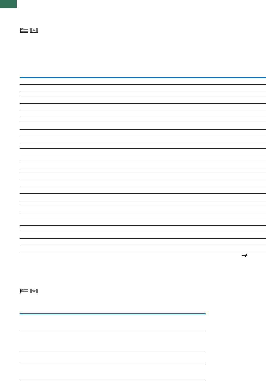
1.1 Contactors
UL/CSA-approved rating data
80 AUTOMATION AND CONTROL www.eaton.com/seasia-electrical
1for North America
DILE, DILA, DILM
DILE, DILA, DILM
Rating data for approved types Contactors
GENERAL USE
Maximum
alternating current-
motor rating
Maximum
motor-
rated current
Single-phase 3-phase Ith
Open/enclosed NEMA size
115 V
120 V 230 V
240 V 200 V
208 V 230 V
240 V 460 V
480 V 575 V
600 V
HP HP HP HP HP HP A Part no.
½1½
235515/13.5 DILEM(4) 00
¼11½23520 DILM7-...(...) 00
½1½3357½20 DILM9-...(...) 00
1233101020 DILM12-...(...) 0
13 5101020 DILM15-...(...) 0
2357½101535 DILM17-...(...) 0
2 5 7½ 7½ 15 20 35 DILM25-...(...) 1
3 5 10 10 20 25 40 DILM32-...(...), DILM38-...(...) 1
3 7½1015304055 DILM40(...) 2
3 101520405065 DILM50(...) 2
5 152025406080 DILM65(...), DILM70(...) 2
7½ 15 25 30 60 75 125 DILM80(...) 3
7½ 15 25 40 75 100 125 DILM95(...) 3
10 25 40 50 100 125 160 DILM115(...) 4
15 30 40 60 125 125 160 DILM150(...), DILM170(...) 4
– – 50 60 125 150 225 DILM185(...) 4
– – 60 75 150 200 250 DILM225(...) 4
– – 75 100 200 250 350 DILM250(...) 5
– – 100 125 250 300 350 DILM300(...) 5
– – 125 150 300 400 450 DILM400(...) 5
– – 150 200 400 500 550 DILM500(...) 6
––200 200 400 600 630 DILM580(...) 6
– – 200 250 500 600 700 DILM650(...) 6
– – 250 300 600 700 800 DILM750(...) 6
––290 350 700 860 850 DILM820(...) 6
– – 350 400 800 1000 1000 DILM1000(...) 7
– – 560 640 1200 1300 1600 DILM1600(...) 8
Further approvals 81
• Elevator control
• Refrigeration control
• Resistance air heating
• Incandescent lamps
• Electrical discharge lamps
• Capacitive switching
Approved rating data
UL -File No. E29184
for auxiliary contacts
Pilot Duty General Use
AC DC AC DC
Part no. VAVA
DIL(E)EM-10(-01)
DILER-40(31)(22)
...(D)DILE
A600 P300 600 10 250 0.5
DILM7-10(-01)
To
DILM32-10(-01)
DILA...
A600 P300 600 15 250 1
DILA-XHI...
DILM32-XHI...
A600 P300 600 15 250 1
DILM...-XHI11-SI
DILM...-XHI11-SA
DILM...-XHI11V-SI
A600 P600 600 10 – –
1.1
Contactors
UL/CSA special purpose rating
81AUTOMATION AND CONTROL www.eaton.com/seasia-electrical
1
for North America
Special purpose rating
DIL M7 M9 M12 M15 M17 M25 M32 M40 M50 M65 M80 M95 M115 M150
MP32 MP63 MP80 M72 MP125 MP160 M170
MP45 MP200
Electrical discharge lamps
(ballast)
480V 60Hz 3phase, 277V
60Hz 1phase A 12 18 20 20 27 35 40 63 79 88 85 100 136 160
600V 60Hz 3phase, 347V
60Hz 1phase A 12 18 20 20 27 35 40 63 79 88 85 100 136 160
Incandescent lamps
(Tungsten)
480V 60Hz 3phase, 277V
60Hz 1phase A 8 11 14 14 23 32 40 55 74 88 85 100 136 160
600V 60Hz 3phase, 347V
60Hz 1phase A 8 11 14 14 23 32 40 55 74 88 85 100 136 160
Resistance air heating
480V60Hz 3phase,
277V60Hz 1phase A 12 18 20 20 27 35 40 63 79 88 94 110 136 160
600V60Hz 3phase,
347V60Hz 1phase A 12 18 20 20 27 35 40 63 79 88 94 110 136 160
Refrigeration control
(CSA only)
LRA 480V 60Hz 3phase A 60 60 60 60 240 240 240 270 270 270 540 540 540 540
LRA 600V 60Hz 3phase A 60 60 60 60 180 180 180 270 270 270 420 420 540 540
480V 60Hz 3phase A 6 7.5 10 10 23 32 40 26 36 45 63 70 84 90
600V 60Hz 3phase A 6 7.5 10 10 17 24 30 26 36 45 63 70 84 90
Elevator control
200V 60Hz 3phase HP (A) ¾ (3.7) 2 (7.8) 2 (7.8) 2 (7.8) 3 (11) 3 (11) 7½
(25.3) 7½
(25.3) 10
(32.2) 10
(32.2) 20
(62.1) 20
(62.1) 30 (92) 30 (92)
240V 60Hz 3phase HP (A) 1½ (6.0) 2 (6.8) 2 (6.8) 3 (9.6) 3 (9.6) 5
(15.2) 7½
(22) 10 (28) 15 (42) 15 (42) 25 (68) 30 (80) 40
(104) 40 (104)
480V 60Hz 3phase HP (A) 2 (3.4) 3 (4.8) 7½
(11) 7½
(11) 7½
(11) 10 (14) 20 (27) 25 (34) 30 (40) 30 (40) 50 (65) 60 (77) 75 (96) 75 (96)
600V 60Hz 3phase HP (A) 3 (3.9) 5 (6.1) 7½
(9.6) 7½
(9.6) 10 (11) 15 (17) 20 (22) 30 (32) 40 (41) 40 (41) 60 (62) 75 (77) 100
(99) 100 (99)
DIL K12 K20 K25 K33 K50
Capacitor Switching
240V 60Hz 3phase A 18 28 36 48 72
480V 60Hz 3phase A 18 28 36 48 72
600V 60Hz 3phase A 14.4 28 38.4 48 72
240V 60Hz 3phase kvar 7.5 12 15 20 30
480V 60Hz 3phase kvar 15 20 30 40 60
600V 60Hz 3phase kvar 15 30 40 50 75
DILM, DILMP, DILK
Special purpose rating
DILM, DILMP, DILK

1.1 Contactors
UL/CSA short circuit current rating
82 AUTOMATION AND CONTROL www.eaton.com/seasia-electrical
1
Short circuit current rating (SCCR)
Contactor Basic Rating 480 V High Fault 600 V High Fault
Max. fuse Max. CB Max. fuse Max. CB Max. fuse Max. CB
kA A A kA A kA A kA A kA A
DILM7-…(…) 5 45 60 100 20 Class J - Fuse only 30 25 - Fuse only
DILM9-…(…) 5 45 60 100 20 Class J - Fuse only 30 25 - Fuse only
DILM12-…(…) 5 45 60 100 20 Class J - Fuse only 30 25 - Fuse only
DILM15-…(…) 5 45 60 20 Class J - Fuse only 30 25 - Fuse only
DILM17-…(…) 5 125 125 100 70 Class J 10 50 10 125 10 50
DILM25-…(…) 5 125 125 100 100 Class J 10 50 10 125 10 50
DILM32-…(…) 5 125 125 100 125 Class J 10 50 10 125 10 50
DILM38-…(…) 5 125 125 100 125 Class J 10 50 10 125 10 50
DILM40(…) 10 250 250 100 150 Class J 65 100 30 250 30 250
DILM50(…) 10 250 250 100 150 Class J 65 100 30 250 30 250
DILM65(…) 10 250 250 100 150 Class J 65 100 30 250 30 250
DILM72(…) 10 250 250 100 150 Class J 65 100 30 250 30 250
DILM80(…) 10 600 600 100 300 Class J 65 250 30 300 30 350
DILM95(…) 10 600 600 100 300 Class J 65 250 30 300 30 350
DILM115(…) 10 600 600 100 300 Class J 65 250 30 300 30 350
DILM150(…) 10 600 600 100 300 Class J 65 250 30 300 30 350
DILM170(…) 10 600 600 100 300 Class J 65 250 30 300 30 350
DILM185(…) 18 700 600 - CB only 65 250 - - - -
DILM225(…) 18 700 600 - CB only 65 250 - - - -
DILM250(…) 18 700 600 - CB only 65 250 - - - -
DILM300(…) 30 800 600 - CB only 42 600 30 800 30 600
DILM400(…) 30 800 600 - CB only 42 600 30 800 30 600
DILM500(…) 30 800 600 - CB only 42 600 30 800 30 600
DILM570(…) 30 800 600 - CB only 42 600 30 800 30 600
DILM580(…) 30 2000 1200 85 2000 85 1200 85 2000 85 1200
DILM650(…) 30 2000 1200 85 2000 85 1200 85 2000 85 1200
DILM750(…) 42 2000 1200 85 2000 85 1200 85 2000 85 1200
DILM820(…) 42 2000 1200 85 2000 85 1200 85 2000 85 1200
DILM1000(…) 85 2000 1200 85 2000 85 1200 85 2000 85 1200
DILM1600(…) 85 2000 - 85 2000 - - 85 2000 85 -
for North America
DILM
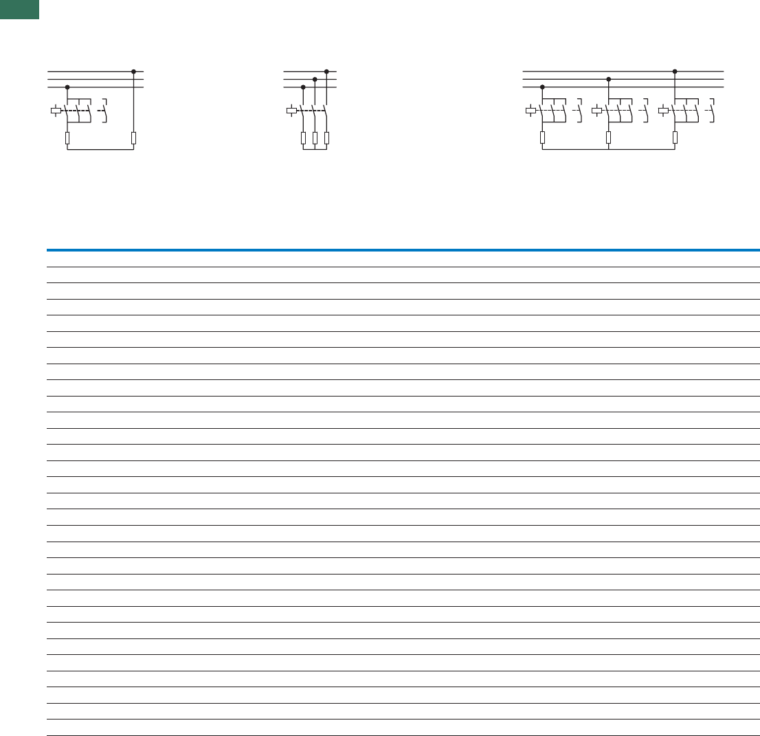
1.1 Contactors
Contactors for resistive load
84 AUTOMATION AND CONTROL www.eaton.com/seasia-electrical
1
Rating data
1-CAgnitaresahp-eerhT1-CAgnitaresahp-eerhT1-CAgnitaresahp-elgniS
Voltage in V Max.
upstream
fuse
gG/gL
Rated
operational
current
Ie= Ith
or Ithe
Voltage in V Max.
upstream
fuse
gG/gL
Rated
operational
current
Ie= Ith
or Ithe
Voltage in V Max.
upstream
fuse
gG/gL
Rated
operational
current
Ie= Ith
or Ithe
220
230
240
380
400
440
660
690 220
230
240
380
400
440
660
690 220
230
240
380
400
440
660
690
kW kW kW kW kW kW kW kW kW A AAAAA
Open version
10 18 31 50 50 7 13 20 20 20 18 31 54 50 50
10 18 31 50 50 7 13 20 20 20 18 31 54 50 50
12 21 37 63 60 – – – – – 21 37 65 63 60
10 18 31 – 50 7 13 22 – 20 18 31 54 – 50
13 22 38 – 60 – – – – – 22 38 65 – 60
18 32 55 – 88 13 22 38 – 35 32 55 95 – 88
21 36 63 – 100 14 25 43 – 40 36 63 109 – 100
26 45 78 – 125 18 31 54 – 50 45 78 136 – 125
34 59 102 – 163 24 41 71 – 65 59 102 176 – 163
42 72 125 – 200 29 50 87 – 80 72 125 217 – 200
47 81 141 – 225 33 56 98 – 90 81 141 244 – 225
57 99 172 – 275 40 69 119 – 110 100 172 299 – 275
68 117 204 – 325 47 81 141 – 130 118 203 353 – 325
84 144 251 – 400 58 100 174 – 160 145 250 434 – 400
101 175 317 – 460 70 120 220 – 185 175 302 549 – 460
144 248 431 800 688 100 172 299 315 275 262 453 786 – 688
165 284 494 800 788 114 197 342 315 315 300 519 900 – 788
172 297 516 1000 825 120 206 357 400 330 333 576 1000 – 875
183 316 548 1000 875 126 219 380 400 350 381 658 1143 – 1000
261 451 784 1250 1250 181 313 543 500 500 476 825 1429 – 1250
366 632 1097 – 1750 253 438 760 800 700 667 1152 2000 – 1750
418 722 1254 – 2000 290 500 869 800 800 762 1316 2286 – 2000
444 767 1332 – 2125 308 531 923 1000 850 810 1400 2429 – 2125
470 812 1411 – 2250 326 563 977 1000 900 857 1480 2572 – 2250
523 903 1568 – 2500 362 625 1086 1000 1000 953 1646 2858 – 2500
732 1264 2195 – 3500 507 875 1520 – 1400 1334 2300 4000 – 3500
1045 1805 3135 – 5000 724 1251 2172 – 2000 1905 3290 5716 – 5000
1150 1985 3449 – 5500 796 1376 2389 – 2200 2095 3619 6288 – 5500
1358 2346 4075 – 6500 941 1626 2827 – 2600 2476 4277 7430 – 6500
Notes 1) Contact 7 – 8 only with DILEM4(-G), DILMP20...
7)
1
135
8642
135
246
7)
1
1
2
35 7
46 8
135 7
246 8
135
246 8
DILM, DILEM
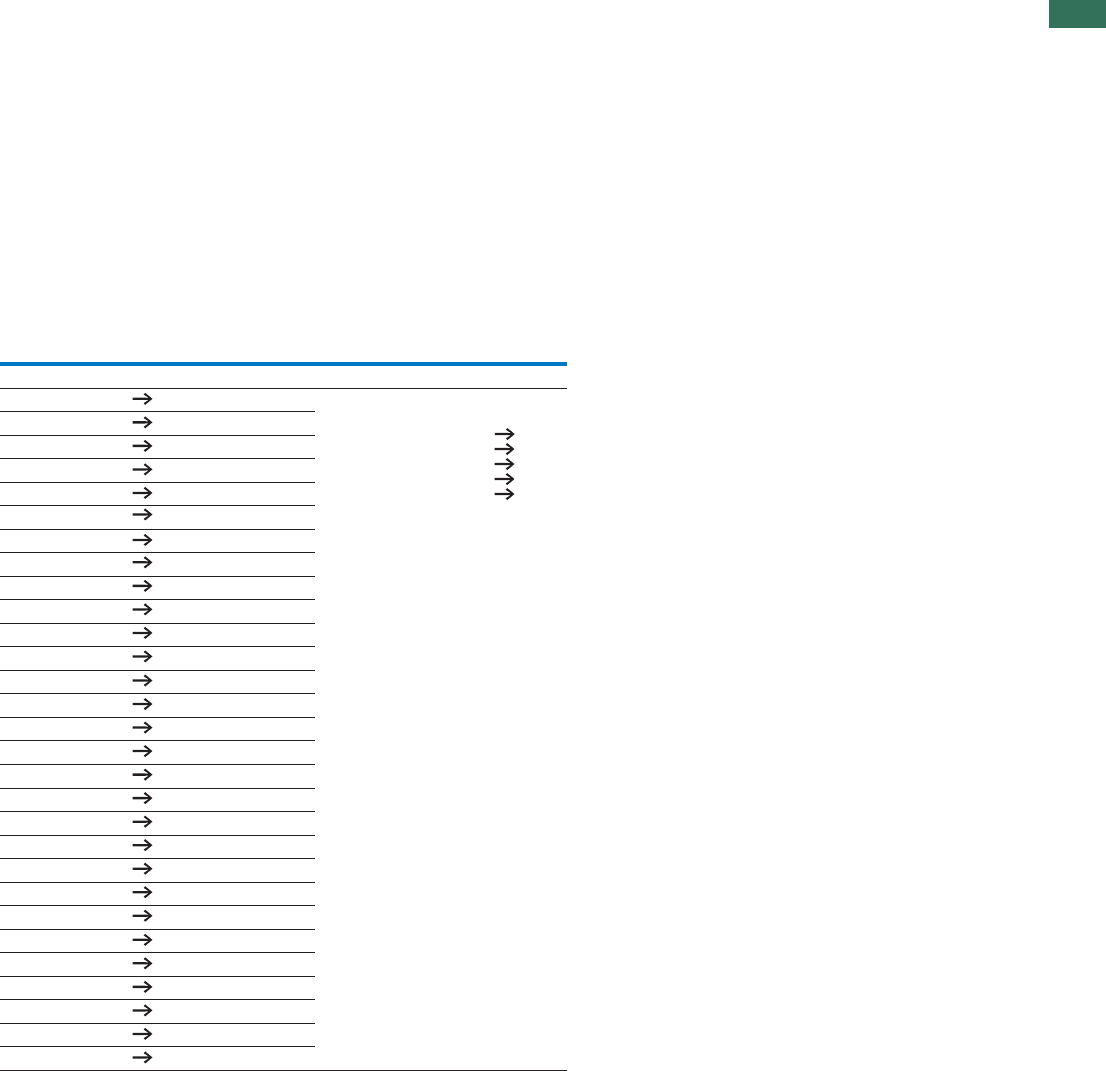
1.1
Contactors
Contactors for resistive load
85AUTOMATION AND CONTROL www.eaton.com/seasia-electrical
1
Part no. Ordering
data Required
accessories:
Paralleling
links
Notes
AC
operated Page Part no.
DILEM-10(…) 4 P1DILEM Accessories Page
Auxiliary contact modules 6
36
Set of paralleling links 53
Enclosure 63
Accessories 52
DILEM-01(…) 4 P1DILEM
DILEM4(…) 4 P1DILEM
DILM7-…(…) 18 DILM12-XP1
DILMP20(…) 34 DILM12-XP1
DILM17-…(…) 18 DILM32-XP1
DILM25-…(…) 18 DILM32-XP1
DILM40(…) 20 DILM65-XP1
DILM50(…) 20 DILM65-XP1
DILM65(…) 20 DILM65-XP1
DILM80(…) 20 DILM150-XP1
DILM95(…) 20 DILM150-XP1
DILM115(…) 20 DILM150-XP1
DILM150(…) 20 DILM150-XP1
DILM170(…) 20 DILM150-KP1
DILM185A(…) 30 DILM185-XP1
DILM225A(…) 30 DILM185-XP1
DILM250(…) 30 –
DILM300A(…) 30 –
DILM400(…) 30 –
DILM500(…) 30 –
DILM580(…) 30 –
DILM650(…) 30 –
DILM750(…) 30 –
DILM820(…) 30 –
DILH1400(…) 32 –
DILH2000(…) 32 –
DILH2200(…) 32 –
DILH2600(…) 32 –
DILM, DILEM
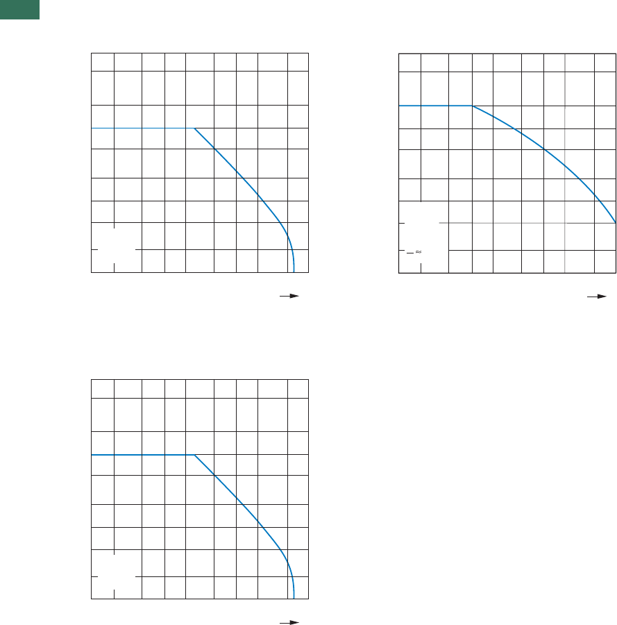
1.1 Mini contactor relays, contactor relays
Electrical lifespan
86 AUTOMATION AND CONTROL www.eaton.com/seasia-electrical
1DILA (AC-15)
Component lifespan (operations)
Ie = Rated operational current
DILA DC1)
Component lifespan (operations)
Ie = Rated operational current
1) Three contacts in series
DILER (AC-15)
Component lifespan (operations)
Ie = Rated operational current
AC-15
240 V
0.01 0.050.02 20.1 0.5 152.0 10 A
20
10
5
2
1
0.5
0.2
0.1
x 10
6
Ie
0.01 0.05 220.0 0.1 0.5 1A0152.0
20
1
0
10
5
2
1
0
.5
0.5
0.2
0.1
X 10
6
L
R
DC
24 V
50 ms
Ie
AC-15
240 V
0.01 0.050.02 20.1 0.5 152.0 10 A
20
10
5
2
1
0.5
0.2
0.1
x 10
6
Ie
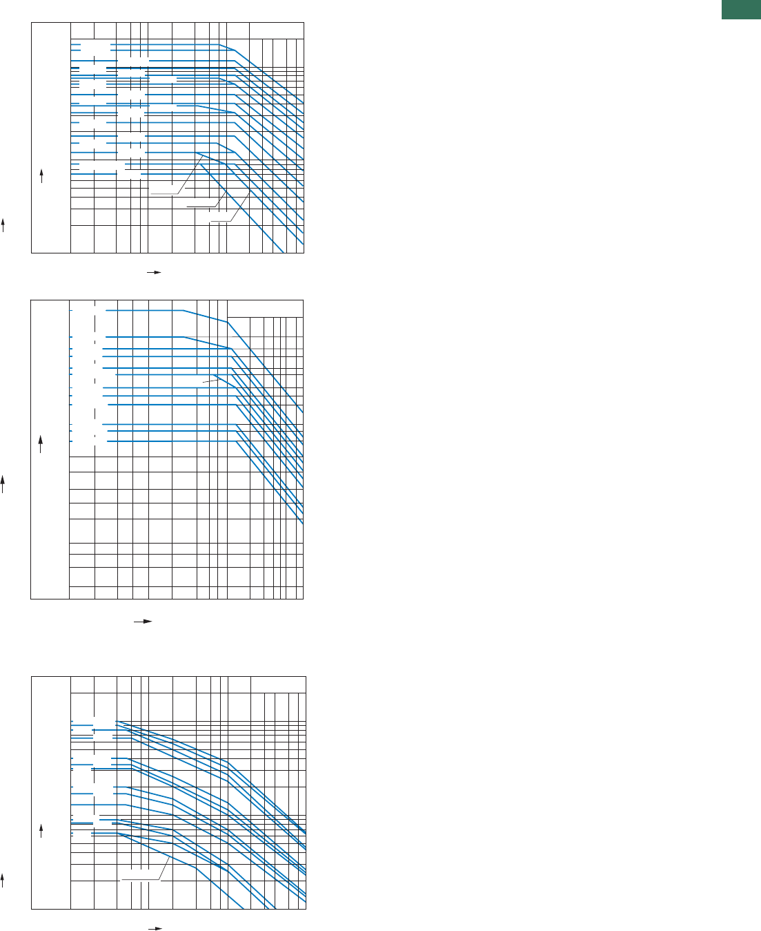
1.1
Contactors
Switching conditions
87AUTOMATION AND CONTROL www.eaton.com/seasia-electrical
1
Normal switching duty
Normal AC induction motor
Operating characteristics
Make: from stop
Break: during run
Electrical characteristics:
Make: up to 6 X rated motor current
Break: up to 1 X rated motor current
Utilization category
100 % AC-3
Typical applications:
Compressors
Pumps
Fan
Hinged flaps
General drives for manufacturing and processing machines
Extreme switching duty
Normal AC induction motor
Operating characteristics
Inching, plugging, reversing
Electrical characteristics:
Make: up to 6 X rated motor current
Break: up to6 X rated motor current
Utilization category
100 % AC-4
Typical applications:
Printing machines Wire-drawing Centrifuges
Special drives on manufacturing and processing machines
A
kW
150
115
95
80
65
50
40
32
25
18
12
9
7
5
4
3
2
AC-3/400V
75
55
45
37
30
22
18.5
15
11
7.5
5.5
4
3
0.01 0.02 0.04 0.06 0.1 0.2 0.4 0.6 1 2 4 610
DILM32
DILM50
DILM25
DILM15
DILM65
DILM115
DILM95
DILM150
170
90 DILM170
DILM17
DILM12
DILM9, DILEM
DILM7
DILEM-G
DILEM
DILEM12
DILM80 DILM72
DILM40 DILM38
Rated output of three-phase motors 50 – 60 Hz
Rated operational current Ie 50 – 60 Hz
Component lifespan [millions of operations]
AC-3/400 V
kW
132
110
90
75
55
45
37
30
22
18.5
15
11
7.5
A
820
750
650
580
500
400
300
250
450
900
400
355
315
250
200
160
225
185
145
104
85
72
58
43
36
30
23
16
DILM185A
DILM225A
DILM250
DILM300A
DILM400
DILM500
DILM580/570
DILM650
DILM750
DILM820
0.01 0.02 0.04
0.06 0.1 0.2 0.4 0.6 1 2 3 4 5 6 810
1600
DILM1000
DILM1600
560 1000
DILM570
Rated output of three-phase motors 50 – 60 Hz
Rated operational current Ie 50 – 60 Hz
Component lifespan [millions of operations]
A
kW
100
90
80
66
40
35
32
20
17
13
9
8.3
6.5
52
47
41
33
19
17
15
9
7.5
5.5
4
3.5
2.5
5
4
3
2
AC-4/400V
0.01 0.02 0.04 0.06 0.1 0.2 0.4 0.6 1 2 4 610
DILM150, DILM170
DILM95
DILM65, DILM72
DILM40
DILM32, DILM38
DILM12.15
DILM7
DILM115
DILM80
DILM50
DILM25
DILM9
DILEM12, DILEM
Rated output of three-phase motors 50 – 60 Hz
Rated operational current Ie50 – 60 Hz
Component lifespan [millions of operations]
Lifts
Escalators
Conveyor belts
Bucket-elevator
Mixers
Agitators
Centrifuges
Air conditioning sys-
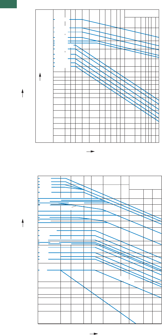
1.1 Contactors
Switching conditions
88 AUTOMATION AND CONTROL www.eaton.com/seasia-electrical
1Extreme switching duty
Normal AC induction motor
Operating characteristics
Inching, plugging, reversing
Electrical characteristics:
Make:up to 6 X rated motor current
Break: 6 X rated motor current
Utilization category
100% AC-4
Typical applications:
Printing
machines Wire-
drawing
machines
Centrifuges
Special drives on manufacturing and processing machines
Switching conditions for 3 pole, non-motor loads
Operating characteristics
Non inductive and slightly inductive loads
Electrical characteristics:
Make: 1 X rated operational current
Break:1 X rated operational current
Utilization category
100% AC-1
Typical applications:
Electric heat
DILM185A
kW
315
280
200
160
110
90
75
55
45
37
30
22
18.5
15
11
7.5
5.5
4
3
2.2
1.5
576
355
450
750
656
512
360
250 456
296
200
132 240
164
140
104
85
72
58
43
36
30
23
16
12
8.8
6.5
5
3.5
DILM225A
DILM250
DILM300A
DILM750
DILM820
800 DILM1000
1280 DILM1600
DILM650
DILM580
DILM500/570
DILM400
AC-4/400 V
A
Component lifespan [millions of operations]
Rated output of three-phase motors 50 – 60 Hz
Rated operational current Ie50 – 60 Hz
0.01 0.02 0.03 0.04 0.06 0.1 0.2 0.3 0.4 0.6 1 2 3 456 810
2000
2200
2600
1800 DILM1600
DILM1400
AC-1/400 V
0.1 0.2 75.0 0.7 1 3510
2
1
3
4
23.0
5
900 850
1400
1000
700
800
500
400
275
300
350
160
10
7
DILM185
DILM150, M170
DILM7, M9, M12 , M15
DILM225
DILM400
DILM300
DILM250
DILM750
DILM650
DILM500 DILM580/570
DILH2000
DILH2200
DILH2600
DILM820/1000
130 DILM115
110 DILM95
90 DILM80
80 DILM65 DILM72
65 DILM50
50 DILM40
40 DILM25, M32; M38
35 DILM17
20 DILEM
DILM750
Component lifespan [Millions of operations]
Breaking current A
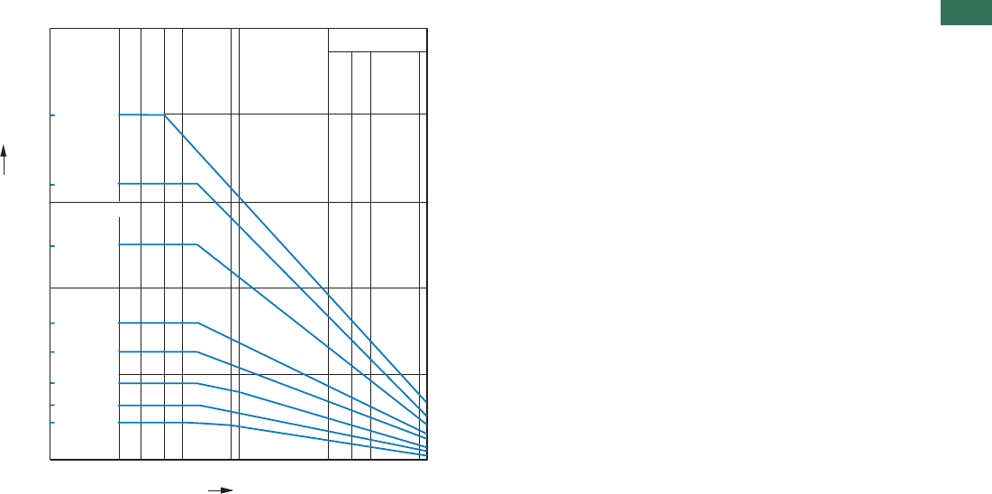
1.1
Contactors
Switching conditions
89AUTOMATION AND CONTROL www.eaton.com/seasia-electrical
1
Switching conditions for 4 pole, non-motor loads
Operating characteristics
Non inductive and slightly inductive loads
Electrical characteristics:
Make: 1 X rated operational current
Break: 1 X rated operational current
Utilization category
100% AC-1
Typical applications:
Electric heat
AC-1/400 V
0.1 0.2 1 10
22
32
0.4 0.6 2 4 6
200
63
45
DILMP20
DILMP32
DILMP45
DILMP63
DILMP80
DILMP125
DILMP160
DILMP200
160
80
125
Component lifespan [Millions of operations]
Breaking current A
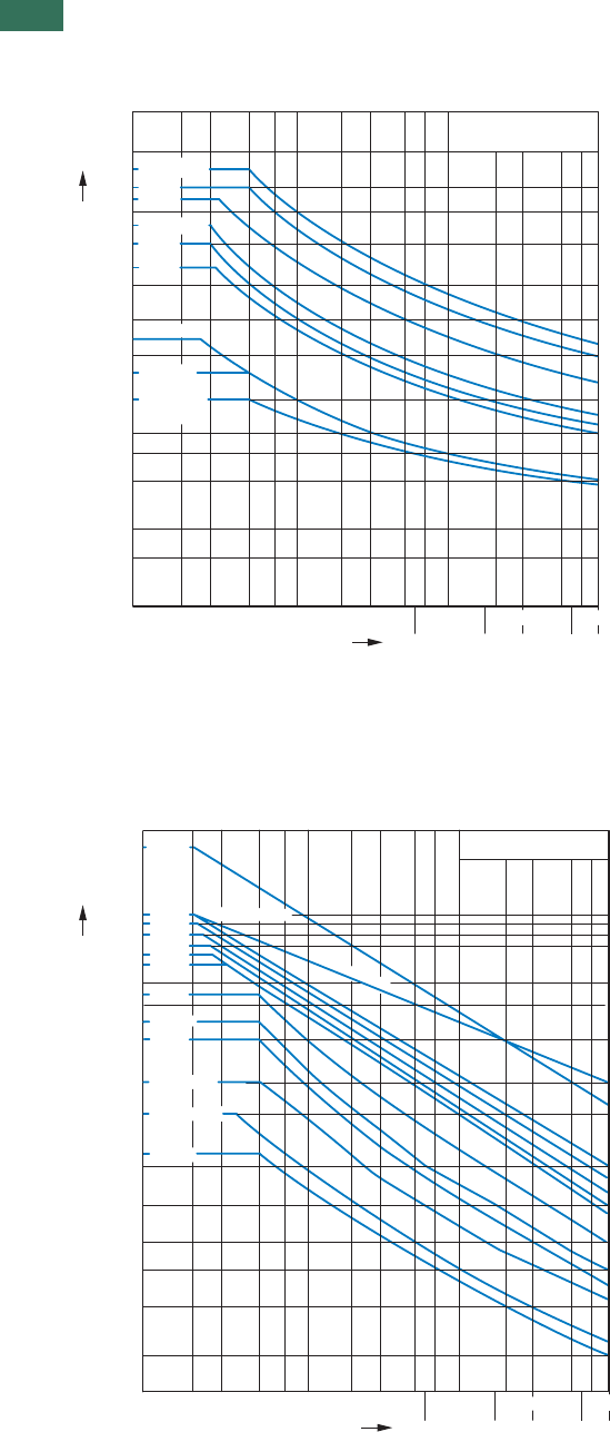
1.1 Contactors
Short-time loading
90 AUTOMATION AND CONTROL www.eaton.com/seasia-electrical
1Short-time loading 3 pole
Time interval between two loads: 15 minutes
10 min 15 min
1 min 3 min 5 min
AC-1/400 V
70 100
5073020
35102
A
700
500
600
400
300
250
15
200
120
100
70
50
40
30
150
900
200 300 500
20
700
DILM17
DILM12, M15
90 DILM7, M9
DIL(E)M(-12)
DILE(E)M(-12)
DILM50
DILM65, M72
450 DILM40
350 DILM32, M38
DILM25
Seconds
Duration of load
Short-time current
10 min 15 min
1 min 3 min 5 min
DILM1000, DILH1400
900
300
70 100
5073020
35102
A
8000
10000
19000
6000
5000
4000
3000
2500
2000
1800
1100
1000
700
500
400
300
1500
DILM80/95
DILM185A/225A
DILM250
DILM300A
DILM400
DILM500
700
200 500
200
AC-1/400 V
DILM580
DILM650
DILM750
DILM820
DILM1600
DILM115,150,170
DILH2000/2200/2600
DILM570
Seconds
Duration of load
Short-time
current
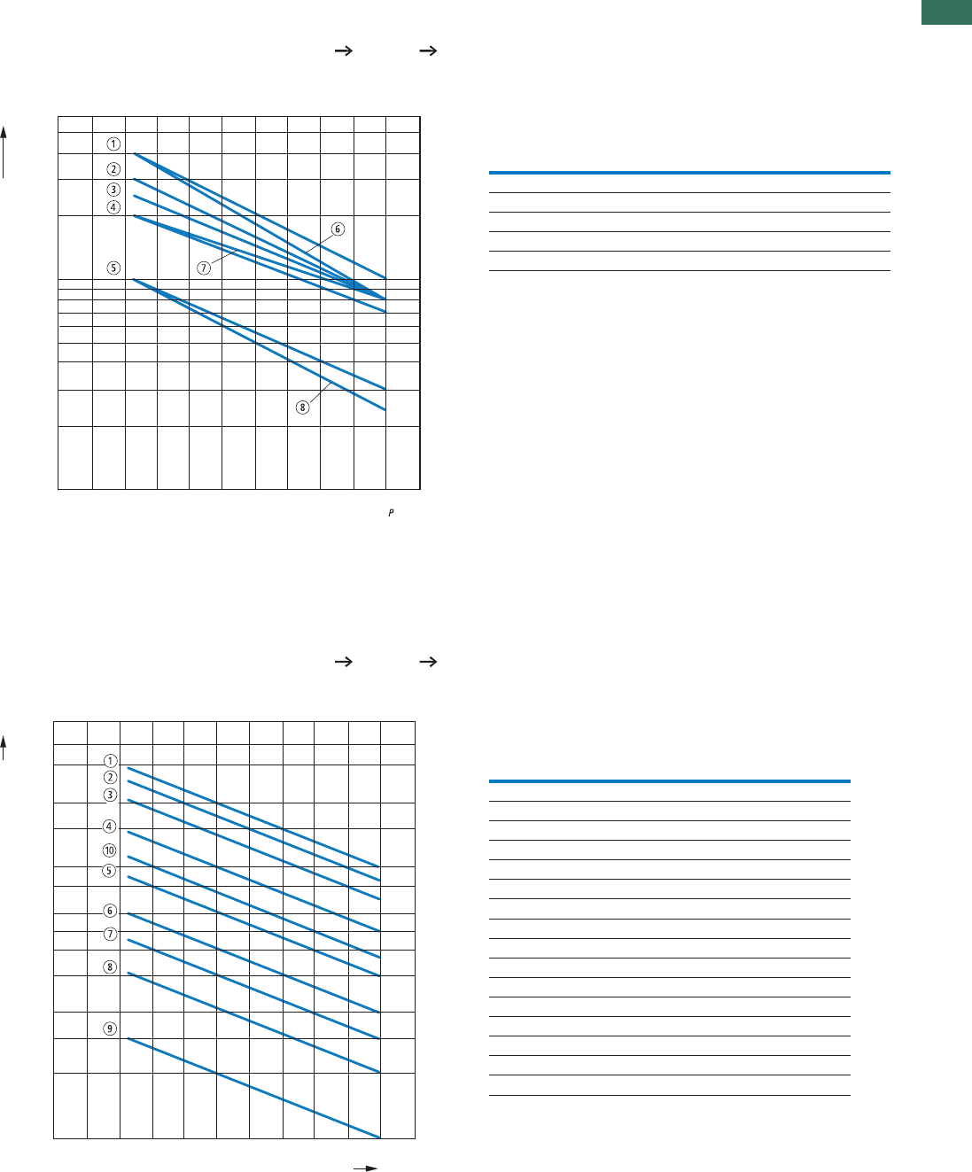
1.1
Contactors
Operating frequency
91AUTOMATION AND CONTROL www.eaton.com/seasia-electrical
1
Determination of the maximum operating frequency dependent on the rating and utilization category
(recommended values) for 400 V
PN = max. rated motor output (kW) of respective contactor according to Page 18 and Page 4
S/h = max. operation per hour
Part no. Characteristic
AC-1 AC-3 AC-2
AC-4
DILE(E)M(-12) 6 8
DILM7, 9, 12, 15 1 5
DILM17, 25, 32, 38 2 5
DILM40, 50, 65, 72 2 5
DILM80, 95, 115, 150, 170 4
7
3
3
3
35
Determination of the maximum operating frequency dependent on the rating and utilization category
(recommended values)
PN = max. rated motor output (kW) of respective contactor according to Page 28 and Page 32
S/h = max. operation per hour
Part no. Characteristic
AC-1 AC-3 AC-4
DILM185A 2 1 8
DILM225A 2 1 8
DILM250 2 1 8
DILM300A 3 2 9
DILM400 3 29
DILM500 3 29
DILM580 3 4 7
DILM650 3 47
DILM750 3 47
DILM820 3 4 7
DILM1000 3 4 7
DILM1600 10 10 7
DILH1400 10 – –
DILH2000 10 – –
DILH2200 10 – –
DILH2600 10 – –
6000
4000
2000
1000
800
600
400
200
100
010 20 30 40 50 60 70 80 90 100 %
[kW]
N
Ops./h
4000
3000
2000
600
500
400
300
200
150
100
50 010 20 30 40 50 60 70 80 90 100 %
1500
1000
800
[kW]
N
P
Ops./h
DILEM, DILM, DILH
DILEM, DILM, DILH
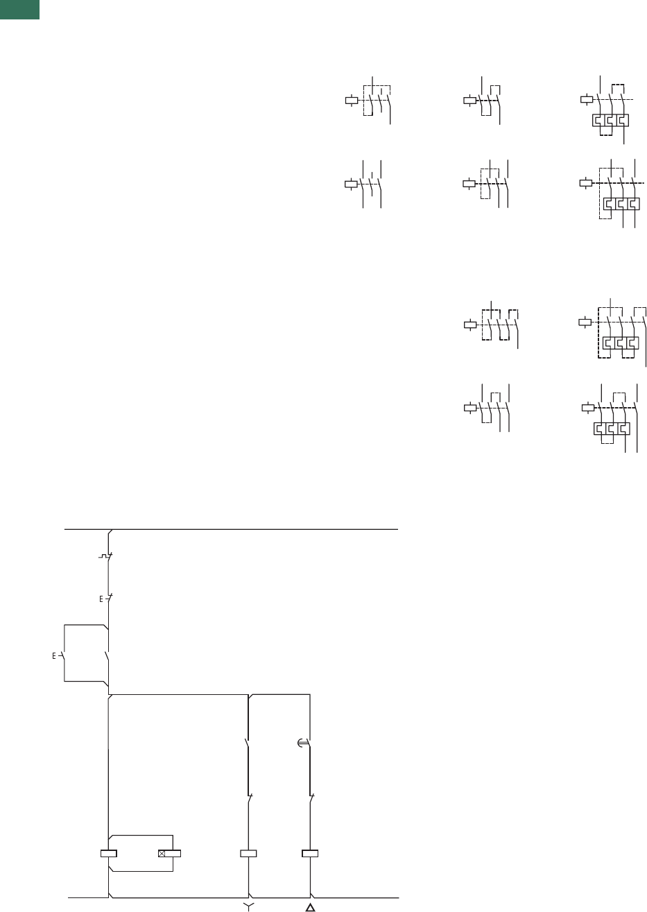
1.1 Contactors
Switching of DC current
92 AUTOMATION AND CONTROL www.eaton.com/seasia-electrical
1DC current switching
– – – – – when necessary
conductor to be
supplied by customer
DILEEM ... DILM700 Without overload relay
60 V DC > 60 V DC With overload relay
> 60 V DC
1 pole
2 pole
DILEM4
DILMP...
1 pole
2 pole
Wiring, star-delta combination with DILM32-XTEY20
-Q11A1
A2
10L10L
20L20L
-K1
N
-Q13A1
A2
I
-K157
58
-Q15
22
21
-Q15A1
A2
-K1 67
68
-Q13
22
21
-Q11
14
13
-F1 95
96
0
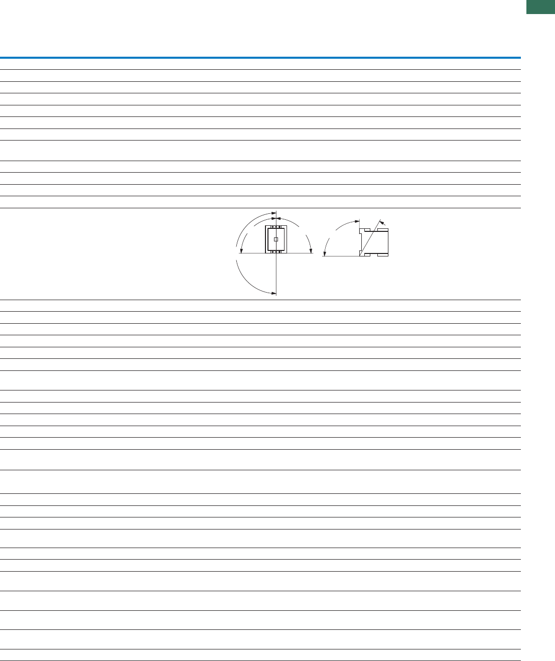
1.1
Mini contactor relays, contactor relays
93AUTOMATION AND CONTROL www.eaton.com/seasia-electrical
1
Technical data
DILA DILA…XHI DILER DILE…
General
Standards IEC/EN 60947, VDE 0660, UL, CSA
Lifespan, mechanical
AC operated
Operations
x 10620 10 10 10
DC operated
Operations
x 10620 10 20 20
Maximum operating frequency
Maximum operating frequency
Operations/h
9000 9000 9000 9000
Climatic proofing Damp heat, constant, to IEC 60068-2-78;
Damp heat, cyclic, to IEC 60068-2-30
Ambient temperature
°C
Open -25…60 -25…60 -25…50 -25…50
°C
Enclosed -25…40 -25…40 -25…40 -25…40
°C
Ambient temperature for storage -40 - 80 -40 - 80
Mounting position
–
Any, except vertically with terminals
A1/A2 below
Mechanical shock resistance (IEC/EN 60068-2-27)
Half-sinusoidal shock 10 ms
Basic devices with auxiliary contact module
gN/O 7 7 10 10
gNC 5 5 8 8
Protection type IP20 IP20 IP20 IP20
Protection against direct contact when actuated
from front (EN 50274)
Finger- and back-of-hand proof
Weight
kgAC operated 0.23 0.05 0.17 –
kgDC operated 0.28 0.05 0.2 –
Terminal capacity
Screw terminals
mmSolid 21 x (0.75 - 4)
2 x (0.75 - 2.5)
1 x (0.75 - 4)
2 x (0.75 - 2.5)
1 x (0.75 - 2.5)
2 x (0.75 - 2.5)
1 x (0.75 - 2.5)
2 x (0.75 - 2.5)
mmFlexible with ferrule 21 x (0.75 - 2.5)
2 x (0.75 - 2.5)
1 x (0.75 - 2.5)
2 x (0.75 - 2.5)
1 x (0.75 - 1.5)
2 x (0.75 - 1.5)
1 x (0.75 - 1.5)
2 x (0.75 - 1.5)
AWGSolid or stranded 18 - 14 18 - 14 18 - 14 18 - 14
Terminal screw M3.5 M3.5 M3.5 M3.5
SizePozidriv screwdriver 2 2 2 2
mmFlat-blade screwdriver 0.8 x 5.5
1 x 6
0.8 x 5.5
1 x 6
0.8 x 5.5
1 x 6
0.8 x 5.5
1 x 6
NmMax. tightening torque 1.2 1.2 1.2 1.2
Spring-loaded terminals
mm²Solid 1 x (0.75 - 2.5)
2 x (0.75 - 2.5)
1 x (0.75 - 2.5)
2 x (0.75 - 2.5)
1 x (1 - 2.5)
2 x (1 - 2.5)
1 x (1 - 2.5)
2 x (1 - 2.5)
mm²Flexible with ferrule 1 x (0.75 - 1.5)
2 x (0.75 - 1.5)
1 x (0.75 - 1.5)
2 x (0.75 - 1.5)
1 x (1 - 2.5)
2 x (1 - 2.5)
1 x (1 - 2.5)
2 x (1 - 2.5)
Flexible without ferrule DIN 46228 mm² 1 x (0.75 - 2.5)
2 x (0.75 - 2.5)
1 x (0.75 - 1.5)
2 x (0.75 - 1.5)
––
AWGSolid or stranded 18 - 14 18 - 14 1 x (16 - 14)
2 x (16 - 14)
1 x (16 - 14)
2 x (16 - 14)
mmFlat-blade screwdriver 0.6 x 3.5 0.6 x 3.5 0.6 x 3.5 0.6 x 3.5
180°
90°
90°
90°
30°
DILER, DILA

1.1 Mini contactor relays, contactor relays
94 AUTOMATION AND CONTROL www.eaton.com/seasia-electrical
1
Contacts
Interlocked opposing contacts to EN 60947-4-1,
Annex L, including auxiliary contact module
Yes Yes Yes Yes
Rated impulse withstand voltage Uimp V AC 6000 6000 6000 6000
Overvoltage category/degree of pollution III/3 III/3 III/3 III/3
URated insulation voltage iV AC 690 690 690 690
URated operating voltage eV AC 690 500 600 600
Safe isolation according to EN 61140
Between coil and auxiliary contacts V AC 400 400 300 300
V ACBetween the auxiliary contacts 400 400 300 300
Rated operational current
AC-15
I220/240 V eA4 4 6 4
I380/415 V eA4 4 3 2
I500 V eA1.5 1.5 1.5 1.5
DC1)
L/R 15 ms
Contacts in series:
1 24 V A 10 10 2.5 2.5
160 VA6 6 ––
2 60 V A 10 10 2.5 2.5
1 110 V A 3 3 – –
3 110 V A 6 6 1.5 1.5
1 220 V A 1 1 – –
3 220 V A 5 5 0.5 0.5
L/R 50 ms
Contacts in series:
324 VA4 2.5 ––
360 VA4 1 ––
3 110 V A 2 0.5 – –
3 220 V A 1 0.25 – –
DC-13 (6xP)
Contacts in series:
324 VA2.5 2.5 ––
360 VA1 1 ––
3 110 V A 0.5 0.5 – –
3 220 V A 0.25 0.25 – –
Control circuit reliability
(at Ue = 24 V DC, Umin = 17 V, I
min = 5.4 mA)
Fault
probability
<10-8, < one failure in 100 million operations
Conventional thermal current Ith A16 16 10 10
Short-circuit strength without welding
Maximum overcurrent protection device
PKZM0220/240 V 4 – 4 4
PKZM0380/415 V 4 – 4 4
Short-circuit protection rating maximum fuse
2)
A gG/gL500 V 10 10 6 6
A fast500 V – – 10 10
Current heat loss at load of Ith
WAC operated 0.3 0.3 0.2 0.2
WDC operated 0.3 0.3 0.3 0.3
Notes 1) Switch-on and switch-off conditions based on DC-13, time
constant as specified
2) See characteristic curve "Fuses" for time/current characteristics (please enquire)
DILA DILA…XHI DILER DILE…
DILER, DILA

1.1
Mini contactor relays, contactor relays
95AUTOMATION AND CONTROL www.eaton.com/seasia-electrical
1
Magnet systems
Voltage tolerance
AC operated
Single-voltage coil 50 Hz and dual-
voltage coil 50 Hz, 60 Hz
Pick-up
Pick-up
x U
x U
x U
c0.8…1.1 – 0.8…1.1 –
Dual-frequency coil 50/60 Hz c0.8…1.1 – 0.85…1.1 –
DC operated1)
x UPick-upStarting voltage c0.8…1.1 – 0.85…1.3 –
At 24 V: without auxiliary contact
module (40 °C)
Pick-up c0.7 - 1.3 – 0.7 - 1.3 –
Power consumption
VAPick-up50 Hz 24 – 25 –
VASealing50 Hz 3.4 – 4.6 –
WSealing50 Hz 1.2 – 1.3 –
VAPick-up60 Hz 30 – 25 –
VASealing60 Hz 4.4 – 4.6 –
WSealing60 Hz 1.4 – 1.3 –
VAPick-up50/60 Hz 27
25
–30
29
–
VASealing50/60 Hz 4.2
3.3
–5.4
3.9
–
WSealing50/60 Hz 1.4
1.2
–1.6
1.1
–
Pick-up =DC operated
sealing
W3 – 2.6 –
% DFDuty factor 100 – 100 –
Changeover times at 100 % U (recommended values)
c
msAC operated closing delay 15 - 21 – 14 - 21 –
AC operated normally open contact opening
delay
ms 9 - 18 – 8 - 18 –
AC operated with auxiliary contact module,
max. closing delay
ms – – 45 45
msDC operated closing delay 31 – 26 - 35 –
DC operated normally open contact opening
delay
ms 12 – 15 - 25 –
DC operated with auxiliary contact module,
max. closing delay
ms – – 70 70
Notes 1) Smoothed DC, three-phase bridge rectifier or smoothed two-phase bridge rectifier
DILA DILA…XHI DILER DILE…
DILER, DILA

1.1 Contactors
Amplifier modules, electronic timer module, contactor monitoring device
96 AUTOMATION AND CONTROL www.eaton.com/seasia-electrical
1
ETS4-VS3 DILM32-XTE CMD(24VDC)
CMD(220-240VAC)
General
Standards IEC/EN 60947, VDE
0660, UL, CSA
DIN EN 61812, IEC/EN
60947, VDE 0660,
UL, CSA
IEC/EN 60947
UL
CSA
Lifespan, mechanical
x 10c (contacts)AC operated 6–310
x 10c (contacts)DC operated 630 3 3
Maximum operating frequency
x 10c (contacts)DC operated 672000 – 9000
Climatic proofing Damp heat, constant, to IEC 60068-2-78
Damp heat, cyclic, to IEC 60068-2-30
Ambient temperature
°CStorage – -40 - 80 -40 - 80
°COpen -25 - 60 -25 - 60 -25 - 50
°CEnclosed -25 - 45 -25 - 40 –
Mounting position Any As required, except
suspended
Any
Mechanical shock resistance (IEC/EN 60068-2-27)
Half-sinusoidal shock 20 ms
gN/O 10 – –
Half-sinusoidal shock 10 ms
gN/O – 6 4
gNC – 6 4
Protection type IP20 IP20 IP20
Protection against direct contact when actuated from front (EN 50274) Finger- and back-of-hand proof
kgWeight 0.09 0.08 0.1
Terminal capacity
mm²Solid 1 x (0.75 - 2.5)
2 x (0.75 - 2.5) 1)
1 x (0.75 - 2.5)
2 x (0.75 - 1.5)
1 x (0.75…2.5)
2 x (0.75…1.5)
mm²Flexible with ferrule 1 x (0.75 - 2.5)
2 x (0.75 - 1.5) 1)
1 x (0.75 - 1.5)
2 x (0.75 - 1.5)
1 x (0.75…1.5)
2 x (0.75…1.5)
AWGSolid or stranded 16 - 14 18 - 14 18…14
Terminal screw M3.5 M3.5 M3.5
SizePozidriv screwdriver 2 2 2
mmFlat-blade screwdriver 0.8 x 5.5
1 x 6
0.8 x 5.5
1 x 6
0.8 x 5.5
1 x 6
NmMax. tightening torque 1.2 1.2 1.2
Notes 1) Use equal cross-sections only
ETS-VS3, DILM, CMD

1.1
Contactors
Amplifier modules, electronic timer module, contactor monitoring device
97AUTOMATION AND CONTROL www.eaton.com/seasia-electrical
1
ETS4-VS3 DILM32-XTE CMD(24VDC) CMD(220-240VAC)
Contacts
Rated impulse withstand voltage U
imp V AC 6000 6000 8000 4000
Overvoltage category/degree of pollution III/2 III/3 III/3 III/3
URated insulation voltage iV AC 440 600 100 250
URated operating voltage eV 440 AC 400 AC 24 DC 250 AC
Rated operational current
AC-15
I220/240 V eA2 3 – –
I280/415 V eA2 – – –
DC-13 1)
DC-13 L/R 15 ms
Contacts in series:
124 VA2.6 1 – –
1 60 V A 1 0.2 – –
1 110 V A 0.6 0.2 – –
1 220 V A 0.2 0.1 – –
DC-13 L/R 50 ms
Contacts in series:
124 VA2 1 – –
1 60 V A 0.6 0.2 – –
1 110 V A 0.08 0.2 – –
1 220 V A 0.08 0.1 – –
DC-13 L/R 300 ms
Contacts in series:
124 VA0.6 1 – –
1 60 V A 0.2 0.2 – –
1 110 V A 0.08 0.2 – –
1 220 V A 0.03 0.1 – –
Safe isolation according to EN 61140
Between coil and auxiliary contacts V AC – 250 – –
V ACBetween the auxiliary contacts – 250 – –
Control circuit reliability
(at Ue = 24 V DC, Umin = 17 V, I
min = 5.4 mA)
Fault
probability
<10-8, < one failure in
100 million operations
–––
Conventional thermal current Ith A6 4 – –
Component lifespan
AC-15
230 V, Ie = 0.1 A
Switch
operations
x 1067–––
230 V, Ie = 1.2 A
Switch
operations
x 1061–––
Short-circuit rating without welding
Short-circuit protection rating maximum fuse 2)
A gG/gL500 V – 4 2 2
A fast500 V 4 – – –
Notes 1) Switch-on and switch-off conditions based on DC-13, time constant as specified
2) See transparent overlay "Fuses" for time/current characteristics (please enquire)
ETS-VS3, DILM, CMD

1.1 Contactors
Amplifier modules, electronic timer module, contactor monitoring device
98 AUTOMATION AND CONTROL www.eaton.com/seasia-electrical
1ETS-VS3, DILM, CMD
ETS4-VS3 DILM32-XTE CMD(24VDC)
CMD(220-240VAC)
Magnet systems
Voltage tolerance
Starting voltage
AC operated
Pick-up x U
x U
c– 0.85 - 1.1 0.85 - 1.1
DC operated1)
Pick-up c0.85 - 1.2 0.7 - 1.2 0.85 - 1.1
Power consumption
VASealingAC operated – 2 4
WSealingAC operated – 1.8 4
Pick-up = WDC operated
sealing
0.6 – 4
% DFDuty factor 100 100 100
Changeover times at 100 % Uc (recommended values)
msDC operated closing delay 7 – –
msDC operated opening delay 3 – –
Maximum operating frequency
Ops/hMax. operating frequency – 3600 –
Ops/h6 A/250 V –360–
Minimum on duration
msOn-delayed –< 50–
msOff-delayed – < 200 –
Repetition accuracy (with constant parameters) Deviation – < 5 –
msRecovery time (after 100% time delay) – 70 –
Contact changeover time
DILM32-XTEE11/DILM32-XTED11 tums – 10 –
DILM32-XTEY20 tums – 50 –
CMD tums––100 ± 20%
Notes 1) Smoothed DC, three-phase bridge rectifier or smoothed two-phase
bridge rectifier
%
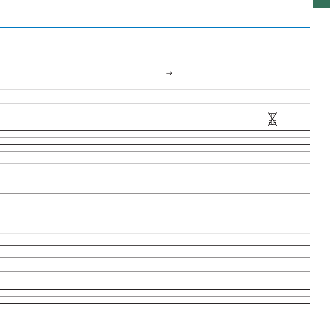
1.1
Mini contactor relays
99AUTOMATION AND CONTROL www.eaton.com/seasia-electrical
1
DILEEM
DILEM
DILEM12
DILEEM-G
DILEM-G
DILEM12-G
DILEM4 DILEM4-G
General
Standards IEC/EN 60947, VDE 0660, CSA, UL
at 50 HzLifespan, mechanical; Coil 50/60 Hz 7 – 7 –
x 10c (contacts)Lifespan, mechanical 610 20 20 –
Maximum operating frequency
Ops/hMechanical 9000
Electrical (Contactor without overload relay) Characteristic curves Page 91
Climatic proofing Damp heat, constant, to IEC 60068-2-78
Damp heat, cyclic, to IEC 60068-2-30
Ambient temperature
°COpen -25 - 50
°CEnclosed -25 - 40
Mounting position
Mechanical shock resistance (IEC/EN 60068-2-27)
Half-sinusoidal shock 10 ms
Basic device without auxiliary contact module
Main circuit normally open
contact
g10
Auxiliary contacts
NC/Normally open contact
g10/8 10/8 – –
Basic devices with auxiliary contact module
Main circuit normally open
contact
g10
Auxiliary contacts Normally
open contact/NC
g20/20
Protection type IP20
Protection against direct contact when actuated from front (EN 50274) Finger- and back-of-hand proof
kgWeight 0.2 0.17 0.2 0.17
Terminal capacity: main and auxiliary contacts
mm²Solid 1 x (0.75 - 2.5)
2 x (0.75 - 2.5)
mm²Flexible with ferrule 1 x (0.75 - 1.5)
2 x (0.75 - 1.5)
AWGSolid or stranded 18 - 14
Terminal screw M3.5
SizePozidriv screwdriver 2
mmFlat-blade screwdriver 0.8 x 5.5
1 x 6
NmMax. tightening torque 1.2
Terminal capacity springloaded terminals main and control circuits
mm²Solid 1 x (1 - 2.5)
2 x (1 - 2.5)
mm²Flexible with ferrule 1 x (1 - 2.5)
2 x (1 - 2.5)
mmFlat-blade screwdriver 0.6 x 3.5
Any, except for vertically with terminals A1/A2 below
A2
A1
DILEEM, DILEM

1.1 Mini contactor relays
100 AUTOMATION AND CONTROL www.eaton.com/seasia-electrical
1
DILEEM
DILEEM-G
DILEM
DILEM-G
DILEM4 DILEM4-G DILEM12
DILEM12-G
Main contacts
URated impulse withstand voltage imp V AC 6000 6000 6000 6000 6000
Overvoltage category/pollution degree III/3 III/3 III/3 III/3 III/3
URated insulation voltage iV AC 690 690 690 690 690
URated operating voltage eV AC 690 690 690 690 690
Safe isolation according to EN 61140
V ACBetween coil and contacts 300 300 300 300 300
V ACBetween the contacts 300 300 300 300 300
Making capacity of up to 440 V (cos as specified in IEC/EN 60947) A 110 110 110 110 120
Breaking
capacity
A220/230 V 90 90 90 90 96
A380/400 V 90 90 90 90 96
A500 V 64 64 64 64 72
A660/690 V 42 42 42 42 42
Devices lifespan Engineering Page 88
AC-3
AC-1
Engineering Page 87
AC-4 Engineering Page 87
Short-circuit protection rating maximum fuse
Type “2” coordination 500 V gL/gG A 10 10 10 10 20
Type “1” coordination 500 V gL/gG A 20 20 20 20 35
AC voltage
AC-1 operation
Conventional thermal current 3 pole 50 - 60 Hz
Open at 40 °C th A22 22 22 22 22
at 50 °C th A20 20 20 20 20
at 55 °C th A19 19 19 19 19
Enclosed 1) th A16 16 16 16 16
Conventional thermal current, 1-pole
Open1) I
I
I
I
I
th A50 50 60 60 50
Enclosed 1) Ith A40 40 50 50 40
AC-3 operation
Rated operational
current AC-3
open,
50 - 60 Hz,
3-pole1)
I220/230 V eA6.699912
I240 V eA6.699912
I380/400 V eA6.699912
I415 V eA6.699912
I440 V eA6.699910.5
I500 V eA5 6.46.46.49
I660/690 V eA3.54.84.84.85.2
kWP220/230 VMotor rating 1.5 2.2 2.2 2.2 3.5
kWP240 V 1.8 2.5 2.5 2.5 3
kWP380/400 V 3 4 4 4 5.5
kWP415 V 3.1 4.3 4.3 4.3 5.5
kWP440 V 3.3 4.6 4.6 4.6 5.5
kWP500 V 3 4 4 4 5.5
kWP660/690 V 3 4 4 4 4
AC-4 operation
Rated operational
current AC-4
open,
50 - 60 Hz,
3-pole1)
I220/230 V eA5 6.66.66.66.6
I240 V eA5 6.66.66.66.6
I280/400 V eA5 6.66.66.66.6
I415 V eA5 6.66.66.66.6
I440 V eA5 6.66.66.66.6
I500 V eA3.75555
I660/690 V eA2.93.43.43.43.4
Rated operational
power
kWP220/230 V 1.1 1.5 1.5 1.5 1.5
kWP240 V 1.3 1.8 1.8 1.8 1.8
kWP380/400 V 2.2 3 3 3 3
kWP415 V 2.3 3.1 3.1 3.1 3.1
kWP440 V 2.4 3.3 3.3 3.3 3.3
kWP500 V 2.2 3 3 3 2.2
kWP660/690 V 2.2 3 3 3 2.2
Notes 1) At maximum permissible ambient air temperature
DILEEM, DILEM

1.1
Mini contactor relays
101AUTOMATION AND CONTROL www.eaton.com/seasia-electrical
1
DILEEM, DILEM
DILEEM DILEEM-
G
DILEM DILEM-
G
DILEM4 DILEM4-
G
DILEM12 DILEM12
-G
DC voltage
Operations Engineering Page 92
Rated operational current open
I12 VDC-1 eA2020202020202020
I24 V eA2020202020202020
I60 V eA2020202020202020
I110 V eA2020202020202020
I220 V eA2020202020202020
I12 VDC-3 eA66888888
I24 V eA66888868
I60 V eA33444444
I110 V eA22333333
I220 V eA– – – – 1 1 – –
I12 VDC-5 eA 1.8 1.8 2.5 2.5 2.5 2.5 2.5 2.5
I24 V eA 1.8 1.8 2.5 2.5 2.5 2.5 2.5 2.5
I60 V eA 1.8 1.8 2.5 2.5 2.5 2.5 2.5 2.5
I110 V eA 1.8 1.8 1.5 1.5 2.5 2.5 1.5 1.5
I220 V eA 0.2 0.2 0.3 0.3 1 1 0.3 0.3
Current heat loss (3-pole or 4-pole)
At Ith W 2 3.5 2 3.5 2.7 4.7 2 3.5
At I to AC-3/400 V
eW 0.5 0.7 0.5 0.7 – – 0.5 0.7
Magnet systems
Voltage tolerance
Single-voltage coil 50 Hz and
dual-voltage coil 50 Hz, 60 Hz
Pick-up x Uc0.8 - 1.1 – 0.8 - 1.1 – 0.8 - 1.1 – 0.8 - 1.1 –
x UPick-upDual-frequency coil 50/60 Hz c0.8 - 1.1 – 0.85 -
1.1
– 0.85 - 1.1 – 0.8 - 1.1 –
x UPick-upDC operated c– 0.8 - 1.1 – 0.8 - 1.1 – 0.85 - 1.1 – 0.8 - 1.1
Power consumption
AC operation Single-voltage coil, 50 Hz, and dual-
voltage coil, 50 Hz, 60 Hz
Pick-up 25 – 25 – 25 – 25 –
Pick-up 22 – 22 – 22 – 22 –
Sealing 4.6 – 4.6 – 4.6 – 4.6 –
Sealing 1.3 – 1.3 – 1.3 – 1.3 –
Dual-frequency coil 50/60 Hz at 50 Hz Pick-up 30 – 30 – 30 – 30 –
Pick-up 26 – 26 – 26 – 26 –
Sealing 5.4 – 5.4 – 5.4 – 5.4 –
Sealing 1.6 – 1.6 – 1.6 – 1.6 –
Dual-frequency coil 50/60 Hz
at 60 Hz
Pick-up 29 – 29 – 29 – 29 –
Pick-up 24 – 24 – 24 – 24 –
Sealing 3.9 – 3.9 – 3.9 – 3.9 –
Sealing 1.1 – 1.1 – 1.1 – 1.1 –
Single-voltage coil, 50 Hz, and dual-
voltage coil, 50 Hz, 60 Hz
Pick-up
VA
W
VA
W
VA
W
VA
W
VA
W
VA
W
VA 25 – 25 – 25 – 25 –
Dual-frequency coil 50/60 Hz at 50 Hz Pick-up VA 30 – 30 – 30 – 30 –
Dual-frequency coil 50/60 Hz at 60 Hz Pick-up VA 29 – 29 – 29 – 29 –
DC operation1) Power consumption
pick-up = sealing
VA/W – 2.6 – 2.6 – 2.6 – 2.6
% DFDuty fac tor 100 100 100 100 100 100 100 100
Switching times at 100 % Uc
msClosing delay min.N/O 14 26 14 26 14 26 14 26
msClosing delay max. 21 35 21 35 21 35 21 35
msOpening delay min. 8 15 8 15 8 15 8 15
msOpening delay max. 18 25 18 25 18 25 18 25
Closing delay with top mounting
auxiliary contact
ms Max. 45 Max. 70 Max. 45 Max. 70 Max. 45 Max. 70 Max. 45 Max. 70
Reversing con- tactorsChangeover time at 110 % Uc
Changeover time min. ms 16 40 16 40 16 40 16 40
Changeover time maX. ms 21 50 21 50 21 50 21 50
msArcing time at 690 V AC Max. 12 Max. 12 Max. 12 Max. 12 Max. 12 Max. 12 Max. 12 Max. 12
Coil Lifespan, mechanical; Coil 50/60 Hz
c
(contacts)
x 1067–7–7–7–
Notes 1) Smoothed DC or three-phase bridge rectifier

1.1 Mini contactor relays
102 AUTOMATION AND CONTROL www.eaton.com/seasia-electrical
1
DILEEM, DILEM
DILE(E)M(-12)... …DILEM
Auxiliary contact
Interlocked opposing contacts to EN 60947-5-1 Annex L, including
auxiliary contact module
Yes Yes
URated impulse withstand voltage imp V AC 6000 6000
Overvoltage category/pollution degree III/3 III/3
URated insulation voltage iV AC 690 690
URated operating voltage eV AC 600 600
Safe isolation according to EN 61140
Between coil and auxiliary contacts V AC 300 300
V ACBetween the auxiliary contacts 300 300
Rated operational current
AC-15
I220/240 V eA6 4
I380/415 V eA3 2
I500 V eA 1.5 1.5
DC L/R 15 ms
Contacts in series:
A24 V1 2.5 2.5
A60 V2 2.5 2.5
A100 V3 1.5 1.5
A220 V3 0.5 0.5
IConventional thermal current th A10 10
Control circuit reliability (at Ue = 24 V DC, Umin = 17 V, I min = 5.4 mA) Fault
probability
<10--8, < one failure in 100 million operations
Component lifespan at Ue = 240 V
x 10c (contacts)AC-15 60.2 0.2
DC1)
L/R = 50 ms: 2 contacts in series at Ie = 0.5 A c (contacts) x 1060.15 0.15
Short-circuit rating without welding
Maximum overcurrent protective device PKZM0-4 PKZM0-4
Short-circuit protection rating maximum fuse
A gG/gL500 V 6 6
A fast500 V 10 10
Current heat loss at load of Ith
WPer contact 0.2 0.2
Notes 1) Switch-on and switch-off conditions based on DC-13, time constant as
specified
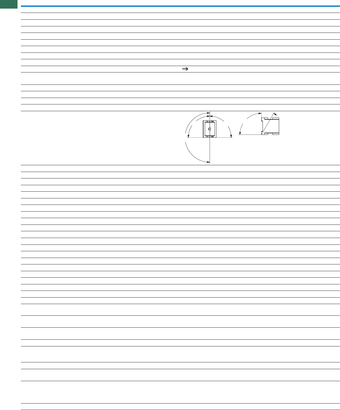
1.1 Contactors
Basic devices up to 170 A
104 AUTOMATION AND CONTROL www.eaton.com/seasia-electrical
1DILM7 DILM9 DILM12 DILM15 DILM17 DILM25
General
Standards IEC/EN 60947, VDE 0660, UL, CSA
Lifespan, mechanical
x 10c (contacts)AC operated 610 10 10 10 10 10
x 10c (contacts)DC operated 610 10 10 10 10 10
Operating frequency, mechanical
Operations/hMechanical, AC operated 9000 9000 9000 5000 5000 5000
Operations/hDC operated 9000 9000 9000 5000 5000 5000
Maximum operating frequency
Electrical (Contactor without overload relay) Characteristic curves Page 74
Climatic proofing Damp heat, constant, to IEC 60068-2-78
Damp heat, cyclic, to IEC 60068-2-30
Ambient temperature
°COpen -25…60 -25…60 -25…60 -25…60 -25…60 -25…60
°CEnclosed -25…40 -25…40 -25…40 -25…40 -25…40 -25…40
°CStorage -40 - 80 -40 - 80 -40 - 80 -40 - 80 -40 - 80 -40 - 80
Mounting position AC- and DC operated
Mechanical shock resistance (IEC/EN 60068-2-27)
Half-sinusoidal shock 10 ms
Main contacts
gN/O 10 10 10 10 10 10
Auxiliary contacts
gN/O 7 7 7 7 7 7
gNC 5 5 5 5 5 5
Mechanical shock resistance (IEC/EN 60068-2-27) with table mounting
Half-sinusoidal shock 10 ms
Main contacts
gN/O 5.7 5.7 5.7 5.7 6.9 6.9
Auxiliary contacts
gN/O 3.4 3.4 3.4 3.4 5.3 5.3
gNC 3.4 3.4 3.4 3.4 3.5 3.5
Protection type IP20 IP20 IP20 IP20 IP00 IP00
Protection against direct contact when actuated from front (EN 50274) Finger- and back-of-hand proof
Weight
kgAC operated 0.23 0.23 0.23 0.23 0.42 0.42
kgDC operated 0.28 0.28 0.28 0.28 0.48 0.48
Terminal type, screw connection
Terminal capacity of main cable
mm²Solid 1 x (0.75 - 4)
2 x (0.75 - 2.5)
1 x (0.75 - 16)
2 x (0.75 - 10)
mm²Flexible with ferrule 1 x (0.75 - 2.5)
2 x (0.75 - 2.5) 1)
1 x (0.75 - 16)
2 x (0.75 - 10)
mm²Stranded – – – – 1 x 16 1 x 16
AWGSolid or stranded 18 - 10 18 - 10 18 - 10 18 - 10 18 - 6 18 - 6
Number ofFlat conductor
layers x width x
thickness
mm – – – – – –
Terminal capacity of control circuit cable
mm²Solid 1 x (0.75 - 4)
2 x (0.75 - 2.5)
1 x (0.75 - 4)
2 x (0.75 - 4)
mm²Flexible with ferrule 1 x (0.75 - 2.5)
2 x (0.75 - 2.5)
1 x
(0.75 - 2.5)
2 x
(0.75 - 2.5)
1 x (0.75 - 2.5)
2 x (0.75 - 2.5)
AWGSolid or stranded 18 - 10 18 - 10 18 - 10 18 - 10 18 - 14 18 - 14
Notes 1) Also without ferrule.
180°
90°
90°
90°
30°
DILM7 ... DILM170
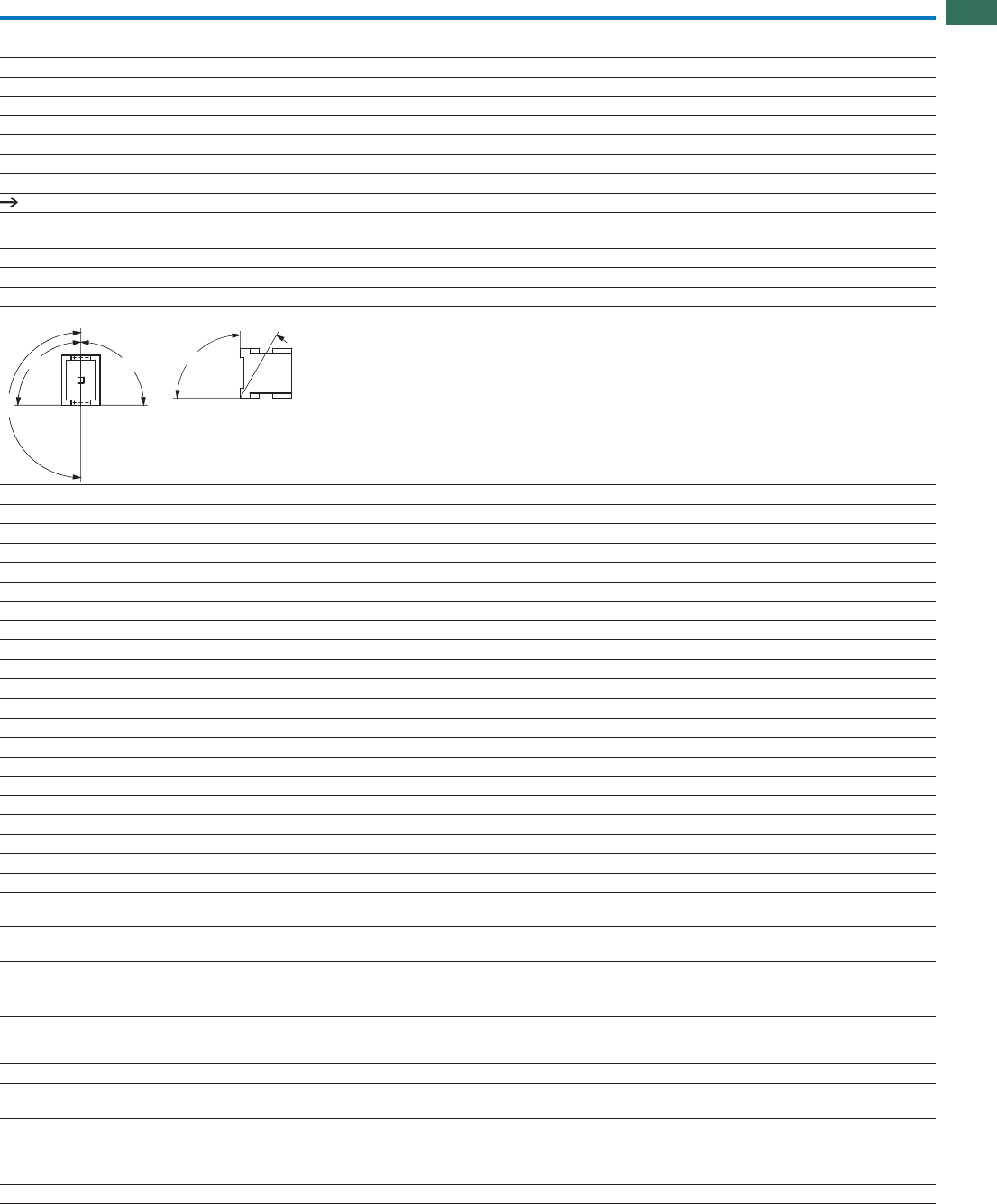
1.1
Contactors
Basic devices up to 170 A
105AUTOMATION AND CONTROL www.eaton.com/seasia-electrical
1
DILM32 DILM38 DILM40 DILM50 DILM65 DILM72 DILM80 DILM95 DILM115 DILM150 DILM170
IEC/EN 60947, VDE 0660, UL, CSA
10 10 10 10 10 10 10 10 10 10 10
10 10 10 10 10 10 10 10 10 10 10
5000 5000 5000 5000 5000 5000 3600 3600 3600 3600 3000
5000 5000 5000 5000 5000 5000 3600 3600 3600 3600 3000
Characteristic curves Page 74
Damp heat, constant, to IEC 60068-2-78
Damp heat, cyclic, to IEC 60068-2-30
-25…60 -25…60 -25…60 -25…60 -25…60 -25…60 -25…60 -25…60 -25…60 -25…60 -25…60
-25…40 -25…40 -25…40 -25…40 -25…40 -25…40 -25…40 -25…40 -25…40 -25…40 -25…40
-40 - 80 -40 - 80 -40 - 80 -40 - 80 -40 - 80 -40 - 80 -40 - 80 -40 - 80 -40 - 80 -40 - 80 -40 - 80
10 10 10 10 10 10 10 10 10 10 10
77777777777
55555555555
6.9 6.9 10 10 10 10 10 10 10 10 10
5.35.3777777777
3.53.5555555555
IP00 IP00 IP00 IP00 IP00 IP00 IP00 IP00 IP00 IP00 IP00
Finger- and back-of-hand proof
0.42 0.42 0.9 0.9 0.9 0.9 2 2 2 2 2
0.48 0.48 1.1 1.1 1.1 1.1 2.1 2.1 2.1 2.1 2.1
1 x (0.75 - 16)
2 x (0.75 - 10)
1 x (0.75 - 16)
2 x (0.75 - 16)
–––––
1 x (0.75 - 16)
2 x (0.75 - 10)
1 x (0.75 - 35)
2 x (0.75 - 25)
1 x (10 - 95)
2 x (10 - 70)
1 x 16 1 x 16 1 x (16 - 50)
2 x (16 - 35)
1 x (16 - 95)
2 x (16 - 70)
18 - 6 18 - 6 12 - 2 12 - 2 12 - 2 12 - 2 8…3/0 8…3/0 8…3/0 8…3/0 8…3/0
– – 2 x (6 x 9 x 0.8) 2 x (6 x 16 x 0.8)
1 x (0.75 - 4)
2 x (0.75 - 4)
1 x (0.75 - 2.5)
2 x (0.75 - 2.5)
18 - 14 18 - 14 18 - 14 18 - 14 18 - 14 18 - 14 18 - 14 18 - 14 18 - 14 18 - 14 18 - 14
180°
90°
90°
90°
30°

1.1 Contactors
Basic devices up to 170 A
106 AUTOMATION AND CONTROL www.eaton.com/seasia-electrical
1DILM7 ... DILM170
DILM7 DILM9 DILM12 DILM15 DILM17 DILM25
General
Main cable connection screw/bolt M3.5 M3.5 M3.5 M3.5 M5 M5
NmTightening torque 1.2 1.2 1.2 1.2 3.2 3.2
Control circuit cable connection screw/bolt M3.5 M3.5 M3.5 M3.5 M3.5 M3.5
NmTightening torque 1.2 1.2 1.2 1.2 1.2 1.2
Tools
Main conductors
SizePozidriv screwdriver 2 2 2 2 2 2
mmSWInternal hexagon – – – – – –
mmFlat-blade screwdriver 0.8 x 5.5
1 x 6
0.8 x 5.5
1 x 6
0.8 x 5.5
1 x 6
0.8 x 5.5
1 x 6
0.8 x 5.5
1 x 6
0.8 x 5.5
1 x 6
Auxiliary conductors
SizePozidriv screwdriver 2 2 2 2 2 2
mmFlat-blade screwdriver 0.8 x 5.5
1 x 6
0.8 x 5.5
1 x 6
0.8 x 5.5
1 x 6
0.8 x 5.5
1 x 6
0.8 x 5.5
1 x 6
0.8 x 5.5
1 x 6
Terminal type spring-cage terminal
Terminal capacity of main cable
mm²Solid 1 x (0.75 - 2.5)
2 x (0.75 - 2.5)
––
mm²Flexible 1 x (0.75 - 2.5)
2 x (0.75 - 2.5) ––
mm²Flexible with ferrule 1 x (0.75 - 1.5)
2 x (0.75 - 1.5)
––
mm²Flexible without ferrule 1 x (0.75 - 2.5)
2 x (0.75 - 2.5)
––
AWGSolid or stranded 18 - 14 18 - 14 18 - 14 18 - 14 – –
Terminal capacity of control circuit cable
mm²Solid 1 x (0.75 - 2.5)
2 x (0.75 - 2.5)
mm²Flexible 1 x (0.75 - 2.5)
2 x (0.75 - 2.5)
mm²Flexible with ferrule 1 x (0.75 - 1.5)
2 x (0.75 - 1.5)
mm²Flexible without ferrule 1 x (0.75 - 2.5)
2 x (0.75 - 2.5) ––
AWGSolid or stranded 18 - 14 18 - 14 18 - 14 18 - 14 18 - 14 18 - 14
Tools
mmStrip length 10 10 10 10 10 10
mmScrewdriver blade width 3.5 3.5 3.5 3.5 3.5 3.5
Main contacts
URated impulse withstand voltage imp V AC 8000 8000 8000 8000 8000 8000
Overvoltage category/pollution degree III/3 III/3 III/3 III/3 III/3 III/3
URated insulation voltage iV AC 690 690 690 690 690 690
URated operating voltage eV AC 690 690 690 690 690 690
Safe isolation according to EN 61140
V ACBetween coil and contacts 400 400 400 400 440 440
V ACBetween the contacts 400 400 400 400 440 440
Making capacity (cos to IEC/EN 60947) To 690 V A 112 112 144 155 238 350
Breaking capacity
A230 V 70 90 120 124 170 250
A280/400 V 70 90 120 124 170 250
A500 V 50 70 100 100 170 250
A660/690 V 40 50 70 70 120 150
Short-circuit rating
Short-circuit protection rating maximum fuse
Type “2” coordination
400 V gG/gL 500 V A 20 20 20 20 35 35
690 V gG/gL 690 V A 16 16 20 20 35 35
Type “1” coordination
400 V gG/gL 500 V A 35 35 35 63 63 100
690 V gG/gL 690 V A 20 20 25 50 50 50

1.1
Contactors
Basic devices up to 170 A
107AUTOMATION AND CONTROL www.eaton.com/seasia-electrical
1
DILM32 DILM38 DILM40 DILM50 DILM65 DILM72 DILM80 DILM95 DILM115 DILM150 DILM170
M5 M5 M6 M6 M6 M6 M10 M10 M10 M10 M10
3.2 3.2 3.3 3.3 3.3 3.3 14 14 14 14 14
M3.5 M3.5 M3.5 M3.5 M3.5 M3.5 M3.5 M3.5 M3.5 M3.5 M3.5
1.2 1.2 1.2 1.2 1.2 1.2 1.2 1.2 1.2 1.2 1.2
222222–––––
––––––55555
0.8 x 5.5
1 x 6
0.8 x 5.5
1 x 6
0.8 x 5.5
1 x 6
0.8 x 5.5
1 x 6
0.8 x 5.5
1 x 6
0.8 x 5.5
1 x 6
–––––
22222222222
0.8 x 5.5
1 x 6
0.8 x 5.5
1 x 6
0.8 x 5.5
1 x 6
0.8 x 5.5
1 x 6
0.8 x 5.5
1 x 6
0.8 x 5.5
1 x 6
0.8 x 5.5
1 x 6
0.8 x 5.5
1 x 6
0.8 x 5.5
1 x 6
0.8 x 5.5
1 x 6
0.8 x 5.5
1 x 6
–––––––––––
–––––––––––
–––––––––––
–––––––––––
–––––––––––
1 x (0.75 - 2.5)
2 x (0.75 - 2.5)
1 x (0.75 - 2.5)
2 x (0.75 - 2.5)
1 x (0.75 - 1.5)
2 x (0.75 - 1.5)
–––––––––––
18 - 14 18 - 14 18 - 14 18 - 14 18 - 14 18 - 14 18 - 14 18 - 14 18 - 14 18 - 14 18 - 14
10 10 10 10 10 10 10 10 10 10 10
3.5 3.5 3.5 3.5 3.5 3.5 3.5 3.5 3.5 3.5 3.5
8000 8000 8000 8000 8000 8000 8000 8000 8000 8000 8000
III/3 III/3 III/3 III/3 III/3 III/3 III/3 III/3 III/3 III/3 III/3
690690690690690690690690690690690
690690690690690690690690690690690
440440440440440440690690690690690
440440440440440440690690690690690
384 384 560 700 910 910 1120 1330 1610 2100 2100
320 320 400 500 650 650 800 950 1150 1500 1500
320 320 400 500 650 650 800 950 1150 1500 1500
320 320 400 500 650 650 800 950 1150 1500 1500
180 180 250 320 370 370 650 800 1100 1200 1320
63 63 63 80 125 125 160 160 250 250 250
35 35 50 63 80 80 160 160 250 250 250
125125125160250250250250250250250
63 63 80 80 100 100 200 200 250 250 250

1.1 Contactors
Basic devices up to 170 A
108 AUTOMATION AND CONTROL www.eaton.com/seasia-electrical
1DILM7 ... DILM170
DILM7 DILM9 DILM12 DILM15 DILM17 DILM25
AC voltage
AC-1 operation
Conventional free air
thermal current
3 pole
50 - 60 Hz
Open A 22 22 22 22 40 45
at 50 °C th
at 50 °C th
A212121213843
at 55 °C th A212121213742
at 60 °C
I
I
I
Ith A202020203540
Enclosed Ith A181818183236
Conventional free air
thermal current 1 pole
IOpen th A5050505088100
Enclosed Ith A454545458090
AC-3 operation
Rated operational current
AC -3 open,
50 – 60 Hz, 3 pole
220/230 V IeA7 9 1215.51825
I240 V eA7 9 1215.51825
380/400 V eA7 9 1215.51825
I415 V eA7 9 1215.51825
I440 V eA7 9 1215.51825
I500 V eA5 7 1012.51825
660/690 V
I
IeA45791215
Rated operational power 220/230 V P kW
kW
kW
kW
2.2 2.5 3.5 4 5 7.5
kWP240 V 2.2 3 4 4.6 5.5 8.5
380/400 V 3 4 5.5 7.5 7.5 11
kWP415 V 4 5.5 7 8 10 14.5
kWP440 V 4.5 5.5 7.5 8.4 10.5 15.5
kWP500 V 3.5 4.5 7 7.5 12 17.5
660/690 V
P
P3.54.56.571114
AC-4 operation
Rated operational current
AC-4 open,
50 - 60 Hz, 3 pole
220/230 V eA56771013
I240 V eA56771013
380/400 V eA56771013
I415 V eA56771013
I440 V eA56771013
I500 V eA4.55661013
660/690 V
I
I
IeA44.555810
Rated operational powe 220/230 V P kW 1 1.5 2 2 2.5 3.5
kWP240 V 1.5 1.6 2.2 2.2 3 4
380/400 V 2.2 2.5 3 3 4.5 6
kWP415 V 2.3 2.8 3.4 3.4 5 6.5
kWP440 V 2.4 3 3.6 3.6 5.5 7
kWP500 V 2.5 2.8 3.5 3.5 6 8
660/690 V
PkW
P 2.9 3.6 4.4 4.4 6.5 8.5
DC voltage
Operations Switching of DC current Page 92
Rated operational current Ieopen
DC-1 operation I60 V eA202020203540
I110 V eA202020203540
I220 V eA151515153540
I440 V eA 1 1.3 1.3 1.3 2.9 2.9
DC-3 operation I660 V eA202020203535
I110 V eA202020203535
I220 V eA1.5 1.5 1.5 1.5 10 10
I440 V eA 0.2 0.2 0.2 0.2 0.6 0.6
DC-5 operation I60 V eA202020203535
I110 V eA202020203535
I220 V eA1.5 1.5 1.5 1.5 10 10
I440 V eA 0.2 0.2 0.2 0.2 0.6 0.6

1.1
Contactors
Basic devices up to 170 A
109AUTOMATION AND CONTROL www.eaton.com/seasia-electrical
1
DILM32 DILM38 DILM40 DILM50 DILM65 DILM72 DILM80 DILM95 DILM115 DILM150 DILM170
45 45 60 80 98 98 110 130 160 190 225
43 43 57 71 88 88 98 125 142 180 200
42 42 55 68 83 83 94 115 135 170 190
40 40 50 65 80 80 90 110 130 160 185
36 36 45 58 72 72 80 100 115 144 166
100100125162200200225275325400460
90 90 112 145 180 180 200 250 285 360 415
32 38 40 50 65 72 80 95 115 150 170
32 38 40 50 65 72 80 95 115 150 170
32 38 40 50 65 72 80 95 115 150 170
32 38 40 50 65 72 80 95 115 150 170
32 38 40 50 65 72 80 95 115 150 170
32 38 40 50 65 72 80 95 115 150 170
18 22.5 25 32 37 37 65 80 93 100 150
10 11 12.5 15.5 20 22 25 30 37 48 52
11 12 13.5 17 22 25 27.5 32 40 52 57
15 18.5 18.5 22 30 37 37 45 55 75 90
19 20 24 30 39 41 48 57 70 91 100
20 21 25 32 41 44 51 60 75 95 105
23 24 28 36 47 50 58 70 85 110 120
17 21 23 30 35 35 63 75 90 96 140
15 15 18 21 25 25 40 50 55 65 65
15 15 18 21 25 25 40 50 55 65 65
15 15 18 21 25 25 40 50 55 65 65
15 15 18 21 25 25 40 50 55 65 65
15 15 18 21 25 25 40 50 55 65 65
15 15 18 21 25 25 40 50 55 65 65
12 12 14 17 20 20 27 37 45 50 50
4456771216172020
4.5 4.5 5.5 6.5 7.5 7.5 13 17 19 22 22
7791012122026283333
7.5 7.5 9.5 11 13 13 24 30 33 39 39
8 8 10 12 14 14 25 32 35 41 41
9 9 11 13 16 16 29 36 40 47 47
10 10 12 14 17 17 26 35 43 48 48
40 40 50 60 72 72 110 110 160 160 160
40 40 50 50 72 72 110 110 160 160 160
40 40 45 45 65 65 70 70 90 90 90
2.9 2.9 2.9 2.9 2.9 2.9 4.5 4.5 4.5 4.5 4.5
40 40 50 60 72 72 110 110 160 160 160
40 40 50 50 72 72 110 110 160 160 160
25 25 25 25 35 35 35 35 40 40 40
0.6 0.6 0.6 0.6 0.6 0.6 1 1 1 1 1
40 40 50 60 72 72 110 110 160 160 160
40 40 50 50 72 72 110 110 160 160 160
10 10 25 25 35 35 35 35 40 40 40
0.6 0.6 0.6 0.6 0.6 0.6 1 1 1 1 1

1.1 Contactors
Basic devices up to 170 A
110 AUTOMATION AND CONTROL www.eaton.com/seasia-electrical
1DILM7 ... DILM170
DILM7 DILM9 DILM12 DILM15 DILM17 DILM25
Current heat loss (3 pole)
Current heat loss at Ith W 3 3 3 3 7.3 9.6
Current heat loss at I to AC-3/400 V
eW 0.37 0.6 1.1 1.8 1.9 3.8
mȍImpedance per pole 2.5 2.5 2.5 2.5 2 2
Magnet systems
Voltage tolerance
x UPick-upAC operated c0.8 - 1.1 0.8 - 1.1 0.8 - 1.1 0.8 - 1.1 0.8 - 1.1 0.8 - 1.1
x UDrop-outAC operated c0.3 - 0.6 0.3 - 0.6 0.3 - 0.6 0.3 - 0.6 0.3 - 0.6 0.3 - 0.6
DC operated3) Pick-up x U
x U
c0.8 - 1.1 0.8 - 1.11) 0.8 - 1.11) 0.8 - 1.11) 0.7 - 1.22) 0.7 - 1.22)
DC operated3) Drop-out c0.15 - 0.6 0.15 - 0.6 0.15 - 0.6 0.15 - 0.6 0.15 - 0.6 0.15 - 0.6
Power consumption of the coil in a cold state and 1.0 x Uc
VAPick-up50 Hz 24 24 24 24 52 52
VASealing50 Hz 3.4 3.4 3.4 3.4 7.1 7.1
WSealing50 Hz 1.2 1.2 1.2 1.2 2.1 2.1
VAPick-up60 Hz 30 30 30 30 67 67
VASealing60 Hz 4.4 4.4 4.4 4.4 8.7 8.7
WSealing60 Hz 1.4 1.4 1.4 1.4 2.6 2.6
VAPick-up50/60 Hz 27
25
27
25
27
25
27
25
62
58
62
58
VASealing50/60 Hz 4.2
3.3
4.2
3.3
4.2
3.3
4.2
3.3
9.1
6.5
9.1
6.5
WSealing50/60 Hz 1.4
1.2
1.4
1.2
1.4
1.2
1.4
1.2
2.5
2
2.5
2
WPick-upDC operated 3 3 4.5 4.5 12 12
WSealingDC operated 3 3 4.5 4.5 0.5 0.5
% DFDuty factor 100 100 100 100 100 100
Changeover times at 100 % U (recommended values)
c
Main contacts
AC operated Closing delay ms
ms
ms
ms
15…21 15…21 15…21 15…21 16…22 16…22
Opening delay 9…18 9…18 9…18 9…18 8…14 8…14
DC operated Closing delay 31 31 31 31 47 47
Opening delay 12 12 12 12 30 30
msArcing time 10 10 10 10 10 10
Permissible residual current when A1 - A2 are
actuated from the electronic system (with 0 signal)
mA – – – – – –
Lifespan, mechanical; Coil 50/60 Hz At 50 Hz Mechanical lifespan at 50 Hz approx. 30% lower than under Technical data general
Electromagnetic compatibility (EMC)
Emitted interference To EN 60947-1
Interference immunity To EN 60947-1
Notes 1) At 24 V DC: 0.7 – 1.3 without auxiliary contact module and at ambient temperature + 40 °C
2) RDC 24 (Umin 24 V DC/Umax 27 V DC)
RDC 60 (Umin 48 V DC/Umax 60 V DC)
RDC 130 (Umin 110 V DC/Umax 130 V DC)
RDC 240 (Umin 200 V DC/Umax 240 V DC)
Example: Uc = 0.7 x Umin - 1.2 x Umax / Uc = 0.7 x 24 V - 1.2 x 27 V DC
3) At least: smoothed two-phase bridge rectifier or three-phase rectifier

1.1
Contactors
Basic devices up to 170 A
111AUTOMATION AND CONTROL www.eaton.com/seasia-electrical
1
DILM32 DILM38 DILM40 DILM50 DILM65 DILM72 DILM80 DILM95 DILM115 DILM150 DILM170
12.1 12.1 11.3 19 28.8 28.8 12.2 18.2 20.3 30.7 41.1
6.1 6.1 7.2 11.3 19 23 9.6 13.5 15.9 27 34.7
2 2 1.51.51.51.50.50.50.40.40.4
0.8 - 1.1 0.8 - 1.1 0.8 - 1.1 0.8 - 1.1 0.8 - 1.1 0.8 - 1.1 0.8 - 1.1 0.8 - 1.1 0.8 - 1.15 0.8 - 1.15 0.8 - 1.15
0.3 - 0.6 0.3 - 0.6 0.3 - 0.6 0.3 - 0.6 0.3 - 0.6 0.3 - 0.6 0.3 - 0.6 0.3 - 0.6 0.25 - 0.6 0.25 - 0.6 0.25 - 0.6
0.7 - 1.22) 0.7 - 1.22) 0.7 - 1.22) 0.7 - 1.22) 0.7 - 1.22) 0.7 - 1.22) 0.7 - 1.22) 0.7 - 1.22) 0.7 - 1.22) 0.7 - 1.22) 0.7 - 1.22)
0.15 - 0.6 0.15 - 0.6 0.15 - 0.6 0.15 - 0.6 0.15 - 0.6 0.15 - 0.6 0.15 - 0.6 0.15 - 0.6 0.15 - 0.6 0.15 - 0.6 0.15 - 0.6
52 52 149 149 149 149 310 310 180 180 180
7.1 7.1 16 16 16 16 26 26 3.1 3.1 3.1
2.1 2.1 4.3 4.3 4.3 4.3 5.8 5.8 2.1 2.1 2.1
67 67 178 178 178 178 345 345 170 170 170
8.7 8.7 19 19 19 19 30 30 3.1 3.1 3.1
2.6 2.6 5.3 5.3 5.3 5.3 7.1 7.1 2.1 2.1 2.1
62
58
62
58
168
154
168
154
168
154
168
154
372
328
372
328
170
170
170
170
170
170
9.1
6.5
9.1
6.5
22
14
22
14
22
14
22
14
37.1
22.6
37.1
22.6
3.1
3.1
3.1
3.1
3.1
3.1
2.5
2
2.5
2
5.3
4.3
5.3
4.3
5.3
4.3
5.3
4.3
7.5
6.1
7.5
6.1
2.1
2.1
2.1
2.1
2.1
2.1
12 12 24 24 24 24 90 90 149 149 149
0.5 0.5 0.5 0.5 0.5 0.5 1.3 1.3 2.1 2.1 2.1
100 100 100 100 100 100 100 100 100 100 100
16…22 16…22 12…18 12…18 12…18 12…18 14…20 14…20 28…33 28…33 28…33
8…14 8…14 8…13 8…13 8…13 8…13 9…14 9…14 35…41 35…41 35…41
47 47 54 54 54 54 45 45 35 35 35
30 30 24 24 24 24 34 34 30 30 30
10 10 10 10 10 10 15 15 15 15 15
–––––– 1 1 1 1
Mechanical lifespan at 50 Hz approx. 30% lower than under Technical data general
To EN 60947-1
To EN 60947-1
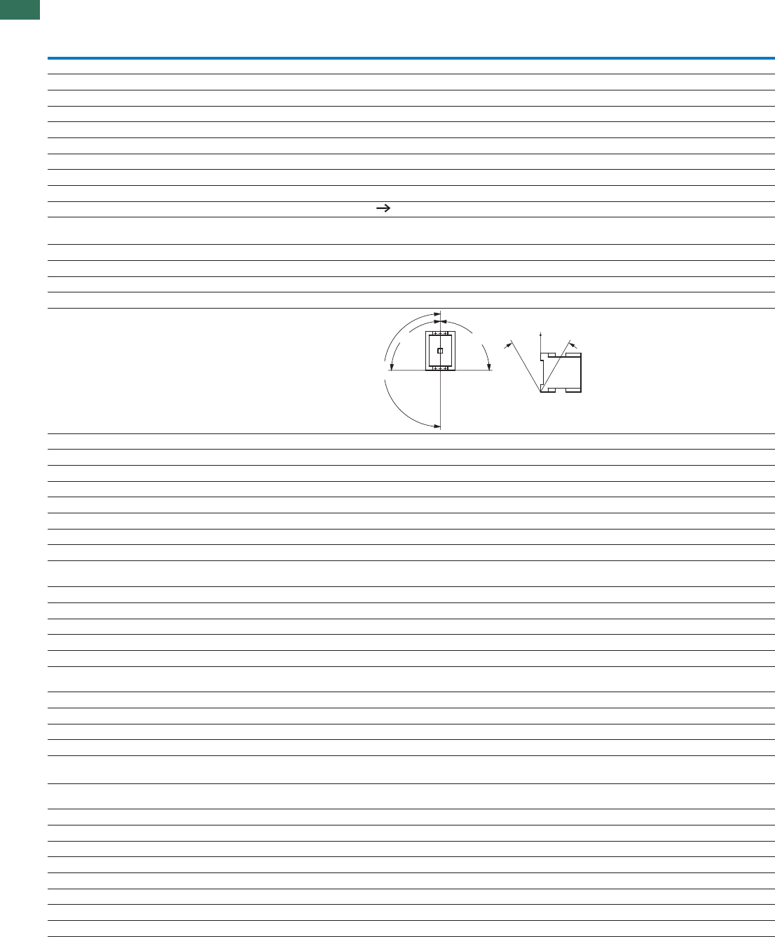
1.1 Contactors
Comfort devices and standard devices greater than 170 A
112 AUTOMATION AND CONTROL www.eaton.com/seasia-electrical
1
Contactors
DILM185A DILM225A DILM250 DILM300A DILM400 DILM500 DILM570
General
Standards IEC/EN 60947, VDE 0660, UL, CSA
Lifespan, mechanical
x 10c (contacts)AC operated 610 10 10 10 7 7 7
x 10c (contacts)DC operated 610 10 10 10 7 7 7
Operating frequency, mechanical
Operations/hAC operated 3000 3000 3000 3000 2000 2000 2000
Operations/hDC operated 3000 3000 3000 3000 2000 2000 2000
Maximum operating frequency
Electrical (Contactor without overload relay) Engineering Page 91
Climatic proofing Damp heat, constant, to IEC 60068-2-78
Damp heat, cyclic, to IEC 60068-2-30
Ambient temperature
°COpen -25…60 -25…60 -25…60 -25…60 -25…60 -25…60 -25…60
°CEnc losed -25…40 -25…40 -25…40 -25…40 -25…40 -25…40 -25…40
°CStorage -40 - 80 -40 - 80 -40 - 80 -40 - 80 -40 - 80 -40 - 80 -40 - 80
Mounting position: AC and DC-actuated
Mechanical shock resistance (IEC/EN 60068-2-27)
Half-sinusoidal shock 10 ms
Main contacts
gN/O 10 10 10 10 10 10 10
Auxiliary contacts
gN/O 10 10 10 10 10 10 10
gNC 8888888
Protection type IP00 IP00 IP00 IP00 IP00 IP00 IP00
Protection against direct contact when actuated
from front (EN 90274)
Finger- and back-of-hand proof with cover or terminal block
Weight
kgWeight 3.2 3.2 6.5 6.5 8 8 8
Terminal capacity of main cable
mm²Flexible with cable lug 50 - 185 50 - 185 50 - 240 50 - 240 50 - 240 50 - 240 50 - 240
mm²Stranded with cable lug 50 - 185 70 - 185 70 - 240 70 - 240 70 - 240 70 - 240 70 - 240
AWGSolid or stranded 1/0 - 350
MCM
2/0 - 250
MCM
2/0 - 500
MCM
2/0 - 500
MCM
2/0 - 500
MCM
2/0 - 500
MCM
2/0 - 500
MCM
mmWidthBusbar 32 32 25 25 25 30 30
Main cable connection screw/bolt M10 M10 M10 M10 M10 M10 M10
NmTightening torque 24 24 24 24 24 24 24
Terminal capacity of control circuit cable
mm²Solid 1 x (0.75 - 2.5)
2 x (0.75 - 2.5)
mm²Flexible with ferrule 1 x (0.75 - 2.5)
2 x (0.75 - 2.5)
AWGSolid or stranded 2 x (18 - 12) 2 x (18 - 12) 2 x (18 - 12) 2 x (18 - 12) 2 x (18 - 12) 2 x (18 - 12) 2 x (18 - 12)
Control circuit cable connection screw/bolt M3.5 M3.5 M3.5 M3.5 M3.5 M3.5 M3.5
NmTightening torque 1.2 1.2 1.2 1.2 1.2 1.2 1.2
Tools
Main conductors
mmWrench 16 16 16 16 16 16 16
Auxiliary conductors
SizePozidriv screwdriver 2 2 2 2222
180°
90°
90°
30
°
30
°
DILM185...DILM1600, DILH
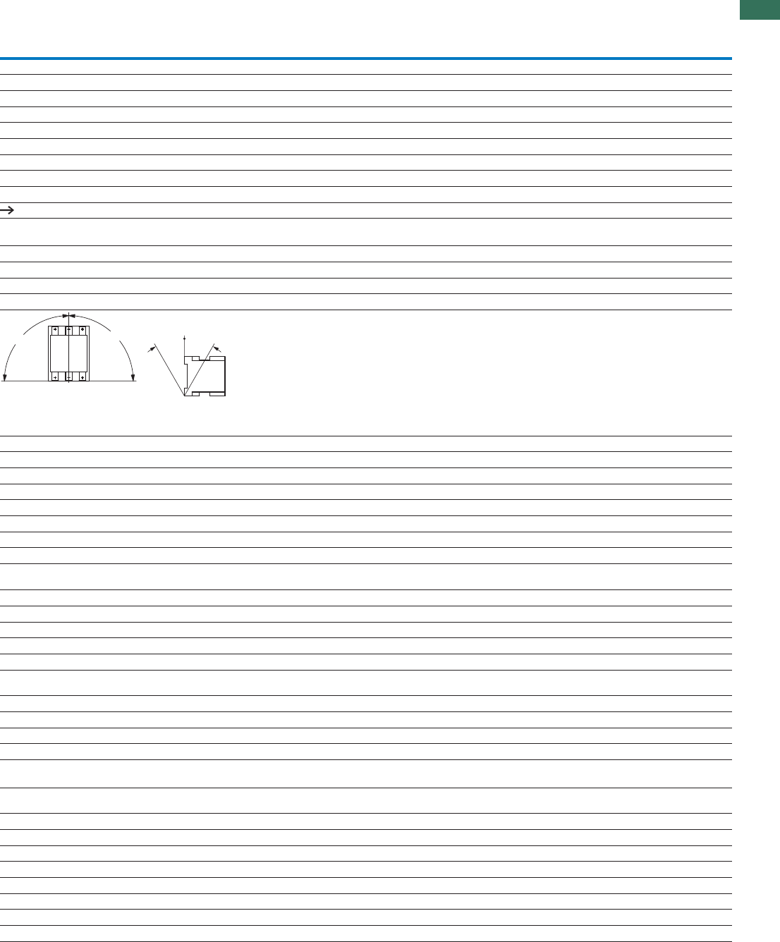
1.1
Contactors
Comfort devices and standard devices greater than 170 A
113AUTOMATION AND CONTROL www.eaton.com/seasia-electrical
1
DILM580 DILM650 DILM750 DILM820 DILM1000 DILM1600 DILH1400 DILH2000 DILH2200 DILH2600
IEC/EN 60947, VDE 0660, UL, CSA
5555555555
5555555555
1000 1000 1000 1000 1000 1000 1000 1000 1000 1000
1000 1000 1000 1000 1000 1000 1000 1000 1000 1000
Engineering Page 91
Damp heat, constant, to IEC 60068-2-78
Damp heat, cyclic, to IEC 60068-2-30
-25…60 -25…60 -25…60 -25…60 -25…60 -25…60 -25…60 -25…60 -25…60 -25…60
-25…40 -25…40 -25…40 -25…40 -25…40 -25…40 -25…40 -25…40 -25…40 -25…40
-40 - 80 -40 - 80 -40 - 80 -40 - 80 -40 - 80 -40 - 80 -40 - 80 -40 - 80 -40 - 80 -40 - 80
10 10 10 10 10 10 10 10 10 10
10 10 10 10 10 10 10 10 10 10
8888888888
IP00 IP00 IP00 IP00 IP00 IP00 IP00 IP00 IP00 IP00
Finger- and back-of-hand proof with cover or terminal block
15 15 15 15 15 32 15 32 32 32
50 - 240 50 - 240 50 - 240 50 - 240 50 - 240 – – – – –
70 - 240 70 - 240 70 - 240 70 - 240 70 - 240 – – – – –
2/0 - 500 MCM 2/0 - 500 MCM 2/0 - 500 MCM 2/0 - 500 MCM 2/0 - 500 MCM – – – – –
50 50 60 60 60 100 80 100 100 100
M10 M10 M12 M12 M12 M12 M12 M12 M12 M12
24 24 35 35 35 35 35 35 35 35
1 x (0.75 - 2.5)
2 x (0.75 - 2.5)
1 x (0.75 - 2.5)
2 x (0.75 - 2.5)
2 x (18 - 12) 2 x (18 - 12) 2 x (18 - 12) 2 x (18 - 12) 2 x (18 - 12) 2 x (18…12) 2 x (18 - 12) 2 x (18 - 12) 2 x (18 - 12) 2 x (18 - 12)
M3.5 M3.5 M3.5 M3.5 M3.5 M3.5 M3.5 M3.5 M3.5 M3.5
1.2 1.2 1.2 1.2 1.2 1.2 1.2 1.2 1.2 1.2
16 16 18 18 18 18 18 18 18 18
2222222222
90°
90°
30
°
30
°

1.1 Contactors
Comfort devices and standard devices greater than 170 A
114 AUTOMATION AND CONTROL www.eaton.com/seasia-electrical
1DILM185...DILM1600, DILH
Main contacts
Rated impulse withstand voltage imp V AC 8000 8000 8000 8000 8000 8000 8000
Overvoltage category/pollution degree III/3 III/3 III/3 III/3 III/3 III/3 III/3
Rated insulation voltage U
U
iV AC 1000 1000 1000 1000 1000 1000 1000
URated operating voltage eV AC 1000 1000 1000 1000 1000 1000 1000
Safe isolation according to EN 61140
V ACBetween coil and contacts 500 500 500 500 500 500 500
V ACBetween the contacts 500 500 500 500 500 500 500
Making capacity (cos to IEC/EN 60947) A 2700 2700 3000 3600 5500 5500 6000
Breaking capacity
A220/230 V 2250 2250 2500 3000 5000 5000 5800
A380/440 V 2250 2250 2500 3000 5000 5000 5800
A500 V 2250 2250 2500 3000 5000 5000 5800
A660/690 V 2250 2250 2500 3000 5000 5000 5800
A1000 V 760 760 760 950 950 950 950
Component lifespan Page 87
Short-circuit rating
Short-circuit protection rating maximum fuse
Type “2” coordination
AgG/gL 500 V400 V 250 250 315 315 500 500 500
AgG/gL 690 V690 V 250 250 315 315 500 500 500
AgG/gL 1000 V1000 V 160 160 160 160 200 200 200
Type “1” coordination
AgG/gL 500 V400 V 400 400 400 400 630 630 800
AgG/gL 690 V690 V 315 315 400 400 630 630 630
AgG/gL 1000 V1000 V 200 200 200 200 250 250 250
AC voltage
AC-1 operation
Conventional thermal current 3 pole 50 - 60 Hz
Open
Iat 40 °C th A337356400430612857920
Iat 50 °C th A301310360385548767821
Iat 55 °C th A287295340365522731783
Iat 60 °C th A275285330350500700750
Enclosed1) Ith A245275300315450650–
Conventional thermal current, 1-pole
Open1) Ith A 685 707 825 875 1250 1750 1875
Enclosed1) Ith A 625 636 742 785 1125 1600 –
AC-3 operation
Rated operational current AC -3 open, 50 – 60 Hz, 3 pole
I220/230 V eA185225250300400500580
I240 V eA185225250300400500580
I380/400 V eA185225250300400500580
I415 V eA185225250300400500580
I440 V eA185225250300400500580
I500 V eA185225250300400500500
I660/690 V eA150160250210360360360
I1000 V eA76767695959595
Rated operational power
kWP220/230 V 55 70 75 90 125 155 185
kWP240 V 62 75 85 100 132 170 200
kWP380/400 V 90 110 132 160 200 250 315
kWP415 V 110 132 148 180 240 300 348
kWP440 V 115 138 132 185 200 250 370
kWP500 V 132 160 180 215 290 360 360
kWP660/690 V 140 150 240 195 344 344 344
kWP1000 V 108 108 108 132 132 132 132
Notes 1) At maximum permissible ambient air temperature
2) To 690 V
Contactors
DILM185A DILM225A DILM250 DILM300A DILM400 DILM500 DILM570

1.1
Contactors
Comfort devices and standard devices greater than 170 A
115AUTOMATION AND CONTROL www.eaton.com/seasia-electrical
1
8000 8000 8000 8000 8000 8000 8000 8000 8000 8000
III/3 III/3 III/3 III/3 III/3 III/3 III/3 III/3 III/3 III/3
1000 1000 1000 1000 1000 1000 1000 1000 1000 1000
1000 1000 1000 1000 1000 1000 1000 1000 1000 1000
500 500 500 500 500 500 500 500 500 500
500 500 500 500 500 500 500 500 500 500
7800 7800 9840 9840 9840 19000 9840 9840 9840 9840
6500 6500 8200 8200 8200 16000 8200 8200 8200 8200
6500 6500 8200 8200 8200 16000 8200 8200 8200 8200
6500 6500 8200 8200 8200 16000 8200 8200 8200 8200
6500 6500 8200 8200 8200 16000 8200 8200 8200 8200
4350 4350 5800 5800 5800 5800 5800 5800 5800 5800
Page 87
630 630 630 630 630 – – – – –
630 630 630 630 630 – – – – –
500 500 630 630 630 – – – – –
1000 1000 1200 1200 1200 – – – – –
1000 1000 1200 1200 1200 – – – – –
630 630 800 800 800 – – – – –
980 1041 1102 1225 1225 22002) 17142) 24502) 27002) 3185 2)
876 931 986 1095 1095 1970 2) 1533 2) 21902) 24002) 28472)
836 888 940 1044 1044 1880 2) 1462 2) 20892) 23002) 27162)
800 850 900 1000 1000 1800 2) 1400 2) 20002) 22002) 26002)
––––––––––
2000 2125 2250 2500 2500 4500 3500 5000 5500 6500 2)
––––––––––
580 650 750 820 1000 1600 – – – –
580 650 750 820 1000 1600 – – – –
580 650 750 820 1000 1600 – – – –
580 650 750 820 1000 1600 – – – –
580 650 750 820 1000 1600 – – – –
580 650 750 820 1000 1600 – – – –
580 650 750 820 1000 1600 – – – –
435 435 580 580 750 1200 – – – –
185 205 240 260 315 500 – – – –
200 225 260 285 340 550 – – – –
315 355 400 450 560 900 – – – –
348 390 455 500 610 930 – – – –
370 420 480 450 650 1000 – – – –
420 470 550 600 730 1180 – – – –
560 630 720 750 1000 1600 – – – –
600 600 800 800 1100 1770 – – – –
DILM580 DILM650 DILM750 DILM820 DILM1000 DILM1600 DILH1400 DILH2000 DILH2200 DILH2600

1.1 Contactors
Comfort devices and standard devices greater than 170 A
116 AUTOMATION AND CONTROL www.eaton.com/seasia-electrical
1DILM185...DILM1600, DILH
AC voltage
AC-4 operation
Rated operational current AC -4 open, 50 – 60 Hz, 3 pole
I220/230 V eA136164200240296360360
I240 V eA136164200240296360360
I380/400 V eA136164200240296360360
I415 V eA136164200240296360360
I440 V eA136164200240296360360
I500 V eA136164200240296360360
I660/690 V eA110120200170296296296
I1000 V eA55557676959595
Rated operational power
kWP220/230 V 41 51 62 75 92 112 112
kWP240 V 45 54 68 82 101 122 122
kWP380/400 V 75 90 110 132 160 200 200
kWP415 V 80 96 117 142 176 216 216
kWP440 V 85 102 125 150 186 229 229
kWP500 V 96 116 143 172 214 260 260
kWP660/690 V 102 110 189 160 283 344 344
kWP1000 V 77 77 108 109 132 132 132
Capacitor operation
Individual compensation rated operational
current Ie of alternating current capacitor
Open
ATo 525 V 220 220 220 307 307 307 307
A690 V 133 133 133 177 177 177 177
x IMax. peak inrush current e30 30 30 30 30 30 30
x 10c (contacts)Component lifespan 60.1 0.1 0.1 0.1 0.1 0.1 0.1
Ops/hMax. operating frequency 200 200 200 200 200 200 200
DC voltage
Operations Engineering Page 92
Rated operational current Ie open
DC-1 operation
I60 V eA300300300400400400400
I110 V eA300300300400400400400
I220 V eA300300300400400400400
I440 V eA11111111111111
DC-3 operation
I60 V eA300300300400400400400
I110 V eA300300300400400400400
I220 V eA300300300400400400400
DC-5 operation
I60 V eA300300300400400400400
I110 V eA300300300400400400400
I220 V eA300300300400400400400
Current heat loss (3 pole)
Current heat loss at Ith W3445553758113130
Current heat loss at I to AC-3/400 V
eW16232821375878
Contactors
DILM185A DILM225A DILM250 DILM300A DILM400 DILM500 DILM570

1.1
Contactors
Comfort devices and standard devices greater than 170 A
117AUTOMATION AND CONTROL www.eaton.com/seasia-electrical
1
456 512 576 656 800 1280 – – – –
456 512 576 656 800 1280 – – – –
456 512 576 656 800 1280 – – – –
456 512 576 656 800 1280 – – – –
456 512 576 656 800 1280 – – – –
456 512 576 656 800 1280 – – – –
456 512 576 656 800 1280 – – – –
348 348 464 464 700 1120 – – – –
143 161 181 209 260 430 – – – –
156 176 200 228 280 450 – – – –
250 280 315 355 450 750 – – – –
274 307 346 394 490 770 – – – –
290 326 367 418 520 830 – – – –
330 370 417 474 590 940 – – – –
440 494 556 633 780 1300 – – – –
509 509 678 678 1000 1650 – – – –
463 463 463 463 463 – – – – –
265 265 265 265 265 – – – – –
30 30 30 30 30 – – – – –
0.1 0.1 0.1 0.1 0.1 – – – – –
200 200 200 200 200 – – – – –
–
––––––––––
––––––––––
––––––––––
––––––––––
––––––––––
––––––––––
––––––––––
––––––––––
––––––––––
––––––––––
61 69 78 96 96 155 188 192 232 250
32 41 54 65 96 123 – – – –
DILM580 DILM650 DILM750 DILM820 DILM1000 DILM1600 DILH1400 DILH2000 DILH2200 DILH2600

1.1 Contactors
Comfort devices and standard devices greater than 170 A
118 AUTOMATION AND CONTROL www.eaton.com/seasia-electrical
1
DILM185...DILM1600, DILH
Magnet systems
Voltage tolerance1) AC operated Pick-up x U
c
0.8 - 1.15 0.8 - 1.15
AC operated Drop-out
c
0.25 - 0.6 0.25 - 0.6
DC operated Pick-up
c
0.7 - 1.2 0.7 - 1.2
DC operated Drop-out
x U
x U
x U
c
0.15 - 0.6 0.15 - 0.6
Power consumption of the
coil in a cold state and
1.0 x Uc
50/60 Hz Pick-up VA
VA
210210–––––
50/60 Hz Sealing 2.6 2.6 – ––––
50/60 Hz Sealing 2.6 2.6 – ––––
DC operated Pick-up 180 180 – ––––
DC operated Sealing
W
W
W2.12.1–––––
Voltage tolerance Comfort series
DILM…
Pick-up c––0.7 x U
c min - 1.15 x U c max
Standard range
DILM…-S
Pick-up c––0.85 x U
c min - 1.1 x U c max
Comfort series
DILM…
Drop-out c––0.2 x U
c min - 0.6 x Uc min
Standard range
DILM…-S
Drop-out
x U
x U
x U
x Uc––0.2 x U
c min - 0.4 x Uc min
Power consumption of the
coil in a cold state and
1.0 x Uc
Comfort series
DILM…
Pick-up – – 380 2) 3802) 4502) 450 2) 4502)
Comfort series
DILM…
Pick-up – – 250 250 350 350 350
Comfort series
DILM… Sealing
VA
VA – – 4.3 4.3 4.3 4.3 4.3
Comfort series
DILM…
Sealing
W
W – – 3.3 3.3 3.3 3.3 3.3
Standard range
DILM…-S
Pick-up – – 360 4) 3604) 7154) 715 4) 7154)
Standard range
DILM…-S Pick-up – – 325 625 645 645 645
Standard range
DILM…-S
Sealing
VA
VA – – 4.3 4.3 4.3 4.3 4.3
Standard range
DILM…-S
Sealing
W
W – – 3.3 3.3 3.3 3.3 3.3
FD%rotcafytuD – – 100 100 100 100 100
Changeover time at 100 % Uc (recommended values), main circuit
Comfort series
DILM…
Closing delay – – < 100 < 80 < 80 < 80 < 80
Opening delay – – < 110 < 110 < 110 < 110 < 110
Standard range
DILM…-S Closing delay < 60 < 60 < 55 < 55 < 55 < 55 < 55
Opening delay
ms
ms
ms
ms < 40 < 40 < 40 < 40 < 50 < 50 < 50
Behavior in limit range and transition area, hold state
Voltage interruption (0 - 0.2 x Uc min ) 10 ms – – Targeted bridging during this time
(0 - 0.2 x Uc min ) > 10 ms Drop-out of the contactor
Voltage drops (0 - 0.2 x Uc min ) 12 ms Targeted bridging during this time
(0.2 - 0.6 x Uc min ) > 12 ms Drop-out of the contactor
(0.6 - 0.7 x Uc min )Contactor remains switched on
Excess voltage (1.15 - 1.3 x Uc max )Contactor remains switched on
(> 1.3 x Uc max ) 3 s Contactor remains switched on
(> 1.3 x Uc max ) > 3 s Drop-out of the contactor
Pick-up phase (0.7 x Uc min )Contactor does not switch on
(0.7 x Uc min - 1.15 x Uc max )Contactor switches on safely
(> 1.15 x Uc max )Contactor switches on safely
Permissible transitional contact resistance
(of external control unit when A11 is actuated)
mȍ–– 500 500 500 500 –
Permissible residual current ( when A11 is
actuated from the electronic system in the event
of a 0 signal)
mA – – 1 1 1 1–
PLC signal level (A3 - A4) to IEC/EN 61131-2 (part no. 2)
VhgiH 151515151515–
VwoL 555555–
Electromagnetic compatibility (EMC)
Electromagnetic compatibility This product is designed for operation in industrial environments (environment 2).
The use in residential environments (environment 1) could cause electrical interference so
that addition suppression must be planned.
Notes 1) U min, U max,
cc
2) Control transformer with uk 0.6
3) Control transformer with uk 0.7
4) uk 10 %
Contactors
DILM185A DILM225A DILM250 DILM300A DILM400 DILM500 DILM570

1.1
Contactors
Comfort devices and standard devices greater than 170 A
119AUTOMATION AND CONTROL www.eaton.com/seasia-electrical
1
––––––––––
––––––––––
––––––––––
––––––––––
––––––––––
0.7 x Uc min - 1.15 x U c max
0.85 x Uc min - 1.1 x U c max
0.2 x Uc min - 0.6 x U c min
0.2 x Uc min - 0.4 x U c min
8003) 8003) 8003) 8003) 8003) 16003) 8003) 16003) 16003) –
700 700 700 700 700 1400 700 1400 1400 –
7.5 7.5 7.5 7.5 7.5 15 7.5 15 15 –
6.5 6.5 6.5 6.5 6.5 13 6.5 13 13 –
––––––––––
––––––––––
––––––––––
––––––––––
100 100 100 100 100 100 100 100 100 100
< 70 < 70 < 70 < 70 < 70 < 70 < 70 < 70 < 70 –
< 110 < 110 < 110 < 110 < 110 < 40 < 40 < 40 < 40 –
––––––––––
––––––––––
Targeted bridging during this time
Drop-out of the contactor
Targeted bridging during this time
Drop-out of the contactor
Contactor remains switched on
Contactor remains switched on
Contactor remains switched on
Drop-out of the contactor
Contactor does not switch on
Contactor switches on safely
Contactor switches on safely
500 500 500 500 500 500 500 500 500 500
1 1 1 1 1 1 1 1 1 1
15 15 15 15 15 15 15 15 15 15
5555555555
This product is designed for operation in industrial environments (environment 2). The use in residential environments (environment 1) could cause electrical interference
so that addition suppression must be planned.
DILM580 DILM650 DILM750 DILM820 DILM1000 DILM1600 DILH1400 DILH2000 DILH2200 DILH2600
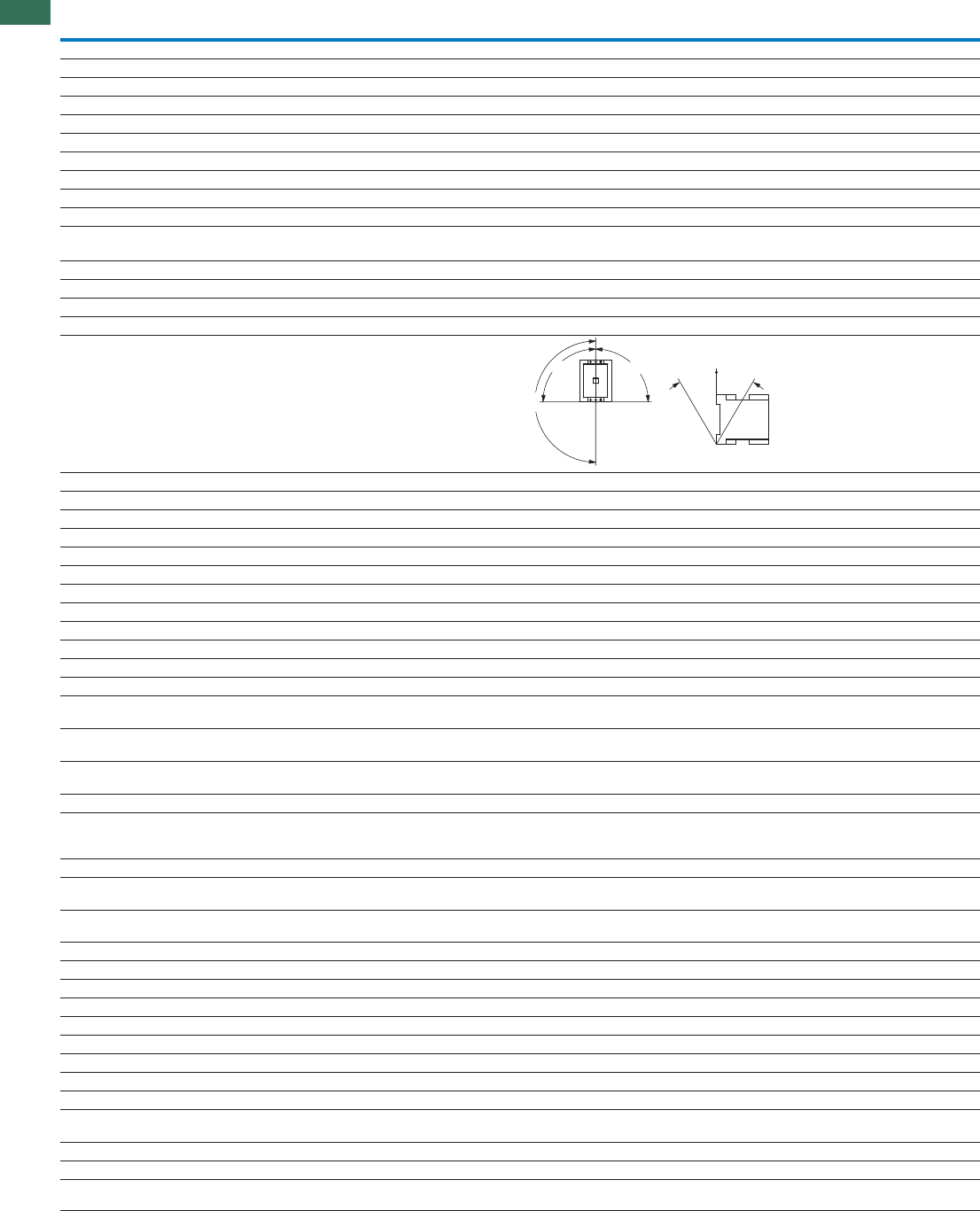
1.1 Contactors
Basic devices up to 200 A, 4 pole
120 AUTOMATION AND CONTROL www.eaton.com/seasia-electrical
1
DILMP20 DILMP32 DILMP63 DILMP125
DILMP45 DILMP80 DILMP160
DILMP200
General
Standards IEC/EN 60947, VDE 0660, UL, CSA
Lifespan, mechanical
x 10c (contacts)AC operated 610
x 10c (contacts)DC operated 610
Operating frequency, mechanical
Operations/hMechanical, AC operated 5000 3600
Operations/hDC operated 5000 3600
Maximum operating frequency
Electrical (Contactor without overload relay) 600
Climatic proofing Damp heat, constant, to IEC 60068-2-3
Damp heat, cyclic, to IEC 60068-2-30
Ambient temperature
°COpen -25…60
°CEnclosed -25…40
°CStorage -40 - 80
Mounting position AC- and DC operated
Mechanical shock resistance (IEC/EN 60068-2-27)
Half-sinusoidal shock 10 ms
Main contacts
gN/O 10
Auxiliary contacts
gN/O 7
gNC 5
Protection type IP20 IP00
With accessories – IP20
Protection against direct contact when actuated from front (EN 50274) Finger- and back-of-hand proof
Terminal type, screw connection
Terminal capacity of main cable
mm²Solid 1 x (0.75 - 4)
2 x (0.75 - 2.5)
1 x (0.75 - 16)
2 x (0.75 - 10)
1 x (2.5 - 16)
2 x (2.5 - 16)
–
mm²Flexible with ferrule 1 x (0.75 - 2.5)
2 x (0.75 - 2.5)
1 x (0.75 - 16)
2 x (0.75 - 10)
1 x (2.5 - 35)
2 x (2.5 - 25)
1 x (10 - 95)
2 x (10 - 70)
mm²Stranded – 1 x 16 1 x (16 - 50)
2 x (16 - 35)
1 x (16 - 120)
2 x (16 - 95)
AWGSolid or stranded 18 - 14 18 - 6 12 - 2 8 - 250MCM
Number ofFlat conductor
layers x width x
thickness
mm – – 2 x
(6 x 9 x 0.8)
2 x
(6 x 16 x 0.8)
Terminal capacity of control circuit cable
mm²Solid 1 x (0.75 - 4)
2 x (0.75 - 2.5)
1 x (0.75 - 4)
2 x (0.75 - 2.5)
1 x (0.75 - 4)
2 x (0.75 - 4)
1 x (0.75 - 4)
2 x (0.75 - 4)
mm²Flexible with ferrule 1 x (0.75 - 2.5)
2 x (0.75 - 2.5)
1 x (0.75 - 2.5)
2 x (0.75 - 2.5)
1 x (0.75 - 2.5)
2 x (0.75 - 2.5)
1 x (0.75 - 2.5)
2 x (0.75 - 2.5)
AWGSolid or stranded 18 - 14 18 - 14 18 - 14 18 - 14
Main cable connection screw/bolt M3.5 M5 M6 M10
NmTightening torque 1.2 3 3.3 14
Control circuit cable connection screw/bolt M3.5 M3.5 M3.5 M3.5
NmTightening torque 1.2 1.2 1.2 1.2
Tools
Main conductors
SizePozidriv screwdriver 2 2 2 –
mmSW
Internal hexagon – – – 5
mmFlat-blade screwdriver 0.8 x 5.5
1 x 6
0.8 x 5.5
1 x 6
0.8 x 5.5
1 x 6
–
Auxiliary conductors
SizePozidriv screwdriver 2 2 2 2
mmFlat-blade screwdriver 0.8 x 5.5
1 x 6
0.8 x 5.5
1 x 6
0.8 x 5.5
1 x 6
0.8 x 5.5
1 x 6
180°
90°
90°
30
°
30
°
DILMP20 ... DILMP200

1.1
Contactors
Basic devices up to 200 A, 4 pole
121AUTOMATION AND CONTROL www.eaton.com/seasia-electrical
1
Main contacts
Rated impulse withstand voltage Uimp V AC 8000
Overvoltage category/pollution degree III/3
URated insulation voltage iV AC 690
URated operating voltage eV AC 690
Safe isolation according to EN 61140
V ACBetween coil and contacts 400 440
V ACBetween the contacts 400 440
Making capacity (cos to IEC/EN 60947) To 690 V A 144 238 350 560 700 1120 1330 1800
Breaking capacity
A220/230 V 120 180 250 400 500 800 950 1150
A380/400 V 120 180 250 400 500 800 950 1150
A500 V 100 180 250 400 500 800 950 1150
A660/690 V 70 120 144 250 296 650 750 800
Short-circuit rating
Short-circuit protection rating maximum fuse
Type “2” coordination
AgG/gL 500 V400 V 20 35 35 63 80 160 160 250
AgG/gL 690 V690 V 20 35 35 50 63 160 160 200
Type “1” coordination
AgG/gL 500 V400 V 35 63 100 125 160 250 250 250
AgG/gL 690 V690 V 25 50 50 80 80 200 200 200
AC voltage
AC-1 operation
Conventional thermal current 3 pole 50 - 60 Hz
Open at 40 °C Ith A 22 32456380125160200
at 50 °C Ith A 21 30416076116150188
at 60 °C Ith A 20 28395469108138172
IEnclosed th A 18 27365064100128160
Conventional thermal current, 1 pole
IOpen th A 60 84 117 162 207 325 415 516
IEnclosed th A 54 76 105 146 186 292 373 464
Rated operational power
kWP220/230 V 8 12 16 23 29 45 58 72
kWP240 V 9 13 18 25 32 49 63 79
kWP380 V 14 20 28 39 50 78 100 125
kWP415 V 15 22 31 43 55 85 109 137
kWP440 V 16 23 33 46 58 90 116 145
kWP500 V 18 26 37 52 66 103 132 165
kWP690 V 24 35 49 68 87 136 174 217
AC-3 operation
Rated operational current AC -3 open, 50 – 60 Hz, 3 pole
I220/230 V eA 12 182540508095115
I240 V eA 12 182540508095115
I380/400 V eA 12 182540508095115
I415 V eA 12 182540508095115
I440 V eA 12 182540508095115
I500 V eA 10 182540508095115
I660/690 V eA 7 12 15 25 32 65 80 93
Rated operational power
kWP220/230 V 3.5 5 7.5 12.5 15.5 25 30 37
kWP240 V 4 5.5 8.5 13.5 17 27.5 33 40
kWP380/400 V 5.5 7.5 11 18.5 22 37 45 55
kWP415 V 7 10 14.5 24 30 48 57 70
kWP440 V 7.5 10.5 15.5 25 32 51 60 75
kWP500 V 7 12 17.5 28 36 58 70 85
kWP660/690 V 6.5 11 14 23 30 63 75 90
DILMP20 DILMP32 DILMP63 DILMP125
DILMP45 DILMP80 DILMP160
DILMP200
DILMP20 ... DILMP200

1.1 Contactors
Basic devices up to 200 A, 4 pole
122 AUTOMATION AND CONTROL www.eaton.com/seasia-electrical
1DILMP20 ... DILMP200
DILMP20 DILMP32 DILMP63 DILMP125
DILMP45 DILMP80 DILMP160
DILMP200
DC voltage
Rated operational current Ie open
DC-1 operation
I60 V eA 22 32456380125160200
I110 V eA 22 32456380125160200
I220 V eA 6 32 45 63 80 125 160 200
I440 V eA 1.3 3 3 5 5 10 10 10
DC-3 operation
I60 V eA 20 32456380125160200
I110 V eA 20 32456380125160200
I220 V eA 1.5 32 45 63 80 125 160 200
I440 V eA 0.2 6688999
DC-5 operation
I60 V eA 20 32456380125160200
I110 V eA 20 25325080125160200
I220 V eA 1.5 15 22 38 70 100 125 150
I440 V eA 0.2 4488888
Current heat loss (3 pole)
Current heat loss at Ith W 4.7 8.2 12 16 23 29 46 60
mȍImpedance per pole 2.5 2 1.5 1 0.7 0.6 0.6 0.5
Magnet systems
Voltage tolerance
x UPick-upAC operated 50 Hz c0.8 - 1.1 0.8 - 1.1 0.8 - 1.1 0.8 - 1.1
x UAC operated 50/60 Hz c0.8 - 1.1 0.85 - 1.1 0.85 - 1.1 0.8 - 1.1
x UDrop-outAC operated c0.4 - 0.6 0.4 - 0.6 0.4 - 0.6 0.4 - 0.6
DC operated1) Pick-up x Uc0.8 - 1.1 0.7 - 1.2 0.7 - 1.2 0.7 - 1.2
DC operated1) Drop-out x Uc0.2 - 0.6 0.2 - 0.6 0.2 - 0.6 0.2 - 0.6
Power consumption of the coil in a cold state and 1.0 x Uc
VAPick-upAC operated 50/60 Hz 24 50 150 180
WPick-upAC operated 50/60 Hz 19 40 95 150
VASealingAC operated 50/60 Hz 4 8 16 3.1
WSealingAC operated 50/60 Hz 1.2 2.4 4 2.1
DC operated1) Pick-up 4.5 12 24 149
DC operated1) Sealing
W
W 4.5 0.5 0.5 2.1
% DFDuty factor 100 100 100 100
Changeover times at 100 % Uc (recommended values)
Main contacts
AC operated
msClosing delay 15…21 16…22 12…18 28…33
msOpening delay 9…18 8…14 8…13 35…41
DC operated1)
msClosing delay 31 47 54 35
msOpening delay 12 30 24 30
msArcing time 10 10 10 15
Permissible residual current when A1 - A2 are
actuated from the electronic system (with 0 signal) mA 1 1 1 1
Notes 1) At least double-pulse bridge rectifier
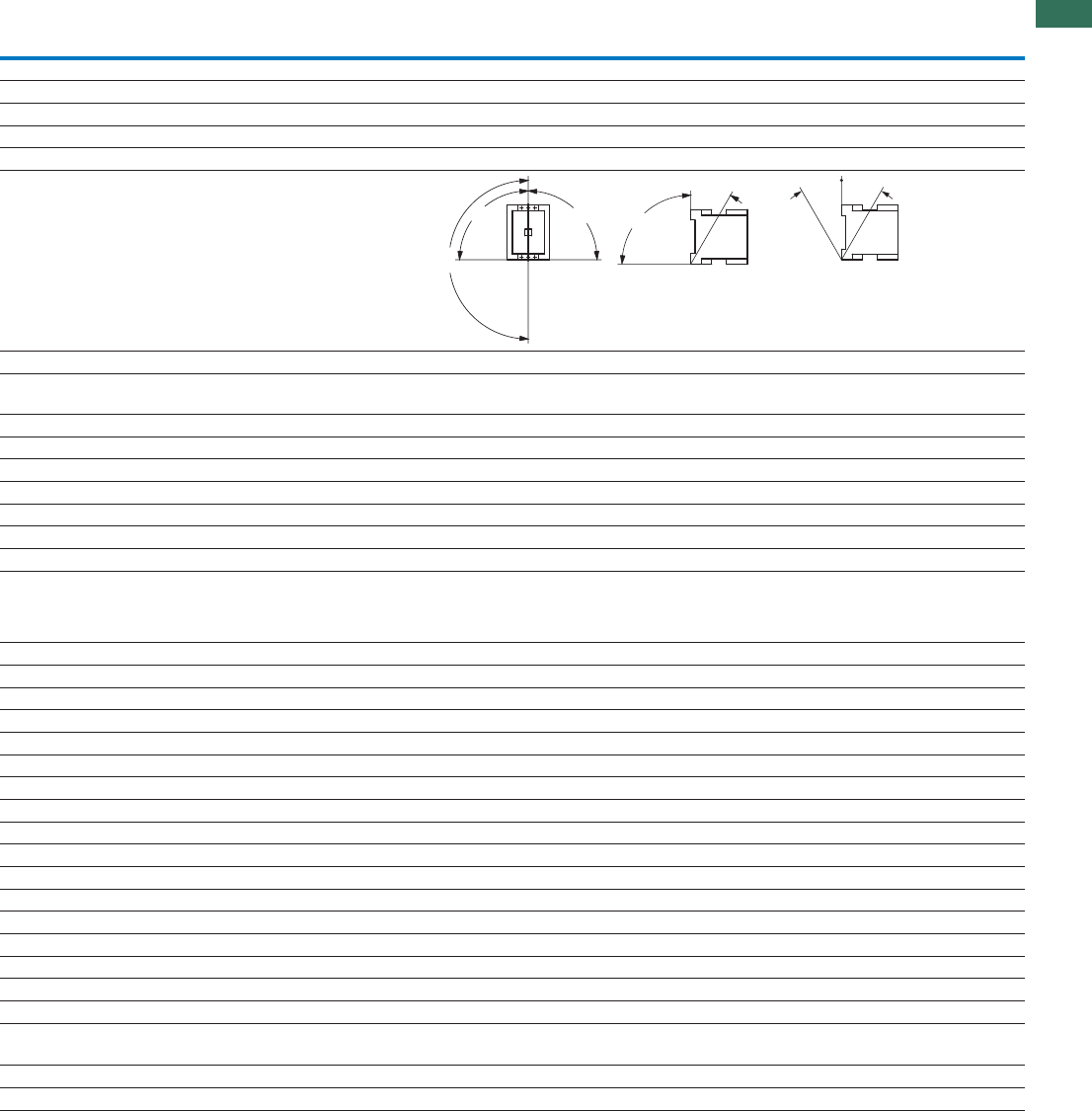
1.1
Contactors
Contactor for capacitors
123AUTOMATION AND CONTROL www.eaton.com/seasia-electrical
1
DILK12 DILK20 DILK25 DILK33 DILK50
General
Standards IEC/EN 60947, VDE 0660
Ambient temperature
°COpen -25…60 -25…60 -25…60 -25…60 -25…60
°CEnclosed -25…40 -25…40 -25…40 -25…40 -25…40
Mounting position
Protection type IP00 IP00 IP00 IP00 IP00
Protection against direct contact when
actuated from front (EN 50274)
Finger- and back-of-hand proof
Weight basic device
kgAC operated 0.55 0.55 0.55 1 1
Terminal capacity of main cable
mm²Solid 1 x (0.75 - 16) 1 x (0.75 - 16) 1 x (0.75 - 16) 1 x (2.5 - 16) 1 x (2.5 - 16)
mm²Flexible with ferrule 1 x (0.75 - 16) 1 x (0.75 - 16) 1 x (0.75 - 16) 1 x (2.5 - 35) 1 x (2.5 - 35)
mm²Stranded 1 x 16 1 x 16 1 x 16 1 x (16 - 50) 1 x (16 - 50)
AWGSolid or stranded 18 - 16 18 - 6 18 - 6 12 - 2 12 - 2
Number ofFlat conductor
layers x
width x
thickness
mm - - - 1 x (6 x 9 x 0.8) 1 x (6 x 9 x 0.8)
Group compensation
60 Hz
kvar230 V 7.5 11 15 20 25
kvar400 V 12.5 20 25 33.3 50
kvar525 V 16.7 25 33.3 40 65
kvar690 V 20 33.3 40 55 85
50/60 Hz
Open
I230 V eA1829385072
I400 V eA1829385072
I525 V eA1829385072
I690 V eA1829385072
Enclosed
I230 V eA1626344565
I400 V eA1626344565
I525 V eA1626344565
I690 V eA1626344565
Making capacity (i-peak value) without
damping
x Ie180 180 180 180 180
x 10c (contacts)Component lifespan 60.15 0.15 0.15 0.15 0.15
Ops/hMaximum operating frequency 120 120 120 120 120
180°
90°
90°
90°
30° 30°30°
DILK

1.1 Contactors
Contactor for capacitors
124 AUTOMATION AND CONTROL www.eaton.com/seasia-electrical
1
Magnet systems
Voltage tolerance
x UPick-upAC operated c0.8 - 1.1 0.8 - 1.1 0.8 - 1.1 0.8 - 1.15 0.8 - 1.15
x UDrop-outAC operated c0.3 - 0.6 0.3 - 0.6 0.3 - 0.6 0.3 - 0.6 0.3 - 0.6
Power consumption of the coil in a cold state
and 1.0 x Uc
VAPick-up50 Hz 58 58 58 45 45
VASealing50 Hz 7.6 7.6 7.6 1.5 1.5
WSealing50 Hz 2.3 2.3 2.3 1.5 1.5
VAPick-up60 Hz 71 71 71 45 45
VASealing60 Hz 9.3 9.3 9.3 1.5 1.5
WSealing60 Hz 2.8 2.8 2.8 1.5 1.5
VAPick-up50/60 Hz 65
59
65
59
65
59
45
45
45
45
VASealing50/60 Hz 9.6
7
9.6
7
9.6
7
1.5
1.5
1.5
1.5
WSealing50/60 Hz 2.7
2.2
2.7
2.2
2.7
2.2
1.5
1.5
1.5
1.5
% DFDuty factor 100 100 100 100 100
Changeover times at 100 % Uc
(recommended values)
Main contacts
AC operated
Closing delay 16…22 16…22 16…22 50 50
Opening delay
ms
ms 8…14 8…14 8…14 40 40
msArcing time 10 10 10 10 10
Electromagnetic compatibility (EMC)
Emitted interference To EN 60947-1 To EN 60947-1 To EN 60947-1 To EN 60947-1 To EN 60947-1
Interference immunity To EN 60947-1 To EN 60947-1 To EN 60947-1 To EN 60947-1 To EN 60947-1
Further technical data
DILAs per contactor M17 M25 M32 M50 M65
DILK12 DILK20 DILK25 DILK33 DILK50
DILK
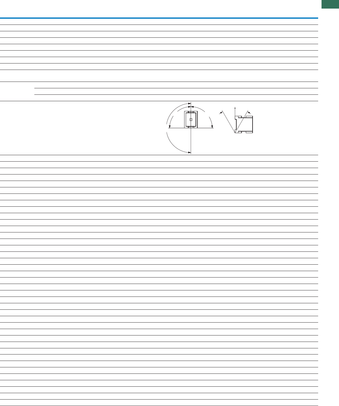
1.1
Contactors
Illumination contactors
125AUTOMATION AND CONTROL www.eaton.com/seasia-electrical
1
DILL12 DILL18 DILL20
General
Standards IEC/EN 60947, VDE 0660, UL, CSA
Lifespan, mechanical
x 10c (contacts)AC operated 6111
Operating frequency, mechanical
Operations/hMechanical, AC operated 60 60 60
Maximum operating frequency
Operations/hElectrical 60 60 60
Climatic proofing Damp heat, constant, to IEC 60068-2-78;
Damp heat, cyclic, to IEC 60068-2-30
Ambient
temperature °COpen -25…60 -25…60 -25…60
°CEnclosed -25…40 -25…40 -25…40
°CStorage -40 - 80 -40 - 80 -40 - 80
Mounting position
Mechanical shock resistance (IEC/EN 60068-2-27)
Half-sinusoidal shock 10 ms 6.9 6.9 6.9
Protection type IP00 IP00 IP00
Weight
kgAC operated 0.42 0.42 0.42
Main contacts
URated impulse withstand voltage imp V AC 8000 8000 8000
Overvoltage category/pollution degree III/3 III/3 III/3
URated insulation voltage iV AC 690 690 690
URated operating voltage eV AC 690 690 690
AMaking capacity 238 350 550
A380/400 VBreaking capacity 170 250 320
c (contacts)Lifespan, electrical 10000 10000 10000
Short-circuit protection rating maximum fuse
AgG/gL 500 V400 V 63 100 125
AC voltage
AC-1 operation
Conventional thermal current
Iat 40 °C th A27 40 45
Iat 60 °C th A24 35 40
I230 V eA12 18 20
I400 V eA12 18 20
AC-1 operation
I220/230 V eA14 21 27
I400 V eA14 21 27
Electric lamps
AFilament bulbs 14 21 27
AMercury blended lamps 12 16 23
Fluorescent lamp load
Conventional reactor starter connection A 20 26 35
ADuo circuit 20 26 35
AElectronic upstream devices 12 18 20
AHigh-pressure mercury vapour lamps 12 18 20
AMetal-halide lamps 12 18 20
AHigh-pressure sodium lamps 12 18 20
ALow-pressure sodium lamps 7.5 10 12
Maximum permissible compensation capacitance μF 470 470 470
Further technical data
DILAs per contactor M17 M25 M32
180°
90°
90°
30°30°
DILL
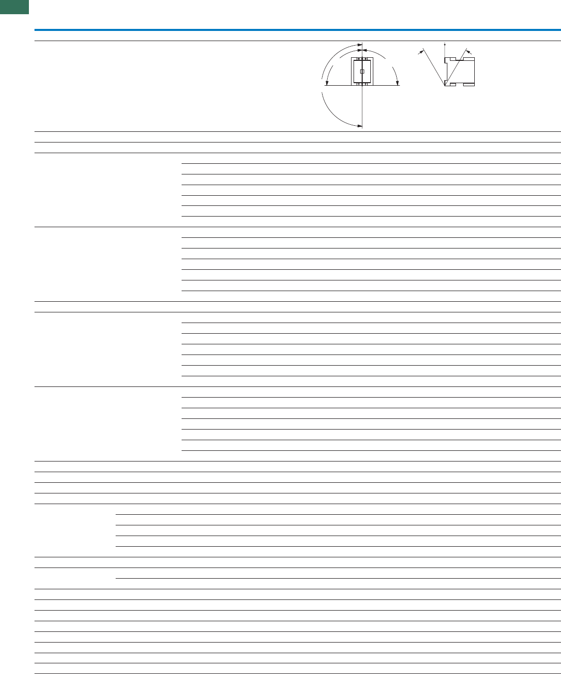
1.1 Contactors
Contactors up to 150 A with electronic actuation
126 AUTOMATION AND CONTROL www.eaton.com/seasia-electrical
1
DILMF8 DILMF11 DILMF14 DILMF17
General
Mounting position
AC voltage
AC-3 operation
Rated operational current AC -3 open,
50 – 60 Hz, 3 pole
220/230 V IeA7 9 12 18
240 VI eA7 9 12 18
380/400 V eA7 9 12 18
415 V eA7 9 12 18
440 V eA7 9 12 18
500 V eA5 7 10 18
660/690 V
I
I
I
I
I
IeA4 5 7 12
Rated operational power 220/230 V P 2.2 2.5 3.5 5
240 V P kW
kW
kW
2.2 3 4 5.5
380/400 V P 3 4 5.5 7.5
415 V 4 5.5 7 10
440 V 4.5 5.5 7.5 10.5
500 V
P
P
P
kW
kW
kW
kW
3.5 4.5 7 12
660/690 V P 3.5 4.5 6.5 11
AC-4 operation
Rated operational current AC-4 open,
50 - 60 Hz, 3 pole
220/230 VI eA5 6 7 10
240 V eA5 6 7 10
380/400 V eA5 6 7 10
415 V eA5 6 7 10
440 V eA5 6 7 10
500 V
I
I
I
I
I
IeA4.5 5 6 10
660/690 V IeA 4 4.5 5 8
Rated operational power 220/230 V P 1 1.5 2 2.5
240 V 1.5 1.6 2.2 3
380/400 V P 2.2 2.5 3 4.5
415 V 2.3 2.8 3.4 5
440 V 2.4 3 3.6 5.5
500 V 2.5 2.8 3.5 6
660/690 V
P
P
P
P
P
kW
kW
kW
kW
kW
kW
kW 2.9 3.6 4.4 6.5
Current heat loss (3 pole)
Current heat loss at Ith W 2.4 2.4 2.4 7.3
Current heat loss at I to AC-3/400 V
eW 0.3 0.6 1 1.9
Magnet systems
x UPick-upAC operatedVoltage tolerance c0.8 - 1.15 0.8 - 1.15 0.8 - 1.15 0.8 - 1.15
x UDrop-outAC operated c0.2 - 0.5 0.2 - 0.5 0.2 - 0.5 0.2 - 0.5
Power consumption of
the coil in a cold state
and 1.0 x Uc
Electronic actuation Pick-up VA 14 14 14 14
Electronic actuation Sealing 0.7 0.7 0.7 0.7
Electronic actuation Sealing
VA
W 0.7 0.7 0.7 0.7
% DFDuty factor 100 100 100 100
Switching times msClosing delay 40 40 40 40
msOpening delay 45 45 45 45
suitable according to SEMI F47 SEMI F47 SEMI F47 SEMI F47
Electromagnetic compatibility (EMC)
Emitted interference To EN 60947-1
Interference immunity To EN 60947-1
Further technical data
DILAs per contactor M7 M9 M12 M17
Terminal type
DILAs per contactor M17 M17 M17 M17
180°
90°
90°
30
°
30
°
DILMF
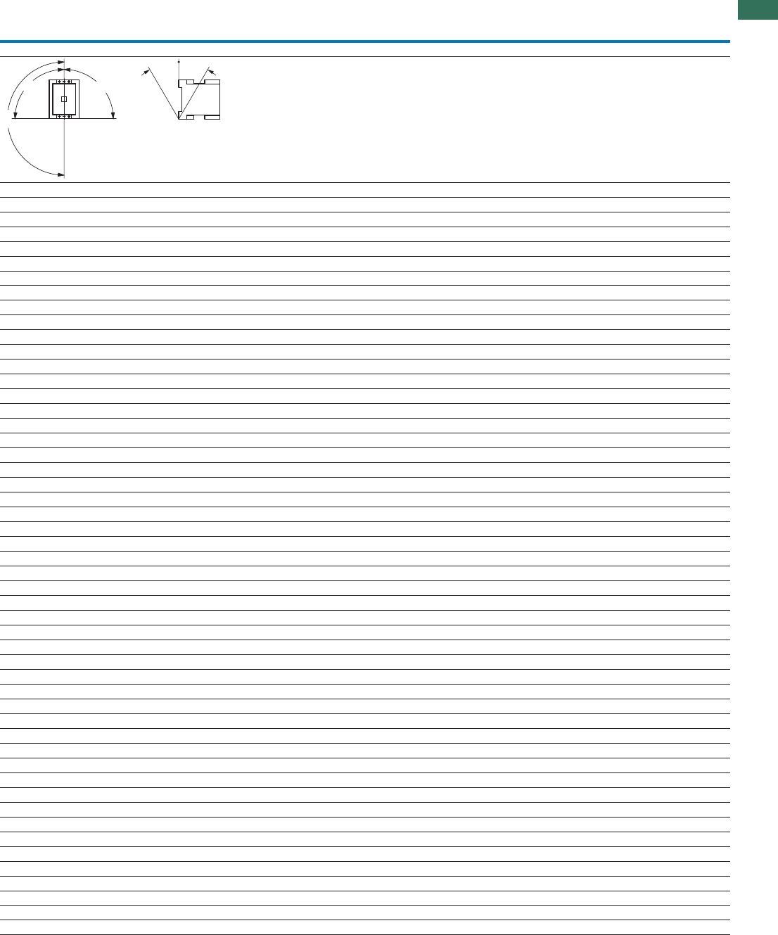
1.1
Contactors
Contactors up to 150 A with electronic actuation
127AUTOMATION AND CONTROL www.eaton.com/seasia-electrical
1
DILMF25 DILMF32 DILMF40 DILMF50 DILMF65 DILMF80 DILMF95 DILMF115 DILMF150
25 32 40 50 65 80 95 115 150
25 32 40 50 65 80 95 115 150
25 32 40 50 65 80 95 115 150
25 32 40 50 65 80 95 115 150
25 32 40 50 65 80 95 115 150
25 32 40 50 65 80 95 115 150
15 18 25 32 37 65 80 93 100
7.51012.515.52025303748
8.5 11 13.5 17 22 27.5 4 40 52
11 15 18.5 22 30 37 45 55 75
14.5 19 24 30 39 48 57 70 91
15.5 20 25 32 41 51 60 75 95
17.5 23 28 36 47 58 70 85 110
14 17 23 30 35 63 75 90 96
13 15 18 21 25 40 50 55 65
13 15 18 21 25 40 50 55 65
13 15 18 21 25 40 50 55 65
13 15 18 21 25 40 50 55 65
13 15 18 21 25 40 50 55 65
13 15 18 21 25 40 50 55 65
10 12 14 17 20 27 37 45 50
3.54 5 6 7 12161720
4 4.55.56.57.513171922
6 7 9 101220262833
6.5 7.5 9.5 11 13 24 30 33 39
7 8 10 12 14 25 32 35 41
8 9 11 13 16 29 36 40 47
8.51012141726354348
9.6 12.1 11.3 19 28.8 14.6 21.8 30.4 46.1
3.8 6.1 7.2 11.3 19 11.5 16.2 23.8 40.5
0.8 - 1.15 0.8 - 1.15 0.8 - 1.15 0.8 - 1.15 0.8 - 1.15 0.8 - 1.15 0.8 - 1.15 0.8 - 1.15 0.8 - 1.15
0.2 - 0.5 0.2 - 0.5 0.2 - 0.5 0.2 - 0.5 0.2 - 0.5 0.2 - 0.5 0.2 - 0.5 0.2 - 0.5 0.2 - 0.5
14 14 45 45 45 75 75 180 180
0.7 0.7 1.5 1.5 1.5 2 2 3.1 3.1
0.7 0.7 1.5 1.5 1.5 2 2 2.1 2.1
100 100 100 100 100 100 100 100 100
40 40 50 50 50 55 55 40 40
45 45 45 45 45 40 40 40 40
SEMI F47 SEMI F47 SEMI F47 SEMI F47 SEMI F47 SEMI F47 SEMI F47 SEMI F47 SEMI F47
To EN 60947-1
To EN 60947-1
M25 M32 M40 M50 M65 M80 M95 M115 M150
M25 M32 M40 M50 M65 M80 M95 M115 M150
180°
90°
90°
30
°
30
°

1.1 Contactors
Auxiliary contact modules
128 AUTOMATION AND CONTROL www.eaton.com/seasia-electrical
1
DILM7-… -
DILM38-…
DILA-
XHI(C)…(-S)
DILM32-
XHI(C)…(-S)
DILM150-
XHI…
DILM1000-XHI…
DILM820-XHI…
Auxiliary contact
Interlocked opposing contacts within an auxiliary
contact module (to IEC 60947-5-1 Annex L) 1)
- Yes Yes Yes Yes
Normally closed (not late-normally closed)
suitable as a mirror contact (to IEC/EN 60947-4-1,
Annex F)
DILM7 -
DILM38
DILM7 -
DILM38
DILM7 -
DILM38
DILM40 -
DILM170
DILM40 - DILM225A
DILM250 - DILM1000
Rated impulse withstand voltage Uimp V AC 6000 6000 6000 6000 6000
Overvoltage category/pollution degree III/3 III/3 III/3 III/3 III/3
URated insulation voltage iV AC 690 690 690 690 690
URated operating voltage eV AC 500 500 500 500 500
Safe isolation according to EN 61140
V ACBetween coil and auxiliary contacts 400 400 400 440 440
V ACBetween the auxiliary contacts 400 400 400 440 440
Rated operational current
AC-15
I2230 V eA44444
I380/415 V eA44444
I500 V eA1.5 – 1.5 1.5 1.5
DC L/R 15 ms2)
I24 V eA10 10 10 10 10
I60 V eA66666
I110 V eA33333
I220 V eA11111
DC-13 (6xP)
Contacts in series:
3 24 V A 2.5 2.5 2.5 – –
3 60 VA111––
3 110 V A 0.5 0.5 0.5 – –
3 220 V A 0.25 0.25 0.25 – –
Conventional thermal current Ith A10 16 16 16 10
Control circuit reliability (at Ue = 24 V DC,
Umin = 17 V, I
min = 5.4 mA)
Fault
probability
< 10-8, < 1 one failure in 100 million operations
Component lifespan
at Ue = 230 V, AC-15, 3 A c (contacts) x 1061.3 1.3 1.3 1.3 1.3
Short-circuit rating without welding
A gG/gLMax. fuse 10 10 10 16 16
Notes 1) Not with DIL…-XHIV and DIL…-XHICV.
2) Switch-on and switch-off conditions based on DC-13, time constant as specified.
DILM..., DILA...

1.1
Contactors
Paralleling link
129AUTOMATION AND CONTROL www.eaton.com/seasia-electrical
1
P1DILEM
DILM12-XP1
DILM32-XP1 DILM65-XP1 DILM150-XP1 DILM185-XP1
Parallel connector
Terminal capacity
mm²Solid 1 - 16 16 16 – –
mm²Flexible with ferrule 1 x (0.5 - 25)
2 x (0.5 - 16)
1 x (16 - 35) 1 x (16 - 120) – –
mm²Stranded 1 x (0.5 - 25)
2 x (0.5 - 16)
1 x (16 - 50) 1 x (16 - 120) 1 x (35 - 300)
2 x (35 - 120)
–
Flat conductor
Number of
layers x width x
thickness
mm 6 x 9 x 0.8 – – 2 x (11 x 21 x 1) 1 x (6 x 16 x 0.8)
2 x (20 x 32 x 0.5)
2 x (11 x 21 x 1)
NmTightening torque 4 4 14 14 6
Terminal capacity of control
circuit cable
mm²Solid – – – – 1 x (0.75 - 4)
2 x (0.75 - 4)
mm²Flexible with ferrule – – – – 1 x (0.75 - 2.5)
2 x (0.75 - 2.5)
Tools
SizePozidriv screwdriver 2 2 – – –
Internal hexagon SW mm – – 5 6 5
Conventional thermal current
I3 pole th A50 100 180 400 700
I4 pole th A60––––
P1SIL...M, DILM...-XP1
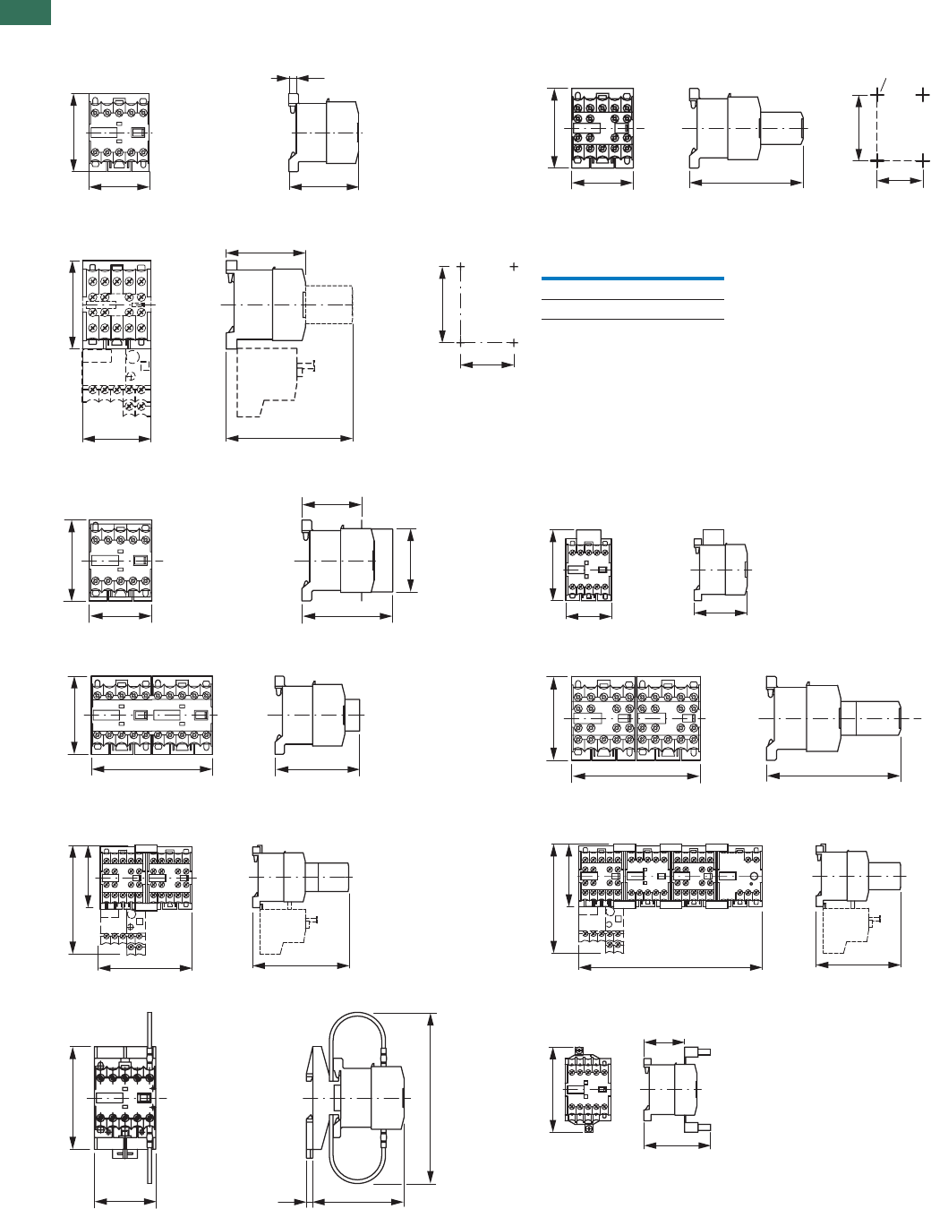
1.1 Contactors
Minicontactor relay, contactor combination
130 AUTOMATION AND CONTROL www.eaton.com/seasia-electrical
1
Dimensions
Mini contactor relays
DILER-...(-C)
DILER-...-G(-C) DILER-...(-C) + ...DILE(-C)
DILER-...-G(-C) + ...DILE(-C)
DILEEM-..., DILEM-...(-C), DILEM-12-...
DILEEM-...-G, DILEM-...-G(-C), DILEM-12-...-G
DILER-... + HDILE
DILER-...-...G + HDILE Suppressor circuit
RCDILE...
VGDILE
2DILE-... + MVDILE
2DILE-...-G + MVDILE 2DILE-... + MVDILE + ...DILE
2DILE-...-G + MVDILE + ...DILE
Star-delta contactorsRsrotcatnocgnisreve
DIULEM SDAINLEM
DILER-... + TDDILE24 Parallel connector
P1DILEM
45
58
52 (54)
5.5
45 83 (86)
58
50
35
M4
35
58
c1
c
50
M4
45
Part no. c c1
DILE(E)M-...(-G) 52 83
DILE(E)M-...-G(-C) 54 86
45
58
65,3
43
45
52
45
62.5
90 63
58
90
58
94
61
108
90 94
61
108
180 83
45
75
67
4,7
~125
40
65.5
83.5
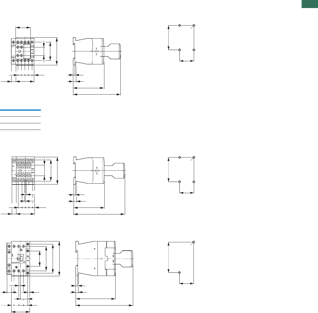
1.1
Contactors
Basic devices up to 170 A, contactor relay
131AUTOMATION AND CONTROL www.eaton.com/seasia-electrical
1
Contactor with auxiliary contact module
DILM7...DILM15
DILA...
DILMC7...DILMC15
DILAC...
DILA-XHIC...
DILM17...DILM38
DILMC17...DILMC32
DILMF8...DILMF32
Clearance at side to grounded
parts: 6 mm
6.5
75
c
3.2
18
45
68
45
36
8.7 8.7 8.7 8.7 (5.1)
10.2
35
2 x M4
60
Part no. c
DILM32-XHI 117
DILA-XHI 117
DILA-XHI...T 125
68
6.5
3.2
75
125
26.4
52.3
45
8.7 8.7 8.7 8.7 (5.1)
1.8
1.8
10.2
35
2 x M4
60
11.611.6
4.5
17.7
10.6
6.4
38
71
60.4
85
45
11 4.8
138
6.5
97.4
4.5 35
2 x M4
75
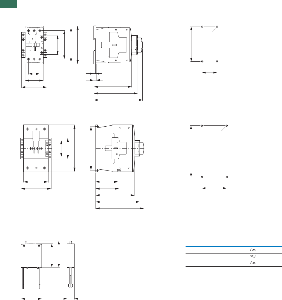
1.1 Contactors
Basic devices up to 170 A, suppressor circuit
132 AUTOMATION AND CONTROL www.eaton.com/seasia-electrical
1Contactors
DILM40...DILM72
DILMC40...DILMC65
DILMF40...DILMF65
Clearance at side to grounded parts: 6 mm
DILM80...DILM170
DILMC80...DILMC150
DILMF80...DILMF150
Clearance at side to
grounded parts: 10 mm
Suppressor circuits
DILM...XSP...
34.4
55
77
57
86.4
104
115
6.9
4.7
114
132.1
147
45
2 x M4
105
90
111
82.5
85.5
142
175
160
76.5
57
170
156
70
4 x M6
156
c
a
b
b1
Part no. a b b1 c
DILM12-XSP... 25 28 32 9
DILM32-XSP... 25 28 32 9
DILM95-XSP... 25 28 32 9
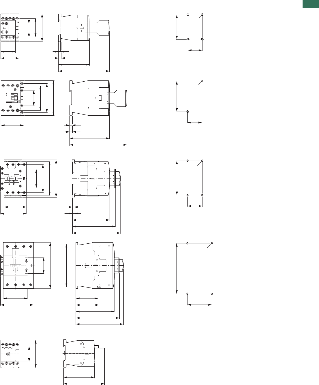
1.1
Contactors
Basic devices up to 200 A
133AUTOMATION AND CONTROL www.eaton.com/seasia-electrical
1
Contactor with auxiliary contact module
DILMP20
DILMP32 DILMP45
Distance at side to
grounded parts: 6 mm
Contactors
DILMP63 DILMP80
Distance at side to
grounded parts: 6 mm
DILMP125 DILMP160 DILMP200
Clearance at side to earthed
parts: 10 mm
Motor suppressor module
DILM12-XMSM
18
45
68
45
36
6.5
75
117
3.2 35
2 x M4
60
38
71
60.4
85
58
138
6.5
97.4
4.5 35
2 x M4
75
6.9
4.7
114
132.1
147
74
85
57
86.4
104
115
45
2 x M4
105
122
133
82.5
85.5
142
175
160
57
170
156
70
4 x M6
156
38.3
68
75
101.2
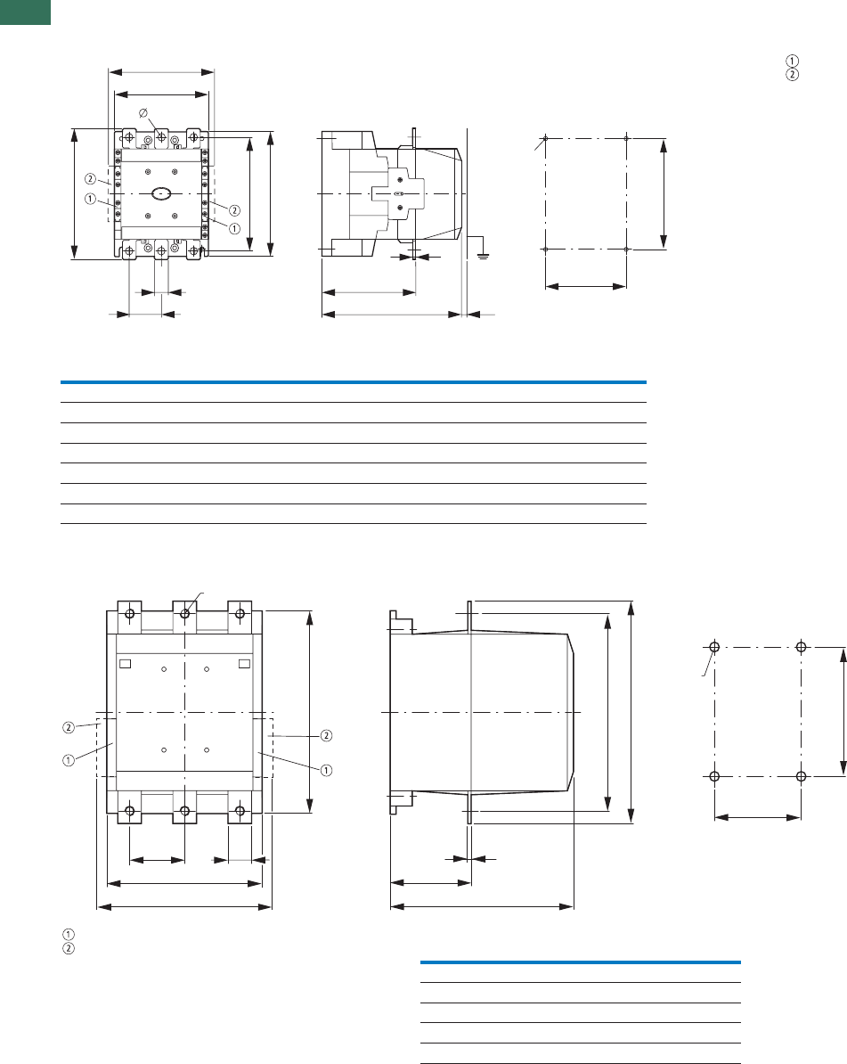
1.1 Contactors
Complete units for currents greater than 170 A
134 AUTOMATION AND CONTROL www.eaton.com/seasia-electrical
1Complete units
DILM185A...DILM500
DILM250-S...DILM570-S
DILM1000-XHI...-SI
DILM1000-XHI11-SA
DILM580...DILM1000
DILM820-XHI...-SI
DILM820-XHI11-SA
c8
f
b1
a1
M6
e
d1
b2
b3
b
d2
a
11
a2
Part no. a a1 a2 b b1 b2 b3 d1 d2 e c f
DILM185A 140 120 160 180 160 165 190 20 41 5 158 83
DILM225A 140 120 160 180 160 165 190 20 41 5 158 83
DILM250 140 120 160 180 160 164 189 25 48 5 208 140
DILM300A 140 120 160 180 160 164 189 25 48 5 208 140
DILM400 160 130 180 200 180 184 209 25 48 6 216 140
DILM500 160 130 180 200 180 189 219 38 57 6 216 140
DILM570 160 130 180 200 180 189 219 38 57 6 216 140
250
80 d1
232
232
b3
140
b2
270
e
165
215
M6
f
Part no. b2 b3 d1 e f
DILM580 256 296 45 6 13.5
DILM650 256 296 45 6 13.5
DILM750 256 296 45 6 13.5
DILM820 256 296 45 6 13.5
DILM1000 256 296 45 10 13.5
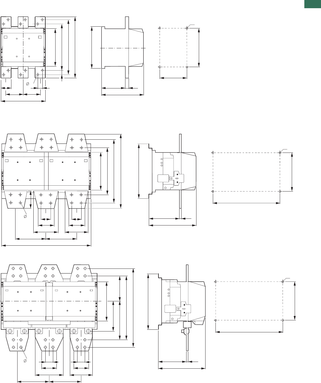
1.1
Contactors
Contactors greater than 1000 A
135AUTOMATION AND CONTROL www.eaton.com/seasia-electrical
1
AC -1 contactors greater than 1000 A
DILH1400
DILM1600
DILH2000
DILH2200
DILH2600
100
60 35
100
210
232
25635
342
308
260
14
165
215
M6
232
130 10
40
80
125
172.5172.5
210
272
352
392
14
300
252
150 10
40
80
150
515
430
270
M6
96
300
252
150 10
430
270
M6
210
160
206 136
422
(342)
14
172.5172.5
125
40
80
150
40
80
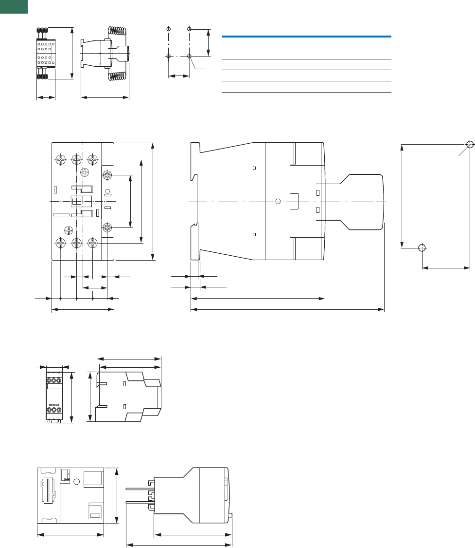
1.1 Contactors
Capacitor contactors, lamp contactors, contactor monitoring devices, SWD contactor modules
136 AUTOMATION AND CONTROL www.eaton.com/seasia-electrical
1Contactor for capacitors
DILK…
Illumination contactors
DILL…
Clearance at side to grounded parts: 6 mm
Contactor monitoring devices
CMD(...)
SWD contactor modules
DIL-SWD-32-...
b
ca
a1
b1
d
Part no. a b c a1 b1 d
DILK12 45 135 138 35 75 2 x M4
DILK20 45 135 138 35 75 2 x M4
DILK25 45 135 138 35 75 2 x M4
DILK33 55 190 147 45 105 2 x M4
DILK50 55 190 147 45 105 2 x M4
11.6 11.6
4.5
17.7
10.6
(6.4)
38
60.4
85
45
4.8
138
6.5
97.4
4.5
35
2 x M4
75
103
98
78
22.5
82.5
38
45 53.1
72.3
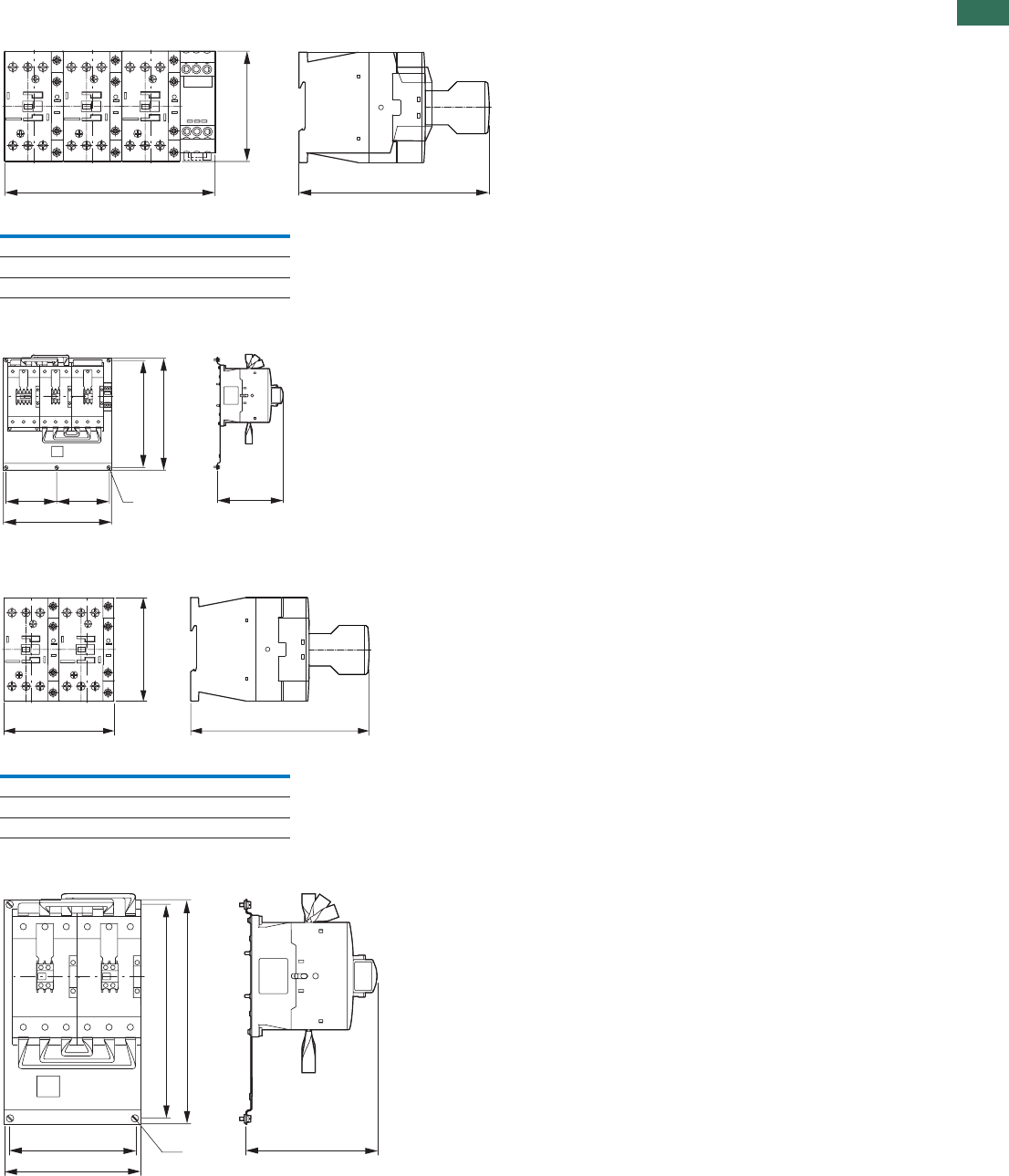
1.1
Contactors
Contactor combinations
137AUTOMATION AND CONTROL www.eaton.com/seasia-electrical
1
Star-delta contactors
SDAINLM12...SDAINLM115
SDAINLM140...SDAINLM260
Reversing contactors
DIULM7...DIULM65
DIULM80…DIULM150
b
ca
Part no. a b c
SDAINLM12...22 158 68 117
SDAINLM30...55 158 85 138
SDAINLM70...115 188 115 147
144 144 M 6
308
314
299
183
c
b
a
Part no. a b c
DIULM7/21...12/21 90 68 117
DIULM17/21...32/21 90 85 138
DIULM40/11...65/11 110 115 147
176
196
183M 6
314
299
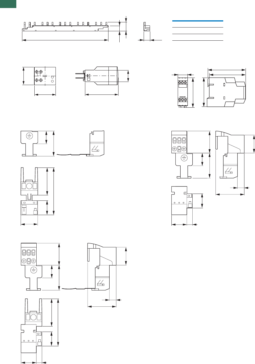
1.1 Contactors
Accessories
138 AUTOMATION AND CONTROL www.eaton.com/seasia-electrical
1Three-phase commoning links
DILM12-XDSB...
Electronic timer modules Amplifier module
3SV-4STEETX…MLID
Wiring set for motor feeder plug
T/PCMX-21MLIDECMX-21MLID
DILM12-XMCP/E
13.1
a
18.1
12.5
Part no. a
DILM12-XDSB0/3 112
DILM12-XDSB0/4 157
DILM12-XDSB0/5 202
38
25
70
45
103
98
78
22.5
82.5
25 45
80
20
45
30 27 12
25 20
45
50
6
37
30
25 45
80
27 12
20
45
50
6
37
30
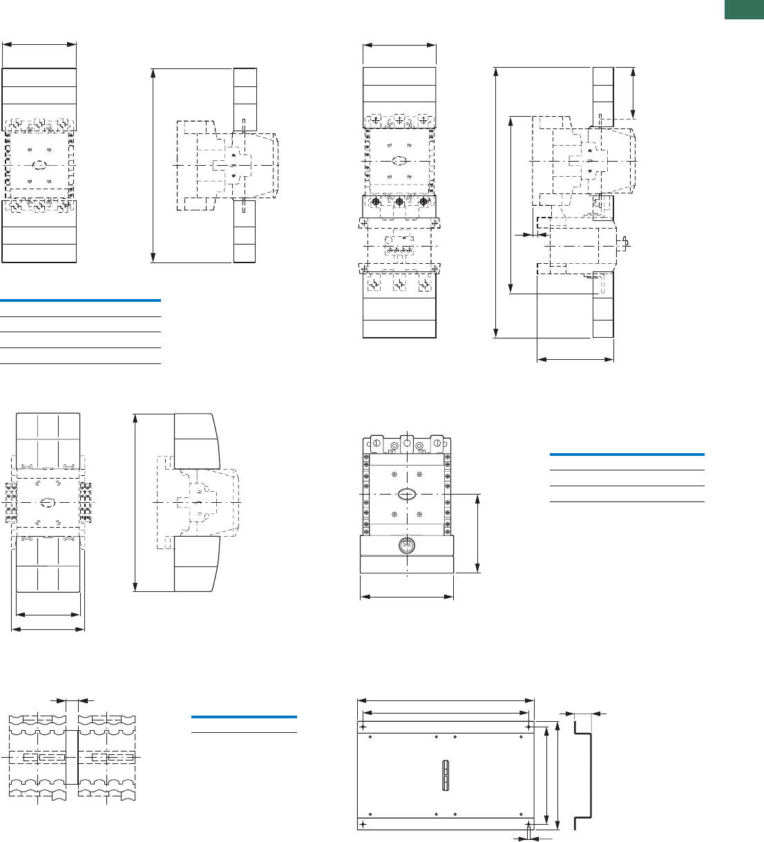
1.1
Contactors
139AUTOMATION AND CONTROL www.eaton.com/seasia-electrical
1
Contactors with terminal shrouds
DILM250 + Z5-.../FF250DILM250...DILM1000 + DILM...-XHB
DILM185A...DILM225A + DILM225A-XHB Contactor with star-point bridge and terminal shroud
DILM...XS1
Mechanical interlock
VMX-028MLIDVMX-005MLID
a
b
150
34
523
110
328
~144
for part no. a b
DILM250, DILM300A 150 384
DILM400 150 404
DILM500 174 426
DILM580...1000 236 506
325
124
140
a
b
for part no. a b
DILM185...250 150 127
DILM300...400 150 137
DILM500 176 146
a
for part no. a
DILM185...500 15
9
515
430
270
300
20
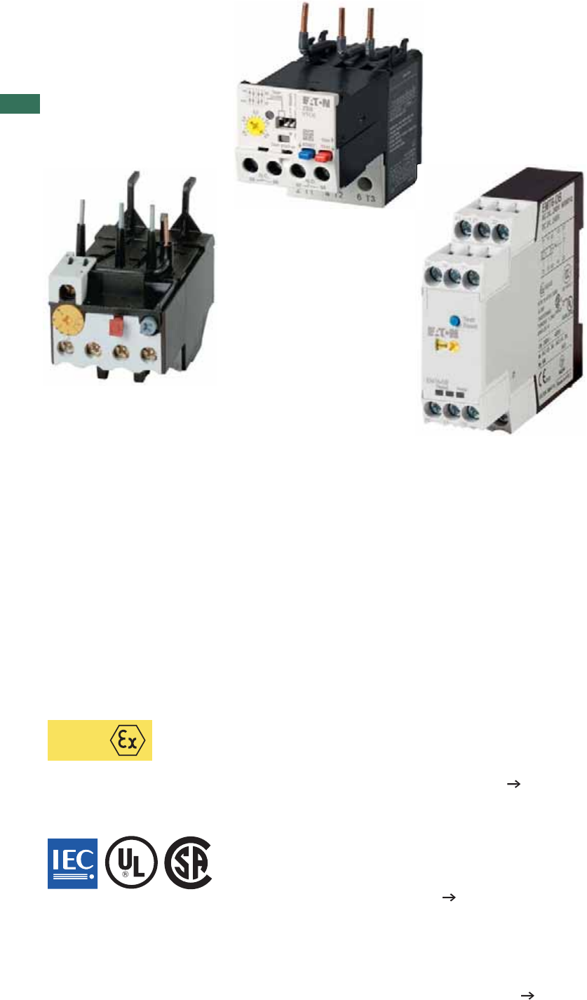
1
AUTOMATION AND CONTROL www.eaton.com/seasia-electrical
ATEX
Bimetal relay - overload relay up to 630 A
ZEB electronic overload relay - overload relay up to 1500 A
EMT6 thermistor overload relay for machine protection
Overload relay
Motor protection is a central task of electrical equipment for machinery. From
cost-effective bimetal solutions to demanding full motor protection with cross-linkage -
we offer the right solution for each application.
Direct mounting on contactor saves mounting time.
ATEX approval for the protection of EEx e motors up to 250 A.
Comprehensive motor protection through phase failure sensitivity.
Integrated test pushbutton facilitates high safety Page 6.
•
•
•
•
ATEX approval for protection of EEx e motors up to 1500 A.
Adjustable tripping classes.
Phase failure and unbalance protection.
Optional earth fault detection.
Additional current setting range (5:1) Page 14.
•
•
•
•
•
Overload protection through direct evaluation of winding temperature.
Quick detection of operating state through LED display.
Suitable for overload monitoring of motors in EEx e range.
Wide range power supply reduces amount of types Page 19.
•
•
•
•
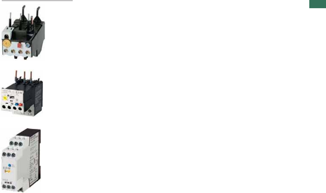
1
1AUTOMATION AND CONTROL www.eaton.com/seasia-electrical
Technical overview
Bimetal relay ZE, ZB, Z5 . . . . . . . . . . . . . . . . . . . . . . . . . . . . . . . . . . . . . . . . . . . . . . . . . . . . . . . . . . . . . . . . . . . . . .
Overload relay ZW7 . . . . . . . . . . . . . . . . . . . . . . . . . . . . . . . . . . . . . . . . . . . . . . . . . . . . . . . . . . . . . . . . . . . . . . . . .
Electronic overload relays ZEB . . . . . . . . . . . . . . . . . . . . . . . . . . . . . . . . . . . . . . . . . . . . . . . . . . . . . . . . . . . . . . . . .
EMT6 thermistor overload relay for machine protection . . . . . . . . . . . . . . . . . . . . . . . . . . . . . . . . . . . . . . . . . . . . .
Ordering
Bimetal relays for mini-contactor relays . . . . . . . . . . . . . . . . . . . . . . . . . . . . . . . . . . . . . . . . . . . . . . . . . . . . . . . . . .
Bimetal relays up to 150 A . . . . . . . . . . . . . . . . . . . . . . . . . . . . . . . . . . . . . . . . . . . . . . . . . . . . . . . . . . . . . . . . . . . .
Bimetal relay greater than 150 A . . . . . . . . . . . . . . . . . . . . . . . . . . . . . . . . . . . . . . . . . . . . . . . . . . . . . . . . . . . . . . .
Overload relays . . . . . . . . . . . . . . . . . . . . . . . . . . . . . . . . . . . . . . . . . . . . . . . . . . . . . . . . . . . . . . . . . . . . . . . . . . . . .
Bimetal relay accessories . . . . . . . . . . . . . . . . . . . . . . . . . . . . . . . . . . . . . . . . . . . . . . . . . . . . . . . . . . . . . . . . . . . . .
ZEB electronic overload relay . . . . . . . . . . . . . . . . . . . . . . . . . . . . . . . . . . . . . . . . . . . . . . . . . . . . . . . . . . . . . . . . . .
Ordering
EMT6 thermistor overload relay for machine protection . . . . . . . . . . . . . . . . . . . . . . . . . . . . . . . . . . . . . . . . . . . . .
Engineering
EMT6 thermistor overload relay for machine protection . . . . . . . . . . . . . . . . . . . . . . . . . . . . . . . . . . . . . . . . . . . . .
Selection criteria ZE, ZB, Z5, ZW7 . . . . . . . . . . . . . . . . . . . . . . . . . . . . . . . . . . . . . . . . . . . . . . . . . . . . . . . . . . . . . .
Characteristic curve ZB, Z5, ZW7 . . . . . . . . . . . . . . . . . . . . . . . . . . . . . . . . . . . . . . . . . . . . . . . . . . . . . . . . . . . . . . .
UL/CSA short-circuit strength ZE, ZB, Z5 . . . . . . . . . . . . . . . . . . . . . . . . . . . . . . . . . . . . . . . . . . . . . . . . . . . . . . . . .
Technical data
Bimetal relay for mini-contactor relays . . . . . . . . . . . . . . . . . . . . . . . . . . . . . . . . . . . . . . . . . . . . . . . . . . . . . . . . . . .
Bimetal relays up to 150A . . . . . . . . . . . . . . . . . . . . . . . . . . . . . . . . . . . . . . . . . . . . . . . . . . . . . . . . . . . . . . . . . . . . .
Overload relays greater than 150 A . . . . . . . . . . . . . . . . . . . . . . . . . . . . . . . . . . . . . . . . . . . . . . . . . . . . . . . . . . . . .
Overload relays . . . . . . . . . . . . . . . . . . . . . . . . . . . . . . . . . . . . . . . . . . . . . . . . . . . . . . . . . . . . . . . . . . . . . . . . . . . . .
ZEB electronic overload relay . . . . . . . . . . . . . . . . . . . . . . . . . . . . . . . . . . . . . . . . . . . . . . . . . . . . . . . . . . . . . . . . . .
EMT6 thermistor overload relay for machine protection . . . . . . . . . . . . . . . . . . . . . . . . . . . . . . . . . . . . . . . . . . . . .
Dimensions
Bimetal relays for mini-contactor relays . . . . . . . . . . . . . . . . . . . . . . . . . . . . . . . . . . . . . . . . . . . . . . . . . . . . . . . . . .
Bimetal relays up to 150A . . . . . . . . . . . . . . . . . . . . . . . . . . . . . . . . . . . . . . . . . . . . . . . . . . . . . . . . . . . . . . . . . . . . .
Bimetal relays greater than 150 A . . . . . . . . . . . . . . . . . . . . . . . . . . . . . . . . . . . . . . . . . . . . . . . . . . . . . . . . . . . . . . .
Overload relay . . . . . . . . . . . . . . . . . . . . . . . . . . . . . . . . . . . . . . . . . . . . . . . . . . . . . . . . . . . . . . . . . . . . . . . . . . . . . .
ZEB electronic overload relay . . . . . . . . . . . . . . . . . . . . . . . . . . . . . . . . . . . . . . . . . . . . . . . . . . . . . . . . . . . . . . . . . .
EMT6 thermistor overload relay for machine protection . . . . . . . . . . . . . . . . . . . . . . . . . . . . . . . . . . . . . . . . . . . . .
2
2
4
4
6
8
12
12
21
14
19
20
23
23
24
25
25
26
26
28
29
30
30
32
32
33
35
Overload relays
Contents
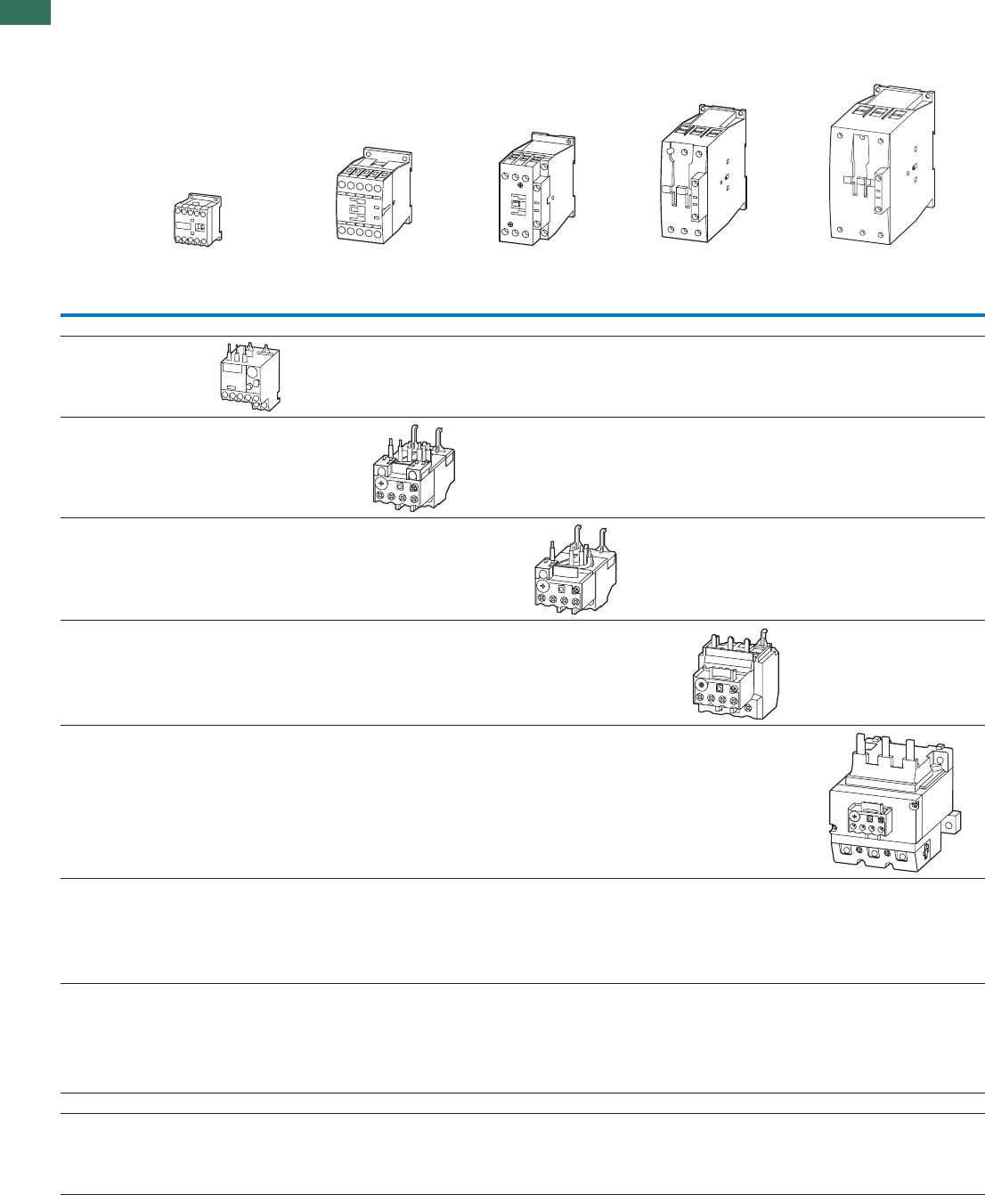
1
2 AUTOMATION AND CONTROL www.eaton.com/seasia-electrical
Technical overview
Electronic overload relays, thermistor overload relay for machine protection
Setting ranges (A)
(note max. current of the contactor)
DILEM DILM7 DILM12 DILM17 DILM32 DILM40 DILM65 DILM80 DILM150
DILM9 DILM15 DILM25 DILM38 DILM50 DILM72 DILM95 DILM170
DILM115
Overload relays
ZE
0.1-12
ZB12
0.1-16
ZB32
0.1-38
ZB65
6-75
ZB150
35-175
Z5-.../FF225A
70-250
Z5-.../FF250
50-300
Current transformer-operated overload relay
ZW7-...
42-630
Overload relays, CT-operated overload relays
1.2 Overload relays
Overload relays, CT-operated overload relays
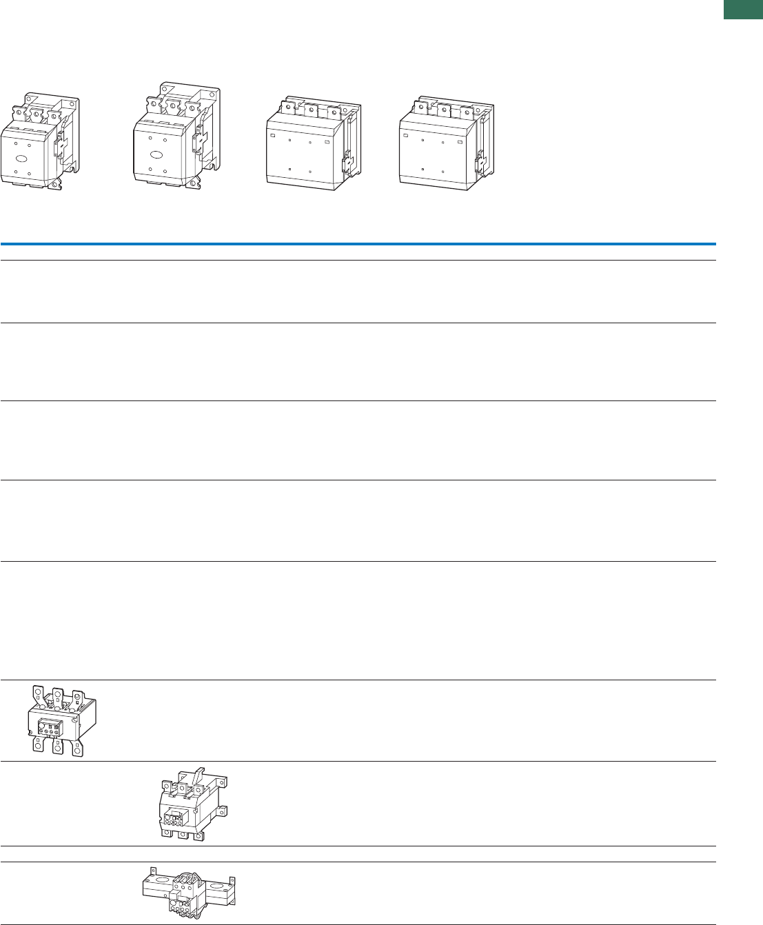
1
3AUTOMATION AND CONTROL www.eaton.com/seasia-electrical
DILM185A DILM250 DILM400 DILM580 DILM650
DILM225A DILM300 DILM500
1.2
Overload relays
Overload relays, CT-operated overload relays
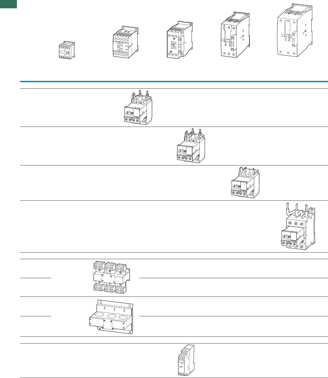
1
1.2 Overload relays
Electronic overload relays, thermistor overload relay for machine protection
4 AUTOMATION AND CONTROL www.eaton.com/seasia-electrical
Electronic overload relays, thermistor overload relay for machine protection
Setting ranges (A)
(note max. current of the contactor)
DILEM DILM7 DILM12 DILM17 DILM32 DILM40 DILM65 DILM80 DILM150
DILM9 DILM15 DILM25 DILM38 DILM50 DILM72 DILM95 DILM170
DILM115
Electronic overload relays
ZEB12
0.33-20
ZEB32
0.33-45
ZEB65
9-100
ZEB150
20-100
ZEB32-5-(GF)/KK combined with
ZEB-XCT300
60-300
ZEB-XCT600
120-600
ZEB-XCT1000
200-1000
ZEB-XCT1500
300-1500
Thermistor overload relay for machine protection
EMT6((DB)K)
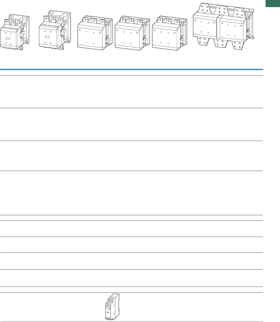
1
1.2
Overload relays
Electronic overload relays, thermistor overload relay for machine protection
5AUTOMATION AND CONTROL www.eaton.com/seasia-electrical
DILM185A DILM250 DILM400 DILM580 DILM750 DILM820 DILM1000 DILM1600
DILM225A DILM300 DILM500 DILM650
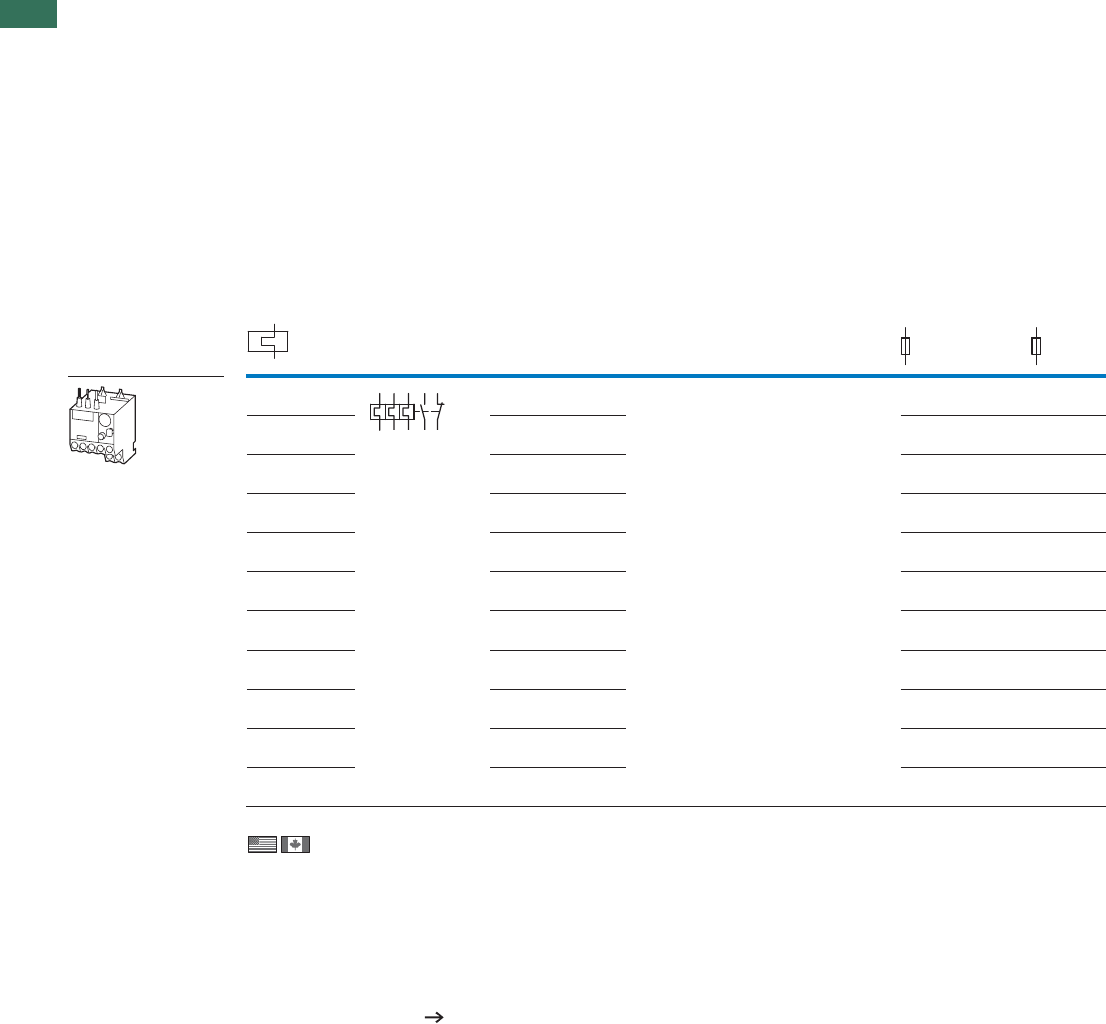
1
1.2 Overload relays
Bimetal relays for mini-contactor relays
6 AUTOMATION AND CONTROL www.eaton.com/seasia-electrical
Ordering
Setting range of
overload
releases
Short-circuit protectionFor use withCircuit symbol Auxiliary contact
N/O = normally open contact
NC = normally closed contact
Type “1”
coordination
Type “2”
coordination
IrgG/gL
A A
gG/gL
A
ZE overload relays for mini contactor relays
• Phase failure sensitivity to IEC/EN 60947, VDE 0660 Part 102
• Test/off pushbutton
• Reset pushbutton manual/auto
• Trip-free release
• Direct mounting
DIULEM/21/MV
DILEM
SDAINLEM
20 0.5
20
0.16 – 0.24 1
0.24 – 0.4 2
0.4 – 0.6 2
0.6 – 1 4
1 – 1.6 6
1.6 – 2.4 6
2.4 – 4 10
10
10
10
4 – 6
6 – 9
9 – 12
Information relevant for export to North America
Product Standards
UL File No.
NCCLU
CSA File No.
CSA Class No.
NA Certification
Suitable for
Max. Voltage Rating
Degree of Protection
See also
2 4 6 98 96
97 95
1 N/O 1 NC
0.1 – 0.16 1 N/O 1 NC
201 N/O 1 NC
201 N/O 1 NC
201 N/O 1 NC
20
1 N/O 1 NC
201 N/O 1 NC
201 N/O 1 NC
20
1 N/O 1 NC
201 N/O 1 NC
20
1 N/O 1 NC
UL 508; CSA-C22.2 No.14; IEC/EN 60947-4-1; CE marking
E29184
NKCR
12528
3211-03
UL Listed, CSA certified
Branch circuits
600 V AC
IEC: IP20, UL/CSA Type: -
Page 24
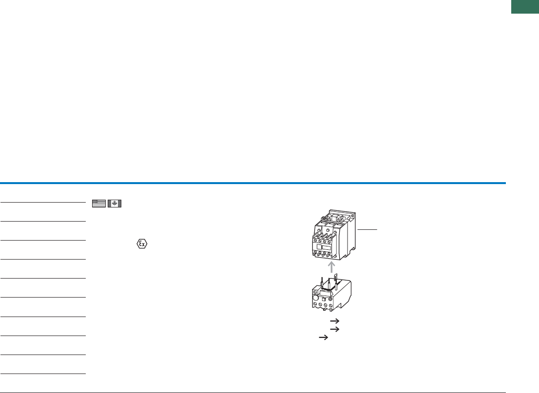
1
1.2
Overload relays
Bimetal relays for mini-contactor relays
7AUTOMATION AND CONTROL www.eaton.com/seasia-electrical
Part no.
Article no. Price
See price
list
Std. pack Notes
ZE-0.16
014263
1 Off Overload release: tripping class 10 A
Short-circuit protection: With direct mounting,
observe the maximum permissible fuse of the
contactor.
Suitable for protection of EEx e motors
II (2) GD
PTB 01 ATEX 3331
Observe manual AWB2300-1425D/GB.
With side-by-side mounting, there must be a minimum clearance
of 5 mm between overload relays.
1 Contactor Chapter 1.1
Accessories Page 21
Manual Page 21
ZE-0.24
014285
ZE-0.4
014300
ZE-0.6
014333
ZE-1.0
014376
ZE-1.6
014432
ZE-2.4
014479
ZE-4
014518
ZE-6
014565
ZE-9
014708
ZE-12
014752
1
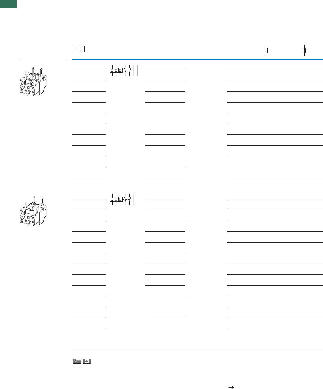
1
1.2 Overload relays
Overload relays up to 150A
8 AUTOMATION AND CONTROL www.eaton.com/seasia-electrical
Information relevant for export to North America
Product Standards
UL File No.
NCCLU
CSA File No.
CSA Class No.
NA Certification
Suitable for
Max. Voltage Rating
Degree of Protection
See also
UL 508; CSA-C22.2 No.14; IEC/EN
60947-4-1; CE marking
E29184
NKCR
12528
3211-03
UL Listed, CSA certified
Branch circuits
600 V AC
IEC: IP20, UL/CSA Type: -
Page 24
Setting range of
overload releases
Short-circuit protectionFor use withAuxiliary contactCircuit symbol
N/O = normally open contact
NC = normally closed contact
Contactors Soft starters Type “1”
coordination
Type “2”
coordination
IrgG/gL gG/gL
AAA
ZB12 overload relay
DILM12, DILM15,
DIULM7, DIULM9,
DIULM12,
SDAINLM12,
SDAINLM16,
SDAINLM22
–250.5
–250.16 – 0.24 1
0.24 – 0.4 2
0.4 – 0.6 4
0.6 – 1 4
1 – 1.6 6
1.6 – 2.4 10
2.4 – 4 61…400XS…43-7SD
4 – 6 02…500XS…43-7SD
6 – 10 DS7-34…SX007…
DS7-34…SX009…
50 25
50 25
50 25
9 – 12 DS7-34…SX012…
12 – 16 –
ZB32 overload relay
DILM32,
DILM17, DILM25,
DILM38,
DILMF8,
DILMF11,
DILMF14,
DILMF17,
DILMF25,
DILMF32,
DIULM17,
DIULM25,
DIULM32,
SDAINLM30,
SDAINLM45,
SDAINLM55
–250.5
0.16 – 0.24 1
0.24 – 0.4 2
0.4 – 0.6 4
0.6 – 1 4
1 – 1.6 6
1.6 – 2.4 10
2.4 – 4 16
4 – 6 20
6 – 10 50 25
10 – 16 DS7-34...SX016... 63 35
16 – 24 DS7-34...SX024... 100 35
24 – 32 DS7-34...SX032... 125 63
32 – 38 –12563
2 4 6 98 96 A2 14/
22
97 95
2 4 6 98 96 14/
22
97 95
ZB12, ZB32
1 N/O 1 NC
DILM7, DILM9, 0.1 – 0.16 1 N/O 1 NC
–25
1 N/O 1 NC
–251 N/O 1 NC
–251 N/O 1 NC
–251 N/O 1 NC
–25
–25
25
25
1 N/O 1 NC
1 N/O 1 NC
1 N/O 1 NC
1 N/O 1 NC
1 N/O 1 NC
1 N/O 1 NC
1 N/O 1 NC
0.1 – 0.16 1 N/O 1 NC
–251 N/O 1 NC
–251 N/O 1 NC
–251 N/O 1 NC
–251 N/O 1 NC
–251 N/O 1 NC
–251 N/O 1 NC
–25
–
1 N/O 1 NC
1 N/O 1 NC
1 N/O 1 NC
1 N/O 1 NC
1 N/O 1 NC
1 N/O 1 NC
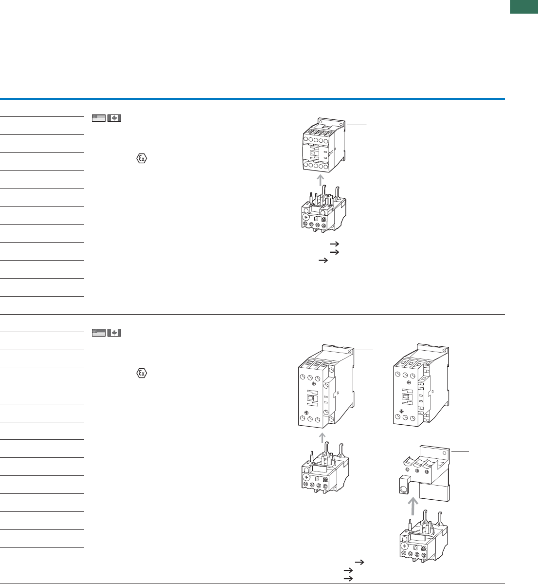
1
1.2
Overload relays
Overload relays up to 150A
9AUTOMATION AND CONTROL www.eaton.com/seasia-electrical
Part no.
Article no. Price
See price
list
Std. pack Notes
ZB12-0,16
278431
1 Off Overload release: tripping class 10 A
Short-circuit protection: With direct mounting,
observe the maximum permissible fuse of the
contactor.
Suitable for protection of EEx e motors.
II (2) GD
PTB 04 ATEX 3022
Observe manual AWB2300-1527D/GB.
• Phase failure sensitivity to IEC/EN 60947, VDE 0660
Part 102
• Test/off pushbutton
• Reset pushbutton manual/auto
• Trip-free release
• Direct mounting
Fitted directly to the contactor
1 Contactor Chapter 1.1
Accessories Page 21
Manual Page 21
ZB12-0,24
278432
ZB12-0,4
278433
ZB12-0,6
278434
ZB12-1
278435
ZB12-1,6
278436
ZB12-2,4
278437
ZB12-4
278438
ZB12-6
278439
ZB12-10
278440
ZB12-12
278441
ZB12-16
290168
ZB32-0,16
278442
1 Off Overload release: tripping class 10 A
Short-circuit protection: With direct mounting,
observe the maximum permissible fuse of the
contactor.
Suitable for protection of EEx e motors.
II (2) GD
PTB 04 ATEX 3022
Observe manual AWB2300-1527D/GB.
• Phase failure sensitivity to IEC/EN 60947, VDE 0660
Part 102
• Test/off pushbutton
• Reset pushbutton manual/auto
• Trip-free release
• Direct mounting
ZB32-0,24
278443
ZB32-0,4
278444
ZB32-0,6
278445
ZB32-1
278446
ZB32-1,6
278447
ZB32-2,4
278448
ZB32-4
278449
ZB32-6
278450
ZB32-10
278451
ZB32-16
278452
ZB32-24
278453
ZB32-32
278454
ZB32-38
112474
1
Fitted directly to the contactor Separate mounting
1 Contactor Chapter 1.1
2 Base Page 21
Manual Page 21
1
1
2
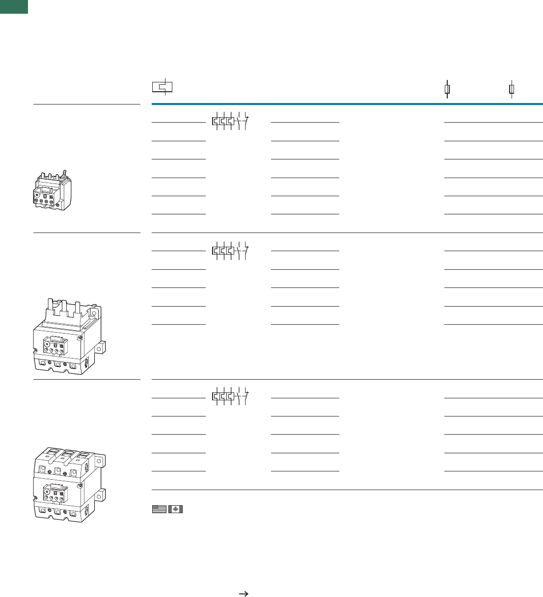
1
1.2 Overload relays
Overload relays up to 150A
10 AUTOMATION AND CONTROL www.eaton.com/seasia-electrical
Setting range of
overload
releases
Circuit symbol Auxiliary contact For use with Short-circuit protection
N/O = normally open contact
NC = normally closed contact
Type “1”
coordination
Type “2”
coordination
IrgG/gL
A A
gG/gL
A
ZB65 overload relay
• Phase failure sensitivity to IEC/EN
60947, VDE 0660 Part 102
• Test/off pushbutton
• Reset pushbutton manual/auto
• Trip-free release
• Direct mounting
DILM65,
DILM40, DILM50,
DILM72,
DILMF40,
DILMF50,
DILMF65,
DIULM40, DIULM50,
DIULM65,
SDAINLM70,
SDAINLM90,
SDAINLM115
50 25
10 – 16 63 35
16 – 24 63 50
24 – 40 125 63
40 – 57 160 80
50 – 65 160 100
65 – 75 250 160
ZB150 overload relay
• Phase failure sensitivity to IEC/EN
60947, VDE 0660 Part 102
• Test/off pushbutton
• Reset pushbutton manual/auto
• Trip-free release
• Direct mounting
DILM115, DILM150,
DILM170
DILMF80,
DILMF95,
DILMF115,
DILMF150,
DIULM80, DIULM95,
DIULM115, DIULM150,
SDAINLM140,
SDAINLM165,
SDAINLM200,
SDAINLM260
160 125
50 – 70 250 160
70 – 100 315 200
95 – 125 315 250
120 – 150 315 250
145 – 175 315 250
ZB150 overload relay
• Phase failure sensitivity to IEC/EN
60947, VDE 0660 Part 102
• Test/off pushbutton
• Reset pushbutton manual/auto
• Trip-free release
• Separate mounting
DILM115, DILM150,
DILM170
DILMF80,
DILMF95,
DILMF115,
DILMF150,
DIULM80, DIULM95,
DIULM115, DIULM150,
SDAINLM140,
SDAINLM165,
SDAINLM200,
SDAINLM260
160 125
50 – 70 250 160
70 – 100 315 200
95 – 125 315 250
120 – 150 315 250
145 – 175 400 315
2 4 6 98 96
97 95
2 4 6 98 96
97 95
2 4 6 98 96
97 95
ZB65, ZB150
1 N/O 1 NC
6 – 10 1 N/O 1 NC
1 N/O 1 NC
1 N/O 1 NC
1 N/O 1 NC
1 N/O 1 NC
1 N/O 1 NC
1 N/O 1 NC
DILM80, DILM95,
35 – 50 1 N/O 1 NC
1 N/O 1 NC
1 N/O 1 NC
1 N/O 1 NC
1 N/O 1 NC
1 N/O 1 NC
DILM80, DILM95,35 – 50 1 N/O 1 NC
1 N/O 1 NC
1 N/O 1 NC
1 N/O 1 NC
1 N/O 1 NC
Information relevant for export to North America
Product Standards
UL File No.
NCCLU
CSA File No.
CSA Class No.
NA Certification
Suitable for
Max. Voltage Rating
Degree of Protection
See also
UL 508; CSA-C22.2 No.14; IEC/EN 60947-4-1; CE marking
E29184
NKCR
12528
3211-03
UL Listed, CSA certified
Branch circuits
600 V AC
IEC: IP00, UL/CSA Type: -
Page 24
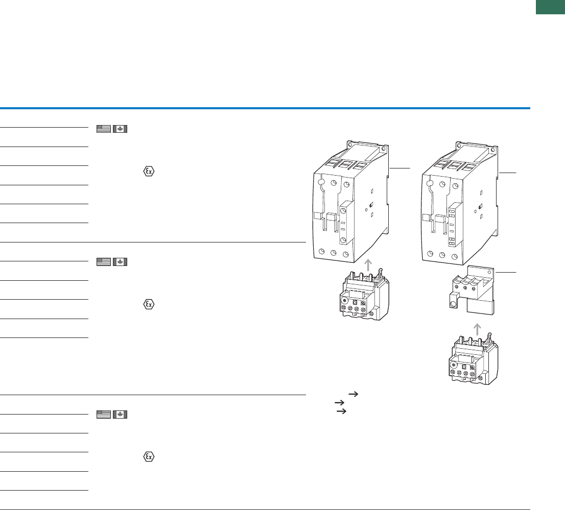
1
1.2
Overload relays
Overload relays up to 150A
11AUTOMATION AND CONTROL www.eaton.com/seasia-electrical
Part no.
Article no. Price
See price
list
Std. pack Notes
ZB65-10
278455 1 Off Overload release: tripping class 10 A
Short-circuit protection: With direct mounting,
observe the maximum permissible fuse of the
contactor.
Suitable for protection of EExe motors.
II (2) GD
PTB 04 ATEX 3022
Observe manual AWB2300-1545D/GB.
ZB65-16
278456
ZB65-24
278457
ZB65-40
278458
ZB65-57
278459
ZB65-65
278460
ZB65-75
108792
ZB150-50
278462
1 Off Overload release: tripping class 10 A
Short-circuit protection: With direct mounting,
observe the maximum permissible fuse of the
contactor.
Suitable for protection of EEx e motors.
II (2) GD
PTB 04 ATEX 3022
Observe manual AWB2300-1545D/GB.
ZB150-70
278463
ZB150-100
278464
ZB150-125
278465
ZB150-150
278466
ZB150-175
107316
ZB150-50/KK
278468
1 Off Overload release: tripping class 10 A
Short-circuit protection: With direct mounting,
observe the maximum permissible fuse of the
contactor.
Suitable for protection of EEx e motors.
II (2) GD
PTB 04 ATEX 3022
Observe manual AWB2300-1545D/GB.
ZB150-70/KK
278469
ZB150-100/KK
278470
ZB150-125/KK
278471
ZB150-150/KK
278472
ZB150-175/KK
107317
Fitted directly to the contactor Separate mounting
1 Contactor Chapter 1.1
2 Base Page 21
Manual Page 21
1
2
1
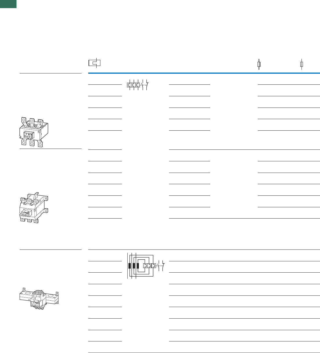
1
1.2 Overload relays
Overload relays greater than 150 A, CT-operated overload relays
12 AUTOMATION AND CONTROL www.eaton.com/seasia-electrical
Setting range of
overload releases
Circuit symbol Auxiliary
contacts
For use with Short-circuit protection
N/O = normally open
contact
NC = normally closed
contact
Type “1”
coordination
gG/gL
Type “2”
coordination
gG/gL
Ir
AAA
Z5 overload relays greater than 150A
• Phase failure sensitivity to IEC/EN
60947, VDE 0660 Part 102
• Test/off pushbutton
• Reset pushbutton manual/auto
• Trip-free release
Direct mounting
Separate mounting
Z5 overload relays greater than 150A
• Phase failure sensitivity to IEC/EN
60947, VDE 0660 Part 102
• Test/off pushbutton
• Reset pushbutton manual/auto
• Trip-free release
Direct mounting
Separate mounting
DILM225A
250
250
160
160
70 – 100 315
315
200
200
95 – 125 315
315
250
250
120 – 160 400
400
250
250
160 – 220 400
500
315
400
200 – 250 400
500
315
400
250
160
160
70 – 100 315
315
200
200
95 – 125 315
315
250
250
120 – 160 400
400
250
250
160 – 220 400
500
315
400
200 – 250
200 – 300
42 – 63
60 – 90
85 – 125
110 – 160
160 – 240
190 – 290
270 – 400
360 – 540
420 – 630
400
500
315
400
500
500 400
400
ZW7 current transformer-operated
overload relays
• Test/off button
• Reset pushbutton manual/auto
• Trip-free release
• Protection with heavy starting duty
Separate mounting
–––
–––
–––
–––
–––
–––
–––
–––
–––
1 3 5 97 95
2 4 6 98 96
9698
9597
Z5, ZW7
1 N/O 1 NC
DILM185A50 – 70 1 N/O 1 NC
1 N/O 1 NC
1 N/O 1 NC
1 N/O 1 NC
1 N/O 1 NC
1 N/O 1 NC DILM250A
1 N/O
25070 – 100
1 NC
1 N/O 1 NC
1 N/O 1 NC
1 N/O 1 NC
1 N/O 1 NC
1 N/O 1 NC DILM300A
1 N/O 1 NC
1 N/O 1 NC
1 N/O 1 NC
1 N/O 1 NC
1 N/O 1 NC
1 N/O 1 NC
1 N/O 1 NC
1 N/O 1 NC
1 N/O 1 NC
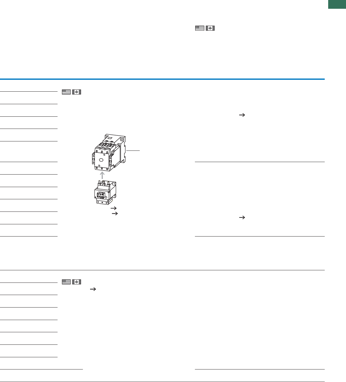
1
1.2
Overload relays
Overload relays greater than 150 A, CT-operated overload relays
13AUTOMATION AND CONTROL www.eaton.com/seasia-electrical
UL 508; CSA-C22.2 No.14;
IEC/EN 60947-4-1; CE marking
Request filed for UL and CSA
Branch circuits
600 V AC
IEC: IP00, UL/CSA Type: -
Page 24
Product Standards
UL File No.
NCCLU
CSA File No.
CSA Class No.
NA Certification
Suitable for
Max. Voltage Rating
Degree of Protection
See also
UL 508; CSA-C22.2 No.14;
IEC/EN 60947-4-1; CE marking
E29184
NKCR
12528
3211-03
UL Listed, CSA certified
Branch circuits
600 V AC
IEC: IP00, UL/CSA Type: -
Page 24
Product Standards
UL File No.
NCCLU
CSA File No.
CSA Class No.
NA Certification
Suitable for
Max. Voltage Rating
Degree of Protection
UL 508; CSA-C22.2 No.14;
IEC/EN 60947-4-1; CE marking
E29184
NKCR
12528
3211-03
UL Listed, CSA certified
Branch circuits
600 V AC
IEC: IP00, UL/CSA Type: -
Part no.
Article no. Price
See price
list
Std. pack aciremAhtroNottropxeroftnavelernoitamrofnIsetoN
Z5-70/FF225A
139572
1 Off Overload release:
tripping class 10 A
Short-circuit protection: With direct mounting,
observe the maximum permissible fuse of the
contactor.
Z5-…/FF225A for protecting
EEx electric motors in preparation.
Fitted directly to the contactor
1 Contactor Chapter 1.1
Accessories Page 22
Product Standards
NA Certification
Suitable for
Max. Voltage Rating
Degree of Protection
See also
UL 508; CSA-C22.2 No.14;
IEC/EN 60947-4-1; CE marking
Request filed for UL and CSA
Branch circuits
600 V AC
IEC: IP00, UL/CSA Type: -
Product Standards
NA Certification
Suitable for
Max. Voltage Rating
Degree of Protection
Z5-100/FF225A
139573
Z5-125/FF225A
139574
Z5-160/FF225A
139575
Z5-220/FF225A
139576
Z5-250/FF225A
139577
Z5-70/FF250
210070
Z5-100/FF250
210071
Z5-125/FF250
210072
Z5-160/FF250
210073
Z5-220/FF250
210074
Z5-250/FF250
210075
Z5-300/FF250
139578
ZW7-63
000245
1 Off The main current characteristic values are defined
by the main current wiring being used.
Adjustment for smaller rated motor currents
Page 23
ZW7-90
002618
ZW7-125
004991
ZW7-160
007364
ZW7-240
009737
ZW7-290
052448
ZW7-400
045329
ZW7-540
047702
ZW7-630
050075
–ffO1
1
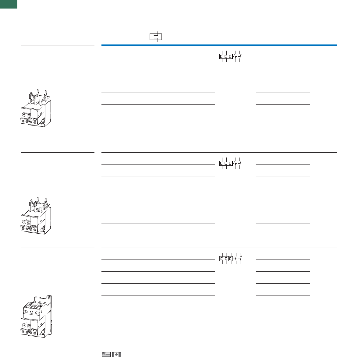
1
1.2 Electronic overload relays to 1500 A
Basic devices
14 AUTOMATION AND CONTROL www.eaton.com/seasia-electrical
Ground fault detection Setting range
of overload releases
Circuit symbol Auxiliary contact For use with
Ir
A
N/O = normally open contact
NC = normally closed contact
ZEB12 electronic overload relay
• Phase-failure sensitivity
• Test/off pushbutton
• Reset button
• Manual/Auto reset selectable
• Protection with heavy starting
duty (Class 5-30)
Direct mounting
DILM9
DILM12
DILM15
DIULM7
DIULM9
DIULM12
SDAINLM12
SDAINLM16
SDAINLM22
Without 1 – 5
Without 4 – 20
With 0.33 – 1.65
With 1 – 5
With 4 – 20
ZEB32 electronic overload relay
• Phase-failure sensitivity
• Test/off pushbutton
• Reset button
• Manual/Auto reset selectable
• Protection with heavy starting
duty (Class 5-30)
ZEB32 electronic overload relay
• Phase-failure sensitivity
• Test/off pushbutton
• Reset button
• Manual/Auto reset selectable
• Protection with heavy starting
duty (Class 5-30)
Direct mounting
DILM25
DILM17
DILM32
DILM38
DIULM17
DIULM25
DIULM32
SDAINLM30
SDAINLM45
SDAINLM55
Without 1 – 5
Without 4 – 20
Without 9 – 45
With 0.33 – 1.65
With 1 – 5
With 4 – 20
With 9 – 45
Separate mounting
DILM25
DILM32
DILM38
DIULM17
DIULM25
DIULM32
SDAINLM30
SDAINLM45
SDAINLM55
Without 1 – 5
Without 4 – 20
Without 9 – 45
With 0.33 – 1.65
With 1 – 5
With 4 – 20
With 9 – 45
2 4 6 98 96
97 95
2 4 6 98 96
97 95
1 3 5 97 95
2 4 6 98 96
ZEB12, ZEB32
1 N/O 1 NC
DILM7Without 0.33 – 1.65 1 N/O 1 NC
1 N/O 1 NC
1 N/O 1 NC
1 N/O 1 NC
1 N/O 1 NC
1 N/O 1 NC
Without 0.33 – 1.65 1 N/O 1 NC
1 N/O 1 NC
1 N/O 1 NC
1 N/O 1 NC
1 N/O 1 NC
1 N/O 1 NC
1 N/O 1 NC
1 N/O 1 NC
DILM17Without 0.33 – 1.65 1 N/O 1 NC
1 N/O 1 NC
1 N/O 1 NC
1 N/O 1 NC
1 N/O 1 NC
1 N/O 1 NC
1 N/O 1 NC
Information relevant for export to North America
Product Standards
NA Certification
Suitable for
Max. Voltage Rating
Degree of Protection
UL 508; CSA-C22.2 No.14; IEC/EN 60947-4-1; CE marking
Request filed for UL and CSA
Branch circuits
600 V AC
IEC: IP20, UL/CSA Type: -
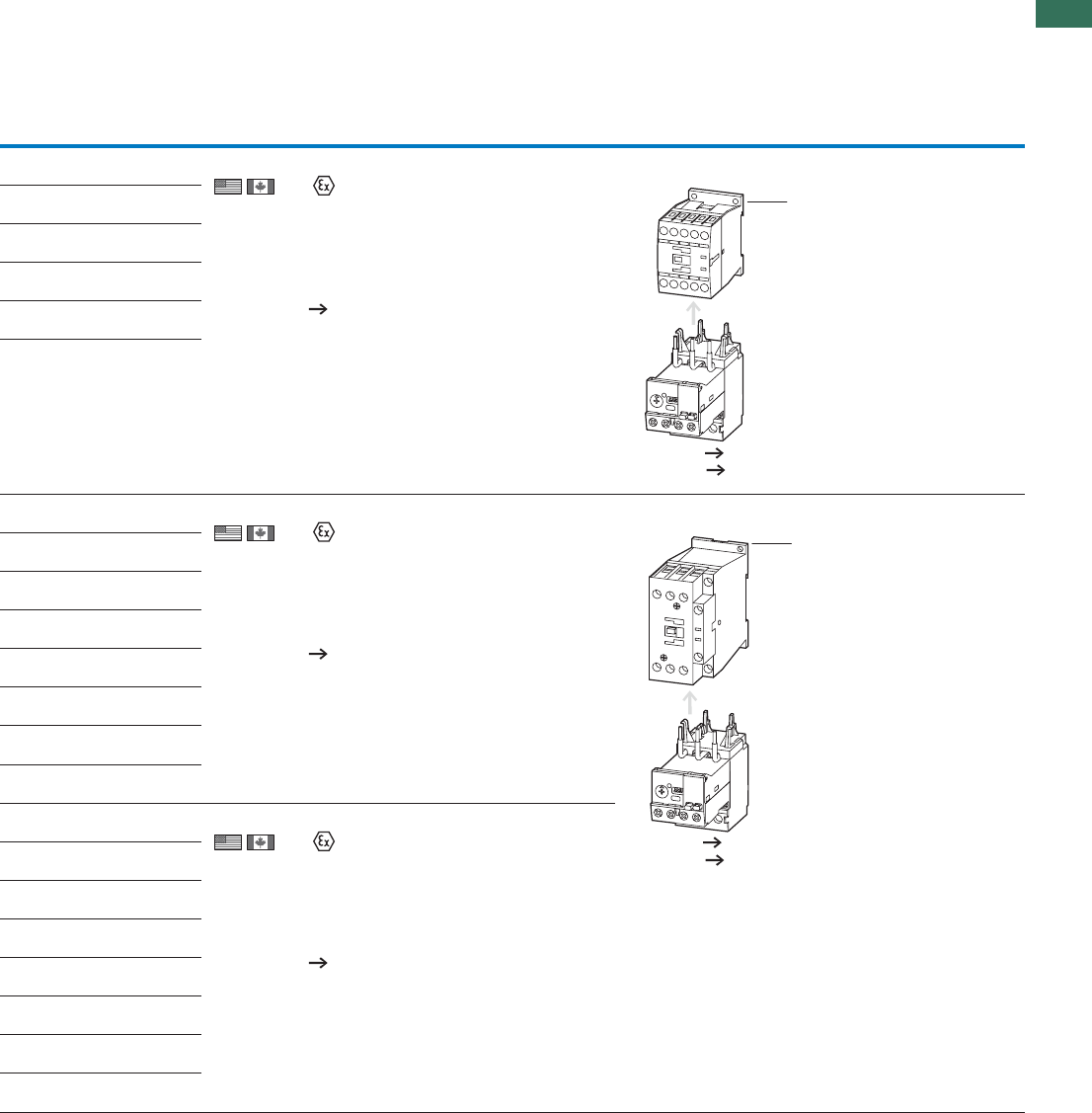
1
1.2
Electronic overload relays to 1500 A
Basic devices
15AUTOMATION AND CONTROL www.eaton.com/seasia-electrical
Part no.
Article no. Price
See price
list
Std. pack Notes
ZEB12-1,65
136480 1 Off Suitable for protection of EEx e motors.
II (2) GD
PTB ATEX starting 08/2010
Observe manual AWB2320-1633D/GB.
Switchgear and cable dimensioning
according to CLASS
Page 18
Fitted directly to the contactor
1 Contactor Chapter 1.1
Accessories Page 18
ZEB12-5
136481
ZEB12-20
136482
ZEB12-1,65-GF
136483
ZEB12-5-GF
136484
ZEB12-20-GF
136485
ZEB32-1.65
136486 1 Off Suitable for protection of EEx e motors.
II (2) GD
PTB ATEX starting 08/2010
Observe manual AWB2320-1633D/GB.
Switchgear and cable dimensioning
according to CLASS
Page 18
Fitted directly to the contactor
1 Contactor Chapter 1.1
Accessories Page 18
ZEB32-5
136487
ZEB32-20
136488
ZEB32-45
136489
ZEB32-1,65-GF
136490
ZEB32-5-GF
136491
ZEB32-20-GF
136492
ZEB32-45-GF
136493
ZEB32-1,65/KK
136494
1 Off Suitable for protection of EEx e motors.
II (2) GD
PTB ATEX starting 08/2010
Observe manual AWB2320-1633D/GB.
Switchgear and cable dimensioning
according to CLASS
Page 18
ZEB32-5/KK
136495
ZEB32-20/KK
136496
ZEB32-45/KK
136497
ZEB32-1,65-GF/KK
136498
ZEB32-5-GF/KK
136499
ZEB32-20-GF/KK
136500
ZEB32-45-GF/KK
136501
1
1
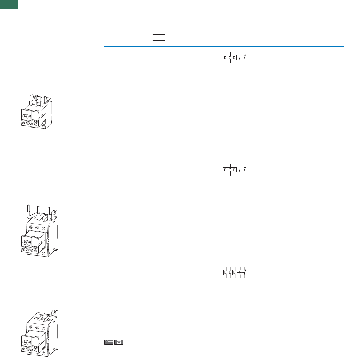
1
1.2 Electronic overload relays to 1500 A
Basic devices
16 AUTOMATION AND CONTROL www.eaton.com/seasia-electrical
ZEB65 electronic overload relay
• Phase-failure sensitivity
• Test/off pushbutton
• Reset button
• Manual/Auto reset selectable
• Protection with heavy starting
duty (Class 5-30)
Direct mounting
DILM50
DILM65
DILM72
DIULM40
DIULM50
DIULM65
SDAINLM70
SDAINLM90
SDAINLM115
With 9 – 45
Without 20 – 100
With 20 – 100
ZEB150 electronic overload relay
• Phase-failure sensitivity
• Test/off pushbutton
• Reset button
• Manual/Auto reset selectable
• Protection with heavy starting
duty (Class 5-30)
Direct mounting
DILM95
DILM115
DILM150
DIULM80
DIULM95
DIULM115
DIULM150
SDAINLM140
SDAINLM165
SDAINLM200
SDAINLM260
Separate mounting
DILM95
DILM115
DILM150
DIULM80
DIULM95
DIULM115
DIULM150
SDAINLM140
SDAINLM165
SDAINLM200
SDAINLM260
Ground fault detection Setting range
of overload releases
Circuit symbol Auxiliary contact For use with
Ir
A
N/O = normally open contact
NC = normally closed contact
24698 96
97 95
24698 96
97 95
1 3 5 97 95
2 4 6 98 96
ZEB65, ZEB150
1 N/O 1 NC
DILM40Without 9 – 45 1 N/O 1 NC
DILM80Without 20 – 100 1 N/O 1 NC
DILM80Without 20 – 100 1 N/O 1 NC
With 20 – 100 1 N/O 1 NC
With 20 – 100 1 N/O 1 NC
1 N/O 1 NC
1 N/O 1 NC
ZEB150 electronic overload relay
• Phase-failure sensitivity
• Test/off pushbutton
• Reset button
• Manual/Auto reset selectable
• Protection with heavy starting
duty (Class 5-30)
Information relevant for export to North America
Product Standards
NA Certification
Suitable for
Max. Voltage Rating
Degree of Protection
UL 508; CSA-C22.2 No.14; IEC/EN 60947-4-1; CE marking
Request filed for UL and CSA
Branch circuits
600 V AC
IEC: IP20, UL/CSA Type: -
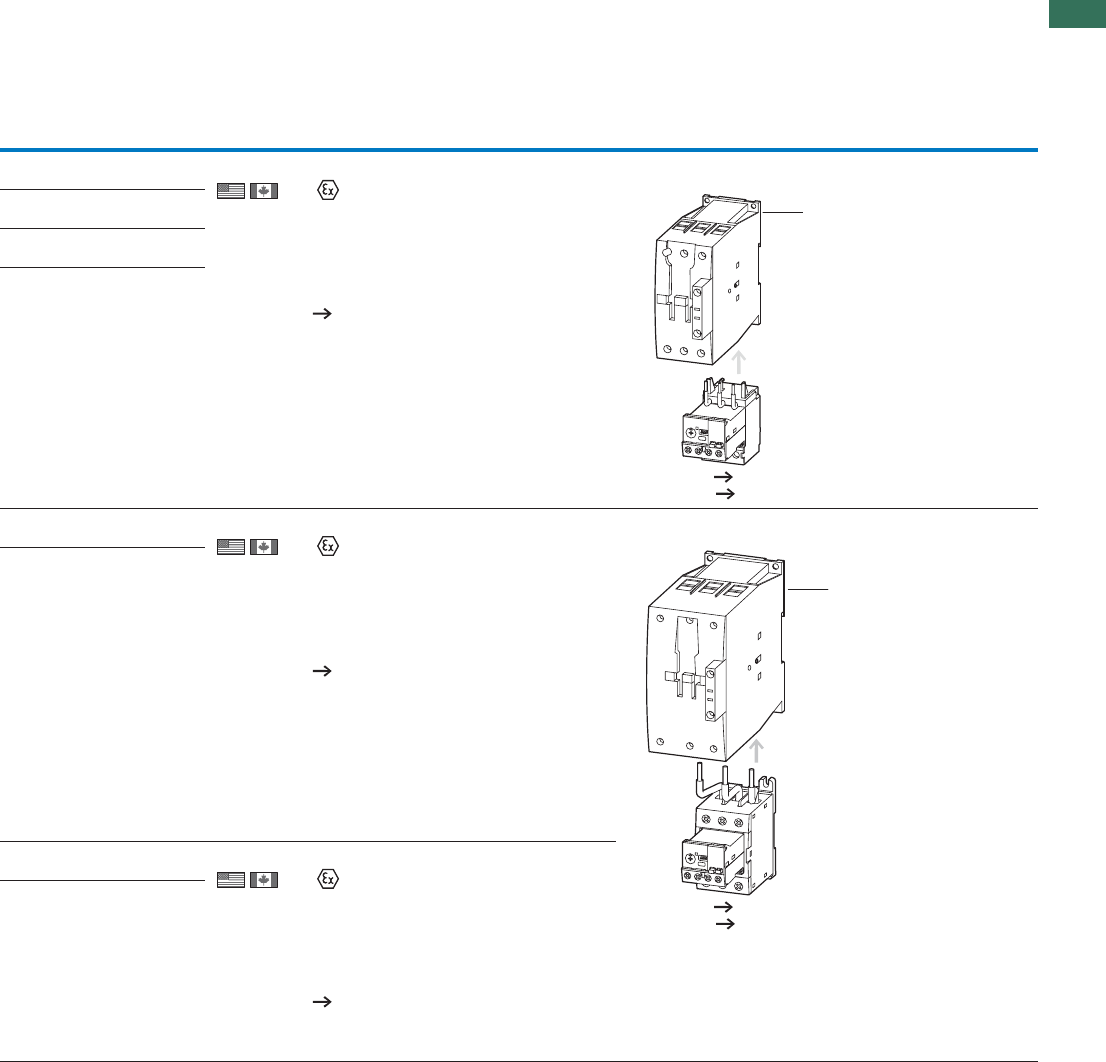
1
1.2
Electronic overload relays to 1500 A
Basic devices
17AUTOMATION AND CONTROL www.eaton.com/seasia-electrical
ZEB65-45
136502
1 Off Suitable for protection of EEx e motors.
II (2) GD
PTB ATEX starting 08/2010
Observe manual AWB2320-1633D/GB.
Switchgear and cable dimensioning
according to CLASS
Page 18
Fitted directly to the contactor
1 Contactor Chapter 1.1
Accessories Page 18
ZEB65-45-GF
136503
ZEB65-100
136504
ZEB65-100-GF
136505
ZEB150-100
136506
1 Off Suitable for protection of EEx e motors.
II (2) GD
PTB ATEX starting 08/2010
Observe manual AWB2320-1633D/GB.
Switchgear and cable dimensioning
according to CLASS
Page 18
Fitted directly to the contactor
1 Contactor Chapter 1.1
Accessories Page 18
ZEB150-100-GF
136507
ZEB150-100/KK
136508
1 Off Suitable for protection of EEx e motors.
II (2) GD
PTB ATEX starting 08/2010
Observe manual AWB2320-1633D/GB.
Switchgear and cable dimensioning
according to CLASS
Page 18
ZEB150-100-GF/KK
136509
Part no.
Article no. Price
See price
list
Std. pack Notes
1
1
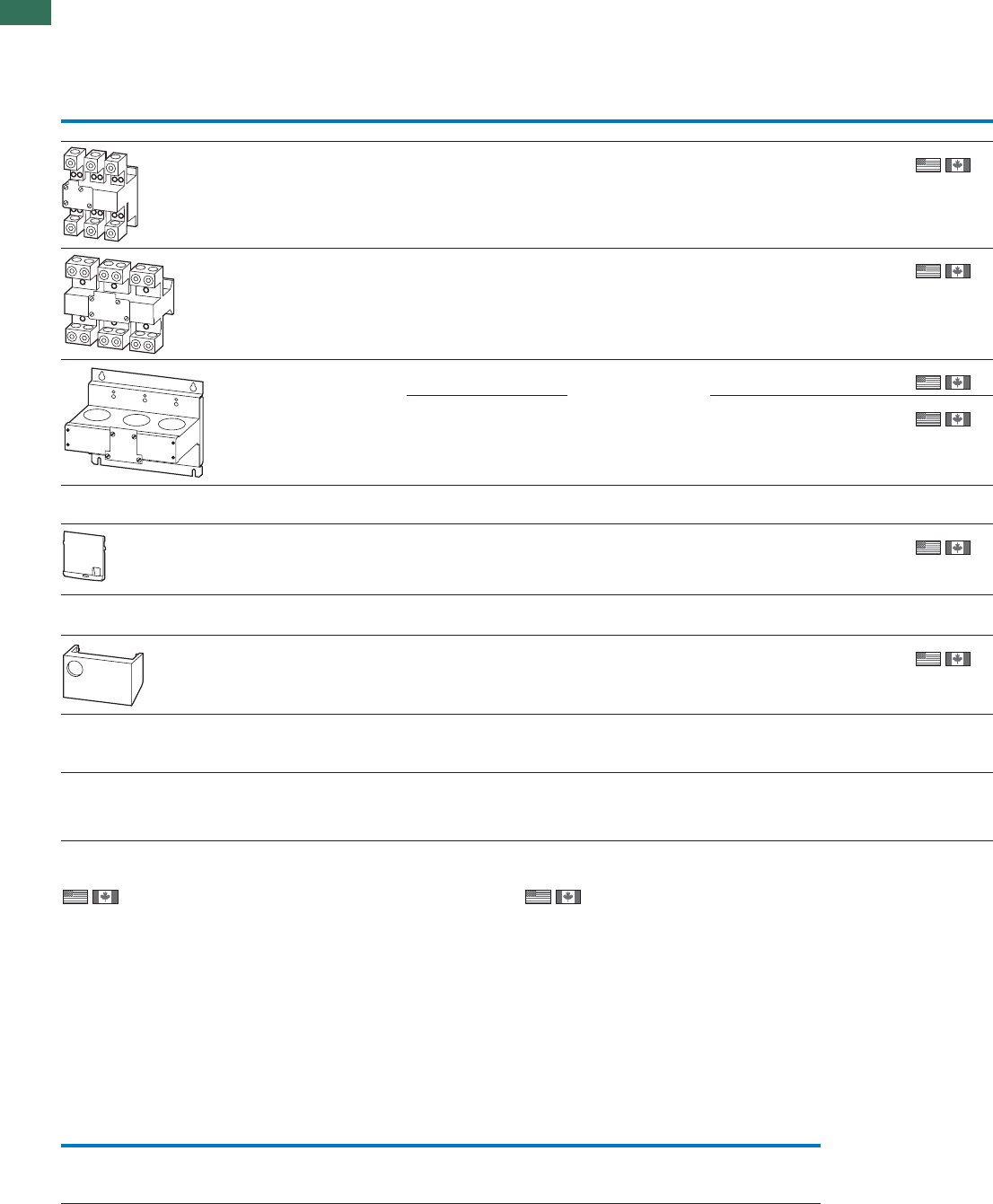
1
1.2 Electronic overload relays to 1500 A
Accessories
18 AUTOMATION AND CONTROL www.eaton.com/seasia-electrical
Setting range of
overload releases
Language Can be used with Part no.
Article no. Price
See price
list
Std. pack
Ir
A
Current sensors
60 – 300 – ZEB32-5-GF/KK
ZEB32-5/KK
ZEB32-5-GF/KK
ZEB32-5/KK
ZEB32-5-GF/KK
ZEB32-5/KK
ZEB-XCT3001)
136511
1off
1off
1off
1off
120 – 600 – ZEB-XCT6001)
136512
200 – 1000 – ZEB-XCT10001)
136517
300 – 1500 – ZEB-XCT15001)
136513
Sealable shroud
Cover to prevent adjustment of motor current (tamper-proof)
–––ZEB-XSC2)
136514
1 off
Reset adapter
Cover to prevent adjustment of motor current (tamper-proof)
–––ZEB-XRB2)
136515
1 off
Documentation
ZEB electronic overload relay
Overload monitoring of EEx e motors
– Deutsch
English
ZEB12
ZEB32
ZEB65
ZEB150
AWB2320-1633DE/EN
136516
1 off
1) 2)
Information relevant for export to North AmericaInformation relevant for export to North America
Product Standards
NA Certification
Suitable for
Max. Voltage Rating
Degree of Protection
Product Standards
NA Certification
Max. Voltage Rating
Degree of Protection
ZEB-XCT…
UL 508; CSA-C22.2 No.14;
IEC/EN 60947-4-1; CE marking
Request filed for UL and CSA
Branch circuits
600 V AC
IEC: IP00, UL/CSA Type: -
UL 508; CSA-C22.2 No.14;
IEC/EN 60947-4-1; CE marking
Request filed for UL and CSA
600 V AC
IEC: IP20, UL/CSA Type: -
Switchgear and cable sizing corresponding to the respective starting inertia (CLASS) for ZEB
Trippling class Class 5 Class 10 Class 15 Class 20 Class 25 Class 30 Class 35 Class 40
Current factor of
rated operational
current Ie
e
1.00 1.00 1.22 1.41 1.58 1.73 1.89 2.00
Switchgear is designed according to "CLASS 10" requirements for both normal and overload operation conditions. In order for the switchgear
(circuit-breaker and contactor) and the cables not to be overloaded with long tripping times, they must be overdimensioned accordingly. The rated
operational current, I , for switchgear and cables can be calculated with the following current factor taking the tripping class into account:
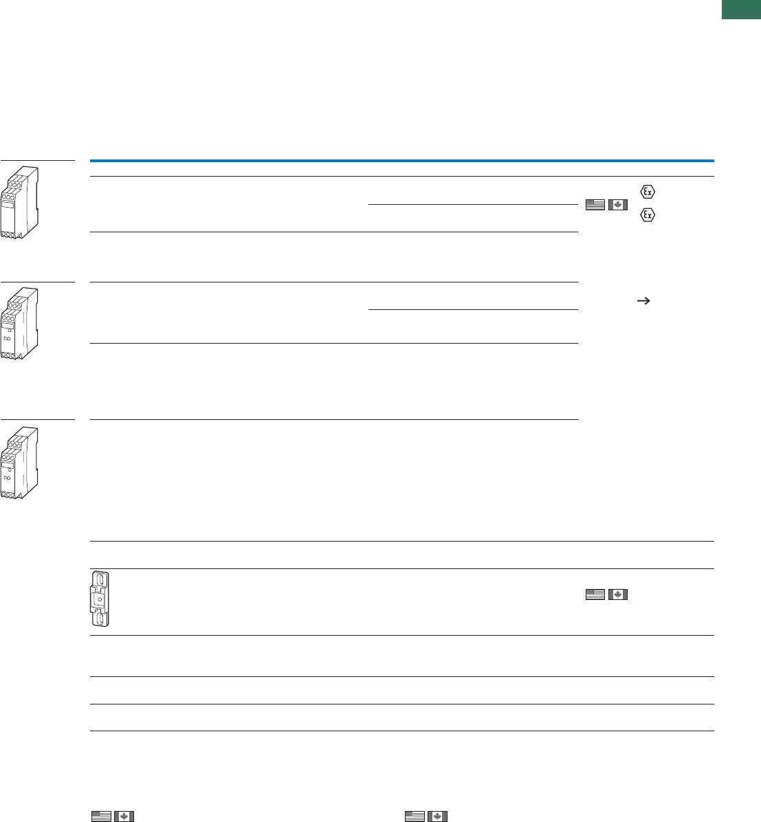
1
1.2
Overload relays for machine protection
Basic devices, accessories
19AUTOMATION AND CONTROL www.eaton.com/seasia-electrical
Ordering
Rated opera-Function
tional current
Conven-
tional
thermal
current
Rated control
voltage Part no.
Article no. Price
See price
list
Std. pack Notes
AC-15
240 V
AC-14
400 V
IeIeIth Us
AAA V
EMT6 thermistor machine protection overload relays
Without automatic reset
Mains and fault LED display
3 3 6 24 - 240 V 50/60 Hz,
336
336
336
336
24 - 240 V DC EMT61) 2)
066166
1 off II (2) G
II (2) GD only
for EMT6-K
PTB 02 ATEX 3162
Observe the manual
AWB 2327-1446
Page 19
Can be snap fitted
on a top-hat rail to
IEC/EN 60715.
Device clearance
̱
3 mm.
230 V 50/60 Hz EMT6(230V)1) 2)
066400
Without automatic reset
Mains and fault LED display
Tripped in the event of a short-circuit in
the sensor-cable
24 - 240 V 50/60 Hz,
24 - 240 V DC EMT6-K 2)
269470
Selector switch with/without automatic
reset
For manual or remote resetting
Test button
Mains and fault LED display
24 - 240 V 50/60 Hz,
24 - 240 V DC EMT6-DB1) 2)
066167
230 V 50/60 Hz EMT6-DB(230V)1) 2)
066401
Selector switch with/without automatic
reset
For manual or remote resetting
Test button
Mains and fault LED display
Trip with short-circuit in the sensor cable
24 - 240 V 50/60 Hz,
24 - 240 V DC EMT6-KDB 2)
269471
All-in-one device
Selector switch with/without automatic
reset
Trip with short-circuit in the sensor cable
Zero-voltage safe
For manual or remote resetting
Test button
Short-circuit detection and retention can
be deactivated
Mains and fault LED display
24 - 240 V 50/60 Hz,
24 - 240 V DC EMT6-DBK 2)
066168
Accessories
Screw adapters for screw fixing
CS-TE 3)
095853
10 off –
Documentation
EMT6 thermistor overload relay
Overload monitoring of machines in the EEx e area
German AWB2327-1446D
264853
1 off
English AWB2327-1446GB
267010
1 off
Notes 1) For EMT6, EMT6(230V), EMT6-DB and EMT6-DB(230V) applies:
Provide additional short-circuit protection in the sensor circuit
with a current monitoring relay.
EMT6
2) 3)
Information relevant for export to North AmericaInformation relevant for export to North America
Product Standards
UL File No.
UL CCN
CSA File No.
CSA Class No.
NA Certification
Max. Voltage Rating
Degree of Protection
UL/CSA certification not required
UL 508; CSA-C22.2 No.14;
IEC/EN 60947-4-1; CE marking
E29184
NKCR
12528
3211-03
UL Listed, CSA certified
600 V AC
IEC: IP20, UL/CSA Type: -
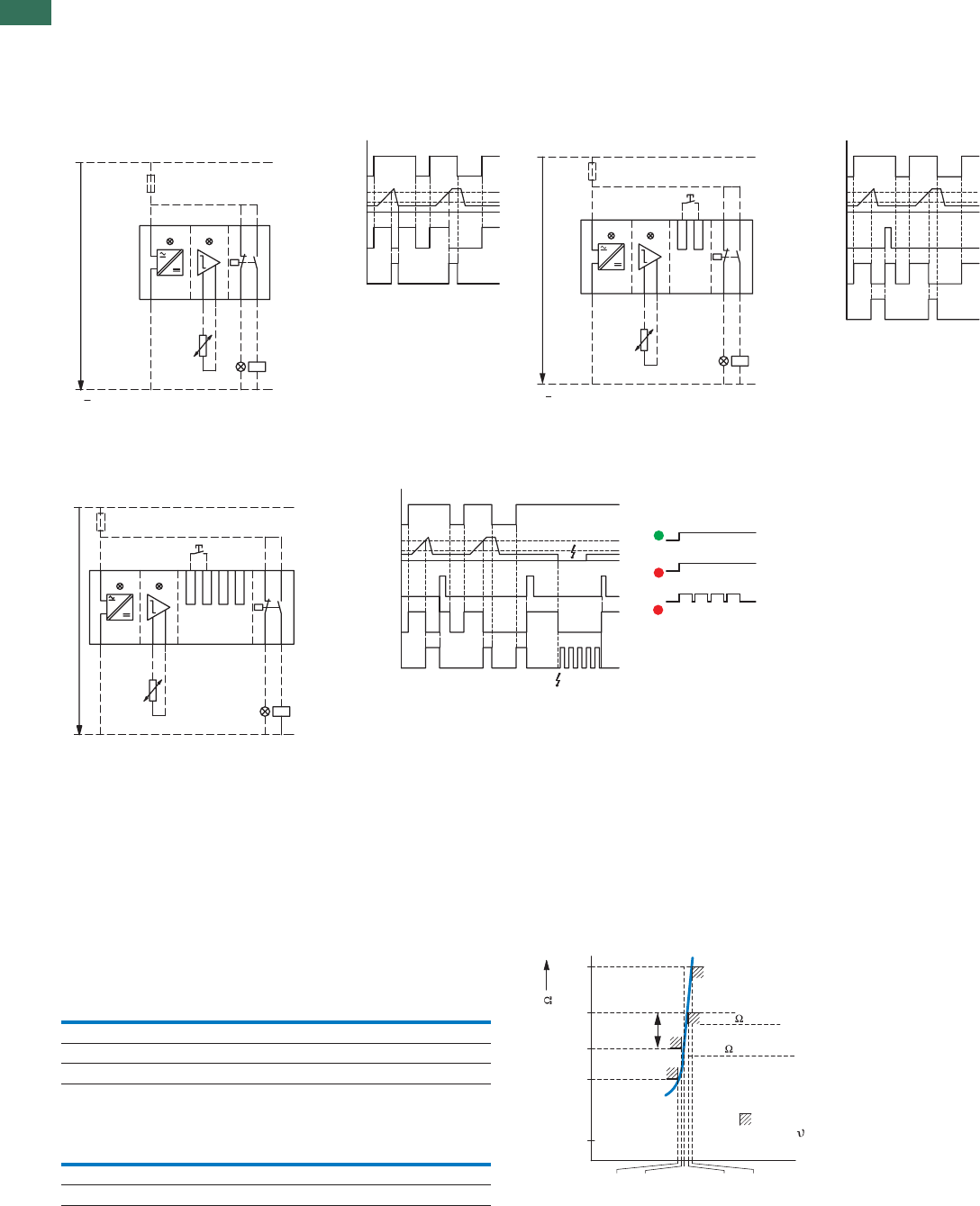
1
1.2 Overload relays for machine protection
Selection aid
20 AUTOMATION AND CONTROL www.eaton.com/seasia-electrical
Engineering
Terminal marking according to EN 50005
EMT6(-K), EMT6-(K)DB, EMT6-DBK
Auto
EMT6-(K)DB, EMT6-DBK
Manual
EMT6-DBK
Zero-voltage safe operation
LED display
Supply voltage present
Device has tripped
Device has tripped/short-circuit in
the sensor circuit
Sensor circuit
At RK̰ 250 ȍ per sensor: 6 sensors, at RK̰ 100 ȍ per sensor: 9 sensors in
the winding (provided by user), max. cable length to sensor 250 m (not shielded);
Total PTC thermistor resistance RK̰
1500 ȍ
Sensor circuit characteristic values at Us and +20 °C
EMT6…
RT1-T2 UT1-T2 IT1-T2
V DC max. mA max.
T1, T2 short-circuited - 1.9
4 kȍ30.8
T1-T2 open 5.1 -
Functions that can be disconnected on the EMT6-DBK:
Function Disconnection by link
Short-circuit monitoring Y1- Y3
Zero-voltage safety Y1- Y4
L +
~
~
N
U
S
A1 21 13
A2 T1 T2 22 14
PTC
Power Tripped
Tripped LED
A1/A2
T1/T2 3.6 K
1.6 K
0
13–14, 21–22
+
L
~
~
N
U
S
A1 21
A2 T1 T2 22 14
PTC
13
Y2
Y1
Power Tripped
Tripped LED
A1/A2
T1/T2
3.6 K
1.6 k
0
13–14, 21–22
Y1/Y2, RESET
L +
~
N –
~
U
S
A1 21
A2 T1 222T 14
PTC
13
Y2
Y1 Y4
Y3
Power Tripped
A1/A2
T1/T2 3.6 K
1.6 K
0
13–14, 21–22
Y1/Y2, RESET
Short-circuit
Tripped LED
60
750
1650
4000
12000
[°C]
NAT NAT
NAT NAT NAT
–20° –5° +5° +15°
3600 Tripping
1600 Reset
Tolerance limits
Temperature
Resistance [ ]
Resetting
range
IEC-
Tripping range
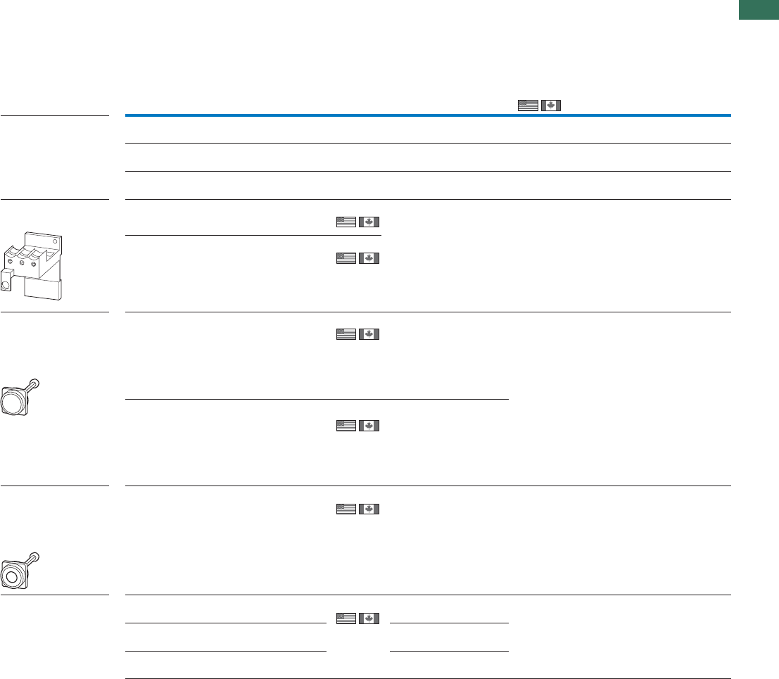
1
1.2
Overload relays
Accessories
21AUTOMATION AND CONTROL www.eaton.com/seasia-electrical
Ordering
For use with Part no.
Article no. Price
See price
list
Std. pack Information relevant for export toNotes
North America
Documentation
Overload relays
Overload monitoring of
EEx e motors
ZE… AWB2300-1425D
258704
1 off German
1 off
1 off
ZB12…
ZB32… AWB2300-1527D/GB
284910
German/English
ZB65…
ZB150… AWB2300-1545D/GB
102065
German/English
Bases
For separate mounting
ZB32 ZB32-XEZ
278473
5 off Can be snap fitted on a
top-hat rail to IEC/EN 60715
or can be screw fitted.
For ZB32-38, use
BK25/3-PKZ0 additionally.
ZB65 ZB65-XEZ
278474
2 off
Pushbuttons
For enclosed
Overload relay
Mounting diameter: 22.3 mm
External reset button, IP65
ZW7...
ZE
Z5
ZB12
ZB32
ZB65
ZB150
M22-DZ-B
254833
10 off Button plate, blue
ZW7...
ZE
Z5
ZB12
ZB32
ZB65
ZB150
M22-DZ-B-GB14
254834
10 off Button plate, blue RESET
Off button, IP65
ZW7...
ZE
Z5
ZB12
ZB32
ZB65
ZB150
M22-DZ-X
254835
10 off Without button plate,
add button plate.
Button plates
M22-DZ-X M22-XD-R
216423
10 off Button plate, red UL/CSA certification not required
M22-DZ-X M22-XD-R-X0
218153
Red button plate with white
circle
M22-DZ-X M22-XD-R-GB0
218194
Button plate red STOP
ZB, Z5, ZW7
Product Standards
UL File No.
NCCLU
CSA File No.
CSA Class No.
NA Certification
Max. Voltage Rating
Degree of Protection
UL 508; CSA-C22.2 No.14;
IEC/EN 60947-4-1; CE marking
E29184
NKCR
12528
3211-03
UL Listed, CSA certified
600 V AC
IEC: IP00, UL/CSA Type: -
Product Standards
UL File No.
NCCLU
CSA File No.
CSA Class No.
NA Certification
UL 508; CSA-C22.2 No.14;
IEC/EN 60947-4-1; CE marking
E29184
NKCR
12528
3211-03
UL Listed, CSA certified
Product Standards
UL File No.
NCCLU
CSA File No.
CSA Class No.
NA Certification
UL 508; CSA-C22.2 No.14;
IEC/EN 60947-4-1; CE marking
E29184
NKCR
12528
3211-03
UL Listed, CSA certified
Pushbuttons
For enclosed
Overload relay
Mounting diameter: 22.3 mm
Pushbuttons
For enclosed
Overload relay
Mounting diameter: 22.3 mm
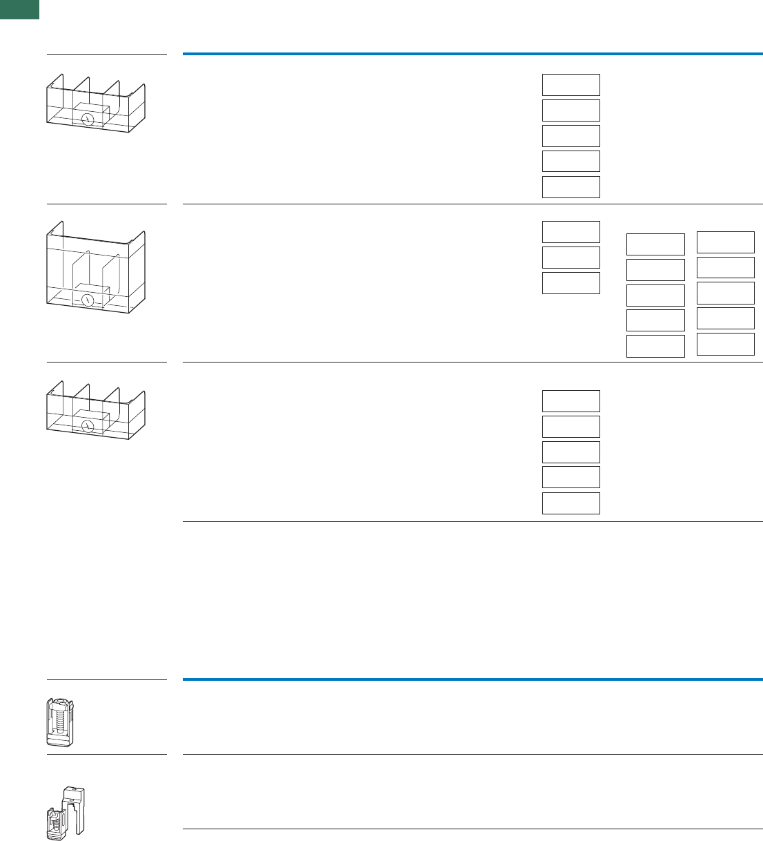
1
1.2 Overload relays
Accessories
22 AUTOMATION AND CONTROL www.eaton.com/seasia-electrical
For use with Part no.
Article no. Price
See price list
Std. pack Notes
For use with Part no.
Article no. Price
See price list
Std. pack Notes
Covers Direct mounting Z5-…/FF225 to
DILM185A
DILM225A
Z5/FF225A-XHB-Z
139579
1 off Fitted directly to the contactor
Z5-…/FF225A
Z5-…/FF250 Z5/FF250-XHB
215217
1 off Separate mounting Fitted directly to
the contactor
Fitted directly to
the contactor
Direct mounting Z5-…/FF250 to
DILM250
DILM300A
Z5/FF250-XHB-Z
215218
1 off Fitted directly to the contactor
Box terminals kit
Consisting of 3 individual clamps
For
connection
of copper
flat strip
max.
W x H
mm
With protective cover Z5-…/FF250 24 x 26 K-B-DIL6AM
064062
1 off When using box terminals the
protective covers must be used.
With control circuit terminal
and protective cover
Z5-…/FF250 24 x 26 KS-B-DIL6AM
064063
1 off When using box terminals the
protective covers must be used.
Z5-.../FF225A
DILM400
-XHB
Z5/FF225A
-XHB-Z
Z5/FF250
-XHB
DILM185A/
225A
Z5/FF250
-XHB
Z5/FF250
-XHB
Z5-.../FF250/
FF225A
Z5-.../FF250
DILM400
-XHB
Z5/FF250
-XHB-Z
Z5/FF250
-XHB
DILM250/
300A
Z5-.../FF225A
DILM400
-XHB
Z5/FF225A
-XHB-Z
Z5/FF250
-XHB
DILM185A/
225A
Z5-.../FF250
DILM400
-XHB
Z5/FF250
-XHB-Z
Z5/FF250
-XHB
DILM250/
300A
Z5..., K-B..., KS-B...
Covers
Covers
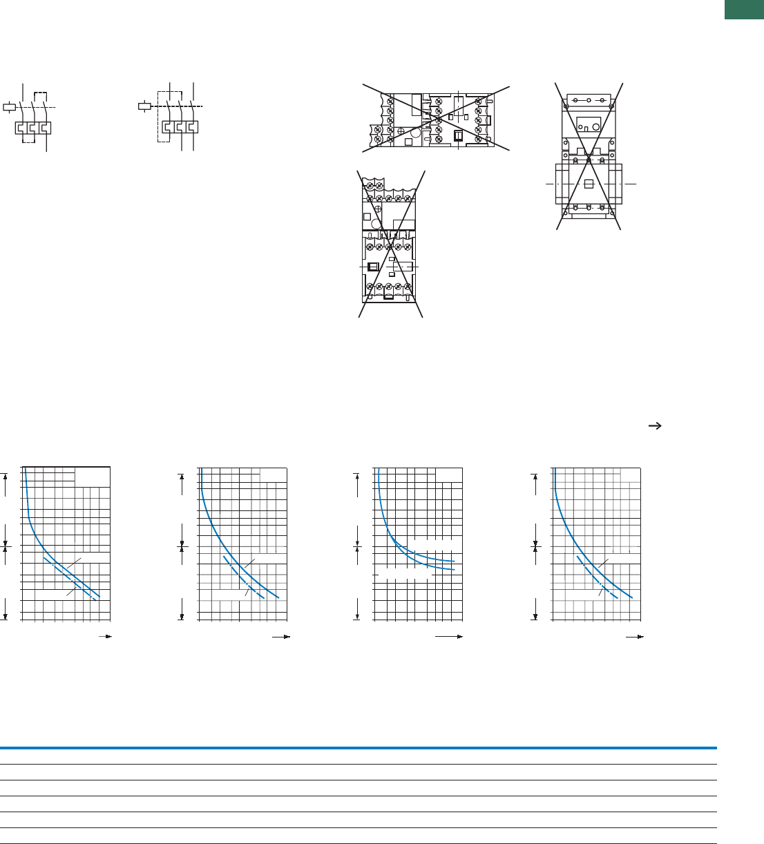
1
1.2
Overload relays
Selection criteria
23AUTOMATION AND CONTROL www.eaton.com/seasia-electrical
Engineering
Protection of single-phase and DC current motors:
1 pole 2 pole
Mounting position:
ZB12, ZB32, ZB65, ZB150, Z5ZE
Tripping characteristics
These tripping characteristics are mean values of the spread at 20 °C ambient temperature in a cold state.
They show the tripping times in relation to the response current. When the devices are at operational temperature the tripping time of the overload
relay drops to approx. 25% of the value shown. Specific characteristics for each individual setting range can be found in the manual on Page 21
2h
100
60
40
20
10
6
4
2
1
40
20
10
6
4
2
1
0.6
ZB12, ZB32,
ZB65, ZE
1 1.5 2 3 4 6 8 10 15 20
x Setting current
2-phase
Seconds Minutes
3-phase
2h
100
60
40
20
10
6
4
2
1
40
20
10
6
4
2
1
0.6
ZB150
6 8 10 15 20
3 4
1 1.5 2
x Setting current
2-phase
Seconds Minutes
3-phase
2 h
100
60
40
20
10
6
4
2
1
40
20
10
6
4
2
1
1 1.5 2 3 4 6 8 10 15 20
0.6
ZW7
Minutes
Seconds
x
Setting current
Minimum
Maximum
2h
100
60
40
20
10
6
4
2
1
40
20
10
6
4
2
1
0.6
Z5
6 8 10 15 20
3 4
1 1.5 2
x Setting current
2 phase
Seconds Minutes
3 phase
Adaption of ZW7 to smaller rated motor currents
Number of loops ZW7 -63 -90 -125 -160 -240 -290 -400 -540 -630
Rated motor current IN [A]
1 42-63 60-90 85-125 110-160 160-240 190-290 270-400 360-540 420-630
2 21-31,5 30-45 42.5-62,5 55-80 80-120 95-145 135-200 180-270 210-315
3 14-21 20-30 28.3-41,7 36.7-53,3 53.3-80 63.3-96,7 90-133,3 120-180 140-210
4 10.5-15,8 15-22,5 21.3-31,3 27.5-40 40-60 47.5-72,5 67.5-100 90-135 105-157,5
5 8.4-12,6 12-18 17-25 22-32 32-48 38-58 54-80 72-108 84-126
1
1.2 Overload relays
UL/CSA-short-circuit strength
24 AUTOMATION AND CONTROL www.eaton.com/seasia-electrical
Overload relay short-circuit strength
UL508, CSA-C22,2 No. 14/SCCR values
Fuse acc. to NEC, CEC CB Fuse acc. to NEC, CEC CB
AkAAkA AkAAkA
600V AC 480V AC 600V AC 600 V AC
ZE-0,16 1 5 15 5 225 5 200 5
ZE-0.24 1 5 15 5 250 10 250 10
ZE-0.4 1 5 15 5 400 CLASS J 10 400 10
ZE-0.6 1 5 15 5 500 CLASS J 10 500 10
ZE-1,0 3 5 15 5 600 CLASS J 10 600 10
ZE-1.6 6 5 15 5 600 CLASS J 10 600 10
ZE-2.4 6 5 15 5 110 CLASS J 100 200 5
ZE-4 15 5 15 5 125 CLASS J 100 250 10
ZE-6 20 5 15 5 200 CLASS J 100 400 10
ZE-9 35 5 15 5 250 CLASS J 100 500 10
ZE-12 45 5 - -
ZB150-50
ZB150-70
ZB150-100
ZB150-125
ZB150-150
ZB150-175
ZB150-50(KK)
ZB150-70(KK)
ZB150-100(KK)
ZB150-125(KK)
ZB150-150(KK) 300 CLASS J 100 600 10
600V AC ZB150-175(KK) 300 CLASS J 100 600 10
ZB12(32)-0,16 1 CLASS J/CC 100 - - 600V AC 600V AC
ZB12(32)-0,24 1 CLASS J/CC 100 - - 250 10 250 10
ZB12(32)-0,4 1 CLASS J/CC 100 - - 400 CLASS J 10 400 10
ZB12(32)-0,6 1 CLASS J/CC 100 - - 500 CLASS J 10 500 10
ZB-12(32)-1,0 1 CLASS J/CC 100 - - 600 CLASS J 10 600 10
ZB-12(32)-1,6 3 CLASS J/CC 100 - - 800 CLASS J 10 800 10
ZB-12(32)-2,4 3 CLASS J/CC 100 - - 700 CLASS J 10 600 10
ZB-12(32)-4 6 CLASS J/CC 100 - - 125 CLASS J 100 - -
ZB-12(32)-6 10 CLASS J/CC 100 - - 200 CLASS J 100 - -
ZB-12(32)-10 15 CLASS J/CC 100 - - 250 CLASS J 100 - -
ZB12-12 15 CLASS J/CC 100 - -
Z5-70/...
Z5-100/...
Z5-125/...
Z5-160/...
Z5-220/...
Z5-250/...
Z5-70/...
Z5-100/...
Z5-125/...
Z5-160/... 300 CLASS J 100 - -
ZB12-16 30 CLASS J/CC 100 - -
ZB32-16 35 CLASS J 100 - -
ZB32-24 45 CLASS J 100 - -
ZB32-32 60 CLASS J 100 - -
600V AC 600V AC
ZB65-10 15 CLASS J 100 40 5
ZB65-16 35 CLASS J 100 60 5
ZB65-24 45 CLASS J 100 90 5
ZB65-40 60 CLASS J 100 125 5
ZB65-57 110 CLASS J 100 150 10
ZB65-65 125 CLASS J 100 150 10
ZB65-75 125 CLASS J 100 150 10
ZE, ZB, Z5

1
1.2
Overload relays
Overload relays
25AUTOMATION AND CONTROL www.eaton.com/seasia-electrical
Technical data
ZE ZB12, ZB32 ZB65 ZB150(KK)
General
Standards IEC/EN 60947, VDE 0660, UL, CSA
Climatic proofing Damp heat, constant, to IEC 60068-2-78
Damp heat, cyclic, to IEC 60068-2-30
Ambient temperature
Open1) °C -25…50 -25…55 -25…55 -25…55
Enclosed1) °C -25…40 -25…40 -25…40 -25…40
Temperature compensation Continuous
Mounting position Page 23
kgWeight 0.07 0.15 0.25 1.64
Mechanical shock resistance half-sinusoidal shock, 10 ms
to IEC 60068-2-27
g10 10 10 10
Protection type IP20 IP20 IP00 IP00
Protection against direct contact when actuated
from front (EN 50274)
Finger- and back-of-hand proof
Main contacts
URated impulse withstand voltage imp V AC 6000 6000 6000 8000
Overvoltage category/pollution degree III/3 III/3 III/3 III/3
Rated insulation voltage
UCA iV AC 690 690 690 1000
URated operating voltage eV AC 690 690 690 1000
Safe isolation according to EN 61140
V ACBetween auxiliary contacts and main contacts 300 440 440 440
V ACBetween the main contacts 300 440 440 440
AOverload relay setting range 0.1…12 0.1…38 6…75 25…175
%/KTemperature compensation residual error > 40 ºC ̰ 0.25 ̰ 0.25 ̰ 0.25 ̰ 0.25
Short-circuit protection rating maximum fuse Page 6 Page 8 Page 10 Page 10
Current heat loss (3 conductors)
WLower value of setting range 2.5 2.5 3 16
WUpper value of setting range 6 6 7.5 18
Terminal capacity
mm²Solid 2 x (0.75 - 2.5) 2 x (1 - 6) 5) 2 x (1 - 16) 4) 2 x (4 - 16)
mm²Flexible with ferrule 2 x (0.5 - 1.5) 2 x (1 - 4) 5)
2 x (1 - 6) 3)
1 × (1…25)
2 x (1…10) 2)
1 x (4 - 70)
2 x (4 - 50)
mm²Stranded – – 1 x (16…25) 1 x (16…50)
2 x (16…50)
AWGSolid or stranded 18 - 14 14 - 85) 14 - 2 3/0
mmWidthBusbar ––––
Terminal screw M3.5 M4 M6 M10
NmTightening torque 1.2 1.85) 3.5 10
Tools
SizePozidriv screwdriver 222–
mmFlat-blade screwdriver 0.8 x 5.5 1 x 6 1 x 6 –
mmSWHexagon socket –––5
Notes 1) Ambient temperature: Operating range to IEC/EN 60947, PTB: -5°C to +55°C
2) Use identical cross-section when using two conductors
3) 6 mm flexible with ferrules to DIN 46228
4) With ZB65-XEZ max 1 x (1… 16)
5) ZB32-38: solid and flexible with ferrule, 2.5 - 25 mm², 3 Nm tightening torque.
AWG10-b, 27 lb-in tightening torque for solid or stranded conductors.
ZE, ZB

1
1.2 Overload relays
Overload relays, CT-operated overload relays
26 AUTOMATION AND CONTROL www.eaton.com/seasia-electrical
Z5-…/FF225A(250) ZW7
General
Standards IEC/EN 60947, VDE 0660, UL, CSA IEC/EN 60947, VDE 0660, UL, CSA
Climatic proofing Damp heat, constant, to IEC 60068-2-78
Damp heat, cyclic, to IEC 60068-2-30
Ambient temperature
Open1) °C -25…50 -25…50
Enclosed 1) °C -25…40 -25…40
Temperature compensation Continuous Continuous
Mounting position Page 23 Any
kgWeight 1.55 0.8
Mechanical shock resistance half-sinusoidal shock, 10 ms
to IEC 60068-2-27
g10 10
Protection type IP00 IP00
Protection against direct contact when actuated
from front (EN 50274)
With terminal cover Finger- and back-of-hand proof
Main contacts
URated impulse withstand voltage imp V AC 8000 6000
Overvoltage category/pollution degree III/3 III/3
Rated insulation voltage
UCA iV AC 1000 690
URated operating voltage eV AC 1000 690
Safe isolation according to EN 61140
V ACBetween auxiliary contacts and main contacts 440 440
V ACBetween the main contacts 440 440
AOverload relay setting range 50…300 42…630
%/KTemperature compensation residual error > 40 ºC ̰ 0.25 –
Short-circuit protection rating maximum fuse Page 12 With overload relay in conjunction
with a transformer as required for the
contactor
Current heat loss (3 conductors)
WLower value of setting range 16 3
WUpper value of setting range 28 10
Terminal capacity
mm²Flexible with ferrule 95 –
mm²Stranded with ferrule 120 –
AWGSolid or stranded 250 MCM –
Flat conductor. Number of segments x width x thickness mm 6 x 16 x 0.82) –
mmWidthBusbar 20 x 3 –
Push-through opening mm – 27
Terminal screw M8 x 25 –
NmTightening torque 24 –
Tools
mmSWHexagonal socket 13 –
Notes 1) Ambient temperature: Operating range to IEC/EN 60947, PTB: -5°C to +50°C
2) Fixing with box terminals
Z5, ZW7

1
1.2
Overload relays
Overload relays, CT-operated overload relays
27AUTOMATION AND CONTROL www.eaton.com/seasia-electrical
ZE ZB12, ZB32 ZB65 ZB150(KK) Z5-.../FF225
Z5-.../FF250
ZW7
Auxiliary and control circuits
Rated impulse withstand voltage U
U
imp V 6000 6000 6000 6000 6000 6000
Overvoltage category/Pollution degree III/3 III/3 III/3 III/3 III/3 III/3
Terminal capacity
mm²Solid 2 x (0.75 - 2.5) 2 x (0.75 - 4) 2 x (0.75 - 4) 2 x (0.75 - 4) 2 x (0.75 - 4) 2 x (0.75 - 4)
mm²Flexible with ferrule 2 x (0.5 - 1.5) 2 x (0.75 - 2.5) 2 x (0.75 - 2.5) 2 x (0.75 - 2.5) 2 x (0.75 - 2.5) 2 x (0.75 - 2.5)
AWGSolid or stranded 2 x (18 - 12) 2 x (18 - 12) 2 x (18 - 12) 2 x (18 - 12) 2 x (18 - 12) 2 x (18 - 12)
Terminal screw M3.5 M3.5 M3.5 M3.5 M3.5 M3.5
NmTightening torque 0.8 - 1.2 0.8 - 1.2 0.8 - 1.2 0.8 - 1.2 0.8 - 1.2 0.8 - 1.2
Tools
SizePozidriv screwdriver 2 2 2 2 2 2
mmFlat-blade screwdriver 0.8 x 5.5 1 x 6 1 x 6 1 x 6 1 x 6 1 x 6
Auxiliary circuit rated insulation voltage iV AC 690 500 500 500 500 500
URated operating voltage eV AC 500 500 500 500 500 500
Safe isolation according to EN 61140
V ACBetween the auxiliary contacts 300 240 240 240 240 240
IConventional thermal current th A6 6 6 6 6 6
Rated operational current
AC-15
N/O
I120 V eA 1.5 1.5 1.5 1.5 1.5 1.5
I240 V eA 1.5 1.5 1.5 1.5 1.5 1.5
I415 V eA 0.5 0.5 0.5 0.5 0.5 0.5
I500 V eA 0.3 0.5 0.5 0.5 0.5 0.5
NC
I120 V eA 1.5 1.5 1.5 1.5 1.5 1.5
I240 V eA 1.5 1.5 1.5 1.5 1.5 1.5
I415 V eA 0.7 0.9 0.9 0.9 0.9 0.9
I500 V eA 0.5 0.8 0.8 0.8 0.8 0.8
DC-13 L/R ̰ 15 ms1)
I24 V eA 0.9 0.9 0.9 0.9 0.9 0.9
I60 V eA 0.75 0.753) 0.753) 0.753) 0.753) 0.753)
I110 V eA 0.4 0.4 0.4 0.4 0.4 0.4
I220 V eA 0.2 0.2 0.2 0.2 0.2 0.2
General Use
VAC operated 240
600
–––––
AAC operated 1.5
0.6
–––––
VDC operated – – – – – –
ADC operated – – – – – –
Pilot Duty
AC operated D300 B3004)
B6005)
B3004)
B6005)
B3004)
B6005)
B3004)
B6005)
B3004)
B6005)
DC operated R300 R300 R300 R300 R300 R300
Short-circuit rating without welding
Max. fuse 2) A gG/gL 4 6 6 6 6 6
Notes 1) Making and breaking conditions to DC-13, time constant as stated
2) See transparent overlay "Fuses" for time/current characteristics (please enquire)
3) Rated operational current DC-13, 60 V: N/O auxiliary contact 0.6 A
4) With opposite polarity
5) With same polarity
ZE, ZB, Z5, ZW7

1
1.2 Electronic overload relays to 1500 A
28 AUTOMATION AND CONTROL www.eaton.com/seasia-electrical
ZEB12, ZEB32 ZEB65-45 ZEB65-100 ZEB150
General
Standards IEC/EN 60947, VDE 0660, UL, CSA
Climatic proofing Damp heat, constant, to IEC 60068-2-78
Damp heat, cyclic, to IEC 60068-2-30
Ambient temperature
°COpen –25…65 –25…65 –25…65 –25…65
°CEnclosed –25…65 –25…40 –25…40 –25…40
Temperature compensation Continuous Continuous Continuous Continuous
Mounting position Any Any Any Any
Mechanical shock resistance half-sinusoidal shock, 10 ms
to IEC 60068-2-27
g15 15 15 15
Protection type IP20 IP20 IP20 IP20
Protection against direct contact when actuated
from front (EN 50274)
Finger- and back-of-hand proof
Main contacts
URated impulse withstand voltage imp V AC 6000 6000 6000 6000
Overvoltage category/pollution degree III / 3 III / 3 III / 3 III / 3
Rated insulation voltage
UAC iV AC 690 690 690 690
URated operating voltage eV AC 690 690 690 690
Safe isolation according to EN 61140
Between auxiliary contacts and main contacts V AC 600 600 600 600
V ACBetween the main contacts 600 600 600 600
AOverload relay setting range 0.3…45 9…45 20…100 20…100
Terminal capacity
mm²Solid 1 x 2.5 - 16 1 x 2.5 - 16 1 x 6 - 50 1 x 6 - 50
AWGSolid or stranded 1 x 14 - 4 1 x 14 - 4 1 x 10 - 1 1 x 10 - 1
Auxiliary and control circuits
URated impulse withstand voltage imp V 6000 6000 6000 6000
Overvoltage category/pollution degree III / 3 III / 3 III / 3 III / 3
Terminal capacity
mm²Solid 2 x (0.75 - 4) 2 x (0.75 - 4) 2 x (0.75 - 4) 2 x (0.75 - 4)
mm²Flexible with ferrule 2 x (0.75 - 2.5) 2 x (0.75 - 2.5) 2 x (0.75 - 2.5) 2 x (0.75 - 2.5)
AWGSolid or stranded 2 x (18 - 12) 2 x (18 - 12) 2 x (18 - 12) 2 x (18 - 12)
Terminal screw M3.5 M3.5 M3.5 M3.5
NmTerminal screw
Tightening torque
0.8 - 1.2 0.8 - 1.2 0.8 - 1.2 0.8 - 1.2
lb-in 7 - 10.6 7 - 10.6 7 - 10.6 7 - 10.6
Tools
SizePozidriv screwdriver 2 2 2 2
mmFlat-blade screwdriver 1 x 6 1 x 6 1 x 6 1 x 6
Auxiliary circuit rated insulation voltage U iV AC 500 500 500 500
URated operating voltage eV AC 500 500 500 500
Safe isolation according to EN 61140
V ACBetween the auxiliary contacts 240 240 240 240
IConventional thermal current th A5 5 5 5
Rated operational current
AC-15
N/O
I120 V eA1.5 1.5 1.5 1.5
I240 V eA1.5 1.5 1.5 1.5
I415 V eA0.5 0.5 0.5 0.5
I500 V eA0.5 0.5 0.5 0.5
NC
I120 V eA1.5 1.5 1.5 1.5
I240 V eA1.5 1.5 1.5 1.5
I415 V eA0.9 0.9 0.9 0.9
I500 V eA0.8 0.8 0.8 0.8
DC-13 L/R ̰ 15 ms
I24 V eA0.9 0.9 0.9 0.9
I60 V eA0.750.750.750.75
I110 V eA0 0.4 0.4 0.4
I220 V eA0.2 0.2 0.2 0.2
Short-circuit rating without welding
A gG/gLMax. fuse 6 6 6 6
ZEB

1
1.2
Thermistor machine protection relays
29AUTOMATION AND CONTROL www.eaton.com/seasia-electrical
EMT6
General
Standards IEC/EN 60947, VDE 0660, EN 55011
Climatic proofing Damp heat, constant, to IEC 60068-2-78;
Damp heat, cyclic, to IEC 60068-2-30
Ambient temperature
Open °C -25…60
Enclosed °C -25…45
Storage °C -45 - 60
Mounting position Any
Weight kg 0.15
gShock resistance half-sinusoidal shock 10 ms to IEC 60068-2-27 10
Protection type IP20
Protection against direct contact when actuated from front (EN 50274) Finger- and back-of-hand proof
Safe isolation according to EN 61140
V ACBetween the contacts 250
V ACBetween contacts and supply voltage 250
Auxiliary and control circuits
URated impulse withstand voltage imp V AC 6000
Overvoltage category/pollution degree III/3
Auxiliary and control circuit terminal capacity
Solid mm² 1 x 2.5
2 x (0.5 - 1.5)
mm²Flexible with ferrule 1 x 2.5
2 x (0.5 - 1.5)
AWGSolid or stranded 20 - 14
Terminal screw M3.5
NmTightening torque 1.2
Tools
SizePozidriv screwdriver 2
mmFlat-blade screwdriver 1 x 6
Auxiliary circuit
URated insulation voltage iV400
Rated operational current
AC-14
N/O
I415 V eA3
NC
I415 V eA3
AC-15
N/O
I240 V eA3
I415 V eA1
NC
I240 V eA3
I415 V eA1
Max. short-circuit protective device
gG/gLFuse 6
Control circuit
URated insulation voltage iV240
URated operational voltage eV240
1)
x UVoltage tolerance e0.85 - 1.1
Power consumption
AC VA 3.5
DC W2
Trip at approx. ȍ̱3600
Reset at approx. ȍ̰1600
Notes 1) EMT6(-DB)230V: Ue = 230 V
EMT6
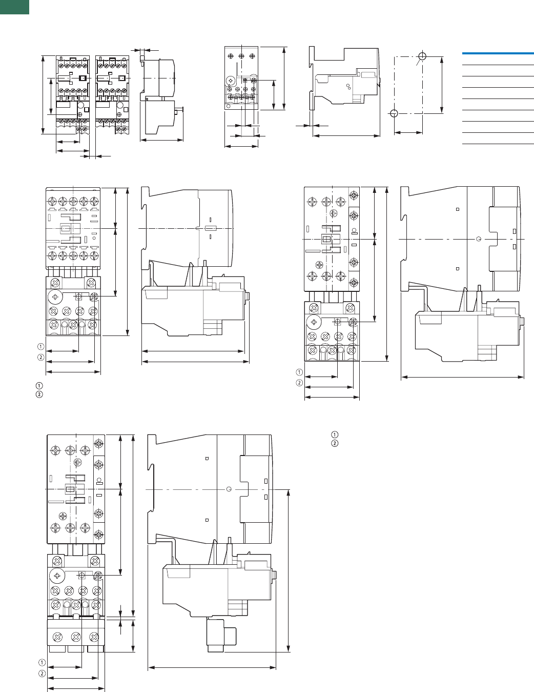
1
1.2 Overload relays
Overload relays
30 AUTOMATION AND CONTROL www.eaton.com/seasia-electrical
Dimensions
BaseOverloadrelays
ZB65-XEZZB32-XEZZE-…
ZB12 ZB32
OFF
Reset/ON
ZB32-38
OFF
Reset/ON
5.5
58
= 5
45
32
49
106
>
5
b2
16.5
c2
b
a
c
b1
a1
2 x d
ZB32 ZB65
a4560
b8586
c 90.5 112
c2 3.8 4.7
a1 35 50
b1 75 75
b2 40.5 47
dM4M5
45
27.5
39 88
84
53 34
120
45
27.5
39
102
2426
136
45
27.5
39
102
622
25
42
136
120
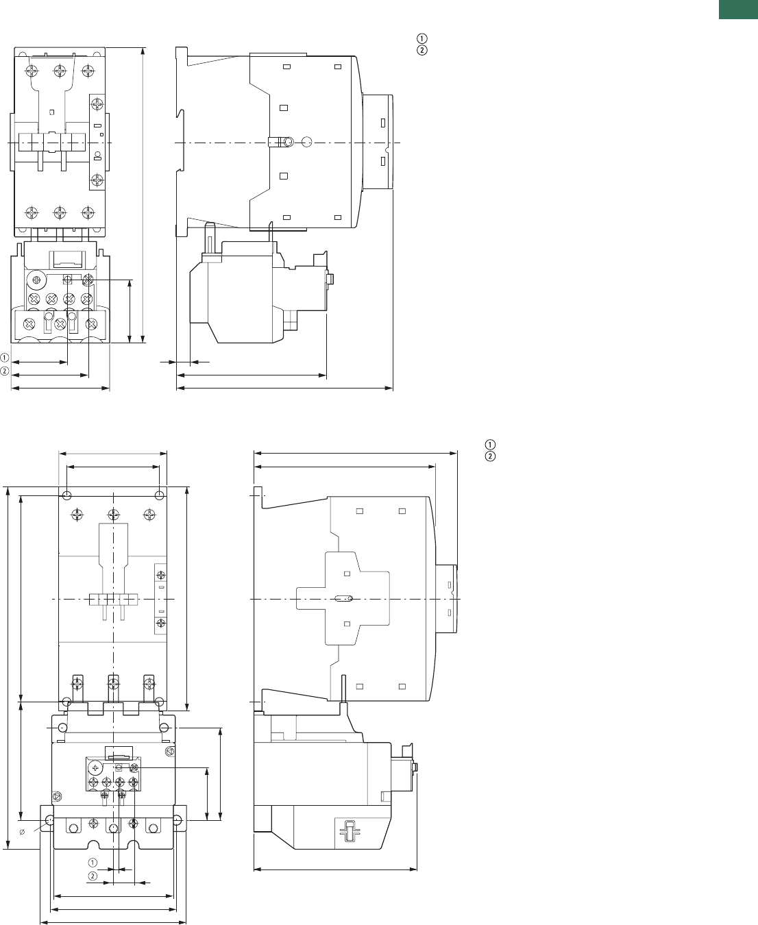
1
1.2
Overload relays
Overload relays
31AUTOMATION AND CONTROL www.eaton.com/seasia-electrical
Overload relays
ZB65
OFF
Reset/ON
ZB150
OFF
Reset/ON
172
40
60
46.5
35 7.5
132
96.5
100
134
44
74
118
95
5
16.5
91
90
150
170
156
160
277
70
7
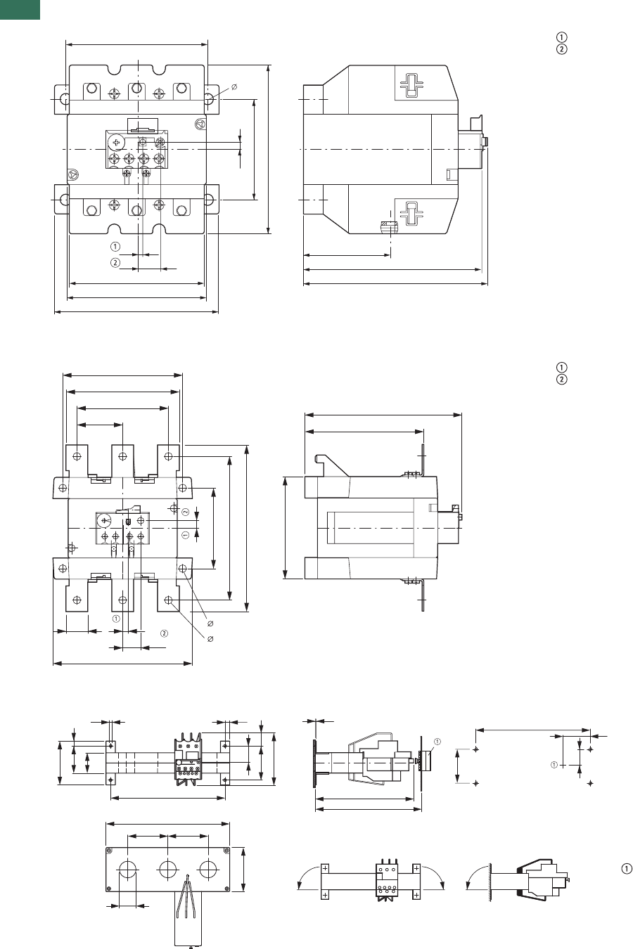
1
1.2 Overload relays
Overload relays, CT-operated overload relays
32 AUTOMATION AND CONTROL www.eaton.com/seasia-electrical
Overload relays
ZB150-50/KK
OFF
Reset/ON
Z5 overload relays greater than 150A
Z5-.../FF250
OFF
Reset/ON
Current transformer-operated overload relays
ZW7-…
121
74
7
5
16.5
63
129
134
100
118
99
95
7
121
110
96
128
74
144
169
48
25 5
16.5
144
111
94
7
7
11
200
185
65
65
71
27
7.5
26
55 21
85
71
44
33
8
4.3
185
M4
44
26
55
1.5
159
172 – 250
90° 90°90° Reset/ON
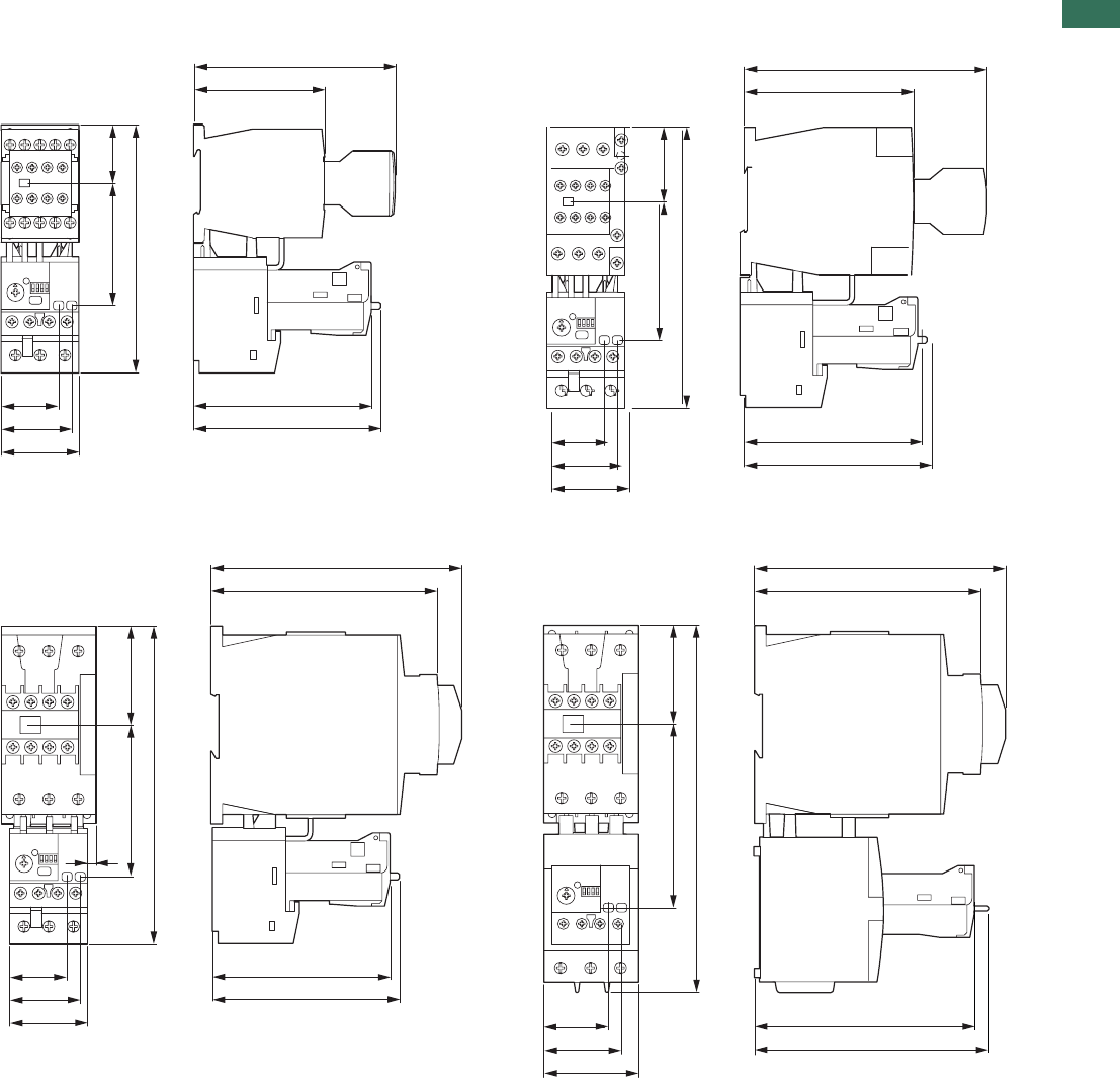
1
1.2
Overload relays
Electronic overload relays
33AUTOMATION AND CONTROL www.eaton.com/seasia-electrical
Electronic overload relays
ZEB12 ZEB32
ZEB65-45 ZEB65-100
76
117
34
143
70
103
108
33.2
40.5
45
97.5
139.5
103
108
43
161
79
33.2
40.5
45
132.5
146.1
57.5
184
87
5
103
108
33.2
40.5
45 38.6
46.2
55
128.2
136.3
57.5
213.6
107
132.5
146.1
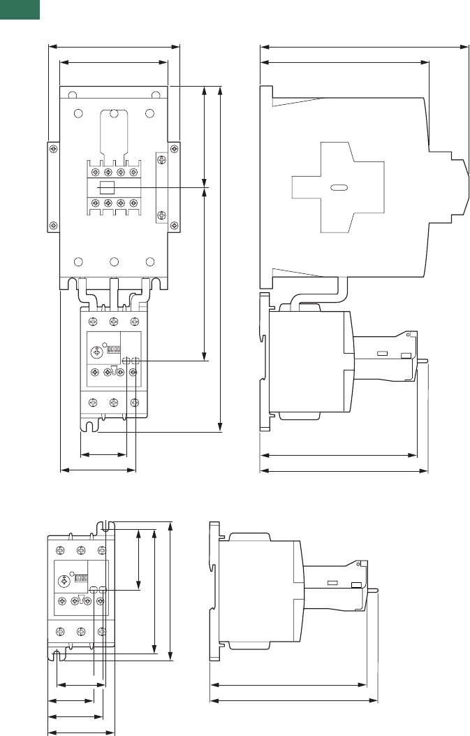
1
1.2 Overload relays
Electronic overload relays
34 AUTOMATION AND CONTROL www.eaton.com/seasia-electrical
Electronic overload relays
ZEB150-100
ZEB150-100/KK
132.4
140.5
85
289.1
145.4
38.6
63.2
90
111.8 175
160
38.6
41
46.1
56
51.7
104.8
116
132.4
140.5
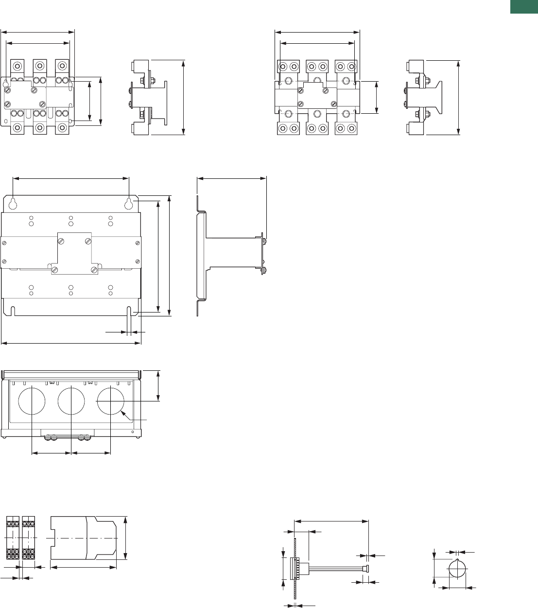
1
1.2
Overload relays
Thermistor overload relays for machine protection, electronic overload relays
35AUTOMATION AND CONTROL www.eaton.com/seasia-electrical
Thermistor overload relays for machine protection, electronic overload relays
Current sensors
ZEB-XCT300 ZEB-XCT600
ZEB-XCT1000
ZEB-XCT1500
EMT6 thermistor overload relays for machine protection External reset button
EMT6… M22-DZ-B
M22-DZ-X
190.5
165.1
106.1
127
193.5
234.2
206
89.2
205.4
304.6
330.2
317 188.9
10.1
383.5
108108
83.5
Ø 73.2
102
78
22.5
3
_>
100
19
2 – 5
8
2.5
24.1
22.3
3.2
Ø 29.5
1
37AUTOMATION AND CONTROL www.eaton.com/seasia-electrical
C441 overload and monitoring relay
Features and benefits . . . . . . . . . . . . . . . . . . . . . . . . . . . . . . . . . . . . . . . . . . . . . . . . . . . . . . . . . . . . .
Catalog number selection . . . . . . . . . . . . . . . . . . . . . . . . . . . . . . . . . . . . . . . . . . . . . . . . . . . . . . . . . .
Product selection . . . . . . . . . . . . . . . . . . . . . . . . . . . . . . . . . . . . . . . . . . . . . . . . . . . . . . . . . . . . . . . . .
Accessories . . . . . . . . . . . . . . . . . . . . . . . . . . . . . . . . . . . . . . . . . . . . . . . . . . . . . . . . . . . . . . . . . . . . .
Technical data and specifications . . . . . . . . . . . . . . . . . . . . . . . . . . . . . . . . . . . . . . . . . . . . . . . . . . . .
Dimensions . . . . . . . . . . . . . . . . . . . . . . . . . . . . . . . . . . . . . . . . . . . . . . . . . . . . . . . . . . . . . . . . . . . . .
38
41
42
43
48
60
C441 overload and monitoring relay
Product description
Eaton’s Motor Insight, the
first product in the Intelligent
Power Control Solutions
family, is a highly configurable
motor, load and line
protection device with power
monitoring, diagnostics and
flexible communications
allowing the customer to
save energy, optimize their
maintenance schedules and
configure greater system
protection, thus reducing
overall costs and downtime.
Motor Insight is available
in either a line-powered or
120 Vac control powered
design, capable of monitoring
voltages up to 660 Vac. Each
of these units is available in
a 1–9 amp or a 5–90 amp FLA
model. With external CTs,
Motor Insight can protect
motors up to 540 amps FLA.
Available add-on accessories
include communication
modules for Modbus RTU,
DeviceNet, PROFIBUS,
Modbus TCP, EtherNet/IP and
HTTP web services all with I/O
options. For ease-of-use and
operator safety, Motor Insight
offers a remote display that
mounts easily with two
30 mm knockouts.
C441 overload and monitoring relay
1.2
C441 overload and monitoring relay
Product description

1
38 AUTOMATION AND CONTROL www.eaton.com/seasia-electrical
1.2 C441 overload and monitoring relay
Features and benefits
Features and Benefits
Features
Size/Range
Broad FLA range of 1–540A
Selectable trip class (5–30)
Four operating voltage
options
Line-powered from
240 Vac, 480 Vac,
600 Vac
Control-powered from
120 Vac
Motor Control
Two output relays
One B300 Form C fault
relay and one B300
ground fault shunt relay
Other relay configurations
are available, including
one Form A and one
Form B SPST (fault and
auxiliary relays) allowing
programmable isolated
relay behavior and
unique voltages
One external remote
reset terminal
Trip status indicator
Motor Protection
Thermal overload
Jam protection
Current imbalance
Current phase loss
Ground fault
Phase reversal
Load Protection
Under current
Low power (kW)
High power (kW)
Line Protection
Over voltage
Under voltage
Voltage imbalance
Voltage phase loss
Monitoring Capabilities
Current—average and
phase rms
Voltage—average and
phase rms
Power—motor kW
Power factor
Frequency
Thermal capacity
Run hours
Ground fault current
Current imbalance %
Voltage imbalance %
Motor starts
Motor run hours
Options
Type 1, 12 remote display
Type 3R remote display kit
Communication modules
Modbus
Modbus with I/O
DeviceNet with I/O
PROFIBUS with I/O
Modbus TCP with I/O
EtherNet/IP with I/O
Benefits
Reliability and Improved Uptime
Advanced diagnostics
allows for quick and
accurate identification of
the root source of a motor,
pump or power quality
fault; reducing trouble-
shooting time and the loss
of productivity, reducing
repeat faults due to
misdiagnosis, and
increasing process output
and profitability
Provides superior
protection of motors and
pumps before catastrophic
failure occurs
Increases profitability with
greater process uptime
and throughput, reduced
costs per repair, reduced
energy consumption and
extended equipment life
Adjustments to overload
configuration can be made
at any time
Safety
IP20 rated terminal blocks
Terminal blocks are set back
from the display to reduce
operator shock hazard
Remote display (optional)
does not require that the
operator open the panel to
configure the device
Flexibility
Communications modules
Offered in a variety of
configurations
External snap-on modules
provide support for
multiple communications
protocols
Advanced power, voltage
and current monitoring
capabilities
Communications modules
and remote display can be
used simultaneously
Highly configurable fault
and reset characteristics
for numerous applications
Fully programmable
isolated fault and auxiliary
relays
Ease of Use
Bright LED display with
easy-to-understand setting
and references
Powered from line voltage
or 120 Vac control power
Remote display powered
from base unit
Full word descriptions and
units on user interface
Standards and Certifications
cULus listed NKCR,
NKCR7, 508
UL® 1053 applicable
sections for ground fault
detection
CSA® certified
(Class 3211-02)
CE
NEMA®
IEC EN 60947-4-1
CCC
RoHS

1
39AUTOMATION AND CONTROL www.eaton.com/seasia-electrical
1.2
C441 overload and monitoring relay
Features and benefits
Advanced Overload Education
Description Definition Source Result
Motor Insight
Protection
Motor Protection
Thermal overload Overload is a condition in which current
draw to a motor exceeds 115% of
the full load amperage rating over a
period of time for an inductive motor.
An increase in the load or torque that
is being driven by the motor.
A low voltage supply to the motor would
cause the current to go high to maintain
the power needed.
A poor power factor would cause
above normal current draw.
Increase in current draw. Current leads
to heat and insulation breakdown,
which can cause system failure.
Additionally, an increase in current can
increase power consumption and
waste valuable energy.
Thermal trip behavior is defined by UL,
CSA and IEC standards.
Trip class is settable from 5–30 by 1
Provides power factor monitoring and low
voltage protection features.
Jam Jam is similar to thermal overload in
that it is a current draw on the motor
above normal operating conditions.
Mechanical stall, interference, jam or
seizure of the motor or motor load.
The motor attempts to drive the load,
which has more resistive force due to
the mechanical interference. In order to
drive the load, the motor draws an
abnormal amount of current, which can
lead to insulation breakdown and
system failure.
Provides a configurable Jam setting that
is active during “motor run state” to avoid
nuisance trips.
Trip Threshold 150–400% of FLA.
Trip Delay 1–20 seconds.
Ground fault A line to ground fault. A current leakage path
to ground.
An undetected ground fault can burn
through multiple insulation windings,
ultimately leading to motor failure.
Motor Insight has ground fault protection
capability down to 0.15 amps estimated
from the existing three-phase CTs using
the residual current method. That is, the
three-phase current signals should sum to
zero unless a ground fault (GF) condition
is present. In the case of a GF, Motor
Insight can alarm, trip the starter, or trip
an alternative relay that can be used to
shunt trip a breaker or light up a warning
light. GF current can also be monitored in
real-time through the advanced
monitoring capabilities.
Note: GF settable thresholds vary with
motor FLA. 0.15 amps may not be
available in all cases.
Imbalanced phases
(voltage and current)
Uneven voltage or currents between
phases in a three-phase system.
When a three-phase load is powered with
a poor quality line, the voltage per phase
may be imbalanced.
Imbalanced voltage causes large
imbalanced currents and as a result this
can lead to motor stator windings being
overloaded, causing excessive heating,
reduced motor efficiency and reduced
insulation life.
Provides two protection settings that
address this problem. The user can
choose to set current imbalance
thresholds or voltage imbalance
thresholds, each of which can trip the
starter. Additionally, both of these may
be monitored through Motor Insight’s
advanced monitoring capabilities,
allowing the customer to notice in real-
time when and where a condition is
present.
Phase loss—current
(single-phasing)
One of the three-phase current is
not present.
Multiple causes, loose wire, improper
wiring, grounded phase, open fuse,
and so on.
Single-phasing can lead to unwanted
motor vibrations in addition to the results
of imbalanced phases as listed above.
Fixed protective setting that takes the
starter offline if a phase drops below
60% of the other two phases.
Phase rotation
(phase-reversal)
Improper wiring, leading to phases being
connected to the motor improperly.
A miswired motor. Inadvertent phase-
reversal by the utility.
Phase-reversal can cause unwanted
directional rotation of a motor. In the
event that the load attached to the motor
can only be driven in one direction, the
result could be significant mechanical
failure and/or injury to an operator.
Configurable phase protection, allowing
the user to define the phase sequencing
intended for that application. If no phase
sequence is required, the user has the
ability to disable this feature.
Frequency variance When line frequency
is inconsistent.
Malfunctioning alternator speed
regulator, or poor line quality caused by
an overload of a supply powered
by individual sources.
Variations in frequency can cause
increases in losses, decreasing the
efficiency of the motor. In addition,
this can result in interference with
synchronous devices.
Advanced monitoring capabilities
allow the user to monitor frequency
in real-time.

1
40 AUTOMATION AND CONTROL www.eaton.com/seasia-electrical
1.2 C441 overload and monitoring relay
Features and benefits
Advanced Overload Education, continued
Description Definition Source Result
Motor Insight
Protection
Load Protection
Under current or
low power
Average rms current provided to the
motor falls below normal operating
conditions.
Under current is usually associated
with a portion of the user’s load
disappearing. Examples of this would
be a broken belt, a dry-pump (low
suction head) or a dead-headed
centrifugal pump.
If under current goes undetected, a
mechanical failure can and has
occurred. In the case of a pump,
running a pump dry or running a pump
in a dead-headed condition can cause
excessive heating, damaging
expensive seals and breaking down
desired fluid properties.
Motor Insight has two protection settings
to detect this: under current and low
power. Low power is a more consistent
way of ensuring detection as power is
linear with motor load, where as current
is not. An unloaded motor may draw 50%
of its rated current, but the power draw
will be less than 10% of rated power due
to a low power factor.
High power The motor load is drawing more power
than it should at normal operating
conditions.
This is typical of batch processing
applications where several ingredients
flow into a mixer. When a substance’s
consistency changes and viscosity
increases from what is expected, the
motor may use more power to blend
the mixture. Out-of-tolerance
conditions can be detected using the
High Power and Low Power settings.
If a high-power fault goes undetected,
the result may be a batch of material
that does not meet specification.
Monitors the three-phase real power. If
the real power value is estimated above
the set threshold for the set length of
time, a fault is detected and the overload
will trip the starter. Additionally, power
can be monitored in real-time.
Line Protection
Over voltage When the line voltage to the motor
exceeds the specified rating.
Poor line quality. An over voltage condition leads to a
lower than rated current draw and a
poor power factor. A trip limit of 110%
of rated voltage is recommended. Over
voltage can also lead to exceeding
insulation ratings.
Monitors the maximum rms value of
the three-phase voltages. If the rms
value rises above the set threshold for the
set length of time, a fault is detected and
the overload can trip the starter or send
and display an alarm of the condition. All
line-related faults have an “alarm-no-
trip” mode.
Under voltage When the line voltage to the motor is
below the specified rating.
Poor line quality. An under voltage condition leads to
excessive current draw. This increases
the heating of the motor windings and
can shorten insulation life. A trip limit
set to 90% of rated voltage is
recommended.
Monitors the minimum rms value of the
three-phase voltages. If the rms value
drops below the set threshold for the
set length of time, a fault is detected
and the overload can trip the starter or
send and display an alarm of the
condition. All line-related faults have
an “alarm-no-trip” mode.
Power-up delay Allows for starting motors and loads
in a deliberate fashion.
When there is a power failure, or
power cycle, multiple loads come
online simultaneously.
Multiple loads starting simultaneously
can cause sags affecting the operation
of devices that may prevent successful
startup.
If power is lost to a motor driving a
pump, it may be necessary to delay a
restart to allow the pump to come to a
complete stop to prevent starting a
motor during backspin.
Configurable to delay closing the fault
relay on power-up. For each Motor Insight
controlling a motor, a different setting can
be programmed, helping to maintain the
integrity of your line power.
1
41AUTOMATION AND CONTROL www.eaton.com/seasia-electrical
1.2
C441 overload and monitoring relay
Catalog number selection
Catalog Number Selection
Motor Insight Overload Relays
Motor Insight Overload Relays—Communications Modules and Accessory Types
Device Type
C441 = Motor Insight overload relay Overload Relay Current Rating
A = 1–9A (1–540A refer to
Page 42 )
B = 5–90A (5–90A refer to
Page 42 )
0109 = 120 Vac control power
(0–660 Vac, 1–9A)
0590 = 120 Vac control power
(0–660 Vac, 5–90A)
Overload Relay
Power Source Voltage
B= 240 Vac (170–264 Vac)
C= 480 Vac (323–528 Vac)
D= 600 Vac (487–660 Vac)
Blank = 120 Vac control power
(170–660 Vac)
C441 B A NOUI
Internal User Interface
Blank = With user interface
(line powered models)
NOUI = Without user interface
(120 Vac control models)
Device Type
C441 = Motor Insight overload relay Communication Module
K= DeviceNet module 4IN/2OUT 120 Vac
L= DeviceNet module 4IN/2OUT 24 Vdc
M= Modbus RTU module
N= Modbus RTU module 4IN/2OUT 120 Vac
P= Modbus RTU module 4IN/2OUT 24 Vdc
Q= PROFIBUS module 4IN/2OUT 120 Vac
R= Modbus TCP / EtherNet/IP module
4IN/2OUT 120 Vac
S= PROFIBUS module 4IN/2OUT 24 Vdc
T= Modbus TCP / EtherNet/IP module
4IN/2OUT 24 Vdc
Accessory Type
1= Type 1 and 12 remote mounted display
3= Type 3R kit for remote display
CMP1 = Conversion plate
C441 K
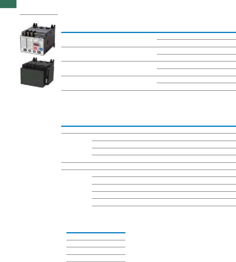
1
42 AUTOMATION AND CONTROL www.eaton.com/seasia-electrical
1.2 C441 overload and monitoring relay
Product selection
Product Selection
Motor Insight
Motor Insight CT Multiplier and Wire Wrap Schedule
Notes
ĿUnderscore indicates Operating Voltage Code required.
Operating Voltage Codes:
ŀAny manufacturer’s CTs may be used.
Power Source
Monitoring
Range
Current
Range
Catalog
Number
240 Vac (170–264) 170–264 Vac 1–9A C441BA
5–90A C441BB
480 Vac (323–528) 323–528 Vac 1–9A C441CA
5–90A C441CB
600 Vac (489–660) 489–660 Vac 1–9A C441DA
5–90A C441DB
120 Vac (93.5–132) 170–660 Vac 1–9A C4410109NOUI
5–90A C4410590NOUI
Catalog
Number Ŀ
Motor
FLA
Number
of Loops
Number of
Conductors Through
CT Primary
CT
Multiplier
Setting
External CT Kit
Catalog Number ŀ
Current Range: 5–90A
C441_B and
C4410590NOUI
5–22.5A 3 4 4 —
6.67–30A 2 3 3 —
10–45A 1 2 2 —
20–90A 0 1 1 —
Current Range: 1–9A
C441_A and
C4410109NOUI
1–5A 1 2 2 —
2–9A 0 1 1 —
60–135A 0 1 150–(150:5) C441CTKIT150
120–270A 0 1 300–(300:5) C441CTKIT300
240–540A 0 1 600–(600:5) C441CTKIT600
Code Voltage
B240 Vac
C480 Vac
D600 Vac
<empty> 120 Vac Control Power
Motor Insight

1
43AUTOMATION AND CONTROL www.eaton.com/seasia-electrical
1.2
C441 overload and monitoring relay
Accessories
Accessories
Modbus Communication Module
The Motor Insight Modbus
Communication Module
is a side-mounted device
providing Modbus
communication capability
to the Motor Insight
overload relay.
The Modbus Communication
Module with I/O provides
communication, monitoring
and control for the Motor
Insight overload relay.
Features and Benefits
The Modbus
communication module is
capable of baud rates
up to 115K
The Modbus address and
baud rate configuration can
be easily changed using
the Motor Insight user
interface (C441M only)
Modbus address and baud
rate are set via convenient
DIP switches (C441N and
C441P); LEDs are provided
to display Modbus traffic
Configuration with
common Modbus
configuration tools
Terminals
Unique locking
mechanism provides for
easy removal of the
terminal block with the
field wiring installed
Each terminal is marked
for ease of wiring and
troubleshooting
Selectable I/O assemblies
4IN/2OUT
Signal types include
24 Vdc I/O and
120 Vac I/O
Each I/O module is
optically isolated
between the field I/O
and the network adapter
to protect the I/O and
communication circuits
from possible damage
due to transients and
ground loops
Input Module features a
user-definable input
debounce, which limits
the effects of transients
and electrical noise
Output Module supports
a user-definable safe
state for loss of
communication; hold
last state, ON or OFF
Modbus Communication Module
Description I/O
Catalog
Number
Modbus Communication Module None C441M
Modbus Communication Module 4IN/2OUT 120 Vac C441N
Modbus Communication Module 4IN/2OUT 24 Vdc C441P
Modbus Module
Modbus with
I/O Module

1
44 AUTOMATION AND CONTROL www.eaton.com/seasia-electrical
1.2 C441 overload and monitoring relay
Product selection
DeviceNet Communication Modules
The DeviceNet
Communication Module
provides monitoring and
control for the Motor Insight
overload relay from a single
DeviceNet node. These
modules also offer convenient
I/O in two voltage options,
24 Vdc and 120 Vac.
Features and Benefits
Communication to
DeviceNet uses only one
DeviceNet MAC ID
Configuration
DeviceNet MAC ID and
Baud rate are set via
convenient DIP switches
with an option to set
from the network
Advanced configuration
available using common
DeviceNet tools
Terminals
Unique locking
mechanism provides for
easy removal of the
terminal block with the
field wiring installed
Each terminal is marked
for ease of wiring and
troubleshooting
Selectable I/O assemblies
4IN/2OUT
Signal types include
24 Vdc I/O and
120 Vac I/O
Each I/O module is
optically isolated
between the field I/O
and the network adapter
to protect the I/O and
communication circuits
from possible damage
due to transients and
ground loops
Input Module features a
user-definable input
debounce, which limits
the effects of transients
and electrical noise
Output Module supports
a user-definable safe
state for loss of
communication; hold
last state, ON or OFF
Combined status LED
DeviceNet Modules
Description I/O
Catalog
Number
DeviceNet Communication Module 120 Vac C441K
DeviceNet Communication Module 24 Vdc C441L
DeviceNet Module

1
45AUTOMATION AND CONTROL www.eaton.com/seasia-electrical
1.2
C441 overload and monitoring relay
Accessories
PROFIBUS Communication Module
The Motor Insight PROFIBUS
Communication Module
is a side-mounted device
providing PROFIBUS
communication capability
to the Motor Insight
overload relay.
The PROFIBUS
Communication Module
with I/O provides
communication, monitoring
and control for the Motor
Insight overload relay.
Features and Benefits
The PROFIBUS
communication module is
capable of baud rates
up to 12 Mb
PROFIBUS address is
set via convenient DIP
switches (C441Q and
C441S); LEDs are
provided to display
PROFIBUS status
Intuitive configuration
with common PROFIBUS
configuration tools
Term i n als
Unique locking
mechanism provides for
easy removal of the
terminal block with the
field wiring installed
Each terminal is marked
for ease of wiring and
troubleshooting
Selectable I/O assemblies
4IN/2OUT
Signal types include
24 Vdc I/O and
120 Vac I/O
Each I/O module is
optically isolated
between the field I/O
and the network adapter
to protect the I/O and
communication circuits
from possible damage
due to transients and
ground loops
Input Module features a
user-definable input
debounce, which limits
the effects of transients
and electrical noise
Output Module supports
a user-definable safe
state for loss of
communication; hold
last state, ON or OFF
PROFIBUS Communication Module
Description I/O
Catalog
Number
PROFIBUS Communication Module 4IN/2OUT 120 Vac C441S
PROFIBUS Communication Module 4IN/2OUT 24 Vdc C441Q
PROFIBUS with
I/O Module

1
46 AUTOMATION AND CONTROL www.eaton.com/seasia-electrical
1.2 C441 overload and monitoring relay
Accessories
Ethernet Communication Module
The Motor Insight Ethernet
Communication Module
is a side-mounted device
providing both Modbus
TCP and EtherNet/IP
communication capabilities
with built-in HTTP web
services to the Motor Insight
overload relay.
The Ethernet Communication
Module with I/O provides
communication, monitoring
and control for the Motor
Insight overload relay.
Features and Benefits
Supports Modbus TCP or
EtherNet/IP in a single
device
Contains internal
embedded switch which
provides two Ethernet
ports allowing linear or ring
network configurations
Embedded web services
allow for simple
configuration and
monitoring through
Internet Explorer
IP Address is set via
convenient DIP Switches
located on the device
Term i n als
Unique locking
mechanism provides for
easy removal of the
terminal block with the
field wiring installed
Each terminal is marked
for ease of wiring and
troubleshooting
Selectable I/O assemblies
4IN/2OUT
Signal types include
24 Vdc I/O and
120 Vac I/O
Each I/O module is
optically isolated
between the field I/O
and the network adapter
to protect the I/O and
communication circuits
from possible damage
due to transients and
ground loops
Input Module features a
user-definable input
debounce, which limits
the effects of transients
and electrical noise
Output Module supports
a user-definable safe
state for loss of
communication; hold
last state, ON or OFF
Ethernet Communication Module
Description I/O
Catalog
Number
Modbus TCP / EtherNet/IP Communication Module 4IN/2OUT 120 Vac C441R
Modbus TCP / EtherNet/IP Communication Module 4IN/2OUT 24 Vdc C441T
Ethernet with
I/O Module
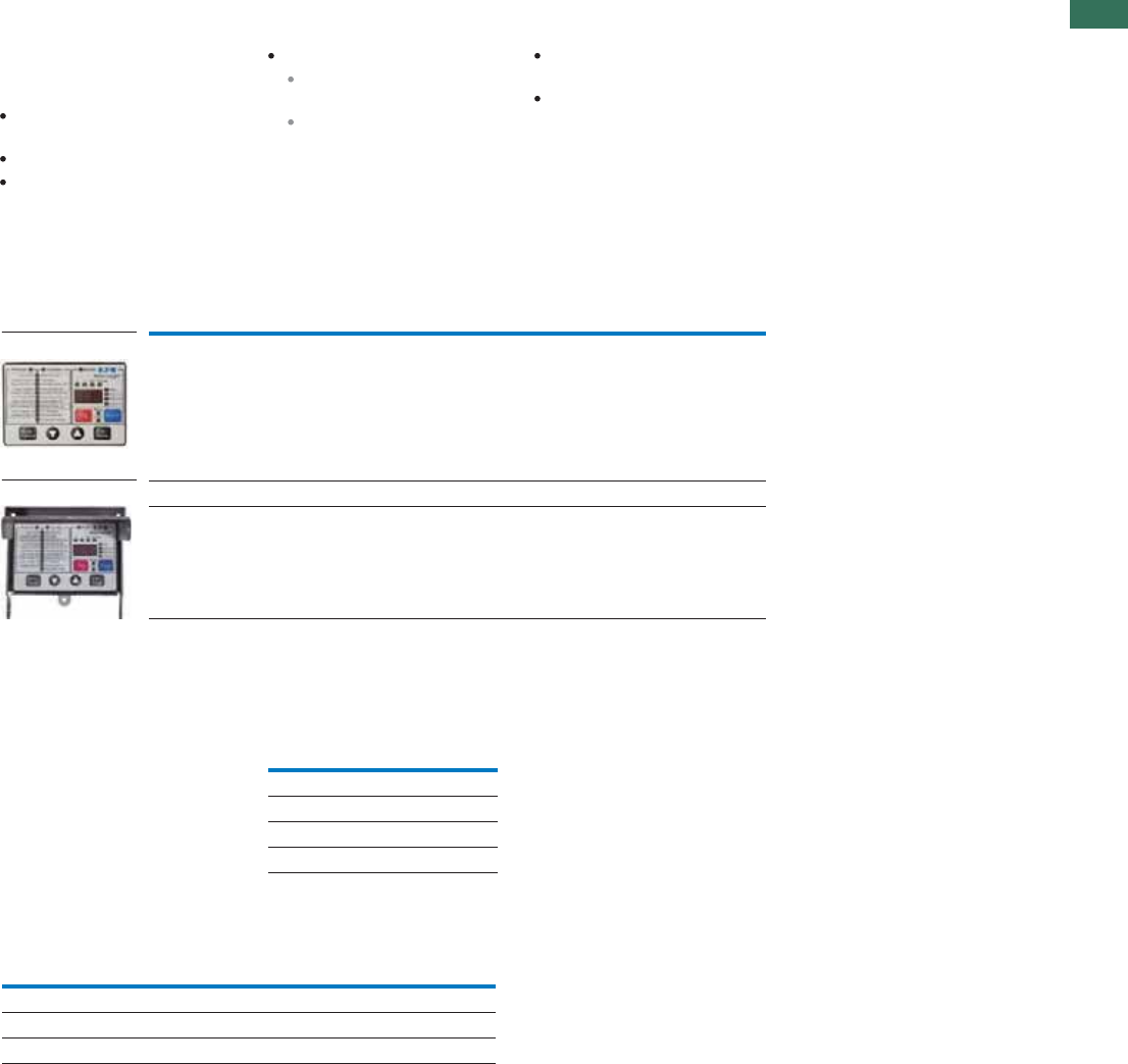
1
47AUTOMATION AND CONTROL www.eaton.com/seasia-electrical
1.2
C441 overload and monitoring relay
Accessories
Type 3R Kit with Remote Display Mounted Inside
Motor Insight offers several
accessories for the
customer’s ease of use
and safety:
Types 1 and 12 remote
display
Type 3R remote display kit
Mounting plate adapter
Features and Benefits
Remote display unit:
Same user interface as
the overload relay
Enhanced operator
safety—operator can
configure the overload
without opening the
enclosure door
Type 3R kit mounts with
standard 30 mm holes
Mounting plate for retrofit
in existing installations
Type 3R Kit with Remote Display Mounted Inside
Communication Cables
The Remote Display requires
a communication cable to
connect to the Motor Insight
overload relay:
Communication Cable
Lengths
Current Transformer Kits
Description
Catalog
Number
Remote display Types 1 and 12 (UL 508) C4411
Type 3R kit for remote display (UL 508) C4413
Conversion plate (not shown) C441CMP1
C4411
C4413
Length in
Inches (meters)
Catalog
Number
9.8 (0.25) D77E-QPIP25
39.4 (1.0) D77E-QPIP100
78.7 (2.0) D77E-QPIP200
118.1 (3.0) D77E-QPIP300
Description
Catalog
Number
Three 150:5 CTs to be used with Motor Insight C441CTKIT150
Three 300:5 CTs to be used with Motor Insight C441CTKIT300
Three 600:5 CTs to be used with Motor Insight C441CTKIT600

1
48 AUTOMATION AND CONTROL www.eaton.com/seasia-electrical
1.2 C441 overload and monitoring relay
Technical data and specifications
Technical Data and Specifications
Motor Insight
Notes
ĿLower levels are achievable with multiple passes.
ŀMotor fault reset characteristics can be programmed as a group or for motor overloads only. Reference the user manual for more detailed information.
Description
Specification
C441B_ C441C_ C441D_ C441_ _ _ _NOUI
Electrical Ratings
Feature Range
Operating voltage (three-
phase) and frequency
170–264 Vac 50/60 Hz 323–528 Vac 50/60 Hz 489–660 Vac 50/60 Hz 170–660 Vac 50/60 Hz
Tri p C l a s s
5–30 Selectable Selectable Selectable Selectable
FLA Range
C441_A and
C4410109NOUI
Up to 540A with external CTs1–9A
Refer to Page 42 for CT
multiplier and wire wrap
schedule.
Up to 540A with external CTs
Refer to Page 42 for CT
multiplier and wire wrap
schedule.
Up to 540A with external CTs
Refer to Page 42 for CT
multiplier and wire wrap
schedule.
C441_B and
C4410590NOUI
5–90A
Monitoring Capabilities
Feature Value
Current Per phase rms (1A, 1B, 1C),
2% accuracy
Average rms, 2% accuracy
Imbalance percent (0–100%)
Ground fault current,
10% accuracy
Per phase rms (1A, 1B, 1C),
2% accuracy
Average rms, 2% accuracy
Imbalance percent (0–100%)
Ground fault current,
10% accuracy
Per phase rms (1A, 1B, 1C),
2% accuracy
Average rms, 2% accuracy
Imbalance percent (0–100%)
Ground fault current,
10% accuracy
Per phase rms (1A, 1B, 1C),
2% accuracy
Average rms, 2% accuracy
Imbalance percent (0–100%)
Ground fault current,
10% accuracy
Voltage Per phase rms (1A, 1B, 1C),
2% accuracy
Average rms, 2% accuracy
Imbalance percent (0–100%)
Per phase rms (1A, 1B, 1C),
2% accuracy
Average rms, 2% accuracy
Imbalance percent (0–100%)
Per phase rms (1A, 1B, 1C),
2% accuracy
Average rms, 2% accuracy
Imbalance percent (0–100%)
Per phase rms (1A, 1B, 1C),
2% accuracy
Average rms, 2% accuracy
Imbalance percent (0–100%)
Power Motor kW, 5% accuracy
Motor power factor,
inductive 0–1.0, 1% accuracy
Motor kW, 5% accuracy
Motor power factor,
inductive 0–1.0, 1% accuracy
Motor kW, 5% accuracy
Motor power factor,
inductive 0–1.0, 1% accuracy
Motor kW, 5% accuracy
Motor power factor,
inductive 0–1.0, 1% accuracy
Thermal capacity 0% cold, 100% trip 0% cold, 100% trip 0% cold, 100% trip 0% cold, 100% trip
Motor run hours 0–65,535 hours 0–65,535 hours 0–65,535 hours 0–65,535 hours
Frequency 47–63 Hz, 1% accuracy 47–63 Hz, 1% accuracy 47–63 Hz, 1% accuracy 47–63 Hz, 1% accuracy
Motor Protection
Thermal overload setting 1.05 x FLA: Does not trip
1.15 x FLA: Overload trip
1.05 x FLA: Does not trip
1.15 x FLA: Overload trip
1.05 x FLA: Does not trip
1.15 x FLA: Overload trip
1.05 x FLA: Does not trip
1.15 x FLA: Overload trip
Feature Range Fault Delay Setting
Jam 150–400% of motor FLA, OFF 150–400% of motor FLA, OFF 150–400% of motor FLA, OFF 50–400% of motor FLA, OFF 1–20 seconds
Current imbalance 1–30%, OFF 1–30%, OFF 1–30%, OFF 1–30%, OFF 1–20 seconds
Current phase loss Fixed threshold 60% Fixed threshold 60% Fixed threshold 60% Fixed threshold 60% 1–20 seconds
Ground fault current
C441_A and
C4410109NOUI
1–9A
0.3–2.0A with one pass
through the CTs Ŀ
0.3–2.0A with one pass
through the CTs Ŀ
0.3–2.0A with one pass
through the CTs Ŀ
0.3–2.0A with one pass
through the CTs Ŀ
<150%, 1–60 seconds
>150%, 2 seconds
>250%, 1 second
C441_B and
C4410590NOUI
5–90A
3.0–20A with one pass
through the CTs Ŀ
3.0–20A with one pass
through the CTs Ŀ
3.0–20A with one pass
through the CTs Ŀ
3.0–20A with one pass
through the CTs Ŀ
<150%, 1–60 seconds
>150%, 2 seconds
>250%, 1 second
Phase reversal OFF = Ignore, 1 = ACB, 2 = ABC OFF = Ignore, 1 = ACB, 2 = ABC OFF = Ignore, 1 = ACB, 2 = ABC OFF = Ignore, 1 = ACB, 2 = ABC
Fault reset delay 2–500 minutes, auto ŀ2–500 minutes, auto ŀ2–500 minutes, auto ŀ2–500 minutes, auto ŀ
Fault reset attempts 0–4 restarts allowed or
automatic reset ŀ
0–4 restarts allowed or
automatic reset ŀ
0–4 restarts allowed or
automatic reset ŀ
0–4 restarts allowed or
automatic reset ŀ

1
49AUTOMATION AND CONTROL www.eaton.com/seasia-electrical
1.2
C441 overload and monitoring relay
Technical data and specifications
Motor Insight, continued
Description
Specification
C441B_ C441C_ C441D_ C441_ _ _ _NOUI
Load Protection
Feature Range Fault Delay Setting
Under current 50–90% of motor FLA 50–90% of motor FLA 50–90% of motor FLA 50–90% of motor FLA 1–60 seconds
Low power (kW) 20–80% of rated kW 20–80% of rated kW 20–80% of rated kW 20–80% of rated kW 1–60 seconds
High power (kW) 50–110% of rated kW 50–110% of rated kW 50–110% of rated kW 50–110% of rated kW 1–60 seconds
Load reset delay 2–500 minutes, auto 2–500 minutes, auto 2–500 minutes, auto 2–500 minutes, auto
Load reset attempts 0–4, auto 0–4, auto 0–4, auto 0–4, auto
Supply Protection
Feature Range Fault Delay Setting
Over voltage 170–264 Vac 323–528 Vac 489–660 Vac 0–660 Vac 1–20 seconds
Under voltage 170–264 Vac 323–528 Vac 489–660 Vac 0–660 Vac 1–20 seconds
Voltage imbalance 1–20% imbalance 1–20% imbalance 1–20% imbalance 1–20% imbalance 1–20% imbalance
Restart delay setting 1–500 seconds 1–500 seconds 1–500 seconds 1–500 seconds 1–500 seconds
Electrical/EMC
Radiated emissions
IEC 60947-4-1—Table 15,
EN 55011 (CISPIR 11)
Group 1, Class A
30–1000 mHz 30–1000 mHz 30–1000 mHz 30–1000 mHz 30–1000 mHz
Conducted emissions
IEC 60947-4-1—Table 14,
EN 55011 (CISPIR 11)
Group 1, Class A
0.15–30 mHz 0.15–30 mHz 0.15–30 mHz 0.15–30 mHz 0.15–30 mHz
ESD immunity
IEC 60947-4-1 (Table 13)
±8 kV air, ±4 kV contact ±8 kV air, ±4 kV contact ±8 kV air, ±4 kV contact ±8 kV air, ±4 kV contact ±8 kV air, ±4 kV contact
Radiated immunity
IEC 60947-4-1
10 V/m 80–1000 mHz
80% amplitude modulated
1 kHz sine wave
10 V/m 80–1000 mHz
80% amplitude modulated
1 kHz sine wave
10 V/m 80–1000 mHz
80% amplitude modulated
1 kHz sine wave
10 V/m 80–1000 mHz
80% amplitude modulated
1 kHz sine wave
10 V/m 80–1000 mHz
80% amplitude modulated
1 kHz sine wave
Conducted immunity
IEC 60947-4-1
140 dBuV (10V rms)
150 kHz–80 mHz
140 dBuV (10V rms)
150 kHz–80 mHz
140 dBuV (10V rms)
150 kHz–80 mHz
140 dBuV (10V rms)
150 kHz–80 mHz
140 dBuV (10V rms)
150 kHz–80 mHz
Fast transient immunity
IEC 60947-4-1 (Table 13)
IEC 61000-4-4
±2 kV using direct method ±2 kV using direct method ±2 kV using direct method ±2 kV using direct method ±2 kV using direct method
Surge immunity
IEC 60947-4-1 (Table 13)
IEC 61000-4-4
Three-phase power inputs:
±2 kV line-to-line (DM)
±4 kV line-to-ground (CM)
Three-phase power inputs:
±2 kV line-to-line (DM)
±4 kV line-to-ground (CM)
Three-phase power inputs:
±2 kV line-to-line (DM)
±4 kV line-to-ground (CM)
Three-phase power inputs:
±2 kV line-to-line (DM)
±4 kV line-to-ground (CM)
Three-phase power inputs:
±2 kV line-to-line (DM)
±4 kV line-to-ground (CM)
IEC 61000-4-5 Class 3 User IO
and communication lines:
±1 kV line-to-line (DM)
±2 kV line-to-ground (CM)
IEC 61000-4-5 Class 3 User IO
and communication lines:
±1 kV line-to-line (DM)
±2 kV line-to-ground (CM)
IEC 61000-4-5 Class 3 User IO
and communication lines:
±1 kV line-to-line (DM)
±2 kV line-to-ground (CM)
IEC 61000-4-5 Class 3 User IO
and communication lines:
±1 kV line-to-line (DM)
±2 kV line-to-ground (CM)
IEC 61000-4-5 Class 3 User IO
and communication lines:
±1 kV line-to-line (DM)
±2 kV line-to-ground (CM)
Voltage variations
immunity
IEC 60947-4-1
30% dip, at 100 ms
60% dip at 10 ms
>95% interrupt at 5 ms
30% dip, at 100 ms
60% dip at 10 ms
>95% interrupt at 5 ms
30% dip, at 100 ms
60% dip at 10 ms
>95% interrupt at 5 ms
30% dip, at 100 ms
60% dip at 10 ms
>95% interrupt at 5 ms
30% dip, at 100 ms
60% dip at 10 ms
>95% interrupt at 5 ms
Electromagnetic field
IEC 60947-4-1 (Table 13)
IEC 61000-4-3
10 V/m 10 V/m 10 V/m 10 V/m 10 V/m
Ground fault UL 508, UL 1053
Sections 21 and 27
UL 508, UL 1053
Sections 21 and 27
UL 508, UL 1053
Sections 21 and 27
UL 508, UL 1053
Sections 21 and 27
UL 508, UL 1053
Sections 21 and 27

1
50 AUTOMATION AND CONTROL www.eaton.com/seasia-electrical
1.2 C441 overload and monitoring relay
Technical data and specifications
Motor Insight, continued
Note
ĿIn this model, there are two isolated relays: one Form A and one Form B SPST. One is the fault relay, and one is a programmable auxiliary relay.
Description
Specification
C441_ _ _ _NOUIC441D_C441C_C441B_
Environmental Ratings
RangeFeature
Ambient temperature (operating) –4° to 122°F (–20° to 50°C) –4° to 122°F (–20° to 50°C) –4° to 122°F (–20° to 50°C) –4° to 122°F (–20° to 50°C)
Ambient temperature (storage) –40° to 85°C –40° to 85°C –40° to 85°C –40° to 85°C
5% to 95% noncondensing5% to 95% noncondensing5% to 95% noncondensing5% to 95% noncondensingOperating humidity
2000m2000m2000m2000mAltitude (no derating)
Shock (IEC 60068-2-27) 15G any direction 15G any direction 15G any direction 15G any direction
Vibration (IEC 60068-2-6) 3G any direction 3G any direction 3G any direction 3G any direction
Pollution degree per IEC 60947-1 3333
Ingress protection IP20 IP20 IP20 IP20
Capacity
Input, auxiliary contact and external reset terminals
Terminal capacity 18–12 AWG 18–12 AWG 18–12 AWG 18–12 AWG
Tightening torque 5.3 lb-in (0.6 Nm) 5.3 lb-in (0.6 Nm) 5.3 lb-in (0.6 Nm) 5.3 lb-in (0.6 Nm)
Voltages
Monitoring voltage 170–264 Vac 50/60Hz 323–528 Vac 50/60Hz 489–660 Vac 60Hz 0–660 Vac 50/60Hz
Insulation voltage Ui (three-phase voltage) 600 Vac 600 Vac 600 Vac 600 Vac
Insulation voltage Ui (control) 240 Vac 240 Vac 240 Vac 240 Vac
Impulse withstand Uimp
(main/control)
6 kV6 kV6 kV6 kV
Expected Life
10 years10 years10 years10 yearsMechanical/electrical
Output Contact Ratings
Two output relays
One Form C SPDT (fault relay)
One Form A SPST (ground fault relay)
C441_ _ _ _NOUI models:
One Form A SPST
One Form B SPST
B300 pilot duty
5A thermal continuous current
30A make 3.00A break
at 120 Vac and
15A make 1.50A break
at 240 Vac
B300 pilot duty
5A thermal continuous current
30A make 3.00A break
at 120 Vac and
15A make 1.50A break
at 240 Vac
B300 pilot duty
5A thermal continuous current
30A make 3.00A break
at 120 Vac and
15A make 1.50A break
at 240 Vac
B300 pilot duty
5A thermal continuous current
30A make 3.00A break
at 120 Vac and
30A make 1.50A break
at 240 Vac Ŀ
External remote reset terminal Isolated 120 Vac digital input
IEC 61131-2 Section 5 Type 1
Isolated 120 Vac digital input
IEC 61131-2 Section 5 Type 1
Isolated 120 Vac digital input
IEC 61131-2 Section 5 Type 1
Isolated 120 Vac digital input
IEC 61131-2 Section 5 Type 1
Indications
Trip Fault Fault Fault Fault
Reset Ready Ready Ready Ready
Autoreset Trip faulted/Ready flashing Trip faulted/Ready flashing Trip faulted/Ready flashing Trip faulted/Ready flashing
Power Consumption
Maximu 5m5W5W5WW
Options
Remote display Type 1, 12 and Type 3R kit Type 1, 12 and Type 3R kit Type 1, 12 and Type 3R kit Type 1, 12 and Type 3R kit
Communications modules Modbus, DeviceNet and
PROFIBUS with I/O
Modbus, DeviceNet and
PROFIBUS with I/O
Modbus, DeviceNet and
PROFIBUS with I/O
Modbus, DeviceNet and
PROFIBUS with I/O

1
51AUTOMATION AND CONTROL www.eaton.com/seasia-electrical
1.2
C441 overload and monitoring relay
Technical data and specifications
Motor Insight Short Circuit Ratings (North America CSA and UL)
Overload
FLA Range
Maximum
Operating
Voltage
Standard-Fault Short Circuit Data
Maximum
Withstand
Rating
Maximum
Fuse (RK5)
Eaton
Thermal-Magnetic
Circuit Breaker
Catalog
Number
Withstand
Rating
Maximum
Fuse (RK5)
Maximum
Thermal-Magnetic
Circuit Breaker
1–9A 264 Vac 5000A at 240 Vac 35A 35A 100 kA at 240 Vac 35A — C441BA
100 kA at 240 Vac — FDC3035L
1–9A 528 Vac 5000A at 480 Vac 35A 35A 100 kA at 480 Vac 35A — C441CA
100 kA at 480 Vac — FDC3035L
1–9A 660 Vac 5000A at 600 Vac 35A 35A 100 kA at 600 Vac 35A — C441DA
35 kA at 600 Vac — FDC3035L
1–9A 660 Vac 5000A at 600 Vac 35A 35A 100 kA at 240 Vac
100 kA at 240 Vac
100 kA at 480 Vac
100 kA at 480 Vac
100 kA at 600 Vac
35 kA at 600 Vac
35A
—
35A
—
35A
—
—
FDC3035L
—
FDC3035L
—
FDC3035L
C4410109NOUI
5–90A 264 Vac 10,000A at 240 Vac 350A 350A 100 kA at 240 Vac 350A — C441BB
100 kA at 240 Vac — KDC3350
5–90A 528 Vac 10,000A at 480 Vac 350A 350A 100 kA at 480 Vac 350A — C441CB
100 kA at 480 Vac — KDC3350
5–90A 660 Vac 10,000A at 600 Vac 350A 350A 100 kA at 600 Vac 350A — C441DB
65 kA at 600 Vac — KDC3350
5–90A 660 Vac 10,000A at 600 Vac 350A 350A 100 kA at 240 Vac
100 kA at 240 Vac
100 kA at 480 Vac
100 kA at 480 Vac
100 kA at 600 Vac
35 kA at 600 Vac
350A
—
350A
—
350A
—
—
KDC3350
—
KDC3350
—
KDC3350
C4410590NOUI
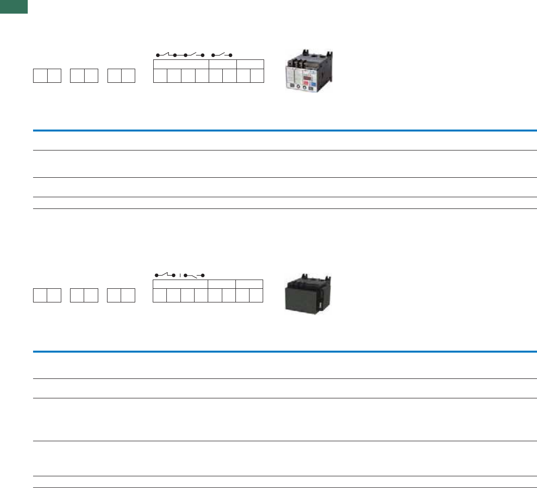
1
52 AUTOMATION AND CONTROL www.eaton.com/seasia-electrical
1.2 C441 overload and monitoring relay
Technical data and specifications
Line Powered Models
Terminal Connection Diagram
Terminal Connection Specifications
Control Powered Models
Terminal Connection Diagram
Terminal Connection Specifications
Note
ĿNo motor loads, 9A maximum.
DescriptionInputDesignationName
Three-phase line voltage inputLine voltageL1, L2, L3Line voltage
L1, L2, L3 connections must correspond to the respective CT1, CT2, CT3 current leads
95/96Fault relay
96/97 (common)
97/98
B300 UL 508 Form C contact:
95/96 Contact opens when the unit is faulted or unpowered
97/98 Contact closes when the unit is faulted or unpowered
15GF shunt
16
B300 UL 508 Form A contact:
Contact closes when a ground fault is active
Fault reset input IEC 61131-2 Type 1120 VacR1, R2Reset input
DescriptionInputDesignationName
Three-phase line voltage inputLine voltageL1, L2, L3Line voltage
L1, L2, L3 connections must correspond to the respective CT1, CT2, CT3 current leads
Terminal provided for wiring control power transformer (9A maximum capacity)
110–120 VacX1, X2Control power
50–60Hz (+10/–15%)
Control power option for C441_ _ _ _NOUI
Fault relay
For C441_ _ _ _NOUI, the fault relay and auxiliary relay are
isolated and do not share a common. By default they will
behave like a Form C, but they can be programmed to act
independently from one another.
95/96
96/97 (isolated)
97/98
B300 UL 508 Form C contact:
95/96 Contact opens when the unit is faulted or unpowered
97/98 Contact closes when the unit is faulted or unpowered
Can be programmed to act independently of the 95/96 only in the C441_ _ _ _NOUI models
GF shunt
This relay does not exist on the C441_ _ _ _NOUI models.
Instead, this functionality is available in the fully
programmable 97/98 auxiliary relay.
97/98 B300 UL 508 Form A contact:
Contact closes when a ground fault is active
Separate GF control can still be achieved by programming auxiliary relay 97/98 to act
independently of the 95/96 relay
Fault reset input IEC 61131-2 Type 1120 VacR1, R2Reset input
L1 L2 L3 95 96 97 98 15 16 R1 R2
NC NO GF Shunt Reset
120 Vac
18–12 AWG; Torque 5.3 lb-in/0.6 Nm
B300 Pilot Duty Only
Use 75C CU wire only
For C441BA, BB, CA, CB, DA and DB
L1 L2 L3 95 96 97 98 X1 X2 R1 R2
NC NO Cntrl. Pwr. Reset
120 Vac120 Vac
For C4410109NOUI and C441059NOUI
ĿĿĿ

1
53AUTOMATION AND CONTROL www.eaton.com/seasia-electrical
1.2
C441 overload and monitoring relay
Technical data and specifications
Modbus Communication Modules
Note
ĿRelates to C441M only.
SpecificationDescription
Electrical/EMC
Radiated emissions
IEC 60947-4-1—Table 15, EN 55011 (CISPIR 11) Group 1, Class A
30–1000 mHz
Conducted emissions
IEC 60947-4-1—Table 14, EN 55011 (CISPIR 11) Group 1, Class A
0.15–30 mHz
ESD immunity
IEC 60947-4-1 (Table 13) IEC 61000-4-2
±8 kV air, ±4 kV contact
Radiated immunity
IEC 60947-4-1
10 V/m 80–1000 mHz
80% amplitude modulated 1 kHz sine wave
Conducted immunity
IEC 60947-4-1
140 dBuV (10V rms)
150 kHz–80 mHz
Fast transient immunity
IEC 60947-4-1 (Table 13) IEC 61000-4-4
±2 kV using direct method
Surge immunity
IEC 60947-4-1 (Table 13)
IEC 61000-4-5 Class 3
User IO and communication lines
Ŀ:
±1 kV line-to-line (DM)
±2 kV line-to-ground (CM)
Electromagnetic field 1
IEC 60947-4-1 (Table 13) IEC 61000-4-3
10 V/m
Environmental Ratings
–20° to 50°CAmbient temperature (operating)
–40° to 85°CAmbient temperature (storage)
5 to 95% noncondensingOperating humidity
2000mAltitude (no derating)
15G any directionShock (IEC 60068-2-27)
3G any directionVibration (IEC 60068-2-6)
3Pollution degree per IEC 60947-1
IP20Degree of protection
IIIOver voltage category per UL 508
C441P 24 Vdc Input
24 VdcNominal input voltage
18–30 VdcOperating voltage
4Number of inputs
5 ms (programmable to 65 sec)Signal delay
< 6 VdcOFF-state voltage
> 18 VdcON-state voltage
5 mANominal input current
1500VIsolation
7–9 in-lbTerminal screw torque
50 mA24 Vdc source current
Operating Voltage Range—DC Input Modules
ON StateTransition RegionOFF State
18–30 Vdc6–18 Vdc0–6 Vdc
C441N 120 Vac Input
120 VacNominal input voltage
80–140 VacOperating voltage
4Number of inputs
< 30 VacOFF-state voltage
> 80 VacON-state voltage
15 mANominal input current
1/2 cycleSignal delay
1500VIsolation
7–9 in-lbTerminal screw torque

1
54 AUTOMATION AND CONTROL www.eaton.com/seasia-electrical
1.2 C441 overload and monitoring relay
Technical data and specifications
Modbus Communication Modules, continued
DeviceNet Communication Modules
Note
ĿResistive current at 55°C ambient.
SpecificationDescription
Operating Voltage Range—AC Input Modules
ON StateTransition RegionOFF State
80–140 Vac30–80 Vac0–30 Vac
Output Modules
120 VacNominal voltage
24 Vdc
(2) 1NO Form A
1NO/NC Form C
Number of outputs
3 msRelay OFF time
7 msRelay ON time
Max. current per point Ŀ5A (B300 rated)
Electrical life 100,000 cycles
Mechanical life 1,000,000 cycles
Description Specification
Electrical/EMC
Radiated emissions
IEC 60947-4-1—Table 15, EN 55011
(CISPIR 11) Group 1, Class A
30–1000 mHz
Conducted emissions
IEC 60947-4-1—Table 14, EN 55011
(CISPIR 11) Group 1, Class A
0.15–30 mHz
ESD immunity
IEC 60947-4-1 (Table 13) IEC 61000-4-2
±8 kV air, ±4 kV contact
Radiated immunity
IEC 60947-4-1
10 V/m 80–1000 mHz
80% amplitude modulated 1 kHz sine wave
Conducted immunity
IEC 60947-4-1
140 dBuV (10V rms)
150 kHz–80 mHz
Fast transient immunity
IEC 60947-4-1 (Table 13) IEC 61000-4-4
±2 kV using direct method
Surge immunity
IEC 60947-4-1 (Table 13)
IEC 61000-4-5 Class 2
User IO and communication lines:
±1 kV line-to-line (DM)
±2 kV line-to-ground (CM)
Electromagnetic field
IEC 60947-4-1 Table 13, IEC 61000-4-3
10 V/m
Environmental Ratings
Ambient temperature (operating) –20° to 50°C
Ambient temperature (storage) –40° to 85°C
Operating humidity 5–95% noncondensing
Altitude (no derating) 2000m
Shock (IEC 60068-2-27) 15G any direction
Vibration (IEC 60068-2-6) 3G any direction
Pollution degree per IEC 60947-1 3
Degree of protection IP20
DeviceNet
DeviceNet connections Group 2, polling, bit strobe, explicit, no UCMM
DeviceNet baud rate 125K, 250K, 500K

1
55AUTOMATION AND CONTROL www.eaton.com/seasia-electrical
1.2
C441 overload and monitoring relay
Technical data and specifications
DeviceNet Communication Modules, continued
Note
ĿResistive current at 55°C ambient.
SpecificationDescription
C441L 24 Vdc Input
24 VdcNominal input voltage
18–30 VdcOperating voltage
4Number of inputs
5 ms (programmable to 65 sec)Signal delay
< 6 VdcOFF-state voltage
> 18 VdcON-state voltage
5 mANominal input current
250VIsolation
7–9 in-lbTerminal screw torque
50 mA24V source current
Operating Voltage Range—DC Input Modules
ON StateTransition RegionOFF State
18–30 Vdc6–18 Vdc0–6 Vdc
C441K 120 Vac Input
120 VacNominal input voltage
80–140 VacOperating voltage
4Number of inputs
< 30 VacOFF-state voltage
> 80 VacON-state voltage
15 mANominal input current
1/2 cycleSignal delay
250VIsolation
7–9 in-lbTerminal screw torque
Operating Voltage Range—AC Input Modules
ON StateTransition RegionOFF State
80–140 Vac30–80 Vac0–30 Vac
Output Modules
120 VacNominal voltage
24 Vdc
(2) 1NO Form A
1NO/NC Form C
Number of outputs
3 msRelay OFF time
7 msRelay ON time
Max. current per point Ŀ5A (B300 rated)
Electrical life 100,000 cycles
Mechanical life 1,000,000 cycles

1
56 AUTOMATION AND CONTROL www.eaton.com/seasia-electrical
1.2 C441 overload and monitoring relay
Technical data and specifications
PROFIBUS Communication Modules
Description Specification
Electrical/EMC
Radiated emissions
IEC 60947-4-1—Table 15, EN 55011
(CISPIR 11) Group 1, Class A
30–1000 mHz
Conducted emissions
IEC 60947-4-1—Table 14, EN 55011
(CISPIR 11) Group 1, Class A
0.15–30 mHz
ESD immunity
IEC 60947-4-1 (Table 13) IEC 61000-4-2
±8 kV air, ±4 kV contact
Radiated immunity
IEC 60947-4-1 Table 13, IEC 61000-4-3
10 V/m 80–1000 mHz
80% amplitude modulated 1 kHz sine wave
Conducted immunity
IEC 60947-4-1
140 dBuV (10V rms)
150 kHz–80 mHz
Fast transient immunity
IEC 60947-4-1 (Table 13) IEC 61000-4-4
±2 kV using direct method
Surge immunity
IEC 60947-4-1 (Table 13)
IEC 61000-4-5 Class 2
User IO and communication lines:
±1 kV line-to-line (DM)
±2 kV line-to-ground (CM)
Environmental Ratings
Ambient temperature (operating) –20° to 50°C
Ambient temperature (storage) –40° to 85°C
Operating humidity 5–95% noncondensing
Altitude (no derating) 2000m
Shock (IEC 60068-2-27) 15G any direction
Vibration (IEC 60068-2-6) 3G any direction
Pollution degree per IEC 60947-1 3
Degree of protection IP20
PROFIBUS
PROFIBUS connections Group 2, polling, bit strobe, explicit, no UCMM
PROFIBUS baud rate 9.6K, 19.2K, 45.45K, 93.75K, 187.5K, 500K, 1.5M, 3M, 6M, 12M
C441Q 24 Vdc Input
Nominal input voltage 24 Vdc
Operating voltage 18–30 Vdc
Number of inputs 4
Signal delay 5 ms (programmable to 65 sec)
OFF-state voltage <6 Vdc
ON-state voltage >10 Vdc
Nominal input current 5 mA
Isolation 1500V
Terminal screw torque 7–9 in-lb
24V source current 50 mA

1
57AUTOMATION AND CONTROL www.eaton.com/seasia-electrical
1.2
C441 overload and monitoring relay
Technical data and specifications
PROFIBUS Communication Modules, continued
Note
ĿResistive current at 55°C ambient.
SpecificationDescription
Operating Voltage Range—DC Input Modules
ON StateTransition RegionOFF State
18–30 Vdc6–18 Vdc0–6 Vdc
C441S 120 Vac Input
120 VacNominal input voltage
80–140 VacOperating voltage
4Number of inputs
< 20 VacOFF-state voltage
> 70 VacON-state voltage
15 mANominal input current
1/2 cycleSignal delay
1500VIsolation
7–9 in-lbTerminal screw torque
Operating Voltage Range—AC Input Modules
ON StateTransition RegionOFF State
80–140 Vac30–80 Vac0–30 Vac
Output Modules
120 VacNominal voltage
24 Vdc
Number of outputs (2) 1NO Form A
1NO/NC Form C
Relay OFF time 3 ms
Relay ON time 7 ms
Max. current per point Ŀ5A (B300 rated)
Electrical life 100,000 cycles
Mechanical life 1,000,000 cycles

1
58 AUTOMATION AND CONTROL www.eaton.com/seasia-electrical
1.2 C441 overload and monitoring relay
Technical data and specifications
Ethernet (Modbus TCP / EtherNet/IP) Communication Modules
Description Specification
Electrical/EMC
Radiated emissions
IEC 60947-4-1, Table 15, EN 55011
(CISPIR 11) Group 1, Class A
30–1000 mHz
Conducted emissions
IEC 60947-4-1, Table 15, EN 55011
(CISPIR 11) Group 1, Class A
0.15–30 mHz
ESD immunity
IEC 60947-4-1 (Table 13) IEC 61000-4-2
±8 kV air, ±4 kV contact
Radiated immunity
IEC 60947-4-1 (Table 13) IEC 61000-4-3
10 V/m 80–1000 mHz
80% amplitude modulated 1 kHz sine wave
Conducted immunity
IEC 60947-4-1
140 dBuV (10V rms)
150 kHz to 80 mHz
Fast transient immunity
IEC 60947-4-1 (Table 13) IEC 61000-4-4
±2 kV using direct method
Surge immunity
IEC 60947-4-1 (Table 13)
IEC 61000-4-5 Class 2
User IO and communication lines:
±1 kV line-to-line (DM)
±2 kV line-to-ground (CM)
Environmental Ratings
Ambient temperature (operating) –20° to 50°C
Ambient temperature (storage) –40° to 85°C
Operating humidity 5–95% noncondensing
Altitude (no derating) 2000m
Shock (IEC 60068-2-27) 15G any direction
Vibration (IEC 60068-2-6) 3G any direction
Pollution degree per IEC 60947-1 3
Degree of protection IP20
Ethernet
Ethernet connections Integrated two-port switch with dual
RJ45 Ethernet connections
Ethernet type Ethernet 10/100 Mbs, AutoMDX,
Auto Negotiation
C441T 24 Vdc Input
Nominal input voltage 24 Vdc
Operating voltage 18–30 Vdc
Number of inputs 4
Signal delay 5 ms (programmable to 65 sec)
OFF-state voltage <6 Vdc
ON-state voltage >18 Vdc
Nominal input current 5 mA
Isolation 1500V
Terminal screw torque 7–9 in-lb
24V source current 50 mA

1
59AUTOMATION AND CONTROL www.eaton.com/seasia-electrical
1.2
C441 overload and monitoring relay
Technical data and specifications
Ethernet (Modbus TCP / EtherNet/IP) Communication Modules, continued
Note
ĿResistive current at 55°C ambient.
SpecificationDescription
Operating Voltage Range—DC Input Modules
ON StateTransition RegionOFF State
18–30 Vdc6–18 Vdc0–6 Vdc
C441R 120 Vac Input
120 VacNominal input voltage
80–140 VacOperating voltage
4Number of inputs
< 30 VacOFF-state voltage
> 80 VacON-state voltage
15 mANominal input current
1/2 cycleSignal delay
1500VIsolation
7–9 in-lbTerminal screw torque
Operating Voltage Range—AC Input Modules
ON StateTransition RegionOFF State
80–140 Vac30–80 Vac0–30 Vac
120 VacNominal voltage
24 Vdc
(2) 1NO Form A
1NO/NC Form C
Number of outputs
3 msRelay OFF time
7 msRelay ON time
Maximum current per point Ŀ5A (B300 rated)
Electrical life 100,000 cycles
Mechanical life 1,000,000 cycles
1
60 AUTOMATION AND CONTROL www.eaton.com/seasia-electrical
1.2 C441 overload and monitoring relay
Dimensions
Dimensions
Approximate Dimensions in mm
Motor Insight Overload Relay
Motor Insight with Mounted DeviceNet, PROFIBUS or Modbus with I/O Communication Module
100.1
5.1
4 Places
84.1
88.9
100.1
Mounting Dimension
(4) 10-32
Terminal Ref.
97.0
100.1
Dia.
17.5
3 Places
101.1 125.0
100.1
5.1 84.1
88.9
100.1
Mounting Dimensions
(4) 10-32
122.9
125.0
101.1
16.0
Dia.
17.5
3 Places
Terminal Ref.
97.0
100.1
83.1
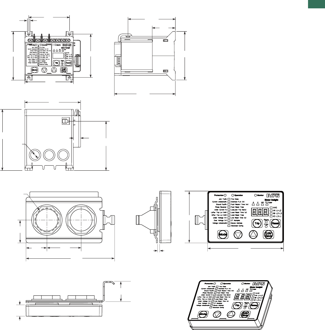
1
61AUTOMATION AND CONTROL www.eaton.com/seasia-electrical
1.2
C441 overload and monitoring relay
Dimensions
Approximate Dimensions in mm
Motor Insight with Mounted Modbus Communication Module
Motor Insight Remote Display
5.1
4 Places 84.1
88.9
100.1
100.1
Mounting Dimensions
(4) 10-32
115.1
125.0 Dia.
17.5
3 Places
101.1
15.0
Terminal Ref.
97.0
48.0
100.1
125.0
68.6
99.1
12 GA Max.
Panel Thickness
2X ø 31.0
Hole in Panel
116.8
44.5
27.9
30.5
25.4
15.2
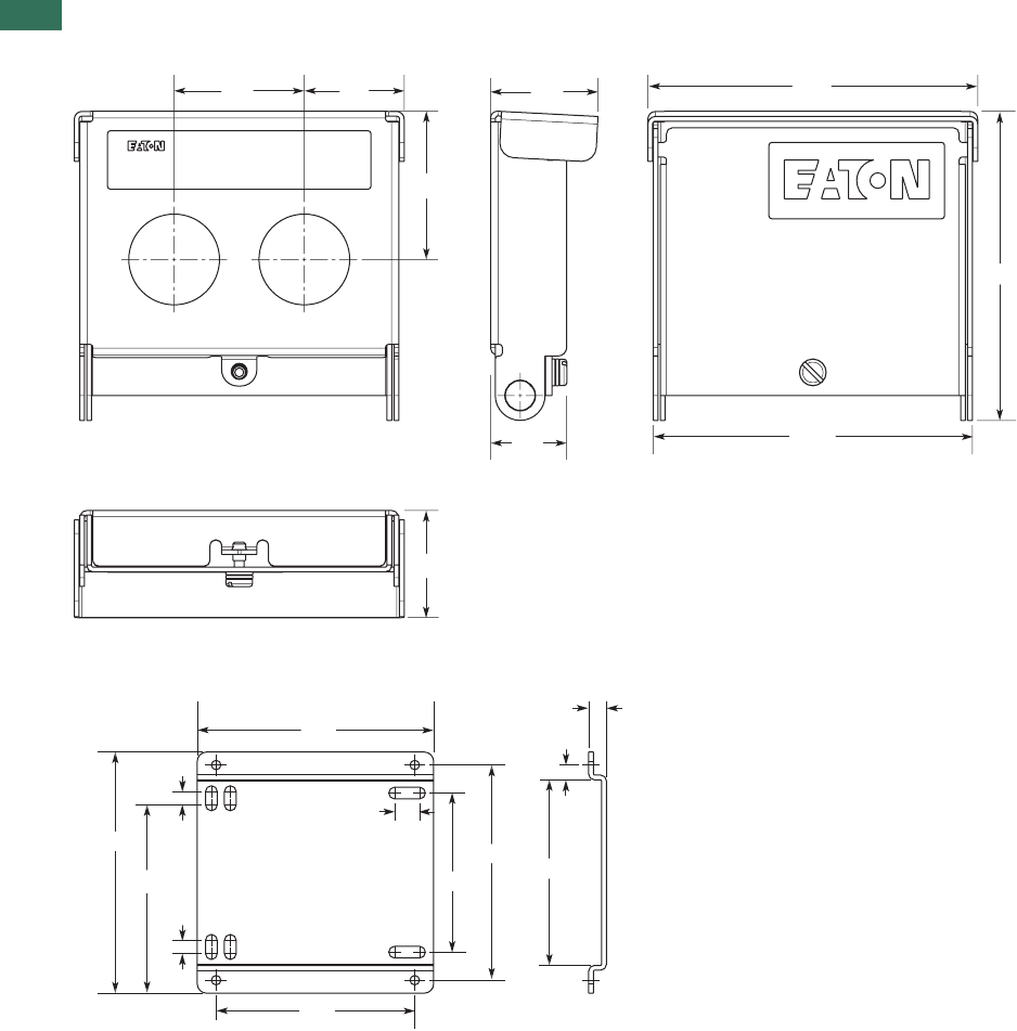
1
62 AUTOMATION AND CONTROL www.eaton.com/seasia-electrical
1.2 C441 overload and monitoring relay
Dimensions
Approximate Dimensions in mm
Motor Insight Cover Assembly
Motor Insight Conversion Plate
106.7
111. 8
109.2
35.6
50.8
35.6
25.4
33.044.5
Motor Insight
7. 6
83.8
5.1
78.7
91.4
68.6
10.2
101.6
58.4
5.1
5.1
99.1
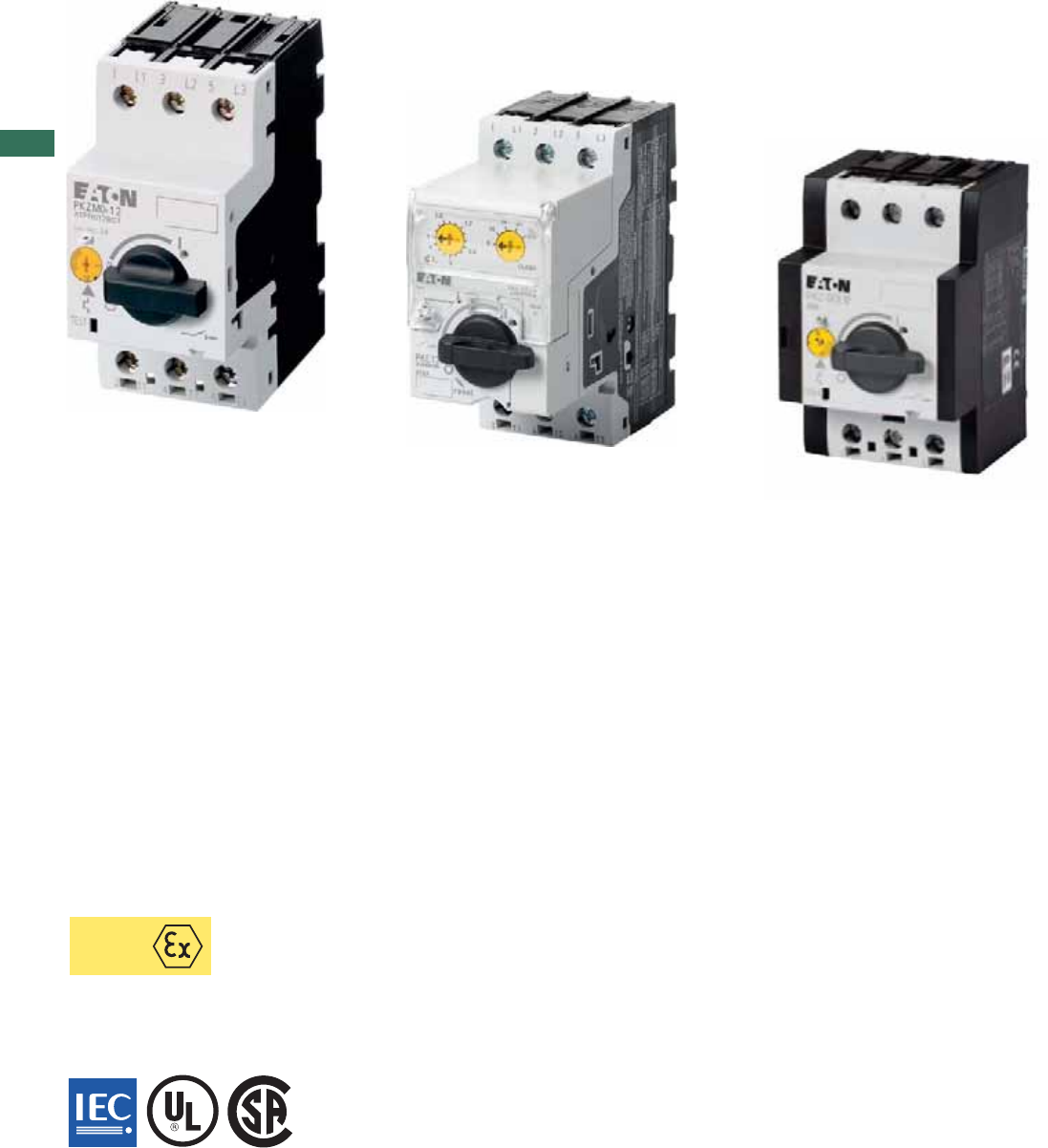
1
AUTOMATION AND CONTROL www.eaton.com/seasia-electrical
Machinery and installation downtimes should be kept as short as possible. The PKZ
fuseless motor-protective circuit-breakers combine short-circuit and overload protection
in one device, allowing fast restart readiness. PKZM01, PKZM0, PKZM4 and PKE have
the same accessories. Combines easily with DILM contactors and DS7 soft starters.
Connecting PKE to SmartWire-DT® facilitates high data transparency.
ATEX
PKZM01 (up to 16 A) motor-protective circuit-breaker with pushbuttons
Motor-protective circuit-breaker in housing for protection types IP40 and IP65.
Integrated EMERGENCY STOP and EMERGENCY OFF pushbuttons reduce wiring.
•
•
PKZM0 (up to 32 A) and PKZM4 (up to 65 A) motor-protective circuit-breakers with rotary handle
Short-circuit proof up to at least 50 kA for easy engineering
Trip-indicating auxiliary contact enables remote diagnosis
High safety through application as main switch or repair and maintenance switch
ATEX approval for protection of EEx e motors up to 65 A
•
•
•
•
PKE (up to 65 A) motor-protective circuit-breakers with electronic wide-range overload protection
High flexibility through plug-in trip block
Wide current setting ranges enable only five trip blocks up to 65 A
Precise and extremely long-term stable characteristic curves
Individual supply through integrated current converter
ATEX approval for protection of EEx e motors up to 65 A
Adjustable tripping classes
•
•
•
•
•
•
DC string circuit-breakers PKZ-SOL and DC switch-disconnectors P-SOL (up to 63 A) for
installations
High string circuit-breaker flexibility due to wide current setting range
Enclosed switch-disconnector for external mounting (IP65)
Remote shutdown through optional secondary voltage and shunt trip
Voltage up to 1000 V DC
TÜV certified
•
•
•
•
•
PKZ and PKE motor-protective
circuit-breakers
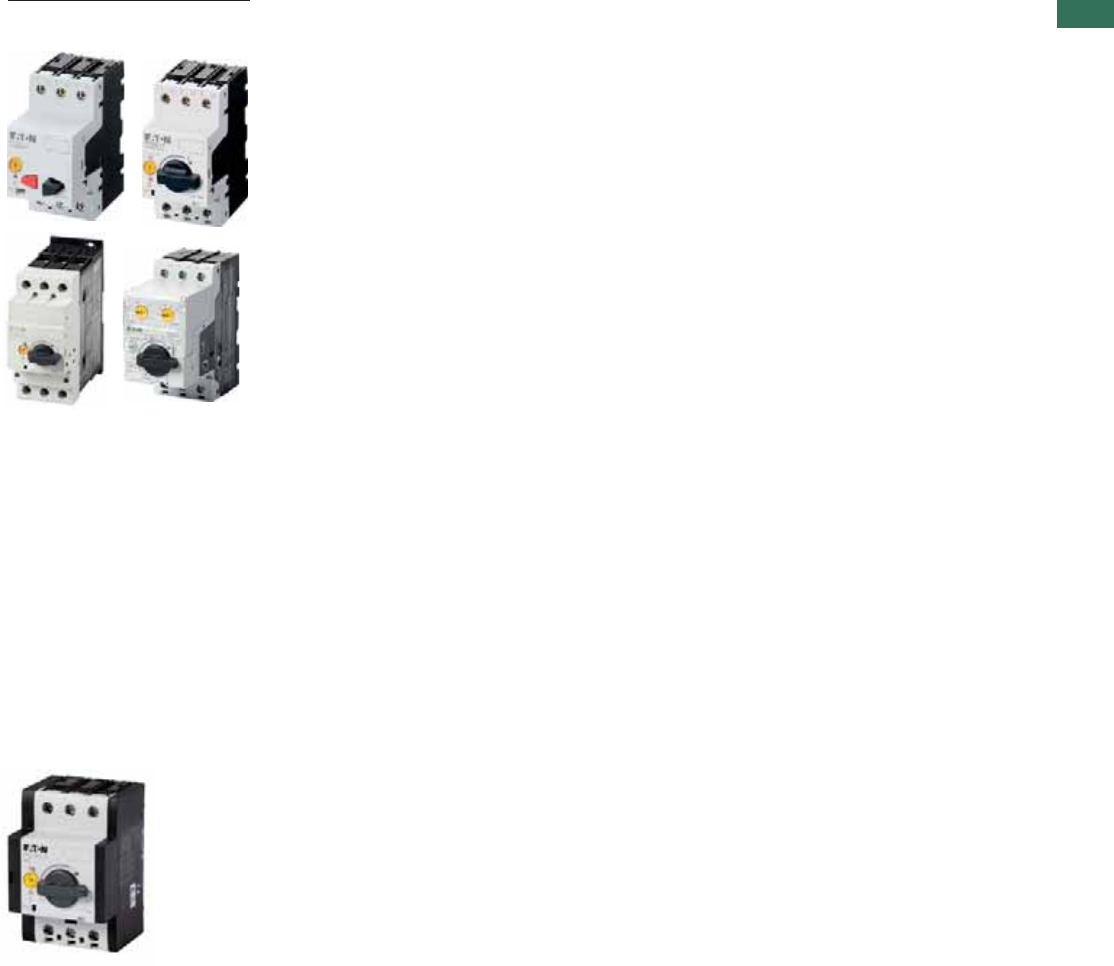
1
Motor-protective circuit-breakers
Contents
1AUTOMATION AND CONTROL www.eaton.com/seasia-electrical
Motor-protective circuit-breaker
PKZM01, PKZM0,PKZM4, PKE
DC string circuit-breaker PKZ-SOL,
DC switch-disconnectors P-SOL, SOL
System overview
PKZM01, PKZM0, PKZM4, PKE motor-protective circuit-breakers . . . . . . . . . . . . . . . . . . . . . . . . . . . . . . . . . . . . . .
Ordering
Motor-protective circuit-breakers . . . . . . . . . . . . . . . . . . . . . . . . . . . . . . . . . . . . . . . . . . . . . . . . . . . . . . . . . . . . . . .
Motor-protective circuit-breakers for startercombinations . . . . . . . . . . . . . . . . . . . . . . . . . . . . . . . . . . . . . . . . . . . .
Transformer-protective circuit-breakers . . . . . . . . . . . . . . . . . . . . . . . . . . . . . . . . . . . . . . . . . . . . . . . . . . . . . . . . . .
PKE electronic motor-protective circuit-breaker . . . . . . . . . . . . . . . . . . . . . . . . . . . . . . . . . . . . . . . . . . . . . . . . . . . .
Standard auxiliary contacts . . . . . . . . . . . . . . . . . . . . . . . . . . . . . . . . . . . . . . . . . . . . . . . . . . . . . . . . . . . . . . . . . . . .
Auxiliary contacts, shunt releases, undervoltage release . . . . . . . . . . . . . . . . . . . . . . . . . . . . . . . . . . . . . . . . . . . . .
Engineering
Accessories for motor-protective circuit-breakers in enclosures . . . . . . . . . . . . . . . . . . . . . . . . . . . . . . . . . . . . . . .
Ordering
Insulated enclosures . . . . . . . . . . . . . . . . . . . . . . . . . . . . . . . . . . . . . . . . . . . . . . . . . . . . . . . . . . . . . . . . . . . . . . . . .
Accessories . . . . . . . . . . . . . . . . . . . . . . . . . . . . . . . . . . . . . . . . . . . . . . . . . . . . . . . . . . . . . . . . . . . . . . . . . . . . . . .
Busbar adapters . . . . . . . . . . . . . . . . . . . . . . . . . . . . . . . . . . . . . . . . . . . . . . . . . . . . . . . . . . . . . . . . . . . . . . . . . . . .
Wiring sets . . . . . . . . . . . . . . . . . . . . . . . . . . . . . . . . . . . . . . . . . . . . . . . . . . . . . . . . . . . . . . . . . . . . . . . . . . . . . . . .
Motor feeder plugs, three-phase commoning links . . . . . . . . . . . . . . . . . . . . . . . . . . . . . . . . . . . . . . . . . . . . . . . . .
Actuating voltages . . . . . . . . . . . . . . . . . . . . . . . . . . . . . . . . . . . . . . . . . . . . . . . . . . . . . . . . . . . . . . . . . . . . . . . . . .
Engineering
Motor-protective circuit-breakers . . . . . . . . . . . . . . . . . . . . . . . . . . . . . . . . . . . . . . . . . . . . . . . . . . . . . . . . . . . . . . .
Characteristic curves . . . . . . . . . . . . . . . . . . . . . . . . . . . . . . . . . . . . . . . . . . . . . . . . . . . . . . . . . . . . . . . . . . . . . . . . .
Switching capacity . . . . . . . . . . . . . . . . . . . . . . . . . . . . . . . . . . . . . . . . . . . . . . . . . . . . . . . . . . . . . . . . . . . . . . . . . .
Technical data
Motor-protective circuit-breakers . . . . . . . . . . . . . . . . . . . . . . . . . . . . . . . . . . . . . . . . . . . . . . . . . . . . . . . . . . . . . . .
Auxiliary contacts . . . . . . . . . . . . . . . . . . . . . . . . . . . . . . . . . . . . . . . . . . . . . . . . . . . . . . . . . . . . . . . . . . . . . . . . . . .
Dimensions
PKZM01, PKZM0 motor-protective circuit-breaker . . . . . . . . . . . . . . . . . . . . . . . . . . . . . . . . . . . . . . . . . . . . . . . . . .
Accessories . . . . . . . . . . . . . . . . . . . . . . . . . . . . . . . . . . . . . . . . . . . . . . . . . . . . . . . . . . . . . . . . . . . . . . . . . . . . . . .
PKZM4 motor-protective circuit-breaker . . . . . . . . . . . . . . . . . . . . . . . . . . . . . . . . . . . . . . . . . . . . . . . . . . . . . . . . . .
Accessories . . . . . . . . . . . . . . . . . . . . . . . . . . . . . . . . . . . . . . . . . . . . . . . . . . . . . . . . . . . . . . . . . . . . . . . . . . . . . . .
Description
DC switches P-SOL, PKZ-SOL, SOL . . . . . . . . . . . . . . . . . . . . . . . . . . . . . . . . . . . . . . . . . . . . . . . . . . . . . . . . . . . . .
Ordering
DC switch-disconnector SOL, ready-to-install . . . . . . . . . . . . . . . . . . . . . . . . . . . . . . . . . . . . . . . . . . . . . . . . . . . . . .
DC switch-disconnector P-SOL, open . . . . . . . . . . . . . . . . . . . . . . . . . . . . . . . . . . . . . . . . . . . . . . . . . . . . . . . . . . . .
DC string circuit-breaker PKZ-SOL . . . . . . . . . . . . . . . . . . . . . . . . . . . . . . . . . . . . . . . . . . . . . . . . . . . . . . . . . . . . . .
Engineering
Circuit P-SOL, PKZ-SOL Interior circuit SOL . . . . . . . . . . . . . . . . . . . . . . . . . . . . . . . . . . . . . . . . . . . . . . . . . . . . . . .
Characteristic curves . . . . . . . . . . . . . . . . . . . . . . . . . . . . . . . . . . . . . . . . . . . . . . . . . . . . . . . . . . . . . . . . . . . . . . . . .
Technical data
DC switch-disconnectors P-SOL,SOL. . . . . . . . . . . . . . . . . . . . . . . . . . . . . . . . . . . . . . . . . . . . . . . . . . . . . . . . . . . .
DC string circuit-breaker PKZ-SOL. . . . . . . . . . . . . . . . . . . . . . . . . . . . . . . . . . . . . . . . . . . . . . . . . . . . . . . . . . . . . . .
Dimensions
DC switches P-SOL, PKZ-SOL, SOL. . . . . . . . . . . . . . . . . . . . . . . . . . . . . . . . . . . . . . . . . . . . . . . . . . . . . . . . . . . . .
2
3
6
6
8
10
12
14
16
20
22
25
26
29
30
30
32
36
38
39
40
45
46
47
48
49
49
50
51
52
53
54
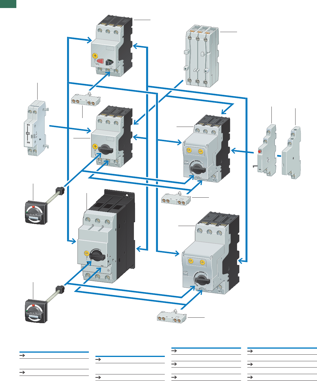
1
2 AUTOMATION AND CONTROL www.eaton.com/seasia-electrical
System overview
Basic devices
Motor-protective circuit-
breaker PKZM01
1
Page 3
Motor-protective circuit-
breaker PKZM0
2
Page 4
Motor-protective circuit-
breakerwith wide-range
overload protection
3
Page 8
Motor-protective circuit-
breaker PKZM4
4
Page 4
Add-on functions
Standard auxiliary contacts 7
Page 10
Shunt release 6
Page 29
Current limiters 8
Page 12
Mounting accessories
Door coupling handles IP65 5
Page 20
Insulated enclosure
Page 16
Mounting/wiring
Page 22
6
5
4
77
7
1
3
3
2
7
7
8
5
1.3 Motor-protective circuit-breakers PKZM01, PKZM0, PKZM4, PKE
Motor-protective circuit-breaker
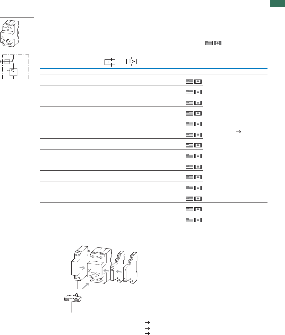
1
3AUTOMATION AND CONTROL www.eaton.com/seasia-electrical
Ordering
Screw terminals
Max. motor rating
AC-3
Rated
uninter-
rupted
current
Setting range Part no.
Article no. Price
See price
list
Std. pack Information relevant for export to
North America
Overload
releases
Short-
circuit
releases
220 V
230 V
240 V
380 V
400 V
415 V
440 V
PPPI
uIrIrm
kW kW kW A A A
Motor-protective circuit-breakers, type “1”; and type “2” coordination
– – – 0.16 0.1…0.16 2.2 PKZM01-0.16
278475
1 off
1 off
1 off
1 off
1 off
1 off
1 off
1 off
1 off
1 off
1 off
1 off
1 off
1 off
– 0.06 0.06 0.25 0.16…0.25 3.5 PKZM01-0.25
278476
0.06 0.09 0.12 0.4 0.25…0.4 5.6 PKZM01-0.4
278477
0.09 0.12 0.18 0.63 0.4…0.63 8.8 PKZM01-0.63
278478
0.12 0.25 0.25 1 0.63…1 14 PKZM01-1
278479
0.25 0.55 0.55 1.6 1…1.6 22 PKZM01-1.6
278480
0.37 0.75 1.1 2.5 1.6…2.5 35 PKZM01-2.5
278481
0.75 1.5 1.5 4 2.5…4 56 PKZM01-4
278482
1.1 2.2 3 6.3 4…6.3 88 PKZM01-6.3
278483
2.2 4 4 10 6.3…10 140 PKZM01-10
278484
3 5.5 5.5 12 8…12 168 PKZM01-12
278485
47.5916 10…16224 PKZM01-16
283390
5.5 9 11 20 16…20 280 PKZM01-20
283383
5.5 12.5 12.5 25 20…25 350 PKZM01-25
288893
Notes
L
T
I >
PageAccessories
3 Standard auxiliary contacts 10
5 Trip-indicating auxiliary contact 12
6 Shunt release, undervoltage release 29
Phase failure sensitivity to IEC/EN 60947-4-1, VDE 0660 Part 102.
Can be snap-fitted to IEC/EN 60715 top-hat rail with 7.5 or 15 mm height
6
3
53
PKZM01
Product Standards
UL File No.
NCCLU
CSA File No.
CSA Class No.
NA Certification
Suitable for
See also
UL 508; CSA-C22.2
No.14; IEC60947-
4-1; CE marking
E36332
NLRV
12528
3211-05
UL Listed, CSA
certified
Branch circuits, or
suitable for group
installations
Page 34
Product Standards
UL File No.
NCCLU
CSA File No.
CSA Class No.
NA Certification
UL 508; CSA-C22.2
No.14; IEC/EN 60947-
4-1; CE marking
E36332
NLRV
12528
3211-05
UL Listed, CSA
certified
1.3
Motor-protective circuit-breakers PKZM01, PKZM0, PKZM4, PKE
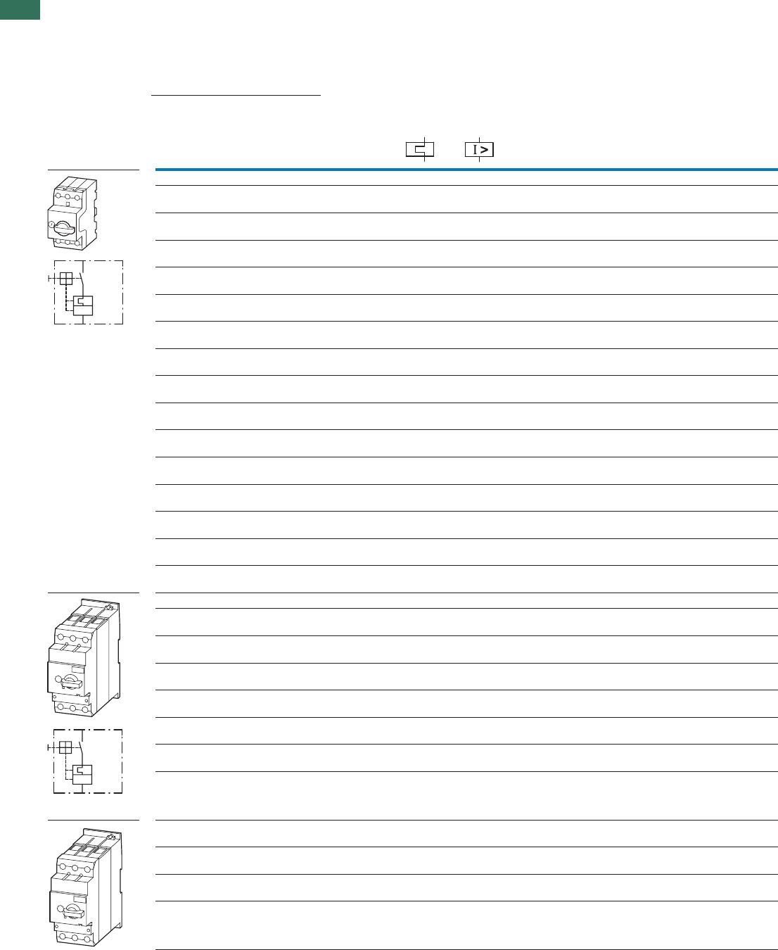
1
1.3 Motor-protective circuit-breakers PKZM01, PKZM0, PKZM4, PKE
Motor-protective circuit-breaker
4 AUTOMATION AND CONTROL www.eaton.com/seasia-electrical
Screw terminals Screw terminals on feed
side, spring-loaded terminals
on output side
Circuit
diagrams
Max. motor rating
AC-3
Rated
uninter-
rupted
current
Setting range Part no.
Article no. Price
See price
list
Part no.
Article no. Price
See price
list
Overload
releases
Short-circuit
releases
220 V
230 V
240 V
380 V
400 V
415 V
440 V 500 V660 V
690 V
PP PPP I
uIrIrm
kW kW kW kW kW A A A
Motor-protective circuit-breakers, type “1” and type “2”coordination1)
– – – – 0.06 0.16 0.1…0.16 2.2 PKZM0-0.16
072730 PKZM0-0,16-SC
229828
– 0.060.060.060.120.25 0.16…0.253.5 PKZM0-0.25
072731 PKZM0-0,25-SC
229829
0.06 0.09 0.12 0.12 0.18 0.4 0.25…0.4 5.6 PKZM0-0.4
072732 PKZM0-0,4-SC
229830
0.09 0.12 0.18 0.25 0.25 0.63 0.4…0.63 8.8 PKZM0-0.63
072733 PKZM0-0,63-SC
229831
0.12 0.25 0.25 0.37 0.55 1 0.63…1 14 PKZM0-1
072734 PKZM0-1-SC
229832
0.25 0.55 0.55 0.75 1.1 1.6 1…1.6 22 PKZM0-1.6
072735 PKZM0-1,6-SC
229833
0.37 0.75 1.1 1.1 1.5 2.5 1.6…2.5 35 PKZM0-2.5
072736 PKZM0-2.5-SC
229834
0.75 1.5 1.5 2.2 3 4 2.5…4 56 PKZM0-4
072737 PKZM0-4-SC
229835
1.1 2.2 3 3 4 6.3 4…6.3 88 PKZM0-6.3
072738 PKZM0-6,3-SC
229836
2.2 4 4 4 7.5 10 6.3…10 140 PKZM0-10
072739 PKZM0-10-SC
229837
3 5.5 5.5 5.5 11 12 8…12 168 PKZM0-12
278486 PKZM0-12-SC
278487
47.59912.516 10…16224 PKZM0-16
046938 PKZM0-16-SC
229838
5.5 9 11 12.5 15 20 16…20 280 PKZM0-20
046988
5.5 12.5 12.5 15 22 25 20…25 350 PKZM0-25
046989
7.51515223032 25…32 448 PKZM0-32
278489
Motor-protective circuit-breakers, type “1” and type “2” coordination 1)
47.59912.516 10…16224 PKZM4-16
222350
5.5 12.5 12.5 15 22 25 16…25 350 PKZM4-25
222352
7.51517.5222232 25…32 448 PKZM4-32
222353
11 20 22 24 30 40 32…40 560 PKZM4-40
222354
14 25 30 30 45 50 40…50 700 PKZM4-50
222355
17 30 37 37 55 58 50…58 812 PKZM4-58
222394
18.5 34 37 45 55 65 55…65 882 PKZM4-63
222413
Circuit-breakers 2)
For line and cable protection
–––––16 10…16224 PKZM4-16-CB
132591
– – – – – 25 16…25 350 PKZM4-25-CB
132592
–––––32 25…32448 PKZM4-32-CB
132593
L
T
I >
L
T
I >
PKZM0, PKZM4
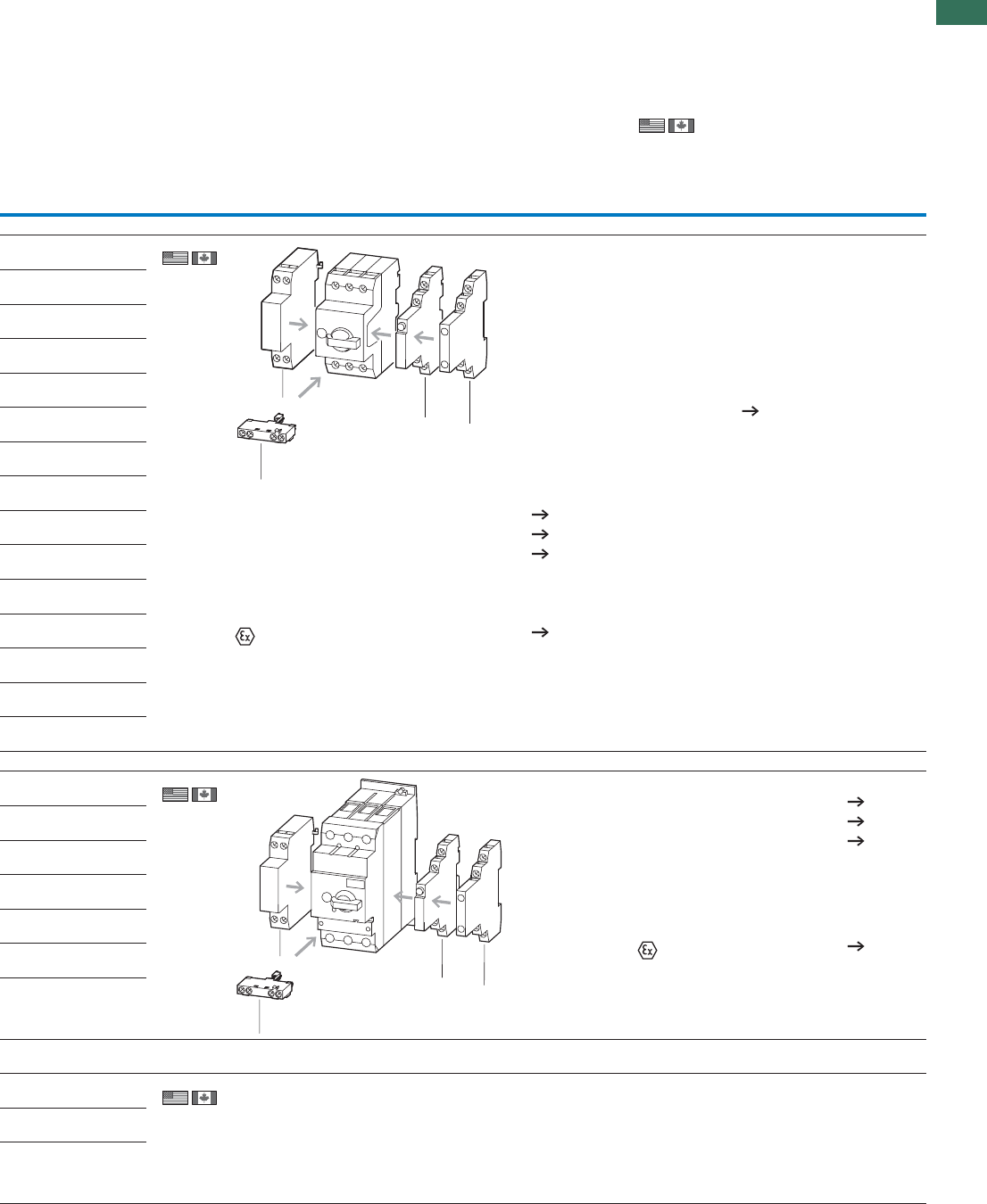
1
1.3
Motor-protective circuit-breakers PKZM01, PKZM0, PKZM4, PKE
Motor-protective circuit-breaker
5AUTOMATION AND CONTROL www.eaton.com/seasia-electrical
Spring-loaded terminals
Part no.
Article no. Price
See price
list
Std. pack Information relevant for export toNotes
North America
PKZM0-0,16-C
229669
1 off 1)
Product Standards
UL File No.
UL CCN
CSA File No.
CSA Class No.
NA Certification
Suitable for
See also
PKZM0-0,25-C
229670
PKZM0-0,4-C
229671
PKZM0-0,63-C
229672
PKZM0-1-C
229673
PKZM0-1,6-C
229674
PKZM0-2.5-C
229675
PKZM0-4-C
229676
PKZM0-6,3-C
229677
PKZM0-10-C
229678
PKZM0-12-C
278488
PKZM0-16-C
229679
1 off
1 off Not usable as a main switch
Phase failure sensitivity to
IEC/EN 60947-4-1, VDE 0660 Part 102.
Switching capacity of SCCR
65 kA (480 Y/277 V)
22 kA (600 Y/347 V)
2)
Product Standards
NA Certification
Specially designed for NA Yes
Suitable for
PageAccessories
3 Standard auxiliary contacts 10
5 Trip-indicating auxiliary contact 12
6 Shunt release, undervoltage release 29
Phase failure sensitivity to IEC/EN 60947-4-1, VDE 0660 Part 102.
Can be snap-fit to IEC/EN 60715 top-hat rail with 7.5 or 15 mm height
PTB 02 ATEX 3151, see manual 21
3
5
6
3
3
5
6
3
PageAccessories
3 Standard auxiliary contacts 10
5 Trip-indicating auxiliary contact 12
6 Shunt release, undervoltage release 29
Only motor-protective circuit-breaker:
Phase failure sensitivity to
IEC/EN 60947-4-1, VDE 0660 Part 102
Can be snap-fitted to IEC/EN 60715 top-hat rail
with 7.5 or 15 mm height
PTB 02 ATEX 3153,
see manual 21
UL 508; CSA-C22.2 No.14;
IEC60947-4-1; CE marking
E36332
NLRV
12528
3211-05
UL Listed, CSA certified
Branch circuit: Manual type E if
used with terminal, or suitable
for group installations
Page 34
UL 489; CSA-C22.2 No.5-09;
IEC 60947-4-1; CE marking
Request filed for UL and CSA
Feeder and branch circuit as BCPD
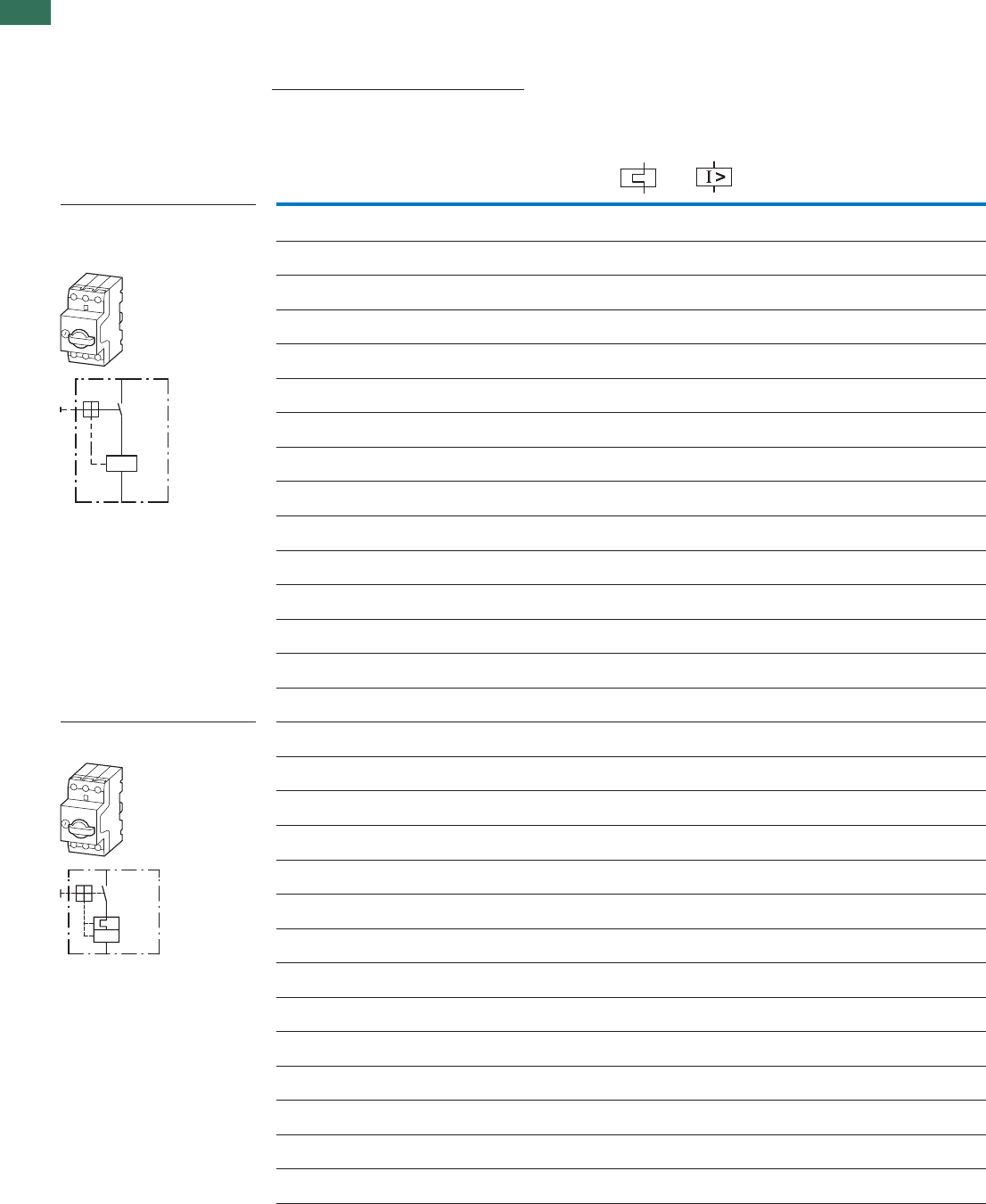
1
1.3 Motor-protective circuit-breakers PKZM01, PKZM0, PKZM4, PKE
Motor-protective circuit-breaker for starter combinations and transformers
6 AUTOMATION AND CONTROL www.eaton.com/seasia-electrical
Screw terminals
RatedMax. motor rating
uninterrupted
current
Setting range Part no.
Article no. Price
See price
list
Std.
pack
daolrevO3-CA
releases
Short-circuit
releases
220 V
230 V
240 V
380 V
400 V
415 V
440 V 500 V 660 V
690 V
IuIrIrm
PPPPPA A A
kW kW kW kW kW
Motor-protective circuit-breakers
for starter combinations
Short-circuit protective breakers
without overload function
2.20.160.06–––– PKM0-0,16
072720
1 off
1 off
1 off
1 off
1 off
1 off
1 off
1 off
1 off
1 off
1 off
1 off
1 off
1 off
1 off
3.50.250.120.060.060.06–
5.60.40.180.120.120.090.06
8.80.630.250.250.180.120.09
1410.550.380.250.250.12
221.61.10.750.550.370.25
352.51.51.11.10.750.37
56432.21.51.50.75
886.34332.21.1
140107.54442.2
16812115.55.55.53
22416
12.5997.54
280201512.51195.5
35025221512.512.55.5
44832302215157.5
PKM0-0,25
072721
PKM0-0,4
072722
PKM0-0,63
072723
PKM0-1
072724
PKM0-1,6
072725
PKM0-2.5
072726
PKM0-4
072727
PKM0-6,3
072728
PKM0-10
072729
PKM0-12
278490
PKM0-16
044502
PKM0-20
203594
PKM0-25
044503
PKM0-32
278491
Transformer-protective circuit-
breakers
– – – – – 0.16 0.1…0.16 2.4 PKZM0-0,16-T
088907
1 off
1 off
1 off
1 off
1 off
1 off
1 off
1 off
1 off
1 off
1 off
1 off
1 off
1 off
– – – – – 0.25 0.16…0.25 4.25 PKZM0-0,25-T
088908
– – – – – 0.4 0.25…0.4 6.8 PKZM0-0,4-T
088909
– – – – – 0.63 0.4…0.63 12 PKZM0-0,63-T
088910
– – – – – 1 0.63…1 20 PKZM0-1-T
088911
–––––1.6 1…1.6 32 PKZM0-1,6-T
088912
–––––2.5 1.6…2.550 PKZM0-2.5-T
088913
–––––4 2.5…484 PKZM0-4-T
088914
–––––6.3 4…6.3 141 PKZM0-6,3-T
088915
–––––10 6.3…10224 PKZM0-10-T
088916
–––––12 8…12 224 PKZM0-12-T
278492
–––––16 10…16280 PKZM0-16-T
088917
–––––20 16…20350 PKZM0-20-T
088918
–––––25 20…25437 PKZM0-25-T
278493
L
T
I >
L
T
I >
PKZM0
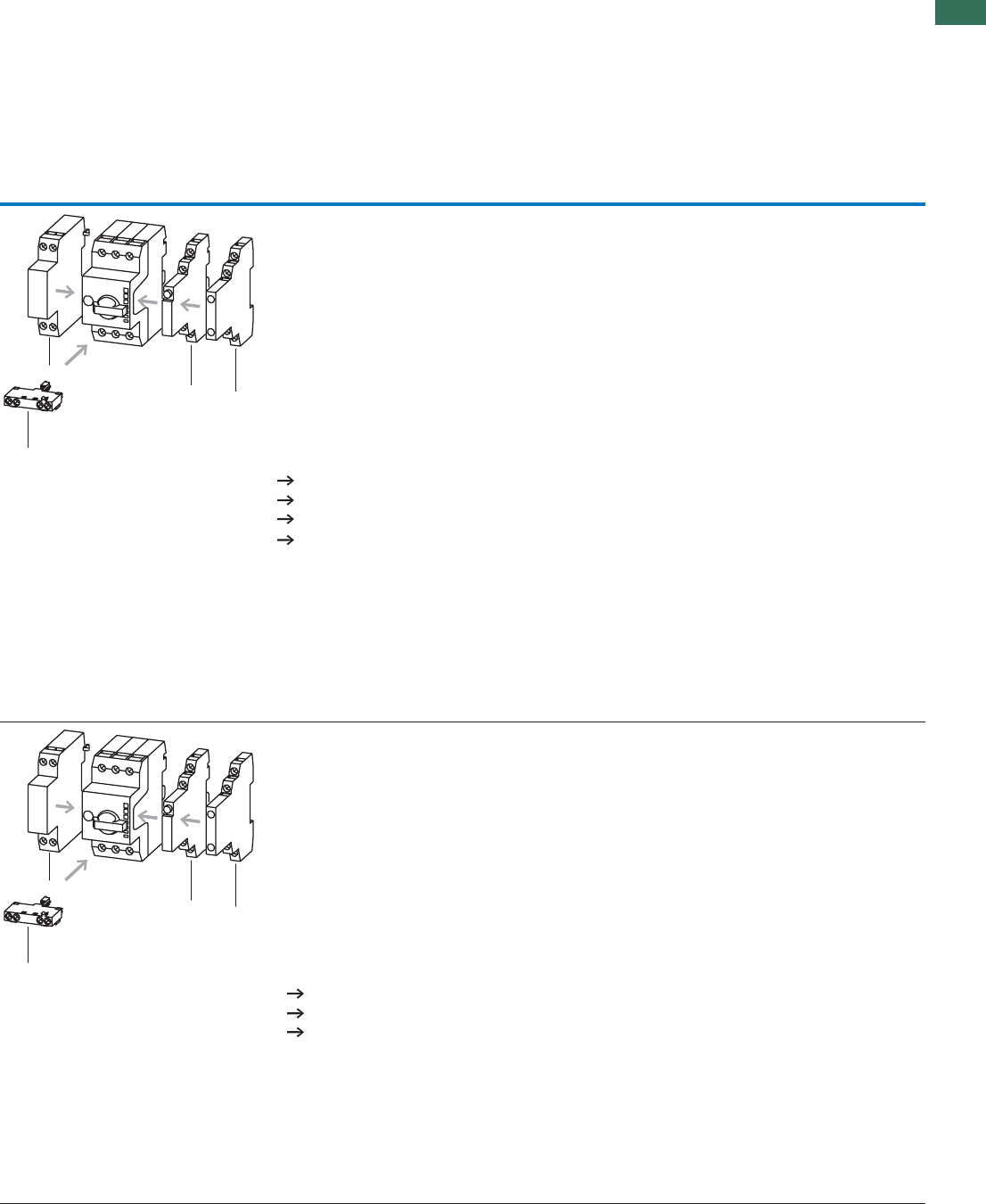
1
1.3
Motor-protective circuit-breakers PKZM01, PKZM0, PKZM4, PKE
Motor-protective circuit-breaker for starter combinations and transformers
7AUTOMATION AND CONTROL www.eaton.com/seasia-electrical
Notes
When using the PKM0 as short-circuit protection for
motors with heavy starting duty, a device must be
selected whose rated operational current Ie is higher
by the following factors:
CLASS 5 = 1.0
CLASS 10 = 1.0
CLASS 15 = 1.22
CLASS 20 = 1.41
CLASS 25 = 1.58
CLASS 30 = 1.73
CLASS 35 = 1.89
CLASS 40 = 2.0
PageAccessories
3 Standard auxiliary contacts 10
5 Trip-indicating auxiliary contact 12
6 Shunt release, undervoltage release 29
Additional accessories 46
Can be snap-fitted to IEC/EN 60715 top-hat rail with 7.5 or 15 mm height
Assignment of the short-circuit protective breakers and contactors in “Fuseless motor-starter combinations” section.
An appropriate overload relay must be fitted to protect motors against overload.
3
5
6
3
PageAccessories
3 Standard auxiliary contacts 10
5 Trip-indicating auxiliary contact 12
6 Shunt release, undervoltage release 29
For the protection of transformers with a high inrush current
Can be snap-fitted to IEC/EN 60715 top-hat rail with 7.5 or 15 mm height
Phase failure sensitivity to IEC/EN 60947-4-1, VDE 0660 Part 102.
3
5
6
3
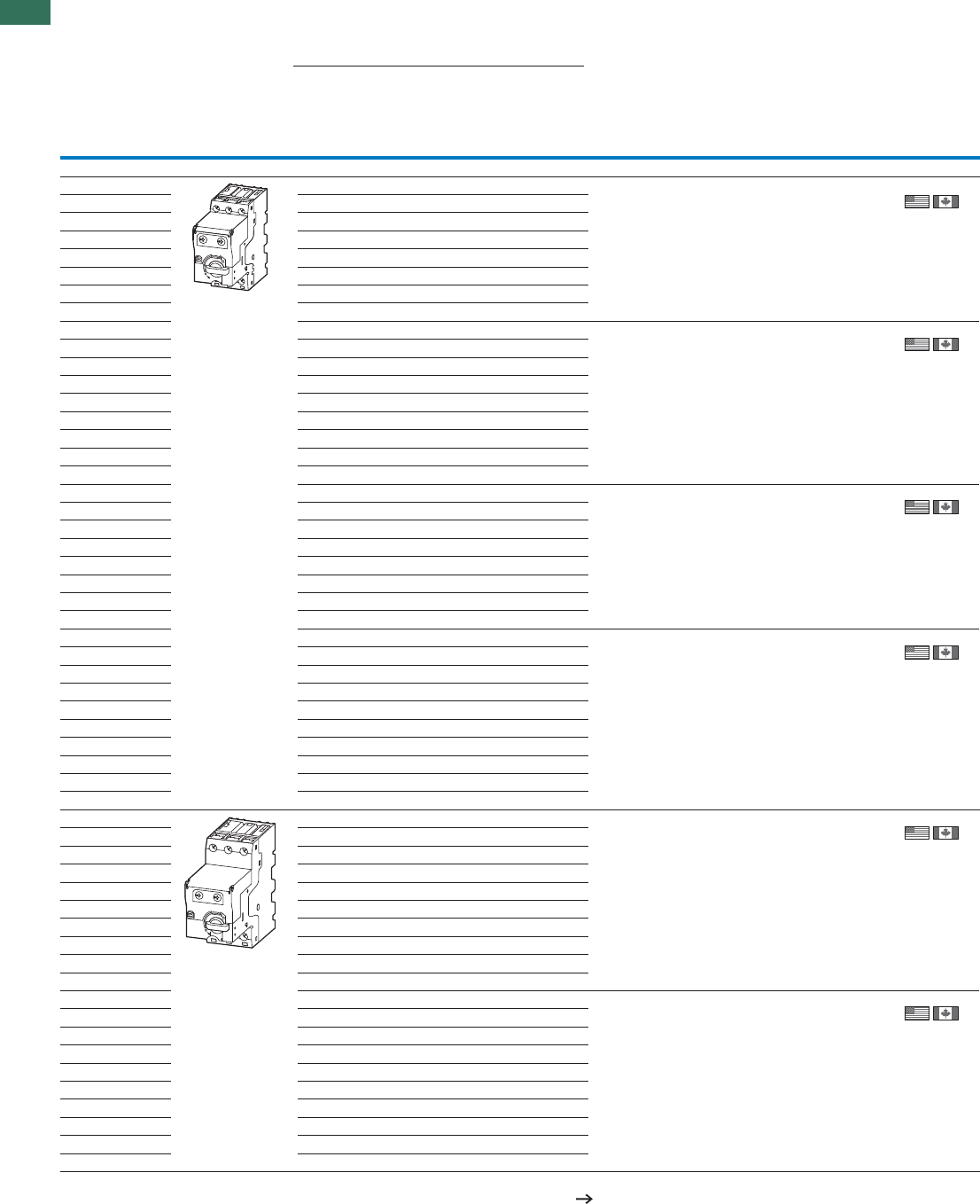
1
1.3 Motor-protective circuit-breakers PKZM01, PKZM0, PKZM4, PKE
Motor-protective circuit-breaker
8 AUTOMATION AND CONTROL www.eaton.com/seasia-electrical
Motor full-load current Basic device
Setting rangeAC-3Motor rating
Overload releases Part no.
Article no.
See price
list
Std. pack
220 V
230 V
240 V
380 V
400 V
415 V
440 V 500 V 660 V
690 V
IIIIIP
AAAAAWk
Motor-protective circuit-breakers, type“1” and type “2” coordination
0.3…1.2 A––––0.370.06 PKE12
121721 1off
–––0.310.540.09
–0.330.370.410.720.12
0.350.480.540.61.040.18
0.50.70.760.8–0.25
0.70.91.021.1–0.37
0.9––––0.55
1.1––––0.75
1…4 A––––1.040.18 PKE12
121721
1off
––––1.40.25
––1.021.120.37
–1.21.391.52.70.55
1.11.51.681.93.20.75
1.52.12.412.6–1.1
2.12.93.283.6–1.5
2.94–––2.2
3.8––––3
3…12 A––––3.20.75 PKE12
121721
1off
––––4.61.1
––3.33.66.31.5
–44.658.72.2
3.85.366.611.53
4.96.87.78.5–4
6.5910.211.3–5.5
8.8––––7.5
8…32 A––––8.72.2 PKE32
121722
1off
––––11.53
–––8.514.84
–910.211.319.65.5
8.812.113.815.226.47.5
12.617.419.821.7–11
1723.426.629.3–15
20.928.9–––18.5
23.8––––22
32––––30
16…65 A––––19.65.5 PKE65
138258
1off
––––26.47.5
–17.419.721.73811
1723.426.629.35115
20.928.932.9366318.5
23.83337.441–22
324450.355–30
395461.4––37
4765–––45 Start of delivery
07/2010
58––––55
8…32 A––––8.72.2 PKE65
138258
1off
––––11.53
–––8.514.84
–910.211.319.65.5
8.812.113.815.226.47.5
12.617.419.821.7–11
1723.426.629.3–15
20.928.9–––18.5
23.8––––22 Start of delivery
07/2010
32––––30
Notes Select switchgear and cables according to Class as shown in the table on Chapter 1.2 (Page 22)
1) For communications, module PKE-SWD-32 for contactors is required in addition, See catalog
PKE
1
1.3
Motor-protective circuit-breakers PKZM01, PKZM0, PKZM4, PKE
Motor-protective circuit-breaker
9AUTOMATION AND CONTROL www.eaton.com/seasia-electrical
Trip module Standard Trip module Expanded1) Motor-protective circuit-
breakers Standard
Complete device
usable
for Part no.
Article no.
See price
list
Std. pack usable
for Part no.
Article no.
See price
list
Std. pack Part no.
Article no.
See price
list
Std. pack
PKE12 PKE-XTU-1,2
121723
1off PKE12 PKE-XTUA-1,2
121727
1off PKE12/XTU-1,2
121731
1off
Start of delivery
07/2010
Start of delivery
07/2010
Start of delivery
07/2010
PKE12 PKE-XTU-4
121724
1off PKE12 PKE-XTUA-4
121728
1off PKE12/XTU-4
121732
1off
Start of delivery
05/2010
PKE12
PKE32
PKE-XTU-12
121725
1off PKE12
PKE32
PKE-XTUA-12
121729
1off PKE12/XTU-12
121733
1off
Start of delivery
05/2010
PKE32 PKE-XTU-32
121726
1off PKE32 PKE-XTUA-32
121730
1off PKE32/XTU-32
121734
1off
Start of delivery
05/2010
PKE65 PKE-XTU-65
138259
1off PKE65 PKE-XTUA-65
138260
1off PKE65/XTU-65
138516
1off
Start of delivery
10/2010
Start of delivery
10/2010
Start of delivery
10/2010
PKE65 PKE-XTUW-32
138261
1off PKE65 PKE-XTUWA-32
138262
1off PKE65/XTUW-32
138517
1 off
Start of delivery
10/2010
Start of delivery
10/2010
Start of delivery
10/2010
Information relevant for export to North America Product Standards UL 508; CSA-C22.2 No. 14; IEC60947-4-1; CE marking
NA Certification Request filed for UL and CSA
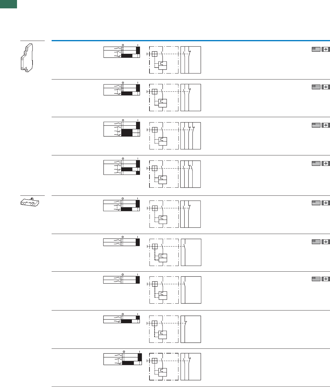
1
1.3 Motor-protective circuit-breakers PKZM01, PKZM0, PKZM4, PKE
Standard auxiliary contacts
10 AUTOMATION AND CONTROL www.eaton.com/seasia-electrical
Contact configuration Contact sequence Circuit diagrams Connection
method
For use
with Part no.
Article no. Price
See price
list
Std. pack
N/O = normally
open contact
NC = normally
closed contact
Standard auxiliary contacts
For motor-protective circuit-breakers
Screw1 NC1 N/O
1 NC1 N/O
2 NC1 N/O
1 NC2 N/O
1 NC1 N/O
–1 N/O
–1 N/O
1 NC–
1 NC1 N/O
terminals
PKZM01
PKZM0
PKZM4
PKZM0-T
PKM0
PKE 1)
PKZM01
PKZM0
PKZM4
PKZM0-T
PKM0
PKE 1)
PKZM01
PKZM0
PKZM4
PKZM0-T
PKM0
PKE 1)
PKZM01
PKZM0
PKZM4
PKZM0-T
PKM0
PKE 1)
PKZM01
PKZM0
PKZM4
PKZM0-T
PKM0
PKE 1)
PKZM01
PKZM0
PKZM4
PKZM0-T
PKM0
PKE 1)
PKZM01
PKZM0
PKZM4
PKZM0-T
PKM0
PKE 1)
PKZM01
PKZM0
PKZM4
PKZM0-T
PKM0
PKE 1)
PKZM01
PKZM0
PKZM4
PKZM0-T
PKM0
PKE 1)
NHI11-PKZ0
072896
5 off
5 off
5 off
5 off
5 off
5 off
5 off
Spring-
loaded
terminals
NHI11-PKZ0-C
229680
Screw
terminals NHI12-PKZ0
072895
Screw
terminals NHI21-PKZ0
072894
Screw
terminals NHI-E-11-PKZ0
082882
Screw
terminals NHI-E-10-PKZ0
082884
Spring-
loaded
terminals
NHI-E-10-PKZ0-C
229681
Spring-
loaded
terminals
NHI-E-01-PKZ0-C
229682
5 off
Screw
terminals NHI-B-11-PKZ0
208277
5 off
Notes 1) Only standard auxiliary contacts manufactured on or after CW 36/2009 are for use with PKE.
NHI11
L1L2L3
1.14 1.22
1.13 1.21
I >
NHI11
L1L2L3
1.14 1.22
1.13 1.21
I >
L1L2L3
NHI12
1.13
1.14 1.22
1.21 1.31
1.32
I >
L1L2L3
NHI21
1.13 1.21 1.33
1.14 1.22 1.34
I >
L1L2L3
NHI-E-11
1.53
1.54
1.61
1.62
I >
L1L2L3
NHI-E-10
1.53
1.54
I >
L1L2L3
NHI-E-10
1.53
1.54
I >
L1L2L3
NHI-E-01
1.51
1.52
I >
NHI-B-11
L1L2L3
1.14 1.22
1.13 1.21
I >
NHI...-PKZ0...
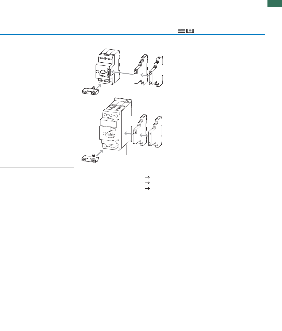
1
1.3
Motor-protective circuit-breakers PKZM01, PKZM0, PKZM4, PKE
Standard auxiliary contacts
11AUTOMATION AND CONTROL www.eaton.com/seasia-electrical
Information relevant for export to North AmericaNotesNotes
Can be fitted to the right side of: motor-protective
circuit-breakers, transformer protective circuit
breakers and motor-protective circuit-breakers
for starter combinations
Can be combined with:
Trip-indicating auxiliary contact AGM, NHI-E-…
Can be fitted to motor-protective circuit-breakers,
transformer-protective circuit-breakers and
motor-protective circuit-breakers for starter
combinations from serial number 01.
45 mm (PKZM0 and PKZM01) or 55 mm (PKZM4)
widths of the motor-protective circuit-breakers
remain unchanged.
NHI-E...-PKZ0-C not for use with MSC...-type motor
starter combinations.
Accessories
1 Motor-protective circuit-breakers 4
5 Trip-indicating auxiliary contact 12
Additional accessories 20
1
5
5
1
Product Standards
UL File No.
UL CCN
CSA File No.
CSA Class No.
NA Certification
UL 508; CSA-C22.2No.14;
IEC 60947-4-1; CE marking
E36332
NLRV
12528
3211-05
UL Listed, CSA certified
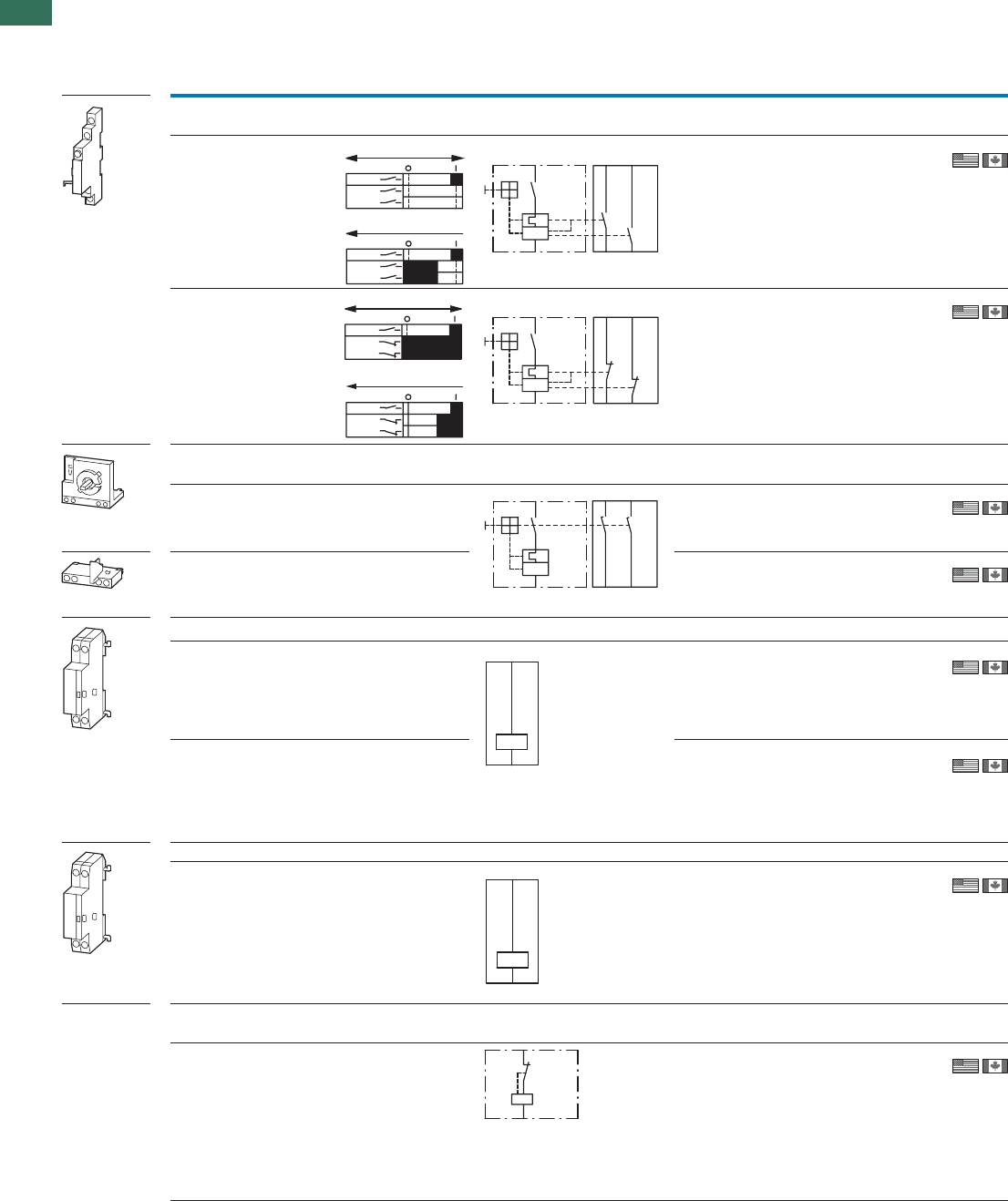
1
1.3 Motor-protective circuit-breakers PKZM01, PKZM0, PKZM4, PKE
Auxiliary contacts, undervoltage releases
12 AUTOMATION AND CONTROL www.eaton.com/seasia-electrical
Contact configuration Contact sequence Circuit diagrams For use with Part no.
Article no. Price
See price
list
Std. pack
N/O = normally
open contact
NC = normally
closed contact
Trip indicators
For motor-protective circuit-breakers
PKZM02 x 1 N/O
PKZM4
PKZM0-T
PKM0
PKZM01
PKE1)
AGM2-10-PKZ0
072898
2 off
PKZM02 x 1 NC–
PKZM4
PKZM0-T
PKM0
PKZM01
PKE1)
AGM2-01-PKZ0
072899
2 off
Early-make auxiliary contacts
For motor-protective circuit-breakers
PKZM0––2 N/O
PKZM0-T
PKM0
PKZM4
VHI20-PKZ0
203595
2 off
PKZM01––2 N/O VHI20-PKZ01
278495
5 off
Shunt release (for power circuit-breakers)
PKZM0–––
PKZM4
PKZM0-T
PKM0
PKZM01
PKE 2)
A-PKZ0(230V50Hz)
073187
2 off
PKZM0–––
PKZM4
PKZM0-T
PKM0
PKZM01
PKE 2)
A-PKZ0(24VDC)
073200
2 off
Undervoltage release
PKZM0–––
PKZM4
PKZM0-T
PKM0
PKZM01
PKE 2)
U-PKZ0(230V50Hz)
073135
2 off
Current limiters
For increasing switching capacity of motor-protective circuit-breakers without auto-protection
PKZM0–––
–
PKZM4
PKE
CL-PKZ0
082881
1 off
Notes 1) Only AGM2-...-PKZ0 manufactured on or after 06/2009 can be fitted.
2) Only A(U)-PKZ0... with serial number 02 or higher can be fitted.
L1L2L3
"+"
"I >"
Einschalten/Ausschalten
L1L2L3
"+"
"I >"
Auslösen "+"
I >
"+"
4.43 4.13
"I >"
4.44 4.14
L1L2L3
"+"
"I >"
Einschalten/Ausschalten
L1L2L3
"+"
"I >"
Auslösen "+"
4.21
"I >"
"+"
4.31
4.32 4.22
I >
3.13 3.23
3.14
3.24
I >
C1
C2
U <
D1
D2
L
T
I >>
AGM2...., VHI...
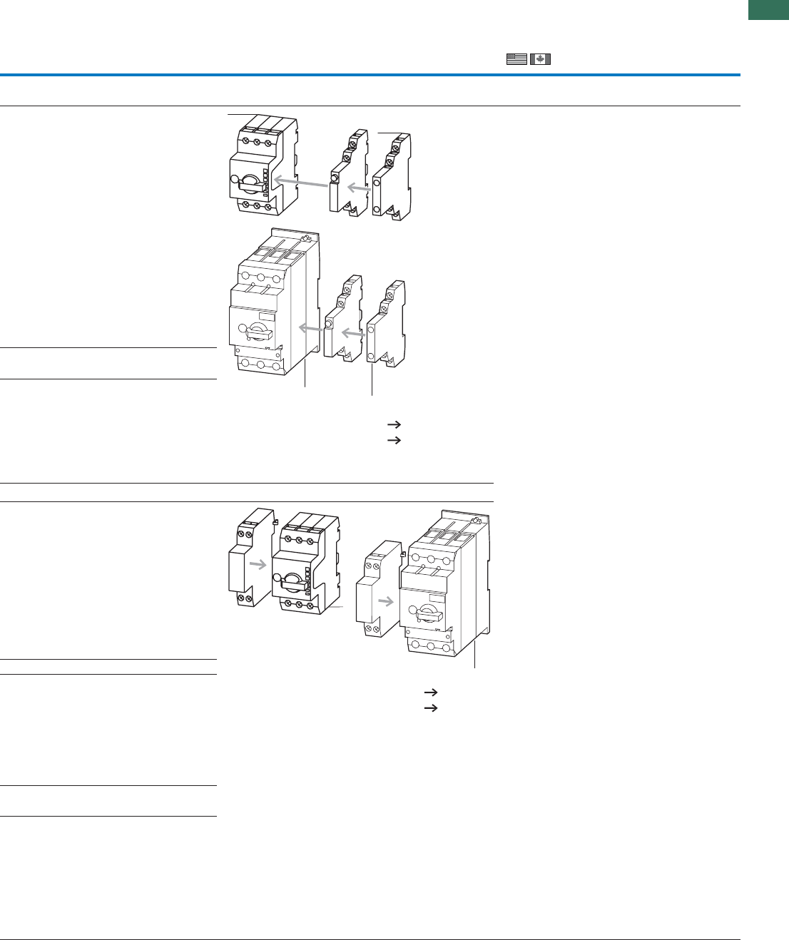
1
1.3
Motor-protective circuit-breakers PKZM01, PKZM0, PKZM4, PKE
Auxiliary contacts, undervoltage releases
13AUTOMATION AND CONTROL www.eaton.com/seasia-electrical
Information relevant for export to North AmericaNotesNotes
Can be fitted to front of motor-protective circuit-
breaker, 45 mm width of the motor-protective
circuit-breaker remains unchanged.
For early energization of undervoltage release,
e.g. in emergency switching off circuits to
EN 60204.
VHI20-PKZ0 cannot be used in combination with
PKZ0-X(R).
Can be fitted to the left side of motor-protective
circuit-breakers.
Cannot be combined with:
undervoltage release U-PKZ0
DC: Intermittent operation 5 s
Can be fitted to the left side of motor-protective
circuit-breakers.
Cannot be combined with:
A-PKZ0 shunt release
When combined with circuit-breaker, can be
used as emergency switching off device to
IEC/EN 60204.
Max. rated operating voltage Ue= 690 V, rated
uninterrupted current Iu =63A
Can be used for individual and group protection.
For group protection and in combination with
PKZM4, order additional BK25/3 incoming terminal
if required.
Mounting next to or behind the motor-protective
circuit-breaker.
PKZM4: 16 - 63 A: 100 kA/400 V
PKZM4: 16 - 63 A: 10 kA/690 V
Can be fitted to the right side of motor-protective
circuit-breakers
Can be combined with:
Standard auxiliary contacts
NHI11-PKZ0
NHI12-PKZ0
NHI21-PKZ0
NHI-E-…
Separate indication of:
a) General trip indication (overload)
b) Short-circuit trip
Local short-circuit indication by red indicator,
manually resettable.
Accessories Page
1 Motor-protective circuit-breakers 4
3 Standard auxiliary contacts 10
1
3
3
1
PageAccessories
1 Motor-protective circuit-breakers 4
Further actuating voltages 29
1
1
Product Standards
UL File No.
UL CCN
CSA File No.
CSA Class No.
NA Certification
UL 508; CSA-C22.2No.14;
IEC60947-4-1; CE marking
E36332
NLRV
12528
3211-05
UL Listed, CSA certified
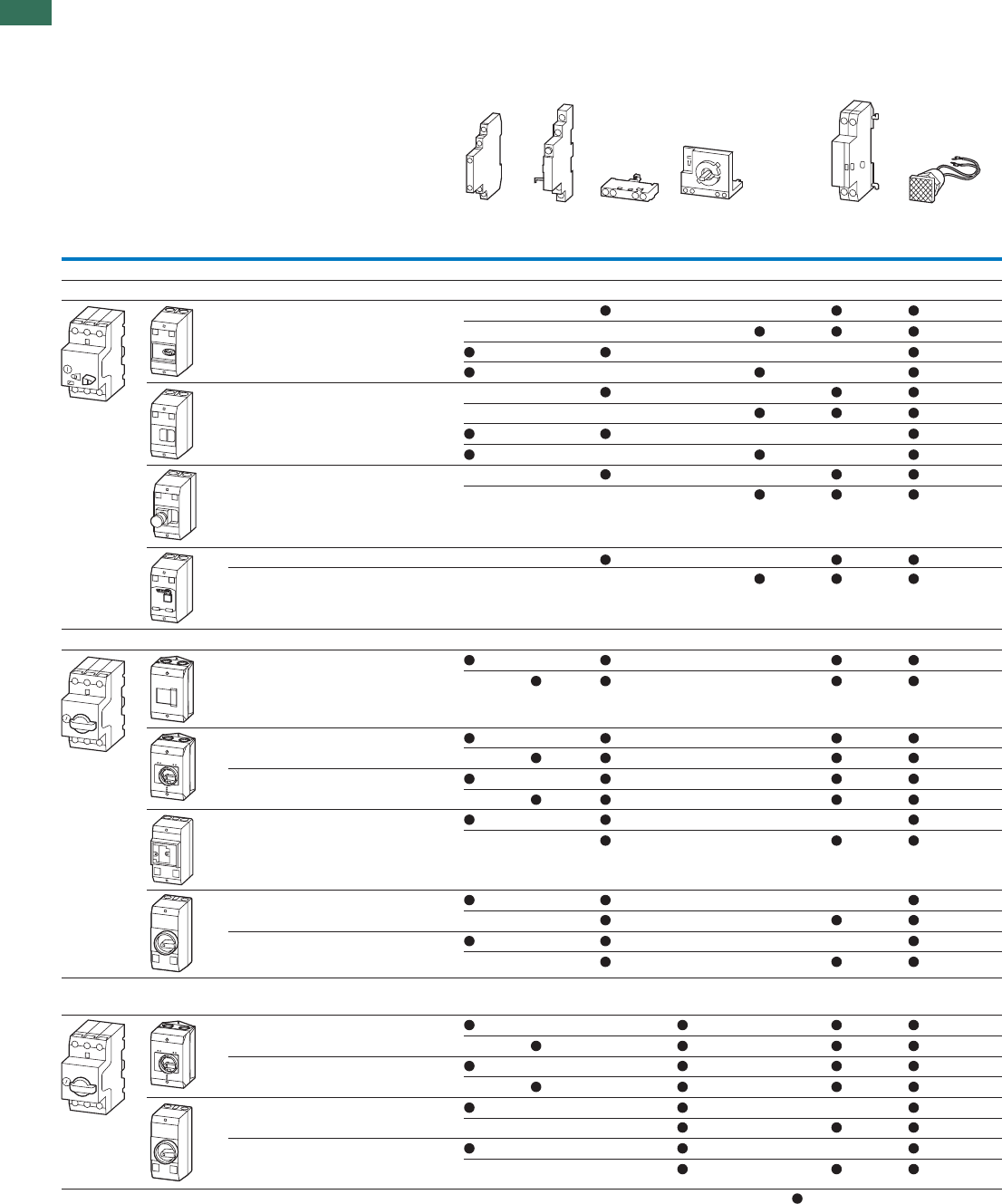
1
1.3 Motor-protective circuit-breakers PKZM01, PKZM0, PKZM4, PKE
Accessories for motor-protective circuit-breakers in enclosures
14 AUTOMATION AND CONTROL www.eaton.com/seasia-electrical
Engineering
AccessoriesEnclosure
Part no. Part no.
Degree of
protection
Handle
color
NHI..-
PKZ0
AGM2-..-
PKZ0
NHI-E..-
PKZ0
VHI..-PKZ0 VHI..-
PKZ01
U-PKZ0
or
A-PKZ0
L-PKZ0
Surface mounting enclosure
Motor-protective circuit-breaker PKZM01
CI-PKZ01 IP40 – – – ––
–– – –
––––
–– – –
CI-PKZ01-G IP65 – – – ––
–– – –
––––
–– – –
CI-PKZ01-PVT
CI-PKZ01-PVS
IP65 Red-
yellow
–– ––
–– – –
CI-PKZ01-SVB IP65 – –– ––
CI-PKZ01-SVB-V IP65 – –– – – 1)
Motor-protective circuit-breaker PKZM0
CI-K2-PKZ0 IP41 – –––
–––
CI-K2-PKZ0-G IP65 Black –––
–––
CI-K2-PKZ0-GR IP65 Red-
yellow –––
–––
CI-PKZ0-M IP40 – – –––
–– ––
CI-PKZ0-GM IP55 Black ––––
–– ––
CI-PKZ0-GRM IP55 Red-
yellow ––––
–– ––
Motor-protective circuit-breaker PKZM0 +
early-make auxiliary contact VHI-PKZ0
CI-K2-PKZ0-GV IP65 Black –– –
– – –
CI-K2-PKZ0-GRV IP65 Red-
yellow –– –
– – –
CI-K2-PKZ0-GVM IP55 Black –– ––
–– – –
CI-K2-PKZ0-GRVM IP55 Red-
yellow –– ––
–– – –
Notes The combination possibilities of circuit-breakers in an enclosure with accessory modules are identified by a
1) Always required
PKZM01, PKZM
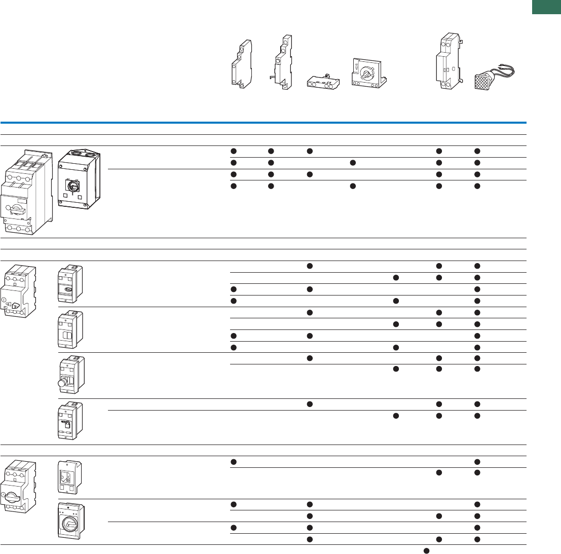
1
1.3
Motor-protective circuit-breakers PKZM01, PKZM0, PKZM4, PKE
15AUTOMATION AND CONTROL www.eaton.com/seasia-electrical
AccessoriesEnclosure
Part no.Part no.
Degree of
protection
Handle
color
NHI..-
PKZ0
AGM2-..-
PKZ0
NHI-E..-
PKZ0
VHI..-PKZ0 VHI..-
PKZ01
U-PKZ0
or
A-PKZ0
L-PKZ0
Surface mounting enclosure
Motor-protective circuit-breaker PKZM4
CI-K4-PKZ4-G IP65 Black ––
– –
CI-K4-PKZ4-GR IP65 Red-
yellow ––
– –
Installation enclosure
Motor-protective circuit-breaker PKZM01
E-PKZ01 IP40 – – – ––
–– – –
––––
–– – –
E-PKZ01-G IP65 – – – ––
–– – –
––––
–– – –
E-PKZ01-PVT
E-PKZ01-PVS
IP65 Red-
yellow –– ––
–– – –
E-PKZ01-SVB IP65 – – – ––
E-PKZ01-SVB-V IP65 – – – – – 1)
Motor-protective circuit-breaker PKZM0
E-PKZ0 IP40 – –––––
–––––
E-PKZ0-G IP55 Black – –––
–– ––
E-PKZ1-GR IP55 Red-
yellow ––––
–– ––
Notes The combination possibilities of circuit-breakers in an enclosure with accessory modules are identified by a
1) Always required
PKZM4, PKZM01, PKZM0
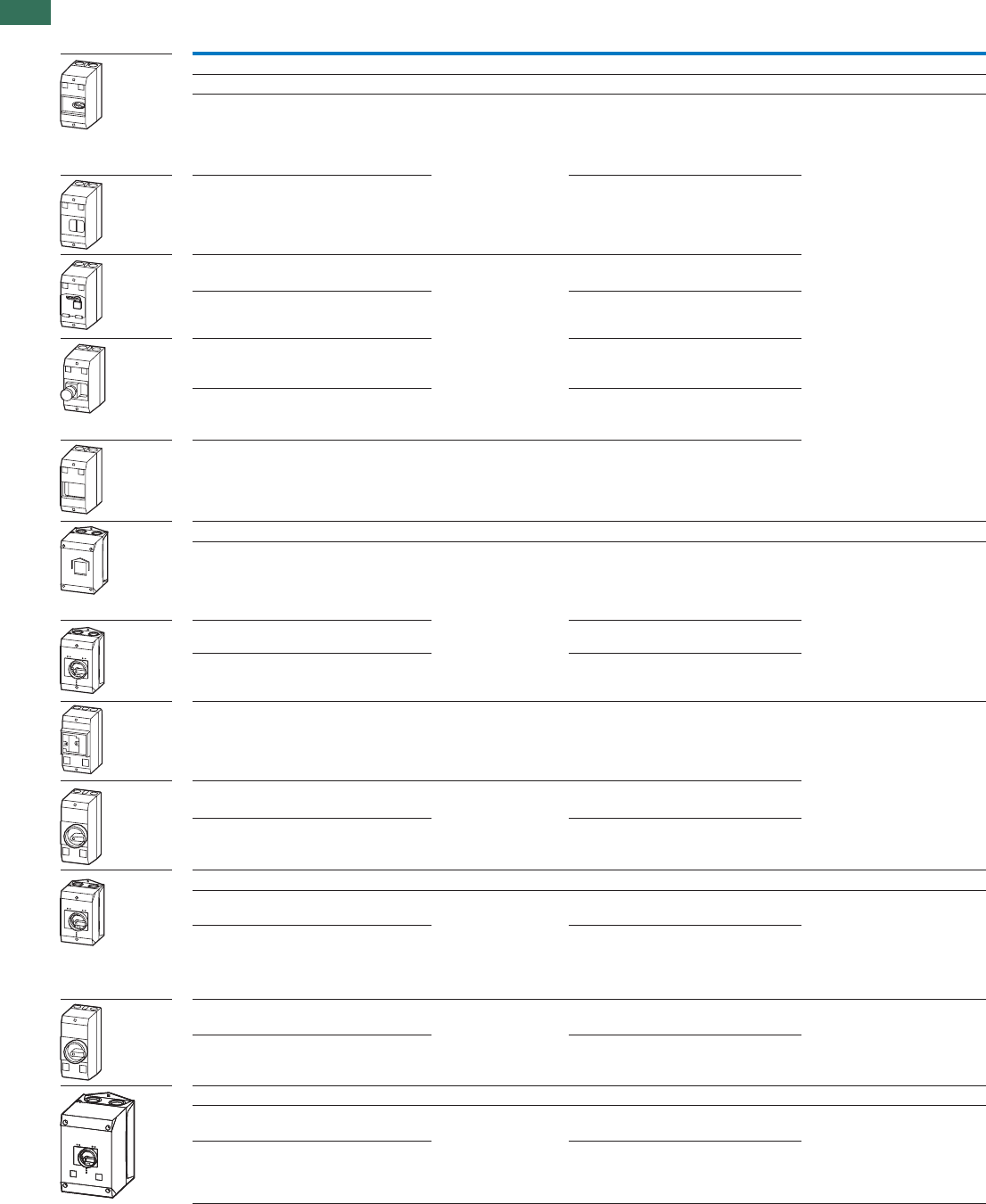
1
1.3 Motor-protective circuit-breakers PKZM01, PKZM0, PKZM4, PKE
Insulated enclosure
16 AUTOMATION AND CONTROL www.eaton.com/seasia-electrical
Degree of
protection
For use with Part no.
Article no. Price
See price
list
Std. pack Notes
Insulated enclosures for surface mounting
For Motor-protective circuit-breaker PKZM01
PKZM01IP40–
+NHI-E or
VHI-PKZ01
+U or A or NHI
+L (2 off)
CI-PKZ01
281403
1 off Integrated terminal for PE(N)
1 off
1 off
1 off
1 off
1 off
1 off
1 off
1 off
1 off
1 off
1 off
1 off
1 off
1 off
1 off
connection, two M25 cable entry
knockouts at top and at bottom.
With operating membrane IP65 CI-PKZ01-G
281404
Lockable in Off position IP65 PKZM01
+NHI-E or
+U or A
+L (2 off)
CI-PKZ01-SVB
281405
Lockable in Off position in
combination with
VHI-PKZ01
IP65 CI-PKZ01-SVB-V
281944
With emergency switching
off mushroom button,
maintained
IP65 CI-PKZ01-PVT
281406
With emergency switching
off mushroom button, with
key-release
IP65 CI-PKZ01-PVS
281407
For extension with inserts
CI/E-PKZ01-X... unit
As insert PKZM01 CI-PKZ01-X
289934
For Motor-protective circuit-breakers PKZM0
Cover with aperture
dimensioned to accommodate
front of breaker. IP40, when
mounted turned through 90° to
left/right
IP41
with verti-
cal mount-
ing
PKZM0-…
+NHI or AGM
+U or A
+NHI-E
+L-PKZ0 (2 off)
CI-K2-PKZ0
219653
1 off M25 metric cable entry knockout,
top and bottom
Cable push-through membrane top,
bottom, in the back plate and as a
control line entry.
Insulated enclosure CI-K2 incl.
N and PE terminal.
With black-grey
rotary knob
IP65 CI-K2-PKZ0-G
219654
With red-yellow rotary knob, for
use as emergency switching off
device to EN 60204
IP65 CI-K2-PKZ0-GR
219655
Cover with aperture
dimensioned to accommodate
front of breaker
IP40 PKZM0-…
+NHI or U or A
+L-PKZ0 (2 off)
CI-PKZ0-M
267083
Integrated terminal for PE(N)
connection, two M25 cable entry
knockouts at top and at bottom.
With black-grey
rotary knob
IP55 PKZM0-…
+NHI-E
+NHI or U or A
+L-PKZ0 (2 off)
CI-PKZ0-GM
260089
With red-yellow rotary knob, for
use as emergency switching off
device to EN 60204
IP55 CI-PKZ0-GRM
260104
For Motor-protective circuit-breakers PKZM0 with early-make VHI auxiliary contacts
With black-grey
rotary knob
IP65 PKZM0-... and VHI
+NHI or AGM
+U or A
+L (2 off)
CI-K2-PKZ0-GV
219657
1 off M25 metric cable entry knockout,
top and bottom
Cable push-through membrane top,
bottom, in the back plate and as a
control line entry.
Insulated enclosure CI-K2 incl.
N and PE terminal.
With red-yellow rotary knob, for
use as emergency switching off
device to EN 60204
IP65 CI-K2-PKZ0-GRV
219656
With black-grey
rotary knob
IP55 PKZM0-... and VHI
+U or A (undervolt-
age or shunt release)
+L-PKZ0 (2 off)
CI-PKZ0-GVM
263526
Integrated terminal for PE(N) con-
nection, two M25 cable entry
knockouts at top and at bottom.
With red-yellow rotary knob, for
use as emergency switching off
device to EN 60204
IP55 CI-PKZ0-GRVM
263525
For Motor-protective circuit-breakers PKZM4
With black-grey rotary knob IP65 PKZM4-…
+VHI or NHI-E
+NHI and AGM
+U or A
+L-PKZ0 (2 off)
CI-K4-PKZ4-G
225524
1 off Metric knockout:
Top and bottom: M25/M32
In the back plate: M25/M32
Control cable entry: M20
CI-K4 insulated enclosure including
insulated PE terminal
With red-yellow rotary knob, for
use as emergency switching off
device to EN 60204
IP65 CI-K4-PKZ4-GR
225525
PKZM01, PKZM0, PKZM4
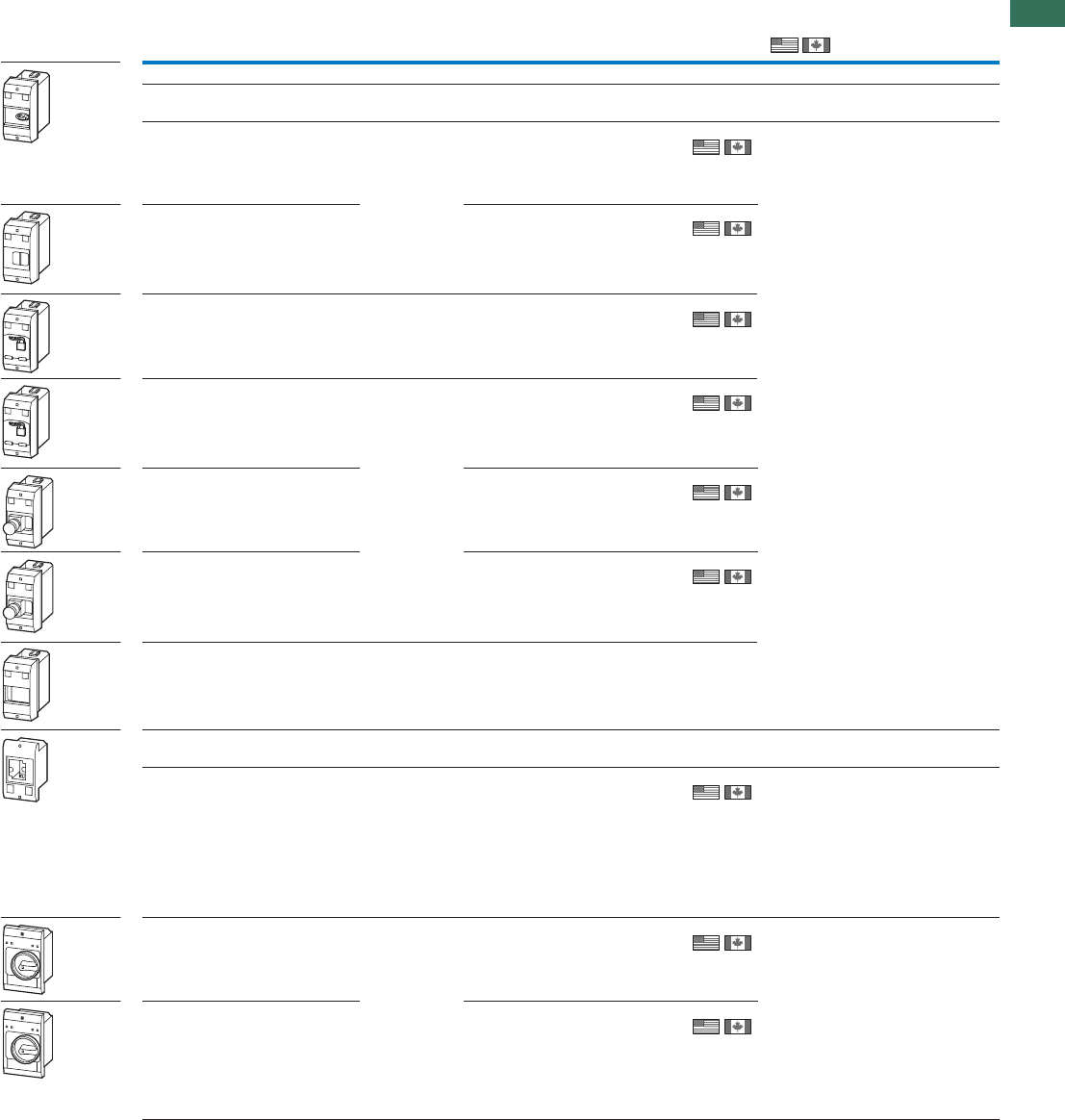
1
1.3
Motor-protective circuit-breakers PKZM01, PKZM0, PKZM4, PKE
Insulated enclosure
17AUTOMATION AND CONTROL www.eaton.com/seasia-electrical
Degree of
protection
For use with Part no.
Article no. Price
See price
list
Std. pack Information relevant for export to
North America
Insulated enclosures for flush mounting
For Motor-protective circuit-breaker PKZM01
Integrated terminal for PE(N) connection.
Front IP40 PKZM01
+NHI or U or
A
+NHI-E or
VHI
+L (2 off)
E-PKZ01
281633
1 off
With operating
membrane
Front IP65 E-PKZ01-G
281634
1 off
Lockable in Off
position
Front IP65 PKZM01
+U or A
+NHI-E
E-PKZ01-SVB
281635
1 off
Lockable in Off
position, in combina-
tion with VHI-PKZ01
Front IP65 PKZM01
+U or A
+NHI-E or
VHI
E-PKZ01-SVB-V
281943
1 off
With emergency
switching off
mushroom button,
maintained
Front IP65 E-PKZ01-PVT
281636
1 off
With emergency
switching off
mushroom button,
with key-release
Front IP65 E-PKZ01-PVS
281637
1 off
For extension with
inserts CI/E-PKZ01-
X... unit
As insert PKZM01 E-PKZ01-X
289935
1 off
For Motor-protective circuit-breakers PKZM0
Integrated terminal for PE(N) connection.
Cover with aperture
dimensioned to
accommodate front
of breaker
Front IP40 PKZM0-…
+NHI or U or
A +L-PKZ0
(2 parts)
E-PKZ0
072906
1 off
With black-grey
rotary knob
Front IP55 PKZM0-…
+NHI or U or
A
+NHI-E
+L-PKZ0
(2 parts)
E-PKZ0-G
072907
1 off
Degree of Protection
With red-yellow
rotary knob, for use
as emergency
switching off device
to EN 60204
Front IP55 E-PKZ0-GR
072908
1 off
E-PKZ
Product Standards
UL File No.
UL CCN
CSA File No.
CSA Class No.
NA Certification
UL 508; CSA-C22.2
No.14; IEC60947-
4-1; CE marking
E36332
NLRV
12528
3211-05
UL Listed, CSA
certified
Product Standards
UL File No.
UL CCN
CSA File No.
CSA Class No.
NA Certification
UL 508; CSA-C22.2
No.14; IEC60947-
4-1; CE marking
E36332
NLRV
12528
3211-05
UL Listed, CSA
certified
Product Standards
UL File No.
UL CCN
CSA File No.
CSA Class No.
NA Certification
UL 508; CSA-C22.2
No.14; IEC60947-
4-1; CE marking
E36332
NLRV
12528
3211-05
UL Listed, CSA
certified
IEC: Front IP55,
UL/CSA Type:
1,12, 3R
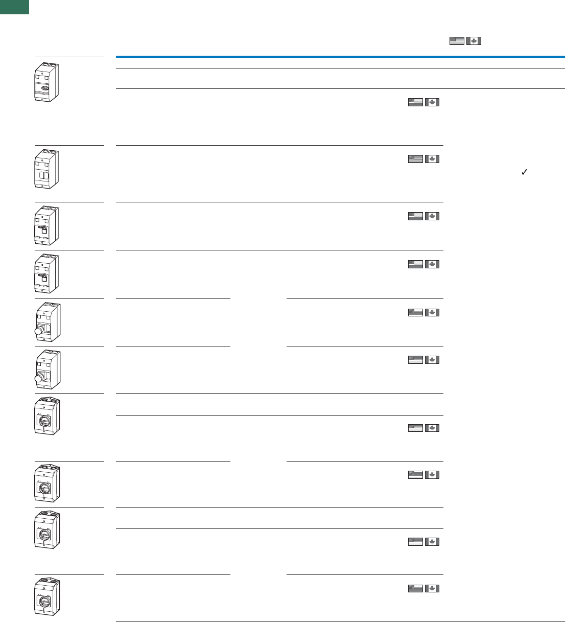
1
1.3 Motor-protective circuit-breakers PKZM01, PKZM0, PKZM4, PKE
Insulated enclosure
18 AUTOMATION AND CONTROL www.eaton.com/seasia-electrical
Insulated enclosures for surface mounting
For Motor-protective circuit-breaker PKZM01s
Integrated terminal for PE(N) connection.
IP41 PKZM01
+NHI-E or
VHI-PKZ01
+U or A or
NHI
+L (2 off)
CI-PKZ01-NA
281408
1 off
Specially designed for NA
Degree of Protection
With operating
membrane
IP65 PKZM01
+NHI-E or
VHI-PKZ01
+U or A or
NHI
+L (2 off)
CI-PKZ01-NA-G
281409
1 off
Lockable in Off
position
IP65 PKZM01
+NHI-E or
VHI-PKZ01
+U or A
+L (2 off)
CI-PKZ01-NA-SVB
281630
1 off
Lockable in Off
position, in
combination with
VHI-PKZ01
IP65 PKZM01
+NHI-E
+U or A
+L (2 off)
CI-PKZ01-NA-SVB-V
281945
1 off
With emergency
switching off
mushroom button,
maintained
IP65 CI-PKZ01-NA-PVT
281631
1 off
With emergency
switching off
mushroom button,
with key-release
IP65 CI-PKZ01-NA-PVS
281632
1 off
For Motor-protective circuit-breakers PKZM0
Integrated N and PE terminals; lower section without knockouts
With black-grey
rotary knob
IP55 PKZM0-…
+NHI or U or
A
+NHI-E
+L-PKZ0
(2 parts)
CI-K2-PKZ0-NA-G
262680
1 off
With red-yellow
rotary knob, for use
as emergency
switching off device
to EN 60204
IP55 CI-K2-PKZ0-NA-GR
262681
1 off
For Motor-protective circuit-breakers PKZM0 with early-make auxiliary contacts
Integrated N and PE terminals; lower section without knockouts
With black-grey
rotary knob
IP55 PKZM0-…
+VHI… +
U…
+L-PKZ0
(2 parts)
CI-K2-PKZ0-NA-GV
262682
1 off
With red-yellow
rotary knob, for use
as emergency
switching off device
to EN 60204
IP55 CI-K2-PKZ0-NA-GRV
262683
1 off
Degree of
protection
For use with Part no.
Article no. Price
See price
list
Std. pack Information relevant for export to
North America
CI-PKZ
Product Standards
UL File No.
UL CCN
CSA File No.
CSA Class No.
NA Certification
UL 508; CSA-C22.2
No.14; IEC60947-
4-1; CE marking
E36332
NLRV
12528
3211-05
UL Listed, CSA
certified
IEC: IP41, UL/CSA
Type: -
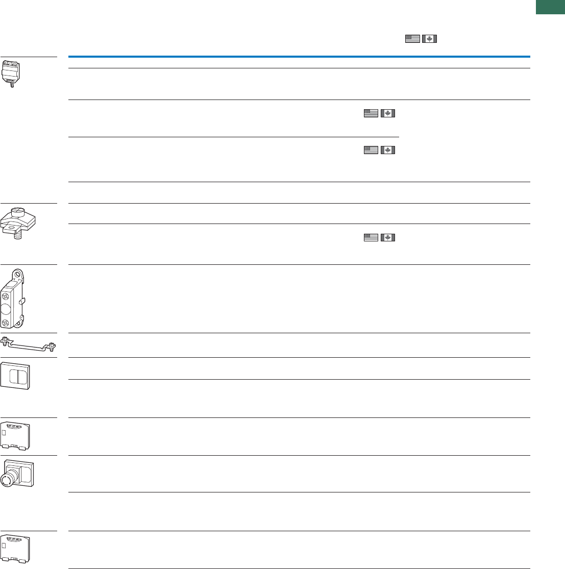
1
1.3
Motor-protective circuit-breakers PKZM01, PKZM0, PKZM4, PKE
Insulated enclosure
19AUTOMATION AND CONTROL www.eaton.com/seasia-electrical
Degree of
protection
For use with Part no.
Article no. Price
See price
list
Std. pack Information relevant for export to
North America
Insulated enclosures, accessories
Padlocking feature
For up to 3 padlocks with 3 – 6 mm hasp thickness, for use as main switch to
IEC/EN60204
Lockable in the
0-position of the PKZM0
or Motor-protective
circuit-breaker PKZM4.
– CI-K2-PKZ0-G(R)(V)
CI-PKZ0-G(R)(V)M SVB-PKZ0-CI
035129
3 off
E-PKZ0-G(R)–– SVB-PKZ0-E
035127
3 off
CI-K4-PKZ4-G(R)–– SVB-PKZ4-CI
225526
1 off
Neutral terminal
For connection of a 5th conductor
Flexible, 1 - 4 mm² – CI-K2-PKZ0-... K-CI-K1/2
207451
20 off UL/CSA certification not required
63 A, flexible,
6 - 16 mm²
– CI-K4-PKZ4-G(R) K25/1
096200
10 off
E-PKZ0(-G)(-GR)––
E-PKZ01(-G) N-PKZ0
082160
20 off
Units for insulated enclosures for PKZ01
Combinable with CI-PKZ01-X and E-PKZ01-X.
With operating membrane Front IP65
Front IP65
Front IP65
Front IP65
Front IP65
PKZM01
+NHI-E or VHI-PKZ01
+U or A or NHI
+L (2 off)
CI/E-PKZ01-
XG
289936
1 off
1 off
1 off
1 off
1 off
Lockable in Off position PKZM01
+NHI-E
+U or A
+L (2 off)
CI/E-PKZ01-
XSVB
289939
With emergency
switching off mushroom
button, maintained
PKZM01
+NHI-E or VHI-PKZ01
+U or A
+L (2 off)
CI/E-PKZ01-
XPVT
289937
With emergency
switching off mushroom
button, with key-release
PKZM01
+NHI-E or VHI-PKZ01
+U or A
+L (2 off)
CI/E-PKZ01-
XPVS
289938
Lockable in Off position,
in combination with
VHI-PKZ01
PKZM01
VHI-PKZ01
+U or A
+L (2 off)
CI/E-PKZ01-
XSVB-V
289980
SVB-PKZ, CL/EPKZ01
Product Standards
UL File No.
UL CCN
CSA File No.
CSA Class No.
NA Certification
UL 508; CSA-C22.2
No.14; IEC60947-
4-1; CE marking
E36332
NLRV
12528
3211-05
UL Listed, CSA
certified
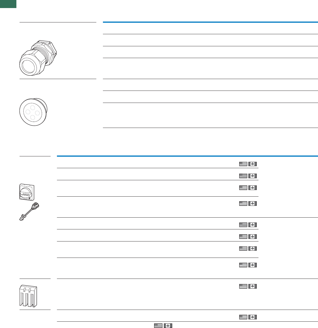
1
1.3 Motor-protective circuit-breakers PKZM01, PKZM0, PKZM4, PKE
Accessories
20 AUTOMATION AND CONTROL www.eaton.com/seasia-electrical
Cable entry Drilling dimensions External cable diameter Part no.
Article no. Price
See price list
Std. pack
mm mm
Metric cable glands to EN 50262
• With lock nut and built-in strain relief
• IP68 up to 5 bar, halogen free
M20 20.5 6 - 13 V-M20
206910
20 off
20 offM25 25.5 9 - 17 V-M25
206911
M32 32.5 13 - 21 V-M32
206912
10 off
10 offM32 32.5 18 - 25 V-M32G
226156
Metric diaphragm grommets
• IP66
• With integral push-through diaphragm
M20 20.5 1 - 13 KT-M20
207602
100 off
100 off
100 off
M25 25.5 1 - 18 KT-M25
207603
M32 32.5 1 - 25 KT-M32
207604
For use
with Part no.
Article no. Price
See price
list
Std. pack Notes
Door coupling
handles
Degree of protec-
tion IP65, UL/CS
Type 4X / Type12
For use as main switch to IEC/EN 60204
PKZM4
PKZM0Black PKZ0-XH1)
106132
1 off
1 off
1 off
1 off
Pluggable PKZ0-XAH extension
shaft, can be cut to any required
length for installation depths of
100…240 mm.
Follower included in delivery.
With ON/OFF switch position and
“+” (tripped), lockable
With 3 padlocks, 4 – 8 mm hasp.
Cannot be used in combination with
VHI20-PKZ0.
For use as a main switch with emergency
switching off function to EN 60204
Red-
yellow
PKZM0
PKZM4 PKZ0-XRH1)
106133
For use as a main switch to EN 60204 in MCC
power distribution systems and with PKZM0
installed rotated by 90°
Black PKZM0
PKZM4 PKZ0-XH-MCC1)
106136
For use as a main switch with emergency
switching off function to EN 60204 in MCC
power distribution systems and with PKZM0
installed rotated by 90°
Red-
yellow
PKZM0
PKZM4 PKZ0-XRH-MCC1)
106137
For use as main switch to IEC/EN 60204 Black PKE PKE-XH1)
142416
1 off
1 off
1 off
1 off
Pluggable PKZ0-XAH extension
shaft, can be cut to any required
length for installation depths of
100…240 mm.
Follower included in delivery.
With ON/OFF switch position and
“+” (tripped), lockable
With 3 padlocks, 4 – 8 mm hasp.
For use as a main switch with emergency
switching off function to EN 60204
Red-
yellow
PKE PKE-XRH1)
142417
For use as a main switch to EN 60204 in MCC
power distribution systems and with PKE
installed rotated by 90°
Black PKE PKE-XH-MCC1)
142418
For use as a main switch with emergency-
switching off function to EN 60204 in MCC
power distribution systems and with PKE
installed rotated by 90°
Red-
yellow
PKE PKE-XRH-MCC1)
142419
Clamp cover For increasing the degree of protection of the
PKZM4 to IP2X
–PKZM4HB-PKZ42)
256581
1 off Suitable for connecting cables with
a max. external diameter of 9.5 mm
Pluggable
extension shaft
PKZM0––
–PKZM4 PKZ0-XAH1)
106134
1 off Follower not included
Information relevant for export to North America
1) Product Standards
UL File No.
UL CCN
CSA File No.
CSA Class No.
NA Certification
Degree of Protection
2) Product Standards
UL File No.
UL CCN
CSA File No.
CSA Class No.
NA Certification
Accessories
UL 508; CSA-C22.2 No.14; IEC60947-4-1; CE marking
E36332
NLRV
12528
3211-05
UL Listed, CSA certified
IEC: IP65, UL/CSA Type: 4X, 12
UL 508; CSA-C22.2 No.14;
IEC60947-4-1; CE marking
E36332
NLRV
12528
3211-05
UL Listed, CSA certified
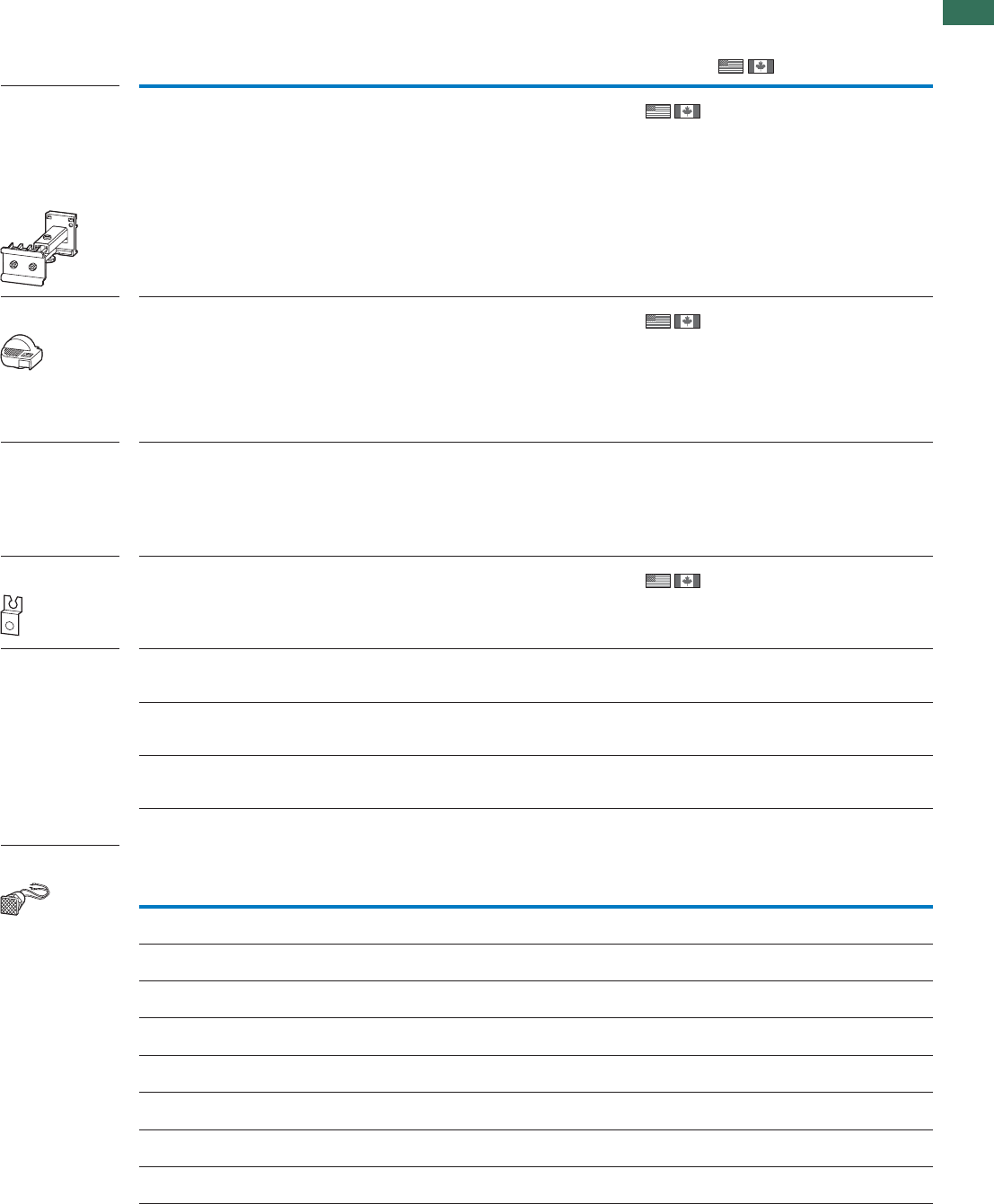
1
1.3
Motor-protective circuit-breakers PKZM01, PKZM0, PKZM4, PKE
Accessories
21AUTOMATION AND CONTROL www.eaton.com/seasia-electrical
Notes Part no.
Article no. Price
See price
list
Std. pack Information relevant for export to
North America
Telescopic adapters
With 45 mm top-hat
rail to IEC/EN 60715
for compensation of
the mounting depth
of rear-mounted
devices enclosures
CI-K and cabinets
Telescopic clip Stepless
adjustment via
scale from
75 – 115 mm.
M22-TA
226161
1 off
Lockable rotary
handle
For locking motor-protective
circuit-breakers PKZM0, PKZM4
and PKE as a main switch in
compliance with EN 60204.
Can be padlocked in the “0”
position.
Hasp thickness: 3 – 6.35 mm
Can not be
combined with
VHI-PKZ0.
AK-PKZ0
030851
5 off
Holding facility To prevent tampering with the
overload release and the test
function, it can be sealed using
industry standard sealing wire
For use with motor-protective
circuit-breakers PKZM0 and
PKZM4
–PL-PKZ0
203599
5 off
Mounting angle
bracket
For screw fixing to mounting
plate
–PKE32-XMB
134837
20 off
Documentation Motor-protective circuit-
breakers PKZM0, overload
monitoring of EEx e motors
German/English AWB1210-1458D/GB
266164
1 off
1 off
1 off
Motor-protective circuit-
breakers PKZM4, overload
monitoring of EEx e motors
German/English AWB1210-1457D/GB
266165
Motor-protective circuit-
breakers PKE, EEx electric
motor overload monitoring
German/English AWB1210-1631DE/EN
134836
For use withColorVoltage Color Voltage Part no.
Article no. Price
See price
list
Std. pack
Us
V
Indicator lights with
glow lamp
CI-K2-PKZ0-… , CI-K4-PKZ4 ,
CI-PKZ0(1) , E-PKZ0(1)
White 110 - 230 L-PKZ0(230V)
082151
10 off
CI-K2-PKZ0-… , CI-K4-PKZ4 ,
CI-PKZ0(1) , E-PKZ0(1)
White 230 - 400 L-PKZ0(400V)
082152
10 off
CI-K2-PKZ0-… , CI-K4-PKZ4 ,
CI-PKZ0(1) , E-PKZ0(1)
White 415 - 500 L-PKZ0(500V)
082153
5 off
CI-K2-PKZ0-… , CI-K4-PKZ4 ,
CI-PKZ0(1) , E-PKZ0(1)
Green 110 - 230 L-PKZ0-GN(230V)
082154
10 off
CI-K2-PKZ0-… , CI-K4-PKZ4 ,
CI-PKZ0(1) , E-PKZ0(1)
Green 230 - 400 L-PKZ0-GN(400V)
082155
10 off
CI-K2-PKZ0-… , CI-K4-PKZ4 ,
CI-PKZ0(1) , E-PKZ0(1)
Green 415 - 500 L-PKZ0-GN(500V)
082156
5 off
CI-K2-PKZ0-… , CI-K4-PKZ4 ,
CI-PKZ0(1) , E-PKZ0(1)
Red 110 - 230 L-PKZ0-RT(230V)
082157
10 off
CI-K2-PKZ0-… , CI-K4-PKZ4 ,
CI-PKZ0(1) , E-PKZ0(1)
Red 230 - 400 L-PKZ0-RT(400V)
082158
10 off
Accessories
IEC/EN60947-5;
UL 508; CSA-C22.2
No.14-05; CSA-
C22.2 No.94-91;
CE marking
E29184
NKCR
012528
3211-03
UL Listed,
CSA certified
Product Standards
UL File No.
UL CCN
CSA File No.
CSA Class No.
NA Certification
UL 508; CSA-C22.2
No.14; IEC/EN 60947-
4-1; CE marking
E36332
NLRV
12528
3211-05
UL Listed,
CSA certified
Product Standards
UL File No.
UL CCN
CSA File No.
CSA Class No.
NA Certification
Product Standards
NA Certification
UL 508; CSA-C22.2
No.14; IEC/EN 60947-
4-1; CE marking
Request filed for UL
and CSA
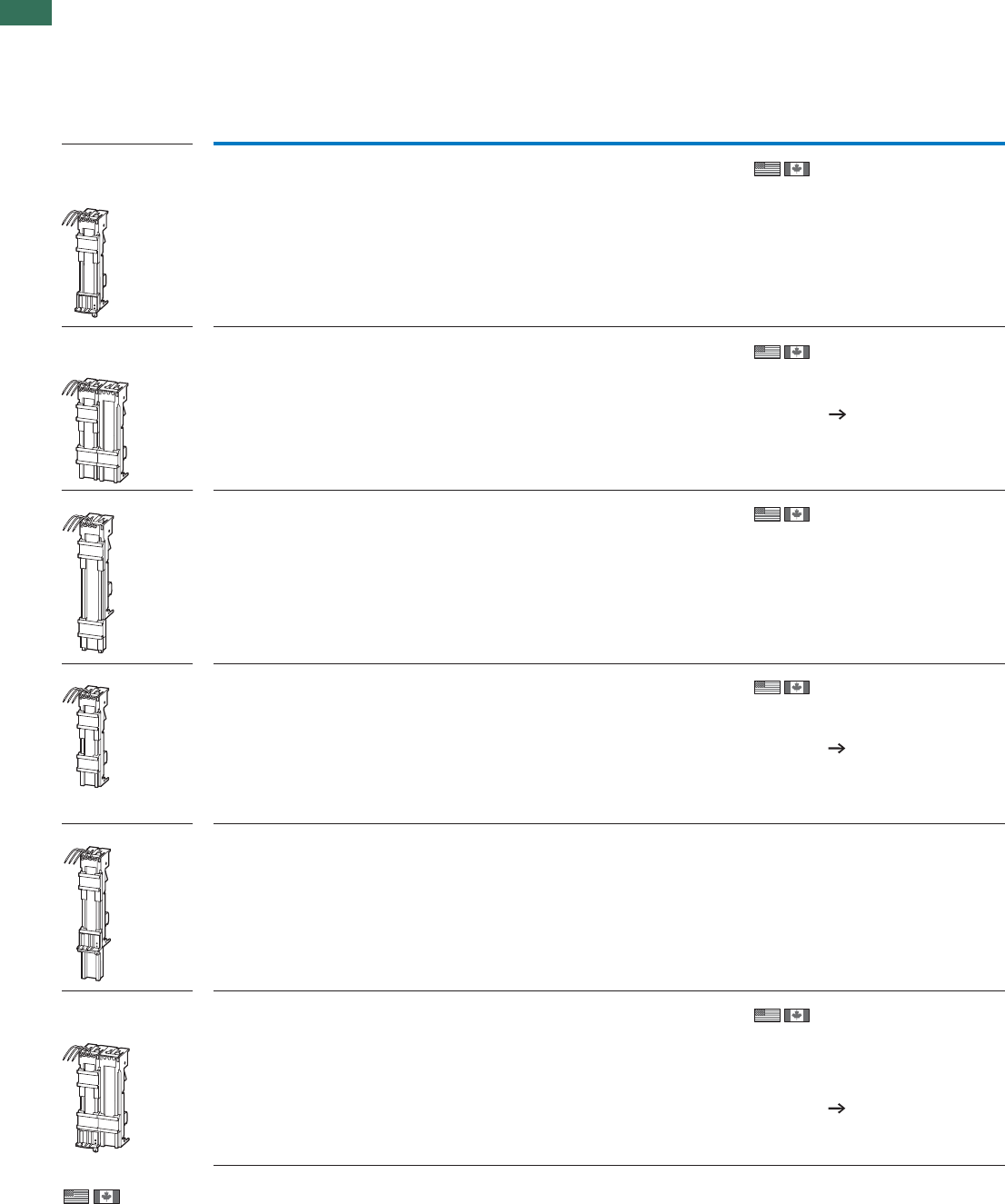
1
1.3 Motor-protective circuit-breakers PKZM01, PKZM0, PKZM4, PKE
Busbar adapters
22 AUTOMATION AND CONTROL www.eaton.com/seasia-electrical
Rated
operational
voltage
Conductor
cross-
section
Adapter
width
Mounting
rails
For use with Part no.
Article no. Price
See
price list
Std. pack Notes
Ue
V mm Number
Busbar adapters for PKZ and PKE
Approved to UL508.
For fitting to flat copper busbars with 60mm between busbar centers, suitable for 5 mm
and 10 mm busbar thickness.
Rated operational
current 16 A
For starters with spring-
loaded terminals
690 AWG 14
(2.5 mm²)
45 2 PKZM0-C + DILMC7
PKZM0-C + DILMC9
PKZM0-C + DILMC12
BBA0C-16
101455
4 off According to UL 508: Ie= 12 A
Rated operational
current 25 A
For reversing starters
690 AWG 12
(4 mm²)
90 1 PKZM0, PKE + 2 x
DILM7-01
PKZM0, PKE + 2 x
DILM9-01
PKZM0, PKE + 2 x
DILM12-01
MSC-R-0,25-M7… -
MSC-R-12-M12…
BBA0R-25
101453
2 off In combination with individual
components PKZM0 and DILM, use
reversing starter kit PKZM0-XRM12.
Fully assembled and tested
combination with MSC-R
Chapter 1.4 (Page 18)
Only busbar adapters/wiring sets
manufactured on or after CW35/
2009 can be used for PKE.
Can be used universally 690 AWG 12
(4 mm²)
45 2 – BBA0-25/2TS
101481
4 off Mounting rails can be moved within
1.25 mm grid.
For DOL starters 690 AWG 12
(4 mm²)
45 1 PKZM0, PKE +
2 x DILM17-01
PKZM0, PKE +
2 x DILM25-
01PKZM0, PKE +
2 x DILM25-01
PKZM0, PKE +
2 x DILM32-01
MSC-R-16-M17…
MSC-R-32-M32…
BBA0-25
101451
4 off In combination with individual
components PKZM0 and DILM, use
DOL starter kit PKZM0-XRM12.
Fully assembled and tested
combination with MSC-D
Chapter 1.4 (Page 2)
Only busbar adapters/wiring sets
manufactured on or after CW35/
2009 can be used for PKE.
For soft starters 690 AWG 12
(4 mm²)
45 1 PKZM0, PKE +
DS7...004N...
PKZM0, PKE +
DS7...007N...
PKZM0, PKE +
DS7...009N...
PKZM0, PKE +
DS7...012N...
BBA0L-25
142526
1 off –
Rated operational
current 32 A
For reversing starters
690 AWG 10
(6 mm²)
90 3 PKZM0, PKE + 2 x
DILM17-01
PKZM0, PKE + 2 x
DILM25-01
PKZM0, PKE + 2 x
DILM32-01
MSC-R-16-M17… -
MSC-R-32-M32…
BBA0R-32
101454
2 off In combination with single
components PKZM0 and DILM,
wiring kit PKZM0-XM32DE and
reversing starter wiring kit
DILM32-XRL can be used.
Fully assembled and tested
combination with MSC-R
Chapter 1.4 (Page 18)
Only busbaradapters/wiring sets
manufactured on or after CW 35/
2009 can be used for PKE.
Information relevant for export to North America Product Standards UL 508A; CSA-C22.2 No. 14;
IEC60439-1; CE marking
UL File No. UL File No.E300273
UL CCN NMTR, NMTRZ
CSA File No.
CSA Class No.
NA Certification
Max. Voltage Rating
232140
3211-37
UL Listed, CSA certified
600 V AC
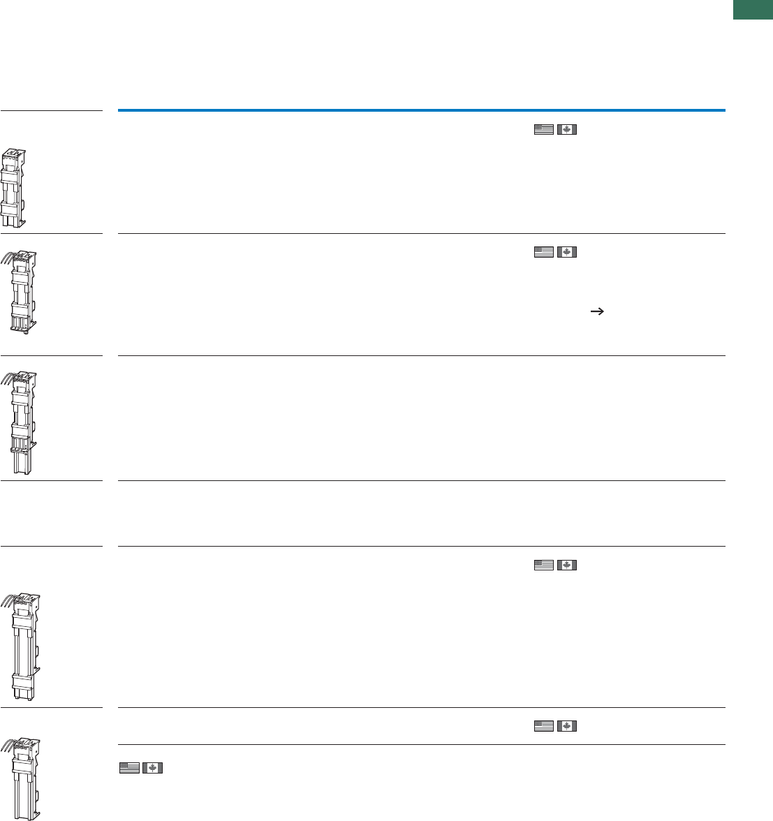
1
1.3
Motor-protective circuit-breakers PKZM01, PKZM0, PKZM4, PKE
Busbar adapters
23AUTOMATION AND CONTROL www.eaton.com/seasia-electrical
Rated operational
current 32 A
Can be used universally.
690 – 45 2 PKZM0…, PKE +
DILM… BBA0-32/2TS-C2)
116708
4 off Universal adapter 1-, 2- and 3-
phase applications.
Mounting rail can be moved within
1.25 mm grid.
For conductor cross-sections,
round conductors of up to 6 mm2.
Only busbaradapters/wiring sets
manufactured on or after CW 35/
2009 can be used for PKE.
For DOL starters. 690 AWG 10
(6 mm²)
45 2 PKZM0, PKE +
DILM17
PKZM0, PKE +
DILM25
PKZM0, PKE +
DILM32
MSC-D-16-M17… -
MSC-D-32-M32…
BBA0-321)
101452
4 off In combination with individual
components PKZM0 and DILM
wiring kit PKZM0-XM32DE can be
used.
Fully assembled and tested
combination with MSC-D
Chapter 1.4 (Page 2)
Only busbar adapters/wiring sets
manufactured on or after CW35/
2009 can be used for PKE.
For soft starters 690 AWG 10
(6 mm²)
45 2 PKZM0, PKE +
DS7...016N...
PKZM0, PKE +
DS7...024N...
PKZM0, PKE +
DS7...032N...
BBA0L-32
142527
1 off –
For 160 mm adapter
system with motor-
protective circuit-
breakers
–
690 AWG 10
(6 mm²)
45 1 PKZM0, PKE BBA0K-32
142528
1 off –
Rated operational
current 63 A
For DOL starters.
690 AWG 8
(10 mm²)
55 2 PKZM4 + DILM17
PKZM4 + DILM25
PKZM4 + DILM32
PKZM4 + DILM40
PKZM4 + DILM50
PKZM4 + DILM65
BBA4L-631)
101459
4 off The following can be used to
establish an electrical connection:
For PKZM4 + DILM17 to DILM32:
MVS-LB0-0M-G
For PKZM4 + DILM40 to DILM65:
PKZM4-XM65DE.
For motor-protective
circuit-breakers
690 AWG 8
(10 mm²)
54 1 PKZM4 BBA4-631)
101457
4 off –
Information relevant for export to North America
1) 2)
Rated
operational
voltage
Conductor
cross-
section
Adapter
width
Mounting
rails
For use with Part no.
Article no. Price
See
price list
Std. pack Notes
Ue
V mmNumber
Product Standards
UL File No.
UL CCN
CSA File No.
CSA Class No.
NA Certification
Max. Voltage Rating
UL 508; CSA-C22.2 No.14; IEC60439-1; CE marking
E300273
NMTR, NMTR7
232140
3211-37
UL Listed, CSA certified
600 V AC
Product Standards
UL File No.
UL CCN
NA Certification
Max. Voltage Rating
UL 508; CSA-C22.2 No.14;
IEC60439-1; CE marking
E300273
NMTR, NMTR7
UL Listed, CSA certified
600 V AC
1
1.3 Motor-protective circuit-breakers PKZM01, PKZM0, PKZM4, PKE
Busbar adapters
24 AUTOMATION AND CONTROL www.eaton.com/seasia-electrical
Product Standards
UL File No.
UL CCN
CSA File No.
CSA Class No.
NA Certification
Max. Voltage Rating
UL 508A; CSA-C22.2 No.14; IEC60439-1; CE marking
E300273
NMTR, NMTR7
232140
3211-37
UL Listed, CSA certified
600 V AC
Product Standards
UL File No.
UL CCN
CSA File No.
CSA Class No.
NA Certification
UL 508A; CSA-C22.2 No.14; IEC60947-4-1; CE marking
E300273
NMTR, NMTR7
232140
3211-37
UL Listed, CSA certified
Product Standards
UL File No.
UL CCN
CSA File No.
CSA Class No.
NA Certification
UL 508A; CSA-C22.2 No.14; IEC60439-1; CE marking
On request
On request
On request
On request
UL Recognized, CSA certified
Without electrical
contacts
Empty module.
–– 452– BBA0/2TS-L1)
101482
4 off Mounting rails can be moved within
a 1.25 mm grid.
Can be used to mount reversing and
star-delta starters.
–– 542– BBA4/2TS-L1)
101483
4 off Mounting rails can be moved within
a 1.25 mm grid.
Can be used to mount reversing and
star-delta starters.
Side-mounted module,
can be attached on
both sides.
–– 9–– BBA-XSM1)
101484
10 off Can be grouped with busbar adapt-
ers in order to extend the mounting
width.
Busbar adapters
accessories
Mounting rails
–– 45–BBA… PKZM0-XMR2)
239364
10 off –
–– 54–BBA… PKZM0-XMR542)
113911
10 off –
–– 72–BBA… PKZM0-XMR722)
113912
10 off –
Connecting cable – – – – BBA…
–
BBA-XLT-6-130 3)
116902
30 off –
– – – – BBA… BBA-XLT-16-1423)
116903
30 off –
Information relevant for export to North America
1) 2)
3)
Rated
operational
voltage
Conductor
cross-
section
Adapter
width
Mounting
rails
For use with Part no.
Article no. Price
See
price list
Std. pack Notes
Ue
V mm Number
BBA, PKZM0-XM
Busbar adapters
accessories
Mounting rails
Busbar adapters
accessories
Mounting rails
1
1.3
Motor-protective circuit-breakers PKZM01, PKZM0, PKZM4, PKE
Wiring sets
25AUTOMATION AND CONTROL www.eaton.com/seasia-electrical
Product Standards
UL File No.
UL CCN
CSA File No.
CSA Class No.
NA Certification
UL 508; CSA-C22.2 No.14; IEC60947-4-1;
CE marking
E36332
NLRV
12528
3211-05
UL Listed, CSA certified
Product Standards
UL File No.
UL CCN
NA Certification
Max. Voltage Rating
UL 508; CSA-C22.2 No.14;
IEC60947-4-1; CE marking
E300273
NMTR, NMTR7
UL Listed, CSA certified
600 V AC
For use with Part no.
Article no. Price
See price
list
Std. pack Notes
Wiring set
DOL starter
DOL starter
PKZM0, PKE + DILM7
PKZM0, PKE + DILM9
PKZM0, PKE + DILM12
PKZM0, PKE + DILM15
DS7-34…SX004…
DS7-34…SX007…
DS7-34…SX009…
DS7-34…SX012…
PKZM0-XDM12
283149
1 off Consists of:
• Mechanical connection element for PKZM0 and contactor
• Main supply wiring between PKZM0 and contactor
with tool-less plug connection
• Cable routing
As auxiliary contact, use DILA-XHIT... Chapter 1.1 (Page 38)
Cannot be combined with NHI-E…PKZ0-C.
Uḛ 415 V 1)
PKZM0, PKE + DILM17
PKZM0, PKE + DILM25
PKZM0, PKE + DILM32
PKZM0-XDM32
283153
1 off Consists of:
• Top-hat rail adapter plates
• Power supply wiring between PKZ and contactor1)
PKZM4 + DILM40
PKZM4 + DILM50
PKZM4 + DILM65
PKZM4-XDM65
101053
1 off
Reversing starters
Reversing starters
PKZM0, PKE + DILM7-01
PKZM0, PKE + DILM9-01
PKZM0, PKE + DILM12-01
PKZM0-XRM12
283185
1 off Consists of:
• Mechanical connection element for PKZM0 and contactor
• Reversing starters main supply wiring with tool-less plug connection
• Control cables for electrical interlocking in tool-less plug connection:
– K1M: A1 -K2M: 21
– K1M: 21 -K2M: A1
– K1M: A2 -K2M: A2
• Cable routing
As auxiliary contact DILA-XHIT...use Chapter 1.1 (Page 38)
Can not be combined with AGM ϋPKZ0.
Uḛ 415 V1)
PKZM0, PKE + DILM17
PKZM0, PKE + DILM25
PKZM0, PKE + DILM32
PKZM0-XRM32
283189
1 off Consists of:
• Top-hat rail adapter plates
• Reversing starters supply wiring1)
Wiring kit PKZM0, PKE + DILM17
PKZM0, PKE + DILM25
PKZM0, PKE + DILM32
DS7-34…SX016…
DS7-34…SX024…
DS7-34…SX032…
PKZM0-XM32DE
239349
5 off • Main supply wiring between PKZM0 and contactor
• Use only in combination with busbar adapter or mounting rail adapter
plate
PKZM4 + DILM40
PKZM4 + DILM50
PKZM4 + DILM65
PKZM4-XM65DE
101056
5 off • Main current supply between PKZM4 and contactor
Top-hat rail adapter plates
Top-hat rail adapter plates
PKZM0-XDM12
PKZM0-XRM12 PKZM0-XC45
283132
4 off Consists of:
• 45 mm wide adapter plate
• Connection element for side-by-side positioning of further plates1)
PKZM4 + DILM40
PKZM4 + DILM50
PKZM4 + DILM65
PKZM4-XC55/2
101054
4 off Consists of:
• 55 mm wide adapter plate
• Connection cam for additional plates
• For use with reversing and start-delta starters
1)
Soft starters
Soft starters
PKZM0, PKE + DS7...004N...
PKZM0, PKE + DS7...007N...
PKZM0, PKE + DS7...009N...
PKZM0, PKE + DS7...012N...
PKZM0-XC45L
142529
1 off Consists of:
• 45 mm wide adapter plate
PKZM0, PKE + DS7...016N...
PKZM0, PKE + DS7...024N...
PKZM0, PKE + DS7...032N...
PKZM0-XC45L/2
142570
1 off Consists of:
• 45 mm wide adapter plate
Notes 1) Use only busbar adapters/wiring sets manufactured on or after CW35/2009 for PKE.
Information relevant for export to North America
2) 3)
UL/CSA certification not
required
4)
1
1.3 Motor-protective circuit-breakers PKZM01, PKZM0, PKZM4, PKE
Motor feeder plugs, three-phase commoning links
26 AUTOMATION AND CONTROL www.eaton.com/seasia-electrical
Description For use with Part no.
Article no. Price
See price
list
Std. pack Notes Information relevant for export to
North America
Motor feeder plug
PE module with contact plate
DILM(C)7
DILM(C)9
DILM(C)12
DILM(C)15
DILM12-XMCE
121764
5 off 35 x 7.5 (15) mm mounting
rail (as per DIN EN 60715)
with PE function required.
For connection of:
PE 0.75 – 4 mm2
Product Standards UL 508; CSA-C22.2
No. 14; IEC60947-4-1;
CE marking
NA Certification Request filed for UL
and CSA
Motor feeder plug with PE module andcontact plate
DILM(C)7
DILM(C)9
DILM(C)12
DILM(C)15
DILM12-XMCP/E
121769
1 off 35 x 7.5 (15) mm mounting
rail (as per DIN EN 60715)
with PE function required.
For connection of:
L1, L2, L3, PE 0.75 – 2.5 mm2
Product Standards IEC/EN 60947-4-1;
UL 508; CSA-C22.2
No. 14-05; CE marking
NA Certification Request filed for UL
and CSA
Motor feeder plug with PE module without
contact plate
PKZM0/PKE + DILM(C)7
PKZM0/PKE + DILM(C)9
PKZM0/PKE + DILM(C)12
PKZM0/PKE + DILM(C)15
MSC-D(E)-…-M7…
MSC-D(E)-…-M9…
MSC-D(E)-…-M15…
DILM12-XMCP/T
121770
1 off For connection of:
L1, L2, L3, PE 0.75 – 2.5 mm2
Product Standards IEC/EN 60947-4-1;
UL 508; CSA-C22.2
No. 14-05; CE marking
NA Certification Request filed for UL
and CSA
Circuit-breakers
Length Unit width Part no.
Article no. Price
See price
list
Std. pack Notes
Number mm mm
Three-phase commoning links, incoming unit via terminals 1, 3, and 5
Finger- and back-of-hand-proof, short-circuit proof, Ue=690 V, Iu=63 A
Can be extended through rotated installation
For PKZM0-... or PKE without side-mounted auxiliary contacts or voltage
releases
29045B3.0/2-PKZ01)
063961
10 off
10 off
10 off
10 off
For parallel feeding of multiple
motor-protective circuit-breakers on
terminals 1, 3, and 5
313545B3.0/3-PKZ01)
232289
418045B3.0/4-PKZ01)
063960
522545B3.0/5-PKZ01)
232290
For motor-protective circuit-breakers with one auxiliary contact or trip-
indicating auxiliary contact each fitted to right side
2 99 45 + 9 B3.1/2-PKZ01)
044945
10 off
10 off
10 off
10 off
For parallel feeding of multiple
motor-protective circuit-breakers on
terminals 1, 3, and 5
3 153 45 + 9 B3.1/3-PKZ01)
044946
4 207 45 + 9 B3.1/4-PKZ01)
044947
5 261 45 + 9 B3.1/5-PKZ01)
044948
For PKZM0-... or PKE with one auxiliary contact or trip-indicating auxiliary
contact each fitted to right side, or one voltage release fitted on left side
2 108 45 + 18 B3.2/2-PKZ01)
063963
10 off For parallel feeding of multiple
motor-protective circuit-breakers on
terminals 1, 3, and 5
4 234 45 + 18 B3.2/4-PKZ01)
063959
10 off
Information relevant for export to North America
1)
Product Standards
UL File No.
UL CCN
CSA File No.
CSA Class No.
NA Certification
UL 508A; CSA-C22.2 No.14; IEC60947-4-1; CE marking
E36332
NLRV
98494
3211-06
UL Listed, CSA certified
1
1.3
Motor-protective circuit-breakers PKZM01, PKZM0, PKZM4, PKE
Incoming terminals
27AUTOMATION AND CONTROL www.eaton.com/seasia-electrical
Circuit-
breakers
For use
with
Unit width Part no.
Article no. Price
See price
list
Std. pack Notes
Number mm
Shroud for unused terminals
Protection against direct contact.
For covering unused terminals on three-phase commoning link B3...-PKZ0
–––H-B3-PKZ01)
032721
20 off –
Incoming terminals
–PKZM0
PKE
–BK25/3-PKZ02)
032720
5 off For three-phase commoning link,
protected against accidental contact,
Ue = 690 V, Iu = 63 A
For conductor cross-sections:
2.5 - 25 mm2 stranded
2.5 - 16 mm2 flexible with ferrule
AWG 14 - 6, usable on terminals 1, 3,
and 5
–PKZM0– BK25/3-PKZ0-E3)
262518
5 off For three-phase commoning link,
protected against accidental contact,
Ue= 690 V, Iu=60A
For conductor cross-sections:
2.5 - 25 mm2 stranded
2.5 - 16 mm2 flexible with ferrule
AWG 14 - 6
For assembly of Type E starters.
–PKZM4– BK50/3-PKZ4-E4)
272165
1 off Can be combined with three-phase
commoning link B3…PKZ4.
Iu =120A.
For assembly of Type E starters.
Information relevant for export to North America
)2)1
)4)3
HB3...PKZO, BK...I3-PKZ
Product Standards
UL File No.
UL CCN
CSA File No.
CSA Class No.
NA Certification
UL 508; CSA-C22.2 No.14; IEC60947-4-1;
CE marking
E36332
NLRV
98494
3211-06
UL Listed, CSA certified
Product Standards
UL File No.
UL CCN
CSA File No.
CSA Class No.
NA Certification
Specially designed for NA
Suitable for
UL 508; CSA-C22.2 No.14; IEC60947-4-1;
CE marking
E36332
NLRV
98494
3211-06
UL Listed, CSA certified
PKZM0/PKE, line terminal required for
Type E/F applications
Product Standards
UL File No.
UL CCN
CSA File No.
CSA Class No.
NA Certification
Specially designed for NA
Suitable for
UL 508; CSA-C22.2 No.14; IEC60947-4-1;
CE marking
E36332
NLRV
12528
3211-06
UL Listed, CSA certified
PKZM4/PKE, line terminal required for
Type E/F applications
Product Standards
UL File No.
UL CCN
CSA File No.
CSA Class No.
NA Certification
UL 508; CSA-C22.2 No.14; IEC60947-4-1;
CE marking
E36332
NLRV
12528
3211-05
UL Listed, CSA certified
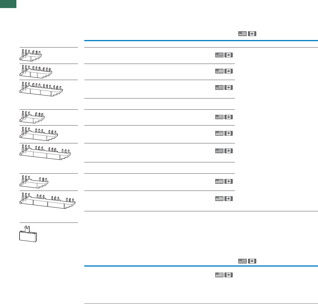
1
1.3 Motor-protective circuit-breakers PKZM01, PKZM0, PKZM4, PKE
Three-phase commoning links
28 AUTOMATION AND CONTROL www.eaton.com/seasia-electrical
Circuit-breakers
Length Unit width Part no.
Article no. Price
See price
list
Std. pack Information relevant for export to
North America
Number mm mm
mm mm
Three-phase commoning links
Finger- and back-of-hand-proof, short-circuit proof Ue= 690 V, Iu= 128 A
For PKZM4 without side-mounted auxiliary contacts or voltage releases
211055B3.0/2-PKZ4
220220
1 off
1 off
1 off
316555
55
B3.0/3-PKZ4
220221
4220 B3.0/4-PKZ4
220222
For PKZM4 with one auxiliary contact or trip-indicating auxiliary contact each
fitted on the right side
2 119 55 + 9
55 + 9
55 + 9
B3.1/2-PKZ4
220223
1 off
1 off
1 off
3183 B3.1/3-PKZ4
220224
4247 B3.1/4-PKZ4
220225
For PKZM4 with one auxiliary contact or trip-indicating auxiliary contact each
fitted to right side, or one voltage release fitted to left side
212855 + 18
55 + 18
B3.2/2-PKZ4
220226
1 off
1 off
10 off
4274 B3.2/4-PKZ4
220227
Shroud for unused terminals
Protection against direct contact.
To cover unused terminals on three-phase commoning link
–––H-B3-PKZ4
220228
Length Unit width
Circuit-breakers
Part no.
Article no. Price
See price
list
Std. pack Information relevant for export to
North America
Number
Product Standards
UL File No.
UL CCN
CSA File No.
CSA Class No.
NA Certification
UL 508; CSA-C22.2 No.14;
IEC60947-4-1; CE marking
E36332
NLRV
12528
3211-06
UL Listed, CSA certified
Product Standards
UL File No.
UL CCN
CSA File No.
CSA Class No.
NA Certification
UL 508; CSA-C22.2 No.14;
IEC60947-4-1; CE marking
E36332
NLRV
12528
3211-06
UL Listed, CSA certified
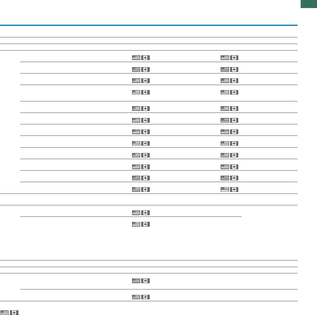
1
1.3
Motor-protective circuit-breakers PKZM01, PKZM0, PKZM4, PKE
Actuating voltages
29AUTOMATION AND CONTROL www.eaton.com/seasia-electrical
Actuating voltage Part no.
Article no. Price
See price
list
Std. pack Part no.
Article no. Price
See price
list
Std. pack Notes
Shunt release, undervoltage
release
AC
Standard voltage
24 V 50 Hz A-PKZ0(24V50Hz)1)
073181
2 off U-PKZ0(24V50Hz)1)
073129
2 off
110 V 50 Hz A-PKZ0(110V50Hz)1)
073184
2 off U-PKZ0(110V50Hz)1)
073132
2 off
220 V 50 Hz A-PKZ0(220V50Hz)1)
073186
2 off U-PKZ0(220V50Hz)1)
073134
2 off
230 V 50 Hz A-PKZ0(230V50Hz)1)
073187
2 off U-PKZ0(230V50Hz)1)
073135
2 off Only A(U)-PKZ0... with
serial number 02 or higher
can be fitted
240 V 50 Hz A-PKZ0(240V50Hz)1)
073188
2 off U-PKZ0(240V50Hz)1)
073136
2 off
380 V 50 Hz A-PKZ0(380V50Hz)1)
073189
2 off U-PKZ0(380V50Hz)1)
073137
2 off
400 V 50 Hz A-PKZ0(400V50Hz)1)
073190
2 off U-PKZ0(400V50Hz)1)
073138
2 off
415 V 50 Hz A-PKZ0(415V50Hz)1)
073191
2 off U-PKZ0(415V50Hz)1)
073139
2 off
120 V 60 Hz A-PKZ0(120V60Hz)1)
073195
2 off U-PKZ0(120V60Hz)1)
073143
2 off
240 V 60 Hz A-PKZ0(240V60Hz)1)
073198
2 off U-PKZ0(240V60Hz)1)
073146
2 off
440 V 60 Hz A-PKZ0(440V60Hz)1)
082164
2 off U-PKZ0(440V60Hz)1)
082161
2 off
480 V 60 Hz A-PKZ0(480V60Hz)1)
073199
2 off U-PKZ0(480V60Hz)1)
073147
2 off
Non-standard voltages not covered
by above standard voltages
…V 50 Hz (24 - 500 V) A-PKZ0(*V50Hz)1)
982165
2 off U-PKZ0(*V50Hz)
982162
The part number for
ordering consists of the
basic part number and the
actuating voltage.
For non-standard voltages,
specify the required
actuating voltage within
the indicated range
(... - ... V).
Minimum order quantity is
10 units
…V 60 Hz (24 – 600 V) A-PKZ0(*V60Hz)1)
982166
2 off U-PKZ0(*V60Hz)
982163
DC
Standard voltage
24 V DC A-PKZ0(24VDC)1)
073200
2 off PKE can be fitted only with
A(U)-PKZ0... with serial
number 02 or higher.
110 V DC A-PKZ0(110VDC)1)
073203
2 off
Information relevant for export to North America
1)
A-PKZO, U-PKZO
Product Standards
UL File No.
UL CCN
CSA File No.
CSA Class No.
NA Certification
UL 508; CSA-C22.2 No.14; IEC60947-4-1; CE marking
E36332
NLRV
12528
3211-05
UL Listed, CSA certified
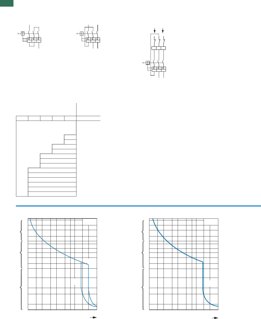
1
1.3 Motor-protective circuit-breakers PKZM01, PKZM0, PKZM4, PKE
30 AUTOMATION AND CONTROL www.eaton.com/seasia-electrical
Engineering
Protection of PVC-insulated cables against thermal overload on short-circuits
The table specifies which minimum conductor cross-sections are protected by motor-protective circuit-breaker PKZ(M) up to their
rated conditional short-circuit current Iq.
1- and 2-pole-connected PKZM0, PKZM4
with AC and DC
135
246
I > I > I >
135
246
I >I >I >
2-pole-connected PKZM0(1) and PKZM4 with CL-PKZ0
135
135
2
L1
CL-PKZ0
PKZ0Z
N
46
246
I > I > I >
I >> I >> I >>
Min. cross-section protected
380 – 415 V, 50 Hz, Cu mm² Device
Part no.
4 2.5 1.5 1 0.75
PKZM0-0,16
...
PKZM0-6.3
PKZM0-10
PKZM0-12
PKZM0-16
PKZM0-20
PKZM0-25
PKZM0-32
PKZM4-16
PKZM4-25
PKZM4-32
PKZM4-40
PKZM4-50
PKZM4-58
PKZM4-63
PKZM0-...T tripping characteristics (not for PKM0-...), PKZM01
PKZM0...-T
PKZM0-...,
PKZM01
mins
ms
2
5
20
50
200
1
2
5
10
20
40
1
2
5
10
20
2 h
1.5 2346810 15 20 30
x Ir
20 x Iu
14 x Iu
2
5
20
50
200
1
2
5
10
20
40
1
2
5
10
20
2 h
1.5 2346810 15 20 30
PKZM4-...
mins
ms
x Ir
14 x I u
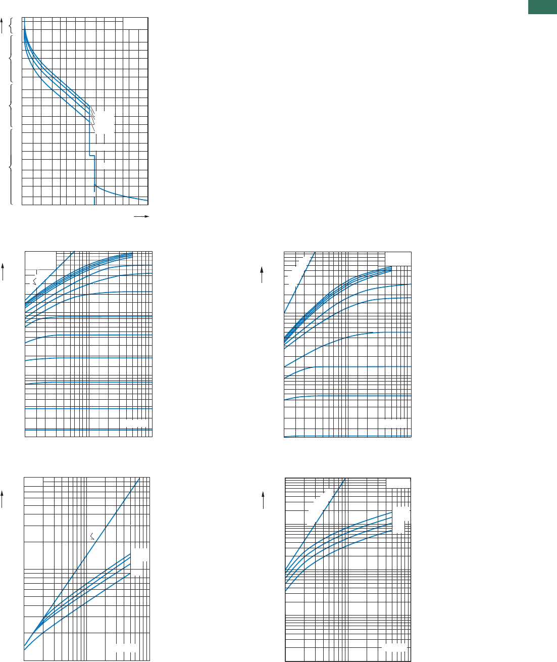
1
1.3
Motor-protective circuit-breakers PKZM01, PKZM0, PKZM4, PKE
31AUTOMATION AND CONTROL www.eaton.com/seasia-electrical
Tripping characteristic curves, wide-range circuit-breaker PKE
Let-through characteristics, motor-protective circuit-breaker, transformer-protective circuit-breakers,
circuit-breaker for starter combinations
Motor-protective circuit-breaker let-through characteristics
PKE...
2
1
20
10
5
2
1
20
10
5
2
1
500
200
100
50
20
10
5
2
10030 40 50 70
2015
10
7
5
4
3
21.5
1
1
t
h
min
sms
x Ir
12 x Ir
14 x Iu
CLASS5
CLASS20
CLASS10
CLASS15
[kA]
Î
D
1
2
3
6
4
8
10
4.0 A
6.3 A
2.5 A
1.6 A
0.25 A
10 A/12 A
0.1
0.2
0.3
0.4
0.6
0.8
0.01
0.02
0.015
0.03
0.04
0.06
0.08
12
1.5 3 4 6 8 10 2015 30 40 60 80100
U
e
= 400 V
16 A
20 A
25 A
32 A
1 A
0.4 A
0.63 A
PKZM0-....
PKZM01-....
PKM0-....
2 · Icc
Icc rms
[kA]
U
e
= 400 V
PKZM01
PKZM0-....
PKM0-....
10
4
1.5
2
3
6
4
8
10
5
4.0 A
6.3 A
2.5 A
1.6 A
1.0 A
10 A/12 A
10
3
2
1.5
3
4
6
8
10
2
2
1.5
3
4
6
8
121.5 3 4 6 8 10 2015 30 40 60 80 100
16 A
20 A
25 A
32 A
[kA]
[A
2
s]
i
2
dt
1st half-wave
Icc rms
U
e
= 400 V
10
10 100
63/58 A
50/40/32 A
25 A
16 A
PKZM4
1
1
100
[kA]
2 · Icc
Î
D
Icc rms
[kA]
10
5
10
6
10
4
10
2
001011
10
3
Ue = 400 V
63/58 A
50/40/32 A
25 A
16 A
PKZM4
[kA]
[A
2
s]
i
2
dt
1
st
half-wave
1
st
half-wave
Icc rms
1
1.3 Motor-protective circuit-breakers PKZM01, PKZM0, PKZM4, PKE
Switching capacity
32 AUTOMATION AND CONTROL www.eaton.com/seasia-electrical
Circuit-breaker switching capacity from serial no. 04
Rated uninterrupted current Iu
Rated conditional short-circuit current I IEC/EN 60947-4-1
q
Rated ultimate short-circuit breaking capacity Icu IEC/EN 60947-2
Rated breaking capacity Ics }
230 V 400 V 440 V 500 V 690 V
IuIqIcu Ics IqIcu Ics IqIcu Ics IqIcu Ics IqIcu Ics
A kAkAkAA
1) kA kA kA A1) kA kA kA A1) kA kA kA A1) kA kA kA A1)
PKZM0, PKZM0...-T, PKM0 with type “1” and “2” coordination
0.16 – 1 150 150 150 N 150 150 150 N N N N
1.6 150 150 150 N 150 150 150 N N N N
2.5 150 150 150 N 150 150 150 N N N 5 5 5 50
4 150 150 150 N 150 150 150 N N N 3 3 3 50
6.3 150 150 150 N 150 150 150 N N 42 42 11 50 3 3 2 50
10 150 150 150 N 150 150 150 N 42 42 12 50 42 42 11 50 3 3 2 50
12 50 50 13 50 50 50 13 50 15 15 12 50 15 15 8 50 3 3 2 50
16 50 50 13 50 50 50 13 50 15 15 12 50 15 15 8 50 3 3 2 50
20 50 50 13 50 50 50 13 50 10 10 13 50 6 6 3 50 3 3 1 50
25 50 50 13 50 50 50 13 50 10 10 13 50 6 6 3 50 3 3 1 50
32 50 50 13 50 50 50 13 50 10 10 13 50 6 6 3 50 3 3 1 50
PKZM0 (PKZM0...-T, PKM0) + CL-PKZ0
0.16 – 1 N N N N 20 N
1.6 NNNN20N
2.5 NNNN202020N
4 NNNN202020N
6.3 N N N 50N 202020N
10 N N N 20N 202020N
12 NNN20N552.5N
16 NNN20N552.5N
20 NNN101010N552.5N
25 NNN101010N552.5N
32 NNN101010N552.5N
PKZM0 (PKZM0...-T, PKM0) + 2 CL-PKZ0
0.16 – 1 N N N N 20 N
1.6 NNNN20N
2.5 NNNN404020N
4 NNNN404020N
6.3 N N N 50N 202020N
10 N N N 40N 202020N
12 N N N 40N 10102.5N
16 N N N 40N 10102.5N
20 NNN202020N10102.5N
25 NNN202020N10102.5N
32 NNN202020N10102.5N
Notes No upstream protective device
required, as it is the auto-
protected range (100/150 kA)
1) Required back-up fuse if the short-circuit current exceeds the device's rated
conditional short-circuit current (Icc > Iq).
N Not necessary

1
1.3
Motor-protective circuit-breakers PKZM01, PKZM0, PKZM4, PKE
Switching capacity
33AUTOMATION AND CONTROL www.eaton.com/seasia-electrical
Circuit-breaker switching capacity
Rated uninterrupted current Iu
Rated conditional short-circuit current I IEC/EN 60947-4-1
q
Rated maximum short-circuit breaking capacity Icu IEC/EN 60947-2
Rated breaking capacity Ics }
230 V 400 V 440 V2) 500 V2) 690 V2)
IuIqIcu Ics IqIcu Ics IqIcu Ics IqIcu Ics IqIcu Ics
AkAkAkAA
1) kA kA kA A1) kA kA kA A1) kA kA kA A1) kA kA kA A1)
PKZM01 with type “1”and “2” coordination
0.16 – 1 50505050 50505050 50505050
1.6 50505050 50505050 50505050
2.5 50505050 50505050 50505050
4 50505050 50505050 50505050
6.3 50505050 50505050 50505050
10 50 50 50 50 50 50 50 50 42 42 10 50
12 50 50 10 50 50 50 10 50 15 15 10 50
16 50 50 10 50 50 50 10 50 15 15 10 50
20, 25 50 50 10 50 50 50 10 50 10 10 3 50
PKZM4 with type “1” and “2” coordination
16 150 150 25 N 150 150 25 N 45 45 25 100 15 15 100 8 8 2.5 100
25 150 150 25 N 150 150 25 N 45 45 25 100 15 15 100 8 8 2.5 100
32 50 50 25 100 50 50 25 100 45 45 25 100 15 15 100 5 5 2.5 100
40 50 50 25 100 50 50 25 100 45 45 25 100 15 15 100 5 5 2.5 100
50 50 50 25 100 50 50 25 100 45 45 25 100 15 15 100 5 5 2.5 100
58 50 50 25 160 50 50 25 160 45 45 25 160 15 15 160 5 5 2.5 160
63 50 50 25 160 50 50 25 160 45 45 25 160 15 15 160 5 5 2.5 160
PKE12...2) with type of coordination „1“ and
0.3 - 1.2 100 50 100 50 50 50 10 50 3 50
1 - 4 100 50 100 50 50 50 10 50 3 50
3 - 12 100 50 100 50 15 50 10 50 3 50
PKE32...2) with type of coordination „1“ and
3 - 12 100 50 100 50 15 50 6 50 3 50
8 - 32 100 50 100 50 25 50 6 50 3 50
Notes No upstream protective device
required,as it is the auto-
protected range (150 kA)
1) Fuse (A gG/gL) for increasing the switching capacity of the motor-protective
circuit-breaker to 100 kA
2) Please enquire for additional information regarding voltages >400 V and
device combinations with CL-PKZ0.
N Not necessary
Motor-protective circuit-breaker internal resistances
Impedance Heat
dissipation
(3 pole at
operating
temperature)
Rated
uninterrupted
current I
u
ȍWA
PKZM0-0,16 78 6 0.16
32 6 0.25
13 6 0.4
5 6 0.63
261
0.8 6 1.6
0.32 6 2.5
0.13 6 4
PKZM0-0.25
PKZM0-0.4
PKZM0-0.63
PKZM0-1
PKZM0-1.6
PKZM0-2.5
PKZM0-4
PKZM0-6.3 0.050 6 6.3
PKZM0-10 0.020 6 10
PKZM0-12 0.014 6 12
PKZM0-16 0.008 6 16
PKZM0-20 0.005 6 20
PKZM0-25 0.003 6 25
PKZM0-32 0.002 6 32
Impedance Heat
dissipation
(3 pole at
operating
temperature)
Rated
uninterrupted
current I
u
ȍWA
PKZM4-16 0.029 22 16
PKZM4-25 0.012 22 25
PKZM4-32 0.007 22 32
PKZM4-40 0.005 22 40
PKZM4-50 0.003 22 50
PKZM4-58 0.002 22 58
PKZM4-63 0.002 22 65

1
1.3 Motor-protective circuit-breakers PKZM01, PKZM0, PKZM4, PKE
Motor-protective circuit-breakers PKZM
34 AUTOMATION AND CONTROL www.eaton.com/seasia-electrical
Approvals for world markets
Rating data for approved types1)
UL 508/CSA C 22.2 No. 14 Maximum motor rating Setting ranges Maximum protective device to UL/
CSA
Three-phase current Group protection2)
Overload
releases Short-circuit-
releases Up to max.
short-circuit
current
Maximum
fuse rating Maximum
circuit
breaker
200 V 230 V 460 V 575 V 600 V with
CL with
CL with
CL
HP HP HP HP A A kA kA A A A A
Motor-protective circuit-breakers
PKZM01 “Manual Motor Starter with thermal and magnetic trip”
PKZM01-0,16 3) 0.1 – 0.16 2.2 50 600 600
PKZM01-0.25 0.16 – 0.25 3.4 50 600 600
PKZM01-0.4 0.25 – 0.4 5.6 50 600 600
PKZM01-0,63 0.4 – 0.63 8.8 50 600 600
PKZM01-1 0.63 – 1 14 50 600 600
PKZM01-1,6 ¾ ¾ 1 – 1.6 22 50 600 600
PKZM01-2.5 ½ ½ 1 1½ 1.6 – 2,5 35 50 600 600
PKZM01-4 ¾ ¾ 2 3 2.5 – 4 56 50 600 600
PKZM01-6,3 1 1½ 3 5 4 – 6.3 88 50 600 600
PKZM01-10 3 3 7½ 10 6.3 – 11 140 22 50 150 600 125 600
PKZM01-12 3 3 7½ 10 9 – 12 168 18 50 150 600 125 600
PKZM01-16 3 5 10 10 10 – 16 224 10 50 150 600 125 600
PKZM01-20 5 - - 15 16 – 20 280 10 18 150 600 125 600
PKZM01-25 - 7½ 15 20 20 – 25 350 10 18 150 600 125 600
Motor-protective circuit-breakers
PKZM01 “Manual Motor Starter with thermal and magnetic trip”
PKZM0-0,16 3) 0.1 – 0.16 2.2 50 600 600
PKZM0-0.25 0.16 – 0.25 3.4 50 600 600
PKZM0-0.4 0.25 – 0.4 5.6 50 600 600
PKZM0-0.63 0.4 – 0.63 8.8 50 600 600
PKZM0-1 0.63 – 1 14 50 600 600
PKZM0-1.6 ¾ ¾ 1 – 1.6 22 50 600 600
PKZM0-2.5 ½ ½ 1 1½ 1.6 – 2,5 35 50 600 600
PKZM0-4 ¾ ¾ 2 3 2.5 – 4 56 50 600 600
PKZM0-6.3 1 1½ 3 5 4 – 6.3 88 50 600 600
PKZM0-10 3 3 7½ 10 6.3 – 11 140 22 50 150 600 125 600
PKZM0-12 3 3 7½ 10 9 – 12 168 18 50 150 600 125 600
PKZM0-16 3 5 10 10 10 – 16 224 10 50 150 600 125 600
PKZM0-20 5 - - 15 16 – 20 280 10 18 150 600 125 600
PKZM0-25 - 7½ 15 20 20 – 25 350 10 18 150 600 125 600
PKZM0-32 7½ 10 20 25 24 – 32 448 10 18 150 600 125 600
Motor-protective circuit-breakers
PKZM4
PKZM4-16 3 5 10 15 10 – 16 224 50 600 600
PKZM4-25 7½ 7½ 20 25 16 – 25 350 50 600 600
PKZM4-32 10 10 25 30 25 – 34 448 50 600 600
PKZM4-40 10 15 30 40 32 – 42 560 50 600 600
PKZM4-50 10 15 30 40 40 – 52 700 10 600 600
PKZM4-58 15 15 40 50 50 – 56 812 10 600 600
PKZM4-63 15 15 40 50 52 – 58 882 10 600 600
Notes Service factor (SF) 1) Devices for world markets IEC UL/CSA
Set value Ir, on the current scale, depending on the
load factor
SF = 1.15 J Ir = 1 x In mot
SF = 1 J Ir = 0.9 x In mot
2) Caution: Changed requirements for group protection
3) Calculate motor output in this range according to rated
operational current. Specified values as per NEC Table 430 – 150
PKZM01, PKZM0, PKZM4
1
1.3
Motor-protective circuit-breakers PKZM01, PKZM0, PKZM4, PKE
Type E starters
35AUTOMATION AND CONTROL www.eaton.com/seasia-electrical
Rating data for approved types1)
UL 508/CSA C 22.2 No. 14 For use with Pilot Duty General Use
Accessories
Standard auxiliary contacts NHI11-PKZ0 PKZM0(-T)
PKZM4 A 600, Q 300 5 A – 600 V AC
1 A – 250 V DC –
NHI12-PKZ0
NHI21-PKZ0
NHI2-11S-PKZ0
NHI-E-11-PKZ0 E150 0.5 A – 250 V AC –
NHI-E-10-PKZ0
Early-make auxiliary contacts VHI20-PKZ0 PKZM0(-T) E150 0.5 A – 250 V AC –
E150 0.5 A – 250 V AC –
VHI20-PKZ01 PKZM01
Trip indicators AGM2-10-PKZ0 PKZM0(-T)
PKZM4 A 600, Q 300 5 A – 600 V AC
1 A – 250 V DC –
AGM2-01-PKZ0
Shunt release A-PKZ0(...) PKZM0(-T)
PKZM4 ––
Actuating voltages and ordering
information Products for the
German market
U-PKZ0(...)
Auxiliary contact for contact
module HI11-S/EZ-PKZ0 PKZM0 A 600, Q 300 5 A – 600 V AC
1 A – 250 V DC –
Notes 1) Devices for world markets IEC UL/CSA
Motor-protective circuit-breakers PKZM0(4) used as "Manual self-protected Motor Starters" – UL 508 Type E
Maximum motor output
AC Setting ranges Interrupting Capacity =
Short Circuit Current (SCCR) Components
200 V
208 V 230 V
240 V 460 V
480 V 575 V
600 V Overload
releases Short-circuit
releases 240 V 480Y/
277 V 2) 600Y/
347 V 2) Motor
Protector Accessories
[HP] [HP] [HP] [HP] [A] [A] [kA] [kA] [kA] Part no. Part no.
1) 0.1 – 0.16 2.2 65 65 50 PKZM0-0.16 BK25/3-PKZ0-E
0.16 – 0.25 3.4 65 65 50 PKZM0-0.25 BK25/3-PKZ0-E
0.25 – 0.4 5.6 65 65 50 PKZM0-0.4 BK25/3-PKZ0-E
0.4 – 0.63 8.8 65 65 50 PKZM0-0.63 BK25/3-PKZ0-E
0.63 – 1 14 65 65 50 PKZM0-1 BK25/3-PKZ0-E
¾ ¾ 1 – 1.6 22 65 65 50 PKZM0-1.6 BK25/3-PKZ0-E
½½ 1 1½ 1.6 – 2,535 65 65 50 PKZM0-2.5 BK25/3-PKZ0-E
¾ ¾ 2 3 2.5 – 4 56 65 65 50 PKZM0-4 BK25/3-PKZ0-E
1 1½ 3 5 4 – 6.3 88 65 65 50 PKZM0-6.3 BK25/3-PKZ0-E
3 3 7½ 10 6.3 – 11 140 65 65 50 PKZM0-10 BK25/3-PKZ0-E
3 3 7½ – 9 – 12 168 65 65 – PKZM0-12 BK25/3-PKZ0-E
3 5 10 – 10 – 16 224 42 42 – PKZM0-16 BK25/3-PKZ0-E
5 – – – 16 – 20 280 18 18 – PKZM0-20 BK25/3-PKZ0-E
– 7½ 15 – 20 – 25 350 18 18 – PKZM0-25 BK25/3-PKZ0-E
7½ 10 20 – 24 – 32 448 18 18 – PKZM0-32 BK25/3-PKZ0-E
3 5 10 10 10 – 16 224 65 65 25 PKZM4-16 BK50/3-PKZ4-E
5 7½ 15 20 16 – 27 350 65 65 25 PKZM4-25 BK50/3-PKZ4-E
7½ 10 20 30 24 – 34 448 65 65 25 PKZM4-32 BK50/3-PKZ4-E
10 – 30 30 32 – 40 560 65 65 25 PKZM4-40 BK50/3-PKZ4-E
– 15 30 – 40 – 52 700 65 65 – PKZM4-50 BK50/3-PKZ4-E
– – 40 – 50 – 56 812 65 65 – PKZM4-58 BK50/3-PKZ4-E
– – 40 – 52 – 58 882 65 – – PKZM4-63 BK50/3-PKZ4-E
Notes 1) Calculate motor power in this range according to the rated current. Stated values to NEC Table 430 -150
2) Suitable for networks with grounded star-point
PKZM
PKZM
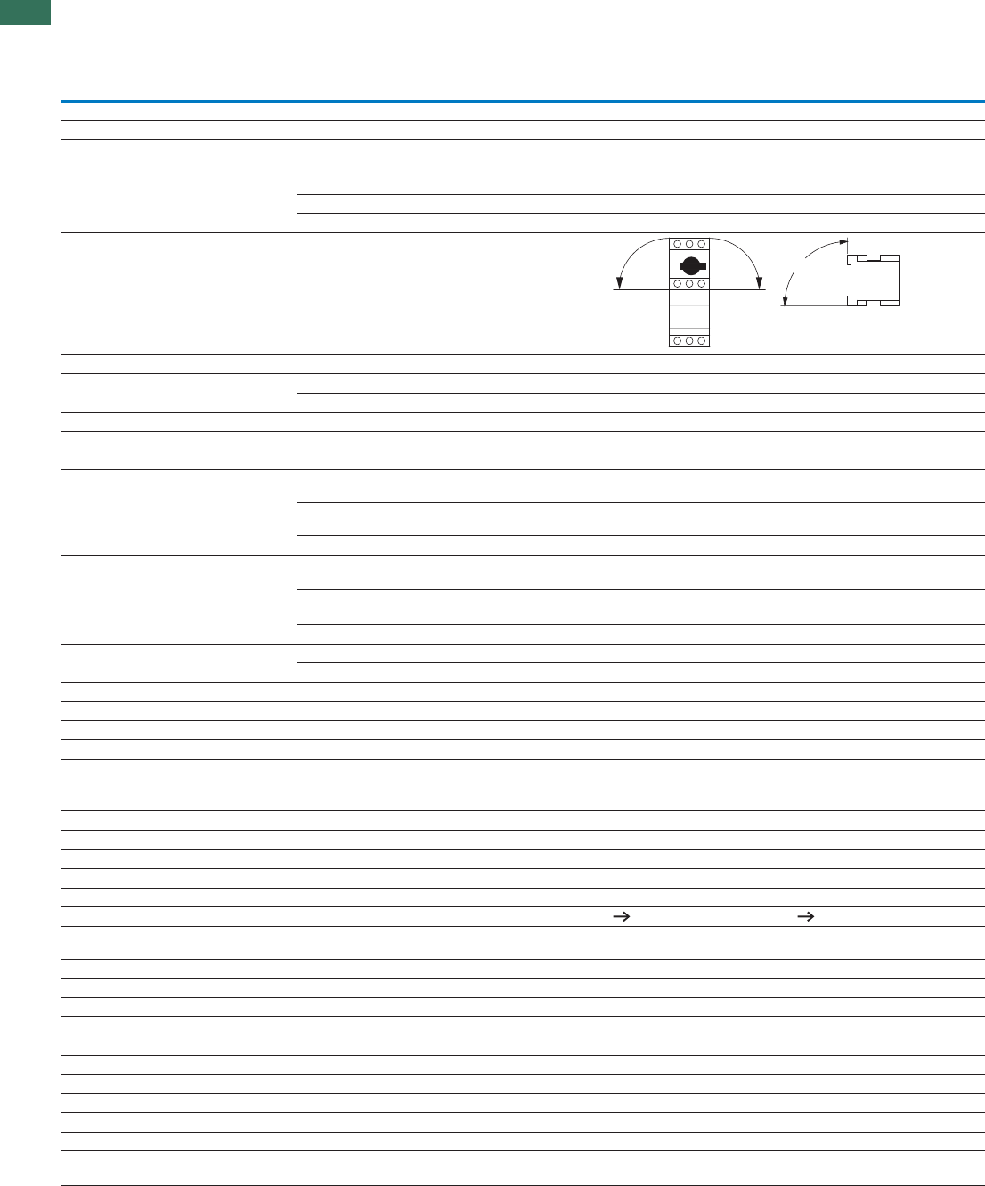
1
1.3 Motor-protective circuit-breakers PKZM01, PKZM0, PKZM4, PKE
Motor-protective circuit-breaker
36 AUTOMATION AND CONTROL www.eaton.com/seasia-electrical
Technical data
PKZM01… PKZM0-…1)
General
Standards IEC/EN 60947, VDE 0660, UL 508, CSA C 22.2 No. 14
Climatic proofing Damp heat, constant, to IEC 60068-2-78
Damp heat, cyclic, to IEC 60068-2-30
°CStorageAmbient temperature -25…80 -25 …80
°COpen -25…55 -25…55
°CEncapsulated -25…40 -25…40
Built-in position
Direction of incoming supply Any Any
Degree of protection Device IP20 IP20
Terminals IP00 IP00
Contact protection to EN 50274 Finger- and back-of-hand proof
gShock resistance, half-sinusoidal shock, 10 ms to IEC 60068-2-27 25 25
medutitlanoitallatsnI max. 2000 max. 2000
mm²SolidTerminal capacity, screw terminals 1 x (1 - 6)
2 x (1 - 6)
1 x (1 - 6)
2 x (1 - 6)
Flexible with ferrule to
DIN 46228
mm² 1 x (1 - 6)
2 x (1 - 6)
1 x (1 - 6)
2 x (1 - 6)
AWGSolid or stranded 18 - 10 18 - 10
mm²Terminal capacity, spring-loaded terminals Solid – 1 x (1…2.5)
2 x (1…2.5)
Flexible with ferrule to
DIN 46228
mm² – 1 x (1…2.5)
2 x (1…2.5)
AWGSolid or stranded – 18…14
NmMain conductorsTerminal screw tightening torque 1.7 1.7
NmAuxiliary conductors 1 1
Main contacts
URated impulse withstand voltage imp V AC 6000 6000
Overvoltage category/pollution degree III/3 III/3
URated operational voltage eV AC 690 690
Rated uninterrupted current = rated operational current Iu
= IeA 16 or current setting of the
overcurrent release
32 or current setting of the
overcurrent release
HzRated frequency 40 - 60 40 - 60
WHeat dissipation (3 pole at operating temperature) 6 6
x 10OperationsLifespan, mechanical 60.05 0.1
x 10OperationsLifespan, electrical (AC-3 at 400 V) 60.05 0.1
Ops/hOperations/hMaximum operating frequency 25 40
Short-circuit rating
AC Page 33 Page 32
DC kA 60 60 (up to PKZM0-16)
40 (PKZM0-20 to PKZM0-32)
Motor switching capacity
AAC-3 up to 690 V 16 32
ADC-5 (up to 250 V) 16 (3 contacts in series) 25 (3 contacts in series)
Trip blocks
Temperature compensation
°CTo IEC/EN 60947, VDE 0660 -5…40 -5…40
°COperating range -25…55 -25…55
%/KTemperature compensation residual error for T > 40 °C ̰ 0.25 ̰ 0.25
x ISetting range of overload releases u0.6 - 1 0.6 - 1
%Short-circuit releases tolerance ± 20 ± 20
Phase-failure sensitivity IEC/EN 60947-4-1,
VDE 0660 Part 102
IEC/EN 60947-4-1,
VDE 0660 Part 102
Notes 1) Tested according to IEC/EN 60947-1 (isolating characteristics) and IEC/EN 60947-2
90°
90°
90°
PKZM, PKE
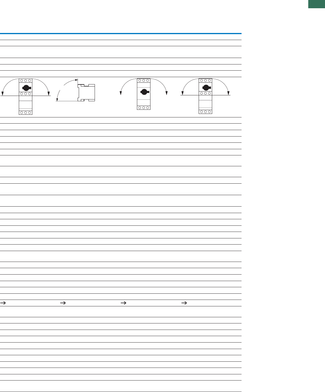
1
1.3
Motor-protective circuit-breakers PKZM01, PKZM0, PKZM4, PKE
Motor-protective circuit-breaker
37AUTOMATION AND CONTROL www.eaton.com/seasia-electrical
PKM0-… PKZM0-…-T PKZM4 PKE
IEC/EN 60947, VDE 0660, UL 508, CSA C 22.2 No. 14
Damp heat, constant, to IEC 60068-2-78
Damp heat, cyclic, to IEC 60068-2-30
-25…80 -25…80 -25…70 -25…80
-25…55 -25…55 -25…55 -25…55
-25…40 -25…40 -25…40 -25…40
Any Any Any Any
IP20 IP20 IP20 IP20
IP00 IP00 IP00 IP00
Finger- and back-of-hand proof
25 25 15 25
max. 2000 max. 2000 max. 2000 max. 2000
1 x (1 - 6)
2 x (1 - 6)
1 x (1 - 6)
2 x (1 - 6)
1 x (1 - 50)
2 x (1 - 35)
1 x (1 - 6)
2 x (1 - 6)
1 x (1 - 6)
2 x (1 - 6)
1 x (1 - 6)
2 x (1 - 6)
1 x (1 - 35)
2 x (1 - 35)
1 x (1 - 6)
2 x (1 - 6)
18 - 10 18 - 10 14 - 2 18 - 10
1 x (1…2.5)
2 x (1…2.5)
– – 1 x (1…2.5)
2 x (1…2.5)
1 x (1…2.5)
2 x (1…2.5)
– – 1 x (1…2.5)
2 x (1…2.5)
18…14 – – 18…14
1.7 1.7 3.3 1.7
1111
6000 6000 6000 6000
III/3 III/3 III/3 III/3
690 690 690 690
32 or current setting of the
overcurrent release
25 or current setting of the over-
current release
65 Open
63 enclosed
32 A or set current
of the overcurrent release
40 - 60 40 - 60 40 - 60 40 - 60
66 226
0.1 0.1 0.03 0.05
0.1 0.1 0.03 0.05
40 40 40 60
Page 32 Page 32 Page 33 Page 33
60 (up to PKM0-16)
40 (PKM0-20 to PKM0-32)
60 (up to PKZM0-16)
40 (PKZM0-20 to PKZM0-32)
60 –
32 25 65 32
25 (3 contacts in series) 25 (3 contacts in series) 63 (3 contacts in series) –
-5…40 -5…40 -5…40 -5…40
-25…55 -25…55 -25…55 -25…55
̰ 0.25 ̰ 0.25 ̰ 0.25
0.6 - 10.6 - 10.25 - 1
± 20 ± 20 ± 20 ± 20
– IEC/EN 60947-1-1,
VDE 0660 Part 102
IEC/EN 60947-4-1,
VDE 0660 Part 102
Yes
90°
90°
90°
90°
90°
90°
90°

1
1.3 Motor-protective circuit-breakers PKZM01, PKZM0, PKZM4, PKE
Auxiliary contacts
38 AUTOMATION AND CONTROL www.eaton.com/seasia-electrical
NHI…PKZ0 NHI-E-…PKZ0 VHI…PKZ0 AGM
Auxiliary contacts
URated impulse withstand voltage imp V AC 6000 4000 4000 6000
Overvoltage category/pollution degree III/3 III/3 III/3 III/3
Rated operating voltage
UeV AC 500 440 440 500
UeV DC 250 250 250 250
Safe isolation according to EN 61140
Between auxiliary contacts and main contacts V AC 690 690 690 690
Rated operational current
AC-15
I220 - 240 V eA 3.5 1 1 3.5
I380 - 415 V eA2––2
I440 - 500 V eA1––1
DC-13 L/R̰100 ms
I24 V eA2222
I60 V eA 1.5 – – 1.5
I110 V eA1––1
I220 V eA 0.25 – – 0.25
Durability
x 10OperationsLifespan, mechanical 6> 0.1 > 0.1 > 0.1 > 0.01
x 10OperationsLifespan, electrical 6> 0.05 > 0.1 > 0.1 > 0.05
Control circuit reliability (at U = 24 V DC, U = 17 V,
emin
Imin= 5.4 mA)
Fault
probability < 10 < 1 failure in 1 x 10 operations
-8 8
Interlocked opposing contacts Yes – – –
Short-circuit rating without welding
Fuseless FAZ-B4/1-HI – – FAZ-B4/1-HI
A gG/gLFuse 10 10 10 10
Terminal capacity
mm²Solid or flexible conductor with ferrule 0.75 - 2.5 0.75 - 1.5 0.75 - 1.5 0.75 - 2.5
AWGSolid or stranded 18 - 14 18 - 16 18 - 16 18 - 14
Undervoltage release
U-PKZ...
Shunt release
A-PKZ...
General
Terminal capacity
mm²Solid or flexible conductor with ferrule 1 x (0.75 - 2.5)
2 x (0.75 - 2.5)
1 x (0.75 - 2.5)
2 x (0.75 - 2.5)
AWGSolid or stranded 1 x (18 - 14)
2 x (18 - 14)
1 x (18 - 14)
2 x (18 - 14)
Main contacts
URated operating voltage eV AC 42 - 480 42 - 480
URated operating voltage eV DC 24 - 250 24 - 250
Pick-up-/drop-out voltage
x UPick-up voltage s0.85 - 1.1
x UDrop-out voltage s0.7 - 0.35
Operating range
x UAC voltage s0.7…1.1
x UDC voltage (intermittent operation 5 s) s0.7…1.1
Power consumption
AC voltage
VAPick-upAC pick-up rating 5 5
VAHoldingAC consumption when closed 3 3
DC voltage
WPick-upDC pick-up rating – 3
WHoldingDC consumption when closed – 3
NHI...PKZ, AGM, U-PKZ, A-PKZ
NHI...PKZ, AGM, U-PKZ, A-PKZ
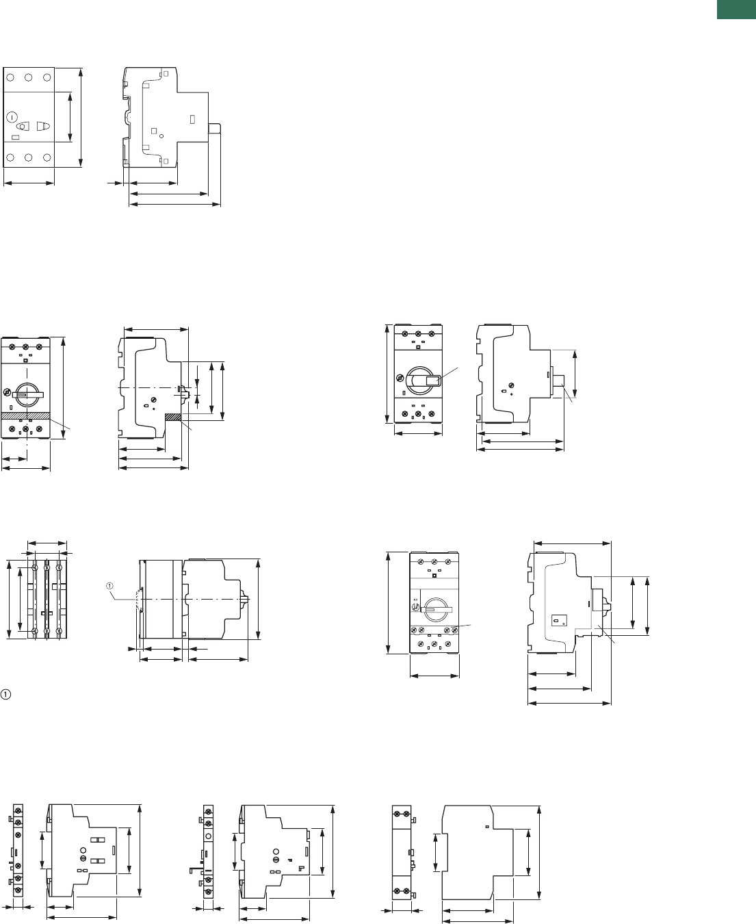
1
1.3
Motor-protective circuit-breakers PKZM01, PKZM0, PKZM4, PKE
Motor-protective circuit-breaker
39AUTOMATION AND CONTROL www.eaton.com/seasia-electrical
Dimensions
Motor-protective circuit-breaker
PKZM01…
Motor-protective circuit-breakers with
lockable rotary handles
Motor-protective circuit-breaker
Transformer-protective circuit-breakers
Motor-protective circuit-breaker with
standard auxiliary contacts
PKZM0-…(+NHI-E-…-PKZ0)
PKZM0-…-T(+NHI-E-…-PKZ0)
PKM0-…(+NHI-E-…-PKZ0)
PKZM0-…+AK-PKZ0
Motor-protective circuit-breakers with
early-make auxiliary contacts
Current limiters
CL-PKZ… PKZM0-…+VHI-…-PKZ0
Top-hat rail IEC/EN 60715
Shunt releaseTrip indicatorsStandard auxiliary
contacts Undervoltage release
A-PKZ0…AGM2…-PKZ0NHI…-PKZ0
U-PKZ0…
5.545
45
93
44
74
85
NHI-E-..-PKZ0 NHI-E-..-PKZ0
70
55
45
25
93
50
76
68
45
4.5
45
AK-PKZ 0
AK-PKZ 0
93
50
88
94
45
70
7.5
49.5
44
7.5
45
28
90
73
93
VHI...-PKZ0
80
55
45
93
50
86
68
45
VHI...-PKZ0
926
68
45
90
36
926
68
45
90
36
18 49
68
36
45
90
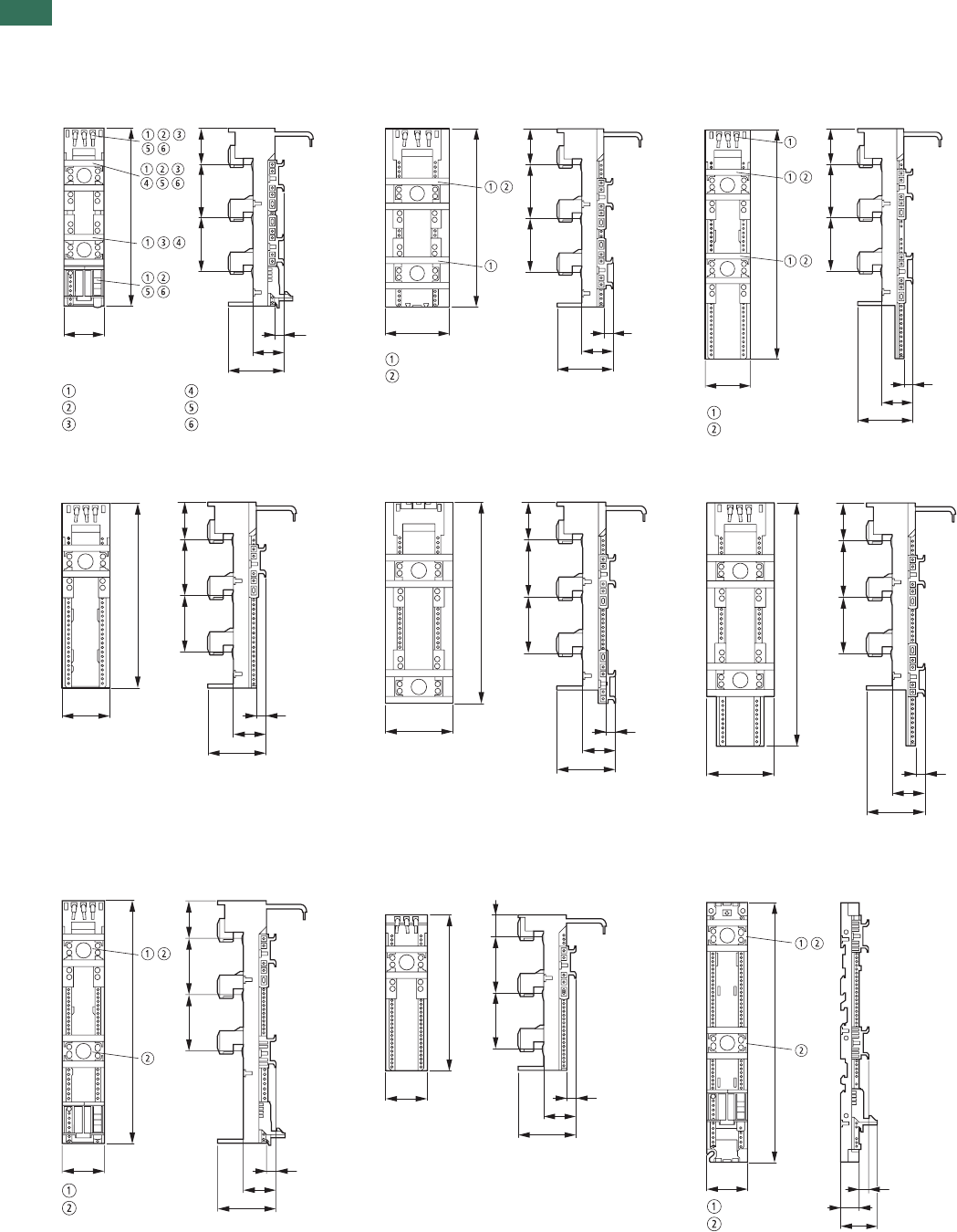
1
1.3 Motor-protective circuit-breakers PKZM01, PKZM0, PKZM4, PKE
Busbar adapters
40 AUTOMATION AND CONTROL www.eaton.com/seasia-electrical
BBA4/2TS-LBBA2-63BBA0-25
BBA4L-63BBA2-63/2TSBBA0-25/2TS
BBA0/2TS-L
BBA0-32
BBA0-32/2TS-C
BBA0C-16
BBA2L-63BBA2-80/2TS-SBBA4-63
PKZM0-XC45LBBA0K-32BBA0L-25
BBA0L-32 PKZM0-XC45L-2
BBA0-32/2TS-C
BBA0-25/2TS
BBA0C-16
BBA0/2TS-L
BBA0-25
BBA0-32
200
45
35
63
10
40
6060
BBA2-63/2TS
BBA2-63
200
72
35
63
10
40
60
60
BBA4L-63
BBA4/2TS-L
35
63
10
40
6060
260
55
35
63
10
40
6060
200
55
214
72
40
6060
35
63
10
260
72
35
63
10
40
6060
BBA0L-25
BBA0L-32
260
45
35
63
10
40
60
60
161
45
20
6060
35
63
10
PKZM0-XC45L
PKZM0-XC45L-2
283
45
20
40
10
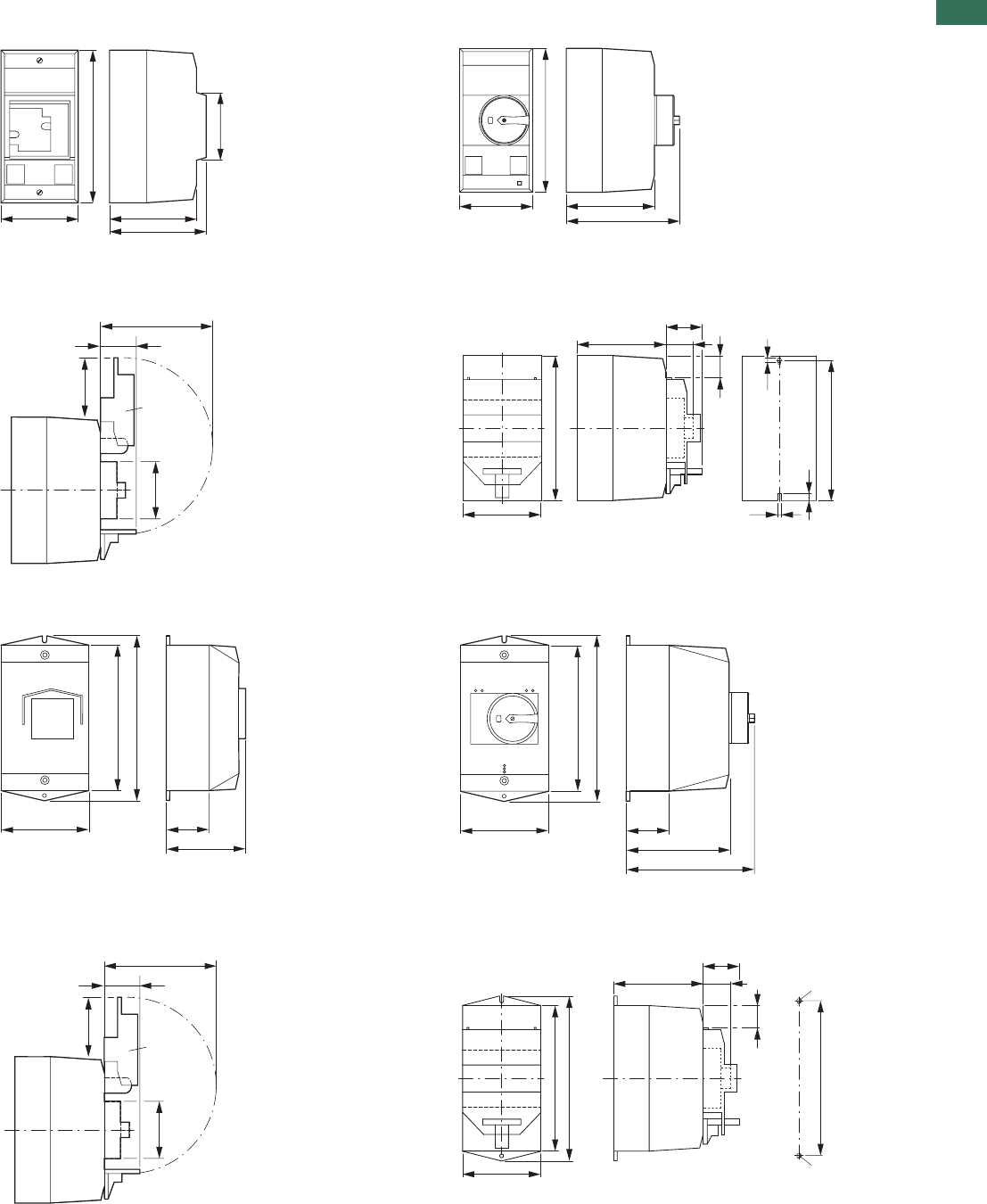
1
1.3
Motor-protective circuit-breakers PKZM01, PKZM0, PKZM4, PKE
Accessories
41AUTOMATION AND CONTROL www.eaton.com/seasia-electrical
Insulated enclosures for surface mounting
CI-PKZ10G...MCI-PKZ0-M
CI-PKZ0-…M
+ SVB-PKZ0-CI
Drilling dimensions
CI-PKZ0-…M
CI-K2-PKZ0G(R)(V)CI-K2-PKZ0
CI-K2-PKZ0-G(R)(V)
+ SVB-PKZ0-CI
Drilling dimensions
CI-K2-PKZ0…
80
158
90
100
70
80
158
97.5
125.5
98
30
44
55
SVB-PKZ0-CI
80
158
28
33
97.5
4.5
153
8
30
4.5
100
160
47.5
104
181
100
160
47.5
103
130
181
98
30
44
55
SVB-PKZ0-CI
97
181
28
33
114
171
M4
M4
30
160
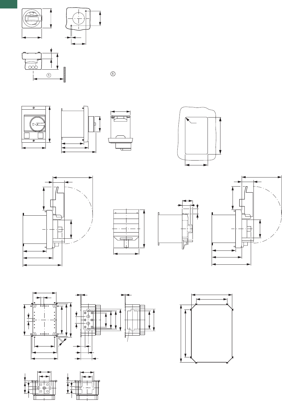
1
1.3 Motor-protective circuit-breakers PKZM01, PKZM0, PKZM4, PKE
Accessories
42 AUTOMATION AND CONTROL www.eaton.com/seasia-electrical
Door coupling handles
PKZ0-X(R)H…
Mounting depth: 100 to 240 mm
from the top edge of the top-hat rail
to the front edge of the cabinet
door/cover
Distance between switch axis and
cover hinge: at least 100 mm
At least 100 mm from cover hinge
Mounting aperture E-PKZ0…IInsulated enclosures for flush mounting
E-PKZ0 E-PKZ0-G…
E-PKZ0-G… + SVB-PKZ0-E
Mounting platesInsulated enclosures for surface mounting
M3-CI23CI23E…
54
20
64
64
48
48
7.5
69
85
129
96
80
124
55
R4
70–72
116 – 118
98
30
58
55
80
96
124
85
129
30
28
21
98
30
58
55
80
96
124
142.5
205
62.5
125
3
3
25
25
187.5
250
162
200
215
225
262
278
56
114
144
147
177
35
60
90
147
177
7knockout
8 x PG 16
2 x PG 21/29
14
27
84.5
114.5
92
14
27
84.5
114.5
92
6 × PG 16
1 × PG 21/29
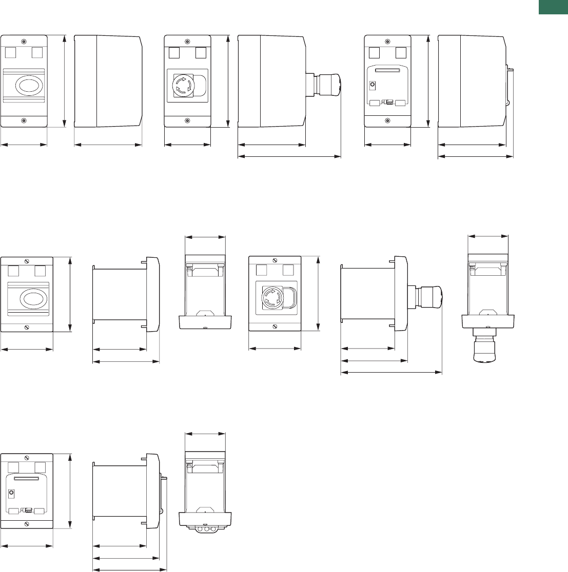
1
1.3
Motor-protective circuit-breakers PKZM01, PKZM0, PKZM4, PKE
Accessories
43AUTOMATION AND CONTROL www.eaton.com/seasia-electrical
Insulated enclosures for surface mounting
CI-PKZ01-SVBCI-PKZ01-PVTCI-PKZ01
CI-PKZ01-SVB-VCI-PKZ01-PVSCI-PKZ01-G
Insulated enclosures for flush mounting
E-PKZ01-PVTE-PKZ01
E-PKZ01-PVSE-PKZ01-G
E-PKZ01-SVB
E-PKZ01-SVB-V
80
158
116.5 80
158
116.5
177.2
80
158
116.5
129.5
69
90.2 93
115.2
129
69
90.2 93
115.2
175.9
129
69
90.2 93
115.2
128.2
129
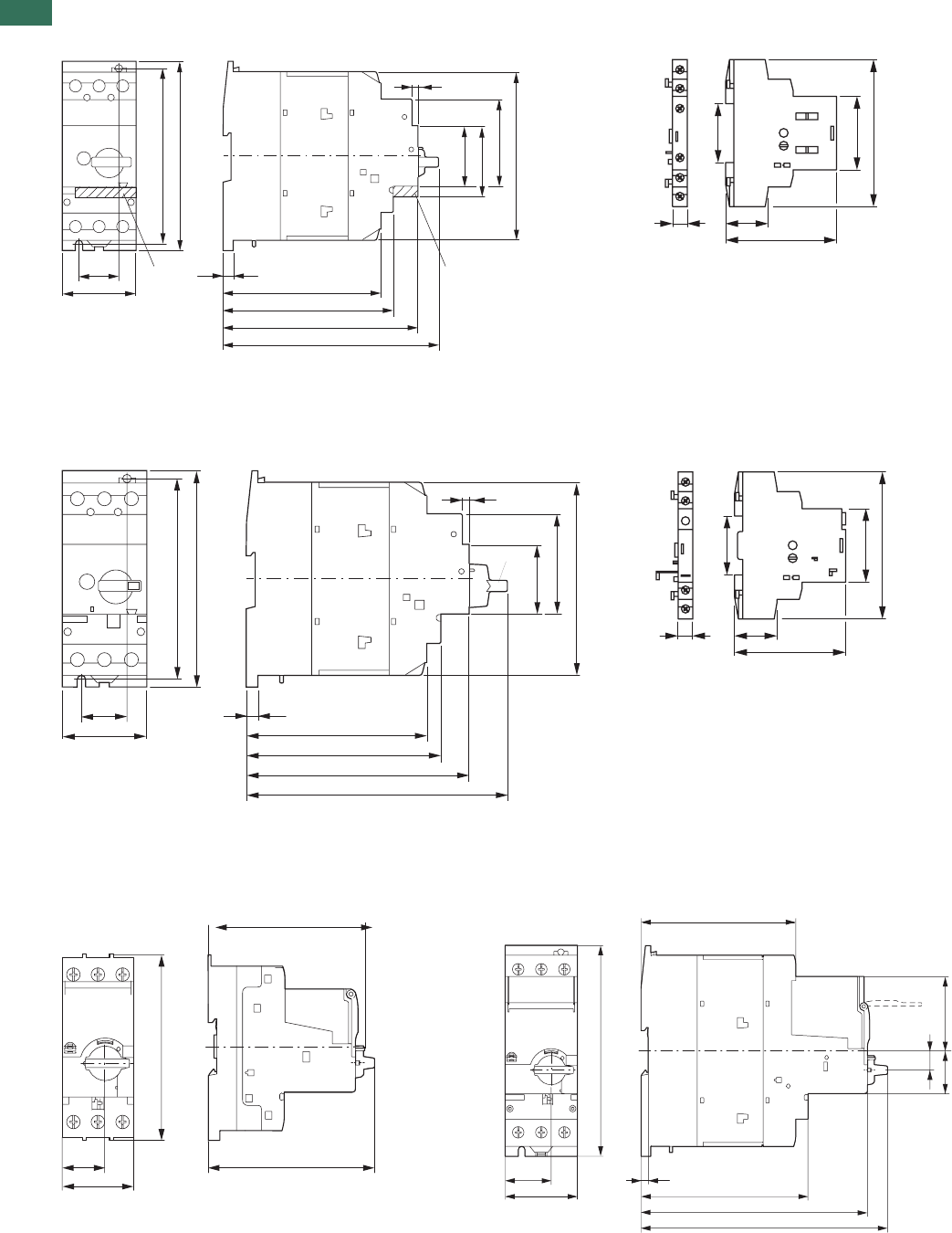
1
1.3 Motor-protective circuit-breakers PKZM01, PKZM0, PKZM4, PKE
Accessories
44 AUTOMATION AND CONTROL www.eaton.com/seasia-electrical
Motor-protective circuit-breaker Standard auxiliary contacts
PKZM4-… NHI…-PKZ…
NHI…-PKZ0
Motor-protective circuit-breakers with lockable cover Tripindicators
PKZM4-… +AK-PKZ0 AGM2…-PKZ…
AGM2…-PKZ0
PKE Motor-protective circuit-breakers
PKE65PKE12 , PKE32
30 NHI-E... 7.5
118
127
145
160
55
130
140
125
65
53
45
4
NHI-E...
926
68
45
90
36
30 7.5
118
127
145
171
55
130
140
125
65
45
4
AK-PKZ0
926
68
45
90
36
101
102.5
100.5
25
45
56.5
160
32.5
35 5.5
55 127
118
172
187
14.5
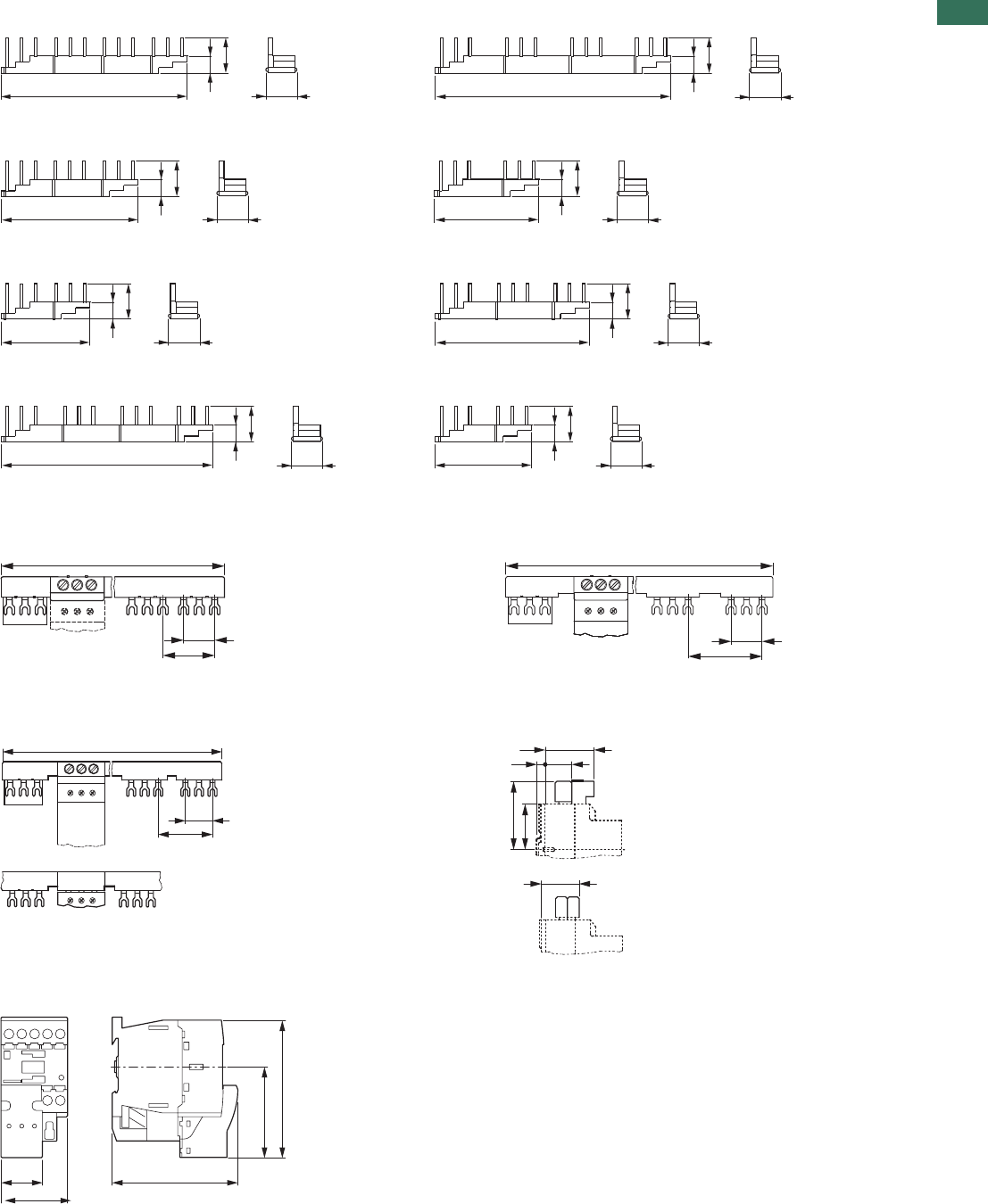
1
1.3
Motor-protective circuit-breakers PKZM01, PKZM0, PKZM4, PKE
Accessories
45AUTOMATION AND CONTROL www.eaton.com/seasia-electrical
Three-phase commoning links
B3.2/4-PKZ4B3.0/4-PKZ4
B3.2/2-PKZ4B3.0/3-PKZ4
B3.0/3-PKZ4B3.0/2-PKZ4
B3.1/2-PKZ4B3.1/4-PKZ4
Three-phase commoning linksThree-phase commoning links
B3.0/4-PKZ0 B3.2/4-PKZ0
B3.0/2-PKZ0 B3.2/2-PKZ0
IncomingterminalsThree-phase commoning links
BK25/3-PKZ0B3.1/3-PKZ0B3.1/5-PKZ0
B3.1/4-PKZ0 B3.1/2-PKZ0
Overlapping
mounting to
extend the
three-phase
commoning link
Motor plug DILM12-XMCP/T
14
205
36
33 33
14
260
36
14
151
36
33
14
115
36
33
14
98
36
33 33
14
170
36
33
14
232
36
33
14
117
36
180 (90)
H-B3-
PKZ 0 27
45
234
H-B3-
PKZ0 27
63
H-B3-
PKZ 0 27
261 (207, 153, 99)
54
BK25/3-PKZ0
̰ 41
73
7.5 31
48
̰ 56
B3...-PKZ0
45
62
94
27 85
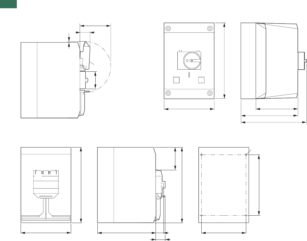
1
1.3 Motor-protective circuit-breakers PKZM01, PKZM0, PKZM4, PKE
Accessories
46 AUTOMATION AND CONTROL www.eaton.com/seasia-electrical
Insulated enclosures for surface mounting
CI-K4-PKZ4-GCI-K4-PKZ4-G(R)
+SVB-PKZ4-CI
Drilling dimensions
CI-K4-PKZ-G(R)
32
98
SVB-PKZ4-CI
72
3
160
240
134
181
197
160 186 28
30
240
240
193
142
Ø 5.6
72
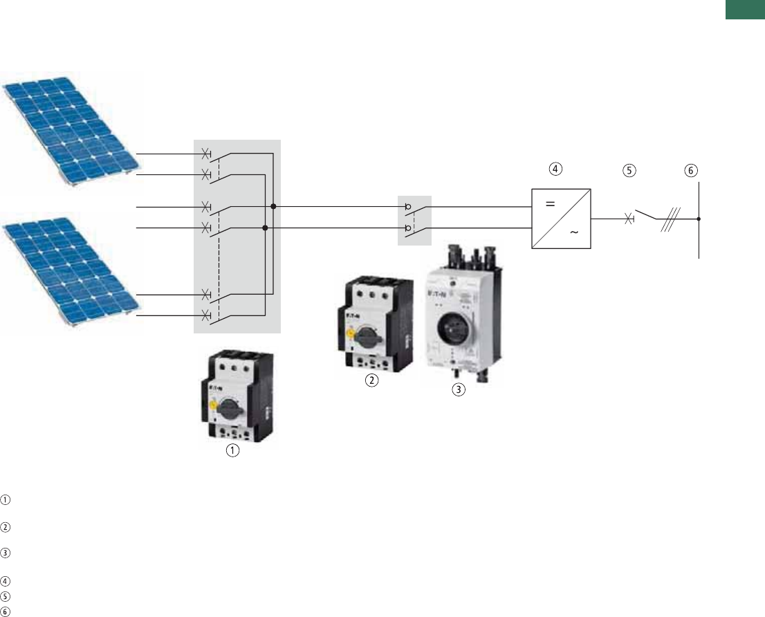
1
1.3
DC string circuit-breakers, DC switch-disconnectors
47AUTOMATION AND CONTROL www.eaton.com/seasia-electrical
Description
Photovoltaics description
Photovoltaic systems convert sunlight
directly into electrical energy using
solar cells. Photovoltaics represent a
renewable source of energy that can
be used on private and public
buildings, as well as in large-scale
power stations.
These systems can be independent
from the power grid or can be
connected to it. Photovoltaic systems
that are connected to the grid feed the
generated power directly into the
mains network. This eliminates the
need for temporary storage. These
systems consist of solar cells, one or
more inverters, and a protective
device for automatic cutoff in the
event of a grid fault. Because of this,
photovoltaic systems that are
connected to the grid require
extremely reliable and safe individual
components.
DC string circuit-breaker
PKZ-SOL
DC switch-disconnector
P-SOL
Ready-to-install DC switch-
disconnector SOL
Inverter module
AC main switch
Network
Features
DC string circuit-breakers
• Protect PV modules from fault
currents, prevent (in larger systems,
for instance) intact modules from
feeding power back into a module
with a short-circuit.
• Are ready for operation immediately
after tripping and after the trip
cause has been fixed.
• Open and for installation in
customized generator terminal boxes.
• Tripping currents are adjustable
within a wide range of limits.
• Optional shunt releases A-PKZ0 and
undervoltage releases U-PKZ0
enable remote shutdown, e.g for the
fire department. Optional auxiliary
contact NHI-E-PKZ0 signals
switching state.
•When installed in an enclosure,
suitable for voltages of up to 900 VDC.
DC switch-disconnectors
• Required, according to standard
VDE 0100-712 (June 2006), between
the PV module and inverter.
• Enclosed and open (for installation
in enclosure) switch-disconnectors
for voltages of up to 1,000 VDC.
• Usable as a separate switching
point as required in VDI Guideline
VDI 6012, e.g. by de-energizing an
inverter in a completely safe
manner.
• Two-pole switching, making it
suitable for non-earthed systems as
well.
• TÜV-certified.
• Open switch-disconnectors P-SOL
are designed for installation in
customer-specific enclosures or
inverters.
• Mounting on 35 mm top-hat rails,
their terminals enable a connection
to all popular cable types.
• Separate rotary handles and shaft
extensions allow for flexible
installation.
• An auxiliary switching block can be
mounted in order to provide
switching state feedback.
• A shunt release or undervoltage
release is available for remote
tripping.
• Switch-disconnectors SOL with
enclosure are ready for installation.
Models for 2 and 4 or 4 and 8 strings
and for the most popular connector
types, such as MC3, MC4, and
metric screw connectors, allow for
easy integration into various system
concepts.
• Enclosure provides degree of
protection IP65, making outdoor
mounting possible.
•Lockable mechanism provides safety
when maintenance is required.
•Pressure-equalizing element
prevents the formation of condensed
water, preventing failures caused by
voltage sparkovers
.
P-SOL, PKZ-SOL, SOL
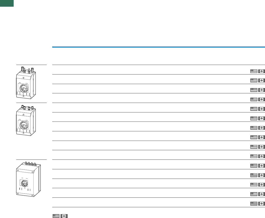
1
1.3 DC string circuit-breakers, DC switch-disconnectors
DC switch-disconnectors, ready to install
48 AUTOMATION AND CONTROL www.eaton.com/seasia-electrical
Ordering
Max. ratedOutputsInputs
operational current
DC-21A
Part no.
Article no. Price
See price
list
Std. pack
Number of
strings
Connection type Number of
strings
Connection type
Ie
A
DC switch-disconnector, ready-to-install
Rated operational voltage U 1000 V
e
Degree of protection IP65
Protection class 2
2 pole
2MC3 1MC3 20 SOL20/2MC3
120913
1 off
1 off
1 off
1 off
1 off
1 off
1 off
1 off
1 off
1 off
1 off
1 off
1 off
1 off
1 off
4MC3 1MC3 20 SOL20/4MC3
120914
2MC4 1MC4 20 SOL20/2MC4
120915
4MC4 1MC4 20 SOL20/4MC4
120916
2 Screw connector M12 1 Screw connector M16 20 SOL20/2MV
120919
2MC3 1MC3 30 SOL30/2MC3
120920
4MC3 1MC3 30 SOL30/4MC3
120921
2MC4 1MC4 30 SOL30/2MC4
120922
4MC4 1MC4 30 SOL30/4MC4
120923
2 Screw connector M12 1 Screw connector M16 30 SOL30/2MV
120926
4 MC3 1 Screw connector M20 63 SOL60/4MC3
120927
8 MC3 1 Screw connector M20 63 SOL60/8MC3
120928
4 MC4 1 Screw connector M20 63 SOL60/4MC4
120929
8 MC4 1 Screw connector M20 63 SOL60/8MC4
120930
4 Screw connector M12 1 Screw connector M20 63 SOL60/4MV
120933
Information relevant for export to North America
NA Certification Request filed for UL and CSA
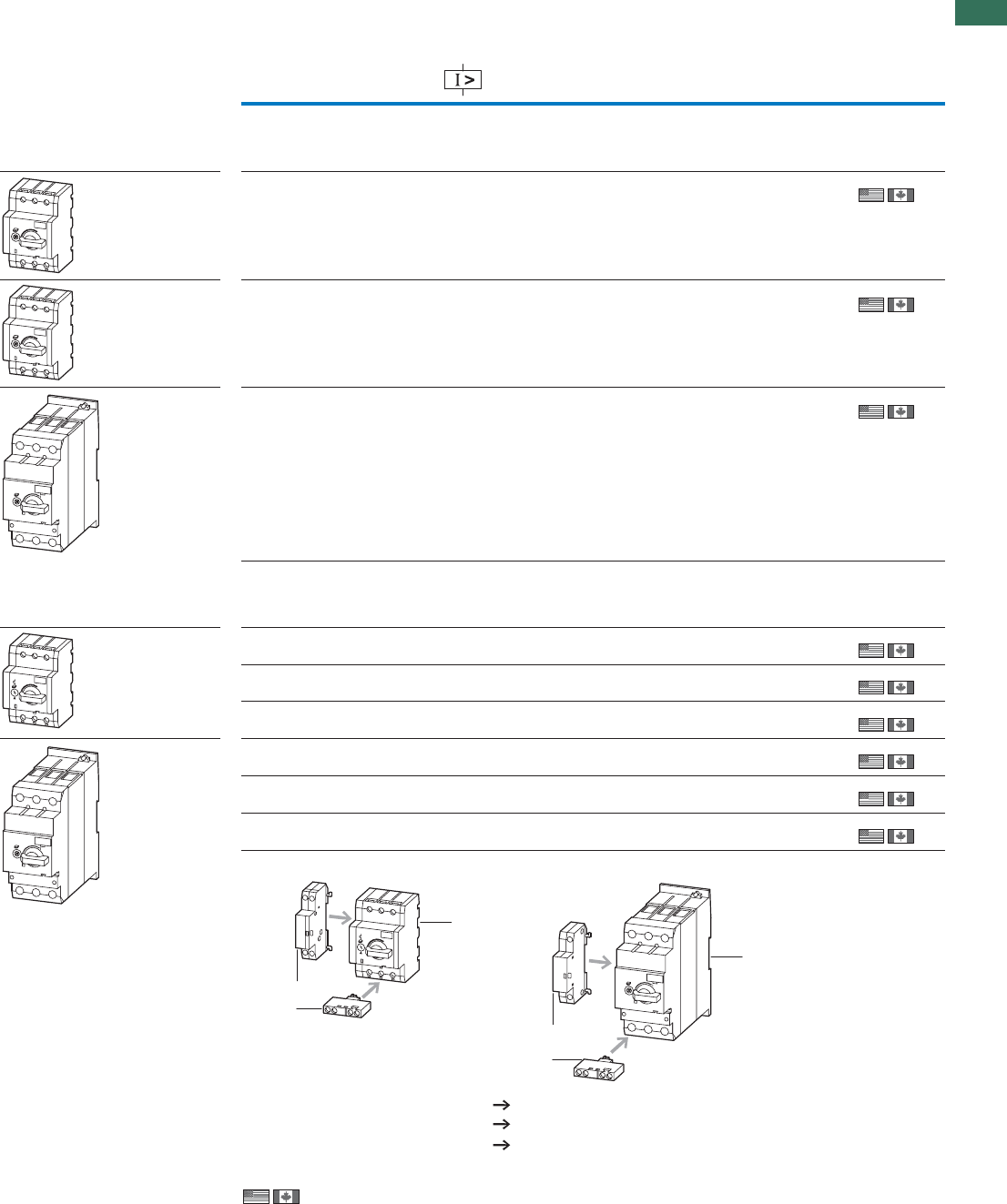
1
1.3
DC string circuit-breakers, DC switch-disconnectors
49AUTOMATION AND CONTROL www.eaton.com/seasia-electrical
Max. rated operational current
DC-21A
Permissible solar module
short-circuit currents Part no.
Article no. Price
See price list
Std. pack
Ie
A
DC switch-disconnector, open
Rated operating voltage U 1000 V
e
Protection class II
2 pole
20 P-SOL20
120934
1 off
1 off
1 off
30 P-SOL30
120935
63 P-SOL60
120936
DC string circuit-breakers
Rated operating voltage U 900 V
e
Protection class II
2 pole
9-521 PKZ-SOL12
120937
1 off
1 off
1 off
1 off
1 off
1 off
51-902 PKZ-SOL20
120938
22-5103 PKZ-SOL30
120939
03-2204 PKZ-SOL401)
120940
83-9205 PKZ-SOL501)
120941
74-8306 PKZ-SOL601)
120942
Notes 1) Availability from November 2010
Information relevant for export to North America
NA Certification Request filed for UL and CSA
1
2
3
1
2
3
PageAccessories
2 Auxiliary contacts NHI-E 10
3 Shunt releases A-PKZ0 29
3 Undervoltage releases U-PKZ0 29
P-SOL, PKZ-SOL
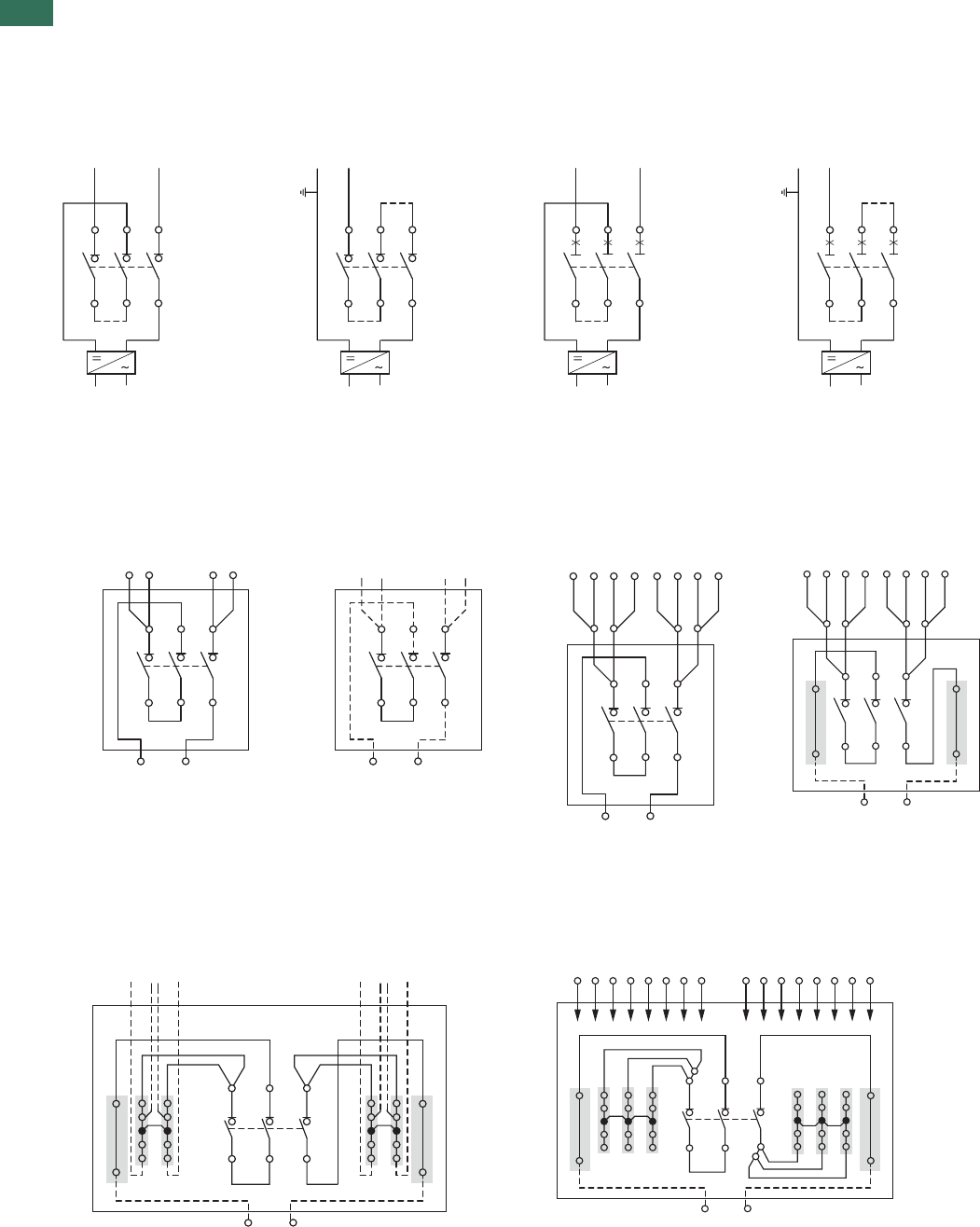
1
1.3 DC string circuit-breakers, DC switch-disconnectors
50 AUTOMATION AND CONTROL www.eaton.com/seasia-electrical
Engineering
P-SOL and PKZ-SOL wiring
String circuit-breaker PKZ-SOLSwitch-disconnector P-SOL
Earthed gridNon-earthed gridEarthed gridNon-earthed grid
SOL internal circuit
SOL20/2MC3
SOL20/2MC4
SOL30/2MC3
SOL30/2MC4
SOL20/2MV
SOL30/2MV SOL20/4MC3
SOL20/4MC4
SOL30/4MC3
SOL30/4MC4
SOL60/4MC3
SOL60/4MC4
SOL60/8MC3SOL60/4MV SOL60/8MC4
1000 VDC
135
246
1000 VDC
135
246
900 VDC
135
246
900 VDC
135
246
- Strings
+ Strings
Output
Input
+
-
135
246
- Strings
+ Strings
Output (M16)
Input (M12)
+
-
135
246
- Strings
+ Strings
Output
Input
+
-
135
246
- Strings
+ Strings
Output (M20)
Input
+
-
1
+
-
35
246
- Strings
+ Strings
Input (M12)
Output (M20)
+
-
+
-
13 5
24 6
- Strings
+ Strings
Input
Output (M20)
+
-
+
-
13 5
24 6
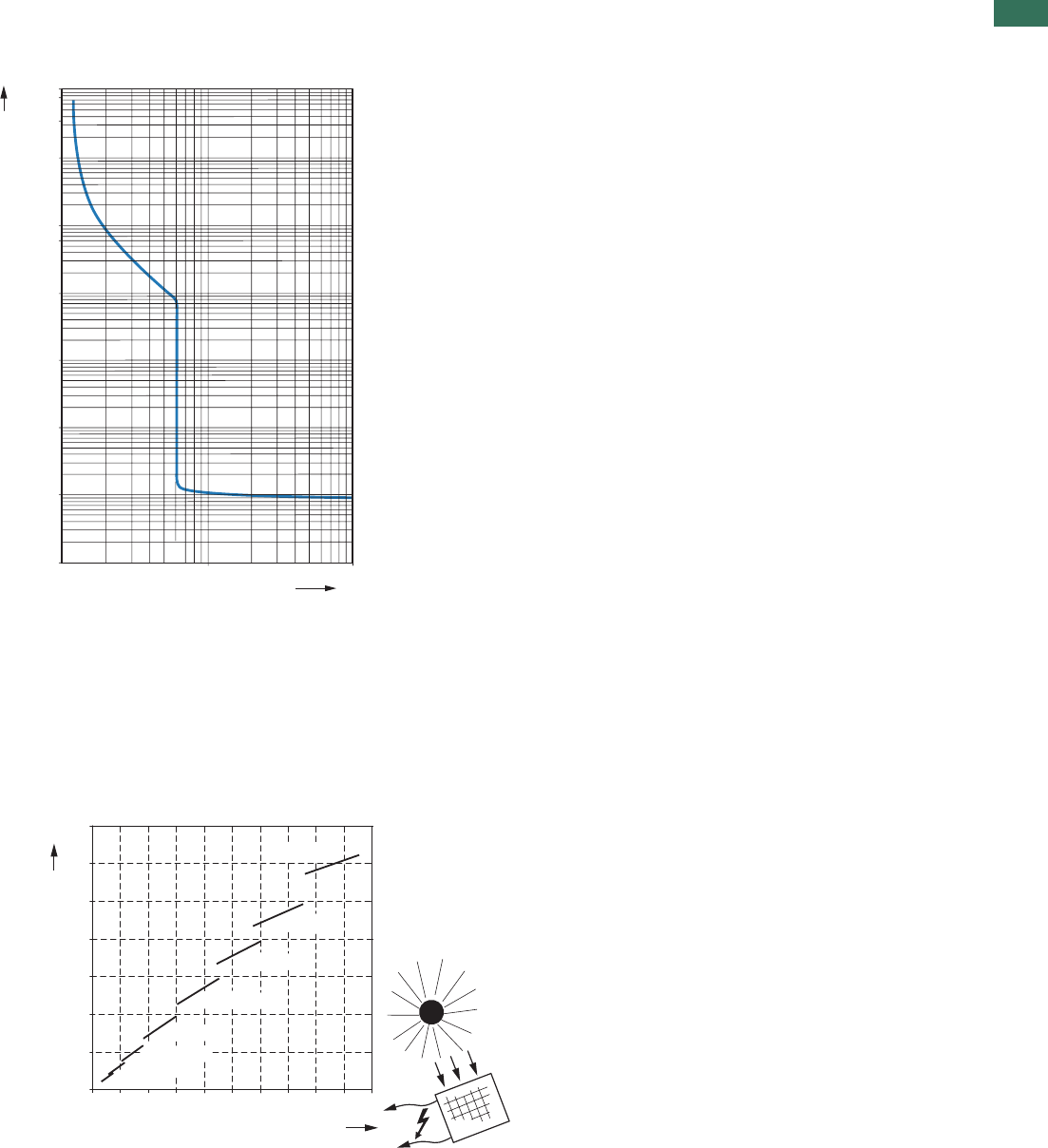
1
1.3
DC string circuit-breakers, DC switch-disconnectors
Characteristic curves
51AUTOMATION AND CONTROL www.eaton.com/seasia-electrical
Characteristic curve set value -
short-circuit current
As specified in the IEC 62548-1 draft for
the protection of photovoltaic modules,
the tripping current of the circuit-
breaker must lie between 1.4 and 2
times the value of the photovoltaic
module‘s short-circuit current.
Since only the current values of the
installed overload release can be
plotted on the setting scale for the
circuit-breaker , the correlation
1)
between the protective device‘s
tripping current and the photovoltaic
module‘s short-circuit current must be
specified for each point of the scale in
a suitable form.
1) Standard IEC/EN 60947-2 (Section
4.7.3) prohibits directly specifying the
photovoltaic short-circuit current on
the circuit-breaker's setting scale,
meaning that only the current set value
of the operating current can be plotted
there.
Tripping characteristics
Tripping characteristics
DC string circuit-breaker PKZ-SOL
101
0.001
0.01
0.1
10.000
1.000
100
10
1
100
xIr
1 h
2 h
(1 min)
t [s]
Setting aid for string circuit-breaker PKZ-SOL
Set value on circuit-breaker [A]
Short-circuit current in solar module [A]
0 5 10 15 20 25 30 35 40 50
0
10
20
30
40
50
60
70
45
PKZ-SOL60
PKZ-SOL50
PKZ-SOL40
PKZ-SOL30
PKZ-SOL20
PKZ-SOL12
PKZ-SOL7
PKZ-SOL4
Ir
[A]
ISC...

1
1.3 DC string circuit-breakers, DC switch-disconnectors
DC switch-disconnectors
52 AUTOMATION AND CONTROL www.eaton.com/seasia-electrical
Technical data
SOL20 SOL30 SOL60
Rated operational current Ie at DC-21A A 20 30 63
Number of poles 2 2 2
Rated operational voltage UeV DC 1000 1000 1000
Isolating characteristics Yes Yes Yes
Standards IEC/EN 60 947-3
UL 508, TÜV certificate
OperationsLifespan mechanical 100,000 100,000 30,000
OperationsLifespan electrical 100,000 100,000 30,000
Max. operating frequency, mechanical
Ops/h
120 120 120
Climatic proofing Damp heat, constant, to IEC 60 068-2-78
Damp heat, cyclic, to IEC 60 068-2-30
°Cmin./max.Ambient temperature -25 ... +60 -25 ... +60 -25 ... +60
Mounting position Any Any Any
IPDegree of protection 65 65 65
Dimensions
mmWidth 100 100 160
mmHeight 215 215 305
mmDepth 130 130 210
kgWeight 0.42 0.42 2.2
Lockable in OFF position Yes Yes Yes
Rated short-time withstand current , 1 s to
EN 60947-3 Icw kA 0.24 0.36 0.72
Rated short-circuit making capacity to
EN 60947-3 Icm kA 0.32 0.32 0.6
mȍInternal resistance 8 7 4
P-SOL20 P-SOL30 P-SOL60
Rated operational current at DC-21A IeA20 30 63
Number of poles 2 2 2
Rated operational voltage UeV DC 1000 1000 1000
Isolating characteristics Yes Yes Yes
Standards IEC/EN 60 947-3
UL 508, TÜV certificate
OperationsLifespan mechanical 100,000 100,000 30,000
OperationsLifespan electrical 100,000 100,000 30,000
Max. operating frequency, mechanical
Ops/h
120 120 120
Climatic proofing Damp heat, constant, to IEC 60 068-2-78
Damp heat, cyclic, to IEC 60 068-2-30
Ambient temperature
°Cmin./max.Open -25 ... +60 -25 ... +60 -25 ... +60
Mounting position Any Any Any
Dimensions
mmWidth 58 58 55
mmHeight 93 93 140
mmDepth 76 76 160
Mounting
Top-hat rail 35 mm 35 mm 35 mm
Screw mounting – – 2 x M4 x 18
30 x 130
kgWeight 0.32 0.32 1.25
Terminals
mm²Flexible with ferrule 1 x (1-6) 1 x (1-6) 1 x (1-35)
mm² 2 x (1-6) 2 x (1-6) 2 x (1-35)
AWGsolid/stranded 18 - 14 18 - 14 14 - 2
Rated short-time withstand current , 1 s to
EN 60947-3 Icw kA 0.24 0.36 0.72
Rated short-circuit making capacity to
EN 60947-3 Icm kA 0.32 0.32 0.6
mȍInternal resistance 6 5 3
P-SOL, SOL
P-SOL, SOL
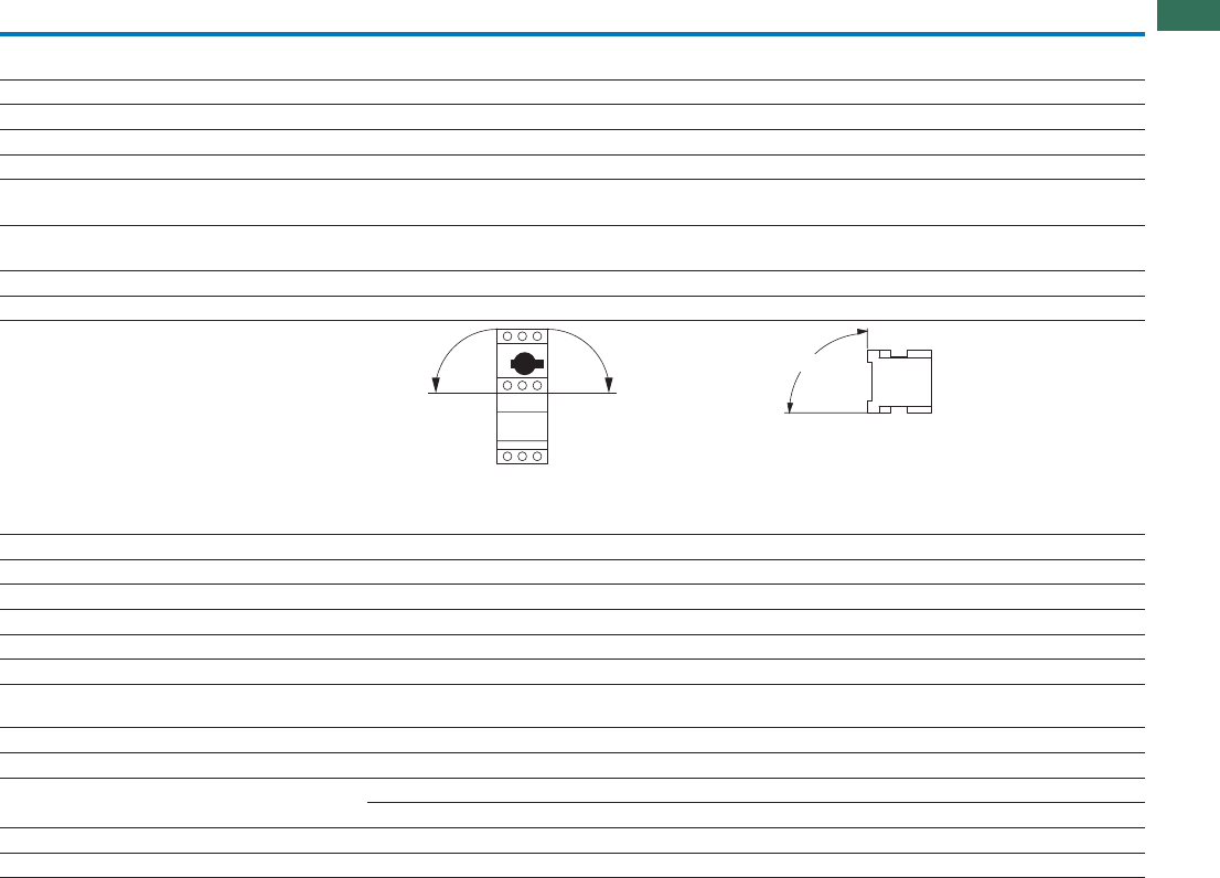
1
1.3
DC string circuit-breakers, DC switch-disconnectors
DC string circuit-breakers, open
53AUTOMATION AND CONTROL www.eaton.com/seasia-electrical
PKZ-SOL12 PKZ-SOL20 PKZ-SOL30 PKZ-SOL40 PKZ-SOL50 PKZ-SOL60
Rated operational current at
DC-21A/750VDC
IeA122030405063
Number of poles 2 2 2 2 2 2
Rated operational voltage UeV DC 900 900 900 900 900 900
Thermal tripping 1.05 ...1.3 x Ie
Electromagnetic tripping 6 x Ie
Standards IEC/EN 60 947-2
UL 508, TÜV certificate
Climatic proofing Damp heat, constant, to IEC 60 068-2-78
Damp heat, cyclic, to IEC 60 068-2-30
Ambient temperature
°Cmin./max.Open -25 ... +60 -25 ... +60 -25 ... +60 -25 ... +60 -25 ... +60 -25 ... +60
Mounting position
PKZ-SOL12
to PKZ-SOL60
PKZ-SOL12
to PKZ-SOL30
Dimensions
mmWidth 58 58 58 55 55 55
mmHeight 93 93 93 140 140 140
mmDepth 76 76 76 160 160 160
Mounting
Top-hat rail 35 mm 35 mm 35 mm 35 mm 35 mm 35 mm
Screw mounting – – – 2 x M4 x 18
30 x 130
2 x M4 x 18
30 x 130
2 x M4 x 18
30 x 130
kgWeight 0.32 0.32 0.32 1.25 1.25 1.25
Terminals
flexible with ferrule mm² 1 x (1-6) 1 x (1-6) 1 x (1-6) 1 x (1-35) 1 x (1-35) 1 x (1-35)
mm² 2 x (1-6) 2 x (1-6) 2 x (1-6) 2 x (1-35) 2 x (1-35) 2 x (1-35)
AWGsolid/stranded 18 - 14 18 - 14 18 - 14 14 - 2 14 - 2 14 - 2
mȍInternal resistance 31 12 7 – – –
90°
90°
90°
PKZ-SOL
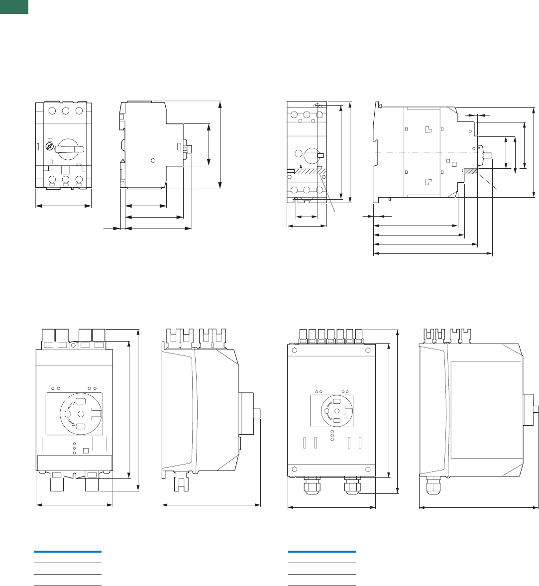
1
1.3 DC switch-disconnectors, DC string circuit-breakers
DC string circuit-breakers, open
54 AUTOMATION AND CONTROL www.eaton.com/seasia-electrical
Dimensions
P-SOL60P-SOL20
PKZ-SOL40P-SOL30
PKZ-SOL50PKZ-SOL12
PKZ-SOL60PKZ-SOL20
PKZ-SOL30
SOL60SOL20
SOL30
58
45
92.5
43.5
62
705.5
30 7.5
118
127
145
160
55
130
140
125
65
45
53
4
NHI-E...
NHI-E...
100
180.3
b
130.5 160
246
b
215
Connection
type b
mm
MC3 195
MC4 234
MV 224
Connection
type b
mm
MC3 275
MC4 314
MV 304
P-SOL, PKZ-SOL, SOL
SOL
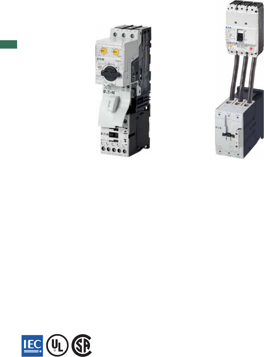
1
AUTOMATION AND CONTROL www.eaton.com/seasia-electrical
Combining a motor protective circuit breaker or circuit breaker with a contactor results in
a motor starter according to coordination type "1" or "2". Both types of coordination safely
control short-circuit by switching it off. Coordination type "2" starters offer a high degree
of operational continuity: after the cause of the short circuit has been removed, they can
be switched back on immediately.
Motor-starter combinations
Motor-starter combination - motor starter up to 1400 A
Highest safety through proven combination in coordination type "1" or "2"
Approved combinations for export to North America
•
•
Conditions for fulfilling type of coordination
Coordination type: "1": Secure switching off of the entered short-circuit current lq
No danger to personnel or installations in case of short-circuit
For further operation without repair and partial renewal, switch does not need to be suitable
Damage to the switch or individual components approved
Coordination type: "2": Secure switching off of the entered short-circuit current lq
No danger to personnel or installations in case of short-circuit
Switch remains suitable for further operation
No damage to switch, except to welds of protective contacts, when these can be easily separated
without significant deformation
•
•
•
•
•
•
•
•
DOL starter and reversing starter MSC… – motor starter with motor-protective circuit-breaker
PKZM0 up to 32A
Mounted starters minimize wiring time
Plug & Play with starters on busbar adapters
Attractive design for high-quality installations
Direct field bus connection through SmartWire-DT® communication system via plug-in type
protective module
•
•
•
•
DOL starter and reversing starter MSC-DE… – motor starter with electric motor-protective
circuit-breaker PKE up to 32A
Increased safety through separate contact systems between switching and safety devices
Direct field bus connection through SmartWire-DT® communication system via plug-in type
protective module
Direct reading of motor current and state, transfer to subordinate control system through
SmartWire-DT®
•
•
•
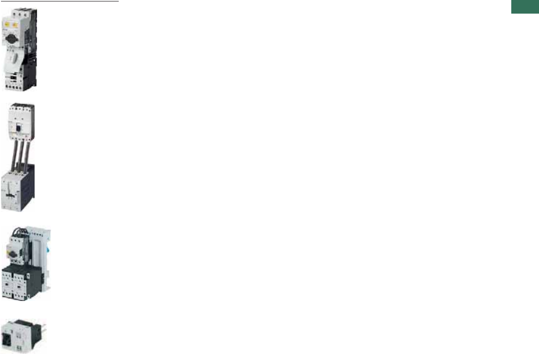
1
Motor-starter combinations
Contents
1AUTOMATION AND CONTROL www.eaton.com/seasia-electrical
Ordering
Direct-on-line starters MSC-D
MSC-D complete units . . . . . . . . . . . . . . . . . . . . . . . . . . . . . . . . . . . . . . . . . . . . . . . . . . . . . . . . . . . . . . . . . . . . . . .
MSC-US complete units . . . . . . . . . . . . . . . . . . . . . . . . . . . . . . . . . . . . . . . . . . . . . . . . . . . . . . . . . . . . . . . . . . . . . .
MSC-DEA complete units . . . . . . . . . . . . . . . . . . . . . . . . . . . . . . . . . . . . . . . . . . . . . . . . . . . . . . . . . . . . . . . . . . . . .
Modules PKZM0/PKZM4 + DILM . . . . . . . . . . . . . . . . . . . . . . . . . . . . . . . . . . . . . . . . . . . . . . . . . . . . . . . . . . . . . . .
Modules NZMN/NZMH + DILM . . . . . . . . . . . . . . . . . . . . . . . . . . . . . . . . . . . . . . . . . . . . . . . . . . . . . . . . . . . . . . . .
Modules PKM0 + DILM + ZB . . . . . . . . . . . . . . . . . . . . . . . . . . . . . . . . . . . . . . . . . . . . . . . . . . . . . . . . . . . . . . . . . .
Modules NZMN + DILM + ZB . . . . . . . . . . . . . . . . . . . . . . . . . . . . . . . . . . . . . . . . . . . . . . . . . . . . . . . . . . . . . . . . .
Ordering
Reversing starter MSC-R
MSC-R complete units . . . . . . . . . . . . . . . . . . . . . . . . . . . . . . . . . . . . . . . . . . . . . . . . . . . . . . . . . . . . . . . . . . . . . . .
Modules PKZM0/PKZM4 + DILM . . . . . . . . . . . . . . . . . . . . . . . . . . . . . . . . . . . . . . . . . . . . . . . . . . . . . . . . . . . . . . .
Modules NZMN/NZMH + DILM . . . . . . . . . . . . . . . . . . . . . . . . . . . . . . . . . . . . . . . . . . . . . . . . . . . . . . . . . . . . . . . .
Ordering
Starter on busbar adapter
DOL starter complete units MSC-D/BBA . . . . . . . . . . . . . . . . . . . . . . . . . . . . . . . . . . . . . . . . . . . . . . . . . . . . . . . . .
Reversing starters complete units MSC-R/BBA . . . . . . . . . . . . . . . . . . . . . . . . . . . . . . . . . . . . . . . . . . . . . . . . . . . .
Ordering
Starter for North America
Modules type F starter combinations . . . . . . . . . . . . . . . . . . . . . . . . . . . . . . . . . . . . . . . . . . . . . . . . . . . . . . . . . . . .
Modules DILEM/DILM + ZE/ZB/Z5/ZW7 . . . . . . . . . . . . . . . . . . . . . . . . . . . . . . . . . . . . . . . . . . . . . . . . . . . . . . . . .
Modules NZMH-…-CNA + DILM + ZB/Z5/ZW7 . . . . . . . . . . . . . . . . . . . . . . . . . . . . . . . . . . . . . . . . . . . . . . . . . . . .
System overview, description
Connection system SmartWire-DT® . . . . . . . . . . . . . . . . . . . . . . . . . . . . . . . . . . . . . . . . . . . . . . . . . . . . . . . . . . . . .
Ordering
Connection system SmartWire-DT® . . . . . . . . . . . . . . . . . . . . . . . . . . . . . . . . . . . . . . . . . . . . . . . . . . . . . . . . . . . . .
Accessories . . . . . . . . . . . . . . . . . . . . . . . . . . . . . . . . . . . . . . . . . . . . . . . . . . . . . . . . . . . . . . . . . . . . . . . . . . . . . . .
Engineering
Connection system SmartWire-DT® . . . . . . . . . . . . . . . . . . . . . . . . . . . . . . . . . . . . . . . . . . . . . . . . . . . . . . . . . . . . .
Technical data
Connection system SmartWire-DT® . . . . . . . . . . . . . . . . . . . . . . . . . . . . . . . . . . . . . . . . . . . . . . . . . . . . . . . . . . . . .
DOL starters MSC-D, MSC-DE(A) . . . . . . . . . . . . . . . . . . . . . . . . . . . . . . . . . . . . . . . . . . . . . . . . . . . . . . . . . . . . . . .
Reversing starter MSC-R . . . . . . . . . . . . . . . . . . . . . . . . . . . . . . . . . . . . . . . . . . . . . . . . . . . . . . . . . . . . . . . . . . . . .
Dimensions
Direct-on-line starter MSC-D
MSC-D complete units . . . . . . . . . . . . . . . . . . . . . . . . . . . . . . . . . . . . . . . . . . . . . . . . . . . . . . . . . . . . . . . . . . . . . . .
MSC-D/BBA complete units . . . . . . . . . . . . . . . . . . . . . . . . . . . . . . . . . . . . . . . . . . . . . . . . . . . . . . . . . . . . . . . . . . .
MSC-DE(A) complete units . . . . . . . . . . . . . . . . . . . . . . . . . . . . . . . . . . . . . . . . . . . . . . . . . . . . . . . . . . . . . . . . . . . .
Reversing starter MSC-R
MSC-R complete units . . . . . . . . . . . . . . . . . . . . . . . . . . . . . . . . . . . . . . . . . . . . . . . . . . . . . . . . . . . . . . . . . . . . . . .
MSC-R/BBA complete units . . . . . . . . . . . . . . . . . . . . . . . . . . . . . . . . . . . . . . . . . . . . . . . . . . . . . . . . . . . . . . . . . . .
Connection system SmartWire-DT® . . . . . . . . . . . . . . . . . . . . . . . . . . . . . . . . . . . . . . . . . . . . . . . . . . . . . . . . . . . . .
2
4
6
8
12
16
16
18
20
22
24
26
28
29
30
31
32
33
34
35
39
39
39
39
40
40
40
41
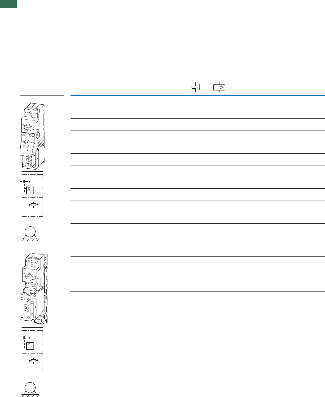
1
1.4 Motor-starter combinations
Complete units
2 AUTOMATION AND CONTROL www.eaton.com/seasia-electrical
Ordering
Setting rangeMotor data Motor starters
actuating voltage
230 V 50 Hz
Motor rating Rated
operational
current
Rated short-circuit current Overload
trip
Short-circuit
release Part no.
Article no. Price
See price
list
Std.
pack
AC-3 AC-3 380 - 415 V 380 - 415 V
380 V
400 V
415 V
400 V Type “1”
coordination
Type “2”
coordination
PI
eIqIqIrIrm
kWA kAkAAA
MSC-D: PKZM0, DILM
Complete units MSC-D
Complete units MSC-D
0.06 0.21 150 50 0.16 - 0.25 3.5 MSC-D-0.25-M7(230V50Hz)1)
281925
1 off
0.09 0.31 150 50 0.25 - 0.4 5.6 MSC-D-0.4-M7(230V50Hz)1)
281926
1 off
0.12
0.18
0.41
0.6
150 50 0.4 - 0.63 8.82 MSC-D-0.63-M7(230V50Hz)1)
281927
1 off
0.25 0.8 150 50 0.63 - 1 14 MSC-D-1-M7(230V50Hz)1)
281929
1 off
0.37
0.55
1.1
1.5
150 50 1 - 1.6 22.4 MSC-D-1.6-M7(230V50Hz)1)
283140
1 off
0.75 1.9 150 50 1.6 - 2.5 35 MSC-D-2.5-M7(230V50Hz)1)
283142
1 off
1.1
1.5
2.6
3.6
150 50 2.5 - 4 56 MSC-D-4-M7(230V50Hz)1)
283143
1 off
2.2 5 150 50 4 - 6.3 88.2 MSC-D-6.3-M7(230V50Hz)1)
283145
1 off
3 6.6 150 – 6.3 - 10 140 MSC-D-10-M7(230V50Hz)
283146
1 off
4 8.5 150 – 6.3 - 10 140 MSC-D-10-M9(230V50Hz)
283147
1 off
5.5 11.3 50 – 8 - 12 168 MSC-D-12-M12(230V50Hz)
283148
1 off
7.5 15.2 50 – 10 - 16 224 MSC-D-16-M15(230V50Hz)
100414
1 off
3
4
6.6
8.5
50 50 6.3 - 10 140 MSC-D-10-M17(230V50Hz)
101045
1 off
5.5 11.3 50 50 8 - 12 168 MSC-D-12-M17(230V50Hz)
101046
1 off
7.5 15.2 50 50 10 - 16 224 MSC-D-16-M17(230V50Hz)1)
283150
1 off
11 21.7 50 50 20 - 25 350 MSC-D-25-M25(230V50Hz)1)
283151
1 off
15 29.3 50 50 25 - 32 448 MSC-D-32-M32(230V50Hz)1)
283152
1 off
I
M
3 ~
I
M
3 ~
I
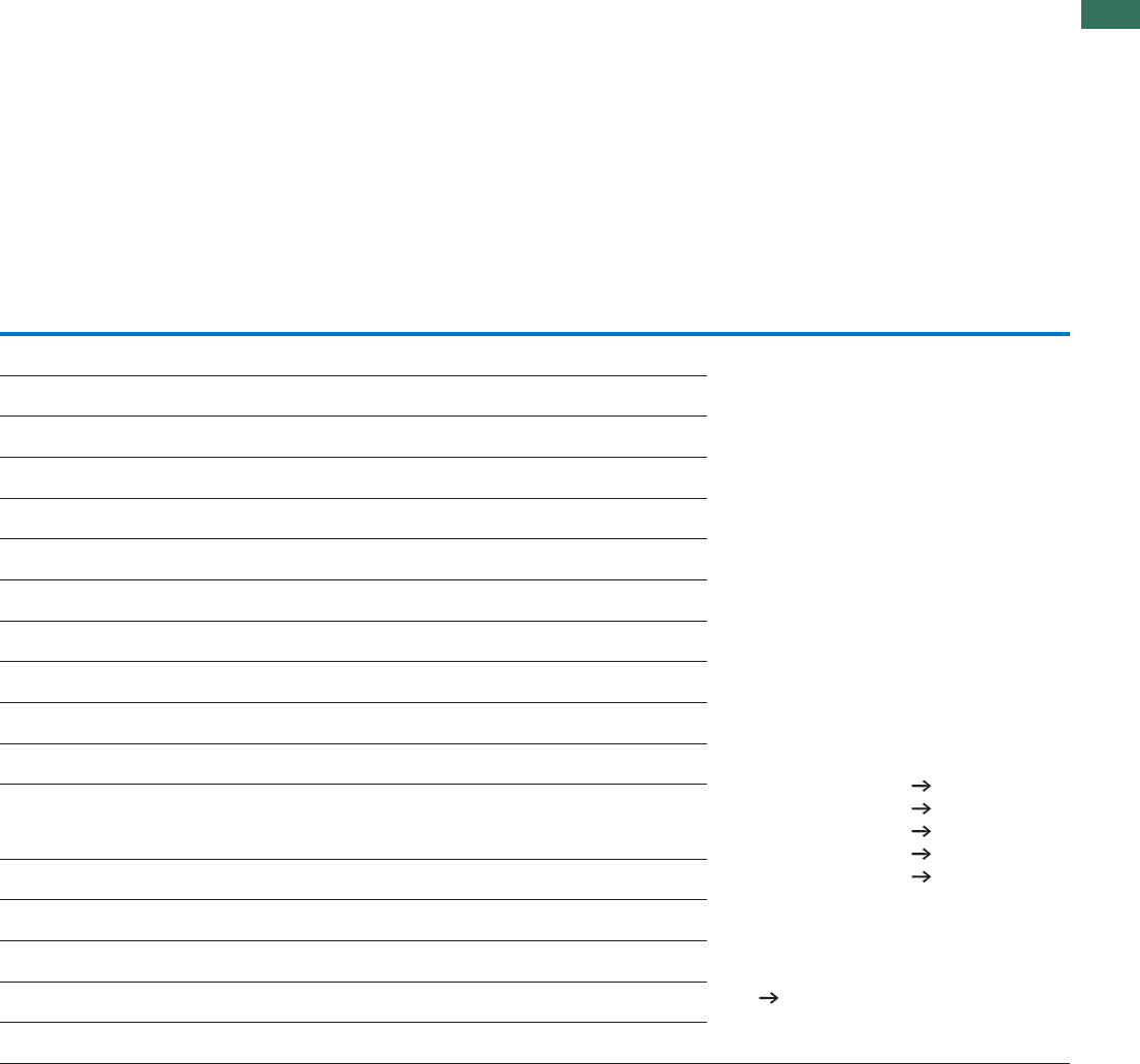
1
1.4
Motor-starter combinations
Complete units
3AUTOMATION AND CONTROL www.eaton.com/seasia-electrical
Motor starters
actuating voltage
24 V DC
Std.
pack Motor
protective
circuit breaker
Contactor DOL starter wiring
set
Notes
Part no.
Article no. Price
See price
list
Mechanical con-
nection module
and electrical
contact module
Type Type Type
MSC-D-0.25-M7(24VDC)1)
283154
1 off PKZM0-0,25 DILM7-10(...) PKZM0-XDM12
MSC-D-0.4-M7(24VDC)1)
283155
1 off PKZM0-0,4 DILM7-10(...) PKZM0-XDM12
MSC-D-0.63-M7(24VDC)1)
283156
1 off PKZM0-0,63 DILM7-10(...) PKZM0-XDM12
MSC-D-1-M7(24VDC)1)
283158
1 off PKZM0-1 DILM7-10(...) PKZM0-XDM12
MSC-D-1.6-M7(24VDC)1)
283159
1 off PKZM0-1,6 DILM7-10(...) PKZM0-XDM12
MSC-D-2.5-M7(24VDC)1)
283161
1 off PKZM0-2,5 DILM7-10(...) PKZM0-XDM12
MSC-D-4-M7(24VDC)1)
283162
1 off PKZM0-4 DILM7-10(...) PKZM0-XDM12
MSC-D-6.3-M7(24VDC)1)
283164
1 off PKZM0-6,3 DILM7-10(...) PKZM0-XDM12
MSC-D-10-M7(24VDC)
283165
1 off PKZM0-10 DILM7-10(...) PKZM0-XDM12
MSC-D-10-M9(24VDC)
283166
1 off PKZM0-10 DILM9-10(...) PKZM0-XDM12
MSC-D-12-M12(24VDC)
283167
1 off PKZM0-12 DILM12-10(...) PKZM0-XDM12
MSC-D-16-M15(24VDC)
100415
1 off PKZM0-16 DILM15-10(...) PKZM0-XDM12
MSC-D-10-M17(24VDC)
101047
1 off PKZM0-10 DILM17-10(...) PKZM0-XDM32
MSC-D-12-M17(24VDC)
101048
1 off PKZM0-12 DILM17-10(...) PKZM0-XDM32
MSC-D-16-M17(24VDC)
283168
1 off PKZM0-16 DILM17-10(...) PKZM0-XDM32
MSC-D-25-M25(24VDC)
283169
1 off PKZM0-25 DILM25-10(...) PKZM0-XDM32
MSC-D-32-M32(24VDC)
283170
1 off PKZM0-32 DILM32-10(...) PKZM0-XDM32
1) To assemble Type F starters that conform with
UL508, incoming terminals BK25/3-PKZ0-E and, if
necessary, three-phase terminal blocks B3.../...-PKZ0
can be added to motor starter combinations. Type F
starter Page 28
Further information Page
Technical data PKZM0 Chapter 1.3
Accessories PKZ Chapter 1.3 (Page 10)
Technical data DILM Chapter 1.1
Further actuating voltages Chapter 1.1 (Page 69)
DILM accessories Chapter 1.1 (Page 50)
The DOL starters (complete devices) consist of a motor
protective circuit breaker PKZM0 and a contactor DILM.
With the adapterless top-hat rail mounting of starters up
to 15 A, only the motor-protective circuit-breaker on the
top-hat rail requires an adapter. The contactors are
provided with mechanical support via a mechanical
connection element.
Control wire guide with max. 6 conductors with up to 2.5
mm external diameter or 4 conductors up to 3.5 mm
external diameter.
From 16 A, the motor protective circuit breaker and
contactors are mounted on the top-hat rail adapter plate.
The connection of the main circuit between PKZ and
contactor is established with electrical contact modules.
When using auxiliary contacts DILA‐XHIT…
J Chapter 1.1 (Page 38) the electrical plugs can be
pulled without having to remove the front mounting
auxiliary contact.
Cannot be combined with NHI-E-...-PKZ0-C standard
auxiliary contact with spring-loaded terminal.
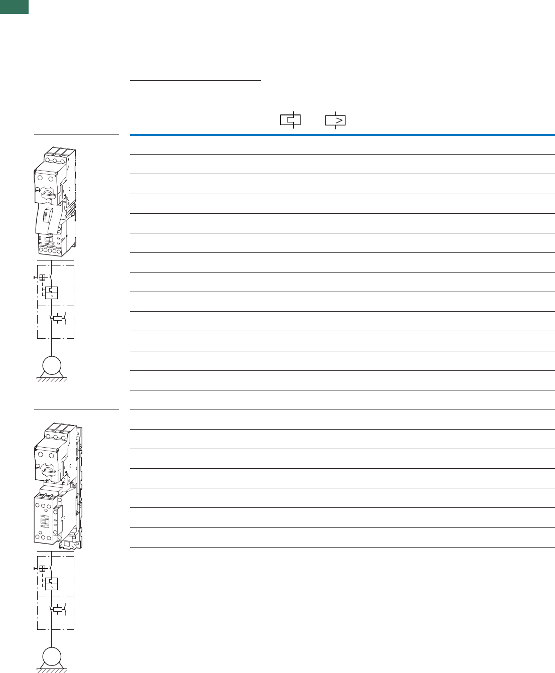
1
1.4 Motor-starter combinations
Complete units 400/415 V
4 AUTOMATION AND CONTROL www.eaton.com/seasia-electrical
Setting rangeMotor data Motor starters
actuating voltage
230 V 50 Hz
Std.
pack
Rated
operational
power
Rated
operational
current
Rated short-
circuit
current
Overload
trip
Short-
circuit
release
Type of
coordina-
tion
Part no.
Article no. Price
See price
list
AC-3 AC-3
380 V
400 V
415 V
400 V 380 - 415 V
PI
eIqIrIrm
kW A kA A A
Complete units MSC-US
Complete units MSC-US
MSC-DE: PKE, DILM
0.06 0.21 100 0.3 - 1.2 16.8 "1" MSC-DE-1.2-M7(230V50Hz)
121735
1 off
0.09 0.31 100 0.3 - 1.2 16.8 "1" MSC-DE-1.2-M7(230V50Hz)
121735
1 off
0.12 0.41 100 0.3 - 1.2 16.8 "1" MSC-DE-1.2-M7(230V50Hz)
121735
1 off
0.18 0.6 100 0.3 - 1.2 16.8 "1" MSC-DE-1.2-M7(230V50Hz)
121735
1 off
0.25 0.8 100 0.3 - 1.2 16.8 "1" MSC-DE-1.2-M7(230V50Hz)
121735
1 off
0.37 1.1 100 0.3 - 1.2 16.8 "1" MSC-DE-1.2-M7(230V50Hz)
121735
1 off
0.55 1.5 100 1 - 4 56 "1" MSC-DE-4-M7(230V50Hz)
121737
1 off
0.75 1.9 100 1 - 4 56 "1" MSC-DE-4-M7(230V50Hz)
121737
1 off
1.1 2.6 100 1 - 4 56 "1" MSC-DE-4-M7(230V50Hz)
121737
1 off
1.5 3.6 100 1 - 4 56 "1" MSC-DE-4-M7(230V50Hz)
121737
1 off
2.2 5 100 3 - 12 168 "1" MSC-DE-12-M7(230V50Hz)
121739
1 off
3 6.6 100 3 - 12 168 "1" MSC-DE-12-M7(230V50Hz)
121739
1 off
4 8.5 100 3 - 12 168 "1" MSC-DE-12-M9(230V50Hz)
121741
1 off
5.5 11.3 100 3 - 12 168 "1" MSC-DE-12-M12(230V50Hz)
121743
1 off
2.2 5 100 3 - 12 168 "1", "2" MSC-DE-12-M17(230V50Hz)
121745
1 off
3 6.6 100 3 - 12 168 "1", "2" MSC-DE-12-M17(230V50Hz)
121745
1 off
4 8.5 100 3 - 12 168 "1", "2" MSC-DE-12-M17(230V50Hz)
121745
1 off
5.5 11.3 100 3 - 12 168 "1", "2" MSC-DE-12-M17(230V50Hz)
121745
1 off
7.5 16.7 100 8 - 32 448 "1", "2" MSC-DE-32-M17(230V50Hz)
121747
1 off
11 21.7 100 8 - 32 448 "1", "2" MSC-DE-32-M25(230V50Hz)
121749
1 off
15 29.3 100 8 - 32 448 "1", "2" MSC-DE-32-M32(230V50Hz)
121751
1 off
I
M
3 ~
I
M
3 ~
I

1
1.4
Motor-starter combinations
Complete units 400/415 V
5AUTOMATION AND CONTROL www.eaton.com/seasia-electrical
Motor starters
actuating voltage
24 V DC
Std.
pack Motor
protective
circuit breaker
Contactor DOL starter
wiring set
Notes
Part no.
Article no. Price
See price
list
Mechanical con-
nection module
and electrical
contact module
Type Type Type
MSC-DE-1.2-M7(24VDC)
121736
1 off PKE12/XTU-1.2 DILM7-10(...) PKZM0-XDM12
MSC-DE-1.2-M7(24VDC)
121736
1 off PKE12/XTU-1.2 DILM7-10(...) PKZM0-XDM12
MSC-DE-1.2-M7(24VDC)
121736
1 off PKE12/XTU-1.2 DILM7-10(...) PKZM0-XDM12
MSC-DE-1.2-M7(24VDC)
121736
1 off PKE12/XTU-1.2 DILM7-10(...) PKZM0-XDM12
MSC-DE-1.2-M7(24VDC)
121736
1 off PKE12/XTU-1.2 DILM7-10(...) PKZM0-XDM12
MSC-DE-1.2-M7(24VDC)
121736
1 off PKE12/XTU-1.2 DILM7-10(...) PKZM0-XDM12
MSC-DE-4-M7(24VDC)
121738
1 off PKE12/XTU-4 DILM7-10(...) PKZM0-XDM12
MSC-DE-4-M7(24VDC)
121738
1 off PKE12/XTU-4 DILM7-10(...) PKZM0-XDM12
MSC-DE-4-M7(24VDC)
121738
1 off PKE12/XTU-4 DILM7-10(...) PKZM0-XDM12
MSC-DE-4-M7(24VDC)
121738
1 off PKE12/XTU-4 DILM7-10(...) PKZM0-XDM12
MSC-DE-12-M7(24VDC)
121740
1 off PKE12/XTU-12 DILM7-10(...) PKZM0-XDM12
MSC-DE-12-M7(24VDC)
121740
1 off PKE12/XTU-12 DILM7-10(...) PKZM0-XDM12
MSC-DE-12-M9(24VDC)
121742
1 off PKE12/XTU-12 DILM9-10(...) PKZM0-XDM12
MSC-DE-12-M12(24VDC)
121744
1 off PKE12/XTU-12 DILM12-10(...) PKZM0-XDM12
MSC-DE-12-M17(24VDC)
121746
1 off PKE12/XTU-12 DILM17-10(...) PKZM0-XDM32
MSC-DE-12-M17(24VDC)
121746
1 off PKE12/XTU-12 DILM17-10(...) PKZM0-XDM32
MSC-DE-12-M17(24VDC)
121746
1 off PKE12/XTU-12 DILM17-10(...) PKZM0-XDM32
MSC-DE-12-M17(24VDC)
121746
1 off PKE12/XTU-12 DILM17-10(...) PKZM0-XDM32
MSC-DE-32-M17(24VDC)
121748
1 off PKE32/XTU-32 DILM17-10(...) PKZM0-XDM32
MSC-DE-32-M25(24VDC)
121750
1 off PKE32/XTU-32 DILM25-10(...) PKZM0-XDM32
MSC-DE-32-M32(24VDC)
121752
1 off PKE32/XTU-32 DILM32-10(...) PKZM0-XDM32
Further information Page
Technical data PKE Chapter 1.3
Accessories PKE Chapter 1.3 (Page 10)
Technical data DILM Chapter 1.1
Further actuating voltages Chapter 1.1 (Page 69)
DILM accessories Chapter 1.1 (Page 50)
The DOL starters (complete devices) consist of a PKE
motor protective circuit breaker and a DILM contactor.
With the adapterless top-hat rail mounting of starters up
to 15 A, only the motor protective circuit breaker on the
top-hat rail requires an adapter.
The contactors are provided with mechanical support via
a mechanical connection element.
Control wire guide with max. 6 conductors with up to
2.5 mm external diameter or 4 conductors up to 3.5 mm
external diameter.
From 16 A, the motor protective circuit breaker and
contactor are mounted on the top-hat rail adapter plate.
The connection of the main circuit between PKE and
contactor is established with electrical contact modules.
When using auxiliary contacts DILA-XHIT…
J Chapter 1.1 (Page 38) the electrical plugs can be
pulled without having to remove the front mounting
auxiliary contact.
Cannot be combined with standard auxiliary contact
NHI-E-...-PKZ0-C with spring-loaded terminals.
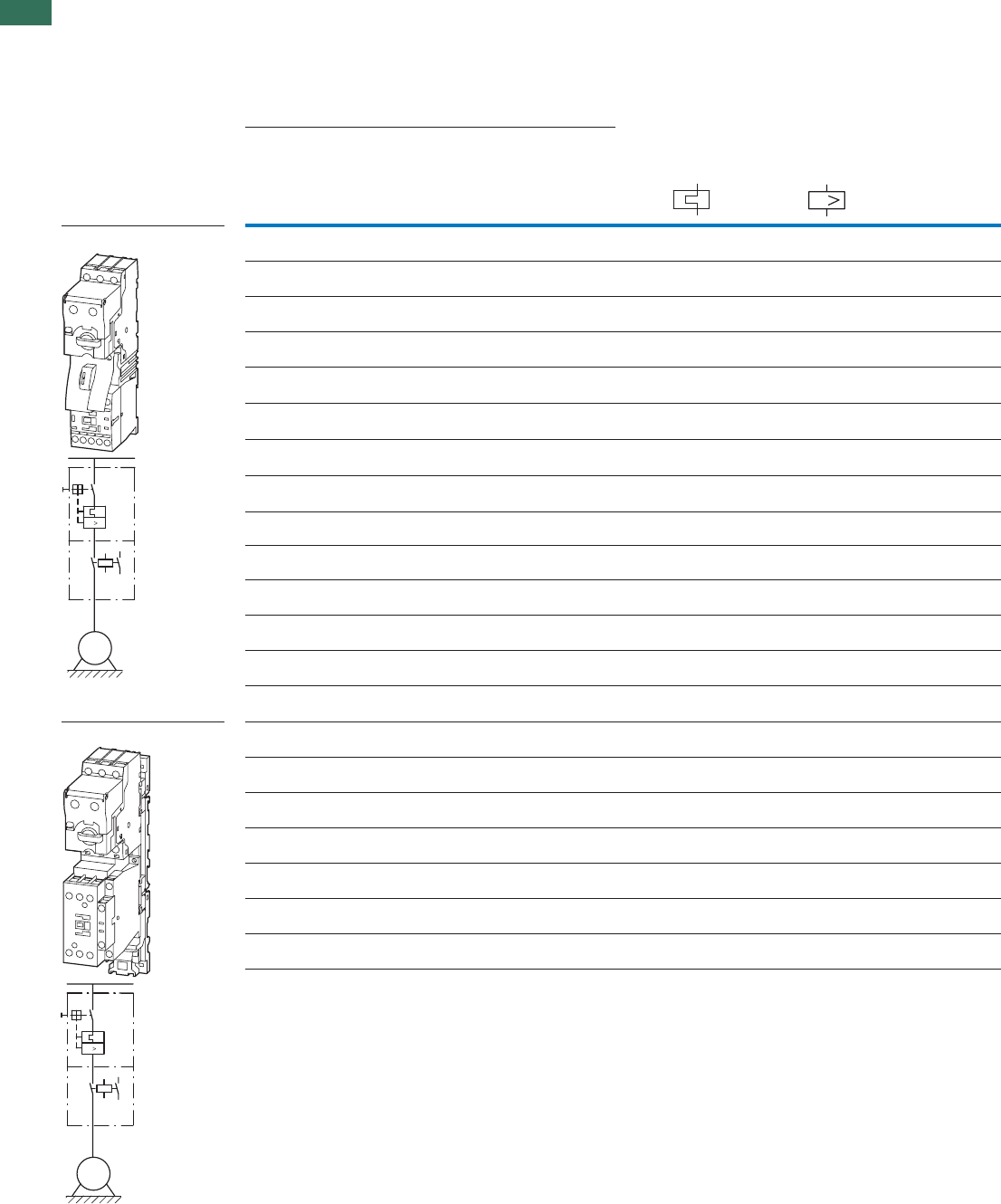
1
1.4 Motor-starter combinations
Complete units 400/415 V
6 AUTOMATION AND CONTROL www.eaton.com/seasia-electrical
Setting rangeMotor data
Rated operational
power
Rated operational
current
Rated short-circuit
current
Overload trip Short-circuit release Type of
coordination
AC-3 AC-3
380 V
400 V
415 V
400 V 380 - 415 V
PI
eIqIrIrm
kW A kA A A
Complete devices MSD-DEA
Complete devices MSD-DEA
0.06 0.21 100 0.3 - 1.2 16.8 "1"
0.09 0.31 100 0.3 - 1.2 16.8 "1"
0.12 0.41 100 0.3 - 1.2 16.8 "1"
0.18 0.6 100 0.3 - 1.2 16.8 "1"
0.25 0.8 100 0.3 - 1.2 16.8 "1"
0.37 1.1 100 0.3 - 1.2 16.8 "1"
0.55 1.5 100 1 - 4 56 "1"
0.75 1.9 100 1 - 4 56 "1"
1.1 2.6 100 1 - 4 56 "1"
1.5 3.6 100 1 - 4 56 "1"
2.2 5 100 3 - 12 168 "1"
3 6.6 100 3 - 12 168 "1"
4 8.5 100 3 - 12 168 "1"
5.5 11.3 100 3 - 12 168 "1"
2.2 5 100 3 - 12 168 "1", "2"
3 6.6 100 3 - 12 168 "1", "2"
4 8.5 100 3 - 12 168 "1", "2"
5.5 11.3 100 3 - 12 168 "1", "2"
7.5 16.7 100 8 - 32 448 "1", "2"
11 21.7 100 8 - 32 448 "1", "2"
15 29.3 100 8 - 32 448 "1", "2"
I
M
3 ~
I
M
3 ~
I
MSC-DEA: PKE, DILM

1
1.4
Motor-starter combinations
Complete units 400/415 V
7AUTOMATION AND CONTROL www.eaton.com/seasia-electrical
Motor starters
actuating voltage
24 V DC
Std.
pack Motor
protective
circuit breaker
Contactor DOL starter
wiring set
Notes
Part no.
Article no. Price
See price
list
Mechanical con-
nection module
and electrical
contact module
Type Type Type
MSC-DEA-1.2-M7(24VDC)
121753
1 off PKE12/XTUA-1.2 DILM7-10(...) PKZM0-XDM12
MSC-DEA-1.2-M7(24VDC)
121753
1 off PKE12/XTUA-1.2 DILM7-10(...) PKZM0-XDM12
MSC-DEA-1.2-M7(24VDC)
121753
1 off PKE12/XTUA-1.2 DILM7-10(...) PKZM0-XDM12
MSC-DEA-1.2-M7(24VDC)
121753
1 off PKE12/XTUA-1.2 DILM7-10(...) PKZM0-XDM12
MSC-DEA-1.2-M7(24VDC)
121753
1 off PKE12/XTUA-1.2 DILM7-10(...) PKZM0-XDM12
MSC-DEA-1.2-M7(24VDC)
121753
1 off PKE12/XTUA-1.2 DILM7-10(...) PKZM0-XDM12
MSC-DEA-4-M7(24VDC)
121754
1 off PKE12/XTUA-4 DILM7-10(...) PKZM0-XDM12
MSC-DEA-4-M7(24VDC)
121754
1 off PKE12/XTUA-4 DILM7-10(...) PKZM0-XDM12
MSC-DEA-4-M7(24VDC)
121754
1 off PKE12/XTUA-4 DILM7-10(...) PKZM0-XDM12
MSC-DEA-4-M7(24VDC)
121754
1 off PKE12/XTUA-4 DILM7-10(...) PKZM0-XDM12
MSC-DEA-12-M7(24VDC)
121755
1 off PKE12/XTUA-12 DILM7-10(...) PKZM0-XDM12
MSC-DEA-12-M7(24VDC)
121755
1 off PKE12/XTUA-12 DILM7-10(...) PKZM0-XDM12
MSC-DEA-12-M9(24VDC)
121756
1 off PKE12/XTUA-12 DILM9-10(...) PKZM0-XDM12
MSC-DEA-12-M12(24VDC)
121757
1 off PKE12/XTUA-12 DILM12-10(...) PKZM0-XDM12
MSC-DEA-12-M17(24VDC)
121758
1 off PKE12/XTUA-12 DILM17-10(...) PKZM0-XDM32
MSC-DEA-12-M17(24VDC)
121758
1 off PKE12/XTUA-12 DILM17-10(...) PKZM0-XDM32
MSC-DEA-12-M17(24VDC)
121758
1 off PKE12/XTUA-12 DILM17-10(...) PKZM0-XDM32
MSC-DEA-12-M17(24VDC)
121758
1 off PKE12/XTUA-12 DILM17-10(...) PKZM0-XDM32
MSC-DEA-32-M17(24VDC)
121759
1 off PKE32/XTUA-32 DILM17-10(...) PKZM0-XDM32
MSC-DEA-32-M25(24VDC)
121760
1 off PKE32/XTUA-32 DILM25-10(...) PKZM0-XDM32
MSC-DEA-32-M32(24VDC)
121761
1 off PKE32/XTUA-32 DILM32-10(...) PKZM0-XDM32
Further information Page
Technical data PKE Chapter 1.3
Accessories PKE Chapter 1.3 (Page 10)
Technical data DILM Chapter 1.1
Further actuating voltages Chapter 1.1 (Page 69)
DILM accessories Chapter 1.1 (Page 50)
The DOL starters (complete devices) consist of a PKE
motor protective circuit breaker and a DILM contactor.
With the adapterless top-hat rail mounting of starters up
to 15 A, only the motor protective circuit breaker on the
top-hat rail requires an adapter.
The contactors are provided with mechanical support via
a mechanical connection element.
Control wire guide with max. 6 conductors with up to
2.5 mm external diameter or 4 conductors up to 3.5 mm
external diameter.
From 16 A, the motor protective circuit breaker and
contactor are mounted on the top-hat rail adapter plate.
The connection of the main circuit between PKE and
contactor is established with electrical contact modules.
When using auxiliary contacts DILA‐XHIT…
J Chapter 1.1 (Page 38) the electrical plugs can be
pulled without having to remove the front mounting
auxiliary contact.
Cannot be combined with standard auxiliary contact
NHI-E-...-PKZ0-C with spring-loaded terminals.
The DOL starters MSC-DEA... are prepared for
communication via SmartWire-DT®. For this the SWD-PKE
communication must be added.
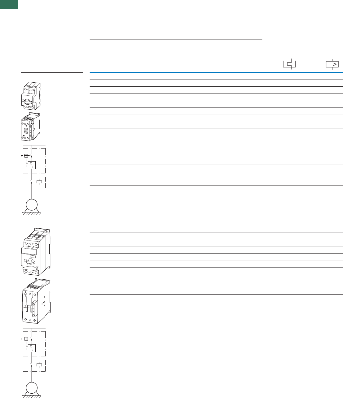
1
1.4 Motor-starter combinations
Modules
8 AUTOMATION AND CONTROL www.eaton.com/seasia-electrical
Motor data Setting range
Rated operational power Rated operational current Overload trip Short-circuit
release
380 - 415 V380 - 415 VAC-3AC-3
380 V
400 V
415 V
400 V Type “1”
coordination
Type “2”
coordination
IP eIqIqIrIrm
AAAkAkAWk
Modules PKZM0 and DILM 5.352.0-61.00505112.060.0
6.54.0-52.00505113.090.0
28.836.0-4.00505114.021.0
28.836.0-4.005051
6.081.0
411-36.0050518.052.0
4.226.1-1050511.173.0
4.226.1-1050515.155.0
535.2-6.1050519.157.0
654-5.20505
16.21.1
654-5.2050516.35.1
2.883.6-40505152.2
04101-3.6050516.63
04101-3.6050515.84
86121-805053.115.5
4226
1-0105052.515.7
05352-0205057.1211
84423-5205053.9251
Modules PKZM4 and DILM 42261-0105053.115.5
42261-0105052.515.7
05352-02050
57.1211
84423-5205053.9251
06504-230505635.81
00705-0405051422
21885-0505055503
28856-5505053643
I
M
3 ~
M
3 ~
PKZM, DILM
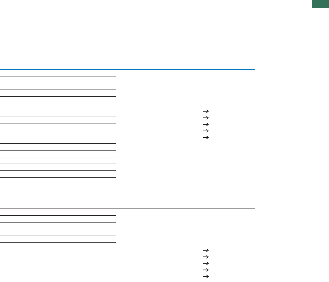
1
1.4
Motor-starter combinations
Modules
9AUTOMATION AND CONTROL www.eaton.com/seasia-electrical
Motor protective
circuit breaker
Contactor Contactor Notes
Type “1”
coordination
Type “2”
coordination
Type Type Type
PKZM0-0,25 DILM7-…(…) DILM7-…(…) The motor-starter combinations consist of the motor protective circuit breaker
or a circuit breaker and a contactor. They conform with IEC/EN 60947-4-1 or
VDE 0660 Part 102.
Iq = conditional rated current
PKZM0-0,4 DILM7-…(…) DILM7-…(…)
PKZM0-0,63 DILM7-…(…) DILM7-…(…)
PKZM0-0,63 DILM7-…(…) DILM7-…(…)
PKZM0-1 DILM7-…(…) DILM7-…(…)
PKZM0-1,6 DILM7-…(…) DILM7-…(…)
PKZM0-1,6 DILM7-…(…) DILM7-…(…)
PKZM0-2,5 DILM7-…(…) DILM7-…(…)
PKZM0-4 DILM7-…(…) DILM7-…(…)
PKZM0-4 DILM7-…(…) DILM7-…(…)
PKZM0-6,3 DILM7-…(…) DILM7-…(…)
PKZM0-10 DILM7-…(…) DILM17-…(…)
PKZM0-10 DILM9-…(…) DILM17-…(…)
PKZM0-12 DILM12-…(…) DILM17-…(…)
PKZM0-16 DILM15-…(…) DILM17-…(…)
PKZM0-25 DILM25-…(…) DILM25-…(…)
PKZM0-32 DILM32-…(…) DILM32-…(…)
PKZM4-16 DILM17-…(…) DILM17-…(…) The motor-starter combinations consist of the motor protective circuit breaker
or a circuit breaker and a contactor. They conform with IEC/EN 60947-4-1 or
VDE 0660 Part 102.
Iq = conditional rated current
PKZM4-16 DILM17-…(…) DILM17-…(…)
PKZM4-25 DILM25-…(…) DILM25-…(…)
PKZM4-32 DILM32-…(…) DILM32-…(…)
PKZM4-40 DILM40(…) DILM40(…)
PKZM4-50 DILM50(…) DILM50(…)
PKZM4-58 DILM65(…) DILM65(…)
PKZM4-63 DILM65(…) DILM65(…)
egaPnoitamrofnirehtruF
Technical data PKZM0 Chapter 1.3
Accessories PKZ Chapter 1.3 (Page 10)
Technical data DILM Chapter 1.1
Further actuating voltages Chapter 1.1 (Page 69)
DILM accessories Chapter 1.1 (Page 50)
egaPnoitamrofnirehtruF
Technical data PKZM4 Chapter 1.3
Accessories PKZ Chapter 1.3 (Page 10)
Technical data DILM Chapter 1.1
Further actuating voltages Chapter 1.1 (Page 70)
DILM accessories Chapter 1.1 (Page 50)
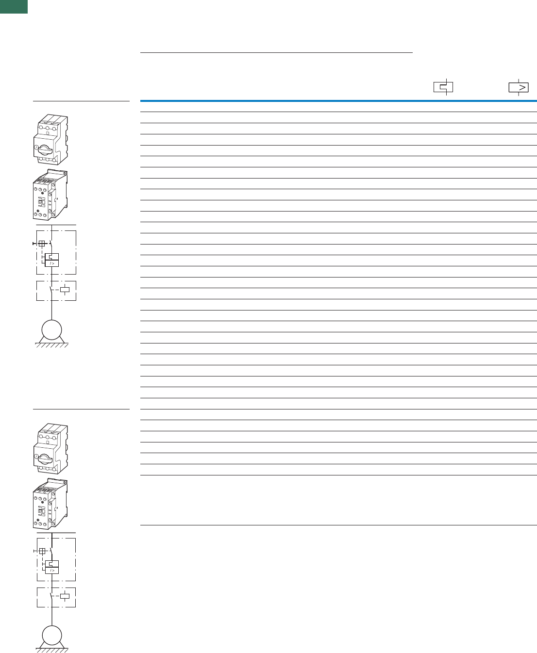
1
1.4 Motor-starter combinations
Modules
10 AUTOMATION AND CONTROL www.eaton.com/seasia-electrical
PKZM, DILM
Motor data Setting range
Rated operational
power
Rated operational
current
Rated short-circuit current Overload trip Short-circuit
release
AC-3 AC-3 500 V 500 V
500 V 500 V Type “1” coordination Type “2” coordination
PI
eIqIqIrIrm
kW A kA kA A A
Modules PKZM0 and DILM 0.06 0.17 100 50 0.16 - 0.25 3.5
0.09 0.25 100 50 0.25 - 0.4 5.6
0.12 0.33 100 50 0.25 - 0.4 5.6
0.18 0.48 100 50 0.4 - 0.63 8.8
0.25 0.7 100 50 0.63 - 1 14
0.37 0.9 100 50 0.63 - 1 14
0.55 1.2 100 50 1 - 1.6 22
0.75 1.5 100 50 1 - 1.6 22
1.1 2.1 100 50 1.6 - 2.5 35
1.5 2.9 100 50 2.5 - 4 56
2.2 4 42 18 4 - 6.3 88
2.2 4 – 50 4 - 6.3 88
35.342184 - 6.388
3 5.3 – 50 4 - 6.3 88
4 6.8 42 18 6.3 - 10 140
4 6.8 – 50 6.3 - 10 140
5.5 9 42 18 6.3 - 10 140
5.5 9 – 50 6.3 - 10 140
6.5 10.6 42 18 8 - 12 168
6.5 10.6 – 50 8 - 12 168
7.512.1151810 - 16224
7.5 12.1 – 50 10 - 16 224
11 17.4 6 – 16 - 20 280
11 17.4 15 – 16 - 20 280
15 23.4 6 – 20 - 25 350
15 23.4 15 – 20 - 25 350
18.5 28.9 6 – 25 - 32 448
18.5 28.9 15 – 25 - 32 448
Modules PKZM4 and DILM 11 17.4 50 50 16 - 25 350
15 23.4 50 50 16 - 25 350
18.5 28.9 50 50 25 - 32 448
22 33 50 50 32 - 40 560
30 44 50 50 40 - 50 700
37 54 50 50 50 - 58 812
45 65 50 50 55 - 65 882
I
M
3 ~
M
3 ~
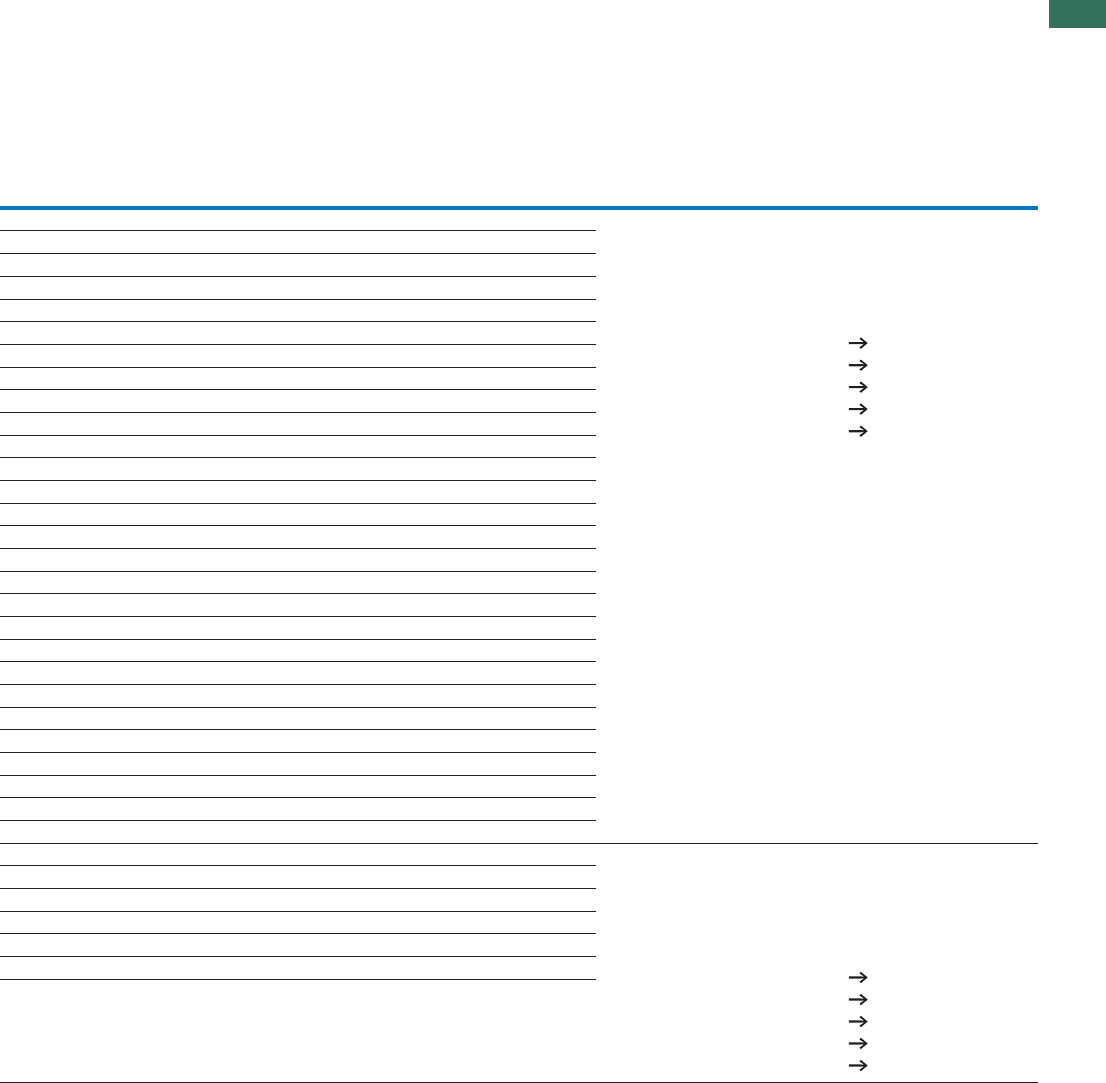
1
1.4
Motor-starter combinations
Modules
11AUTOMATION AND CONTROL www.eaton.com/seasia-electrical
NotesMotor protective circuit
breaker
Contactor Contactor Current limiter
Type “1” coordination Type “2” coordination
Type Type Type Type
PKZM0-0,25 DILM7-…(…) DILM7-…(…) – The motor-starter combinations consist of the motor protective
circuit breaker or a circuit breaker and a contactor.
They conform with IEC/EN 60947-4-1 or VDE 0660 Part 102.
Iq = rated conditional short-circuit current.
PKZM0-0,4 DILM7-…(…) DILM7-…(…) –
PKZM0-0,4 DILM7-…(…) DILM7-…(…) –
PKZM0-0,63 DILM7-…(…) DILM7-…(…) –
PKZM0-1 DILM7-…(…) DILM7-…(…) –
PKZM0-1 DILM7-…(…) DILM7-…(…) –
PKZM0-1,6 DILM7-…(…) DILM7-…(…) –
PKZM0-1,6 DILM7-…(…) DILM7-…(…) –
PKZM0-2,5 DILM7-…(…) DILM17-…(…) –
PKZM0-4 DILM7-…(…) DILM17-…(…) –
PKZM0-6,3 DILM7-…(…) DILM17-…(…) –
PKZM0-6,3 – DILM17-…(…) CL-PKZ0
PKZM0-6,3 DILM7-…(…) DILM17-…(…) –
PKZM0-6,3 – DILM17-…(…) CL-PKZ0
PKZM0-10 DILM9-…(…) DILM17-…(…) –
PKZM0-10 – DILM17-…(…) CL-PKZ0
PKZM0-10 DILM9-…(…) DILM17-…(…) –
PKZM0-10 – DILM17-…(…) CL-PKZ0
PKZM0-12 DILM12-…(…) DILM17-…(…) –
PKZM0-12 – DILM17-…(…) CL-PKZ0
PKZM0-16 DILM17-…(…) DILM17-…(…) –
PKZM0-16 – DILM17-…(…) CL-PKZ0
PKZM0-20 DILM25-…(…) – –
PKZM0-20 DILM25-…(…) – CL-PKZ0
PKZM0-25 DILM25-…(…) – –
PKZM0-25 DILM25-…(…) – CL-PKZ0
PKZM0-32 DILM32-…(…) – –
PKZM0-32 DILM32-…(…) – CL-PKZ0
PKZM4-25 DILM40(…) DILM40(…) – The motor-starter combinations consist of the motor protective
circuit breaker or a circuit breaker and a contactor.
They conform with IEC/EN 60947-4-1 or VDE 0660 Part 102.
Iq = rated conditional short-circuit current.
PKZM4-25 DILM40(…) DILM40(…) –
PKZM4-32 DILM40(…) DILM40(…) –
PKZM4-40 DILM40(…) DILM40(…) –
PKZM4-50 DILM50(…) DILM50(…) –
PKZM4-58 DILM65(…) DILM65(…) –
PKZM4-63 DILM65(…) DILM65(…) –
Further information Page
Technical data PKZM... Chapter 1.3
PKZM accessories... Chapter 1.3 (Page 10)
Technical data DILM Chapter 1.1
Further actuating voltages Chapter 1.1 (Page 71)
DILM accessories Chapter 1.1 (Page 52)
Further information Page
Technical data PKZM... Chapter 1.3
PKZM accessories... Chapter 1.3 (Page 10)
Technical data DILM Chapter 1.1
Further actuating voltages Chapter 1.1 (Page 71)
DILM accessories Chapter 1.1 (Page 52)
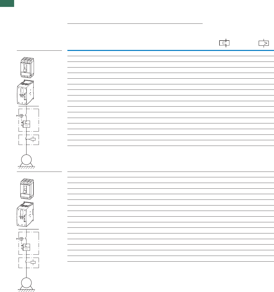
1
1.4 Motor-starter combinations
Modules
12 AUTOMATION AND CONTROL www.eaton.com/seasia-electrical
Motor data Setting range
Rated operational power Rated operational current Rated short-circuit current Overload trip Short-circuit
release
AC-3AC-3
380 V
400 V
415 V
400/415 V400 V
IP eIqIrIrm
AAAkAWk
Modules NZMN and DILM 320 - 56032 - 40503618.5
400 - 70040 - 50504122
504 - 88250 - 63505530
640 - 112063 - 80506837
800 - 125080 - 100508145
800 - 125080 - 100509955
1280 - 2240125 - 1605013475
1600 - 2500160 - 2005016190
1600 - 2500160 - 20050196110
350 - 4900175 - 35050231132
350 - 4900175 - 35050279160
350 - 4900175 - 35050349200
450 - 6300225 - 45050437250
550 - 7700275 - 55050544315
875 - 12250438 - 87550683400
875 - 12250438 - 87550750450
875 - 12250438 - 87550820500
1400 -19600700 - 140050947560
Modules NZMH and DILM 400 - 70040 - 501004122
504 - 88250 - 631005530
640 - 112063 - 801006837
800 - 125080 - 1001008145
1000 - 1750100 - 12510010055
1280 - 2240125 - 16010013475
90 - 126045 - 901005530
90 - 126045 - 901006837
90 - 126045 - 901008145
140 - 196070 - 14010010055
140 - 196070 - 14010013475
220 - 3080110 - 12010016190
220 - 3080110 - 120100196110
350 - 4900175 - 350100231132
350 - 4900175 - 350100279160
350 - 4900175 - 350100349200
I
M
3 ~
M
3 ~
NZMN, NZMH, DILM

1
1.4
Motor-starter combinations
Modules
13AUTOMATION AND CONTROL www.eaton.com/seasia-electrical
Notes
Circuit-breaker Contactor Contactor
Type “1” coordination Type “2” coordination
Type Type Type
NZMN1-M40 DILM40(…) DILM80(…) The motor-starter combinations consist of the motor protective circuit breaker
or a circuit breaker and a contactor. They conform with IEC/EN 60947-4-1 or
VDE 0660 Part 102.
Iq = conditional rated current
NZMN1-M50 DILM50(…) DILM80(…)
NZMN1-M63 DILM65(…) DILM80(…)
NZMN1-M80 DILM80(…) DILM80(…)
NZMN1-M100 DILM95(…) DILM95(…)
NZMN1-M100 DILM115(…) DILM115(…)
NZMN2-M160 DILM150(…) DILM150(…)
NZMN2-M200 DILM185A/22(…) DILM185A/22(…)
NZMN2-M200 DILM225A/22(…) DILM225A/22(…)
NZMN3-ME350 DILM250/22(…) DILM250/22(…)
NZMN3-ME350 DILM300A/22(…) DILM300A/22(…)
NZMN3-ME350 DILM400/22(…) DILM400/22(…)
NZMN3-ME450 DILM500/22(…) DILM500/22(…)
NZMN4-ME550 DILM580/22(…) –
NZMN4-ME875 DILM650/22(…) –
NZMN4-ME875 DILM750/22(…) –
NZMN4-ME875 DILM820/22(…) –
NZMN4-ME1400 DILM1000/22(…) –
NZMH2-M50 DILM80(…) DILM80(…) The motor-starter combinations consist of the motor protective circuit breaker
or a circuit breaker and a contactor. They conform with IEC/EN 60947-4-1 or
VDE 0660 Part 102.
Iq = conditional rated current
NZMH2-M63 DILM80(…) DILM80(…)
NZMH2-M80 DILM80(…) DILM80(…)
NZMH2-M100 DILM95(…) DILM95(…)
NZMH2-M125 DILM115(…) DILM115(…)
NZMH2-M160 DILM150(…) DILM150(…)
NZMH2-ME90 DILM80(…) DILM80(…)
NZMH2-ME90 DILM80(…) DILM80(…)
NZMH2-ME90 DILM95(…) DILM95(…)
NZMH2-ME140 DILM115(…) DILM115(…)
NZMH2-ME140 DILM150(…) DILM150(…)
NZMH2-ME220 DILM185A/22(…) DILM185A/22(…)
NZMH2-ME220 DILM225A/22(…) DILM225A/22(…)
NZMH3-ME350 DILM250/22(…) DILM250/22(…)
NZMH3-ME350 DILM300A/22(…) DILM300A/22(…)
NZMH3-ME350 DILM400/22(…) DILM400/22(…)
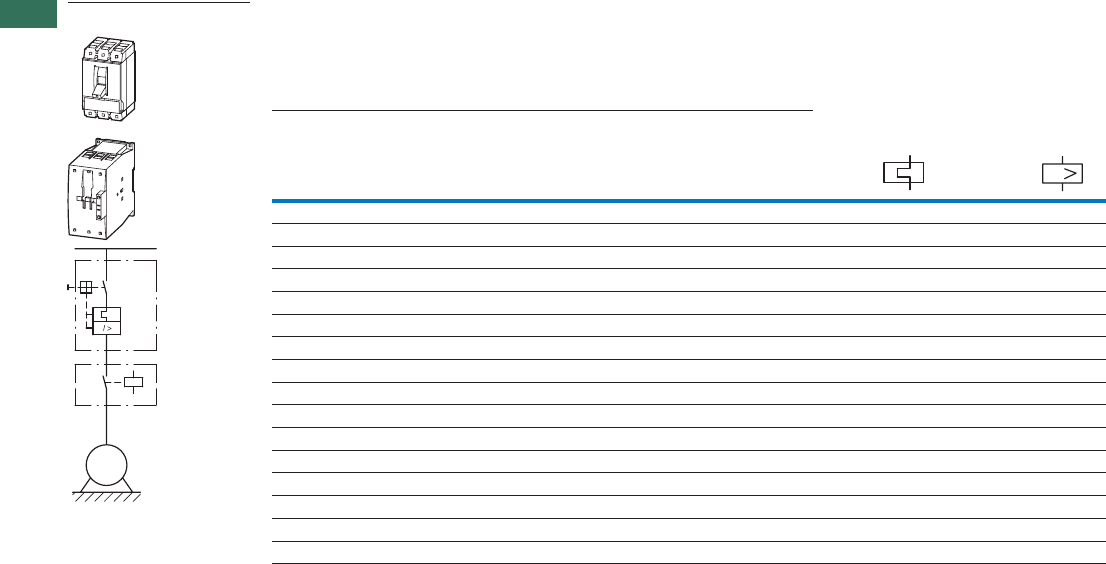
1
1.4 Motor-starter combinations
Modules
14 AUTOMATION AND CONTROL www.eaton.com/seasia-electrical
Motor data Setting range
Rated operational
power
Rated operational current Rated short-circuit current Overload trip Short-circuit
release
AC-3
500 V
525 V
500 V 525 V 500/525 V
PI
eIeIqIrIrm
AAAkAAWk
Modules NZMH and DILM
350 - 35016 - 20501717.411
350 - 35020 - 255022.523.415
320 - 44825 - 32502828.918.5
320 - 56032 - 4050323322
400 - 70040 - 5050434430
504 - 88250 - 6350545437
640 - 112063 - 8050646545
640 - 112063 - 8050787955
1000 - 1750100 - 1255010610775
1280 - 2240125 - 1605012712990
90 - 126045 - 9050434430
90 - 126045 - 9050545437
90 - 126045 - 9050646545
90 - 126045 - 9050787955
140 - 196070 - 1405010610775
140 - 196070 - 140
5012712990
I
M
3 ~
NZMH, DILM

1
1.4
Motor-starter combinations
Modules
15AUTOMATION AND CONTROL www.eaton.com/seasia-electrical
NotesCircuit-breaker Contactor Contactor
Type “1” coordination Type “2” coordination
Type Type Type
NZMH2-M20 DILM40(…) DILM80(…) The motor-starter combinations consist of the motor protective circuit breaker or
a circuit breaker and a contactor. They conform with IEC/EN 60947-4-1 or
VDE 0660 Part 102.
Iq = conditional rated current
NZMH2-M25 DILM40(…) DILM80(…)
NZMH2-M32 DILM40(…) DILM80(…)
NZMH2-M40 DILM40(…) DILM80(…)
NZMH2-M50 DILM80(…) DILM80(…)
NZMH2-M63 DILM80(…) DILM80(…)
NZMH2-M80 DILM80(…) DILM80(…)
NZMH2-M80 DILM80(…) DILM80(…)
NZMH2-M125 DILM115(…) DILM115(…)
NZMH2-M160 DILM150(…) DILM150(…)
NZMH2-ME90 DILM80(…) DILM80(…)
NZMH2-ME90 DILM80(…) DILM80(…)
NZMH2-ME90 DILM80(…) DILM80(…)
NZMH2-ME90 DILM80(…) DILM80(…)
NZMH2-ME140 DILM115(…) DILM115(…)
NZMH2-ME140 DILM150(…) DILM150(…)
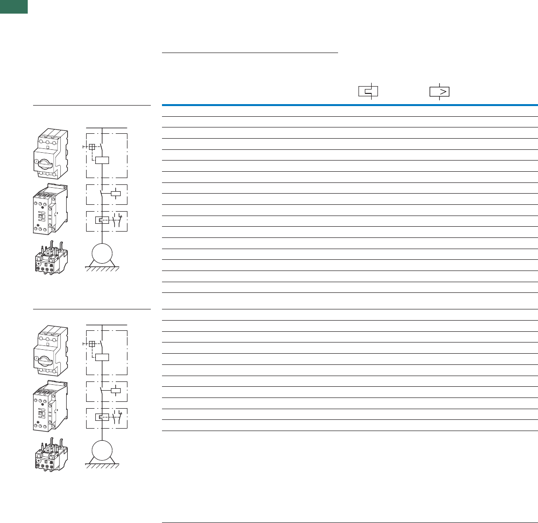
1
1.4 Motor-starter combinations
Modules
16 AUTOMATION AND CONTROL www.eaton.com/seasia-electrical
Setting rangeMotor data Basic unit
Rated operational
power
Rated operational
current
Rated short-circuit
current
Overload trip Short-circuit release
AC-3 AC-3
380 V
400 V
415 V
400 V 380 - 415 V
PI
eIqIrIrm Type
kW A kA A A
Modules PKM0, DILM and ZB with
and without automatic reset
0.06 0.21 100 0.16 - 0.24 3.5 PKM0-0,25
0.09 0.31 100 0.24 - 0.4 5.6 PKM0-0,4
0.12 0.41 100 0.4 - 0.6 8.82 PKM0-0,63
0.18 0.6 100 0.4 - 0.6 8.82 PKM0-0,63
0.25 0.8 100 0.6 - 1 14 PKM0-1
0.37 1.1 100 1 - 1.6 22.4 PKM0-1,6
0.55 1.5 100 1 - 1.6 22.4 PKM0-1,6
0.75 1.9 100 1.6 - 2.4 35 PKM0-2,5
1.1 2.6 100 2.4 - 4 56 PKM0-4
1.5 3.6 100 2.4 - 4 56 PKM0-4
2.2 5 100 4 - 6 88.2 PKM0-6,3
3 6.6 100 6 - 10 140 PKM0-10
4 8.5 100 6 - 10 140 PKM0-10
5.5 11.3 50 8 - 12 168 PKM0-12
5.5 11.3 50 10 - 16 168 PKM0-12
7.5 15.2 50 10 - 16 224 PKM0-16
11 21.7 50 16 - 24 350 PKM0-25
15 29.3 50 20 - 32 448 PKM0-32
Modules NZMN1, DILM and Z... 18.5 36 50 24 - 40 320 - 560 NZMN1-S40
18.5 36 50 3 - 65 320 - 560 NZMN1-S40
22 41 50 40 - 57 400 - 700 NZMN1-S50
22 41 50 3 - 65 400 - 700 NZMN1-S50
30 55 50 40 - 57 504 - 882 NZMN1-S63
30 55 50 3 - 65 504 - 882 NZMN1-S63
37 68 50 50 - 70 640 - 1120 NZMN1-S80
37 68 50 10 - 145 640 - 1120 NZMN1-S80
45 81 50 70 - 100 800 - 1250 NZMN1-S100
45 81 50 10 - 145 800 - 1250 NZMN1-S100
55 99 50 70 - 100 800 - 1250 NZMN1-S100
55 99 50 10 - 145 800 - 1250 NZMN1-S100
I
M
3 ~
I >
M
3 ~
I >
PKZM0, DILM, ZB; NZMN1, DILM, ZB
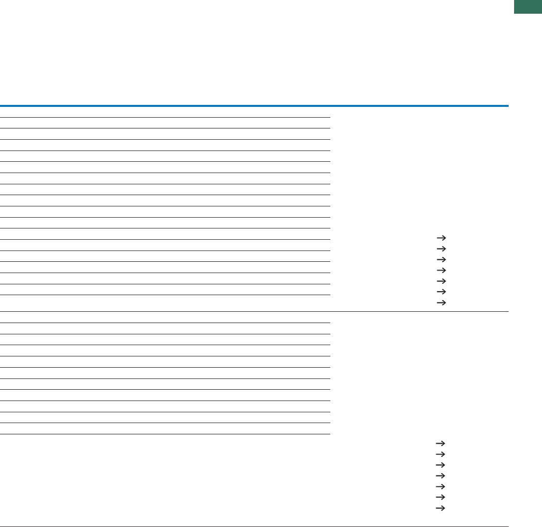
1
1.4
Motor-starter combinations
Modules
17AUTOMATION AND CONTROL www.eaton.com/seasia-electrical
Contactor Overload relay Contactor Overload relay Current sensor Notes
Type “1” coordination Type “1” coordination Type “2” coordination Type “2” coordination
Type Type Type Type Type
DILM7-…(…) ZB12-0,24 DILM7-…(…) ZB12-0,24 – The motor-starter combinations consist of the motor
protective circuit breaker (without overload function),
a contactor and overload relay modules.
They conform with IEC/EN 60947-4-1 or VDE 0660
Part 102.
Iq = conditional rated current
The combinations can be operated with or without
manual reset. In the Manual position, the combination is
blocked against automatic restarting and must be reset
locally. In the Auto position, the combination automati-
cally switches on again after the bimetallic elements
have cooled down.
DILM7-…(…) ZB12-0,4 DILM7-…(…) ZB12-0,4 –
DILM7-…(…) ZB12-0,6 DILM7-…(…) ZB12-0,6 –
DILM7-…(…) ZB12-0,6 DILM7-…(…) ZB12-0,6 –
DILM7-…(…) ZB12-1 DILM7-…(…) ZB12-1 –
DILM7-…(…) ZB12-1,6 DILM7-…(…) ZB12-1,6 –
DILM7-…(…) ZB12-1,6 DILM7-…(…) ZB12-1,6 –
DILM7-…(…) ZB12-2,4 DILM7-…(…) ZB12-2,4 –
DILM7-…(…) ZB12-4 DILM7-…(…) ZB12-4 –
DILM7-…(…) ZB12-4 DILM7-…(…) ZB12-4 –
DILM7-…(…) ZB12-6 DILM17-…(…) ZB32-6 –
DILM9-…(…) ZB12-10 DILM17-…(…) ZB32-10 –
DILM9-…(…) ZB12-10 DILM17-…(…) ZB32-10 –
DILM12-…(…) ZB12-12 – – –
– – DILM17-…(…) ZB32-16 –
DILM17-…(…) ZB32-16 DILM17-…(…) ZB32-16 –
DILM25-…(…) ZB32-24 DILM25-…(…) ZB32-24 –
DILM32-…(…) ZB32-32 DILM32-…(…) ZB32-32 –
DILM40(…) ZB65-40 – The motor-starter combinations consist of the circuit-
breaker (without overload function), contactor and
overload relay module.
They conform with IEC/EN 60947-4-1 or VDE 0660
Part 102.
Iq = conditional rated current
The combinations can be operated with or without
manual reset. In the Manual position, the combination is
blocked against automatic restarting and must be reset
locally. In the Auto position, the combination automati-
cally switches on again after the bimetallic elements
have cooled down.
Maximum tripping tolerance CLASS10.
– – DILM40(…)
DILM50(…) ZB65-57 –
– – DILM50(…)
DILM65(…) ZB65-57 –
– – DILM65(…)
DILM80(…) ZB150-70 –
– – DILM80(…)
DILM95(…) ZB150-100 –
– – DILM95(…)
DILM115(…) ZB150-100 –
– – DILM115(…)
Further information Page
Technical data PKZMO Chapter 1.3
Accessories PKZ Chapter 1.3 (Page 10)
Technical data DILM Chapter 1.1
Further actuating voltages Chapter 1.1 (Page 69)
DIL accessories Chapter 1.1 (Page 52)
Technical data ZB... Chapter 1.2
Accessories ZB... Chapter 1.2 (Page 21)
Further information Page
Technical data NZMN1 See catalog
Accessories NZM1 See catalog
Technical data DILM Chapter 1.1
Further actuating voltages Chapter 1.1 (Page 71)
DIL accessories Chapter 1.1 (Page 50)
Technical data ZB... Chapter 1.2
Accessories ZB... Chapter 1.2 (Page 21)
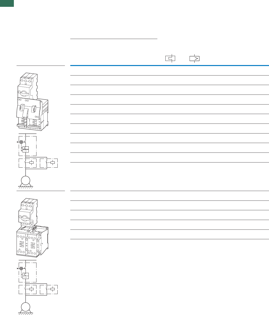
1
1.4 Motor-starter combinations
Complete units
18 AUTOMATION AND CONTROL www.eaton.com/seasia-electrical
Setting rangeMotor data Motor starters
actuating voltage
230 V 50 Hz
Price
See price
list
Rated
operational
power
Rated
operational
current
Rated short-circuit
current
Overload
trip
Short-
circuit
releases
Part no.
Article no.
AC-3 AC-3 380 - 415 V 380 - 415 V
380 V
400 V
415 V
400 V Type “1”
coordina-
tion
Type “2”
coordina-
tion
PI
eIqIqIrIrm
kW A kA kA A A
Complete units MSC-R
Complete units MSC-R
0.06 0.21 150 50 0.16 - 0.25 3.5 MSC-R-0.25-M7(230V50Hz)
283171
0.09 0.31 150 50 0.25 - 0.4 5.6 MSC-R-0.4-M7(230V50Hz)
283172
0.12
0.18
0.41
0.6
150 50 0.4 - 0.63 8.82 MSC-R-0.63-M7(230V50Hz)
283173
0.25 0.8 150 50 0.63 - 1 14 MSC-R-1-M7(230V50Hz)
283175
0.37
0.55
1.1
1.5
150 50 1 - 1.6 22.4 MSC-R-1.6-M7(230V50Hz)
283176
0.75 1.9 150 50 1.6 - 2.5 35 MSC-R-2.5-M7(230V50Hz)
283178
1.1
1.5
2.6
3.6
150 50 2.5 - 4 56 MSC-R-4-M7(230V50Hz)
283179
2.2 5 150 50 4 - 6.3 88.2 MSC-R-6.3-M7(230V50Hz)
283181
3 6.6 150 – 6.3 - 10 140 MSC-R-10-M7(230V50Hz)
283182
4 8.5 150 – 6.3 - 10 140 MSC-R-10-M9(230V50Hz)
283183
5.5 11.3 50 – 8 - 12 168 MSC-R-12-M12(230V50Hz)
283184
3 6.6 50 50 6.3 - 10 140 MSC-R-10-M17(230V50Hz)
101049
4 11.3 50508 - 12168 MSC-R-12-M17(230V50Hz)
101050
7.5 15.2 50 50 10 - 16 224 MSC-R-16-M17(230V50Hz)
283186
11 21.7 50 50 20 - 25 350 MSC-R-25-M25(230V50Hz)
283187
15 29.3 50 50 25 - 32 448 MSC-R-32-M32(230V50Hz)
283188
I
M
3 ~
M
3 ~
MSC-R: PKZM0, DILM

1
1.4
Motor-starter combinations
Complete units
19AUTOMATION AND CONTROL www.eaton.com/seasia-electrical
Motor starters
actuating voltage
24 V DC
Price
See price
list
Std. pack Motor protective
circuit breaker
Contactor Reversing starter
wiring set
Notes
Part no.
Article no.
Mechanical
connection
module,
electrical
contact module
and reversing
connector
Type Type Type
MSC-R-0.25-M7(24VDC)
283190
1 off
1 off
1 off
1 off
1 off
1 off
1 off
1 off
1 off
1 off
1 off
1 off
1 off
1 off
1 off
1 off
PKZM0-0,25 DILM7-01(...) PKZM0-XRM12
MSC-R-0.4-M7(24VDC)
283191
PKZM0-0,4 DILM7-01(...) PKZM0-XRM12
MSC-R-0.63-M7(24VDC)
283192
PKZM0-0,63 DILM7-01(...) PKZM0-XRM12
MSC-R-1-M7(24VDC)
283194
PKZM0-1 DILM7-01(...) PKZM0-XRM12
MSC-R-1.6-M7(24VDC)
283195
PKZM0-1,6 DILM7-01(...) PKZM0-XRM12
MSC-R-2.5-M7(24VDC)
283197
PKZM0-2,5 DILM7-01(...) PKZM0-XRM12
MSC-R-4-M7(24VDC)
283198
PKZM0-4 DILM7-01(...) PKZM0-XRM12
MSC-R-6.3-M7(24VDC)
283200
PKZM0-6,3 DILM7-01(...) PKZM0-XRM12
MSC-R-10-M7(24VDC)
283201
PKZM0-10 DILM7-01(...) PKZM0-XRM12
MSC-R-10-M9(24VDC)
283202
PKZM0-10 DILM9-01(...) PKZM0-XRM12
MSC-R-12-M12(24VDC)
283203
PKZM0-12 DILM12-01(...) PKZM0-XRM12
MSC-R-10-M17(24VDC)
101051
PKZM0-10 DILM17-01(...) PKZM0-XRM32
MSC-R-12-M17(24VDC)
101052
PKZM0-12 DILM17-01(...) PKZM0-XRM32
MSC-R-16-M17(24VDC)
283204
PKZM0-16 DILM17-01(...) PKZM0-XRM32
MSC-R-25-M25(24VDC)
283205
PKZM0-25 DILM25-01(...) PKZM0-XRM32
MSC-R-32-M32(24VDC)
283206
PKZM0-32 DILM32-01(...) PKZM0-XRM32
Further information Page
Technical data PKZM0 Chapter 1.3
Accessories PKZ Chapter 1.3 (Page 10)
Technical data DILM Chapter 1.1
Further actuation voltages Chapter 1.1 (Page 69)
DILM accessories Chapter 1.1 (Page 50)
The reversing starters (complete devices) consist of a
PKZM0 motor protective circuit breaker and two
contactors DILM.
With the adapterless top-hat rail mounting of starters up
to 12 A, only the motor-protective circuit-breaker on the
top-hat rail requires an adapter. The contactors are
provided with mechanical support via a mechanical
connection element.
Control wire guide with max. 6 conductors with up to
2.5 mm external diameter or 4 conductors up to 3.5 mm
external diameter.
From 16 A, the motor protective circuit breaker and
contactors are mounted on the top-hat rail adapter plate.
The connection of the main circuit between PKZ and
contactor is established with electrical contact modules.
Complete units with mechanical interlock, starters up to
12 A also with electrical interlock.
When using auxiliary contacts DILA‐XHIT…
J Chapter 1.1 (Page 38) the electrical plugs can be
pulled without having to remove the front mounting
auxiliary contact.
Cannot be combined with standard auxiliary contact
NHI-E-...-PKZ0-C with spring-loaded terminal.
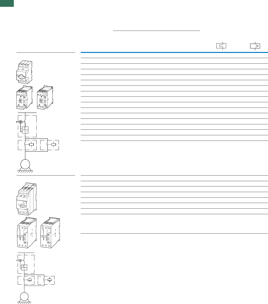
1
1.4 Motor-starter combinations
Modules
20 AUTOMATION AND CONTROL www.eaton.com/seasia-electrical
Motor data Setting range
Rated operational
power
Rated operational
current
Rated short-circuit current Overload trip Short-circuit
release
400 V AC-3 380 - 415 V 380 - 415 V
400 V Type “1”
coordination
Type “2”
coordination
PI
eIqIqIrIrm
kW A kA kA A A
Modules PKZM0 and DILM 0.06 0.21 150 50 0.16 - 0.25 3.5
0.09 0.31 150 50 0.25 - 0.4 5.6
0.12 0.41 150 50 0.4 - 0.63 8.82
0.18 0.6 150 50 0.4 - 0.63 8.82
0.25 0.8 150 50 0.63 - 1 14
0.37 1.1 150 50 1 - 1.6 22.4
0.55 1.5 150 50 1 - 1.6 22.4
0.75 1.9 150 50 1.6 - 2.5 35
1.1 2.6 150 50 2.5 - 4 56
1.5 3.6 150 50 2.5 - 4 56
2.2 5 150 50 4 - 6.3 88.2
3 6.6 150 50 6.3 - 10 140
4 8.5 150 50 6.3 - 10 140
5.5 11.3 50 50 8 - 12 168
7.515.2505010 - 16224
11 21.7 50 50 20 - 25 350
15 29.3 50 50 25 - 32 448
Modules PKZM4 and DILM 5.511.3505010 - 16224
7.515.2505010 - 16224
11 21.7 50 50 20 - 25 350
15 29.3 50 50 25 - 32 448
18.5 36 50 50 32 - 40 560
22 41 50 50 40 - 50 700
30 55 50 50 50 - 58 812
34 63 50 50 55 - 65 882
I
M
3 ~
M
3 ~
PKZM, DILM
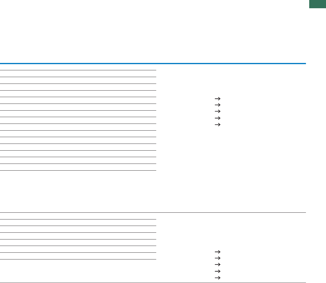
1
1.4
Motor-starter combinations
Modules
21AUTOMATION AND CONTROL www.eaton.com/seasia-electrical
Motor protective
circuit breaker
Contactor Contactor Notes
Type “1”
coordination
Type “2”
coordination
Type Type Type
PKZM0-0,25 2 x
2 x
DILM7-…(…) 2 x
2 x
2 x 2 x
2 x 2 x
2 x 2 x
2 x 2 x
2 x 2 x
2 x 2 x
2 x 2 x
2 x 2 x
2 x 2 x
2 x 2 x
2 x 2 x
2 x 2 x
2 x 2 x
2 x 2 x
2 x 2 x
2 x 2 x
2 x 2 x
2 x 2 x
2 x 2 x
2 x 2 x
2 x 2 x
2 x 2 x
DILM7-…(…) The motor-starter combinations consist of the motor protective circuit breaker
or a circuit breaker and a contactor. They conform with IEC/EN 60947-4-1 or
VDE 0660 Part 102.
Iq = conditional rated current
PKZM0-0,4 DILM7-…(…) DILM7-…(…)
PKZM0-0,63 DILM7-…(…) DILM7-…(…)
PKZM0-0,63 DILM7-…(…) DILM7-…(…)
PKZM0-1 DILM7-…(…) DILM7-…(…)
PKZM0-1,6 DILM7-…(…) DILM7-…(…)
PKZM0-1,6 DILM7-…(…) DILM7-…(…)
PKZM0-2,5 DILM7-…(…) DILM7-…(…)
PKZM0-4 DILM7-…(…) DILM7-…(…)
PKZM0-4 DILM7-…(…) DILM7-…(…)
PKZM0-6,3 DILM7-…(…) DILM7-…(…)
PKZM0-10 DILM9-…(…) DILM17-…(…)
PKZM0-10 DILM9-…(…) DILM17-…(…)
PKZM0-12 DILM12-…(…) DILM17-…(…)
PKZM0-16 DILM17-…(…) DILM17-…(…)
PKZM0-25 DILM25-…(…) DILM25-…(…)
PKZM0-32 DILM32-…(…) DILM32-…(…)
PKZM4-16 2 x DILM17-…(…) 2 x DILM17-…(…) The motor-starter combinations consist of the motor protective circuit breaker
or a circuit breaker and a contactor.
They conform with IEC/EN 60947-4-1 or VDE 0660 Part 102.
Iq = rated conditional short-circuit current.
PKZM4-16 DILM17-…(…) DILM17-…(…)
PKZM4-25 DILM25-…(…) DILM25-…(…)
PKZM4-32 DILM32-…(…) DILM32-…(…)
PKZM4-40 DILM40(…) DILM40(…)
PKZM4-50 DILM50(…) DILM50(…)
PKZM4-58 DILM65(…) DILM65(…)
PKZM4-63 DILM65(…) DILM65(…)
Further information Page
Technical data PKZM0 Chapter 1.3
Accessories PKZ Chapter 1.3 (Page 10)
Technical data DILM Chapter 1.1
Other operating voltages Chapter 1.1 (Page 69)
DILM accessories Chapter 1.1 (Page 50)
Further information Page
Technical data PKZM0 Chapter 1.3
Accessories PKZ Chapter 1.3 (Page 10)
Technical data DILM Chapter 1.1
Other operating voltages Chapter 1.1 (Page 70)
DILM accessories Chapter 1.1 (Page 50)
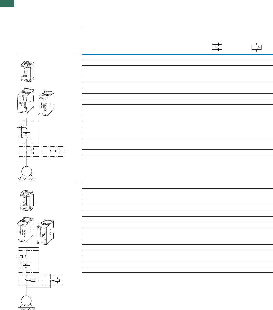
1
1.4 Motor-starter combinations
Modules
22 AUTOMATION AND CONTROL www.eaton.com/seasia-electrical
Setting rangeMotor data
Rated operational power Rated operational current Rated short-circuit
current
Overload trip Short-circuit
release
AC-3 AC-3
380 V
400 V
415 V
400 V 400/415 V
IP eIqIrIrm
AAAkAWk
Modules NZMN and DILM 320 - 44825 - 325029.315
320 - 56032 - 40503618.5
400 - 70040 - 50504122
504 - 88250 - 63505530
640 - 112063 - 80506837
800 - 125080 - 100508145
800 - 125080 - 100509955
1280 - 2240125 - 1605013475
1600 - 2500160 - 2005016190
1600 - 2500160 - 20050196110
350 - 4900175 - 35050231132
350 - 4900175 - 35050279160
350 - 4900175 - 35050349200
450 - 6300225 - 45050437250
550 - 7700275 - 55050544315
875 - 12250438 - 87550683400
875 - 12250438 - 87550750450
875 - 12250438 - 87550820500
1400 - 19600700 - 140050
947560
Modules NZMH and DILM 400 - 70040 - 501004122
504 - 88250 - 631005530
640 - 112063 - 801006837
800 - 125080 - 1001008155
1000 - 1750100 - 12510010055
1280 - 2240125 - 16010013475
90 - 126045 - 901005530
90 - 126045 - 901006837
90 - 126045 - 901008145
140 - 196070 - 14010010055
140 - 196070 - 14010013475
220 - 3080110 - 12010016190
220 - 3080110 - 120100196110
350 - 4900175 - 350100231132
350 - 4900175 - 350100279160
350 - 4900175 - 350100349200
I
M
3 ~
M
3 ~
NZMN, NZMH, DILM

1
1.4
Motor-starter combinations
Modules
23AUTOMATION AND CONTROL www.eaton.com/seasia-electrical
Circuit-breaker Contactor Contactor Notes
Type “1” coordination Type “2” coordination
Type Type Type
NZMN1-M32 2 x DILM40(…) 2 x DILM80(…) The motor starter combinations consist of the motor protective
circuit-breaker and a contactor.
They comply with IEC/EN 60947-4-1 and VDE 0660 Part 102.
Iq = conditional rated current.
NZMN1-M40 2 x DILM40(…) 2 x DILM80(…)
NZMN1-M50 2 x DILM50(…) 2 x DILM80(…)
NZMN1-M63 2 x DILM65(…) 2 x DILM80(…)
NZMN1-M80 2 x DILM80(…) 2 x DILM80(…)
NZMN1-M100 2 x DILM95(…) 2 x DILM95(…)
NZMN1-M100 2 x DILM115(…) 2 x DILM115(…)
NZMN2-M160 2 x DILM150(…) 2 x DILM150(…)
NZMN2-M200 2 x DILM185A/22(…) 2 x DILM185A/22(…)
NZMN2-M200 2 x DILM225A/22(…) 2 x DILM225A/22(…)
NZMN3-ME350 2 x DILM250/22(…) 2 x DILM250/22(…)
NZMN3-ME350 2 x DILM300A/22(…) 2 x DILM300A/22(…)
NZMN3-ME350 2 x DILM400/22(…) 2 x DILM400/22(…)
NZMN3-ME450 2 x DILM500/22(…) 2 x DILM500/22(…)
NZMN4-ME550 2 x DILM580/22(…) 2 x –
NZMN4-ME875 2 x DILM650/22(…) 2 x –
NZMN4-ME875 2 x DILM750/22(…) 2 x –
NZMN4-ME875 2 x DILM820/22(…) 2 x –
NZMN4-ME1400 2 x DILM1000/22(…) 2 x –
NZMH2-M50 2 x DILM80(…) 2 x DILM80(…) The motor-starter combinations consist of the motor protective
circuit breaker or a circuit breaker and a contactor.
They conform with IEC/EN 60947-4-1 or VDE 0660 Part 102.
Iq = rated conditional short-circuit current.
NZMH2-M63 2 x DILM80(…) 2 x DILM80(…)
NZMH2-M80 2 x DILM80(…) 2 x DILM80(…)
NZMH2-M100 2 x DILM95(…) 2 x DILM95(…)
NZMH2-M125 2 x DILM115(…) 2 x DILM115(…)
NZMH2-M160 2 x DILM150(…) 2 x DILM150(…)
NZMH2-ME90 2 x DILM80(…) 2 x DILM80(…)
NZMH2-ME90 2 x DILM80(…) 2 x DILM80(…)
NZMH2-ME90 2 x DILM95(…) 2 x DILM95(…)
NZMH2-ME140 2 x DILM115(…) 2 x DILM115(…)
NZMH2-ME140 2 x DILM150(…) 2 x DILM150(…)
NZMH2-ME220 2 x DILM185A/22(…) 2 x DILM185A/22(…)
NZMH2-ME220 2 x DILM225A/22(…) 2 x DILM225A/22(…)
NZMH3-ME350 2 x DILM250/22(…) 2 x DILM250/22(…)
NZMH3-ME350 2 x DILM300A/22(…) 2 x DILM300A/22(…)
NZMH3-ME350 2 x DILM400/22(…) 2 x DILM400/22(…)
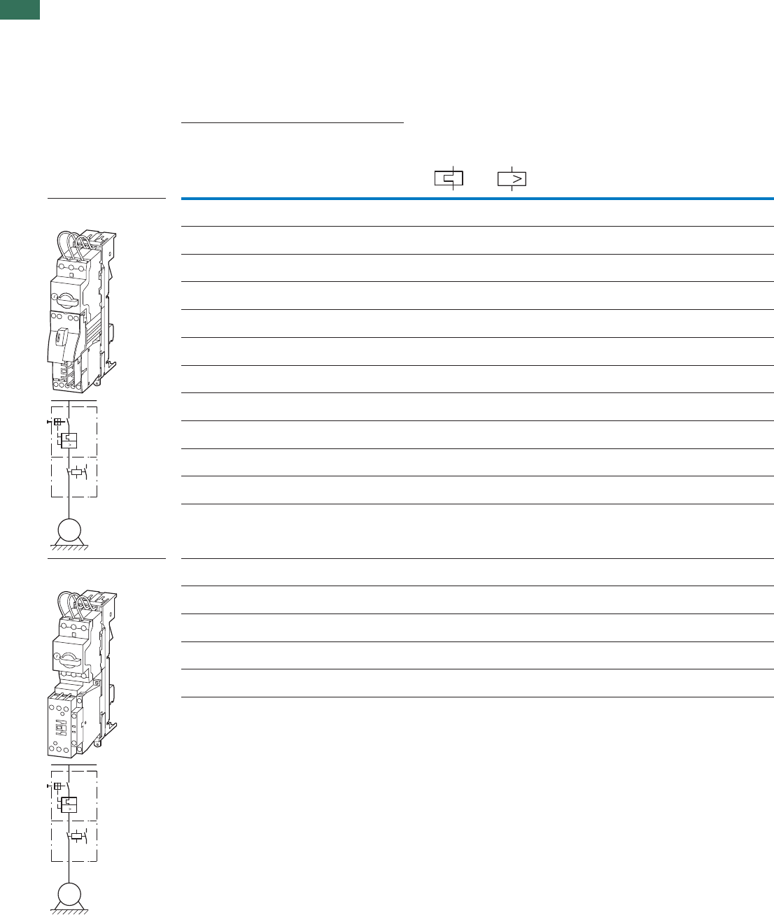
1
1.4 Motor-starter combinations
DOL starters
24 AUTOMATION AND CONTROL www.eaton.com/seasia-electrical
Setting rangeMotor data Motor starters
actuating voltage
230 V 50 Hz
Price
See price
list
Std.
pack
Motor
rating
Rated
opera-
tional
current
Rated short-circuit current Overload
trip
Short-
circuit
release
Part no.
Article no.
AC-3 AC-3 380 - 415 V 380 - 415 V
380 V
400 V
415 V
400 V Type “1”
coordination
Type “2”
coordination
PI
eIqIqIrIrm
kW A kA kA A A
Complete devices PKZ
and DIL on BBA
Complete devices PKZ
and DIL on BBA
0.06 0.21 100 50 0.16 - 0.25 3.5 MSC-D-0.25-M7(230V50Hz)/BBA1)
102737
1 off
1 off
1 off
1 off
1 off
1 off
1 off
1 off
1 off
1 off
1 off
1 off
1 off
1 off
1 off
1 off
1 off
0.09 0.31 100 50 0.25 - 0.4 5.6 MSC-D-0.4-M7(230V50Hz)/BBA1)
102738
0.12
0.18
0.41
0.6
100 50 0.4 - 0.63 8.82 MSC-D-0.63-M7(230V50Hz)/BBA1)
102739
0.25 0.8 100 50 0.63 - 1 14 MSC-D-1-M7(230V50Hz)/BBA1)
102950
0.37
0.55
1.1
1.5
100 50 1 - 1.6 22.4 MSC-D-1.6-M7(230V50Hz)/BBA1)
102951
0.75 1.9 100 50 1.6 - 2.5 35 MSC-D-2.5-M7(230V50Hz)/BBA1)
102952
1.1
1.5
2.6
3.6
100 50 2.5 - 4 56 MSC-D-4-M7(230V50Hz)/BBA1)
102953
2.2 5 100 50 4 - 6.3 88.2 MSC-D-6.3-M7(230V50Hz)/BBA1)
102954
3 6.6 100 – 6.3 - 10 140 MSC-D-10-M7(230V50Hz)/BBA
102955
4 8.5 100 – 6.3 - 10 140 MSC-D-10-M9(230V50Hz)/BBA
102956
5.5 11.3 100 – 8 - 12 168 MSC-D-12-M12(230V50Hz)/BBA
102957
7.5 15.2 50 – 10 - 16 224 MSC-D-16-M15(230V50Hz)/BBA
102958
3
4
6.6
8.5
100 50 6.3 - 10 140 MSC-D-10-M17(230V50Hz)/BBA
102959
5.5 11.3 100 50 8 - 12 168 MSC-D-12-M17(230V50Hz)/BBA
102960
7.515.2505010 - 16224MSC-D-16-M17(230V50Hz)/BBA1)
102961
11 21.7 50 50 20 - 25 350 MSC-D-25-M25(230V50Hz)/BBA1)
102962
15 29.3 50 50 25 - 32 448 MSC-D-32-M32(230V50Hz)/BBA1)
102963
I
M
3 ~
I
M
3 ~
I
MSC-D.../BBA
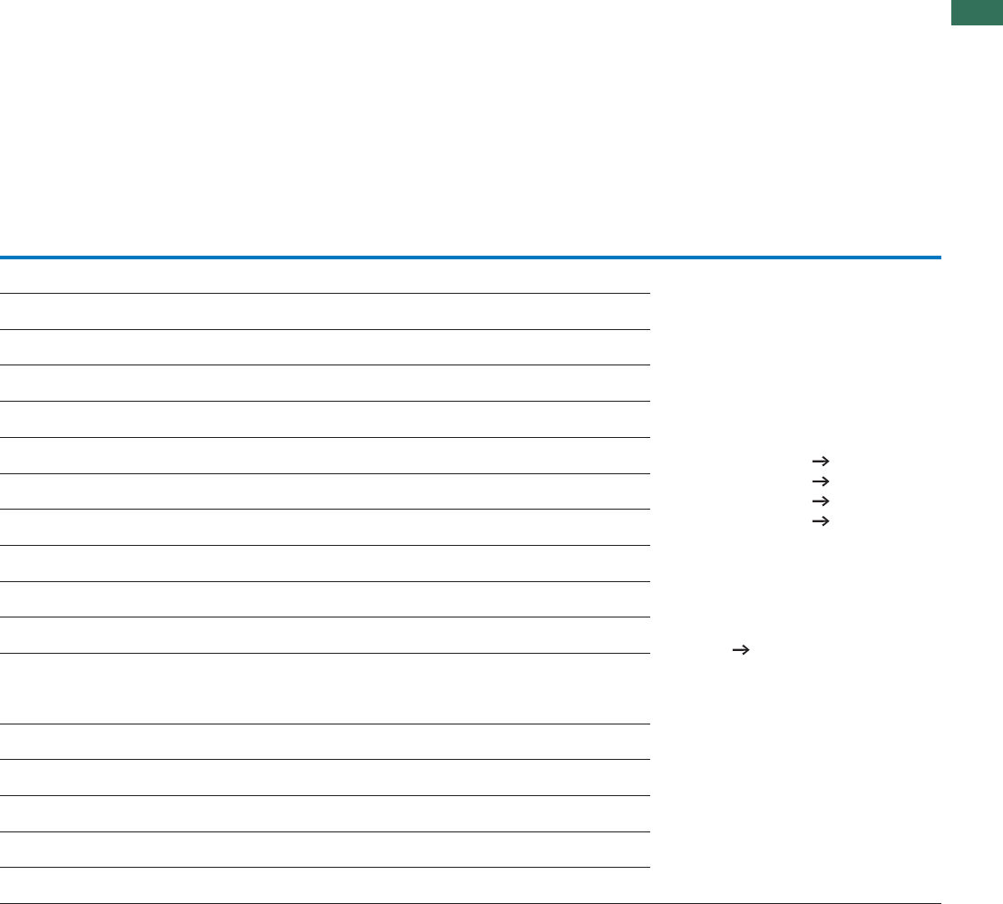
1
1.4
Motor-starter combinations
DOL starters
25AUTOMATION AND CONTROL www.eaton.com/seasia-electrical
Motor starters
actuating voltage
24 V DC
Price
See price
list
Std.
pack Motor
protective
circuit
breaker
Contactor DOL starter
wiring set
Busbar
adapter
Notes
Part no.
Article no.
Mechanical con-
nection module
and electrical
contact module
Type Type Type Type
MSC-D-0.25-M7(24VDC)/BBA1)
102964
1 off
1 off
PKZM0-0,25 DILM7-10(…) PKZM0-XDM12 BBA0-25
BBA0-25
1 off BBA0-25
1 off BBA0-25
1 off BBA0-25
1 off BBA0-25
1 off BBA0-25
1 off BBA0-25
1 off BBA0-25
1 off BBA0-25
1 off BBA0-25
1 off
1 off
BBA0-25
The DOL starters (complete devices) consist of a
motor protective circuit breaker PKZM0 and a
contactor DILM. These combinations are
mounted on busbars.
The connection of the main circuit between PKZ
and contactor is established with electrical
contact modules.
Cannot be combined with standard auxiliary
contact NHI-E-...-PKZ0-C with spring-loaded
terminal.
1) To assemble Type F starters that conform
with UL508, incoming terminals BK25/3-PKZ0-E
and, if necessary, three-phase terminal blocks
B3.../...-PKZ0 can be added to motor starter
combinations.
Type F starter Page 28
MSC-D-0.4-M7(24VDC)/BBA1)
102965
PKZM0-0,4 DILM7-10(…) PKZM0-XDM12
MSC-D-0.63-M7(24VDC)/BBA1)
102966
PKZM0-0,63 DILM7-10(…) PKZM0-XDM12
MSC-D-1-M7(24VDC)/BBA1)
102967
PKZM0-1 DILM7-10(…) PKZM0-XDM12
MSC-D-1.6-M7(24VDC)/BBA1)
102968
PKZM0-1,6 DILM7-10(…) PKZM0-XDM12
MSC-D-2.5-M7(24VDC)/BBA1)
102969
PKZM0-2,5 DILM7-10(…) PKZM0-XDM12
MSC-D-4-M7(24VDC)/BBA1)
102970
PKZM0-4 DILM7-10(…) PKZM0-XDM12
MSC-D-6.3-M7(24VDC)/BBA
102971
PKZM0-6,3 DILM7-10(…) PKZM0-XDM12
MSC-D-10-M7(24VDC)/BBA
102972
PKZM0-10 DILM7-10(…) PKZM0-XDM12
MSC-D-10-M9(24VDC)/BBA
102973
PKZM0-10 DILM9-10(…) PKZM0-XDM12
MSC-D-12-M12(24VDC)/BBA
102974
PKZM0-12 DILM12-10(…) PKZM0-XDM12
MSC-D-16-M15(24VDC)/BBA
102975
PKZM0-16 DILM15-10(…) PKZM0-XDM12
MSC-D-10-M17(24VDC)/BBA
102976
PKZM0-10 DILM17-10(…) PKZM0-XM32DE BBA0-32
1 off BBA0-32
1 off BBA0-32
1 off BBA0-32
1 off BBA0-32
MSC-D-12-M17(24VDC)/BBA
102977
PKZM0-12 DILM17-10(…) PKZM0-XM32DE
MSC-D-16-M17(24VDC)/BBA
102978
PKZM0-16 DILM17-10(…) PKZM0-XM32DE
MSC-D-25-M25(24VDC)/BBA
102979
PKZM0-25 DILM25-10(…) PKZM0-XM32DE
MSC-D-32-M32(24VDC)/BBA
102980
PKZM0-32 DILM32-10(…) PKZM0-XM32DE
Further information Page
Technical data PKZM0 Chapter 1.3
Accessories PKZ Chapter 1.3 (Page 10)
Technical data DILM Chapter 1.1
DILM accessories Chapter 1.1 (Page 50)
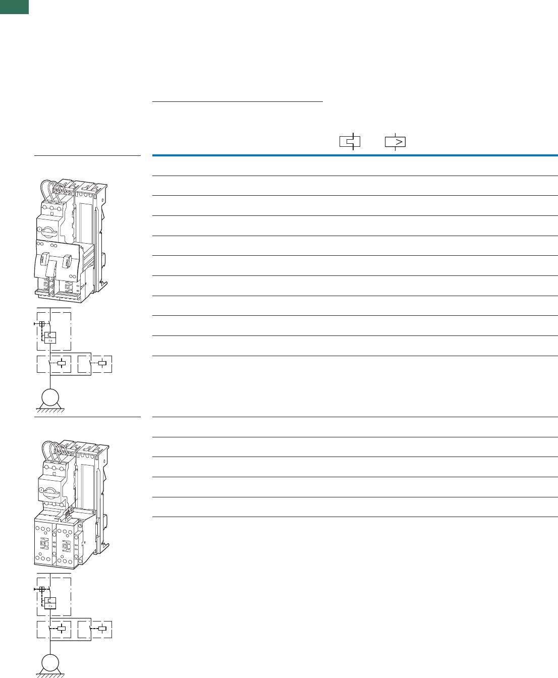
1
1.4 Motor-starter combinations
Reversing starters
26 AUTOMATION AND CONTROL www.eaton.com/seasia-electrical
Motor starters
actuating voltage
230 V 50 Hz
Price
See price
list
Setting rangeMotor data
Motor rating Rated
operational
current
Rated short-circuit
current
Overload
trip
Short-circuit
release Part no.
Article no.
AC-3 AC-3 380 - 415 V 380 - 415 V
380 V
400 V
415 V
400 V Type “1”
coordina-
tion
Type “2”
coordina-
tion
PI
eIqIqIrIrm
kW A kAkAA A
Complete devices PKZ and DILM
on BBA for reversing starters
Complete devices PKZ and DILM
on BBA for reversing starters
0.06 0.21 100 50 0.16 - 0.25 3.5 MSC-R-0.25-M7(230V50Hz)/BBA
102981
0.09 0.31 100 50 0.25 - 0.4 5.6 MSC-R-0.4-M7(230V50Hz)/BBA
102982
0.12
0.18
0.41
0.6
100 50 0.4 - 0.63 8.82 MSC-R-0.63-M7(230V50Hz)/BBA
102983
0.25 0.8 100 50 0.63 - 1 14 MSC-R-1-M7(230V50Hz)/BBA
102984
0.37
0.55
1.1
1.5
100 50 1 - 1.6 22.4 MSC-R-1.6-M7(230V50Hz)/BBA
102985
0.75 1.9 100 50 1.6 - 2.5 35 MSC-R-2.5-M7(230V50Hz)/BBA
102986
1.1
1.5
2.6
3.6
100 50 2.5 - 4 56 MSC-R-4-M7(230V50Hz)/BBA
102987
2.2 5 100 50 4 - 6.3 88.2 MSC-R-6.3-M7(230V50Hz)/BBA
102988
3 6.6 100 – 6.3 - 10 140 MSC-R-10-M7(230V50Hz)/BBA
102989
4 8.5 100 – 6.3 - 10 140 MSC-R-10-M9(230V50Hz)/BBA
102990
5.5 11.3 100 – 8 - 12 168 MSC-R-12-M12(230V50Hz)/BBA
102991
3
4
6.6
8.5
100 50 6.3 - 10 140 MSC-R-10-M17(230V50Hz)/BBA
102992
5.5 11.3 100 50 8 - 12 168 MSC-R-12-M17(230V50Hz)/BBA
102993
7.5 15.2 50 50 10 - 16 224 MSC-R-16-M17(230V50Hz)/BBA
102994
11 21.7 50 50 20 - 25 350 MSC-R-25-M25(230V50Hz)/BBA
102995
15 29.3 50 50 25 - 32 448 MSC-R-32-M32(230V50Hz)/BBA
102996
I
M
3 ~
M
3 ~
MSC-R.../BBA

1
1.4
Motor-starter combinations
Reversing starters
27AUTOMATION AND CONTROL www.eaton.com/seasia-electrical
Motor starters
actuating voltage
24 V DC
Price
See price
list
Std.
pack Motor
protective
circuit
breaker
Contactor Wiring set
Reversing
starters
Busbar
adapter
Mechanical con-
nection module,
electrical contact
module and
reversing connec-
tor
Notes
Part no.
Article no.
Type Type Type Type
MSC-R-0.25-M7(24VDC)/BBA
102997
1 off PKZM0-0,25 2 x DILM7-01(…) PKZM0-XRM12 BBA0R-25
1 off BBA0R-25
1 off BBA0R-25
1 off BBA0R-25
1 off BBA0R-25
1 off BBA0R-25
1 off BBA0R-25
1 off BBA0R-25
1 off BBA0R-25
1 off BBA0R-25
1 off
1 off
BBA0R-25
The reversing starters (complete
devices) consist of a PKZM0 motor
protective circuit breaker and two
contactors DILM.
These combinations are mounted on bus-
bars.
The connection of the main circuit
between PKZ and contactor is estab-
lished with electrical contact modules.
Complete units with mechanical inter-
lock, starters up to 12 A also with
electrical interlock.
MSC-R-0.4-M7(24VDC)/BBA
102998
PKZM0-0,4 2 x DILM7-01(…) PKZM0-XRM12
MSC-R-0.63-M7(24VDC)/BBA
102999
PKZM0-0,63 2 x DILM7-01(…) PKZM0-XRM12
MSC-R-1-M7(24VDC)/BBA
103000
PKZM0-1 2 x DILM7-01(…) PKZM0-XRM12
MSC-R-1.6-M7(24VDC)/BBA
103001
PKZM0-1,6 2 x DILM7-01(…) PKZM0-XRM12
MSC-R-2.5-M7(24VDC)/BBA
103002
PKZM0-2,5 2 x DILM7-01(…) PKZM0-XRM12
MSC-R-4-M7(24VDC)/BBA
103003
PKZM0-4 2 x DILM7-01(…) PKZM0-XRM12
MSC-R-6.3-M7(24VDC)/BBA
103004
PKZM0-6,3 2 x DILM7-01(…) PKZM0-XRM12
MSC-R-10-M7(24VDC)/BBA
103005
PKZM0-10 2 x DILM7-01(…) PKZM0-XRM12
MSC-R-10-M9(24VDC)/BBA
103006
PKZM0-10 2 x DILM9-01(…) PKZM0-XRM12
MSC-R-12-M12(24VDC)/BBA
103007
PKZM0-12 2 x DILM12-01(…) PKZM0-XRM12
MSC-R-10-M17(24VDC)/BBA
103008
PKZM0-10 2 x DILM17-01(…) PKZM0-XM32DE +
DILM32-XRL
BBA0R-32
1 off BBA0R-32
1 off BBA0R-32
1 off BBA0R-32
1 off BBA0R-32
MSC-R-12-M17(24VDC)/BBA
103009
PKZM0-12 2 x DILM17-01(…) PKZM0-XM32DE +
DILM32-XRL
MSC-R-16-M17(24VDC)/BBA
103010
PKZM0-16 2 x DILM17-01(…) PKZM0-XM32DE +
DILM32-XRL
MSC-R-25-M25(24VDC)/BBA
103011
PKZM0-25 2 x DILM25-01(…) PKZM0-XM32DE +
DILM32-XRL
MSC-R-32-M32(24VDC)/BBA
103012
PKZM0-32 2 x DILM32-01(…) PKZM0-XM32DE +
DILM32-XRL
Further information Page
Technical data PKZM0 Chapter1.3
Accessories PKZ Chapter 1.3 (Page 10)
Technical data DILM Chapter1.1
DILM accessories Chapter 1.1 (Page 50)
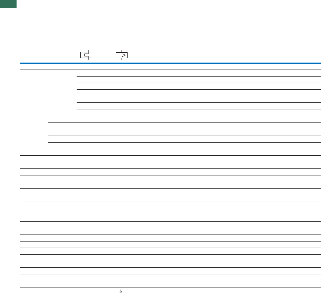
1
1.4 Motor-starter combinations
Type F starter combinations
28 AUTOMATION AND CONTROL www.eaton.com/seasia-electrical
Maximum motor rating Setting range Rated short-circuit
breaking capacity Icn
Extension terminal Motor protective
circuit breaker Contactor
Alternating current HP Overload trip Short-circuit
release
240 V 480 Y
277 V 2)
600 Y
347 V 2)
200 V
208 V
230 V
240 V
460 V
480 V
575 V
600 V Type Type Type
HP HP HP HP IrIrm kA kA kA
AA
Modules PKZM0, DIL, BK
1) 0.1 - 0.16 2.2 65 65 50 BK25/3-PKZ0 PKZM0-0,16 DILEM…(…)
0.1 - 0.16 2.2 65 65 50 BK25/3-PKZ0 PKZM0-0,16 DILM7-…(…)
0.16 - 0.25 3.4 65 65 50 BK25/3-PKZ0 PKZM0-0,25 DILEM…(…)
0.16 - 0.25 3.4 65 65 50 BK25/3-PKZ0 PKZM0-0,25 DILM7-…(…)
0.25 - 0.4 5.6 65 65 50 BK25/3-PKZ0 PKZM0-0,4 DILEM…(…)
0.25 - 0.4 5.6 65 65 50 BK25/3-PKZ0 PKZM0-0,4 DILM7-…(…)
0.4 - 0.63 8.8 65 65 50 BK25/3-PKZ0 PKZM0-0,63 DILEM…(…)
0.4 - 0.63 8.8 65 65 50 BK25/3-PKZ0 PKZM0-0,63 DILM7-…(…)
½ ½ 0.63 - 1 14 65 65 50 BK25/3-PKZ0 PKZM0-1 DILEM…(…)
½ ½ 0.63 - 1 14 65 65 50 BK25/3-PKZ0 PKZM0-1 DILM7-…(…)
¾ 1 1 - 1.6 22 65 65 50 BK25/3-PKZ0 PKZM0-1,6 DILEM…(…)
¾ 1 1 - 1.6 22 65 65 50 BK25/3-PKZ0 PKZM0-1,6 DILM7-…(…)
½ ½ 1 1½ 1.6 - 2.5 35 65 65 50 BK25/3-PKZ0 PKZM0-2,5 DILEM…(…)
½ ½ 1 1½ 1.6 - 2.5 35 65 65 50 BK25/3-PKZ0 PKZM0-2,5 DILM7-…(…)
1 1 2 3 2.5 - 4 56 65 65 50 BK25/3-PKZ0 PKZM0-4 DILEM…(…)
1 1 2 3 2.5 - 4 56 65 65 50 BK25/3-PKZ0 PKZM0-4 DILM7-…(…)
1½ 1½ 3 5 4 - 6.3 88 65 65 50 BK25/3-PKZ0 PKZM0-6,3 DILEM…(…)
1½ 1½ 3 5 4 - 6.3 88 65 65 50 BK25/3-PKZ0 PKZM0-6,3 DILM7-…(…)
3 3 7½ 10 6.3 - 11 140 65 65 50 BK25/3-PKZ0 PKZM0-10 DILM9-…(…)
3 3 7½ – 9 - 12 168 65 65 50 BK25/3-PKZ0 PKZM0-12 DILM12-…(…)
3 5 10 – 10 - 16 224 50 50 – BK50/3-PKZ4-E PKZM0-16 DILM17-…(…)
3 5 10 – 10 - 16 224 18 18 – BK50/3-PKZ4-E PKZM0-16 DILM17-…(…)
5 5 10 – 16 - 20 280 18 18 – BK50/3-PKZ4-E PKZM0-20 DILM25-…(…)
5 7½ 15 – 20 - 25 350 18 18 – BK50/3-PKZ4-E PKZM0-25 DILM25-…(…)
7½ 10 20 – 25 - 32 448 18 18 – BK50/3-PKZ4-E PKZM0-32 DILM32-…(…)
Modules PKZM4, DIL, BK
3 5 10 15 10 - 16 224 65 65 50 BK50/3-PKZ4-E PKZM4-16 DILM17-…(…)
5 7½ 15 20 16 - 27 350 65 65 50 BK50/3-PKZ4-E PKZM4-25 DILM25-…(…)
7½ 10 25 30 24 - 34 448 65 65 50 BK50/3-PKZ4-E PKZM4-32 DILM32-…(…)
10 15 30 30 32 - 40 560 65 65 50 BK50/3-PKZ4-E PKZM4-40 DILM40(…)
10 15 30 – 40 - 52 700 65 65 – BK50/3-PKZ4-E PKZM4-50 DILM50(…)
15 15 40 – 50 - 56 812 65 65 – BK50/3-PKZ4-E PKZM4-58 DILM65(…)
15 15 40 – 52 - 58 882 65 65 – BK50/3-PKZ4-E PKZM4-63 DILM65(…)
Notes Device for world markets IEC UL/CSA
Service factor (SF)
Set value I on the current scale, depending on the load factor
r
SF=1.15 -> Ir = 1 x In mot
SF=1.0 -> Ir = 0.9 x In mot
1) Calculate motor power in this range according to the rated operational current. Stated values to NEC
Table 430 - 150.
2) Suitable for networks with grounded star-point
Type F starter combinations do not need an upstream protective device.
For use in Canada, the switch must be fitted with an AK-PKZ0.
I
PKZMO, DILM, BK...

1
1.4
Motor-starter combinations
Function blocks
29AUTOMATION AND CONTROL www.eaton.com/seasia-electrical
Rating data for approved types1) Max. rated motor
current Contactor Overload relay Maximum short-circuit protective device for North
America
Maximum motor rating Fuse
CEC or NEC
Circuit-breaker2)
Alternating current HP Continuous
current
Short-circuit
release
200 V
208 V
230 V
240 V
460 V
480 V
575 V
600 V Type Type
HP HP HP HP AAA
Modules DIL, Z
– – ½ ½ 1 DILEM-…(…) ZE-1.0 3 15 –
– – ¾ 1 1.4 DILEM-…(…) ZE-1.6 6 15 –
½ ½ 1 1½ 2.3 DILEM-…(…) ZE-2.4 6 15 –
– 1 2 3 3.9 DILEM-…(…) ZE-4 15 15 –
1½ 1½ 3 – 6 DILEM-…(…) ZE-6 20 15 –
– 2 – – 6.8 DILEM-…(…) ZE-9 35 15 –
2 2 5 5 7.8 DILEM-…(…) ZE-9 35 15 –
2 3 5 5 9.6 DILEM-…(…) ZE-12 45 – –
– – ½ ½ 1 DILM7…(…) ZB12-1 3 25 200
– – ¾ 1 1.4 DILM7…(…) ZB12-1,6 6 25 200
½ ½ 1 1½ 2.3 DILM7…(…) ZB12-2,4 6 25 200
11233.9 DILM7…(…)ZB12-4 15 25 200
1½ ½ 3 – 6 DILM7…(…) ZB12-6 20 25 200
– – – 7½ 9 DILM9…(…) ZB12-10 25 25 200
– 3 5 7½ 9.6 DILM12…(…) ZE-12 25 25 200
– – 7½ 10 11 DILM12…(…) ZB12-12 45 25 200
– 5 10 – 15.2 DILM15…(…) ZB12-16 60 40 320
– – ½ ½ 1 DILM17…(…) ZB32-1 3 25 200
– – ¾ 1 1.4 DILM17…(…) 278447 6 25 200
½ ½ 1 1½ 2.3 DILM17…(…) ZB32-2,4 6 25 200
1 1 2 3 3.9 DILM17…(…) ZB32-4 15 25 200
½ 1½ 3 – 6 DILM17…(…) ZB32-6 20 25 200
– 3 5 7½ 9.6 DILM17…(…) ZB32-10 25 25 200
– – 7½ 10 11 DILM17…(…) ZB32-16 40 30 320
– 5 10 – 15.2 DILM17…(…) ZB32-16 40 30 320
– 7½ 15 20 22 DILM25…(…) ZB32-24 90 100 1200
– 10 20 25 32.2 DILM32…(…) ZB32-32 125 125 1200
– 3 5 7½ 9.6 DILM40(…) ZB65-10 40 40 380
– 5 10 10 15.2 DILM40(…) ZB65-16 60 60 760
– 7½ 20 25 32.2 DILM40(…) ZB65-24 90 90 1200
– 10 20 30 34 DILM40(…) ZB65-40 125 125 1200
– 20 40 50 54 DILM50(…) ZB65-57 200 150 2000
– 20 50 50 63 DILM65(…) ZB65-65 200 160 2000
– 25 50 60 68 DILM80(…) ZB150-70 250 250 2500
– 30 75 100 99 DILM95(…) ZB150-100 400 400 3200
– 40 100 100 124 DILM115(…) ZB150-125 500 500 4000
– 60 125 125 156 DILM150(…) ZB150-150 600 600 4800
50 60 125 150 156 DILM185A/22(…) Z5-160/FF225A 600 CLASS J 600 7200
60 75 150 200 192 DILM225A/22(…) Z5-220/FF225A 800 CLASS J 800 16000
75 100 200 250 248 DILM250/22(…) Z5-250/FF250 700 CLASS J 600 –
100 125 250 300 312 DILM300A/22(…) ZW7-400 1000 1000 –
125 150 300 400 382 DILM400/22(…) ZW7-400 1000 1000 –
150 200 400 500 480 DILM500/22(…) ZW7-540 1000 600 –
Notes 1) Devices for world markets IEC UL/CSA
2) Circuit-breaker -> See catalog
DILM, ZE, ZB, Z5, ZW7
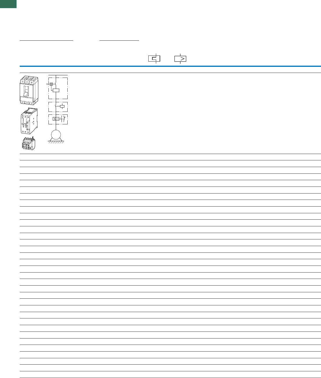
1
1.4 Motor-starter combinations
Function blocks
30 AUTOMATION AND CONTROL www.eaton.com/seasia-electrical
Rating data for approved
types
Setting range Circuit-breaker Contactor Overload
relay
Minimum
enclosure
volume
Maximum motor rating Max. rated
motor
current
Rated short-circuit
breaking capacity
Overload
trip
Short-
circuit
releases
Alternating current HP
200 V
208 V
230 V
240 V
460 V
480 V
575 V
600 V
480 V 600 Y
347 V1)
600 V Type Type Type
IrIrm
HP HP HP HP AkA kA kA A A cm 3
Module NZMH...-S...-CNA, DILM, Z
– – – ½ 0.9 100 50 – 0.6 - 1 12.8 - 22.5 NZMH2-S1.6-CNA DILM17-…(…) ZB32-1 81.5
– – ½ ¾ 1.3 100 50 – 1 - 1.6 12.8 - 22.5 NZMH2-S1.6-CNA DILM17-…(…) ZB32-1,6 81.5
– – ¾ – 1.6 100 50 – 1 - 1.6 19.2 - 33.6 NZMH2-S2.4-CNA DILM17-…(…) ZB32-1,6 81.5
– – 1 1 2.1 100 50 – 1.6 - 2.4 19.2 - 33.6 NZMH2-S2.4-CNA DILM17-…(…) ZB32-2,4 81.5
– ½ – 1½ 2.4 100 50 – 1.6 - 2.4 32 - 56 NZMH2-S5-CNA DILM17-…(…) ZB32-2,4 81.5
¾ ¾ 2 3 3.9 100 50 – 2.4 - 4 32 - 56 NZMH2-S5-CNA DILM17-…(…) ZB32-4 81.5
– 1 – – 4.2 100 50 – 4 - 6 32 - 56 NZMH2-S5-CNA DILM17-…(…) ZB32-6 81.5
1 1½ 3 – 6 100 50 – 4 - 6 48 - 84 NZMH2-S8-CNA DILM17-…(…) ZB32-6 81.5
1½ 2 – 5 6.9 100 50 – 6 - 10 48 - 84 NZMH2-S8-CNA DILM17-…(…) ZB32-10 81.5
2 3 5 7½ 9.6 100 50 – 6 - 10 80 - 140 NZMH2-S12-CNA DILM17-…(…) ZB32-10 81.5
3 5 10 10 15.2 100 50 – 10 - 16 128 - 224 NZMH2-S18-CNA DILM17-…(…) ZB32-16 81.5
5 – – 15 17.5 100 50 – 16 - 24 200 - 350 NZMH2-S26-CNA DILM17-…(…) ZB32-24 81.5
– 7½ 15 20 22 100 50 – 16 - 24 200 - 350 NZMH2-S26-CNA DILM25-…(…) ZB32-24 81.5
7½ – – – 25.3 100 50 – 24 - 32 256 - 448 NZMH2-S33-CNA DILM25-…(…) ZB32-32 81.5
– 10 20 25 28 100 50 – 24 - 32 256 - 448 NZMH2-S33-CNA DILM32-…(…) ZB32-32 81.5
10 – – – 32.2 100 50 – 24 - 32 320 - 560 NZMH2-S40-CNA DILM32-…(…) ZB32-32 81.5
– – 25 30 34 100 50 – 32 - 40 320 - 560 NZMH2-S40-CNA DILM40(…) ZB65-40 81.5
– – 30 – 40 100 50 – 32 - 40 400 - 700 NZMH2-S50-CNA DILM40(…) ZB65-40 81.5
– 15 – 40 42 100 50 – 40 - 57 400 - 700 NZMH2-S50-CNA DILM40(…) ZB65-57 81.5
15 20 40 50 54 100 50 – 40 - 57 504 - 882 NZMH2-S63-CNA DILM50(…) ZB65-57 81.5
20 – 50 60 65 100 50 – 57 - 65 640 - 1120 NZMH2-S80-CNA DILM65(…) ZB65-65 81.5
– 25 – – 68 100 50 – 50 - 70 640 - 1120 NZMH2-S80-CNA DILM80(…) ZB150-70 163
25 30 60 75 80 100 50 – 70 - 100 800 - 1400 NZMH2-S100-CNA DILM80(…) ZB150-100 163
– 40 75 100 104 100 50 – 70 - 100 1000 - 1750 NZMH2-S125-CNA DILM95(…) ZB150-100 163
30 – – – 92 100 50 – 70 - 100 1000 - 1750 NZMH2-S125-CNA DILM115(…) ZB150-100 163
40 – 100 125 125 100 50 – 100 - 125 1280 - 2240 NZMH2-S160-CNA DILM115(…) ZB150-125 163
– 50 – – 130 100 50 – 125 - 150 1280 - 2240 NZMH2-S160-CNA DILM115(…) ZB150-150 163
– – 125 – 156 100 50 – 125 - 150 1600 - 2500 NZMH2-S200-CNA DILM150(…) ZB150-150 265
50 60 – 150 154 100 50 – 120 - 160 1600 - 2500 NZMH2-S200-CNA DILM185/22(…) Z5-160/FF250 265
60 75 150 200 192 100 50 – 160 - 220 220 - 3080 NZMH2-SE220-CNA DILM225/22(…) Z5-220/FF250 265
75 100 200 250 248 100 50 50 160 - 220 350 - 4900 NZMH3-SE350-CNA DILM250/22(…) Z5-220/FF250 306
100 – – 300 289 100 50 50 190 - 290 350 - 4900 NZMH3-SE350-CNA DILM300/22(…) ZW7-290 306
– 125 250 – 302 100 50 50 270 - 400 450 - 6300 NZMH3-SE450-CNA DILM300/22(…) ZW7-400 306
125 150 300 400 382 100 50 50 270 - 400 450 - 6300 NZMH3-SE450-CNA DILM400/22(…) ZW7-400 306
Notes 1) Suitable for networks with grounded star-point
I
M
3 ~
I >
NZMH...-S...-CNA, DILM..., ZB, Z5, ZW7
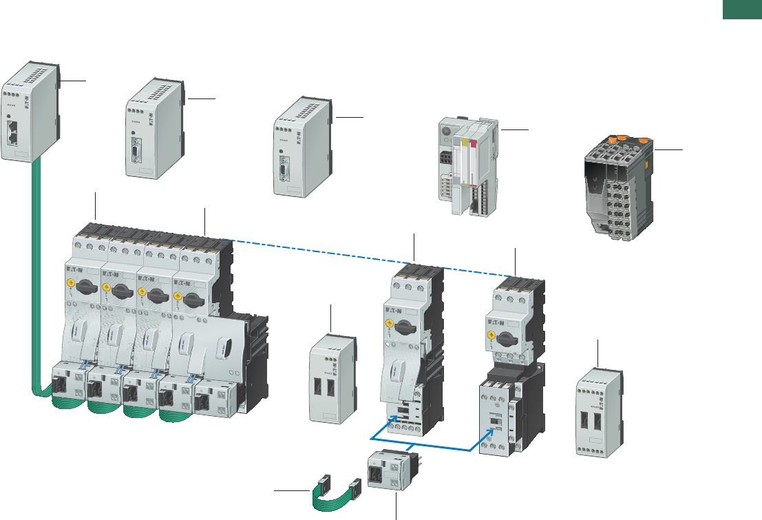
1
1.4
Connection system SmartWire-DT®
Function blocks
31AUTOMATION AND CONTROL www.eaton.com/seasia-electrical
Description
SWIRE-…
1
2
I/
ONX
4
5
10
9
8
9
13
7
3
11
12
1 Gateway easy NET/CAN open
2 Gateway PROFIBUS-DP
3 Gateway MODBUS
4 Coupling unit XI/ON with SmartWire-DT®
Interface card MicroInnovation AG,
www.microinnovation.com
5 Interface module B & R CS1011
for X20 system,
www.br-automation.com
6 SmartWire-DT® I/O module
7 DOL starter MSC-D up to 32 A
8 DOL starter MSC-D up to 15.5 A
9 SmartWire-DT® power module
10 Connection cable
11 SmartWire-DT® module for DILM
12 Reversing starter MSC-R up to 12 A
System description
With the SmartWire-DT® connection system,
switchgear can be connected to a programmable
logic controller without the need for complex
control wiring. Plug-in SmartWire-DT® cards for
DILM and a preassembled connection cable
replace the control wiring, dramatically reducing
wiring complexity and completely eliminating
wiring errors. SmartWire-DT® also cuts the time
needed for installation, commissioning and
troubleshooting.
The PLC’s inputs and outputs are replaced by the
SmartWire-DT® module for DILM, and no control
wiring terminals are required.
Connection to the various fieldbus systems is
through third-party gateways or interface
modules.
Features
• Gateway
• Connects the SmartWire-DT® cards with
the fieldbus
• Supports the fieldbus standards
PROFIBUS-DP, MODBUS, CANopen and
easy-NET
• Supplies the control voltage for the motor
starter or contactor
• Supplies the supply voltage for the
SmartWire-DT® connection system
• Configuration button for automatic
addressing of the SmartWire-DT® modules
for DILM
• Supports max. 16 SmartWire-DT® modules
for DILM
• Interface of third-party manufacturers, e.g.
for the XI/ON I/O system, X20 system CS1011
interface module
• Connection to the field buses
PROFIBUS-DP, MODBUS, CANopen and
DeviceNET
• SmartWire-DT® module for DILM
• Pluggable on contactors
• Suitable for contactors DILM7 to DILM32
(24 V DC), DILMC7 to DILMC32 (24 V DC),
DILMP20 (24 V DC) or motor starter
MSC-... (24 V DC)
• Use the standard switchgear of the xStart
range
• Suitable for DOL and reversing starters
• The accessories of the contactor series
can be used
• Suitable for contactor combinations with
PKZ or with Z relays
• Integrated switch position monitoring of
the contactors
• Integrated mechanical switch position
display
• Actuation of the contactors
• Scanning of a potential-free contact, e.g.
NHI-E-10-PKZ0
• Electrical interlocking, e.g. possible with
reversing starters
• LED for status and diagnostic display
• Connection to gateway or interface from
third party devices
• SmartWire-DT® I/O module
• 4 digital inputs for connection of
potential-free contacts
• Power supply for the digital inputs comes
from the device
• 2 relay outputs 250 V AC
• SmartWire-DT® power module
• Supply of the 24 V DC control voltage for
actuation of contactors DILM
• Assembly of Emergency Off groups
• Increases the control voltage power in the
SmartWire-DT® line
• Safety engineering
• Emergency switching off disconnection as
per IEC/EN 954-1, Switching Category 3
• Central switch off of control voltage at the
gateway or SmartWire-DT® power module
• Combination with safety-relevant
switchgear possible
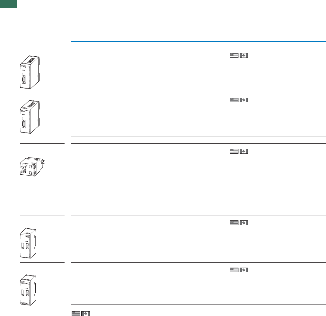
1
1.4 Connection system SmartWire-DT®
32 AUTOMATION AND CONTROL www.eaton.com/seasia-electrical
Ordering
Description Part no.
Article no. Price
See price
list
Std. pack Notes
Gateway
PROFIBUS-DP Gateway with integrated supply for the SmartWire-DT®
module and control voltage for the switchgear.
- Connection to PROFIBUS-DP as slave.
- Transmission rate: 9.6 Kbits/s to 12 MBit/s.
- 9 pole SUB-D socket.
- Address range 1…126.
- Connection to SmartWire-DT® module as master.
- Supports 16 SmartWire-DT® modules.
SWIRE-GW-DP
107027
1 off –
MODBUS Gateway with integrated supply for the SmartWire-DT®
module and control voltage for the switchgear.
- Connection to MODBUS-RTU as slave.
- Transmission rate: 9.6 to 57.6 Kbits/s.
- 9 pole SUB-D socket RS232/RS485.
- Address range 1…31.
- Connection to SmartWire-DT® module as master.
- Supports 16 SmartWire-DT® modules.
SWIRE-GW-MB
118562
1 off –
Modules
SmartWire-DT® module
for DILM
SmartWire-DT® module to assemble on the contactors
DILM(C)7…DILM(C)38, DILA…, DILMP20
- One module is necessary per contactor.
- Connection to SmartWire-DT® gateway as slave.
- Max. 16 SmartWire-DT® modules per line.
- 1 digital input for floating contact.
- Signaling contactor switch position.
SWIRE-DIL
107028
5 off • Take account of the max. current consump-
tion of the contactor coils per
SmartWire-DT® line.
• Length of connection cable at the input and
the electrical interlock < 2.8 m.
• The A2 connection of the contactors must
not be linked.
• Electrical interlocking only possible via the
terminals on the module for DILM.
• Wiring sets DILM 12-XRL and PKZM0-
XRM12 cannot be used.
• Connection terminals for electrical
interlocking are not suitable for safety
technology.
SmartWire-DT®
power module
Power module for suppling the control voltage.
- Connection on SmartWire-DT® gateway as
interactive station (no address).
SWIRE-PF
107029
1 off Max. 4 power modules per SmartWire-DT®
line.
SmartWire-DT® I/O
mod-ule
4 digital inputs
2 digital relay outputs SWIRE-4DI-2DO-R
107030
1 off Max. 4 SmartWire-DT® I/O modules per line.
SWIRE-…
Information relevant for export to North America
Product Standards
UL File No.
UL CCN
CSA File No.
CSA Class No.
NA Certification
IEC/EN 60947-4-1; UL 508; CSA-C22.2 No.14-05;
CE marking
E29184
NKCR
012528
2252-01
UL Listed, CSA certified
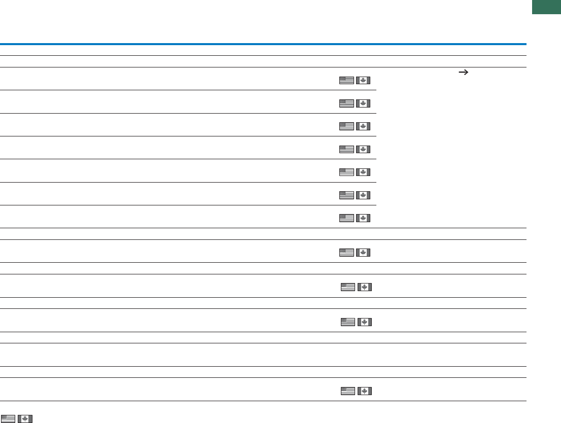
1
1.4
Connection system SmartWire-DT®
33AUTOMATION AND CONTROL www.eaton.com/seasia-electrical
Accessory
SmartWire-DT® connection cable1)
Length: 85 mm SWIRE-CAB-008
107032
25 off
25 off
Cable lengths: Engineering 34
Length: 110 mm SWIRE-CAB-011
107033
Length: 150 mm SWIRE-CAB-015
107034
5 off
5 off
Length: 250 mm SWIRE-CAB-025
107035
Length: 500 mm SWIRE-CAB-050
112027
1 off
1 off
1 off
Length: 1000 mm SWIRE-CAB-100
107036
Length: 2000 mm SWIRE-CAB-200
107037
Termination connector1)
– Termination plug for last SmartWire-DT® card,
6 pole, no electrical function. SWIRE-CAB-000
107031
25 off –
Data cable1)
– 6-core, ribbon cable, length: 100 m. SWIRE-CAB-100M
107038
1 off Preassembly of cable only possible with
special tool.
Plug 1)
– 6-pin plug for ribbon cable. SWIRE-CAB-CON
107039
50 off For use with SWIRE-CAB-100M.
NHI-E with cable1)
– NHI-E-10-PKZ0 with connection cable AWG18 blue,
for connection to SmartWire-DT® module for DILM. NHI-E-10L-PKZ0
107040
5 off –
Plug-in reversing bridge 2)
– For assembling reversing starters with tool-less
plug connection DILM12-XR
110099
20 off For use with DILM7…DILM15, without A2 link.
Information relevant for export to North America
1) 2)
Description Part no.
Article no. Price
See price
list
Std. pack Notes
SWIRE-…
Product Standards
UL File No.
UL CCN
CSA File No.
CSA Class No.
NA Certification
IEC/EN 60947-4-1; UL 508;
CSA-C22.2 No.14-05; CE marking
E29184
NKCR
012528
2252-01
UL Listed, CSA certified
Product Standards
UL File No.
UL CCN
CSA File No.
CSA Class No.
NA Certification
IEC/EN 60947-4-1; UL 508;
CSA-C22.2 No.14-05; CE marking
E36332
NLRV
012528
3211-05
UL Listed, CSA certified

1
1.4 Connection system SmartWire-DT®
34 AUTOMATION AND CONTROL www.eaton.com/seasia-electrical
SWIRE-…
Engineering
Cable lengths
SWIRE-…
SWIRE-…
Cable lengths
For connection between motor starters and contactors DILM, the cable lengths depend on the combination and assembly of the devices.
Cable lengthtofromPKZ accessoriesApplications
Contactors DILM None
(45 grid) DILM7-…15 DILM7-…15 85 mm
DILM17-…38 DILM17-…38 85 mm
DILM7-…38 DILM17-…38 110 mm
DILM17-…38 DILM7-…15 110 mm
PKZM0 with U-/A…/NHI…/AGM… DILM7-…15 DILM7-…15 110 mm
DILM17-…32 DILM17-…32 110 mm
DILM7-…15 DILM17-…32 110 mm
DILM17-…32 DILM7-…15 110 mm
Motor starters MSC None
(45 grid) DILM7-…15 DILM7-…15 85 mm
DILM17-…32 DILM17-…32 85 mm
DILM7-…15 DILM17-…32 110 mm
DILM17-…32 DILM7-…15 110 mm
PKZM0 with U-/A…/NHI…/AGM… DILM7-…15 DILM7-…15 110 mm
DILM17-…32 DILM17-…32 110 mm
DILM7-…15 DILM17-…32 150 mm
DILM17-…32 DILM7-…15 150 mm
The cable lengths for connecting SmartWire-DT® devices depend on the combination and assembly of the devices.
Applications Cable length
250 mmConnection from power module to SWIRE-DIL with mounting beside PKZ
150 mmConnection from power module to SWIRE-DIL with mounting beside DILM
250 mmConnection from gateway to SWIRE-DIL with mounting beside PKZ
250 mmConnection from coupling unit to SWIRE-DIL with mounting beside DILM
Magnet systems
The number of motor starters or contactors DILM that can be connected is dependant on the power consumption of the magnet systems per SmartWire-DT® line.
To increase the number of SmartWire-DT® modules that can be connected, power modules can be used.
DILM7 DILM9 DILM12 DILM15 DILM17 DILM25 DILM32/3824 V DC
Pick-up power W 3 3 4.5 12 at 24 V 12 at 24 V 12 at 24 V 12 at 24 V
Holding power W 3 3 4.5 0.5 at 24 V 0.5 at 24 V 0.5 at 24 V 0.5 at 24 V

1
1.4
Connection system SmartWire-DT®
35AUTOMATION AND CONTROL www.eaton.com/seasia-electrical
SWIRE-…
Technical data
SWIRE-GW-DP SWIRE-PF SWIRE-DIL
General
Standards
General IEC/EN 60947
EN 55011
EN 55022
IEC/EN 61000-4
IEC/EN 60068-2-27
Profibus-DP IEC 61158 – –
Mounting Top-hat rail IEC/EN 60715 (35mm) or screw fixing with fixing
brackets ZB4-101-GF1 (accessories)
on DILM7…DILM38
mmDimensions (w x d x h) 35 x 90 x 109 35 x 90 x 74 45 x 44 x 81
kgWeight 0.15 0.1 0.04
Terminal capacity
mm²Solid 0.34…1.5 0.34…1.5 0.34…1.5
mm²Flexible with ferrule 0.34…1.5 0.34…1.5 0.34…1.5
AWGSolid or stranded 22…16 22…16 22…16
mmFlat-blade screwdriver 3.5 x 0.8 3.5 x 0.8 3.5 x 0.8
NmMax. tightening torque 0.6 0.6 0.5
Ambient climatic conditions
°COperationAmbient temperature -25 - +55 -25 - +55 -25 - +60
°CStorage -25 - +70 -25 - +70 -25 - +70
Condensation Prevent condensation by means of suitable measures
Relative humidity, non-condensing (IEC/EN 60068-2-30) % 5 - 95 5 - 95 5 - 95
hPaAir pressure (in operation) 795 - 1080 795 - 1080 795 - 1080
Ambient mechanical conditions
Protection type (IEC/EN 60529) IP20 IP20 IP20
Pollution degree 2 2 2
Mounting position Vertical Vertical As per DILM7 to DILM38
Electromagnetic compatibility (EMC)
Electrostatic discharge (IEC EN 61000-4-2, Level 3, ESD)
kVAir discharge 8 8 8
kVContact discharge – – –
Electromagnetic fields
(IEC/EN 61000-4-3, RFI)
V/m 10 10 10
Radio interference suppression (EN 55011, EN 55022) Class A Class A Class A
Burst pulses(IEC/EN 61000-4-4, level 3)
kVSupply cables 2 2 2
kVSignal cables 2 2 2
High-energy pulses (surge)
(IEC/EN 61000-4-5, level 2)
kV 0.5 (supply cables, symmetrical)
VEmitted RFI (IEC/EN 61000-4-6) 10 10 10
Insulation resistance
Clearances and creepage distances EN 50178, EN 60947-1, UL 508, CSA C22.2 No 142
Insulation resistance EN 50178, EN 60947-1
Supply voltage, gateway electronics and SmartWire-DT® station electronics
Ugateway
Rated operational voltage Ugateway V DC 24, -15 %, +20 % – –
Permissible range 20.4...28.8 20.4...28.8 Supply from gateway or
power module
%Ripple ̰ 5– –
Maximum coupling unit power consumption at
24 V DC
mA 500
(typically 100 for gateway +
typically 25 per SmartWire-DT®
module)
––
msVoltage dips (IEC/EN 61131-2) 10 – –
WHeat dissipation at 24 V DC Normally 6 Normally 1 Normally 0.6
Protection against polarity reversal Yes
Short-circuit protection, SmartWire-DT® side Yes – –

1
1.4 Connection system SmartWire-DT®
36 AUTOMATION AND CONTROL www.eaton.com/seasia-electrical
General
Supply voltage U (supply voltage for switching SmartWire-DT® elements,
AUX
e.g. contactor coils)
Rated operational voltage UAUX V DC 24, -15 %, +20 %
(Derating from > 40 °C)
24, -15 %, +20 %
(Derating from > 40 °C)
Supply from gateway or
power module
V DCPermissible range 20.4…28.8,
at 45 °C: 21…28.8,
at 50 °C: 21.6…28.8,
at 55 °C: 22.2…27.6
20.4…28.8,
at 45 °C: 21…28.8,
at 50 °C: 21.6…28.8,
at 55 °C: 22.2…27.6
Supply from gateway or
power module
Input current U at 24 V DC
AUX A Normally 3 Normally 3 –
%Ripple ̰ 5 ̰ 5–
msVoltage dips (IEC/EN 61131-2) 10 10 –
Protection against polarity reversal
Short-circuit protection, SmartWire-DT® side No, external fuse
3 A or FAZ-Z3
No, external fuse
3 A or FAZ-Z3
–
LED indicators
Operational Ready: green – Ready: green
Power supply, SmartWire-DT® contactors U : green
Aux UAux : green –
PROFIBUS-DP status PROFIBUS-DP: green – –
SmartWire-DT® status SmartWire-DT®: green – above Ready
Output status – – –
Connection floating contacts
Number – – 1
Rated voltage (internal supply) UeV DC – – 17
mAInput current at “1” signal, typically – – 5
Potential isolation – – No
mMax. cable length – – < 2.8
PROFIBUS-DP
Terminal type SUB-D 9-pole, socket – –
Station address 1 … 125 – –
Address setting DIP switches – –
Potential isolation
From U power supply
AUX Yes
From U power supply
Gateway Yes
To SmartWire-DT®Yes
Function PROFIBUS-DP
slave
––
Bus protocol PROFIBUS-DP – –
Bus Terminating Resistors can be connected via plug – –
Baud rate Automatic, up to 12 Mbits/s – –
SmartWire-DT®
Terminal type Plug, 6-pole Plug, 6-pole Plug, 6-pole
Data/power cable 6-core ribbon cable 6-core ribbon cable 6-core ribbon cable
Maximum cable length, SmartWire-DT® system m Max. 4 Max. 4 Max. 4
Bus termination No Plug connectors Plug connectors
Station address Automatic assignment None 1…16
Station max. 126 PROFIBUS
stations
Max. 4 SmartWire-DT® cards
per line
Max. 16 SmartWire-DT® cards
per line
Address setting None None automatically via SmartWire-DT®
Potential isolation
From U power supply
AUX No No No
From U power supply
Gateway No No No
Function SmartWire-DT® master no SmartWire-DT® station SmartWire-DT® slave
Data transfer time, SmartWire-DT® system
Write switch – – Normally 20 ms for all stations
Read status information – – Normally 10 ms per station
SWIRE-GW-DP SWIRE-PF SWIRE-DIL
SWIRE-…

1
1.4
Connection system SmartWire-DT®
37AUTOMATION AND CONTROL www.eaton.com/seasia-electrical
SWIRE-4DI-2DO-R SWIRE-GW-MB
General
Standards
General IEC/EN 60947, EN 55011, EN 55022,
IEC/EN 61000-4, IEC/EN 60068-2-27
Mounting Tophat rail IEC/EN 60715 (35 mm) or screw fixing with fixing brackets
ZB4-101-GF1 (accessories)
mmDimensions (w x d x h) 35 x 90 x 74 35 x 90 x 109
kgWeight 0.12 0.15
Terminal capacity
mm²Solid 0.5…1.5 0.5…1.5
mm²Flexible with ferrule 0.5…1.5 0.5…1.5
AWGSolid or stranded 22…16 22…16
mmFlat-blade screwdriver 3.5 x 0.8 3.5 x 0.8
NmMax. tightening torque 0.6 0.6
Ambient climatic conditions
°COperationAmbient temperature -25 - +55 -25 - +55
°CStorage -25 - +70 -25 - +70
Condensation Prevent condensation by means of suitable measures
%Relative humidity, non-condensing (IEC/EN 60068-2-30) 5 - 95 5 - 95
hPaAir pressure (in operation) 795 - 1080 795 - 1080
Ambient mechanical conditions
Protection type (IEC/EN 60529, EN50178, VBG 4) IP20 IP20
Pollution degree 2 2
Mounting position Vertical Vertical
Electromagnetic compatibility (EMC)
Electrostatic discharge (IEC/EN 61000-4-2, Level 3, ESD)
kVAir discharge 8 8
kVContact discharge – –
V/mElectromagnetic fields (IEC/EN 61000-4-3, RFI) 10 10
Radio interference suppression (EN 55011, EN 55022) Class A Class A
Burst pulses (IEC/EN 61000-4-4, level 3)
kVSupply cables 2 2
kVSignal cables – 2
kVpower pulses (surge) (IEC/EN 61000-4-5, level 2) 0.5 (supply cables, symmetrical)
VEmitted RFI (IEC/EN 61000-4-6) 10 10
Insulation resistance
Clearances and creepage distances EN 50178, EN 60947-1, UL 508, CSA C22.2 No 142
Insulation resistance EN 50178, EN 60947-1
Supply voltage, gateway electronics and SmartWire-DT® station
electronics Ugateway
Rated operational voltage Ugateway V DC – 24, -15 %, +20 %
Permissible range Supply from gateway or power module 20.4...28.8
%Ripple – ̰ 5
mAMaximum gateway current consumption at 24 V DC – 500 (normally 100 coupling unit +
normally 25 per SmartWire-DT® card)
msVoltage dips (IEC/EN 61131-2) – 10
WHeat dissipation at 24 V DC – Normally 6
Protection against polarity reversal Yes
Short-circuit protection, SmartWire-DT® side – Yes
Power supply U (power supply for switching the
AUX
SmartWire-DT® slaves, e.g. contactor coils)
Rated operational voltage UAUX V DC – 24, -15 %, +20 % (Derating from > 40 °C)
V DCPermissible range – 20.4…28.8, at 45 °C: 21…28.8,
at 50 °C: 21.6…28.8,
at 55 °C: 22.2…27.6
Input current U at 24 V DC
AUX A– Normally 3
%Ripple – ̰ 5
msVoltage dips (IEC/EN 61131-2) – 10
Protection against polarity reversal Yes
Voltage UsV– Yes
Short-circuit protection, SmartWire-DT® side – No, external 3 A fuse or FAZ-Z3
SWIRE-…

1
1.4 Connection system SmartWire-DT®
38 AUTOMATION AND CONTROL www.eaton.com/seasia-electrical
SWIRE-…
LED indicators
Operational Ready: green Ready: green
Power supply, SmartWire-DT® contactors – UAux : green
MODBUS status – MODBUS: yellow
SmartWire-DT® status – SmartWire-DT®: green
Output status Q1, Q2: green –
Connection floating contacts
Number 4–
URated voltage (internal supply) eV DC 17 –
mAInput current at “1” signal, typically 5 –
Potential isolation – Yes
mMax. cable length < 2.8 –
MODBUS
Terminal type – SUB-D, 9 pole, socket RS232/RS485
Station address –1 … 31
Address setting – DIP switches
Potential isolation
From U power supply
AUX –Yes
From U power supply
Gateway –Yes
To SmartWire-DT®–Yes
Function – MODBUS-RTU
Slave
Bus protocol – MODBUS-RTU
Bus Terminating Resistors – can be connected via plug
Baud rate – Adjustable up to 57.6 (9.6/19.2/38.4)
kbit/s
SmartWire-DT®
Terminal type Plug, 6-pole Plug, 6-pole
Data/power cable 6-core ribbon cable 6-core ribbon cable
mMaximum cable length, SmartWire-DT® system Max. 4 Max. 4
Bus termination Plug connectors No
Station address 1…16 Automatic assignment
Station Max. 4 SmartWire-DT® modules per line. Max. 16
Address setting automatically via SmartWire-DT®None
Potential isolation
From U power supply
AUX No No
From U power supply
Gateway No No
Function SmartWire-DT® slave SmartWire-DT® master
Data transfer time, SmartWire-DT® system
Write switch Normally 20 ms for all stations –
Read status information Normally 10 ms per station –
Relay outputs
URated impulse withstand voltage imp V AC 4000 –
Overvoltage category/pollution degree III/3
URated insulation voltage iV 250 –
URated operating voltage eV250 –
AMaking capacity 30 –
A380/400 VBreaking capacity 10 –
Rated operational current
IAC-15, 250 V eA3 –
IDC-12, 30 V eA3 –
IConventional thermal current th A6 6
Short-circuit rating without welding
AgG/gLmax.fuse 10 –
SWIRE-4DI-2DO-R SWIRE-GW-MB
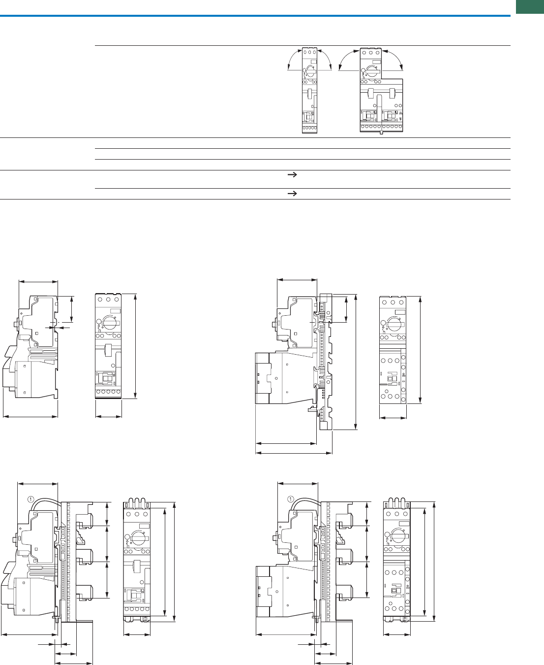
1
1.4
Motor-starter combinations
DOL starters, reversing starters
39AUTOMATION AND CONTROL www.eaton.com/seasia-electrical
Dimensions
General Standards IEC/EN 60947-4-1, VDE 0660
UL 508 (please enquire)
CSA C 22.2 No. 14 (please enquire)
Mounting position
Main contacts Rated impulse withstand voltage Uimp V AC 6000
Overvoltage category/pollution degree III/3
Rated operating voltage UeV230 - 415
Further technical data Motor protective circuit breaker
PKZM0, PKE
Chapter 1.3
Contactors DILM Chapter 1.1
DOL starters
MSC-D-…-M17[…32]…MSC-D-…-M7[…15]…
MSC-D-…-M17[…32]BBA…MSC-D-…-M7[…15]BBA…
90º
90º
90º
90º
95 45
67
6
46
180
45
180
97.4
123.4
67
46
228
95
35
63
10
45
67
40
6060
180
200
35
63
10
45
67
40
6060
180
200
97.4
MSC-D, MSC-R, MSC-DE(A)
MSC-D, MSC-R, MSC-DE(A)
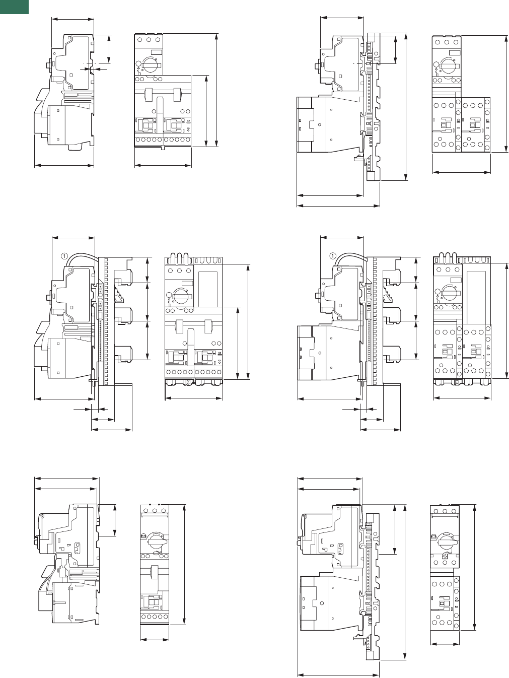
1
1.4 Motor-starter combinations
DOL starters, reversing starters
40 AUTOMATION AND CONTROL www.eaton.com/seasia-electrical
Reversing starters
MSC-R-…-M7[…12]… MSC-R-…-M17[…32]…
MSC-R-…-M7[…12]BBA… MSC-R-…-M17[…32]BBA…
DOL starters
MSC-DE(A)-...-M7[...12]...MSC-DE(A)-...-M7[...12]...
95 90
67
6
46
114
180
90
180
97.4
123.4
67
46
228
95
35
63
10
67
40
60
60
90
114
180
35
63
10
67
40
60
60
97.4 90
180
97
102
189
50
45
78
242
196
128
97
102
45
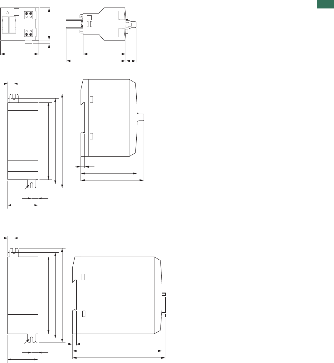
1
1.4
Connection system SmartWire-DT®
DOL starters, reversing starters
41AUTOMATION AND CONTROL www.eaton.com/seasia-electrical
Modules
SWIRE-DIL
SWIRE-PF , SWIRE-4DI-2DO-R
Gateways
SWIRE-GW-DP..., SWIRE-GW-MB
384
45 50
12
70
M4
7.5
35.5
7.5
90
102
110
66
74
4.5
M4
7.5
35.5
7.5
90
102
110
105
109
4.5
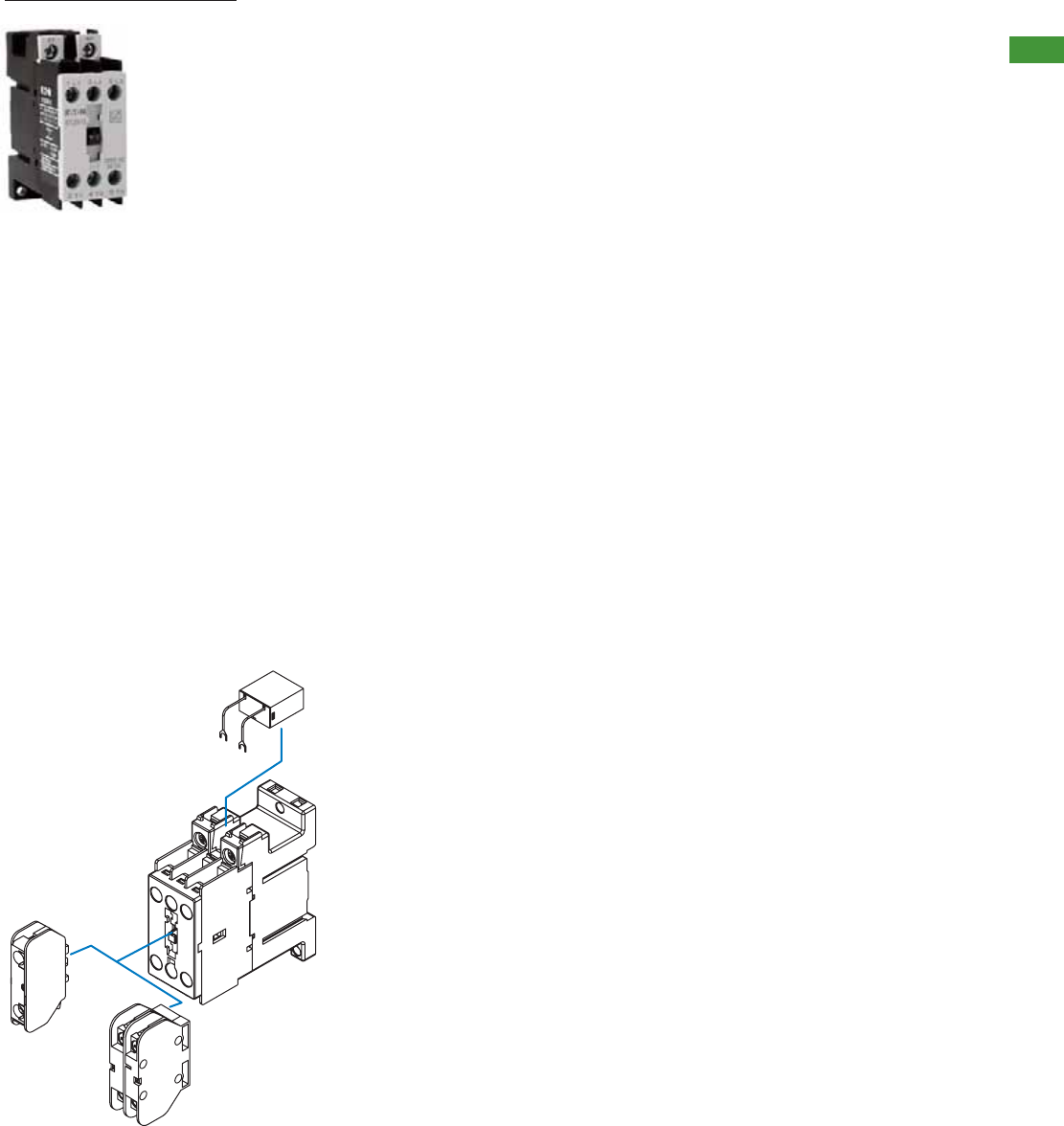
2AUTOMATION AND CONTROL www.eaton.com/seasia-electrical
2
Control relays XTRG
Control relays XTRG
System overview . . . . . . . . . . . . . . . . . . . . . . . . . . . . . . . . . . . . . . . . . . . . . . . . . . . . . . . . . . . . . . . . .
Basic devices XTRG . . . . . . . . . . . . . . . . . . . . . . . . . . . . . . . . . . . . . . . . . . . . . . . . . . . . . . . . . . . . . . .
Auxiliary contact modules . . . . . . . . . . . . . . . . . . . . . . . . . . . . . . . . . . . . . . . . . . . . . . . . . . . . . . . . . . .
Technical data . . . . . . . . . . . . . . . . . . . . . . . . . . . . . . . . . . . . . . . . . . . . . . . . . . . . . . . . . . . . . . . . . . . .
2
3
3
4
Accessory overview
Control relays XTRG
Product description
• GB 14048
• IEC/EN 60947
• CCC
• CE
Standards and certifications
Part of the E Line family of
controls, the XTRG control relay
offers space savings, enhanced
reliability and more efficient use
of materials. Rated to operate
thermal currents up to 10A, AC
voltages up to 660V or DC
voltages up to 250V, the XTRG
contactor relay offers optimum
performance in a compact
package.
Features
• 10A Control relay
• 690V Insulation rating
• 660VAC or 250VDC
Operational voltage
• Up to 5 sets of normally
open or normally closed
contacts with add-on blocks
• All common AC control
voltages
• DIN rail or panel mount
options
• Unique 27mm design
1 Contactor relay
2 Auxiliary contact modules
3 Surge suppressor
System overview
Control relays are used to
remotely switch small loads or
in complex control schemes.
The XTRG relay can be
integrated with contactors from
the E Line ramily of motor
controls to create compact,
efficient control panels for a
multitude of applications.
1
2
1X
1X
3
2.1
Control relays XTRG
Contents, system overview
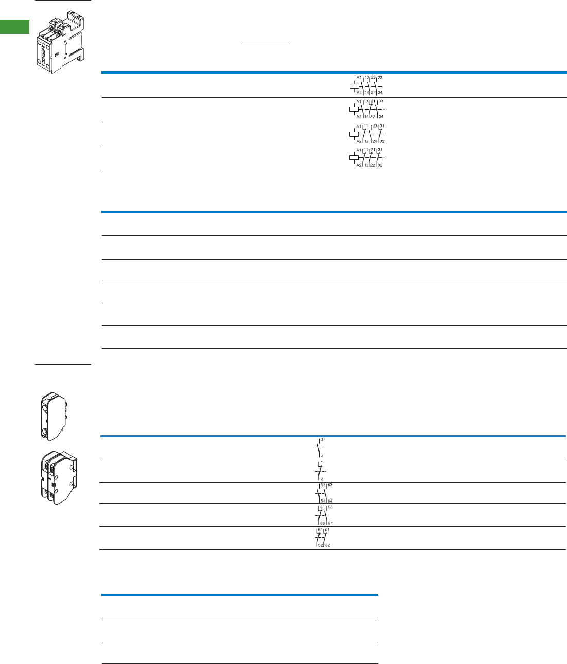
3 AUTOMATION AND CONTROL www.eaton.com/seasia-electrical
2
2.1 Control relays XTRG
Basic devices / Auxiliary contact modules, actuating voltages
XTRG
XTCGXFAC10
XTCGXFAC..
XTRG10B30DT
168044
XTCGXFAC10
XTCGXFAC..
XTCGXFAC10
XTCGXFAC..
XTCGXFAC10
XTCGXFAC..
1 piece
1 piece
1 piece
1 piece
Screw terminals
Screw terminals
Screw terminals
Screw terminals
3 N/O
2 N/O
1 N/O
-
-
1 N/C
2 N/C
3 N/C
4
4
4
4
1.9
1.9
1.9
1.9
10
10
10
10
XTRG10B21DT
167927
XTRG10B12DT
167968
XTRG10B03DT
167978
Circuit
symbol
Can be
combined with
auxiliary contact
module
Standard
package
AC operation
Part no.
Article no.
Actuating voltage
220V 50HZ
Conventional
thermal
current,
open, 40°C
Ith (A)
Control relays
Contact
N/O=Normally open
N/C=Normally closed
Connection
type
Rated operational
current
AC-15 Ie (A)
220V
230V
240V
380 V
400 V
415 V
Alternate actuating voltages
Coil Voltage 3NO 2NO/1NC 1NO/2NC 3NC
24VAC 50Hz XTRG10B30B5 XTRG10B21B5 XTRG10B12B5 XTRG10B03B5
168040 167923 167933 167974
36VAC 50Hz XTRG10B30DS XTRG10B21DS XTRG10B12DS XTRG10B03DS
168041 167924 167934 167975
48VAC 50Hz XTRG10B30C5 XTRG10B21C5 XTRG10B12C5 XTRG10B03C5
168042 167925 167966 167976
110VAC 50Hz XTRG10B30E5 XTRG10B21E5 XTRG10B12E5 XTRG10B03E5
168043 167926 167967 167977
220VAC 50Hz XTRG10B30DT XTRG10B21DT XTRG10B12DT XTRG10B03DT
168044 167927 167968 167978
380VAC 50Hz XTRG10B30DU XTRG10B21DU XTRG10B12DU XTRG10B03DU
168047 167930 167971 167936
Coil surge supressor
Coil voltage RC Varistor
XTCGXRSCN2 XTCGXVSCN2
167946 167949
XTCGXRSCDV XTCGXVSCDV
167947 167950
XTCGXRSCCM XTCGXVSCCM
167948
24-48V
110-220V
380-440V
167951
XTCGXFAC10
167939
XTCGXFAC01
167940
XTCGXFAC20
167941
XTCGXFAC11
167942
XTCGXFAC02
167943
XTRG10B..
XTRG10B..
XTRG10B..
XTRG10B..
XTRG10B..
-
1 N/C
-
1 N/C
2 N/C
1 N/O
-
2 N/O
1 N/O
-
10
10
10
10
10
1 pole
1 pole
2 pole
2 pole
2 pole
Screw
terminals
Screw
terminals
Screw
terminals
Screw
terminals
Screw
terminals
1 piece
1 piece
1 piece
1 piece
1 piece
Part no.
Article no.
Standard
package
Can be
combined with
control relay
Conventional
thermal current
open, 40°C
Ith = Ie AC-1
A
Contact
N/O=Normally open
N/C=Normal closed
Circuit
symbol
Auxiliary contact modules
Auxiliary contact,
top mounting Connection
type
4AUTOMATION AND CONTROL www.eaton.com/seasia-electrical
2
2.1
Control relays XTRG
Technical data
XTRG10B.. XTCGXFAC..
XTRG10B.. XTCGXFAC..
General
Standards
Mechanical lifespan
Maximum operating frequency
Climatic proofing Damp heat, constant, to IEC 60068-2-78
Damp heat, cyclic, to IEC 60068-2-30
Ambient temperature
Protection type
Contacts
Rated impulse withstand voltage
Overvoltage category/degree of pollution
Rated insulation voltage
Rated operational voltage
Rated operational current
AC-15
DC-13
Conventional thermal current
Electrical lifespan
AC operated Operations
IEC/EN 60947, GB 14048
10
600
-5~40
-25~55
-5~40
-25~55
IP20
0.17kg
10
600
IP20
0.02
x 106
°C
°C
Operations/h
Maximum operating frequency
Operation
Storage
Weight approximate weight
6000
III/3
690
660
6
4
1.9
1.5
1.4
1.2
0.55
0.27
10
1
6000
III/3
690
660
6
4
1.9
0.55
0.27
10
1
at Ue=230V, AC-15, 3A
120V
240V
380V
480V
500V
600V
125V
250V
Uimp
Ui
Ue
Ie
Ie
Ie
Ie
Ie
Ie
Ie
Ie
Ith
Operations
VAC
VAC
VAC
A
A
A
A
A
A
A
A
A
x 106
Magnet system
Voltage tolerance
AC operated
Power consumption
Pick-up
Pick-up
Sealing
Sealing
x Uc
VA
VA
W
0.85-1.1
30
6
2
XTRG10B..
Terminals
XTRG10B..
XTCGXFAC..
0.75-2.5
0.75-2.5
0.75-2.5 0.8 0.80.75-2.5
0.75-2.5
mm2mm2Nm mm2Nm
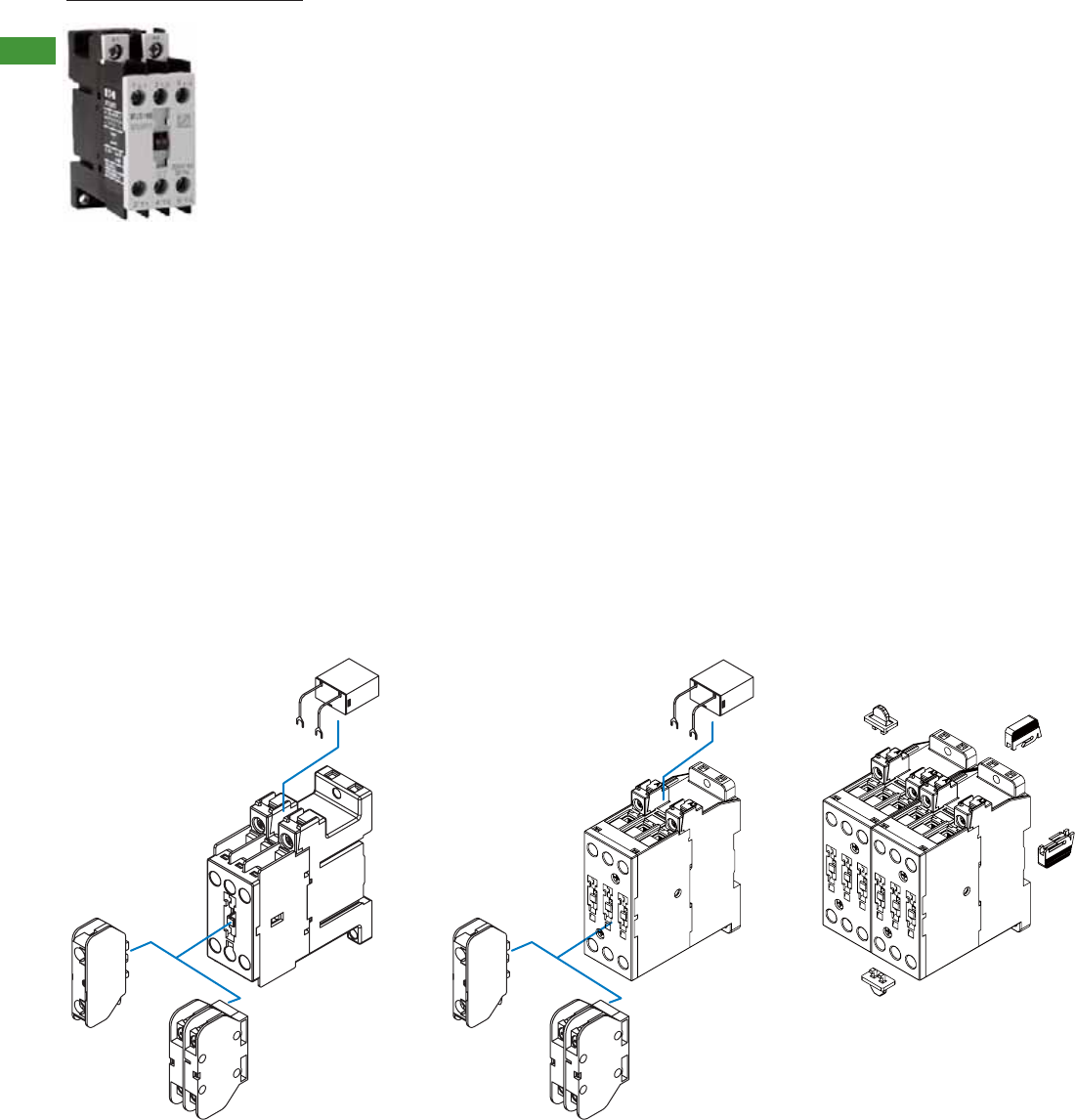
5 AUTOMATION AND CONTROL www.eaton.com/seasia-electrical
2
2.1 Contactors XTCG
Contents
Accessory overview
Contactors XTCG
Product description
7-12A Frame 18-32A Frame 18-32A Frame with mechanical
interlock
• GB 14048
• IEC/EN 60947
• CCC
• CE
Standards and certifications
The XTCG is the flagship of the
E Line family of motor controls.
The XTCG contactor offers
space savings, enhanced
reliability and more efficient use
of materials. Boasting AC-3
ratings up to 32A @ 400V and
with a maximum operating
voltage of 660V, XTCG offers
tremendous performance in a
small package.
Features
• Technologically advanced
contact design
• 690V insulation rating
• Operating voltage up to
660VAC
• Up to (3) add on auxiliary
contact modules
• All common AC control
voltages
• DIN rail or panel mount
options
• Unique space saving design
1 Contactor relay
2 Auxiliary contact modules
3 Surge suppressor
4 Interlocking kit
System overview
3 phase contactors are used to
start motors or control industrial
loads. The E Line family of
contactors allows the starting of
motors up to 15kW, and when
combined with an XTOD
overload relay or PKZC motor
protective circuit breaker offers
a complete package of
protection and control for long
life and reliable operation.
1
2
1X
1X
3
2
1X
1X
1
3
4
Contactors XTCG Contactors XTCG
System overview . . . . . . . . . . . . . . . . . . . . . . . . . . . . . . . . . . . . . . . . . . . . . . . . . . . . . . . . . . . . . . . . .
Contactors
Basic devices XTCG . . . . . . . . . . . . . . . . . . . . . . . . . . . . . . . . . . . . . . . . . . . . . . . . . . . . . . . . . . . . . . .
Auxiliary contact modules . . . . . . . . . . . . . . . . . . . . . . . . . . . . . . . . . . . . . . . . . . . . . . . . . . . . . . . . . . .
Accessories . . . . . . . . . . . . . . . . . . . . . . . . . . . . . . . . . . . . . . . . . . . . . . . . . . . . . . . . . . . . . . . . . . . . . .
Technical data
Contactors XTCG . . . . . . . . . . . . . . . . . . . . . . . . . . . . . . . . . . . . . . . . . . . . . . . . . . . . . . . . . . . . . . . . .
Auxiliary contact modules . . . . . . . . . . . . . . . . . . . . . . . . . . . . . . . . . . . . . . . . . . . . . . . . . . . . . . . . . . .
5
6
6
6
7
7
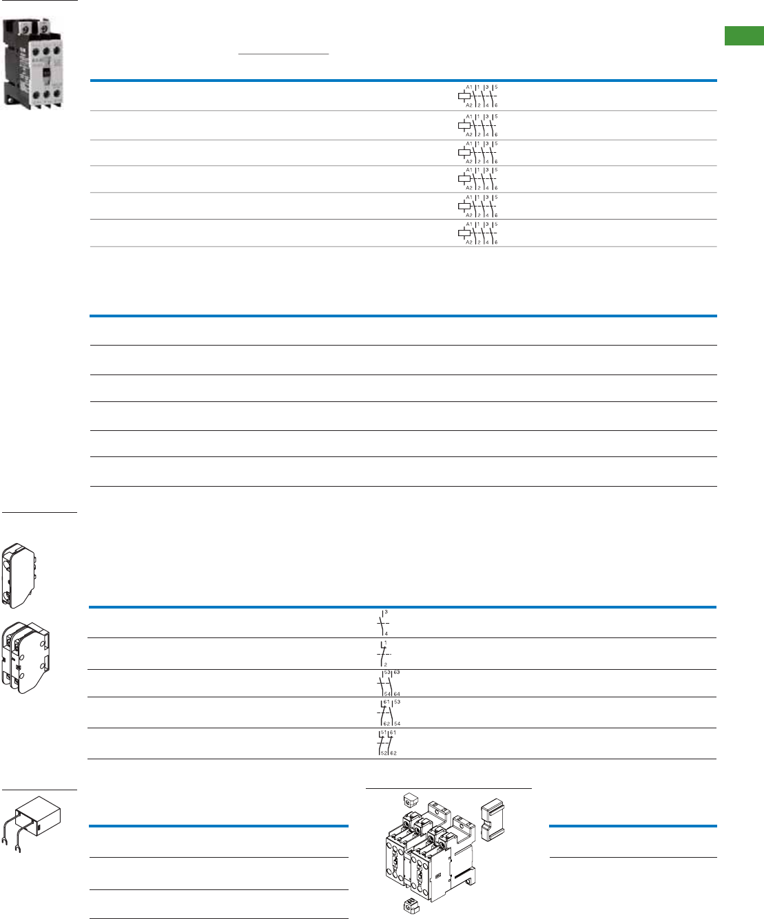
6AUTOMATION AND CONTROL www.eaton.com/seasia-electrical
2
2.1
Contactors XTCG
Basic devices / Auxiliary contact modules, actuating voltages / Accessories
24VAC 50Hz
36VAC 50Hz
48VAC 50Hz
110VAC 50Hz
220VAC 50Hz
380VAC 50Hz
Screw
terminals
Screw
terminals
Screw
terminals
Screw
terminals
Screw
terminals
1 pole
1 pole
2 pole
2 pole
2 pole
10
10
10
10
10
1 N/O
-
2 N/O
1 N/O
-
-
1 N/C
-
1 N/C
2 N/C
XTCG10B...
XTCG10B...
XTCG10B...
XTCG10B...
XTCG10B...
XTCGXFAC10
167939
XTCGXFAC01
167940
XTCGXFAC20
167941
XTCGXFAC11
167942
XTCGXFAC02
167943
1 piece
1 piece
1 piece
1 piece
1 piece
XTCG007B00B5 XTCG009B00B5 XTCG012B00B5 XTCG018C00B5 XTCG025C00B5 XTCG032C00B5
167980 167990 168000 168010 168020 168030
XTCG007B00DS XTCG009B00DS XTCG012B00DS XTCG018C00DS XTCG025C00DS XTCG032C00DS
167981 167991 168001 168011 168021 168031
XTCG007B00C5 XTCG009B00C5 XTCG012B00C5 XTCG018C00C5 XTCG025C00C5 XTCG032C00C5
167982 167992 168002 168012 168022 168032
XTCG007B00E5 XTCG009B00E5 XTCG012B00E5 XTCG018C00E5 XTCG025C00E5 XTCG032C00E5
167983 167993 168003 168013 168023 168033
XTCG007B00DT XTCG009B00DT XTCG012B00DT XTCG018C00DT XTCG025C00DT XTCG032C00DT
167984 167994 168004 168014 168024 168034
XTCG007B00DU XTCG009B00DU XTCG012B00DU XTCG018C00DU XTCG025C00DU XTCG032C00DU
167987 167997 168007 168017 168027 168037
Standard package: 1piece
20
20
25
35
40
AC operation
Part no.
Article no.
Actuating voltage
220V 50Hz
3-pole contactors
XTCG
Rated
operational
current
AC-3 Ie (A)
380V
Conventional
thermal current,
open, 40 °C
Ith = Ie AC-1(A)
Circuit
symbol
7.5
10
2.5
3.5
5 7.5
11
15
7.5
11
15
4.54
5.55.5
2.2
220V 380V 660V
Max motor rating for
3-phase motors,
50-60Hz AC-3 P kW
3.5320
XTCG009B00DT
167994
XTCG012B00DT
168004
XTCG018C00DT
168014
XTCG025C00DT
168024
XTCG032C00DT
168034
XTCG007B00DT
167984
Screw
terminals
Screw
terminals
Screw
terminals
Screw
terminals
Screw
terminals
Screw
terminals
9
12
18
25
32
7
Connection
type
Part no.
Article no.
Standard
package
Can be
combined with
control relay
Conventional
thermal current
open, 40°C
Ith = Ie AC-1
A
Contact
N/O=Normally open
N/C=Normal closed
Circuit
symbol
Auxiliary contact modules
Auxiliary contact,
top mounting Connection
type
Alternate actuating voltages
Coil voltage 7A 9A 12A 18A 25A 32A
Mechanical interlock
7-12A 18-32A
XTCGXMLB XTCGXMLC
167944 167945
Coil surge supressor
Coil voltage RC Varistor
XTCGXRSCN2 XTCGXVSCN2
167946 167949
XTCGXRSCDV XTCGXVSCDV
167947 167950
XTCGXRSCCM XTCGXVSCCM
167948
24-48V
110-220V
380-440V
167951
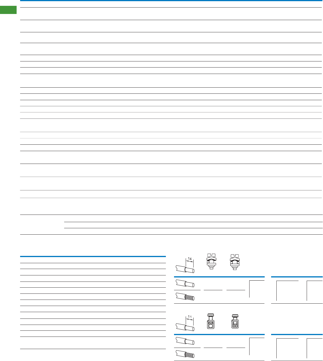
7 AUTOMATION AND CONTROL www.eaton.com/seasia-electrical
2
2.1 Contactors XTCG
Technical data
Standards
Lifespan, mechanical
Operating frequency
Climatic Proofing
Ambient temperature
Protection type
Weight
Terminal capacity of main cable
AC operated Operations
Damp heat,constant,to IEC60068-2-78
Damp heat,cyclic,to IEC60068-2-30
Operations/h
AC operated
Operation
Storage
Main contacts
Terminal capacity of control circuit cable
Solid/stranded
Main cable connection screws / bolts
Tightening torque
Control circuit cable connection screws / bolts
Tightening torque
Rated impulse withstand voltage
Overvoltage category / pollution degree
Rated insulation voltage
Rated operational voltage
Making capacity
(cos ij to IEC/EN60947)
Breaking capacity
(cos ij to IEC/EN60947)
Electrical lifespan
General
XT Basic device CG007 CG009 CG012
380V
380V
AC-4
Uimp
Ui
Ue
A
A
V AC
V AC
V AC
Nm
Nm
AWG
kg
mm
2
Op.
x 106
°C
°C
70
III/3
56
6000
0.8
0.8
0.17
IP20
0.75-2.5
M3.5
M3.5
100,000
10
600
-5~40
-25~55
90
III/3
72
6000
0.8
0.8
0.17
IP20
0.75-2.5
M3.5
M3.5
100,000
10
600
-5~40
-25~55
120
III/3
96
6000
0.8
0.8
0.17
IP20
0.75-2.5
M3.5
M3.5
100,000
10
600
-5~40
-25~55
CG018
180
III/3
144
6000
0.8
2
0.35
IP20
0.75-2.5
M5
M3.5
100,000
10
600
-5~40
-25~55
CG025
250
III/3
200
6000
0.8
2
0.35
IP20
0.75-2.5
M5
M3.5
100,000
10
600
-5~40
-25~55
CG032
320
660 660 660 660 660 660
690 690 690 690 690 690
III/3
256
6000
0.8
2
0.35
IP20
0.75-2.5
M5
M3.5
100,000
AC-3 Op.
1,500,000 1,500,000 1,500,000 1,000,000 1,000,000 1,000,000
10
600
-5~40
-25~55
IEC/EN 60947, GB 14048
Pick-up
Pick-up
Sealing
Sealing
x Uc
VA
VA
W
Magnet systems
Voltage tolerance
AC operated
Power consumption
of coil in a cold
state and 1.0 xUc
0.85-1.1
30
6
2
0.85-1.1
30
6
2
0.85-1.1
30
6
2
0.85-1.1
80
8.1
2.4
0.85-1.1
80
8.1
2.4
0.85-1.1
80
8.1
2.4
Conventional thermal current
Electrical lifespan
Rated impulse withstand voltage
Overvoltage category/degree of pollution
Rated insulation voltage
Rated operational current
AC-15
Aux Contact
DC-13
Rated operational voltage
Auxiliary contact
XTCGXFAC..
120V
240V
380V
125V
250V
at Ue=230V, AC-15, 3A
Uimp
Ui
Ue
Ie
Ie
Ie
Ie
Ie
Ith
Operations
VAC
VAC
VAC
A
A
A
A
A
A
x 106
6000
III/3
690
660
6
4
1.9
0.55
0.27
10
1
Terminals
0.75-2.5
0.75-2.5
0.75-2.5 0.8 0.80.75-2.5
0.75-2.5
Aux Contact
20.80.75-2.5
1 - 6
(1 - 10)*
1 - 4
(1 - 10)*
1 - 6
(1 - 10)*
1 - 4
(1 - 10)*
7-12A
18-32A
mm2Nm
mm2
mm2
mm2
mm2
mm2Nm
Nm
Nm
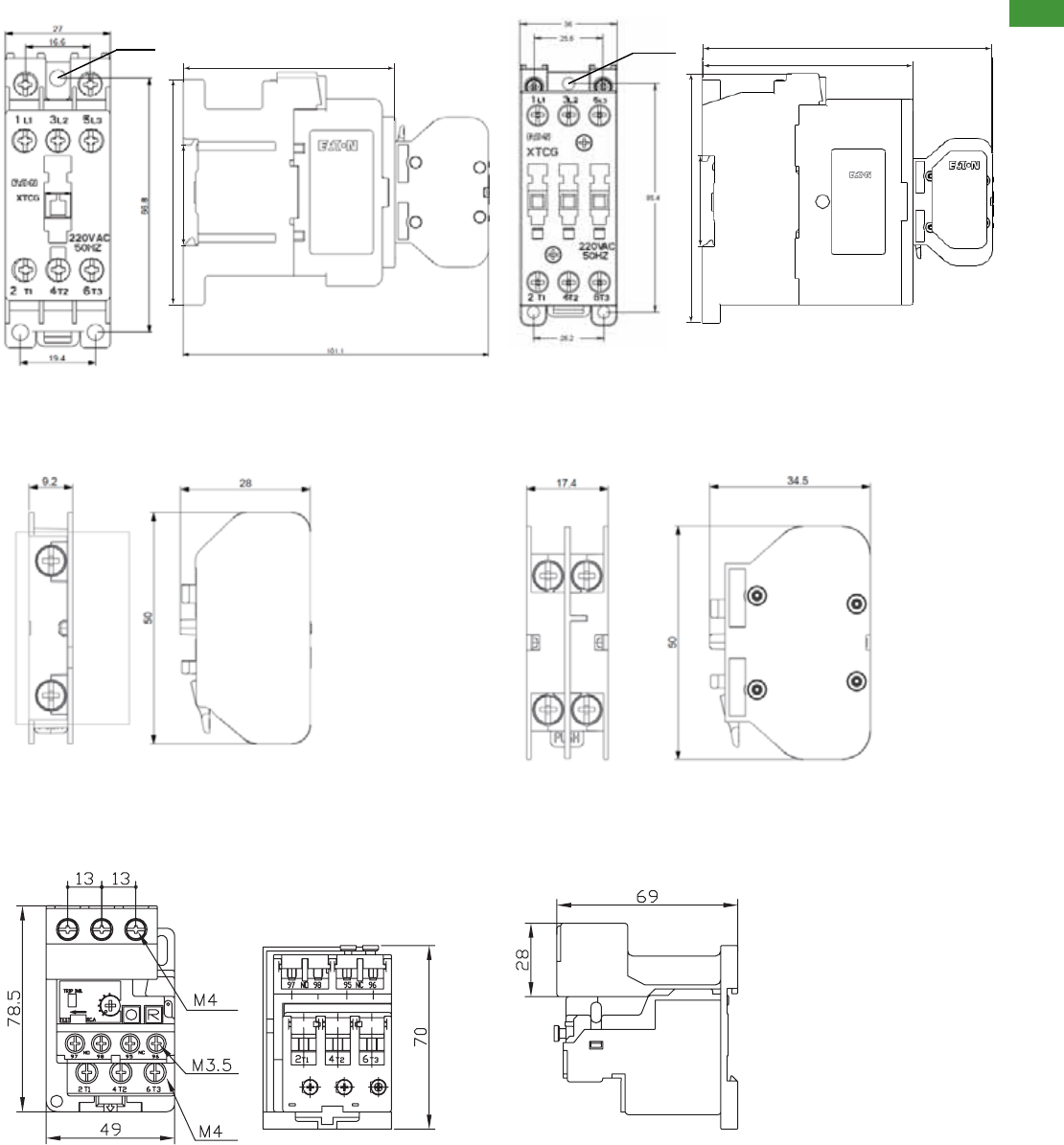
8AUTOMATION AND CONTROL www.eaton.com/seasia-electrical
2
2.1
Dimensions
Thermal overload relay + mounting adapter
XTOD..CC1S
7-12A Frame 18-32A Frame
Auxiliary contact module
Contactors
1 Pole 2 Pole
3hĭ4
35.3
77.5
70.1
35.3
97.5
82
113
3hĭ4
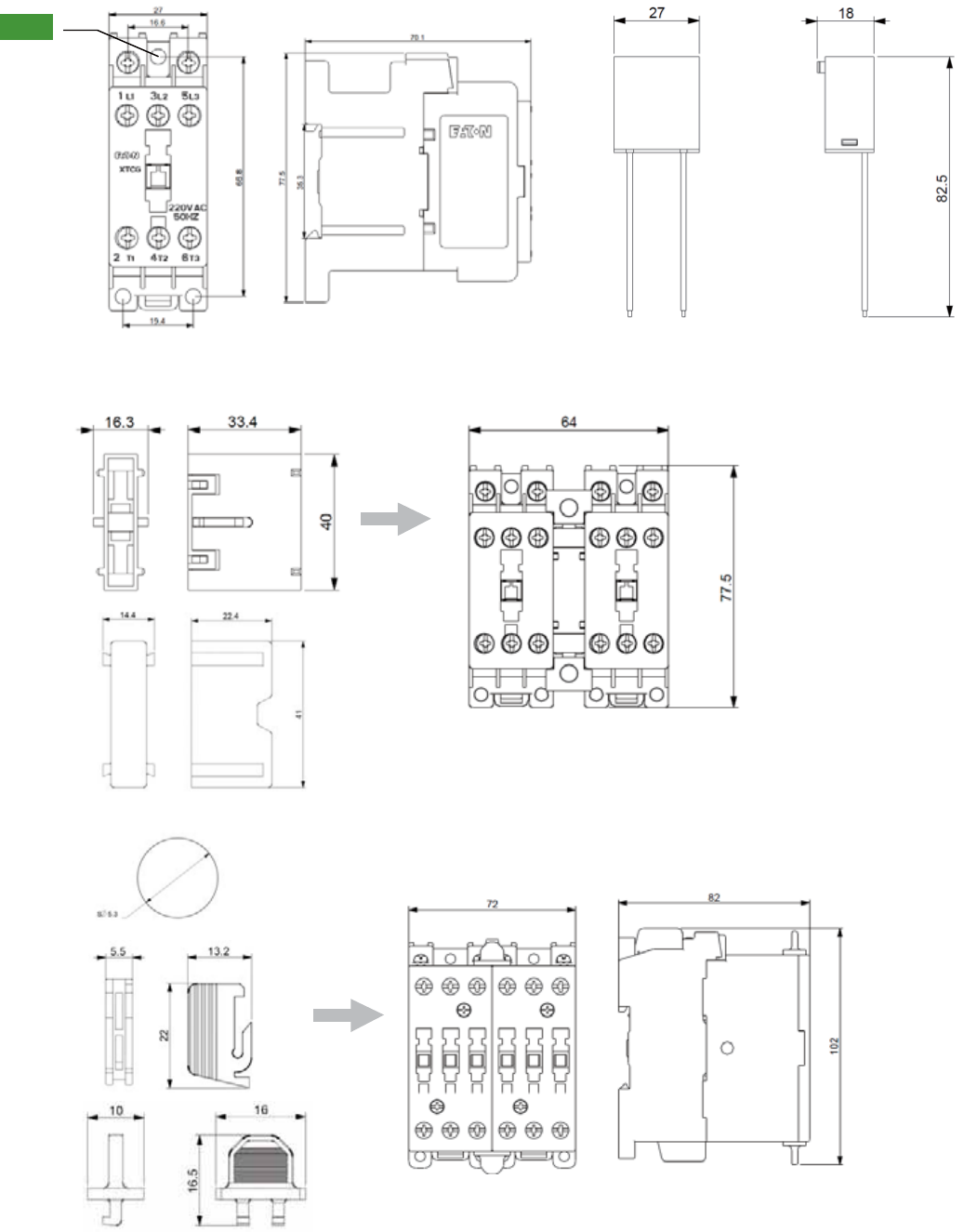
9 AUTOMATION AND CONTROL www.eaton.com/seasia-electrical
2
2.1 Dimensions
Control Relay Surge suppressor
3 × ĭ4
Mechanical interlock
7-12A Frame
18-32A Frame
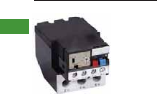
2 AUTOMATION AND CONTROL www.eaton.com/seasia-electrical
2
2.2 Thermal overload relays XTOD
Contents
Thermal overload relays XTOD Thermal overload relays XTOD
System overview . . . . . . . . . . . . . . . . . . . . . . . . . . . . . . . . . . . . . . . . . . . . . . . . . . . . . . . . . . . . . . . . .
Thermal overload relays . . . . . . . . . . . . . . . . . . . . . . . . . . . . . . . . . . . . . . . . . . . . . . . . . . . . . . . . . . . .
Technical data . . . . . . . . . . . . . . . . . . . . . . . . . . . . . . . . . . . . . . . . . . . . . . . . . . . . . . . . . . . . . . . . . . . .
Dimensions . . . . . . . . . . . . . . . . . . . . . . . . . . . . . . . . . . . . . . . . . . . . . . . . . . . . . . . . . . . . . . . . . . . . . .
2
3
3
5
Thermal overload relays XTOD
Product description
• GB 14048
• IEC/EN 60947
• CCC
• CE
Standards and certifications
XTOD thermal overload relays
offer precision motor protection
with phase loss protection and
ambient temperature
compensation. The seperate
mount design allows for
flexibility and the units can be
mounted on DIN rail or directly
on the panel adjacent the motor
contactor.
Features
• Precision motor protection up
to 32A
• Integral 1NO/1NC contact for
contactor control and alarm
signal
• Phase loss protection
• Ambient temperature
compensation
• DIN rail or panel mount
options
System overview
Thermal overload relays provide
protective features for 1 or 3
phase motors. The relay
monitors the operating current
of the motor and switched the
contactor off in the event of an
overload situation. It also
protects the motor from
damage during phase loss.
3AUTOMATION AND CONTROL www.eaton.com/seasia-electrical
2
2.2
Thermal overload relays XTOD
Thermal overload relays
Thermal overload relays
Part no.
Article no.
Standard
package
XTOD..CC1S Seperate mounting 1 N/O 1 N/C 1 piece
Seperate mounting 1 N/O 1 N/C 1 piece
Seperate mounting
Seperate mounting
1 N/O 1 N/C 1 piece
1 N/O 1 N/C 1 piece
Seperate mounting 1 N/O 1 N/C 1 piece
Seperate mounting 1 N/O 1 N/C 1 piece
Seperate mounting 1 N/O 1 N/C 1 piece
Auxiliary
contact
N/O =Normally open
N/C =Normally closed
Circuit
symbol
Setting range
of overload
releases Ir(A)
Seperate mounting 1 N/O 1 N/C 1 piece
Seperate mounting 1 N/O 1 N/C 1 piece
Seperate mounting 1 N/O 1 N/C 1 piece
Seperate mounting 1 N/O 1 N/C 1 piece
1 N/O 1 N/C 1 piece
Seperate mounting
Seperate mounting
1 N/O 1 N/C 1 piece
Seperate mounting
0.3~0.45
0.45 ~0.67
0.67~1.0
1.0 ~1.5
1.4 ~2.1
1.8~2.7
2.4~3.6
3.5~5.0
4.0~6.0
5.5~8.5
8.5~12.5
17~24
12.5~18
22~30 1 N/O 1 N/C
XTODP45CC1S
167952
XTODP67CC1S
167953
XTOD001CC1S
167954
XTOD1P5CC1S
167955
XTOD2P2CC1S
167956
XTOD2P7CC1S
167957
XTOD3P6CC1S
167958
XTOD005CC1S
167959
XTOD006CC1S
167960
XTOD8P5CC1S
167961
XTOD013CC1S
167962
XTOD018CC1S
167963
XTOD024CC1S
167964
XTOD030CC1S
167965 1 piece
For use with
XTCG007
XTCG009
XTCG012
XTCG018
XTCG025
XTCG032
97 95
98
246 96
97 95
98
246 96
97 95
98
246 96
97 95
98
246 96
97 95
98
246 96
97 95
98
246 96
97 95
98
246 96
97 95
98
246 96
97 95
98
246 96
97 95
98
246 96
97 95
98
246 96
97 95
98
246 96
97 95
98
246 96
97 95
98
246 96

4 AUTOMATION AND CONTROL www.eaton.com/seasia-electrical
2
2.2 Thermal overload relays XTOD
Technical data
Main contacts
Auxiliary and control circuits
Ambient temperature
Temperature compensation
Weight
Protection type
Rated impulse withstand voltage
Overvoltage category/pollution degree
Rated insulation voltage
Rated operational voltage
Overload release setting range
Terminal capacity
Terminal screw
Tightening torque
Rated impulse withstand voltage
Overvoltage category/pollution degree III/3
Terminal capacity
Terminal screw
Tightening torque
Rated insulation voltage
Rated operational voltage
Conventional thermal current
Rated operational current
AC
General
Standards
Climatic Proofing Damp heat, constant, to IEC60068-2-78
Damp heat, cyclic, to IEC60068-2-30
Open
Enclosed
Solid
Flexible with ferrule
Solid/stranded
Solid
Flexible with ferrule
Solid/stranded
XTOD..CC1S
XTOD..CC1S
XTOD..CC1S
AC-15
DC-13
125V
IEC/EN 60947, GB 14048
Uimp
Ui
Ue
Uimp
Ui
Ue
Ie
Ie
Ie
Ie
Ie
Ie
Ie
Ie
Ith
VAC
VAC
A
A
A
A
A
A
120V
220/240V
380V
480V
500V
600V
A
VAC
VAC
VAC
A
A
A250V
V
mm2
mm2
Nm
AWG
kg
mm2
mm2
Nm
AWG
°C
°C
°C
690
600
6
3
1.9
1.5
1.4
1.2
10
690
6000
III/3
600
0.3-30
0.55
0.27
6000
1 x (1-6)
2 x (1-6)
1 x (1-6)
2 x (1-6)
0.8
M3.5
0.15
IP20
1 x (1-6)
2 x (1-6)
1 x (1-6)
2 x (1-6)
1.2
M4
-5~40
-25~40
-25~55
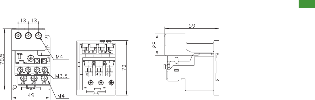
5AUTOMATION AND CONTROL www.eaton.com/seasia-electrical
2
2.2
Thermal overload relays XTOD
Dimensions
Dimensions
Thermal overload relay + mounting adapter
XTOD..CC1S
