CoreliteCatalog
R Series Corelite_Catalog_09_
2014-11-11
: Pdf 629898-Attachment 629898-Attachment 662401 Batch12 unilog
Open the PDF directly: View PDF ![]() .
.
Page Count: 176 [warning: Documents this large are best viewed by clicking the View PDF Link!]
Product Catalog
2009
The climate is changing,
environmentally, economically
and architecturally. Budgets are tightening.
Savings for the end-user, both in the immediate and
long into the future, is now imperative to successful design.
And even with emphasis on supreme efficiency and functionality,
there is still an expectation of fresh, unique aesthetics suitable for
contemporary architecture. It can be a daunting mission for lighting companies.
It can be – unless it’s what you do best...
4
Innovative engineering and design, dedication to high performance and energy efficiency,
and pioneering use of cutting-edge technologies are all in a day’s work at Corelite.
The goal is to provide designers and owners alike with an arsenal of energy saving
luminaires and platforms to face the challenges of a new energy culture head-on.
5
Table of Contents
RECESSED Fluorescent Luminaires
Class R1-1-3/4” Deep Ultra Shallow Recessed T5 Luminaire ................................................. 14
Class R2-2-7/8” Deep Shallow Recessed T5 Luminaire .......................................................... 16
Class R3-3-3/4” Deep, T5/T8/CFL Recessed Luminaire .......................................................... 18
Class R Retrofi t- T5/T8 Field Retrofi ttable Luminaire ............................................................... 20
SUSPENDED Linear Fluorescent Lighting Systems
Class A Family- Steel, Radiused Profi le, T5/T8 Lighting System ............................................. 30
Iridium Family- Steel, Slim Radiused Profi le, T5/T8 Lighting System ...................................... 50
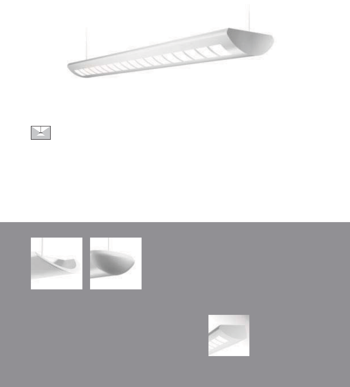
Stellar Family- Open Baffl e, T5/T8 Lighting System ................................................................ 64
Element- Extruded Aluminum, Rectangular Profi le, T5/T8 Lighting System ............................ 82
Loft- Extruded Aluminum, Trapezoidal Profi le, T5/T8 Lighting System .................................... 86
Vertechs- Extruded Aluminum, “Stepped” Rectangular Profi le, T5/T8 Lighting System .......... 90
Traverse- Extruded Aluminum, Rectangular Profi le, T5/T8 Lighting System ............................ 92
Navigator- Extruded Aluminum, Obround Profi le, T5/T8 Lighting System ............................... 94
Minigator- Extruded Aluminum, Obround Profi le, T5/T8 Lighting System ............................... 96
WALL MOUNTED Linear Fluorescent Lighting Systems
Class A D/I- Open Baffl e, Steel, Radiused Profi le, T5/T8 Lighting System ............................ 110
Class A D/I- Lensed, Steel, Radiused Profi le, T5/T8 Lighting System ................................... 112
Class A Perf- Perf Steel, Radiused Profi le, T5/T8 Lighting System ....................................... 114
Class A Indirect- Steel, Radiused Profi le, T5/T8 Lighting System ......................................... 116
Iridium- Perf Steel, Slim Radiused Profi le, T5/T8 Lighting System ........................................ 118
Stellar- Open Baffl e, T5/T8 Lighting System .......................................................................... 120
Element- Extruded Aluminum, Rectangular Profi le, T5/T8 Lighting System .......................... 122
Loft- Extruded Aluminum, Trapezoidal Profi le, T5/T8 Lighting System .................................. 126
Vertechs- Extruded Aluminum, “Stepped” Rectangular Profi le, T5/T8 Lighting System ........ 130
Traverse- Extruded Aluminum, Rectangular Profi le, T5/T8 Lighting System .......................... 132
Gator- Extruded Aluminum, Obround Profi le, T5/T8 Lighting System ................................... 134
SURFACE MOUNTED Linear Fluorescent Lighting Systems
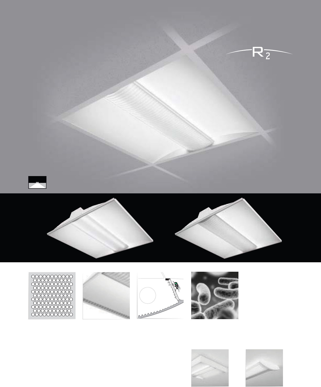
Class R2 ................................................................................................................................. 142
Class Rs ................................................................................................................................. 144
Stellar Q 2T5 .......................................................................................................................... 146
Stellar Q 2T8 .......................................................................................................................... 148
Stellar 2T5 .............................................................................................................................. 150
Stellar 2T8 .............................................................................................................................. 152
ARCHITECTURAL COVE Fluorescent Lighting Systems
Solo- 1T5 Performance Cove Lighting System ...................................................................... 160
Duo- 2T5/1T8 Performance Cove Lighting System ............................................................... 162
Trio- 2T8 Performance Cove Lighting System ....................................................................... 164
SMART ENVIRONMENTS with Integrated Lighting Controls
Day-Sense, Integral Luminaire Daylight Sensor ..................................................................... 170
2Sense, Integral Luminaire Daylight and PIR Occupancy Sensor .......................................... 171
InClass Command, Classroom Lighting Controls .................................................................. 172
6
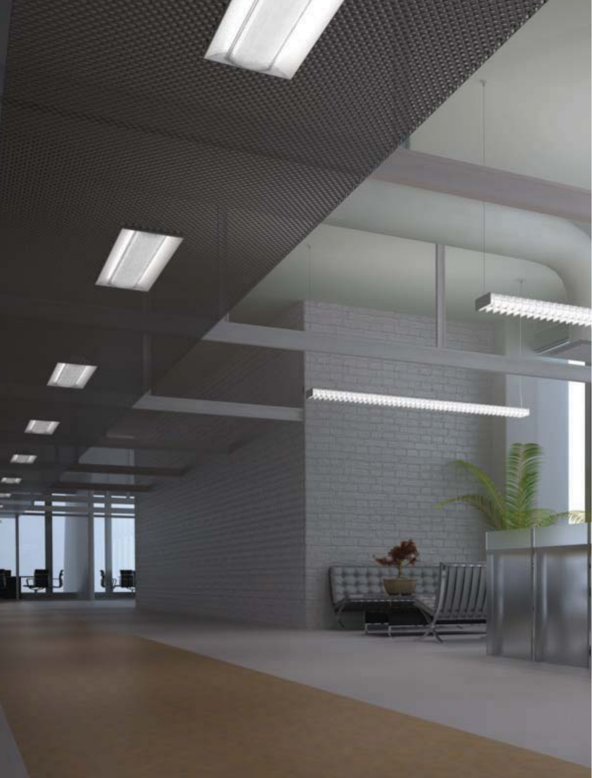
Recessed Lighting
Suspended
Wall Mounted
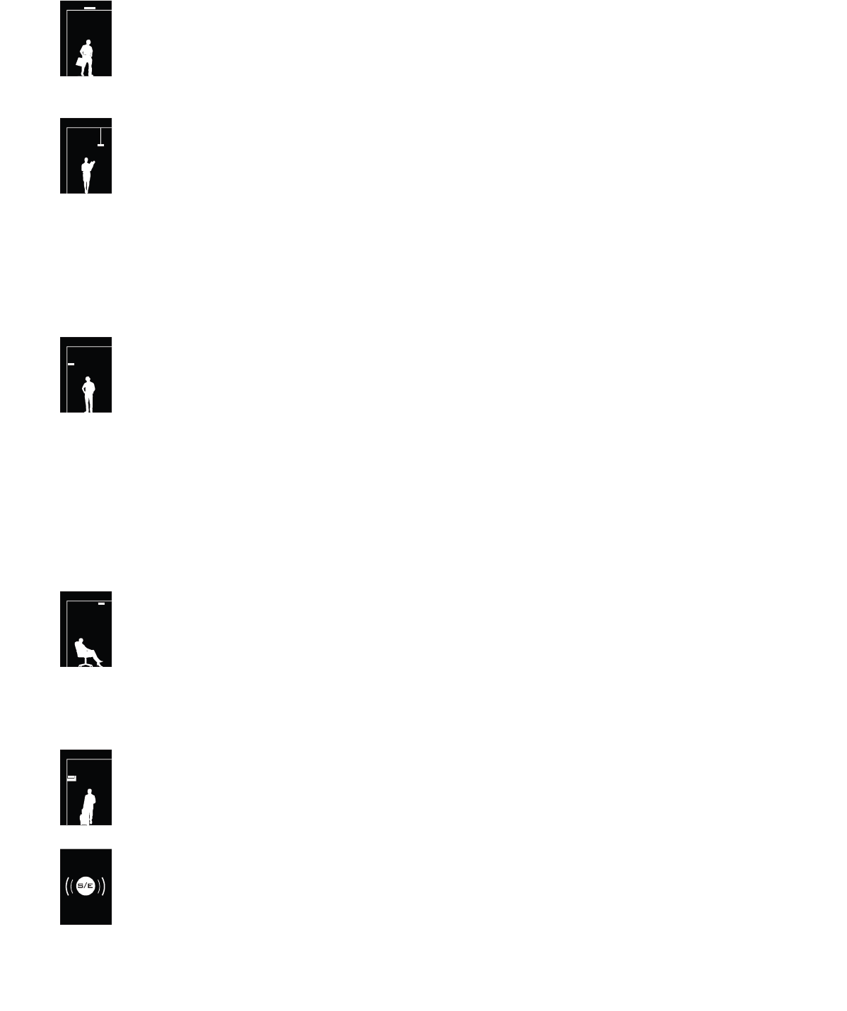
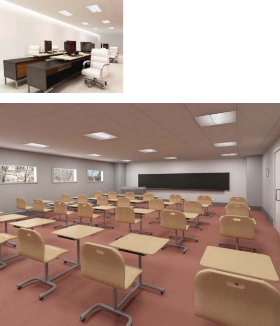
An obvious departure from Corelite’s signature linear
lighting systems, the Class R recessed family redefines not
only Corelite’s brand identity, but the identity of recessed
lighting altogether. The Class R family of luminaires presents
an entirely new pallet of low-profile, low-energy recessed
lighting solutions, suited to even the most challenging
modern application. The driving force behind the Class R
family’s conception was the constrained architectural
environment. Modern architectural projects have greater
material and spatial efficacy, are technologically advanced,
and are more budget conscious than ever. These factors
combined point towards lower ceiling heights, cluttered
plenum spaces, and a specific need for the solutions offered
by Corelite’s Class R series.
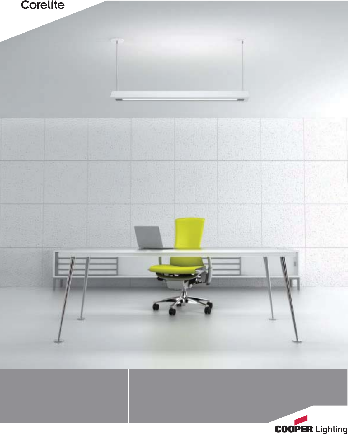
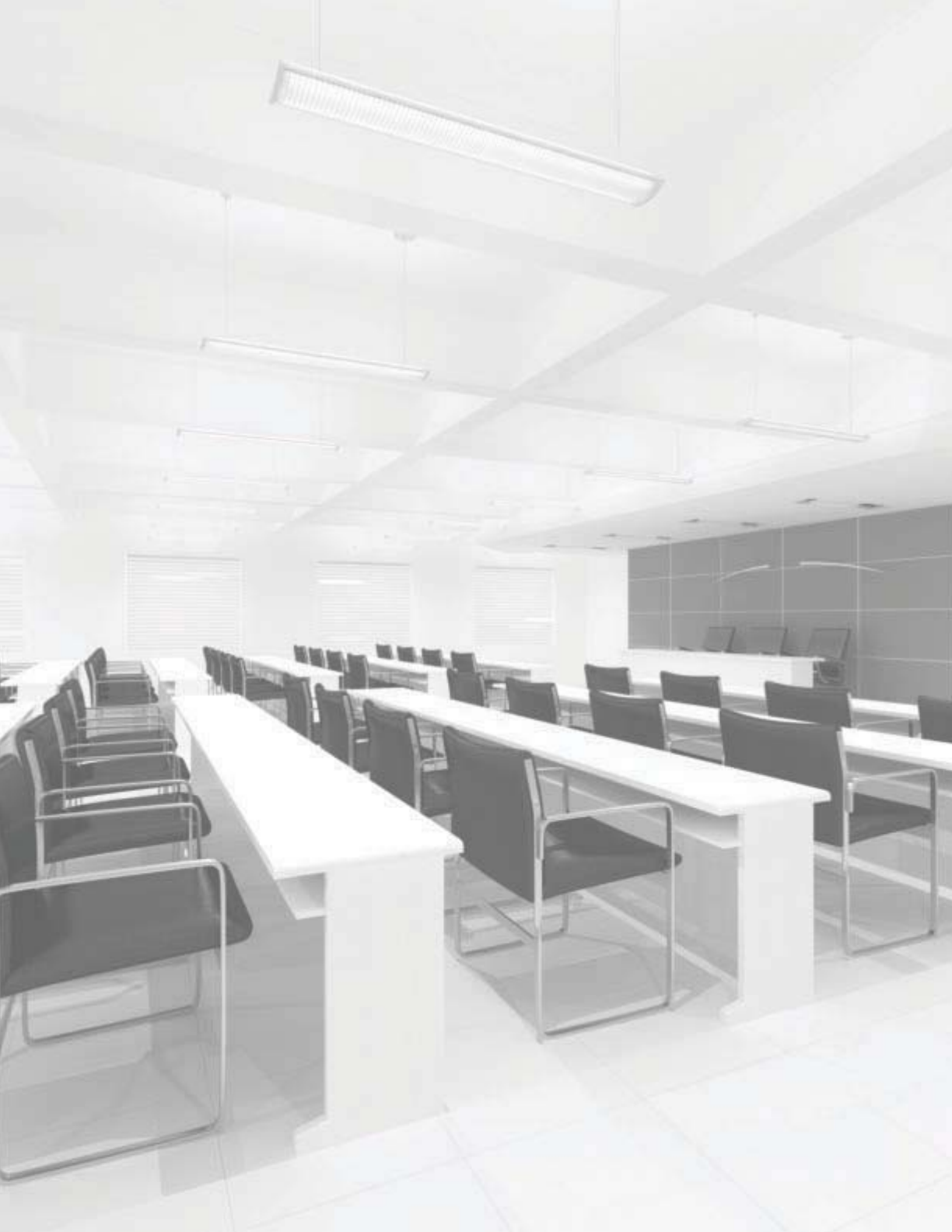
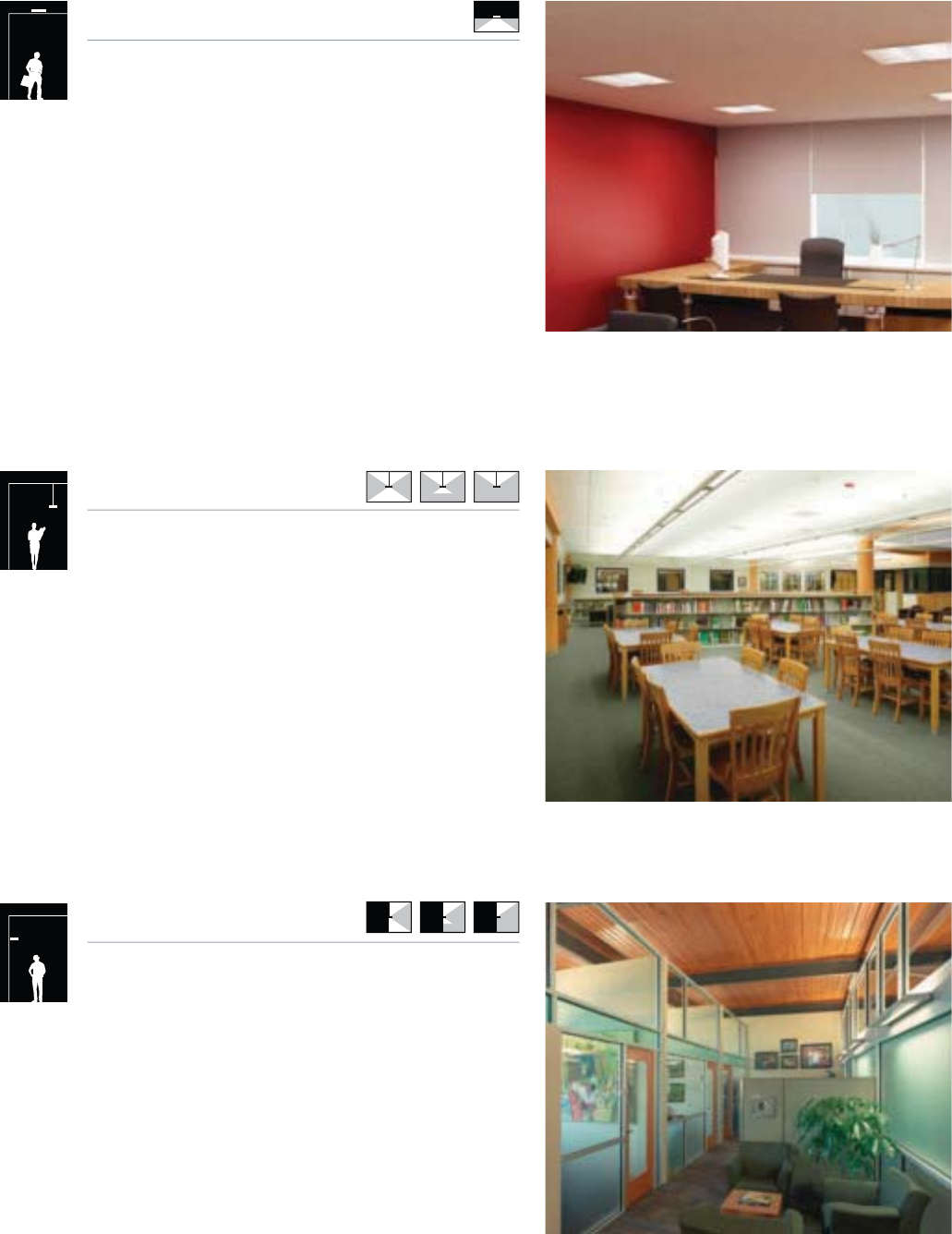
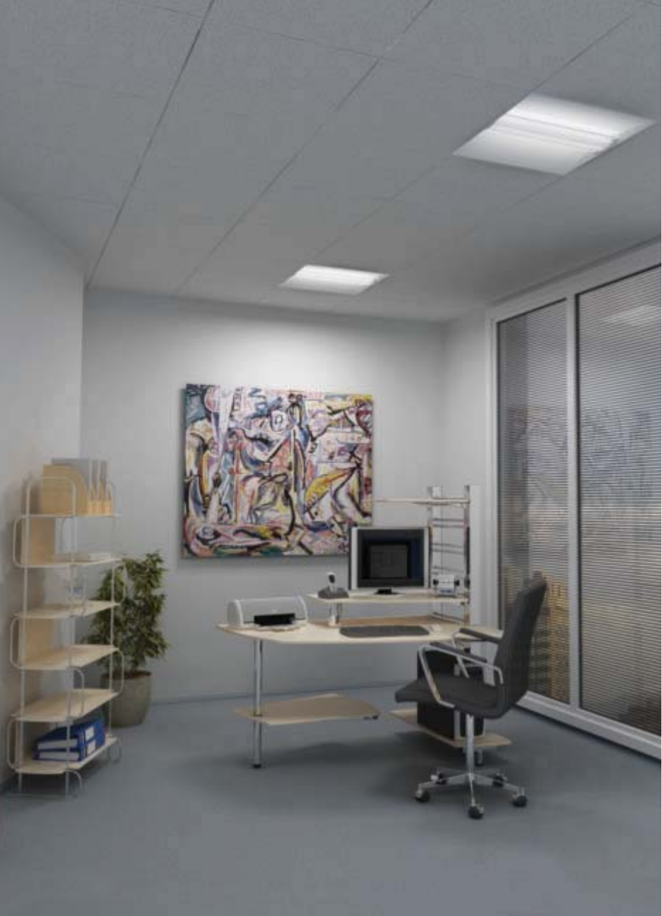
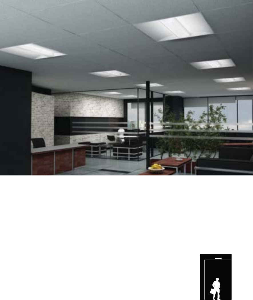
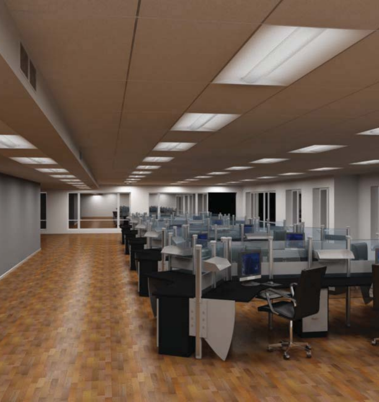
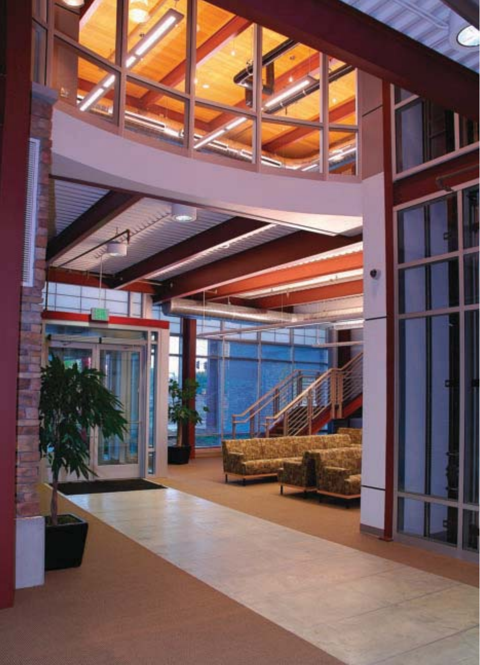
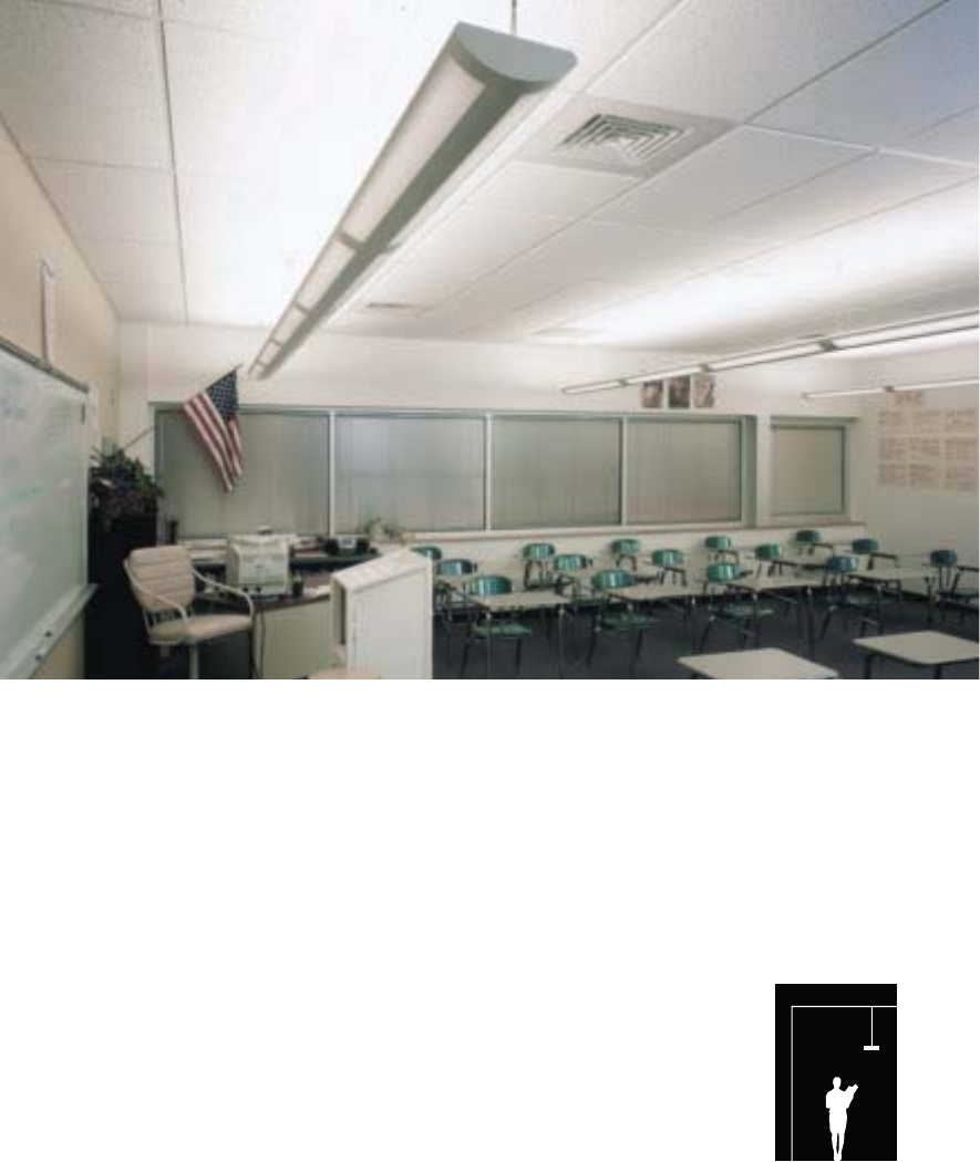
Generous ambient illumination and effective control of
light output are key elements of a productive and efficient
working atmosphere. With the combination of low-glare direct
lighting, optimal for visual tasks, and laterally efficient indirect
lighting, allowing for wide luminaire row spacing, Corelite
offers a unique line of suspended architectural luminaires
perfectly suited to the creation of task-friendly and energy
efficient environments. The product families include an array
of indirect, semi-indirect, and direct-indirect contemporary
interior lighting solutions, ideal for commercial, educational
and institutional applications.
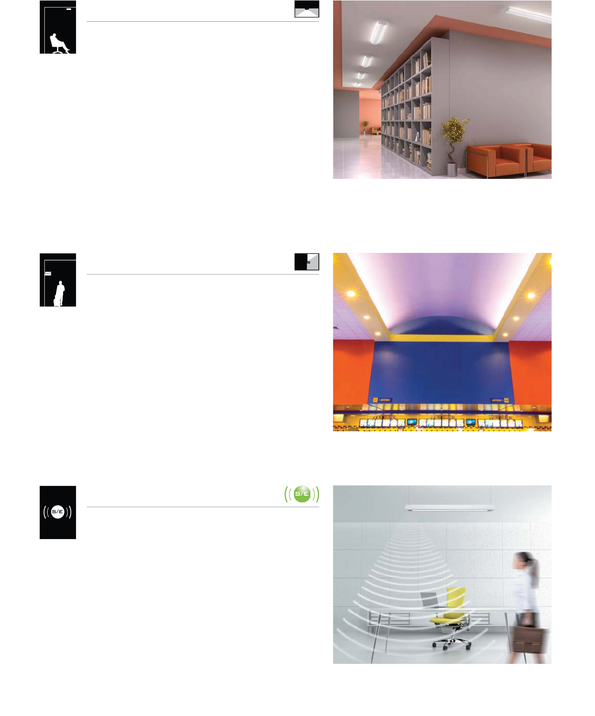
Corridors, room perimeters and restrooms, typically
challenging to light properly, are easily illuminated with the
use of wall mounted luminaires. The scale and performance
of Corelite’s wall mount fixtures make them ideal solutions for
narrow spaces or restricted ceiling applications. Innovative
optical design for the widest asymmetrical distribution and
large lumen packages with up to two T5HO lamps serve
only to enhance their performance and appeal. And, as all
Corelite’s wall mount luminaires have a matching suspended
companion, the cohesive aesthetic of the design does not
require compromise with their employment.
Individual recessed fluorescent lighting for
ambient lighting applications
Continuous ceiling mounted linear fluorescent
lighting for ambient lighting applications
Continuous wall mounted linear fluorescent
lighting for ambient lighting applications
CORELITE by Application
7
Surface Mounted
Cove Lighting
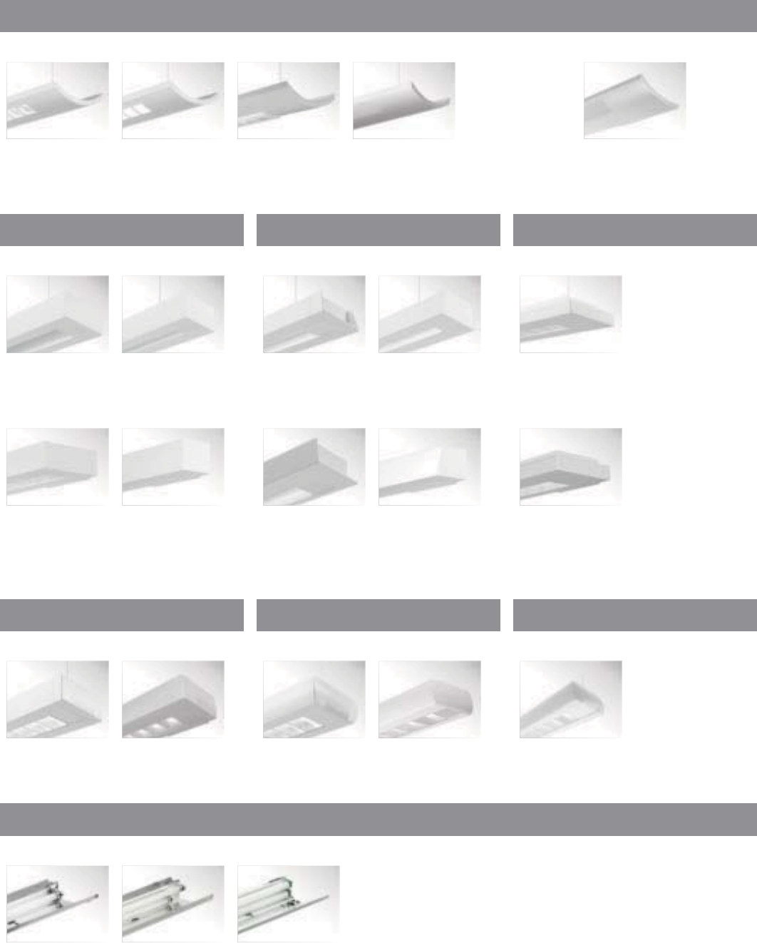
Smart Environments
As architectural trends continue to point to the popularity
of remodels and retrofits, Corelite responds with an array
of surface mountable luminaires, aptly suited for the most
challenging renovations. With low impact to the ceiling and
a continued dedication to the highest performance and
design, surface mounted fixtures from Corelite provide the
widest possible light distribution and efficiency for budget
and energy savings without compromising style – an unlikely
ability for traditional surface mount solutions of the past.
Ranging from individual and continuous linear to recessed-
style luminaires, Corelite has the ideal solution for every “re-”
project imaginable.
Cove lighting is a powerful tool for discreetly illuminating,
defining, accenting and delineating architectural
environments. When the goal is to hide the lighting elements
while at the same time providing a smooth gradient of
light onto architectural surfaces, free from shadows and
light striations, Corelite Cove Systems provide the means.
Corelite’s optical expertise is highly pronounced in the cove
offering – a line of three distinct profiles, each designed with
specific lamping and optical characteristics that suit any
cove application.
Increasing the intelligence of a project’s lighting systems
with the use of the latest in lighting control technology is
imperative to long-term energy savings, as energy-efficient
luminaires alone can no longer combat the economic and
energy crunch. Lighting controls have the ability to effectively
elevate savings to the next level, and it is with that mind
that Corelite introduces a new system platform: Smart
Environments. Enabling the user to seamlessly integrate
cutting-edge technology into Corelite’s innovative linear
lighting systems, Smart Environments provides a turnkey
package of lighting and controls without the traditional
requirements of system set-up or commissioning.
Continuous surface mounted linear fluorescent
lighting for ambient lighting applications
Continuous cove mounted linear fluorescent
lighting for ambient applications
Continuous ceiling mounted linear fluorescent
lighting for ambient applications

8
Stellar
Suspended Wall Mount
Surface Mount
STELLAR
2T5
pg. 68-69
STELLAR
SURFACE 2T5
pg. 150-151
STELLAR
2T8
pg. 70-71
STELLAR
SURFACE 2T8
pg. 152-153
STELLAR
4T5/T8
pg. 72-73
STELLAR WALL
2T5
pg. 120-121
STELLAR Q
2T8
pg. 66-67
STELLAR Q
SURFACE 2T8
pg. 148-149
STELLAR Q
2T5
pg. 64-65
STELLAR Q
SURFACE 2T5
pg. 146-147
Class R
Recessed Surface Mount
CLASS R1
pg. 14-15
CLASS R2
pg. 16-17
CLASS Rs
SURFACE
pg. 144-145
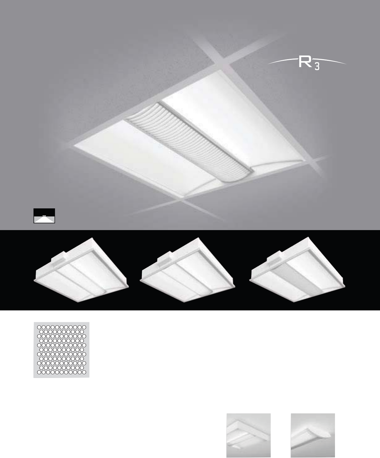
CLASS R3
pg. 18-19
CLASS R2
SURFACE
pg. 142-143
CLASS R
RETROFIT
pg. 20-21
Class A
Suspended
Wall Mount
CLASS A
D/I BAFFLE
pg. 30-31
CLASS A D/I
BAFFLE WALL
pg. 110-111
CLASS A
D/I LENSED
pg. 32-33
CLASS A D/I
LENSED WALL
pg. 112-113
CLASS A
FULL PERF
pg. 38-39
CLASS A
PERF D/I
pg. 34-35
CLASS A
PERF WALL
pg. 114-115
CLASS A
INDIRECT
pg. 40-41
CLASS A
PERF
pg. 36-37
CLASS A
INDIRECT WALL
pg. 116-117
CORELITE by Product Family
9
Traverse
Suspended
TRAVERSE
pg. 92-93
TRAVERSE WALL
pg. 132-133
Navigator
Suspended Wall MountWall Mount
NAVIGATOR II
pg. 94-95
GATOR WALL
pg. 134-135
Minigator
Suspended
MINIGATOR
pg. 96-97
Element
Suspended
ELEMENT
pg. 82-83
ELEMENT WALL
pg. 122-123
ELEMENT MICRO
pg. 84-85
ELEMENT MICRO
WALL pg. 124-125
Loft
Suspended
LOFT
pg. 86-87
LOFT WALL
pg. 126-127
LOFT MICRO
pg. 88-89
LOFT MICRO
WALL pg. 128-129
Wall Mount Wall Mount Wall Mount
Iridium
Suspended Wall Mount
IRIDIUM IQ
BAFFLE pg. 50-51
IRIDIUM IQ
LENSED pg. 52-53
IRIDIUM PERF
WALL pg. 118-119
IRIDIUM D/I
pg. 54-55
IRIDIUM PERF
pg. 56-57
Vertechs
Cove
Suspended
VERTECHS
pg. 90-91
COVE SOLO
pg. 160-161
VERTECHS
WALL pg. 130-131
COVE DUO
pg. 162-163
COVE TRIO
pg. 164-165

10
RECESSED
Low profile. Low energy. High impact.
In an architectural age where plenum heights are shrinking,
energy costs are rising, and innovation in recessed
lighting has essentially flat-lined, how do you answer to
a specification driven by modern demands? You redefine
the concept of recessed lighting, that’s how.
11
12
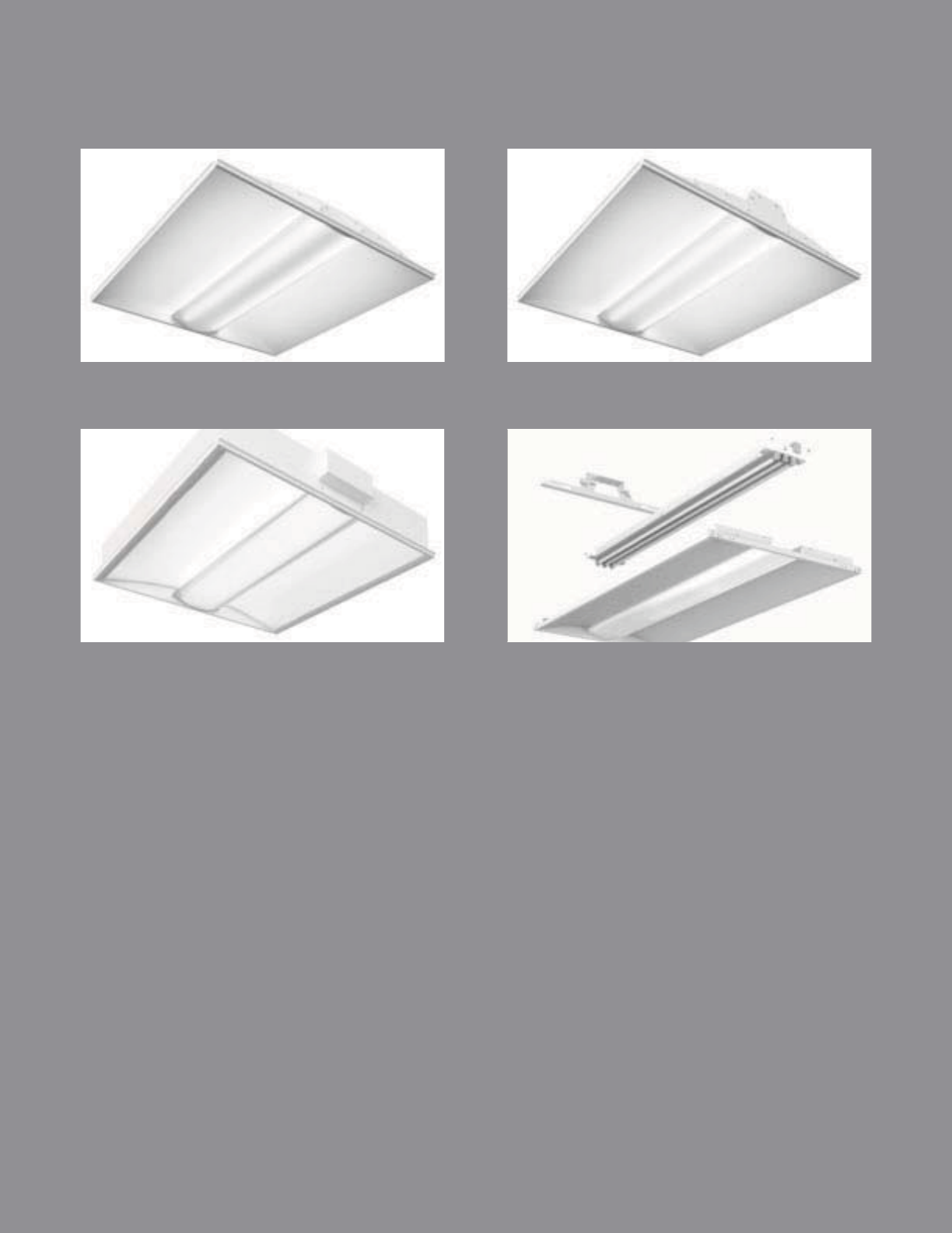
Recessed, Redefi ned.
Discarding the traditional “box” design, the Class R1 and
R2 boast an innovative and unobtrusive low-profi le housing
shape, providing the perfect answer to constrained plenum
space, while the Class R3 provides the broadest selection of
optics and lampings available in a minimized housing scale.
The entire Class R family features low-energy technology
and highly effi cient optical engineering to aid in “green”
sustainable design. The ability to retain ceiling heights,
reduce plenum space, and potentially save stories worth of
building materials is perhaps the Class R’s highest impact on
architecture overall. And with the sleek modern design of the
Class R, compromising spaces will no longer have to suffer
from compromised fi xture performance or aesthetics.
Class R
13
CLASS R1
pg. 14-15
CLASS R2
pg. 16-17
CLASS R3
pg. 18-19
CLASS R RETROFIT
pg. 20-21
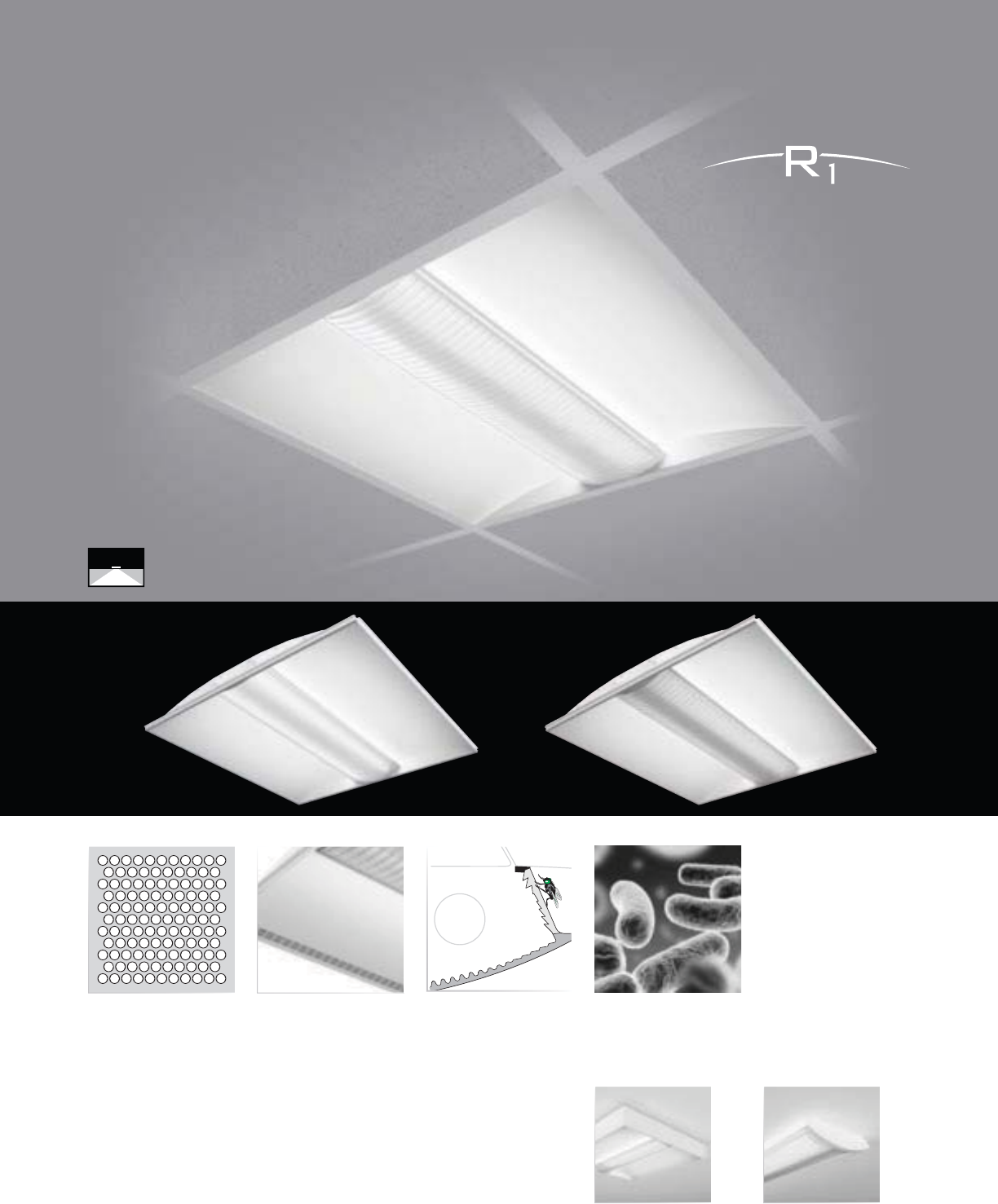
14
Micro Baffle
• 2T5 specifi c design
• 1-3/4” installed depth
• 80.8% effi ciency (R1-WL-2N5-22)
• 4 unique shielding options
• Supports energy saving ballasts and controls
Round Perf (R1-WP)
Class Rs Surface
(pages 144-145)
Class R2 Surface
(pages 142-143)
Lens Rectangular Perf
Class R1
RECESSED | DIRECT | T5 / T5HO
Installing in half the space of
traditional lay-ins, the Class R1 is
the ultra shallow plenum solution.
Lens Gasketing (LG)
(page 23)
Anti-Microbial (AM)
(page 23)
Air Return (AR)
(page 22)

15
1 3/4" [44MM]
23 3/4" [603MM]
1x4
2x2
2x4
S
ERIE
S
R1
=
C
lass R1
(
1-3/4”
)
Recesse
d
REFLE
C
T
OR
W=Whit
e
S
HIELDIN
G
B=Micro Baffl
e
L=Len
s
P=R
ou
n
d
P
e
r
f
R=Rectan
g
ular Per
f
N
U
MBER
O
F LAMP
S
2
=2 Lam
ps
LAMP TYPE
N5=T5 Normal Out
p
ut
T5=T5 Hi
g
h Outpu
t
NUMBER
O
F
C
IR
C
UIT
S*
1=1
C
ir
cu
i
t
2
=2
C
ir
cu
it
s
WIRIN
G
*
C=Standard Circuit
B=Batter
y
D=Dimmin
g
/
S
tep Dimmin
g
(
see
O
PTI
O
N
S)
E
=
E
mer
g
enc
y
Y=Daylight
T=Nightlight
V
O
LTA
G
E*
120=120
V
2
77=277V
3
47=
3
47V
UNV
=
U
n
i
versa
l
(
120
V
-277
V)
S
IZE
24
=
2’x4’
22
=
2’x2’
14=1
’
x4
’
C
EILIN
G
TYPE
T1=1”
G
rid,
S
lot-
G
rid, 9
/
16” Te
g
ular
T9=9
/
16”
G
rid
CC=Concealed Ceiling (see note)
OPTIONS*
A
R=Air R
e
t
u
r
n
CP=Chica
g
o Plenu
m
NY=New York
C
ity
C
onstructio
n
A
M=Anti-Microbial
C
oatin
g
LG=Lens Gasketin
g
W
6=6
’
Whip
Fl
ex
W
12=12
’
Whi
p
Fl
e
x
S
D=
S
tep Dimming
PROJECT NAME: TYPE:
CATALOG #:
- - - - - - - -
*Not all options available. Please consult your
C
ooper Lighting Representative for availability and
t
echnical information.
S
pecifications and dimensions subject to change without notice.
ORDERING INFORMATION:
SAMPLE NUMBER:R1-WL-2N5-1C-UNV-22-T1
RECESSED CLASS R1
Construction: Low profile housin
g
die-formed
2
0
g
au
g
e co
ld
ro
ll
e
d
stee
l
w
i
t
h
i
nte
g
ra
l
o
ne-piece 20 gauge gear tray.
O
ptional welded
a
nd gasketed construction available for NY
a
nd Chicago Plenum applications. Air Return
also
a
v
ailable
.
Reflectors: High reflectance white powder coat
p
ainted reflector s
y
stem
.
S
hieldin
g
: Lens secured to housin
g
via in
j
ection
m
olded inserts for easy lamp access.
Lens: Linear
p
rismatic co-extruded acr
y
lic lens
w
ith full
y
frosted center and clear/frost blended
l
ens returns.
M
icro Baffle: Linear
p
rismatic co-extruded
a
cr
y
lic lens with white internal micro ba
ff
le,
c
lear center and clear
/
frost blended lens returns.
Perf: Linear prismatic co-extruded acrylic lens
w
ith
p
er
f
orated
f
ormed steel shield,
f
ull
y
f
rosted
ce
nt
e
r
a
n
d
c
l
ea
r
/
fr
os
t
b
l
e
n
ded
l
e
n
s
r
e
t
u
rn
s
.
Electrical: T5
/
T5H
O
fixtures use UL listed
C
lass
P, T5/T5HO program rapid start universal voltage
e
lectronic ballasts,
p
ower
f
actor o
f
97% with
less
t
ha
n 1
0%
THD
.
Finish: Fixture housings are high re
f
lectance
whi
te us
i
n
g
e
l
ectrostat
i
ca
ll
y app
li
e
d
po
l
yester
p
ow
d
er coat pa
i
nt
.
M
ountin
g
:
S
tandard flan
g
e desi
g
n works with
m
ost
l
ay-
i
n ce
ili
n
g
types.
I
nte
g
ra
l
pry-out ta
b
s
secure luminaire to ceiling grid from above.
Fixt
u
r
e
offe
r
s
ti
e
-in l
oca
ti
o
n
s
fo
r ti
e
-wir
e
o
n
a
ll
c
orners, consult local code
f
or a
pp
ro
p
riate
ti
e-w
i
re recommen
d
at
i
ons.
Concealed Ceiling Note: Class R may be
i
nstalled into inaccessible ceilings (sheet
r
oc
k
, woo
d
pane
l
, etc.
)
.
Thi
s
i
s ac
hi
eve
d
w
i
t
h
t
he Metalux DFW series drywall frame-in kit,
o
rdered separately from Metalux.
S
pecify “
CC
”
f
or the Corelite Ceiling Type. Specify the follow-
i
n
g
part numbers separately,
f
rom Metalux:
For 1x4, order Metalux part #DF-14W-U
For 2x2, order Metalux part #DF-22W-U
For 2x4, order Metalux part #DF-24W-U
RECESSED
Lens Rectangular Perf
Lens Gasketing (LG)
(page 23)
Anti-Microbial (AM)
(page 23)
Air Return (AR)
(page 22)
Round Perf (R2-WP)
16
• 2-7/8” installed depth
• 84.2% effi ciency (R2-WL-2N5-22)
• Accommodates up to 3 T5 lamps
• 4 unique shielding options
• Supports energy saving ballasts and controls
Class R2
RECESSED | DIRECT | T5 / T5HO
The Class R2 offers a wide range
of shielding and lamp options in
a minimal shallow profi le.
Micro Baffle
Class Rs Surface
(pages 144-145)
Class R2 Surface
(pages 142-143)
17
2-7/8" [73MM]
23 3/4" [603MM]
1x4
2x2
2x4
S
ERIE
S
R2=
C
lass R2
(
2-7
/
8”
)
Recesse
d
REFLE
C
T
OR
W=Whit
e
S
HIELDIN
G
B=Micro Baffl
e
L=Len
s
P=R
ou
n
d
P
e
r
f
R=Rectan
g
ular Per
f
NUMBER
O
F LAMP
S
1=1 Lam
p
2
=2 Lam
ps
3=3
L
amp
s
LAMP TYPE
N5=T5 Normal Out
p
ut
T5=T5 Hi
g
h Outpu
t
NUMBER
O
F
C
IR
C
UIT
S*
1=1
C
ir
cu
i
t
2
=2
C
ir
cu
it
s
WIRIN
G
*
C=Standard Circuit
B=Batter
y
D=Dimmin
g
/
S
tep Dimmin
g
(
see
O
PTI
O
N
S)
E
=
E
mer
g
enc
y
Y=Daylight
T=Nightlight
V
O
LTA
G
E*
120=120
V
2
77=277V
3
47=
3
47V
UNV
=
U
n
i
versa
l
(
120
V
-277
V)
S
IZE
2
4=2’x4’
22
=
2’x2’
14
=
1’x4’
C
EILIN
G
TYPE
T1=1”
G
rid,
S
lot-
G
rid, 9
/
16” Te
g
ular
T9=9
/
16”
G
rid
CC
=
C
oncealed
C
eiling (see note)
O
PTI
O
N
S
*
A
R=Air Retur
n
CP=Chicago Plenu
m
NY=New York Cit
y
Constructio
n
A
M=Anti-Microbial
C
oatin
g
L
G
=Lens
G
asketin
g
W6=6’ Whi
p
Flex
W
12=12
’
Whip
Fl
e
x
S
D=
S
tep Dimmin
g
PROJECT NAME: TYPE:
CATALOG #:
- - - - - - - -
*Not all options available. Please consult your
C
ooper Lighting Representative for availability and
t
echnical information.
S
pecifications and dimensions subject to change without notice.
ORDERING INFORMATION:
SAMPLE NUMBER:R2-WL-2N5-1C-UNV-22-T1
RECESSED CLASS R2
Construction: Low profile housin
g
die-formed
2
0
g
au
g
e co
ld
ro
ll
e
d
stee
l
w
i
t
h
i
nte
g
ra
l
o
ne-piece 20 gauge gear tray.
O
ptional welded
a
nd gasketed construction available for NY
a
nd Chicago Plenum applications. Air Return
also
a
v
ailable
.
Reflectors: High reflectance white powder coat
p
ainted reflector s
y
stem
.
S
hieldin
g
: Lens secured to housin
g
via in
j
ection
m
olded inserts for easy lamp access.
Lens: Linear
p
rismatic co-extruded acr
y
lic lens
w
ith full
y
frosted center and clear/frost blended
l
ens returns.
M
icro Baffle: Linear
p
rismatic co-extruded
a
cr
y
lic lens with white internal micro ba
ff
le,
c
lear center and clear
/
frost blended lens returns.
Per
f
: Linear
p
rismatic co-extruded acr
y
lic lens
w
ith
p
er
f
orated
f
ormed steel shield,
f
ull
y
f
rosted
c
enter and clear
/
frost blended lens returns.
Electrical: T5
/
T5H
O
fixtures use UL listed
C
lass
P, T5/T5HO program rapid start universal voltage
e
lectronic ballasts,
p
ower
f
actor o
f
97% with
less
t
ha
n 1
0%
THD
.
Finish: Fixture housings are high reflectance
w
hite using electrostatically applied polyester
p
ow
d
er coat
p
a
i
nt
.
M
ounting: Standard flange design works with
m
ost
l
ay-
i
n ce
ili
n
g
types.
I
nte
g
ra
l
pry-out ta
b
s
secure luminaire to ceilin
g
g
rid from above.
Fixture offers tie-in locations for tie-wire on all
c
orners, consult local code
f
or a
pp
ro
p
riate
tie
-w
i
r
e
r
eco
mm
e
n
da
t
io
n
s
.
C
oncealed
C
eiling Note:
C
lass R may be
i
nstalled into inaccessible ceilings (sheet
r
ock, wood panel, etc.). This is achieved with
t
he Metalux DFW series dr
y
wall
f
rame-in kit,
o
rdered separately from Metalux.
S
pecify “
CC
”
f
or the
C
orelite
C
eiling Type.
S
pecify the
f
ollowing part numbers separately, from
Me
t
alu
x:
For 1x4, order Metalux part #DF-14W-U
For 2x2, order Metalux part #DF-22W-U
For 2x4, order Metalux part #DF-24W-U
RECESSED
Round Perf Inlay
(R3-WD)
18
• 3-3/4” installed depth
• Available in 2’x2’ or 2’x4’ housing sizes
• Accommodates T5, T8 and CFL lamps
• 5 unique shielding options
• Supports energy saving ballasts and controls
Clear Lens Frosted Lens Rectangular Perf Inlay
Class R3
RECESSED | DIRECT | T5 / T5HO / T8 / CFL
A fully luminous housing and
myriad optical confi gurations put
Class R3 in a class unto itself.
Micro Baffle
Class Rs Surface
(pages 144-145)
Class R2 Surface
(pages 142-143)

19
3 3/4" [95MM]
23 3/4" [603MM]
S
ERIE
S
R3=
C
las
s
R3
(
3-3
/
4”
)
R
ecesse
d
REFLE
C
T
OR
W
=
Whi
te
S
HIELDIN
G
B=Mi
c
r
o
B
aff
l
e
C
=
C
lea
r
P
r
i
smat
i
c
L
=
L
en
s
D=Round Per
f
Inla
y
G=Rectangula
r
P
e
r
f
Inla
y
NUMBER
OF
LAMP
S
1=1 Lamp
2
=
2
Lam
ps
3
=
3
Lam
ps
LAMP
TYPE
N5=T
5
Norma
l
Output
T
5
=T
5
High Out
p
u
t
T8
=
T8
No
rm
al
Out
p
ut
40=40
W
att
C
F
L
(2
l
amps max
)
50=50 Watt
C
F
L
(
2
lamps max
)
55
=
55
W
a
tt
C
F
L
(
2
lam
p
s max
)
80
=
80
Wa
tt
C
F
L
(
1
l
am
p
on
l
y
)
NUMBER
OF
C
IR
C
UIT
S*
1=1 Circui
t
2
=
2
C
ir
cu
it
s
WIRIN
G
*
C
=
S
tandar
d
C
ircuit
B=Batter
y
D
=
Di
mm
i
n
g
/
Step
/
Di
mm
i
n
g
(
se
e
OPTIONS
)
E
=
E
mer
g
enc
y
Y
=
D
ay
li
g
h
t
T=Nightlight
V
O
LTA
G
E*
120=120
V
2
77=277V
3
47=
3
47V
UNV
=
U
n
i
v
e
r
sal
(
120
V
-277
V)
S
IZE
2
4=2’x4’
22
=
2
’
x2
’
C
EILIN
G
TYPE
T1=1
”
Grid
,
Slot-Grid,
9/
1
6
” Tegular
T
9
=
9/
1
6
”
G
ri
d
CC
=
C
onceale
d
C
eilin
g
(
se
e
note
)
O
PTI
O
N
S
*
AR
=
Ai
r
R
etur
n
C
P=
C
hicag
o
Plenu
m
W
6
=
6
’ Whi
p
Fl
e
x
W12
=
12’
Whip
Flex
S
D=
S
tep
Di
mm
i
n
g
PROJECT NAME: TYPE:
CATALOG #:
- - - - - - - -
*N
ot a
ll
opt
i
ons ava
il
a
bl
e.
Pl
eas
e
consu
lt
your
C
ooper
Li
g
h
t
i
ng
R
epresentat
i
ve fo
r
ava
il
a
bili
t
y
an
d
t
ec
h
n
i
ca
l
information.
S
pecifications an
d
di
mens
i
ons su
bj
ect
t
oc
h
ang
e
w
i
t
h
out not
i
ce.
ORDERING INFORMATION:
SAMPLE NUMBER:R3-WL-2N5-1C-UNV-22-T1
RECESSED CLASS R3
Co
n
s
tr
uc
ti
o
n
:
L
o
w
p
ro
f
il
e
housin
g
d
i
e
-
fo
rm
ed
20
g
au
ge
co
ld
ro
ll
e
d
stee
l
w
i
t
h
i
nte
g
ra
l
one-p
i
ece
2
0 gaug
e
gea
r
t
ray
.
R
ef
l
ec
t
o
r
s
:
Mic
r
o
p
r
i
smat
i
c acr
yli
c
le
n
s
c
ompose
d
o
f
frosted an
d
c
l
ear
bl
en
d.
Shielding: L
e
n
s
secu
r
ed
t
o
housing vi
a
injectio
n
mo
l
ded
in
se
rt
s
for
easy
lam
p
access
.
L
ens:
Li
nea
r
pr
i
smat
i
c co-extru
d
e
d
acry
lic
l
ens
w
i
t
h full
y
froste
d
center an
d
clear/frost blende
d
le
n
s
r
e
t
u
rn
s.
C
lear
P
r
i
smat
i
c
:
Li
nea
r
pr
i
smat
i
c co-extru
d
e
d
a
cryli
c
lens wi
th
clea
r
cen
t
er an
d
clear
/
frost
b
l
e
n
ded
l
e
n
s
r
e
t
u
rn
s
.
Mi
cro Baffle:
Li
near pr
i
smat
ic
co-extru
d
e
d
a
cryli
c
lens wi
th
white internal micr
o
baffle
,
c
l
ear
ce
nt
er
a
n
d
c
l
ea
r
/
fr
ost
b
l
e
n
ded
l
e
n
s
r
e
t
u
rn
s.
Perf
:
Linea
r
prismatic co-extruded acrylic len
s
w
i
t
h
p
erforate
d
p
rin
t
inla
y,
fr
os
t
ed
ce
nt
e
r
a
n
d
c
l
ea
r
/
fr
ost
ble
n
ded
le
n
s
r
e
t
u
rn
s.
El
ectr
i
ca
l:
T5
/
T5H
O
fixture
s
us
e
UL
li
ste
d
C
las
s
P, T5
/
T5H
O
program
rapid s
t
ar
t
universa
l
voltage
e
l
ec
tr
o
ni
c
ballasts
,
po
w
er
fac
t
or
of
9
7
%
wi
t
h
less
t
ha
n
10%
THD.
T8
f
ixt
u
r
es
are
p
re-w
i
re
d
wi
t
h
quick
wire
k
connec
t
or
s
an
d
us
e
UL
li
ste
d
C
lass
P,
265m
a
T
8
i
nstant s
t
ar
t
un
i
versa
l
vo
l
tage
e
lectroni
c
ballasts
,
po
w
er
facto
r
o
f
9
5
%
wi
t
h
less
th
a
n
10%
THD.
C
FL
f
ixt
u
r
es
use
U
L li
s
t
ed
C
l
ass
P,
C
F
L
pro
g
ra
m
ra
pid
s
t
a
rt
a
n
d
i
n
s
t
a
n
t
s
t
ar
t
un
i
versa
l
vo
l
ta
g
e e
l
ectron
i
c
b
a
ll
asts
,
power
f
actor
s
betwee
n
90%-110
%
depending
on
l
am
p
wattag
e
a
n
d
su
pp
l
y
voltage, wi
th
l
ess
th
a
n
10%
THD.
Fi
xt
u
r
es
a
n
d
elec
tr
ical
com
p
onent
s
c
erti
f
ie
d
to
UL
an
d
C
UL stan
d
ar
d
s
.
Finish
:
Fixture housing
s
are
high reflectanc
e
w
hit
e
usin
g
electrostaticall
y
a
pp
lie
d
p
ol
y
este
r
p
ow
d
e
r
coa
t
p
a
i
nt
.
M
ount
i
n
g:
S
t
a
n
da
r
d
f
lan
ge
d
es
ig
nw
o
r
ks
w
i
t
h
m
os
t
l
ay-
in
ce
ili
n
g
t
ypes.
I
nte
g
ra
l
pry-ou
t
ta
bs
sec
u
re
luminair
e
t
o ceiling grid from above
.
Fixt
u
r
e
o
ff
e
r
s
ti
e
-in l
oca
ti
o
n
s
f
or
ti
e
-wir
e
on
a
l
l
corners,
co
n
sult
local
code
fo
ra
pp
ro
p
r
i
ate
ti
e-w
i
r
e
recommen
d
at
i
ons
.
Co
n
cea
l
ed
Ceiling N
o
t
e:
C
l
ass
R
may
be
i
n
s
t
alled
i
nt
o
i
n
accessible
ce
ili
n
g
s
(
s
h
ee
t
r
oc
k,
woo
d
pane
l,
etc.
)
.
This
is
ac
hi
eve
d
w
i
t
h
t
he Metalu
x
DF
W
serie
s
drywal
l
frame-i
n
kit,
o
r
de
r
ed
se
p
aratel
y
fr
o
mM
e
t
a
l
u
x. S
p
ecif
y
“
CC”
for
t
he
Co
r
e
lit
e
Ceilin
g
Typ
e. S
p
ecif
y
t
he
f
ollowin
g
p
ar
t
num
b
ers se
p
arate
ly,
f
ro
m
M
eta
l
ux:
For 1x4, order Metalux part #DF-14W-U
For 2x2, order Metalux part #DF-22W-U
For 2x4, order Metalux part #DF-24W-U
2x2
2x4
RECESSED
9
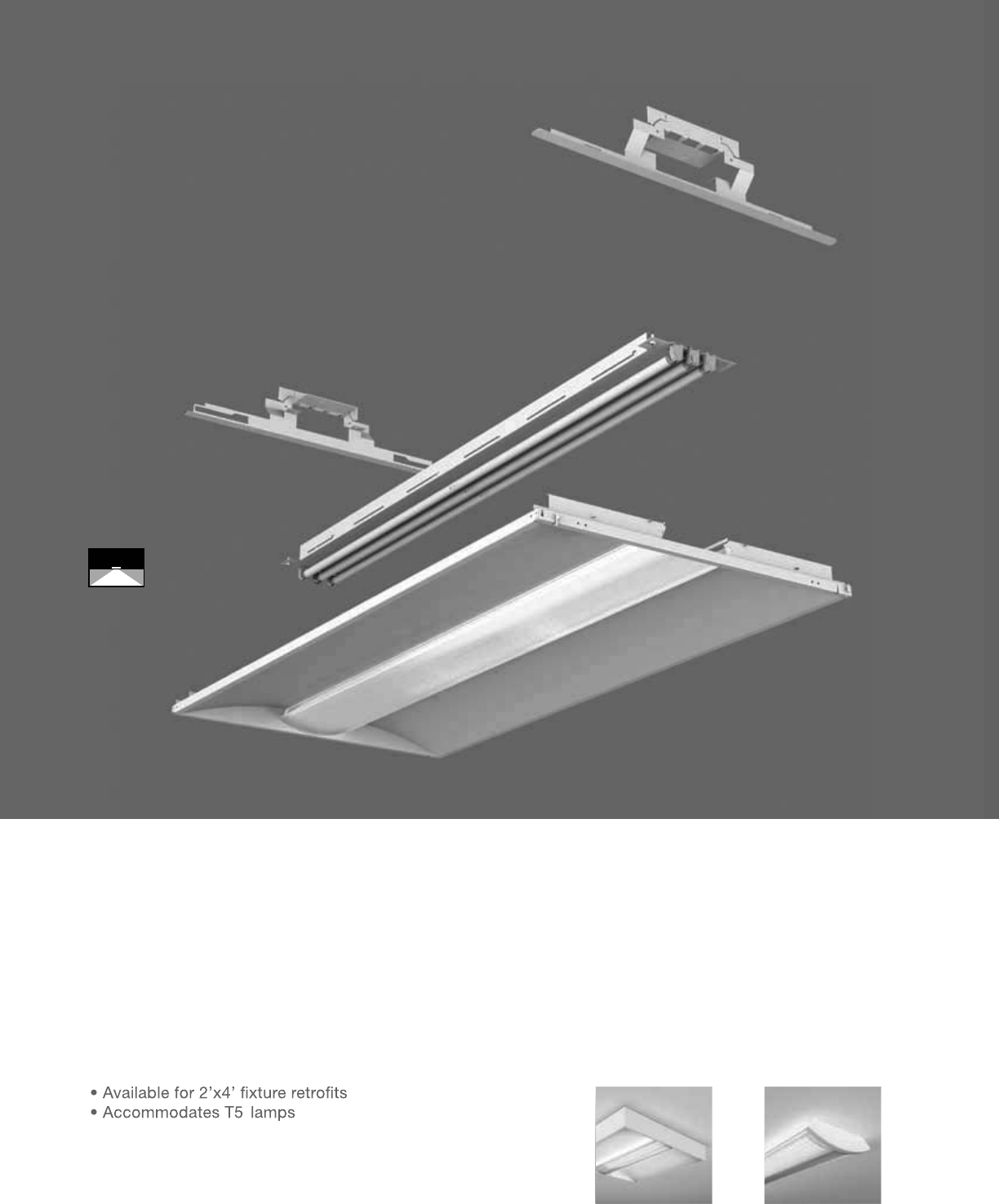
Class R Retrofit
RECESSED | DIRECT | T5 / T5HO
With several energy saving lamp
configurations, the Class R Retrofit
is the ideal upgrade.
Class Rs SurfaceClass R2 Surface

10
SERIES
RF1=Class R Retrofit Recessed
REFLECTOR
W=White
SHIELDING
L=Lens
NUMBER OF LAMPS
1=1 Lamp
2=2 Lamps
3=3 Lamps
LAMP TYPE
N5=T5 Normal Output
T5=T5 High Output
NUMBER OF CIRCUITS*
1=1 Circuit
2=2 Circuits
WIRING*
C=Standard Circuit
D=Dimming / Step Dimming (see OPTIONS)
VOLTAGE*
120=120V
277=277V
347=347V
UNV=Universal (120V-277V)
SIZE
24=2’x4’
CEILING TYPE
T1=1” Grid, Slot-Grid, 9/16” Tegular
OPTIONS*
SD=Step Dimming
PROJECT NAME: TYPE:
CATALOG #:
-
-
-
-
-
-
-
-
*Not all options available. Please consult your Cooper Lighting Representative for availability and
technical information. Specifications and dimensions subject to change without notice.
ORDERING INFORMATION:
SAMPLE NUMBER:RF1-WL-2N5-1C-UNV-24-T1
RECESSED CLASS R RETROFIT
Construction: Low profile retrofit housing
is constructed of formed white painted 22
gauge aluminum and stainless steel fasteners.
Combination of housing frame, white painted
pre-wired gear tray, and prepaint Internal
mounting brackets allow for fast and simple
installation into any existing 2x4 parabolic deep
cell luminaire. Simply remove existing reflector
and ballast and quickly install the Retrofit.
Reflectors: High reflectance white powder coat
painted reflector system.
Shielding: Lens secured to housing via injection
molded inserts for easy lamp access.
Lens: Linear prismatic co-extruded acrylic lens
with fully frosted center and clear/frost blended
lens returns.
Electrical: T5/T5HO fixtures use UL listed Class
P, T5/T5HO program rapid start universal voltage
electronic ballasts, power factor of 97% with
less than 10% THD.
Finish: Fixture housings are high reflectance
white using electrostatically applied polyester
powder coat paint.
Mounting: Retrofit hardware consists of a
Reflector Frame, Lens, Prewired Gear Tray, and
End Mounting Brackets. The Contractor simply
removes existing reflectors and ballasts, then
installs end plates with self drilling screws.
Next, the gear tray mounts into end brackets
and frame assembly simply slides onto end
bracket corners.
23 3/4" [603MM]
3" [76MM]
2x4
RECESSED
22
AIR
RETURN
(
AR
)
The Class R’s Air Return option is comprised of
a unique perforated housing, which allows for
efficient airflow and reclamation in open spaces.
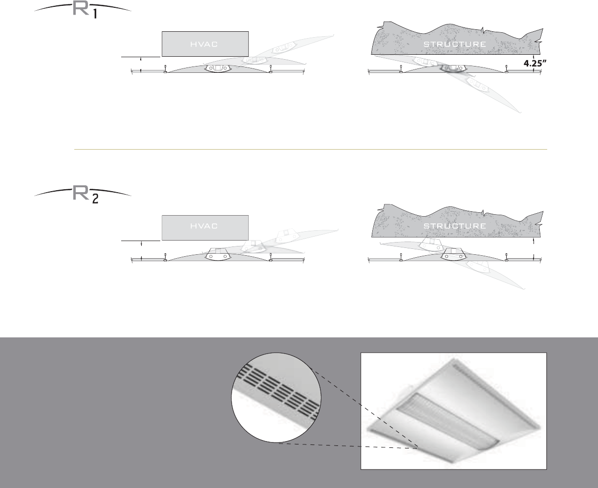
Continuous ObstructionIntermittent Obstruction
3.
7
5
”
Continuous ObstructionIntermittent Obstruction
5.
2
5
”
4
.
75
”
Taking on obstructions from every angle.
Lift and shift installation in less space.
Whether installing from below the plenum, or sliding over from an adjacent grid space, the Class R’s
innovative “out-of-the-box” chamfered design allows for ease of installation in the tightest of spaces,
and may be installed in half the space required for traditional lay-ins.
Options

23
9/16 Flush (T9) 9/16 Slot Grid (T1)
15/16 Flush (T1)
Concealed Ceiling (CC) Metalux™ DF Series Frame-In Kit*
9/16 Tegular (T1)
L
EN
S
GASKETIN
G
(
LG
)
The Lens Gasketing option prevents the ingress
of unsightly and unsanitary dust and insects,
and enables easy wipe-down cleaning ideal
for sterile healthcare environments.
ANTI-MICROBIAL
(
AM
)
The Anti-Microbial coating option thwarts the growth
and dispersion of bacteria, and is beneficial in
environments prone to airborne germs such as
healthcare and childcare facilities.
RECESSED INSTALLATION
Blend in and stand out.
Class R has seamless ceiling integration covered.
Whatever your ceiling grid style, the Class R has been uniquely engineered for precise
integration with 4 standard “T” interfaces. This clean and flush finish to typical architectural
ceilings and the attention to detail sets the Class R miles apart from competition.
Metalux Part Numbers
1x4=DF-14W-U
2x2=DF-22W-U
2x4=DF-24W-U
*Specify “CC” in the Corelite part number to designate the condition of a
concealed ceiling. Frame-in kit must be ordered separately through Metalux.

24

25
26
27
SUSPENDED
Efficiency Begets Efficiency.
With the reflection of light off the ceiling and back down
into work areas, suspended linear indirect fixtures create
softer and more balanced lighting than other systems,
resulting in a reduction of shadows, improved control of
task lighting and uniform ceiling illumination. Engineered
to operate at their peak of efficiency and performance,
suspended Corelite luminaires in turn enable the same for
the occupants of any workspace.
28
29
30
One Style, Endless Applications.
The high-performance Class A family is one of Corelite’s
most asked-for signature series. Combining a sleek, elegant
appearance with multiple lamping and distribution options,
Class A luminaires ideally suit contemporary offi ce and
educational environments as well as a variety of other interior
applications calling for fl uorescent ambient light. Superior
in its versatility, with myriad end caps and downlight media
options, the Class A family combines the same classic
design and contemporary styling throughout the product
line, allowing for multiple fi xture styles in one architectural
project while maintaining a cohesive and fl uid visual appeal.
Class A
CLASS A D/I BAFFLE
pg. 32-33
CLASS A D/I LENSED
pg. 34-35
CLASS A PERF D/I
pg. 36-37
CLASS A FULL PERF
pg. 40-41
CLASS A PERF
pg. 38-39
CLASS A INDIRECT
pg. 42-43
31
• Additional glare reduction with the
Eclipse louver
• 80% and 100% Downlight Isolators
• Standard Flat or Optional Tapered or
Rounded end caps
32
AB-WB with standard flat end plates
Class A D/I
Baffle Wall
(pages 110-111)
100% Downlight
Isolators (DL100)
Rounded End Cap (ER)Eclipse Louver
(AB-WE)
Tapered End Cap (ET) 80% Downlight
Isolators (DL80)
Class A D/I Baffl e
SUSPENDED | DIRECT-INDIRECT | T5 / T5HO / T8
The Class A D/I offers three innovative
downlight control options for any task-
friendly application.

33
2-7/8" [73MM]
9" [229MM]
Dimensions do not include
end plates or caps
96”48” 144”
S
ERIE
S
A
B=
C
lass A D
/
I
S
uspended
OPTICS UP
W=Whit
e
O
PTI
CS
D
O
WN
B=Perforated Baffle (standard
)
E=Ecli
p
se Louve
r
NUMBER
O
F LAMP
S
2
=2
L
amp
s
3=3 Lamp
s
4=4 Lam
ps
LAMP
TYPE
N5=T5 Normal
O
utput
T5=T5 High Outpu
t
T8=T8 Normal Out
p
ut
NUMBER
O
F
C
IR
C
UIT
S
1=1 Circui
t
2
=2
C
ir
cu
it
s
WIRIN
G
*
C
=
S
tandard
C
ircuit
D=Dimming
E
=
E
mer
g
ency
B
=
B
attery
P
ac
k
T
=
Ni
g
h
t
li
g
h
t
Y=Daylight
V
O
LTA
G
E*
120=120
V
2
77=277V
3
47=
3
47V
UNV
=
U
n
i
versa
l
(
120
V
-277
V)
S
U
S
PEN
S
I
ON
A
=Aircraft Cabl
e
P=Rigid Pendant
P
O
WER FEED*
C
=
S
traight
C
ord
K=Curl
y
Cord
P
=
Rigid
P
en
d
ant
S
U
S
PEN
S
I
O
N LEN
G
T
H
-Fixed Cabl
e
12”, 15”, 18”, 21”, 24” or 27” (+/- 1/2” adjustment)
-Ad
j
ustable
C
able
48”, 120”, 240”, 300”, or 360”
(in
f
inite adjustment along entire length o
f
cable
)
-
Rigid
P
en
d
ant
12
”,
15
”,
18
”,
21
”,
24
”
or 27
”
(additional pendant lengths available, consult factory
)
C
EILIN
G
TYPE*
T
1=1
”
T
-
B
a
r
T9=9
/
16” T-Bar
T
S
=
S
l
o
tt
ed
T-B
a
r
S
T=
S
tr
uc
t
u
r
e
JB=4”
O
cta
g
onal J-Bo
x
RUN LENGTH
Specify luminaire length in feet.
-
I
n
di
v
id
ua
lly
M
ounte
d
L
um
i
na
i
res may
b
e 4
’
,8
’
, or 12
’
i
n
l
en
g
t
h
.
-
C
ontinuously Mounted
Standard row configurations over 12’ consist of 8’ and 12’ sections
.
O
PTI
O
N
S
ET=Tapered End
C
a
p
ER=Rounded End Cap
DL100=100% Downlight Isolators
f
or outboard lamp
s
DL80=80% Downli
g
ht Isolators
f
or outboard lamps
PROJECT NAME: TYPE:
CATALOG #:
- - - - - - - -
*Not all options available. Please consult your
C
ooper Lighting Representative for availability and
t
echnical information.
S
pecifications and dimensions subject to change without notice.
ORDERING INFORMATION:
SAMPLE NUMBER:AB-WB-4T5-1C-UNV-AC48-T1-32’-ET
SUSPENDED CLASS A D/I BAFFLE
Construction: Housin
g
is one piece die-formed
2
0-
g
au
g
e cold rolled steel, formin
g
a 9”x2-7
/
8”
a
rchitectural profile.
S
tandard 4’-0”, 8’-0”, and
12’-0” fixture lengths combine for continuous
runs.
Reflectors: Reflector pan is painted with a hi
g
h
r
eflectance white powder coat finish
.
Louvers:
S
tandard white aluminum
p
erforated
b
lades.
O
ptional Eclipse Louver with white
p
erforated blades and ribbed diffuse anodized
a
l
u
min
u
m r
u
nn
e
r
s.
Electrical: T5
/
T5H
O
fixtures are pre-wired with
quick wire connectors and use UL listed Class P,
T5/T5HO program rapid start universal voltage
e
lectronic ballasts,
p
ower
f
actor o
f
97% with
l
ess than 10% THD. T8 fixtures are pre-wired
w
ith quick wire connectors and use UL listed
Class P, 265ma T8 instant start universal voltage
e
lectronic ballasts,
p
ower
f
actor o
f
95% with
l
ess t
h
an 10%
THD
.
Fi
xtures an
d
e
l
ectr
i
ca
l
c
omponents certified to UL and
C
UL standards.
M
ounting:
S
tandard aircraft cable mounts on
4’-0”, 8’-0”, and 12’-0” centers. Refer to spec
sheets
f
or various ceiling inter
f
ace details and
rigid
pen
d
ant mount
i
n
g
d
eta
il
s.
Fi
n
i
s
h
:
Fi
xture
h
ous
i
n
g
s are stan
d
ar
d
w
hi
te
u
s
i
n
g
e
l
ectrostat
i
ca
ll
y app
li
e
d
po
l
yester pow
d
er
c
oat paint.
End Plates:
S
tandard laser cut 14-
g
au
g
e cold
r
o
ll
e
d
stee
l
, mec
h
an
i
ca
ll
y attac
h
e
d
w
i
t
h
no
e
xposed fasteners. Optional die cast aluminum
e
nd ca
p
s also available.
SUSPENDED
• Standard Flat or Optional Tapered or
Rounded end caps
AB-WO with standard flat end plates
34
Class A D/I
Lensed Wall
(pages 112-113)
Rounded End Cap (ER)Tapered End Cap (ET)
Class A D/I Lensed
SUSPENDED | SEMI-INDIRECT | T5 / T5HO / T8
The Class A D/I Lensed provides
semi-indirect distribution with
direct-indirect appeal.

35
2-7/8" [73MM]
9" [229MM]
S
ERIE
S
A
B=
C
lass A D
/
I
S
uspended
OPTICS UP
W=Whit
e
O
PTI
CS
D
O
WN
O
=White
O
pal Lens
N
U
MBER
O
F LAMP
S
2
=2
L
am
ps
3=3
L
amp
s
4=4 Lamp
s
LAMP TYPE
N5=T5 Normal
O
utput
T5=T5 High
O
utpu
t
T8=T8 Normal Out
p
ut
NUMBER
O
F
C
IR
C
UIT
S
1=1
C
ircui
t
2
=2 Circuits
WIRIN
G
*
C
=
S
tandard
C
ircuit
D=Dimming
E=Emergency
B
=
B
atter
y
P
ac
k
T
=
Nigh
t
ligh
t
Y
=
D
ay
li
g
h
t
V
O
LTA
G
E*
12
0
=12
0V
2
77=277
V
347=347V
U
NV=Universal (120V-277V)
S
U
S
PEN
S
I
ON
A
=Aircraft
C
abl
e
P=Rigid Pendant
P
O
WER FEED*
C
=
S
trai
g
ht
C
ord
K=
C
urly
C
ord
P=Rigid Pendant
S
U
S
PEN
S
I
O
N LEN
G
T
H
-Fixed
C
abl
e
12”, 15”, 18”, 21”, 24” or 27” (+/- 1/2” adjustment)
-Ad
j
ustable
C
able
48
”,
120
”,
240
”,
300
”,
or 360
”
(infinite adjustment along entire length of cable
)
-
Rigid
P
en
d
ant
12
”,
15
”,
18
”,
21
”,
24
”
or 27
”
(additional pendant lengths available, consult factory
)
C
EILIN
G
TYPE*
T
1=1
”
T
-
Bar
T9=9
/
16” T-Bar
T
S
=
S
lotted T-Bar
S
T=
S
tr
uc
t
u
r
e
JB=4” Octa
g
onal J-Bo
x
RUN LEN
G
TH
Specify luminaire length in feet.
-Individuall
y
Mounted
L
um
i
na
i
res may
b
e 4
’
,8
’
, or 12
’
i
n
l
en
g
t
h
.
-
C
ontinuously Mounted
S
tandard row configurations over 12’ consist of 8’ and 12’ sections
.
O
PTI
O
N
S
ET=Ta
p
ered End
C
a
p
ER=Rounded End
C
ap
PROJECT NAME: TYPE:
CATALOG #:
-
-
-
-
-
-
-
-
t
echnical information.
S
pecifications and dimensions subject to change without notice.
ORDERING INFORMATION:
SAMPLE NUMBER:AB-WO-4T5-1C-UNV-AC48-T1-32’-ET
SUSPENDED CLASS A D/I LENSED
Construction: Housin
g
is one piece die-formed
2
0-
g
au
g
e cold rolled steel, formin
g
a 9”x2-7
/
8”
a
rchitectural profile.
S
tandard 4’-0”, 8’-0”, and
12’-0” fixture lengths combine for continuous
runs.
Reflectors: Reflector pan is painted with a high
r
eflectance white
p
owder coat finish
.
Lens:
S
tandard white o
p
al.
Electrical: T5
/
T5H
O
fixtures are pre-wired with
quick wire connectors and use UL listed
C
lass P,
T5/T5HO program rapid start universal voltage
e
lectronic ballasts,
p
ower
f
actor o
f
97% with
l
ess than 10% THD. T8
f
ixtures are
p
re-wired
wi
t
h
qu
i
c
k
w
i
re connectors an
d
use
UL
li
ste
d
C
lass P, 265ma T8 instant start universal voltage
e
lectronic ballasts,
p
ower factor of 95% with
less
t
ha
n 1
0%
THD
.
Fi
xt
u
r
es
a
n
d
elec
tr
ical
co
m-
p
onents certified to UL and
C
UL standards
.
M
ountin
g
:
S
tandard aircraft cable mounts on
4’-0”, 8’-0”, and 12’-0” centers. Refer to spec
sheets for various ceiling interface details and
r
igid pendant mounting details.
Fi
n
i
s
h
:
Fi
xture
h
ous
i
n
g
s are stan
d
ar
d
w
hi
te
u
s
i
ng e
l
ectrostat
i
ca
ll
y app
li
e
d
po
l
yester pow
d
er
c
oat paint.
End Plates: Standard laser cut 14-gauge cold
r
o
ll
e
d
stee
l
, mec
h
an
i
ca
lly
attac
h
e
d
w
i
t
h
no
e
x
p
osed fasteners.
Op
tional die cast aluminum
e
n
d
caps a
l
so ava
il
a
bl
e.
Dimensions do not include
end plates or caps
96”48” 144”
SUSPENDED

• 100% Downlight Isolator
• Standard Flat or Optional Tapered or
Rounded end caps
AP-WB with standard flat end plates
36
Tapered End Cap (ET)
Semi Specular Baffle
(AP-WM)
100% Downlight
Isolator (DL100)
Perforated Baffle
(AP-WB)
Translucent Baffle
(AP-WT)
Rounded End Cap (ER)
Class A Perf D/I
SUSPENDED | DIRECT-INDIRECT | T8
Three stylized louver options
make customization standard
with the Class A Perf D/I.

37
2-7/8" [73MM]
9" [229MM]
S
ERIE
S
A
P=
C
lass A Perf D
/
I
S
uspende
d
O
PTI
CS
U
P
W
=
Whi
t
e
O
PTI
CS
D
O
WN
B=White Perf Baffle (standard)
T=Tr
a
n
s
l
uce
nt B
aff
l
e
M
=
S
emi
Sp
ecular Baffl
e
NUMBER OF LAMPS
2
=2 Lam
ps
3=3
L
am
ps
4=4
L
amp
s
LAMP TYPE
T8=T8 Normal Out
p
ut
NUMBER
O
F
C
IR
C
UIT
S*
1=1 Circui
t
2
=2
C
ir
cu
it
s
WIRIN
G
*
C
=
S
tandard
C
ircuit
D=Dimming
E
=
E
mer
g
ency
B
=
B
attery
P
ac
k
T
=
Ni
g
h
t
li
g
h
t
Y=Daylight
V
O
LTA
G
E*
120=120
V
2
77=277V
3
47=
3
47V
UNV
=
U
n
i
versa
l
(
120
V
-277
V)
S
U
S
PEN
S
I
ON
A
=Aircraft Cabl
e
P=Rigid Pendant
P
O
WER FEED*
C
=
S
traight
C
ord
K=Curl
y
Cord
P
=
Rigid
P
en
d
ant
S
U
S
PEN
S
I
O
N LEN
G
T
H
-Fixed Cabl
e
12”, 15”, 18”, 21”, 24” or 27” (+/- 1/2” adjustment)
-Ad
j
ustable
C
able
48”, 120”, 240”, 300”, or 360”
(in
f
inite adjustment along entire length o
f
cable
)
-
Rigid
P
en
d
ant
12
”,
15
”,
18
”,
21
”,
24
”
or 27
”
(additional pendant lengths available, consult factory
)
C
EILIN
G
TYPE*
T
1=1
”
T
-
B
a
r
T9=9
/
16” T-Bar
T
S
=
S
l
o
tt
ed
T-B
a
r
S
T=
S
tr
uc
t
u
r
e
JB=4”
O
cta
g
onal J-Bo
x
RUN LENGTH
Specify luminaire length in feet.
-
I
n
di
v
id
ua
lly
M
ounte
d
L
um
i
na
i
res may
b
e 4
’
,8
’
, or 12
’
i
n
l
en
g
t
h
.
-
C
ontinuously Mounted
Standard row configurations over 12’ consist of 8’ and 12’ sections
.
O
PTI
O
N
S
ET=Tapered End
C
a
p
ER=Rounded End Cap
DL100=100% Downlight Isolator
f
or inboard lamp
PROJECT NAME: TYPE:
CATALOG #:
-
-
-
-
-
-
-
-
t
echnical information.
S
pecifications and dimensions subject to change without notice.
ORDERING INFORMATION:
SAMPLE NUMBER:AP-WB-3T8-1C-UNV-AC48-T1-32’-ET
SUSPENDED CLASS A PERF D/I
Construction: Housin
g
is one piece die-formed
2
0-
g
au
g
e cold rolled steel, formin
g
a 9”x2-7
/
8”
a
rchitectural profile. Two 13” long perforated
b
affle sections integrated with standard 1-5/8”
b
lade spacing. Standard 4’-0”, 8’-0”, and 12’-0”
f
ixture len
g
ths combine
f
or continuous runs.
Reflectors: Reflector pan is painted with a high
r
eflectance white
p
owder coat finish.
Electrical: Fixtures are prewired with quick wire
co
nn
ec
t
o
r
s
a
n
d
use
in
s
t
a
nt
s
t
a
rt
U
L li
s
t
ed
C
l
ass
P, 265ma T8 electronic ballasts,
p
ower
f
actor
o
f 95% with less than 10% THD. Fixtures and
e
lectrical components certified to UL and
C
UL
s
t
a
n
da
r
ds.
M
ounting:
S
tandard aircraft cable mounts on
4’-0”, 8’-0”, and 12’-0” centers. Refer to spec
sheets
f
or various ceiling inter
f
ace details and
rigid
pen
d
ant mount
i
n
g
d
eta
il
s.
Finish: Fixture housings are standard white
u
s
i
n
g
e
l
ectrostat
i
ca
ll
y app
li
e
d
po
l
yester pow
d
er
c
oat pa
i
nt.
End Plates: Standard laser cut 14-
g
au
g
e cold
r
o
ll
e
d
stee
l
, mec
h
an
i
ca
lly
attac
h
e
d
w
i
t
h
no
e
xposed fasteners.
O
ptional die cast aluminum
e
nd caps also available.
Dimensions do not include
end plates or caps
96”48” 144”
SUSPENDED

• Standard Flat or Optional Tapered or
Rounded end caps
AP-WP with standard flat end plates
38
Class A Perf Wall
(pages 114-115)
Rounded End Cap (ER)Tapered End Cap (ET)
Class A Perf
SUSPENDED | SEMI-INDIRECT | T5 / T5HO / T8
With classic styling and
high-performance optics, the
applications for Class A Perf
are endless.

39
S
ERIE
S
A
P=
C
lass A Perf
S
uspended
O
PTI
CS
U
P
W
=
Whi
t
e
S
=
S
pecular
O
PTI
CS
D
O
WN
P=P
e
r
fo
r
a
t
ed
NUMBER
O
F LAMP
S
1=1 Lamp (N5, T5)
2
=2 Lamps (N5, T5, T8)
3=3
L
amps
(N
5,
T
5,
T
8
)
4=4
L
amps
(T
8
)
LAMP TYPE
N5=T5 Normal Out
p
ut
T5=T5 Hi
g
h
O
utpu
t
T8=T8 Normal
O
utput
N
U
MBER
O
F
C
IR
CU
IT
S*
1=1
C
ir
cu
i
t
2
=2
C
ircuits
WIRIN
G
*
C
=
S
t
a
n
da
r
d
C
ir
cu
it
D
=
Di
mm
i
n
g
E
=
E
mergency
B=Battery Pack
T=Nightlight
Y
=
D
ay
ligh
t
V
O
LTA
G
E*
12
0
=12
0
V
277
=
277V
347=347
V
UNV
=
U
n
i
versa
l
(
120
V
-277
V)
SUS
PEN
S
I
ON
A
=Air
c
r
a
ft
Cab
l
e
P
=
Rigid
P
en
d
ant
P
O
WER FEED*
C=Strai
g
ht Cord
K=
C
urly
C
ord
P
=
Ri
g
id
P
en
d
ant
SUS
PEN
S
I
O
N LEN
G
T
H
-Fix
ed
Cab
l
e
12”, 15”, 18”, 21”, 24” or 27”
(
+
/
- 1
/
2” ad
j
ustment
)
-Adjustable Cable
48
”,
120
”,
240
”,
300
”,
or 360
”
(
in
f
inite ad
j
ustment alon
g
entire len
g
th o
f
cable
)
-Rigid Pendant
12”, 15”, 18”, 21”, 24” or 27”
(
additional pendant len
g
ths available, consult
f
actory
)
C
EILIN
G
TYPE*
T1=1” T-B
ar
T
9
=
9/
1
6
” T-B
a
r
T
S
=
S
lotted T-Bar
S
T=
S
tructure
JB=4” Octagonal J-Bo
x
R
U
N LEN
G
TH
S
pecify luminaire len
g
th in feet.
-Individually Mounted
Luminaires may be 4’,8’, or 12’ in length.
-Continuousl
y
Mounted
S
tandard row confi
g
urations over 12’ consist of 8’ and 12’ sections
.
OPTION
S
ET=Ta
p
ered End Ca
p
ER=Rounded End Ca
p
PROJECT NAME: TYPE:
CATALOG #:
-
-
-
-
-
-
-
-
t
echnical information.
S
pecifications and dimensions subject to change without notice.
ORDERING INFORMATION:
SAMPLE NUMBER:AP-WP-2T8-1C-UNV-AC48-T1-32’-ET
SUSPENDED CLASS A PERF
Construction: Housin
g
is one piece die-formed
2
0-
g
au
g
e cold rolled steel, formin
g
a 9”x2-7
/
8”
a
rchitectural profile. Perforated sections are
2
3% open with 0.0625” staggered hole pattern
a
nd o
p
al diffuser. Standard 4’-0”, 8’-0”, and
12’-0”
f
ixture len
g
ths combine
f
or continuous
r
uns
.
Re
f
lectors: Re
f
lector pan is painted with a hi
g
h
r
eflectance white
p
owder coat finish.
Op
tional
die-formed side reflectors are highly specular
a
nodized aluminum.
Electrical: T5/T5HO fixtures are
p
re-wired with
q
uick wire connectors and use UL listed Class P,
T5
/
T5H
O
pro
g
ram rapid start universal volta
g
e
e
lectronic ballasts, power factor of 97% with
l
ess than 10% THD. T8 fixtures are pre-wired
w
ith
q
uick wire connectors and use UL listed
Class P, 265ma T8 instant start universal volta
g
e
e
lectronic ballasts, power factor of 95% with
l
ess than 10% THD. Fixtures and electrical
c
om
p
onents certified to UL and CUL standards.
M
ounting: Standard aircraft cable mounts on
4’-0”, 8’-0”, and 12’-0” centers. Re
f
er to s
p
ec
sheets for various ceilin
g
interface details and
r
igid pendant mounting details.
Fi
n
i
s
h
:
Fi
xture
h
ous
i
n
g
s are stan
d
ar
d
w
hi
te
u
sing electrostatically applied polyester powder
c
oat
p
aint.
End Plates:
S
tandard laser cut 14-gauge cold
r
olled steel, mechanically attached with no
e
x
p
osed fasteners. O
p
tional die cast aluminum
e
n
d
ca
p
s a
l
so ava
il
a
bl
e.
2-7/8" [73MM]
9" [229MM]
Dimensions do not include
end plates or caps
96”48” 144”
SUSPENDED

Class A Perf Wall
(pages 114-115)
Rounded End Cap (ER)Tapered End Cap (ET)
• Standard Flat or Optional Tapered or
Rounded end caps
40
AZ-WP with standard flat end plates
Class A Full Perf
SUSPENDED | SEMI-INDIRECT | T5 / T5HO / T8
A subtle sparkle across the entire
fi xture makes Class A Full Perf a
standout in its class.

41
2-7/8" [73MM]
9" [229MM]
S
ERIE
S
A
Z=
C
lass A Full Perf
S
uspende
d
OPTICS UP
W=Whit
e
O
PTI
CS
D
O
WN
P=Perforate
d
N
U
MBER
O
F LAMP
S
2
=2
L
am
ps
LAMP TYPE
N5=T5 Normal Out
p
ut
T5=T5 Hi
g
h Outpu
t
T8=T8 Normal
O
utput
N
U
MBER
O
F
C
IR
CU
IT
S
1=1
C
ir
cu
i
t
2
=2
C
ircuits
WIRING*
C
=
S
t
a
n
da
r
d
C
ir
cu
it
D
=
Di
mm
i
n
g
E
=
E
mer
g
ency
B=Battery Pack
T=Nightlight
Y
=
D
ay
ligh
t
V
O
LTA
G
E*
120=120V
277
=
277V
3
47=
3
47
V
UNV
=
U
n
i
versa
l
(
120
V
-277
V)
SUS
PEN
S
I
ON
A
=Air
c
r
a
ft
Cab
l
e
P
=
Rigid
P
en
d
ant
POWER FEED*
C=Straight Cord
K=
C
url
y
C
ord
P
=
Rigid
P
en
d
ant
SUS
PEN
S
I
O
N LEN
G
T
H
-Fix
ed
Cab
l
e
12”, 15”, 18”, 21”, 24” or 27”
(
+
/
- 1
/
2” ad
j
ustment
)
-Adjustable Cable
48”, 120”, 240”, 300”, or 360”
(
in
f
inite ad
j
ustment alon
g
entire len
g
th o
f
cable
)
-Rigid Pendant
12”, 15”, 18”, 21”, 24” or 27”
(
additional pendant len
g
ths available, consult
f
actory
)
C
EILIN
G
TYPE*
T1=1” T-Ba
r
T
9
=
9/
1
6
” T-B
a
r
T
S
=
S
l
o
tt
ed
T-B
a
r
S
T=
S
tructure
JB=4”
O
ctagonal J-Bo
x
R
U
N LEN
G
TH
S
pecify luminaire len
g
th in feet.
-
I
n
di
v
id
ua
ll
y
M
ounte
d
Luminaires may be 4’,8’, or 12’ in length.
-Continuousl
y
Mounted
Standard row confi
g
urations over 12’ consist of 8’ and 12’ sections
.
O
PTI
O
N
S
ET=Ta
p
ered End Ca
p
ER=Rounded End Ca
p
PROJECT NAME: TYPE:
CATALOG #:
-
-
-
-
-
-
-
-
t
echnical information.
S
pecifications and dimensions subject to change without notice.
ORDERING INFORMATION:
SAMPLE NUMBER:AZ-WP-2T8-1C-UNV-AC48-T1-32’-ET
SUSPENDED CLASS A FULL PERF
Construction: Housin
g
is one piece die-formed
2
0-
g
au
g
e cold rolled steel, formin
g
a 9”x2-7
/
8”
a
rchitectural profile.
S
tandard 4’-0”, 8’-0”, and
12’-0” fixture lengths combine for continuous
runs.
Reflectors: Reflector pan is painted with a hi
g
h
r
eflectance white powder coat finish.
Electrical: T5/T5HO fixtures are pre-wired with
q
uick wire connectors and use UL listed Class P,
T5/T5HO pro
g
ram rapid start universal volta
g
e
e
lectronic ballasts, power factor of 97% with
l
ess than 10% THD. T8 fixtures are pre-wired
w
ith
q
uick wire connectors and use UL listed
Class P, 265ma T8 instant start universal volta
g
e
e
lectronic ballasts, power
f
actor o
f
95% with
l
ess t
h
an 10%
THD
.
Fi
xtures an
d
e
l
ectr
i
ca
l
c
omponents certified to UL and CUL standards.
M
ounting: Standard aircraft cable mounts on
4’-0”, 8’-0”, and 12’-0” centers. Re
f
er to s
p
ec
sheets
f
or various ceilin
g
inter
f
ace details and
ri
g
id
pen
d
ant mount
i
ng
d
eta
il
s.
Fi
n
i
s
h
:
Fi
xture
h
ous
i
n
g
s are stan
d
ar
d
w
hi
te
u
s
i
ng e
l
ectrostat
i
ca
ll
y app
li
e
d
po
l
yester pow
d
er
c
oat paint.
End Plates:
S
tandard laser cut 14-
g
au
g
e cold
r
olled steel, mechanically attached with no
e
x
p
osed fasteners. O
p
tional die cast aluminum
e
n
d
ca
p
s a
l
so ava
il
a
bl
e.
Dimensions do not include
end plates or caps
96”48” 144”
SUSPENDED
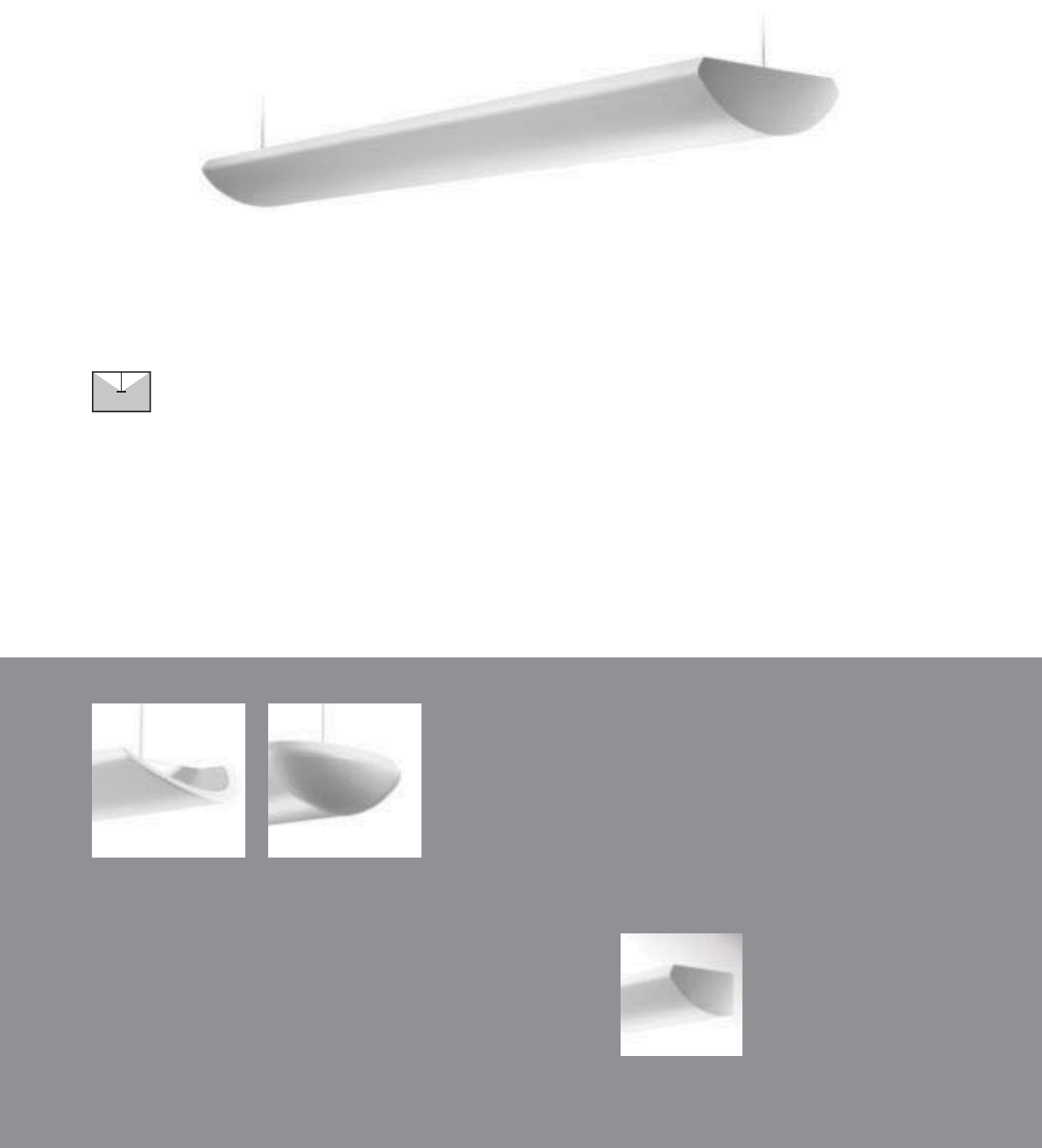
Class A
Indirect Wall
(pages 116-117)
Rounded End Cap (ER)Tapered End Cap (ET)
• Standard Flat or Optional Tapered or
Rounded end caps
AI-WN with standard flat end plates
42
Class A Indirect
SUSPENDED | FULL INDIRECT | T5 / T5HO / T8
The Class A Indirect has the greatest
selection of lamp confi gurations in
the entire linear category.

43
2-7/8" [73MM]
9" [229MM]
S
ERIE
S
A
I=
C
lass A Indirect
S
uspended
O
PTI
CS
UP
W=White
S=S
p
ecular
O
PTI
CS
D
O
WN
N
=
N
one
N
U
MBER
O
F LAMP
S
1=1
L
am
p
s
2
=2
L
amp
s
3=3 Lamp
s
4=4 Lam
ps
LAMP TYPE
N5=T5 Normal
O
utput
T5=T5 High Outpu
t
T8=T8 Normal Out
p
ut
NUMBER
O
F
C
IR
C
UIT
S*
1=1
C
ircui
t
2
=2
C
ir
cu
it
s
WIRIN
G
*
C
=
S
tandard
C
ircuit
D=Dimming
E=Emergency
B
=
B
atter
y
P
ac
k
T
=
Nigh
t
ligh
t
Y=Daylight
V
O
LTA
G
E*
120=120
V
2
77=277
V
347=347V
U
NV=Universal (120V-277V)
S
U
S
PEN
S
I
ON
A
=Aircraft
C
abl
e
P=Rigid Pendant
P
O
WER FEED*
C
=
S
traight
C
ord
K=Curly Cord
P=Rigid Pendant
S
U
S
PEN
S
I
O
N LEN
G
T
H
-Fixed
C
abl
e
12”, 15”, 18”, 21”, 24” or 27” (+/- 1/2” adjustment)
-Ad
j
ustable
C
able
48
”,
120
”,
240
”,
300
”,
or 360
”
(infinite adjustment along entire length of cable
)
-
Rigid
P
en
d
ant
12
”,
15
”,
18
”,
21
”,
24
”
or 27
”
(additional pendant lengths available, consult factory
)
C
EILIN
G
TYPE*
T
1=1
”
T
-
B
a
r
T9=9
/
16” T-Bar
TS=Slotted T-Bar
S
T=
S
tr
uc
t
u
r
e
JB=4” Octa
g
onal J-Bo
x
R
U
N LEN
G
TH
Specify luminaire len
g
th in feet.
-
I
n
di
v
id
ua
lly
M
ounte
d
L
um
i
na
i
res may
b
e 4
’
,8
’
, or 12
’
i
n
l
engt
h
.
-Continuously Mounted
Standard row configurations over 12’ consist of 8’ and 12’ sections
.
O
PTI
O
N
S
ET=Ta
p
ered End Ca
p
ER=Rounded End Ca
p
PROJECT NAME: TYPE:
CATALOG #:
-
-
-
-
-
-
-
-
t
echnical information.
S
pecifications and dimensions subject to change without notice.
ORDERING INFORMATION:
SAMPLE NUMBER:AI-WN-2T8-1C-UNV-AC48-T1-32’-ET
SUSPENDED CLASS A INDIRECT
Construction: Housin
g
is one piece die-formed
2
0-
g
au
g
e cold rolled steel, formin
g
a 9”x2-7
/
8”
a
rchitectural profile.
S
tandard 4’-0”, 8’-0”, and
12’-0” fixture lengths combine for continuous
runs.
Reflectors: Reflector pan is painted with a hi
g
h
r
eflectance white powder coat finish.
O
ptional
die-formed side reflectors are highly specular
a
n
od
iz
ed
a
l
u
min
u
m.
Electrical: T5/T5HO fixtures are
p
re-wired with
q
uick wire connectors and use UL listed Class P,
T5
/
T5H
O
pro
g
ram rapid start universal volta
g
e
e
lectronic ballasts, power factor of 97% with
l
ess than 10% THD. T8 fixtures are
p
re-wired
w
ith
q
uick wire connectors and use UL listed
C
lass P, 265ma T8 instant start universal volta
g
e
e
lectronic ballasts, power factor of 95% with
l
ess than 10% THD. Fixtures and electrical
c
om
p
onents certified to UL and CUL standards.
M
ountin
g
:
S
tandard aircraft cable mounts on
4’-0”, 8’-0”, and 12’-0” centers. Refer to spec
sheets
f
or various ceiling inter
f
ace details and
rigid
pen
d
ant mount
i
n
g
d
eta
il
s.
Finish: Fixture housings are standard white
u
s
i
n
g
e
l
ectrostat
i
ca
ll
y app
li
e
d
po
l
yester pow
d
er
c
oat pa
i
nt.
End Plates:
S
tandard laser cut 14-
g
au
g
e cold
r
olled steel, mechanically attached with no
e
x
p
osed fasteners. O
p
tional die cast aluminum
e
nd ca
p
s also available.
Dimensions do not include
end plates or caps
96”48” 144”
SUSPENDED
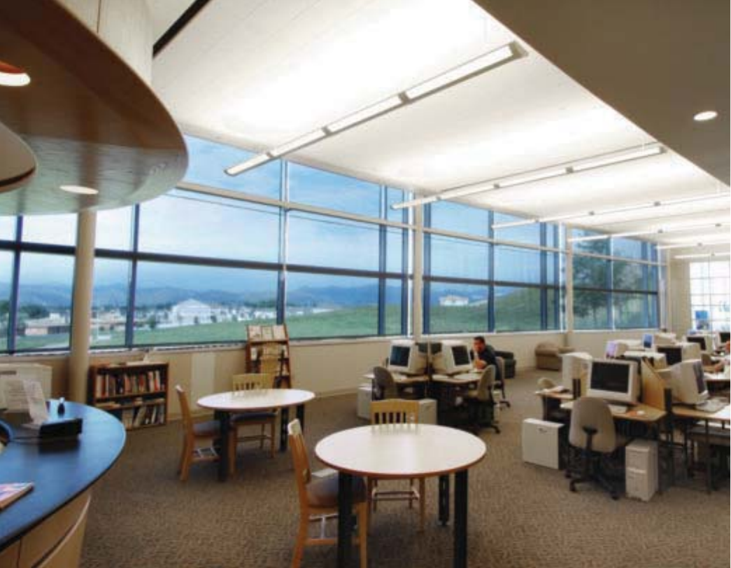
44
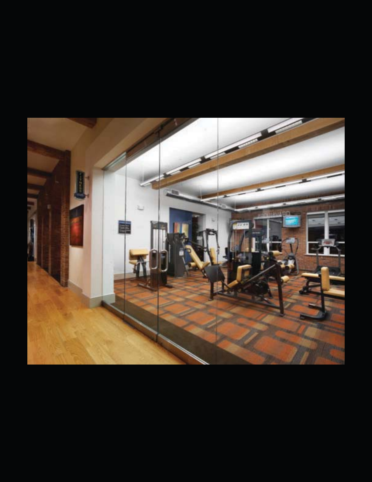
45
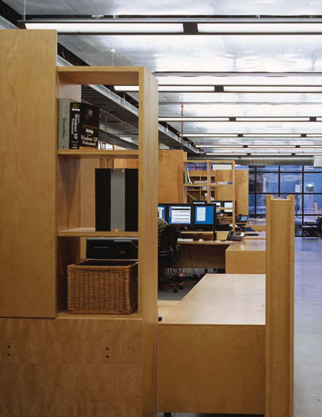
46
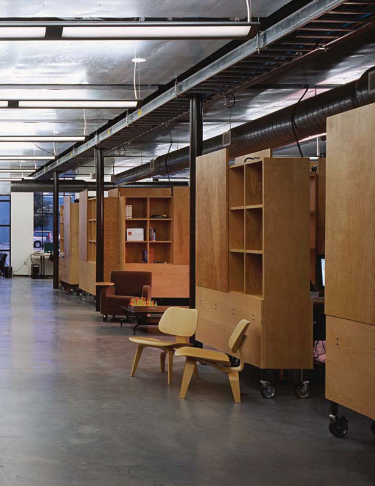
47
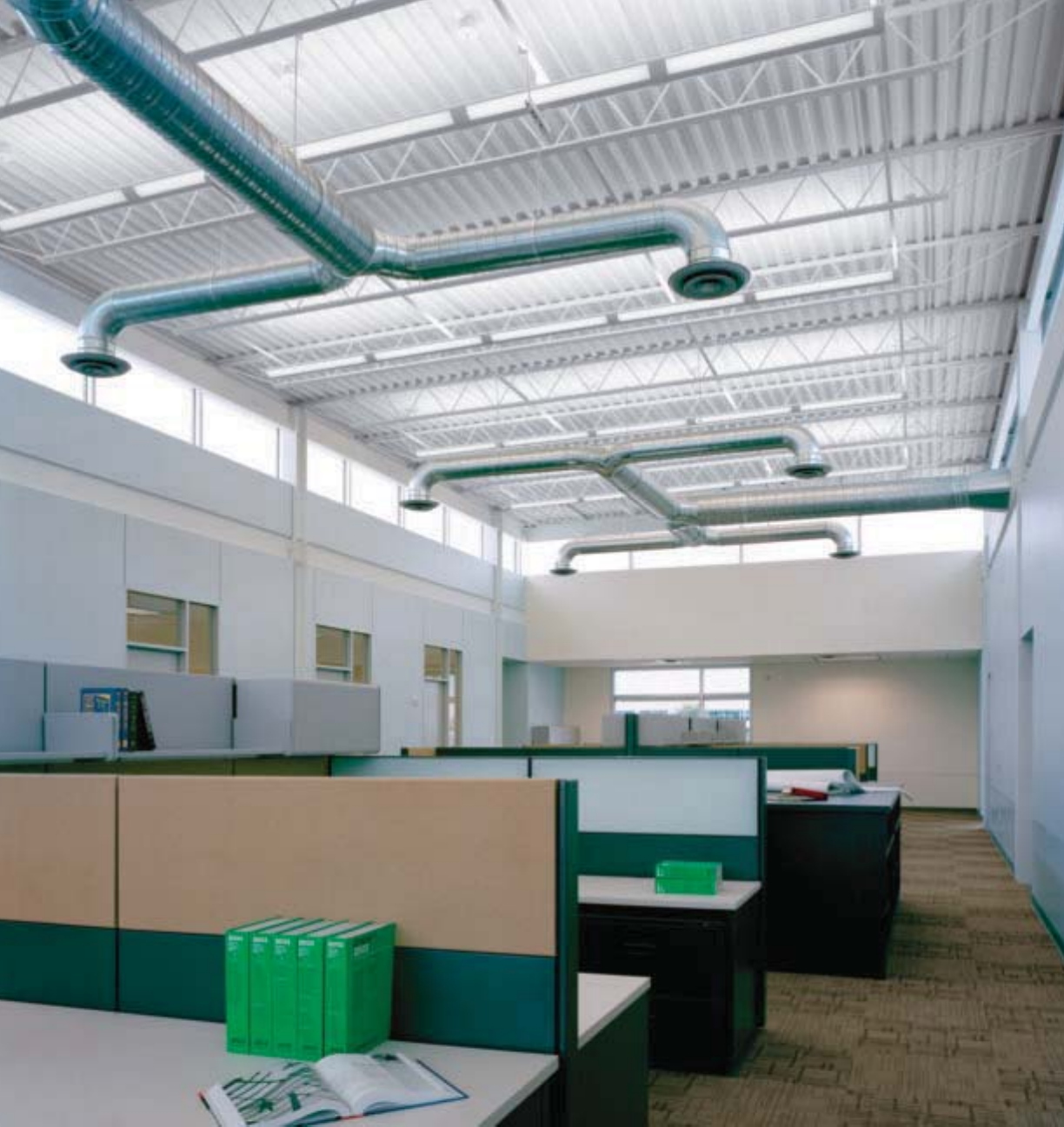
48

49

50
The Sophistication of Simplicity.
Versatile enough to satisfy any application and sleek enough
to please the most discriminating palette, the Iridium family
presents a complete line of semi-indirect to direct-indirect
luminaires in one series. The innovative Iridium IQ, the “Smart
Fixture”, leads the way in optical and aesthetic fl exibility with
the introduction of a third Slide-N-LockTM scale, a second
optional die-cast end cap, and another opportunity to take
advantage of the glare-reduction capability of the Eclipse
Louver. Rounding out the family are the Iridium D/I and
Iridium Perf, which offer a variety of optics and distributions,
enabling spaces designed with varied light levels to achieve
a cohesive aesthetic.
Iridium
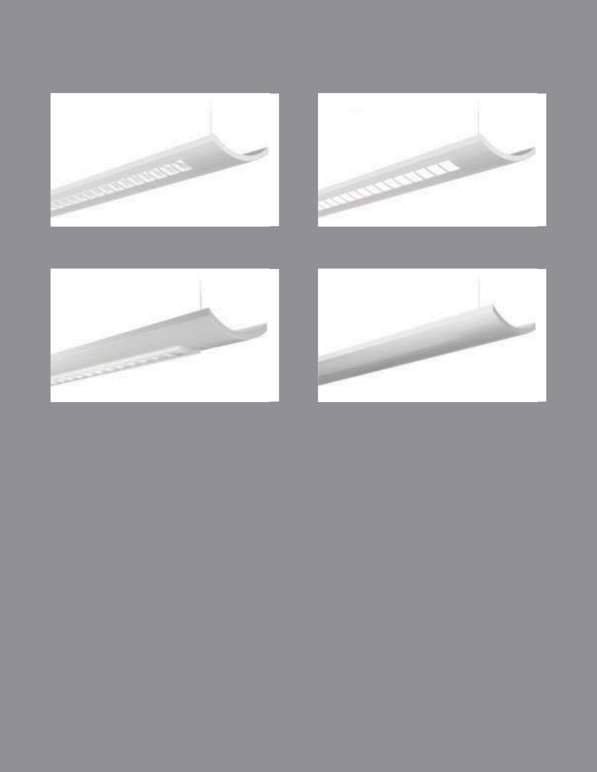
IRIDIUM IQ BAFFLE
pg. 52-53
IRIDIUM IQ LENSED
pg. 54-55
IRIDIUM D/I
pg. 56-57
IRIDIUM PERF
pg. 58-59
51
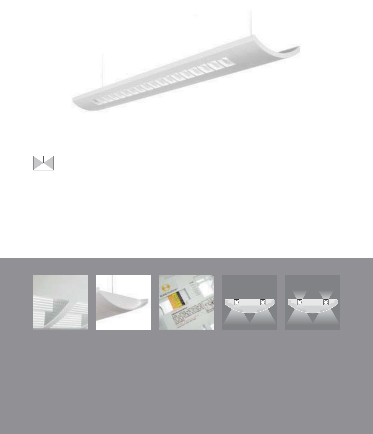
100% Downlight
Isolators (DL100)
Slide-N-Lock™
(pages 98-99)
Eclipse Louver (IQ-WE) Beveled End Cap (EB) 80% Downlight
Isolators (DL80)
• Slide-N-Lock™ optics with eight field
adjustable settings
• Standard Straight or optional Beveled end caps
• Additional glare reduction with the
Eclipse Louver
• 80% and 100% Downlight Isolators
IQ-WB with standard straight end caps (ES)
52
Iridium IQ Baffl e
SUSPENDED | DIRECT-INDIRECT | T5 / T5HO / T8
With four innovative downlight controls,
Iridium IQ – the smart fi xture – has the
highest IQ in its class.
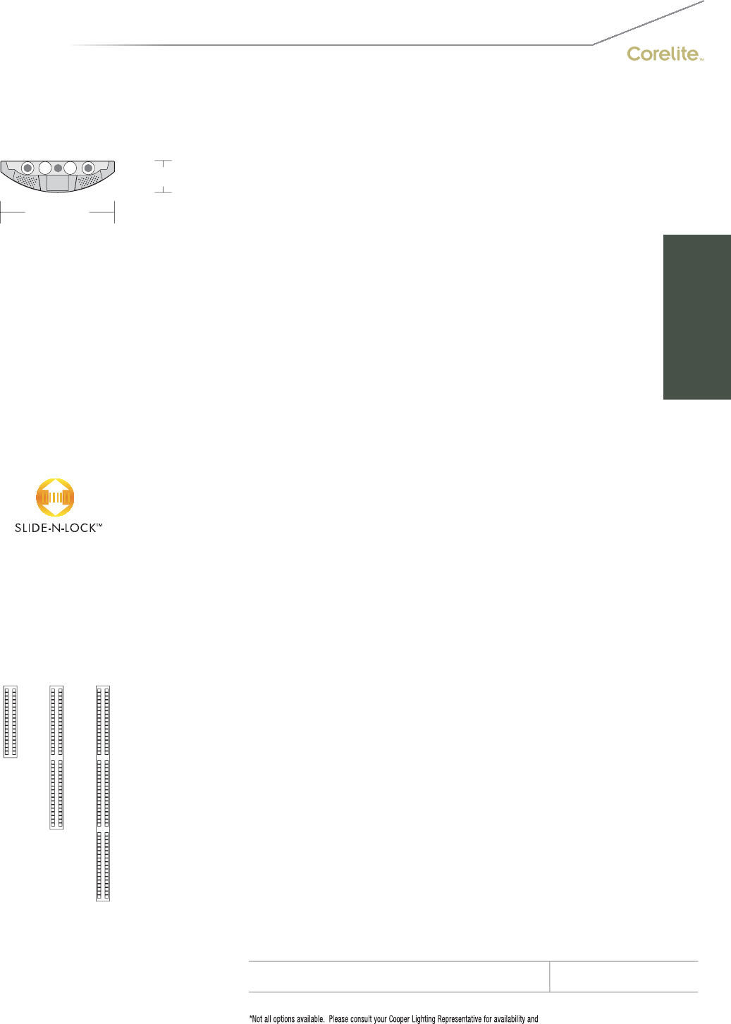
53
2-1/2" [64MM]
9" [228MM]
S
ERIE
S
I
Q
=Iridium I
Q
S
uspended
OPTICS UP
W=Whit
e
S=S
p
ecular
O
PTI
CS
D
O
WN
B=Perforated Baffle (standard
)
E=Ecli
p
se Louve
r
NUMBER
O
F LAMP
S
2
=2 Lamps (N5, T5, T8)
3=3 Lamps (N5, T5, T8)
4=4
L
amps
(T
8
)
LAMP TYPE
N5=T5 Normal Out
p
ut
T5=T5 Hi
g
h Outpu
t
T8=T8 Normal
O
utput
NUMBER OF CIRCUITS
*
1=1
C
ir
cu
i
t
2
=2
C
ir
cu
it
s
WIRIN
G
*
C=Standard Circuit B=Batter
y
Pac
k
D
=
Di
mm
i
n
g
T
=
Nigh
t
ligh
t
E
=
E
mer
g
ency
Y
=
D
ay
light
VOLTAGE*
12
0
=12
0
V
277
=
277V
347=347
V
U
NV=Universal (120V-277V)
SUS
PEN
S
I
ON
A
=Aircraft
C
abl
e
P
=
Ri
g
id
P
en
d
ant
P
O
WER FEED*
C
=
S
trai
g
ht
C
ord
K=
C
urly
C
ord
P=Rigid Pendant
SUS
PEN
S
I
O
N LEN
G
T
H
-Fixed
C
abl
e
12”, 15”, 18”, 21”, 24” or 27” (+
/
- 1
/
2” adjustment)
-Adjustable Cable
48
”,
120
”,
240
”,
300
”,
or 360
”
(
infinite ad
j
ustment alon
g
entire len
g
th of cable
)
-Rigid Pendant
12
”,
15
”,
18
”,
21
”,
24
”
or 27
”
(
additional pendant len
g
ths available, consult
f
actory
)
CEILING TYPE*
T1=1” T-B
ar
T
9
=
9/
1
6
” T-B
a
r
T
S
=
S
lotted T-Bar
S
T=
S
tructure
JB=4” Octagonal J-Bo
x
RUN LEN
G
TH
S
pecify luminaire length in feet.
-Individually Mounted
Luminaires may be 4’,8’, or 12’ in length.
-Continuousl
y
Mounted
S
tandard row confi
g
urations over 12’ consist of 8’ and 12’ sections
.
O
PTI
O
N
S
ES=Strai
g
ht End Cap
(
provided if none specified
)
EB=Beveled End
C
a
p
DL100=100% Downlight Isolators for outboard lamp
s
DL80=80% Downlight Isolators
f
or outboard lamps
Slide-N-Lock
TM
k
(
p
g
. 98-99
)
DL1=95% Downlight DL5=75% Downlight
DL2=90% Downlight DL6=70% Downlight
DL3=85% Downli
g
ht DL7=65% Downli
g
ht
DL
4=80%
D
own
ligh
t
DL
8=60%
D
own
ligh
t
PROJECT NAME: TYPE:
CATALOG #:
-
-
-
-
-
-
-
-
t
echnical information.
S
pecifications and dimensions subject to change without notice.
ORDERING INFORMATION:
SAMPLE NUMBER:IQ-WB-2T8-1C-UNV-AC48-T1-32’-ES
SUSPENDED IRIDIUM IQ BAFFLE
Construction: Housin
g
is one piece die-formed
c
old rolled steel, formin
g
a 9”x2-1
/
2”
a
rchitectural profile.
S
tandard 4’-0”, 8’-0”,
a
nd 12’-0” fixture lengths combine for
co
ntin
uous
r
u
n
s
.
Reflectors: Reflector pan is painted with a high
r
eflectance white
p
owder coat finish. O
p
tional
die-
f
ormed side re
f
lectors are hi
g
hly specular
a
no
di
ze
d
a
l
um
i
num.
Louvers: Standard white aluminum perforated
b
lades. O
p
tional Ecli
p
se louver with white
p
er
f
orated blades and ribbed di
ff
use anodized
al
um
i
num runners
.
Electrical: T5/T5HO fixtures are pre-wired with
q
uick wire connectors and use UL listed Class P,
T5/T5HO pro
g
ram rapid start universal volta
g
e
e
lectronic ballasts, power factor of 97% with
l
ess than 10% THD. T8 fixtures are pre-wired
w
ith
q
uick wire connectors and use UL listed
Class P, 265ma T8 instant start universal volta
g
e
e
lectronic ballasts, power
f
actor o
f
95% with
l
ess t
h
an 10%
THD
.
Fi
xtures an
d
e
l
ectr
i
ca
l
c
omponents certified to UL and CUL standards.
M
ountin
g
: Standard aircraft cable mounts on
4’-0”, 8’-0”, and 12’-0” centers. Re
f
er to spec
sheets for various ceiling interface details and
r
igid pendant mounting details.
Fi
n
i
s
h
:
Fi
xture
h
ous
i
ngs are stan
d
ar
d
w
hi
te
u
sing electrostatically applied polyester powder
c
oat
p
aint.
End
C
aps: End caps are precision die-cast
a
luminum mechanicall
y
attached without
e
x
p
osed
f
asteners
.
Dimensions do not include
end plates or caps
96”48” 144”
SUSPENDED

Beveled End Cap (EB)
54
IQ-WO with standard straight end caps (ES)
• Standard Straight or optional Beveled end caps
Iridium IQ Lensed
SUSPENDED | SEMI-INDIRECT | T5 / T5HO / T8
The Iridium IQ Lensed provides
semi-indirect distribution with
direct-indirect appeal.

55
2-1/2" [64MM]
9" [228MM]
S
ERIE
S
I
Q
=Iridium I
Q
S
uspended
OPTICS UP
W=Whit
e
S=S
p
ecular
O
PTI
CS
D
O
WN
O=White O
p
al Lens
NUMBER
O
F LAMP
S
2
=2
L
amps
(N
5,
T
5,
T
8
)
3=3 Lamps (N5, T5, T8)
4=4 Lamps (T8
)
LAMP
TYPE
N5=T5 Normal
O
utput
T5=T5 High Outpu
t
T8=T8 Normal Out
p
ut
NUMBER
O
F
C
IR
C
UIT
S*
1=1 Circui
t
2
=2
C
ir
cu
it
s
WIRIN
G
*
C
=
S
tandard
C
ircuit
D=Dimming
E
=
E
mer
g
ency
B
=
B
attery
P
ac
k
T
=
Ni
g
h
t
li
g
h
t
Y=Daylight
V
O
LTA
G
E*
120=120
V
2
77=277V
3
47=
3
47V
UNV
=
U
n
i
versa
l
(
120
V
-277
V)
S
U
S
PEN
S
I
ON
A
=Aircraft Cabl
e
P=Rigid Pendant
P
O
WER FEED*
C
=
S
traight
C
ord
K=Curl
y
Cord
P
=
Rigid
P
en
d
ant
S
U
S
PEN
S
I
O
N LEN
G
T
H
-Fixed Cabl
e
12”, 15”, 18”, 21”, 24” or 27” (+/- 1/2” adjustment)
-Ad
j
ustable
C
able
48”, 120”, 240”, 300”, or 360”
(in
f
inite adjustment along entire length o
f
cable
)
-
Rigid
P
en
d
ant
12
”,
15
”,
18
”,
21
”,
24
”
or 27
”
(additional pendant lengths available, consult factory
)
C
EILIN
G
TYPE*
T
1=1
”
T
-
B
a
r
T9=9
/
16” T-Bar
T
S
=
S
l
o
tt
ed
T-B
a
r
S
T=
S
tr
uc
t
u
r
e
JB=4”
O
cta
g
onal J-Bo
x
RUN LENGTH
Specify luminaire length in feet.
-
I
n
di
v
id
ua
lly
M
ounte
d
L
um
i
na
i
res may
b
e 4
’
,8
’
, or 12
’
i
n
l
en
g
t
h
.
-
C
ontinuously Mounted
Standard row configurations over 12’ consist of 8’ and 12’ sections
.
O
PTI
O
N
S
E
S
=
S
traight End
C
ap (provided if none specified)
EB=Beveled End Ca
p
PROJECT NAME: TYPE:
CATALOG #:
-
-
-
-
-
-
-
-
t
echnical information.
S
pecifications and dimensions subject to change without notice.
ORDERING INFORMATION:
SAMPLE NUMBER:IQ-WO-2T8-1C-UNV-AC48-T1-32’-ES
SUSPENDED IRIDIUM IQ LENSED
Construction: Housin
g
is one piece die-formed
c
old rolled steel, formin
g
a 9”x2-1
/
2”
a
rchitectural profile.
S
tandard 4’-0”, 8’-0”,
a
nd 12’-0” fixture lengths combine for
co
ntin
uous
r
u
n
s
.
Reflectors: Reflector pan is painted with a high
r
eflectance white
p
owder coat finish. O
p
tional
die-
f
ormed side re
f
lectors are hi
g
hly specular
a
no
di
ze
d
a
l
um
i
num.
Lens: Standard white opal
.
Electrical: T5
/
T5H
O
fixtures are pre-wired with
quick wire connectors and use UL listed Class P,
T5/T5HO program rapid start universal voltage
e
lectronic ballasts,
p
ower
f
actor o
f
97% with
l
ess than 10% THD. T8 fixtures are pre-wired
w
ith quick wire connectors and use UL listed
Class P, 265ma T8 instant start universal voltage
e
lectronic ballasts,
p
ower
f
actor o
f
95% with
l
ess t
h
an 10%
THD
.
Fi
xtures an
d
e
l
ectr
i
ca
l
c
omponents certified to UL and
C
UL standards.
M
ounting:
S
tandard aircraft cable mounts on
4’-0”, 8’-0”, and 12’-0” centers. Refer to spec
sheets
f
or various ceiling inter
f
ace details and
rigid
pen
d
ant mount
i
n
g
d
eta
il
s.
Finish: Fixture housings are standard white
u
s
i
n
g
e
l
ectrostat
i
ca
ll
y app
li
e
d
po
l
yester pow
d
er
c
oat pa
i
nt.
End Ca
p
s: End ca
p
s are
p
recision die-cast
al
um
i
num mec
h
an
i
ca
lly
attac
h
e
d
w
i
t
h
out
e
xposed fasteners
.
Dimensions do not include
end plates or caps
96”48” 144”
SUSPENDED

Lamp Isolators
(pages 98-99)
Slide-N-Lock™
(pages 98-99)
Beveled End Cap (EB)
Concave Metallic
Perf (IB-WC)
RPerformance™
Louver (IB-WH)
Micro Prismatic Lens
(IB-WM)
Cross Blade Parabolic
Louver (IB-WB)
High Efficiency Louver
(IB-WW)
56
IB-WB with standard straight end caps (ES)
• RPerformance™ louver meets RP1 requirements
• Slide-N-Lock™ optics with eight field adjustable settings
• Standard Straight or optional Beveled end caps
• Five unique louver options
• Lamp Isolator kits
Iridium D/I
SUSPENDED | DIRECT-INDIRECT / SEMI-INDIRECT | T5 / T5HO / T8
Five unique media options in one
sleek profi le make the Iridium D/I
an ideal design solution.

57
2-5/8" [67MM]
9" [228MM]
S
ERIE
S
IB=Iridium D
/
I
S
uspende
d
OPTICS UP
W=Whit
e
S=S
p
ecular
O
PTI
CS
D
O
WN
B=
C
r
oss
Bl
ade
P
a
r
abo
li
c
L
ou
v
e
r
C
=
Co
n
ca
v
e
M
e
t
a
lli
c
P
e
rf
H=RPer
f
ormance™ Louver
M
=
Mi
cro
P
r
i
smat
i
c
L
en
s
W=High Efficiency Louve
r
N
U
MBER
O
F LAMP
S
1=1
L
amp
(N
5,
T
5
)
2
=2 Lamps (N5, T5, T8)
3=3 Lamps (N5, T5
)
LAMP TYPE
N5=T5 Normal
O
utput
T5=T5 High Outpu
t
T8=T8 Normal Out
p
ut
NUMBER
O
F
C
IR
C
UIT
S*
1=1
C
ircui
t
2
=2
C
ir
cu
it
s
WIRIN
G
*
C
=
S
tandard
C
ircuit B=Battery Pac
k
D=Dimming T=Nightlight
E=Emergency Y=Daylight
V
O
LTA
G
E*
120=120V 347=347V
2
77=277V UNV=Universal (120V-277V
)
S
U
S
PEN
S
I
ON
A
=Aircraft
C
abl
e
P=Rigid Pendant
P
O
WER FEED*
C
=
S
trai
g
ht
C
ord
K=
C
urly
C
ord
P=Rigid Pendant
S
U
S
PEN
S
I
O
N LEN
G
T
H
-Adjustable
C
able
48”, 120”, 240”, 300”, or 360”
(in
f
inite adjustment along entire length o
f
cable
)
-
Rigid
P
en
d
ant
12”, 15”, 18”, 21”, 24” or 27”
(additional pendant lengths available, consult
f
actory
)
C
EILIN
G
TYPE*
T
1=1
”
T
-
B
a
r
T9=9/16” T-Bar
T
S
=
S
l
o
tt
ed
T-B
a
r
S
T=
S
tr
uc
t
u
r
e
JB=4”
O
cta
g
onal J-Bo
x
R
U
N LEN
G
TH
Specify luminaire len
g
th in feet.
-
I
n
di
v
id
ua
ll
y
M
ounte
d
L
um
i
na
i
res may
b
e 4
’
or 8
’
i
n
l
engt
h
.
-Continuously Mounted
Standard row configurations over 8’ consist of 4’ and 8’ sections
.
O
PTI
O
N
S
*
E
S
=
S
traight End
C
ap (provided if none specified)
EB=Beveled End Ca
p
Slide-N-Lock
TM
k
(
p
g
. 98-99
)
DL
1=95%
D
own
li
g
h
t
DL
5=75%
D
own
li
g
h
t
DL2=90% Downlight DL6=70% Downlight
DL3=85% Downlight DL7=65% Downlight
DL
4=80%
D
own
ligh
t
DL
8=60%
D
own
ligh
t
Lamp Isolators (pg. 98-99
)
DL/UDU=2 lam
p
s u
p
1 lam
p
down
DL/DUD=2 lam
p
s down 1 lam
p
u
p
DL
/
UXU=2 lamps u
p
DL
/
DXD=2 lamps dow
n
DL/XUX=1 lamp u
p
DL/XDX=1 lam
p
dow
n
PROJECT NAME: TYPE:
CATALOG #:
-
-
-
-
-
-
-
-
t
echnical information.
S
pecifications and dimensions subject to change without notice.
ORDERING INFORMATION:
SAMPLE NUMBER:IB-WB-2T8-1C-UNV-AC48-T1-32’-ES
SUSPENDED IRIDIUM D/I
Construction: Housin
g
is one piece die-formed
c
old rolled steel, formin
g
a 9”x2-1
/
2”
a
rchitectural profile.
S
tandard 4’-0” and 8’-0”
f
ixture lengths combine for continuous runs.
Reflectors: Reflector pan is painted with a high
r
eflectance white
p
owder coat finish. O
p
tional
die-
f
ormed side re
f
lectors are hi
g
hly specular
a
no
di
ze
d
a
l
um
i
num.
Le
n
s
:
Le
n
s
is
.12
5”
t
hick
clea
r m
ic
r
oli
n
ea
r
p
rismatic acrylic material offerin
g
93%
t
ransmission.
Louvers:
C
ross Blade and RPerformance™ are
c
ontinuous semi-specular aluminum. Perf is
semi-specular material, perforated section is
15% o
p
en with 0.062” diameter holes and o
p
al
di
ff
user. Hi
g
h E
ff
iciency is continuous hi
g
hly
r
eflective painted white aluminum
.
Electrical: T5
/
T5H
O
fixtures are pre-wired with
quick wire connectors and use UL listed
C
lass P,
T5/T5HO program rapid start universal voltage
e
lectronic ballasts,
p
ower
f
actor o
f
97% with
l
ess than 10% THD. T8
f
ixtures are
p
re-wired
wi
t
h
qu
i
c
k
w
i
re connectors an
d
use
UL
li
ste
d
C
lass P, 265ma T8 instant start universal voltage
e
lectronic ballasts,
p
ower
f
actor o
f
95% with
less
t
ha
n 1
0%
THD
.
Fi
xt
u
r
es
a
n
d
elec
tr
ical
c
omponents certified to UL and
C
UL standards.
M
ountin
g
:
S
tandard aircraft cable mounts on
4’-0” and 8’-0” centers. Refer to spec sheets
f
or various ceiling interface details and rigid
p
endant mounting details
.
Fi
n
i
s
h
:
Fi
xture
h
ous
i
n
g
s are stan
d
ar
d
w
hi
te
u
sing electrostatically applied polyester powder
c
oat
p
aint.
End Ca
p
s: End ca
p
s are
p
recision die-cast
al
um
i
num mec
h
an
i
ca
lly
attac
h
e
d
w
i
t
h
out
e
xposed fasteners
.
Dimensions do not include
end plates or caps
96”48”
SUSPENDED
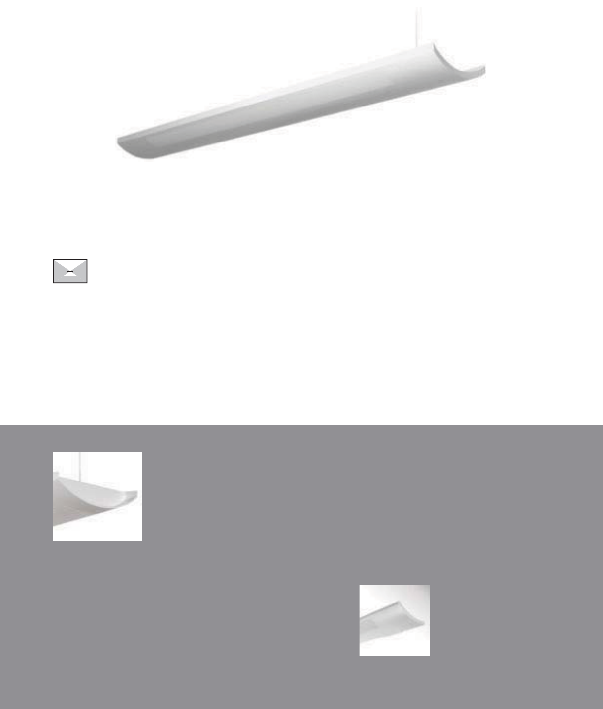
Beveled End Cap (EB)
• Straight or optional Beveled end caps
58
IP-WP with standard straight end caps (ES)
Iridium Wall
(pages 118-119)
Iridium Perf
SUSPENDED | SEMI-INDIRECT | T5 / T5HO / T8
The Iridium Perf offers sleek
standard features with modern
custom appeal.
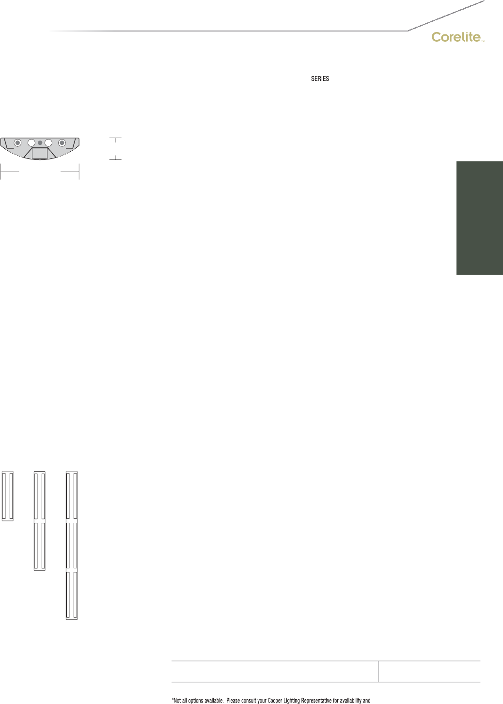
59
2-1/2" [63MM]
9" [228MM]
IP=Iridium Perf
S
uspende
d
O
PTI
CS
UP
W=White
S=S
p
ecular
O
PTI
CS
D
O
WN
P=Perforate
d
N
U
MBER
O
F LAMP
S
1=1
L
amp
(N
5,
T
5
)
2
=2
L
amps
(N
5,
T
5,
T
8
)
3=3 Lamps (N5, T5, T8)
4=4 Lamps (T8
)
LAMP TYPE
N5=T5 Normal
O
utput
T5=T5 High Outpu
t
T8=T8 Normal Out
p
ut
NUMBER
O
F
C
IR
C
UIT
S*
1=1
C
ircui
t
2
=2
C
ir
cu
it
s
WIRIN
G
*
C
=
S
tandard
C
ircuit
D=Dimming
E=Emergency
B
=
B
atter
y
P
ac
k
T
=
Nigh
t
ligh
t
Y=Daylight
V
O
LTA
G
E*
120=120
V
2
77=277
V
347=347V
U
NV=Universal (120V-277V)
S
U
S
PEN
S
I
ON
A
=Aircraft
C
abl
e
P=Rigid Pendant
P
O
WER FEED*
C
=
S
traight
C
ord
K=Curly Cord
P=Rigid Pendant
S
U
S
PEN
S
I
O
N LEN
G
T
H
-Fixed
C
abl
e
12”, 15”, 18”, 21”, 24” or 27” (+/- 1/2” adjustment)
-Ad
j
ustable
C
able
48
”,
120
”,
240
”,
300
”,
or 360
”
(infinite adjustment along entire length of cable
)
-
Rigid
P
en
d
ant
12
”,
15
”,
18
”,
21
”,
24
”
or 27
”
(additional pendant lengths available, consult factory
)
C
EILIN
G
TYPE*
T
1=1
”
T
-
B
a
r
T9=9
/
16” T-Bar
TS=Slotted T-Bar
S
T=
S
tr
uc
t
u
r
e
JB=4” Octa
g
onal J-Bo
x
RUN LEN
G
TH
Specify luminaire length in feet.
-
I
n
di
v
id
ua
lly
M
ounte
d
L
um
i
na
i
res may
b
e 4
’
,8
’
, or 12
’
i
n
l
en
g
t
h
.
-
C
ontinuously Mounted
Standard row configurations over 12’ consist of 8’ and 12’ sections
.
O
PTI
O
N
S
E
S
=
S
trai
g
ht End
C
ap
(
provided if none specified
)
EB=Beveled End
C
a
p
PROJECT NAME: TYPE:
CATALOG #:
-
-
-
-
-
-
-
-
t
echnical information.
S
pecifications and dimensions subject to change without notice.
ORDERING INFORMATION:
SAMPLE NUMBER:IP-WP-2T8-UNV-AC48-T1-32’-ES
SUSPENDED IRIDIUM PERF
Construction: Housin
g
is one piece die-formed
c
old rolled steel, formin
g
a 9”x2-1
/
2”
a
rchitectural profile.
S
tandard 4’-0”, 8’-0”,
a
nd 12’-0” fixture lengths combine for
co
ntin
uous
r
u
n
s
.
Reflectors: Reflector pan is painted with a hi
g
h
r
eflectance white powder coat finish.
O
ptional
die-formed side reflectors are highly specular
a
n
od
iz
ed
a
l
u
min
u
m.
Electrical: T5/T5HO fixtures are
p
re-wired with
q
uick wire connectors and use UL listed Class P,
T5
/
T5H
O
pro
g
ram rapid start universal volta
g
e
e
lectronic ballasts, power factor of 97% with
l
ess than 10% THD. T8 fixtures are
p
re-wired
w
ith
q
uick wire connectors and use UL listed
C
lass P, 265ma T8 instant start universal volta
g
e
e
lectronic ballasts, power factor of 95% with
l
ess than 10% THD. Fixtures and electrical
c
om
p
onents certified to UL and CUL standards.
M
ountin
g
:
S
tandard aircraft cable mounts on
4’-0”, 8’-0”, and 12’-0” centers. Refer to spec
sheets
f
or various ceiling inter
f
ace details and
rigid
pen
d
ant mount
i
n
g
d
eta
il
s.
Finish: Fixture housings are standard white
u
s
i
n
g
e
l
ectrostat
i
ca
ll
y app
li
e
d
po
l
yester pow
d
er
c
oat pa
i
nt.
End ca
p
s: End ca
p
s are
p
recision die-cast
al
um
i
num mec
h
an
i
ca
lly
attac
h
e
d
w
i
t
h
out
e
xposed fasteners
.
Dimensions do not include
end plates or caps
96”48” 144”
SUSPENDED
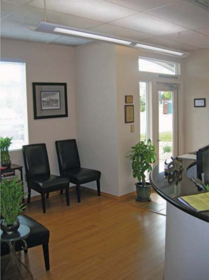
60
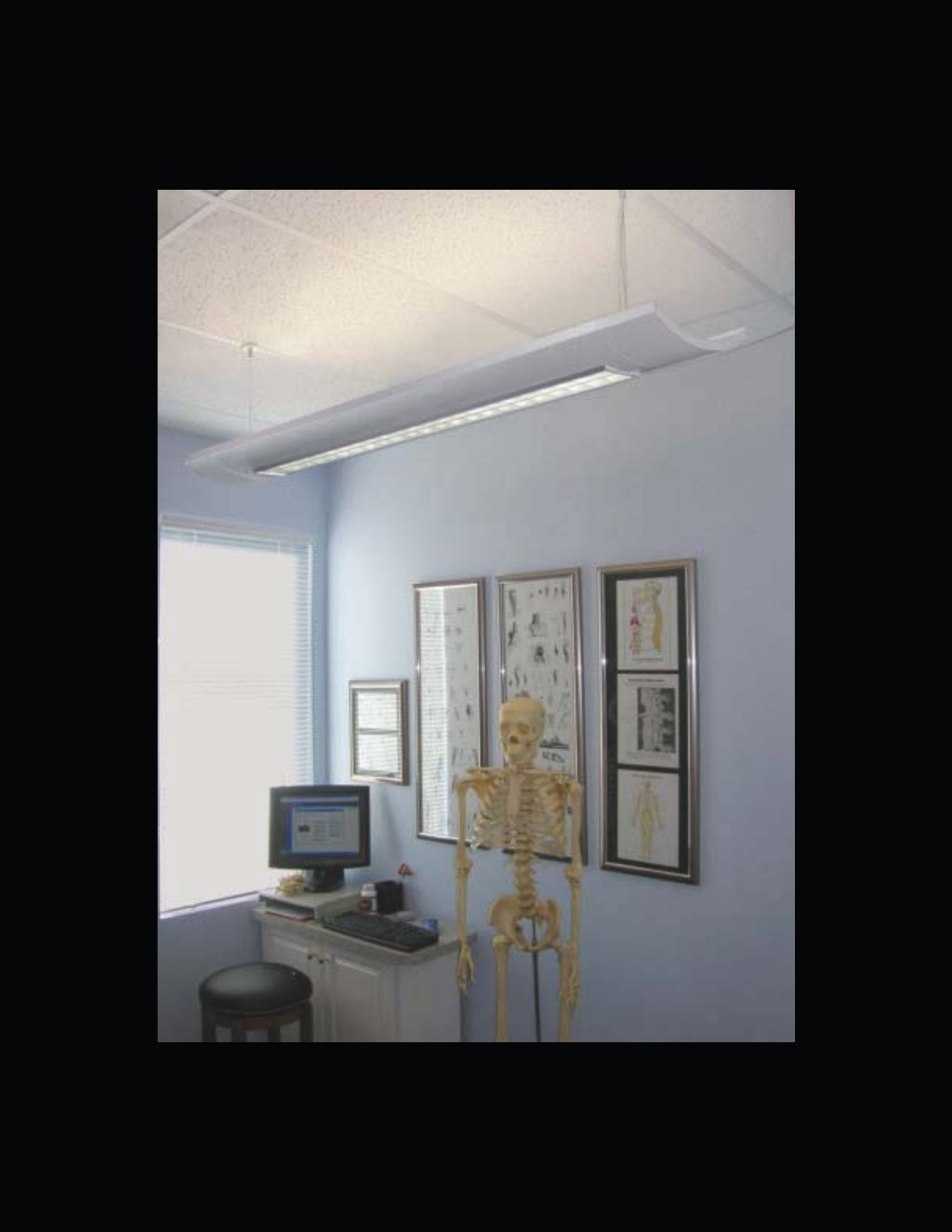
61
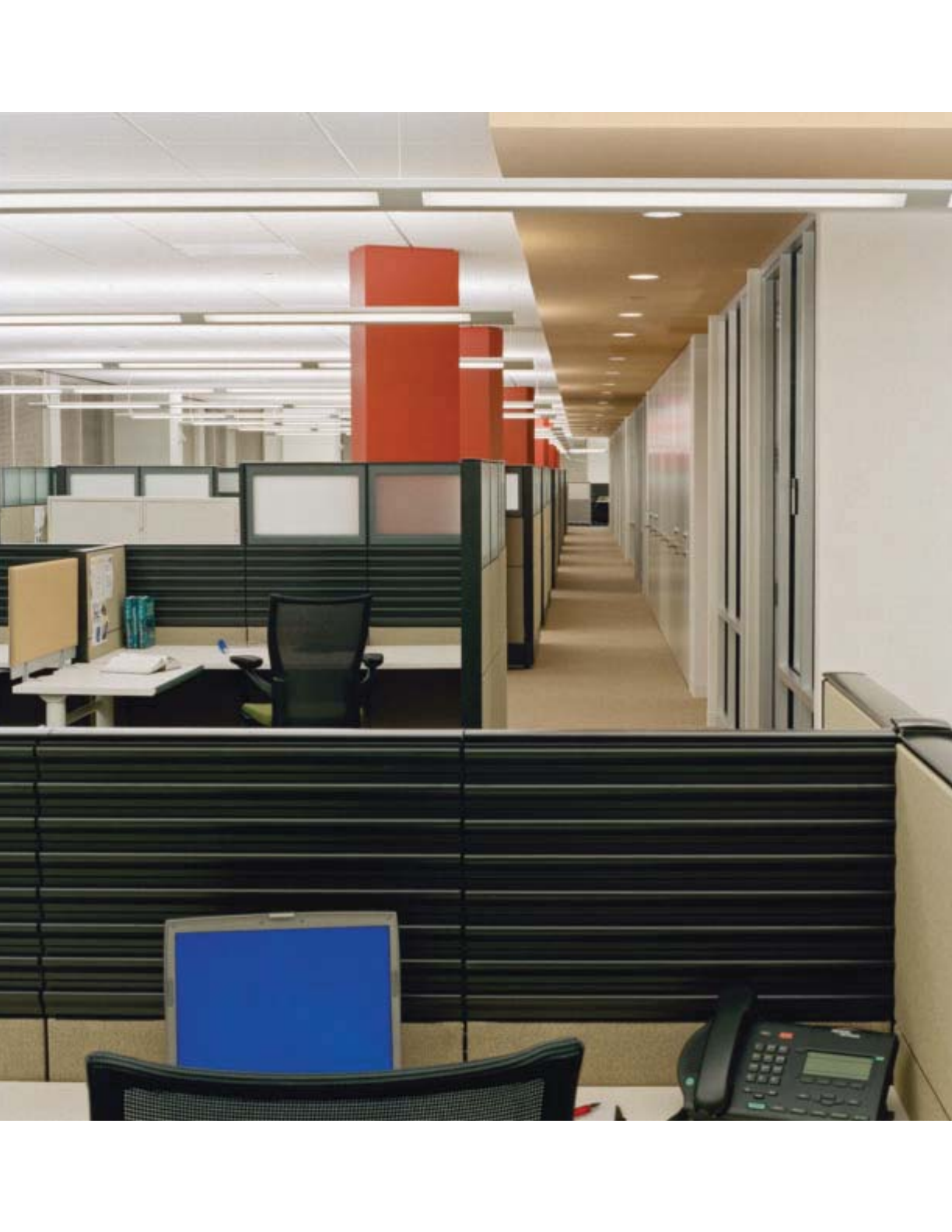
62
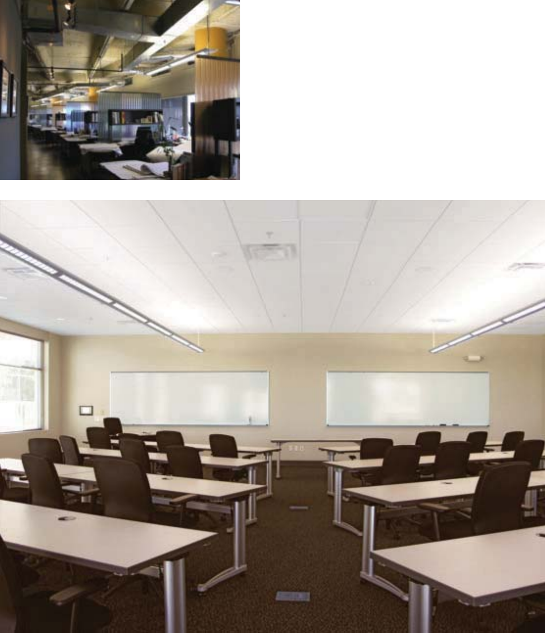
63
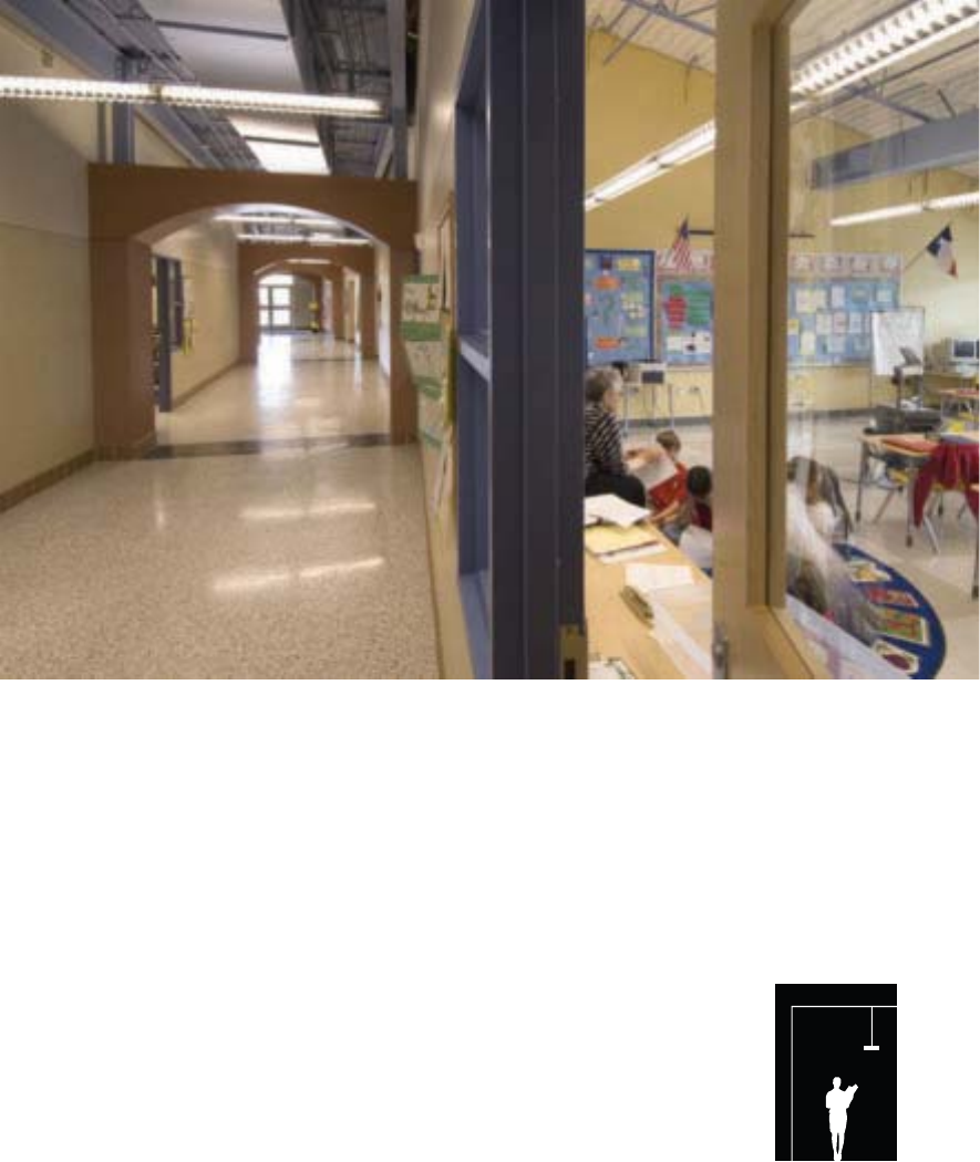
64
A Product of its Surroundings.
The Stellar family of ambient fl uorescent lighting, including
the new squared Stellar Q series, features an open-baffl e
design to facilitate effi cient direct-indirect light distribution,
and a “refi ned industrial” appearance to echo trends in
architecture where structure is often creatively revealed.
Stellar fi xtures deliver high vertical footcandles making them
ideally suited to library stacks and high-ceiling open offi ces.
Furthermore, Stellar series fi xtures offer optional downlight
kits and a unique optional metallic paint fi nish enabling the
achievement of a truly customized look and feel.
Stellar
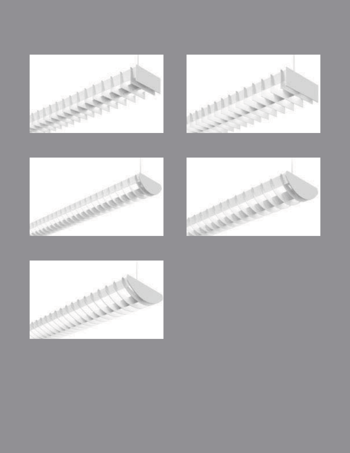
STELLAR Q 2T5
pg. 66-67
STELLAR Q 2T8
pg. 68-69
STELLAR 2T5
pg. 70-71
STELLAR 4T5/4T8
pg. 74-75
STELLAR 2T8
pg. 72-73
65
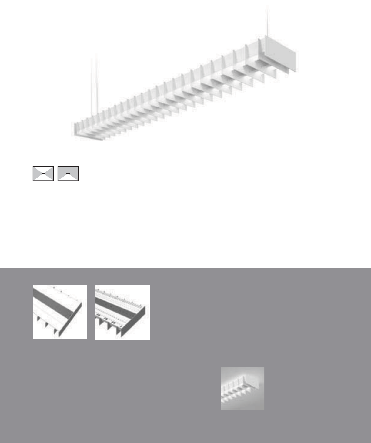
Stellar Q1 Surface
(pages 146-147)
Q1-WB with standard flat end plates
66
• 2T5 specific design
• 100% or 70% Downlight Kits
70% Downlight Kit
(DL70)
100% Downlight Kit
(DL100)
Stellar Q 2T5 (6”)
SUSPENDED | DIRECT-INDIRECT / DIRECT | T5 / T5HO
With its two-lamp T5 specifi c profi le,
the squared Stellar Q stands at the
very edge of modern design.

67
2-1/2" [64MM]
6" [152MM]
S
ERIE
S
Q
1=
S
tellar
Q
S
uspended
OPTICS UP
W=Whit
e
O
PTI
CS
D
O
WN
B= Baffle
NUMBER
O
F LAMP
S
2
=2
L
amp
s
LAMP TYPE
N5=T5 Normal Out
p
ut
T5=T5 Hi
g
h
O
utpu
t
N
U
MBER
O
F
C
IR
CU
IT
S
1=1
C
ir
cu
i
t
2
=2
C
ircuits
WIRING*
C
=
S
t
a
n
da
r
d
C
ir
cu
it
D
=
Di
mm
i
n
g
E
=
E
mer
g
ency
B=Battery Pack
T=Nightlight
Y
=
D
ay
ligh
t
V
O
LTA
G
E*
120=120V
277
=
277V
3
47=
3
47
V
UNV
=
U
n
i
versa
l
(
120
V
-277
V)
SUS
PEN
S
I
ON
A
=Aircraft
C
abl
e
P
=
Ri
g
id
P
en
d
ant
P
O
WER FEED*
C
=
S
trai
g
ht
C
ord
K=
C
urly
C
ord
P=Rigid Pendant
SUS
PEN
S
I
O
N LEN
G
T
H
-Fixed
C
abl
e
12”, 15”, 18”, 21”, 24” or 27” (+
/
- 1
/
2” adjustment)
-Adjustable Cable
48
”,
120
”,
240
”,
300
”,
or 360
”
(
infinite ad
j
ustment alon
g
entire len
g
th of cable
)
-Rigid Pendant
12
”,
15
”,
18
”,
21
”,
24
”
or 27
”
(
additional pendant len
g
ths available, consult
f
actory
)
CEILING TYPE*
T1=1” T-B
ar
T
9
=
9/
1
6
” T-B
a
r
T
S
=
S
lotted T-Bar
S
T=
S
tructure
JB=4” Octagonal J-Bo
x
O
PTI
O
N
S
DL
100=100%
D
own
ligh
t
Ki
t
DL
70=70%
D
own
ligh
t
Ki
t
PROJECT NAME: TYPE:
CATALOG #:
-
-
-
-
-
-
-
-
t
echnical information.
S
pecifications and dimensions subject to change without notice.
ORDERING INFORMATION:
SAMPLE NUMBER:Q1-WB-2T5-1C-UNV-AC48-T1-32’-DL70
SUSPENDED STELLAR Q
Co
n
s
tr
uc
ti
o
n: Di
e
-f
o
rm
ed
a
ll
a
l
u
min
u
m
ba
ffl
e
a
ssem
bl
y
(
1.5
”
bl
a
d
e spac
i
n
g)
mec
h
an
i
ca
ll
y
a
ttached to a corrosion resistant formed steel
b
allast channel. Perforated siderail sections are
2
3% open with 0.0625” stagger hole spacing.
Standard 4’-0”, 8’-0”, and 12’-0” fixture len
g
ths
c
ombine for continuous runs.
Electrical: T5
/
T5H
O
fixtures are
p
re-wired with
quick wire connectors and use UL listed
C
lass P,
T5/T5HO program rapid start universal voltage
e
lectronic ballasts,
p
ower
f
actor o
f
97% with
less
t
ha
n 1
0%
THD
.
M
ountin
g
: Standard aircraft cable mounts on
4’-0”, 8’-0”, and 12’-0” centers. Re
f
er to spec
sheets for various ceiling interface details and
r
igid pendant mounting details.
Fi
n
i
s
h
:
Fi
xture
h
ous
i
ngs are stan
d
ar
d
w
hi
te
u
sing electrostatically applied polyester powder
c
oat
p
aint. Consult factor
y
for custom finishes
.
End Plates: Laser cut 14-gauge cold rolled
steel, mechanicall
y
attached without ex
p
osed
fas
t
e
n
e
r
s
.
Dimensions do not include
end plates or caps
96”48” 144”
SUSPENDED

Stellar Q2 Surface
(pages 148-149)
68
Q2-WB with standard flat end plates
• 2T8 specific design
• 100% or 70% Downlight Kits
70% Downlight Kit
(DL70)
100% Downlight Kit
(DL100)
Stellar Q 2T8 (9”)
SUSPENDED | DIRECT-INDIRECT / DIRECT | T8
With its two-lamp T8 specifi c profi le,
the squared Stellar Q stands at the
very edge of modern design.

69
9" [229MM]
2-7/8" [73MM]
S
ERIE
S
Q
2=
S
tellar
Q
S
uspended
OPTICS UP
W=Whit
e
O
PTI
CS
D
O
WN
B= Baffle
NUMBER
O
F LAMP
S
2
=2
L
amp
s
LAMP TYPE
T8=T8 Normal Out
p
ut
NUMBER
O
F
C
IR
C
UIT
S
1=1
C
ir
cu
i
t
2
=2
C
ir
cu
it
s
WIRIN
G
*
C=Standard Circuit
D=Dimming
E
=
E
mer
g
ency
B
=
B
attery
P
ac
k
T=Nightlight
Y=Daylight
V
O
LTA
G
E*
120=120
V
2
77=277V
3
47=
3
47V
UNV
=
U
n
i
versa
l
(
120
V
-277
V)
SUS
PEN
S
I
ON
A
=Air
c
r
a
ft
Cab
l
e
P
=
Rigid
P
en
d
ant
POWER FEED*
C=Straight Cord
K=
C
url
y
C
ord
P
=
Rigid
P
en
d
ant
SUS
PEN
S
I
O
N LEN
G
T
H
-Fix
ed
Cab
l
e
12”, 15”, 18”, 21”, 24” or 27”
(
+
/
- 1
/
2” ad
j
ustment
)
-Adjustable Cable
48”, 120”, 240”, 300”, or 360”
(
in
f
inite ad
j
ustment alon
g
entire len
g
th o
f
cable
)
-Rigid Pendant
12”, 15”, 18”, 21”, 24” or 27”
(
additional pendant len
g
ths available, consult
f
actory
)
C
EILIN
G
TYPE*
T1=1” T-Ba
r
T
9
=
9/
1
6
” T-B
a
r
T
S
=
S
l
o
tt
ed
T-B
a
r
S
T=
S
tructure
JB=4”
O
ctagonal J-Bo
x
RUN LEN
G
TH
S
pecify luminaire length in feet.
-Individually Mounted
Luminaires may be 4’,8’, or 12’ in length.
-Continuousl
y
Mounted
S
tandard row confi
g
urations over 12’ consist of 8’ and 12’ sections
.
O
PTI
O
N
S
DL
100=100%
D
own
ligh
t
Ki
t
DL
70=70%
D
own
li
g
h
t
Ki
t
PROJECT NAME: TYPE:
CATALOG #:
-
-
-
-
-
-
-
-
t
echnical information.
S
pecifications and dimensions subject to change without notice.
ORDERING INFORMATION:
SAMPLE NUMBER:Q2-WB-2T8-1C-UNV-AC48-T1-32’-DL70
SUSPENDED STELLAR Q
Co
n
s
tr
uc
ti
o
n: Di
e
-f
o
rm
ed
a
ll
a
l
u
min
u
m
ba
ffl
e
a
ssem
bl
y
(
2
”
bl
a
d
e spac
i
n
g)
mec
h
an
i
ca
ll
y
a
ttached to a corrosion resistant formed steel
b
allast channel. Perforated siderail sections are
2
3% open with 0.0625” stagger hole spacing.
Standard 4’-0”, 8’-0”, and 12’-0” fixture len
g
ths
c
ombine for continuous runs.
Electrical: T8
f
ixtures are
p
re-wired with
q
uick
w
ire connectors and use UL listed
C
lass P,
2
65ma T8 instant start universal voltage
e
lectronic ballasts,
p
ower
f
actor o
f
95% with
less
t
ha
n 1
0%
THD
.
Fi
xt
u
r
es
a
n
d
elec
tr
ical
c
omponents certified to UL and
C
UL standards.
M
ounting: Standard aircraft cable mounts on
4’-0”, 8’-0”, and 12’-0” centers. Re
f
er to s
p
ec
sheets
f
or various ceilin
g
inter
f
ace details and
ri
g
id
pen
d
ant mount
i
ng
d
eta
il
s.
Fi
n
i
s
h
:
Fi
xture
h
ous
i
n
g
s are stan
d
ar
d
w
hi
te
u
s
i
n
g
e
l
ectrostat
i
ca
ll
y app
li
e
d
po
l
yester pow
d
er
c
oat paint.
C
onsult factory for custom finishes
.
End Plates: Laser cut 14-gauge cold rolled
stee
l
, mec
h
an
i
ca
lly
attac
h
e
d
w
i
t
h
out ex
p
ose
d
f
asteners.
Dimensions do not include
end plates or caps
96”48” 144”
SUSPENDED

Stellar Wall
(pages 120-121)
Stellar 2T5 Surface
(pages 150-151)
• 2T5 specific design
• 100% or 70% Downlight Kits
S1-WB with standard flat end plates
70
70% Downlight Kit
(DL70)
100% Downlight Kit
(DL100)
Stellar 2T5 (6”)
SUSPENDED | DIRECT-INDIRECT / DIRECT | T5 / T5HO
The industrial styled Stellar
provides three light distributions
for additional fl exibility.
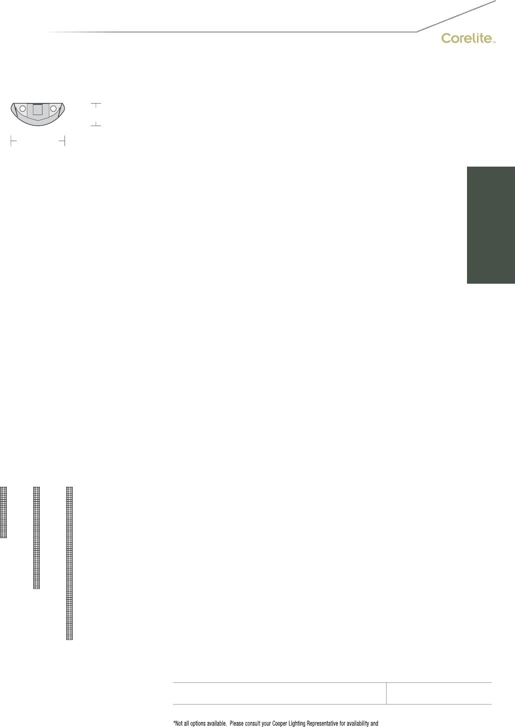
71
2-1/2" [64MM]
6" [152MM]
S
ERIE
S
S
1=
S
tellar
S
uspended
OPTICS UP
W=Whit
e
O
PTI
CS
D
O
WN
B= Baffle
NUMBER
O
F LAMP
S
2
=2
L
amp
s
LAMP TYPE
N5=T5 Normal Out
p
ut
T5=T5 Hi
g
h
O
utpu
t
N
U
MBER
O
F
C
IR
CU
IT
S
1=1
C
ir
cu
i
t
2
=2
C
ircuits
WIRING*
C
=
S
t
a
n
da
r
d
C
ir
cu
it
D
=
Di
mm
i
n
g
E
=
E
mer
g
ency
B=Battery Pack
T=Nightlight
Y
=
D
ay
ligh
t
V
O
LTA
G
E*
120=120V
277
=
277V
3
47=
3
47
V
UNV
=
U
n
i
versa
l
(
120
V
-277
V)
SUS
PEN
S
I
ON
A
=Aircraft
C
abl
e
P
=
Ri
g
id
P
en
d
ant
P
O
WER FEED*
C
=
S
trai
g
ht
C
ord
K=
C
urly
C
ord
P=Rigid Pendant
SUS
PEN
S
I
O
N LEN
G
T
H
-Fixed
C
abl
e
12”, 15”, 18”, 21”, 24” or 27” (+
/
- 1
/
2” adjustment)
-Adjustable Cable
48
”,
120
”,
240
”,
300
”,
or 360
”
(
infinite ad
j
ustment alon
g
entire len
g
th of cable
)
-Rigid Pendant
12
”,
15
”,
18
”,
21
”,
24
”
or 27
”
(
additional pendant len
g
ths available, consult
f
actory
)
CEILING TYPE*
T1=1” T-B
ar
T
9
=
9/
1
6
” T-B
a
r
T
S
=
S
lotted T-Bar
S
T=
S
tructure
JB=4” Octagonal J-Bo
x
RUN LEN
G
TH
Specify luminaire length in feet.
-Individuall
y
Mounted
L
um
i
na
i
res may
b
e 4
’
,8
’
, or 12
’
i
n
l
en
g
t
h
.
-
C
ontinuously Mounted
S
tandard row configurations over 12’ consist of 8’ and 12’ sections
.
O
PTI
O
N
S
DL
100=100%
D
own
li
g
h
t
Ki
t
DL70=70% Downlight Kit
PROJECT NAME: TYPE:
CATALOG #:
-
-
-
-
-
-
-
-
t
echnical information.
S
pecifications and dimensions subject to change without notice.
ORDERING INFORMATION:
SAMPLE NUMBER:S1-WB-2T5-1C-UNV-AC48-T1-32’-DL70
SUSPENDED STELLAR
Co
n
s
tr
uc
ti
o
n: Di
e
-f
o
rm
ed
a
ll
a
l
u
min
u
m
ba
ffl
e
a
ssem
bl
y
(
1.5
”
bl
a
d
e spac
i
n
g)
mec
h
an
i
ca
ll
y
a
ttached to a corrosion resistant formed steel
b
allast channel. Perforated siderail sections are
2
3% open with 0.0625” stagger hole spacing.
Standard 4’-0”, 8’-0”, and 12’-0” fixture len
g
ths
c
ombine for continuous runs.
Electrical: T5
/
T5H
O
fixtures are
p
rewired with
quick wire connectors and use UL listed
C
lass P,
T5/T5HO program rapid start universal voltage
e
lectronic ballasts,
p
ower
f
actor o
f
97% with
less
t
ha
n 1
0%
THD
.
M
ountin
g
: Standard aircraft cable mounts on
4’-0”, 8’-0”, and 12’-0” centers. Re
f
er to spec
sheets for various ceiling interface details and
r
igid pendant mounting details.
Fi
n
i
s
h
:
Fi
xture
h
ous
i
n
g
s are stan
d
ar
d
w
hi
te
u
s
i
ng e
l
ectrostat
i
ca
ll
y app
li
e
d
po
l
yester pow
d
er
c
oat paint. Consult factory for custom finishes
.
E
n
d
Pl
ates:
L
aser cut 14-
g
au
g
e co
ld
ro
ll
e
d
stee
l
, mec
h
an
i
ca
lly
attac
h
e
d
w
i
t
h
out ex
p
ose
d
f
asteners.
Dimensions do not include
end plates or caps
96”48” 144”
SUSPENDED

Stellar Wall
(pages 120-121)
Stellar 2T8 Surface
(pages 152-153)
72
S2-WB with standard flat end plates
100% Downlight Kit
(DL100)
70% Downlight Kit
(DL70)
• 2T8 specific design
• 100% or 70% Downlight Kits
Stellar 2T8 (9”)
SUSPENDED | DIRECT-INDIRECT / DIRECT | T8
The industrial styled Stellar
provides three light distributions
for additional fl exibility.

73
9" [229MM]
2-7/8" [73MM]
S
ERIE
S
S
2=
S
tellar
S
uspended
OPTICS UP
W=Whit
e
O
PTI
CS
D
O
WN
B= Baffle
NUMBER
O
F LAMP
S
2
=2
L
amp
s
LAMP TYPE
T8=T8 Normal Out
p
ut
NUMBER
O
F
C
IR
C
UIT
S
1=1
C
ir
cu
i
t
2
=2
C
ir
cu
it
s
WIRIN
G
*
C=Standard Circuit
D=Dimming
E
=
E
mer
g
ency
B
=
B
attery
P
ac
k
T=Nightlight
Y=Daylight
V
O
LTA
G
E*
120=120
V
2
77=277V
3
47=
3
47V
UNV
=
U
n
i
versa
l
(
120
V
-277
V)
SUS
PEN
S
I
ON
A
=Air
c
r
a
ft
Cab
l
e
P
=
Rigid
P
en
d
ant
POWER FEED*
C=Straight Cord
K=
C
url
y
C
ord
P
=
Rigid
P
en
d
ant
SUS
PEN
S
I
O
N LEN
G
T
H
-Fix
ed
Cab
l
e
12”, 15”, 18”, 21”, 24” or 27”
(
+
/
- 1
/
2” ad
j
ustment
)
-Adjustable Cable
48”, 120”, 240”, 300”, or 360”
(
in
f
inite ad
j
ustment alon
g
entire len
g
th o
f
cable
)
-Rigid Pendant
12”, 15”, 18”, 21”, 24” or 27”
(
additional pendant len
g
ths available, consult
f
actory
)
C
EILIN
G
TYPE*
T1=1” T-Ba
r
T
9
=
9/
1
6
” T-B
a
r
T
S
=
S
l
o
tt
ed
T-B
a
r
S
T=
S
tructure
JB=4”
O
ctagonal J-Bo
x
RUN LEN
G
TH
S
pecify luminaire length in feet.
-Individually Mounted
Luminaires may be 4’,8’, or 12’ in length.
-Continuousl
y
Mounted
S
tandard row confi
g
urations over 12’ consist of 8’ and 12’ sections
.
O
PTI
O
N
S
DL
100=100%
D
own
ligh
t
Ki
t
DL
70=70%
D
own
li
g
h
t
Ki
t
PROJECT NAME: TYPE:
CATALOG #:
-
-
-
-
-
-
-
-
t
echnical information.
S
pecifications and dimensions subject to change without notice.
ORDERING INFORMATION:
SAMPLE NUMBER:S2-WB-2T8-1C-UNV-AC48-T1-32’-DL70
SUSPENDED STELLAR
Co
n
s
tr
uc
ti
o
n: Di
e
-f
o
rm
ed
a
ll
a
l
u
min
u
m
ba
ffl
e
a
ssem
bl
y
(
2
”
bl
a
d
e spac
i
n
g)
mec
h
an
i
ca
ll
y
a
ttached to a corrosion resistant formed steel
b
allast channel. Perforated siderail sections are
2
3% open with 0.0625” stagger hole spacing.
Standard 4’-0”, 8’-0”, and 12’-0” fixture len
g
ths
c
ombine for continuous runs.
Electrical: T8
f
ixtures are
p
re-wired with
q
uick
w
ire connectors and use UL listed
C
lass P,
2
65ma T8 instant start universal voltage
e
lectronic ballasts,
p
ower
f
actor o
f
95% with
less
t
ha
n 1
0%
THD
.
Fi
xt
u
r
es
a
n
d
elec
tr
ical
c
omponents certified to UL and
C
UL standards.
M
ounting: Standard aircraft cable mounts on
4’-0”, 8’-0”, and 12’-0” centers. Re
f
er to s
p
ec
sheets
f
or various ceilin
g
inter
f
ace details and
ri
g
id
pen
d
ant mount
i
ng
d
eta
il
s.
Fi
n
i
s
h
:
Fi
xture
h
ous
i
n
g
s are stan
d
ar
d
w
hi
te
u
s
i
n
g
e
l
ectrostat
i
ca
ll
y app
li
e
d
po
l
yester pow
d
er
c
oat paint.
C
onsult factory for custom finishes
.
End Plates: Laser cut 14-gauge cold rolled
stee
l
, mec
h
an
i
ca
lly
attac
h
e
d
w
i
t
h
out ex
p
ose
d
f
asteners.
Dimensions do not include
end plates or caps
96”48” 144”
SUSPENDED
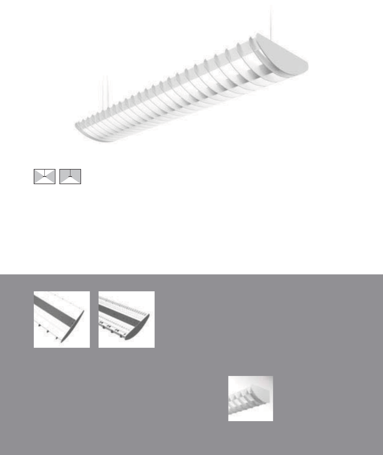
Stellar Wall
(pages 120-121)
74
S4-WB with standard flat end plates
100% Downlight Kit
(DL100)
70% Downlight Kit
(DL70)
• 4-lamp specific design
• 100% or 70% Downlight Kits
Stellar 4T5/4T8 (12”)
SUSPENDED | DIRECT-INDIRECT / DIRECT | T5 / T5HO / T8
The industrial styled Stellar
provides three light distributions
for additional fl exibility.
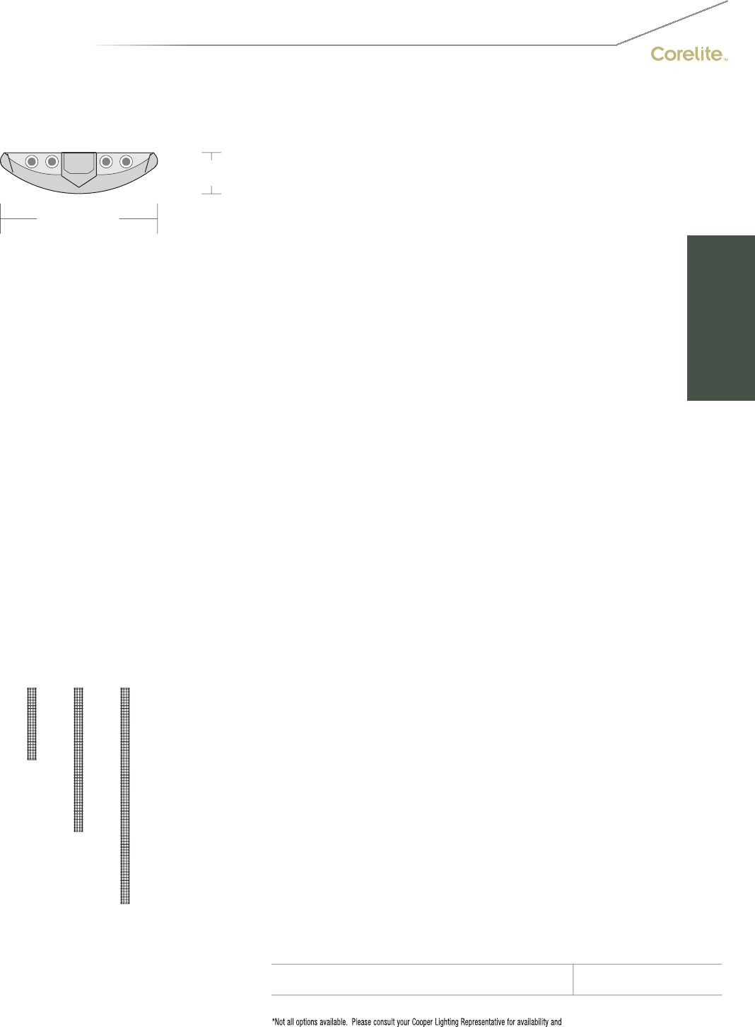
75
12-3/8" [314MM]
3-1/4" [83MM]
S
ERIE
S
S
4=
S
tellar
S
uspended
OPTICS UP
W=Whit
e
O
PTI
CS
D
O
WN
B= Baffle
N
U
MBER
O
F LAMP
S
4=4
L
am
ps
LAMP TYPE
N5=T5 Normal Out
p
ut
T5=T5 Hi
g
h Outpu
t
T8=T8 Normal
O
utput
N
U
MBER
O
F
C
IR
CU
IT
S
1=1
C
ir
cu
i
t
2
=2
C
ircuits
WIRING*
C
=
S
t
a
n
da
r
d
C
ir
cu
it
D
=
Di
mm
i
n
g
E
=
E
mer
g
ency
B=Battery Pack
T=Nightlight
Y
=
D
ay
ligh
t
V
O
LTA
G
E*
120=120V
277
=
277V
3
47=
3
47
V
UNV
=
U
n
i
versa
l
(
120
V
-277
V)
SUS
PEN
S
I
ON
A
=Aircraft
C
abl
e
P
=
Ri
g
id
P
en
d
ant
P
O
WER FEED*
C
=
S
trai
g
ht
C
ord
K=
C
urly
C
ord
P=Rigid Pendant
SUS
PEN
S
I
O
N LEN
G
T
H
-Fixed
C
abl
e
12”, 15”, 18”, 21”, 24” or 27” (+
/
- 1
/
2” adjustment)
-Adjustable Cable
48
”,
120
”,
240
”,
300
”,
or 360
”
(
infinite ad
j
ustment alon
g
entire len
g
th of cable
)
-Rigid Pendant
12
”,
15
”,
18
”,
21
”,
24
”
or 27
”
(
additional pendant len
g
ths available, consult
f
actory
)
CEILING TYPE*
T1=1” T-B
ar
T
9
=
9/
1
6
” T-B
a
r
T
S
=
S
lotted T-Bar
S
T=
S
tructure
JB=4” Octagonal J-Bo
x
RUN LEN
G
TH
Specify luminaire length in feet.
-Individuall
y
Mounted
L
um
i
na
i
res may
b
e 4
’
,8
’
, or 12
’
i
n
l
en
g
t
h
.
-
C
ontinuously Mounted
S
tandard row configurations over 12’ consist of 8’ and 12’ sections
.
O
PTI
O
N
S
DL
100=100%
D
own
ligh
t
Ki
t
DL
70=70%
D
own
li
g
h
t
Ki
t
PROJECT NAME: TYPE:
CATALOG #:
-
-
-
-
-
-
-
-
t
echnical information.
S
pecifications and dimensions subject to change without notice.
ORDERING INFORMATION:
SAMPLE NUMBER:S4-WB-4T8-1C-UNV-AC48-T1-32’-DL70
SUSPENDED STELLAR
Co
n
s
tr
uc
ti
o
n: Di
e
-f
o
rm
ed
a
ll
a
l
u
min
u
m
ba
ffl
e
a
ssem
bl
y
(
3
”
bl
a
d
e spac
i
n
g)
mec
h
an
i
ca
ll
y
a
ttached to a corrosion resistant formed steel
b
allast channel. Perforated siderail sections are
2
3% open with 0.0625” stagger hole spacing.
Standard 4’-0”, 8’-0”, and 12’-0” fixture len
g
ths
c
ombine for continuous runs.
Electrical: T5/T5HO fixtures are
p
re-wired with
q
uick wire connectors and use UL listed
C
lass P,
T5
/
T5H
O
program rapid start universal voltage
e
lectronic ballasts, power factor of 97% with
l
ess than 10% THD. T8
f
ixtures are
p
re-wired
wi
t
h
q
u
i
c
k
w
i
re connectors an
d
use
UL
li
ste
d
C
lass P, 265ma T8 instant start universal volta
g
e
e
lectronic ballasts, power factor of 95% with
less
th
a
n 1
0%
THD. Fixt
u
r
es
a
n
d
e
l
ec
tri
ca
l
c
om
p
onents certified to UL and CUL standards.
M
ountin
g
: Standard aircraft cable mounts on
4’-0”, 8’-0”, and 12’-0” centers. Re
f
er to spec
sheets for various ceiling interface details and
r
igid pendant mounting details.
Fi
n
i
s
h
:
Fi
xture
h
ous
i
n
g
s are stan
d
ar
d
w
hi
te
u
s
i
ng e
l
ectrostat
i
ca
ll
y app
li
e
d
po
l
yester pow
d
er
c
oat paint. Consult factory for custom finishes
.
End Plates: Laser cut 14-gauge cold rolled
stee
l
, mec
h
an
i
ca
lly
attac
h
e
d
w
i
t
h
out ex
p
ose
d
f
asteners.
Dimensions do not include
end plates or caps
96”48” 144”
SUSPENDED
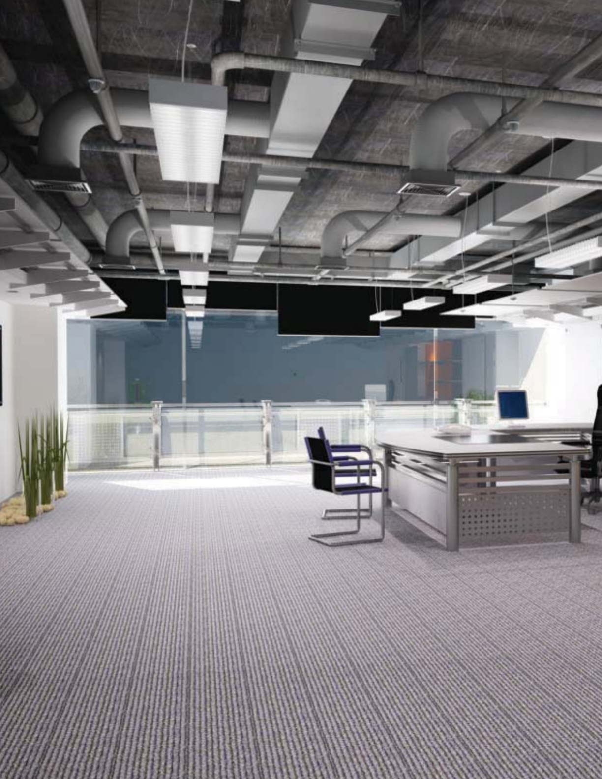
76

77
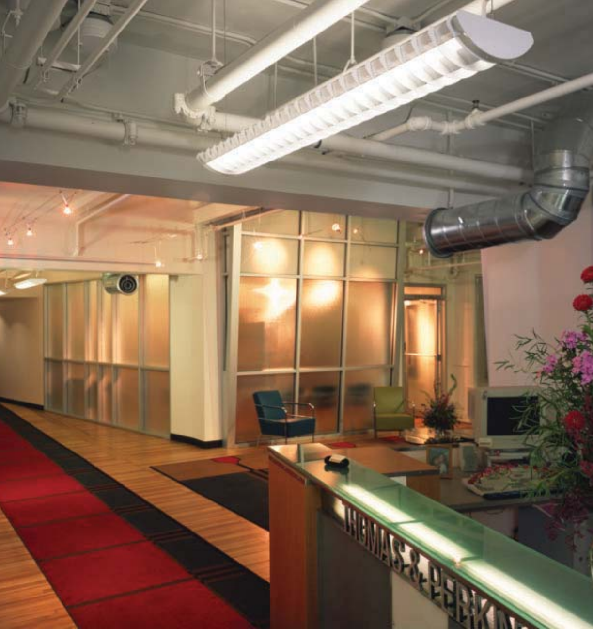
78
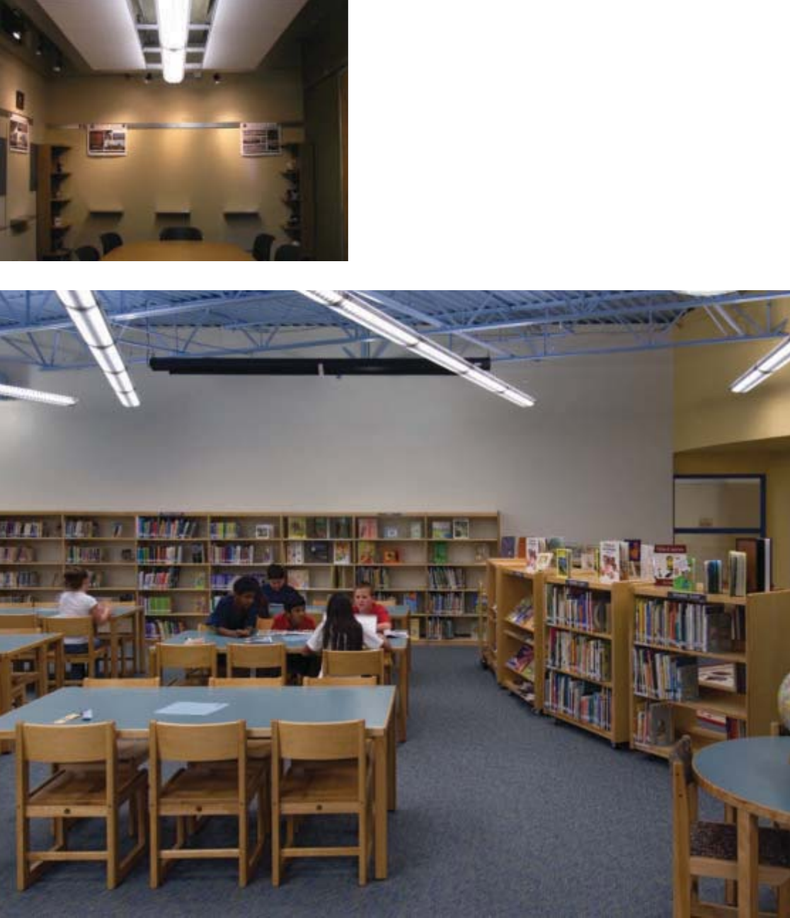
79
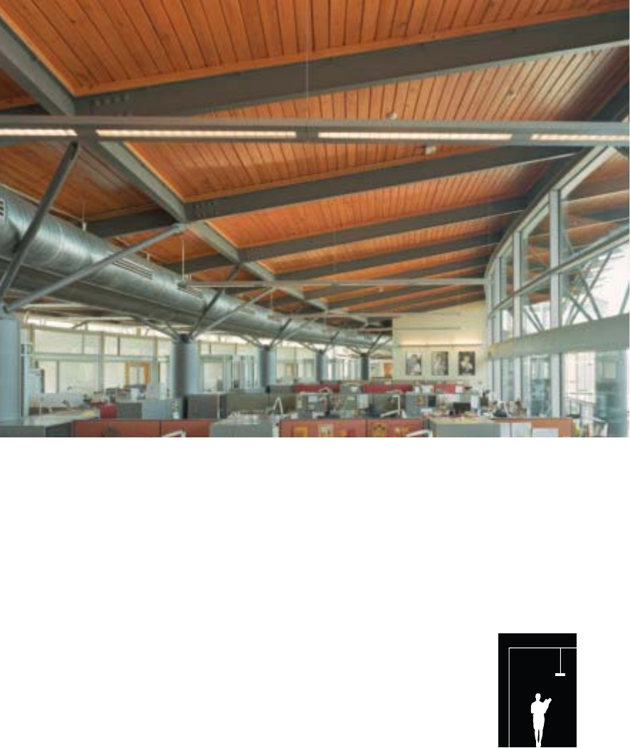
80
Versatility. Scalability. Capability.
Corelite’s extensive lines of Direct/Indirect Extruded product
families infallibly provide the simple solution to complex
spaces. The Element, Loft, Vertechs, Traverse and Navigator
families of luminaires offer versatile lighting solutions for
modern architectural spaces with their innovative uplight and
downlight control features and unique scalability between
fi xtures. All D/I Extrusion fi xtures provide both task and
ambient illumination, while offering elegant styling, extruded
aluminum housings and up to fi ve unique media options.
Corelite’s D/I Extrusions also provide the ideal platform for
the revolutionary Slide-N-Lock™ adjustable optics, as well
as the cutting-edge Smart Environment control system.
D/I Extrusions
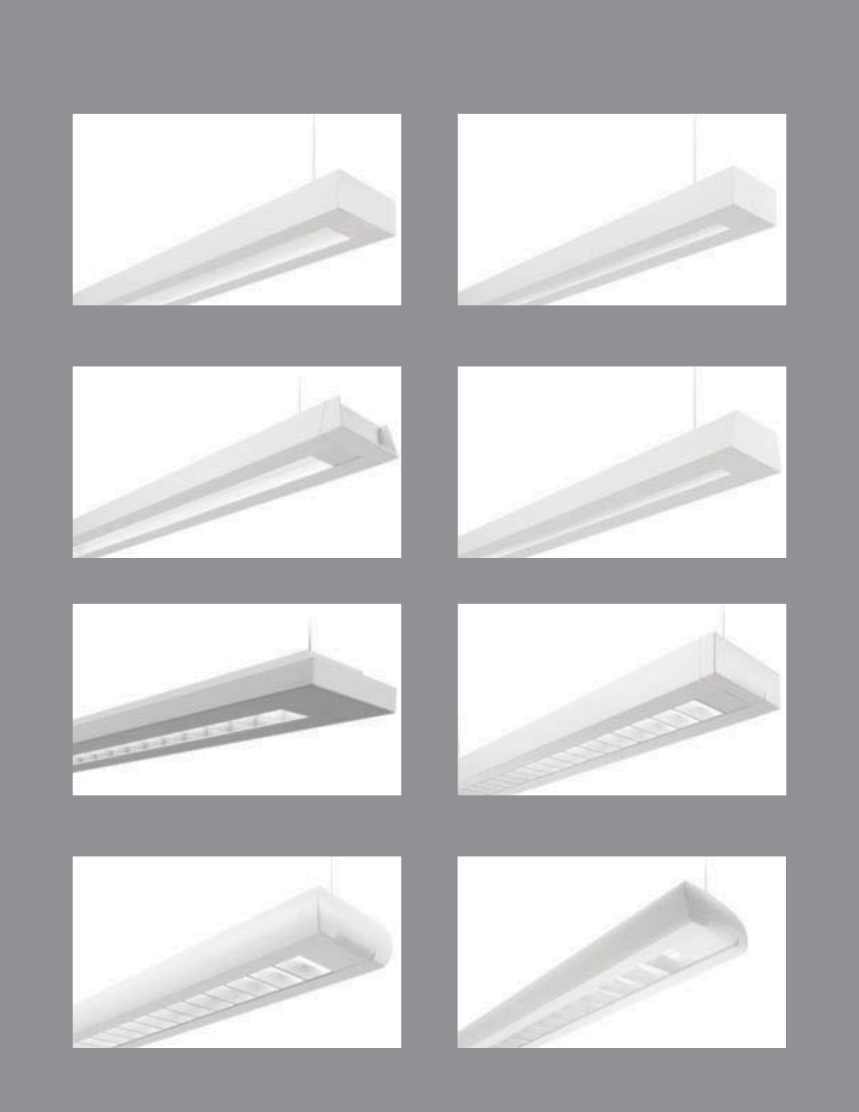
81
VERTECHS
pg. 90-91
TRAVERSE
pg. 92-93
NAVIGATOR II
pg. 94-95
MINIGATOR
pg. 96-97
ELEMENT
pg. 82-83
ELEMENT MICRO
pg. 84-85
LOFT
pg. 86-87
LOFT MICRO
pg. 88-89
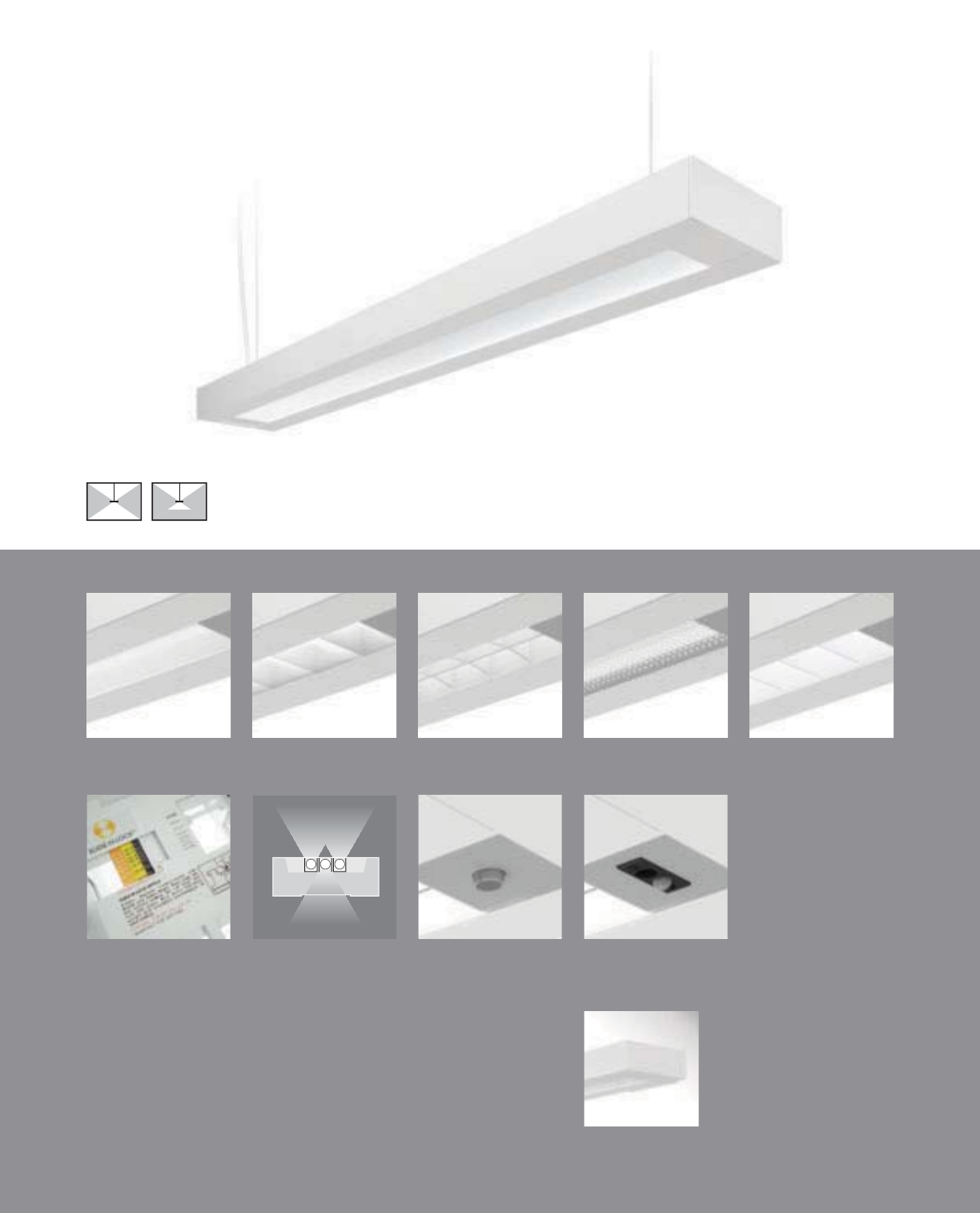
82
E2-WM with standard die-cast end caps
Element Wall
(pages 122-123)
• Five downlight media options
• RPerformance™ Louver meets RP1 requirements
• Slide-N-Lock™ optics with 8 field-adjustable settings
• Lamp Isolator kits
• Day-Sense integral daylight sensor and 2Sense integral
daylight/occupancy sensor
2Sense
(page 171)
Day-Sense
(page 170)
Lamp Isolators
(pages 98-99)
Slide-N-Lock™
(pages 98-99)
Concave Metallic
Perf (E2-WC)
RPerformance™
Louver (E2-WH)
Micro Prismatic
Lens (E2-WM)
Cross Blade Parabolic
Louver (E2-WB)
High Efficiency
Louver (E2-WW)
Element
SUSPENDED | DIRECT-INDIRECT / SEMI-INDIRECT | T5 / T5HO / T8
A minimal rectilinear profi le with
dedication to innovative optical
controls is the essence of Element.

83
2-1/2" [64MM]
6-3/4" [171MM]
S
ERIE
S
E
2=
El
emen
t
S
uspended
OPTIC
S
UP
W=Whit
e
S=S
p
ecular
O
PTI
CS
D
O
WN
B=
C
r
oss
Bl
ade
P
a
r
abo
li
c
L
ou
v
er
C
=
Co
n
ca
v
e
M
e
t
a
lli
c
P
e
r
f
H=RPer
f
ormance™
L
ouver
M
=
Mi
cr
o
P
r
i
smat
i
c
L
en
s
W=Hig
h
Efficienc
y
Louve
r
NUMBER
OF
LAMP
S
1=1
L
amp
(N
5
,
T
5
)
2
=
2
Lamp
s
(N5, T5
,
T8)
3
=
3
Lam
ps
(N5, T5
)
LAMP
TYPE
N
5=
T5
N
orma
l
O
utpu
t
T5=T5 High Outpu
t
T
8
=T
8
N
o
rm
a
l Out
p
ut
NUMBER
OF
C
IR
C
UIT
S*
1=1
C
ircui
t
2
=
2
C
ir
cu
it
s
WIRIN
G
*
C
=
S
tandar
d
C
ircuit
B
=
B
attery
P
ac
k
D=Dimming T=Nightlight
E=Emergenc
y
Y
=Dayligh
t
V
O
LTA
G
E*
120=120V 347=347V
2
77=277V
U
NV=
U
niv
e
r
sa
l (120V-277V
)
S
U
S
PEN
S
I
ON
A
=Aircraft
C
abl
e
P=Rigid Pendant
P
O
WE
R
FEED*
C
=
S
trai
g
ht
C
ord
K=
C
urly
C
ord
P=Rigid P
e
n
da
nt
S
U
S
PEN
S
I
ON
LEN
G
T
H
-
Adj
usta
ble
C
able
48”, 120”
,
240”
,
300”
,
360”
(in
f
init
e
adjustmen
t
alon
g
e
ntir
e
lengt
h
of
cable
)
-
Rigid
P
en
d
ant
12”, 15”, 18”, 21”, 24
”
or
27”
(additiona
l
p
endant length
s
available
,
co
n
su
l
t
f
actory
)
C
EILIN
G
TYPE*
T
1=1
”
T
-
B
a
r
T9=9/16” T-Ba
r
T
S
=
S
l
o
tt
ed
T-B
a
r
S
T=
S
tr
uc
t
u
r
e
JB
=4
”
O
cta
g
onal
J
-
B
o
x
R
U
N LEN
G
TH
S
p
ecif
y
lu
m
i
n
ai
r
e
l
en
g
t
h
in
fee
t
.
-
I
n
di
v
id
ua
lly
M
ounte
d
L
um
i
na
i
re
s
may
be
4
’
,8
’,
or 12
’
i
n
l
engt
h
.
-Continuously Mounted
S
t
a
n
da
r
d
row
con
f
igurations
o
v
er
12’
co
n
s
i
s
t
of
8
’
a
n
d
12’
sec
ti
o
n
s.
O
PTI
O
N
S
S
lide-N-Lock™ (page 98-99
)
DL1=
95%
Downligh
t
DL
5
=7
5%
Downligh
t
DL
2=
90%
D
own
light
DL6
=7
0%
D
own
light
DL
3=85
%
D
own
light
DL
7=65
%
D
own
light
DL
4=80
%
D
own
li
g
ht
DL
8=60
%
D
own
li
g
ht
Lam
p
I
so
l
a
t
or
Kit
s*
(page 98-99
)
DL
/U
D
U
=
2
l
am
ps
u
p
1
l
am
p
do
w
n
DL
/
DUD=
2
l
amp
s
d
own 1
l
am
p
up
DL
/
UXU=2 lamp
s
up
DL
/
DXD=2 lam
p
s
do
w
n
DL
/
XDX=
1
lam
p
do
wn
DL
/
XUX=1
l
am
p
up
DS=Day-Sense Integral Daylight Sensor
2S
=2
Se
n
se
Integra
l
Daylight/Occupanc
y
Se
n
so
r
PROJECT NAME: TYPE:
CATALOG #:
-
-
-
-
-
-
-
-
a
ll
opt
i
on
s
ava
il
a
bl
e.
Pl
eas
e
consu
lt
you
r
C
ooper
Li
g
h
t
i
n
g
R
epresentat
i
ve fo
r
ava
il
a
bili
ty an
d
t
echnical information.
S
pecifications and dimensions subject
t
o chang
e
without notice.
ORDERING INFORMATION:
SAMPLE NUMBER:E2-WM-2N5-1C-UNV-AC48-T1-12
SUSPENDED ELEMENT
Co
n
s
tr
uc
ti
o
n
:
Housin
g
i
s
6063
T
5
a
l
u
min
u
m
e
xtrus
i
o
n
f
ormin
g
a 7-1
/
2”
x
2-1
/
2” rect
ili
nea
r
p
rofile.
S
tandard 4
’
-0
”
, 8
’
-0
”
an
d
12
’
-0
”
fixtur
e
l
engths combine for continuou
s
r
u
ns.
Reflectors: Reflecto
r
pa
n
is painte
d
wi
t
h a high
re
fl
ec
t
a
n
ce
whit
e
p
owde
r
coat
fini
s
h
.
O
p
tiona
l
d
i
e
-
fo
rm
ed
s
i
de
r
ef
l
ec
t
o
r
s
are
hi
g
hly s
p
ecula
r
a
no
di
ze
d
a
l
um
i
num.
Lens: Lens is .125
”
thick
clear
k
micro-prismati
c
a
cr
y
li
c
m
a
t
e
ri
a
l o
ff
ering
91%
tr
a
n
s
mi
ss
i
o
n
.
L
ouvers
:
C
ros
s
Bl
a
d
e an
d
RPerformance
™
ar
e
c
ontinuous semi-specula
r
aluminum
.
Per
f
is
semi-s
p
ecular material
,
p
erforated
sec
ti
on
i
s
15%
open
with
0
.
06
2”
d
i
a
m
e
t
e
r h
o
l
es
a
n
d
o
p
a
l
di
ff
user.
High
E
ff
icienc
y
i
s cont
i
nuous
highly
r
eflectiv
e
pa
i
nte
d
w
hi
te a
l
um
i
num
.
Elec
tr
ical:
T
5/
T
5
H
O
f
ixt
u
r
es
a
r
e
p
re-w
i
re
d
w
i
t
h
quick
wire
k
connec
t
or
s
an
d
use
UL
li
ste
d
C
las
s
P,
T5
/
T5H
O
program
rapid s
t
ar
t
universa
l
voltag
e
e
l
ec
tr
o
ni
c
ballasts
,
po
w
er
f
ac
t
or
o
f
9
7
%
wi
t
h
less
t
han
10%
THD.
T8
f
ixt
u
r
es
are
p
re-w
i
re
d
wi
t
h
quick
wire
k
connec
t
or
s
an
d
use
UL
li
ste
d
C
lass
P,
265ma
T
8
i
nstan
t
s
t
ar
t
un
i
versa
l
vo
l
tag
e
e
lectroni
c
ballasts
,
po
w
er
facto
r
of 95
%
wi
t
h
less
th
an
10%
THD.
Fixt
u
r
es
a
n
d
e
l
ec
tri
ca
l
c
om
p
onen
ts
ce
rti
f
i
ed
to
UL
a
n
d
CUL
s
t
a
n
da
r
ds
.
M
ount
i
n
g:
S
t
a
n
da
r
d
a
ir
c
r
aft
cable
m
ou
nt
s
on
4
’
-0
”,
8
’
-0
”
an
d
12
’
-0
”
cen
t
ers. Re
f
e
r
t
o
i
nsta
ll
at
i
o
n
sect
i
on for var
i
ous ce
ili
n
g
interface
details an
d
rigi
d
pendan
t
mounting details.
Fi
n
ish:
Fi
xt
u
r
e
h
ous
i
n
gs
are
s
t
a
n
da
r
d
w
hi
t
e
u
s
i
n
g
e
l
ectrostat
i
ca
ll
y app
li
e
d
po
l
yeste
r
pow
d
e
r
c
oa
t
pa
i
nt.
E
n
d
C
aps:
S
tandar
d
en
d
cap
s
are prec
i
s
i
o
n
die-cast aluminum, mechanicall
y
attache
d
w
ith
out
ex
p
osed f
as
t
e
n
e
r
s.
Dimensions do not include
end plates or caps
96”48” 144”
SUSPENDED
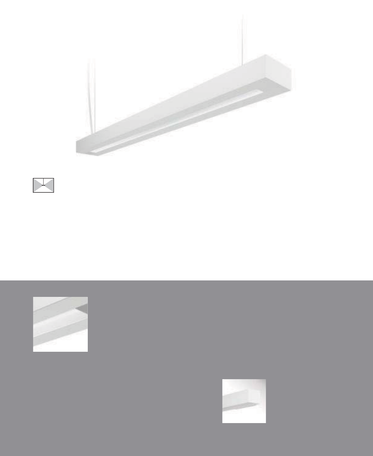
Micro Prismatic
Lens (E1-WM)
84
• Highly efficient micro prismatic lens
E1-WM with standard die-cast end caps
Element Micro Wall
(pages 124-125)
Element Micro
SUSPENDED | DIRECT-INDIRECT | T5 / T5HO / T8
The Element Micro offers
maximized performance in a
modern micro-scaled package.

85
2-1/2" [64MM]
5-1/4" [133MM]
S
ERIE
S
E
1=
El
emen
t
Mi
cro
S
uspended
OPTIC
S
UP
W=Whit
e
S=S
p
ecular
O
PTI
CS
D
O
WN
M
=Mi
c
r
o
Pri
s
m
a
ti
c
L
e
n
s
NUMBER
OF
LAMP
S
1=1
L
amp
(N
5
,
T
5,
T
8
)
2
=
2
Lamp
s
(N5, T5
)
LAMP TYPE
N
5
=T
5
N
o
rm
a
l Out
p
u
t
T
5
=T
5
Hi
g
h Out
p
u
t
T
8=
T8
N
orma
l
O
utput
NUMBE
R
O
F
CIRCUITS
*
1
=
1
C
ir
cu
i
t
2
=
2
C
ir
cu
it
s
WIRIN
G
*
C
=
S
t
a
n
da
r
d
C
ir
cu
it
D
=
Di
mm
i
n
g
E
=
E
mer
g
enc
y
B
=
B
attery
P
ac
k
T=Nightlight
Y=Daylight
V
O
LTA
G
E*
120=120V
2
77=277V
3
47=
3
47
V
UNV
=
U
n
i
versa
l
(
120
V
-277
V)
SUSPENSIO
N
A
=Air
c
r
af
t
Cab
l
e
P
=
Rigid
Pe
n
da
nt
P
O
WE
R
FEED*
C=Straight
Co
r
d
K=Curl
y
Co
r
d
P
=
Rigid
P
en
d
ant
SUSPENSIO
N
LENGT
H
-Adjustabl
e
Cab
l
e
48
”,
120
”,
240
”,
300
”,
360”
(
infinit
e
a
dj
ustmen
t
a
l
on
g
ent
i
re
l
en
g
t
h
o
f
ca
bl
e
)
C
EILIN
G
TYPE*
T1
=
1”
T
-
Bar
T9=9
/
16”
T
-
B
a
r
T
S
=
S
lotte
d
T
-
B
ar
ST=Structure
J
B=4” Octagonal
J
-B
ox
RUN
LEN
G
TH
S
pecif
y
luminaire lengt
h
i
n
feet
.
-Individuall
y
M
ou
nt
ed
Lu
m
i
n
ai
r
es
may
be
4
’,
8
’,
or
12’
in
l
en
g
t
h
.
-
C
ontinuously
M
ounte
d
S
tandar
d
ro
w
configurations ove
r
12
’
cons
i
st of 8
’
an
d
12
’
sect
i
ons
.
PROJECT NAME: TYPE:
CATALOG #:
-
-
-
-
-
-
-
-
a
ll
opt
i
on
s
ava
il
a
bl
e.
Pl
eas
e
consu
lt
you
r
C
ooper
Li
g
h
t
i
n
g
R
epresentat
i
ve fo
r
ava
il
a
bili
ty an
d
t
echnical information.
S
pecifications and dimensions subject
t
o chang
e
without notice.
ORDERING INFORMATION:
SAMPLE NUMBER:E1-WM-2N5-1C-UNV-AC48-T1-12
SUSPENDED ELEMENT MICRO
Co
n
s
tr
uc
ti
o
n
:
Housin
g
i
s
6063
T
5
a
l
u
min
u
m
e
xtrus
i
o
n
f
ormin
g
a 5-1
/
4”
x
2-1
/
2” rect
ili
nea
r
p
rofile.
S
tandard 4
’
-0
”
, 8
’
-0
”
an
d
12
’
-0
”
fixtur
e
l
engths combine for continuou
s
r
u
ns.
Reflectors: Reflecto
r
pa
n
is painte
d
wi
t
h a high
re
fl
ec
t
a
n
ce
whit
e
p
owde
r
coat
fini
s
h
.
O
p
tiona
l
d
i
e
-
fo
rm
ed
s
i
de
r
ef
l
ec
t
o
r
s
are
hi
g
hly s
p
ecula
r
a
no
di
ze
d
a
l
um
i
num.
Lens: Lens is .125
”
thick
clear
k
micro-prismati
c
a
cr
y
li
c
m
a
t
e
ri
a
l o
ff
ering
91%
tr
a
n
s
mi
ss
i
o
n
.
El
ectr
i
ca
l:
T5
/
T5H
O
fixture
s
are pre-w
i
re
d
w
i
t
h
quick
wire
k
connec
t
or
s
an
d
use U
L
listed
C
las
s
P
,
T
5/
T
5
H
O
program
ra
p
id
s
t
a
r
t
u
niv
e
r
sal
voltag
e
e
l
ec
tr
o
ni
c
ballasts
,
po
w
er
fac
t
or
of
9
7
%
with
l
es
s
t
h
a
n
10%
THD.
T8
f
ixtures ar
e
pre-w
i
re
d
wi
t
h
quick
wire
k
connec
t
or
s
an
d
use
UL
li
ste
d
Class P,
26
5ma T8 instan
t
start universal voltag
e
e
l
ec
tr
o
ni
c
ballasts
,
po
w
er
fac
t
or
of
95%
wi
t
h
less
t
han
10%
THD.
Fi
xt
u
r
es
a
n
d
elec
tr
ical
c
omponen
ts
certified
t
o
UL
an
d
C
U
L
stan
d
ar
d
s.
M
ount
i
ng:
S
tandar
d
aircraf
t
ca
ble
moun
t
s on
4’-0”, 8’-0
”
an
d
12’-0” centers. Refe
r
to
i
n
s
t
a
ll
a
ti
on
sec
ti
o
n
fo
r v
a
ri
ous
ceilin
g
int
e
r
face
de
t
ails
a
n
d
r
igid
p
en
d
an
t
mount
i
n
g
de
t
ails
.
Fi
n
i
s
h:
Fi
xtur
e
h
ous
i
ngs ar
e
stan
d
ar
d
w
hi
te
u
sing electrostatically applied polyeste
r
powde
r
coat
p
aint.
En
d
Ca
p
s:
S
t
a
n
da
r
d
e
n
d
caps
are
p
recisio
n
die
-
cas
t a
l
um
i
num
,
mec
h
an
i
ca
lly
a
tt
ached
wi
t
h
ou
t
expose
d
f
asteners
.
Dimensions do not include
end plates or caps
96”48” 144”
SUSPENDED
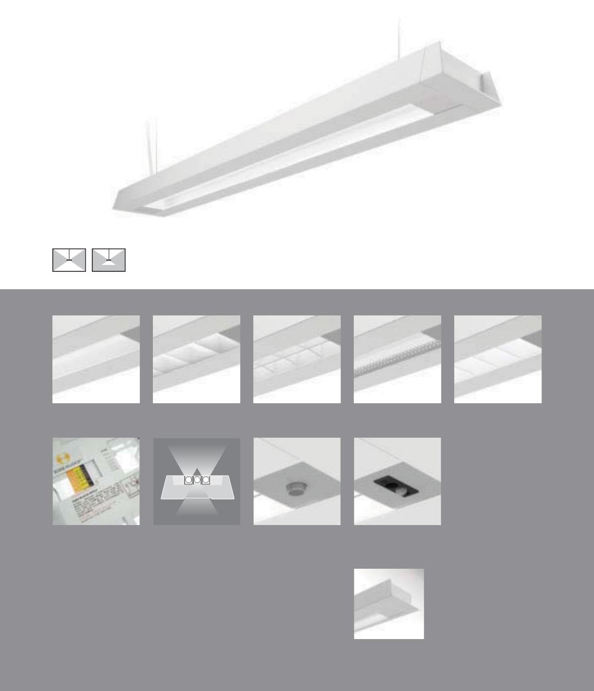
86
L2-WM with standard die-cast end caps
Loft Wall
(pages 126-127)
2Sense
(page 171)
Day-Sense
(page 170)
Lamp Isolators
(pages 98-99)
Slide-N-Lock™
(pages 98-99)
Concave Metallic
Perf (L2-WC)
RPerformance™
Louver (L2-WH)
Micro Prismatic
Lens (L2-WM)
Cross Blade Parabolic
Louver (L2-WB)
High Efficiency
Louver (L2-WW)
• Five downlight media options
• RPerformance™ Louver meets RP1 requirements
• Slide-N-Lock™ optics with 8 field-adjustable settings
• Lamp Isolator kits
• Day-Sense integral daylight sensor and 2Sense
integral daylight/occupancy sensor
Loft
SUSPENDED | DIRECT-INDIRECT / SEMI-INDIRECT | T5 / T5HO / T8
The exceptionally versatile Loft
takes effi ciency and modern design
sophistication to new heights.
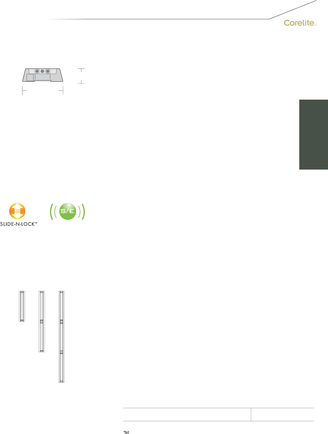
87
2-1/2" [64MM]
7-1/2" [191MM]
S
ERIE
S
L2=Lo
f
t
S
uspende
d
OPTIC
S
UP
W=Whit
e
S=S
p
ecular
O
PTI
CS
D
O
WN
B=
C
r
oss
Bl
ade
P
a
r
abo
li
c
L
ou
v
er
C
=
Co
n
ca
v
e
M
e
t
a
lli
c
P
e
r
f
H=RPer
f
ormance™
L
ouver
M
=
Mi
cr
o
P
r
i
smat
i
c
L
en
s
W=Hig
h
Efficienc
y
Louve
r
NUMBER
OF
LAMP
S
1=1
L
amp
(N
5
,
T
5
)
2
=
2
Lamp
s
(N5, T5
,
T8)
3
=
3
Lam
ps
(N5, T5
)
LAMP
TYPE
N
5=
T5
N
orma
l
O
utpu
t
T5=T5 High Outpu
t
T
8
=T
8
N
o
rm
a
l Out
p
ut
NUMBER
OF
C
IR
C
UIT
S*
1=1
C
ircui
t
2
=
2
C
ir
cu
it
s
WIRIN
G
*
C
=
S
tandar
d
C
ircuit
B
=
B
attery
P
ac
k
D=Dimming T=Nightlight
E=Emergenc
y
Y
=Dayligh
t
V
O
LTA
G
E*
120=120V 347=347V
2
77=277V
U
NV=
U
niv
e
r
sa
l (120V-277V
)
S
U
S
PEN
S
I
ON
A
=Aircraft
C
abl
e
P=Rigid Pendant
P
O
WE
R
FEED*
C
=
S
trai
g
ht
C
ord
K=
C
urly
C
ord
P=Rigid P
e
n
da
nt
S
U
S
PEN
S
I
ON
LEN
G
T
H
-
Adj
usta
ble
C
able
48”, 120”
,
240”
,
300”
,
360”
(in
f
init
e
adjustmen
t
alon
g
e
ntir
e
lengt
h
of
cable
)
-
Rigid
P
en
d
ant
12”, 15”, 18”, 21”, 24
”
or
27”
(additiona
l
p
endant length
s
available
,
co
n
su
l
t
f
actory
)
C
EILIN
G
TYPE*
T
1=1
”
T
-
B
a
r
T9=9/16” T-Ba
r
T
S
=
S
l
o
tt
ed
T-B
a
r
S
T=
S
tr
uc
t
u
r
e
JB
=4
”
O
cta
g
onal
J
-
B
o
x
R
U
N LEN
G
TH
S
p
ecif
y
lu
m
i
n
ai
r
e
l
en
g
t
h
in
fee
t
.
-
I
n
di
v
id
ua
lly
M
ounte
d
L
um
i
na
i
re
s
may
be
4
’
,8
’,
or 12
’
i
n
l
engt
h
.
-Continuously Mounted
S
t
a
n
da
r
d
row
con
f
igurations
o
v
er
12’
co
n
s
i
s
t
of
8
’
a
n
d
12’
sec
ti
o
n
s.
O
PTI
O
N
S
S
lide-N-Lock™ (page 98-99
)
DL1=
95%
Downligh
t
DL
5
=7
5%
Downligh
t
DL
2=
90%
D
own
light
DL6
=7
0%
D
own
light
DL
3=85
%
D
own
light
DL
7=65
%
D
own
light
DL
4=80
%
D
own
li
g
ht
DL
8=60
%
D
own
li
g
ht
Lam
p
I
so
l
a
t
or
Kit
s*
(page 98-99
)
DL
/U
D
U
=
2
l
am
ps
u
p
1
l
am
p
do
w
n
DL
/
DUD=
2
l
amp
s
d
own 1
l
am
p
up
DL
/
UXU=2 lamp
s
up
DL
/
DXD=2 lam
p
s
do
w
n
DL
/
XDX=
1
lam
p
do
wn
DL
/
XUX=1
l
am
p
up
DS=Day-Sense Integral Daylight Sensor
2S
=2
Se
n
se
Integra
l
Daylight/Occupanc
y
Se
n
so
r
PROJECT NAME: TYPE:
CATALOG #:
-
-
-
-
-
-
-
-
a
ll
opt
i
on
s
ava
il
a
bl
e.
Pl
eas
e
consu
lt
you
r
C
ooper
Li
g
h
t
i
n
g
R
epresentat
i
ve fo
r
ava
il
a
bili
ty an
d
t
echnical information.
S
pecifications and dimensions subject
t
o chang
e
without notice.
ORDERING INFORMATION:
SAMPLE NUMBER:L2-WM-1T5-1C-UNV-AC48-T1-12
SUSPENDED LOFT
Co
n
s
tr
uc
ti
o
n
:
Housin
g
i
s
6063
T
5
a
l
u
min
u
m
e
xtrus
i
o
n
f
ormin
g
a 7-1
/
2”
x
2-1
/
2” an
gl
e
d
p
rofile.
S
tandard 4
’
-0
”
, 8
’
-0
”
an
d
12
’
-0
”
fixtur
e
l
engths combine for continuou
s
r
u
ns.
Reflectors: Reflecto
r
pa
n
is painte
d
wi
t
h a high
re
fl
ec
t
a
n
ce
whit
e
p
owde
r
coat
fini
s
h
.
O
p
tiona
l
d
i
e
-
fo
rm
ed
s
i
de
r
ef
l
ec
t
o
r
s
are
hi
g
hly s
p
ecula
r
a
no
di
ze
d
a
l
um
i
num.
Lens: Lens is .125
”
thick
clear
k
micro-prismati
c
a
cr
y
li
c
m
a
t
e
ri
a
l o
ff
ering
91%
tr
a
n
s
mi
ss
i
o
n
.
L
ouvers
:
C
ros
s
Bl
a
d
e an
d
RPerformance
™
ar
e
c
ontinuous semi-specula
r
aluminum
.
Per
f
is
semi-s
p
ecular material
,
p
erforated
sec
ti
on
i
s
15%
open
with
0
.
06
2”
d
i
a
m
e
t
e
r h
o
l
es
a
n
d
o
p
a
l
di
ff
user.
High
E
ff
icienc
y
i
s cont
i
nuous
highly
r
eflectiv
e
pa
i
nte
d
w
hi
te a
l
um
i
num
.
Elec
tr
ical:
T
5/
T
5
H
O
f
ixt
u
r
es
a
r
e
p
re-w
i
re
d
w
i
t
h
quick
wire
k
connec
t
or
s
an
d
use
UL
li
ste
d
C
las
s
P,
T5
/
T5H
O
program
rapid s
t
ar
t
universa
l
voltag
e
e
l
ec
tr
o
ni
c
ballasts
,
po
w
er
f
ac
t
or
o
f
9
7
%
wi
t
h
less
t
han
10%
THD.
T8
f
ixt
u
r
es
are
p
re-w
i
re
d
wi
t
h
quick
wire
k
connec
t
or
s
an
d
use
UL
li
ste
d
C
lass
P,
265ma
T
8
i
nstan
t
s
t
ar
t
un
i
versa
l
vo
l
tag
e
e
lectroni
c
ballasts
,
po
w
er
facto
r
of 95
%
wi
t
h
less
th
an
10%
THD.
Fixt
u
r
es
a
n
d
e
l
ec
tri
ca
l
c
om
p
onen
ts
ce
rti
f
i
ed
to
UL
a
n
d
CUL
s
t
a
n
da
r
ds
.
M
ount
i
n
g:
S
t
a
n
da
r
d
a
ir
c
r
aft
cable
m
ou
nt
s
on
4
’
-0
”,
8
’
-0
”
an
d
12
’
-0
”
cen
t
ers. Re
f
e
r
t
o
i
nsta
ll
at
i
o
n
sect
i
on for var
i
ous ce
ili
n
g
interface
details an
d
rigi
d
pendan
t
mounting details.
Fi
n
ish:
Fi
xt
u
r
e
h
ous
i
n
gs
are
s
t
a
n
da
r
d
w
hi
t
e
u
s
i
n
g
e
l
ectrostat
i
ca
ll
y app
li
e
d
po
l
yeste
r
pow
d
e
r
c
oa
t
pa
i
nt.
E
n
d
C
aps:
S
tandar
d
en
d
cap
s
are prec
i
s
i
o
n
die-cast aluminum, mechanicall
y
attache
d
w
ith
out
ex
p
osed f
as
t
e
n
e
r
s.
Dimensions do not include
end plates or caps
96”48” 144”
SUSPENDED

Micro Prismatic
Lens (L1-WM)
88
L1-WM with standard die-cast end caps
Loft Micro Wall
(pages 128-129)
• Highly efficient micro prismatic lens
Loft Micro
SUSPENDED | DIRECT-INDIRECT | T5 / T5HO / T8
The Loft Micro combines
maximized performance with a
uniquely minimalistic profi le.

89
2-1/2" [64MM]
5-7/8" [149MM]
S
ERIE
S
L1=Lo
f
t
Mi
cr
o
S
uspende
d
OPTIC
S
UP
W=Whit
e
S=S
p
ecular
O
PTI
CS
D
O
WN
M
=Mi
c
r
o
Pri
s
m
a
ti
c
L
e
n
s
NUMBER
OF
LAMP
S
1=1
L
amp
(N
5
,
T
5,
T
8
)
2
=
2
Lamp
s
(N5, T5
)
LAMP
TYPE
N
5=
T5
N
orma
l
O
utpu
t
T5=T5 High
O
utpu
t
T
8
=T
8
N
o
rm
a
l Out
p
ut
NUMBER
OF
C
IR
C
UIT
S*
1=1
C
ircui
t
2
=
2
Circuits
WIRIN
G
*
C
=
S
tandar
d
C
ircuit
D=Dimming
E=Emergenc
y
B
=
B
atter
y
Pack
T
=
Nigh
t
ligh
t
Y
=
D
ay
li
g
h
t
V
O
LTA
G
E*
12
0
=12
0V
2
77=277
V
347=347V
U
NV=
U
niv
e
r
sal
(120V-277V)
S
U
S
PEN
S
I
ON
A
=Aircraft
C
abl
e
P=Rigid Pendant
P
O
WE
R
FEED*
C
=
S
trai
g
ht
C
ord
K=
C
urly
C
ord
P=Rigid P
e
n
da
nt
S
U
S
PEN
S
I
ON
LEN
G
T
H
-
Adj
usta
ble
C
able
48”, 120”
,
240”
,
300”
,
360”
(in
f
init
e
adjustmen
t
alon
g
e
ntir
e
lengt
h
of
cable
)
C
EILIN
G
TYPE*
T1=1
”
T-Ba
r
T
9
=
9/
1
6
” T-B
ar
T
S
=
S
l
o
tt
ed
T
-
Ba
r
S
T=
S
tructure
JB
=4
”
O
ctagonal
J
-
B
o
x
R
U
N LEN
G
TH
S
p
ecif
y
lu
m
i
n
ai
r
e
l
en
g
t
h
in
fee
t
.
-
I
n
di
v
id
ua
lly
M
ounte
d
Luminaire
s
ma
y b
e
4’,8’
,
or
12
’
in length.
-Continuousl
y
M
ou
nt
ed
S
t
a
n
da
r
d
row
con
f
i
g
urations
o
v
er
12’
co
n
sis
t
of
8’
a
n
d
12’
sec
t
io
n
s.
PROJECT NAME: TYPE:
CATALOG #:
-
-
-
-
-
-
-
-
a
ll
opt
i
on
s
ava
il
a
bl
e.
Pl
eas
e
consu
lt
you
r
C
ooper
Li
g
h
t
i
n
g
R
epresentat
i
ve fo
r
ava
il
a
bili
ty an
d
t
echnical information.
S
pecifications and dimensions subject
t
o chang
e
without notice.
ORDERING INFORMATION:
SAMPLE NUMBER:L1-WM-1T5-1C-UNV-AC48-T1-12
SUSPENDED LOFT MICRO
Co
n
s
tr
uc
ti
o
n
:
Housin
g
i
s
6063
T
5
a
l
u
min
u
m
e
xtrus
i
o
n
f
ormin
g
a 5-7
/
8”
x
2-1
/
2” an
gl
e
d
p
rofile.
S
tandard 4
’
-0
”
, 8
’
-0
”
an
d
12
’
-0
”
fixtur
e
l
engths combine for continuou
s
r
u
ns.
Reflectors: Reflecto
r
pa
n
is painte
d
wi
t
h a high
re
fl
ec
t
a
n
ce
whit
e
p
owde
r
coat
fini
s
h
.
O
p
tiona
l
d
i
e
-
fo
rm
ed
s
i
de
r
ef
l
ec
t
o
r
s
are
hi
g
hly s
p
ecula
r
a
no
di
ze
d
a
l
um
i
num.
Lens: Lens is .125
”
thick
clear
k
micro-prismati
c
a
cr
y
li
c
m
a
t
e
ri
a
l o
ff
ering
91%
tr
a
n
s
mi
ss
i
o
n
.
El
ec
tri
ca
l
:
T
5/
T
5
H
O
f
ixt
u
r
es
are
p
re-wired with
quick
wire
k
connec
t
or
s
an
d
use
UL
li
ste
d
C
las
s
P,
T5
/
T5H
O
program rap
id
s
t
ar
t
un
i
versa
l
vo
l
tag
e
e
lectroni
c
ballasts
,
po
w
er
facto
r
of
9
7
%
wi
t
h
less
th
an
10%
THD.
T
8
f
ixt
u
r
es
are
p
re-wire
d
wi
t
h
quick
wire
k
co
nn
ec
t
o
r
s
a
n
d
use
UL
lis
t
ed
C
lass
P,
265ma
T
8
i
nstan
t
s
t
ar
t
un
i
versa
l
vo
l
ta
ge
e
lectroni
c
ballasts
,
po
w
er
facto
r
of 95
%
wi
t
h
less
th
an
10%
THD. Fixt
u
r
es
a
n
d
e
l
ec
tri
ca
l
c
om
p
onent
s
ce
rti
f
i
ed
t
o
UL
a
n
d
CUL
s
t
a
n
da
r
ds
.
M
ount
i
n
g:
S
t
a
n
da
r
d
a
ir
c
r
aft
cable
m
ou
nt
s
on
4
’
-0
”,
8
’
-0
”
an
d
12
’
-0
”
cen
t
ers. Re
f
e
r
t
o
i
nsta
ll
at
i
o
n
sect
i
on for var
i
ous ce
ili
n
g
interface
details an
d
rigi
d
pendan
t
mounting details.
Fi
n
ish:
Fi
xt
u
r
e
h
ous
i
n
gs
are
s
t
a
n
da
r
d
w
hi
t
e
u
s
i
n
g
e
l
ectrostat
i
ca
ll
y app
li
e
d
po
l
yeste
r
pow
d
e
r
c
oa
t
pa
i
nt.
E
n
d
C
aps:
S
tandar
d
en
d
cap
s
are prec
i
s
i
o
n
die-cast aluminum, mechanicall
y
attache
d
w
ith
out
ex
p
osed f
as
t
e
n
e
r
s.
Dimensions do not include
end plates or caps
96”48” 144”
SUSPENDED
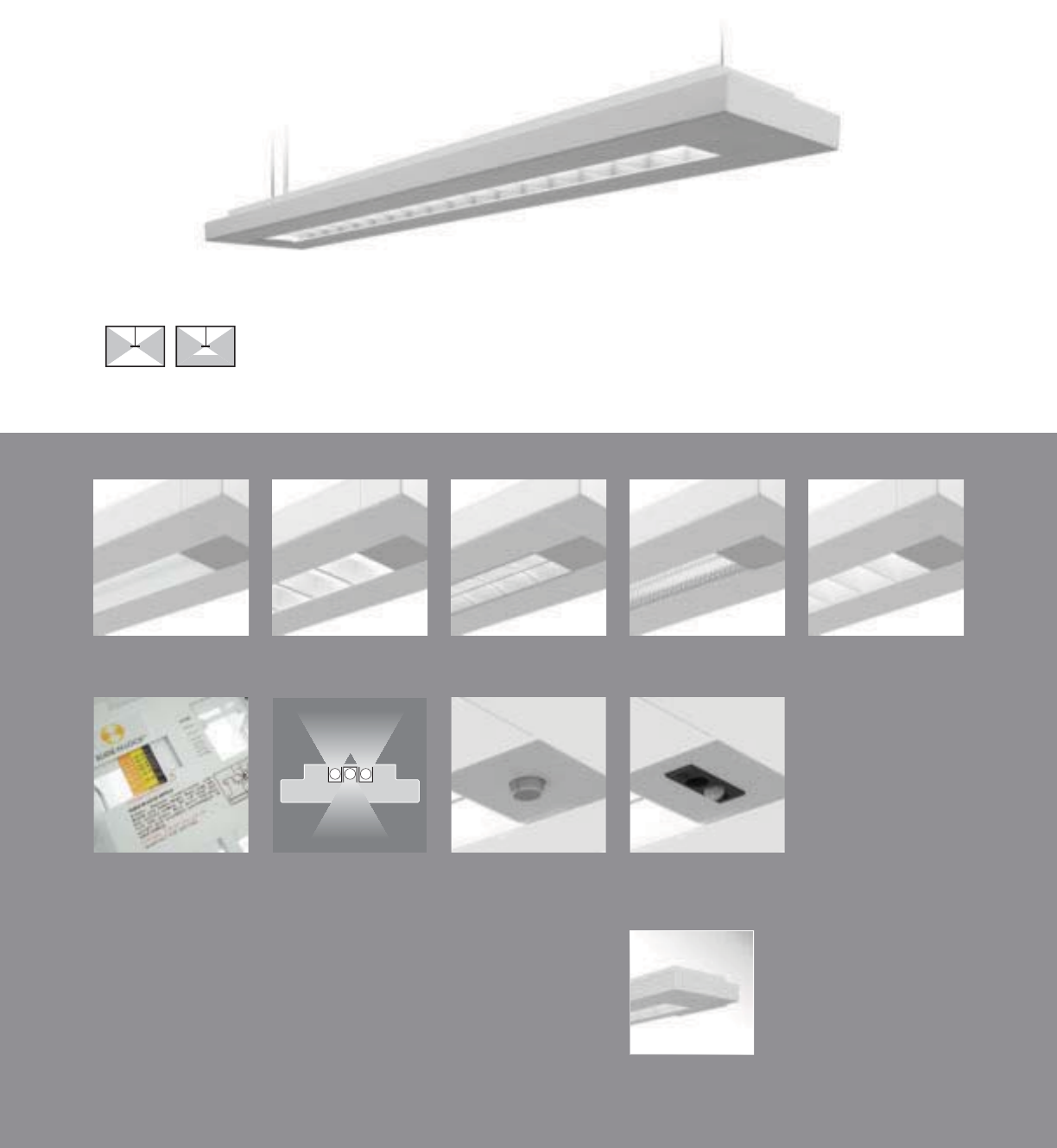
VB-WB with standard die-cast end caps
90
Vertechs Wall
(pages 130-131)
2Sense
(page 171)
Day-Sense
(page 170)
Lamp Isolators
(pages 98-99)
Slide-N-Lock™
(pages 98-99)
Concave Metallic
Perf (VB-WC)
RPerformance™
Louver (VB-WH)
Micro Prismatic
Lens (VB-WM)
Cross Blade Parabolic
Louver (VB-WB)
High Efficiency
Louver (VB-WW)
• Five downlight media options
• RPerformance™ Louver meets RP1 requirements
• Slide-N-Lock™ optics with 8 field-adjustable settings
• Lamp Isolator kits
• Day-Sense integral daylight sensor and 2Sense integral
daylight/occupancy sensor
Vertechs
SUSPENDED | DIRECT-INDIRECT / SEMI-INDIRECT | T5 / T5HO / T8
Vertechs embodies the twenty-fi rst
century demands of architecturally
attractive and effi cient design.

S
ERIE
S
VB
=
V
ertec
hs
S
uspende
d
OPTICS UP
W=Whit
e
S=S
p
ecular
O
PTI
CS
D
O
W
N
B=
C
r
oss
Bl
ade
P
a
r
abo
li
c
L
ou
v
er
C
=
Co
n
ca
v
e
M
e
t
a
lli
c
P
e
r
f
H=RPer
f
ormance
™
L
ouver
M
=
Mi
cr
o
P
r
i
smat
i
c
L
ens
W=Hig
h
Efficienc
y
Louver
NUMBER
O
F LAMP
S
1=1
L
amp
(N
5,
T
5
)
2
=2 Lamps ((N5, T5, T8
)
3
=
3
Lam
p
s (N5
,
T5)
LAMP
TYPE
N
5=
T5
N
orma
l
O
utpu
t
T5=T5 High Outpu
t
T
8
=T
8
N
o
rm
a
l Out
p
ut
NUMBER
O
F
C
IR
C
UIT
S*
1=1
C
ircuit
2
=
2
C
ir
cu
it
s
WIRIN
G
*
C
=
S
tandar
d
C
ircui
t
E
=
E
mergency
B=Batter
y
Pac
k
Y
=Dayligh
t
D=Dimming T=Nightlight
V
O
LTA
G
E*
120=120V 347=347V
2
77=277V
U
NV=
U
niv
e
r
sal
(120V-277V
)
S
U
S
PEN
S
I
ON
A
=Aircraft
C
abl
e
P=Rigid Pendant
P
O
WE
R
FEED*
C
=
S
trai
g
h
t
C
ord
K=
C
urly
C
ord
P=Rigid P
e
n
da
nt
S
U
S
PEN
S
I
ON
LEN
G
T
H
-
Adj
usta
bl
e
C
able
48”, 120”
,
240”, 300”, 360
”
(in
f
inite adjustment alon
g
e
ntir
e
length
of
cable
)
-
Rigid
P
en
d
an
t
12”, 15”
,
18”, 21”, 24
”
or
27
”
(additiona
l
p
endant length
s
available
,
co
n
su
l
t
f
actory
)
C
EILIN
G
TYPE*
T
1=1
”
T
-
B
ar
T9=9/16” T-Ba
r
T
S
=
S
l
o
tt
ed
T-B
a
r
S
T=
S
tr
uc
t
u
r
e
JB
=4
”
O
cta
g
onal
J
-
B
o
x
R
UN
LEN
G
TH
S
p
ecif
y
lu
m
i
n
ai
r
e
l
en
g
t
h
in
fee
t.
-
I
n
di
v
id
ua
ll
y
M
ounte
d
L
um
i
na
i
re
s
may
b
e 4
’
,8
’,
o
r
12
’
in
l
engt
h
.
-Continuousl
y
Mounte
d
S
t
a
n
da
r
d
row
configurations
w
over
12’
r
consist
of
t
8
’
f
a
n
d
12
’
sec
ti
o
n
s
.
O
PTI
O
N
S
S
lide-N-Lock
™
(pg. 98-99
)
DL1=
95%
Downligh
t
DL
5
=7
5%
Downligh
t
DL
2=
90%
D
own
light
DL6
=7
0%
D
own
light
DL
3=85%
D
own
light
DL
7=65%
D
own
light
DL
4=80%
D
own
li
g
ht
DL
8=60%
D
own
li
g
ht
Lam
p
I
so
l
a
t
o
r Kit
s*
(pg. 98-99
)
DL
/U
D
U
=
2
l
am
p
su
p
1
l
am
p
do
wn
DL
/
DUD=2
l
amp
s
d
own 1
l
am
p
u
p
DL
/
UXU=2 lamp
s
u
p
DL
/
DXD=
2
lam
p
s
do
w
n
DL
/
XDX=
1
lam
p
do
w
n
DL
/
XUX=1
l
amp up
DS=Day-Sense Integral Daylight Sensor
2S
=2
Se
n
se
Integra
l
Daylight/Occupanc
y
Se
n
so
r
PROJECT NAME: TYPE:
CATALOG #:
-
-
-
-
-
-
-
-
a
ll
opt
i
on
s
ava
il
a
bl
e.
Pl
eas
e
consu
lt
you
r
C
ooper
Li
g
h
t
i
n
g
R
epresentat
i
ve fo
r
ava
il
a
bili
ty an
d
t
echnical information.
S
pecifications and dimensions subject
t
o chang
e
without notice.
ORDERING INFORMATION:
SAMPLE NUMBER:VB-WB-2T8-1C-UNV-AC48-T1-32’-DL5
91
SUSPENDED VERTECHS
9" [229MM]
2-1/2" [64MM]
Co
n
s
tr
uc
ti
o
n
:
Housin
g
i
s
6063
T
5
a
l
u
min
u
m
e
xtrus
i
o
n
f
ormin
g
a 9”x2-1
/
2
”
rectan
g
u
l
ar
p
rofile.
S
tandard 4
’
-0
”
, 8
’
-0
”,
an
d
12
’
-0
”
fixture
l
engths combine for continuou
s
r
u
ns.
R
ef
l
ec
t
o
r
s
: R
ef
l
ec
t
or
p
a
n
is
p
a
i
nte
d
w
i
t
h
a
high
r
eflectanc
e
w
hi
t
e
pow
d
e
r
coa
t
finish
.
O
ptiona
l
die-forme
d
side reflector
s
ar
e
highly specula
r
a
n
od
iz
ed
a
l
u
min
u
m.
Le
n
s
:
Le
n
s
is
.12
5”
thick
clear
k
m
i
cro-
p
r
i
smat
ic
a
cry
lic
mater
i
a
l
offerin
g
91
%
transm
i
ss
i
on
.
L
ou
v
e
r
s:
C
r
oss
Bl
ade
a
n
d
RP
e
rf
o
rm
a
n
ce™
are
co
ntin
uous
semi-s
p
ecula
r
a
l
u
min
u
m
.
P
e
r
f
i
s
sem
i
-specu
l
ar mater
i
a
l,
per
f
orated sect
i
o
n
i
s
15% ope
n
w
i
t
h
0.062
”
di
ameter
h
o
l
e
s
an
d
opa
l
diffuser. Hig
h
Efficienc
y
is continuous highl
y
ref
l
ec
tiv
e
p
ainte
d
whit
e
a
l
u
min
u
m
.
Elec
tr
ical:
T
5/
T
5
H
O
f
ixt
u
r
es
are
p
re-w
i
re
d
w
i
t
h
quick
wire
k
connec
t
or
s
an
d
use
UL
li
ste
d
C
las
s
P,
T5
/
T5H
O
program rap
id
s
t
ar
t
un
i
versa
l
vo
l
tag
e
e
lectroni
c
ballasts
,
po
w
er
facto
r
of 97
%
wi
t
h
less
th
an
10%
THD.
T
8
f
ixt
u
r
es
are
p
re-wire
d
wi
t
h
quick
wire
k
co
nn
ecto
r
s
a
n
d
use
UL
lis
t
ed
C
lass
P,
265ma
T
8
i
nstan
t
s
t
ar
t
un
i
versa
l
vo
l
ta
ge
e
lectroni
c
ballasts
,
po
w
er
facto
r
of 95
%
wi
t
h
less
th
an
10%
THD. Fixt
u
r
es
a
n
d
e
l
ec
tri
ca
l
c
om
p
onent
s
ce
rti
f
i
ed
t
o
UL
a
n
d
CUL
s
t
a
n
da
r
ds
.
M
ount
i
n
g:
S
tandar
d
aircraf
t
ca
ble
moun
t
s on
4’-0”, 8’-0”, and 12’-0
”
cen
t
ers
.
Refer
to
spec
s
h
ee
t
s
for
v
a
ri
ous
ceiling int
e
r
face
de
t
a
il
s
a
n
d
rigid
p
en
d
ant mount
i
n
g
de
t
ails
.
Finish
:
Fixtur
e
housings
are
standar
d
white
u
sing electrostaticall
y
a
pp
lied
p
ol
y
este
r
p
owde
r
coat
p
a
i
nt.
En
d
Ca
p
s:
S
t
a
n
da
r
d
e
n
d
caps
are
p
recisio
n
d
i
e-
cas
ta
l
um
i
num
,
mec
h
an
i
ca
lly
a
tt
ached
w
i
t
hout
e
xpose
d
fasteners
.
Dimensions do not include
end plates or caps
96”48” 144”
SUSPENDED
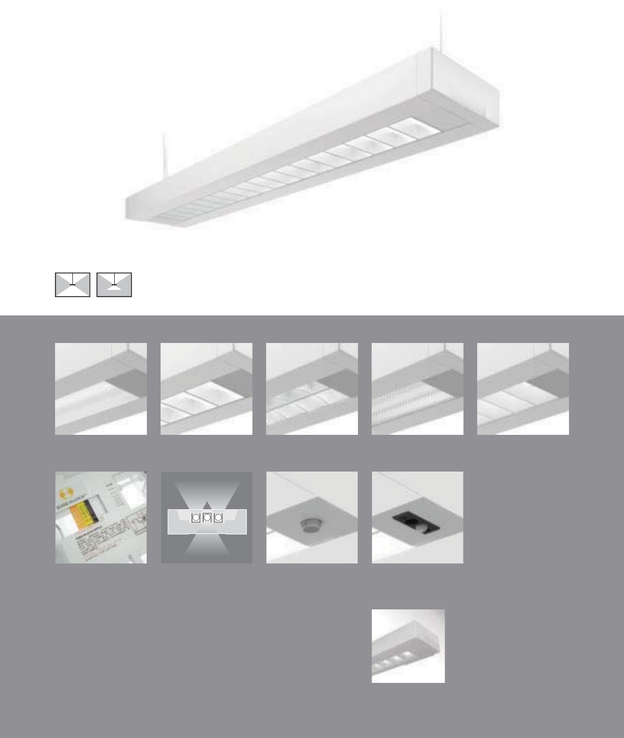
Traverse Wall
(pages 132-133)
Day-Sense
(pages 170)
Lamp Isolators
(pages 98-99)
Slide-N-Lock™
(pages 98-99)
Concave Metallic
Perf (TB-WC)
RPerformance™
Louver (TB-WH)
Micro Prismatic
Lens (TB-WM)
Cross Blade Parabolic
Louver (TB-WB)
High Efficiency
Louver (TB-WW)
• Five downlight media options
• RPerformance™ Louver meets RP1 requirements
• Slide-N-Lock™ optics with 8 field-adjustable settings
• Lamp Isolator kits
• Day-Sense integral daylight sensor and 2Sense
integral daylight/occupancy sensor
TB-WB with standard die-cast end caps
92
Traverse
SUSPENDED | DIRECT-INDIRECT / SEMI-INDIRECT | T5 / T5HO / T8
No matter the design goal, the
Traverse is equipped with the
media and controls to achieve it.
2Sense
(pages 171)

93
2-7/8" [73MM]
9" [229MM]
S
ERIE
S
TB=Traverse
S
uspende
d
OPTICS U
P
S=S
p
ecular
W
=
Whi
t
e
O
PTI
CS
D
O
WN
B=
C
r
oss
Bl
ade
P
a
r
abo
li
c
L
ou
v
e
r
C
=
Co
n
ca
v
e
M
e
t
a
lli
c
P
e
rf
H=RPer
f
ormance™ Louver
M
=
Mi
cro
P
r
i
smat
i
c
L
en
s
W=High Efficiency Louve
r
N
U
MBER
O
F LAMP
S
1=1
L
amp
2
=2 Lamp
s
3=3 Lam
ps
LAMP TYPE
N5=T5 Normal
O
utput
T5=T5 High Outpu
t
T8=T8 Normal Out
p
ut
NUMBER
O
F
C
IR
C
UIT
S*
1=1
C
ircui
t
2
=2
C
ir
cu
it
s
WIRIN
G
*
C
=
S
tandard
C
ircuit E=Emergency
B=Battery Pack Y=Daylight
D=Dimming T=Nightlight
V
O
LTA
G
E*
120=120V 347=347V
2
77=277V UNV=Universal (120V-277V
)
S
U
S
PEN
S
I
ON
A
=Aircraft
C
abl
e
P=Rigid Pendant
P
O
WER FEED*
C
=
S
trai
g
ht
C
ord
K=
C
urly
C
ord
P=Rigid Pendant
S
U
S
PEN
S
I
O
N LEN
G
T
H
-Adjustable
C
able
48”, 120”, 240”, 300”, 360”
(in
f
inite adjustment along entire length o
f
cable
)
-
Rigid
P
en
d
ant
12”, 15”, 18”, 21”, 24” or 27”
(additional pendant lengths available, consult
f
actory
)
C
EILIN
G
TYPE*
T
1=1
”
T
-
B
a
r
T9=9/16” T-Bar
T
S
=
S
l
o
tt
ed
T-B
a
r
S
T=
S
tr
uc
t
u
r
e
JB=4”
O
cta
g
onal J-Bo
x
R
U
N LEN
G
TH
Specify luminaire len
g
th in feet.
-
I
n
di
v
id
ua
ll
y
M
ounte
d
L
um
i
na
i
res may
b
e 4
’
,8
’
, or 12
’
i
n
l
engt
h
.
-Continuously Mounted
Standard row configurations over 12’ consist of 8’ and 12’ sections
.
O
PTI
O
N
S
S
lide-N-Lock™ (page
9
8-99)
DL1=95% Downlight DL5=75% Downligh
t
DL
2=90%
D
own
ligh
t
DL
6=70%
D
own
light
DL
3=85%
D
own
ligh
t
DL
7=65%
D
own
light
DL
4=80%
D
own
li
g
h
t
DL
8=60%
D
own
li
g
ht
Lamp Isolator Kits* (page
9
8-99)
DL/UDU=2 lam
p
s u
p
1 lam
p
dow
n
DL
/
DUD=2 lamps down 1 lamp up
DL
/
UXU=2 lamps up
DL/DXD=2 lam
p
s dow
n
DL/XDX=1 lam
p
down
DL
/
XUX=1 lamp up
DS=Day-Sense Integral Daylight Sensor
2
S=2Sense Integral Daylight/Occupancy Sensor
PROJECT NAME: TYPE:
CATALOG #:
-
-
-
-
-
-
-
-
t
echnical information.
S
pecifications and dimensions subject to change without notice.
ORDERING INFORMATION:
SAMPLE NUMBER:TB-WB-3T8-1C-UNV-AC48-T1-32
SUSPENDED TRAVERSE
Construction: Housin
g
is 6063 T5 aluminum
e
xtrusion formin
g
a 9”x2-7
/
8” rectan
g
ular
p
rofile.
S
tandard 4’-0”, 8’-0”, and 12’-0” fixture
l
engths combine for continuous runs.
Reflectors: Reflector pan is painted with a high
r
eflectance white
p
owder coat finish. O
p
tional
die-
f
ormed side re
f
lectors are hi
g
hly specular
a
no
di
ze
d
a
l
um
i
num.
L
ens:
L
ens
i
s .125
”
t
hi
c
k
c
l
ear m
i
cro-
p
r
i
smat
i
c
a
crylic material offerin
g
91% transmission
.
L
ou
v
e
r
s
:
C
r
oss
Bl
ade
a
n
d
RP
e
rf
o
rm
a
n
ce
™
a
r
e
c
ontinuous semi-s
p
ecular aluminum. Per
f
is
semi-specular material, per
f
orated section is
15% open w
i
t
h
0.062
”
di
ameter
h
o
l
es an
d
opa
l
diffuser. High Efficiency is continuous highly
r
e
f
lective
p
ainted white aluminum
.
Electrical: T5/T5HO fixtures are
p
re-wired with
quick wire connectors and use UL listed
C
lass P,
T5
/
T5H
O
program rapid start universal voltage
e
lectronic ballasts, power factor of 97% with
l
ess than 10% THD. T8
f
ixtures are
p
re-wired
wi
t
h
q
u
i
c
k
w
i
re connectors an
d
use
UL
li
ste
d
C
lass P, 265ma T8 instant start universal volta
g
e
e
lectronic ballasts, power factor of 95% with
less
th
a
n 1
0%
THD. Fixt
u
r
es
a
n
d
e
l
ec
tri
ca
l
c
om
p
onents certified to UL and CUL standards.
M
ounting: Aircra
f
t cable mounts on 4’-0”, 8’-0”,
a
nd 12’-0” centers. Re
f
er to s
p
ec sheets
f
or
v
arious ceilin
g
interface details and ri
g
id
p
endant mounting details.
Finish: Fixture housings are standard white
u
sing electrostatically applied polyester powder
c
oat
p
a
i
nt.
End Caps: Standard end caps are precision
die-cast aluminum, mechanicall
y
attached
w
ithout ex
p
osed
f
asteners
.
Dimensions do not include
end plates or caps
96”48” 144”
SUSPENDED
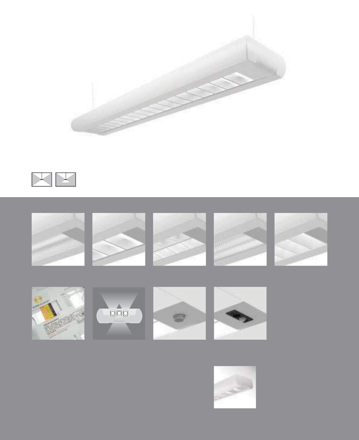
Gator Wall
(pages 134-135)
Day-Sense
(page 170)
Lamp Isolators
(pages 98-99)
Slide-N-Lock™
(pages 98-99)
Concave Metallic
Perf (NB-WC)
RPerformance™
Louver (NB-WH)
Micro Prismatic
Lens (NB-WM)
Cross Blade Parabolic
Louver (NB-WB)
High Efficiency
Louver (NB-WW)
NB-WB with standard die-cast end caps
94
• Five downlight media options
• RPerformance™ Louver meets RP1 requirements
• Slide-N-Lock™ optics with 8 field-adjustable settings
• Lamp Isolator kits
• Day-Sense integral daylight sensor and 2Sense
integral daylight/occupancy sensor
Navigator II
SUSPENDED | DIRECT-INDIRECT / SEMI-INDIRECT | T5 / T5HO / T8
The classic Navigator II, now updated
and tailored to the requirements of
contemporary design.
2Sense
(page 171)

2-7/8" [73MM]
9" [229MM]
95
S
ERIE
S
NB=Navi
g
ator II
S
uspende
d
OPTICS UP
S=S
p
ecular
W
=
Whi
t
e
O
PTI
CS
D
O
WN
B=
C
r
oss
Bl
ade
P
a
r
abo
li
c
L
ou
v
e
r
C
=
Co
n
ca
v
e
M
e
t
a
lli
c
P
e
rf
H=RPer
f
ormance™ Louver
M
=
Mi
cro
P
r
i
smat
i
c
L
en
s
W=High Efficiency Louve
r
N
U
MBER
O
F LAMP
S
1=1
L
amp
2
=2 Lamp
s
3=3 Lam
ps
LAMP TYPE
N5=T5 Normal
O
utput
T5=T5 High Outpu
t
T8=T8 Normal Out
p
ut
NUMBER
O
F
C
IR
C
UIT
S*
1=1
C
ircui
t
2
=2
C
ir
cu
it
s
WIRIN
G
*
C
=
S
tandard
C
ircuit E=Emergency
B=Battery Pack Y=Daylight
D=Dimming T=Nightlight
V
O
LTA
G
E*
120=120V 347=347V
2
77=277V UNV=Universal (120V-277V
)
S
U
S
PEN
S
I
ON
A
=Aircraft
C
abl
e
P=Rigid Pendant
P
O
WER FEED*
C
=
S
trai
g
ht
C
ord
K=
C
urly
C
ord
P=Rigid Pendant
S
U
S
PEN
S
I
O
N LEN
G
T
H
-Adjustable
C
able
48”, 120”, 240”, 300”, 360”
(in
f
inite adjustment along entire length o
f
cable
)
-
Rigid
P
en
d
ant
12”, 15”, 18”, 21”, 24” or 27”
(additional pendant lengths available, consult
f
actory
)
C
EILIN
G
TYPE*
T
1=1
”
T
-
B
a
r
T9=9/16” T-Bar
T
S
=
S
l
o
tt
ed
T-B
a
r
S
T=
S
tr
uc
t
u
r
e
JB=4”
O
cta
g
onal J-Bo
x
R
U
N LEN
G
TH
Specify luminaire len
g
th in feet.
-
I
n
di
v
id
ua
ll
y
M
ounte
d
L
um
i
na
i
res may
b
e 4
’
,8
’
, or 12
’
i
n
l
engt
h
.
-Continuously Mounted
Standard row configurations over 12’ consist of 8’ and 12’ sections
.
O
PTI
O
N
S
S
lide-N-Lock™ (page 98-99
)
DL1=95% Downlight DL5=75% Downligh
t
DL
2=90%
D
own
ligh
t
DL
6=70%
D
own
light
DL
3=85%
D
own
ligh
t
DL
7=65%
D
own
light
DL
4=80%
D
own
li
g
h
t
DL
8=60%
D
own
li
g
ht
Lamp Isolator Kits* (page 98-99
)
DL/UDU=2 lam
p
s u
p
1 lam
p
dow
n
DL
/
DUD=2 lamps down 1 lamp up
DL
/
UXU=2 lamps up
DL/DXD=2 lam
p
s dow
n
DL/XDX=1 lam
p
down
DL
/
XUX=1 lamp up
DS=Day-Sense Integral Daylight Sensor
2
S=2Sense Integral Daylight/Occupancy Sensor
PROJECT NAME: TYPE:
CATALOG #:
-
-
-
-
-
-
-
-
t
echnical information.
S
pecifications and dimensions subject to change without notice.
ORDERING INFORMATION:
SAMPLE NUMBER:NB-WB-2N5-1C-UNV-AC48-T1-32-DL1
SUSPENDED NAVIGATOR II
Construction: Housin
g
is 6063 T5 aluminum
e
xtrusion formin
g
a 9”x2-7
/
8” rounded profile.
S
tandard 4’-0”, 8’-0”, and 12’-0” fixture lengths
c
ombine for continuous runs.
Reflectors: Reflector pan is painted with a high
r
eflectance white
p
owder coat finish. O
p
tional
die-
f
ormed side re
f
lectors are hi
g
hly specular
a
no
di
ze
d
a
l
um
i
num.
L
ens:
L
ens
i
s .125
”
t
hi
c
k
c
l
ear m
i
cro-
p
r
i
smat
i
c
a
crylic material offerin
g
91% transmission
.
L
ou
v
e
r
s
:
C
r
oss
Bl
ade
a
n
d
RP
e
rf
o
rm
a
n
ce
™
a
r
e
c
ontinuous semi-specular aluminum. Per
f
is
semi-specular material, perforated section is
15% open with 0.062” diameter holes and opal
di
ff
user. High E
ff
iciency is continuous highly
r
e
f
lective
p
ainted white aluminum
.
Electrical: T5/T5HO fixtures are
p
re-wired with
quick wire connectors and use UL listed
C
lass P,
T5
/
T5H
O
program rapid start universal voltage
e
lectronic ballasts, power factor of 97% with
l
ess than 10% THD. T8
f
ixtures are
p
re-wired
wi
t
h
q
u
i
c
k
w
i
re connectors an
d
use
UL
li
ste
d
C
lass P, 265ma T8 instant start universal volta
g
e
e
lectronic ballasts, power factor of 95% with
less
th
a
n 1
0%
THD. Fixt
u
r
es
a
n
d
e
l
ec
tri
ca
l
c
om
p
onents certified to UL and CUL standards.
M
ounting: Standard aircraft cable mounts on
4’-0”, 8’-0”, and 12’-0” centers. Re
f
er to s
p
ec
sheets for various ceilin
g
interface details and
r
igid pendant mounting details.
Finish: Fixture housings are standard white
u
sing electrostatically applied polyester powder
c
oat
p
a
i
nt.
End Caps: Standard end caps are precision
die-cast aluminum, mechanicall
y
attached
w
ithout ex
p
osed
f
asteners
.
Dimensions do not include
end plates or caps
96”48” 144”
SUSPENDED

MB-WB with standard die-cast end caps
96
Concave Metallic
Perf (MB-WC)
RPerformance™
Louver (MB-WH)
Micro Prismatic
Lens (MB-WM)
Cross Blade Parabolic
Louver (MB-WB)
High Efficiency
Louver (MB-WW)
• Five downlight media options
• RPerformance™ Louver meets RP1 requirements
• Slide-N-Lock™ optics with 8 field-adjustable settings
• Lamp Isolator kits
• Day-Sense integral daylight sensor and 2Sense
integral daylight/occupancy sensor
Minigator
SUSPENDED | DIRECT-INDIRECT / SEMI-INDIRECT | T5 / T5HO / T8
The Minigator offers a minimal profi le
with the same immense capabilities
as its larger counterpart.
Day-Sense
(page 170)
Lamp Isolators
(pages 98-99)
Slide-N-Lock™
(pages 98-99)
2Sense
(page 171)
Gator Wall
(pages 134-135)
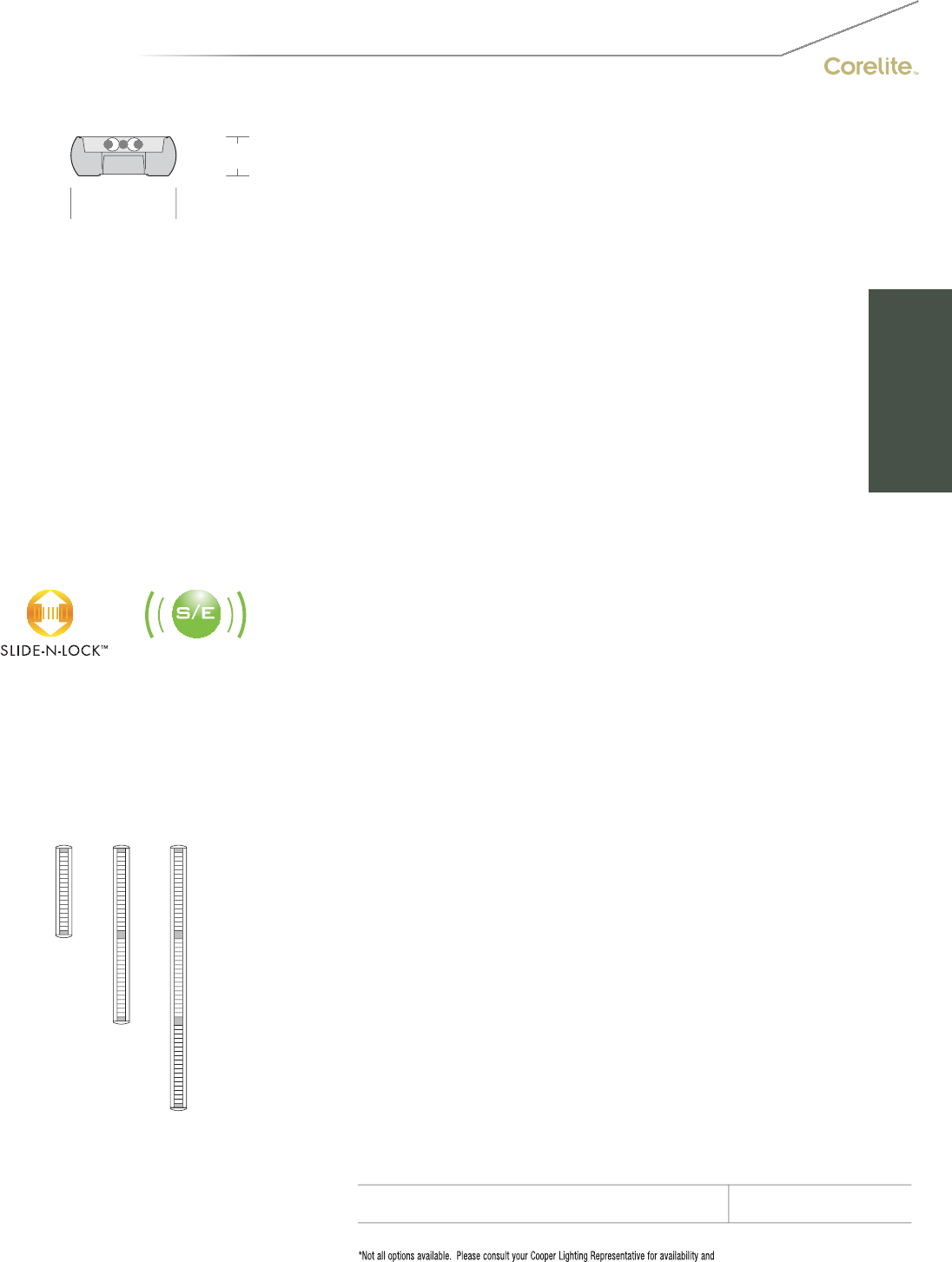
97
2-1/2" [64MM]
6-3/4" [171MM]
S
ERIE
S
M
B=Mini
g
ator
S
uspended
OPTICS UP
W=Whit
e
S=S
p
ecular
O
PTI
CS
D
O
WN
B=
C
r
oss
Bl
ade
P
a
r
abo
li
c
L
ou
v
er
C
=
Co
n
ca
v
e
M
e
t
a
lli
c
P
e
rf
H=RPer
f
ormance™ Louver
M
=
Mi
cro
P
r
i
smat
i
c
L
en
s
W=High Efficiency Louve
r
N
U
MBER
O
F LAMP
S
1=1
L
amp
(N
5,
T
5
)
2
=2 Lamps (N5, T5, T8)
3=3 Lamps (N5, T5
)
LAMP TYPE
N5=T5 Normal
O
utput
T5=T5 High Outpu
t
T8=T8 Normal Out
p
ut
NUMBER
O
F
C
IR
C
UIT
S*
1=1
C
ircui
t
2
=2
C
ir
cu
it
s
WIRIN
G
*
C
=
S
tandard
C
ircuit B=Battery Pac
k
D=Dimming T=Nightlight
E=Emergency Y=Dayligh
t
V
O
LTA
G
E*
120=120V 347=347V
2
77=277V UNV=Universal (120V-277V
)
S
U
S
PEN
S
I
ON
A
=Aircraft
C
abl
e
P=Rigid Pendant
P
O
WER FEED*
C
=
S
trai
g
ht
C
ord
K=
C
urly
C
ord
P=Rigid Pendant
S
U
S
PEN
S
I
O
N LEN
G
T
H
-Adjustable
C
able
48”, 120”, 240”, 300”, 360”
(in
f
inite adjustment along entire length o
f
cable
)
-
Rigid
P
en
d
ant
12”, 15”, 18”, 21”, 24” or 27”
(additional pendant lengths available, consult
f
actory
)
C
EILIN
G
TYPE*
T
1=1
”
T
-
B
a
r
T9=9/16” T-Bar
T
S
=
S
l
o
tt
ed
T-B
a
r
S
T=
S
tr
uc
t
u
r
e
JB=4”
O
cta
g
onal J-Bo
x
R
U
N LEN
G
TH
Specify luminaire len
g
th in feet.
-
I
n
di
v
id
ua
ll
y
M
ounte
d
L
um
i
na
i
res may
b
e 4
’
,8
’
, or 12
’
i
n
l
engt
h
.
-Continuously Mounted
Standard row configurations over 12’ consist of 8’ and 12’ sections
.
O
PTI
O
N
S
S
lide-N-Lock™ (page 98-99
)
DL1=95% Downlight DL5=75% Downligh
t
DL
2=90%
D
own
ligh
t
DL
6=70%
D
own
light
DL
3=85%
D
own
ligh
t
DL
7=65%
D
own
light
DL
4=80%
D
own
li
g
h
t
DL
8=60%
D
own
li
g
ht
Lamp Isolator Kits* (page 98-99
)
DL/UDU=2 lam
p
s u
p
1 lam
p
dow
n
DL
/
DUD=2 lamps down 1 lamp up
DL
/
UXU=2 lamps up
DL/DXD=2 lam
p
s dow
n
DL/XDX=1 lam
p
down
DL
/
XUX=1 lamp up
DS=Day-Sense Integral Daylight Sensor
2
S=2Sense Integral Daylight/Occupancy Sensor
PROJECT NAME: TYPE:
CATALOG #:
-
-
-
-
-
-
-
-
t
echnical information.
S
pecifications and dimensions subject to change without notice.
ORDERING INFORMATION:
SAMPLE NUMBER:MB-WB-2T8-1C-UNV-AC48-T1-32’-DL5
SUSPENDED MINIGATOR
Construction: Housin
g
is 6063 T5 aluminum
e
xtrusion formin
g
a 6-3
/
4”x2-1
/
2” rounded
p
rofile.
S
tandard 4’-0”, 8’-0”, and 12’-0” fixture
l
engths combine for continuous runs.
Reflectors: Reflector pan is painted with a high
r
eflectance white
p
owder coat finish. O
p
tional
die-
f
ormed side re
f
lectors are hi
g
hly specular
a
no
di
ze
d
a
l
um
i
num.
L
ens:
L
ens
i
s .125
”
t
hi
c
k
c
l
ear m
i
cro-
p
r
i
smat
i
c
a
crylic material offerin
g
91% transmission
.
L
ou
v
e
r
s
:
C
r
oss
Bl
ade
a
n
d
RP
e
rf
o
rm
a
n
ce
™
a
r
e
c
ontinuous semi-specular aluminum. Per
f
is
semi-specular material, perforated section is
15% open with 0.062” diameter holes and opal
di
ff
user. High E
ff
iciency is continuous highly
r
e
f
lective
p
ainted white aluminum
.
Electrical: T5/T5HO fixtures are
p
re-wired with
quick wire connectors and use UL listed
C
lass P,
T5
/
T5H
O
program rapid start universal voltage
e
lectronic ballasts, power factor of 97% with
l
ess than 10% THD. T8
f
ixtures are
p
re-wired
wi
t
h
q
u
i
c
k
w
i
re connectors an
d
use
UL
li
ste
d
C
lass P, 265ma T8 instant start universal volta
g
e
e
lectronic ballasts, power factor of 95% with
less
th
a
n 1
0%
THD. Fixt
u
r
es
a
n
d
e
l
ec
tri
ca
l
co
m-
p
onents certified to UL and CUL standards
.
M
ounting: Standard aircraft cable mounts on
4’-0”, 8’-0”, and 12’-0” centers. Re
f
er to s
p
ec
sheets
f
or various ceilin
g
inter
f
ace details and
rigid
pen
d
ant mount
i
n
g
d
eta
il
s.
Finish: Fixture housings are standard white
u
sing electrostatically applied polyester powder
c
oat
p
a
i
nt.
End Caps: Standard end caps are precision
die-cast aluminum, mechanicall
y
attached
w
ithout ex
p
osed
f
asteners
.
Dimensions do not include
end plates or caps
96”48” 144”
SUSPENDED

98
LAMP ISOLATORS
*All distributions based on a 2T8 lamping
95%
DL1
90%
DL2
85%
D
L
3
80%
DL4
75%
DL5
70%
DL
6
75%
DL7
60%
D
L
8
up
l
i
gh
t
downlight
SLIDE-N-LOCK™
D - U - D D - X - D X - U - X U - X - U X - D - X
U=Isolator Up
D=Isolator Down
X=No Isolator
U - D - U
The ability to isolate uplight and downlight when combined with dual circuit
wiring is an added feature of several Corelite fixtures. This feature is ideal
for training rooms, classrooms and lecture halls where three light levels may
be required to accommodate a variety of room tasks.
The original revolutionary Slide-N-Lock™ optics designed for the Navigator II can
also be specifi ed for all D/I Extruded families. Rather than one optic per confi guration,
the Slide-N-Lock™ is a one-size-fi ts-all optic with 8 settings that are factory pre-
set at the specifi ed level and, if necessary, can later be easily adjusted in the fi eld.
To adjust, simply depress the control notch, then “Slide-N-Lock” the optic into the
new desired setting.
• 8 UPLIGHT AND
DOWNLIGHT SETTINGS
• FULLY FIELD ADJUSTABLE
• ADDED FLEXIBILITY WITH
DUAL CIRCUIT WIRING
• IDEAL FOR MEDIA
PRESENTATIONS
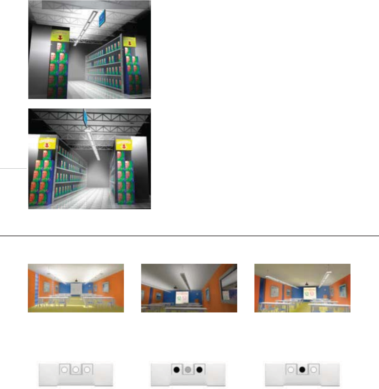
99
Scenario 1
• D-U-D Lamp Isolator configuration
• Outboard lamps at 100%
inboard lamp at 100%
Maximum system brightness for
clean-up and non-media presenta-
tions, notice the screen is washed out.
Scenario 2
• D-U-D Lamp Isolator configuration
• Outboard lamps off,
inboard lamp at 5%
This setting creates enough ambient
illumination for wayfinding and note
taking while creating ideal projection
screen contrast.
Scenario 3
• D-U-D Lamp Isolator configuration
• Outboard lamps at 100%
inboard lamp off
This condition creates recommended
light levels for reading and writing
while also creating great projection
screen contrast by eliminating the
uplight component.
Scenario 1
• 14’ Ceiling
• 11.5’ Mounting height
• 3T8* “Open” confi guration
• Average Horizontal Illuminance (.8 llf)
Vertical Shelf Surface: 25.9 fc
Floor: 39.5 fc
Ceiling: 114.0 fc
• 1.43 Watts per sq ft
* Lamp: Standard T8, 3000 initial lumens
Ballast: .88 Ballast factor, 85 input watts
Application Example > Classroom/Training Room
Application Example > Supermarket – Low-Energy Stacks
Scenario 2
• 14’ Ceiling
• 9’ Mounting height
• 2T8** DL5 ("super" T8) confi guration
• Average Horizontal Illuminance
Vertical Shelf Surface: 28.8 fc
Floor: 41.5 fc
Ceiling: 19.8 fc
• 0.85 Watts per sq ft
** Lamp: “Super T8”, 3100 Initial Lumens
Ballast: .88 Ballast Factor, 55 input watts
SUMMARY
Scenario 1 illustrates a typical direct-indirect
supermarket application wherein luminaires
are suspended high above the floors and
aligned with the aisles. Although the bright
ceiling surfaces create an "open" feel,
wasted light in the ceiling truss represents
wasted energy.
SUMMARY
By lowering the luminaire's mounting
height, eliminating a lamp, utilizing an ultra
energy effi cient lamp/ballast combination
and adding Slide-N-Lock™ Optics in the
DL5 confi guration, light levels improve
and energy consumption is substantially
reduced. Although the uplight is lowered
dramatically, 25% of the total output still
gently illuminates the ceiling for subtle
luminous effects.
IMPROVED VERTICAL AND
HORIZONTAL ILLUMINANCE
USING 40% LESS
ENERGY!
3T8 Traditional
2T8 Ultra Energy Efficient
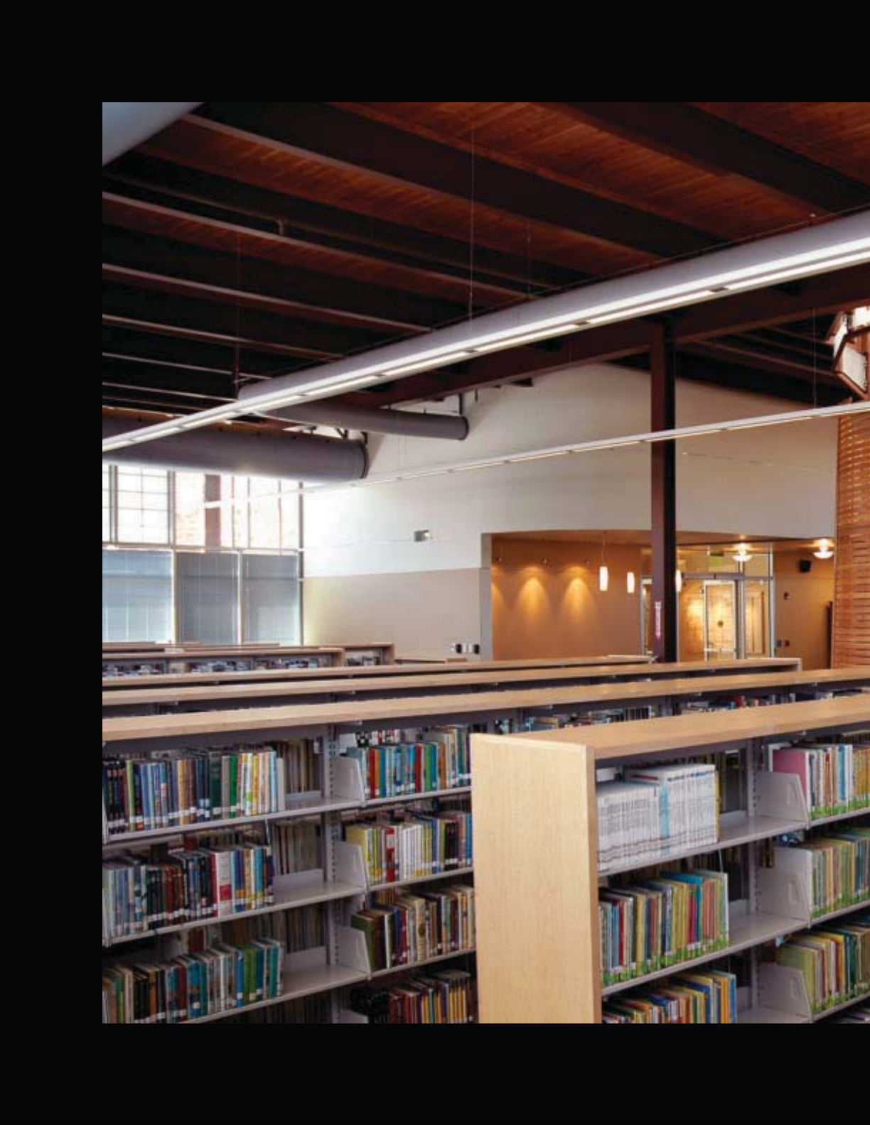
100
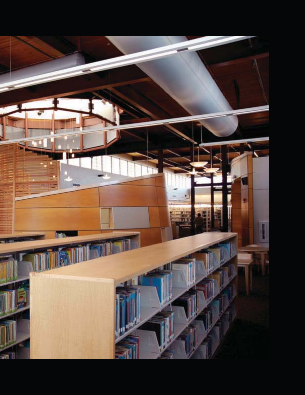
101

102
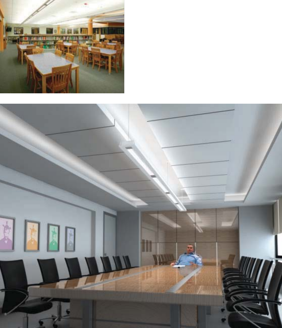
103
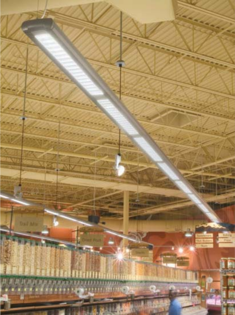
104
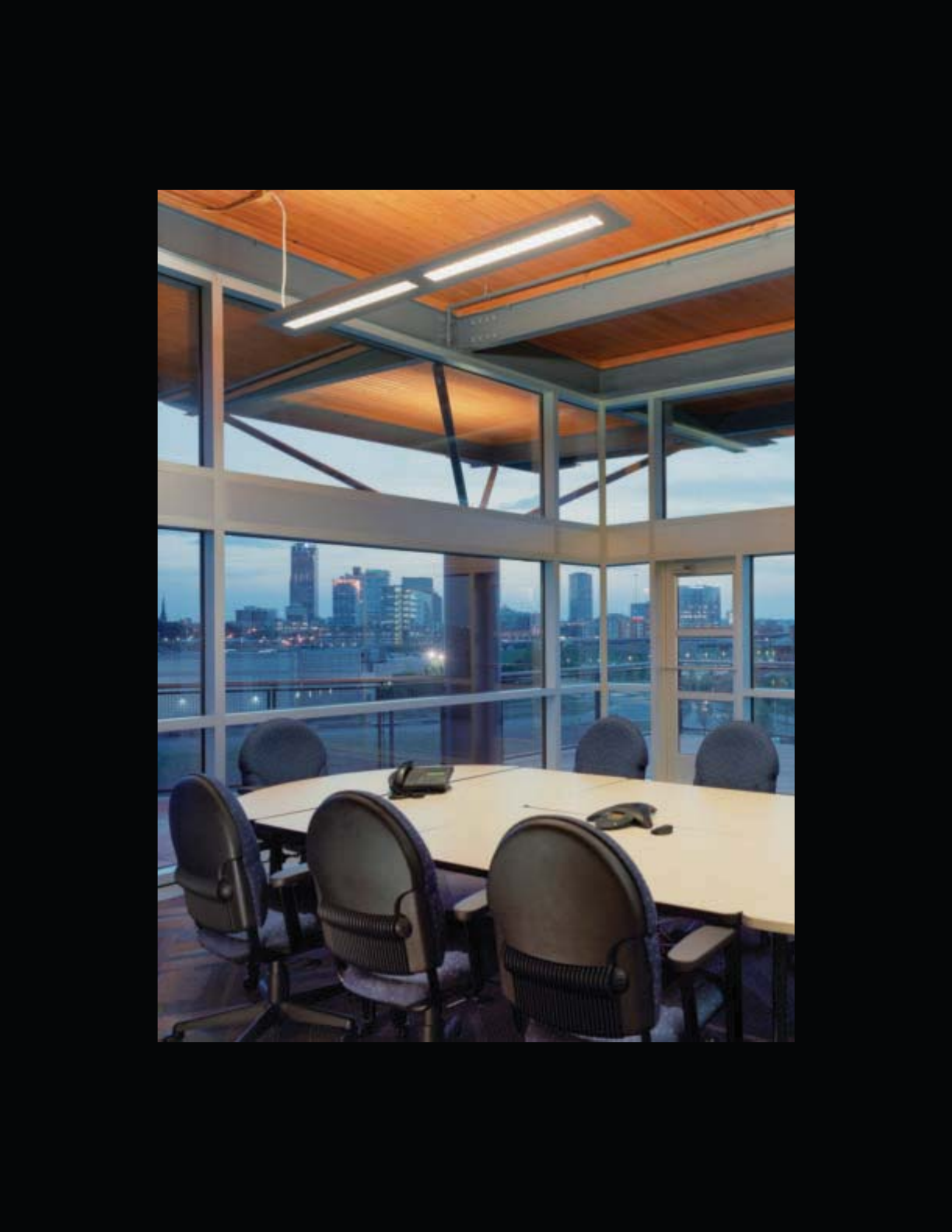
105
WALL
Lighting Inside The Lines.
From narrow corridors to wide-open office perimeters, wall
mounted luminaires provide the necessary performance
to illuminate the most challenging architectural spaces.
As they share the same uncompromising design sense
with their linear suspended counterparts, Corelite’s wall
mount fixtures maintain the aesthetic synergy of any
project.
106
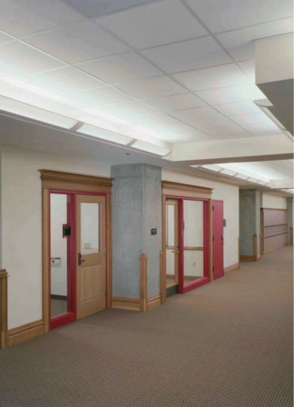
107
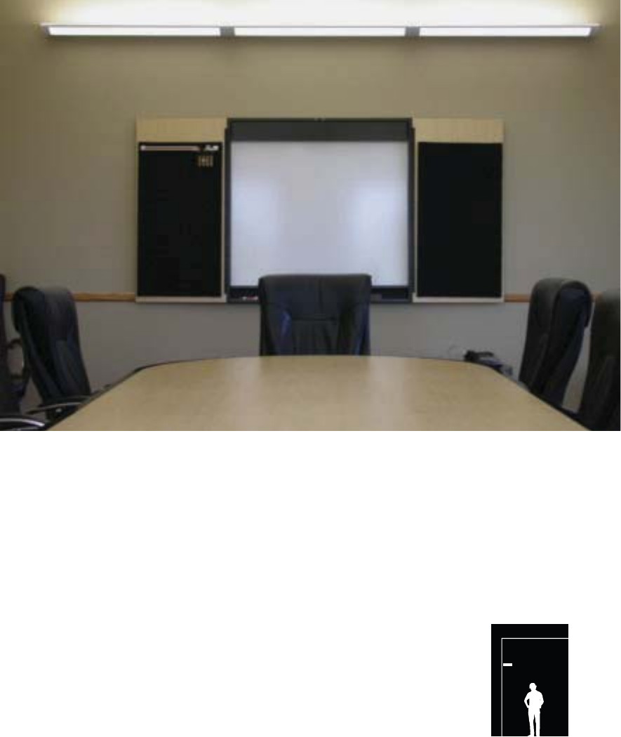
108
It’s All in the Family.
One of Corelite’s most unique attributes is the inclusion of
a wall mount companion for every product family, without
exception. Wall mount fixtures enhance the uniformity and
cohesiveness of the overall aesthetic appeal of a project,
while also adding further flexibility, allowing the designer
to continue with one product family in spaces that are not
conducive to suspended fixtures, such as corridors and
office perimeters. A variety of families also accommodate
the innovative Slide-N-Lock™ adjustable optics and Smart
Environment control systems, and are even ADA compliant.
Wall
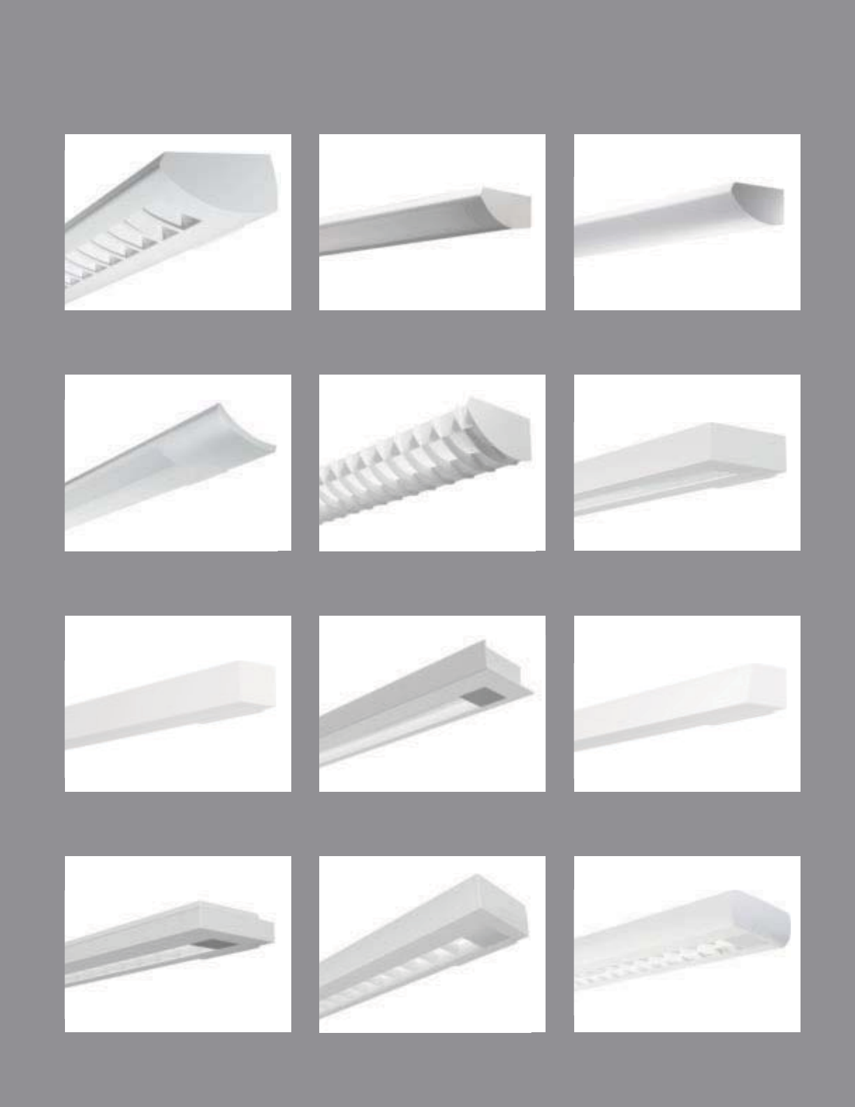
109
VERTECHS
pg. 130-131
TRAVERSE
pg. 132-133
GATOR
pg. 134-135
ELEMENT
CLASS A D/I
BAFFLE pg. 110-111
CLASS A D/I
LENSED pg. 112-113
CLASS A PERF
pg. 114-115
CLASS A INDIRECT
pg. 116-117
IRIDIUM PERF
pg. 118-119
STELLAR
pg. 120-121
ELEMENT
pg. 122-123
ELEMENT MICRO
pg. 124-125
LOFT
pg. 126-127
LOFT MICRO
pg. 128-129
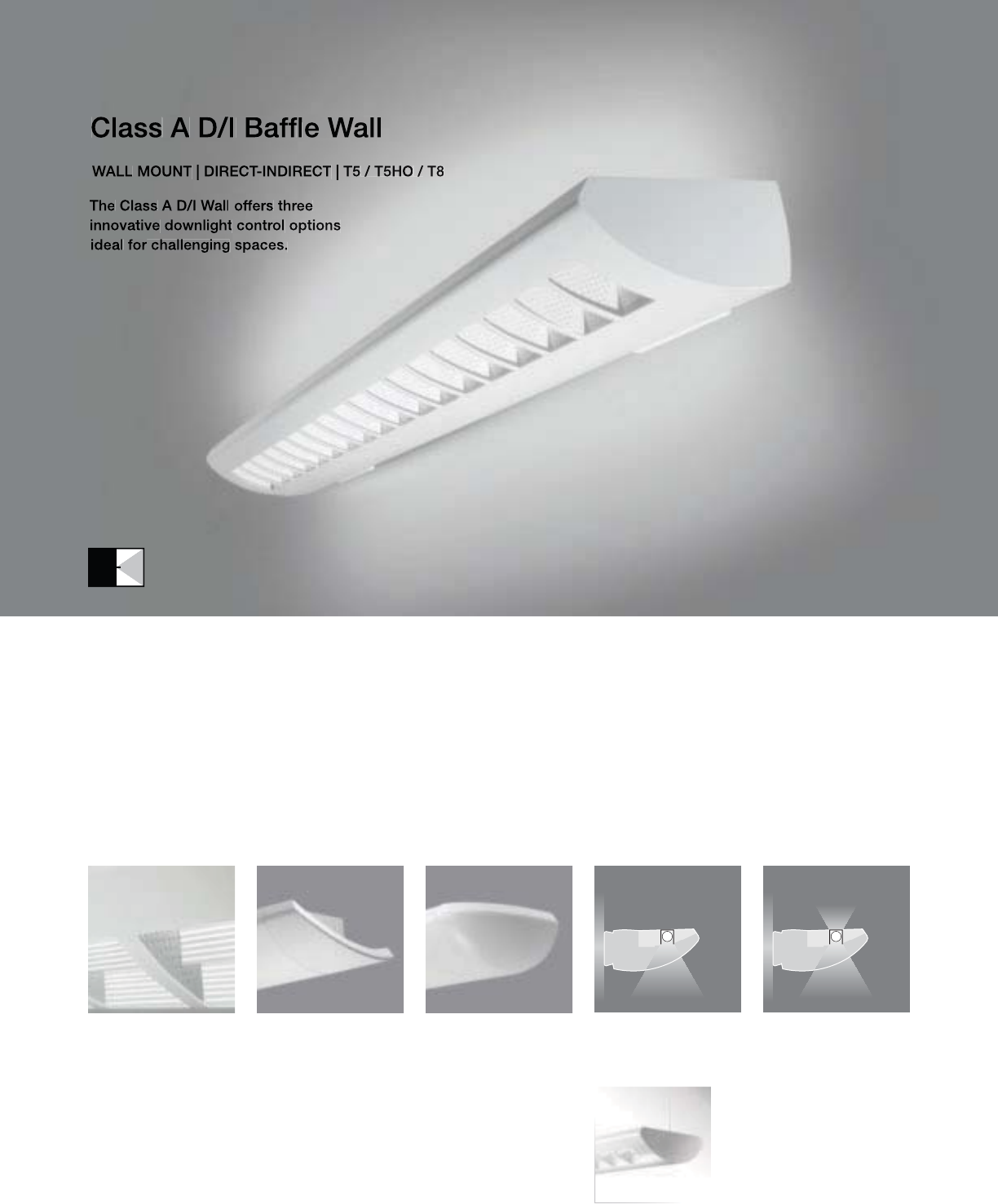
110
• Glare reduction with the Eclipse louver
• 80% and 100% Downlight Isolators
• Standard Flat or Optional Tapered or
Rounded end caps
AW-WB with standard flat end plates
Class A D/I Baffle
Suspended
(pages 32-33)
100% Downlight
Isolators (DL100)
Rounded End Cap (ER)Eclipse Louver
(AW-WE)
Tapered End Cap (ET) 80% Downlight
Isolators (DL80)

111
2-7/8" [73MM]
6-1/2" [165MM]
S
ERIE
S
A
W=
C
lass A D
/
I Wall
O
PTI
CS
UP
W=White
O
PTI
CS
D
O
WN
B=Perforated Baffle
(S
tandard
)
E
=
E
c
li
pse
L
ouve
r
N
U
MBER
O
F LAMP
S
1=1
L
amp
2
=2 Lamp
s
LAMP TYPE
N5=T5 Normal
O
utput
T5=T5 High
O
utpu
t
T8=T8 Normal Output
N
U
MBER
O
F
C
IR
CU
IT
S*
1=1
C
ircui
t
2
=2
C
ircuits
WIRIN
G
*
C
=
S
tandard
C
ircuit
D
=
Di
mm
i
ng
E=Emergency
B=Batter
y
Pack
T
=
Nigh
t
ligh
t
Y
=
D
ay
ligh
t
V
O
LTA
G
E*
12
0
=12
0V
277
=
277V
347=347
V
U
NV=Universal (120V-277V)
MO
UNTIN
G
S
U-WA=
S
urface Wall Mount
RUN LEN
G
TH
Specify luminaire length in feet.
-Individuall
y
Mounted
L
um
i
na
i
res may
b
e 4
’
,8
’
, or 12
’
i
n
l
en
g
t
h
.
-
C
ontinuously Mounted
S
tandard row configurations over 12’ consist of 8’ and 12’
sec
ti
o
n
s
.
O
PTI
O
N
S
ET=Tapered End Ca
p
ER=Rounded End Ca
p
DL100=100% Downli
g
ht Isolator
f
or outboard lamp
DL80=80% Downli
g
ht Isolator for outboard lam
p
PROJECT NAME: TYPE:
CATALOG #:
-
-
-
-
-
-
-
-
t
echnical information.
S
pecifications and dimensions subject to change without notice.
ORDERING INFORMATION:
SAMPLE NUMBER:AW-WB-2T8-1C-UNV-SU-WA-12’-ET
WALL CLASS A D/I BAFFLE
Construction: Housin
g
is one piece die-formed
c
old rolled steel, formin
g
a 6”x2-7
/
8” architec
-
t
ural profile.
S
tandard 4’-0”, 8’-0”, and 12’-0”
f
ixture lengths combine for continuous runs.
Reflectors: Reflector pan is painted with a hi
g
h
r
eflectance white powder coat finish
.
Louvers: Standard white aluminum
p
erforated
b
lades.
Op
tional Ecli
p
se Louver with white
p
erforated blades and ribbed diffuse anodized
a
luminum runners
.
Electrical: T5/T5HO fixtures are
p
re-wired with
quick wire connectors and use UL listed
C
lass P,
T5
/
T5H
O
program rapid start universal voltage
e
lectronic ballasts,
p
ower factor of 97% with
l
ess than 10% THD. T8
f
ixtures are
p
re-wired
wi
t
h
qu
i
c
k
w
i
re connectors an
d
use
UL
li
ste
d
C
lass P, 265ma T8 instant start universal voltage
e
lectronic ballasts, power factor of 95% with
less
th
a
n 1
0%
THD. Fixt
u
r
es
a
n
d
e
l
ec
tri
ca
l
c
om
p
onents certified to UL and CUL standards.
M
ount
i
n
g
:
Fi
xture mounts
di
rect
l
y to ex
i
st
i
n
g
structure over a 2”x4” standard electrical box
m
ounted horizontall
y
into the wall.
Fi
n
i
s
h
:
Fi
xture
h
ous
i
ngs are stan
d
ar
d
w
hi
te
u
sing electrostatically applied polyester powder
c
oat
p
aint.
End Plates:
S
tandard laser cut 14-
g
au
g
e cold
r
o
ll
e
d
stee
l
, mec
h
an
i
ca
ll
y attac
h
e
d
w
i
t
h
no
e
xposed fasteners. Optional die cast aluminum
e
nd ca
p
s also available.
Dimensions do not include
end plates or caps
96”48” 144”
WALL

112
• Standard Flat or Optional Tapered or
Rounded end caps
AW-WO with standard flat end plates
Rounded End Cap (ER)Tapered End Cap (ET)
Class A D/I Lensed
Suspended
(pages 34-35)

113
2-7/8" [73MM]
6-1/2" [165MM]
S
ERIE
S
A
W=
C
lass A D
/
I Wall
O
PTI
CS
UP
W=White
O
PTI
CS
D
O
WN
O
=White
Op
al Lens
NUMBER OF LAMPS
1=1 Lam
p
2
=2
L
am
ps
LAMP TYPE
N5=T5 Normal Out
p
ut
T5=T5 Hi
g
h Outpu
t
T8=T8 Normal
O
utput
NUMBER OF CIRCUITS
*
1=1
C
ir
cu
i
t
2
=2
C
ir
cu
it
s
WIRIN
G
*
C
=
S
t
a
n
da
r
d
C
ir
cu
it
D
=
Di
mm
i
n
g
E
=
E
mer
g
ency
B
=
B
attery
P
ac
k
T=Nightlight
Y=Daylight
V
O
LTA
G
E*
120=120V
2
77=277V
3
47=
3
47
V
UNV
=
U
n
i
versa
l
(
120
V
-277
V)
MOU
NTIN
G
SU
-WA=
Su
rf
ace
W
a
ll M
ou
nt
R
U
N LEN
G
TH
S
pecify luminaire len
g
th in feet.
-
I
n
di
v
id
ua
ll
y
M
ounte
d
Luminaires may be 4’,8’, or 12’ in length.
-Continuousl
y
Mounted
S
tandard row confi
g
urations over 12’ consist of 8’ and 12’ sections
.
O
PTI
O
N
S
ET=Ta
p
ered End Ca
p
ER=Rounded End
C
ap
PROJECT NAME: TYPE:
CATALOG #:
-
-
-
-
-
-
-
-
t
echnical information.
S
pecifications and dimensions subject to change without notice.
ORDERING INFORMATION:
SAMPLE NUMBER:AW-WO-2T8-1C-UNV-SU-WA-12’-ET
WALL CLASS A D/I LENSED
Construction: Housin
g
is one piece die-formed
c
old rolled steel, formin
g
a 6”x2-7
/
8” architec
-
t
ural profile.
S
tandard 4’-0”, 8’-0”, and 12’-0”
f
ixture lengths combine for continuous runs.
Reflectors: Reflector pan is painted with a hi
g
h
r
eflectance white powder coat finish
.
Lens: Standard white o
p
al.
Electrical: T5
/
T5H
O
fixtures are pre-wired with
q
uick wire connectors and use UL listed Class P,
T5/T5HO pro
g
ram rapid start universal volta
g
e
e
lectronic ballasts, power
f
actor o
f
97% with
l
ess than 10% THD. T8 fixtures are pre-wired
w
ith quick wire connectors and use UL listed
Class P, 265ma T8 instant start universal voltage
e
lectronic ballasts,
p
ower
f
actor o
f
95% with
l
ess t
h
an 10%
THD
.
Fi
xtures an
d
e
l
ectr
i
ca
l
c
omponents certified to UL and
C
UL standards.
M
ounting: Fixture mounts directly to existing
s
tr
uc
t
u
r
e
o
v
e
r
a
2
”
x4
”
s
t
a
n
da
r
d
elec
tr
ical
bo
x
m
ounte
d
h
or
i
zonta
ll
y
i
nto t
h
e wa
ll
.
Fi
n
i
s
h
:
Fi
xture
h
ous
i
n
g
s are stan
d
ar
d
w
hi
te
u
s
i
n
g
e
l
ectrostat
i
ca
ll
y app
li
e
d
po
l
yester pow
d
er
c
oat pa
i
nt.
End Plates: Standard laser cut 14-gauge cold
r
o
ll
e
d
stee
l
, mec
h
an
i
ca
lly
attac
h
e
d
w
i
t
h
no
e
xposed fasteners.
O
ptional die cast aluminum
e
n
d
caps a
l
so ava
il
a
bl
e.
Dimensions do not include
end plates or caps
96”48” 144”
WALL
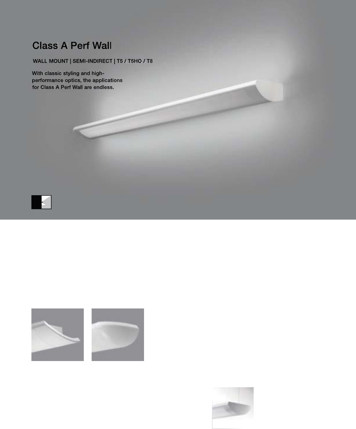
114
AW-SP with standard flat end plates
Rounded End Cap (ER)Tapered End Cap (ET)
Class A Perf
Suspended
(pages 38-39)
• Standard Flat or Optional Tapered or
Rounded end caps

115
2-7/8" [73MM]
6-1/2" [165MM]
S
ERIE
S
A
W=
C
lass A Perf Wal
l
O
PTI
CS
UP
S=S
p
ecular
O
PTI
CS
D
O
WN
P=Perforate
d
N
U
MBER
O
F LAMP
S
1=1
L
amp
2
=2 Lamp
s
LAMP TYPE
N5=T5 Normal
O
utput
T5=T5 High
O
utpu
t
T8=T8 Normal Output
N
U
MBER
O
F
C
IR
CU
IT
S*
1=1
C
ircui
t
2
=2
C
ircuits
WIRIN
G
*
C
=
S
tandard
C
ircuit
D
=
Di
mm
i
ng
E=Emergency
B=Batter
y
Pack
T
=
Nigh
t
ligh
t
Y
=
D
ay
ligh
t
V
O
LTA
G
E*
12
0
=12
0V
277
=
277V
347=347
V
U
NV=Universal (120V-277V)
MO
UNTIN
G
S
U-WA=
S
urface Wall Mount
RUN LEN
G
TH
Specify luminaire length in feet.
-Individuall
y
Mounted
L
um
i
na
i
res may
b
e 4
’
,8
’
, or 12
’
i
n
l
en
g
t
h
.
-
C
ontinuously Mounted
S
tandard row configurations over 12’ consist of 8’ and 12’ sections
.
O
PTI
O
N
S
ET=Tapered End
C
a
p
ER=Rounded End Cap
PROJECT NAME: TYPE:
CATALOG #:
-
-
-
-
-
-
-
-
t
echnical information.
S
pecifications and dimensions subject to change without notice.
ORDERING INFORMATION:
SAMPLE NUMBER:AW-SP-2T8-1C-UNV-SU-WA-12’-ET
WALL CLASS A PERF
Construction: Housin
g
is one piece die-formed
c
old rolled steel, formin
g
a 6”x2-7
/
8”
a
rchitectural profile. Perforated section is 23%
o
pen with 0.0625” staggered hole pattern and
op
al diffuser. Standard 4’-0”, 8’-0”, and 12’-0”
f
ixture len
g
ths combine
f
or continuous runs.
Reflectors: Die-formed reflectors are highly
s
p
ecular anodized aluminum
.
Electrical: T5/T5HO fixtures are
p
re-wired with
quick wire connectors and use UL listed
C
lass P,
T5
/
T5H
O
program rapid start universal voltage
e
lectronic ballasts,
p
ower factor of 97% with
l
ess than 10% THD. T8
f
ixtures are
p
re-wired
wi
t
h
qu
i
c
k
w
i
re connectors an
d
use
UL
li
ste
d
C
lass P, 265ma T8 instant start universal voltage
e
lectronic ballasts, power factor of 95% with
less
th
a
n 1
0%
THD. Fixt
u
r
es
a
n
d
e
l
ec
tri
ca
l
c
om
p
onents certified to UL and CUL standards.
M
ount
i
n
g
:
Fi
xture mounts
di
rect
l
y to ex
i
st
i
n
g
structure over a 2”x4” standard electrical box
m
ounted horizontall
y
into the wall.
Fi
n
i
s
h
:
Fi
xture
h
ous
i
ngs are stan
d
ar
d
w
hi
te
u
sing electrostatically applied polyester powder
c
oat
p
aint.
End Plates:
S
tandard laser cut 14-
g
au
g
e cold
r
o
ll
e
d
stee
l
, mec
h
an
i
ca
ll
y attac
h
e
d
w
i
t
h
no
e
xposed fasteners. Optional die cast aluminum
e
nd ca
p
s also available.
Dimensions do not include
end plates or caps
96”48” 144”
WALL
116
AW-SN with standard flat end plates
Rounded End Cap (ER)Tapered End Cap (ET)
Class A Indirect
Suspended
(pages 42-43)
• Standard Flat or Optional Tapered or
Rounded end caps

117
2-7/8" [73MM]
6-1/2" [165MM]
S
ERIE
S
A
W=
C
lass A Indirect Wall
O
PTI
CS
UP
S
=
S
pecular
O
PTI
CS
D
O
WN
N
=
N
on
e
N
U
MBER
O
F LAMP
S
1=1
L
am
p
2
=2
L
amp
s
LAMP TYPE
N5=T5 Normal Out
p
ut
T5=T5 Hi
g
h
O
utpu
t
T8=T8 Normal
O
utput
N
U
MBER
O
F
C
IR
CU
IT
S*
1=1
C
ir
cu
i
t
2
=2
C
ircuits
WIRIN
G
*
C
=
S
t
a
n
da
r
d
C
ir
cu
it
D
=
Di
mm
i
n
g
E
=
E
mergency
B=Battery Pack
T=Nightlight
Y
=
D
ay
ligh
t
V
O
LTA
G
E*
12
0
=12
0
V
277
=
277V
347=347
V
UNV
=
U
n
i
versa
l
(
120
V
-277
V)
MOU
NTIN
G
S
U-WA=
S
urface Wall Mount
RUN LEN
G
TH
S
pecify luminaire length in feet.
-Individually Mounted
Luminaires may be 4’,8’, or 12’ in length.
-
C
ontinuousl
y
Mounted
S
tandard row confi
g
urations over 12’ consist of 8’ and 12’ sections
.
O
PTI
O
N
S
ET=Tapered End
C
a
p
ER=Rounded End
C
ap
PROJECT NAME: TYPE:
CATALOG #:
-
-
-
-
-
-
-
-
t
echnical information.
S
pecifications and dimensions subject to change without notice.
ORDERING INFORMATION:
SAMPLE NUMBER:AW-SN-2T8-1C-UNV-SU-WA-12’-ET
WALL CLASS A INDIRECT
Construction: Housin
g
is one piece die-formed
c
old rolled steel, formin
g
a 6”x2-7
/
8”
a
rchitectural profile.
S
tandard 4’-0”, 8’-0”,
a
nd 12’-0” fixture lengths combine for
co
ntin
uous
r
u
n
s
.
Reflectors: Die-formed reflectors are hi
g
hly
specular anodized aluminum
.
Electrical: T5/T5HO fixtures are
p
re-wired with
q
uick wire connectors and use UL listed Class P,
T5
/
T5H
O
pro
g
ram rapid start universal volta
g
e
e
lectronic ballasts, power factor of 97% with
l
ess than 10% THD. T8 fixtures are
p
re-wired
w
ith
q
uick wire connectors and use UL listed
C
lass P, 265ma T8 instant start universal volta
g
e
e
lectronic ballasts, power factor of 95% with
l
ess than 10% THD. Fixtures and electrical
c
om
p
onents certified to UL and CUL standards.
M
ount
i
n
g
:
Fi
xture mounts
di
rect
l
y to ex
i
st
i
n
g
structure over a 2
”
x4
”
stan
d
ar
d
e
l
ectr
i
ca
l
b
ox
m
ounted horizontally into the wall.
Fi
n
i
s
h
:
Fi
xture
h
ous
i
n
g
s are stan
d
ar
d
w
hi
te
u
s
i
ng e
l
ectrostat
i
ca
ll
y app
li
e
d
po
l
yester pow
d
er
c
oat paint.
End Plates: Standard laser cut 14-
g
au
g
e cold
r
o
ll
e
d
stee
l
, mec
h
an
i
ca
ll
y attac
h
e
d
w
i
t
h
no
e
xposed fasteners.
O
ptional die cast aluminum
e
nd caps also available.
Dimensions do not include
end plates or caps
96”48” 144”
WALL
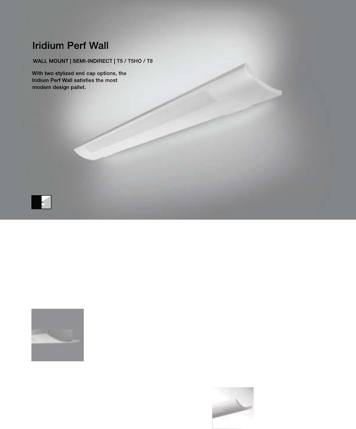
118
• Standard Straight or optional Beveled end caps
IW-SP with standard Straight end caps (ES)
Beveled End Cap (EB)
Iridium Perf
Suspended
(pages 58-59)

119
2-1/2" [63MM]
7" [178MM]
S
ERIE
S
IW
=
I
r
idi
um
W
a
ll
O
PTI
CS
U
P
S
=
S
pecular
O
PTI
CS
D
O
WN
P=P
e
r
fo
r
a
t
ed
NUMBER OF LAMPS
1=1 Lam
p
2
=2
L
am
ps
LAMP TYPE
N5=T5 Normal Out
p
ut
T5=T5 Hi
g
h Outpu
t
T8=T8 Normal
O
utput
NUMBER OF CIRCUITS
*
1=1
C
ir
cu
i
t
2
=2
C
ir
cu
it
s
WIRIN
G
*
C
=
S
t
a
n
da
r
d
C
ir
cu
it
D
=
Di
mm
i
n
g
E
=
E
mer
g
ency
B
=
B
attery
P
ac
k
T=Nightlight
Y=Daylight
V
O
LTA
G
E*
120=120V
2
77=277V
3
47=
3
47
V
UNV
=
U
n
i
versa
l
(
120
V
-277
V)
MOU
NTIN
G
SU
-WA=
Su
rf
ace
W
a
ll M
ou
nt
R
U
N LEN
G
TH
Specify luminaire len
g
th in feet.
-
I
n
di
v
id
ua
ll
y
M
ounte
d
L
um
i
na
i
res may
b
e 4
’
or 8
’
i
n
l
engt
h
.
-Continuously Mounted
Standard row configurations over 8’ consist of 4’ and 8’ sections
.
O
PTI
O
N
S
ES=Straight End Cap (provided if none specified)
EB=Beveled End Ca
p
PROJECT NAME: TYPE:
CATALOG #:
-
-
-
-
-
-
-
-
t
echnical information.
S
pecifications and dimensions subject to change without notice.
ORDERING INFORMATION:
SAMPLE NUMBER:IW-SP-2T8-1C-UNV-SU-WA-8’-ES
WALL IRIDIUM PERF
Construction: Housin
g
is one piece die-formed
c
old rolled steel, formin
g
a 6-1
/
2”x2-1
/
2”
a
rchitectural profile.
S
tandard 4’-0” and 8’-0”
f
ixture lengths combine for continuous runs.
Re
f
lectors: Die-
f
ormed re
f
lectors are hi
g
hly
specu
l
ar ano
di
ze
d
a
l
um
i
num
.
Electrical: T5/T5HO fixtures are pre-wired with
q
uick wire connectors and use UL listed Class P,
T5/T5HO pro
g
ram rapid start universal volta
g
e
e
lectronic ballasts, power factor of 97% with
l
ess than 10% THD. T8 fixtures are pre-wired
w
ith
q
uick wire connectors and use UL listed
Class P, 265ma T8 instant start universal volta
g
e
e
lectronic ballasts, power
f
actor o
f
95% with
l
ess t
h
an 10%
THD
.
Fi
xtures an
d
e
l
ectr
i
ca
l
c
omponents certified to UL and CUL standards.
M
ounting: Fixture mounts directly to existing
s
tr
uc
t
u
r
e
o
v
e
r
a
2
”
x4
”
s
t
a
n
da
r
d
elec
tr
ical
bo
x
m
ounte
d
h
or
i
zonta
ll
y
i
nto t
h
e wa
ll
.
Finish: Fixture housings are standard white
u
s
i
n
g
e
l
ectrostat
i
ca
ll
y app
li
e
d
po
l
yester pow
d
er
c
oat pa
i
nt.
End caps: End caps are precision die-cast
a
luminum,mechanicall
y
attached without
e
x
p
osed
f
asteners
.
Dimensions do not include
end plates or caps
96”48”
WALL

Stellar Suspended
(pages 70-71)
Stellar Surface
(pages 150-151)
70% Downlight Kit
(DL70)
100% Downlight Kit
(DL100)
120
• 100% or 70% Downlight Kits
SW-WB with standard flat end plates
121
3-1/4" [83MM]
6-1/2" [165MM]
S
ERIE
S
S
W=
S
tellar Wal
l
OPTICS UP
W=Whit
e
O
PTI
CS
D
O
WN
B=Baffle
NUMBER
O
F LAMP
S
1=1
L
amp
(N
5,
T
5,
T
8
)
2
=2 Lamps (N5, T5
)
LAMP TYPE
N5=T5 Normal
O
utput
T5=T5 High
O
utpu
t
T8=T8 Normal Out
p
ut
NUMBER
O
F
C
IR
C
UIT
S*
1=1
C
ircui
t
2
=2 Circuits
WIRIN
G
*
C
=
S
tandard
C
ircuit
D=Dimming
E=Emergency
B
=
B
atter
y
P
ac
k
T
=
Nigh
t
ligh
t
Y
=
D
ay
li
g
h
t
V
O
LTA
G
E*
12
0
=12
0V
2
77=277
V
347=347V
U
NV=Universal (120V-277V)
MO
UNTIN
G
SU-WA=Surface Wall Mount
R
U
N LEN
G
TH
Specify luminaire len
g
th in feet.
-
I
n
di
v
id
ua
ll
y
M
ounte
d
L
um
i
na
i
res may
b
e 4
’
,8
’
, or 12
’
i
n
l
engt
h
.
-Continuously Mounted
Standard row configurations over 12’ consist of 8’ and 12’ sections
.
O
PTI
O
N
S
DL100=100% Downlight Kit
DL
70=70%
D
own
ligh
t
Ki
t
PROJECT NAME: TYPE:
CATALOG #:
-
-
-
-
-
-
-
-
t
echnical information.
S
pecifications and dimensions subject to change without notice.
ORDERING INFORMATION:
SAMPLE NUMBER:SW-WB-1T8-1C-UNV-SU-WA-12’-DL70
WALL STELLAR
Co
n
s
tr
uc
ti
o
n: Di
e
-f
o
rm
ed
a
ll
a
l
u
min
u
m
ba
ffl
e
a
ssem
bl
y
(
2
”
bl
a
d
e spac
i
n
g)
mec
h
an
i
ca
ll
y
a
ttached to a corrosion resistant formed steel
b
allast channel. Perforated side rail sections are
2
3% open with 0.0625” stagger hole spacing.
Standard 4’-0”, 8’-0”, and 12’-0” fixture len
g
ths
c
ombine for continuous runs.
Electrical: T5
/
T5H
O
fixtures are
p
re-wired with
quick wire connectors and use UL listed
C
lass P,
T5/T5HO program rapid start universal voltage
e
lectronic ballasts,
p
ower
f
actor o
f
97% with
l
ess than 10% THD. T8
f
ixtures are
p
re-wired
wi
t
h
qu
i
c
k
w
i
re connectors an
d
use
UL
li
ste
d
C
lass P, 265ma T8 instant start universal voltage
e
lectronic ballasts,
p
ower factor of 95% with
less
th
a
n 1
0%
THD. Fixt
u
r
es
a
n
d
e
l
ec
tri
ca
l
c
omponents certified to UL and
C
UL standards.
M
ount
i
ng:
Fi
xture mounts
di
rect
l
y to ex
i
st
i
ng
structure over a 2”x4” standard electrical box
m
ounted horizontall
y
into the wall. Field
a
d
j
ustable brackets
(
+
/
-3°
)
allow for perfect
c
ont
i
nuous a
lig
nment
.
Finish: Fixture housings are standard white
u
s
i
n
g
e
l
ectrostat
i
ca
ll
y app
li
e
d
po
l
yester pow
d
er
c
oat paint.
C
onsult factory for custom finishes
.
End Plates: End plates are laser cut 14-gauge
co
l
d
r
o
ll
ed
s
t
ee
l.
Dimensions do not include
end plates or caps
96”48” 144”
WALL
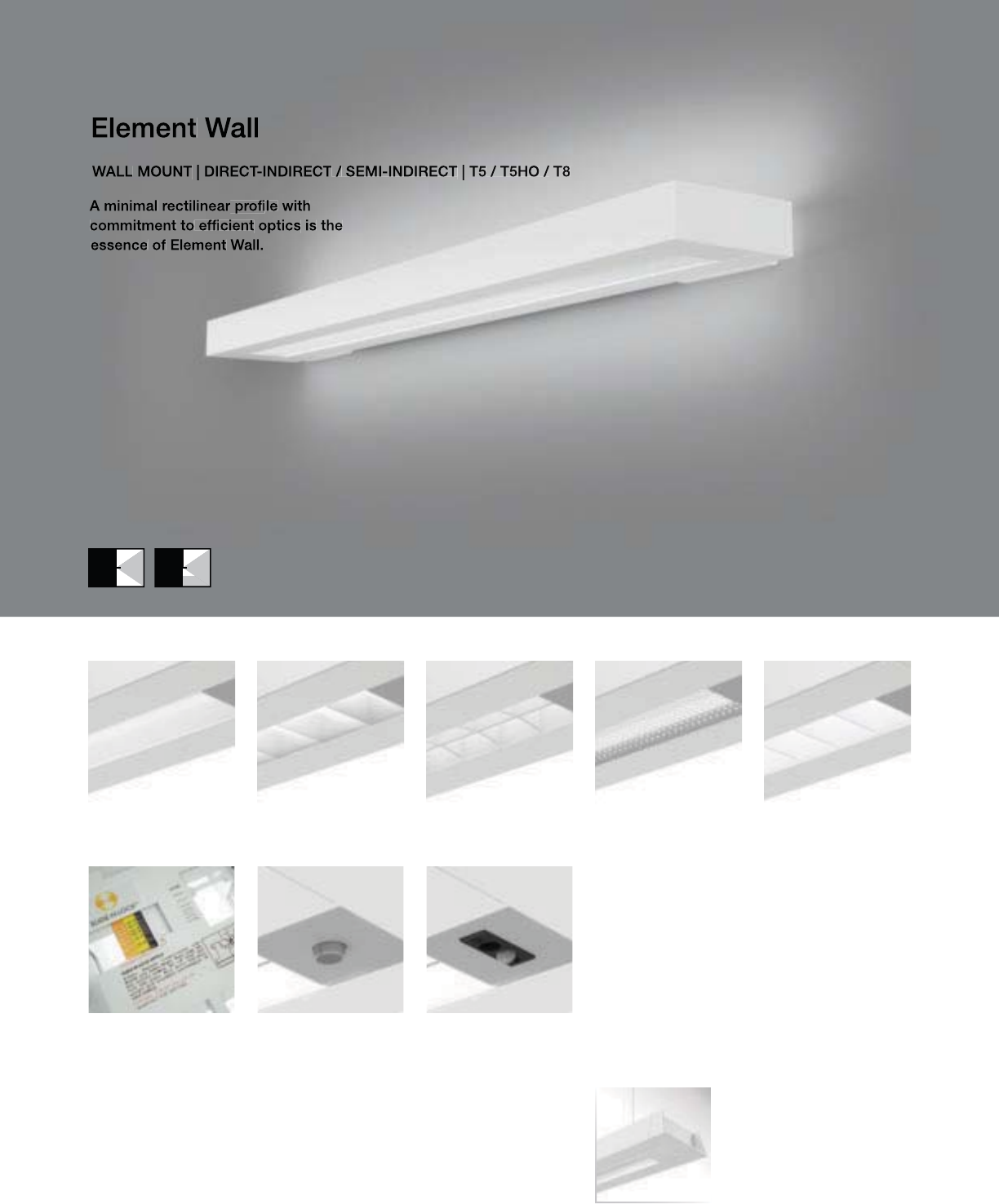
E2W-WM with standard die-cast end caps
122
• Five downlight media options
• RPerformance™ Louver meets RP1 requirements
• Slide-N-Lock™ optics with 8 field-adjustable settings
• Day-Sense integral daylight sensor and 2Sense integral
daylight/occupancy sensor
Element Suspended
(pages 82-83)
2Sense
(pages 171)
Day-Sense
(pages 170)
Slide-N-Lock™
(pages 98-99)
Concave Metallic
Perf (E2W-WC)
RPerformance™
Louver (E2W-WH)
Micro Prismatic
Lens (E2W-WM)
Cross Blade Parabolic
Louver (E2W-WB)
High Efficiency
Louver (E2W-WW)

123
2-1/2" [64MM]
7-1/8" [181MM]
S
ERIE
S
E
2
W
=
El
ement
W
a
ll
O
PTI
CS
U
P
W
=
Whi
te
S
=
S
pecular
O
PTI
CS
D
O
WN
B=
C
ross Blade Parabolic Louver
C=Concave Metallic Perf
H=RP
e
r
fo
rm
a
n
ce
™ L
ou
v
e
r
M
=
Mic
r
o
P
r
is
m
a
t
ic
Le
n
s
W=Hi
g
h Efficiency Louve
r
N
U
MBER
O
F LAMP
S
1=1 Lam
p
2
=2
L
amp
s
LAMP TYPE
N5=T5 Normal Out
p
ut
T5=T5 Hi
g
h Outpu
t
T8=T8 Normal
O
utput
N
U
MBER
O
F
C
IR
CU
IT
S*
1=1
C
ir
cu
i
t
2
=2
C
ircuits
WIRING*
C
=
S
t
a
n
da
r
d
C
ir
cu
it
D
=
Di
mm
i
n
g
E
=
E
mer
g
ency
B=Battery Pack
T=Nightlight
Y
=
D
ay
ligh
t
V
O
LTA
G
E*
120=120V
277
=
277V
3
47=
3
47
V
UNV
=
U
n
i
versa
l
(
120
V
-277
V)
MOU
NTIN
G
SU
-WA=
Su
rf
ace
W
a
ll M
ou
nt
RUN LENGTH
Specify luminaire length in feet.
-
I
n
di
v
id
ua
lly
M
ounte
d
L
um
i
na
i
res may
b
e 4
’
or 8
’
i
n
l
en
g
t
h
.
-
C
ontinuously Mounted
Standard row configurations over 8’ consist of 4’ and 8’ sections
.
O
PTI
O
N
S
Slide-N-Lock™ (pg. 98-99)
DL1=95% Downlight DL5=75% Downligh
t
DL
2=90%
D
own
ligh
t
DL
6=70%
D
own
light
DL
3=85%
D
own
ligh
t
DL
7=65%
D
own
light
DL4=80% Downlight DL8=60% Downligh
t
DS=Day-Sense Inte
g
ral Dayli
g
ht Sensor
2S
=2
S
ense Inte
g
ral Dayli
g
ht
/O
ccupancy
S
ensor
PROJECT NAME: TYPE:
CATALOG #:
-
-
-
-
-
-
-
-
t
echnical information.
S
pecifications and dimensions subject to change without notice.
ORDERING INFORMATION:
SAMPLE NUMBER:E2W-WM-1T5-1C-UNV-SU-WA-8’-DL8
WALL ELEMENT
Construction: Housin
g
is 6063 T5 aluminum
e
xtrusion formin
g
a 6-5
/
8” x 2-1
/
2” rectan
g
ular
p
rofile.
S
tandard 4’-0” and 8’-0” fixture lengths
c
ombine for continuous runs.
Re
f
lectors: Re
f
lector pan is painted with a hi
g
h
r
eflectance white powder coat finish with one
die-formed highly specular anodized aluminum
s
i
de
r
e
fl
ec
t
o
r
.
L
ens:
L
ens
i
s .125
”
t
hi
c
k
c
l
ear m
i
cro-
p
r
i
smat
i
c
a
crylic material offering 91% transmission
.
L
ou
v
e
r
s
:
C
r
oss
Bl
ade
a
n
d
RP
e
rf
o
rm
a
n
ce
™
a
r
e
c
ontinuous semi-s
p
ecular aluminum. Per
f
is
semi-specular material, perforated section is
15% open with 0.062” diameter holes and opal
diffuser. High Efficiency is continuous highly
r
e
f
lective
p
ainted white aluminum
.
Electrical: T5
/
T5H
O
fixtures are pre-wired with
quick wire connectors and use UL listed Class P,
T5/T5HO program rapid start universal voltage
e
lectronic ballasts,
p
ower
f
actor o
f
97% with
l
ess than 10% THD. T8 fixtures are pre-wired
w
ith quick wire connectors and use UL listed
Class P, 265ma T8 instant start universal voltage
e
lectronic ballasts,
p
ower
f
actor o
f
95% with
l
ess t
h
an 10%
THD
.
Fi
xtures an
d
e
l
ectr
i
ca
l
c
omponents certified to UL and
C
UL standards.
M
ounting: Fixture mounts directly to existing
s
tr
uc
t
u
r
e
o
v
e
r
a
2”x4”
s
t
a
n
da
r
d
e
l
ec
tri
ca
l
bo
x
m
ounte
d
h
or
i
zonta
lly
i
nto t
h
e wa
ll
.
Fi
n
i
s
h
:
Fi
xture
h
ous
i
ngs are stan
d
ar
d
w
hi
te
u
sing electrostatically applied polyester powder
c
oat
p
aint.
End
C
aps:
S
tandard end caps are precision
di
e-cast a
l
um
i
num, mec
h
an
i
ca
ll
y attac
h
e
d
w
ithout exposed fasteners
.
Dimensions do not include
end plates or caps
96”48”
WALL
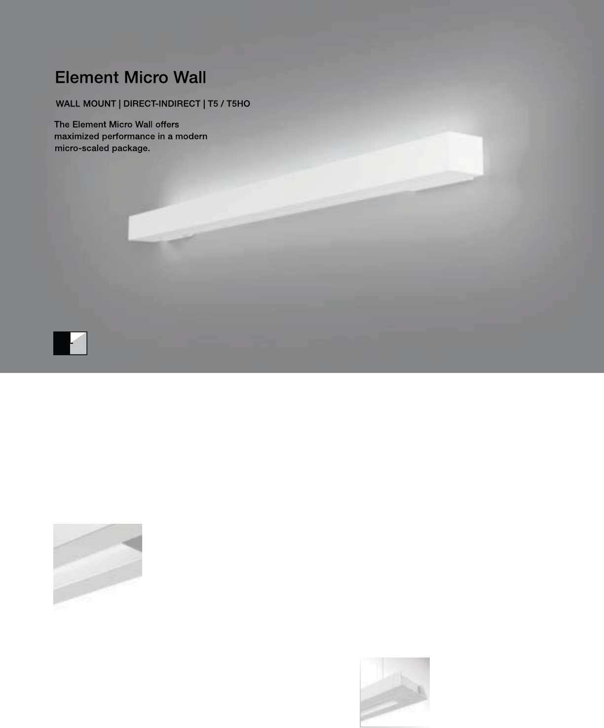
E1W-SM with standard die-cast end caps
124
• Highly efficient micro prismatic lens
• ADA compliant
Element Micro
Suspended
(pages 84-85)
Micro Prismatic
Lens (E1W-WM)
125
S
ERIE
S
E
1
W
=
El
ement
Mi
cro
W
a
ll
O
PTI
CS
U
P
S
=
S
pecular
O
PTI
CS
D
O
WN
M
=
Mi
cro
P
r
i
smat
i
c
L
en
s
N
U
MBER
O
F LAMP
S
1=1
L
amp
LAMP TYPE
N5=T5 Normal Out
p
ut
T5=T5 Hi
g
h
O
utpu
t
NUMBER OF CIRCUITS
*
1=1
C
ir
cu
i
t
2
=2
C
ir
cu
it
s
WIRIN
G
*
C
=
S
t
a
n
da
r
d
C
ir
cu
it
D
=
Di
mm
i
n
g
E
=
E
mer
g
ency
B
=
B
attery
P
ac
k
T=Nightlight
Y=Daylight
V
O
LTA
G
E*
120=120V
2
77=277V
3
47=
3
47
V
UNV
=
U
n
i
versa
l
(
120
V
-277
V)
M
OUNTING
SU
-WA=
Su
rf
ace
W
a
ll M
ou
nt
RUN LEN
G
TH
Specify luminaire length in feet.
-
I
n
di
v
id
ua
lly
M
ounte
d
L
um
i
na
i
res may
b
e 4
’
or 8
’
i
n
l
en
g
t
h
.
-
C
ontinuously Mounted
Standard row configurations over 8’ consist of 4’ and 8’ sections
.
PROJECT NAME: TYPE:
CATALOG #:
-
-
-
-
-
-
-
-
t
echnical information.
S
pecifications and dimensions subject to change without notice.
ORDERING INFORMATION:
SAMPLE NUMBER:E1W-SM-1T5-1C-UNV-SU-WA-8’-DL8
WALL ELEMENT MICRO
Construction: Housin
g
is 6063 T5 aluminum
e
xtrusion formin
g
a 3-1
/
4” x 2-1
/
2” rectan
g
ular
p
rofile.
S
tandard 4’-0” and 8’-0” fixture lengths
c
ombine for continuous runs.
Re
f
lectors: Re
f
lector pan is painted with a hi
g
h
r
eflectance white powder coat finish with one
die-formed highly specular anodized aluminum
s
i
de
r
e
fl
ec
t
o
r
.
L
ens:
L
ens
i
s .125
”
t
hi
c
k
c
l
ear m
i
cro-
p
r
i
smat
i
c
a
crylic material offering 91% transmission
.
Electrical: T5/T5HO fixtures are
p
re-wired with
q
uick wire connectors and use UL listed Class P,
T5
/
T5H
O
pro
g
ram rapid start universal volta
g
e
e
lectronic ballasts, power factor of 97% with
less
th
a
n 1
0%
THD.
M
ount
i
n
g
:
Fi
xture mounts
di
rect
l
y to ex
i
st
i
n
g
structure over a 2
”
x4
”
stan
d
ar
d
e
l
ectr
i
ca
l
b
ox
m
ounte
d
h
or
i
zonta
ll
y
i
nto t
h
e wa
ll
.
Finish: Fixture housings are standard white
u
s
i
n
g
e
l
ectrostat
i
ca
ll
y app
li
e
d
po
l
yester pow
d
er
c
oat pa
i
nt.
End Caps: Standard end caps are precision
die-cast aluminum, mechanicall
y
attached
w
ithout ex
p
osed
f
asteners
.
Dimensions do not include
end plates or caps
96”48”
2-1/2" [64MM]
3-3/4"
[95MM]
WALL
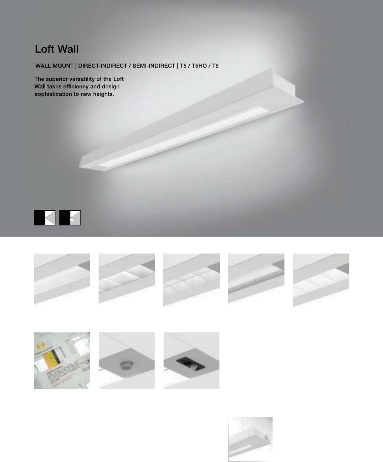
126
L2W-WM with standard die-cast end caps
• Five downlight media options
• RPerformance™ Louver meets RP1 requirements
• Slide-N-Lock™ optics with 8 field-adjustable settings
• Day-Sense integral daylight sensor and 2Sense integral
daylight/occupancy sensor
Loft Suspended
(pages 86-87)
Concave Metallic
Perf (L2W-WC)
RPerformance™
Louver (L2W-WH)
Micro Prismatic
Lens (L2W-WM)
Cross Blade Parabolic
Louver (L2W-WB)
High Efficiency
Louver (L2W-WW)
2Sense
(pages 171)
Day-Sense
(pages 170)
Slide-N-Lock™
(pages 98-99)
127
2-1/2" [64MM]
7-3/8" [187MM]
S
ERIE
S
L2W=Lo
f
t Wal
l
O
PTI
CS
U
P
W
=
Whi
te
S
=
S
pecular
O
PTI
CS
D
O
WN
B=
C
ross Blade Parabolic Louver
C=Concave Metallic Perf
H=RP
e
r
fo
rm
a
n
ce
™ L
ou
v
e
r
M
=
Mic
r
o
P
r
is
m
a
t
ic
Le
n
s
W=Hi
g
h Efficiency Louve
r
N
U
MBER
O
F LAMP
S
1=1 Lam
p
2
=2
L
amp
s
LAMP TYPE
N5=T5 Normal Out
p
ut
T5=T5 Hi
g
h
O
utpu
t
T8=T8 Normal
O
utput
N
U
MBER
O
F
C
IR
CU
IT
S*
1=1
C
ircui
t
2
=2
C
ircuits
WIRIN
G
*
C
=
S
t
a
n
da
r
d
C
ir
cu
it
D
=
Di
mm
i
n
g
E=Emergency
B=Batter
y
Pack
T
=
Nigh
t
ligh
t
Y
=
D
ay
ligh
t
VOLTAGE*
12
0
=12
0
V
277
=
277V
347=347
V
U
NV=Universal (120V-277V)
MOU
NTIN
G
S
U-WA=
S
urface Wall Mount
R
U
N LEN
G
TH
S
pecify luminaire len
g
th in feet.
-
I
n
di
v
id
ua
ll
y
M
ounte
d
Luminaires may be 4’ or 8’ in length.
-Continuousl
y
Mounted
Standard row confi
g
urations over 8’ consist of 4’ and 8’ sections
.
OPTION
S
Slide-N-Lock™ (pg. 98-99)
DL
1=95%
D
own
ligh
t
DL
5=75%
D
own
light
DL
2=90%
D
own
ligh
t
DL
6=70%
D
own
light
DL3=85% Downlight DL7=65% Downligh
t
DL4=80% Downlight DL8=60% Downligh
t
D
S
=Day-
S
ense Inte
g
ral Dayli
g
ht
S
ensor
2S
=2
S
ense Integral Daylight
/O
ccupancy
S
ensor
PROJECT NAME: TYPE:
CATALOG #:
-
-
-
-
-
-
-
-
t
echnical information.
S
pecifications and dimensions subject to change without notice.
ORDERING INFORMATION:
SAMPLE NUMBER:L2W-WM-1T5-1C-UNV-SU-WA-8’-DL8
WALL LOFT
Construction: Housin
g
is 6063 T5 aluminum
e
xtrusion formin
g
a 6-7
/
8” x 2-1
/
2” an
g
le
d
p
rofile.
S
tandard 4’-0” and 8’-0” fixture lengths
c
ombine for continuous runs.
Re
f
lectors: Re
f
lector pan is painted with a hi
g
h
r
eflectance white powder coat finish with one
die-formed highly specular anodized aluminum
s
i
de
r
e
fl
ec
t
o
r
.
L
ens:
L
ens
i
s .125
”
t
hi
c
k
c
l
ear m
i
cro-
p
r
i
smat
i
c
a
crylic material offering 91% transmission
.
L
ou
v
e
r
s
:
C
r
oss
Bl
ade
a
n
d
RP
e
rf
o
rm
a
n
ce
™
a
r
e
c
ontinuous semi-s
p
ecular aluminum. Per
f
is
semi-specular material, perforated section is
15% open with 0.062” diameter holes and opal
diffuser. High Efficiency is continuous highly
r
e
f
lective
p
ainted white aluminum
.
Electrical: T5/T5HO fixtures are pre-wired with
q
uick wire connectors and use UL listed Class P,
T5/T5HO pro
g
ram rapid start universal volta
g
e
e
lectronic ballasts, power factor of 97% with
l
ess than 10% THD. T8 fixtures are pre-wired
w
ith
q
uick wire connectors and use UL listed
Class P, 265ma T8 instant start universal volta
g
e
e
lectronic ballasts, power
f
actor o
f
95% with
l
ess t
h
an 10%
THD
.
Fi
xtures an
d
e
l
ectr
i
ca
l
c
omponents certified to UL and CUL standards.
M
ounting: Fixture mounts directly to existing
s
tr
uc
t
u
r
e
o
v
e
r
a
2
”
x4
”
s
t
a
n
da
r
d
elec
tr
ical
bo
x
m
ounte
d
h
or
i
zonta
ll
y
i
nto t
h
e wa
ll
.
Finish: Fixture housings are standard white
u
sing electrostatically applied polyester powder
c
oat
p
a
i
nt.
End
C
aps:
S
tandard end caps are precision
die-cast aluminum, mechanically attached
w
ithout ex
p
osed
f
asteners
.
Dimensions do not include
end plates or caps
96”48”
WALL

128
L1W-SM with standard die-cast end caps
• Highly efficient micro prismatic lens
• ADA compliant
Loft Micro
Suspended
(pages 88-89)
Micro Prismatic
Lens (E1W-WM)

129
2-1/2" [64MM]
4" [102MM]
S
ERIE
S
L1W=Lo
f
t Micro Wal
l
O
PTI
CS
U
P
S
=
S
pecular
O
PTI
CS
D
O
WN
M
=
Mi
cro
P
r
i
smat
i
c
L
en
s
N
U
MBER
O
F LAMP
S
1=1
L
amp
LAMP TYPE
N5=T5 Normal Out
p
ut
T5=T5 Hi
g
h
O
utpu
t
NUMBER OF CIRCUITS
*
1=1
C
ir
cu
i
t
2
=2
C
ir
cu
it
s
WIRIN
G
*
C
=
S
t
a
n
da
r
d
C
ir
cu
it
D
=
Di
mm
i
n
g
E
=
E
mer
g
ency
B
=
B
attery
P
ac
k
T=Nightlight
Y=Daylight
V
O
LTA
G
E*
120=120V
2
77=277V
3
47=
3
47
V
UNV
=
U
n
i
versa
l
(
120
V
-277
V)
M
OUNTING
SU
-WA=
Su
rf
ace
W
a
ll M
ou
nt
RUN LEN
G
TH
Specify luminaire length in feet.
-
I
n
di
v
id
ua
lly
M
ounte
d
L
um
i
na
i
res may
b
e 4
’
or 8
’
i
n
l
en
g
t
h
.
-
C
ontinuously Mounted
Standard row configurations over 8’ consist of 4’ and 8’ sections
.
PROJECT NAME: TYPE:
CATALOG #:
-
-
-
-
-
-
-
-
t
echnical information.
S
pecifications and dimensions subject to change without notice.
ORDERING INFORMATION:
SAMPLE NUMBER:L1W-SM-1T5-1C-UNV-SU-WA-8’-DL8
WALL LOFT MICRO
Construction: Housin
g
is 6063 T5 aluminum
e
xtrusion formin
g
a 3-1
/
2” x 2-1
/
2” an
g
led pro-
f
ile.
S
tandard 4’-0” and 8’-0” fixture lengths
c
ombine for continuous runs.
Re
f
lectors: Re
f
lector pan is painted with a hi
g
h
r
eflectance white powder coat finish with one
die-formed highly specular anodized aluminum
s
i
de
r
e
fl
ec
t
o
r
.
L
ens:
L
ens
i
s .125
”
t
hi
c
k
c
l
ear m
i
cro-
p
r
i
smat
i
c
a
crylic material offering 91% transmission
.
Electrical: T5/T5HO fixtures are
p
re-wired with
q
uick wire connectors and use UL listed Class P,
T5
/
T5H
O
pro
g
ram rapid start universal volta
g
e
e
lectronic ballasts, power factor of 97% with
less
th
a
n 1
0%
THD. Fixt
u
r
es
a
n
d
e
l
ec
tri
ca
l
c
om
p
onents certified to UL and CUL standards.
M
ounting: Fixture mounts directly to existing
s
tr
uc
t
u
r
e
o
v
e
r
a
2
”
x4
”
s
t
a
n
da
r
d
elec
tr
ical
bo
x
m
ounte
d
h
or
i
zonta
ll
y
i
nto t
h
e wa
ll
.
Finish: Fixture housings are standard white
u
s
i
n
g
e
l
ectrostat
i
ca
ll
y app
li
e
d
po
l
yester pow
d
er
c
oat pa
i
nt.
End
C
aps:
S
tandard end caps are precision
die-cast aluminum, mechanicall
y
attached
w
ithout ex
p
osed
f
asteners
.
Dimensions do not include
end plates or caps
96”48”
WALL
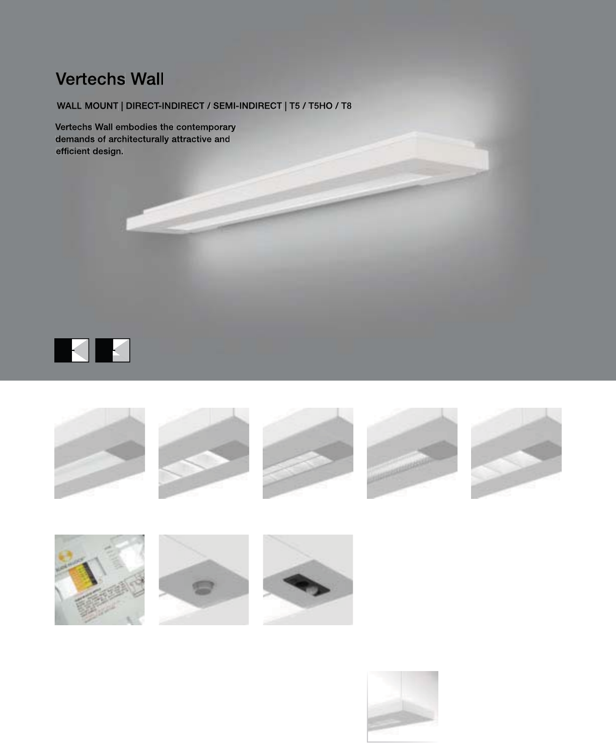
130
• Five downlight media options
• RPerformance™ Louver meets RP1 requirements
• Slide-N-Lock™ optics with 8 field-adjustable settings
• Day-Sense integral daylight sensor and 2Sense integral
daylight/occupancy sensor
VW-SM with standard die-cast end caps
Vertechs
Suspended
(pages 90-91)
Concave Metallic
Perf (VW-SC)
RPerformance™
Louver (VW-SH)
Micro Prismatic Lens
(VW-SM)
Cross Blade Parabolic
Louver (VW-SB)
High Efficiency
Louver (VW-SW)
2Sense
(pages 171)
Day-Sense
(pages 170)
Slide-N-Lock™
(pages 98-99)
131
2-1/2" [64MM]
8-1/4" [210MM]
Se
ri
es
VW
=
V
ertec
h
s
W
a
ll
O
PTI
CS
U
P
S=S
p
ecular
O
PTI
CS
D
O
WN
B=
C
ross Blade Parabolic Louve
r
C
=
C
oncave Metallic Perf
H=RPerformance™ Louver
M
=Mi
c
r
o
Pri
s
m
a
ti
c
L
e
n
s
W=Hi
g
h E
ff
iciency Louve
r
N
U
MBER
O
F LAMP
S
1=1 Lam
p
2
=2
L
amp
s
LAMP TYPE
N5=T5 Normal Out
p
ut
T5=T5 Hi
g
h Outpu
t
T8=T8 Normal
O
utput
N
U
MBER
O
F
C
IR
CU
IT
S*
1=1
C
ir
cu
i
t
2
=2
C
ircuits
WIRING*
C
=
S
t
a
n
da
r
d
C
ir
cu
it
D
=
Di
mm
i
n
g
E
=
E
mer
g
ency
B=Battery Pack
T=Nightlight
Y
=
D
ay
ligh
t
V
O
LTA
G
E*
120=120V
277
=
277V
3
47=
3
47
V
UNV
=
U
n
i
versa
l
(
120
V
-277
V)
MOU
NTIN
G
S
U-WA=
S
urface Wall Mount
R
U
N LEN
G
TH
S
pecify luminaire len
g
th in feet.
-Individually Mounted
Luminaires may be 4’ or 8’ in length.
-Continuousl
y
Mounted
S
tandard row confi
g
urations over 8’ consist of 4’ and 8’ sections
.
O
PTI
O
N
S
Slide-N-Lock™
(
p
g
. 98-99
)
DL
1=95%
D
own
ligh
t
DL
5=75%
D
own
light
DL2=90% Downlight DL6=70% Downligh
t
DL3=85% Downlight DL7=65% Downligh
t
DL
4=80%
D
own
ligh
t
DL
8=60%
D
own
light
D
S
=Day-
S
ense Integral Daylight
S
ensor
2
S=2Sense Integral Daylight/Occupancy Sensor
PROJECT NAME: TYPE:
CATALOG #:
-
-
-
-
-
-
-
-
t
echnical information.
S
pecifications and dimensions subject to change without notice.
ORDERING INFORMATION:
SAMPLE NUMBER:VW-SB-2T8-1C-UNV-SU-WA-8’-DL5
WALL VERTECHS
Construction: Housin
g
is 6063 T5 aluminum
e
xtrusion formin
g
a 7-3
/
4” x 2-1
/
2” rectan
g
ular
p
rofile.
S
tandard 4’-0” and 8’-0” fixture lengths
c
ombine for continuous runs.
Re
f
lectors: Re
f
lector pan is painted with a hi
g
h
r
eflectance white powder coat finish with one
die-formed highly specular anodized aluminum
s
i
de
r
e
fl
ec
t
o
r
.
L
ens:
L
ens
i
s .125
”
t
hi
c
k
c
l
ear m
i
cro-
p
r
i
smat
i
c
a
crylic material offering 91% transmission
.
L
ou
v
e
r
s
:
C
r
oss
Bl
ade
a
n
d
RP
e
rf
o
rm
a
n
ce
™
a
r
e
c
ontinuous semi-s
p
ecular aluminum. Per
f
is
semi-specular material, perforated section is
15% open with 0.062” diameter holes and opal
diffuser. High Efficiency is continuous highly
r
e
f
lective
p
ainted white aluminum
.
Electrical: T5/T5HO fixtures are
p
re-wired with
q
uick wire connectors and use UL listed Class P,
T5
/
T5H
O
pro
g
ram rapid start universal volta
g
e
e
lectronic ballasts, power factor of 97% with
l
ess than 10% THD. T8 fixtures are
p
re-wired
wi
t
h
q
u
i
c
k
w
i
re connectors an
d
use
UL
li
ste
d
C
lass P, 265ma T8 instant start universal volta
g
e
e
lectronic ballasts, power factor of 95% with
l
ess than 10% THD. Fixtures and electrical
c
om
p
onents certified to UL and CUL standards.
M
ounting: Fixture mounts directly to existing
s
tr
uc
t
u
r
e
o
v
e
r
a
2
”
x4
”
s
t
a
n
da
r
d
elec
tr
ical
bo
x
m
ounte
d
h
or
i
zonta
ll
y
i
nto t
h
e wa
ll
.
Finish: Fixture housings are standard white
u
s
i
n
g
e
l
ectrostat
i
ca
ll
y app
li
e
d
po
l
yester pow
d
er
c
oat pa
i
nt.
End Caps: Standard end caps are precision
die-cast aluminum, mechanicall
y
attached
w
ithout ex
p
osed
f
asteners
.
Dimensions do not include
end plates or caps
96”48”
WALL
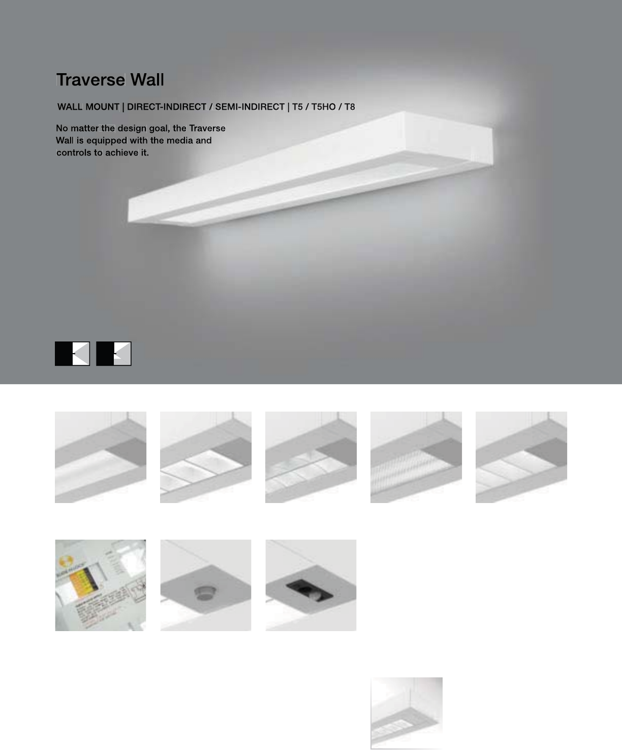
TW-WM with standard die-cast end caps
132
• Five downlight media options
• RPerformance™ Louver meets RP1 requirements
• Slide-N-Lock™ optics with 8 field-adjustable settings
• Day-Sense integral daylight sensor and 2Sense integral
daylight/occupancy sensor
Concave Metallic
Perf (TW-WC)
RPerformance™
Louver (TW-WH)
Micro Prismatic Lens
(TW-WM)
Cross Blade Parabolic
Louver (TW-WB)
High Efficiency
Louver (TW-WW)
Traverse
Suspended
(pages 92-93)
2Sense
(pages 171)
Day-Sense
(pages 170)
Slide-N-Lock™
(pages 98-99)

133
2-7/8" [73MM]
6-7/8" [174MM]
S
ERIE
S
TW
=
T
raverse
W
a
ll
OPTICS UP
S=S
p
ecular
W
=
Whi
t
e
O
PTI
CS
D
O
WN
B=
C
r
oss
Bl
ade
P
a
r
abo
li
c
L
ou
v
e
r
C
=
Co
n
ca
v
e
M
e
t
a
lli
c
P
e
rf
H=RPer
f
ormance™ Louver
M
=
Mi
cro
P
r
i
smat
i
c
L
en
s
W=High Efficiency Louve
r
N
U
MBER
O
F LAMP
S
1=1
L
amp
2
=2 Lamp
s
LAMP TYPE
N5=T5 Normal
O
utput
T5=T5 High
O
utpu
t
T8=T8 Normal Output
N
U
MBER
O
F
C
IR
CU
IT
S*
1=1
C
ircui
t
2
=2
C
ircuits
WIRIN
G
*
C
=
S
tandard
C
ircuit
D
=
Di
mm
i
ng
E=Emergency
B=Batter
y
Pack
T
=
Nigh
t
ligh
t
Y
=
D
ay
ligh
t
V
O
LTA
G
E*
12
0
=12
0V
277
=
277V
347=347
V
U
NV=Universal (120V-277V)
MOU
NTIN
G
S
U-WA=
S
urface Wall Mount
R
U
N LEN
G
TH
S
pecify luminaire len
g
th in feet.
-
I
n
di
v
id
ua
ll
y
M
ounte
d
Luminaires may be 4’ or 8’ in length.
-Continuousl
y
Mounted
S
tandard row confi
g
urations over 8’ consist of 4’ and 8’ sections
.
O
PTI
O
N
S
Slide-N-Lock™
(
p
g
. 98-99
)
DL
1=95%
D
own
ligh
t
DL
5=75%
D
own
light
DL
2=90%
D
own
li
g
h
t
DL
6=70%
D
own
li
g
ht
DL3=85% Downlight DL7=65% Downligh
t
DL4=80% Downlight DL8=60% Downligh
t
D
S
=Day-
S
ense Inte
g
ral Dayli
g
ht
S
ensor
2S
=2
S
ense Integral Daylight
/O
ccupancy
S
ensor
PROJECT NAME: TYPE:
CATALOG #:
-
-
-
-
-
-
-
-
t
echnical information.
S
pecifications and dimensions subject to change without notice.
ORDERING INFORMATION:
SAMPLE NUMBER:TW-WB-1T8-1C-UNV-SU-WA-12’
WALL TRAVERSE
Construction: Housin
g
is 6063 T5 aluminum
e
xtrusion formin
g
a 6-3
/
8”x2-7
/
8” rectan
g
ular
p
rofile.
S
tandard 4’-0” and 8’-0” fixture lengths
c
ombine for continuous runs.
Reflectors: Reflector pan is painted with a high
r
eflectance white
p
owder coat finish. O
p
tional
die-
f
ormed side re
f
lectors are hi
g
hly specular
a
no
di
ze
d
a
l
um
i
num.
L
ens:
L
ens
i
s .125
”
t
hi
c
k
c
l
ear m
i
cro-
p
r
i
smat
i
c
a
crylic material offerin
g
91% transmission
.
L
ou
v
e
r
s
:
C
r
oss
Bl
ade
a
n
d
RP
e
rf
o
rm
a
n
ce
™
a
r
e
c
ontinuous semi-s
p
ecular aluminum. Per
f
is
semi-specular material, per
f
orated section is
15% open w
i
t
h
0.062
”
di
ameter
h
o
l
es an
d
opa
l
diffuser. High Efficiency is continuous highly
r
e
f
lective
p
ainted white aluminum
.
Electrical: T5/T5HO fixtures are
p
re-wired with
q
uick wire connectors and use UL listed Class P,
T5
/
T5H
O
pro
g
ram rapid start universal volta
g
e
e
lectronic ballasts, power factor of 97% with
l
ess than 10% THD. T8 fixtures are pre-wired
w
ith
q
uick wire connectors and use UL listed
C
lass P, 265ma T8 instant start universal volta
g
e
e
lectronic ballasts, power factor of 95% with
l
ess than 10% THD. Fixtures and electrical
c
om
p
onents certified to UL and CUL standards.
M
ounting: Fixture mounts directly to existing
s
tr
uc
t
u
r
e
o
v
e
r
a
2
”
x4
”
s
t
a
n
da
r
d
elec
tr
ical
bo
x
m
ounte
d
h
or
i
zonta
ll
y
i
nto t
h
e wa
ll
.
Finish: Fixture housings are standard white
u
s
i
n
g
e
l
ectrostat
i
ca
ll
y app
li
e
d
po
l
yester pow
d
er
c
oat pa
i
nt.
End
C
aps:
S
tandard end caps are precision
die-cast aluminum, mechanicall
y
attached
w
ithout ex
p
osed
f
asteners
.
Dimensions do not include
end plates or caps
96”48”
WALL
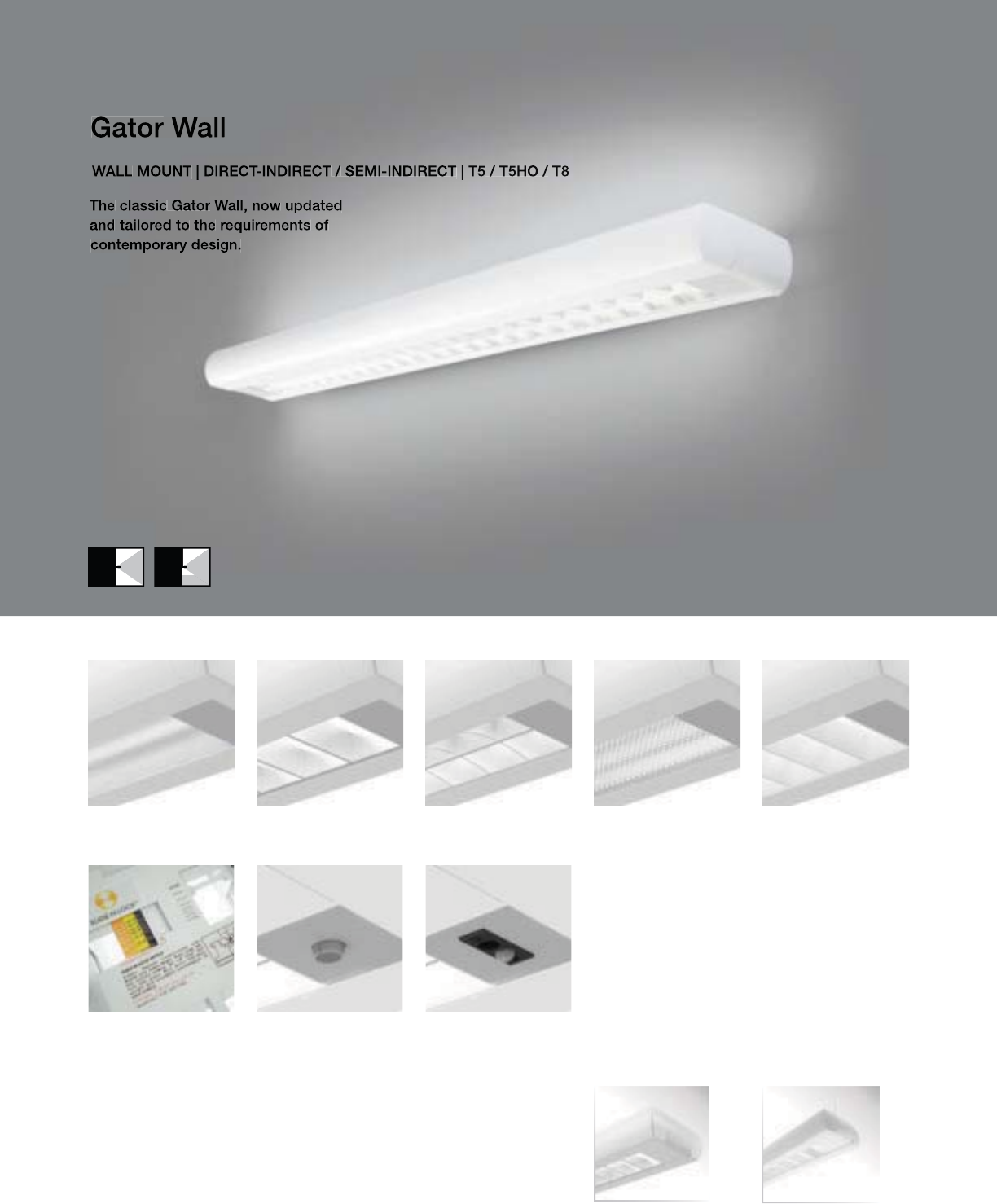
134
GW-WH with standard die-cast end caps
Minigator
Suspended
(pages 96-97)
Concave Metallic
Perf (GW-WC)
RPerformance™
Louver (GW-WH)
Micro Prismatic Lens
(GW-WM)
Cross Blade Parabolic
Louver (GW-WB)
High Efficiency
Louver (GW-WW)
Navigator
Suspended
(pages 94-95)
• Five downlight media options
• RPerformance™ Louver meets RP1 requirements
• Slide-N-Lock™ optics with 8 field-adjustable settings
• Day-Sense integral daylight sensor and 2Sense integral
daylight/occupancy sensor
2Sense
(pages 171)
Day-Sense
(pages 170)
Slide-N-Lock™
(pages 98-99)

135
2-7/8" [73MM]
6-7/8" [174MM]
G
W=
G
ator Wal
l
O
PTI
CS
U
P
S
=
S
pecular
W=White
O
PTI
CS
D
O
WN
B=
C
ross Blade Parabolic Louver
C=Concave Metallic Perf
H=RP
e
r
fo
rm
a
n
ce
™ L
ou
v
e
r
M
=
Mic
r
o
P
r
is
m
a
t
ic
Le
n
s
W=Hi
g
h Efficiency Louve
r
N
U
MBER
O
F LAMP
S
1=1
L
amp
2
=2
L
amp
s
LAMP TYPE
N5=T5 Normal Out
p
ut
T5=T5 Hi
g
h
O
utpu
t
T8=T8 Normal
O
utput
N
U
MBER
O
F
C
IR
CU
IT
S*
1=1
C
ircui
t
2
=2
C
ircuits
WIRIN
G
*
C
=
S
t
a
n
da
r
d
C
ir
cu
it
D
=
Di
mm
i
n
g
E=Emergency
B=Batter
y
Pack
T
=
Nigh
t
ligh
t
Y
=
D
ay
ligh
t
VOLTAGE*
12
0
=12
0
V
277
=
277V
347=347
V
U
NV=Universal (120V-277V)
MO
UNTIN
G
S
U-WA=
S
urface Wall Mount
RUN LEN
G
TH
S
pecify luminaire length in feet.
-Individuall
y
Mounted
L
um
i
na
i
res may
b
e 4
’
or 8
’
i
n
l
en
g
t
h
.
-
C
ontinuously Mounted
S
tandard row configurations over 8’ consist of 4’ and 8’ sections
.
O
PTI
O
N
S
S
lide-N-Lock™ (pg. 98-99)
DL1=95% Downlight DL5=75% Downligh
t
DL
2=90%
D
own
ligh
t
DL
6=70%
D
own
light
DL
3=85%
D
own
ligh
t
DL
7=65%
D
own
light
DL
4=80%
D
own
li
g
h
t
DL
8=60%
D
own
li
g
ht
DS=Day-Sense Integral Daylight Sensor
2
S=2Sense Inte
g
ral Dayli
g
ht/Occupancy Sensor
PROJECT NAME: TYPE:
CATALOG #:
-
-
-
-
-
-
-
-
t
echnical information.
S
pecifications and dimensions subject to change without notice.
ORDERING INFORMATION:
SAMPLE NUMBER:GW-WB-2T8-1C-UNV-SU-WA-8’-DL5
WALL GATOR
Construction: Housin
g
is 6063 T5 aluminum
e
xtrusion formin
g
a 6-3
/
8” x 2-7
/
8” rounded
p
rofile.
S
tandard 4’-0” and 8’-0” fixture lengths
c
ombine for continuous runs.
Re
f
lectors: Re
f
lector pan is painted with a hi
g
h
r
eflectance white powder coat finish.
O
ptional
die-formed side reflector is a highly specular
a
n
od
iz
ed
a
l
u
min
u
m.
L
ens:
L
ens
i
s .125
”
t
hi
c
k
c
l
ear m
i
cro-
p
r
i
smat
i
c
a
crylic material offering 91% transmission
.
L
ou
v
e
r
s
:
C
r
oss
Bl
ade
a
n
d
RP
e
rf
o
rm
a
n
ce
™
a
r
e
c
ontinuous semi-s
p
ecular aluminum. Per
f
is
semi-specular material, perforated section is
15% open with 0.062” diameter holes and opal
diffuser. High Efficiency is continuous highly
r
e
f
lective
p
ainted white aluminum
.
Electrical: T5/T5HO fixtures are
p
re-wired with
q
uick wire connectors and use UL listed Class P,
T5
/
T5H
O
pro
g
ram rapid start universal volta
g
e
e
lectronic ballasts, power factor of 97% with
l
ess than 10% THD. T8 fixtures are pre-wired
w
ith
q
uick wire connectors and use UL listed
C
lass P, 265ma T8 instant start universal volta
g
e
e
lectronic ballasts, power factor of 95% with
l
ess than 10% THD. Fixtures and electrical
c
om
p
onents certified to UL and CUL standards.
M
ount
i
n
g
:
Fi
xture mounts
di
rect
l
y to ex
i
st
i
n
g
structure over a 2
”
x4
”
stan
d
ar
d
e
l
ectr
i
ca
l
b
ox
m
ounte
d
h
or
i
zonta
ll
y
i
nto t
h
e wa
ll
.
Fi
n
i
s
h
:
Fi
xture
h
ous
i
n
g
s are stan
d
ar
d
w
hi
te
u
s
i
n
g
e
l
ectrostat
i
ca
ll
y app
li
e
d
po
l
yester pow
d
er
c
oat paint.
End Ca
p
s: Standard end ca
p
s are
p
recision
di
e-cast a
l
um
i
num, mec
h
an
i
ca
ll
y attac
h
e
d
w
ithout exposed fasteners
.
Dimensions do not include
end plates or caps
96”48”
WALL

136
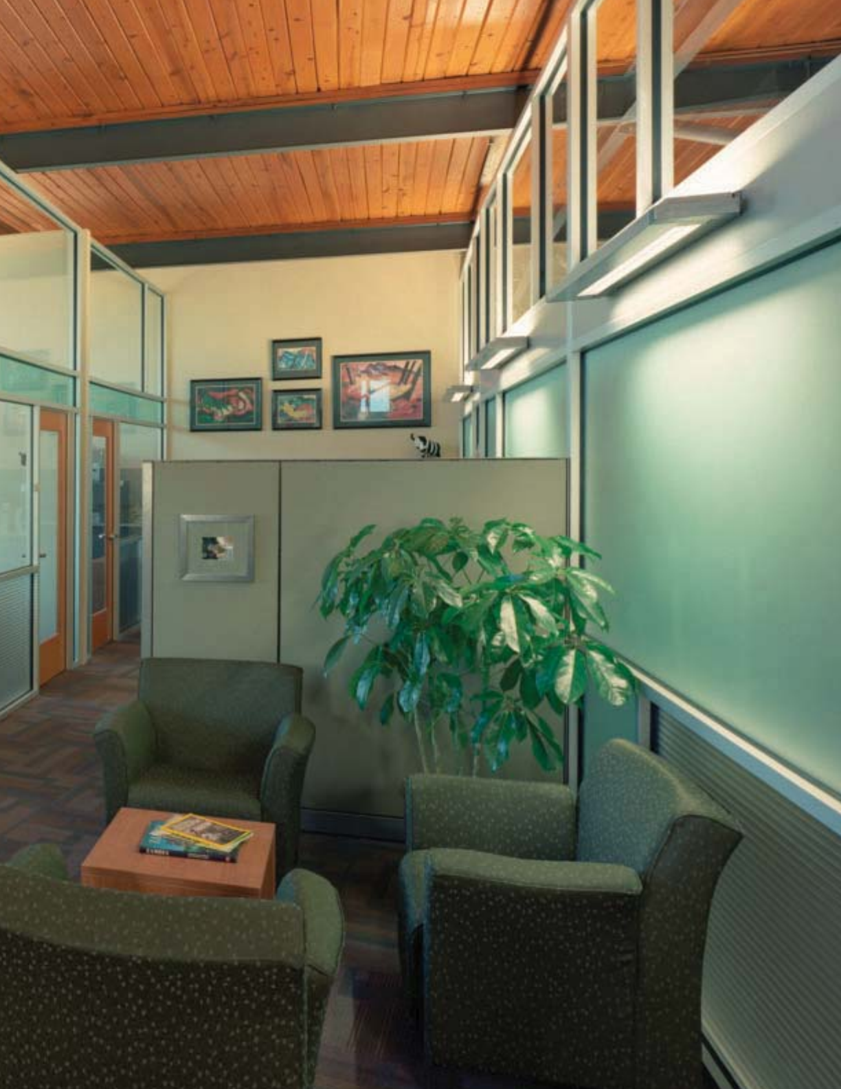
137

SURFACE
No Strings Attached.
It is always a challenge to illuminate open spaces with low
or obstructed ceilings where wall mounted fixtures alone
cannot suffice, yet the benefits and aesthetics of linear
architectural lighting are still desired. Surface mounted
fixtures, with the same wide light distribution and row
spacing as their suspended and recessed counterparts,
offer an attractive architectural solution.
138
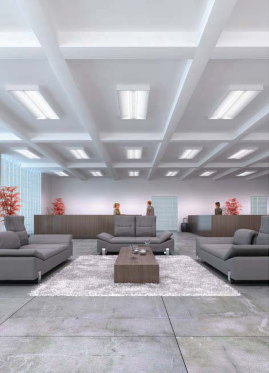
139
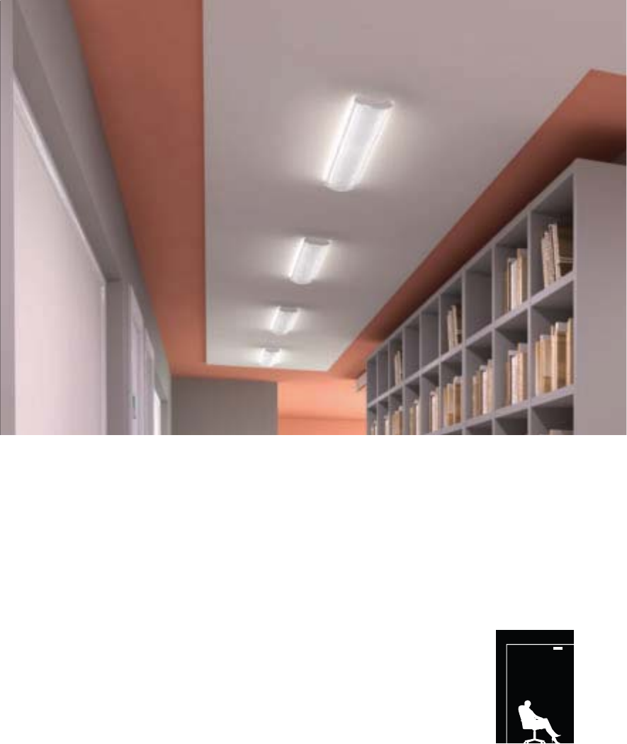
140
No plenum? No problem.
Whether the preference is individual recessed or
continuous linear suspended, and when the ceiling
allows neither, Corelite has the surface mounted solution
to satisfy. In applications with compromised plenums
– or none at all – Corelite offers a surface mountable
alternative to the recessed Class R series, in both
traditional and linear forms. For spaces with low ceilings
or tall interior elements, library stacks for example, both
the Stellar and Stellar Q linear series’ provide effective
and attractive surface mount options.
Surface
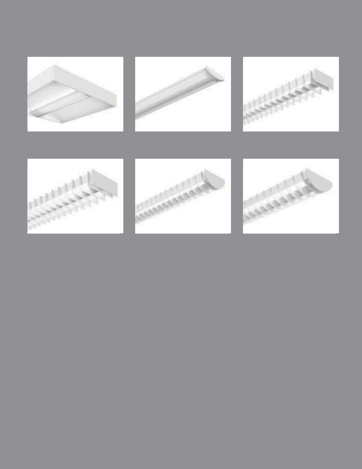
CLASS R2
pg. 142-143
CLASS Rs
pg. 144-145
STELLAR Q 2T5
pg. 146-147
STELLAR Q 2T8
pg. 148-149
STELLAR 2T5
pg. 150-151
STELLAR 2T8
pg. 152-153
141
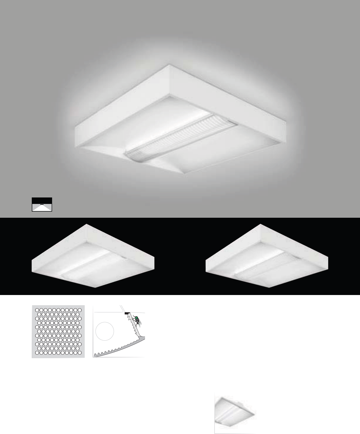
142
• Minimal 3” frame height
• 84.2% effi ciency (R2-WL-2N5-22)
• Accommodates up to 3 T5 lamps
• Four unique shielding options
• Supports energy saving ballasts and controls
Micro Baffle
Lens Gasketing (LG)Round Perf (R2-WP)
Class R2 Recessed
(pages 16-17)
Rectangular PerfLens
Class R2 Surface
SURFACE MOUNT | DIRECT | T5 / T5HO
The Class R2 Surface mount is the
ultimate obstructed plenum solution
with recessed appeal.
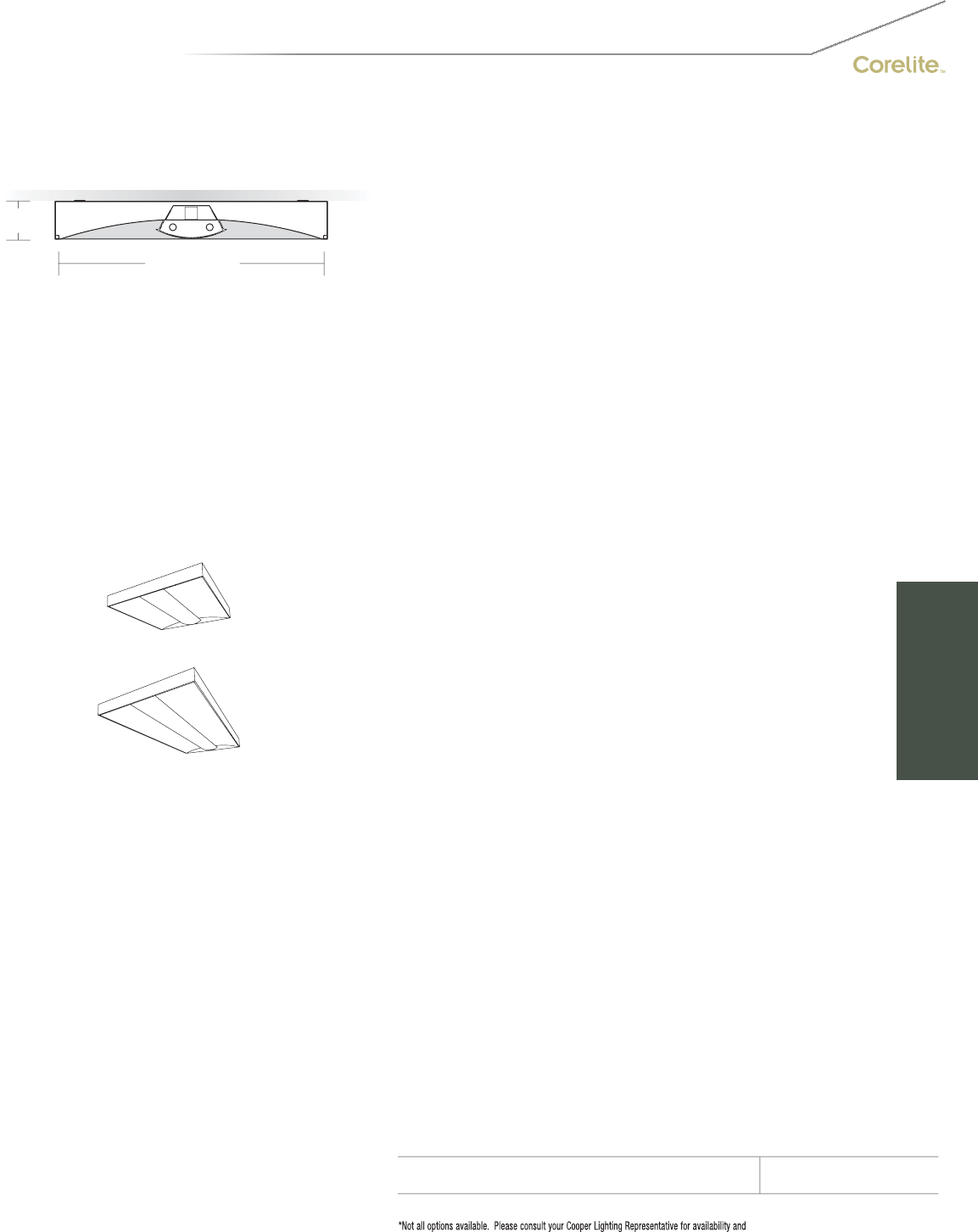
143
2x2
2x4
3" [76MM]
23 3/4" [603MM]
S
ERIE
S
R2=
C
lass R2
(
3”
)
S
urface
REFLE
C
T
OR
W=White
S
HIELDIN
G
B=Micro Ba
ff
l
e
L
=
L
en
s
P=Round Perf
R=Rectangular Per
f
NUMBER
O
F LAMP
S
1=1 Lamp
2
=2 Lam
ps
3=3 Lam
ps
LAMP
TYPE
N5=T5 Normal Output
T5=T5 High Outpu
t
NUMBER
O
F
C
IR
C
UIT
S*
1=1
C
ircui
t
2
=2
C
ir
cu
it
s
WIRIN
G
*
C
=
S
tandard
C
ircuit
B=Battery
D=Dimming / Step Dimming (see OPTIONS)
E
=
E
mer
g
enc
y
Y
=
D
ay
ligh
t
T=Nightlight
V
O
LTA
G
E*
120=120
V
2
77=277
V
347=347V
U
NV=Universal (120V-277V)
S
IZE
2
4=2’x4’
2
2=2’x2’
C
EILIN
G
TYPE
SU=Surface Mount
O
PTI
O
N
S
LG=Lens Gasketin
g
SD=Step Dimmin
g
PROJECT NAME: TYPE:
CATALOG #:
-
-
-
-
-
-
-
-
t
echnical information.
S
pecifications and dimensions subject to change without notice.
ORDERING INFORMATION:
SAMPLE NUMBER:R2-WB-2N5-1C-UNV-22-SU
SURFACE CLASS R2
Construction: Low profile housin
g
die-formed 20
g
au
g
e co
ld
ro
ll
e
d
stee
l
w
i
t
h
i
nte
g
ra
l
one-p
i
ece
2
0 gauge gear tray.
S
urface mounting kit with
snap-together frame design constructed of die
-
f
ormed 20 gauge cold rolled steel.
Reflectors: Hi
g
h reflectance white powder coat
p
ainted reflector system
.
Shieldin
g
: Lens secured to housin
g
via in
j
ection
m
olded inserts
f
or eas
y
lam
p
access.
Lens: Linear prismatic co-extruded acrylic lens
w
ith full
y
frosted center and clear/frost blended
le
n
s
r
e
t
u
rn
s
.
M
icro Baffle: Linear prismatic co-extruded
a
cr
y
lic lens with white internal micro baffle,
c
l
ea
r
ce
nt
e
r
a
n
d
c
l
ea
r
/
fr
os
t
b
l
e
n
ded
l
e
n
s
r
e
t
u
rn
s
.
Perf: Linear prismatic co-extruded acrylic lens
w
ith perforated formed steel shield, fully frosted
ce
nt
e
r
a
n
d
c
l
ea
r
/
fr
os
t
b
l
e
n
ded
l
e
n
s
r
e
t
u
rn
s
.
Electrical: T5
/
T5H
O
fixtures are pre-wired with
quick wire connectors and use UL listed
C
lass P,
T5/T5HO program rapid start universal voltage
e
lectronic ballasts,
p
ower
f
actor o
f
97% with
less
t
ha
n 1
0%
THD
.
Finish: Fixture housin
g
s and sur
f
ace mount kits
a
re hi
g
h re
f
lectance white usin
g
electrostatically
a
pp
li
e
d
po
l
yester pow
d
er coat pa
i
nt.
M
ounting:
S
urface mount kit installs easily with
f
our (4) 1/4-20 screws. Frame mounts first onto
sur
f
ace, by others. Fixture housing slides into
o
pen end o
f
f
rame and remainin
g
f
rame piece
snaps into place for seamless finish.
S
ee
i
nstallation instructions for further detail.
SURFACE
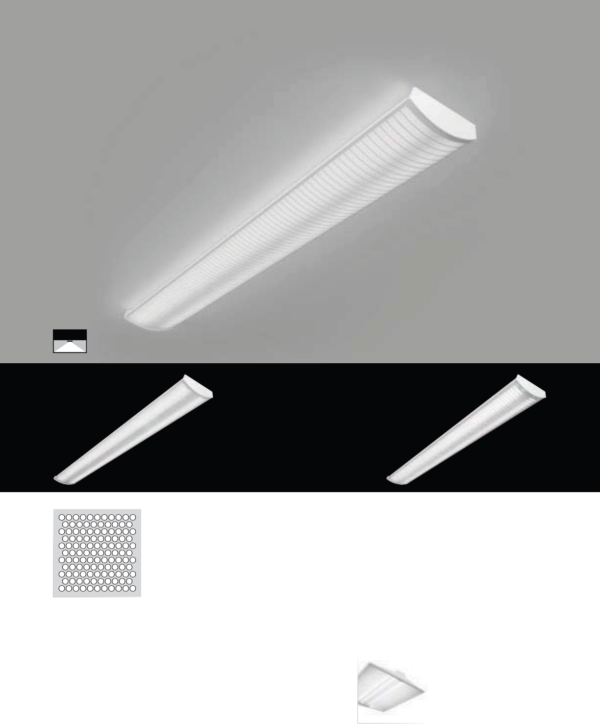
144
Rectangular Perf
• Accommodates 2 T5 or T5HO lamps
• Four unique shielding options
• Individual 4’ units only
Class R2 Recessed
(pages 16-17)
Round Perf (RB-WP)
Lens Micro Baffle
Class Rs Surface
SURFACE MOUNT | DIRECT | T5 / T5HO
Lower ceiling heights, not expectations,
with the T5-specifi c micro-scaled linear
Class Rs Surface.

145
1 3/4" [44MM]
6" [152MM]
S
ERIE
S
RB=
C
lass Rs
S
urface
OPTICS UP
W=Whit
e
O
PTI
CS
D
O
WN
B=Mi
c
r
o
B
a
ffl
e
L=L
e
n
s
P=Round Per
f
R=Rectangular Perf
N
U
MBER
O
F LAMP
S
2
=2
L
amp
s
LAMP TYPE
N5=T5 Normal Out
p
ut
T5=T5 Hi
g
h
O
utpu
t
NUMBER OF CIRCUITS
*
1=1
C
ir
cu
i
t
2
=2
C
ir
cu
it
s
WIRIN
G
*
C
=
S
t
a
n
da
r
d
C
ir
cu
it
B
=
B
atter
y
D=Dimmin
g
/
S
tep Dimmin
g
(
see
O
PTI
O
N
S)
E
=
E
mergenc
y
Y=Daylight
T=Nightlight
V
O
LTA
G
E*
120=120V
2
77=277V
3
47=
3
47
V
UNV
=
U
n
i
versa
l
(
120
V
-277
V)
M
OUNTING
SU
-
J
B=
Su
rf
ace
M
ou
nt
O
PTI
O
N
S
*
S
D=
S
tep Dimming
PROJECT NAME: TYPE:
CATALOG #:
-
-
-
-
-
-
-
-
t
echnical information.
S
pecifications and dimensions subject to change without notice.
ORDERING INFORMATION:
SAMPLE NUMBER:RB-WL-2N5-1C-UNV-SU-JB
SURFACE CLASS Rs
Construction: Formed 20
g
au
g
e steel
g
ear tray
m
ounts to shieldin
g
via 2
f
actory supplied clips.
Reflectors: High reflectance white powder coat
p
ainted re
f
lector s
y
stem
.
S
hielding: Lens secured to housing via injection
m
olded inserts for eas
y
lam
p
access.
L
ens:
Li
near
p
r
i
smat
i
c co-extru
d
e
d
acr
yli
c
l
ens
w
ith fully frosted center and clear
/
frost blended
l
ens returns.
M
icro Ba
ff
le: Linear
p
rismatic co-extruded
a
crylic lens with white internal micro baffle,
c
lear center and clear
/
frost blended lens returns.
Per
f
: Linear
p
rismatic co-extruded acr
y
lic lens
w
ith per
f
orated
f
ormed steel shield,
f
ully
f
rosted
c
enter and clear
/
frost blended lens returns.
Electrical: T5
/
T5H
O
fixtures are pre-wired with
q
uick wire connectors and use UL listed Class P,
T5/T5HO pro
g
ram rapid start universal volta
g
e
e
lectronic ballasts, power
f
actor o
f
97% with
l
ess t
h
an 10%
THD
.
M
ounting: Class Rs is for individual surface
m
ounting only. Luminaire requires 2
f
actory
supplied
f
ormed steel painted mountin
g
clips
t
o
b
e
i
nsta
ll
e
d
to structure w
i
t
h
h
ar
d
ware
b
y
o
thers (see installation instructions). Fixture then
t
emporarily hangs onto clips to allow hands-
f
ree
w
irin
g
, then
f
ixture swin
g
s into place and is
ultimately secured by
f
actory supplied hardware
.
End Caps: Injection-molded plastic end caps.
48”
Dimensions do not include
end plates or caps
SURFACE

Q1-WB with standard flat end plates
146
• 2T5 specific design
• 100% or 70% Downlight Kits
Stellar Q1
Suspended
(pages 66-67)
70% Downlight Kit
(DL70)
100% Downlight Kit
(DL100)
Stellar Q 2T5 (6”) Surface
SURFACE MOUNT | DIRECT | T5 / T5HO
With its two-lamp T5 specifi c profi le, the
squared Stellar Q Surface stands at the
very edge of modern design.
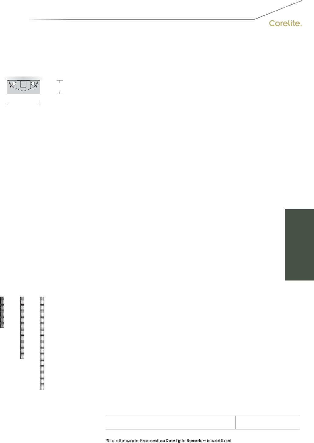
147
2-1/2" [64MM]
6" [152MM]
S
ERIE
S
Q
1=
S
tellar
Q
S
urface
O
PTI
CS
U
P
W
=
Whi
te
OPTICS DOWN
B= B
aff
l
e
NUMBER
O
F LAMP
S
2
=2 Lam
ps
LAMP TYPE
N5=T5 Normal
O
utput
T5=T5 High Outpu
t
N
U
MBER
O
F
C
IR
CU
IT
S
1=1
C
ircui
t
2
=2
C
ircuits
WIRIN
G
*
C
=
S
tandard
C
ircuit
D
=
Di
mm
i
ng
E=Emergency
B=Batter
y
Pack
T
=
Nigh
t
ligh
t
Y
=
D
ay
ligh
t
V
O
LTA
G
E*
12
0
=12
0V
277
=
277V
347=347
V
U
NV=Universal (120V-277V)
MOU
NTIN
G
S
U-JB=
S
urface Mount
RUN LEN
G
TH
S
pecify luminaire length in feet.
-Individually Mounted
Luminaires may be 4’,8’, or 12’ in length.
-
C
ontinuousl
y
Mounted
S
tandard row confi
g
urations over 12’ consist of 8’
a
nd 12’ sections
.
O
PTI
O
N
S
DL
100=100%
D
own
ligh
t
Ki
t
(recommended for surface mount applications
)
DL70=70% Downlight Kit
PROJECT NAME: TYPE:
CATALOG #:
-
-
-
-
-
-
-
-
t
echnical information.
S
pecifications and dimensions subject to change without notice.
ORDERING INFORMATION:
SAMPLE NUMBER:Q1-WB-2T5-1C-UNV-SU-JB-32’-DL100
SURFACE STELLAR Q
Co
n
s
tr
uc
ti
o
n: Di
e
-f
o
rm
ed
a
ll
a
l
u
min
u
m
ba
ffl
e
a
ssem
bl
y
(
1.5
”
bl
a
d
e spac
i
n
g)
mec
h
an
i
ca
ll
y
a
ttached to a corrosion resistant formed steel
b
allast channel. Perforated siderail sections are
2
3% open with 0.0625” stagger hole spacing.
Standard 4’-0”, 8’-0”, and 12’-0” fixture len
g
ths
c
ombine for continuous runs.
Electrical: T5/T5HO fixtures are
p
re-wired with
q
uick wire connectors and use UL listed
C
lass P,
T5
/
T5H
O
program rapid start universal voltage
e
lectronic ballasts, power factor of 97% with
less
th
a
n 1
0%
THD.
M
ountin
g
:
C
rossbar cover supports the fixture
a
t t
h
e power mount an
d
connects to 4
”
o
ctagonal junction box, by others. All other
m
ounts interface to 1/4”-20 studs b
y
others,
p
rotrudin
g
f
rom the ceilin
g
. The
f
irst suspension
p
oint is the len
g
th of the fixture less 2-3
/
8”, all
o
t
h
er suspens
i
on po
i
nts are 4
’
, 8
’
or 12
’
o
n-center. See installation instructions
.
Fi
n
i
s
h
:
Fi
xture
h
ous
i
n
g
s are stan
d
ar
d
w
hi
te
u
s
i
n
g
e
l
ectrostat
i
ca
ll
y app
li
e
d
po
l
yester pow
d
er
c
oat paint.
C
onsult factory for custom finishes
.
E
n
d
Pl
ates:
L
aser cut 14-
g
au
g
e co
ld
ro
ll
e
d
stee
l
, mec
h
an
i
ca
ll
y attac
h
e
d
w
i
t
h
out expose
d
f
asteners.
Dimensions do not include
end plates or caps
96”48” 144”
SURFACE

148
Q2-WB with standard flat end plates
Stellar Q2
Suspended
(pages 68-69)
70% Downlight Kit
(DL70)
100% Downlight Kit
(DL100)
• 2T8 specific design
• 100% or 70% Downlight Kits
Stellar Q 2T8 (9”) Surface
SURFACE MOUNT | DIRECT | T8
With its two-lamp T8 specifi c profi le, the
squared Stellar Q Surface stands at the
very edge of modern design.
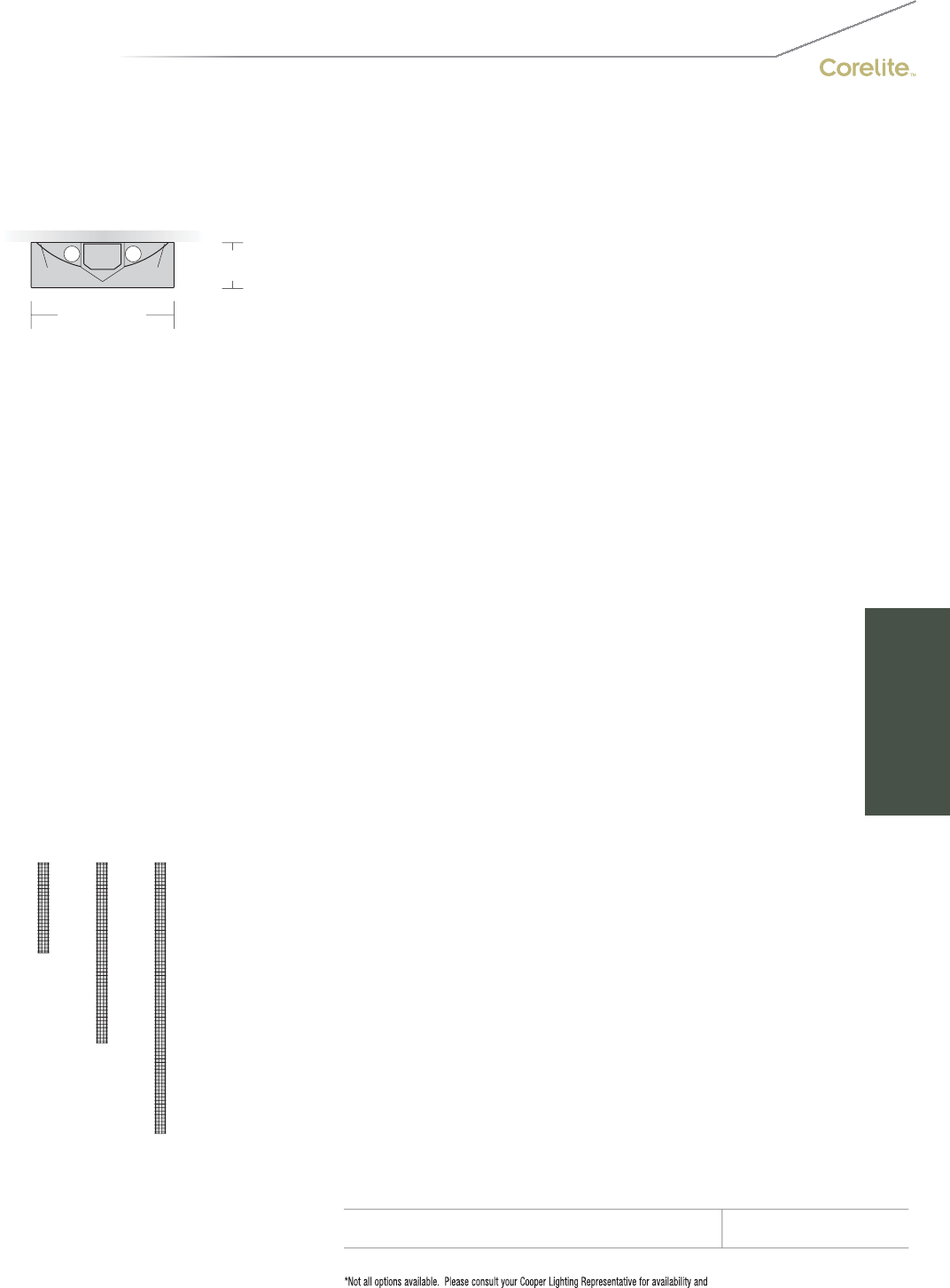
149
9" [229MM]
2-7/8" [73MM]
S
ERIE
S
Q
2=
S
tellar
Q
S
urface
O
PTI
CS
U
P
W
=
Whi
te
OPTICS DOWN
B= B
aff
l
e
NUMBER
O
F LAMP
S
2
=2 Lam
ps
LAMP TYPE
T8=T8 Normal
O
utput
N
U
MBER
O
F
C
IR
CU
IT
S
1=1
C
ir
cu
i
t
2
=2
C
ircuits
WIRIN
G
*
C
=
S
t
a
n
da
r
d
C
ir
cu
it
D
=
Di
mm
i
n
g
E
=
E
mergency
B=Battery Pack
T=Nightlight
Y
=
D
ay
ligh
t
V
O
LTA
G
E*
12
0
=12
0
V
277
=
277V
347=347
V
UNV
=
U
n
i
versa
l
(
120
V
-277
V)
MOU
NTIN
G
S
U-JB=
S
urface Mount
R
U
N LEN
G
TH
S
pecify luminaire len
g
th in feet.
-
I
n
di
v
id
ua
ll
y
M
ounte
d
Luminaires may be 4’,8’, or 12’ in length.
-Continuousl
y
Mounted
S
tandard row confi
g
urations over 12’ consist of 8’
a
n
d
12
’
sect
i
ons
.
O
PTI
O
N
S
DL
100=100%
D
own
ligh
t
Ki
t
(
recommended
f
or sur
f
ace mount applications
)
DL
70=70%
D
own
li
g
h
t
Ki
t
PROJECT NAME: TYPE:
CATALOG #:
-
-
-
-
-
-
-
-
t
echnical information.
S
pecifications and dimensions subject to change without notice.
ORDERING INFORMATION:
SAMPLE NUMBER:Q2-WB-2T8-1C-UNV-SU-JB-32’-DL100
SURFACE STELLAR Q
Co
n
s
tr
uc
ti
o
n: Di
e
-f
o
rm
ed
a
ll
a
l
u
min
u
m
ba
ffl
e
a
ssem
bl
y
(
2
”
bl
a
d
e spac
i
n
g)
mec
h
an
i
ca
ll
y
a
ttached to a corrosion resistant formed steel
b
allast channel. Perforated siderail sections are
2
3% open with 0.0625” stagger hole spacing.
Standard 4’-0”, 8’-0”, and 12’-0” fixture len
g
ths
c
ombine for continuous runs.
Electrical: T8
f
ixtures are
p
re-wired with
q
uick
w
ire connectors and use UL listed
C
lass P
,
2
65ma
T
8
i
nstant start un
i
versa
l
vo
l
tage
e
lectronic ballasts, power factor of 95% with
less
th
a
n 1
0%
THD. Fixt
u
r
es
a
n
d
e
l
ec
tri
ca
l
c
om
p
onents certified to UL and CUL standards.
M
ountin
g
:
C
rossbar cover supports the fixture
a
t t
h
e power mount an
d
connects to 4
”
o
ctagonal junction box, by others. All other
m
ounts interface to 1/4”-20 studs b
y
others,
p
rotrudin
g
f
rom the ceilin
g
. The
f
irst suspension
p
oint is the len
g
th of the fixture less 2-3
/
8”, all
o
t
h
er suspens
i
on po
i
nts are 4
’
, 8
’
or 12
’
o
n-center. See installation instructions
.
Finish: Fixture housings are standard white
u
s
i
n
g
e
l
ectrostat
i
ca
ll
y app
li
e
d
po
l
yester pow
d
er
c
oat paint.
C
onsult factory for custom finishes
.
End Plates: Laser cut 14-gauge cold rolled
stee
l
, mec
h
an
i
ca
lly
attac
h
e
d
w
i
t
h
out ex
p
ose
d
f
asteners.
Dimensions do not include
end plates or caps
96”48” 144”
SURFACE

150
• 2T5 specific design
• 100% or 70% Downlight Kits
S1-WB with standard die-cast end caps
Stellar 2T5
Suspended
(pages 70-71)
Stellar Wall
(pages 120-121)
70% Downlight Kit
(DL70)
100% Downlight Kit
(DL100)
Stellar 2T5 (6”) Surface
SURFACE MOUNT | DIRECT | T5 / T5HO
The industrial styled Stellar Surface
provides effi cient direct illumination in the
most challenging spaces.

151
2-1/2" [64MM]
6" [152MM]
S
ERIE
S
S
1=
S
tellar
S
urface
O
PTI
CS
U
P
W
=
Whi
te
OPTICS DOWN
B= B
aff
l
e
NUMBER
O
F LAMP
S
2
=2 Lam
ps
LAMP TYPE
N5=T5 Normal
O
utput
T5=T5 High Outpu
t
N
U
MBER
O
F
C
IR
CU
IT
S*
1=1
C
ircui
t
2
=2
C
ircuits
WIRIN
G
*
C
=
S
tandard
C
ircuit
D
=
Di
mm
i
ng
E=Emergency
B=Batter
y
Pack
T
=
Nigh
t
ligh
t
Y
=
D
ay
ligh
t
V
O
LTA
G
E*
12
0
=12
0V
277
=
277V
347=347
V
U
NV=Universal (120V-277V)
MO
UNTIN
G
S
U-JB=
S
urface Mount
RUN LEN
G
TH
Specify luminaire length in feet.
-Individuall
y
Mounted
L
um
i
na
i
res may
b
e 4
’
,8
’
, or 12
’
i
n
l
en
g
t
h
.
-
C
ontinuously Mounted
S
tandard row configurations over 12’ consist of 8’
a
n
d
12’
sec
ti
o
n
s.
O
PTI
O
N
S
DL100=100% Downlight Kit
(recommended
f
or sur
f
ace mount applications
)
DL
70=70%
D
own
ligh
t
Ki
t
PROJECT NAME: TYPE:
CATALOG #:
-
-
-
-
-
-
-
-
t
echnical information.
S
pecifications and dimensions subject to change without notice.
ORDERING INFORMATION:
SAMPLE NUMBER:S1-WB-2T5-1C-UNV-SU-JB-12’-DL100
SURFACE STELLAR
Co
n
s
tr
uc
ti
o
n: Di
e
-f
o
rm
ed
a
ll
a
l
u
min
u
m
ba
ffl
e
a
ssem
bl
y
(
1.5
”
bl
a
d
e spac
i
n
g)
mec
h
an
i
ca
ll
y
a
ttached to a corrosion resistant formed steel
b
allast channel. Perforated siderail sections are
2
3% open with 0.0625” stagger hole spacing.
Standard 4’-0”, 8’-0”, and 12’-0” fixture len
g
ths
c
ombine for continuous runs.
Electrical: T5
/
T5H
O
fixtures are pre-wired with
q
uick wire connectors and use UL listed Class P,
T5/T5HO pro
g
ram rapid start universal volta
g
e
e
lectronic ballasts, power
f
actor o
f
97% with
l
ess t
h
an 10%
THD
.
M
ountin
g
:
C
rossbar cover supports the fixture
a
t the power mount and connects to 4”
o
ctagonal junction box, by others. All other
m
ounts interface to 1/4”-20 studs b
y
others,
p
rotrudin
g
f
rom the ceilin
g
. The
f
irst suspension
p
oint is the length of the fixture less 2-3
/
8”, all
o
ther suspension points are 4’, 8’ or 12’
o
n-
ce
nt
e
r.
See
in
s
t
a
ll
a
ti
o
n in
s
tr
uc
ti
o
n
s.
Fi
n
i
s
h
:
Fi
xture
h
ous
i
ngs are stan
d
ar
d
w
hi
te
u
sing electrostatically applied polyester powder
c
oat
p
aint. Consult factor
y
for custom finishes
.
End Plates: Laser cut 14-gauge cold rolled
steel, mechanicall
y
attached without ex
p
osed
fas
t
e
n
e
r
s
.
Dimensions do not include
end plates or caps
96”48” 144”
SURFACE

152
S2-WB with standard die-cast end caps
Stellar 2T8
Suspended
(pages 72-73)
Stellar Wall
(pages 120-121)
70% Downlight Kit
(DL70)
100% Downlight Kit
(DL100)
• 2T8 specific design
• 100% or 70% Downlight Kits
Stellar 2T8 (9”) Surface
SURFACE MOUNT | DIRECT | T8
The industrial styled Stellar Surface
provides effi cient direct illumination in the
most challenging spaces.

153
9" [229MM]
2-7/8" [73MM]
S
2=
S
tellar
S
urface
O
PTI
CS
U
P
W=Whit
e
O
PTI
CS
D
O
WN
B= Baffle
NUMBER
O
F LAMP
S
2
=2 Lamp
s
LAMP TYPE
T8=T8 Normal
O
utput
NUMBER OF CIRCUITS
*
1=1
C
ir
cu
i
t
2
=2
C
ir
cu
it
s
WIRIN
G
*
C
=
S
t
a
n
da
r
d
C
ir
cu
it
D
=
Di
mm
i
n
g
E
=
E
mer
g
ency
B
=
B
attery
P
ac
k
T=Nightlight
Y=Daylight
V
O
LTA
G
E*
120=120V
2
77=277V
3
47=
3
47
V
UNV
=
U
n
i
versa
l
(
120
V
-277
V)
MOU
NTIN
G
SU
-
J
B=
Su
rf
ace
M
ou
nt
R
U
N LEN
G
TH
Specify luminaire len
g
th in feet.
-
I
n
di
v
id
ua
ll
y
M
ounte
d
L
um
i
na
i
res may
b
e 4
’
,8
’
, or 12
’
i
n
l
engt
h
.
-Continuously Mounted
Standard row configurations over 12’ consist of 8’
a
n
d
12
’
sec
t
io
n
s.
O
PTI
O
N
S
DL
100=100%
D
own
ligh
t
Ki
t
(recommended for surface mount applications
)
DL70=70% Downlight Kit
PROJECT NAME: TYPE:
CATALOG #:
-
-
-
-
-
-
-
-
t
echnical information.
S
pecifications and dimensions subject to change without notice.
ORDERING INFORMATION:
SAMPLE NUMBER:S2-WB-2T8-1C-UNV-SU-JB-12’-DL100
SURFACE STELLAR
Co
n
s
tr
uc
ti
o
n: Di
e
-f
o
rm
ed
a
ll
a
l
u
min
u
m
ba
ffl
e
a
ssem
bl
y
(
2
”bl
a
d
e spac
i
n
g)
mec
h
an
i
ca
ll
y
a
ttached to a corrosion resistant formed steel
b
allast channel. Perforated siderail sections are
2
3% open with 0.0625” stagger hole spacing.
Standard 4’-0”, 8’-0”, and 12’-0” fixture len
g
ths
c
ombine for continuous runs.
Electrical: T8 fixtures are pre-wired with quick
w
ire connectors and use UL listed
C
lass P,
2
65ma T8 instant start universal voltage
e
lectronic ballasts,
p
ower
f
actor o
f
95% with
l
ess t
h
an 10%
THD
.
Fi
xtures an
d
e
l
ectr
i
ca
l
c
omponents certified to UL and
C
UL standards.
M
ounting: Crossbar cover supports the fixture
a
t t
h
e
p
ower mount an
d
connects to 4
”
o
cta
g
ona
l
j
unct
i
on
b
ox,
b
y ot
h
ers.
All
ot
h
er
m
ounts interface to 1
/
4”-20 studs by others,
p
rotruding
f
rom the ceiling. The
f
irst suspension
p
oint is the len
g
th of the fixture less 2-3/8”, all
o
t
h
er suspens
i
on po
i
nts are 4
’
, 8
’
or 12
’
o
n-center.
S
ee installation instructions
.
Fi
n
i
s
h
:
Fi
xture
h
ous
i
n
g
s are stan
d
ar
d
w
hi
te
u
s
i
n
g
e
l
ectrostat
i
ca
ll
y app
li
e
d
po
l
yester pow
d
er
c
oat paint.
C
onsult factory for custom finishes
.
E
n
d
Pl
ates:
L
aser cut 14-
g
au
g
e co
ld
ro
ll
e
d
stee
l
, mec
h
an
i
ca
ll
y attac
h
e
d
w
i
t
h
out expose
d
f
asteners.
Dimensions do not include
end plates or caps
96”48” 144”
SURFACE
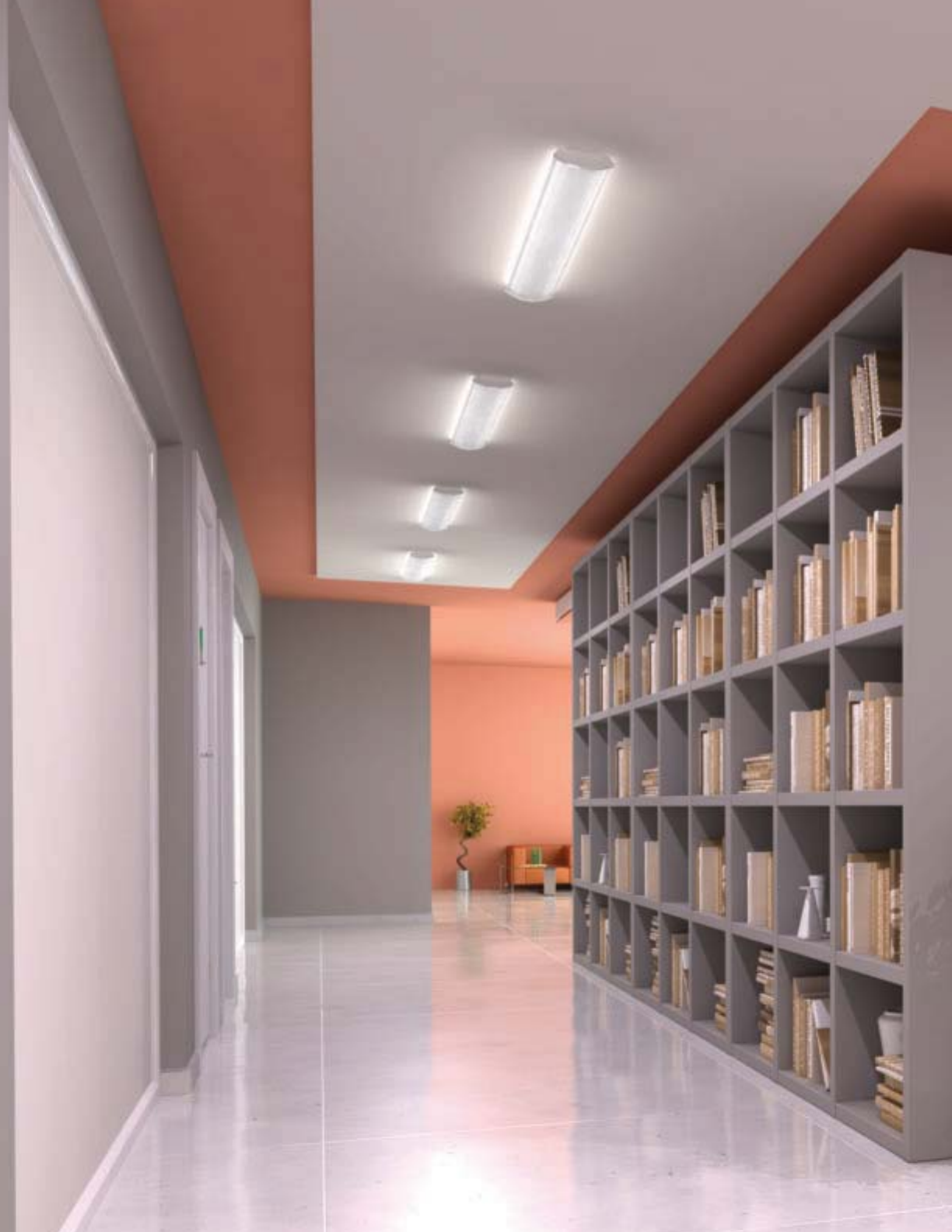
154
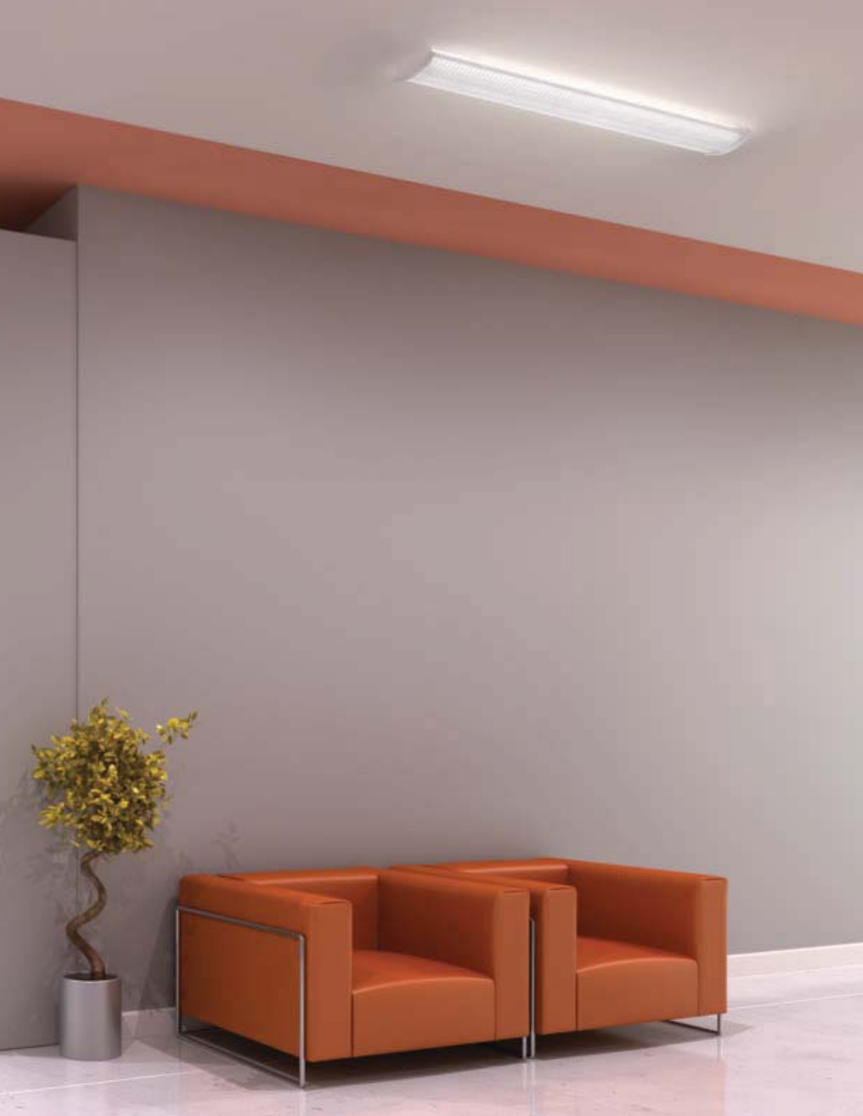
155

COVE
Highlight The Subject, Not The Source.
Cove lighting is commonly used to accent archetectural
surfaces and details while completely concealing the
lamp source. A splash of light on the ceiling can change
the character of a room by giving it a larger, more open
feel. All of Corelite’s cove luminaires may also function
as a primary source of general illumination by combining
either 2T5 or 2T8 lumen packages with optically designed
asymmetric reflector systems.
156
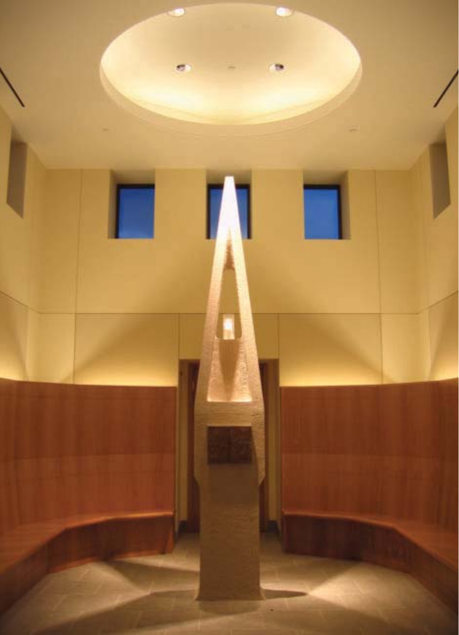
157
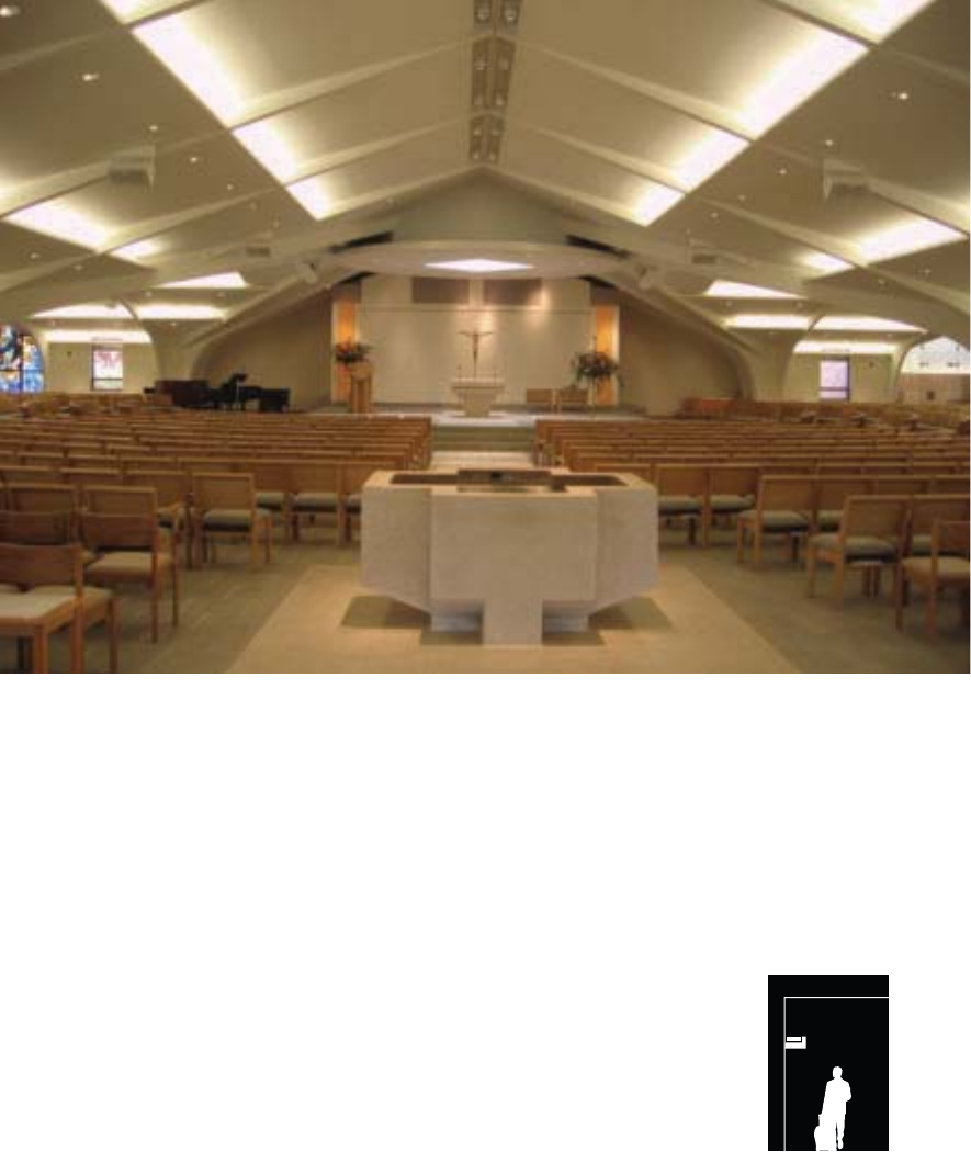
Navigator II
A Means to Every End...
158
One of These Three is Just Right.
The Corelite Cove series of luminaires aim to be wholly
complementary to any application. Corelight Cove series
luminaires carry three specific lumen packages that easily
address changing scales within architectural spaces. The
Cove Solo offers a micro-profile 1-1/2” x 6” 1T5 dedicated
housing, while the Duo offers two lamping options, 2T5
and 1T8, in a mid-sized 2” x 6” housing. The large scale
Trio maximizes the performance of a 2T8 lamping in an
efficiently engineered 2-7/8” x 8-1/2” housing. Ideas of
scale in architecture are extended by the component of
light, and it is the goal of the Corelite Cove Series to do
just that.
Cove
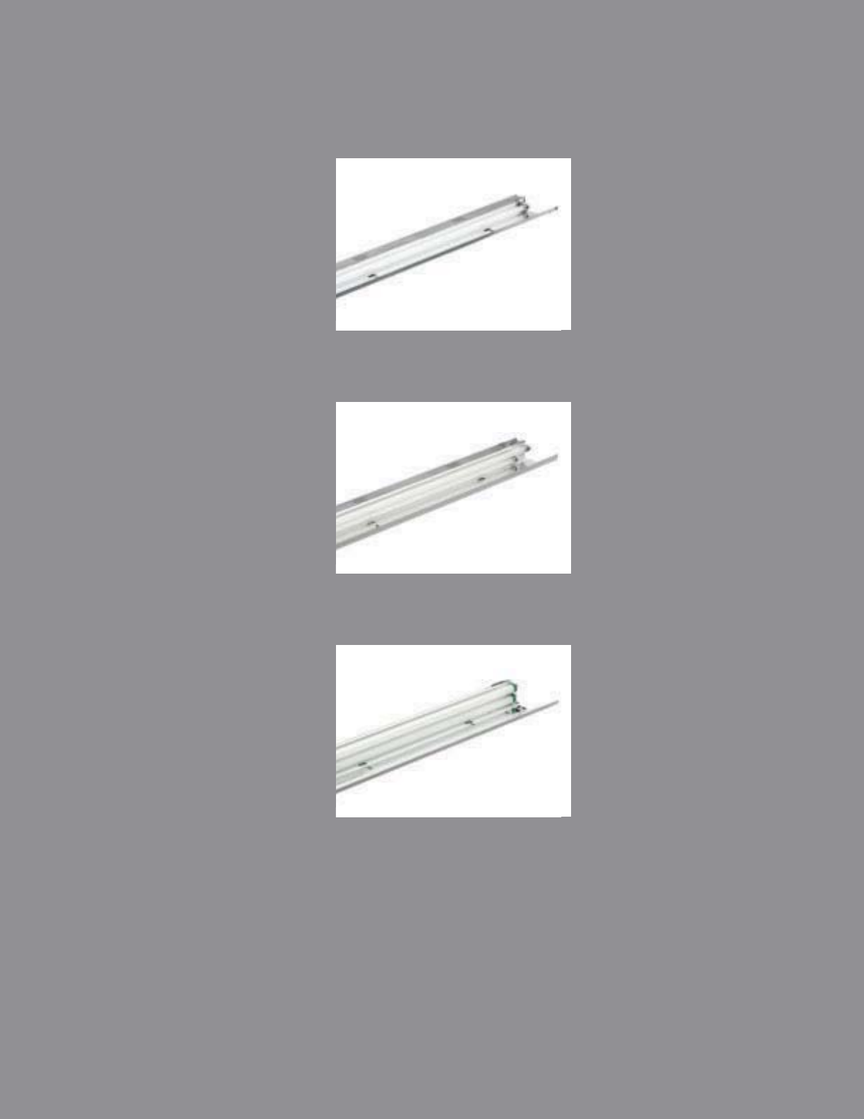
159
SOLO
pg. 160-161
DUO
pg. 162-163
TRIO
pg. 164-165
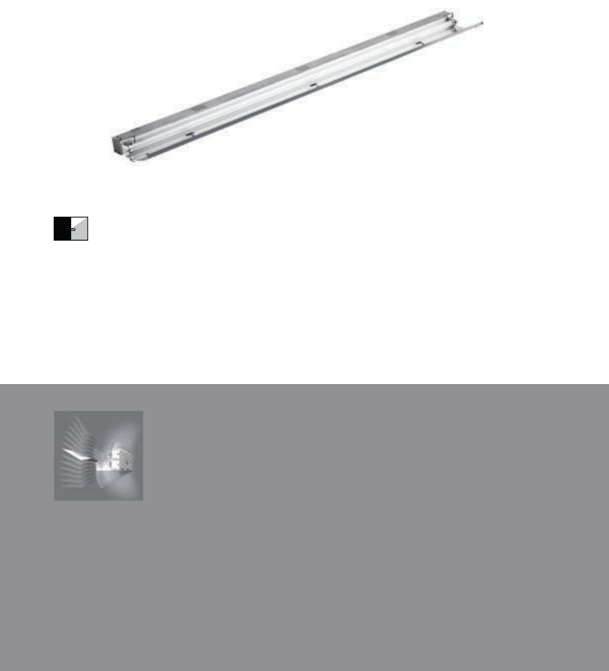
160
• Plus5TM Adjustable Aiming System
• Standard 2’, 3’, 4’ and 8’ nominal fixture lengths
• Optimizes single T5 lamp performance
Plus 5 Aiming System
(P5)
Solo
COVE MOUNT | ASYMMETRIC INDIRECT | T5 / T5HO
The Cove Solo offers T5 lamp-
specifi c lengths to go the distance in
preventing socket shadows.

161
6" [152 MM]
1 1/2" [38 MM]
2195
5
5
1646
46
4
549
49
49
098
8
8
1098
98
0
098
1T5/1T5HO
S
ERIE
S
CS
=
C
ove
S
ol
o
O
PTI
CS
UP
S=S
p
ecula
r
O
PTI
CS
D
O
WN
N
=
N
one
NUMBER
OF
LAMP
S
1=1
L
amp
LAMP TYPE
N
5
=T
5
N
o
rm
a
l Out
p
u
t
T
5=
T
5
High
O
utpu
t
NUMBE
R
O
F
CIRCUITS
*
1
=
1
C
ir
cu
i
t
WIRIN
G
*
C
=
S
tandar
d
C
ircuit
D=Dimming
E
=
E
mer
g
ency
B
=
B
attery
P
ac
k
T
=
Ni
g
h
t
li
g
h
t
Y=Daylight
V
O
LTA
G
E*
120=120
V
2
77=277V
3
47=
3
47V
UNV
=
U
n
i
v
e
r
sal
(
120
V
-277
V)
RUN LENGTH
S
p
ecif
y
l
u
min
a
ir
e
lengt
h
in
fee
t
.
-
I
n
di
v
id
ua
lly
Mou
nt
ed
L
um
i
na
i
re
s
may
be
2
’,
3
’,
4
’,
or 8
’
in
l
en
g
t
h.
-
C
ontinuously Mounted
S
t
a
n
da
r
d
row
con
f
igurations
o
v
er
8’
co
n
s
i
s
t
of
4
’
a
n
d
8
’
sec
ti
o
n
s
.
2’
a
n
d
3’
sec
t
io
n
s
will
be
used
for
ro
w
l
en
g
t
h
s
o
t
he
r t
han
in
4’
i
ncrements.
OPTION
S
P
5
=Pl
us5
Aimin
g
S
y
stem
PROJECT NAME: TYPE:
CATALOG #:
-
-
-
-
-
-
-
-
a
ll
opt
i
on
s
ava
il
a
bl
e.
Pl
eas
e
consu
lt
you
r
C
ooper
Li
g
h
t
i
n
g
R
epresentat
i
ve fo
r
ava
il
a
bili
ty an
d
t
echnical information.
S
pecifications and dimensions subject
t
o chang
e
without notice.
ORDERING INFORMATION:
SAMPLE NUMBER:CS-SN-1T5-1C-UNV-8’-P5
COVE SOLO
Co
n
s
tr
uc
ti
o
n
:
Housin
g
i
s
one
p
iec
e
d
i
e
-
fo
rm
ed
2
0-
g
au
ge
corros
i
on res
i
stan
t
stee
l,
f
ormin
g
a
1 1
/
2”
d
eep
b
a
ll
as
t
c
h
anne
l
.
S
tandar
d
nom
i
na
l
2
’-0”, 3’-0”, 4’-0”
,
and 8’-0” fixture length
s
co
m
b
in
e
for
co
ntin
uous
runs
.
Reflectors: Die-forme
d
reflectors are highly
s
p
ecular
a
n
od
iz
ed
a
l
u
min
u
m
.
Elec
tr
ical:
Fi
xt
u
r
es
a
r
e
p
rew
i
re
d
w
i
t
h
quick
wire
k
c
onnec
t
ors an
d
us
e
UL
li
ste
d
C
lass
P,
T5
/
T5H
O
p
rogram rapid s
t
ar
t
universa
l
voltage electronic
ba
ll
as
t
s.
P
o
w
e
r f
ac
t
o
r
o
f
9
7
%
wi
t
h l
ess
th
a
n
10%
THD.
Fixt
u
r
es
a
n
d
e
l
ec
tri
ca
l com
p
onents
c
erti
f
ie
d
to
UL
an
d
C
UL stan
d
ar
d
s
.
Fi
n
ish:
R
ef
l
ec
t
o
r
p
ans
a
r
e
a
n
odi
z
ed
alu
m
i
n
u
m.
B
a
ll
ast c
h
anne
ls
are corros
i
o
n
res
i
stant stee
l
.
O
ptions
:
Pl
us
5
Adj
usta
ble
Ai
m
i
ng
S
yste
m
a
ll
ow
s
f
o
r
5
degree incrementa
l
adjustments.
Degree of Lift
0 (Standard)
5
10
15
20
25
30
Front Mount
1-1/2 x 6
2 x 6
2-1/2 x 6
3 x 5-3/4
3-1/2 x 5-5/8
3-7/8 x 5-1/2
4-1/4 x 5-1/4
Back Mount
1-1/2 x 6
1-7/8 x 6-1/8
2-1/8 x 6-1/4
2-1/2 x 6-1/4
2-3/4 x 6-1/8
3 x 6
3-3/8 x 6
96”48”36”24”
Note: Fixture lengths shown are nominal
COVE
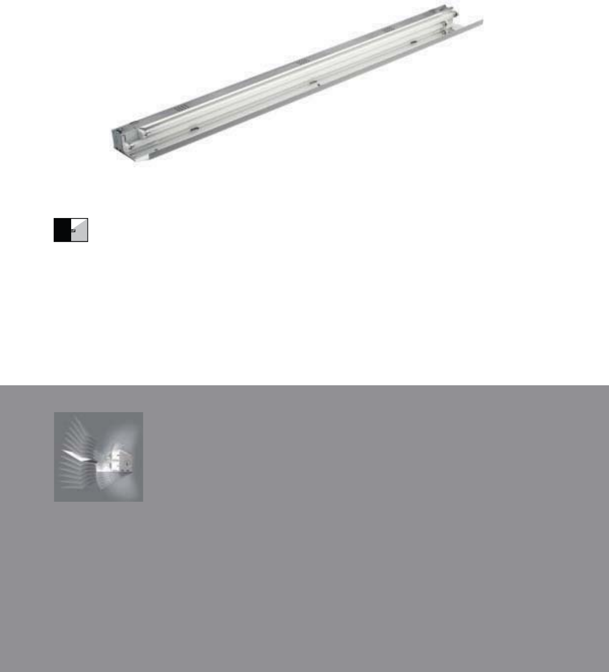
Plus 5 Aiming System
(P5)
162
• Plus5TM Adjustable Aiming System
• Standard 2’, 3’, 4’ and 8’ fixture lengths
• Optimizes single T8 and dual T5/T5HO
lamp performance
Duo
COVE MOUNT | ASYMMETRIC INDIRECT | T5 / T5HO / T8
Optimizing dual T5 and single T8
lampings, the Cove Duo is the
solution for any cove application.

163
2" [51 MM]
6" [152 MM]
3001
01
1
2250
50
5
750
50
50
1500
00
500
2T5/2T5HO
S
ERIE
S
C
D=
C
ov
e
D
u
o
O
PTI
CS
UP
S
=
S
pecular
O
PTI
CS
D
O
WN
N
=
N
on
e
N
U
MBER
OF
LAMP
S
1
=
1
L
am
p
(T
8
)
2
=
2
L
amp
s
(N
5,
T
5
)
LAMP TYPE
N
5
=T
5
N
o
rm
a
l Out
p
u
t
T
5=
T
5
High
O
utpu
t
T
8=
T8
N
orma
l
O
utput
N
U
MBE
R
OF
C
IR
CU
IT
S*
1
=
1
C
ir
cu
i
t
2
=
2
C
ircuits
WIRIN
G
*
C
=
S
t
a
n
da
r
d
C
ir
cu
it
D
=
Di
mm
i
n
g
E
=
E
mergency
B=Battery Pack
T=Nightlight
Y
=
D
ay
ligh
t
V
O
LTA
G
E*
12
0
=12
0
V
277
=
277V
347=347
V
UNV
=
U
n
i
versa
l
(
120
V
-277
V)
RUN
LEN
G
TH
S
pecif
y
l
um
i
na
i
re
l
en
g
t
h
in
feet
.
-Individuall
y
Mounte
d
L
u
min
a
ir
es
may
be
2’,3’
,
4’
,
or
8
’ i
n
length
.
-Continuousl
y
Mou
nt
ed
S
tandar
d
ro
w
con
f
i
g
urations ove
r
8
’
cons
i
st o
f
4’
an
d
8
’
sect
i
ons.
2’
an
d
3
’
sect
i
ons w
ill
be
use
d
fo
r
row
l
engt
h
s ot
h
er t
h
a
n
in
4
’
i
ncrements.
O
PTI
O
N
S
P5=Plus5 Aimin
g
S
ystem
PROJECT NAME: TYPE:
CATALOG #:
-
-
-
-
-
-
-
-
a
ll
opt
i
on
s
ava
il
a
bl
e.
Pl
eas
e
consu
lt
you
r
C
ooper
Li
g
h
t
i
n
g
R
epresentat
i
ve fo
r
ava
il
a
bili
ty an
d
t
echnical information.
S
pecifications and dimensions subject
t
o chang
e
without notice.
ORDERING INFORMATION:
SAMPLE NUMBER:CD-SN-1T8-1C-UNV-8’-P5
COVE DUO
Co
n
s
tr
uc
ti
o
n
:
Housin
g
i
s
one
p
iec
e
d
i
e
-
fo
rm
ed
2
0-
g
au
ge
corros
i
on res
i
stan
t
stee
l,
f
ormin
g
a
2”
d
ee
p
b
a
ll
ast c
h
anne
l.
S
tandar
d
2
’
-0
”,
3
’
-0
”
,
4’-0”, an
d
8’-0” fixture length
s
combin
e
for
co
ntin
uous
runs
.
Reflectors: Die-forme
d
reflectors are
h
ighly s
p
ecula
r
a
n
od
iz
ed
a
l
u
min
u
m.
El
ec
tri
ca
l
:
T
5/
T
5
H
O
f
ixt
u
r
es
are
p
re-wired wi
t
h
quick
wire
k
co
nn
ec
t
o
r
s
a
n
d
use
UL
lis
t
ed
C
l
ass
P,
T5
/
T5H
O
pro
g
ram rap
id
s
t
ar
t
un
i
versa
l
vo
l
ta
ge
e
lectroni
c
ballasts
,
power facto
r
of 97
%
wi
t
h
less
th
an
10%
THD. T
8
fixt
u
r
es
are
p
re-wire
d
w
ith
quick
wire
k
co
nn
ec
t
o
r
s
a
n
d
use
UL
li
s
t
ed
C
lass
P,
265ma
T
8
i
nstan
t
s
t
ar
t
un
i
versa
l
vo
l
ta
ge
el
ectron
ic
b
a
ll
asts
,
power facto
r
of 95
%
w
i
t
h
l
es
s
tha
n
10%
THD. Fixture
s
an
d
electrical
com
-
p
onent
s
ce
rti
f
i
ed
t
o
UL
a
n
d
CU
L
s
t
a
n
da
r
ds.
Fi
n
ish:
R
ef
l
ec
t
o
r
p
ans
a
r
e
a
n
odi
z
ed
alu
m
i
n
u
m.
B
a
ll
ast c
h
anne
ls
are corros
i
o
n
res
i
stant stee
l
.
O
p
tions
:
Pl
us5
Adjustabl
e
Aiming S
y
ste
m
a
ll
o
w
s
for
5
d
e
g
ree
i
n
c
r
e
m
e
nt
al
a
dj
ustments.
Degree of Lift
0 (Standard)
5
10
15
20
25
30
Front Mount
2 x 6
2-1/2 x 6-1/8
3 x 6-1/4
3-1/2 x 6-1/4
4 x 6-1/4
4-3/8 x 6-1/4
4-3/4 x 6-1/4
Back Mount
2 x 6
2-1/2 x 6-1/8
3 x 6-1/4
3-1/2 x 6-1/4
3-7/8 x 6-1/4
4-1/4 x 6-1/4
4-3/4 x 6-1/4
96”48”36”24”
COVE
Plus 5 Aiming System
(P5)
164
• Plus5TM Adjustable Aiming System
• Standard 2’, 3’, 4’ and 8’ fixture lengths
• Optimizes dual T8 lamp performance
Trio
COVE MOUNT | ASYMMETRIC INDIRECT | T8
Engineered for a dual T8 lamp
confi guration, the Cove Trio is the
most commanding of the line.
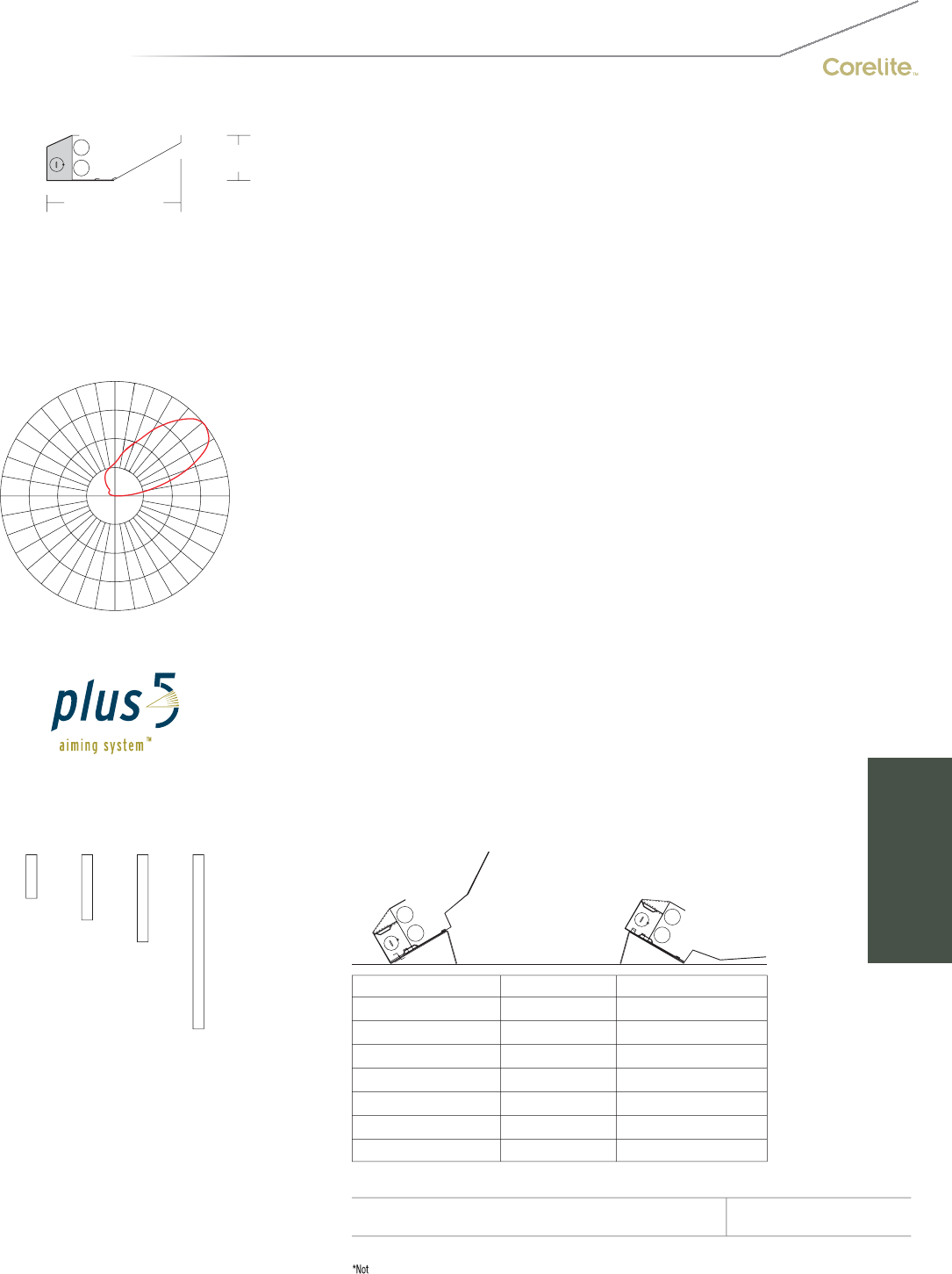
S
ERIE
S
C
T=
C
ov
e
T
r
io
O
PTI
CS
UP
S
=
S
pecula
r
O
PTI
CS
D
O
WN
N
=
N
on
e
N
U
MBER
OF
LAMP
S
2
=
2
L
am
ps
LAMP TYPE
T
8
=T
8
N
o
rm
a
l Out
p
ut
NUMBER
OF
C
IR
C
UIT
S*
1=1
C
ircui
t
2
=
2
Circuits
WIRIN
G
*
C
=
S
tandar
d
C
ircuit
D=Dimming
E=Emergency
B
=
B
atter
y
Pack
T
=
Nigh
t
ligh
t
Y
=
D
ay
li
g
h
t
V
O
LTA
G
E*
12
0
=12
0V
2
77=277
V
347=347V
U
NV=
U
niv
e
r
sal
(120V-277V)
RUN
LEN
G
TH
Specif
y
luminaire lengt
h
i
n
feet
.
-Individuall
y
M
ou
nt
ed
Lu
m
i
n
ai
r
es
ma
y
be
2
’,
3
’,
4
’,
o
r
8’
in
l
en
g
t
h.
-
C
ontinuously
M
ounte
d
S
tandar
d
row
configurations
o
v
er
8
’
consist o
f
4
’
and 8’ sections.
2’
a
n
d
3
’
sec
ti
o
n
s
wil
l
be
used
for
ro
w lengths
o
th
e
r th
an
i
n
4
’
i
n
c
r
e
m
e
nt
s
.
O
PTI
O
N
S
P5
=
Plus5
Ai
m
i
n
g
Sy
stem
PROJECT NAME: TYPE:
CATALOG #:
-
-
-
-
-
-
-
-
a
ll
opt
i
on
s
ava
il
a
bl
e.
Pl
eas
e
consu
lt
you
r
C
ooper
Li
g
h
t
i
n
g
R
epresentat
i
ve fo
r
ava
il
a
bili
ty an
d
t
echnical information.
S
pecifications and dimensions subject
t
o chang
e
without notice.
ORDERING INFORMATION:
SAMPLE NUMBER:CT-SN-1T8-1C-UNV-8’-P5
COVE TRIO
Co
n
s
tr
uc
ti
o
n
:
Housin
g
i
s
one
p
iec
e
d
i
e
-
fo
rm
ed
2
0-
g
au
ge
corros
i
on res
i
stan
t
stee
l,
f
ormin
g
a
3
”
d
ee
p
b
a
ll
ast c
h
anne
l.
S
tandar
d
2
’
-0
”,
3
’
-0
”
,
4’-0”, an
d
8’-0” fixture length
s
combin
e
for
co
ntin
uous
runs
.
Reflectors: Highly specula
r
anodize
d
aluminum
stri
p
in housing t
o
e
nh
a
n
ce
out
p
ut.
El
ec
tri
ca
l
:
Fixt
u
r
es
are
p
rewired wi
t
h
quick
wire
k
co
nn
ec
t
o
r
s
a
n
d
use
i
n
s
t
a
n
t
s
t
a
rt
UL
lis
t
ed
C
l
ass
P,
265ma
T
8 e
l
ectron
i
c
b
a
ll
asts.
P
owe
r
facto
r
of
95
%
wi
th
les
s
tha
n
10% THD. Fixture
s
an
d
e
l
ec
tri
ca
l com
p
onents
ce
rtifi
ed
t
o
UL
a
n
d
CUL
s
t
a
n
da
r
ds.
Fi
n
i
s
h:
Reflector pans are pre-pa
i
nt w
hi
t
e
90
%
r
eflectiv
e
aluminum. Ballas
t
channels
are
co
rr
os
i
o
n r
es
i
s
t
a
n
t
s
t
ee
l
.
O
ptions
:
Pl
us
5
Adj
usta
ble
Ai
m
i
ng
S
yste
m
a
ll
ow
s
f
o
r
5
degree incrementa
l
adjustments.
165
2 7/8" [73 MM]
8 1/2" [215 MM]
2T8
1
61
2361
1
70
0
177
7
590
90
90
80
80
118
180
80
0
80
Degree of Lift
0 (Standard)
5
10
15
20
25
30
Front Mount
2-7/8 x 8-1/2
3-5/8 x 8-1/2
4-1/4 x 8-1/4
5 x 8
5-5/8 x 7-3/4
6-1/4 x 7-1/2
6-3/4 x 7
Back Mount
2-7/8 x 8-1/2
3 x 8-3/4
3-1/4 x 8-7/8
3-1/2 x 9
3-1/2 x 9
3-3/4 x 9
4 x 8-7/8
96”48”36”24”
COVE
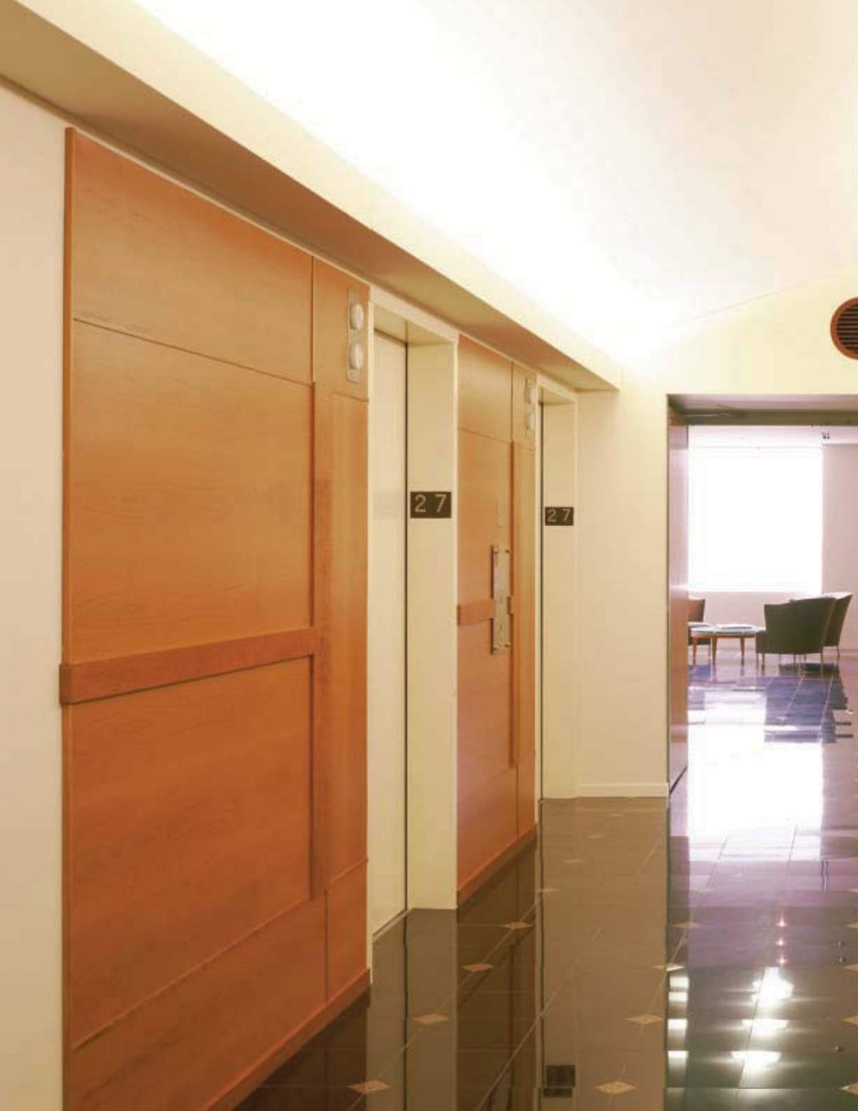
166
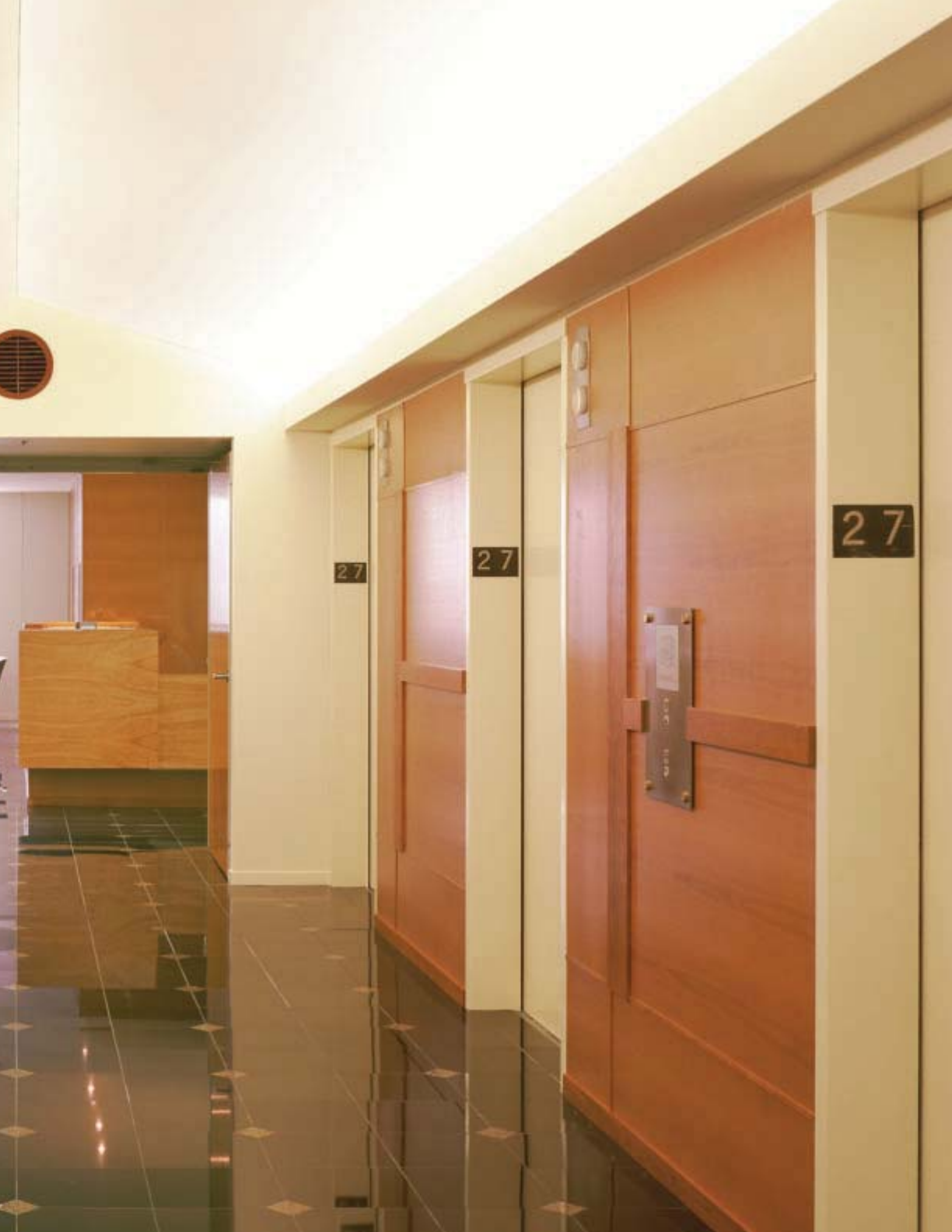
167

SMART
ENVIRONMENTS
Smarter Than The Average System.
More than ever, reigning in energy expenses and harnessing
the power of natural resources – sunlight, for example –
are imperative to operational success. It is Corelite’s goal
to provide as many cutting-edge tools to make doing so
not just possible for those in the know, but simple and
accessible for everyone. With so much intelligence ingrained
in Corelite’s platforms, just sit back and let it do what it does
best: save you money.
Who’s the smart one now?
168
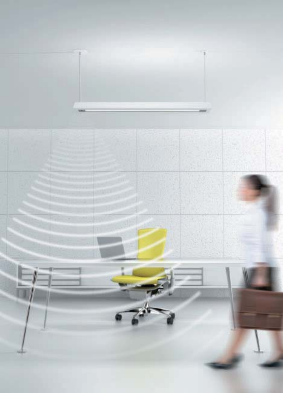
169

170
DAY-SENSE™
SMART ENVIRONMENTS
The Day-Sense sensor is an innovative
in-fi xture energy saving device. It
detects an infl ux of daylight, and in
turn automatically dims a fl uorescent
luminaire, or series of luminaires. This
sensor is manually adjustable to allow
for greater or lesser sensitivity to light
dependent upon user preference.
• Manually adjustable “Iris” type sensor allows user to set light sensitivity
• Footcandle Range: Application specific, consult factory
• Controls any 0-10 volt dimming ballast (no dimming controls required)
• Wall dimming controls not required, works with simple on/off switch
• Commissioning not required
• 1 Day-Sense sensor controls up to 20 ballasts
• Recommended for use in small private offices and conference rooms with windows
• Maximum recommended mounting height: 10’
• Available with all Corelite D/I Extrusion families
How to order:
L2-WM-2T5-1D-120-AC48-T1-12-DS
Note: Day-Sense (DS) must be specified with Dimming (D) and specific voltage (120, 277 or 347).
W
atts/Sq. ft.
W
atts/Sq. ft. Watts/Sq. ft
.
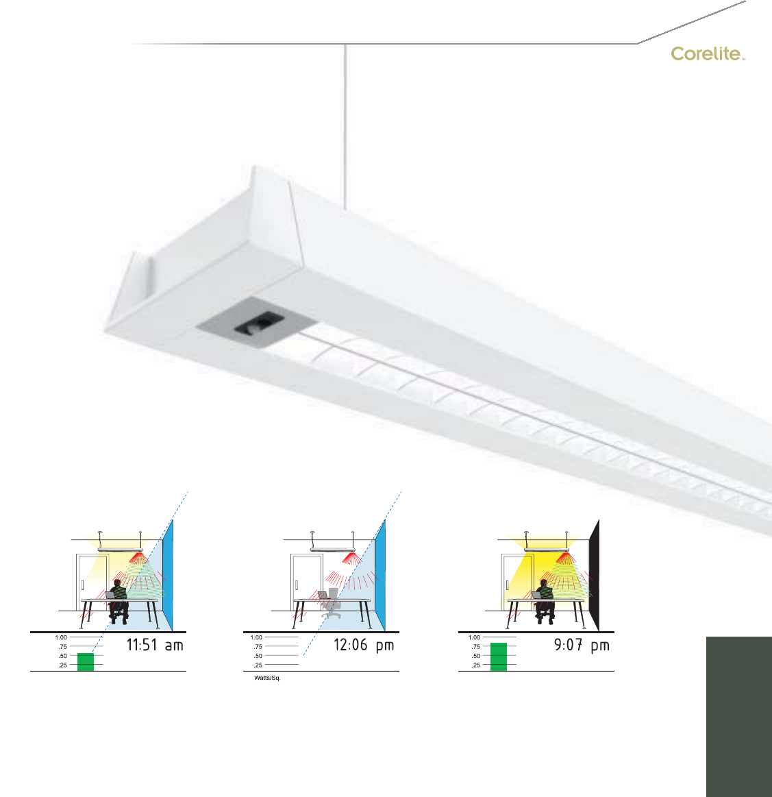
171
2SENSE™
• Controls any DALI protocol ballast (no dimming controls required)
• Footcandle Range: Application specific, consult factory.
• Wall dimming controls not required, works with simple on/off switch
• Commissioning not required
• Passive Infrared (PIR) Occupancy sensor with 2 settings (toggle on sensor):
Setting 1: Open Office Mode – steps lighting down to 50% after 15 minute of inactivity
Setting 2: Private Office Mode – shuts lighting completely off after 15 minutes of inactivity.
• Recommended for use in small private offices and conference rooms with windows
• Maximum recommended mounting height: 10’
• Available with all Corelite D/I Extrusion families
How to order:
L2-WM-2T5-1D-120-AC48-T1-12-2S
Note: 2Sense (2S) must be specified with Dimming (D) and specific voltage (120, 277 or 347).
W
atts
/Sq
.
ft
.
ft
.Watts
/Sq.
ft.
The energy saving 2Sense system
provides a combination of daylight
and occupancy sensing technology
(PIR) into one petite in-fi xture sensor.
2Sense’s daylight sensor automatically
dims the luminaire when daylight is
detected, while its occupancy sensor
will shut-off the luminaire if human
body heat has not been detected for
15 minutes.
SMART
ENVIRONMENTS

172
INCLASS COMMAND
SMART ENVIRONMENTS
A comprehensive turnkey lighting and control package that places the teacher in
command of the classrooom and the environment.
Teacher Lighting Controls:
Integration of lighting and controls into
one package, with command at the
teacher’s fingertips, could very well be the
teacher’s new best friend. Ensuring that
lighting is task appropriate – from ambient
illumination for reading to whiteboard
or media presentations – is crucial to
a productive atmosphere, and is easily
achieved with any of several customizable
switch interfaces. These controls
seamlessly combine the desired lighting
scenarios, making an attentive audience
just a switch-flip away.
Energy Saving Technology
In addition to the benefits of user control,
InClass Command employs occupancy and
daylight sensors to ensure that the lighting
system is as energy efficient as possible.
When daylight is present, the lighting dims
down. When students and teacher are no
longer present, the lighting shuts off. It’s
simple, smart and in command of true
energy savings.
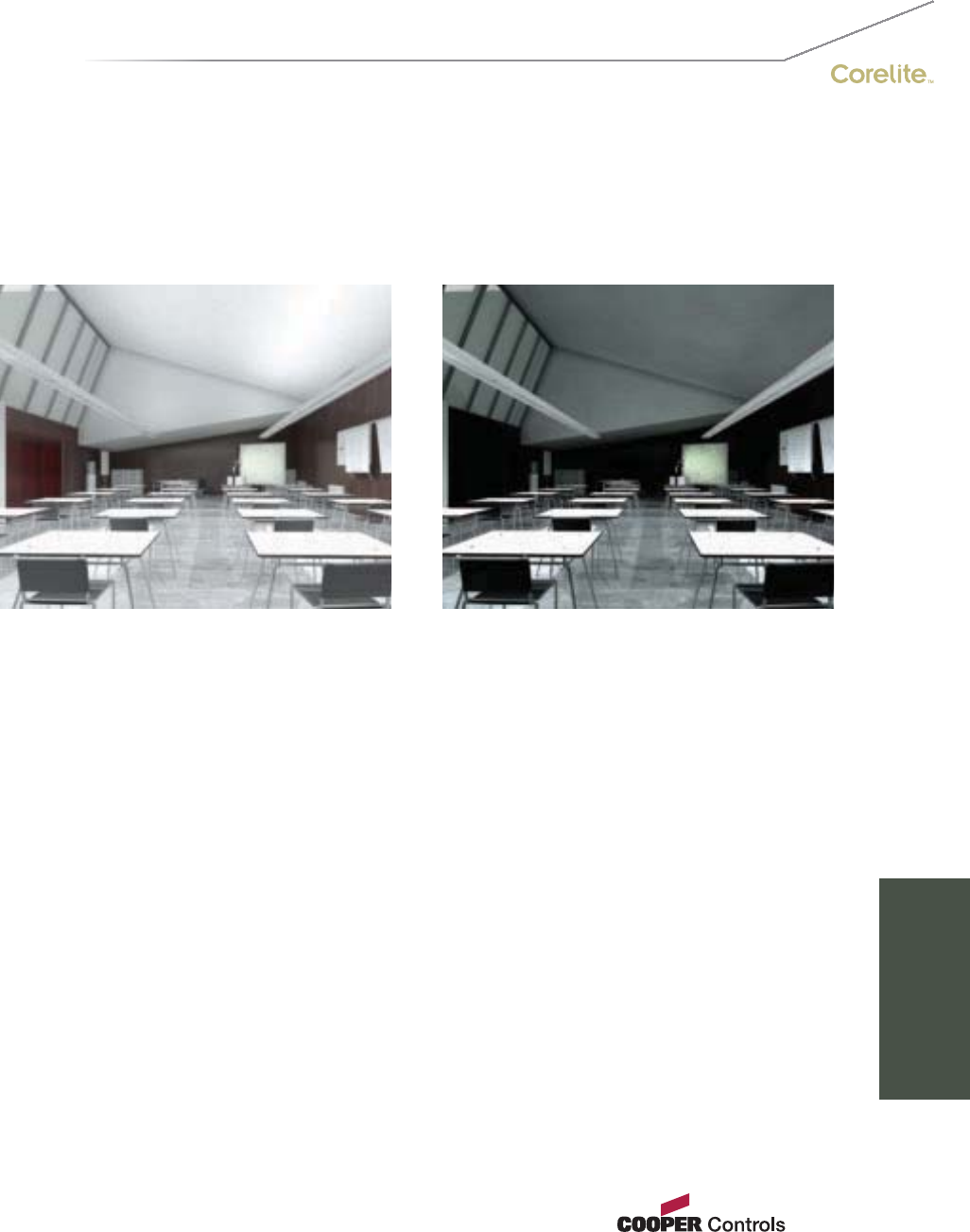
173
Lighting The Classroom
Creating an inviting and efficient atmosphere conducive to learning is of the utmost concern
when lighting for classrooms, and the needs of the instructor and the student must both
be considered. For the instructor, whiteboard visibility and the ability to adjust lighting for
multimedia presentations are critical. Students require efficient and controlled task lighting
for note taking and unimpeded computer screen visibility. Direct-Indirect suspended
luminaires, with their highly efficient bilateral ambient light distribution and isolatable
downlight components, address all of these requirements. The ability to easily integrate
energy-saving control systems only serves to further their appeal.
General Illumination A/V Mode
SMART
ENVIRONMENTS
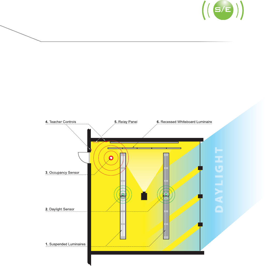
174
INCLASS COMMAND
SMART ENVIRONMENTS
(S
urfac
e
Mount
)
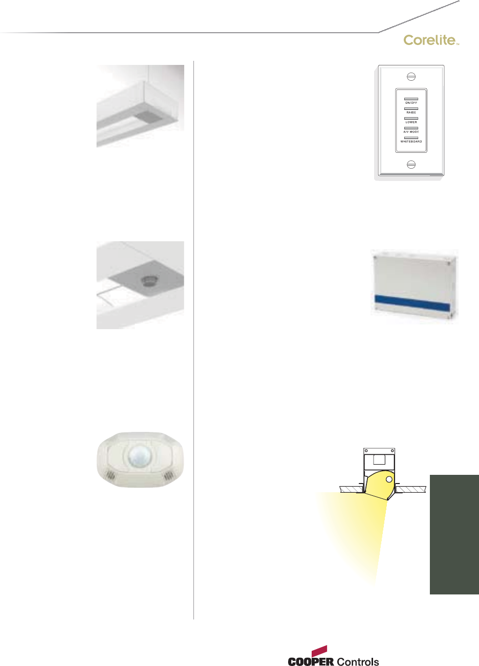
1. Suspended Luminaires
Corelite’s D/I Extrusion families supply
direct-indirect light distribution, offering
the ideal combination of functional direct
work surface illumination and indirect
ambient lighting for visual comfort. The
combination of lamp distribution isolators
and energy saving teacher controls truly
gives the teacher command of the class
and the classroom.
4. Teacher Lighting Controls
A decorator style switch with up
to fi ve buttons offers ON/OFF
control of relay groups with the
touch of a button. The switch also
provides scene control and raise/
lower control of lighting loads
when used in conjuction with the
relay panel.
5. Relay Panel
Corelite’s lighting control panel
is a cost effective specifi cation
grade lighting control system
packed with plenty of standard
features. Control up to 4 relays
per panel with optional support
for up to 4 0-10V dimming ballast
control outputs. Network up to 254
ControlKeeper panels for a state of
the art lighting control system.
2. Daylight Sensor
An innovative energy-saving device,
the Day-Sense sensor can detect a
specifi c user-defi ned daylight level in a
space, and in turn automatically dim the
luminaire down. When used properly in
environments having suffi cient daylight,
an energy savings of at least 35% can
be achieved.
3. Occupancy Sensor
Corelite’s Dual Technology surface
mount oc cupancy sensor’s combination
of Ultrasonic and Passive Infrared
technologies offers the most complete
sensing equipment available today.
This pairing helps eliminate false
activations or deactivations for additional
energy savings. The OMC-DT sensors are
also equipped with MicroSet technology,
which pro vides a revolutionary adaptive
and airfl ow tolerant technology, making
them ideal for spaces with increased
airfl ow due to higher occupant levels.
MicroSet Dual Tech sensors radically
simplify and reduce a contractor’s
installation and adjustment time period.
6. Recessed Whiteboard Luminaire
When ambient lighting
alone cannot adequately
provide the necessary
vertical footcandles, wall-
washing luminaires such
as the Neoray Series 23
may supplement the
lighting package to supply
the enhanced vertical
surface illumina tion
required for perfect
visibility of whiteboards.
175
SMART
ENVIRONMENTS
International Sales, USA
Cooper Lighting
1121 Highway 74 South
Peachtree City, GA 30269
P: 770-486-4800
F: 770-486-4801
Canada
Cooper Lighting
5925 McLaughlin Road
Mississauga, Ontario L5R 1B8
P: 905-507-4000
F: 905-568-7049
The Cooper Lighting Family
Halo
Metalux
Lumark
Sure-Lites
Neo-Ray
Corelite
Portfolio
Iris
Shaper
io
Lumière
Invue
McGraw-Edison
Streetworks
Fail-Safe
PDS
MWS
RSA
Ametrix
P
rinted i
n
US
A
A
DE090950
Cooper Industries, Ltd.
600 Travis, Ste. 5800
Houston, TX 77002-1001
P: 713-209-8400
www.cooperindustries.com
D
o
m
es
ti
c
F
ac
iliti
es
C
ranbury
,
N
e
w
J
erse
y
Elk
G
rove
Vill
age
,
Illi
no
is
Irvin
g,
T
e
x
as
O
ntario
,
C
aliforni
a
P
eac
h
tree
C
ity
,
G
eorgi
a
C
anadian F
ac
iliti
es
C
al
g
ary, Al
be
rt
a
T2E
7V
9
Mi
ss
i
ssauga,
O
ntario
L
5
R
1
B
8
C
oo
p
er Li
g
htin
g
a
n
d
Co
r
e
lit
e
lo
g
o
s
a
r
e
v
a
l
uab
l
e
tr
ade
m
a
rk
s
of
Cooper
f
In
dus
tri
es
in
th
e
U
nit
ed
S
t
a
t
es
a
n
d
o
th
e
r
cou
ntri
es.
Y
ou
a
r
e
no
t
p
ermitted
t
ou
se
the Coo
p
er Trademarks withou
t
the
p
rio
r
written consen
t
o
f
Cooper
f
Industries.
Corelite
4675 Holly Street
Denver, CO 80216
P: 303-393-1522
F: 303-393-1477
Cooper Lighting
Customer First Center
1121 Highway 74 South
Peachtree City, GA 30269
P: 770-486-4800
F: 770-486-4801
www.cooperlighting.com
