CA08100014E
64962-Catalog 64962-Catalog 64962-Catalog 782113 Batch8 unilog cesco-content
115768-Catalog 115768-Catalog 115768-Catalog Batch9 unilog cesco-content
133013-Catalog 133013-Catalog 133013-Catalog Batch9 unilog cesco-content
109967-Catalog 109967-Catalog 109967-Catalog 782113 Batch7 unilog cesco-content
116493-Attachment 116493-Attachment 116493-Attachment 782114 Batch7 unilog cesco-content
2014-11-11
: Pdf 64326-Attachment 64326-Attachment 786685 Batch12 unilog
Open the PDF directly: View PDF ![]() .
.
Page Count: 96
Volume 12—Aftermarket, Renewal Parts and Life Extension Solutions CA08100014E—November 2013 www.eaton.com V12-T13-1
1
2
3
4
5
6
7
8
9
10
11
12
13
14
15
16
17
18
19
20
21
22
23
24
25
Motor Control
Motor Control
13 Motor Control
Contactors, Starters and Brakes . . . . . . . . . . . . . . . . . . . . . . . . . . . . . V12-T13-2
Adjustable Frequency AC Drives . . . . . . . . . . . . . . . . . . . . . . . . . . . . . V12-T13-69
Synchronous . . . . . . . . . . . . . . . . . . . . . . . . . . . . . . . . . . . . . . . . . . . . V12-T13-73
Starters (Medium Voltage). . . . . . . . . . . . . . . . . . . . . . . . . . . . . . . . . . V12-T13-84

V12-T13-2 Volume 12—Aftermarket, Renewal Parts and Life Extension Solutions CA08100014E—November 2013 www.eaton.com
1
2
3
4
5
6
7
8
9
10
11
12
13
14
15
16
17
18
19
20
21
22
23
24
25
13
Motor Control
Contactors, Starters and Brakes
Contents
Description Page
Pre 3-Star
Product History Time Line, Replacement
Capabilities, Technology Upgrades . . . . . . . . . . . . . . V12-T13-4
3-Star
Product History Time Line, Replacement
Capabilities, Technology Upgrades . . . . . . . . . . . . . . V12-T13-5
Citation
Product History Time Line. . . . . . . . . . . . . . . . . . . . . V12-T13-6
Replacement Capabilities . . . . . . . . . . . . . . . . . . . . . V12-T13-7
Ty p e N
Product History Time Line, Replacement
Capabilities, Technology Upgrades . . . . . . . . . . . . . V12-T13-22
A200
Product History Time Line, Replacement
Capabilities . . . . . . . . . . . . . . . . . . . . . . . . . . . . . . . V12-T13-23
Technology Upgrades . . . . . . . . . . . . . . . . . . . . . . . V12-T13-26
A202
Product History Time Line, Replacement
Capabilities . . . . . . . . . . . . . . . . . . . . . . . . . . . . . . . V12-T13-33
V201 and V200
Replacement Capabilities . . . . . . . . . . . . . . . . . . . . V12-T13-36
Freedom
Product Description, Product History Time Line . . . V12-T13-37
Replacement Capabilities . . . . . . . . . . . . . . . . . . . . V12-T13-38
Technology Upgrades . . . . . . . . . . . . . . . . . . . . . . . V12-T13-46
IT. Electromechanical NEMA
Product Description, Product History Time Line,
Replacement Capabilities, Technology Upgrades . . V12-T13-47
IT. Electromechanical IEC
Product Description, Product History Time Line,
Replacement Capabilities, Technology Upgrades . . V12-T13-48
XT IEC Power Control
Product Description, Product History Time Line,
Replacement Capabilities, . . . . . . . . . . . . . . . . . . . V12-T13-49
Advantage
Product Description, Product History Time Line,
Replacement Capabilities, Technology Upgrades . . V12-T13-51
Definite Purpose
Product History Time Line, Replacement
Capabilities, Technology Upgrades . . . . . . . . . . . . . V12-T13-52
JF Autostarter
Product History Time Line, Replacement
Capabilities, Technology Upgrades . . . . . . . . . . . . . V12-T13-53
ME and MD dc Contactors
Product Description, Product History,
Product History Time Line, Replacement
Capabilities . . . . . . . . . . . . . . . . . . . . . . . . . . . . . . . V12-T13-54
Technology Upgrades . . . . . . . . . . . . . . . . . . . . . . . V12-T13-57
C80 Mill Type dc Contactors
Product Description, Product History Time Line,
Replacement Capabilities, Technology Upgrades . . V12-T13-58
Description Page
511 AC and DC Brakes
Product Description, Product History Time Line,
Replacement Capabilities, Technology Upgrades . . .V12-T13-61
DPM-Contactor
Product Description, Product History Time Line,
Replacement Capabilities, Technology Upgrades . . .V12-T13-62
AVD-Contactor
Product Description, Product History,
Product History Time Line,
Replacement Capabilities, Technology Upgrades . . .V12-T13-63
D-Contactor
Product Description, Product History,
Product History Time Line, Replacement
Capabilities, Technology Upgrades . . . . . . . . . . . . . . V12-T13-64
Reversing/Assignment Contactors
Product Description, Product History,
Product History Time Line, Replacement
Capabilities, Technology Upgrades . . . . . . . . . . . . . . V12-T13-65
P- & S-Contactors
Product Description, Product History,
Product History Time Line, Replacement
Capabilities, Technology Upgrades . . . . . . . . . . . . . . V12-T13-66
Overview
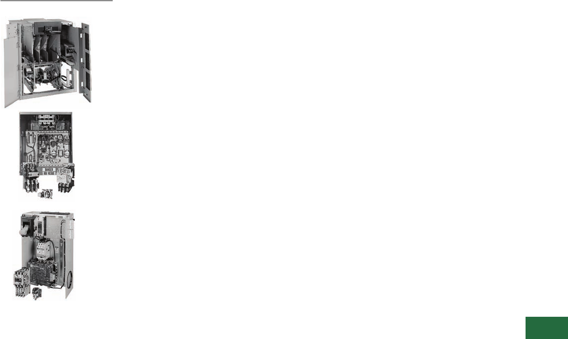
Type N Contactor Citation Starter
Product Description
Cutler-Hammer® Starters and Contactors from Eaton’s electrical
business were and are designed to control functions of a
connected motor by starting, stopping, reversing, regulating and
protecting. When functions do not include speed regulation, this
device is known as a starter rather than a controller.
Applications for starter functions are fans, pumps, constant
horsepower, constant or variable torque machine tools, constant
torque metalworking machinery, variable torque and horsepower
fans and blowers, constant power heating, lighting, pumps and
motors for all types of applications.

Volume 12—Aftermarket, Renewal Parts and Life Extension Solutions CA08100014E—November 2013 www.eaton.com V12-T13-3
1
2
3
4
5
6
7
8
9
10
11
12
13
14
15
16
17
18
19
20
21
22
23
24
25
13
Motor Control
Contactors, Starters and Brakes
Product History
Freedom
The Cutler-Hammer line of
contactors and starters dates
back to the early 1920s in
Milwaukee, WI. Changes
in coil construction, making
the first moisture-proof
vacuum with impregnated
coils, were innovations
in this line of contactors and
starters manufactured before
the 3-Star line (now known as
the Pre 3-Star). Eutectic alloy
overloads were used later in
this design with the design
change to the 3-Star line. A
few of the new features of
the 3-Star line of contactors
and starters were the first
standard three-coil overload
relays, new molding
compounds, new metals
and cast resin coils.
IT.
The Type F magnetic
contactor is the first
magnetically controlled
contactor in our
Westinghouse® records.
It was open in design,
simple in construction and
was state-of-the-art due to
its magnetically controlled
armature. The Type F
contactor was replaced by
the DE-ION® contactor, which
featured the Westinghouse
trademark DE-ION arc
quenching. The DE-ION was
followed by the Type DN,
Type N and the Type A, today
known as the A200. The Type
B was developed in the late
1970s and was obsoleted
two or three years later. The
A200 open control is still a
current offering. Prior to
1985, some of the larger
sizes (5–9) were known as
GCA and GCD.
The Citation line of contactors
and starters was introduced
in 1968 with many new
features: the new CI non-
wearing totally enclosed
permanent air gap magnet
structure; dual wound
magnet coil with plug-in
feature; color coded, twin
break dust-safe contacts;
and straight-through wiring.
Although the Citation line
was obsoleted in 1997,
replacement contact kits,
magnet coils and heater coils
will continue to be available.
Today, the Freedom™
contactor, launched in 1986,
coexists with the solid-state
heaterless IT. contactor, a
microprocessor-controlled
magnetic contactor
introduced in 2002.
V12-T13-4 Volume 12—Aftermarket, Renewal Parts and Life Extension Solutions CA08100014E—November 2013 www.eaton.com
1
2
3
4
5
6
7
8
9
10
11
12
13
14
15
16
17
18
19
20
21
22
23
24
25
13
Motor Control
Contactors, Starters and Brakes
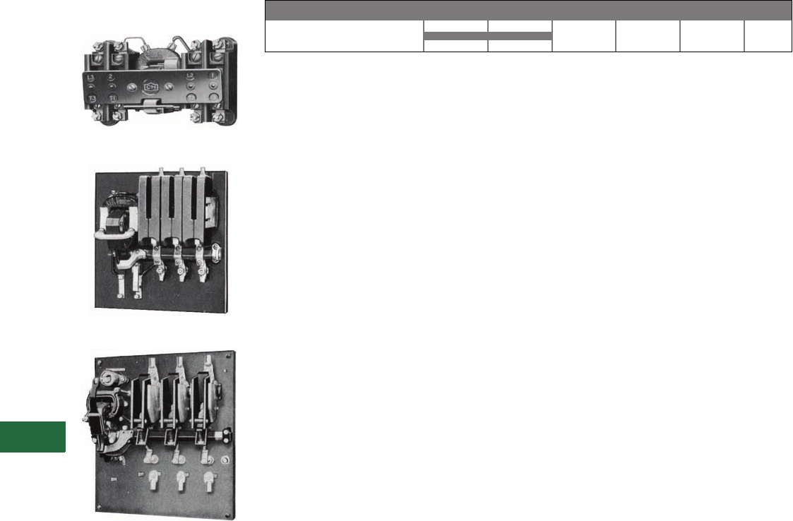
Pre 3-Star
Originally a Cutler-Hammer
Product
Size 1 Contactor
Size 2 Contactor
Size 5 Contactor
Parts are no longer available
for Pre-3 Star.
Product History Time Line for Pre 3-Star, Bulletin 9586 1
Replacement Capabilities
There are no replacement
parts available. Replace with
new contactor or starter.
Technology Upgrades
Size 00–3—Freedom or IT.
Sizes 4–5—Freedom,
Vacuum or IT.
Note
1For all NEMA® rated starters, please
contact Standard Open Control
Aftermarket at 1-800-535-8992.
Sizes 00 – 5
Size 1920 1940 1960 1980 2000 Present
Volume 12—Aftermarket, Renewal Parts and Life Extension Solutions CA08100014E—November 2013 www.eaton.com V12-T13-5
1
2
3
4
5
6
7
8
9
10
11
12
13
14
15
16
17
18
19
20
21
22
23
24
25
13
Motor Control
Contactors, Starters and Brakes
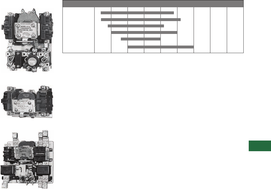
3-Star
Originally a Cutler-Hammer
Product
Typical Size 0—Starter
Typical Size 1—Contactor
Typical Size 5—Starter
Product History Time Line for 3-Star, Bulletin 9560, 9586, 9589, 9591, 9556, 9658,
9736 and 9739 1
Replacement Capabilities
There are no replacement
parts available. Replace with
new contactor or starter.
Technology Upgrades
Sizes 00–3—Freedom or IT.
Sizes 4–5—Freedom,
Vacuum or IT.
Note
1For all NEMA rated Bulletin 9586
starters, please contact Standard
Open Control Aftermarket
at 1-800-535-8992.
Size 0
Size 1
Size 2
Size 3
Size 4
Size 5
Size 1950 1955 1960 1965 1970 1975 1985 2000 Present
V12-T13-6 Volume 12—Aftermarket, Renewal Parts and Life Extension Solutions CA08100014E—November 2013 www.eaton.com
1
2
3
4
5
6
7
8
9
10
11
12
13
14
15
16
17
18
19
20
21
22
23
24
25
13
Motor Control
Contactors, Starters and Brakes
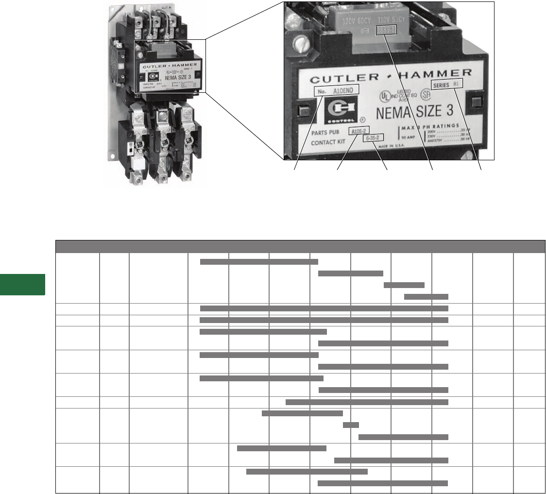
Citation
Originally a Cutler-Hammer Product
Citation Starter and Nameplate
Product History Time Line for Citation A10, A11, A13, A30, A31, A40, A41, A50, A51, A70, A71, A80, A81, B10, B11, B50, B51,
B52, C10, C30 and C50
Note
1Although the number “9” is not imprinted on the coil, it must be used when ordering. For example, the proper ordering number for a 120V, 60 Hz,
AC magnet coil would be 9-1887-1 (refer to the style numbers on Page V12-T13-7).
Catalog
Number
Parts
Publication
SeriesCoil 1
Contact
Kit
NEMA Size Series 1965 1970 1975 1980 1985 1990 1995 2000 Present
Size 00 A1
B1
C1
D1
Size 0 A1
Size 1 A1
Size 2 A1
B1
Size 3 A1
B1
Size 4 A1
B1
Size 5 A1
Size 6 A1
B1
C1
Size 7 A1
B1
Size 8 A1
B1

Volume 12—Aftermarket, Renewal Parts and Life Extension Solutions CA08100014E—November 2013 www.eaton.com V12-T13-7
1
2
3
4
5
6
7
8
9
10
11
12
13
14
15
16
17
18
19
20
21
22
23
24
25
13
Motor Control
Contactors, Starters and Brakes
Replacement Capabilities
Replacement Capabilities—Contacts and Coils
Replacement Capabilities—Contacts and Coils, continued
Notes
1Citation overload relays are no longer available. A Freedom overload may be an option. Contact Control Aftermarket at 1-800-535-8992.
2Replace complete contactor.
3Non-encapsulated coil.
4For use in existing DC operated devices. Not for conversion of existing AC operated devices to DC.
Description
Coil
Suffix
Style and Part Numbers
Size 00 Size 00 Size 00 Size 00 Size 0 Size 1 Size 2 Size 2 Size 3 Size 3
Series A1 1Series B1 Series C1 Series D1 Series A1 Series B1 Series A1 Series B1
Contact Kits
Part number on contactor or
starter nameplate
Two-pole without interlock — 6-21 222 6-22 6-23 6-24 6-34 6-25 6-35
Three-pole without interlock — 6-21-2 222 6-22-2 6-23-2 6-24-2 6-34-2 6-25-2 6-35-2
Three-pole with interlock — 6-21-3 22— ——————
Four-pole without interlock — — — — — 6-22-3 6-23-3 —6-34-3 ——
Five-pole without interlock — — — — — 6-22-4 6-23-4 —6-34-4 ——
Magnet Coils
120V, 60 Hz or 110V, 50 Hz A 9-1945-1 9-2183-1 9-2650-1 9-2823-1 9-1887-1 9-1887-1 9-1889-1 9-2526-1 9-1891-1 9-1889-1
240V, 60 Hz or 220V, 50 Hz B 9-1945-2 9-2183-2 9-2650-2 9-2823-2 9-1887-2 9-1887-2 9-1889-2 9-2526-2 9-1891-2 9-1889-2
480V, 60 Hz or 440V, 50 Hz C 9-1945-3 9-2183-5 9-2650-3 9-2823-3 9-1887-3 9-1887-3 9-1889-3 9-2526-3 9-1891-3 9-1889-3
600V, 60 Hz or 550V, 50 Hz D 9-1945-4 9-2183-19 9-2650-4 9-2823-4 9-1887-4 9-1887-4 9-1889-4 9-2526-4 9-1891-4 9-1889-4
208V, 60 Hz E 9-1945-5 9-2183-17 9-2650-5 9-2823-5 9-1887-5 9-1887-5 9-1889-13 9-2526-5 9-1891-13 9-1889-13
24V, 60 Hz T 9-1945-8 9-2183-16 9-2650-7 9-2823-18 9-1887-7 9-1887-7 9-1889-20 9-2526-6 9-1891-15 9-1889-20
380V, 50 Hz L 9-1945-6 9-2183-3 9-2650-6 9-2421-18 39-1887-8 9-1887-8 9-1889-14 9-2526-7 9-1891-14 9-1889-14
277V, 60 Hz H 9-1945-16 9-2183-18 9-2650-13 9-2823-12 9-1887-16 9-1887-16 9-1889-31 9-2526-15 9-1891-26 9-1889-31
9-2823-17
120 Vdc 4A1 — — — — 9-2024-2 9-2024-2 9-2025-2 9-2626-2 9-2026-2 9-2025-2
240 Vdc 4B1 — — — — 9-2024-1 9-2024-1 9-2025-1 9-2626-1 9-2026-1 9-2025-1
24 Vdc 4T1 — — — — 9-2024-4 9-2024-4 9-2025-4 9-2626-4 9-2026-4 9-2025-4
48 Vdc 4W1 — — — — 9-2024-3 9-2024-3 9-2025-3 9-2626-3 9-2026-3 9-2025-3
Description
Coil
Suffix
Style and Part Numbers
Size 4Size 4Size 5Size 6Size 6Size 6Size 7Size 7Size 8 Size 8
Series A1 Series B1 Series A1 Series B1 Series C1 Series A1 Series B1 Series A1 Series B1
Contact Kits
Part number on contactor or
starter nameplate
Two-pole — 6-26 6-36-3 6-27 6-28 —6-601-2 6-28 —— —
Three-pole — 6-26-2 6-36-4 6-27-2 6-28-2 6-570 6-601 6-28-2 6-570 646C829G05 6-571
Magnet Coils
120V, 60 Hz or 110V, 50 Hz A 9-1891-1 9-1891-1 9-1891-1 9-1875-1 9-2651 9-2698 9-1875-1 9-2651 438C805G12 9-2654
240V, 60 Hz or 220V, 50 Hz B 9-1891-2 9-1891-2 9-1891-2 9-1875-2 9-2651-2 9-2698-2 9-1875-2 9-2651-2 438C805G11 9-2654-2
480V, 60 Hz or 440V, 50 Hz C 9-1891-3 9-1891-3 9-1891-3 9-1875-3 9-2651-3 9-2698-3 9-1875-3 9-2651-3 438C805G10 9-2654-3
600V, 60 Hz or 550V, 50 Hz D 9-1891-4 9-1891-4 9-1891-4 9-1875-4 9-2651-4 9-2698-4 9-1875-4 9-2651-4 —9-2654-4
208V, 60 Hz E 9-1891-13 9-1891-13 9-1891-13 9-1875-14 9-2651-6 9-2698-5 9-1875-14 9-2651-6 438C805G11 9-2654-6
24V, 60 Hz T 9-1891-15 9-1891-15 9-1891-15 —————— —
380V, 50 Hz L 9-1891-14 9-1891-14 9-1891-14 —9-2651-5 9-2698-6 —9-2651-5 438C805G15 9-2654-5
277V, 60 Hz H 9-1891-26 9-1891-26 9-1891-26 —————— —
120 Vdc 4A1 9-2026-2 9-2026-2 9-2026-2 —————— —
240 Vdc 4B1 9-2026-1 9-2026-1 9-2026-1 —————— —
24 Vdc 4T1 9-2026-4 9-2026-4 9-2026-4 —————— —
48 Vdc 4W1 9-2026-3 9-2026-3 9-2026-3 —————— —
V12-T13-8 Volume 12—Aftermarket, Renewal Parts and Life Extension Solutions CA08100014E—November 2013 www.eaton.com
1
2
3
4
5
6
7
8
9
10
11
12
13
14
15
16
17
18
19
20
21
22
23
24
25
13
Motor Control
Contactors, Starters and Brakes
Three-Pole Contact Kit, Size 3, Series B1 Three-Pole Contact Kit, Size 5
Replacement Capabilities—Overload Relays
Replacement Capabilities—Overload Relays, continued
Technology Upgrades
Sizes 00–3—Freedom or IT.
Sizes 4–6—Freedom, Vacuum
or IT.
Sizes 7–8—Freedom
Adapter Plates
The adapter plates make it
possible to replace a Citation
starter
with a Freedom or
Advantage starter and
the
same mounting holes can
be used.
Notes
1Citation overload relays are no longer
available. Replace with up-to-date
starter, or contact Standard Open Control
Aftermarket at 1-800-535-8992
to determine Freedom overload relay
compatibility.
2No longer available. Replace with up-to-
date overload relay or starter.
3Will no longer be available once stock
is depleted. If stock is out, replace with
up-to-date overload relay or starter.
4On Vista; no price.
Description
Style and Part Numbers
Size 00 Size 00 Size 00 Size 00 Size 0 Size 1 Size 2 Size 2 Size 3 Size 3
Series A1 Series B1 Series C1 Series D1 Series A1 Series B1 Series A1 Series B1
Overload Relays
Without mounting plates—
for replacement on existing starters
Standard trip (Class 20)
Eutectic — 1 Element
3 Element
3 Element with
alarm circuit
11111 1 1111
Slow trip (Class 30)
Eutectic — 1 Element
3 Element
11111 1 1111
Replacement Thermal Elements
Standard trip eutectic
22222 2 2222
Slow trip eutectic
10-5018 310-5018 310-5018 310-5018 310-5018 310-5018 310-5018 310-5018 310-5018 310-5018 3
Description
Style and Part Numbers
Size 4 Size 4 Size 5 Size 6 Size 6 Size 6 Size 7 Size 7 Size 8 Size 8
Series A1 Series B1 Series A1 Series B1 Series C1 Series A1 Series B1 Series A1 Series B1
Overload Relays
Without mounting plates—
for replacement on existing starters
Standard trip (Class 20)
Eutectic — 1 Element
3 Element
3 Element with
alarm circuit
11111 1 1111
Replacement Thermal Elements
Standard trip eutectic
22222 2 2222
Slow trip eutectic
10-5018 310-5018 310-5018 3—— — ————
Current transformer — — — — 42-3418-3 442-3418-3 4————
Magnet Coil, 120V/60 Hz for Size 3,
Series A1
Adapter Plates Ordering Information
NEMA
Size
Adapter Plate Catalog Number
Freedom Advantage
00, 0 C321CMP0 —
1C321CMP1 WBASE12
2C321CMP2 WBASE 12
3C321CMP3 WBASE 34
4C321CMP4 WBASE 34
5C321CMP5 —

Volume 12—Aftermarket, Renewal Parts and Life Extension Solutions CA08100014E—November 2013 www.eaton.com V12-T13-9
1
2
3
4
5
6
7
8
9
10
11
12
13
14
15
16
17
18
19
20
21
22
23
24
25
13
Motor Control
Contactors, Starters and Brakes
Heaters
Overload relays do not include
heaters. Please see table for
heater element index.
Heater Selection
For Replacement in Existing
Applications Only
Heaters are rated to protect
40°C rise of motors; and,
open and drip-proof motors
having a service factor of
1.15 where the motor and
the controller are at the same
ambient temperature.
For other conditions:
1. For 50°C, 55°C and 75°C
(122°F, 131°F and 167°F)
rise motors and
enclosed motors having
a service factor of 1.0,
select one size smaller.
2. Ambient temperature of
the starter lower than
the motor by 26°C
(79°F), use one size
smaller.
3. Ambient temperature of
the starter higher than
the motor by 26°C
(79°F), use one size
larger.
Ultimate tripping current of
heaters is approximately 1.25
times the minimum current
rating listed in the tables.
Heater Selection Index
Note: Use this index to cross-reference tables on Pages V12-T13-9 through V12-T13-21.
Index of Overload Relay Heater Selection Tables
Notes
1Select heaters for 50% of rated full load current.
2Select heaters for 68% of rated full load current.
Individually boxed heaters master packed 10 per carton.
Starter
Type
Catalog
Prefix Type
Heater Selection Table Number
NEMA Size of Starter
00-0-1
(1-1/2)2345678
A10 Open ST-1 ST-3 ST-5 ST-7 ST-16 ST-10 ST-11 ST-12
Enclosed ST-2 ST-4 ST-6 ST-7 ST-16 ST-10 ST-11 ST-12
A11 Open BNC-1 BNC-3 BNC-5 BNC-7 BNC-9 — — —
Enclosed BNC-2 BNC-4 BNC-6 BNC-7 BNC-9 — — —
A13 Open LT-2 LT-4 LT-6 LT-7 LT-8 — — —
Enclosed LT-1 LT-3 LT-5 LT-7 LT-8 — — —
A30 and A40 Enclosed ST-9 ST-3 ST-6 ST-7 ST-16 ST-10 ST-11 ST-12
A31 and A41 Enclosed BNC-8 BNC-3 BNC-6 BNC-7 BNC-9 — — —
A50 Open ST-1 ST-3 ST-5 ST-7 ST-16 ST-10 ST-11 ST-12
Enclosed ST-2 ST-4 ST-6 ST-7 ST-16 ST-10 ST-11 ST-12
A51 Open BNC-1 BNC-3 BNC-5 BNC-7 BNC-9 — — —
Enclosed BNC-2 BNC-4 BNC-6 BNC-7 BNC-9 — — —
A70 and A80 Enclosed ST-9 ST-3 ST-6 ST-7 ST-16 ST-10 ST-11 ST-12
A71 and A81 Enclosed BNC-8 BNC-3 BNC-5 BNC-7 BNC-9 — — —
A400-A420 Enclosed — — ST-14 ST-15 ST-16 ST-10 ST-11 ST-12
A460 1Enclosed ST-2 1ST-4 1ST-6 1ST-7 1ST-16 1ST-10 1ST-11 1ST-12 1
A490 2Enclosed ST-2 2ST-4 2ST-6 2ST-7 2ST-16 2ST-10 2ST-11 2ST-12 2
A700 Open ST-1 ST-3 ST-5 ST-7 ST-16 — — —
Enclosed ST-2 ST-4 ST-6 ST-7 ST-16 ST-10 — —
A800-A803 Enclosed ST-9 ST-3 ST-5 ST-7 ST-16 ST-10 ST-11 —
A804-A806 Enclosed ST-9 ST-3 ST-5 — — — — —
A808-A809 Enclosed — ST-13 ST-5 ST-5 — — — —
B10 and B50 Enclosed ST-1 ST-3 ST-5 ST-7 — — — —
B11 and B51 Open BNC-1 — — — — — — —
Enclosed BNC-2 BNC-3 BNC-5 — — — — —
C300 Open and
enclosed
ST-1 ST-3 ST-5 ST-7 — — — —
C301 Open and
enclosed
BNC-1 BNC-4 BNC-5 BNC-7 — — — —
C303 Open and
enclosed
LT-2 LT-4 LT-6 LT-7 — — — —

V12-T13-10 Volume 12—Aftermarket, Renewal Parts and Life Extension Solutions CA08100014E—November 2013 www.eaton.com
1
2
3
4
5
6
7
8
9
10
11
12
13
14
15
16
17
18
19
20
21
22
23
24
25
13
Motor Control
Contactors, Starters and Brakes
Overload Relay Heater Selection Tables
Type ST Standard Trip Eutectic Alloy
For replacement in existing applications only; for motors with 1.15 service factor.
Notes
1For A460 controllers, select heaters at 50% of rated full load current.
2For A490 controllers, select heaters at 58% of rated full load current.
Individually boxed heaters master packed 10 per carton.
Table ST-1 Table ST-2 Table ST-3 Table ST-4 Table ST-5
Heater
Catalog
Number
NEMA Sizes 00, 0, 1, 1-1/2 NEMA Sizes 00, 0, 1, 1-1/2 NEMA Size 2 NEMA Size 2 NEMA Size 3
For Open Type
Catalog Prefix A10, A50,
A700, B10, B50, C300
For Enclosed Type
Catalog Prefix B10,
B50, C300
For Enclosed Type
Catalog Prefix A10, A50,
A460 1, A490 2, A700
For Open Type
Catalog Prefix A10, A50,
A700, B10, C300
For Enclosed Type
Catalog Prefix B10, C300, A30,
A40, A70, A80, A800-A803
For Enclosed Type
Catalog Prefix A10, A50,
A460 1, A490 2, A700
For Open Type
Catalog Prefix A10, A50,
A700, B10, C300
For Enclosed Type
Catalog Prefix A70, A80,
A800-A803, A808-A809, B10
Heater Ampere Range
0.167–0.187 0.155–0.173 — — — H1101
0.188–0.210 0.174–0.195 — — — H1102
0.211–0.237 0.196–0.220 — — — H1103
0.238–0.266 0.221–0.247 — — — H1104
0.267–0.298 0.248–0.278 — — — H1105
0.299–0.334 0.279–0.310 — — — H1106
0.335–0.376 0.311–0.349 — — — H1107
0.377–0.422 0.350–0.391 — — — H1108
0.423–0.474 0.392–0.441 — — — H1109
0.475–0.532 0.442–0.495 — — — H1110
0.533–0.598 0.496–0.555 — — — H1111
0.599–0.672 0.556–0.624 — — — H1112
0.673–0.757 0.625–0.703 — — — H1113
0.758–0.855 0.704–0.795 — — — H1114
0.865–0.959 0.796–0.895 — — — H1115
0.960–1.07 0.896–0.999 — — — H1116
1.08–1.21 1.00–1.12 — — — H1117
1.22–1.35 1.13–1.25 — — — H1018
1.36–1.52 1.26–1.41 — — — H1019
1.53–1.70 1.42–1.58 — — — H1020
1.71–1.90 1.59–1.77 — — — H1021
1.91–2.10 1.78–1.96 — — — H1022
2.11–2.33 1.97–2.17 — — — H1023
2.34–2.62 2.18–2.44 — — — H1024
2.63–2.93 2.45–2.72 — — — H1025
2.94–3.27 2.73–3.04 — — — H1026
3.28–3.64 3.05–3.38 — — — H1066
3.65–4.06 3.39–3.73 3.72–4.10 — — H1027
4.07–4.55 3.74–4.18 4.11–4.59 3.86–4.31 — H1028
4.56–5.03 4.19–4.63 4.60–5.07 4.32–4.77 — H1029

Volume 12—Aftermarket, Renewal Parts and Life Extension Solutions CA08100014E—November 2013 www.eaton.com V12-T13-11
1
2
3
4
5
6
7
8
9
10
11
12
13
14
15
16
17
18
19
20
21
22
23
24
25
13
Motor Control
Contactors, Starters and Brakes
Type ST Standard Trip Eutectic Alloy, continued
For replacement in existing applications only; for motors with 1.15 service factor.
Notes
1For A460 controllers, select heaters at 50% of rated full load current.
2For A490 controllers, select heaters at 58% of rated full load current.
Individually boxed heaters master packed 10 per carton.
Table ST-1 Table ST-2 Table ST-3 Table ST-4 Table ST-5
Heater
Catalog
Number
NEMA Sizes 00, 0, 1, 1-1/2 NEMA Sizes 00, 0, 1, 1-1/2 NEMA Size 2 NEMA Size 2 NEMA Size 3
For Open Type
Catalog Prefix A10, A50,
A700, B10, B50, C300
For Enclosed Type
Catalog Prefix B10,
B50, C300
For Enclosed Type
Catalog Prefix A10, A50,
A460 1, A490 2, A700
For Open Type
Catalog Prefix A10, A50,
A700, B10, C300
For Enclosed Typ e
Catalog Prefix B10, C300, A30,
A40, A70, A80, A800-A803
For Enclosed Type
Catalog Prefix A10, A50,
A460 1, A490 2, A700
For Open Type
Catalog Prefix A10, A50,
A700, B10, C300
For Enclosed Type
Catalog Prefix A70, A80,
A800-A803, A808-A809, B10
Heater Ampere Range
5.04–5.59 4.64–5.15 5.08–5.65 4.78–5.31 — H1030
5.60–6.25 5.16–5.68 5.66–6.29 5.32–5.90 — H1031
6.26–6.92 5.69–6.30 6.30–7.00 5.91–6.55 — H1032
6.93–7.75 6.31–7.05 7.01–7.82 6.56–7.33 — H1033
7.76–8.63 7.06–7.76 7.83–8.79 7.34–8.15 8.32–9.27 H1034
8.64–9.59 7.77–8.63 8.80–9.67 8.16–9.03 9.28–10.1 H1035
9.60–10.6 8.64–9.51 9.68–10.8 9.04–10.1 10.2–11.4 H1036
10.7–11.9 9.52–10.5 10.9–12.0 10.2–11.2 11.5–12.8 H1037
12.0–13.3 10.6–11.8 12.1–13.4 11.3–12.5 12.9–14.3 H1038
13.4–14.7 11.9–13.1 13.5–14.9 12.6–13.9 14.4–16.0 H1039
14.8–16.6 13.2–14.8 15.0–17.6 14.0–15.7 16.1–17.8 H1040
16.7–18.8 14.9–16.7 17.7–19.0 15.8–17.5 17.9–20.3 H1041
18.9–21.2 16.8–18.9 19.1–21.5 17.6–19.8 20.4–22.9 H1042
21.3–23.9 19.0–21.3 21.6–24.5 19.9–22.3 23.0–26.0 H1043
24.0–27.0 21.4–24.1 24.6–27.9 22.4–25.4 26.1–29.5 H1044
— 24.2–27.0 28.0–32.0 25.5–28.7 29.6–33.5 H1045
— — 32.1–36.6 28.8–32.5 33.6–37.8 H1046
— — 36.7–41.8 32.6–36.6 37.9–42.8 H1047
— — 41.9–45.0 36.7–41.0 42.9–48.5 H1048
— — — 41.1–45.0 48.6–55.1 H1049
— — — — 55.2–62.3 H1050
— — — — 62.4–69.5 H1051
— — — — 69.6–79.1 H1052
— — — — 79.2–90.0 H1054
——— —— H1055
——— —— H1056
——— —— H1057
——— —— H1058

V12-T13-12 Volume 12—Aftermarket, Renewal Parts and Life Extension Solutions CA08100014E—November 2013 www.eaton.com
1
2
3
4
5
6
7
8
9
10
11
12
13
14
15
16
17
18
19
20
21
22
23
24
25
13
Motor Control
Contactors, Starters and Brakes
Type ST Standard Trip Eutectic Alloy, continued
For replacement in existing applications only; for motors with 1.15 service factor.
Notes
1For A460 controllers, select heaters for 50% of rated full load current.
2For A490 controllers, select heaters for 58% of rated full load current.
Individually boxed heaters master packed 10 per carton.
Table ST-6 Table ST-7 Table ST-8 Table ST-9 Table ST-10
Heater
Catalog
Number
NEMA Size 3 NEMA Size 4 NEMA Size 5 NEMA Size 0 and 1 NEMA Size 6
For Enclosed Type
Catalog Prefix A10, A30,
A40, A50, A460 1, A490 2,
A700
For Open Type
Catalog Prefix A10, A50, C300
For Enclosed Typ e
Catalog Prefix A10, A30,
A40, A50, A70, A80, A460 1,
A490 2, A700, A800-A803
For Open and Enclosed
Catalog Prefix A10, A50,
A30-40, A70, A80, A400,
A410, A420, A460, A490,
A800-A801
For Enclosed Type
Catalog Prefix A30, A40,
A70, A80, A800-A803
For Open Type
Catalog Prefix A10, A50,
A700
For Enclosed Type
Catalog Prefix A10, A30,
A40, A50, A70, A80, A400,
A460 1, A490 2, A700
Heater Ampere Range
— — — 0.164–0.183 — H1101
— — — 0.184–0.205 — H1102
— — — 0.206–0.232 — H1103
— — — 0.233–0.260 — H1104
— — — 0.261–0.293 — H1105
— — — 0.294–0.328 — H1106
— — — 0.329–0.369 — H1107
— — — 0.370–0.414 — H1108
— — — 0.415–0.465 — H1109
— — — 0.466–0.522 — H1110
— — — 0.523–0.586 — H1111
— — — 0.587–0.659 — H1112
— — — 0.660–0.743 — H1113
— — — 0.744–0.839 — H1114
— — — 0.840–0.943 — H1115
— — — 0.944–1.05 — H1116
— — — 1.06–1.17 — H1117
— — — 1.18–1.31 — H1018
— — — 1.32–1.47 154–171 H1019
— — 92–101 1.48–1.66 172–192 H1020
— — 102–113 1.67–1.85 193–215 H1021
— — 114–125 1.86–2.04 216–237 H1022
— — 126–139 2.05–2.26 238–263 H1023
— — 140–157 2.27–2.54 264–295 H1024
— — 158–175 2.55–2.85 296–330 H1025
— — 176–196 2.86–3.18 331–369 H1026
— — 197–218 3.19–3.53 370–410 H1066
— — 219–243 3.54–3.95 411–458 H1027
— — 244–270 3.96–4.41 459–512 H1028
— — — 4.42–4.88 513–574 H1029

Volume 12—Aftermarket, Renewal Parts and Life Extension Solutions CA08100014E—November 2013 www.eaton.com V12-T13-13
1
2
3
4
5
6
7
8
9
10
11
12
13
14
15
16
17
18
19
20
21
22
23
24
25
13
Motor Control
Contactors, Starters and Brakes
Type ST Standard Trip Eutectic Alloy, continued
For replacement in existing applications only; for motors with 1.15 service factor.
Notes
1For A460 controllers, select heaters for 50% of rated full load current.
2For A490 controllers, select heaters for 58% of rated full load current.
Individually boxed heaters master packed 10 per carton.
Table ST-6 Table ST-7 Table ST-8 Table ST-9 Table ST-10
Heater
Catalog
Number
NEMA Size 3 NEMA Size 4 NEMA Size 5 NEMA Size 0 and 1 NEMA Size 6
For Enclosed Type
Catalog Prefix A10, A30,
A40, A50, A460 1, A490 2,
A700
For Open Type
Catalog Prefix A10, A50, C300
For Enclosed Type
Catalog Prefix A10, A30,
A40, A50, A70, A80, A460 1,
A490 2, A700, A800-A803
For Open and Enclosed
Catalog Prefix A10, A50,
A30-40, A70, A80, A400,
A410, A420, A460, A490,
A800-A801
For Enclosed Type
Catalog Prefix A30, A40,
A70, A80, A800-A803
For Open Typ e
Catalog Prefix A10, A50,
A700
For Enclosed Type
Catalog Prefix A10, A30,
A40, A50, A70, A80, A400,
A460 1, A490 2, A700
Heater Ampere Range
— — — 4.89–5.42 — H1030
— — — 4.89–5.42 — H1031
— — — 6.08–6.64 — H1032
— — — 6.65–7.43 — H1033
8.24–9.19 — — 7.44–8.23 — H1034
9.20–10.1 — — 8.24–9.19 — H1035
10.2–11.3 — — 9.20–10.1 — H1036
11.4–12.7 — — 10.2–11.3 — H1037
12.8–14.1 — — 11.4–12.6 — H1038
14.2–15.8 — — 12.7–14.0 — H1039
15.9–17.7 — — 14.1–15.7 — H1040
17.8–20.1 — — 15.8–17.7 — H1041
20.2–22.7 20.6–23.3 — 17.8–19.8 — H1042
22.8–25.5 23.4–26.3 — 19.9–22.0 — H1043
25.6–28.9 26.4–30.8 — 22.1–24.9 — H1044
29.0–32.5 30.9–34.0 — 25.0–27.0 — H1045
32.6–36.7 34.1–38.3 — — — H1046
36.8–41.0 38.4–43.4 — — — H1047
41.1–46.0 43.5–49.3 — — — H1048
46.1–51.8 49.4–55.8 — — — H1049
51.9–58.6 55.9–63.1 — — — H1050
58.7–64.6 63.2–70.4 — — — H1051
64.7–72.7 70.5–79.9 — — — H1052
72.8–83.1 80.0–92.7 — — — H1054

V12-T13-14 Volume 12—Aftermarket, Renewal Parts and Life Extension Solutions CA08100014E—November 2013 www.eaton.com
1
2
3
4
5
6
7
8
9
10
11
12
13
14
15
16
17
18
19
20
21
22
23
24
25
13
Motor Control
Contactors, Starters and Brakes
Type ST Standard Trip Eutectic Alloy, continued
For replacement in existing applications only; for motors with 1.15 service factor.
Notes
1For A460 controllers, select heaters for 50% of rated full load current.
2For A490 controllers, select heaters for 58% of rated full load current.
Individually boxed heaters master packed 10 per carton.
Table ST-11 Table ST-12 Table ST-13 Table ST-14 Table ST-15
Heater
Catalog
Number
NEMA Size 7 NEMA Size 8 NEMA Size 2 NEMA Size 3 NEMA Size 4
For Open Type
Catalog Prefix A10, A50, A700
For Enclosed Type
Catalog Prefix A10, A30,
A40, A50, A70, A80, A400,
A460 1, A490 2, A700
For Open Type
Catalog Prefix A10, A50, A700
For Enclosed Type
Catalog Prefix A10, A30,
A40, A50, A70, A80, A400,
A460 1, A490 2, A700
For Enclosed Type
Catalog Prefix A808, A809
For Enclosed Type
Catalog Prefix A400
For Enclosed Type
Catalog Prefix A400
Heater Ampere Range
—————H1101
—————H1102
—————H1103
—————H1104
—————H1105
—————H1106
—————H1107
—————H1108
—————H1109
—————H1110
—————H1111
—————H1112
—————H1113
—————H1114
—————H1115
—————H1116
—————H1117
229–255 — ———H1018
256–287 384–429 ———H1019
288–321 430–482 ———H1020
322–359 483–538 ———H1021
360–397 539–595 ———H1022
398–439 596–657 ———H1023
440–492 658–741 ———H1024
493–551 742–827 ———H1025
552–615 828–924 ———H1026
616–685 925–1027 ———H1066
686–763 1028–1147 ———H1027
764–855 1148–1285 3.89–4.35 — — H1028
——4.36–4.81 — — H1029

Volume 12—Aftermarket, Renewal Parts and Life Extension Solutions CA08100014E—November 2013 www.eaton.com V12-T13-15
1
2
3
4
5
6
7
8
9
10
11
12
13
14
15
16
17
18
19
20
21
22
23
24
25
13
Motor Control
Contactors, Starters and Brakes
Type ST Standard Trip Eutectic Alloy, continued
For replacement in existing applications only; for motors with 1.15 service factor.
Notes
1For A460 controllers, select heaters for 50% of rated full load current.
2For A490 controllers, select heaters for 58% of rated full load current.
Individually boxed heaters master packed 10 per carton.
Table ST-11 Table ST-12 Table ST-13 Table ST-14 Table ST-15
Heater
Catalog
Number
NEMA Size 7 NEMA Size 8 NEMA Size 2 NEMA Size 3 NEMA Size 4
For Open Type
Catalog Prefix A10, A50, A700
For Enclosed Type
Catalog Prefix A10, A30,
A40, A50, A70, A80, A400,
A460 1, A490 2, A700
For Open Type
Catalog Prefix A10, A50, A700
For Enclosed Typ e
Catalog Prefix A10, A30,
A40, A50, A70, A80, A400,
A460 1, A490 2, A700
For Enclosed Type
Catalog Prefix A808, A809
For Enclosed Type
Catalog Prefix A400
For Enclosed Type
Catalog Prefix A400
Heater Ampere Range
— — 4.82–5.35 — — H1030
— — 5.36–5.96 — — H1031
— — 5.97–6.63 — — H1032
— — 6.64–7.41 — — H1033
— — 7.42–8.23 7.84–8.71 — H1034
— — 8.24–9.19 8.72–9.67 — H1035
— — 9.20–10.2 9.68–10.8 — H1036
— — 10.3–11.4 10.9–12.0 — H1037
— — 11.5–12.8 12.1–13.5 — H1038
— — 12.9–14.1 13.6–15.0 — H1039
— — 14.2–15.9 15.1–16.8 — H1040
— — 16.0–18.1 16.9–19.1 — H1041
— — 18.2–20.4 19.2–21.6 19.5–21.9 H1042
— — 20.5–23.3 21.7–24.5 22.0–24.7 H1043
— — 23.4–26.5 24.6–27.8 24.8–29.0 H1044
— — 26.6–30.3 27.9–31.5 29.1–31.9 H1045
— — 30.4–34.7 31.6–35.5 32.0–36.1 H1046
— — 34.8–39.6 35.6–40.3 36.2–40.7 H1047
— — 39.7–45.0 40.4–45.6 40.8–46.2 H1048
— — — 45.7–51.8 46.3–52.4 H1049
— — — 51.9–58.6 52.5–59.2 H1050
— — — 58.7–65.2 59.3–66.3 H1051
— — — 65.3–74.3 66.4–75.1 H1052
— — — 74.4–86.3 75.2–87.1 H1054

V12-T13-16 Volume 12—Aftermarket, Renewal Parts and Life Extension Solutions CA08100014E—November 2013 www.eaton.com
1
2
3
4
5
6
7
8
9
10
11
12
13
14
15
16
17
18
19
20
21
22
23
24
25
13
Motor Control
Contactors, Starters and Brakes
Type BNC Bimetal
For replacement in existing applications only; for motors with 1.15 service factor.
Note
Individually boxed heaters master packed 10 per carton.
Table BNC-1 Table BNC-2 Table BNC-3 Table BNC-4
Heater
Catalog
Number
NEMA Sizes 00, 0, 1, 1-1/2 NEMA Sizes 00, 0, 1, 1-1/2 NEMA Size 2 NEMA Size 2
For Open Type
Catalog Prefix A11, A51, B11, B51, C301
For Enclosed Type
Catalog Prefix C301
For Enclosed Type
Catalog Prefix A11, A51, B11, B51
For Open Type
Catalog Prefix A11, A51, B11, C301
For Enclosed Type
Catalog Prefix A31, A41, A71, A81, B11
For Enclosed Type
Catalog Prefix A11, A51, C301
Heater Ampere Range
0.180–0.201 0.167–0.187 — — H1101
0.202–0.226 0.188–0.210 — — H1102
0.227–0.254 0.211–0.236 — — H1103
0.255–0.285 0.237–0.266 — — H1104
0.286–0.320 0.267–0.297 — — H1105
0.321–0.357 0.298–0.332 — — H1106
0.358–0.402 0.333–0.373 — — H1107
0.403–0.451 0.374–0.419 — — H1108
0.452–0.506 0.420–0.470 — — H1109
0.507–0.568 0.471–0.528 — — H1110
0.569–0.638 0.529–0.592 — — H1111
0.639–0.716 0.593–0.663 — — H1112
0.717–0.799 0.664–0.743 — — H1113
0.800–0.911 0.744–0.847 — — H1114
0.912–1.01 0.848–0.951 — — H1115
1.02–1.14 0.952–1.06 — — H1116
1.15–1.29 1.07–1.20 — — H1117
1.30–1.44 1.21–1.33 — — H1018
1.45–1.61 1.34–1.49 — — H1019
1.62–1.80 1.50–1.67 — — H1020
1.81–2.03 1.68–1.89 — — H1021
2.04–2.25 1.90–2.09 — — H1022
2.26–2.49 2.10–2.32 — — H1023
2.50–2.76 2.33–2.57 — — H1024
2.77–3.05 2.58–2.83 — — H1025
3.06–3.39 2.84–3.15 — — H1026
3.40–3.83 3.16–3.51 3.87–4.18 — H1066
3.84–4.22 3.52–3.87 4.19–4.60 3.94–4.33 H1027
4.23–4.63 3.88–4.25 4.61–5.10 4.34–4.78 H1028
4.64–5.19 4.26–4.76 5.11–5.60 4.79–5.27 H1029

Volume 12—Aftermarket, Renewal Parts and Life Extension Solutions CA08100014E—November 2013 www.eaton.com V12-T13-17
1
2
3
4
5
6
7
8
9
10
11
12
13
14
15
16
17
18
19
20
21
22
23
24
25
13
Motor Control
Contactors, Starters and Brakes
Type BNC Bimetal
For replacement in existing applications only; for motors with 1.15 service factor.
Note
Individually boxed heaters master packed 10 per carton.
Table BNC-1 Table BNC-2 Table BNC-3 Table BNC-4
Heater
Catalog
Number
NEMA Sizes 00, 0, 1, 1-1/2 NEMA Sizes 00, 0, 1, 1-1/2 NEMA Size 2 NEMA Size 2
For Open Type
Catalog Prefix A11, A51, B11, B51,
C301
For Enclosed Type
Catalog Prefix C301
For Enclosed Type
Catalog Prefix A11, A51, B11, B51
For Open Type
Catalog Prefix A11, A51, B11, C301
For Enclosed Type
Catalog Prefix A31, A41, A71, A81,
B11
For Enclosed Type
Catalog Prefix A11, A51, C301
Heater Ampere Range
5.20–5.73 4.77–5.27 5.61–6.20 5.28–5.83 H1030
5.74–6.49 5.28–5.90 6.21–6.92 5.84–6.51 H1031
6.50–7.32 5.91–6.63 6.93–7.76 6.52–7.29 H1032
7.33–8.07 6.64–7.35 7.77–8.63 7.30–8.07 H1033
8.08–9.03 7.36–8.15 8.64–9.67 8.08–9.03 H1034
9.04–9.99 8.16–8.87 9.68–10.5 9.04–9.99 H1035
10.0–11.1 8.88–9.99 10.6–11.8 10.0–11.1 H1036
11.2–12.5 10.0–11.1 11.9–13.2 11.2–12.3 H1037
12.6–14.1 11.2–12.5 13.3–15.0 12.4–14.1 H1038
14.2–15.9 12.6–14.1 15.1–17.2 14.2–16.1 H1039
16.0–18.0 14.2–16.1 17.3–19.1 16.2–17.8 H1040
18.1–19.8 16.2–17.7 19.2–21.5 17.9–19.9 H1041
19.9–22.2 17.8–19.8 21.6–23.6 20.0–21.9 H1042
22.3–25.0 19.9–22.2 23.7–27.0 22.0–24.7 H1043
25.1–27.0 22.3–25.0 27.1–30.6 24.8–27.9 H1044
— 25.1–27.0 30.7–35.1 28.0–31.6 H1045
— — 35.2–39.8 31.7–35.3 H1046
— — 39.9–45.0 35.4–39.4 H1047
— — — 39.5–44.4 H1048
— — — 44.5–45.0 H1049
——— —H1050
——— —H1051
——— —H1052
——— —H1054
——— —H1055
——— —H1056
——— —H1057
——— —H1058

V12-T13-18 Volume 12—Aftermarket, Renewal Parts and Life Extension Solutions CA08100014E—November 2013 www.eaton.com
1
2
3
4
5
6
7
8
9
10
11
12
13
14
15
16
17
18
19
20
21
22
23
24
25
13
Motor Control
Contactors, Starters and Brakes
Type BNC Bimetal, continued
For replacement in existing applications only; for motors with 1.15 service factor.
Note
Individually boxed heaters master packed 10 per carton.
Table BNC-5 Table BNC-6 Table BNC-7 Table BNC-8 Table BNC-9
Heater
Catalog
Number
NEMA Size 3 NEMA Size 3 NEMA Size 4 NEMA Sizes 0 and 1 NEMA Size 5
For Open Type
Catalog Prefix A11, B11, A51, C301
For Enclosed Type
Catalog Prefix B11, A71, A81
For Enclosed Type
Catalog Prefix A11, A31,
A41, A51
For Open Type
Catalog Prefix A11, A51, C301
For Enclosed Typ e
Catalog Prefix A11, A31, A41,
A51, A71, A81
For Enclosed Type
Catalog Prefix A31, A41,
A71, A81
For Open and
Enclosed Type
Catalog Prefix A11,
A31-41, A51, A71, A81
Heater Ampere Range
— — — 0.176–0.198 — H1101
— — — 0.199–0.221 — H1102
— — — 0.222–0.249 — H1103
— — — 0.250–0.279 — H1104
— — — 0.280–0.313 — H1105
— — — 0.314–0.350 — H1106
— — — 0.351–0.395 — H1107
— — — 0.396–0.442 — H1108
— — — 0.443–0.497 — H1109
— — — 0.498–0.556 — H1110
— — — 0.557–0.626 — H1111
— — — 0.627–0.703 — H1112
— — — 0.704–0.783 — H1113
— — — 0.784–0.895 — H1114
— — — 0.896–0.999 — H1115
— — — 1.00–1.12 — H1116
— — — 1.13–1.25 — H1117
— — — 1.26–1.40 — H1018
— — — 1.41–1.56 — H1019
— — — 1.57–1.74 96.8–108 H1020
— — — 1.75–1.97 109–121 H1021
— — — 1.98–2.19 122–135 H1022
— — — 2.20–2.42 136–149 H1023
— — — 2.43–2.68 150–166 H1024
— — — 2.69–2.95 167–182 H1025
— — — 2.96–3.29 183–203 H1026
— — — 3.30–3.72 204–229 H1066
— — — 3.73–4.10 230–253 H1027
— — — 4.11–4.49 254–283 H1028
— — — 4.50–5.04 — H1029

Volume 12—Aftermarket, Renewal Parts and Life Extension Solutions CA08100014E—November 2013 www.eaton.com V12-T13-19
1
2
3
4
5
6
7
8
9
10
11
12
13
14
15
16
17
18
19
20
21
22
23
24
25
13
Motor Control
Contactors, Starters and Brakes
Type BNC Bimetal, continued
For replacement in existing applications only; for motors with 1.15 service factor.
Note
Individually boxed heaters master packed 10 per carton.
Table BNC-5 Table BNC-6 Table BNC-7 Table BNC-8 Table BNC-9
Heater
Catalog
Number
NEMA Size 3 NEMA Size 3 NEMA Size 4 NEMA Sizes 0 and 1 NEMA Size 5
For Open Type
Catalog Prefix A11, B11, A51, C301
For Enclosed Type
Catalog Prefix B11, A71, A81
For Enclosed Typ e
Catalog Prefix A11, A31,
A41, A51
For Open Type
Catalog Prefix A11, A51, C301
For Enclosed Type
Catalog Prefix A11, A31, A41,
A51, A71, A81
For Enclosed Type
Catalog Prefix A31, A41,
A71, A81
For Open and
Enclosed Type
Catalog Prefix A11,
A31-41, A51, A71, A81
Heater Ampere Range
— — — 5.05–5.56 — H1030
— — — 5.57–6.23 — H1031
— — — 6.24–7.03 — H1032
7.57–8.47 7.57–8.39 — 7.04–7.75 — H1033
8.48–9.35 8.40–9.27 — 7.76–8.71 — H1034
9.36–10.1 9.28–10.1 — 8.72–9.59 — H1035
10.2–11.2 10.2–11.1 — 9.60–10.5 — H1036
11.3–12.2 11.2–12.1 — 10.6–11.8 — H1037
12.3–13.7 12.2–13.6 — 11.9–13.3 — H1038
13.8–15.7 13.7–15.5 — 13.4–14.9 — H1039
15.8–17.3 15.6–17.2 — 15.0–16.9 — H1040
17.4–19.9 17.3–19.8 — 17.0–18.5 — H1041
20.0–22.9 19.9–22.7 20.0–22.9 18.6–20.7 — H1042
23.0–26.4 22.8–26.0 23.0–26.4 20.8–23.0 — H1043
26.5–30.6 26.1–30.0 26.5–30.6 23.1–25.7 — H1044
30.7–35.5 30.1–34.4 30.7–35.5 25.8–27.0 — H1045
35.6–41.2 34.5–39.5 35.6–41.2 — — H1046
41.3–46.5 39.6–44.3 41.3–46.5 — — H1047
46.6–52.4 44.4–49.9 46.6–52.4 — — H1048
52.5–57.8 50.0–54.3 52.5–57.8 — — H1049
57.9–63.6 54.4–59.8 57.9–63.6 — — H1050
63.7–69.9 59.9–65.1 63.7–69.9 — — H1051
70.0–79.5 65.2–73.1 70.0–79.5 — — H1052
79.6–90.0 73.2–83.9 79.6–92.0 — — H1054

V12-T13-20 Volume 12—Aftermarket, Renewal Parts and Life Extension Solutions CA08100014E—November 2013 www.eaton.com
1
2
3
4
5
6
7
8
9
10
11
12
13
14
15
16
17
18
19
20
21
22
23
24
25
13
Motor Control
Contactors, Starters and Brakes
Type 8LT Slow Trip Eutectic Alloy
For replacement in existing applications only; for motors with 1.15 service factor.
Notes
Individually boxed heaters master packed 10 per carton.
Individually boxed heater coils master packed 10 per carton.
Table LT-1 Table LT-2 Table LT-3 Table LT-4 Table LT-5 Table LT-6 Table LT-7 Table LT-8
Heater
Catalog
Number
NEMA Size 00, 0, 1, 1-1/2 NEMA Size 2 NEMA Size 2 NEMA Size 3 NEMA Size 3 NEMA Size 4 NEMA Size 5
For Enclosed
Type
Catalog Prefix
A13
For Open Type
Catalog Prefix A13,
C303
For Enclosed Type
Catalog Prefix C303
For Enclosed
Type
Catalog Prefix
A13
For Open Type
Catalog Prefix A13,
C303
For Enclosed Type
Catalog Prefix C303
For Enclosed
Type
Catalog Prefix
A13
For Open Type
Catalog Prefix
A13, C303
For Open Type
Catalog Prefix A13,
C303
For Enclosed Typ e
Catalog Prefix A13
For Open and
Enclosed Type
Catalog Prefix A13
Heater Ampere Range
0.167–0.186 0.167–0.186 — — — — — — H1001
0.187–0.209 0.187–0.209 — — — — — — H1002
0.210–0.233 0.210–0.233 — — — — — — H1003
0.234–0.260 0.234–0.260 — — — — — — H1004
0.261–0.293 0.261–0.293 — — — — — — H1005
0.294–0.329 0.294–0.329 — — — — — — H1006
0.330–0.373 0.330–0.373 — — — — — — H1007
0.374–0.417 0.374–0.417 — — — — — — H1008
0.418–0.471 0.418–0.471 — — — — — — H1009
0.472–0.531 0.472–0.531 — — — — — — H1010
0.532–0.591 0.532–0.591 — — — — — — H1011
0.592–0.660 0.592–0.660 — — — — — — H1012
0.661–0.739 0.661–0.739 — — — — — — H1013
0.740–0.823 0.740–0.823 — — — — — — H1014
0.824–0.919 0.824–0.919 — — — — — — H1015
0.920–1.01 0.920–1.01 — — — — — — H1016
1.02–1.14 1.02–1.14 — — — — — — H1017
1.15–1.27 1.15–1.27 — — — — — — H1018
1.28–1.41 1.28–1.41 — — — — — — H1019
1.42–1.61 1.42–1.61 — — — — — — H1020
1.62–1.86 1.62–1.86 — — — — — 96.8–111 H1021
1.87–2.01 1.87–2.01 — — — — — 112–120 H1022
2.02–2.27 2.02–2.27 — — — — — 121–136 H1023
2.28–2.51 2.28–2.51 — — — — — 137–150 H1024
2.52–2.80 2.52–2.80 — — — — — 151–168 H1025
2.81–3.21 2.81–3.21 — — — — — 169–192 H1026
3.22–3.51 3.22–3.51 — — — — — 193–210 H1066
3.52–3.86 3.52–3.86 3.67–3.99 3.67–3.99 — — — 211–231 H1027
3.87–4.36 3.87–4.36 4.00–4.51 4.00–4.51 — — — 232–261 H1028
4.37–4.78 4.37–4.83 4.52–5.03 4.52–5.03 — — — 262–293 H1029

Volume 12—Aftermarket, Renewal Parts and Life Extension Solutions CA08100014E—November 2013 www.eaton.com V12-T13-21
1
2
3
4
5
6
7
8
9
10
11
12
13
14
15
16
17
18
19
20
21
22
23
24
25
13
Motor Control
Contactors, Starters and Brakes
Type LT Slow Trip Eutectic Alloy, continued
For replacement in existing applications only; for motors with 1.15 service factor.
Notes
Individually boxed heaters master packed 10 per carton.
Individually boxed heater coils master packed 10 per carton.
Table LT-1 Table LT-2 Table LT-3 Table LT-4 Table LT-5 Table LT-6 Table LT-7 Table LT-8
Heater
Catalog
Number
NEMA Size 00, 0, 1, 1-1/2 NEMA Size 2 NEMA Size 2 NEMA Size 3 NEMA Size 3 NEMA Size 4 NEMA Size 5
For Enclosed
Type
Catalog Prefix
A13
For Open Type
Catalog Prefix A13,
C303
For Enclosed Type
Catalog Prefix C303
For Enclosed
Type
Catalog Prefix
A13
For Open Type
Catalog Prefix A13,
C303
For Enclosed Type
Catalog Prefix C303
For Enclosed
Type
Catalog Prefix
A13
For Open Type
Catalog Prefix
A13, C303
For Open Type
Catalog Prefix A13,
C303
For Enclosed Type
Catalog Prefix A13
For Open and
Enclosed Type
Catalog Prefix A13
Heater Ampere Range
4.79–5.35 4.84–5.41 5.04–5.59 5.04–5.59 — — — — H1030
5.36–6.00 5.42–6.07 5.60–6.20 5.60–6.20 — — — — H1031
6.01–6.59 6.08–6.66 6.21–6.88 6.21–6.88 — — — — H1032
6.60–7.35 6.67–7.51 6.89–7.80 6.89–7.80 — — — — H1033
7.36–8.14 7.52–8.31 7.81–8.71 7.81–8.71 8.16–9.11 8.24–9.19 — — H1034
8.15–9.11 8.32–9.27 8.72–9.59 8.72–9.59 9.12–9.99 9.20–10.0 — — H1035
9.12–10.0 9.28–10.3 9.60–10.5 9.60–10.7 10.0–11.2 10.1–11.3 — — H1036
10.1–11.3 10.4–11.7 10.6–11.8 10.8–12.0 11.3–12.3 11.4–12.5 — — H1037
11.4–12.5 11.8–13.0 11.9–13.3 12.1–13.4 12.4–13.9 12.6–14.1 — — H1038
12.6–13.9 13.1–14.5 13.4–14.8 13.5–14.9 14.0–15.5 14.2–15.7 — — H1039
14.0–15.5 14.6–16.3 14.9–16.6 15.0–16.8 15.6–17.4 15.8–17.6 — — H1040
15.6–17.0 16.4–18.1 16.7–18.5 16.9–18.8 17.5–19.6 17.7–19.8 — — H1041
17.1–18.9 18.2–20.3 18.6–20.7 18.9–21.1 19.7–21.9 19.9–22.1 20.0–22.3 — H1042
19.0–21.2 20.4–23.0 20.8–23.3 21.2–24.1 22.0–24.7 22.2–25.2 22.4–25.5 — H1043
21.3–23.3 23.1–25.9 23.4–26.5 24.2–27.3 24.8–28.1 25.3–28.7 25.6–28.9 — H1044
23.4–26.1 26.0–27.0 26.6–30.0 27.4–31.3 28.2–31.8 28.8–32.7 29.0–33.7 — H1045
26.2–27.0 — 30.1–33.7 31.4–35.5 31.9–36.1 32.8–37.3 33.8–37.5 — H1046
— — 33.8–37.5 35.6–40.3 36.2–40.7 37.4–42.3 37.6–42.6 — H1047
— — 37.6–41.9 40.4–45.0 40.8–45.5 42.4–47.9 42.7–48.2 — H1048
— — 42.0–45.0 — 45.6–52.0 48.0–55.4 48.3–55.9 — H1049
—— — — 52.1–58.2 55.5–61.9 56.0–62.3 — H1050
— — — — 58.3–63.2 62.0–67.9 62.4–68.4 — H1051
— — — — 63.3–68.3 68.0–73.3 68.5–73.7 — H1052
— — — — 68.4–79.9 73.4–87.9 73.8–88.7 — H1054
V12-T13-22 Volume 12—Aftermarket, Renewal Parts and Life Extension Solutions CA08100014E—November 2013 www.eaton.com
1
2
3
4
5
6
7
8
9
10
11
12
13
14
15
16
17
18
19
20
21
22
23
24
25
13
Motor Control
Contactors, Starters and Brakes
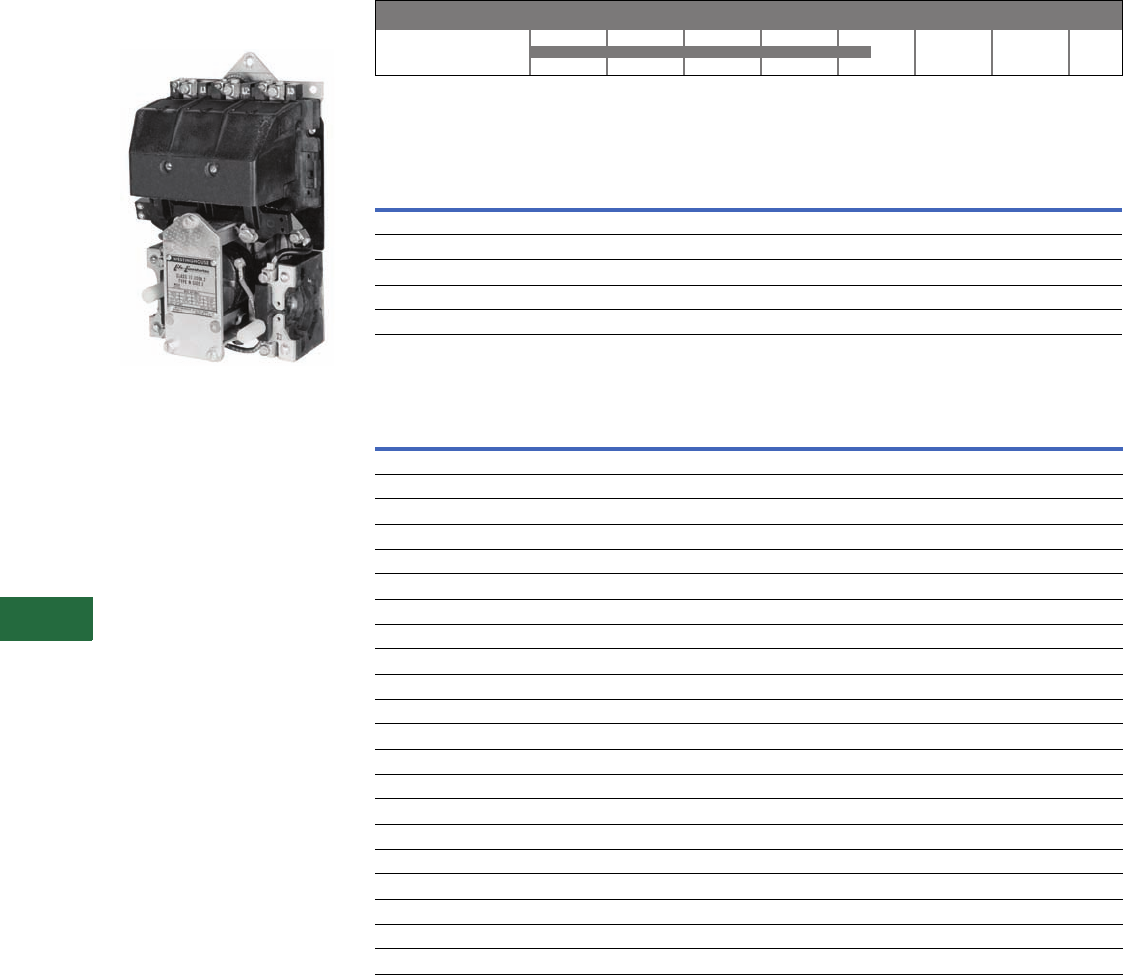
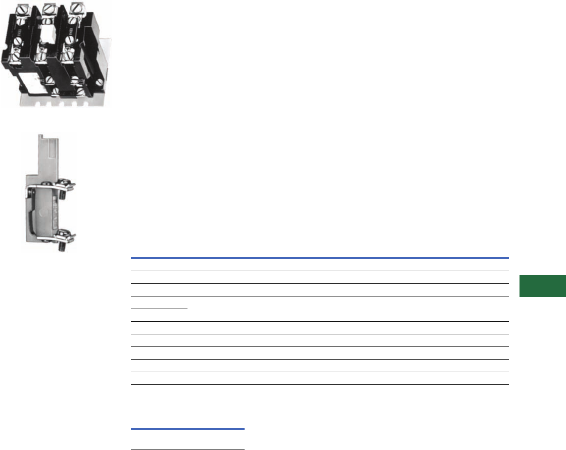
Type N
Originally a Westinghouse
Product
Type N Contactor
Product History Time Line for Type N
Replacement Capabilities
Contact Kits
AC Coils
Technology Upgrades
Sizes 00–3—Freedom or IT.
Sizes 4–5—Freedom,
Vacuum or IT.
0–4
Size 1940 1950 1960 1970 1980 1990 2000 Present
NEMA
Size Poles
Style
Number
031605226
131605212
231605202
331625563
431625564
Voltage Hz
Part Number
Two-, Three-Pole Four-, Five-Pole
Original New Original New
Sizes 0, 1
220/380/440 25/50/60 1470243 9969D90G03 1470263 9969D90G18
550 60 1470244 9969D90G04 N/A N/A
120 60 1605268 9969D90G09 N/A N/A
115/208/230 60/60/60 1605513 9969D90G15 N/A N/A
600 60 1470245 9969D90G20 N/A N/A
Size 2
110/208/220 25/60/60 1470202 9969D92G02 1470222 9969D93G02
220/380/440/480 25/50/60/60 1470203 9969D92G03 N/A N/A
600 60 1470205 9969D92G08 1470225 9969D93G08
120/110 60/50 1605478 9969D92G10 N/A N/A
Size 3
110/208/220 25/60/60 1490646 9969D96G05 1490646 9969D96G05
220/380/400/440 25/50/50/60 1490647 9969D96G06 1490647 9969D96G06
120/110 60/50 1600770 9969D96G09 1600770 9969D96G09
600/500 60/50 1490649 9969D96G21 1490649 9969D96G21
Size 4
110/208/220 25/60/60 1490658 9969D96G11 1597724 9969D96G02
600/500 60/50 1596635 9969D96G16 1490649 9969D96G21
440 60 1490659 9969D96G12 N/A N/A
120/110 60/50 1600771 9969D96G20 N/A N/A
Volume 12—Aftermarket, Renewal Parts and Life Extension Solutions CA08100014E—November 2013 www.eaton.com V12-T13-23
1
2
3
4
5
6
7
8
9
10
11
12
13
14
15
16
17
18
19
20
21
22
23
24
25
13
Motor Control
Contactors, Starters and Brakes
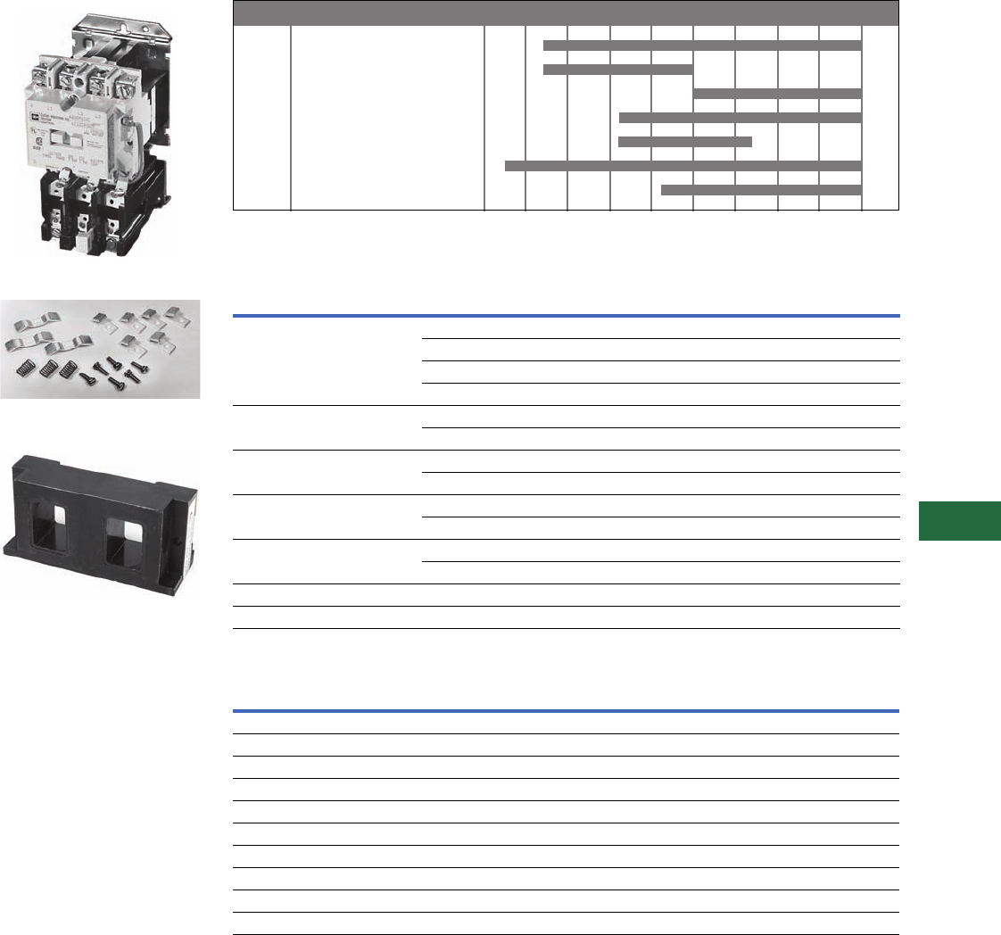
A200
Originally a Westinghouse
Product
A200 Size 1 Starter
Contact Kit for A200 Model J,
Size Two-, Three-Pole
A200 AC Coil, 120/110V, 60/50 Hz,
Two-, Three-, Four-Pole, Sizes 00, 0 and 1
Product History Time Line for A200, A201, A203, A204, A206, A210, A211, A213, A214, A216,
A220, A223, A224, A226, A250, A251, A600, A603, A604, A606, A700, A703, A704, A706, A800,
A804 and A806
Replacement Capabilities
Kits for Model J, Sizes 00, 0, 1 and 2 1
AC Coils
Notes
1Model C contact kits and coils 00–4, two-, three-, four- and five-pole contactors are same as Model J.
All other parts are unavailable.
2Use quantity two—373B331G11 (two-pole kit).
3Use one each of 373B331G11 (two-pole kit) and 373B331G12 (three-pole kit).
4Mounting hardware included.
5Dual voltage coils. Use only on contactors or starters originally supplied with a dual voltage coil.
00–3 J
4 J
4 K
5–6 Electrically held
5–6 Mechanically held
7–8
9
Size Model 1960 1965 1970 1975 1980 1985 1990 1995 2000 Present
Description Poles Size 00 Size 0 Size 1 Size 2
Contact kit 2 373B331G17 373B331G02 373B331G07 373B331G11
3373B331G18 373B331G04 373B331G09 373B331G12
4373B331G18 373B331G04 373B331G09 373B331G13 2
5373B331G19 373B331G05 373B331G10 373B331G14 3
Arc box 42–4 6714C74G01 6714C74G02 6714C74G03 6714C74G07 (two-, three-pole)
56714C74G04 6714C74G05 6714C74G06 6714C74G08 (four-, five-pole)
Cross bar 2–3 N/A N/A N/A 672B788G32
4–5 N/A N/A N/A 672B788G34
Upper base (for single rated coils only) 2–3 N/A N/A N/A 672B788G33
4–5 N/A N/A N/A 672B788G35
Lower base 2–3 N/A N/A N/A 1250C33G09
4–5 N/A N/A N/A 1250C33G05
KO spring (pk. of 10) All N/A N/A N/A 503C796G01
Terminal line/load (pk. of 3) All N/A N/A N/A 371B870G03
Voltage Hz
Sizes 00, 0 and 1 Size 2
Two-, Three-, Four-Pole Five-Pole Two-, Three-Pole Four-, Five-Pole
120/110 60/50 505C806G01 505C808G01 505C806G01 505C818G01
208 60 505C806G02 505C808G02 505C806G02 505C818G02
600/550 60/50 505C806G05 505C808G05 505C806G05 505C818G05
380 50 505C806G07 505C808G07 505C806G07 505C818G07
240/220 60/50 505C806G12 505C808G12 505C806G12 505C818G12
480/440 60/50 505C806G13 505C808G13 505C806G13 505C818G13
24 60 505C806G16 N/A 505C806G16 505C818G15
277 60 505C806G18 505C808G16 505C806G18 505C818G16
240/480 560/60 505C806G03 505C808G03 505C806G03 505C818G03
120/240 560/60 505C806G10 505C808G10 505C806G10 505C818G10

V12-T13-24 Volume 12—Aftermarket, Renewal Parts and Life Extension Solutions CA08100014E—November 2013 www.eaton.com
1
2
3
4
5
6
7
8
9
10
11
12
13
14
15
16
17
18
19
20
21
22
23
24
25
13
Motor Control
Contactors, Starters and Brakes
A200 AC Coil, 110/120V, 60 Hz, Size 6
A200 AC Coil, 120/110V, 60/50 Hz,
Two-, Three-Pole, Sizes 3 and 4, Model J
DC Coils 1
Kits for Model J–K, Sizes 3 and 4 3
AC Coils
DC Coils k
Notes
1Use only on contactors originally supplied with a DC coil.
2Dual voltage coils. Use only on contactors or starters originally supplied with a dual voltage coil.
3Model C contact kits and coils 00–4, two-, three-, four- and five-pole contactors are same as Model J.
All other parts are unavailable.
4Model K replaces Model J.
5Use quantity two–626B187G12 (two-pole kits).
6Use one of each of 626B187G12 (two-pole kit) and 626B187G13 (three-pole kit).
7Use quantity two–626B187G16 (two-pole kit).
8Use one each of 626B187G16 (two-pole kit) and 626B187G17 (three-pole kit).
9Model K replaces Model J.
jDual voltage coils. Use only on contactors or starters originally supplied with a dual voltage coil.
kUse only on units originally supplied with DC coil.
Voltage
Size 0Size 1Size 2
Single-, Two-, Three-, Four-Pole Single-, Two-, Three-, Four-Pole Single-, Two-, Three-, Four-Pole
12 1268C86G07 1268C86G07 1268C86G07
24 1268C86G04 1268C86G04 1268C86G04
48 1268C86G05 1268C86G05 1268C86G05
125 1268C86G02 1268C86G02 1268C86G02
250 1268C86G01 1268C86G01 1268C86G01
125/250 21268C86G03 1268C86G03 1268C86G03
Description Poles Size 3—Model J Size 4—Model J Size 4—Model K 4
Contact kit 2 626B187G12 626B187G16 5250C81G16
3626B187G13 626B187G17 5250C81G17
4626B187G14 5626B187G18 75250C81G18
5626B187G15 6626B187G19 85250C81G19
Arc box 2–3 6714C74G09 6714C74G11 6714C74G11
4–5 6714C74G10 6714C74G12 6714C74G12
Cross bar 2–3 672B788G36 672B788G36 672B788G40
4–5 672B788G38 672B788G38 —
Upper base 2–3 672B788G37 672B788G37 672B788G52
4–5 672B788G39 672B788G39 —
Lower base 2–3 1250C33G03 1250C33G03 1250C33G10
4–5 1250C33G06 1250C33G06 —
KO spring (pk. of 10) All 503C796G02 503C796G02 672B788G50
Terminals line/load (pk. of 3) All 372B357G12 372B357G13 372B357G13
Voltage Hz
Model J, Sizes 3–4 Model K, Size 4 9
Two-, Three-Pole Four-, Five-Pole Two-, Three-Pole Four-, Five-Pole
120/110 60/50 505C633G01 505C635G01 5250C79G01 5250C80G01
208 60 505C633G02 505C635G02 5250C79G02 5250C80G02
600/550 60/50 505C633G05 505C635G05 5250C79G05 5250C80G05
380 50 505C633G07 505C635G07 5250C79G07 5250C80G07
240/220 60/50 505C633G12 505C635G12 5250C79G12 5250C80G12
480/440 60/50 505C633G13 505C635G13 5250C79G13 5250C80G13
24 60 505C633G34 N/A 5250C79G34 N/A
277 60 505C633G14 N/A 5250C79G14 N/A
240/480 j60/60 505C633G03 505C635G03 5250C79G03 5250C80G03
120/240 j60/60 505C633G10 505C635G10 5250C79G10 5250C80G10
Voltage
Model J, Sizes 3–4
Two-, Three-Pole
24 1255C68G04
48 1255C68G05
125 1255C68G01
250 1255C68G02
125/250 1255C68G03

Volume 12—Aftermarket, Renewal Parts and Life Extension Solutions CA08100014E—November 2013 www.eaton.com V12-T13-25
1
2
3
4
5
6
7
8
9
10
11
12
13
14
15
16
17
18
19
20
21
22
23
24
25
13
Motor Control
Contactors, Starters and Brakes
Kits for GCA 530/630, Sizes 5–9—and GPD Sizes 7–9 1
Coils Coils
Notes
1Catalog No. A201/A200 Series replaces GCA/GPD Series. Renewal parts are the same.
2Use 477B477G06 for Silver Tungsten applications.
3CT Kit replaces the single molded one CT assembly used on the old Size 6 airbrake. The kit
includes a single molded three CT assembly, two busbars and hardware. This CT Kit also
replaces the single molded three CT assembly used on the present Size 6 airbrake and Size 6
vacuum contactor.
4Rectifier 125V 2018A40G01 (one required).
5Rectifier 250V 2018A40G02 (one required).
6Rectifier 600V 2018A40G03 (one required).
7These coils require an external rectifier. If the rectifier needs to be replaced, order by the
appropriate style number.
Kit Size 5 Size 6 Size 7 Size 8 Size 9
Contact kit (one per pole) 477B477G05 22066A10G11 461A757G17 646C829G05 5264C42G01 (rear connected)
— — — — 5264C42G02 (front connected)
Arc box 2050A15G45 2066A10G45 831D580G01 831D580G01 9917D69G02
Magnet assembly 2050A15G46 2050A15G46 N/A N/A N/A
Magnet spacing kit 2050A15G47 2050A15G47 N/A N/A N/A
Arc cup kit 2050A15G48 N/A N/A N/A N/A
Load connection kit 2050A15G49 2066A10G49 N/A N/A N/A
Line connection kit 2050A15G50 2066A10G50 N/A N/A N/A
KO spring-6 2050A15G51 2066A10G46 N/A N/A N/A
CT 300/5 655C285H03 N/A N/A N/A N/A
CT 400/5 655C285H04 — — — —
CT 600/5 N/A 2066A10G18 3N/A N/A N/A
CT 800/5 N/A 2066A10G19 3N/A N/A N/A
Phase barrier N/A N/A 640C441G01 640C441G01 5264C35G03 (rear connected)
Cross bar 2050A15G12 2066A10G15 N/A N/A N/A
Shunt N/A 2066A10G48 650C129G01 646C831G02 (set of three) 5264C39G02 (set of four)
Voltage Hz Size 5 Size 6
110/120 60 2050A14G05 2050A12G05
110/120 50 2050A14G06 2050A12G06
200/208 50 2050A14G07 2050A12G07
220/240 50 2050A14G08 2050A12G08
200/208 60 2050A14G09 2050A12G09
220/240 60 2050A14G10 2050A12G10
277/303 60 2050A14G12 2050A12G12
380/415 50 2050A14G14 2050A12G14
440/480 60 2050A14G15 2050A12G15
440/480 50 2050A14G16 2050A12G16
550/600 60 2050A14G17 2050A12G17
550/600 50 2050A14G18 2050A12G18
380/415 60 2050A14G19 2050A12G19
120/240 60 2050A14G20 2050A12G20
24 DC — 2050A14G21 2050A12G21
48 DC — 2050A14G22 2050A12G22
125 DC — 2050A14G25 2050A12G25
250 DC — 2050A14G27 2050A12G27
Line Voltage Sizes 7–8 Required Size 9
115 Vdc 438C805G01 2 100 Vdc
5264C34G01
(contains coil
and resistor)
125 Vdc 438C805G04 2
230 Vdc 438C805G02 2
250 Vdc 438C805G03 2
110/120 Vac 47 438C805G12 2
220/240 Vac 57 438C805G11 2
380 Vac 67 438C805G15 2
440/480 Vac 67 438C805G10 2
550/575 Vac 67 438C805G13 2
V12-T13-26 Volume 12—Aftermarket, Renewal Parts and Life Extension Solutions CA08100014E—November 2013 www.eaton.com
1
2
3
4
5
6
7
8
9
10
11
12
13
14
15
16
17
18
19
20
21
22
23
24
25
13
Motor Control
Contactors, Starters and Brakes
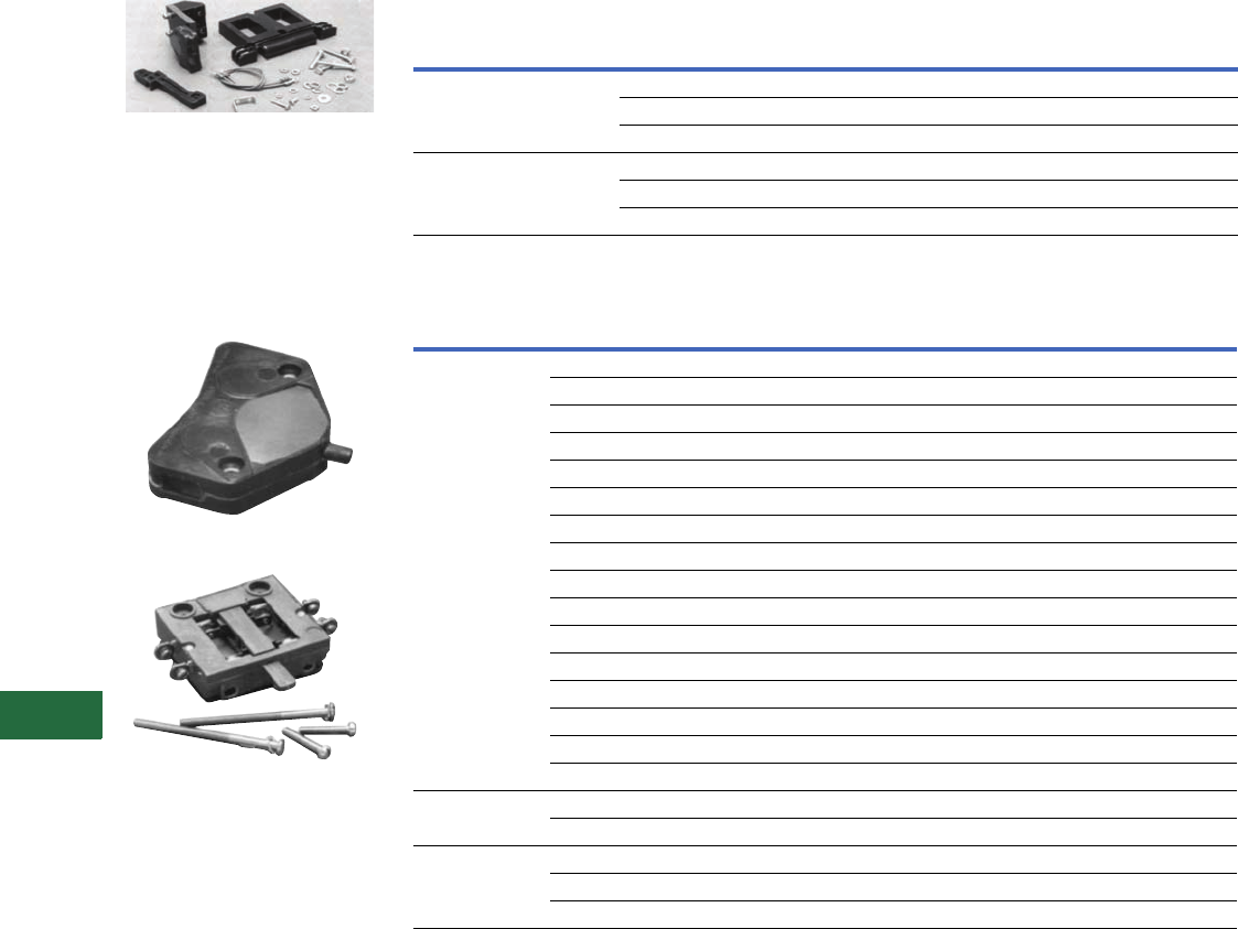
DC Coil Conversion Kit—
Style Number 7864A29G01
A rectifier circuit converts the
AC supply to DC supply. This
conversion provides quiet
operation and improves
pickup and dropout
characteristics. All necessary
parts are included in the kit.
L63—Style Number 578D461G01
L64—Style Number 843D943G04
Accessories for Size 5–9 AC Contactors—Coils
Accessories for Size 5–9 AC Contactors—Auxiliary Electrical Interlock
Technology Upgrades
Sizes 00–3—Freedom or IT.
Sizes 4–6—Freedom, Vacuum or IT.
Sizes 7–8—Freedom
Size 9—No upgrade available
AC Contactors Voltage
AC/DC Coil
Conversion Kit
Replacement
Coil
Size 5 120 Vac 7864A28G01 7856A15G05
240 Vac 7864A28G02 7856A15G10
480 Vac 7864A28G03 7856A15G15
Size 6 120 Vac 7864A29G01 7856A16G05
240 Vac 7864A29G02 7856A16G10
480 Vac 7864A29G03 7856A16G15
Contactor Size
Catalog
Number
(Obsolete)
Style Number
(Obsolete) Circuits
Catalog
Number
(Current)
Style
Number
(Current)
00–6 (L-56) (2609D01G01) 1NO and 1NC J11 9084A17G01
(L-56D) (2609D01G02) 2NO J20 9084A17G02
(L-56E) (2609D01G03) 1NO and 1NC J11 9084A17G01
(L-56B) (2609D01G04) 2NO J20 9084A17G02
(L-56H) (2609D01G05) 2NO J20 9084A17G02
(L-56J) (2609D01G06) 1NO and 1NC DB J1C N/A
(T-56A) (2609D01G07) N/A N/A N/A
(T-56A) (2609D01G07) N/A N/A N/A
(T-56B) (2609D01G08) N/A N/A N/A
(L-56F) (2609D01G09) N/A N/A N/A
(L-56G) (2609D01G10) 1NO and 1NC DB J1C 9084A17G04
(L-56C) (2609D01G11) 2NC J02 9084A17G03
(L-56M) (2609D01G12) N/A N/A N/A
(L-56P) (2609D01G17) 1NO and 1NC J11 9084A17G01
(L-56R) (2609D01G18) 2NC J02 9084A17G03
(L-56S) (2609D01G19) 1NO and 1NC J11 9084A17G01
7–8 L63 — NO — 578D461G01
L63 — NC — 578D461G03
9L64—NO/NC—843D943G04
L64 — 2NO — 843D943G05
L64 — 2NC — 843D943G06
Volume 12—Aftermarket, Renewal Parts and Life Extension Solutions CA08100014E—November 2013 www.eaton.com V12-T13-27
1
2
3
4
5
6
7
8
9
10
11
12
13
14
15
16
17
18
19
20
21
22
23
24
25
13
Motor Control
Contactors, Starters and Brakes
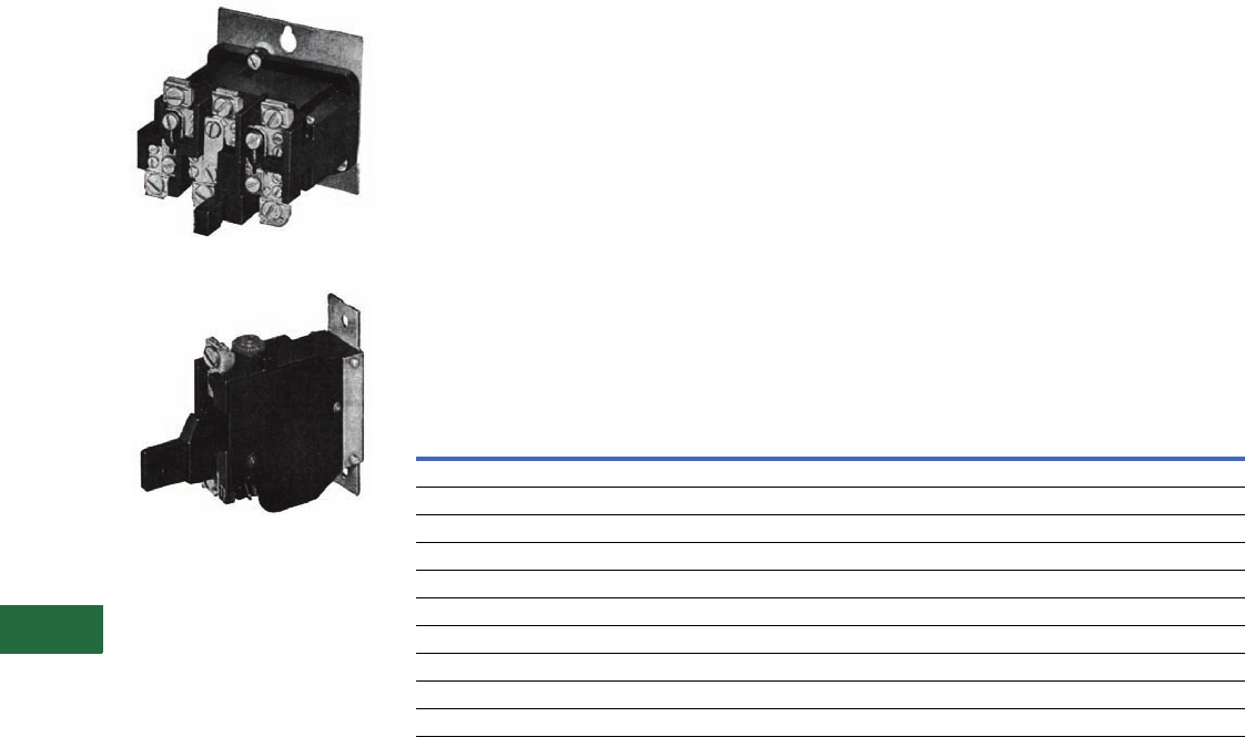
Manual Reset, Class 20,
Thermal Type B Overload
Relay
Type B Overload Relay, Panel Mounted
Field-Mountable Alarm Contact
Note: Alarm contact available as
factory modification of field
mountable. For factory
modification, add suffix B.
Application Description
The Type B overload relay is
designed to protect industrial
motors against overload
conditions. Using modern
block-type, bimetallic design,
this relay will provide Class 20
operation in either single-
phase or three-phase
applications.
Features
●Ambient compensation
standard
●Alarm contact field
mountable
●Class 20—600V design
●Inverse time delay trip
●Test trip device for weld
check
●High visibility up-front trip
indication
●Trip-free reset mechanism
Operation
The Type B overload relay is a
bimetallic actuated device. The
bimetal elements are operated
by precisely calibrated heaters.
The heater elements connect
either directly in the circuit to
be measured, or through
current transformers on
applications NEMA Size 5
and larger.
As the bimetals are heated by
motor current flow, a
deflection force is produced.
Upon a sustained level of
abnormal current flow, the
deflection becomes great
enough to open the snap
action output contact.
Ambient Compensation
The Type B ambient
compensated design is
supplied as standard on all
A200 starters. This design
uses a second compensating
bimetal responsive to
ambient air temperature in
the surrounding enclosure.
This feature reduces
nuisance tripping in
applications using compact
control panels and motor
control centers where
internal temperature rise is
significant compared to
motor ambient temperature.
The compensating
characteristic is maintained in
ambient temperatures from
40°C to 77°C.
Design Standards
UL® 508, CSA®, ANSI/NEMA
ICS 2-222.
Overload Relay Selection Table
For replacement in existing applications only.
Alarm Contact Kit Selection Heaters
Price of overload relay does
not include heaters. Select
from the tables on Pages
V12-T13-30 to V12-T13-32.
Notes
1Includes contactor mounting bracket,
overload relay and connection straps
to contactor.
2For replacement on B200 sizes 00, 0
and 1, use BA23A instead of BA13A
and use BN23A instead of BN13A.
Motor Full
Load
Amperes
Panel Mounted
Catalog Number
Starter Mounted Catalog Number
Replacement for Type B
Overload Relays
Replacement for Type A Overload
Relays in Manual Reset Mode
(Three-Pole Only) 1
Ambient
Comp. Non-Comp.
Ambient
Comp. Non-Comp.
Ambient
Comp. Non-Comp.
Single-Pole (One NC Contact)
0.25–26.2 BA11JP BN11JP BA11A BN11A ——
26.3–45.0 BA21JP BN21JP BA21A BN21A ——
19.0–90.0 Use three-pole design, wire three-poles in series
19.0–135.0
Three-Pole (One NC Contact)
0.25–26.2 BA13JP BN13JP BA13A 2BN13A 2BA13J BN13J
26.3–45.0 BA23JP BN23JP BA23A BN23A BA23J BN23J
19.0–90.0 BA33P BN33P BA33A BN33A BA33A BN33A
19.0–135.0 BA43P BN43P BA43A BN43A BA43A BN43A
Type B Overload
Relay Size
Catalog
Number
1, 2
3, 4
B3NO-2
B3NO-4
V12-T13-28 Volume 12—Aftermarket, Renewal Parts and Life Extension Solutions CA08100014E—November 2013 www.eaton.com
1
2
3
4
5
6
7
8
9
10
11
12
13
14
15
16
17
18
19
20
21
22
23
24
25
13
Motor Control
Contactors, Starters and Brakes
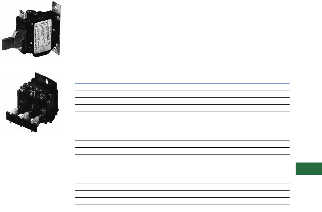
Auto/Manual Reset,
Class 20, Thermal Type A
Overload Relay
Three-Pole Panel Mounted
Single-Pole Panel Mounted
Application Description
The Type A overload relay is
designed to protect industrial
motors against overload
conditions. Using modern
block-type, bimetallic design,
this relay will provide Class 20
operation in either single-
phase or three-phase
applications.
Features
●Field selectable manual/
auto reset
●Alarm contact factory
available
●Class 20—600V design
●Inverse time delay trip
●Adjustable trip rating
±15%
●Color-coded reset rod:
Compensated (gray)
Non-compensated (red)
Operation
The Type A overload relay is a
bimetallic actuated device. The
bimetal elements are operated
by precisely calibrated heaters.
The heater elements
connected either directly in the
circuit to be measured, or
through current transformers
on applications NEMA Size 5
and larger.
As the bimetals are heated by
motor current flow, a
deflection force is produced.
Upon a sustained level of
abnormal current flow, the
deflection becomes great
enough to open the snap
action output contact.
Automatic Reset
The Type A overload relay can
be supplied as an option on all
A200 starters to provide
automatic reset operation.
The overload relay is always
shipped in the non-automatic
mode. To set up auto
operation, reposition the
reset rod by loosening and re-
tightening a hold-down clamp
at the base of overload relay.
Design Standards
UL 508, CSA, ANSI/NEMA
ICS 2-222.
Overload Relay Selection Table
For replacement in existing applications only.
Heaters
Price of overload relay does
not include heaters. Select
from the tables on Pages
V12-T13-30 to V12-T13-32.
Notes
1 Three-pole Type B Overload Relay is a
suitable alternative to a three-pole Type
A Overload Relay in Manual Reset Mode.
For example, use BA13JP for AA13P
and BN23J for AN23A, etc. (See
Page V12-T13-27.)
Alarm contact available only as factory
modification on Type A relay.
Motor Full
Load Amperes
Panel Mounted Catalog Number Starter Mounted Catalog Number
Ambient Comp. Non-Comp. Ambient Comp. Non-Comp.
Single-Pole (One NC Contact)
0.25–26.2 AA11P AN11P AA11A AN11A
26.3–45.0 AA21P AN21P AA21A AN21A
19.0–90.0 AA31P AN31P AA31A AN31A
19.0–135.0 AA41P AN41P AA41A AN41A
Three-Pole (One NC Contact) 1
0.25–26.2 AA13P AN13P AA13A AN13A
26.3–45.0 AA23P AN23P AA23A AN23A
19.0–90.0 AA33P AN33P AA33A AN33A
19.0–135.0 AA43P AN43P AA43A AN43A
Volume 12—Aftermarket, Renewal Parts and Life Extension Solutions CA08100014E—November 2013 www.eaton.com V12-T13-29
1
2
3
4
5
6
7
8
9
10
11
12
13
14
15
16
17
18
19
20
21
22
23
24
25
13
Motor Control
Contactors, Starters and Brakes
Type FT Fast Trip,
Class 10
Overload Relay
Single-Pole Fast Trip, Panel Mounted
Three-Pole Fast Trip, Panel Mounted
Application Description
The Type FT overload relay is
designed to protect special
purpose motors having
restricted thermal and locked
rotor capabilities. Using
modern block-type, bimetallic
design, this relay will provide
Class 10 operation in single-
phase or three-phase
applications.
Features
●Class 10—600V design
●Inverse time delay trip
●Color-coded reset rod—
green
●Alarm contact factory
available
●Field selectable manual/
auto reset
●Adjustable trip rating
±20%
●Ambient compensation
included
Operation
The Type FT overload relay is
a bimetallic actuated device.
The bimetal elements are
operated directly from line
current, thus separate
calibrating heater elements
are not used. The overload
relay may be wired directly in
the motor circuit, or through
current transformers on
applications larger than 150A.
As the bimetals are heated
by motor current flow, a
deflection is produced. Upon
a sustained level of abnormal
current flow, the deflection
becomes great enough to
open the snap action output
contact.
Overload Relay Selection Table
For replacement in existing applications only.
Notes
1Single-pole (one NO–NC contact): Add suffix B.
2Three-pole (three NO–NC contacts): Add suffix B. Example: FT13PB-12.
Alarm contact available only as factory modification on FT relay.
Motor Full Load
Amperes
Panel Mounted Catalog Number Starter Mounted Catalog Number 1
Single-Pole 1Three-Pole 2NEMA Size Single-Pole
Single-Pole (One NC Contact); Three-Phase (Three NC Contacts in Series)
0.76–1.1 FT11P-1.1 FT13P-1.1 —FT11A-1.1
1.1–1.6 FT11P-1.6 FT13P-1.6 —FT11A-1.6
1.6–2.4 FT11P-2.4 FT13P-2.4 0, 1 FT11A-2.4
2.4–3.6 FT11P-3.6 FT13P-3.6 0, 1 FT11A-3.6
3.6–5.4 FT11P-5.4 FT13P-5.4 0, 1 FT11A-5.4
5.4–8.0 FT11P-8 FT13P-8 0, 1 FT11A-8
8.0–12 FT11P-12 FT13P-12 0, 1 FT11A-12
12–18 FT11P-18 FT13P-18 1FT11A-18
16–24 FT11P-24 FT13P-24 1FT11A-24
22–32 FT11P-32 FT13P-32 0, 1 FT11A-32
24–36 FT21P-36 FT23P-36 2FT21A-36
36–54 FT21P-54 FT23P-54 2FT21A-54
22–32 FT31P-32 FT33P-32 3FT31A-32
32–48 FT31P-48 FT33P-48 3FT31A-48
48–72 FT31P-72 FT33P-72 3FT31A-72
72–110 FT41P-110 FT43P-110 4FT41A-110
100–150 FT41P-150 FT43P-150 4FT41A-150

V12-T13-30 Volume 12—Aftermarket, Renewal Parts and Life Extension Solutions CA08100014E—November 2013 www.eaton.com
1
2
3
4
5
6
7
8
9
10
11
12
13
14
15
16
17
18
19
20
21
22
23
24
25
13
Motor Control
Contactors, Starters and Brakes
Heaters for Thermal
Types A and B Overload
Relays
Product Description
Each heater is identified by
a catalog number stamped
on one terminal. The heater
application table indicates
the range of full load motor
current to which a given
heater may be applied.
Heaters should be selected
on the basis of the actual
full load current and service
factor as shown on the
motor nameplate or in the
manufacturer’s published
literature.
When motor and overload
relay are in the same ambient
and the service factor of the
motor is 1.15 to 1.25, select
heaters from the heater
application table. If the service
factor of the motor is 1.0, or
there is no service factor
shown, or a maximum of
115% protection is desired,
select one size smaller
heater than indicated.
When motor and overload
relay are in different
ambients and when using
non-compensated overload
relays, select heaters from
the tables on Pages
V12-T13-30 through
V12-T13-32 using adjusted
motor currents as follows:
decrease rated motor current
1% for each °C motor
ambient exceeds controller
ambient. Increase rated
motor current 1% for each °C
controller ambient exceeds
motor ambient.
For temperature
compensated overload
relays, select heaters
according to the tables on
Pages V12-T13-30 through
V12-T13-32 and selection
information above regardless
of ambient.
Protect the starter against
short circuits by providing
branch circuit protection
per National Electrical
Code® (NEC®).
Heater Selection for Types A and B Overload Relays, Sizes 00, 0, 1 and 2 Starters
Notes
1Based on 60°C and 75°C wire for 30A or less.
2Based on 60°C wire for 31 to 95A.
Heaters are packaged in strips of six. Minimum ordering quantity is 12.
Non-Compensated Open Starters and
Ambient Compensated Open and Enclosed Starters
Non-Compensated
Enclosed Starters
Heater
Catalog
Number
Block-Type Overload
Using Three Heaters
Single-Pole
Type Overload
Block-Type Overload
Using Three Heaters
Single-Pole
Type Overload
Full Load Current of Motor (Amperes) 12
For Sizes 0, 1 and 2 Starters
0.25–0.27 0.29–0.31 0.24–0.25 0.28–0.30 FH03
0.28–0.31 0.32–0.35 0.26–0.28 0.31–0.34 FH04
0.32–0.34 0.36–0.39 0.29–0.31 0.35–0.37 FH05
0.35–0.38 0.40–0.43 0.32–0.35 0.38–0.42 FH06
0.39–0.42 0.44–0.48 0.36–0.39 0.43–0.47 FH07
0.43–0.46 0.49–0.53 0.40–0.43 0.48–0.52 FH08
0.47–0.50 0.54–0.58 0.44–0.47 0.53–0.56 FH09
0.51–0.55 0.59–0.64 0.48–0.51 0.57–0.63 FH10
0.56–0.62 0.65–0.71 0.52–0.57 0.64–0.70 FH11
0.63–0.68 0.72–0.79 0.58–0.63 0.71–0.77 FH12
0.69–0.75 0.80–0.87 0.64–0.70 0.78–0.85 FH13
0.76–0.83 0.88–0.96 0.71–0.77 0.86–0.94 FH14
0.84–0.91 0.97–1.06 0.78–0.85 0.95–1.03 FH15
0.92–1.00 1.07–1.16 0.86–0.93 1.04–1.13 FH16
1.01–1.11 1.17–1.28 0.94–1.03 1.14–1.25 FH17
1.12–1.22 1.29–1.41 1.04–1.13 1.26–1.38 FH18
1.23–1.34 1.42–1.55 1.14–1.25 1.39–1.52 FH19
1.35–1.47 1.56–1.71 1.26–1.37 1.53–1.67 FH20
1.48–1.62 1.72–1.87 1.38–1.51 1.68–1.83 FH21
1.63–1.78 1.88–2.06 1.52–1.65 1.84–2.01 FH22
1.79–1.95 2.07–2.26 1.66–1.81 2.02–2.21 FH23
1.96–2.15 2.27–2.48 1.82–1.99 2.22–2.43 FH24
2.16–2.35 2.49–2.72 2.00–2.19 2.44–2.66 FH25
2.36–2.58 2.73–2.99 2.20–2.39 2.67–2.92 FH26
2.59–2.83 3.00–3.28 2.40–2.63 2.93–3.21 FH27
2.84–3.11 3.29–3.60 2.64–2.89 3.22–3.53 FH28
3.12–3.42 3.61–3.95 2.90–3.17 3.54–3.87 FH29
3.43–3.73 3.96–4.31 3.18–3.47 3.88–4.22 FH30
3.74–4.07 4.32–4.71 3.48–3.79 4.23–4.61 FH31
4.08–4.39 4.72–5.14 3.80–4.11 4.62–4.9 FH32
4.40–4.87 5.15–5.6 4.12–4.55 5.0–5.5 FH33
4.88–5.3 5.7–6.2 4.56–5.0 5.6–6.0 FH34

Volume 12—Aftermarket, Renewal Parts and Life Extension Solutions CA08100014E—November 2013 www.eaton.com V12-T13-31
1
2
3
4
5
6
7
8
9
10
11
12
13
14
15
16
17
18
19
20
21
22
23
24
25
13
Motor Control
Contactors, Starters and Brakes
Heater Selection for Types A and B Overload Relays, Sizes 00, 0, 1 and 2 Starters, continued
Notes
1Based on 60°C and 75°C wire for 30A or less.
2Based on 60°C wire for 31 to 95A.
Heaters are packaged in strips of six. Minimum ordering quantity is 12.
Non-Compensated Open Starters and
Ambient Compensated Open and Enclosed Starters
Non-Compensated
Enclosed Starters
Heater
Catalog
Number
Block-Type Overload
Using Three Heaters
Single-Pole
Type Overload
Block-Type Overload
Using Three Heaters
Single-Pole
Type Overload
Full Load Current of Motor (Amperes) 12
For Sizes 0, 1 and 2 Starters
5.4–5.9 6.3–6.8 5.1–5.5 6.1–6.6 FH35
6.0–6.4 6.9–7.5 5.6–5.9 6.7–7.3 FH36
6.5–7.1 7.6–8.2 6.0–6.6 7.4–8.0 FH37
7.2–7.8 8.3–9.0 6.7–7.2 8.1–8.7 FH38
7.9–8.5 9.1–9.9 7.3–7.9 8.8–9.7 FH39
8.6–9.4 10.0–10.8 8.0–8.7 9.8–10.5 FH40
9.5–10.3 10.9–11.9 8.8–9.5 10.6–11.7 FH41
10.4–11.3 12.0–13.1 9.6–10.5 11.8–12.7 FH42
11.4–12.4 13.2–14.3 10.6–11.5 12.8–14.0 FH43
12.5–13.5 14.4–15.7 11.6–12.6 14.1–15.3 FH44
13.6–14.9 15.8–17.2 12.7–13.8 15.4–16.6 FH45
15.0–16.3 — 13.9–15.1 — FH46
16.4–18.0 — 15.2–16.7 — FH47
For Sizes 1 and 2 Starters
—17.3–18.9 — 16.7–18.3 FH46
—19.0–20.8 — 18.4–20.0 FH47
18.1–19.8 20.9–22.9 16.8–18.3 20.1–21.9 FH48
19.9–21.7 23.0–25.2 18.4–20.2 22.0–23.9 FH49
21.8–23.9 25.3–27.6 20.3–22.2 24.0–26.2 FH50
24.0–26.2 — 22.3–24.3 — FH51
— — 24.4–26.6 — FH52
For Size 2 Starters
—27.7–30.3 — 26.3–28.8 FH51
26.3–28.7 30.4–33.3 — 28.9–31.4 FH52
28.8–31.4 33.4–36.4 26.7–29.1 31.5–34.5 FH53
31.5–34.0 36.5–39.9 29.2–32.0 34.6–37.9 FH54
34.6–37.9 42.0–43.9 32.1–35.2 38.0–41.9 FH55
38.0–41.5 — 35.3–38.5 42.0–45.0 FH56
41.6–45.0 — 38.6–42.3 — FH57

V12-T13-32 Volume 12—Aftermarket, Renewal Parts and Life Extension Solutions CA08100014E—November 2013 www.eaton.com
1
2
3
4
5
6
7
8
9
10
11
12
13
14
15
16
17
18
19
20
21
22
23
24
25
13
Motor Control
Contactors, Starters and Brakes
Heater Selection for Types A and B Overload Relays,
Sizes 3 and 4 Starters 123
Ambient
Compensated
Enclosed Starters
Non-Compensated
Enclosed Starters Heater
Catalog
Number
All Applications
Full Load Current of Motor (Amperes) 1
For Sizes 3 and 4 Starters
12.8–14.1 11.9–13.0 FH68
14.2–15.5 13.1–14.3 FH69
15.6–17.1 14.4–15.9 FH70
17.2–18.9 16.0–17.4 FH71
19.0–20.8 17.5–19.1 FH72
20.9–22.9 19.2–21.1 FH73
23.0–25.2 21.2–23.2 FH74
25.3–27.8 23.3–25.6 FH75
27.9–30.6 25.7–28.1 FH76
30.7–33.5 28.2–30.8 FH77
33.6–37.5 30.9–34.5 FH78
37.6–41.5 34.6–38.2 FH79
41.6–46.3 38.3–42.6 FH80
46.4–50 42.7–46 FH81
51–55 47–51 FH82
56–61 52–56 FH83
62–66 57–61 FH84
67–73 62–67 FH85
74–78 68–72 FH86
79–84 73–77 FH87
85–92 78–84 FH88
— 85–91 FH89
For Size 4 Starters
93–101 — FH89
102–110 92–99 FH90
111–122 100–110 FH91
123–129 111–122 FH92
130–133 123–128 FH93
—129
–133 FH94
Heater Selection for Types A and B Overload Relays,
Sizes 5 and 6 Starters 4
Notes
1Based on 60°C and 75°C wire for 30A or less.
2Based on 60°C wire for 31 to 95A.
3Based on 75°C wire for greater than 95A.
4Based on 75°C wire.
Heaters are packaged in strips of six. Minimum ordering quantity is 12.
Compensated Overload Relay Heater
Catalog
Number
Open Starter Enclosed Starter
Full Load Current of Motor (Amperes)
Size 5 (With 300/5 Current Transformers)
——FH23
118–129 118–129 FH24
130–141 130–141 FH25
142–155 142–155 FH26
156–170 156–170 FH27
171–187 171–187 FH28
188–205 188–205 FH29
206–224 206–224 FH30
225–244 225–244 FH31
245–263 245–263 FH32
264–292 264–292 FH33
293–300 — FH34
Size 6 (With 600/5 Current Transformers)
——FH23
236–259 236–259 FH24
260–283 260–283 FH25
284–310 284–310 FH26
311–340 311–340 FH27
341–374 341–374 FH28
375–411 375–411 FH29
412–448 412–448 FH30
449–489 449–489 FH31
490–527 490–527 FH32
528–585 528–540 FH33
586–600 — FH34
Size 7 and Larger
Advise full load current

Volume 12—Aftermarket, Renewal Parts and Life Extension Solutions CA08100014E—November 2013 www.eaton.com V12-T13-33
1
2
3
4
5
6
7
8
9
10
11
12
13
14
15
16
17
18
19
20
21
22
23
24
25
13
Motor Control
Contactors, Starters and Brakes
A202 Lighting Contactor
(Electrically Held/
Magnetically Latched)
Originally a Westinghouse
Product
30A, Four-Pole Magnetically Latched
Product History Time Line for A202 Lighting Contactor
(Electrically Held/Magnetically Latched)
Replacement Capabilities
A202 Kits for 30 to 200A
Notes
1For 200A A202 Magnetically Latched Lighting Contactors, order three-pole contact kit style 672B788G07.
2Model K replaces Model J, offering superior design and life characteristics. Renewal parts are different.
Use parts for proper model only.
3Use quantity two–373B331G11 (two-pole kit).
4Use one each of 373B331G11 (two-pole kit) and 373B331G12 (three-pole kit).
5Use quantity two–626B187G12 (two-pole kit).
6Use one each of 626B187G12 (two-pole kit) and 626B187G13 (three-pole kit).
7Use quantity two–626B187G16 (two-pole kit).
8Use one each of 626B187G16 (two-pole kit) and 626B187G17 (three-pole kit).
Size Amperes Model 1965 1970 1975 1980 1985 1990 1995 2000 Present
Size 1 30
Size 2 60
Size 3 100
Size 4 200 J
Size 4 200 K
Description Poles 30A 60A 100A
200A—
Model J 1
200A—
Model K 2
Contact kit 2 373B331G07 373B331G11 626B187G12 626B187G16 5250C81G16
3373B331G09 373B331G12 626B187G13 626B187G17 5250C81G17
4373B331G09 3575250C81G18
5373B331G10 4685250C81G19
Arc box 2, 3, 4 6714C74G03 6714C74G07 6714C74G09 6714C74G11 6714C74G11
56714C74G06 6714C74G08 6714C74G10 6714C74G12 6714C74G12
Cross bar 2–3 — 672B788G32 672B788G36 672B788G36 672B788G40
4–5 — 672B788G34 672B788G38 672B788G38 —
Upper base
(for single rated
coils only)
2–3 — 672B788G33 672B788G37 672B788G37 672B788G52
4–5 — 672B788G35 672B788G39 672B788G39 —
Lower base 2–3 — 1250C33G09 1250C33G03 1250C33G03 1250C33G10
4–5 — 1250C33G05 1250C33G06 1250C33G06 —
Electrically Held Only
KO spring
(pack of 10)
All — 503C796G01 503C796G02 503C796G02 672B788G50
Terminal line/load
(pack of 3)
All — 371B870G03 372B357G12 372B357G13 372B357G13
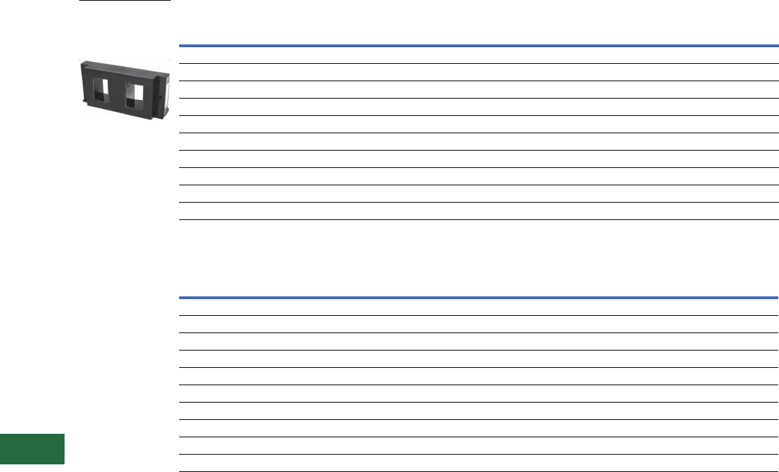
V12-T13-34 Volume 12—Aftermarket, Renewal Parts and Life Extension Solutions CA08100014E—November 2013 www.eaton.com
1
2
3
4
5
6
7
8
9
10
11
12
13
14
15
16
17
18
19
20
21
22
23
24
25
13
Motor Control
Contactors, Starters and Brakes
AC Coils Electrically Held
AC Coils Electrically Held, continued
Notes
1 Dual voltage coils. Use only on contactors or starters originally supplied with a dual voltage coil.
2 Model K replaces Model J. Renewal parts are different. Use parts for proper model only.
Voltage Hz
30A 60A
Two-, Three-, Four-Pole Five-Pole Two-, Three-Pole Four-, Five-Pole
120/110 60/50 505C806G01 505C808G01 505C806G01 505C818G01
208 60 505C806G02 505C808G02 505C806G02 505C818G02
600/550 60/50 505C806G05 505C808G05 505C806G05 505C818G05
380 50 505C806G07 505C808G07 505C806G07 505C818G07
240/220 60/50 505C806G12 505C808G12 505C806G12 505C818G12
480/440 60/50 505C806G13 505C808G13 505C806G13 505C818G13
24 60 505C806G16 N/A 505C806G16 505C818G15
227 60 505C806G18 505C808G16 505C806G18 505C818G16
240/480 160/60 505C806G03 505C808G03 505C806G03 505C818G03
120/240 160/60 505C806G10 505C808G10 505C806G10 505C818G10
Voltage Hz
100 and 200A—Model J 200A—Model K 2
Two-, Three-Pole Four-, Five-Pole Two-, Three-Pole Four-, Five-Pole
120/110 60/50 505C633G01 505C635G01 52050C79G01 5250C80G01
208 60 505C633G02 505C635G02 52050C79G02 5250C80G02
600/550 60/50 505C633G05 505C635G05 52050C79G05 5250C80G05
380 50 505C633G07 505C635G07 52050C79G07 5250C80G07
240/220 60/50 505C633G12 505C635G12 52050C79G12 5250C80G12
480/440 60/50 505C633G13 505C635G13 52050C79G13 5250C80G13
24 60 505C633G34 N/A 52050C79G34 N/A
227 60 505C633G14 N/A 52050C79G14 N/A
240/480 160/60 505C633G03 505C635G03 52050C79G03 5250C80G03
120/244 160/60 505C633G10 505C635G10 52050C79G10 5250C80G10
120V Coil for
Electrically Held
Lighting Contactor—
Style Number
505C633G01

Volume 12—Aftermarket, Renewal Parts and Life Extension Solutions CA08100014E—November 2013 www.eaton.com V12-T13-35
1
2
3
4
5
6
7
8
9
10
11
12
13
14
15
16
17
18
19
20
21
22
23
24
25
13
Motor Control
Contactors, Starters and Brakes
AC Coils Magnetically Latched
Terminals (Line and Load)
Other Accessories
Notes
1Order quantity of two for four-pole design.
2Group numbers for the five-pole terminals represent the combination of the two-pole and
three-pole number.
Voltage Hz Two-Pole Three-Pole Four-Pole Five-Pole
30A
110/120 50/60 7874A93G01 7874A93G01 7874A93G01 7874A89G01
208/240 50/60 7874A93G02 7874A93G02 7874A93G02 7874A89G02
277 50/60 7874A93G03 7874A93G03 7874A93G03 7874A89G03
440/480 50/60 7874A93G04 7874A93G04 7874A93G04 7874A89G04
575 50/60 7874A93G05 7874A93G05 7874A93G05 7874A89G05
60A
110/120 50/60 7874A93G01 7874A93G01 7874A87G01 7874A87G01
208/240 50/60 7874A93G02 7874A93G02 7874A87G02 7874A87G02
277 50/60 7874A93G03 7874A93G03 7874A87G03 7874A87G03
440/480 50/60 7874A93G04 7874A93G04 7874A87G04 7874A87G04
110/120 50/60 7874A93G01 7874A93G01 7874A87G01 7874A87G05
100 and 200A
110/120 50/60 7874A85G01 7874A85G01 7874A83G01 7874A83G01
208/240 50/60 7874A85G02 7874A85G02 7874A83G02 7874A83G02
277 50/60 7874A85G03 7874A85G03 7874A83G03 7874A83G03
440/480 50/60 7874A85G04 7874A85G04 7874A83G04 7874A83G04
550/575 50/60 7874A85G05 7874A85G05 7874A83G05 7874A83G05
Size Two-Pole Three-Pole Four-Pole Five-Pole
30A N/A N/A N/A N/A
60A 179C755G17 179C755G16 179C755G17 1179C755G16 + G17 2
100A 179C755G19 179C755G18 179C755G19 1179C755G18 + G19 2
200A Model K Model J Model K Model J Model K Model J Model K Model J
179C755G28 179C755G31 179C755G27 179C755G30 179C755G28 1179C755G3 1179C755G27 + G28 2179C755G30 + G3 2
Size Control Module (Rectifier)
30 to 200A 3915B98G01
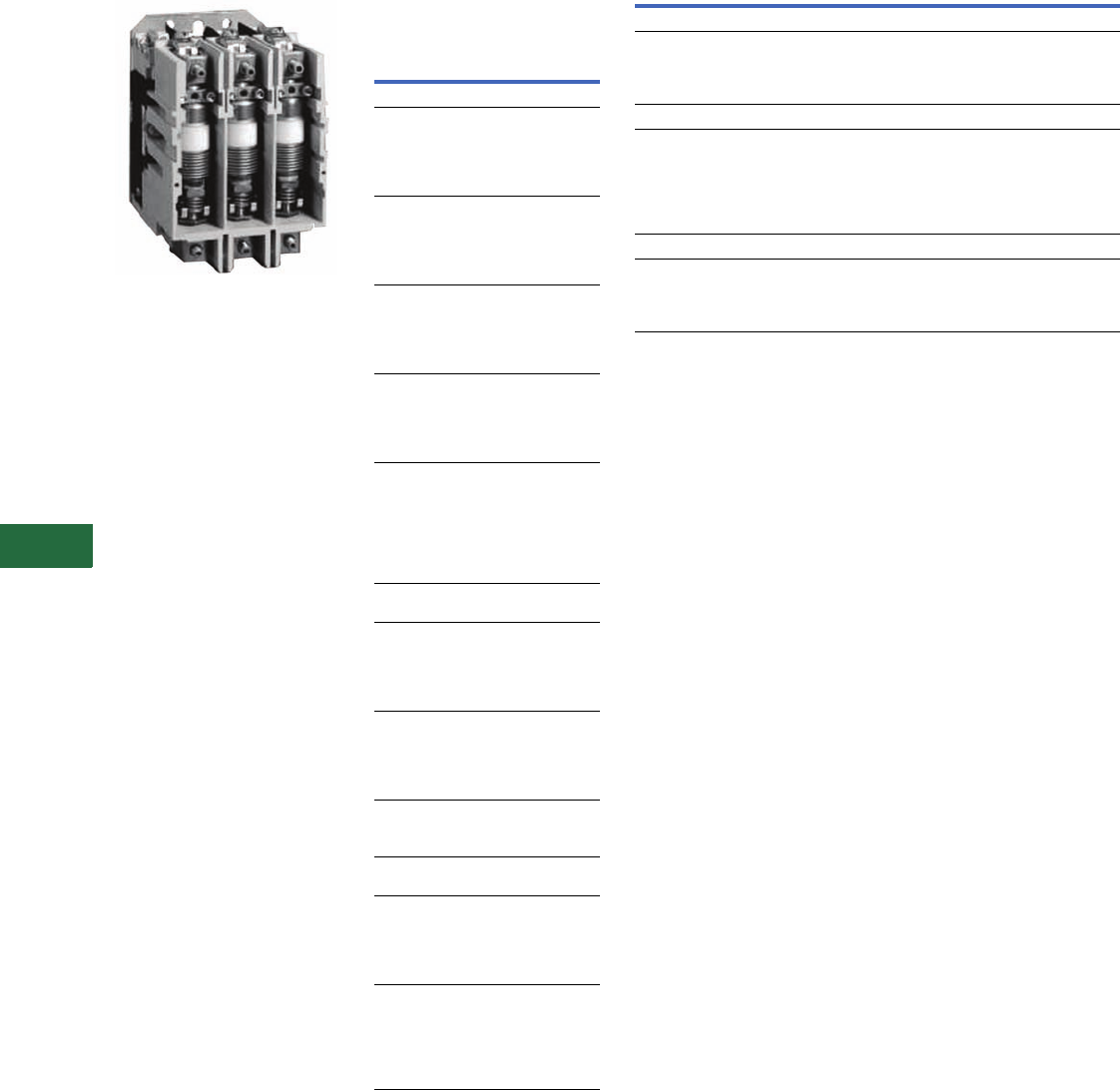
V12-T13-36 Volume 12—Aftermarket, Renewal Parts and Life Extension Solutions CA08100014E—November 2013 www.eaton.com
1
2
3
4
5
6
7
8
9
10
11
12
13
14
15
16
17
18
19
20
21
22
23
24
25
13
Motor Control
Contactors, Starters and Brakes
V201 and V200 Vacuum
Contactors and Starters
Originally a Westinghouse
Product
Size 4 Vacuum Contactors
Heater Coils
Heater Coil Selection for
Type B Overload Relay
Motor Full Load Current in Amperes for
Use with Three Heaters Only
Open Starter Heater
Catalog
Number 1
Ambient Compensated
Overload Relay
Size 4 and 160A
12.8–14.1
14.2–15.5
15.6–17.1
17.2–18.9
19.0–20.8
FH68
FH69
FH70
FH71
FH72
20.9–22.9
23.0–25.2
25.3–27.8
27.9–30.6
30.7–33.5
FH73
FH74
FH75
FH76
FH77
33.6–37.5
37.6–41.5
41.6–46.3
46.4–50
51–55
FH78
FH79
FH80
FH81
FH82
56–61
62–66
67–73
74–78
79–84
FH83
FH84
FH85
FH86
FH87
85–92
93–101
102–110
111–122
123–129
130–133
—
FH88
FH89
FH90
FH91
FH92
FH93
FH94
Size 5 and 320A with 300/5
Current Transformers
107–117
118–129
130–141
142–155
156–170
FH23
FH24
FH25
FH26
FH27
171–187
188–205
206–224
225–244
245–263
FH28
FH29
FH30
FH31
FH32
264–292
293–318
319–350
FH33
FH34
FH35
Size 6 and 540A with 600/5
Current Transformers
236–259
260–283
284–310
311–340
341–374
FH24
FH25
FH26
FH27
FH28
375–411
412–448
449–489
490–527
528–585
586–600
FH29
FH30
FH31
FH32
FH33
FH34
Replacement Coils
Vacuum Contactor—Replacement Coils
Notes
1Three are required per overload relay.
2125 Vdc can be directly applied to the Size 5 and 6 coil rated for 120V/60 Hz AC
(cannot be applied to Size 4).
3250 Vdc can be directly applied to the Size 5 and 6 coil rated for 240V/60 Hz AC
(cannot be applied to Size 4).
Description Suffix
Part
Number
Size 4
110/120 Vac, 50/60 Hz
220/240 Vac, 50/60 Hz
380/415 Vac, 50/60 Hz
440/480 Vac, 50/60 Hz
J
K
H
U
9085A57G01
9085A57G02
ID89221G07
9085A57G03
Size 5
24 Vdc
48 Vdc
110/120 Vac, 50/60 Hz
220/240 Vac, 50/60 Hz
380/415 Vac, 50/60 Hz
440/480 Vac, 50/60 Hz
—
—
J
K
H
U
7874A09G07
7874A09G08
7874A09G01 2
7874A09G04 3
7874A09G10
7874A09G05
Size 6
110/120 Vac, 50/60 Hz
220/240 Vac, 50/60 Hz
380/415 Vac, 50/60 Hz
440/480 Vac, 50/60 Hz
J
K
H
U
7874A24G01 2
7874A24G02 3
7874A24G07
7874A24G03
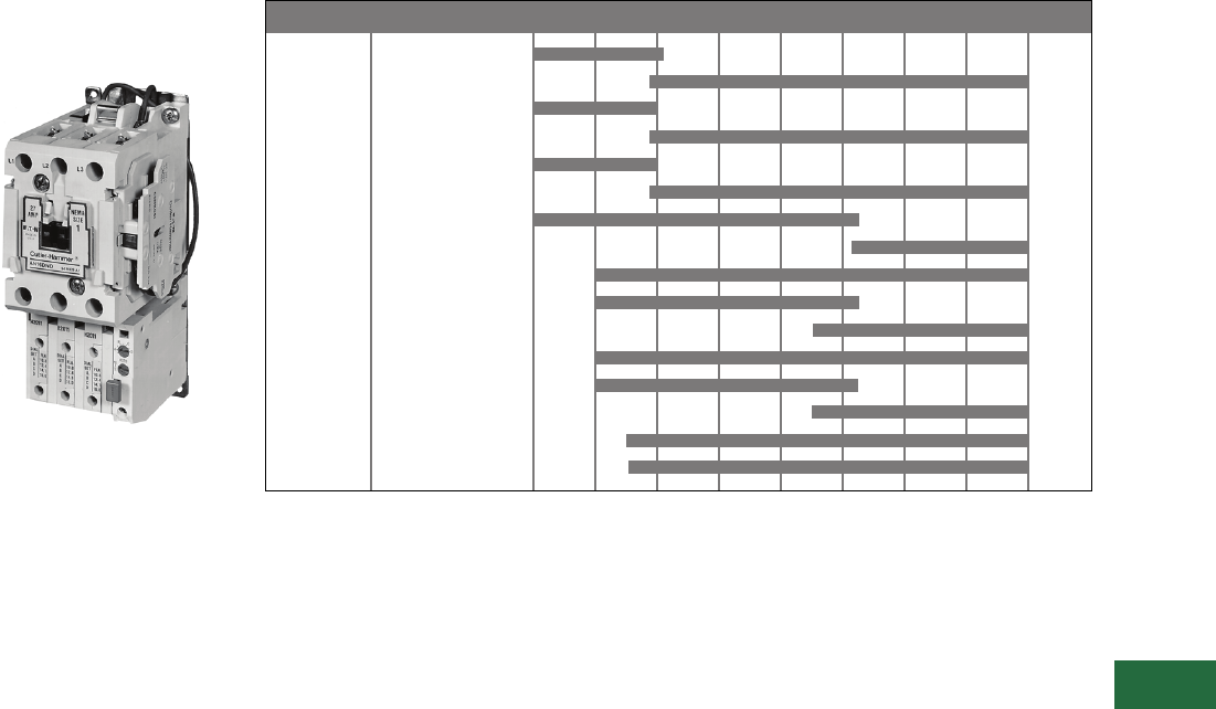
Volume 12—Aftermarket, Renewal Parts and Life Extension Solutions CA08100014E—November 2013 www.eaton.com V12-T13-37
1
2
3
4
5
6
7
8
9
10
11
12
13
14
15
16
17
18
19
20
21
22
23
24
25
13
Motor Control
Contactors, Starters and Brakes
Freedom Series—
NEMA and IEC
Originally a Cutler-Hammer
Product
Freedom
Product Description
The Cutler-Hammer Freedom
Series starters and
contactors feature a compact
space-saving design using
state-of-the-art technology
and the latest in high
strength, impact and
temperature-resistant
insulating materials. Starters
and contactors are available
in two rating/configuration
styles—NEMA (National
Electrical Manufacturers
Association) and IEC
(International
Electrotechnical
Commission). The NEMA
devices are sized based
on traditional NEMA
classifications and the IEC
devices on international
ratings. Internationally rated
starters and contactors, as
compared to NEMA devices,
generally are physically down-
sized to provide higher
ratings in a smaller package.
Product History Time Line for Freedom CN15 and AN15
Note: See contactor/starter nameplate to determine Series A1, B1 or C1.
Size 00 A1
B1
Size 0 A1
B1
Size 1 A1
B1
Size 2 A1
B1
Size 3 A1
Size 4 A1
B1
Size 5 A1
Size 6 A1
B1
Size 7 A1
Size 8 A1
NEMA Size Series 1986 1988 1990 1992 1994 1996 1998 2000 Present

V12-T13-38 Volume 12—Aftermarket, Renewal Parts and Life Extension Solutions CA08100014E—November 2013 www.eaton.com
1
2
3
4
5
6
7
8
9
10
11
12
13
14
15
16
17
18
19
20
21
22
23
24
25
13
Motor Control
Contactors, Starters and Brakes
Replacement Capabilities
NEMA Sizes 00, 0, 1, 2 and 3
NEMA Sizes 00 and 0—See Contactor/Starter Nameplate to Determine Series A1, B1 or C1
Note
1Replace with complete contactor.
Description
NEMA Size 00–0 NEMA Size 00 NEMA Size 00 NEMA Size 0 NEMA Size 0
Series A1 Series B1 Series C1 Series B1 Series C1
Part Number Part Number Part Number Part Number Part Number
Renewal Parts Publication Number None None None None None
Contact Kits
Two-pole 11111
Three-pole 11111
Four-pole 11111
Five-pole 11111
Magnet Coils Coil Suffix
120V, 60 Hz or 110V, 50 Hz A 9-2650-1 9-2875-1 9-2875-1 9-2876-1 9-2876-1
240V, 60 Hz or 220V, 50 Hz B 9-2650-2 9-2875-2 9-2875-2 9-2876-2 9-2876-2
480V, 60 Hz or 440V, 50 Hz C 9-2650-3 9-2875-3 9-2875-3 9-2876-3 9-2876-3
600V, 60 Hz or 550V, 50 Hz D 9-2650-4 9-2875-4 9-2875-4 9-2876-4 9-2876-4
208V, 60 Hz E 9-2650-5 9-2875-5 9-2875-5 9-2876-5 9-2876-5
277V, 60 Hz H 9-2650-13 9-2875-12 9-2875-12 9-2876-12 9-2876-12
208/240V, 60 Hz J — 9-2875-37 9-2875-37 9-2876-17 9-2876-17
240V, 50 Hz K 9-2650-12 9-2875-11 9-2875-11 9-2876-11 9-2876-11
380–415V, 50 Hz L 9-2650-6 9-2875-6 9-2875-6 9-2876-6 9-2876-6
380V, 50 Hz L — — — — —
415V, 50 Hz M — — — — —
550V, 50 Hz N — — — — —
24V, 60 Hz–24V, 50 Hz T —9-2875-36 9-2875-36 9-2876-36 9-2876-36
24V, 60 Hz T 9-2650-7 ————
24V, 50 Hz U 9-2650-14 9-2875-36 9-2875-36 9-2876-36 9-2876-36
32V, 50 Hz V 9-2650-9 9-2875-16 9-2875-16 9-2876-16 9-2876-16
48V, 60 Hz W 9-2650-8 9-2875-8 9-2875-8 9-2876-8 9-2876-8
48V, 50 Hz Y 9-2650-10 9-2875-9 9-2875-9 9-2876-9 9-2876-9
Magnet Frame Armature
Lower magnet frame 11111
Upper magnet frame 11111

Volume 12—Aftermarket, Renewal Parts and Life Extension Solutions CA08100014E—November 2013 www.eaton.com V12-T13-39
1
2
3
4
5
6
7
8
9
10
11
12
13
14
15
16
17
18
19
20
21
22
23
24
25
13
Motor Control
Contactors, Starters and Brakes
NEMA Sizes 1, 2 and 3—See Contactor/Starter Nameplate to Determine Series A1 or B1
Description
NEMA Size 1 NEMA Size 1 NEMA Size 2 NEMA Size 2 NEMA Size 3
Series A1 Series B1 Series A1 Series B1
Part Number Part Number Part Number Part Number Part Number
Renewal Parts Publication Number 20861 22177 20861 22177 20426
Contact Kits
Two-pole 6-65 6-65 6-65-7 6-65-7 6-43-5
Three-pole 6-65-2 6-65-2 6-65-8 6-65-8 6-43-6
Four-pole 6-65-9 6-65-9 6-65-15 6-65-15 —
Five-pole 6-65-10 6-65-10 6-65-16 6-65-16 —
Magnet Coils Coil Suffix
120V, 60 Hz or 110V, 50 Hz A 9-2703-1 9-2703-1 9-2703-1 9-2703-1 9-2756-1
240V, 60 Hz or 220V, 50 Hz B 9-2703-2 9-2703-2 9-2703-2 9-2703-2 9-2756-2
480V, 60 Hz or 440V, 50 Hz C 9-2703-3 9-2703-3 9-2703-3 9-2703-3 9-2756-3
600V, 60 Hz or 550V, 50 Hz D 9-2703-4 9-2703-4 9-2703-4 9-2703-4 9-2756-4
208V, 60 Hz E 9-2703-9 9-2703-9 9-2703-9 9-2703-9 9-2756-5
277V, 60 Hz H 9-2703-7 9-2703-7 9-2703-7 9-2703-7 9-2756-9
208/240V, 60 Hz J — — — — —
240V, 50 Hz K 9-2703-14 9-2703-14 9-2703-14 9-2703-14 9-2756-13
380–415V, 50 Hz L 99-2703-8 9-2703-8 9-2703-8 9-2703-8 —
380V, 50 Hz L — — — — 9-2756-12
415V, 50 Hz M — — — — 9-2756-8
550V, 50 Hz N — — — — 9-2756-14
24V, 60 Hz–24V, 50 Hz T —————
24V, 60 Hz T 9-2703-6 9-2703-6 9-2703-6 9-2703-6 9-2756-6
24V, 50 Hz U 9-2703-12 9-2703-12 9-2703-12 9-2703-12 9-2756-11
32V, 50 Hz V 9-2703-10 9-2703-10 9-2703-10 9-2703-10 9-2756-10
48V, 60 Hz W 9-2703-11 9-2703-11 9-2703-11 9-2703-11 9-2756-15
48V, 50 Hz Y 9-2703-13 9-2703-13 9-2703-13 9-2703-13 9-2756-7
Magnet Frame Armature
Lower magnet frame 17-18200 17-18200 17-18200 17-18200 17-8955-2
Upper magnet frame 48-1936 48-1936 48-1936 48-1936 48-1902

V12-T13-40 Volume 12—Aftermarket, Renewal Parts and Life Extension Solutions CA08100014E—November 2013 www.eaton.com
1
2
3
4
5
6
7
8
9
10
11
12
13
14
15
16
17
18
19
20
21
22
23
24
25
13
Motor Control
Contactors, Starters and Brakes
NEMA Sizes 4, 5 and 6—See Contactor/Starter Nameplate to Determine Series A1 or B1
Description
NEMA Size 4 NEMA Size 4 NEMA Size 5 NEMA Size 5 NEMA Size 6 NEMA Size 6
Series A1 Series B1 Series A1 Series B1 Series A1 Series B1
Part Number Part Number Part Number Part Number Part Number Part Number
Renewal Parts Publication Number 20428 20428 20429 20429 20146 20146
Contact Kits
Two-pole 6-44 6-26 6-45 6-45 6-601-2 6-648
Three-pole 6-44-2 6-26-2 6-45-2 6-45-2 6-601 —
Magnet Coils Coil Suffix
120V, 60 Hz or 110V, 50 Hz A 9-1891-1 9-1891-1 9-1891-1 9-1891-1 9-2698 9-2698
240V, 60 Hz or 220V, 50 Hz B 9-1891-2 9-1891-2 9-1891-2 9-1891-2 9-2698-2 9-2698-2
480V, 60 Hz or 440V, 50 Hz C 9-1891-3 9-1891-3 9-1891-3 9-1891-3 9-2698-3 9-2698-3
600V, 60 Hz or 550V, 50 Hz D 9-1891-4 9-1891-4 9-1891-4 9-1891-4 9-2698-4 9-2698-4
208V, 60 Hz E 9-1891-13 9-1891-13 9-1891-13 9-1891-13 9-2698-5 9-2698-5
277V, 60 Hz H 9-1891-26 9-1891-26 9-1891-26 9-1891-26 — —
208/240V, 60 Hz J ——————
240V, 50 Hz K 9-1891-20 9-1891-20 9-1891-20 9-1891-20 — —
380–415V, 50 Hz L ————9-2698-69-2698-6
380V, 50 Hz L 9-1891-14 9-1891-14 9-1891-14 9-1891-14 — —
415V, 50 Hz M 9-1891-21 9-1891-21 9-1891-21 9-1891-21 — —
550V, 50 Hz N 9-1891-8 9-1891-8 9-1891-8 9-1891-8 — —
24V, 60 Hz–24V, 50 Hz T ——————
24V, 60 Hz T 9-1891-15 9-1891-15 9-1891-15 9-1891-15 — —
24V, 50 Hz U 9-1891-16 9-1891-16 9-1891-16 9-1891-16 — —
32V, 50 Hz V 9-1891-27 9-1891-27 9-1891-27 9-1891-27 — —
48V, 60 Hz W ————9-2698-89-2698-8
48V, 50 Hz Y 9-1891-18 9-1891-18 9-1891-18 9-1891-18 — —
Overload Relays
For replacement on existing starters
three-pole—ambient compensated bimetallic 10-6530-4 10-6530-4 C306DN3B C306DN3B C306DN3B C306DN3B
Current Transformer
For replacement on existing starters only ——42-3564 42-3564 42-3598 42-3598
Magnet Frame Armature
Lower magnet frame 48-1030-2 48-1030-2 48-1030-2 48-1030-2 ——
Upper magnet frame 48-1029-4 48-1029-4 48-1029-4 48-1029-4 ——

Volume 12—Aftermarket, Renewal Parts and Life Extension Solutions CA08100014E—November 2013 www.eaton.com V12-T13-41
1
2
3
4
5
6
7
8
9
10
11
12
13
14
15
16
17
18
19
20
21
22
23
24
25
13
Motor Control
Contactors, Starters and Brakes
NEMA Sizes 7 and 8—See Contactor/Starter Nameplate to Determine Series A1 or B1
Note
1Contact Standard Open Control Aftermarket at 1-800-535-8992 for assistance.
Description
NEMA Size 7 NEMA Size 7 NEMA Size 8 NEMA Size 8
Series A1 Series B1 Series A1 Series B1
Part Number Part Number Part Number Part Number
Renewal Parts Publication Number 20848 20848 20849 20849
Contact Kits
Two-pole ————
Three-pole 6-613 6-613 6-571 6-571
Magnet Coils Coil Suffix
120V, 60 Hz or 110V, 50 Hz A 9-2698 9-2698 9-2654 9-2654
240V, 60 Hz or 220V, 50 Hz B 9-2698-2 9-2698-2 9-2654-2 9-2654-2
480V, 60 Hz or 440V, 50 Hz C 9-2698-3 9-2698-3 9-2654-3 9-2654-3
600V, 60 Hz or 550V, 50 Hz D 9-2698-4 9-2698-4 9-2654-4 9-2654-4
208V, 60 Hz E 9-2698-5 9-2698-5 9-2654-6 9-2654-6
277V, 60 Hz H ————
208/240V, 60 Hz J ————
240V, 50 Hz K ————
380–415V, 50 Hz L ————
380V, 50 Hz L 9-2698-6 9-2698-6 9-2654-5 9-2654-5
415V, 50 Hz M ————
550V, 50 Hz N ————
24V, 60 Hz–24V, 50 Hz T — — — —
24V, 60 Hz T — — — —
24V, 50 Hz U — — — —
32V, 50 Hz V — — — —
48V, 60 Hz W — — — —
48V, 50 Hz Y — — — —
Overload Relays
For replacement on existing starters
three-pole—ambient compensated bimetallic C306DN3B C306DN3B C306DN3B C306DN3B
Magnet Frame Armature 1
Lower magnet frame — — — —
Upper magnet frame ————

V12-T13-42 Volume 12—Aftermarket, Renewal Parts and Life Extension Solutions CA08100014E—November 2013 www.eaton.com
1
2
3
4
5
6
7
8
9
10
11
12
13
14
15
16
17
18
19
20
21
22
23
24
25
13
Motor Control
Contactors, Starters and Brakes
IEC Sizes A–F—See Contactor/Starter Nameplate to Determine Series A1, B1 or C1
Notes
1Non-encapsulated coils.
2Replace with complete contactor.
Description
IEC Sizes A–F IEC Sizes A–C 1IEC Sizes A–C 1IEC Sizes D–F 1IEC Sizes D–F 1
Series A1 Series B1 Series C1 Series B1 Series C1
Part Number Part Number Part Number Part Number Part Number
Renewal Parts Publication Number None None None None None
Contact Kits
Two-pole 22222
Three-pole 22222
Four-pole 22222
Five-pole 22222
Magnet Coils Coil Suffix
120V, 60 Hz or 110V, 50 Hz A 9-2650-1 9-2875-1 9-2875-1 9-2876-1 9-2876-1
240V, 60 Hz or 220V, 50 Hz B 9-2650-2 9-2875-2 9-2875-2 9-2876-2 9-2876-2
480V, 60 Hz or 440V, 50 Hz C 9-2650-3 9-2875-3 9-2875-3 9-2876-3 9-2876-3
600V, 60 Hz or 550V, 50 Hz D 9-2650-4 9-2875-4 9-2875-4 9-2876-4 9-2876-4
208V, 60 Hz E 9-2650-5 9-2875-5 9-2875-5 9-2876-5 9-2876-5
277V, 60 Hz H 9-2650-13 9-2875-12 9-2875-12 9-2876-12 9-2876-12
208/240V, 60 Hz J — 9-2875-37 9-2875-37 9-2876-37 9-2876-37
240V, 50 Hz K 9-2650-12 9-2875-11 9-2875-11 9-2876-11 9-2876-11
380–415V, 50 Hz L 9-2650-6 9-2875-6 9-2875-6 9-2876-6 9-2876-6
24V, 60 Hz–24V, 50 Hz T —9-2875-36 9-2875-36 9-2876-36 9-2876-36
24V, 60 Hz T 9-2650-7 ————
24V, 50 Hz U 9-2650-14 9-2875-13 9-2875-13 9-2876-13 9-2876-13
32V, 50 Hz V 9-2650-9 9-2875-16 9-2875-16 9-2876-16 9-2876-16
48V, 60 Hz W 9-2650-8 9-2875-8 9-2875-8 9-2876-8 9-2876-8
48V, 50 Hz Y 9-2650-10 9-2875-9 9-2875-9 9-2876-9 9-2876-9
Overload Relays
For replacement on existing starters:
three-pole—ambient compensated bimetallic C306DN3B C306DN3B C306DN3B C306DN3B C306DN3B
Current Transformer
Transformer — — — — —
Magnet Frame Armature
Lower magnet frame 22222
Upper magnet frame 22222

Volume 12—Aftermarket, Renewal Parts and Life Extension Solutions CA08100014E—November 2013 www.eaton.com V12-T13-43
1
2
3
4
5
6
7
8
9
10
11
12
13
14
15
16
17
18
19
20
21
22
23
24
25
13
Motor Control
Contactors, Starters and Brakes
IEC Sizes G and H—See Contactor/Starter Nameplate to Determine Series A1 and B1
Description
NEMA Size G NEMA Size G NEMA Size H NEMA Size H
Series A1 Series B1 Series A1 Series B1
Part Number Part Number Part Number Part Number
Renewal Parts Publication Number 20862 22178 20862 22178
Contact Kits
Two-pole 6-65-3 6-65-3 6-65-5 6-65-5
Three-pole 6-65-4 6-65-4 6-65-6 6-65-6
Four-pole 6-65-11 6-65-11 6-65-13 6-65-13
Five-pole 6-65-12 6-65-12 6-65-14 6-65-14
Magnet Coils Coil Suffix
120V, 60 Hz or 110V, 50 Hz A 9-2703-1 9-2703-1 9-2703-1 9-2703-1
240V, 60 Hz or 220V, 50 Hz B 9-2703-2 9-2703-2 9-2703-2 9-2703-2
480V, 60 Hz or 440V, 50 Hz C 9-2703-3 9-2703-3 9-2703-3 9-2703-3
600V, 60 Hz or 550V, 50 Hz D 9-2703-4 9-2703-4 9-2703-4 9-2703-4
208V, 60 Hz E 9-2703-9 9-2703-9 9-2703-9 9-2703-9
277V, 60 Hz H 9-2703-7 9-2703-7 9-2703-7 9-2703-7
240V, 50 Hz K 9-2703-14 9-2703-14 9-2703-14 9-2703-14
380–415V, 50 Hz L 9-2703-8 9-2703-8 9-2703-8 9-2703-8
24V, 60 Hz–24V, 50 Hz T ————
24V, 60 Hz T 9-2703-6 9-2703-6 9-2703-6 9-2703-6
24V, 50 Hz U 9-2703-12 9-2703-12 9-2703-12 9-2703-12
32V, 50 Hz V 9-2703-10 9-2703-10 9-2703-10 9-2703-10
48V, 60 Hz W 9-2703-11 9-2703-11 9-2703-11 9-2703-11
48V, 50 Hz Y 9-2703-13 9-2703-13 9-2703-13 9-2703-13
Overload Relays
For replacement on existing starters:
three-pole—ambient compensated bimetallic C306DN3B C306DN3B C306DN3B C306DN3B
Current Transformer
Transformer — — — —
Magnet Frame Armature
Lower magnet frame 17-18200 17-1820 17-18200 17-18200
Upper magnet frame 48-1936 48-1936 48-1936 48-1936

V12-T13-44 Volume 12—Aftermarket, Renewal Parts and Life Extension Solutions CA08100014E—November 2013 www.eaton.com
1
2
3
4
5
6
7
8
9
10
11
12
13
14
15
16
17
18
19
20
21
22
23
24
25
13
Motor Control
Contactors, Starters and Brakes
IEC Sizes J and K—See Contactor/Starter Nameplate to Determine Series A1 and B1
Description
NEMA Size J NEMA Size J NEMA Size K NEMA Size K
Series A1 Series B1 Series A1 Series B1
Part Number Part Number Part Number Part Number
Renewal Parts Publication Number 20862 22178 20862 22178
Contact Kits
Two-pole 6-65-7 6-65-7 6-65-18 6-65-20
Three-pole 6-65-8 6-65-8 6-65-17 6-65-19
Four-pole 6-65-15 6-65-15 ——
Five-pole 6-65-16 6-65-16 ——
Magnet Coils Coil Suffix
120V, 60 Hz or 110V, 50 Hz A 9-2703-1 9-2703-1 9-2703-1 9-2703-1
240V, 60 Hz or 220V, 50 Hz B 9-2703-2 9-2703-2 9-2703-2 9-2703-2
480V, 60 Hz or 440V, 50 Hz C 9-2703-3 9-2703-3 9-2703-3 9-2703-3
600V, 60 Hz or 550V, 50 Hz D 9-2703-4 9-2703-4 9-2703-4 9-2703-4
208V, 60 Hz E 9-2703-9 9-2703-9 9-2703-9 9-2703-9
277V, 60 Hz H 9-2703-7 9-2703-7 9-2703-7 9-2703-7
240V, 50 Hz K 9-2703-14 9-2703-14 9-2703-14 9-2703-14
380–415V, 50 Hz L 9-2703-8 9-2703-8 9-2703-8 9-2703-8
24V, 60 Hz–24V, 50 Hz T ————
24V, 60 Hz T 9-2703-6 9-2703-6 9-2703-6 9-2703-6
24V, 50 Hz U 9-2703-12 9-2703-12 9-2703-12 9-2703-12
32V, 50 Hz V 9-2703-10 9-2703-10 9-2703-10 9-2703-10
48V, 60 Hz W 9-2703-11 9-2703-11 9-2703-11 9-2703-11
48V, 50 Hz Y 9-2703-13 9-2703-13 9-2703-13 9-2703-13
Overload Relays
For replacement on existing starters:
three-pole—ambient compensated bimetallic C306GN3B C306GN3B C306GN3B C306GN3B
Current Transformer
Transformer — — — —
Magnet Frame Armature
Lower magnet frame 17-18200 17-18200 17-18200 17-18200
Upper magnet frame 48-1936 48-1936 48-1936 48-1936

Volume 12—Aftermarket, Renewal Parts and Life Extension Solutions CA08100014E—November 2013 www.eaton.com V12-T13-45
1
2
3
4
5
6
7
8
9
10
11
12
13
14
15
16
17
18
19
20
21
22
23
24
25
13
Motor Control
Contactors, Starters and Brakes
IEC Sizes L, M and N
Description
IEC Size L IEC Size M IEC Size N
Part Number Part Number Part Number
Contact Kits
Two-pole 6-43-3 6-43 6-43-5
Three-pole 6-43-4 6-43-2 6-43-6
Four-pole — — —
Five-pole — — —
Magnet Coils Coil Suffix
120V, 60 Hz or 110V, 50 Hz A 9-2756-1 9-2756-1 9-2756-1
240V, 60 Hz or 220V, 50 Hz B 9-2756-2 9-2756-2 9-2756-2
480V, 60 Hz or 440V, 50 Hz C 9-2756-3 9-2756-3 9-2756-3
600V, 60 Hz or 550V, 50 Hz D 9-2756-4 9-2756-4 9-2756-4
208V, 60 Hz E 9-2756-5 9-2756-5 9-2756-5
277V, 60 Hz H 9-2756-9 9-2756-9 9-2756-9
240V, 50 Hz K 9-2756-13 9-2756-13 9-2756-13
380–415V, 50 Hz L — — —
380V, 50 Hz L 9-2756-12 9-2756-12 9-2756-12
415V, 50 Hz M 9-2756-8 9-2756-8 9-2756-8
550V, 50 Hz N 9-2756-14 9-2756-14 9-2756-14
24V, 60 Hz–24V, 50 Hz T ———
24V, 60 Hz T 9-2756-6 9-2756-6 9-2756-6
24V, 50 Hz U 9-2756-11 9-2756-11 9-2756-11
32V, 50 Hz V 9-2756-10 9-2756-10 9-2756-10
48V, 60 Hz W 9-2756-15 9-2756-15 9-2756-15
48V, 50 Hz Y 9-2756-7 9-2756-7 9-2756-7
Overload Relays
For replacement on existing starters
three-pole—ambient compensated bimetallic 10-6530 10-6530-2 10-6530-3
Current Transformer
Transformer — — —
Magnet Frame Armature
Lower magnet frame 17-8955-2 17-8955-2 17-8955-2
Upper magnet frame 48-1902 48-1902 48-1902

V12-T13-46 Volume 12—Aftermarket, Renewal Parts and Life Extension Solutions CA08100014E—November 2013 www.eaton.com
1
2
3
4
5
6
7
8
9
10
11
12
13
14
15
16
17
18
19
20
21
22
23
24
25
13
Motor Control
Contactors, Starters and Brakes
IEC Sizes P, R and S
IEC Size T, U and V
Technology Upgrades
This product currently listed in Volume 5—Motor Control and Protection, CA08100006E, Tab 1.
Description
IEC Size P IEC Size R IEC Size S
Part Number Part Number Part Number
Renewal Parts Publication Number 22278 22278 22278
Contact Kits Size 6-294 6-288 6-286
Magnet Coils Coil Suffix
120V, 60 Hz or 110V, 50 Hz A 9-1891-1 9-1891-1 9-1891-1
200V, 50 Hz or 118V, 60 Hz E — ——
240V, 60 Hz or 220V, 50 Hz B 9-1891-2 9-1891-2 9-1891-2
254V, 50 Hz or 277V, 60 Hz H ———
380V, 50 Hz or 415V, 60 Hz L ———
480V, 60 Hz or 440V, 50 Hz C 9-1891-3 9-1891-3 9-1891-3
600V, 60 Hz or 550V, 50 Hz D 9-1891-4 9-1891-4 9-1891-4
208V, 60 Hz E 9-1891-13 9-1891-13 9-1891-13
277V, 60 Hz H 9-1891-26 9-1891-26 9-1891-26
240V, 50 Hz K 9-1891-20 9-1891-20 9-1891-20
380V, 50 Hz L 9-1891-14 9-1891-14 9-1891-14
415V, 50 Hz M 9-1891-21 9-1891-21 9-1891-21
24V, 60 Hz T 9-1891-15 9-1891-15 9-1891-15
Overload Relays
Reference C316 overload relays
Magnet Frame Armature
Lower magnet frame 48-1030-2 48-1030-2 48-1030-2
Upper magnet frame 48-1029-4 48-1029-4 48-1029-4
Description
IEC Size T IEC Size U IEC Size V
Part Number Part Number Part Number
Renewal Parts Publication Number 22275 22276 22586
Contact Kits Size 6-621 6-622 6-601
Magnet Coils Coil Suffix
120V, 60 Hz or 110V, 50 Hz A 9-3006 9-3006 9-2698
200V, 50 Hz or 118V, 60 Hz E 9-3006-5 9-3006-5 —
240V, 60 Hz or 220V, 50 Hz B 9-3006-2 9-3006-2 9-2698-2
254V, 50 Hz or 277V, 60 Hz H 9-3006-6 9-3006-6 9-2698-2
380V, 50 Hz or 415V, 60 Hz L 9-3006-7 9-3006-7 9-2698-6
480V, 60 Hz or 440V, 50 Hz C 9-3006-3 9-3006-3 9-2698-3
600V, 60 Hz or 550V, 50 Hz D 9-3006-4 9-3006-4 9-2698-4
208V, 60 Hz E — — 9-2698-5
277V, 60 Hz H — — —
240V, 50 Hz K — — —
380V, 50 Hz L — — —
415V, 50 Hz M — — —
24V, 60 Hz T — — —
Overload Relays
Reference C316 overload relays
Magnet Frame Armature
Lower magnet frame ———
Upper magnet frame ———
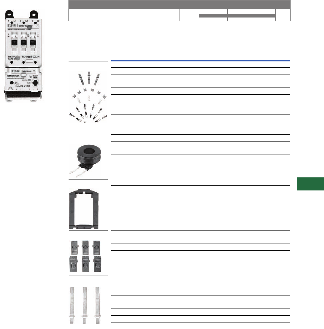
Volume 12—Aftermarket, Renewal Parts and Life Extension Solutions CA08100014E—November 2013 www.eaton.com V12-T13-47
1
2
3
4
5
6
7
8
9
10
11
12
13
14
15
16
17
18
19
20
21
22
23
24
25
13
Motor Control
Contactors, Starters and Brakes
IT. Electromechanical
NEMA
NEMA Full Voltage Non-reversing
Starter, Size 0
Product Description
The Cutler-Hammer
Intelligent Technologies® (IT.)
electromechanical starter
from Eaton’s electrical
business consists of an IT.
electromechanical contact
block or contactor and an IT.
electromechanical solid-state
overload relay as a full voltage
non-reversing (FVNR) or a full
voltage reversing (FVR)
device. Size 00 to Size 5
Starters are factory or field
assembled.
Product History Time Line for IT. Electromechanical NEMA
Replacement Capabilities
Replacements for NEMA Contacts and Starters
Notes
1 H = Hold-Open.
2 For reversing contactors and starters, order two.
Technology Upgrades
This product currently listed in Volume 5—Motor Control and Protection,
CA08100006E, Tab 2.
IT. Electromechanical NEMA
Product 2000 2005 Present
NEMA
Size Description
Catalog
Number
140A EMHCKT40 1
150A EMHCKT50 1
265A EMHCKT65 1
285A EMHCKT85 1
2100A EMHCKT100 1
3, 4 125A EMCKT125
3, 4 160A EMCKT160
3, 4 200A EMCKT200
5250A EMCKT250
5315A EMCKT315
5400A EMCKT400
1Coil EMCC
2Coil EMCD
3, 4 Coil EMCE
5Coil EMCF
00, 0, 1 Catch with leaf spring and pad EMDRCB
2 Catch with leaf spring and pad EMDRCD
1Lug EMLUGKTC
2Lug EMLUGKTD
3, 4 Lug EMLUGKTE
5 Horizontal box lug kit EMLUGKTFA
5 Vertical box lug kit EMLUGKTFB
5 Dual lug kit EMLUGKTFC
00, 0 For contactors and starters EMBBB
1 For starters EMBBC
1 For reversing contactors and reversing starters EMBBRC
2 For starters EMBBD
2 For reversing contactors and reversing starters EMBBRD
3, 4 For starters EMBBE
3, 4 For reversing contactors and reversing starters EMBBRE
5 Overload relay EMBBOF
Contact Kits
Coils 2
DIN Rail Catch
Lug Kits
Overload Busbars
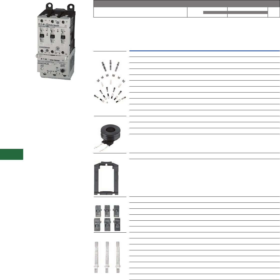
V12-T13-48 Volume 12—Aftermarket, Renewal Parts and Life Extension Solutions CA08100014E—November 2013 www.eaton.com
1
2
3
4
5
6
7
8
9
10
11
12
13
14
15
16
17
18
19
20
21
22
23
24
25
13
Motor Control
Contactors, Starters and Brakes
IT. Electromechanical IEC
IEC FVNR Starter, C-Frame
Product Description
The Cutler-Hammer
Intelligent Technologies (IT.)
electromechanical starter
from Eaton’s electrical
business consists of an IT.
electromechanical contact
block or contactor and IT.
electromechanical solid-state
overload relay as a full voltage
non-reversing (FVNR) or full
voltage reversing (FVR)
device. A-Frame (27 mm) to
F-Frame (140 mm) Starters
are factory or field
assembled.
Product History Time Line for IT. Electromechanical IEC
Replacement Capabilities
Replacements for IEC Contacts and Starters
Note
1 For reversing contactors and starters, order two.
Technology Upgrades
This product currently listed in Volume 5—Motor Control and Protection, CA08100006E, Tab 2.
IT. Electromechanical IEC
Product 2000 2005 Present
Frame
Size Description
Catalog
Number
C40A EMCKT40
C50A EMCKT50
D65A EMCKT65
D85A EMCKT85
D 100A EMCKT100
E 125A EMCKT125
E 160A EMCKT160
E 200A EMCKT200
F 250A EMCKT250
F 315A EMCKT315
F 400A EMCKT400
CCoil EMCC
DCoil EMCD
ECoil EMCE
FCoil EMCF
B, C Catch with leaf spring and pad EMDRCB
D Catch with leaf spring and pad EMDRCD
CLug EMLUGKTC
DLug EMLUGKTD
ELug EMLUGKTE
F Horizontal box lug kit EMLUGKTFA
F Vertical box lug kit EMLUGKTFB
F Dual lug kit EMLUGKTFC
B For contactors and starters EMBBB
C For starters EMBBC
C For reversing contactors and reversing starters EMBBRC
D For starters EMBBD
D For reversing contactors and reversing starters EMBBRD
E For starters EMBBE
E For reversing contactors and reversing starters EMBBRE
F Overload relay EMBBOF
Contact Kits
Coils 2
DIN Rail Catch
Lug Kits
Overload Busbars

Volume 12—Aftermarket, Renewal Parts and Life Extension Solutions CA08100014E—November 2013 www.eaton.com V12-T13-49
1
2
3
4
5
6
7
8
9
10
11
12
13
14
15
16
17
18
19
20
21
22
23
24
25
13
Motor Control
Contactors, Starters and Brakes
XT IEC Power Control
XT Family of Contactors
Product Description
Eaton’s line of XT Contactors
and Starters includes non-
reversing and reversing
contactors, overload relay
and a variety of related
accessories. Because XT
meets IEC, UL, CSA, CCC
and CE standards, it is the
perfect product solution for
IEC applications all over the
world. The compact, space
saving and easy to install XT
line of IEC contactors and
starters is the efficient and
effective solution for
customer applications from
7A to 2000A.
Product History Time Line
for XT IEC Power Control
XT IEC
Power
Control
Product 2005 Present
Replacement Capabilities
Replacement Coils
Voltage
Coil
Suffix
Catalog
Number
Frame C
110/50 120/60 A XTCERENCOILCA
110–130 Vdc AD XTCERENCOILCAD
220/50 240/80 B XTCERENCOILCB
200–240 Vdc BD XTCERENCOILCBD
415/50 460/60 C XTCERENCOILCC
550/50 600/60 D XTCERENCOILCD
208/60 E XTCERENCOILCE
230/50 F XTCERENCOILCF
190/50 220/60 G XTCERENCOILCG
240/50 277/60 H XTCERENCOILCH
380/50 440/60 L XTCERENCOILCL
400/50 N XTCERENCOILCN
380/60 P XTCERENCOILCP
12/50 12/60 R XTCERENCOILCR
12–14 Vdc RD XTCERENCOILCRD
24/5024/60 T XTCERENCOILCT
24–27 Vdc TD XTCERENCOILCTD
24/50 42/50 U XTCERENCOILCU
48/60 W XTCERENCOILCW
48–60 Vdc WD XTCERENCOILCWD
48/50 Y XTCEBENCOILCY
Frame D
110/50 120/60 A XTCERENCOILDA
110–130 Vdc AD XTCERENCOILDAD
220/50 240/80 B XTCERENCOILDB
200–240 Vdc BD XTCERENCOILDBD
415/50 480/60 C XTCERENCOILDC
550/50 600/60 D XTCERENCOILDD
208/60 E XTCERENCOILDE
230/50 F XTCERENCOILDF
190/50 220/60 G XTCERENCOILDG
240/50 277/60 H XTCERENCOILDH
380/50 440/60 L XTCERENCOILDL
400/50 N XTCERENCOILDN
380/60 P XTCERENCOILDP
12/50 12/60 R XTCERENCOILOR
12–14 Vdc RD XTCERENCOILDRD
24/50 24/60 T XTCERENCOILDT
24–27 Vdc TD XTCERENCOILDTD
24/50 42/50 U XTCERENCOILDU
48/60 W XTCERENCOILDW
48–60 Vdc WD XTCERENCOILDWD
48/50 Y XTCERENCOILDY

V12-T13-50 Volume 12—Aftermarket, Renewal Parts and Life Extension Solutions CA08100014E—November 2013 www.eaton.com
1
2
3
4
5
6
7
8
9
10
11
12
13
14
15
16
17
18
19
20
21
22
23
24
25
13
Motor Control
Contactors, Starters and Brakes
Replacement Coils, continued
Voltage
Coil
Suffix
Catalog
Number
Frame F
110/50 120/60 A
XTCERENCOILFA
110–130 Vdc AD
XTCERENCOILFAD
220/50 240/60 B
XTCERENCOILFB
200–240 Vdc BD
XTCERENCOILFBD
415/50 480/60 C
XTCERENCOILFC
550/50 600/60 D
XTCEREN
COIL
FD
208/60 E
XTCERENCOILFE
230/50 F
XTCEREN
COIL
FF
190/50 220/60 G
XTCERENCOILFG
240/50 277/60 H
XTCERENCOILFH
380/50 440/60 L
XTCEREN
COIL
FL
400/50 N
XTCERENCOILFN
380/60 P
XTCERENCOILFP
12/50 12/60 R
XTCERENCOILFR
24/50 24/60 T
XTCERENCOILFT
24–27 Vdc TD
XTCERENCOILFTD
24/50 U
XTCERENCOILFU
42/50 48/60 W
XTCERENCOILFW
48–60 Vdc WD
XTCERENCOILFWD
48/50 Y
XTCERENCOILFY
Frame G
100–120V 50/60 A
XTCERENCOILGA
110–130 Vdc AD
XTCERENCOILGAD
190–240V 50/60 B
XTCERENCOILGB
200–240 Vdc BD
XTCEREN
COIL
GBD
480–500V 50/60 C
XTCEREN
COIL
GC
380–440V 50/60 L
XTCEREN
COIL
GL
24/50 24/60 T
XTCERENCOILGT
24–27 Vdc TD
XTCERENCOILGTD
42–48V 50/60 W
XTCERENCOILGW
48–60 Vdc WD
XTCERENCOILGWD
Frame L 1
110–250 Vac/Vdc
A
XTCERENCOILLA
250–500V 40–60
C
XTCERENCOILLC
24–48 Vdc
TD
XTCERENCOILLTD
48–110 Vac/Vdc
Y
XTCERENCOILLY
Frame M 1
110–250 Vac/Vdc
A
XTCERENCOILMA
250–500V 40–60
C
XTCERENCOILMC
24–48 Vdc
TD
XTCEREN
COIL
MTD
48–110 Vac/Vdc
Y
XTCEREN
COIL
MY
Frame N 1
110–250 Vac/Vdc
A
XTCERENCOILNA
250–500V 40–60
C
XTCERENCOILNC
48–110 Vac/Vdc
Y
XTCERENCOILNY
Replacement Contact Kits
Replacement Vacuum Tube Assembly
Replacement Arc Chambers
Note
1Electronic modules including coils.
For use with…
Catalog
Number
XTAE040D–XTAE065D
XTCERENCONTACTD
XTCE185L–XTCE250L
XTCERENCONTACTL
XTCE300M–XTCE500M
XTCERENCONTACTM
For use with…
Catalog
Number
XTCE580N XTCERENVACT580
XTCE650N XTCERENVACTBB0
XTCE750N XTCERENVACT750
XTCE820N XTCERENVACT820
For use with…
Catalog
Number
XTCE185L XTCERENARC185
XTCE225L XTCERENARC225
XTCE250L XTCERENARC250
XTCE300M XTCERENARC300
XTCE400M XTCERENARC400
XTCE500M XTCERENARC500

Volume 12—Aftermarket, Renewal Parts and Life Extension Solutions CA08100014E—November 2013 www.eaton.com V12-T13-51
1
2
3
4
5
6
7
8
9
10
11
12
13
14
15
16
17
18
19
20
21
22
23
24
25
13
Motor Control
Contactors, Starters and Brakes
Advantage™
Originally a Westinghouse
Product
Advantage Starter
Product Description
Setting a new standard in
motor control, revolutionary
in design, Advantage motor
starters employ state-of-the-
art technology in solving
motor control application
problems that have existed
for ages. Customer focus
group input and 66,000
man-hours of engineering
ingenuity have been
combined to create a motor
starter that dramatically
extends operating life in a
physical space requirement
one half the size of
conventional motor starters.
Product History Time Line for Advantage Contactors and Starters
Replacement Capabilities
Replacements for Contact Kits and Coils
Technology Upgrades
This product currently listed in Volume 5—Motor Control and Protection, CA08100006E, Tab 2.
Sizes 1–6
Size 1991 1995 2000 Present
Description
Catalog
Number
Replacement contact kit, size single, three-pole WCK13
Replacement contact kit, size two, three-pole WCK23
Replacement contact kit, size three, three-pole WCK33
Replacement contact kit, size four, three-pole WCK43
Replacement contact kit, size five, three-pole WCK53
Replacement contact kit, size six, three-pole WCK63
Size one and two, 110/120V, 60 Hz WCOIL12F
Size three and four, 110/120V, 60 Hz WCOIL34F
Size five and six, 110/120V, 60 Hz WCOIL56F
Contact Kits
Coils
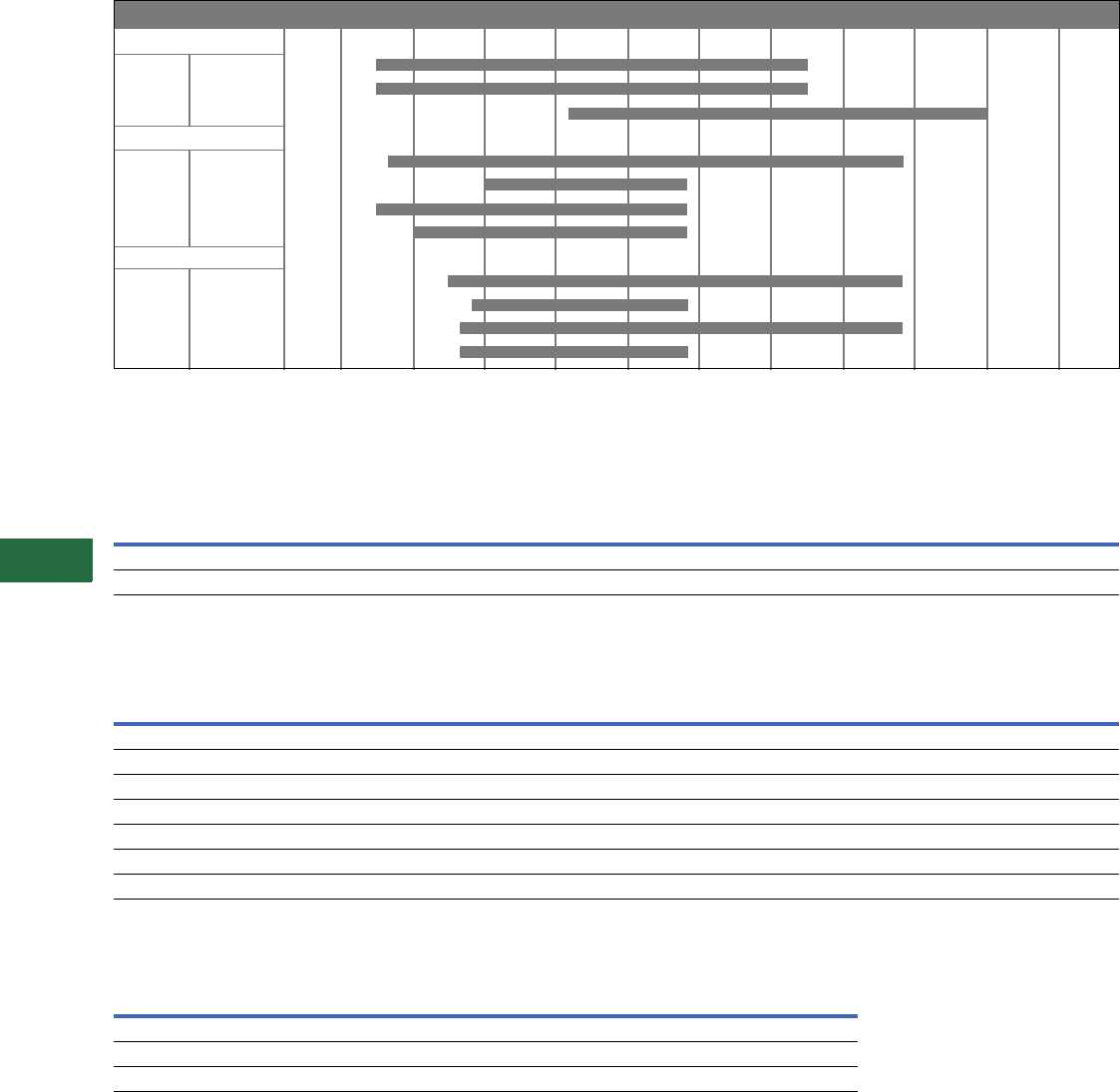
V12-T13-52 Volume 12—Aftermarket, Renewal Parts and Life Extension Solutions CA08100014E—November 2013 www.eaton.com
1
2
3
4
5
6
7
8
9
10
11
12
13
14
15
16
17
18
19
20
21
22
23
24
25
13
Motor Control
Contactors, Starters and Brakes
Definite Purpose
Originally a Cutler-Hammer Product
Product History Time Line for Definite Purpose, Bulletin 9560, 9584 and 9586
Replacement Capabilities
Contact Kits for Types 9560, 9584, 9586
Magnetic Coils for Types 9560, 9584 and 9586
Technology Upgrades
Definite Purpose Technology Upgrades
Note
1Replace with new Definite Purpose contactor or starter.
Pole Amperes 1955 1960 1965 1970 1975 1980 1985 1990 1995 2000 Present
9560 Contactors
2P, 3P, 4P 25, 30, 40
2P, 3P 50, 60
2P, 3P 75, 90
9584 Starters
1P 30
40
50
60
9586 Starters
1P 30
40
50
60
Description
Contact Kit Part Number
Contactor or Starter Size, Ampere Rating
12A Inductive
15A Resistive
25, 30A Inductive
30, 40A Resistive
40A Inductive
50A Resistive
50, 60A Inductive
60, 75A Resistive
75A Inductive
90A Resistive
90A Inductive
120A Resistive
Single-pole kit 16-331-3 6-331-4 —6-331-8 6-331-8
Three-pole kit 1——6-331-39 ——
Coil
Suffix
Coil Voltage
Coil Part Number
Ampere Rating
60 Hz 50 Hz
12, 25 and 30A Inductive
15, 30 and 40A Resistive
40A Inductive
50A Resistive
50, 60, 75 and 90A Inductive
60, 75, 90 and 120A Resistive
-7 — 380 111
-47 277 — 111
-49 104–120 104–120 111
-50 208–240 208–240 111
-69 24 24 111
-72 480 480 111
-74 600 600 111
Type A25 C25 C32 B25
9560 Contactors — 15–90A 120–350A —
9584 Starters — — — 25–40A
9586 Starters 25–60A — — —
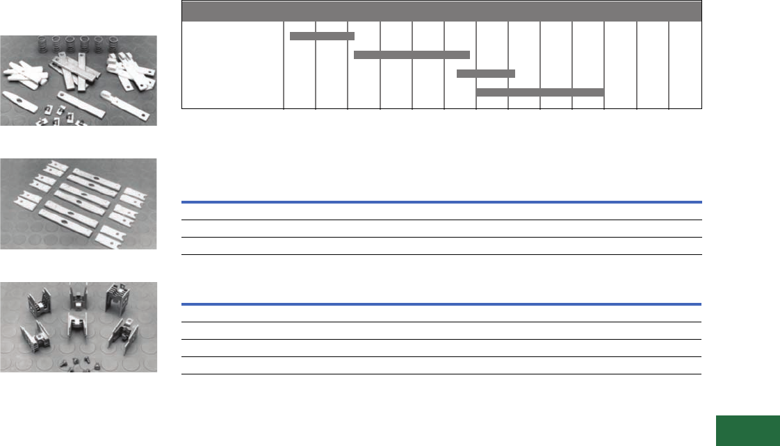
Volume 12—Aftermarket, Renewal Parts and Life Extension Solutions CA08100014E—November 2013 www.eaton.com V12-T13-53
1
2
3
4
5
6
7
8
9
10
11
12
13
14
15
16
17
18
19
20
21
22
23
24
25
13
Motor Control
Contactors, Starters and Brakes
JF Autostarter
Originally a Westinghouse
Product
Start Kit—Style Number 550D409G18
Run Kit—Style Number 550D409G19
Grid Kit—Style Number 3354D90G10
Product Description
Kits contain a complete
set of moving contacts,
stationary contacts
and springs.
Product History Time Line for JF Autostarter
Replacement Capabilities
Manual Autostarter Kits
Solenoid Assembly with Coil (All Sizes)
Technology Upgrades
ECN42–ECN44 reduced voltage auto-transformer starter or IT. solid-state reduced voltage starter.
Notes
1When replacing solenoid assembly series 416C160, use adapter plate style 9917D02H01—quantity one required.
2These styles replace coil style 296B892G_ _. When ordering new style as replacement, customer must order adapter plate 9917D02H01—
quantity one required.
AF
A
MB
JF
Type 1930 1935 1940 1945 1950 1955 1960 1965 1975 1985 1995 2000 Present
Frame
Size Required
Start
Contacts Required
Run
Contacts Required
Grid
Stack Kit
2–3 1 38A7018G12 138A7018G13 13354D90G10
4–5, 5L 1 550D409G18 1550D409G19 13354D90G10
5M–5MM 1 3354D90G08 13354D90G09 23354D90G10
Volt Hz Style 2
115 60 5264C05H01
230 60 5264C05H02
460 60 5264C05H03
575 60 5264C05H04

V12-T13-54 Volume 12—Aftermarket, Renewal Parts and Life Extension Solutions CA08100014E—November 2013 www.eaton.com
1
2
3
4
5
6
7
8
9
10
11
12
13
14
15
16
17
18
19
20
21
22
23
24
25
13
Motor Control
Contactors, Starters and Brakes
ME and MD
DC Contactors
Originally a Westinghouse
Product
Single-Pole, Cat. No. MD510 with
L-64 Auxiliary Contact
Product Description
The Cutler-Hammer ME and
MD line of DC contactors
were and are designed to
control functions of a
connected motor by starting,
stopping, reversing and
regulating. Motor protection
is provided when the
contactors are combined with
an appropriate protective
device such as an
overcurrent relay.
Application Description
Typical applications for the
contactor functions are as
variable voltage controller
disconnects, fans, pumps,
conveyors, rolling mills,
cranes, or anywhere a DC
motor is used.
Product History
The Cutler-Hammer ME and
MD line of DC contactors
dates back to the early 1940s
in East Pittsburgh, PA, where
the development of the M
contactors was begun by the
Westinghouse Electric
Corporation to be used in
steel rolling mills and
nicknamed “mill duty”
devices. Added frame sizes
were developed to complete
the line in Buffalo in the late
1940s. These devices were
primarily mounted on
insulating plates and were
rear connected for ease of
wiring the motor current
conductors. In the 1960s,
front-mounted MD versions
of the devices were
developed to mount devices
on steel panels because the
insulating panels were
expensive and difficult
to manufacture.
In the late 1970s, rear-
connected devices were rare
and the ME contactor line
was created for front
connection, with a rear
connection kit available and
the M rear connected version
discontinued. The MR
normally closed line was
also introduced as a standard
at that time.
Product History Time Line for M Series DC Contactors
NEMA Size 1941 1945 1948 1952 1958 1964 1977 1978 1993 2000 Present
Sizes 0–1 small frame
Type M
Type MD
Type ME
Large frame
Type M
Size 2 large frame
Type M
Type ME
Sizes 3–4
Type MME
Type ME
Sizes 3–4
Type M
Type MD
Size 5
front connected
Type M
Type MD
Rear connected
Type MR
Sizes 6–9
front connected
Type M
Type MD
Rear connected
Type MR

Volume 12—Aftermarket, Renewal Parts and Life Extension Solutions CA08100014E—November 2013 www.eaton.com V12-T13-55
1
2
3
4
5
6
7
8
9
10
11
12
13
14
15
16
17
18
19
20
21
22
23
24
25
13
Motor Control
Contactors, Starters and Brakes
Replacement Capabilities
ME Series Renewal Parts—Kits
ME Series Renewal Parts—Coils
Note
1If lower coils are required, order separately.
Description
1NO Pole 2NO Poles 1NC Pole 1NO/NC Pole
Qty.
Part
Number Qty.
Part
Number Qty.
Part
Number Qty.
Part
Number
Contact kit 1 2184A10G14 22184A10G14 12184A10G14 22184A10G14
Arc box 10/25/50A 1 2184A10G09 22184A10G09 12184A10G09 22184A10G09
Arc box 100/150A 1 2184A10G10 22184A10G10 12184A10G10 22184A10G10
Shunt kit 1 2184A10G21 12184A20G16 12084A01G07 12184A11G07
Armature kit 1 2184A10G19 12184A20G15 12084A01G06 12184A11G06
Blowout assembly
10A 1 2184A10G15 12184A20G11 12184A10G15 22184A10G15
25A 1 2184A10G16 12184A20G12 12184A10G16 22184A10G16
50A 1 2184A10G17 12184A20G13 12184A10G17 22184A10G17
110/150A 1 2184A10G18 12184A20G14 12184A10G18 22184A10G18
Rear connection kit 1 2184A10G08 12184A10G08 12184A10G08 12184A10G08
Voltage
Part Number
Operating Coils Holding Coils (Lower) 1 — 1NO/1NC Contactors Only
10/25/50/100/150
Ampere Sizes
10/25/50
Ampere Sizes
100/150
Ampere Sizes
65 30B4376G06 44A6366G10 30B4376G27
90/92 30B4376G25 44A6366G12 427C048G16
115 30B4376G07 44A6366G13 30B4376G01
125 30B4376G08 44A6366G19 30B4376G26
230/240 30B4376G09 44A6366G15 30B4376G02
250 30B4376G10 44A6366G23 30B4376G17
500 30B4376G14 N/A N/A
550 30B4376G11 44A6366G18 30B4376G03

V12-T13-56 Volume 12—Aftermarket, Renewal Parts and Life Extension Solutions CA08100014E—November 2013 www.eaton.com
1
2
3
4
5
6
7
8
9
10
11
12
13
14
15
16
17
18
19
20
21
22
23
24
25
13
Motor Control
Contactors, Starters and Brakes
MR and MD Series 1 Sizes 5–9 Renewal Parts—Kits
Notes
1MR = rear connected; MD = front connected.
2Type MR only.
3Type MD only.
Type MR
and MD
Part Number
Current
Contact Kit
501/501R 26D2610G22
510 26D2610G15
601/701 26D2610G24
610/710 26D2610G16
810 26D2610G18
810R 26D2610G19
910 26D2610G20
Shunt
501/501R 25A1650G02
510 25A1641G02
601 25A1666G03
610 25A1654G03
701 25A1666G04
710 25A1654G04
810/810R 25A1693G02
910 45A1425G02
Arc Box
501/510 25A1646G01
601/610, 701/710 25A1662G01
810/910 25A1677G05
Armature Kit
501/501R 25A1649G05
510 25A1640G05
601/701 25A1667G03
610/710 25A1655G04
810/810R 25A1694G05
910 38A2269G02
Blowout Coil Assembly Kit 2
M501/510 25A1644G05
M601/610 25A1659G05
M701/710 25A1660G03
M810/810R 25A1698G03
M910 238A2273G02
Blowout Coil Assembly Kit 3
M501/510 857D505G05
M601/610 857D506G08
M701/710 857D516G05
M810 857D508G07
M910 857D509G04

Volume 12—Aftermarket, Renewal Parts and Life Extension Solutions CA08100014E—November 2013 www.eaton.com V12-T13-57
1
2
3
4
5
6
7
8
9
10
11
12
13
14
15
16
17
18
19
20
21
22
23
24
25
13
Motor Control
Contactors, Starters and Brakes
M and MD Series Sizes 5–9—Coils
Technology Upgrades
This product currently listed in Volume 5—Motor Control and Protection, CA08100006E, Tab 4.
Notes
1Two coils connected in series.
2Two coils connected in parallel.
3Two resistors connected in parallel.
4Resistors connected in series.
Voltage
M and MD 501 M and MD 510 M and MD 610/710
Part
Number
Symmetrical
Wiring
Part
Number
Symmetrical
Wiring
Part
Number
Symmetrical
Wiring
65 N/A — 45A5515G11 ———
90/92 N/A — 45A5515G23 —30B4377G17 —
115 30B4375G04 —45A5515G01 —30B4377G04 —
125 30B4375G24 —45A5515G07 —30B4377G10 —
230 30B4375G05 —45A5515G04 —30B4377G05 —
250 30B4375G12 —45A5515G12 —30B4377G07 —
550 30B4375G06 —45A5515G05 —30B4377G08 —
Voltage
M and MD 601/701 M and MD 810 M and MD 910
Part
Number
Symmetrical
Wiring
Part
Number
Symmetrical
Wiring
Part
Number
Symmetrical
Wiring
92 — — 435A928G01 1435A930G01 1
115 30B4377G23 1435A929G01 1L483507G01 1
115 30B4377G01 2L482211G01 2L483507G01 2
125 30B4377G24 1435A966G01 1435A967G01 1
125 30B4377G13 2—— — —
230 30B4377G01 1L482211G01 1L483507G01 1
230 30B4377G02 2—— — —
250 30B4377G13 1334P064G01 1LR549720G01 2
250 30B4377G08 2—— — —
550 30B4377G25 1L482213G01 2L483508G01 2
550 30B4377G03 2—— — —
600 — — N/A — L548879G01 1
Voltage
M and MD 810R
Coil Resistor Resistor Mounting
Part
Number
Symmetrical
Wiring
Part
Number
Symmetrical
Wiring
Part
Number
Symmetrical
Wiring
115 N/A — N/A — N/A —
230 L482211G0 157D1336G10 357D1340G02 —
550 N/A 157D1336G12 457D1340G02 —

V12-T13-58 Volume 12—Aftermarket, Renewal Parts and Life Extension Solutions CA08100014E—November 2013 www.eaton.com
1
2
3
4
5
6
7
8
9
10
11
12
13
14
15
16
17
18
19
20
21
22
23
24
25
13
Motor Control
Contactors, Starters and Brakes
C80 Mill Type DC
Contactors
Originally a Cutler-Hammer
Product
Size 2—Two-Pole Contactor
NO Contactor
Product Description
These DC mill type
contactors are designed for
heavy industry service and
are suitable for use on
moving machinery. The
contactors listed in this
section are for surface
mounting on steel panels and
front-of-panel wiring. The
power stud assembly is
mounted on the side of the
contactor, rather than as part
of a separate mounting kit.
The contactors feature forged
steel armature levers and
magnet frames for superior
physical strength. Self-
lubricating bearings eliminate
the need for lubricating the
contactor.
New hot-molded arc chute
assemblies contain no
asbestos and have better arc
extinction characteristics for
longer contact life. The short
stroke armature results in a
mechanical life of more than
20 million operations.
Product History Time Line for C80 Mill Type DC Contactors
Note: The C80 contactors were renumbered in 1984 from the old 6002 Series, which date back to 1919.
Consult factory for old 6002 Series replacements and parts.
Sizes 2 – 8
Size 1980 1985 1990 1995 2000 Present
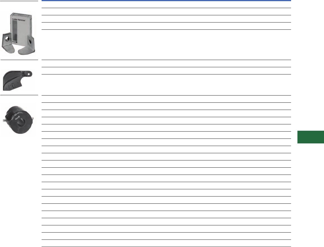
Volume 12—Aftermarket, Renewal Parts and Life Extension Solutions CA08100014E—November 2013 www.eaton.com V12-T13-59
1
2
3
4
5
6
7
8
9
10
11
12
13
14
15
16
17
18
19
20
21
22
23
24
25
13
Motor Control
Contactors, Starters and Brakes
Replacement Capabilities
Replacement Capabilities for C80 Mill Type DC Contactors
Technology Upgrades
This product currently listed in Volume 5—Motor Control and Protection, CA08100006E, Tab 4.
Notes
1Series resistor used with coil for voltage shown.
2Magnet closing coil only. If holdout coil is required, give number stamped on coil or advise
Bulletin or Serial Number of controller.
Description
Part Numbers
Size 2
Single-Pole,
Two-Pole,
Three-Pole and
Ltl® 25 and 50A
Size 3
Single-Pole
NO, NC
and Ltl 100A
Size 4
Single-Pole
NO, NC
and Ltl 150A
Size 5
Single-Pole
NO, NC
and Ltl 300A
Size 6
Single-Pole
NO, NC
and Ltl 600A
Size 6A
Single-Pole
NO, NC
and Ltl 810A
Size 8
Single-Pole
NO 1350A
Set of Contacts
Single-pole copper 6-599 6-189 6-189 6-189-3 6-189-4 6-189-4 6-215
Single-pole silver — 6-189-5 6-189-6 6-189-7 6-189-8 6-189-8 6-215-2
Two-pole copper 6-169-4 ——————
Three-pole copper 6-169-5 ——————
Arc Shield
Right hand 73-2676-2 62-791 62-791 62-793 62-840 62-840 62-804
Left hand 73-2676 62-791-2 62-791-2 62-793-2 62-840-2 62-840-2 62-804
Coils
Single-pole NO 100V 9-1549-18 9-1583-15 9-1583-15 9-1589-10 9-1688-8 9-1688-8 9-547-7 1
115V 9-1549-2 9-1583-2 9-1583-2 9-1589-2 9-1688-2 9-1688-2 9-547-7 1
115V 9-1549-2 9-1583-2 9-1583-2 9-1589-2 9-1688-2 9-1688-2 9-547-7 1
550V 9-1549-3 9-1583-3 9-1583-3 9-1589-3 9-1688-3 9-1688-3 9-547-28 1
Single-pole NC 100V — 9-1585-18 9-1585-18 9-967-13 9-1717-4 ——
115V — 9-1585-2 9-1585-2 9-967-8 9-1717-1 ——
230V — 9-1585-1 9-1585-1 9-967-7 9-1717-2 ——
550V — 9-1585-3 9-1585-3 9-967-12 9-1717-3 ——
Single-pole Ltl 2 100V 9-1549-18 9-1583-15 9-1583-15 9-1589-10 9-1688-8 ——
115V 9-1549-2 9-1583-2 9-1583-2 9-1589-2 9-1688-2 ——
230V 9-1549-1 9-1583-1 9-1583-1 9-1589-1 9-1688-1 ——
550V 9-1549-3 9-1583-3 9-1583-3 9-1589-3 9-1688-3 ——
Two-pole 100V 9-1585-18 ——————
115V 9-1585-2 ——————
230V 9-1585-1 ——————
550V 9-1585-3 ——————
Three-pole 100V 9-1585-18 ——————
115V 9-1585-2 ——————
230V 9-1585-1 ——————
550V 9-1585-3 ——————
Set of Contact
Arc Shield
Coils

V12-T13-60 Volume 12—Aftermarket, Renewal Parts and Life Extension Solutions CA08100014E—November 2013 www.eaton.com
1
2
3
4
5
6
7
8
9
10
11
12
13
14
15
16
17
18
19
20
21
22
23
24
25
13
Motor Control
Contactors, Starters and Brakes
511 AC and DC Brakes
Originally a Cutler-Hammer
Product
Size 4-Inch Brake and Wheel
Product Description
Cutler-Hammer Type S
brakes are field-proven AC/
DC brakes. For applications
up to 1800 rpm/50 hp.
Precision holding and
stopping in 4, 5.5, 7 and
10-inch wheel sizes. With 15
standard bore sizes—straight
or tapered, non-asbestos
linings and off-the-shelf
availability, electrically
released and spring applied,
providing “fail-safe”
operation.
The retarding torque developed
is directly
proportional to the
spring pressure.
Typical applications include
conveyors, machine tools,
printing presses, small
cranes, overhead doors,
dumb waiters, vacuum
molding machines and
carnival rides.
Product History Time Line for 511 AC and DC Brakes
Types 1934 1940 1950 1960 1970 1980 1990 2000 Present
4-inch Small Solenoid
4-inch Large Solenoid
5-1/2-inch Old Style
5-1/2-inch Updated
7-inch
7-inch High Torque
8-1/2-inch
10-inch

Volume 12—Aftermarket, Renewal Parts and Life Extension Solutions CA08100014E—November 2013 www.eaton.com V12-T13-61
1
2
3
4
5
6
7
8
9
10
11
12
13
14
15
16
17
18
19
20
21
22
23
24
25
13
Motor Control
Contactors, Starters and Brakes
Replacement Capabilities
Renewal Parts for Cat. No. 511 Shoe Brakes 1
Technology Upgrades
This product currently listed in Volume 5—Motor Control and Protection, CA08100006E, Tab 2.
1Parts listed are for current line of 511 brakes.
2Kit contains two linings and rivets for one brake.
3Part number covers one shoe only.
Description
Part Numbers
4-Inch Brake 5-1/2-Inch Brake 7-Inch Brake 10-Inch Brake
3, 10 and 15 Lb
Torque
25 and 35 Lb
Torque
50 and 75 Lb
Torque
85 and 110 Lb
Torque
125 Lb
Torque
160 Lb
Torque
Magnet Coils Coil Suffix
120V, 60 Hz -39 9-591-9 9-585-9 9-941-20 9-941-8 9-758-36 9-758-37
110V, 50 Hz -5 9-591-9 9-585-9 9-585-9 9-941-39 9-758-26 9-758-10
120/110V, 50/60 Hz -66 9-591-9 9-585-9 ——— —
208V, 60 Hz -45 9-591-16 9-585-33 9-941-35 9-941-45 9-758-30 9-758-31
208/240V, 50/60 Hz -50 9-591-3 ———— —
240V, 60 Hz -40 9-591-10 9-585-10 9-941-15 9-941-4 9-758-2 9-758-30
220/240V, 50/60 Hz -67 9-591-10 9-585-10 ——— —
480V, 60 Hz -41 9-591-11 9-585-16 9-941-12 9-941-6 9-758-4 9-758-20
440/480V, 50/60 Hz -70 9-591-11 —————
600V, 60 Hz -58 9-591-12 9-585-26 9-941-32 9-941-25 9-758-13 9-758-5
550/600V, 50/60 Hz -71 9-591-12 —————
220V, 50 Hz -6 9-591-10 9-585-10 9-585-10 9-941-29 9-758-6 9-758-2
380V, 50 Hz -7 9-591-13 9-585-5 9-585-5 9-941-30 9-758-4 9-758-28
440V, 50 Hz -8 9-591-11 9-585-11 9-585-11 9-941-3 9-758-7 9-758-4
550V, 50 Hz -9 9-591-12 9-585-12 9-585-12 9-941-41 9-758-27 9-758-13
120 Vdc -97 9-1346-3 9-1347-10 9-1347-10 9-1347-12 ——
240 Vdc -98 9-1346-4 9-1347-11 9-1347-11 9-1347-13 ——
Lining kit with rivets 26-166 6-166-2 6-166-5 6-166-5 6-166-4
Shoe with lining 48-306 348-1787 348-1200-3 348-1200-3 324-2146-3 Inner 3
24-2146-4 Outer 3
Solenoid without coil AC 88-1553-8 88-2930-4 88-1342-11 88-1342-11 17-17199
DC 88-521-6 88-521-5 88-521-5 88-521-5 —
RP publication number 19320 AC 17377 AC 15475 AC 15475 AC 17379
13864 DC 17378 DC 15477 DC 15477 DC —
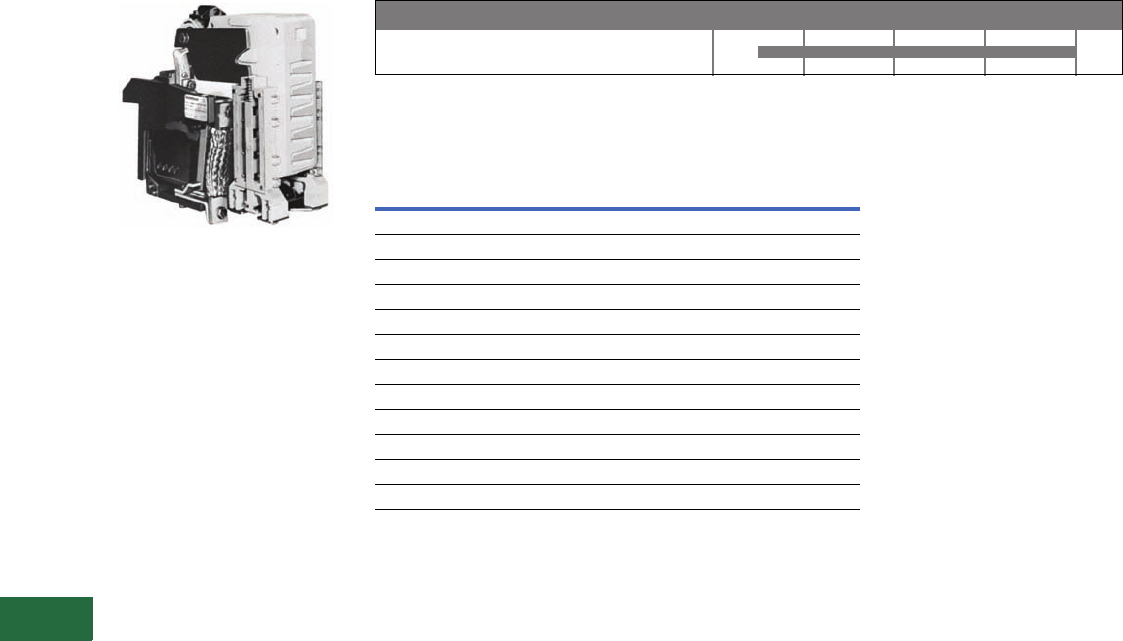
V12-T13-62 Volume 12—Aftermarket, Renewal Parts and Life Extension Solutions CA08100014E—November 2013 www.eaton.com
1
2
3
4
5
6
7
8
9
10
11
12
13
14
15
16
17
18
19
20
21
22
23
24
25
13
Motor Control
Contactors, Starters and Brakes
DPM-Contactor
DPM 1000 Vdc Contactor
Product Description
The Cutler-Hammer DPM
1000 Vdc Definite Purpose
Contactor has been designed
to meet severe environmental
and vibration conditions
found in your worst
applications. The contactor
is of unit construction,
assembled on a molded
insulated base, providing
maximum performance in
minimum space.
Product History Time Line for DPM-Contactor
Replacement Capabilities
DPM-Contactor Renewal Parts
Technology Upgrades
This product currently listed in Volume 5—Motor Control and
Protection, CA08100006E, Tab 4.
DPM-Contactor
Device 1970 1980 1990 2000 Present
Description
Catalog
Number
Contact kit 2131A94G10
Arc box 2131A94G03
Shunt 3534C86G01
Coils
28 Vdc 2114A92G04
36 Vdc 2114A92G05
55 Vdc 2114A92G06
74 Vdc 2114A92G09
110/115 Vdc 2114A92G14
125 Vdc 2114A92G15
275 Vdc 2114A92G16
600 Vdc 2114A92G20
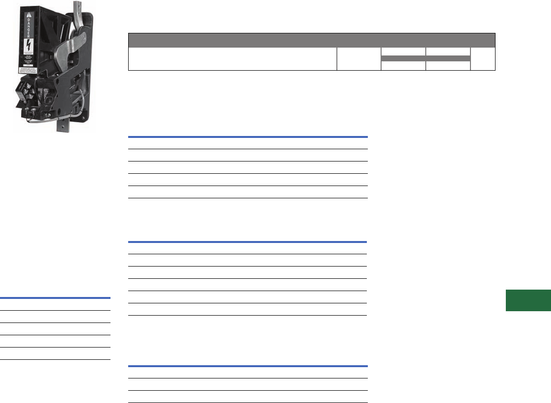
Volume 12—Aftermarket, Renewal Parts and Life Extension Solutions CA08100014E—November 2013 www.eaton.com V12-T13-63
1
2
3
4
5
6
7
8
9
10
11
12
13
14
15
16
17
18
19
20
21
22
23
24
25
13
Motor Control
Contactors, Starters and Brakes
AVD-Contactor
2000 Vdc Contactor
Product Description
The AVD-Contactor is a
single-pole normally open,
load break, bi-directional
definite purpose DC
contactor. The device is rated
at 1400A continuous and is
capable of switching up to
2000 Vdc loads.
Operating Coil
Characteristics
Coil
Voltage
Current Draw at
Nominal Voltage
(± 5% at 20°C)
Catalog
Number
28 1.87 9-3004-2
37 1.58 9-3004-3
74 0.79 9-3004-1
100 0.62 9-3004-5
230 0.25 9-3004-4
Product History
The Cutler-Hammer AVD (Advanced DC Contactor) was released for sale in 1995. The device has
not gone through any significant redesigns since its introduction.
Product History Time Line for AVD-Contactor
Replacement Capabilities
Replacement Coils
Auxiliary Contacts
Replacement Contacts and Arc Chute
Technology Upgrades
This product currently listed in Volume 5—Motor Control and
Protection, CA08100006E, Tab 4.
AVD-Contactor
Device 1993 1995 2000 Present
Coil Voltage (Vdc)
Catalog
Number
28 9-3004-2
37 9-3004-3
74 9-3004-1
100 9-3004-5
230 9-3004-4
Contact
Configuration
Terminal
Configuration
Catalog
Number
1NO/1NC Fast-on 10-3519-5
2NO Fast-on 10-3519-6
2NC Fast-on 10-3519-7
1NO/1NC Screw type 10-6817
2NO Screw type 10-6817-2
2NC Screw type 10-6817-3
Description
Quantity
Required per
Contactor
Catalog
Number
Stationary contact 1 23-7253
Movable contact 2 23-7255
Arc chute 1 62-1038

V12-T13-64 Volume 12—Aftermarket, Renewal Parts and Life Extension Solutions CA08100014E—November 2013 www.eaton.com
1
2
3
4
5
6
7
8
9
10
11
12
13
14
15
16
17
18
19
20
21
22
23
24
25
13
Motor Control
Contactors, Starters and Brakes
D-Contactor
750 Vdc Contactor
Product Description
The D-Contactor is a single-
pole normally open, load
break, bi-directional definite
purpose DC contactor. Two
devices are available rated at
1800 and 3000A at 750 Vdc.
Operating Coil
Characteristics
Coil
Voltage
Current Draw at
Nominal Voltage
(± 7.5% at 20°C)
Catalog
Number
12 3.96 9-1688-15
24 2.00 9-1688-7
32 1.44 9-1688-9
48 1.00 9-1688-12
74 .97 9-2064-3
100 .45 9-1688-8
115 .37 9-1688-2
230 .20 9-1688-1
Product History
The Cutler-Hammer
D-Contactor was released for
sale in early 1970s. The
original device included a
permanent magnet blowout
coil and square main
contacts. The permanent
magnet blowout coil device
was uni-directional or the
current could only flow
through the device in one
direction. As such, it
was
essential that the polarity as
marked
on the power
terminals be maintained. The
permanent magnet blowout
device is no longer offered.
The device was redesigned in
the early 1980s to include
round main contacts and an
intermittent duty blowout
coil in lieu of the permanent
magnet blowout. The
blowout coil device is
bi-directional or current can
flow through the device in
either direction. Although
contact life is maximized if
the +terminal is at the top of
the device, it is not essential
that polarity be maintained.
The present blowout coil
device is a form, fit, function
replacement for the original
permanent magnet blowout
device. In addition, the
present contact kits with the
round contacts can be used
on the original devices that
employed the square main
contacts. Subsequent minor
product enhancements
have been made with the
new parts being a direct
replacement for the parts
that they replaced.
Product History Time Line for D-Contactor
Replacement Capabilities
Replacement Coils Auxiliary Contacts
Replacement Contacts, Blowout Coil and Arc Chute
Technology Upgrades
This product currently listed in Volume 5—Motor Control and
Protection, CA08100006E, Tab 4.
Permanant Magnet Blowout Device
Blowout Coil Device
Device 1970 1980 1990 2000 Present
Coil Voltage
(Vdc)
Catalog
Number
12 9-1688-15
24 9-1688-7
32 9-1688-9
48 9-1688-12
74 9-2064-3
100 9-1688-8
115 9-1688-2
230 9-1688-1
Contact
Configuration
Terminal
Configuration
Catalog
Number
1NO/1NC Fast-on 10-3519-5
2NO Fast-on 10-3519-6
2NC Fast-on 10-3519-7
1NO/1NC Screw type 10-6817
2NO Screw type 10-6817-2
2NC Screw type 10-6817-3
Device Rating
Amperes
Main Contact
Configuration Contacts
Catalog
Number
1800 Two-main Main contacts 6-497
1800 Two-main Arcing contacts 23-5449
3000 Four-main Main contacts 6-496
3000 Four-main Arcing contacts 23-5448
1800 and 3000 Two- and four-main Blowout coil 9-2592
1800 and 3000 Two- and four-main Arc chute 62-822
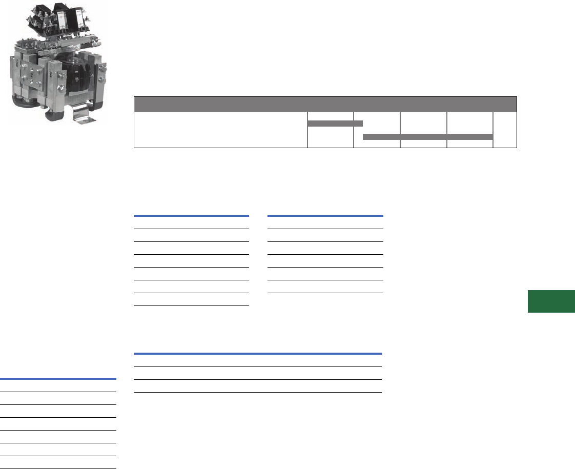
Volume 12—Aftermarket, Renewal Parts and Life Extension Solutions CA08100014E—November 2013 www.eaton.com V12-T13-65
1
2
3
4
5
6
7
8
9
10
11
12
13
14
15
16
17
18
19
20
21
22
23
24
25
13
Motor Control
Contactors, Starters and Brakes
Reversing/Assignment
Contactors
1000 Vdc Contactor
Product Description
The Reversing/Assignment
Contactor is a double-pole,
double-throw, non-load break
definite purpose DC
contactor. A three-position
center-off and a two-position
magnetically-latched
configuration is available.
The device is rated for
1100A, 1000 Vdc. The
Reversing Contactor includes
cross-over busbars for DC
motor reversing applications;
the Assignment Contactor
omits the cross-over busbars
for motor assignment
applications.
Operating Coil
Characteristics
Coil
Voltage
Current Draw at
Nominal Voltage
(± 7.5% at 20°C)
Catalog
Number
24 1.60 9-1903-9
28 1.30 9-1903-1
36 1.06 9-1903-3
74 0.49 9-1903-7
110 0.33 9-1903-6
125 0.33 9-1903-4
250 0.17 9-1903-8
Product History
The Cutler-Hammer
Reversing/Assignment
Contactor was released for
sale in the early 1970s. The
original device incorporated a
leaf spring contact assembly
and square contacts. The
device was redesigned in the
early 1980s to incorporate a
coil spring contact assembly
with round contacts. The
present device is a form, fit,
function replacement for the
original device. In addition,
the original leaf spring contact
assembly devices can be
upgraded to the new coil
spring contact assembly with
the one-time purchase of a
contact upgrade kit. The
standard contact kit can then
be used for subsequent
contact replacements.
Product History Time Line for Reversing/Assignment Contactors
Replacement Capabilities
Replacement Coils Auxiliary Contacts
Replacement Contacts
Technology Upgrades
This product currently listed in Volume 5—Motor Control and
Protection, CA08100006E, Tab 4.
Note
1The 6-602-3 contact kit will upgrade the three-position, reversing/assignment device from the
original design that incorporated a leaf spring contact structure to the present design that
incorporates a coil spring contact structure. The 6-602 contact kit can then be used after the
device has been upgraded for the subsequent contact replacement.
Leaf Spring Contact Assembly Device
Coil Spring Contact Assembly Device
Device 1970 1980 1990 2000 Present
Coil Voltage
(Vdc)
Catalog
Number
24 9-1903-9
28 9-1903-1
36 9-1903-3
74 9-1903-7
110 9-1903-6
125 9-1903-4
250 9-1903-8
Contact
Configuration
Terminal
Configuration
Catalog
Number
1NO/1NC Fast-on 10-3519-5
2NO Fast-on 10-3519-6
2NC Fast-on 10-3519-7
1NO/1NC Screw type 10-6817
2NO Screw type 10-6817-2
2NC Screw type 10-6817-3
Device Configuration
Catalog
Number
Reversing/assignment Three-position 6-602
Reversing/assignment upgrade kit 1Three-position 6-602-3
Magnetic latched reversing/assignment Two-position 6-602-5
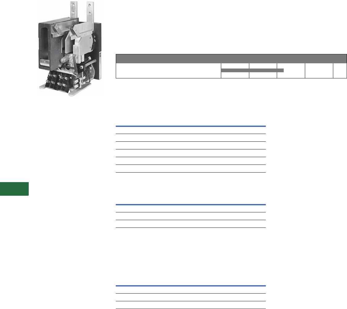
V12-T13-66 Volume 12—Aftermarket, Renewal Parts and Life Extension Solutions CA08100014E—November 2013 www.eaton.com
1
2
3
4
5
6
7
8
9
10
11
12
13
14
15
16
17
18
19
20
21
22
23
24
25
13
Motor Control
Contactors, Starters and Brakes
P- and S-Contactors
Power Contactor
Product Description
The P- and S-Contactors are
single-pole normally open,
load break DC contactors.
Although the devices have
two arc shields, they are
functionally single-pole
devices. The contactors
typically carried a 1000 Vdc,
1000A rating and were
applied in locomotive, rapid
transit and high horsepower
DC drive applications.
Product History
The Cutler-Hammer
P-Contactor and S-Contactor
were released for sale in the
1960s. These were single-
pole DC contactors that used
two arc chutes.
They typically carried a
1000 Vdc, 1200A rating and
were discontinued in the mid
1980s. A few renewal parts
are still available.
Product History Time Line for P- and S-Contactors
Replacement Capabilities
A few renewal parts are still available.
Auxiliary Contacts
Replacement Contacts, Blowout Coil and Arc Chute
Technology Upgrades
This product can potentially be replaced with the DPM-Contactor
or D-Contactor depending on the application. Please contact our
Technical Resource Center for replacement device selection.
Further Information
For further replacement parts information, contact Standard
Open Control Aftermarket at 1-800-535-8992.
Pricing Information
Price and Availability Digest (PAD)
Vista/VISTALINE Discount Symbols 1CD-5C, 1CD-1C, 15CD3
and 1CD-1
Contact
Configuration
Terminal
Configuration
Catalog
Number
1NO/1NC Fast-on 10-3519-5
2NO Fast-on 10-3519-6
2NC Fast-on 10-3519-7
1NO/1NC Screw type 10-6817
2NO Screw type 10-6817-2
2NC Screw type 10-6817-3
Description
Quantity
Required per
Contactor
Catalog
Number
Contact kit 1 6-332
Arc chute 2 62-469
Blowout coil 2 62-532
P- & S-Contactors
Device 1960 1970 1980 2000 Present
Publication
Number Description
PT03304001E Genuine Cutler-Hammer Replacement Contact Kits and Coils Wall Chart
B8F01SE Vacuum Starters and Contactors
CA08100006E Volume 5—Motor Control and Protection

Volume 12—Aftermarket, Renewal Parts and Life Extension Solutions CA08100014E—November 2013 www.eaton.com V12-T13-67
1
2
3
4
5
6
7
8
9
10
11
12
13
14
15
16
17
18
19
20
21
22
23
24
25
13
Motor Control
Solid-State Low Voltage Reduced Voltage Motor Starters
Contents
Description Page
Low Voltage Reduced
Voltage Motor Starters
Product Description,
Product History,
Product History
Time Line . . . . .
V12-T13-67
Replacement
Capabilities,
Technology
Upgrades . . . . .
V12-T13-68
Low Voltage Adjustable
Frequency AC Drives
Product Description,
Product History
Time Line . . . . .
V12-T13-69
Replacement
Capabilities,
Technology
Upgrades . . . . .
V12-T13-71
Reduced Voltage Motor
Starters
IT. Reduced Voltage
Solid-State Motor Starter
Product Description
Reduced voltage solid-state
motor starters serve to
provide reduced voltage
starting, protection and
control for standard three-
phase induction motors.
They are commonly found in
applications like conveyors,
compressors, extruders,
pumps and blowers, etc.
Reduced voltage starting is
beneficial because current
and torque are reduced
during the motor starting
process. This reduces the
electrical and mechanical
shock experienced during
motor starting, prolonging
motor and equipment life.
Reduced voltage starters
also provide for maximum
efficiency of the motor duty
cycle by electronically
sensing the motor load and
reducing the voltage applied
to the motor when it is
running at less than full
load torque.
Solid-state motor starters
also provide short circuit and
various types of electronic
protective functions.
Common features include
phase loss, undervoltage,
current balance, phase
rotation, current limit,
overtemperature, etc.
Reduced voltage solid-state
controllers are similar to
reduced voltage motor
starters, except they include
no overload or short-circuit
protection. Motor controllers
are applied in series with
conventional electromechanical
starters to provide the
benefits of reduced voltage
starting at lower cost.
Electromechanical starter
contact life is also improved
by the reduced voltage motor
controller.
Product History
Eaton’s present line of Cutler-
Hammer reduced voltage
starters is the culmination of
38 years of product
development. In 1958,
Vectrol Engineering began
manufacturing SCR Gate
Driver circuitry and
progressed into their own
soft starter product line,
known as the Vectrol Motor
Starter (VMS). In 1980,
Vectrol was purchased by
Westinghouse. The VMS
was quickly phased out of
production and the Vectrol
ES (Energy Saver) solid-state
reduced voltage starter
was introduced. The Vectrol
ES combined features of
automatic power factor
adjustment and reduced
voltage, maximizing the
efficiency of the motor duty
cycle. The Vectrol ES starter
was actively manufactured
until 1988 when the Easy-
Start Motor Starter was
introduced.
Eaton entered the market in
1975 with the A415, A445
and A485 product lines. By
1983, Eaton had released the
A515/A545 Model A solid-
state reduced voltage starter
and followed up in late 1984
with the improved Model B
A515. This starter used a
solid-state controller, an
overload relay and a six SCR
full-wave power section. In
1988, Westinghouse
introduced its Easy-Start and
Easy-Start Jr. product lines
that also used a solid-state
control circuit and a six SCR
full-wave
power section. In
1995, the newly formed
Solid-
State Motor Control Division
(SSMC) of the new Eaton
released the Easy-Start EA
Reduced Voltage Starter,
combining the voltage control
of SCRs with the durability of
the Advantage motor starter
into a uniquely small package.
The EA, EJ and the ES
product lines have been
replaced by the IT. line of
solid-state reduced voltage
starters. Introduced in
October of 1999, the IT.
Starter is compact, easy to
install, easy to program and is
the most advanced solid-
state reduced voltage starter
available anywhere.
Product History Time Line
Cutler-Hammer A415/A445/A485
Westinghouse Vectrol VMS
Westinghouse Vectrol Energy Saver
Westinghouse Vectrol Startrol
Westinghouse Vectrol Startrol Power Miser
Cutler-Hammer A515/A545 Model A
Westinghouse Power Miser 2
Cutler-Hammer A515/A545 Model B
Westinghouse Easy-Start
Westinghouse Easy-Start 120
Cutler-Hammer Easy-Start ES
Westinghouse Power Miser 2, Model 3
Cutler-Hammer C514
Cutler-Hammer Easy-Start EC
Westinghouse Easy-Start Jr.
Westinghouse Easy-Start 100
Cutler-Hammer Easy-Start EJ
Cutler-Hammer Easy-Start EA
Cutler-Hammer IT. Starter
Product 1975 1980 1985 1990 1995 2000 Present

V12-T13-68 Volume 12—Aftermarket, Renewal Parts and Life Extension Solutions CA08100014E—November 2013 www.eaton.com
1
2
3
4
5
6
7
8
9
10
11
12
13
14
15
16
17
18
19
20
21
22
23
24
25
13
Motor Control
Solid-State Low Voltage Reduced Voltage Motor Starters
Replacement Capabilities
In most cases, recommended
replacement product is the
Cutler-Hammer IT. Soft Start
Starter. Eaton’s Electrical
Services & Systems (EESS)
has trained technicians
nation
wide. See
Ta b 2 2
in this
catalog for further
information
about EESS capabilities.
Technology Upgrades
The
IT.
line provides an easy-to-
program,
easy-to-install line of
reduced voltage Soft Starters
that is the most advanced
available anywhere in the
world. With a
range of 12–
850A and 13 models
in four
frame sizes, the IT. Soft
Starter provides advanced
functionality with
unsurpassed configuration
flexibility for open, enclosed
or motor control center
applications.
Support Chart for Non-Current Vintage Products
Advanced Technology Services, 8200 N. University, Peoria, IL 61615, now provides support for these products.
Their toll-free number is 1-877-645-3606.
Definitions
PCB Repair
Printed circuit boards may be
returned to Advanced
Technology Services for
repair. All PCBs are upgraded
to the most
current revision at
the time of the repair.
Upgrade Kits
Kits are available to upgrade
the basic
performance of
certain vintage products.
Contact Advanced
Technology Services for
more information.
Service Depot Repairs
Entire assemblies may be
returned to
Advanced
Technology Services
for
repair, upgrade or
refurbishment.
Field Service
Eaton’s Electrical Services &
Systems (EESS) has trained
technicians nation
wide. See
Ta b 2 2
in this catalog for further
information about EESS
capabilities.
Technical Support
The trained technicians at
Advanced Technology
Services are available to
provide assistance over
the telephone.
Spare Parts
Advanced Technology
Services main
tains a complete
inventory of spare parts.
Note
1Original printed circuit boards (PCBs) are
not available as spares. Please select the
appropriate upgrade board for
replacement.
Model
(See below for topic definitions)
PCB Repair Upgrade Kits Factory Repair Field Service Technical Support Spare Parts
Cutler-Hammer Solid-State Reduced Voltage Starters
A415/A445/A485 ■ ■■■ ■
A515/A545 Model A ■ ■■■ ■
A515/A545 Model B ■ ■■■ ■
C514 ■ ■■■ ■
Westinghouse Solid-State Reduced Voltage Starters
Vectrol VMS ■■
Vectrol Energy Saver ■■■ ■ 1
Easy-Start/Easy-Start 120 ■ ■■■ ■
Easy-Start Jr./Easy-Start 100 ■ ■■■ ■
Startrol
Startrol Power Miser
Power Miser 2 ■ ■■■ ■
Power Miser 2, Model 3 ■ ■■■ ■
Easy-Start Advantage ■■■■■ ■
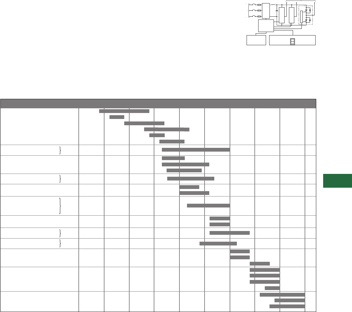
Volume 12—Aftermarket, Renewal Parts and Life Extension Solutions CA08100014E—November 2013 www.eaton.com V12-T13-69
1
2
3
4
5
6
7
8
9
10
11
12
13
14
15
16
17
18
19
20
21
22
23
24
25
13
Motor Control
Adjustable Frequency AC Drives—Solid-State Low Voltage
Adjustable Frequency
AC Drives
Product Description
Cutler-Hammer Adjustable
Frequency Controllers (AFCs)
serve to provide adjustable
speed and control for
standard AC induction
motors. AFCs rectify the
incoming AC line voltage to
supply a fixed potential DC
bus. An inverter section is
employed to invert the DC
bus voltage to an adjustable
frequency output voltage.
The solid-state logic section
controls the inverter and
ultimately the magnitude and
frequency of the output
voltage to the motor. Input to
the solid-state logic can be
manual (from an operator
type keypad) or automatic
(from design features
programmed into the
drive logic).
The advent of
microprocessor-
based logic and the
advancements of solid-state
power technology have
dramatically reduced the
costs of AFCs and enhanced
their product features. This
has permitted a more
economical solution for
adjustable speed motor
applications because AFCs
permit the use of standard
squirrel cage induction
motors instead of DC motors,
which are more expensive
and harder to maintain. AFCs
are ideal for variable torque
applications like centrifugal
pumps and fans, and
constant torque applications
like conveyers and extruders.
Typical Adjustable
Frequency Controller
Block Diagram
Product History Time Line
To Motor
Pole A Pole B
Pole C
AB C
Gate Driver
Converter
Microprocessor Logic
460 Volt, 60 Hertz
Operator Panel Status and Fault Indication Panel
Dynamatic AF-3000
Dynamatic VLT-5
Dynamatic AF-2000
Dynamatic AF-300 (Responder)
Dynamatic AF-6000
Westinghouse Accutrol 100
Dynamatic AF-7000
Dynamatic IS-7000
Dynamatic AF-8000
Westinghouse Accutrol 300
Westinghouse Accutrol 150
Westinghouse Accutrol 200
Westinghouse Accuow
Dynamatic AF-1000
Dynamatic AF-5000
Westinghouse Accutrol 110
Westinghouse Accuow Jr.
Dynamatic AF-1500
Westinghouse Accuow 110
Dynamatic AF-1600
Westinghouse Accutrol 400
Westinghouse Accutrol 700
Cutler-Hammer AF97
Dynamatic AF-5000+
Dynamatic IS-5000+
Cutler-Hammer AF93
Cutler-Hammer AF95
Cutler-Hammer AF91
Cutler-Hammer SV9000
Cutler-Hammer HV9000
Cutler-Hammer CP9000
Cutler-Hammer BP9000
Eaton CH MVX 9000
Eaton CH SVX 9000
Eaton CH HVX 9000
Product 1965 1970 1975 1980 1985 1990 1995 2000 2005 Present

V12-T13-70 Volume 12—Aftermarket, Renewal Parts and Life Extension Solutions CA08100014E—November 2013 www.eaton.com
1
2
3
4
5
6
7
8
9
10
11
12
13
14
15
16
17
18
19
20
21
22
23
24
25
13
Motor Control
Adjustable Frequency AC Drives—Solid-State Low Voltage
General Information
Notes
1Also available with a single-phase output.
2Standard 220V output only.
3Analog controls on pre-1988 models.
4Gate Turn-off Thyristor (GTO) output devices on pre-1986 models. Transistor versions have a T as the third character in the style number.
Model hp Range Input Voltage Output Devices Output Algorithm Control Type
VLT-5 1–5 240, 415 SCR VVI Analog
AF-1000 1–5 1230, 480 Transistors PWM Analog
AF-1500 1–30 240, 480 Transistors PWM Digital
AF-1600 1–20 240, 480 IGBT Vector PWM Digital
AF-2000 5–10 230 SCR VVI Analog
AF-300 N/A N/A SCR CSI Analog
AF-3000 230–250 230, (460 opt) SCR PWM Analog
AF-5000 5 –100 380–480 Transistor PWM Analog
AF-5000+ 5–600 380–480 Transistor PWM Digital
AF-6000 15–300 480 SCR VVI Analog
AF-7000 20–600 480, 575 Transistor VVI Analog
AF-8000 3 and 5 480 SCR PWM Analog
Accutrol 100 1–5 230 Transistor PWM Analog
Accutrol 110 1–75 230, 460 Transistor PWM Digital 3
Accutrol 150 3–50 460 Transistor 4PWM Analog
Accutrol 200 3–250 460 Transistor 4PWM Analog
Accutrol 300 15–600 460, 575 Gate turn-off thyristor VVI Analog
Accutrol 400 3–150 460 Transistor PWM Digital
Accutrol 700 100–600 480 IGBT Vector PWM Digital
AF93 2–20 240, 480 Insulated gate bipolar transistor Vector PWM Digital
AF95 15–200 480 Insulated gate bipolar transistor PWM Digital
AF97 100–600 480 Insulated gate bipolar transistor Vector PWM Digital
AF91 Fractional to 10 240, 460 Insulated gate bipolar transistor PWM Digital
MVX9000 Fractional to 10 120, 240, 480 Insulated gate bipolar transistor PWM Digital
9000 Series Fractional to 1100 208–575 Insulated gate bipolar transistor PWM Digital
SVX9000 Fractional to 2000 208–575 Insulated gate bipolar transistor PWM Digital

Volume 12—Aftermarket, Renewal Parts and Life Extension Solutions CA08100014E—November 2013 www.eaton.com V12-T13-71
1
2
3
4
5
6
7
8
9
10
11
12
13
14
15
16
17
18
19
20
21
22
23
24
25
13
Motor Control
Adjustable Frequency AC Drives—Solid-State Low Voltage
Replacement Capabilities
Replacement Capabilities
Model
Recommended
Replacement
Dynamatic Adjustable Frequency Drives
VLT-5 MVX9000
AF-1000 MVX9000
AF-1500
1
MVX9000
AF-1600 MVX9000
AF-2000 MVX9000
AF-300 (Responder) SV/HV/CP9000
AF-3000 SV/HV/CP9000
AF-5000 SV/HV/CP9000
AF-5000+ / IS-5000+ SV/HV/CP9000
AF-6000 SV/HV/CP9000
AF-7000 / IS-7000 SV/HV/CP9000
AF-8000 AF91SV
Westinghouse Adjustable Frequency Drives
Accutrol 100 MVX9000
Accutrol 110/Accuflow Jr.
1
MVX9000
Accutrol 150 SVX/HVX/CPX9000
Accutrol 200/Accuflow SVX/HVX/CPX9000
Accutrol 300 SVX/HVX/CPX9000
Accutrol 400 SVX/HVX/CPX9000
Accutrol 700 SVX/HVX/CPX9000
Cutler-Hammer Drives
AF91 MVX9000
AV91 MVX9000
AF93 SVX/HVX/CPX9000
AF95 SVX/HVX/CPX9000
AF97 SVX/HVX/CPX9000
SV9000 SVX9000
HV9000 HVX9000
CP9000 CPX9000
Eaton’s Electrical Services &
Systems (EESS) has trained
technicians nationwide. See
Tab 22 in this catalog for
further information about
EESS capabilities.
Technology Upgrades
The SVX9000 improves upon
the SV9000 with modular
construction and greater
program capability. Clean
power, 18-pulse
configurations are available to
meet IEEE-519 requirements
for electro-magnetic
compliance. The HVX9000
provides a simpler parameter
set geared toward the HVAC
industry, and the HVX
Intellipass provides automatic
bypass with 24 Vdc control.
Additionally, the MVX9000
gives customers a compact,
low-cost alternative to the
full-featured drives of 10 hp
or less. The same general
controls are available, with the
exception of closed-loop
(encoder) control. The
MVX9000 boasts a PLC-like
control in the form of a step
sequence program for
repeated process
applications.
These units combine digital
microprocessor control, a
user-friendly keypad, IGBT
technology, and a Windows®-
based programmer to provide
an adjustable frequency drive
that can be customized to
almost any application.
Note
1The AF-1500, Accutrol 110 and Accuflow
Jr. are identical units.

V12-T13-72 Volume 12—Aftermarket, Renewal Parts and Life Extension Solutions CA08100014E—November 2013 www.eaton.com
1
2
3
4
5
6
7
8
9
10
11
12
13
14
15
16
17
18
19
20
21
22
23
24
25
13
Motor Control
Adjustable Frequency AC Drives—Solid-State Low Voltage
Support Chart for Non-Current Vintage Products
Advanced Technology Services, 8200 N. University, Peoria, IL 61615, now provides support for these products.
Their toll-free number is 1-877-645-3606.
Definitions
PCB Repair
Printed circuit boards may be
returned to Advanced
Technology Services for
repair. All PCBs are upgraded
to the most
current revision at
the time of the repair.
Upgrade Kits
Kits are available to upgrade
the basic
performance of
certain vintage products.
Contact Advanced Technology
Services for more
information.
Service Depot Repairs
Entire assemblies may be
returned to
Advanced
Technology Services
for
repair, upgrade or
refurbishment.
Field Service
Eaton’s Electrical Services &
Systems (EESS) has trained
technicians nationwide. See
Ta b 2 2 in this catalog for
further information about
EESS capabilities.
Technical Support
The trained technicians at
Advanced Technology
Services are available to
provide assistance over
the telephone.
Spare Parts
Advanced Technology
Services main
tains a complete
inventory of spare parts.
Product Support Services
For all Product Support
Services for these “legacy”
products, contact Advanced
Technology Services at
1-877-645-3606. For technical
support with Eaton’s current
line of variable frequency
drives, contact the
Drives Technical Resource
Center at 1-800-322-4986.
Notes
1The AF-1500, Accutrol 110 and Accuflow
Jr. are identical units.
2No upgrades are available for Gate Turn-
off Thyristor (GTO) versions. Transistor
versions are identified by a leading “A1T”
or “A2T” in the model number.
3GTOs are not available as spare parts
for models below 100 hp.
Model
(See below for topic definitions)
PCB Repair Upgrade Kits Factory Repair Field Service Technical Support Spare Parts
Dynamatic Adjustable Frequency Drives
VLT-5
AF-1000
AF-1500 1■■■■■
AF-1600 ■■■■■
AF-2000
AF-300 (Responder)
AF-3000
AF-5000 ■■■■■
AF-5000+ / IS-5000+ ■■■■■
AF-6000
AF-7000 / IS-7000 ■■■■■
AF-8000
Westinghouse Adjustable Frequency Drives
Accutrol 100
Accutrol 110/Accuflow Jr. 1■■■■■
Accutrol 150 ■■ 2■■■ ■
Accutrol 200/Accuflow ■■ 2■■■ ■
Accutrol 300 ■■■■
■ 3
Accutrol 400 ■■■■■
Accutrol 700 ■■■■■ ■
Cutler-Hammer Drives
AF93
AF95 ■■■■■ ■
AF97 ■■■■■ ■

Volume 12—Aftermarket, Renewal Parts and Life Extension Solutions CA08100014E—November 2013 www.eaton.com V12-T13-73
1
2
3
4
5
6
7
8
9
10
11
12
13
14
15
16
17
18
19
20
21
22
23
24
25
13
Motor Control
Synchronous—Relay or Solid-State Mark V Slipsyn for Brush and Brushless Motors
Contents
Description Page
Brush Type Relay Slipsyn Class
14-100 Field Application Panel
Product
Description,
Technology
Upgrades . . . . .
V12-T13-75
Brush Type Mark
V
Solid-State
Slipsyn Class 14-100 Field
Application Panel
Product
Description . . . .
V12-T13-77
Replacement
Capabilities,
Technology
Upgrades . . . . .
V12-T13-78
Brush Type Mark
V
Solid-State
Slipsyn Class 14-100 Low
Voltage Motor Starters
Product
Description,
Technology
Upgrades . . . . .
V12-T13-79
Brushless Type Relay Slipsyn
Class 14-100 Field Application
Panel
Product
Description . . . .
V12-T13-80
Replacement
Capabilities,
Technology
Upgrades . . . . .
V12-T13-81
Brushless Type Mark
V
Solid-
State Slipsyn Class 14-100 Field
Application Panel
Product
Description,
Technology
Upgrades . . . . .
V12-T13-82
Relay and Solid-State Slipsyn
Control
Further
Information,
Pricing
Information . . . .
V12-T13-83
Synchronous—Relay or
Solid-State Mark V
Slipsyn for Brush and
Brushless Motors
Product Description
Synchronous Motors
Polyphase synchronous
motors are used primarily to
obtain high pullout torques,
constant operating speed, or
generation of leading reactive
kVA for power factor (PF)
correction. To bring a motor
to a constant speed, DC
power is applied to a special
winding in a synchronous
motor. This winding is called
a field coil winding and is
controlled by “field control.”
Power (DC) for a brush type
motor is usually supplied with
the starter and entails using
an exciter. Power (DC) for a
brushless type motor is
supplied by an exciter
mounted on the motor.
Synchronous Motor Control
Synchronous motor “field
application control” generally
includes a synchronous
device to apply DC power to
the motor field circuit at the
optimum speed. It may also
include protective features
such as locked rotor
protection, failure to
synchronize, incomplete
sequence, field failure,
pullout protection, etc.
depending on the type of field
application control selected.
Relay Type vs. Solid-State
Type—Mark V
Relay Type
The relay type used the ASR
synchronizing relay. Inherent
in using the relay type are the
problems that are associated
with using contacts or
mechanical closing devices
such as arcing, spring and
bearing deterioration and
wear, dirty atmospheres, etc.
Solid-State—Mark V
The Mark V is 100% solid-
state and features a “soft-
turn-on” circuit that applies
DC field voltage to the motor
field. It enables all required
functions for correct
synchronization to be
accomplished without the
use of moving contacts or
mechanical closing devices.
With the Mark V, the static
exciter power supply is
always supplied and is part of
the “system.”
Also available as a modification
with the Mark V is a VAR or
power factor, DC field current
regulator. The regulator
consists of a printed circuit
board, auxiliary devices
and potentiometers for
adjustment.
Product History
Originally a Westinghouse
Product
Synchronous Motor Control
Brush type synchronous field
control was originally
available in the 1940s. Motor
starters for brushless
synchronous motors have
been offered since the late
1960s. Synchronous motors
can be medium voltage
(2300–7200V) or low voltage
(600V and below). A
synchronous motor starter
includes the basic motor
control PLUS the
synchronous control and
protection functions.
Typically, the basic motor
control and the field
application control are
mounted in separate
compartments within
the starter. Ratings of
synchronous control are in
terms of the maximum DC
field amperes required by the
motor. Current ratings are 45,
90, 135, 160, 200 or 270A
DC, through 6000 hp at 5 kV.
Relay and Solid-State Type
Control
Relay type Slipsyn was
introduced in 1947 and uses
the ASR synchronizing relay.
Forms of solid-state type
Slipsyn were introduced in
the late 1950s and early
1960s, but were not
completely solid-state and
had some of the operation
problems that the relay type
control encountered. These
were called Mark I and Mark
II Static Slipsyn. In 1989, the
Mark V Solid-State Slipsyn
field control was introduced.
Medium Voltage (AMPGARD®
)
Starters
The AMI AMPGARD
synchronous starter (1957–
1970) used a 60-inch deep
enclosure with the
synchronous control in the
low voltage section in the
front bottom two thirds of the
starter enclosure. The basic
motor control was located in
the rear bottom two thirds of
the enclosure, barriered off
from the low voltage section.
The AMI AMPGARD for
synchronous motors used the
ASR relay type control.
The LF AMPGARD (1962–
1988) primarily used the ASR
field application relay control.
Mark I and Mark II Static
Slipsyn were also used during
their availability periods. The
LF AMPGARD for synchronous
motors included the basic
induction motor control (ISO®
switch, contactor and starter
control) in the bottom half of
the structure.

V12-T13-74 Volume 12—Aftermarket, Renewal Parts and Life Extension Solutions CA08100014E—November 2013 www.eaton.com
1
2
3
4
5
6
7
8
9
10
11
12
13
14
15
16
17
18
19
20
21
22
23
24
25
13
Motor Control
Synchronous—Relay or Solid-State Mark V Slipsyn for Brush and Brushless Motors
The upper half contained the
step-down
static excitation
transformer with current
limiting fuses, the Silicon
Controlled Rectifier (SCR)
type static exciter and the
synchronizing control and
motor field protection panel.
The SJ AMPGARD (1982–
2000) family of synchronous
control is very similar
to the
LF AMPGARD. Until the
availability
of the Mark V solid-
state synchronous control,
the SJ used the ASR relay
type field control. With the
advent of the
Mark
V
, most of
the synchronous starters
are
supplied with this type of
control. In both ASR and
Mark V control schemes,
the
synchronous gear is usually
mounted
in the top half of
the starter.
The SL AMPGARD (2000–
present) is similar to the SJ
AMPGARD but uses the
Mark V solid-state
synchronous controller,
exclusively.
Low Voltage Synchronous
Starters
Low voltage synchronous
starters are similar in nature
to high voltage synchronous
starters except in two
regards. High voltage
starters, unlike low voltage
starters, must isolate the low
voltage from the high voltage.
The components for the field
control are the same.
The second difference lies in
the primary disconnect used
in the starters. Low voltage
starters can be supplied with
no short-circuit protection,
with a non-fusible disconnect,
a fusible disconnect switch or
with a molded-case circuit
breaker. Low voltage
synchronous starters were
manufactured in the late
1940s with the introduction
of the ASR relay, until
September of 1989. In 1991,
the product was reintroduced
using the Mark V solid-state
field control.
Product History Time Line
V12-T13-73 ASR Relay Slipsyn (Brush Type)
Mark I Static Slipsyn (Brush Type)
Mark II Static Slipsyn (Brush Type)
V12-T13-78 Mark V Slipsyn
V12-T13-80 Brushless Motor Control
Page Product 1945 1955 1965 1975 1985 1995 2000 Present
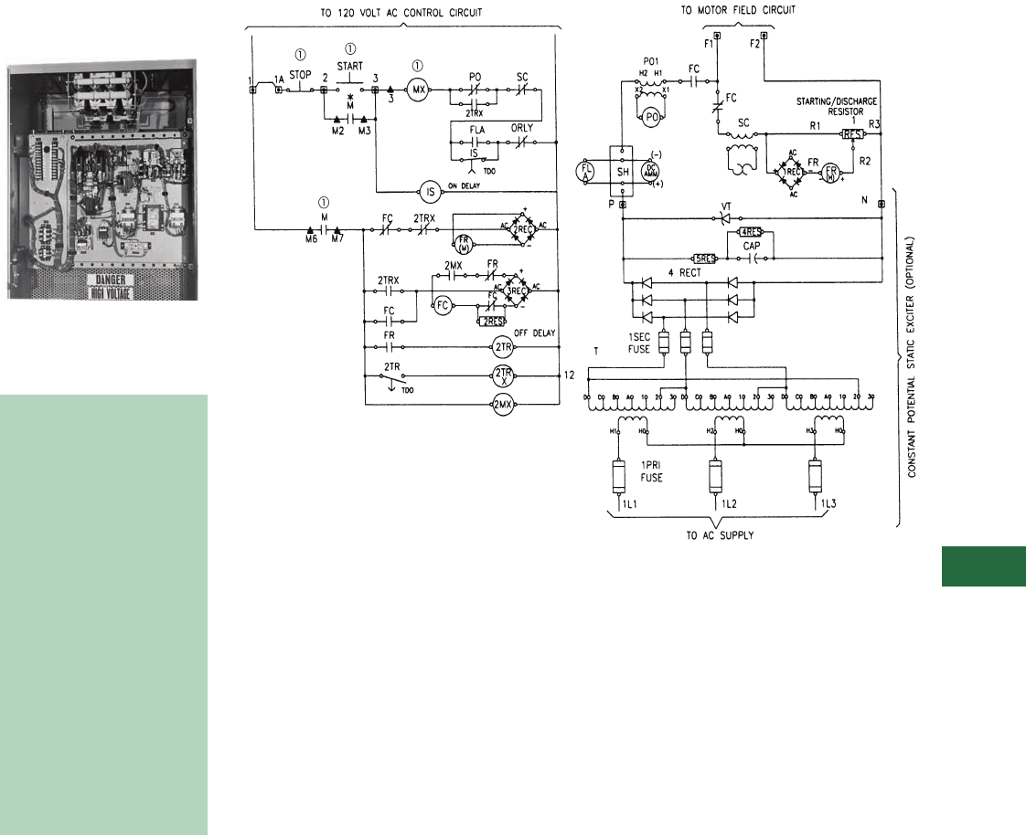
Volume 12—Aftermarket, Renewal Parts and Life Extension Solutions CA08100014E—November 2013 www.eaton.com V12-T13-75
1
2
3
4
5
6
7
8
9
10
11
12
13
14
15
16
17
18
19
20
21
22
23
24
25
13
Motor Control
Synchronous—Brush Type Relay Slipsyn Class 14-100 Panel
Relay Slipsyn Automatic
Field Application Panel
Product Description
Relay Field Panel
■
Shaded area denotes
obsolete or discontinued
products and services.
Automatic Field Application
Control
The field application panel
provides Slipsyn automatic
field application identical
to that in complete
synchronous motor
starters. It is designed for
use in conjunction with a
primary line closing device
such as a circuit breaker or
a linestarter. One interlock
on the primary device is
used to actuate the field
application control. When
the motor accelerates to
proper speed for pull-in, the
field is automatically applied.
The controller is available
for floor mounting. Floor-
mounted cabinets are
NEMA 1 with hinged front
door and removable
rear plates.
Ty p i c a l S c h e m a t i c
Note
1Not supplied with 14-100 panel or static exciter.
Typical 14-100 Panel with Constant Static Exciter
(Optional) for use with Primary Motor Starter

V12-T13-76 Volume 12—Aftermarket, Renewal Parts and Life Extension Solutions CA08100014E—November 2013 www.eaton.com
1
2
3
4
5
6
7
8
9
10
11
12
13
14
15
16
17
18
19
20
21
22
23
24
25
13
Motor Control
Synchronous—Brush Type Relay Slipsyn Class 14-100 Panel
■
Shaded area denotes
obsolete or discontinued
products and services.
Information Required from
Customer for Upgrade
Evaluation
1. Original assembly
nameplate data including
general order “GO”
number as well as any
drawing numbers.
2. Complete motor data
including horsepower,
phase, voltage/Hz, RPM,
FLA, LRA, full-load DC
amperes, power factor,
excitation voltage,
induced field amperes
at 95% speed and at 0%
speed, recommended
discharge resistor ohms
and maximum time at
zero speed (locked rotor).
3. Excitation control detail
such as
“constant-
potential” or “adjustable-
potential.” Adjustable-
potential usually requires
a field rheostat (motor
field-resistor).
4. Detail on the motor’s
function such as the
application data and
other service conditions
such as duty-cycle, etc.
The cabinets contain the
following equipment:
1– Polarized slip frequency
field application relay
type ASR (FR) with half-
wave rectifier (REC).
1– Time relay with contacts
available for unloader
circuit (2TR).
1– Pullout relay and
transformer (PO).
1– Field contactor, two-pole
(FC).
1–
Damper winding
protective relay (SC).
1– Starting and field
discharge resistor
when size permits;
otherwise, provided for
separate mounting)
(1RES).
1– DC field ammeter, panel
type, semi-flush
mounted (DC AMM).
1– DC field ammeter shunt
(SH).
1– DC field failure
protection (FLA).
2– Auxiliary relays (2TRX),
(2MX).
1– Incomplete sequence
relay (IS).
Static Excitation Power
Supply Panel
Constant Potential Type
Power conversion AC to DC
units are designed for
individual synchronous
motor field excitation.
These units are convection
cooled, solid-state and are
completely assembled and
wired as a self-contained
package with a relay Slipsyn
automatic field application
control. The connections
necessary to the external
circuits are line leads, motor
leads, field connections and
control interconnection.
The static system consists
of a convection-cooled
silicon rectifier three-phase
full-wave bridge assembly,
a set of current limiting
fuses in the secondary side
of the transformer and a set
of surge protecting devices.
The transformer has
secondary taps that are
adjustable with four course
taps that provide
approximately 12%
adjustment per tap, and
three fine taps that
provide 4% adjustment
per tap.
Adjustable Potential Type
An adjustable potential
exciter is similar to the
constant potential exciter
except that it uses SCRs
and the voltage adjustment
is made with a potentiometer
mounted on the door.
Technology Upgrades
For Brush-Type, Relay-Panel
Slipsyn (Class 14-100)
Upgrades
New synchronous field
controllers using the latest
solid-state technology are
usually available. Upgrades
for primary starter and
contactor components may
also be available.
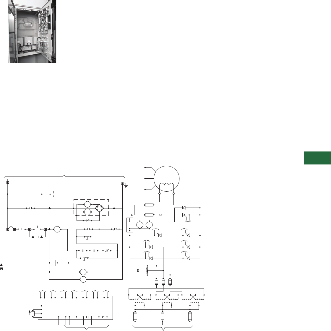
Volume 12—Aftermarket, Renewal Parts and Life Extension Solutions CA08100014E—November 2013 www.eaton.com V12-T13-77
1
2
3
4
5
6
7
8
9
10
11
12
13
14
15
16
17
18
19
20
21
22
23
24
25
13
Motor Control
Synchronous—Brush Type Mark V Solid-State Slipsyn Class 14-100 Panel
Slipsyn Automatic Field
Application Panel with
Static Exciter
Product Description
Mark V Field Controller
Automatic Field Application
Control
The Slipsyn panel provides
automatic field application
identical to that in complete
synchronous motor starters.
It is designed for use in
conjunction with a primary line
closing device, such as a
circuit breaker or a linestarter.
When the motor accelerates
to proper speed for pull-in, the
field is automatically applied.
The solid-state Mark V
Slipsyn controller will provide
the following protective
functions:
A. Locked rotor protection.
B. Incomplete sequence.
C. Failure to synchronize.
D. Fuse failure (Mark V).
E. Pullout protection.
F. DC current failure
protection.
Also the application of the DC
power to the motor field
windings is accomplished
without mechanically moving
parts, and the device features
a “soft-turn-on” circuit when
applying DC voltage to the
motor field.
Depending on the size of the
solid-state application panel,
the controller is available in
a NEMA 1 floor-mounted
enclosure or an AMPGARD
type cell construction.
In both designs, a hinged
front door with externally
ventilated heat sinks will
be provided.
The cabinets will contain
the following equipment:
1 – Step-down exciter
transformer—
three-phase (TX).
3 – Primary fuses (3 PRI).
3 – Secondary fuses (3 SEC).
1 – “SCR” power supply
panel.
1 – Synchronous control
board (CB).
1 – DC
ammeter—panel type
(DC AMM).
3 – “MOV” for surge
protection (MOV).
1 – Starting and field
discharge resistor (when
size permits; otherwise
provided for separate
mounting).
1 – Field failure relay (FLA).
1 – Incomplete SEQ Timer
(FLT).
1 – Start timer (SYTR).
1 – Potentiometer (P2).
Ty p i c a l S c h e m a t i c
Note
1Not supplied with Mark V.
IN
PSC
P2
1L21 1L22 1L23
_ _ AMPS
1x1
1x3
1x2
1x4
2x1
2x3
2x2
2x4
3x1
3x3
3x2
3x4
IH1 IH2 2HI 2H2 3H1 3H2
TX
1L11 1L12 1L13
1L1 1L2 1L3
_ _ AMPS
3 PRI
FUSE
3 SEC
FUSE
MOV
MOV
MOV
1L31 1L32 1L33
P
N
QA2
CA2
KA2
CB2
KB2
CC2
KC2
CA1
KA1
CB1
KB1
QA1
QB2QB1
QC2QC1
CC1
KC1
TO CB
TO CB
TO CB
TO CB
TO CB TO CB
TO CB
TO CB
VR
FLA
DC
AMM
SH
(–)
(+)
KQ4
CQ4
F2
F1
FIELD
MOTOR
T1
T2
T3
R1 Q4
D1
R3
STARTING/DISCHARGE
RESISTOR
1RES
RES
12
MB
OL
+RECT
–
AC
AC
D
M
C
A
MA
MA
M
MA
LN
FLA
11A
*
START
*
STOP 233
3MX
F
CB
M
M2 M3
FLA
11 14
FLT
TDO
MX
KK1
ST1 ST2 SQ1 SQ1
RLY1 RLY3
K2
SYTR
TDO
115
PW
HW
TO PRIMARY CONTROL CIRCUIT – 120 Vac
ON DELAY
.1 - 30 SEC
FLT
SY
TR
(SET 2 SEC LONGER THAN
ACCELERATION TIME)
SET @ .5 SEC
TO
QA2
TO
QB2
TO
QC2
TO
QA1
TO
QB1
TO
QC1
TO
Q4
KA2
CA2
KB2
CB2
KC2
CC2
KA1
CA1
KB1
CB1
KC1
CC1
CQ4
KQ4
(WB)
AV2
AV1
VPF
TO
D1
VR
115
IN–
IN+
ST1
RLY 1 RLY 3
ST2
SO1
SO2
TO 120 V CONTROL CIRCUIT
ON DELAY
.1 - 30 SEC
= REMOTE DEVICE
= TERM. BLOCK(S)
= CUST. TERM. BLK.
*
CW
TO ac SUPPL Y
햲
햲
햲
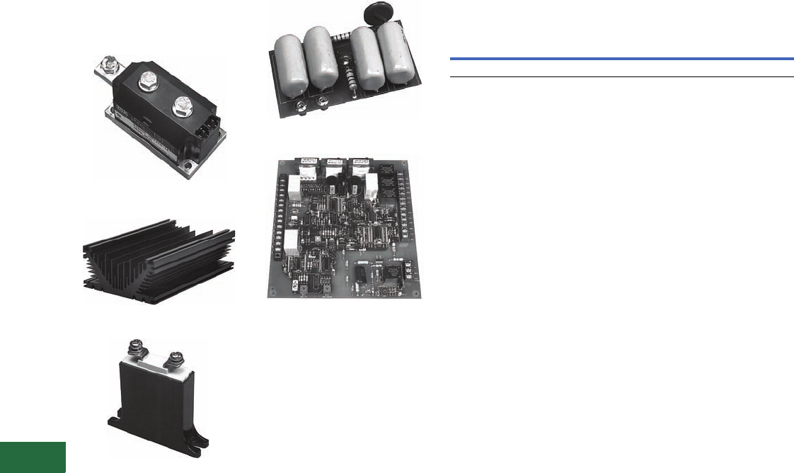
V12-T13-78 Volume 12—Aftermarket, Renewal Parts and Life Extension Solutions CA08100014E—November 2013 www.eaton.com
1
2
3
4
5
6
7
8
9
10
11
12
13
14
15
16
17
18
19
20
21
22
23
24
25
13
Motor Control
Synchronous—Brush Type Mark V Solid-State Slipsyn Class 14-100 Panel
Replacement Capabilities—
Typical Solid-State
Components
Power Module, 200A, Three Required
Heat Sink
MOV
Snubber for Thyristor Stack
Main Synchronizing Control/
Protection Board
Note: Typical solid-state
components used in Mark V
Slipsyn—Refer to RPD 8855S for
renewal parts for synchronous
control.
Field Panel with Static Exciter
20 kW Maximum—Approximate Dimensions in Inches
Technology Upgrades
For Brush Type Mark V Solid-
State Slipsyn (Class 14-100)
Upgrades
New synchronous field
controllers using the latest
solid-state technology are
available. Replacements and
upgrades for primary starter
and contactor components
are also available.
Information Required from
Customer for Upgrade
Evaluation
1. Original assembly
nameplate data including
general order “GO”
number as well as any
drawing numbers.
2. Complete motor data
including horsepower,
phase, voltage/Hz, RPM,
FLA, LRA, full-load DC
amperes, power factor,
excitation voltage,
induced field amperes
at 95% speed and at 0%
speed, recommended
discharge resistor ohms
and maximum time at
zero speed (locked rotor).
3. Excitation control detail
such as
“constant-
potential” or “adjustable-
potential.” Adjustable-
potential usually requires
a field rheostat (motor
field-resistor).
4. Detail on the motor’s
function such as the
application data and
other service conditions
such as duty-cycle, etc.
Open Cell Floor Mounted — NEMA 1
Height Width Depth Height Width Depth
45 36 30 90 36 30
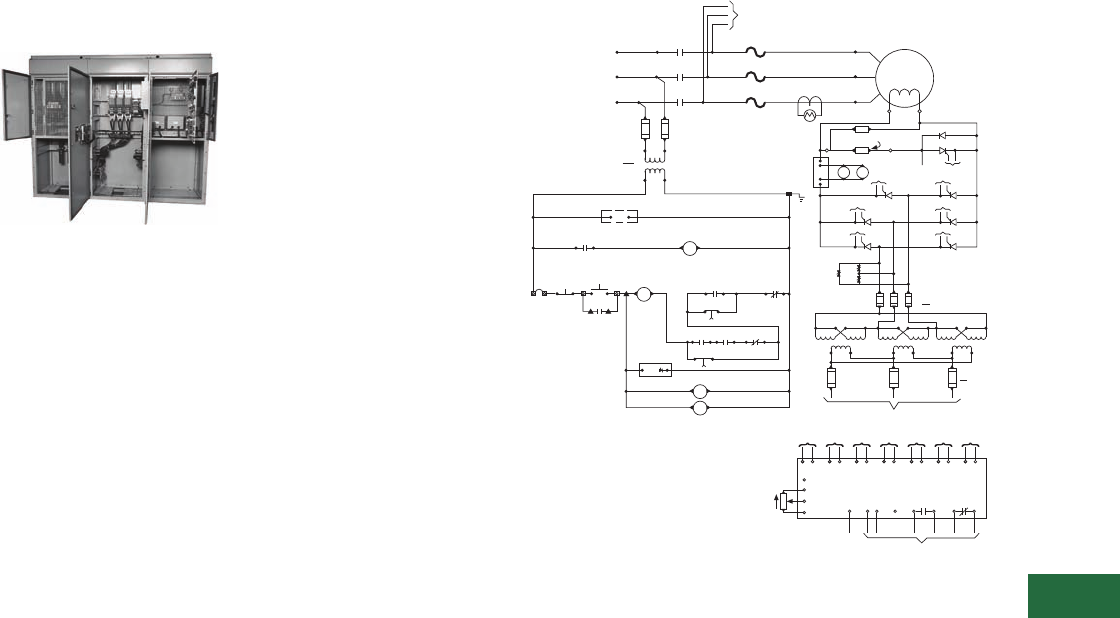
Volume 12—Aftermarket, Renewal Parts and Life Extension Solutions CA08100014E—November 2013 www.eaton.com V12-T13-79
1
2
3
4
5
6
7
8
9
10
11
12
13
14
15
16
17
18
19
20
21
22
23
24
25
13
Motor Control
Synchronous—Brush Type Mark V Solid-State Slipsyn Class 14-200 LV Motor Starters
Synchronous—Brush
Type Mark V Solid-State
Slipsyn Class 14-200 LV
Motor Starter
600V, NEMA Size 8,
Synchronous Starter
Product Description
Slipsyn magnetic starters
provide reliable, automatic
starting of synchronous
motors. Automatic
synchronization is provided by
the Mark V Solid-State Field
Panel, which ensures
application of the field at
proper motor speed, and at a
favorable angular position of
stator and rotor poles. As a
result, line disturbance
resulting from synchronization
is reduced and effective motor
pull-in torque is increased.
Application of DC power to
motor field windings is
accomplished without
mechanically moving parts,
and the device features a
“soft-turn on” circuit when
applying DC voltage to the
motor field.
The solid-state Mark V Slipsyn
controller will provide the
following protective
functions:
A. Locked rotor protection.
B. Incomplete sequence.
C. Failure to synchronize.
D. Fuse failure (Mark V).
E. Pullout protection.
F. DC current failure
protection.
The cabinet will contain the
following:
1 – Primary starter full voltage
or reduced voltage.
1 – Ammeter shunt (when
required).
1 – Auxiliary relay for main
line contactor (when
required) (MX).
1 – Starting and field
discharge resistor (IRES).
1 – Current transformer for
AC ammeter through
NEMA Size 4; Sizes 5 and
larger use three current
transformers for overload
relays and AC ammeter.
1 – Set control circuit terminal
blocks.
3 – Type AN manual reset
thermal overload relay and
three heater elements
(OL).
1 – Step-down exciter
transformer—three-phase
(TX).
3 – Primary fuses (3 PRI).
3 – Secondary fuses (3 SEC).
1 – SCR power supply panel.
1 – Synchronous control
board (CB).
3 – MOV for surge protection
(MOV).
1 – Starting and field
discharge resistor (when
size permits; otherwise
provided for separate
mounting).
1 – AC ammeter, panel type
(AM).
1 – DC ammeter, panel type
(DC AMM).
1 – Exciter field
potentiometer (P2).
1 – Field failure relay (FLA).
1 – Incomplete SEQ Timer
(FLT).
1 – Start timer (SYTR).
Typical Schematic Full Voltage Starter, Class 14-200,
Non-Combination Type
Technology Upgrades
For Brush-Type Mark V Solid-
State Slipsyn (Class 14-200) Low
Voltage Motor Starter Upgrades
New synchronous field
controllers using the latest
solid-state technology are
usually available.
Replacements and upgrades
for primary starter and
contactor components are
also usually available.
Information Required from
Customer for Upgrade
Evaluation
1. Original assembly
nameplate data including
General Order “GO”
number as well as any
drawing numbers.
2. Complete motor data
including horsepower,
phase, voltage/Hz, RPM,
FLA, LRA, full-load DC
amperes, power factor,
excitation voltage,
induced field amperes
at 95% speed and at 0%
speed, recommended
discharge resistor ohms
and maximum time at
zero speed (locked rotor).
3. Excitation control detail
such as
“constant-
potential” or “adjustable-
potential.” Adjustable-
potential usually requires
a field rheostat (motor
field-resistor).
4. Detail on the motor’s
function such as the
application data and
other service conditions
such as duty-cycle, etc.
Note
1Remote device.
TO
QA2
TO
QB2
TO
QC2
TO
QA1
TO
QB1
TO
QC1
TO
Q4
KA2
CA2
KB2
CB2
KC2
CC2
KA1
CA1
KB1
CB1
KC1
CC1
CQ4
KQ4
(WB)
VPF
AV1
AV2
PSC
CB
SYNCHRONIZING AND CONTROL CIRCUIT
VR
115
IN-
IN+
ST1
ST2
SQ1
SQ2
TO
D1 TO 120V CONTROL CIRCUIT
RLY 1 RLY 3
P2
CW
11A
햲
STOP 2
START
3
MX F
M
M2 M3
FLA
11 14
OL
FLT
TDO
WX K
ST1
RLY1K1
ST2
SQ1
RLY3
SQ2
K2
SYTR
TDO
CB
115
3
ON DELAY
.1-30 SEC
(SET 2 SEC LONGER THAN
ACCELERATION TIME)
ON DELAY
.1-30 SEC SET @ .5 SEC
3SEC
FUSE
1L21 1L22 1L23
AMPS
1X1 1X3 1X21X4 2X12X3 2X2 2X4 3X1 3X3 3X2 3X4
TX
3PRI
FUSE
1L1 1L2 1L3
1L11 1L12 1L13
AMPS
TO AC SUPPLY
1H1 1H2 2H1 2H2 3H1 3H2
1L31
TO CB
1L32 1L33
P
N
QA1
KA1
CA1
TO CB
QA2
KA2
CA2
TO CB
QB1
KB1
CB1
TO CB
QB1
KB2
CB2
TO CB
QC1
KC1
CC1
TO CB
QC1
KC2
CC2
FLA
DC
AMM
(-)
(+)
SH
RES
1RES
TO CB
Q4
D1
TO CB
VR
R1 R3
STARTING/DISCHARGE
RESISTOR
F1 F2
MOTOR
T3
FIELD
T1
T2
1L1
1L2
1L3
TO
3 PRI
FUSE
M
C
B
A
L3
L2
L1
AC
SUPPLY
PRI FUSE
3 AMP
CPT
X1 X2
M
M
VA
H1 H2
OL
OL
OL
12
FLA
LN
MX
M
SY
TR
FLT
햲
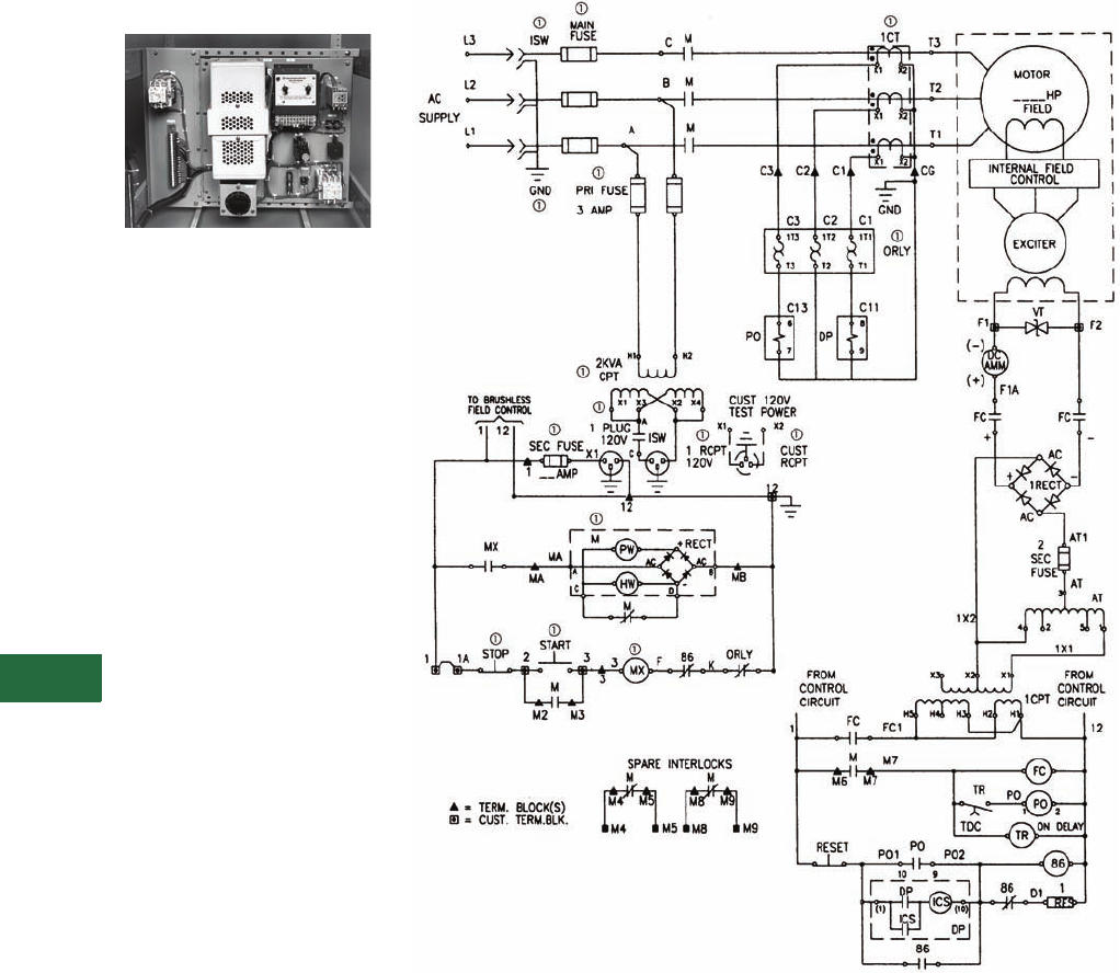
V12-T13-80 Volume 12—Aftermarket, Renewal Parts and Life Extension Solutions CA08100014E—November 2013 www.eaton.com
1
2
3
4
5
6
7
8
9
10
11
12
13
14
15
16
17
18
19
20
21
22
23
24
25
13
Motor Control
Synchronous — Brushless Type Relay Slipsyn Class 14-100 Panel
Relay Slipsyn Automatic
Field Application Panel
Brushless Field Panel
Product Description
This field application panel
provides DC power to the
exciter field and is designed
for use in conjunction with
a primary line closing device
such as a contactor motor
starter or a circuit breaker
motor starter. A normally
open electrical interlock on
the primary device is used to
actuate the field application
control. This panel utilizes
electromechanical devices to
apply DC power to the motor
exciter field circuit.
Note: The power rectifiers for the
motor field circuit and automatic
synchronizer are mounted on the
synchronous motor rotor.
Brushless Synchronous Control
The controller can be
supplied with or without
enclosure. Panel mounted
or open cell are suitable for
mounting within other
larger enclosures.
The cabinet or open panel
or open cell contains the
following equipment:
1 – Solar transformer (1 CPT).
1 – Power factor relay (PO).
1 – Auto-transformer (AT)
Powerstat.
1 – Damper winding
protection relay (DP).
1 – Field contactor (FC).
1 – Volt trap (VT).
1 – Rectifier (REC).
1 – Sequence relay (TR).
1 – Damper winding
protection hold-in relay
(DPX)—if required.
2 – Fuses (SEC FU),
(2 SEC FU).
1 – DC ammeter—panel type
(DC AMM).
Typical Starter Schematic
Notes
1Starter devices not supplied with field panel.
Devices shown without a a constitute 14-100 panel.
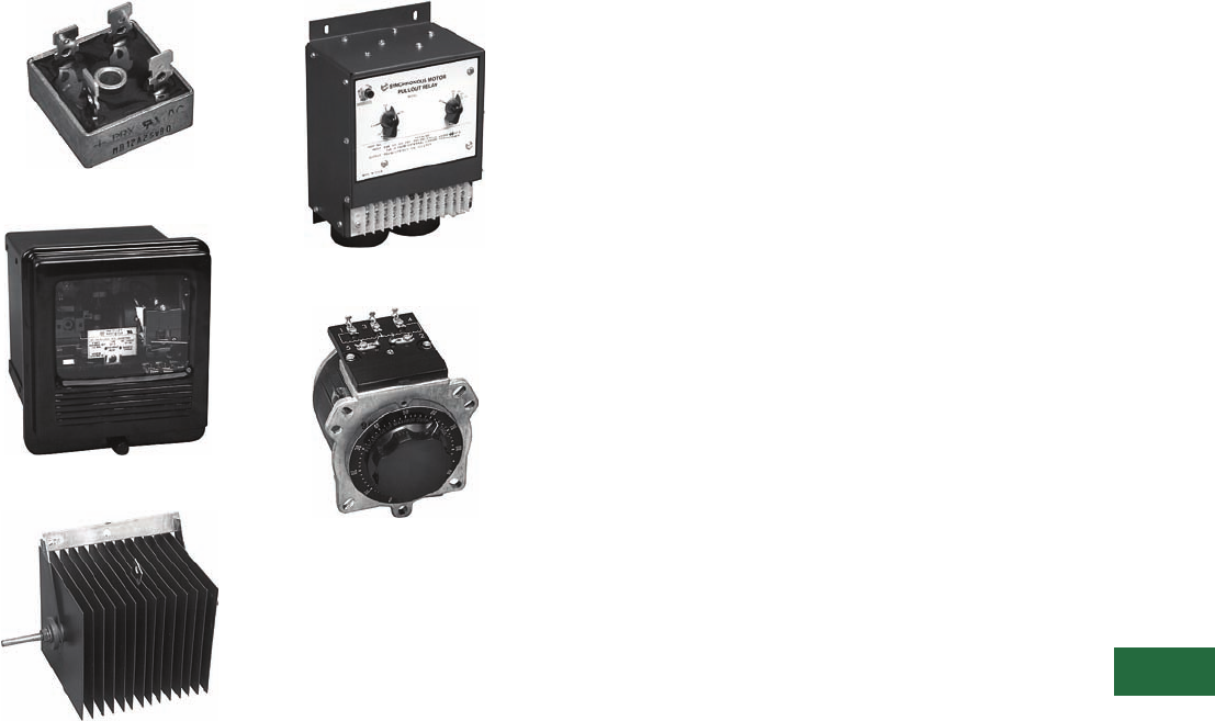
Volume 12—Aftermarket, Renewal Parts and Life Extension Solutions CA08100014E—November 2013 www.eaton.com V12-T13-81
1
2
3
4
5
6
7
8
9
10
11
12
13
14
15
16
17
18
19
20
21
22
23
24
25
13
Motor Control
Synchronous—Brushless Type Relay Slipsyn Class 14-100 Panel
Replacement Capabilities—Typical Components
Rectifier
Damper Winding Protection Relay
Volt Trap
Pullout/Power Factor Relay
Powerstat
Note: Typical components used in
Relay Slipsyn Brushless Control—
Refer to RPD 8855S for renewal
parts for synchronous control.
Technology Upgrades
For Brushless-Type Relay-Panel
Slipsyn (Class 14-100) Upgrades
New synchronous field
controllers using the latest
solid-state technology are
available. Replacements and
upgrades for primary starter
and contactor components
are also available.
Information Required from
Customer for Upgrade
Evaluation
1. Original assembly
nameplate data including
general order “GO”
number as well as any
drawing numbers.
2. Complete motor data
including horsepower,
phase, voltage/Hz, RPM,
FLA, LRA, full-load DC
amperes, power factor,
excitation voltage,
induced field amperes
at 95% speed and at 0%
speed, and maximum
time at zero speed
(locked rotor).
3. Excitation control detail
such as
“constant-
potential” or “adjustable-
potential.” Adjustable-
potential usually requires
a field rheostat (motor
field-resistor).
4. Detail on the motor’s
function such as the
application data and
other service conditions
such as duty-cycle, etc.
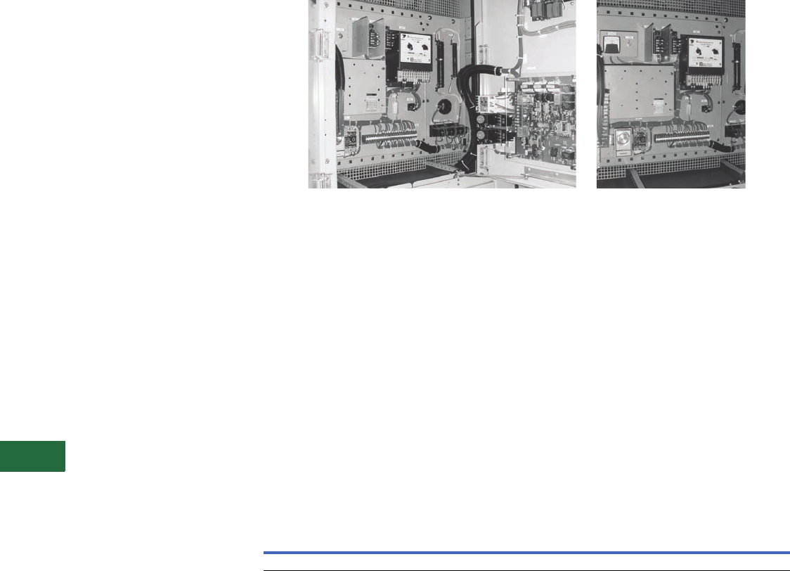
V12-T13-82 Volume 12—Aftermarket, Renewal Parts and Life Extension Solutions CA08100014E—November 2013 www.eaton.com
1
2
3
4
5
6
7
8
9
10
11
12
13
14
15
16
17
18
19
20
21
22
23
24
25
13
Motor Control
Synchronous—Brushless Type Mark V Solid-State Slipsyn Class 14-100 Panel
Slipsyn Automatic Field
Application Panel with
Static Exciter
Product Description
Automatic Field
Application Control
The field application panel
provides Slipsyn automatic
field application identical
to that in complete
synchronous motor starters.
It is designed for use in
conjunction with a primary
line closing device such as
a circuit breaker or a
linestarter. Automatic
synchronization is provided
by the Mark V solid-state
field panel, which ensures
application of the field at
proper motor speed and
at a favorable angular
position of stator and rotor
poles. As a result, line
disturbance resulting from
synchronization is reduced
and effective motor pull-in
torque is increased.
Application of DC power
to motor field windings is
accomplished without
mechanically moving parts,
and the device features a
“soft-turn-on” circuit when
applying DC field voltage to
the motor field.
This unit also comes
standard with a VAR or
power factor, DC field
current regulator. The VAR
regulator controls the AC
reactive current flow out of
the motor during varying load
conditions by varying the
motor field excitation. The PF
regulator controls the motor
power factor under varying
load conditions by varying the
motor field excitation. The
DC field current regulator
compensates for the motor
field resistance as the motor
field heats up by increasing
the motor field voltage.
Note: Power factor regulation—
cannot provide regulation below
50% of rated voltage and/or 25%
of rated current. Regulation
cannot be accomplished on light
loads, i.e., less than 20% load.
Mark V Brushless Field Controller
The solid-state Mark V Slipsyn
controller will provide the
following protective
functions:
A. Locked rotor protection.
B. Incomplete sequence.
C. Failure to synchronize.
D. Fuse failure (Mark V).
E. Pullout protection.
F. DC current failure
protection.
This control is available in a
NEMA 1 floor-mounted
enclosure or an AMPGARD
type cell construction. In both
designs, a hinged front door
with externally ventilated heat
sinks will be provided.
The cabinets will contain the
following equipment:
1 – Step-down exciter
transformer—three-phase
(TX).
3 – Primary fuses (3 PRI).
3 – Secondary fuses (3 SEC).
1 – SCR power supply panel.
1 – Synchronous control
board (CB).
3 – MOV for surge protection
(MOV).
1 – AC ammeter, panel type
(AM).
1 – DC ammeter, panel type
(DC AMM).
4 – Potentiometer (P2, P3,
P4, P5).
1 – Field failure relay (FLA).
1 – Incomplete SEQ Timer
(FLT).
1 – Start timer (SYTR).
1 – MP-3000 without RTD
module.
1 – DP-4000.
1 – VAR/PF/DC field current
board (CB1).
1 – Auto/manual selector
switch (SSI).
1 – Timer (AUTO).
1 – Pullout relay (PO).
Approximate Dimensions in Inches
Technology Upgrades
For Brushless-Type Mark V
Solid-State Slipsyn
(Class 14-100) Upgrades
New synchronous field
controllers using the latest
solid-state technology are
available. Replacements and
upgrades for primary starter
and contactor components
are also available.
Information Required from
Customer for Upgrade
Evaluation
1. Original assembly
nameplate data including
general order “GO”
number as well as any
drawing numbers.
2. Complete motor data
including horsepower,
phase, voltage/Hz, RPM,
FLA, LRA, full-load DC
amperes, power factor,
excitation voltage,
induced field amperes
at 95% speed and at 0%
speed, and maximum
time at zero speed
(locked rotor).
3. Excitation control detail
such as
“constant-
potential” or “adjustable-
potential.” Adjustable-
potential usually requires
a field rheostat (motor
field-resistor).
4. Detail on the motor’s
function such as the
application data and
other service conditions
such as duty-cycle, etc.
Open Cell Floor Mounted—NEMA 1
Height Width Depth Height Width Depth
45 36 30 90 36 30

Volume 12—Aftermarket, Renewal Parts and Life Extension Solutions CA08100014E—November 2013 www.eaton.com V12-T13-83
1
2
3
4
5
6
7
8
9
10
11
12
13
14
15
16
17
18
19
20
21
22
23
24
25
13
Motor Control
Synchronous—Relay or Solid-State Mark V Slipsyn for Brush and Brushless Motors
Identifying Renewal Parts
Renewal parts data for the
entire history of synchronous
control is contained in RPD
8855S, which provides the
proper identification of
standard parts that may be
required under normal
operation:
1. Identify the design of
synchronous control
(Relay, Mark I, Mark II
or Mark V Slipsyn) from
the synchronous panel
nameplate.
2. Now that you have
identified the type of the
synchronous control,
determine from the
photographs in RPD
8855S which parts are
required and identify
them by style number.
3. Because many starters
are supplied to meet
specific customer
requirements, other
parts not shown in
RPD 8855S might
occasionally be needed.
Price and availability of
parts not listed may be
obtained by providing a
complete description of
the part, along with the
complete data on the
starter nameplate, which
is found in the low
voltage area. Be sure to
include the following:
ratings, shop order and
diagram reference.
Further Information
Pricing Information
Price and Availability Digest (PAD)
Publication
Number Description
RP04304009E Common Replacement Parts for Mark V Synchronous Field Controller
RPD 8855S Renewal Parts Data for Synchronous Control
TD.48A.01.T.E Descriptive Bulletin for AMPGARD Starters
IL 17097 Instruction Leaflet for Relay Slipsyn
IB 48008 Instruction Leaflet for Solid-State Slipsyn
IB 48009 Instruction Leaflet for Mark V VAR/PF/DC Field Current Regulator
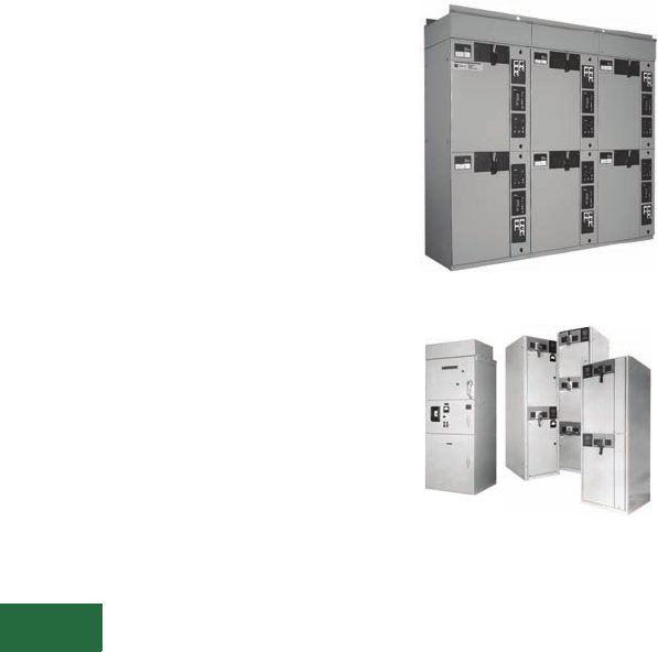
V12-T13-84 Volume 12—Aftermarket, Renewal Parts and Life Extension Solutions CA08100014E—November 2013 www.eaton.com
1
2
3
4
5
6
7
8
9
10
11
12
13
14
15
16
17
18
19
20
21
22
23
24
25
13
Motor Control
Medium Voltage Starters
Contents
Description Page
AMI AMPGARD
Product Description,
Technology
Upgrades . . . . .
V12-T13-88
LF Air AMPGARD
Product Description,
Replacement Capabilities,
Technology
Upgrades . . . . .
V12-T13-89
SL and SJ Vacuum
AMPGARD
Product Description,
Replacement
Capabilities. . . .
V12-T13-91
Technology
Upgrades . . . . .
V12-T13-92
Further Information,
Pricing
Information. . . .
V12-T13-96
AMPGARD
Originally a Westinghouse
Product
AMPGARD Motor Control Assembly
(AMI Vintage), 5000V 200A, 2500V 200A,
2500/5000V 400A (LF-Air Vintage)
Product Description
A medium voltage starter is an
assembly
used to control and
protect an alternating current
(AC) electric motor rated at
2300, 4160 or 7200V. The
controlling function is provided
by a magnetically held
contactor. The overload
protection is provided by an
overload relay of some type,
and the short-circuit protection
is provided by a non-load break
fused disconnect switch. 400A
starters are typically mounted
two-high in a 90-inch high
enclosure. 800A starters are
mounted one-high.
Product History
The AMPGARD starter line
originated in the early 1940s
and has undergone two major
design changes and one
major evolution.
Prior to the introduction of
the AMI, the AMPGARD was
simply a fused motor starter
in a cabinet with no
disconnect switch. It was
built in the early 1940s
through the 1950s. There
was no standard design.
The AMI AMPGARD (1950s
through 1960s) was a
standardized design. The AMI
was one starter per structure
designed to cover all ratings
and incor
porated a disconnect
switch (ISO-Switch)
in the
upper compartment and
either an air or oil contactor in
the bottom compartment.
In the mid 1960s, a full line of
starters was introduced,
tailored to the horsepower
requirement of the motor and
using the LF air contactor.
The starter incorporated the
ISO-Switch and power fuses
into the same cell as the air
contactor. Starters were one-,
two- or three-high per
structure, depending on the
rating required. The ratings of
the LF AMPGARD were 200,
400 and 700A.
Cutler-Hammer manufactured
MV motor
control from 1966–
1976. It was Bulletin 9950
Series, stacked two-high,
with no
specific trade name
(such as AMPGARD).
The manufacturing facility
moved from Buffalo, NY, to
Asheville, NC, in 1978.
In the 1980s with the advent
of vacuum technology, the LF
air contactor design
was
discontinued. The SJ vacuum
contactor
was matched with a
fused isolation switch. Now
two current ratings are
offered — 400 amperes, one-
or two- high, and 800
amperes, one-high. Starters
are sized per the motor
horsepower and full load
amperes.
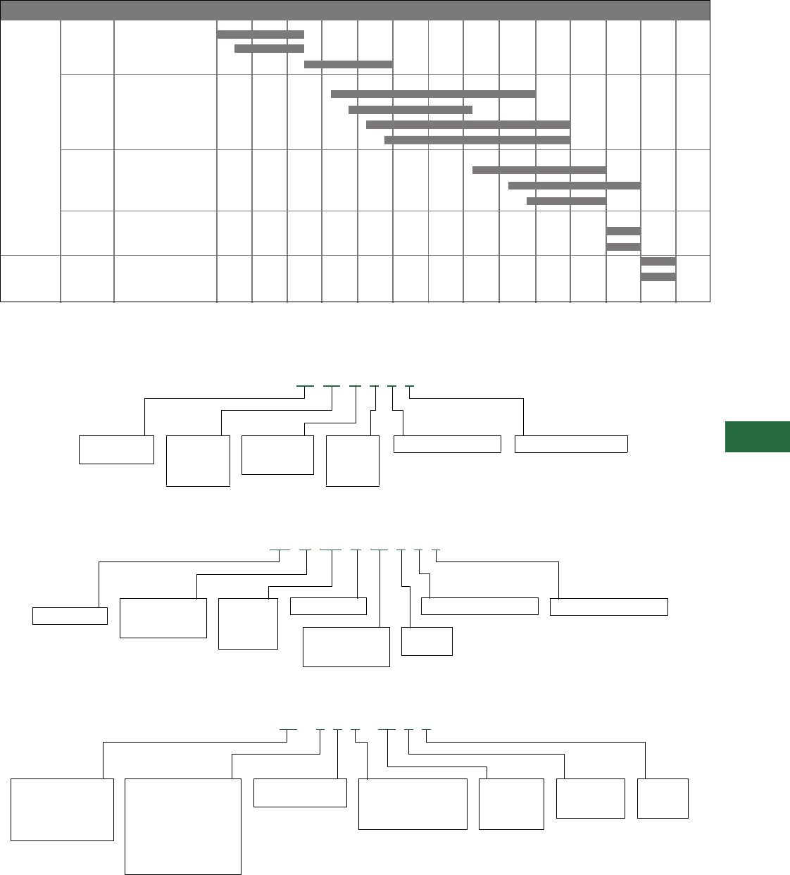
Volume 12—Aftermarket, Renewal Parts and Life Extension Solutions CA08100014E—November 2013 www.eaton.com V12-T13-85
1
2
3
4
5
6
7
8
9
10
11
12
13
14
15
16
17
18
19
20
21
22
23
24
25
13
Motor Control
Medium Voltage Starters
Product History Time Line
Catalog Number Selection
Old Catalog Numbering System—Contactors Only
Old Catalog Numbering System—Contactors Only
Old Catalog Numbering System—Starters (with Isolating Switch, Power Fuses, Contactor, etc.)
Page Product 1945 1950 1955 1960 1965 1970 1975 1980 1985 1990 1995 2000 2005 Present
AMPGARD OIL
AMPGARD AH
V12-T13-88 AMI AMPGARD
V12-T13-89, LF Air
V12-T13-90 – 25L2 200A
– 50L2 200A
– 25/50L4 400A
– 25/50L7 700A
V12-T13-91 SJ Vacuum
– SJA 400A (roll-out)
– SJA 800A (roll-out)
– SJS 400A (slide-out)
V12-T13-91 SL Vacuum
– SLW 400A (roll-out)
– SLF 400A (slide-out)
V12-T13-93 SLB (bolted)
SLS (stab)
Classic
AMPGARD
Next
Generation
AMPGARD
LF 25 H 4 3 0
Normally closed polesNormally open poles2 = 200A
4 = 400A
7 = 700A
8 = 800A
H = Air break
V = Vacuum
J = Vacuum
LF = Air break
SJ = Vacuum
25 = 2500V
33 = 3300V
50 = 5000V
72 = 7200V
Normally closed poles
W = Bottle
M = Metric bottle
(obsolete)
SJ A 5 0 V W 4 3 0
Normally opened poles
4 = 400A
8 = 800A
V = Vacuum break
25 = 2500V
33 = 3300V
50 = 5000V
72 = 7200V
SJ = Vacuum A = Roll-out
O = OEM design
S = Slide-out
2 = Non-load break,
fused switch
1 = Non-load break,
non-fused switch
L = Air break
V = Vacuum
J = Vacuum
2 = 200A
4 = 400A
7 = 700A
11 – 2 0 2 – 25 L 2
25 = 2500V
33 = 3300V
50 = 5000V
72 = 7200V
0 = Non-reversing
1 = Reversing
10 = Manual
11 = Magnetic
13 = Wound rotor
14 = Synchronous
17 = Air conditioning
2 = Full voltage
3 = Solid-state
4 = Resistor
5 = Reactor
6 = RV autotransformer
7 = RV part winding
8 = RV wye-delta
9 = FV multispeed
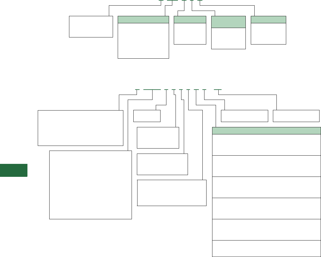
V12-T13-86 Volume 12—Aftermarket, Renewal Parts and Life Extension Solutions CA08100014E—November 2013 www.eaton.com
1
2
3
4
5
6
7
8
9
10
11
12
13
14
15
16
17
18
19
20
21
22
23
24
25
13
Motor Control
Medium Voltage Starters
Old Catalog Numbering System—Starters (with Isolating Switch, Power Fuses, Contactors, etc.)
Old Catalog Numbering System—Contactors Only
Voltage Class
E= 2400V, 60 Hz
G= 4160V, 60 Hz
K= 6900V, 60 Hz
L= 3300V, 60 Hz
Contactor
Ampere Rating
2 = 200A
4 = 400A
7 = 700A
8 = 800A
H = Air break (obsolete)
V = Vacuum break roll-out
S = Vacuum break
slide-out
S 202 S 4 G
Type of Starter
202 = FV non-reversing
212 = FV reversing
502 = Reactor
602 = Autotransformer
702 = Part winding
802 = Wye-delta
902 = Multispeed
Enclosure
S= NEMA 1
A= NEMA 1A
J= NEMA 12
R= NEMA 3
H= Air break
S= Vacuum, slide-out (standard)
V= Vacuum, roll-out (standard)
E= Vacuum, slide-out (OEM)
D= Vacuum, slide-out (with fingers)
T= Vacuum, slide-out (with long harness)
R= 50L2 vacuum retrofit
1 = 120V coil, 50/60 Hz
2 = 240V coil, 50/60 Hz
T1 = CPT, standard VA
T2 = CPT, 2 kVA
2 = 200A, air-break or 50L2 retrofit
4 = 400A, air-break
4 = 400A, Vacuum
7 = 700A, Air-break
8 = 800A, Vacuum
L= With line-fingers
or terminals
N= Without line-fingers
or terminals
F= With main fuse
provisions
N= Without main fuse
provisions
3 = Three-pole
2 = Two-pole
Models “A” & “B” Model “C”
E= 2300/2400 Vac 60 Hz A= 2400 Vac 60 Hz
Y= 3000 Vac 60 Hz B= 3000 Vac 60 Hz
F= 3300/3600 Vac 60 Hz C= 3300 Vac 60 Hz
G= 4000/4160 Vac 60Hz D= 3600 Vac 60 Hz
H= 4600/4800 Vac 60 Hz E= 4160 Vac 60 Hz
R=
6000/63000 Vac
60 Hz F= 4800 Vac 60 Hz
K= 6600/6900 Vac 60 Hz G= 5500 Vac 60 Hz
T= 2000 Vac 50 Hz H= 6000 Vac 60 Hz
J= 2300 Vac 50 Hz J= 6300 Vac 60 Hz
L= 3300 Vac 50 Hz K= 6600 Vac 60 Hz
V= 3600 Vac 50 Hz L=
6900/7200 Vac
60 Hz
N= 4000 Vac 50 Hz M= 2400 Vac 50 Hz
P= 4600 Vac 50 Hz N= 3000 Vac 50 Hz
S= 6000 Vac 50 Hz P= 3300 Vac 50 Hz
M= 6600 Vac 50 Hz Q= 3600 Vac 50 Hz
X= Unknown voltage R= 4160 Vac 50 Hz
S= 4800 Vac 50 Hz
T= 5500 Vac 50 Hz
U= 6000 Vac 50 Hz
V= 6300 Vac 50 Hz
W= 6600 Vac 50 Hz
X=
6900/7200 Vac
50 Hz
Z= Unknown voltage
MAN = Main
FWD = Forward
RVS = Reverse
RNR = Reactor
RNA = Autotransformer
BAR = Shorting contactor
SLW = Slow two-winding motor
FST = Fast two-winding motor
SLS = Slow single-winding motor
FAS = Fast single-winding motor
PWA = Part-winding motor, 1st contactor
PWB = Part-winding motor, 2nd contactor
PFC = Power factor capacitor contactor
XXX = Undefined application
V MAN 3 F L 4 A 1 – T1
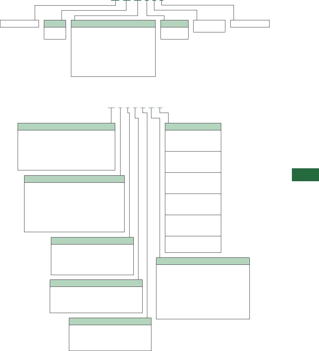
Volume 12—Aftermarket, Renewal Parts and Life Extension Solutions CA08100014E—November 2013 www.eaton.com V12-T13-87
1
2
3
4
5
6
7
8
9
10
11
12
13
14
15
16
17
18
19
20
21
22
23
24
25
13
Motor Control
Medium Voltage Starters
New Catalog Numbering System—SL Contactors Only
New Catalog Numbering System—SL Starters Only
0 = None NC poles2 = 2NO poles
3 = 3NO poles
SL = SL contactor Volts
50 = 5000
72 = 7200
NEMA Size
2 = 200A
4 = 400A
Contactor Type/Rating
G= 200A, roll-out
W= 400A, roll-out
K= 200A, slide-out
F= 400A, slide-out
L= 200A, narrow-design with fingers
N= 400A, narrow-design with fingers
P= 200A, narrow-design without fingers
X= 400A, narrow-design without fingers
B= 200A, open/standalone
C= 400A, open/standalone
SL 50 W 4 3 0
Enclosure Type
A= No enclosure (NEMA 1 doors)
B= Type 1 general purpose
C= Type 1 with gasketed doors
D= Type 2 drip shield
E= Type 12 dust-tight
F= Type 3R outdoor non-walk-in
G= Type 3R outdoor non-walk-in, 72-inch high
H= Type 3R outdoor walk-in
J= Type 1 half-high (NEMA 1 only)
K= Type 1 half-high with gasketed door
L= No enclosure (NEMA 3/12 doors)
Disconnect Switch
S= Isolation switch
A= Mechanical future with cover plate
F= Electrical future with cover plate
G= Electrical future with isolation plate
P= No isolation switch, cover plate only
Synchronous Type
0 = Non-synchronous
1 = Brush-type solid-state panel (Mark V)
3 = Brush-type relay panel (no longer available)
4 = Brushless-type relay panel
5 = Brushless-type solid-state
Motor Type
1 = Induction, single-speed
2 = Induction, two-speed, two-winding
3 = Induction, two-speed, single-winding
4 = Synchronous
6 = Wound rotor
7 = Non-motor feeder (transformer, caps, etc.)
Starter Type
2 = FVNR
3 = FVR
4 = RVSS
5 = RV reactor-type
6 = RVAT
7 = RV reversing, reactor-type
8 = RVAT reversing
9 = RVSS reversing
X = FV with auxiliary special use three-pole contactor
(without mechanical interlock, with load panel)
Contactor Type/Rating
F= 400A vacuum, slide-out
W= Vacuum, roll-out
N= 400A vacuum, narrow-design with stabs
X= 400A vacuum, narrow-design without stabs
K= 200A vacuum, slide-out
G= 200A vacuum, roll-out
L= 200A vacuum, narrow-design with stabs
P= 200A vacuum, narrow-design without stabs
Voltage
A= 2400 Vac 60 Hz
B= 3000 Vac 60 Hz
C= 3300 Vac 60 Hz
D= 3600 Vac 60 Hz
E= 4160 Vac 60 Hz
F= 4800 Vac 60 Hz
G= 5500 Vac 60 Hz
H= 6000 Vac 60 Hz
J= 6300 Vac 60 Hz
K= 6600 Vac 60 Hz
L= 6900/7200 Vac 60 Hz
M= 2400 Vac 50 Hz
N= 3000 Vac 50 Hz
P= 3300 Vac 50 Hz
Q= 3600 Vac 50 Hz
R= 4160 Vac 50 Hz
S= 4800 Vac 50 Hz
T= 5500 Vac 50 Hz
U= 6000 Vac 50 Hz
V= 6300 Vac 50 Hz
W= 6600 Vac 50 Hz
X= 6900/7200 Vac 50 Hz
Z= Unknown voltage
W 2 1 0 S B A
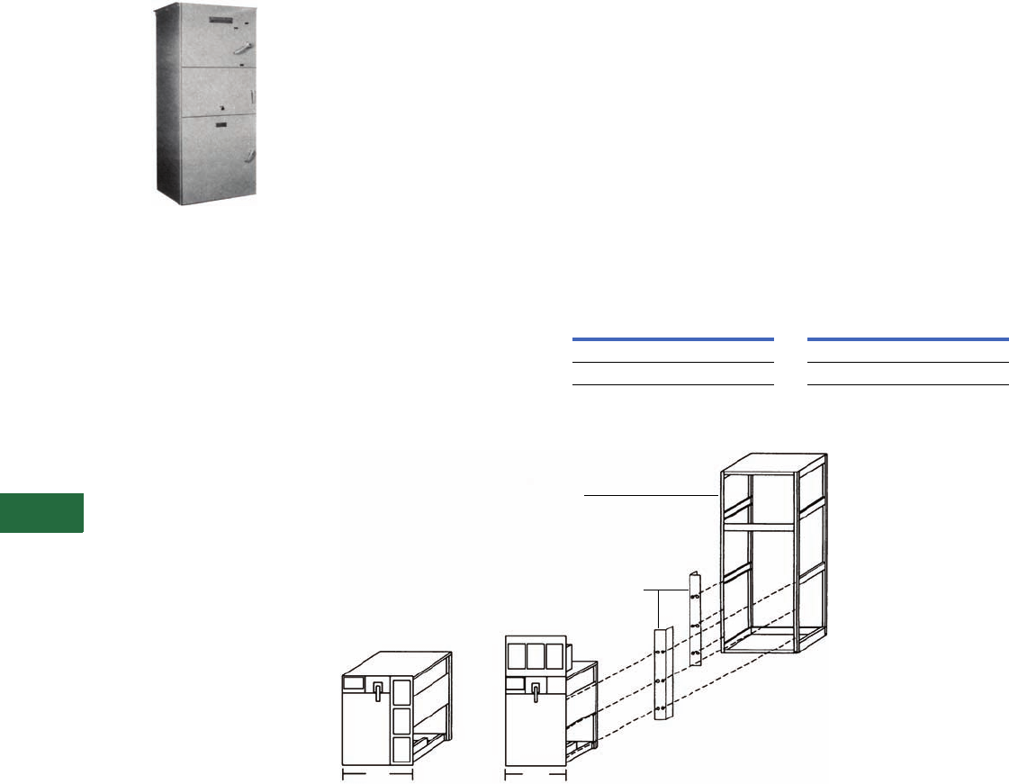
V12-T13-88 Volume 12—Aftermarket, Renewal Parts and Life Extension Solutions CA08100014E—November 2013 www.eaton.com
1
2
3
4
5
6
7
8
9
10
11
12
13
14
15
16
17
18
19
20
21
22
23
24
25
13
Motor Control
AMI AMPGARD Starters (Medium Voltage)
AMI AMPGARD
Originally a Westinghouse
Product
AMI AMPGARD Starter
Product Description
The AMI design AMPGARD
starter introduced in 1957 was
a complete line of starters for
magnetic control of squirrel
cage, wound rotor and
synchronous motors. The AMI
was the first front-accessible
starter and was available with
air break (Type H) or oil
immersed (Type K) contactors.
The standard AMI for full
voltage starting was 30 inches
deep, 38 inches wide and 90
inches high. All components
were accessible from the front
through three doors that
opened into separate
compartments. The top
compartment enclosed the
isolating switch and current
limiting power fuses. The
middle compartment enclosed
the AC low voltage control
panel and behind it the CTs.
The bottom compartment
housed the contactor.
Note: The pre-AMI design was a
rear-access assembly with two
compartments—current limiting
fuses on the top and the
contactor below.
Ratings (Maximum)
400A 1500 hp at 2500V;
2500 hp at 5000V.
Chronology
The AMI design AMPGARD
was manufactured from 1957
until 1970 at the General
Control Division in Buffalo, NY,
and Westinghouse
Manufacturing and Repair
(M&R) facilities around the
country. The air contactor was
available through 1966. The oil
contactor was available
through 1970.
Replacement Capabilities
The AMI vintage is obsolete
but upgrading to the latest
vacuum technology with a
cell-retrofill solution is
available. See Technology
Upgrades for further
information.
Add-On Structure
New add-on vacuum
structures as an extension to
the AMI type structure may
be connected directly to the
main bus without a transition
section using special bus
links. Contact your local Eaton
Field Sales office.
Technology Upgrades
Standard AMI 36-Inch Wide
Vacuum Starter Cell-Retrofill
This kit includes a standard
full-voltage non-reversing
vacuum starter in a welded
cell assembly with horizontal
top barriers and deep flanged
doors. Optional components
include a new electronic
motor protection relay
MP-3000 and electronic
meter DP-4000. It will retrofit
the AMI designs that are
at least 36 inches wide and
30 inches deep. The cell is
45 inches high.
Standard AMI 36-Inch Wide
Vacuum Starter Cell-
Retrofill Style Number
Narrow AMI 30-Inch Wide
Vacuum Starter Cell-Retrofill
This kit includes a standard full-
voltage non-reversing vacuum
starter in a welded cell
assembly with horizontal top
barriers and deep flanged
doors. Optional components
include a new electronic
motor protection relay
MP-3000 and electronic
meter DP-4000. It will retrofit
the AMI designs that are at
least 30 inches wide and
30 inches deep. The cell is
58 inches high.
Narrow AMI 30-Inch Wide
Vacuum Starter Cell-
Retrofill Style Number
AMI Starter Cell-Retrofill
Note
1Upper filler cover may require field modification.
Description
Style
Number
SJ Contactor 2147A95G41
SL Contactor 2147A95G61
Description
Style
Number
SJ Contactor 2147A95G42
SL Contactor 2147A95G62
36
Standard
30
Narrow
G42
G62
G41
G61
Replacement Vacuum Starter Cell with all
New Controls
New Filter
Strips 1
Existing Starter Structure
to be Stripped before Cell Retrofit
Westinghouse Type “H,” “AH”
or other Structure
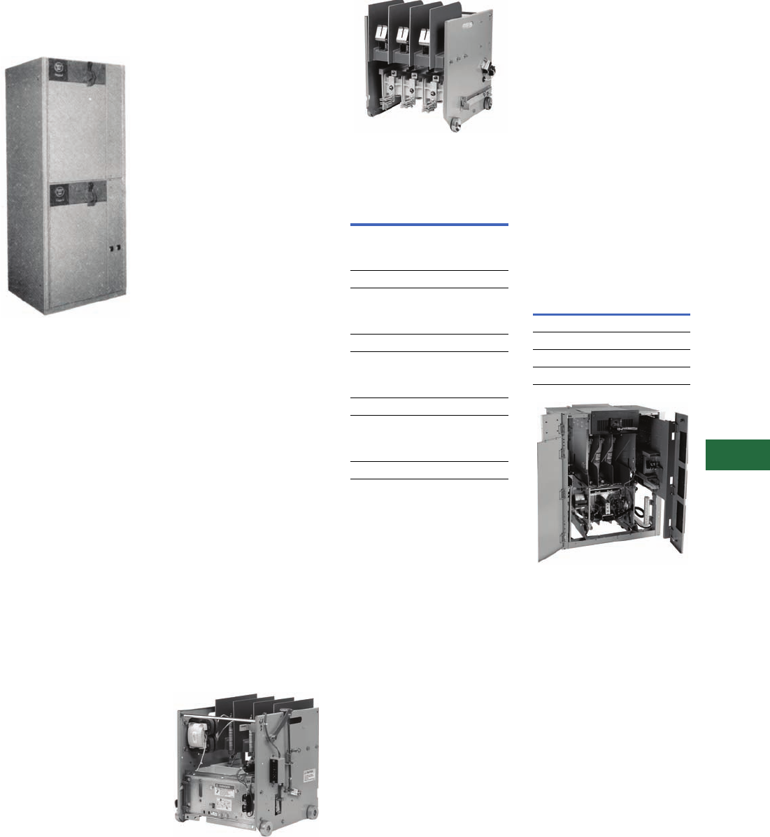
Volume 12—Aftermarket, Renewal Parts and Life Extension Solutions CA08100014E—November 2013 www.eaton.com V12-T13-89
1
2
3
4
5
6
7
8
9
10
11
12
13
14
15
16
17
18
19
20
21
22
23
24
25
13
Motor Control
LF Air AMPGARD Starters (Medium Voltage)
LF Air AMPGARD
Originally a Westinghouse
Product
The LF Air-Break Design
AMPGARD Starter
Product Description
The LF air-break design
AMPGARD starter was
introduced in 1962. The
LF design introduced the
component-to-component
circuitry concept. This design
greatly reduced the current-
carrying connections and
allowed for significant space
savings.
The 25L2 and 50L2 floor-
mounted NEMA 1 structures
were 26 inches wide x 30
inches deep x 90 inches high.
The 25L2 came in 1, 2 or 3
starters per structure. The
50L2 came in 1 or 2 starters
per structure.
The 25L4 and 50L4 floor-
mounted NEMA 1 starters
were 36 inches wide x 30
inches deep x 90 inches high.
These 400A starters could
have been mounted two-high
per structure.
The 25L7 and 50L7 floor-
mounted NEMA 1 starters
were 40 inches wide x 30
inches deep x 90 inches high.
These 700A starters were
mounted one per vertical
structure.
Ratings (Maximum)
200, 400 and 700A 2500 hp at
2500V; 4500 hp at 5000V.
Chronology
The LF air-break design
starter was introduced in
1962, first with the 2500V,
200A starter, then with the
5000V design and the 400
and 700A ratings. The
starters were built in Buffalo,
NY, until the operation was
transferred to Asheville, NC,
in 1978, where it was
discontinued in the late 1980s.
Replacement Capabilities
Renewal and Replacement Parts
for LF Design Starters
Refer to RPD 8855A for
identifying the parts needed.
Among the parts available
are:
●Current and potential
transformers
●Control transformers
●Fuses
●O/L relays and heaters
●Isolation switches
●Some air-break
contactor parts
Technology Upgrades
Add-On Vacuum Starter
Structures
New add-on vacuum
structures as an extension to
the LF type starter assembly
may be connected directly to
the main bus without a
transition section.
50L4 (400A) Vacuum
Replacement Contactor
For replacing an existing
400A LF air contactor with
the directly interchangeable
400A vacuum contactor.
50L4 Vacuum Replacement (Front)
50L4 Vacuum Replacement (Rear)
400A Air-to-Vacuum
Contactor Replacement
Note: Style numbers listed above
identify a basic contactor that
might not include other available
accessories that were specified
on a customer order. Contact
factory with original general order
number starter drawing number
and date of manufacture for
assistance.
400A Air-to-Vacuum Starter
Cell Kit
Complete full-voltage, non-
reversing, induction, vacuum
AMPGARD motor starter,
400A, 7200V maximum, for
mounting in existing 36-inch
wide enclosure. Includes
main contactor, isolation
switch, three power fuses,
MP-3000 motor protection
without RTD module, three-
phase current transformer,
vertical bus, high and low
voltage doors, and welded
cell assembly for mounting
in existing 36-inch wide
enclosure.
400A Air-to-Vacuum Starter
Cell Kit
Completely New Starter Cell
Description
Style
Number
Basic contactor 2300/120V,
750 VA transformer:
SJ contactor 2147A45G01
SL contactor 2147A50G01
Basic contactor 2300/120V,
2 kVA transformer:
SJ contactor 2147A45G02
SL contactor 2147A50G02
Basic contactor 4160/120V,
600 VA transformer:
SJ contactor 2147A45G03
SL contactor 2147A50G03
Basic contactor 4160/120V,
2 kVA transformer:
SJ contactor 2147A45G04
SL contactor 2147A50G04
Description
Style
Number
Slide-out with SJ 2147A95G01
Roll-out with SJ 2147A95G02
Slide-out with SL 2147A95G03
Roll-out with SL 2147A95G04
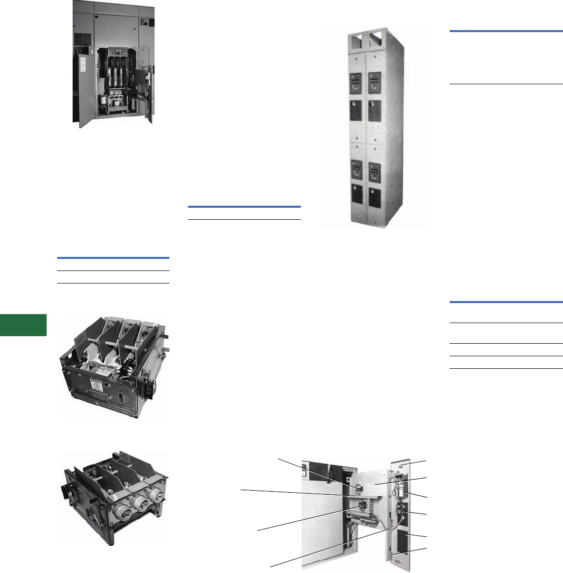
V12-T13-90 Volume 12—Aftermarket, Renewal Parts and Life Extension Solutions CA08100014E—November 2013 www.eaton.com
1
2
3
4
5
6
7
8
9
10
11
12
13
14
15
16
17
18
19
20
21
22
23
24
25
13
Motor Control
LF Air AMPGARD Starters (Medium Voltage)
50L7 Vacuum Retrofit
700A Air-to-Vacuum
Conversion Kits
These kits will convert an
existing full-voltage non-
reversing 700A air break
starter to vacuum.
700A Air-to-Vacuum
Conversion Kit
25L2 Vacuum Replacement
Contactor
25L2 Vacuum Replacement—
Front View
25L2 Vacuum Replacement—
Rear View
This solution uses the latest
technology “SL” contactor
and is designed to replace
vintage 25L2, 2500V, 200A,
1962 air-break contactors.
Description
Style
Number
450–630A maximum 2147A95G31
720A maximum 2147A95G32
50L2 Air-to-Vacuum Retrofit Kit
This kit replaces the out-of-
production 5000V, 200A
air-break contactor with an
SJ vacuum contactor, for
starters built after 1974
with ISO-Switch shutter
mechanism mounted
in the cell. The customer
keeps the existing starter
cell and isolation switch and
modifies the cell to accept
the SJ contactor that is
mechanically interlocked
with the isolation switch.
The rating remains 200A.
50L2 Air-to-Vacuum
Retrofit Kit
Ampacity upgrade to 320A
design for pre-1974 50L2
retrofit kits available.
Metering and Protective
Relay Upgrades
IQ Floor-Mounted Enclosure
IQ Floor-Mounted Enclosure
This kit is for mounting IQ
family products. Includes
standard AMPGARD structure
construction to be used as a
lineup extension. Each 90-
inch high x 30-inch deep
section comes with two
doors, each with a works-in-a-
drawer drawout panel. Each
door has a maximum of three
standard IQ cutouts with
device panels. Supplied with
or without IQ and PB devices.
(Photo left shows two
auxiliary sections with
optional bus enclosure,
IQ and PB devices.)
IQ Floor-Mounted Upgrade
MP-3000 and DP-4000
upgrades used for upgrading
overload-relay technology from
“Type-A,” IQ 2000A, IQ
2000B or IQ 1000II to the
latest technology. Also
upgrades with a new,
slideout, LV control panel.
The kit includes:
●Typical starter schematic
●0.50-inch deep, flange LV
door with three cut-outs for
new devices
●Works-in-a-drawer slide-out
panel for LV control devices
Metering and Protective
Relay Upgrades
Works-in-a-Drawer Metering and Protective Relay LV Device Panel
Description
Style
Number
200A maximum 2147A95G30
Description
Style
Number
Auxiliary section with
cutouts only. 10-inch
wide x 30-inch deep x
90-inch high (does not
include bus enclosure,
IQ or PB devices)
2147A95G35
Description
Style
Number
DP-4000 and MP-3000
(without RTD)
2147A95G37
MP-3000
(without RTD) only
2147A95G39
DP-4000 only 2147A95G48
IQ 300 only 2147A95G49
Current Transformer Shorting
Terminal Blocks (when specified)
Routing of
Control
Wire in
Wire Channel
Interposing
Control Relay
DIN Rail Mounted
Wiring is Protected
Between Low Voltage
Panel and Hinged Low
Voltage Door
Blank Device Panel
Indicating Lights and
Pushbuttons Rear View
MP-3000 Rear View
Predrilled Holes for
Additional Control Devices
Rear of 1/4 Turn Fastener
Note: Low voltage door is
hinged to slide-out control
panel.
Low Voltage Panel Completely Extended
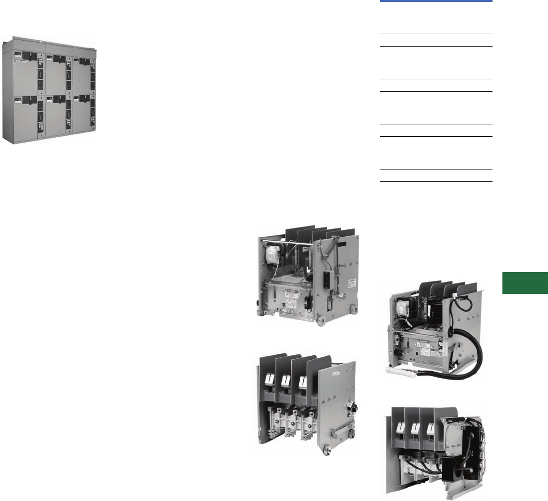
Volume 12—Aftermarket, Renewal Parts and Life Extension Solutions CA08100014E—November 2013 www.eaton.com V12-T13-91
1
2
3
4
5
6
7
8
9
10
11
12
13
14
15
16
17
18
19
20
21
22
23
24
25
13
Motor Control
SL and SJ Vacuum AMPGARD Starters (Medium Voltage)
Classic AMPGARD
SL and SJ Vacuum
AMPGARD
Originally a Westinghouse
Product
SJ Vacuum AMPGARD Assembly
Product Description
The SJ vacuum contactor was
designed and engineered
specifically for use in
AMPGARD starters. The
contactor is a low-chop design
that permits application
matching of the starter to the
motor for 2200–7200V and
ratings of 400 and 800A. The
400A contactor is available in
both slide-out and roll-out
configurations. The 800A
contactor is available in the
roll-out design only. The SJ
AMPGARD is a horsepower
specific starter design that
uses the component-to-
component circuitry concept.
The full-voltage 400A rating in a
NEMA 1 enclosure is 36 inches
wide x 30 inches deep x
90 inches high. These 400A
starters are mounted one- or
two-high per structure. The
800A rating in an enclosure is
40 inches wide x 30 inches
deep x 90 inches high in a
one-high construction for a
full-voltage starter.
Ratings (Maximum)
400 and 800A, 3000 hp at
2500V; 5500 hp at 5000V;
8000 hp at 7200V.
Chronology
The SJ vacuum design
AMPGARD starter
was
introduced in 1982 with the
400A rating. The 800A rating
followed in 1987. With the
introduction of the vacuum
contactor, the air-break starter
has been gradually phased out
and is rarely specified in an
assembly. The starters are built
in Asheville, NC.
AMPGARD assemblies were
made available with the new
SL Contactor in late 1999.
Except for the 400A
frame contactor, SJ and SL
AMPGARD assemblies are
virtually identical.
Replacement Capabilities
Renewal and Replacement Parts
for SJ Design Starters
Refer to RP.48J.01.T.E for
identifying the parts needed.
Common Replacement Parts for
SL Design Starters
Refer to RP02003002E
for identifying the parts
needed.
Add-On Vacuum Starter
Structures
New add-on vacuum
structures as an extension to
the SJ type structure may be
connected directly to the
main bus without a transition
section. Contact your local
Eaton Field Sales office.
Replacement Vacuum
Contactors
New replacement vacuum
break contactors are available
for all SJ model ratings.
400A SL Roll-Out Replacement (Front)
400A SL Roll-Out Replacement (Rear)
400A Vacuum Roll-out
Replacement Contactor
Note: Style numbers listed above
identify a basic contactor that
might not include other available
accessories that were specified
on a customer order. Contact
factory with original general order
number, starter drawing number,
and date of manufacture for
assistance.
400A SL Slide-Out Replacement (Front)
400A SL Slide-Out Replacement (Rear)
Description
Style
Number
Basic contactor 2300/120V,
750 VA transformer:
SJ contactor 2147A45G01
SL contactor 2147A50G01
Basic contactor 2300/120V,
2 kVA transformer:
SJ contactor 2147A45G02
SL contactor 2147A50G02
Basic contactor 4160/120V,
750 VA transformer:
SJ contactor 2147A45G03
SL contactor 2147A50G03
Basic contactor 4160/120V,
2 kVA transformer:
SJ contactor 2147A45G04
SL contactor 2147A50G04
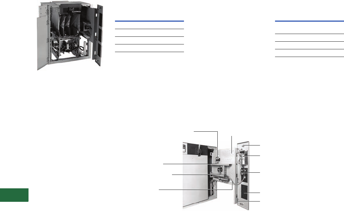
V12-T13-92 Volume 12—Aftermarket, Renewal Parts and Life Extension Solutions CA08100014E—November 2013 www.eaton.com
1
2
3
4
5
6
7
8
9
10
11
12
13
14
15
16
17
18
19
20
21
22
23
24
25
13
Motor Control
SL and SJ Vacuum AMPGARD Starters (Medium Voltage)
Completely New Starter Cell
400A Vacuum Starter Cell Kit
The 400A vacuum starter cell
kit is used to fill a blank cell in
an SL or SJ AMPGARD
assembly or to completely
replace an existing 400A SL or
SJ starter.
It is a complete full-voltage,
non-
reversing, induction,
vacuum AMPGARD
motor
starter, 400A, 7200V
maximum, for mounting in
existing 36-inch wide
enclosure. It includes main
contactor, isolation switch
three power fuses, MP-3000
motor protection without
RTD module, three-phase
current transformer, vertical
bus, high and low
voltage
doors, and welded cell
assembly
for mounting in
existing 36-inch
wide customer enclosure.
400A Vacuum Starter
Retrofit Kit Technology Upgrades
MP-3000 and DP-4000
upgrades used for
upgrading
overload-relay technology
from “Type-A,” IQ 2000A,
IQ 2000B or IQ 1000II to
the latest technology. Also
upgrades with a new,
slideout, LV control panel.
The kit includes:
●Typical starter schematic
●0.50-inch deep, flange LV
door with three cut-outs for
new devices
●Works-in-a-drawer slide-out
panel for LV control devices
Metering and Protective
Relay Upgrades
Works-in-a-Drawer Metering and Protective Relay LV Device Panel
Description
Style
Number
Slide-out with SJ 2147A95G01
Roll-out with SJ 2147A95G02
Slide-out with SL 2147A95G03
Roll-out with SL 2147A95G04
Description
Style
Number
DP-4000 and MP-3000
(without RTD)
2147A95G37
MP-3000 (without RTD) only 2147A95G39
DP-4000 only 2147A95G48
IQ Data only 2147A95G49
Current Transformer Shorting
Terminal Blocks (when
specified)
Routing of Control
Wire in Wire Channel
Interposing Control Relay
DIN Rail Mounted
Wiring is Protected
Between Low Voltage
Panel and Hinged Low
Voltage Door
Blank Device Panel
Indicating Lights and
Pushbuttons Rear View
(when specified)
MP-3000 Rear View
(when specified)
Predrilled Holes for
Additional Control Devices
Rear of 1/4 Turn Fastener
Note: Low voltage door is
hinged to slide-out
control panel.
Low Voltage Panel
Completely Extended
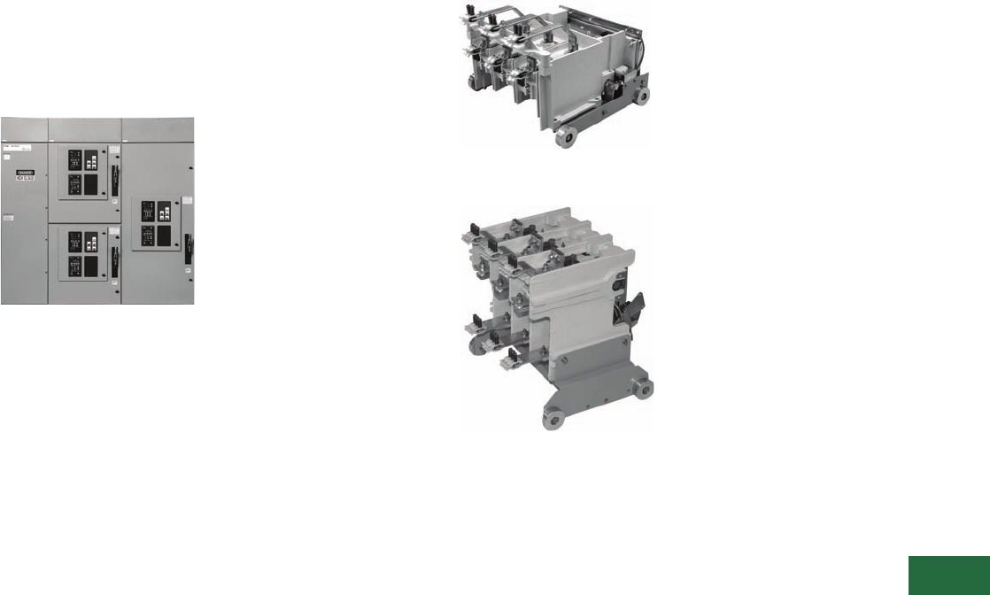
Volume 12—Aftermarket, Renewal Parts and Life Extension Solutions CA08100014E—November 2013 www.eaton.com V12-T13-93
1
2
3
4
5
6
7
8
9
10
11
12
13
14
15
16
17
18
19
20
21
22
23
24
25
13
Motor Control
SLB and SLS Contactors AMPGARD (Medium Voltage)
Next Generation
AMPGARD
SLB and SLS Contactors
AMPGARD
Next Generation AMPGARD Lineup—
Front View
Product Description
Medium voltage control
reaches a higher level of
design with the next
generation of Cutler-Hammer
AMPGARD
starters from
Eaton. This product
incorporates 60 years of
experience with over 75,000
units installed worldwide. The
SLB and SLS contactor is
a low-chop design that
controls 200–8000 hp motors
with ratings of 400 and 800A
vacuum contactors. The
contactor is available in a stab
(SLS) or bolted (SLB) design
within the starter cell. The
two-high structure design can
accommodate two 400A or
one 800A contactor/starter
designs. The two-high
structure is 36 W x 92 H x 30
D inches (914.4 x 2336.8 x
762.0 mm), which includes a
12-inch high top-mounted
main bus compartment.
Ratings (Maximum)
400 and 800A 3000 hp at
2500V; 5500 hp at 5000V;
8000 hp at 7200V.
Chronology
The SLB and SLS vacuum
design AMPGARD starter
was introduced in 2005 with
both 400 and 800A ratings to
be incorporated into the next
generation of AMPGARD
assembly. The starters are
built in Asheville, NC. The
new SLS and SLB contactors
will not be interchangeable
with the existing SJ or SL
contactors.
Replacement Capabilities
For further information,
contact the Asheville plant
at 1-800-523-3775.
Stab-In AMPGARD 400A
Contactor—Rear View
Stab-In AMPGARD 800A
Contactor—Rear View
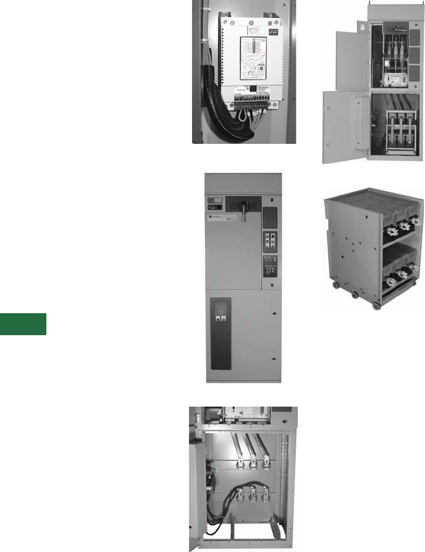
V12-T13-94 Volume 12—Aftermarket, Renewal Parts and Life Extension Solutions CA08100014E—November 2013 www.eaton.com
1
2
3
4
5
6
7
8
9
10
11
12
13
14
15
16
17
18
19
20
21
22
23
24
25
13
Motor Control
SL and SJ Vacuum AMPGARD Starters (Medium Voltage)
AMPGARD IT. Soft Start
Components
The Cutler-Hammer
AMPGARD IT. Soft Start
components are now
available for upgrading
existing full-voltage and
reduced-voltage starters. The
requirements to convert
starters into AMPGARD IT.
Soft Start will depend on
specific configurations of the
existing starter. Space will be
required for two 36-inch
wide, 45-inch high cells that
are ideally mounted in the
same vertical structure. The
upper compartment contains
the ‘M’ Contactor Cell and
the lower compartment
contains the SCR Truck Cell.
The new door provided with
the SCR Truck Cell includes
the MV801 control module
and is made to interlock with
the door on the upper
compartment.
If the targeted upgrade is for
a FVNR AMPGARD starter
presently located in the upper
compartment, then the
conversion is simplified by
using the existing FVNR
starter as the ‘M’ contactor
cell and converting the
bottom compartment into the
SCR truck cell. The ‘M’
contactor load terminals are
connected to the SCR truck
cell terminals using three
copper bus connectors.
Available SCR truck ratings
include 200A and 400A.
See Page V12-T13-95 for a
description of other existing
starter configurations. The
advanced diagnostics
included in the MV801
control module include:
●Phase loss
●Phase imbalance
●Jam
●Stall
●Over/undervoltage
●Motor overload
MV801 Control Module
AMPGARD IT. Soft Start
SCR Truck Cell
AMPGARD IT. Soft Start (Doors Open)
SCR Truck (Rear)
Volume 12—Aftermarket, Renewal Parts and Life Extension Solutions CA08100014E—November 2013 www.eaton.com V12-T13-95
1
2
3
4
5
6
7
8
9
10
11
12
13
14
15
16
17
18
19
20
21
22
23
24
25
13
Motor Control
Synchronous
Typical AMPGARD Starter Configurations
Example 1
(Before Retrofit)
Note: Example 1—Upper
Compartment must be converted
to ‘M’ contactor cell. Lower
compartment must be converted
into SCR truck cell.
Example 2
(Before Retrofit)
Note: Example 2—Upper
compartment FVNR can be used
as the ‘M’ contactor cell. Lower
compartment must be converted
to SCR truck cell.
Example 1 and 2
(After Retrofit)
Example 3 (Before Retrofit) Example 3 (After Retrofit)
Note: Example 3—‘M’
contactor cell can be relocated to
upper compartment. Lower
compartment must be converted
into SCR truck cell.
Upper
Compartment
Lower
Compartment
New
SCR
Truck Cell
‘M’
Contactor
‘M’
Contactor
‘R’ Contactor
(RVAT) Upper
Compartment
‘S’ (RVAT)
or
‘R’ (RVPR)
Autotransformer
or
Reactor
New
SCR
Truck Cell
‘M’
Contactor
Available for
Other Use

V12-T13-96 Volume 12—Aftermarket, Renewal Parts and Life Extension Solutions CA08100014E—November 2013 www.eaton.com
1
2
3
4
5
6
7
8
9
10
11
12
13
14
15
16
17
18
19
20
21
22
23
24
25
13
Motor Control
Synchronous
AMPGARD Solutions Overview
AMPGARD Selection Table
Notes
1Add-on structures contain vacuum starters only.
2Complete cell including frame, ISO-switch, vacuum or air contactor, and all components to complete a starter.
3Isolation switch only (LFR replaced LFM after 1974).
4Complete contactor, available in SJ or SL.
5New, genuine parts per original specs.
Vacuum replacements— OIL, AH, AMI (one-high starters) Complete Cell Retrofill
25L2 Vacuum Replacement Contactor
50L2 Vacuum Retrofit Kit
50V4 Vacuum Replacement Contactor
25/50L4 Vacuum Replacement Contactor
Synchronous Mark V Solid-State Control Retrofit
25/50L7 Vacuum Replacement Contactor and Some Cell Modification
6Check with factory.
Further Information
Pricing Information
Price and Availability Digest (PAD)
Installed
Equipment Vintage
AMPGARD Aftermarket Products Available
Reference
Material
Add-on
Structure 1Cell 2
Isolation
Switch 3Contactor 4Parts 5
Vacuum
Replace-
ments
Class 1
Recondi-
tioning
AMPGARD OIL 1945–1957 ■—
AMPGARD AH 1948–1957 ■—
AMPGARD AMI 1948–1957 ■—
AMPGARD 25L2 1962–1990 ■■ 6■■RPD8855A
AMPGARD 50L2 1963–1981 ■■ 6■■RPD8855A
AMPGARD 50V4 1972–1979 ■■■ ■■RP48J01TE
AMPGARD 25/50L4 1966–1989 ■■■ ■ 6■■RPD8855A
AMPGARD 25/50L7 1969–1989 ■■■ 6■■RPD8855A
AMPGARD V202 (SJ) 400A 1982–2000 ■ ■■■ ■■■RP48J01TE
AMPGARD S202 (SJ) 400A 1987–2000 ■ ■■■ ■■■RP48J01TE
AMPGARD W210 (SL) 400A 2000– ■ ■■■ ■■■RP02003002E
AMPGARD F210 (SL) 400A 2000– ■ ■■■ ■■■RP02003002E
AMPGARD V202 (SJ) 800A 1985– ■ ■■ ■■■RP48J01TE
Synchronous Control 1950– ■■ ■ RP04304009E
Publication
Number Description
RPD8855A Renewal Parts Data for AMPGARD LF Air-Break Vintage 200–700A
RPD8855S Renewal Parts Data for AMPGARD Slipsyn Synchronous Control
RP48J01TE Renewal Parts for AMPGARD SJ Vacuum-Break Vintage 400–800A
RP02003002E Common Renewal Parts for AMPGARD SL 400A Vacuum Contactors
TD48A01ATE Technical Data for AMPGARD MV Starters
PG48C01TE Product Guide “SL” Medium Voltage Vacuum Contactors
IB48008 Instructions for AMPGARD Mark V Solid-State, Brush-Type, Synchronous Motor Controllers
IB48009 Instructions for AMPGARD Synchronous Motor Field Regulator with VAR and PF Control
