661870 Catalog
185820-Brochure 185820-Brochure 185820-Brochure 768386 Batch5 unilog cesco-content
2014-07-05
: Pdf 661870-Catalog 661870-Catalog 768386 Batch5 unilog
Open the PDF directly: View PDF ![]() .
.
Page Count: 195 [warning: Documents this large are best viewed by clicking the View PDF Link!]
- Navigator_Cover_FRONT
- Sect_i_Table_of_Contents_7-21-10
- Sect_1 Magnetic_7-21-10
- Sect_2 Electronic_7-21-10
- Sect_3_DCL_7-21-10
- Sect_3_Dimming_7-15-10
- Sect_4_CompactFluor_7-21-10
- Sect_5 HID_7-21-10
- Sect_6_Electronic_HID_7-21-10
- Sect_7_Sign_7-21-10
- Sect_8_Glossary_5-19-10
- Sect_10_Index_5-19-10
- Warranty_5-19-10
- Navigator_Cover_Back_7-21-10

FOR MORE INFORMATION CALL
1-800-BALLAST
(225-5278)
i
Table of Contents
Table of Contents
Fluorescent Electromagnetic Ballasts Section 1- Page
Product Overview ...........................................................................................................................................1-2
Application Operation Information ................................................................................................................1-4
Typical Specifications .....................................................................................................................................1-8
Lead Lengths ...................................................................................................................................................1-9
T8 (265 mA)..................................................................................................................................................1-10
T12 .................................................................................................................................................................1-11
T12 High Output ...........................................................................................................................................1-13
T12 Very High Output ..................................................................................................................................1-17
Circline ..........................................................................................................................................................1-18
T12 Slimline .................................................................................................................................................1-19
Preheat and Trigger Start .............................................................................................................................1-21
Export ...........................................................................................................................................................1-25
Dimming .......................................................................................................................................................1-29
Export ...........................................................................................................................................................1-30
Fluorescent Electronic Ballasts Section 2- Page
Product Overview ...........................................................................................................................................2-2
Application Operation Information ................................................................................................................2-4
Typical Specifications .....................................................................................................................................2-7
F17T8 ............................................................................................................................................................2-14
F25T8 ............................................................................................................................................................2-16
F32T8 (32, 30, 25 & 28 Watt Four Foot Lamps) .......................................................................................2-19
F40T8 ............................................................................................................................................................2-31
F96T8 Slimline .............................................................................................................................................2-33
F96T8HO High Output.................................................................................................................................2-34
T5 ...................................................................................................................................................................2-35
T5HO .............................................................................................................................................................2-37
T12 ................................................................................................................................................................2-39
T12 Slimline ..................................................................................................................................................2-41
T12HO High Output .....................................................................................................................................2-43
T2 ...................................................................................................................................................................2-44
Energy Management Systems Section 3- Page
--DCL With DEMANDflex
Product Overview ...........................................................................................................................................3-2
DemandFlex T8 ..............................................................................................................................................3-3
DemandFlex T5, T5HO & TT5 .....................................................................................................................3-6
DemandFlex T8 Wiring Diagram ..................................................................................................................3-7
Controllable Lighting Section 3- Page
--Fluorescent Energy Management/Dimming Ballasts and Controls
Product Overview .........................................................................................................................................3-10
Ballastar® Light Level Switching ...............................................................................................................3-10
SuperDim® Analog Dimming .....................................................................................................................3-11
DaliPro™ Digital Dimming .........................................................................................................................3-13
Application Operation Information ..............................................................................................................3-14
Controls for Analog Dimming Ballasts .......................................................................................................3-15
DaliPro®........................................................................................................................................................3-16
SuperDim® ...................................................................................................................................................3-17
Ballastar® 0-10 Volt .....................................................................................................................................3-18
Ballastar® Light Level Switching ...............................................................................................................3-19

FOR MORE INFORMATION CALL
1-800-BALLAST
(225-5278)
ii
Table of Contents
Table of Contents
Compact Fluorescent Ballasts Section 4- Page
Product Overview ...........................................................................................................................................4-2
Understanding Compact Fluorescent Technology ........................................................................................4-3
Configurations .................................................................................................................................................4-4
Lamp Matrix ...................................................................................................................................................4-5
Typical Specifications .....................................................................................................................................4-6
Nomenclature ..................................................................................................................................................4-7
5-13 Watt Twin, Quad and Triple ..................................................................................................................4-8
18 Watt Twin, Quad and Multiple ...............................................................................................................4-10
26-28 Watt Quad and Triple .......................................................................................................................4-11
32 to 70 Watt Triple and Multiple ...............................................................................................................4-12
2D and T5 Circular .......................................................................................................................................4-14
Long Twin T5 ...............................................................................................................................................4-18
High Intensity Discharge (HID) Ballasts Section 5- Page
Product Overview ...........................................................................................................................................5-3
Oil Filled Capacitors .......................................................................................................................................5-5
Dry Capacitors ................................................................................................................................................5-7
Bracket Reference Chart .................................................................................................................................5-9
Application and Operation Information .......................................................................................................5-10
Nomenclature ................................................................................................................................................5-13
Typical Specifications ...................................................................................................................................5-14
Distributor Replacement Kits .......................................................................................................................5-15
Core and Coil
Metal Halide .......................................................................................................................................5-19
Pulse Start Metal Halide .....................................................................................................................5-23
High Pressure Sodium .........................................................................................................................5-30
50 Hz Core and Coil Ballasts .......................................................................................................................5-34
F-Can Ballast .................................................................................................................................................5-36
Potted Core and Coil .....................................................................................................................................5-39
Indoor Encased ..............................................................................................................................................5-40
Ignitors ...........................................................................................................................................................5-41
Reference Drawings ............................................................................................................................5-43
Electronic High Intensity Discharge (eHID) Ballasts Section 6- Page
Product Overview ...........................................................................................................................................6-2
Product Family Chart ......................................................................................................................................6-3
Wiring Diagrams .............................................................................................................................................6-4
Dimensions ......................................................................................................................................................6-5
Application and Operation Information .........................................................................................................6-7
Sign Ballasts Section 7- Page
Application and Operation Information .........................................................................................................7-2
Sign Ballast Footage Chart & Lead Lengths .................................................................................................7-3
Standard ...........................................................................................................................................................7-4
Max-3 Series ...................................................................................................................................................7-5
SIGNA Electronic Sign Ballasts ....................................................................................................................7-6

FOR MORE INFORMATION CALL
1-800-BALLAST
(225-5278)
iii
Table of Contents
Table of Contents
Glossary Section 8- Page
.........................................................................................................................................................................7-1
Obsolete Cross Reference Section 9- Page
.........................................................................................................................................................................8-1
Index Section 10- Page
.........................................................................................................................................................................9-1
Warranty Section 11- Page
.......................................................................................................................................................................10-1
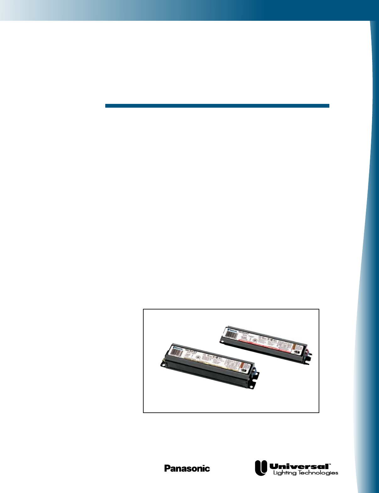
Fluorescent-ElectromagneticFluorescent-Electromagnetic
Electromagnetic
Fluorescent Ballasts
A Wide Product Line
To Meet All Your Needs
Our comprehensive line of magnetic ballasts offer outstanding
performance and value. These energy-efficient ballasts carry
the trusted UNIVERSAL® brand and are available for a wide
variety of applications.
Universal Lighting Technologies’ (“Universal”) full spectrum of
solutions includes ballasts for T12/T10/T8 applications, plus
Slimline, Circline, trigger-start and preheat ballasts. We also
make rugged weatherproof ballasts ... and models specifically
engineered for the fast growing export market.
Our comprehensive line of energy-efficient magnetic ballasts carry the
trusted UNIVERSAL® brand name.
Universal Lighting Technologies is a subsidiary of
Panasonic Electric Works Co., Ltd., a member of the Panasonic Group
FOR MORE INFORMATION CALL
1-800-BALLAST
(225-5278)
Fluorescent-Electromagnetic
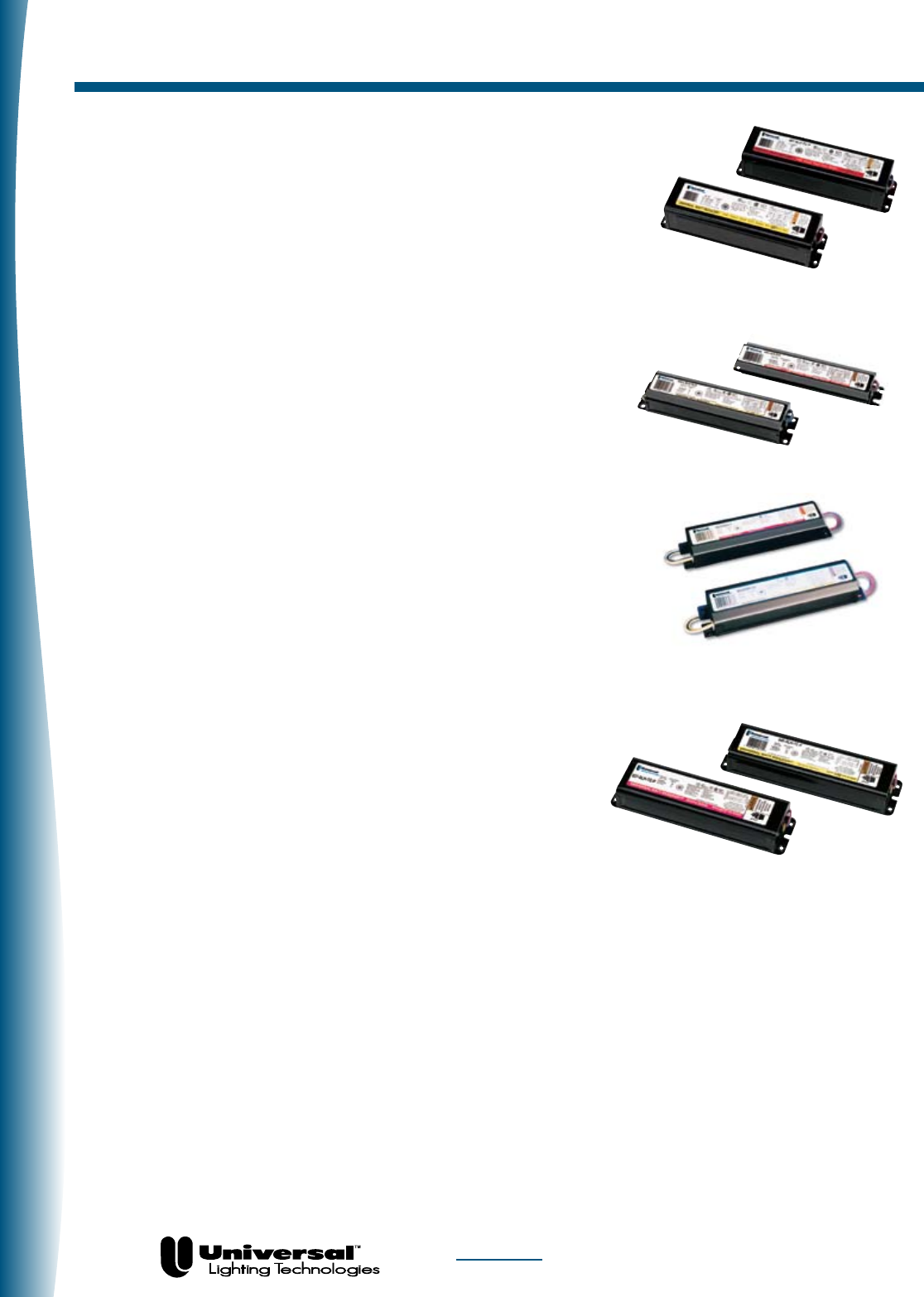
Product Overview
PAGE 1-2
T12/T10 Applications
Rapid Start Ballasts
T8 Applications
Slimline Ballasts
Rapid Start Ballasts
These ballasts provide smooth starting to Rapid Start lamps —
reaching full brightness in about two seconds without the use of
starters. They have built-in filament windings that energize the low-
voltage cathodes in Rapid Start lamps. Because electrodes are con-
tinuously heated, less voltage is required to strike an arc through a
Rapid Start lamp than a Slimline one.
Ballasts for T12/T10 Applications
Universal offers a wide variety of T12 and T10 ballasts to operate
1 - 3 Rapid Start lamps. This lamp/ballast system provides smooth,
virtually instant starting without the use of starters (30- and 40-watt
T12 models and 40-watt T10 models are available). Models for
U-lamp applications are also available. UNIVERSAL® PLUS models
are available for use where maximum efficiency is required. These
“hybrid” type ballasts in corporate an electronic switch which dis-
connects power to the lamp cathodes after
start-up, saving additional energy.
Ballasts for T8 Applications
Universal’s T8 product offering includes models for F17, F25,
F32 and F40 type T8 lamps. This product line features our OcTek™
electromagnetic ballast models. These models are low initial cost
energy efficient options for use with F32T8,
4 foot Rapid Start lamps. These models are available in several
variations, including full, medium, low light output and hybrid
versions (OcTek™ Plus). These models maximize energy savings
and provide effective choices when retrofitting 4-foot T12 fixtures.
Slimline Ballasts
Our Slimline models are designed for use with single-pin Slimline
lamps. They do not require the use of starters. These ballasts
deliver a high starting voltage to the lamps, enabling an arc to strike
through the tube without preheating the lamp cathodes (which are
specially constructed to withstand the shock).
FOR MORE INFORMATION CALL
1-800-BALLAST
(225-5278)
Fluorescent-Electromagnetic
PAGE 1-3
Product Overview
Circline Ballasts
These products are available in 430 mA Rapid Start and preheat
types, designed for use with Circline lamps. The operating
characteristics are the same for both Circline and conventional
lamps. All Circline socket wires are fully sleeved.
Trigger-Start Ballasts
These ballasts are designed for use with general fluorescent
lamps and do not require the use of starters. They contain
preheat windings which allow regular lamp filaments to be
heated in one second. However, they require a higher
open-circuit voltage than Rapid Start ballasts.
Preheat Ballasts
These units are designed for use with general fluorescent lamps
and require the use of starters. These ballasts deliver an open-
circuit voltage high enough to activate the starter to preheat lamp
filaments to a temperature approximately 1750° F. After a few
seconds, the starter opens the filament circuit. This provides an
additional power surge to enable an electric arc to strike through
the lamp and ignite it. Lamp current is then limited by the ballast
to an operating level proper for the lamp.
Export (50/60 Hz) Ballasts
Our export product offering consists of a variety of one- and two-
lamp models for Rapid Start, Preheat, High Output, Slimline, and
1500 mA lamps. Included in this product line are ballasts for 50
and 60 Hz applications, including 120, 127 and 220 volts. Many of
these models are available with resetting thermal protection.
Export (50/60 HZ) Ballast
Preheat Ballast

FOR MORE INFORMATION CALL
1-800-BALLAST
(225-5278)
Fluorescent-Electromagnetic
Application And Operating Information
PAGE 1-4
SAFETY
NEC & UL Requirements
Ballast installation presents the possibility of exposure to
potentially hazardous voltages and should be performed
only by qualified personnel. All installation, inspection and
maintenance should be performed only with power to the
fixture turned off. Additionally, all fixtures and ballasts must
be installed and operated in compliance with the National
Electrical Code, Underwriters Laboratories Inc. (UL) require-
ments and all applicable codes and regulations.
Polarity
Polarity refers to the proper connection of ballast lead wires
to line wires. To aid you in making a correct installation,
Universal ballast leads are color-coded for easy identifica-
tion. The WHITE ballast lead is to be connected to the neutral
(grounded) and the BLACK (or black with white tracer) lead
always to the phase (“hot”) line wire. Systems where neither
of the line wires are at ground potential require specially
designed ballasts. A change in polarity may result in the volt-
age from the lead to the ground exceeding UL-specified limits.
In some types of ballasts, a change in polarity may decrease
voltage from the lead to the ground, thereby impeding the
starting dependability of the ballast.
Grounding
Ballast cases and fixtures must always be grounded. The
ballast case may be grounded to the fixture or otherwise
grounded. It could be hazardous to make contact with an
ungrounded fixture or ballast when in operation. Neglecting
to properly ground the ballast and fixture combination may
also result in failure of certain lamps to start or for unaccept-
able levels of electromagnetic noise to be conducted onto the
power lines.
Operating Line Voltage Limits
To receive the full benefits of rated lamp output and to pro-
long ballast life, it is essential that voltage supplied to an
installation be maintained within limits prescribed for each
circuit. These limits are listed below:
Subjecting a ballast to excessive voltage for an extended period
of time results in the deterioration of the insulation. This insu-
lation breakdown will cause early ballast failure. Low voltage
has no damaging effect on the ballast. However, lamps may not
start reliably, and early lamp failure could result.
Internal Ballast Protection
Class P Classification - Since January 1, 1984, the National
Electrical Code requires that “where Fluorescent fixtures are
installed indoors, the ballast shall have thermal protection
integral within the ballast except for simple reactance bal-
lasts.” This ruling applies to replacement ballasts as well as to
those contained within new light fixtures.
In compliance with the National Electrical Code, UL has
established a Class P ballast classification for fluorescent light
fixtures indoors.
A Class P ballast must employ internal thermal protection lim-
iting its operating temperature.
Universal UL-approved Class P ballasts comply with the
National Electrical Code requirement and are equipped with an
automatic resetting thermal protector, built-in and adjacent to
the transformer coils. The resetting thermal protector func-
tions as a thermostat which will open and temporarily deacti-
vate the ballast when it exceeds the permissible temperature.
It will reset when the ballast cools to a safe operating tem-
perature. The ballast will continue to cycle until the cause of
overheating is eliminated. If the ballast is defective, it must be
replaced. If the cause is external, a Class P ballast will resume
normal operation after abnormal conditions are eliminated.
Fusing
Class P ballasts do not require fusing. Fusing can be used
when a single circuit has a large number of fixtures/ballasts.
For a comprehensive list of appropriate fuses, contact our
Technical Engineering Services (TES) Department at
1-800-BALLAST or check out our TES home page at www.
unvlt.com
VOLTAGE RANGE
Nominal Voltage Minimum Maximum
120 110 125
220 205 232
240 220 250
277 255 290
347 315 364
480 450 505
600 570 630
FOR MORE INFORMATION CALL
1-800-BALLAST
(225-5278)
Fluorescent-Electromagnetic
PAGE 1-5
Application And Operating Information
PERFORMANCE
Lamp Connections
Electromagnetic fluorescent ballasts are designed to generate
voltages in excess of 300 volts. It is imperative that proper
connection to good quality sockets be assured in accordance
with wiring diagrams on each page of the catalog and on
product labels. Some applications may not require the use of
all of the ballasts output leads. If any leads are not to be con-
nected, each should be individually capped and insulated to at
least 600 volts.
Application Versatility
Many models are designed to allow for applications with dif-
ferent types or quantities of lamps. Use of products other
than noted is not covered by UL Listing and/or CSA certifica-
tion and cannot be warranted.
Audible Noise (Sound)
Electrical equipment, including most fluorescent lamp bal-
lasts, produces some noise. Care must be taken to select a
ballast with the proper sound rating for a particular lighting
installation. Ballast sound will be noticeable only when it
exceeds the ambient sound level.
Although no industry standards currently exist, the generally
accepted criteria for sound rating specifications are as fol-
lows:
Average Ballast
Location Ambient Noise Recommendation
Typical Office < 30 decibels A
Noisy Office or Retail 31-36 decibels B
Factory, Outdoor > 36 decibels C
Remote Mounting
Excessive hot or cold temperatures, audible noise requirements or a desire to operate lamps in more than one fixture with the
same ballast (master/slave), may make it desirable to mount the ballast remotely. Care must be taken to allow for ballast heat dis-
sipation and proper grounding.
In any application, the wire used to extend leads must be at least as large as the wire supplied on the ballast (18 AWG) with an
insulation rating of 1000 VAC at 90°C.
Lead lengths in excess of those noted cause loading effects that can dramatically impact ballast performance and void the war-
ranty.
Electromagnetic and hybrid ballasts may be remote mounted according to the table below:
30-40 Watt 800 mA - HO Instant Start
Wire Size Rapid Start 1500 mA - VHO (Slimline)
Red/Blue Yellow Red/Blue Yellow
Leads Leads Leads Leads All Leads
#6 544’ 384’ 272’ 192’ 544’
#8 340’ 240’ 170’ 120’ 340’
#10 214’ 150’ 107’ 75’ 214’
#12 134’ 94’ 67’ 47’ 134’
#14 84’ 60’ 42’ 30’ 84’
#16 52’ 36’ 26’ 18’ 52’
#18 30’ 20’ 21’ 15’ 30’

FOR MORE INFORMATION CALL
1-800-BALLAST
(225-5278)
Fluorescent-Electromagnetic
PAGE 1-6
Application And Operating Information
PERFORMANCE
Operating Temperature
Most fluorescent ballasts and lamps are designed to provide
optimum performance at ambient temperature of 77˚F. Three
key performance attributes can be impacted by the ambient
(room) temperature of the installation:
• Lamp Starting Dependability
Fluorescent lamps are inherently more difficult to
start at low temperatures. All ballasts have
limitations as to their ability to start lamps at low
ambient temperatures. In this catalog, the low
starting point for each lamp/ballast combination
appears in the column marked “Minimum Starting
Temperature.”
• Light Output
Optimum light output from fluorescent lamps is
achieved when the lamp wall is at 100-110°F.
Any substantial excursion (either colder or warmer)
will result in a reduction in light output.
• Ballast Life
A fluorescent lamp ballast, like any other electrical
device, generates heat during its normal operation.
Ballast temperatures should be kept as low as
possible. Maximum dissipation of heat through
fixture design and proper ballast installation will
help. Although excessive temperature may not cause
the ballast to fail immediately, it can dramatically
shorten ballast life. To assure maximum life, the
ballast case temperature should not exceed 90˚C.
CAUSES OF BALLAST OVERHEATING:
• Incorrectprimaryvoltageorfrequency
• Incorrectsize,typeornumberoflamps
• Failedlampstarter
• Incorrectwiring
• Poorheatdissipationduetosurrounding
insulation
• Sealed(VaporTight)Fixtures-Unusualheat
build-up due to lack of ventilation in fixtures
may cause thermal (on/off) cycling of certain
ballasts. Consult Universal for specific
recommendations.
RECOMMENDATIONS...
• Selectionofaproperballasttomatchthe
requirements of the lamp, fixture, voltage and
installation.
• Mountingofballastwithinthefixturewithasmuch
surface contact as possible between the ballast and
metal portions of the fixture.
• Theuseofheat-conductingdissipators(radiators),
if necessary, which increase surface contact between
the ballast and fixture.
• Ifnecessary,locatetheballastinaremote,cooler
area outside the fixture.
• Plannedlampmaintenance–theorganized
replacement of failed and failing lamps, particularly
with Preheat or Slimline Systems.
• UseofspecialLOWHEAT(-LH)rise,VERYLOW
HEAT (-VLH) rise and SUPER LOW HEAT (-SLH)
rise ballasts where available and necessary.

FOR MORE INFORMATION CALL
1-800-BALLAST
(225-5278)
Fluorescent-Electromagnetic
LOW-LEAKAGE CURRENT TO GROUND BALLASTS
Manyone-andtwo-lamp,30-and40-watthighpowerRapidStartballasts–andtwo-andthree-lamp20-wattTriggerStart
ballasts–meetrequirementsfor“low-leakage-current-to-ground.”Thosemostfrequentlyusedinlow-leakageapplicationsare
listed below.
Other ballasts can also be manufactured to meet low-leakage requirements. Consult Universal’s Technical Engineering Services
Department at 1-800-BALLAST for complete information regarding low-leakage ballasts.
TYPE 1 BALLASTS
All Universal outdoor non-weatherproof magnetic ballasts (except those for sign applications) are designed to meet UL require-
ments for Type 1 use (metal enclosure required for wet or damp locations).
BALLASTS FOR GERMICIDAL LAMPS
Universal manufactures ballasts to operate germicidal lamps. When ordering, make sure the ANSI designation of the germicidal
lamp matches exactly with the ballast’s recommended application.
Several typically encountered germicidal lamps are listed below along with the proper Universal ballast for their operation.
Contact Universal’s Technical Engineering Services at
1-800-BALLAST
for additional information or applications not listed
PAGE 1-7
Application And Operating Information
Germicidal Lamp Universal Ballast See Page Number
(1)G15T8 200-H2 1-46–1-48
All high power factor ballasts are equipped with capacitors.
Oil-filled capacitors contain non-resetting internal protection
and are manufactured without PCBs.
Maximum
Line Voltage Leakage
Lamps @ 60Hz To Ground Catalog Number
(1)F40T12/RS 120 30uA 412-L-SLH-TC-P
(2)F40T12/RS 120 30uA 446-L-SLH-TC-P
(1)F40T12/RS 277 50uA 458-L-SLH-TC-P
(2)F40T12/RS 277 50uA 443-L-SLH-TC-P
(2)F20T12 120 15uA 447-LR-VLH-TC-P

FOR MORE INFORMATION CALL
1-800-BALLAST
(225-5278)
Fluorescent-Electromagnetic
Specifications
PAGE 1-8
TYPICAL SPECIFICATIONS
FOR ELECTROMAGNETIC BALLASTS
1. Ballasts shall be certified energy saving magnetic type and operate lamps at a frequency of 60 Hz.
2. Ballasts shall be specifically designed to operate (Quantity & Type) lamps.
3. Ballasts shall operate from 60 Hz input source of _____ volts, and tolerate sustained variations of +5%-10%
with no damage to the ballasts.
4. Ballasts shall provide transient immunity as specified by ANSI C62.41-1991, Location Category A1.
5. Ballasts shall provide starting sequence consistent with ANSI standard C82.1.
6. Ballasts shall tolerate sustained open circuit and short circuit output conditions with no damage to the ballasts.
7. Ballasts shall be:
– UL LISTED as Class P, and for use in indoor or Type 1 outdoor applications.
– CSA CERTIFIED where applicable (120 and 347 volt models).
8. Ballasts shall tolerate operation, in most fixtures, at ambient temperatures up to 105°F (40°C). Ballast enclo-
sure is limited to 90˚C maximum temperature.
9. Ballasts shall have Power Factor greater than .90.
10. Lamp Current Crest Factor (ratio of peak to RMS lamp current) shall be 1.7 or less in accordance with lamp
manufacturers recommendation and ANSI C82.1.
– 1.85 or less for instant start slimline (also per ANSI C82.1).
11. Ballasts shall have a Ballast Factor greater than .925 per ANSI C82.1.
– .95 or greater for HO and VHO applications.
12. Input current Total Harmonic Distortion shall not exceed .32 per ANSI C82.1.
13. Ballasts shall be fully encapsulated (potted) to ensure maximum thermal and structural integrity.
14. Manufacturer shall provide written warranty against defects in material or workmanship.
15. Manufacturer shall have been manufacturing electromagnetic ballasts for at least twenty years.
16. Ballasts shall be manufactured in North America.
17. Universal model ___________ (or approved equal).
FOR MORE INFORMATION CALL
1-800-BALLAST
(225-5278)
Fluorescent-Electromagnetic
PAGE 1-9
Lead Lengths
Catalog #
Quantity
Exit
Length
Quantity
Exit
Length
Quantity
Exit
Length
Quantity
Exit
Length
Quantity
Exit
Length
Quantity
Exit
Length
Quantity
Exit
Length
Quantity
Exit
Length
Quantity
Exit
Black Black/White White Red Blue Yellow Blue/White Brown Red/White
Catalog #
Exit
Quantity
Exit
Quantity
Exit
Quantity
Exit
Quantity
Exit
Quantity
Exit
Quantity
Exit
Quantity
Exit
Quantity
Exit
Length
Black Black/White White Red Blue Yellow Blue/White Brown Red/White
200-C-S-P 1 R 12 2 R 12 1 R 12 1 R 12 1 R 12
200-H2 2 8-15
202-B-TC-P 1 L 12 1 L 12 1 R 12
202-SB-TC-P 1 12 2 12 1 26 1 12 1 12
213-TC-P 1 L 12 1 L 12 1 R 12 1 R 12
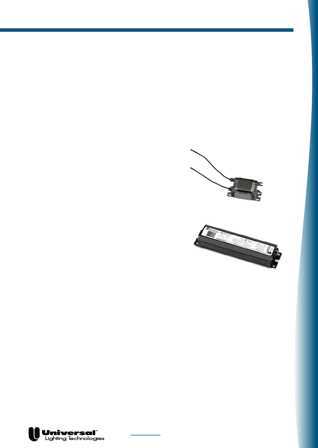
412-L-SLH-TC-P
1 L 12 1 L 12 2 L 12
412-L-TC-P 1 L 12 1 L 25 2 L 37
413-C-TC-P 1 L 9 1 L 29 2 R 30 1 L 29
420-L-TC-P 1 L 20 1 L 20 2 R 24 2 R 24 2 L 36
443-L-SLH-TC-P
1 L 12 1 L 12 2 R 12 2 R 12 2 L 12
445-RS-WS-TC-P
1 L 12 2 12 2 R 12 1 R 12
446-L-SLH-TC-P
1 L 12 1 L 12 2 R 12 2 R 12 2 L 12
446-LR-TC-P
1 L 22 1 L 22 2 R 26 2 R 26 2 L 36
447-LR-TC-P 1 L 10 1 L/R 10 2 R 13 2 R 13 2 L 18
447-LR-VLH-TC-P
1 L 10 1 L 10 2 R 13 2 R 13 2 L 18
458-L-SLH-TC-P
1 L 12 1 L 12 2 L 12 2 R 12
480-SLH-TC-P
1 L 18 1 L 18 2 R 46 2 R 46 2 L 65
480-XLH-TC-P
1 L 12 1 L 12 2 R 12 2 R 12 2 L 12
481-LH-TC-P 1 L 10 1 L 10 2 R 44 2 L 60
487-SLH-TC-P
1 L 18 1 L 18 2 R 46 2 R 46 2 L 65
487-XLH-TC-P
1 L 12 1 L 12 2 R 12 2 R 12 2 L 12
490-XLH-TC-P
1 L 18 1 L 18 2 R 33 2 R 33 2 L 51
502-A-TC-P 1 L 12 1 L 12 2 R 12 1 L 12 2 R 12
532-BR-TC-P 1 L 12 1 L 12 1 R 12 1 R 12
540-L-TC-P 1 L 20 1 L 20 2 R 25 2 R 25 2 L 37
546-B-TC-P 1 L 12 1 L 12 2 R 12 1 L 12
547-RS-WS-TC-P
1 L 12 2 L/R 12 2 R 12 1 R 12
554-L-TC-P 1 L 12 1 L 12 2 R 12 2 R 12 2 L 12
564-L-TC-P 1 L 10 1 L 10 2 R 13 2 R 13 2 L 16
567-L-TC 1 L 10 1 L 10 2 R 13 2 R 13 2 L 16
573-L-TC-P 1 L 12 1 L 12 2 R 12 2 R 12 2 L 12
595-L-TC-P 1 L 20 1 L 20 2 R 24 2 R 24 2 L 36
597-L-TC-P 1 L 10 1 L 10 2 R 13 2 R 13 2 L 16
631-LH-TC-P 1 L 18 1 L 18 2 R 20 2 R 20 2 L 32
698-L-SLH-TC
1 L 22 1 L 22 2 R 26 2 R 26 2 L 36
726-L-VLH-WS-TC-P
1 L 12 1 L 12 2 L 12 2 R 12 4 L/R 12
757-XLH-TC 1 L 18 1 L 18 2 R 46 2 R 46 2 L 65
778-XLH-TC 1 L 18 1 L 18 2 R 33 2 R 33 2 L 51
789-SLH-TC-P 1 L 10 1 L 10 2 R 10 2 R 10 2 L 10
806-BR-TC-P 1 L 68 1 L 68 1 R 44 1 R 44
806-SLH-TC-P
1 L 12 1 L 12 1 R 12 1 R 12
808-BR-TC-P 1 L 68 1 L 68 1 R 44 1 R 44
822-BR-TC-P 1 L 8 1 L 68 1 R 44
827-SLH-TC-P
1 L 12 1 L 12 1 R 12 1 R 12
828-BR-TC-P 1 12 1 L 12 1 R 12
831-TC 1 L 73 1 L 73 1 R 49 1 R 49
881-BR-TC-P 1 L 12 1 L 12 1 R 12 1 R 12
897-SLH-TC 1 L 12 1 L 12 1 R 12 1 R 12
930-K-TC-P 1 L 12 1 L 12 2 R 12 2 R 12 2 L 12
931-LH-TC-P 1 L 12 1 L 12 2 R 12 2 R 12 2 L 12
937-K-TC-P 1 L 12 1 L 12 2 R 12 2 R 12 2 L 12
CF1320H2P 1,1 L,R 9,18
M232SR120C 1 L 20 1 L 20 2 R 24 2 R 24 2 L 36
M232SR277C 1 L 20 1 L 20 2 R 24 2 R 24 2 L 36
W-589-D-TC-P
1 L 12 1 L 12 2 R 12 2 R 12 2 L 12
4105F2P 2 L 10
4105P 2 L 12
Lead Quantities (per color), Exits (L=Left, R=Right, B=Bottom) and Lengths (in inches, +/- 1”)
2 R 12
2 R 27
2 R 12
1 L 12 1 R 12
2 L 12
2 L 12
2 L 12
FOR MORE INFORMATION CALL
1-800-BALLAST
(225-5278)
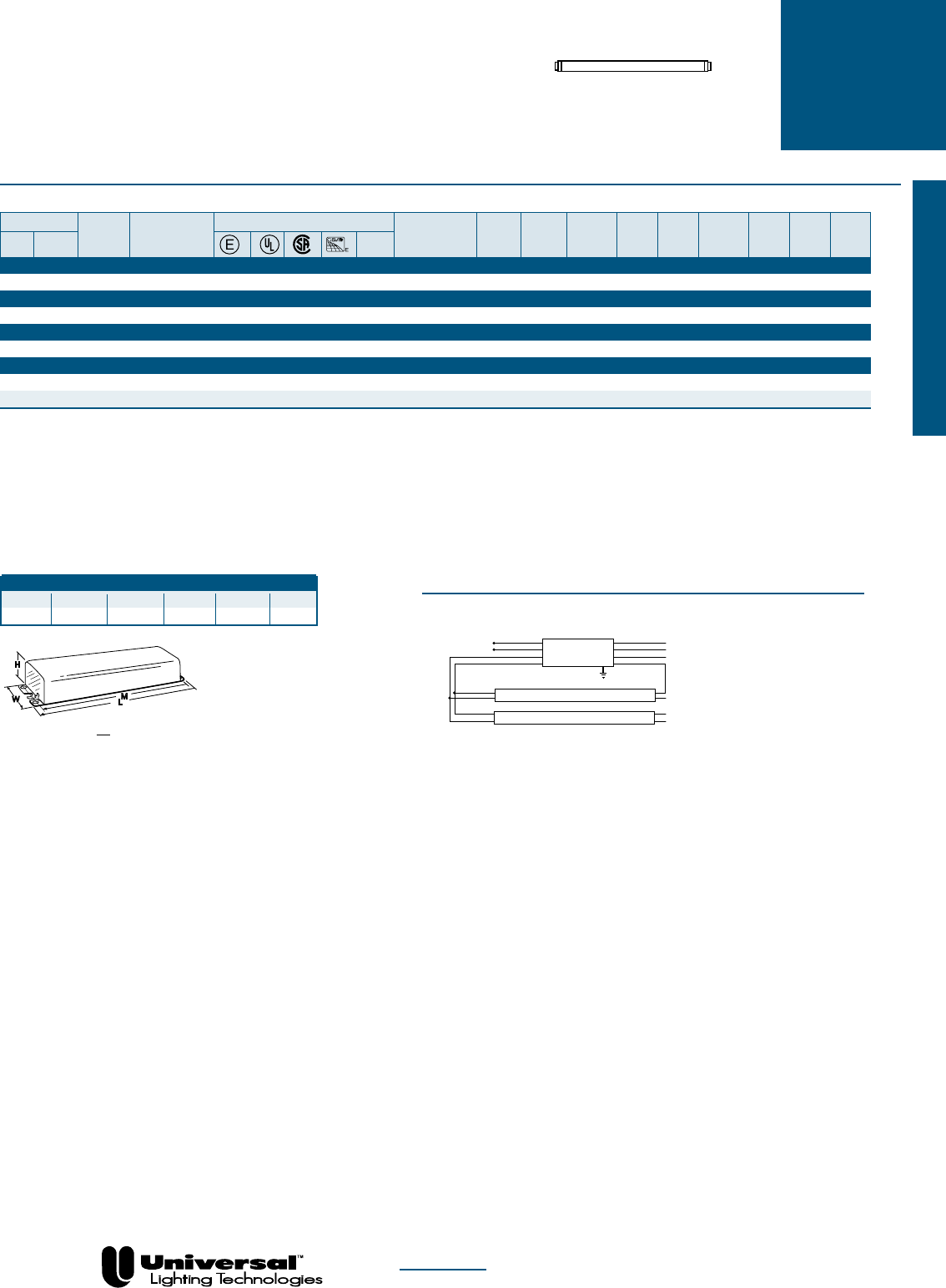
PAGE 1-10
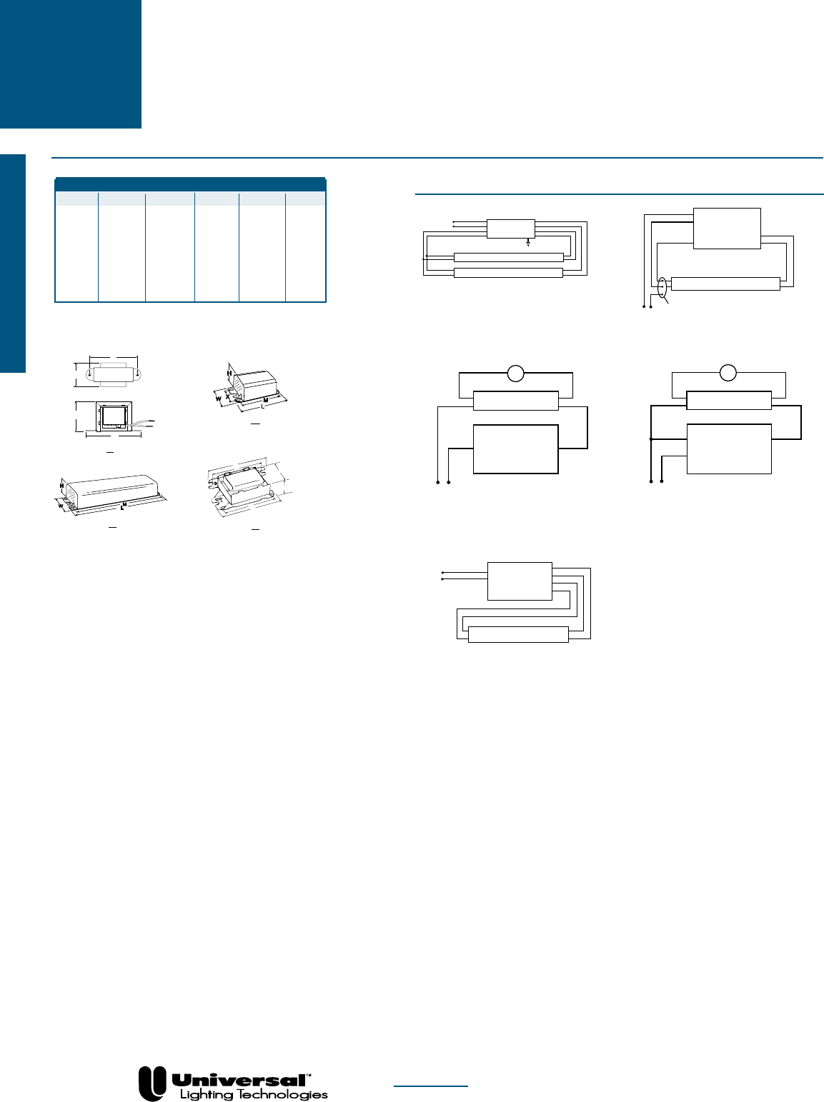
High Output Lamps
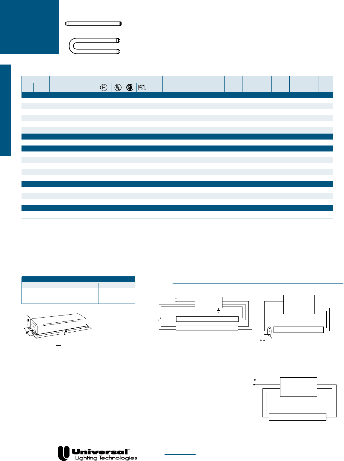
Fluorescent-Electromagnetic
T8 • 265 mA
• 4´ Lamp Applications
• OcTek™ Series Featured
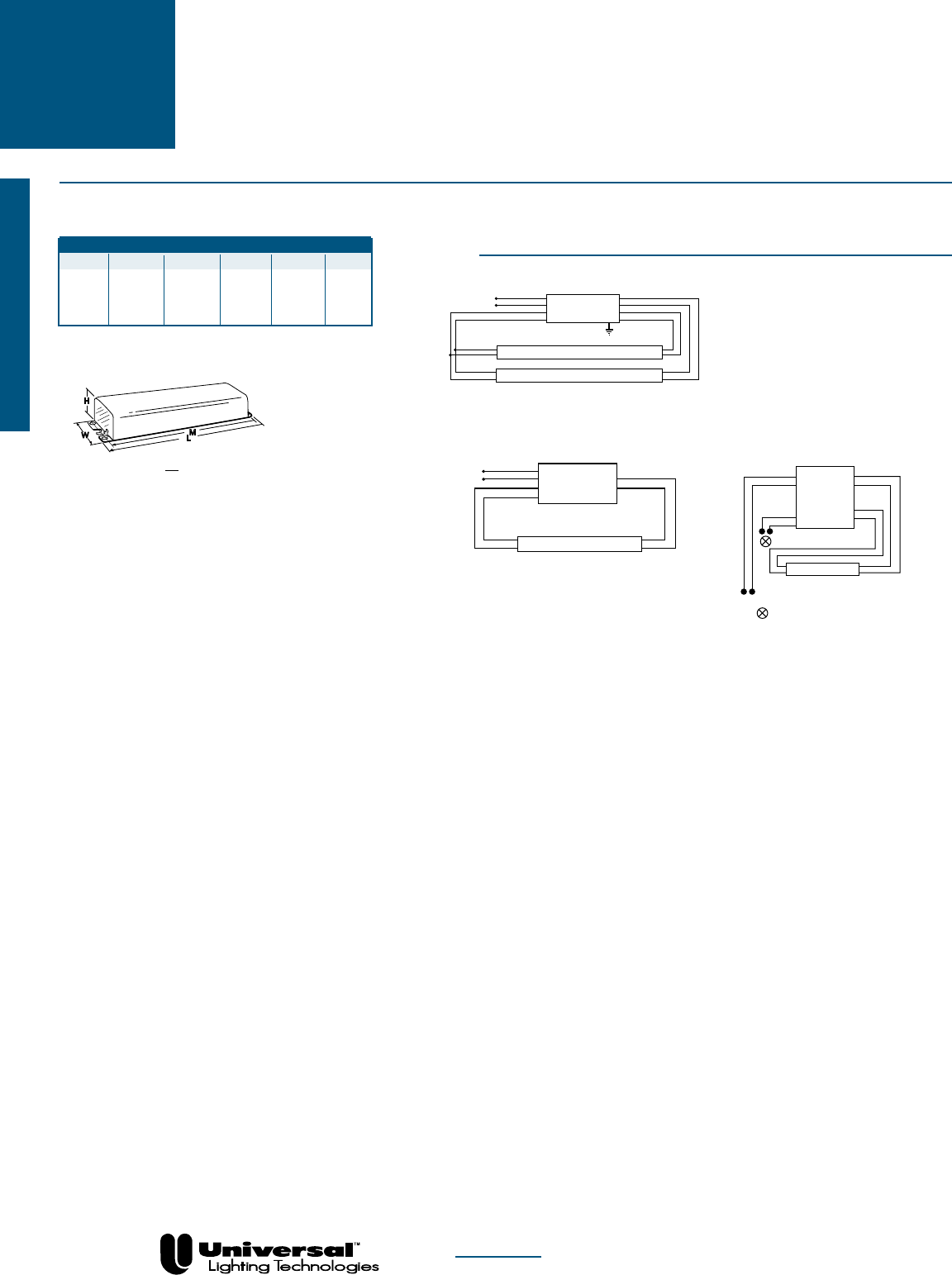
WIRING DIAGRAMS
Overall Dimensions Mounting Dimensions
Draw # L W H M X
D2 9 1/2 2 3/8 1 1/2 8 57/64 1
DIAGRAM 1
Diagram 1
White
Black
Yellow
Blue
Red
Line
BALLAST
Yellow
Blue
Red
LAMP
LAMP
W
H
L
M
D
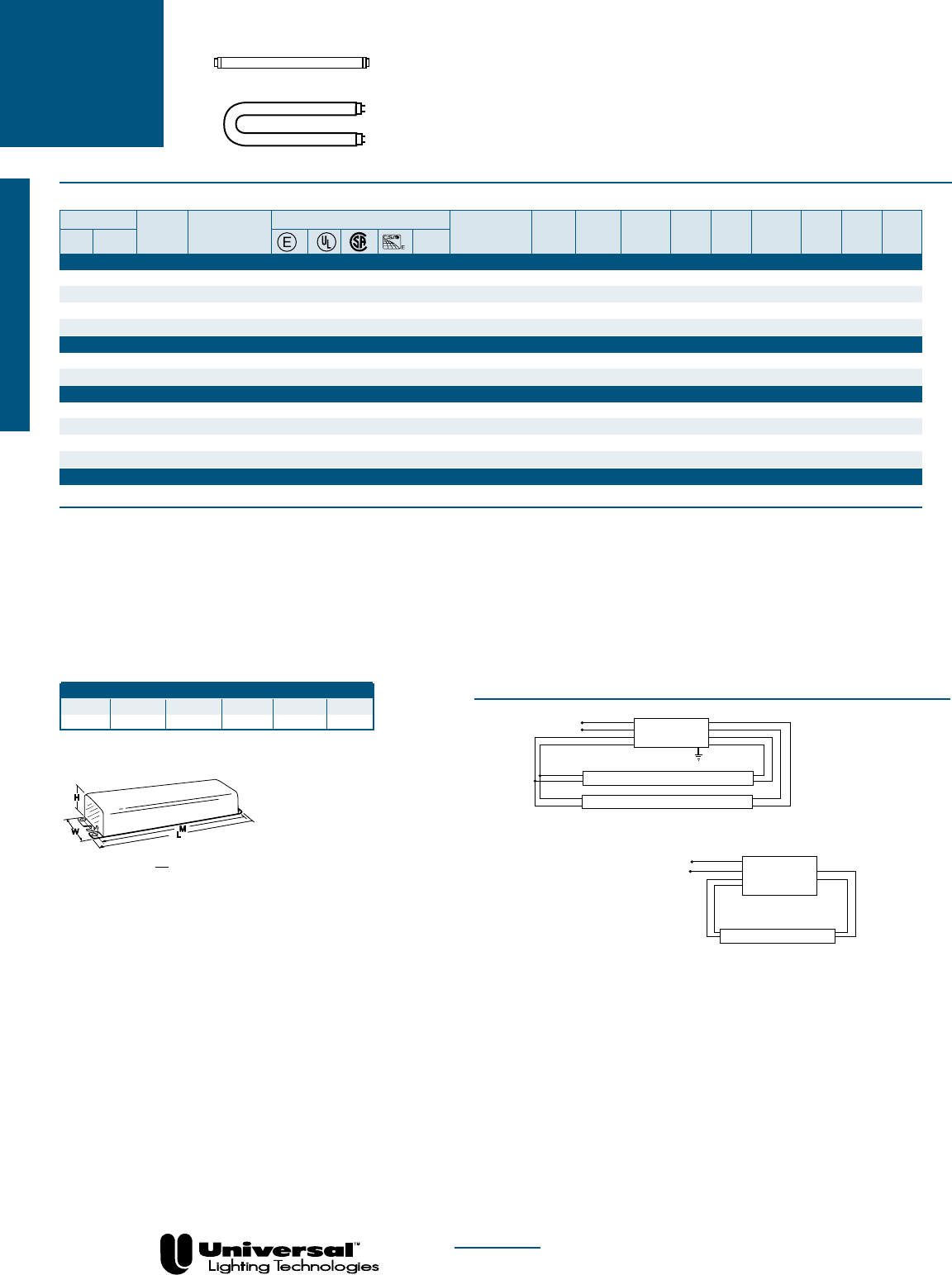
T8 U-Shaped Lamps
NOM
Lamp
Certification Line Input Ballast Min. F/C
Line Catalog Current Power Ballast Efficacy Crest THD Start Sound Wiring
Qty. Descr. Volts Number (Amps) (Watts) Factor Factor Factor % Temp Rating Diag. Dim.
F32T8 - High Power Factor OcTek®
2 Rapid 120 M232SR120C • • • • .65 74 .95 1.28 <1.7 <20 50/10 A 1 D2
2 Rapid 277 M232SR277C • • • .28 74 .95 1.28 <1.7 <20 50/10 A 1 D2
F32T8/U-HighPowerFactorOcTek™
2 Rapid 120 M232SR120C • • • • .65 74 .95 1.28 <1.7 <20 50/10 A 1 D2
2 Rapid 277 M232SR277C • • • .28 74 .95 1.28 <1.7 <20 50/10 A 1 D2
UNIVERSAL
®
ELECTROMAGNETIC
BALLASTS
FOR F32T8 and F32T8/U LAMPS
FOR MORE INFORMATION CALL
1-800-BALLAST
(225-5278)
PAGE 1-11
High Output Lamps
T12
UNIVERSAL
®
ELECTROMAGNETIC
BALLASTS
FOR F30T12, F30T12ES, and F40T12 LAMPS
• 430 and 460 mA
• 3´ and 4´ Lamp Applications
WIRING DIAGRAMS
Overall Dimensions Mounting Dimensions
Draw # L W H M X
D1 6 7/16 1 7/8 1 1/2 6 -
D2 9 1/2 2 3/8 1 1/2 8 57/64 1 11/16
D4 9 1/2 2 3/8 1 11/16 8 57/64 1 11/16
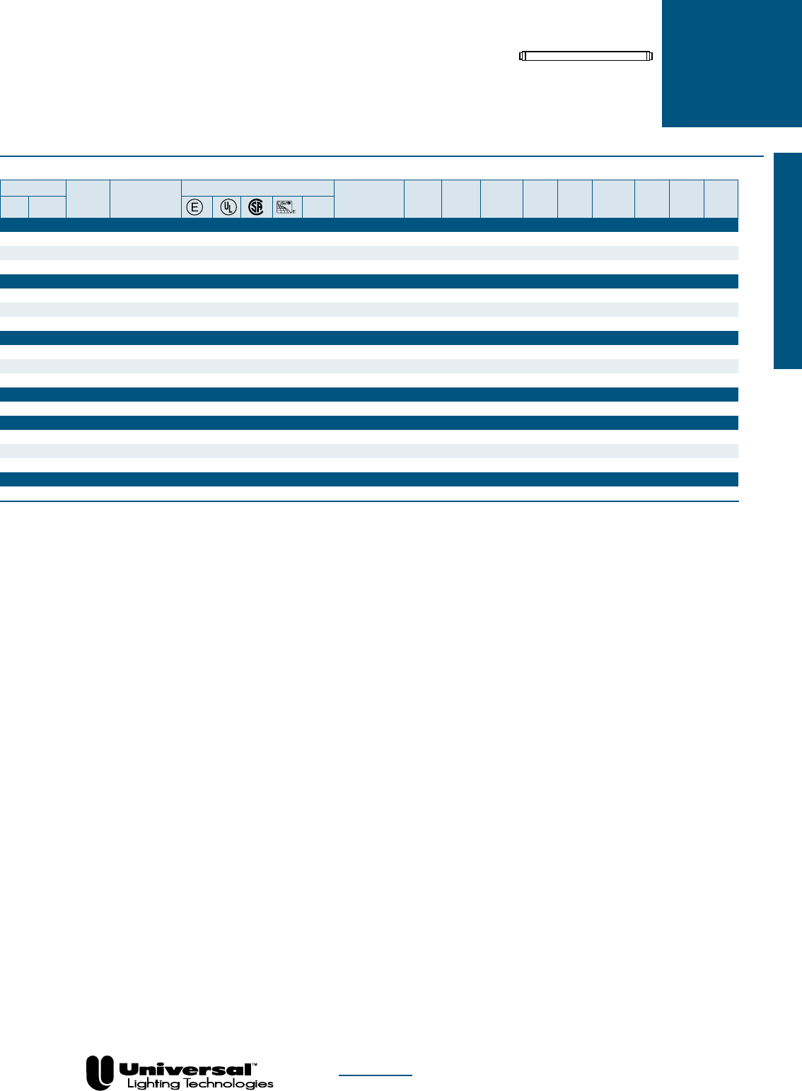
DIAGRAM 1
Diagram 1
White
Black
Yellow
Blue
Red
Line
BALLAST
Yellow
Blue
Red
LAMP
LAMP
DIAGRAM 8
White
Black
Blue
Red
Line
Red
Diagram 8
Use disconnect
lampholder only
BALLAST
LAMP
W
H
L
M
D
Fluorescent-Electromagnetic
DIAGRAM 42
BALLAST
Blue
Red
Line
LAMP
White
Black
Blue
Red
Diagram 42
NOM
❉
For Residential Use Only
★
Not for use with “U” lamps
◆
Not for use with Energy Saver “U” lamps
✚Operates at 50 or 60 Hz
n For Replacement Only
X For Distribution Only
Lamp
Certification Line Input Ballast Min. F/C
Line Catalog Current Power Ballast Efficacy Crest THD Start Sound Wiring
Qty. Descr. Volts Number (Amps) (Watts) Factor Factor Factor % Temp Rating Diag. Dim.
F30T12 - High Power Factor
2 Rapid 120 W-589-D-TC-P
n
• • .66 79 .90 1.14 <1.9 <20 0/-18 A 1 D4
2 Rapid 120 573-L-TC-P
X
• • .66 79 .95 1.21 <1.7 <20 60/15 A 1 D2
F30T12 - Normal Power Factor
1 Rapid 120 413-C-TC-P
❉
• • • .63 37 .72 1.95 <1.7 <10 50/10 A 8 D1
F30T12ES - High Power Factor
2 Rapid 120 W-589-D-TC-P
n
• • .58 68 .86 1.26 <1.9 <20 60/15 A 1 D4
2 Rapid 120 573-L-TC-P
X
• • .57 67 .89 1.33 <1.9 <20 50/10 A 1 D2
F40T12-HighPowerFactor
1 Rapid 120
412-L-SLH-TC-P★
n
• • • • • .45 52 .95 1.83 <1.7 <20 50/10 A 42 D2
1 Rapid 277
458-L-SLH-TC-P★
n
• • • • • .19 51 .95 1.86 <1.7 <20 50/10 A 42 D2
2 Hybrid 120 420-L-TC-P
◆
• • • • .62 72 .85 1.18 <1.7 <20 50/10 A 1 D2
2 Rapid 120 446-L-SLH-TC-P
n
• • • • • .75 89 .94 1.06 <1.7 <20 50/10 A 1 D2
2 Rapid 120 W-589-D-TC-P
n
• • .80 92 .88 0.96 <1.7 <20 0/-18 A 1 D4
2 Rapid 277 443-L-SLH-TC-P
n
• • • • • .34 90 .95 1.06 <1.7 <20 50/10 A 1 D2
2 Rapid 347 698-L-SLH-TC • • • • .27 92 .95 1.03 <1.7 <20 50/10 A 1 D2
F40T12-NormalPowerFactor
1 Rapid 120 413-C-TC-P
❉
• • • .53 36 .61 1.69 <1.7 <20 50/10 A 8 D1
FOR MORE INFORMATION CALL
1-800-BALLAST
(225-5278)
PAGE 1-12
High Output Lamps
Fluorescent-Electromagnetic
T12 UNIVERSAL
®
ELECTROMAGNETIC
BALLASTS
FOR F40T12ES, F40T12/U, F40T12ES/U, F48“ 25W/UTLS
AND WORKLITE 25
LAMPS
• 430 and 460 mA
• 4´ Energy Saver Lamp
Applications
• Energy Efficient
WIRING DIAGRAMS
Overall Dimensions Mounting Dimensions
Draw # L W H M X
D1 6 7/16 1 7/8 1 1/2 6 -
D2 9 1/2 2 3/8 1 1/2 8 57/64 1
11/16
DIAGRAM 1
Diagram 1
White
Black
Yellow
Blue
Red
Line
BALLAST
Yellow
Blue
Red
LAMP
LAMP
DIAGRAM 8
White
Black
Blue
Red
Line
Red
Diagram 8
Use disconnect
lampholder only
BALLAST
LAMP
W
H
L
M
D
DIAGRAM 42
BALLAST
Blue
Red
Line
LAMP
White
Black
Blue
Red
Diagram 42
T8 U-Shaped Lamps
NOM
❉
For Residential Use Only
★
Not for use with “U” lamps
◆
Not for use with Energy Saver “U” lamps
n For Replacement Only
Lamp
Certification Line Input Ballast Min. F/C
Line Catalog Current Power Ballast Efficacy Crest THD Start Sound Wiring
Qty. Descr. Volts Number (Amps) (Watts) Factor Factor Factor % Temp Rating Diag. Dim.
F40T12ES-HighPowerFactor
1 Rapid 120
412-L-SLH-TC-P★
n
• • • • • .38 44 .88 2.00 <1.9 <20 60/15 A 42 D2
1 Rapid 277
458-L-SLH-TC-P★
n
• • • • • .17 44 .88 2.00 <1.85 <20 60/15 A 42 D2
2 Hybrid 120 420-L-TC-P
◆
• • • • .50 59 .80 1.36 <1.9 <20 60/15 A 1 D2
2 Rapid 120
446-L-SLH-TC-P
n
• • • • • .65 74 .90 1.22 <1.9 <20 60/15 A 1 D2
2 Rapid 277
443-L-SLH-TC-P
n
• • • • • .28 74 .90 1.22 <1.9 <20 60/15 A 1 D2
2 Rapid 347 698-L-SLH-TC • • • .24 78 .90 1.15 <1.9 <20 60/15 A 1 D2
F40T12ES-NormalPowerFactor
1 Rapid 120 413-C-TC-P
❉
• • • .61 33 .68 2.06 <1.9 <20 60/15 A 8 D1
F40T12/U-HighPowerFactor
2 Hybrid 120 420-L-TC-P
◆
• • • • .64 74 .83 1.12 <1.7 <32 50/10 A 1 D2
2 Rapid 120
446-L-SLH-TC-P
n
• • • • • .76 90 .93 1.03 <1.7 <20 50/10 A 1 D2
2 Rapid 120 W-589-D-TC-P
n
• • .84 97 .92 0.95 <1.7 <20 0/-18 A 1 D4
2 Rapid 277
443-L-SLH-TC-P
n
• • • • • .34 92 .95 1.03 <1.7 <20 50/10 A 1 D2
2 Rapid 347 698-L-SLH-TC • • • .27 92 .93 1.01 <1.7 <20 50/10 A 1 D2
F40T12ES/U-HighPowerFactor
2 Rapid 120
446-L-SLH-TC-P
n
• • • • • .65 74 .90 1.22 <1.9 <20 60/15 A 1 D2
2 Rapid 277
443-L-SLH-TC-P
n
• • • • • .28 74 .90 1.22 <1.9 <20 60/15 A 1 D2
2 Rapid 347 698-L-SLH-TC • • • .24 78 .90 1.15 <1.9 <20 60/15 A 1 D2
F48”25W/UTLS&WORKLITE-NormalPowerFactor
1 Rapid 120 413-C-TC-P❉ • • • .51 32 .90 2.79 <1.7 <20 50/10 A 8 D1
FOR MORE INFORMATION CALL
1-800-BALLAST
(225-5278)
PAGE 1-13
High Output Lamps
T12
HO
UNIVERSAL
®
ELECTROMAGNETIC
BALLASTS
FOR F24, F30, F36, F42 AND F48T12HO LAMPS
• 800 mA
• 2-3 1/2´ Lamp Applications
• Standard & Weatherproof Models
See page 1-3 for additional information on weatherproof applications.
Fluorescent-Electromagnetic
NOM
See page 1-16 for Dimensions and Wiring Diagrams
Lamp
Certification Line Input Ballast Min. F/C
Line Catalog Current Power Ballast Efficacy Crest THD Start Sound Wiring
Qty. Descr. Volts Number (Amps) (Watts) Factor Factor Factor % Temp Rating Diag. Dim.
F24T12HO-HighPowerFactor
2 Rapid 120 490-XLH-TC-P • • .95 103 .81 0.79 <2.0 >32 -20/-29 B 1 D7
2 Rapid 120 631-LH-TC-P❁ • • 1.13 100 .83 0.83 <2.0 <32 -20/-29 B 1 D6
2 Rapid 347 778-XLH-TC • .31 103 .81 0.79 <2.0 >32 -20/-29 B 1 D7
F36T12HO-HighPowerFactor
2 Rapid 120 490-XLH-TC-P • • 1.06 121 .84 0.69 <2.0 <32 50/10 B 1 D7
2 Rapid 120 631-LH-TC-P✪ • • 1.20 122 .85 0.69 <1.9 <20 -20/-29 B 1 D6
2 Rapid 347 778-XLH-TC • .41 141 .80 0.57 <2.0 <32 -20/-29 B 1 D7
F42T12HO-HighPowerFactor
2 Rapid 120 490-XLH-TC-P • • 1.12 130 .86 0.66 <2.0 <32 50/10 B 1 D7
F48T12HO-HighPowerFactor
1 Rapid 120 481-LH-TC-P
▼
• • .79 82 .84 1.02 <1.9 >32 -20/-29 B 12 D7
1 Rapid 120 490-XLH-TC-P▼ • • .82 82 .81 0.99 <2.0 >32 -20/-29 B 15 D7
1 Rapid 120 631-LH-TC-P▼ • • 1.05 82 .83 1.02 <1.9 <32 -20/-29 B 15 D6
1 Rapid 347 778-XLH-TC▼ • .32 83 .79 0.95 <2.0 >32 -20/-29 B 15 D7
2 Rapid 120 490-XLH-TC-P • • 1.18 139 .87 0.63 <2.0 <20 -20/-29 B 1 D7
2 Rapid 120 631-LH-TC-P • • 1.25 137 .85 0.62 <1.7 <20 -20/-29 B 1 D6
2 Rapid 347 778-XLH-TC • .42 139 .86 0.62 <2.0 <32 -20/-29 B 1 D7
❁
Power Factor Corrected to 75% for (2) F24T12HO
✪
Power Factor Corrected to 85% for (2) F36T12HO
▼
Power Factor Corrected to >70%
XFor Distribution Only
FOR MORE INFORMATION CALL
1-800-BALLAST
(225-5278)
PAGE 1-14
High Output Lamps
T12
HO
• 800-840 mA
• 4´-5´4´´ Lamp Applications
• Standard and Weatherproof
Models
UNIVERSAL
®
ELECTROMAGNETIC
BALLASTS
FOR F48T12HOES, F60T12HO AND
F64T12HO LAMPS
NOM
Lamp
Certification Line Input Ballast Min. F/C
Line Catalog Current Power Ballast Efficacy Crest THD Start Sound Wiring
Qty. Descr. Volts Number (Amps) (Watts) Factor Factor Factor % Temp Rating Diag. Dim.
F48T12HOES-HighPowerFactor
1 Rapid 120 481-LH-TC-P▼ • • .77 75 .79 1.05 <1.9 >32 60/15 B 12 D7
1 Rapid 120 490-XLH-TC-P
▼
• • .80 76 .78 1.03 <2.0 >32 60/15 B 15 D7
1 Rapid 120 631-LH-TC-P▼ • • 1.03 75 .77 1.03 <1.9 <32 60/15 B 15 D6
1 Rapid 347 778-XLH-TC▼ • .31 78 .75 0.97 <2.0 >32 60/15 B 15 D7
2 Rapid 120 490-XLH-TC-P • • 1.07 124 .83 0.67 <2.0 <32 60/15 B 1 D7
2 Rapid 120 631-LH-TC-P • • 1.15 124 .80 0.64 <1.9 <20 60/15 B 1 D6
2 Rapid 347 778-XLH-TC • .39 126 .81 0.64 <2.0 <32 60/15 B 1 D7
F60T12HO-HighPowerFactor
1 Rapid 120 481-LH-TC-P • • .86 100 .87 0.87 <1.9 <32 -20/-29 B 12 D7
1 Rapid 120 490-XLH-TC-P • • .92 99 .83 0.84 <2.0 >32 -20/-29 B 15 D7
1 Rapid 120 631-LH-TC-P
▼
• • 1.08 94 .85 0.90 <1.7 <32 -20/-29 B 15 D6
1 Rapid 347 778-XLH-TC▼ • .34 96 .82 0.85 <2.0 >32 -20/-29 B 15 D7
2 Rapid 120 490-XLH-TC-P • • 1.42 169 .89 0.53 <2.0 <20 -20/-29 B 1 D7
2 Rapid 347 778-XLH-TC • .49 169 .88 0.52 <2.0 <20 -20/-29 B 1 D7
F64T12HO-HighPowerFactor
1 Rapid 120 481-LH-TC-P • • .90 102 .87 0.85 <1.9 <32 -20/-29 B 12 D7
1 Rapid 120 490-XLH-TC-P • • .93 101 .84 0.83 <1.9 >32 -20/-29 B 15 D7
1 Rapid 347 778-XLH-TC▼ • .35 103 .82 0.80 <2.0 >32 -20/-29 B 15 D7
2 Rapid 120 490-XLH-TC-P • • 1.50 178 .89 0.50 <1.9 <20 -20/-29 B 1 D7
2 Rapid 347 778-XLH-TC • .52 178 .93 0.52 <2.0 <20 -20/-29 B 1 D7
▼
Power Factor Corrected to >70%
X For Distribution Only
Fluorescent-Electromagnetic
See page 1-16 for Dimensions and Wiring Diagrams
FOR MORE INFORMATION CALL
1-800-BALLAST
(225-5278)
PAGE 1-15
High Output Lamps
T12
HO
UNIVERSAL
®
ELECTROMAGNETIC
BALLASTS
FOR F72T12HO, F84T12HO, F96T12HO
AND F96T12HOES LAMPS
• 800 - 840 mA
• 6´ - 8´ Lamp Applications
• Standard, Weatherproof
& Tanning Models
See page 1-3 for additional information on weatherproof applications.
Fluorescent-Electromagnetic
NOM
Lamp
Certification Line Input Ballast Min. F/C
Line Catalog Current Power Ballast Efficacy Crest THD Start Sound Wiring
Qty. Descr. Volts Number (Amps) (Watts) Factor Factor Factor % Temp Rating Diag. Dim.
F72T12HO-HighPowerFactor
1 Rapid 120 481-LH-TC-P • • .92 106 .89 0.84 <1.9 <32 -20/-29 B 12 D7
1 Rapid 120 490-XLH-TC-P • • .95 107 .86 0.80 <2.0 >32 -20/-29 B 15 D7
1 Rapid 347 778-XLH-TC
✜
• .35 106 .84 0.79 <2.0 >32 -20/-29 B 15 D7
2 Rapid 120 480-SLH-TC-P • • • • • 1.69 196 .97 0.49 <1.9 <20 -20/-29 B 1 D7
2 Rapid 120 480-XLH-TC-P
n
• • 1.69 196 .97 0.49 <1.9 <20 -20/-29 B 1 D7
2 Rapid 120 490-XLH-TC-P • • 1.50 177 .92 0.52 <1.7 <10 -20/-29 B 1 D7
2 Rapid 277 487-SLH-TC-P • • • • • .74 197 .96 0.48 <1.7 <20 -20/-29 B 1 D7
2 Rapid 277 487-XLH-TC-P
n
• • .78 208 .95 0.46 <1.7 <20 -20/-29 B 1 D7
2 Rapid 347 778-XLH-TC • .54 187 .95 0.51 <1.7 <10 -20/-29 B 1 D7
F84T12HO-HighPowerFactor
1 Rapid 120 481-LH-TC-P • • 1.02 119 .88 0.74 <1.9 <32 -20/-29 B 12 D7
2 Rapid 120 480-SLH-TC-P • • • • • 1.87 220 .93 0.42 <1.9 <20 -20/-29 B 1 D7
2 Rapid 120 480-XLH-TC-P
n
• • 1.98 235 .93 0.40 <1.9 <20 -20/-29 B 1 D7
2 Rapid 277 487-SLH-TC-P • • • • • .87 235 .97 0.41 <1.9 <20 -20/-29 B 1 D7
2 Rapid 277 487-XLH-TC-P
n
• • .89 244 .95 0.39 <1.9 <20 -20/-29 B 1 D7
F96T12HO-HighPowerFactor
1 Rapid 120 481-LH-TC-P • • 1.16 136 .91 0.67 <1.9 <20 -20/-29 B 12 D7
1 Rapid 120 490-XLH-TC-P • • 1.10 124 .85 0.65 <2.0 <20 -20/-29 B 15 D7
1 Rapid 347 778-XLH-TC • .41 137 .83 0.71 <2.0 <32 -20/-29 B 15 D7
2 Rapid 120 480-SLH-TC-P • • • • • 1.99 237 .96 0.41 <1.7 <10 -20/-29 B 1 D7
2 Rapid 120 480-XLH-TC-P
n
• • 2.15 246 .96 0.39 <1.7 <10 -20/-29 B 1 D7
2 Rapid 277 487-SLH-TC-P • • • • • .87 237 .95 0.40 <1.7 <10 -20/-29 B 1 D7
2 Rapid 277 487-XLH-TC-P
n
• • .95 249 .97 0.39 <1.7 <10 -20/-29 B 1 D7
F96T12HOES-HighPowerFactor
1 Rapid 120 481-LH-TC-P • • .96 110 .84 0.77 <1.9 <32 60/15 B 12 D7
1 Rapid 120 490-XLH-TC-P • • .94 106 .81 0.76 <2.0 <32 60/15 B 15 D7
1 Rapid 347 778-XLH-TC • .37 116 .83 0.71 <2.0 <32 60/15 B 15 D7
2 Rapid 120 480-SLH-TC-P • • • • • 1.72 202 .89 0.44 <1.9 <20 60/15 B 1 D7
2 Rapid 120 480-XLH-TC-P
n
• • 1.80 209 .89 0.43 <1.9 <20 60/15 B 1 D7
2 Rapid 277 487-SLH-TC-P • • • • • .75 205 .91 0.44 <1.9 <20 60/15 B 1 D7
2 Rapid 277 487-XLH-TC-P
n
• • .83 223 .92 0.41 <1.9 <20 60/15 B 1 D7
✜
Power Factor Corrected to >85%
nFor Replacement Only
X For Distribution Only
See page 1-16 for Dimensions and Wiring Diagrams
FOR MORE INFORMATION CALL
1-800-BALLAST
(225-5278)
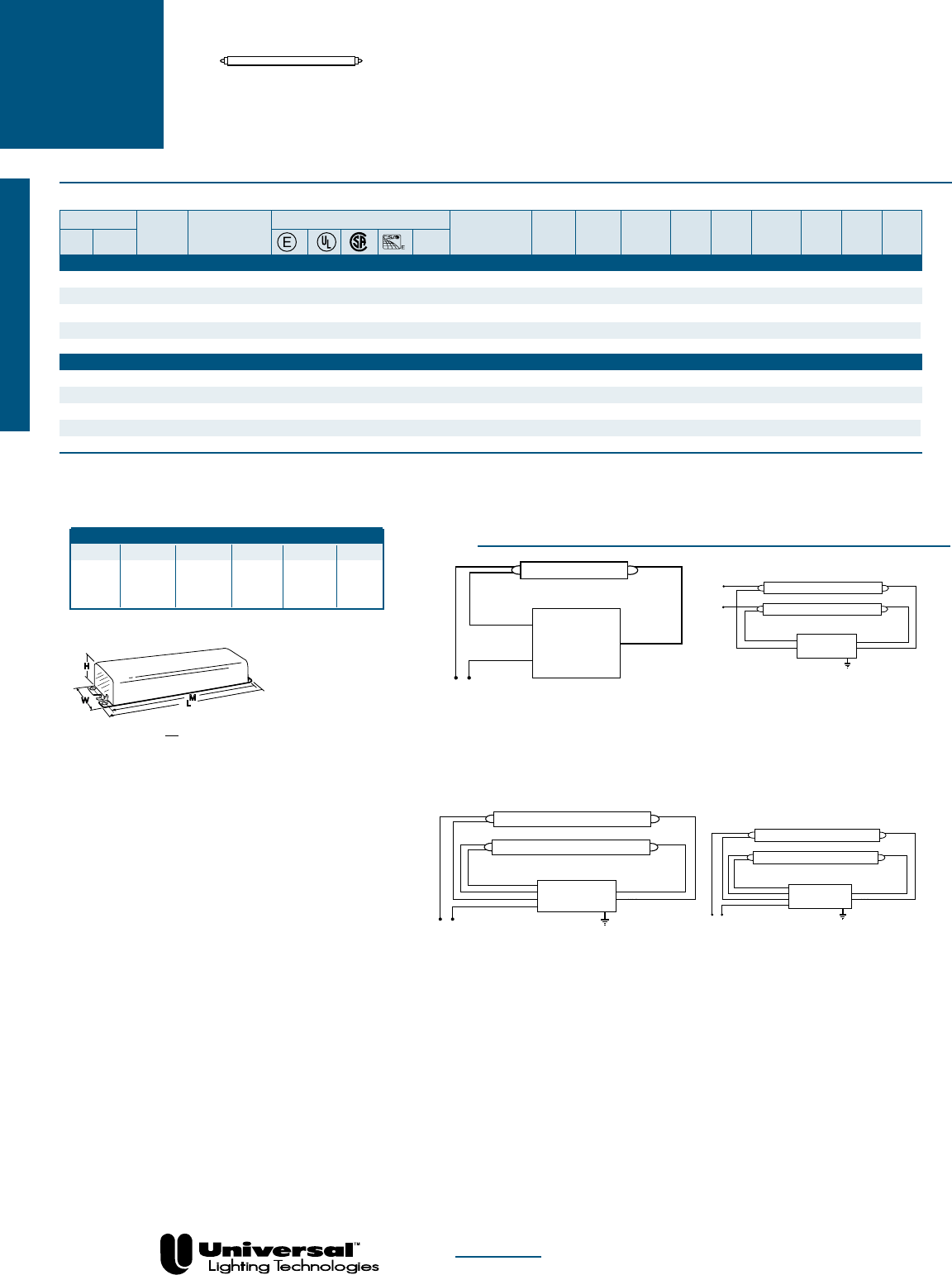
WIRING DIAGRAMS
Overall Dimensions Mounting Dimensions
Draw # L W H M X
D6 11 3/4 3 1/8 1 25/32 11 9/64 2
D7 11 3/4 3 3/16 1 5/8 11 9/64 2
D8 14 5/16 3 3/16 2 5/8 13 3/4 2
D9 19 3/16 3 3/16 2 5/8 18 5/8 2
DIAGRAM 1
Diagram 1
White
Black
Yellow
Blue
Red
Line
BALLAST
Yellow
Blue
Red
LAMP
LAMP
DIAGRAM 12
Diagram 12
BALLAST
Blue
Red
Line
LAMP
White
Black
Blue
Red
W
H
L
M
D
DIAGRAM 15
Diagram 15
Line
Yellow
Red
White
Black
Yellow
Blue
Red
Blue
INSULATE EACH YELLOW LEAD
INDIVIDUALLY
BALLAST
LAMP
PAGE 1-16
Fluorescent-Electromagnetic
T12
HO & VHO UNIVERSAL
®
ELECTROMAGNETIC
BALLASTS
FOR MORE INFORMATION CALL
1-800-BALLAST
(225-5278)
PAGE 1-17
High Output Lamps
T12
VHO
UNIVERSAL
®
ELECTROMAGNETIC
BALLASTS
FOR F72PG17, F72T12VHO, F96PG17, F96PG17ES,
F96T12VHO AND F96T12VHOES LAMPS
•1500 - 1580 mA
• 4´ and 6´ VHO, SHO & PG Lamp
Applications
Fluorescent-Electromagnetic
NOM
See page 1-18 for Dimensions and Wiring Diagrams
Lamp
Certification Line Input Ballast Min. F/C
Line Catalog Current Power Ballast Efficacy Crest THD Start Sound Wiring
Qty. Descr. Volts Number (Amps) (Watts) Factor Factor Factor % Temp Rating Diag. Dim.
F72PG17-HighPowerFactor
2 Rapid 120 930-K-TC-P
❷X
• • 3.05 360 .95 0.26 <1.7 <20 -20/-29 D 1 D8
2 Rapid 120 931-LH-TC-P①
X
• • 2.77 303 .82 0.27 <1.7 <20 -20/-29 D 1 D8
2 Rapid 277 937-K-TC-P❷
X
• • 1.26 341 .92 0.27 <1.7 <20 -20/-29 D 1 D8
F72T12VHO-HighPowerFactor
2 Rapid 120 930-K-TC-P❷
X
• • 3.05 360 .95 0.26 <1.7 <20 -20/-29 D 1 D8
2 Rapid 120 931-LH-TC-P
①X
• • 2.77 303 .80 0.26 <1.7 <20 -20/-29 D 1 D8
2 Rapid 277 937-K-TC-P
❷X
• • 1.26 341 .91 0.27 <1.7 <20 -20/-29 D 1 D8
F96PG17-HighPowerFactor
2 Rapid 120 930-K-TC-P
❷X
• • 3.83 446 .98 0.22 <1.7 <20 -20/-29 D 1 D8
2 Rapid 120 931-LH-TC-P①
X
• • 3.25 380 .83 0.22 <1.7 <20 -20/-29 D 1 D8
2 Rapid 277 937-K-TC-P
❷X
• • 1.61 429 .95 0.22 <1.7 <20 -20/-29 D 1 D8
F96PG17ES-HighPowerFactor
2 Rapid 120 931-LH-TC-P
X
• • 2.88 333 .75 0.22 <1.7 <32 60/15 D 1 D8
F96T12VHO-HighPowerFactor
2 Rapid 120 930-K-TC-P
❷X
• • 4.10 482 .99 0.21 <1.7 <20 -20/-29 D 1 D8
2 Rapid 120 931-LH-TC-P①
X
• • 3.83 431 .93 0.22 <1.7 <20 -20/-29 D 1 D8
2 Rapid 277 937-LH-TC-P
❷X
• • 1.64 450 .95 0.21 <1.7 <20 -20/-29 D 1 D8
F96T12VHOES-HighPowerFactor
2 Rapid 120 931-LH-TC-P
X
• • 3.09 361 .83 0.23 <1.7 <20 60/15 D 1 D8
❷
Cannot be used with T10 or T10J lamps
①
May be used with equivalent T10 or T10J Lamps
X For Distribution Only
FOR MORE INFORMATION CALL
1-800-BALLAST
(225-5278)
CIRCLINE UNIVERSAL
®
ELECTROMAGNETIC
BALLASTS
FOR 20, 22, 32 AND 40 WATT LAMPS
PAGE 1-18
Circline Lamps
• 430 mA
• 20-40 Watt Lamp Applications
WIRING DIAGRAMS
DIAGRAM 1
Overall Dimensions Mounting Dimensions
Draw # L W H M X
D1 6 7/16 1 7/8 1 1/2 6 -
D4 9 1/2 2 3/8 1 11/16 8 57/64 1
11/16
Diagram 1
White
Black
Yellow
Blue
Red
Line
BALLAST
Yellow
Blue
Red
LAMP
LAMP
W
H
L
M
D
BALLAST
Line
LAMP
White
Black
Blue
Diagram 22
S
S
DIAGRAM 29
Blue
Red
Line White
Black Red
Metal contacts
lamp to fixture
White
Diagram 29
BALLAST
DIAGRAM 28
BALLAST
Yellow
Blue
Red
Line
LAMP
White
Black
White
Diagram 28
Mount lamp within 1/2" of
grounded metal reflector
NOM
DIAGRAM 22
Lamp
Certification Line Input Ballast Min. F/C
Line Catalog Current Power Ballast Efficacy Crest THD Start Sound Wiring
Qty. Descr. Volts Number (Amps) (Watts) Factor Factor Factor % Temp Rating Diag. Dim.
FC6T9(20Watt)-NormalPowerFactor
1 Preheat 120 200-C-S-P
♣X
• • .40 29 1.01 3.47 <1.7 <10 50/10 A 28 D11
1 Rapid 120
547-RS-WS-TC-P
X
• • .64 27 .90 3.30 <1.7 <10 50/10 A 29 D1
FC8T9(22Watt)-NormalPowerFactor
1 Preheat 120 200-C-S-P
♣X
• • .24 22 .93 4.19 <1.7 <10 50/10 A 28 D11
1 Rapid 120
547-RS-WS-TC-P✩
X
• • .60 30 .85 2.83 <1.7 <10 50/10 A 29 D1
FC12T9(32Watt)-HighPowerFactor
2 Rapid 120 W-589-D-TC-P
❸n
• • .64 76 .89 1.17 <1.9 <20 0/-18 A 1 D4
FC12T9(32Watt)-NormalPowerFactor
1 Preheat 120 202-B-TC-P
❶X
• • .67 37 .91 2.44 <1.7 <10 50/10 A 22 D11
1 Preheat 120 202-SB-TC-P♣
X
• • .67 37 .91 2.44 <1.7 <10 50/10 A 28 D11
1 Rapid 120
445-RS-WS-TC-P✩
X
• • .60 35 .68 1.97 <1.7 <20 50/10 A 29 D1
FC16T9(40Watt)-HighPowerFactor
2 Rapid 120 W-589-D-TC-P❸
n
• • .88 98 .95 0.96 <1.7 <20 0/-18 A 1 D4
FC16T9(40Watt)-NormalPowerFactor
1 Rapid 120
445-RS-WS-TC-P✩
X
• • .55 33 .60 1.83 <1.7 <20 50/10 A 29 D1
✩
Also available in White Cans
♥
Only available in White Cans
♣
Starter is built in as an integral component
❶
Requires Starter
❸
May be used with any combination of F30T12/RS, F40T12/RS, FC12T9/RS and FC16T9/RS
nFor Replacement Only
XFor Distribution Only
Fluorescent-Electromagnetic

FOR MORE INFORMATION CALL
1-800-BALLAST
(225-5278)
UNIVERSAL
®
ELECTROMAGNETIC
BALLASTS
FOR F24 - F84T12 LAMPS
PAGE 1-19
Slimline Lamps
T12
SLIMLINE
• 425-440 mA
• 2´-7´ Lamp Applications
• Slimline
NOM
See page 1-23 for Dimensions and Wiring Diagrams
Fluorescent-Electromagnetic
Lamp
Certification Line Input Ballast Min. F/C
Line Catalog Current Power Ballast Efficacy Crest THD Start Sound Wiring
Qty. Descr. Volts Number (Amps) (Watts) Factor Factor Factor % Temp Rating Diag. Dim.
F24T12-HighPowerFactor
2 Instant 277 532-BR-TC-P
◗X
• • .29 60 .96 1.60 <1.85 <32 32/0 B 40 D6
F36T12-HighPowerFactor
2 Instant 120 213-TC-P
X
• • • .70 77 .95 1.24 <1.85 >32 50/10 B 39 D10
2 Instant 277 532-BR-TC-P
◗X
• • .34 75 .93 1.24 <1.85 <32 32/0 B 40 D12
F40T12/IS-BiPin-HighPowerFactor
2 Instant 120 213-TC-P
X
• • • .80 94 .92 0.98 <1.85 <20 50/10 B 39 D10
2 Instant 277 532-BR-TC-P
X
• • .37 94 .92 0.98 <1.85 <32 32/0 B 40 D12
F42T12-HighPowerFactor
2 Instant 120 213-TC-P
X
• • • .74 86 .93 1.09 <2.0 <32 50/10 B 39 D10
2 Instant 277 532-BR-TC-P
X
• • .34 84 .94 1.11 <1.85 <32 32/0 B 40 D12
F48T12-HighPowerFactor
2 Instant 120 213-TC-P
X
• • • .79 95 .92 0.89 <1.85 <20 50/10 B 39 D10
2 Instant 277 532-BR-TC-P
X
• • .35 95 .96 1.01 <1.85 <32 32/0 B 40 D12
F48T12ES-HighPowerFactor
2 Instant 120 213-TC-P
X
• • • .72 80 .91 1.14 <2.0 <32 60/15 B 39 D10
2 Instant 277 532-BR-TC-P
X
• • .32 82 .94 1.15 <2.0 <32 60/15 B 40 D12
F60T12-HighPowerFactor
2 Instant 120 881-BR-TC-P
❏X
• • .96 109 .84 0.77 <1.85 <32 0/-18 C 39 D6
F64T12-HighPowerFactor
2 Instant 120 881-BR-TC-P
❏X
• • 1.05 119 .84 0.71 <1.85 <32 0/-18 C 39 D6
F72T12-HighPowerFactor
1 Instant 120 822-BR-TC-P • • • .72 81 .95 1.17 <1.85 <32 0/-18 C 34 D6
1 Instant 277 828-BR-TC-P
X
• • .30 78 .92 1.18 <1.85 <32 0/-18 C 34 D6
2 Instant 120 806-SLH-TC-P
n
• • • • • 1.13 133 1.01 0.76 <1.85 <20 50/10 C 39 D6
2 Instant 120 881-BR-TC-P
X
• • 1.03 120 .82 0.69 <1.85 <32 0/-18 C 39 D6
2 Instant 277 827-SLH-TC-P
n
• • • • • .49 135 .93 0.69 <1.85 <20 50/10 C 40 D12
2 Instant 347 897-SLH-TC
X
• • • .37 123 .91 0.74 <1.85 <32 50/10 C 65 D12
F84T12-HighPowerFactor
1 Instant 120 822-BR-TC-P • • • .77 89 .96 1.09 <1.85 <32 0/-18 C 34 D6
1 Instant 277 828-BR-TC-P
X
• • .33 86 .94 1.09 <1.85 <32 0/-18 C 34 D6
2 Instant 120 806-SLH-TC-P
n
• • • • • 1.26 143 .95 0.67 <1.85 <20 50/10 C 39 D6v
2 Instant 277 827-SLH-TC-P
n
• • • • • .55 150 .95 0.63 <1.85 <10 50/10 C 40 D12
2 Instant 347 897-SLH-TC
X
• • • .42 141 .92 0.65 <1.85 <32 50/10 C 65 D12
◗
Power Factor Corrected to >75%
❏
Use with any combination of F60T12 & F64T12
nFor Replacement Only
XFor Distribution Only
FOR MORE INFORMATION CALL
1-800-BALLAST
(225-5278)
UNIVERSAL
®
ELECTROMAGNETIC
BALLASTS
FOR F96T12 AND F96T12ES LAMPS
PAGE 1-20
Slimline Lamps
T12
SLIMLINE
• 425-440 mA
• 8´ Lamp Applications
WIRING DIAGRAMS
Overall Dimensions Mounting Dimensions
Draw # L W H M X
D6 11 3/4 3 1/8 1 25/32 11 9/64 2
D10 9 29/64 3 3/32 1 25/32 8 57/64 1
11/16
W
H
L
M
D
DIAGRAM 34
BALLAST
Line
White
Black
Red
Diagram 34
LAMP
DIAGRAM 39
BALLAST
LAMP
LAMP
Blue
Line
White
Black
Red
Diagram 39
DIAGRAM 65
Blue
Red
Line
White
Black
Yellow
Yellow
Diagram 65
BALLAST
LAMP
LAMP
DIAGRAM 40
Blue
Red
Line
White
Black
Brown
Brown
Diagram 40
BALLAST
LAMP
LAMP
NOM
Fluorescent-Electromagnetic
n For Replacement Only
X For Distribution Only
Lamp
Certification Line Input Ballast Min. F/C
Line Catalog Current Power Ballast Efficacy Crest THD Start Sound Wiring
Qty. Descr. Volts Number (Amps) (Watts) Factor Factor Factor % Temp Rating Diag. Dim.
F96T12-HighPowerFactor
1 Instant 120 822-BR-TC-P • • • .84 96 .95 0.98 <1.85 <32 0/-18 C 34 D6
1 Instant 277 828-BR-TC-P
X
• • .35 93 .93 1.00 <1.85 <32 0/-18 C 34 D6
2 Instant 120 806-SLH-TC-P
n
• • • • • 1.41 165 .95 0.57 <1.85 <10 50/10 C 39 D6
2 Instant 277 827-SLH-TC-P
n
• • • • • .58 158 .93 0.59 <1.85 <10 50/10 C 40 D12
2 Instant 347 897-SLH-TC
X
• • .45 151 .89 0.59 <1.85 <32 50/10 C 65 D12
F96T12ES-HighPowerFactor
1 Instant 120 822-BR-TC-P • • • .70 79 .90 1.14 <2.0 <32 60/15 C 34 D6
1 Instant 277 828-BR-TC-P
X
• • .30 79 .96 1.22 <2.0 <32 60/15 C 34 D6
2 Instant 120 806-SLH-TC-P
n
• • • • • 1.13 133 .91 0.68 <2.0 <20 60/15 C 39 D6
2 Instant 277 827-SLH-TC-P
n
• • • • • .48 132 .89 0.67 <2.0 <20 60/15 C 40 D12
2 Instant 347 897-SLH-TC
X
• • .38 121 .86 0.71 <2.0 <32 60/15 C 65 D12

FOR MORE INFORMATION CALL
1-800-BALLAST
(225-5278)
PAGE 1-21
High Output Lamps
PREHEAT/
TRIGGER
UNIVERSAL
®
ELECTROMAGNETIC
BALLASTS
FOR F4, F6, F8, F13T5, F14T8
AND F14T12 LAMPS
• 4-13 Watt T5 Lamp Applications
• 1 4 Watt T8 & T12 Applications
Fluorescent-Electromagnetic
NOM
See page 1-24 for Dimensions and Wiring Diagrams
Lamp
Certification Line Input Ballast Min. F/C
Line Catalog Current Power Ballast Efficacy Crest THD Start Sound Wiring
Qty. Descr. Volts Number (Amps) (Watts) Factor Factor Factor % Temp Rating Diag. Dim.
F6T5-NormalPowerFactor
1
Preheat
120 4105P❶ • • .18 9 1.00 11.11 <1.5 10 50 A 21 C1
1
Preheat
120 4105F2P❶ • • .18 9 1.00 11.11 <1.5 10 50 A 21 B1
F8T5-NormalPowerFactor
1
Preheat
120 4105P
❶
• • .17 9.5 1.00 10.53 <1.5 9 50 A 21 C1
1
Preheat
120 4105F2P
❶
• • .17 9.5 1.00 10.53 <1.5 9 50 A 21 B1
F14T8-NormalPowerFactor
1
Preheat
120 200-C-S-P
♣X
• • .42 22 1.07 4.89 <1.7 <10 50/10 A 28 D11
1
Preheat
120 200-H2❶ • • • .36 19 .99 5.15 <1.7 <10 50/10 A 21 E1
F14T12-HighPowerFactor
2
Preheat
120 564-L-TC-P • • • .39 45 .79 1.75 <1.7 <20 50/10 A 1 D2
2
Preheat
277 554-L-TC-P
X
• • .17 45 .79 1.76 <1.9 <20 50/10 A 1 D2
F14T12-NormalPowerFactor
1
Preheat
120 200-C-S-P♣
X
• • .43 22 1.11 4.96 <1.7 <10 50/10 A 28 D11
1
Preheat
120 200-H2
❶
• • • .37 20 .98 4.85 <1.7 <10 50/10 A 21 E1
1
Preheat
120 546-B-TC-P
♠X
• • • .66 30 .86 2.87 <1.7 <10 50/10 A 8 D1
2
Preheat
120
447-LR-VLH-TC-P❺
• .62 40 .77 1.95 <1.7 <20 50/10 A 1 D3
❶
Requires Starter
♣
Starter is built in as an integral component
♠
Requires one circuit interrupting lamp holder
❺
Recommended for enclosed Fixtures Requiring “very low heat” ballasts
XFor Distribution Only
FOR MORE INFORMATION CALL
1-800-BALLAST
(225-5278)
PAGE 1-22
High Output Lamps
Fluorescent-Electromagnetic
PREHEAT/
TRIGGER UNIVERSAL
®
ELECTROMAGNETIC
BALLASTS
FOR F15T8, F18T8, F19T8 AND F15T12 LAMPS
• 15, 18 & 19 Watt T8 Lamp
Applications
• 15 Watt T12 Lamp Applications
NOM
Lamp
Certification Line Input Ballast Min. F/C
Line Catalog Current Power Ballast Efficacy Crest THD Start Sound Wiring
Qty. Descr. Volts Number (Amps) (Watts) Factor Factor Factor % Temp Rating Diag. Dim.
F15T8-HighPowerFactor
2
Preheat
120 564-L-TC-P • • • .47 51 .91 1.78 <1.7 <32 50/10 A 1 D2
2
Preheat
277 554-L-TC-P
X
• • .20 51 .89 1.76 <1.9 <20 50/10 A 1 D2
F15T8-NormalPowerFactor
1
Preheat
120 200-C-S-P♣
X
• • .36 22 1.05 4.86 <1.7 <10 50/10 A 28 D11
1
Preheat
120 200-H2
❶
• • • .32 20 1.05 5.13 <1.7 <10 50/10 A 21 E1
1
Preheat
120 546-B-TC-P
♠X
• • • .55 25 .89 3.50 <1.7 <10 50/10 A 8 D1
1
Preheat
120 CF1320H2P❶ • • .26 17 .75 4.55 <1.7 <15 50/10 A 21 E2
2
Preheat
120 447-LR-TC-P • • .50 39 .75 1.92 <1.7 <20 50/10 A 1 D3
2
Preheat
120
447-LR-VLH-TC-P❺
• • .53 38 .76 2.02 <1.7 <20 50/10 A 1 D3
F18T8 - Normal Power
1
Preheat
120 200-C-S-P♣
X
• • .33 21 .91 4.31 <1.7 <10 50/10 A 28 D11
1
Preheat
120 200-H2
❶
• • • .28 19 .80 4.29 <1.7 <10 50/10 A 21 E1
F19T8-NormalPower
1
Preheat
120 200-C-S-P
♣X
• • .31 21 .91 4.28 <1.7 <10 50/10 A 28 D11
1
Preheat
120 200-H2❶ • • • .26 18 .80 4.33 <1.7 <10 50/10 A 21 E1
F15T12-HighPower
2
Preheat
120 564-L-TC-P • • • .43 44 .85 1.91 <1.7 <20 50/10 A 1 D2
2
Preheat
277 554-L-TC-P
X
• • .20 49 .87 1.78 <1.9 <20 50/10 A 1 D2
F15T12-NormalPower
1
Preheat
120 200-C-S-P♣
X
• • .41 23 1.20 5.26 <1.7 <10 50/10 A 28 D11
1
Preheat
120 200-H2
❶
• • • .44 21 1.08 5.19 <1.7 <10 50/10 A 21 E1
1
Preheat
120 546-B-TC-P
♠X
• • • .61 30 .96 3.23 <1.7 <10 50/10 A 8 D1
2
Preheat
120 447-LR-TC-P • • .56 42 .80 1.90 <1.7 <20 50/10 A 1 D3
2
Preheat
120
447-LR-VLH-TC-P❺
• • .58 40 .77 1.93 <1.7 <10 50/10 A 1 D3
♣
Starter is built in as an integral component
♠
Requires one circuit interrupting lamp holder
❶
Requires Starter
❺
Recommended for enclosed Fixtures Requiring “very low heat” ballasts
X For Distribution Only
See page 1-24 for Dimensions and Wiring Diagrams
FOR MORE INFORMATION CALL
1-800-BALLAST
(225-5278)
PAGE 1-23
High Output Lamps
PREHEAT/
TRIGGER
60Hz
UNIVERSAL
®
ELECTROMAGNETIC
BALLASTS
FOR F20, F25, F30, F40T12
AND F30T8 LAMPS
• 20-40 Watt T12
Lamp Applications
• 30 Watt T8 Lamp Applications
NOM
♣
Starter is built in as an integral component
❶
Requires Starter
♠
Requires one circuit interrupting lamp holder
❺
Recommended for enclosed Fixtures Requiring
“very low heat” ballasts
X For Distribution Only
Fluorescent-Electromagnetic
See page 1-24 for Dimensions and Wiring Diagrams
Lamp
Certification Line Input Ballast Min. F/C
Line Catalog Current Power Ballast Efficacy Crest THD Start Sound Wiring
Qty. Descr. Volts Number (Amps) (Watts) Factor Factor Factor % Temp Rating Diag. Dim.
F20T12 - High Power Factor
2
Preheat
120 564-L-TC-P • • • .51 55 .85 1.55 <1.7 <20 50/10 A 1 D2
2
Preheat
277 554-L-TC-P
X
• • .22 55 .86 1.55 <1.7 <20 50/10 A 1 D2
F20T12 - Normal Power Factor
1
Preheat
120 200-C-S-P♣
X
• • .35 23 .95 4.15 <1.7 <10 50/10 A 28 D11
1
Preheat
120 200-H2
❶
• • • .30 20 .83 4.15 <1.7 <10 50/10 A 21 E1
1
Preheat
120 546-B-TC-P
♠X
• • • .58 29 .82 2.83 <1.7 <10 50/10 A 8 D1
1
Preheat
120 CF1320H2P❶ • • .26 17 .75 4.55 <1.7 <15 50/10 A 21 E2
2
Preheat
120 447-LR-TC-P • • .43 37 .56 1.51 <1.7 <20 50/10 A 1 D3
2
Preheat
120
447-LR-VLH-TC-P❺
• • .42 35 .55 1.57 <1.7 <20 50/10 A 1 D3
F30T8 - Normal Power Factor
1
Preheat
120 202-B-TC-P
❶X
• • .62 37 .97 2.62 <1.7 <10 50/10 A 22 D11
1
Preheat
120 202-SB-TC-P♣
X
• • .62 39 2.97 7.62 <1.7 <10 50/10 A 28 D11
F30T12 - Normal Power Factor
1
Preheat/RS
120 202-B-TC-P
❶X
• • .68 37 .85 2.28 <1.7 <10 50/10 A 22 D11
1
Preheat/RS
120 202-SB-TC-P♣
X
• • .68 37 .85 2.28 <1.7 <10 50/10 A 28 D11
F40T12-NormalPowerFactor
1
Preheat/RS
120 202-B-TC-P
❶X
• • .60 39 .77 1.99 <1.7 <10 50/10 A 22 D11
1
Preheat/RS
120 202-SB-TC-P♣
X
• • .60 39 .77 1.99 <1.7 <10 50/10 A 28 D11
F40T12ES-NormalPowerFactor
1
Preheat/RS
120 202-B-TC-P❶
X
• • .68 37 .82 2.22 <1.9 <10 60/15 A 22 D11
1
Preheat/RS
120 202-SB-TC-P
♣X
• • .68 37 .82 2.22 <1.9 <10 60/15 A 28 D11
FOR MORE INFORMATION CALL
1-800-BALLAST
(225-5278)
WIRING DIAGRAMS
Overall Dimensions Mounting Dimensions
Draw # L W H M X
B1 2 3/8 27/32 1 13/32 2 -
C1 2 3/4 1 27/32 1 3/32 2 13/32 -
D1 6 7/16 1 7/8 1 1/2 6 -
D2 9 1/2 2 3/8 1 1/2 8 57/64 1
11/16
D3 6 19/32 2 3/8 1 1/2 6 -
D11 6 7/16 1 7/8 1 5/16 6 -
E1 3 1/16 1 25/32 1 5/16 2 3/4 -
A
H
L
M
W
B
L
L
M
M
W
3/32" Slots
E
H
C
DIAGRAM 1
Diagram 1
White
Black
Yellow
Blue
Red
Line
BALLAST
Yellow
Blue
Red
LAMP
LAMP
DIAGRAM 28
BALLAST
Yellow
Blue
Red
Line
LAMP
White
Black
White
Diagram 28
Mount lamp within 1/2" of
grounded metal reflector
DIAGRAM 8
White
Black
Blue
Red
Line
Red
Diagram 8
Use disconnect
lampholder only
BALLAST
LAMP
W
H
L
M
D
PAGE 1-24
Fluorescent-Electromagnetic
PREHEAT/
TRIGGER UNIVERSAL
®
ELECTROMAGNETIC
BALLASTS
BALLAST
Line
LAMP
Black
Black
Diagram 21
S
DIAGRAM 21
BALLAST
Line
LAMP
White
Black
Blue
Diagram 22
S
S
DIAGRAM 22
FOR MORE INFORMATION CALL
1-800-BALLAST
(225-5278)
UNIVERSAL
®
ELECTROMAGNETIC
BALLASTS
FOR 14 - 20 WATT, T8 AND T12 LAMPS
PAGE 1-25
High Output Lamps
• 14-20 Watt
• Preheat/Trigger
• T12/T8
WIRING DIAGRAMS
Overall Dimensions Mounting Dimensions
Draw # L W H M X
D2 9 1/2 2 3/8 1 1/2 8 57/64 1
DIAGRAM 1
Diagram 1
White
Black
Yellow
Blue
Red
Line
BALLAST
Yellow
Blue
Red
LAMP
LAMP
W
H
L
M
D
NOM
Lamp
Certification Line Input Ballast Min. F/C
Line Catalog Current Power Ballast Efficacy Crest THD Start Sound Wiring
Qty. Descr. Volts Number (Amps) (Watts) Factor Factor Factor % Temp Rating Diag. Dim.
F14T12-HighPowerFactor
2 Trigger 220/60Hz 567-L-TC • .22 44 .76 1.74 <1.9 <20 50/10 A 1 D2
F15T12-HighPowerFactor
2 Trigger 220/60Hz 567-L-TC • .24 47 .85 1.81 <1.9 <20 50/10 A 1 D2
F15T8-HighPowerFactor
2 Trigger 220/60Hz 567-L-TC • .25 49 .86 1.77 <1.9 <32 50/10 A 1 D2
F20T12 - High Power Factor
2 Trigger 127/60Hz 597-L-TC-P
❾
• • .45 55 .88 1.60 <1.7 <15 50/10 A 1 D2
2 Trigger 220/60Hz 567-L-TC • .26 53 .83 1.55 <1.7 <20 50/10 A 1 D2
❾May also be used with F14T12, F15T8 and F15T12 Lamps
EXPORT
Fluorescent-Electromagnetic
PAGE 1-26 FOR MORE INFORMATION CALL
1-800-BALLAST
(225-5278)
EXPORT
• 430-460 mA
• Rapid Start T12
WIRING DIAGRAMS
Overall Dimensions Mounting Dimensions
Draw # L W H M X
D2 9 1/2 2 3/8 1 1/2 8 57/64 1
DIAGRAM 1
W
H
L
M
D
NOM
Lamp
Certification Line Input Ballast Min. F/C
Line Catalog Current Power Ballast Efficacy Crest THD Start Sound Wiring
Qty. Descr. Volts Number (Amps) (Watts) Factor Factor Factor % Temp Rating Diag. Dim.
F40T12-HighPowerFactor
2 Rapid 120/60Hz 446-LR-TC-P➐
•
•
•
.77 91 .93 1.02 <1.7 <20 50/10 A 1 D2
2 Rapid 127/60Hz 595-L-TC-P❿ • • .70 87 .88 1.01 <1.7 <20 50/10 A 1 D2
2 Rapid 220/60Hz 540-L-TC-P
•
.42 90 .91 1.01 <1.7 <20 50/10 A 1 D2
2 Rapid 277/60Hz 808-BR-TC-P➐ • • • .36 96 .94 0.97 <1.7 <20 50/10 A 1 D2
F40T12/U-HighPowerFactor
1 Rapid 120/60Hz 412-L-TC-P➐ • • .48 57 .95 1.67 <1.7 <20 60/15 A 42 D2
2 Rapid 120/60Hz 446-LR-TC-P➐ • • • .77 91 .91 1.00 <1.7 <20 50/10 A 1 D2
F40T12ES-HighPowerFactor
1 Rapid 120/60Hz 412-L-TC-P
➐ • •
.44 51 .90 1.76 <1.7 <20 50/10 A 42 D2
2 Rapid 120/60Hz 446-LR-TC-P➐ • • • .66 75 .86 1.15 <1.9 <20 60/15 A 1 D2
2 Rapid 220/60Hz 540-L-TC-P
•
.36 75 .86 1.15 <1.9 <20 60/15 A 1 D2
2 Rapid 277/60Hz 443-L-TC-P➐ • • • .32 82 .88 1.08 <1.9 <20 60/15 A 1 D2
F40T12ES/U-HighPowerFactor
2 Rapid 120/60Hz 446-LR-TC-P➐ • • • .66 75 .86 1.15 <1.9 <20 60/15 A 1 D2
❍Power Factor Corrected to >80%
✜Power Factor Corrected to >85%
➐For Export Only-may not be purchased for use in the USA
For Distribution Only
Fluorescent-Electromagnetic
High Output Lamps
T8 U-Shaped Lamps
UNIVERSAL
®
ELECTROMAGNETIC
BALLASTS
FOR F30T12, F30T12ES, F40T12, F40T12/U,
F40T12ES AND F40T12ES/U LAMPS
❿May also be used with F40T12ES Lamps
■For Replacement Only
✠For Distribution Only
Diagram 1
White
Black
Yellow
Blue
Red
Line
BALLAST
Yellow
Blue
Red
LAMP
LAMP
BALLAST
Blue
Red
Line
LAMP
White
Black
Blue
Red
Diagram 42
DIAGRAM 42
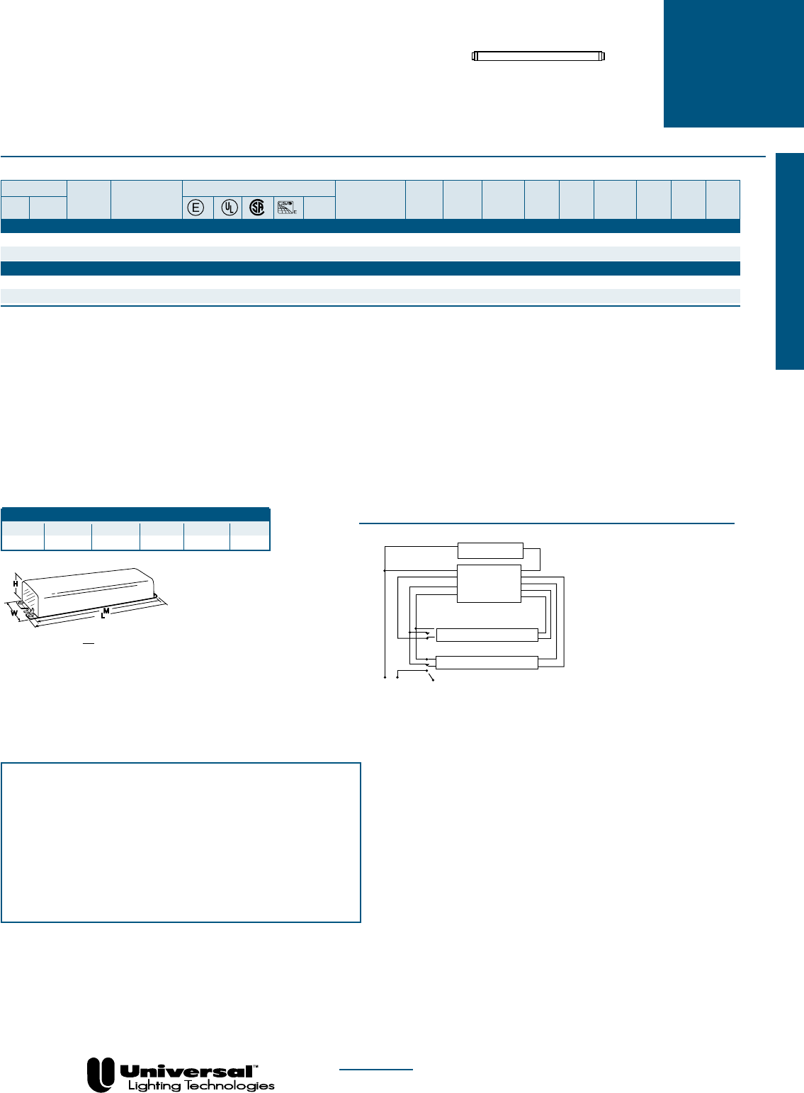
PAGE 1-27 FOR MORE INFORMATION CALL
1-800-BALLAST
(225-5278)
UNIVERSAL
®
ELECTROMAGNETIC
BALLASTS
FOR F30T12 AND F40T12 LAMPS
High Output Lamps
• 430 mA
• Rapid Start
• Continuous Dimming
WIRING DIAGRAMS
Overall Dimensions Mounting Dimensions
Draw # L W H M X
D5 16 3/8 2 3/8 1 1/2 15 25/32 1
DIAGRAM 18
W
H
L
M
D
NOM
Lamp
Certification Line Input Ballast Min. F/C
Line Catalog Current Power Ballast Efficacy Crest THD Start Sound Wiring
Qty. Descr. Volts Number (Amps) (Watts) Factor Factor Factor % Temp Rating Diag. Dim.
F40T12-HighPowerFactor
2 @100% 120 502-A-TC-P✝➑✠ • • .85 94 .88 0.94 <1.7 <20 50/10 A 18 D5
2 @ 20% 120 502-A-TC-P✝➑✠ • • .68 35 .20 .57 <1.7 <32 50/10 A 18 D5
F30T12 - Corrected Power Factor
2 @100% 120 502-A-TC-P➑➂✠ • • .87 83 .89 1.07 <1.7 <20 50/10 A 18 D5
2 @ 20% 120 502-A-TC-P➑➁✠ • • .58 27 .21 .77 <1.9 <32 50/10 A 18 D5
EXPORT
Fluorescent-Electromagnetic
♠Requires one circuit interrupting lamp holder
✝Requires two circuit interrupting lamp holder
➑UL component recognized for use with specific Dimming Controls
➁Power Factor Corrected to <60%
➂Power Factor Corrected to >60%
✠For Distribution Only
Blue/White
Yellow
Blue Red
Line
DIMMER
Ballast must be grounded. Install in accordance with the national Electric Code
White
White
Black
Black
Yellow
Red
Brown
Diagram 18
LAMP
Use disconnect
lampholder only
LAMP
BALLAST
WARNING
External fuses should not be used with 277-volt dimming ballasts.
CAUTION
The control circuit line will carry approximately 0.375 amps per 40-watt lamps
(and approximately 0.41 amps per 30-watt lamp). This means that the control
circuit attached to the ballast brown wire must be sized appropriately. Please
note that the ampacity of the control line is approximately double the ampacity
requirement of the line when 277-volt dimming ballasts are used. When 120-volt
ballasts are used, the ampacity requirement of the control lead is slightly lower
than the line current.
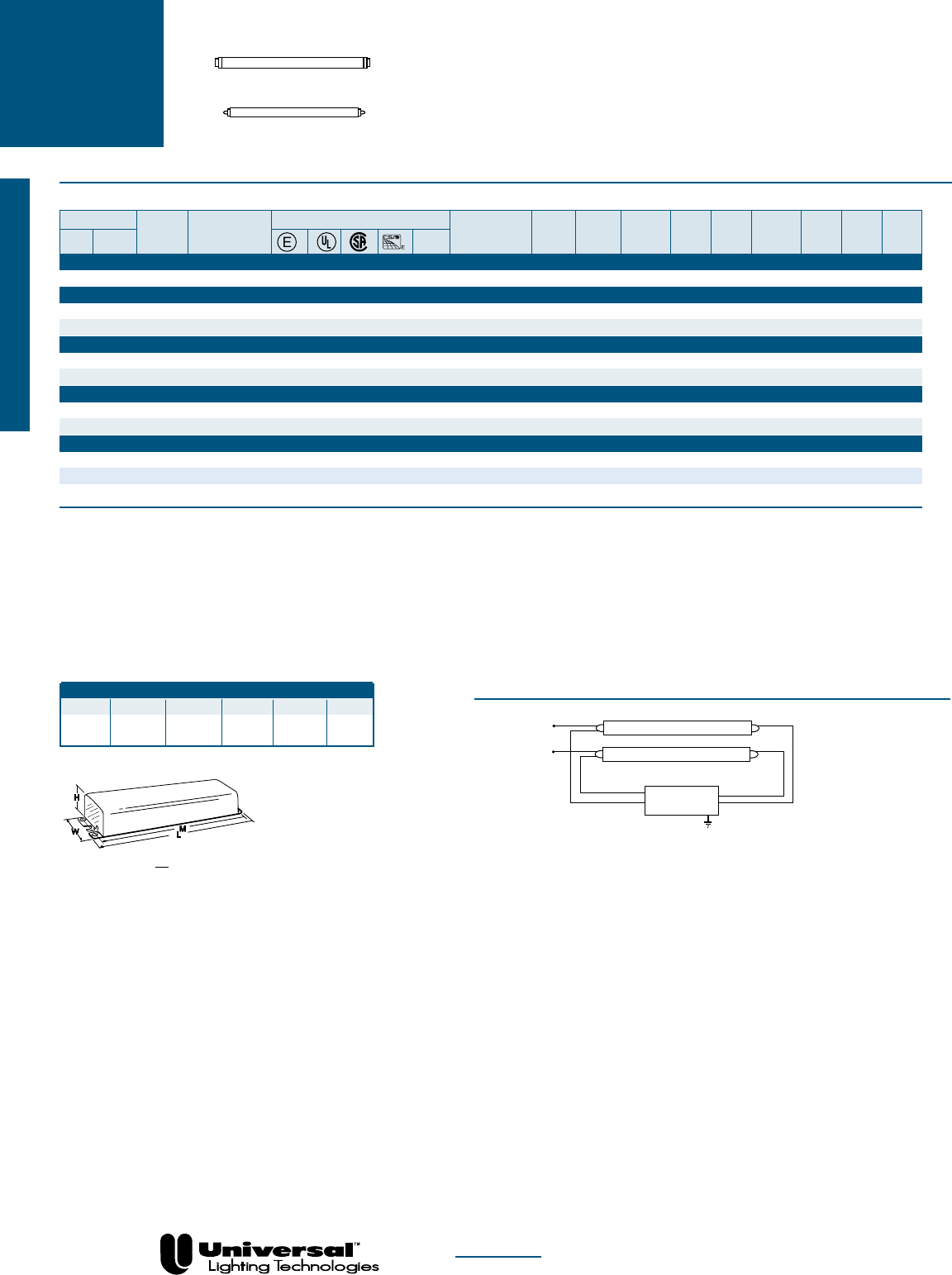
FOR MORE INFORMATION CALL
1-800-BALLAST
(225-5278)
UNIVERSAL
®
ELECTROMAGNETIC
BALLASTS
FOR F64, F72, F84, F96T12 AND F96T12ES LAMPS
PAGE 1-28
EXPORT
Slimline Lamps
• 425-440 mA
• 4´-8´ Lamp Applications
• T12 Slimline
• Instant Start
WIRING DIAGRAMS
Overall Dimensions Mounting Dimensions
Draw # L W H M X
D10 9 29/64 3 3/32 1 25/32 8 57/64 1
11/16
DIAGRAM 39
BALLAST
LAMP
LAMP
Blue
Line
White
Black
Red
Diagram 39
W
H
L
M
D
NOM
Lamp
Certification Line Input Ballast Min. F/C
Line Catalog Current Power Ballast Efficacy Crest THD Start Sound Wiring
Qty. Descr. Volts Number (Amps) (Watts) Factor Factor Factor % Temp Rating Diag. Dim.
F64T12-HighPowerFactor
2 Instant 120/60Hz 806-BR-TC-P
•
•
1.05 124 1.05 0.84 <1.85 <20 50/10 C 39 D12
F72T12-HighPowerFactor
2 Instant 120/60Hz 806-BR-TC-P➐ • • 1.15 131 .90 0.69 <1.85 <32 50/10 C 39 D12
2 Instant 220/60Hz 808-BR-TC-P❍ • .73 134 .93 0.69 <1.85 <32 50/10 C 39 D12
F84T12-HighPowerFactor
2 Instant 120/60Hz 806-BR-TC-P
➐ • •
1.29 149 .92 0.62 <1.85 <32 50/10 C 39 D12
2 Instant 220/60Hz 808-BR-TC-P • .77 152 .95 0.63 <1.85 <32 50/10 C 39 D12
F96T12-HighPowerFactor
2 Instant 120/60Hz 806-BR-TC-P➐ • • 1.40 162 .89 0.55 <1.85 <32 50/10 C 39 D12
2 Instant 220/60Hz 808-BR-TC-P
✜ • •
.85 165 .92 0.55 <1.85 <32 50/10 C 39 D12
F96T12ES-HighPowerFactor
2 Instant 120/60Hz 806-BR-TC-P➐ • • 1.16 129 .86 0.67 <2.0 <32 60/15 C 39 D12
2 Instant 220/60Hz 808-BR-TC-P
◗ • •
.76 130 .86 0.66 <2.0 <32 60/15 C 39 D12
2 Instant 127/60Hz 831-TC
• 1.07 124 .68 0.55 <1.85 <25 50/10 B 39 D10
◗Power Factor Corrected to >75%
❍Power Factor Corrected to >80%
✜Power Factor Corrected to >85%
➐For Export Only-may not be purchased for use in the USA
XFor Distribution Only
High Output Lamps
Fluorescent-Electromagnetic
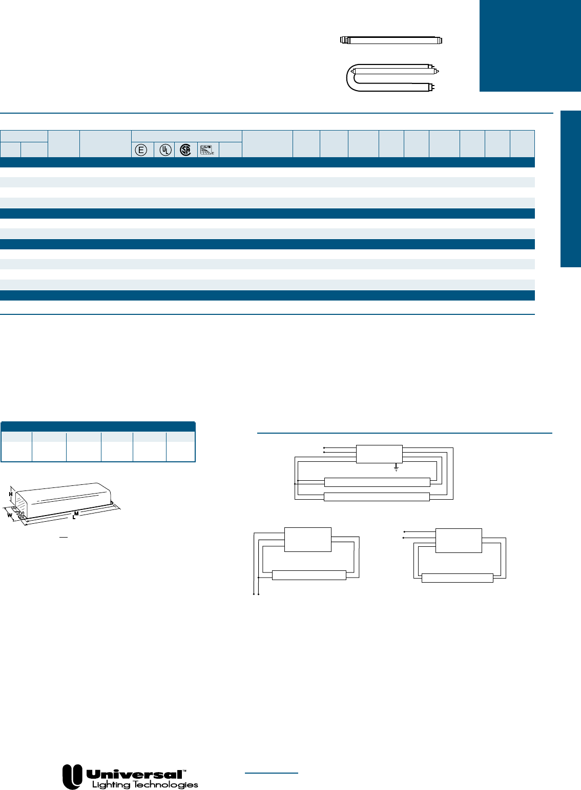
PAGE 1-29 FOR MORE INFORMATION CALL
1-800-BALLAST
(225-5278)
• 430-460 mA
• Rapid Start T12
WIRING DIAGRAMS
DIAGRAM 1
W
H
L
M
D
NOM
Lamp
Certification Line Input Ballast Min. F/C
Line Catalog Current Power Ballast Efficacy Crest THD Start Sound Wiring
Qty. Descr. Volts Number (Amps) (Watts) Factor Factor Factor % Temp Rating Diag. Dim.
F40T12-HighPowerFactor
2 Rapid 120/60Hz 446-LR-TC-P➐
•
•
•
.77 91 .93 1.02 <1.7 <20 50/10 A 1 D2
2 Rapid 127/60Hz 595-L-TC-P❿ • • .70 87 .88 1.01 <1.7 <20 50/10 A 1 D2
2 Rapid 220/60Hz 540-L-TC-P
•
.42 90 .91 1.01 <1.7 <20 50/10 A 1 D2
2 Rapid 277/60Hz 808-BR-TC-P➐ • • • .36 96 .94 0.97 <1.7 <20 50/10 A 1 D2
F40T12/U-HighPowerFactor
1 Rapid 120/60Hz 412-L-TC-P➐ • • .48 57 .95 1.67 <1.7 <20 60/15 A 42 D2
2 Rapid 120/60Hz 446-LR-TC-P➐ • • • .77 91 .91 1.00 <1.7 <20 50/10 A 1 D2
F40T12ES-HighPowerFactor
1 Rapid 120/60Hz 412-L-TC-P
➐ • •
.44 51 .90 1.76 <1.7 <20 50/10 A 42 D2
2 Rapid 120/60Hz 446-LR-TC-P➐ • • • .66 75 .86 1.15 <1.9 <20 60/15 A 1 D2
2 Rapid 220/60Hz 540-L-TC-P
•
.36 75 .86 1.15 <1.9 <20 60/15 A 1 D2
2 Rapid 277/60Hz 443-L-TC-P➐ • • • .32 82 .88 1.08 <1.9 <20 60/15 A 1 D2
F40T12ES/U-HighPowerFactor
2 Rapid 120/60Hz 446-LR-TC-P➐ • • • .66 75 .86 1.15 <1.9 <20 60/15 A 1 D2
❍Power Factor Corrected to >80%
✜Power Factor Corrected to >85%
➐For Export Only-may not be purchased for use in the USA
For Distribution Only
High Output Lamps
T8 U-Shaped Lamps
UNIVERSAL
®
ELECTROMAGNETIC
BALLASTS
FOR F30T12, F30T12ES, F40T12, F40T12/U,
F40T12ES AND F40T12ES/U LAMPS
❿May also be used with F40T12ES Lamps
■For Replacement Only
✠For Distribution Only
Diagram 1
White
Black
Yellow
Blue
Red
Line
BALLAST
Yellow
Blue
Red
LAMP
LAMP
BALLAST
Blue
Red
Line
LAMP
White
Black
Blue
Red
Diagram 42
DIAGRAM 42
Overall Dimensions Mounting Dimensions
Draw # L W H M X
D1 6 7/16 1 7/8 1 1/2 6 -
D2 9 1/2 2 3/8 1 1/2 8 57/64 1
BALLAST
Black/White
Blue
Red
Line
LAMP
White Red
Diagram 14
DIAGRAM 14
Slimline Lamps
High Output Lamps
EXPORT
Fluorescent-Electromagnetic

PAGE 1-30 FOR MORE INFORMATION CALL
1-800-BALLAST
(225-5278)
WIRING DIAGRAMS
DIAGRAM 39
BALLAST
LAMP
LAMP
Blue
Line
White
Black
Red
Diagram 39
W
H
L
M
D
NOM
Lamp
Certification Line Input Ballast Min. F/C
Line Catalog Current Power Ballast Efficacy Crest THD Start Sound Wiring
Qty. Descr. Volts Number (Amps) (Watts) Factor Factor Factor % Temp Rating Diag. Dim.
F64T12-HighPowerFactor
2 Instant 120/60Hz 806-BR-TC-P
•
•
1.05 124 1.05 0.84 <1.85 <20 50/10 C 39 D12
F72T12-HighPowerFactor
2 Instant 120/60Hz 806-BR-TC-P➐ • • 1.15 131 .90 0.69 <1.85 <32 50/10 C 39 D12
2 Instant 220/60Hz 808-BR-TC-P❍ • .73 134 .93 0.69 <1.85 <32 50/10 C 39 D12
F84T12-HighPowerFactor
2 Instant 120/60Hz 806-BR-TC-P
➐ • •
1.29 149 .92 0.62 <1.85 <32 50/10 C 39 D12
2 Instant 220/60Hz 808-BR-TC-P • .77 152 .95 0.63 <1.85 <32 50/10 C 39 D12
F96T12-HighPowerFactor
2 Instant 120/60Hz 806-BR-TC-P➐ • • 1.40 162 .89 0.55 <1.85 <32 50/10 C 39 D12
2 Instant 220/60Hz 808-BR-TC-P
✜ • •
.85 165 .92 0.55 <1.85 <32 50/10 C 39 D12
F96T12ES-HighPowerFactor
2 Instant 120/60Hz 806-BR-TC-P➐ • • 1.16 129 .86 0.67 <2.0 <32 60/15 C 39 D12
2 Instant 220/60Hz 808-BR-TC-P
◗ • •
.76 130 .86 0.66 <2.0 <32 60/15 C 39 D12
2 Instant 127/60Hz 831-TC
• 1.07 124 .68 0.55 <1.85 <25 50/10 B 39 D10
◗Power Factor Corrected to >75%
❍Power Factor Corrected to >80%
✜Power Factor Corrected to >85%
➐For Export Only-may not be purchased for use in the USA
XFor Distribution Only
Overall Dimensions Mounting Dimensions
Draw # L W H M X
D6 11 3/4 3 1/8 1 25/32 11 9/64 2
D10 9 29/64 3 3/32 1 25/32 8 57/64 1
11/16
BALLAST
Line
White
Black
Red
Diagram 34
LAMP
DIAGRAM 34
UNIVERSAL
®
ELECTROMAGNETIC
BALLASTS
FOR F64, F72, F84, F96T12 AND F96T12ES LAMPS
EXPORT
Slimline Lamps
• 425-440 mA
• 4´-8´ Lamp Applications
• T12 Slimline
• Instant Start
High Output Lamps
Fluorescent-Electromagnetic
PAGE 1-31 FOR MORE INFORMATION CALL
1-800-BALLAST
(225-5278)
UNIVERSAL
®
ELECTROMAGNETIC
BALLASTS
FOR F30T12 AND F40T12 LAMPS
High Output Lamps
• 430 mA
• Rapid Start
• Continuous Dimming
WIRING DIAGRAMS
DIAGRAM 18
W
H
L
M
D
NOM
Lamp
Certification Line Input Ballast Min. F/C
Line Catalog Current Power Ballast Efficacy Crest THD Start Sound Wiring
Qty. Descr. Volts Number (Amps) (Watts) Factor Factor Factor % Temp Rating Diag. Dim.
F40T12-HighPowerFactor
2 @100% 120 502-A-TC-P✝➑✠ • • .85 94 .88 0.94 <1.7 <20 50/10 A 18 D5
2 @ 20% 120 502-A-TC-P✝➑✠ • • .68 35 .20 .57 <1.7 <32 50/10 A 18 D5
2 @100% 277 678-A-TC-P✝➑✠ • • .39 100 .88 0.94 <1.7 <32 50/10 A 16 D5
2 @20% 277 678-A-TC-P✝➑✠ • • .34 30 .20 .67 <1.7 <32 50/10 A 16 D5
F30T12 - Corrected Power Factor
2 @100% 120 502-A-TC-P➑➂✠ • • .87 83 .89 1.07 <1.7 <20 50/10 A 18 D5
2 @ 20% 120 502-A-TC-P➑➁✠ • • .58 27 .21 .77 <1.9 <32 50/10 A 18 D5
2 @100% 277 678-A-TC-P➑➂✠ • • .85 96 .90 0.93 <1.7 <32 50/10 A 16 D5
2 @20% 277 678-A-TC-P✝➑➁✠ • • .68 33 .23 .70 <1.7 <32 50/10 A 16 D5
DIMMING
Fluorescent-Electromagnetic
♠Requires one circuit interrupting lamp holder
✝Requires two circuit interrupting lamp holder
➑UL component recognized for use with specific Dimming Controls
➁Power Factor Corrected to <60%
➂Power Factor Corrected to >60%
✠For Distribution Only
Blue/White
Yellow
Blue Red
Line
DIMMER
Ballast must be grounded. Install in accordance with the national Electric Code
White
White
Black
Black
Yellow
Red
Brown
Diagram 18
LAMP
Use disconnect
lampholder only
LAMP
BALLAST
WARNING
External fuses should not be used with 277-volt dimming ballasts.
CAUTION
The control circuit line will carry approximately 0.375 amps per 40-watt lamps
(and approximately 0.41 amps per 30-watt lamp). This means that the control
circuit attached to the ballast brown wire must be sized appropriately. Please
note that the ampacity of the control line is approximately double the ampacity
requirement of the line when 277-volt dimming ballasts are used. When 120-volt
ballasts are used, the ampacity requirement of the control lead is slightly lower
than the line current.
Overall Dimensions Mounting Dimensions
Draw # L W H M X
D2 9 1/2 2 3/8 1 1/2 8 57/64 1
11/16
BALLAST
White
Black/White
Blue Red
Line
LAMP
DIMMER
Red
Diagram 9
Use disconnect
lampholder only
DIAGRAM 9
Blue/White Yellow
Blue Red
Line White
Black
Yellow
Brown
Red
Diagram 16
Use disconnect
lampholder only
Red/White
Red/White
LAMP
DIMMER
LAMP
BALLAST
DIAGRAM 16
Blue/White
Brown
Blue Red
Line
White
Black
Red
Diagram 19
Use disconnect
lampholder only
Blue/White
LAMP
DIMMER
BALLAST
DIAGRAM 19
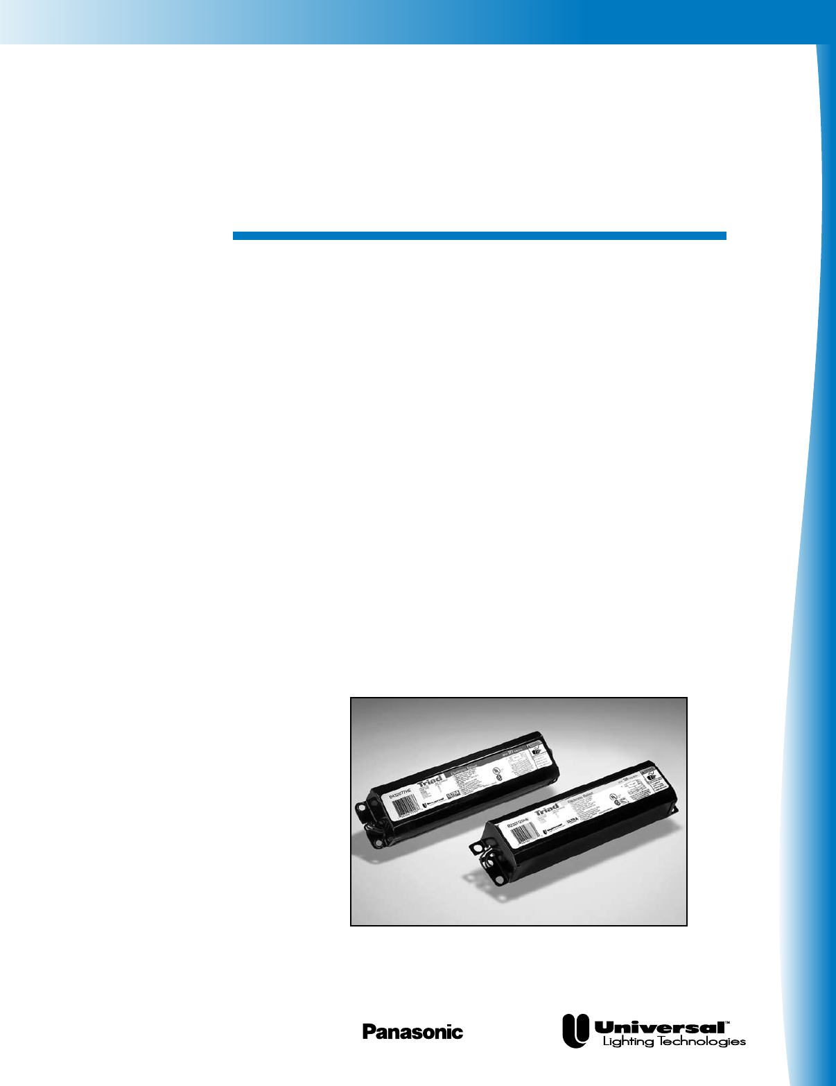
Fluorescent-Electronic
Electronic
Fluorescent Ballasts
A Complete Range of
Solutions — From The
Name You Trust
For more than 30 years, the lighting industry has
relied on our TRIAD® brand for the most specified,
most installed, most reliable electronic ballasts in the
business.
The TRIAD® line offers advantages like installer-
friendly universal input voltage, which ensures that
you have the right voltage ballast every time. We’re
also the industry leader in low profile design -
lightweight, space-saving ballasts that offer the same
footprint and wiring as conventional ballasts. And our
AccuStart™ ballasts feature programmed rapid start
technology that dramatically enhances lamp life.
Universal is the leader in energy saving electronic ballasts.
Fluorescent-Electronic
Universal Lighting Technologies is a subsidiary of
Panasonic Electric Works Co., Ltd., a member of the Panasonic Group
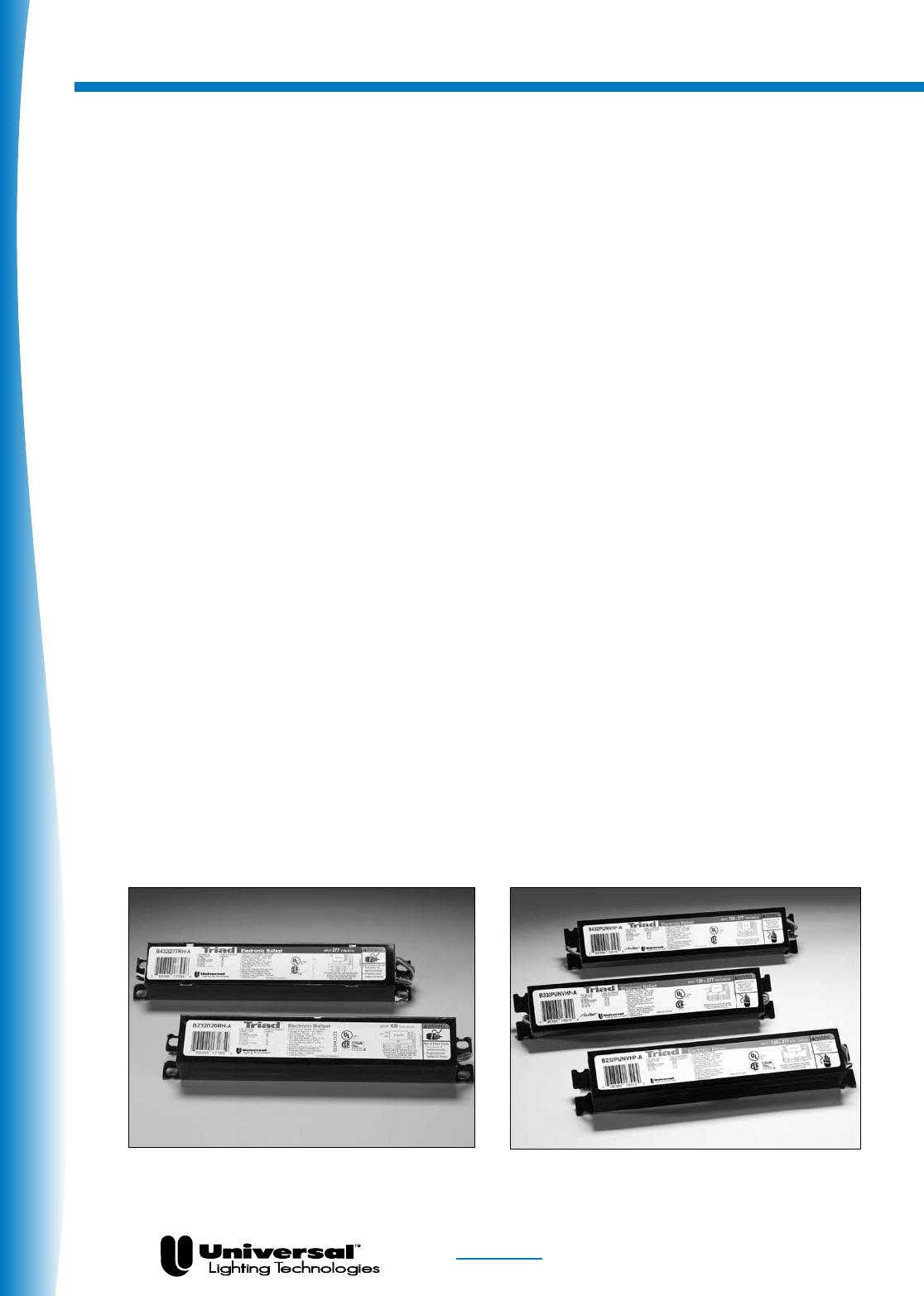
Fluorescent-Electronic
FOR MORE INFORMATION CALL
1-800-BALLAST
(225-5278)
Product Overview
PAGE 2-2
Setting The Pace In T8 Technology
Universal Lighting keeps pushing the frontier of T8 technology with innovative products that deliver
dramatic energy savings, greater fixture design flexibility, longer lamp life and installation ease. You
can count on Universal for some of the industry’s smallest, lightest and most hassle-free T8 ballasts.
Universal Voltage Low Profile High Performance (HP-A and HP-B)
Our low profile High Performance ballasts with THD<10% offer the convenience of universal input volt-
age (108 - 305 volts) as a standard feature. Universal input is “installer-friendly” - ensuring that you
have the right voltage ballast every time. Our low profile models also feature a remarkably small pack-
age and cross section (1.0”H x 1.5”W) for greater flexibility in fixture design. Since the mounting and
wiring footprints are the same as a standard size ballast, our low profile HP models will easily retrofit
into any T12 or T8 fixture.
High Efficiency Lamp/Ballast System
The High Efficiency Lamp/Ballast System is the most significant advancement in linear fluorescent
energy savings in more than a quarter century. The system delivers up to 40% energy savings
compared to conventional magnetic T12 energy-saving systems and up to 11% versus standard
electronic T8 systems. Our High Efficiency ballast is designed to operate any lamp manufacturer’s
F32T8/ES energy-saving lamp or standard F32T8 lamp. There are two options:
- EL suffix denotes .77 ballast factor
- HE suffix denotes .87 ballast factor
- HEH suffix denotes 1.18 ballast factor
AccuStart®
AccuStart® ballasts are ideal for frequently switched applications or as a rapid start alternative. They incor-
porate programmed rapid start technology to properly heat the lamp filaments, which yields an increase in
lamp life up to 50%. The 1-4 lamp models offer universal input voltage - an industry exclusive.
T8 Super Low Profile
Our T8 super low profile models offer maximum fixture flexibility. They’re ideal for pendant mount and
other specialty lighting applications. They feature a small cross section (1.0”H x 1.18”W) and low pro-
file dimensions for indirect/direct fixtures, plus installer-friendly universal input voltage
(108 - 305 volts).
Low Power (L-A)
Family of Low Profile Ballasts. AccuStart® ballasts for frequently switched applications.

Fluorescent-Electronic
FOR MORE INFORMATION CALL
1-800-BALLAST
(225-5278)
PAGE 2-3
Product Overview
Low Power (L-A)
The L-A Series ballasts offer the option of a .78 ballast factor for maximum energy savings. They
feature space-saving low profile design. The 2- to 4-lamp models are ideal for retrofitting energy-
saving T12 lamps - and offer parallel lamp operation and THD<20%.
Low Profile Reduced Harmonic (RH-A)
Our low profile RH ballasts are over 45% smaller and 30% lighter. They feature a space-saving pack-
age and cross section (1.18” H x 1.7”W) for greater flexibility in fixture design. The 1- to 4-lamp
model features parallel lamp operation, with standard mounting footprint and wiring for ease of
replacement. They offer high efficiency performance with THD<20%.
Reduced Harmonic High Output (RHH and RHH-A)
These ballasts deliver the maximum light output by operating lamps at their rated current of 265mA
without compromising lamp life. They feature a 1.18 ballast factor versus the industry standard .88
to provide lighting design flexibility.
T5 Ballasts For Indirect And High-End Architectural Applications
T5 systems are gaining greater popularity for high-end architectural applications. Universal Lighting
gives you a wide range of T5 solutions, from 14 to 54 watts. Our T5 ballasts operate multiple (1 or
2) F35T5, F28T5, F21T5 and F14T5 lamps. Additionally, our T5HO ballasts operate multiple (1 or 2)
F54T5HO, F39T5HO and F24T5HO lamps. Moreover, they make your life easier with standard features
that include universal input voltage (108 - 305 volts), programmed rapid start technology for longer
lamp life and end of lamp life shutdown circuit with auto-reset.
T5 Standard Output
Our standard output T5 ballasts support multiple lamp operation (including 14-, 21-, 28-, and
35-watt lamps). They’re ideal for indirect pendant mount, surface mount, cove, undercabinet or task
lighting. With a small cross section (1.0”H x 1.18”W), our T5 models give you more options for slim
fixture design. Standard features include universal input voltage, end-of-lamp-life shutdown circuit
and programmed rapid start technology.
T5 High Output
Universal’s high output T5 ballasts support 24-, 39- and 54-watt lamps. They offer the same
standard features and compact dimensions as our T5 standard output line - and they’re also well-
suited to applications where space is at a premium, including slim pendant mounted fixtures, cove
and task lighting.
Family of Universal HP Ballasts. Flexible Fixture design options for T5 and T5HO lamps.
Fluorescent-Electronic
FOR MORE INFORMATION CALL
1-800-BALLAST
(225-5278)
Application And Operating Information
PAGE 2-4
SAFETY
NEC & UL Requirements
Ballast installation presents the possibility of exposure to potentially hazardous voltages and should be performed only by qualified
personnel. All installation, inspection and maintenance should be performed only with power to the fixture turned off. Additionally, all
fixtures and ballasts must be installed and operated in compliance with the National Electrical Code, Underwriters Laboratories Inc. (UL)
requirements, and all local applicable codes and regulations.
Polarity
Polarity refers to the proper connection of ballast lead wires to line wires. To aid you in making a correct installation, Universal bal-
last leads are color-coded for easy identification. The WHITE ballast lead is to be connected to the neutral (grounded) and the BLACK
(or black with white tracer) lead always to the phase (“hot”) line wire. Systems where neither of the line wires are at ground potential
require specially designed ballasts. A change in polarity may result in the voltage from the lead to the ground exceeding UL-specified
limits. In some types of ballasts, a change in polarity may decrease voltage from the lead to the ground, thereby impeding the starting
dependability of the ballast.
Grounding
Ballast cases and fixtures must always be grounded. The ballast case may be grounded to the fixture or otherwise grounded. It could be
hazardous to make contact with an ungrounded fixture or ballast when in operation. Neglecting to properly ground the ballast and fix-
ture combination may also result in failure of certain lamps to start or for unacceptable levels of electromagnetic noise to be conducted
onto the power lines.
Operating Line Voltage Limits
To receive the full benefits of rated lamp output and to prolong ballast life, it is essential that voltage supplied to an installation be main-
tained within limits prescribed for each circuit. These limits are listed below:
Subjecting a ballast to exces-
sive voltage for an extended period results in the deterioration of the insulation. This insulation breakdown will cause early ballast fail-
ure.
Low voltage has no damaging effect on the ballast. However, lamps may not start reliably, and early lamp failure could result.
Internal Ballast Protection
Class P Classification - Since January 1, 1984, the National Electrical Code requires that “where Fluorescent fixtures are installed
indoors, the ballast shall have thermal protection integral within the ballast except for simple reactance ballasts.” This ruling applies to
replacement ballasts as well as to those contained within new fixtures.
In compliance with the National Electrical Code, UL has established a Class P ballast classification for fluorescent light fixtures.
A Class P ballast must employ internal thermal protection limiting its operating temperature.
Universal UL-approved Class P ballasts comply with the National Electrical Code requirement and are equipped with an automatic reset-
ting thermal protector, built-in and adjacent to the transformer coils. The resetting thermal protector functions as a thermostat which
will open and temporarily deactivate the ballast when it exceeds the permissible temperature. It will reset when the ballast cools to a
safe operating temperature. The ballast will continue to cycle until the cause of overheating is eliminated. If the ballast is defective, it
must be replaced. If the cause is external, a Class P ballast will resume normal operation after abnormal conditions are eliminated.
VOLTAGE RANGE
Nominal Voltage Minimum Maximum
120 108 132
220 198 242
277 249 305
347 312 382
120-277 (UNV) 108 305
347-480 (HRV) 312 528

Fluorescent-Electronic
FOR MORE INFORMATION CALL
1-800-BALLAST
(225-5278)
PAGE 2-5
Application And Operating Information
SAFETY
Dimming Ballasts - Ballastar® Dimming Ballasts are controlled by using 10-0vDC. Care should be taken to insure that the line
voltage (AC) wires are not connected to the low voltage DC wires. Ballastar® Electronic Dimming Ballasts have protection (safety)
circuitry, that will sense the error so as not to harm the installer or the ballast. Dimming ballasts manufactured after May 1999 have
the protection circuit. Dimming ballasts manufactured before this date do not have low voltage circuit protection.
Fusing - Class P ballasts do not require fusing. Fusing can be used when a single circuit has a large number of fixtures/ballasts.
For a comprehensive list of appropriate fuses, contact our Technical Engineering Services (TES) Department at 1-800-BALLAST
or check out our TES home page at www.unvlt.com.
Grounding - ANSI C82.1 recommends all fixtures and ballasts be grounded. Universal requires all electronic ballasts be grounded.
Thermal Protection - All Universal electronic ballasts meet UL 935 Standard for thermal protection. These ballasts are designated
Class P. A Class P ballast will disconnect the ballast from input power in the event of internal over-temperature.
PERFORMACE
Lamp Connections
Fluorescent ballasts are designed to generate voltages in excess of 300 volts. It is imperative that proper connection to quality sockets
be assured in accordance with wiring diagrams on each page of the catalog and on product labels. Some applications may not require
the use of all of the ballast output leads. If any leads are not to be connected, each should be individually capped and insulated to at
least 600 volts.
Application Versatility
Many Universal models are designed to allow for applications with different types or quantities of lamps. Lamp applications not listed
on label cannot be warranted.
Audible Noise (Sound)
Electrical equipment, including most fluorescent lamp ballasts, produces some noise. Care must be taken to select a ballast with the
proper sound rating for a particular lighting installation. Secure mounting can reduce the potential for audible noise. Typically, elec-
tronic ballasts operate up to 75% quieter than electromagnetic ballasts for fluorescent lamps.
EMI/RFI
Electronic ballasts operate at high frequency and, therefore, may produce radio frequency interference (RFI) or electromagnetic interfer-
ence (EMI). Some sensitive electrical equipment such as televisions, radios, or some medical equipment can be adversely affected by this
RFI or EMI interference. Currently the electronic frequencies from 450 kilohertz (kHz) to 300 megahertz (MHz) are regulated by the FCC. For
electronic ballasts, the limits and regulations are listed in the Code of Federal Regulations, Title 47, Part 18, Subpart C titled RF Lighting
Devices. ULT provides ballasts compliant with non-consumer limits for commercial applications,
as well as several models in compliance with consumer limits for residential use.
See the Data Sheets for the electronic ballast of interest to determine which FCC requirement, consumer or non-consumer
the particular product meets.
Remote Mounting
Excessive hot or cold temperatures, audible noise requirements, or a desire to operate lamps in more than one fixture with the same
ballast (master/slave), may make it desirable to mount the ballast remotely. Care must be taken to allow for ballast heat dissipation and
proper grounding.
In any application, the wire used to extend leads must be at least as large as the wire supplied on the ballast (18 AWG) with an insula-
tion rating of 1000 VAC at 90°C.
Lead lengths in excess of those noted cause loading effects that can dramatically impact ballast performance and void the warranty.
Universal T8 Instant Start and Programmed Rapid Start Electronic ballasts can be mounted remotely, from the lamp sockets, up to 18 feet.
Universal T8 Rapid Start Electronic ballasts can be mounted remotely, from the lamp sockets, up to 12 feet.

Fluorescent-Electronic
FOR MORE INFORMATION CALL
1-800-BALLAST
(225-5278)
PAGE 2-6
Application And Operating Information
PERFORMANCE
• LampStartingDependability
Fluorescent lamps are inherently more difficult to start at low temperatures. All ballasts have limitations
as to their ability to start lamps at low ambient temperatures. In this catalog, the low starting point for
each lamp/ballast combination appears in the column marked “Minimum Starting Temperature.”
Universal four lamp instant start ballasts can operate at a minimum starting temperature down to -18°C (0°F)
under the following conditions:
1. Lead lengths to the lamps are those supplied, by Universal, with the ballast or shorter.
2. The distance from the lamp to the ground plane is no greater than 3/4”.
3. The line voltage supplied to the ballast is no less than rated nominal.
4. The ballast or lamps are not remotely mounted.
5. The lamps have been burned in per lamp manufacturer requirements (typically 100 hours).
The lamp manufacturer should be contacted for lamp operating characteristics and requirments below 15°C (50°F).
• LightOutput
Optimum light output from fluorescent lamps is achieved when the lamp wall is at 100-110°F.
Any substantial excursion (either colder or warmer) will result in a reduction in light output.
• BallastLife
A fluorescent lamp ballast, like any other electrical device, generates heat during its normal operation.
Ballast temperatures should be kept as low as possible. Maximum dissipation of heat through fixture
design and proper ballast installation will help. Although excessive temperature may not cause the
ballast to fail immediately, it can shorten ballast life. To assure maximum life, the ballast case temperature
should not exceed 75˚C, in a maximum ambient (fixture cavity) of 40˚C.
Causes of ballast overheating:
• Incorrectlinevoltageorfrequency
• Incorrectsize,typeornumberoflamps
• Incorrectwiring
• Poorheatdissipationduetosurroundinginsulation
• Sealed(VaporTight)Fixtures-Unusualheatbuild-upduetolackofventilationin
fixtures may cause thermal (on/off) cycling of certain ballasts. Consult Universal for
specific recommendations.
RECOMMENDATIONS...
• Selectionofaproperballasttomatchtherequirementsofthelamp,
fixture, voltage and installation.
• Mountingofballastwithinthefixturewithasmuchsurfacecontact
as possible between the ballast and metal portions of the fixture.
Secure mounting will aid in proper heat dissipation and can minimize
the potential for ballast hum.
• Theuseofheat-conductingdissipators(radiators),ifnecessary,
which increase surface contact between the ballast and fixture.
• Ifnecessary,locatetheballastinaremote,coolerareaoutsidethefixture.
• ConsultUniversalforremotemountingrecommendations.
•
Starting Method Legend
IS = Instant Start
PRS = Programmed Rapid Start
RS = Rapid Start
PAR-IS = Parallel Instant Start
PAR-PRS = Parallel Programmed Rapid Start
PAR-RS = Parallel Rapid Start
SER-RS = Series Rapid Start

Fluorescent-Electronic
FOR MORE INFORMATION CALL
1-800-BALLAST
(225-5278)
TYPICAL SPECIFICATIONS
FOR INSTANT START BALLASTS FOR:
•RH (Reduced Harmonic)
•L (Low Wattage)
•RHHandRHH-A (Reduced Harmonic High Output)
1. Ballasts (1-4 lamp) shall operate as a Parallel Circuit, allowing remaining lamp(s) to maintain full light output
if one or more lamps fail.
2. Ballasts shall operate from 60 Hz input source of 120, 277 Volts, and sustained variations of
± 10% (Voltage & Frequency) with no damage to the ballasts.
3. Ballasts shall be a high frequency electronic type, and operate lamps at a frequency above 20 kHz.
4. Lamp Current Crest Factor (ratio of peak to RMS current) shall be 1.7 or less in accordance with lamp
manufacturer recommendation and ANSI C82.11-1993.
5. Ballasts shall comply with FCC Part 18 Non-Consumer Equipment for EMI (power line conducted) and
RFI (Radiated).
6. Ballasts shall provide transient immunity as recommended by ANSI C62.41-1991, Location A2.
7. Ballasts shall operate lamps with no visible flicker (<3% flicker index).
8. Ballasts shall tolerate sustained open circuit and short circuit output conditions without damage.
9. Ballasts shall be Underwriters Laboratory (UL 935) listed, Class P, Type 1 Outdoor, and CSA certified
where applicable.
10. Ballast shall have a Ballast Factor greater than .85 per ANSI C82.11-1993.
- Ballast Factor for Low Power (L-A) models shall be greater than .77.
11. Input current Total Harmonic Distortion shall not exceed 20% for the primary lamp applications
12. Ballasts shall have a Power Factor greater than .95 for primary lamp applications.
13. The ballasts do not contain any PCB’s.
14. The manufacturer shall provide written warranty against defects in material or workmanship, including
replacement, for five years from date of manufacture.
15. Manufacturer shall have been manufacturing electronic ballasts for at least fifteen years.
16. Ballast shall be manufactured in an ISO 9001 Certified Facility
17. Ballasts shall provide instant starting sequence consistent with ANSI standard C82.11-1993.
18. Universal model ______________ (or approved equal).
PAGE 2-7
Specifications

Fluorescent-Electronic
FOR MORE INFORMATION CALL
1-800-BALLAST
(225-5278)
Specifications
PAGE 2-8
TYPICAL SPECIFICATIONS
FOR INSTANT START BALLASTS FOR:
Universal Voltage
•HP (High Performance)
1. Ballasts (1-4 lamp) shall operate as a Parallel Circuit, allowing remaining lamp(s) to maintain full light output
if one or more lamps fail.
2. Ballasts shall operate from 50/60 Hz input source of 120 through 277 Volts, and sustained variations of
± 10% (Voltage & Frequency) with no damage to the ballasts.
3. Ballasts shall be a high frequency electronic type, and operate lamps at a frequency above 42 kHz to
minimize interference with infared control systems.
4. Lamp Current Crest Factor (ratio of peak to RMS current) shall be 1.7 or less in accordance with lamp
manufacturer recommendation and ANSI C82.11-1993.
5. Ballasts shall comply with FCC Part 18 Non-Consumer Equipment for EMI (power line conducted) and
RFI (Radiated).
6. Ballasts shall provide transient immunity as recommended by ANSI C62.41-1991, Location A2.
7. Ballasts shall operate lamps with no visible flicker (<3% flicker index).
8. Ballasts shall tolerate sustained open circuit and short circuit output conditions without damage.
9. Ballasts shall be Underwriters Laboratory (UL 935) listed, Class P, Type 1 Outdoor, and CSA certified
where applicable.
10. Ballast shall have a Ballast Factor greater than .85 per ANSI C82.11-1993.
11. Input current Total Harmonic Distortion shall not exceed 10% for the primary lamp.
12. Ballasts shall have a Power Factor greater than .98 for primary lamp.
13. The ballasts shall not have any PCB’s.
14. The manufacturer shall provide written warranty against defects in material or workmanship, including
replacement, for five years from date of manufacture.
15. Manufacturer shall have been manufacturing electronic ballasts for at least fifteen years.
16. Ballast shall be manufactured in an ISO 9001 Certified Facility.
17. Ballasts shall provide instant starting sequence consistent with ANSI standard C82.11-1993.
18. Ballast shall be Universal Lighting Technologies Bx32IUNVHP-B (x=1 or 2) or Bx32IUNVHP-A (x=3 or 4)
depending upon the quantity of lamps per fixture.
19. Universal model ______________ (or approved equal).

Fluorescent-Electronic
FOR MORE INFORMATION CALL
1-800-BALLAST
(225-5278)
PAGE 2-9
Specifications
TYPICAL SPECIFICATIONS
FOR INSTANT START BALLASTS FOR:
•HP (High Performance)
•HPL (High Performance Low Power)
•HPH (High Performance High Light)
1. Ballasts (1-4 lamp) shall operate as a Parallel Circuit, allowing remaining lamp(s) to maintain full light output
if one or more lamps fail (except T12 High Output).
2. Ballasts shall operate from 50/60 Hz input source of 120, 277, and 347 Volts, and sustained variations of
± 10% (Voltage & Frequency) with no damage to the ballasts.
3. Ballasts shall be a high frequency electronic type, and operate lamps at a frequency above 20 kHz.
4. Lamp Current Crest Factor (ratio of peak to RMS current) shall be 1.7 or less in accordance with lamp
manufacturer recommendation and ANSI C82.11-1993.
5. Ballasts shall provide transient immunity as recommended by ANSI C62.41-1991, Location A2.
6. Ballasts shall operate lamps with no visible flicker (<3% flicker index).
7. Ballasts shall tolerate sustained open circuit and short circuit output conditions without damage.
8. Ballasts shall be Underwriters Laboratory (UL 935) listed, Class P, Type 1 Outdoor, and CSA certified
where applicable.
9. Ballast shall have a Ballast Factor greater than .85 per ANSI C82.11-1993.
- Ballast Factor for Low Power (L) models shall be greater than .77.
10. Input current Total Harmonic Distortion shall not exceed 10% for the primary lamp.
11. Ballasts shall have a Power Factor greater than .98 for primary lamp.
12. The ballasts do not contain any PCB’s.
13. The manufacturer shall provide written warranty against defects in material or workmanship, including
replacement, for five years from date of manufacture.
14. Manufacturer shall have been manufacturing electronic ballasts for at least fifteen years.
15. Ballast shall be manufactured in an ISO 9001 Certified Facility
16. Ballasts shall provide instant starting sequence consistent with ANSI standard C82.11-1993.
17. Universal model ______________ (or approved equal).

Fluorescent-Electronic
FOR MORE INFORMATION CALL
1-800-BALLAST
(225-5278)
Specifications
TYPICAL SPECIFICATIONS
FOR RAPID START BALLASTS
1. Ballasts (1-4 lamp) shall operate as a Parallel Circuit, allowing remaining lamps(s) to maintain full light output
if one or more lamps fail (except T12 High Output).
2. Ballasts shall operate from 60 Hz input source of 120, 277 Volts, and sustained variations of
± 10% (Voltage & Frequency) with no damage to the ballasts.
3. Ballasts shall be a high frequency electronic type, and operate lamps at a frequency above 20 kHz.
4. Lamp Current Crest Factor (ratio of peak to RMS current) shall be 1.7 or less in accordance with lamp
manufacturer recommendation and ANSI C82.11-1993.
5. Ballasts shall comply with FCC Part 18 Non-Consumer Equipment for EMI (power line conducted) and
RFI (Radiated).
6. Ballasts shall provide transient immunity as recommended by ANSI C62.41-1991, Location A2.
7. Ballasts shall operate lamps with no visible flicker (<3% flicker index).
8. Ballasts shall tolerate sustained open circuit and short circuit output conditions without damage.
9. Ballasts shall be Underwriters Laboratory (UL 935) listed, Class P, Type 1 Outdoor, CSA Certified
where applicable.
10. Ballast shall have a Ballast factor greater than .85, per ANSI C82.11-1993.
11. Input current Total Harmonic Distortion shall not exceed 10% for primary lamp applications.
12. Ballast shall be manufactured in an ISO 9001 Certified Facility
13. Ballasts shall have a Power Factor greater than 0.98 primary applications.
14. The ballasts do not contain any PCB’s.
15. The manufacturer shall provide written warranty against defects in material or workmanship, including
replacement, for five years from date of manufacture.
16. Manufacturer shall have been manufacturing electronic ballasts for at least fifteen years.
17. Ballasts shall provide rapid starting sequence consistent with ANSI standard C82.11-1993.
18. Universal model ______________ (or approved equal).
PAGE 2-10

Fluorescent-Electronic
FOR MORE INFORMATION CALL
1-800-BALLAST
(225-5278)
Specifications
TYPICAL SPECIFICATIONS
FOR PROGRAMMED RAPID START BALLASTS:
1. Ballasts shall have a minimum start temperature of 0°F.
2. Ballasts shall operate from a 50/60 Hz input source of 120 through 277 Volts, and sustained variations of
± 10% (Voltage & Frequency) with no damage to the ballasts.
3. Ballasts shall be a high frequency electronic type, and operate lamps at a frequency above 42 kHz to minimize
interference with infrared control systems.
4. Lamp Current Crest Factor (ratio of peak to RMS current) shall be 1.7 or less in accordance with lamp
manufacturer recommendation and ANSI C82.11-1993.
5. Ballasts shall comply with FCC Part 18 Non-Consumer Equipment for EMI (power line conducted) and
RFI (Radiated).
6. Ballasts shall provide transient immunity as recommended by ANSI C62.41-1991, Location A2.
7. Ballasts shall operate lamps with no visible flicker (<3% flicker index).
8. Ballasts shall tolerate sustained open circuit and short circuit output conditions without damage.
9. Ballasts shall be Underwriters Laboratory (UL 935) listed, Class P, Type 1 Outdoor, and CSA certified
where applicable.
10. Ballast shall have a Ballast factor greater than .85, per ANSI C82.11-1993.
11. Input current Total Harmonic Distortion shall not exceed 10%.
12. Ballasts shall have a Power Factor greater than 0.98, for primary application.
13. The ballasts shall not have any PCB’s.
14. The manufacturer shall provide written warranty against defects in material or workmanship, including
replacement, for five years from date of manufacture.
15. Manufacturer shall have been manufacturing electronic ballasts for at least fifteen years.
16. Ballast shall be manufactured in an ISO 9001 Certified Facility.
17. Ballast shall be manufactured in North America.
18. Ballast shall be Universal Lighting Technologies AccuStart HP Product Bx32PUNVHP-A (x=1,2,3. or 4).
19. Universal model ______________ (or approved equal).
PAGE 2-11

Fluorescent-Electronic
FOR MORE INFORMATION CALL
1-800-BALLAST
(225-5278)
Specifications
TYPICAL SPECIFICATIONS
FOR INSTANT START T5 AND T5 HIGH OUTPUT (HO) BALLASTS :
1. Ballast shall be Instant Start.
2. Ballast shall incorporate lamp shutdown circuitry for end of lamp life protection.
3. Ballast shall allow for re-lamping without the need to cycle power.
4. Ballasts shall operate from 50/60 Hz input source from 108-305 Volts with no damage to the ballasts.
5. Ballasts shall be a high frequency electronic type, and operate lamps at a frequency above 20 kHz.
6. Lamp Current Crest Factor (ratio of peak to RMS current) shall be 1.7 or less in accordance with lamp
manufacturer recommendation and ANSI C82.11-1993.
7. Ballasts shall comply with FCC Part 18 Non-Consumer Equipment for EMI (power line conducted) and
RFI (Radiated).
8. Ballasts shall provide transient immunity recommended by ANSI C62.41-1991, Location A2.
9. Ballasts shall operate lamps with no visible flicker (<3% flicker index).
10. Ballasts shall tolerate sustained open and short circuit output conditions without damage.
11. Ballasts shall be Underwriters Laboratory (UL 935) listed, Class P, Type 1 Outdoor, and CSA certified
where applicable.
12. Ballast shall have a Ballast Factor greater than 0.95 per ANSI C82.11-1993.
13. Input current Total Harmonic Distortion shall not exceed 10% for the primary lamp.
14. Ballasts shall have a Power Factor greater than .98.
15. The ballasts do not contain any PCB’s.
16. The manufacturer shall provide written warranty against defects in material or workmanship, including
replacement, for up to five years from date of manufacture.
17. Manufacturer shall have been manufacturing electronic ballasts for at least fifteen years.
18. Ballast shall be manufactured in an ISO 9001 Certified Facility.
19. Universal model ______________ (or approved equal).
PAGE 2-12

Fluorescent-Electronic
FOR MORE INFORMATION CALL
1-800-BALLAST
(225-5278)
PAGE 2-13
Specifications
TYPICAL SPECIFICATIONS
FOR PROGRAMMED RAPID START T5 AND T5 HIGH OUTPUT (HO) BALLASTS :
1. Ballast shall be Programmed Rapid Start.
2. Ballast shall incorporate lamp shutdown circuitry for end of lamp life protection.
3. Ballast shall allow for re-lamping without the need to cycle power.
4. Ballasts shall operate from 50/60 Hz input source from 108-305 Volts with no damage to the ballasts.
5. Ballasts shall be a high frequency electronic type, and operate lamps at a frequency above 20 kHz.
6. Lamp Current Crest Factor (ratio of peak to RMS current) shall be 1.7 or less in accordance with lamp
manufacturer recommendation and ANSI C82.11-1993.
7. Ballasts shall comply with FCC Part 18 Non-Consumer Equipment for EMI (power line conducted) and
RFI (Radiated).
8. Ballasts shall provide transient immunity recommended by ANSI C62.41-1991, Location A2.
9. Ballasts shall operate lamps with no visible flicker (<3% flicker index).
10. Ballasts shall tolerate sustained open and short circuit output conditions without damage.
11. Ballasts shall be Underwriters Laboratory (UL 935) listed, Class P, Type 1 Outdoor, and CSA certified
where applicable.
12. Ballast shall have a Ballast Factor greater than 0.95 per ANSI C82.11-1993.
13. Input current Total Harmonic Distortion shall not exceed 10% for the primary lamp.
14. Ballasts shall have a Power Factor greater than .98.
15. The ballasts do not contain any PCB’s.
16. The manufacturer shall provide written warranty against defects in material or workmanship, including
replacement, for up to five years from date of manufacture.
17. Manufacturer shall have been manufacturing electronic ballasts for at least fifteen years.
18. Ballast shall be manufactured in an ISO 9001 Certified Facility.
19. Universal model ______________ (or approved equal).

FOR MORE INFORMATION CALL
1-800-BALLAST
(225-5278)
F17T8 TRIAD® ELECTRONIC BALLASTS
FOR (1) & (2)
F17T8 LAMP
PAGE 2- 14
IS = Instant Start
PRS = Programmed Rapid Start
RS = Rapid Start
STARTING METHOD LEGEND
PAR-IS = Parallel Instant Start
PAR-PRS = Parallel Programmed Rapid Start
SER-PRS = Series Programmed Rapid Start
PAR-RS = Parallel Rapid Start
SER-RS = Series Rapid Start
SER-IS = Series Instant Start
•Low Profile
Designs Featured
•Instant & Programmed
Rapid Starting Options
•1-2 Lamp Applications
NOM
See page 2-18 for Dimensions and Wiring Diagrams
Fluorescent-Electronic
Lamp
Certification Line Input Power Ballast Ballast Min. F/C
Starting Line Catalog Current Power Factor Factor Efficacy THD Start Wiring
Qty. Method Volts Number (Amps) (Watts) (PF) (BF) Factor (BEF) % Temp Diag. Dim.
F17T8 - One Lamp Application
120 B132I120RH-A • • • 0.17 19 >.90 0.93 4.89 <32 0/-18 1 -A
277 B132I277RH-A • • 0.07 20 >.90 0.93 4.65 <32 0/-18 1 -A
347 B132I347RH • 0.05 18 >.95 0.92 5.11 <20 0/-18 1 ST
1 IS
120 B132IUNVHP-B • • 0.14 17 >.95 0.89 5.24 <10 0/-18 1 -B
277 0.07 <15
347 B132I347HP • 0.05 18 >.95 0.92 5.11 <15 0/-18 1 ST
120 B232I120RES-A* • • • 0.35 21 >.50 1.08 5.14 <150 0/-18 3a -A
120 B232I120RES-G* • • • 0.34 22 >.50 1.08 4.91 <150 0/-18 3a -G
120 B232IUNV-C • • 0.17 20 >.98 1.04 5.20 <10 0/-18 21a -C
277 0.08 >.95
120 B132IUNVEL-A • • 0.12 14 >.98 0.78 5.57 <15 0/-18 1 -A
277 0.06 >.90
120 B132IUNVHE-A • • 0.13 16 >.98 0.90 5.63 <10 0/-18 1 -A
277 0.07 >.90
120 ES1608A • • 0.14 16 >.97 0.87 5.44 <10 0/-18 39a ESA
277 0.07 17 5.12
1 PRS
120 B132PUNVHP-A • • • 0.15 17 >.99 0.91 5.35 <10 0/-18 2 -A
277 0.07 >.96 <15
347 ES1510A • 0.05 18 >.97 0.87 4.83 <10 0/-18 40 ESA
F17T8 - Two Lamp Applications
120 B232I120L-A • • 0.27 30 >.90 0.85 2.83 <32 0/-18 3 -A
277 B232I277L-A • • 0.12 30 >.90 0.86 2.87 <32 0/-18 3 -A
347 B232I347L-A • 0.09 29 >.98 0.80 2.76 <20 0/-18 3 -A
120 B232I120RES-G* • • • 0.49 33 >.50 0.94 2.85 <140 0/-18 3 -G
120 B232I120RES-A* • • • 0.49 32 >.50 0.94 2.94 <140 0/-18 3 -A
120 B232I120RH-A • • • 0.31 34 >.90 0.95 2.79 <32 0/-18 3 -A
277 B232I277RH-A • • • 0.13 34 >.90 0.95 2.79 <32 0/-18 3 -A
347 B232I347RH-A • 0.09 32 >.95 0.92 2.88 <20 0/-18 3 -A
2 PAR-IS 347 B232I347HPL • 0.09 29 >.98 0.79 2.72 <10 0/-18 3 ST
120 B232IUNVHP-B • • • 0.26 32 >.99 0.91 2.84 <10 0/-18 3 -B
277 0.12 >.98
347 B232I347HP-A • 0.09 32 >.95 0.92 2.88 <10 0/-18 3 -A
120 B232IUNV-C • • 0.27 31 >.99 0.91 2.94 <10 0/-18 21 -C
277 0.12 >.98 <10
120 B232IUNVEL-A • • 0.21 25 >.95 0.80 3.20 <10 0/-18 3 -A
277 0.10 26 3.08
120 B232I120EL • • 0.22 26 >.98 0.79 3.04 <10 0/-18 3 ST
277 B232I277EL • • 0.11 27 >.98 0.80 2.96 <15 0/-18 3 ST
120 B232IUNVHE-A • • 0.24 30 >.95 0.90 3.00 <10 0/-18 3 -A
277 0.12
120 B232IUNVHEH-A • • 0.33 41 >.95 1.18 2.88 <10 0/-18 3 -A
277 0.15 40 2.95
120 B232I120HE • • 0.25 30 >.98 0.91 3.03 <10 0/-18 3 ST
277 B232I277HE • • 0.12 30 >.95 0.91 3.03 <10 0/-18 3 ST
2 SER-IS 120 ES1608A • • 0.24 29 >.97 0.87 3.00 <10 0/-18 39 ESA
277 0.11 30 2.90
120 B232PUNVEL-A • 0.22 26 >.90 0.72 2.77 <10 0/-18 30 -A
277 0.10 26 2.77
120 B232PUNVHE-A • 0.24 29 >.90 0.84 2.90 <10 0/-18 30 -A
277 0.11 28 3.00
2 SER-PRS 120 ES4800A • • 0.29 35 >.97 0.95 2.71 <10 0/-18 37 ESA
277 0.13 36 2.64
120 B232PUNVHP-A • • 0.28 34 >.99 0.95 2.79 <10 0/-18 30 -A
277 • 0.13 >.95 <15
347 ES1329A • • 0.11 36 >.97 0.87 2.42 <10 0/-18 37 ESA
*ForResidentialUseOnly

FOR MORE INFORMATION CALL
1-800-BALLAST
(225-5278)
PAGE 2- 15
F17T8
•Low Profile
Designs Featured
•Instant & Programmed
Rapid Starting Options
•3-4 Lamp Applications
TRIAD® ELECTRONIC BALLASTS
FOR (3) & (4) F17T8 LAMPS
NOM
See page 2-18 for Dimensions and Wiring Diagrams
Fluorescent-Electronic
Lamp
Certification Line Input Power Ballast Ballast Min. F/C
Starting Line Catalog Current Power Factor Factor Efficacy THD Start Wiring
Qty. Method Volts Number (Amps) (Watts) (PF) (BF) Factor (BEF) % Temp Diag. Dim.
F17T8-ThreeLampApplications
120 B332I120L-A • • 0.40 44 >.90 0.86 1.95 <30 0/-18 6 -A
277 B332I277L-A • • 0.17 44 >.95 0.88 2.00 <25 0/-18 6 -A
347 B332I347L • 0.12 43 >.99 0.80 1.85 <20 0/-18 6 ST
120 B332I120RH-A • • • 0.47 52 >.90 0.99 1.90 <32 0/-18 6 -A
277 B332I277RH-A • • • 0.20 52 >.90 0.99 1.90 <32 0/-18 6 -A
347 B332I347RH • 0.14 47 >.95 0.90 1.91 <20 0/-18 6 ST
3 PAR-IS
347 B332I347HPL • 0.12 43 >.99 0.80 1.85 <10 0/-18 6 ST
120 B332IUNVHP-A • • • 0.38 45 >.99 0.92 2.04 <10 0/-18 6 -A
277 0.18 >.90
347 B332I347HP • 0.14 48 >.98 0.92 1.92 <10 0/-18 6 ST
120 B332IUNVEL-A • • 0.35 42 >.99 0.82 1.95 <10 0/-18 6 -A
277 0.15 41 >.95 2.00
120 B332I120EL • • 0.32 38 >.98 0.79 2.08 <10 0/-18 6 ST
277 B332I277EL • • 0.15 40 >.98 0.80 2.00 <15 0/-18 6 ST
120 B332IUNVHE-A • • 0.39 46 >.99 0.92 2.00 <10 0/-18 6 -A
277 0.17 >.97
120 B332I120HE • • 0.36 43 >.98 0.89 2.07 <10 0/-18 6 ST
277 B332I277HE • • 0.17 44 >.95 0.91 2.07 <10 0/-18 6 ST
120 B332IUNVHEH-A • • 0.49 60 >.95 1.19 1.98 <10 0/-18 6 -A
277 0.22 58 2.05
120 B432I120RES-A* • • • 0.72 51 >.50 1.00 1.96 <135 0/-18 7a -A
120 B432IUNV-D • • 0.41 49 >.98 0.99 1.98 <10 0/-18 24 -D
277 0.18 48 >.95 2.02 <12
120 ES1720B • • 0.39 46 >.97 0.87 1.89 <10 0/-18 38a ESB
277 0.18 47 1.85
3 SER-PRS 120 B332PUNVHP-A • • • 0.41 49 >.99 0.93 1.90 <10 0/-18 23 -A
277 0.19 48 >.90 1.94
F17T8-FourLampApplications
120 B432I120L-A • • 0.48 55 >.95 0.79 1.44 <20 0/-18 7a -A
277 B432I277L-A • • 0.21 54 >.95 0.80 1.48 <20 0/-18 7a -A
347 B432I347L • 0.17 56 >.97 0.82 1.46 <20 0-/18 7 ST
120 B432I120RES-A* • • • 0.84 61 >.50 0.92 1.51 <130 0/-18 7a -A
120 B432I120RH-A • • • 0.54 63 >.95 0.92 1.46 <20 0/-18 7a -A
277 B432I277RH-A • • • 0.23 61 >.95 0.92 1.51 <20 0/-18 7a -A
347 B432I347RH • 0.19 64 >.95 0.92 1.44 <20 0/-18 7a ST
4 PAR-IS
347 B432I347HPL • 0.17 56 >.97 0.82 1.46 <10 0/-18 7 ST
120 B432IUNVHP-A • • • 0.49 59 >.98 0.90 1.53 <10 0/-18 7a -A
277 0.22 58 >.90 1.55
347 B432I347HP • 0.19 62 >.98 0.92 1.48 <10 0/-18 7a ST
120 B432IUNV-D • • 0.49 59 >.98 0.91 1.51 <10 0/-18 25 -D
277 0.22 58 >.95 1.56 <12
120 B432IUNVEL-A • • 0.44 53 >.98 0.79 1.49 <10 0/-18 7a -A
277 0.20 52 >.95 1.52
120 B432I120EL • • 0.42 51 >.98 0.81 1.59 <10 0/-18 7a ST
277 B432I277EL • • 0.22 51 >.98 0.80 1.57 <15 0/-18 7a ST
120 B432IUNVHE-A • • 0.49 59 >.98 0.90 1.53 <10 0/-18 7a -A
277 0.22 58 >.95 1.55
120 B432I120HE • • 0.47 56 >.98 0.91 1.63 <10 0/-18 7a ST
277 B432I277HE • • 0.22 58 >.98 0.91 1.57 <10 0/-18 7a ST
277 B432I277HEH • • 0.28 77 >.99 1.20 1.56 <10 0/-18 7a ST
120 ES1720B • • 0.48 57 >.97 0.87 1.53 <10 0/-18 38 ESB
277 0.23 58 1.50
4 SER-PRS 120 B432PUNVHP-A • • • 0.53 63 >.99 0.91 1.44 <10 0/-18 8 -A
277 0.24 62 >.90 1.47
*ForResidentialUseOnly

FOR MORE INFORMATION CALL
1-800-BALLAST
(225-5278)
PAGE 2- 16
F25T8 • Standard & Low Profile
Designs Featured
•Instant & Programmed
Rapid Starting Options
• 1-2 Lamp Applications
TRIAD® ELECTRONIC BALLASTS
FOR (1) & (2) F25T8 LAMP
NOM
See page 2-18 for Dimensions and Wiring Diagrams
Fluorescent-Electronic
Lamp
Certification Line Input Power Ballast Ballast Min. F/C
Starting Line Catalog Current Power Factor Factor Efficacy THD Start Wiring
Qty. Method Volts Number (Amps) (Watts) (PF) (BF) Factor (BEF) % Temp Diag. Dim.
F25T8-OneLampApplications
120 B132I120RH-A • • • 0.22 26 >.97 0.92 3.54 <25 0/-18 1 -A
277 B132I277RH-A • • 0.10 27 >.97 0.92 3.41 <25 0/-18 1 -A
347 B132I347RH • 0.07 25 >.95 0.90 3.60 <20 0/-18 1 ST
120 B132IUNVHP-B • • 0.21 24 >.95 0.88 3.67 <10 0/-18 1 -B
277 0.09
1 IS 347 B132I347HP • 0.07 25 >.95 0.90 3.60 <10 0/-18 1 ST
120 B132IUNVEL-A • • 0.18 19 >.98 0.78 4.11 <10 0/-18 1 -A
277 0.09 >.90
120 B132IUNVHE-A • • 0.18 22 >.98 0.89 4.05 <10 0/-18 1 -A
277 0.10 >.95
1 PRS 120 B132PUNVHP-A • • • 0.20 24 >.99 0.91 3.79 <10 0/-18 2 -A
277 0.09 >.98
347 ES1510A • • 0.07 24 >.97 0.87 2.81 <10 0/-18 40 ESA
347 B232I347HPL • 0.08 26 >.98 0.88 3.38 <10 0/-18 3 ST
120 B232I120RES-A* • • • 0.43 28 >.50 1.08 3.86 <150 0/-18 3a -A
120 B232I120RES-G* • • • 0.43 28 >.50 1.08 3.86 <150 0/-18 3a -G
1 IS 120 B232IUNV-C • • 0.24 28 >.98 1.02 3.64 <10 0/-18 21 -C
277 0.11
120 ES1608A • • 0.19 23 >.97 0.87 3.78 <10 0/-18 39a ESA
277 0.09 24 3.63
1 PRS 120 ES4800A • • 0.22 25 >.97 1.02 3.92 <10 0/-18 37 ESA
277 0.09 26 4.08
F25T8-TwoLampApplications
120 B232I120L-A • • 0.37 43 >.95 0.78 1.81 <20 0/-18 3 -A
277 B232I277L-A • • 0.16 43 >.95 0.80 1.86 <20 0/-18 3 -A
347 B232I347L-A • 0.12 39 >.98 0.79 2.03 <20 0/-18 3 -A
120 B232I120RES-A* • • • 0.64 46 >.50 0.92 2.00 <130 0/-18 3 -A
120 B232I120RES-G* • • • 0.64 46 >.50 0.92 2.00 <140 0/-18 3 -G
120 B232I120RH-A • • • 0.41 48 >.95 0.93 1.94 <20 0/-18 3 -A
277 B232I277RH-A • • • 0.18 48 >.95 0.93 1.94 <20 0/-18 3 -A
347 B232I347RH-A • 0.13 46 >.95 0.89 1.93 <20 0/-18 3 -A
347 B232I347HPL • 0.12 41 >.98 0.75 1.83 <10 0/-18 3 ST
120 B232IUNVHP-B • • • 0.37 45 >.99 0.90 2.00 <10 0/-18 3 -B
277 0.16 44 >.98 2.05
2 PAR-IS 347 B232I347HP-A • 0.13 46 >.95 0.89 1.93 <10 0/-18 3 -A
120 B232IUNV-C • • 0.37 45 >.98 0.90 2.00 <10 0/-18 21 -C
277 0.16 44 2.05
120 B232IUNVEL-A • • 0.30 36 >.95 0.79 2.19 <10 0/-18 3 -A
277 0.14 37 0.80 2.18
120 B232I120EL • • 0.33 39 >.98 0.78 2.00 <10 0/-18 3 ST
277 B232I277EL • • 0.15 37 >.98 0.79 2.14 <10 0/-18 3 ST
120 B232IUNVHE-A • • 0.36 44 >.95 0.88 2.00 <10 0/-18 3 -A
277 0.16
120 B232IUNVHEH-A • • 0.51 61 >.95 1.18 1.93 <10 0/-18 3 -A
277 0.22 60 1.97
120 B232I120HE • • 0.35 42 >.98 0.90 2.14 <10 0/-18 3 ST
277 B232I277HE • • 0.16 43 >.98 0.90 2.09 <10 0/-18 3 ST
2 SER-IS 120 ES1608A • • 0.36 43 >.97 0.87 2.02 <10 0/-18 39 ESA
277 0.16
120 B232PUNVEL-A • 0.31 37 >.90 0.71 1.92 <10 0/-18 30 -A
277 0.14 36 2.00
120 B232PUNVHE-A • 0.35 42 >.90 0.83 1.98 <10 0/-18 30 -A
277 0.15 41 2.02
2 SER-PRS 120 B232PUNVHP-A • • • 0.40 47 >.99 0.94 2.00 <10 0/-18 30 -A
277 0.17 46 >.97 2.04
347 ES1329A • • 0.14 49 >.97 0.87 1.78 <10 0/-18 37 ESA
120 ES4800A • • 0.40 47 >.97 0.94 2.00 <10 0/-18 37 ESA
277 0.17 46 2.04
*ForResidentialUseOnly

FOR MORE INFORMATION CALL
1-800-BALLAST
(225-5278)
IS = Instant Start
PRS = Programmed Rapid Start
RS = Rapid Start
STARTING METHOD LEGEND
PAR-IS = Parallel Instant Start
PAR-PRS = Parallel Programmed Rapid Start
SER-PRS = Series Programmed Rapid Start
PAR-RS = Parallel Rapid Start
SER-RS = Series Rapid Start
PAGE 2- 17
F25T8
TRIAD® ELECTRONIC BALLASTS
FOR (3) & (4) F25T8 LAMPS
•Low Profile
Designs Featured
•Instant & Programmed
Rapid Starting Options
•3-4 Lamp Applications
NOM
See page 2-18 for Dimensions and Wiring Diagrams
Fluorescent-Electronic
Lamp
Certification Line Input Power Ballast Ballast Min. F/C
Starting Line Catalog Current Power Factor Factor Efficacy THD Start Wiring
Qty. Method Volts Number (Amps) (Watts) (PF) (BF) Factor (BEF) % Temp Diag. Dim.
F25T8-ThreeLampApplications
120 B332I120L-A • • 0.52 61 >.95 0.82 1.34 <25 0/-18 6 -A
277 B332I277L-A • • 0.22 62 <.98 0.83 1.34 <20 0/-18 6 -A
347 B332I347L • 0.17 60 >.99 0.76 1.26 <20 0/-18 6 ST
120 B332I120RH-A • • • 0.60 70 >.95 0.93 1.33 <20 0/-18 6 -A
277 B332I277RH-A • • • 0.26 70 >.95 0.93 1.33 <25 0/-18 6 -A
347 B332I347RH • 0.20 68 >.95 0.90 1.32 <20 0/-18 6 ST
3 PAR-IS 347 B332I347HPL • 0.17 60 >.99 0.76 1.26 <10 0/-18 6 ST
120 B332IUNVHP-A • • • 0.55 66 >.99 0.92 1.36 <10 0/-18 6 -A
277 0.25 65 >.98 1.38
347 B332I347HP • 0.20 68 >.99 0.91 1.34 <10 0/-18 6 ST
120 B332IUNVEL-A • • 0.49 59 >.99 0.80 1.36 <10 0/-18 6 -A
277 0.22 58 >.97 1.38
120 B332I120EL • • 0.47 56 >.98 0.78 1.39 <10 0/-18 6 ST
277 B332I277EL • • 0.20 56 >.98 0.79 1.41 <10 0/-18 6 ST
120 B332IUNVHE-A • • 0.56 67 >.99 0.90 1.34 <10 0/-18 6 -A
277 0.24 66 >.98 1.36
120 B332I120HE • • 0.52 61 >.98 0.88 1.44 <10 0/-18 6 ST
277 B332I277HE • • 0.24 64 >.98 0.90 1.41 <10 0/-18 6 ST
120 B332IUNVHEH-A • • 0.69 83 >.95 1.16 1.40 <10 0/-18 6 -A
277 0.30 81 1.43
3 SER-PRS 120 B332PUNVHP-A • • • 0.58 70 >.99 0.92 1.31 <10 0/-18 23 -A
277 0.26 >.95
3 PAR-IS
120 B432I120RES-A* • • • 0.96 71 >.50 0.98 1.38 <130 0/-18 7a -A
120 B432IUNV-D • • 0.62 74 >.98 0.98 1.32 <10 0/-18 24 -D
277 0.26 72 1.36
120 ES1720B • • 0.52 63 >.97 0.87 1.38 <10 0/-18 38a ESB
277 0.24 64 1.36
F25T8-FourLampApplications
120 B432I120L-A • • 0.68 78 >.95 0.78 1.00 <20 0/-18 7a -A
277 B432I277L-A • • 0.30 76 >.95 0.78 1.03 <20 0/-18 7a -A
347 B432I347L • 0.24 83 >.98 0.78 0.94 <20 0/-18 7 ST
120 B432I120RES-A* • • • 1.13 85 >.50 0.90 1.06 <130 0/-18 7a -A
120 B432I120RH-A • • • 0.74 87 >.95 0.91 1.05 <20 0/-18 7a -A
277 B432I277RH-A • • • 0.32 84 >.95 0.91 1.08 <20 0/-18 7a -A
347 B432I347RH • 0.26 90 >.95 0.90 1.00 <20 0/-18 7a ST
347 B432I347HPL • 0.24 83 >.98 0.78 0.94 <10 0/-18 7 ST
4 PAR-IS 120 B432IUNVHP-A • • • 0.74 87 >.99 0.89 1.02 <10 0/-18 7a -A
277 0.32 85 >.95 1.05
347 B432I347HP • 0.26 90 >.98 0.90 1.00 <10 0/-18 7a ST
120 B432IUNV-D • • 0.73 87 >.98 0.90 1.03 <10 0/-18 25 -D
277 0.31 85 1.06
120 B432IUNVEL-A • • 0.65 78 >.98 0.78 1.00 <10 0/-18 7a -A
277 0.28 76 1.03
120 B432I120EL • • 0.60 77 >.98 0.80 1.04 <10 0/-18 7a ST
277 B432I277EL • • 0.28 77 >.98 0.79 1.03 <10 0/-18 7a ST
120 B432IUNVHE-A • • 0.72 87 >.99 0.89 1.02 <10 0/-18 7a -A
277 0.31 85 >.98 1.05
120 B432I120HE • • 0.71 85 >.98 0.89 1.05 <10 0/-18 7a ST
277 B432I277HE • • 0.32 86 >.98 0.89 1.03 <10 0/-18 7a ST
277 B432I277HEH • • 0.41 114 >.99 1.19 1.04 <10 0/-18 7a ST
120 ES1720B • • 0.69 83 >.97 0.87 1.05 <10 0/-18 38 ESB
277 0.31
4 SER-PRS 120 B432PUNVHP-A • • • 0.77 92 >.99 0.89 0.97 <10 0/-18 8 -A
277 0.33 89 >.95 1.00
*ForResidentialUseOnly
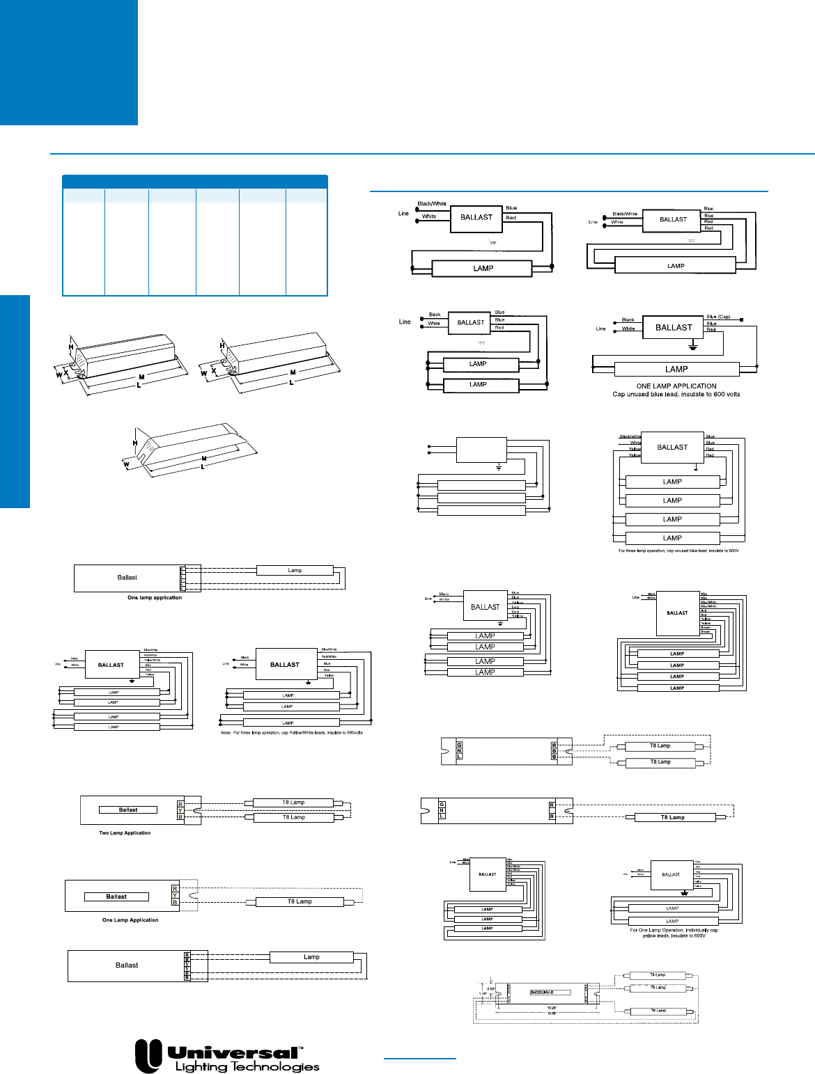
FOR MORE INFORMATION CALL
1-800-BALLAST
(225-5278)
Overall Dimensions Mounting Dimensions
Draw # L W H M X
ST 9.50” 2.40” 1.55” 8.89” 1.69”
-A 9.50” 1.70” 1.18” 8.89” 1.69”
-B 9.50” 1.50” 1.00” 8.89” 0.88”
-C 14.25” 1.18” 1.00” 13.75” ---
-D 16.88” 1.18” 1.00” 16.20” ---
-G 9.50” 1.18” 1.00” 8.89” ---
ESA 9.50” 1.56” 1.00” 8.88” 0.78”
ESB 9.50” 2.38” 1.00” 8.88” ---
-C, -D
WIRING DIAGRAMS
DIAGRAM 1
DIAGRAM 3a
DIAGRAM 2
DIAGRAM 21a
DIAGRAM 39a
DIAGRAM 40
DIAGRAM 3
DIAGRAM 30
DIAGRAM 21
DIAGRAM 39
DIAGRAM 6
Line White
Black Blue
Blue
Blue
Red
BALLAST
LAMP
LAMP
LAMP
DIAGRAM 24
DIAGRAM 23
DIAGRAM 38a
DIAGRAM 7a
For three lamp operation, cap
any blue lead, insulate to 600V
DIAGRAM 7
DIAGRAM 8
DIAGRAM 38
DIAGRAM 37a
PAGE 2- 18
F17T8
&
F25T8
TRIAD® ELECTRONIC BALLASTS
FOR F17T8 & F25T8 LAMPS
-A, -B, -G, ESA, ESB
Fluorescent-Electronic
ST

FOR MORE INFORMATION CALL
1-800-BALLAST
(225-5278)
PAGE 2- 19
IS = Instant Start
PRS = Programmed Rapid Start
RS = Rapid Start
STARTING METHOD LEGEND
PAR-IS = Parallel Instant Start
PAR-PRS = Parallel Programmed Rapid Start
PAR-RS = Parallel Rapid Start
SER-RS = Series Rapid Start
F32T8
TRIAD® ELECTRONIC BALLASTS
FOR (1) F32T8 LAMP
•Low Profile
Designs Featured
•Instant & Programmed
Rapid Starting Options
•1 Lamp Applications
NOM
See page 2-23 for Dimensions and Wiring Diagrams
Fluorescent-Electronic
Lamp
Certification Line Input Power Ballast Ballast Min. F/C
Starting Line Catalog Current Power Factor Factor Efficacy THD Start Wiring
Qty. Method Volts Number (Amps) (Watts) (PF) (BF) Factor (BEF) % Temp Diag. Dim.
F32T8 - One Lamp Applications
120 B132I120RH-A • • • 0.26 31 >.98 0.88 2.84 <20 0/-18 1 -A
277 B132I277RH-A • • 0.11 31 >.97 0.88 2.84 <20 0/-18 1 -A
347 B132I347RH • 0.09 31 >.98 0.88 2.84 <20 0/-18 1 ST
120 B132IUNVHP-B • • 0.25 30 >.95 0.88 2.93 <10 0/-18 1 -B
277 0.12 29 3.03
347 B132I347HP • 0.09 31 >.98 0.88 2.84 <10 0/-18 1 ST
120 B132IUNVEL-A • • 0.22 25 >.98 0.77 3.08 <10 0/-18 1 -A
277 0.11 >.95
120 B132IUNVHE-A • • 0.24 28 >.98 0.87 3.11 <10 0/-18 1 -A
277 0.12 >.95
120 B232I120L-A • • 0.29 33 >.90 0.96 2.91 <32 0/-18 3a -A
277 B232I277L-A • • 0.13 33 >.90 1.00 3.03 <32 0/-18 3a -A
347 B232I347L-A • 0.10 33 >.98 0.96 2.91 <20 0/-18 3a -A
120 B232I120RES-A* • • • 0.53 35 >.50 1.06 3.03 <135 0/-18 3a -A
120 B232I120RES-G* • • • 0.53 36 >.50 1.06 2.94 <150 0/-18 3a -G
120 B232I120RH-A • • • 0.31 38 >.90 1.09 2.87 <25 0/-18 3a -A
277 B232I277RH-A • • • 0.14 38 >.90 1.09 2.87 <25 0/-18 3a -A
347 B232I347RH-A • 0.11 36 >.95 1.05 2.92 <20 0/-18 3a -A
347 B232I347HPL • 0.09 32 >.98 0.91 2.84 <10 0/-18 3a ST
1 IS 120 B232IUNVHP-B • • • 0.29 35 >.99 1.05 3.00 <10 0/-18 3a -B
277 0.13 >.98
347 B232I347HP-A • 0.11 36 >.95 1.05 2.92 <10 0/-18 3a -A
120 B232IUNV-C • • 0.29 35 >.98 1.02 3.19 <10 0/-18 22 -C
277 0.13
120 B232IUNVEL-A • • 0.24 30 >.95 0.95 3.17 <10 0/-18 3a -A
277 0.11
120 B232I120EL • • 0.24 29 >.98 0.90 3.10 <10 0/-18 3a ST
277 B232I277EL • • 0.11 30 >.98 0.92 3.07 <10 0/-18 3a ST
120 B232IUNVHE-A • • 0.28 33 >.95 1.05 3.18 <10 0/-18 3a -A
277 0.13
120 B232IUNVHEH-A1• • 0.39 47 >.95 1.38 2.94 <10 0/-18 3a -A
277 0.18 46 3.00
120 B232I120HE • • 0.27 33 >.98 1.00 3.03 <10 0/-18 3a ST
277 B232I277HE • • 0.13 34 >.98 1.03 3.03 <10 0/-18 3a ST
120 ES1608A • • 0.25 30 >.97 0.87 2.90 <10 0/-18 39a ESA
277 0.11 31 2.81
120 B232PUNVHE-A • 0.24 29 >.90 0.88 3.03 <10 0/-18 30 -A
277 0.11
120 B232PUNVEL-A • 0.20 25 >.90 0.88 2.89 <10 0/-18 30 -A
277 0.09 23 3.09
120 B132PUNVHP-A • • • 0.26 31 >.99 0.88 2.84 <10 0/-18 2 -A
1 PRS 277 0.11 30 >.98 2.93
347 ES1510A • 0.09 31 >.97 0.87 2.81 <10 0/-18 40 ESA
120 ES4800A • • 0.26 31 >.97 1.00 3.23 <10 0/-18 37 ESA
277 0.12 32 3.13
120 B232PUNVHP-A • • • 0.27 32 >.99 1.00 3.13 <10 0/-18 30 -A
277 0.12 >.95 <15
*ForResidentialUseOnly
1ConsultLampManufacturersforapplicationswithBallastFactor>1.20

FOR MORE INFORMATION CALL
1-800-BALLAST
(225-5278)
PAGE 2- 20
TRIAD® ELECTRONIC BALLASTS
FOR (2) F32T8 LAMPS
•Low Profile
Designs Featured
•Instant & Programmed
Rapid Starting Options
•2 Lamp Applications
F32T8
NOM
See page 2-23 for Dimensions and Wiring Diagrams
Fluorescent-Electronic
Lamp
Certification Line Input Power Ballast Ballast Min. F/C
Starting Line Catalog Current Power Factor Factor Efficacy THD Start Wiring
Qty. Method Volts Number (Amps) (Watts) (PF) (BF) Factor (BEF) % Temp Diag. Dim.
F32T8 - Two Lamp Applications
120 B232I120L-A • • 0.44 51 >.95 0.78 1.53 <20 0/-18 3 -A
277 B232I277L-A • • 0.19 51 >.95 0.78 1.53 <20 0/-18 3 -A
347 B232I347L-A • 0.15 51 >.98 0.78 1.53 <20 0/-18 3 -A
120 B232I120RES-A* • • • 0.80 56 >.50 0.88 1.57 <120 0/-18 3 -A
120 B232I120RES-G* • • • 0.80 56 >.50 0.88 1.57 <130 0/-18 3 -G
120 B232I120RH-A • • • 0.49 58 >.98 0.88 1.52 <20 0/-18 3 -A
277 B232I277RH-A • • • 0.22 58 >.98 0.88 1.52 <20 0/-18 3 -A
347 B232I347RH-A • 0.17 58 >.99 0.88 1.52 <20 0/-18 3 -A
120 B232I120RHH-A • • 0.66 77 >.98 1.18 1.53 <20 0/-18 3 -A
277 B232I277RHH-A • • 0.29 77 >.98 1.18 1.53 <20 0/-18 3 -A
347 B232I347HPL • 0.14 50 >.99 0.78 1.56 <10 0/-18 3 ST
2 PAR-IS 120 B232IUNVHP-B • • • 0.47 56 >.99 0.88 1.57 <10 0/-18 3 -B
277 0.19 55 1.60
347 B232I347HP-A • 0.17 58 >.99 0.88 1.52 <10 0/-18 3 -A
120 B232IUNV-C • • 0.48 58 >.98 0.88 1.52 <10 0/-18 21 -C
277 0.20 56 1.57
120 B232IUNVEL-A • • 0.40 48 >.95 0.77 1.60 <10 0/-18 3 -A
277 0.17
120 B232I120EL • • 0.40 47 >.98 0.77 1.64 <10 0/-18 3 ST
277 B232I277EL • • 0.18 47 >.98 0.77 1.64 <10 0/-18 3 ST
120 B232IUNVHE-A • • 0.45 55 >.95 0.87 1.58 <10 0/-18 3 -A
277 0.20 54 1.61
120 B232IUNVHEH-A • • 0.62 74 >.95 1.18 1.59 <10 0/-18 3 -A
277 0.26 73 1.62
120 B232I120HE • • 0.45 54 >.98 0.87 1.61 <10 0/-18 3 ST
277 B232I277HE • • 0.20 53 >.98 0.87 1.64 <10 0/-18 3 ST
347 B332IHRVHB-E • • 0.22 76 >.97 1.22 1.61 <10 0/-18 46 -E
2 SER-IS 480 0.17 >.90
120 ES1608A • • 0.48 57 >.97 0.87 1.53 <10 0/-18 39 ESA
277 0.21 56 1.55
120 B332I120L-A • • 0.51 58 >.95 0.92 1.59 <25 0/-18 6 -A
277 B332I277L-A • • 0.21 61 >.98 0.92 1.51 <20 0/-18 6 -A
347 B332I347L • 0.16 56 >.99 0.87 1.55 <20 0/-18 6 ST
120 B332I120RH-A • • • 0.59 69 >.95 1.03 1.49 <25 0/-18 6 -A
277 B332I277RH-A • • • 0.26 69 >.95 1.04 1.51 <25 0/-18 6 -A
347 B332I347RH • 0.19 65 >.95 0.99 1.52 <20 0/-18 6 ST
347 B332I347HPL • 0.16 56 >.99 0.87 1.55 <10 0/-18 6 ST
120 B332IUNVHP-A • • • 0.53 63 >.99 0.99 1.57 <10 0/-18 6 -A
277 0.24 >.95
2 PAR-IS 347 B332I347HP • 0.19 66 >.99 0.99 1.50 <10 0/-18 6 ST
120 B332IUNVEL-A • • 0.48 57 >.99 0.89 1.56 <10 0/-18 6 -A
277 0.21 56 >.97 1.59
120 B332I120EL • • 0.45 53 >.98 0.86 1.62 <10 0/-18 6 ST
277 B332I277EL • • 0.20 55 >.98 0.87 1.58 <10 0/-18 6 ST
120 B332IUNVHE-A • • 0.53 64 >.99 0.99 1.55 <10 0/-18 6 -A
277 0.23 63 >.98 1.57
120 B332I120HE • • 0.50 60 >.98 0.96 1.60 <10 0/-18 6 ST
277 B332I277HE • • 0.23 61 >.98 1.01 1.66 <10 0/-18 6 ST
120 B332IUNVHEH-A1 • • 0.69 83 >.95 1.27 1.53 <10 0/-18 6 -A
277 0.30 81 1.57
120 B232PUNVEL-A • 0.40 47 >.90 0.71 1.51 <10 0/-18 30 -A
277 0.17 46 >.90 1.54
2 SER-PRS 120 B232PUNVHE-A • 0.47 56 >.90 0.88 1.57 <10 0/-18 30 -A
277 0.20 55 >.90 1.60
120 B232PUNVHP-A • • • 0.52 62 >.99 0.88 1.42 <10 0/-18 30 -A
277 0.22 60 >.98 1.47
*ForResidentialUseOnly
1Consultlampmanufacturers

FOR MORE INFORMATION CALL
1-800-BALLAST
(225-5278)
PAGE 2- 21
F32T8
•Low Profile
Designs Featured
•Instant & Programmed
Rapid Starting Options
•3 Lamp Applications
TRIAD® ELECTRONIC BALLASTS
FOR (3) F32T8 LAMPS
NOM
See page 2-23 for Dimensions and Wiring Diagrams
Fluorescent-Electronic
Lamp
Certification Line Input Power Ballast Ballast Min. F/C
Starting Line Catalog Current Power Factor Factor Efficacy THD Start Wiring
Qty. Method Volts Number (Amps) (Watts) (PF) (BF) Factor (BEF) % Temp Diag. Dim.
120 ES4800A • • 0.49 58 >.97 0.87 1.50 <10 0/-18 37 ESA
277 0.22 60 1.45
347 ES1329A • • 0.17 59 >.97 0.87 1.47 <10 0/-18 37 ESA
120 B332PUNVHP-A • • • 0.54 64 >.99 0.99 1.55 <10 0/-18 23 -A
277 0.24 63 >.90 1.57
F32T8-ThreeLampApplications
120 B332I120L-A • • 0.65 76 >.98 0.78 1.03 <20 0/-18 6 -A
277 B332I277L-A • • 0.28 76 >.98 0.78 1.03 <20 0/-18 6 -A
347 B332I347L • 0.21 75 >.99 0.79 1.05 <20 0/-18 6 ST
120 B332I120RH-A • • • 0.75 86 >.98 0.88 1.02 <20 0/-18 6 -A
277 B332I277RH-A • • • 0.33 86 >.98 0.88 1.02 <20 0/-18 6 -A
347 B332I347RH • 0.25 85 >.98 0.88 1.04 <20 0/-18 6 ST
120 B332I120RHH • • 0.98 113 >.98 1.18 1.04 <20 0/-18 6 ST
277 B332I277RHH • • 0.43 113 >.98 1.18 1.04 <20 0/-18 6 ST
347 B332I347HPL • 0.21 75 >.99 0.79 1.05 <10 0/-18 6 ST
3 PAR-IS 120 B332IUNVHP-A • • • 0.71 85 >.99 0.88 1.02 <10 0/-18 6 -A
277 0.31 83 >.98 1.05
347 B332I347HP • 0.25 88 >.99 0.88 1.00 <10 0/-18 6 ST
120 B332IUNVEL-A • • 0.61 74 >.99 0.77 1.05 <10 0/-18 6 -A
277 0.26 73 >.98 1.07
120 B332I120EL • • 0.59 70 >.98 0.77 1.10 <10 0/-18 6 ST
277 B332I277EL • • 0.26 70 >.99 0.77 1.10 <10 0/-18 6 ST
120 B332IUNVHE-A • • 0.70 83 >.99 0.87 1.04 <10 0/-18 6 -A
277 0.30 81 >.98 1.05
120 B332I120HE • • 0.67 80 >.98 0.87 1.09 <10 0/-18 6 ST
277 B332I277HE • • 0.30 79 >.99 0.87 1.10 <10 0/-18 6 ST
120 B332IUNVHEH-A • • 0.91 111 >.98 1.18 1.06 <10 0/-18 6 -A
277 0.39 108 1.09
3 SER-IS 347 B332IHRVHB-E • • 0.32 110 >.98 1.18 1.07 <10 0/-18 46 -E
480 0.24 109 >.95 1.08
3 SER-RS 120 B332PUNVHP-A • • • 0.77 92 >.99 0.88 0.96 <10 0/-18 23 -A
277 0.34 90 >.95 0.98
120 B432I120L-A • • 0.71 83 >.97 0.83 1.00 <20 0/-18 7a -A
277 B432I277L-A • • 0.31 83 >.97 0.84 1.01 <20 0/-18 7a -A
347 B432I347L • 0.24 83 >.98 0.87 1.05 <20 0/-18 7 ST
120 B432I120RES-A* • • • 1.20 92 >.50 0.96 1.04 <130 0/-18 7a -A
120 B432I120RH-A • • • 0.78 92 >.95 0.94 1.02 <20 0/-18 7a -A
277 B432I277RH-A • • • 0.33 92 >.95 0.99 1.08 <20 0/-18 7a -A
347 B432I347RH • 0.28 95 >.95 0.99 1.04 <20 0/-18 7a ST
347 B432I347HPL • 0.24 83 >.98 0.87 1.05 <10 0/-18 7 ST
120 B432IUNVHP-A • • • 0.77 92 >.99 0.94 1.02 <10 0/-18 7a -A
3 PAR-IS 277 0.34 89 >.95 1.06
347 B432I347HP • 0.28 92 >.98 0.99 1.08 <10 0/-18 7a S
120 B432IUNV-D • • 0.77 92 >.98 0.96 1.02 <10 0/-18 24 -D
277 0.33 91 1.05
120 B432IUNVEL-A • • 0.67 80 >.99 0.86 1.08 <10 0/-18 7a -A
277 0.29 78 >.98 1.10
120 B432I120EL • • 0.67 79 >.98 0.84 1.06 <10 0/-18 7 ST
277 B432I277EL • • 0.28 76 >.98 0.87 1.14 <10 0/-18 7 ST
120 B432IUNVHE-A • • 0.74 89 >.99 0.94 1.06 <10 0/-18 7a -A
277 0.32 87 >.98 1.08
120 B432I120HE • • 0.74 88 >.98 0.96 1.09 <10 0/-18 7 ST
277 B432I277HE • • 0.33 89 >.98 0.96 1.08 <10 0/-18 7 ST
277 B432I277HEH1 • • 0.43 119 >.99 1.28 1.08 <10 0/-18 7 ST
120 ES1720B • • 0.68 80 >.97 0.87 1.09 <10 0/-18 38a ESB
277 0.31 82 1.06
3 SER-PRS 120 B432PUNVHP-A • • • 0.77 92 >.99 0.93 1.01 <10 0/-18 8 -A
277 0.34 90 >.95 1.03
*ForResidentialUseOnly
1ConsultlampmanufacturersforapplicationswithBallastFactor>1.20
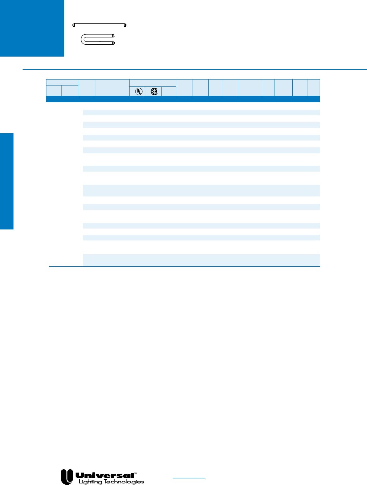
FOR MORE INFORMATION CALL
1-800-BALLAST
(225-5278)
PAGE 2- 22
IS = Instant Start
PRS = Programmed Rapid Start
RS = Rapid Start
STARTING METHOD LEGEND
PAR-IS = Parallel Instant Start
PAR-PRS = Parallel Programmed Rapid Start
SER-PRS = Series Programmed Rapid Start
PAR-RS = Parallel Rapid Start
SER-RS = Series Rapid Start
F32T8 TRIAD® ELECTRONIC BALLASTS
FOR (4) F32T8 LAMPS
•Low Profile
Designs Featured
•Instant & Programmed
Rapid Starting Options
•4 Lamp Applications
Lamp
Certification Line Input Power Ballast Ballast Min. F/C
Starting Line Catalog Current Power Factor Factor Efficacy THD Start Wiring
Qty. Method Volts Number (Amps) (Watts) (PF) (BF) Factor (BEF) % Temp Diag. Dim.
F32T8-FourLampApplications
120 B432I120L-A • • 0.85 100 >.98 0.78 0.78 <20 0/-18 7a -A
277 B432I277L-A • • 0.36 98 >.98 0.78 0.80 <20 0/-18 7a -A
347 B432I347L • 0.29 101 >.99 0.78 0.77 <20 0/-18 7 ST
120 B432I120RES-A* • • • 1.40 109 >.50 0.87 0.80 <130 0/-18 7a -A
120 B432I120RH-A • • • 0.93 112 >.99 0.88 0.79 <20 0/-18 7a -A
277 B432I277RH-A • • • 0.40 110 >.98 0.88 0.80 <20 0/-18 7a -A
347 B432I347RH • 0.33 114 >.98 0.88 0.77 <20 0/-18 7a ST
347 B432I347HPL • 0.29 101 >.99 0.78 0.77 <10 0/-18 7 ST
120 B432IUNVHP-A • • • 0.93 112 >.99 0.88 0.79 <10 0/-18 7a -A
277 0.40 108 >.98 0.80
347 B432I347HP • 0.33 114 >.99 0.88 0.77 <10 0/-18 7a ST
4 PAR-IS
120 B432IUNV-D • • 0.93 111 >.98 0.88 0.77 <10 0/-18 25 -D
277 0.40 109 0.80
120 B432IUNVEL-A • • 0.80 97 >.99 0.77 0.79 <10 0/-18 7a -A
277 0.34 96 >.98 0.80
120 B432I120EL • • 0.81 95 >.99 0.77 0.81 <10 0/-18 7a ST
277 B432I277EL • • 0.35 93 >.99 0.77 0.83 <10 0/-18 7a ST
120 B432IUNVHE-A • • 0.91 109 >.99 0.87 0.80 <10 0/-18 7a -A
277 0.38 106 0.82
120 B432I120HE • • 0.90 106 >.99 0.87 0.82 <10 0/-18 7a ST
277 B432I277HE • • 0.39 105 >.99 0.87 0.83 <10 0/-18 7a ST
277 B432I277HEH • • 0.53 145 >.99 1.18 0.81 <10 0/-18 7a ST
120 ES1720B • • 0.88 107 >.97 0.87 0.81 <10 0/-18 38 ESB
277 0.40 108 0.82
4 SER-PRS 120 B432PUNVHP-A • • • 1.00 119 >.99 0.88 0.74 <10 0/-18 8 -A
277 0.42 115 >.98 0.77
NOM
*ForResidentialUseOnly
See page 2-23 for Dimensions and Wiring Diagrams
Fluorescent-Electronic
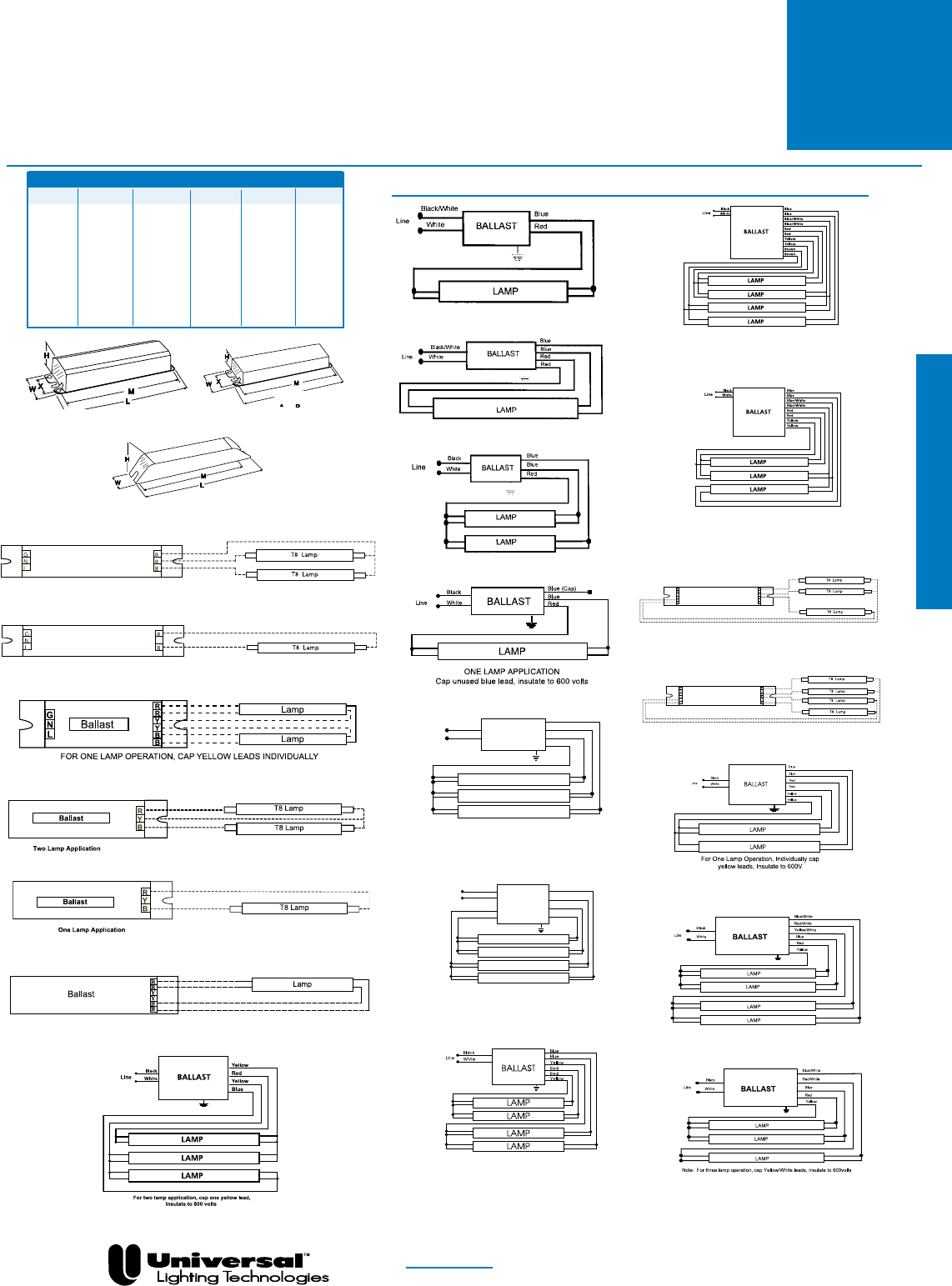
FOR MORE INFORMATION CALL
1-800-BALLAST
(225-5278)
Overall Dimensions Mounting Dimensions
Draw # L W H M X
ST 9.50” 2.40” 1.55” 8.89” 1.69”
-A 9.50” 1.70” 1.18” 8.89” 1.69”
-B 9.50” 1.50” 1.00” 8.89” 0.88”
-C 14.25” 1.18” 1.00” 13.75” ---
-D 16.88” 1.18” 1.00” 16.20” ---
-E 16.88” 1.74” 1.18” 16.28” ---
-G 9.50” 1.18” 1.00” 8.89” ---
ESA
9.50” 1.56” 1.00” 8.88” 0.78”
ESB 9.50” 2.38” 1.00” 8.88” ---
-C, -D
-A, -B, -E, -G ESA, ESB
WIRING DIAGRAMS
DIAGRAM 1
DIAGRAM 2
DIAGRAM 40
DIAGRAM 30
DIAGRAM 22
DIAGRAM 39a
DIAGRAM 3a
DIAGRAM 3
DIAGRAM 21
DIAGRAM 39
DIAGRAM 23
For Two Lamp operation, individually
cap yellow leads, Insulate to 600V
DIAGRAM 6
For Two Lamp operation,
Insulate one blue lead to 600V
Line White
Black Blue
Blue
Blue
Red
BALLAST
LAMP
LAMP
LAMP
DIAGRAM 7
For Three Lamp Operation,
Insulate one blue lead to 600V
White
Black
Line
Yellow Red
Red
Blue
Blue
Yellow BALLAST
LAMP
LAMP
LAMP
LAMP
DIAGRAM 7a
DIAGRAM 8
DIAGRAM 38a
For three lamp operation, cap any
blue lead, insulate to 600V
For Three Lamp Application, Individually
cap brown leads, Insulate to 600V
DIAGRAM 25
DIAGRAM 38
DIAGRAM 24
DIAGRAM 37
PAGE 2- 23
F32T8
TRIAD® ELECTRONIC BALLASTS
FOR F32T8 LAMPS
DIAGRAM 46
Fluorescent-Electronic
ST

FOR MORE INFORMATION CALL
1-800-BALLAST
(225-5278)
PAGE 2- 24
F32T8ES
30 WATT
•High Performance
Models and Low Profile
Designs
•Instant and Programmed
Rapid Starting Options
•1-2 Lamp Applications
TRIAD® ELECTRONIC BALLASTS
FOR (1) & (2) F32T8ES(30 WATT) LAMPS
NOM
See page 2-30 for Dimensions and Wiring Diagrams
Fluorescent-Electronic
Lamp
Certification Line Input Power Ballast Ballast Min. F/C
Starting Line Catalog Current Power Factor Factor Efficacy THD Start Wiring
Qty. Method Volts Number (Amps) (Watts) (PF) (BF) Factor (BEF) % Temp Diag. Dim.
F32T8ES(30W)-OneLampApplications
277 B132I277RH-A • • 0.11 29 >.97 0.94 3.24 <15 60/16 1 -A
120 B132IUNVHP-B • • 0.25 29 >.95 0.88 3.03 <10 60/16 1 -B
1 IS 277 0.11
120 B132IUNVEL-A • • 0.22 25 >.98 0.77 3.08 <10 60/16 1 -A
277 0.11 >.95
120 B132IUNVHE-A • • 0.24 28 >.98 0.87 3.11 <10 60/16 1 -A
277 0.12 >.95
1 PRS 120 B132PUNVHP-A • • • 0.23 28 >.99 0.88 3.14 <10 60/16 2 -A
277 0.10 >.98
277 B232I277L-A • 0.12 33 >.90 0.98 2.97 <32 60/16 3a -A
347 B232I347L-A • 0.15 51 >.98 0.78 1.53 <20 60/16 3a -A
120 B232I120RH-A • • • 0.32 35 >.90 1.10 3.14 <32 60/16 3a -A
277 B232I277RH-A • • • 0.15 38 >.90 1.10 2.89 <25 60/16 3a -A
347 B232I347RH-A • 0.15 54 >.98 0.88 1.63 <20 60/16 3a -A
120 B232IUNVHP-B • • • 0.28 33 >.99 1.05 3.18 <10 60/16 3a -B
1 PAR-IS 277 0.12 >.98
347 B232I347HP-A • 0.15 53 >.98 0.88 1.66 <10 60/16 3a -A
120 B232IUNVEL-A • • 0.23 28 >.95 0.92 3.92 <10 60/16 3a -A
277 0.11
120 B232I120EL • • 0.24 28 >.98 0.89 3.18 <10 60/16 3 ST
277 B232I277EL • • 0.11 28 >.98 0.92 3.29 <10 60/16 3 ST
120 B232IUNVHE-A • • 0.25 32 >.95 1.05 3.28 <10 60/16 3a -A
277 0.12
120 B232IUNVHEH-A1• • 0.37 43 >.95 1.38 3.21 <10 60/16 3a -A
277 0.16
120 B232I120HE • • 0.26 30 >.98 1.00 3.33 <10 60/16 3 ST
277 B232I277HE • • 0.12 32 >.98 1.03 3.22 <10 60/16 3 ST
120 B232PUNVEL-A • 0.19 22 >.90 0.72 3.27 <10 60/16 30 -A
277 0.09 23 3.12
1 PRS 120 B232PUNVHE-A • 0.22 27 >.90 0.88 3.26 <10 60/16 30 -A
277 0.10 26 3.38
120 B232PUNVHP-A • • • 0.25 30 >.99 1.00 3.33 <10 60/16 30 -A
277 0.11 >.95
F32T8ES(30W)-TwoLampApplications
120 B232IUNVEL-A • • 0.38 46 >.95 0.77 1.67 <10 60/16 3 -A
277 0.17
120 B232I120EL • • 0.38 44 >.98 0.77 1.75 <10 60/16 3 ST
277 B232I277EL • • 0.17 44 >.98 0.77 1.75 <10 60/16 3 ST
120 B232IUNVHE-A • • 0.42 52 >.95 0.87 1.67 <10 60/16 3 -A
277 0.19 51 1.71
120 B232IUNVHEH-A • • 0.59 70 >.95 1.18 1.69 <10 60/16 3 -A
277 0.25 68 1.74
120 B232I120HE • • 0.43 51 >.98 0.87 1.71 <10 60/16 3 ST
277 B232I277HE • • 0.19 50 >.98 0.87 1.74 <10 60/16 3 ST
277 B232I277L-A • 0.18 49 >.95 0.77 1.57 <20 60/16 3 -A
347 B232I347L-A • 0.14 48 >.98 0.96 3.10 <20 60/16 3 -A
2 PAR-IS 120 B232I120RH-A • • • 0.47 55 >.98 0.89 1.62 <20 60/16 3 -A
277 B232I277RH-A • • • 0.21 58 >.98 0.89 1.53 <20 60/16 3 -A
347 B232I347RH-A • 0.10 34 >.98 1.04 3.06 <20 60/16 3 -A
120 B232I120RHH-A • • 0.63 73 >.98 1.18 1.62 <20 60/16 3 -A
277 B232I277RHH-A • • 0.26 73 >.98 1.18 1.62 <20 60/16 3 -A
120 B232IUNVHP-B • • • 0.44 53 >.99 0.88 1.66 <10 60/16 3 -B
277 0.19 52 >.98 1.69
347 B232I347HP-A • 0.10 34 >.98 1.04 3.06 <10 60/16 3 -A
120 B232PUNVEL-A • 0.37 45 >.90 0.71 1.59 <10 60/16 30 -A
277 0.16 44 1.61
2 SER-PRS 120 B232PUNVHE-A • 0.43 50 >.90 0.87 1.74 <10 60/16 30 -A
277 0.18 49 1.78
120 B232PUNVHP-A • • • 0.50 60 >.99 0.88 1.47 <10 60/16 30 -A
277 0.21 58 >.98 1.52
120 B332I120RH-A • • • 0.54 63 >.96 1.01 1.60 <25 60/16 6 -A
277 B332I277RH-A • • • 0.23 63 >.97 1.00 1.59 <25 60/16 6 -A
120 B332IUNVHP-A • • • 0.50 59 >.99 0.99 1.68 <10 60/16 6 -A
277 0.22 >.95
2 PAR-IS 120 B332IUNVEL-A • • 0.46 54 >.99 0.89 1.65 <10 60/16 6 -A
277 0.20 53 >.98 1.68
120 B332I120EL • • 0.42 51 >.98 0.86 1.69 <10 60/16 6 ST
277 B332I277EL • • 0.19 50 >.98 0.86 1.72 <10 60/16 6 ST
120 B332IUNVHE-A • • 0.49 59 >.99 0.99 1.68 <10 60/16 6 -A
277 0.21 57 >.97 1.74
1Consultlampmanufacturers

FOR MORE INFORMATION CALL
1-800-BALLAST
(225-5278)
F32T8ES
30 WATT
•High Performance
Models and Low Profile
Designs
•Instant and Programmed
Rapid Starting Options
•3-4 Lamp Applications
TRIAD® ELECTRONIC BALLASTS
FOR (2)(cont.), (3) & (4) F32T8ES LAMPS
NOM
IS = Instant Start
PRS = Programmed Rapid Start
RS = Rapid Start
STARTING METHOD LEGEND
PAR-IS = Parallel Instant Start
PAR-PRS = Parallel Programmed Rapid Start
SER-PRS = Series Programmed Rapid Start
PAR-RS = Parallel Rapid Start
SER-RS = Series Rapid Start
SER-IS = Series Instant Start
PAGE 2- 25
See page 2-30 for Dimensions and Wiring Diagrams
Fluorescent-Electronic
Lamp
Certification Line Input Power Ballast Ballast Min. F/C
Starting Line Catalog Current Power Factor Factor Efficacy THD Start Wiring
Qty. Method Volts Number (Amps) (Watts) (PF) (BF) Factor (BEF) % Temp Diag. Dim.
F32T8ES(30W)-TwoLampApplications
120 B332I120HE • • 0.47 57 >.98 0.96 1.68 <10 60/16 6 ST
2 PAR-IS 277 B332I277HE • • 0.21 58 >.98 0.99 1.71 <10 60/16 6 ST
120 B332IUNVHEH-A • • 0.65 78 >.95 1.28 1.64 <10 60/16 6 -A
277 0.28 76 1.68
2 SER-IS 347 B332IHRVHB-E • • 0.21 71 >.97 1.22 1.72 <10 60/16 46 -E
480 0.16 >.90
2 SER-PRS 120 B332PUNVHP-A • • • 0.51 61 >.99 0.99 1.62 <10 60/16 23 -A
277 0.23 60 >.90 1.65
F32T8ES(30W)-ThreeLampApplications
120 B332I120RH-A • • • 0.69 81 >.98 0.88 1.09 <20 60/16 6 -A
277 B332I277RH-A • • • 0.30 81 >.98 0.88 1.09 <20 60/16 6 -A
120 B332IUNVHP-A • • • 0.66 79 >.99 0.89 1.13 <10 60/16 6 -A
277 0.29 77 >.95 1.16
3 PAR-IS 120 B332IUNVEL-A • • 0.58 70 >.99 0.77 1.10 <10 60/16 6 -A
277 0.25 69 >.98 1.12
120 B332I120EL • • 0.56 66 >.98 0.77 1.17 <10 60/16 6 ST
277 B332I277EL • • 0.24 65 >.99 0.77 1.18 <10 60/16 6 ST
120 B332IUNVHE-A • • 0.65 79 >.99 0.87 1.10 <10 60/16 6 -A
277 0.28 77 >.98 1.13
120 B332I120HE • • 0.63 76 >.98 0.87 1.14 <10 60/16 6 ST
277 B332I277HE • • 0.28 75 >.99 0.87 1.16 <10 60/16 6 ST
120 B332IUNVHEH-A • • 0.86 104 >.95 1.18 1.13 <10 60/16 6 -A
277 0.37 101 1.17
3 SER-IS 347 B332IHRVHB-E • • 0.30 102 >.98 1.18 1.16 <10 60/16 46 -E
480 0.22 101 >.95 1.17
3 SER-PRS 120 B332PUNVHP-A • • • 0.73 87 >.99 0.88 1.01 <10 60/16 23 -A
277 0.32 85 >.95 1.04
120 B432I120L-A • 0.65 78 >.98 0.86 1.10 <20 60/16 7a -A
120 B432I120RH-A • • • 0.71 85 >.99 0.88 1.04 <10 60/16 7a -A
347 B432I347HP • 0.26 88 >.98 0.99 1.13 <10 60/16 7a ST
347 B432I347RH • 0.26 88 >.98 0.99 1.13 <20 60/16 7a ST
120 B432IUNVHP-A • • • 0.72 86 >.98 0.96 1.12 <10 60/16 7a -A
277 0.32 84 >.95 1.14
3 PAR-IS 120 B432IUNVEL-A • • 0.62 75 >.99 0.86 1.15 <10 60/16 7a -A
277 0.27 73 >.98 1.18
120 B432I120EL • • 0.61 73 >.98 0.85 1.16 <10 60/16 7a ST
277 B432I277EL • • 0.27 73 >.98 0.84 1.15 <10 60/16 7a ST
120 B432IUNVHE-A • • 0.70 84 >.98 0.96 1.14 <10 60/16 7a -A
277 0.30 82 1.17
120 B432I120HE • • 0.70 83 >.98 0.96 1.16 <10 60/16 7 ST
3 SER-PRS 277 B432I277HE • • 0.31 84 >.98 0.96 1.14 <10 60/16 7 ST
120 B432PUNVHP-A • • • 0.73 87 >.99 0.93 1.07 <10 60/16 8 -A
277 0.32 85 >.95 1.09
F32T8ES(30W)-FourLampApplications
120 B432I120L-A • 0.80 95 >.98 0.80 0.84 <20 60/16 7a -A
120 B432I120RH-A • • • 0.87 104 >.99 0.88 0.85 <10 60/16 7a -A
347 B432I347HP • 0.31 106 >.99 0.88 0.83 <10 60/16 7a ST
347 B432I347RH • 0.31 106 >.99 0.88 0.83 <20 60/16 7a ST
120 B432IUNVHP-A • • • 0.87 104 >.98 0.88 0.85 <10 60/16 7a -A
277 0.38 101 >.95 0.87
4 PAR-IS 120 B432IUNVEL-A • • 0.80 97 >.99 0.77 0.79 <10 60/16 7a -A
277 0.34 96 >.98 0.80
120 B432I120EL • • 0.75 89 >.99 0.77 0.87 <10 60/16 7a ST
277 B432I277EL • • 0.32 87 >.99 0.77 0.89 <10 60/16 7a ST
120 B432IUNVHE-A • • 0.91 109 >.99 0.87 0.80 <10 60/16 7a -A
277 0.38 106 0.82
120 B432I120HE • • 0.85 100 >.99 0.87 0.87 <10 60/16 7a ST
277 B432I277HE • • 0.37 99 >.99 0.87 0.88 <10 60/16 7a ST
277 B432I277HEH • • 0.49 134 >.99 1.18 0.88 <10 60/16 7a ST
4 SER-PRS 120 B432PUNVHP-A • • • 0.95 114 >.99 0.88 0.77 <10 60/16 8 -A
277 0.41 110 >.95 0.80

FOR MORE INFORMATION CALL
1-800-BALLAST
(225-5278)
F32T8ES
(25 WATT)
•High Performance
Models and Low Profile
Designs
•1-2 Lamp Applications
TRIAD® ELECTRONIC BALLASTS
FOR (1) & (2)
F32T8ES (25 WATT) LAMPS
NOM
PAGE 2- 26
See page 2-30 for Dimensions and Wiring Diagrams
Fluorescent-Electronic
Lamp
Certification Line Input Power Ballast Ballast Min. F/C
Starting Line Catalog Current Power Factor Factor Efficacy THD Start Wiring
Qty. Method Volts Number (Amps) (Watts) (PF) (BF) Factor (BEF) % Temp Diag. Dim.
F32T8ES(25W)-OneLampApplications
120 B132IUNVHP-B • • 0.24 24 >.95 0.88 3.67 <10 60/16 1 -B
277 0.09
120 B132IUNVEL-A • • 0.17 20 >.98 0.77 3.85 <10 60/16 1 -A
277 0.07 >.95
120 B132IUNVHE-A • • 0.19 23 >.98 0.87 3.78 <10 60/16 1 -A
277 0.09 >.95
120 B232IUNVHP-B • • • 0.23 28 >.99 1.05 3.75 <10 60/16 3a -B
277 0.10 >.98
1 IS 120 B232IUNVEL-A • • 0.20 24 >.99 0.95 3.96 <10 60/16 3a -A
277 0.09 25 >.95 3.80 <15
120 B232I120EL • • 0.19 23 >.98 0.89 3.87 <10 60/16 3a ST
277 B232I277EL • • 0.08 23 >.98 0.92 4.00 <15 60/16 3a ST
120 B232IUNVHE-A • • 0.23 27 >.98 1.05 3.89 <10 60/16 3a -A
277 0.10 >.95
120 B232IUNVHEH-A1• • 0.32 38 >.95 1.38 3.63 <10 60/16 3a -A
277 0.14 37 3.73
120 B232I120HE • • 0.21 25 >.98 1.00 4.00 <10 60/16 3 ST
277 B232I277HE • • 0.90 24 >.98 1.03 4.29 <10 60/16 3 ST
120 B132PUNVHP-A • • • 0.21 25 >.99 0.88 3.52 <10 60/16 2 -A
277 0.09
120 B232PUNVEL-A • 0.16 19 >.90 0.71 3.74 <10 60/16 30 -A
1 PRS 277 0.08 19 3.74
120 B232PUNVHE-A • 0.20 25 >.90 0.88 3.52 <10 60/16 30 -A
277 0.09 24 3.67
120 B232PUNVHP-A • • • 0.22 27 >.99 1.00 3.70 <10 60/16 30 -A
277 0.10 >.94
F32T8ES(25W)-TwoLampApplications
120 B232IUNVHP-B • • • 0.37 44 >.99 0.88 2.00 <10 60/16 3 -B
277 0.16 43 >.98 2.05
120 B232IUNVEL-A • • 0.33 39 >.99 0.77 1.97 <10 60/16 3 -A
277 0.14 38 >.98 2.03
120 B232I120EL • • 0.31 37 >.98 0.77 2.08 <10 60/16 3 ST
277 B232I277EL • • 0.14 37 >.98 0.77 2.08 <10 60/16 3 ST
120 B232IUNVHE-A • • 0.37 44 >.98 0.87 1.98 <10 60/16 3 -A
277 0.16 43 2.02
120 B232IUNVHEH-A • • 0.49 59 >.95 1.18 2.00 <10 60/16 3 -A
277 0.21 58 2.03
120 B232I120HE • • 0.34 41 >.98 0.87 2.12 <10 60/16 3 ST
277 B232I277HE • • 0.15 41 >.98 0.87 2.12 <10 60/16 3 ST
2 PAR-IS 120 B332IUNVHP-A • • • 0.43 51 >.98 1.00 1.96 <10 60/16 6 -A
277 0.20 >.90
120 B332IUNVEL-A • • 0.37 44 >.99 0.89 2.02 <10 60/16 6 -A
277 0.16 43 >.95 2.07
120 B332I120EL • • 0.35 42 >.98 0.86 2.05 <10 60/16 6 ST
277 B332I277EL • • 0.16 43 >.98 0.86 2.00 <10 60/16 6 ST
120 B332IUNVHE-A • • 0.43 51 >.98 0.99 1.94 <10 60/16 6 -A
277 0.19 50 >.95 1.98
120 B332I120HE • • 0.40 48 >.98 0.96 2.00 <10 60/16 6 ST
277 B332I277HE • • 0.17 48 >.99 0.99 2.06 <10 60/16 6 ST
120 B332IUNVHEH-A1• • 0.55 66 >.95 1.28 1.94 <10 60/16 6 -A
277 0.25 65 1.97
347 B332IHRVH-E • • 0.18 61 >.95 1.14 1.87 <10 60/16 46 -E
480 0.14 >.90
2 SER-IS 120 B232PUNVHP-A • • • 0.43 52 >.99 0.88 1.69 <10 60/16 30 -A
277 0.19 51 >.98 1.73
120 B332PUNVHP-A • • • 0.42 50 >.99 0.99 1.98 <10 60/16 23 -A
277 0.20 >.90
120 B232PUNVEL-A • 0.32 38 >.90 0.71 1.87 <10 60/16 30 -A
2 SER-PRS 277 0.14 38 1.87
120 B232PUNVHE-A • 0.37 44 >.90 0.87 1.98 <10 60/16 30 -A
277 0.16 41 2.02
1ConsultlampmanufacturersforapplicationswithBallastFactor>1.20

FOR MORE INFORMATION CALL
1-800-BALLAST
(225-5278)
TRIAD® ELECTRONIC BALLASTS
FOR (3) & (4)
F32T8ES (25 WATT) LAMPS
PAGE 2- 27
IS = Instant Start
PRS = Programmed Rapid Start
RS = Rapid Start
STARTING METHOD LEGEND
PAR-IS = Parallel Instant Start
PAR-PRS = Parallel Programmed Rapid Start
SER-PRS = Series Programmed Rapid Start
PAR-RS = Parallel Rapid Start
SER-RS = Series Rapid Start
SER-IS = Series Instant Start
F32T8ES
(25 WATT)
•High Performance
Models and Low Profile
Designs
•3-4 Lamp Applications
NOM
See page 2-30 for Dimensions and Wiring Diagrams
Fluorescent-Electronic
Lamp
Certification Line Input Power Ballast Ballast Min. F/C
Starting Line Catalog Current Power Factor Factor Efficacy THD Start Wiring
Qty. Method Volts Number (Amps) (Watts) (PF) (BF) Factor (BEF) % Temp Diag. Dim.
F32T8ES(25W)-ThreeLampApplications
120 B332IUNVHP-A • • • 0.57 69 >.99 0.90 1.30 <10 60/16 6 -A
277 0.26 68 >.95 1.32
120 B332IUNVEL-A • • 0.48 58 >.99 0.77 1.33 <10 60/16 6 -A
277 0.21 57 >.97 1.35
120 B332I120EL • • 0.47 56 >.98 0.77 1.38 <10 60/16 6 ST
3 PAR-IS 277 B332I277EL • • 0.20 56 >.98 0.77 1.38 <10 60/16 6 ST
120 B332IUNVHE-A • • 0.24 66 >.98 0.87 1.32 <10 60/16 6 -A
277 0.60 65 >.95 1.34
120 B332I120HE • • 0.54 64 >.98 0.87 1.36 <10 60/16 6 ST
277 B332I277HE • • 0.23 64 >.99 0.87 1.36 <10 60/16 6 ST
120 B332IUNVHEH-A • • 0.72 87 >.95 1.18 1.36 <10 60/16 6 -A
277 0.32 85 1.39
3 SER-IS 347 B332IHRVHB-E • • 0.26 88 >.97 1.11 1.26 <10 60/16 46 -E
480 0.19 >.90
120 B432IUNVHP-A • • • 0.61 73 >.98 0.97 1.33 <10 60/16 7a -A
277 0.27 72 >.95 1.35
120 B432I120EL • • 0.51 61 >.98 0.85 1.39 <10 60/16 7 ST
3 PAR-IS 277 B432I277EL • • 0.22 61 >.98 0.87 1.43 <10 60/16 7 ST
120 B432IUNVHE-A • • 0.60 72 >.99 0.96 1.33 <10 60/16 7a -A
277 0.26 71 >.95 1.35
120 B432I120HE • • 0.57 68 >.99 0.96 1.41 <10 60/16 7a ST
274 B432I277HE • • 0.25 69 >.99 0.96 1.39 <10 60/16 7a ST
120 B332PUNVHP-A • • • 0.61 73 >.99 0.88 1.21 <10 60/16 23 -A
3 SER-PRS 277 0.27 71 >.95 1.24
120 B432PUNVHP-A • • • 0.62 75 >.99 0.93 1.24 <10 60/16 8 -A
277 0.28 73 >.95 1.27
F32T8ES(25W)-FourLampApplications
120 B432IUNVHP-A • • • 0.74 90 >.98 0.89 0.99 <10 60/16 7a -A
277 0.33 88 >.95 1.01
120 B432I120EL • • 0.62 74 >.98 0.77 1.04 <10 60/16 7a ST
277 B432I277EL • • 0.26 72 >.98 0.77 1.07 <10 60/16 7a ST
4 PAR-IS 120 B432IUNVHE-A • • 0.73 87 >.99 0.87 1.00 <10 60/16 7a -A
277 0.31 85 >.98 1.02
120 B432I120HE • • 0.70 84 >.99 0.87 1.04 <10 60/16 7a ST
277 B432I277HE • • 0.30 84 >.99 0.87 1.04 <10 60/16 7a ST
4 SER-PRS 120 B432PUNVHP-A • • • 0.84 100 >.99 0.88 0.88 <10 60/16 8 -A
277 0.36 98 >.95 0.90
1ConsultlampmanufacturersforapplicationswithBallastFactor>1.20

FOR MORE INFORMATION CALL
1-800-BALLAST
(225-5278)
F28T8 •High Performance
Models and Low Profile
Designs
•Instant and Programmed
Rapid Starting Options
•1-2 Lamp Applications
TRIAD® ELECTRONIC BALLASTS
FOR (1) & (2) F28T8 LAMPS
NOM
PAGE 2- 28
See page 2-30 for Dimensions and Wiring Diagrams
Fluorescent-Electronic
Lamp
Certification Line Input Power Ballast Ballast Min. F/C
Starting Line Catalog Current Power Factor Factor Efficacy THD Start Wiring
Qty. Method Volts Number (Amps) (Watts) (PF) (BF) Factor (BEF) % Temp Diag. Dim.
F28T8 - One Lamp Applications
277 B132I277RH-A • • 0.10 27 >.98 0.97 3.59 <20 60/16 1 -A
120 B132IUNVHP-B • • 0.21 26 >.95 0.88 3.38 <10 60/16 1 -B
277 0.09
120 B132IUNVEL-A • • 0.20 21 >.98 0.77 3.67 <10 60/16 1 -A
277 0.10 >.95
120 B132IUNVHE-A • • 0.20 24 >.98 0.87 3.63 <10 60/16 1 -A
277 0.10 >.95
277 B232I277L-A • • 0.12 30 >.90 0.96 3.20 <32 60/16 3a -A
347 B232I347L-A • 0.08 29 >.98 0.96 3.31 <20 60/16 3a -A
120 B232I120RH-A • • • 0.30 33 >.90 1.10 3.33 <32 60/16 3a -A
277 B232I277RH-A • • • 0.13 33 >.90 1.10 3.33 <32 60/16 3a -A
1 IS 347 B232I347RH-A • 0.09 32 >.98 1.04 3.25 <20 60/16 3a -A
120 B232IUNVHP-B • • • 0.26 31 >.99 1.05 3.39 <10 60/16 3a -B
277 0.11 30 >.98 3.50
347 B232I347HP-A • 0.09 32 >.98 0.88 3.25 <10 60/16 3a -A
120 B232IUNVEL-A • • 0.22 26 >.95 0.95 3.65 <10 60/16 3a -A
277 0.10 27 3.52
120 B232I120EL • • 0.23 28 >.98 0.92 3.29 <10 60/16 3a ST
277 B232I277EL • • 0.09 26 >.98 0.92 3.54 <10 60/16 3a ST
120 B232IUNVHE-A • • 0.24 29 >.95 1.10 3.79 <10 60/16 3a -A
277 0.11
120 B232IUNVHEH-A1• • 0.33 40 >.95 1.38 3.45 <10 60/16 3a -A
277 0.15 39 3.54
120 B232I120HE • • 0.23 28 >.98 1.01 3.61 <10 60/16 3a ST
277 B232I277HE • • 0.12 29 >.98 1.02 3.52 <10 60/16 3a ST
120 B132PUNVHP-A • • • 0.28 27 >.99 0.88 3.26 <10 60/16 2 -A
277 0.11
120 B232PUNVEL-A • 0.18 21 >.90 0.71 3.38 <10 60/16 30 -A
1 PRS 277 0.08 21 3.38
120 B232PUNVHE-A • 0.21 25 >.90 0.88 3.49 <10 60/16 30 -A
277 0.09 24 3.67
120 B232PUNVHP-A • • • 0.25 30 >.99 1.00 3.33 <10 60/16 30 -A
277 0.11 >.95
F28T8 - Two Lamp Applications
277 B232I277L-A • • 0.17 45 >.95 0.75 1.67 <25 60/16 3 -A
347 B232I347L-A • 0.13 44 >.98 0.78 1.77 <20 60/16 3 -A
120 B232I120RH-A • • • 0.43 51 >.98 0.90 1.76 <20 60/16 3 -A
277 B232I277RH-A • • • 0.19 51 >.98 0.90 1.76 <20 60/16 3 -A
347 B232I347RH-A • 0.14 50 >.98 0.88 1.76 <20 60/16 3 -A
120 B232IUNVHP-B • • • 0.41 48 >.99 0.88 1.83 <10 60/16 3 -B
277 0.17 47 >.98 1.87
347 B232I347HP-A • 0.14 50 >.98 1.04 1.76 <10 60/16 3 -A
120 B232IUNVEL-A • • 0.36 43 >.95 0.77 1.79 <10 60/16 3 -A
277 0.15
120 B232I120EL • • 0.35 41 >.98 0.77 1.88 <10 60/16 3 ST
277 B232I277EL • • 0.14 41 >.98 0.77 1.88 <10 60/16 3 ST
120 B232IUNVHE-A • • 0.40 49 >.95 0.87 1.78 <10 60/16 3 -A
2 PAR-IS 277 0.18 48 1.81
120 B232IUNVHEH-A • • 0.53 64 >.95 1.18 1.84 <10 60/16 3 -A
277 0.23 62 1.90
120 B232I120HE • • 0.38 48 >.98 0.87 1.81 <10 60/16 3 ST
277 B232I277HE • • 0.17 47 >.98 0.87 1.85 <10 60/16 3 ST
120 B332I120RH-A • • • 0.50 57 >.95 1.02 1.79 <32 60/16 6 -A
277 B332I277RH-A • • • 0.22 57 >.95 1.00 1.75 <25 60/16 6 -A
120 B332IUNVHP-A • • • 0.46 55 >.99 0.99 1.80 <10 60/16 6 -A
277 0.21 54 >.90 1.83
120 B332IUNVEL-A • • 0.41 49 >.99 0.89 1.82 <10 60/16 6 -A
277 0.18 48 >.95 1.85
120 B332I120EL • • 0.38 45 >.98 0.86 1.91 <10 60/16 6 ST
277 B332I277EL • • 0.18 47 >.98 0.88 1.87 <10 60/16 6 ST
120 B332IUNVHE-A • • 0.45 54 >.99 0.99 1.83 <10 60/16 6 -A
277 0.19 53 >.97 1.87
120 B332IUNVHEH-A1• • 0.57 71 >.95 1.28 1.80 <10 60/16 6 -A
277 0.27 69 1.86
1ConsultlampmanufacturersforapplicationswithBallastFactors>1.20

FOR MORE INFORMATION CALL
1-800-BALLAST
(225-5278)
TRIAD® ELECTRONIC BALLASTS
FOR (2)(cont.), (3) & (4) F28T8 LAMPS F28T8
•High Performance
Models and Low Profile
Designs
•Instant and Programmed
Rapid Starting Options
•2-4 Lamp Applications
NOM
IS = Instant Start
PRS = Programmed Rapid Start
RS = Rapid Start
STARTING METHOD LEGEND
PAR-IS = Parallel Instant Start
PAR-PRS = Parallel Programmed Rapid Start
SER-PRS = Series Programmed Rapid Start
PAR-RS = Parallel Rapid Start
SER-RS = Series Rapid Start
SER-IS = Series Instant Start
PAGE 2- 29
See page 2-30 for Dimensions and Wiring Diagrams
Fluorescent-Electronic
Lamp
Certification Line Input Power Ballast Ballast Min. F/C
Starting Line Catalog Current Power Factor Factor Efficacy THD Start Wiring
Qty. Method Volts Number (Amps) (Watts) (PF) (BF) Factor (BEF) % Temp Diag. Dim.
2 PAR-IS 120 B332I120HE • • 0.42 51 >.98 0.96 1.88 <10 60/16 6 ST
277 B332I277HE • • 0.20 52 >.98 0.98 1.88 <10 60/16 6 ST
2 SER-IS 347 B332IHRVH-E1 • • 0.19 65 >.97 1.22 1.88 <10 60/16 46 -E
480 0.15 >.90
120 B232PUNVHP-A • • • 0.25 30 >.99 1.00 3.33 <10 60/16 30 -A
277 0.11 >.95
120 B232PUNVEL-A • 0.34 41 >.90 0.70 1.71 <10 60/16 30 -A
2 SER-PRS 277 0.15 40 1.75
120 B232PUNVHE-A • 0.39 47 >.90 0.87 1.85 <10 60/16 30 -A
277 0.17 46 1.89
120 B332PUNVHP-A • • • 0.46 55 >.99 0.99 1.80 <10 60/16 23 -A
277 0.21 54 >.90 1.83
F28T8-ThreeLampApplications
120 B332I120RH-A • • • 0.63 74 >.98 0.88 1.19 <20 60/16 6 -A
277 B332I277RH-A • • • 0.27 74 >.98 0.88 1.19 <20 60/16 6 -A
120 B332IUNVHP-A • • • 0.61 73 >.99 0.89 1.22 <10 60/16 6 -A
277 0.27 71 >.95 1.25
120 B332IUNVEL-A • • 0.53 66 >.99 0.77 1.17 <10 60/16 6 -A
3 PAR-IS 277 0.23 65 >.97 1.18
120 B332I120EL • • 0.50 62 >.98 0.77 1.24 <10 60/16 6 ST
277 B332I277EL • • 0.22 61 >.98 0.77 1.26 <10 60/16 6 ST
120 B332IUNVHE-A • • 0.60 75 >.99 0.87 1.16 <10 60/16 6 -A
277 0.26 73 >.98 1.19
120 B332I120HE • • 0.57 72 >.98 0.87 1.21 <10 60/16 6 ST
277 B332I277HE • • 0.24 71 >.98 0.87 1.23 <10 60/16 6 ST
120 B332IUNVHEH-A • • 0.78 95 >.95 1.18 1.24 <10 60/16 6 -A
277 0.34 92 1.28
3 SER-IS 347 B332IHRVHB-E • • 0.28 94 >.97 1.18 1.26 <10 60/16 46 -E
480 0.21 >.90
347 B432I347RH • 0.23 78 >.98 0.99 1.27 <10 60/16 7a ST
347 B432I347HP • 0.23 78 >.98 0.99 1.27 <10 60/16 7a ST
120 B432IUNVHP-A • • • 0.66 79 >.98 0.97 1.23 <10 60/16 7a -A
277 0.29 77 >.95 0.97 1.26
120 B432IUNVEL-A • • 0.57 69 >.99 0.86 1.25 <10 60/16 7a -A
277 0.26 68 >.95 1.26
277 B432I277EL • • 0.25 66 >.98 0.88 1.33 <10 60/16 7a ST
120 B432IUNVHE-A • • 0.64 77 >.99 0.96 1.25 <10 60/16 7a -A
277 0.28 75 >.98 1.28
277 B432I277HE • • 0.28 74 >.98 0.98 1.32 <10 60/16 7a ST
120 B332PUNVHP-A • • • 0.66 79 >.99 0.88 1.11 <10 60/16 23 -A
3 SER-PRS 277 0.29 78 >.95 1.13
120 B432PUNVHP-A • • • 0.68 82 >.99 0.93 1.13 <10 60/16 8 -A
277 0.30 80 >.95 1.16
F28T8-FourLampApplications
347 B432I347HP • 0.28 95 >.99 0.88 0.93 <10 60/16 7a ST
347 B432I347RH • 0.28 95 >.99 0.88 0.93 <20 60/16 7a ST
120 B432IUNVHP-A • • • 0.80 96 >.98 0.89 0.93 <10 60/16 7a -A
277 0.35 93 >.95 0.88 0.95
120 B432IUNVEL-A • • 0.70 85 >.99 0.77 0.91 <10 60/16 7a -A
277 0.31 84 >.98 0.92
120 B432I120EL • • 0.75 83 >.99 0.77 0.93 <10 60/16 7a ST
277 B432I277EL • • 0.29 81 >.98 0.77 0.95 <10 60/16 7a ST
4 PAR-IS 120 B432IUNVHE-A • • 0.77 97 >.99 0.87 0.90 <10 60/16 7a -A
277 0.33 94 >.98 0.93
120 B432I120HE • • 0.85 94 >.99 0.87 0.93 <10 60/16 7a ST
277 B432I277HE • • 0.32 93 >.98 0.87 0.94 <10 60/16 7a ST
277 B432I277HEH • • 0.45 123 >.99 1.18 0.96 <10 60/16 7a ST
4 SER-PRS 120 B432PUNVHP-A • • • 0.89 107 >.99 0.88 0.82 <10 60/16 8 -A
277 0.39 104 >.95 0.85

FOR MORE INFORMATION CALL
1-800-BALLAST
(225-5278)
F32T8ES
&
F28T8
TRIAD® ELECTRONIC BALLASTS
FOR F32T8ES AND F28T8 LAMPS
PAGE 2- 30
Overall Dimensions Mounting Dimensions
Draw # L W H M X
ST 9.50” 2.40” 1.55” 8.89” 1.69”
-A 9.50” 1.70” 1.18” 8.89” 1.69”
-E 16.88” 1.74” 1.18” 16.28” ---
-A, -E
WIRING DIAGRAMS
DIAGRAM 1
DIAGRAM 2
DIAGRAM 30
DIAGRAM 46
DIAGRAM 3a
DIAGRAM 3
DIAGRAM 23
For Two Lamp operation, individually
cap yellow leads, Insulate to 600V
DIAGRAM 6
For Two Lamp operation,
Insulate one blue lead to 600V
Line White
Black Blue
Blue
Blue
Red
BALLAST
LAMP
LAMP
LAMP
DIAGRAM 7
For Three Lamp Operation,
Insulate one blue lead to 600V
White
Black
Line
Yellow Red
Red
Blue
Blue
Yellow BALLAST
LAMP
LAMP
LAMP
LAMP
DIAGRAM 7a
DIAGRAM 8
For three lamp operation, cap any
blue lead, insulate to 600V
For Three Lamp Application, Individually
cap brown leads, Insulate to 600V
Fluorescent-Electronic
ST

FOR MORE INFORMATION CALL
1-800-BALLAST
(225-5278)
TRIAD® ELECTRONIC BALLASTS
FOR (1), (2), AND (3) F40T8 LAMPS
NOM
PAGE 2- 31
F40T8
•Low Profile
Designs Featured
•Instant & Programmed
Rapid Starting Options
•1-3 Lamp Applications
See page 2-32 for Dimensions and Wiring Diagrams
Fluorescent-Electronic
Lamp
Certification Line Input Power Ballast Ballast Min. F/C
Starting Line Catalog Current Power Factor Factor Efficacy THD Start Wiring
Qty. Method Volts Number (Amps) (Watts) (PF) (BF) Factor (BEF) % Temp Diag. Dim.
F40T8-OneLampApplications
120 B132I120RH-A • • • 0.30 35 >.96 0.83 2.37 <15 50/10 1 -A
277 B132I277RH-A • • 0.13 37 >.95 0.83 2.24 <15 50/10 1 -A
120 B132IUNVHP-B • • 0.31 37 >.95 0.85 2.30 <10 32/0 1 -B
277 0.13 36 2.36
120 B132IUNVEL-A • • 0.25 32 >.98 0.76 2.38 <10 0/-18 1 -A
277 0.13 >.95
120 B132IUNVHE-A • • 0.30 35 >.98 0.86 2.46 <10 0/-18 1 -A
277 0.14 >.95
120 B232I120L-A • • 0.34 40 >.95 0.91 2.28 <25 0/-18 3a -A
277 B232I277L-A • • 0.15 40 >.95 0.91 2.28 <25 0/-18 3a -A
347 B232I347L-A • 0.11 38 >.98 0.95 2.50 <20 0/-18 3a -A
1 IS 120 B232I120RH-A • • • 0.38 45 >.95 1.03 2.29 <25 0/-18 3a -A
277 B232I277RH-A • • • 0.17 45 >.95 1.03 2.29 <25 0/-18 3a -A
347 B232I347HP-A • 0.13 45 >.98 1.02 2.27 <10 0/-18 3a -A
347 B232I347HPL • 0.11 38 >.98 0.86 2.26 <10 0/-18 3a ST
120 B232IUNVHP-B • • • 0.36 43 >.99 1.03 2.40 <10 32/0 3a -B
277 0.15 42 >.98 2.45
347 B232I347RH-A • 0.13 45 >.98 1.02 2.27 <20 0/-18 3a -A
120 B232IUNV-C • • 0.37 43 >.98 0.99 2.30 <10 0/-18 22 -C
277 0.16 42 2.36
120 B232PUNVEL-A • 0.25 30 >.90 0.71 2.37 <10 0/-18 30 -A
277 0.11 29 2.45
120 B232PUNVHE-A • 0.30 36 >.90 0.84 2.33 <10 0/-18 30 -A
1 PRS 277 0.13 35 2.40
120 ES4800A • • 0.31 37 >.97 1.05 2.84 <10 0/-18 37 ESA
277 0.14 39 2.69
347 ES1679A • 0.13 44 >.97 0.87 1.98 <10 0/-18 37 ESA
F40T8-TwoLampApplications
347 B259I347HP • 0.22 76 >.98 0.91 1.20 <10 0/-18 14 ST
120 B332I120L-A • • 0.60 71 >.98 0.87 1.23 <20 0/-18 6 -A
277 B332I277L-A • • 0.26 72 >.98 0.89 1.24 <20 0/-18 6 -A
347 B332I347L • 0.20 69 >.99 0.82 1.18 <20 0/-18 6 ST
120 B332I120RH-A • • • 0.73 82 >.98 0.96 1.17 <20 0/-18 6 -A
277 B332I277RH-A • • • 0.31 82 >.98 1.00 1.22 <20 0/-18 6 -A
2 PAR-IS 347 B332I347HPL • 0.20 69 >.99 0.82 1.19 <10 0/-18 6 ST
120 B332IUNVHP-A • • • 0.65 78 >.99 0.95 1.22 <10 0/-18 6 -A
277 0.29 77 >.95 1.23
120 B332IUNVEL-A • • 0.57 68 >.99 0.89 1.31 <10 0/-18 6 -A
277 0.25 66 >.98 1.35
120 B332IUNVHE-A • • 0.64 77 >.99 0.99 1.29 <10 0/-18 6 -A
277 0.27 75 >.98 1.32
120 B332IUNVHEH-A • • 0.84 101 >.95 1.26 1.25 <10 0/-18 6 -A
277 0.36 101 1.25
F40T8-ThreeLampApplications
120 B432I120L-A • • 0.84 100 >.98 0.84 0.84 <20 0/-18 7a -A
347 B432I347L • 0.29 100 >.99 0.81 0.81 <20 0/-18 7 ST
120 B432I120RH-A • • • 0.93 112 >.99 0.90 0.80 <10 0/-18 7a -A
277 B432I277RH-A • • • 0.40 109 >.99 0.90 0.83 <10 0/-18 7a -A
347 B432I347HPL • 0.29 100 >.99 0.81 0.81 <10 0/-18 7 ST
3 PAR-IS 120 • 0.95 114 >.99 0.81
277 B432IUNVHP-A • •
0.41 109 >.98
0.92
0.84
<10 0/-18 7a -A
120 B432IUNV-D • • 0.94 112 >.98 0.94 0.84 <10 0/-18 24 -D
277 0.40 109 0.86
120 B432IUNVEL-A • • 0.81 97 >.99 0.86 0.89 <10 0/-18 7a -A
277 0.35 94 >.98 0.91
120 B432IUNVHE-A • • 0.93 111 >.99 0.96 0.86 <10 0/-18 7a -A
277 0.39 107 >.98 0.90
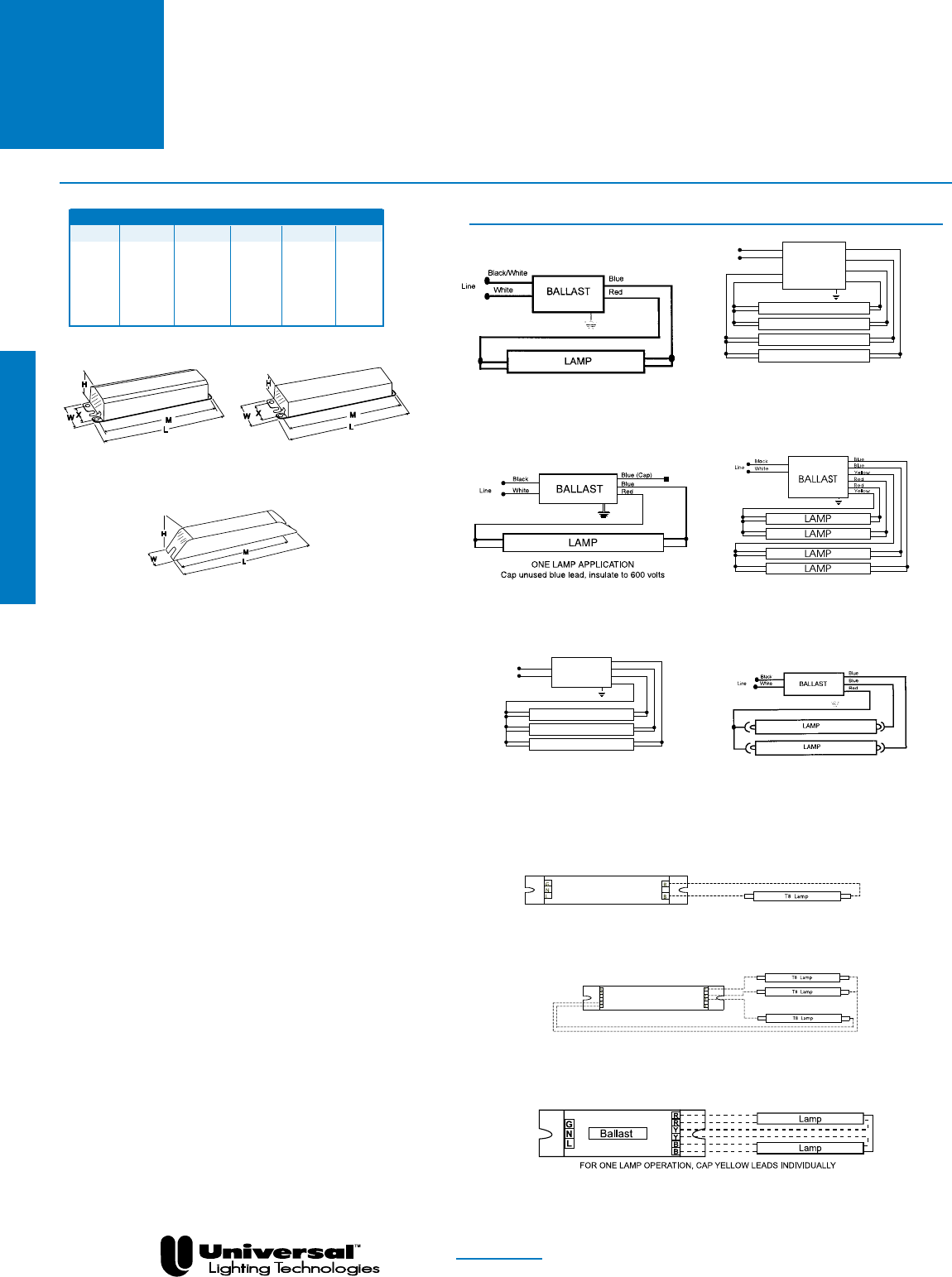
FOR MORE INFORMATION CALL
1-800-BALLAST
(225-5278)
Overall Dimensions Mounting Dimensions
Draw # L W H M X
ST 9.50” 2.40” 1.55” 8.89” 1.69”
-A 9.50” 1.70” 1.18” 8.89” 1.69”
-B 9.50” 1.50” 1.00” 8.89” 0.88”
-C 14.25” 1.18” 1.00” 13.75” ---
-D 16.88” 1.18” 1.00” 16.20” ---
ESA 9.50” 1.56” 1.00” 8.88” 0.78”
WIRING DIAGRAMS
DIAGRAM 24
DIAGRAM 6
For Two Lamp Operation,
Insulate one blue lead to 600V
Line White
Black Blue
Blue
Blue
Red
BALLAST
LAMP
LAMP
LAMP
DIAGRAM 14
DIAGRAM 7
For Three Lamp Operation,
Insulate one blue lead to 600V
White
Black
Line
Yellow Red
Red
Blue
Blue
Yellow BALLAST
LAMP
LAMP
LAMP
LAMP
F40T8 TRIAD® ELECTRONIC BALLASTS
FOR F40T8 LAMPS
DIAGRAM 7a
For three lamp operation, cap any
blue lead, insulate to 600V
PAGE 2- 32
DIAGRAM 1
-C, -D
-A, -B, ESA
DIAGRAM 22
DIAGRAM 3a
DIAGRAM 37
Fluorescent-Electronic
ST

FOR MORE INFORMATION CALL
1-800-BALLAST
(225-5278)
TRIAD® ELECTRONIC BALLASTS
FOR (1) AND (2)
F48T8, F72T8, F96T8 AND F96T8ES LAMPS
Lamp
Certification Line Input Power Ballast Ballast Min. F/C
Starting Line Catalog Current Power Factor Factor Efficacy THD Start Wiring
Qty. Method Volts Number (Amps) (Watts) (PF) (BF) Factor (BEF) % Temp Diag. Dim.
F48T8-OneLampApplications
1 IS 120 B259I120HE • • 0.29 34 >.98 1.07 3.15 <10 0/-18 14 ST
277 B259I277HE • • 0.16 35 >.97 1.07 3.06 <10 0/-18 14 ST
F48T8-TwoLampApplications
2 PAR-IS 120 B259I120HE • • 0.47 56 >.99 0.90 1.61 <10 0/-18 14 ST
277 B259I277HE • • 0.20 55 >.97 0.90 1.64 <10 0/-18 14 ST
F72T8 - One Lamp Applications
1 IS 120 B259I120HE • • 0.42 50 >.99 1.05 2.10 <10 0/-18 14 ST
120 B259I277HE • • 0.19 51 >.97 1.05 2.06 <10 0/-18 14 ST
F72T8 - Two Lamp Applications
2 PAR-IS 277 B259I120HE • • 0.71 84 >.99 0.88 1.05 <10 0/-18 14 ST
277 B259I277HE • • 0.30 82 >.97 0.88 1.07 <10 0/-18 14 ST
F96T8-OneLampApplications
120 B159I120RH • • 0.52 58 >.96 0.88 1.52 <20 50/10 13 ST
277 B159I277RH • • 0.22 58 >.96 0.88 1.52 <20 50/10 13 ST
120 B259I120RH • • • 0.62 68 >.97 1.05 1.54 <25 50/10 14 ST
277 B259I277RH • • • 0.26 68 >.97 1.05 1.54 <20 50/10 14 ST
1 IS 120 B259I120HPL • • 0.51 60 >.98 0.92 1.53 <10 50/10 14 ST
277 B259I277HPL • • 0.22 60 >.98 0.92 1.53 <10 50/10 14 ST
120 B259IUNVHP-A • • • 0.60 72 >.99 1.08 1.50 <10 32/0 14 -A
277 0.26 71 >.98 1.52
347 B259I347HP • 0.20 68 >.97 1.05 1.54 <10 32/0 14 ST
120 B259I120HE • • 0.58 69 >.97 1.05 1.53 <10 32/0 13 ST
277 B259I277HE • • 0.25 69 >.97 1.05 1.52 <10 32/0 13 ST
F96T8-TwoLampApplications
120 B259I120RH • • • 0.95 112 >.98 0.88 0.79 <20 50/10 14 ST
277 B259I277RH • • • 0.41 112 >.98 0.88 0.79 <20 50/10 14 ST
120 B259I120RHH • • 1.30 150 >.98 1.18 0.79 <20 32/0 14 SL
277 B259I277RHH • • 0.56 150 >.98 1.18 0.79 <20 32/0 14 SL
2 PAR-IS 120 B259I120HPL • • 0.84 100 >.98 0.78 0.78 <10 50/10 14 ST
277 B259I277HPL • • 0.36 100 >.98 0.78 0.78 <10 50/10 14 ST
120 B259IUNVHP-A • • • 0.95 113 >.99 0.88 0.78 <10 32/0 14 -A
277 0.40 110 >.98 0.80
347 B259I347HP • 0.33 113 >.99 0.89 0.79 <10 32/0 14 ST
120 B259I120HE • • 0.92 108 >.99 0.88 0.81 <10 32/0 14 ST
277 B259I277HE • • 0.38 106 >.99 0.88 0.83 <10 32/0 14 ST
F96T8ES-OneLampApplications
1 PAR-IS 120 B259I120HE • • 0.53 63 >.97 1.05 1.66 <10 60/16 13 ST
277 B259I277HE • • 0.23 63 >.97 1.05 1.66 <10 60/16 13 ST
F96T8ES-TwoLampApplications
120 B259I120RHH • • 1.20 142 >.98 1.18 0.83 <20 60/16 14 SL
277 B259I277RHH • • 0.50 138 >.98 1.18 0.86 <20 60/16 14 SL
2 PAR-IS 120 B259I120HE • • 0.85 102 >.99 0.88 0.86 <10 60/16 14 ST
277 B259I277HE • • 0.36 100 >.99 0.88 0.88 <10 60/16 14 ST
NOM
Overall Dimensions Mounting Dimensions
Draw # L W H M X
ST 9.50” 2.40” 1.55” 8.89” 1.69”
SL 11.75” 3.13” 1.78” 11.14” 2.00”
-A 9.50” 1.70” 1.18” 8.89” 1.69”
WIRING DIAGRAMS
DIAGRAM 13 For One Lamp Operation, Insulate one blue
lead to 600V
DIAGRAM 14
Slimline Lamps
T8
SLIMLINE
•Instant Starting Options
•1-2 Lamp Applications
•8’ T8 SLIMLINE
•High Performance
Models
PAGE 2- 33
ST, SL
Fluorescent-Electronic
IS = Instant Start
PRS = Programmed Rapid Start
RS = Rapid Start
STARTING METHOD LEGEND
PAR-IS = Parallel Instant Start
PAR-PRS = Parallel Programmed Rapid Start
PAR-RS = Parallel Rapid Start
SER-RS = Series Rapid Start
-A
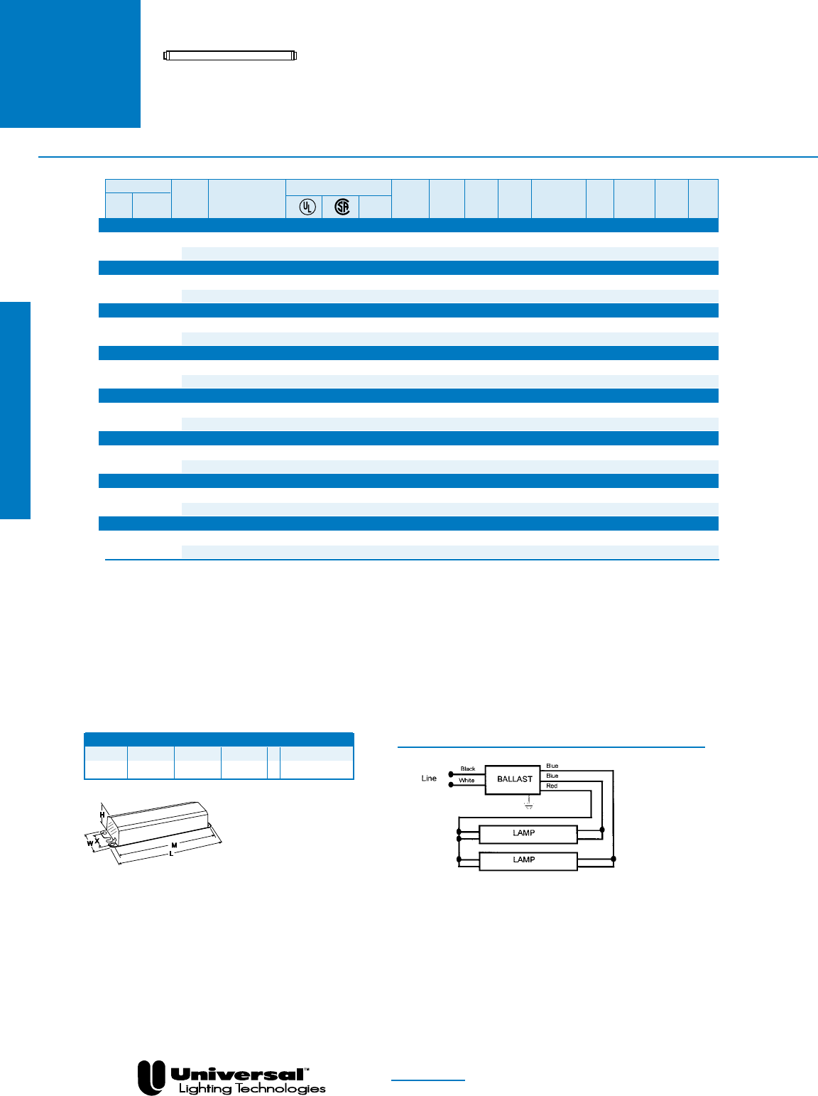
FOR MORE INFORMATION CALL
1-800-BALLAST
(225-5278)
TRIAD® ELECTRONIC BALLASTS
FOR (1) AND (2)
F48T8HO, F60T8HO, F72T8HO AND
F96T8HO LAMPS
PAGE 2- 34
High Output Lamps
T8HO •Instant Starting Options
•1-2 Lamp Applications
•4-8’ T8 High Output
Overall Dimensions Mounting Dimensions
Draw # L W H M X
SL 11.75” 3.13” 1.78” 11.14” 2.00”
WIRING DIAGRAMS
DIAGRAM 3
For One Lamp Operation, Insulate one blue lead to 600V
Lamp
Certification Line Input Power Ballast Ballast Min. F/C
Starting Line Catalog Current Power Factor Factor Efficacy THD Start Wiring
Qty. Method Volts Number (Amps) (Watts) (PF) (BF) Factor (BEF) % Temp Diag. Dim.
F48T8HO-OneLampApplications
1 IS 120 B286I120RH • • • 0.47 48 >.90 1.00 2.08 <30 -20/-29 3 SL
277 B286I277RH • • • 0.20 47 >.90 1.00 2.13 <30 -20/-29 3 SL
F60T8HO-OneLampApplications
1 IS 120 B286I120RH • • • 0.56 60 >.90 0.99 1.65 <30 -20/-29 3 SL
277 B286I277RH • • • 0.23 57 >.90 0.98 1.72 <30 -20/-29 3 SL
F72T8HO - One Lamp Applications
1 IS 120 B286I120RH • • • 0.64 71 >.90 0.98 1.38 <30 -20/-29 3 SL
277 B286I277RH • • • 0.26 67 >.90 0.98 1.46 <30 -20/-29 3 SL
F96T8HO-OneLampApplications
1 IS 120 B286I120RH • • • 0.79 92 >.90 0.96 1.04 <25 -20/-29 3 SL
277 B286I277RH • • • 0.32 87 >.90 0.93 1.07 <25 -20/-29 3 SL
F48T8HO-TwoLampApplications
2 PAR-IS 120 B286I120RH • • • 0.70 80 >.95 0.85 1.06 <25 -20/-29 3 SL
277 B286I277RH • • • 0.30 77 >.90 0.84 1.09 <25 -20/-29 3 SL
F60T8HO-TwoLampApplications
2 PAR-IS 120 B286I120RH • • • 0.85 99 >.95 0.85 0.86 <20 -20/-29 3 SL
277 B286I277RH • • • 0.36 96 >.95 0.84 0.88 <20 -20/-29 3 SL
F72T8HO - Two Lamp Applications
2 PAR-IS 120 B286I120RH • • • 1.00 117 >.95 0.85 0.73 <20 -20/-29 3 SL
277 B286I277RH • • • 0.42 114 >.95 0.84 0.74 <20 -20/-29 3 SL
F96T8HO-TwoLampApplications
2 PAR-IS 120 B286I120RH • • • 1.30 151 >.95 0.81 0.54 <20 -20/-29 3 SL
277 B286I277RH • • • 0.53 144 >.95 0.81 0.56 <20 -20/-29 3 SL
NOM
Fluorescent-Electronic
IS = Instant Start
PRS = Programmed Rapid Start
RS = Rapid Start
STARTING METHOD LEGEND
PAR-IS = Parallel Instant Start
PAR-PRS = Parallel Programmed Rapid Start
PAR-RS = Parallel Rapid Start
SER-RS = Series Rapid Start
SL

FOR MORE INFORMATION CALL
1-800-BALLAST
(225-5278)
TRIAD® T5 ELECTRONIC
BALLASTS
FOR F8, F13, F14, F21 AND F24 LAMPS
PAGE 2- 35
T5
•Multiple Lamp Operation
•Rapid and Programmed Rapid
Starting Options
•T5 Ballasts meet ANSI requirement for
end-of-lamp life safety shutdown
•Super Low Profile Designs
•1-2 Lamp Applications
NOM
See page 2-38 for Dimensions and Wiring Diagrams
Lamp
Certification Line Input Power Ballast Ballast Min. F/C
Starting Line Catalog Current Power Factor Factor Efficacy THD Start Wiring
Qty. Method Volts Number (Amps) (Watts) (PF) (BF) Factor (BEF) % Temp Diag. Dim.
F8T5-OneLampApplications
1 RS 120 CBT113L-120n • • 0.18 10 >.50 1.30 13.00 <150 0/-18 47 CBT
F8T5-TwoLampApplications
2 RS 120 CBT213L-120n • • 0.34 22 >.50 1.30 5.91 <150 0/-18 47 CBT
F13T5-OneLampApplications
1 RS 120 CBT113L-120n • • 0.25 15 >.50 1.10 9.33 <150 0/-18 47 CBT
F13T5-TwoLampApplications
2 SER-RS 120 CBT213L-120n • • 0.48 28 >.50 1.10 3.93 <150 0/-18 48 CBT
F14T5-OneLampApplications
120 B228PUNV-C • • • 0.15 18 >.98 1.05 5.83 <10 0/-18 37 -C
277 0.07 >.90 <15
1 PRS 120 B228PUNV90-C • • 0.14 16 >.98 0.89 5.56 <15 0/-18 37 -C
277 0.07 17 >.85 5.24 <20
120 ES4528X • • 0.15 19 >.97 1.00 5.26 <10 0/-18 40 ESX
277 0.07 20 5.00
1 RS 120 CBT113L-120n • • 0.25 16 >.50 0.97 6.06 <150 0/-18 47 CBT
F14T5-TwoLampApplications
120 B228PUNV-C • • • 0.28 34 >.98 1.00 2.94 <10 0/-18 37 -C
277 0.13 >.95
120 B228PUNV90-C • • 0.24 29 >.99 0.89 3.07 <10 0/-18 37 -C
277 0.11 >.90 <15
2 SER-PRS 120 B228PUNV95-D • • 0.25 31 >.99 0.95 3.06 <10 0/-18 37 -D
277 0.11 >.98
120 B228PUNV115-D • • 0.31 37 >.99 1.15 3.12 <10 0/-18 37 -D
277 0.13 36 >.98 3.19
2 SER-RS 120 CBT213L-120n • • 0.46 30 >.50 0.97 3.23 <150 0/-18 48 CBT
F21T5-OneLampApplications
120 B228PUNV-C • • • 0.21 25 >.98 1.03 4.12 <10 0/-18 37 -C
277 0.10 >.95 <15
1 PRS 120 B228PUNV90-C • • 0.19 22 >.99 0.89 4.05 <10 0/-18 37 -C
277 0.09 23 >.90 3.87 <15
120 ES4528X • • 0.20 26 >.97 1.00 3.85 <10 0/-18 40 ESX
277 0.09
RS 120 CBT213L-120n • • 0.36 25 >.50 1.15 4.60 <150 0/-18 47 CBT
F21T5-TwoLampApplications
120 B228PUNV-C • • • 0.41 49 >.98 1.00 2.04 <10 0/-18 37 -C
277 0.18 48 2.08
120 B228PUNV90-C • • 0.35 42 >.99 0.89 2.12 <10 0/-18 37 -C
2 SER-PRS 277 0.16 >.95
120 B228PUNV95-D • • 0.37 44 >.99 0.95 2.16 <10 0/-18 37 -D
277 0.16 >.98
120 B228PUNV115-D • • 0.44 52 >.99 1.15 2.21 <10 0/-18 37 -D
277 0.19 51 >.98 2.25
F24T5-OneLampApplications
1 RS 120 CBT126L-120n • • 0.40 26 >.50 1.00 3.85 <150 0/-18 47 CBT
nAdd“B”forBottomExitor“S”forSideExit
or“BS”forBottomExitwith2”O.C.screwstuds.
Fluorescent-Electronic
IS = Instant Start
PRS = Programmed Rapid Start
RS = Rapid Start
STARTING METHOD LEGEND
PAR-IS = Parallel Instant Start
PAR-PRS = Parallel Programmed Rapid Start
PAR-RS = Parallel Rapid Start
SER-RS = Series Rapid Start

FOR MORE INFORMATION CALL
1-800-BALLAST
(225-5278)
PAGE 2- 36
T5 •Multiple Lamp Operation
•Rapid and Programmed Rapid
Starting Options
•T5 Ballasts meet ANSI requirement for
end-of-lamp life safety shutdown
•Super Low Profile Designs
•1-2 Lamp Applications
TRIAD® T5 ELECTRONIC
BALLASTS
FOR F28 AND F35T5 LAMPS
NOM
Fluorescent-Electronic
See page 2-38 for Dimensions and Wiring Diagrams
Lamp
Certification Line Input Power Ballast Ballast Min. F/C
Starting Line Catalog Current Power Factor Factor Efficacy THD Start Wiring
Qty. Method Volts Number (Amps) (Watts) (PF) (BF) Factor (BEF) % Temp Diag. Dim.
F28T5-OneLampApplications
120 B228PUNV-C • • • 0.28 33 >.98 1.00 3.03 <10 0/-18 37 -C
277 0.12 >.95
1 PRS 120 B228PUNV90-C • • 0.11 29 >.99 0.90 3.10 <10 0/-18 37 -C
277 0.25 30 >.90 3.00 <15
120 ES4528X • • 0.27 34 >.97 1.00 2.94 <10 0/-18 40 ESX
277 0.12
1 RS 120 CBT213L-120n • • 0.45 30 >.50 0.96 3.20 <150 0/-18 47 CBT
F28T5-TwoLampApplications
120 B228PUNV-C • • • 0.55 66 >.98 1.00 1.52 <10 0/-18 37 -C
277 0.23 64 1.56
120 B228PUNV90-C • • 0.48 58 >.98 0.90 1.55 <10 0/-18 37 -C
2 SER-PRS 277 0.21 56 1.61
120 B228PUNV95-D • • 0.50 58 >.99 0.95 1.64 <10 0/-18 37 -D
277 0.21 57 >.98 1.67
120 B228PUNV115-D • • 0.59 69 >.99 1.15 1.67 <10 0/-18 37 -D
277 0.25 68 >.98 1.69
F35T5-OneLampApplications
1 PRS 120 ES4528X • • 0.34 42 >.97 1.00 2.38 <10 0/-18 40 ESX
277 0.15
nAdd“B”forBottomExitor“S”forSideExit
or“BS”forBottomExitwith2”O.C.screwstuds.
IS = Instant Start
PRS = Programmed Rapid Start
RS = Rapid Start
STARTING METHOD LEGEND
PAR-IS = Parallel Instant Start
PAR-PRS = Parallel Programmed Rapid Start
PAR-RS = Parallel Rapid Start
SER-RS = Series Rapid Start

FOR MORE INFORMATION CALL
1-800-BALLAST
(225-5278)
PAGE 2- 37
T5HO
TRIAD® T5HO ELECTRONIC
BALLASTS
FOR F24, F39 AND
F54 T5HO LAMPS
•Multiple Lamp Operation
•Programmed Rapid and
Instant Starting Models
•T5HO Ballasts meet ANSI
requirements for end-of-lamp
life safety shutdown
•Super Low Profile Designs
•1-4 Lamp Applications
NOM
Fluorescent-Electronic
See page 2-38 for Dimensions and Wiring Diagrams
Lamp
Certification Line Input Power Ballast Ballast Min. F/C
Starting Line Catalog Current Power Factor Factor Efficacy THD Start Wiring
Qty. Method Volts Number (Amps) (Watts) (PF) (BF) Factor (BEF) % Temp Diag. Dim.
F24T5HO-OneLampApplications
120 B224PUNV-C • • 0.23 28 >.98 1.06 3.79 <10 0/-18 37 -C
1 PRS 277 • 0.10 >.95
F24T5HO-TwoLampApplications
120 B224PUNV-C • • • 0.45 53 >.98 1.00 1.89 <10 0/-18 37 -C
2 SER-PRS 277 0.19 52 1.92
120 B239PUNV-D • • • 0.51 59 >.98 1.15 1.95 <10 0/-18 37 -D
277 0.22 >.95
F39T5HO-OneLampApplications
120 B224PUNV-C • • • 0.34 41 >.98 0.95 2.32 <10 0/-18 37 -C
1 PRS 277 0.15 40 2.38
120 B239PUNV-D • • • 0.39 47 >.98 1.10 2.34 <10 0/-18 37 -D
277 0.18 >.95
F39T5HO-TwoLampApplications
2 SER-PRS 120 B239PUNV-D • • • 0.75 89 >.98 1.00 1.12 <10 0/-18 37 -D
277 0.32 88 1.14
F54T5HO-OneLampApplications
347 B254PHRVHB-E • • 0.19 66 >.98 1.02 1.55 <10 0/-18 42 -E
480 0.15 >.90 <15
120 B254PUNV-D • • • 0.52 63 >.99 1.02 1.62 <10 0/-18 37 -D
1 PRS 277 0.23 62 >.95 1.65
120 B254PUNVHB-D • • • 0.52 63 >.99 1.02 1.62 <10 0/-18 37 -D
277 0.23 62 >.95 1.65
347 B254P347-D • 0.19 64 >.95 1.02 1.59 <10 0/-18 4b -D
F54T5HO-TwoLampApplications
347 B254PHRVHB-E • • 0.35 120 >.98 1.00 0.83 <10 0/-18 41 -E
480 0.26 119 >.95 0.84
120 B254PUNV-D • • 1.03 120 >.99 1.00 0.83 <10 0/-18 37 -D
277 • 0.43 117 >.98 0.85
120 B254PUNVHB-E • • 1.03 120 >.99 1.00 0.83 <10 0/-18 37 -D
2 SER-PRS 277 • 0.43 117 >.98 0.85
347 B254P347-D • 0.35 120 >.98 1.00 0.83 <10 0/-18 4b -D
120 B454PUNV-E • • 1.01 121 >.95 1.00 0.83 <10 0/-18 44 -E
277 0.44 116 0.86 <15
120 B454PUNVHB-E • • 1.01 122 >.95 1.00 0.82 <10 0/-18 44 -E
277 0.44 121 0.83 <15
F54T5HO-ThreeLampApplications
120 B454PUNV-E • • 1.52 181 >.98 1.05 0.58 <10 0/-18 44 -E
3 SER-PRS 277 0.66 178 >.95 0.59
120 B454PUNVHB-E • • 1.52 184 >.98 1.05 0.57 <10 0/-18 44 -E
277 0.66 182 >.95 0.58
F54T5HO-FourLampApplications
120 B454PUNV-E • • 2.01 240 >.98 1.00 0.42 <10 0/-18 44 -E
4 SER-PRS 277 0.86 234 >.99 0.43
120 B454PUNVHB-E • • 1.96 235 >.98 1.00 0.43 <10 0/-18 44 -E
277 0.84 229 >.99 0.44
F80T5HO-OneLampApplications
1 PRS 120 ES4515K • • 0.73 87 >.97 1.00 1.15 <10 0/-18 43 ESK
277 0.32 86 1.16
IS = Instant Start
PRS = Programmed Rapid Start
RS = Rapid Start
STARTING METHOD LEGEND
PAR-IS = Parallel Instant Start
PAR-PRS = Parallel Programmed Rapid Start
PAR-RS = Parallel Rapid Start
SER-RS = Series Rapid Start
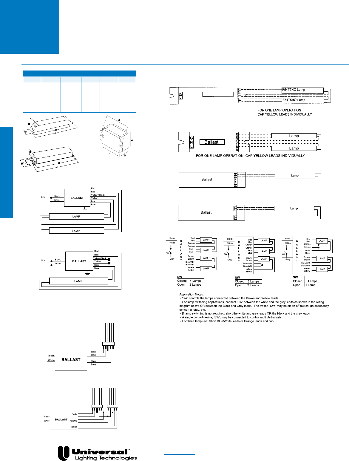
FOR MORE INFORMATION CALL
1-800-BALLAST
(225-5278)
PAGE 2- 38
T5
&
T5HO
Overall Dimensions Mounting Dimensions
Draw # L W H M X
-C 14.25” 1.18” 1.00” 13.75” —
CBT 3.86” 2.00” 1.00” 3.50” —
-D 16.88” 1.18” 1.00” 16.20” —
-E 16.88” 1.74” 1.18” 16.28” —
ESK 16.65” 1.24” 1.00” 16.30” —
ESX 14.13” 1.24” 0.73” 13.78” —
TRIAD® T5 & T5HO ELECTRONIC
BALLASTS
WIRING DIAGRAMS
T5 ballasts incorporate poke
in connectors, for easy installation
-C, -D
DIAGRAM 37
DIAGRAM 4b
Fluorescent-Electronic
DIAGRAM 41
DIAGRAM 42
DIAGRAM 43
DIAGRAM 44
DIAGRAM 40
CBT
DIAGRAM 47
DIAGRAM 48
-E, ESK, ESX
For one lamp operation, individually cap
yellow and yellow/black leads,
insulate to 600V.
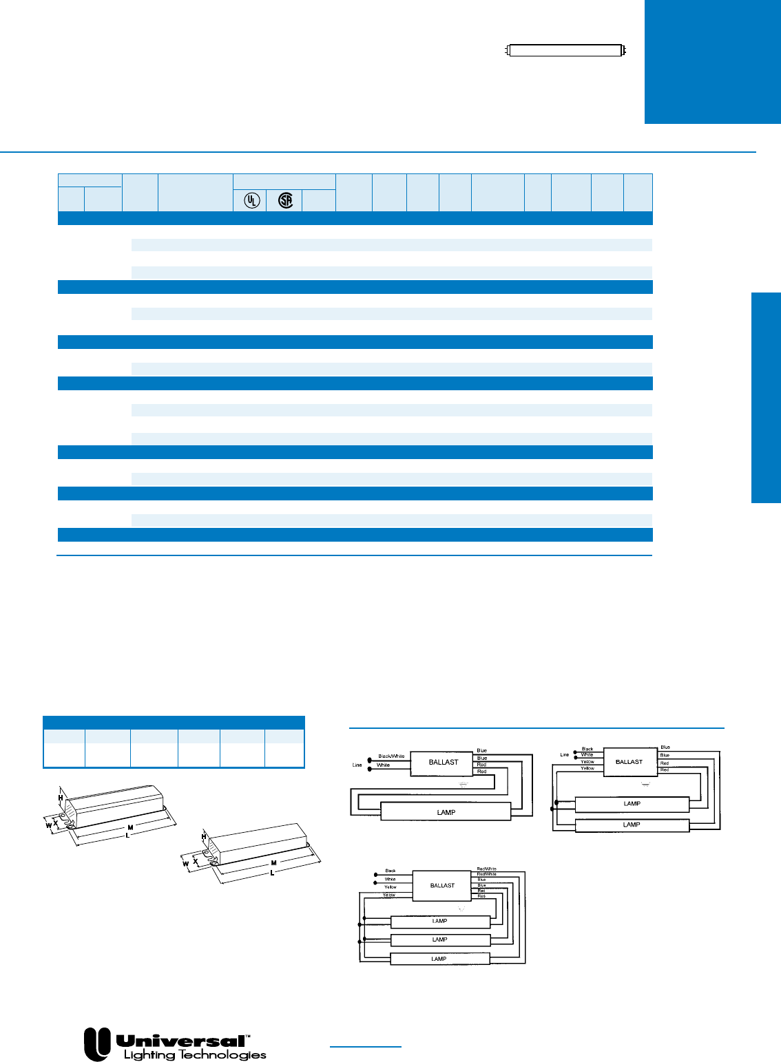
FOR MORE INFORMATION CALL
1-800-BALLAST
(225-5278)
PAGE 2- 39
T12 Straight Lamps
F30T12,
F30T12ES,
F32T12
TRIAD® ELECTRONIC BALLASTS
FOR (1), (2) AND (3)
F30T12, F30T12ES, & (2)F32T12 LAMPS
•Rapid Starting Options
•Standard & High
Performance Models
•1-3 Lamp Applications
Overall Dimensions Mounting Dimensions
Draw # L W H M X
ST 9.50” 2.40” 1.55” 8.89” 1.69”
-A 9.50” 1.70” 1.18” 8.89” 1.69”
WIRING DIAGRAMS
DIAGRAM 2
DIAGRAM 4
For One lamp Operation, Individually Cap
blue leads, Insulate to 600V
DIAGRAM 5
NOM
Fluorescent-Electronic
Lamp
Certification Line Input Power Ballast Ballast Min. F/C
Starting Line Catalog Current Power Factor Factor Efficacy THD Start Wiring
Qty. Method Volts Number (Amps) (Watts) (PF) (BF) Factor (BEF) % Temp Diag. Dim.
F30T12 - One Lamp Applications
120 B140R120HP • • 0.26 30 >.95 0.91 3.03 <10 50/10 2 ST
1 RS 277 B140R277HP • • 0.11 30 >.95 0.91 3.03 <10 50/10 2 ST
120 B240R120HP • • • 0.33 37 >.95 1.05 2.84 <10 50/10 4 ST
277 B240R277HP • • 0.14 37 >.95 1.05 2.84 <10 50/10 4 ST
F30T12 - Two Lamp Applications
120 B240R120RH • • 0.51 59 >.95 0.92 1.56 <20 50/10 4 ST
2 PAR-RS 120 B240R120HP • • • 0.50 60 >.95 0.92 1.53 <10 50/10 4 ST
277 B240R277HP • • 0.22 60 >.95 0.92 1.53 <10 50/10 4 ST
F30T12-ThreeLampApplications
3 PAR-RS 120 B340R120HP • • 0.75 90 >.98 0.91 1.01 <10 50/10 5 ST
277 B340R277HP • • 0.33 90 >.98 0.91 1.01 <10 50/10 5 ST
F30T12ES-OneLampApplications
120 B140R120HP • • 0.24 27 >.97 0.86 3.19 <10 60/16 2 ST
1 RS 277 B140R277HP • • 0.10 27 >.97 0.86 3.19 <10 60/16 2 ST
120 B240R120HP • • • 0.30 33 >.95 1.00 3.03 <10 60/16 4 ST
277 B240R277HP • • 0.13 33 >.95 1.00 3.03 <10 60/16 4 ST
F30T12ES-TwoLampApplications
2 PAR-RS 120 B240R120HP • • • 0.46 53 >.98 0.88 1.66 <10 60/16 4 ST
277 B240R277HP • • 0.20 53 >.98 0.88 1.66 <10 60/16 4 ST
F30T12ES-ThreeLampApplications
3 PAR-RS 120 B340R120HP • • 0.64 76 >.98 0.88 1.16 <10 60/16 5 ST
277 B340R277HP • • 0.28 76 >.98 0.88 1.16 <10 60/16 5 ST
F32T12 - Two Lamp Applications
2SER-RS 120 B234SR120M-A • • 0.48 56 >.98 0.90 1.61 <25 50/10 2 -A
IS = Instant Start
PRS = Programmed Rapid Start
RS = Rapid Start
STARTING METHOD LEGEND
PAR-IS = Parallel Instant Start
PAR-PRS = Parallel Programmed Rapid Start
PAR-RS = Parallel Rapid Start
SER-RS = Series Rapid Start
ST
-A
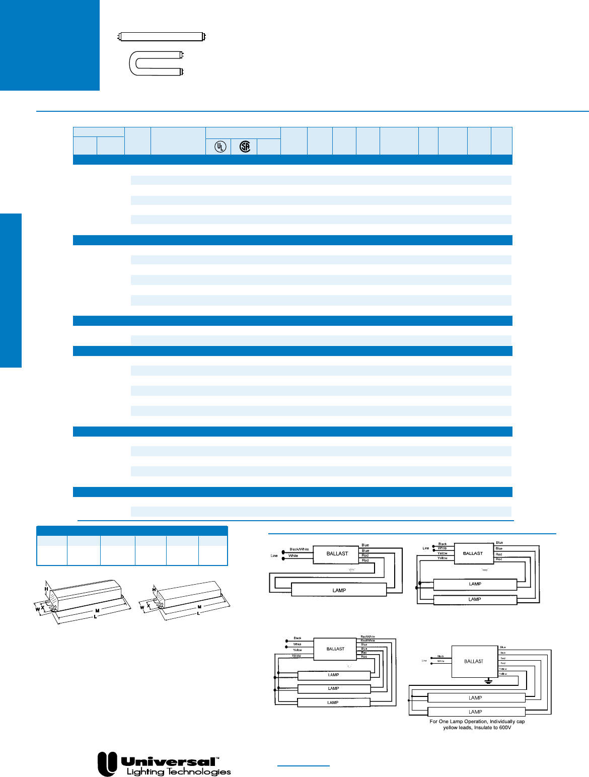
FOR MORE INFORMATION CALL
1-800-BALLAST
(225-5278)
PAGE 2- 40
T12 Straight Lamps
T12 U-Shaped Lamps
Fluorescent-Electronic
F40T12
&
F34T12ES
TRIAD® ELECTRONIC BALLASTS
FOR (1) , (2) AND (3)
F40T12 AND F34T12ES LAMPS
•Standard & High
Performance Models
•Rapid Starting Options
•1-3 Lamp Applications
Overall Dimensions Mounting Dimensions
Draw # L W H M X
ST 9.50” 2.40” 1.55” 8.89” 1.69”
-A 9.50” 1.70” 1.18” 8.89” 1.69”
WIRINGDIAGRAMS
DIAGRAM 2 For One Lamp Applications, individually cap
blue leads, Insulate fo 600V
DIAGRAM 4
DIAGRAM 5
NOM
DIAGRAM 30
Lamp
Certification Line Input Power Ballast Ballast Min. F/C
Starting Line Catalog Current Power Factor Factor Efficacy THD Start Wiring
Qty. Method Volts Number (Amps) (Watts) (PF) (BF) Factor (BEF) % Temp Diag. Dim.
F40T12-OneLampApplications
120 B140R120HP • • 0.33 38 >.99 0.88 2.32 <10 50/10 2 ST
277 B140R277HP • • 0.14 38 >.99 0.88 2.32 <10 50/10 2 ST
120 B134R120M-A • • 0.36 36 >.90 0.86 2.39 <30 50/10 2 -A
1 RS 277 B234SR277M-A • • 0.17 42 >.88 0.94 2.24 <30 50/10 4 -A
120 B240R120RH • • 0.41 46 >.90 1.09 2.37 <20 50/10 4 ST
120 B240R120HP • • • 0.42 46 >.98 1.02 2.22 <10 50/10 4 ST
277 B240R277HP • • 0.18 46 >.98 1.02 2.22 <10 50/10 4 ST
F40T12-TwoLampApplications
120 B240R120RH • • 0.62 73 >.98 0.89 1.22 <20 50/10 4 ST
120 B240R120HP • • • 0.65 75 >.99 0.90 1.20 <10 50/10 4 ST
2 PAR-RS 277 B240R277HP • • 0.28 74 >.99 0.90 1.22 <10 50/10 4 ST
120 B340R120HP • • 0.70 84 >.98 1.04 1.24 <10 50/10 5 ST
277 B340R277HP • • 0.31 84 >.98 1.04 1.24 <10 50/10 5 ST
2 SER-RS 120 B234SR120M-A • • 0.63 71 >.90 0.90 1.27 <30 50/10 30 -A
277 B234SR277M-A • • 0.26 70 >.90 0.87 1.24 <30 50/10 4 -A
F40T12-ThreeLampApplications
3 PAR-RS 120 B340R120HP • 0.94 113 >.99 0.88 0.78 <10 50/10 5 ST
277 B340R277HP • • 0.41 113 >.99 0.88 0.78 <10 50/10 5 ST
F34T12ES-OneLampApplications
120 B140R120HP • • 0.28 32 >.98 0.86 2.69 <10 60/16 2 ST
277 B140R277HP • • 0.12 32 >.98 0.86 2.69 <10 60/16 2 ST
120 B134R120M-A • • 0.30 31 >.90 0.86 2.77 <30 60/16 2 -A
1 RS 277 B234SR277M-A • • 0.15 25 >.80 0.94 2.69 <30 50/10 4 -A
120 B240R120RH • • 0.36 39 >.89 1.10 2.82 <20 60/16 4 ST
120 B240R120HP • • • 0.35 39 >.98 0.97 2.49 <10 60/16 4 ST
277 B240R277HP • • 0.15 39 >.98 0.97 2.49 <10 60/16 4 ST
F34T12ES-TwoLampApplications
120 B240R120RH • • 0.53 62 >.95 0.89 1.44 <20 60/16 4 ST
2 PAR-RS 120 B240R120HP • • • 0.54 63 >.99 0.86 1.37 <10 60/16 4 ST
277 B240R277HP • • 0.23 63 >.99 0.86 1.37 <10 60/16 4 ST
2 SER-RS 120 B234SR120M-A • • 0.49 59 >.90 0.86 1.46 <30 60/16 30 -A
277 B234SR277M-A • • 0.23 60 >.90 0.87 1.45 <30 50/10 4 -A
F34T12ES-ThreeLampApplications
3 PAR-RS 120 B340R120HP • • 0.78 93 >.99 0.86 0.92 <10 60/16 5 ST
277 B340R277HP • • 0.34 93 >.99 0.86 0.92 <10 60/16 5 ST
ST -A
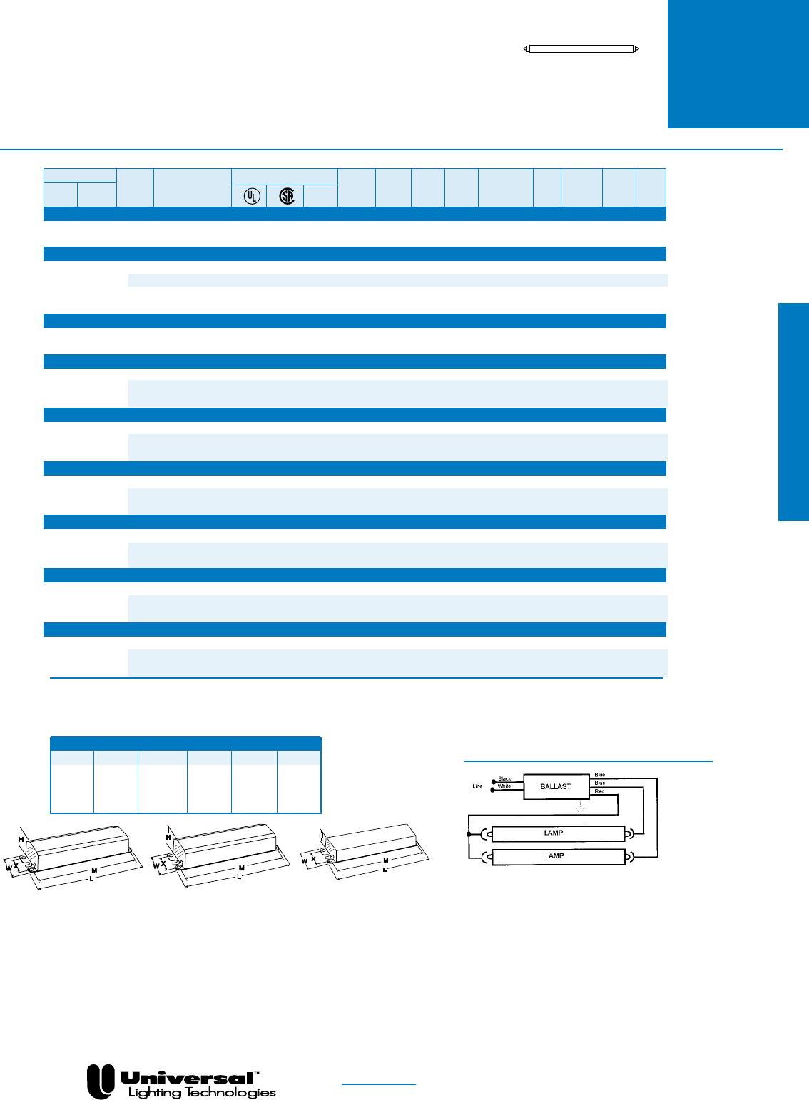
FOR MORE INFORMATION CALL
1-800-BALLAST
(225-5278)
PAGE 2- 41
Slimline Lamps
Fluorescent-Electronic
T12
SLIMLINE
•Standard & High
Performance Models
•Instant Starting Options
•1-2 Lamp Applications
Overall Dimensions Mounting Dimensions
Draw # L W H M X
SL 11.75” 3.13” 1.78” 11.14” 2.00”
-A 9.50” 1.70” 1.18” 8.89” 1.69”
ST 9.50” 2.40” 1.55” 8.89” 1.69”
TRIAD® ELECTRONIC BALLASTS
FOR F48T12, F48T12ES, F60T12, F64T12 &
F72T12 LAMPS
WIRING DIAGRAMS
DIAGRAM 14
For One Lamp Operation, Insulate one blue lead to 600V
NOM
Lamp
Certification Line Input Power Ballast Ballast Min. F/C
Starting Line Catalog Current Power Factor Factor Efficacy THD Start Wiring
Qty. Method Volts Number (Amps) (Watts) (PF) (BF) Factor (BEF) % Temp Diag. Dim.
F48T12-OneLampApplications
1 IS 120 B260IUNVHP • • 0.39 47 >.95 1.10 2.34 <10 0/-18 14 SL
277 0.18
F48T12-TwoLampApplications
120 B260I120RH • • 0.68 76 >.95 0.92 1.21 <20 0/-18 14 ST
2 PAR-IS 120 B260I120M-A • • 0.62 68 >.90 0.90 1.32 <30 50/10 14 -A
120 B260IUNVHP • • 0.61 75 >.98 0.95 1.27 <10 0/-18 14 SL
277 0.27 74 >.95 1.28
F48T12ES-OneLampApplications
1 IS 120 B260IUNVHP • • 0.32 38 >.98 1.10 2.89 <10 60/16 14 SL
277 0.15 39 >.95 2.82
F48T12ES-TwoLampApplications
120 B260I120RH • • 0.60 64 >.95 0.92 1.44 <20 60/16 14 ST
2 PAR-IS 120 B260IUNVHP • • 0.57 67 >.95 0.93 1.39 <10 60/16 14 SL
277 0.25 66 1.41
F60T12-OneLampApplications
120 B260I120RH • • 0.46 55 >.95 1.02 1.85 <20 0/-18 14 ST
1 PAR-IS 120 B260IUNVHP • • 0.49 58 >.98 1.10 1.90 <10 0/-18 14 SL
277 0.22 >.95
F60T12-TwoLampApplications
120 B260I120RH • • 0.74 89 >.95 0.90 1.01 <20 0/-18 14 ST
2 PAR-IS 120 B260IUNVHP • • 0.77 92 >.98 0.92 1.00 <10 0/-18 14 SL
277 0.33 91 1.01
F64T12-OneLampApplications
120 B260I120RH • • 0.49 59 >.95 1.03 1.75 <20 0/-18 14 ST
1 PAR-IS 120 B260IUNVHP • • 0.51 61 >.98 1.10 1.80 <10 0/-18 14 SL
277 0.35 96 >.95 1.15
F64T12-TwoLampApplications
120 B260I120RH • • 0.80 95 >.95 0.90 0.95 <20 0/-18 14 ST
2 PAR-IS 120 B260IUNVHP • • 0.81 97 >.98 0.92 0.95 <10 0/-18 14 SL
277 0.35 96 0.96
F72T12 - One Lamp Applications
120 B260I120RH • • 0.60 66 >.95 1.04 1.58 <20 0/-18 14 ST
1 IS 120 B260IUNVHP • • 0.55 68 >.95 1.06 1.56 <10 0/-18 14 SL
277 0.25 67 1.58
IS = Instant Start
PRS = Programmed Rapid Start
RS = Rapid Start
STARTING METHOD LEGEND
PAR-IS = Parallel Instant Start
PAR-PRS = Parallel Programmed Rapid Start
PAR-RS = Parallel Rapid Start
SER-RS = Series Rapid Start
ST
-A
SL
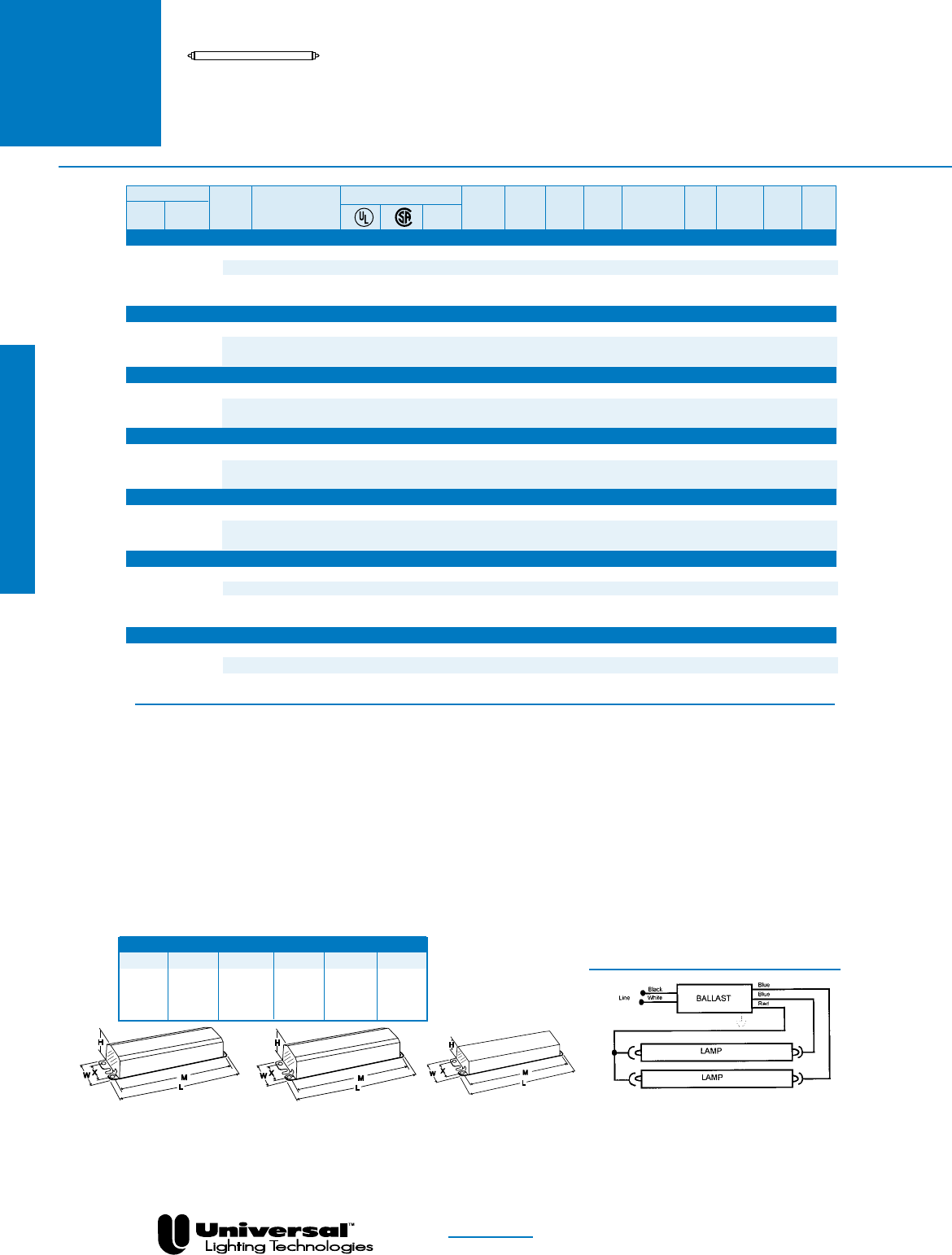
FOR MORE INFORMATION CALL
1-800-BALLAST
(225-5278)
PAGE 2- 42
Slimline Lamps
T12
SLIMLINE
•Standard & High
Performance Models
•Instant Starting Options
•1-2 Lamp Applications
TRIAD® ELECTRONIC BALLASTS
F72T12(cont.), F84T12, F96T12 & F96T12ES
LAMPS
WIRING DIAGRAMS
DIAGRAM 14
For One Lamp Operation, Insulate one blue lead to 600V
NOM
Overall Dimensions Mounting Dimensions
Draw # L W H M X
SL 11.75” 3.13” 1.78” 11.14” 2.00”
-A 9.50” 1.70” 1.18” 8.89” 1.69”
ST 9.50” 2.40” 1.55” 8.89” 1.69”
Fluorescent-Electronic
Lamp
Certification Line Input Power Ballast Ballast Min. F/C
Starting Line Catalog Current Power Factor Factor Efficacy THD Start Wiring
Qty. Method Volts Number (Amps) (Watts) (PF) (BF) Factor (BEF) % Temp Diag. Dim.
F72T12 - Two Lamp Applications
120 B260I120RH • • 0.92 107 >.95 0.90 0.84 <20 0/-18 14 ST
2 PAR-IS 120 B260I120M-A • • 0.90 105 >.95 0.90 0.86 <30 50/10 14 -A
120 B260IUNVHP • • 0.90 109 >.99 0.91 0.83 <10 0/-18 14 SL
277 0.39 107 0.85
F84T12-OneLampApplications
120 B260I120RH • • 0.63 74 >.95 1.05 1.42 <20 0/-18 14 ST
1 IS 120 B260IUNVHP • • 0.63 76 >.98 1.10 1.45 <10 0/-18 14 -A
277 0.28 75 1.47
F84T12-TwoLampApplications
120 B260I120RH • • 1.02 120 >.95 0.88 0.73 <20 0/-18 14 ST
2 PAR-IS 120 B260IUNVHP • • 1.03 123 >.98 0.88 0.72 <10 0/-18 14 -A
277 0.44 120 0.73
F96T12-OneLampApplications
120 B260I120RH • • 0.73 83 >.95 1.02 1.23 <20 0/-18 14 ST
1 IS 120 B260IUNVHP • • 0.70 85 >.98 1.05 1.24 <10 0/-18 14 SL
277 0.31 84 1.25
F96T12-TwoLampApplications
120 B260I120RH • • 1.16 133 >.95 0.86 0.65 <20 0/-18 14 ST
2 PAR-IS 120 B260IUNVHP • • 1.16 139 >.99 0.88 0.63 <10 0/-18 14 SL
277 0.50 137 0.64
F96T12ES-OneLampApplications
120 B260I120RH • • 0.60 66 >.95 1.05 1.59 <20 60/16 14 ST
1 IS 120 B260I120M-A • • 0.61 66 >.90 1.09 1.65 <30 60/16 14 -A
120 B260IUNVHP • • 0.59 72 >.98 1.03 1.43 <10 60/16 14 SL
277 0.26 70 1.47
F96T12ES-TwoLampApplications
120 B260I120RH • • 0.93 107 >.95 0.88 0.82 <20 60/16 14 ST
2 PAR-IS 120 B260I120M-A • • 0.90 105 >.95 0.88 0.84 <30 60/16 14 -A
120 B260IUNVHP • • 0.96 112 >.99 0.88 0.79 <10 60/16 14 SL
277 0.40 110 0.80
IS = Instant Start
PRS = Programmed Rapid Start
RS = Rapid Start
STARTING METHOD LEGEND
PAR-IS = Parallel Instant Start
PAR-PRS = Parallel Programmed Rapid Start
PAR-RS = Parallel Rapid Start
SER-RS = Series Rapid Start
ST SL -A
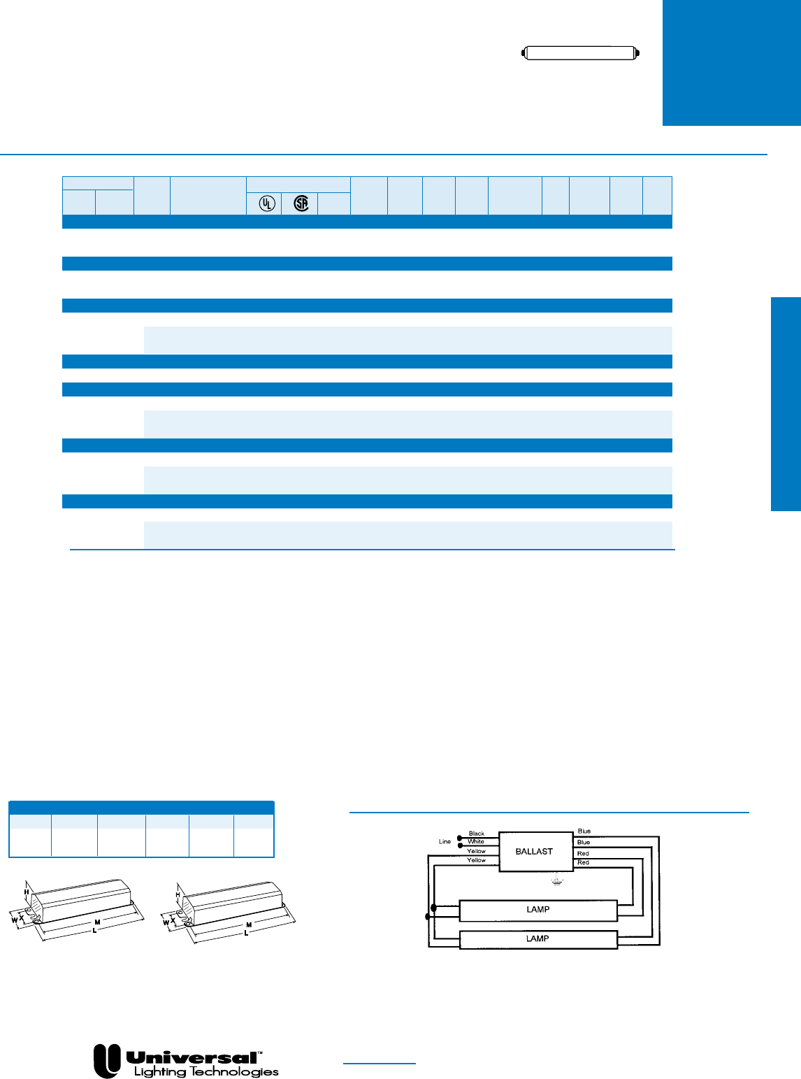
FOR MORE INFORMATION CALL
1-800-BALLAST
(225-5278)
PAGE 2- 43
T12HO
TRIAD® ELECTRONIC BALLASTS
FOR T12 HIGH
OUTPUT LAMPS
•High Performance
Models
• Rapid Starting Options
•2 Lamp Applications
Overall Dimensions Mounting Dimensions
Draw # L W H M X
ST 9.50” 2.40” 1.55” 8.89” 1.69”
SL 11.75” 3.13” 1.78” 11.14” 2.00”
WIRING DIAGRAMS
DIAGRAM 4
NOM
Fluorescent-Electronic
Lamp
Certification Line Input Power Ballast Ballast Min. F/C
Starting Line Catalog Current Power Factor Factor Efficacy THD Start Wiring
Qty. Method Volts Number (Amps) (Watts) (PF) (BF) Factor (BEF) % Temp Diag. Dim.
F48T12HO-TwoLampApplications
2 SER-RS 120 B295SRUNVHP • • 0.92 110 >.98 0.89 0.81 <10 -20/-29 4 SL
277 0.40 109 0.82
F60T12HO-TwoLampApplications
2 SER-RS 120 B295SRUNVHP • • 1.11 134 >.98 0.89 0.66 <10 -20/-29 4 SL
277 0.48 132 0.67
F72T12HO - Two Lamp Applications
2 SER-RS
120 B295SR120HP • • 1.40 169 >.99 0.95 0.56 <10 -20/-29 4 SL
120 B295SRUNVHPº • • 1.40 162 >.99 0.89 0.55 <10 -20/-29 4 SL
277 0.61 160 0.56
F73T12/BL/HO-TwoLampApplications
2 SER-RS 120 493B2 • • 1.60 180 >.90 1.00 0.56 <25 50/10 4 ST
F84T12HO-TwoLampApplications
2 SER-RS
120 B295SR120HP • • 1.60 185 >.99 0.89 0.48 <10 -20/-29 4 SL
120 B295SRUNVHPº • • 1.60 176 >.99 0.89 0.48 <10 -20/-29 4 SL
277 0.69 173 0.49
F96T12HO-TwoLampApplications
2 SER-RS
120 B295SR120HP • • 1.77 208 >.99 0.88 0.43 <10 -20/-29 4 SL
120 B295SRUNVHPº • • 1.77 205 >.99 0.88 0.43 <10 -20/-29 4 SL
277 0.76 209 0.44
F96T12HOES-TwoLampApplications
2 SER-RS
120 B295SR120HP • • 1.47 174 >.99 0.88 0.51 <10 60/16 4 SL
120 B295SRUNVHPº • • 1.47 174 >.99 0.88 0.51 <10 60/16 4 SL
277 0.63 171
ºPreliminaryData
IS = Instant Start
PRS = Programmed Rapid Start
RS = Rapid Start
STARTING METHOD LEGEND
PAR-IS = Parallel Instant Start
PAR-PRS = Parallel Programmed Rapid Start
PAR-RS = Parallel Rapid Start
SER-RS = Series Rapid Start
ST SL
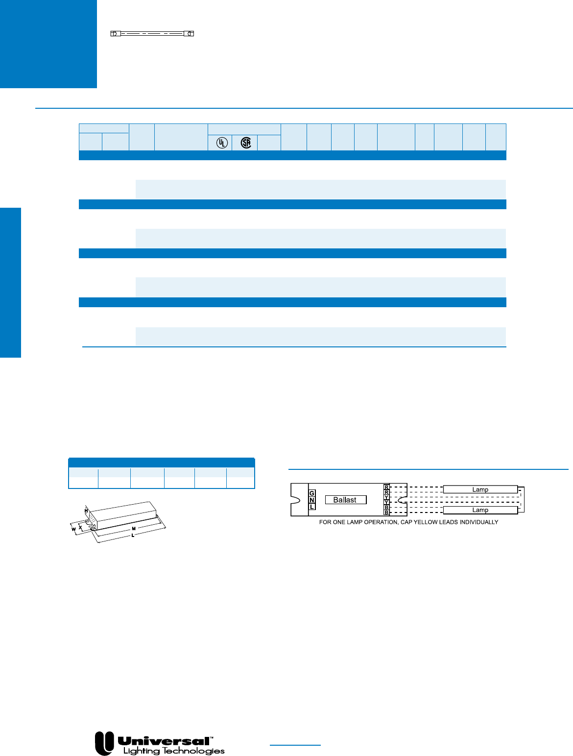
FOR MORE INFORMATION CALL
1-800-BALLAST
(225-5278)
PAGE 2- 44
T2
•Programmed Rapid
Starting Options
•1-2 Lamp Applications
TRIAD® ELECTRONIC BALLASTS
FOR F6T2, F8T2, F11T2 AND F13T2 LAMPS
WIRING DIAGRAMS
DIAGRAM 37
NOM
Overall Dimensions Mounting Dimensions
Draw # L W H M X
ESX 14.13” 1.24” 0.73” 13.78” —
ESX
Fluorescent-Electronic
Lamp
Certification Line Input Power Ballast Ballast Min. F/C
Starting Line Catalog Current Power Factor Factor Efficacy THD Start Wiring
Qty. Method Volts Number (Amps) (Watts) (PF) (BF) Factor (BEF) % Temp Diag. Dim.
F6T2-OneAndTwoLampApplications
2 SER-PRS 120 ES1786X • • 0.12 14 >.97 1.00 7.14 <10 0/-18 37 ESX
277 0.07 15 6.67
1 PRS 120 ES1786X • • 0.07 8 >.97 1.00 12.50 <10 0/-18 37 ESX
277 0.05 9 11.11
F8T2-OneAndTwoLampApplications
2 SER-PRS 120 ES1786X • • 0.17 20 >.97 1.00 5.00 <10 0/-18 37 ESX
277 0.08 21 4.76
1 PRS 120 ES1786X • • 0.10 11 >.97 1.00 9.09 <10 0/-18 37 ESX
277 0.06
F11T2-OneAndTwoLampApplications
2 SER-PRS 120 ES1786X • • 0.20 26 >.97 1.00 3.85 <10 0/-18 37 ESX
277 0.09
1 PRS 120 ES1786X • • 0.12 15 >.97 1.00 6.67 <10 0/-18 37 ESX
277 0.07
F13T2-OneAndTwoLampApplications
2 SER-PRS 120 ES1786X • • 0.27 31 >.97 1.00 3.23 <10 0/-18 37 ESX
277 0.13 32 3.13
1 PRS 120 ES1786X • • 0.15 16 >.97 1.00 6.25 <10 0/-18 37 ESX
277 0.08 17 5.88
IS = Instant Start
PRS = Programmed Rapid Start
RS = Rapid Start
STARTING METHOD LEGEND
PAR-IS = Parallel Instant Start
PAR-PRS = Parallel Programmed Rapid Start
PAR-RS = Parallel Rapid Start
SER-RS = Series Rapid Start
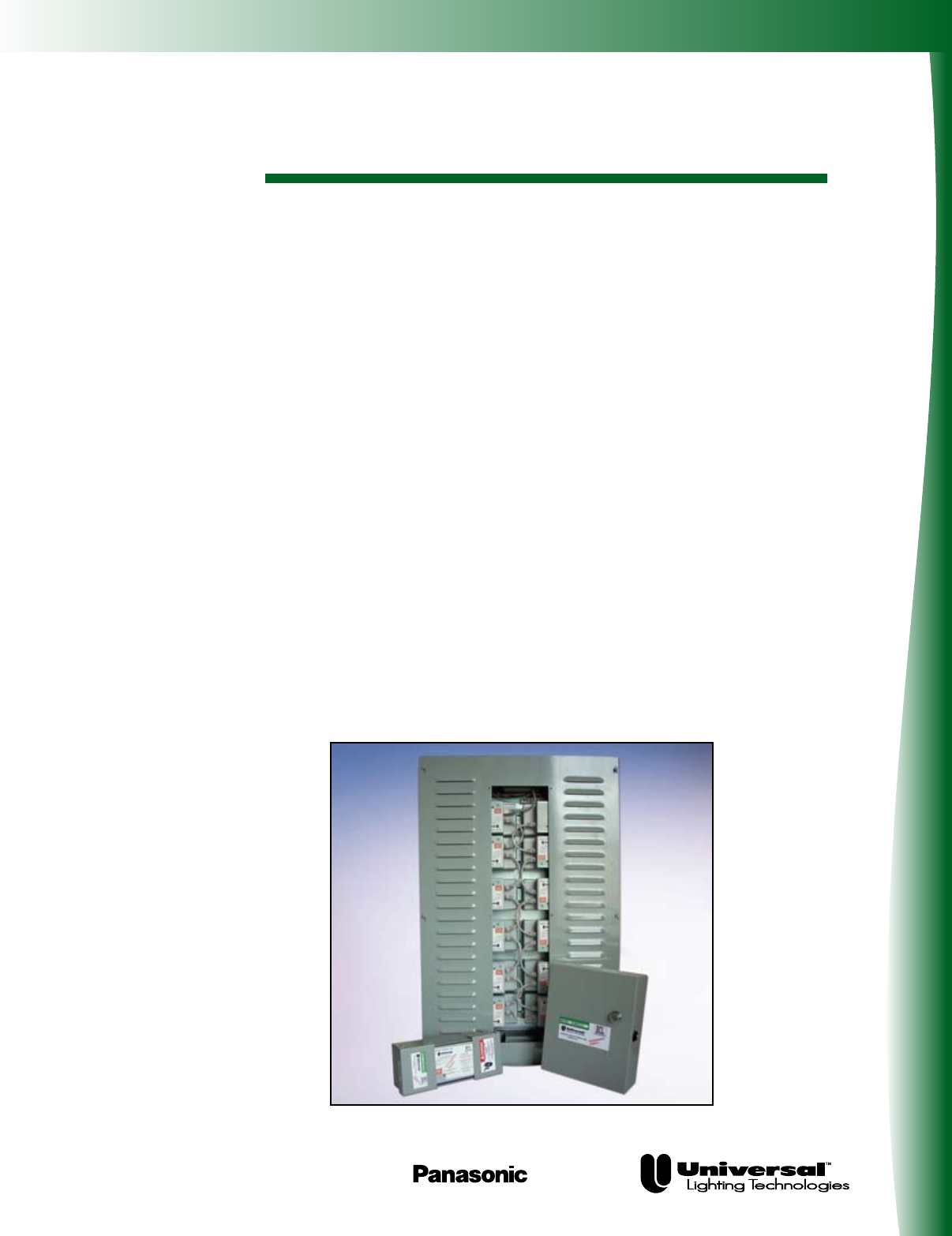
Energy Management System
DCL® with DEMANDflex®
DEMANDflex® ballasts are high efficiency program start
ballasts with the flexibility to be tuned at the circuit level
to fixed power levels during installation. They are fully
compatible with occupancy sensors and exceed the CEE
requirements for high efficiency program start T8
ballasts. DEMANDflex® ballasts having tuning capabili-
ties with ranges from 100% to 50% power levels, making
them applicable for a wide range of lighting installations.
Installations can start with DEMANDflex® ballasts and
after installation, the ballasts can be tuned to maximize
energy savings with fixed light levels. No dimming
control wires are associated with DEMANDflex® ballasts
which makes them easy to install in all existing fluores-
cent lighting applications. DEMANDflex® ballasts can also
be integrated with DCL® controls to be part of the most
cost-effective lighting system available.
DCL® controls allow for local control with energy manage-
ment systems and external control via the internet for
networked managed systems. DCL® controls allow for
integration with utility demand response programs that
provide for improved pricing contracts to end-users in
exchange for the utility to have the ability to lower
lighting power levels during periods of high demand.
DCL/DEMANDflex
Universal Lighting Technologies is a subsidiary of
Panasonic Electric Works Co., Ltd., a member of the Panasonic Group

Product Overview
PAGE 3-2
DEMANDflex® Ballasts
n Power level tuning potential to 50%
–Set the circuit power level at installation
–Typical 10% to 15% power reduction
n Install the same as standard PRS ballasts
–No control wires necessary
–Standard mounting footprint
–Same wiring as program rapid start ballasts
n High efficiency program start operation
–Exceeds CEE T8 requirements
–Compatible with occupancy sensors
n NEMA premium
–Exceeds CEE T8 requirements
–Compatible with occupancy sensors
DCL® Controlled Systems
n Reduces lighting power by up to 50%
–Avoid high peak charges
–Reduce demand costs
n Programmable fade rates
–Gradual transitions
–No disruptions
n Use existing power connections to communicate to the ballasts
–No control wires
n Implement with various controls and systems
–BAS Systems
–Photo Cells
–Occupancy Sensors
–Contact Closure
For more information contact Universal or visit www.unvlt.com.
FOR MORE INFORMATION CALL
1-800-BALLAST
(225-5278)
DCL/DEMANDflex

DEMANDflex®
FOR (1), (2), (3) & (4) LAMPS
• Universal DCL® Dimming
• Programmed Rapid Start
• 1, 2, 3, & 4 Lamp Applications
• Visit www.unvlt.com for a comprehensive
description of the DCL® system and
DEMANDflex® ballasts
PAGE 3-3 FOR MORE INFORMATION CALL
1-800-BALLAST
(225-5278)
See page 3-7 for Dimensions and Wiring Diagrams
Lamp
Certification Line Input Power Ballast Ballast Min. F/C
Starting Line Catalog Current Power Factor Factor Efficacy THD Start Wiring
Qty. Method Volts Number c (Amps) (Watts) (PF) (BF) Factor (BEF) % Temp Diag. Dim.
F32T8 - One Lamp Applications
120 B232PUNVDR-A @ 100% • • 0.24 29 > .95 0.88 3.01 < 10 32/0 12a -A
B232PUNVDR-A @ 50% • • 0.11 14 > .95 0.28 2.05 < 15 32/0 12a -A
277 B232PUNVDR-A @ 100% • • 0.11 29 > .95 0.88 3.03 < 10 32/0 12a -A
B232PUNVDR-A @ 50% • • 0.05 14 > .90 0.28 1.96 < 15 32/0 12a -A
120 B232PUNVDRH-A @ 100% • • 0.32 38 > .95 1.15 3.03 < 10 32/0 12a -A
1 PRS B232PUNVDRH-A @ 50% • • 0.15 18 > .95 0.50 2.78 < 10 32/0 12a -A
277 B232PUNVDRH-A @ 100% • • 0.14 39 > .95 1.15 2.95 < 10 32/0 12a -A
B232PUNVDRH-A @ 50% • • 0.07 19 > .95 0.50 2.63 < 10 32/0 12a -A
120 B232PUNVDRL-A @ 100% • • 0.20 24 > .95 0.68 2.85 < 10 32/0 12a -A
B232PUNVDRL-A @ 50% • • 0.09 11 > .95 0.18 1.64 < 10 32/0 12a -A
277 B232PUNVDRL-A @ 100% • • 0.09 24 > .95 0.68 2.85 < 10 32/0 12a -A
B232PUNVDRL-A @ 50% • • 0.05 12 > .95 0.18 1.57 < 10 32/0 12a -A
F32T8 - Two Lamp Applications
120 B232PUNVDR-A @ 100% • • 0.47 57 > .95 0.87 1.53 < 10 32/0 12b -A
B232PUNVDR-A @ 50% • • 0.22 28 > .95 0.34 1.20 < 10 32/0 12b -A
277 B232PUNVDR-A @ 100% • • 0.20 56 > .95 0.87 1.56 < 10 32/0 12b -A
B232PUNVDR-A @ 50% • • 0.10 28 > .95 0.35 1.22 < 10 32/0 12b -A
120 B232PUNVDRH-A @ 100% • • 0.62 75 > .95 1.15 1.53 < 10 32/0 12b -A
2 PRS B232PUNVDRH-A @ 50% • • 0.30 37 > .90 0.50 1.35 < 10 32/0 12b -A
277 B232PUNVDRH-A @ 100% • • 0.26 73 > .95 1.15 1.58 < 10 32/0 12b -A
B232PUNVDRH-A @ 50% • • 0.13 36 > .90 0.50 1.39 < 10 32/0 12b -A
120 B232PUNVDRL-A @ 100% • • 0.40 47 > .95 0.71 1.51 < 10 32/0 12b -A
B232PUNVDRL-A @ 50% • • 0.19 24 > .95 0.19 0.81 < 10 32/0 12b -A
277 B232PUNVDRL-A @ 100% • • 0.17 47 > .95 0.71 1.51 < 10 32/0 12b -A
B232PUNVDRL-A @ 50% • • 0.09 24 > .95 0.19 0.81 < 10 32/0 12b -A
F32T8 - Three Lamp Applications
120 B332PUNVDR-A @ 100% • • 0.70 85 > .95 0.87 1.02 < 10 32/0 12c -A
B332PUNVDR-A @ 50% • • 0.34 42 > .95 0.35 0.83 < 10 32/0 12c -A
277 B332PUNVDR-A @ 100% • • 0.30 83 > .95 0.87 1.05 < 10 32/0 12c -A
B332PUNVDR-A @ 50% • • 0.16 41 > .95 0.35 0.85 < 10 32/0 12c -A
120 B332PUNVDRL-A @ 100% • • 0.59 72 > .95 0.71 0.99 < 10 32/0 12c -A
3 PRS B332PUNVDRL-A @ 50% • • 0.29 36 > .95 0.22 0.61 < 10 32/0 12c -A
277 B332PUNVDRL-A @ 100% • • 0.25 72 > .95 0.71 0.99 < 10 32/0 12c -A
B332PUNVDRL-A @ 50% • • 0.13 36 > .95 0.22 0.61 < 10 32/0 12c -A
120 B332PUNVDRH-E @ 100% • • 0.95 115 > .95 1.15 1.00 < 10 32/0 12d -A
B332PUNVDRH-E @ 50% • • 0.48 57 > .95 0.50 0.88 < 10 32/0 12d -A
277 B332PUNVDRH-E @ 100% • • 0.41 111 > .95 1.15 1.04 < 10 32/0 12d -A
B332PUNVDRH-E @ 50% • • 0.21 55 > .95 0.50 0.91 < 10 32/0 12d -A
F32T8 - Four Lamp Applications
120 B432PUNVDR-E @ 100% • • 0.96 116 > .95 0.88 0.75 < 10 32/0 12e -A
B432PUNVDR-E @ 50% • • 0.48 58 > .95 0.35 0.60 < 10 32/0 12e -A
277 B432PUNVDR-E @ 100% • • 0.41 112 > .95 0.88 0.79 < 10 32/0 12e -A
4 PRS B432PUNVDR-E @ 50% • • 0.20 56 > .95 0.35 0.63 < 15 32/0 12e -A
120 B432PUNVDRL-E @ 100% • • 0.78 93 > .95 0.71 0.76 < 10 32/0 12e -A
B432PUNVDRL-E @ 50% • • 0.37 47 > .95 0.21 0.45 < 15 32/0 12e -A
277 B432PUNVDRL-E @ 100% • • 0.34 93 > .95 0.71 0.76 < 10 32/0 12e -A
B432PUNVDRL-E @ 50% • • 0.17 47 > .95 0.21 0.45 < 15 32/0 12e -A
DEMANDflex
T8
DEMANDflex

• Universal DCL® Dimming
• Programmed Rapid Start
• 1, 2, 3, & 4 Lamp Applications
• Visit www.unvlt.com for a comprehensive
description of the DCL system and
DEMANDflex ballasts
PAGE 3-4 FOR MORE INFORMATION CALL
1-800-BALLAST
(225-5278)
See page 3-7 for Dimensions and Wiring Diagrams
DEMANDflex®
FOR (1), (2), (3) & (4) LAMPS
Lamp
Certification Line Input Power Ballast Ballast Min. F/C
Starting Line Catalog Current Power Factor Factor Efficacy THD Start Wiring
Qty. Method Volts Number c (Amps) (Watts) (PF) (BF) Factor (BEF) % Temp Diag. Dim.
F25T8 - One Lamp Applications
120 B232PUNVDR-A @ 100% • • 0.19 22 > .95 0.87 4.00 < 10 32/0 12a -A
B232PUNVDR-A @ 50% • • 0.10 12 > .95 0.35 2.93 < 15 32/0 12a -A
277 B232PUNVDR-A @ 100% • • 0.08 22 > .95 0.88 3.95 < 10 32/0 12a -A
B232PUNVDR-A @ 50% • • 0.05 13 > .90 0.35 2.82 < 10 32/0 12a -A
120 B232PUNVDRH-A @ 100% • • 0.25 30 > .95 1.16 3.87 < 10 32/0 12a -A
1 PRS B232PUNVDRH-A @ 50% • • 0.12 14 > .95 0.50 3.57 < 10 32/0 12a -A
277 B232PUNVDRH-A @ 100% • • 0.11 30 > .95 1.16 3.81 < 10 32/0 12a -A
B232PUNVDRH-A @ 50% • • 0.06 15 > .90 0.50 3.33 < 10 32/0 12a -A
120 B232PUNVDRL-A @ 100% • • 0.15 18 > .95 0.69 3.85 < 10 32/0 12a -A
B232PUNVDRL-A @ 50% • • 0.08 10 > .95 0.18 1.84 < 15 32/0 12a -A
277 B232PUNVDRL-A @ 100% • • 0.07 18 > .95 0.69 3.77 < 10 32/0 12a -A
B232PUNVDRL-A @ 50% • • 0.04 10 > .95 0.18 1.75 < 15 32/0 12a -A
F25T8 - Two Lamp Applications
120 B232PUNVDR-A @ 100% • • 0.36 44 > .95 0.87 2.01 < 10 32/0 12b -A
B232PUNVDR-A @ 50% • • 0.19 23 > .95 0.35 1.56 < 10 32/0 12b -A
277 B232PUNVDR-A @ 100% • • 0.16 43 > .95 0.87 2.05 < 10 32/0 12b -A
B232PUNVDR-A @ 50% • • 0.09 23 > .95 0.35 1.53 < 10 32/0 12b -A
120 B232PUNVDRH-A @ 100% • • 0.46 55 > .95 1.15 2.09 < 10 32/0 12b -A
2 PRS B232PUNVDRH-A @ 50% • • 0.21 26 > .90 0.50 1.92 < 10 32/0 12b -A
277 B232PUNVDRH-A @ 100% • • 0.20 55 > .95 1.15 2.08 < 10 32/0 12b -A
B232PUNVDRH-A @ 50% • • 0.10 26 > .90 0.50 1.92 < 10 32/0 12b -A
120 B232PUNVDRL-A @ 100% • • 0.30 36 > .95 0.69 1.93 < 10 32/0 12b -A
B232PUNVDRL-A @ 50% • • 0.15 18 > .95 0.19 1.06 < 10 32/0 12b -A
277 B232PUNVDRL-A @ 100% • • 0.13 35 > .95 0.69 1.95 < 10 32/0 12b -A
B232PUNVDRL-A @ 50% • • 0.07 18 > .95 0.19 1.03 < 10 32/0 12b -A
F25T8 - Three Lamp Applications
120 B332PUNVDR-A @ 100% • • 0.55 66 > .95 0.87 1.32 < 10 32/0 12c -A
B332PUNVDR-A @ 50% • • 0.27 33 > .95 0.35 1.06 < 10 32/0 12c -A
277 B332PUNVDR-A @ 100% • • 0.24 65 > .95 0.87 1.34 < 10 32/0 12c -A
B332PUNVDR-A @ 50% • • 0.13 32 > .95 0.35 1.09 < 15 32/0 12c -A
120 B332PUNVDRL-A @ 100% • • 0.47 56 > .95 0.71 1.27 < 10 32/0 12c -A
3 PRS B332PUNVDRL-A @ 50% • • 0.24 28 > .95 0.23 0.81 < 10 32/0 12c -A
277 B332PUNVDRL-A @ 100% • • 0.21 55 > .95 0.71 1.29 < 10 32/0 12c -A
B332PUNVDRL-A @ 50% • • 0.11 29 > .90 0.23 0.80 < 10 32/0 12c -A
120 B332PUNVDRH-E @ 100% • • 0.74 89 > .95 1.17 1.31 < 10 32/0 12d -A
B332PUNVDRH-E @ 50% • • 0.35 42 > .95 0.50 1.19 < 15 32/0 12d -A
277 B332PUNVDRH-E @ 100% • • 0.33 89 > .95 1.17 1.31 < 10 32/0 12d -A
B332PUNVDRH-E @ 50% • • 0.16 43 > .95 0.50 1.16 < 15 32/0 12d -A
F25T8 - Four Lamp Applications
120 B432PUNVDR-E @ 100% • • 0.75 90 > .95 0.89 0.99 < 10 32/0 12e -A
B432PUNVDR-E @ 50% • • 0.37 44 > .95 0.35 0.80 < 15 32/0 12e -A
277 B432PUNVDR-E @ 100% • • 0.33 89 > .95 0.89 1.00 < 10 32/0 12e -A
4 PRS B432PUNVDR-E @ 50% • • 0.17 44 > .90 0.35 0.80 < 15 32/0 12e -A
120 B432PUNVDRL-E @ 100% • • 0.61 73 > .95 0.71 0.97 < 10 32/0 12e -A
B432PUNVDRL-E @ 50% • • 0.31 37 > .95 0.21 0.56 < 15 32/0 12e -A
277 B432PUNVDRL-E @ 100% • • 0.27 72 > .95 0.71 0.98 < 10 32/0 12e -A
B432PUNVDRL-E @ 50% • • 0.15 38 > .90 0.21 0.56 < 15 32/0 12e -A
DEMANDflex
DEMANDflex
T8

PAGE 3-5
DEMANDflex®
FOR (1), (2), (3) & (4) LAMPS
• Universal DCL® Dimming
• Programmed Rapid Start
• 1, 2, 3, & 4 Lamp Applications
• Visit www.unvlt.com for a comprehensive
description of the DCL system and
DEMANDflex ballasts
FOR MORE INFORMATION CALL
1-800-BALLAST
(225-5278)
See page 3-7 for Dimensions and Wiring Diagrams
Lamp
Certification Line Input Power Ballast Ballast Min. F/C
Starting Line Catalog Current Power Factor Factor Efficacy THD Start Wiring
Qty. Method Volts Number c (Amps) (Watts) (PF) (BF) Factor (BEF) % Temp Diag. Dim.
F17T8 - One Lamp Applications
120 B232PUNVDR-A @ 100% • • 0.14 16 > .95 0.92 5.65 < 10 32/0 12a -A
B232PUNVDR-A @ 50% • • 0.08 10 > .95 0.27 2.81 < 15 32/0 12a -A
277 B232PUNVDR-A @ 100% • • 0.06 17 > .95 0.92 5.48 < 10 32/0 12a -A
B232PUNVDR-A @ 50% • • 0.04 10 > .85 0.27 2.66 < 15 32/0 12a -A
120 B232PUNVDRH-A @ 100% • • 0.18 22 > .95 1.15 5.23 < 10 32/0 12a -A
1 PRS B232PUNVDRH-A @ 50% • • 0.09 11 > .95 0.50 4.63 < 15 32/0 12a -A
277 B232PUNVDRH-A @ 100% • • 0.09 22 > .95 1.15 5.23 < 10 32/0 12a -A
B232PUNVDRH-A @ 50% • • 0.05 11 > .90 0.50 4.55 < 15 32/0 12a -A
120 B232PUNVDRL-A @ 100% • • 0.11 13 > .95 0.70 5.47 < 10 32/0 12a -A
B232PUNVDRL-A @ 50% • • 0.09 10 > .95 0.20 1.98 < 15 32/0 12a -A
277 B232PUNVDRL-A @ 100% • • 0.05 13 > .95 0.70 5.22 < 10 32/0 12a -A
B232PUNVDRL-A @ 50% • • 0.04 11 > .85 0.20 1.87 < 15 32/0 12a -A
F17T8 - Two Lamp Applications
120 B232PUNVDR-A @ 100% • • 0.25 30 > .95 0.90 3.00 < 10 32/0 12b -A
B232PUNVDR-A @ 50% • • 0.13 16 > .95 0.27 1.72 < 10 32/0 12b -A
277 B232PUNVDR-A @ 100% • • 0.13 30 > .95 0.90 3.00 < 10 32/0 12b -A
B232PUNVDR-A @ 50% • • 0.06 16 > .95 0.27 1.67 < 10 32/0 12b -A
120 B232PUNVDRH-A @ 100% • • 0.32 38 > .95 1.16 3.05 < 10 32/0 12b -A
2 PRS B232PUNVDRH-A @ 50% • • 0.16 19 > .95 0.50 2.63 < 10 32/0 12b -A
277 B232PUNVDRH-A @ 100% • • 0.14 39 > .95 1.16 2.97 < 10 32/0 12b -A
B232PUNVDRH-A @ 50% • • 0.07 19 > .90 0.50 2.63 < 10 32/0 12b -A
120 B232PUNVDRL-A @ 100% • • 0.21 25 > .95 0.69 2.78 < 10 32/0 12b -A
B232PUNVDRL-A @ 50% • • 0.12 15 > .95 0.19 1.29 < 15 32/0 12b -A
277 B232PUNVDRL-A @ 100% • • 0.09 25 > .95 0.69 2.76 < 10 32/0 12b -A
B232PUNVDRL-A @ 50% • • 0.06 15 > .95 0.19 1.24 < 10 32/0 12b -A
F17T8 - Three Lamp Applications
120 B332PUNVDR-A @ 100% • • 0.40 48 > .95 0.89 1.86 < 10 32/0 12c -A
B332PUNVDR-A @ 50% • • 0.20 24 > .95 0.36 1.51 < 10 32/0 12c -A
277 B332PUNVDR-A @ 100% • • 0.18 48 > .95 0.89 1.86 < 10 32/0 12c -A
B332PUNVDR-A @ 50% • • 0.10 24 > .90 0.36 1.51 < 15 32/0 12c -A
120 B332PUNVDRL-A @ 100% • • 0.33 40 > .95 0.73 1.83 < 10 32/0 12c -A
3 PRS B332PUNVDRL-A @ 50% • • 0.18 22 > .95 0.23 1.05 < 10 32/0 12c -A
277 B332PUNVDRL-A @ 100% • • 0.15 40 > .95 0.73 1.83 < 10 32/0 12c -A
B332PUNVDRL-A @ 50% • • 0.09 23 > .85 0.23 1.02 < 15 32/0 12c -A
120 B332PUNVDRH-E @ 100% • • 0.54 65 > .95 1.19 1.83 < 10 32/0 12d -A
B332PUNVDRH-E @ 50% • • 0.25 32 > .95 0.51 1.59 < 15 32/0 12d -A
277 B332PUNVDRH-E @ 100% • • 0.24 65 > .95 1.19 1.84 < 10 32/0 12d -A
B332PUNVDRH-E @ 50% • • 0.12 32 > .90 0.51 1.59 < 15 32/0 12d -A
F17T8 - Four Lamp Applications
120 B432PUNVDR-E @ 100% • • 0.53 64 > .95 0.91 1.42 < 10 32/0 12e -A
B432PUNVDR-E @ 50% • • 0.27 32 > .95 0.35 1.09 < 15 32/0 12e -A
277 B432PUNVDR-E @ 100% • • 0.24 63 > .95 0.91 1.44 < 10 32/0 12e -A
4 PRS B432PUNVDR-E @ 50% • • 0.13 32 > .90 0.35 1.09 < 15 32/0 12e -A
120 B432PUNVDRL-E @ 100% • • 0.43 52 > .95 0.73 1.41 < 10 32/0 12e -A
B432PUNVDRL-E @ 50% • • 0.26 31 > .95 0.21 0.69 < 15 32/0 12e -A
277 B432PUNVDRL-E @ 100% • • 0.20 52 > .95 0.73 1.41 < 10 32/0 12e -A
B432PUNVDRL-E @ 50% • • 0.12 31 > .90 0.21 0.67 < 15 32/0 12e -A
DEMANDflex
T8
DEMANDflex

• Universal DCL® Dimming
• Programmed Rapid Start
• 2 Lamp Applications for T5 & T5HO
• 1 & 2 Lamp Applications for TT5
• Visit www.unvlt.com for a comprehensive
description of the DCL system and DEMANDflex ballasts
PAGE 3-6 FOR MORE INFORMATION CALL
1-800-BALLAST
(225-5278)
See page 3-7 for Dimensions and Wiring Diagrams
DEMANDflex®
FOR (2) T5, (2) T5HO and
FOR (1) & (2) TT5 LAMPS
Lamp
Certification Line Input Power Ballast Ballast Min. F/C
Starting Line Catalog Current Power Factor Factor Efficacy THD Start Wiring
Qty. Method Volts Number c (Amps) (Watts) (PF) (BF) Factor (BEF) % Temp Diag. Dim.
F28T5 - Two Lamp Applications
120 B228PUNVDRH-D @ 100% • • 0.60 72 > .95 1.15 1.60 < 10 50/10 12f -A
2 PRS B228PUNVDRH-D @ 50% • • 0.30 36 > .95 0.51 1.42 < 10 50/10 12f -A
277 B228PUNVDRH-D @ 100% • • 0.25 70 > .95 1.15 1.64 < 10 50/10 12f -A
B228PUNVDRH-D @ 50% • • 0.13 35 > .95 0.50 1.43 < 10 50/10 12f -A
F35T5 - Two Lamp Applications
120 B228PUNVDRH-D @ 100% • • 0.75 90 > .95 1.13 1.26 < 10 50/10 12f -A
2 PRS B228PUNVDRH-D @ 50% • • 0.38 45 > .95 0.51 1.13 < 10 50/10 12f -A
277 B228PUNVDRH-D @ 100% • • 0.31 87 > .95 1.13 1.30 < 10 50/10 12f -A
B228PUNVDRH-D @ 50% • • 0.17 44 > .95 0.51 1.16 < 10 50/10 12f -A
F21T5 - Two Lamp Applications
120 B228PUNVDRH-D @ 100% • • 0.47 56 > .95 1.16 2.07 < 10 50/10 12f -A
2 PRS B228PUNVDRH-D @ 50% • • 0.23 28 > .95 0.51 1.82 < 10 50/10 12f -A
277 B228PUNVDRH-D @ 100% • • 0.20 55 > .95 1.16 2.11 < 10 50/10 12f -A
B228PUNVDRH-D @ 50% • • 0.11 28 > .90 0.51 1.82 < 10 50/10 12f -A
F14T5 - Two Lamp Applications
120 B228PUNVDRH-D @ 100% • • 0.34 40 > .95 1.17 2.93 < 10 50/10 12f -A
2 PRS B228PUNVDRH-D @ 50% • • 0.16 19 > .95 0.52 2.74 < 10 50/10 12f -A
277 B228PUNVDRH-D @ 100% • • 0.15 40 > .95 1.17 2.93 < 10 50/10 12f -A
B228PUNVDRH-D @ 50% • • 0.08 20 > .85 0.52 2.60 < 10 50/10 12f -A
F54T5HO - Two Lamp Applications
120 B254PUNVDR-D @ 100% • • 1.00 120 > .95 1.00 0.83 < 10 0/-18 12f -A
2 PRS B254PUNVDR-D @ 50% • • 0.50 60 > .95 0.45 0.75 < 10 0/-18 12f -A
277 B254PUNVDR-D @ 100% • • 0.43 120 > .95 1.00 0.83 < 10 0/-18 12f -A
B254PUNVDR-D @ 50% • • 0.22 60 > .90 0.45 0.75 < 10 0/-18 12f -A
FT55W/2G11 - Two Lamp Applications
120 B254PUNVDR-D @ 100% • • 0.90 108 > .95 1.06 0.98 < 10 0/-18 12f -A
2 PRS B254PUNVDR-D @ 50% • • 0.41 50 > .95 0.57 1.14 < 10 0/-18 12f -A
277 B254PUNVDR-D @ 100% • • 0.39 106 > .95 1.06 1.00 < 10 0/-18 12f -A
B254PUNVDR-D @ 50% • • 0.19 50 > .95 0.57 1.14 < 10 0/-18 12f -A
FT50W/2G11 - Two Lamp Applications
120 B254PUNVDR-D @ 100% • • 0.97 115 > .95 1.10 0.96 < 10 0/-18 12f -A
2 PRS B254PUNVDR-D @ 50% • • 0.47 57 > .95 0.63 1.11 < 10 0/-18 12f -A
277 B254PUNVDR-D @ 100% • • 0.42 113 > .95 1.11 0.98 < 10 0/-18 12f -A
B254PUNVDR-D @ 50% • • 0.21 57 > .95 0.63 1.11 < 10 0/-18 12f -A
FC12T5-55W - Two Lamp Applications
120 B254PUNVDR-D @ 100% • • 0.88 106 > .95 1.04 0.98 < 10 0/-18 12f -A
2 PRS B254PUNVDR-D @ 50% • • 0.41 49 > .95 0.56 1.14 < 10 0/-18 12f -A
277 B254PUNVDR-D @ 100% • • 0.38 104 > .95 1.04 1.00 < 10 0/-18 12f -A
B254PUNVDR-D @ 50% • • 0.19 48 > .95 0.56 1.17 < 10 0/-18 12f -A
FT40W/2G11 - Two Lamp Applications
120 C240PUNVDR-A @ 100% • • 0.59 69 > .95 0.88 1.28 < 10 32/0 12g -A
2 PRS C240PUNVDR-A @ 50% • • 0.30 35 > .90 0.40 1.14 < 10 32/0 12g -A
277 C240PUNVDR-A @ 100% • • 0.25 68 > .95 0.88 1.29 < 10 32/0 12g -A
C240PUNVDR-A @ 50% • • 0.13 34 > .90 0.40 1.18 < 10 32/0 12g -A
FT40W/2G11 - One Lamp Applications
120 C240PUNVDR-A @ 100% • • 0.29 34 > .95 0.88 2.59 < 10 32/0 12h -A
1 PRS C240PUNVDR-A @ 50% • • 0.16 18 > .90 0.40 2.22 < 10 32/0 12h -A
277 C240PUNVDR-A @ 100% • • 0.13 36 > .95 0.88 2.44 < 10 32/0 12h -A
C240PUNVDR-A @ 50% • • 0.08 20 > .90 0.40 2.00 < 10 32/0 12h -A
FT40W/2G11/ES - Two Lamp Applications
2 PRS 120 C240PUNVDR-A @ 100% • • 0.52 62 > .95 0.86 1.39 < 10 32/0 12g -A
277 C240PUNVDR-A @ 100% • • 0.22 62 > .95 0.87 1.40 < 10 32/0 12g -A
FT40W/2G11/ES - One Lamp Applications
1 PRS 120 C240PUNVDR-A @ 100% • • 0.25 28 > .95 0.87 3.11 < 10 32/0 12h -A
277 C240PUNVDR-A @ 100% • • 0.12 33 > .95 0.87 2.64 < 10 32/0 12h -A
DEMANDflex
DEMANDflex
T5, T5HO & TT5
WIRING DIAGRAMS
PAGE 3-7
DEMANDflex®
FOR MORE INFORMATION CALL
1-800-BALLAST
(225-5278)
Wiring Diagram 12a
Wiring Diagram 12b
Wiring Diagram 12c
Wiring Diagram 12d
Wiring Diagram 12e
Wiring Diagram 12f
Wiring Diagram 12g
Wiring Diagram 12h
DEMANDflex
T8
DEMANDflex
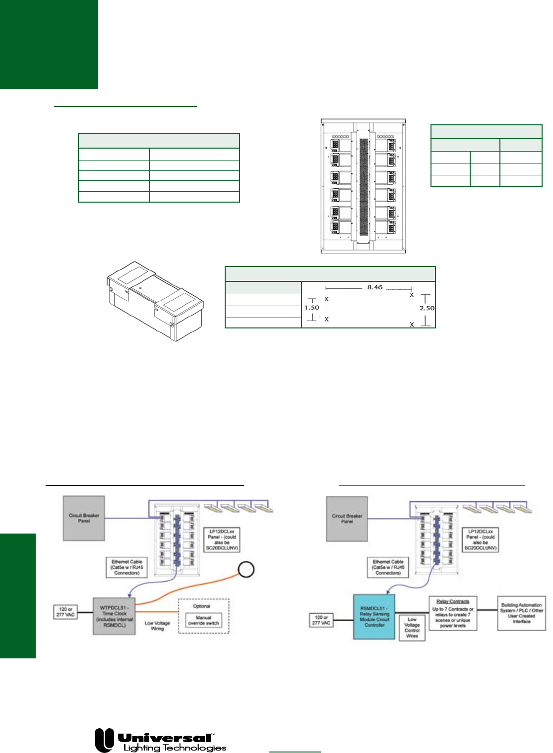
DCL Controls
DCL Controls
PAGE 3-8
FOR MORE INFORMATION CALL
1-800-BALLAST
(225-5278)
DCL CONTROLS
MODEL DESCRIPTION
LP12DCLUNV-xx Circuit Control Panel
SC20DCLUNV Single Circuit Controller
RSMDCL51 Contact Interface Controller
WTPDCL51 Time/Photo Controller
WPS5527K Photo Sensor for WTPDCL
xx = number of circuits (03-12)
SC20DCLUNV MOUNTING PATTERN
Dimensions
Length 9.66”
Width 3.98”
Depth 3.21”
LP12DCLUNV-xx
Dimensions Mounting
Length 32” 24”
Width 20” 16”
Depth 4.3”
The same cabinet size is used
for the four different panels. the
quantity of individual controllers
installed is determined by the
model number.
Circuit control panels are used to send commands down the lighting circuit to the DemandFlex ballasts. The
LP12DCLUNV-xx panels are available with 3 to 12 integral circuit control modules. If more than 12 circuits are
being controlled, additional panels can be used.
The SC20DCLUNV is used when there are a small number of circuits or space limitations prevent the use of
an LP12DCLUNV panel.
One RSMDCL51 or WTPDCL51 can control up to 63 circuits. If more than 63 circuits are to be controlled, an
RSMDCL can be connected in parallel with either controller for another 63 circuits.
Stand Alone Time Clock/Photo Cell Contact Closure Interface Control
The WTPDCL51 controller provides time of day
scheduling and can also be connected to the
WPS5527K Photo Cell for daylight harvesting.
Manual override switches are also available.
The RSMDCL51 controller integrates with external
relays or switches to translate commands to the DCL
system. This controller can be used to interface with
building automation systems, PLC’s, or switches.
These systems may also incorporate photo cells for
dayllight harvesting.

Controllable Lighting
Fluorescent Energy
Management / Dimming
Ballasts and Controls
The effective dimming of fluorescent lights delivers a wide
range of benefits: greater control of workspace lighting, ability
to create a mood, energy savings, and more.
Universal Lighting Technologies (“Universal”) line of electronic
dimming ballasts and controls lets you accomplish these goals
with a variety of products to suit your dimming needs. From
light level switching and analog dimming to digital dimming and
controls, Universal has the products and technologies to meet
today’s dimming requirements for energy savings and control-
lable lighting.
Fluorescent Dimming
Universal Lighting Technologies is a subsidiary of
Panasonic Electric Works Co., Ltd., a member of the Panasonic Group
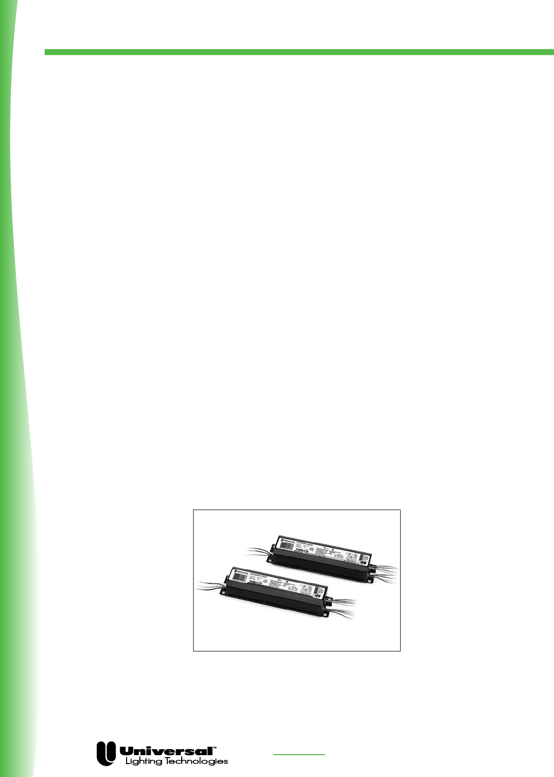
FOR MORE INFORMATION CALL
1-800-BALLAST
(225-5278)
Fluorescent Dimming
Product Overview
PAGE 3-10
Universal offers three different families of dimming products that can be used for today’s dimming
requirements for architectural lighting control and energy management applications:
Ballastar: Light Level Switching
SuperDim: Analog (0 to 10 volt) dimming
DaliPro: Digital Dimming with the DALI protocol
Ballastar® Light Level Switching (S30 & S50)
Our Ballastar® line offers two options of light level switching (either 100/50% or 100/60/30%).
That makes Ballastar® a cost-effective solution for both new construction and retrofits.
Universal Ballastar® ballasts are designed to ensure optimum lamp performance. Their Lamp Current
Crest Factors are well below the maximum 1.7 ANSI standard — and they start the lamps according
to ANSI recommendations at all dimming levels. Both of these important design parameters ensure
optimum lamp performance. In addition, Ballastar® ballasts actually increase cathode heating when
dimming to maintain the cathode’s proper temperature, which enhances lamp life and performance stability.
• 1, 2, & 3 lamp models for 120 & 277 volt
• Switches to preset light levels, keeping all lamps illuminated
• Eliminates the dark spots associated with inboard/outboard configurations
• Connects with two line voltage power leads
— Wires the same as an inboard/outboard fixture
— No special controls required; uses two wall switches
• Meets all ASHRAE 90.1 and California Title 24 requirements for lighting control
• THD <10%
• Lower installed costs; less wiring and equipment required
Ballastar® Light Level Switching for ultimate control.

FOR MORE INFORMATION CALL
1-800-BALLAST
(225-5278)
Fluorescent Dimming
Product Overview
PAGE 3-11
SuperDim® Analog Dimming Ballasts
Universal Lighting’s new SuperDim® analog dimming ballasts are the most cost-effective choice for
large scale dimming applications. SuperDim® ballasts are designed for T8 and T5 linear fluorescent
lamps and T4 4-pin quad and triple compact fluorescent lamps.
SuperDim® ballasts are compatible with a wide range of 0 – 10 volt controls and can be connected to
photocells for daylight harvesting. The resulting energy savings makes it easy to adhere to even the
strictest energy requirements, including California Title 24 and ASHRAE 90.1.
These versatile ballasts offer programmed rapid start technology for longer lamp life. They also
incorporate end-of-lamp-life shutdown circuits, low profile designs and < 10% THD at full bright.
Features and Benefits
• Ideal for T8 and T5 linear fluorescent lamps and T4 4-pin
quad and triple compact fluorescent lamps
• Compatible with most 0 – 10 volt manufactured controls
• Daylight harvesting options with photocells for maximum
energy savings
• Programmed rapid start technology maximizes lamp life
• Low profile design for fixture design flexibility
• End-of-lamp-life shutdown circuitry ensures safe operation
• < 10% THD at full bright
• Universal input voltage (120–277 volts) for installation flexibility

FOR MORE INFORMATION CALL
1-800-BALLAST
(225-5278)
Fluorescent Dimming
Notes
PAGE 3-12

FOR MORE INFORMATION CALL
1-800-BALLAST
(225-5278)
Fluorescent Dimming
Product Overview
PAGE 3-13
DaliPro Digital Dimming Ballasts for DALI
New DaliPro™ ballasts from Universal Lighting let you take full advantage of the Digital Addressable
Lighting Interface (DALI) standard...and that means greater flexibility, greater savings.
The DALI Advantage
The DALI protocol uses a 2-wire control loop to communicate with up to 64 ballasts. Broadcast, group
and individual addressing is used to control light levels, recall scenes and poll ballast status.
Many DALI-compatible controls are now available from established manufacturers; and new varieties
are being developed daily.
DaliPro Features and Benefits
• Available for T8, T5, T5HO and compact fluorescent lamps
• Provides dimming down to 1% for linear lamps and 3% for compact fluorescent lamps
• Lets you adapt instantly to additions or changes in lighting design without ballast or fixture rewiring
• Offers status/performance data, including lamp status and system faults
• Low profile designs for easy installation in a wide variety of fixtures
• Universal input voltage (120– 277 volts)
—Installer-friendly; ensures you have the right ballast every time
—Reduces inventory costs and requirements
• End-of-Lamp Life Shutdown with auto reset circuitry for safe operation
• Programmed Rapid Start for long lamp life

FOR MORE INFORMATION CALL
1-800-BALLAST
(225-5278)
Fluorescent Dimming
PAGE 3-14
Application And Operating Information
Dimming ballasts follow the same guidelines as electronic ballasts in regard to the application and operating information.
In addition to the section for electronic ballasts, the following applies specifically to dimming electronic ballasts.
SAFETY
Analog dimming ballasts are controlled by using a low voltage 10-0vDC control circuit. Care should be taken to insure that
the line voltage (AC) wires are not connected to the low voltage DC wires. SuperDim® Electronic dimming ballasts have a
protection circuit that will sense if the ballast has been connected in this manner and not harm the ballast or the installer. If
connected in this mode, the lamps will dim to the 30% level.
New Lamp Installation
When new lamps are installed, they must operate at a full bright level for a minimum of 100 hours prior to dimming.
Failure to do this will effect lamp life and cause the lamps to not dim properly. Consult your lamp manufacturer for further
lamp information.
Light Level Switching Installation Note
The two power leads for the light level switching ballasts must be connected to the same power circuit. The leads should
connect to separate switches or relays for control of the light level switching operation. Connection of the input leads to
separate power circuits can damage the ballasts.
Note:
Do not connect any other ballast to the load side of the switches controlling the switched
dimming ballast.
Compatible Dimming Controls
For a listing of compatible controls for universal analog ballasts, please consult catalog page 3-7, or call 1-800-BALLAST
or check out the Dimming and Controls section of our home page at www.unvlt.com.
Fusing
Class P ballasts do not require fusing. Fusing can be used when a single circuit has a large number of fixtures/ballasts.
For a comprehensive list of appropriate fuses, contact our Technical Engineering Services (TES) Department at 1-800-BAL-
LAST.
Detailed Operating Instructions
For additional information on all of Universal’s dimming products, consult our website at www.unvlt.com. Application
notes, dimming brochures and online training is available

FOR MORE INFORMATION CALL
1-800-BALLAST
(225-5278)
Fluorescent Dimming
PAGE 3-15
Controls For Analog Dimming Ballasts
The information listed above is provided by Universal Lighting Technologies to facilitate development of dimming systems. All information has been provided by the controls
manufacturers, and Universal Lighting Technologies makes no guarantee regarding its accuracy. The reader is advised to contact these, and other manufacturers of analog dimming
systems, to obtain application advice, to determine availability of the controls listed above, and to learn about other controls that may be offered.
Data is subject to change without notice.
Manual Controls: Wall Stations & Hand-Held Remotes
Manufacturer Website Telephone
Architectural Lighting Management www.almsys.com (888) 446-9137
Douglas Lighting Controls, Inc. www.douglaslightingcontrols.com (604) 873-2797
Electronics Diversified, Inc. www.edionline.com (800) 547-2690
Genlyte Controls www.lolcontrols.com (800) 526-2731
HUNT Dimming www.huntdimming.com (970) 484-9048
Lehigh Electric Products Co. www.lehighdim.com (610) 395-3386
Leviton www.leviton.com (800) 323-8902
Lutron www.lutron.com/universal (888) LUTRON1 - Sales
(800) 523-9466 - Technical Support
NexLight www.nexlight.com (218) 828-3700
PLC-Multipoint www.plcmultipoint.com (425) 353-7552
Sensor Switch, Inc. www.sensorswitch.com (800) 727-7483
The Watt Stopper, Inc. www.wattstopper.com (800) 879-8585
Occupancy Sensors & Controls
Manufacturer Website Telephone
Electronics Diversified, Inc. www.edionline.com (800) 547-2690
Lehigh Electric Products Co. www.lehighdim.com (610) 395-3386
Leviton www.leviton.com (800) 323-8902
Lutron www.lutron.com/universal (888) LUTRON1 - Sales
(800) 523-9466 - Technical Support
Marlin Controls, Inc. www.marlincontrols.com (800) 788-5750
NexLight www.nexlight.com (218) 828-3700
Novitas www.novitas.com (310) 218-5360
The Watt Stopper, Inc. www.wattstopper.com (800) 879-8585
Photodetectors & Daylight Controls
Manufacturer Website Telephone
Douglas Lighting Controls, Inc. www.douglaslightingcontrols.com (604) 873-2797
Electronics Diversified, Inc. www.edionline.com (800) 547-2690
Hubbell Building Automation, Inc. www.hubbell-automation.com (888) 698-3242
Lehigh Electric Products Co. www.lehighdim.com (610) 395-3386
Leviton www.leviton.com (800) 323-8902
Lutron www.lutron.com/universal (888) LUTRON1 - Sales
(800) 523-9466 - Technical Support
Marlin Controls, Inc. www.marlincontrols.com (800) 788-5750
NexLight www.nexlight.com (218) 828-3700
Novitas www.novitas.com (310) 218-5360
PLC-Multipoint www.plcmultipoint.com (425) 353-7552
Sensor Switch, Inc. www.sensorswitch.com (800) 727-7483
The Watt Stopper, Inc. www.wattstopper.com (800) 879-8585
Systems: Control Panels, Building Management Systems, etc.
Manufacturer Website Telephone
Architectural Lighting Management www.almsys.com (888) 446-9137
Douglas Lighting Controls, Inc. www.douglaslightingcontrols.com (604) 873-2797
Electronics Diversified, Inc. www.edionline.com (800) 547-2690
Genlyte Controls www.lolcontrols.com (800) 526-2731
HUNT Dimming www.huntdimming.com (970) 484-9048
Lehigh Electric Products Co. www.lehighdim.com (610) 395-3386
Leviton www.leviton.com (800) 323-8902
Lutron www.lutron.com/universal (888) LUTRON1 - Sales
(800) 523-9466 - Technical Support
Marlin Controls, Inc. www.marlincontrols.com (800) 788-5750
NexLight www.nexlight.com (218) 828-3700
PLC-Multipoint www.plcmultipoint.com (425) 353-7552
Touch-Plate Lighting Controls www.touchplate.com (800) 227-5154
The Watt Stopper, Inc. www.wattstopper.com (800) 879-8585
Universal Lighting Technologies Analog Dimming Ballasts

FOR MORE INFORMATION CALL
1-800-BALLAST
(225-5278)
DaliPro® DIMMING BALLASTS
Fluorescent Dimming
DaliPro®
PAGE 3- 16
STARTING METHOD LEGEND
IS = Instant Start
PRS = Programmed Rapid Start
RS = Rapid Start
PAR-IS = Parallel Instant Start
PAR-PRS = Parallel Programmed Rapid Start
PAR-RS = Parallel Rapid Start
SER-RS = Series Rapid Start
l Minimum Dimming Temperature is 50°F / 10°C
w Minimum Dimming Temperature is 32°F / 0°C
£Also operates (1) CFTR18W/Gx24q
n Also operates (2) CFTR18W/Gx24q
´Also operates (1) CFTR26W/Gx24q
pAlso operates (2) CFTR26W/Gx24q
See page 3-20 for Dimensions
and Wiring Diagrams
Lamp
Line Input Power Ballast Ballast Min. F/C
Starting Line Catalog Current Power Factor Factor Efficacy THD Start Wiring
Qty. Method Volts Number (Amps) (Watts) (PF) (BF) Factor (BEF) % Temp Diag. Dim.
F32T8
1 PRS 120 B132PUNVDV1
l
0.31 37 > .98 1.00 2.70 <10 0/-18 7 DP1
277 0.13 36 2.78
2 PRS 120 B232PUNVDV1
l
0.61 73 > .98 1.00 1.37 <10 0/-18 8 DP1
277 0.26 70 1.43
F14T5
1 PRS 120 B114PUNVDV1 0.15 18 > .98 1.00 5.56 <10 50/10 7 DP1
277 0.07
2 PRS 120 B214PUNVDV1 0.28 18 > .98 1.00 2.86 <10 50/10 8 DP1
277 0.13
F28T5
1 PRS 120 B128PUNVDV1 0.27 32 > .98 1.00 3.13 <10 50/10 7 DP1
277 0.11 31 3.23
2 PRS 120 B228PUNVDV1 0.55 66 > .98 1.00 1.52 <10 50/10 8 DP1
277 0.23 63 1.59
F54T5HO
1 PRS 120 B154PUNVDV1 0.52 62 > .98 1.00 1.61 <10 50/10 7 DP1
277 0.22 60 1.67
2 PRS 120 B254PUNVDV1 1.05 126 > .98 1.00 0.79 <10 50/10 8 DP1
277 0.44 121 0.83
CFQ18W/Gx24q
1 PRS 120 C118PUNVDV3
w£
0.19 21 > .95 1.00 4.76 <10 0/-18 9 DP2
277 0.10 20 5.00
2 PRS 120 C218PUNVDV3
wn
0.34 39 > .95 1.00 2.56 <10 0/-18 10 DP2
277 0.16 38 2.63
CFQ26W/Gx24q
1 PRS 120 C126PUNVDV3
w´
0.28 28 > .95 1.00 3.57 <10 0/-18 9 DP2
277 0.12 27 3.70
2 PRS 120 C226PUNVDV3
wp
0.50 54 > .95 1.00 1.85 <10 0/-18 10 DP2
277 0.23 53 1.89
CFTR32W/Gx24q
1 PRS 120 C132PUNVDV3
w
0.34 38 > .95 1.00 2.63 <10 0/-18 9 DP2
277 0.15 37 2.70
2 PRS 120 C232PUNVDV3
w
0.58 71 > .95 1.00 1.41 <10 0/-18 10 DP2
277 0.26 70 1.43
CFM42W/Gx24q
1 PRS 120 C142PUNVDV3
w
0.43 47 > .95 1.00 2.13 <10 0/-18 9 DP2
277 0.19 45 2.22
2 PRS 120 C242PUNVDV3
w
0.82 92 > .95 1.00 1.09 <10 0/-18 10 DP2
277 0.36 91 1.10
FT40W/2G11
1 PRS 120 C140PUNVDV3
w
0.37 45 > .95 1.00 2.22 <10 0/-18 9 DP1
277 0.16 44 2.27
2 PRS 120 C240PUNVDV3
w
0.83 97 > .95 1.00 1.03 <10 0/-18 10 DP1
277 0.37 94 1.06
All models are cULus Listed

FOR MORE INFORMATION CALL
1-800-BALLAST
(225-5278)
SuperDim® DIMMING BALLASTS
SuperDim®
PAGE 3- 17
STARTING METHOD LEGEND
PRS = Programmed Rapid Start
£Also operates (1) CFQ/H13W
n Also operates (1) CFQ/H18W
´Also operates (1) CFQ/H26W
pAlso operates (1) CFH32W and (1) FQ/H26W
See page 3-20 for Dimensions
and Wiring Diagrams
Fluorescent Dimming
v HT suffix—Lead entry is bottom feed
GT suffix—Lead entry is end feed
µIncorporates lead wires
Lamp
Certification Line Input Power Ballast Ballast Min. F/C
Starting Line Catalog Current Power Factor Factor Efficacy THD Start Wiring
Qty. Method Volts Number Description (Amps) (Watts) (PF) (BF) Factor (BEF) % Temp Diag. Dim.
F17T8
1 PRS 120 ES5833B ES-1-T8-17-UNV-B-DIM-10 • • 0.17 20 > .99 0.87 4.35 <10 32/0 1 ESB
277 0.08 21 > .95 4.20
1 PRS 120 ES5818K ES-1-T8-17-UNV-K-DIM-10 • • 0.17 20 > .99 0.87 4.35 <10 32/0 1 ESK
277 0.08 21 > .95 4.20
2 PRS 120 ES5834B ES-2-T8-17-UNV-B-DIM-10 • • 0.29 35 > .99 0.87 2.51 <10 32/0 2 ESB
277 0.13 > .98 2.47
2 PRS 120 ES5817K ES-2-T8-17-UNV-K-DIM-10 • • 0.29 35 > .99 0.87 2.51 <10 32/0 2 ESK
277 0.13 > .98 2.47
F25T8
1 PRS 120 ES5821B ES-1-T8-32/25-UNV-B-DIM-10 • • 0.21 26 > .99 0.87 3.41 <10 32/0 1 ESB
277 0.10 > .90 3.36
1 PRS 120 ES5835K ES-1-T8-32/25-UNV-K-DIM-10 • • 0.21 26 > .99 0.87 3.40 <10 32/0 1 ESK
277 0.10 > .90 3.31
2 PRS 120 ES5822B ES-2-T8-32/25-UNV-B-DIM-10 • • 0.41 48 > .99 0.87 1.80 <10 32/0 1 ESB
277 0.18 > .95 1.82
2 PRS 120 ES5836K ES-2-T8-32/25-UNV-K-DIM-10 • • 0.41 48 > .99 0.87 1.80 <10 32/0 1 ESK
277 0.18 > .95 1.82
F32T8
1 PRS 120 ES5821B ES-1-T8-32/25-UNV-B-DIM-10 • • 0.29 34 > .99 0.87 2.60 <10 32/0 1 ESB
277 0.13 > .95 2.57
1 PRS 120 ES5835K ES-1-T8-32/25-UNV-K-DIM-10 • • 0.27 33 > .99 0.87 2.63 <10 32/0 1 ESK
277 0.13 34 > .95 2.60
2 PRS 120 ES5822B ES-2-T8-32/25-UNV-B-DIM-10 • • 0.56 65 > .99 0.87 1.33 <10 32/0 2 ESB
277 0.23 64 > .98 1.37
2 PRS 120 ES5836K ES-2-T8-32/25-UNV-K-DIM-10 • • 0.56 65 > .99 0.87 1.33 <10 32/0 2 ESK
277 0.23 64 > .95 1.37
F14T5
1 PRS 120 ES5849K ES-1-T5-14-UNV-K-DIM-10 • • 0.16 20 > .99 1.00 5.13 <10 32/0 1 ESK
277 0.07 > .98 4.95
2 PRS 120 ES5851K ES-2-T5-14-UNV-K-DIM-10 • • 0.28 34 > .99 1.00 2.94 <10 32/0 2 ESK
277 0.13 > .95
F21T5
1 PRS 120 ES5839K ES-1-T5-21-UNV-K-DIM-10 • • 0.23 28 > .99 1.00 3.64 <10 32/0 1 ESK
277 0.16 > .98
2 PRS 120 ES5861K ES-2-T5-21-UNV-K-DIM-10 • • 0.40 48 > .99 1.00 2.08 <10 32/0 2 ESK
277 0.17 > .98
F28T5
1 PRS 120 ES5846K ES-1-T5-28-UNV-K-DIM-10 • • 0.30 37 > .99 1.00 2.67 <10 32/0 1 ESK
277 0.14 > .95 2.71
2 PRS 120 ES5847K ES-2-T5-28-UNV-K-DIM-10 • • 0.56 67 > .99 1.00 1.49 <10 32/0 2 ESK
277 0.25 > .98 1.50
F35T5
1 PRS 120 ES5853K ES-1-T5-35-UNV-K-DIM-10 • • 0.34 40 > .99 1.00 2.50 <10 32/0 1 ESK
277 0.15 41 > .98 2.44
CFQ/H13W
2 PRS 120 ES5011GT/HT
£v
ES-2/1-CFQ-13-UNV-GT/HT-DIM-10 • • 0.25 30 > .99 1.00 3.38 <10 32/0 3 GT/HT
277 0.11 29 > .95 3.41
CFQ/H18W
2 PRS 120 ES5012GT/HT
nv
ES-2/1-CFQ-18-UNV-GT/HT-DIM-10 • • 0.31 38 > .99 1.00 2.66 <10 32/0 3 GT/HT
277 0.14 > .95
CFQ/H26W
2 PRS 120 ES5013GT/HT
´v
ES-2/1-CFQ-26-UNV-GT/HT-DIM-10 • • 0.46 54 > .99 1.00 1.85 <10 32/0 3 GT/HT
277 0.19 52 > .95 1.94
CFH42W
1 PRS 120 ES5010GT/HT
pv
ES-1-CFH-42/36/26-UNV-GT/HT-DIM-10
• • 0.34 46 > .99 1.00 2.41 <10 32/0 4 GT/HT
277 0.15 > .95 2.20
FT40W/2G11
1 PRS 120 ES5006BM
µ
ES-1-CFT-40-UNV-BM-DIM-10 • • 0.35 44 > .99 1.09 2.48 <10 32/0 5 ESBM
277 0.16 43 > .98 2.53
2 PRS 120 ES5007BMT
µ
ES-2-CFT-40-UNV-BMT-DIM-10 • • 0.73 88 > .99 1.09 1.24 <10 32/0 6 ESBMT
277 0.31 87 1.25
Please visit www.unvlt.com for the most up to date status
and recent changes to the SuperDim product family.

FOR MORE INFORMATION CALL
1-800-BALLAST
(225-5278)
T8 Straight Lamps
T12 U-Shaped Lamps
• Analog Dimming
• Rapid Start
• 1, 2, 3 & 4 Lamp Applications
BALLASTAR ® 0-10 VOLT
DIMMING BALLASTS
FOR (1), (2), (3) & (4) T8 LAMPS
Fluorescent Dimming
BALLASTAR
0-10V
DIMMING
PAGE 3- 18
IS = Instant Start
PRS = Programmed Rapid Start
RS = Rapid Start
STARTING METHOD LEGEND
PAR-IS = Parallel Instant Start
PAR-PRS = Parallel Programmed Rapid Start
PAR-RS = Parallel Rapid Start
SER-RS = Series Rapid Start
See page 3-20 for Dimensions
and Wiring Diagrams
All models except B232SR347V5 are cULus Listed
B232SR347V5 is CSA Certified
Lamp
Line Input Power Ballast Ballast Min. F/C
Starting Line Catalog Current Power Factor Factor Efficacy THD Start Wiring
Qty. Method Volts Number (Amps) (Watts) (PF) (BF) Factor (BEF) % Temp Diag. Dim.
F25T8 - One Lamp Applications
120 B132R120V5 @ 100% 0.22 26 > .99 0.90 3.46 < 10 50/10 13 ST
B132R120V5 @ 5% 0.06 7 > .90 0.05 0.71 < 15 50/10 13 ST
1 RS 277 B132R277V5 @ 100% 0.10 26 > .99 0.90 3.46 < 10 50/10 13 ST
B132R277V5 @ 5% 0.03 7 > .90 0.05 0.71 < 20 50/10 13 ST
347 B132R347V5 @ 100% 0.08 26 > .99 0.90 3.46 < 10 50/10 13 ST
B132R347V5 @ 5% 0.02 7 > .90 0.05 0.71 < 30 50/10 13 ST
F25T8 - Two Lamp Applications
2 RS 347 B232SR347V5 @ 100% 0.14 47 > .99 0.93 1.98 <10 50/10 15 -E
B232SR347V5 @ 5% 0.04 12 > .90 0.05 0.42 <15 50/10 15 -E
F25T8 - Four Lamp Applications
4 PAR-PRS 277 B432P277V5-E @ 100% 0.33 90 > .98 0.88 0.98 <10 50/10 14 -E
B432P277V5-E @ 5% 0.09 22 > .90 0.05 0.23 <15 0/10 14 -E
F32T8 - One Lamp Applications
120 B132R120V5 @ 100% 0.27 32 > .99 0.88 2.75 < 10 50/10 13 ST
B132R120V5 @ 5% 0.07 8 > .90 0.05 0.63 < 10 50/10 13 ST
1 RS 277 B132R277V5 @ 100% 0.12 32 > .99 0.88 2.75 < 10 50/10 13 ST
B132R277V5 @ 5% 0.03 8 > .90 0.05 0.63 < 15 50/10 13 ST
347 B132R347V5 @ 100% 0.09 32 > .99 0.88 2.75 < 10 50/10 13 ST
B132R347V5 @ 5% 0.02 8 > .90 0.05 0.63 < 20 50/10 13 ST
F32T8 - Two Lamp Applications
120 B232SR120V5 @ 100% 0.52 62 > .99 0.88 1.42 < 10 50/10 15 ST
B232SR120V5 @ 5% 0.12 13 > .90 0.05 0.38 < 10 50/10 15 ST
2 SER-RS 277 B232SR277V5 @ 100% 0.23 62 > .99 0.88 1.42 < 10 50/10 15 ST
B232SR277V5 @ 5% 0.05 13 > .90 0.05 0.38 < 15 50/10 15 ST
347 B232SR347V5 @ 100% 0.18 62 > .99 0.88 1.42 < 10 50/10 15 ST
B232SR347V5 @ 5% 0.04 13 > .90 0.05 0.38 < 15 50/10 15 ST
2 RS 347 B232SR347V5 @ 100% 0.18 62 > .99 0.88 1.42 <10 50/10 15 -E
B232SR347V5 @ 5% 0.04 13 > .90 0.05 0.38 <15 50/10 15 -E
F32T8 - Three Lamp Applications
120 B332SR120V5 @ 100% 0.77 92 > .99 0.88 0.96 < 10 50/10 17 ST
3 SER-RS B332SR120V5 @ 5% 0.17 20 > .90 0.05 0.25 < 10 50/10 17 ST
277 B332SR277V5 @ 100% 0.33 92 > .99 0.88 0.96 < 10 50/10 17 ST
B332SR277V5 @ 5% 0.07 20 > .90 0.05 0.25 < 15 50/10 17 ST
F32T8 - Four Lamp Applications
4 SER/PAR-RS 277 B432SR277V5 @ 100% 0.42 117 > .99 0.88 0.79 < 10 50/10 18 -ZZ
B432SR277V5 @ 5% 0.11 27 > .90 0.05 0.19 < 15 50/10 18 -ZZ
4 SER-PRS 277 B432P277V5-E@ 100% 0.42 115 > .99 0.88 0.77 < 10 50/10 14 -E
B432P277V5-E@ 5% 0.10 24 > .90 0.05 0.21 < 15 50/10 14 -E
B432P277V5H-E
@ 100% 0.55 150 > .99 1.18 0.79 < 10 50/10 14 -E
4 SER-PRS 277
B432P277V5H-E
@ 5% 0.12 28 > .90 0.06 0.22 < 15 50/10 14 -E
Please visit www.unvlt.com for the most up to date status
and recent changes to the Ballastar 0-10V product family.

FOR MORE INFORMATION CALL
1-800-BALLAST
(225-5278)
T8 Straight Lamps
BALLASTAR ® STEP DIMMING BALLASTS
FOR (1), (2) & (3) T8 LAMPS
• Step Dimming
• Rapid Start
• 1-3 Lamp Applications
BALLASTAR
LIGHT LEVEL
SWITCHING
Fluorescent Dimming
T12 U-Shaped Lamps
PAGE 3-19
See page 3-20 for Dimensions and Wiring Diagrams
All models are cULus Listed
Lamp
Line Input Power Ballast Ballast Min. F/C
Starting Line Catalog Current Power Factor Factor Efficacy THD Start Wiring
Qty. Method Volts Number (Amps) (Watts) (PF) (BF) Factor (BEF) % Temp Diag. Dim.
F17T8 - One Lamp Applications
120 B232PUS50-A @ 100% 0.14 16 > .95 0.88 5.50 < 15 32/0 12a -A
1 PRS B232PUS50-A @ 50% 0.08 9 > .95 0.29 3.22 < 15 32/0 12a -A
277 B232PUS50-A @ 100% 0.08 16 > .70 0.88 5.50 < 15 32/0 12a -A
B232PUS50-A @ 50% 0.05 9 > .70 0.29 3.22 < 15 32/0 12a -A
F17T8 - Two Lamp Applications
120 B232PUS50-A @ 100% 0.25 30 > .99 0.87 2.90 < 10 32/0 12 -A
2 PRS B232PUS50-A @ 50% 0.14 16 > .98 0.30 1.88 < 15 32/0 12 -A
277 B232PUS50-A @ 100% 0.12 30 > .88 0.87 2.90 < 10 32/0 12 -A
B232PUS50-A @ 50% 0.07 16 > .85 0.30 1.88 < 15 32/0 12 -A
F25T8 - One Lamp Applications
120 B232PUS50-A @ 100% 0.21 24 > .95 0.85 3.54 < 10 32/0 12a -A
1 RS B232PUS50-A @ 50% 0.10 12 > .90 0.28 2.33 < 10 32/0 12a -A
277 B232PUS50-A @ 100% 0.11 24 > .80 0.85 3.54 < 10 32/0 12a -A
B232PUS50-A @ 50% 0.06 12 > .80 0.28 2.33 < 10 32/0 12a -A
F25T8 - Two Lamp Applications
120 B232PUS50-A @ 100% 0.39 46 > .98 0.84 1.83 < 10 32/0 12 -A
2 SER-RS B232PUS50-A @ 50% 0.20 24 > .95 0.28 1.17 < 10 32/0 12 -A
277 B232PUS50-A @ 100% 0.18 46 > .98 0.84 1.83 < 10 32/0 12 -A
B232PUS50-A @ 50% 0.09 24 > .90 0.28 1.17 < 10 32/0 12 -A
F32T8 - One Lamp Applications
B132R120S30 @ 100% 0.27 32 > .99 0.89 2.78 < 10 50/10 11 ST
120 B132R120S30 @ 60% 0.19 23 > .99 0.60 2.61 < 10 50/10 11 ST
B132R120S30 @ 30% 0.12 14 > .98 0.28 2.00 < 10 50/10 11 ST
B132R277S30 @ 100% 0.13 33 > .99 0.89 2.70 < 10 50/10 11 ST
1 RS 277 B132R277S30 @ 60% 0.09 25 > .98 0.63 2.52 < 15 50/10 11 ST
B132R277S30 @ 30% 0.06 15 > .95 0.28 1.87 < 20 50/10 11 ST
120 B232PUS50-A @ 100% 0.25 29 > .99 0.88 3.03 < 10 32/0 12a ST
B232PUS50-A @ 50% 0.12 14 > .98 0.29 2.07 < 10 32/0 12a ST
277 B232PUS50-A @ 100% 0.12 29 > .85 0.88 3.03 < 10 32/0 12a ST
B232PUS50-A @ 50% 0.06 14 > .80 0.29 2.07 < 20 32/0 12a ST
F32T8 - Two Lamp Applicationswa
B232SR120S30 @ 100% 0.52 62 > .99 0.88 1.42 < 10 50/10 12 ST
120 B232SR120S30 @ 60% 0.38 45 > .95 0.58 1.29 < 10 50/10 12 ST
B232SR120S30 @ 30% 0.24 28 > .95 0.27 0.96 < 10 50/10 12 ST
B232SR277S30 @ 100% 0.23 62 > .99 0.88 1.42 < 10 50/10 12 ST
2 SER-RS 277 B232SR277S30 @ 60% 0.17 45 > .95 0.58 1.29 < 10 50/10 12 ST
B232SR277S30 @ 30% 0.11 28 > .95 0.27 0.96 < 10 50/10 12 ST
120 B232PUS50-A @ 100% 0.48 57 > .99 0.88 1.54 < 10 32/0 12 -A
B232PUS50-A @ 50% 0.24 28 > .99 0.30 1.07 < 10 32/0 12 -A
277 B232PUS50-A @ 100% 0.21 56 > .95 0.88 1.57 < 10 32/0 12 -A
B232PUS50-A @ 50% 0.11 28 > .90 0.30 1.07 < 10 32/0 12 -A
F32T8 - Three Lamp Applications
B332SR120S30 @ 100% 0.78 93 > .99 0.88 0.95 < 10 50/10 16 ST
120 B332SR120S30 @ 60% 0.61 69 > .95 0.60 0.87 < 10 50/10 16 ST
3 SER-RS B332SR120S30 @ 30% 0.40 43 > .95 0.30 0.70 < 10 50/10 16 ST
B332SR277S30 @ 100% 0.34 94 > .99 0.88 0.94 < 10 50/10 16 ST
277 B332SR277S30 @ 60% 0.26 69 > .95 0.60 0.87 < 10 50/10 16 ST
B332SR277S30 @ 30% 0.16 43 > .95 0.30 0.70 < 10 50/10 16 ST
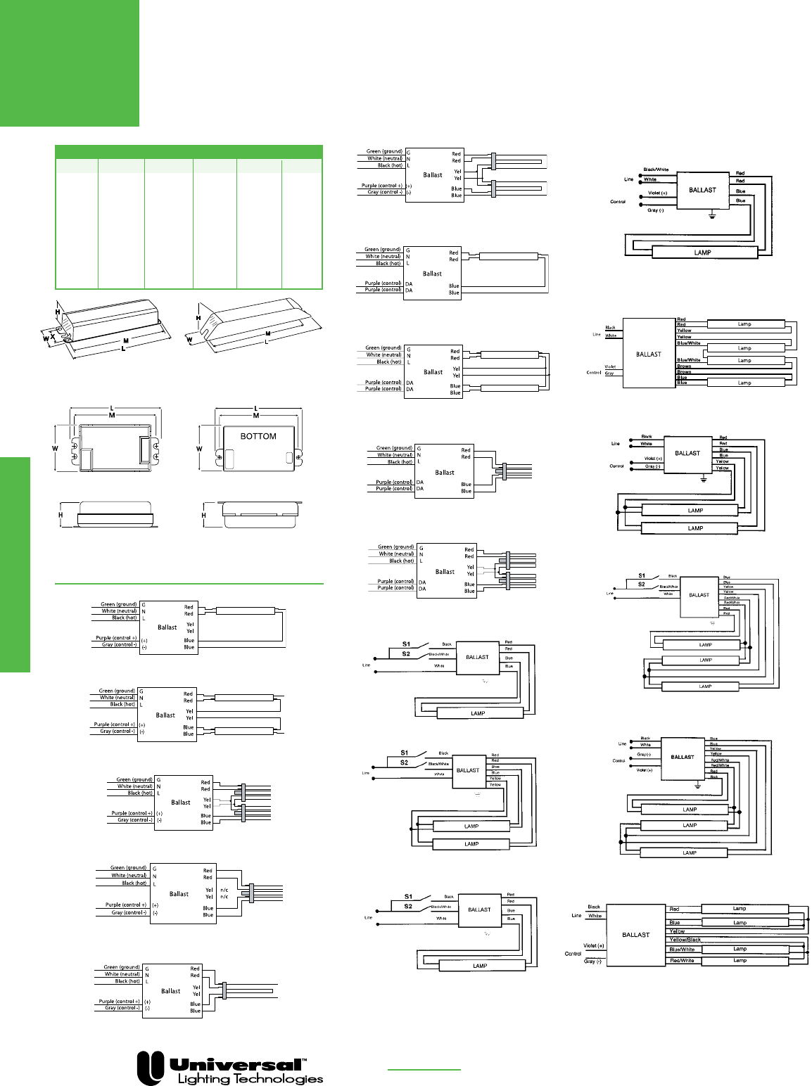
FOR MORE INFORMATION CALL
1-800-BALLAST
(225-5278)
DIMENSIONS AND WIRING DIAGRAMS
Fluorescent Dimming
T8
DIMMING
PAGE 3-20
DIAGRAM 11
DIAGRAM 12
DIAGRAM 13
Overall Dimensions Mounting Dimensions
Draw # L W H M X
ST 9.50” 2.40” 1.55” 8.89” 1.69”
-E 16.88” 1.74” 1.18” 16.28” —
-ZZ 16.40” 2.40” 1.50” 15.88” 1.69”
ESB 9.50” 2.38” 1.00” 8.88” —
ESK 16.65” 1.24” 1.00” 16.30” —
GT/HT 4.95” 3.00” 1.18” 4.63” —
ESBM 9.50” 2.38” 1.00” 8.88” —
ESBMT 9.50” 2.38” 1.20” 8.88” —
DP1 18.00” 1.18” 1.18” 17.70” —
DP2 4.95” 2.93” 1.38” 4.57” —
WIRING DIAGRAMS
DIAGRAM 14
DIAGRAM 15
DIAGRAM 16
DIAGRAM 17
DIAGRAM 18
DIAGRAM 1
DIAGRAM 2
DIAGRAM 3
DIAGRAM 4
DIAGRAM 5
DIAGRAM 6
DIAGRAM 7
DIAGRAM 8
DIAGRAM 9
DIAGRAM 10
-E, ESB, ESK, ESBM,
ESBMT, DP1
ST, -ZZ
GT HT, DP2
DIAGRAM 12a
INDIVIDUALLY CAP YELLOW LEADS

FOR MORE INFORMATION CALL
1-800-BALLAST
(225-5278)
T5 Straight Lamps
BALLASTAR ® STEP DIMMING BALLASTS
FOR T5 LAMPS
• Step Dimming
• Programmed Rapid Start
• 2 Lamp Applications
BALLASTAR
LIGHT LEVEL
SWITCHING
Fluorescent Dimming
PAGE 3- 21
IS = Instant Start
PRS = Programmed Rapid Start
RS = Rapid Start
STARTING METHOD LEGEND
PAR-IS = Parallel Instant Start
PAR-PRS = Parallel Programmed Rapid Start
PAR-RS = Parallel Rapid Start
SER-RS = Series Rapid Start
Overall Dimensions Mounting Dimensions
Draw # L W H M X
-D 16.88” 1.18” 1.00” 16.20” —
-A 9.50” 1.70” 1.18” 8.89” —
-D
WIRING DIAGRAMS
-A
All models are cULus Listed
Lamp
Line Input Power Ballast Ballast Min. F/C
Starting Line Catalog Current Power Factor Factor Efficacy THD Start Wiring
Qty. Method Volts Number (Amps) (Watts) (PF) (BF) Factor (BEF) % Temp Diag. Dim.
F14T5 - One Lamp Applications
120 B214PU115S50A @ 100% 0.17 21 > .95 1.19 5.90 < 15 50/10 12a -A
1 PRS B214PU115S50A @ 50% 0.09 10 > .95 0.40 3.74 < 15 50/10 12a -A
277 B214PU115S50A @ 100% 0.09 21 > .75 1.19 5.80 < 15 50/10 12a -A
B214PU115S50A @ 50% 0.05 10 > .75 0.40 3.50 < 15 50/10 12a -A
F14T5 - Two Lamp Applications
120 B214PU115S50A @ 100% 0.33 37.5 > .95 1.15 3.10 < 10 50/10 12 -A
B214PU115S50A @ 50% 0.15 18 > .95 0.40 2.19 < 15 50/10 12 -A
277 B214PU115S50A @ 100% 0.15 37 > .90 1.15 3.11 < 10 50/10 12 -A
2 PRS B214PU115S50A @ 50% 0.08 19 > .85 0.40 2.14 < 15 50/10 12 -A
120 B228PU95S50D @ 100% 0.29 35 > .95 1.00 2.86 < 10 50/10 19 -D
B228PU95S50D @ 50% 0.13 16 > .95 0.37 2.30 < 10 50/10 19 -D
277 B228PU95S50D @ 100% 0.13 35 > .95 1.00 2.86 < 10 50/10 19 -D
B228PU95S50D @ 50% 0.06 16 > .90 0.37 2.29 < 10 50/10 19 -D
F21T5 - One Lamp Applications
120 B214PU115S50A @ 100% 0.24 29 > .95 1.18 4.09 < 10 50/10 12a -A
1 PRS B214PU115S50A @ 50% 0.12 14 > .95 0.39 2.84 < 15 50/10 12a -A
277 B214PU115S50A @ 100% 0.12 29 > .85 1.18 4.06 < 15 50/10 12a -A
B214PU115S50A @ 50% 0.62 14 > .85 0.40 2.75 < 15 50/10 12a -A
120 B228PU95S50D @ 100% 0.40 48 > .95 0.99 2.06 < 10 50/10 19 -D
2 PRS B228PU95S50D @ 50% 0.18 21 > .95 0.36 1.73 < 10 50/10 19 -D
277 B228PU95S50D @ 100% 0.17 47 > .95 0.99 2.10 < 10 50/10 19 -D
B228PU95S50D @ 50% 0.08 22 > .95 0.36 1.65 < 10 50/10 19 -D
F28T5 - Two Lamp Applications
2 PRS
120 B228PU95S50D @100% 0.50 58 > .99 0.95 1.64 < 10 50/10 19 -D
B228PU95S50D @50% 0.23 28 > .99 0.35 1.25 < 20
277 B228PU95S50D @100% 0.21 57 > .98 0.95 1.67 < 10 50/10 19 -D
B228PU95S50D @50% 0.10 28 > .95 0.35 1.25 < 20
2 PRS
120 B228PU115S50D @100% 0.59 71 > .99 1.15 1.62 < 10 50/10 19 -D
B228PU115S50D @50% 0.29 34 > .99 0.45 1.32 < 10
277 B228PU115S50D @100% 0.25 69 > .98 1.15 1.67 < 10 50/10 19 -D
B228PU115S50D @50% 0.12 34 > .95 0.45 1.32 < 15
º Preliminary Data

Fluorescent Dimming
PAGE 3- 22
Notes
Compact Fluorescent
Compact Fluorescent
Ballasts
The Courage To Dream Small
Universal Lighting Technologies (“Universal”) offers a
full range of magnetic and electronic compact fluores-
cent ballasts. Our magnetic models come in a variety
of shapes and sizes, from core and coils to High Power
Factor potted ballasts with bottom exit leads and mount-
ing studs for all downlighting applications.
Our newest electronic models offer installer-friendly
universal input voltage, which reduces your inventory
and ensures that you have the right voltage ballast every
time. These models feature a low profile case that fits in
any fixture. And their metal housing construction meets
all plenum codes and delivers maximum heat transfer to
extend ballast life.
Our newest compact fluorescent models offer installer-friendly universal
input voltage.
Universal Lighting Technologies is a subsidiary of
Panasonic Electric Works Co., Ltd., a member of the Panasonic Group

Compact Fluorescent
Product Overview
FOR MORE INFORMATION CALL
1-800-BALLAST
(225-5278)
PAGE 4-2
Electronic Compact Fluorescent Ballasts
Universal’s newest TRIAD® electronic compact fluorescent ballasts feature installer-friendly universal input
voltage (108 to 305 volts) and metal case designs for compliance with all plenum and construction code
requirements. They also offer an end-of-lamp-life shutdown circuit with auto-reset that meets ANSI/NEMA
requirements—a feature that eliminates lamp/socket damage while allowing you to replace failed lamps
after shutdown without turning off the power.
Our universal voltage compact fluorescent ballasts offer both 1- and 2-lamp operation—and they’re ideal for
a wide variety of downlight and surface mount applications for atriums, hotel corridors, offices, and outdoors.
All models operate multiple lamp types for added versatility in many different applications.
All universal voltage compact fluorescent ballasts incorporate Universal’s Programmed Rapid Start (PRS)
technology that increases lamp life for those frequently switched applications where occupancy sensors are
used. PRS is recommended by all lamp manufacturers.
For the Canadian market, we have 347 volt compact fluorescent models. These also offer outstanding reli-
ability and lamp performance. These 347 volt models are available for 1 and 2 lamp operation for lamps
ranging from 13 to 70 Watts.
These ballasts are designed and manufactured for long life. Lamps can be mounted in close proximity to
these ballasts because they have no temperature-critical components near the can sides. And their circuit
board potting enhances reliability by lowering case temperatures.
CFL Mult-E Kit
The multi-exit ballast lead wire connectors accomodate side and bottom lead exit requirements.
The snap mount adapter plate adds bottom-exit studs and additional flexibility for replacement of
older magnetic ballasts. They also fit virtually every j-box cover and fixture application. This
product is for distribution sale only.
Mult-E Kit products:
C213UNVME000K
C218UNVME000K
C2642UNVME000K
Mult-E Kit contains:
Multi-exit ballast
Snap-mount adapter plate
Lead wire set
Wire extraction tool
Instructions
Magnetic Compact Fluorescent Ballasts
Universal offers a complete line of magnetic compact fluorescent ballasts, ranging from 5 - 40
watts (10 - 38 watts for 2D lamps). Both core & coil and F-can models are available...in a variety
of configurations that include Side Exit, Bottom Exit and Bottom Exit Studs.
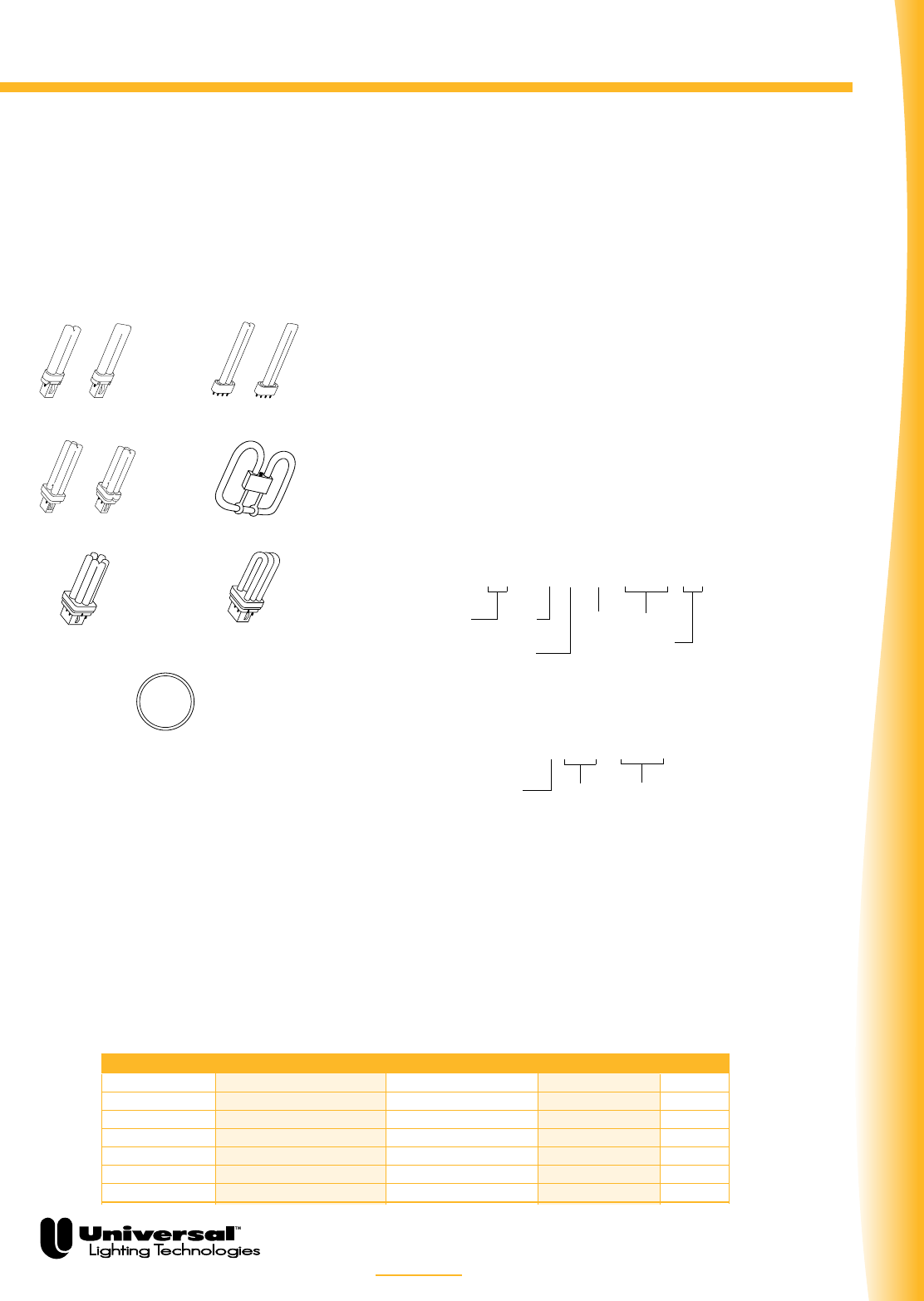
Compact Fluorescent
FOR MORE INFORMATION CALL
1-800-BALLAST
(225-5278)
PAGE 4-3
Understanding Compact Fluorescent Technology
Industry Watts GE OSI Philips
Single or Twin 5, 7, 9, 13 Low Watt Biax Dulux S, S/E PL-S
Double or Quad 9, 13, 18, 20, 26, 27 Double Biax
Dulux D, D/E
PL-C
Multiple 13, 18, 26, 32, 42 Biax T/E Dulux T, T/E,
T/E/IN
PL-T
Multiple 42, 57, 70 Biax Q/E Dulux T/E/IN PL-T
Long Twin T5 18, 24/27, 36/39, 40, 50, 80 High Lumen Biax Dulux L, F PL-L
Square 10, 16, 21, 28, 38, 55 2D –– ––
Circline 22, 40, 55 — Pentron Silhouette
Compact fluorescent (CFL) lamps are single-ended and
plug into sockets. They’re sometimes referred to as “sin-
gle-based” or “single-ended” fluorescent lamps.
Lamp Shapes
Today’s CFL lamps come in these basic shapes: twin tube,
quad, triple, multi and circular. Each of these shapes has its
own subset of sizes. For example, the twin tube may range
from 4˝ long (5 watt) to 22˝ long (40 watt).
Pins and Starters
CFL lamps feature either two pins or four pins. Those
with two pins have starters built into their bases, and
they require a magnetic preheat ballast. The two-pin CFL
lamps are available in wattages from 5 to 28.
Four-pin lamps are traditionally powered by electronic
ballasts. These lamps do not have an internal starter, so
the other filament terminals (pins) are made
accessible for external connection to the ballasts. Note:
Universal offers both magnetic and electronic ballasts for
the four-pin 32 and 26 watt lamps and all four-pin Long
Twin T5 lamps.
Lamp Bases
There are a variety of lamp bases used with today’s CFL
lamps. This provides a safeguard to make sure that the
proper lamp/ballast combination is installed. The lamp
base style is part of the ANSI/NEMA
designation.
In this catalog, Universal CFL ballasts are classified
according to lamp type. Icons representing each lamp
type provide a quick visual reference. Within each clas-
sification, the lamps and their appropriate ballasts can
be found by referring to the generic NEMA lamp descrip-
tions.
Lamp Designation
There are two different industry-recognized
nomenclatures for identifying CFL lamps: ANSI
Lamp Designations and NEMA Lamp Designations. Here
are examples of each:
ANSI Designation
NEMA Designation
Both lamp designations refer to lamp wattage, shape,
and base type. Since the NEMA designation is shorter, it
will probably be the nomenclature of choice in the future.
All of the major lamp companies have trade names for
various CFL lamp types, such as GE’s “Biax” and “2D”
lamps, OSI’s “Dulux,” and Philips’ “PL”. These names
have become more widely used than either of the indus-
try designations.
2-Pin 4-Pin
Quad 9w – 27w
Square (2D)
10w – 55w
Twin, 2-Pin
5w – 13w
OR
Long Twin T5, 4-Pin
5w – 80w
OR
OR
Multiple, 4-Pin
(GE & OSI)
18w – 70w
Multiple, 4-Pin
(Philips)
18w – 42w
T5 Circular
22w - 55w
CFT 13W / GX23
Twin (T)
Quad (Q)
Multi (M)
2D (S)
Lamp
Wattage
Base
13W / 7T4 / T / GX23 / PH
Lamp
Wattage
Lamp
Length
Lamp
Diameter
1/8˝
Twin (T)
Quad (Q)
Multi (M)
2D (S)
Base
Starting:
PH – Preheat
RS – Rapid Start
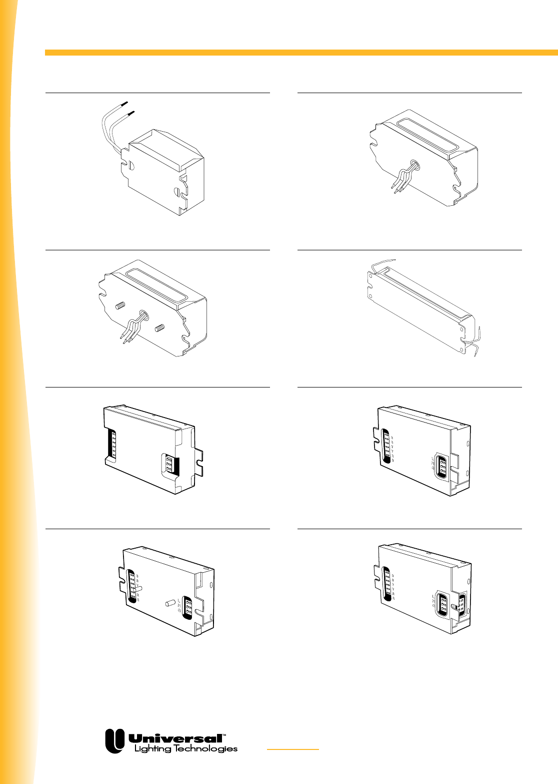
Compact Fluorescent
Configurations
FOR MORE INFORMATION CALL
1-800-BALLAST
(225-5278)
PAGE 4-4
Standard Side Exit Bottom Exit*
Bottom Exit with Studs** Standard Side Exit – Both Ends
Electronic Side Exit
Electronic Bottom Exit with Studs
Electronic Bottom Exit
Electronic Multi-Exit
For full versatility in application according to various fixture requirements, Universal manufactures encased ballasts in three lead and mounting
options. This catalog lists ordering codes for standard side exit units. *Bottom exit units should be ordered with suffix “-BE” attached to the
catalog number. **Bottom exit with studs should be ordered with suffix “-BES” attached to the catalog number.
(Example: Standard Unit: “4000P”; Bottom Exit unit “4000-BE”; Bottom Exit with Studs: “4000-BES”).
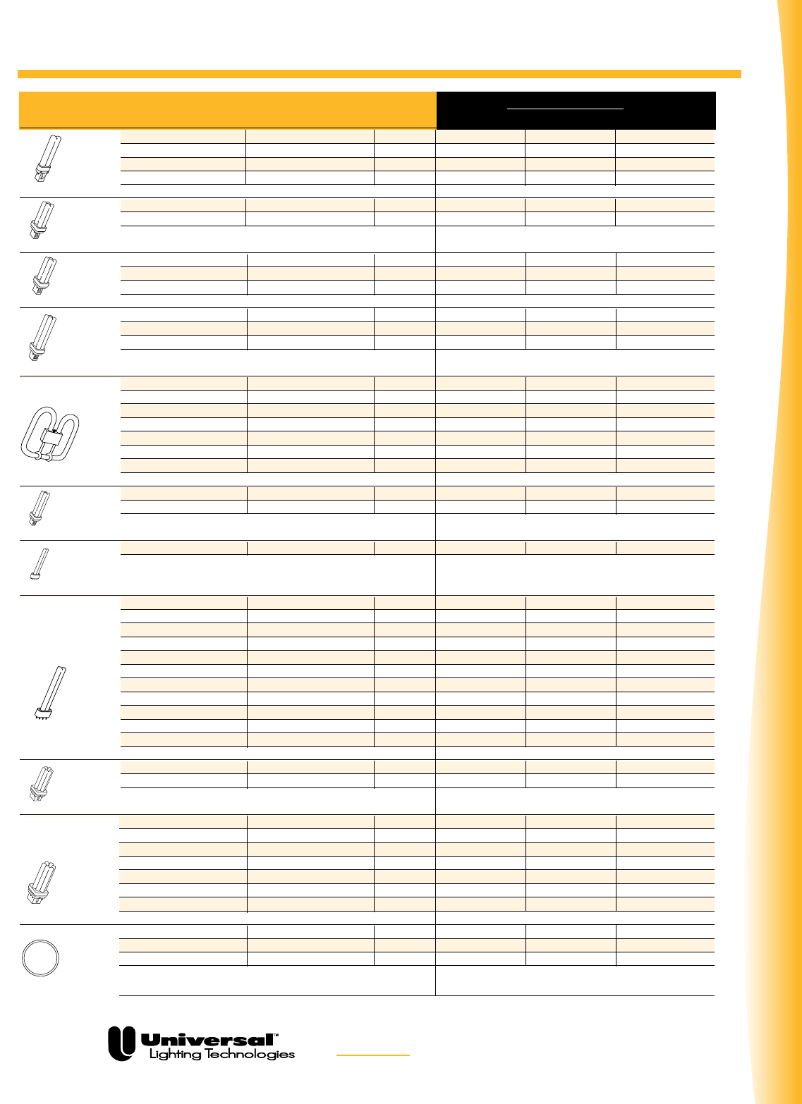
Compact Fluorescent
FOR MORE INFORMATION CALL
1-800-BALLAST
(225-5278)
PAGE 4-5
Product Overview
ANSI Lamp NEMA Lamp Built-In LAMP MANUFACTURER
Designation Designation Starter GE OSI Philips
5W/4T4/T/G23/PH CFT5W/G23 YES F5 BX CF 5DS PL-S 5W
7W/5T4/T/G23/PH CFT7W/G23 YES F7 BX CF 7DS PL-S 7W
9W/6T4/T/G23/PH CFT9W/G23 YES F9 BX CF 9DS PL-S 9W
13W/7T4/T/GX23/PH CFT13W/GX23 YES F13 BX CF 13DS PL-S 13W
Twin, 2-Pin
9W/4T4/Q/G23-2/PH CFQ9W/G23 YES F9 DBX23 CF 9DD —
13W/5T4/Q/GX23-2/PH CFQ13W/GX23 YES F13 DBX23 CF 13DD PL-C 13W/USA
Quad, 2-Pin
13W/6T4/Q/G24d-1/PH CFQ13W/G24d YES F13 DBX T4 — PL-C 13W
18W/7T4/Q/G24d-2/PH CFQ18W/G24d YES F18 DBX T4 CF 18DD PL-C 18W
26W/8T4/Q/G24d-3/PH CFQ26W/G24d YES F26 DBX T4 CF 26DD PL-C 26W
Quad, 2-Pin
13W/6T4/Q/G24q-1 CFQ13W/G24q NO F13 DBX/4P CF 13DD/E PL-C 13W/4P
18W/7T4/Q/G24q-2 CFQ18W/G24q NO F18 DBX/4P CF 18DD/E PL-C 18W/4P
26W/8T4/Q/G24q-3 CFQ26W/G24q NO F26 DBX/4P CF 26DD/E PL-C 26W/4P
Quad, 4-Pin
10W/3.5T4/S/GR10q-4 CFS10W/GR10q NO F10 2D/4P — —
16W/5.5T4/S/GR10q-4 CFS16W/GR10q NO F16 2D/4P — —
21W/5.5T4/S/GR10q-4 CFS21W/GR10q NO F21 2D/4P — —
28W/8T6/S/GR8-2/PH CFS28W/GR8 YES F28 2D — —
28W/8T6/S/GR10q-4 CFS28W/GR10q NO F28 2D/4P — —
38W/8T6/S/GR10q-4 CFS38W/GR10q NO F38 2D/4P — —
55W/8T6/S/GRY10q-3 CFS55W/GRY10q NO F55 2D/4P — —
Square, (2D)
20W/6T5/Q/GX32d-2/PH CFQ20W/GX32d YES — —
PL-C 15MM/22W
27W/7T5/Q/GX32d-3/PH CFQ27W/GX32d YES — —
PL-C 15MM/28W
T5 Quad, 2-Pin
13W/6T4/T/2GX7 CFT13W/2GX7 NO — CF 13DS/E
—
Twin T4, 4-Pin
18-20W/9T5/T/2G11/PH-RS
FT18W/2G11 NO F18 BX FT 18DL —
18W/10T5/T/2G11/RS FT18W/2G11/RS NO F18 BX/RS FT 18DL/RS PL-L 18W
18W/5T5/T/2G10
CFM18W/2G10 NO — CF 18DF —
24-27W/13T5/T/2G11/PH-RS
FT24W/2G11/RS NO F27 BX/RS FT 24DL PL-L 24W
24W/7T5/T/2G10 CFM24W/2G10 NO — CF 24DF —
36-39W/16T5/T/2G11/PH-RS
FT36W/2G11/RS NO F39 BX/RS FT 36DL PL-L 36W
36W/9T5/T/2G10 CFM36W/2G10 NO — CF 36DF —
40W/22T5/T/2G11/RS
FT40W/2G11/RS NO F40 BX/RS FT 40DL/RS PL-L 40W/RS
50W/22T5/T/2G11/RS FT50W/2G11/RS NO F50 BX/RS — PL-L 50W/RS
55W/21T5/T/2G11
FT55W/2G11 NO F55 BX FT 55DL —
80W/22T5/T/2G11 FT80W/2G11 NO — — PL-L 80W
Long Twin T5, 4-Pin
18W/5T4/M/GX24d-2 CFM18W/GX24d YES — CF 18DT
—
26W/6T4/M/GX24d-3 CFM26W/GX24d YES — CF 26DT
—
Multiple, 2-Pin
13W/5T4/M/GX24q-1
CFM13W/GX24q NO F13 TBX/4P CF 13DT/E —
18W/5T4/M/GX24q-2 CFM18W/GX24q NO F18 TBX/4P CF 18DT/E/IN PL-T 18W/4P
26W/6T4/M/GX24q-3 CFM26W/GX24q NO F26 TBX/4P CF 26DT/E/IN PL-T 26W/4P
32W/6T4/M/GX24q-3 CFM32W/GX24q NO F32 TBX/4P/EOL CF 32DT/E/IN PL-T 32W/4P
42W/7T4/M/GX24q-4 CFM42W/GX24q NO F42 TBX/4P/EOL CF 42DT/E/IN PL-T 42W/4P
57W/7T4/M/GX24q-5 CFM57W/GX24q NO F57 QBX/4P/EOL CF 57DT/E/IN —
70W/8T4/M/GX24q-6 CFM70W/GX24q NO F70 QBX/4P/EOL — —
Multiple, 4-Pin
— FC9T5-22W/2GX13 NO — FPC22 FC9T5 22W
— FC12T5-40W/2GX13 NO — FPC40 FC12T5 40W
— FC12T5-55W/2GX13 NO — FPC55/HO FC12T5 55W
T5 Circular, 4-Pin
OR

Compact Fluorescent
FOR MORE INFORMATION CALL
1-800-BALLAST
(225-5278)
PAGE 4-6
Specifications
TYPICAL SPECIFICATIONS FOR
ELECTRONIC COMPACT FLUORESCENT BALLASTS
1. Ballast shall be Programmed Rapid Start.
2. Ballast shall incorporate lamp shutdown circuitry for end of lamp life protection.
3. Ballast shall allow for re-lamping without the need to cycle power.
4. Ballasts shall operate from 50/60 Hz input source of 120, 277, or 347 Volts with no damage
to the ballasts.
4a. Ballasts shall operate from 50/60 Hz input source of 108-305 Volts with no damage to the
ballasts for High Performance (HP) models.
5. Ballast shall be of metal can construction to meet all plenum requirements and to eliminate the
need for extra grounding wires.
6. Ballasts shall be a high frequency electronic type, and operate lamps at a frequency above
50 kHz to minimize interference with infrared control systems.
7. Lamp Current Crest Factor (ratio of peak to RMS current) shall be 1.7 or less in accordance with
lamp manufacturer recommendation and ANSI C82.11-1993.
8. Ballasts shall tolerate operation in ambient temperatures up to 140°F (55°C) without damage.
9. Ballasts shall have a maximum case temperature test point of 75°C printed on the label for easy
fixture testing and trouble shooting.
10. Ballast shall have a maximum case temperature rise of 15°C.
11. Ballasts shall comply with FCC Part 18 Non-Consumer Equipment for EMI (power line
conducted) and RFI (Radiated).
12. Ballasts shall provide transient immunity as recommended by ANSI C62.41-1991.
13. Ballasts shall operate lamps with no visible flicker (<3% flicker index).
14. Ballasts shall tolerate sustained open and short circuit output conditions without damage.
15. Ballasts shall be Underwriters Laboratory (UL 935) listed, Class P, Type 1 Outdoor, and CSA
certified, and unless noted otherwise, approved for use in hazardous locations (Type HL).
16. Input current Total Harmonic Distortion shall not exceed 10% for the primary lamp.
17. Ballasts shall have a Power Factor greater than .98 for the primary lamp.
18. The ballasts shall not have any PCB’s.
19. The manufacturer shall provide written warranty against defects in material or workmanship,
including replacement, for five years from date of manufacture.
20. Manufacturer shall have been manufacturing electronic ballasts for at least fifteen years.
21. Ballast shall be manufactured in an ISO 9001 Certified Facility.
22. Universal model ___________ (or approved equal).

Compact Fluorescent
FOR MORE INFORMATION CALL
1-800-BALLAST
(225-5278)
PAGE 4-7
Understanding Universal Part Numbers
MAGNETIC
Our part number nomenclature for magnetic ballasts is
shown below:
Example: 4123PBES000T
Ballast for CFL Lamps: Indicated by “4” prefix
Voltage: 120V
Lamp Type: 26W Quad Lamp (refer to catalog
for wattage)
Power Factor: Normal
Encased and Potted: Indicated by absence of F1, F2,
or H2)
P: Thermally protected
BES: Bottom exit leads with studs
000: Color—Black
T: Packaging container style—Tray Pack
These ballasts are available for a wide variety of applications
with lamps, voltages, mounting configurations, and
performance characteristics. For more detailed information,
just identify the lamps to be ballasted and work forward to
determine the ballast part number.
ELECTRONIC
Our nomenclature for electronic CFL ballasts follows the
system already in place for other Universal electronic bal-
lasts. The exceptions are that the model number
prefix for compact fluorescent is a C rather than a
B—and the suffixes for the mounting configuration
will be the same as those used for magnetic products (BE
and BES). If you don’t see these suffixes, the ballast has
traditional side exit leads.
Example:Electronic C240PUNVHP-B
Ballast Type: C — CFL Electronic Ballast
Lamp Qty: 2
Lamp Type: 40W TT5, 4 Pin (FT40W/2611)
P: Programmed Rapid Start
Voltage: UNV 120 to 277 volts
HP-B: High Performance <10%; low profile can
000: Color—Black
C: Packaging container style—Carton Pack
Example: C213UNVBES000C*
Ballast Type: C
Lamp Quantity: 2
Lamp Type: 13W Quad, 4 Pin (CFQ13W/G24q)
Voltage: UNV 120 to 277 volts
BES: Bottom exit connection, studs
000C: Color—Black
C: Packaging container style—Carton Pack
* Exception is C2642, which does not distinguish
number of lamps. See catalog.
4XXX XX P XXX XXX X
1 – 120V
2 – 277V
3 – 347V
F1 – Frame
F2 – Fr. w/feet
H2 – Cover/Fr.
Odd = NPF
Even = HPF
No suffix – Side Exit
BE – Bottom Exit
BES – Bottom Exit
with Studs
C – Carton
T – Tray Pack
Thermally
Protected
Color:
001 – White
000 – Black
CXXX X XXX XXX XXX X
# of Lamps
Lamp
Wattage*
No suffix=P
P= Programmed
Rapid Start
I=Instant Start
SE – Side Exit
BE – Bottom Exit
BES – Bottom
Exit/Studs
ME
–
Multi Exit
MES
–
Multi Exit with Studs
HP-B – Low Profile
RH – Reduced Harmonics
T = Tray Pack
C – Carton Pack
I – Individual
K-Replacement Kit
120V, 277V
347V, UNV
(120-277)
Colors
000 – Black
001 – White
CXXX XX XXX XXX XXX X
# of lamps SR- Series,
Rapid Start
R-Rapid Start
Lamp
Wattage
No suffix or SE –
Side Exit
BE – Bottom Exit
BES – Bottom Exit
with Studs
ME-Multi Exit
MES-Multi Exit with Studs
UNV or 347V Color: 001-White
000-Black
C-Carton
T-Tray Pack
I-Individual
K-Replacement Kit
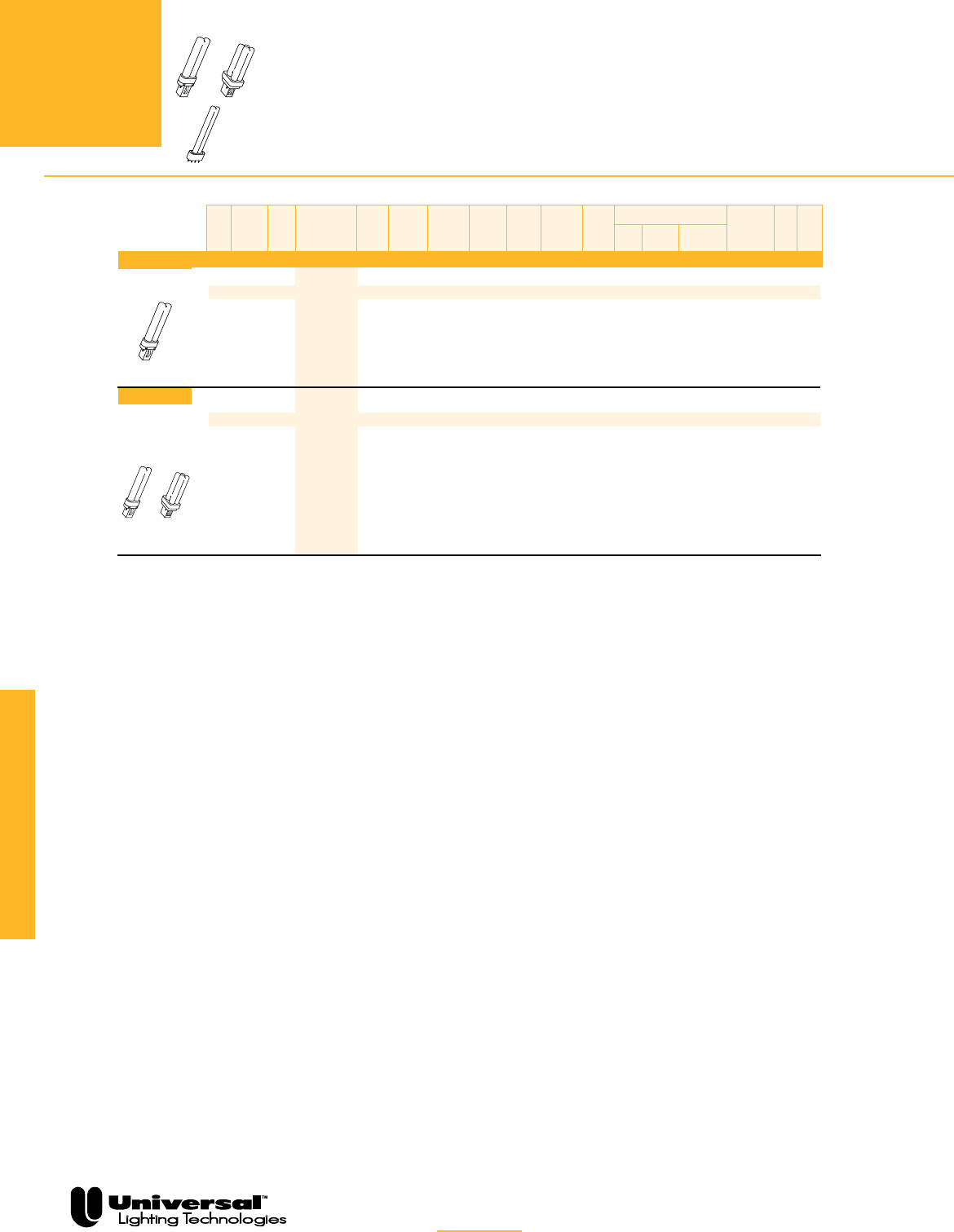
FOR MORE INFORMATION CALL
1-800-BALLAST
(225-5278)
PAGE 4-8
Compact Fluorescent
The encased ballasts listed on this page
are available in white (001) or black (000)
cans, except CBT’s, which are all in white
cans.
All ballasts are UL listed, CSA approved
QUICK
REFERENCE
Nominal lamp watts
and configuration
TWIN
LAMPS
5, 7, 9 & 11
WATTS
MAGNETIC AND ELECTRONIC
COMPACT FLUORESCENT BALLASTS
FOR TWIN LAMPS
5, 7, 9 AND 11 WATTS
• Open core & coil or encased
& potted designs
• 1 & 2 lamp models available
• Ideal for surface mount fixtures,
exit & retail display signs
OR
Twin, 2-Pin
OR
Twin or Quad,
2-Pin
See page 4-13 for Dimensions
and Wiring Diagrams.
Mag Qty Line Starting Min Lead Configuration
or of Line Catalog Input Current Current Ballast Start Power Side Bottom Bottom Starting Wir
Elec Lamps Volt Number Watts Amps Amps Factor Temp Factor THD Exit Exit Exit Studs Method
✿
Dim Diag
Electrical Characteristics - 60 Hz
M 1 120 4105F2P
■★
10 0.18 0.20 0.95 0° F Normal <10% X — — PH B2 1
M 1 120 4105P 10 0.18 0.20 0.95 0° F Normal <10% X — — PH C1 1
M 1 120 4105F2P
■★
10 0.18 0.20 0.90 25° F Normal <10% X — — PH B2 1
M 1 120 4105P 10 0.18 0.20 0.90 25° F Normal <10% X — — PH C1 1
★ Non-thermally protected models available.
✿ PH = Preheat
F2 indicates an open core & coil unit with mounting feet.
H2 indicates clamped & covered core & coil with mounting feet.
µAdd “B” for Bottom Exit or “S” for Side Exit or “BS” for
Bottom Exit with 2” O.C. screw studs.
Not approved for use in hazardous locations.
Lamp Type
7 Watts
CFT7W/G23
Lamp Type
9 Watts
CFT9W/G23
OR
CFQ9W/G23
❍
❍
■
{
❍
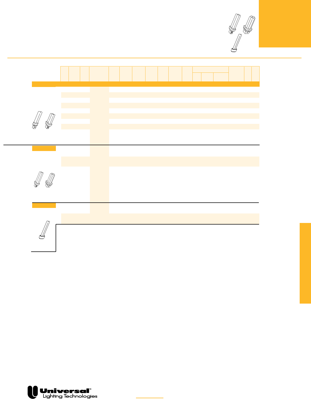
FOR MORE INFORMATION CALL
1-800-BALLAST
(225-5278)
PAGE 4-9
OR
Twin or Quad,
2-Pin
U.S. type
The encased ballasts listed on this page
are available in white (001) or black (000)
cans, except CBT’s, which are all in white
cans.
All ballasts are UL listed, CSA approved
QUICK
REFERENCE
Nominal lamp watts
and configuration
TWIN, QUAD
& MULTIPLE
LAMPS
13 WATTS
MAGNETIC AND ELECTRONIC
COMPACT FLUORESCENT
BALLASTS FOR TWIN, QUAD
AND MULTIPLE LAMPS
13 WATTS
• Ideal for downlights & wall sconces
•
Electronic models feature universal input
voltage from 120V to 277V. 347V models are
also available.
•
Electronic models feature programmed rapid start
for excellent lamp performance & auto reset shut-
down circuit
Compact Fluorescent
Twin T4,
4-Pin
OR
See page 4-13 for Dimensions
and Wiring Diagrams.
Lamp Type
13 Watts
CFT13W/GX23
OR
CFQ13W/GX23
OR
Quad or
Multiple,
4-Pin
Lamp Type
13 Watts
CFQ13W/G24q
OR
CFM13W/GX24q
Lamp Type
13 Watts
CFT13W/2GX7
Mag Qty Line Starting Min Lead Configuration
or of Line Catalog Input Current Current Ballast Start Power Side Bottom Bottom Starting Wir
Elec Lamps Volt Number Watts Amps Amps Factor Temp Factor THD Exit Exit Exit Studs Method
✿
Dim Diag
Electrical Characteristics - 60 Hz
M 1 120 CF1320H2P
■
16 0.24 0.30 0.85 32° F Normal <15% X — — PH B10 1
M 1 120 4113P 14 0.24 0.36 0.80 32° F Normal <10% X — — PH C2 1
M 1 277 4211F2P
■★
22 0.16 0.35 1.00 32° F Normal <10% X — — PH B3 1
M 1 277 4211PBES 22 0.16 0.35 1.00 32° F Normal <10% X — — PH C3 1
M 1 120 4112P 14 0.13 0.14 0.80 32° F High <20% X X X PH C2 2
M 1 120 4113P 14 0.24 0.36 0.90 32° F Normal <10% X X X PH C2 1
M 1 277 4210PBES 21 0.10 0.11 1.00 32° F High <20% X X X PH C3 2
M 2 120 4114P 31 0.26 0.33 0.95 32° F High <20% X — X PH C5 8
M 2 277 4214PBES 26 0.09 0.09 0.85 32° F High <20% X — X PH C4 9
E 1 120 C213UNV
◆r
18 0.15 —— 1.00 0° F High <10% X X X PRS C10 18
277 0.07 <15%
E 2 120C213UNV
◆r
30 0.26 —— 1.00 0° F High <10% X X X PRS C10 19
277 0.11
E 1 347 C213/347
◆
18 0.06 —— 1.00 0°F High <10% X X X PRS C10 18
2 33 0.10 —— 0.98 19
E 1 120CT213UNV◆ 15 0.12 —— 0.98 0°F High <10% X X X PRS C10 20✛
277 0.06 <12%
E 2 120 CT213UNV◆ 26 0.22 —— 0.98 0°F High <10% X X X PRS C10 20
277 0.10
Non-thermally protected models available.
✿ PH = Preheat; PRS = Programmed Rapid Start; RS=Rapid Start
F2 indicates an open core & coil unit with mounting feet.
H2 indicates clamped & covered core & coil with mounting feet.
◆Add following suffix for complete catalog #: “SE” for Side Exit
connectors, “BE” for Bottom Exit connectors, “BES”
for Bottom Exit connectors with 2˝ O.C. screw studs, "ME" for
Multi Exit connectors, or "MES" for Multi Exit with 2" OC screw studs.
❍Not approved for use in hazardous locations.
rAdd “ME000K” suffix for Mult-E Kit. For Distribution only.
■
{
❍
❍
❍
❍
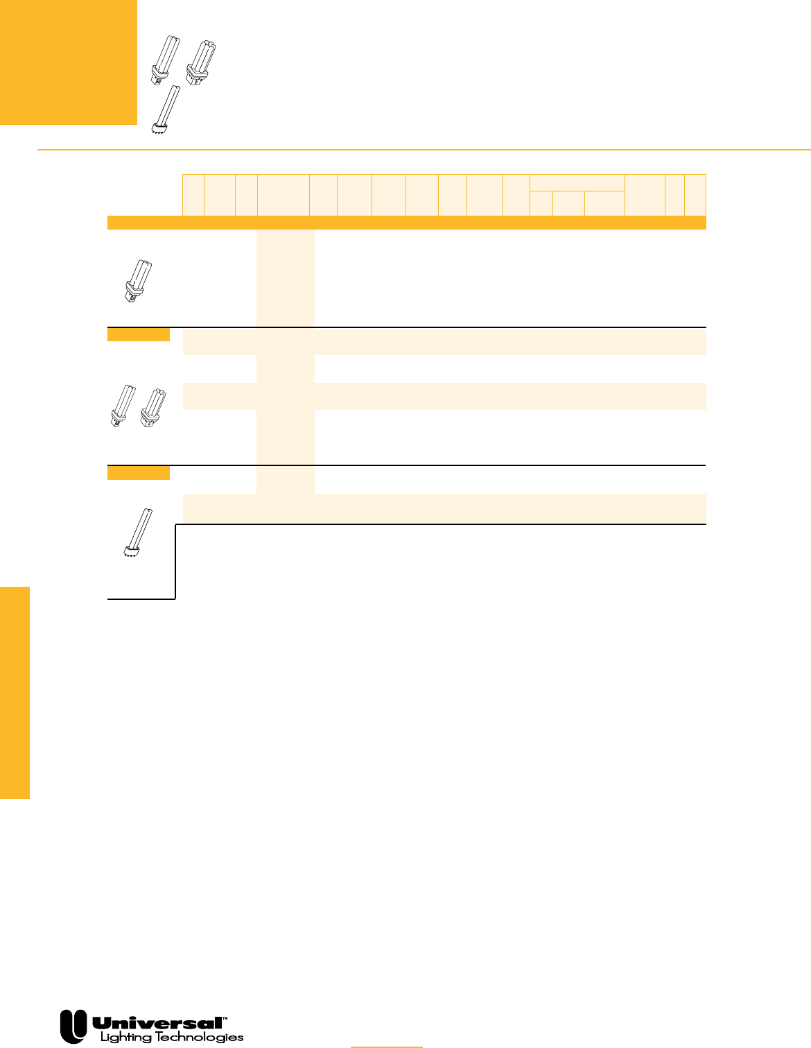
PAGE 4-10
Compact Fluorescent
The encased ballasts listed on this page are
available in white (001) or black (000) cans,
except CBT’s, which are all in white cans.
All ballasts are UL listed, CSA approved and
designated Class P (thermally protected),
Type HL.
QUICK
REFERENCE
Nominal lamp watts
and configuration
Quad, 2-Pin
TWIN, QUAD
& MULTIPLE
LAMPS
18 WATTS
MAGNETIC AND ELECTRONIC
COMPACT FLUORESCENT
BALLASTS FOR TWIN, QUAD
AND MULTIPLE LAMPS
18 WATTS
• Ideal for downlights, surface
mount & outdoor fixtures
•
Electronic models feature universal input voltage from
120V to 277V. 347V models are also available.
• Electronic models feature programmed rapid start
for excellent lamp performance
& auto reset shutdown circuit
OR
Quad or
Multiple, 4-Pin
FOR MORE INFORMATION CALL
1-800-BALLAST
(225-5278)
OR
See page 4-13 for Dimensions
and Wiring Diagrams.
Mag Qty Line Starting Min Lead Configuration
or of Line Catalog Input Current Current Ballast Start Power Side Bottom Bottom Starting Wir
Elec Lamps Volt Number Watts Amps Amps Factor Temp Factor THD Exit Exit Exit Studs Method
✿
Dim Diag
Electrical Characteristics - 60 Hz
M 2 120 4122PBES 50 0.45 0.27 0.88 15° F High <20% — — X PH C6 10
E 1 120 C218UNV
◆r
19 0.16 —— 1.00 0° F High <10% X X X PRS C10 18
277 0.07 <15%
E 2 120C218UNV
◆r
35 0.30 —— 0.95 0° F High <10% X X X PRS C10 19
277 0.13
E 1 347 C218/347
◆
21 0.11 —— 1.00 0°F High <10% X X X PRS C10 18
2 38 0.06 —— 0.98 19
E 1 120
CT218UNVSE
◆
23 0.19 —— 1.00 0° F High <10% X __ __ PRS C10 18
277 0.07
E 2 120
CT218UNVSE
◆
43 0.37 —— 0.98 0° F High <10% X __ __ PRS C10 19
277 42 0.16
✿ PH = Preheat; PRS = Programmed Rapid Start; RS=Rapid Start
◆Add following suffix for complete catalog #: “SE” for Side Exit
connectors, “BE” for Bottom Exit connectors, “BES”
for Bottom Exit connectors with 2˝ O.C. screw studs, "ME" for
Multi Exit connectors, or "MES" for Multi Exit with 2" OC screw
studs.
rAdd “ME000K” suffix for Mult-E Kit. For Distribution only.
Lamp Type
18 Watts
CFQ18W/G24d
Lamp Type
18 Watts
CFQ18W/G24q
OR
CFM18W/GX24q
Twin T5,
4-Pin,
Lamp Type
18 Watts
FT18W/2G11RS
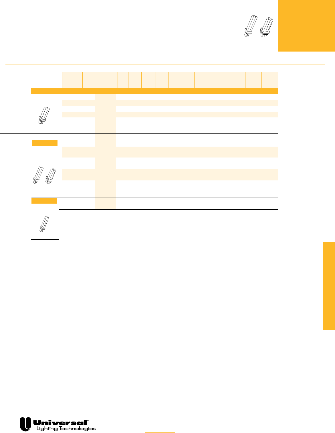
PAGE 4-11
The encased ballasts listed on this page
are available in white (001) or black (000)
cans, except CBT’s, which are all in white
cans.
All ballasts are UL listed, CSA approved
QUICK
REFERENCE
Nominal lamp watts
and configuration
Quad, 2-Pin
Compact Fluorescent
QUAD AND
MULTIPLE
LAMPS
26 & 28 WATTS
MAGNETIC AND ELECTRONIC
COMPACT FLUORESCENT
BALLASTS
FOR QUAD AND MULTIPLE LAMPS
26 AND 28 WATTS
• Ideal for downlights, surface
mount & outdoor fixtures
• Electronic models feature universal input
voltage from120V to 277V. 347V models
are also available.
• Electronic models feature programmed
rapid start for excellent lamp performance
& auto reset shutdown circuit
OR
FOR MORE INFORMATION CALL
1-800-BALLAST
(225-5278)
See page 4-13 for Dimensions
and Wiring Diagrams.
Mag Qty Line Starting Min Lead Configuration
or of Line Catalog Input Current Current Ballast Start Power Side Bottom Bottom Starting Wir
Elec Lamps Volt Number Watts Amps Amps Factor Temp Factor THD Exit Exit Exit Studs Method
✿
Dim Diag
Electrical Characteristics - 60 Hz
M 1 120 4124PBES 30 0.27 0.46 0.88 25° F High <30% — X — PH C4 3
M 1 120 4124PBES 30 0.27 0.46 0.88 25° F High < 30% — — X PH C4 3
M 2 120 4128PBES 61 0.55 0.38 0.90 32° F High <20% X — X PH C6 16
M 2 277 4226PBES 62 0.22 0.34 0.90 32° F High <20% X — X PH C4 8
E 1 120 C2642UNV
◆r
28 0.25 —— 1.02 0° F High <10% X X X PRS C10 18
277 0.11
E 2 120C2642UNV
◆r
56 0.47 —— 0.98 0° F High <10% X X X PRS C10 19
277 0.21
E 1 347 C2642/347
◆
31 0.09 —— 1.02 0°F High <10% X X X PRS C10 18
2 57 0.17 —— 0.98 19
E 2 120C242UNV
◆
56 0.46 —— 1.02 0° F High <10% X X X PRS C11 19
277 55 0.20
E 2 347 C242/347
◆
44 0.14 —— 1.02 0° F High <10% X X X PRS C11 19
M 1 120 4139F2P
■
32 0.65 0.84 0.95 15° F Normal <10% X — — PH B3 1
✿ PH = Preheat; PRS = Programmed Rapid Start; RS = Rapid Start
■F2 indicates an open core & coil unit with mounting feet.
◆ Add following suffix for complete catalog #: “SE” for Side Exit
connectors or “BE” suffix for Bottom Exit connectors or “BES”
for Bottom Exit connectors with 2˝ O.C. screw studs.
❍Not approved for use in hazardous locations.
rAdd “ME” suffix for Mult-E Kit. For Distribution only.
µAdd “B” for Bottom Exit or “S” for Side Exit or “BS” for
Bottom Exit with 2” O.C. screw studs.
Lamp Type
26 Watts
CFQ26W/G24d
OR
Quad or
Multiple,
4-Pin
Lamp Type
26 Watts
CFQ26W/G24q
OR
CFM26W/GX24q
Lamp Type
28 Watts
CFQ28W/GX32d
T5 Quad, 2-Pin
❍
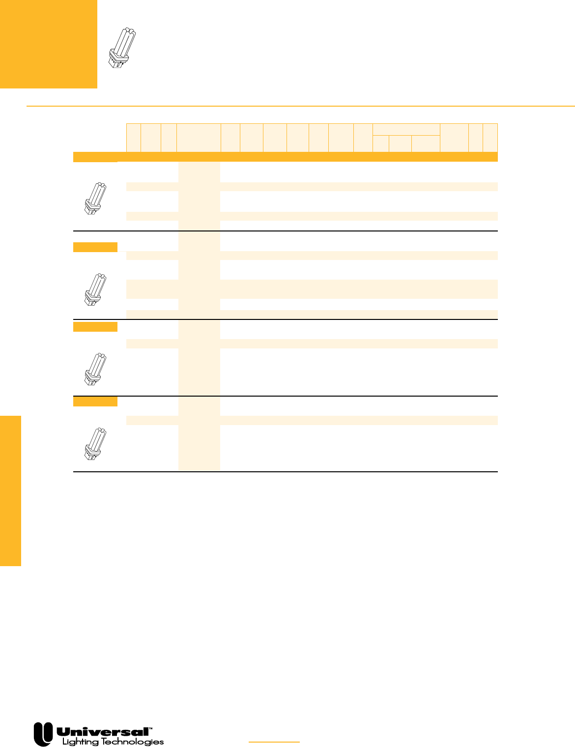
FOR MORE INFORMATION CALL
1-800-BALLAST
(225-5278)
PAGE 4-12
Compact Fluorescent
The encased ballasts listed on this page are
available in white (001) or black (000) cans.
All ballasts are UL listed, CSA approved and
designated Class P (thermally protected), Type
HL.
QUICK
REFERENCE
Nominal lamp watts
and configuration
MULTIPLE
LAMPS
32, 42, 57 & 70 WATTS
ELECTRONIC
COMPACT FLUORESCENT
BALLASTS FOR MULTIPLE LAMPS
32, 42, 57 & 70 WATTS
• Ideal for downlights, surface mount &
outdoor fixtures
•
Electronic models feature universal input
voltage from 120V to 277V. 347V models
are also available.
• Electronic models feature programmed
rapid start for excellent lamp performance
& auto reset shutdown circuit
Multiple, 4-Pin
Multiple, 4-Pin
See page 4-13 for Dimensions
and Wiring Diagrams.
Mag Qty Line Starting Min Lead Configuration
or of Line Catalog
✪
Input Current Current Ballast Start Power Side Bottom Bottom Starting Wir
Elec Lamps Volt Number Watts Amps Amps Factor Temp Factor THD Exit Exit Exit Studs Method
✿
Dim Diag
Electrical Characteristics - 60 Hz
E 1 120 C2642UNV
◆r
36 0.30 —— 1.00 0° F High <10% X X X PRS C10 18
277 0.13
E 1 347 C2642/347
◆
36 0.11 —— 0.98 0° F High <10% X X X PRS C10 18
E 2 120 C242UNV
◆
69 0.58 —— 1.00 0° F High <10% X X X PRS C11 19
277 67 0.26
E 2 347 C242/347
◆
62 0.19 —— 1.00 0° F High <10% X X X PRS C11 19
E 1 120C2642UNV
◆r
48 0.41 —— 0.98 0° F High <10% X X X PRS C10 18
277 0.18
E 1 347 C2642/347
◆
50 0.15 —— 1.00 0° F High <10% X X X PRS C10 18
E 1 120 C242UNV
◆
45 0.40 —— 1.00 0° F High <10% X X X PRS C11 19
277 0.18
E 2 120C242UNV
◆
91 0.76 —— 0.98 0° F High <10% X X X PRS C11 19
277 90 0.32
E 1 347 C242/347
◆
42 0.13 —— 1.00 0° F High <10% X X X PRS C11 18
E 2 347 C242/347
◆
80 0.25 —— 0.98 0° F High <10% X X X PRS C11 19
E 1 120C242UNV
◆
58 0.52 —— 1.00 0° F High <10% X X X PRS C11 19
277 57 0.21
E 1 347 C242/347
◆
61 0.18 —— 1.00 0° F High < 10% X X X PRS C11 19
E 1 120C242UNV
◆
73 0.61 —— 1.00 0° F High <10% X X X PRS C11 19
277 72 0.27
E 1 347 C242/347
◆
74 0.21 —— 1.00 0° F High < 10% X X X PRS C11 19
✿ RS = Rapid Start; PRS = Programmed Rapid Start
◆ Add following suffix for complete catalog #: “SE” for Side Exit
connectors or “BE” suffix for Bottom Exit connectors or “BES”
for Bottom Exit connectors with 2˝ O.C. screw studs.
rAdd “ME” suffix for Mult-E Kit. For Distribution only.
µAdd “B” for Bottom Exit or “S” for Side Exit or “BS” for
Bottom Exit with 2” O.C. screw studs.
Multiple, 4-Pin
Lamp Type
32 Watts
CFM32W/GX24q
Lamp Type
42 Watts
CFM42W/GX24q
Multiple, 4-Pin
Lamp Type
57 Watts
CFM57W/GX24q
Lamp Type
70 Watts
CFM70W/GX24q
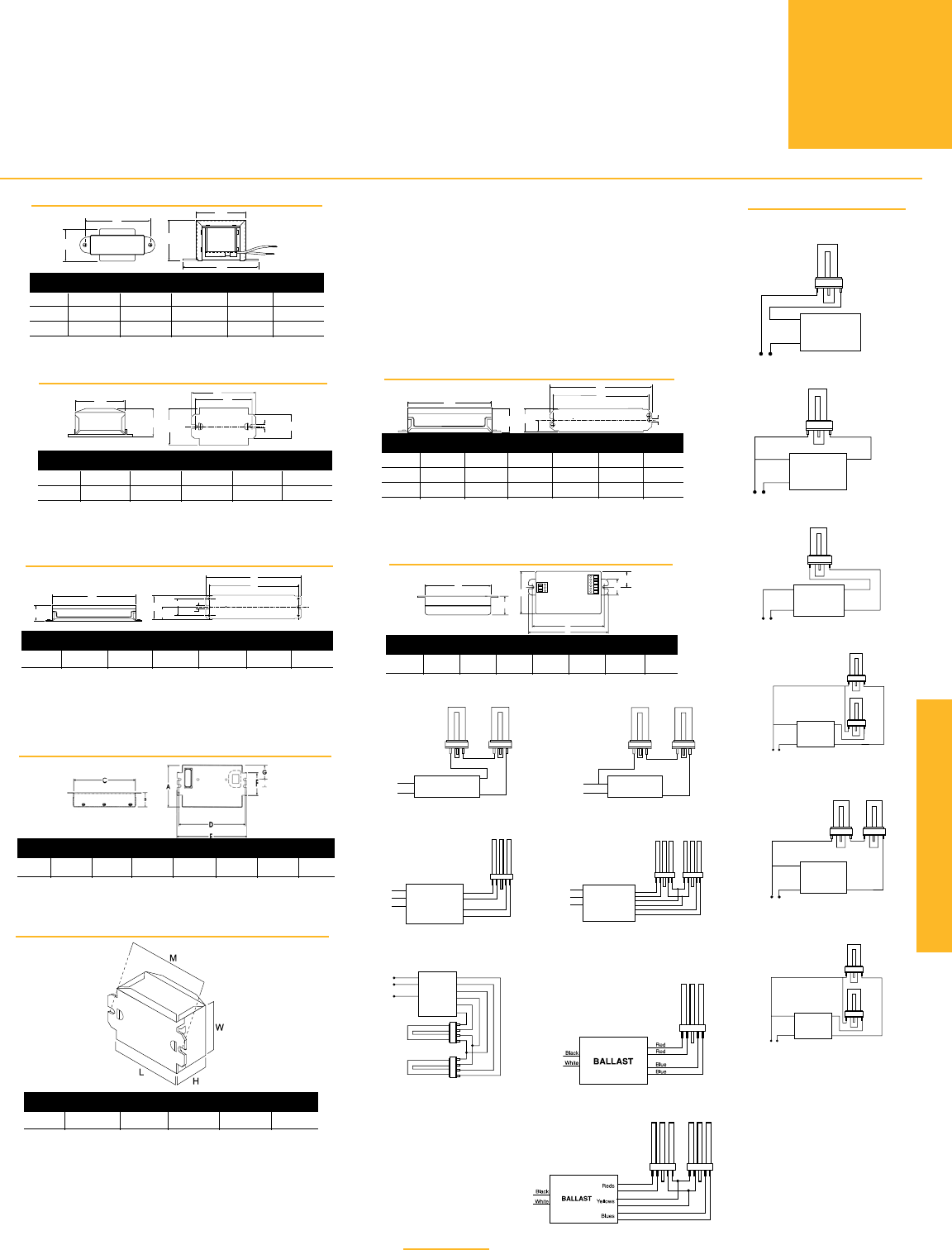
REFERENCE DRAWING FOR B1-B3
AB
C
E
D
Lead Lengths: 10˝-12˝
Dwg. A B C D E
B1 0.84” 1.41” 1.72” 2.00” 2.38”
B2 1.23” 1.64” 1.97” 2.38” 2.81”
B3 1.50” 1.95” 2.34” 2.81” 3.25”
REFERENCE D
RAWING FOR
C1, C2
17/64"
3/16"
C
BA
ED
Dwg. A B C D E
C1 1.84” 1.09” 2.06” 2.41” 2.75”
C2 1.84” 1.42” 2.40” 2.75” 3.13”
Lead Lengths: Side–12˝
BE/BES–8˝
Dwg. A B C D E F
C3 2.14” 1.56” 3.50” 4.31” 4.75” 0.22”
C4 2.34” 1.53” 5.45” 6.00” 6.59” 0.31”
C5 1.88” 1.47” 5.13” 6.00” 6.44” 0.25”
REFERENCE D
RAWING FOR
C3, C4, C5
15/16"
AF
B
D
E
C
Lead Lengths: Side–12˝
BE/BES–8˝
Dwg. A B C D E F
C6 2.38” 1.53” 8.31” 8.89” 9.48” 1.19”
REFERENCE D
RAWING FOR
C6
B
C
AF
E
D
5/16"
111/16"
Lead Lengths: Side
•Black/White–
11˝
•Red/Blue–12˝
BE/BES–8˝
REFERENCE D
RAWING FOR
C10
D
F
E
A
G
C
B
Dwg. A B C D E F G
C10 2.31” 1.00” 4.25” 4.61” 4.94” 0.98” 1.00”
Leadless-Poke-in wire connection
WIRING DIAGRAMS
Install in accordance with
National Electrical Code.
BALLAST
Black
Black
Line
DIAGRAM 1
BALLAST
Black
Line
WhiteBlue
DIAGRAM 2
Line
Black
White Blue
Blue
BALLAST
DIAGRAM 8
Parallel lamp operation
Black
White
Blue
BALLAST
Line
DIAGRAM 9
Series lamp opera-
Black
White Red
Blue
BALLAST
Line
DIAGRAM 10
Parallel lamp operation
Black
White
Green
Red
Red
Yellow
Yellow
Blue
Blue
BALLAST
DIAGRAM 20
Series lamp opera-
Black
White
Red
Red
Blue
Blue
BALLAST
Green
DIAGRAM 18
Ballast should be ground-
Black
White
Red
Blue
Y e llow
BALLAST
Green
Red
Y e llow
Blue
DIAGRAM 19
Series lamp operation
Ballast should be grounded
Black
White Red
Blue
BALLAST
Line
DIAGRAM 16
Series lamp operation
Black
White
Blue
BALLAST
Line
DIAGRAM 17
Series lamp operation
BALLAST
Black Red
Line
White Blue
DIAGRAM 3
PAGE 4-13
REFERENCE D
RAWING FOR
C11
Dwg. A B C D E F G
C11 2.98” 1.00” 4.25” 4.61” 4.94” 1.55” 1.00”
Leadless-Poke-in wire connection
Compact Fluorescent
TWIN, TRIPLE,
QUAD &
MULTIPLE
LAMPS
MAGNETIC AND ELECTRONIC
COMPACT FLUORESCENT
BALLASTS
WIRING DIAGRAMS AND DIMENSIONS
FOR MORE INFORMATION CALL
1-800-BALLAST
(225-5278)
REFERENCE D
RAWING FOR
CBT
Dwg. A B C D E
CBT 3.86” 2.00” 1.00” 3.50” ——
DIAGRAM 47
DIAGRAM 48
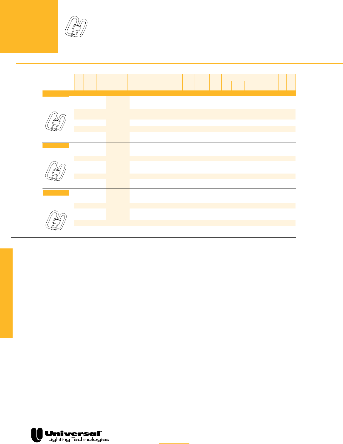
FOR MORE INFORMATION CALL
1-800-BALLAST
(225-5278)
PAGE 4-14
2D
LAMPS
10, 16 & 21
WATTS
MAGNETIC & ELECTRONIC
COMPACT FLUORESCENT
BALLASTS FOR 2D LAMPS
10, 16 AND 21 WATTS
• Ideal for surface mount fixtures
• All magnetic models are encased & potted.
• Magnetic and electronic models available.
•
Electronic models feature universal input voltage
from 120V to 277V. 347V models are also available.
• Electronic models feature programmed
rapid start for excellent lamp performance
& auto reset shutdown circuit
The encased ballasts listed on this page are
available in white (001) or black (000) cans.
All ballasts are UL listed, CSA approved and
designated Class P (thermally protected), Type
HL.
QUICK
REFERENCE
Nominal lamp watts
and configuration
2D, 4-Pin
Lamp Type
16 Watts
CFS16W/GR10q
2D, 4-Pin
Compact Fluorescent
See page 4-16 for Dimensions
and Wiring Diagrams.
Mag Qty Line Starting Min Lead Configuration
or of Line Catalog Input Current Current Ballast Start Power Side Bottom Bottom Starting Wir
Elec Lamps Volt Number Watts Amps Amps Factor Temp Factor THD Exit Exit Exit Studs Method
✿
Dim Diag
Electrical Characteristics - 60 Hz
E 1 120 C213UNV
◆r
15 0.12 —— 1.02 0° F High <10% X X X PRS C10 18a
277 0.06 <15%
E 2 120 C213UNV
◆r
26 0.22 —— 1.02 0° F High <10% X X X PRS C10 19a
277 0.10
E 1 347 C213/347
◆
16 0.05 —— 1.02 0° F High <10% X X X PRS C10 18a
E 2 347 C213/347
◆
28 0.08 —— 1.02 0° F High <10% X X X PRS C10 19a
E 1 120 C213UNV
◆r
19 0.15 —— 0.95 0° F High <10% X X X PRS C10 18a
277 0.07 <15%
E 1 347 C213/347
◆
20 0.06 —— 0.95 0°F High <10% X X X PRS C10 18a
E 2 120 C213UNV
◆r
33 0.28 —— 0.95 0° F High <10% X X X PRS C10 19a
277 0.12
E 2 347 C213/347
◆
34 0.10 —— 0.95 0°F High <10% X X X PRS C10 19a
E 1 120C218UNV
◆r
24 0.18 —— 0.98 0° F High <10% X X X PRS C10 18a
277 0.08 <15%
E 1 347 C218/347
◆
21 0.06 —— 0.98 0° F High <10% X X X PRS C10 18a
E 2 120 C218UNV
◆r
43 0.37 —— 0.95 0° F High <10% X X X PRS C10 19a
277 0.16 <15%
E 2 347 C218/347
◆
39 0.12 —— 0.95 0° F High <10% X X X PRS C10 19a
● Starter required: use COP-40 or FS-4 type fluorescent starter.
✿ PH = Preheat; PRS = Programmed Rapid Start
◆Add following suffix for complete catalog #: “SE” for Side Exit
connectors, “BE” for Bottom Exit connectors, “BES” for Bottom
Exit connectors with 2˝ O.C. screw studs, "ME" for Multi Exit
connectors, or "MES" for Multi Exit with 2" OC screw studs.
rAdd “ME000K” suffix for Mult-E Kit. For Distribution only.
Lamp Type
10 Watts
CFS10W/GR10q
Lamp Type
21 Watts
CFS21W/GR10q
2D, 4-Pin

Compact Fluorescent
FOR MORE INFORMATION CALL
1-800-BALLAST
(225-5278)
PAGE 4-15
The encased ballasts listed on this page are
available in white (001) or black (000) cans.
All ballasts are UL listed, CSA approved and
designated Class P (thermally protected),
Type HL.
QUICK
REFERENCE
Nominal lamp watts
and configuration
2D, 4-Pin
2D
LAMPS
28, 38 & 55
WATTS
MAGNETIC & ELECTRONIC
COMPACT FLUORESCENT
BALLASTS FOR 2D LAMPS
28, 38 & 55 WATTS
• Ideal for surface mount fixtures
• All magnetic models are encased & potted
• Magnetic & electronic models available
•
Electronic models feature universal input voltage
from 120V to 277V.
• Electronic models feature programmed
rapid start for excellent lamp performance
& auto reset shutdown circuit
See page 4-16 for Dimensions
and Wiring Diagrams.
Mag Qty Line Starting Min Lead Configuration
or of Line Catalog
✪
Input Current Current Ballast Start Power Side Bottom Bottom Starting Wir
Elec Lamps Volt Number Watts Amps Amps Factor Temp Factor THD Exit Exit Exit Studs Method
✿
Dim Diag
Electrical Characteristics - 60 Hz
M 1 120 4124PBES 37 0.34 0.46 0.88 32° F High <20% — X — PH C4 1a
M 1 120 4124PBES 37 0.34 0.46 0.88 32° F High <20% — — X PH C4 1a
M 2 120 4128PBES 61 0.55 0.38 0.90 32° F High <20% X — X PH C6 13a
M 2 277 4226PBES 66 0.23 0.34 0.93 25° F High <20% X — X PH C4 7a
E 1 120 C2642UNV◆r 31 0.27 —— 0.95 0° F High <10% X X X PRS C10 18a
277 0.12
E 1 347 C2642/347◆ 33 0.10 —— 0.95 0°F High <10% X X X PRS C10 18a
E 2 120 C242UNV◆ 64 0.54 —— 1.00 0° F High <10% X X X PRS C11 19a
277 63 0.24
E 2 347 C242/347◆ 60 0.18 —— 1.00 0°F High <10% X X X PRS C11 19a
E 1 120 C2642UNV
◆r
33 0.27 —— 0.80 0°F High <10% X — X PRS C10 18a
277 0.12
✿ PH = Preheat; PRS = Programmed Rapid Start
◆Add following suffix for complete catalog #: “SE” for Side Exit
connectors or “BE” suffix for Bottom Exit connectors or “BES”
for Bottom Exit connectors with 2˝ O.C. screw studs.
rAdd “ME” suffix for Mult-E Kit. For Distribution only.
Lamp Type
28 Watts
CFS28W/GR8
2D, 2-Pin
Lamp Type
28 Watts
CFS28W/GR10q
Lamp Type
38 Watts
CFS38W/GR10q
2D, 4-Pin
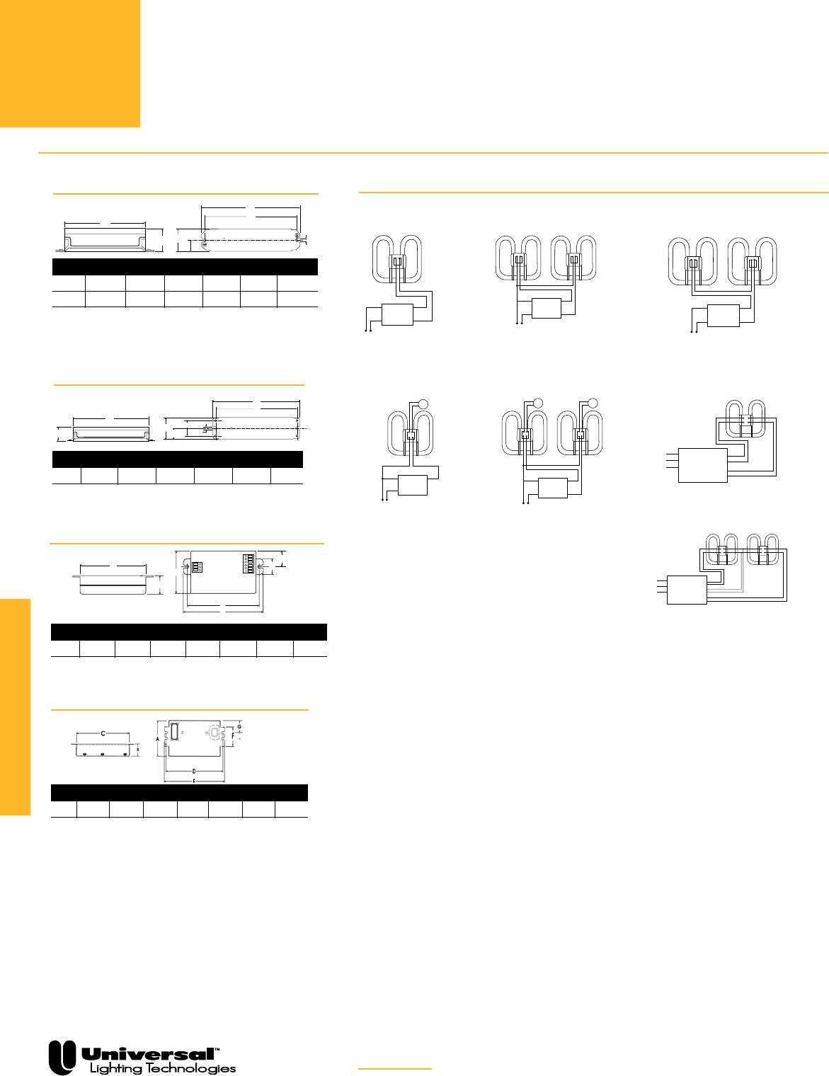
REFERENCE DRAWING FOR C6
B
C
AF
E
D
5/16"
111/16"
Dwg. A B C D E F
C6 2.40” 1.55” 8.31” 8.89” 9.50” 1.19”
Lead Lengths: Side–12˝
BE/BES–8˝
REFERENCE DRAWING FOR C4, C5
Dwg. A B C D E F
C4 2.34” 1.53” 5.45” 6.00” 6.59” 0.31”
C5 1.88” 1.47” 5.13” 6.00” 6.44” 0.25”
15/16"
AF
B
D
E
C
Lead Lengths: Side–12˝
BE/BES–8˝
REFERENCE DRAWING FOR C10
D
F
E
A
G
C
B
Dwg. A B C D E F G
C10 2.31” 1.00” 4.25” 4.61” 4.94” 0.98” 1.00”
Leadless-Poke-in wire connection
REFERENCE DRAWING FOR C11
Dwg. A B C D E F G
C11 2.98” 1.00” 4.25” 4.61” 4.94” 1.55” 1.00”
Leadless-Poke-in wire connection
BALLAST
Line
Blue
White
Black
SFS-4
DIAGRAM 5a
BALLAST
Line
Blue
Blue
White
Black
SS
FS-4 FS-4
DIAGRAM 9a
Parallel lamp operation
Red
Blue
Y e llow
BALLAST
Black
White
Green
Red
Y e llow
Blue
DIAGRAM 19a
Series lamp operation
Black
White
Red
Red
Blue
Blue
BALLAST
Green
DIAGRAM 18a
BALLAST
Line
Blue
Blue
White
Black
DIAGRAM 7a
Parallel lamp opera-
BALLAST
Line
Red
Blue
White
Black
DIAGRAM 13a
Series lamp operation
BALLAST
Line
Black Blue
White Red
DIAGRAM 1a
WIRING DIAGRAMS
Install in accordance with
National Electrical Code.
FOR MORE INFORMATION CALL
1-800-BALLAST
(225-5278)
PAGE 4-16
Compact Fluorescent
2D
LAMPS
MAGNETIC & ELECTRONIC COMPACT
FLUORESCENT BALLASTS FOR
2D LAMPS
WIRING DIAGRAMS AND DIMENSIONS
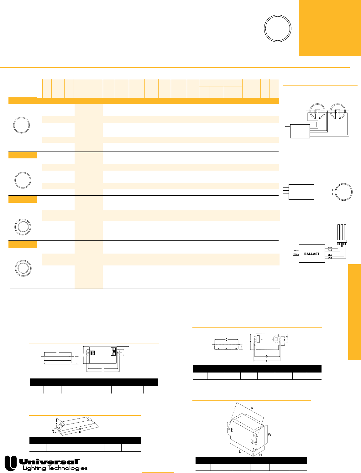
ELECTRONIC COMPACT
FLUORESCENT BALLASTS
22, 40 & 55 WATTS
• Ideal for surface mount fixtures
•
Electronic models feature universal input
voltage from 120V to 277V. 347V models
are also available.
• Electronic models feature rapid and programmed
rapid start for excellent lamp performance
& auto reset shutdown circuit
PAGE 4-17
T5
CIRCULAR
LAMPS
22,40 & 55 WATTS
Compact Fluorescent
WIRING DIAGRAMS
Install in accordance with
National Electrical Code.
BALLAST
Black
White
Green
Red
Blue
DIAGRAM 28
QUICK
REFERENCE
Nominal lamp watts
and configuration
T5 CIRCULAR
T5 CIRCULAR
The encased ballasts listed on this page are
available in white (001) or black (000) cans, except
CBT’s, which are all in white cans.
All ballasts are UL listed, CSA approved and
designated Class P (thermally protected).
REFERENCE DRAWING FOR C10
D
F
E
A
G
C
B
Dwg. A B C D E F G
C10 2.31” 1.00” 4.25” 4.61” 4.94” 0.98” 1.00”
Leadless-Poke-in wire connection
Red
Blue
Y e llow
BALLAST
Black
White
Green
DIAGRAM 23
Series lamp operation
REFERENCE DRAWING FOR C11
Dwg. A B C D E F G
C11 2.98” 1.00” 4.25” 4.61” 4.94” 1.56” 1.00”
Leadless-Poke-in wire connection
REFERENCE DRAWING FOR -D
Dwg. L W H M X
-D 16.88” 1.16” 1.00” 16.28” ---
T5 CIRCULAR
REFERENCE DRAWING FOR CBT
Dwg. A B C D E
CBT 3.86” 2.00” 1.00” 3.50” ——
DIAGRAM 47
Mag Qty Line Starting Min Lead Configuration
or of Line Catalog
✪
Input Current Current Ballast Start Power Side Bottom Bottom Starting Wir
Elec Lamps Volt Number Watts Amps Amps Factor Temp Factor THD Exit Exit Exit Studs Method
✿
Dim Diag
Electrical Characteristics - 60 Hz
E 1 120 C2642UNV
◆r
25 0.21 —— 1.00 0° F High <10% X X X PRS C10 28
277 0.10
E 1 347 C2642/347
◆
26 0.08 —— 0.98 0° F High <10% X X X PRS C10 28
E 2 120 C242UNV
◆
50 0.42 —— 1.05 0° F High <10% X X X PRS C11 23
277 0.19
E 2 347 C242/347
◆
47 0.14 —— 1.05 0° F High <10% X X X PRS C11 23
E 1 120 C2642UNV
◆r
42 0.35 —— 0.98 0° F High <10% X X X PRS C10 28
277 0.16
E 1 347 C2642/347
◆
40 0.12 —— 0.98 0° F High <10% X X X PRS C10 28
E 2 120 C242UNV
◆
80 0.65 —— 0.98 0° F High <10% X X X PRS C11 23
277 79 0.29
E 2 347 C242/347
◆
71 0.22 —— 0.98 0° F High <10% X X X PRS C11 23
E 2 120 C242UNV
◆
66 0.54 —— 0.98 0° F High <10% X X X PRS C11 23
277 64 0.24
E 2 120 C242/347
◆
59 0.18 —— 0.98 0° F High <10% X X X PRS C11 23
277
E 1 120 B254PUNV-D 56 0.46 —— 0.87 0° F High <10% X — — PRS -D 28
277 0.21
E 2 120 B254PUNV-D 106 0.88 —— 0.85 0° F High <10% X — — PRS -D 23
277 103 0.38
✿ PRS = Programmed Rapid Start; RS=Rapid Start
◆Add following suffix for complete catalog #: “SE” for Side Exit
connectors or “BE” suffix for Bottom Exit connectors or “BES”
for Bottom Exit connectors with 2˝ O.C. screw studs.
µAdd “B” for Bottom Exit or “S” for Side Exit or “BS” for
Bottom Exit with 2” O.C. screw studs.
❍Not approved for use in hazardous locations.
Lamp Type
40 Watts
FC12T5-40W
Lamp Type
22 & 40 Watts
FC9T5-22W &
FC12T5-40W
Lamp Type
22 Watts
FC9T5-22W
Lamp Type
55 Watts
FC12T5-55W
T5 CIRCULAR
❍
❍
Compact Fluorescent
FOR MORE INFORMATION CALL
1-800-BALLAST
(225-5278)
PAGE 4-18
LONG TWIN
T5 LAMPS
18, 24/27 WATTS
ELECTRONIC
COMPACT FLUORESCENT BALLASTS
FOR LONG TWIN T5 LAMPS
18 AND 24/27 WATTS (BIAX, DULUX L AND PLL)
• Ideal for track light & surface mount fixtures
• Electronic models feature universal input
voltage from 120V to 277V. 347V models are also
available
• Electronic models feature rapid and pro-
grammed rapid start for excellent lamp perfor-
mance & auto reset shutdown circuit
The encased ballasts listed on this page
are available in white (001) or black (000)
cans, excpet CBT’s, which are all in white
cans.
All ballasts are UL listed, CSA approved
QUICK
REFERENCE
Nominal lamp watts
and configuration
See pages 4-21 and 4-22 for
Dimensions and Wiring Diagrams.
Mag Qty Line Starting Min Lead Configuration
or of Line Catalog Input Current Current Ballast Start Power Side Bottom Bottom Starting Wir
Elec Lamps Volt Number Watts Amps Amps Factor Temp Factor THD Exit Exit Exit Studs Method
✿
Dim Diag
Electrical Characteristics - 60 Hz
E 1 120
CBT126L-120
µ
20 0.36 —— 1.10 0° F Normal <150% X X X RS CBT 47
E 1 120
CT218UNVSE
23 0.19 —— 1.00 0° F High <10% X — — PRS C10 21
277 0.07 —— X — — PRS C10 21
120
43 0.37 —— X — — PRS C10 20
E 2 277
CT218UNVSE
42 0.16 —— 0.98 0° F High <10% X — — PRS C10 20
E 1 120 B224PUNV-C 27 0.23 —— 1.05 0° F High <10% X — — PRS -C 29
277 0.10 <15%
E 2 120 B224PUNV-C 52 0.43 —— 1.00 0° F High <10% X — — PRS -C 29
277 51 0.18
E 1 347 C2642/347
◆
29 0.09 —— 0.90 0° F High <10% X X X PRS C10 21
E 2 120 C242UNV
◆
51 0.43 —— 1.02 0° F High <10% X X X PRS C11 20
277 50 0.19
E 2 347 C242/347
◆
49 0.14 —— 1.02 0° F High <10% X X X PRS C11 20
E 1 120 C2642UNV 26 0.22 —— 1.01 0° F High <10% X X X PRS C10 21
277 0.10
E 2 120 C2642UNV 47 0.40 —— 0.98 0° F High <10% X X X PRS C10 21
277 49 0.18
E 1 120 B224PUNV-C 24 0.20 —— 1.05 0° F High <10% X — — PRS -C 29
277 0.09 <15%
E 2 120 B224PUNV-C 48 0.40 —— 1.00 0° F High <10% X — — PRS -C 29
277 47 0.17
✿ RS = Rapid Start; PRS = Programmed Rapid Start
❍Not approved for use in hazardous locations.
◆ Add following suffix for complete catalog #: “SE” for Side Exit
connectors or “BE” suffix for Bottom Exit connectors or “BES”
for Bottom Exit connectors with 2˝ O.C. screw studs.
rAdd “ME” suffix for Mult-E Kit. For Distribution only.
µAdd “B” for Bottom Exit or “S” for Side Exit or “BS” for
Bottom Exit with 2” O.C. screw studs.
Long Twin T5,
4-Pin
Lamp Type
18 Watts
FT18W/2G11/RS
T5 F-Lamp,
4-Pin
❍
❍
❍
❍
Lamp Type
24/27 Watts
FT24W/2G11/RS
Long Twin T5,
4-Pin
Lamp Type
24/27 Watts
CFM24W/2G10
FOR MORE INFORMATION CALL
1-800-BALLAST
(225-5278)
PAGE 4-19
Compact Fluorescent
LONG TWIN
T5 LAMPS
36/39 & 40
WATTS
ELECTRONIC
LONG TWIN T5 BALLASTS
36/39 AND 40 WATTS
(BIAX, DULUX L AND PLL)
• Ideal for track light & surface mount fixtures
• New electronic 1 & 2 lamp models for 24 watt lamps
• Electronic models feature universal input voltage
from 120V to 277V. 347V models are also available.
• Electronic models feature programmed rapid start for
excellent lamp performance & auto reset shutdown circuit
See pages 4-21 and 4-22 for
Dimensions and Wiring Diagrams.
Mag Qty Line Starting Min Lead Configuration
or of Line Catalog Input Current Current Ballast Start Power Bottom Bottom Starting Wir
Elec Lamps Volt Number Watts Amps Amps Factor Temp Factor THD Side Exit Exit Studs Method
✿
Dim Diag
Electrical Characteristics - 60 Hz
120
36 0.30 —— — —
E 1 277
B224PUNV-C
•
0.13 —— 0.95 0° F High <10% X PRS -C 29
120
71 0.59 —— — —
E 2 277
B239PUNV-D
•
70 0.26 —— 0.97 0° F High <10% X PRS -D 29
E 1 120
B254PUNV-D£
44 0.37 —— 1.22 0° F High <10% X — — PRS -D 28
277 0.17
E 2 120 B254PUNV-D 90 0.75 —— 1.20 0° F High <10% X — — PRS -D 23
277 88 0.32
E 1 120 C242UNV
◆
34 0.29 —— 0.88 0° F High < 10% X X X PRS C11 20
277 0.14 < 20%
120 64 0.43 ——
E 2 277
C242UNV
•◆
0.19 —— 0.83 0° F High <10% X X X PRS C11 20
E 2 347
C242/347
•◆
64 0.19 —— 0.90 0° F High <10% X X X PRS C11 20
E 1 120
B224PUNV-C• 34 0.28
—— 0.95 0° F High <10% X — — PRS -C 29
277 0.12
E 1 120 C2642UNV
◆r
32 0.27 —— 0.98 0° F High <10% X X X PRS C10 21
277 0.12 ——
E 1 120 C242UNV
◆
33 0.28 —— 0.98 0° F High <15% X X X PRS C11 20
277 0.14
120
68 0.57 ——
E 2 277
C242UNV
•◆r
67 0.25 —— 0.90 0° F High <10% X X X PRS C11 20
E 1 120 C240SI120RH 40 0.40 —— 1.02 50° F High <20% X — — IS C6 12
✛
E 1 277 C240SI277RH 40 0.17 —— 1.02 50° F High <20% X — — IS C6 12
✛
E 1 120
C240PUNVHP-B
• 41 0.34 —— 1.00 0° F High <10% X — — PRS -B 20
277 40 0.15
E 2 120
C242
UNV
◆
93 0.78 —— 1.00 0° F High <10% X X X PRS C11 20
277 87 0.34
E 2 120 C340SI120RH 75 0.68 —— 0.99 50° F High <20% X — — IS C6 14
✛
E 2 277 C340SI277RH 75 0.30 —— 0.99 50° F High <20% X — — IS C6 14
✛
E 2 120 C240SI120RH 67 0.61 —— 0.88 50°F High <20% X — — IS C6 12
E 2 277 C240SI277RH 67 0.27 —— 0.88 50°F High <20% X — — IS C6 12
E 2 120
C240PUNVHP-B
• 76 0.63 —— 0.90 0° F High <10% X — — PRS -B 20
277 73 0.27
E 1 120
C242
UNV
◆
47 0.40 —— 1.08 0° F High <10% X X X PRS C11 20
277 0.18
E 3 120 C340SI120RH 98 0.88 —— 0.88 50° F High <20% X — — IS C6 14
E 3 277 C340SI277RH 98 0.39 —— 0.88 50° F High <20% X — — IS C6 14
✿ PRS = Programmed Rapid Start; IS = Instant Start
◆Add following suffix for complete catalog #: “SE” for Side Exit
connectors or “BE” suffix for Bottom Exit connectors or “BES”
for Bottom Exit connectors with 2˝ O.C. screw studs.
❍Not approved for use in hazardous locations.
£Consult lamp manufacturers for applications with Ballast Factor >1.20.
rAdd “ME” suffix for Mult-E Kit. For Distribution only.
The encased ballasts listed on this page
are available in white (001) or black (000)
cans.
All ballasts are UL listed, CSA approved
QUICK
REFERENCE
Nominal lamp watts
and configuration
Lamp Type
36/39 Watts
FT36W/2G11/RS
Long Twin T5,
4-Pin
Lamp Type
36/39 Watts
CFM36W/2G10
T5 F-Lamp,
4-Pin
Lamp Type
40 Watts
FT40W/2G11
Long Twin T5,
4-Pin
❍
❍
❍
❍
❍
❍
❍
❍
❍
❍
❍
❍
❍
ELECTRONIC
LONG TWIN
T5 LAMPS
50, 55 & 80 WATTS
Compact Fluorescent
ELECTRONIC
LONG TWIN T5 BALLASTS
50, 55 AND 80 WATTS
(BIAX, DULUX L AND PLL)
• Ideal for track light & recessed fixtures
• Electronic models for 1, 2, 3 & 4 lamp applications
• Programmed Rapid & Instant Starting Options
• Models feature auto reset shutdown circuit
The encased ballasts listed on this page are available in
white (001) or black (000) cans. All ballasts are UL listed, CSA
approved and designated Class P (thermally protected).
QUICK
REFERENCE
Nominal lamp watts
and configuration
FOR MORE INFORMATION CALL
1-800-BALLAST
(225-5278)
PAGE 4-20
❍
❍
❍
❍
See pages 4-21 and 4-22 for
Dimensions and Wiring Diagrams.
Mag Qty Line Starting Min Lead Configuration
or of Line Catalog Input Current Current Ballast Start Power Side Bottom Bottom Starting Wir
Elec Lamps Volt Number Watts Amps Amps Factor Temp Factor THD Exit Exit Exit Studs Method
✿
Dim Diag
Electrical Characteristics - 60 Hz
E 1 120 B254PUNV-D 60 0.50 —— 1.12 0° F High <10% X — — PRS -D 29
277 59 0.22
E 2 120 B254PUNV-D 112 1.00 —— 1.10 0° F High <10% X — — PRS -D 29
277 109 0.43
E 1 347 B254P347-D 58 0.17 —— 1.12 0° F High <10% X — — PRS -D 27
E 2 347 B254P347-D 106 0.31 —— 1.10 0° F High <10% X — — PRS -D 27
E 1 347 B254PHRVHB-E 65 0.19 —— 1.12 0° F High <10% X — — PRS -E 42
480 0.15 <15%
E 2 347 B254PHRVHB-E 115 0.33 —— 1.10 0° F High <10% X — — PRS -E 41
480 114 0.25
E 3 120 B454PUNV-E 180 1.51 —— 1.13 0° F High <10% X — — PRS -E 44
277 178 0.65
E 4 120 B454PUNV-E 233 1.87 —— 1.10 0° F High <10% X — — PRS -E 44
277 225 0.80
E 4 120 B454PUNVHB-E 240 1.98 —— 1.10 0° F High <10% X — — PRS -E 44
277 235 0.84
E 1 120 B254PUNV-D 58 0.48 —— 0.92 0° F High <10% X — — PRS -D 29
277 0.22
E 2 120 B254PUNV-D 112 0.93 —— 0.90 0° F High <10% X — — PRS -D 29
277 109 0.40
E 1 347 B254P347-D 57 0.17 —— 0.92 0° F High <10% X — — PRS -D 27
E 2 347 B254P347-D 102 0.30 —— 0.90 0° F High <10% X — — PRS -D 27
E 1 120 C242UNV
◆
46 0.38 —— 0.83 0° F High <10% X X X PRS C11 21
277 0.17
E 1 347 C242/347
◆
43 0.13 —— 0.83 0° F High <10% X X X PRS C11 21
E 1 347 B254PHRVHB-E 61 0.19 —— 0.92 0° F High <10% X — — PRS -E 42
480 0.14 <15%
E 2 347 B254PHRVHB-E 109 0.33 —— 0.90 0° F High <10% X — — PRS -E 41
480 108 0.24
E 3 120 B454PUNV-E 170 1.42 —— 0.93 0° F High <10% X — — PRS -E 44
277 167 0.62
E 4 120 B454PUNV-E 223 1.87 —— 0.90 0° F High <10% X — — PRS -E 44
277 217 0.80
E 4 120 B454PUNVHB-E 229 1.91 —— 0.90 0° F High <10% X — — PRS -E 44
277 223 0.80
E 1 120 ES4515K 88 0.74 —— 1.00 0° F High <10% X — — PRS ESK 43
277 87 0.32
✿ IS = Instant Start; PRS = Programmed Rapid Start
◆Add following suffix for complete catalog #: “SE” for Side Exit
connectors or “BE” suffix for Bottom Exit connectors or “BES”
for Bottom Exit connectors with 2˝ O.C. screw studs.
❍Not approved for use in hazardous locations.
Lamp Type
50 Watts
FT50W/2G11
Long Twin T5,
4-Pin
Lamp Type
55 Watts
FT55W/2G11
Long Twin T5,
4-Pin
Lamp Type
80 Watts
FT80W/2G11
Long Twin T5,
4-Pin
Compact Fluorescent
PAGE 4-21
LONG TWIN
T5 LAMPS
MAGNETIC AND ELECTRONIC
COMPACT FLUORESCENT
BALLASTS
DIMENSIONS
REFERENCE DRAWING FOR -D, -E, ESK
Dwg. L W H M X
-D 16.88” 1.18” 1.00” 16.20” ---
-E 16.88” 1.74” 1.18” 16.28” ---
ESK 16.65” 1.24” 1.00” 16.30” ---
REFERENCE DRAWING FOR C6
Dwg. A B C D E F
C6 2.40” 1.55” 8.31” 8.89” 9.50” 1.19”
B
C
AF
E
D
5/16 "
111/16"
Lead Lengths: Side
•Black/White–11˝
•Red/Blue–16˝
•Yellow–16˝
REFERENCE DRAWING FOR C10
D
F
E
A
G
C
B
Dwg. A B C D E F G
C10 2.31” 1.00” 4.25” 4.61” 4.94” 0.98” 1.00”
Leadless-Poke-in wire connection
REFERENCE DRAWING FOR C11
Dwg. A B C D E F G
C11 2.98” 1.00” 4.25” 4.61” 4.94” 1.56” 1.00”
Leadless-Poke-in wire connection
REFERENCE DRAWING FOR -B
Dwg. L W H M X
-B 9.50” 1.50” 1.00” 8.89” 0.88”
REFERENCE DRAWING FOR CBT
Dwg. A B C D E
CBT 3.86” 2.00” 1.00” 3.50” ——
LONG TWIN
T5 LAMPS
Compact Fluorescent
MAGNETIC AND ELECTRONIC
COMPACT FLUORESCENT
BALLASTS
WIRING DIAGRAMS
PAGE 4-22
DIAGRAM 27
Series lamp operation
DIAGRAM 29
DIAGRAM 43
DIAGRAM 44
DIAGRAM 33
DIAGRAM 41
DIAGRAM 42
For one lamp application, individually cap
yellow and yellow/black leads, insulate to 600V
DIAGRAM 34
Black
White
Yellow
Yellow
Red
Red
Blue
Blue
BALLAST
Line
DIAGRAM 5
Parallel lamp operation
Mount lamp within 1" of grounded metal reflector.
BALLAST
Black
Line
White
Green
Red
Red
Blue
Blue
DIAGRAM 21
Black
White
Green
Red
Red
Yellow
Yellow
Blue
Blue
BALLAST
DIAGRAM 20
Series lamp operation
BALLAST
Black
White
Green
Red
Blue
DIAGRAM 28
Red
Blue
Y e llow
BALLAST
Black
White
Green
DIAGRAM 23
Series lamp operation
BALLAST
Black
Line White Blue
Blue
Red
DIAGRAM 12
Parallel lamp operation
✛Cap unused blue lead; insulate to 600
BALLAST
Black
Line White Blue
Blue
Blue
Red
DIAGRAM 14
Parallel lamp operation
FOR MORE INFORMATION CALL
1-800-BALLAST
(225-5278)
DIAGRAM 47
Ballasts For High Intensity
Discharge Lamps
Universal Means Higher
Expectations In High
Intensity Discharge
Universal Lighting Technologies (“Universal”) offers a
wide array of ballasts for High Intensity Discharge (HID)
lamps. Applications include Metal Halide (MH), Pulse
Start Metal Halide (PSMH), and High Pressure Sodium
(HPS) lamps ranging from 35 to 1500 watts.
We’re the technology leader in every category of
HID ballasts. Our Universal Precise™ line is the latest
innovation in magnetic core & coil technology in years.
Universal offers a complete line of HID ballasts for applications ranging from
35 - 1500 watts.
HID
Universal Lighting Technologies is a subsidiary of
Panasonic Electric Works Co., Ltd., a member of the Panasonic Group

HID
FOR MORE INFORMATION CALL
1-800-BALLAST
(225-5278)
Notes
PAGE 5-2

HID
FOR MORE INFORMATION CALL
1-800-BALLAST
(225-5278)
Product Overview
PAGE 5-3
Core & Coil
Core & coil ballasts are used in over 90% of all HID fixtures. Universal’s core & coil models are available for
all HID lamp types, including single-, dual-, tri-, quad- and multi-volt designs. For added
versatility and reduced inventory costs, Universal has also introduced the industry’s first Multi-5™
ballast (120, 208, 240, 277, or 480 volt), featuring a 480-volt tap on a conventional quad-tap ballast.
Our core & coil models are ideal for a wide variety of lighting applications, including factories,
warehouses, gymnasiums and retail stores. All these ballasts feature precision-wound coils, ensuring even
heat dissipation and the highest electrical integrity.
Universal’s Universal Precise™ is the next generation in core & coil technology, featuring a smaller, light-
weight design and improved temperature performance. Universal Precise™ fits virtually all
applications, and has no exposed live metal parts. There are no plastic extrusions, which prevents
breakage during shipping. Color-coded leads make installation easy.
50 Hertz
Universal offers 50 Hz core & coil ballasts to meet the rapid growth in demand in international
markets. Our ballasts are available for 220, 230, and 240 volt electrical systems.
F-Can
These ballasts are used primarily for indoor downlighting applications where quiet operation is essential. All
the components of these ballasts are enclosed in a fluorescent-style ballast can and are thermally
protected.
Core and Coil Ballasts HID Ballast Kits
F-Can Ballasts
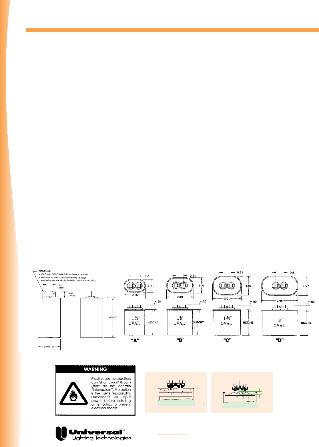
HID
FOR MORE INFORMATION CALL
1-800-BALLAST
(225-5278)
Product Overview
PAGE 5-4
Normal Position of Protective Device
Protective Device (Only in metal cases)
Protective device to prevent case rupture
Barrier Barrier
Normal Cover Position
1/2"
Capacitor Protective Devices
Position of Protective Device
After Activation
Barrier Barrier
Normal Cover Position
1/2"
Capacitor Protective Devices
For maximum safety and reliability, all Universal capacitors come with built-in bleed resistors (patented
by Universal) and approved by CSA (CSA file #LR51331, metal cases only). Environmental safety is
assured by use of biodegradable, nontoxic (no PCBs) dielectric fluid (soybean oil), patented by Universal
for use in capacitors. Dry-film capacitors do not include protective devices. Since they can fail in a haz-
ardous manner, it is the responsibility of the purchaser to take appropriate precautions.
Capacitors
Universal has a comprehensive line of capacitors in metal cases (up to 525V ratings) and plastic cases
(up to 400V ratings). All Universal capacitors are designed for 60,000 hours of continuous life. They’re
exceptionally reliable because we put them through accelerated life testing at 125% rated voltage and
rated temperature +10°C.
Universal capacitors are normally packaged with ballasts. They may also be ordered separately, bulk
packaged, or individually boxed with the suffix “BH” (metal cases only). Capacitor weights vary from
1/4 lb. to 1 lb. each.
Dry Capacitors
Type “P” plastic case capacitors described in this section are dry and do NOT contain safety
interrupters (or oil). Plastic cases are UL rated “94V-O” (for use up to 100°C maximum). Type “P”
capacitors are supplied with stranded copper wire leads 8 inches long (18 awg, with 150°C rated insu-
lation). Capacitor rolls are sealed inside plastic cases using epoxy. Design and testing of Universal
capacitors follow specifications in Electronic Industries Association (EIA) Standard 456-A, titled
“Metalized Film Dielectric Capacitors for Alternating Current Application.”
“P” capacitors are designed and rated for continuous duty AC voltages below 400VAC @ 50 or 60 Hz.
Capacitors used with HID ballasts at voltages above 400VAC should contain interrupters (available from
Universal in oval “MF” and round “RMF” oil-filled metal cases).
Plastic Dry Type Capacitors Metal and Oil Filled Capacitors

HID
FOR MORE INFORMATION CALL
1-800-BALLAST
(225-5278)
PAGE 5-5
Oil-Filled Capacitors
µF VACr Part # Case Ht (“)
5.0 300 005-1466-BH 1.25 oval 2.2
6.0 300 005-1561-BH 1.25 oval 2.2
7.0 300 005-1410-BH 1.25 oval 2.2
8.0 330 005-1411-BH 1.25 oval 2.2
10.0 330 005-1413-BH 1.25 oval 2.7
10.0 400 005-2666-BH 1.25 oval 3.9
10.0 400 005-1184-BH 1.50 oval 2.7
10.0 400 005-2167-BH 1.75 dia 2.9
12.0 300 005-1467-BH 1.25 oval 3.1
12.0 400 005-2799-BH 1.50 oval 2.7
12.0 440 005-1464-BH 1.50 oval 3.1
13.0 300 005-1414-BH 1.25 oval 3.1
14.0 240 005-1884-BH 1.75 dia 2.3
14.0 300 005-1415-BH 1.50 oval 2.7
15.0 400 005-1185-BH 1.75 oval 2.7
16.0 300 005-1498-BH 1.50 oval 2.7
17.5 300 005-1417-BH 1.50 oval 3.1
18.0 440 005-1401-BH 1.75 oval 3.1
18.5 330 005-1796-BH 1.50 oval 3.1
20.0 240 005-1885-BH 1.75 dia 2.3
20.0 330 005-1418-BH 1.50 oval 3.1
20.5 400 005-3262-BH 1.75 oval 3.1
21.0 525 005-1495-BH 1.75 oval 3.9
22.5 300 005-1419-BH 1.50 oval 3.5
24.0 360 005-3160-BH 1.75 oval 3.1
24.0 400 005-2664-BH 1.75 oval 3.1
µF VACr Part # Case Ht (“)
24.0 480 005-2779-BH 1.75 oval 3.9
24.5 300 005-3278-BH 1.75 oval 2.7
26.0 330 005-2669-BH 1.75 oval 3.1
26.0 525 0052776-BH 1.75 oval 4.3
28.0 240 005-1886-BH 1.75 dia 2.3
28.0 300 005-1468-BH 1.75 oval 3.1
28.0 425 005-1799-BH 1.75 oval 3.9
30.0 440 005-1475-BH 1.75 oval 3.9
32.0 300 005-2351-BH 1.75 oval 3.1
32.0 525 005-1474-BH 2.00 oval 3.9
33.0 300 005-1470-BH 1.75 oval 3.1
35.0 330 005-1421-BH 1.75 oval 3.1
36.0 525 005-2793-BH 2.00 oval 4.3
40.0 240 005-1887-BH 1.75 dia 2.7
40.0 300 005-1768-BH 1.75 oval 3.9
48.0 330 005-1422-BH 1.75 oval 3.9
52.0 240 005-1888-BH 2.00 dia 2.9
55.0 240 005-1594-BH 1.75 oval 3.5
55.0 300 005-2117-BH 1.75 oval 3.9

HID
FOR MORE INFORMATION CALL
1-800-BALLAST
(225-5278)
Notes
PAGE 5-2

FOR MORE INFORMATION CALL
1-800-BALLAST
(225-5278)
PAGE 5-7
Dry Capacitors
-- 90°C Rated 100°C Rated 105°C Rated
µF V Part # DIA (“) L (“) Part # DIA (“) L (“) Part # DIA (“) L (“)
5.0 280 005-4400-BH 1.18 2.20 R17058511-BH 1.26 2.36
5.0 280 005-4051-BH 1.18 2.76 R17058512-BH 1.26 2.83
5.0 330 R17058539-BH 1.26 2.24
6.0 280 R17058513-BH 1.26 2.36
6.0 280 005-4052-BH 1.18 2.76 R17058514-BH 1.26 2.83
7.0 280 005-4053-BH 1.58 2.76 R17058515-BH 1.65 2.83
8.0 300 005-4054-BH 1.58 2.76 R17058535-BH 1.65 2.83
8.0 330 R17058541-BH 1.65 2.83
10.0 280 005-4407-BH 1.18 2.76 R17058517-BH 1.26 2.83
10.0 280 005-4056-BH 1.58 2.76 R17058519-BH 1.65 2.83 R17058226-BH 1.65 2.83
10.0 330 005-4408-BH 1.58 2.76 R17058578-BH 1.65 2.83 R17058227-BH 1.65 2.83
10.0 400 005-4409-BH 1.58 2.76 R17058555-BH 1.65 2.83
10.0 400 005-4025-BH 1.58 3.74 R17058557-BH 1.65 3.82 R17058310-BH 1.65 3.82
11.0 400 005-4485-BH 1.58 2.76 R17058558-BH 1.65 2.83
12.0 300 005-4099-BH 1.58 2.76 R17058536-BH 1.65 2.83
12.0 330 005-4411-BH 1.58 2.76 R17058543-BH 1.65 2.83
12.0 400 005-4412-BH 1.58 3.74 R17058580-BH 1.65 3.82
13.0 330 005-4044-BH 1.58 3.74
14.0 170 R17058500-BH 1.26 2.83
14.0 280 005-4060-BH 1.58 2.76 R17058520-BH 1.65 2.83
14.0 280 005-4416-BH 1.58 2.76 R17058520-BH 1.65 2.83 R17058232-BH 1.65 2.83
14.0 400 005-4164-BH 1.58 3.74 R17058560-BH 1.65 3.82
15.0 400 R17058562-BH 1.65 3.82
15.0 400 005-4026-BH 1.77 3.74 R17058563-BH 1.85 3.82 R17058320-BH 1.85 3.82
16.0 280 005-4062-BH 1.58 2.76 R17058522-BH 1.65 2.83
16.0 280 005-4420-BH 1.58 2.76 R17058522-BH 1.65 2.83
16.0 330 R17058547-BH 1.65 2.83
17.0 400 R17058588-BH 1.65 3.82
17.5 280 R17058523-BH 1.65 3.82
20.0 170 005-4065-BH 1.58 2.76 R17058501-BH 1.65 2.83
20.0 280 005-4066-BH 1.58 3.74 R17058526-BH 1.65 3.82
20.0 330
20.0 400 R17058564-BH 1.85 3.82
20.5 400 005-4432-BH 1.77 3.74 R17058565-BH 1.85 3.82
21.0 400 005-4128-BH 1.77 3.74 R17058567-BH 1.85 3.82
22.0 400 005-4483-BH 1.77 3.74 R17058569-BH 1.85 3.82
22.5 280 R17058527-BH 1.65 3.15
22.5 280 R17058528-BH 1.65 3.82
24.0 280 R17058529-BH 1.65 3.82
24.0 400 005-4438-BH 1.85 3.74 R17058571-BH 1.85 3.82 R17058342-BH 1.85 5.31
24.0 400 005-4027-BH 1.77 4.61
24.5 330 005-4047-BH 1.58 4.61 R17058552-BH 1.65 4.76
26.0 300 005-4048-BH 1.58 4.61 R17058537-BH 1.65 4.76
26.5 400 005-4484-BH 1.77 4.61 R17058574-BH 1.85 4.76
28.0 170 005-4071-BH 1.58 2.76 R17058502-BH 1.65 2.83
28.0 280 005-4072-BH 1.58 4.61 R17058530-BH 1.65 4.76
28.0 330 005-4447-BH 1.77 3.74 8R17058553-BH 1.85 3.82
HID
FOR MORE INFORMATION CALL
1-800-BALLAST
(225-5278)
PAGE 5-8
Dry Capacitors (Cont.)
HT HID Ballasts
Designed for high temperature applications
Includes 105º Capacitors and Ignitors
High Pressure Sodium
Refer to catalog pages for ballast dimensions and electrical data
Quad-Tap: 120/208/240/277 Volt
Multi-5: 120/208/240/277/480 Volt
Tri-Trap: 120/277/347
480V include 120V tap for stand-by lighting
Pulse Start Metal Halide
Lamp Wattage Voltage Catalog Number Carton Pack Kit
175W Quad-Tap M175MLTAC3M 818C
175W Multi-5 M175ML5AC3M 818C 818K
175W 480V M17548TAC3M 818C
175W Tri-Tap M175TRIAC30 818C
250W Quad-Tap M250MLTAC3M 818C
250W Quad-Tap M250MLTAC4M 818C
250W Multi-5 M250ML5AC3M 818C 818K
250W Multi-5 M250ML5AC4M 818K
250W 480V M25048TAC3M 818C
250W 480V M25048TAC4M 818C
400W Quad-Tap M400MLTAC4M 818C
400W Multi-5 M400ML5AC4M 818C 818K
400W 480V M40048TAC4M 818C
400W Tri-Tap M400TRIAC4M 818C
90°C Rated 100°C Rated 105°C Rated
µF V Part # DIA (“) L (“) Part # DIA (“) L (“) Part # DIA (“) L (“)
35.0 280 R17058531-BH 1.65 3.82
35.0 280 005-4075-P 1.77 4.61 R17058532-BH 1.85 4.76
40.0 240 005-4456-P 1.58 3.74 R17058505-BH 1.65 3.82
40.0 240 005-4077-P 1.58 4.61 R17058506-BH 1.65 4.76
48.0 280 R17058533-BH 1.85 4.76
48.0 330 R17058554-BH 2.05 4.76
52.0 170 005-4087-P 1.77 3.74 R17058503-BH 1.85 3.82
52.0 280 005-4127-P 1.77 4.61 R17058534-BH 1.85 4.76
55.0 240 005-4465-P 1.77 3.74 R17058507-BH 1.85 3.82 R17058212-BH 1.85 5.31
55.0 240 005-4084-P 1.77 4.61 R17058509-BH 1.85 4.76
55.0 300 R17058538-BH 1.85 4.76
Lamp Wattage Voltage Catalog Number Carton Pack Kit
175W Quad-Tap P175MLTAC3M 818C
175W Multi-5 P175ML5AC3M 818K
400W Quad-Tap P400MLTAC4M 818C
400W Multi-5 P400ML5AC4M 818K
100W Quad-Tap S100MLTLC3M 818C 818K
100W 480V S10048TLC3M 818C
150W Quad-Tap S150MLTLC3M 818C 818K
150W 480V S15048TLC3M 818C
150W Tri-Trap S150TRILC3M 818C
250W Multi-5 S250ML5AC4M 818K
400W Quad-Tap S400MLTAC4M 818C
400W Multi-5 S400ML5AC4M 818C 818K
400W Multi-5 S400ML5AC5M 818K
400W 480V S40048TAC4M 818C
Metal Halide
HID
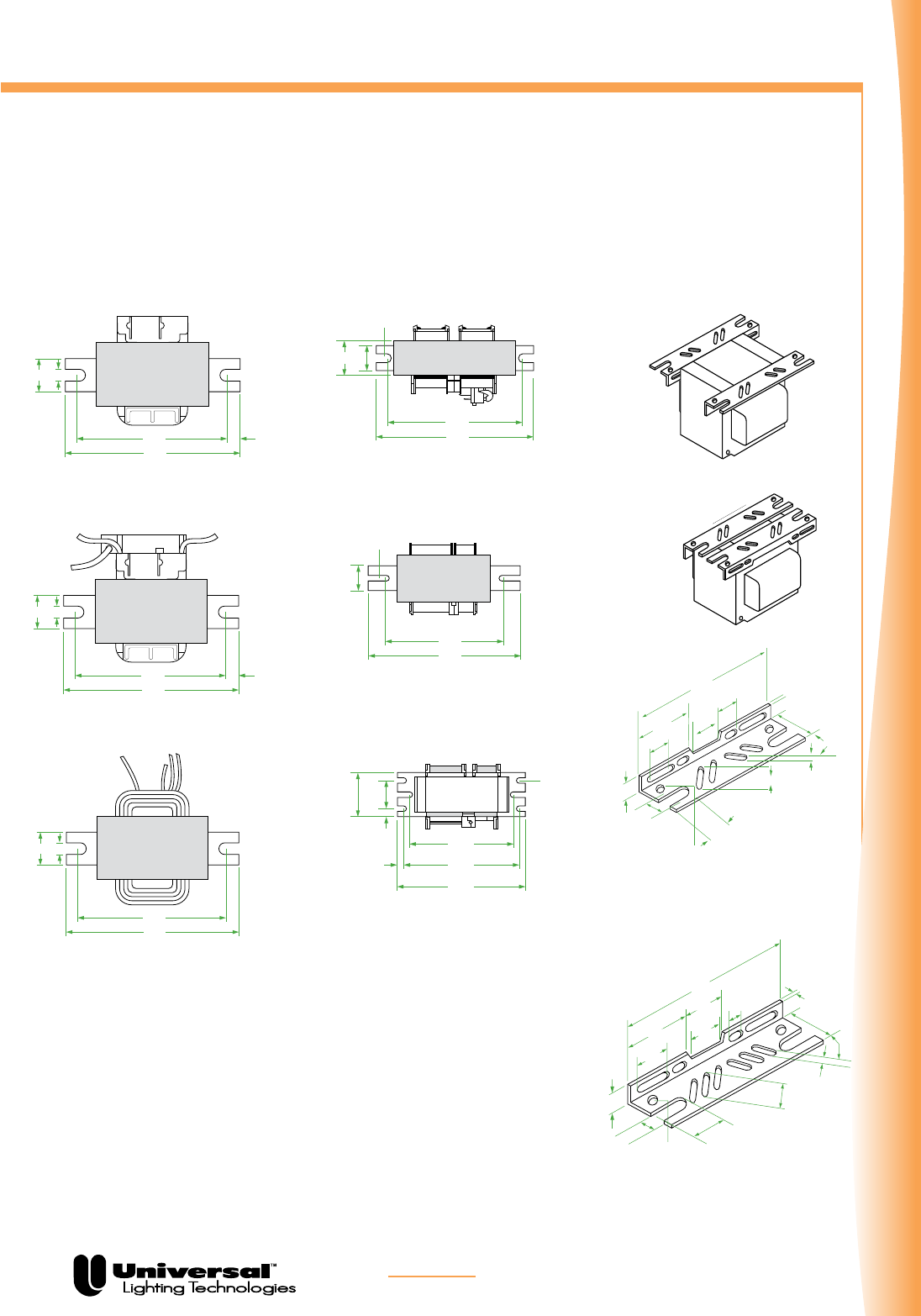
FOR MORE INFORMATION CALL
1-800-BALLAST
(225-5278)
Bracket Reference Chart
PAGE 5-9
CORE & COIL
WELDED
BRACKETS
All welded brackets are .093” thick.
0.75"0.25"
4.00"
3.35" 0.30"
0.75"0.25"
4.00"
3.35" 0.30"
Bracket B1 Bracket B1-A Bracket B2
1.00"
1.25"
5.25"
4.60"
.250 Slot
2 Places
1.25"
Bracket B3
7.75"
7.75"
.281 Slot
2 Places
1.75"
on center
2.75"
Bracket B4
7.75"
6.75"
on center
0.50"
0.50"
TYP.
6.10"
on center
.281 Slot
6 Req.
R. TYP.
OR
2.65"
1.50"
0.55"
0.70"
0.70"
.640"
0.25" Dia.
3 Holes
0.75"0.25"
4.00"
3.35" 0.30"
0.75"0.25"
4.00"
3.35" 0.30"
Bracket B1 Bracket B1-A Bracket B2
1.00"
1.25"
5.25"
4.60"
.250 Slot
2 Places
1.25"
Bracket B3
7.75"
7.75"
.281 Slot
2 Places
1.75"
on center
2.75"
Bracket B4
7.75"
6.75"
on center
0.50"
0.50"
TYP.
6.10"
on center
.281 Slot
6 Req.
R. TYP.
OR
2.65"
1.50"
0.55"
0.70"
0.70"
.640"
0.25" Dia.
3 Holes
0.75" 0.25"
4.00"
3.35" 0.25"
0.75" 0.25"
4.00"
3.35" 0.25"
Bracket B1 Bracket B1-A Bracket B2
1.00"
1.25"
5.25"
4.60"
.250 Slot
2 Places
1.25"
Bracket B3
7.75"
5.75"
.281 Slot
2 Places
1.75"
on center
2.75"
Bracket B4
7.75"
6.75"
on center
0.50"
0.50"
TYP.
6.10"
on center
.281 Slot
6 Req.
R. TYP.
OR
2.65" 1.50"
0.55"
0.70"
0.70"
.640"
0.25" Dia.
3 Holes
For use with:
• 50 to 175 watt Mercury, High Pressure Sodium and
Metal Halide and some 250 watt Metal Halide
1.81" 1.30"
0.58"
0.93"
0.43"
.29"
0.25" Dia.
2 Holes
0.09"
5.50"
0.93"
0.29"
0.90"
1.75"
45º
For use with:
• 250 to 1500 watt Metal Halide
• 250 to 1000 watt High Pressure Sodium and
Mercury Vapor
7.25"
1.300"
.090"
.580" .930"
.735"
.290"
1/4" Dia.
2 Holes
.290"
45ϒ
1. 880"
2.685" 1.750"
.835"
.460"
Ref. Drawing B2
Ref. Drawing ADJ1
Ref. Drawing ADJ2
Ref. Drawing MB1
Ref. Drawing MB2
Ref. Drawing B1-A
1.00"
0.25"
5.25"
4.60"
Bracket B1-B
Ref. Drawing B1-B
Ref. Drawing B3
Ref. Drawing B4
Ref. Drawing B1
CORE & COIL
ADJUSTABLE
MOUNTING
BRACKETS
Routinely supplied with replacement kits.
HID

FOR MORE INFORMATION CALL
1-800-BALLAST
(225-5278)
PAGE 5-10
Application And Operating Information
Underwriters’ Laboratories, Inc. Acceptance
All F-Can and Weatherproof ballasts listed in this
catalog are Underwriters’ Laboratories, Inc. white card
listed, except those for 347 volt operation. All Core &
Coil and Potted Core & Coil ballasts listed in this cata-
log are Underwriters’ Laboratories, Inc.
yellow card listed (component recognized).
Ballast Replacement
Ballast replacement presents the possibility of
exposure to potentially hazardous voltages and should
be performed only by qualified personnel. All installa-
tion, inspection and maintenance should be performed
only with the entire circuit power to fixture or equip-
ment turned off. Installation shall be in accordance
with National Electric Code.
Heat
A ballast, like any other electrical device, generates
heat during normal operation. Planning for maximum
heat dissipation with proper fixture design, installa-
tion planning and ballast selection will minimize the
possibility of a heat-related problem arising. Excessive
temperature will have an adverse effect on ballast life.
Normal temperature limits:
F-Can Ballasts
Maximum case temperature: 90°C
Potted Core & Coil Ballasts and
Core & Coil Ballasts
Insulation: Class 180°C
Maximum coil temperature: 165°C
(measured by change of resistance method)
All F-Can ballasts listed in this catalog are equipped
with built-in automatic resetting internal thermal
protection as a standard feature.
Whenever a ballast with thermal protection is used, it
is imperative that the fixture/ballast/lamp combination
be heat tested under actual or simulated installation
conditions to assure that the ballast will not cycle.
The resetting thermal protector functions as a
thermostat which will open and temporarily
deactivate the ballast when it exceeds the permissible
temperature. The ballast will continue to cycle until
the cause of overheating is eliminated. If the ballast is
defective, it must be replaced. If the cause is external,
the ballast will resume normal operation after
abnormal conditions are eliminated.
To attain normal ballast life, the maximum coil
temperature of the ballast should not exceed the
rating of the insulation system. A temperature increase
of 10° C results in a 50% reduction of ballast life.
Low Ambient Temperature (cold)
As temperatures drop, less and less vaporized gas is
available within the arc tube of a high intensity
discharge lamp, thereby causing an increase in the open
circuit voltage required to initiate an arc in the lamp,
until a point is reached where the lamp cannot be start-
ed. The minimum temperature at which any ballast listed
in this catalog will provide reliable starting is
listed with the electrical characteristics.
Ballasts should be protected from weather, moisture, or
other abnormal atmospheric conditions, unless specifi-
cally designed for use under adverse conditions.
Fusing
The purpose of fusing an HID ballast is to remove the bal-
last from the power line in the event of a ballast system
failure. A fuse does not protect the ballast from failing.
Because the temperature in the ballast compartment is
high, typically 90OC, fuse ratings are specified at 25OC, and
that this rating declines as the temperature increases, HID
fuse recommendations are made between 2 and 3 times
the maximum current the ballast will draw during all nor-
mal conditions.
Fast-blow fuses should not be used due to the possibility
of high inrush currents. These currents are due to the
fact that the power can be applied ant any point in the AC
voltage waveform. Standard and slow-blow are acceptable.
When using the 120V tap for auxiliary lighting, a slow-
blow fuse should be used to protect the ballast from dam-
age from a fault in the auxiliary lighting circuit.
REMOTE MOUNTING DISTANCE
Maximum Length in Feet for Remote Mounting of HID Ballasts to Lamp
For proper installation, insure that remote ballasts are properly vented and mounted to a heat-dissipating surface.
ANSI Lamp Type Watts 12 GA 14 GA 16 GA 18 GA
M57 Metal Halide 175 272 171 107 67
M58 Metal Halide 250 194 122 77 48
M59 Metal Halide 400 132 83 52 33
M47 Metal Halide 1000 196 123 77 48
M48 Metal Halide 1500 146 92 58 36
HID

FOR MORE INFORMATION CALL
1-800-BALLAST
(225-5278)
Application And Operating Information
PAGE 5-11
Sound
High intensity discharge lamp ballasts, like all electro-
magnetic devices, produce noise, or “hum.” It is the
degree of noise which determines the existence of a
problem. Ballast noise will only be noticeable when it
exceeds the ambient sound level of the installation. It
is obvious that a ballast designed primarily for
outdoor or factory use would not be suitable in an
office environment.
The vast improvements in all high intensity discharge
lamps and ballasts, and their excellent energy
efficiency, have made them viable options for many
indoor applications. The ballasts being considered
should be carefully analyzed to insure that there will
not be an objectionable level of ballast noise.
All F-Can ballasts listed in this catalog are “Sound
Rated” to aid in the selection of a ballast which is
proper for the environment in which it will operate.
Potted Core & Coil ballasts are also designed to
operate at reduced sound levels, generally several
decibels lower than a standard Core & Coil ballast.
Core & Coil ballasts are not sound rated.
In situations where light output necessitates using a
ballast with a sound rating or noise level not normally
acceptable, the ballast should be remotely mounted.
Note, however, that not all ballasts listed in this
catalog are designed or recommended for remote
mounting.
Polarity
Polarity refers to the proper connection of ballast lead
wires to line wires. To aid you in making a
correct installation, Universal ballast leads are
color-coded for easy identification. The white or
yellow ballast lead is to be connected to the neutral or
common. Choose the appropriate ballast voltage lead
to connect to the line.
Grounding
Ballasts and capacitors or starters in metallic casings
must always be grounded. Ballasts and components
may be grounded to the fixture or otherwise
connected to ground. It would be hazardous to make
contact with an ungrounded fixture, ballast or other
electrical component while in operation.
Operating Line Voltage Limits
To receive the full benefits of rated lamp output and
to prolong ballast life, it is essential that the voltage
supplied to an installation be maintained within the
prescribed limits.
In general, the line voltage supplied to a lag type
ballast (reactor or high reactance autotransformer)
should be maintained within 5% of the voltage for
which the ballast is rated. The line voltage to lead type
ballasts (constant wattage autotransformer or constant
wattage isolated) should be maintained within 10%.
Subjecting a ballast to excessive voltage for an
extended period of time results in the deterioration
of the coil insulation. This insulation breakdown will
cause early ballast failure.
Low voltage has no damaging effect on the ballast. It
could, however, have an adverse effect on lamp
performance and starting dependability.
Maintenance
Selecting and installing an adequate and efficient
lighting system means nothing if it is not properly
maintained. Maintenance must always be considered
as part of the life cycle cost of any high intensity
discharge lighting installation in order to assure the
continued performance of the system as originally
specified.
First and foremost in importance is proper lamp main-
tenance. High intensity discharge lamps do not “burn
out” like an incandescent bulb, but rather, undergo
changes within the arc tube which prevent the lamp
from starting properly, warming up and
producing full light output. The beginning of
difficulties such as these generally indicates the end
of a lamp’s useful life. Also, a dead lamp left in a
fixture can be very damaging to the ignitor in
systems which utilize them. To overcome this
problem, Universal offers automatic shutoff
ignitors, which are described in the ignitor section of
this catalog.
HID

FOR MORE INFORMATION CALL
1-800-BALLAST
(225-5278)
PAGE 5-12
In difficult locations, group replacement of all the
lamps, working or not, is often more economical
and convenient than spot replacement. The same,
of course, applies to ballasts which might be
approaching the end of their life. Only you can decide
what is right for your lighting system, but what is
important is that you have a maintenance program.
Periodic cleaning of the fixtures’ lenses and reflectors
is also important in maintaining proper light output.
For indoor systems, maintenance of reflective
surfaces, such as walls and ceilings, will also help
assure proper levels of illumination.
STANDBY LIGHTING AND PACKAGING
Standby Lighting
To provide light during a high intensity discharge
lamp’s warmup period, or the cool-down period
following a power interruption which has
extinguished it, incandescent standby lighting can be
incorporated. This is accomplished by use of a
standby lighting device, or remote, that switches off
an incandescent lamp incorporated into the fixture
once an arc has been established, or reestablished, in
the HID lamp. Generally, standby lighting devices oper-
ate on 120 volts, so a tap must be provided on ballasts
designed to operate at higher line voltages.
The 120 volt terminal or lead on all Universal dual-,
tri-, quad- and multi-volt ballasts can be used as a tap
for standby lighting when the ballast is utilized for any
of the higher voltages. Many single voltage
ballasts are available with a 120 volt tap and are
listed throughout the Core & Coil data section. Other
single voltage ballasts may be available in this
version. Consult our Customer Service Department
for availability and price information.
Any connection to the 120 volt tap must be
accomplished by means of a slow-blow fuse. This fuse
will protect the ballast from abnormal conditions in
the standby lamp circuit or its control device. The fuse
should be located in the coolest place in the
fixture (below 80°C). The recommended fuse
amperage and maximum auxiliary lamp wattage
are listed in this catalog for each ballast suitable for
standby lighting applications.
Be sure to follow the wiring instructions of the
standby lighting device manufacturer. All applicable
requirements of the National Electrical Code must be
met.
Packaging
Standard Pack
Universal’s high intensity discharge lamp ballasts are
routinely packed in easy-to-handle cartons
containing from 1 to 20 units per carton, depending on
the size and weight of the ballasts. Consult Customer
Service for the number of “units per carton” for ship-
ment with attached mounting brackets, capacitors
(for high power factor units), and ignitors (if required).
Other ordering criteria may cause
packaging to vary.
Tray Pack
For the convenience of large quantity users who
request it, Universal ballasts may be packed in trays.
The number of units depends upon the size and weight
of each ballast. These trays are large
corrugated cartons with lids and sides that come off
easily. This type of packaging affords Universal
customers a savings of time and money on their own
production costs. There are fewer cartons to open,
break up and dispose of on the assembly line;
warehouse handling is reduced and inventory control
is easier. There is no additional charge for tray
packing.
Individual Cartons
All Distributor Replacement Kits, Weatherproof, Potted
Core & Coil and other larger ballasts are
packaged in individual cartons.
Individual cartons serve a threefold purpose: as a
display carton, a stock package, and a shipping
container for the retail market. Individual cartons may
be packed in master cartons, depending on weight
and size.
Individual carton packaging may be available for other
ballasts. Contact our Customer Service Department
for availability and cost.
Application And Operating Information
HID

FOR MORE INFORMATION CALL
1-800-BALLAST
(225-5278)
PAGE 5-13
Nomenclature
UNIVERSAL PRECISE™
ABBREVIATIONS
CWA Constant Wattage Autotransformer
CWI Constant Wattage Isolated
ISO Regulated Lag
R-HPF Reactor—High Power Factor
R-NPF Reactor—Normal Power Factor
HX-HPF Lag Type — High Reactance
Autotransformer—High Power Factor
HX-NPF Lag Type — High Reactance
Autotransformer—Normal Power Factor
UL Bench Top Rise Temperature Code
To facilitate UL inspection, the UL Bench Top Rise
Temperature Code is shown on the Universal Core &
Coil Ballast label as 1029X. 1029 is the UL Standard
for HID Ballasts, and the X is the
temperature code. If a fixture is UL listed for 1029D,
then automatically all ballasts with an A, B, C or D
temperature classification are acceptable for use
within that same fixture.
UL Bench Top Rise Letter Code
Temperature Range for
Class H (180° C) Ballasts
A<75°C B 75°C < 80°C C 80°C < 85°C
D 85°C < 90°C E 90°C < 95°C F 95°C < 100°C
1 2 3 4 5 6 7 8 9
Number of Digits
1 2 to 4 3 1 1 1 1 3 1
M 2 0 0 0 M L T A C 5 M 0 0 0 C
Field Description
1 (M) Metal Halide, (P) Pulse Start Metal Halide, (S) High Pressure Sodium
2 35 to 2000 Watts (Varies from two to four digits)
3 (MLT) Quad, (ML5) Multi-5, (TRI) TriVolt, (48T) 480/120, (120) 120, (277) 277, (230) 230V/50Hz
4 (R) Reactor, (A) CWA, (I) CWI, (O) IsoReg, (L) High Reactance/Lag, (M) MagLag
5 (C), C&C, (F) F-Can, (W) Weatherproof, (E) Encased/Potted C&C (I) Indoor Encased
6 (E) E&I, (3) 3x4, (4) 4-3/4, (5) 5-3/4, (X) Non Core and Coil
7 (M) Mogul or Medium, (D) Double Ended, (X) Multiple Lamps, (L) Low Loss
8 Pack Code (000 to 999, per pack code listing)
9 (C) Carton, (T) Tray, (I) Individual, (K) Kit
Field
Lamp Type
(M/P/S/H)
Wattage
Primary
Voltage
(MLT/ML5/TRI/
48T/120/277/
230)
Circuit Type
(R/A/I/O/L/M)
Style
(C/F/W/E/I/P)
Frame Size
(E/3/4/5/X)
Socket Type & Other
Oddities (M/D/X/L)
Pack Code
(000 TO 999)
Container Type
(C/T/I/K)
HID

FOR MORE INFORMATION CALL
1-800-BALLAST
(225-5278)
Specifications
PAGE 5-14
TYPICAL SPECIFICATIONS
FOR HID BALLASTS
1. Ballasts shall be designed in accordance with all applicable ANSI specifications including ANSI C82.4.
2 . The Core & Coil ballast shall be designed with class “H” (180°C) or higher insulation system and vacuum
impregnated with a 100% solid based resin.
3 . All coils shall be precision wound.
4 . Core & Coil ballasts shall be designed to operate at least 180 cycles of 12 hours on and 12 hours off, with
the lamp circuit in an open or short-circuited condition and without undue reduction in ballast life.
5. Core & Coil ballast and starter combinations shall be designed to provide a reliable lamp starting down to
-40°C for High Pressure Sodium and Pulse Start Metal Halide and -30°C for Metal Halide and Mercury at
minimum rated line voltage.
6. Manufacturer shall provide written warranty against defects in workmanship, including replacement, for two
years from date of manufacture.
CAPACITORS
1. All capacitors will be provided with a self-contained internal bleeder resistor.
2. All oil-filled capacitors will be housed in corrosion-resistant steel cans and contain .25” quick disconnect
terminals.
3. All capacitors will be supplied by ballast manufacturer.
IGNITORS
1. All ignitors will be epoxy-filled with either a plastic or aluminum external housing.
2. The ignitor shall be so designed to provide six months of lamp open circuit operation without failure.
KITS
1. All HID kits shall be precision wound to insure proper insulation.
2. All HID kits shall be pre-wired.
3. All HID kits shall be built with color-coded leads.
4. All HID kits are to be UL and CSA recognized following the guidelines found in UL 1029 and
CAN/CSA-22.2 No. 74-92 (part 2 and 3).
5. Universal Model __________________________ (or approved equal).
HID

FOR MORE INFORMATION CALL
1-800-BALLAST
(225-5278)
PAGE 5-15
Distributor Replacement Kits
Universal’s HID distributor replacement kits contain the appropriate core & coil, a properly rated capacitor, and all
other components required for ballast replacement. Our kits are the quickest and easiest to install of any on the
market, thanks to unique design features like:
• Prewiredcapacitorandignitor(ifrequired)tosaveinstallationtimeandreducewiringerrors.
• Color-codedleadstoreduceriskofincorrectwiringinsidethefixture.
• FeaturesthatexceedULstandards,includingcapacitorsthatoffertripfaultprotection.
• Simpleinstallationinstructionsandtroubleshootingtips.
• UPSshippablebox.
Our kit offerings include many quad voltage (120, 208, 240, or 277 volt) and 480 volt core & coil ballasts, as well as
the new Multi-5 five-voltage ballast. 480 volt ballasts are equipped with a 120 volt tap to accommodate stand by
lighting.
Also available for Metal Halide and High Pressure Sodium applications, Universal Lighting’s Multi-5TM Ballast-Lamp
Replacement Kit. This easy to carry convenient all-in-one kit ensures ballast lamp compatibility.
Distributor replacement kit cartons are packaged in master cartons in quantities from 1 to 6 units. Master carton
quantities can be found on Universal’s list and distributor price sheets.
Quad, 480 Volt, Multi-5™ and Multi-5™ Uni-Pak™ Distributor Replacement Kits
LampType Wattage Voltage Frame Size Old Part Number New Part Number
175 120/208/240/277 3 x 4 1130-91R-500K M175MLTAC3M500K
175 Multi-5 3 x 4 New M175ML5AC3M500K
175
Multi-5™ Uni-Pak™
3 x 4 New M175ML5AC3M555K
175 480-120 3 x 4 1130-31-500K M17548TAC3M500K
250 120/208/240/277 3 x 4 1130-92-500K M250MLTAC3M500K
250 Multi-5 3 x 4 New M250ML5AC3M500K
Metal 250
Multi-5™ Uni-Pak™
3 x 4 New M250ML5AC3M555K
Halide 250 480-120 3 x 4 1130-32-500K M25048TAC3M500K
250 120/208/240/277 4.25 x 4.75 1130-92R-500K M250MLTAC4M500K
250 Multi-5 4.25 x 4.75 New M250ML5AC4M500K
250
Multi-5™ Uni-Pak™
4.25 x 4.75 New M250ML5AC4M555K
250 480-120 4.25 x 4.75 1130-32R-500K M25048TAC4M500K
400 120/208/240/277 4.25 x 4.75 1130-93U-500K M400MLTAC4M500K
400 120/208/240/277 4.25 x 4.75 1130-93R-500K M400MLTAC4M500K
400 Multi-5 4.25 x 4.75 1130-826S-500K M400ML5AC4M500K
400
Multi-5™ Uni-Pak™
4.25 x 4.75 New M400ML5AC4M555K
400 480-120 4.25 x 4.75 1130-33R-500K M40048TAC4M500K
1000 120/208/240/277 4.25 x 5.75 1130-97-500K M1000MLTAC5M500K
1000 120/208/240/277 4.25 x 5.75 1130-97R-500K M1000MLTAC5M500K
1000 Multi-5 4.25 x 5.75 New M1000ML5AC5M500K
1000
Multi-5™ Uni-Pak™
4.25 x 5.75 New M1000ML5AC5M555K
1000 480-120 4.25 x 5.75 1130-57-500K M100048TAC5M500K
1250 120/208/240/277 4.25 x 5.75 New M1250MLTAC5M500K
1500 120/208/240/277 4.25 x 5.75 1130-99R-500K M1500MLTAC5M500K
1500 480-120 4.25 x 5.75 1130-69R-500K M150048TAC5M500K
HID

FOR MORE INFORMATION CALL
1-800-BALLAST
(225-5278)
Distributor Replacement Kits
Quad, 480 Volt, Multi-5™ and Multi-5™ Uni-Pak™ Distributor Replacement Kits
PAGE 5-16
LampType Wattage Voltage Frame Size Old Part Number New Part Number
35 120/208/240/277 3 x 4 New M35MLTLC3M500K
50 120/208/240/277 3 x 4 11310-95-500K M50MLTLC3M500K
70 120/208/240/277 3 x 4 11310-510-500K M70MLTLC3M500K
70 480-120 3 x 4 New M7048TLC3M500K
70 120/208/240/277 3 x 4 New M70MLTLC3D500K
100 120/208/240/277 3 x 4 11310-90-500K M100MLTLC3M500K
100 120/208/240/277 3 x 4 New M100MLTLC3D500K
100 480-120 3 x 4 New M10048TLC3M500K
150 120/208/240/277 3 x 4 11310-543-500K M150MLTLC3M500K
150 120/208/240/277 3 x 4 New M150MLTLC3D500K
150 480-120 3 x 4 New M15048TLC3M500K
175 120/208/240/277 3 x 4 New P175MLTAC3M500K
175 120/208/240/277 3 x 4 New P175MLTAC3L500K
175 Multi-5 3 x 4 New P175ML5AC3M500K
175 120/208/240/277 4.25 x 5.75 New P175MLTAC4L500K
175 480-120 4.25 x 5.75 New P17548TAC4L500K
200 Multi-5 3 x 4 New P200ML5AC3M500K
250 120/208/240/277 4.25 x 4.75 New P250MLTAC4L500K
250 Multi-5 4.25 x 4.75 New P250ML5AC4M500K
250 Multi-5 4.25 x 4.75 New P250ML5AC4L500K
250 480-120 4.25 x 4.75 New P25048TAC4L500K
Pulse Start 320 120/208/240/277 4.25 x 4.75 1130-827-500K P320MLTAC4O500K
Metal Halide 320 Multi-5 4.25 x 4.75 New P320ML5AC4M500K
320 480-120 4.25 x 4.75 New P32048TAC4M500K
320 480-120 4.25 x 4.75 New P32048TAC4L500K
350 120/208/240/277 4.25 x 4.75 1130-622-500K P350MLTAC4M500K
350 Multi-5 4.25 x 4.75 New P350ML5AC4M500K
350 Multi-5 4.25 x 4.75 New P350ML5AC4L500K
350 480-120 4.25 x 4.75 New P35048TAC4L500K
400 120/208/240/277 4.25 x 4.75 1130-829-500K P400MLTAC4L500K
400 Multi-5 4.25 x 4.75 New P400ML5AC4M500K
400 480-120 4.25 x 4.75 New P40048TAC4M500K
450 120/208/240/277 4.25 x 4.75 New P450MLTAC4M500K
450 Multi-5 4.25 x 4.75 New P450ML5AC4M500K
450 480-120 4.25 x 4.75 New P45048TAC4M500K
750 120/208/240/277 4.25 x 5.75 New P750MLTAC5M500K
750 Multi-5 4.25 x 5.75 New P750ML5AC5M500K
750 480-120 4.25 x 5.75 New P75048TAC5M500K
875 120/208/240/277 4.25 x 5.75 New P875MLTAC5M500K
1000 120/208/240/277 4.25 x 5.75 New P1000MLTAC5M500K
1000 Multi-5 4.25 x 5.75 New P1000ML5AC5M500K
HID

FOR MORE INFORMATION CALL
1-800-BALLAST
(225-5278)
Distributor Replacement Kits
PAGE 5-17
Quad, 480 Volt, Multi-5™ and Multi-5™ Uni-Pak™ Distributor Replacement Kits
LampType Wattage Voltage Frame Size Old Part Number New Part Number
50 120/208/240/277 3 x 4 12310-95-500K S50MLTLC3M500K
70 120/208/240/277 3 x 4 12310-153-500K S70MLTLC3M500K
70 480-120 3 x 4 12310-148R-500K S7048TLC3M500K
100 120/208/240/277 3 x 4 12310-90-500K S100MLTLC3M500K
100 480-120 3 x 4 12310-30R-500K S10048TLC3M500K
150 120/208/240/277 3 x 4 12310-165-500K S150MLTLC3M500K
150 480-120 3 x 4 12310-160S-500K S15048TLC3M500K
200 120/208/240/277 4.25 x 4.75 New S200MLTAC4M500K
200 480-120 4.25 x 4.75 New S20048TAC4M500K
250 Multi-5 4.25 x 4.75 New S250ML5AC4M500K
250 120/208/240/277 4.25 x 4.75 1230-92S-500K S250MLTAC4M500K
250 480-120 4.25 x 4.75 1230-32S-500K S25048TAC4M500K
H.P.S. 250
Multi-5™ Uni-Pak™
4.25 x 4.75 New S250ML5AC4M555K
400 Multi-5 4.25 x 4.75 New S400ML5AC4M500K
400 120/208/240/277 4.25 x 4.75 1230-93U-500K S400MLTAC4M500K
400 480-120 4.25 x 4.75 1230-33U-500K S40048TAC4M500K
400 Multi-5 4.25 x 5.75 New S400ML5AC5M500K
400 120/208/240/277 4.25 x 5.75 1230-93S-500K S400MLTAC5M500K
400 480-120 4.25 x 5.75 1230-33S-500K S40048TAC5M500K
400
Multi-5™ Uni-Pak™
4.25 x 4.75 New S400ML5AC4M555K
600 120/208/240/277 4.25 x 5.75 New S600MLTAC5M500K
1000 120/208/240/277 4.25 x 5.75 1230-97S-500K S1000MLTAC5M500K
1000 Multi-5 4.25 x 5.75 New S1000ML5AC5M500K
1000
Multi-5™ Uni-Pak™
4.25 x 5.75 New S1000ML5AC5M555K
1000 480-120 4.25 x 5.75 1230-57S-500K S100048TAC5M500K
HID
FOR MORE INFORMATION CALL
1-800-BALLAST
(225-5278)
Distributor Replacement Kits
PAGE 5-18
LampType Wattage Voltage Frame Size Old Part Number New Part Number
175 120/277/347 3 x 4 1130-605-502K M175TRIAC30502K
250 120/277/347 3 x 4 New M250TRIAC3M502K
Metal 250 120/277/347 4.25 x 4.75 1130-593R-502K M250TRIAC4M502K
Halide 400 120/277/347 4.25 x 4.75 1130-595R-502K M400TRIAC4M502K
1000 120/277/347 4.25 x 5.75 1130-598-502K M1000TRIAC5M502K
1500 120/277/347 4.25 x 5.75 1130-599-502K M1500TRIAC5M502K
35 120/277/347 3 x 4 New M35TRILC3M502K
50 120/277/347 3 x 4 New M50TRILC3M502K
70 120/277/347 3 x 4 11310-604-502K M70TRILC3M502K
100 120/277/347 3 x 4 11310-584-502K M100TRILC3M502K
150 120/277/347 3 x 4 11310-590-502K M150TRILC3M502K
Pulse Start 175 120/277/347 3 x 4 New P175TRIAC3M502K
Metal Halide 200 120/277/347 3 x 4 New P200TRIAC3M502K
250 120/277/347 4.25 x 4.75 New P250TRIAC4M502K
320 120/277/347 4.25 x 4.75 New P320TRIAC4M502K
350 120/277/347 4.25 x 4.75 New P350TRIAC4M502K
400 120/277/347 4.25 x 4.75 New P400TRIAC4M502K
450 120/277/347 4.25 x 4.75 New P450TRIAC4M502K
750 120/277/347 4.25 x 5.75 New P750TRIAC5M502K
70 120/277/347 3 x 4 12310-579-502K S70TRILC3M502K
100 120/277/347 3 x 4 12310-584-502K S100TRILC3M502K
150 120/277/347 3 x 4 12310-588-502K S150TRILC3M502K
H.P.S. 250 120/277/347 4.25 x 4.75 1230-593S-502K S250TRIAC4M502K
400 120/277/347 4.25 x 4.75 1230-595U-502K S400TRIAC4M502K
400 120/277/347 4.25 x 5.75 1230-595S-502K S400TRIAC5M502K
1000 120/277/347 4.25 x 5.75 1230-598S-502K S1000TRIAC5M502K
Canadian Tri-Tap Distributor Replacement Kits
HID

FOR MORE INFORMATION CALL
1-800-BALLAST
(225-5278)
HID CORE & COIL BALLASTS
METAL HALIDE
• 60 Hz
• Minimum starting
temperature: -30° C
• Normal and High Power Factor
models available
PAGE 5-19
MH
175-250
WATT
HID
CORE & COIL
3 Capacitors are available as an option for high power
factor operation. See page 5-23 for Reference
Drawings and Wiring Diagrams.
Nom Dimensions Capacitor Ignitor
Max Open Total Max UL
Input Catalog* Circuit Watts Input Circuit Fuse Wir Ref Min Dry Film Oil Filled Weight Catalog Distance Bench
Volts Number Type Input Current Voltage Rating Dia Dwg A B µF Volt Dia Ht Oval Ht (lbs.) Number
to lamp (ft)
Top Rise
(1) 175 WATT M57, M107 METAL HALIDE LAMP
120 M175120AC3M
CWA 213 1.90 305 5 17 PC1 2.2 3.6 10 400 1.65 2.83 1.56x2.69 2.69 6.1 n/a n/a A
230 M175230AC3M
CWA 205 1.00 310 3 46 PC1 2.25 3.55 12 400 1.65 3.82 1.56x2.69 2.7 6.7 n/a n/a C
120 or
M175TRIAC30 CWA 211
2.15
305
5
17 PC1 2.45 3.8 10 400 1.65 2.83 1.56x2.69 2.69 6.8 n/a n/a C
277 or 0.95 2
347 0.75 2
120 or
M175MLTAC3M CWA 213
1.90
305
5
16 PC1 2.2 3.6 10 400 1.65 2.83 1.56x2.69 2.69 6.1 n/a n/a
A
208 or
1.10 3 C
240 or 0.95 3 B
277 0.85 2 C
120 or 1.94 5
208 or
1.11 3
240 or
M175ML5AC3M
CWA 208 1.00 300 3 25 PC1 2.3 3.6 10 400 1.65 2.83 1.56x2.69 2.69 6.8 n/a n/a B
277 or 0.83 2
480 0.50 2
480 M17548TAC3M
CWA 210 0.51 315 2 15 PC1 2.0 3.3 10 400 1.65 2.83 1.56x2.69 2.69 5.6 n/a n/a D
(1) 250 WATT M58 METAL HALIDE LAMP - 4” Frame
230 M250230AC3M CWA 282 1.40 285 4 46 PC1 3.0 4.3 18 400 n/a n/a 1.75 3.1 9.0 n/a n/a D
120 or 2.78 8 B
277 or
M250TRIAC3M
CWA 295 1.30 320 3 17 PC1 3.0 4.5 15 400 1.85 3.82 2.01x3.01 2.69 9.0 n/a n/a D
347 1.05 3 D
120 or 2.65 8
208 or M250MLTAC3M CWA 297 1.58 315 5 16 PC1 3.0 4.3 15 400 1.85 3.82 2.01x3.01 2.69 9.0 n/a n/a
240 or 1.30 4 D
277 1.13 3
120 or 2.50 8
208 or
1.50 5
240 or M250ML5AC3M CWA 280 1.25 290 4 25 PC1 3.0 4.3 15 400 1.6 3.82 2.01x3.01 2.69 9.0 n/a n/a C
277 or 1.10 3
480 0.65 2
347 M250347AC3M CWA 293 1.05 320 3 42 PC1 3.0 4.5 15 400 1.85 3.82 2.01x3.01 2.69 9.0 n/a n/a D
480 M25048TAC3M CWA 292 0.71 320 2 15 PC1 3.0 4.3 15 400 1.85 3.82 2.01x3.01 2.69 9.0 n/a n/a D

FOR MORE INFORMATION CALL
1-800-BALLAST
(225-5278)
HID CORE & COIL BALLASTS
METAL HALIDE
• 60 Hz
• Minimum starting
temperature: -30° C
• High Power Factor models
available
• Feature CWA design
PAGE 5-20
HID
CORE & COIL
MH
250-400
WATT
Nom Dimensions Capacitor Ignitor
Max Open Total Max UL
Input Catalog* Circuit Watts Input Circuit Fuse Wir Ref Min Dry Film Oil Filled Weight Catalog Distance Bench
Volts Number Type Input Current Voltage Rating Dia Dwg A B µF Volt Dia Ht Oval Ht (lbs.) Number
to lamp (ft)
Top Rise
(1) 250 WATT M58 METAL HALIDE LAMP - 4.75” Frame
120 or 3.05 8
277 or
M250TRIAC4M
CWA 280 1.25 305 3 17 PC2 1.63 3.63 15 400 1.85 3.82 2.01x3.01 2.69 9.5 n/a n/a B
347 1.05 3
120 or 3.05 8
208 or
M250MLTAC4M
CWA 290 1.65 310 5 16 PC2 1.53 3.53 15 400 1.85 3.82 2.01x3.01 2.69 9.5 n/a n/a B
240 or 1.55 4
277 1.25 3
120 or 2.42 8
208 or 1.40 5
240 or
M250ML5AC4M
CWA 282 1.20 300 4 25 PC2 1.82 3.62 15 360 1.85 3.82 2.01x3.01 2.69 10.8 n/a n/a A
277 or 1.00 3
480 0.60 2
480
M25048TAC4M
CWA 284 0.61 300 2 15 PC2 1.82 3.62 15 360 1.85 3.82 2.01x3.01 2.69 10.8 n/a n/a B
(1) 400 WATT M59 METAL HALIDE LAMP
120 M400120AC4M CWA 458 3.94 299 10 28 PC2 2.0 3.86 24 360 1.85 3.82 2.01x3.01 3.12 11.2 n/a n/a E
230 M400230AC4M CWA 448 2.20 300 6 46 PC2 2.13 3.75 28 425 n/a n/a
2.91
3.88 13.0 n/a n/a D
277 M400277AC4M CWA 458 1.69 299 5 14 PC2 2.0 3.86 24 360 1.85 3.82
2.01x3.01
3.12 11.2 n/a n/a E
120 or 4.22 10
277 or M400TRIAC4M CWA 455 1.67 297 5 17 PC2 2.0 3.9 24 360 1.85 3.82 2.01x3.01 3.12 11.0 n/a n/a C
347 1.44 5
120 or 3.90 10 C
277 or M400TRIAC40 CWA 455 1.70 295 5 29 PC2 2.15 3.90 24 360 n/a n/a 1.91x2.91 3.10 10.5 n/a n/a D
347 1.35 4 D
120 or 3.94 10
208 or M400MLTAC4M CWA 458 2.20 299 8 16 PC2 2.0 3.9 24 360 1.85 3.82 2.01x3.01 3.12 11.2 n/a n/a
240 or 1.93 5 E
277 1.69 5
120 or 4.00 10
208 or 2.30 8
240 or M400ML5AC4M CWA 458 2.00 300 5 25 PC2 2.0 3.9 24 360 1.85 3.82 2.01x3.01 3.12 11.2 n/a n/a E
277 or 1.70 5
480 1.00 50
480
M40048TAC4M CWA 458 1.00 300 3 15 PC2 2.0 3.9 24 360 1.85 3.82
2.01x3.01
3.12 11.0 n/a n/a E
See page 5-23 for Reference
Drawings and Wiring Diagrams.

FOR MORE INFORMATION CALL
1-800-BALLAST
(225-5278)
HID CORE & COIL BALLASTS
METAL HALIDE-
FEATURING MULTI-5™
• 60 HZ.
• Minimum Starting
Temperature: -30° C
• Feature CWA Design
PAGE 5-21
MH
1000-1500
WATT
HID
CORE & COIL
Nom Dimensions Capacitor Ignitor
Max Open Total Max UL
Input Catalog* Circuit Watts Input Circuit Fuse Wir Ref Min Dry Film Oil Filled Weight Catalog Distance Bench
Volts Number Type Input Current Voltage Rating Dia Dwg A B µF Volt Dia Ht Oval Ht (lbs.) Number
to lamp (ft)
Top Rise
(1) 1000 WATT M47 METAL HALIDE LAMP
120
M1000120AC5M
CWA 1080 9.00 425 23 28 PC3 2.9 4.75 24 480 n/a n/a 2.01x3.01 4.0 18.0 n/a n/a D
230
M1000230AC5M
CWA 1080 4.70 420 13 46 PC3 3.4 5.30 30 440 n/a n/a 2.91 3.87 21.0 n/a n/a C
120 or 9.00 20 D
277 or
M1000TRIAC5M
CWA 1080 3.90 435 10 17 PC3 3.0 4.95 24 480 n/a n/a 2.01x3.01 4.0 19.0 n/a n/a D
347 3.20 8 E
120 or 8.95 20
208 or
M1000MLTAC5M
CWA 1080 5.15 425 15 16 PC3 2.9 5.05 24 480 n/a n/a 2.01x3.01 4.0 22.0 n/a n/a D
240 or 4.50 10
277 3.90 10
120 or 9.15 20 F
208 or
5.25 15 E
240 or
M1000ML5AC5M
CWA 1080 4.55 420 10 25 PC3 2.9 5.05 24 480 n/a n/a 2.01x3.01 4.0 22.0 n/a n/a E
277 or 3.95 10 E
480 2.30 6 E
480
M100048TAC5M
CWA 1080 2.30 410 6 15 PC3 2.85 4.80 24 480 n/a n/a 2.01x3.01 4.0 22.0 n/a n/a D
480
M100048TAN5M
CWA 1080 2.30 410 6 15 PC3 2.85 4.75 24 480 n/a n/a 2.01x3.01 3.9 22.0 n/a n/a A
(1) 1250 WATT M180 METAL HALIDE LAMP
120 or 12.00 30 F
208 or
6.90 20 D
240 or M1250MLTAC5M CWA 1360 6.00 420 15 17 PC3 4.4 6.4 32 440 n/a n/a 1.97x3.66 3.88 25.0 n/a n/a D
277 5.20 15 E
(1) 1500 WATT M48 METAL HALIDE LAMP
230 M1500230AC5M CWA 1605 7.00 430 20 46 PC3 4.38 6.18
42(2x21)
480 n/a n/a 1.96x3.65 3.9 30.0 n/a n/a C
120 or 13.70 40
277 or M1500TRIAC5M CWA 1610 6.00 460 20 17 PC3 4.38 6.38 32 525 n/a n/a 1.96x3.65 3.9 29.5 n/a n/a G
347 4.70 15
120 or 14.30 40 F
208 or M1500MLTAC5M CWA 1615 8.30 455 25 48 PC3 4.4 6.4 32 525 n/a n/a 1.96x3.65 3.9 30.0 n/a n/a G
240 or 7.20 20 F
277 6.20 20 E
480
M150048TAC5M CWA 1620 3.50 445 10 15 PC3 4.4 6.4 32 525 n/a n/a 1.96x3.65 3.9 30.0 n/a n/a E
See page 5-23 for Reference
Drawings and Wiring Diagrams.
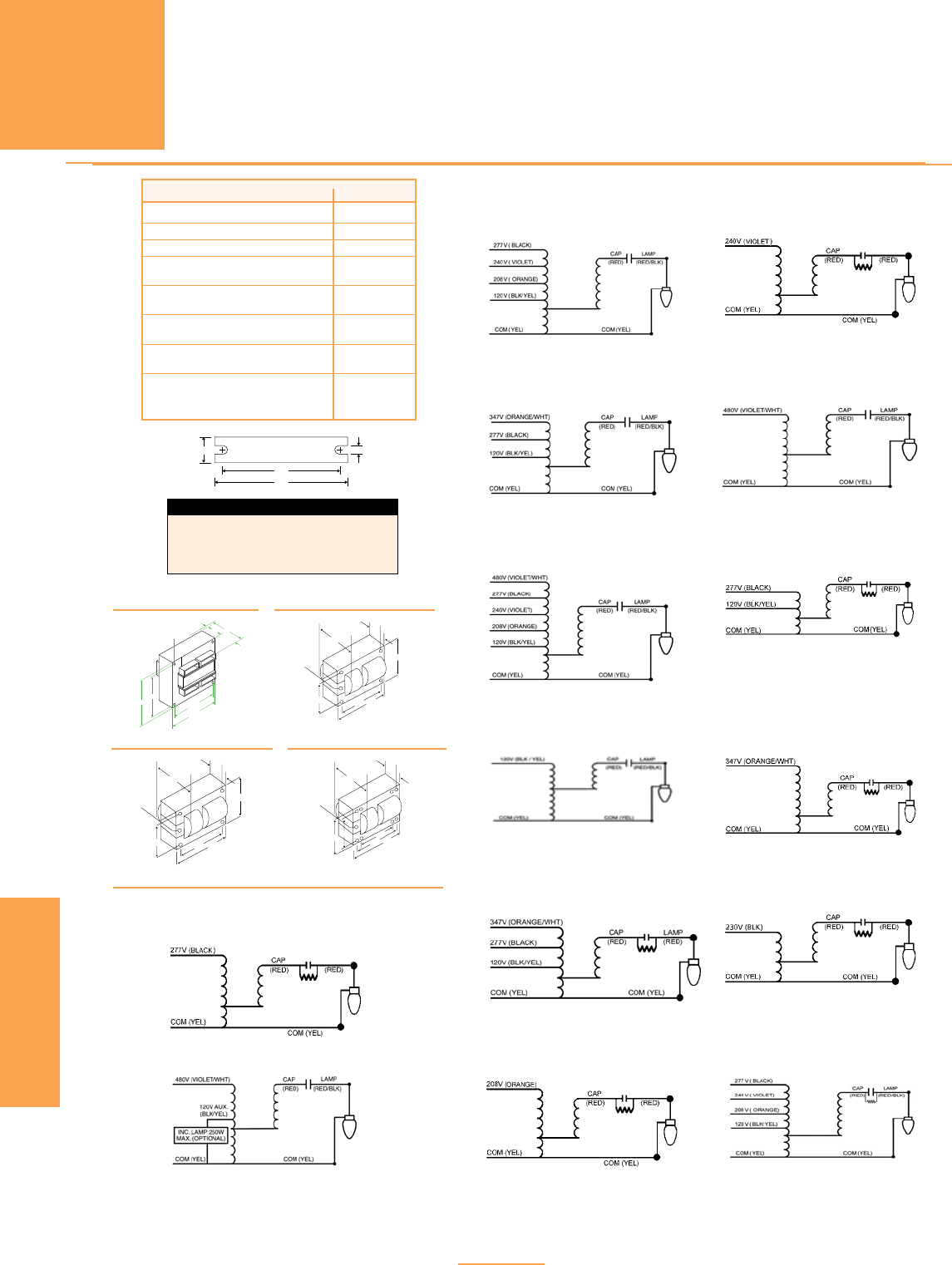
PAGE 5-22
MH
HID
CORE & COIL
FOR MORE INFORMATION CALL
1-800-BALLAST
(225-5278)
B
MAX
2 Holes Cleared
for #10 Thru-Bolts
8 Holes Cleared
for #10 Thru-Bolts
A
3.875˝
4.250˝4.375˝
5.375˝5.750˝
REFERENCE DRAWING PC3
DESCRIPTION SUFFIX *
For Ballast Only 000
For Bracket Only (see pg. 5-7) 200
For
Capacitor Only
(see pg. 5-5, 5-6)
500
For Distributor Replacement Kit
(see pg. 5-13 thru 5-15) 500K
For Canadian Distributor
Replacement Kit (see pg. 5-16) 502K
For Dry-Capacitor & Ballast
(see pg. 5-6) 518
For Bracket & Capacitor
(see pg. 5-5, 5-7) 700
For Bracket & Dry-Capacitor
(see pg. 5-6, 5-7) 718
BRef. Dwg. L W M S
1 4.00” 0.75” 3.35” 0.25”
PC1 5.25” 1.25” 4.60” 0.25”
PC2 7.75” 2.75” 6.10” 0.25”
PC3 7.75” 2.75” 6.10” 0.25”
M
L
WS
Bracket
See p. 5-7 for adjustable mounting brackets and detailed bracket drawings.
B
MAX
2 Holes Cleared
for #10 Thru-Bolts
4 Holes Cleared
for #10 Thru-Bolts
A
2.438˝
2.812
˝
3.500˝3.938˝
REFERENCE DRAWING PC1
B
MAX
2 Holes Cleared
for #10 Thru-Bolts
4 Holes Cleared
for #10 Thru-Bolts
A
3.875˝
4.250
˝
4.375˝4.750˝
REFERENCE DRAWING PC2
.203" Dia Thru
4 Holes 0.594"
0.438"
Reference Drawing
1
1.750"
.203" Dia Thru
4 Holes
2.625"
2.188"
0.594"
0.438"
0.438"
2.188"
AB
Reference Drawing
1-A
0.438"
Reference Drawing
2
.199" Dia Thru
4 Holes
.250" Dia Thru
2 Holes
.199" Dia Thru
4 Holes
.250" Dia Thru
2 Holes
Four 0.250" Male
Quick Connect
Blade Terminals
0.437"
0.812"
Reference Drawing
3
.218" Dia Thru
4 Holes
0.843"
0.656"
Reference Drawing
4
0.625"
Reference Drawing
5
.250" Dia Thru
4 Holes
Reference Drawing
6
0.637"
Reference Drawing
7
.250" Dia Thru
8 Holes
Reference Drawing
8
Reference Drawing
13
.218" Dia Thru
4 Holes
0.687"
Reference Drawing
14
0.625"
Reference Drawing
15
.250" Dia Thru
8 Holes
.250" Dia Thru
4 Holes
0.625"
Reference Drawing
16
.250" Dia Thru
2 Holes
.250" Dia Thru
2 Holes
.250" Dia Thru
2 Holes
.250" Dia Thru
2 Holes
0.625"
AB
.250" Dia Thru
8 Holes
.250" Dia Thru
2 Holes
.250" Dia Thru
8 Holes
Four 0.250"
Male Quick
Connect
Terminals
0.625"
.250" Dia Thru
2 Holes
B
A
2.188"
1.750"
2.625"
2.188"
2.437"
1.218"
2.812"
3.938"
3.500"
AB
B
A
3.500"
3.937"
2.812"
2.437"
1.218"
AB
3.125"
3.750"
3.125"
2.500"
2.937"
B
A
4.250"
3.875"
1.937"
5.750"
5.375"
4.375"
5.750"
5.375"
4.375"
4.250"
3.875"
1.937"
AB
.250" Dia Thru
4 Holes
Four 0.250"
Male Quick
Connect
Terminals
0.637"
.250" Dia Thru
2 Holes
B
A
4.250"
3.875"
1.937"
4.750"
4.375"
AB
4.750"
4.375"
4.250"
3.875"
1.937"
4.250"
3.875"
1.937"
5.750"
5.375"
4.375"
AB
1.062"
4.125"
3.437"
3.437"
3.437"
2.750"
4.250"
3.875"
1.937" 4.250"
3.875"
1.937"
5.750"
5.375"
4.375"
AB
4.750"
4.375"
A B
REFERENCE DRAWING 1
WIRING DIAGRAMS
Wiring Diagram 48
Wiring Diagram 17
Wiring Diagram 30
Wiring Diagram 42
Wiring Diagram 31
Wiring Diagram 32
Wiring Diagram 33Wiring Diagram 25
Wiring Diagram 28
Wiring Diagram 14
Wiring Diagram 46
Wiring Diagram 15
Wiring Diagram 16
Wiring Diagram 29
HID CORE & COIL BALLASTS
METAL HALIDE

PAGE 5-23
HID
CORE & COIL
PULSE START
MH
35/39-100 WATT
FOR MORE INFORMATION CALL
1-800-BALLAST
(225-5278)
HID CORE & COIL BALLASTS
PULSE START METAL HALIDE
• 60 Hz
• Minimum starting
temperature: -30° C
• Normal and High Power Factor
models available
3 Capacitors are available as an option for high power
factor operation. See page 5-23 for Reference
Drawings and Wiring Diagrams.
Nom Dimensions Capacitor Ignitor
Max Open Total Max UL
Input Catalog* Circuit Watts Input Circuit Fuse Wir Ref Min Dry Film Oil Filled Weight Catalog Distance Bench
Volts Number Type Input Current Voltage Rating Dia Dwg A B µF Volt Dia Ht Oval Ht (lbs.) Number
to lamp (ft)
Top Rise
(1) 35/39 WATT M130 METAL HALIDE LAMP
120 or .84 2
277 or M35TRILC3M HX-HPF 54 .40 235 1 4 PC1 0.85 2.15 5 300 1.26 2.36 1.31x2.16 2.2 1.7 MH100-3A 5 A
347 .30 1
120 or .82 2
208 or M35MLTLC3M HX-HPF 50 .48 230 1 3 PC1 0.85 2.0 5 277 1.26 2.83 1.31x2.16 2.2 1.7 MH100-3A 5 A
240 or .42 1
277 .36 1
(1) 50 WATT M110 METAL HALIDE LAMP — Medium Base
120 or 1.30 3
277 or M50TRILC3M HX-HPF 67 .61 250 2 5 PC1 1.05 2.55 6 300 1.26 2.83 1.31x2.16 2.2 4.25 MH100-3A 10 A
347 .48 2
120 or 1.16 3
208 or M50MLTLC3M HX-HPF 67 0.67 252 3 3 PC1 1.05 2.55 6 300 1.26 2.36 1.31x2.16 2.2 4.25 MH100-3A 10 A
240 or 0.57 2
277 0.50 2
(1) 70 WATT M98 METAL HALIDE LAMP - Medium Base
120 or 1.85 4
277 or
M70TRILC3M
HX-HPF 91 0.80 260 2 4 PC1 1.5 2.65 8 280 1.65 2.83 1.31x2.16 2.2 5.0 MH100-3A 10 A
347 0.65 2
120 or 1.70 4
208 or
M70MLTLC3M
HX-HPF
95 1.04 250 3 3 PC1 1.33 2.88 8 300 1.65 2.83 1.31x2.16 2.2 4.25 MH100-3A 10 B
240 or 0.87 3
277 0.78 2
480
M7048TLC3M HX-HPF 100 0.50 250 1 6 PC1 1.38 2.88 8 300 1.65 2.83 1.31x2.16 2.2 4.25 MH100-3A 10 E
(1) 70 WATT M85 METAL HALIDE LAMP - Double Ended
120 or 1.70 4
208 or M70MLTLC3D
HX-HPF 95 1.04 250 3
3 PC1 1.38 2.88 8 300 1.65 2.83 1.31x2.16 2.2 4.25 MH70-3B 10 B
240 or 0.87 3
277 0.78 2
(1) 100 WATT M90 OR M92 METAL HALIDE LAMP - Medium Base
120 or 2.50 7
277 or M100TRILC3M HX-HPF 125 1.10 265 3 4 PC1 1.6 2.95 12 280 1.65 2.83 1.31.2.16 3.13 5.5 MH100-3A 10 A
347 0.90 3
120 or
M100MLTLC3M HX-HPF 130
2.40
260
5
13 PC1 1.5 2.8 12 300 1.65 2.83 1.31x2.16 3.12 5.0 MH100-3A 10 A
208 or 1.45 4
240 or 1.20 3
277 1.00 3
480 M10048TLC3M HX-HPF 132 0.62 285 2 6 PC1 1.7 3.0 10 300 1.65 2.83 1.31x2.16 2.7 5.5 MH100-3A 10 C
(1) 100 WATT M91 METAL HALIDE LAMP - Double Ended
120 or
M100MLTLC3D HX-HPF 130
2.40
260
5
13 PC1 1.5 2.6 12 300 1.65 2.83 1.31x2.16 3.12 5.0 MH70-3B 10 A
208 or 1.45 4
240 or 1.20 3
277 1.00 3

HID CORE & COIL BALLASTS
PULSE START METAL HALIDE
• 60 Hz
• Minimum Starting
Temperature: -40° C
• Feature CWA Design
PAGE 5-24
PULSE START
MH
150-200 WATT
HID
CORE & COIL
Nom Dimensions Capacitor Ignitor
Max Open Total Max UL
Input Catalog* Circuit Watts Input Circuit Fuse Wir Ref Min Dry Film Oil Filled Weight Catalog Distance Bench
Volts Number Type Input Current Voltage Rating Dia Dwg A B µF Volt Dia Ht Oval Ht (lbs.) Number
to lamp (ft)
Top Rise
(1) 150 WATT M102/M142 METAL HALIDE LAMP - Medium Base
120 or 3.32 10
277 or M150TRILC3M HX-HPF 185 1.48 245 4 5 PC1 2.38 3.65 16 280 1.65 2.83 1.56x2.69 2.69 7.3 MH100-3A 10 D
347 0.65 2
120 or 3.32 10
208 or M150MLTLC3M HX-HPF 185 1.93 245 5 3 PC1 2.38 3.88 16 300 1.65 2.83 1.56x2.69 2.69 7.3 MH100-3A 10 A
240 or 1.66 5
277 1.48 4
120 or 1.50 4 C
208 or M150MLTAC3M CWA 188 0.90 210 3 9 PCI 2.5 3.75 16 330 1.65 3.82 n/a n/a 7.1 MH150-1A 10 D
240 or 0.75 3 C
277 0.65 2 C
480 M15048TLC3M HX-HPF 185 1.00 260 3 6 PC1 2.3 3.6 16 280 1.65 2.83 1.56x2.69 2.69 7.0 MH100-3A 10 F
(1) 150 WATT M81 METAL HALIDE LAMP - Double Ended
120 or 3.32 10
208 or
M150MLTLC3D HX-HPF 185 1.93 245 5 3 PC1 2.38 3.88 16 277 1.65 2.83 1.56x2.69 2.69 7.3 MH70-3B 10 D
240 or 1.66 5
277 1.48 4
(1) 175 WATT M152 METAL HALIDE PULSE START LAMP
277
P175277RCEM RX-NPF 199 1.50 277 3 1 RX1 2.3 3.4 12 300 n/a n/a n/a n/a 3.9 MH350-1A 10 C
RX-HPF 1.25 1.6 2.8 1.31x2.16 3.9
120 or 1.84 5
277 or P175TRIAC3M CWA 208 0.79 308 2 12 PC1 2.5 3.6 10 400 1.6 2.8 1.31x2.16 3.9 6.8 MH350-1 10 B
347 0.63 2
120 or 2.09 5
208 or P175MLTAC3M CWA 208 1.26 306 3 9 PC1 2.5 3.6 10 400 1.6 2.8 1.31x2.16 3.9 6.8 MH350-1A 10
240 or 1.02 3 A
277 0.96 2
120 or 1.95 5
208 or P175MLTAC3L CWA 198 1.10 285 3 9 PC1 3.10 4.20 11 370 1.65 2.83 n/a n/a 8.5 MH350-1A 2 A
240 or 1.00 3
277 0.80 2
120 or 1.70 5
208 or P175MLTAC4L CWA 198 0.95 270 3 9 PC2 1.77 3.3 12.5 330 1.55 2.83 n/a n/a 8.45 MH350-1A 10
240 or 0.85 3 A
277 0.75 2
120 or 1.80 5
208 or 1.05 3
240 or P175ML5AC3M CWA 210 0.90 295 3 26 PC1 2.6 4.0 10 400 1.6 2.8 2.7 2.7 8.0 MH350-1A 10 B
277 or 0.80 2
480 0.45 2
480 P17548TAC3L CWA 198 0.50 285 2 11 PC1 3.10 4.20 11 360 1.65 2.83 n/a n/a 8.5 MH350-1A 2 A
480
P17548TAC4L CWA 198 0.40 275 2 11 PC2 1.80 3.5 12.5 330 1.6 2.8 n/a n/a 9.6 MH350-1A 10 A
(1) 200 WATT M136 METAL HALIDE PULSE START LAMP
277
P200277RCEM RX-HPF 218 0.92 277 4 1 RX1 1.0 2.8 13 280 1.6 3.6 n/a n/a 4.7 MH350-1A 10 A
120 or 2.70 6
277 or P200TRIAC3M CWA 240 1.04 310 3 12 PC1 2.8 4.0 11 400 1.6 2.8 2.7 3.6 8.0 MH350-1A 10 C
347 0.87 3
120 or 2.66 6
208 or 1.52 4
240 or P200ML5AC3M CWA 233 1.31 303 3 26 PC1 2.7 4.0 11 400 1.6 2.7 n/a n/a 8.0 MH350-1A 10 C
277 or 1.12 3
480 0.68 2
480
P20048TAC3M CWA 232 0.50 305 2 11 PC1 2.8 4.1 11 400 1.6 2.8 1.56x2.69 2.7 8.5 MH350-1 10 C

PULSE START
MH
250-320 WATT
HID CORE & COIL BALLASTS
PULSE START METAL HALIDE
• 60 Hz
• Minimum Starting
Temperature: -40° C
• CWA and High Power
Factor Models Available
PAGE 5-25
HID
CORE & COIL
See page 5-29 for Reference
Drawings and Wiring Diagrams.
Nom Dimensions Capacitor Ignitor
Max Open Total Max UL
Input Catalog* Circuit Watts Input Circuit Fuse Wir Ref Min Dry Film Oil Filled Weight Catalog Distance Bench
Volts Number Type Input Current Voltage Rating Dia Dwg A B µF Volt Dia Ht Oval Ht (lbs.) Number
to lamp (ft)
Top Rise
(1) 250 WATT M153 METAL HALIDE PULSE START LAMP
277
P250277RCEM RX-NPF 278 2.00 5 1 RX1 1.0 2.8 17.5 300 n/a n/a n/a n/a 4.8 MH350-1A 10 A
RX-HPF 1.25 277 1.6 3.7 n/a n/a
120 or 2.61 8
277 or P250TRIAC4M CWA 300 1.28 292 3 12 PC2 1.4 3.4 14 400 1.6 3.7 2.3 4.0 9.0 MH350-1A 10 A
347 1.09 3
120 or 2.40 8
208 or P250MLTAC40 CWA 291 1.40 277 5 9 PC2 1.45 3.10 17 360 1.6 3.7 2.3 3.1 9.0 MH350-1A 10 A
240 or 1.20 5
277 1.05 3
120 or 2.50 8
208 or P250MLTAC4L CWA 283 1.50 270 5 9 PC2 2.05 3.65 17 360 1.65 3.82 2.3 3.1 10.9 MH350-1A 15 A
240 or 1.30 5
277 1.10 3
120 or 2.45 8
208 or 1.42 5
240 or P250ML5AC4M CWA 285 1.22 290 5 26 PC2 2.0 3.9 14 400 1.6 3.7 1.56x2.69 3.1 11.3 MH350-1A 10 A
277 or 1.05 3
480 0.62 2
120 or 2.45 8
208 or 1.42 5
240 or P250ML5AC4M CWA 285 1.22 290 5 26 PC2 2.0 3.9 14 400 1.6 3.7 1.56x2.69 3.1 11.3 MH350-1A 10 A
277 or 1.05 3
480
480 P25048TAC4L CWA 283 0.60 275 2 11 PC2 1.9 3.6 17 360 1.65 3.82 n/a n/a 10.0 MH350-1A 10 A
(1) 320 WATT M154 METAL HALIDE PULSE START LAMP
277
P320277RCEM RX-NPF 348 3.05 277 10 1 RX1 1.5 3.3 22.5 280 n/a n/a n/a n/a 6.8 MH350-1A 10 A
RX-HPF 1.51 6 1.8 3.6 n/a n/a
120 or 4.50 8
277 or P320TRIAC4M CWA 370 2.00 281 4 12 PC2 2.0 3.7 20.5 400 1.6 3.7 2.9 3.6 11.0 MH350-1A 10 C
347 1.50 3
120 or 3.10 9
208 or P320MLTAC40 CWA 364 1.80 275 5 9 PC2 2.0 3.9 21.0 360 1.85 3.82 2.9 3.6 11.0 MH350-1A 10 A
240 or 1.55 5
277 1.35 4
120 or 4.00 10
208 or 2.40 7
240 or P320ML5AC4M CWA 370 2.10 280 5 26 PC2 2.0 3.9 20.5 360 1.8 3.7 1.91x2.91 3.6 11.3 MH350-1A 10 D
277 or 1.85 5
480 1.06 3
120 or 4.00 10
208 or 2.40 7
240 or P320ML5AN4M CWA 405 2.10 282 5 26 PC2 2.0 3.86 20.5 360 1.85 3.82 1.75 3.1 11.3 MH350-1A 10 A
277 or 1.85 5
480 1.06 3
120 or 3.10 10
208 or 1.80 7
240 or P320ML5AC4L CWA 363 1.55 275 8 26 PC2 1.88 3.8 21 360 n/a n/a 2.91 3.13 12.0 MH350-1A 10 A
277 or 1.35 5
480 0.80 3
FOR MORE INFORMATION CALL
1-800-BALLAST
(225-5278)

FOR MORE INFORMATION CALL
1-800-BALLAST
(225-5278)
PAGE 5-26
HID CORE & COIL BALLASTS
PULSE START METAL HALIDE
• 60 Hz
• Minimum Starting
Temperature: -40° C
• Feature CWA Design
HID
CORE & COIL
See page 5-29 for Reference
Drawings and Wiring Diagrams.
PULSE START
MH
320-350 WATT
Nom Dimensions Capacitor Ignitor
Max Open Total Max UL
Input Catalog* Circuit Watts Input Circuit Fuse Wir Ref Min Dry Film Oil Filled Weight Catalog Distance Bench
Volts Number Type Input Current Voltage Rating Dia Dwg A B µF Volt Dia Ht Oval Ht (lbs.) Number
to lamp (ft)
Top Rise
(1) 350 WATT M131 METAL HALIDE PULSE START LAMP
120 or 3.10 8
208 or 1.80 5
240 or P320ML5AN4L CWA 363 1.55 275 5 26 PC2 1.88 3.8 21 360 1.85 3.82 n/a n/a 12.0 MH350-1A 10 A
277 or 1.35 4
480 0.80 3
480
P32048TAC4L CWA 364 0.80 280 3 11 PC2 2.0 3.9 21 360 1.85 3.82 n/a n/a 11.0 MH350-1A 10 A
277 P350277RCEM RX-NPF 377 3.80 277 8 1 RX1 1.5 3.3 22.5 300 — — — — 6.8 MH350-1 10 A
RX-HPF 2.34 n/a n/a 1.56x2.69 3.9
120 or 4.00 10
277 or P350TRIAC4M CWA 405 2.00 280 5 12 PC2 2.0 4.0 21 400 n/a n/a 2.9 3.1 11.5 MH350-1A 10 C
347 1.50 3
120 or 3.40 9
208 or P350MLTAC4M CWA 400 2.00 275 6 9 PC2 2.0 3.9 22 360 n/a n/a 2.7 3.9 11.0 MH350-1A 10 C
240 or 1.70 5
277 1.45 4
120 or
P350MLTAN4M CWA 400
2.40
275
9
47 PC2 2.0 3.9 22 360 n/a n/a 2.7 3.9 11.0 MH350-1A 10 A
208 or 2.00 6
240 or 1.70 5
277 1.45 4
120 or 4.22 10
208 or 2.49 7
240 or P350ML5AC4M CWA 405 2.16 282 5 26 PC2 2.0 3.9 21 400 n/a n/a 1.91x2.91 3.1 11.3 MH350-1A 10 D
277 or 1.87 5
480 1.09 3
120 or 4.22 10
208 or 2.49 7
240 or P350ML5AN4M CWA 405 2.16 282 5 26 PC2 2.0 3.9 21 400 n/a n/a 1.91x2.91 3.1 11.3 MH350-1A 10 D
277 or 1.87 5
480 1.09 3
120 or 3.35 10
208 or 1.90 7
240 or P350ML5AC4L CWA 397 1.65 275 9 26 PC2 1.88 3.8 22 360 1.85 3.82 2.69 3.9 12.0 MH350-1A 10 B
277 or 1.45 5
480 0.85 3
120 or 3.35 9
208 or 1.90 6
240 or P350ML5AN4L CWA 397 1.65 275 5 26 PC2 1.88 3.8 22 360 1.85 3.82 2.69 3.9 12.0 MH350-1A 10 A
277 or 1.45 4
480 0.85 3
480
P35048TAC4L CWA 397 0.85 280 3 11 PC2 2.00 3.9 22 360 1.85 3.82 2.69 3.9 11.0 MH350-1A 10 C

FOR MORE INFORMATION CALL
1-800-BALLAST
(225-5278)
HID CORE & COIL BALLASTS
PULSE START METAL HALIDE
PAGE 5-27
PULSE START
MH
400 WATT
• 60 Hz
• Minimum Starting
Temperature: -40° C
• CWA and High Power
Factor Models Available
HID
CORE & COIL
See page 5-29 for Reference
Drawings and Wiring Diagrams.
Nom Dimensions Capacitor Ignitor
Max Open Total Max UL
Input Catalog* Circuit Watts Input Circuit Fuse Wir Ref Min Dry Film Oil Filled Weight Catalog Distance Bench
Volts Number Type Input Current Voltage Rating Dia Dwg A B µF Volt Dia Ht Oval Ht (lbs.) Number
to lamp (ft)
Top Rise
(1) 400 WATT M135 METAL HALIDE PULSE START LAMP
120 or 4.40 10
277 or P400TRIAC4M CWA 457 2.01 287 5 12 PC2 2.0 3.8 24 400 1.8 3.6 2.9 3.1 11.0 MH350-1A 10 D
347 1.52 4
120 or 4.05 10
277 or P400TRIAN4M CWA 454 1.95 285 5 12 PC2 2.0 3.9 24 400 1.8 3.6 2.9 3.1 11.0 MH350-1A 10 D
347 1.40 4
120 or 3.90 10 B
208 or P400MLTAC4L CWA 454 2.25 280 7 9 PC2 2.30 4.20 26 330 1.85 3.82 n/a n/a 11 MH350-1A 10 B
240 or 1.95 5 B
277 1.70 5 C
120 or 4.00 10
208 or 2.40 7
240 or P400ML5AC4M CWA 457 2.10 286 5 26 PC2 2.0 3.9 24 400 1.8 3.7 1.91x2.91 3.1 11.3 MH350-1A 10 D
277 or 1.85 5
480 1.06 3
120 or 3.90 10
208 or 2.25 7
240 or P400ML5AN4M CWA 455 1.95 286 5 26 PC2 2.0 3.9 24 400 1.8 3.7 1.91x2.91 3.1 11.3 MH350-1A 10 D
277 or 1.70 5
480 0.95 3
480
P40048TAC4L CWA 455 1.00 275 3 11 PC2 2.3 4.2 28 330 1.85 3.82 n/a n/a 12 MH350-1A 10 D
480
P40048TAC4M CWA 457 1.00 285 3 11 PC2 2.0 3.9 24 400 1.8 3.6 3.7 3.1 11.3 MH350-1A 10 D

FOR MORE INFORMATION CALL
1-800-BALLAST
(225-5278)
HID CORE & COIL BALLASTS
PULSE START METAL HALIDE
• 60 Hz
• Minimum Starting
Temperature: -40° C
• CWA and High Power
Factor Models Available
PAGE 5-28
HID
CORE & COIL
PULSE START
MH
450-1000 WATT
See page 5-29 for Reference
Drawings and Wiring Diagrams.
Nom Dimensions Capacitor Ignitor
Max Open Total Max UL
Input Catalog* Circuit Watts Input Circuit Fuse Wir Ref Min Dry Film Oil Filled Weight Catalog Distance Bench
Volts Number Type Input Current Voltage Rating Dia Dwg A B µF Volt Dia Ht Oval Ht (lbs.) Number
to lamp (ft)
Top Rise
(1) 450 WATT M144 METAL HALIDE PULSE START LAMP
120 or 4.40 10
208 or
P450MLTAC4M
CWA 510 2.60 285 8 9 PC2 2.3 4.0 26.5 400 1.8 4.7 2.9 3.5 11.0 MH350-1A 10 C
240 or 2.20 7
277 1.90 5
120 or 4.44 10
208 or 2.56 8
240 or P450ML5AC4M CWA 510 2.38 305 7 26 PC2 2.6 4.7 26.5 400 1.8 4.7 1.91x2.91 3.9 12.0 MH350-1 10 D
277 or 1.92 5
480 1.22 4
480 P45048TAC4M CWA 511 1.40 305 10 11 PC2 2.7 4.7 26.5 400 0.8 4.6 2.9 3.5 12.0 MH350-1A 10 D
(1) 750 WATT M149 METAL HALIDE PULSE START LAMP
120 or 7.05 15 B
277 or P750TRIAC5M CWA 820 3.05 340 8 12 PC3 2.8 4.6 28 425 n/a n/a 2.91 3.9 18.0 P750-1B 10 C
347 2.45 8 C
120 or 7.10 18 D
208 or
P750MLTAC5M
CWA 825 4.10 340 10 9 PC3 2.8 4.8 28 400 n/a n/a 2.91 3.9 18.0 P750-1B 10 A
240 or 3.55 10 B
277 3.10 8 B
120 or 6.95 18 C
208 or 4.00 10 C
240 or P750ML5AC5M CWA 820 3.50 340 10 26 PC3 2.8 4.9 28 400 n/a n/a 2.9 3.9 19.0 P750-1B 16 D
277 or 3.00 8 D
480 1.75 5 C
480
P75048TAC5M CWA 822 1.80 335 5 11 PC3 2.8 4.8 28 400 n/a n/a 2.91 3.9 18.0 P750-1B 10 D
(1) 875 WATT M166 METAL HALIDE PULSE START LAMP
120 or 8.50 20 D
208 or
P875MLTAC5M
CWA 945 5.30 395 15 9 PC3 2.8 4.5 24 440 n/a n/a 2.9 3.9 17.5 HPS1000-48 10 C
240 or 4.30 10 A
277 3.80 10 C
120 or 8.05 20 E
208 or 4.65 12 C
240 or P875ML5AC5M CWA 950 4.05 395 10 26 PC3 2.8 4.8 24 440 n/a n/a 2.9 3.9 19.4 HPS1000-4B 10 B
277 or 3.50 10 C
480 2.00 5 C
(1) 1000 WATT M141 METAL HALIDE PULSE START LAMP
120 or 9.00 20
208 or
P1000MLTAC5M
CWA 1080 5.20 420 15 9 PC3 2.9 5.1 24 480 n/a n/a 2.9 3.9 22.0 HPS1000-4B 20 D
240 or 4.50 10
277 3.90 10
120 or 8.95 20 G
208 or 5.15 15 B
240 or P1000ML5AC5M CWA 1080 4.45 420 10 26 PC3 2.9 5.1 24 480 n/a n/a 2.9 3.9 22.0 HPS1000-4B 20 C
277 or 3.85 10 C
480 2.25 10 C
480
P100048TAC5M CWA 1080 2.55 410 10 11 PC3 2.8 4.8 24 480 n/a n/a 2.9 3.9 22.0 HPS1000-4B 15 D
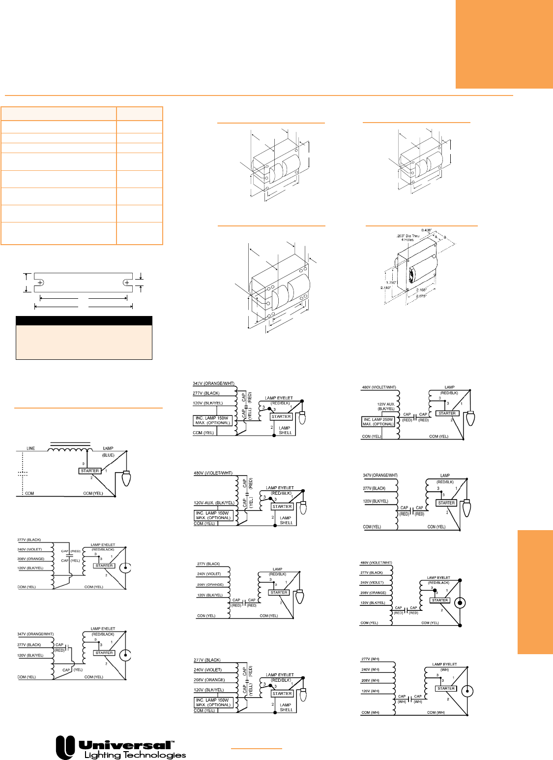
FOR MORE INFORMATION CALL
1-800-BALLAST
(225-5278)
HID CORE & COIL BALLASTS
PULSE START METAL HALIDE
PAGE 5-29
HID
CORE & COIL
PULSE START
MH
B
MAX
2 Holes Cleared
for #10 Thru-Bolts
4 Holes Cleared
for #10 Thru-Bolts
A
2.438˝
2.812
˝
3.500˝3.938˝
REFERENCE DRAWING PC1
REFERENCE DRAWING RX1
DESCRIPTION SUFFIX *
For Ballast Only 000
For Bracket Only (see pg. 5-7) 200
For
Capacitor Only
(see pg. 5-5, 5-6)
500
For Distributor Replacement Kit
(see pg. 5-13 thru 5-15) 500K
For Canadian Distributor
Replacement Kit (see pg. 5-16) 502K
For Dry-Capacitor & Ballast
(see pg. 5-6) 518
For Bracket & Capacitor
(see pg. 5-5, 5-7) 700
For Bracket & Dry-Capacitor
(see pg. 5-6, 5-7) 718
BRef. Dwg. L W M S
PC1 5.25” 1.25” 4.60” 0.25”
PC2 7.75” 1.25” 5.75” 0.25”
PC3 7.75” 2.75” 6.10” 0.25”
RX1 4.00” 0.75” 3.35” 0.25”
M
L
WS
Bracket
See p. 5-7 for adjustable mounting brackets and detailed bracket drawings.
B
MAX
2 Holes Cleared
for #10 Thru-Bolts
4 Holes Cleared
for #10 Thru-Bolts
A
3.875˝
4.250
˝
4.375˝4.750˝
REFERENCE DRAWING PC2
B
MAX
2 Holes Cleared
for #10 Thru-Bolts
8 Holes Cleared
for #10 Thru-Bolts
A
3.875˝
4.250˝4.375˝
5.375˝5.750˝
REFERENCE DRAWING PC3
Wiring Diagram 1
Wiring Diagram 47
Wiring Diagram 11
Wiring Diagram 26
Wiring Diagram 12
WIRING DIAGRAMS
Wiring Diagram 13
Wiring Diagram 3
Wiring Diagram 4
Wiring Diagram 6
Wiring Diagram 5
Wiring Diagram 9

FOR MORE INFORMATION CALL
1-800-BALLAST
(225-5278)
HID CORE & COIL BALLASTS
HIGH PRESSURE SODIUM
• 60 Hz
• Minimum Starting
Temperature: -40° C
• Normal and High Power
Factor Models
PAGE 5-30
HPS
35-100
WATT
1
Also can be used on a 277 volt line in conjuction with the step down transformers
3
Capacitors are available as an option for High Power Factor operation
◆
Ballast has built-in starter.
HID
CORE & COIL
See pages 5-34 and 5-35 for
Reference Drawings and Wiring Diagrams.
Nom Dimensions Capacitor Ignitor
Max Open Total Max UL
Input Catalog* Circuit Watts Input Circuit Fuse Wir Ref Min Dry Film Oil Filled Weight Catalog Distance Bench
Volts Number Type Input Current Voltage Rating Dia Dwg A B µF Volt Dia Ht Oval Ht (lbs.) Number
to lamp (ft)
Top Rise
(1) 35 WATT S76 HIGH PRESSURE SODIUM LAMP
1201 1233-251W ◆ R-HPF 3 43 0.65 120 2 2 1a 0.6 1.7 14 120 n/a n/a 1.56x2.69 2.7 1.5 HPS150-3A 3 A
Permanently Attached
120 S35120RCEM RX-NPF 44 0.85 120 2 1 5 0.6 1.7 14 240 — — 1.9 2.3 1.0 HPS150-3A 10 A
RX-HPF 0.63 3
(1) 50 WATT S68 HIGH PRESSURE SODIUM LAMP
1201 1233-35W ◆ R-HPF 3 60 0.90 120 5 2 1a 0.9 2.4 20 240 n/a n/a 1.56x2.69 3.1 2.0 HPS150-3A 3 A
Permanently Attached
120 S50120RCEM RX-NPF 60 1.12 120 8 1 5 0.8 2.0 20 240 — — 1.9 2.3 2.0 HPS150-3A 3 A
RX-HPF 0.90 5
120 or 1.24 5
208 or
S50MLTLC3M
HX-HPF 66 0.60 130 3 3 PC1 1.3 2.7 5 300 1.2 2.2 2.2 2.2 4.1 HPS150-3A 5 A
240 or 0.52 3
277 0.45 2
(1) 70 WATT S62 HIGH PRESSURE SODIUM LAMP
120 1233-142W ◆ R-HPF 83 1.30 120 5 2 1a 1.3 2.8 2.8 120 1.6 2.7 n/a n/a 2.5 HPS150-3A 3 A
Permanently Attached
120 S70120RCEM RX-NPF 80 1.60 120 8 1 RX1 1.1 2.8 28 240 n/a n/a 1.3 2.7 2.0 HPS150-3A 3 A
RX-HPF 1.30 4
230 S70230LC3M HX-HPF 88 1.00 120 2 35 PC1 1.9 3.2 10 280 1.6 2.7 1.3 2.7 5.7 HPS150-3A 3 A
120 or S7027TLC3M HX-HPF 98 1.50 120 5 36 PC1 1.3 2.8 7 300 n/a n/a 1.3 2.2 4.1 HPS150-3A 10 B
277 0.65 2
120 or 1.50 5
277 or S70TRILC3M HX-HPF 94 0.65 120 2 4 PC1 2.0 3.5 7 300 1.2 2.7 1.31x2.16 2.2 4.2 HPS150-3A 10 B
347 0.50 2
120 or 1.50 5
208 or
S70MLTLC3M
HX-HPF 98 0.88 120 3 3 PC1 1.3 2.8 7 300 1.2 2.8 1.31x2.16 2.2 4.2 HPS150-3A 10
240 or 0.75 3 B
277 0.65 2
480
S7048TLC3M HX-HPF 94 0.34 120 2 6 PC1 1.8 2.9 7 300 1.2 2.8 1.3 2.2 5.6 HPS150-3A 10 A
(1) 100 WATT S54 HIGH PRESSURE SODIUM LAMP
--
120 1 1233-10W ◆ R-HPF 3 117 1.80 120 8 2 1a 1.5 2.9 40 240 1.6 3.6 1.87 2.9 2.8 HPS150-3A 3 A
Permanently Attached
120 S100120RCEM RX-NPF 115 2.24 120 10 1 5 1.50 2.8 40 240 — — 1.8 2.7 2.0 HPS150-3A 10 A
RX-HPF 112 1.81 8
120 or S10027TLC3M HX-HPF 122 2.20 120 3 36 PC1 2.0 3.4 10 330 1.6 2.7 1.3 2.7 5.9 HPS150-3A 10 B
277 0.95 2
120 or 2.20 8
277 or
S100TRILC3M
HX-HPF 130 0.95 120 3 5 PC1 2.0 3.5 10 330 1.2 2.7 1.31x2.16 2.7 5.9 HPS150-3A 10 B
347 0.69 2
120 or 2.20 8
208 or
S100MLTLC3M
HX-HPF 122 1.30 120 5 3 PC1 2.0 3.4 10 330 1.2 2.7 2.2 2.7 6.0 HPS150-3A 10 B
240 or 1.10 5
277 0.95 3
480
S10048TLC3M HX-HPF 135 0.57 120 2 6 PC1 2.0 3.3 10 277 1.6 2.8 1.3 2.2 6.2 HPS150-3A 5 E

* Also can be used on a 277 volt line in conjunction with
the step-down transformers described on page 5-53.
3 Capacitors are available as an option for high power
factor operation.
◆ Ballast has built-in starter.
HID CORE & COIL BALLASTS
HIGH PRESSURE SODIUM
• 60 Hz
• Minimum Starting
Temperature: -40° C
• CWA, Normal and High Power
Factor Models
PAGE 5-31
HPS
150-250
WATT
HID
CORE & COIL
See pages 5-34 and 5-35 for
Reference Drawings and Wiring Diagrams.
Nom Dimensions Capacitor Ignitor
Max Open Total Max UL
Input Catalog* Circuit Watts Input Circuit Fuse Wir Ref Min Dry Film Oil Filled Weight Catalog Distance Bench
Volts Number Type Input Current Voltage Rating Dia Dwg A B µF Volt Dia Ht Oval Ht (lbs.) Number
to lamp (ft)
Top Rise
(1) 150 WATT S55 HIGH PRESSURE SODIUM LAMP
1201 1233-154W ◆ R-HPF 3 171 2.40 120 8 2 1a 2.0 3.4 52 240 1.8 3.0 2.12 2.9 3.5 HPS150-3A 3 A
Permanently Attached
120 S150120RCEM RX-NPF 168 4.40 120 5 1 5 2.0 3.1 15 240 n/a n/a 2.0 2.9 3.3 HPS150-3A 3 A
RX-HPF 2.35
208
S150208LC3M HX-HPF 190 0.95 120 5 37 PC1 2.3 3.8 14 300 n/a n/a 1.5 2.7 7.0 HPS150-3A 10 C
120 or
S15027TLC3M HX-HPF 295
1.90
185
10
36 PC1
2.5 3.9 14 280 n/a n/a 2.7 2.7 7.0 HPS150-3A 10
B
277
0.80
5 A
120 or 3.00 10 B
277 or
S150T
RILC3M HX-HPF 188 1.35 120 5 5 PC1 2.3 3.7 14 300 1.6 2.8 1.56x2.69 2.7 7.0 HPS150-3A 10 C
347 1.00 4 B
120
or
1.90 10 B
208
or
S150MLTLC3M
HX-HPF 188 1.00 120 5 3 PC1 2.5 3.9 14 280 1.6 2.8 2.7 2.7 7.0 HPS150-3A 10 A
240
or
0.95 5 B
277 0.80 5 A
480
S15048TLC3M
HX-HPF 189 0.72 120 3 6 PC1 3.0 4.5 14 277 1.6 2.7 1.56x2.69 2.7 8.7 HPS150-3A 10 D
(1) 150 WATT S56 HIGH PRESSURE SODIUM LAMP
120 1.65 5
208
S150MLTAC3M
CWA 188 1.50 210 3 9 PC1 2.5 3.9 20 240 1.6 3.6 n/a n/a 8.0 HPS150-3A 10 D
240 0.85 3
277 0.75 3
(1) 200 WATT S66 HIGH PRESSURE SODIUM LAMP
240 1233-183S R-NPF 225 2.80 240 8 1 4 1.5 3.0 — — — — — — 5.3 HPS450-1B 5 A
R-HPF 3 2.00 3 22.5 240 n/a n/a 1.56X2.69 3.5
120 2.00 7
277 S200TRIAC4M CWA 233 0.86 184 3 12 PC2 1.4 3.3 28 280 n/a n/a 1.91x2.91 3.1 8.7 HPS400-3A 10 C
347 0.68 3
120 or 2.10 7
208 or S200MLTAC4M CWA 230 1.20 175 4 9 PC2 1.2 3.0 28 300 1.8 3.7 1.91X2.91 3.1 8.5 HPS400-3A 10
240 or 1.00 4 B
277 0.88 3
480 S20048TAC4M CWA 240 0.56 172 2 34 PC2 2.0 3.8 28 280 1.6 4.6 1.7 3.1 11.0 HPS400-3A 10 C
(1) 250 WATT S50 HIGH PRESSURE SODIUM LAMP
240 1233-24S R-NPF 278 3.50 240 10 1 4 2.0 3.5 — — — — — — 6.8 HPS450-1B 5 A
R-HPF 2.50 5 28 240 n/a n/a 1.87 2.3
120 S250120AC4M CWA 295 2.50 185 8 38 PC2 1.8 3.7 35 330 n/a n/a 1.8 3.1 10.3 HPS400-3A 10 A
230 S250230AC4M CWA 280 1.24 188 5 39 PC2 1.7 3.6 40 300 n/a n/a 1.8 3.9 10.3 HPS400-3A 3 B
240 S250240AC4M CWA 295 1.20 185 4 40 PC2 1.8 3.7 35 330 n/a n/a 1.8 3.1 10.3 HPS400-3A 10 A
120 2.50 8
277 S250TRIAC4M CWA 300 1.20 190 4 12 PC2 1.7 3.8 35 330 1.6 3.7 1.91x2.91 3.1 10.3 HPS400-3A 10 C
347 1.00 3
120 2.50 8
208 S250MLTAC4M CWA 295 1.40 190 5 9 PC2 1.8 3.7 35 330 1.6 3.7 1.91x2.91 3.1 10.3 HPS400-3A 10 A
240 1.20 4
277 1.10 4
120 2.50 8
208 1.40 5
240 S250ML5AC4M CWA 300 1.20 200 4 26 PC2 2.0 3.8 35 330 1.6 3.7 1.91x2.91 3.1 14.0 HPS400-3A 10 A
277 1.10 4
480 0.60 2
480 S250480AC4M CWA 285 0.62 200 2 39 PC2 1.8 3.7 35 280 1.8 4.6 n/a n/a 10.4 HPS400-3A 5 A
480 S25048TAC4M CWA 285 0.62 200 2 11 PC2 1.8 3.7 35 280 1.6 3.7 1.91x2.91 3.1 10.4 HPS400-3A 5 A

FOR MORE INFORMATION CALL
1-800-BALLAST
(225-5278)
HID CORE & COIL BALLASTS
HIGH PRESSURE SODIUM-
FEATURING MULTI-5™
• 60 Hz
• Minimum Starting
Temperature: -40° C
• CWA, Normal and High Power
Factors Models Available
PAGE 5-32
HPS
400-430
WATTS
3 Capacitors are available as an option for high power
factor operation.
HID
CORE & COIL
See pages 5-34 and 5-35 for
Reference Drawings and Wiring Diagrams.
Nom Dimensions Capacitor Ignitor
Max Open Total Max UL
Input Catalog* Circuit Watts Input Circuit Fuse Wir Ref Min Dry Film Oil Filled Weight Catalog Distance Bench
Volts Number Type Input Current Voltage Rating Dia Dwg A B µF Volt Dia Ht Oval Ht (lbs.) Number
to lamp (ft)
Top Rise
(1) 400 WATT S51 HIGH PRESSURE SODIUM LAMP - 4 3/4” Frame
230 S400230AC4M CWA 465 2.05 190 8 39 PC2 2.5 4.3 64 300 n/a n/a 1.8 3.2 15.5 HPS400-3A 10 D
277 S400277AC4M CWA 460 1.70 192 5 41 PC2 2.32 4.1 55 240 1.8 4.6 1.8 3.9 14.0 HPS400-3A 10 D
120 or 3.95 10
277 or
S400TRIAC4M
CWA 465 1.70 192 5 12 PC2 2.32 4.1 55 240 1.8 3.7 1.91x2.91 3.5 14.0 HPS400-3A 10 D
347 1.35 4
120 or 3.80 10
208 or
S400MLTAC4M
CWA 463 2.20 190 6 9 PC2 2.32 4.1 55 240 1.8 3.7 1.91x2.91 3.5 14.0 HPS400-3A 10 D
240 or 1.80 5
277 1.70 5
120 or 3.95 10
208 or 2.30 6
240 or
S400ML5AC4M
CWA 465 2.00 190 5 26 PC2 2.44 4.3 55 240 1.8 3.7 1.91x2.91 3.5 14.0 HPS400-3A 10 D
277 or 1.70 5
480 1.00 3
480 S400480AC4M CWA 464 1.00 190 3 11 PC2 2.32 4.1 55 240 1.8 4.6 1.8 3.9 14.0 HPS400-3A 10 D
480
S40048TAC4M CWA 464 1.00 190 3 11 PC2 2.32 4.1 55 240 1.8 3.7 1.91x2.91 3.5 14.0 HPS400-3A 10 D
(1) 400 WATT S51 HIGH PRESSURE SODIUM LAMP - 5 3/4” Frame
120 or 3.90 10
277 or S400TRIAC5M CWA 467 1.70 200 5 12 PC2 2.2 4.1 48 280 2.0 4.7 1.91x2.91 3.9 16.0 HPS400-3A 10 E
347 1.35 4
120 or 3.95 10
208 or
S400MLTAC5M CWA 470 2.30 200 6 9 PC3 2.25 4.1 48 280 2.0 4.7 1.91x2.91 3.9 16.0 HPS400-3A 10 D
240
or
2.00 5
277 1.70 5
120 or 4.00 10
208 or 2.30 6
240 or S400ML5AC5M CWA 468 2.00 200 5 26 PC3 2.5 4.5 48 300 2.0 4.7 1.91x2.91 3.9 17.5 HPS400-3A 10 D
277 or 1.75 5
480 1.00 3
480
S40048TAC5M CWA 467 1.00 200 3 11 PC3 2.25 4.1 48 280 2.0 4.7 1.91x2.91 3.9 16.0 HPS400-3A 10 D
(1) 430 WATT SON AGRO HIGH PRESSURE SODIUM LAMP
120 or 4.50 10
208 or
S430MLTAC4M CWA 490 2.50 205 8 9 PC2 2.2 4.3 48 330 2.0 4.7 1.91x2.91 3.9 11.0 HPS400-3A 10 D
240
or
2.10 7
277 1.80 5

FOR MORE INFORMATION CALL
1-800-BALLAST
(225-5278)
HID CORE & COIL BALLASTS
HIGH PRESSURE SODIUM
• 60 Hz
• Minimum starting
temperature: -40° C
• CWA models available
PAGE 5-33
HID
CORE & COIL
HPS
600-1000
WATT
See pages 5-34 and 5-35 for
Reference Drawings and Wiring Diagrams.
Nom Dimensions Capacitor Ignitor
Max Open Total Max UL
Input Catalog* Circuit Watts Input Circuit Fuse Wir Ref Min Dry Film Oil Filled Weight Catalog Distance Bench
Volts Number Type Input Current Voltage Rating Dia Dwg A B µF Volt Dia Ht Oval Ht (lbs.) Number
to lamp (ft)
Top Rise
(1) 600 WATT S106 HIGH PRESSURE SODIUM LAMP
120 or 5.10 20
208 or
S600MLTAC5M
CWA 640 3.10 240 15 9 PC3 3.0 5.0 55 300 1.8 4.7 1.91x2.91 3.9 21.0 HPS600-1B 10 A
240 or 2.70 10
277 2.35 10
(1) 1000 WATT S52 HIGH PRESSURE SODIUM LAMP
220
or
5.15 15
230
or
S1000230AC5M CWA 1100 5.00 405 15 39 PC3 4.0 5.8 36 540 n/a n/a 3.66 4.25 25.5
HPS1000-4B
10 D
240 4.80 15
120 or S100024TAC5M CWA 1100 9.50 440 20 40 PC3 3.7 5.7 26 525 n/a n/a 1.8 4.3 26.0 HPS1000-4B 10 C
240 4.80 10
120
or
9.60 20
277
or
S1000TRIAC5M CWA 1100 4.30 440 10 12 PC3 3.8 5.8 26 525 n/a n/a 1.9 2.9 27.0
HPS1000-4B
15 D
347 3.40 10
120
or
9.50 20
208
or
S1000MLTAC5M
CWA 1100 5.50 440 15 9 PC3 3.7 5.7 26 525 n/a n/a 1.91x2.91 4.3 26.0
HPS1000-4B
15 C
240
or
4.80 10
277 4.20 10
120
or
9.10 20
208
or
5.40 15
240
or
S1000ML5AC5M CWA 1048 4.60 440 10 26 PC3 3.7 5.6 26 480 n/a n/a 1.91x2.91 4.3 26.0 HPS1000-4B 15 D
277
or
4.10 10
480 2.45 8
480 S1000480AC5M CWA 1100 2.45 440 8 11 PC3 3.7 6.0 26 500 n/a n/a 1.8 4.3 25.0 HPS1000-4B 15 D
480 S100048TAC5M CWA 1100 2.45 440 8 11 PC3 3.7 6.0 26 525 n/a n/a 1.91x2.91 4.3 25.0
HPS1000-4B
15 D
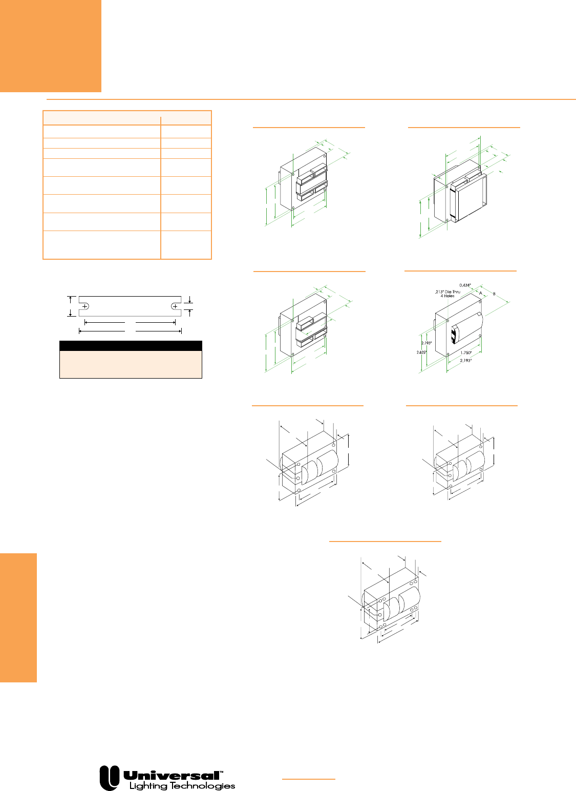
FOR MORE INFORMATION CALL
1-800-BALLAST
(225-5278)
HID CORE & COIL BALLASTS
HIGH PRESSURE SODIUM
PAGE 5-34
HPS
DESCRIPTION SUFFIX *
For Ballast Only 000
For Bracket Only (see pg. 5-7) 200
For
Capacitor Only
(see pg. 5-5, 5-6)
500
For Distributor Replacement Kit
(see pg. 5-13 thru 5-15) 500K
For Canadian Distributor
Replacement Kit (see pg. 5-16) 502K
For Dry-Capacitor & Ballast
(see pg. 5-6) 518
For Bracket & Capacitor
(see pg. 5-5, 5-7) 700
For Bracket & Dry-Capacitor
(see pg. 5-6, 5-7) 718
BRef. Dwg. L W M S
1, 1a, 5 4.00” 0.75” 3.35” 0.25”
PC1, 4 5.25” 1.25” 4.60” 0.25”
PC2, PC3 7.75” 1.25” 5.75” 0.25”
M
L
WS
Bracket
See p. 5-7 for adjustable mounting brackets and detailed bracket drawings.
.203" Dia Thru
4 Holes 0.594"
0.438"
Reference Drawing
1
1.750"
.203" Dia Thru
4 Holes
2.625"
2.188"
0.594"
0.438"
0.438"
2.188"
AB
Reference Drawing
1-A
0.438"
Reference Drawing
2
.199" Dia Thru
4 Holes
.250" Dia Thru
2 Holes
.199" Dia Thru
4 Holes
.250" Dia Thru
2 Holes
Four 0.250" Male
Quick Connect
Blade Terminals
0.437"
0.812"
Reference Drawing
3
.218" Dia Thru
4 Holes
0.843"
0.656"
Reference Drawing
4
0.625"
Reference Drawing
5
.250" Dia Thru
4 Holes
Reference Drawing
6
0.637"
Reference Drawing
7
.250" Dia Thru
8 Holes
Reference Drawing
8
Reference Drawing
13
.218" Dia Thru
4 Holes
0.687"
Reference Drawing
14
0.625"
Reference Drawing
15
.250" Dia Thru
8 Holes
.250" Dia Thru
4 Holes
0.625"
Reference Drawing
16
.250" Dia Thru
2 Holes
.250" Dia Thru
2 Holes
.250" Dia Thru
2 Holes
.250" Dia Thru
2 Holes
0.625"
AB
.250" Dia Thru
8 Holes
.250" Dia Thru
2 Holes
.250" Dia Thru
8 Holes
Four 0.250"
Male Quick
Connect
Terminals
0.625"
.250" Dia Thru
2 Holes
B
A
2.188"
1.750"
2.625"
2.188"
2.437"
1.218"
2.812"
3.938"
3.500"
AB
B
A
3.500"
3.937"
2.812"
2.437"
1.218"
AB
3.125"
3.750"
3.125"
2.500"
2.937"
B
A
4.250"
3.875"
1.937"
5.750"
5.375"
4.375"
5.750"
5.375"
4.375"
4.250"
3.875"
1.937"
AB
.250" Dia Thru
4 Holes
Four 0.250"
Male Quick
Connect
Terminals
0.637"
.250" Dia Thru
2 Holes
B
A
4.250"
3.875"
1.937"
4.750"
4.375"
AB
4.750"
4.375"
4.250"
3.875"
1.937"
4.250"
3.875"
1.937"
5.750"
5.375"
4.375"
AB
1.062"
4.125"
3.437"
3.437"
3.437"
2.750"
4.250"
3.875"
1.937" 4.250"
3.875"
1.937"
5.750"
5.375"
4.375"
AB
4.750"
4.375"
A B
REFERENCE DRAWING 1
.203" Dia Thru
4 Holes 0.594"
0.438"
Reference Drawing
1
1.750"
.203" Dia Thru
4 Holes
2.625"
2.188"
0.594"
0.438"
0.438"
2.188"
AB
Reference Drawing
1-A
0.438"
Reference Drawing
2
.199" Dia Thru
4 Holes
.250" Dia Thru
2 Holes
.199" Dia Thru
4 Holes
.250" Dia Thru
2 Holes
Four 0.250" Male
Quick Connect
Blade Terminals
0.437"
0.812"
Reference Drawing
3
.218" Dia Thru
4 Holes
0.843"
0.656"
Reference Drawing
4
0.625"
Reference Drawing
5
.250" Dia Thru
4 Holes
Reference Drawing
6
0.637"
Reference Drawing
7
.250" Dia Thru
8 Holes
Reference Drawing
8
Reference Drawing
13
.218" Dia Thru
4 Holes
0.687"
Reference Drawing
14
0.625"
Reference Drawing
15
.250" Dia Thru
8 Holes
.250" Dia Thru
4 Holes
0.625"
Reference Drawing
16
.250" Dia Thru
2 Holes
.250" Dia Thru
2 Holes
.250" Dia Thru
2 Holes
.250" Dia Thru
2 Holes
0.625"
AB
.250" Dia Thru
8 Holes
.250" Dia Thru
2 Holes
.250" Dia Thru
8 Holes
Four 0.250"
Male Quick
Connect
Terminals
0.625"
.250" Dia Thru
2 Holes
B
A
2.188"
1.750"
2.625"
2.188"
2.437"
1.218"
2.812"
3.938"
3.500"
AB
B
A
3.500"
3.937"
2.812"
2.437"
1.218"
AB
3.125"
3.750"
3.125"
2.500"
2.937"
B
A
4.250"
3.875"
1.937"
5.750"
5.375"
4.375"
5.750"
5.375"
4.375"
4.250"
3.875"
1.937"
AB
.250" Dia Thru
4 Holes
Four 0.250"
Male Quick
Connect
Terminals
0.637"
.250" Dia Thru
2 Holes
B
A
4.250"
3.875"
1.937"
4.750"
4.375"
AB
4.750"
4.375"
4.250"
3.875"
1.937"
4.250"
3.875"
1.937"
5.750"
5.375"
4.375"
AB
1.062"
4.125"
3.437"
3.437"
3.437"
2.750"
4.250"
3.875"
1.937" 4.250"
3.875"
1.937"
5.750"
5.375"
4.375"
AB
4.750"
4.375"
A B
REFERENCE DRAWING 1a
B
MAX
2 Holes Cleared
for #10 Thru-Bolts
4 Holes Cleared
for #10 Thru-Bolts
A
2.438˝
2.812
˝
3.500˝3.938˝
REFERENCE DRAWING PC1
.203" Dia Thru
4 Holes 0.594"
0.438"
Reference Drawing
1
1.750"
.203" Dia Thru
4 Holes
2.625"
2.188"
0.594"
0.438"
0.438"
2.188"
AB
Reference Drawing
1-A
0.438"
Reference Drawing
2
.199" Dia Thru
4 Holes
.250" Dia Thru
2 Holes
.199" Dia Thru
4 Holes
.250" Dia Thru
2 Holes
Four 0.250" Male
Quick Connect
Blade Terminals
0.437"
0.812"
Reference Drawing
3
.218" Dia Thru
4 Holes
0.843"
0.656"
Reference Drawing
4
0.625"
Reference Drawing
5
.250" Dia Thru
4 Holes
Reference Drawing
6
0.637"
Reference Drawing
7
.250" Dia Thru
8 Holes
Reference Drawing
8
Reference Drawing
13
.218" Dia Thru
4 Holes
0.687"
Reference Drawing
14
0.625"
Reference Drawing
15
.250" Dia Thru
8 Holes
.250" Dia Thru
4 Holes
0.625"
Reference Drawing
16
.250" Dia Thru
2 Holes
.250" Dia Thru
2 Holes
.250" Dia Thru
2 Holes
.250" Dia Thru
2 Holes
0.625"
AB
.250" Dia Thru
8 Holes
.250" Dia Thru
2 Holes
.250" Dia Thru
8 Holes
Four 0.250"
Male Quick
Connect
Terminals
0.625"
.250" Dia Thru
2 Holes
B
A
2.188"
1.750"
2.625"
2.188"
2.437"
1.218"
2.812"
3.938"
3.500"
AB
B
A
3.500"
3.937"
2.812"
2.437"
1.218"
AB
3.125"
3.750"
3.125"
2.500"
2.937"
B
A
4.250"
3.875"
1.937"
5.750"
5.375"
4.375"
5.750"
5.375"
4.375"
4.250"
3.875"
1.937"
AB
.250" Dia Thru
4 Holes
Four 0.250"
Male Quick
Connect
Terminals
0.637"
.250" Dia Thru
2 Holes
B
A
4.250"
3.875"
1.937"
4.750"
4.375"
AB
4.750"
4.375"
4.250"
3.875"
1.937"
4.250"
3.875"
1.937"
5.750"
5.375"
4.375"
AB
1.062"
4.125"
3.437"
3.437"
3.437"
2.750"
4.250"
3.875"
1.937" 4.250"
3.875"
1.937"
5.750"
5.375"
4.375"
AB
4.750"
4.375"
A B
REFERENCE DRAWING 4 REFERENCE DRAWING 5
B
MAX
2 Holes Cleared
for #10 Thru-Bolts
8 Holes Cleared
for #10 Thru-Bolts
A
3.875˝
4.250˝4.375˝
5.375˝5.750˝
REFERENCE DRAWING PC3
B
MAX
2 Holes Cleared
for #10 Thru-Bolts
4 Holes Cleared
for #10 Thru-Bolts
A
3.875˝
4.250
˝
4.375˝4.750˝
REFERENCE DRAWING PC2
HID
CORE & COIL
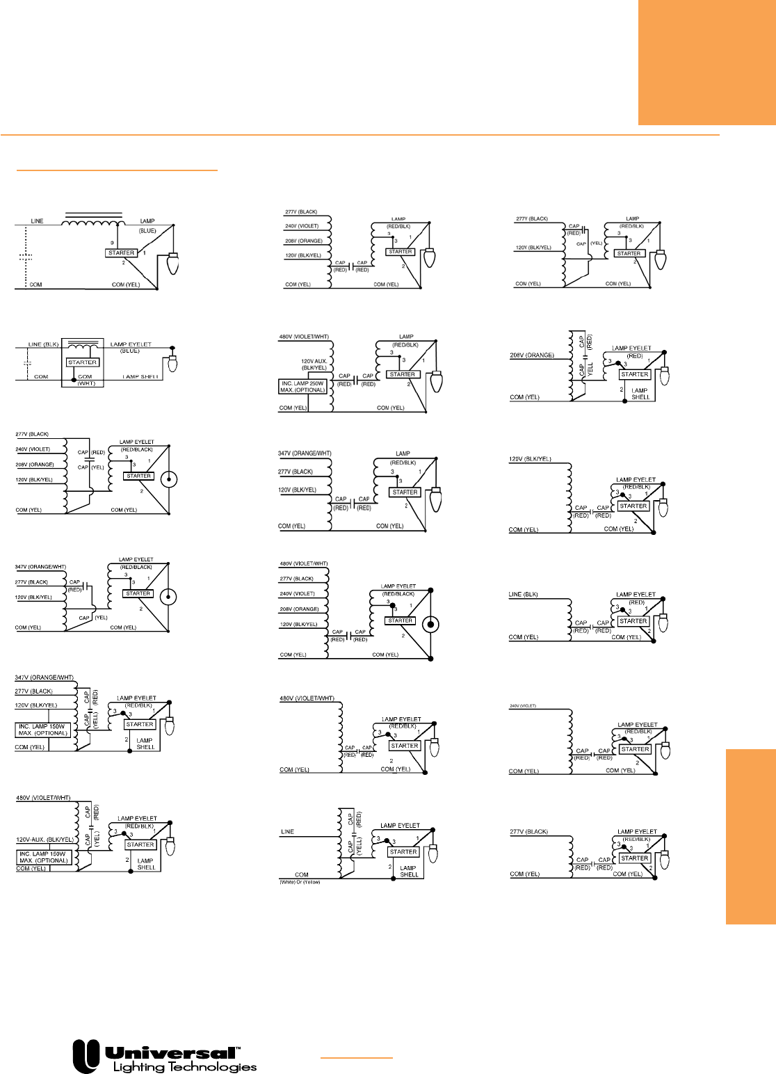
FOR MORE INFORMATION CALL
1-800-BALLAST
(225-5278)
HID CORE & COIL BALLASTS
HIGH PRESSURE SODIUM
PAGE 5-35
HID
CORE & COIL
HPS
Wiring Diagram 1
Wiring Diagram 2
Wiring Diagram 3
Wiring Diagram 4
Wiring Diagram 5
Wiring Diagram 6
Wiring Diagram 9
Wiring Diagram 37
Wiring Diagram 38
Wiring Diagram 39
Wiring Diagram 40
Wiring Diagram 41
Wiring Diagram 11
Wiring Diagram 26
Wiring Diagram 34
Wiring Diagram 35
Wiring Diagram 36
Wiring Diagram 12
WIRING DIAGRAMS

HID CORE & COIL BALLASTS
50 HERTZ
• 50 Hz
• Minimum Starting
Temperature: -40° C
• CWA, Normal and High Power
factor models available
PAGE 5-36
HID
CORE & COIL 50 HERTZ
MH & HPS
50 HZ
See page 5-37 for Reference Drawings and
Wiring Diagrams.
Nom Dimensions Capacitor Ignitor UL
Max Open Total Max
Bench
Input Catalog* Circuit Input Input Circuit Fuse Wir Ref Min Dry Film Oil Filled Wt. Catalog Dist. Top
Volts Number Type Watts Curr. Volt.
Rating
Dia Dwg A B
µF
Volt Dia Ht Oval Ht (lbs.)
Number
lamp Rise
(1) 175 WATT M57 METAL HALIDE LAMP
230 M175230AC3M CWA 205 1.17 312 2 14 PC1 2.25 3.55 12 400 1.56 3.74 1.5 3.13 6.7 n/a n/a C
(1) 250 WATT M58 METAL HALIDE LAMP
230 M250230AC3M CWA 282 1.55 285 3 14 PC1 3.0 4.3 18 400 n/a n/a 2.01x3.01 3.1 9.0 n/a n/a D
(1) 400 WATT M59 METAL HALIDE LAMP
230 M400230AC4M CWA 435 2.44 300 5 14 PC2 2.13 3.73 28 425 n/a n/a 1.91x2.91 3.9 13.0 n/a n/a D
(1) 1000 WATT M47 METAL HALIDE LAMP
230 M1000230AC5M CWA 1080 5.33 405 15 14 PC3 3.44 5.24 30 440 n/a n/a 2.01x3.01 3.9 24.0 n/a n/a C
(1) 1500 WATT M48 METAL HALIDE LAMP
230 M1500230AC5M CWA 1605 7.29 430 20 14 PC3 4.38 6.18
42(2x21)
480
n/a n/a 1.97x3.66 3.9 30 n/a n/a C
(1) 200 WATT S66 HIGH PRESSURE SODIUM LAMP
240 1238-183S R-NPF 225 2.90 240 8 1 4 1.5 3.0 — — — — — — 5.4 HPS460-1B 10 D
R-HPF 2.06 3 28 240 n/a n/a 1.91x2.91 3.1
(1) 250 WATT S50
HIGH PRESSURE SODIUM LAMP
230 1238-133S R-NPF 278 3.60 230 10 1 4 2.0 3.5 — — — — — — 7.1 HPS460-1B 10 A
R-HPF 2.50 5 35 240 1.8 4.6 n/a n/a
230 S250230AC4M CWA 280 1.38 188 5 8 PC2 1.78 3.58 40 300 n/a n/a 2.01x3.01 3.9 10.3 HPS400-3A 3 B
(1) 400 WATT S51 HIGH PRESSURE SODIUM LAMP (continued)
230 S400230AC4M CWA 465 2.26 190 8 10 PC2 2.5 4.3 64 300 n/a n/a 1.91x2.91 3.1 15.5 HPS400-3A 3 D
(1) 1000 WATT S52 HIGH PRESSURE SODIUM LAMP
230 S1000230AC5M CWA 1100 5.44 405 15 39 PC3 4.0 5.8 36 540 n/a n/a 1.96x3.65 4.25 25.5 HPS1000-4B 10 D
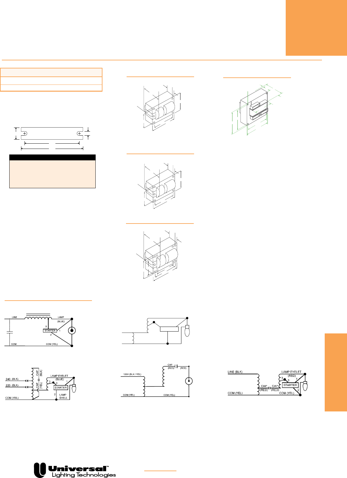
FOR MORE INFORMATION CALL
1-800-BALLAST
(225-5278)
HID CORE & COIL BALLASTS
50 HERTZ
PAGE 5-37
HID
CORE & COIL 50 HERTZ
50 HZ
BRef. Dwg. L W M S
1 4.00” 0.75” 3.60” 0.25”
2, 3, 4 5.25” 1.75” 4.60” 0.25”
PC1 5.25” 1.25” 4.60” 0.25”
PC2 7.75” 1.25” 5.75” 0.25”
PC3 7.75” 2.75” 6.10” 0.25”
M
L
WS
Bracket
DESCRIPTION SUFFIX *
For Ballast Only 000
For
Capacitor Only
(see pg. 5-5, 5-6)
500
B
MAX
2 Holes Cleared
for #10 Thru-Bolts
4 Holes Cleared
for #10 Thru-Bolts
A
3.875˝
4.250
˝
4.375˝4.750˝
REFERENCE DRAWING PC2
B
MAX
0.250 Dia Thru
2 Holes
0.250 Dia Thru
8 Holes
A
3.875˝
4.250˝4.375˝
5.375˝5.750˝
REFERENCE DRAWING PC3
B
MAX
0.250 Dia Thru
2 Holes
0.199 Dia Thru
4 Holes
A
2.438˝
2.812˝
3.500˝3.938˝
REFERENCE DRAWING PC1
See p. 5-8 for adjustable mounting brackets and detailed bracket drawings.
.203" Dia Thru
4 Holes 0.594"
0.438"
Reference Drawing
1
1.750"
.203" Dia Thru
4 Holes
2.625"
2.188"
0.594"
0.438"
0.438"
2.188"
AB
Reference Drawing
1-A
0.438"
Reference Drawing
2
.199" Dia Thru
4 Holes
.250" Dia Thru
2 Holes
.199" Dia Thru
4 Holes
.250" Dia Thru
2 Holes
Four 0.250" Male
Quick Connect
Blade Terminals
0.437"
0.812"
Reference Drawing
3
.218" Dia Thru
4 Holes
0.843"
0.656"
Reference Drawing
4
0.625"
Reference Drawing
5
.250" Dia Thru
4 Holes
Reference Drawing
6
0.637"
Reference Drawing
7
.250" Dia Thru
8 Holes
Reference Drawing
8
Reference Drawing
13
.218" Dia Thru
4 Holes
0.687"
Reference Drawing
14
0.625"
Reference Drawing
15
.250" Dia Thru
8 Holes
.250" Dia Thru
4 Holes
0.625"
Reference Drawing
16
.250" Dia Thru
2 Holes
.250" Dia Thru
2 Holes
.250" Dia Thru
2 Holes
.250" Dia Thru
2 Holes
0.625"
AB
.250" Dia Thru
8 Holes
.250" Dia Thru
2 Holes
.250" Dia Thru
8 Holes
Four 0.250"
Male Quick
Connect
Terminals
0.625"
.250" Dia Thru
2 Holes
B
A
2.188"
1.750"
2.625"
2.188"
2.437"
1.218"
2.812"
3.938"
3.500"
AB
B
A
3.500"
3.937"
2.812"
2.437"
1.218"
AB
3.125"
3.750"
3.125"
2.500"
2.937"
B
A
4.250"
3.875"
1.937"
5.750"
5.375"
4.375"
5.750"
5.375"
4.375"
4.250"
3.875"
1.937"
AB
.250" Dia Thru
4 Holes
Four 0.250"
Male Quick
Connect
Terminals
0.637"
.250" Dia Thru
2 Holes
B
A
4.250"
3.875"
1.937"
4.750"
4.375"
AB
4.750"
4.375"
4.250"
3.875"
1.937"
4.250"
3.875"
1.937"
5.750"
5.375"
4.375"
AB
1.062"
4.125"
3.437"
3.437"
3.437"
2.750"
4.250"
3.875"
1.937" 4.250"
3.875"
1.937"
5.750"
5.375"
4.375"
AB
4.750"
4.375"
A B
REFERENCE DRAWING 4
Wiring Diagram 1
Wiring Diagram 8
120V
Cap Cap
(Black)
Lamp Eyelet
(Blue)
Com
(White)
1
2
3
3
To Lamp Shell
STARTER
277V
(White)
Cap Cap
(Black)
Lamp Eyelet
(Blue)
Com
(Yellow)
1
2
3
3
To Lamp Shell
STARTER
(Yellow)
Lamp Eyelet
(Red) 1
2
33
277V
240V
208V
120V
Com
(Yellow)
Com
(Yellow)
STARTER
Blue/White
Trace
Yellow/Red
Trace
(Blue)
Line
Com
(White)
Com
(White)
Cap
(Red)
Cap
(Red)
Red to Lamp Eyelet
1
2
33
Line
Com
(White)
or (Yellow)
Com
(White)
or (Yellow)
To Lamp Shell
STARTER
Red to Lamp Eyelet
1
2
33
Line
Com
(White)
or (Yellow)
Cap
(White)
Red
Lamp Shell
STARTER
Lamp Eyelet
(Blue)
1
2
3
3
Com
(White)
Com
(White)
STARTER
Line
240V
277V
208V
120V
Cap Cap
(Black)
Lamp Eyelet
(Blue)
Com
(Yellow)
1
2
3
3
To Lamp Shell
STARTER
(Yellow)
277V
347V
120V
3
7
11
8
4 4a
Cap
(Red)
Cap
(Red)
Lamp Eyelet
(Red)
1
2
3
3
347V
277V
120V
Com
(White)
Com
(White)
STARTER
15
Cap
(Red)
Cap
(Red)
12
16
IGNITOR
(Red)
(Brown)
(Yellow)
Wiring Diagram 10
Wiring Diagram 14
WIRING DIAGRAMS
Wiring Diagram 39

Nom Dimensions Max
Max Open Dist Certifications
Input Catalog Circuit Input Input Circuit Fuse Wir Overall Case Mtg Total To Sound
Volts Number Type Watts Current Voltage Rating Dia Length Length Dim Weight
Lamp (ft)
Rating UL CSA
(1) 35/39 WATT M130 METAL HALIDE (with built-in ignitor)
120 1120-251A-TC CWA 55 0.50 225 2 21 9.50 8.35 8.85 3.0 20 B Yes Yes
(1) 50 WATT M110 METAL HALIDE (with built-in ignitor)
120
or
11210-236C-TC HX-HPF 70 0.64 240 3 20 11.75 10.56 11.14 11.0 20 B Yes Yes
277 0.65 2
(1) 70 WATT M85 METAL HALIDE (with built-in ignitor)
120
or
11210-277C-TC7 HX-HPF 98 2.00 250 6 20 11.75 10.56 11.14 11.0 20 B Yes Yes
277 0.90 3
(1) 70 WATT M98 METAL HALIDE (with built-in ignitor)
120
or
11210-506C-TC22 HX-HPF 90 2.00 250 6 20 11.75 10.56 11.14 11.0 20 B Yes Yes
277 0.90 3
120
or
11210-554C-TC HX-HPF 90 2.00 250 6 20 11.75 10.56 11.14 11.0 20 B No Yes
347 0.80 3
(1) 100 WATT M90 METAL HALIDE (with built-in ignitor)
120
or
11210-239C-TC HX-HPF 125 2.20 250 8 20 11.75 10.56 11.14 11.0 20 B Yes Yes
277 1.00 4
120
or
11210-606C-TC HX-HPF 125 2.20 250 8 20 11.75 10.56 11.14 11.0 20 B No Yes
347 0.70 2
(1) 150 WATT M81 METAL HALIDE (with built-in ignitor)
120
or
11210-242C-TC HX-HPF 185 3.70 260 10 20 14.31 13.19 13.75 14.0 20 B Yes Yes
277 1.60 5
(1) 150 WATT M102 METAL HALIDE (with built-in ignitor)
120
or
11210-539C-TC HX-HPF 185 3.70 260 10 20 14.31 13.19 13.75 14.0 20 B Yes Yes
277 1.60 4
(1) 175 WATT M57 METAL HALIDE LAMP
120
or
1110-245SC-TC CWA 205 1.75 300 5 20 14.32 13.19 13.75 14.0 * B Yes Yes
277 0.75 3
120
or
1110-564C-TC CWA 205 1.75 300 5 20 11.75 10.55 11.10 14.0 * B Yes Yes
347 0.62 2
(1) 250 WATT M58 METAL HALIDE LAMP
120
or
1110-246C-TC 8c CWA 295 2.50 280 8 20 16.75 15.57 16.13 17.5 * C Yes Yes
277 1.10 4
120
or
1111-246C-TC 23 CWA 300 2.50 300 8 22 11.75 10.55 11.10 11.0 * B Yes Yes
277 1.10 4
120
or
1110-566C-TC CWA 295 2.50 285 8 20 16.65 15.55 16.10 17.5 * C Yes Yes
347 0.95 3
(1) 400 WATT M59 METAL HALIDE LAMP
120
or
1110-247SC-TC CWA 455 3.90 300 10 20 19.25 18.06 18.63 23.0 * C Yes Yes
277 1.70 5
120
or
1111-247SC-TC23 CWA 460 3.90 300 10 22 14.31 13.19 13.75 14.0 * B Yes Yes
277 1.70 5
120
or
1110-568C-TC CWA 460 3.90 300 10 20 19.25 18.05 18.60 23.0 * C Yes Yes
347 1.30 5
7 This ballast may also be used with (1) 70 watt S88
High Pressure Sodium lamp.
22 M98 Designates Venture Lighting catalog numbers
MH70/4/MED, C/4/MED or MS70/C/84/MED/W
8c This ballast can be used with a MH200 ignitor to operate
(1) 250 watt M103 lamp. Consult Universal for instructions.
23 Two of these ballasts are required to operate the lamp.
Electrical data is for two ballasts, except for “Sound Rating,”
which is for each ballast
* Refer to Page 5-5.
F-CAN BALLASTS
METAL HALIDE
• 60 Hz
• Minimum Starting
Temperature: -30° C
• CWA and High Power
Factor Designs
PAGE 5-38
MH
35-400
WATT
HID
F-CAN
See page 5-40 for Reference Drawings and
Wiring Diagrams.
FOR MORE INFORMATION CALL
1-800-BALLAST
(225-5278)

F-CAN BALLASTS
HIGH PRESSUE SODIUM
• 60 Hz
• Minimum Starting
Temperature: -40° C
• CWA and High Power
Factor Designs
PAGE 5-39
HID
F-CAN
HPS
35-250
WATT
See page 5-40 for Reference Drawings and
Wiring Diagrams.
Nom Dimensions Max
Max Open Dist Certifications
Input Catalog Circuit Input Input Circuit Fuse Wir Overall Case Mtg Total To Sound
Volts Number Type Watts Current Voltage Rating Dia Length Length Dim Weight
Lamp (ft)
Rating UL CSA
(1) 35 WATT S76 HIGH PRESSURE SODIUM (with built-in starter)
120
or
12210-261C-TC HX-HPF 55 0.80 120 5 20 11.75 10.55 11.10 9.0 10 B Yes Yes
277 0.35 2
(1) 50 WATT S68 HIGH PRESSURE SODIUM (with built-in starter)
120
or
12210-236C-TC HX-HPF 75 1.40 120 5 20 11.75 10.55 11.10 9.0 10 B Yes Yes
277 0.60 2
(1) 70 WATT S62 HIGH PRESSURE SODIUM (with built-in starter)
120
or
12210-237C-TC HX-HPF 97 1.60 140 5 20 11.75 10.56 11.14 9.15 10 B Yes Yes
277 0.70 2
120
or
12210-552C-TC HX-HPF 109 1.69 145 5 20 11.75 10.55 11.10 9.2 10 B Yes Yes
347 0.63 2
(1) 100 WATT S54 HIGH PRESSURE SODIUM (with built-in starter)
120
or
12210-239C-TC HX-HPF 125 2.10 130 6 20 11.75 10.55 11.10 10.4 10 B Yes Yes
277 1.00 3
120
or
12210-606C-TC HX-HPF 126 2.10 165 6 20 11.75 10.55 11.10 10.4 10 B Yes Yes
347 0.90 3
(1) 150 WATT S55 HIGH PRESSURE SODIUM (with built-in starter)
120
or
12210-241C-TC HX-HPF 185 2.80 120 8 20 14.30 13.15 13.75 14.1 10 B Yes Yes
277 1.20 4
120
or
12210-602C-TC HX-HPF 185 2.80 120 8 20 14.30 13.15 13.75 14.1 10 B Yes Yes
347 1.03 3
FOR MORE INFORMATION CALL
1-800-BALLAST
(225-5278)
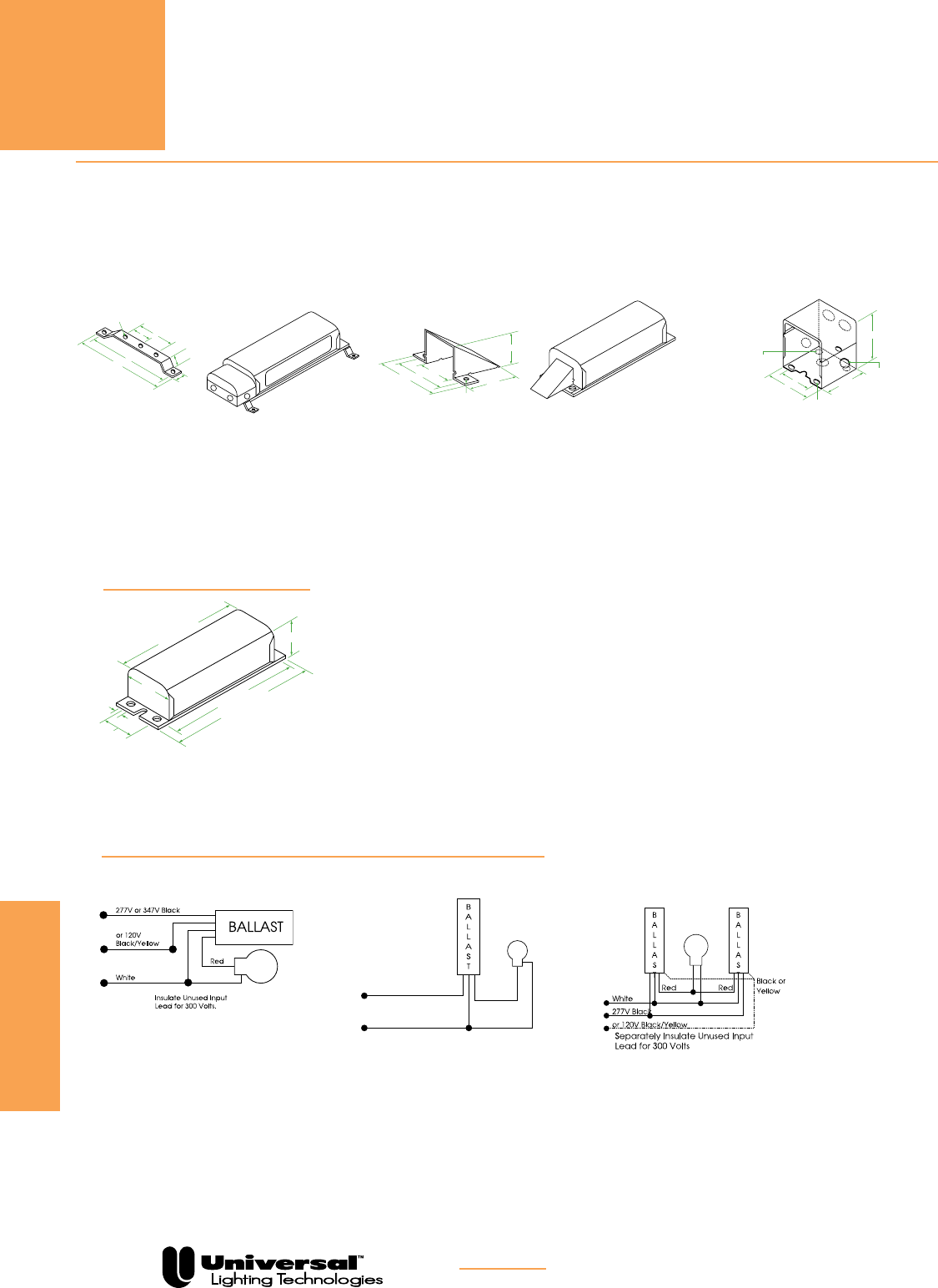
FOR MORE INFORMATION CALL
1-800-BALLAST
(225-5278)
HID CORE & COIL BALLASTS
F-CAN
PAGE 5-40
F-CAN
Case Length
Overall Length
Mounting
Height
Mounting
Width
Hole
Width
277V or 347V Black
or 120V
Black/Yellow
White
Red Black
White or
Yellow
Line
Red
Insulate Unused Input
Lead for 300 Volts.
Wiring Diagram
34
Wiring Diagram
35
BALLAST
B
A
L
L
A
S
T
White
277V Black
Red Red
Wiring Diagram
36
Mounting Bracket Assemblies
Black or
Yellow
B
A
L
L
A
S
T
or 120V Black/Yellow
B
A
L
L
A
S
T
4.500"
0.562"
0.406"
4.000"
1.000" 2.000"
0.250" Dia.
1.750"
1.437"
2.562"
1.500"
2.000"
0.218" Dia.
Tee-Pee Lead Wire Covers
Splice Box
2.812"
3.000"
2.000"
2.531"
0.850" Dia.
Knockouts
5 Places
Embossed Dimples
2 Places
0.297" Dia.
Mounting Holes
2 Places
Separately Insulate Unused Input
Lead for 300 Volts
Mounting Bracket Assemblies
F-CAN BALLASTS OPTIONAL ACCESSORIES
Case Length
Overall Length
Mounting
Height
Mounting
Width
Hole
Width
277V or 347V Black
or 120V
Black/Yellow
White
Red Black
White or
Yellow
Line
Red
Insulate Unused Input
Lead for 300 Volts.
Wiring Diagram
34
Wiring Diagram
35
BALLAST
B
A
L
L
A
S
T
White
277V Black
Red Red
Wiring Diagram
36
Mounting Bracket Assemblies
Black or
Yellow
B
A
L
L
A
S
T
or 120V Black/Yellow
B
A
L
L
A
S
T
4.500"
0.562"
0.406"
4.000"
1.000" 2.000"
0.250" Dia.
1.750"
1.437"
2.562"
1.500"
2.000"
0.218" Dia.
Tee-Pee Lead Wire Covers
Splice Box
2.812"
3.000"
2.000"
2.531"
0.850" Dia.
Knockouts
5 Places
Embossed Dimples
2 Places
0.297" Dia.
Mounting Holes
2 Places
Separately Insulate Unused Input
Lead for 300 Volts
Tee-Pee Lead Wire Covers
Case Length
Overall Length
Mounting
Height
Mounting
Width
Hole
Width
277V or 347V Black
or 120V
Black/Yellow
White
Red Black
White or
Yellow
Line
Red
Insulate Unused Input
Lead for 300 Volts.
Wiring Diagram
34
Wiring Diagram
35
BALLAST
B
A
L
L
A
S
T
White
277V Black
Red Red
Wiring Diagram
36
Mounting Bracket Assemblies
Black or
Yellow
B
A
L
L
A
S
T
or 120V Black/Yellow
B
A
L
L
A
S
T
4.500"
0.562"
0.406"
4.000"
1.000" 2.000"
0.250" Dia.
1.750"
1.437"
2.562"
1.500"
2.000"
0.218" Dia.
Tee-Pee Lead Wire Covers
Splice Box
2.812"
3.000"
2.000"
2.531"
0.850" Dia.
Knockouts
5 Places
Embossed Dimples
2 Places
0.297" Dia.
Mounting Holes
2 Places
Separately Insulate Unused Input
Lead for 300 Volts
Catalog Number 2-BMB-1.
Available for the remote installation of ballasts. Each
assembly consists of two (2) mounting brackets, four (4)
screws, four (4) washers and four (4) nuts.
Catalog Number SB-4. Ref. part #001-2009
For use with all F-Can Ballasts. It is easily installed on
the anchor bracket provided on each F-Can ballast. It
contains five (5) 7/8” diameter knockouts.
Catalog Number TP5. Ref.part #001-2013.
For use where ballast is attached to the surface of an
enclosure or raceway.
Case Length
Overall Length
Mounting
Height
Mounting
Width
Hole
Width
277V or 347V Black
or 120V
Black/Yellow
White
Red Black
White or
Yellow
Line
Red
Insulate Unused Input
Lead for 300 Volts.
Wiring Diagram
34
Wiring Diagram
35
BALLAST
B
A
L
L
A
S
T
White
277V Black
Red Red
Wiring Diagram
36
Mounting Bracket Assemblies
Black or
Yellow
B
A
L
L
A
S
T
or 120V Black/Yellow
B
A
L
L
A
S
T
4.500"
0.562"
0.406"
4.000"
1.000" 2.000"
0.250" Dia.
1.750"
1.437"
2.562"
1.500"
2.000"
0.218" Dia.
Tee-Pee Lead Wire Covers
Splice Box
2.812"
3.000"
2.000"
2.531"
0.850" Dia.
Knockouts
5 Places
Embossed Dimples
2 Places
0.297" Dia.
Mounting Holes
2 Places
Separately Insulate Unused Input
Lead for 300 Volts
REFERENCE DRAWING
FOR F-CAN
Wiring Diagram 20 Wiring Diagram 22
WIRING DIAGRAMS
HID
F-CAN
Splice Box
Wiring Diagram 21
120V Black
Neutral to Lamp Shell
Red
White

PAGE 5-41
IGNITORS
Catalog Number Description Reference Drawing Number
STANDARD IGNITORS • INSTANT RESTRIKE IGNITORS •
LONG DISTANCE IGNITORS • AUTOMATIC SHUTOFF
IGNITORS • SHUTOFF DEVICES
HID
IGNITORS
--STANDARD IGNITORS (See pg. 5-43)
PULSE START METAL HALIDE
MH 70-3B13 For double-ended MH lamps with HX-HPF ballasts: 70 watt (M85), 100 watt (M91), and 150 watt (M81) 27
MH 100-3A For MH lamps with HX-HPF ballasts: 35/39w(M130), 50w(M110), 70w(M98), 100w(M90/M140), and 150w(M102/M142) 25
MH 150-1A For 150 watt (M102/M142) lamp with CWA ballast 28
MH 200-1B13 For double-ended MH 250 watt (M80) lamp 28
MH 350-1A For MH lamps with CWA ballasts: 175 watt (M152/M137), 200 watt (M136), 250 watt (M153/M138),
320 watt (M154/M132), 350 watt (M131), 400 watt (M155/M135), and 450 watt (M144) 24
P 750-1B13 For 750 watt (M149) MH lamp 28
HPS 1000-4B13 For MH lamps: 875 watt (M166) and 1000 watt (M141). It is also used for 1000W HPS lamps 28
HIGH PRESSURE SODIUM
HPS 150-3A For HPS lamps of 150 watt or less with HX-HPF ballast, except 150 watt S56 lamp 24
HPS 400-3A For HPS lamps from 200 to 400 watts and 150 watt S56 lamp with CWA ballasts 25
HPS 450-1B13 For 150 watt S56, 200, 250 or 400 watt lamps with 240 volt/60 Hz reactor ballasts. With attached mounting bracket. 28
HPS 460-1B13 For 200, 250 and 400 watt lamps with HX-HPF ballasts and 50 Hz reactor ballasts. With attached mounting bracket. 28
HPS 600-1B For 600 watt lamps. 28
HPS 610-1B For 600 watt lamps. 27
HPS 1000-4B13 For 1000 watt HPS and Pulse Start Metal Halide lamps. With attached mounting bracket. 27
HPS 1000-6B13 Obsolete 27
PLUG REPLACEABLE IGNITORS
PULSE START METAL HALIDE
MH 150-G15 For MH lamps with HX-HPF ballasts: 35/39 watt (M130), 50 watt (M110), 70 watt (M98), 100 watt (M90/M140),
and 150 watt (M102/M142) 32
MH 350-G05 For MH lamps with CWA ballasts: 175 watt (M152/M137), 200 watt (M136), 250 watt (M153/M138),
320 watt (M154/M132), 350 watt (M131), 400 watt (M155/M135), and 450 watt (M144) 32
HIGH PRESSURE SODIUM
HPS 150-G01 For HPS lamps of 150 watt or less with HX-HPF ballast, except 150 watt S56 lamp 32
HPS 400-G05 For HPS lamps from 200 to 400 watts and 150 watt S56 lamp with CWA ballasts 32
INSTANT RESTRIKE IGNITORS
HIGH PRESSURE SODIUM
HPS 150-5B13 Instant Restrike Ignitor — for lamps of 150 watts or less except 150 watt S56. Ignitor has attached mounting bracket. 30
LONG DISTANCE IGNITORS
PULSE START METAL HALIDE
MH 100-5A For MH lamps from 35 to 50 watts. Max Ballast to Lamp Distance ( ~20’) 25
MH 100-5A For MH lamps from 70 to 150 watts. Max Ballast to Lamp Distance ( ~30’) 25
MH UNV-5B For MH lamps from 35 to 450 watts. Ignitor incorporates automatic resetting thermal protection.
Max Ballast to Lamp Distance ( ~50’) 25
HIGH PRESSURE SODIUM
HPS 150-4A For HPS lamps of 150 watt or less, excerpt 150 watt S56 lamp. Max Ballast to Lamp Distance ( ~20’) 24
HPS 400-4A For HPS lamps from 200 to 400 watts and 150 watt S56 lamp. Max Ballast to Lamp Distance ( ~25’) 25
HPS 1000-5B For 1000 watt HPS lamps. Ignitor incorporates automatic resetting thermal protection. Max Ballast to Lamp Distance ( ~50’) 25
AUTOMATIC SHUTOFF IGNITORS
PULSE START METAL HALIDE
MH 100-35B13 For MH lamps: 35/39 watt (M130), 50 watt (M110), 70 watt (M98), 100 watt (M90/M140), and 150 watt (M102/M142).
With attached mounting bracket 28
MH 150-35B13 For 150 watt M81 lamp with CWA ballasts. With attached mounting bracket. 31
MH 350-15B13 For MH lamps: 175 watt (M152/M137), 200 watt (M136), 250 watt (M153/M138), 320 watt (M154/M132),
350 watt (M131), 400 watt (M155/M135), and 450 watt (M144) 31
P 750-15B13 For 750 watt (M149) MH lamp 31
HPS 1000-55B13 For MH lamps: 875 watt (M166) and 1000 watt (M141). It is also used for 1000W HPS lamps 31
HIGH PRESSURE SODIUM
HPS 150-45B13 For lamps of 150 watts or less except 150 watt S56. With attached mounting bracket. 28
HPS 400-45B13 For lamps from 200 to 400 watts and 150 watt S56 with constant wattage autotransformer ballasts.
With attached mounting bracket. 28
HPS 1000-55B13 For 1000 watt HPS and Pulse Start Metal Halide lamps. With attached mounting bracket. 31
AUTOMATIC SHUTOFF DEVICES
In addition to one-piece shutoff ignitors, automatic shutoff devices are available as separate components for use with the ignitors below.
SA-55 HPS 150-3A, HPS 150-5B 25
SA-100 MH70-3B, MH100-3A, MH150-1A, MH350-1A, HPS150-4A, HPS400-3A, HPS600-1B 25
SA-250 HPS1000-4B ignitor, only with 1000 watt HPS ballasts 33
FOR MORE INFORMATION CALL
1-800-BALLAST
(225-5278)
13 May also be available without attached mounting bracket. Substitute “A” suffix for “B” suffix when ordering. Minimum quantities may apply.

PAGE 5-42
IGNITORS
IGNITORS
STANDARD IGNITORS
Standard Ignitors are supplied with all Universal High
Pressure Sodium and Metal Halide ballasts requiring ignitors.
These ballasts are supplied with an appropriate external ignitor
unless the ignitor is permanently attached to or built into the
ballast.
INSTANT RESTRIKE IGNITORS
An Instant Restrike Ignitor generates multiple pulses to
restrike a lamp arc after a brief power interruption has
extinguished it, without the typical 3-minute cool-down time.
A Standard Ignitor cannot restrike an arc until the lamp has
had time to sufficiently cool. Even though an Instant Restrike
Ignitor can reinitiate the lamp arc immediately upon restoration
of power, the lamp is still subject to warmup. The following
chart is based on an S55 lamp.
PLUG REPACEABLE IGNITORS
Incorporates terminals and a separate mounting base to
simplify construction and replacement.
1 second 2 seconds 87% 35 seconds
5 seconds Instant 83% 70 seconds
15 seconds Instant 76% 130 seconds
30 seconds Instant 62% 190 seconds
1 minute Instant 46% 255 seconds
Cold Start Instant 36% 360 seconds
Time Lamp Is Restrike Light Output Lamp Warmup
Extinguished Time On Reignition Time
Lamp ANSI Circuit Standard Auto Instant Long Distance
Watts Code Type Ignitors Shutoff Restrike Ignitors
Lamp ANSI Circuit Standard Auto Long Distance
Watts Code Type Ignitors Shutoff Ignitors
HIGH PRESSURE SODIUM IGNITORS
35 S76 Reactor HPS 150-3A HPS 150-45B HPS 150-5B HPS 150-4A
50 S68 Reactor, HX HPS 150-3A HPS 150-45B HPS 150-5B HPS 150-4A
70 S62 Reactor, HX HPS 150-3A HPS 150-45B HPS 150-5B HPS 150-4A
100 S54 Reactor, HX HPS 150-3A HPS 150-45B HPS 150-5B HPS 150-4A
150 S55 Reactor, HX HPS 150-3A HPS 150-45B HPS 150-5B HPS 150-4A
150 S56 CWA HPS 400-3A HPS 400-45B — HPS 400-4A
250 S50 Reactor HPS 450-1B HPS 400-45B — HPS 400-4A
250 S50 CWA HPS 400-3A HPS 400-45B — HPS 400-4A
250 S50 HX HPS 460-1B HPS 400-45B — HPS 400-4A
400 S51 Reactor HPS 450-1B HPS 400-45B — HPS 400-4A
400 S51 CWA HPS 400-3A HPS 400-45B — HPS 400-4A
400 S51 HX HPS 460-1B HPS 400-45B — HPS 400-4A
600 S106 CWA HPS 600-1B — — —
600 S106 Reactor HPS 610-1B — — —
1000 S52 CWA HPS 1000-4B HPS 1000-55B — —
METAL HALIDE IGNITORS
35 M130 Reactor MH 100-3A — MH 100-5A
50 M110 HX MH 100-3A — MH 100-5A
70 M85 HX MH 70-3B MH 70-35B MH 100-5A
70 M98 HX MH 100-3A MH 100-35B MH 100-5A
100 M90 Reactor MH 100-3A MH 100-35B MH 100-5A
100 M90 CWA MH 100-3A MH 100-35B MH 100-5A
100 M91 HX MH 70-3B — —
150 M81 HX MH 70-3B — —
150 M81 CWA MH 150-35B MH 150-35B —
150 M102 HX MH 100-3A MH 100-35B MH 100-5A
350 M131 Reactor MH 70-3B — —
350 M131 HX MH 70-3B — —
LONG DISTANCE IGNITORS
Long Distance Ignitors are used in situations where a ignitor
must be mounted further from the lamp than is recommended
for a standard ignitor. The maximum lamp to ignitor distance
for these ignitors is 50 feet, which may vary depending on the
type of lamp, ballast, fixture, and wiring.
AUTOMATIC SHUTOFF IGNITORS
In the event of a lamp failure, a Standard Ignitor will continue
to pulse, trying to start the lamp. This may reduce the life of
the ignitor. An Automatic Shutoff Ignitor will apply pulses for
10 to 12 minutes and then deactivate if a lamp arc cannot be
initiated. Resetting the ignitor is accomplished by momentarily
interrupting the power to the ballast. For this reason, these
ignitors are not recommended for use on unswitched circuits.
SHUTOFF DEVICES
Ignitor Accessory (IA) devices can be used to convert
a Standard Ignitor into an Automatic Shutoff Ignitor. Simply
match the Shutoff Device catalog number on page 5-62 with
the Standard Ignitor that is supplied with the ballast. Using the
IA device with the Standard Ignitor eliminates the need to buy
a separate Automatic Shutoff Ignitor.
TEMPERATURE RATING
Most ignitors are rated for a 105°C maximum case
temperature. Consult ballast specification sheets at
www.unvlt.com for specific details.
HID
IGNITORS
FOR MORE INFORMATION CALL
1-800-BALLAST
(225-5278)
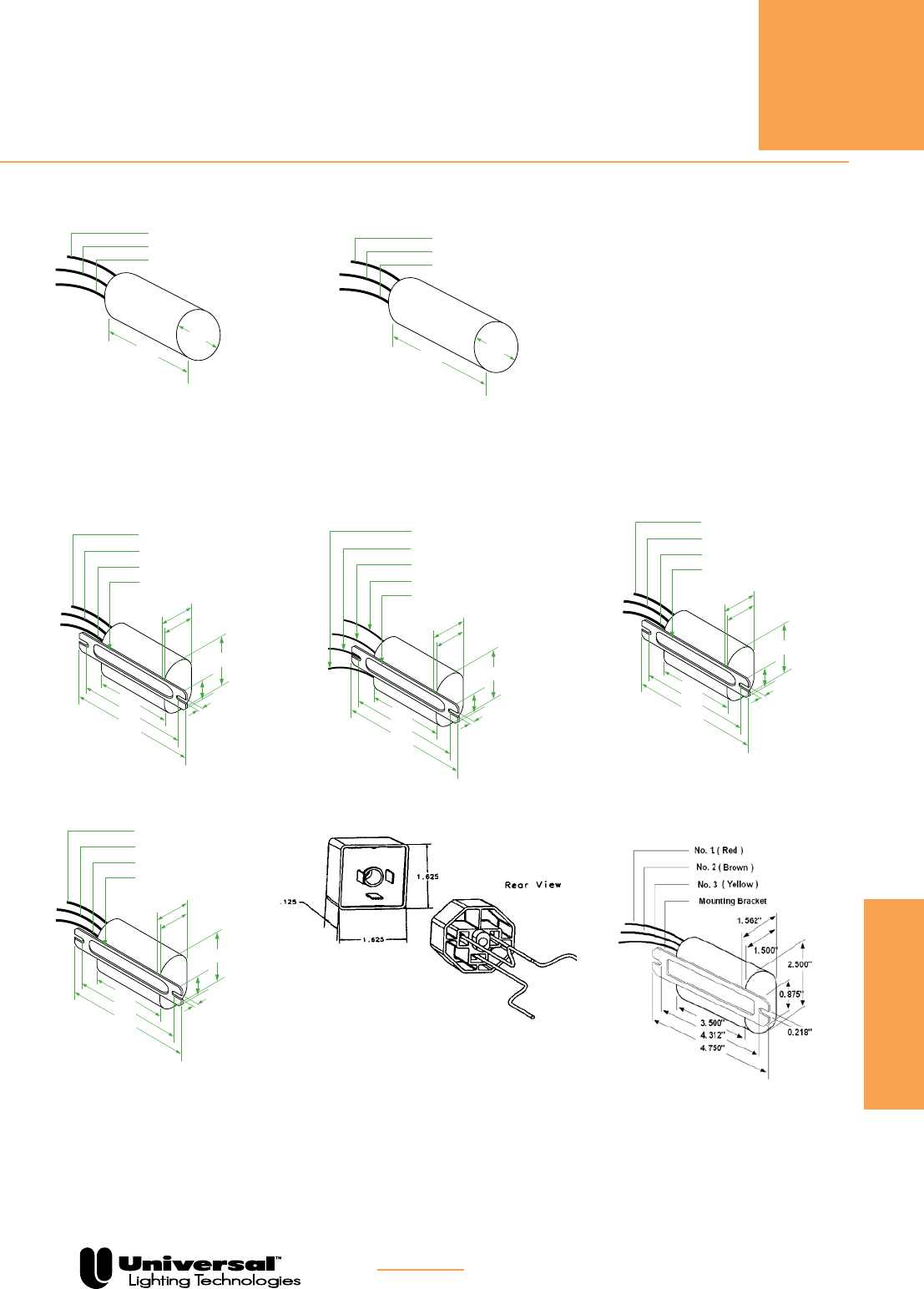
PAGE 5-43
IGNITORS
REFERENCE DRAWINGS
All dimensions in decimals.
All lead lengths: 13 inches ±1
No. 1 (Red or Blue)
No. 3 (Brown)
No. 2 (Yellow)
1.250"
2.000"
No. 1 (Red or Blue)
No. 3 (Brown)
No. 2 (Yellow)
1.250"
2.500"
1.265"
0.500"
0.750"
No. 1 (Red or Blue)
No. 3 (Brown)
No. 2 (Yellow)
Starter Reference Drawing
24
Starter Reference Drawing
26
Starter Reference Drawing
27
Starter Reference Drawing
25
2.031"
4.750"
4.312"
1.312"
3.500"
0.218"
0.875
"
.219 Dia. Thru
1.250"
Mounting Bracket
No. 1 (Red or Blue)
No. 3 (Brown)
No. 2 (Yellow)
Starter Reference Drawing
28
2.031"
4.750"
4.312"
1.312"
3.500"
0.218"
0.875"
1.250"
Mounting Bracket
No. 1 (Red or Blue)
No. 3 (Brown)
No. 2 (Yellow)
Starter Reference Drawing
29
2.031"
4.750"
4.312"
1.312"
3.500"
0.218"
0.875"
1.250"
Mounting Bracket
Com. (Yellow)
Ballast (Blue/White)
Lamp (Blue)
Starter Reference Drawing
30
2.500"
4.750"
4.312"
1.562"
3.500"
0.218"
0.875"
1.500"
Mounting Bracket
Ballast (Blue/White)
Lamp (Blue)
Com. (Yellow)
Starter Reference Drawing
31
2.531"
4.750"
4.312"
1.562"
3.750"
0.218"
0.875"
1.531"
Mounting Bracket
No. 1 (Red or Blue)
No. 3 (Brown)
No. 2 (Yellow)
1.250"
2.000"
No. 1 (Red or Blue)
No. 3 (Brown)
No. 2 (Yellow)
1.250"
2.500"
1.265"
0.500"
0.750"
No. 1 (Red or Blue)
No. 3 (Brown)
No. 2 (Yellow)
Starter Reference Drawing
24
Starter Reference Drawing
26
Starter Reference Drawing
27
Starter Reference Drawing
25
2.031"
4.750"
4.312"
1.312"
3.500"
0.218"
0.875
"
.219 Dia. Thru
1.250"
Mounting Bracket
No. 1 (Red or Blue)
No. 3 (Brown)
No. 2 (Yellow)
Starter Reference Drawing
28
2.031"
4.750"
4.312"
1.312"
3.500"
0.218"
0.875"
1.250"
Mounting Bracket
No. 1 (Red or Blue)
No. 3 (Brown)
No. 2 (Yellow)
Starter Reference Drawing
29
2.031"
4.750"
4.312"
1.312"
3.500"
0.218"
0.875"
1.250"
Mounting Bracket
Com. (Yellow)
Ballast (Blue/White)
Lamp (Blue)
Starter Reference Drawing
30
2.500"
4.750"
4.312"
1.562"
3.500"
0.218"
0.875"
1.500"
Mounting Bracket
Ballast (Blue/White)
Lamp (Blue)
Com. (Yellow)
Starter Reference Drawing
31
2.531"
4.750"
4.312"
1.562"
3.750"
0.218"
0.875"
1.531"
Mounting Bracket
Ref. Drawing 24 Ref. Drawing 25
Ref. Drawing 27 Ref. Drawing 28
Ref. Drawing 31 Ref. Drawing 32
No. 1 (Red or Blue)
No. 3 (Brown)
No. 2 (Yellow)
1.250"
2.000"
No. 1 (Red or Blue)
No. 3 (Brown)
No. 2 (Yellow)
1.250"
2.500"
1.265"
0.500"
0.750"
No. 1 (Red or Blue)
No. 3 (Brown)
No. 2 (Yellow)
Starter Reference Drawing
24
Starter Reference Drawing
26
Starter Reference Drawing
27
Starter Reference Drawing
25
2.031"
4.750"
4.312"
1.312"
3.500"
0.218"
0.875
"
.219 Dia. Thru
1.250"
Mounting Bracket
No. 1 (Red or Blue)
No. 3 (Brown)
No. 2 (Yellow)
Starter Reference Drawing
28
2.031"
4.750"
4.312"
1.312"
3.500"
0.218"
0.875"
1.250"
Mounting Bracket
No. 1 (Red or Blue)
No. 3 (Brown)
No. 2 (Yellow)
Starter Reference Drawing
29
2.031"
4.750"
4.312"
1.312"
3.500"
0.218"
0.875"
1.250"
Mounting Bracket
Com. (Yellow)
Ballast (Blue/White)
Lamp (Blue)
Starter Reference Drawing
30
2.500"
4.750"
4.312"
1.562"
3.500"
0.218"
0.875"
1.500"
Mounting Bracket
Ballast (Blue/White)
Lamp (Blue)
Com. (Yellow)
Starter Reference Drawing
31
2.531"
4.750"
4.312"
1.562"
3.750"
0.218"
0.875"
1.531"
Mounting Bracket
Ref. Drawing 30
HID
IGNITORS
Ref. Drawing 33
FOR MORE INFORMATION CALL
1-800-BALLAST
(225-5278)
No. 1 (Blue)
No. 3 (Brown)
No. 2 (Yellow)
2.057"
4.750"
4.312"
1.312"
3.46"
.218"
.875"
1.25"
Bracket
120V (Black/Yellow)

PAGE 5-44
Notes
FOR MORE INFORMATION CALL
1-800-BALLAST
(225-5278)
HID
eHID
Universal Lighting Technologies is a subsidiary of
Panasonic Electric Works Co., Ltd., a member of the Panasonic Group
Experience significant energy savings and increased lumen output vs. halogen lamps with Electronic
High Intensity Discharge (HID) ballasts from Universal Lighting Technologies. Vossloh-Schwabe (VS), also
a Panasonic Lighting Company, recently merged its US operation into Universal. This merger combines
Vossloh’s market leading high quality electronic HID product line with Universal’s extensive offering.
There are numerous advantages of using VS electronic HID ballasts. Operating HID lamps used in HID
lighting systems with electronic ballasts greatly increases system efficiency in comparison with magnetic
ballasts. These ballasts are designed to provide optimal lamp performance
and maximum energy savings. With enhanced capabilities to downsize
the form factor of luminaire housings and reduce wiring costs, VS electron-
ic HID ballasts lead the way to electronic solutions for HID lighting. Micro-
processor controlled intelligence offers superior lamp performance and the
flexibility for proprietary value-added functions. VS electronic HID ballasts
cover your HID needs with products for Metal Halide Lamps ranging from
20 Watts to 250 Watts.
VS electronic HID ballasts continuously monitors lamp characteristics
during operation and adjusts the lamp current to optimize performance.
This guarantees controlled operation in all modes of operation. The lamp
color temperature is also stabilized by using VS electronic HID ballasts
due to its relatively constant output power characteristics in addition to
producing flicker free lighting that usually occurs at the end of the discharge lamp’s service life. The
technology enhancements of VS electronic HID ballasts, allowing very small form factors and light weight
designs, has enabled new, innovative luminaire designs.
ELECTRONIC HID
Less energy. Enhanced performances.
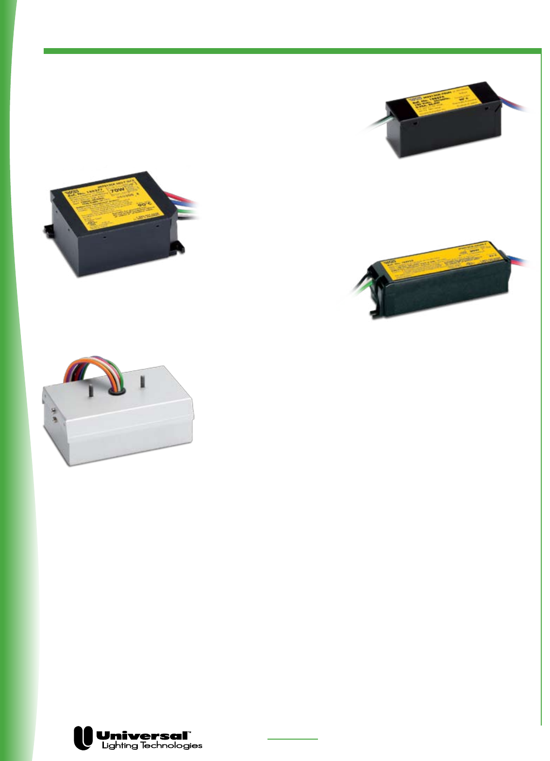
PAGE 6-2 FOR MORE INFORMATION CALL
1-800-BALLAST
(225-5278)
Micro Series: The introduction of the smallest eHID ballasts in the market was
coordinated with the launch of the new miniaturized capsule MH lamps
enabling the ultimate luminaire design flexibility. Extremely compact
and aesthetically pleasing, luminaire designs are approaching
the form factor and size of low voltage halogen systems.
Mini Ballast Series: Two ideal form factors that are used
in millions of HID track light luminaires characterize the mini series
of eHID ballasts. The mini-slim and mini-square units revolutionized
track lighting by allowing significantly smaller and greater
variety of luminaire designs while providing
energy savings of 60-70%
versus halogen systems.
Standard Case “Valued-added Series”: Millions of recessed,
track-head and specialty luminaires have used the de facto industry
standard enclosure since introduction. The significant energy savings
and enhanced reliability of our ballasts promoted the rapid escalation
of electronically ballasted MH luminaires for almost 15 years. Techno-
logical advancements have now allowed the integration of multiple,
value-added functions such as: a powersource for the self-heating
thermal protectors, an electronic 277V step-down transformer, and
an intelligent auxiliary lighting control for back-up lighting during
lamp hot restrike modes. Ideal for new, retrofit and replacement
applications in recessed luminaires.
Features and Benefits:
• Optimum lamp performance
• Rugged, compact and lightweight design
• High power factor
• Enhanced color and CRI uniformity
• Shut-down protection
• Reduced wiring costs
• Eliminates nuisance lamp cycling at end-of-lamp life (intelligent lamp sensing capabilities)
• Constant lamp power
• Reduced lamp dropouts due to improved line voltage dip withstand
• Quiet operation
• Durable performance for various applications
• Fewer SKUs required in inventory
• Broadens design exibility for new applications and luminaries
Product Overview
ELECTRONIC HID

PAGE 6-3 FOR MORE INFORMATION CALL
1-800-BALLAST
(225-5278)
Order code Part # Lamp Wattage Lamp Type Input Voltage Mounting Lead Exit Dimensions Wiring
Micro Series
188514 M2012CK-7EUN 20 M/C156 120 No Feet Side 1 1
188882 M2012CK-7EUN-F 20 M/C156 120 Feet Side 2 1
188883 M2012CK-7EUN-J 20 M/C156 120 Studs Top 3 1
188574 M2212CK-7EUN 22 M/C175 120 No Feet Side 1 1
188884 M2212CK-7EUN-F 22 M/C175 120 Feet Side 2 1
188885 M2212CK-7EUN-J 22 M/C175 120 Studs Top 3 1
188635 M3912CK-7EUN 39 M/C130 120 No Feet Side 4 1
188776 M3912CK-7EUN-F 39 M/C130 120 Feet Side 2 1
188756 M3912CK-7EUN-J 39 M/C130 120 Studs Top 3 1
188757 MTm3912CK-7EUN 39Tm M/C179 120 No Feet Side 4 1
188777 MTm3912CK-7EUN-F 39Tm M/C179 120 Feet Side 2 1
188758 MTm3912CK-7EUN-J 39Tm M/C179 120 Studs Top 3 1
Mini-Slim Series
188152 M2012CK-6EUN-F 20 M/C156 120 Feet Side 5 1
188246 M3912CK-6EUN-F 39 M/C130 120 Feet Side 5 1
188702 M3927CK-6EUN-F 39 M/C130 277 Feet Side 6 1
188774 M3927CK-6EUN-J 39 M/C130 277 Studs Top 7 1
188164 M7012CK-6EUN-F 70 M/C98, M/C139, M/C143 120 Feet Side 5 1
188703 M7027CK-6EUN-F 70 M/C98, M/C139, M/C143 277 Feet Side 6 1
188775 M7027CK-6EUN-J 70 M/C98, M/C139, M/C143 277 Studs Top 7 1
Mini-Square Series
188151 M2012CK-6EU-F 20 M/C156 120 Feet Side 8 1
188627 M2012CK-6EU-J 20 M/C156 120 Studs Top 9 1
188701 M2212CK-6EU-J 22 M/C175 120 Studs Top 9 1
188293 M3912CK-6EU-F 39 M/C130 120 Feet Side 8 1
188512 M3912CK-6EU-J 39 M/C130 120 Studs Top 9 1
188402 M3927CK-6EU-F 39 M/C130 277 Feet Side 10 1
188551 M3927CK-6EU-J 39 M/C130 277 Studs Top 9 1
188377 JM7012CK-6EU-F 70 M/C98, M/C139, M/C143 120 Feet Side 11 1
188628 M7012CK-6EU-J 70 M/C98, M/C139, M/C143 120 Studs Top 9 1
188895 M3912-27CK-6EU-F 39 M/C130 120-277 Feet Side 10 1
188896 M3912-27CK-6EU-J 39 M/C130 120-277 Studs Top 9 1
188897 M3912/27CK-6EU-JT3 39 M/C130 120/277 Studs Top 9 2a,2b,2c
188901 M2012-27CK-6EU-F 20 M/C156 120-277 Feet Side 10 1
188902 M2012-27CK-6EU-J 20 M/C156 120-277 Studs Top 9 1
188903 M2012/27CK-6EU-JT3 20 M/C156 120/277 Studs Top 9 2a,2b,2c
188939 M7012-27CK-6EU-F 70 M/C198,M/C139,M/C143 120-277 Feet Side 10 1
188940 M7012-27CK-6EU-J 70 M/C198,M/C139,M/C143 120-277 Studs Top 9 1
188941 M7012/27CK-6EU-JT3 70 M/C198,M/C139,M/C143 120/277 Studs Top 9 2a,2b,2c
Standard Series
188610 M2012-27CK-5EU-F 20 M/C156 120-277 Feet Side 12 1
188611 M2012/27CK-5EU-JT3 20 M/C156 120/277 Studs Top 13 2a, 2b, 2c
188156 M3912-27CK-5EU 39 M/C130 120-277 No Feet Side 14 1
188157 M3912-27CK-5EU-F 39 M/C130 120-277 Feet Side 12 1
188301 M3912-27CK-5EU-J 39 M/C130 120-277 Studs Top 13 1
188629 M3912/27CK-5EU-JT3 39 M/C130 120/277 Studs Top 13 2a, 2b, 2c
188630 M3912/27CK-5EU-JA3 39 M/C130 120/277 Studs Top 13 3a, 3b, 3c
188612 M5012-27CK-5EU-F 50 M148 or M110 120-277 Feet Side 12 1
188613 M5012/27CK-5EU-JT3 50 M148 or M110 120/277 Studs Top 13 2a, 2b, 2c
188165 M7012-27CK-5EU 70 M/C98, M/C139, M/C143 120-277 No Feet Side 14 1
188166 M7012-27CK-5EU-F 70 M/C98, M/C139, M/C143 120-277 Feet Side 12 1
188167 M7012-27CK-5EU-J 70 M/C98, M/C139, M/C143 120-277 Studs Top 13 1
188631 M7012/27CK-5EU-JT3 70 M/C98, M/C139, M/C143 120/277 Studs Top 13 2a, 2b, 2c
188632 M7012/27CK-5EU-JA3 70 M/C98, M/C139, M/C143 120/277 Studs Top 13 3a, 3b, 3c
188633 M10012/27CK-5EU-JT3 100 M/C90, M/C140 and M/C164 120/277 Studs Top 13 2a, 2b, 2c
188168 M10012-27CK-5EU 100 M/C90, M/C140 and M/C164 120-277 No Feet Side 14 1
188169 M10012-27CK-5EU-F 100 M/C90, M/C140 and M/C164 120-277 Feet Side 12 1
188302 M10012-27CK-5EU-J 100 M/C90, M/C140 and M/C164 120-277 Studs Top 13 1
188634 M10012/27CK-5EU-JA3 100 M/C90, M/C140 and M/C164 120/277 Studs Top 13 3a, 3b, 3c
188638 M15012-27CK-5EU-F 150 M/C102/E and M/C142/E 120-277 Feet Side 12 1
188639 M15012-27CK-5EU-J 150 M/C102/E and M/C142/E 120-277 Studs Top 13 1
Mid Wattage
188909 M21020-27CK-2EUN-F 210 C183 208-277 Feet Side 17 4a, 4b
188911 M25020-27CK-2EUN-F 250 (100V) M80/M168 208-277 Feet Side 17 4a, 4b
eHID Product Family
ELECTRONIC HID
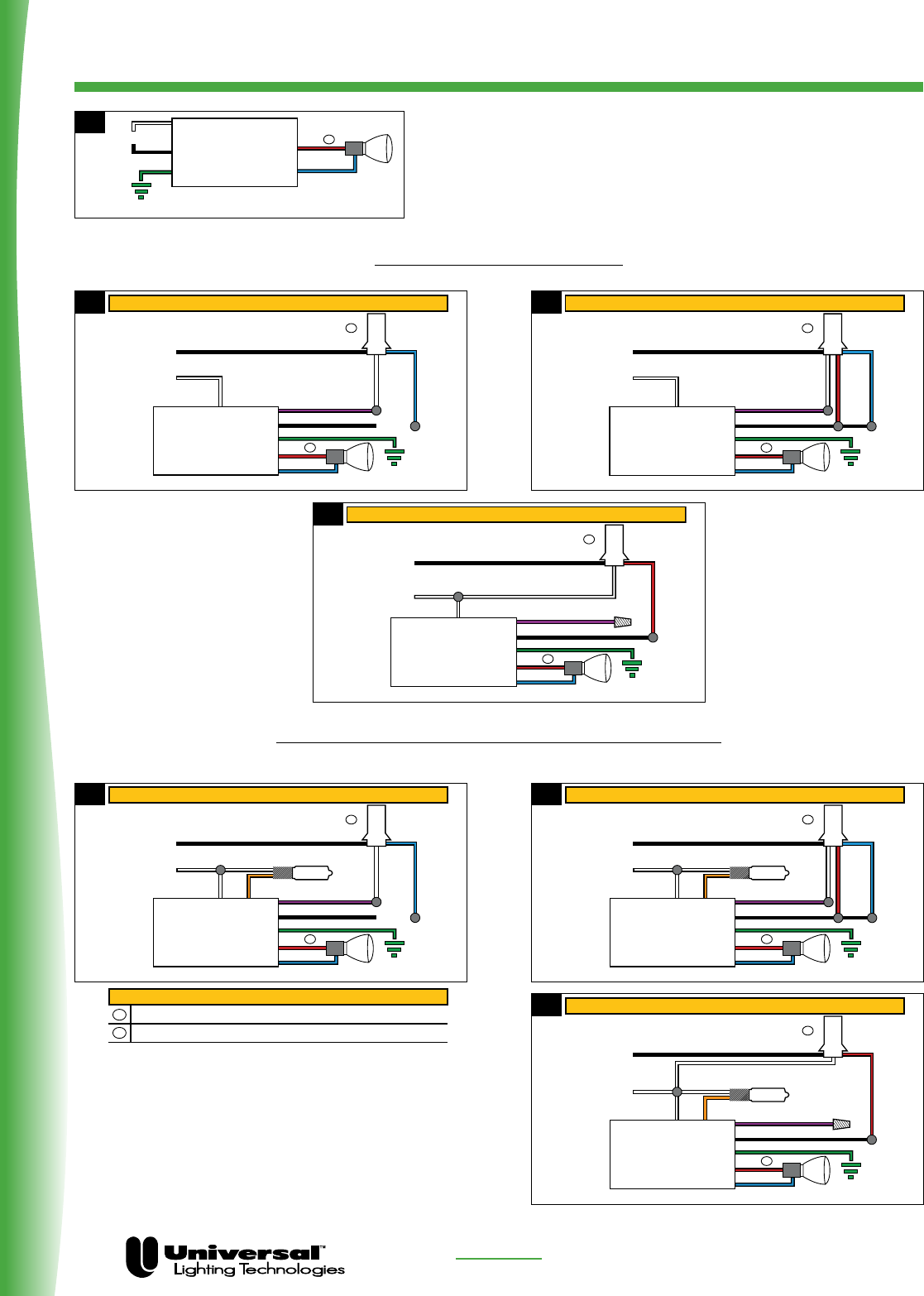
PAGE 6-4 FOR MORE INFORMATION CALL
1-800-BALLAST
(225-5278)
Wiring Diagrams
ELECTRONIC HID
120/277V with IDTP Tap
BLACK
WHITE
120/277
black
RP-1B
IDTP
blue
white
N
L
PURPLE
GREEN
RED
BLUE
2
1
WIRING (with 3-wire 120V IDTP)
2a
BLACK
WHITE
277
black
RP-4A
IDTP
red
white
N
L
PURPLE
GREEN
RED
BLUE
2
1
WIRING (with 3-wire 277V IDTP)
2c
BLACK
WHITE
120/277
black
RP-5A
IDTP
blue
white
red
N
L
PURPLE
GREEN
RED
BLUE
2
1
WIRING (with 4-wire 120V IDTP)
2b
120/277V with Auxiliary Control + IDTP Tap
BLACK
120/277
black
RP-1B
IDTP
blue
L
PURPLE
HALOGEN LAMP
<150W
ORANGE
GREEN
RED
BLUE
2
1
1
2
WIRING
Wiring & Dimensions Diagrams (shown in millimeters and inches)
(with 3-wire 120V IDTP)
Notes for Wiring Diagram
Connect red lead to center contact on Edison base lampholders
IDTP - Insulation Detector Thermal Protector
WHITE
white
N
3a
120/277
black
RP-5A
IDTP
L
HALOGEN LAMP
<150W
ORANGE
GREEN
RED
BLUE
2
1
WIRING (with 4-wire 120V IDTP)
WHITE
N
BLACK
blue
white
red
PURPLE
3b
277
black
white
RP-4A
IDTP
L
HALOGEN LAMP
<150W
ORANGE
GREEN
RED
BLUE
2
1
WIRING (with 3-wire 277V IDTP)
WHITE
N
BLACK
red
PURPLE
3c
BLACK
GREEN
WHITE
120V
N
L
RED
BLUE
1
1
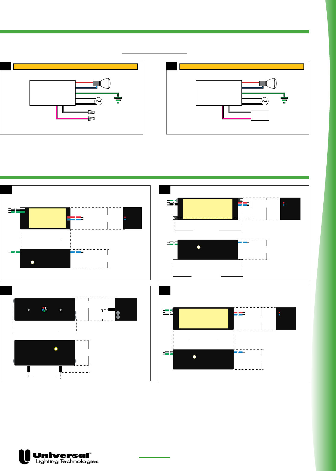
PAGE 6-4 FOR MORE INFORMATION CALL
1-800-BALLAST
(225-5278)
Wiring
Dimensions
ELECTRONIC HID
1
3
2
4
Temp. Testpoint
97.7/3.85
104.7/4.12
33.5/1.32
31.0/1.22
29.7/1.17
Temp. Testpoint
8-32 stud 11.8/0.47
33.5/1.32
96.7/3.81
38.1/1.5
50.8/2.0
16.7/0.66
Temp. Testpoint
76.0/2.99
33.0/1.30
28.0/1.10
Temp. Testpoint
90.7/3.57
33.5/1.35
30.1/1.19
Dimming Ballasts
4b4a
WIRING (For Fixed Output)
GREEN
WHITE
PINK (+)
GREY (+)
BLACK
RED
BLUE
WIRING (For Dimming Control)
GREEN
WHITE
PINK (+)
GREY (+)
BLACK
RED
BLUE
0 - 10V
DIMMER
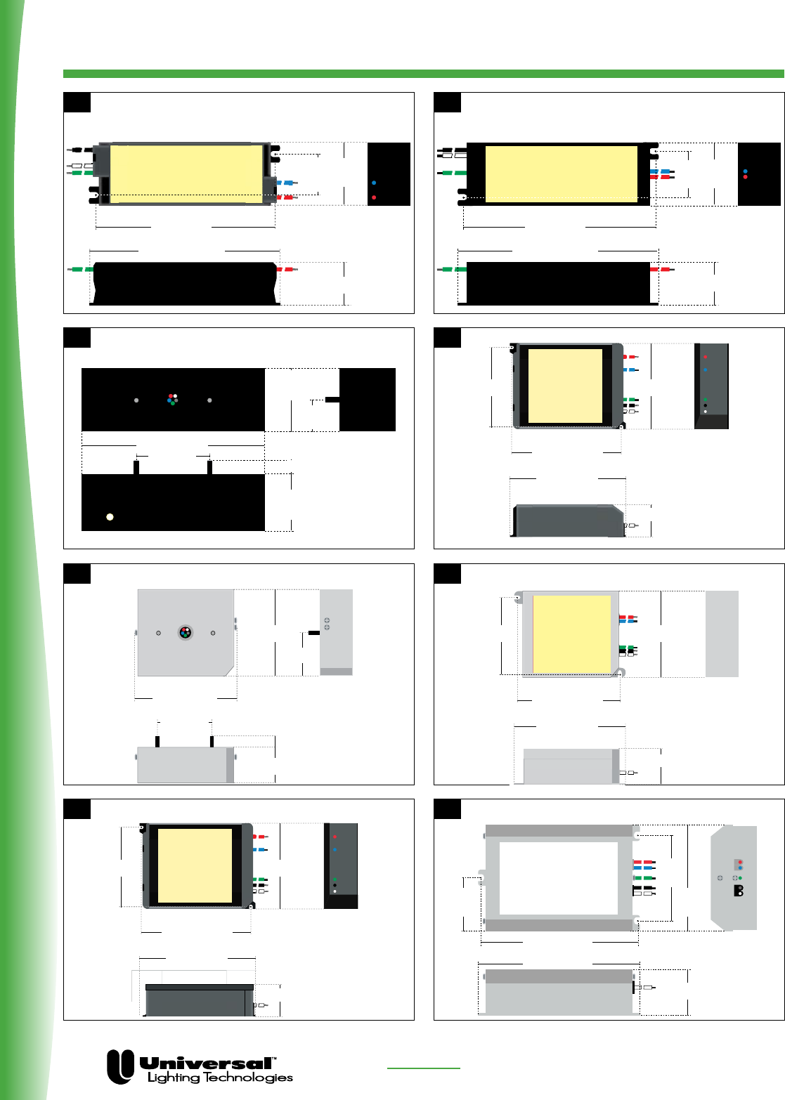
PAGE 6-5 FOR MORE INFORMATION CALL
1-800-BALLAST
(225-5278)
Dimensions
ELECTRONIC HID
76.2/3.0
39.7/1.56
50.8/2.0
11.8/0.47
38.1/1.5
8-32 stud
89.4/3.52
95.1/3.74
86.8/3.42
64.8/2.55 76.0/2.99
31.8/1.25
9
11
10
12
133.5/5.26
39.9/1.57
72.1/
2.84
140.0/5.51
46.0/
1.31
92.0/
3.62
95.1/3.74
86.8/3.42
64.8/2.55 75.6/2.98
30.6/1.21
5
7
6
140..0/5.51
133/5.25
28.6/
1.13
44.2/
1.74
30.0/1.18
Temp. Testpoint
50.8/2
127. 8/5.03
44.2/
1.74
22.1/
0.87
10.9/0.43
39.5/
1.56
140.0/5.51
133/5.25
28.6/
1.13
44.2/
1.74
30.0/1.18
8
95.1/3.74
86.8/3.42
64.8/2.55 75.6/2.98
30.6/1.21
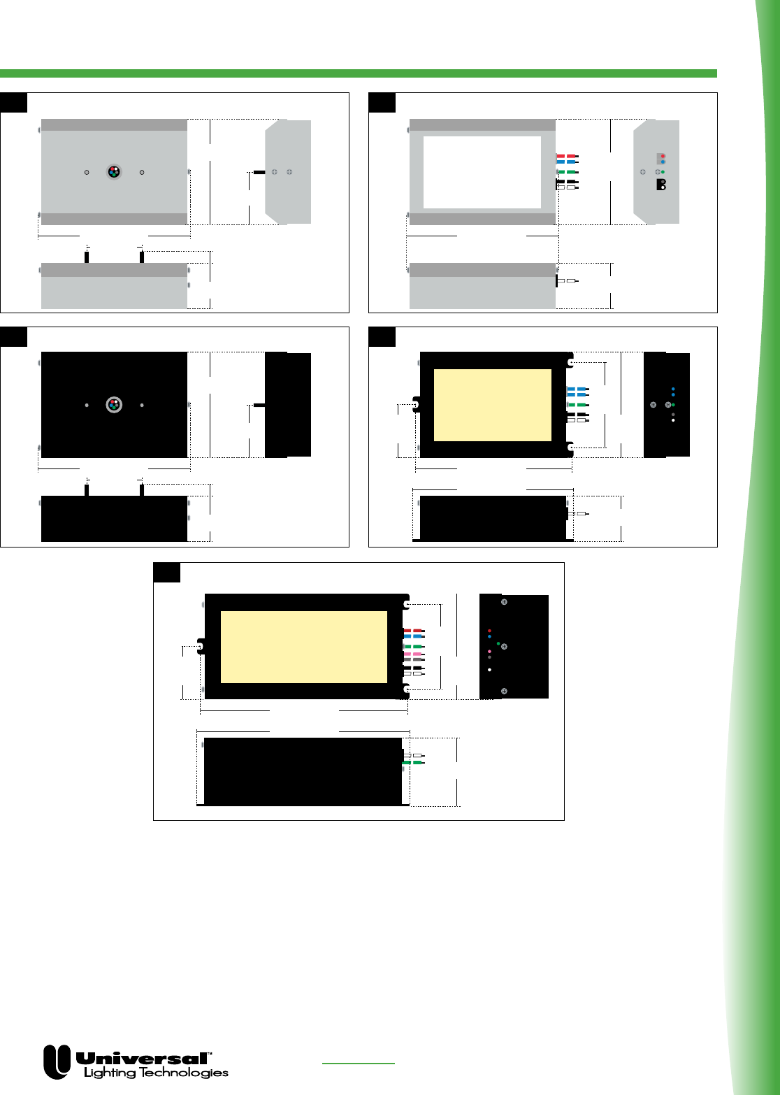
Dimensions
ELECTRONIC HID
PAGE 6-6 FOR MORE INFORMATION CALL
1-800-BALLAST
(225-5278)
13 14
133.5/5.26
39.9/1.57
92.0/
3.62
127. 5/5.02
50.8/2.011.4/0.45
8-32 stud
39.9/1.57
92.0/3.62
46.0/1.31
15 16
127. 5/5.02
50.8/2.011.4/0.45
8-32 stud
39.9/1.57
92.0/3.62
46.0/1.31
133.5/5.26
39.9/1.57
72.1/
2.84
140.0/5.51
46.0/
1.31
92.0/
3.62
17
202.0/ 7.95
60.0/ 2.36
72.0/
2.84
208.0/ 8.19
46.0/
1.31
92.0/
3.62

PAGE 6-7 FOR MORE INFORMATION CALL
1-800-BALLAST
(225-5278)
Application And Operating Information
General:
If the electrical current through an HID lamp is properly stabilized, an HID plasma arc with very high luminous efficiency is created
in the arc tube chamber resulting in a very efficient light source. The internal pressure of the arc tube chamber rises as the arc
tube temperature increases and will attain between 1 and 10 bar; thereby, defining these lamps as high-pressure HID lamps, high
intensity discharge lamps or simply HID lamps. The light output and color rendition of HID lamps vary considerably depending on
the lamp family (mercury, metal halide or sodium lamps).
HID lamps can only be started and operated with ballasts. Ignitors or ignition voltage characteristics are additionally required for
sodium and metal halide lamps. As well as stabilizing the lamp’s operating point, ballasts also influence the lamp’s output and
luminous flux, the system light output, the service life of the lamps as well as the color temperature of the light source.
Electromagnetic or electronic ballasts can be used for HID lamps, but unlike fluorescent lamps, lamp
efficiency is not significantly improved by the use of electronic ballasts. However, electronic ballasts can
lead to a reduction of the inherent losses and thus to an increase in system efficiency. In addition,
electronic ballasts can ensure gentle lamp operation, which may increase lamp’s service life.
Electronic Ballasts for Metal Halide Lamps
Electronic ballasts are designed with all the components required to operate metal halide lamps, including ignition, power factor
correction, and stable normal operation. Furthermore, they safely shutdown lamps at the end of their service life to prevent high
temperatures from being generated in the luminaires that could influence the service life of the luminaire or its components.
Vossloh-Schwabe also provides special electronic ballasts for additional luminaire functions such as heater power for insulation
detection thermal protectors and for switching on of an auxiliary incandescent lamp for the dark phase of an HID lamp during
initial warm-up or during hot-restrike cool-down mode.
Standards/Regulations
ANSI C82.14
UL 1598
ANSI C82.77
ANSI/UL 1029
ANSI/IEEE C62.41
US Code of Federal Regulations Title 47 –Telecommunications Part 18– Industrial, Scientific and Medical Devices
Low-Frequency Square Wave Electronic Ballasts for Metal Halide Lamps
Standard for Safety-Luminaires
Harmonic Emission Limits-Related Power Quality Requirements
or Lighting Equipment
Standard for Safety-High Intensity HID Lamp Ballasts
Surge Voltages in Low Voltage AC Power Circuits
ELECTRONIC HID

PAGE 6-8 FOR MORE INFORMATION CALL
1-800-BALLAST
(225-5278)
Application And Operating Information
Technical Specifications:
Operating voltage range
120VAC rated: 120V 277V ±10%
277VAC rated: 277V ±10%
120–277V rated: 108V–305V
120/277V rated: 108V–132V and 249V–305V
Leakage current
≤
0.5mA
Hot restrike auxiliary lamp operation
In order to ensure continuous illumination even during the ignition period or in the event of a lamp drop-out due to short term
power outage, an additional incandescent lamp (maximum 150W) can be used on models designated with a JA suffix.
Short circuit issues
The ballast output metal halide lamp leads are basically short-circuit-proof. However, any shorts or connections between those
lamp leads to the ballast case or to safetyneutral (earth ground) will destroy the ballasts. Likewise the metal halide lamp leads
shall not be connected to input power connections nor shall the auxiliary lamp leadsbe shorted together otherwise the ballast’s
circuitry could be damaged or fail.
Provisions in the luminaire design should be implemented to prevent all lead wires but especially lamp leads from being pinched,
damaged, or cut during luminaire assembly, field installation or normal service.
Mechanical Mounting:
Surface
Firm, flat, preferably metal surface required to ensure good heat transfer for long ballast service life and reliability. Avoid mounting
on uneven or protruding surfaces.
Mounting Location
Electronic ballasts must be protected against moisture and heat. Outdoor applications must utilize luminaires with the appropriate
weatherproof ratings depending on location. Most Vossloh-Schwabe electronic ballasts are rated “Outdoor Type 1”.
Fastening
Use mechanical means to ensure ballasts are fixed tightly to flat surfaces. Use appropriately sized screws depending on the
ballast mounting slot size or spring clips to provide interference fit.
Heat transfer
If ballast is destined for installation in a luminaire, sufficient heat transfer must be ensured between the electronic ballast and the
luminaire housing. Electronic ballasts should be mounted with the greatest possible clearance from heat sources or lamps.
During operation, the temperature measured at the ballast’s tc point must not exceed the specified maximum value.
ELECTRONIC HID

PAGE 6-9 FOR MORE INFORMATION CALL
1-800-BALLAST
(225-5278)
Application And Operating Information
Technical Specifications:
• Dimensional tolerances:
– Case: ±1mm (±0.039”)
– Standard lead length tolerances: +50mm (+2”) or –30mm (–1”) Micro lead length tolerances: ±15mm (±0.6”)
– Slot width on “F” mounting tabs: 5mm (0.20”); for Mini-Square Size: 4mm (0.157”)
• Remote wiring guidelines:
– Each lamp’s lead wires must be run in a separate conduit from the input power leads to achieve good EMI performance and
maximum remote capabilities. Lamp leads shall not be bundled together, but each set of lamp leads shall be run in its own
conduit.
– Individual lamp lead wires must be used for external fixture wire extensions using wire types SF-2 (equivalent to SEW-2 or
3071) or SFF-2 (equivalent to SEWF-2 or 3070) or alternately, if approved by VS, high voltage luminaire wire with a 18AWG
conductor and a 1000VAC minimum voltage rating. Temperature rating is especially critical if the lamp lead extension wires are
directly connected to lampholder terminals.
– Maximum remote distances:
See individual model specification sheets.
The specified maximum remote distances are based on lamp leads run in a minimum ½” internal diameter conduit, pipe or
flexible conduit. For longer remote distances contact the TES group at Universal Lighting.
– Using service power cords (types SJ, SO, ST, SV etc.) or metal clad cable assemblies for lamp lead extension wire are not
recommended as they are not compatible with the above characteristics, can cause starting problems and shall not be used
unless VS gives written approval.
Insulation clearance
Remote mounted ballasts shall be installed per National Electrical Code and local codes while also complying with wiring
methods per Vossloh-Schwabe recommendations. Per UL requirements, thermal insulation shall be a minimum of 3” from
any ballast surface.
ELECTRONIC HID

PAGE 6-10 FOR MORE INFORMATION CALL
1-800-BALLAST
(225-5278)
Application And Operating Information
Safety Functions:
Regulatory approvals
Vossloh-Schwabe electronic HID ballasts are UL listed or UL recognized component and cUL listed for use in Canada.
Shutdown of defective lamps
In the event of a lamp failing to ignite or of a lamp with low or high operating voltages (end of lamp’s service life), the electronic
ballast will switch off after a defined period of time (typically 30 minutes). The ballast will also shut-down if the lamp fails to
achieve symmetrical current operation (rectification) or if lamp leads are shorted to each other. After lamp replacement, the ballast
output can be reset by disconnecting (count to 10) and then reconnecting input power.
Transient input voltage
Electronic ballasts incorporate transient protection that complies with ANSI C62.41 and ANSI C82.14 test procedure and values.
Temperature Protection
To prevent excess temperatures, ballasts contain thermal protection devices or thermal sensing circuitry. A ballast will restart
after it has cooled down, however, it might be necessary to briefly reset the input power after the over-temperature condition is
resolved.
General guidelines
Always disconnect power to the luminaire before installation or service of the ballasts. Install to all provisions of local or National
Electric Codes. The ballast case/green lead must be grounded. Dispose of any replaced ballasts or lamps properly per local
environmental regulations.
Reliability and Service Life:
The electronic ballast service life is inversely proportional to the temperature of its critical internal components. Normal ballast
operation shall have the temperature of the tc point less than the warranted values in the individual specification sheets
Electrical Installation:
3-Phase connection of luminaires with electronic ballasts
Prior to operating newly installed lighting systems, please check the ballast’s rated voltage range to ensure it is appropriate
for the job site input power supply voltage. The neutral power supply wire must be connected securely to all luminaires and to
all ballasts. Power supply conductors must only be connected or disconnected when the circuit is not energized. The neutral
conductor must never be disconnected as the first disconnected wire nor individually at the circuit panel, at a distribution wiring
junction box or at the luminaire during energized power supply operation as out-of balance voltage operation can lead to serious
over-voltages and subsequent ballast failures.
Power factor compensation
Luminaires with electronic ballasts do not need power factor compensation, as the typical power factor range of electronic
ballasts is 95 to 99%.
ELECTRONIC HID

PAGE 6-11 FOR MORE INFORMATION CALL
1-800-BALLAST
(225-5278)
Application And Operating Information
Wiring
Wiring between the power supply, electronic ballasts and lamp must comply with the respective circuit diagram.
Note: the ballast (metal) case (using toothed washer) or provided green lead must be connected to safety-neutral (earth ground).
In addition, all metal luminaire parts and metal lamp reflector/housings shall also be connected to earth ground for safety and for
proper lamp starting. Metal halide luminaires must only be fitted with electrical components that are rated to withstand ignition
voltages of 4kV. To ensure compliance with RFI suppression limits, input and output conductors should not be run in the same
conduit as lamp conductors. Conduit size recommendations are stated in the individual ballast specification sheets or
construction notes.
Lamp maintenance notice
To replace end-of-service lamps, turn-off luminaire power, remove and replace lamps then turn-on luminaire power. If power was
not turned off during lamp replacement, the luminaire/ballast-input power must be reset to restart the new lamp. If the lamp or
wiring is defective, the ballast will “shut-down” in 1.5 to 30 minutes depending upon the fault condition.
Supplemental IDTP wiring
The IDTP (insulation detector thermal protector) is required by UL for most recessed luminaires. This fast acting thermal
protector is typically mounted on the same junction box as the electronic ballast. Special “JT” electronic ballasts provide a
separate 120V power supply for the IDTP heater to allow the luminaire to be rated for both 120V and 277V operation. See the
individual ballast specifications for the proper wiring procedures for JT & JA ballasts with this IDTP heater function.
Note: When using JT or JA ballasts on multiple lamp luminaires, only one ballast yellow or purple lead should be connected to the
IDTP heater. All other ballasts’ yellow or purple leads should be capped-off. Operation of JT and JA ballasts on 208V and 240V is
not recommended, as the IDTP may not function properly.
Lamp compatibility
Not all HID lamps are compatible with all electronic ballasts. Therefore, consult with Vossloh-Schwabe Technical Support or a
specific lamp company regarding a certain lamp’s compatibility.
ELECTRONIC HID

Sign Illuminating
Ballasts
A Complete Range Of Solutions…
From The Name You Trust
Universal Lighting Technologies (“Universal”) is known throughout the sign
business as a company that can set and meet today’s toughest industry
standards. Our high-output ballasts are great for rugged outdoor sign
cabinet applications because they provide ultra-reliable, low-temperature
starting as low as -20° F. All Universal sign ballasts offer Class P thermal
protection. We have three product lines spanning the sign business:
• TheUNIVERSAL® USB is a line that offers complete
coverage with 6 units.
• TheUNIVERSAL® MAX-3 ensures that the installer has the
right sign ballast on the truck for every application, from
1-6 lamps, 2-48 feet — replacing up to 100 conventional
ballasts with a maximum of three models.
• Signa®ElectronicSignballastsareidealfornewsign
installations with minimum wire connections, universal input
voltage, parallel lamp operation, and maximum energy savings.
Universal offers the convenience of one-stop shopping for not just sign bal-
lasts, but compact fluorescent, linear fluorescent, HID, and all your other
ballast needs.
For the unmistakable sign of quality and reliability, turn to Universal.
Universal ® sign ballasts provide ultra-reliable low-temperature starting —
plus Class P thermal protection.
Plastic Sign Ballasts
Universal Lighting Technologies is a subsidiary of
Panasonic Electric Works Co., Ltd., a member of the Panasonic Group

Application And Operating Information
PAGE 6-2
Heat
Ballasts generate heat during normal operation. By design,
fluorescent ballasts should operate so that their maximum
hot-spot case temperature does not exceed 90°C (194°F).
Operating at higher temperatures will shorten ballast life or
may cause the thermal protection cicuit to trip.
The temperature the ballast reaches depends on the tempera-
ture of the area surrounding it — plus the heat-conducting
surface touching the ballast. Ballasts should be installed in a
manner that avoids future overheating. To maintain normal
ballast temperature, you should:
1. Mount the ballast against a flat surface of heavy gauge
metal such as the structural part of the sign.
2. Keep the ballast as far away as possible from other
ballasts, lamps or reflective surfaces. (Lamps generate
approximately three-fourths of the heat in a plastic sign.)
The ends of the lamps are the hottest part, so you should
mount the ballast as far away from the ends as possible.
3. Paint the inside of the sign with flat white paint.
Moisture Protection
1. Vent the sign as well as possible without allowing
water to enter.
2. Ballasts should be mounted horizontally (except for weath-
erproof types). If the ballast must be mounted vertically,
allow room for sufficient air circulation. Wherever possible,
mount the ballast in an enclosure outside the sign by using
Universal pup tents. You can
get pup tents at no charge when you order the plastic
sign ballast. Your wholesaler will also have a supply
for your convenience.
Grounding
The white lead of a 120-volt ballast must be connected to the
neutral or ground side of the power supply. All metal parts of
the sign, as well as the ballast case, must be grounded either
through the conduit which holds the power supply or by
direct connection with a grounding wire. An ungrounded sign
is a potential hazard—and it can give misleading symptoms
when looking for sign faults.
Proper Lamp Life and Starting
In rapid-start installations, proper filament heating is neces-
sary for reliable starting and normal lamp life. To ensure
that proper heating is taking place, the following steps are
recommended:
1. Lamp leads should be kept as short as possible and with a
minimum of splices.
2. All connections should be soldered.
3. Maintain proper alignment and spacing of lamp holders
to ensure good contact in the sockets.
4. Mount lamps within one inch of grounded metal. This is
one lamp manufacturer’s published requirement for reliable
starting.
Light Output vs. Temperature
The light output of a fluorescent lamp varies according to the
mercury vapor pressure inside the lamp. This pressure is
controlled by the coldest spot on the bulb wall. The ballast may
start the lamp, but the light output can be very low if the bulb
wall temperature is low. Several factors influence this, including
ambient temperatures, wind, type of enclosure, etc. If maximum
light output is critical, consult a lamp manufacturer for advice.
Lamp Starting Problems
Occasionally a field problem will arise involving improper
lamp starting. The usual complaint is that the lamps start
slowly (or not at all). Here are some of the causes:
1. Low line voltage
2. Improper sign grounding
3. Insufficient or no filament voltage
4. Insufficient or no open circuit voltage
5. Dirty lamps during high-humidity operating conditions
6. Lamps improperly inserted in the sockets
If lamp starting is a problem in your installation, check the sign
grounding, filament voltage (3.4 - 3.9 volts), and open circuit
voltage. If all are normal, the probable cause is dirty lamps. The
lamps should be washed in clean water, drip-dried, and rein-
stalled. If this doesn’t solve the problem, contact your nearest
Universal representative for further assistance.
Short Lamp Life
If the lamp has not given proper length of service as specified
by the lamp manufacturer, the following reasons
for early failure should be considered:
1. Improper starting due to insufficient filament voltage
2. Frequent starting and short operating periods
3. Improper ballast
4. Improper voltage supply
5. Faulty wiring
6. Defective lamps
7. Lamps improperly inserted in sockets
Early lamp failure will be preceded by a dense blackening on
either or both ends of the lamps. This blackening will extend
three or four inches from the lamp base and should not be
confused with a small dense spot, which is a mercury deposit
that can occur any time during lamp life. Dense blackening
due to early lamp failure should not be confused with the gray
bands that sometimes appear toward the end of normal lamp
life (about two inches from either end of the lamp).
FOR MORE INFORMATION CALL
1-800-BALLAST
(225-5278)
Plastic Sign Ballasts
PAGE 6-3
Sign Ballast Footage Chart
FOR MORE INFORMATION CALL
1-800-BALLAST
(225-5278)
Plastic Sign Ballasts LEAD LENGTHS (Inches)
Note: Maximum volts above ground, any lead 590 volts.
UNIVERSAL® USB Fluorescent Sign Ballast Matrix
TOTAL LAMP FOOTAGE REQUIRED
2 4 6 8 10 12 14 16 18 20 22 24 26 28 30 32 34 36 38 40 42 44 46 48
1-2 USB-0412-12
USB-0816-14
1-4 USB-1024-14
2-4
USB-1632-24
USB-2036-46
USB-2048-46
UNIVERSAL® MAX-3 Fluorescent Sign Ballast Matrix
TOTAL LAMP FOOTAGE REQUIRED
2 4 6 8 10 12 14 16 18 20 22 24 26 28 30 32 34 36 38 40 42 44 46 48
USB-0218-16
1-6 USB-1232-16
USB-1048-16
SIGNA® Electronic Sign Ballast Matrix
TOTAL LAMP FOOTAGE REQUIRED
2 4 6 8 10 12 14 16 18 20 22 24 26 28 30 32 34 36 38 40 42 44 46 48
1-2 ESB216-12
2-4 ESB432-14
4-6 ESB848-46
1-4 ESB1040-14
Catalog Orange Blue Red
Number White Black Blues Reds Yellows Browns Oranges Blacks Whites Whites
PLASTIC SIGN BALLASTS - HIGH OUTPUT 800mA RS LAMPS - 120 Volts - 60 Hz
TWO LAMP BALLASTS
USB-0412-12 24 24 38 38 48
FOUR LAMP BALLASTS
USB-0816-14 36 24 65 40 39 56 48
USB-1024-14 24 24 79 48 75 83 57
USB-1632-24 24 24 80 54 60 80 72
SIX LAMP BALLASTS
USB-2036-46 24 24 50 80 70 38 50 50 38
USB-2048-46 24 24 80 80 70 50 50 50 50
MAX- 3 HIGH OUTPUT SIGN BALLASTS 800mA RS LAMPS - 120 Volts - 60 Hz
ONE TO SIX LAMP BALLASTS
USB-0218-16 24 24 60 60 60 60 60 60 60
USB-1232-16 24 24 80 60 60 80 60 60 72
USB-1048-16 24 24 80 80 70 50 60 60 50
SIGNA ELECTRONIC SIGN BALLASTS- T12 RAPID START HIGH OUTPUT LAMPS - 108 to 305 VOLTS - 50/60 Hz
ONE TO SIX LAMP BALLASTS
ESB216-12 68 68
ESB432-14 80 80 80 80
ESB848-46 80 80 80 80 80 80
No. of
Lamps
Per
Ballast
No. of
Lamps
Per
Ballast
No. of
Lamps
Per
Ballast
4-6
Plastic Sign Ballasts
PAGE 6-4
STANDARD
HIGH OUTPUT
SIGN BALLASTS
• Provide ultra-reliable
low-temperature starting
(as low as –20°F)
• Support 1 to 6 lamps
• Ideal for rugged outdoor
sign cabinet applications
• Class P thermally protected
Diagrams Notes:
Note 1: When operating a two-lamp ballast on one lamp
insulate each yellow lead.
Note 3: When operating a four-lamp ballast on three
lamps insulate each yellow blue/white, and brown
lead.
Total Start Max. Max. Open
Catalog Lamp Temp Line Input Circuit Wiring Dimen. Weight
Number Footage (°F) Cur. Watts Volt. Diagram Chart Ref. (lbs.)
PLASTIC SIGN BALLASTS - HIGH OUTPUT 800mA RS LAMPS - 120 Volts - 60 Hz
TWO LAMP BALLASTS
USB-0412-12 4´ min. - 12´ max. -20 1.35 160 500 1a, 2a 1 8
FOUR LAMP BALLASTS
USB-0816-14 8´ min. - 16´ max. -20 1.90 220 590 4a, 6a, 9, 1b 2 12
USB-1024-14 10´ min. - 24´ max. -20 2.70 325 720 4a, 6a, 9, 1b 3 14
USB-1632-24 16´ min. - 32´ max. -20 3.50 420 950 4a, 6a, 9 4 16
SIX LAMP BALLASTS
USB-2036-46 20´ min. - 36´ max. -20 4.00 480 600 5a, 7, 7a 4 18
USB-2048-46 20´ min. - 48´ max. -20 5.00 600 720 5a, 7, 7a 4 18
WHITE
BLACK
BLUE
BLUE
RED
RED
YELLO W
YELLO W
LINE
B A LLAST
LAMP
Diagram 1a
WHITE
BLACK
YELLOW
YELLOW
RED
RED
BLUE
BLUE
LINE
BALLAST
LAMP 1
LAMP 2
MOUNT LAMPS WITHIN 1˝ OF
GROUNDED METAL REFLECTOR
Diagram 2a
WHITE
BLACK
BROWN
BROWN
YELLOW
YELLOW
LINEBLUE
BLUE
BLUE / WH
BLUE / WH
RED
RED
BALLAST
LAMP 1
LAMP 2
LAMP 4
MOUNT LAMPS WITHIN 1 ˝ OF
GROUNDED METAL REFLECTOR
LAMP 3
Diagram 4a
BLACK
BLUE
BLUE
BRO W N
BRO W N
YELLOW
YELLOW
RED
RED
BLUE/WHITE
BLUE/WHITE
LINE
B A LLAST
LAMP
Diagram 1b
WHITE
BLACK
BROWN
BROWN
BLUE / WH
BLUE / WH
YELLOW
YELLOW
LINE BLUE
BLUE
ORANGE / BLK
ORANGE / BLK
ORANGE
ORANGE
RED
RED
BALLAST
LAMP 1
LAMP 2
LAMP 4
MOUNT LAMPS WITHIN 1˝ OF
GROUNDED METAL REFLECTOR
LAMP 3
LAMP 6
LAMP 5
Diagram 5a
BLACK
WHITE
YELLOW
YELLOW
BROWN
BROWN
RED
RED
BLUE / WH
BLUE / WH
BLUE
BLUE
LINE
BALLAST
LAMP 2
LAMP 3
INDIVIDUALLY CAP
THE YELLOW LEADS
LAMP 1
Diagram 6a
BLACK
WHITE
BROWN
BROWN
BLUE / WH
BLUE / WH
YELLOW
YELLOW
LINEBLUE
BLUE
ORANGE / BLK
ORANGE / BLK
ORANGE
ORANGE
RED
RED
BALLAST
INDIVIDUALL Y CAP
THE YELLOW LEADS
LAMP 5
LAMP 2
LAMP 3
LAMP 4
LAMP 1
Diagram 7a Diagram 9
PLASTIC SIGN FLUORESCENT BALLASTS
DIMENSION CHART - STANDARD CASE (INCHES)
Ref. # A B C D E
1 10 37/64˝ 1145/64˝ 119/64˝ 13/4˝ 33/16˝
2 1037/64˝ 1145/64˝ 119/64˝ 243/64˝ 33/16˝
3 13 3/16˝ 145/16˝ 133/4˝ 243/64˝ 33/16˝
4 15 3/16˝ 1611/16˝ 161/8˝ 243/64˝ 33/16˝
HIGH
OUTPUT
BALLASTS
Plastic Sign Ballasts
FOR MORE INFORMATION CALL
1-800-BALLAST
(225-5278)
3
4
Diagram 7
MAX-3 SERIES HIGH OUTPUT SIGN BALLASTS
DIMENSION CHART
Ref. # A B C D E
1 133/16˝ 145/16˝ 133/4˝ 2 43/64˝ 33/16˝
2 159/16˝ 1611/16˝ 161/8˝ 2 43/64˝ 33/16˝
PAGE 6-5
MAX-3 Series Ballasts
UNIVERSAL®
MAX-3
HIGH OUTPUT
SIGN BALLASTS
Diagram 1 Diagram 2
Diagram 5
2
Diagram 6
3
4
Diagram 7
Diagram 8
Diagrams Notes:
Note 1: When operating a two-lamp ballast on one lamp
insulate each yellow lead.
Note 2: When operating a three-lamp ballast on two
lamps insulate each yellow and blue/white lead.
Note 3: When operating a four-lamp ballast on three
lamps insulate each yellow blue/white, and brown
lead.
3
4
5
Diagram 4
2
3
Diagram 3
See page 6-3 for Lead Lengths
• Superior fill material coats all components and fills all
voids to dissipate heat for cooler operation, longer life.
• Supports 1 to 6 lamps, 2 to 48 feet total length
• Low watt-loss steel lamination and all-copper coils
assure cooler, more efficient operation and performance.
• Class P thermally protected
MAX-3
BALLASTS
FOR MORE INFORMATION CALL
1-800-BALLAST
(225-5278)
Total Start Max. Max. Open
Catalog Lamp Temp Line Input Circuit Wiring Dimen. Weight
Number Footage (°F) Cur. Watts Volt. Diagram Chart Ref. (lbs.)
MAX-3 HIGH OUTPUT SIGN BALLASTS 800mA RS LAMPS - 120 Volts - 60 Hz
ONE TO SIX LAMP BALLASTS
USB-0218-16 2´ min. - 18´ max. -20° 2.00 240 625 3, 4, 5, 6, 7, 8 1 15
USB-1232-16 12´ min. - 32´ max. -20° 3.50 410 970 3, 4, 5, 6, 7, 8 1 16
USB-1048-16 10´ min. - 48´ max. -20° 4.80 570 800 1, 2, 3, 4, 7, 8 2 18
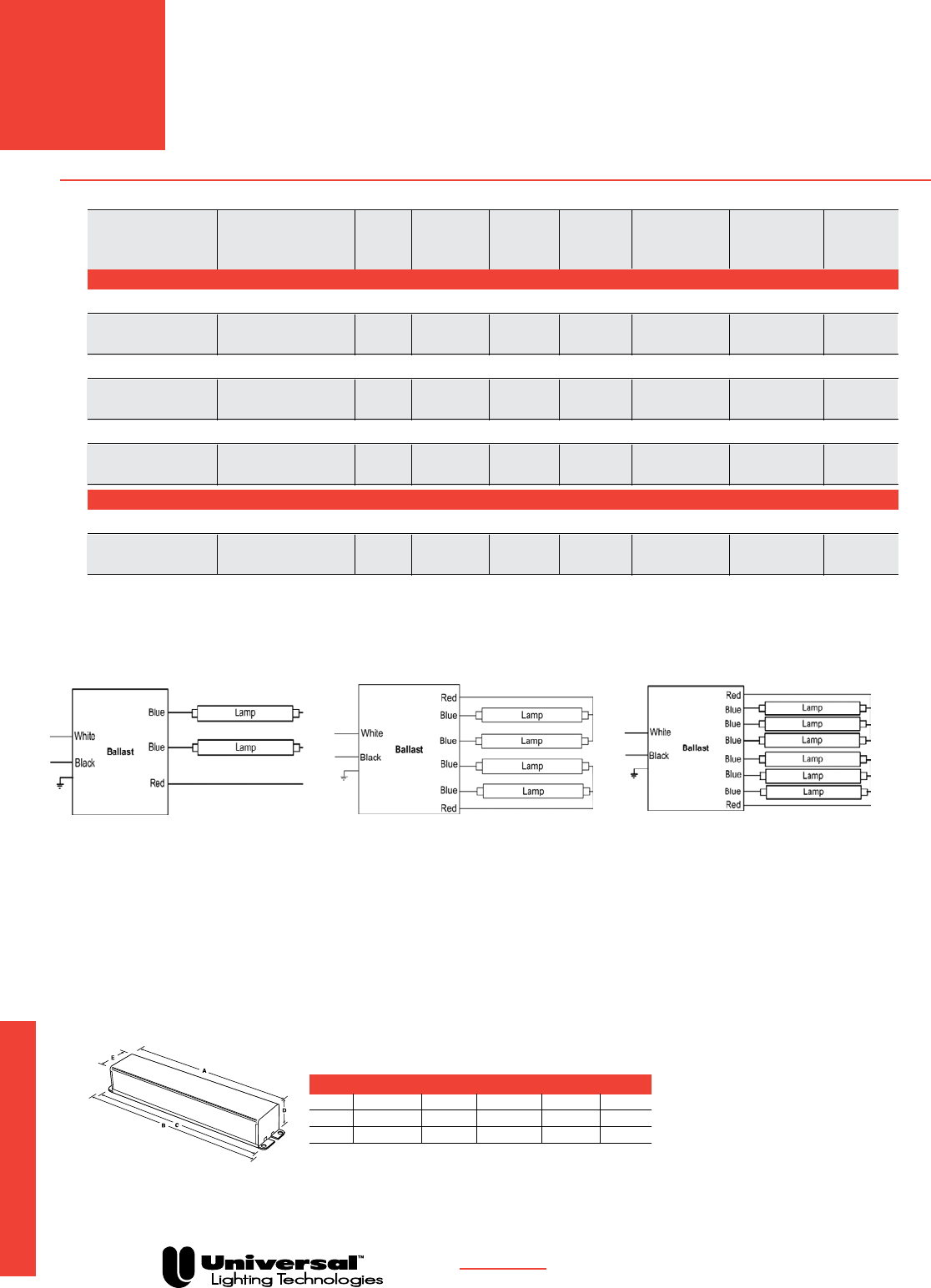
ELECTRONIC SIGN BALLASTS
DIMENSION CHART - STANDARD CASE (INCHES)
Ref. # A B C D E
1 10 37/64 ˝ 1145/64˝ 119/64˝ 13/4˝ 33/16˝
2 133/16˝ 145/16˝ 133/4˝ 243/64˝ 3 3/16˝
3 15 9/16˝ 1611/16˝ 161/8˝ 243/64˝ 33/16˝
PAGE 6-6
Electronic Sign Ballasts
ELECTRONIC
SIGN
BALLASTS
FOR MORE INFORMATION CALL
1-800-BALLAST
(225-5278)
SIGNA® ELECTRONIC
SIGN BALLASTS
• Instant start for maximum energy savings
• Simplified wiring for fewer connections
• Universal input voltage
• Parallel Lamp Operation
Diagram 10 Diagram 11 Diagram 12
Consult www.signasign.com for complete specification information
Diagrams Notes:
When Operating less than the maximum number of
lamps, insulate unused blue leads.
Total Start Max. Max.
Catalog Lamp Temp Input Input Line Wiring Dimen. Weight
Number Footage (°F) Voltage Watts Current (A) Diagram Chart Ref. (lbs.)
T12HO UP TO 8’ IN LENGTH OR T8HO UP TO 6’ IN LENGTH - 120 to 277 Volts - 50/60 Hz
ONE TO TWO LAMP BALLASTS
ESB216-12 2´ min. - 16´ max. -20 120 134 1.12 10 1 4.2
277 130 0.47
ONE, TWO, THREE OR FOUR LAMP BALLASTS
ESB432-14 4´ min. - 32´ max. -20 120 280 2.34 11 2 7.4
277 274 0.99
FOUR, FIVE OR SIX LAMP BALLASTS
ESB848-46 8´ min. - 48´ max. -20 120 408 3.41 12 3 9.7
277 395 1.47
T12HO UP TO 8’ IN LENGTH OR T8HO UP TO 8’ IN LENGTH - 120 to 277 Volts - 50/60 Hz
ONE, TWO, THREE OR FOUR LAMP BALLASTS
ESB1040-14 10´ min. - 40´ max. -20 120 341 2.85 11 3 10
277 331 1.25

FOR MORE INFORMATION CALL
1-800-BALLAST
(225-5278)
PAGE 7-1
Glossary
AC (Alternating Current)–Current which passes from the
generator in one direction and then the other, alternately
ANSI (American National Standards Institute)–Non-profit
organization that generates voluntary product performance
standards for many U.S. industries. ANSI Standard C82.1 applies
to electromagnetic ballasts.
Arc–Intense luminous discharge formed by the passage of
electric current across a space between electrodes.
Auto Reset Shutdown Circuit–Circuit senses lamp end of life
and will automatically shut off power to the lamp(s). When a
new lamp is inserted in the socket, the ballast resets, and turns
on the lamp automatically. Some shutdown circuits require the
power to be interrupted before a new lamp
will re-light.
Ballast–Device for starting and regulating fluorescent and high
intensity discharge lamps.
Ballast Efficacy Factor (BEF) – Value used to evaluate various
lighting systems based on light output and power input. The
BEF can only be used to compare systems operating the same
type and quantity of lamps.
Ballast Factor (BF)–Measure of light output from lamp operated
by commercial ballast as compared to a laboratory standard ref-
erence ballast. Ballast factor .94 means ballast produces 94% of
light produced by ANSI C82.2 reference ballast operating same
lamps.
Ballast Hum–Sound generated by the vibration of laminations
in the electromagnetic field that transforms the current for dis-
charge lamp use.
Ballast Losses–
Power which is supplied to a ballast that is not
converted into lamp energy. Ballast loss is dissipated as heat.
Bottom Exit (BE)–A configuration with leads or a wire-trap on
the bottom or base of the ballast. This type of configuration
is usually used when the ballast is mounted onto a junction box
plate.
Bottom Exit Studs (BES)–A configuration with screw studs
mounted on the base plate or bottom of the ballast. The screws
are 3/8˝ inches long with a #8-32 thread size (#8-32 nut). They
are mounted on a two-inch center. The studs are usually used
to mount the ballast directly onto a junction
box plate.
Canadian Energy Standards –Indicates ballast complies
with Canadian Energy Standards and meets the require-
ments ofCAN/CSA-C654-M91.
Canadian Standards Association (CSA)–Association that
generates product performance and safety
standards for many Canadian industries.
Capacitor–Device in ballast that stores electrical energy.
Often used for power factor correction and lamp regulation(see
“Power Factor”).
Cathode–See “Electrode”.
Centigrade (C)–Celsius temperature scale where 0°C = 32°F.
Circle E–Designates a ballast meets or exceeds the
requirements of Public Law 100-357 establishing standards
of efficiency.
Class P Thermal Protector–A switching device sensitive to
current and heat that automatically disconnects ballast if the
ballast temperature exceeds UL temperature limitations.
Coil–Windings of copper or aluminum wire surrounding the
steel core in ballast.
Core–Component of electromagnetic ballast that is surrounded
by the coil. Core is comprised of steel laminations or solid
ferrite material.
Core & Coil Ballast–Another term for an electromagnetic
ballast.
Crest Factor (Lamp Current Crest Factor)–Ratio of peak lamp
current to RMS or average lamp operating current.
Efficacy–Lumen output per unit of power supplied to ballast
(lumens per watt).
Electrical Testing Laboratory (ETL)–Independent testing
laboratory that performs ballast tests and certifies accuracy
of performance data.
Electrode–Metal filaments that emit electrons in a fluorescent
lamp. Negatively charged free electrons emitted by one
electrode are attracted to the positive electrode (anode),
creating an electric current and arc between electrodes.
Electromagnetic Ballast (Magnetic Ballast)–A ballast that uses
a “Core & Coil” assembly to transform electrical current to start
and operate fluorescent lamps.
EMI (Electromagnetic Interference)–Electrical interference
(noise) generated by electrical and electronic devices. Levels
generated by high frequency electronic devices are subject to
regulation by Federal Communications Commission (FCC).
Filament–Metal Tungsten wire coated with Barium Oxide that
emits electrons when voltage is applied.
Filament Voltage–Voltage applied to the lamp cathode.
Fluorescent Lamp–Gas filled lamp in which light is produced
by the interaction of electrons with phosphors lining the lamp’s
glass tube.
Foot Candles–Measure of light level on a surface being
illuminated. Defined as one lumen of light per one square
foot of surface area.
Four-Pin Compact Fluorescent Lamps–Type of lamps that do
not have any starter built into the base of the lamp. Therefore,
the ballast has the starting circuit. Traditionally 4-pin lamps are
designed to work with electronic ballasts; however, Universal
does offer magnetic ballasts to operate some 4-pin lamps.
Frequency–Rate of alteration in an AC current. Expressed in
cycles per second or Hertz (Hz).
Harmonic–An integral multiple of the fundamental fre-
quency (60 Hz) that becomes a component of the current (see
“Harmonic Distortion”).
Harmonic Distortion–Distortion of an AC waveform caused by
multiples of the fundamental frequency (harmonics). Odd triplet
harmonics (thirds, ninths, etc.) may result in large currents on
the neutral line in a four-wire Wye three-phase system.
Hertz (Hz)–Unit used to measure frequency of alteration of cur-
rent or voltage; cycles per second.
Glossary

Glossary
FOR MORE INFORMATION CALL
1-800-BALLAST
(225-5278)
PAGE 7-2
High Efficiency (Energy Saving) Electromagnetic Ballast–
Ballast with Core & Coils, designed to minimize ballast losses
compared to the “standard” ballast.
High Intensity Discharge (HID) Lamp–A lamp containing
a filled arc tube in which the active element becomes vaporized
(a gaseous state) and is discharged into the arc stream
to produce light.
High Power Factor–A ballast whose power factor is corrected to
90% or greater by use of a capacitor.
Incandescent Lamp–Lamp in which light is produced by a
filament heated by an electric current.
Input Voltage–Power supply voltage required for proper opera-
tion of an arc discharge lighting ballast.
Inputs Watts–The total power input to the ballast which
includes lamp watts and ballast losses. The total power input to
the fixture is the input watts to the ballast or ballasts and is the
value to be used when calculating cost of energy and air condi-
tioning loads.
Instant Start Lamp–a fluorescent lamp with a single pin at each
end. The lamp is ignited by a high voltage without any
filament heating.
Instant Start–Lamp starting method in which lamps are
started by high voltage input with no preheating of lamp
filaments. Some rapid start lamps are designed so that they may
be instant started.
Laminations–Layers of steel, making up the “core” that is sur-
rounded by the coils in a core & coil ballasts.
Lamp Current Crest Factor–See “Crest Factor”.
Lamp Filament–See “Electrode”.
Lamp Watts –Input power used to operate lamps.
Lumens/Watt–
A measurement of white light produced by each output
watt.
Metal Cases–Case design used in both magnetic and
electronic ballasts. These ballasts are grounded once they
are mounted to the fixture. They meet all safety codes, some
of which do not allow plastic in open plenum areas.
National Electric Code (NEC)–A nationally accepted electri-
cal installation code to reduce the risk of fire, developed by the
National Fire Protection Association.
National Energy Standards for Fluorescent Ballasts–A federal
law enacted in 1988 that sets energy standards for ballasts con-
sistent throughout the United States.
NOM –Laboratory that sets safety standards for building materi-
als, electrical appliances and other products for Mexico.
Non-PCB Capacitor–Capacitor used in ballasts to help provide
power factor correction. Contains no polychlorinated biphenyls
and meets EPA requirements.
Normal Power Factor–Ballasts with power factor less than .90
and do not incorporate any means of Power Factor Correction.
Parallel Lamp Operation–Refers to ballasts that employ multi-
ple-output current paths from a single ballast to allow lamps to
operate independent of one another, allowing other lamps oper-
ated by the ballast to remain lit should companion lamp(s) fail.
PCB (Polychlorinated Biphenyls)–Chemical pollutant formerly
used in ballast capacitors.
Potting–Material used to completely surround and cover
components of some magnetic and electronic ballasts.
Potting compound fulfills functions of protecting components,
dampening sound, and dissipating heat.
Power Factor–Measurement of the relationship between the AC
source voltage and current. High power factor ballasts require
less AC operating current operating at the same wattage than
an equivalent low power factor ballast. Formula: Power Factor
equals Input Watts divided by the product of
Line Volts times Line Amps (Volt Amps or VA).
Power Factor Corrected–Ballasts that incorporate a means
of Power Factor Correction but whose power factor is <90% and
>50%.
Preheat Lamp–A fluorescent lamp in which the filament must
be heated by use of a starter before the arc is created. These
lamps are typically operated with electromagnetic ballasts.
Programmed Rapid Start–lamp starting method which
preheats the lamp filaments while not allowing the lamp to ignite
and then applies the open circuit voltage (OCV) to start the lamp.
The user may experience a half to one-second delay after turning
on the lamps while the pre-heating takes place. This type of start-
ing circuit keeps lamp end blackening to a minimum and improves
lamp life performance, especially in applications where the lamps
are frequently switched on and off.
Rapid Start Lamp–A fluorescent lamp with two pins at each
end connected to the filament. The filaments are heated by the
ballast to aid in starting. Some rapid start lamps may be instant
started without filament heat, for example, the F32T8 lamp.
Rapid Start–Lamp starting method in which lamp filaments are
heated while open circuit voltage (OCV) is applied to
facilitate lamp ignition.
Series Lamp Operation–Refers to ballasts that employ a
single current path passing through all lamps operated by the
ballast. If one lamp should fail, companion lamps operated by
the same ballasts will also extinguish or dim.
Standard Alternating Current Frequency in the United States–
60 Hertz (Hz) or 60 cycles per second.
Total Harmonic Distortion (THD)–The combined effect of
Harmonic Distortion on the AC waveform produced by a ballast
or other device. Expressed as a percentage. Excessive levels of
THD can create large currents on the neutral line of a four-wire
Wye three phase system. (See “Harmonic Distortion”.)
Transients–High voltage surges through an electrical system
caused by lightning strikes to nearby transformers, overhead
lines or the ground. May also be caused by switching of motors
and compressors, as well as by short circuits or utility system
switching. Can lead to premature ballast failure.
Two-Pin Compact Fluorescent Lamps–Type of lamps that
have the glow bottle starter built into the base of the lamp.
Traditionally 2-pin lamps are designed to work with
electromagnetic ballasts.
UL (Underwriters’ Laboratories, Inc.)–Laboratory that
sets safety standards for building materials, electrical
appliances and other products.
Watts–Measurement of electrical ability to do work.
Glossary

Index
FOR MORE INFORMATION CALL
1-800-BALLAST
(225-5278)
PAGE 9-1
Index
200-C-S-P 1-24, 1-25, 1-26, 1-27
200-H2 1-25, 1-26, 1-27
202-B-TC-P 1-24, 1-27
202-SB-TC-P 1-24, 1-27
213-TC-P 1-22
300-H2 1-27
412-L-SLH-TC-P 1-13, 1-14
412-L-TC-P 1-30
413-C-TC-P 1-13, 1-14
420-L-TC-P 1-13, 1-14
443-L-SLH-TC-P 1-13, 1-14
445-RS-WS-TC-P 1-24
446-L-SLH-TC-P 1-13, 1-14
446-LR-TC-P 1-30
447-LR-TC-P 1-26, 1-27
447-LR-VLH-TC-P 1-25, 1-26, 1-27
458-L-SLH-TC-P 1-13, 1-14
480-SLH-TC-P 1-17
480-XLH-TC-P 1-17
481-LH-TC-P 1-16, 1-17
487-SLH-TC-P 1-17
487-XLH-TC-P 1-17
490-XLH-TC-P 1-15, 1-16, 1-17
493B2 2-41
532-BR-TC-P 1-22
540-L-TC-P 1-30
546-B-TC-P 1-25, 1-26, 1-27
547-RS-WS-TC-P 1-24
554-L-TC-P 1-25, 1-26, 1-27
564-L-TC-P 1-25, 1-26, 1-27
567-L-TC 1-34
573-L-TC-P 1-13
595-L-TC-P 1-30
597-L-TC-P 1-34
631-LH-TC-P 1-15, 1-16
698-L-SLH-TC 1-13, 1-14
726-L-VLH-WS-TC-P 1-24
778-XLH-TC 1-15, 1-16, 1-17
806-BR-TC-P 1-33
806-SLH-TC-P 1-22, 1-23
808-BR-TC-P 1-33
822-BR-TC-P 1-22, 1-23
827-SLH-TC-P 1-22, 1-23
828-BR-TC-P 1-22, 1-23
831-TC 1-33
897-SLH-TC 1-22, 1-23
930-K-TC-P 1-19, 1-20
931-LH-TC-P 1-19, 1-20
937-K-TC-P 1-19, 1-20
1010-236RC-TC 5-39
1010-238C-TC 5-39
1010-239RC-TC 5-39
1010-245C-TC 5-39
1010-246C-TC 5-39
1010-247SC-TC 5-39
1033-15S 5-43
1033-16S 5-34
1033-17S 5-34
1033-23S 5-43
1033-24S 5-34
1038-113S 5-33
1038-122S 5-36
1038-130S 5-36
1110-245SC-TC 5-38
1110-246C-TC 5-38
1110-247SC-TC 5-52
1110-564C-TC 5-38
1110-566C-TC 5-38
1110-568C-TC 5-38
1111-246C-TC 5-38
1111-247SC-TC 5-38
1120-251A-TC 5-38
11210-236C-TC 5-38
11210-239C-TC 5-38
11210-242C-TC 5-38
11210-277C-TC 5-38
11210-506C-TC 5-38
11210-539C-TC 5-38
11210-554C-TC 5-38
11210-606C-TC 5-38
1220-246C-TC 5-39
1233-10W 5-26
1233-24S 5-27
1233-35UN 5-26
1233-35W 5-26
1233-142W 5-26
1233-154W 5-27
1233-183S 5-27
1233-251UN 5-26
1233-251W 5-26
1238-133S 5-36
1238-183S 5-36
12210-236C-TC 5-39
12210-237C-TC 5-39
12210-239C-TC 5-39
12210-241C-TC 5-39
12210-261C-TC 5-39
12210-552C-TC 5-39
12210-602C-TC 5-39
12210-606C-TC 5-39
4105F2P 1-25, 4-8
4105P 1-25
4112PBES 4-9
4113P 4-9
4114P 4-9
4114PBES 4-9
Catalog # Page # Catalog # Page #
Index
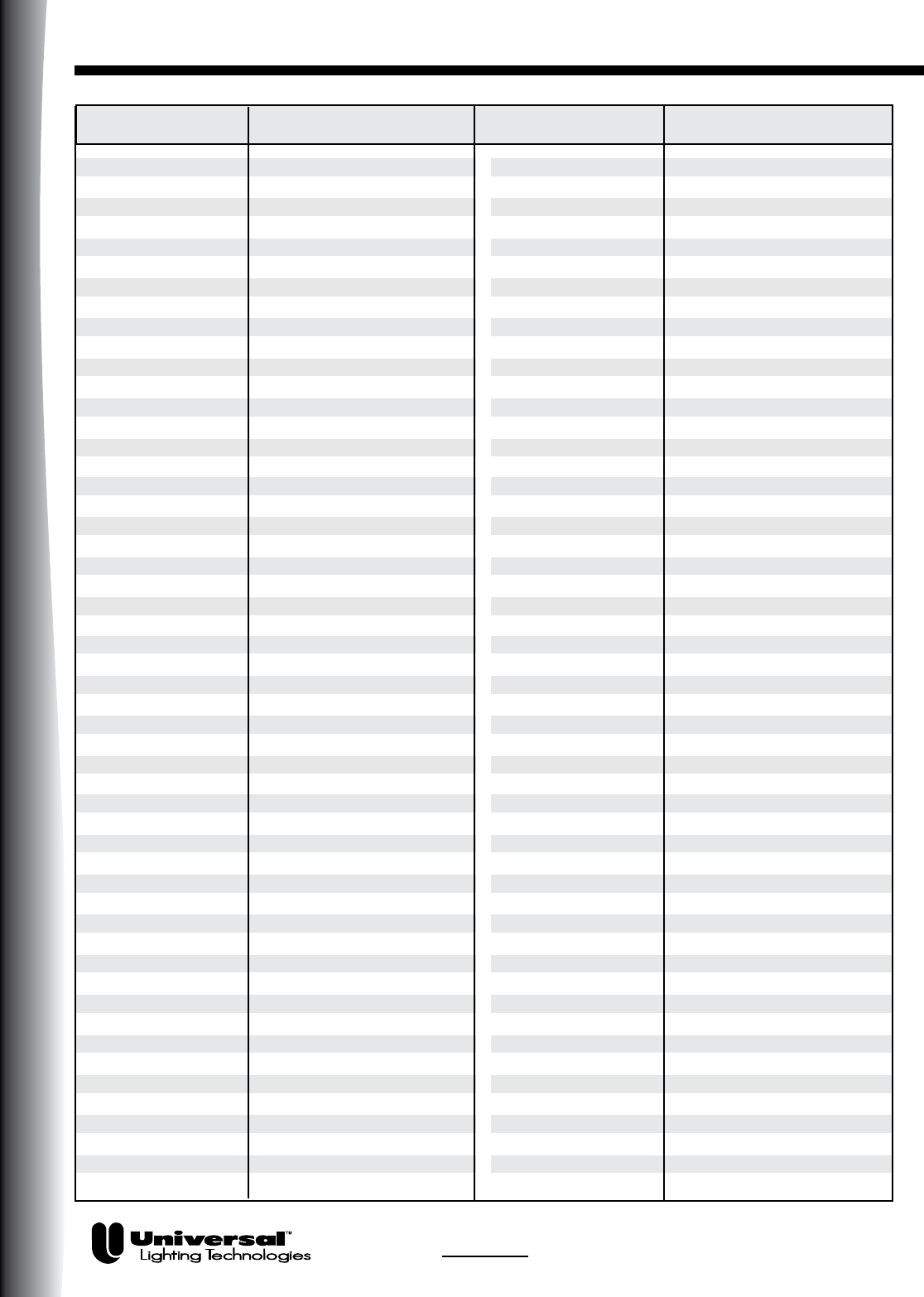
Index
Index
FOR MORE INFORMATION CALL
1-800-BALLAST
(225-5278)
PAGE 9-2
4122PBES 4-10
4124PBES 4-11, 4-15
4128PBES 4-11, 4-15
4139F2P 4-19
4205F2P 4-8
4214PBES 4-9
4226PBES 4-11, 4-15
B114PUNVDV1 3-10
B128PUNVDV1 3-10
B132I120RH-A 2-14, 2-16, 2-19, 2-30
B132I277RH-A
2-14, 2-16, 2-19, 2-24, 2-26, 2-27, 2-30
B132I347HP 2-14, 2-16, 2-19
B132I347RH 2-14, 2-16, 2-19
B132IUNVEL-A 2-14, 2-16, 2-19, 2-24, 2-27, 2-30
B132IUNVHE-A
2-14, 2-16, 2-19, 2-24, 2-26, 2-27, 2-30
B132IUNVHP-B
2-14, 2-16, 2-19, 2-24, 2-26, 2-27, 2-30
B132PUNVDV1 3-10
B132PUNVHP-A
2-14, 2-16, 2-19, 2-24, 2-26, 2-29
B132R120S30 3-13
B132R120S50 3-13
B132R120V5 3-12
B132R277S30 3-13
B132R277S50 3-13
B132R277V5 3-12
B132R347V5 3-12
B134R120M-A 2-38
B140R120HP 2-37, 2-38
B140R277HP 2-37, 2-38
B154PUNVDV1 3-10
B159I120RH 2-32
B159I277RH 2-32
B214PUNVDV1 3-10
B224PUNV-C 2-35, 4-18, 4-19
B228PU90S50D 3-15
B228PU95S50D 3-15
B228PU115S50D 3-15
B228PUNV90-C 2-34
B228PUNV95-D 2-34, 2-36
B228PUNV115-D 2-34, 2-36
B228PUNVDV1 3-10
B228PUNV-C 2-34
B232I120EL
2-14, 2-16, 2-19, 2-20, 2-24, 2-26, 2-27
B232I120HE
2-14, 2-16, 2-19, 2-20, 2-24, 2-26, 2-27
B232I120L-A 2-14, 2-16, 2-19, 2-20, 2-30
B232I120RES-A 2-14, 2-16, 2-19, 2-20
B232I120RES-G 2-14, 2-16, 2-19, 2-20
B232I120RH-A
2-14, 2-16, 2-19, 2-20, 2-24, 2-27, 2-30
B232I120RHH-A 2-20, 2-24
B232I277EL
2-14, 2-16, 2-19, 2-20, 2-24, 2-26, 2-27
B232I277HE
2-14, 2-16, 2-19, 2-20, 2-24, 2-26, 2-27
B232I277L-A
2-14, 2-16, 2-19, 2-20, 2-24, 2-27, 2-30
B232I277RH-A
2-14, 2-16, 2-19, 2-20, 2-24, 2-27, 2-30
B232I277RHH-A 2-20, 2-24
B232I347HP-A
2-14, 2-16, 2-19, 2-20, 2-24, 2-27, 2-30
B232I347HPL 2-14, 2-16, 2-19, 2-20, 2-30
B232I347L-A
2-14, 2-16, 2-19, 2-20, 2-24, 2-27, 2-30
B232I347RH-A
2-14, 2-16, 2-19, 2-20, 2-24, 2-27, 2-30
B232IUNV-C 2-14, 2-16, 2-19, 2-20, 2-30
B232IUNVEL-A
2-14, 2-16, 2-19, 2-20, 2-24, 2-26, 2-27
B232IUNVHE-A
2-14, 2-16, 2-19, 2-20, 2-24, 2-26, 2-27
B232IUNVHEH-A 2-14, 2-16, 2-19, 2-20, 2-24, 2-26, 2-27
B232IUNVHP-B 2-14, 2-16, 2-19, 2-20, 2-24,
2-26, 2-27, 2-30
B232PUNVDV1 3-10
B232PUNVEL-A 2-20
B232PUNVHE-A 2-20
B232PUNVHP-A
2-14, 2-16, 2-19, 2-20, 2-24, 2-26, 2-27
B232SR120S30 3-13
B232SR120V5 3-12
B232SR277S30 3-13
B232SR277V5 3-12
B232SR347V5 3-12
B234SR120M-A 2-37, 2-38
B234SR277M-A 2-37, 2-38
B239PUNV-D 2-35, 4-19
B240R120HP 2-37, 2-38
B240R120RH 2-37, 2-38
B240R277HP 2-37, 2-38
B254P347-D 2-35, 4-20
B254HRVHB-E 2-35, 4-20
B254PUNVDV1 3-10
B254PUNV-D 2-35, 4-17, 4-19, 4-20
B254PUNVHB-D 2-35, 4-17, 4-19, 4-20
B259I120HE 2-32
B259I120HPL 2-32
B259I120RH 2-32
B259I120RHH 2-32
B259I277HE 2-32
B259I277HPL 2-32
B259I277RH 2-32
B259I277RHH 2-32
B259I347HP 2-30, 2-32
B259IUNVHP-A 2-32
B260I120M-A 2-39, 2-40
B260I120RH 2-39, 2-40
B260IUNVHP 2-39, 2-40
B286I120RH 2-33
B286I277RH 2-33
B295SR120HP 2-41, 4-32
B295SRUNVHP 2-41
B332I120EL 2-15, 2-17, 2-20, 2-21, 2-24,
2-25, 2-26, 2-27, 2-28
B332I120HE 2-15, 2-17, 2-20, 2-21, 2-24,
2-25, 2-26, 2-27, 2-28
Catalog # Page # Catalog # Page #

Index
B332I120L-A 2-15, 2-17, 2-20, 2-21, 2-30
B332I120RH-A 2-15, 2-17, 2-20, 2-21, 2-24,
2-25, 2-27, 2-28, 2-30
B332I120RHH 2-21
B332I277EL 2-15, 2-17, 2-20, 2-21, 2-24,
2-25, 2-26, 2-27, 2-28
B332I277HE 2-15, 2-17, 2-20, 2-21, 2-24,
2-25, 2-26, 2-27, 2-28
B332I277L-A 2-15, 2-17, 2-20, 2-21, 2-30
B332I277RH-A 2-15, 2-17, 2-20, 2-21, 2-24,
2-25, 2-27, 2-28, 2-30
B332I277RHH 2-21
B332I347HP 2-15, 2-17, 2-20, 2-21
B332I347HPL 2-15, 2-17, 2-20, 2-21, 2-30
B332I347RH 2-15, 2-17, 2-20, 2-21
B332I347L 2-15, 2-17, 2-20, 2-21, 2-30
B332IHRVH-E 2-20, 2-21, 2-24, 2-25, 2-26, 2-28
B332IUNVEL-A
2-15, 2-17, 2-20, 2-21, 2-24, 2-25,
2-26, 2-27, 2-28, 2-30
B332IUNVHE-A
2-15, 2-17, 2-20, 2-21, 2-24, 2-25,
2-26, 2-27, 2-28, 2-30
B332IUNVHEH-A
2-15, 2-17, 2-20, 2-21, 2-24, 2-25,
2-26, 2-27, 2-28, 2-30
B332IUNVHP-A
2-15, 2-17, 2-20, 2-21, 2-24, 2-25,
2-26, 2-27, 2-28
B332PUNVHP-A
2-15, 2-17, 2-20, 2-21, 2-24, 2-25,
2-26, 2-27, 2-28
B332SR120S30 3-13
B332SR120V5 3-12
B332SR277S30 3-13
B332SR277V5 3-12
B340R120HP 2-37, 2-38
B340R277HP 2-37, 2-38
B432I120EL
2-15, 2-17, 2-21, 2-22, 2-25, 2-26, 2-27
B432I120HE
2-15, 2-17, 2-21, 2-22, 2-25, 2-26, 2-27
B432I120L-A
2-15, 2-17, 2-21, 2-22, 2-25, 2-30
B432I120RES-A 2-15, 2-17, 2-21, 2-22
B432I120RH-A
2-15, 2-17, 2-21, 2-22, 2-25, 2-30
B432I277EL
2-15, 2-17, 2-21, 2-22, 2-25, 2-26, 2-28
B432I277HE
2-15, 2-17, 2-21, 2-22, 2-25, 2-26, 2-28
B432I277HEH 2-15, 2-17, 2-21, 2-22, 2-25, 2-28
B432I277L-A 2-15, 2-17, 2-21, 2-22
B432I277RH-A 2-15, 2-17, 2-21, 2-22, 2-30
B432I347HP 2-15, 2-17, 2-21, 2-22
B432I347HPL 2-15, 2-17, 2-21, 2-22, 2-30
B432I347L 2-15, 2-17, 2-21, 2-22, 2-30
B432I347RH 2-15, 2-17, 2-21, 2-22
B432IUNV-D 2-15, 2-17, 2-21, 2-22, 2-30
B432IUNVEL-A
2-15, 2-17, 2-21, 2-22, 2-25, 2-28, 2-30
B432IUNVHE-A 2-15, 2-17, 2-21, 2-22, 2-25,
2-26, 2-28, 2-30
B432IUNVHP-A 2-15, 2-17, 2-21, 2-22, 2-25,
2-26, 2-28, 2-30
B432PUNVHP-A
2-15, 2-17, 2-21, 2-22, 2-25, 2-26, 2-28
B432P277V5-E 3-12
B432P277V5H-E 3-12
B432SR277V5 3-12
B454PUNV-E 2-35, 4-20
B454PUNVHB-E 2-35, 4-20
C118PUNVDV3 3-10
C126PUNVDV3 3-10
C132PUNVDV3 3-10
C140PUNVDV3 3-10
C142PUNVDV3 3-10
C213/347 4-9, 4-14
C213UNV 4-9, 4-14
C218/347 4-10, 4-14
C218PUNVDV3 3-10
C218UNV 4-10, 4-14
C226PUNVDV3 3-10
C232PUNVDV3 3-10
C240PUNVDV3 3-10
C240PUNVHP-B 4-19
C240SI120RH 4-19
C240SI277RH 4-19
C242/347
4-11, 4-12, 4-15, 4-17, 4-18, 4-19, 4-20
C242PUNVDV3 3-10
C242UNV
4-11, 4-12, 4-15, 4-17, 4-18, 4-19, 4-20
C340SI120RH 4-19
C340SI277RH 4-19
C2642/347 4-11, 4-12, 4-15, 4-17, 4-18
C2642UNV
4-11, 4-12, 4-15, 4-17, 4-20
CBT113L-120 2-34, 4-8, 4-9
CBT213L-120 2-34, 4-8, 4-9
CBT218L-120xC 4-10
CBT126L-120 2-34, 4-11, 4-17, 4-18
CF1320H2P 1-26, 1-27, 4-9
CT213UNV 4-9
CT218UNVSE 4-10, 4-18
ESB213-12 7-6
ESB432-14 7-6
ES1329A 2-14, 2-16, 2-20
ES1510A 2-14, 2-16, 2-19
ES1608A 2-14, 2-16, 2-19, 2-20
ES1679A 2-30
ES1720B 2-15, 2-17, 2-21, 2-22
ES1786X 2-42
ES4515K 2-35, 4-20
ES4528X 2-34
ES4800A 2-14, 2-16, 2-19, 2-20, 2-30
ES5000GT/HT 3-8
ES5001GT/HT 3-8
ES5002GT/HT 3-8
ES5003GT/HT 3-8
Catalog # Page # Catalog # Page #
FOR MORE INFORMATION CALL
1-800-BALLAST
(225-5278)
PAGE 9-3
Index

Index
ES5006BM 3-11
ES5007BMT 3-11
ES5008BM 3-8
ES5009BMT 3-8
ES5010GT/HT 3-11
ES5011GT/HT 3-11
ES5012GT/HT 3-11
ES5013GT/HT 3-11
ES5702CTL 3-9
ES5703CTL 3-9
ES5704CTL 3-9
ES5705CTL 3-9
ES5720CTL 3-9
ES5721CTL 3-9
ES5722CTL 3-9
ES5723CTL 3-9
ES5723HT 3-9
ES5733HT 3-9
ES5734HT 3-9
ES5817K 3-11
ES5818K 3-11
ES5821B 3-11
ES5822B 3-11
ES5825K 3-8
ES5826K 3-8
ES5827B 3-8
ES5828K 3-8
ES5829K 3-8
ES5830K 3-8
ES5831B 3-8
ES5832B 3-8
ES5833B 3-11
ES5834B 3-11
ES5835K 3-11
ES5836K 3-11
ES5838K 3-8
ES5839K 3-11
ES5840K 3-8
ES5842K 3-8
ES5843K 3-8
ES5844K 3-11
ES5846K 3-11
ES5847K 3-11
ES5848K 3-8
ES5849K 3-11
ES5850K 3-8
ES5851K 3-11
ES5852K 3-8
ES5853K 3-11
ES5860K 3-8
ES5861K 3-11
ES5901CTL 3-9
ES5902CTL 3-9
ES5903CTL 3-9
ES5961CTL 3-9
HPS 150-3A 5-41
HPS 150-4A 5-41
HPS 150-5B 5-41
HPS 150-45B 5-41
HPS 150-G01 5-43
HPS 400-3A 5-43
HPS 400-4A 5-43
HPS 400-45B 5-43
HPS 400-G05 5-43
HPS 450-1B 5-43
HPS 460-1B 5-43
HPS 600-1B 5-43
HPS 1000-4B 5-43
HPS 1000-55B 5-43
M35MLTLC3M 5-17
M35TRILC3M 5-17
M50MLTLC3M 5-17
M50TRILC3M 5-17
M70MLTLC3D 5-17
M70MLTLC3M 5-17
M70TRILC3M 5-17
M100MLTLC3D 5-19
M100MLTLC3M 5-17
M100TRILC3M 5-17
M150MLTLC3D 5-18
M150MLTLC3M 5-18
M150TRILC3M 5-18
M175ML5AC3M 5-18
M175MLTAC3M 5-18
M175MLTAE3M 5-41
M175TRIAC30 5-18
M232SR120C 1-12
M232SR277C 1-12
M250ML5AC3M 5-18
M250ML5AC4M 5-19
M250MLTAC3M 5-18
M250MLTAC4M 5-19
M250MLTAE3M 5-41
M250TRIAC3M 5-18
M250TRIAC4M 5-19
M260I120L 1-39, 1-40
M400ML5AC4M 5-19
M400MLTAC4L 5-19
M400MLTAC4M 5-19
M400MLTAE4M 5-41
M400MLTAI4X 5-42
M400TRIAC4M 5-19
Catalog # Page # Catalog # Page #
Index
FOR MORE INFORMATION CALL
1-800-BALLAST
(225-5278)
PAGE 9-4

Index
FOR MORE INFORMATION CALL
1-800-BALLAST
(225-5278)
PAGE 9-5
Index
M1000ML5AC5M 5-20
M1000MLTAC5M 5-20
M1000TRIAC5M 5-20
M1500MLTAC5M 5-20
M1500TRIAC5M 5-20
M7048TLC3M 5-17
M10048TLC3M 5-17
M15048TLC3M 5-18
M17548TAC3M 5-18
M25048TAC3M 5-18
M25048TAC4M 5-19
M400120AC4M 5-19
M400208AC4M 5-19
M400277AC4M 5-19
M40027TAC4M 5-19
M40048TAC4M 5-19
M100048TAC5M 5-20
M150048TAC5M 5-20
M100120LC3N 5-17
M175120AC3M 5-18
M175277AC3M 5-18
M250120AC3M 5-18
M250208AC3M 5-18
M250230AC3M 5-36
M250240AC3M 5-18
M250277AC3M 5-18
M250347AC3M 5-18
M400230AC4M 5-36
M1000120AC5M 5-20
M1000208AC5M 5-20
M1000230AC5M 5-36
M1000240AC5M 5-20
M1000277AC5M 5-20
M1000480AC5M 5-20
M1500230AC5M 5-20, 5-36
M1500480AC5M 5-20
MH 70-3B 5-43
MH 100-3A 5-43
MH 100-5A 5-43
MH 100-35B 5-43
MH 150-35B 5-43
MH 200-1B 5-43
MH 350-1A 5-43
MH150-G15 5-43
P 350-15B 5-43
P175ML5AC3M 5-22
P175MLTAC3M 5-22
P175TRIAC3M 5-22
P200ML5AC3M 5-22
P200MLTAC3M 5-22
P200TRIAC3M 5-22
P250ML5AC4M 5-22
P250MLTAC4M 5-22
P250TRIAC4M 5-22
P320ML5AC4M 5-23
P320MLTAC4M 5-23
P320TRIAC4M 5-23
P350ML5AC4M 5-23
P350MLTAC4M 5-23
P350TRIAC4M 5-23
P400ML5AC4M 5-24
P400MLTAC4M 5-24
P400TRIAC4M 5-24
P450ML5AC4M 5-24
P450MLTAC4M 5-24
P750ML5AC5M 5-24
P750MLTAC5M 5-24
P750TRIAC5M 5-24
P1000ML5AC5M 5-24
P1000MLTAC5M 5-24
P17548TAC3M 5-22
P20048TAC3M 5-22
P25048TAC4M 5-22
P32048TAC4M 5-23
P35048TAC4M 5-23
P40048TAC4M 5-24
P45048TAC4M 5-24
P75048TAC5M 5-24
P100048TAC5M 5-24
P175277RCEM 5-22
P200277RCEM 5-22
P250277RCEM 5-22
P32027TAFXM 5-38
P320277RCEM 5-23
P350277RCEM 5-23
P350480AC4M 5-23
P400277RCEM 5-24
S35120RCEM 5-26
S70120RCEM 5-26
S50120RCEM 5-26
S50MLTLC3M 5-26
S70MLTLC3M 5-26
S70TRILC3M 5-26
S100120RCEM 5-26
S100MLTLC3M 5-26
S100TRILC3M 5-26
S150120RCEM 5-27
S150MLTLC3M 5-27
S150TRILC3M 5-27
S20048TAC4M 5-27
S200MLTAC4M 5-27
S200TRIAC4M 5-27
S250240AC4M 5-27
S250480AC4M 5-27
Catalog # Page # Catalog # Page #

Index
S250ML5AC4M 5-27
S250MLTAC4M 5-27
S250TRIAC4M 5-27
S40048TAC4M 5-28
S400ML5AC4M 5-28
S400ML5AC5M 5-28
S400MLTAC4M 5-28
S400MLTAC5M 5-28
S400TRIAC4M 5-28
S400TRIAC5M 5-28
S430MLTAC4M 5-28
S600MLTAC5M 5-29
S100024TAC5M 5-29
S1000480AC5M 5-29
S1000ML5AC5M 5-29
S1000MLTAC5M 5-29
S1000TRIAC5M 5-29
S7027TLC3M 5-26
S7048TLC3M 5-26
S10027TLC3M 5-26
S10048TLC3M 5-26
S15027TLC3M 5-27
S15048TLC3M 5-27
S25048TAC4M 5-27
S40048TAC5M 5-28
S400230AC4M 5-28
S400277AC4M 5-28
S400480AC4M 5-28
S100048TAC5M 5-29
S150208LC3M 5-27
S250230AC4M 5-27, 5-36
S400230AC4M 5-36
S1000230AC5M 5-36
SA-55 5-43
SA-100 5-43
USB-0218-16 7-3, 7-5
USB-0412-12 7-3, 7-4
USB-0816-14 7-3, 7-4
USB-1024-14 7-3, 7-4
USB-1048-16 7-3, 7-5
USB-1232-16 7-3, 7-5
USB-1632-24 7-3, 7-4
USB-2036-46 7-3, 7-4
USB-2048-46 7-3, 7-4
W-589-D-TC-P 1-13, 1-14, 1-24
Index
FOR MORE INFORMATION CALL
1-800-BALLAST
(225-5278)
PAGE 9-6
Catalog # Page # Catalog # Page #

Limited Warranty
Universal Lighting Technologies, Inc. • 26 Century Blvd., Suite 500 • Nashville, Tennessee 37214-3683 • 1-800-BALLAST
Form No. LPGWTY0410
Universal Lighting Technologies, 26 Century Blvd., Suite 500, Nashville, TN 37214-3683, 1-800-BALLAST, (hereinafter called “Universal”)
warrants to the purchaser that its lamp ballasts (hereinafter called “Lighting Products”) will be free from defects in material and workman-
ship for the specified warranty periods beginning from the date of manufacture.
TRIAD Electronic Fluorescent Ballasts up to 60 Months*
Universal, Energy Saving Electromagnetic Fluorescent Ballasts 36 Months
AddressPro, SuperDim, and DaliPro Ballasts 36 Months
Standard Universal Electromagnetic, Fluorescent & HID Ballasts 24 Months
Universal Sign Ballasts 24 Months
MAX-3 Series Sign Ballasts 36 Months
Basic-12 and Homestar Electronic Ballasts 36 Months
VS Lampholders 36 Months
VS Brand Magnetic IEC, Electronic IEC, Ignitors, Switches and Capacitors 36 Months
Electronic HID up to 60 Months*
*Consult individual product information sheets at www.unvlt.com for specific warranty information.
If it appears within the specified warranty period that any Universal Lighting Product does not meet the warranty specified above, Universal
will provide a replacement lighting product. Universal extends this limited warranty to the first end-user purchaser only. This warranty is
conditional based upon proper storage, installation, use and maintenance.
This warranty is not applicable to, and Universal makes no warranty whatsoever with respect to, any Lighting Product not installed and
operated in accordance with the National Electric Code (NEC), the Standards for Safety of Underwriters Laboratories, Inc. (UL), Standards for
the American National Standards Institute (ANSI), in Canada, the Canadian Standards Association (CSA), or the International Electrotechnical
Commission (IEC). Nor is this warranty applicable to any Lighting Product which has not been installed and operated in accordance with
Universal’s specifications and connection diagrams or Lighting Products which have been submitted to abnormal operating conditions. This
includes, but is not limited to, excessive temperatures as specified in Universal’s published literature. The conditions for any tests (to be)
performed on Lighting Products which are claimed to have not performed in accordance with the terms of the warranty shall be mutually
agreed upon in writing and Universal may be represented at any such tests.
NO IMPLIED WARRANTY OF MERCHANTABILITY OR FITNESS FOR A PARTICULAR PURPOSE SHALL APPLY BEYOND THE AFOREMENTIONED
WARRANTY PERIOD. The foregoing warranty is exclusive of all other statutory, written or oral warranties and no other warranties of any kind,
statutory or otherwise, are given or herein expressed. Warranty claims are to be made in accordance with Universal’s published Warranty
Service Program, which is available upon request. This warranty sets forth Universal’s obligations and responsibilities regarding its Lighting
Products and is the exclusive remedy available to the claimant.
LIMITATIONS OF LIABILITY. Under no circumstances, whether as a result of breach of contract, breach of warranty, tort, strict liability or
otherwise, will Universal be liable for consequential, incidental, special or exemplary damages, including, but not limited to, loss of profits,
loss of use or damage to any property or equipment, cost of capital, cost of substitute product, facilities or services, down time costs or
claims of claimant’s customers. Universal’s liability for all claims of any kind or for any loss or damages arising out of, resulting from or
concerning any aspect of this warranty or from the Lighting Products or services furnished hereunder, shall not exceed the price of the
specific Lighting Product which gives right to the claim, except in accordance with Universal’s Technical Engineering Service Program.
STATE LAW RIGHT. Some states do not allow the exclusion or limitation of consequential or incidental damages or the duration of time for
an implied warranty. Therefore, the limitations or exclusions of consequential or incidental damage and implied warranties may not apply to
certain claimants. This warranty provides the claimant with specific legal rights and claimants may have other rights that vary from state to
state.

All specication information is subject to change without
notication. ULTNAV0710
Universal Lighting Technologies is a subsidiary of
Panasonic Electric Works Co., Ltd., a member of the Panasonic Group
IT’S EASY TO REACH US...
Universal Lighting Technologies, Inc.
26 Century Blvd., Suite 500
Nashville, TN 37214-3683
General Info: (615) 316-5100
For Technical Engineering Services (TES), application
support and warranty information, call 1-800-BALLAST
Website:
Email: webmaster@unvlt.com
