665914 Catalog
2014-07-29
: Pdf 665914-Catalog 665914-Catalog 001227 Batch6 unilog
Open the PDF directly: View PDF ![]() .
.
Page Count: 308 [warning: Documents this large are best viewed by clicking the View PDF Link!]
- Cover
- What’s New?
- PRODUCT SELECTION LOCATOR
- Table of Contents - 1
- Table of Contents - 2
- Table of Contents - 3
- Table of Contents - 4
- Table of Contents - 5
- Table of Contents - 6
- Table of Contents - 7
- Table of Contents -8
- Table of Contents - 9
- Table of Contents - 10
- Corporate Social Responsibility
- General Cable - One Company Connecting the World
- Section 1: 300 V Instrumentation Cables
- SPEC 1050 - CHTC® XLPE/XL-CPE, Instrumentation, Shielded 300 V, UL Type PLTC, Overall Shielded Pairs/Triads
- SPEC 1100 - CHTC® XLPE/XL-CPE, Instrumentation, Shielded 300 V, UL Type PLTC, Individual and Overall Shielded Pairs
- SPEC 1150 - CVTC® XLPE/PVC, Instrumentation, Shielded 300 V, UL Type PLTC, Overall Shielded Pairs/Triads
- SPEC 1200 - CVTC® XLPE/PVC, Instrumentation, Shielded 300 V, UL Type PLTC, Individual and Overall Shielded Pairs
- SPEC 1250 - PVIC® PVC/PVC, Instrumentation, Shielded 300 V, UL Type PLTC/ITC, Overall Shielded Pairs/Triads
- SPEC 1300 - PVIC® PVC/PVC, Instrumentation, Shielded 300 V, UL Type PLTC/ITC, Individual and Overall Shielded Pairs
- SPEC 1350 - PVIC® PVC/PVC, Instrumentation, Shielded 300 V, UL Type PLTC/ITC, Individual and Overall Shielded Triads
- Section 2: 600 V Instrumentation Cables
- SPEC 2050 - CHTC® XLPE/XL-CPE, Instrumentation, Shielded 600 V, UL Type TC, Individual and Overall Shielded Pairs/Triads
- SPEC 2100 - FREP® FR-EPR/CPE, Instrumentation, Shielded 600 V, UL Type TC, Overall Shielded Pairs/Triads
- SPEC 2150 - FREP® FR-EPR/CPE, Instrumentation, Shielded 600 V, UL Type TC, Individual and Overall Shielded Pairs
- SPEC 2200 - FREP® FR-EPR/CPE, Instrumentation, Shielded 600 V, UL Type TC, Individual and Overall Shielded Triads
- SPEC 2250 - Arctic-Flex® XLPE/ARCTIC-PVC, Instrumentation, Shielded 600 V, UL Type TC, CSA Type CIC, Overall Shielded Pairs/Triads
- SPEC 2300 - Arctic-Flex® XLPE/ARCTIC-PVC, Instrumentation, Shielded 600 V, UL Type TC, CSA Type CIC, Individual and Overall Shielded Pairs
- SPEC 2350 - CVTC® XLPE/PVC, Instrumentation, Shielded 600 V, UL Type TC, Overall Shielded Pairs/Triads
- SPEC 2400 - CVTC® XLPE/PVC, Instrumentation, Shielded 600 V, UL Type TC, Individual and Overall Shielded Pairs
- SPEC 2450 - VNTC® PVC/Nylon/PVC, Instrumentation, Shielded 600 V, UL Type TC, Overall Shielded Pairs/Triads
- SPEC 2500 - VNTC® PVC/Nylon/PVC, Instrumentation, Shielded 600 V, UL Type TC, Individual and Overall Shielded Pairs
- SPEC 2600 - GenFree® XLPE/LSZH, Instrumentation, Shielded 600 V, UL Type TC-LS, Overall Shielded Pairs/Triads
- SPEC 2625 - GenFree® XLPE/LSZH, Instrumentation, Shielded 600 V, UL Type TC-LS, Individual and Overall Shielded Pairs
- SPEC 2650 - GenFree®XLPE/LSZH, Instrumentation, Shielded 600 V, UL Type TC-LS, Individual and Overall Shielded Triads
- Section 3: 600 V Flexible Control and Power Cables
- Section 4: 600 V Multi-Conductor Control and Power Cables
- SPEC 4050 - CHTC® XLPE/XL-CPE, Control, Unshielded 600 V, UL Type TC—E-2 Color Code
- SPEC 4075 - CHTC® XLPE/XL-CPE, Control, Unshielded 600 V, UL Type TC—E-1 Color Code
- SPEC 4100 - CHTC® XLPE/XL-CPE, Low-Voltage Power, Unshielded 600 V, UL Type TC-ER1—Method 4 Color Code
- SPEC 4150 - EHTC® FR-EPR/XL-CPE, Control, Unshielded 600 V, UL Type TC (18 AWG/16 AWG)—E-2 Color Code
- SPEC 4200 - EHTC® FR-EPR/XL-CPE, Control, Unshielded 600 V, UL Type TC (14 AWG—10 AWG)—E-2 Color Code
- SPEC 4250 - EHTC® FR-EPR/XL-CPE, Low-Voltage Power, Unshielded 600 V, UL Type TC-ER1—Method 4 Color Code
- SPEC 4300 - FREP® FR-EPR/CPE, Control, Unshielded 600 V, UL Type TC-ER1—E-2 Color Code
- SPEC 4310 - FREP® FR-EPR/CPE, Control, Unshielded 600 V, UL Type TC-ER1—E-1 Color Code
- SPEC 4325 - FREP® FR-EPR/CPE, Control, Shielded 600 V, UL Type TC-ER1, Overall Shielded—E-2 Color Code
- SPEC 4350 - FREP® FR-EPR/CPE, Low-Voltage Power, Unshielded 600 V, UL Type TC-ER1—Method 4 Color Code
- SPEC 4400 - Arctic-Flex® XLPE/Arctic-PVC, Control, Unshielded 600 V, UL Type TC-ER1, CSA Type RW90 XLPE, CSA Type TC
- SPEC 4450 - Arctic-Flex® XLPE/Arctic-PVC, Low-Voltage Power, Unshielded 600 V, UL Type TC-ER1, CSA Type RW90 XLPE, CSA Type TC
- SPEC 4460 - CCTC™ FR-XLPE/CPE, Control, Shielded 600 V, UL Type TC-ER1 — E-1 Color Code
- SPEC 4480 - CCTC™ FR-XLPE/CPE, Low-Voltage Power, Shielded 600 V, UL Type TC-ER1 — Method 4 Color Code
- SPEC 4500 - CVTC® XLPE/PVC, Control, Unshielded 600 V, UL Type TC-ER1—E-2 Color Code
- SPEC 4550 - CVTC® XLPE/PVC, Low-Voltage Power, Unshielded 600 V, UL Type TC-ER1—Method 4 Color Code
- SPEC 4575 - CVTC® VFDXLPE/PVC, Low-Voltage Power, Shielded 2000 V, UL Type TC-ER1—Method 4 Color Code
- SPEC 4580 - CVTC® VFDXLPE/PVC, Low-Voltage Power, Copper Tape Shielded 2000 V, UL Type TC-ER1—Method 4 Color Code
- SPEC 4600 - VNTC® PVC/Nylon/PVC, Control, Unshielded 600 V, UL Type TC-ER1 (18 AWG/16 AWG)—E-2 Color Code
- SPEC 4650 - VNTC® PVC/Nylon/PVC, Control, Unshielded 600 V, UL Type TC-ER1 (14 AWG—10 AWG)—E-2 Color Code
- SPEC 4700 - VNTC® PVC/Nylon/PVC, Control, Shielded 600 V, UL Type TC-ER1, Overall Shielded—E-2 Color Code
- SPEC 4750 - VNTC® PVC/Nylon/PVC, Low-Voltage Power, Unshielded 600 V, UL Type TC-ER1 — Method 4 Color Code
- SPEC 4775 - TC-Flex™ Tray Cable 18 AWG (1,0 mm²) — 16 AWG (1,5 mm²) UL Type WTTC 1000 V or Type TC-ER 600 V or Type MTW and c(UL) CIC/TC 600 V FT4 or CSA AWM 90°C 1000 V, Flexible, Oil Res I/II, Sunlight- and Torsion-Resistant, Flame-Retardant, -40˚C to +90˚C
- SPEC 4780 - TC-Flex™ Tray Cable 14 AWG (2,5 mm²) – 10 AWG (6,0 mm²) UL Type WTTC 1000 V or Type TC-ER 600 V or Type MTW and c(UL) CIC/TC 600 V FT4 or CSA AWM 90°C 1000 V, Flexible, Oil Res I/II, Sunlight- and Torsion-Resistant, Flame-Retardant, -40˚C to +90˚C
- SPEC 4785 - TC-Flex™ Shielded Tray Cable 18 AWG (1,0 mm²) — 16 AWG (1,5 mm²) UL Type WTTC 1000 V or Type TC-ER 600 V or Type MTW and c(UL) CIC/TC 600 V FT4 or CSA AWM 90°C 1000 V, Flexible, Oil Res I/II, Sunlight- and Flame-Retardant, -40˚C to +90˚C
- SPEC 4790 - TC-Flex™ Shielded Tray Cable 14 AWG (2,5 mm²) — 4 AWG (35,0 mm²) UL Type WTTC 1000 V or Type TC-ER 600 V or Type MTW and c(UL) CIC/TC 600 V FT4 or CSA AWM 90°C 1000 V, Flexible, Oil Res I/II, Sunlight- and Flame-Retardant, -40˚C to +90˚C
- SPEC 4800 - 20/10 PE/PVC/PVC, Control, Unshielded 600 V (18 AWG/16 AWG)—E-1 Color Code
- SPEC 4850 - 20/10 PE/PVC/PVC, Control, Unshielded 600 V (14 AWG—10 AWG)—E-1 Color Code
- SPEC 4900 - GenFree® XLPE/LSZH, Control 600 V, UL Type TC-LS-ER1—E-2 Color Code
- SPEC 4925 - GenFree® XLPE/LSZH, Control, Shielded 600 V, UL Type TC-LS-ER1, Overall Shielded—E-2 Color Code
- SPEC 4950 - GenFree® XLPE/LSZH, Low-Voltage Power, Unshielded 600 V, UL Type TC-LS-ER—Method 4 Color Code
- Section 5: 600 V – 2 kV Industrial Power Cables
- SPEC 5050 - DuraSheath® EPR/XL-CPE, Low-Voltage Power, Unshielded 600 V, UL Type RHH/RHW-2/USE-2
- SPEC 5075 - SPEC 5075 GenFree® II LSZH XLPO/LSZH XLPO, Low-Voltage Power, Unshielded 600 V, UL Type RHH/RHW-2/USE-2
- SPEC 5100 - Unicon® FREP® FR-EPR, Low-Voltage Power, Unshielded 600 V, UL Type RHH/RHW-2/USE-2
- SPEC 5125 - GenFree® II LSZH XLPO, Low-Voltage Power, Unshielded 600 V, UL Type XHHW-2
- SPEC 5150 - XHHW-2 VW-1 XLPE, Control and Low-Voltage Power, 600 V UL Type SIS/XHHW-2, VW-1 Rated, Single Conductor, Copper
- SPEC 5175 - XHHW-2 CT XLPE, Low-Voltage Power, 600 V UL Type XHHW-2, CT Rated, Single Conductor, Copper
- SPEC 5250 - Unicon® XLPE XLPE, Low-Voltage Power 600 V, UL Type RHH/RHW-2/USE-2, Single Conductor, Copper
- SPEC 5275 - GenFree® II LSZH XLPO, Low-Voltage Power, Unshielded 600 V, UL Type RHH/RHW-2/USE-2
- SPEC 5290 - THHN/THWN-2 PVC, Low-Voltage Power 600 V, Type THHN/THWN-2, Single Conductor, Copper
- SPEC 5300 - Super Vu-Tron® EPR/CPE, Diesel Locomotive Cable 90°C, 2000 V, DLO, UL Type RHH/RHW, 600 V, CSA Type R90, 1000 V
- SPEC 5310 - Diesel Locomotive Cable 2000 Volts (EPR/XL-CPE) UL RHH/RHW-2 2000 V and C(UL) RW90 1000 V Flexible, Oil-, Sunlight- and Ozone-Resistant, Flame-Retardant, -40°C to 90°C
- SPEC 5350 - GenFree® LSZH XLPE, Low-Smoke, Zero-Halogen (LSZH), Low-Voltage Power, Unshielded 600 V, Type RHH/RHW-LS/USE, CSA AWM I A/B, Class B
- SPEC 5400 - GenFree® LSZH XLPE, Low-Smoke, Zero-Halogen (LSZH), Low-Voltage Power, Unshielded 600 V, Type RHH/RHW-LS/USE, CSA AWM I A/B, Class I
- SPEC 5700 - RHH/RHW-2 XLPE, Low-Voltage Power, Unshielded 2000 V, UL Type RHH/RHW-2, Single Conductor, Aluminum
- Harnessing the Renewable Power of the Sun - Solar Photovoltaic Wire: Why Choose SunGen®?
- SPEC 5790 - SunGen®Global XLPE/LSZH XLPO, Photovoltaic Wire, TÜV 2 pfg 1169/08.2007 PV1-F AC Uo/U0 .6/1 kV, UL 4703, PV Wire 2000 V
- SPEC 5800 - SPEC 5790 - SunGen® Global XLPE/LSZH XLPO, Photovoltaic Wire, TÜV 2 pfg 1169/08.2007 PV1-F AC Uo/U 0.6/1 kV, UL 4703, PV Wire 2000 V
- SPEC 5800A - SunGen®Dual-Layer EPR/XL-CPE, Photovoltaic Wire, 600 V, UL Type PV/USE-2/RHH or RHW-2 Single Conductor, Aluminum
- SPEC 5810 - SunGen® Dual-Layer EPR/XL-CPE, Photovoltaic Wire, 2000 V, UL Type PV/RHH or RHW-2 or 600 V USE-2 Single Conductor, Copper
- SPEC 5810A - SunGen®Dual-Layer EPR/XL-CPE, Photovoltaic Wire, 2000 V, UL Type PV/RHH or RHW-2 or 600 V USE-2 Single Conductor, Aluminum
- SPEC 5840 - SunGen® XLPE, Photovoltaic Wire, 600 V, UL Type PV/USE-2 or 2000 V RHH orRHW-2 or CSA RPVU90, 1000 V Single Conductor, Copper
- SPEC 5840A - SunGen® XLPE, Photovoltaic Wire, 600 V, UL Type PV/USE-2 or 2000 V RHH orRHW-2 or CSA RPVU90, 1000 V Single Conductor, Aluminum
- SPEC 5845 - SunGen® IC XLPE, Photovoltaic Wire, 600 V, UL Type PV/USE-2 or 2000 V RHH or RHW-2 or CSA RPVU90 1000 V, Single Conductor, Copper
- SPEC 5850 -SunGen® XLPE, Photovoltaic Wire, 2000 V, UL Type PV/RHH or RHW-2 or 600 V USE-2 or CSA RPVU90, 1000 V Single Conductor, Copper
- SPEC 5850A - SunGen® XLPE, Photovoltaic Wire, 2000 V, UL Type PV/RHH or RHW-2 or 600 V USE-2 or CSA RPV U90, 1000 VSingle Conductor, Aluminum
- SPEC 5855 - SunGen® IC XLPE, Photovoltaic Wire, 2000 V, UL Type PV/RHH or RHW-2 or 600 V USE-2 or CSA RPVU90 1000 V, Single Conductor, Copper
- SPEC 5880 -SunGen® MI XLPE/PVC, AC Micro-Inverter Cable 600 V, UL Type TC-ER¹
- SPEC 5890 - SunGen® MI-LS XLPO/LSZH, AC Micro-Inverter Cable 600 V, UL Type TC-LS-ER¹
- Section 6: 2.4 kV — 35 kV Industrial Medium-Voltage Cables
- SPEC 6050 - DuraSheath® EPR/XL-CPE, Medium-Voltage Power, Nonshielded 2400 V, UL Type MV-90
- SPEC 6100 - UniShield® EPR/Copper Wire Shield/CPE, Medium-Voltage Power, Shielded 5 kV and 8 kV, UL Type MV-105, 133%/100% Ins. Levels, 115 Mils
- SPEC 6150 - Uniblend® EPR/Copper Tape Shield/PVC, Medium-Voltage Power, Shielded 5 kV and 8 kV, UL Type MV-105, 133%/100% Ins. Levels, 115 Mils
- SPEC 6155 - Uniblend® LF EPR/Copper Tape Shield/PVC, Medium-Voltage Power, Shielded 5 kV and 8 kV, UL Type MV-105, 133%/100% Ins. Levels, 115 Mils
- SPEC 6160 - Aluminum Uniblend® LF EPR/Copper Tape Shield/PVC, Medium-Voltage Power, Shielded 5 kV and 8 kV, UL Type MV-105, 133%/100% Ins. Levels, 115 Mils
- SPEC 6175 - Uniblend® EPR/Copper Tape Shield/CPE, Medium-Voltage Power, Shielded 5 kV and 8 kV, UL Type MV-105, 133%/100% Ins. Levels, 115 Mils
- SPEC 6180 - GenFree® Uniblend® EPR/Copper Tape Shield/LSZH, Medium-Voltage Power, Shielded 5 kV and 8 kV, UL Type MV-105/ST1, 133%/100% Ins. Levels, 115 Mils
- SPEC 6200 - Copper Wire Shield TRXLPE/Copper Wire Shield/PVC, Medium-Voltage Power 5 kV, UL Type MV-105, 100% Ins. Level, 90 Mils
- SPEC 6250 - Uniblend® EPR/Copper Tape Shield with Overall PVC Jacket, Medium-Voltage Power, Shielded 5 kV and 8 kV, UL Type MV-105, 133%/100% Ins. Levels, 115 Mils, Three Conductor
- SPEC 6255 - Uniblend® LF EPR/Copper Tape Shield with Overall PVC Jacket Medium-Voltage Power, Shielded, 5 kV and 8 kV, UL Type MV-105 133%/100% Ins. Levels, 115 Mils, Three Conductor
- SPEC 6275 - Uniblend® EPR/Copper Tape Shield with Overall CPE Jacket, Medium-Voltage Power, Shielded 5 kV and 8 kV, UL Type MV-105, 133%/100% Ins. Levels, 115 Mils, Three Conductor
- SPEC 6280 - GenFree® Uniblend® EPR/Copper Tape Shield with Overall LSZH Jacket, Medium-Voltage Power, Shielded 5 kV and 8 kV, UL Type MV-105, 133%/100% Ins. Levels, 115 Mils, Three Conductor
- SPEC 6300 - UniShield® EPR/Copper Wire Shield/CPE, Medium-Voltage Power, Shielded 15 kV, UL Type MV-105, 133% Ins. Level, 220 Mils
- SPEC 6350 - Uniblend® EPR/Copper Tape Shield/PVC, Medium-Voltage Power, Shielded 15 kV, UL Type MV-105, 133% Ins. Level, 220 Mils
- SPEC 6355 - Uniblend® LF EPR/Copper Tape Shield/PVC, Medium-Voltage Power, Shielded 15 kV, UL Type MV-105, 133% Ins. Level, 220 Mils
- SPEC 6360 - Aluminum Uniblend® LF EPR/Copper Tape Shield/PVC, Medium-Voltage Power, Shielded 15 kV, UL Type MV-105, 133% Ins. Level, 220 Mils
- SPEC 6375 - Uniblend® EPR/Copper Tape Shield/CPE, Medium-Voltage Power, Shielded 15 kV, UL Type MV-105, 133% Ins. Level, 220 Mils
- SPEC 6380 - GenFree® Uniblend® EPR/Copper Tape Shield/LSZH, Medium-Voltage Power, Shielded 15 kV, UL Type MV-105/ST1, 133% Ins. Level, 220 Mils
- SPEC 6400 - Copper Wire Shield TRXLPE/Copper Wire Shield/PVC, Medium-Voltage Power 15 kV, UL Type MV-105, 133% Ins. Level, 220 Mils
- SPEC 6450 - Uniblend® EPR/Copper Tape Shield with Overall PVC Jacket, Medium-Voltage Power, Shielded 15 kV, UL Type MV-105, 133% Ins. Level, 220 Mils, Three Conductor
- SPEC 6455 - Uniblend® LF EPR/Copper Tape Shield with Overall PVC Jacket Medium-Voltage Power, Shielded, 15 kV, UL Type MV-105, 133% Ins. Level, 220 Mils, Three Conductor
- SPEC 6475 - Uniblend® EPR/Copper Tape Shield with Overall CPE Jacket, Medium-Voltage Power, Shielded 15 kV, UL Type MV-105, 133% Ins. Level, 220 Mils, Three Conductor
- SPEC 6480 - GenFree® Uniblend® EPR/Copper Tape Shield with Overall LSZH Jacket, Medium-Voltage Power, Shielded 15 kV, UL Type MV-105, 133% Ins. Level, 220 Mils, Three Conductor
- SPEC 6500 - UniShield® EPR/Copper Wire Shield/CPE, Medium-Voltage Power, Shielded 25 kV and 35 kV, UL Type MV-105, 133%/100% Ins. Levels, 345 Mils
- SPEC 6550 - Uniblend® EPR/Copper Tape Shield/PVC, Medium-Voltage Power, Shielded 25 kV and 35 kV, UL Type MV-105, 133%/100% Ins. Levels, 345 Mils
- SPEC 6555 - Uniblend® LF EPR/Copper Tape Shield/PVC, Medium-Voltage Power, Shielded 25 kV and 35 kV, UL Type MV-105, 133%/100% Ins. Levels, 345 Mils
- SPEC 6560 - Aluminum Uniblend® LF EPR/Copper Tape Shield/PVC, Medium-Voltage Power, Shielded 25 kV and 35 kV, UL Type MV-105, 133%/100% Ins. Levels, 345 Mils
- SPEC 6575 - Uniblend® EPR/Copper Tape Shield/CPE, Medium-Voltage Power, Shielded 25 kV and 35 kV, UL Type MV-105, 133%/100% Ins. Levels, 345 Mils
- SPEC 6580 - GenFree® Uniblend® EPR/Copper Tape Shield/LSZH, Medium-Voltage Power, Shielded 25 kV and 35 kV, UL Type MV-105/ST1, 133%/100% Ins. Levels, 345 Mils
- SPEC 6600 - Uniblend® EPR/Copper Tape Shield with Overall PVC Jacket, Medium-Voltage Power, Shielded 25 kV and 35 kV, UL Type MV-105, 133%/100% Ins. Levels, 345 Mils, Three Conductor
- SPEC 6605 - Uniblend® LF EPR/Copper Tape Shield with Overall PVC Jacket Medium-Voltage Power, Shielded, 25 kV and 35 kV, UL Type MV-105 133%/100% Ins. Levels, 345 Mils, Three Conductor
- SPEC 6650 - Uniblend® EPR/Copper Tape Shield/PVC, Medium-Voltage Power, Shielded 35 kV, UL Type MV-105, 133% Ins. Levels, 420 Mils
- SPEC 6655 - Uniblend® LF EPR/Copper Tape Shield/PVC, Medium-Voltage Power, Shielded 35 kV, UL Type MV-105, 133% Ins. Levels, 420 Mils
- SPEC 6660 - Aluminum Uniblend® LF EPR/Copper Tape Shield/PVC, Medium-Voltage Power, Shielded 35 kV, UL Type MV-105, 133% Ins. Levels, 420 Mils
- Section 7: 600 V – 35 kV Industrial Armored Cables
- SPEC 7050 - Duralox® XLPE/AIA/PVC, Control, Armored 600 V, UL Type MC, Multi-Conductor
- SPEC 7100 - Duralox® XLPE/AIA/PVC, Power, Armored 600 V, UL Type MC, Three and Four Conductor (8 AWG—4/0 AWG)
- SPEC 7150 - Duralox® XLPE/AIA/PVC, Power, Armored 600 V, UL Type MC, Three and Four Conductor (250 kcmil—1000 kcmil)
- SPEC 7160 - Duralox® XLPE/AIA/PVC, Power, Armored, with Enhanced Ground Wires (50%) 600 V, UL Type MC, Three Conductor (1/0 AWG—1000 kcmil)
- SPEC 7200 - Duralox® EPR/AIA/PVC, Power, Nonshielded, Armored 2400 V, UL Type MV-90 or MC, Three Conductor
- SPEC 7250 - Duralox® Uniblend® EPR/AIA/PVC, Power, Shielded, Armored 5 kV/8 kV, UL Type MV-105 or MC, 133%/100% Ins. Levels, 115 Mils, Three Conductor
- SPEC 7300 - Duralox® Uniblend® EPR/AIA/PVC, Power, Shielded, Armored 15 kV, UL Type MV-105 or MC, 133% Ins. Level, 220 Mils, Three Conductor
- SPEC 7310 - Duralox® Uniblend® EPR/AIA/PVC, Power, Shielded, Armored, with Enhanced Ground Wires (50%) 15 kV, UL Type MV-105 or MC, 133% Ins. Level, 220 Mils, Three Conductor
- SPEC 7350 - Duralox® Uniblend® EPR/AIA/PVC, Power, Shielded, Armored 25 kV, UL Type MV-105 or MC, 100% Ins. Level, 260 Mils, Three Conductor
- SPEC 7400 - Duralox® Uniblend®EPR/AIA/PVC, Power, Shielded, Armored 35 kV, UL Type MV-105 or MC, 100% Ins. Level, 345 Mils, Three Conductor
- Section 8: 600 V – 28 kV TECK90 Armored Control and Power Cables
- SPEC 8025 - TECK90 XLPE/PVC/AIA/PVC, Control, Armored 600 V, CSA TECK90, Multi-Conductor, 14 AWG
- SPEC 8050 - TECK90 XLPE/PVC/AIA/PVC, Control, Armored 600 V, CSA TECK90, Multi-Conductor, 12 AWG
- SPEC 8075 - TECK90 XLPE/PVC/AIA/PVC, Control, Armored 600 V, CSA TECK90, Multi-Conductor, 10 AWG
- SPEC 8100 - TECK90 XLPE/PVC/AIA/PVC, Power, Armored 1000 V, CSA TECK90, Single Conductor
- SPEC 8125 - TECK90 XLPE/PVC/AIA/PVC, Control and Power, Armored 1000 V, CSA TECK90, Two Conductor
- SPEC 8150 - TECK90 XLPE/PVC/AIA/PVC, Control and Power, Armored 1000 V, CSA TECK90, Three Conductor
- SPEC 8175 - TECK90 XLPE/PVC/AIA/PVC, Control and Power, Armored 1000 V, CSA TECK90, Four Conductor
- SPEC 8200 - TECK90 XLPE/PVC/AIA/PVC, Power/Control Composite 600 V, CSA TECK90, Three Power and Three 14 AWG Control Conductors
- SPEC 8225 - TECK90 TRXLPE/PVC/AIA/PVC, Power, Unshielded, Armored 5 kV, CSA TECK90, 100%/133% Ins. Levels, Single Conductor
- SPEC 8250 - TECK90 TRXLPE/PVC/AIA/PVC, Power, Unshielded, Armored 5 kV, CSA TECK90, 100%/133% Ins. Levels, Three Conductor
- SPEC 8275 - HVTECKTRX LPE/Wire Shield/PVC/AIA/PVC, Power, Shielded, Armored 5 kV, CSA HVTECK, 100%/133% Ins. Levels, 90 Mils, Single Conductor
- SPEC 8300 - HVTECKTRX LPE/Wire Shield/PVC/AIA/PVC, Power, Shielded, Armored 5 kV, CSA HVTECK, 133% Ins. Level, 115 Mils, Single Conductor
- SPEC 8325 - HVTECK TRXLPE/Tape Shield/PVC/AIA/PVC, Power, Shielded, Armored 5 kV, CSA HVTECK, 100%/133% Ins. Levels, 90 Mils, Three Conductor
- SPEC 8350 - HVTECK TRXLPE/Tape Shield/PVC/AIA/PVC, Power, Shielded, Armored 5 kV, CSA HVTECK, 133% Ins. Level, 115 Mils, Three Conductor
- SPEC 8375 - HVTECK TRXLPE/Wire Shield/PVC/AIA/PVC, Power, Shielded, Armored 15 kV, CSA HVTECK, 100% Ins. Level, 175 Mils, Single Conductor
- SPEC 8400 - HVTECK TRXLPE/Wire Shield/PVC/AIA/PVC, Power, Shielded, Armored 15 kV, CSA HVTECK, 133% Ins. Level, 220 Mils, Single Conductor
- SPEC 8425 - HVTECK TRXLPE/Tape Shield/PVC/AIA/PVC, Power, Shielded, Armored 15 kV, CSA HVTECK, 100% Ins. Level, 175 Mils, Three Conductor
- SPEC 8450 - HVTECK TRXLPE/Tape Shield/PVC/AIA/PVC, Power, Shielded, Armored 15 kV, CSA HVTECK, 133% Ins. Level, 220 Mils, Three Conductor
- SPEC 8475 - HVTECK TRXLPE/Tape Shield/PVC/AIA/PVC, Power, Shielded, Armored 25 kV, CSA HVTECK, 100% Ins. Level, 260 Mils, Three Conductor
- SPEC 8500 - HVTECK TRXLPE/Tape Shield/PVC/AIA/PVC, Power, Shielded, Armored 25 kV, CSA HVTECK, 133% Ins. Level, 320 Mils, Three Conductor
- SPEC 8525 - HVTECK TRXLPE/Tape Shield/PVC/AIA/PVC, Power, Shielded, Armored 28 kV, CSA HVTECK, 133% Ins. Level, 345 Mils, Three Conductor
- SPEC 8550 - VERTITECK® TECK90 XLPE/PVC/GSIA/PVC, Power, Unshielded, Armored 1 kV, CSA TECK90, Three Conductor
- SPEC 8575 - VERTITECK® TECK90 TRXLPE/PVC/GSIA/PVC, Power, Unshielded, Armored 5 kV, CSA TECK90, 90 Mils, Three Conductor
- SPEC 8600 - VERTITECK® HVTECK TRXLPE/Tape Shield/PVC/GSIA/PVC, Power, Shielded, Armored 15 kV, CSA HVTECK, 133% Ins. Level, 220 Mils, Three Conductor
- SPEC 8625 - VERTITECK® HVTECKTRX LPE/Tape Shield/PVC/GSIA/PVC, Power, Shielded, Armored 15 kV, CSA HVTECK, 100% Ins. Level, 175 Mils, Three Conductor
- SPEC 8700 - ACWU XLPE/AIA/PVC, Control, Armored 600 V, CSA ACWU90 (-40°C), Single Conductor
- SPEC 8750 - ACWU XLPE/AIA/PVC, Control, Armored 600 V, CSA ACWU90 (-40°C), Three Conductor
- SPEC 8775 - ACWU XLPE/AIA/PVC, Control, Armored 600 V, CSA ACWU90 (-40°C), Four Conductor
- Section 9: 300 V – 35 kV CCW® Armored Cables for Hazardous Locations
- SPEC 9025 - CCW® Armored Thermocouple, Single Pair, Overall Shield UL Type ITC-HL/PLTC, PVC, 105°C, Sunlight-Resistant, Direct Burial UL Marine Shipboard Cable, ABS CWCMC
- SPEC 9050 - CCW® Armored Thermocouple, Pairs, Overall Shield UL Type ITC-HL/PLTC, PVC, 105°C, Sunlight-Resistant, Direct Burial UL Marine Shipboard Cable, ABS CWCMC
- SPEC 9075 - CCW® Armored Thermocouple, Pairs, Individual and Overall Shield UL Type ITC-HL/PLTC, PVC, 105°C, Sunlight-Resistant, Direct Burial UL Marine Shipboard Cable, ABS CWCMC
- SPEC 9125 - CCW® Armored Instrumentation, Pairs/Triads, Overall Shield UL Type ITC-HL/PLTC, XLPE, 300 V, 90°C, Sunlight-Resistant, Direct Burial UL Marine Shipboard Cable, ABS CWCMC
- SPEC 9150 - CCW® Armored Instrumentation, Pairs/Triads, Individual and Overall Shield UL Type ITC-HL/PLTC, XLPE, 300 V, 90°C, Sunlight-Resistant, Direct Burial UL Marine Shipboard Cable, ABS CWCMC
- SPEC 9225 - CCW® Armored Instrumentation, Pairs/Triads, Overall Shield UL Type ITC-HL/PLTC, PVC, 300 V, 105°C, Sunlight-Resistant, Direct Burial UL Marine Shipboard Cable, ABS CWCMC
- SPEC 9250 - CCW® Armored Instrumentation, Pairs/Triads, Individual and Overall Shield UL Type ITC-HL/PLTC, PVC, 300 V, 105°C, Sunlight-Resistant, Direct Burial UL Marine Shipboard Cable, ABS CWCMC
- SPEC 9325 - CCW® Armored Instrumentation, Pairs/Triads, Overall Shield UL Type MC-HL, PVC/Nylon, 600 V, 90°C, Cable Tray Use, Sunlight-Resistant, Direct Burial UL Marine Shipboard Cable, ABS CWCMC
- SPEC 9350 - CCW® Armored Instrumentation, Pairs/Triads, Individual and Overall Shield UL Type MC-HL, PVC/Nylon, 600 V, 90°C, Cable Tray Use, Sunlight-Resistant, Direct Burial UL Marine Shipboard Cable, ABS CWCMC
- SPEC 9500 - CCW® Armored Control With Grounding Conductor UL Type MC-HL, XLPE, 600 V, 90°C, Cable Tray Use, Sunlight-Resistant, Direct Burial UL Marine Shipboard Cable, ABS CWCMC
- SPEC 9510 - CCW® Armored Control With Bare Grounding Conductor UL Type MC-HL, XLPE, 600 V, 90°C, Cable Tray Use, Sunlight-Resistant, Direct Burial UL Marine Shipboard Cable, ABS CWCMC
- SPEC 9525 - CCW® Armored Control Without Grounding Conductor UL Type MC, XLPE, 600 V, 90°C, Cable Tray Use, Sunlight-Resistant, Direct Burial UL Marine Shipboard Cable, ABS CWCMC
- SPEC 9600 - CCW® Armored Power, 3/C VFD and 4/C UL Type MC-HL, XLPE, 600 V, 90°C, Cable Tray Use, Sunlight-Resistant, Direct Burial UL Marine Shipboard Cable, ABS CWCMC
- SPEC 9615 - CCW® Armored Power, 3/C VFD UL Type MC-HL, XLPE, 2000 V, 90°C, Cable Tray Use, Sunlight-Resistant, Direct Burial UL Marine Shipboard Cable, ABS CWCMC
- SPEC 9625 - CCW® Armored Composite Power and Control UL Type MC-HL, XLPE, 600 V, 90°C, Cable Tray Use, Sunlight-Resistant, Direct Burial UL Marine Shipboard Cable, ABS CWCMC
- SPEC 9650 - CCW® Armored Composite Power and Control Without Ground UL Type MC, XLPE, 600 V, 90°C, Cable Tray Use, Sunlight-Resistant, Direct Burial UL Marine Shipboard Cable, ABS CWCMC
- SPEC 9675 - CCW® Armored Power, 1000 V, 3/C VFD CSA Type RA90, XLPE, 1000 V, 90°C, Cable Tray Use, Sunlight-Resistant Direct Burial, FT4, -40°C, AG14, HL
- SPEC 9700 - CCW® Armored Power, 2.4 kV, Nonshielded, 3/C VFD UL Type MC-HL or MV-90, EPR, 90°C, Cable Tray Use, Sunlight-Resistant Direct Burial, ABS CWCMC
- SPEC 9800 - CCW® Armored Power, 5 kV 133%/8 kV 100%, Shielded, 3/C VFD UL Type MC-HL or MV-105, EPR, 105°C, Cable Tray Use, Sunlight-Resistant Direct Burial, ABS CWCMC
- SPEC 9815 - CCW® Armored Power, 8 kV 133%, Shielded, 3/C VFD UL Type MC-HL or MV-105, EPR, 105°C, Cable Tray Use, Sunlight-Resistant Direct Burial, ABS CWCMC
- SPEC 9825 - CCW® Armored Power, 15 kV 100%, Shielded, 3/C UL Type MC-HL or MV-105, EPR, 105°C, Cable Tray Use, Sunlight-Resistant Direct Burial, ABS CWCMC
- SPEC 9835 - CCW® Armored Power, 15 kV 133%, Shielded, 3/C UL Type MC-HL or MV-105, EPR, 105°C, Cable Tray Use, Sunlight-Resistant Direct Burial, ABS CWCMC
- SPEC 9845 - CCW® Armored Power, 25 kV 100%, Shielded, 3/C UL Type MC-HL or MV-105, EPR, 105°C, Cable Tray Use, Sunlight-Resistant Direct Burial, ABS CWCMC
- SPEC 9855 - CCW® Armored Power, 25 kV 133%/35 kV 100%, Shielded, 3/C UL Type MC-HL or MV-105, EPR, 105°C, Cable Tray Use, Sunlight-Resistant Direct Burial, ABS CWCMC
- SPEC 9875 - CCW® Armored Power, 35 kV 133%, Shielded, 3/C UL Type MC-HL or MV-105, EPR, 105°C, Cable Tray Use, Sunlight-Resistant Direct Burial, ABS CWCMC
- SPEC 9900 - CCW® Armored Cable Tool Kit For Removal of CCW Armor Sheath Including Accessories
- Technical Information
- SPEC A005 - Glossary
- SPEC A025 - Reference Standards
- SPEC A050 - Checklist for Specifications
- SPEC A075 - NEC and CSA Designations
- SPEC A100 - Common Color Sequence
- SPEC A150 - Metric Conversion Factors
- SPEC A200 - Reel Capacity Chart
- SPEC B005 - Conductor Reference
- SPEC B025 - Class B Conductors for General Wiring
- SPEC B030 - Class C Conductors for General Wiring
- SPEC B035 - Class H Conductors for General Wiring
- SPEC B040 - Class I Conductors for General Wiring
- SPEC B045 - Class K Conductors for General Wiring
- SPEC C005 - Jacket and Insulation Material Properties
- SPEC C010 - Jacket and Insulation Material Properties
- SPEC D005 - Recommended Reel Handling Practices
- SPEC D025 - Recommended Cable Handling Practices
- SPEC D050 - Recommended Cable Storage Practices
- SPEC E005 - Pre-Installation Instructions
- SPEC E025 - Installation – Overview and Checklist
- SPEC E050 - Installation – Feed-In Setups
- SPEC E075 - Installation – Conductor Maximum Pulling Tensions. Multi-Conductor Cables Having Equal-Sized Conductors; In Parallel or as Multiplexed Assemblies
- SPEC E100 - Installation – Training and Bending Limitations
- SPEC E125 - Installation – Maximum Sidewall Pressure
- SPEC F005 - DC “HI-POT” Pre-Test Guidelines for MV Cables
- SPEC F025 - DC “HI-POT” Testing Guidelines for MV Cables
- SPEC F075 - Field Electrical “HI-POT” Testing Guidelines
- SPEC F100 - Emergency Overload Current Guidelines
- SPEC F125 - Short Circuit Current Calculation Overview
- SPEC F125 - Short Circuit Currents Allowable Short Circuit Currents For Thermoset Insulated Copper Conductors Rated For 90°C Maximum Continuous Operation
- SPEC F150 - Short Circuit Current for Copper Shields
- SPEC F175 - AC Resistance & Inductive Reactance
- Catalog Number Index
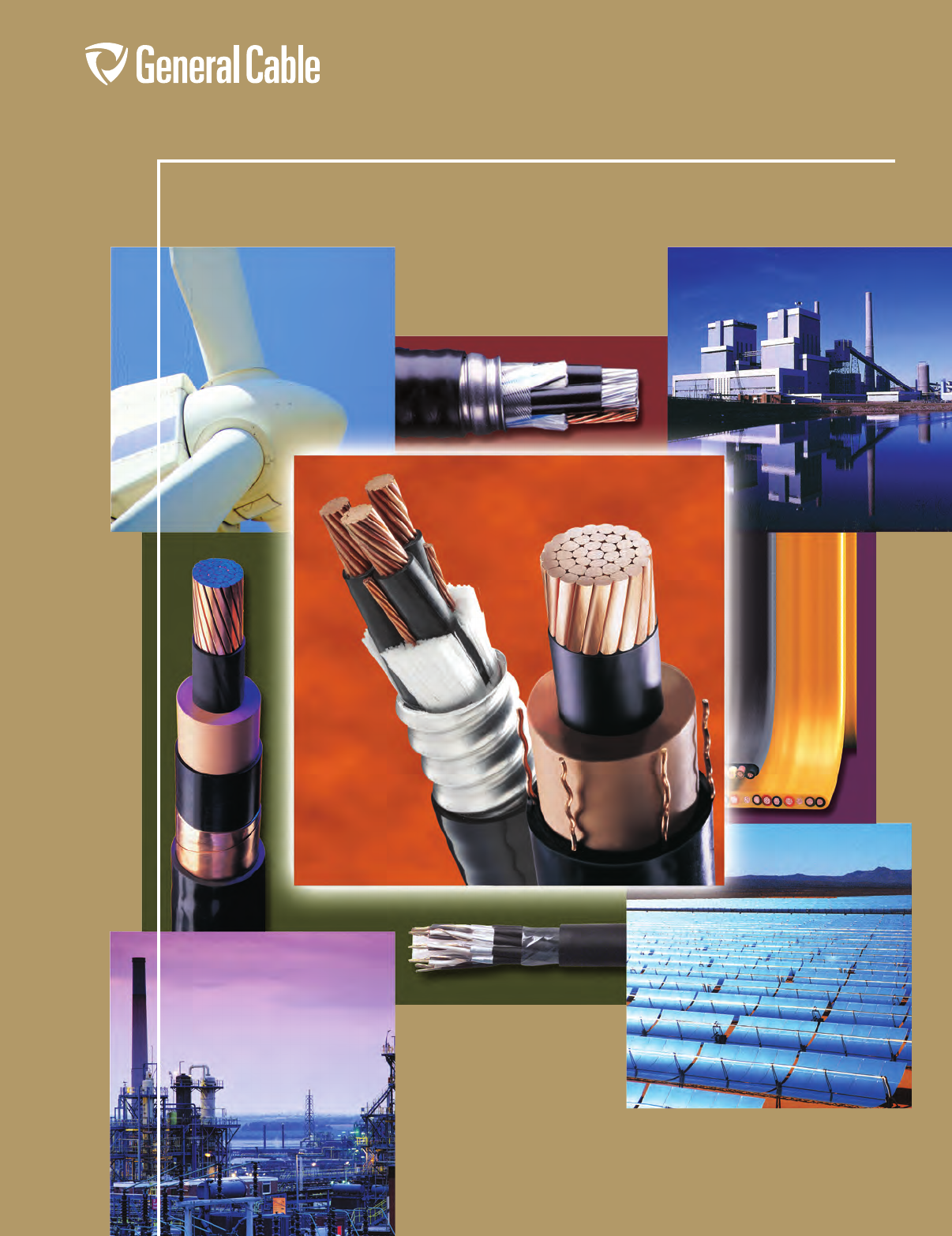
Industrial
Servicing Industrial,
Commercial and Specialty
Applications
This catalog contains in-depth
information on the most
comprehensive line of
instrumentation, power and
control cable available today.
It features the latest information
on products, along with detailed
technical and specification data
in indexed sections — with an
easy-to-use “spec-on-a-page”
format.
The “spec-on-a-page” format
was developed to meet your
needs. It features up-to-the-
minute product information,
from applications and
constructions to detailed
technical and specification
data. There’s also a glossary of
technical terms for additional
assistance.
And, of course, if you need any
further data, General Cable’s
Customer Service staff provides
the answers you need quickly
and efficiently.
All information in this catalog is presented solely
as a guide to product selection and is believed
to be reliable. All printing errors are subject to
correction in subsequent releases of this catalog.
Although General Cable has taken precautions to
ensure the accuracy of the product specifications
at the time of publication, the specifications of all
products contained herein are subject to change
without notice.
GENERAL CABLE, ARCTIC-FLEX, CCW, CHTC,
CVTC, DURAFLEX, DURALOX, DURASHEATH,
EHTC, FLEXFOIL, FREP, GENFREE, NVN, PNH,
PVIC, STRANDFILL, SUNGEN, SUPER VU-
TRON, VERTITECK, VNTC, UNIBLEND, UNICON
and UNISHIELD are trademarks of General Cable
Technologies Corporation.
© 2013. General Cable Technologies Corporation.
Highland Heights, KY 41076
All rights reserved. Printed in USA.
HARNESSING THE RENEWABLE POWER
OF THE SUN
General Cable has the offering to comprise a complete cable
solution for solar power applications. From low-voltage DC and
AC connections and medium-voltage distribution to high-voltage
overhead and underground transmission lines, General Cable’s
range of products is engineered to withstand the demands of
entire solar power generation, transmission and distribution
systems — from the sun to the outlet.
GLOBAL OIL AND GAS SOLUTIONS
From exploration and extraction to production and processing
of natural resources, General Cable’s products satisfy virtually
every cabling requirement around the globe.
DELIVERING THE RENEWABLE POWER
OF WIND ENERGY
General Cable has the offering to comprise a complete cable
solution for wind power applications. From optical fiber and
grounding wires for SCADA systems, low-voltage DC and AC
connections and medium-voltage distribution to high-voltage
overhead, underground and submarine transmission lines,
General Cable has the range of products engineered to withstand
the demands of entire wind power generation, transmission and
distribution systems — from the wind to the outlet.
What’s New?
BUILDING WIRE
Building wire is the most frequently specified wiring solution
today for commercial and residential construction projects.
General Cable offers a complete line of copper and aluminum alloy
building wire to serve virtually all the requirements of the electrical
industry. Our aluminum alloy building wire line consists of service
entrance cables for residential applications and power distribution
feeder cables for commercial, institutional and industrial
construction applications. Find out more about General Cable's
STABILOY® and NUAL® Brands of aluminum alloy cables.
Phone: 888-593-3355
www.generalcable.com
PRODUCT SELECTION LOCATOR
SECTION SPECIFICATION
1300 V Instrumentation Cables 1000
2600 V Instrumentation Cables 2000
3600 V Flexible Control and Power Cables 3000
4600 V Multi-Conductor Control and Power Cables 4000
5600 V — 2 kV Industrial Power Cables 5000
62.4 kV — 35 kV Industrial Medium-Voltage Cables 6000
7600 V — 35 kV Industrial Armored Cables 7000
8600 V — 28 kV TECK90 Armored Control and Power Cables 8000
9300 V — 35 kV CCW
®
Armored Cables for Hazardous Locations 9000
Technical Information A – F
Phone: 888-593-3355
www.generalcable.com
Section 1 300 V Instrumentation Cables
SPECIFICATION NO. PRODUCT DESCRIPTION REVISION DATE
1050 CHTC® XLPE/XL-CPE, Instrumentation, Shielded
300 V, UL Type PLTC, Overall Shielded Pairs/Triads
Mar. 2012
1100 CHTC® XLPE/XL-CPE, Instrumentation, Shielded
300 V, UL Type PLTC, Individual and Overall Shielded Pairs
Mar. 2012
1150 CVTC® XLPE/PVC, Instrumentation, Shielded
300 V, UL Type PLTC, Overall Shielded Pairs/Triads
Mar. 2012
1200 CVTC® XLPE/PVC, Instrumentation, Shielded
300 V, UL Type PLTC, Individual and Overall Shielded Pairs
Mar. 2012
1250†PVIC® PVC/PVC, Instrumentation, Shielded
300 V, UL Type PLTC/ITC, Overall Shielded Pairs/Triads
Mar. 2012
1300†PVIC® PVC/PVC, Instrumentation, Shielded
300 V, UL Type PLTC/ITC, Individual and Overall Shielded Pairs
Mar. 2012
1350 PVIC® PVC/PVC, Instrumentation, Shielded
300 V, UL Type PLTC/ITC, Individual and Overall Shielded Triads
Mar. 2012
Section 2 600 V Instrumentation Cables
SPECIFICATION NO. PRODUCT DESCRIPTION REVISION DATE
2050†CHTC® XLPE/XL-CPE, Instrumentation, Shielded
600 V, UL Type TC, Individual and Overall Shielded Pairs/Triads
Mar. 2012
2100†FREP® FR-EPR/CPE, Instrumentation, Shielded
600 V, UL Type TC, Overall Shielded Pairs/Triads
Mar. 2012
2150†FREP® FR-EPR/CPE, Instrumentation, Shielded
600 V, UL Type TC, Individual and Overall Shielded Pairs
Mar. 2012
2200 FREP® FR-EPR/CPE, Instrumentation, Shielded
600 V, UL Type TC, Individual and Overall Shielded Triads
Mar. 2012
2250 Arctic-Flex® XLPE/ARCTIC-PVC, Instrumentation, Shielded
600 V, UL Type TC, CSA Type CIC, Overall Shielded Pairs/Triads
Mar. 2012
2300 Arctic-Flex® XLPE/ARCTIC-PVC, Instrumentation, Shielded
600 V, UL Type TC, CSA Type CIC, Individual and Overall Shielded Pairs
Mar. 2012
2350 CVTC® XLPE/PVC, Instrumentation, Shielded
600 V, UL Type TC, Overall Shielded Pairs/Triads
Mar. 2012
2400 CVTC® XLPE/PVC, Instrumentation, Shielded
600 V, UL Type TC, Individual and Overall Shielded Pairs
Mar. 2012
2450†VNTC® PVC/Nylon/PVC, Instrumentation, Shielded
600 V, UL Type TC, Overall Shielded Pairs/Triads
Mar. 2012
2500†VNTC® PVC/Nylon/PVC, Instrumentation, Shielded
600 V, UL Type TC, Individual and Overall Shielded Pairs
Mar. 2012
2600†GenFree® XLPE/LSZH, Instrumentation, Shielded
600 V, UL Type TC-LS, Overall Shielded Pairs/Triads
Mar. 2012
2625†GenFree®XLPE/LSZH, Instrumentation, Shielded
600 V, UL Type TC-LS, Individual and Overall Shielded Pairs
Mar. 2012
2650 GenFree® XLPE/LSZH, Instrumentation, Shielded
600 V, UL Type TC-LS, Individual and Overall Shielded Triads
Mar. 2012
Section 3 600 V Flexible Control and Power Cables
SPECIFICATION NO. PRODUCT DESCRIPTION REVISION DATE
3150 NVN®PVC/Nylon/Neoprene, Thermoset Flexible Control
600 V, UL Type TC
Jan. 2010
3250 MTW PVC/Nylon/PVC, Thermoplastic Flexible Control
600 V, UL Type MTW/CSA AWM
Jan. 2010
3300 Festoon PVC/PVC, Thermoplastic Extreme Flexing Festoon Control and Power
600 V, UL/CSA Type Festoon
Jan. 2010
Table of Contents
Date of Issue 06/13
†Indicates these products are stocked by General Cable

Phone: 888-593-3355
www.generalcable.com
Table of Contents
Date of Issue 06/13
†Indicates these products are stocked by General Cable
Section 4 600 V Multi-Conductor Control and Power Cables
SPECIFICATION NO. PRODUCT DESCRIPTION REVISION DATE
4050†CHTC®XLPE/XL-CPE, Control, Unshielded
600 V, UL Type TC—E-2 Color Code
Mar. 2012
4075†CHTC®XLPE/XL-CPE, Control, Unshielded
600 V, UL Type TC—E-1 Color Code
Mar. 2012
4100†CHTC®XLPE/XL-CPE, Low-Voltage Power, Unshielded
600 V, UL Type TC-ER—Method 4 Color Code
Mar. 2012
4150 EHTC®FR-EPR/XL-CPE, Control, Unshielded
600 V, UL Type TC (18 AWG/16 AWG)—E-2 Color Code
Mar. 2012
4200 EHTC®FR-EPR/XL-CPE, Control, Unshielded
600 V, UL Type TC (14 AWG—10 AWG)—E-2 Color Code
Mar. 2012
4250 EHTC®FR-EPR/XL-CPE, Low-Voltage Power, Unshielded
600 V, UL Type TC-ER—Method 4 Color Code
Mar. 2012
4300†FREP®FR-EPR/CPE, Control, Unshielded
600 V, UL Type TC-ER—E-2 Color Code
Mar. 2012
4310†FREP®FR-EPR/CPE, Control, Unshielded
600 V, UL Type TC-ER—E-1 Color Code
Mar. 2012
4325†FREP®FR-EPR/CPE, Control, Shielded
600 V, UL Type TC-ER, Overall Shielded—E-2 Color Code
Mar. 2012
4350†FREP®FR-EPR/CPE, Low-Voltage Power, Unshielded
600 V, UL Type TC-ER—Method 4 Color Code
Aug. 2012
4400 Arctic-Flex®XLPE/Arctic-PVC, Control, Unshielded
600 V, UL Type TC-ER, CSA Type RW90 XLPE, CSA Type TC
Mar. 2012
4450 Arctic-Flex®XLPE/Arctic-PVC, Low-Voltage Power, Unshielded
600 V, UL Type TC-ER, CSA Type RW90 XLPE, CSA Type TC
Mar. 2012
4460 CCTC™FR-XLPE/CPE, Control, Shielded
600 V, UL Type TC-ER—E-1 Color Code
Jun. 2012
4480 CCTC™FR-XLPE/CPE, Low-Voltage Power, Shielded
600 V, UL Type TC-ER—Method 4 Color Code
Jun. 2012
4500†CVTC®XLPE/PVC, Control, Unshielded
600 V, UL Type TC-ER—E-2 Color Code
Mar. 2012
4550†CVTC®XLPE/PVC, Low-Voltage Power, Unshielded
600 V, UL Type TC-ER—Method 4 Color Code
Mar. 2012
4575 CVTC® VFD XLPE/PVC, Low-Voltage Power, Shielded
2000 V, UL Type TC-ER—Method 4 Color Code
Mar. 2012
4580†CVTC® VFD XLPE/PVC, Low-Voltage Power, Copper Tape Shielded
2000 V, UL Type TC-ER—Method 4 Color Code
Mar. 2012
4600†VNTC®PVC/Nylon/PVC, Control, Unshielded
600 V, UL Type TC-ER (18 AWG/16 AWG)—E-2 Color Code
Mar. 2012
4650†VNTC®PVC/Nylon/PVC, Control, Unshielded
600 V, UL Type TC-ER (14 AWG—10 AWG)—E-2 Color Code
Mar. 2012
4700†VNTC®PVC/Nylon/PVC, Control, Shielded
600 V, UL Type TC-ER, Overall Shielded—E-2 Color Code
Mar. 2012
4750†VNTC®PVC/Nylon/PVC, Low-Voltage Power, Unshielded
600 V, UL Type TC-ER—Method 4 Color Code
Mar. 2012
4775†TC-Flex™18 AWG (1,0 mm²)—16 AWG (1,5 mm²)
UL Type WTTC 1000 V or Type TC-ER 600 V or Type MTW and c(UL) CIC/TC
600 V FT4 or CSA AWM 90°C 1000 V
Jun. 2013
4780†TC-Flex™14 AWG (2,5 mm²)–10 AWG (6,0 mm²)
UL Type WTTC 1000 V or Type TC-ER 600 V or Type MTW and c(UL) CIC/TC
600 V FT4 or CSA AWM 90°C 1000 V
Jun. 2013
Phone: 888-593-3355
www.generalcable.com
Section 4 (cont’d.) 600 V Multi-Conductor Control and Power Cables
SPECIFICATION NO. PRODUCT DESCRIPTION REVISION DATE
4785†TC-Flex™18 AWG (1,0 mm²)—16 AWG (1,5 mm²)
UL Type WTTC 1000 V or Type TC-ER 600 V or Type MTW and c(UL) CIC/TC
600 V FT4 or CSA AWM 90°C 1000 V
Jun. 2013
4790†TC-Flex™14 AWG (2,5 mm²)—4 AWG (35,0 mm²)
UL Type WTTC 1000 V or Type TC-ER 600 V or Type MTW and c(UL) CIC/TC
600 V FT4 or CSA AWM 90°C 1000 V
Jun. 2013
4800 20/10 PE/PVC/PVC, Control, Unshielded
600 V (18 AWG/16 AWG)—E-1 Color Code
Jul. 2010
4850 20/10 PE/PVC/PVC, Control, Unshielded
600 V (14 AWG—10 AWG)—E-1 Color Code
Jul. 2010
4900†GenFree®XLPE/LSZH, Control
600 V, UL Type TC-LS-ER—E-2 Color Code
Oct. 2012
4925 GenFree®XLPE/LSZH, Control, Shielded
600 V, UL Type TC-LS-ER, Overall Shielded—E-2 Color Code
Oct. 2012
4950†GenFree®XLPE/LSZH, Low-Voltage Power, Unshielded
600 V, UL Type TC-LS-ER—Method 4 Color Code
Oct. 2012
Section 5 600 V – 2 kV Industrial Power Cables
SPECIFICATION NO. PRODUCT DESCRIPTION REVISION DATE
5050†DuraSheath®EPR/XL-CPE, Low-Voltage Power, Unshielded
600 V, UL Type RHH/RHW-2/USE-2
Mar. 2012
5075GenFree® II LSZH XLPO/LSZH XLPO, Low-Voltage Power, Unshielded
600 V, UL Type RHH/RHW-2/USE-2
Jun. 2013
5100 Unicon® FREP®FR-EPR, Low-Voltage Power, Unshielded
600 V, UL Type RHH/RHW-2/USE-2
Jan. 2010
5125 GenFree® II LSZH XLPO, Low-Voltage Power, Unshielded
600 V, UL Type XHHW-2
Jun. 2013
5150†XHHW-2 VW-1 XLPE, Control and Low-Voltage Power
600 V, UL Type SIS/XHHW-2, VW-1 Rated
Oct. 2012
5175†XHHW-2 CT XLPE, Low-Voltage Power
600 V, UL Type XHHW-2, CT Rated, Single Conductor, Copper
Jan. 2013
5250†Unicon® XLPE XLPE, Low-Voltage Power
600 V, UL Type RHH/RHW-2/USE-2
Oct. 2012
5275 GenFree® II LSZH XLPO, Low-Voltage Power, Unshielded
600 V, UL Type RHH/RHW-2/USE-2
Jun. 2013
5290†THHN/THWN-2 PVC, Low-Voltage Power
600 V, UL Type THHN/THWN-2, Single Conductor, Copper
Oct. 2012
5300 Super Vu-Tron®EPR/CPE, Diesel Locomotive Cable
90°C, 2000 V, DLO, UL Type RHH/RHW, 600 V, CSA Type R90, 1000 V
Mar. 2012
5310†
Diesel Locomotive
Cable
2000 Volts (EPR/XL-CPE), UL RHH/RHW-2 2000 V and c(UL) RW90 1000 V
Flexible, Oil-, Sunlight- and Ozone-Resistant, Flame-Retardant, -40°C to 90°C
May 2012
5350†GenFree® LSZH Sept. 2013
5400 GenFree® LSZH Sept. 2013
5700†RHH/RHW-2 XLPE, Low-Voltage Power, Unshielded
2000 V, UL Type RHH/RHW-2, Single Conductor, Aluminum
Mar. 2012
5790 SunGen® Global XLPE/LSZH XLPO, Photovoltaic Wire, TÜV 2 pfg
1169/08.2007 PV1-F AC Uo/U 0.6/1 kV, UL 4703, PV Wire 2000 V
May 2012
Table of Contents
Date of Issue 06/13
†Indicates these products are stocked by General Cable
DISCONTINUED
DISCONTINUED
Phone: 888-593-3355
www.generalcable.com
Section 5 (cont’d.) 600 V – 2 kV Industrial Power Cables
SPECIFICATION NO. PRODUCT DESCRIPTION REVISION DATE
5800†SunGen®Dual-Layer EPR/XL-CPE, Photovoltaic Wire
600 V, UL Type PV/USE-2/RHH or RHW-2, Single Conductor, Copper
May 2012
5800A SunGen®Dual-Layer EPR/XL-CPE, Photovoltaic Wire
600 V, UL Type PV/USE-2/RHH or RHW-2, Single Conductor, Aluminum
Oct. 2012
5810†SunGen®Dual-Layer EPR/XL-CPE, Photovoltaic Wire
2000 V, UL Type PV/RHH or RHW-2 or 600 V USE-2, Single Conductor, Copper
May 2012
5810A SunGen®Dual-Layer EPR/XL-CPE, Photovoltaic Wire
2000 V, UL Type PV/RHH or RHW-2 or 600 V USE-2, Single Conductor, Aluminum
Oct. 2012
5840†SunGen®XLPE, Photovoltaic Wire
600 V, UL Type PV/USE-2 or 2000 V RHH or RHW-2 or CSA RPVU90
1000 V, Single Conductor, Copper
May 2012
5840A SunGen®XLPE, Photovoltaic Wire
600 V, UL Type PV/USE-2 or 2000 V RHH or RHW-2 or CSA RPVU90
1000 V, Single Conductor, Aluminum
Oct. 2012
5845†SunGen® IC XLPE, Photovoltaic Wire
600 V, UL Type PV/USE-2 or 2000 V RHH or RHW-2 or CSA RPVU90
1000 V, Single Conductor, Copper
May 2012
5850†SunGen®XLPE, Photovoltaic Wire
2000 V, UL Type PV/RHH or RHW-2 or 600 V USE-2 or CSA RPVU90
1000 V, Single Conductor, Copper
May 2012
5850A SunGen®XLPE, Photovoltaic Wire
2000 V, UL Type PV/RHH or RHW-2 or 600 V USE-2 or CSA RPVU90
1000 V, Single Conductor, Aluminum
Oct. 2012
5855†SunGen® IC XLPE, Photovoltaic Wire
2000 V, UL Type PV/RHH or RHW-2 or 600 V USE-2 or CSA RPVU90
1000 V, Single Conductor, Copper
May 2012
5880†SunGen® MI XLPE/PVC, AC Micro-Inverter Cable
600 V, UL Type TC-ER
May 2012
5890†SunGen® MI-LS XLPO/LSZH, AC Micro-Inverter Cable
600 V, UL Type TC-LS-ER
May 2012
Section 6 2.4 kV – 35 kV Industrial Medium-Voltage Cables
SPECIFICATION NO. PRODUCT DESCRIPTION REVISION DATE
6050†DuraSheath®EPR/XL-CPE, Medium-Voltage Power, Nonshielded
2400 V, UL Type MV-90
Aug. 2011
6100†UniShield®EPR/Copper Wire Shield/CPE, Medium-Voltage Power, Shielded
5 kV and 8 kV, UL Type MV-105, 133%/100% Ins. Levels, 115 Mils
Jun. 2013
6150 Uniblend®EPR/Copper Tape Shield/PVC, Medium-Voltage Power, Shielded
5 kV and 8 kV, UL Type MV-105, 133%/100% Ins. Levels, 115 Mils
Mar. 2012
6155†Uniblend® LF EPR/Copper Tape Shield/PVC, Medium-Voltage Power, Shielded
5 kV and 8 kV, UL Type MV-105, 133%/100% Ins. Levels, 115 Mils
Mar. 2012
6160†Aluminum
Uniblend® LF
EPR/Copper Tape Shield/PVC, Medium-Voltage Power, Shielded
5 kV and 8 kV, UL Type MV-105, 133%/100% Ins. Levels, 115 Mils
Mar. 2012
6175 Uniblend®EPR/Copper Tape Shield/CPE, Medium-Voltage Power, Shielded
5 kV and 8 kV, UL Type MV-105, 133%/100% Ins. Levels, 115 Mils
Mar. 2012
6180†GenFree®
Uniblend®
EPR/Copper Tape Shield/LSZH, Medium-Voltage Power, Shielded
5 kV and 8 kV, UL Type MV-105/ST1, 133%/100% Ins. Levels, 115 Mils
Mar. 2012
6200 Copper Wire
Shield
TRXLPE/Copper Wire Shield/PVC, Medium-Voltage Power
5 kV, UL Type MV-105, 100% Ins. Level, 90 Mils
Jan. 2011
6250 Uniblend®EPR/Copper Tape Shield with Overall PVC Jacket
Medium-Voltage Power, Shielded, 5 kV and 8 kV, UL Type MV-105
133%/100% Ins. Levels, 115 Mils, Three Conductor
Mar. 2012
Table of Contents
Date of Issue 06/13
†Indicates these products are stocked by General Cable
Phone: 888-593-3355
www.generalcable.com
Table of Contents
Date of Issue 06/13
†Indicates these products are stocked by General Cable
Section 6 (cont’d.) 2.4 kV – 35 kV Industrial Medium-Voltage Cables
SPECIFICATION NO. PRODUCT DESCRIPTION REVISION DATE
6255†Uniblend® LF EPR/Copper Tape Shield with Overall PVC Jacket
Medium-Voltage Power, Shielded, 5 kV and 8 kV, UL Type MV-105
133%/100% Ins. Levels, 115 Mils, Three Conductor
Mar. 2012
6275 Uniblend®EPR/Copper Tape Shield with Overall CPE Jacket
Medium-Voltage Power, Shielded, 5 kV and 8 kV, UL Type MV-105
133%/100% Ins. Levels, 115 Mils, Three Conductor
Mar. 2012
6280 GenFree®
Uniblend®
EPR/Copper Tape Shield with Overall LSZH Jacket
Medium-Voltage Power, Shielded, 5 kV and 8 kV, UL Type MV-105
133%/100% Ins. Levels, 115 Mils, Three Conductor
Mar. 2012
6300†UniShield®EPR/Copper Wire Shield/CPE, Medium-Voltage Power, Shielded
15 kV, UL Type MV-105, 133% Ins. Level, 220 Mils
Jun. 2013
6350 Uniblend®EPR/Copper Tape Shield/PVC, Medium-Voltage Power, Shielded
15 kV, UL Type MV-105, 133% Ins. Level, 220 Mils
Mar. 2012
6355†Uniblend® LF EPR/Copper Tape Shield/PVC, Medium-Voltage Power, Shielded
15 kV, UL Type MV-105, 133% Ins. Level, 220 Mils
Apr. 2011
6360†Aluminum
Uniblend® LF
EPR/Copper Tape Shield/PVC, Medium-Voltage Power, Shielded
15 kV, UL Type MV-105, 133% Ins. Level, 220 Mils
Apr. 2011
6375 Uniblend®EPR/Copper Tape Shield/CPE, Medium-Voltage Power, Shielded
15 kV, UL Type MV-105, 133% Ins. Level, 220 Mils
Apr. 2011
6380†GenFree®
Uniblend®
EPR/Copper Tape Shield/LSZH, Medium-Voltage Power, Shielded
15 kV, UL Type MV-105/ST1, 133% Ins. Level, 220 Mils
Mar. 2012
6400 Copper Wire
Shield
TRXLPE/Copper Wire Shield/PVC, Medium-Voltage Power
15 kV, UL Type MV-105, 133% Ins. Level, 220 Mils
Jan. 2011
6450 Uniblend®EPR/Copper Tape Shield with Overall PVC Jacket
Medium-Voltage Power, Shielded, 15 kV, UL Type MV-105
133% Ins. Level, 220 Mils, Three Conductor
Mar. 2012
6455†Uniblend® LF EPR/Copper Tape Shield with Overall PVC Jacket
Medium-Voltage Power, Shielded, 15 kV, UL Type MV-105
133% Ins. Level, 220 Mils, Three Conductor
Mar. 2012
6475 Uniblend®EPR/Copper Tape Shield with Overall CPE Jacket
Medium-Voltage Power, Shielded, 15 kV, UL Type MV-105
133% Ins. Level, 220 Mils, Three Conductor
Mar. 2012
6480 GenFree®
Uniblend®
EPR/Copper Tape Shield with Overall LSZH Jacket
Medium-Voltage Power, Shielded, 15 kV, UL Type MV-105
133% Ins. Level, 220 Mils, Three Conductor
Mar. 2012
6500 UniShield®EPR/Copper Wire Shield/CPE, Medium-Voltage Power, Shielded
25 kV and 35 kV, UL Type MV-105, 133%/100% Ins. Levels, 345 Mils
Jun. 2013
6550 Uniblend®EPR/Copper Tape Shield/PVC, Medium-Voltage Power, Shielded
25 kV and 35 kV, UL Type MV-105, 133%/100% Ins. Levels, 345 Mils
Mar. 2012
6555†Uniblend® LF EPR/Copper Tape Shield/PVC, Medium-Voltage Power, Shielded
25 kV and 35 kV, UL Type MV-105, 133%/100% Ins. Levels, 345 Mils
Mar. 2012
6560 Aluminum
Uniblend® LF
EPR/Copper Tape Shield/PVC, Medium-Voltage Power, Shielded
25 kV and 35 kV, UL Type MV-105, 133%/100% Ins. Levels, 345 Mils
Mar. 2012
6575 Uniblend®EPR/Copper Tape Shield/CPE, Medium-Voltage Power, Shielded
25 kV and 35 kV, UL Type MV-105, 133%/100% Ins. Levels, 345 Mils
Mar. 2012
6580 GenFree®
Uniblend®
EPR/Copper Tape Shield/LSZH, Medium-Voltage Power, Shielded
25 kV and 35 kV, UL Type MV-105/ST1, 133%/100% Ins. Levels, 345 Mils
Mar. 2012
6600 Uniblend®EPR/Copper Tape Shield with Overall PVC Jacket
Medium-Voltage Power, Shielded, 25 kV and 35 kV, UL Type MV-105
133%/100% Ins. Levels, 345 Mils, Three Conductor
Mar. 2012
Phone: 888-593-3355
www.generalcable.com
Table of Contents
Date of Issue 06/13
†Indicates these products are stocked by General Cable
Section 6 (cont’d.) 2.4 kV – 35 kV Industrial Medium-Voltage Cables
SPECIFICATION NO. PRODUCT DESCRIPTION REVISION DATE
6605 Uniblend® LF EPR/Copper Tape Shield with Overall PVC Jacket
Medium-Voltage Power, Shielded, 25 kV and 35 kV, UL Type MV-105
133%/100% Ins. Levels, 345 Mils, Three Conductor
Mar. 2012
6650 Uniblend®EPR/Copper Tape Shield/PVC, Medium-Voltage Power, Shielded
35 kV, UL Type MV-105, 133% Ins. Levels, 420 Mils
Apr. 2011
6655 Uniblend® LF EPR/Copper Tape Shield/PVC, Medium-Voltage Power, Shielded
35 kV, UL Type MV-105, 133% Ins. Levels, 420 Mils
Apr. 2011
6660 Aluminum
Uniblend® LF
EPR/Copper Tape Shield/PVC, Medium-Voltage Power, Shielded
35 kV, UL Type MV-105, 133% Ins. Levels, 420 Mils
Apr. 2011
Section 7 600 V – 35 kV Industrial Armored Cables
SPECIFICATION NO. PRODUCT DESCRIPTION REVISION DATE
7050†Duralox®XLPE/AIA/PVC, Control, Armored
600 V, UL Type MC, Multi-Conductor
Jan. 2010
7100†Duralox®XLPE/AIA/PVC, Power, Armored
600 V, UL Type MC, Three and Four Conductor (8 AWG - 4/0 AWG)
Jun. 2013
7150†Duralox®XLPE/AIA/PVC, Power, Armored
600 V, UL Type MC, Three and Four Conductor (250 kcmil - 1000 kcmil)
Jun. 2013
7160†Duralox®XLPE/AIA/PVC, Power, Armored, with Enhanced Ground Wires (50%)
600 V, UL Type MC, Three Conductor (1/0 AWG - 1000 kcmil)
Jun. 2013
7200†Duralox®EPR/AIA/PVC, Power, Nonshielded, Armored
2400 V, UL Type MV-90 or MC, Three Conductor
Jan. 2010
7250†Duralox®
Uniblend®
EPR/AIA/PVC, Power, Shielded, Armored
5 kV/8 kV, UL Type MV-105 or MC, 133%/100% Ins. Levels, 115 Mils, Three Conductor
Aug. 2010
7300†Duralox®
Uniblend®
EPR/AIA/PVC, Power, Shielded, Armored
15 kV, UL Type MV-105 or MC, 133% Ins. Level, 220 Mils, Three Conductor
Aug. 2010
7310†Duralox®
Uniblend®
EPR/AIA/PVC, Power, Shielded, Armored, with Enhanced Ground Wires (50%)
15 kV, UL Type MV-105 or MC, 133% Ins. Level, 220 Mils, Three Conductor
Aug. 2010
7350 Duralox®
Uniblend®
EPR/AIA/PVC, Power, Shielded, Armored
25 kV, UL Type MV-105 or MC, 100% Ins. Level, 260 Mils, Three Conductor
Aug. 2010
7400 Duralox®
Uniblend®
EPR/AIA/PVC, Power, Shielded, Armored
35 kV, UL Type MV-105 or MC, 100% Ins. Level, 345 Mils, Three Conductor
Aug. 2010
Section 8 600 V – 28 kV TECK90 Armored Control and Power Cables
SPECIFICATION NO. PRODUCT DESCRIPTION REVISION DATE
8025†TECK90 XLPE/PVC/AIA/PVC, Control, Armored
600 V, CSA TECK90, Multi-Conductor, 14 AWG
Mar. 2012
8050†TECK90 XLPE/PVC/AIA/PVC, Control, Armored
600 V, CSA TECK90, Multi-Conductor, 12 AWG
Mar. 2012
8075†TECK90 XLPE/PVC/AIA/PVC, Control, Armored
600 V, CSA TECK90, Multi-Conductor, 10 AWG
Mar. 2012
8100 TECK90 XLPE/PVC/AIA/PVC, Power, Armored
1000 V, CSA TECK90, Single Conductor
Mar. 2012
8125 TECK90 XLPE/PVC/AIA/PVC, Control and Power, Armored
1000 V, CSA TECK90, Two Conductor
Mar. 2012
8150†TECK90 XLPE/PVC/AIA/PVC, Control and Power, Armored
1000 V, CSA TECK90, Three Conductor
Mar. 2012
8175†TECK90 XLPE/PVC/AIA/PVC, Control and Power, Armored
1000 V, CSA TECK90, Four Conductor
Mar. 2012
Phone: 888-593-3355
www.generalcable.com
Section 8 (cont’d.) 600 V – 28 kV TECK90 Armored Control and Power Cables
SPECIFICATION NO. PRODUCT DESCRIPTION REVISION DATE
8200 TECK90 XLPE/PVC/AIA/PVC, Power/Control Composite
600 V, CSA TECK90, Three Power and Three 14 AWG Control Conductors
Mar. 2012
8225 TECK90 XLPE/PVC/AIA/PVC, Power, Unshielded, Armored
5 kV, CSA TECK90, 100%/133% Ins. Levels, Single Conductor
Oct. 2012
8250†TECK90 XLPE/PVC/AIA/PVC, Power, Unshielded, Armored
5 kV, CSA TECK90, 100%/133% Ins. Levels, Three Conductor
Jun. 2013
8275 HVTECK TRXLPE/Wire Shield/PVC/AIA/PVC, Power, Shielded, Armored
5 kV, CSA HVTECK, 100%/133% Ins. Levels, 90 Mils, Single Conductor
Oct. 2012
8300 HVTECK TRXLPE/Wire Shield/PVC/AIA/PVC, Power, Shielded, Armored
5 kV, CSA HVTECK, 133% Ins. Level, 115 Mils, Single Conductor
Oct. 2012
8325 HVTECK TRXLPE/Tape Shield/PVC/AIA/PVC, Power, Shielded, Armored
5 kV, CSA HVTECK, 100%/133% Ins. Levels, 90 Mils, Three Conductor
Oct. 2012
8350 HVTECK TRXLPE/Tape Shield/PVC/AIA/PVC, Power, Shielded, Armored
5 kV, CSA HVTECK, 133% Ins. Level, 115 Mils, Three Conductor
Oct. 2012
8375 HVTECK TRXLPE/Wire Shield/PVC/AIA/PVC, Power, Shielded, Armored
15 kV, CSA HVTECK, 100% Ins. Level, 175 Mils, Single Conductor
Oct. 2012
8400 HVTECK TRXLPE/Wire Shield/PVC/AIA/PVC, Power, Shielded, Armored
15 kV, CSA HVTECK, 133% Ins. Level, 220 Mils, Single Conductor
Oct. 2012
8425 HVTECK TRXLPE/Tape Shield/PVC/AIA/PVC, Power, Shielded, Armored
15 kV, CSA HVTECK, 100% Ins. Level, 175 Mils, Three Conductor
Oct. 2012
8450†HVTECK TRXLPE/Tape Shield/PVC/AIA/PVC, Power, Shielded, Armored
15 kV, CSA HVTECK, 133% Ins. Level, 220 Mils, Three Conductor
Oct. 2012
8475 HVTECK TRXLPE/Tape Shield/PVC/AIA/PVC, Power, Shielded, Armored
25 kV, CSA HVTECK, 100% Ins. Level, 260 Mils, Three Conductor
Oct. 2012
8500 HVTECK TRXLPE/Tape Shield/PVC/AIA/PVC, Power, Shielded, Armored
25 kV, CSA HVTECK, 133% Ins. Level, 320 Mils, Three Conductor
Oct. 2012
8525 HVTECK TRXLPE/Tape Shield/PVC/AIA/PVC, Power, Shielded, Armored
28 kV, CSA HVTECK, 133% Ins. Level, 345 Mils, Three Conductor
Oct. 2012
8550 VERTITECK®
TECK90
XLPE/PVC/GSIA/PVC, Power, Unshielded, Armored
1 kV, CSA TECK90, Three Conductor
Jan. 2010
8575 VERTITECK®
TECK90
XLPE/PVC/GSIA/PVC, Power, Unshielded, Armored
5 kV, CSA TECK90, 90 Mils, Three Conductor
Oct. 2012
8600
VERTITECK
®
HVTECK
TRXLPE/Tape Shield/PVC/GSIA/PVC, Power, Shielded, Armored
15 kV, CSA HVTECK, 133% Ins. Level, 220 Mils, Three Conductor
Oct. 2012
8625
VERTITECK
®
HVTECK
TRXLPE/Tape Shield/PVC/GSIA/PVC, Power, Shielded, Armored
15 kV, CSA HVTECK, 100% Ins. Level, 175 Mils, Three Conductor
Oct. 2012
8700†ACWU XLPE/AIA/PVC, Control, Armored
600 V, CSA ACWU90 (-40˚C), Single Conductor
Mar. 2012
8750†ACWU XLPE/AIA/PVC, Control, Armored
600 V, CSA ACWU90 (-40˚C), Three Conductor
Mar. 2012
8775†ACWU XLPE/AIA/PVC, Control, Armored
600 V, CSA ACWU90 (-40˚C), Four Conductor
Mar. 2012
Table of Contents
Date of Issue 06/13
†Indicates these products are stocked by General Cable
Phone: 888-593-3355
www.generalcable.com
Table of Contents
Date of Issue 06/13
†Indicates these products are stocked by General Cable
Section 9 300 V - 35 kV CCW® Armored Cables for Hazardous Locations
SPECIFICATION NO. PRODUCT DESCRIPTION REVISION DATE
9025 CCW®
Armor
Thermocouple Extension, Single Pair, Overall Shield (OS)
UL Type ITC-HL/PLTC, PVC, 105°C, ABS CWCMC
Apr. 2011
9050 CCW®
Armor
Thermocouple Extension, Pairs, Overall Shield (OS)
UL Type ITC-HL/PLTC, PVC, 105°C, ABS CWCMC
Apr. 2011
9075 CCW®
Armor
Thermocouple Extension, Pairs, Individual and Overall Shield (IS-OS)
UL Type ITC-HL/PLTC, PVC, 105°C, ABS CWCMC
Apr. 2011
9125 CCW®
Armor
300 V Instrumentation, Pairs/Triads, Overall Shield (OS)
UL Type ITC-HL/PLTC, XLPE, 90°C, ABS CWCMC
Apr. 2011
9150 CCW®
Armor
300 V Instrumentation, Pairs/Triads, Individual and Overall Shield (IS-OS)
UL Type ITC-HL/PLTC, XLPE, 90°C, ABS CWCMC
Apr. 2011
9225 CCW®
Armor
300 V Instrumentation, Pairs/Triads, Overall Shield (OS)
UL Type ITC-HL/PLTC, PVC, 105°C, ABS CWCMC
Apr. 2011
9250 CCW®
Armor
300 V Instrumentation, Pairs/Triads, Individual and Overall Shield (IS-OS)
UL Type ITC-HL/PLTC, PVC, 105°C, ABS CWCMC
Apr. 2011
9325 CCW®
Armor
600 V Instrumentation, Pairs/Triads, Overall Shield (OS)
UL Type MC-HL, PVC/Nylon, 90°C, ABS CWCMC
Feb. 2011
9350 CCW®
Armor
600 V Instrumentation, Pairs/Triads, Individual and Overall Shield (IS-OS)
UL Type MC-HL, PVC/Nylon, 90°C, ABS CWCMC
Feb. 2011
9500 CCW®
Armor
600 V Control With Grounding Conductor
UL Type MC-HL, XLPE, 90°C, ABS CWCMC
Feb. 2011
9510 CCW®
Armor
600 V Control With Bare Grounding Conductor
UL Type MC-HL, XLPE, 90°C, ABS CWCMC
Feb. 2011
9525 CCW®
Armor
600 V Control Without Grounding Conductor
UL Type MC, XLPE, 90°C, ABS CWCMC
Feb. 2011
9600 CCW®
Armor
600 V Power, 3/C VFD and 4/C
UL Type MC-HL, XLPE, 90°C, ABS CWCMC
Feb. 2011
9615 CCW®
Armor
2000 V Power, 3/C VFD
UL Type MC-HL, XLPE, 90°C, ABS CWCMC
Feb. 2011
9625 CCW®
Armor
600 V Composite Power and Control
UL Type MC-HL, XLPE, 90°C, ABS CWCMC
Jan. 2011
9650 CCW®
Armor
600 V Composite Power and Control Without Ground
UL Type MC, XLPE, 90°C, ABS CWCMC
Feb. 2011
9675 CCW®
Armor
1000 V Power, 3/C VFD
CSA Type RA90, HL, XLPE, 90°C
Mar. 2012
9700 CCW®
Armor
2.4 kV Power, Nonshielded, 3/C VFD
UL Type MC-HL or MV-90, EPR, 90°C, ABS CWCMC
Feb. 2011
9800 CCW®
Armor
5 kV 133%/8 kV 100% Power, Shielded, 3/C VFD
UL Type MC-HL or MV-105, EPR, 105°C, ABS CWCMC
May 2012
9815 CCW®
Armor
8 kV 133% Power, Shielded, 3/C VFD
UL Type MC-HL or MV-105, EPR, 105°C, ABS CWCMC
May 2012
9825 CCW®
Armor
15 kV 100% Power, Shielded, 3/C
UL Type MC-HL or MV-105, EPR, 105°C, ABS CWCMC
May 2012
9835 CCW®
Armor
15 kV 133% Power, Shielded, 3/C
UL Type MC-HL or MV-105, EPR, 105°C, ABS CWCMC
May 2012
9845 CCW®
Armor
25 kV 100% Power, Shielded, 3/C
UL Type MC-HL or MV-105, EPR, 105°C, ABS CWCMC
May 2012
9855 CCW®
Armor
25 kV 133%/35 kV 100% Power, Shielded, 3/C
UL Type MC-HL or MV-105, EPR, 105°C, ABS CWCMC
Feb. 2011
9875 CCW®
Armor
35 kV 133% Power, Shielded, 3/C
UL Type MC-HL or MV-105, EPR, 105°C, ABS CWCMC
Feb. 2011
9900 CCW®
Armor
CCW® Armored Cable Tool Kit Jan. 2010
Phone: 888-593-3355
www.generalcable.com
Section A General Technical Information
SPECIFICATION NO. DESCRIPTION REVISION DATE
A005 Glossary Jan. 2010
A025 Reference Standards Jan. 2010
A050 Checklist for Specifications Jan. 2010
A075 NEC and CSA Designations Jan. 2010
A100 Common Color Sequence May 2013
A150 Metric Conversion Factors Sept. 2010
A200 Reel Capacity Chart Jan. 2012
Section B Conductor Data
SPECIFICATION NO. DESCRIPTION REVISION DATE
B005 Conductor Reference Jan. 2010
B025 Class B Conductors for General Wiring Mar. 2012
B030 Class C Conductors for General Wiring Feb. 2011
B035 Class H Conductors for General Wiring Feb. 2011
B040 Class I Conductors for General Wiring Mar. 2012
B045 Class K Conductors for General Wiring Mar. 2012
Section C Material Properties
SPECIFICATION NO. DESCRIPTION REVISION DATE
C005 Thermoplastic Jacket and Insulation Material Properties Sept. 2012
C010 Thermoset Jacket and Insulation Material Properties Jan. 2010
Section D Handling and Storage Recommendations
SPECIFICATION NO. DESCRIPTION REVISION DATE
D005 Recommended Reel Handling Practices May 2013
D025 Recommended Cable Handling Practices Oct. 2011
D050 Recommended Cable Storage Practices May 2013
Table of Contents
Date of Issue 06/13
Phone: 888-593-3355
www.generalcable.com
Section E Cable Installation Guidelines
SPECIFICATION NO. DESCRIPTION REVISION DATE
E005 Pre-Installation Instructions Apr. 2010
E025 Installation – Overview and Checklist Jan. 2011
E050 Installation – Feed-In Setups Apr. 2010
E075 Installation – Conductor Maximum Pulling Tensions Oct. 2012
E100 Installation – Training and Bending Limitations Apr. 2010
E125 Installation – Maximum Sidewall Pressure Oct. 2012
Section F Cable Testing
SPECIFICATION NO. DESCRIPTION REVISION DATE
F005 DC “HI-POT” Pre-Test Guidelines for MV Cables Apr. 2010
F025 DC “HI-POT” Testing Guidelines for MV Cables Apr. 2010
F075 Field Electrical “HI-POT” Testing Guidelines Apr. 2010
F100 Emergency Overload Current Guidelines Jan. 2010
F125 Short Circuit Current Calculation Overview Jan. 2010
F150 Short Circuit Current for Copper Shields Jan. 2010
F175 AC Resistance & Inductive Reactance Jun. 2013
Table of Contents
Date of Issue 06/13
General Cable believes corporate social responsibility (CSR) is about creating shared value. That
means keeping a dual focus in our business decisions: what is good for us as a company and what
contributes to the greater good of the communities in which we live and work.
Corporate Social Responsibility
CREATING SHARED VALUE
+1.859.572.8000
info@generalcable.com
SAFETY
Working safer by working together
General Cable has one worldwide safety vision and goal – ZERO & BEYOND. We
measure safety performance globally, share best practices and implement sound health
and safety management systems. Many of our facilities worldwide are OHSAS 18001
(safety management system) certified. All North American facilities have implemented
an equivalent health and safety management system. General Cable was a pioneer in
obtaining the OHSAS 18001 Certificate for Occupational Health and Safety Management
Systems in Europe and North Africa.
SUSTAINABILITY
Responsible practices in daily operations
As a global leader in the wire and cable industry, General Cable recognizes its role and
responsibility in promoting sustainability. Our strongest business value is continuous
improvement in all areas of our company. Across our many businesses, the quest to
introduce new and better products through continuous improvement in environmental
designs reflects our commitment to achieving industry-leading standards and responding
proactively to global environmental issues. General Cable was the first cable manufacturer
to obtain certification for its environmental management system, in accordance with the
ISO 14001 and EMAS Standards.
CITIZENSHIP
A commitment to being good citizens
Being responsible citizens in our communities is of the utmost importance to us.
Unequivocal honesty, integrity, forthrightness and fair dealing have long been part of
General Cable’s core values and are expected globally in all of our business relationships
with our customers, employees, suppliers, neighbors and competitors. Our company
leaders and employees strive to make a difference throughout a host of volunteer activities
and financial support, improving the communities in which we live and work.
INNOVATION
Technologies that power and connect the world
General Cable is delivering innovation that matters. We are focusing on R&D expertise and
investing in developing wire and cable solutions that meet the challenges confronting our
customers and the world. In working together and using all the ingenuity and creativity we
have, we will reach the goal of being the preeminent supplier of wire and cabling solutions
in the industry, both with green constructions and designs for the ever-growing renewable
energy market.
Visit www.GeneralCableCSR.com to learn more.
A commitment to achieving industry-leading standards
and responding proactively to environmental global issues.
General Cable is a leader in the
development, design, manufacture,
marketing and distribution of copper,
aluminum and fiber optic wire and cable
for the energy, industrial, specialty and
communications markets.
Our products inspire progress worldwide …
customers use our value-added products
to create global infrastructure that
improves the standard of living for
people everywhere.
Each day we’re building business
momentum — developing ideas into
innovative solutions and industry-leading
products, expanding geographic access and
furthering our investment in highly capable
associates, Lean Manufacturing, material
science and technology resources.
As one of the largest wire and cable manufacturers with more than
14,000 associates, 57 manufacturing facilities in 26 countries and
sales representation and distribution worldwide, we are truly
One Company Connecting the World.
Energy Cables
Our cables carry energy across the world — through the air,
underground and under the sea. Increasing demand for energy is
accelerating investment in exploration, extraction, power generation,
transmission and distribution — whether based on coal, natural gas,
oil, nuclear, wind, solar or water.
Industrial & Specialty Cables
Our cables channel the power and signals that make equipment hum
and engines run. From oil rigs and broadcast studios to cars and trains,
and in commercial buildings, public venues, factory floors and special
applications such as military, nuclear, marine and mining — we serve
an extensive range of markets.
Communications Cables
Our cables keep information flowing — facilitating a non-stop stream
of words and images around the world. We meet the high-speed
bandwidth needs of global communications networks, from fiber
optic submarine communications cables, copper and fiber aerial and
underground cables to copper and fiber optic enterprise cables and
system solutions.
World Headquarters
General Cable
4 Tesseneer Drive
Highland Heights, KY
41076-9753 U.S.A.
Building Bridges in the Sky
Making Contact with the World
Directing Traffic without Gridlock
Phone: 888-593-3355
www.generalcable.com
Date of Issue 06/13
Section 1 Industrial Cables
SPECIFICATION NO. PRODUCT DESCRIPTION REVISION DATE
1050 CHTC® XLPE/XL-CPE, Instrumentation, Shielded
300 V, UL Type PLTC, Overall Shielded Pairs/Triads
Mar. 2012
1100 CHTC® XLPE/XL-CPE, Instrumentation, Shielded
300 V, UL Type PLTC, Individual and Overall Shielded Pairs
Mar. 2012
1150 CVTC® XLPE/PVC, Instrumentation, Shielded
300 V, UL Type PLTC, Overall Shielded Pairs/Triads
Mar. 2012
1200 CVTC® XLPE/PVC, Instrumentation, Shielded
300 V, UL Type PLTC, Individual and Overall Shielded Pairs
Mar. 2012
1250†PVIC® PVC/PVC, Instrumentation, Shielded
300 V, UL Type PLTC/ITC, Overall Shielded Pairs/Triads
Mar. 2012
1300†PVIC® PVC/PVC, Instrumentation, Shielded
300 V, UL Type PLTC/ITC, Individual and Overall Shielded Pairs
Mar. 2012
1350 PVIC® PVC/PVC, Instrumentation, Shielded
300 V, UL Type PLTC/ITC, Individual and Overall Shielded Triads
Mar. 2012
†Indicates these products are stocked by General Cable
300 V Instrumentation Cables
Phone: 888-593-3355
www.generalcable.com
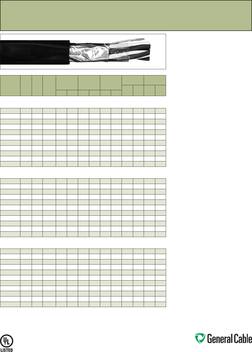
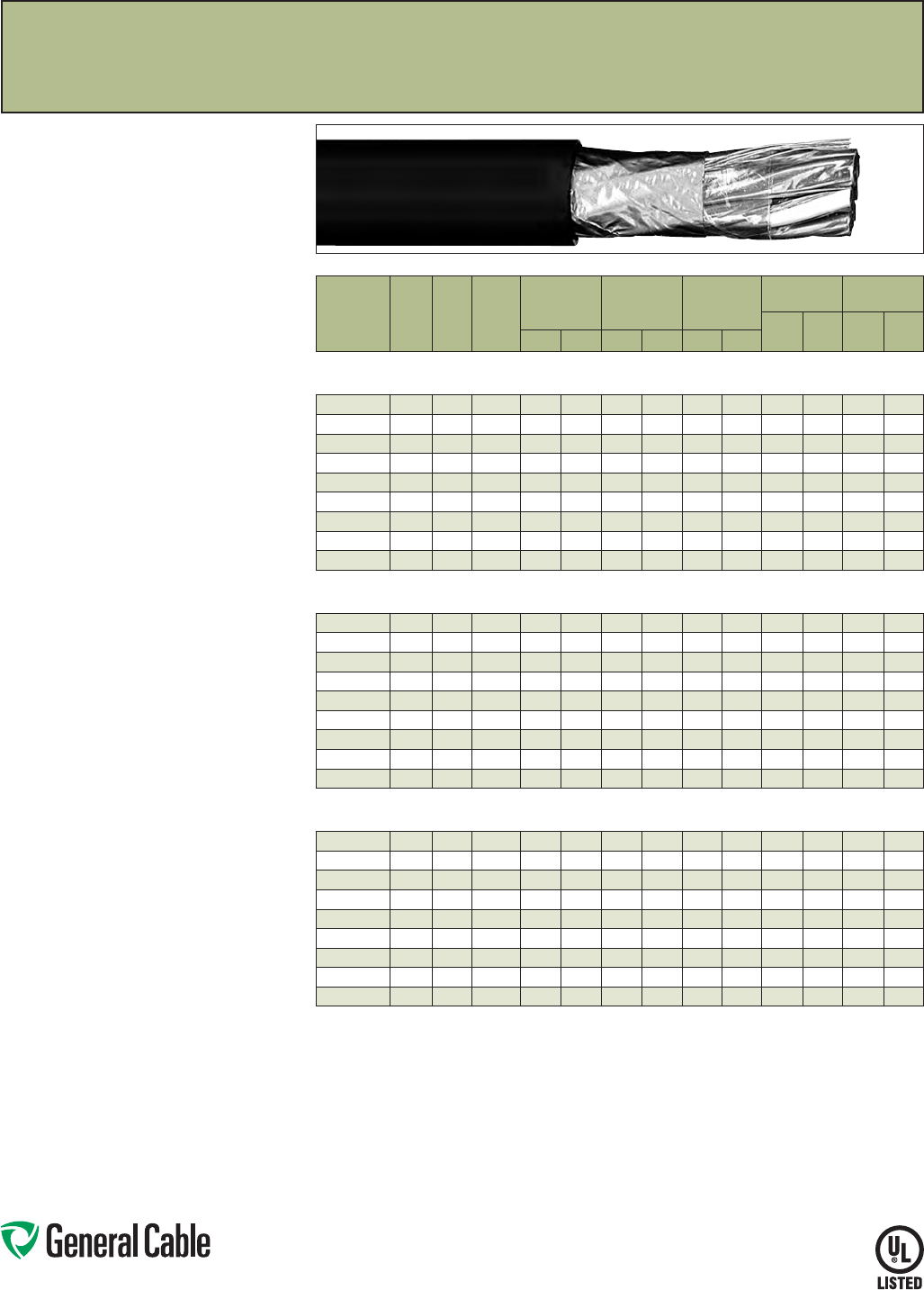
SPEC 1050
March, 2012
CHTC
®
XLPE/XL-CPE, Instrumentation, Shielded
300 V, UL Type PLTC, Overall Shielded Pairs/Triads
Product Construction:
Conductor:
• 20 AWG thru 16 AWG tinned, annealed copper per
ASTM B33
• Class B stranding per ASTM B8
Insulation:
• Flame-retardant Cross-linked Polyethylene (XLPE)
• Color-coded per ICEA Method 1: Pairs - black
and white; Triads - black, white and red. One
conductor in each pair or triad is printed alpha-
numerically for easy identification
Shield:
Overall shielded pairs/triads
• Overall shield is Flexfoil® aluminum/polymer in
contact with stranded tinned copper drain wire
Jacket:
• Lead-free Cross-linked Chlorinated Polyethylene
(XL-CPE )
Print:
• GENERAL CABLE® (PLANT OF MFG) CHTC XX/
PS/TS XXAWG CU/XLP/XL-CPE SHIELDED (UL)
TYPE PLTC 90˚C SUN RES OIL RES I & II PLUS
DAY/MONTH/YEAR OF MFG SEQUENTIAL
FOOTAGE MARK
Options:
• Bare copper conductor
• Class C stranding
• Individual and overall shielded pairs/triads
• Thermoplastic Low-Smoke, Zero-Halogen (LSZH)
jacket
• In accordance with UL Subject 2250 as
Instrumentation Tray Cable (ITC)
• Other constructions available upon request
Applications:
• Typical applications include audio, intercom,
control, energy management and alarm circuits
• In free air or raceways in accordance with NEC
• Permitted for use in Class I, Division 2 industrial
hazardous locations per NEC
• In ducts, cable trays or conduit
• In accordance with UL Subject 13 as Power-
Limited Circuit Cable
• In class 3 circuits in accordance with NEC
Features:
• Rated at 90˚C
• Ripcord applied to all cables with jacket thickness
of 60 mils or less
• Oil-resistant jacket
• Sunlight- and weather-resistant
• Excellent electrical, thermal and physical
properties
• Excellent moisture resistance
• Excellent flame resistance
• “Heavy duty” rating per ICEA standards
• Excellent low temperature cold bend
characteristics
• Meets cold bend test at -35˚C
Compliances:
Industry Compliances:
• UL 13 Type PLTC, UL File # E36118
• UL 1581
Flame Test Compliances:
• UL 1581/UL 2556 VW-1
• IEEE 383
• IEEE 1202
• CSA FT4
Other Compliances:
• EPA 40 CFR, Part 261 for leachable lead
content per TCLP
• OSHA Acceptable
Packaging:
• Material cut to length and shipped on
non-returnable wood reels
CATALOG
NUMBER
NO. OF
PAIRS/
TRIADS
COND.
SIZE
(AWG)
COND.
STRAND
MINIMUM AVG.
INSULATION
THICKNESS
MINIMUM AVG.
JACKET
THICKNESS
NOMINAL
CABLE O.D.
COPPER
WEIGHT NET WEIGHT
LBS/
1000 FT kg/km
LBS/
1000 FT kg/kmINCHES mm INCHES mm INCHES mm
OVERALL SHIELDED PAIRS/TRIADS
20 AWG CONDUCTORS
337770* 120 7/.0121 0.012 0.30 0.035 0.89 0.230 5.84 914 27 40
337780* 1 TRI 20 7/.0121 0.012 0.30 0.035 0.89 0.240 6.10 13 19 33 49
337790* 2 20 7/.0121 0.012 0.30 0.040 1.02 0.320 8.13 17 25 48 71
309660* 4 20 7/.0121 0.012 0.30 0.040 1.02 0.370 9.40 31 47 73 109
309670* 8 20 7/.0121 0.012 0.30 0.050 1.27 0.500 12.70 60 90 138 205
309680* 12 20 7/.0121 0.012 0.30 0.050 1.27 0.575 14.61 89 133 186 277
337800* 16 20 7/.0121 0.012 0.30 0.060 1.52 0.665 16.89 118 176 248 369
337810* 20 20 7/.0121 0.012 0.30 0.060 1.52 0.740 18.80 148 220 300 446
309690* 24 20 7/.0121 0.012 0.30 0.060 1.52 0.795 20.19 177 263 350 521
311640* 36 20 7/.0121 0.012 0.30 0.070 1.78 1.005 25.53 264 392 525 781
309700* 50 20 7/.0121 0.012 0.30 0.070 1.78 1.175 29.85 365 544 697 1037
OVERALL SHIELDED PAIRS/TRIADS
18 AWG CONDUCTORS
337820* 118 7/.0152 0.015 0.38 0.035 0.89 0.245 6.22 13 19 32 48
337830* 1 TRI 18 7/.0152 0.015 0.38 0.035 0.89 0.255 6.48 18 26 40 60
337840* 218 7/.0152 0.015 0.38 0.040 1.02 0.350 8.89 23 34 58 86
337850* 418 7/.0152 0.015 0.38 0.050 1.27 0.425 10.80 44 65 99 147
337860* 818 7/.0152 0.015 0.38 0.050 1.27 0.545 13.84 86 127 173 257
337870* 12 18 7/.0152 0.015 0.38 0.060 1.52 0.640 16.26 127 189 245 365
337880* 16 18 7/.0152 0.015 0.38 0.060 1.52 0.730 18.54 169 251 318 473
337890* 20 18 7/.0152 0.015 0.38 0.060 1.52 0.810 20.57 210 313 392 583
337900* 24 18 7/.0152 0.015 0.38 0.070 1.78 0.895 22.73 252 375 450 670
337910* 36 18 7/.0152 0.015 0.38 0.070 1.78 1.095 27.81 377 561 672 1000
337920* 50 18 7/.0152 0.015 0.38 0.070 1.78 1.255 31.88 523 778 904 1345
OVERALL SHIELDED PAIRS/TRIADS
16 AWG CONDUCTORS
309520* 116 7/.0192 0.015 0.38 0.035 0.89 0.270 6.86 18 28 41 61
337930* 1 TRI 16 7/.0192 0.015 0.38 0.035 0.89 0.285 7.24 27 40 54 80
337940* 216 7/.0192 0.015 0.38 0.050 1.27 0.430 10.92 36 53 85 126
337950* 416 7/.0192 0.015 0.38 0.050 1.27 0.490 12.45 69 102 135 201
337960* 816 7/.0192 0.015 0.38 0.060 1.52 0.650 16.51 135 201 246 366
337970* 12 16 7/.0192 0.015 0.38 0.060 1.52 0.755 19.18 202 300 346 515
337980* 16 16 7/.0192 0.015 0.38 0.060 1.52 0.845 21.46 268 399 444 661
337990* 20 16 7/.0192 0.015 0.38 0.060 1.52 0.900 22.86 335 498 552 821
338000* 24 16 7/.0192 0.015 0.38 0.070 1.78 1.020 25.91 401 597 655 975
338010* 36 16 7/.0192 0.015 0.38 0.070 1.78 1.225 31.12 601 894 649 966
338020* 50 16 7/.0192 0.015 0.38 0.080 2.03 1.415 35.94 834 1241 1308 1947
Dimensions and weights are nominal; subject to industry tolerances.
* Non-stock item; minimum runs apply. Please consult Customer Service for price and delivery.
Phone: 888-593-3355
www.generalcable.com
S P E C 110 0
March, 2012
CHTC
®
XLPE/XL-CPE, Instrumentation, Shielded
300 V, UL Type PLTC, Individual and Overall Shielded Pairs
CATALOG
NUMBER
NO. OF
PAIRS
COND.
SIZE
(AWG)
COND.
STRAND
MINIMUM AVG.
INSULATION
THICKNESS
MINIMUM AVG.
JACKET
THICKNESS
NOMINAL
CABLE O.D.
COPPER
WEIGHT NET WEIGHT
LBS/
1000 FT kg/km
LBS/
1000 FT kg/kmINCHES mm INCHES mm INCHES mm
INDIVIDUAL AND OVERALL SHIELDED PAIRS
20 AWG CONDUCTORS
338030* 2 20 7/.0121 0.012 0.30 0.040 1.02 0.340 8.64 21 31 54 80
309540* 4 20 7/.0121 0.012 0.30 0.050 1.27 0.415 10.54 40 60 93 138
309550* 8 20 7/.0121 0.012 0.30 0.050 1.27 0.525 13.34 78 116 157 234
309560* 12 20 7/.0121 0.012 0.30 0.060 1.52 0.645 16.38 117 147 233 347
338040* 16 20 7/.0121 0.012 0.30 0.060 1.52 0.715 18.16 155 231 294 438
338050* 20 20 7/.0121 0.012 0.30 0.060 1.52 0.785 19.94 193 287 357 531
309570* 24 20 7/.0121 0.012 0.30 0.070 1.78 0.875 22.23 231 344 422 628
309580* 36 20 7/.0121 0.012 0.30 0.070 1.78 1.045 26.54 346 515 620 923
338060* 50 20 7/.0121 0.012 0.30 0.070 1.78 1.215 30.86 479 713 828 1232
INDIVIDUAL AND OVERALL SHIELDED PAIRS
18 AWG CONDUCTORS
338070* 218 7/.0152 0.015 0.38 0.050 1.27 0.415 10.54 28 41 76 113
338080* 418 7/.0152 0.015 0.38 0.050 1.27 0.475 12.07 53 79 113 168
338090* 818 7/.0152 0.015 0.38 0.060 1.52 0.605 15.37 104 155 203 302
338100* 12 18 7/.0152 0.015 0.38 0.060 1.52 0.750 19.05 155 231 300 446
338110* 16 18 7/.0152 0.015 0.38 0.060 1.52 0.830 21.08 206 307 383 570
338120* 20 18 7/.0152 0.015 0.38 0.070 1.78 0.945 24.00 254 378 483 719
338130* 24 18 7/.0152 0.015 0.38 0.070 1.758 1.045 26.54 308 459 571 850
338140* 36 18 7/.0152 0.015 0.38 0.070 1.78 1.225 31.12 461 687 816 1214
338150* 50 18 7/.0152 0.015 0.38 0.080 2.03 1.450 36.83 640 952 1119 1665
INDIVIDUAL AND OVERALL SHIELDED PAIRS
16 AWG CONDUCTORS
338160* 216 7/.0192 0.015 0.38 0.050 1.27 0.440 11.18 40 60 92 137
338170* 416 7/.0192 0.015 0.38 0.050 1.27 0.545 13.84 78 116 163 243
338180* 816 7/.0192 0.015 0.38 0.060 1.52 0.965 24.51 153 228 287 427
338190* 12 16 7/.0192 0.015 0.38 0.060 1.52 0.885 22.48 229 341 437 650
338200* 16 16 7/.0192 0.015 0.38 0.070 1.78 0.980 24.89 304 453 553 823
338210* 20 16 7/.0192 0.015 0.38 0.070 1.78 1.080 27.43 380 566 680 1012
338220* 24 16 7/.0192 0.015 0.38 0.070 1.78 1.235 31.37 455 677 800 1191
338230* 36 16 7/.0192 0.015 0.38 0.080 2.03 1.405 35.69 662 985 1108 1649
338240* 50 16 7/.0192 0.015 0.38 0.080 2.03 1.640 41.66 945 1408 1523 2267
Dimensions and weights are nominal; subject to industry tolerances.
* Non-stock item; minimum runs apply. Please consult Customer Service for price and delivery.
Product Construction:
Conductor:
• 20 AWG thru 16 AWG tinned, annealed copper per
ASTM B33
• Class B stranding per ASTM B8
Insulation:
• Flame-retardant Cross-linked Polyethylene (XLPE)
• Color-coded per ICEA Method 1: Pairs - black and
white. One conductor in each pair is printed alpha-
numerically for easy identification
Shield:
Individual and overall shielded pairs
• Individual pairs are 100% shielded with Flexfoil®
aluminum/polyester in contact with stranded
tinned copper drain wire
• Overall shield is Flexfoil® aluminum/polymer in
contact with stranded tinned copper drain wire
Jacket:
• Lead-free Cross-linked Chlorinated Polyethylene
(XL-CPE )
Print:
• GENERAL CABLE® (PLANT OF MFG) CHTC XX/
SPS XX AWG CU/XLP/XL-CPE SHIELDED (UL)
TYPE PLTC 90˚C SUN RES OIL RES I & II DAY/
MONTH/YEAR OF MFG SEQUENTIAL FOOTAGE
MARK
Options:
• Bare copper conductor
• Class C stranding
• Overall shielded pairs
• Thermoplastic Low-Smoke, Zero-Halogen (LSZH)
jacket
• In accordance with UL Subject 2250 as
Instrumentation Tray Cable (ITC)
• Other constructions available upon request
Applications:
• Typical applications include audio, intercom,
control, energy management and alarm circuits
• In free air or raceways in accordance with NEC
• Permitted for use in Class I, Division 2 industrial
hazardous locations per NEC
• In ducts, cable trays or conduit
• In accordance with UL Subject 13 as Power-
Limited Circuit Cable
• In class 3 circuits in accordance with NEC
Features:
• Rated at 90˚C
• Ripcord applied to all cables with jacket thickness
of 60 mils or less
• Oil-resistant jacket
• Sunlight- and weather-resistant
• Excellent electrical, thermal and physical
properties
• Excellent moisture resistance
• Excellent flame resistance
• “Heavy duty” rating per ICEA standards
• Excellent low temperature cold bend
characteristics
• Meets cold bend test at -35˚C
Compliances:
Industry Compliances:
• UL 13 Type PLTC, UL File # E36118
• UL 1581
Flame Test Compliances:
• UL 1581/UL 2556 VW-1
• IEEE 383
• IEEE 1202
• CSA FT4
Other Compliances:
• EPA 40 CFR, Part 261 for leachable lead
content per TCLP
• OSHA Acceptable
Packaging:
• Material cut to length and shipped on
non-returnable wood reels
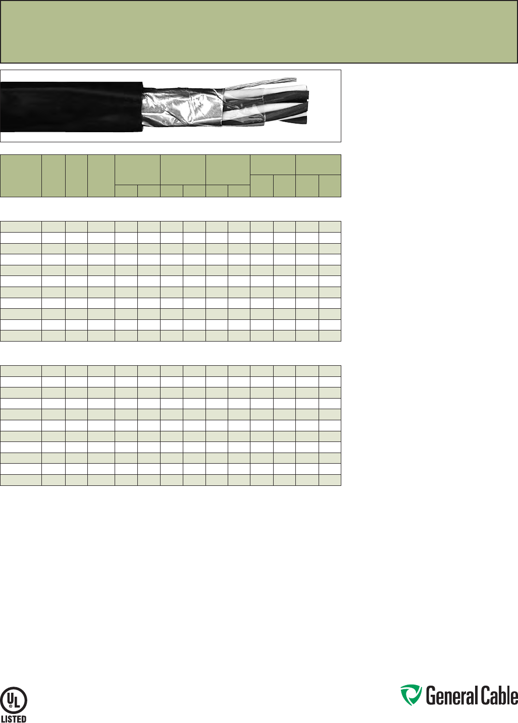
Phone: 888-593-3355
www.generalcable.com
S P E C 115 0
March, 2012
Product Construction:
Conductor:
• 18 AWG and 16 AWG bare, annealed
copper per ASTM B3
• Class B stranding per ASTM B8
Insulation:
• Flame-retardant Cross-linked Polyethylene (XLPE)
• Color-coded per ICEA Method 1: Pairs - black
and white; Triads - black, white and red. One
conductor in each pair or triad is printed alpha-
numerically for easy identification
Shield:
Overall shielded pairs/triads
• Overall shield is Flexfoil® aluminum/polymer in
contact with stranded tinned copper drain wire
Jacket:
• Lead-free, flame-retardant, sunlight-resistant
Polyvinyl Chloride (PVC)
Print:
• GENERAL CABLE® (PLANT OF MFG) CVTC XX/
PS/TS XXAWG FR-XLP/PVC SHIELDED (UL) TYPE
PLTC 90
˚
C SUN RES PLUS DAY/MONTH/YEAR
OF MFG SEQUENTIAL FOOTAGE MARK
Options:
• Tinned copper conductor
• Class C stranding
• Individual and overall shielded pairs/triads
• Ethylene Propylene Rubber (EPR) insulation
• In accordance with UL Subject 2250 as
Instrumentation Tray Cable (ITC)
• Other constructions available upon request
Applications:
• In free air and raceways in accordance with NEC
• Typical applications include audio, intercom,
control, energy management and alarm circuits
• In ducts, cable trays or conduit
• In accordance with UL Subject 13 as Power-
Limited Circuit Cable
• In Class 3 circuits in accordance with NEC
• Permitted for use in Class I, Division 2 industrial
hazardous locations per NEC
Features:
• Rated at 90
˚
C
• Ripcord applied to all cables with jacket thickness
of 60 mils or less
• Abrasion- and chemical-resistant
• Excellent electrical properties
• Sunlight- and weather-resistant
• Meets cold bend test at -25
˚
C
Compliances:
Industry Compliances:
• UL 13 Type PLTC, UL File # E36118
• UL 1581
Flame Test Compliances:
• UL 1581/UL 2556 VW-1
• IEEE 383
Other Compliances:
• EPA 40 CFR, Part 261 for leachable lead
content per TCLP
• OSHA Acceptable
Packaging:
• Material cut to length and shipped on
non-returnable wood reels
CVTC
®
XLPE/PVC, Instrumentation, Shielded
300 V, UL Type PLTC, Overall Shielded Pairs/Triads
CATALOG
NUMBER
NO. OF
PAIRS/
TRIADS
COND.
SIZE
(AWG)
COND.
STRAND
MINIMUM AVG.
INSULATION
THICKNESS
MINIMUM AVG.
JACKET
THICKNESS
NOMINAL
CABLE O.D.
COPPER
WEIGHT NET WEIGHT
LBS/
1000 FT kg/km
LBS/
1000 FT kg/kmINCHES mm INCHES mm INCHES mm
OVERALL SHIELDED PAIRS/TRIADS
18 AWG CONDUCTORS
366140* 118 7/.0152 0.015 0.38 0.035 0.89 0.235 5.97 13 19 32 48
342930* 1 TRI 18 7/.0152 0.015 0.38 0.040 1.02 0.250 6.35 18 27 40 60
342940* 218 7/.0152 0.015 0.38 0.040 1.02 0.365 9.27 25 37 56 83
342950* 418 7/.0152 0.015 0.38 0.050 1.27 0.440 11.18 46 68 98 146
342960* 818 7/.0152 0.015 0.38 0.050 1.27 0.550 13.97 87 129 175 260
342970* 12 18 7/.0152 0.015 0.38 0.060 1.52 0.675 17.15 129 192 250 372
342980* 16 18 7/.0152 0.015 0.38 0.060 1.52 0.750 19.05 171 254 317 472
342990* 20 18 7/.0152 0.015 0.38 0.060 1.52 0.785 19.94 211 314 392 583
343000* 24 18 7/.0152 0.015 0.38 0.060 1.52 0.905 22.99 253 377 476 708
343010* 36 18 7/.0152 0.015 0.38 0.070 1.78 1.080 27.43 377 561 681 1013
343020* 50 18 7/.0152 0.015 0.38 0.070 1.78 1.245 31.62 524 780 913 1359
OVERALL SHIELDED PAIRS/TRIADS
16 AWG CONDUCTORS
366150* 116 7/.0192 0.015 0.38 0.035 0.89 0.262 6.65 19 28 42 63
343030* 1 TRI 16 7/.0192 0.015 0.38 0.040 1.02 0.280 7.11 27 40 53 79
343040* 216 7/.0192 0.015 0.38 0.050 1.27 0.430 10.92 37 55 81 121
343050* 416 7/.0192 0.015 0.38 0.050 1.27 0.490 12.45 71 106 131 195
343060* 816 7/.0192 0.015 0.38 0.060 1.52 0.650 16.51 135 201 254 378
343070* 12 16 7/.0192 0.015 0.38 0.060 1.52 0.755 19.18 203 302 350 521
343080* 16 16 7/.0192 0.015 0.38 0.060 1.52 0.845 21.46 270 402 451 671
343090* 20 16 7/.0192 0.015 0.38 0.070 1.78 0.880 22.35 334 497 545 811
343100* 24 16 7/.0192 0.015 0.38 0.070 1.78 1.020 25.91 400 595 657 978
343110* 36 16 7/.0192 0.015 0.38 0.070 1.78 1.220 30.99 599 891 965 1423
343120* 50 16 7/.0192 0.015 0.38 0.080 2.03 1.405 35.69 831 1237 1322 1967
Dimensions and weights are nominal; subject to industry tolerances.
* Non-stock item; minimum runs apply. Please consult Customer Service for price and delivery.
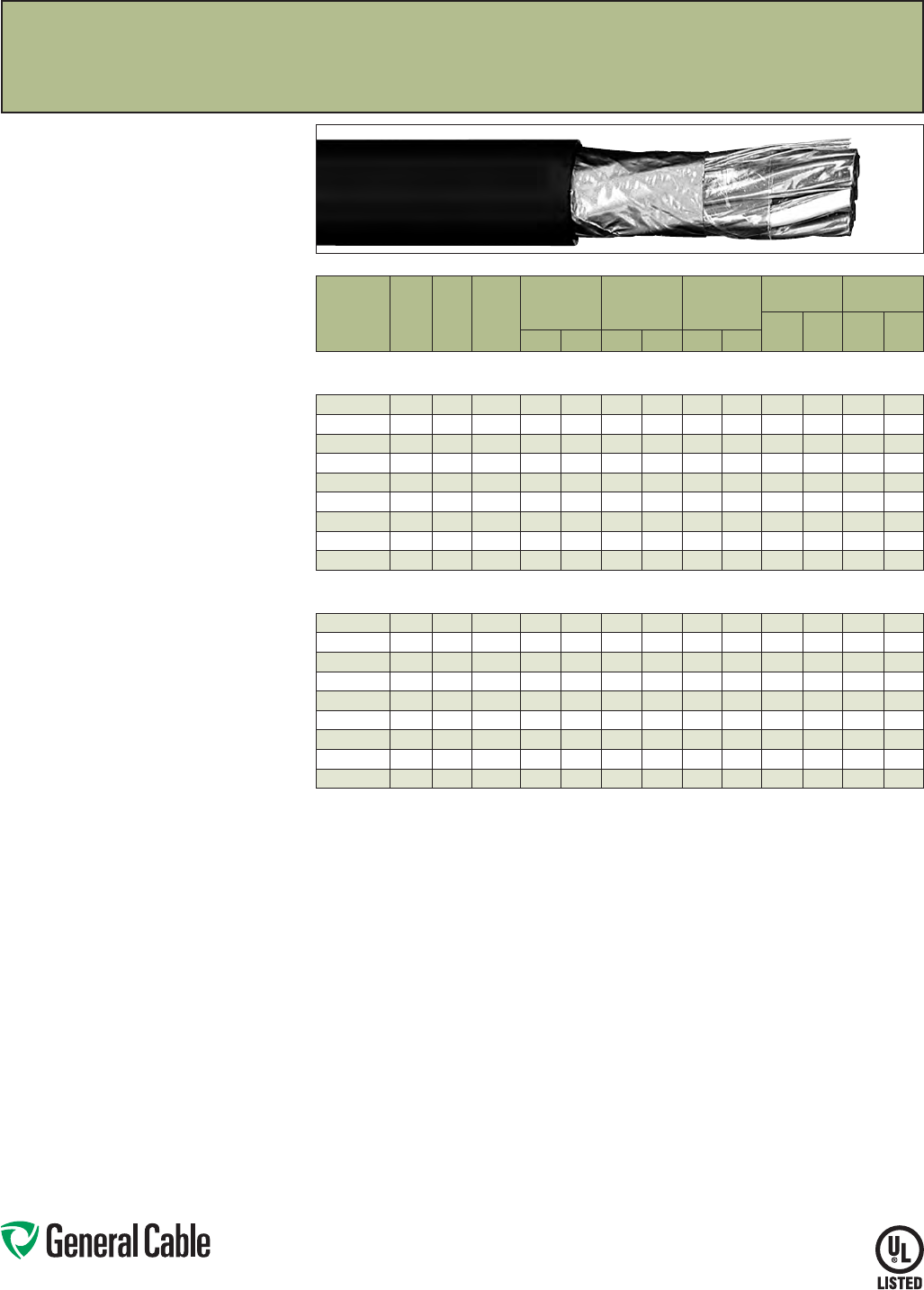
Phone: 888-593-3355
www.generalcable.com
SPEC 1200
March, 2012
CATALOG
NUMBER
NO. OF
PAIRS
COND.
SIZE
(AWG)
COND.
STRAND
MINIMUM AVG.
INSULATION
THICKNESS
MINIMUM AVG.
JACKET
THICKNESS
NOMINAL
CABLE O.D.
COPPER
WEIGHT NET WEIGHT
LBS/
1000 FT kg/km
LBS/
1000 FT kg/kmINCHES mm INCHES mm INCHES mm
INDIVIDUAL AND OVERALL SHIELDED PAIRS
18 AWG CONDUCTORS
343140* 218 7/.0152 0.015 0.38 0.050 1.27 0.410 10.41 30 45 73 109
343150* 418 7/.0152 0.015 0.38 0.050 1.27 0.475 12.07 55 82 117 174
343160* 818 7/.0152 0.015 0.38 0.050 1.27 0.605 15.37 105 156 215 320
343170* 12 18 7/.0152 0.015 0.38 0.060 1.52 0.750 19.05 156 232 308 458
343180* 16 18 7/.0152 0.015 0.38 0.060 1.52 0.830 21.08 207 308 392 583
343190* 20 18 7/.0152 0.015 0.38 0.070 1.78 0.955 24.26 252 375 494 735
343200* 24 18 7/.0152 0.015 0.38 0.070 1.78 1.030 26.16 302 449 583 868
343210* 36 18 7/.0152 0.015 0.38 0.070 1.78 1.210 30.73 452 673 830 1235
343220* 50 18 7/.0152 0.015 0.38 0.080 2.03 1.425 36.20 637 948 1145 1704
INDIVIDUAL AND OVERALL SHIELDED PAIRS
16 AWG CONDUCTORS
343240* 216 7/.0192 0.015 0.38 0.050 1.27 0.455 11.56 42 63 96 143
343250* 416 7/.0192 0.015 0.38 0.050 1.27 0.530 13.46 80 119 160 238
343260* 816 7/.0192 0.015 0.38 0.060 1.52 0.710 18.03 155 231 293 436
343270* 12 16 7/.0192 0.015 0.38 0.060 1.52 0.855 21.72 230 342 425 632
343280* 16 16 7/.0192 0.015 0.38 0.070 1.78 0.955 24.26 306 455 563 838
343290* 20 16 7/.0192 0.015 0.38 0.070 1.78 1.055 26.80 375 558 664 988
343300* 24 16 7/.0192 0.015 0.38 0.070 1.78 1.160 29.46 456 679 780 1161
343310* 36 16 7/.0192 0.015 0.38 0.080 2.03 1.380 35.05 674 1003 1137 1692
343320* 50 16 7/.0192 0.015 0.38 0.080 2.03 1.580 40.13 945 1406 1518 2259
Dimensions and weights are nominal; subject to industry tolerances.
* Non-stock item; minimum runs apply. Please consult Customer Service for price and delivery.
Product Construction:
Conductor:
• 18 AWG and 16 AWG bare, annealed copper per
ASTM B3
• Class B stranding per ASTM B8
Insulation:
• Flame-retardant Cross-linked Polyethylene (XLPE)
• Color-coded per ICEA Method 1: Pairs - black and
white. One conductor in each pair is printed alpha-
numerically for easy identification
Shield:
Individual and overall shielded pairs
• Individual pairs are 100% shielded with Flexfoil®
aluminum/polyester in contact with stranded
tinned copper drain wire
• Overall shield is Flexfoil® aluminum/polymer in
contact with stranded tinned copper drain wire
Jacket:
• Lead-free, flame-retardant, sunlight-resistant
Polyvinyl Chloride (PVC)
Print:
• GENERAL CABLE® (PLANT OF MFG) CVTC XX/
SPS XXAWG FR-XLP/PVC SHIELDED (UL) TYPE
PLTC 90
˚
C SUN RES PLUS DAY/MONTH/YEAR
OF MFG SEQUENTIAL FOOTAGE MARK
Options:
• Tinned copper conductor
• Class C stranding
• Overall shielded pairs
• Ethylene Propylene Rubber (EPR) insulation
• In accordance with UL Subject 2250 as
Instrumentation Tray Cable (ITC)
• Other constructions available upon request
Applications:
• In free air and raceways in accordance with NEC
• Typical applications include audio, intercom,
control, energy management and alarm circuits
• In ducts, cable trays or conduit
• In accordance with UL Subject 13 as Power-
Limited Circuit Cable
• In Class 3 circuits in accordance with NEC
• Permitted for use in Class I, Division 2 industrial
hazardous locations per NEC
Features:
• Rated at 90
˚
C
• Ripcord applied to all cables with jacket thickness
of 60 mils or less
• Abrasion- and chemical-resistant
• Excellent electrical properties
• Sunlight- and weather-resistant
• Meets cold bend test at -25
˚
C
Compliances:
Industry Compliances:
• UL 13 Type PLTC, UL File # E36118
• UL 1581
Flame Test Compliances:
• UL 1581/UL 2556 VW-1
• IEEE 383
Other Compliances:
• EPA 40 CFR, Part 261 for leachable lead
content per TCLP
• OSHA Acceptable
Packaging:
• Material cut to length and shipped on
non-returnable wood reels
CVTC
®
XLPE/PVC, Instrumentation, Shielded
300 V, UL Type PLTC, Individual and Overall Shielded Pairs
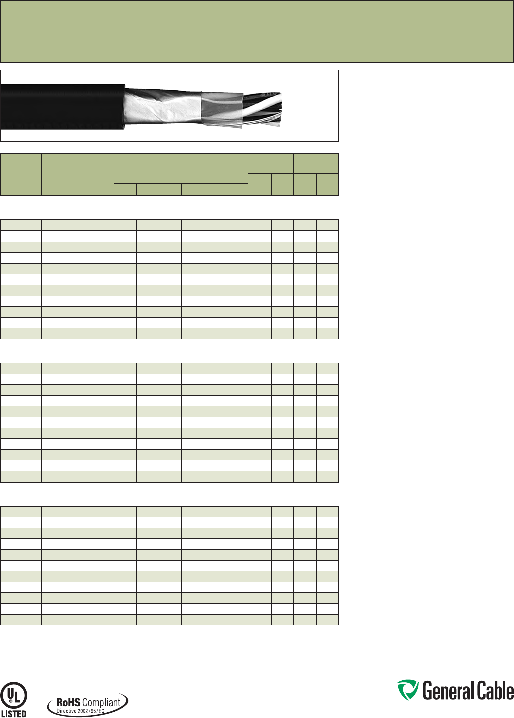
Phone: 888-593-3355
www.generalcable.com
SPEC 1250
March, 2012
Product Construction:
Conductor:
• 20 AWG thru 16 AWG bare, annealed
copper per ASTM B3
• Class B stranding per ASTM B8
Insulation:
• Lead-free Polyvinyl Chloride (PVC)
• Color-coded per ICEA Method 1: Pairs - black
and white; Triads - black, white and red. One
conductor in each pair or triad is printed alpha-
numerically for easy identification
Shield:
Overall shielded pairs/triads
• Overall shield is Flexfoil® aluminum/polymer in
contact with stranded tinned copper drain wire
Jacket:
• Lead-free, sunlight-resistant Polyvinyl Chloride
(PVC)
Print:
• GENERAL CABLE® (PLANT OF MFG) PVIC® XX/
PS/TS XXAWG PVC/PVC SHIELDED (UL) TYPE
PLTC OR ITC 105
˚
C SUN RES MONTH/YEAR OF
MFG SEQUENTIAL FOOTAGE MARK
Options:
• Tinned copper conductor
• Class C stranding
• Other constructions available upon request
Applications:
• In free air and raceways in accordance with NEC
• Typical applications include audio, intercom,
control, energy management and alarm
circuits
• In ducts, cable trays or conduit
• In accordance with UL Subject 13 as Power-
Limited Circuit Cable
• In Class 3 circuits in accordance with NEC
Article 725
• In accordance with UL Subject 2250 as
Instrumentation Tray Cable (ITC)
• Permitted for use in Class I, Division 2 industrial
hazardous locations per NEC Article
501.10(B)(4) for UL Type PLTC/ITC cables
• Per NEC Article 727 for Type PLTC/ITC
Features:
• Rated at 105
˚
C
• Good electrical properties
• Oil- and sunlight-resistant
• Flame-retardant
• Good mechanical properties
• Meets cold bend test at -25
˚
C
Compliances:
Industry Compliances:
• UL Type PLTC/ITC, UL File # E36118
•
RoHS Compliant
Flame Test Compliances:
• IEEE 383 (70,000 BTU/hr)
• UL Subject 13 (70,000 BTU/hr) for PLTC
• UL Subject 2250 (70,000 BTU/hr) for ITC
Other Compliances:
• EPA 40 CFR, Part 261 for leachable
lead content per TCLP method
• OSHA Acceptable
Packaging:
• Material cut to length and shipped on
non-returnable wood reels
PVIC
®
PVC/PVC, Instrumentation, Shielded
300 V, UL Type PLTC/ITC, Overall Shielded Pairs/Triads
CATALOG
NUMBER
NO. OF
PAIRS/
TRIADS
COND.
SIZE
(AWG)
COND.
STRAND
MINIMUM AVG.
INSULATION
THICKNESS
MINIMUM AVG.
JACKET
THICKNESS
NOMINAL
CABLE O.D.
COPPER
WEIGHT NET WEIGHT
LBS/
1000 FT kg/km
LBS/
1000 FT kg/kmINCHES mm INCHES mm INCHES mm
OVERALL SHIELDED PAIRS/TRIADS
20 AWG CONDUCTORS
325900 120 7/.0121 0.012 0.30 0.040 1.02 0.220 5.59 913 28 42
325910 1 TRI 20 7/.0121 0.012 0.30 0.040 1.02 0.241 6.12 12 18 34 51
325920 2 20 7/.0121 0.012 0.30 0.040 1.02 0.255 6.48 17 25 41 60
325940 4 20 7/.0121 0.012 0.30 0.042 1.07 0.321 8.15 30 45 65 97
339620* 8 20 7/.0121 0.012 0.30 0.050 1.27 0.475 12.07 54 80 104 154
348090* 12 20 7/.0121 0.012 0.30 0.050 1.27 0.545 13.84 83 124 195 290
334630* 16 20 7/.0121 0.012 0.30 0.050 1.27 0.605 15.37 107 159 248 369
348100* 20 20 7/.0121 0.012 0.30 0.060 1.52 0.650 16.51 135 201 309 460
759610* 24 20 7/.0121 0.012 0.30 0.060 1.52 0.740 18.80 153 228 376 559
339650* 36 20 7/.0121 0.012 0.30 0.060 1.52 0.850 21.59 238 354 530 789
339660* 50 20 7/.0121 0.012 0.30 0.070 1.78 0.970 24.64 330 491 713 1061
OVERALL SHIELDED PAIRS/TRIADS
18 AWG CONDUCTORS
325830 118 7/.0152 0.015 0.38 0.040 1.02 0.240 6.10 12 18 35 52
325840 1 TRI 18 7/.0152 0.015 0.38 0.040 1.02 0.264 6.71 18 27 44 66
325850 218 7/.0152 0.015 0.38 0.042 1.07 0.325 8.26 25 37 55 82
325880 418 7/.0152 0.015 0.38 0.042 1.07 0.357 9.07 46 68 90 133
348020* 818 7/.0152 0.015 0.38 0.060 1.52 0.646 16.41 87 129 192 285
348030* 12 18 7/.0152 0.015 0.38 0.060 1.52 0.670 17.02 129 192 293 436
348040* 16 18 7/.0152 0.015 0.38 0.060 1.52 0.750 19.05 171 254 374 556
339670* 20 18 7/.0152 0.015 0.38 0.060 1.52 0.780 19.81 211 314 449 668
339680* 24 18 7/.0152 0.015 0.38 0.070 1.78 0.915 23.24 253 377 564 839
791720* 36 18 7/.0152 0.015 0.38 0.070 1.78 1.030 26.16 453 674 787 1171
339690* 50 18 7/.0152 0.015 0.38 0.070 1.78 1.180 29.97 524 780 1059 1576
OVERALL SHIELDED PAIRS/TRIADS
16 AWG CONDUCTORS
325770 116 7/.0192 0.015 0.38 0.040 1.02 0.273 6.93 18 27 45 67
325780 1 TRI 16 7/.0192 0.015 0.38 0.042 1.07 0.297 7.54 27 40 58 86
325790 216 7/.0192 0.015 0.38 0.042 1.07 0.344 8.74 37 55 74 109
325810 416 7/.0192 0.015 0.38 0.053 1.35 0.481 12.22 71 106 132 197
339700* 816 7/.0192 0.015 0.38 0.060 1.52 0.726 18.44 135 201 259 385
298830* 12 16 7/.0192 0.015 0.38 0.060 1.52 0.755 19.18 203 302 408 607
760530* 16 16 7/.0192 0.015 0.38 0.070 1.78 0.845 21.46 270 402 526 783
339710* 20 16 7/.0192 0.015 0.38 0.070 1.78 0.905 22.99 334 497 655 975
339720* 24 16 7/.0192 0.015 0.38 0.070 1.78 1.030 26.16 400 595 803 1195
339730* 36 16 7/.0192 0.015 0.38 0.070 1.78 1.165 29.59 599 891 1122 1670
339740* 50 16 7/.0192 0.015 0.38 0.080 2.03 1.355 34.42 831 1237 1544 2298
Dimensions and weights are nominal; subject to industry tolerances.
* Non-stock item; minimum runs apply. Please consult Customer Service for price and delivery.
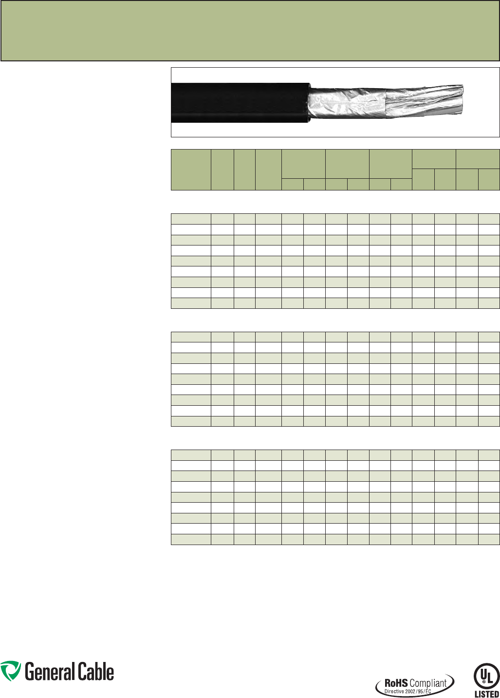
Phone: 888-593-3355
www.generalcable.com
SPEC 1300
March, 2012
PVIC
®
PVC/PVC, Instrumentation, Shielded
300 V, UL Type PLTC/ITC, Individual and Overall Shielded Pairs
CATALOG
NUMBER
NO. OF
PAIRS
COND.
SIZE
(AWG)
COND.
STRAND
MINIMUM AVG.
INSULATION
THICKNESS
MINIMUM AVG.
JACKET
THICKNESS
NOMINAL
CABLE O.D.
COPPER
WEIGHT NET WEIGHT
LBS/
1000 FT kg/km
LBS/
1000 FT kg/kmINCHES mm INCHES mm INCHES mm
INDIVIDUAL AND OVERALL SHIELDED PAIRS
20 AWG CONDUCTORS
325930 2 20 7/.0121 0.012 0.30 0.040 1.02 0.316 8.03 22 33 46 69
325950 4 20 7/.0121 0.012 0.30 0.042 1.07 0.325 8.26 39 58 76 113
339750 8 20 7/.0121 0.012 0.30 0.050 1.27 0.426 10.82 71 106 148 220
339760* 12 20 7/.0121 0.012 0.30 0.060 1.52 0.640 16.26 83 124 223 332
348110* 16 20 7/.0121 0.012 0.30 0.060 1.52 0.705 17.91 165 246 280 417
339770* 20 20 7/.0121 0.012 0.30 0.060 1.52 0.780 19.81 175 260 339 504
339780* 24 20 7/.0121 0.012 0.30 0.060 1.52 0.845 21.46 209 311 397 591
348120* 36 20 7/.0121 0.012 0.30 0.070 1.78 1.015 25.78 324 482 586 872
341790* 50 20 7/.0121 0.012 0.30 0.070 1.78 1.190 30.23 433 644 786 1170
INDIVIDUAL AND OVERALL SHIELDED PAIRS
18 AWG CONDUCTORS
325860 218 7/.0152 0.015 0.38 0.042 1.07 0.380 9.65 30 45 61 91
325890 418 7/.0152 0.015 0.38 0.042 1.07 0.410 10.41 55 82 100 149
348060 818 7/.0152 0.015 0.38 0.060 1.52 0.485 12.32 105 156 212 316
348070* 12 18 7/.0152 0.015 0.38 0.060 1.52 0.760 19.30 156 232 315 469
760420* 16 18 7/.0152 0.015 0.38 0.060 1.52 0.845 21.46 207 308 401 597
339800* 20 18 7/.0152 0.015 0.38 0.070 1.78 0.955 24.26 252 375 505 752
339810* 24 18 7/.0152 0.015 0.38 0.070 1.78 1.040 26.42 302 449 596 887
339820* 36 18 7/.0152 0.015 0.38 0.070 1.78 1.215 30.86 452 673 846 1259
339830* 50 18 7/.0152 0.015 0.38 0.080 2.03 1.450 36.83 628 935 1165 1734
INDIVIDUAL AND OVERALL SHIELDED PAIRS
16 AWG CONDUCTORS
325800 216 7/.0192 0.015 0.38 0.042 1.07 0.346 8.79 42 63 80 119
325820 416 7/.0192 0.015 0.38 0.053 1.35 0.506 12.85 80 119 151 225
298880 816 7/.0192 0.015 0.38 0.060 1.52 0.665 16.89 155 231 288 429
298890 12 16 7/.0192 0.015 0.38 0.060 1.52 0.855 21.72 230 342 435 647
759770* 16 16 7/.0192 0.015 0.38 0.070 1.78 0.970 24.64 306 455 575 856
339840* 20 16 7/.0192 0.015 0.38 0.070 1.78 1.080 27.43 375 558 705 1049
759780* 24 16 7/.0192 0.015 0.38 0.070 1.78 1.165 29.59 456 679 828 1232
339850* 36 16 7/.0192 0.015 0.38 0.080 2.03 1.390 35.31 674 1003 1215 1808
339860* 50 16 7/.0192 0.015 0.38 0.090 2.29 1.655 42.04 935 1391 1670 2485
Dimensions and weights are nominal; subject to industry tolerances.
* Non-stock item; minimum runs apply. Please consult Customer Service for price and delivery.
Product Construction:
Conductor:
• 20 AWG thru 16 AWG bare, annealed
copper per ASTM B3
• Class B stranding per ASTM B8
Insulation:
• Lead-free Polyvinyl Chloride (PVC)
• Color-coded per ICEA Method 1: Pairs - black and
white. One conductor in each pair is printed alpha-
numerically for easy identification
Shield:
Individual and overall shielded pairs
• Individual pairs are 100% shielded with Flexfoil®
aluminum/polyester in contact with stranded
tinned copper drain wire
• Overall shield is Flexfoil® aluminum/polymer in
contact with stranded tinned copper drain wire
Jacket:
• Lead-free, sunlight-resistant Polyvinyl Chloride
(PVC)
Print:
• GENERAL CABLE® (PLANT OF MFG) PVIC XX/
SPS XXAWG PVC/PVC SHIELDED (UL) TYPE
PLTC OR ITC 105
˚
C SUN RES MONTH/YEAR OF
MFG SEQUENTIAL FOOTAGE MARK
Options:
• Tinned copper conductor
• Class C stranding
• Other constructions available upon request
Applications:
• In free air and raceways in accordance with NEC
• Typical applications include audio, intercom,
control, energy management and alarm circuits
• In ducts, cable trays or conduit
• In accordance with UL Subject 13 as Power-
Limited Circuit Cable
• In Class 3 circuits in accordance with NEC
Article 725
• In accordance with UL Subject 2250 as
Instrumentation Tray Cable (ITC)
• Permitted for use in Class I, Division 2 industrial
hazardous locations per NEC Article
501.10(B)(4) for UL Type PLTC/ITC cables
• Per NEC Article 727 for Type PLTC/ITC
Features:
• Rated at 105
˚
C
• Good electrical properties
• Oil- and sunlight-resistant
• Flame-retardant
• Good mechanical properties
• Meets cold bend test at -25
˚
C
Compliances:
Industry Compliances:
• UL Type PLTC/ITC, UL File # E36118
•
RoHS Compliant
Flame Test Compliances:
• IEEE 383 (70,000 BTU/hr)
• UL Subject 13 (70,000 BTU/hr) for PLTC
• UL Subject 2250 (70,000 BTU/hr) for ITC
Other Compliances:
• EPA 40 CFR, Part 261 for leachable
lead content per TCLP method
• OSHA Acceptable
Packaging:
• Material cut to length and shipped on
non-returnable wood reels
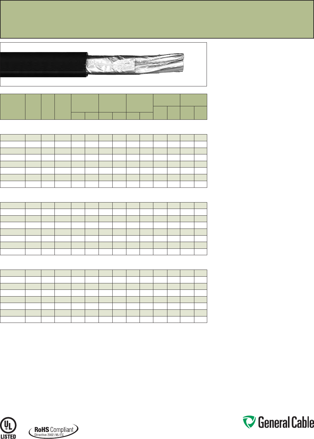
Phone: 888-593-3355
www.generalcable.com
SPEC 1350
March, 2012
Product Construction:
Conductor:
• 20 AWG thru 16 AWG bare, annealed
copper per ASTM B3
• Class B stranding per ASTM B8
Insulation:
• Lead-free Polyvinyl Chloride (PVC)
• Color-coded per ICEA Method 1: Triads - black,
white and red. One conductor in each triad is
printed alpha-numerically for easy identification
Shield:
Individual and overall shielded triads
• Individual triads are 100% shielded with Flexfoil®
aluminum/polyester in contact with stranded
tinned copper drain wire
• Overall shield is Flexfoil® aluminum/polymer in
contact with stranded tinned copper drain wire
Jacket:
• Lead-free, sunlight-resistant Polyvinyl Chloride
(PVC)
Print:
• GENERAL CABLE® (PLANT OF MFG) PVIC XX/
STS XXAWG PVC/PVC SHIELDED (UL) TYPE
PLTC OR ITC 105
˚
C SUN RES MONTH/YEAR OF
MFG SEQUENTIAL FOOTAGE MARK
Options:
• Tinned copper conductor
• Class C stranding
• Other constructions available upon request
Applications:
• In free air and raceways in accordance with NEC
• Typical applications include audio, intercom,
control, energy management and alarm circuits
• In ducts, cable trays or conduit
• In accordance with UL Subject 13 as Power-
Limited Circuit Cable
• In Class 3 circuits in accordance with NEC
Article 725
• In accordance with UL Subject 2250 as
Instrumentation Tray Cable (ITC)
• Permitted for use in Class I, Division 2 industrial
hazardous locations per NEC Article
501-4(b) for UL Type PLTC/ITC cables
• Per NEC Article 727 for Type PLTC/ITC
Features:
• Rated at 105
˚
C
• Good electrical properties
• Oil and sunlight resistance
• Flame-retardant
• Good mechanical properties
• Meets cold bend test at -25
˚
C
Compliances:
Industry Compliances:
• UL Type PLTC/ITC, UL File # E36118
•
RoHS Compliant
Flame Test Compliances:
• IEEE 383 (70,000 BTU/hr)
• UL Subject 13 (70,000 BTU/hr) for PLTC
• UL Subject 2250 (70,000 BTU/hr) for ITC
Other Compliances:
• EPA 40 CFR, Part 261 for leachable
lead content per TCLP method
• OSHA Acceptable
Packaging:
• Material cut to length and shipped on
non-returnable wood reels
PVIC
®
PVC/PVC, Instrumentation, Shielded
300 V, UL Type PLTC/ITC, Individual and Overall Shielded Triads
CATALOG
NUMBER
NO. OF
TRIADS
COND.
SIZE
(AWG)
COND.
STRAND
MINIMUM AVG.
INSULATION
THICKNESS
MINIMUM AVG.
JACKET
THICKNESS
NOMINAL
CABLE O.D.
COPPER
WEIGHT NET WEIGHT
LBS/
1000 FT kg/km
LBS/
1000 FT kg/kmINCHES mm INCHES mm INCHES mm
INDIVIDUAL AND OVERALL SHIELDED TRIADS
20 AWG CONDUCTORS
339870* 2 TRI 20 7/.0121 0.012 0.30 0.040 1.07 0.340 8.64 26 39 59 88
339880* 4 TRI 20 7/.0121 0.012 0.30 0.040 1.07 0.365 9.27 48 71 97 144
339890* 8 TRI 20 7/.0121 0.012 0.30 0.050 1.27 0.566 14.38 97 144 187 279
339900* 12 TRI 20 7/.0121 0.012 0.30 0.060 1.52 0.705 17.91 145 216 287 427
339910* 16 TRI 20 7/.0121 0.012 0.30 0.060 1.52 0.780 19.81 192 286 365 543
339920* 20 TRI 20 7/.0121 0.012 0.30 0.060 1.52 0.860 21.84 240 357 440 655
339930* 24 TRI 20 7/.0121 0.012 0.30 0.070 1.78 0.955 24.26 288 429 541 805
339940* 36 TRI 20 7/.0121 0.012 0.30 0.070 1.78 1.115 28.32 431 641 767 1141
INDIVIDUAL AND OVERALL SHIELDED TRIADS
18 AWG CONDUCTORS
325870* 2 TRI 18 7/.0152 0.015 0.38 0.040 1.07 0.321 8.15 38 57 77 115
339960* 4 TRI 18 7/.0152 0.015 0.38 0.050 1.27 0.444 11.28 73 109 143 213
348010* 8 TRI 18 7/.0152 0.015 0.38 0.060 1.52 0.691 17.55 147 219 275 409
760300* 12 TRI 18 7/.0152 0.015 0.38 0.060 1.52 0.840 21.34 215 320 412 613
339980* 16 TRI 18 7/.0152 0.015 0.38 0.070 1.78 0.960 24.38 286 426 550 819
339990* 20 TRI 18 7/.0152 0.015 0.38 0.070 1.78 1.060 26.92 357 531 668 994
340000* 24 TRI 18 7/.0152 0.015 0.38 0.070 1.78 1.145 29.08 428 637 785 1168
340010* 36 TRI 18 7/.0152 0.015 0.38 0.080 2.03 1.365 34.67 641 954 1151 1713
INDIVIDUAL AND OVERALL SHIELDED TRIADS
16 AWG CONDUCTORS
340020* 2 TRI 16 7/.0192 0.015 0.38 0.040 1.07 0.367 9.32 54 80 104 154
340030* 4 TRI 16 7/.0192 0.015 0.38 0.050 1.27 0.502 12.75 108 161 195 290
340040* 8 TRI 16 7/.0192 0.015 0.38 0.060 1.52 0.786 19.96 218 324 375 558
340050* 12 TRI 16 7/.0192 0.015 0.38 0.070 1.78 0.970 24.64 325 484 597 888
340060* 16 TRI 16 7/.0192 0.015 0.38 0.070 1.78 1.075 27.31 433 644 765 1138
340070* 20 TRI 16 7/.0192 0.015 0.38 0.070 1.78 1.195 30.35 541 805 933 1388
340080* 24 TRI 16 7/.0192 0.015 0.38 0.080 2.03 1.310 33.27 649 966 1125 1674
340090* 36 TRI 16 7/.0192 0.015 0.38 0.080 2.03 1.540 40.39 972 1447 1620 2411
Dimensions and weights are nominal; subject to industry tolerances.
* Non-stock item; minimum runs apply. Please consult Customer Service for price and delivery.
Phone: 888-593-3355
www.generalcable.com
Date of Issue 06/13
Section 2 Industrial Cables
600 V Instrumentation Cables
SPECIFICATION NO. PRODUCT DESCRIPTION REVISION DATE
2050†CHTC® XLPE/XL-CPE, Instrumentation, Shielded
600 V, UL Type TC, Individual and Overall Shielded Pairs/Triads
Mar. 2012
2100†FREP® FR-EPR/CPE, Instrumentation, Shielded
600 V, UL Type TC, Overall Shielded Pairs/Triads
Mar. 2012
2150†FREP® FR-EPR/CPE, Instrumentation, Shielded
600 V, UL Type TC, Individual and Overall Shielded Pairs
Mar. 2012
2200 FREP® FR-EPR/CPE, Instrumentation, Shielded
600 V, UL Type TC, Individual and Overall Shielded Triads
Mar. 2012
2250 Arctic-Flex® XLPE/ARCTIC-PVC, Instrumentation, Shielded
600 V, UL Type TC, CSA Type CIC, Overall Shielded Pairs/Triads
Mar. 2012
2300 Arctic-Flex® XLPE/ARCTIC-PVC, Instrumentation, Shielded
600 V, UL Type TC, CSA Type CIC, Individual and Overall Shielded Pairs
Mar. 2012
2350 CVTC® XLPE/PVC, Instrumentation, Shielded
600 V, UL Type TC, Overall Shielded Pairs/Triads
Mar. 2012
2400 CVTC® XLPE/PVC, Instrumentation, Shielded
600 V, UL Type TC, Individual and Overall Shielded Pairs
Mar. 2012
2450†VNTC® PVC/Nylon/PVC, Instrumentation, Shielded
600 V, UL Type TC, Overall Shielded Pairs/Triads
Mar. 2012
2500†VNTC® PVC/Nylon/PVC, Instrumentation, Shielded
600 V, UL Type TC, Individual and Overall Shielded Pairs
Mar. 2012
2600†GenFree® XLPE/LSZH, Instrumentation, Shielded
600 V, UL Type TC-LS, Overall Shielded Pairs/Triads
Mar. 2012
2625†GenFree®XLPE/LSZH, Instrumentation, Shielded
600 V, UL Type TC-LS, Individual and Overall Shielded Pairs
Mar. 2012
2650 GenFree® XLPE/LSZH, Instrumentation, Shielded
600 V, UL Type TC-LS, Individual and Overall Shielded Triads
Mar. 2012
†Indicates these products are stocked by General Cable
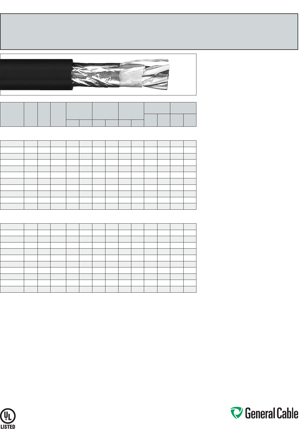
Phone: 888-593-3355
www.generalcable.com
SPEC 2050
March, 2012
CATALOG
NUMBER
NO. OF
PAIRS/
TRIADS
COND.
SIZE
(AWG)
COND.
STRAND
MINIMUM AVG.
INSULATION
THICKNESS
MINIMUM AVG.
JACKET
THICKNESS
NOMINAL
CABLE O.D.
COPPER
WEIGHT NET WEIGHT
LBS/
1000 FT kg/km
LBS/
1000 FT kg/kmINCHES mm INCHES mm INCHES mm
INDIVIDUAL AND OVERALL SHIELDED PAIRS/TRIADS
18 AWG CONDUCTORS
285150 118 7/.0152 0.030 0.76 0.045 1.52 0.315 8.15 13 19 49 73
337620* 1 TRI 18 7/.0152 0.030 0.76 0.045 1.14 0.335 8.51 18 26 64 95
337630* 218 7/.0152 0.030 0.76 0.045 1.14 0.510 12.95 28 42 92 137
337640* 418 7/.0152 0.030 0.76 0.060 1.52 0.630 16.00 53 79 167 249
337650* 818 7/.0152 0.030 0.76 0.080 2.03 0.855 21.72 104 155 326 485
337660* 12 18 7/.0152 0.030 0.76 0.080 2.03 1.030 26.16 155 231 441 656
337670* 16 18 7/.0152 0.030 0.76 0.080 2.03 1.140 28.96 206 307 554 824
337680* 20 18 7/.0152 0.030 0.76 0.080 2.03 1.265 32.13 256 381 676 1006
337690* 24 18 7/.0152 0.030 0.76 0.080 2.03 1.450 36.83 308 459 795 1183
337700* 36 18 7/.0152 0.030 0.76 0.110 2.79 1.650 41.91 461 687 1118 1664
337710* 50 18 7/.0152 0.030 0.76 0.110 2.79 2.085 52.96 637 948 1616 2405
INDIVIDUAL AND OVERALL SHIELDED PAIRS/TRIADS
16 AWG CONDUCTORS
240990 116 7/.0192 0.030 0.76 0.045 1.52 0.345 8.76 19 28 61 91
241510 1 TRI 16 7/.0192 0.030 0.76 0.045 1.52 0.360 9.10 28 42 85 127
241010 216 7/.0192 0.030 0.76 0.060 1.52 0.585 14.86 40 60 130 193
232560 416 7/.0192 0.030 0.76 0.060 1.52 0.675
17.15
78 116 204 304
241000* 816 7/.0192 0.030 0.76 0.080 2.03 0.915 23.24 153 228 394 586
252370 12 16 7/.0192 0.030 0.76 0.080 2.03 1.110 28.19 229 341 548 816
337720* 16 16 7/.0192 0.030 0.76 0.080 2.03 1.350 34.29 304 453 713 1061
337730* 20 16 7/.0192 0.030 0.76 0.080 2.03 1.365 34.67 380 566 850 1265
337740* 24 16 7/.0192 0.030 0.76 0.080 2.03 1.570 39.88 455 677 1001 1490
337750* 36 16 7/.0192 0.030 0.76 0.110 2.79 1.980 50.29 682 1014 1548 2304
337760* 50 16 7/.0192 0.030 0.76 0.110 2.79 2.165 54.99 946 1408 2020 3006
Dimensions and weights are nominal; subject to industry tolerances.
* Non-stock item; minimum runs apply. Please consult Customer Service for price and delivery.
CHTC
®
XLPE/XL-CPE, Instrumentation, Shielded
600 V, UL Type TC, Individual and Overall Shielded Pairs/Triads
Product Construction:
Conductor:
• 18 AWG and 16 AWG tinned, annealed
copper per ASTM B33
• Class B stranding per ASTM B8
Insulation:
• Flame-retardant Cross-linked Polyethylene (XLPE)
• Color-coded per ICEA Method 1: Pairs - black
and white; Triads - black, white and red. One
conductor in each pair or triad is printed alpha-
numerically for easy identification
Shield:
Individual and overall shielded pairs/triads
• Individual pairs/triads are 100% shielded with
Flexfoil® aluminum/polyester in contact with
stranded tinned copper drain wire
• Overall shield is Flexfoil® aluminum/polymer in
contact with stranded tinned copper drain wire
Jacket:
• Lead-free Cross-linked Chlorinated Polyethylene
(XL-CPE )
Print:
• GENERAL CABLE® (PLANT OF MFG) CHTC®
XX/SPS/STS XXAWG SHIELDED CU/XLP/XL-CPE
SHIELDED (UL) TYPE TC 600 V 90˚C WET OR
DRY SUN RES OIL RES I & II DAY/MONTH/YEAR
OF MFG SEQUENTIAL FOOTAGE MARK
Options:
• 300 V Type PLTC
• Bare copper conductor
• Class C stranding
• Overall shielded pairs/triads
• EHTC®—Ethylene Propylene Rubber (EPR)
insulation
• Thermoplastic Low-Smoke, Zero-Halogen (LSZH)
jacket
• Other constructions available upon request
Applications:
• In free air, raceways or direct burial
• In wet or dry locations
• Permitted for use in Class I, Division 2
industrial hazardous locations per NEC
Features:
• Rated at 90˚C wet or dry
• Ripcord applied to all cables with jacket thickness
of 60 mils or less
• Oil-resistant jacket
• Sunlight- and weather-resistant
• Excellent electrical, thermal and physical
properties
• Excellent moisture resistance
• Excellent flame resistance
• “Heavy duty” rating per ICEA standards
• Excellent low temperature cold bend
characteristics
• Meets cold bend test at -35˚C
Compliances:
Industry Compliances:
• UL Type RFH-2, FFH-2 conductors
• UL 1277 Type TC, UL File # E57179
• UL 1581
• ICEA S-73-532/WC57
Flame Test Compliances:
• UL 1581/UL 2556 VW-1
• UL 1685 Vertical Flame Test
• IEEE 383
• IEEE 1202
• CSA FT4
• ICEA T-29-520
Other Compliances:
• EPA 40 CFR, Part 261 for leachable lead
content per TCLP
• OSHA Acceptable
Packaging:
• Material cut to length and shipped on
non-returnable wood reels
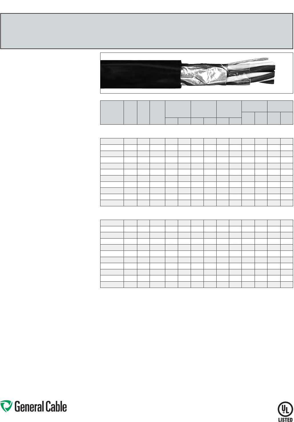
Phone: 888-593-3355
www.generalcable.com
SPEC 2100
March, 2012
CATALOG
NUMBER
NO. OF
PAIRS/
TRIADS
COND.
SIZE
(AWG)
COND.
STRAND
MINIMUM AVG.
INSULATION
THICKNESS
MINIMUM AVG.
JACKET
THICKNESS
NOMINAL
CABLE O.D.
COPPER
WEIGHT NET WEIGHT
LBS/
1000 FT kg/km
LBS/
1000 FT kg/kmINCHES mm INCHES mm INCHES mm
OVERALL SHIELDED PAIRS/TRIADS
18 AWG CONDUCTORS
287650* 118 7/.0152 0.025 0.64 0.045 1.14 0.300 7.62 13 19 42 63
325250* 1 TRI 18 7/.0152 0.025 0.64 0.045 1.14 0.315 8.00 18 26 53 79
337010* 218 7/.0152 0.025 0.64 0.045 1.14 0.420 10.67 23 34 75 112
337020* 418 7/.0152 0.025 0.64 0.045 1.14 0.490 12.45 44 65 117 174
337030* 818 7/.0152 0.025 0.64 0.060 1.52 0.675 17.15 86 127 224 333
337040* 12 18 7/.0152 0.025 0.64 0.060 1.52 0.775 19.69 127 189 305 454
294580* 16 18 7/.0152 0.025 0.64 0.080 2.03 0.925 23.50 169 251 425 632
337050* 20 18 7/.0152 0.025 0.64 0.080 2.03 1.025 26.04 210 313 510 759
337060* 24 18 7/.0152 0.025 0.64 0.080 2.03 1.105 28.07 252 375 604 899
337070* 36 18 7/.0152 0.025 0.64 0.080 2.03 1.360 34.54 377 561 865 1287
337080* 50 18 7/.0152 0.025 0.64 0.080 2.03 1.555 39.50 523 778 1144 1703
OVERALL SHIELDED PAIRS/TRIADS
16 AWG CONDUCTORS
314960 116 7/.0192 0.025 0.64 0.045 1.14 0.320 8.13 18 28 52 77
279690 1 TRI 16 7/.0192 0.025 0.64 0.045 1.14 0.335 8.51 26 39 66 98
283170* 216 7/.0192 0.025 0.64 0.045 1.14 0.460 11.68 36 54 95 141
283180* 416 7/.0192 0.025 0.64 0.060 1.52 0.560 14.22 69 103 171 254
337090* 816 7/.0192 0.025 0.64 0.060 1.52 0.740 18.80 135 201 294 438
283190* 12 16 7/.0192 0.025 0.64 0.080 2.03 0.900 22.86 202 300 438 652
337100* 16 16 7/.0192 0.025 0.64 0.080 2.03 1.015 25.78 268 399 560 833
337110* 20 16 7/.0192 0.025 0.64 0.080 2.03 1.130 28.70 335 498 680 1012
337120* 24 16 7/.0192 0.025 0.64 0.080 2.03 1.215 30.86 401 597 807 1201
337130* 36 16 7/.0192 0.025 0.64 0.080 2.03 1.505 38.23 601 894 1160 1726
337140* 50 16 7/.0192 0.025 0.64 0.080 2.03 2.095 53.21 834 1241 1702 2533
Dimensions and weights are nominal; subject to industry tolerances.
* Non-stock item; minimum runs apply. Please consult Customer Service for price and delivery.
Product Construction:
Conductor:
• 18 AWG and 16 AWG tinned, annealed copper per
ASTM B33
• Class B stranding per ASTM B8
Insulation:
• Flame-Retardant Ethylene Propylene Rubber
(FR-EPR) Type II
• Color-coded per ICEA Method 1: Pairs - black
and white; Triads - black, white and red. One
conductor in each pair or triad is printed alpha-
numerically for easy identification
Shield:
Overall shielded pairs/triads
• Overall shield is Flexfoil® aluminum/polymer in
contact with stranded tinned copper drain wire
Jacket:
• Lead-free, flame-retardant, thermoplastic
Chlorinated Polyethylene (CPE)
Print:
• GENERAL CABLE® (PLANT OF MFG) FREP®
XX/PS/TS XXAWG EPR/CPE SHIELDED
(UL) TYPE TC 90˚C WET OR DRY 600 V DIR
BUR SUN RES DAY/MONTH/YEAR OF MFG
SEQUENTIAL FOOTAGE MARK
Options:
• Bare copper conductor
• Class C stranding
• Individual and overall shielded pairs/triads
• CCTC—Cross-linked Polyethylene (XLPE)
insulation
• FREP® XL-flame-retardant, thermoset Chlorinated
Polyethylene (XL-CPE) jacket
• FREP® II-flame-retardant, thermoplastic Low-
Smoke, Zero-Halogen (LSZH) Polyolefin jacket
• FREP® 300 V-UL Type PLTC
• Other constructions available upon request
Applications:
• In free air, raceways or direct burial
• In wet or dry locations
• Permitted for use in Class I, Division 2 industrial
hazardous locations per NEC
Features:
• Rated at 90˚C wet or dry
• Ripcord applied to all cables with jacket thickness
of 60 mils or less
• Excellent physical, thermal and electrical
properties
• Excellent moisture resistance
• Excellent resistance to compression cuts and heat
deformation
• Excellent flame resistance—burns to an ash; does
not exhibit thermoplastic drip
• Low coefficient of friction for easy pulling
• Sunlight- and weather-resistant
• Excellent low temperature cold bend
characteristics
• Meets cold bend test at -40˚C
Compliances:
Industry Compliances:
• UL 1277 Type TC, UL File # E57179
• UL 1581
• ICEA S-73-532/NEMA WC57
Flame Test Compliances:
• UL 1581/UL 2556 VW-1
• UL 1685 Vertical Flame Test
• IEEE 383
• IEEE 1202
• CSA FT4
• ICEA T-29-520
Other Compliances:
• EPA 40 CFR, Part 261 for leachable lead
content per TCLP
• OSHA Acceptable
Packaging:
• Material cut to length and shipped on
non-returnable wood reels
FREP
®
FR-EPR/CPE, Instrumentation, Shielded
600 V, UL Type TC, Overall Shielded Pairs/Triads
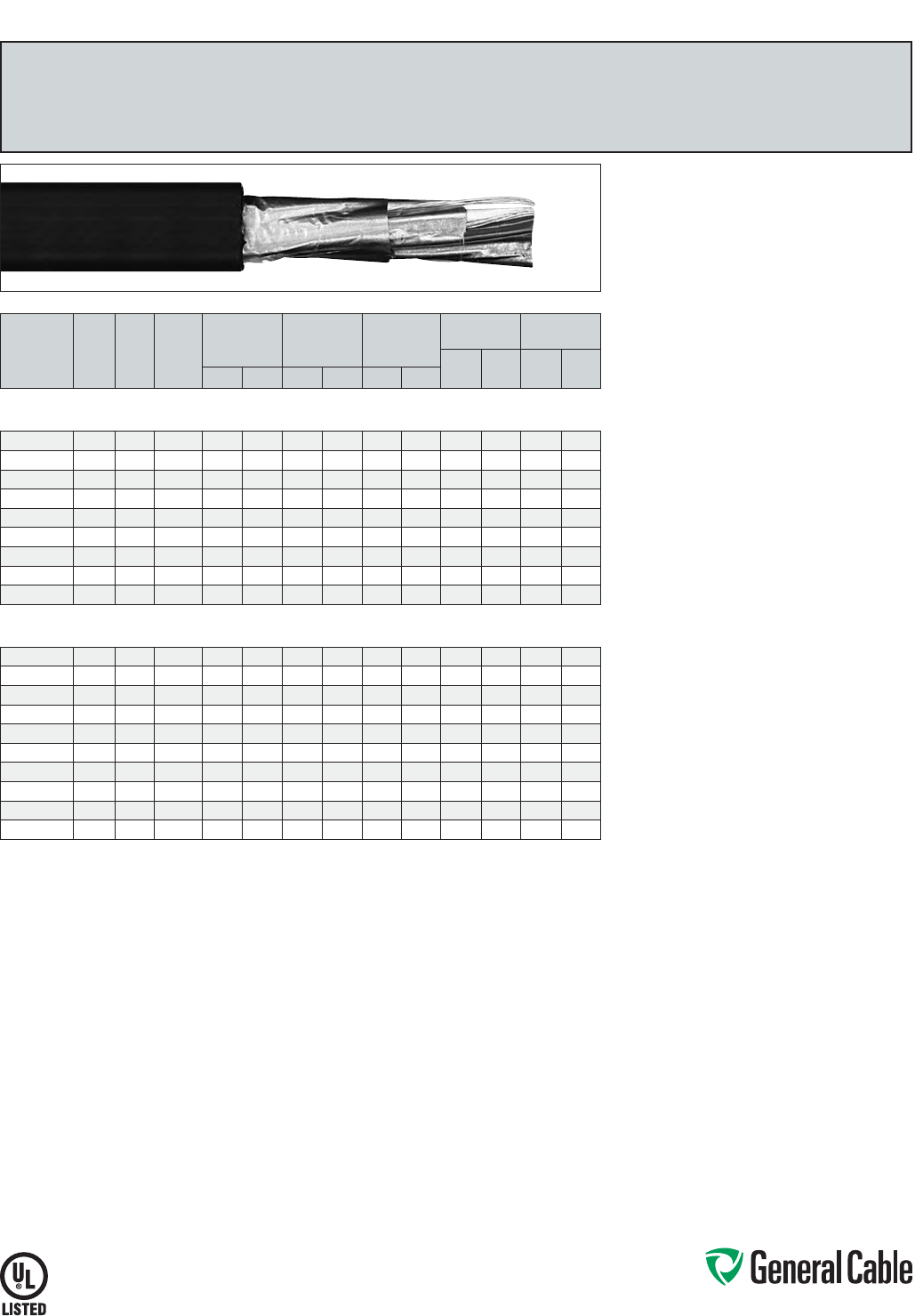
Phone: 888-593-3355
www.generalcable.com
SPEC 2150
March, 2012
CATALOG
NUMBER
NO. OF
PAIRS
COND.
SIZE
(AWG)
COND.
STRAND
MINIMUM AVG.
INSULATION
THICKNESS
MINIMUM AVG.
JACKET
THICKNESS
NOMINAL
CABLE O.D.
COPPER
WEIGHT NET WEIGHT
LBS/
1000 FT kg/km
LBS/
1000 FT kg/kmINCHES mm INCHES mm INCHES mm
INDIVIDUAL AND OVERALL SHIELDED PAIRS
18 AWG CONDUCTORS
279700 218 7/.0152 0.025 0.64 0.045 1.14 0.473 12.01 27 41 83 124
279710 418 7/.0152 0.025 0.64 0.060 1.52 0.586 14.88 53 78 152 226
279720* 818 7/.0152 0.025 0.64 0.060 1.52 0.751 19.08 103 153 259 385
279730* 12 18 7/.0152 0.025 0.64 0.080 2.03 0.948 24.08 153 228 398 592
279740* 16 18 7/.0152 0.025 0.64 0.080 2.03 1.050 26.67 206 307 502 747
319270* 20 18 7/.0152 0.025 0.64 0.080 2.03 1.185 30.10 254 378 623 927
279750* 24 18 7/.0152 0.025 0.64 0.080 2.03 1.220 30.99 311 463 709 1055
337240* 36 18 7/.0152 0.025 0.64 0.080 2.03 1.474 37.4 4 461 687 1008 1500
337250* 50 18 7/.0152 0.025 0.64 0.110 2.79 1.780 45.21 640 952 1454 2164
INDIVIDUAL AND OVERALL SHIELDED PAIRS
16 AWG CONDUCTORS
280500 216 7/.0192 0.025 0.64 0.045 1.14 0.500 12.70 40 59 103 153
280520 416 7/.0192 0.025 0.64 0.060 1.52 0.650 16.51 77 114 189 281
280530 616 7/.0192 0.025 0.64 0.060 1.52 0.755 19.18 115 171 268 399
280540 816 7/.0192 0.025 0.64 0.060 1.52 0.840 21.34 151 225 330 491
279760 12 16 7/.0192 0.025 0.64 0.080 2.03 1.065 27.05 226 337 506 753
280990* 16 16 7/.0192 0.025 0.64 0.080 2.03 1.185 30.10 305 453 643 957
337260* 20 16 7/.0192 0.025 0.64 0.080 2.03 1.320 33.53 380 566 777 1156
279770* 24 16 7/.0192 0.025 0.64 0.080 2.03 1.485 37.72 455 677 932 1387
288260* 36 16 7/.0192 0.025 0.64 0.080 2.03 1.760 44.70 683 1016 1410 2098
288250* 50 16 7/.0192 0.025 0.64 0.110 2.79 2.035 51.69 946 1408 1883 2802
Dimensions and weights are nominal; subject to industry tolerances.
* Non-stock item; minimum runs apply. Please consult Customer Service for price and delivery.
Product Construction:
Conductor:
• 18 AWG and 16 AWG tinned, annealed copper per
ASTM B33
• Class B stranding per ASTM B8
Insulation:
• Flame-Retardant Ethylene Propylene Rubber
(FR-EPR) Type II
• Color-coded per ICEA Method 1: Pairs - black and
white. One conductor in each pair is printed alpha-
numerically for easy identification
Shield:
Individual and overall shielded pairs
• Individual pairs are 100% individually shielded
with Flexfoil® aluminum/polyester in contact with
stranded tinned copper drain wire
• Overall shield is Flexfoil® aluminum/polymer in
contact with stranded tinned copper drain wire
Jacket:
• Lead-free, flame-retardant, thermoplastic
Chlorinated Polyethylene (CPE)
Print:
• GENERAL CABLE® (PLANT OF MFG) FREP® XX/
SPS XXAWG EPR/CPE SHIELDED (UL) TYPE
TC 90˚C WET OR DRY 600 V DIR BUR SUN
RES DAY/MONTH/YEAR OF MFG SEQUENTIAL
FOOTAGE MARK
Options:
• Bare copper conductor
• Class C stranding
• Overall shielded pairs
• CCTC—Cross-linked Polyethylene (XLPE)
insulation
• FREP® XL-flame-retardant, thermoset Chlorinated
Polyethylene (XL-CPE) jacket
• FREP® II-flame-retardant, thermoplastic Low-
Smoke, Zero-Halogen (LSZH) Polyolefin jacket
• FREP® 300 V-UL Type PLTC
• Other constructions available upon request
Applications:
• In free air, raceways or direct burial
• In wet or dry locations
• Permitted for use in Class I, Division 2 industrial
hazardous locations per NEC
Features:
• Rated at 90˚C wet or dry
• Ripcord applied to all cables with jacket thickness
of 60 mils or less
• Excellent physical, thermal and electrical
properties
• Excellent moisture resistance
• Excellent resistance to compression cuts and heat
deformation
• Excellent flame resistance—burns to an ash; does
not exhibit thermoplastic drip
• Low coefficient of friction for easy pulling
• Sunlight- and weather-resistant
• Excellent low temperature cold bend
characteristics
• Meets cold bend test at -40˚C
Compliances:
Industry Compliances:
• UL 1277 Type TC, UL File # E57179
• UL 1581
• ICEA S-73-532/NEMA WC57
Flame Test Compliances:
• UL 1581/UL 2556 VW-1
• UL 1685 Vertical Flame Test
• IEEE 383
• IEEE 1202
• CSA FT4
• ICEA T-29-520
Other Compliances:
• EPA 40 CFR, Part 261 for leachable lead
content per TCLP
• OSHA Acceptable
Packaging:
• Material cut to length and shipped on
non-returnable wood reels
FREP
®
FR-EPR/CPE, Instrumentation, Shielded
600 V, UL Type TC, Individual and Overall Shielded Pairs
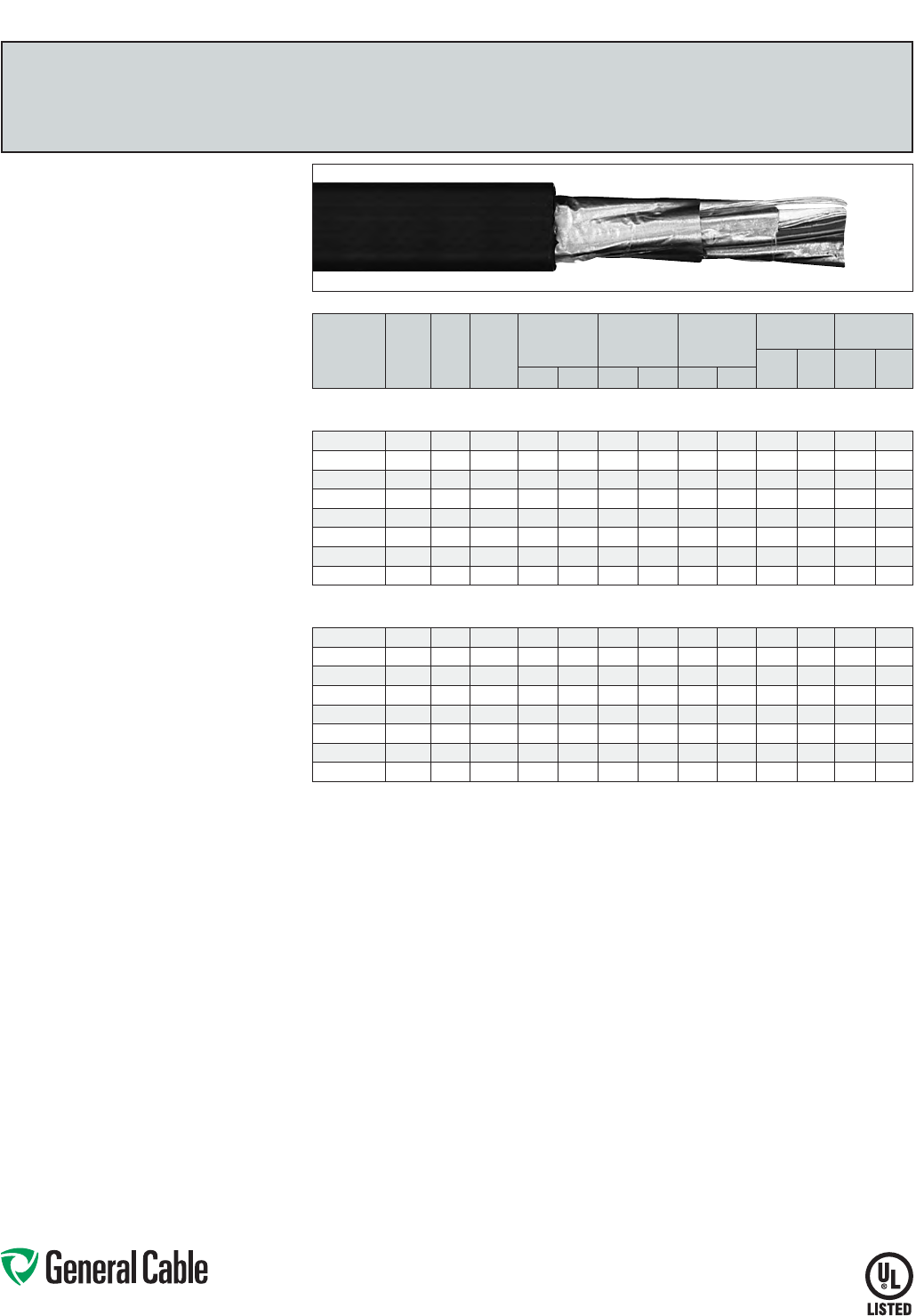
Phone: 888-593-3355
www.generalcable.com
SPEC 2200
March, 2012
CATALOG
NUMBER
NO. OF
TRIADS
COND.
SIZE
(AWG)
COND.
STRAND
MINIMUM AVG.
INSULATION
THICKNESS
MINIMUM AVG.
JACKET
THICKNESS
NOMINAL
CABLE O.D.
COPPER
WEIGHT NET WEIGHT
LBS/
1000 FT kg/km
LBS/
1000 FT kg/kmINCHES mm INCHES mm INCHES mm
INDIVIDUAL AND OVERALL SHIELDED TRIADS
18 AWG CONDUCTORS
337150* 2 TRI 18 7/.0152 0.025 0.64 0.060 1.52 0.560 14.22 38 57 127 189
319250* 4 TRI 18 7/.0152 0.025 0.64 0.060 1.52 0.640 16.26 73 109 201 299
319260* 8 TRI 18 7/.0152 0.025 0.64 0.080 2.03 0.825 20.96 144 214 343 510
337160* 12 TRI 18 7/.0152 0.025 0.64 0.080 2.03 1.065 27.05 218 324 528 786
294540* 16 TRI 18 7/.0152 0.025 0.64 0.080 2.03 1.180 29.97 290 431 675 1005
337170* 20 TRI 18 7/.0152 0.025 0.64 0.080 2.03 1.310 33.27 361 538 825 1228
337180* 24 TRI 18 7/.0152 0.025 0.64 0.080 2.03 1.500 38.10 433 645 972 1447
337190* 36 TRI 18 7/.0152 0.025 0.64 0.080 2.03 1.740 44.20 649 965 1470 2188
INDIVIDUAL AND OVERALL SHIELDED TRIADS
16 AWG CONDUCTORS
280950* 2 TRI 16 7/.0192 0.025 0.64 0.060 1.52 0.615 15.62 57 84 159 237
280960* 4 TRI 16 7/.0192 0.025 0.64 0.060 1.52 0.705 17.91 108 160 249 371
280970* 8 TRI 16 7/.0192 0.025 0.64 0.080 2.03 0.850 21.59 217 323 472 702
287410* 12 TRI 16 7/.0192 0.025 0.64 0.080 2.03 1.160 29.46 328 487 683 1016
337200* 16 TRI 16 7/.0192 0.025 0.64 0.080 2.03 1.290 32.77 436 649 879 1308
337210* 20 TRI 16 7/.0192 0.025 0.64 0.080 2.03 1.380 35.05 545 811 1058 1575
337220* 24 TRI 16 7/.0192 0.025 0.64 0.080 2.03 1.615 41.02 653 972 1266 1884
337230* 36 TRI 16 7/.0192 0.025 0.64 0.110 2.79 1.920 48.77 979 1457 1918 2854
Dimensions and weights are nominal; subject to industry tolerances.
* Non-stock item; minimum runs apply. Please consult Customer Service for price and delivery.
Product Construction:
Conductor:
• 18 AWG and 16 AWG tinned, annealed copper per
ASTM B33
• Class B stranding per ASTM B8
Insulation:
• Flame-Retardant Ethylene Propylene Rubber
(FR-EPR) Type II
• Color-coded per ICEA Method 1: Triads - black,
white and red. One conductor in each triad is
printed alpha-numerically for easy identification
Shield:
Individual and overall shielded triads
• Individual triads are 100% shielded with Flexfoil®
aluminum/polyester in contact with stranded
tinned copper drain wire
• Overall shield is Flexfoil® aluminum/polymer in
contact with stranded tinned copper drain wire
Jacket:
• Lead-free, flame-retardant, thermoplastic
Chlorinated Polyethylene (CPE)
Print:
• GENERAL CABLE® (PLANT OF MFG) FREP® XX/
STS XXAWG EPR/CPE SHIELDED (UL) TYPE
TC 90˚C WET OR DRY 600 V DIR BUR SUN
RES DAY/MONTH/YEAR OF MFG SEQUENTIAL
FOOTAGE MARK
Options:
• Bare copper conductor
• Class C stranding
• Overall shielded pairs/triads
• CCTC—Cross-linked Polyethylene (XLPE)
insulation
• FREP® XL-flame-retardant, thermoset Chlorinated
Polyethylene (XL-CPE) jacket
• FREP® II-flame-retardant, thermoplastic Low-
Smoke, Zero-Halogen (LSZH) polyolefin jacket
• FREP® 300 V-UL Type PLTC
• Other constructions available upon request
Applications:
• In free air, raceways or direct burial
• In wet or dry locations
• Permitted for use in Class I, Division 2 industrial
hazardous locations per NEC
Features:
• Rated at 90˚C wet or dry
• Ripcord applied to all cables with jacket thickness
of 60 mils or less
• Excellent physical, thermal and electrical
properties
• Excellent moisture resistance
• Excellent resistance to compression cuts and heat
deformation
• Excellent flame resistance—burns to an ash; does
not exhibit thermoplastic drip
• Low coefficient of friction for easy pulling
• Sunlight- and weather-resistant
• Excellent low temperature cold bend
characteristics
• Meets cold bend test at -40˚C
Compliances:
Industry Compliances:
• UL 1277 Type TC, UL File # E57179
• UL 1581
• ICEA S-73-532/NEMA WC57
Flame Test Compliances:
• UL 1581/UL 2556 VW-1
• UL 1685 Vertical Flame Test
• IEEE 383
• IEEE 1202
• CSA FT4
• ICEA T-29-520
Other Compliances:
• EPA 40 CFR, Part 261 for leachable lead
content per TCLP
• OSHA Acceptable
Packaging:
• Material cut to length and shipped on
non-returnable wood reels
FREP
®
FR-EPR/CPE, Instrumentation, Shielded
600 V, UL Type TC, Individual and Overall Shielded Triads
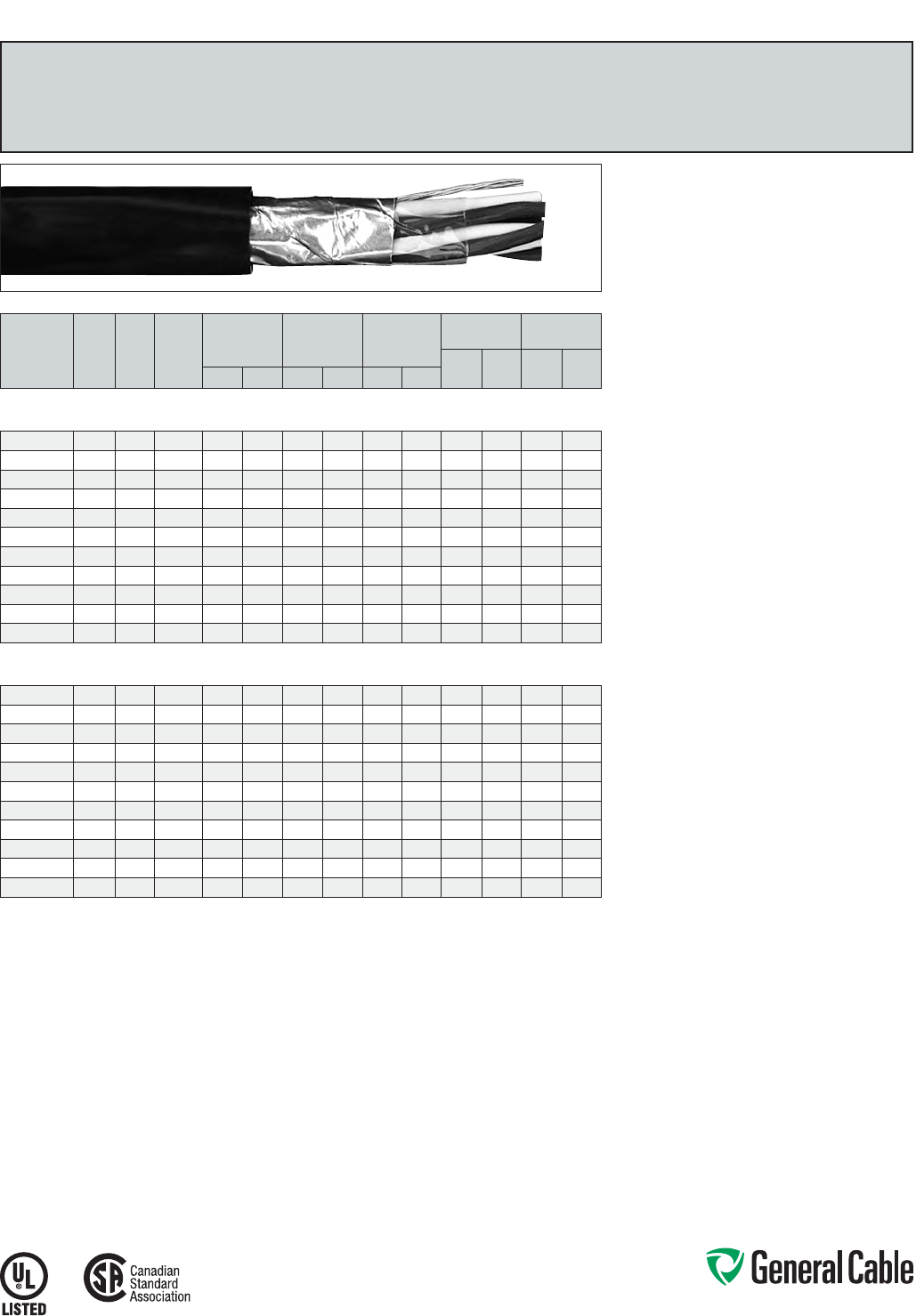
Phone: 888-593-3355
www.generalcable.com
SPEC 2250
March, 2012
CATALOG
NUMBER
NO. OF
PAIRS/
TRIADS
COND.
SIZE
(AWG)
COND.
STRAND
MINIMUM AVG.
INSULATION
THICKNESS
MINIMUM AVG.
JACKET
THICKNESS
NOMINAL
CABLE O.D.
COPPER
WEIGHT NET WEIGHT
LBS/
1000 FT kg/km
LBS/
1000 FT kg/kmINCHES mm INCHES mm INCHES mm
OVERALL SHIELDED PAIRS/TRIADS
18 AWG CONDUCTORS
366170* 118 7/.0152 0.030 0.76 0.045 1.14 0.315 8.00 12 18 46 68
347630* 1 TRI 18 7/.0152 0.030 0.76 0.045 1.14 0.340 8.64 18 26 57 85
347640* 218 7/.0152 0.030 0.76 0.045 1.14 0.450 11.43 23 34 88 131
347650* 418 7/.0152 0.030 0.76 0.045 1.14 0.560 14.22 44 65 144 214
347660* 818 7/.0152 0.030 0.76 0.060 1.52 0.750 19.05 94 140 263 391
347670* 12 18 7/.0152 0.030 0.76 0.080 2.03 0.850 21.59 141 210 358 533
347680* 16 18 7/.0152 0.030 0.76 0.080 2.03 1.010 25.65 187 278 461 686
347690* 20 18 7/.0152 0.030 0.76 0.080 2.03 1.085 27.56 233 347 600 893
347700* 24 18 7/.0152 0.030 0.76 0.080 2.03 1.210 30.73 279 415 761 1043
347710* 36 18 7/.0152 0.030 0.76 0.080 2.03 1.500 38.10 418 622 1005 1496
347720* 50 18 7/.0152 0.030 0.76 0.080 2.03 2.570 65.28 580 863 1603 2386
OVERALL SHIELDED PAIRS/TRIADS
16 AWG CONDUCTORS
366180* 116 7/.0192 0.030 0.76 0.045 1.14 0.345 8.76 19 28 32 48
347730* 1 TRI 16 7/.0192 0.030 0.76 0.045 1.14 0.360 9.14 27 40 71 106
347740* 216 7/.0192 0.030 0.76 0.045 1.14 0.560 14.22 36 53 121 181
347750* 416 7/.0192 0.030 0.76 0.060 1.52 0.650 16.51 69 102 186 277
347760* 816 7/.0192 0.030 0.76 0.060 1.52 0.810 20.57 135 201 324 482
347770* 12 16 7/.0192 0.030 0.76 0.080 2.03 1.000 25.40 202 300 486 723
347780* 16 16 7/.0192 0.030 0.76 0.080 2.03 1.120 28.45 268 399 616 917
347790* 20 16 7/.0192 0.030 0.76 0.080 2.03 1.170 29.72 335 498 734 1092
347800* 24 16 7/.0192 0.030 0.76 0.080 2.03 1.440 36.58 401 597 894 1330
347810* 36 16 7/.0192 0.030 0.76 0.080 2.03 1.650 41.91 601 894 1254 1866
347820* 50 16 7/.0192 0.030 0.76 0.110 2.79 2.020 51.31 834 1241 1800 2679
Dimensions and weights are nominal; subject to industry tolerances.
* Non-stock item; minimum runs apply. Please consult Customer Service for price and delivery.
Product Construction:
Conductor:
• 18 AWG and 16 AWG tinned, annealed copper per
ASTM B3
• Class B stranding per ASTM B8
Insulation:
• Lead-free, flame-retardant Cross-linked
Polyethylene (XLPE)
• Color-coded per ICEA Method 1: Pairs - black
and white; Triads - black, white, and red. One
conductor in each pair or triad is printed alpha-
numerically for easy identification
Shield:
Overall shielded pairs/triads
• Overall shield is Flexfoil® aluminum/polymer in
contact with stranded tinned copper drain wire
Jacket:
• Lead-free, flame-retardant, sunlight-resistant
Arctic-grade Polyvinyl Chloride (PVC)
Print:
• GENERAL CABLE® (PLANT OF MFG) (UL) TYPE
TC ARCTIC-FLEX® FR-XLP/PVC XX PS/TS XX
AWG SHIELDED 90C WET OR DRY SUN RES
DIR BUR 600 V - CSA TYPE CIC SHIELDED
INSTRUMENTATION CABLE XLPE 90C WET OR
DRY -40C FT4 PLUS DAY/MONTH/YEAR OF MFG
SEQUENTIAL FOOTAGE MARK
Options:
• Bare copper
• Class C stranding
• E-2 Color Code
• CSA Rated TC for 14 AWG and larger
• Other constructions available upon request
Applications:
• Industrial lighting, control and signaling circuits
• Primary installations in cable trays, raceways or
outdoor applications where supported by a
messenger wire
• In wet or dry locations
Features:
• Rated 90˚C wet or dry
• Ripcord applied to all cables with jacket thickness
of 60 mils or less
• Sunlight- and weather-resistant
• Meets CSA cold impact test at -40˚C
• Meets ICEA and CSA cold bend test at -60˚C
Compliances:
Industry Compliances:
• UL 1277 Type TC, UL File # E57179
• UL 1581
• CSA C22.2 No. 239 Type CIC
Flame Test Compliances:
• UL 1581/UL 2556 VW-1
• UL 1685 Vertical Flame Test
• CSA FT4
• IEEE 383
Other Compliances:
• EPA 40 CFR, Part 261 for leachable lead
content per TCLP
• OSHA Acceptable
Packaging:
• Material cut to lengths and shipped on
non-returnable wood reels
Arctic-Flex
®
XLPE/ARCTIC-PVC, Instrumentation, Shielded
600 V, UL Type TC, CSA Type CIC, Overall Shielded Pairs/Triads
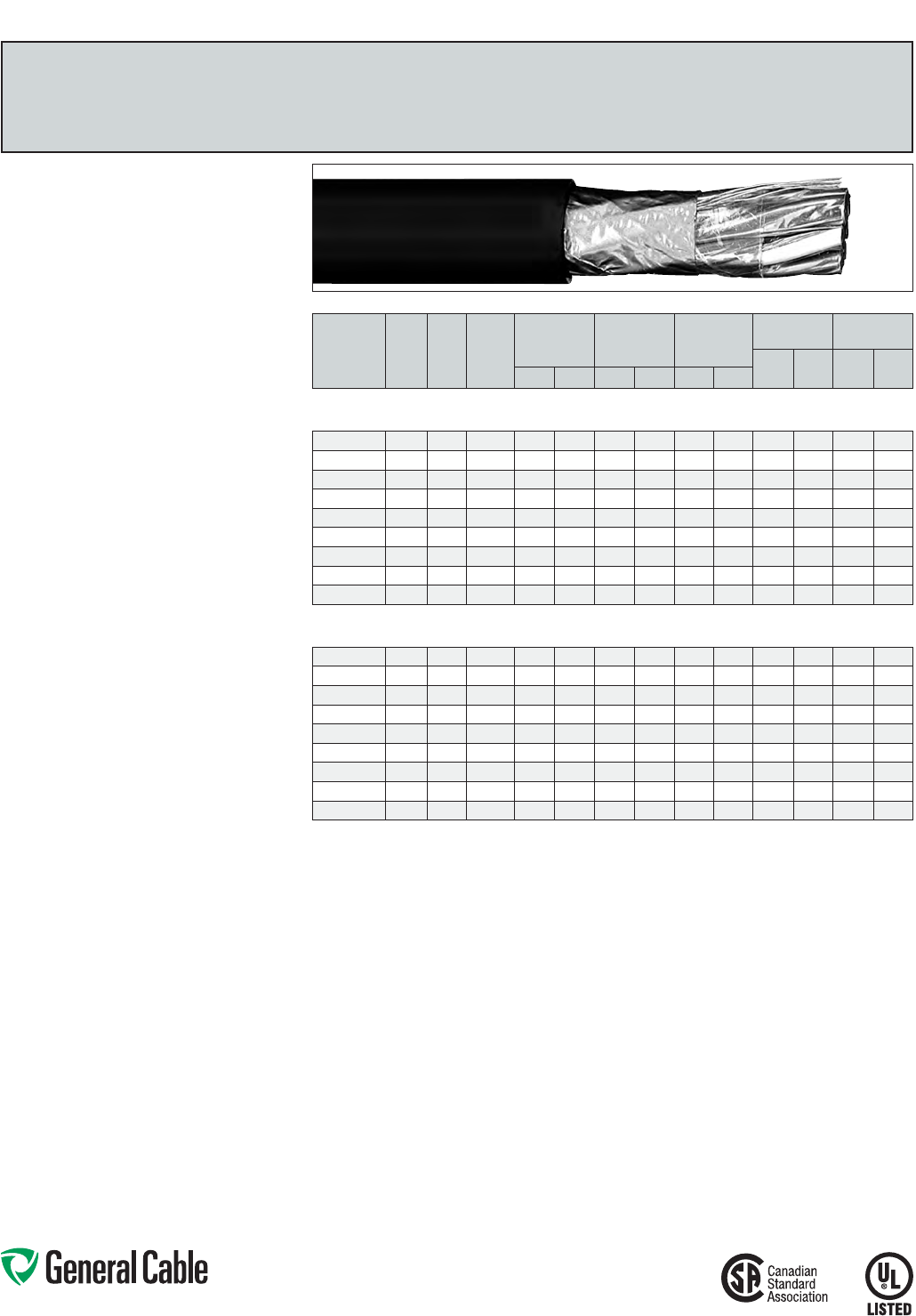
Phone: 888-593-3355
www.generalcable.com
SPEC 2300
March, 2012
CATALOG
NUMBER
NO. OF
PAIRS
COND.
SIZE
(AWG)
COND.
STRAND
MINIMUM AVG.
INSULATION
THICKNESS
MINIMUM AVG.
JACKET
THICKNESS
NOMINAL
CABLE O.D.
COPPER
WEIGHT NET WEIGHT
LBS/
1000 FT kg/km
LBS/
1000 FT kg/kmINCHES mm INCHES mm INCHES mm
INDIVIDUAL AND OVERALL SHIELDED PAIRS
18 AWG CONDUCTORS
347830* 218 7/.0152 0.030 0.76 0.045 1.14 0.515 13.08 30 45 93 138
347840* 418 7/.0152 0.030 0.76 0.060 1.52 0.625 15.88 55 82 167 248
347850* 818 7/.0152 0.030 0.76 0.060 1.52 0.805 20.45 105 156 304 460
347860* 12 18 7/.0152 0.030 0.76 0.080 2.03 1.020 25.91 156 232 449 668
347870* 16 18 7/.0152 0.030 0.76 0.080 2.03 1.130 28.70 207 308 554 824
347880* 20 18 7/.0152 0.030 0.76 0.080 2.03 1.235 31.37 252 375 666 991
347890* 24 18 7/.0152 0.030 0.76 0.080 2.03 1.465 37. 21 308 458 794 1182
347900* 36 18 7/.0152 0.030 0.76 0.080 2.03 1.630 41.40 461 686 1122 1670
347910* 50 18 7/.0152 0.030 0.76 0.110 2.79 1.975 50.17 640 952 1598 2378
INDIVIDUAL AND OVERALL SHIELDED PAIRS
16 AWG CONDUCTORS
347920* 216 7/.0192 0.030 0.76 0.060 1.52 0.595 15.11 42 63 132 196
347930* 416 7/.0192 0.030 0.76 0.060 1.52 0.695 17.65 80 119 212 315
347940* 816 7/.0192 0.030 0.76 0.060 1.52 0.900 22.86 155 231 395 588
347950* 12 16 7/.0192 0.030 0.76 0.080 2.03 1.110 28.19 230 342 578 860
347960* 16 16 7/.0192 0.030 0.76 0.080 2.03 1.260 32.00 306 455 733 1091
347970* 20 16 7/.0192 0.030 0.76 0.080 2.03 1.315 33.40 375 558 845 1258
347980* 24 16 7/.0192 0.030 0.76 0.080 2.03 1.510 38.35 456 679 1009 1502
347990* 36 16 7/.0192 0.030 0.76 0.110 2.79 1.820 46.23 674 1003 1259 1874
348000* 50 16 7/.0192 0.030 0.76 0.110 2.79 2.095 53.21 946 1408 2032 3024
Dimensions and weights are nominal; subject to industry tolerances.
* Non-stock item; minimum runs apply. Please consult Customer Service for price and delivery.
Product Construction:
Conductor:
• 18 AWG and 16 AWG tinned, annealed copper per
ASTM B3
• Class B stranding per ASTM B8
Insulation:
• Lead-free, flame-retardant Cross-linked
Polyethylene (XLPE)
• Color-coded per ICEA Method 1: Pairs - black and
white. One conductor in each pair is printed alpha-
numerically for easy identification
Shield:
Individual and overall shielded pairs
• Individual pairs are 100% shielded with Flexfoil®
aluminum/polyester in contact with stranded
tinned copper drain wire
• Overall shield is Flexfoil® aluminum/polymer in
contact with stranded tinned copper drain wire
Jacket:
• Lead-free, flame-retardant, sunlight-resistant
Arctic-grade Polyvinyl Chloride (PVC)
Print:
• GENERAL CABLE® (PLANT OF MFG) (UL) TYPE
TC ARCTIC-FLEX® FR-XLP/PVC XX SPS/STS
XX AWG SHIELDED 90C WET OR DRY SUN
RES DIR BUR 600 V - CSA TYPE CIC SHIELDED
INSTRUMENTATION CABLE XLPE 90C WET OR
DRY -40C FT4 PLUS DAY/MONTH/YEAR OF MFG
SEQUENTIAL FOOTAGE MARK
Options:
• Bare copper
• Class C stranding
• E-2 Color Code
• CSA Rated TC for 14 AWG and larger
• Other constructions available upon request
Applications:
• Industrial lighting, control and signaling circuits
• Primary installations in cable trays, raceways or
outdoor applications where supported by a
messenger wire
• In wet or dry locations
Features:
• Rated 90˚C wet or dry
• Ripcord applied to all cables with jacket thickness
of 60 mils or less
• Sunlight- and weather-resistant
• Meets CSA cold impact test at -40˚C
• Meets ICEA and CSA cold bend test at -60˚C
Compliances:
Industry Compliances:
• UL 1277 Type TC, UL File # E57179
• UL 1581
• CSA C22.2 No. 239 Type CIC
Flame Test Compliances:
• UL 1581/UL 2556 VW-1
• UL 1685 Vertical Flame Test
• CSA FT4
• IEEE 383
Other Compliances:
• EPA 40 CFR, Part 261 for leachable lead
content per TCLP
• OSHA Acceptable
Packaging:
• Material cut to lengths and shipped on
non-returnable wood reels
Arctic-Flex
®
XLPE/ARCTIC-PVC, Instrumentation, Shielded
600 V, UL Type TC, CSA Type CIC, Individual and Overall Shielded Pairs
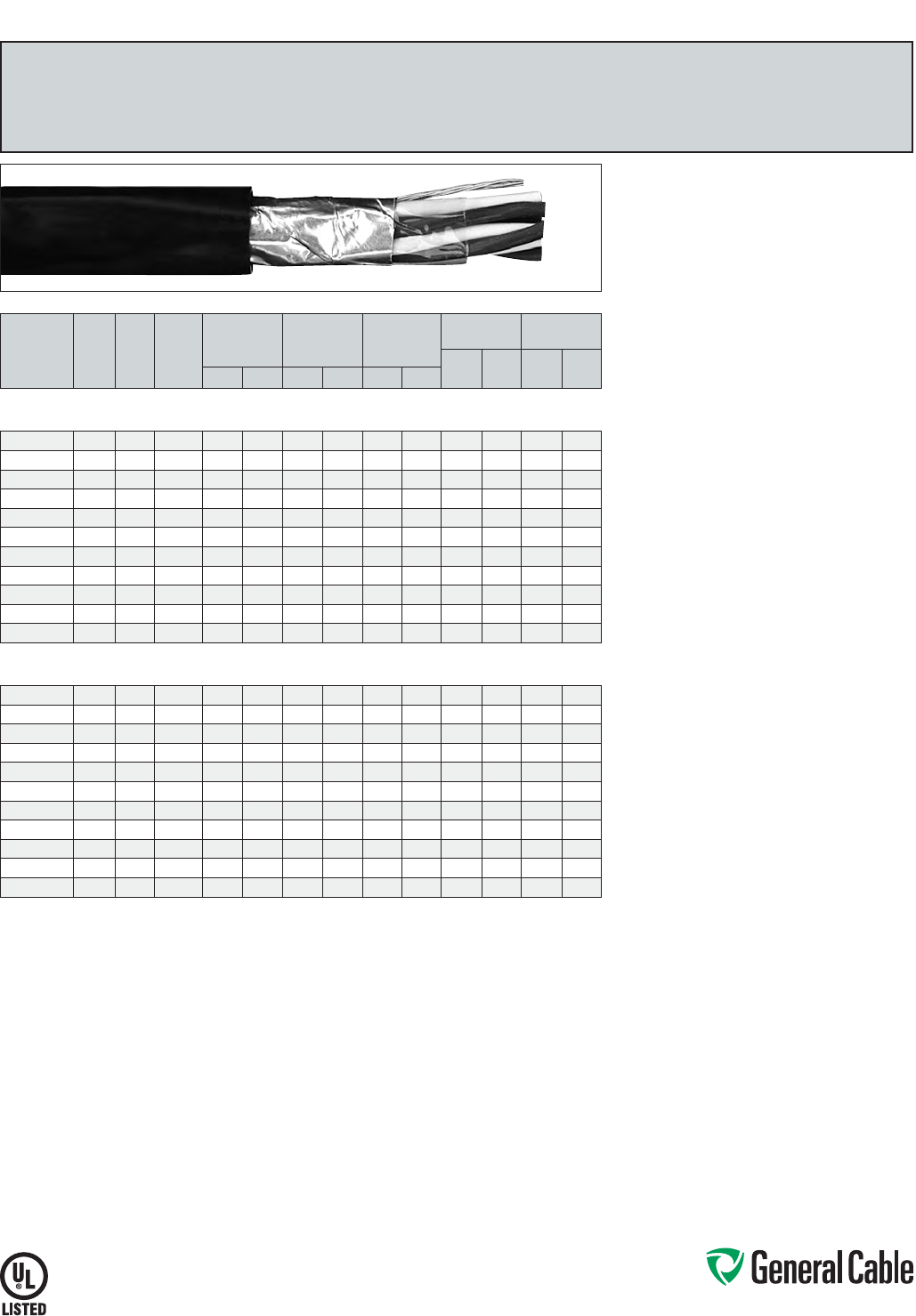
Phone: 888-593-3355
www.generalcable.com
SPEC 2350
March, 2012
CATALOG
NUMBER
NO. OF
PAIRS/
TRIADS
COND.
SIZE
(AWG)
COND.
STRAND
MINIMUM AVG.
INSULATION
THICKNESS
MINIMUM AVG.
JACKET
THICKNESS
NOMINAL
CABLE O.D.
COPPER
WEIGHT NET WEIGHT
LBS/
1000 FT kg/km
LBS/
1000 FT kg/kmINCHES mm INCHES mm INCHES mm
OVERALL SHIELDED PAIRS/TRIADS
18 AWG CONDUCTORS
366160* 118 7/.0152 0.030 0.76 0.045 1.14 0.315 8.00 12 18 46 68
337270* 1 TRI 18 7/.0152 0.030 0.76 0.045 1.14 0.340 8.64 18 26 58 86
337360* 218 7/.0152 0.030 0.76 0.045 1.14 0.450 11.43 23 34 88 131
337280* 418 7/.0152 0.030 0.76 0.045 1.14 0.560 14.22 44 65 144 214
337290* 818 7/.0152 0.030 0.76 0.060 1.52 0.750 19.05 94 140 263 391
337300* 12 18 7/.0152 0.030 0.76 0.080 2.03 0.850 21.59 141 210 358 533
337310* 16 18 7/.0152 0.030 0.76 0.080 2.03 1.010 25.65 187 278 461 686
337320* 20 18 7/.0152 0.030 0.76 0.080 2.03 1.085 27.56 233 347 600 893
337330* 24 18 7/.0152 0.030 0.76 0.080 2.03 1.210 30.73 279 415 701 1043
337340* 36 18 7/.0152 0.030 0.76 0.080 2.03 1.500 38.10 418 622 1005 1496
337350* 50 18 7/.0152 0.030 0.76 0.080 2.03 2. 570 65.28 580 863 1603 2386
OVERALL SHIELDED PAIRS/TRIADS
16 AWG CONDUCTORS
319810* 116 7/.0192 0.030 0.76 0.045 1.14 0.345 8.76 19 28 32 48
319870* 1 TRI 16 7/.0192 0.030 0.76 0.045 1.14 0.360 9.14 27 40 72 107
337370* 216 7/.0192 0.030 0.76 0.045 1.14 0.560 14.22 36 53 121 180
382260* 416 7/.0192 0.030 0.76 0.060 1.52 0.650 16.51 69 102 186 277
337390* 816 7/.0192 0.030 0.76 0.060 1.52 0.810 20.57 135 201 324 482
337400* 12 16 7/.0192 0.030 0.76 0.080 2.03 1.000 25.40 202 300 486 723
337410* 16 16 7/.0192 0.030 0.76 0.080 2.03 1.120 28.45 268 399 616 917
337420* 20 16 7/.0192 0.030 0.76 0.080 2.03 1.170 29.72 335 498 734 1092
337430* 24 16 7/.0192 0.030 0.76 0.080 2.03 1.440 36.58 401 597 894 1330
337440* 36 16 7/.0192 0.030 0.76 0.080 2.03 1.650 41.91 601 894 1254 1866
337450* 50 16 7/.0192 0.030 0.76 0.110 2.79 2.020 51.31 834 1241 1800 2679
Dimensions and weights are nominal; subject to industry tolerances.
* Non-stock item; minimum runs apply. Please consult Customer Service for price and delivery.
Product Construction:
Conductor:
• 18 AWG and 16 AWG bare, annealed
copper per ASTM B3
• Class B stranding per ASTM B8
Insulation:
• Flame-retardant Cross-linked Polyethylene (XLPE)
• Color-coded per ICEA Method 1: Pairs - black
and white; Triads - black, white and red. One
conductor in each pair or triad is printed alpha-
numerically for easy identification
Shield:
Overall shielded pairs/triads
• Overall shield is Flexfoil® aluminum/polymer in
contact with stranded tinned copper drain wire
Jacket:
• Lead-free, flame-retardant, sunlight-resistant
Polyvinyl Chloride (PVC)
Print:
• GENERAL CABLE® (PLANT OF MFG) CVTC®
XX/PS/TS XXAWG FR-XLP/PVC SHIELDED (UL)
TYPE TC 90˚C WET OR DRY DIR BUR SUN RES
600 V MONTH/YEAR OF MFG SEQUENTIAL
FOOTAGE MARK
Options:
• 300 V Type PLTC
• Tinned copper conductor
• Class C stranding
• Individual and overall shielded pairs/triads
• EVTC—Ethylene Propylene Rubber (EPR)
insulation
• Other constructions available upon request
Applications:
• In free air, raceways or direct burial
• In wet or dry locations
• Permitted for use in Class I, Division 2 industrial
hazardous locations per NEC
Features:
• Rated at 90˚C wet or dry
• Ripcord applied to all cables with jacket thickness
of 60 mils or less
• Abrasion- and chemical-resistant
• Excellent electrical properties
• Sunlight- and weather-resistant
• Meets cold bend test at -25˚C
Compliances:
Industry Compliances:
• UL 1277 Type TC, UL File # E57179
• UL 1581
• ICEA S-73-532/NEMA WC57
Flame Test Compliances:
• UL 1581/UL 2556 VW-1
• UL 1685 Vertical Flame Test
• IEEE 383
• IEEE 1202
• ICEA T-29-520 (210,000 BTU/hr)
• CSA FT4
Other Compliances:
• EPA 40 CFR, Part 261 for leachable lead
content per TCLP
• OSHA Acceptable
Packaging:
• Material cut to length and shipped on
non-returnable wood reels
CVTC
®
XLPE/PVC, Instrumentation, Shielded
600 V, UL Type TC, Overall Shielded Pairs/Triads
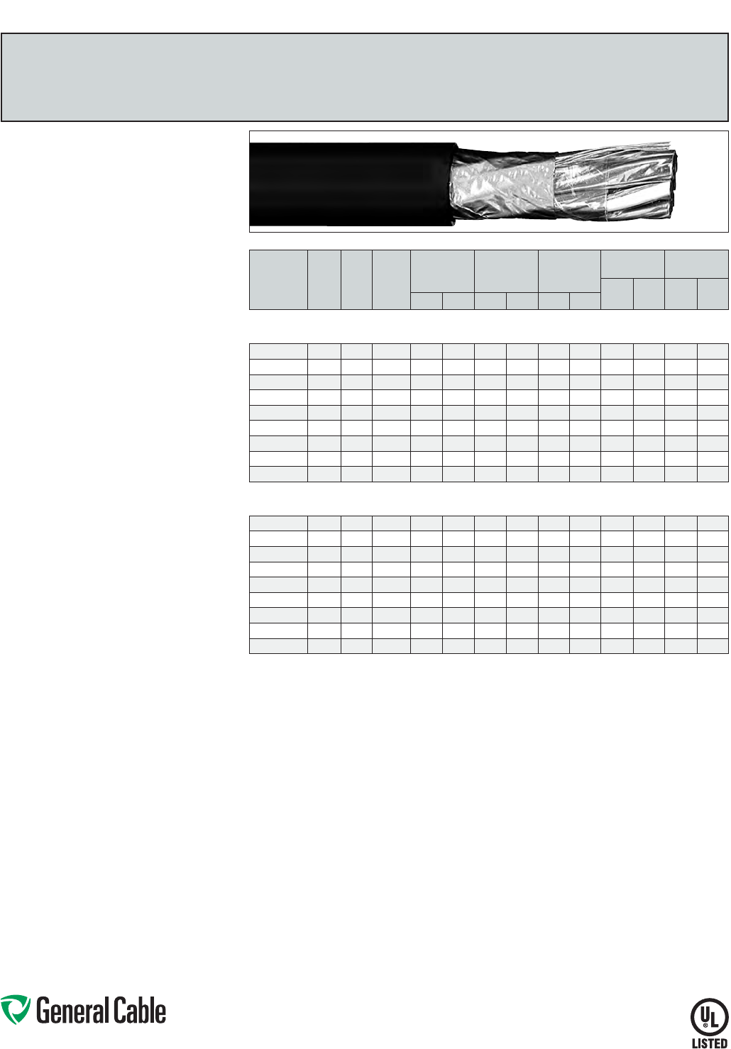
Phone: 888-593-3355
www.generalcable.com
SPEC 2400
March, 2012
CATALOG
NUMBER
NO. OF
PAIRS
COND.
SIZE
(AWG)
COND.
STRAND
MINIMUM AVG.
INSULATION
THICKNESS
MINIMUM AVG.
JACKET
THICKNESS
NOMINAL
CABLE O.D.
COPPER
WEIGHT NET WEIGHT
LBS/
1000 FT kg/km
LBS/
1000 FT kg/kmINCHES mm INCHES mm INCHES mm
INDIVIDUAL AND OVERALL SHIELDED PAIRS
18 AWG CONDUCTORS
319820* 218 7/.0152 0.030 0.76 0.045 1.14 0.515 13.08 28 41 95 141
319840* 418 7/.0152 0.030 0.76 0.060 1.52 0.625 15.88 53 53 170 253
319850* 818 7/.0152 0.030 0.76 0.060 1.52 0.805 20.45 104 155 292 435
337460* 12 18 7/.0152 0.030 0.76 0.080 2.03 1.020 25.91 155 231 442 658
337470* 16 18 7/.0152 0.030 0.76 0.080 2.03 1.130 28.70 206 307 554 824
337480* 20 18 7/.0152 0.030 0.76 0.080 2.03 1.235 31.37 254 378 666 991
337490* 24 18 7/.0152 0.030 0.76 0.080 2.03 1.465 37.21 308 459 802 1194
337500* 36 18 7/.0152 0.030 0.76 0.080 2.03 1.630 41.40 461 687 1116 1661
337510* 50 18 7/.0152 0.030 0.76 0.110 2.79 1.975 50.17 640 952 1598 2378
INDIVIDUAL AND OVERALL SHIELDED PAIRS
16 AWG CONDUCTORS
337520* 216 7/.0192 0.030 0.76 0.060 1.52 0.595 15.11 40 60 135 201
337530* 416 7/.0192 0.030 0.76 0.060 1.52 0.695 17.6 5 78 116 214 318
337540* 816 7/.0192 0.030 0.76 0.060 1.52 0.900 22.86 153 228 399 594
337550* 12 16 7/.0192 0.030 0.76 0.080 2.03 1.110 28.19 229 341 584 869
337560* 16 16 7/.0192 0.030 0.76 0.080 2.03 1.260 32.00 304 453 712 1060
337570* 20 16 7/.0192 0.030 0.76 0.080 2.03 1.315 33.40 380 566 845 1258
337580* 24 16 7/.0192 0.030 0.76 0.080 2.03 1.510 38.35 455 677 1009 1502
337590* 36 16 7/.0192 0.030 0.76 0.110 2.79 1.820 46.23 682 1014 1259 1874
337600* 50 16 7/.0192 0.030 0.76 0.110 2.79 2.095 53.21 946 1408 2032 3024
Dimensions and weights are nominal; subject to industry tolerances.
* Non-stock item; minimum runs apply. Please consult Customer Service for price and delivery.
CVTC
®
XLPE/PVC, Instrumentation, Shielded
600 V, UL Type TC, Individual and Overall Shielded Pairs
Product Construction:
Conductor:
• 18 AWG and 16 AWG bare, annealed
copper per ASTM B3
• Class B stranding per ASTM B8
Insulation:
• Flame-retardant Cross-linked Polyethylene (XLPE)
• Color-coded per ICEA Method 1: Pairs - black and
white. One conductor in each pair is printed alpha-
numerically for easy identification
Shield:
Individual and overall shielded pairs
• Individual pairs are 100% shielded with Flexfoil®
aluminum/polyester in contact with stranded
tinned copper drain wire
• Overall shield is Flexfoil® aluminum/polymer in
contact with stranded tinned copper drain wire
Jacket:
• Lead-free, flame-retardant, sunlight-resistant
Polyvinyl Chloride (PVC)
Print:
• GENERAL CABLE® (PLANT OF MFG) CVTC®
XX/SPS XXAWG FR-XLP/PVC SHIELDED (UL)
TYPE TC 90˚C WET OR DRY DIR BUR SUN
RES 600 V PLUS MONTH/YEAR OF MFG
SEQUENTIAL FOOTAGE MARK
Options:
• 300 V Type PLTC
• Tinned copper conductor
• Class C stranding
• Overall shielded pairs/triads
• EVTC—Ethylene Propylene Rubber (EPR)
insulation
• Other constructions available upon request
Applications:
• In free air, raceways or direct burial
• In wet or dry locations
• Permitted for use in Class I, Division 2 industrial
hazardous locations per NEC
Features:
• Rated at 90˚C wet or dry
• Ripcord applied to all cables with jacket thickness
of 60 mils or less
• Abrasion- and chemical-resistant
• Excellent electrical properties
• Sunlight- and weather-resistant
• Meets cold bend test at -25˚C
Compliances:
Industry Compliances:
• UL 1277 Type TC, UL File # E57179
• UL 1581
• ICEA S-73-532/NEMA WC57
Flame Test Compliances:
• UL 1581/UL 2556 VW-1
• UL 1685 Vertical Flame Test
• IEEE 383
• IEEE 1202
• ICEA T-29-520 (210,000 BTU/hr)
• CSA FT4
Other Compliances:
• EPA 40 CFR, Part 261 for leachable lead
content per TCLP
• OSHA Acceptable
Packaging:
• Material cut to length and shipped on
non-returnable wood reels
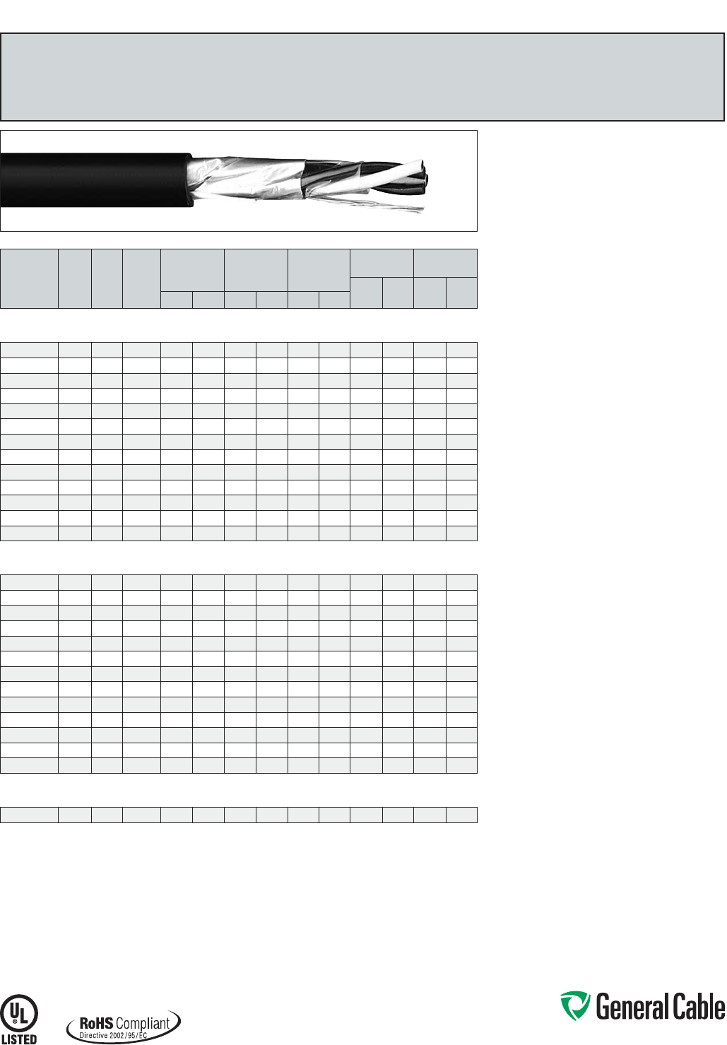
Phone: 888-593-3355
www.generalcable.com
SPEC 2450
March, 2012
CATALOG
NUMBER
NO. OF
PAIRS/
TRIADS
COND.
SIZE
(AWG)
COND.
STRAND
MINIMUM AVG.
INSULATION
THICKNESS
MINIMUM AVG.
JACKET
THICKNESS
NOMINAL
CABLE O.D.
COPPER
WEIGHT NET WEIGHT
LBS/
1000 FT kg/km
LBS/
1000 FT kg/kmINCHES mm INCHES mm INCHES mm
OVERALL SHIELDED PAIRS/TRIADS
18 AWG CONDUCTORS
235020 118 7/.0152 0.020 0.51 0.045 1.14 0.280 7.11 12 19 41 61
239210 1 TRI 18 7/.0152 0.020 0.51 0.045 1.14 0.300 7.6 2 18 27 49 73
235910 218 7/.0152 0.020 0.51 0.045 1.14 0.440 11.18 23 34 72 107
319740* 318 7/.0152 0.020 0.51 0.045 1.14 0.465 11.81 33 50 90 134
235980 418 7/.0152 0.020 0.51 0.045 1.14 0.505 12.83 44 65 110 164
336830* 518 7/.0152 0.020 0.51 0.060 1.52 0.570 14.48 55 82 144 214
336840* 718 7/.0152 0.020 0.51 0.060 1.52 0.585 14.86 75 112 177 263
230760* 12 18 7/.0152 0.020 0.51 0.060 1.52 0.770 19.56 127 189 277 412
270970* 16 18 7/.0152 0.020 0.51 0.080 2.03 0.825 20.96 168 250 355 528
336850* 20 18 7/.0152 0.020 0.51 0.080 2.03 0.905 22.99 210 313 455 677
230750* 24 18 7/.0152 0.020 0.51 0.080 2.03 1.020 25.91 252 375 544 810
230800* 36 18 7/.0152 0.020 0.51 0.080 2.03 1.150 29.21 378 562 763 1135
336860* 50 18 7/.0152 0.020 0.51 0.080 2.03 1.405 35.69 525 781 1036 1542
OVERALL SHIELDED PAIRS/TRIADS
16 AWG CONDUCTORS
230830 116 7/.0192 0.020 0.51 0.045 1.14 0.300 7.6 2 20 29 52 77
230840 1 TRI 16 7/.0192 0.020 0.51 0.045 1.14 0.315 8.00 27 40 61 91
238410* 216 7/.0192 0.020 0.51 0.045 1.14 0.470 11.94 37 54 93 138
239200* 316 7/.0192 0.020 0.51 0.045 1.14 0.505 12.83 53 79 117 174
230790* 416 7/.0192 0.020 0.51 0.060 1.52 0.575 14.61 69 103 160 238
336870* 516 7/.0192 0.020 0.51 0.060 1.52 0.610 15.49 87 129 190 283
336880* 716 7/.0192 0.020 0.51 0.060 1.52 0.630 16.00 117 174 239 356
244590* 12 16 7/.0192 0.020 0.51 0.060 1.52 0.825 20.96 201 299 370 551
244610* 16 16 7/.0192 0.020 0.51 0.080 2.03 0.970 24.64 267 397 513 763
336890* 20 16 7/.0192 0.020 0.51 0.080 2.03 1.010 25.65 337 502 628 935
230780* 24 16 7/.0192 0.020 0.51 0.080 2.03 1.135 28.83 398 592 740 1101
230820* 36 16 7/.0192 0.020 0.51 0.080 2.03 1.375 34.93 595 886 1063 1582
230810* 50 16 7/.0192 0.020 0.51 0.080 2.03 1.570 39.88 833 1240 1435 2136
OVERALL SHIELDED PAIRS/TRIADS
14 AWG CONDUCTORS
237490 114 7/.0242 0.015 0.38 0.045 1.14 0.325 8.26 28 42 62 92
Dimensions and weights are nominal; subject to industry tolerances.
* Non-stock item; minimum runs apply. Please consult Customer Service for price and delivery.
VNTC
®
PVC/Nylon/PVC, Instrumentation, Shielded
600 V, UL Type TC, Overall Shielded Pairs/Triads
Product Construction:
Conductor:
• 18 AWG thru 14 AWG bare, annealed
copper per ASTM B3
• Class B stranding per ASTM B8
Insulation:
• Flame-retardant Polyvinyl Chloride (PVC) with
clear Polyamide (nylon)
• Color-coded per ICEA Method 1: Pairs - black
and white; Triads - black, white and red. One
conductor in each pair or triad is printed alpha-
numerically for easy identification
Shield:
Overall shielded pairs/triads
• Overall shield is Flexfoil® aluminum/polymer in
contact with stranded tinned copper drain wire
Jacket:
• Lead-free, flame-retardant, sunlight-resistant
Polyvinyl Chloride (PVC)
Print:
• GENERAL CABLE® (PLANT OF MFG) VNTC®
XX/PS/TS XXAWG SHIELDED (UL) TYPE TC 600
V TFN SUN RES DIR BUR ROHS DAY/MONTH/
YEAR OF MFG SEQUENTIAL FOOTAGE MARK
Options:
• Tinned copper conductor
• Class C stranding
• Individual and overall shielded pairs/triads
• Other constructions available upon request
Applications:
• In free air, raceways or direct burial
• In wet or dry locations
• Permitted for use in Class I, Division 2 industrial
hazardous locations per NEC
Features:
• Rated at 90˚C dry, 75˚C wet
• Ripcord applied to all cables with jacket thickness
of 60 mils or less
• Provides sunlight, cold bend and cold impact
resistance
• Offer the smallest cable O.D. available for suitable
applications
• Provides excellent oil and chemical resistance
• Provides a long service life
• Meets cold bend test at -25˚C
Compliances:
Industry Compliances:
• UL 1277 Type TC, UL File # E57179
• UL 1581
• NEC Type TFN conductors
• ICEA S-73-532/NEMA WC57
Flame Test Compliances:
• UL 1685 Vertical Flame Test
• IEEE 383
• IEEE 1202
• CSA FT4
Other Compliances:
• EPA 40 CFR, Part 261 for leachable lead
content per TCLP
• OSHA Acceptable
• RoHS Compliant
Packaging:
• Material cut to length and shipped on
non-returnable wood reels
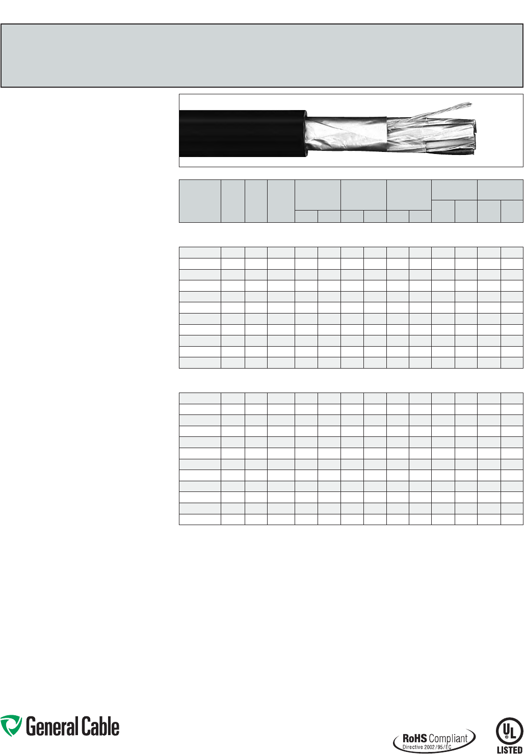
Phone: 888-593-3355
www.generalcable.com
SPEC 2500
March, 2012
CATALOG
NUMBER
NO. OF
PAIRS
COND.
SIZE
(AWG)
COND.
STRAND
MINIMUM AVG.
INSULATION
THICKNESS
MINIMUM AVG.
JACKET
THICKNESS
NOMINAL
CABLE O.D.
COPPER
WEIGHT NET WEIGHT
LBS/
1000 FT kg/km
LBS/
1000 FT kg/kmINCHES mm INCHES mm INCHES mm
INDIVIDUAL AND OVERALL SHIELDED PAIRS
18 AWG CONDUCTORS
235970* 218 7/.0152 0.020 0.51 0.045 1.14 0.445 11.30 28 41 84 125
336900* 318 7/.0152 0.020 0.51 0.045 1.14 0.480 12.19 46 68 106 158
235900* 418 7/.0152 0.020 0.51 0.045 1.14 0.555 14.10 53 79 145 216
336910* 518 7/.0152 0.020 0.51 0.060 1.52 0.580 14.73 74 110 169 252
336920* 718 7/.0152 0.020 0.51 0.060 1.52 0.650 16.51 102 152 219 326
241020* 12 18 7/.0152 0.020 0.51 0.060 1.52 0.845 21.46 193 287 390 506
336930* 16 18 7/.0152 0.020 0.51 0.080 2.03 0.960 24.38 229 341 473 704
336940* 20 18 7/.0152 0.020 0.51 0.080 2.03 1.050 26.67 283 421 594 884
241030* 24 18 7/.0152 0.020 0.51 0.080 2.03 1.175 29.85 340 506 689 1025
243880* 36 18 7/.0152 0.020 0.51 0.080 2.03 1.380 35.05 508 756 979 1457
256300* 50 18 7/.0152 0.020 0.51 0.080 2.03 1.615 41.02 705 1049 1371 1960
INDIVIDUAL AND OVERALL SHIELDED PAIRS
16 AWG CONDUCTORS
237180 216 7/.0192 0.020 0.51 0.045 1.14 0.495 12.57 44 65 105 156
235990* 316 7/.0192 0.020 0.51 0.045 1.14 0.520 13.21 64 95 137 204
237160 416 7/.0192 0.020 0.51 0.045 1.14 0.600 15.24 84 125 188 280
336950* 516 7/.0192 0.020 0.51 0.060 1.52 0.655 16.64 105 157 224 333
336960* 716 7/.0192 0.020 0.51 0.060 1.52 0.710 18.03 145 216 290 432
235750 816 7/.0192 0.020 0.51 0.060 1.52 0.760 19.30 155 224 307 457
242870 12 16 7/.0192 0.020 0.51 0.060 1.52 0.940 23.88 244 363 498 741
237130* 16 16 7/.0192 0.020 0.51 0.080 2.03 1.055 26.80 324 482 635 945
277820* 20 16 7/.0192 0.020 0.51 0.080 2.03 1.175 29.85 407 605 768 1143
242860* 24 16 7/.0192 0.020 0.51 0.080 2.03 1.350 34.29 486 724 903 1344
243890* 36 16 7/.0192 0.020 0.51 0.080 2.03 1.480 37.59 732 1089 1290 1920
244600* 50 16 7/.0192 0.020 0.51 0.080 2.03 1.810 45.97 1011 1504 1809 2692
Dimensions and weights are nominal; subject to industry tolerances.
* Non-stock item; minimum runs apply. Please consult Customer Service for price and delivery.
Product Construction:
Conductor:
• 18 AWG and 16 AWG bare, annealed
copper per ASTM B3
• Class B stranding per ASTM B8
Insulation:
• Flame-retardant Polyvinyl Chloride (PVC) with
clear Polyamide (nylon)
• Color-coded per ICEA Method 1: Pairs - black and
white. One conductor in each pair is printed alpha-
numerically for easy identification
Shield:
Individual and overall shielded pairs
• Individual pairs are 100% shielded with Flexfoil®
aluminum/polyester in contact with stranded
tinned copper drain wire
• Overall shield is Flexfoil® aluminum/polymer in
contact with stranded tinned copper drain wire
Jacket:
• Lead-free, flame-retardant, sunlight-resistant
Polyvinyl Chloride (PVC)
Print:
• GENERAL CABLE® (PLANT OF MFG) VNTC®
XX/SPS XXAWG SHIELDED (UL) TYPE TC 600 V
TFN SUN RES DIR BUR ROHS PLUS DAY/
MONTH/YEAR OF MFG SEQUENTIAL FOOTAGE
MARK
Options:
• Tinned copper conductor
• Class C stranding
• Overall shielded pairs/triads
• Other constructions available upon request
Applications:
• In free air, raceways or direct burial
• In wet or dry locations
• Permitted for use in Class I, Division 2 industrial
hazardous locations per NEC
Features:
• Rated at 90˚C dry, 75˚C wet
• Ripcord applied to all cables with jacket thickness
of 60 mils or less
• Provides sunlight, cold bend and cold impact
resistance
• Offer the smallest cable O.D. available for suitable
applications
• Provides excellent oil and chemical
resistance
• Provides a long service life
• Meets cold bend test at -25˚C
Compliances:
Industry Compliances:
• UL 1277 Type TC, UL File # E57179
• UL 1581
• NEC Type TFN conductors
• ICEA S-73-532/NEMA WC57
Flame Test Compliances:
• UL 1685 Vertical Flame Test
• IEEE 383
• IEEE 1202
• CSA FT4
Other Compliances:
• EPA 40 CFR, Part 261 for leachable lead
content per TCLP
• OSHA Acceptable
• RoHS Compliant
Packaging:
• Material cut to length and shipped on
non-returnable wood reels
VNTC
®
PVC/Nylon/PVC, Instrumentation, Shielded
600 V, UL Type TC, Individual and Overall Shielded Pairs
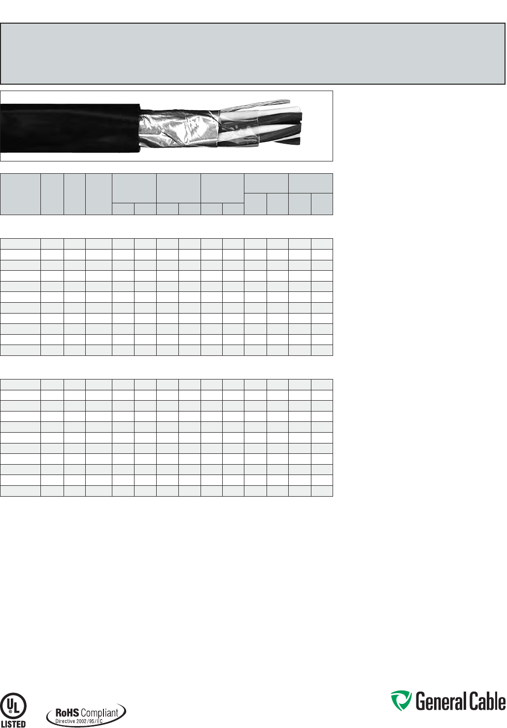
Phone: 888-593-3355
www.generalcable.com
SPEC 2600
March, 2012
CATALOG
NUMBER
NO. OF
PAIRS/
TRIADS
COND.
SIZE
(AWG)
COND.
STRAND
MINIMUM AVG.
INSULATION
THICKNESS
MINIMUM AVG.
JACKET
THICKNESS
NOMINAL
CABLE O.D.
COPPER
WEIGHT NET WEIGHT
LBS/
1000 FT kg/km
LBS/
1000 FT kg/kmINCHES mm INCHES mm INCHES mm
OVERALL SHIELDED PAIRS/TRIADS
18 AWG CONDUCTORS
393710* 118 7/.0152 0.030 0.76 0.045 1.14 0.315 8.00 13 19 46 68
393720* 1 TRI 18 7/.0152 0.030 0.76 0.045 1.14 0.340 8.64 18 26 58 86
393730* 218 7/.0152 0.030 0.76 0.045 1.14 0.450 11.43 23 34 88 131
393740* 418 7/.0152 0.030 0.76 0.045 1.14 0.560 14.22 44 65 144 214
393750* 818 7/.0152 0.030 0.76 0.060 1.52 0.750 19.05 86 127 263 391
393760* 12 18 7/.0152 0.030 0.76 0.080 2.03 0.850 21.59 127 189 358 533
393770* 16 18 7/.0152 0.030 0.76 0.080 2.03 1.010 25.65 169 251 461 686
393780* 20 18 7/.0152 0.030 0.76 0.080 2.03 1.085 27. 56 210 313 600 893
393790* 24 18 7/.0152 0.030 0.76 0.080 2.03 1.210 30.73 252 375 701 1043
393800* 36 18 7/.0152 0.030 0.76 0.080 2.03 1.500 38.10 377 561 1005 1496
393810* 50 18 7/.0152 0.030 0.76 0.080 2.03 2.570 65.28 523 778 1603 2386
OVERALL SHIELDED PAIRS/TRIADS
16 AWG CONDUCTORS
393820 116 7/.0192 0.030 0.76 0.045 1.14 0.345 8.76 18 28 32 48
393830 1 TRI 16 7/.0192 0.030 0.76 0.045 1.14 0.360 9.14 26 39 72 107
393840* 216 7/.0192 0.030 0.76 0.045 1.14 0.560 14.22 36 54 121 180
393850* 416 7/.0192 0.030 0.76 0.060 1.52 0.650 16.51 69 103 186 277
393860* 816 7/.0192 0.030 0.76 0.060 1.52 0.810 20.57 135 201 324 482
393870* 12 16 7/.0192 0.030 0.76 0.080 2.03 1.000 25.40 202 300 486 723
393880* 16 16 7/.0192 0.030 0.76 0.080 2.03 1.120 28.45 268 399 616 917
393890* 20 16 7/.0192 0.030 0.76 0.080 2.03 1.170 29.72 335 498 734 1092
393900* 24 16 7/.0192 0.030 0.76 0.080 2.03 1.440 36.58 401 597 894 1330
393910* 36 16 7/.0192 0.030 0.76 0.080 2.03 1.650 41.91 601 894 1254 1866
393920* 50 16 7/.0192 0.030 0.76 0.110 2.79 2.020 51.31 834 1241 1800 2679
Dimensions and weights are nominal; subject to industry tolerances.
* Non-stock item; minimum runs apply. Please consult Customer Service for price and delivery.
Product Construction:
Conductor:
• 18 AWG and 16 AWG tinned, annealed copper per
ASTM B33
• Class B stranding per ASTM B8
Insulation:
• Lead-free, flame-retardant, low-smoke
Cross-linked Polyethylene (XLPE)
• Color-coded per ICEA Method 1: Pairs - black
and white; Triads - black, white and red. One
conductor in each pair or triad is printed alpha-
numerically for easy identification
Shield:
Overall shielded pairs/triads
• Overall shield is Flexfoil® aluminum/polymer in
contact with stranded tinned copper drain wire
Jacket:
• Lead-free, flame-retardant, sunlight-resistant,
Low-Smoke, Zero-Halogen Polyolefin (LSZH)
Print:
• GENERAL CABLE® (PLANT OF MFG) GENFREE®
XX/PS/TS XXAWG XLPE/LSZH SHIELDED (UL)
TYPE TC-LS 90˚C WET OR DRY 600 V DIR BUR
SUN RES ROHS DAY/MONTH/YEAR OF MFG
SEQUENTIAL FOOTAGE MARK
Options:
• Class C stranding
• Individual and overall shielded pairs/triads
• Other constructions available upon request
Applications:
• In free air, raceways, aerial or direct burial
• In wet or dry locations
• Permitted for use in Class I, Division 2 industrial
hazardous locations per NEC
Features:
• Rated at 90˚C wet or dry
• Ripcord applied to all cables with jacket thickness
of 60 mils or less
• Excellent physical and electrical properties
• Excellent moisture resistance
• Excellent resistance to compression and impact
• Chemical-resistant
• Low coefficient of friction for easy pulling
• Sunlight- and weather-resistant
• Meets cold bend test at -30˚C
• Low-Smoke, Zero-Halogen jacket is
environmentally safe
• Low-Smoke, Zero-Halogen jacket reduces the
amount of toxic and corrosive gases emitted
during combustion, providing a safer environment
for personnel and equipment during the hazards
of fire
Compliances:
Industry Compliances:
• UL 1277 Type TC-LS, UL File # E57179
• UL 1581
• ICEA S-73-532/NEMA WC57
• ICEA T-33-655
• RoHS Compliant
Flame Test Compliances:
• UL 1581
• UL 1685 Vertical Flame Test
• IEEE 1202
Other Compliances:
• EPA 40 CFR, Part 261 for leachable lead
content per TCLP
• OSHA Acceptable
Packaging:
• Material cut to length and shipped on
non-returnable wood reels
GenFree
®
XLPE/LSZH, Instrumentation, Shielded
600 V, UL Type TC-LS, Overall Shielded Pairs/Triads
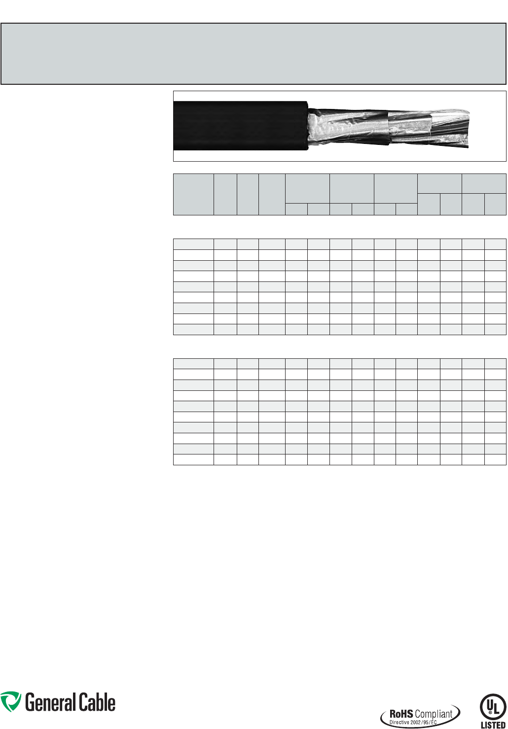
Phone: 888-593-3355
www.generalcable.com
SPEC 2625
March, 2012
CATALOG
NUMBER
NO. OF
PAIRS
COND.
SIZE
(AWG)
COND.
STRAND
MINIMUM AVG.
INSULATION
THICKNESS
MINIMUM AVG.
JACKET
THICKNESS
NOMINAL
CABLE O.D.
COPPER
WEIGHT NET WEIGHT
LBS/
1000 FT kg/km
LBS/
1000 FT kg/kmINCHES mm INCHES mm INCHES mm
INDIVIDUAL AND OVERALL SHIELDED PAIRS
18 AWG CONDUCTORS
393930 218 7/.0152 0.030 0.76 0.045 1.14 0.510 12.95 27 41 92 137
393940 418 7/.0152 0.030 0.76 0.060 1.52 0.630 16.00 53 78 167 249
393950* 818 7/.0152 0.030 0.76 0.080 2.03 0.855 21.72 103 153 326 485
393960* 12 18 7/.0152 0.030 0.76 0.080 2.03 1.030 26.16 153 228 441 656
393970* 16 18 7/.0152 0.030 0.76 0.080 2.03 1.140 28.96 206 307 554 824
393980* 20 18 7/.0152 0.030 0.76 0.080 2.03 1.265 32.13 254 378 676 1006
393990* 24 18 7/.0152 0.030 0.76 0.080 2.03 1.450 36.83 311 463 795 1183
394000* 36 18 7/.0152 0.030 0.76 0.010 2.79 1.650 41.91 461 687 1118 1664
394010* 50 18 7/.0152 0.030 0.76 0.010 2.79 2.085 52.96 640 952 1616 2405
INDIVIDUAL AND OVERALL SHIELDED PAIRS
16 AWG CONDUCTORS
394020 216 7/.0192 0.030 0.76 0.060 1.52 0.585 14.86 40 59 130 193
394030 416 7/.0192 0.030 0.76 0.060 1.52 0.675
17.15
77 114 204 304
394040 616 7/.0192 0.030 0.76 0.060 1.52 0.800 20.32 115 171 301 447
394050 816 7/.0192 0.030 0.76 0.080 2.03 0.915 23.24 151 225 394 586
394060 12 16 7/.0192 0.030 0.76 0.080 2.03 1.110 28.19 226 337 548 816
394070* 16 16 7/.0192 0.030 0.76 0.080 2.03 1.350 34.29 305 453 713 1061
394080* 20 16 7/.0192 0.030 0.76 0.080 2.03 1.365 34.67 380 566 850 1265
394090* 24 16 7/.0192 0.030 0.76 0.080 2.03 1.570 39.88 455 677 1001 1490
394100* 36 16 7/.0192 0.030 0.76 0.110 2.79 1.980 50.29 683 1016 1548 2304
394110* 50 16 7/.0192 0.030 0.76 0.110 2.79 2.165 54.99 946 1408 2020 3006
Dimensions and weights are nominal; subject to industry tolerances.
* Non-stock item; minimum runs apply. Please consult Customer Service for price and delivery.
Product Construction:
Conductor:
• 18 AWG and 16 AWG tinned, annealed copper per
ASTM B33
• Class B stranding per ASTM B8
Insulation:
• Lead-free, flame-retardant, low-smoke
Cross-linked Polyethylene (XLPE)
• Color-coded per ICEA Method 1: Pairs - black and
white. One conductor in each pair is printed alpha-
numerically for easy identification
Shield:
Individual and overall shielded pairs
• Individual pairs are 100% individually shielded
with Flexfoil® aluminum/polyester in contact with
stranded tinned copper drain wire
• Overall shield is Flexfoil® aluminum/polymer in
contact with stranded tinned copper drain wire
Jacket:
• Lead-free, flame-retardant, sunlight-resistant
Low-Smoke, Zero-Halogen Polyolefin (LSZH)
Print:
• GENERAL CABLE® (PLANT OF MFG) GENFREE®
XX/SPS XXAWG XLPE/LSZH SHIELDED (UL)
TYPE TC-LS 90˚C WET OR DRY 600 V DIR BUR
SUN RES ROHS DAY/MONTH/YEAR OF MFG
SEQUENTIAL FOOTAGE MARK
Options:
• Class C stranding
• Overall shielded pairs
• Other constructions available upon request
Applications:
• In free air, raceways, aerial or direct burial
• In wet or dry locations
• Permitted for use in Class I, Division 2 industrial
hazardous locations per NEC
Features:
• Rated at 90˚C wet or dry
• Ripcord applied to all cables with jacket thickness
of 60 mils or less
• Excellent physical and electrical properties
• Excellent moisture resistance
• Excellent resistance to compression and impact
• Chemical-resistant
• Low coefficient of friction for easy pulling
• Sunlight- and weather-resistant
• Meets cold bend test at -30˚C
• Low-Smoke, Zero-Halogen jacket is
environmentally safe
• Low-Smoke, Zero-Halogen jacket reduces the
amount of toxic and corrosive gases emitted during
combustion, providing a safer environment for
personnel and equipment during the hazards of fire
Compliances:
Industry Compliances:
• UL 1277 Type TC-LS, UL File # E57179
• UL 1581
• ICEA S-73-532/NEMA WC57
• ICEA T-33-655
• RoHS Compliant
Flame Test Compliances:
• UL 1581
• UL 1685 Vertical Flame Test
• IEEE 1202
Other Compliances:
• EPA 40 CFR, Part 261 for leachable lead
content per TCLP
• OSHA Acceptable
Packaging:
• Material cut to length and shipped on
non-returnable wood reels
GenFree
®
XLPE/LSZH, Instrumentation, Shielded
600 V, UL Type TC-LS, Individual and Overall Shielded Pairs
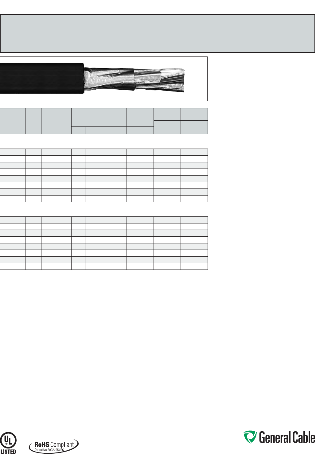
Phone: 888-593-3355
www.generalcable.com
SPEC 2650
March, 2012
CATALOG
NUMBER
NO. OF
TRIADS
COND.
SIZE
(AWG)
COND.
STRAND
MINIMUM AVG.
INSULATION
THICKNESS
MINIMUM AVG.
JACKET
THICKNESS
NOMINAL
CABLE O.D.
COPPER
WEIGHT NET WEIGHT
LBS/
1000 FT kg/km
LBS/
1000 FT kg/kmINCHES mm INCHES mm INCHES mm
INDIVIDUAL AND OVERALL SHIELDED TRIADS
18 AWG CONDUCTORS
394120* 2 TRI 18 7/.0152 0.030 0.76 0.060 1.52 0.595 15.11 38 57 150 223
394130* 4 TRI 18 7/.0152 0.030 0.76 0.060 1.52 0.690 17.53 74 110 231 344
394140* 8 TRI 18 7/.0152 0.030 0.76 0.080 2.03 0.940 23.88 145 216 435 647
394150* 12 TRI 18 7/.0152 0.030 0.76 0.080 2.03 1.135 28.83 217 323 612 911
394160* 16 TRI 18 7/.0152 0.030 0.76 0.080 2.03 1.265 32.13 289 430 773 1150
394170* 20 TRI 18 7/.0152 0.030 0.76 0.080 2.03 1.405 35.69 361 537 935 1391
394180* 24 TRI 18 7/.0152 0.030 0.76 0.080 2.03 1.565 39.75 432 643 1097 1633
394190* 36 TRI 18 7/.0152 0.030 0.76 0.110 2.79 1.860 47.24 647 963 1662 2473
INDIVIDUAL AND OVERALL SHIELDED TRIADS
16 AWG CONDUCTORS
394200* 2 TRI 16 7/.0192 0.030 0.76 0.060 1.52 0.640 16.26 57 84 183 272
394210* 4 TRI 16 7/.0192 0.030 0.76 0.060 1.52 0.745 18.92 111 165 494 735
394220* 8 TRI 16 7/.0192 0.030 0.76 0.080 2.03 1.015 25.78 219 326 549 817
394230* 12 TRI 16 7/.0192 0.030 0.76 0.080 2.03 1.230 31.24 328 487 777 1156
394240* 16 TRI 16 7/.0192 0.030 0.76 0.080 2.03 1.370 34.80 437 650 988 1470
394250* 20 TRI 16 7/.0192 0.030 0.76 0.080 2.03 1.525 38.74 545 811 1120 1667
394260* 24 TRI 16 7/.0192 0.030 0.76 0.110 2.79 1.760 44.70 654 973 1530 2277
394270* 36 TRI 16 7/.0192 0.030 0.76 0.110 2.79 2.015 51.18 979 1457 2142 3188
Dimensions and weights are nominal; subject to industry tolerances.
* Non-stock item; minimum runs apply. Please consult Customer Service for price and delivery.
Product Construction:
Conductor:
• 18 AWG and 16 AWG tinned, annealed copper per
ASTM B33
• Class B stranding per ASTM B8
Insulation:
• Lead-free, flame-retardant, low-smoke
Cross-linked Polyethylene (XLPE)
• Color-coded per ICEA Method 1: Triads - black,
white and red. One conductor in each triad is
printed alpha-numerically for easy identification
Shield:
Individual and overall shielded triads
• Individual triads are 100% shielded with Flexfoil®
aluminum/polyester in contact with stranded
tinned copper drain wire
• Overall shield is Flexfoil® aluminum/polymer in
contact with stranded tinned copper drain wire
Jacket:
• Lead-free, flame-retardant, sunlight-resistant
Low-Smoke, Zero-Halogen Polyolefin (LSZH)
Print:
• GENERAL CABLE® (PLANT OF MFG) GENFREE®
XX/STS XXAWG XLPE/LSZH SHIELDED (UL)
TYPE TC-LS 90˚C WET OR DRY 600 V DIR BUR
SUN RES ROHS DAY/MONTH/YEAR OF MFG
SEQUENTIAL FOOTAGE MARK
Options:
• Class C stranding
• Overall shielded pairs/triads
• Other constructions available upon request
Applications:
• In free air, raceways, aerial or direct burial
• In wet or dry locations
• Permitted for use in Class I, Division 2 industrial
hazardous locations per NEC
Features:
• Rated at 90˚C wet or dry
• Ripcord applied to all cables with jacket thickness
of 60 mils or less
• Excellent physical and electrical properties
• Excellent moisture resistance
• Excellent resistance to compression and impact
• Chemical-resistant
• Low coefficient of friction for easy pulling
• Sunlight- and weather-resistant
• Meets cold bend test at -30˚C
• Low-Smoke, Zero-Halogen jacket is
environmentally safe
• Low-Smoke, Zero-Halogen jacket reduces the
amount of toxic and corrosive gases emitted during
combustion, providing a safer environment for
personnel and equipment during the hazards of fire
Compliances:
Industry Compliances:
• UL 1277 Type TC-LS, UL File # E57179
• UL 1581
• ICEA S-73-532/NEMA WC57
• ICEA T-33-655
• RoHS Compliant
Flame Test Compliances:
• UL 1581
• UL 1685 Vertical Flame Test
• IEEE 1202
Other Compliances:
• EPA 40 CFR, Part 261 for leachable lead
content per TCLP
• OSHA Acceptable
Packaging:
• Material cut to length and shipped on
non-returnable wood reels
GenFree
®
XLPE/LSZH, Instrumentation, Shielded
600 V, UL Type TC-LS, Individual and Overall Shielded Triads
Phone: 888-593-3355
www.generalcable.com
Date of Issue 06/13
Section 3 Industrial Cables
600 V Flexible Control and Power Cables
SPECIFICATION NO. PRODUCT DESCRIPTION REVISION DATE
3150 NVN®PVC/Nylon/Neoprene, Thermoset Flexible Control
600 V, UL Type TC
Jan. 2010
3250 MTW PVC/Nylon/PVC, Thermoplastic Flexible Control
600 V, UL Type MTW/CSA AWM
Jan. 2010
3300 Festoon PVC/PVC, Thermoplastic Extreme Flexing Festoon Control and Power
600 V, UL/CSA Type Festoon
Jan. 2010
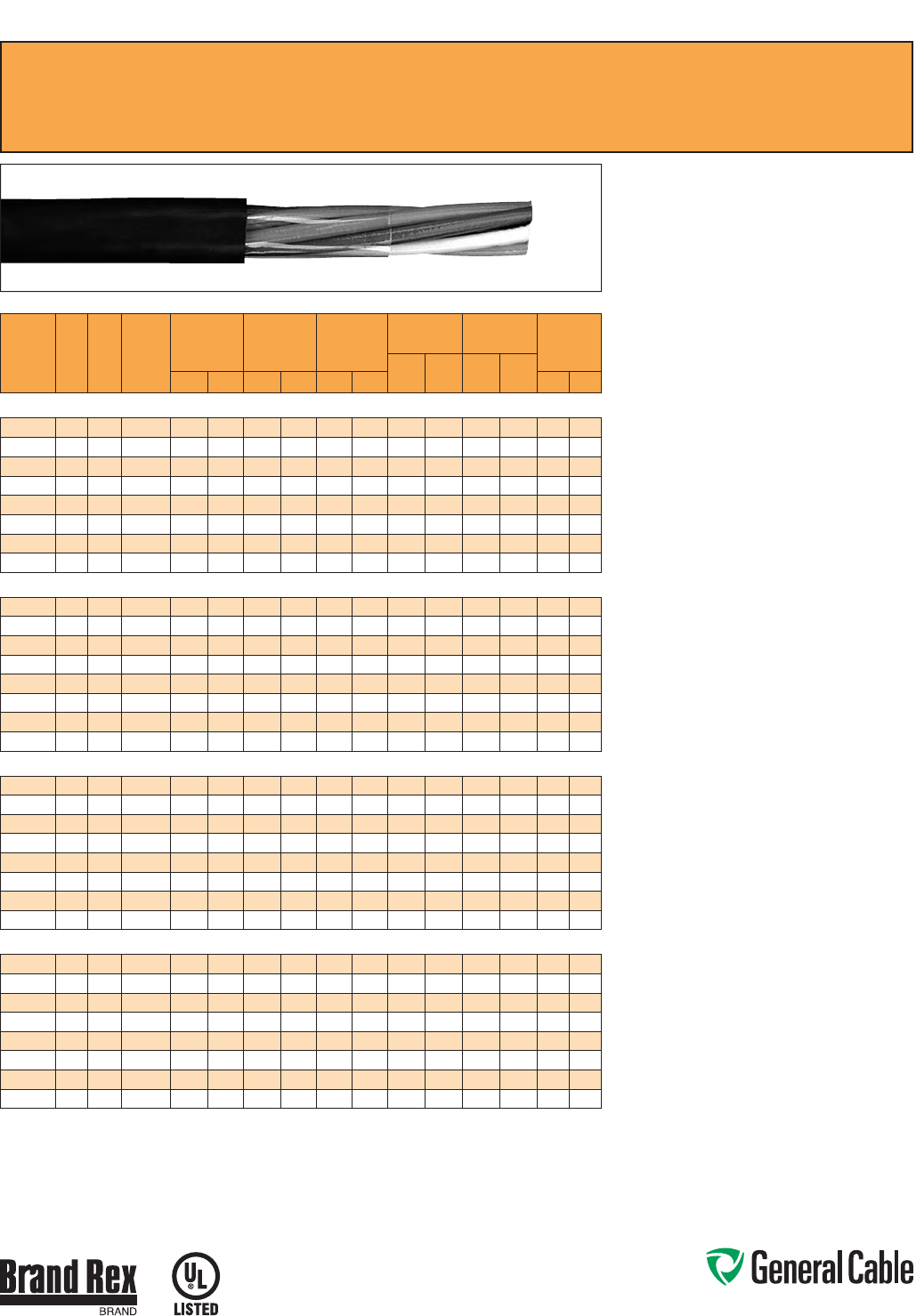
Phone: 888-593-3355
www.generalcable.com
SPEC 3150
January, 2010
CATALOG
NUMBER
NO. OF
COND.
COND.
SIZE
(AWG)
COND.
STRAND
MINIMUM AVG.
INSULATION
THICKNESS
MINIMUM AVG.
JACKET
THICKNESS
NOMINAL
CABLE O.D.
COPPER
WEIGHT NET WEIGHT MINIMUM
BEND
RADIS
LBS/
1000 FT kg/km
LBS/
1000 FT kg/kmINCHES mm INCHES mm INCHES mm
INCHES
mm
18 AWG CONDUCTORS
554420* 418 19/.0092 0.020 0.51 0.045 1.14 0.310 7.87 21 31 65 97 2.5 63.5
624740* 818 19/.0092 0.020 0.51 0.045 1.14 0.420 10.67 42 63 116 173 3.3 83.8
624750* 10 18 19/.0092 0.020 0.51 0.045 1.14 0.450 11.43 53 79 135 201 3.6 91.5
624760* 12 18 19/.0092 0.020 0.51 0.045 1.14 0.465 11.81 63 94 137 204 3.7 94.0
624010* 16 18 19/.0092 0.020 0.51 0.045 1.14 0.515 13.08 85 126 175 260 4.1 104.1
624780* 19 18 19/.0092 0.020 0.51 0.060 1.52 0.570 14.48 100 149 192 286 4.6 116.8
624790* 24 18 19/.0092 0.020 0.51 0.060 1.52 0.660 16.76 127 189 297 442 5.3 134.6
686890* 30 18 19/.0092 0.020 0.51 0.060 1.52 0.695 17.6 5 158 235 345 513 5.6 142.2
16 AWG CONDUCTORS
625160* 416 19/.0117 0.020 0.51 0.045 1.14 0.345 8.76 33 49 85 126 2.8 71.1
625200* 816 19/.0117 0.020 0.51 0.045 1.14 0.465 11.81 66 98 153 228 3.7 94.0
625220* 10 16 19 /.0117 0.020 0.51 0.045 1.14 0.500 12.70 83 124 179 266 4.0 101.6
625230* 12 16 19 /.0117 0.020 0.51 0.045 1.14 0.520 13.21 100 149 186 277 4.2 106.7
625250* 16 16 19 /.0117 0.020 0.51 0.045 1.14 0.605 15.37 133 198 257 382 4.8 121.9
625270* 19 16 19 /.0117 0.020 0.51 0.060 1.52 0.635 16.13 158 235 320 476 5.1 129.5
625280* 24 16 19 /.0117 0.020 0.51 0.060 1.52 0.735 18.67 199 296 403 600 5.9 149.9
625290* 30 16 19/.0117 0.020 0.51 0.060 1.52 0.775 19.69 249 371 476 708 6.2 157.5
14 AWG CONDUCTORS
624950* 414 19/.0147 0.020 0.51 0.045 1.14 0.375 9.53 53 79 117 174 3.0 76.2
624980* 814 19/.0147 0.020 0.51 0.045 1.14 0.485 12.32 105 156 181 269 3.9 99.1
624990* 10 14 19/.0147 0.020 0.51 0.060 1.52 0.595 15.11 132 196 270 402 4.8 121.9
625000* 12 14 19/.0147 0.020 0.51 0.060 1.52 0.615 15.62 158 235 278 414 4.9 124.5
625020* 16 14 19/.0147 0.020 0.51 0.060 1.52 0.675 17.15 210 313 353 525 5.4 137.2
625030* 19 14 19/.0147 0.020 0.51 0.060 1.52 0.710 18.03 250 372 449 668 5.7 144.8
625040* 24 14 19/.0147 0.020 0.51 0.060 1.52 0.825 20.96 316 470 565 841 6.6 167.6
625050* 30 14 19/.0147 0.020 0.51 0.080 2.03 0.920 23.37 394 586 727 1082 7.4 188.0
12 AWG CONDUCTORS
324820* 412 19/.0185 0.020 0.51 0.045 1.14 0.420 10.67 84 125 157 234 3.4 86.4
624850* 812 19/.0185 0.020 0.51 0.060 1.52 0.575 14.61 167 249 272 405 4.6 116.9
624860* 10 12 19/.0185 0.020 0.51 0.060 1.52 0.670 17.02 209 311 369 549 5.4 137. 2
624870* 12 12 19/.0185 0.020 0.51 0.060 1.52 0.690 17.53 250 372 389 579 5.5 139.7
624890* 16 12 19/.0185 0.020 0.51 0.060 1.52 0.765 19.43 334 497 503 749 6.1 155.0
624900* 19 12 19/.0185 0.020 0.51 0.060 1.52 0.805 20.45 397 591 638 949 6.5 165.1
624910* 24 12 19/.0185 0.020 0.51 0.080 2.03 0.980 24.89 501 746 841 1252 7.8 198.1
624920* 30 12 19/.0185 0.020 0.51 0.080 2.03 1.040 26.42 626 932 1017 1513 8.3 210.8
Dimensions and weights are nominal; subject to industry tolerances.
* Non-stock item; minimum runs apply. Please consult Customer Service for price and delivery.
NVN
®
PVC/Nylon/Neoprene, Thermoset Flexible Control
600 V, UL Type TC
Product Construction:
Conductor:
• 18 AWG thru 12 AWG fully annealed stranded bare
copper per ASTM B3
• Class C stranding per ASTM B8
Insulation:
• Flame-retardant Polyvinyl Chloride (PVC) with
clear Polyamide (nylon)
• Color-coded per ICEA Method 1, Table E-2 (does
not include white or green)
Jacket:
• Thermosetting Neoprene
Print:
• GENERAL CABLE® BRAND REX BRAND
(PLANT OF MFG) NVN 90˚C FLEXIBLE CONTROL
CABLE 600 V TYPE TC SUN RES XX/C XXAWG
(TFFN) OR (THHN/THWN) (UL)
Applications:
• Tight installations
• Trays, conduits and raceways
• Cranes and hoists
• Pendant stations
• Load lifts and platforms
• Recommended for moderate flex applications
Features:
• Rated at 90
˚
C
• Moderate flex cable
• Small diameter
• Thermosetting rubber jacket
• Flame-retardant
• Suitable for indoor and outdoor applications
• Meets cold bend test at -40
˚
C
Compliances:
Industry Compliances:
• UL Type TC - 600 V, UL File # E57179
Flame Test Compliances:
• IEEE 1202 (70,000 BTU/hr)
• IEEE 383 (70,000 BTU/hr)
Other Compliances:
• EPA 40 CFR, Part 261 for leachable
lead content per TCLP method
• OSHA Acceptable
Packaging:
• Material cut to length and shipped on
non-returnable wood reels
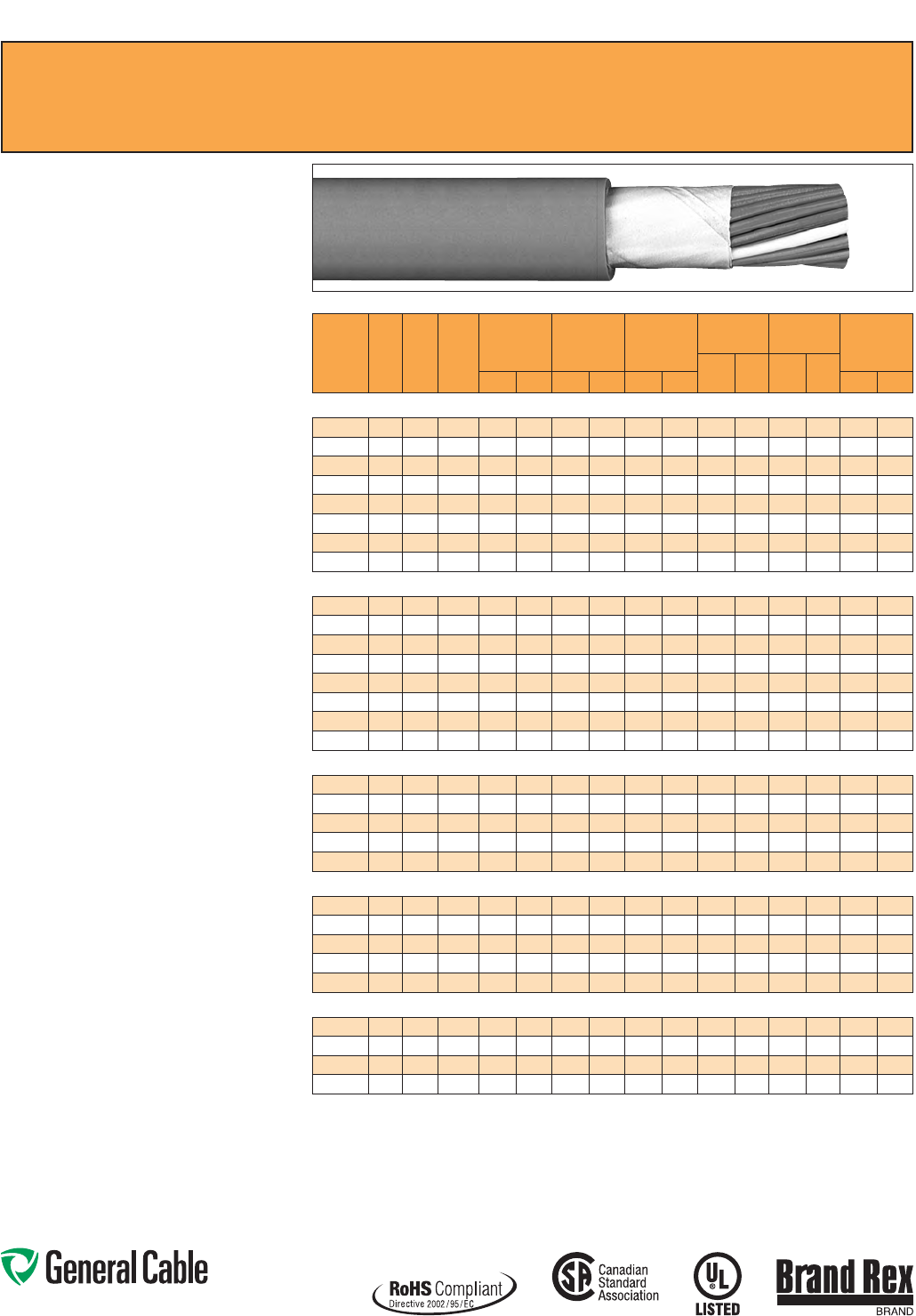
Phone: 888-593-3355
www.generalcable.com
SPEC 3250
January, 2010
CATALOG
NUMBER
NO. OF
COND.
COND.
SIZE
(AWG)
COND.
STRAND
MINIMUM AVG.
INSULATION
THICKNESS
MINIMUM AVG.
JACKET
THICKNESS
NOMINAL
CABLE O.D.
COPPER
WEIGHT NET WEIGHT MINIMUM
BEND
RADIUS
LBS/
1000 FT kg/km
LBS/
1000 FT kg/kmINCHES mm INCHES mm INCHES mm
INCHES
mm
18 AWG CONDUCTORS
339170* 618 41/34 0.020 0.51 0.045 1.14 0.400 10.16 32 48 88 131 3.0 76.2
339180* 818 41/34 0.020 0.51 0.045 1.14 0.455 11.56 42 63 108 161 3.5 88.9
339190* 12 18 41/34 0.020 0.51 0.045 1.14 0.500 12.70 63 94 144 214 4.0 101.6
339200* 16 18 41/34 0.020 0.51 0.060 1.52 0.580 14.73 84 125 196 292 4.5 114.3
339210* 22 18 41/34 0.020 0.51 0.060 1.52 0.660 16.76 116 173 252 375 5.0 127.0
339220* 31 18 41/34 0.020 0.51 0.060 1.52 0.760 19.30 163 243 325 484 6.0 152.4
339230* 41 18 41/34 0.020 0.51 0.080 2.03 0.890 22.61 216 321 460 685 7.0 177.8
339240* 60 18 41/34 0.020 0.51 0.080 2.03 1.010 25.65 316 470 617 918 8.0 203.2
16 AWG CONDUCTORS
339250* 616 65/34 0.020 0.51 0.045 1.14 0.440 11.18 50 74 113 168 3.5 88.9
339260* 816 65/34 0.020 0.51 0.045 1.14 0.500 12.70 66 98 141 210 4.0 101.6
339270* 12 16 65/34 0.020 0.51 0.060 1.52 0.585 14.86 99 147 214 318 4.5 114.3
339280* 16 16 65/34 0.020 0.51 0.060 1.52 0.640 16.26 132 196 263 391 5.0 127.0
339290* 22 16 65/34 0.020 0.51 0.060 1.52 0.735 18.67 182 271 377 561 5.5 139.7
339300* 31 16 65/34 0.020 0.51 0.060 1.52 0.845 21.46 256 381 518 771 6.5 165.1
339310* 41 16 65/34 0.020 0.51 0.080 2.03 0.995 25.27 339 504 652 970 8.0 203.2
339320* 60 16 65/34 0.020 0.51 0.080 2.03 1.125 28.58 496 738 909 1353 9.0 228.2
14 AWG CONDUCTORS
339330* 614 41/30 0.020 0.51 0.045 1.14 0.470 11.94 80 119 149 222 3.5 88.9
339340* 814 41/30 0.020 0.51 0.060 1.52 0.570 14.48 107 159 204 304 4.5 114.3
339350* 12 14 41/30 0.020 0.51 0.060 1.52 0.630 16.00 160 238 279 415 5.0 127.0
339360* 16 14 41/30 0.020 0.51 0.060 1.52 0.690 17.53 213 317 354 527 5.5 139.7
339370* 22 14 41/30 0.020 0.51 0.060 1.52 0.795 20.19 293 436 467 695 6.0 152.4
12 AWG CONDUCTORS
339380* 612 65/30 0.020 0.51 0.060 1.52 0.565 14.35 129 192 226 336 4.5 114.3
339390* 812 65/30 0.020 0.51 0.060 1.52 0.645 16.38 172 256 289 430 5.0 127.0
339400* 12 12 65/30 0.020 0.51 0.060 1.52 0.715 18.16 258 384 398 592 5.5 139.7
339410* 16 12 65/30 0.020 0.51 0.060 1.52 0.790 20.07 344 512 506 753 6.0 152.4
339420* 22 12 65/30 0.020 0.51 0.080 2.03 0.955 24.26 473 704 720 1072 7.5 190.0
10 AWG CONDUCTORS
339430* 610 105/30 0.026 0.66 0.060 1.52 0.665 16.89 205 305 329 490 5.0 127.0
339440* 810 105/30 0.026 0.66 0.060 1.52 0.765 19.43 274 408 424 631 6.0 152.4
339450* 12 10 105/30 0.026 0.66 0.080 2.03 0.895 22.73 411 612 604 899 7.0 177. 8
339460* 16 10 105/30 0.026 0.66 0.080 2.03 1.155 29.34 548 816 852 1268 9.0 228.6
Dimensions and weights are nominal; subject to industry tolerances.
* Non-stock item; minimum runs apply. Please consult Customer Service for price and delivery.
Product Construction:
Conductor:
• 18 AWG thru 10 AWG fully annealed stranded bare
copper per ASTM B3
• Class M-18 AWG thru 16 AWG
• Class K-14 AWG thru 10 AWG
• Stranding per ASTM B8
Insulation:
• Flame-retardant Polyvinyl Chloride (PVC) with
clear Polyamide (nylon)
• Color-coded: all conductors red, except #2 is
white and #3 is green. All with alpha-numeric
designations
Jacket:
• Heat-, moisture- and oil-resistant Polyvinyl
Chloride (PVC)
Print:
• GENERAL CABLE
®
BRAND REX BRAND
(PLANT OF MFG) TYPE MTW FLEXING 600 V
(UL) NO OF COND/AWG SIZE/CSA AWM IIA
90˚C 600 V FT1
Applications:
• Pendant cable
• Machine tool
• Internal machine connections
• Material handling equipment
• Moderate flex
Features:
• Rated at 90
˚
C
• Moisture- and oil-resistant
• Heavy-duty PVC jacket
• Meets cold bend test at -25
˚
C
Compliances:
Industry Compliances:
• UL Type MTW/CSA AWM
Other Compliances:
• EPA 40 CFR, Part 261 for leachable
lead content per TCLP method
• OSHA Acceptable
• RoHS Compliant
Packaging:
• Material cut to length and shipped on
non-returnable wood reels
MTW
PVC/Nylon/PVC, Thermoplastic Flexible Control
600 V, UL Type MTW/CSA AWM
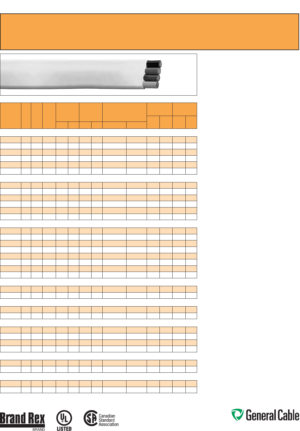
Phone: 888-593-3355
www.generalcable.com
SPEC 3300
January, 2010
Festoon
PVC/PVC, Thermoplastic Extreme Flexing Festoon Control and Power
600 V, UL/CSA Type Festoon
Product Construction:
Conductor:
• 16 AWG thru 2 AWG fully annealed stranded bare
copper per ASTM B3
• Class M - 16 AWG
• Class K - 14 AWG thru 2 AWG
• Stranding per ASTM B8
Insulation:
• Flame-retardant Polyvinyl Chloride (PVC)
• Color-coded per ICEA Method 1, Table E-2 (does
not include white or green). All with alpha-numeric
designations
Jacket:
• Flame-retardant Polyvinyl Chloride (PVC),
yellow or black
Print:
• E-24573 PVC T-XXXXX 105
˚
C 600 V VW-1 (UL)-
FESTOON CABLE OUTDOOR XX/C XX/AWG-CSA
LL9755 105
˚
C 600 V FT1
Applications:
• Cranes and hoists
• Festooning systems
• Track systems
• Robots
• Conveyors
• Telescoping jetways
Features:
• Rated at 105
˚
C
• Designed for continuous extreme flexing
applications
• Anti-coiling in festoon applications
• Small bending radii
• Flat construction allows for stacking
• Oil- and chemical-resistant
• Indoor or outdoor use
• Meets cold bend test at -55
˚
C
Compliances:
Industry Compliances:
• UL listed/CSA certified flat festoon cable
Flame Test Compliances:
• UL VW-1/CSA FT1
Other Compliances:
• EPA 40 CFR, Part 261 for leachable
lead content per TCLP method
• OSHA Acceptable
Packaging:
• Material cut to length and shipped on
non-returnable wood reels
CATALOG
NUMBER
NO.
OF
COND.
COND.
SIZE
(AWG)
COND.
STRAND
MINIMUM AVG.
INSULATION
THICKNESS
MINIMUM AVG.
JACKET
THICKNESS
NOMINAL
CABLE O.D.
COPPER
WEIGHT NET WEIGHT
LBS/
1000 FT kg/km
LBS/
1000 FT kg/kmINCHES mm INCHES mm INCHES mm
16 AWG CONDUCTORS
¥245310*
416 65/34 0.030 0.76 0.035 0.89 0.200 x 0.580 5.1 x 14.73 31.92 47.05 91 135
419630*
416 65/34 0.030 0.76 0.035 0.89 0.200 x 0.580 5.1 x 14.73 31.92 47.05 91 135
¥245320*
816 65/34 0.030 0.76 0.035 0.89 0.200 x 1.110 5.1 x 28.20 63.84 95.00 173 257
404010*
816 65/34 0.030 0.76 0.035 0.89 0.200 x 1.110 5.1 x 28.20 63.84 95.00 173 257
¥245330*
12 16 65/34 0.030 0.76 0.035 0.89 0.200 x 1.605 5.1 x 40.77 95.76 142.50 253 377
404020*
12 16 65/34 0.030 0.76 0.035 0.89 0.200 x 1.605 5.1 x 40.77 95.76 142.50 253 377
14 AWG CONDUCTORS
¥245340*
414 41/30 0.030 0.76 0.035 0.89 0.210 x 0.710 5.33 x 18.54 51.52 76.67 116 173
404030*
414 41/30 0.030 0.76 0.035 0.89 0.210 x 0.710 5.33 x 18.54 51.52 76.67 116 173
¥245350*
814 41/30 0.030 0.76 0.035 0.89 0.210 x 1.175 5.33 x 29.85 103.04 153.33 224 333
404090*
814 41/30 0.030 0.76 0.035 0.89 0.210 x 1.175 5.33 x 29.85 103.04 153.33 224 333
¥245360*
12 14 41/30 0.030 0.76 0.035 0.89 0.210 x 1.700 5.33 x 43.18 154.56 230.00 330 491
403990*
12 14 41/30 0.030 0.76 0.035 0.89 0.210 x 1.700 5.33 x 43.18 154.56 230.00 330 491
12 AWG CONDUCTORS
¥245370*
412 65/30 0.030 0.76 0.035 0.89 0.230 x 0.710 5.84 x 18.54 83.04 123.57 160 238
404040*
412 65/30 0.030 0.76 0.035 0.89 0.230 x 0.710 5.84 x 18.54 83.04 123.57 160 238
¥245380*
512 65/30 0.030 0.76 0.035 0.89 0.230 x 0.865 5.84 x 21.97 103.80 154.47 195 290
238800*
512 65/30 0.030 0.76 0.035 0.89 0.230 x 0.865 5.84 x 21.97 103.80 154.47 195 290
¥365680*
712 65/30 0.030 0.76 0.035 0.89 0.230 x 1.340 5.84 x 34.04 145.32 216.25 271 403
404080*
712 65/30 0.030 0.76 0.035 0.89 0.230 x 1.340 5.84 x 34.04 145.32 216.25 271 403
¥245390*
812 65/30 0.030 0.76 0.035 0.89 0.230 x 1.650 5.84 x 41.91 166.08 247.14 307 457
404330*
812 65/30 0.030 0.76 0.035 0.89 0.230 x 1.650 5.84 x 41.91 166.08 247.14 307 457
10 AWG CONDUCTORS
¥245400*
410 105/30 0.030 0.76 0.045 1.14 0.270 x 0.880 6.86 x 22.35 132.32 196.91 241 359
404000*
410 105/30 0.030 0.76 0.045 1.14 0.270 x 0.880 6.86 x 22.35 132.32 196.91 241 359
8 AWG CONDUCTORS
¥245410*
4 8 168/30 0.045 1.14 0.045 1.14 0.365 x 1.190 9.27 x 30.23 212.40 316.07 405 603
406320*
4 8 168/30 0.045 1.14 0.045 1.14 0.365 x 1.190 9.27 x 30.23 212.40 316.07 405 603
6 AWG CONDUCTORS
¥245420*
4 6 266/30 0.060 1.52 0.045 1.14 0.430 x 1.450
10.92 x 36.83
332.88 495.36 612 911
404050*
4 6 266/30 0.060 1.52 0.045 1.14 0.430 x 1.450
10.92 x 36.83
332.88 495.36 612 911
¥332010*
5 6 266/30 0.060 1.52 0.045 1.14 0.430 x 1.735
10.92 x 44.07
416.10 619.20 747 1112
434680*
5 6 266/30 0.060 1.52 0.045 1.14 0.430 x 1.735
10.92 x 44.07
416.10 619.20 747 1112
4 AWG CONDUCTORS
¥245440*
4 4 420/30 0.060 1.52 0.045 1.14 0.490 x 1.690
12.45 x 42.93
560.00 833.34 750 1116
404060*
4 4 420/30 0.060 1.52 0.045 1.14 0.490 x 1.690
12.45 x 42.93
560.00 833.34 750 1116
2 AWG CONDUCTORS
¥
245450*
4 2 665/30 0.060 1.52 0.045 1.14 0.560 x 1.955
14.23 x 49.66
852.00 1267.86 1273 1894
404070*
4 2 665/30 0.060 1.52 0.045 1.14 0.560 x 1.955
14.23 x 49.66
852.00 1267.86 1273 1894
Dimensions and weights are nominal; subject to industry tolerances.
* Non-stock item; minimum runs apply. Please consult Customer Service for price and delivery.
¥ Indicates black jacketed cables.

Phone: 888-593-3355
www.generalcable.com
Date of Issue 06/13
Section 4 Industrial Cables
600 V Multi-Conductor Control and Power Cables
SPECIFICATION NO. PRODUCT DESCRIPTION REVISION DATE
4050†CHTC®XLPE/XL-CPE, Control, Unshielded
600 V, UL Type TC—E-2 Color Code
Mar. 2012
4075†CHTC®XLPE/XL-CPE, Control, Unshielded
600 V, UL Type TC—E-1 Color Code
Mar. 2012
4100†CHTC®XLPE/XL-CPE, Low-Voltage Power, Unshielded
600 V, UL Type TC-ER—Method 4 Color Code
Mar. 2012
4150 EHTC®FR-EPR/XL-CPE, Control, Unshielded
600 V, UL Type TC (18 AWG/16 AWG)—E-2 Color Code
Mar. 2012
4200 EHTC®FR-EPR/XL-CPE, Control, Unshielded
600 V, UL Type TC (14 AWG—10 AWG)—E-2 Color Code
Mar. 2012
4250 EHTC®FR-EPR/XL-CPE, Low-Voltage Power, Unshielded
600 V, UL Type TC-ER—Method 4 Color Code
Mar. 2012
4300†FREP®FR-EPR/CPE, Control, Unshielded
600 V, UL Type TC-ER—E-2 Color Code
Mar. 2012
4310†FREP®FR-EPR/CPE, Control, Unshielded
600 V, UL Type TC-ER—E-1 Color Code
Mar. 2012
4325†FREP®FR-EPR/CPE, Control, Shielded
600 V, UL Type TC-ER, Overall Shielded—E-2 Color Code
Mar. 2012
4350†FREP®FR-EPR/CPE, Low-Voltage Power, Unshielded
600 V, UL Type TC-ER—Method 4 Color Code
Aug. 2012
4400 Arctic-Flex®XLPE/Arctic-PVC, Control, Unshielded
600 V, UL Type TC-ER, CSA Type RW90 XLPE, CSA Type TC
Mar. 2012
4450 Arctic-Flex®XLPE/Arctic-PVC, Low-Voltage Power, Unshielded
600 V, UL Type TC-ER, CSA Type RW90 XLPE, CSA Type TC
Mar. 2012
4460 CCTC™FR-XLPE/CPE, Control, Shielded
600 V, UL Type TC-ER—E-1 Color Code
Jun. 2012
4480 CCTC™FR-XLPE/CPE, Low-Voltage Power, Shielded
600 V, UL Type TC-ER—Method 4 Color Code
Jun. 2012
4500†CVTC®XLPE/PVC, Control, Unshielded
600 V, UL Type TC-ER—E-2 Color Code
Mar. 2012
4550†CVTC®XLPE/PVC, Low-Voltage Power, Unshielded
600 V, UL Type TC-ER—Method 4 Color Code
Mar. 2012
4575 CVTC® VFD XLPE/PVC, Low-Voltage Power, Shielded
2000 V, UL Type TC-ER—Method 4 Color Code
Mar. 2012
4580†CVTC® VFD XLPE/PVC, Low-Voltage Power, Copper Tape Shielded
2000 V, UL Type TC-ER—Method 4 Color Code
Mar. 2012
†Indicates these products are stocked by General Cable

Phone: 888-593-3355
www.generalcable.com
Date of Issue 06/13
Industrial Cables Section 4
600 V Multi-Conductor Control and Power Cables
SPECIFICATION NO. PRODUCT DESCRIPTION REVISION DATE
4600†VNTC®PVC/Nylon/PVC, Control, Unshielded
600 V, UL Type TC-ER (18 AWG/16 AWG)—E-2 Color Code
Mar. 2012
4650†VNTC®PVC/Nylon/PVC, Control, Unshielded
600 V, UL Type TC-ER (14 AWG—10 AWG)—E-2 Color Code
Mar. 2012
4700†VNTC®PVC/Nylon/PVC, Control, Shielded
600 V, UL Type TC-ER, Overall Shielded—E-2 Color Code
Mar. 2012
4750†VNTC®PVC/Nylon/PVC, Low-Voltage Power, Unshielded
600 V, UL Type TC-ER—Method 4 Color Code
Mar. 2012
4775†TC-Flex™18 AWG (1,0 mm²)—16 AWG (1,5 mm²)
UL Type WTTC 1000 V or Type TC-ER 600 V or Type MTW and c(UL) CIC/TC
600 V FT4 or CSA AWM 90°C 1000 V
Jun. 2013
4780†TC-Flex™14 AWG (2,5 mm²)–10 AWG (6,0 mm²)
UL Type WTTC 1000 V or Type TC-ER 600 V or Type MTW and c(UL) CIC/TC
600 V FT4 or CSA AWM 90°C 1000 V
Jun. 2013
4785†TC-Flex™18 AWG (1,0 mm²)—16 AWG (1,5 mm²)
UL Type WTTC 1000 V or Type TC-ER 600 V or Type MTW and c(UL) CIC/TC
600 V FT4 or CSA AWM 90°C 1000 V
Jun. 2013
4790†TC-Flex™14 AWG (2,5 mm²)—4 AWG (35,0 mm²)
UL Type WTTC 1000 V or Type TC-ER 600 V or Type MTW and c(UL) CIC/TC
600 V FT4 or CSA AWM 90°C 1000 V
Jun. 2013
4800 20/10 PE/PVC/PVC, Control, Unshielded
600 V (18 AWG/16 AWG)—E-1 Color Code
Jul. 2010
4850 20/10 PE/PVC/PVC, Control, Unshielded
600 V (14 AWG—10 AWG)—E-1 Color Code
Jul. 2010
4900†GenFree®XLPE/LSZH, Control
600 V, UL Type TC-LS-ER—E-2 Color Code
Oct. 2012
4925 GenFree®XLPE/LSZH, Control, Shielded
600 V, UL Type TC-LS-ER, Overall Shielded—E-2 Color Code
Oct. 2012
4950†GenFree®XLPE/LSZH, Low-Voltage Power, Unshielded
600 V, UL Type TC-LS-ER—Method 4 Color Code
Oct. 2012
†Indicates these products are stocked by General Cable

Phone: 888-593-3355
www.generalcable.com
SPEC 4050
March, 2012
Product Construction:
Conductor:
• 16 AWG thru 10 AWG fully annealed stranded
tinned copper per ASTM B33
• Class B stranding per ASTM B8
Insulation:
• Flame-retardant Cross-linked Polyethylene (XLPE)
• Color-coded per ICEA Method 1, Table E-2 plus
alpha-numeric printed numbers (does not include
white or green)
Jacket:
• Lead-free Cross-linked Chlorinated Polyethylene
(XL-CPE )
Print
• GENERAL CABLE® (PLANT OF MFG) CHTC®
XX/C XXAWG CU/XLP/XL-CPE (UL) TYPE TC
XHHW-2 CDRS DIR BUR SUN RES OIL RES I & II
600 V DAY/MONTH/YEAR OF MFG SEQUENTIAL
FOOTAGE MARK
Options:
• 2 kV version
• Bare copper conductor
• Class C stranding
• E-1 Color Code—see Spec 4075
• Overall shielded multi-conductor
• Ethylene Propylene Rubber (EPR)
insulation—see EHTC® Spec 4200
• Thermoplastic Low-Smoke, Zero-Halogen
(LSZH) jacket
• Flame-retardant Polyvinyl Chloride (PVC)
jacket—see CVTC® Spec 4500
• Other constructions available upon request
Applications:
• In free air, raceways or direct burial
• In wet or dry locations
• Permitted for use in Class I, Div. 2 industrial
hazardous locations per NEC Article 501 and
Class 1 circuits per NEC
Features:
• Rated at 90˚C wet or dry
• Ripcord applied to all cables with jacket thickness
of 60 mils or less
• Excellent physical, thermal and electrical
properties
• Excellent moisture resistance
• Excellent resistance to crush, compression cuts
and heat deformation
• Excellent flame resistance
• Oil-resistant jacket
• “Heavy Duty” rating per ICEA standards
• Sunlight- and weather-resistant
• Excellent low temperature cold bend
characteristics
• Meets cold bend test at -35˚C
Compliances:
Industry Compliances:
• UL 44 Type XHHW-2
• UL 1277 Type TC, UL File # E57179
• UL 1581
• ICEA S-73-532/NEMA WC57
Flame Test Compliances:
• UL 1581/UL 2556 VW-1
• UL 1685 Vertical Flame Test
• IEEE 383
• IEEE 1202
• CSA FT4
• ICEA T-29-520
Other Compliances:
• EPA 40 CFR, Part 261 for leachable lead
content per TCLP
• OSHA Acceptable
Packaging:
• Material cut to length and shipped on
non-returnable wood reels
CHTC
®
XLPE/XL-CPE, Control, Unshielded
600 V, UL Type TC—E-2 Color Code
CATALOG
NUMBER
NO.
OF
COND.
COND.
SIZE
(AWG)
COND.
STRAND
MINIMUM AVG.
INSULATION
THICKNESS
MINIMUM AVG.
JACKET
THICKNESS
NOMINAL
CABLE O.D.
COPPER
WEIGHT NET WEIGHT
LBS/
1000 FT kg/km
LBS/
1000 FT kg/kmINCHES mm INCHES mm INCHES mm
16 AWG MULTI-CONDUCTORS
241420 216 7/.0192 0.030 0.76 0.045 1.14 0.340 8.64 17 25 61 91
312500 316 7/.0192 0.030 0.76 0.045 1.14 0.360 9.14 25 37 73 109
312510 416 7/.0192 0.030 0.76 0.045 1.14 0.390 9.91 33 49 91 135
312520 516 7/.0192 0.030 0.76 0.045 1.14 0.420 10.67 41 61 110 164
241430 716 7/.0192 0.030 0.76 0.045 1.14 0.460 11.68 58 86 141 210
241440 916 7/.0192 0.030 0.76 0.060 1.52 0.565 14.35 74 110 199 296
14 AWG MULTI-CONDUCTORS
223650* 2 Flat 14 7/.0242 0.030 0.76 0.045 1.14
.230 x .365
5.84 x 9.27
26 39 68 101
272270 214 7/.0242 0.030 0.76 0.045 1.14 0.370 9.40 26 39 75 112
223790 314 7/.0242 0.030 0.76 0.045 1.14 0.390 9.91 39 59 95 141
223780 414 7/.0242 0.030 0.76 0.045 1.14 0.425
10.80
53 78 118 176
223770 514 7/.0242 0.030 0.76 0.045 1.14 0.465 11.81 66 98 143 213
223750 714 7/.0242 0.030 0.76 0.045 1.14 0.505 12.83 92 137 179 266
223760 914 7/.0242 0.030 0.76 0.060 1.52 0.620 15.75 118 176 249 371
223640 12 14 7/.0242 0.030 0.76 0.060 1.52 0.700 17.78 158 235 317 472
223670* 19 14 7/.0242 0.030 0.76 0.060 1.52 0.815 20.70 250 372 467 695
232850* 37 14 7/.0242 0.030 0.76 0.080 2.03 1.130 28.70 490 730 899 1338
12 AWG MULTI-CONDUCTORS
260730* 2 Flat 12 7/.0305 0.030 0.76 0.045 1.14
.250 x .400
6.35 x 10.16
50 74 85 126
272260 212 7/.0305 0.030 0.76 0.045 1.14 0.410 10.41 51 76 98 146
223910 312 7/.0305 0.030 0.76 0.045 1.14 0.435 11.05 64 95 127 189
223930 412 7/.0305 0.030 0.76 0.045 1.14 0.475 12.07 85 126 160 238
223920 512 7/.0305 0.030 0.76 0.045 1.14 0.520 13.21 106 158 194 289
224080 712 7/.0305 0.030 0.76 0.060 1.52 0.595 15.11 168 251 264 393
224070 912 7/.0305 0.030 0.76 0.060 1.52 0.695 17.6 5 191 285 345 513
224090 12 12 7/.0305 0.030 0.76 0.060 1.52 0.780 19.81 255 380 435 647
265940* 19 12 7/.0305 0.030 0.76 0.080 2.03 0.955 24.26 403 600 690 1027
347050* 37 12 7/.0305 0.030 0.76 0.080 2.03 1.265 32.13 741 1103 1393 2073
10 AWG MULTI-CONDUCTORS
361350* 2 Flat 10 7/.0385 0.030 0.76 0.045 1.14
.270 x .445
6.86 x 11.30
66 98 117 174
355210 210 7/.0385 0.030 0.76 0.045 1.14 0.455 5.26 67 100 126 188
224100 310 7/.0385 0.030 0.76 0.045 1.14 0.485 12.32 100 150 176 262
224110 410 7/.0385 0.030 0.76 0.060 1.52 0.560 14.22 134 199 240 357
224120* 510 7/.0385 0.030 0.76 0.060 1.52 0.615 15.62 167 249 291 433
224130* 710 7/.0385 0.030 0.76 0.060 1.52 0.670 17.0 2 234 349 376 560
347060* 910 7/.0385 0.030 0.76 0.060 1.52 0.765 19.43 302 449 456 679
347070* 12 10 7/.0385 0.030 0.76 0.080 2.03 0.905 22.99 404 601 636 946
Dimensions and weights are nominal; subject to industry tolerances.
* Non-stock item; minimum runs apply. Please consult Customer Service for price and delivery.
Phone: 888-593-3355
www.generalcable.com
SPEC 4075
March, 2012
Product Construction:
Conductor:
• 14 AWG thru 10 AWG fully annealed stranded
tinned copper per ASTM B33
• Class B stranding per ASTM B8
Insulation:
• Flame-retardant Cross-linked Polyethylene (XLPE)
• Color-coded per ICEA Method 1, Table E-1
Jacket:
• Lead-free Cross-linked Chlorinated Polyethylene
(XL-CPE )
Print
• GENERAL CABLE® (PLANT OF MFG) CHTC®
XX/C XXAWG CU/XLP/XL-CPE (UL) TYPE TC
XHHW-2 CDRS DIR BUR SUN RES OIL RES I & II
600 V DAY/MONTH/YEAR OF MFG SEQUENTIAL
FOOTAGE MARK
Options:
• 2 kV version
• Bare copper conductor
• Class C stranding
• E-2 Color Code—see Spec 4050
• Overall shielded multi-conductor
• Ethylene Propylene Rubber (EPR)
insulation—see EHTC Spec 4200
• Thermoplastic Low-Smoke, Zero-Halogen (LSZH)
jacket
• Flame-retardant Polyvinyl Chloride (PVC)
jacket—see CVTC® Spec 4500
• Other constructions available upon request
Applications:
• In free air, raceways or direct burial
• In wet or dry locations
• Permitted for use in Class I, Div. 2 industrial
hazardous locations per NEC Article 501 and
Class 1 circuits per NEC
Features:
• Rated at 90˚C wet or dry
• Ripcord applied to all cables with jacket thickness
of 60 mils or less
• Excellent physical, thermal and electrical
properties
• Excellent moisture resistance
• Excellent resistance to crush, compression cuts
and heat deformation
• Excellent flame resistance
• Oil-resistant jacket
• “Heavy Duty” rating per ICEA standards
• Sunlight- and weather-resistant
• Excellent low temperature cold bend
characteristics
• Meets cold bend test at -35˚C
Compliances:
Industry Compliances:
• UL 44 Type XHHW-2
• UL 1277 Type TC, UL File # E57179
• UL 1581
• ICEA S-73-532/NEMA WC57
Flame Test Compliances:
• UL 1581/UL 2556 VW-1
• UL 1685 Vertical Flame Test
• IEEE 383
• IEEE 1202
• CSA FT4
• ICEA T-29-520
Other Compliances:
• EPA 40 CFR, Part 261 for leachable lead
content per TCLP
• OSHA Acceptable
Packaging:
• Material cut to length and shipped on
non-returnable wood reels
CHTC
®
XLPE/XL-CPE, Control, Unshielded
600 V, UL Type TC—E-1 Color Code
CATALOG
NUMBER
NO.
OF
COND.
COND.
SIZE
(AWG)
COND.
STRAND
MINIMUM AVG.
INSULATION
THICKNESS
MINIMUM AVG.
JACKET
THICKNESS
NOMINAL
CABLE O.D.
COPPER
WEIGHT NET WEIGHT
LBS/
1000 FT kg/km
LBS/
1000 FT kg/kmINCHES mm INCHES mm INCHES mm
14 AWG MULTI-CONDUCTORS
256260* 2 Flat 14 7/.0242 0.030 0.76 0.045 1.14
.230 x .365
5.84 x 9.27
26 39 68 101
330580 214 7/.0242 0.030 0.76 0.045 1.14 0.370 9.40 26 39 75 112
244160 314 7/.0242 0.030 0.76 0.045 1.14 0.390 9.91 39 59 95 141
239640 414 7/.0242 0.030 0.76 0.045 1.14 0.425
10.80
53 78 118 176
239700 514 7/.0242 0.030 0.76 0.045 1.14 0.465 11.81 66 98 143 213
237500 714 7/.0242 0.030 0.76 0.045 1.14 0.505 12.83 92 137 179 266
239660 914 7/.0242 0.030 0.76 0.060 1.52 0.620 15.75 118 176 249 371
252400 12 14 7/.0242 0.030 0.76 0.060 1.52 0.700 17.78 158 235 317 472
252410* 19 14 7/.0242 0.030 0.76 0.060 1.52 0.815 20.70 250 372 467 695
383980* 25 14 7/.0242 0.030 0.76 0.080 2.03 1.000 25.40 330 491 632 941
383990* 30 14 7/.0242 0.030 0.76 0.080 2.03 1.050 26.67 398 592 731 1088
384000* 37 14 7/.0242 0.030 0.76 0.080 2.03 1.130 28.70 490 730 899 1338
12 AWG MULTI-CONDUCTORS
233320* 2 Flat 12 7/.0305 0.030 0.76 0.045 1.14
.250 x .400
6.35 x 10.16
42 63 85 126
239670 212 7/.0305 0.030 0.76 0.045 1.14 0.410 10.41 42 63 98 146
233330 312 7/.0305 0.030 0.76 0.045 1.14 0.435 11.05 64 95 127 189
239680 412 7/.0305 0.030 0.76 0.045 1.14 0.475 12.07 85 126 160 238
239650 512 7/.0305 0.030 0.76 0.045 1.14 0.520 13.21 106 158 194 289
243530 712 7/.0305 0.030 0.76 0.060 1.52 0.595 15.11 168 251 264 393
239620 912 7/.0305 0.030 0.76 0.060 1.52 0.695 17.65 191 285 345 513
252360 12 12 7/.0305 0.030 0.76 0.060 1.52 0.780 19.81 255 380 435 647
252230* 19 12 7/.0305 0.030 0.76 0.080 2.03 0.955 24.26 403 600 690 1027
384010* 25 12 7/.0305 0.030 0.76 0.080 2.03 1.095 27.81 515 767 858 1277
384020* 30 12 7/.0305 0.030 0.76 0.080 2.03 1.175 29.85 618 920 997 1484
384030* 37 12 7/.0305 0.030 0.76 0.080 2.03 1.265 32.13 741 1103 1393 2073
10 AWG MULTI-CONDUCTORS
384040* 2 Flat 10 7/.0385 0.030 0.76 0.045 1.14
.270 x .445
6.86 x 11.30
66 98 117 174
243540 210 7/.0385 0.030 0.76 0.045 1.14 0.455 5.26 67 100 126 188
239630 310 7/.0385 0.030 0.76 0.045 1.14 0.485 12.32 100 150 176 262
233310 410 7/.0385 0.030 0.76 0.060 1.52 0.560 14.22 134 199 240 357
262680* 510 7/.0385 0.030 0.76 0.060 1.52 0.615 15.62 167 249 291 433
375010* 710 7/.0385 0.030 0.76 0.060 1.52 0.670 17.0 2 234 349 376 560
235680* 910 7/.0385 0.030 0.76 0.060 1.52 0.765 19.43 302 449 456 679
375470* 12 10 7/.0385 0.030 0.76 0.080 2.03 0.905 22.99 404 601 636 946
Dimensions and weights are nominal; subject to industry tolerances.
* Non-stock item; minimum runs apply. Please consult Customer Service for price and delivery.
Phone: 888-593-3355
www.generalcable.com
SPEC 4100
March, 2012
Product Construction:
Conductor:
• 14 AWG thru 500 kcmil tinned, annealed
copper per ASTM B33
• Class B stranding per ASTM B8
Insulation:
• Flame-retardant Cross-linked Polyethylene (XLPE)
• Color-coded per ICEA Method 4; individual
conductors colored black with conductor number
surface printed in contrasting ink
Ground:
• Uninsulated tinned annealed copper
per ASTM B3
• Class B stranding per ASTM B8
Jacket:
• Lead-free Cross-linked Chlorinated Polyethylene
(XL-CPE )
Print:
• GENERAL CABLE® (PLANT OF MFG) CHTC®
XX/C XXAWG WITH GRND CU/XLP/XL-CPE (UL)
TYPE TC-ER XHHW-2 CDRS DIR BUR SUN RES
600 V MONTH/YEAR OF MFG SEQUENTIAL
FOOTAGE MARK
Options:
• Bare copper conductor
• Class C stranding
• 2 kV version
• E-1 or E-2 Color Code
• Overall shielded multi-conductor
• Insulated ground conductor
• Flame-retardant Ethylene Propylene Rubber (EPR)
insulation—see EHTC® Spec 4250
Options (cont’d.):
• Thermoplastic Low-Smoke, Zero-Halogen (LSZH)
jacket
• Other constructions available upon request
Applications:
• In free air, raceways or direct burial
• In wet or dry locations
• Permitted for Exposed Run (ER) use in
accordance with NEC for 2 AWG and larger
• Permitted for use in Class I, Division 2 industrial
hazardous locations per NEC
Features:
• Rated at 90˚C wet or dry
• Ripcord applied to all cables with jacket thickness
of 60 mils or less
• Excellent physical, thermal and electrical
properties
• Excellent moisture resistance
• Excellent resistance to crush, compression cuts
and heat deformation
• Excellent flame resistance
• Excellent low temperature cold bend
characteristics
• “Heavy duty” rating per ICEA standards
• Sunlight- and weather-resistant
• Oil-resistant jacket
Features (cont’d.):
• Meets cold bend test at -35˚C
• Meets the crush and impact requirements of Type
MC cable for 2 AWG and larger
Compliances:
Industry Compliances:
• UL 44 Type XHHW-2
• UL 1277 Type TC-ER for 2 AWG and larger,
UL File # E57179
• UL 1581
• ICEA S-95-658/NEMA WC70
Flame Test Compliances:
• UL 1581/UL 2556 VW-1
• UL 1685 Vertical Flame Test
• IEEE 383
• IEEE 1202
• CSA FT4
• ICEA T-29-520
Other Compliances:
• EPA 40 CFR, Part 261 for leachable lead
content per TCLP
• OSHA Acceptable
Packaging:
• Material cut to length and shipped on
non-returnable wood reels
CHTC
®
XLPE/XL-CPE, Low-Voltage Power, Unshielded
600 V, UL Type TC-ER
1
—Method 4 Color Code
CATALOG
NUMBER
NO. OF
COND.
COND.
SIZE
(AWG/
kcmil)
COND.
STRAND
GROUND
WIRE SIZE
(AWG)
MINIMUM AVG.
INSULATION
THICKNESS
MINIMUM AVG.
JACKET THICKNESS
NOMINAL
CABLE O.D.
COPPER
WEIGHT NET WEIGHT
INCHES mm INCHES mm INCHES mm
LBS/
1000 FT kg/km
LBS/
1000 FT kg/km
14 AWG - 500 kcmil MULTI-CONDUCTORS
383790* 314 7/.0242 14 0.030 0.76 0.045 1.14 0.425 10.80 53 78 118 176
309340* 312 7/.0305 12 0.030 0.76 0.045 1.14 0.475 12.07 85 126 160 238
282570* 310 7/.0385 10 0.030 0.76 0.060 1.52 0.526 14.22 134 199 240 357
282580 387/.0486 10 0.045 1.14 0.060 1.52 0.635 16.13 190 283 325 483
282590* 487/.0486 10 0.045 1.14 0.060 1.52 0.705 17.91 242 360 405 603
282600 367/.0612 80.045 1.14 0.060 1.52 0.720 18.29 301 448 481 716
282610* 467/.0612 80.045 1.14 0.060 1.52 0.820 20.83 384 571 600 893
282620 347/.0772 80.045 1.14 0.080 2.03 0.860 21.84 448 667 667 992
282630* 447/.0772 80.045 1.14 0.080 2.03 0.950 24.13 578 861 905 1347
282640 327/.0974 60.045 1.14 0.080 2.03 1.000 25.40 716 1066 1024 1524
282650* 427/.0974 60.045 1.14 0.080 2.03 1.120 28.45 919 1368 1295 1927
366070* 3119/.0664 60.055 1.40 0.080 2.03 1.120 28.45 872 1298 1199 1784
366080* 4119/.0664 60.055 1.40 0.080 2.03 1.235 31.37 1136 1691 1704 2536
282660* 31/0 19/.0745 60.055 1.40 0.080 2.03 1.215 30.86 1081 1609 1463 2177
338860* 41/0 19/.0745 60.055 1.40 0.080 2.03 1.330 33.78 1413 2103 1830 2723
282670* 32/0 19/.0837 60.055 1.40 0.080 2.03 1.310 33.27 1341 1996 1810 2694
292410* 42/0 19/.0837 60.055 1.40 0.080 2.03 1.480 37.59 1760 2619 2326 3462
366090* 33/0 19/.0940 40.055 1.40 0.080 2.03 1.420 36.07 1717 2555 2437 3627
366100* 43/0 19/.0940 40.055 1.40 0.080 2.03 1.570 39.88 2245 3341 3123 4648
282680* 34/0 19/.1055 40.055 1.40 0.080 2.03 1.540 39.12 2132 3173 2659 3957
338880* 44/0 19/.1055 40.055 1.40 0.110 2.79 1.765 44.83 2796 4161 3909 5817
338890* 3250 37/.0822 40.065 1.65 0.110 2.79 1.740 44.20 2494 3712 3196 4756
338900* 4250 37/.0822 40.065 1.65 0.110 2.79 1.935 49.15 3282 4884 4571 6803
282690* 3350 37/.0973 30.065 1.65 0.110 2.79 2.010 51.05 3477 5174 4423 6582
338910* 4350 37/.0973 30.065 1.65 0.110 2.79 2.180 55.37 4577 6811 6068 9030
282710* 3500 37/.1162 20.065 1.65 0.110 2.79 2.305 58.55 4938 7349 6097 9074
331150* 4500 37/.1162 20.065 1.65 0.110 2.79 2.555 64.90 6509 9647 7905 11764
Dimensions and weights are nominal; subject to industry tolerances.
* Non-stock item; minimum runs apply. Please consult Customer Service for price and delivery.
¹ Approved as TYPE TC-ER for Exposed Run applications of 2 AWG and larger defined by NEC.
Phone: 888-593-3355
www.generalcable.com
SPEC 4150
March, 2012
CATALOG
NUMBER
NO.
OF
COND.
COND.
SIZE
(AWG)
COND.
STRAND
MINIMUM AVG.
INSULATION
THICKNESS
MINIMUM AVG.
JACKET
THICKNESS
NOMINAL
CABLE O.D.
COPPER
WEIGHT NET WEIGHT
LBS/
1000 FT kg/km
LBS/
1000 FT kg/kmINCHES mm INCHES mm INCHES mm
18 AWG MULTI-CONDUCTORS
366190* 2 Flat 18 7/.0152 0.025 0.64 0.045 1.14
.192 x .290
4.88 x 7.37
10 15 37 55
343330* 218 7/.0152 0.025 0.64 0.045 1.14 0.295 7.49 10 15 45 67
343340* 318 7/.0152 0.025 0.64 0.045 1.14 0.310 7.88 15 23 55 82
343350* 418 7/.0152 0.025 0.64 0.045 1.14 0.340
8.64
20 30 67 100
343360* 518 7/.0152 0.025 0.64 0.045 1.14 0.365 9.27 26 38 79 118
343370* 718 7/.0152 0.025 0.64 0.045 1.14 0.395 10.03 36 53 97 144
343380* 918 7/.0152 0.025 0.64 0.045 1.14 0.455 11.56 46 69 123 183
343390* 10 18 7/.0152 0.025 0.64 0.045 1.14 0.485 12.32 51 76 137 204
343400* 12 18 7/.0152 0.025 0.64 0.045 1.14 0.510 12.95 61 91 153 228
343410* 15 18 7/.0152 0.025 0.64 0.060 1.52 0.580 14.73 77 114 202 301
343420* 19 18 7/.0152 0.025 0.64 0.060 1.52 0.625 15.88 97 144 243 362
343430* 25 18 7/.0152 0.025 0.64 0.060 1.52 0.720 18.29 128 190 301 448
343440* 30 18 7/.0152 0.025 0.64 0.060 1.52 0.770 19.56 154 229 345 513
343450* 37 18 7/.0152 0.025 0.64 0.060 1.52 0.830 21.08 189 281 414 616
16 AWG MULTI-CONDUCTORS
366200* 2 Flat 16 7/.0192 0.025 0.64 0.045 1.14
.204 x .314
5.18 x 7.9 8
16 24 46 68
343460* 216 7/.0192 0.025 0.64 0.045 1.14 0.320 8.13 16 24 55 82
343470* 316 7/.0192 0.025 0.64 0.045 1.14 0.340 8.67 24 36 69 130
343480* 416 7/.0192 0.025 0.64 0.045 1.14 0.365 9.27 32 48 85 126
343490* 516 7/.0192 0.025 0.64 0.045 1.14 0.400 10.20 40 60 102 152
343500* 716 7/.0192 0.025 0.64 0.045 1.14 0.430 10.90 56 84 127 189
343510* 916 7/.0192 0.025 0.64 0.045 1.14 0.500 12.70 72 108 162 241
343520* 10 16 7/.0192 0.025 0.64 0.060 1.52 0.565 14.40 80 119 197 293
343530* 12 16 7/.0192 0.025 0.64 0.060 1.52 0.590 14.97 97 144 221 329
343540* 15 16 7/.0192 0.025 0.64 0.060 1.52 0.640 16.26 121 180 270 402
343550* 19 16 7/.0192 0.025 0.64 0.060 1.52 0.690 17. 53 153 228 327 487
343560* 25 16 7/.0192 0.025 0.64 0.060 1.52 0.795 20.19 201 299 424 631
343570* 30 16 7/.0192 0.025 0.64 0.080 2.03 0.890 22.61 242 360 508 756
343580* 37 16 7/.0192 0.025 0.64 0.080 2.03 0.955 24.26 298 443 609 906
Dimensions and weights are nominal; subject to industry tolerances.
* Non-stock item; minimum runs apply. Please consult Customer Service for price and delivery.
EHTC
®
FR-EPR/XL-CPE, Control, Unshielded
600 V, UL Type TC (18 AWG/16 AWG)—E-2 Color Code
Product Construction:
Conductor:
• 18 AWG and 16 AWG tinned, annealed copper per
ASTM B33
• Class B stranding per ASTM B8
Insulation:
• Flame-Retardant Ethylene Propylene Rubber
(FR-EPR) Type II
• Color-coded per ICEA Method 1, Table E-2
(does not include white or green)
Jacket:
• Lead-free Cross-linked Chlorinated Polyethylene
(XL-CPE )
Print
• GENERAL CABLE® (PLANT OF MFG) EHTC®
XX/C XXAWG EPR/XL-CPE (UL) TYPE TC 90˚
WET OR DRY CDRS BUR SUN RES 600 V DAY/
MONTH/YEAR OF MFG SEQUENTIAL FOOTAGE
MARK
Options:
• 2 kV version
• Bare copper conductors
• Class C stranding
• Insulated or uninsulated ground conductors
• Overall shielded multi-conductors
• Duralox® aluminum interlocked armor
• E-1 Color Code
• Flame-retardant Polyvinyl Chloride (PVC) jacket
• Thermoplastic Low-Smoke, Zero-Halogen (LSZH)
jacket
• Flame-retardant thermoplastic Chlorinated
Polyethylene (CPE)—See FREP® Spec 4300
• Other constructions available upon request
Applications:
• In free air, raceways or direct burial
• In wet or dry locations
• At temperature as low as -35˚C
• In Class I, Division 2 industrial hazardous locations
per NEC
Features:
• Rated at 90˚C wet or dry
• Ripcord applied to all cables with jacket thickness
of 60 mils or less
• Excellent physical, thermal and electrical
properties
• Excellent moisture resistance
• Excellent resistance to crush, compression cuts
and heat deformation
• Excellent flame resistance
• Excellent low temperature cold bend
characteristics
• Good abrasion resistance
• Low moisture absorption characteristics
• “Heavy duty” rated per ICEA standards
• Meets cold bend test at -35˚C
Compliances:
Industry Compliances:
• UL 1277 Type TC, UL File # E57179
• UL 1581
• ICEA S-73-532/NEMA WC57
Flame Test Compliances:
• UL 1581/UL 2556 VW-1
• UL 1685 Vertical Flame Test
• IEEE 383
• IEEE 1202
• CSA FT4
• ICEA T-29-520
Other Compliances:
• EPA 40 CFR, Part 261 for leachable lead
content per TCLP
• OSHA Acceptable
Packaging:
• Material cut to length and shipped on
non-returnable wood reels

Phone: 888-593-3355
www.generalcable.com
SPEC 4200
March, 2012
CATALOG
NUMBER
NO.
OF
COND.
COND.
SIZE
(AWG)
COND.
STRAND
MINIMUM AVG.
INSULATION
THICKNESS
MINIMUM AVG.
JACKET
THICKNESS
NOMINAL
CABLE O.D.
COPPER
WEIGHT NET WEIGHT
LBS/
1000 FT kg/km
LBS/
1000 FT kg/kmINCHES mm INCHES mm INCHES mm
14 AWG MULTI-CONDUCTORS
262130* 2 Flat 14 7/.0242 0.030 0.76 0.045 1.14
.230 x .365
5.84 x 9.27
26 38 68 101
343590* 214 7/.0242 0.030 0.76 0.045 1.14 0.370 9.40 26 39 76 113
262140* 314 7/.0242 0.030 0.76 0.045 1.14 0.390 9.91 39 59 97 144
248240* 414 7/.0242 0.030 0.76 0.045 1.14 0.425
10.80
53 78 120 179
262150* 514 7/.0242 0.030 0.76 0.045 1.14 0.465 11.81 66 98 145 216
262160* 714 7/.0242 0.030 0.76 0.045 1.14 0.505 12.83 92 137 183 272
343600* 914 7/.0242 0.030 0.76 0.060 1.52 0.620 15.75 118 176 254 378
248290* 12 14 7/.0242 0.030 0.76 0.060 1.52 0.700 17.78 158 235 323 481
343630* 19 14 7/.0242 0.030 0.76 0.060 1.52 0.815 20.71 250 372 477 710
262190* 25 14 7/.0242 0.030 0.76 0.080 2.03 1.000 25.40 330 491 645 960
343640* 30 14 7/.0242 0.030 0.76 0.080 2.03 1.050 26.70 398 592 746 1110
343650* 37 14 7/.0242 0.030 0.76 0.080 2.03 1.130 28.71 490 729 919 1368
12 AWG MULTI-CONDUCTORS
343660* 2 Flat 12 7/.0305 0.030 0.76 0.045 1.14
.250 x .400
6.35 x 10.16
50 76 88 131
343670* 212 7/.0305 0.030 0.76 0.045 1.14 0.410 10.41 51 76 99 147
343680* 312 7/.0305 0.030 0.76 0.045 1.14 0.435 11.05 64 95 129 192
343690* 412 7/.0305 0.030 0.76 0.045 1.14 0.475 12.07 85 127 163 243
262200* 512 7/.0305 0.030 0.76 0.045 1.14 0.520 13.21 106 158 198 295
343700* 712 7/.0305 0.030 0.76 0.060 1.52 0.595 15.11 168 250 269 400
343710* 912 7/.0305 0.030 0.76 0.060 1.52 0.695 17.65 191 285 351 522
343730* 12 12 7/.0305 0.030 0.76 0.060 1.52 0.780 19.81 255 380 443 659
343750* 19 12 7/.0305 0.030 0.76 0.080 2.03 0.955 24.26 403 600 703 1046
343760* 25 12 7/.0305 0.030 0.76 0.080 2.03 1.115 28.32 515 767 875 1302
343770* 30 12 7/.0305 0.030 0.76 0.080 2.03 1.150 29.21 618 920 1017 1513
343780* 37 12 7/.0305 0.030 0.76 0.080 2.03 1.240 31.50 741 1103 1421 2115
10 AWG MULTI-CONDUCTORS
343790* 2 Flat 10 7/.0385 0.030 0.76 0.045 1.14
.270 x .445
6.86 x 11.30
66 98 119 177
343800* 210 7/.0385 0.030 0.76 0.045 1.14 0.455 11.6 67 100 134 199
343810* 310 7/.0385 0.030 0.76 0.045 1.14 0.485 12.3 100 150 178 265
264990* 410 7/.0385 0.030 0.76 0.060 1.52 0.560 14.2 134 199 243 362
343820* 510 7/.0385 0.030 0.76 0.060 1.52 0.615 15.6 167 249 295 439
343830* 710 7/.0385 0.030 0.76 0.060 1.52 0.670 17.0 234 349 382 568
343840* 910 7/.0385 0.030 0.76 0.060 1.52 0.765 19.4 302 449 492 732
343860* 12 10 7/.0385 0.030 0.76 0.080 2.03 0.905 23.0 404 601 662 985
Dimensions and weights are nominal; subject to industry tolerances.
* Non-stock item; minimum runs apply. Please consult Customer Service for price and delivery.
Product Construction:
Conductor:
• 14 AWG thru 10 AWG tinned, annealed copper per
ASTM B33
• Class B stranding per ASTM B8
Insulation:
• Flame-Retardant Ethylene Propylene Rubber
(FR-EPR) Type II
• Color-coded per ICEA Method 1, Table E-2 (does
not include white or green)
Jacket:
• Lead-free Cross-linked Chlorinated Polyethylene
(XL-CPE )
Print
• GENERAL CABLE® (PLANT OF MFG) EHTC®
XX/C XXAWG EPR/XL-CPE (UL) TYPE TC XHHW-
2 CDRS BUR SUN RES 600 V DAY/MONTH/YEAR
OF MFG SEQUENTIAL FOOTAGE MARK
Options:
• 2 kV version
• Bare copper conductors
• Class C stranding
• Insulated or uninsulated ground conductors
• Overall shielded multi-conductors
• Duralox® aluminum interlocked armor
• E-1 Color Code
• Flame-retardant Polyvinyl Chloride (PVC) jacket
• Thermoplastic Low-Smoke, Zero-Halogen (LSZH)
jacket
• Flame-retardant thermoplastic Chlorinated
Polyethylene (CPE)—see FREP® Spec 4300
• Other constructions available upon request
Applications:
• In free air, raceways or direct burial
• In wet or dry locations
• At temperature as low as -35˚C
• In Class I, Division 2 industrial hazardous locations
per NEC
Features:
• Rated at 90˚C wet or dry
• Ripcord applied to all cables with jacket thickness
of 60 mils or less
• Excellent physical, thermal and electrical
properties
• Excellent moisture resistance
• Excellent resistance to crush, compression cuts
and heat deformation
• Excellent flame resistance
• Excellent low temperature cold bend
characteristics
• Good abrasion resistance
• Low moisture absorption characteristics
• “Heavy duty” rated per ICEA standards
• Meets cold bend test at -35˚C
Compliances:
Industry Compliances:
• UL 44 Type XHHW-2
• UL 1277 Type TC, UL File # E57179
• UL 1581
• ICEA S-73-532/NEMA WC57
Flame Test Compliances:
• UL 1581/UL 2556 VW-1
• UL 1685 Vertical Flame Test
• IEEE 383
• IEEE 1202
• CSA FT4
• ICEA T-29-520
Other Compliances:
• EPA 40 CFR, Part 261 for leachable lead
content per TCLP
• OSHA Acceptable
Packaging:
• Material cut to length and shipped on
non-returnable wood reels
EHTC
®
FR-EPR/XL-CPE, Control, Unshielded
600 V, UL Type TC (14 AWG—10 AWG)—E-2 Color Code
Phone: 888-593-3355
www.generalcable.com
SPEC 4250
March, 2012
CATALOG
NUMBER
NO. OF
COND.
COND.
SIZE
(AWG/
kcmil)
COND.
STRAND
GROUND
WIRE SIZE
(AWG)
MINIMUM AVG.
INSULATION
THICKNESS
MINIMUM AVG.
JACKET THICKNESS NOMINAL CABLE O.D.
COPPER
WEIGHT NET WEIGHT
INCHES mm INCHES mm INCHES mm
LBS/
1000 FT kg/km
LBS/
1000 FT kg/km
14 AWG - 500 kcmil MULTI-CONDUCTORS
383800* 314 7/.0242 14 0.030 0.76 0.045 1.14 0.390 9.91 53 78 118 176
383810* 312 7/.0305 12 0.030 0.76 0.045 1.14 0.435 11.05 85 126 160 238
383820* 310 7/.0385 10 0.030 0.76 0.060 1.52 0.485 12.32 134 199 240 357
261000* 387/.0486 10 0.045 1.14 0.060 1.52 0.660 16.76 190 283 223 332
338670* 487/.0486 10 0.045 1.14 0.060 1.52 0.725 18.42 242 360 421 627
366210* 367/.0612 80.045 1.14 0.060 1.52 0.745 18.92 301 448 481 716
338680* 467/.0612 80.045 1.14 0.060 1.52 0.820 20.83 384 571 600 893
261010* 347/.0772 80.045 1.14 0.080 2.03 0.890 22.61 448 667 702 1045
338690* 447/.0772 80.045 1.14 0.080 2.03 0.975 24.77 578 860 882 1313
338700* 327/.0974 60.045 1.14 0.080 2.03 1.020 25.91 716 1066 1024 1524
338710* 427/.0974 60.045 1.14 0.080 2.03 1.120 28.45 919 1368 1295 1927
366220* 3119/.0664 60.055 1.40 0.080 2.03 1.120 28.45 872 1298 1199 1784
366230* 4119/.0664 60.055 1.40 0.080 2.03 1.235 31.37 1136 1691 1704 2536
338720* 31/0 19/.0740 60.055 1.40 0.080 2.03 1.240 31.50 1081 1609 1505 2240
338730* 41/0 19/.0740 60.055 1.40 0.080 2.03 1.330 33.78 1413 2103 1830 2723
338740* 32/0 19/.0837 60.055 1.40 0.080 2.03 1.340 34.04 1341 1996 1810 2694
338750* 42/0 19/.0837 60.055 1.40 0.080 2.03 1.480 37.59 1760 2619 2326 3462
366240* 33/0 19/.0940 40.055 1.40 0.080 2.03 1.420 36.07 1717 2555 2437 3627
366250* 43/0 19/.0940 40.055 1.40 0.080 2.03 1.570 39.88 2245 3341 3123 4648
360990* 34/0 19/.1055 40.055 1.40 0.080 2.03 1.575 40.01 2132 3173 2725 4055
338770* 44/0 19/.1055 40.055 1.40 0.110 2.79 1.765 44.83 2796 4161 3909 5817
338780* 3250 37/.0822 40.065 1.65 0.110 2.79 1.755 44.58 2494 3712 3605 5365
338790* 4250 37/.0822 40.065 1.65 0.110 2.79 1.935 49.15 3282 4884 4571 6803
338800* 3350 37/.0973 30.065 1.65 0.110 2.79 2.010 51.05 3477 5174 4423 6582
338310* 4350 37/.0973 30.065 1.65 0.110 2.79 2.180 55.37 4577 6811 6068 9030
338820* 3500 37/.1162 20.065 1.65 0.110 2.79 2.305 58.55 4938 7349 6097 9074
338830* 4500 37/.1162 20.065 1.65 0.110 2.79 2.555 64.90 6509 9687 7905 11764
Dimensions and weights are nominal; subject to industry tolerances.
* Non-stock item; minimum runs apply. Please consult Customer Service for price and delivery.
¹ Approved as TYPE TC-ER for Exposed Run applications of 2 AWG and larger defined by NEC.
EHTC
®
FR-EPR/XL-CPE, Low-Voltage Power, Unshielded
600 V, UL Type TC-ER
1
—Method 4 Color Code
Product Construction:
Conductors:
• 14 AWG thru 500 kcmil tinned, annealed copper
per ASTM B33
• Class B stranding per ASTM B8
Insulation:
• Flame-Retardant Ethylene Propylene Rubber
(FR-EPR) Type II
• Color-coded per ICEA Method 4; individual
conductors colored black with conductor number
surface printed in contrasting ink
Ground:
• Uninsulated tinned annealed copper per ASTM B3
• Class B stranding per ASTM B8
Jacket:
• Lead-free Cross-linked Chlorinated Polyethylene
(XL-CPE )
Print:
• GENERAL CABLE® (PLANT OF MFG) EHTC®
XX/C XXAWG WITH GRND EPR/XL-CPE (UL)
TYPE TC-ER XHHW-2 CDRS DIR BUR SUN RES
600 V DAY/MONTH/YEAR OF MFG SEQUENTIAL
FOOTAGE MARK
Options:
• 2 kV version
• Bare copper conductors
• Insulated ground conductor
• Cross-linked Polyethylene (XLPE) insulation
• Flame-retardant Polyvinyl Chloride (PVC) jacket
• Thermoplastic Low-Smoke, Zero-Halogen
(LSZH) jacket
• Flame-retardant Thermoplastic Chlorinated
Polyethylene (CPE)—see FREP® Spec 4350
• Class C stranding
• E-1 or E-2 Color Code
• Other constructions available upon request
Applications:
• In free air, raceways or direct burial
• In wet or dry locations
• Permitted for Exposed Run (ER) use in
accordance with NEC for 2 AWG and larger
• In Class I, Division 2 industrial hazardous locations
per NEC
Features:
• Rated at 90˚C wet or dry
• Ripcord applied to all cables with jacket thickness
of 60 mils or less
Features (cont’d.):
• UL 44 Type XHHW-2, VW-1, 600 V
• Excellent physical, thermal and electrical
properties
• Excellent resistance to moisture
• Excellent resistance to crush, compression cuts
and heat deformation
• Excellent flame resistance
• “Heavy Duty” rated per ICEA standards
• Excellent low temperature cold bend
characteristics
• Meets cold bend test at -35˚C
• Meets the crush and impact requirements of Type
MC cable for 2 AWG and larger
Compliances:
Industry Compliances:
• UL 44 Type XHHW-2
• UL 1277 Type TC-ER for 2 AWG & larger,
UL File # E57179
• UL 1581
• ICEA S-95-658/NEMA WC70
Flame Test Compliances:
• UL 1581/UL 2556 VW-1
• UL 1685 Vertical Flame Test
• IEEE 383
• IEEE 1202
• CSA FT4
• ICEA T-29-520
Other Compliances:
• EPA 40 CFR, Part 261 for leachable lead
content per TCLP
• OSHA Acceptable
Packaging:
• Material cut to length and shipped on
non-returnable wood reels

Phone: 888-593-3355
www.generalcable.com
SPEC 4300
March, 2012
CATALOG
NUMBER
NO.
OF
COND.
COND.
SIZE
(AWG)
COND.
STRAND
MINIMUM AVG.
INSULATION
THICKNESS
MINIMUM AVG.
JACKET
THICKNESS
NOMINAL
CABLE O.D.
COPPER
WEIGHT NET WEIGHT
LBS/
1000 FT kg/km
LBS/
1000 FT kg/kmINCHES mm INCHES mm INCHES mm
14 AWG MULTI-CONDUCTORS
279560 2 Flat 14 7/.0242 0.030 0.76 0.045 1.14
.365 x .230
9.30 x 5.80
26 38 61 91
305320* 214 7/.0242 0.030 0.76 0.045 1.14 0.370 9.40 26 39 71 106
280180 314 7/.0242 0.030 0.76 0.045 1.14 0.390 9.91 39 59 92 137
280190 414 7/.0242 0.030 0.76 0.045 1.14 0.425
10.80
53 78 115 171
279870 514 7/.0242 0.030 0.76 0.045 1.14 0.465 11.81 66 98 139 207
280200 714 7/.0242 0.030 0.76 0.045 1.14 0.505 12.83 92 137 173 257
280210 914 7/.0242 0.030 0.76 0.060 1.52 0.620 15.75 118 176 240 357
279880 12 14 7/.0242 0.030 0.76 0.060 1.52 0.700 17.78 158 235 301 448
279580 19 14 7/.0242 0.030 0.76 0.060 1.52 0.815 20.70 250 372 468 696
279590 25 14 7/.0242 0.030 0.76 0.080 2.03 0.935 23.75 323 481 624 929
347080* 30 14 7/.0242 0.030 0.76 0.080 2.03 1.030 26.16 387 576 747 1112
279600* 37 14 7/.0242 0.030 0.76 0.080 2.03 1.110 28.19 466 694 875 1302
12 AWG MULTI-CONDUCTORS
279840 2 Flat 12 7/.0305 0.030 0.76 0.045 1.14
.400 x .245
10.20 x 6.20
40 60 82 122
307690* 212 7/.0305 0.030 0.76 0.045 1.14 0.410 10.41 41 61 94 140
280170
3+ Grnd
12 7/.0305 0.030 0.76 0.045 1.14 0.435 11.05 85 127 148 220
280300 312 7/.0305 0.030 0.76 0.045 1.14 0.435 11.05 64 95 124 185
280310 412 7/.0305 0.030 0.76 0.045 1.14 0.475 12.07 85 127 157 234
280320 512 7/.0305 0.030 0.76 0.045 1.14 0.520 13.21 106 158 191 284
279890 712 7/.0305 0.030 0.76 0.060 1.52 0.595 15.11 149 221 268 399
280330 912 7/.0305 0.030 0.76 0.060 1.52 0.695 17.6 5 191 285 337 502
280340 12 12 7/.0305 0.030 0.76 0.060 1.52 0.765 19.43 247 368 428 637
279610 19 12 7/.0305 0.030 0.76 0.080 2.03 0.940 23.88 391 582 688 1024
295400* 25 12 7/.0305 0.030 0.76 0.080 2.03 1.095 27. 81 515 767 854 1271
347100* 30 12 7/.0305 0.030 0.76 0.080 2.03 1.150 29.21 618 920 1002 1491
301870 37 12 7/.0305 0.030 0.76 0.080 2.03 1.240 31.50 762 1134 1240 1845
10 AWG MULTI-CONDUCTORS
279570 2 Flat 10 7/.0385 0.030 0.76 0.045 1.14
.445 x .270
11.30 x 6.90
64 95 113 168
305340* 210 7/.0385 0.030 0.76 0.045 1.14 0.455 11.56 65 97 128 190
279680
3+ Grnd
10 7/.0385 0.030 0.76 0.045 1.14 0.485 12.32 134 199 225 335
280410 310 7/.0385 0.030 0.76 0.045 1.14 0.485 12.32 100 150 172 256
279900 410 7/.0385 0.030 0.76 0.060 1.52 0.560 14.22 134 199 234 348
279620 510 7/.0385 0.030 0.76 0.060 1.52 0.615 15.62 167 249 284 423
279630 710 7/.0385 0.030 0.76 0.060 1.52 0.670 17.02 234 349 381 567
279640 910 7/.0385 0.030 0.76 0.060 1.52 0.760 19.30 295 440 464 691
279650 12 10 7/.0385 0.030 0.76 0.080 2.03 0.905 22.99 402 598 651 696
Dimensions and weights are nominal; subject to industry tolerances.
* Non-stock item; minimum runs apply. Please consult Customer Service for price and delivery.
¹ Approved as TYPE TC-ER for Exposed Run applications of 3 or more conductors as defined by NEC.
FREP
®
FR-EPR/CPE, Control, Unshielded
600 V, UL Type TC-ER
1
—E-2 Color Code
Product Construction:
Conductor:
• 14 AWG thru 10 AWG fully annealed stranded
tinned copper per ASTM B33
• Class B stranding per ASTM B8
Insulation:
• Flame-Retardant Ethylene Propylene Rubber
(FR-EPR) Type II
• Color-coded per ICEA Method 1, Table E-2 (does
not include white or green)
Jacket:
• Lead-free, flame-retardant thermoplastic
Chlorinated Polyethylene (CPE)
Print
• GENERAL CABLE® (PLANT OF MFG) FREP®
XX/C XXAWG EPR/CPE (UL) TYPE TC-ER
XHHW-2 CDRS 90°C WET OR DRY 600 V DIR
BUR SUN RES DAY/MONTH/YEAR OF MFG
SEQUENTIAL FOOTAGE MARK
Options:
• 2 kV version
• Bare copper conductor
• Class C stranding
• E-1 Color Code—see Spec 4310
• Overall shielded multi-conductor
• Flame-Retardant Cross-linked Polyethene
(FR-XLPE) insulation
• Thermoplastic Low-Smoke, Zero-Halogen (LSZH)
jacket
• Other constructions available upon request
Applications:
• In free air, raceways or direct burial
• In wet or dry locations
• Permitted for Exposed Run (ER) use in
accordance with NEC for 3 or more conductors
• Approved for direct burial
• Class I, Division 2 industrial hazardous locations
per NEC
Features:
• Rated at 90˚C wet or dry
• Ripcord applied to all cables with jacket thickness
of 60 mils or less
• Excellent physical, thermal and electrical
properties
• Sunlight- and weather-resistant
• Excellent moisture resistance
• Excellent resistance to compression cuts and heat
deformation
• Low coefficient of friction for easy pulling
• Excellent flame resistance—burns to ash; does
not exhibit thermoplastic drip
• Excellent low temperature cold bend
characteristics
• Meets cold bend test at -40˚C
• Meets the crush and impact requirements of Type
MC cable for 3 or more conductors
Compliances:
Industry Compliances:
• UL 44 Type XHHW-2
• UL 1277 Type TC-ER for 3 or more conductors,
UL File # E57179
• UL 1581
• ICEA S-73-532/NEMA WC57
Flame Test Compliances:
• UL 1581/UL 2556 VW-1
• UL 1685 Vertical Flame Test
• IEEE 383
• IEEE 1202
• CSA FT4
• ICEA T-29-520
Other Compliances:
• EPA 40 CFR, Part 261 for leachable lead
content per TCLP
• OSHA Acceptable
Packaging:
• Material cut to length and shipped on
non-returnable wood reels
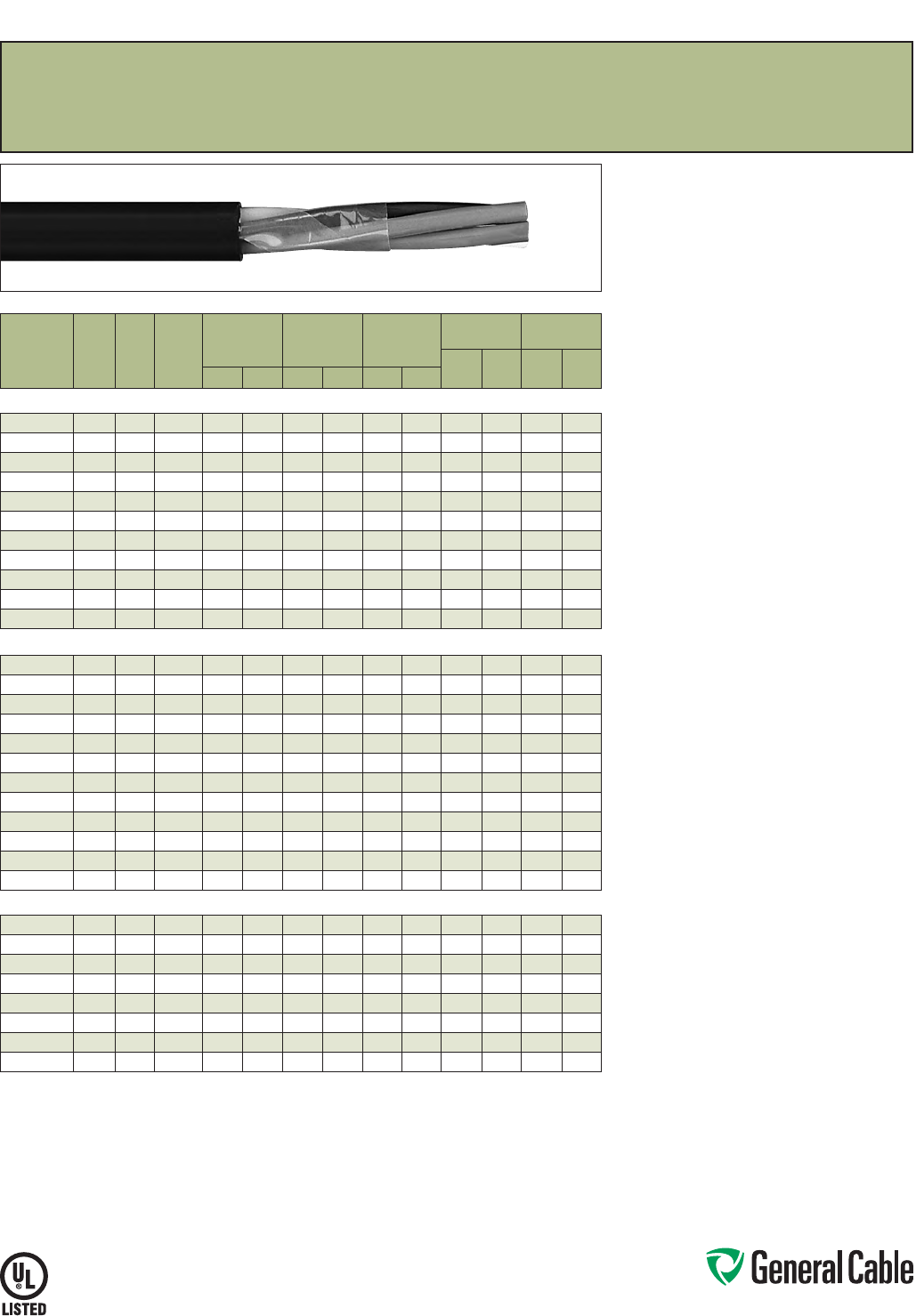
Phone: 888-593-3355
www.generalcable.com
SPEC 4310
March, 2012
Product Construction:
Conductor:
• 14 AWG thru 10 AWG fully annealed stranded
tinned copper per ASTM B33
• Class B stranding per ASTM B8
Insulation:
• Flame-Retardant Ethylene Propylene Rubber
(FR-EPR) Type II
• Color-coded per ICEA Method 1, Table E-1
(includes white or green)
Jacket:
• Lead-free, flame-retardant thermoplastic
Chlorinated Polyethylene (CPE)
Print
• GENERAL CABLE® (PLANT OF MFG) FREP®
XX/C XXAWG EPR/CPE (UL) TYPE TC-ER
XHHW-2 CDRS 90°C WET OR DRY 600 V DIR
BUR SUN RES DAY/MONTH/YEAR OF MFG
SEQUENTIAL FOOTAGE MARK
Options:
• 2 kV version
• Bare copper conductor
• Class C stranding
• E-2 Color Code—see Spec 4300
• Overall shielded multi-conductor
• Flame-Retardant Cross-linked Polyethene
(FR-XLPE) insulation
• Thermoplastic Low-Smoke, Zero-Halogen
(LSZH) jacket
• Other constructions available upon request
Applications:
• In free air, raceways or direct burial
• In wet or dry locations
• Permitted for Exposed Run (ER) use in
accordance with NEC for 3 or more conductors
• Approved for direct burial
• Class I, Division 2 industrial hazardous locations
per NEC
Features:
• Rated at 90˚C wet or dry
• Ripcord applied to all cables with jacket thickness
of 60 mils or less
• Excellent physical, thermal and electrical
properties
• Sunlight- and weather-resistant
• Excellent moisture resistance
• Excellent resistance to compression cuts and heat
deformation
• Low coefficient of friction for easy pulling
• Excellent flame resistance—burns to ash;
does not exhibit thermoplastic drip
• Excellent low temperature cold bend
characteristics
• Meets cold bend test at -40˚C
• Meets the crush and impact requirements of
Type MC cable for 3 or more conductors
Compliances:
Industry Compliances:
• UL 44 Type XHHW-2
• UL 1277 Type TC-ER for 3 or more conductors,
UL File # E57179
• UL 1581
• ICEA S-73-532/NEMA WC57
Flame Test Compliances:
• UL 1581/UL 2556 VW-1
• UL 1685 Vertical Flame Test
• IEEE 383
• IEEE 1202
• CSA FT4
• ICEA T-29-520
Other Compliances:
• EPA 40 CFR, Part 261 for leachable lead
content per TCLP
• OSHA Acceptable
Packaging:
• Material cut to length and shipped on
non-returnable wood reels
FREP
®
FR-EPR/CPE, Control, Unshielded
600 V, UL Type TC-ER
1
—E-1 Color Code
CATALOG
NUMBER
NO.
OF
COND.
COND.
SIZE
(AWG)
COND.
STRAND
MINIMUM AVG.
INSULATION
THICKNESS
MINIMUM AVG.
JACKET
THICKNESS
NOMINAL
CABLE O.D.
COPPER
WEIGHT NET WEIGHT
LBS/
1000 FT kg/km
LBS/
1000 FT kg/kmINCHES mm INCHES mm INCHES mm
14 AWG MULTI-CONDUCTORS
280590 2 Flat 14 7/.0242 0.030 0.76 0.045 1.14
.365 x .230
9.30 x 5.80
26 38 61 91
280230 314 7/.0242 0.030 0.76 0.045 1.14 0.390 9.91 39 59 92 137
280240 414 7/.0242 0.030 0.76 0.045 1.14 0.425
10.80
53 78 115 171
280250 514 7/.0242 0.030 0.76 0.045 1.14 0.465 11.81 66 98 139 207
280260 714 7/.0242 0.030 0.76 0.045 1.14 0.505 12.83 92 137 173 257
280270 914 7/.0242 0.030 0.76 0.060 1.52 0.620 15.75 118 176 240 357
280280 12 14 7/.0242 0.030 0.76 0.060 1.52 0.700 17.78 158 235 301 448
280290* 19 14 7/.0242 0.030 0.76 0.060 1.52 0.815 20.70 250 372 468 696
385350* 25 14 7/.0242 0.030 0.76 0.080 2.03 0.935 23.75 323 481 624 929
385360* 30 14 7/.0242 0.030 0.76 0.080 2.03 1.030 26.16 387 576 747 1112
385370* 37 14 7/.0242 0.030 0.76 0.080 2.03 1.110 28.19 466 694 875 1302
12 AWG MULTI-CONDUCTORS
279850 2 Flat 12 7/.0305 0.030 0.76 0.045 1.14
.400 x .245
10.20 x 6.20
42 63 82 122
280350* 212 7/.0305 0.030 0.76 0.045 1.14 0.410 10.41 42 63 94 140
280360 312 7/.0305 0.030 0.76 0.045 1.14 0.435 11.05 64 95 124 185
279910 412 7/.0305 0.030 0.76 0.045 1.14 0.475 12.07 85 127 157 234
280370 512 7/.0305 0.030 0.76 0.045 1.14 0.520 13.21 106 158 191 284
280380 712 7/.0305 0.030 0.76 0.060 1.52 0.595 15.11 149 221 268 399
280390* 912 7/.0305 0.030 0.76 0.060 1.52 0.695 17.65 191 285 337 502
280400 12 12 7/.0305 0.030 0.76 0.060 1.52 0.765 19.43 247 368 428 637
383930* 19 12 7/.0305 0.030 0.76 0.080 2.03 0.940 23.88 391 582 688 1024
383940* 25 12 7/.0305 0.030 0.76 0.080 2.03 1.095 27.81 515 767 854 1271
383950* 30 12 7/.0305 0.030 0.76 0.080 2.03 1.150 29.21 618 920 1002 1491
330800* 37 12 7/.0305 0.030 0.76 0.080 2.03 1.240 31.50 762 1134 1240 1845
10 AWG MULTI-CONDUCTORS
280600* 2 Flat 10 7/.0385 0.030 0.76 0.045 1.14
.445 x .270
11.30 x 6.90
64 95 113 168
280420* 210 7/.0385 0.030 0.76 0.045 1.14 0.455 11.56 65 97 128 190
279920 310 7/.0385 0.030 0.76 0.045 1.14 0.485 12.32 100 150 172 256
279930 410 7/.0385 0.030 0.76 0.060 1.52 0.560 14.22 134 199 234 348
330990* 510 7/.0385 0.030 0.76 0.060 1.52 0.615 15.62 167 249 284 423
280430* 710 7/.0385 0.030 0.76 0.060 1.52 0.670 17.02 234 349 381 567
382880* 910 7/.0385 0.030 0.76 0.060 1.52 0.760 19.30 295 440 464 691
383970* 12 10 7/.0385 0.030 0.76 0.080 2.03 0.950 22.99 402 598 651 969
Dimensions and weights are nominal; subject to industry tolerances.
* Non-stock item; minimum runs apply. Please consult Customer Service for price and delivery.
¹ Approved as TYPE TC-ER for Exposed Run applications of 3 or more conductors as defined by NEC.
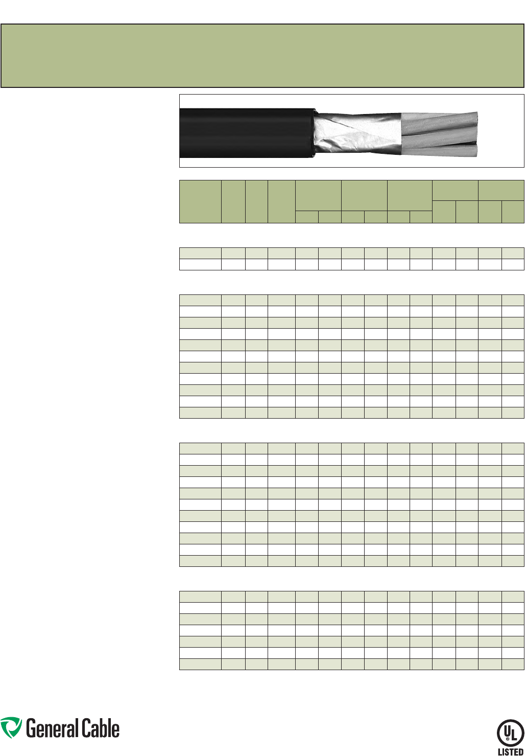
Phone: 888-593-3355
www.generalcable.com
SPEC 4325
March, 2012
CATALOG
NUMBER
NO.
OF
COND.
COND.
SIZE
(AWG)
COND.
STRAND
MINIMUM AVG.
INSULATION
THICKNESS
MINIMUM AVG.
JACKET
THICKNESS
NOMINAL
CABLE O.D.
COPPER
WEIGHT NET WEIGHT
LBS/
1000 FT kg/km
LBS/
1000 FT kg/kmINCHES mm INCHES mm INCHES mm
OVERALL SHIELDED MULTI-CONDUCTORS
16 AWG CONDUCTORS
280470 216 7/.0192 0.025 0.64 0.045 1.14 0.320
8.13
19 28 52 77
280490 316 7/.0192 0.025 0.64 0.045 1.14 0.335 8.51 27 40 66 98
OVERALL SHIELDED MULTI-CONDUCTORS
14 AWG CONDUCTORS
280980* 214 7/.0242 0.030 0.76 0.045 1.14 0.375 9.53 29 43 74 110
354800* 314 7/.0242 0.030 0.76 0.045 1.14 0.395 10.03 42 63 95 141
305300* 414 7/.0242 0.030 0.76 0.045 1.14 0.430 10.92 55 82 118 176
354810* 514 7/.0242 0.030 0.76 0.045 1.14 0.470 11.94 68 101 142 211
354820* 714 7/.0242 0.030 0.76 0.045 1.14 0.510 12.95 94 140 176 262
367120* 914 7/.0242 0.030 0.76 0.060 1.52 0.625 15.88 121 180 243 362
354830* 12 14 7/.0242 0.030 0.76 0.060 1.52 0.705 17.91 160 238 304 452
305360* 19 14 7/.0242 0.030 0.76 0.060 1.52 0.820 20.83 252 375 471 701
367130* 25 14 7/.0242 0.030 0.76 0.080 2.03 0.940 25.53 325 484 627 933
367140* 30 14 7/.0242 0.030 0.76 0.080 2.03 1.035 26.29 389 579 750 1116
367150* 37 14 7/.0242 0.030 0.76 0.080 2.03 1.115 28.32 468 696 878 1307
OVERALL SHIELDED MULTI-CONDUCTORS
12 AWG CONDUCTORS
367160* 212 7/.0305 0.030 0.76 0.045 1.14 0.415 10.45 43 64 97 144
367170* 312 7/.0305 0.030 0.76 0.045 1.14 0.440 11.18 66 98 127 189
326650* 412 7/.0305 0.030 0.76 0.045 1.14 0.480 12.19 87 129 160 238
367180* 512 7/.0305 0.030 0.76 0.045 1.14 0.525 13.34 108 162 194 289
326660* 712 7/.0305 0.030 0.76 0.060 1.52 0.600 15.24 151 225 271 403
367190* 912 7/.0305 0.030 0.76 0.060 1.52 0.700 17.78 193 287 340 506
326640* 12 12 7/.0305 0.030 0.76 0.060 1.52 0.770 19.56 249 371 431 641
326670* 19 12 7/.0305 0.030 0.76 0.080 2.03 0.945 24.00 393 585 691 1028
367200* 25 12 7/.0305 0.030 0.76 0.080 2.03 1.10 0 27.94 517 769 857 1275
367210* 30 12 7/.0305 0.030 0.76 0.080 2.03 1.155 29.80 620 923 1005 1496
367220* 37 12 7/.0305 0.030 0.76 0.080 2.03 1.245 31.62 764 1137 1243 1850
OVERALL SHIELDED MULTI-CONDUCTORS
10 AWG CONDUCTORS
31190 0* 210 7/.0385 0.030 0.76 0.045 1.14 0.460 11.68 68 101 131 195
367230* 310 7/.0385 0.030 0.76 0.045 1.14 0.490 12.45 103 155 175 260
311910* 410 7/.0385 0.030 0.76 0.060 1.52 0.565 14.35 136 202 237 353
367240* 510 7/.0385 0.030 0.76 0.060 1.52 0.620 15.75 170 253 287 427
367250* 710 7/.0385 0.030 0.76 0.060 1.52 0.675 17.15 237 353 384 571
367260* 910 7/.0385 0.030 0.76 0.060 1.52 0.765 19.43 298 443 467 695
367270* 12 10 7/.0385 0.030 0.76 0.080 2.03 0.910 23.11 404 601 654 973
Dimensions and weights are nominal; subject to industry tolerances.
* Non-stock item; minimum runs apply. Please consult Customer Service for price and delivery.
¹ Approved as TYPE TC-ER for Exposed Run applications of 3 or more conductors as defined by NEC.
FREP
®
FR-EPR/CPE, Control, Shielded
600 V, UL Type TC-ER
1
, Overall Shielded—E-2 Color Code
Product Construction:
Conductor:
• 16 AWG thru 10 AWG fully annealed stranded
tinned copper per ASTM B33
• Class B stranding per ASTM B8
Insulation:
• Flame-Retardant Ethylene Propylene Rubber
(FR-EPR) Type II
• Color-coded per ICEA Method 1, Table E-2
(does not include white or green)
Shield:
Overall shielded multi-conductor cable
• Overall shield is Flexfoil® aluminum/polymer in
contact with stranded tinned copper drain wire
Jacket:
• Lead-free, flame-retardant thermoplastic
Chlorinated Polyethylene (CPE)
Print
• GENERAL CABLE® (PLANT OF MFG) SHIELDED
FREP® XX/C XXAWG EPR/CPE (UL) TYPE TC-ER
XHHW-2 CDRS 90˚C WET OR DRY 600 V DIR
BUR SUN RES DAY/MONTH/YEAR OF MFG
SEQUENTIAL FOOTAGE MARK
Options:
• 2 kV version
• Bare copper conductor
• Class C stranding
• E-1 Color Code
• Unshielded multi-conductors
• Flame-Retardant Cross-linked Polyethene
(FR-XLPE) insulation
• Thermoplastic Low-Smoke, Zero-Halogen
(LSZH) jacket
• Other constructions available upon request
Applications:
• In free air, raceway and direct burial
• In wet or dry locations
• Permitted for Exposed Run (ER) use in
accordance with NEC for 3 or more conductors
• Approved for direct burial
• Class I, Division 2 industrial hazardous locations
per NEC
Features:
• Rated at 90˚C wet or dry
• Ripcord applied to all cables with jacket thickness
of 60 mils or less
• Excellent physical, thermal and electrical
properties
• Sunlight- and weather-resistant
• Excellent moisture resistance
• Excellent resistance to compression cuts and heat
deformation
• Low coefficient of friction for easy pulling
• Excellent flame resistance—burns to ash;
does not exhibit thermoplastic drip
• Excellent low temperature cold bend
characteristics
• Meets cold bend test at -40˚C
• Meets the crush and impact requirements of
Type MC cable for 3 conductors or more
Compliances:
Industry Compliances:
• UL 44 Type XHHW-2
• UL 1277 Type TC-ER for 3 or more conductors,
UL File # E57179
• UL 1581
• ICEA S-73-532/NEMA WC57
Flame Test Compliances:
• UL 1581/UL 2556 VW-1
• UL 1685 Vertical Flame Test
• IEEE 383
• IEEE 1202
• CSA FT4
• ICEA T-29-520
Other Compliances:
• EPA 40 CFR, Part 261 for leachable lead
content per TCLP
• OSHA Acceptable
Packaging:
• Material cut to length and shipped on
non-returnable wood reels
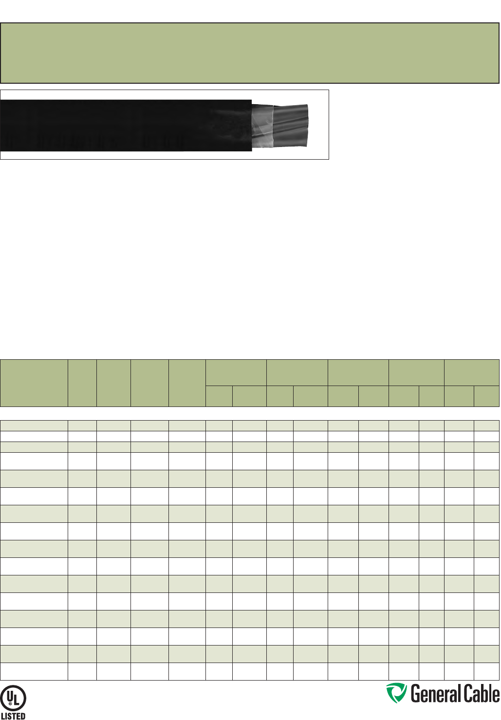
Phone: 888-593-3355
www.generalcable.com
SPEC 4350
August, 2012
CATALOG
NUMBER
NO. OF
COND.
COND.
SIZE
(AWG/
kcmil)
COND.
STRAND
GROUND
WIRE SIZE
(AWG)
MINIMUM AVG.
INSULATION
THICKNESS
MINIMUM AVG.
JACKET THICKNESS NOMINAL CABLE O.D.
COPPER
WEIGHT NET WEIGHT
INCHES mm INCHES mm INCHES mm
LBS/
1000 FT kg/km
LBS/
1000 FT kg/km
14 AWG - 750 kcmil MULTI-CONDUCTORS
383830* 314 7/.0242 14 0.030 0.76 0.045 1.14 0.390 9.91 55 82 118 176
296450* 312 7/.0305 12 0.030 0.76 0.045 1.14 0.435 11.05 87 129 160 238
296440* 310 7/.0385 10 0.030 0.76 0.060 1.52 0.485 12.32 136 202 237 353
279660 387/.0486 10 0.045 1.14 0.060 1.52 0.655 16.64 190 283 314 467
279670 487/.0486 10 0.045 1.14 0.060 1.52 0.720 18.29 242 360 393 585
283210 367/.0612 80.045 1.14 0.060 1.52 0.740 18.80 297 442 456 679
300380 467/.0612 80.045 1.14 0.060 1.52 0.790 20.07 384 571 561 835
283200 347/.0772 80.045 1.14 0.080 2.03 0.880 22.35 442 658 642 955
295390 447/.0772 80.045 1.14 0.080 2.03 0.950 24.13 578 861 822 1223
293600 327/.0974 60.045 1.14 0.080 2.03 1.010 25.65 703 1046 979 1457
295890 427/.0974 60.045 1.14 0.080 2.03 1.090 27.6 9 919 1368 1235 1838
297730* 3119/.0664 60.055 1.40 0.080 2.03 1.120 28.45 872 1298 1021 1594
356740* 4119/.0664 60.055 1.40 0.080 2.03 1.235 31.37 1136 1691 1521 2264
283220 31/0 19 /.0745 60.055 1.40 0.080 2.03 1.225 31.12 1069 1591 1439 2142
294530* 41/0 19/.0745 60.055 1.40 0.080 2.03 1.330 33.78 1413 2103 1820 2709
284560 32/0 19/.0837 60.055 1.40 0.080 2.03 1.300 33.02 1340 1994 1720 2560
295360* 42/0 19/.0837 60.055 1.40 0.080 2.03 1.440 36.58 1760 2619 2208 3286
325700* 33/0 19/.0940 40.055 1.40 0.080 2.03 1.420 36.07 1717 2555 2176 3238
365750* 43/0 19/.0940 40.055 1.40 0.080 2.03 1.570 39.88 2245 3341 2788 3405
325110 34/0 19 /.1055 40.055 1.40 0.080 2.03 1.540 39.12 2130 3170 2614 3890
346980* 44/0 19/.1055 40.055 1.40 0.110 2.79 1.790 45.47 2796 4161 3495 5201
300780 3250 37/.0822 40.065 1.65 0.110 2.79 1.760 44.70 2494 3712 3184 4738
346990* 4250 37/.0822 40.065 1.65 0.110 2.79 1.915 48.64 3282 4884 4019 5981
325120 3350 37/.0973 30.065 1.65 0.110 2.79 1.960 49.78 3474 5170 4187 6231
347000* 4350 37/.0973 30.065 1.65 0.110 2.79 2.165 5499 4577 6811 5436 8090
298020 3500 37/.1162 20.065 1.65 0.110 2.79 2.245 57.02 4934 7343 5847 8702
14407.546500* 4500 37/.1162 20.065 1.65 0.110 2.79 2.475 62.87 6509 9687 7607 11321
14407.247000* 3750 61/.110 9 10.080 2.03 0.140 3.56 2.810 71.37 7278 10831 9145 13610
14407.547000* 4750 61/.1109 10.080 2.03 0.140 3.56 3.115 79.12 9712 14453 11805 17569
Dimensions and weights are nominal; subject to industry tolerances.
* Non-stock item; minimum runs apply. Please consult Customer Service for price and delivery.
¹ Approved as TYPE TC-ER for Exposed Run applications of 3 or more conductors as defined by NEC.
FREP
®
FR-EPR/CPE, Low-Voltage Power, Unshielded
600 V, UL Type TC-ER
1
—Method 4 Color Code
Product Construction:
Conductor:
• 14 AWG thru 750 kcmil tinned, annealed
copper per ASTM B33
• Class B stranding per ASTM B8
Insulation:
• Flame-Retardant Ethylene Propylene Rubber
(FR-EPR) Type II
• Color-coded per ICEA Method 4; individual
conductors colored black with conductor number
surface printed in contrasting ink
Ground:
• Uninsulated tinned annealed copper per
ASTM B3
• Class B stranding per ASTM B8
Jacket:
• Lead-free, flame-retardant thermoplastic
Chlorinated Polyethylene (CPE)
Print:
• GENERAL CABLE® (PLANT OF MFG) FREP®
XX/C XXAWG WITH GRND EPR/CPE (UL) TYPE
TC-ER XHHW-2 CDRS 90˚C WET OR DRY 600 V
DIR BUR SUN RES DAY/MONTH/YEAR OF MFG
SEQUENTIAL FOOTAGE MARK
Options:
• 2 kV version
• Bare copper conductor
• Class C stranding
• E-1 or E-2 Color Code
• Insulated ground conductors
• Overall shielded multi-conductors
• Flame-Retardant Cross-linked Polyethylene
(FR-XLPE) insulation
• Flame-retardant, thermoplastic
Low-Smoke, Zero-Halogen (LSZH) jacket
• Other constructions available upon request
Applications:
• In free air, raceways or direct burial
• In wet or dry locations
• Permitted for Exposed Run (ER) use in
accordance with NEC for 3 or more conductors
• Permitted for use in Class I, Division 2 industrial
hazardous locations per NEC
Features:
• Rated at 90˚C wet or dry
• Ripcord applied to all cables with jacket thickness
of 60 mils or less
• Excellent physical, thermal and electrical
properties
Features (cont’d.):
• Excellent moisture resistance
• Excellent resistance to crush, compression cuts
and heat deformation
• Excellent low temperature cold bend
characteristics
• Excellent flame resistance—burns to ash; does
not exhibit thermoplastic drip
• Low coefficient of friction for easy pulling
• Sunlight- and weather-resistant
• Meets cold bend test at -40˚C
Compliances:
Industry Compliances:
• UL 44 Type XHHW-2
• UL 1277 Type TC-ER, UL File # E57179
• UL 1581
• ICEA S-95-658/NEMA WC70
Flame Test Compliances:
• UL 1581/UL 2556 VW-1
• UL 1685 Vertical Flame Test
• IEEE 383
• IEEE 1202
• CSA FT4
• ICEA T-29-520
Other Compliances:
• EPA 40 CFR, Part 261 for leachable lead
content per TCLP
• OSHA Acceptable
Packaging:
• Material cut to length and shipped on
non-returnable wood reels
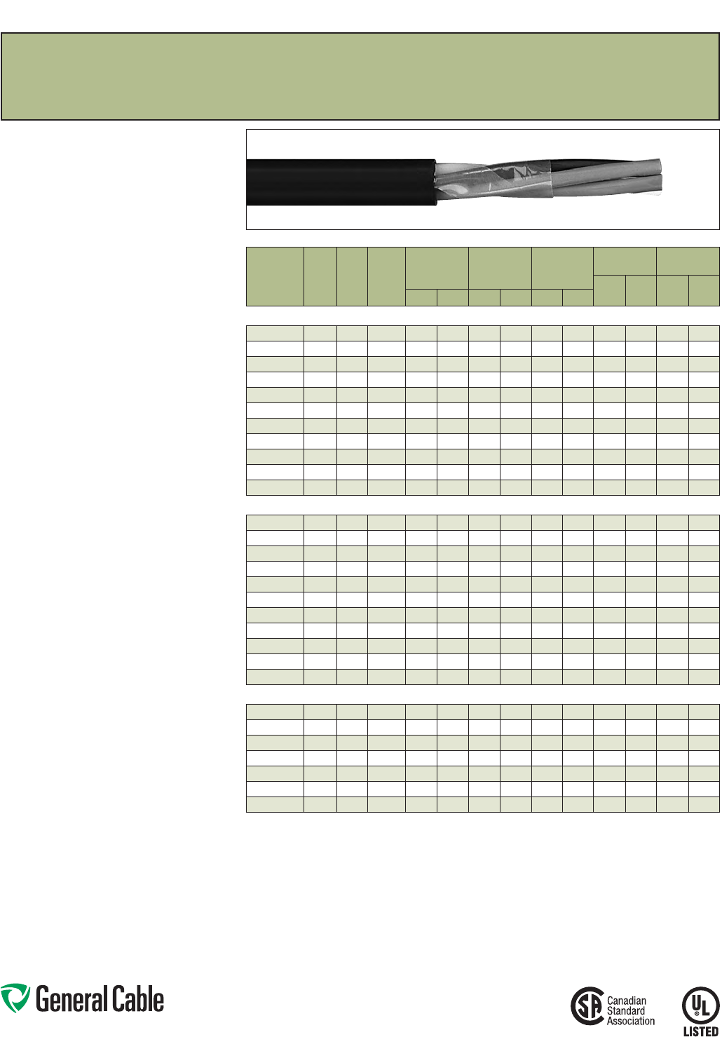
Phone: 888-593-3355
www.generalcable.com
SPEC 4400
March, 2012
Product Construction:
Conductor:
• 14 AWG thru 10 AWG tinned, annealed copper
per ASTM B3
• Class B stranding per ASTM B8
Insulation:
• Lead-free, flame-retardant Cross-linked
Polyethylene (XLPE)
• Color-coded per CSA Standard C22.2 No. 38 as
follows:
Number of color coding of circuit conductors
No. of Cond. Color Code
2 blk, wht
3 blk, red, blu
4 blk, red, blu, wht
≥5 all black
All conductors for all constructions are alpha-
numeric printed
Jacket:
• Lead-free, flame-retardant, sunlight-resistant
Arctic-grade Polyvinyl Chloride (PVC)
Print:
• GENERAL CABLE® (PLANT OF MFG) (UL) TYPE
TC-ER ARCTIC-FLEX® XX/C XXAWG FR-XLP/
PVC XHHW-2 CDRS 90C WET OR DRY SUN RES
DIR BUR 600 V - (CSA) TYPE RW90 XLPE -40C
TC FT4 600 V PLUS DAY/MONTH/YEAR OF MFG
SEQUENTIAL FOOTAGE MARK
Options:
• Bare copper, class C stranding
• Uninsulated ground (bonding) conductor
• Optional color code as specified per CSA
standard C22.2 No. 38 for two to four conductor
cable
• Non-UL 1000 volt CSA Type RW90 XLPE, CSA
Type TC
• Other constructions available upon request
Applications:
• Industrial lighting, control and signaling circuits
• Approved for direct burial, Class I, Div. 2 industrial
hazardous locations per NEC for UL Type TC
cables. In Canada, protection may be required by
inspection authority per Canadian electrical code
• Permitted for Exposed Run (ER) use in
accordance with NEC for 3 or more conductors
• Approved for cable in tray; industrial hazardous
locations; Class I, Zone 2; and Class II, Division 2
per CEC Rules 18-152 and 18-252 when used with
certified HL glands
Features:
• Rated 90˚C wet or dry
• Ripcord applied to all cables with jacket thickness
of 60 mils or less
• Meets CSA cold impact test at -40˚C
• Meets ICEA and CSA cold bend test at -60˚C
• Meets the crush and impact requirements of Type
MC cable
Compliances:
Industry Compliances:
• ICEA S-73-532/NEMA WC57
• UL 44 Type XHHW-2
• UL 1277 Type TC-ER for 3 or more conductors,
UL File # E57179
• UL 1581
• CSA C22.2 No. 38 XLPE RW90
• CSA C22.2 No. 230 Type TC
Flame Test Compliances:
• UL 1581/UL 2556 VW-1
• UL 1685 Vertical Flame Test
• IEEE 383
• CSA FT4
Other Compliances:
• EPA 40 CFR, Part 261 for leachable lead
content per TCLP
• OSHA Acceptable
Packaging:
• Material cut to lengths and shipped on non-
returnable wood reels
CATALOG
NUMBER
NO.
OF
COND.
COND.
SIZE
(AWG)
COND.
STRAND
MINIMUM AVG.
INSULATION
THICKNESS
MINIMUM AVG.
JACKET
THICKNESS
NOMINAL
CABLE O.D.
COPPER
WEIGHT NET WEIGHT
LBS/
1000 FT kg/km
LBS/
1000 FT kg/kmINCHES mm INCHES mm INCHES mm
14 AWG MULTI-CONDUCTORS
347340* 214 7/.0242 0.030 0.76 0.045 1.14 0.405 10.29 25 37 71 106
347350* 314 7/.0242 0.030 0.76 0.045 1.14 0.390 9.91 40 59 90 134
347360* 414 7/.0242 0.030 0.76 0.045 1.14 0.425 10.80 53 79 113 168
347370* 514 7/.0242 0.030 0.76 0.045 1.14 0.465
11.81
66 99 140 208
347380* 714 7/.0242 0.030 0.76 0.045 1.14 0.590 14.99 93 138 176 262
347390* 914 7/.0242 0.030 0.76 0.060 1.52 0.620 15.75 119 177 245 365
347400* 12 14 7/.0242 0.030 0.76 0.060 1.52 0.680 17. 27 159 237 302 449
347410* 19 14 7/.0242 0.030 0.76 0.060 1.52 0.800 20.32 252 375 460 685
347420* 25 14 7/.0242 0.030 0.76 0.060 1.52 0.985 25.02 323 481 641 954
347430* 30 14 7/.0242 0.030 0.76 0.080 2.03 1.050 26.67 387 576 740 1101
347440* 37 14 7/.0242 0.030 0.76 0.080 2.03 1.130 28.70 490 729 888 1322
12 AWG MULTI-CONDUCTORS
347450* 212 7/.0305 0.030 0.76 0.045 1.14 0.410 10.41 41 61 96 143
347460* 312 7/.0305 0.030 0.76 0.045 1.14 0.435 11.05 65 96 125 186
347470* 412 7/.0305 0.030 0.76 0.045 1.14 0.475 12.07 86 128 157 234
347480* 512 7/.0305 0.030 0.76 0.045 1.14 0.520 13.21 108 160 191 284
347490* 712 7/.0305 0.030 0.76 0.060 1.52 0.595 15.11 150 224 260 387
347500* 912 7/.0305 0.030 0.76 0.060 1.52 0.695 17.65 193 288 340 506
347510* 12 12 7/.0305 0.030 0.76 0.060 1.52 0.780 19.81 258 385 429 638
347520* 19 12 7/.0305 0.030 0.76 0.080 2.03 0.930 23.62 403 600 681 1013
347530* 25 12 7/.0305 0.030 0.76 0.080 2.03 1.095 27.81 515 767 885 1317
347540* 30 12 7/.0305 0.030 0.76 0.080 2.03 1.150 29.21 618 920 1005 1496
347550* 37 12 7/.0305 0.030 0.76 0.080 2.03 1.240 31.50 741 1103 1185 1764
10 AWG MULTI-CONDUCTORS
347560* 210 7/.0385 0.030 0.76 0.045 1.14 0.455 11.56 67 100 130 193
347570* 310 7/.0385 0.030 0.76 0.045 1.14 0.485 12.32 101 150 168 250
347580* 410 7/.0385 0.030 0.76 0.060 1.52 0.515 13.08 135 200 229 341
347590* 510 7/.0385 0.030 0.76 0.060 1.52 0.615 15.62 167 249 281 418
347600* 710 7/.0385 0.030 0.76 0.060 1.52 0.670 17.02 234 349 377 561
347610* 910 7/.0385 0.030 0.76 0.060 1.52 0.785 19.94 295 440 479 713
347620* 12 10 7/.0385 0.030 0.76 0.080 2.03 0.895 22.73 402 598 644 958
Dimensions and weights are nominal; subject to industry tolerances.
* Non-stock item; minimum runs apply. Please consult Customer Service for price and delivery.
¹ Approved as TYPE TC-ER for Exposed Run applications of 3 or more conductors as defined by NEC.
Arctic-Flex
®
XLPE/Arctic-PVC, Control, Unshielded
600 V, UL Type TC-ER
1
, CSA Type RW90 XLPE, CSA Type TC
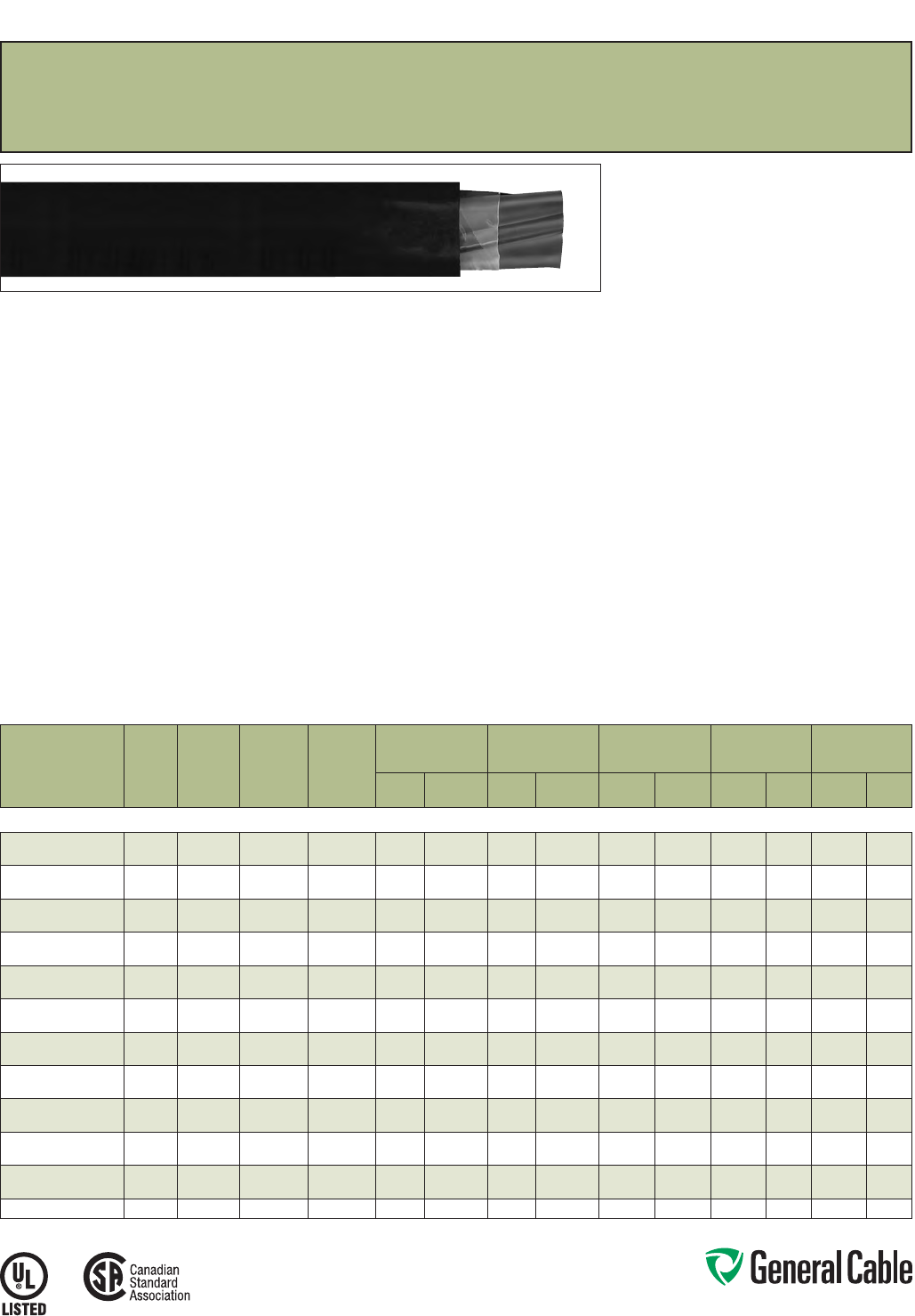
Phone: 888-593-3355
www.generalcable.com
SPEC 4450
March, 2012
CATALOG
NUMBER
NO. OF
COND.
COND.
SIZE
(AWG/
kcmil)
COND.
STRAND
GROUND
WIRE SIZE
(AWG)
MINIMUM AVG.
INSULATION
THICKNESS
MINIMUM AVG.
JACKET THICKNESS NOMINAL CABLE O.D.
COPPER
WEIGHT NET WEIGHT
INCHES mm INCHES mm INCHES mm
LBS/
1000 FT kg/km
LBS/
1000 FT kg/km
8 AWG - 500 kcmil MULTI-CONDUCTORS
347150* 387/.0486 10 0.045 1.14 0.060 1.52 0.640 16.26 190 283 314 467
347160* 487/.0486 10 0.045 1.14 0.060 1.52 0.705 17.91 242 360 385 573
347170* 367/.0612 80.045 1.14 0.060 1.52 0.720 18.29 301 448 445 662
347180* 467/.0612 80.045 1.14 0.060 1.52 0.790 20.07 384 571 558 830
347190* 347/.0772 80.045 1.14 0.080 2.03 0.875 22.23 448 667 653 972
347200* 447/.0772 80.045 1.14 0.080 2.03 0.950 24.13 578 862 820 1220
347210* 327/.0974 60.045 1.14 0.080 2.03 1.000 25.40 716 1066 964 1435
347220* 427/.0974 60.045 1.14 0.080 2.03 1.095 27.81 919 1368 1214 1807
371280* 3119/.0664 60.055 1.40 0.080 2.03 1.120 28.45 872 1298 1199 1784
371290* 4119/.0664 60.055 1.40 0.080 2.03 1.235 31.37 1136 1691 1704 2536
347230* 31/0 19/.0745 60.055 1.40 0.080 2.03 1.215 30.86 1081 1609 1414 2104
347240* 41/0 19 /.0745 60.055 1.40 0.080 2.03 1.340 34.04 1413 2103 1825 2716
347250* 32/0 19/.0837 60.055 1.40 0.080 2.03 1.310 33.27 1341 1996 1706 2539
347260* 42/0 19/.0837 60.055 1.40 0.080 2.03 1.450 36.83 1760 2619 2223 3308
371300* 33/0 19/.0940 40.055 1.40 0.080 2.03 1.420 36.07 1717 2555 2437 3627
371310* 43/0 19/.0940 40.055 1.40 0.080 2.03 1.570 39.88 2245 3341 3123 4648
347270* 34/0 19/.1055 40.055 1.40 0.080 2.03 1.540 39.12 2132 3173 2600 3869
347280* 44/0 19/.1055 40.055 1.40 0.110 2.79 1.765 44.83 2796 4161 3444 5125
347290* 3250 37/.0822 40.065 1.65 0.110 2.79 1.750 44.45 2494 3712 3142 4676
347300* 4250 37/.0822 40.065 1.65 0.110 2.79 1.930 49.02 3282 4884 4048 6024
347310* 3350 37/.0973 30.065 1.65 0.110 2.79 1.970 50.04 3474 5170 4230 6295
347320* 4350 37/.0973 30.065 1.65 0.110 2.79 2.180 55.37 4577 6811 5470 8140
347330* 3500 37/.1162 20.065 1.65 0.110 2.79 2.250 57.15 4938 7349 5829 8675
Dimensions and weights are nominal; subject to industry tolerances.
* Non-stock item; minimum runs apply. Please consult Customer Service for price and delivery.
¹ Approved as TYPE TC-ER for Exposed Run applications of 3 or more conductors as
defined by NEC.
Arctic-Flex
®
XLPE/Arctic-PVC, Low-Voltage Power, Unshielded
600 V, UL Type TC-ER
1
, CSA Type RW90 XLPE, CSA Type TC
Product Construction:
Conductor:
• 8 AWG thru 500 kcmil bare, annealed copper per
ASTM B3
• Class B stranding per ASTM B8
Insulation:
• Lead-free, flame-retardant Cross-linked
Polyethylene (XLPE)
• Color-coded per CSA Standard C22.2
No. 38 as follows:
Number of color coding of circuit conductors
No. of Cond. Color Code
2 blk, wht
3 blk, red, blu
4 blk, red, blu, wht
≥5 all black
All conductors for all constructions are
alphanumeric printed
Ground (Bonding) Conductor:
• Uninsulated bare annealed copper
per ASTM B3
• Class B stranding per ASTM B8
Jacket:
• Lead-free, flame-retardant, sunlight-resistant
Arctic-grade Polyvinyl Chloride (PVC)
Print:
• GENERAL CABLE® (PLANT OF MFG) (UL) TYPE
TC-ER ARCTIC-FLEX® XX/C XXAWG WITH GRND
FR-XLP/PVC XHHW-2 CDRS 90C WET OR DRY
SUN RES DIR BUR 600 V (CSA) TYPE RW90
XLPE -40C TC FT4 600 V PLUS DAY/MONTH/
YEAR OF MFG SEQUENTIAL FOOTAGE MARK
Options:
• Tinned copper
• Class C stranding
• Overall shielded multi-conductors
• Optional Color Code as specified per CSA
standard C22.2 No. 38 for two to four conductor
cable
• Non-UL 1000 volt CSA Type RW90 XLPE,
CSA Type TC
• Other constructions are available upon request
Applications:
• Industrial power and control circuits
• Permitted for Exposed Run (ER) use in
accordance with NEC for 3 or more conductors
• Approved for direct burial; Class I, Div. 2 industrial
hazardous locations per NEC for UL Type TC
cables. In Canada protection may be required by
inspection authority per Canadian electrical code
Applications (cont’d.):
• Approved for cable in tray; industrial hazardous
locations; Class I Zone 2; and Class I, Division 2
per CEC rules 18-156 and 18-252 when used with
certified HL cable glands
Features:
• Rated 90
˚
C wet or dry
• Ripcord applied to all cables with jacket thickness
of 60 mils or less
• Meets CSA cold impact test at -40
˚
C
• Meets ICEA and CSA cold bend test at -60
˚
C
• Meets the crush and impact requirements of Type
MC cable
Compliances:
Industry Compliances:
• UL 44 Type XHHW-2
• UL 1277 Type TC-ER for 3 or more conductors,
UL File # E57179
• UL 1581
• ICEA S-95-658/NEMA WC70
• CSA C22.2 No. 38 RW90 XLPE
• CSA C22.2 No. 230 Type TC
Flame Test Compliances:
• UL 1581/UL 2556 VW-1
• UL 1685 Vertical Flame Test
• IEEE 383
• IEEE 1202
• CSA FT4
Other Compliances:
• EPA 40 CFR, Part 261 for leachable lead
content per TCLP
• OSHA Acceptable
Packaging:
• Material cut to lengths and shipped on
non-returnable wood reels
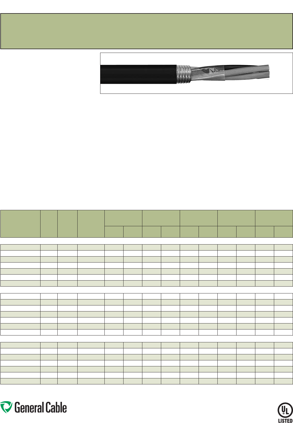
Phone: 888-593-3355
www.generalcable.com
SPEC 4460
June, 2012
CCTC™
FR-XLPE/CPE, Control, Shielded
600 V, UL Type TC-ER
1
— E-1 Color Code
Product Construction:
Conductor:
• 14 AWG thru 10 AWG fully annealed stranded bare
copper per ASTM B3
• Class B stranding per ASTM B8
Insulation:
• Flame-Retardant Cross-linked Polyethene
(FR-XLPE) insulation
• Color-coded per ICEA Method 1, Table E-1
(includes white or green)
Shield:
• Bare 5 mil corrugated copper tape longitudinally
applied
Jacket:
• Lead-free, flame-retardant thermoplastic
Chlorinated Polyethylene (CPE)
Print
• GENERAL CABLE® (PLANT OF MFG) CCTC™
XX/C XXAWG FR-XLPE/CPE (UL) TYPE TC-ER
XHHW-2 CDRS 90°C WET OR DRY 600 V DIR
BUR SUN RES DAY/MONTH/YEAR OF MFG
SEQUENTIAL FOOTAGE MARK
Options:
• 2 kV version
• Tinned copper conductor
• Class C stranding
• E-2 Color Code
• Flame-Retardant Ethylene Propylene Rubber
(FR-EPR) Type II
• Thermoplastic Low-Smoke, Zero-Halogen
(LSZH) jacket
• Other constructions available upon request
Applications:
• In free air, raceways or direct burial
• In wet or dry locations
• Permitted for Exposed Run (ER) use in
accordance with NEC for 3 or more conductors
• Approved for direct burial
• Class I, Division 2 industrial hazardous locations
per NEC
Features:
• Rated at 90˚C wet or dry
• Ripcord applied to all cables with jacket thickness
of 60 mils or less
• Excellent physical, thermal and electrical
properties
• Sunlight- and weather-resistant
• Excellent moisture resistance
• Excellent resistance to compression cuts and heat
deformation
• Low coefficient of friction for easy pulling
• Excellent flame resistance—burns to ash;
does not exhibit thermoplastic drip
• Excellent low temperature cold bend
characteristics
• Meets cold bend test at -40˚C
• Meets the crush and impact requirements of
Type MC cable for 3 or more conductors
Compliances:
Industry Compliances:
• UL 44 Type XHHW-2
• UL 1277 Type TC-ER for 3 or more conductors,
UL File # E57179
• UL 1581
• ICEA S-73-532/NEMA WC57
Flame Test Compliances:
• UL 1581/UL 2556 VW-1
• UL 1685 Vertical Flame Test
• IEEE 383
• IEEE 1202
• CSA FT4
• ICEA T-29-520
Other Compliances:
• EPA 40 CFR, Part 261 for leachable lead
content per TCLP
• OSHA Acceptable
Packaging:
• Material cut to length and shipped on
non-returnable wood reels
CATALOG
NUMBER
NO. OF
COND.
COND.
SIZE
(AWG)
COND.
STRAND
MINIMUM AVG.
INSULATION
THICKNESS
MINIMUM AVG.
JACKET THICKNESS NOMINAL CABLE O.D.
COPPER
WEIGHT NET WEIGHT
INCHES mm INCHES mm INCHES mm
LBS/
1000 FT kg/km
LBS/
1000 FT kg/km
14 AWG MULTI-CONDUCTORS
397310* 214 7/.0242 0.030 0.76 0.045 1.14 0.440 11.18 50 74 96 143
397320* 3 14 7/.0242 0.030 0.76 0.045 1.14 0.460 11.68 65 97 119 177
397330* 4 14 7/.0242 0.030 0.76 0.045 1.14 0.495 12.57 80 119 143 213
397340* 514 7/.0242 0.030 0.76 0.060 1.52 0.565 14.35 95 141 182 271
397350* 714 7/.0242 0.030 0.76 0.060 1.52 0.605 15.37 123 183 227 338
397360* 914 7/.0242 0.030 0.76 0.060 1.52 0.685 17.40 153 228 279 415
397370* 12 14 7/.0242 0.030 0.76 0.060 1.52 0.760 19.30 196 292 349 519
12 AWG MULTI-CONDUCTORS
397380* 2 12 7/.0305 0.030 0.76 0.045 1.14 0.480 12.19 67 100 119 177
397390* 312 7/.0305 0.030 0.76 0.045 1.14 0.500 12.70 90 134 151 225
397400* 412 7/.0305 0.030 0.76 0.060 1.52 0.570 14.48 112 167 199 296
397410* 5 12 7/.0305 0.030 0.76 0.060 1.52 0.615 15.62 135 201 234 348
397420* 7 12 7/.0305 0.030 0.76 0.060 1.52 0.660 16.76 177 263 297 442
397430* 9 12 7/.0305 0.030 0.76 0.060 1.52 0.755 19.18 225 335 370 551
397440* 12 12 7/.0305 0.030 0.76 0.060 1.52 0.835 21.21 291 433 468 696
10 AWG MULTI-CONDUCTORS
397450* 210 7/.0385 0.030 0.76 0.060 1.52 0.555 14.10 94 140 167 248
397460* 3 10 7/.0385 0.030 0.76 0.060 1.52 0.580 14.73 129 192 215 320
397470* 4 10 7/.0385 0.030 0.76 0.060 1.52 0.630 16.00 164 244 264 393
397480* 510 7/.0385 0.030 0.76 0.060 1.52 0.680 17.27 201 299 317 472
397490* 710 7/.0385 0.030 0.76 0.060 1.52 0.730 18.54 269 400 408 607
397500* 910 7/.0385 0.030 0.76 0.080 2.03 0.885 22.48 342 509 547 814
397510* 12 10 7/.0385 0.030 0.76 0.080 2.03 0.975 24.77 444 661 691 1028
Dimensions and weights are nominal; subject to industry tolerances.
* Non-stock item; minimum runs apply. Please consult Customer Service for price and delivery.
¹ Approved as TYPE TC-ER for Exposed Run applications of 3 or more conductors as defined by NEC.
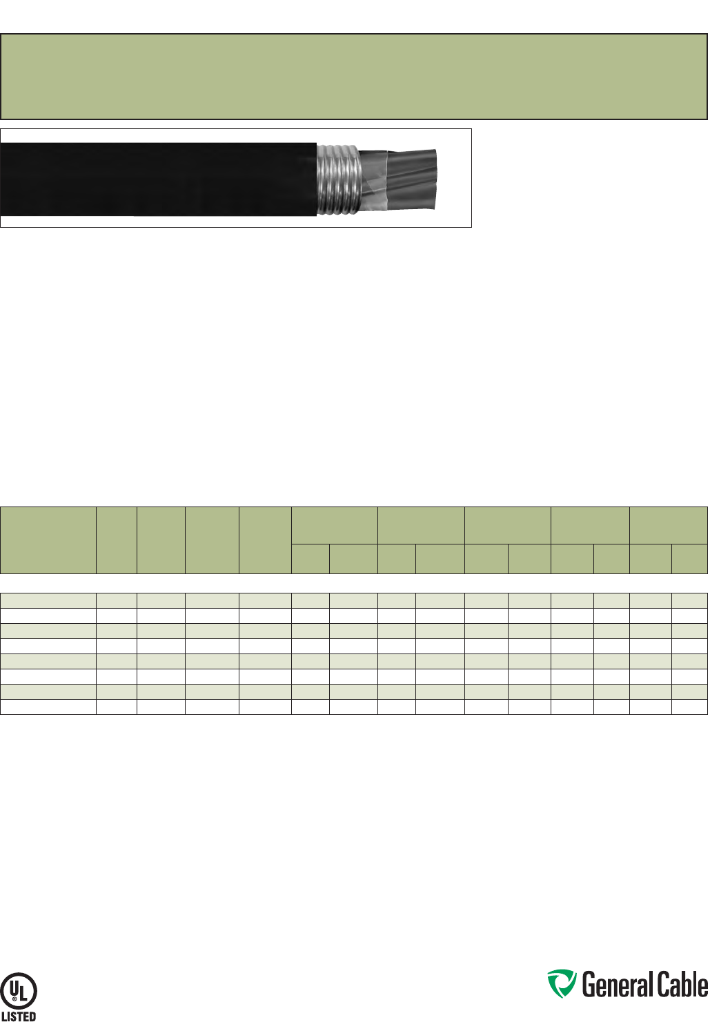
Phone: 888-593-3355
www.generalcable.com
SPEC 4480
June, 2012
CATALOG
NUMBER
NO. OF
COND.
COND.
SIZE
(AWG)
COND.
STRAND
GROUND
WIRE SIZE
(AWG)
MINIMUM AVG.
INSULATION
THICKNESS
MINIMUM AVG.
JACKET THICKNESS NOMINAL CABLE O.D.
COPPER
WEIGHT NET WEIGHT
INCHES mm INCHES mm INCHES mm
LBS/
1000 FT kg/km
LBS/
1000 FT kg/km
8 AWG - 2 AWG MULTI-CONDUCTORS
397520* 387/.0486 10 0.045 1.14 0.060 1.52 0.715 18.16 229 341 356 530
397530* 487/.0486 10 0.045 1.14 0.060 1.52 0.775 19.69 283 421 435 647
397540* 3 6 7/.0612 80.045 1.14 0.060 1.52 0.790 20.07 336 500 483 719
397550* 4 6 7/.0612 80.045 1.14 0.080 2.03 0.905 22.99 421 626 634 943
397560* 3 4 7/.0772 80.045 1.14 0.080 2.03 0.935 23.75 499 743 711 1058
397570* 4 4 7/.0772 80.045 1.14 0.080 2.03 1.020 25.91 636 946 888 1321
397580* 327/.0974 60.045 1.14 0.080 2.03 1.060 26.92 755 1123 1007 1498
397590* 427/.0974 60.045 1.14 0.080 2.03 1.160 29.46 964 1434 1267 1885
Dimensions and weights are nominal; subject to industry tolerances.
* Non-stock item; minimum runs apply. Please consult Customer Service for price and delivery.
¹ Approved as TYPE TC-ER for Exposed Run applications of 3 or more conductors as defined by NEC.
CCTC™
FR-XLPE/CPE, Low-Voltage Power, Shielded
600 V, UL Type TC-ER
1
— Method 4 Color Code
Product Construction:
Conductor:
• 8 AWG thru 2 AWG bare, annealed copper per
ASTM B3
• Class B stranding per ASTM B8
Insulation:
• Flame-Retardant Cross-linked Polyethylene
(FR-XLPE) insulation
• Color-coded per ICEA Method 4; individual
conductors colored black with conductor number
surface printed in contrasting ink
Shield:
• Bare 5 mil corrugated copper tape longitudinally
applied
Ground:
• Uninsulated bare annealed copper per
ASTM B3
• Class B stranding per ASTM B8
Jacket:
• Lead-free, flame-retardant thermoplastic
Chlorinated Polyethylene (CPE)
Print:
• GENERAL CABLE® (PLANT OF MFG) CCTC™
XX/C XXAWG WITH GRND FR-XLPE/CPE (UL)
TYPE TC-ER XHHW-2 CDRS 90˚C WET OR DRY
600 V DIR BUR SUN RES DAY/MONTH/YEAR OF
MFG SEQUENTIAL FOOTAGE MARK
Options:
• 2 kV version
• Tinned copper conductor
• Class C stranding
• E-1 or E-2 Color Code
• Insulated ground conductors
• Flame-Retardant Ethylene Propylene Rubber
(FR-EPR) Type II
• Flame-retardant, thermoplastic
Low-Smoke, Zero-Halogen (LSZH) jacket
• Other constructions available upon request
Applications:
• In free air, raceways or direct burial
• In wet or dry locations
• Permitted for Exposed Run (ER) use in
accordance with NEC for 3 or more conductors
• Permitted for use in Class I, Division 2 industrial
hazardous locations per NEC
Features:
• Rated at 90˚C wet or dry
• Ripcord applied to all cables with jacket thickness
of 60 mils or less
• Excellent physical, thermal and electrical
properties
• Excellent moisture resistance
• Excellent resistance to crush, compression cuts
and heat deformation
• Excellent low temperature cold bend
characteristics
• Excellent flame resistance—burns to ash; does
not exhibit thermoplastic drip
• Low coefficient of friction for easy pulling
• Sunlight- and weather-resistant
• Meets cold bend test at -40˚C
Compliances:
Industry Compliances:
• UL 44 Type XHHW-2
• UL 1277 Type TC-ER, UL File # E57179
• UL 1581
• ICEA S-95-658/NEMA WC70
Flame Test Compliances:
• UL 1581/UL 2556 VW-1
• UL 1685 Vertical Flame Test
• IEEE 383
• IEEE 1202
• CSA FT4
• ICEA T-29-520
Other Compliances:
• EPA 40 CFR, Part 261 for leachable lead
content per TCLP
• OSHA Acceptable
Packaging:
• Material cut to length and shipped on
non-returnable wood reels
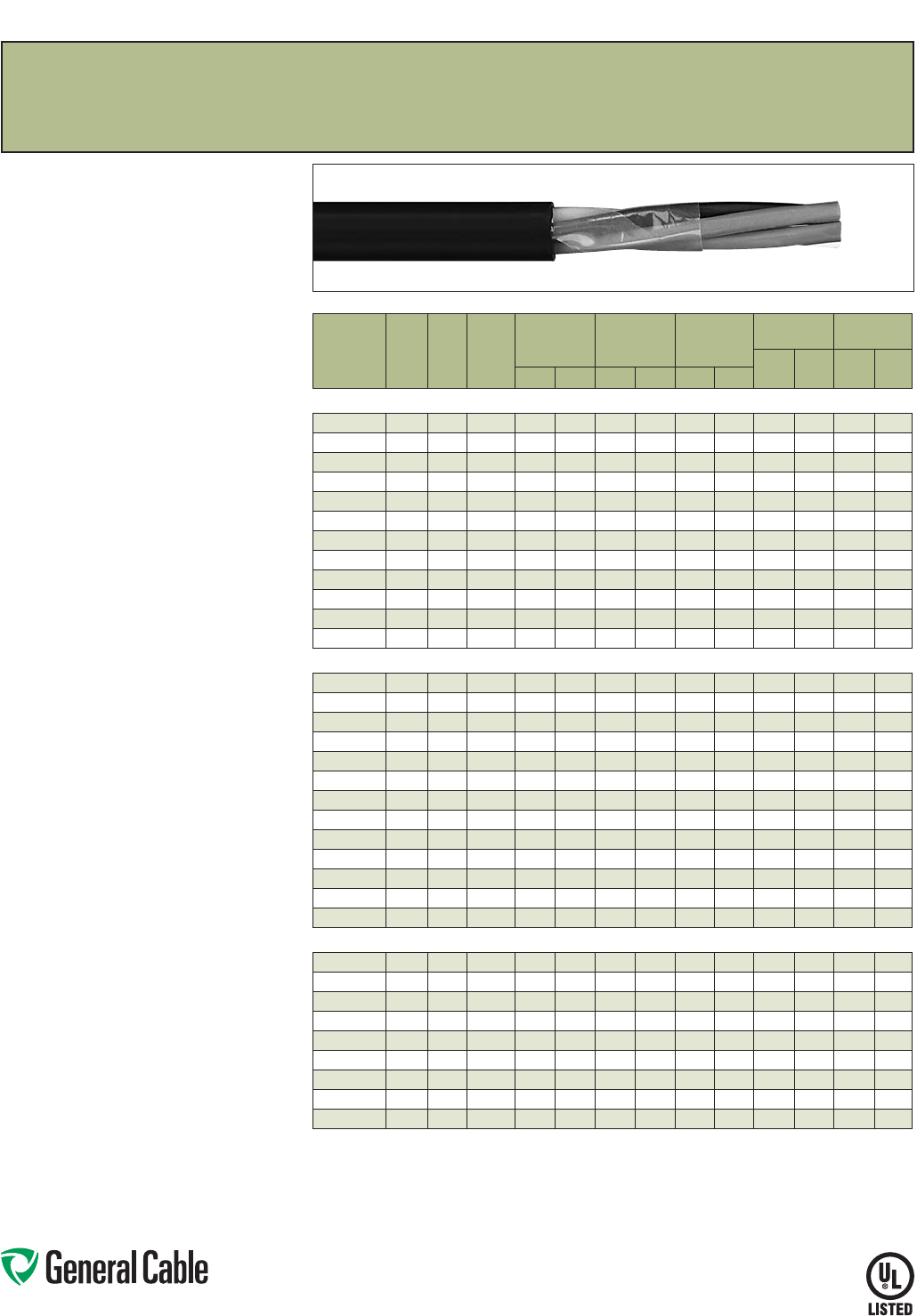
Phone: 888-593-3355
www.generalcable.com
SPEC 4500
March, 2012
Product Construction:
Conductor:
• 14 AWG thru 10 AWG fully annealed stranded bare
copper per ASTM B3
• Class B stranding per ASTM B8
Insulation:
• Flame-retardant Cross-linked Polyethylene (XLPE)
• Color-coded per ICEA Method 1, Table E-2
(does not include white or green)
Jacket:
• Lead-free, flame-retardant, sunlight-resistant
Polyvinyl Chloride (PVC)
Print
• GENERAL CABLE® (PLANT OF MFG) CVTC®
XX/C XXAWG FR-XLP/PVC (UL) TYPE TC-ER
XHHW-2 CDRS DIR BUR SUN RES 90˚C WET
OR DRY 600 V DAY/MONTH/YEAR OF MFG
SEQUENTIAL FOOTAGE MARK
Options:
• Tinned copper conductor
• Class C stranding
• E-1 Color Code
• Overall shielded multi-conductors
• Ethylene Propylene Rubber (EPR) insulation
• Low-lead Hypalon Chlorosulfonated Polyethylene
(CSPE)/Elastomer blend—see CHTC® Spec 4050
• Insulated or uninsulated ground conductor
• Other constructions available upon request
Applications:
• In free air, raceways and direct burial
• In wet or dry locations
• Approved for direct burial
• Class I, Division 2 industrial hazardous locations
per NEC
• Permitted for Exposed Run (ER) use in
accordance with NEC for 3 or more conductors
Features:
• Rated at 90˚C wet or dry
• Ripcord applied to all cables with jacket thickness
of 60 mils or less
• Excellent electrical properties
• Abrasion- and chemical-resistant
• Sunlight- and weather-resistant
• Meets cold bend test at -25˚C
• Meets the crush and impact requirements of Type
MC cable
Compliances:
Industry Compliances:
• UL 44 Type XHHW-2
• UL 1277 Type TC-ER for 3 or more conductors,
UL File # E57179
• UL 1581
• ICEA S-73-532/NEMA WC57
Flame Test Compliances:
• UL 1581/UL 2556 VW-1
• UL 1685 Vertical Flame Test
• IEEE 383
• IEEE 1202
• ICEA T-29-520 (210,000 BTU/hr)
• CSA FT4
Other Compliances:
• EPA 40 CFR, Part 261 for leachable lead
content per TCLP
• OSHA Acceptable
Packaging:
• Material cut to length and shipped on
non-returnable wood reels
CATALOG
NUMBER
NO.
OF
COND.
COND.
SIZE
(AWG)
COND.
STRAND
MINIMUM AVG.
INSULATION
THICKNESS
MINIMUM AVG.
JACKET
THICKNESS
NOMINAL
CABLE O.D.
COPPER
WEIGHT NET WEIGHT
LBS/
1000 FT kg/km
LBS/
1000 FT kg/kmINCHES mm INCHES mm INCHES mm
14 AWG MULTI-CONDUCTORS
770460 2 Flat 14 7/.0242 0.030 0.76 0.045 1.14
.235 x .370 5.97 x 9.40
25 37 62 92
771080* 214 7/.0242 0.030 0.76 0.045 1.14 0.365 9.27 25 37 73 109
770530 314 7/.0242 0.030 0.76 0.045 1.14 0.390 9.91 40 59 93 138
770610 414 7/.0242 0.030 0.76 0.045 1.14 0.425
10.80
53 79 116 173
770420 514 7/.0242 0.030 0.76 0.045 1.14 0.465 11.81 66 99 140 208
770560 714 7/.0242 0.030 0.76 0.045 1.14 0.590 14.99 93 138 176 262
770540 914 7/.0242 0.030 0.76 0.060 1.52 0.620 15.75 119 177 245 365
770470 12 14 7/.0242 0.030 0.76 0.060 1.52 0.680 17. 27 159 237 302 449
770550 19 14 7/.0242 0.030 0.76 0.060 1.52 0.800 20.32 252 375 460 685
770450* 25 14 7/.0242 0.030 0.76 0.080 2.03 0.985 25.02 323 481 641 954
295320* 30 14 7/.0242 0.030 0.76 0.080 2.03 1.050 26.67 387 571 740 1101
770430* 37 14 7/.0242 0.030 0.76 0.080 2.03 1.130 28.70 490 729 888 1322
12 AWG MULTI-CONDUCTORS
770480 2 Flat 12 7/.0305 0.030 0.76 0.045 1.14
.245 x .400
6.22 x 10.16
40 60 86 128
346920* 212 7/.0305 0.030 0.76 0.045 1.14 0.410 10.41 41 61 96 143
365720
3+ Grnd
12 7/.0305 0.030 0.76 0.045 1.14 0.435 11.05 86 128 143 213
770570 312 7/.0305 0.030 0.76 0.045 1.14 0.435 11.05 65 96 125 186
770490 412 7/.0305 0.030 0.76 0.045 1.14 0.475 12.07 86 128 157 234
770410 512 7/.0305 0.030 0.76 0.045 1.14 0.515 13.08 108 160 191 284
770950 712 7/.0305 0.030 0.76 0.060 1.52 0.595 15.11 150 224 260 387
770580 912 7/.0305 0.030 0.76 0.060 1.52 0.695 17.65 193 288 340 506
770520 12 12 7/.0305 0.030 0.76 0.060 1.52 0.780 19.81 258 385 429 638
770700* 19 12 7/.0305 0.030 0.76 0.080 2.03 0.930 23.62 403 600 681 1013
347110* 25 12 7/.0305 0.030 0.76 0.080 2.03 1.095 27.81 515 767 885 1317
347120* 30 12 7/.0305 0.030 0.76 0.080 2.03 1.150 29.21 618 920 1005 1496
347130* 37 12 7/.0305 0.030 0.76 0.080 2.03 1.240 31.50 741 1103 1185 1764
10 AWG MULTI-CONDUCTORS
770590 2 Flat 10 7/.0385 0.030 0.76 0.045 1.14
.290 x .480
7.37 x 12.19
66 98 114 170
346930* 210 7/.0385 0.030 0.76 0.045 1.14 0.455 11.56 67 100 130 193
770670
3+ Grnd
10 7/.0385 0.030 0.76 0.045 1.14 0.485 12.32 135 200 201 299
770600 310 7/.0385 0.030 0.76 0.045 1.14 0.485 12.32 101 150 173 257
770370 410 7/.0385 0.030 0.76 0.060 1.52 0.515 13.08 135 200 236 351
770380 510 7/.0385 0.030 0.76 0.060 1.52 0.615 15.62 167 249 287 427
770900 710 7/.0385 0.030 0.76 0.060 1.52 0.670 17.0 2 234 349 371 552
770390* 910 7/.0385 0.030 0.76 0.060 1.52 0.785 19.94 295 440 479 713
770400 12 10 7/.0385 0.030 0.76 0.080 2.03 0.895 22.73 402 598 644 958
Dimensions and weights are nominal; subject to industry tolerances.
* Non-stock item; minimum runs apply. Please consult Customer Service for price and delivery.
1 Approved as TYPE TC-ER for Exposed Run applications of 3 or more conductors as defined by NEC.
CVTC
®
XLPE/PVC, Control, Unshielded
600 V, UL Type TC-ER
1
—E-2 Color Code
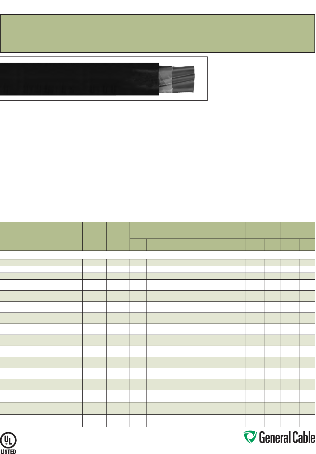
Phone: 888-593-3355
www.generalcable.com
SPEC 4550
March, 2012
CATALOG
NUMBER
NO. OF
COND.
COND.
SIZE
(AWG/
kcmil)
COND.
STRAND
GROUND
WIRE SIZE
(AWG)
MINIMUM AVG.
INSULATION
THICKNESS
MINIMUM AVG.
JACKET THICKNESS NOMINAL CABLE O.D.
COPPER
WEIGHT NET WEIGHT
INCHES mm INCHES mm INCHES mm
LBS/
1000 FT kg/km
LBS/
1000 FT kg/km
14 AWG - 750 kcmil MULTI-CONDUCTORS
383860* 314 7/.0242 14 0.030 0.76 0.045 1.14 0.390 9.91 53 79 116 173
383870* 312 7/.0305 12 0.030 0.76 0.045 1.14 0.435 11.05 86 128 157 234
383880* 310 7/.0385 10 0.030 0.76 0.060 1.52 0.485 12.32 135 200 236 351
783160 387/.0486 10 0.045 1.14 0.060 1.52 0.640 16.26 190 283 314 467
783190 487/.0486 10 0.045 1.14 0.060 1.52 0.705 17.91 242 360 385 573
339470 367/.0612 80.045 1.14 0.060 1.52 0.720 18.29 301 448 445 662
339480 467/.0612 80.045 1.14 0.060 1.52 0.790 20.07 384 571 558 830
783330 347/.0772 80.045 1.14 0.080 2.03 0.875 22.23 448 667 653 972
339500* 447/.0772 80.045 1.14 0.080 2.03 0.950 24.13 578 862 820 1220
325610 327/.0974 60.045 1.14 0.080 2.03 1.000 25.40 716 1066 964 1435
339520* 427/.0974 60.045 1.14 0.080 2.03 1.095 27.81 919 1368 1214 1807
352150* 3119/.0664 60.055 1.40 0.080 2.03 1.120 28.45 872 1298 1199 1784
371250* 4119/.0664 60.055 1.40 0.080 2.03 1.235 31.37 1136 1691 1704 2536
339530 31/0 19/.0745 60.055 1.40 0.080 2.03 1.215 30.86 1081 1609 1414 2104
339540* 41/0 19 /.0745 60.055 1.40 0.080 2.03 1.340 34.04 1413 2103 1825 2716
339550 32/0 19/.0837 60.055 1.40 0.080 2.03 1.310 33.27 1341 1996 1706 2539
339560* 42/0 19/.0837 60.055 1.40 0.080 2.03 1.450 36.83 1760 2619 2223 3308
371260* 33/0 19/.0940 40.055 1.40 0.080 2.03 1.420 36.07 1717 2555 2437 3627
371270* 43/0 19/.0940 40.055 1.40 0.080 2.03 1.570 39.88 2245 3341 3123 4648
783230 34/0 19/.1055 40.055 1.40 0.080 2.03 1.540 39.12 2132 3173 2600 3869
339570* 44/0 19/.1055 40.055 1.40 0.110 2.79 1.765 44.83 2796 4161 3444 5125
328540* 3250 37/.0822 40.065 1.65 0.110 2.79 1.750 44.45 2494 3712 3142 4676
339590* 4250 37/.0822 40.065 1.65 0.110 2.79 1.930 49.02 3282 4884 4048 6024
222570 3350 37/.0973 30.065 1.65 0.110 2.79 1.970 50.04 3474 5170 4230 6295
339600* 4350 37/.0973 30.065 1.65 0.110 2.79 2.180 55.37 4577 6811 5470 8140
222710 3500 37/.1162 20.065 1.65 0.110 2.79 2.250 57.15 4938 7349 5829 8675
06790.086500* 4500 37/.1162 20.065 1.65 0.110 2.79 2.475 62.87 6509 9687 7579 11279
06790.077000* 3750 61/.1109 10.080 2.03 0.140 3.56 2.810 71.37 7278 10831 9101 13544
06790.047000* 4750 61/.1109 10.080 2.03 0.140 3.56 3.115 79.12 9712 14453 11746 17480
Dimensions and weights are nominal; subject to industry tolerances.
* Non-stock item; minimum runs apply. Please consult Customer Service for price and delivery.
1 Approved as TYPE TC-ER for Exposed Run applications of 3 or more conductors as defined by NEC.
CVTC
®
XLPE/PVC, Low-Voltage Power, Unshielded
600 V, UL Type TC-ER
1
—Method 4 Color Code
Product Construction:
Conductor:
• 14 AWG thru 750 kcmil bare, annealed copper per
ASTM B3
• Class B stranding per ASTM B8
Insulation:
• Flame-retardant Cross-linked Polyethylene (XLPE)
• Color-coded per ICEA Method 4; individual
conductors colored black with conductor
number surface printed in contrasting ink
Ground:
• Uninsulated bare annealed copper
per ASTM B3
• Class B stranding per ASTM B8
Jacket:
• Lead-free, flame-retardant, sunlight-resistant
Polyvinyl Chloride (PVC)
Print:
• GENERAL CABLE® (PLANT OF MFG) CVTC®
XX/C XXAWG WITH GRND FR-XLP/PVC (UL)
Print (cont’d.):
TYPE TC-ER XHHW-2 CDRS 90˚C WET OR DRY
DIR BUR SUN RES 600 V DAY/MONTH/YEAR
SEQUENTIAL FOOTAGE MARK
Options:
• Tinned copper conductor
• Class C stranding
• E-1 or E-2 Color Code
• Insulated ground conductors
• Overall shielded multi-conductors
• Flame-retardant Ethylene Propylene Rubber (EPR)
insulation
• Low-lead Hypalon Chlorosulfonated Polyethylene
(CSPE)/Elastomer blend—see CHTC® Spec 4100
• ICEA 1000 V rated cable
• Other constructions available upon request
Applications:
• In free air, raceways or direct burial
• In wet or dry locations
• Permitted for use in Class I, Division 2 industrial
hazardous locations per NEC
• Permitted for Exposed Run (ER) use in
accordance with NEC
Features:
• Rated at 90
˚
C wet or dry
• Ripcord applied to all cables with jacket thickness
of 60 mils or less
• Abrasion- and chemical-resistant
• Excellent electrical properties
• Sunlight- and weather-resistant
• Meets cold bend test at -25
˚
C
• Meets the crush and impact requirements of
Type MC cable
Compliances:
Industry Compliances:
• UL 44 Type XHHW-2
• UL 1277 Type TC-ER, UL File # E57179
• UL 1581
• ICEA S-95-658/NEMA WC70
Flame Test Compliances:
• UL 1581/UL 2556 VW-1
• UL 1685 Vertical Flame Test
• IEEE 383
• IEEE 1202
• ICEA T-29-520 (210,000 BTU/hr)
• CSA FT4
Other Compliances:
• EPA 40 CFR, Part 261 for leachable lead
content per TCLP
• OSHA Acceptable
Packaging:
• Material cut to length and shipped on
non-returnable wood reels
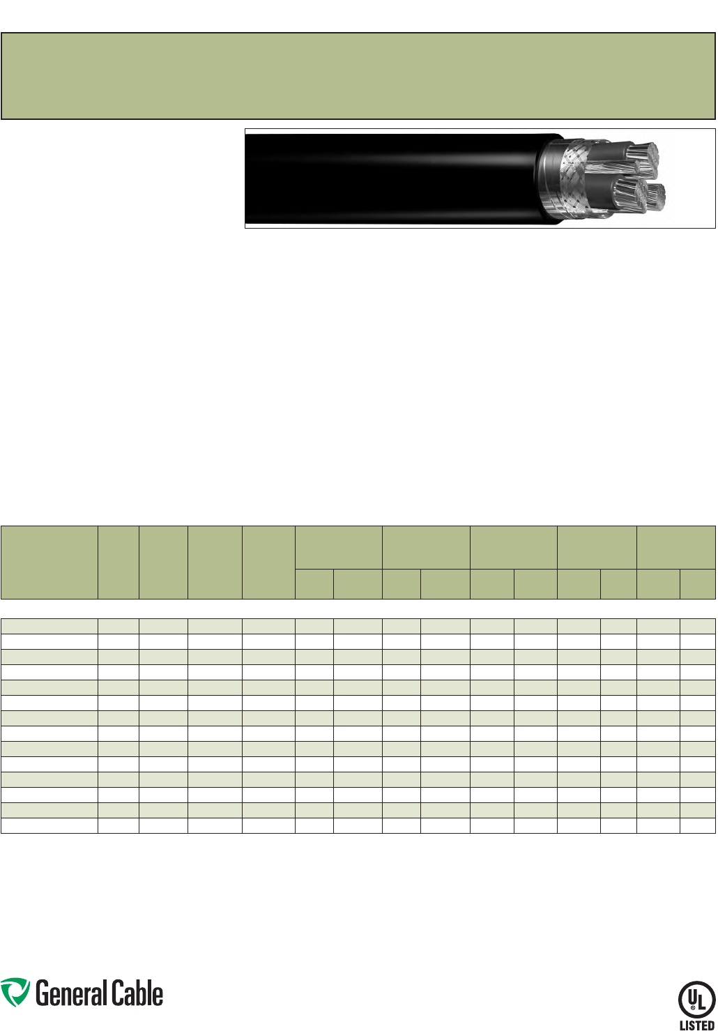
Phone: 888-593-3355
www.generalcable.com
SPEC 4575
March, 2012
CVTC
®
VFD
XLPE/PVC, Low-Voltage Power, Shielded
2000 V, UL Type TC-ER
1
—Method 4 Color Code
Product Construction:
Conductor:
• 14 AWG thru 500 kcmil fully annealed tinned
stranded copper
• Class B stranding per ASTM B8
Insulation:
• Flame-retardant Cross-linked Polyethylene
(XLPE)—90°C, VW-1
• Color-coded per ICEA Method 4; individual
conductors colored black with conductor
number surface printed in contrasting ink
Ground:
• 3 symmetrically placed annealed tinned copper
conductors in direct contact with shield
• Class B stranding per ASTM B8
Dual Shield:
• Overall tinned copper braided shield in
conjunction with an aluminum/polymer
tape shield
Jacket:
• Lead-free, flame-retardant, sunlight-resistant
Polyvinyl Chloride (PVC)
Print:
• GENERAL CABLE® (PLANT OF MFG) CVTC® VFD
XX/C XXAWG WITH GRND FR-XLP/PVC (UL)
TYPE TC-ER RHH or RHW-2 CDRS 90˚C WET OR
DRY 2000 V DIR BUR SUN RES DAY/MONTH/
YEAR SEQUENTIAL FOOTAGE MARK
Applications:
• For use with AC motors controlled by pulse-width
modulated inverter in VFD applications rated
up to 2000 volts. These motor drive systems
require cables that are designed to prevent radio
frequency interference (RFI) which can lead to
malfunction
• In raceways, cable trays or direct burial
• In wet or dry locations
• Permitted for use in Class I, Division 2 industrial
hazardous locations per NEC
• Permitted for Exposed Run (ER) use in
accordance with NEC
Features:
• Rated at 90˚C wet or dry
• Dual shield provides maximum shield coverage
required for Variable Frequency Drive (VFD)
applications
• Meets cold bend test at -25°C
• Meets crush and impact requirements to Type MC
cable
Features (cont’d.):
• Abrasion- and chemical-resistant
• Excellent electrical properties
• Sunlight- and weather-resistant
Compliances:
Industry Compliances:
• UL 1277 Type TC-ER, UL File # E57179
• UL Type RHH or RHW-2 conductors per UL 44
Flame Test Compliances:
• UL 1581/UL 2556 VW-1
• UL 1685 Vertical Flame Test
• IEEE 383
• IEEE 1202
• ICEA T-29-520 (210,000 BTU/hr)
Other Compliances:
• EPA 40 CFR, Part 261 for leachable lead
content per TCLP
• OSHA Acceptable
Packaging:
• Material cut to length and shipped on
non-returnable wood reels
CATALOG
NUMBER
NO. OF
COND.
COND.
SIZE
(AWG/
kcmil)
COND.
STRAND
GROUND
WIRE SIZE
(AWG)
MINIMUM AVG.
INSULATION
THICKNESS
MINIMUM AVG.
JACKET THICKNESS NOMINAL CABLE O.D.
COPPER
WEIGHT NET WEIGHT
INCHES mm INCHES mm INCHES mm
LBS/
1000 FT kg/km
LBS/
1000 FT kg/km
14 AWG - 500 kcmil MULTI-CONDUCTORS
384730* 314 7/.0242 3 x 18 0.060 1.52 0.060 1.52 0.565 14.35 79 118 190 283
384740* 312 7/.0305 3 x 16 0.060 1.52 0.060 1.52 0.605 15.37 114 170 236 351
384750* 310 7/.0385 3 x 14 0.060 1.52 0.060 1.52 0.665 16.89 172 256 313 466
384760* 387/.0486 3 x 14 0.070 1.78 0.060 1.52 0.785 19.94 234 348 420 625
384770* 367/.0612 3 x 12 0.070 1.78 0.080 2.03 0.910 23.11 354 527 605 900
384780* 347/.0772 3 x 12 0.070 1.78 0.080 2.03 1.010 25.65 507 755 800 1191
384790* 327/.0974 3 x 10 0.070 1.78 0.080 2.03 1.315 28.83 783 1165 1126 1676
384800* 31/0 19 /.0745 3 x 6 0.090 2.29 0.080 2.03 1.390 35.31 1251 1861 1832 2726
384810* 32/0 19/.0837 3 x 6 0.090 2.29 0.080 2.03 1.490 37.85 1511 2248 2134 3175
384820* 33/0 19/.0940 3 x 5 0.090 2.29 0.080 2.03 1.595 40.51 1897 2823 2553 3799
384830* 34/0 19/.1055 3 x 4 0.090 2.29 0.110 2.79 1.775 45.09 2355 3504 3254 4842
384840* 3250 37/.0822 3 x 4 0.105 2.67 0.110 2.79 1.940 49.28 2719 4046 3726 5544
384850* 3350 37/.0973 3 x 2 0.105 2.67 0.110 2.79 2.160 54.86 3883 5778 5040 7500
384860* 3500 37/.1162 3 x 1 0.105 2.67 0.110 2.79 2.440 61.98 5507 8194 6809 10132
Dimensions and weights are nominal; subject to industry tolerances.
* Non-stock item; minimum runs apply. Please consult Customer Service for price and delivery.
1 Approved as TYPE TC-ER for Exposed Run applications of 3 or more conductors as defined by NEC.
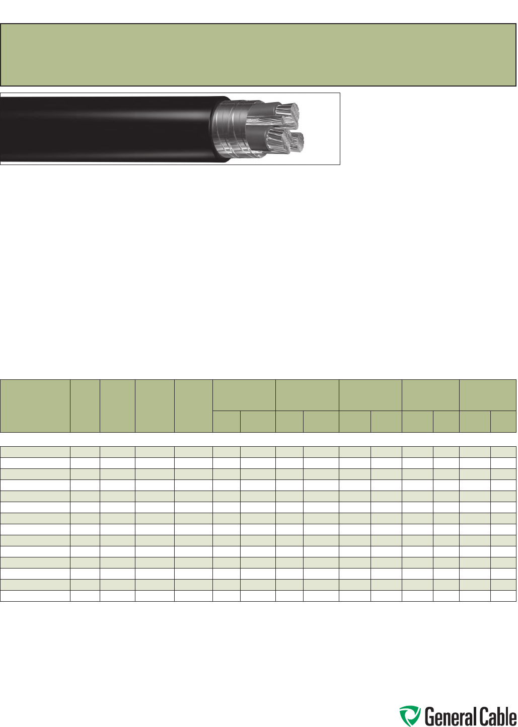
Phone: 888-593-3355
www.generalcable.com
SPEC 4580
March, 2012
CATALOG
NUMBER
NO. OF
COND.
COND.
SIZE
(AWG/
kcmil)
COND.
STRAND
GROUND
WIRE SIZE
(AWG)
MINIMUM AVG.
INSULATION
THICKNESS
MINIMUM AVG.
JACKET THICKNESS NOMINAL CABLE O.D.
COPPER
WEIGHT NET WEIGHT
INCHES mm INCHES mm INCHES mm
LBS/
1000 FT kg/km
LBS/
1000 FT kg/km
14 AWG - 500 kcmil MULTI-CONDUCTORS
395070V 314 7/.0242 3 x 18 0.060 1.52 0.060 1.52 0.580 14.73 91 135 212 315
395080V 312 7/.0305 3 x 16 0.060 1.52 0.060 1.52 0.615 15.37 127 189 260 387
395090V 310 7/.0385 3 x 14 0.060 1.52 0.060 1.52 0.670 17.02 183 272 329 490
395100V 387/.0486 3 x 14 0.070 1.78 0.060 1.52 0.770 19.56 246 366 441 656
395110V 367/.0612 3 x 12 0.070 1.78 0.080 2.03 0.895 22.73 368 548 618 920
395120V 347/.0772 3 x 12 0.070 1.78 0.080 2.03 0.995 25.27 522 777 830 1235
395130V 327/.0974 3 x 10 0.070 1.78 0.080 2.03 1.125 28.58 801 1192 1152 1714
395140V 31/0 19/.0745 3 x 6 0.090 2.29 0.080 2.03 1.385 35.18 1348 2006 1853 2757
395150V 32/0 19/.0837 3 x 6 0.090 2.29 0.080 2.03 1.480 37. 59 1616 2405 2169 3227
395160V* 33/0 19/.0940 3 x 5 0.090 2.29 0.080 2.03 1.590 40.39 2010 2991 2619 3897
395170V 34/0 19 /.1055 3 x 4 0.090 2.29 0.110 2.79 1.780 45.21 2517 3745 3241 4823
395180V* 3250 37/.0822 3 x 4 0.105 2.67 0.110 2.79 1.940 49.28 2895 4308 3763 5599
395190V 3350 37/.0973 3 x 2 0.105 2.67 0.110 2.79 2.160 54.86 4089 6084 5109 7602
395200V 3500 37/.1162 3 x 1 0.105 2.67 0.110 2.79 2.455 62.36 5693 8471 6933 10316
Dimensions and weights are nominal; subject to industry tolerances.
* Non-stock item; minimum runs apply. Please consult Customer Service for price and delivery.
1 Approved as TYPE TC-ER for Exposed Run applications of 3 or more conductors as defined by NEC.
Product Construction:
Conductor:
• 14 AWG thru 500 kcmil fully annealed bare
stranded copper
• Class B stranding per ASTM B8
Insulation:
• Flame-retardant Cross-linked Polyethylene
(XLPE)—90°C, VW-1
• Color-coded per ICEA Method 4; individual
conductors colored black with conductor
number surface printed in contrasting ink
Ground:
• 3 symmetrically placed annealed bare copper
conductors in direct contact with shield
• Class B stranding per ASTM B8
Metallic Shield:
• Overall 5 mil annealed bare copper tape shield
with 50% overlap
Jacket:
• Lead-free, flame-retardant, sunlight-resistant
Polyvinyl Chloride (PVC)
Print:
• GENERAL CABLE® (PLANT OF MFG) CVTC® VFD
XX/C XXAWG WITH GRNDS FR-XLP/PVC (UL)
TYPE TC-ER RHH or RHW-2 CDRS 90˚C WET OR
DRY 2000 V DIR BUR SUN RES DAY/MONTH/
YEAR SEQUENTIAL FOOTAGE MARK
Applications:
• For use with AC motors controlled by pulse-width
modulated inverter in VFD applications rated
up to 2000 volts. These motor drive systems
require cables that are designed to prevent radio
frequency interference (RFI) which can lead to
malfunction
• In raceways, cable trays or direct burial
• In wet or dry locations
• Permitted for use in Class I, Division 2 industrial
hazardous locations per NEC
• Permitted for Exposed Run (ER) use in
accordance with NEC
Features:
• Rated at 90˚C wet or dry
• Overlapped bare copper tape shield provides
necessary shield coverage required for Variable
Frequency Drive (VFD) applications
• Meets cold bend test at -25°C
• Meets crush and impact requirements for
Type MC cable
• Abrasion- and chemical-resistant
• Excellent electrical properties
• Sunlight- and weather-resistant
Compliances:
Industry Compliances:
• UL 1277 Type TC-ER, 2000 V, UL File # E57179
• UL Type RHH or RHW-2 conductors per UL 44
Flame Test Compliances:
• UL 1581/UL 2556 VW-1
• UL 1685 Vertical Flame Test
• IEEE 383
• IEEE 1202
• ICEA T-29-520 (210,000 BTU/hr)
Other Compliances:
• EPA 40 CFR, Part 261 for leachable lead
content per TCLP
• OSHA Acceptable
Packaging:
• Material cut to length and shipped on
non-returnable wood reels
CVTC
®
VFD
XLPE/PVC, Low-Voltage Power, Copper Tape Shielded
2000 V, UL Type TC-ER
1
—Method 4 Color Code
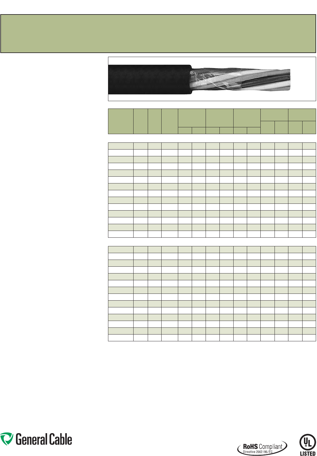
Phone: 888-593-3355
www.generalcable.com
SPEC 4600
March, 2012
Product Construction:
Conductor:
• 18 AWG and 16 AWG fully annealed stranded bare
copper to ASTM B3
• Class B stranding per ASTM B8
Insulation:
• Flame-retardant Polyvinyl Chloride (PVC) with
clear Polyamide (nylon)
• Color-coded per ICEA Method 1, Table E-2 plus
alpha-numeric printed numbers (does not include
white or green)
Jacket:
• Lead-free, flame-retardant, sunlight-resistant
Polyvinyl Chloride (PVC)
Print
• GENERAL CABLE® (PLANT OF MFG) VNTC®
XX/C XXAWG (UL) TYPE TC-ER TFN SUN RES
DIR BUR 600 V ROHS DAY/MONTH/YEAR OF
MFG SEQUENTIAL FOOTAGE MARK
Options:
• Tinned copper conductor
• Class C stranding
• E-1 Color Code
• Overall shielded multi-conductors
• Other constructions available upon request
Applications:
• In free air, raceways or direct burial
• In wet or dry locations
• Approved for direct burial
• Class I, Division 2 industrial hazardous locations
per NEC
• Permitted for Exposed Run (ER) use in
accordance with NEC for 3 or more conductors
Features:
• Rated at 90˚C dry, 75˚C wet
• Ripcord applied to all cables with jacket thickness
of 60 mils or less
• Provides outstanding sunlight, cold bend and cold
impact resistance
• Offers the smallest cable O.D. available for
suitable applications
• Provides long service life
• Provides good oil and chemical resistance
• Meets cold bend test at -25˚C
• Meets the crush and impact requirements of Type
MC cable
Compliances:
Industry Compliances:
• UL 66 NEC Type TFN conductors
• UL 1277 Type TC-ER for 3 or more conductors,
UL File # E57179
• UL 1581
• ICEA S-73-532/NEMA WC57
Flame Test Compliances:
• UL 1685 Vertical Flame Test
• IEEE 383
• IEEE 1202
• CSA FT4
Other Compliances:
• EPA 40 CFR, Part 261 for leachable lead
content per TCLP
• OSHA Acceptable
• RoHS Compliant
Packaging:
• Material cut to length and shipped on
non-returnable wood reels
VNTC
®
PVC/Nylon/PVC, Control, Unshielded
600 V, UL Type TC-ER
1
(18 AWG/16 AWG)—E-2 Color Code
CATALOG
NUMBER
NO.
OF
COND.
COND.
SIZE
(AWG)
COND.
STRAND
MINIMUM AVG.
INSULATION
THICKNESS
MINIMUM AVG.
JACKET
THICKNESS
NOMINAL
CABLE O.D.
COPPER
WEIGHT NET WEIGHT
LBS/
1000 FT kg/km
LBS/
1000 FT kg/km
INCHES mm INCHES mm INCHES mm
18 AWG MULTI-CONDUCTORS
236090 2 Flat 18 7/.0152 0.020 0.51 0.045 1.14
.190 x .285
4.80 x 7. 20
10 15 36 54
318050* 218 7/.0152 0.020 0.51 0.045 1.14 0.270 6.86 11 19 38 57
245920 318 7/.0152 0.020 0.51 0.045 1.14 0.285 7. 24 15 23 46 68
236100 418 7/.0152 0.020 0.51 0.045 1.14 0.310
7.87
20 30 56 83
244680 518 7/.0152 0.020 0.51 0.045 1.14 0.335 8.51 26 38 65 97
244660 718 7/.0152 0.020 0.51 0.045 1.14 0.360 9.14 36 53 82 122
264570* 918 7/.0152 0.020 0.51 0.045 1.14 0.420 10.67 46 69 105 156
233270* 10 18 7/.0152 0.020 0.51 0.045 1.14 0.425 10.80 51 76 114 170
236120 12 18 7/.0152 0.020 0.51 0.045 1.14 0.445 11.30 61 91 131 195
244720* 15 18 7/.0152 0.020 0.51 0.045 1.14 0.485 12.32 77 114 162 241
236130 19 18 7/.0152 0.020 0.51 0.060 1.52 0.570 14.48 97 144 209 311
236140* 25 18 7/.0152 0.020 0.51 0.060 1.52 0.655 16.64 128 190 266 396
347140* 30 18 7/.0152 0.020 0.51 0.060 1.52 0.695 17.6 5 154 229 310 461
236150 37 18 7/.0152 0.020 0.51 0.060 1.52 0.745 18.92 189 281 371 552
16 AWG MULTI-CONDUCTORS
236160 2 Flat 16 7/.0192 0.020 0.51 0.045 1.14
.200 x .310
5.08 x 7.87
16 24 42 71
245580 216 7/.0192 0.020 0.51 0.045 1.14 0.300 7.62 20 29 50 74
236170 316 7/.0192 0.020 0.51 0.045 1.14 0.315 8.00 24 36 60 89
236180 416 7/.0192 0.020 0.51 0.045 1.14 0.340 8.64 32 48 74 110
236190 516 7/.0192 0.020 0.51 0.045 1.14 0.370 9.40 40 60 97 144
236210 716 7/.0192 0.020 0.51 0.045 1.14 0.400 10.16 56 84 111 165
243640 916 7/.0192 0.020 0.51 0.045 1.14 0.460 11.68 72 108 141 210
236230* 10 16 7/.0192 0.020 0.51 0.045 1.14 0.495 12.57 80 119 154 229
236240 12 16 7/.0192 0.020 0.51 0.045 1.14 0.505 12.83 97 144 178 265
244650* 15 16 7/.0192 0.020 0.51 0.060 1.52 0.605 15.37 121 180 239 356
236260 19 16 7/.0192 0.020 0.51 0.060 1.52 0.635 16.13 153 228 284 423
236280 25 16 7/.0192 0.020 0.51 0.060 1.52 0.705 17.91 201 299 364 542
244670* 30 16 7/.0192 0.020 0.51 0.060 1.52 0.760 19.30 242 360 426 634
236290* 37 16 7/.0192 0.020 0.51 0.080 2.03 0.880 22.35 306 455 552 821
Dimensions and weights are nominal; subject to industry tolerances.
* Non-stock item; minimum runs apply. Please consult Customer Service for price and delivery.
1 Approved as TYPE TC-ER for Exposed Run applications of 3 or more conductors as defined by NEC.
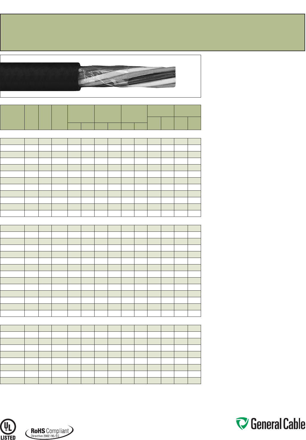
Phone: 888-593-3355
www.generalcable.com
Product Construction:
Conductor:
• 14 AWG thru 10 AWG fully annealed stranded bare
copper per ASTM B3
• Class B stranding per ASTM B8
Insulation:
• Flame-retardant Polyvinyl Chloride (PVC) with
clear Polyamide (nylon)
• Color-coded per ICEA Method 1, Table E-2 plus
alpha-numeric printed numbers (does not include
white or green)
Jacket:
• Lead-free, flame-retardant, sunlight-resistant
Polyvinyl Chloride (PVC)
Print
• GENERAL CABLE® (PLANT OF MFG) VNTC®
XX/C XXAWG (UL) TYPE TC-ER THHN/THWN
SUN RES DIR BUR 600 V ROHS DAY/MONTH/
YEAR OF MFG SEQUENTIAL FOOTAGE MARK
Options:
• Tinned copper conductor
• Class C stranding
• E-1 Color Code
• Overall shielded multi-conductors
• Other constructions available upon request
Applications:
• In free air, raceways and direct burial
• In wet or dry locations
• Approved for direct burial
• Class I, Division 2 industrial hazardous locations
per NEC
• Permitted for Exposed Run (ER) use in
accordance with NEC for 3 or more conductors
Features:
• Rated at 90˚C dry, 75˚C wet
• Ripcord applied to all cables with jacket thickness
of 60 mils or less
• Provides outstanding sunlight, cold bend and cold
impact resistance
• Offers the smallest cable O.D. available for
suitable applications
• Provides long service life
• Provides good oil and chemical resistance
• Meets cold bend test at -25˚C
• Meets the crush and impact requirements of
Type MC cable
Compliances:
Industry Compliances:
• UL 83 NEC Type THHN/THWN conductors
• UL 1277 Type TC-ER for 3 or more conductors,
UL File # E57179
• UL 1581
• ICEA S-73-532/NEMA WC57
Flame Test Compliances:
• UL 1685 Vertical Flame Test
• IEEE 383
• IEEE 1202
• CSA FT4
Other Compliances:
• EPA 40 CFR, Part 261 for leachable lead
content per TCLP
• OSHA Acceptable
• RoHS Compliant
Packaging:
• Material cut to length and shipped on
non-returnable wood reels
SPEC 4650
March, 2012
VNTC
®
PVC/Nylon/PVC, Control, Unshielded
600 V, UL Type TC-ER
1
(14 AWG—10 AWG)—E-2 Color Code
CATALOG
NUMBER
NO.
OF
COND.
COND.
SIZE
(AWG)
COND.
STRAND
MINIMUM AVG.
INSULATION
THICKNESS
MINIMUM AVG.
JACKET
THICKNESS
NOMINAL
CABLE O.D.
COPPER
WEIGHT NET WEIGHT
LBS/
1000 FT kg/km
LBS/
1000 FT kg/kmINCHES mm INCHES mm INCHES mm
14 AWG MULTI-CONDUCTORS
235040 2 Flat 14 7/.0242 0.020 0.51 0.045 1.14
.210 x .320
5.33 x 8.13
25 37 54 80
245590* 214 7/.0242 0.020 0.51 0.045 1.14 0.320 8.13 26 39 64 95
235050 314 7/.0242 0.020 0.51 0.045 1.14 0.345 8.76 39 58 80 119
235060 414 7/.0242 0.020 0.51 0.045 1.14 0.365
9.27
52 77 100 149
235070 514 7/.0242 0.020 0.51 0.045 1.14 0.410 10.41 65 97 118 176
235080 714 7/.0242 0.020 0.51 0.045 1.14 0.445 11.30 90 134 153 228
235090 914 7/.0242 0.020 0.51 0.060 1.52 0.505 12.83 116 173 213 317
235110 12 14 7/.0242 0.020 0.51 0.060 1.52 0.595 15.11 155 231 267 397
235130 19 14 7/.0242 0.020 0.51 0.060 1.52 0.695 17.65 245 365 396 589
235150 25 14 7/.0242 0.020 0.51 0.060 1.52 0.785 19.94 323 481 507 755
235160* 30 14 7/.0242 0.020 0.51 0.080 2.03 0.895 22.73 387 576 637 948
235170 37 14 7/.0242 0.020 0.51 0.080 2.03 0.970 24.64 478 711 766 1140
12 AWG MULTI-CONDUCTORS
234580 2 Flat 12 7/.0305 0.020 0.51 0.045 1.14
.225 x .360
5.72 x 9.14
40 60 74 110
260150* 212 7/.0305 0.020 0.51 0.045 1.14 0.355 9.02 41 61 85 127
234590 312 7/.0305 0.020 0.51 0.045 1.14 0.385 9.78 62 92 131 195
255090
3+Grnd
12 7/.0305 0.020 0.51 0.045 1.14 0.385 9.78 83 124 131 195
277460²312 7/.0305 0.020 0.51 0.045 1.14 0.385 9.78 62 92 131 195
234600 412 7/.0305 0.020 0.51 0.045 1.14 0.420 10.67 83 124 138 205
226420 512 7/.0305 0.020 0.51 0.045 1.14 0.445 11.30 108 160 165 246
234620 712 7/.0305 0.020 0.51 0.045 1.14 0.490 12.45 144 214 217 323
226500 912 7/.0305 0.020 0.51 0.060 1.52 0.605 15.37 185 275 297 442
234640 12 12 7/.0305 0.020 0.51 0.060 1.52 0.675 17.15 247 368 377 561
243600 19 12 7/.0305 0.020 0.51 0.060 1.52 0.785 19.94 391 582 568 845
243610* 25 12 7/.0305 0.020 0.51 0.080 2.03 0.940 23.88 515 767 775 1153
321720* 30 12 7/.0305 0.020 0.51 0.080 2.03 1.030 26.16 618 920 919 1368
234680* 37 12 7/.0035 0.020 0.51 0.080 2.03 1.105 28.07 762 1134 1100 1637
10 AWG MULTI-CONDUCTORS
236300 2 Flat 10 7/.0385 0.026 0.66 0.045 1.14
.260 x .425
6.60 x 10.80
64 95 108 161
243630* 210 7/.0385 0.026 0.66 0.045 1.14 0.420 10.67 65 97 115 171
236310 310 7/.0385 0.026 0.66 0.045 1.14 0.450 11.43 131 195 191 284
255080
3+Grnd
10 7/.0385 0.026 0.66 0.045 1.14 0.450 11.43 131 195 191 284
236320 410 7/.0385 0.026 0.66 0.045 1.14 0.505 12.83 135 200 209 311
236330 510 7/.0385 0.026 0.66 0.060 1.52 0.570 14.48 169 252 268 399
236340 710 7/.0385 0.026 0.66 0.060 1.52 0.620 15.75 236 351 350 521
243620* 910 7/.0385 0.026 0.66 0.060 1.52 0.725 18.42 295 440 440 655
236350 12 10 7/.0385 0.026 0.66 0.060 1.52 0.815 20.70 404 602 584 869
Dimensions and weights are nominal; subject to industry tolerances.
* Non-stock item; minimum runs apply. Please consult Customer Service for price and delivery.
¹ Approved as TYPE TC-ER for Exposed Run applications of 3 or more conductors as defined by NEC.
² Color Code: black, white, green
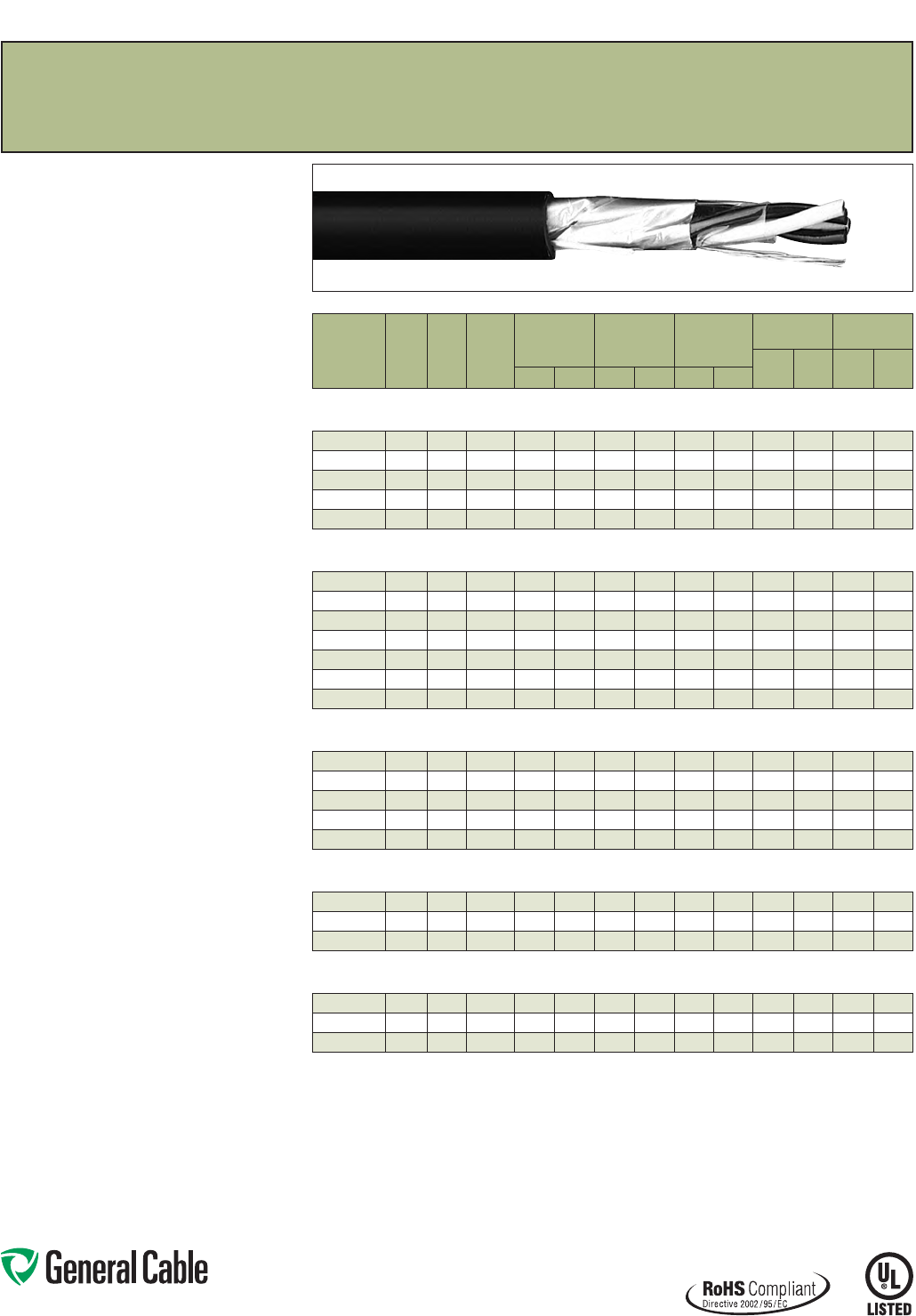
Phone: 888-593-3355
www.generalcable.com
SPEC 4700
March, 2012
Product Construction:
Conductor:
• 18 AWG thru 10 AWG fully annealed stranded bare
copper per ASTM B3
• Class B stranding per ASTM B8
Insulation:
• Flame-retardant Polyvinyl Chloride (PVC) with
clear Polyamide (nylon)
• Color-coded per ICEA Method 1, Table E-2 plus
alpha-numeric printed numbers (does not include
white or green)
Shield:
Overall shielded multi-conductor
• Overall shield is Flexfoil® aluminum/polymer,
in contact with stranded tinned copper drain wire
Jacket:
• Lead-free, flame-retardant, sunlight-resistant
Polyvinyl Chloride (PVC)
Print
• GENERAL CABLE® (PLANT OF MFG) SHIELDED
VNTC® XX/C XX AWG (UL) TYPE TC-ER TFN OR
THHN/THWN SUN RES DIR BUR 600 V ROHS
DAY/MONTH/YEAR OF MFG SEQUENTIAL
FOOTAGE MARK
Options:
• Tinned copper conductor
• Class C stranding
• E-1 Color Code
• Unshielded multi-conductors
• Other constructions available upon request
Applications:
• In free air, raceways and direct burial
• In wet or dry locations
• Approved for direct burial
• Class I, Division 2 industrial hazardous locations
per NEC
• Permitted for Exposed Run (ER) use in
accordance with NEC for 3 or more conductors
Features:
• Rated at 90˚C dry, 75˚C wet
• Ripcord applied to all cables with jacket thickness
of 60 mils or less
• Provides outstanding sunlight, cold bend and cold
impact resistance
• Offers the smallest cable O.D. available for
suitable applications
• Provides long service life
• Provides good oil and chemical resistance
• Meets cold bend test at -25˚C
• Meets the crush and impact requirements of
Type MC cable
Compliances:
Industry Compliances:
• UL 1277 Type TC-ER for 3 or more conductors,
UL File # E57179
• UL 1581
• UL 66 NEC Type TFN conductors
(16 & 18 AWG)
• UL 83 NEC Type THHN/THWN conductors
(14 through 10 AWG)
• ICEA S-73-532/NEMA WC57
Flame Test Compliances:
• UL 1685 Vertical Flame Test
• IEEE 383
• IEEE 1202
• CSA FT4
Other Compliances:
• EPA 40 CFR, Part 261 for leachable lead
content per TCLP
• OSHA Acceptable
• RoHS Compliant
Packaging:
• Material cut to length and shipped on
non-returnable wood reels
VNTC
®
PVC/Nylon/PVC, Control, Shielded
600 V, UL Type TC-ER
1
, Overall Shielded—E-2 Color Code
CATALOG
NUMBER
NO.
OF
COND.
COND.
SIZE
(AWG)
COND.
STRAND
MINIMUM AVG.
INSULATION
THICKNESS
MINIMUM AVG.
JACKET
THICKNESS
NOMINAL
CABLE O.D.
COPPER
WEIGHT NET WEIGHT
LBS/
1000 FT kg/km
LBS/
1000 FT kg/kmINCHES mm INCHES mm INCHES mm
OVERALL SHIELDED MULTI-CONDUCTORS
18 AWG CONDUCTORS
261130 218 7/.0152 0.020 0.51 0.045 1.14 0.280 7.11 12 19 40 60
261140 318 7/.0152 0.020 0.51 0.045 1.14 0.290 7.37 18 26 49 73
261150 418 7/.0152 0.020 0.51 0.045 1.14 0.310 7.87 23 34 58 86
260000* 518 7/.0152 0.020 0.51 0.045 1.14 0.340 8.64 28 41 70 104
259980* 718 7/.0152 0.020 0.51 0.045 1.14 0.370 9.40 39 58 89 132
OVERALL SHIELDED MULTI-CONDUCTORS
16 AWG CONDUCTORS
247620 216 7/.0192 0.020 0.51 0.045 1.14 0.300
7.62
20 29 52 77
26116 0 316 7/.0192 0.020 0.51 0.045 1.14 0.320 8.13 28 41 63 94
243710 416 7/.0192 0.020 0.51 0.045 1.14 0.350 8.89 36 53 77 115
266580* 516 7/.0192 0.020 0.51 0.045 1.14 0.370 9.40 44 65 91 135
243740* 716 7/.0192 0.020 0.51 0.045 1.14 0.410 10.41 60 89 119 177
243560* 916 7/.0192 0.020 0.51 0.045 1.14 0.470 11.97 76 113 150 223
229600* 12 16 7/.0192 0.020 0.51 0.045 1.14 0.510 12.95 100 149 185 275
OVERALL SHIELDED MULTI-CONDUCTORS
14 AWG CONDUCTORS
243660 214 7/.0242 0.020 0.51 0.045 1.14 0.330 8.38 31 46 67 100
243720 314 7/.0242 0.020 0.51 0.045 1.14 0.350 8.89 44 65 84 125
243650 414 7/.0242 0.020 0.51 0.045 1.14 0.380 9.65 57 85 104 155
243570* 514 7/.0242 0.020 0.51 0.045 1.14 0.400 10.16 70 104 123 183
243580 714 7/.0242 0.020 0.51 0.045 1.14 0.440 11.18 96 142 161 240
OVERALL SHIELDED MULTI-CONDUCTORS
12 AWG CONDUCTORS
243670 212 7/.0305 0.020 0.51 0.045 1.14 0.370 9.40 43 64 83 124
243810* 312 7/.0305 0.020 0.51 0.045 1.14 0.390 9.91 64 95 111 165
243840 412 7/.0305 0.020 0.51 0.045 1.14 0.420 10.67 85 126 139 207
OVERALL SHIELDED MULTI-CONDUCTORS
10 AWG CONDUCTORS
243770* 210 7/.0385 0.026 0.66 0.045 1.14 0.430 10.92 68 101 119 177
243820* 310 7/.0385 0.026 0.66 0.045 1.14 0.460 11.68 101 150 162 241
243690* 410 7/.0385 0.026 0.66 0.045 1.14 0.500 12.70 133 198 205 305
Dimensions and weights are nominal; subject to industry tolerances.
* Non-stock item; minimum runs apply. Please consult Customer Service for price and delivery.
¹ Approved as TYPE TC-ER for Exposed Run applications of 3 or more conductors as defined by NEC.
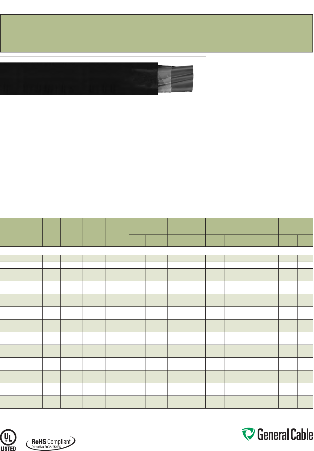
Phone: 888-593-3355
www.generalcable.com
SPEC 4750
March, 2012
CATALOG
NUMBER
NO. OF
COND.
COND.
SIZE
(AWG/
kcmil)
COND.
STRAND
GROUND
WIRE SIZE
(AWG)
MINIMUM AVG.
INSULATION
THICKNESS
MINIMUM AVG.
JACKET THICKNESS NOMINAL CABLE O.D.
COPPER
WEIGHT NET WEIGHT
INCHES mm INCHES mm INCHES mm
LBS/
1000 FT kg/km
LBS/
1000 FT kg/km
14 AWG - 500 kcmil MULTI-CONDUCTORS
383890* 314 7/.0242 14 0.020 0.51 0.045 1.14 0.345 8.76 52 77 100 149
234250 312 7/.0305 12 0.020 0.51 0.045 1.14 0.385 9.78 86 128 138 205
234260 310 7/.0385 10 0.020 0.51 0.045 1.14 0.450 11.43 135 200 209 311
386700** 310 7/.0385 10 0.020 0.51 0.045 1.14 0.450 11.43 135 200 209 311
236370 387/.0486 10 0.036 0.91 0.060 1.52 0.600 15.24 189 281 308 458
236380 487/.0486 10 0.036 0.91 0.060 1.52 0.655 16.64 241 359 373 555
226410 367/.0612 80.036 0.91 0.060 1.52 0.690 17.53 300 446 434 646
231980 467/.0612 80.036 0.91 0.060 1.52 0.760 19.30 383 570 533 793
236400 347/.0772 80.048 1.22 0.080 2.03 0.875 22.28 446 664 650 967
236410* 447/.0772 80.048 1.22 0.080 2.03 0.970 24.64 578 860 824 1226
236420 327/.0974 60.048 1.22 0.080 2.03 1.000 25.40 710 1057 964 1435
236430* 427/.0974 60.048 1.22 0.080 2.03 1.100 27.94 919 1368 1227 1826
236440 31/0 19/.0745 60.059 1.50 0.080 2.03 1.225 31.12 1080 1607 1447 2153
219580* 41/0 19/.0745 60.059 1.50 0.080 2.03 1.360 34.54 1413 2103 1830 2723
243760 32/0 19/.0837 60.059 1.50 0.080 2.03 1.320 33.53 1340 1994 1754 2610
219610* 42/0 19/.0837 60.059 1.50 0.080 2.03 1.455 36.96 1760 2619 2252 3351
221560 34/0 19/.1055 40.059 1.50 0.080 2.03 1.545 39.24 2130 3170 2630 3914
329240* 44/0 19 /.1055 40.059 1.50 0.110 2.79 1.770 44.96 2796 4161 3502 5212
222490 3250 37/.0822 40.070 1.78 0.110 2.79 1.740 44.20 2494 3696 3177 4728
297050* 4250 37/.0822 40.070 1.78 0.110 2.79 1.945 49.40 3281 4883 4107 6112
226430 3350 37/.0973 30.070 1.78 0.110 2.79 1.990 50.55 3474 5170 4263 6344
297060* 4350 37/.0973 30.070 1.78 0.110 2.79 2.190 55.63 4586 6825 5585 8312
219630 3500 37/.1162 20.070 1.78 0.110 2.79 2.270 57.66 4934 7343 5890 8765
222510* 4500 37/.1162 20.070 1.78 0.110 2.79 2.505 63.63 6509 9687 7694 11450
Dimensions and weights are nominal; subject to industry tolerances.
* Non-stock item; minimum runs apply. Please consult Customer Service for price and delivery.
** E-2 Color Code.
¹ Approved as TYPE TC-ER for Exposed Run applications as defined by NEC.
VNTC
®
PVC/Nylon/PVC, Low-Voltage Power, Unshielded
600 V, UL Type TC-ER
1
— Method 4 Color Code
Print:
• GENERAL CABLE® (PLANT OF MFG) VNTC®
XX/C XXAWG WITH GRND (UL) TYPE TC-ER
THHN/THWN CDRS DIR BUR SUN RES 600 V
ROHS DAY/MONTH/YEAR OF MFG SEQUENTIAL
FOOTAGE MARK
Options:
• Tinned copper conductor
• Class C stranding
• Insulated ground conductors
• 5 mil bare copper tape shield with 25% overlap
• Other constructions available upon request
Applications:
• In free air, raceways or direct burial
• In wet or dry locations
• Permitted for use in Class I, Division 2 industrial
hazardous locations per NEC
• Permitted for Exposed Run (ER) use in
accordance with NEC
Features:
• Rated at 90˚C dry, 75˚C wet
• Ripcord applied to all cables with jacket thickness
of 60 mils or less
• Provide outstanding sunlight, cold bend and cold
impact resistance
• Offer the smallest cable O.D. available for suitable
applications
• Provide good oil and chemical resistance
• Provides a long service life
• Meets cold bend test at -25˚C
• Meets the crush and impact requirements of
Type MC cable
Compliances:
Industry Compliances:
• NEC Type THHN/THWN conductors
• UL 1277 Type TC-ER, UL File # E57179
• UL 1581
• ICEA S-95-658/NEMA WC70
Flame Test Compliances:
• UL 1685 Vertical Flame Test
• IEEE 383
• IEEE 1202
• CSA FT4
Other Compliances:
• EPA 40 CFR, Part 261 for leachable lead
content per TCLP
• OSHA Acceptable
• RoHS Compliant
Packaging:
• Material cut to length and shipped on
non-returnable wood reels
Product Construction:
Conductor:
• 14 AWG thru 500 kcmil bare, annealed
copper per ASTM B3
• Class B stranding per ASTM B8
Insulation:
• Flame-retardant Polyvinyl Chloride (PVC) with
clear Polymide (nylon)
• Color-coded per ICEA Method 4; individual
conductors colored black with conductor number
surface printed in contrasting ink
Ground:
• Uninsulated bare annealed copper per ASTM B3
• Class B stranding per ASTM B8
Jacket:
• Lead-free, flame-retardant, sunlight-resistant
Polyvinyl Chloride (PVC)
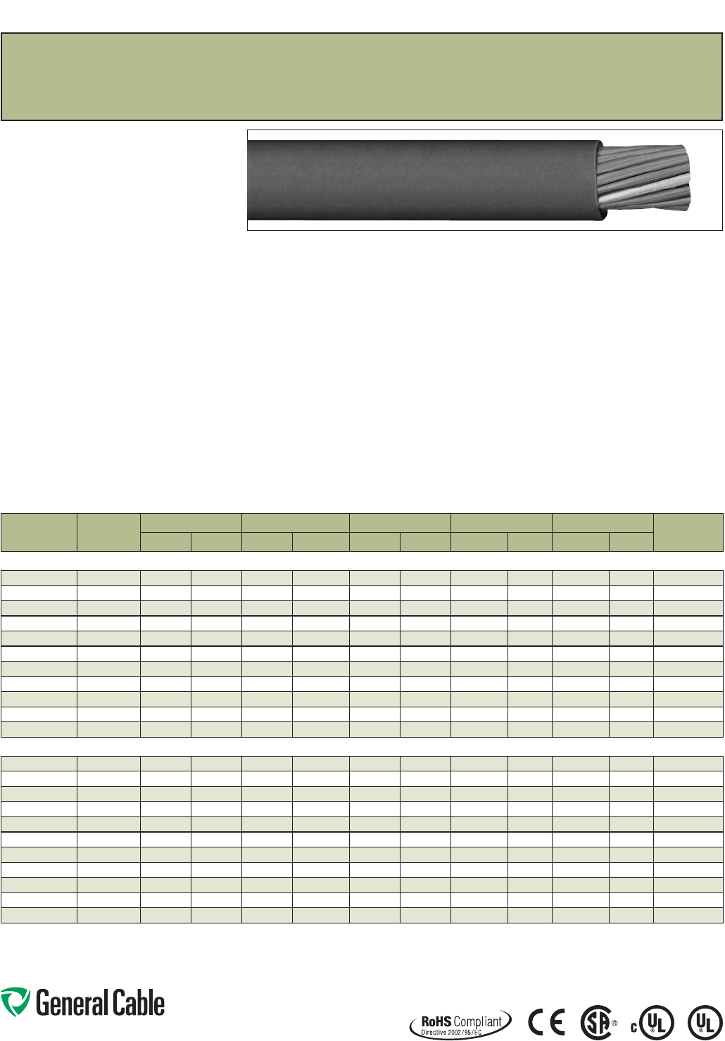
Phone: 888-593-3355
www.generalcable.com
TC-Flex™ Tray Cable
18 AWG (1,0 mm
²
) — 16 AWG (1,5 mm
²
)
UL Type WTTC 1000 V or Type TC-ER 600 V or Type MTW and c(UL) CIC/TC 600 V FT4 or CSA AWM
90°C 1000 V, Flexible, Oil Res I/II, Sunlight- and Torsion-Resistant, Flame-Retardant, -40˚C to +90˚C
SPEC 4775
November, 2013
Product Construction:
Conductors:
• 18 AWG (1,0 mm²) and 16 AWG (1,5 mm²) fully
annealed flexible stranded bare copper with
Class 5 stranding per EN 60228 (IEC 60228)
Insulation:
• Polyvinyl Chloride (PVC) insulation with a clear
Polyamide (nylon) jacket per UL 83
Conductor Identification:
• Conductors are black with printed numbers and
green/yellow grounding conductor
Cable Assembly:
• Conductors cabled with non-hygroscopic fillers
to make the cable suitably round
Jacket:
• Black, flexible, flame-retardant, sunlight- and oil-
resistant Polyvinyl Chloride (PVC) jacket
Print:
• GENERAL CABLE® TC-FLEX™ XX/C XXAWG
(XXMM2) (UL) TC-ER TYPE TFFN 90˚C DRY
600 V SUN RES DIR BUR OIL RES I/II OR MTW
OR WTTC 1000 V 90˚C DRY c(UL) CIC/TC PVC/N
90˚C FT4 --- CSA AWM I/II A/B 90˚C 1000 V
– ROHS CE – MADE IN USA DAY/MONTH/YEAR
OF MFG SEQUENTIAL FOOTAGE MARKER
Minimum Bending Radius:
• 4x O.D. for fixed installation
• 8x O.D. for flexing applications
Torsion:
• 10,000 cycles at -40°C, +/- 150° twist per meter,
cable weight compensated to 20 meters
Applications:
• In free air, raceways or direct burial
• (UL) WTTC cables for use up to 1000 V in wind
turbine generator applications in accordance with
UL Subject 6140
• (UL) TC-ER cables for use up to 600 V as power
and control cables in accordance with NEC®
Article 336
• (UL) MTW cables for machine tool and wire up to
600 V as power and control cables in accordance
with UL 1063
• (CSA) CIC/TC cables for use up to 600 V in cable
trays and other applications when installed in
accordance with the Canadian Electrical Code,
Part I
• (CSA) AWM cables for use up to 1000 V as
equipment wiring in accordance with the
Canadian Electrical Code, Part I
Specifications:
Design Adherence:
• UL 66 & UL 83/CSA C22.2 No. 75-08
Thermoplastic Insulated Wires
• UL 1063/MTW Machine Tool Wire
• UL 1277 Power and Control Tray Cables
• UL 2277 Wind Turbine Tray Cables
• CSA C22.2 No. 230-09 Tray Cables
• CSA C22.2 No. 239-09 Control and
Instrumentation Cables
• CSA C22.2 No. 210-11 Appliance Wiring
Material Products
Flame Tests:
• IEEE 1202/CSA FT4
Compliances:
• Type TC-ER 90°C Dry, 75°C Wet, 600 V
• Type MTW
• Type WTTC 90°C, 1000 V
• Type CIC/TC 90°C, 600 V
• Type AWM I/II A/B, 90°C, 1000 V FT4
• RoHS Compliant
CATALOG
NUMBER
NO. OF COND.
INC. GRND.
NOM. INS. THICKNESS NOM. JACKET THICKNESS NOM. CABLE O.D. NOM. COPPER WEIGHT NOM. CABLE WEIGHT 90°C AMP. @
30°C AMBIENT¹INCHES mm INCHES mm INCHES mm LBS/1000 FT kg/km LBS/1000 FT kg/km
18 AWG (1,0 mm²) 19 Strands
4775.03018
3 0.021 0.53 0.048 1.22 0.313 7.9 18 26 50 74 8
4775.04018
40.021 0.53 0.048 1.22 0.338 8.6 23 35 61 90 8
4775.05018
50.021 0.53 0.048 1.22 0.363 9.2 29 43 72 107 8
4775.07018
7 0.021 0.53 0.048 1.22 0.409 10.4 41 61 93 138 8
4775.09018*
90.021 0.53 0.048 1.22 0.448 11.4 53 78 114 169 7
4775.12018
12 0.021 0.53 0.048 1.22 0.497 12.6 70 104 144 214 7
4775.16018
16 0.021 0.53 0.063 1.60 0.578 14.7 94 139 197 294 6
4775.19018
19 0.021 0.53 0.063 1.60 0.623 15.8 111 165 229 340 6
4775.25018*
25 0.021 0.53 0.063 1.60 0.697 17.7 146 217 289 429 6
4775.30018*
30 0.021 0.53 0.063 1.60 0.735 18.7 175 261 336 500 5
4775.37018*
37 0.021 0.53 0.063 1.60 0.789 20.0 216 322 402 598 5
16 AWG (1,5 mm²) 28 Strands
4775.03016
3 0.021 0.53 0.048 1.22 0.339 8.6 26 39 63 93 10
4775.04016
40.021 0.53 0.048 1.22 0.367 9.3 35 52 77 115 10
4775.05016
50.021 0.53 0.048 1.22 0.396 10.1 44 66 92 137 10
4775.07016
7 0.021 0.53 0.048 1.22 0.448 11.4 62 92 121 179 10
4775.09016*
90.021 0.53 0.048 1.22 0.491 12.5 79 118 149 221 9
4775.12016
12 0.021 0.53 0.063 1.60 0.577 14.6 106 157 204 304 9
4775.16016
16 0.021 0.53 0.063 1.60 0.634 16.1 141 210 259 385 7
4775.19016
19 0.021 0.53 0.063 1.60 0.686 17.4 167 249 301 448 7
4775.25016
25 0.021 0.53 0.063 1.60 0.769 19.5 220 328 383 570 7
4775.30016*
30 0.021 0.53 0.063 1.60 0.812 20.6 264 393 448 666 6
4775.37016*
37 0.021 0.53 0.085 2.16 0.917 23.3 326 485 573 853 6
* Non-stock item; minimum runs apply. Please consult Customer Service for price and delivery.
¹ Ampacities provided are for open cable runs, in a raceway, directly buried, or as aerial cable supported on a messenger in accordance with NEC® Articles 336.80 and 392.11,
Table 310.16 and are derated in accordance with NEC® 310.15.B.2.
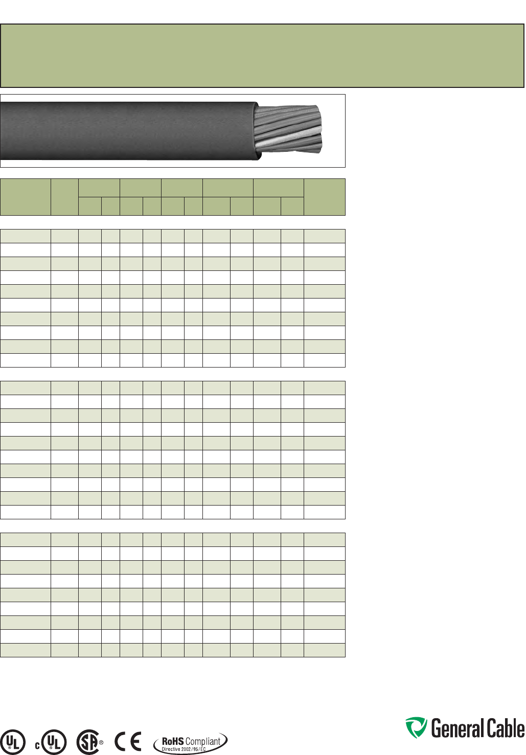
Phone: 888-593-3355
www.generalcable.com
TC-Flex™ Tray Cable
14 AWG (2,5 mm
²
) – 10 AWG (6,0 mm
²
)
UL Type WTTC 1000 V or Type TC-ER 600 V or Type MTW and c(UL) CIC/TC 600 V FT4 or CSA AWM
90°C 1000 V, Flexible, Oil Res I/II, Sunlight- and Torsion-Resistant, Flame-Retardant, -40˚C to +90˚C
SPEC 4780
November, 2013
Product Construction:
Conductors:
• 14 AWG (2,5 mm²) thru 10 AWG (6,0 mm²) fully
annealed flexible stranded bare copper with
Class 5 stranding per EN 60228 (IEC 60228)
Insulation:
• Polyvinyl Chloride (PVC) insulation with a clear
Polyamide (nylon) jacket per UL 83
Conductor Identification:
• Conductors are black with printed numbers and
green/yellow grounding conductor
Cable Assembly:
• Conductors cabled with non-hygroscopic fillers
to make the cable suitably round
Jacket:
• Black, flexible, flame-retardant, sunlight- and oil-
resistant Polyvinyl Chloride (PVC) jacket
Print:
• GENERAL CABLE® TC-FLEX™ XX/C XXAWG
(XXMM2) (UL) TC-ER TYPE THHN/THWN 90˚C DRY
75˚C WET 600 V SUN RES DIR BUR OIL RES I/II
OR MTW OR WTTC 1000 V 90˚C DRY c(UL) CIC/TC
PVC/N 90˚C FT4 --- CSA AWM I/II A/B 90˚C 1000 V
– ROHS CE – MADE IN USA DAY/MONTH/YEAR OF
MFG SEQUENTIAL FOOTAGE MARKER
Minimum Bending Radius:
• 4x O.D. for fixed installation
• 8x O.D. for flexing applications
Torsion:
• 10,000 cycles at -40°C, +/- 150° twist per meter,
cable weight compensated to 20 meters
Applications:
• In free air, raceways or direct burial
• (UL) WTTC cables for use up to 1000 V in wind
turbine generator applications in accordance with
UL Subject 6140
• (UL) TC-ER cables for use up to 600 V as power and
control cables in accordance with NEC® Article 336
• (UL) MTW cables for machine tool and wire up to
600 V as power and control cables in accordance
with UL 1063
• (CSA) CIC/TC cables for use up to 600 V in cable
trays and other applications when installed in
accordance with the Canadian Electrical Code,
Part I
• (CSA) AWM cables for use up to 1000 V as
equipment wiring in accordance with the
Canadian Electrical Code, Part I
Specifications:
Design Adherence:
• UL 66 & UL 83/CSA C22.2 No. 75-08
Thermoplastic Insulated Wires
• UL 1063/MTW Machine Tool Wire
• UL 1277 Power and Control Tray Cables
• UL 2277 Wind Turbine Tray Cables
• CSA C22.2 No. 230-09 Tray Cables
• CSA C22.2 No. 239-09 Control
and Instrumentation Cables
• CSA C22.2 No. 210-11 Appliance Wiring
Material Products
Flame Tests:
• IEEE 1202/CSA FT4
Compliances:
• Type TC-ER 90°C Dry, 75°C Wet, 600 V
• Type MTW
• Type WTTC 90°C, 1000 V
• Type CIC/TC 90°C, 600 V
• Type AWM I/II A/B, 90°C, 1000 V FT4
• RoHS Compliant
CATALOG
NUMBER
NO. OF
COND.
INC.
GRND.
NOM. INS.
THICKNESS
NOM. JACKET
THICKNESS
NOM.
CABLE O.D.
NOM. COPPER
WEIGHT
NOM. CABLE
WEIGHT
90°C
AMP.
@ 30°C
AMBIENT¹
INCHES mm INCHES mm INCHES mm
LBS/
1000 FT kg/km
LBS/
1000 FT kg/km
14 AWG (2,50 mm²) 46 Strands
4780.03014 3 0.021 0.53 0.048 1.22 0.375 9.5 43 65 85 126 18
4780.04014 40.021 0.53 0.048 1.22 0.408 10.4 58 86 106 158 18
4780.05014 50.021 0.53 0.048 1.22 0.442 11.2 72 108 128 190 18
4780.07014 7 0.021 0.53 0.048 1.22 0.502 12.8 101 151 170 253 18
4780.09014* 90.021 0.53 0.063 1.60 0.583 14.8 130 194 226 336 16
4780.12014* 12 0.021 0.53 0.063 1.60 0.647 16.4 174 259 289 429 16
4780.19014* 19 0.021 0.53 0.063 1.60 0.774 19.7 275 410 432 642 12
4780.25014* 25 0.021 0.53 0.085 2.16 0.915 23.2 362 539 587 874 12
4780.30014* 30 0.021 0.53 0.085 2.16 0.965 24.5 435 647 686 1,021 10
4780.37014* 37 0.021 0.53 0.085 2.16 1.036 26.3 536 798 826 1,229 10
12 AWG (4,0 mm²) 56 Strands
4780.03012 3 0.021 0.53 0.048 1.22 0.435 11.1 72 108 123 183 25
4780.04012 40.021 0.53 0.048 1.22 0.476 12.1 97 144 155 231 25
4780.05012 50.021 0.53 0.048 1.22 0.517 13.1 121 180 188 280 25
4780.07012* 7 0.021 0.53 0.063 1.60 0.622 15.8 169 252 269 401 25
4780.09012* 90.021 0.53 0.063 1.60 0.684 17.4 217 323 335 498 20
4780.12012* 12 0.021 0.53 0.063 1.60 0.763 19.4 290 431 431 642 20
4780.19012* 19 0.021 0.53 0.085 2.16 0.964 24.5 459 683 689 1,025 17
4780.25012* 25 0.021 0.53 0.095 2.41 1.103 28.0 604 898 901 1,341 17
4780.30012* 30 0.021 0.53 0.095 2.41 1.164 29.6 724 1,078 1,057 1,572 14
4780.37012* 37 0.021 0.53 0.095 2.41 1.252 31.8 893 1,329 1,275 1,897 14
10 AWG (6,0 mm²) 82 Strands
4780.03010 3 0.027 0.69 0.048 1.22 0.491 12.5 109 162 172 256 35
4780.04010 40.027 0.69 0.063 1.60 0.567 14.4 146 217 234 348 35
4780.05010 50.027 0.69 0.063 1.60 0.618 15.7 182 271 284 422 35
4780.07010* 7 0.027 0.69 0.063 1.60 0.705 17.9 255 379 381 568 35
4780.09010* 90.027 0.69 0.063 1.60 0.779 19.8 327 487 477 710 30
4780.12010* 12 0.027 0.69 0.085 2.16 0.915 23.2 437 650 654 973 30
4780.19010* 19 0.027 0.69 0.095 2.41 1.119 28.4 691 1,029 1,007 1,499 25
4780.25010* 25 0.027 0.69 0.095 2.41 1.259 32.0 910 1,354 1,293 1,925 20
4780.30010* 30 0.027 0.69 0.095 2.41 1.331 33.8 1,092 1,625 1,524 2,268 20
* Non-stock item; minimum runs apply. Please consult Customer Service for price and delivery.
¹ Ampacities provided are for open cable runs, in a raceway, directly buried, or as aerial cable supported on a
messenger in accordance with NEC® Articles 336.80 and 392.11, Table 310.16 and are derated in accordance with
NEC® 310.15.B.2.
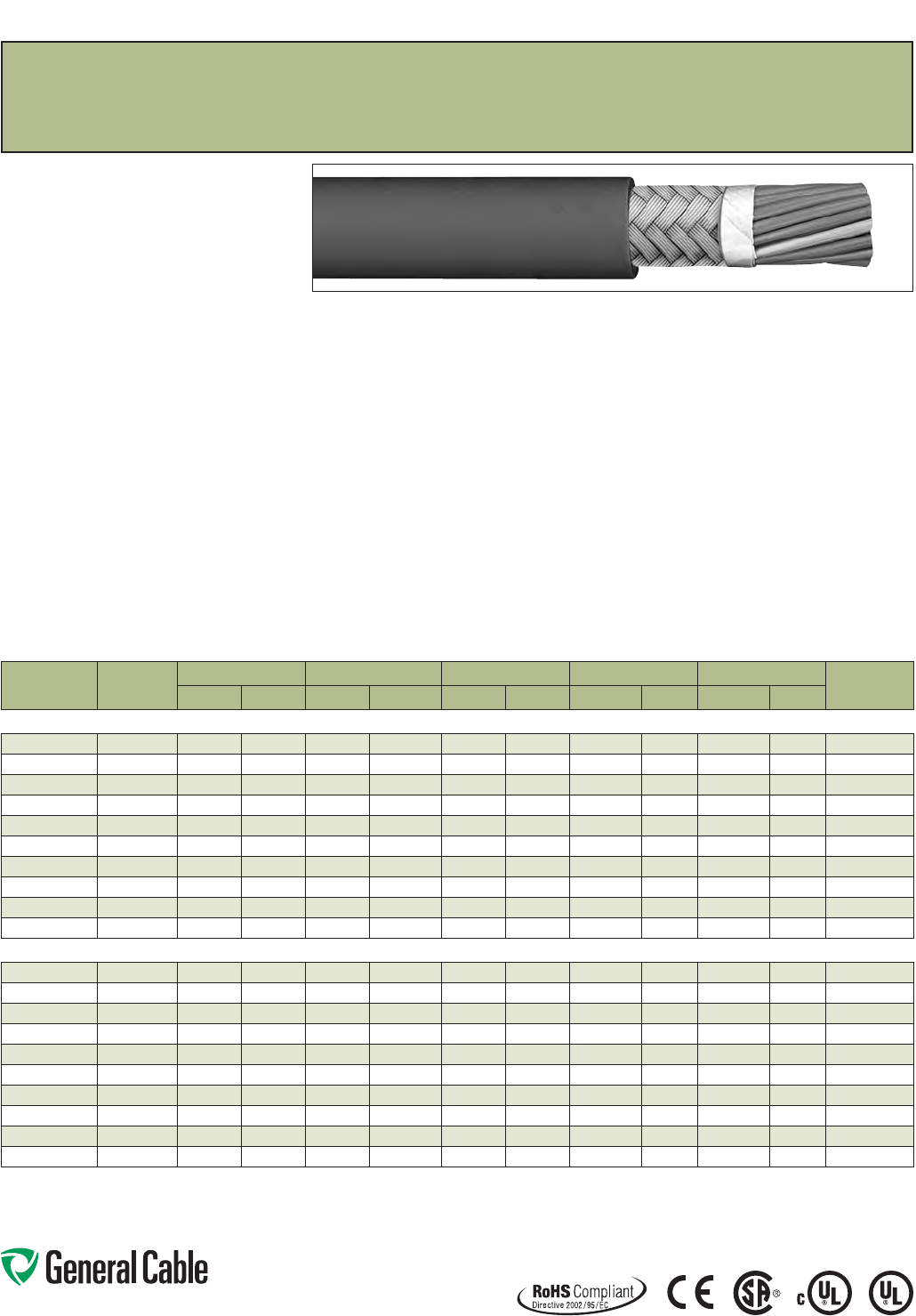
Phone: 888-593-3355
www.generalcable.com
SPEC 4785
November, 2013
TC-Flex™ Shielded Tray Cable
18 AWG (1,0 mm
²
) — 16 AWG (1,5 mm
²
)
UL Type WTTC 1000 V or Type TC-ER 600 V or Type MTW and c(UL) CIC/TC 600 V FT4 or CSA AWM
90°C 1000 V, Flexible, Oil Res I/II, Sunlight- and Flame-Retardant, -40˚C to +90˚C
Product Construction:
Conductors:
• 18 AWG (1,0 mm²) and 16 AWG (1,5 mm²) fully
annealed flexible stranded bare copper with Class
5 stranding per EN 60228 (IEC 60228)
Insulation:
• Polyvinyl Chloride (PVC) insulation with a clear
Polyamide (nylon) jacket per UL 83
Conductor Identification:
• Conductors are black with printed numbers and
green/yellow grounding conductor
Cable Assembly:
• Conductors cabled with non-hygroscopic fillers
to make cable suitably round
Shield:
• Aluminum/Mylar foil shield providing 100%
coverage combined with a tinned copper braid
with 85% nom. coverage
Jacket:
• Black, flexible, flame-retardant, sunlight- and
oil-resistant Polyvinyl Chloride (PVC) jacket
Print:
• GENERAL CABLE® TC-FLEX™ XX/C XXAWG
(XXMM2) SHIELDED (UL) TC-ER TYPE TFFN 90˚C
DRY 600 V SUN RES DIR BUR OIL RES I/II OR
MTW OR WTTC 1000 V 90˚C DRY c(UL) CIC/TC
PVC/N 90˚C FT4 --- CSA AWM I/II A/B 90˚C
1000 V – ROHS CE – MADE IN USA DAY/
MONTH/YEAR OF MFG SEQUENTIAL FOOTAGE
MARKER
Minimum Bending Radius:
• 4x O.D. for fixed installation
• 8x O.D. for flexing applications
Applications:
• In free air, raceways or direct burial
• (UL) WTTC cables for use up to 1000 V in wind
turbine generator applications in accordance with
UL Subject 6140
• (UL) TC-ER cables for use up to 600 V as power and
control cables in accordance with NEC® Article 336
• (UL) MTW cables for machine tool and wire up to
600 V as power and control cables in accordance
with UL 1063
• (CSA) CIC/TC cables for use up to 600 V in cable
trays and other applications when installed in
accordance with the Canadian Electrical Code,
Part I
• (CSA) AWM cables for use up to 1000 V as
equipment wiring in accordance with the
Canadian Electrical Code, Part I
• 4/C designs suitable for use in general
purpose 600 V Variable Frequency Drive (VFD)
applications2
Specifications:
Design Adherence:
• UL 66 & UL 83/CSA C22.2 No. 75-08
Thermoplastic Insulated Wires
• UL 1063/MTW Machine Tool Wire
• UL 1277 Power and Control Tray Cables
• UL 2277 Wind Turbine Tray Cables
• CSA C22.2 No. 230-09 Tray Cables
• CSA C22.2 No. 239-09 Control and
Instrumentation Cables
• CSA C22.2 No. 210-11 Appliance Wiring
Material Products
Flame Tests:
• IEEE 1202/CSA FT4
Compliances:
• Type TC-ER 90°C Dry, 75°C Wet, 600 V
• Type MTW
• Type WTTC 90°C, 1000 V
• Type CIC/TC 90°C, 600 V
• Type AWM I/II A/B, 90°C, 1000 V FT4
• RoHS Compliant
CATALOG
NUMBER
NO. OF COND.
INC. GRND.
NOM. INS. THICKNESS NOM. JACKET THICKNESS NOM. CABLE O.D. NOM. COPPER WEIGHT NOM. CABLE WEIGHT 90°C AMP. @
30°C AMBIENT¹INCHES mm INCHES mm INCHES mm LBS/1000 FT kg/km LBS/1000 FT kg/km
18 AWG (1,0 mm²) 19 Strands
4785.03018*
3 0.021 0.53 0.048 1.22 0.334 8.5 30 44 63 93 8
4785.04018
40.021 0.53 0.048 1.22 0.359 9.1 41 62 79 118 8
4785.05018*
50.021 0.53 0.048 1.22 0.384 9.8 49 72 92 136 8
4785.07018*
7 0.021 0.53 0.048 1.22 0.430 10.9 64 95 116 173 8
4785.09018*
90.021 0.53 0.048 1.22 0.469 11.9 79 117 140 208 7
4785.12018*
12 0.021 0.53 0.048 1.22 0.518 13.2 100 149 174 258 7
4785.19018*
19 0.021 0.53 0.063 1.60 0.644 16.4 148 221 266 395 6
4785.25018*
25 0.021 0.53 0.063 1.60 0.718 18.2 189 281 331 492 6
4785.30018*
30 0.021 0.53 0.063 1.60 0.756 19.2 221 329 381 567 5
4785.37018*
37 0.021 0.53 0.063 1.60 0.810 20.6 268 399 453 674 5
16 AWG (1,5 mm²) 28 Strands
4785.03016*
3 0.021 0.53 0.048 1.22 0.360 9.1 44 66 81 121 10
4785.04016
40.021 0.53 0.048 1.22 0.388 9.8 56 83 98 146 10
4785.05016*
50.021 0.53 0.048 1.22 0.417 10.6 66 99 114 170 10
4785.07016*
7 0.021 0.53 0.048 1.22 0.469 11.9 88 131 147 218 10
4785.09016*
90.021 0.53 0.048 1.22 0.512 13.0 109 162 178 265 9
4785.12016*
12 0.021 0.53 0.063 1.60 0.598 15.2 139 207 238 354 9
4785.19016*
19 0.021 0.53 0.063 1.60 0.707 18.0 210 312 343 510 7
4785.25016*
25 0.021 0.53 0.063 1.60 0.790 20.1 269 401 431 641 7
4785.30016*
30 0.021 0.53 0.085 2.16 0.877 22.3 318 473 533 793 6
4785.37016*
37 0.021 0.53 0.085 2.16 0.938 23.8 385 573 632 940 6
* Non-stock item; minimum runs apply. Please consult Customer Service for price and delivery.
¹ Ampacities provided are for open cable runs, in a raceway, directly buried, or as aerial cable supported on a messenger in accordance with NEC® Articles 336.80 and 392.11,
Table 310.16 and are derated in accordance with NEC® 310.15.B.2.
2 Consult manufacturer’s specifications to verify applicability for installation with specific variable frequency drive.
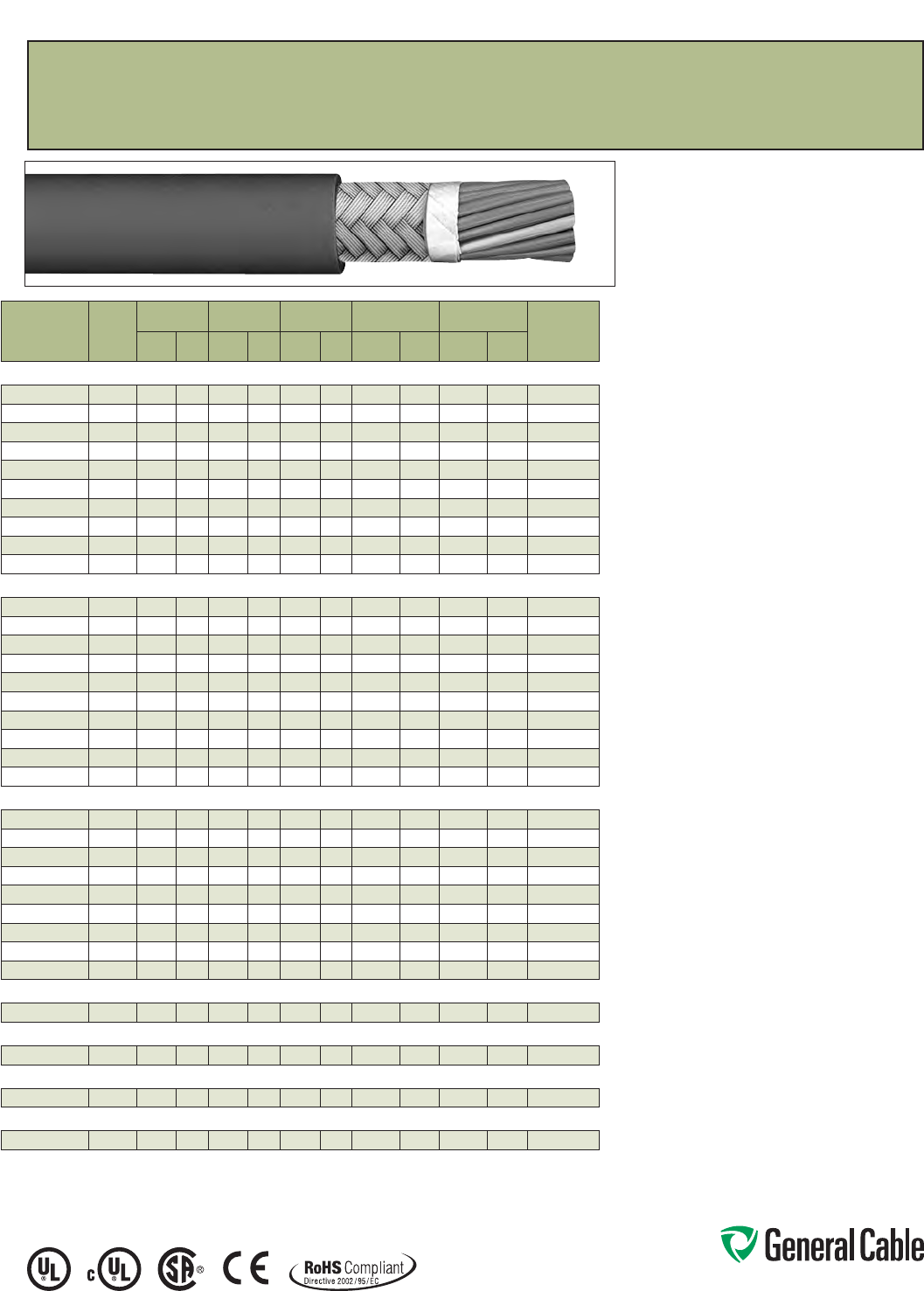
Phone: 888-593-3355
www.generalcable.com
TC-Flex™ Shielded Tray Cable
14 AWG (2,5 mm
²
) — 2 AWG (35,0 mm
²
)
UL Type WTTC 1000 V or Type TC-ER 600 V or Type MTW and c(UL) CIC/TC 600 V FT4 or CSA AWM
90°C 1000 V, Flexible, Oil Res I/II, Sunlight- and Flame-Retardant, -40˚C to +90˚C
Product Construction:
Conductors:
• 14 AWG (2,5 mm²) thru 2 AWG (35,0 mm²) fully
annealed flexible stranded bare copper with
Class 5 stranding per EN 60228 (IEC 60228)
Insulation:
• Polyvinyl Chloride (PVC) insulation with a clear
Polyamide (nylon) jacket per UL 83
Conductor Identification:
• Conductors are black with printed numbers and
green/yellow grounding conductor
Cable Assembly:
• Conductors cabled with non-hygroscopic fillers
to make the cable suitably round
Shield:
• Aluminum/Mylar foil shield providing 100%
coverage in combination with a tinned copper
braid providing 85% nominal coverage
Jacket:
• Black, flexible, flame-retardant, sunlight- and
oil-resistant Polyvinyl Chloride (PVC) jacket
Print:
• GENERAL CABLE® TC-FLEX™ XX/C XXAWG
(XXMM2) SHIELDED (UL) TC-ER TYPE THHN/THWN
90˚C DRY 75˚C WET 600 V SUN RES DIR BUR OIL
RES I/II OR MTW OR WTTC 1000 V 90˚C DRY c(UL)
CIC/TC PVC/N 90˚C FT4 --- CSA AWM I/II A/B 90˚C
1000 V – ROHS CE – MADE IN USA DAY/MONTH/
YEAR OF MFG SEQUENTIAL FOOTAGE MARKER
Minimum Bending Radius:
• 4x O.D. for fixed installation
• 8x O.D. for flexing applications
Applications:
• In free air, raceways or direct burial
• (UL) WTTC cables for use up to 1000 V in wind
turbine generator applications in accordance with
UL Subject 6140
• (UL) TC-ER cables for use up to 600 V as power and
control cables in accordance with NEC® Article 336
• (UL) MTW cables for machine tool and wire up to
600 V as power and control cables in accordance
with UL 1063
• (CSA) CIC/TC cables for use up to 600 V in cable trays
and other applications when installed in accordance
with the Canadian Electrical Code, Part I
• (CSA) AWM cables for use up to 1000 V as equipment
wiring in accordance with the Canadian Electrical
Code, Part I
• 4/C designs suitable for use in general purpose
600 V Variable Frequency Drive (VFD) applications2
Specifications:
Design Adherence:
• UL 66 & UL 83/CSA C22.2 No. 75-08
Thermoplastic Insulated Wires
• UL 1063/MTW Machine Tool Wire
• UL 1277 Power and Control Tray Cables
• UL 2277 Wind Turbine Tray Cables
• CSA C22.2 No. 230-09 Tray Cables
• CSA C22.2 No. 239-09 Control and
Instrumentation Cables
• CSA C22.2 No. 210-11 Appliance Wiring
Material Products
Flame Tests:
• IEEE 1202/CSA FT 4
Compliances:
• Type TC-ER 90°C Dry, 75°C Wet, 600 V
• Type MTW
• Type WTTC 90°C, 1000 V
• Type CIC/TC 90°C, 600 V
• Type AWM I/II A/B, 90°C, 1000 V FT4
• RoHS Compliant
SPEC 4790
November, 2013
CATALOG
NUMBER
NO. OF
COND.
INC.
GRND.
NOM. INS.
THICKNESS
NOM. JACKET
THICKNESS
NOM.
CABLE O.D.
NOM. COPPER
WEIGHT
NOM. CABLE
WEIGHT
90°C
AMP.
@ 30°C
AMBIENT¹
INCHES mm INCHES mm INCHES mm
LBS/
1000 FT kg/km
LBS/
1000 FT kg/km
14 AWG (2,50 mm²) 46 Strands
4790.03014*
3 0.021 0.53 0.048 1.22 0.396 10.1 64 95 106 158 18
4790.04014
40.021 0.53 0.048 1.22 0.429 10.9 81 121 118 176 18
4790.05014*
50.021 0.53 0.048 1.22 0.463 11.8 98 146 139 206 18
4790.07014*
7 0.021 0.53 0.063 1.60 0.553 14.1 132 196 192 285 18
4790.09014*
90.021 0.53 0.063 1.60 0.604 15.3 164 244 230 342 16
4790.12014*
12 0.021 0.53 0.063 1.60 0.668 17.0 214 318 287 427 16
4790.19014*
19 0.021 0.53 0.063 1.60 0.795 20.2 325 483 412 613 12
4790.25014*
25 0.021 0.53 0.085 2.16 0.936 23.8 421 627 555 826 12
4790.30014*
30 0.021 0.53 0.085 2.16 0.986 25.0 498 741 639 951 10
4790.37014*
37 0.021 0.53 0.085 2.16 1.057 26.8 605 901 757 1,127 10
12 AWG (4,0 mm²) 56 Strands
4790.03012*
3 0.021 0.53 0.048 1.22 0.456 11.6 98 146 149 221 25
4790.04012
40.021 0.53 0.048 1.22 0.497 12.6 126 187 184 274 25
4790.05012*
50.021 0.53 0.063 1.60 0.568 14.4 153 228 235 350 25
4790.07012*
7 0.021 0.53 0.063 1.60 0.643 16.3 208 309 308 458 25
4790.09012*
90.021 0.53 0.063 1.60 0.705 17.9 261 388 378 562 20
4790.12012*
12 0.021 0.53 0.063 1.60 0.784 19.9 340 506 480 715 20
4790.19012*
19 0.021 0.53 0.085 2.16 0.985 25.0 525 781 754 1,122 17
4790.25012*
25 0.021 0.53 0.095 2.41 1.124 28.5 680 1,012 976 1,453 17
4790.30012*
30 0.021 0.53 0.095 2.41 1.185 30.1 807 1,201 1,138 1,693 14
4790.37012*
37 0.021 0.53 0.095 2.41 1.273 32.3 986 1,468 1,366 2,033 14
10 AWG (6,0 mm²) 82 Strands
4790.03010*
3 0.027 0.69 0.063 1.60 0.542 13.8 139 208 216 321 35
4790.04010
40.027 0.69 0.063 1.60 0.588 14.9 179 267 268 399 35
4790.05010*
50.027 0.69 0.063 1.60 0.639 16.2 219 326 321 477 35
4790.07010*
7 0.027 0.69 0.063 1.60 0.726 18.4 299 445 425 633 35
4790.09010*
90.027 0.69 0.063 1.60 0.800 20.3 378 562 527 784 30
4790.12010*
12 0.027 0.69 0.085 2.16 0.936 23.8 496 739 713 1,061 30
4790.19010*
19 0.027 0.69 0.095 2.41 1.145 29.1 767 1,142 1,083 1,611 25
4790.25010*
25 0.027 0.69 0.095 2.41 1.285 32.6 999 1,486 1,381 2,055 20
4790.30010*
30 0.027 0.69 0.095 2.41 1.357 34.5 1,189 1,769 1,620 2,410 20
8 AWG (10 mm²) 74 strands
4790.04008
40.039 0.99 0.063 1.60 0.735 18.7 280 417 412 613 55
6 AWG (16 mm²) 119 Strands
4790.04006
40.039 0.99 0.085 2.16 0.914 23.2 435 647 632 941 75
4 AWG (21 mm²) 413 Strands
4790.04004
40.050 1.27 0.095 2.41 1.094 27.8 586 872 867 1,290 90
2 AWG (35 mm²) 665 Strands
4790.04002
40.050 1.27 0.110 2.79 1.289 32.7 928 1,381 1,294 1,926 130
* Non-stock item; minimum runs apply. Please consult Customer Service for price and delivery.
¹ Ampacities provided are for open cable runs, in a raceway, directly buried, or as aerial cable supported on a messenger
in accordance with NEC® Articles 336.80 and 392.11, Table 310.16 and are derated in accordance
with NEC® 310.15.B.2.
2 Consult manufacturer’s specifications to verify applicability for installation with specific variable frequency drive.

Phone: 888-593-3355
www.generalcable.com
SPEC 4800
July, 2010
Product Construction:
Conductor:
• 18 AWG and 16 AWG
• Bare, annealed copper per ASTM B3
• Class B stranding per ASTM B8
Insulation:
• Lead-free, clear Polyethylene (PE)
Conductor Jacket:
• Color-coded Polyvinyl Chloride (PVC)
• Color-coded per ICEA Method 1, Table E-1
(includes white and green)
Cable Core:
• Conductors are cabled with non-hygroscopic
fillers as necessary, and an overall binder tape
Overall Jacket:
• Lead-free, flame-retardant, sunlight-resistant
Polyvinyl Chloride (PVC)
Print:
• GENERAL CABLE® SUBSTATION CONTROL
CABLE X/C XXAWG CU/PE/PVC 75˚C 600 V
YEAR OF MFG SEQUENTIAL FOOTAGE MARK
Options:
• Tinned copper conductors
• Class C stranding per ASTM B8
• Insulated or uninsulated ground conductors
• Copper tape shield or aluminum/polymer tape
shield with tinned copper drain wire over cable
core
• Bare or tinned copper braided basket weave
shield
• Duralox® aluminum or galvanized steel interlocked
armor
• Intergrabon® Moisture Barrier system
• Corrugated copper tape shield longitudinally
applied
Applications:
• For applications where environmental factors
require cable characteristics including flame-
retardance, resistance to chemicals, abrasion and
resistance to the harmful effects of sunlight and
weather
• May be installed in ducts; cable trays; conduit;
Class I, Division 2 industrial hazardous locations
or continuous rigid cable supports
Features:
• Rated at 75˚C
• Thermoplastic PE insulation provides chemical
resistance and excellent electrical properties
• Flame-Retardant PVC conductor jacket is color-
coded for easy circuit identification
• Flame-Retardant PVC overall jacket provides
abrasion, chemical, sunlight and weathering
resistance
Compliances:
Industry Compliances:
• ICEA S-73-532
Other Compliances:
• EPA 10 CFR, Part 261 for leachable
lead content per TCLP method
CATALOG
NUMBER
NO.
OF
COND.
COND.
SIZE
(AWG/
kcmil)
MINIMUM AVG.
INSULATION
THICKNESS
MINIMUM AVG.
JACKET
THICKNESS
NOMINAL
CABLE O.D.
COPPER
WEIGHT NET WEIGHT
LBS/
1000 FT kg/km
LBS/
1000 FT kg/kmINCHES mm INCHES mm INCHES mm
18 AWG MULTI-CONDUCTORS
365290* 2 Flat 18 0.025 0.64 0.045 1.14
.200 x .300
5.10 x 7. 50
10 15 39 58
365300* 218 0.025 0.64 0.045 1.14 0.30 7.6 10 15 41 61
389710* 318 0.025 0.64 0.045 1.14 0.31 7.9 15 23 49 73
543640* 418 0.025 0.64 0.045 1.14 0.34
8.6
20 30 60 89
365320* 518 0.025 0.64 0.045 1.14 0.37 9.4 25 38 71 106
365330* 718 0.025 0.64 0.045 1.14 0.40 10.2 36 53 90 134
365340* 918 0.025 0.64 0.045 1.14 0.46 11.7 46 68 113 168
547230* 12 18 0.025 0.64 0.045 1.14 0.51 13.0 61 91 145 216
365350* 19 18 0.025 0.64 0.060 1.52 0.63 16.0 96 143 229 341
16 AWG MULTI-CONDUCTORS
283530* 2 Flat 16 0.025 0.64 0.045 1.14
.210 x .320
5.30 x 8.10
16 24 43 84
365360* 216 0.025 0.64 0.045 1.14 0.32 8.1 16 24 49 73
365370* 316 0.025 0.64 0.045 1.14 0.34 8.6 24 36 62 92
647530* 416 0.025 0.64 0.045 1.14 0.37 9.4 32 48 77 115
283540* 516 0.025 0.64 0.045 1.14 0.40 10.2 40 60 92 137
365380* 716 0.025 0.64 0.045 1.14 0.43 10.9 56 84 118 176
365390* 916 0.025 0.64 0.045 1.14 0.50 12.7 73 108 148 220
647550* 12 16 0.025 0.64 0.060 1.52 0.59 15.0 97 144 209 311
365400* 19 16 0.025 0.64 0.060 1.52 0.69 17.5 153 228 304 452
Dimensions and weights are nominal; subject to industry tolerances.
* Non-stock item; minimum runs apply. Please consult Customer Service for price and delivery.
20/10
PE/PVC/PVC, Control, Unshielded
600 V (18 AWG/16 AWG)—E-1 Color Code
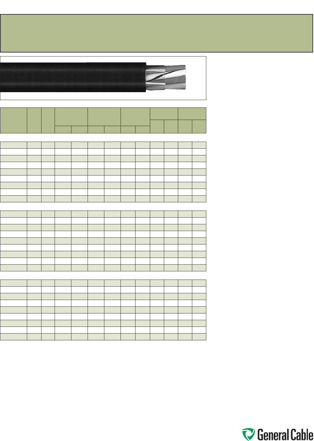
Phone: 888-593-3355
www.generalcable.com
SPEC 4850
July, 2010
Product Construction:
Conductor:
• 14 AWG thru 10 AWG
• Bare, annealed copper per ASTM B3
• Class B stranding per ASTM B8
Insulation:
• Lead-free, clear Polyethylene (PE)
Conductor Jacket:
• Color-coded Polyvinyl Chloride (PVC)
• Color-coded per ICEA Method 1, Table E-1
(includes white and green)
Cable Core:
• Conductors are cabled with non-hygroscopic
fillers as necessary, and an overall binder tape
Overall Jacket:
• Lead-free, flame-retardant, sunlight-resistant
Polyvinyl Chloride (PVC)
Print:
• GENERAL CABLE® SUBSTATION CONTROL
CABLE X/C XXAWG CU/PE/PVC 75˚C 600 V
YEAR OF MFG SEQUENTIAL FOOTAGE MARK
Options:
• Tinned copper conductors
• Class C stranding per ASTM B8
• Insulated or uninsulated ground conductors
• Copper tape shield or aluminum/polymer tape
shield with tinned copper drain wire over cable
core
• Bare or tinned copper braided basket weave
shield
• Duralox® aluminum or galvanized steel interlocked
armor
• Intergrabon® Moisture Barrier system
• Corrugated copper tape shield longitudinally
applied
Applications:
• For applications where environmental factors
require cable characteristics including flame-
retardance, resistance to chemicals, abrasion and
resistance to the harmful effects of sunlight and
weather
• May be installed in ducts; cable trays; conduit;
Class I, Division 2 industrial hazardous locations
or continuous rigid cable supports
Features:
• Rated at 75˚C
• Thermoplastic PE insulation provides chemical
resistance and excellent electrical properties
• Flame-retardant PVC conductor jacket is color-
coded for easy circuit identification
• Flame-retardant PVC overall jacket provides
abrasion, chemical, sunlight and weathering
resistance
Compliances:
Industry Compliances:
• ICEA S-73-532
Other Compliances:
• EPA 10 CFR, Part 261 for leachable
lead content per TCLP method
CATALOG
NUMBER
NO.
OF
COND.
COND.
SIZE
(AWG/
kcmil)
MINIMUM AVG.
INSULATION
THICKNESS
MINIMUM AVG.
JACKET
THICKNESS
NOMINAL
CABLE O.D.
COPPER
WEIGHT NET WEIGHT
LBS/
1000 FT kg/km
LBS/
1000 FT kg/kmINCHES mm INCHES mm INCHES mm
14 AWG MULTI-CONDUCTORS
269080* 2 Flat 14 0.030 0.76 0.045 1.14
.230 x .370
5.30 x 9.30
25 38 57 85
647560* 214 0.030 0.76 0.045 1.14 0.37 9.4 26 38 66 98
365410* 314 0.030 0.76 0.045 1.14 0.39 9.9 38 57 87 130
267950* 414 0.030 0.76 0.045 1.14 0.42
10.7
51 76 108 161
286130* 514 0.030 0.76 0.045 1.14 0.46 11.7 64 95 130 194
365240* 714 0.030 0.76 0.045 1.14 0.50 12.7 90 133 173 258
365430* 914 0.030 0.76 0.060 1.52 0.62 15.8 116 172 236 351
647590* 12 14 0.030 0.76 0.060 1.52 0.69 17.5 154 229 300 447
647600* 19 14 0.030 0.76 0.060 1.52 0.80 20.3 244 363 443 659
12 AWG MULTI-CONDUCTORS
257750* 2 Flat 12 0.030 0.76 0.045 1.14
.250 x .400
6.40 x 10.30
40 60 82 122
257770* 212 0.030 0.76 0.045 1.14 0.40 10.2 41 61 87 130
267830* 312 0.030 0.76 0.045 1.14 0.43 10.9 61 91 116 173
257730* 412 0.030 0.76 0.045 1.14 0.47 11.9 81 121 147 219
270720* 512 0.030 0.76 0.045 1.14 0.52 13.2 102 152 180 268
256750* 712 0.030 0.76 0.060 1.52 0.59 15.0 143 212 255 380
270730* 912 0.030 0.76 0.060 1.52 0.68 17.3 184 273 321 478
267860* 12 12 0.030 0.76 0.060 1.52 0.77 19.6 245 364 412 613
647650* 19 12 0.030 0.76 0.080 2.03 0.94 23.9 388 577 654 973
10 AWG MULTI-CONDUCTORS
257760* 2 Flat 10 0.030 0.76 0.045 1.14
.270 x .450
6.90 x 11.40
64 96 110 164
257780* 210 0.030 0.76 0.045 1.14 0.45 11.4 65 96 130 194
267840* 310 0.030 0.76 0.045 1.14 0.48 12.2 97 96 170 253
257740* 410 0.030 0.76 0.060 1.52 0.52 13.2 129 144 235 350
257790* 510 0.030 0.76 0.060 1.52 0.60 15.2 162 192 286 426
257800* 710 0.030 0.76 0.060 1.52 0.66 16.8 227 241 365 543
261690* 910 0.030 0.76 0.060 1.52 0.76 19.3 292 337 466 694
257810* 12 10 0.030 0.76 0.080 2.03 0.90 22.9 389 434 626 932
271740* 19 10 0.030 0.76 0.080 2.03 1.05 26.7 616 579 930 1384
Dimensions and weights are nominal; subject to industry tolerances.
* Non-stock item; minimum runs apply. Please consult Customer Service for price and delivery.
20/10
PE/PVC/PVC, Control, Unshielded
600 V (14 AWG—10 AWG)—E-1 Color Code
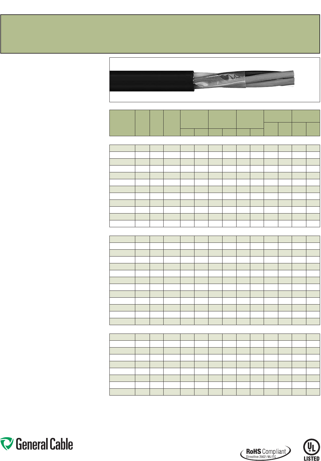
Phone: 888-593-3355
www.generalcable.com
SPEC 4900
October, 2012
CATALOG
NUMBER
NO.
OF
COND.
COND.
SIZE
(AWG)
COND.
STRAND
MINIMUM AVG.
INSULATION
THICKNESS
MINIMUM AVG.
JACKET
THICKNESS
NOMINAL
CABLE O.D.
COPPER
WEIGHT NET WEIGHT
LBS/
1000 FT kg/km
LBS/
1000 FT kg/kmINCHES mm INCHES mm INCHES mm
14 AWG MULTI-CONDUCTORS
394280 2 Flat 14 7/.0242 0.030 0.76 0.045 1.14
.365 x .230
9.30 x 5.80
26 38 61 91
394290* 214 7/.0242 0.030 0.76 0.045 1.14 0.370 9.40 26 39 71 106
394300 314 7/.0242 0.030 0.76 0.045 1.14 0.390 9.91 39 59 92 137
394310 414 7/.0242 0.030 0.76 0.045 1.14 0.425
10.80
53 78 115 171
394320 514 7/.0242 0.030 0.76 0.045 1.14 0.465 11.81 66 98 139 207
394330 714 7/.0242 0.030 0.76 0.045 1.14 0.505 12.83 92 137 173 257
394340 914 7/.0242 0.030 0.76 0.060 1.52 0.620 15.75 118 176 240 357
394350 12 14 7/.0242 0.030 0.76 0.060 1.52 0.700 17.78 158 235 301 448
394360 19 14 7/.0242 0.030 0.76 0.060 1.52 0.815 20.70 250 372 468 696
394370* 25 14 7/.0242 0.030 0.76 0.080 2.03 0.935 23.75 323 481 624 929
394380* 30 14 7/.0242 0.030 0.76 0.080 2.03 1.030 26.16 387 576 747 1112
394390* 37 14 7/.0242 0.030 0.76 0.080 2.03 1.110 28.19 466 694 875 1302
12 AWG MULTI-CONDUCTORS
394400 2 Flat 12 7/.0305 0.030 0.76 0.045 1.14
.400 x .245
10.20 x 6.20
40 60 82 122
394410* 212 7/.0305 0.030 0.76 0.045 1.14 0.410 10.41 41 61 94 140
3944202
3+ Grnd
12 7/.0305 0.030 0.76 0.045 1.14 0.435 11.05 85 127 148 220
394430 312 7/.0305 0.030 0.76 0.045 1.14 0.435 11.05 64 95 124 185
394440 412 7/.0305 0.030 0.76 0.045 1.14 0.475 12.07 85 127 157 234
394450 512 7/.0305 0.030 0.76 0.045 1.14 0.520 13.21 106 158 191 284
394460 712 7/.0305 0.030 0.76 0.060 1.52 0.595 15.11 149 221 268 399
394470 912 7/.0305 0.030 0.76 0.060 1.52 0.695 17.6 5 191 285 337 502
394480 12 12 7/.0305 0.030 0.76 0.060 1.52 0.765 19.43 247 368 428 637
394490 19 12 7/.0305 0.030 0.76 0.080 2.03 0.940 23.88 391 582 688 1024
394500* 25 12 7/.0305 0.030 0.76 0.080 2.03 1.095 27.81 515 767 854 1271
394510* 30 12 7/.0305 0.030 0.76 0.080 2.03 1.150 29.21 618 920 1002 1491
394520* 37 12 7/.0305 0.030 0.76 0.080 2.03 1.240 31.50 762 1134 1240 1845
10 AWG MULTI-CONDUCTORS
394530 2 Flat 10 7/.0385 0.030 0.76 0.045 1.14
.445 x .270
11.30 x 6.90
64 95 113 168
394540* 210 7/.0385 0.030 0.76 0.045 1.14 0.455 11.56 65 97 128 190
3945502
3+ Grnd
10 7/.0385 0.030 0.76 0.045 1.14 0.485 12.32 134 199 225 335
394560 310 7/.0385 0.030 0.76 0.045 1.14 0.485 12.32 100 150 172 256
394570 410 7/.0385 0.030 0.76 0.060 1.52 0.560 14.22 134 199 234 348
394580 510 7/.0385 0.030 0.76 0.060 1.52 0.615 15.62 167 249 284 423
394590 710 7/.0385 0.030 0.76 0.060 1.52 0.670 17.02 234 349 381 567
394600 910 7/.0385 0.030 0.76 0.060 1.52 0.760 19.30 295 440 464 691
394610 12 10 7/.0385 0.030 0.76 0.080 2.03 0.905 22.99 402 598 651 696
Dimensions and weights are nominal; subject to industry tolerances.
* Non-stock item; minimum runs apply. Please consult Customer Service for price and delivery.
¹ Approved as -ER for Exposed Run applications of 3 or more conductors as defined by the NEC.
² This construction does not require an -ER mark.
GenFree
®
XLPE/LSZH, Control
600 V, UL Type TC-LS-ER
1
—E-2 Color Code
Product Construction:
Conductor:
• 14 AWG thru 10 AWG stranded tinned copper per
ASTM B33
• Class B stranding per ASTM B8
Insulation:
• Lead-free, flame-retardant, low-smoke
Cross-linked Polyethylene (XLPE)
• Color-coded per ICEA Method 1, Table E-2 (does
not include white or green)
Jacket:
• Lead-free, flame-retardant, sunlight-resistant,
Low-Smoke, Zero-Halogen Polyolefin (LSZH)
Print
• GENERAL CABLE® (PLANT OF MFG) GENFREE®
XX/C XXAWG XLPE/LSZH (UL) TYPE TC-LS-ER
XHHW-2 CDRS 90°C WET OR DRY 600 V DIR
BUR SUN RES ROHS DAY/MONTH/YEAR OF
MFG SEQUENTIAL FOOTAGE MARK
Options:
• Bare copper conductor
• E-1 Color Code
• Overall shielded multi-conductor
• Other constructions available upon request
Applications:
• In free air, raceways, aerial or direct burial
• In wet or dry locations
• Permitted for use in Class I, Division 2 industrial
hazardous locations per NEC
• Permitted for Exposed Run (ER) use in
accordance with the NEC for 3 or more
conductors
Features:
• Rated at 90˚C wet or dry
• Ripcord applied to all cables with jacket thickness
of 60 mils or less
• Excellent physical and electrical properties
• Excellent moisture resistance
• Excellent resistance to compression and impact
• Chemical-resistant
• Low coefficient of friction for easy pulling
• Sunlight- and weather-resistant
• Meets cold bend test at -30˚C
• Low-Smoke, Zero-Halogen jacket is
environmentally safe
• Low-Smoke, Zero-Halogen jacket reduces the
amount of toxic and corrosive gases emitted
during combustion, providing a safer environment
for personnel and equipment during the hazards
of fire
• Meets the crush and impact requirements of Type
MC cable for 3 or more conductors
Compliances:
Industry Compliances:
• UL 44 Type XHHW-2
• UL 1277 Type TC-LS-ER, UL File # E57179
• UL 1581
• ICEA S-73-532/NEMA WC57
• ICEA T-33-655
• RoHS Compliant
Flame Test Compliances:
• UL 1581/UL 2556
• UL 1685 Vertical Flame Test
• IEEE 1202
Other Compliances:
• EPA 40 CFR, Part 261 for leachable lead
content per TCLP
• OSHA Acceptable
Packaging:
• Material cut to length and shipped on
non-returnable wood reels
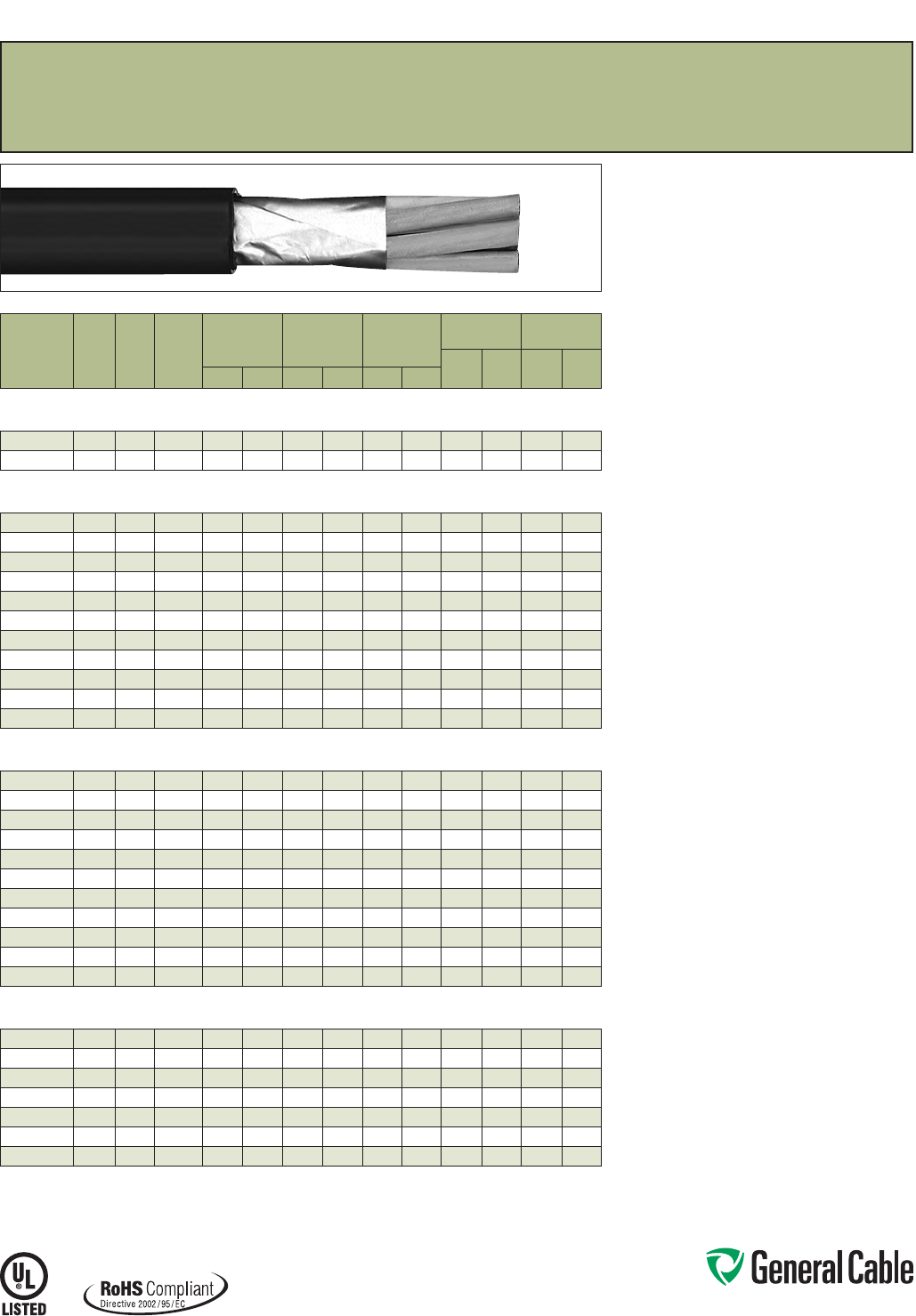
Phone: 888-593-3355
www.generalcable.com
SPEC 4925
October, 2012
CATALOG
NUMBER
NO.
OF
COND.
COND.
SIZE
(AWG)
COND.
STRAND
MINIMUM AVG.
INSULATION
THICKNESS
MINIMUM AVG.
JACKET
THICKNESS
NOMINAL
CABLE O.D.
COPPER
WEIGHT NET WEIGHT
LBS/
1000 FT kg/km
LBS/
1000 FT kg/kmINCHES mm INCHES mm INCHES mm
OVERALL SHIELDED MULTI-CONDUCTORS
16 AWG CONDUCTORS
394960* 216 7/.0192 0.025 0.64 0.045 1.14 0.320
8.13
19 28 52 77
394630* 316 7/.0192 0.025 0.64 0.045 1.14 0.335 8.51 27 40 66 98
OVERALL SHIELDED MULTI-CONDUCTORS
14 AWG CONDUCTORS
394640* 214 7/.0242 0.030 0.76 0.045 1.14 0.375 9.53 29 43 74 110
394650* 314 7/.0242 0.030 0.76 0.045 1.14 0.395 10.03 42 63 95 141
394660* 414 7/.0242 0.030 0.76 0.045 1.14 0.430 10.92 55 82 118 176
394670* 514 7/.0242 0.030 0.76 0.045 1.14 0.470 11.94 68 101 142 211
394680* 714 7/.0242 0.030 0.76 0.045 1.14 0.510 12.95 94 140 176 262
394690* 914 7/.0242 0.030 0.76 0.060 1.52 0.625 15.88 121 180 243 362
394700* 12 14 7/.0242 0.030 0.76 0.060 1.52 0.705 17.91 160 238 304 452
394710* 19 14 7/.0242 0.030 0.76 0.060 1.52 0.820 20.83 252 375 471 701
394720* 25 14 7/.0242 0.030 0.76 0.080 2.03 0.940 25.53 325 484 627 933
394730* 30 14 7/.0242 0.030 0.76 0.080 2.03 1.035 26.29 389 579 750 1116
394740* 37 14 7/.0242 0.030 0.76 0.080 2.03 1.115 28.32 468 696 878 1307
OVERALL SHIELDED MULTI-CONDUCTORS
12 AWG CONDUCTORS
394750* 212 7/.0305 0.030 0.76 0.045 1.14 0.415 10.45 43 64 97 144
394760* 312 7/.0305 0.030 0.76 0.045 1.14 0.440 11.18 66 98 127 189
394770* 412 7/.0305 0.030 0.76 0.045 1.14 0.480 12.19 87 129 160 238
394780* 512 7/.0305 0.030 0.76 0.045 1.14 0.525 13.34 108 162 194 289
394790* 712 7/.0305 0.030 0.76 0.060 1.52 0.600 15.24 151 225 271 403
394800* 912 7/.0305 0.030 0.76 0.060 1.52 0.700 17.78 193 287 340 506
394810* 12 12 7/.0305 0.030 0.76 0.060 1.52 0.770 19.56 249 371 431 641
394820* 19 12 7/.0305 0.030 0.76 0.080 2.03 0.945 24.00 393 585 691 1028
394830* 25 12 7/.0305 0.030 0.76 0.080 2.03 1.100 27.94 517 769 857 1275
394840* 30 12 7/.0305 0.030 0.76 0.080 2.03 1.155 29.80 620 923 1005 1496
394850* 37 12 7/.0305 0.030 0.76 0.080 2.03 1.245 31.62 764 1137 1243 1850
OVERALL SHIELDED MULTI-CONDUCTORS
10 AWG CONDUCTORS
394860* 210 7/.0385 0.030 0.76 0.045 1.14 0.460 11.68 68 101 131 195
394870* 310 7/.0385 0.030 0.76 0.045 1.14 0.490 12.45 103 155 175 260
394880* 410 7/.0385 0.030 0.76 0.060 1.52 0.565 14.35 136 202 237 353
394890* 510 7/.0385 0.030 0.76 0.060 1.52 0.620 15.75 170 253 287 427
394900* 710 7/.0385 0.030 0.76 0.060 1.52 0.675 17.15 237 353 384 571
394910* 910 7/.0385 0.030 0.76 0.060 1.52 0.765 19.43 298 443 467 695
394920* 12 10 7/.0385 0.030 0.76 0.080 2.03 0.910 23.11 404 601 654 973
Dimensions and weights are nominal; subject to industry tolerances.
* Non-stock item; minimum runs apply. Please consult Customer Service for price and delivery.
¹ Approved as -ER for Exposed Run applications of 3 or more conductors as defined by the NEC.
GenFree
®
XLPE/LSZH, Control, Shielded
600 V, UL Type TC-LS-ER
1
, Overall Shielded—E-2 Color Code
Product Construction:
Conductor:
• 16 AWG thru 10 AWG stranded tinned copper per
ASTM B33
• Class B stranding per ASTM B8
Insulation:
• Lead-free, flame-retardant, low-smoke
Cross-linked Polyethylene (XLPE)
• Color-coded per ICEA Method 1, Table E-2
(does not include white or green)
Shield:
Overall shielded multi-conductor cable
• Overall shield is Flexfoil® aluminum/polymer in
contact with stranded tinned copper drain wire
Jacket:
• Lead-free, flame-retardant, sunlight-resistant,
Low-Smoke, Zero-Halogen Polyolefin (LSZH)
Print
• GENERAL CABLE® (PLANT OF MFG) SHIELDED
GENFREE® XX/C XXAWG XLPE/LSZH (UL) TYPE
TC-LS-ER XHHW-2 CDRS 90˚C WET OR DRY 600
V DIR BUR SUN RES ROHS DAY/MONTH/YEAR
OF MFG SEQUENTIAL FOOTAGE MARK
Options:
• Bare copper conductor
• E-1 Color Code
• Unshielded multi-conductors
• Other constructions available upon request
Applications:
• In free air, raceway, aerial and direct burial
• In wet or dry locations
• Permitted for use in Class I, Division 2 industrial
hazardous locations per NEC
• Permitted for Exposed Run (ER) use in
accordance with the NEC for 3 or more
conductors
Features:
• Rated at 90˚C wet or dry
• Ripcord applied to all cables with jacket thickness
of 60 mils or less
• Excellent physical and electrical properties
• Excellent moisture resistance
• Excellent resistance to compression and impact
• Chemical-resistant
• Low coefficient of friction for easy pulling
• Sunlight- and weather-resistant
• Meets cold bend test at -30˚C
• Low-Smoke, Zero-Halogen jacket is
environmentally safe
• Low-Smoke, Zero-Halogen jacket reduces the
amount of toxic and corrosive gases emitted
during combustion, providing a safer environment
for personnel and equipment during the hazards
of fire
• Meets the crush and impact requirements of Type
MC cable for 3 or more conductors
Compliances:
Industry Compliances:
• UL 44 Type XHHW-2
• UL 1277 Type TC-LS-ER, UL File # E57179
• UL 1581/UL 2556
• ICEA S-73-532/NEMA WC57
• ICEA T-33-655
• RoHS Compliant
Flame Test Compliances:
• UL 1581/UL 2556
• UL 1685 Vertical Flame Test
• IEEE 1202
Other Compliances:
• EPA 40 CFR, Part 261 for leachable lead
content per TCLP
• OSHA Acceptable
Packaging:
• Material cut to length and shipped on
non-returnable wood reels
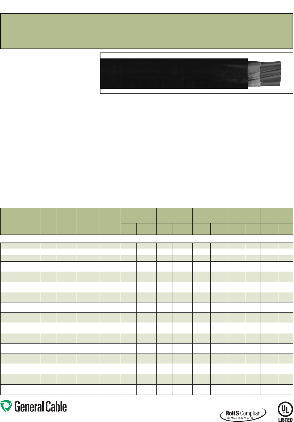
Phone: 888-593-3355
www.generalcable.com
CATALOG
NUMBER
NO. OF
COND.
COND.
SIZE
(AWG/
kcmil)
COND.
STRAND
GROUND
WIRE SIZE
(AWG)
MINIMUM AVG.
INSULATION
THICKNESS
MINIMUM AVG.
JACKET THICKNESS NOMINAL CABLE O.D.
COPPER
WEIGHT NET WEIGHT
INCHES mm INCHES mm INCHES mm
LBS/
1000 FT kg/km
LBS/
1000 FT kg/km
14 AWG - 750 kcmil MULTI-CONDUCTORS
394930* 314 7/.0242 14 0.030 0.76 0.045 1.14 0.390 9.91 55 82 118 176
394940* 312 7/.0305 12 0.030 0.76 0.045 1.14 0.435 11.05 87 129 160 238
394950* 310 7/.0385 10 0.030 0.76 0.045 1.14 0.485 12.32 124 184 194 289
14428.030800 387/.0486 10 0.045 1.14 0.060 1.52 0.655 16.64 190 283 314 467
14428.040800* 487/.0486 10 0.045 1.14 0.060 1.52 0.720 18.29 242 360 393 585
14428.030600 367/.0612 80.045 1.14 0.060 1.52 0.740 18.80 297 442 456 679
14428.040600* 467/.0612 80.045 1.14 0.060 1.52 0.790 20.07 384 571 561 835
14428.030400 347/.0772 80.045 1.14 0.080 2.03 0.880 22.35 442 658 642 955
14428.040400* 447/.0772 80.045 1.14 0.080 2.03 0.950 24.13 578 861 822 1223
14428.030200 327/.0974 60.045 1.14 0.080 2.03 1.010 25.65 703 1046 979 1457
14428.040200* 427/.0974 60.045 1.14 0.080 2.03 1.090 27.69 919 1368 1235 1838
14428.030100* 3119/.0664 60.055 1.40 0.080 2.03 1.120 28.45 872 1298 1021 1594
14428.040100* 4119/.0664 60.055 1.40 0.080 2.03 1.235 31.37 1136 1691 1521 2264
14428.035100 31/0 19/.0745 60.055 1.40 0.080 2.03 1.225 31.12 1069 1591 1439 2142
14428.045100* 41/0 19 /.0745 60.055 1.40 0.080 2.03 1.330 33.78 1413 2103 1820 2709
14428.035200 32/0 19/.0837 60.055 1.40 0.080 2.03 1.300 33.02 1340 1994 1720 2560
14428.045200* 42/0 19/.0837 60.055 1.40 0.080 2.03 1.440 36.58 1760 2619 2208 3286
14428.035300* 33/0 19/.0940 40.055 1.40 0.080 2.03 1.420 36.07 1717 2555 2176 3238
14428.045300* 43/0 19/.0940 40.055 1.40 0.080 2.03 1.570 39.88 2245 3341 2788 3405
14428.035400 34/0 19/.1055 40.055 1.40 0.080 2.03 1.540 39.12 2130 3170 2614 3890
14428.045400* 44/0 19/.1055 40.055 1.40 0.110 2.79 1.790 45.47 2796 4161 3495 5201
14428.036000* 3250 37/.0822 40.065 1.65 0.110 2.79 1.760 44.70 2494 3712 3184 4738
14428.046000* 4250 37/.0822 40.065 1.65 0.110 2.79 1.915 48.64 3282 4884 4019 5981
14428.036200* 3350 37/.0973 30.065 1.65 0.110 2.79 1.960 49.78 3474 5170 4187 6231
14428.046200* 4350 37/.0973 30.065 1.65 0.110 2.79 2.165 54.99 4577 6811 5436 8090
14428.036500* 3500 37/.1162 20.065 1.65 0.110 2.79 2.245 57.02 4934 7343 5847 8702
14428.046500* 4500 37/.1162 20.065 1.65 0.110 2.79 2.475 62.87 6509 9687 7607 11321
14428.037000* 3750 61/.1109 10.080 2.03 0.140 3.56 2.810 71.37 7278 10831 9145 13610
14428.047000* 4750 61/.1109 10.080 2.03 0.140 3.56 3.115 79.12 9712 14453 11805 17569
Dimensions and weights are nominal; subject to industry tolerances.
* Non-stock item; minimum runs apply. Please consult Customer Service for price and delivery.
SPEC 4950
October, 2012
GenFree
®
XLPE/LSZH, Low-Voltage Power, Unshielded
600 V, UL Type TC-LS-ER—Method 4 Color Code
Product Construction:
Conductor:
• 14 AWG thru 750 kcmil tinned annealed
copper per ASTM B33
• Class B stranding per ASTM B8
Insulation:
• Lead-free, flame-retardant, low-smoke
Cross-linked Polyethylene (XLPE)
• Color-coded per ICEA Method 4; individual
conductors colored black with conductor number
surface printed in contrasting ink
Ground:
• Uninsulated bare annealed copper per ASTM B3
• Class B stranding per ASTM B8
Jacket:
• Lead-free, flame-retardant, sunlight-resistant,
Low-Smoke, Zero-Halogen Polyolefin (LSZH)
Print:
• GENERAL CABLE® (PLANT OF MFG) GENFREE®
XX/C XXAWG XLPE/LSZH (UL) TYPE TC-LS-ER
XHHW-2 CDRS 90˚C WET OR DRY 600 V DIR
BUR SUN RES ROHS DAY/MONTH/YEAR OF
MFG SEQUENTIAL FOOTAGE MARK
Options:
• Bare copper conductor
• E-1 or E-2 Color Code
• Insulated ground conductors
• Overall shielded multi-conductors
• Other constructions available upon request
Applications:
• In free air, raceways, aerial or direct burial
• In wet or dry locations
• Permitted for use in Class I, Division 2 industrial
hazardous locations per NEC
• Permitted for Exposed Run (ER) use in
accordance with the NEC
Features:
• Rated at 90˚C wet or dry
• Ripcord applied to all cables with jacket thickness
of 60 mils or less
• Excellent physical, thermal and electrical
properties
• Excellent moisture resistance
• Excellent resistance to crush, compression and
impact
• Chemical-resistant
• Low coefficient of friction for easy pulling
• Sunlight- and weather-resistant
• Meets cold bend test at -30˚C
• Low-Smoke, Zero-Halogen jacket is
environmentally safe
Features (cont’d.):
•
Low-Smoke, Zero-Halogen jacket reduces the
amount of toxic and corrosive gases emitted during
combustion, providing a safer environment for
personnel and equipment during the hazards of fire
Compliances:
Industry Compliances:
• UL 44 Type XHHW-2
• UL 1277 Type TC-LS-ER, UL File # E57179
• UL 1581/UL 2556
• ICEA S-95-658/NEMA WC70
• ICEA T-33-655
• RoHS Compliant
Flame Test Compliances:
• UL 1581/UL 2556
• UL 1685 Vertical Flame Test
• IEEE 1202
Other Compliances:
• EPA 40 CFR, Part 261 for leachable lead
content per TCLP
• OSHA Acceptable
Packaging:
• Material cut to length and shipped on
non-returnable wood reels
Phone: 888-593-3355
www.generalcable.com
Date of Issue 06/13
Industrial Cables Section 5
600 V – 2 kV Industrial Power Cables
SPECIFICATION NO. PRODUCT DESCRIPTION REVISION DATE
5050†DuraSheath®EPR/XL-CPE, Low-Voltage Power, Unshielded
600 V, UL Type RHH/RHW-2/USE-2
Mar. 2012
5075GenFree® II LSZH XLPO/LSZH XLPO, Low-Voltage Power, Unshielded
600 V, UL Type RHH/RHW-2/USE-2
Jun. 2013
5100 Unicon® FREP®FR-EPR, Low-Voltage Power, Unshielded
600 V, UL Type RHH/RHW-2/USE-2
Jan. 2010
5125 GenFree® II LSZH XLPO, Low-Voltage Power, Unshielded
600 V, UL Type XHHW-2
Jun. 2013
5150†XHHW-2 VW-1 XLPE, Control and Low-Voltage Power
600 V, UL Type SIS/XHHW-2, VW-1 Rated
Oct. 2012
5175†XHHW-2 CT XLPE, Low-Voltage Power
600 V, UL Type XHHW-2, CT Rated, Single Conductor, Copper
Jan. 2013
5250†Unicon® XLPE XLPE, Low-Voltage Power
600 V, UL Type RHH/RHW-2/USE-2
Oct. 2012
5275 GenFree® II LSZH XLPO, Low-Voltage Power, Unshielded
600 V, UL Type RHH/RHW-2/USE-2
Jun. 2013
5290†THHN/THWN-2 PVC, Low-Voltage Power
600 V, UL Type THHN/THWN-2, Single Conductor, Copper
Oct. 2012
5300 Super Vu-Tron®EPR/CPE, Diesel Locomotive Cable
90°C, 2000 V, DLO, UL Type RHH/RHW, 600 V, CSA Type R90, 1000 V
Mar. 2012
5310†Diesel
Locomotive Cable
2000 Volts (EPR/XL-CPE), UL RHH/RHW-2 2000 V and c(UL) RW90 1000 V
Flexible, Oil-, Sunlight- and Ozone-Resistant, Flame-Retardant, -40°C to 90°C
May 2012
5350†GenFree® LSZH Sept. 2013
5400 GenFree® LSZH Sept. 2013
5700†RHH/RHW-2 XLPE, Low-Voltage Power, Unshielded
2000 V, UL Type RHH/RHW-2, Single Conductor, Aluminum
Mar. 2012
5790 SunGen®
Global
XLPE/LSZH XLPO, Photovoltaic Wire, TÜV 2 pfg
1169/08.2007 PV1-F AC Uo/U 0.6/1 kV, UL 4703, PV Wire 2000 V
May 2012
5800†SunGen®Dual-Layer EPR/XL-CPE, Photovoltaic Wire
600 V, UL Type PV/USE-2/RHH or RHW-2, Single Conductor, Copper
May 2012
5800A SunGen®Dual-Layer EPR/XL-CPE, Photovoltaic Wire
600 V, UL Type PV/USE-2/RHH or RHW-2, Single Conductor, Aluminum
Oct. 2012
5810†SunGen®Dual-Layer EPR/XL-CPE, Photovoltaic Wire
2000 V, UL Type PV/RHH or RHW-2 or 600 V USE-2, Single Conductor, Copper
May 2012
†Indicates these products are stocked by General Cable
DISCONTINUED
DISCONTINUED
Phone: 888-593-3355
www.generalcable.com
Date of Issue 06/13
Section 5 Industrial Cables
600 V – 2 kV Industrial Power Cables
SPECIFICATION NO. PRODUCT DESCRIPTION REVISION DATE
5810A SunGen®Dual-Layer EPR/XL-CPE, Photovoltaic Wire
2000 V, UL Type PV/RHH or RHW-2 or 600 V USE-2, Single Conductor, Aluminum
Oct. 2012
5840†SunGen®XLPE, Photovoltaic Wire
600 V, UL Type PV/USE-2 or 2000 V RHH or RHW-2 or CSA RPVU90
1000 V, Single Conductor, Copper
May 2012
5840A SunGen®XLPE, Photovoltaic Wire
600 V, UL Type PV/USE-2 or 2000 V RHH or RHW-2 or CSA RPVU90
1000 V, Single Conductor, Aluminum
Oct. 2012
5845†SunGen® IC XLPE, Photovoltaic Wire
600 V, UL Type PV/USE-2 or 2000 V RHH or RHW-2 or CSA RPVU90
1000 V, Single Conductor, Copper
May 2012
5850†SunGen®XLPE, Photovoltaic Wire
2000 V, UL Type PV/RHH or RHW-2 or 600 V USE-2 or CSA RPVU90
1000 V, Single Conductor, Copper
May 2012
5850A SunGen®XLPE, Photovoltaic Wire
2000 V, UL Type PV/RHH or RHW-2 or 600 V USE-2 or CSA RPVU90
1000 V, Single Conductor, Aluminum
Oct. 2012
5855†SunGen® IC XLPE, Photovoltaic Wire
2000 V, UL Type PV/RHH or RHW-2 or 600 V USE-2 or CSA RPVU90
1000 V, Single Conductor, Copper
May 2012
5880†SunGen® MI XLPE/PVC, AC Micro-Inverter Cable
600 V, UL Type TC-ER
May 2012
5890†SunGen® MI-LS XLPO/LSZH, AC Micro-Inverter Cable
600 V, UL Type TC-LS-ER
May 2012
†Indicates these products are stocked by General Cable
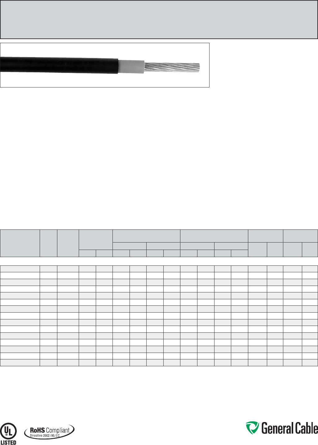
Phone: 888-593-3355
www.generalcable.com
CATALOG
NUMBER
COND.
SIZE
(AWG/
kcmil)
COND.
STRAND
NOMINAL COND.
DIAMETER
MINIMUM AVG.
INSULATION
MINIMUM AVG.
JACKET
COPPER
WEIGHT NET WEIGHT
THICKNESS DIAMETER THICKNESS DIAMETER LBS/
1000 FT
kg/
km
LBS/
1000 FT
kg/
kmINCHES mm INCHES mm INCHES mm INCHES mm INCHES mm
14 AWG - 1000 kcmil CONDUCTORS
14511.411400 14 7/.0242 0.07 1.78 0.030 0.76 0.14 3.56 0.015 0.38 0.17 4.32 13 19 24 36
14511.411200 12 7/.0305 0.09 2.29 0.030 0.76 0.16 4.06 0.015 0.38 0.19 4.83 20 30 33 49
14511.411000 10 7/.0385 0.12 3.05 0.030 0.76 0.18 4.57 0.015 0.38 0.21 5.33 32 48 48 71
14511.410800 8 7/.0486 0.15 3.81 0.045 1.14 0.24 6.10 0.015 0.38 0.28 7.11 50 75 77 115
14511.410600 6 7/.0612 0.18 4.57 0.045 1.14 0.28 7.11 0.030 0.76 0.35 8.89 81 121 122 182
14511.410400 4 7/.0772 0.23 5.84 0.045 1.14 0.33 8.38 0.030 0.76 0.39 9.91 129 192 178 265
14511.710200 2 7/.0974 0.29 7.37 0.045 1.14 0.39 9.91 0.030 0.76 0.46 11.68 205 305 265 394
14511.715100 1/0 19/.0740 0.37 9.40 0.055 1.40 0.48 12.19 0.045 1.14 0.58 14.73 326 485 422 628
14511.715200 2/0 19/.0837 0.41 10.41 0.055 1.40 0.53 13.46 0.045 1.14 0.63 16.00 411 612 518 771
14511.715400 4/0 19/.1055 0.52 13.21 0.055 1.40 0.64 16.26 0.045 1.14 0.74 18.80 653 972 785 1168
14511.716000 250 37/.0822 0.56 14.22 0.065 1.65 0.70 17.78 0.065 1.65 0.85 21.59 772 1149 960 1429
14511.716200 350 37/.0973 0.67 17.02 0.065 1.65 0.81 20.57 0.065 1.65 0.96 24.38 1081 1609 1299 1933
14511.716500 500 37/.1162 0.80 20.32 0.065 1.65 0.94 23.88 0.065 1.65 1.09 27.69 1542 2295 1803 2683
14511.717000 750 61/.1109 0.98 24.89 0.080 2.03 1.15 29.21 0.065 1.65 1.31 33.27 2316 3447 2664 3965
14511.717500 1000 61/.1280 1.13 28.70 0.080 2.03 1.31 33.27 0.065 1.65 1.46 37.08 3086 4593 3989 5936
Dimensions and weights are nominal; subject to industry tolerances.
SPEC 5050
March, 2012
DuraSheath
®
EPR/XL-CPE, Low-Voltage Power, Unshielded
600 V, UL Type RHH/RHW-2/USE-2
Product Construction:
Conductor:
•14AWGthru1000kcmiltin-coatedcopper
compressedClassBstrandingperASTMB33
and B8
Insulation:
•Lead-freeEthylenePropyleneRubber(EPR)
coloredtocontrastwithjacket
Jacket:
•Lead-freeCross-linkedChlorinatedPolyethylene
(XL-CPE ) ,black
Print:
For 1 AWG and smaller:
•GENERALCABLE®MIDURASHEATH® TYPE
USE-2ORRHHORRHW-2VW-1(AWGSIZE)
(MMSIZE)EP600VOLTSSUNRES(UL)ROHS
MONTH/YEAROFMFGSEQUENTIALFOOTAGE
MARK
For 1/0 AWG and larger:
•GENERALCABLE®MIDURASHEATH® LL TYPE
USE-2ORRHHORRHW-2VW-1(AWGSIZE)
(MMSIZE)EP600VOLTSSUNRESFORCTUSE
(UL)ROHSMONTH/YEAROFMFGSEQUENTIAL
FOOTAGEMARK
Options:
•Coloredjacketsavailableuponrequest
•2000Vratedcables
Applications:
•Ideallysuitedforuseinabroadrangeof
commercial, industrial and utility applications
where reliability is a major concern and where
maximum performance will be demanded
•Infreeair,racewaysordirectburial
•Foruseinaerial,conduit,opentrayand
underground duct/installations
Features:
•Ratedat90˚Cwetordry
•Deformation-resistantathightemperatures
•Excellentmoistureresistance,exceedsUL44
•Stableelectricalpropertiesoverabroad
temperature range
•Excellentflexibilityatlowtemperatures;suitable
for installation in sub-zero conditions
•Extra-tough,mechanicallyruggedcomposite
insulationandjacketconstruction
•Resistanttomostoilsandchemicals
•UV/sunlight-resistant
•MeetsUL44coldbendtestat-40˚C
Compliances:
Industry Compliances:
•NationalElectricCode(NEC)
•ICEAS-95-658/NEMAWC70
•“FORCTUSE”on1/0AWGandlarger
inaccordancewiththeNEC
•UL44TypeRHH/RHW-2,ULFile#E90494
•UL854TypeUSE-2,ULFile#E90499
Flame Test Compliances:
•UL1581VW-1
•IEEE1202/CSAFT4
Other Compliances:
•EPA40CFR,Part261forleachablelead
content per TCLP
•OSHAAcceptable
•RoHSCompliant
Packaging:
•Materialcuttolengthandshippedon
non-returnable wood reels
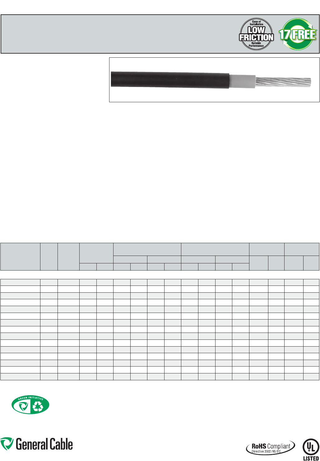
Phone: 888-593-3355
www.generalcable.com
GenFree
®
II
LSZHXLPO/LSZHXLPO,Low-VoltagePower,Unshielded
600 V, UL Type RHH/RHW-2/USE-2
Product Construction:
Conductor:
•14AWGthru1000kcmilcompressedtinnedcopper
perASTMB33
•ClassBstrandingperASTMB8
Insulation:
•CompositeLow-Smoke,Zero-HalogenCross-linked
Polyolefin(LSZHXLPO)coloredforcontrastwith
blackLow-Smoke,Zero-HalogenCross-linked
Polyolefin(LSZHXLPO)
Print:
•GENERALCABLE®(PLANTOFMFG)GENFREE® II
17FREE™LSZHTYPEUSE-2ORRHHORRHW-2
(SIZE)600VOILRESISUNRES-40CST1*
FORCTUSE*(UL)DAY/MONTH/YEAROFMFG
SEQUENTIALFOOTAGEMARK
*“ST1”and“FORCTUSE”on1/0AWGandlarger
Options:
•2kVversion
•Barecopperconductor
•Otherstrandingavailable
Applications:
•Foruseinclosedenvironmentsorpopulatedspaces
such as auditoriums, arenas and health facilities
where more stringent customer specifications for
smokeandhalogen-freematerialsaredesired
•Ideallysuitedforuseinabroadrangeof
commercial, industrial and utility applications
where reliability is a major concern, where
maximum performance will be demanded and
where space is limited
•Foruseinfreeair,racewaysordirectburialin
accordancewithNEC
Features:
•Ratedat90˚Cwetordry
•Low-Smoke,Zero-Halogeninsulationsystem
•Extra-tough,mechanicallyruggedcomposite
insulation construction
•LowFrictionforeasypullingon8AWGandlarger
•Excellentelectrical,thermalandphysicalproperties
•Excellentmoistureresistance,exceedingUL44
requirements
•Excellentresistancetocrush,compressioncuts
and heat deformation
•Excellentflameresistance
•Resistanttomostoilsandchemicals
•UV/sunlight-resistant
•RatedST-1forLimitedSmokeperUL44onsizes
1/0AWGandlarger
•Stableelectricalpropertiesoverabroad
temperature range
•Excellentlowtemperaturecoldbendcharacteristics,
meetscoldbendandcoldimpacttestat-40˚C
Compliances:
Industry Compliances:
•NationalElectricalCode(NEC)
•“FORCTUSE”on1/0AWGandlargerin
accordancewithNEC
•UL44TypeRHH/RHW-2,ULFile#E90494
•UL854TypeUSE-2,ULFile#E90499
•LimitedSmokeratingperUL44andUL1685
•ICEAT-33-655smoke,halogenandacidgas
requirements
•ICEAS-95-658/NEMAWC70
Flame Test Compliances:
•For1/0AWGandlarger:IEEE383,IEEE1202/CSAFT4
•UL1685
Other Compliances:
•EPA40CFR,Part261forleachableleadcontent
per TCLP
•OSHAAcceptable
•RoHSCompliant
Packaging:
•Materialcuttolengthandshippedon
non-returnable wood reels
SPEC 5075
June, 2013
CATALOG
NUMBER
COND.
SIZE
(AWG/
kcmil)
COND.
STRAND
NOMINAL COND.
DIAMETER
MINIMUM AVG.
INSULATION
MINIMUM AVG.
JACKET
COPPER
WEIGHT NET WEIGHT
THICKNESS DIAMETER THICKNESS DIAMETER LBS/
1000 FT
kg/
km
LBS/
1000 FT
kg/
kmINCHES mm INCHES mm INCHES mm INCHES mm INCHES mm
14 AWG - 1000 kcmil CONDUCTORS
14711.411400 14 7/.0242 0.07 1.78 0.030 0.76 0.14 3.56 0.015 0.38 0.17 4.32 13 19 24 36
14711.411200 12 7/.0305 0.09 2.29 0.030 0.76 0.16 4.06 0.015 0.38 0.19 4.83 20 30 33 49
14711.411000 10 7/.0385 0.12 3.05 0.030 0.76 0.18 4.57 0.015 0.38 0.21 5.33 32 48 48 71
14711.410800 8 7/.0486 0.15 3.81 0.045 1.14 0.24 6.10 0.015 0.38 0.28 7.11 50 75 77 115
14711.410600 6 7/.0612 0.18 4.57 0.045 1.14 0.28 7.11 0.030 0.76 0.35 8.89 81 121 122 182
14711.410400 4 7/.0772 0.23 5.84 0.045 1.14 0.33 8.38 0.030 0.76 0.39 9.91 129 192 178 265
14711.710200 2 7/.0974 0.29 7.37 0.045 1.14 0.39 9.91 0.030 0.76 0.46 11.68 205 305 265 394
14711.715100 1/0 19/.0740 0.37 9.40 0.055 1.40 0.48 12.19 0.045 1.14 0.58 14.73 326 485 422 628
14711.715200 2/0 19/.0837 0.41 10.41 0.055 1.40 0.53 13.46 0.045 1.14 0.63 16.00 411 612 518 771
14711.715400 4/0 19/.1055 0.52 13.21 0.055 1.40 0.64 16.26 0.045 1.14 0.74 18.80 653 972 785 1168
14711.716000 250 37/.0822 0.56 14.22 0.065 1.65 0.70 17.78 0.065 1.65 0.85 21.59 772 1149 960 1429
14711.716200 350 37/.0973 0.67 17.02 0.065 1.65 0.81 20.57 0.065 1.65 0.96 24.38 1081 1609 1299 1933
14711.716500 500 37/.1162 0.80 20.32 0.065 1.65 0.94 23.88 0.065 1.65 1.09 27.69 1542 2295 1803 2683
14711.717000 750 61/.1109 0.97 24.62 0.080 2.03 1.15 29.21 0.065 1.65 1.31 33.27 2316 3447 2664 3965
14711.717500* 1000 61/.1280 1.13 28.70 0.080 2.03 1.31 33.27 0.065 1.65 1.46 37.08 3806 5664 3989 5936
Dimensions and weights are nominal; subject to industry tolerances.
*Non-stockitem;minimumrunsapply.PleaseconsultCustomerServiceforpriceanddelivery.
Going Green with General Cable
GeneralCablehasaccelerateditsenvironmentalcommitment,addressingitsgreenalternativeapproachbyidentifyinggreeneropportunities
andpromotinggreencablingsolutionswhereverfeasible.Thisincludespromotingourexistinggreenproducts,partneringwithkeycustomers
intheirgreenendeavors,identifyingandprovidingforgreenproductgaps,andparticipatingasamemberoftheUnitedStatesGreenBuilding
Council(USGBC)andcollaborativeventuressuchastheGreenSuppliersNetwork(GSN).
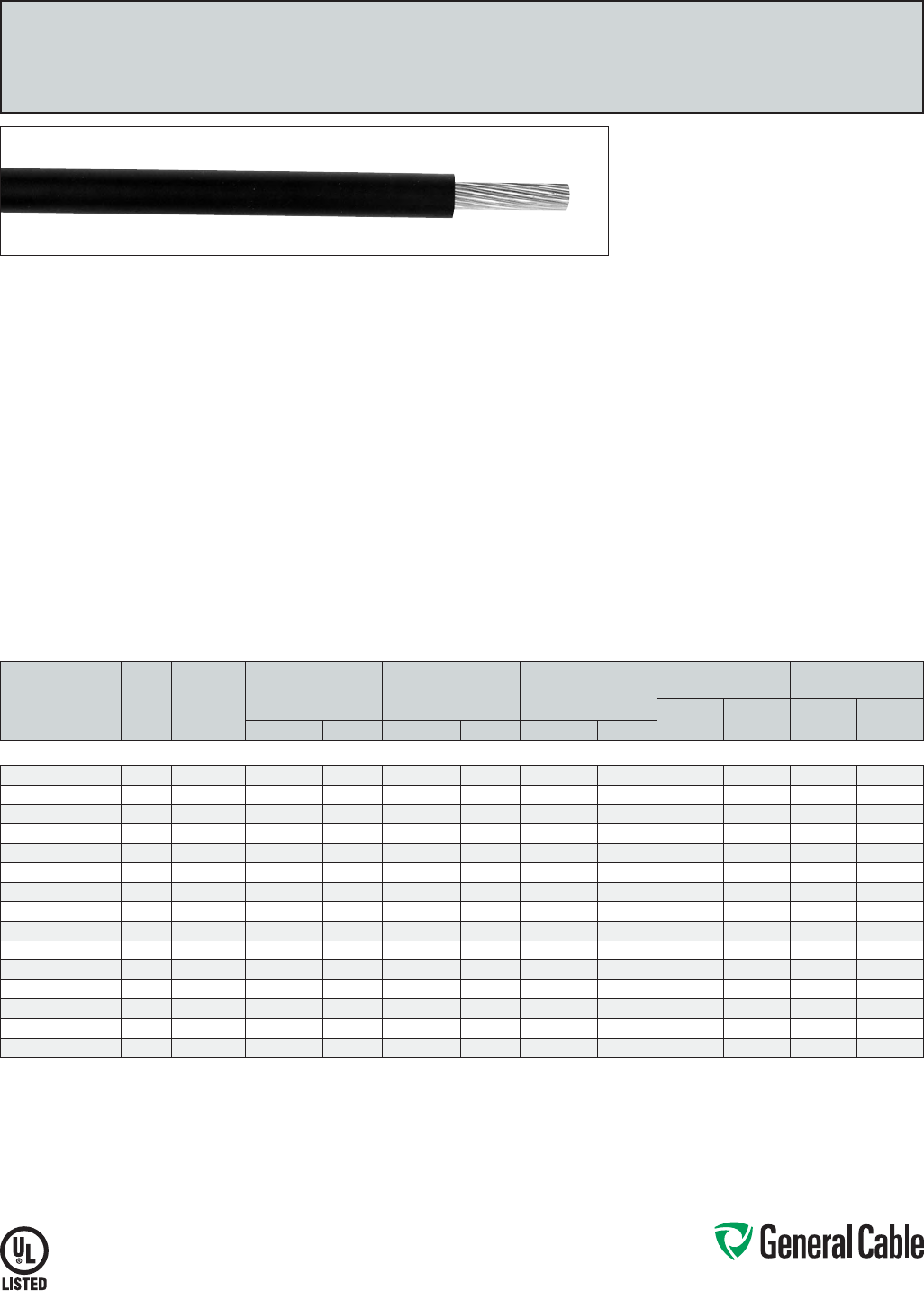
Phone: 888-593-3355
www.generalcable.com
SPEC 5100
January, 2010
CATALOG
NUMBER
COND.
SIZE
(AWG/
kcmil)
COND.
STRAND
NOMINAL COND.
DIAMETER
MINIMUM AVG.
INSULATION THICKNESS
NOMINAL CABLE
O.D.
COPPER
WEIGHT NET WEIGHT
LBS/
1000 FT kg/km
LBS/
1000 FT kg/kmINCHES mm INCHES mm INCHES mm
14 AWG - 1000 kcmil CONDUCTORS
14101.211400* 14 7/.0242 0.07 1.78 0.045 1.14 0.17 4.32 13 19 24 36
14101.211200* 12 7/.0305 0.09 2.29 0.045 1.14 0.19 4.83 20 30 33 49
14101.211000* 10 7/.0385 0.12 3.05 0.045 1.14 0.21 5.33 32 48 48 71
14101.210800* 8 7/.0486 0.15 3.81 0.060 1.52 0.27 6.86 50 75 78 116
14101.210600* 6 7/.0612 0.18 4.57 0.060 1.52 0.31 7.87 81 121 114 170
14101.210400* 4 7/.0772 0.23 5.84 0.060 1.52 0.36 9.14 129 192 169 252
14101.210200* 2 7/.0974 0.29 7.37 0.060 1.52 0.42 10.67 205 305 254 378
14101.215100* 1/0 19/.0740 0.37 9.40 0.080 2.03 0.53 13.46 326 485 402 598
14101.215200* 2/0 19/.0837 0.41 10.41 0.080 2.03 0.58 14.73 411 612 500 744
14101.215400* 4/0 19/.1055 0.52 13.21 0.080 2.03 0.69 17.53 653 972 759 1130
14101.216000* 250 37/.0822 0.56 14.22 0.095 2.41 0.77 19.56 772 1149 905 1347
14101.216200* 350 37/.0973 0.67 17.02 0.095 2.41 0.87 22.10 1081 1609 1235 1838
14101.216500* 500 37/.1162 0.80 20.32 0.095 2.41 1.00 25.40 1542 2295 1728 2572
14101.217000* 750 61/.1109 0.98 24.89 0.110 2.79 1.22 30.99 2316 3447 2573 3829
14101.217500* 1000 61/.1280 1.13 28.70 0.110 2.79 1.37 34.80 3086 4593 3402 5063
Dimensions and weights are nominal; subject to industry tolerances.
*Non-stockitem;minimumrunsapply.PleaseconsultCustomerServiceforpriceanddelivery.
Unicon
®
FREP
®
FR-EPR,Low-VoltagePower,Unshielded
600 V, UL Type RHH/RHW-2/USE-2
Product Construction:
Conductor:
•14AWGthru1000kcmilstrandedannealed
bare copper compressed Class B stranding per
ASTMB8
Insulation:
•Flame-retardantEthylenePropylene
Rubber(EPR)
Print:
•GENERALCABLE®(PLANTOFMFG)UNICON®
FREP® TYPE USE-2 OR RHH OR RHW-2
VW-1SIZE(AWGORKCMIL)600VOLTS
SUNRESFORCTUSE(UL)DAY/MONTH/YEAR
OFMFGSEQUENTIALFOOTAGEMARK
*Sizessmallerthan1/0AWGdonotinclude
“FORCTUSE”
Options:
•2kVversion
•Tinnedcopperconductor
•ClassCstranding
•Unicon®XLPE—flame-retardantCross-linked
Polyethylene(XLPE)insulation
•Otherconstructionsavailableuponrequest
Applications:
•Ideallysuitedforuseinbroadrangeof
commercial, industrial and utility applications
where reliability is the major concern, where
maximum performance will be demanded and
where space is limited
•Infreeair,racewaysordirectburialinaccordance
withNEC
Features:
•Ratedat90˚Cwetordry
•Smallercablediameter
•Excellentelectrical,thermalandphysical
properties
•Excellentresistancetomoisture
•Excellentresistancetocrush,compressioncuts
and heat deformation
•Excellentflameresistance
•Excellentlowtemperaturecoldbend
characteristics
•Meetscoldbendtestat-25˚C
Compliances:
Industry Compliances:
•NationalElectricalCode(NEC)
•UL44TypeRHH/RHW-2,ULFile#E90494
•UL854TypeUSE-2,ULFile#E90499
•ICEAS-95-658/NEMAWC70
•“FORCTUSE”on1/0AWGandlargerin
accordancewithNEC
•ULListedVW-1
Flame Test Compliances:
•UL1581VW-1
•For1/0AWGandlarger:IEEE383,IEEE1202/
CSAFT4,ICEAT-29-520
Other Compliances:
•EPA40CFR,Part261forleachablelead
content per TCLP
•OSHAAcceptable
Packaging:
•Materialcuttolengthandshippedonnon-
returnable wood reels
Phone: 888-593-3355
www.generalcable.com
SPEC 5125
June, 2013
GenFree
®
II
LSZHXLPO,Low-VoltagePower,Unshielded
600 V, UL Type XHHW-2
CATALOG
NUMBER
COND.
SIZE
(AWG/
kcmil)
COND.
STRAND
NOMINAL COND.
DIAMETER
MINIMUM AVG.
INSULATION
THICKNESS
NOMINAL CABLE
O.D.
COPPER
WEIGHT NET WEIGHT AMPACITY (1)
LBS/
1000 FT kg/km
LBS/
1000 FT kg/km 60°C 75°C 90°CINCHES mm INCHES mm INCHES mm
14 AWG - 750 kcmil CONDUCTORS
5125.014* 14 7/.0240 0.07 1.80 0.030 0.76 0.13 3.38 12 18 17 25 15 15 15
5125.012* 12 7/.0305 0.09 2.26 0.030 0.76 0.15 3.84 20 30 26 39 20 20 20
5125.010* 10 7/.0385 0.11 2.87 0.030 0.76 0.18 4.57 32 48 38 57 30 30 30
5125.008* 8 7/.0486 0.14 3.56 0.045 1.14 0.24 6.10 51 76 65 97 40 50 55
5125.006* 6 7/.0612 0.18 4.57 0.045 1.14 0.28 7.11 81 121 99 147 55 65 75
5125.004* 4 7/.0772 0.23 5.84 0.045 1.14 0.33 8.38 129 192 152 226 70 85 95
5125.002* 2 7/.0974 0.29 7.37 0.045 1.14 0.39 9.91 205 305 233 347 95 115 130
5125.001* 1 19/.0664 0.32 8.13 0.055 1.40 0.44 11.18 256 381 293 437 110 130 145
5125.110* 1/0 19/.0740 0.36 9.14 0.055 1.40 0.48 12.19 326 485 364 572 125 150 170
5125.210* 2/0 19/.0837 0.41 10.41 0.055 1.40 0.53 13.46 411 612 453 674 145 175 195
5125.310* 3/0 19/.0940 0.46 11.68 0.055 1.40 0.58 14.73 518 772 565 842 165 200 225
5125.410* 4/0 19/.1055 0.51 12.95 0.055 1.40 0.63 16.00 653 972 706 1051 195 230 260
5125.250* 250 37/.0822 0.56 14.22 0.065 1.65 0.70 17.78 722 1074 837 1246 215 255 290
5125.350* 350 37/.0973 0.66 16.76 0.065 1.65 0.80 20.32 1081 1609 1157 1722 260 310 350
5125.500* 500 37/.1162 0.79 20.07 0.065 1.65 0.93 23.62 1544 2298 1634 2432 320 380 430
5125.600* 600 61/.0992 0.87 22.10 0.080 2.03 1.04 26.42 1853 2758 1972 2935 350 420 475
5125.750* 750 61/.1109 0.97 24.62 0.080 2.03 1.15 29.21 2316 3447 2448 3643 400 475 535
Dimensions and weights are nominal; subject to industry tolerances.
*Non-stockitem;minimumrunsapply.PleaseconsultCustomerServiceforpriceanddelivery.
(1)AllowableampacitiesshownareforgeneraluseasspecifiedbytheNationalElectricCode,2011Edition,section310.15(B)(16).Adjustmentsandcorrectionsmayapply:
60°C–Whenterminatedtoequipmentforcircuitsrated100amperesorlessormarkedfor14through1AWGconductors.
75°C–Whenterminatedtoequipmentforcircuitsratedover100amperesormarkedforconductorslargerthan1AWG.
90°C–Wetordrylocations.Forampacityderatingpurposes.
Dwelling–Fordwellingunits,conductorsshallbepermittedaslistedampacitiesat120/240-volt,3-wire,single-phaseservicesandfeeders.
Product Construction:
Conductor:
•14AWGthru1000kcmilstrandedannealedbare
copperperASTMB3
•CompressedClassBstrandingperASTMB8
Insulation:
•Low-Smoke,Zero-HalogenFlame-Retardant
Cross-linkedPolyolefin(LSZHXLPO),black
•Colorsavailableuponrequest
Print:
•GENERALCABLE®(PLANTOFMFG)GENFREE® II
17FREE™LSZHTYPEXHHW-2(SIZE)600VOIL
RESISUNRES-40ºCST1*FORCTUSE*(UL)
DAY/MONTH/YEAROFMFGSEQUENTIAL
FOOTAGEMARK
*“ST1”and“FORCTUSE”on1/0AWGandlarger
Options:
•Tinnedcopperconductor
•Otherstrandingavailable
•Colorsavailableuponrequest
Applications:
•Foruseinclosedenvironmentsorpopulatedspaces
such as auditoriums, arenas and health facilities
where more stringent customer specifications for
smokeandhalogen-freematerialsaredesired
•Ideally suited for use in a broad range of commercial,
industrial and utility applications where reliability is a
major concern, where maximum performance will be
demanded and where space is limited
Applications (cont'd):
•Foruseinfreeair,racewaysordirectburialin
accordancewithNEC
Features:
•Ratedat90˚Cwetordry
•Low-Smoke,Zero-Halogeninsulationsystem
•SmallercableO.D.
•LowFrictionforeasypullingon8AWGandlarger
•Excellentelectrical,thermalandphysicalproperties
•Excellentmoistureresistance,exceedingUL44
requirements
•Excellentresistancetocrush,compressioncuts
and heat deformation
•Excellentflameresistance
•Resistanttomostoilsandchemicals
•UV/sunlight-resistant
•RatedST-1forLimitedSmokeperUL44onsizes
1/0AWGandlarger
•Stableelectricalpropertiesoverabroad
temperature range
•Excellentlowtemperaturecoldbendcharacteristics,
meetscoldbendandcoldimpacttestat-40˚C
Compliances:
Industry Compliances:
•NationalElectricalCode(NEC)
•“FORCTUSE”on1/0AWGandlargerin
accordancewithNEC
•UL44TypeXHHW-2,ULFile#E90494
•LimitedSmokeratingperUL44andUL1685
•ICEAT-33-655smoke,halogenandacidgas
requirements
•ICEAS-95-658/NEMAWC70
Flame Test Compliances:
•For1/0AWGandlarger:IEEE383,IEEE1202/CSAFT4
•UL1685
Other Compliances:
•EPA40CFR,Part261forleachableleadcontent
per TCLP
•OSHAAcceptable
•RoHSCompliant
Packaging:
•Materialcuttolengthandshippedonnon-
returnable wood reels
Going Green with General Cable
GeneralCablehasaccelerateditsenvironmentalcommitment,addressingitsgreenalternativeapproachbyidentifyinggreeneropportunities
andpromotinggreencablingsolutionswhereverfeasible.Thisincludespromotingourexistinggreenproducts,partneringwithkeycustomers
intheirgreenendeavors,identifyingandprovidingforgreenproductgaps,andparticipatingasamemberoftheUnitedStatesGreenBuilding
Council(USGBC)andcollaborativeventuressuchastheGreenSuppliersNetwork(GSN).
Phone: 888-593-3355
www.generalcable.com
SPEC 5150
October, 2012
XHHW-2 VW-1
XLPE, Control and Low-Voltage Power, 600 V
UL Type SIS/XHHW-2, VW-1 Rated, Single Conductor, Copper
Product Construction:
Conductor:
•18AWGthru1000kcmiltinned,annealed
copperperASTMB33
•ClassBstrandingperASTMB8
Insulation:
•Flame-retardantCross-linkedPolyethylene(XLPE)
Print:
For 18 AWG and 16 AWG:
•GENERALCABLE®(PLANTOFMFG)1CXXAWG
COPPERXLPESISTYPE600V90CYEAROF
MFG
For 14 AWG thru 4 AWG:
•GENERALCABLE®(PLANTOFMFG)1CXXAWG
COPPERXLPETYPESIS/XHHW-2VW-1(UL)
600V90CYEAROFMFG
For 2 AWG and larger:
•GENERALCABLE®(PLANTOFMFG)1CXXAWG
COPPERXLPETYPEXHHW-2VW-1SUNRES
FORCTUSE(UL)YEAROFMFGSEQUENTIAL
FOOTAGEMARK
*Sizessmallerthan1/0AWGdonotinclude“FORCTUSE”
Applications:
•Foruseinpowerandcontrolcircuitsin
switchboards, control panels and raceways in
applicationsnotexceeding600volts
•AcceptableforuseinOSHAregulatedinstallations
Features:
•Ratedat90˚Cwetordry
•ULListedasSIS/XHHW-2¥ and XHHW-2¥¥ for
general power or control wiring in accordance
withtheNationalElectricalCode,Section310.15,
Tables310.15(B)16or310.15(B)17
•Sizes1/0andlargerforCTuse
•Excellentflameresistance
•Sunlight-resistant
•Excellentphysical,thermalandelectrical
properties
Compliances:
Industry Compliances:
•ULTypeSIS/XHHW-2¥—600 V
•ULFile#E90494
•ULTypeXHHW-2¥¥—600 V
•ICEAS-95-658/NEMAWC70
•1/0andlargerarelisted“SunResFORCT
USE”inaccordancewithNEC
Flame Test Compliances:
•UL44VW-1
Other Compliances:
•EPA40CFR,Part261forleachable
lead content per TCLP method
•OSHAAcceptable
Packaging:
•Materialtobeshippedonspoolsornon-
returnable wood reels
¥ULTypeSIS/XHHW-2forsizes14AWGthru
4AWG
¥¥ULTypeXHHW-2forsizes2AWGthru
1000kcmil
CATALOG
NUMBER
COND.
SIZE
(AWG/
kcmil)
COND.
STRAND
NOMINAL COND.
DIAMETER
MINIMUM AVG.
INSULATION
THICKNESS
NOMINAL CABLE
O.D.
COPPER
WEIGHT NET WEIGHT AMPACITY (1)
LBS/
1000 FT kg/km
LBS/
1000 FT kg/km 60°C 75°C 90°CINCHES mm INCHES mm INCHES mm
18 AWG - 1000 kcmil CONDUCTORS
381500
18 7/.0152 0.05 1.27 0.030 0.76 0.11 2.74 5 8 9 14 — — —
381510
16 7/.0192 0.06 1.47 0.030 0.76 0.12 3.05 8 12 13 20 — — —
381520
14 7/.0242 0.07 1.80 0.030 0.76 0.13 3.38 13 19 19 28 15 15 15
381530
12 7/.0305 0.09 2.29 0.030 0.76 0.15 3.86 20 30 27 41 20 20 20
381540
10 7/.0385 0.11 2.87 0.030 0.76 0.18 4.45 32 48 41 61 30 30 30
381550
8 7/.0486 0.14 3.56 0.045 1.14 0.24 6.05 51 76 69 102 40 50 55
381560
6 7/.0612 0.18 4.57 0.045 1.14 0.28 6.99 81 121 103 153 55 65 75
381570
4 7/.0772 0.23 5.84 0.045 1.14 0.32 8.18 129 192 156 232 70 85 95
06591.210200
2 7/.0974 0.29 7.37 0.045 1.14 0.38 9.68 205 305 239 355 95 115 130
06591.215100
1/0 19/.0745 0.36 9.14 0.055 1.40 0.48 12.14 326 485 373 556 125 150 170
06591.215200
2/0 19/.0837 0.41 10.41 0.055 1.40 0.52 13.28 411 612 464 691 145 175 195
06591.215300
3/0 19/.0940 0.46 11.68 0.055 1.40 0.57 14.55 518 771 579 862 165 200 225
06591.215400
4/0 19/.1055 0.51 12.95 0.055 1.40 0.63 15.98 653 972 722 1075 195 230 260
06591.216000
250 37/.0822 0.56 14.22 0.065 1.65 0.70 17.75 772 1149 860 1280 215 255 290
06591.216200
350 37/.0973 0.66 16.76 0.065 1.65 0.80 20.37 1081 1609 1185 1764 260 310 350
06591.216500
500 37/.1162 0.79 20.07 0.065 1.65 0.93 23.65 1544 2298 1669 2484 320 380 430
06591.217000
750 61/.1109 0.97 24.64 0.080 2.03 1.14 29.03 2316 3447 2520 3750 400 475 535
06591.217500
1000 61/.1280 1.13 28.70 0.080 2.03 1.30 33.02 3086 4593 3283 4886 445 545 615
Dimensions and weights are nominal; subject to industry tolerances.
(1)AllowableampacitiesshownareforgeneraluseasspecifiedbytheNationalElectricCode,2011Edition,section310.15(B)(16).Adjustmentsandcorrectionsmayapply:
60°C–Whenterminatedtoequipmentforcircuitsrated100amperesorlessormarkedfor14through1AWGconductors.
75°C–Whenterminatedtoequipmentforcircuitsratedover100amperesormarkedforconductorslargerthan1AWG.
90°C–Wetordrylocations.Forampacityderatingpurposes.
Dwelling–Fordwellingunits,conductorsshallbepermittedaslistedampacitiesat120/240-volt,3-wire,single-phaseservicesandfeeders.
Phone: 888-593-3355
www.generalcable.com
S P E C 5175
January, 2013
XHHW-2 CT
XLPE, Low-Voltage Power, 600 V
UL Type XHHW-2, CT Rated, Single Conductor, Copper
CATALOG
NUMBER
COND.
SIZE
(AWG/
kcmil)
COND.
STRAND
NOMINAL COND.
DIAMETER
MINIMUM AVG.
INSULATION
THICKNESS
NOMINAL CABLE
O.D.
COPPER
WEIGHT NET WEIGHT AMPACITY (1)
LBS/
1000 FT kg/km
LBS/
1000 FT kg/km 60°C 75°C 90°CINCHES mm INCHES mm INCHES mm
14 AWG - 750 kcmil CONDUCTORS
391070 14 7/.0240 0.07 1.80 0.030 0.76 0.13 3.38 12 18 17 25 15 15 15
391080 12 7/.0305 0.09 2.26 0.030 0.76 0.15 3.84 20 30 26 39 20 20 20
391090 10 7/.0385 0.11 2.87 0.030 0.76 0.18 4.57 32 48 38 57 30 30 30
5175.008 8 7/.0486 0.14 3.56 0.045 1.14 0.24 6.10 51 76 65 97 40 50 55
5175.006 6 7/.0612 0.18 4.57 0.045 1.14 0.28 7.11 81 121 99 147 55 65 75
5175.004 4 7/.0772 0.23 5.84 0.045 1.14 0.33 8.38 129 192 152 226 70 85 95
5175.002 2 7/.0974 0.29 7.37 0.045 1.14 0.39 9.91 205 305 233 347 95 115 130
5175.001 1 19/.0664 0.32 8.13 0.055 1.40 0.44 11.18 256 381 293 437 110 130 145
5175.110 1/0 19/.0740 0.36 9.14 0.055 1.40 0.48 12.19 326 485 364 572 125 150 170
5175.210 2/0 19/.0837 0.41 10.41 0.055 1.40 0.53 13.46 411 612 453 674 145 175 195
5175.310 3/0 19/.0940 0.46 11.68 0.055 1.40 0.58 14.73 518 772 565 842 165 200 225
5175.410 4/0 19/.1055 0.51 12.95 0.055 1.40 0.63 16.00 653 972 706 1051 195 230 260
5175.250 250 37/.0822 0.56 14.22 0.065 1.65 0.70 17.78 722 1074 837 1246 215 255 290
5175.350 350 37/.0973 0.66 16.76 0.065 1.65 0.80 20.32 1081 1609 1157 1722 260 310 350
5175.500 500 37/.1162 0.79 20.07 0.065 1.65 0.93 23.62 1544 2298 1634 2432 320 380 430
5175.600 600 37/.1109 0.87 22.10 0.080 2.03 1.04 26.42 1853 2758 1972 2935 350 420 475
5175.750 750 61/.1280 0.98 24.89 0.080 2.03 1.15 29.21 2316 3447 2448 3643 400 475 535
Dimensions and weights are nominal; subject to industry tolerances.
(1)AllowableampacitiesshownareforgeneraluseasspecifiedbytheNationalElectricCode,2011Edition,section310.15(B)(16).Adjustmentsandcorrectionsmayapply:
60°C–Whenterminatedtoequipmentforcircuitsrated100amperesorlessormarkedfor14through1AWGconductors.
75°C–Whenterminatedtoequipmentforcircuitsratedover100amperesormarkedforconductorslargerthan1AWG.
90°C–Wetordrylocations.Forampacityderatingpurposes.
Dwelling–Fordwellingunits,conductorsshallbepermittedaslistedampacitiesat120/240-volt,3-wire,single-phaseservicesandfeeders.
Product Construction:
Conductor:
•14AWGthru750kcmilannealedbarecopper
perASTMB3
•ClassBstrandingperASTMB8
Insulation:
•Flame-retardantCross-linked
Polyethylene(XLPE)
Print:
•GENERALCABLE®(PLANTOFMFG)AWG/
KCMILLOWFRICTION*TYPEXHHW-2(UL)600V
SUNRESFORCTUSE**MONTH/YEAROFMFG
SEQUENTIALFOOTAGEMARK
*Sizes14AWG-10AWGdonotinclude“LOWFRICTION”
**Sizessmallerthan1/0AWGdonotinclude“SUNRESFOR
CTUSE”
Options:
•Tinnedcopperconductor
•Fullcoloredinsulation
Applications:
•Generalpurposebuildingwireforuseprimarilyin
conduit or other recognized raceways as specified
intheNationalElectricalCode
•Industrialenvironmentswheresuperiorinsulation
toughnessandchemicalresistancearerequired
•Maximumoperatingtemperaturenottoexceed
90˚Cindryorwetlocations
•Infreeair,racewaysorcabletraysinaccordance
withNEC
Features:
•LowFrictionforeasypullingon8AWGandlarger
•“FORCTUSE”on1/0AWGandlarger
•Sunlight-resistantfor1/0AWGandlarger,all
colors
•Ratedat90˚Cwetordry
•SmallercableO.D.
•Excellentelectrical,thermalandphysical
properties
•Excellentresistancetomoisture
•Excellentresistancetocrush,compressioncuts
and heat deformation
Compliances:
Industry Compliances:
•NationalElectricCode(NEC)
•UL44StandardforRubberInsulatedWire
and Cable
•ICEAS-95-658/NEMAWC70
•ULListedasTypeXHHW-2,ULFile#E90494
•OSHAAcceptable
Flame Test Compliances:
•UL1685,1/0AWGandlarger
Packaging:
•Materialcuttolengthandshippedon
non-returnable wood reels
Phone: 888-593-3355
www.generalcable.com
SPEC 5250
October, 2012
Unicon
®
XLPE
XLPE, Low-Voltage Power
600 V, UL Type RHH/RHW-2/USE-2, Single Conductor, Copper
Product Construction:
Conductor:
•14AWGthru1000kcmilstrandedannealedbare
copper compressed class B stranding per
ASTMB8
Insulation:
•Flame-retardantCross-linkedPolyethylene(XLPE),
black
Print:
For 14 AWG – 4 AWG:
•GENERALCABLE®(PLANTOFMFG)UNICON®-
XLPTYPEUSE-2ORRHHORRHW-2VW-1SIZE
(AWGORKCMIL)600VOLTSSUNRES(UL)DAY/
MONTH/YEAROFMFGSEQUENTIALFOOTAGE
MARK
For 2 AWG and larger:
•GENERALCABLE®(PLANTOFMFG)UNICON®-
XLP TYPE USE-2 OR RHH OR RHW-2 VW-1
(SIZE)600VOLTSSUNRESFORCTUSE(UL)
DAY/MONTH/YEAROFMFGSEQUENTIAL
FOOTAGEMARK
*Sizessmallerthan1/0AWGdonotinclude“FORCTUSE”
Options:
•2kVversion
•Tinnedcopperconductor
•ClassCstranding
•Variouscolorsavailable
•Unicon®FREP® — flame-retardant Ethylene
PropyleneRubber(EPR)insulation
•Otherconstructionsavailableuponrequest
Applications:
•Ideallysuitedforuseinabroadrangeof
commercial, industrial and utility applications
where reliability is a major concern, where
maximum performance will be demanded and
where space is limited
•Infreeair,racewaysordirectburialinaccordance
withNEC
Features:
•Ratedat90˚Cwetordry
•SmallercableO.D.
•Excellentelectrical,thermalandphysical
properties
•Excellentresistancetomoisture
•Excellentresistancetocrush,compressioncuts
and heat deformation
•Excellentflameresistance
•Excellentlowtemperturecoldbendcharacteristics
•Meetscoldbendtestat-25˚C
Compliances:
Industry Compliances:
•NationalElectricalCode(NEC)
•ICEAS-95-658/NEMAWC70
•“FORCTUSE”on1/0AWGandlarger
inaccordancewithNEC
•UL44TypeRHH/RHW-2,ULFile#E90494
•UL854TypeUSE-2,ULFile#E90499
Flame Test Compliances:
•UL1581VW-1
•For1/0AWGandlarger:IEEE383,
IEEE1202/CSAFT4,ICEAT-29-520
Other Compliances:
•EPA40CFR,Part261forleachablelead
content per TCLP
•OSHAAcceptable
Packaging:
•Materialcuttolengthandshippedon
non-returnable wood reels
CATALOG
NUMBER
COND.
SIZE
(AWG/
kcmil)
COND.
STRAND
NOMINAL COND.
DIAMETER
MINIMUM AVG.
INSULATION
THICKNESS
NOMINAL CABLE
O.D.
COPPER
WEIGHT NET WEIGHT AMPACITY (1)
LBS/
1000 FT kg/km
LBS/
1000 FT kg/km 60°C 75°C 90°CINCHES mm INCHES mm INCHES mm
14 AWG - 1000 kcmil CONDUCTORS
364830* 14 7/.0242 0.07 1.78 0.045 1.14 0.17 4.32 13 19 24 36 15 15 15
364840* 12 7/.0305 0.09 2.29 0.045 1.14 0.19 4.83 20 30 33 49 20 20 20
364850* 10 7/.0385 0.12 3.05 0.045 1.14 0.21 5.33 32 48 48 71 30 30 30
16602.210800 8 7/.0486 0.15 3.81 0.060 1.52 0.27 6.86 50 75 78 116 40 50 55
16602.210600 6 7/.0612 0.18 4.57 0.060 1.52 0.31 7.87 81 121 114 170 55 65 75
16602.210400 4 7/.0772 0.23 5.84 0.060 1.52 0.36 9.14 129 192 169 252 70 85 95
16602.210200 2 7/.0974 0.29 7.37 0.060 1.52 0.42 10.67 205 305 254 378 95 115 130
16602.215100 1/0 19/.0740 0.37 9.40 0.080 2.03 0.53 13.46 326 485 403 600 125 150 170
16602.215200 2/0 19/.0837 0.41 10.41 0.080 2.03 0.58 14.73 411 612 501 746 145 175 195
16602.215400 4/0 19/.1055 0.52 13.21 0.080 2.03 0.69 17.53 653 972 760 1131 195 230 260
16602.216000 250 37/.0822 0.56 14.22 0.095 2.41 0.77 19.56 772 1149 906 1349 215 255 290
16602.216200 350 37/.0973 0.67 17.02 0.095 2.41 0.87 22.10 1081 1609 1237 1841 260 310 350
16602.216500 500 37/.1162 0.80 20.32 0.095 2.41 1.00 25.40 1542 2295 1730 2575 320 380 430
16602.217000 750 61/.1109 0.98 24.89 0.110 2.79 1.22 30.99 2316 3447 2576 3834 400 475 535
16602.217500* 1000 61/.1280 1.13 28.70 0.110 2.79 1.37 34.80 3086 4593 3405 5068 445 545 615
Dimensions and weights are nominal; subject to industry tolerances.
*Non-stockitem;minimumrunsapply.PleaseconsultCustomerServiceforpriceanddelivery.
(1)Temperature,sizeandampacityperNationalElectricCode,2011NECsections110.14(c)(1)(a)&(b).
60°C–Whenterminatedtoequipmentforcircuitsrated100amperesorlessormarkedfor14through1AWGconductors.
75°C–Whenterminatedtoequipmentforcircuitsratedover100amperesormarkedforconductorslargerthan1AWG.
90°C–Wetordrylocations.Forampacityderatingpurposes.
Dwelling–Fordwellingunits,conductorsshallbepermittedaslistedampacitiesat120/240-volt,3-wire,single-phaseservicesandfeeders.
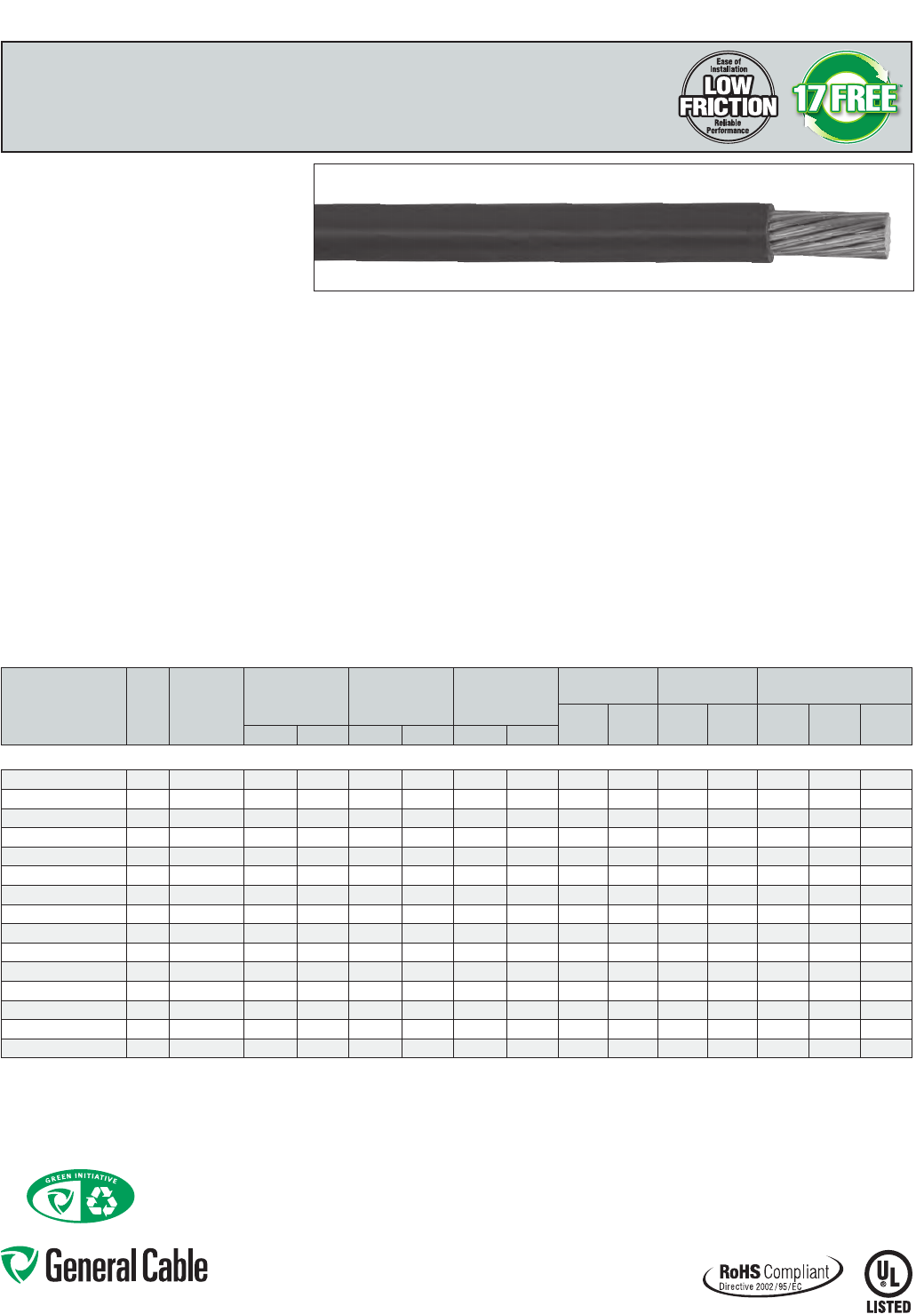
Phone: 888-593-3355
www.generalcable.com
GenFree
®
II
LSZHXLPO,Low-VoltagePower,Unshielded
600 V, UL Type RHH/RHW-2/USE-2
Product Construction:
Conductor:
•14AWGthru1000kcmilstrandedannealedtinned
copperperASTMB33
•CompressedClassBstrandingperASTMB8
Insulation:
•Low-Smoke,Zero-HalogenCross-linkedPolyolefin
(LSZHXLPO),black
•Colorsavailableuponrequest
Print:
•GENERALCABLE®(PLANTOFMFG)GENFREE® II
17FREE™LSZHTYPEUSE-2ORRHHORRHW-2
(SIZE)600VOILRESISUNRES-40CST1*FOR
CTUSE*(UL)DAY/MONTH/YEAROFMFG
SEQUENTIALFOOTAGEMARK
*“ST1”and“FORCTUSE”on1/0AWGandlarger
Options:
•2kVversion
•Barecopperconductor
•Otherstrandingavailable
•Colorsavailableuponrequest
Applications:
•Foruseinclosedenvironmentsorpopulatedspaces
such as auditoriums, arenas and health facilities
where more stringent customer specifications for
smokeandhalogen-freematerialsaredesired
•Ideallysuitedforuseinabroadrangeof
commercial, industrial and utility applications
where reliability is a major concern, where
maximum performance will be demanded and
where space is limited
Applications (cont’d.):
•Foruseinfreeair,racewaysordirectburialin
accordancewithNEC
Features:
•Ratedat90˚Cwetordry
•Low-Smoke,Zero-Halogeninsulationsystem
•SmallercableO.D.
•LowFrictionforeasypullingon8AWGandlarger
•Excellentelectrical,thermalandphysical
properties
•Excellentmoistureresistance,exceedingUL44
requirements
•Excellentresistancetocrush,compressioncuts
and heat deformation
•Excellentflameresistance
•Resistanttomostoilsandchemicals
•UV/sunlight-resistant
•RatedST-1forLimitedSmokeperUL44onsizes
1/0AWGandlarger
•Stableelectricalpropertiesoverabroad
temperature range
•Excellentlowtemperaturecharacteristics,meets
coldbendandcoldimpacttestat-40˚C
Compliances:
Industry Compliances:
•NationalElectricalCode(NEC)
•“FORCTUSE”on1/0AWGandlargerinaccordance
withNEC
•UL44TypeRHH/RHW-2,ULFile#E90494
•UL854TypeUSE-2,ULFile#E90499
•LimitedSmokeratingperUL44andUL1685
•ICEAT-33-655smoke,halogenandacidgas
requirements
•ICEAS-95-658/NEMAWC70
Flame Test Compliances:
•For1/0AWGandlarger:IEEE383,IEEE1202/CSAFT4
•UL1685
Other Compliances:
•EPA40CFR,Part261forleachableleadcontent
per TCLP
•OSHAAcceptable
•RoHSCompliant
Packaging:
•Materialcuttolengthandshippedonnon-returnable
wood reels
CATALOG
NUMBER
COND.
SIZE
(AWG/
kcmil)
COND.
STRAND
NOMINAL COND.
DIAMETER
MINIMUM AVG.
INSULATION
THICKNESS
NOMINAL CABLE
O.D.
COPPER
WEIGHT NET WEIGHT AMPACITY (1)
LBS/
1000 FT kg/km
LBS/
1000 FT kg/km 60°C 75°C 90°CINCHES mm INCHES mm INCHES mm
14 AWG - 1000 kcmil CONDUCTORS
17602.210014* 14 7/.0242 0.07 1.78 0.045 1.14 0.17 4.32 13 19 24 36 15 15 15
17602.210012* 12 7/.0305 0.09 2.29 0.045 1.14 0.19 4.83 20 30 33 49 20 20 20
17602.210010* 10 7/.0385 0.12 3.05 0.045 1.14 0.21 5.33 32 48 48 71 30 30 30
17602.210800* 8 7/.0486 0.15 3.81 0.060 1.52 0.27 6.86 50 75 78 116 40 50 55
17602.210600* 6 7/.0612 0.18 4.57 0.060 1.52 0.31 7.87 81 121 114 170 55 65 75
17602.210400* 4 7/.0772 0.23 5.84 0.060 1.52 0.36 9.14 129 192 169 252 70 85 95
17602.210200* 2 7/.0974 0.29 7.37 0.060 1.52 0.42 10.67 205 305 254 378 95 115 130
17602.215100* 1/0 19/.0740 0.37 9.40 0.080 2.03 0.53 13.46 326 485 403 600 125 150 170
17602.215200* 2/0 19/.0837 0.41 10.41 0.080 2.03 0.58 14.73 411 612 501 746 145 175 195
17602.215400* 4/0 19/.1055 0.52 13.21 0.080 2.03 0.69 17.53 653 972 760 1131 195 230 260
17602.216000* 250 37/.0822 0.56 14.22 0.095 2.41 0.77 19.56 772 1149 906 1349 215 255 290
17602.216200* 350 37/.0973 0.67 17.02 0.095 2.41 0.87 22.10 1081 1609 1237 1841 260 310 350
17602.216500* 500 37/.1162 0.80 20.32 0.095 2.41 1.00 25.40 1542 2295 1730 2575 320 380 430
17602.217000* 750 61/.1109 0.97 24.62 0.110 2.79 1.22 30.99 2316 3447 2576 3834 400 475 535
17602.217500* 1000 61/.1280 1.13 28.70 0.110 2.79 1.37 34.80 3086 4593 3405 5068 445 545 615
Dimensions and weights are nominal; subject to industry tolerances.
*Non-stockitem;minimumrunsapply.PleaseconsultCustomerServiceforpriceanddelivery.
(1)AllowableampacitiesshownareforgeneraluseasspecifiedbytheNationalElectricCode,2011Edition,section310.15(B)(16).Adjustmentsandcorrectionsmayapply:
60°C–Whenterminatedtoequipmentforcircuitsrated100amperesorlessormarkedfor14through1AWGconductors.
75°C–Whenterminatedtoequipmentforcircuitsratedover100amperesormarkedforconductorslargerthan1AWG.
90°C–Wetordrylocations.Forampacityderatingpurposes.
Dwelling–Fordwellingunits,conductorsshallbepermittedaslistedampacitiesat120/240-volt,3-wire,single-phaseservicesandfeeders.
SPEC 5275
June, 2013
Going Green with General Cable
GeneralCablehasaccelerateditsenvironmentalcommitment,addressingitsgreenalternativeapproachbyidentifyinggreeneropportunities
andpromotinggreencablingsolutionswhereverfeasible.Thisincludespromotingourexistinggreenproducts,partneringwithkeycustomers
intheirgreenendeavors,identifyingandprovidingforgreenproductgaps,andparticipatingasamemberoftheUnitedStatesGreenBuilding
Council(USGBC)andcollaborativeventuressuchastheGreenSuppliersNetwork(GSN).
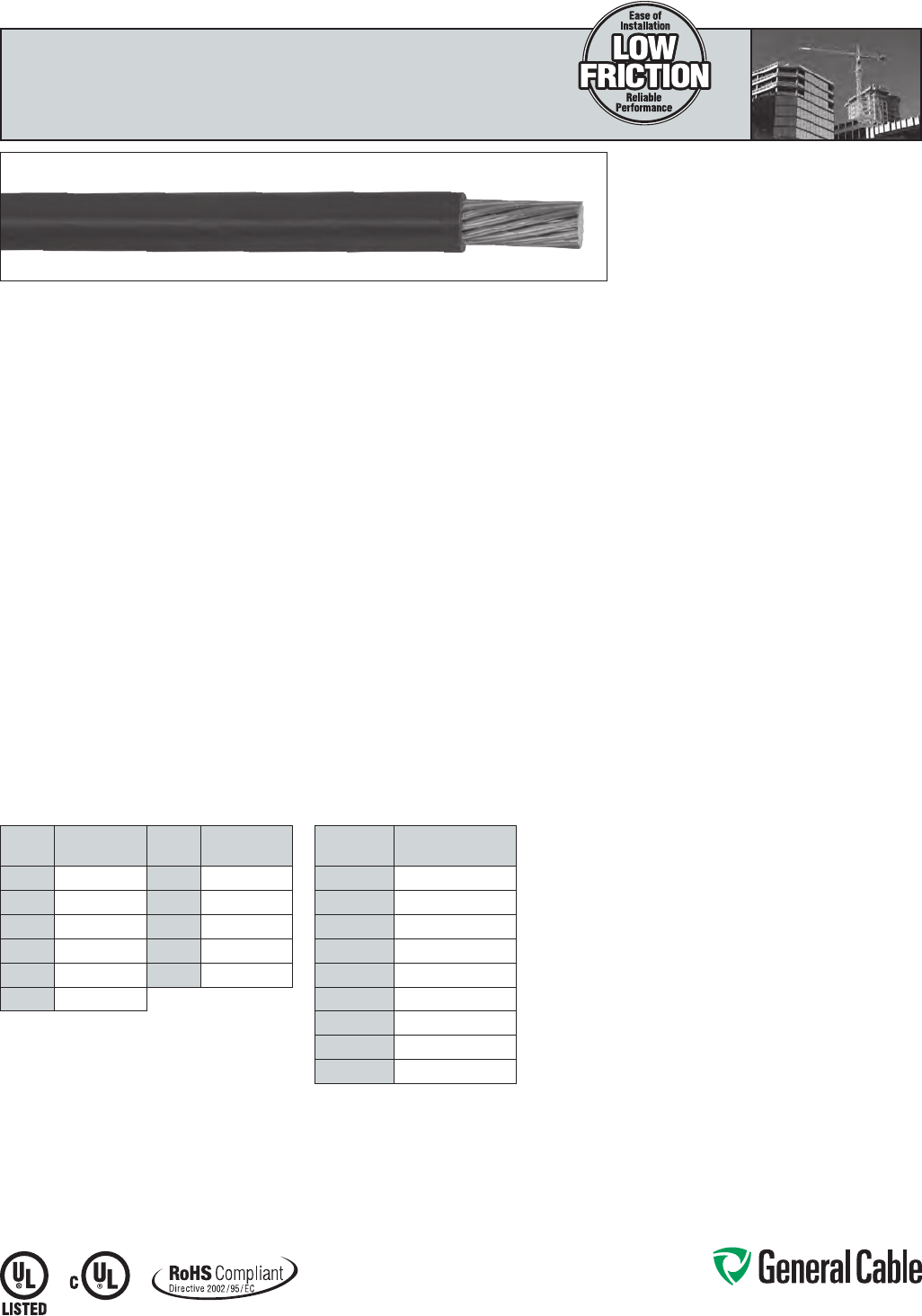
Phone: 888-593-3355
www.generalcable.com
SPEC 5290
October, 2012
COLOR CODE CHART
COLOR
CODE COLOR
COLOR
CODE COLOR
1Black 7Blue
2White 8Orange
3Red 9Gray
4Green APurple
5Yellow BPink
6Brown
PACKAGING CODE CHART
PACKAGING
CODE PACKAGE
10 2x500'
20 4x500'
32 500' Reel
33 1000' Reel
54 2000' Reel
34 2500' Reel
55 5000' Reel
00 Cut to order
XX MasterReel
THHN/THWN-2
PVC, Low-Voltage Power
600V,TypeTHHN/THWN-2,SingleConductor,Copper
Product Construction:
Conductor:
•14AWGthru750kcmilbareannealedstranded
copperperASTMB3andASTMB8
•14AWGthru10AWGsolidplaincopperperASTM
B3
Insulation:
•Color-codedpremium-gradeflame-retardant,
heat-andmoisture-resistantPolyvinylChloride
(PVC)
Jacket:
•ToughPolyamide(Nylon)
Print:
For 14 AWG solid thru 10 AWG solid:
•GENERALCABLE®(PLANTOFMFG)(YEAROF
MFG)THHN/THWN(SIZE)AWG(SIZEmm²)
GASANDOILRESII600VVW-1(UL)E66903
C(UL)T90NYLON/TWN75FT1(-25°C)
For 14 AWG strand thru 10 AWG strand:
•GENERALCABLE®(PLANTOFMFG)(YEAROF
MFG)THHN/THWN(SIZE)AWG(SIZEmm²)
GASANDOILRESII600VVW-1ORAWM(UL)
E66903C(UL)T90NYLON/TWN75FT1(-25°C)
For 8 AWG thru 1 AWG:
•GENERALCABLE®(PLANTOFMFG)(YEAROF
MFG)LOWFRICTIONTHHN/THWN-2(SIZE)AWG
(SIZEmm²)GASANDOILRESII600VVW-1OR
AWM(UL)E66903C(UL)T90NYLON/TWN75FT1
(-25°C)
Print (cont’d.):
For 1/0 and larger, black only:
•GENERALCABLE®(PLANTOFMFG)(YEAROF
MFG)LOWFRICTIONTHHN/THWN-2(SIZE)AWG
(SIZEmm²)GASANDOILRESIIORSUNRES
FORCTUSE600VORAWM(UL)E66903C(UL)
T90NYLON/TWN75FT1(-25°C)
For 1/0 and larger, all colors:
•GENERALCABLE®(PLANTOFMFG)(YEAROF
MFG)LOWFRICTIONTHHN/THWN-2(SIZE)AWG
(SIZEmm²)CUGASANDOILRESIIFORCTUSE
600VORAWM(UL)E66903C(UL)T90NYLON/
TWN75FT1(-25°C)
Applications:
•Generalpurposebuildingwireforservices,
feeders and branch circuits
•Conduitandraceways
•1/0andlargerforcabletrayuse
Features:
•LowFrictionNylonjacketprovideseasypullingfor
8AWGandlarger
•1/0AWGandlargerareratedforcabletrayuse
•RatedGasolineandOil-ResistantII
•Resistanttoabrasion,acids,alkalines,ozone,and
water
Features (cont’d.):
•ForTHHNapplications,theconductoris
appropriate for use in dry locations not to exceed
90°C
•ForTHWN-2applications,theconductoris
appropriate for wet or dry locations not to exceed
90°C
•ForMTWapplications,theconductoris
appropriate for use in dry locations at 90°C or not
to exceed 60°C in wet locations or where exposed
tooilorcoolants(withampacitylimitedtothat
for75°Cconductortemperature)asoutlined
inNFPA79ElectricalStandardsforIndustrial
Machinery
•Sequentialfootmarkingsevery2feeton8AWG
and larger for easy measuring
•Sunlight-resistantfor1/0andlarger,forblackonly
•Meetscoldbendandcoldimpacttestsat-25°C
Compliances:
Industry Compliances:
•ASTMB3andB8
•ULStandard83–THHN/THWN-2
•ULStandard1063formachinetoolwire(MTW)
•ICEAS-95-658/NEMAWC70
• N E C ®Article310
•RoHSCompliant
•c(UL)–T90Nylon
Flame Test Compliances:
•UL2556VW-1ratedthrough1AWG
•UL2556CTUSE1/0andlarger
Packaging:
•Cut-to-lengthservicesavailablefor8AWG
and larger
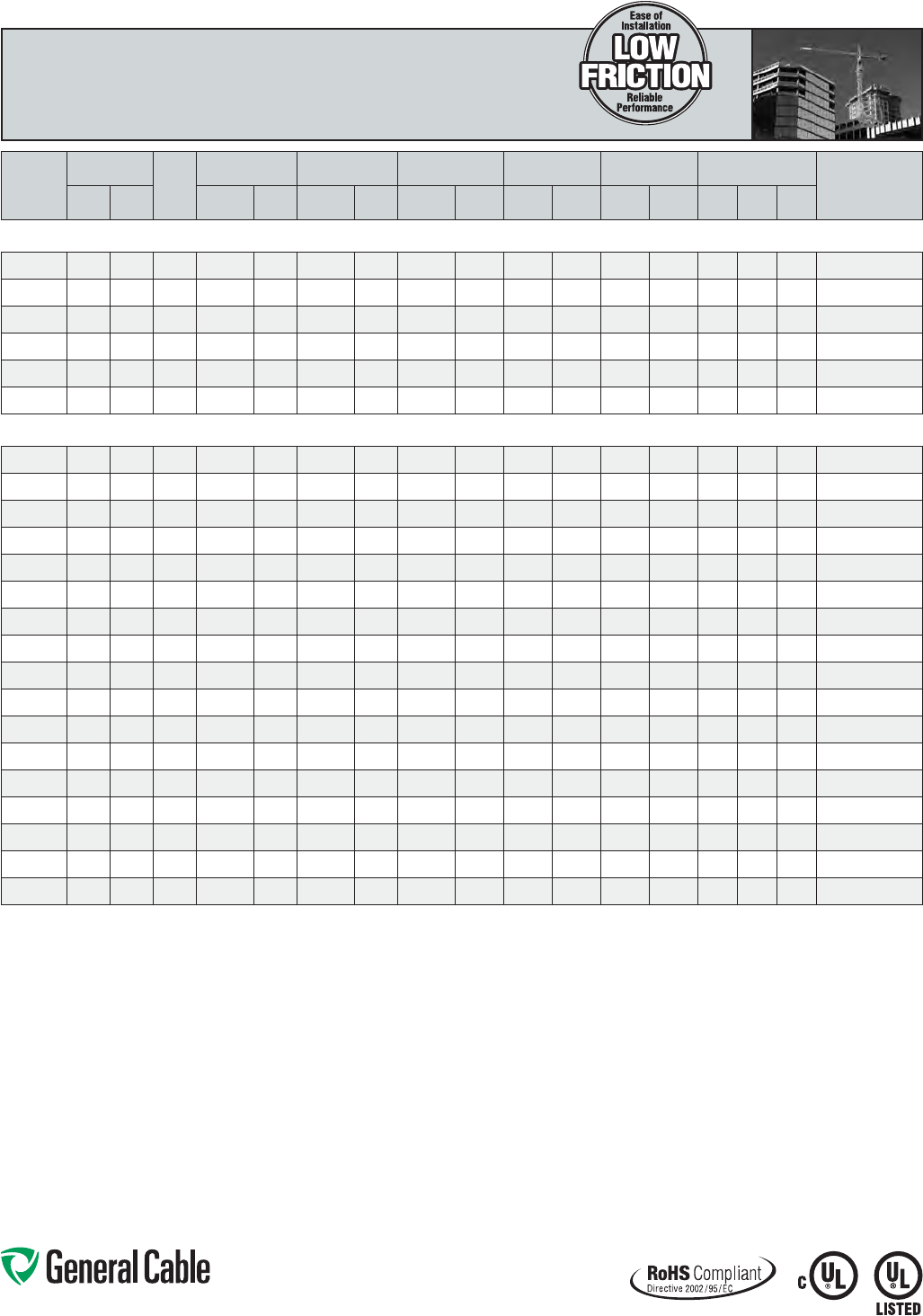
Phone: 888-593-3355
www.generalcable.com
SPEC 5290
October, 2012
THHN/THWN-2
PVC, Low-Voltage Power
600V,TypeTHHN/THWN-2,SingleConductor,Copper
CATALOG
NUMBER
SIZE
NO. OF
WIRES
INS. THKN. JACKET THKN.
NOMINAL
CABLE O.D. COPPER WEIGHT NET WEIGHT AMPACITY (1)
PACKAGING
PUT-UP
CODE
AWG OR
kcmil mm² INCHES mm INCHES mm INCHES mm
LBS/
1000 FT kg/km
LBS/
1000 FT kg/km 60°C 75°C 90°C
TYPE THHN 90°C DRY LOCATIONS/THWN 75°C WET LOCATIONS
23014 14 2.08 1 0.015 0.38 0.004 0.10 0.101 2.57 12 18 15 22 15 15 15 20, 34
23012 12 3.31 1 0.015 0.38 0.004 0.10 0.120 3.05 20 29 23 34 20 20 20 20, 34
23010 10 5.26 1 0.020 0.51 0.004 0.10 0.149 3.78 31 47 37 55 20 20 30 10, 34
24014 14 2.08 19 0.015 0.38 0.004 0.10 0.109 2.77 13 19 16 25 15 15 15 20, 34
24012 12 3.31 19 0.015 0.38 0.004 0.10 0.127 3.23 20 30 23 36 20 20 20 20, 34
24010 10 5.26 19 0.020 0.51 0.004 0.10 0.160 4.07 32 48 38 57 30 30 30 10, 34
TYPE THHN/THWN-2 90°C WET OR DRY LOCATIONS
25008 8 8.37 19 0.030 0.76 0.005 0.13 0.212 5.39 51 76 62 94 40 50 55 32, 33, XX, 00
25006 6 13.3 19 0.030 0.76 0.005 0.13 0.248 6.30 81 121 94 141 55 65 75 32, 33, XX, 00
25004 4 21.2 19 0.040 1.02 0.006 0.15 0.317 8.06 129 192 153 228 70 85 95 32, 55, XX, 00
25003 3 26.7 19 0.040 1.02 0.006 0.15 0.344 8.74 163 242 189 281 85 100 115 32, 55, XX, 00
25002 2 33.6 19 0.040 1.02 0.006 0.15 0.375 9.53 205 305 233 348 95 115 130 55, XX, 00
25001 1 42.4 19 0.050 1.27 0.007 0.18 0.435 11.05 258 385 298 445 110 130 145 55, XX, 00
26110 1/0 53.5 19 0.050 1.27 0.007 0.18 0.474 12.04 326 485 372 554 125 150 170 55, XX, 00
26210 2/0 67.4 19 0.050 1.27 0.007 0.18 0.518 13.16 411 611 462 687 145 175 195 55, XX, 00
26310 3/0 85 19 0.050 1.27 0.007 0.18 0.568 14.43 518 771 572 851 165 200 225 55, XX, 00
26410 4/0 107 19 0.050 1.27 0.007 0.18 0.624 15.85 653 972 712 1059 195 230 260 55, XX, 00
27250 250 124 37 0.060 1.52 0.008 0.20 0.678 17.23 772 1149 849 1266 215 255 290 55, XX, 00
27300 300 152 37 0.060 1.52 0.008 0.20 0.730 18.54 926 1378 1010 1503 240 285 320 34, XX, 00
27350 350 177 37 0.060 1.52 0.008 0.20 0.777 19.74 1081 1609 1170 1741 260 320 350 34, XX, 00
27400 400 203 37 0.060 1.52 0.008 0.20 0.821 20.85 1235 1838 1330 1979 280 335 380 34, XX, 00
27500 500 253 37 0.060 1.52 0.008 0.20 0.902 22.91 1544 2298 1650 2455 320 380 430 34, XX, 00
27600 600 304 61 0.070 1.78 0.009 0.23 1.051 26.70 1853 2758 2019 3004 350 420 475 54, XX, 00
27750 750 380 61 0.070 1.78 0.009 0.23 1.156 29.36 2316 3447 2466 3670 400 475 535 54, XX, 00
Dimensions and weights are nominal; subject to industry tolerances.
(1)Temperature,sizeandampacityperNationalElectricCode,2011NECsections110.14(c)(1)(a)&(b).
60°C–Whenterminatedtoequipmentforcircuitsrated100amperesorlessormarkedfor14through1AWGconductors.
75°C–Whenterminatedtoequipmentforcircuitsratedover100amperesormarkedforconductorslargerthan1AWG.
90°C–Wetordrylocations.Forampacityderatingpurposes.
Dwelling–Fordwellingunits,conductorsshallbepermittedaslistedampacitiesat120/240-volt,3-wire,single-phaseservicesandfeeders.
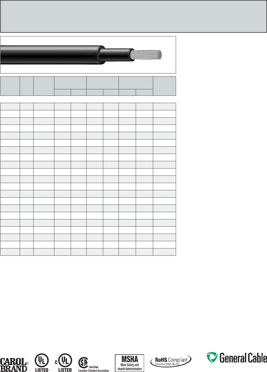
Phone: 888-593-3355
www.generalcable.com
SPEC 5300
March, 2012
Super Vu-Tron
®
EPR/CPE,DieselLocomotiveCable
90°C,2000V,DLO,ULTypeRHH/RHW,600V,CSATypeR90,1000V
Product Construction:
Conductor:
•14AWGthrough1111.1kcmilstrandedtinned
annealedcopperperAAR589
Insulation:
•Premium-grade90ºCEP
Jacket:
•ChlorinatedPolyethylene(CPE),black
Jacket Marking:
•SIZES14THROUGH1AWG-CAROLSUPER
VU-TRON®(SIZE)(STRANDING)90°CDLO2000
VOLTSP-7K-123040MSHACSAR901000V(UL)
RHH or RHW 600 VOLTS
•SIZES1/0THROUGH646.4-CAROLSUPER
VU-TRON®(SIZE)90°CDLO2000VOLTSP-7K-
123040MSHACSAR901000V(-40°C)FT-1(UL)
RHHorRHW600VOLTSSUNLIGHTRESISTANT
FORCTUSE
NOTE:535.3AND646.4kcmilprinted(UL)RHH
OR RHW 2000 VOLTS
•SIZES777.7THROUGH1111.1kcmil-CAROL
SUPERVU-TRON®C(UL)TYPERHW-22kV
VW-1FORCTUSETYPEDLO2000V90°C
P-102MSHA
Applications:
•Dieselelectriclocomotives
•Telecompowersupply
•Miningandearth-movingequipment
•Shipyards
•Motorleads
•Whereflexiblepowerleadsmustbeinstalledin
conduit or raceways
Features:
•90ºCtemperaturerating
•Excellentimpactandabrasionresistance
•Resistsoils,acids,alkalies,heat,flame
•Flexibletinnedcopperstranding
•FT4uponrequest
•Sunlight-resistant
Industry Approvals:
•ULTypeRHH/RHW,ULFile#E90494
•Acceptedforlistingasflame-resistant
byMSHA
•CSAR90
•RoHSCompliant
Packaging:
•Lengthscuttoorder
CATALOG
NUMBER
COND.
SIZE
(AWG/
kcmil)
COND.
STRAND
NOM. INS.
THICKNESS NOMINAL O.D.
CURRENT
AMPS APPROX.
NET WEIGHT
LBS/MFT(S)
INCHES mm INCHES mm (1) (2)
14 AWG - 1111.1 kcmil DLO - 2000 VOLT
81914*
14 19/0.0147 0.045 1.14 0.21 5.44 25 35 34
81912*
12 19/0.0185 0.047 1.19 0.24 6.10 30 40 45
81910*
10 27/24 0.045 1.14 0.26 6.60 40 55 60
81908*
8 37/24 0.060 1.52 0.34 8.64 55 80 95
81906*
6 61/24 0.060 1.52 0.40 10.16 75 105 145
81904*
4 105/24 0.060 1.52 0.46 11.68 95 140 205
81902*
2 154/24 0.060 1.52 0.52 13.21 130 190 295
81901*
1 224/24 0.080 2.03 0.65 16.51 150 220 440
81911*
1/0 280/24 0.080 2.03 0.69 17.53 170 260 515
81920*
2/0 329/24 0.080 2.03 0.73 18.54 195 300 580
81930*
3/0 456/24 0.080 2.03 0.81 20.57 225 350 770
81940*
4/0 551/24 0.080 2.03 0.87 22.10 260 405 930
81926*
262.6 650/24 0.095 2.41 1.00 25.40 296 467 1130
81931*
313.3 777/24 0.095 2.41 1.06 26.92 326 522 1295
81937*
373.7 925/24 0.095 2.41 1.10 27.94 362 591 1545
81944*
444.4 1110/24 0.095 2.41 1.23 31.24 400 652 1820
81953*
535.3 1332/24 0.120 3.05 1.34 34.04 445 728 2195
81964*
646.4 1609/24 0.120 3.05 1.45 36.83 493 815 2560
81977*
777.7 1924/24 0.120 3.05 1.50 38.10 546 904 3050
81929*
929.2 2299/24 0.120 3.05 1.67 42.42 602 1014 3625
81999*
1111.1 2745/24 0.140 3.56 1.84 46.74 635 1115 4354
Dimensions and weights are nominal; subject to industry tolerances.
(1)Ampacitiesbasedon90°Cconductorand30°CambienttemperaturebasedontheNationalElectricalCode® for not more
than three current-carrying conductors in raceway, cable or earth.
(2)Ampacitiesbasedonsingleconductorinfreeair,90°Cconductortemperatureandanambientairtemperatureof30°C,in
accordancewithNationalElectricalCode®(NEC).
(S)Actualshippingweightmayvary.
*Non-stockitem
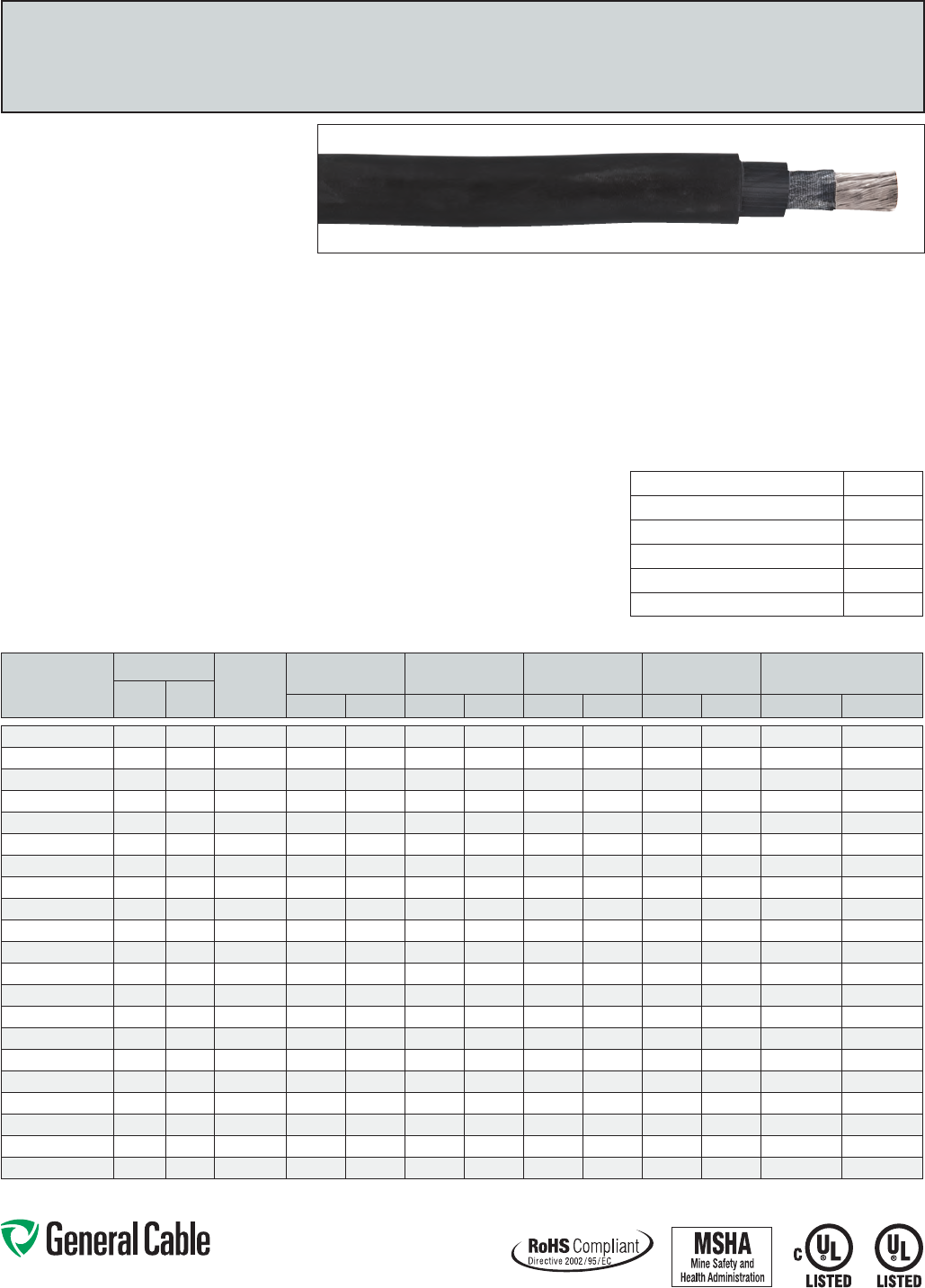
Phone: 888-593-3355
www.generalcable.com
Diesel Locomotive Cable 2000 Volts (EPR/XL-CPE)
ULRHH/RHW-22000VandC(UL)RW901000V
Flexible,Oil-,Sunlight-andOzone-Resistant,Flame-Retardant,-40°Cto90°C
CATALOG
NUMBER
COND. SIZE
COND.
STRAND
NOMINAL
COND. O.D.
NOM. INS.
THICKNESS
JACKET
THICKNESS NOMINAL O.D.
APPROX.
NET WEIGHT
AWG/
kcmil mm2INCHES mm INCHES mm INCHES mm INCHES mm LBS/1000 FT kg/km
5310.01014 14 2.08 19/.0147 0.070 1.8 0.045 1.1 0.015 0.4 0.20 5.1 30 45
5310.01012 12 3.31 19/.0185 0.088 2.2 0.045 1.1 0.015 0.4 0.22 5.6 39 58
5310.01010 10 5.26 27/24 0.117 3.0 0.045 1.1 0.015 0.4 0.25 6.4 56 83
5310.01008 8 8.36 37/24 0.144 3.7 0.055 1.4 0.030 0.8 0.33 8.3 87 129
5310.01006 6 13.3 61/24 0.190 4.8 0.060 1.5 0.030 0.8 0.38 9.7 131 195
5310.01004 4 21.1 105/24 0.262 6.7 0.060 1.5 0.030 0.8 0.46 11.7 202 301
5310.01002 2 33.6 158/24 0.315 8.0 0.060 1.5 0.030 0.8 0.51 13.0 285 424
5310.01001 1 42.4 224/24 0.375 9.5 0.080 2.0 0.045 1.1 0.64 16.3 417 621
5310.01110 1/0 53.5 280/24 0.435 11.0 0.080 2.0 0.045 1.1 0.70 17.8 494 735
5310.01210 2/0 67.4 329/24 0.465 11.8 0.080 2.0 0.045 1.1 0.73 18.5 587 874
5310.01310 3/0 85 456/24 0.535 13.6 0.080 2.0 0.045 1.1 0.80 20.3 718 1069
5310.01410 4/0 107 551/24 0.581 14.8 0.080 2.0 0.045 1.1 0.84 21.3 845 1258
5310.01262 262.6 133 650/24 0.617 15.7 0.090 2.3 0.065 1.7 0.94 23.9 1050 1563
5310.01313 313.3 158 777/24 0.671 17.0 0.090 2.3 0.065 1.7 1.00 25.3 1195 1778
5310.01373 373.7 189 925/24 0.735 18.7 0.090 2.3 0.065 1.7 1.06 26.9 1384 2060
5310.01444 444.4 225 1110/24 0.786 20.0 0.090 2.3 0.065 1.7 1.11 28.2 1634 2432
5310.01535 535.3 271 1332/24 0.877 22.3 0.090 2.3 0.065 1.7 1.20 30.5 1925 2865
5310.01646 646.4 327 1609/24 0.960 24.4 0.090 2.3 0.065 1.7 1.29 32.8 2307 3433
5310.01777 777.7 394 1924/24 1.054 26.8 0.090 2.3 0.065 1.7 1.38 35.1 2728 4060
5310.01929* 929.9 475 2318/24 1.230 31.2 0.090 2.3 0.065 1.7 1.56 39.6 3570 5313
5310.01111* 1111.1 562 2745/24 1.328 33.7 0.115 2.9 0.095 2.4 1.77 44.9 4232 6298
*Non-stockitem;minimumrunsapply.PleaseconsultCustomerServiceforpriceanddelivery.
Product Construction:
Conductor:
•14AWG(2.08mm)thru1111.1kcmil(562mm)
Class I fully annealed flexible stranded tin coated
copperperAAR589
Insulation:
•Flame-retardant,lead-freecross-linkedEthylene
Propylene(EP)withseparatortapeoverthe
conductor to facilitate stripping
Jacket:
•Black,flame-retardant,sunlight-,ozone-and
oil-resistant,lead-freeCross-linkedChlorinated
Polyethylene(XL-CPE)
Print:
•GENERALCABLE®(MFGLOCATION)
DIESEL
LOCOMOTIVE
2000VP-07-KA120005-MSHA
C(UL)USTYPERHHORRHW-2VW-1(SIZE)
AWG/kcmil(MM2)EPFORCTUSE*SR-40ºCFT4
ORRW90EP1000VROHSMONTH/YEAROF
MFGSEQUENTIALFOOTAGEMARK
*Applicable for sizes1/0AWGand larger only
Options:
•Fullyannealed,flexiblebarecopperstrandingper
AAR589
•Otherjacketcolorsavailableuponrequest
Applications:
•Foruseupto2000Vaspowercablesin
wind turbine generator applications per UL
Subject 6140
•Dieselelectriclocomotives
Applications (cont’d.):
•Miningandearth-movingequipment
•Generalpurposeuseasflexiblepowerleads
•Flexiblepowerleadsincabletraysinsizes
1/0AWGandlarger
•Acceptedforlistingasflame-resistantbyMSHA
Features:
•Rated90°CwetordryperUL44/CSAC.22.2-38
•Flexibletinnedcopperstranding
•Excellentresistancetooils,gearlubricants,ozone,
sunlight, heat and flame
•Designedtowithstandcontinuousflexing
Minimum Bend Radius:
•8XO.D.forfixedinstallationsormobile
applications
Torsion Requirements:
•+/-180°twistspermeterfor5,000cyclesat-40°C
with cable weight compensated to 18 meters
Compliances:
Industry Compliances:
•TypeRHH/RHW-2perUL44,ULFile#E90494
•c(UL)USTypeRW90perCSAC.22.2-38,
ULFile#E90494
•NationalElectricalCode(NEC)
•ICEAS-95-658/NEMAWC70
•“ForCTUse”on1/0AWGandlargerin
accordancewithNEC®
•
AcceptedforlistingasflameresistantbyMSHA
•RoHS Compliant
Flame Test Compliances:
•UL2556VW-1
•IEEE1202/CSAFT4forsizes1/0AWGandlarger
SPEC 5310
May, 2012
AC Withstand Voltage Testing
requirements per UL 44:
14-10AWG 6000 V
8-2AWG 7500 V
1-4/0AWG 9000 V
262.6kcmil-444kcmil 10000 V
535.3kcmil-929.9kcmil 11000 V
1111.1kcmil 13500 V
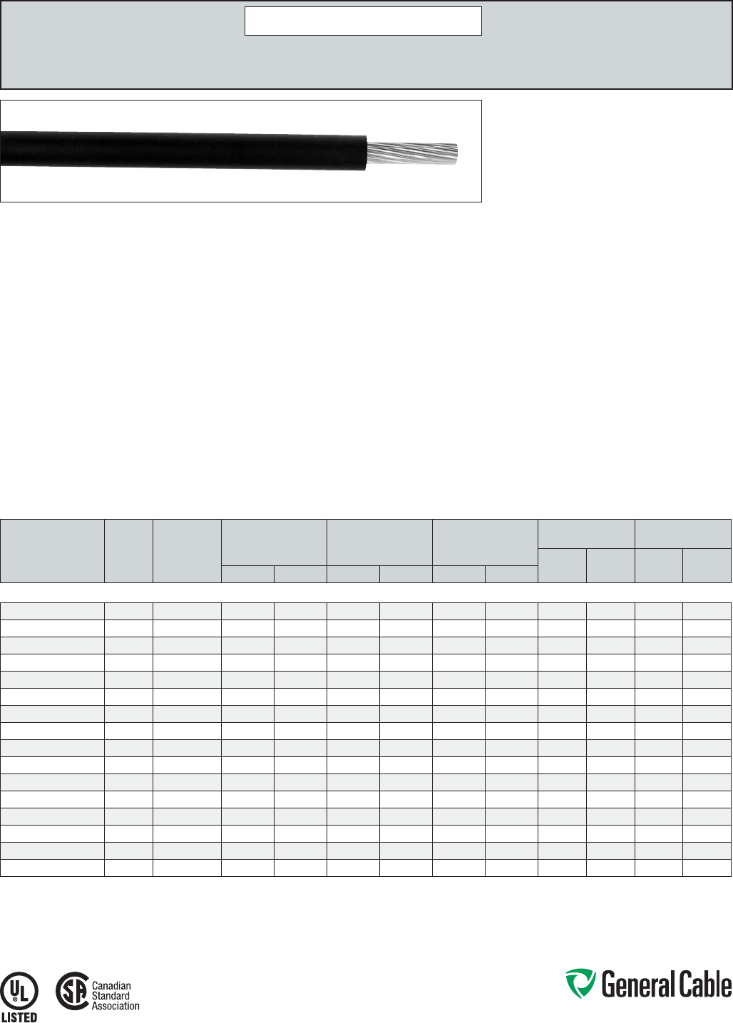
Phone: 888-593-3355
www.generalcable.com
CATALOG
NUMBER
COND.
SIZE
(AWG/
kcmil)
COND.
STRAND
(CLASS B)
NOMINAL COND.
DIAMETER
MINIMUM AVG.
INSULATION THICKNESS
NOMINAL CABLE
O.D.
COPPER
WEIGHT NET WEIGHT
LBS/
1000 FT kg/km
LBS/
1000 FT kg/kmINCHES mm INCHES mm INCHES mm
14 AWG - 750 kcmil CONDUCTORS, CLASS B
14311.011400 14 7/.0242 0.07 1.78 0.045 1.14 0.17 4.32 13 19 18 27
14311.011200 12 7/.0305 0.09 2.29 0.045 1.14 0.19 4.83 20 30 25 37
14311.011000 10 7/.0385 0.12 3.05 0.045 1.14 0.22 5.59 32 48 38 57
14311.010800 8 7/.0486 0.15 3.81 0.060 1.52 0.28 7.11 50 75 58 86
14311.010600 6 7/.0612 0.18 4.57 0.060 1.52 0.31 7.87 81 121 116 173
14311.010400 4 7/.0772 0.23 5.84 0.060 1.52 0.36 9.14 129 192 171 254
14311.010200 2 7/.0974 0.28 7.11 0.060 1.52 0.42 10.67 205 305 257 382
14311.010100 1 19/.0644 0.32 8.13 0.080 2.03 0.49 12.45 258 385 331 493
14311.015100 1/0 19/.0745 0.36 9.14 0.080 2.03 0.53 13.46 326 485 406 604
14311.015200 2/0 19/.0837 0.41 10.41 0.080 2.03 0.58 14.73 411 612 495 737
14311.015300 3/0 19/.0940 0.46 11.68 0.080 2.03 0.63 16.00 518 771 612 911
14311.015400 4/0 19/.1055 0.51 12.95 0.080 2.03 0.68 17.27 653 972 757 1126
14311.016000 250 37/.0822 0.56 14.22 0.095 2.41 0.76 19.30 772 1149 905 1347
14311.016200 350 37/.0973 0.66 16.76 0.095 2.41 0.87 22.10 1081 1609 1237 1841
14311.016500 500 37/.1162 0.79 20.07 0.095 2.41 1.00 25.40 1544 2298 1728 2571
14311.017000 750 61/.1109 0.97 24.64 0.110 2.79 1.21 30.73 2316 3447 2572 3827
Dimensions and weights are nominal; subject to industry tolerances.
Product Construction:
Conductor:
• 14 AWG thru 750 kcmil bare compressed copper
per ASTM B3. Class B stranding per ASTM B8
Composite Insulation/Jacket:
• Flame-retardant, oil-resistant, limited smoke
Cross-linked Polyethylene (XLPE), black
Print:
• GENERAL CABLE® GENFREE® LSZH (PLANT
OF MFG) (UL) TYPE USE OR RHH OR RHW-ST1
(SIZE) 600 V OIL RES I SUN RES FOR CT USE*/
CSA AWM I A/B 105˚C 600 V FT4 MONTH/YEAR
OF MFG SEQUENTIAL FOOTAGE MARK
* Sizes smaller than 1/0 AWG do not include “FOR CT USE”
Options:
• Available in blue, green, red and gray
• Tinned copper conductors
Applications:
• General purpose 600 V Power Cable Applications
• RHH/RHW ratings for installation in conduit
or raceway
• USE rating for direct burial applications
Applications (cont’d.):
• CT rated for installation in Cable Tray – 1/0 AWG
and larger
• For use in all closed environments or populated
spaces such as auditoriums, arenas and health
facilities where more stringent specifications for
smoke and toxicity emission levels are desired
• Ideally suited for use in a broad range of
commercial and Industrial applications where
reliability is the major concern, where maximum
performance is demanded and where space
is limited
Features:
• UL Type RHH/RHW/USE Rated at 90˚C dry,
75˚C wet, UL File # E90494 and E90499
• CSA AWM I A/B Rated at 105˚C
• UL AWM styles 3237 and 3578
• Smooth surface for reduced coefficient of friction
for ease of installation
• Excellent moisture resistance
• Excellent resistance to salt water
• Available in colors for ease of phase identification
• Minimum acid gas emissions under combustion
• Meets cold bend test at -40˚C
• Meets UL Oil Res. I and II
Compliances:
• UL 44 Standard for Rubber Insulated Wire
• UL 758 Standard for Appliance Wiring Material
• UL 854 Standard for Service Entrance Cable
• UL 1685 Standard for Vertical Tray Fire
Propagation and Smoke Release Test for Electrical
and Optical Fiber Cables
• Telcordia GR347 Core
• ICEA S-95-658/NEMA WC70
• ICEA T-33-655
• IEEE 1202 (70,000 BTU/hr)
• IEEE 383 (70,000 BTU/hr)
• Sizes 1/0 AWG and larger are listed “FOR CT USE”
• CSA FT4
• CSA Standard C22.2 No. 0.3
• CSA Standard C22.2 No. 210.2
• EPA 40 CFR, Part 261 for leachable lead content
per TCLP method
• OSHA Acceptable
Packaging:
• Material cut to length and shipped on non-
returnable wood reels
GenFree
®
LSZH
XLPE, Low-Smoke, Zero-Halogen (LSZH), Low-Voltage Power, Unshielded
600 V, Type RHH/RHW-LS/USE, CSA AWM I A/B, Class B
SPEC 5350
September, 2013
DISCONTINUED
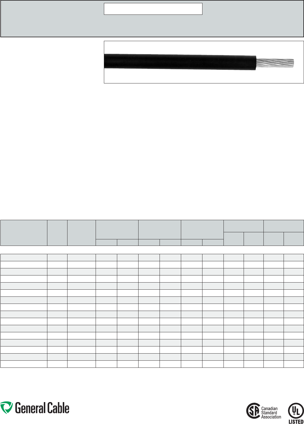
Phone: 888-593-3355
www.generalcable.com
CATALOG
NUMBER
COND.
SIZE
(AWG/
kcmil)
COND.
STRAND
(CLASS I)¹
NOMINAL COND.
DIAMETER
MINIMUM AVG.
INSULATION THICKNESS
NOMINAL CABLE
O.D.
COPPER
WEIGHT NET WEIGHT
LBS/
1000 FT kg/km
LBS/
1000 FT kg/kmINCHES mm INCHES mm INCHES mm
14 AWG - 750 kcmil CONDUCTORS, CLASS I
14315.011400* 14 41 0.07 1.88 0.045 1.14 0.18 4.57 14 20 20 29
14315.011200* 12 65 0.09 2.39 0.045 1.14 0.20 5.08 21 31 27 40
14315.011000* 10 65 0.12 3.15 0.045 1.14 0.23 5.84 33 48 39 58
14315.010800* 8 41 0.16 4.06 0.060 1.52 0.29 7.37 51 76 59 87
14315.010600* 6 63/24 0.21 5.33 0.060 1.52 0.34 8.64 80 119 120 179
14315.010400* 4 105/24 0.26 6.60 0.060 1.52 0.38 9.65 134 199 184 274
14315.010200* 2 161/24 0.32 8.13 0.060 1.52 0.45 11.43 205 305 266 396
14315.010100* 1 210/24 0.38 9.65 0.080 2.03 0.55 13.97 261 389 356 530
14315.015100* 1/0 259/24 0.42 10.67 0.080 2.03 0.59 14.99 329 489 433 644
14315.015200* 2/0 329/24 0.47 11.94 0.080 2.03 0.64 16.26 417 621 529 787
14315.015300* 3/0 413/24 0.53 13.46 0.080 2.03 0.71 18.03 524 780 654 973
14315.015400* 4/0 532/24 0.61 15.49 0.080 2.03 0.78 19.81 682 1014 831 1237
14315.016000* 250 608/24 0.65 16.51 0.095 2.41 0.85 21.59 779 1159 946 1408
14315.016200* 350 851/24 0.78 19.81 0.095 2.41 1.00 25.40 1095 1630 1301 1936
14315.016500* 500 1221/24 0.95 24.13 0.095 2.41 1.16 29.46 1517 2258 1821 2710
14315.017000* 750 1850/24 1.11 28.19 0.110 2.79 1.36 34.54 2408 3584 2723 4052
Dimensions and weights are nominal; subject to industry tolerances.
* Non-stock item; minimum runs apply. Please consult Customer Service for price and delivery.
¹ Class I: sizes 8 AWG and larger.
GenFree
®
LSZH
XLPE, Low-Smoke, Zero-Halogen (LSZH), Low-Voltage Power, Unshielded
600 V, Type RHH/RHW-LS/USE, CSA AWM I A/B, Class I
1
Product Construction:
Conductor:
• 14 AWG thru 750 kcmil tinned coated copper
per ASTM B3. Class I stranding per ASTM B8
Composite Insulation/Jacket:
• Flame-retardant, oil-resistant, limited smoke
Cross-linked Polyethylene (XLPE), black
Print:
• GENERAL CABLE® GENFREE® LSZH (PLANT
OF MFG) (UL) TYPE USE OR RHH OR RHW-ST1
(SIZE) 600 V OIL RES. I SUN RES FOR CT USE*/
CSA AWM I A/B 105˚C 600 V FT4 MONTH/YEAR
OF MFG SEQUENTIAL FOOTAGE MARK
* Sizes smaller than 1/0 AWG do not include “FOR CT USE”
Options:
• Available in blue, green, red and gray
• Tinned copper conductors
Applications:
• General purpose 600 V Power Cable Applications
• RHH/RHW ratings for installation in conduit
or raceway
• USE rating for direct burial applications
• CT rated for installation in Cable Tray – 1/0 AWG
and larger
• For use in all closed environments or populated
spaces such as auditoriums, arenas and health
facilities where more stringent specifications for
smoke and toxicity emission levels are desired
• Ideally suited for use in a broad range of
commercial and Industrial applications where
reliability is the major concern, where maximum
performance is demanded and where space
is limited
Features:
• UL Type RHH/RHW/USE Rated at 90
˚
C dry,
75
˚
C wet, UL File # E90494 and E90499
• CSA AWM I A/B Rated at 105
˚
C
• UL AWM styles 3237 and 3578
• Smooth surface for reduced coefficient of friction
for ease of installation
• Excellent moisture resistance
• Excellent resistance to salt water
• Available in colors for ease of phase identification
• Minimum acid gas emissions under combustion
• Meets cold bend test at -40
˚
C
• Meets UL Oil Res. I and II
Compliances:
• UL 44 Standard for Rubber Insulated Wire
• UL 758 Standard for Appliance Wiring Material
• UL 854 Standard for Service Entrance Cable
• UL 1685 Standard for Vertical Tray Fire
Propagation and Smoke Release Test for Electrical
and Optical Fiber Cables
• Telcordia GR347 Core
• ICEA S-95-658/NEMA WC70
• ICEA T-33-655
• IEEE 1202 (70,000 BTU/hr)
• IEEE 383 (70,000 BTU/hr)
Compliances (cont’d.):
• Sizes 1/0 AWG and larger are listed “FOR CT USE”
• CSA FT4
• CSA Standard C22.2 No. 0.3
• CSA Standard C22.2 No. 210.2
• EPA 40 CFR, Part 261 for leachable lead content
per TCLP method
• OSHA Acceptable
Packaging:
• Material cut to length and shipped on non-
returnable wood reels
SPEC 5400
September, 2013
DISCONTINUED
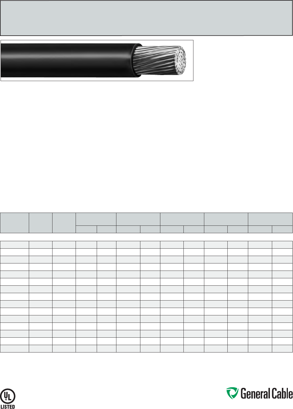
Phone: 888-593-3355
www.generalcable.com
SPEC 5700
March, 2012
Product Construction:
Conductor:
• 8 AWG thru 1000 kcmil compacted aluminum
ACM (AA-8000 Series)
Insulation:
• Flame-retardant Cross-linked
Polyethylene (XLPE), black
Print:
• GENERAL CABLE® (PLANT OF MFG) AWG/KCMIL
TYPE RHH/RHW-2 (UL) 2000 V YEAR OF MFG
SEQUENTIAL FOOTAGE MARK
CATALOG
NUMBER
CONDUCTOR
SIZE
(AWG/kcmil)
COND.
STRAND
NOMINAL CONDUCTOR
DIAMETER
NOMINAL AVERAGE
INSULATION THICKNESS
NOMINAL
CABLE O.D.
NOMINAL ALUMINUM
WEIGHT
NET
WEIGHT
INCHES mm INCHES mm INCHES mm LBS/1000 FT kg/km LBS/1000 FT kg/km
8 AWG - 1000 kcmil CONDUCTORS
522582M* 8 7/W 0.134 3.4 0.070 1.78 0.285 7.20 15.49 23.05 38.15 56.78
650981M* 6 7/W 0.169 4.1 0.070 1.78 0.320 8.10 24.60 36.61 51.08 76.01
589692M* 4 7/W 0.213 5.4 0.070 1.78 0.360 9.10 40.20 59.82 71.50 106.40
313406M* 2 2/W 0.268 6.8 0.070 1.78 0.420 10.70 62.40 92.86 100.10 148.96
149512M* 1 18/W 0.301 7.6 0.090 2.29 0.495 12.60 77.81 115.79 133.76 199.05
827197M* 1/0 18/W 0.339 8.6 0.090 2.29 0.530 13.50 100.12 148.99 160.82 239.32
977766M* 2/0 18/W 0.379 9.6 0.090 2.29 0.580 14.70 123.90 184.38 191.50 284.97
861898M* 3/0 18/W 0.426 10.8 0.090 2.29 0.615 15.60 156.22 232.47 228.68 340.30
763699M* 4/0 18/W 0.476 12.1 0.090 2.29 0.665 16.90 201.40 299.70 281.10 418.31
607078M* 250 35/W 0.524 13.3 0.105 2.70 0.745 18.90 233.50 347.47 336.15 500.23
506887M* 350 35/W 0.619 15.7 0.105 2.70 0.840 21.30 330.90 492.41 448.90 668.00
292686M* 500 35/W 0.740 18.8 0.105 2.70 0.960 24.40 467.10 695.09 604.77 899.96
526839M* 600 58/W 0.820 20.8 0.105 2.70 1.040 26.40 559.50 832.59 710.14 1056.76
883753M* 750 58/W 0.910 23.1 0.120 3.05 1.175 29.90 700.50 1042.41 901.20 1341.08
614607M 1000 58/W 1.060 26.9 0.120 3.05 1.325 33.70 939.00 1397.33 1168.00 1738.10
Dimensions and weights are nominal; subject to industry tolerances.
* Non-stock item; minimum runs apply. Please consult Customer Service for price and delivery.
Applications:
• For use from the lower control box at the base
of the wind power tower and out to the step-up
transformer through conduit
• General purpose building wire for use in air and
approved raceways
• Industrial environments where superior insulation
toughness and chemical resistance is required
• Maximum operating temperature not to exceed
90°C in wet or dry locations
Features:
• Rated at 90°C wet or dry
• UV resistant - black is marked SR
• Smaller cable O.D.
• Excellent electrical, thermal and physical
properties
• Excellent resistance to moisture
• Excellent reisistance to crush, compression cuts
and heat deformation
Compliances:
• National Electric Code (NEC)
• UL 44 Stranded for rubber-insulated wires and
cables
• ICEA S-95-685/NEMA WC70
• UL Listed as Type RHH/RHW-2, UL File # E90494
• OSHA Acceptable
Packaging:
• Material cut to length and shipped on
non-returnable wood reels
RHH/RHW-2
XLPE, Low-Voltage Power, Unshielded
2000 V, UL Type RHH/RHW-2, Single Conductor, Aluminum
Phone: 888-593-3355
www.generalcable.com
Phone: 888-593-3355
www.generalcable.com
Harnessing the Renewable Power of the Sun
Solar Photovoltaic Wire: Why Choose SunGen
®
?
The SunGen® Difference
As a company committed to environmental stewardship and renewable energy, General Cable has
specifically designed its UL 4703 SunGen® suite of photovoltaic (PV) products to effectively and
efficiently connect solar panels and concentrated solar power technologies while being able to
withstand the harsh operating environments of solar power applications.
• ResistanttoUV/sunlight,ozoneandwaterabsorption
• Ratedfordirectburial
• Stableelectricalpropertiesoverabroadtemperaturerange(-40°Cto120°C)
• Excellentflexibilityandperformanceinlow-temperatureenvironments
• Highlyresistanttodeformation,eveninprolongedexposureathightemperatures
• Mechanicallyruggedconstructionresistscutting,tearingandabrasions
• CSARPVU90listed
• TÜVcertified,halogen-free,fire-retardantandlowcorrosivegasemissionprovide
added degree of safety
• Singleandmulti-conductorcableconstructions
• 18AWG–1000kcmilstrandedcopperand8AWG–1000kcmilaluminumconductors
PerNECArticle690,singleconductorcablelistedandlabeledasphotovoltaic(PV)wireand
singleconductorcableTypeUSE-2shallbepermittedinexposedoutdoorlocationsinphotovoltaic
sourcecircuitsforphotovoltaicmoduleinterconnectionswithinthephotovoltaicarray.Whenit
comes to the wire and cable for today’s solar energy projects with PV module interconnections
within the photovoltaic array, General Cable’s SunGen® UL Listed 4703 PV wire carries a quad
ratingandoffersfarmoresuperiorsunlightresistanceandlow-temperatureflexibilityformaximum
performanceandreliabilityforlong-termoutdoorexposuretothesun.
SunGen® — the obvious choice for solar photovoltaic applications. See for yourself.
DEFORMATION-RESISTANT
DIRECT BURIAL
FLEXIBLE
MOISTURE-RESISTANT
COLD IMPACT
OIL-RESISTANT
UV/SUNLIGHT-RESISTANT
MECHANICALLY RUGGED
LOW SMOKE EMISSIONS
Key Performance Differences Between UL Type PV and UL Type USE-2 Wire
PV Wire
Applications/Compliances
SunGen® PV Wire -
UL Type PV/RHH/RHW-2/USE-2 UL Type USE-2
Voltage:600,1000and2000Volts
DirectBuried:600,1000and2000Volts
Conduit/Duct/Raceway
NECArticle690–PVSystems
UL 4703 PV Wire
UL 854 USE-2
FlameTestRequirements:FT1&VW-1
MaximumOperatingTemperature:
90ºCWetorDry
ColdBend:-40ºC
WeatherometerSunlightResistance:
720 Hour
NOW
AVAILABLE IN
SUN-RESISTANT
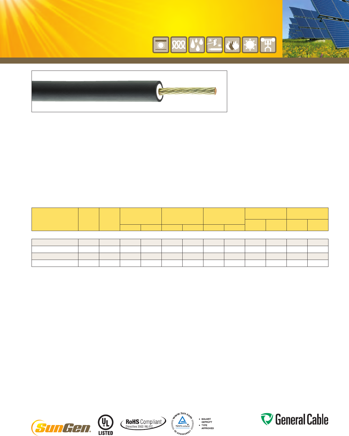
Phone: 888-593-3355
www.generalcable.com
Product Construction:
Conductor:
•1,5mm²(16AWG)thru6,0mm²(10AWG)fully
annealed flexible stranded tinned copper with
Class5strandingperEN60228(IEC60228)
Composite Insulation/Jacket
(Sheath):
•Zero-HalogenCross-linkedPolyethylene
(ZHXLPE)withblackLow-Smoke,Zero-Halogen
Cross-linkedPolyolefin(LSZHXLPO)
Print
•GENERALCABLE®(PLANTOFMFG)SUNGEN®
GLOBALXXMM²(XXAWG)TÜVPV1-F600/1000
VAC(UL)PVWIRE2000VDIRBUR90ºCWET
ORDRYVW-1SUNRES-40ºCROHSMONTH/
YEARSEQMARKING
Applications:
•TÜV2pfg1169/08.2007:Singleconductor,
sunlight-resistantphotovoltaicwire-40ºCto
+90ºC,maxtemperatureofconductor120ºCfor
20,000 hours
•RatedVoltage:ACUO/U0,6/1kVmaxvoltage
1.8kVDC(conductor–conductor,non-earthed
system,circuitnotunderload)
•UL4703:Photovoltaicwirerated90ºCwetordry,
2000Vforuseinphotovoltaicsystem
Features:
• Rated90°Cwetanddry
• UV/sunlight-resistant
• Meetscoldbendandcoldimpacttests
at -40°C
• Directburial
Compliances:
Industry Compliances:
• UL4703PVWire
• TÜV2pfg1169/08.2007PV1-Fforusein
photovoltaicsystems
• RoHSCompliant
Flame Test Compliances:
• UL2556VW-1
• EN60332-1-2verticalflame
Packaging:
•Materialcuttolengthandshippedonnon-
returnable wood reels
SPEC 5790
May, 2012
SunGen
®
Global
XLPE/LSZHXLPO,PhotovoltaicWire,TÜV2pfg
1169/08.2007PV1-FACUo/U
0.6/1kV,UL4703,PVWire2000V
CATALOG
NUMBER
COND.
SIZE
(mm2)
COND.
STRAND
COUNT
MINIMUM AVG.
INSULATION
THICKNESS
MINIMUM AVG.
JACKET (SHEATH)
THICKNESS
NOMINAL CABLE
DIAMETER
COPPER
WEIGHT NET WEIGHT
LBS/
1000 FT kg/km
LBS/
1000 FT kg/kmINCHES mm INCHES mm INCHES mm
1,5 mm2 (16 AWG) - 6,0 mm2 (10 AWG) CONDUCTORS
395400 1.5 28 0.045 1.14 0.030 0.76 0.216 5.49 9 13 28 42
395390 2.5 46 0.045 1.14 0.030 0.76 0.234 5.94 14 21 35 52
395380 4.0 56 0.045 1.14 0.030 0.76 0.263 6.68 24 36 49 73
395370 6.0 84 0.045 1.14 0.030 0.76 0.277 7.04 36 54 63 94
Dimensions and weights are nominal; subject to industry tolerances.

Phone: 888-593-3355
www.generalcable.com
Product Construction:
Conductor:
•14AWGthru2AWGtinnedcoatedcompressed
copper.ClassCstrandingperASTMB33andB8
•1AWGthru1000kcmiltinnedcoatedcompressed
copper.ClassBstrandingperASTMB33andB8
Insulation:
•Lead-freeEthylenePropyleneRubber(EPR)
coloredforcontrastwithblackjacket
Jacket:
•Black,lead-free,flame-retardant,oil-,chemical-
andsunlight-resistantCross-linkedChlorinated
Polyethylene(XL-CPE)
Print:
•GENERALCABLE®(PLANTOFMFG)SUNGEN®
600 V PV WIRE DIR BUR OR RHH OR RHW-2 OR
USE-2(SIZE)90°CWETORDRYSUNRES(UL)
-40°CVW-1MONTH/YEAROFMFGSEQUENTIAL
FOOTAGEMARK
Options:
•Barecopperconductor
•Otherstrandingoptionsareavailableuponrequest
•Nowavailableincolors
Applications:
•Singleconductor,sunlight-resistant,direct
burialphotovoltaicwirerated90°Cwetordry,
600 V for interconnection wiring of grounded
andungroundedphotovoltaicpowersystems
asdescribedinSection690.31(A)andother
applicablepartsoftheNationalElectricalCode
(NEC),NFPA70
Features:
•Rated90°Cwetanddry
•Ratedfordirectburial
•Deformation-resistantathightemperatures
•Excellentmoistureresistance,exceedsUL44
•Stableelectricalpropertiesoverabroad
temperature range
•Extratough,mechanicallyruggeddual-layer
construction
•Increasedflexibility
•Resistanttomostoilsandchemicals
•UV/sunlight-resistant
•Meetscoldbendandcoldimpacttestsat-40°C
Compliances:
Industry Compliances:
•UL4703TypePV,ULFile#E323451
•NationalElectricalCode(NEC)
•ICEAS-95-658/NEMAWC70
•UL44TypeRHHorRHW-2,ULFile#E90494
or E54260
•UL854TypeUSE-2,ULFile#E90499
or E86307
•LimitedSmokeRatingperUL
•RoHSCompliant
Flame Test Compliances:
•UL1581VW-1
•Forsizes1/0andlarger:IEEE383,
IEEE1202/CSAFT4
Other Compliances:
•EPA40CFR,Part261forleachablelead
content per TCLP
•OSHAAcceptable
Packaging:
•Materialcuttolengthandshippedon
non-returnable wood reels
SPEC 5800
May, 2012
SunGen
®
Dual-LayerEPR/XL-CPE,PhotovoltaicWire,600V,ULType
PV/USE-2/RHH or RHW-2
Single Conductor, Copper
CATALOG
NUMBER
COND.
SIZE
(AWG/
kcmil)
COND.
STRAND
NOMINAL COND. O.D.
MINIMUM AVG.
INSULATION
THICKNESS
MINIMUM AVG.
JACKET THICKNESS
NOMINAL CABLE
DIAMETER
COPPER
WEIGHT NET WEIGHT
LBS/
1000 FT kg/km
LBS/
1000 FT kg/kmINCHES mm INCHES mm INCHES mm INCHES mm
14 AWG - 1000 kcmil CONDUCTORS
12211.711400 14 19/.0142 0.070 1.78 0.030 0.76 0.030 0.76 0.201 5.10 13 19 32 48
12211.711200 12 19/.0185 0.088 2.23 0.030 0.76 0.030 0.76 0.219 5.56 20 30 42 62
12211.711100 10 19/.0234 0.112 2.84 0.030 0.76 0.030 0.76 0.242 6.15 32 48 59 88
12211.710800* 8 19/.0295 0.143 3.63 0.045 1.14 0.030 0.76 0.310 7.87 50 74 89 132
12211.710600* 6 19/.0372 0.184 4.67 0.045 1.14 0.045 1.14 0.376 9.55 81 121 141 210
12211.710400* 4 19/.0469 0.234 5.94 0.045 1.14 0.045 1.14 0.420 10.67 129 192 202 301
12211.710200* 2 19/.0526 0.296 7.52 0.045 1.14 0.045 1.14 0.487 12.37 205 305 292 434
12211.710100* 1 19/.0664 0.323 8.20 0.055 1.40 0.060 1.52 0.539 13.69 258 384 408 607
12211.715100* 1/0 19/.0740 0.370 9.40 0.055 1.40 0.060 1.52 0.587 14.91 326 485 478 711
12211.715200* 2/0 19/.0837 0.410 10.41 0.055 1.40 0.060 1.52 0.632 16.05 411 611 590 878
12211.715300* 3/0 19/.0940 0.460 11.68 0.055 1.40 0.060 1.52 0.678 17.22 518 771 734 1092
12211.715400* 4/0 19/.1055 0.520 13.21 0.055 1.40 0.060 1.52 0.738 18.74 653 972 865 1287
12211.716250* 250 37/.0822 0.558 14.17 0.065 1.65 0.080 2.03 0.862 21.89 772 1149 995 1481
12211.716300* 300 37/.0900 0.611 15.52 0.065 1.65 0.080 2.03 0.915 23.24 926 1378 1167 1737
12211.716350* 350 37/.0972 0.661 16.79 0.065 1.65 0.080 2.03 0.965 24.51 1063 1582 1321 1966
12211.716400* 400 37/.1040 0.706 17.93 0.065 1.65 0.080 2.03 1.010 25.65 1235 1838 1508 2244
12211.716500* 500 37/.1159 0.789 20.04 0.065 1.65 0.080 2.03 1.093 27.76 1509 2246 1810 2694
12211.716600* 600 61/.0992 0.866 22.00 0.080 2.03 0.080 2.03 1.200 30.48 1883 2802 2237 3329
12211.716750* 750 61/.1109 0.968 24.59 0.080 2.03 0.080 2.03 1.302 33.07 2316 3447 2707 4028
12211.717000* 1000 61/.1280 1.117 28.37 0.080 2.03 0.080 2.03 1.451 36.86 3088 4595 3534 5259
Dimensions and weights are nominal; subject to industry tolerances.
*Non-stockitem;minimumrunsapply.PleasecontactCustomerServiceforpriceanddelivery.
NOW
AVAILABLE IN
SUN-RESISTANT

Phone: 888-593-3355
www.generalcable.com
SPEC 5800A
October, 2012
SunGen
®
Dual-LayerEPR/XL-CPE,PhotovoltaicWire,600V,ULType
PV/USE-2/RHH or RHW-2
SingleConductor,Aluminum
NOW
AVAILABLE IN
SUN-RESISTANT
CATALOG
NUMBER
COND.
SIZE
(AWG/
kcmil)
COND.
STRAND (1)
NOMINAL COND. O.D.
MINIMUM AVG.
INSULATION
THICKNESS
MINIMUM AVG.
JACKET THICKNESS
NOMINAL CABLE
DIAMETER
ALUMINUM
WEIGHT NET WEIGHT
LBS/
1000 FT kg/km
LBS/
1000 FT kg/kmINCHES mm INCHES mm INCHES mm INCHES mm
8 AWG - 1000 kcmil CONDUCTORS
12211.710800A*
8 7/.0486 0.134 3.40 0.030 0.76 0.030 0.76 0.258 6.55 16 23 40 59
12211.710600A*
6 7/.0612 0.169 4.29 0.045 1.14 0.045 1.14 0.357 9.07 25 37 74 110
12211.710400A*
4 7/.0772 0.213 5.41 0.045 1.14 0.045 1.14 0.401 10.19 39 58 97 144
12211.710200A*
2 7/.0974 0.268 6.81 0.045 1.14 0.045 1.14 0.456 11.58 63 93 131 194
12211.710100A*
1 19/.0664 0.299 7.59 0.055 1.40 0.060 1.52 0.539 13.69 79 117 179 267
12211.715100A*
1/0 19/.0745 0.336 8.53 0.055 1.40 0.060 1.52 0.576 14.63 99 148 209 311
12211.715200A*
2/0 19/.0837 0.376 9.55 0.055 1.40 0.060 1.52 0.616 15.65 125 186 244 364
12211.715300A*
3/0 19/.0940 0.423 10.74 0.055 1.40 0.060 1.52 0.663 16.84 158 235 289 430
12211.715400A*
4/0 19/.1055 0.475 12.07 0.055 1.40 0.060 1.52 0.715 18.16 199 296 343 510
12211.716250A*
250 37/.0822 0.520 13.21 0.065 1.65 0.080 2.03 0.824 20.93 262 390 468 697
12211.716300A*
300 37/.0900 0.570 14.48 0.065 1.65 0.080 2.03 0.874 22.20 282 420 504 749
12211.716350A*
350 37/.0972 0.616 15.65 0.065 1.65 0.080 2.03 0.920 23.37 329 490 565 841
12211.716400A*
400 37/.1040 0.659 16.74 0.065 1.65 0.080 2.03 0.963 24.46 376 560 625 931
12211.716500A*
500 37/.1159 0.736 18.69 0.065 1.65 0.080 2.03 1.040 26.42 471 701 745 1108
12211.716600A*
600 61/.0992 0.813 20.65 0.080 2.03 0.080 2.03 1.147 29.13 565 841 894 1331
12211.716750A*
750 61/.1109 0.908 23.06 0.080 2.03 0.080 2.03 1.242 31.55 706 1051 1068 1589
12211.717000A*
1000 61/.1280 1.060 26.92 0.080 2.03 0.080 2.03 1.394 35.41 914 1360 1328 1977
Dimensions and weights are nominal; subject to industry tolerances.
*Non-stockitem;minimumrunsapply.PleasecontactCustomerServiceforpriceanddelivery.
(1)Forcompactstrandedconstructions,thenumberofwiresmaybereducedasfollows:
19-Wire Constructions — 18 wires minimum
37-Wire Constructions — 35 wires minimum
61-Wire Constructions — 58 wires minimum
Product Construction:
Conductor:
•8AWGthru1000kcmilcompactaluminumACM
(8000series)
Insulation:
•Lead-freeEthylenePropyleneRubber(EPR)
coloredforcontrastwithblackjacket
Jacket:
•Black,lead-free,flame-retardant,oil-,chemical-
andsunlight-resistantCross-linkedChlorinated
Polyethylene(XL-CPE)
Print:
•GENERALCABLE®(PLANTOFMFG)SUNGEN®
600 V PV WIRE DIR BUR OR RHH OR RHW-2 OR
USE-2(SIZE)ALACM90°CWETORDRYSUN
RES(UL)-40°CVW-1MONTH/YEAROFMFG
SEQUENTIALFOOTAGEMARK
Options:
•Otherstrandingoptionsareavailableuponrequest
•Nowavailableincolors
Applications:
•Singleconductor,sunlight-resistant,direct
burialphotovoltaicwirerated90°Cwetordry,
600 V for interconnection wiring of grounded
andungroundedphotovoltaicpowersystems
asdescribedinSection690.31(A)andother
applicablepartsoftheNationalElectricalCode
(NEC),NFPA70
Features:
•Rated90°Cwetanddry
•Ratedfordirectburial
•Deformation-resistantathightemperatures
•Excellentmoistureresistance,exceedsUL44
•Stableelectricalpropertiesoverabroad
temperature range
Features (cont’d.):
•Extratough,mechanicallyruggeddual-layer
construction
•Increasedflexibility
•Resistanttomostoilsandchemicals
•UV/sunlight-resistant
•Meetscoldbendandcoldimpacttestsat-40°C
Compliances:
Industry Compliances:
•UL4703TypePV,ULFile#E323451
•NationalElectricalCode(NEC)
•ICEAS-95-658/NEMAWC70
•UL44TypeRHHorRHW-2,ULFile#E90494
or E54260
•UL854TypeUSE-2,ULFile#E90499
or E86307
•LimitedSmokeRatingperUL
•RoHSCompliant
Flame Test Compliances:
•UL1581VW-1
•Forsizes1/0andlarger:IEEE383,
IEEE1202/CSAFT4
Other Compliances:
•EPA40CFR,Part261forleachablelead
content per TCLP
•OSHAAcceptable
Packaging:
•Materialcuttolengthandshippedon
non-returnable wood reels
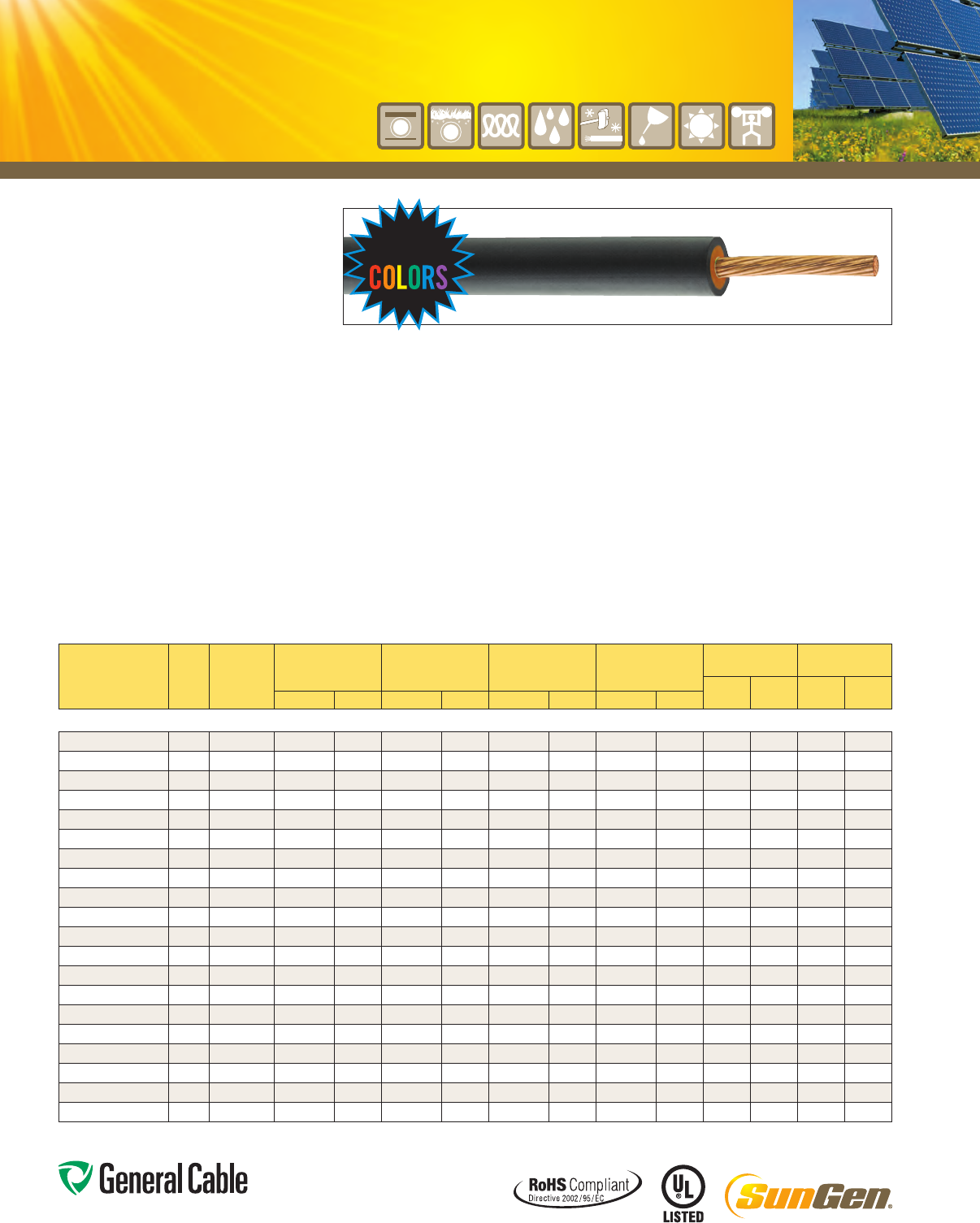
Phone: 888-593-3355
www.generalcable.com
Product Construction:
Conductor:
•14AWGthru2AWGtinnedcoatedcompressed
copper.ClassCstrandingperASTMB33andB8
•1AWGthru1000kcmiltinnedcoatedcompressed
copper.ClassBstrandingperASTMB33andB8
Insulation:
•Lead-freeEthylenePropyleneRubber(EPR)
coloredforcontrastwithblackjacket
Jacket:
•Black,lead-free,flame-retardant,oil-,chemical-
andsunlight-resistantCross-linkedChlorinated
Polyethylene(XL-CPE)
Print:
•GENERALCABLE®(PLANTOFMFG)SUNGEN®
2000 V PV WIRE DIR BUR OR RHH OR RHW-2
OR600VUSE-2(SIZE)90°CWETORDRY
SUNRES(UL)-40°CVW-1c(UL)RWU90
1000VMONTH/YEAROFMFGSEQUENTIAL
FOOTAGEMARK
Options:
•Barecopperconductor
•Otherstrandingoptionsareavailableuponrequest
•Nowavailableincolors
Applications:
•Singleconductor,sunlight-resistant,direct
burialphotovoltaicwirerated90°Cwetordry,
2000 V for interconnection wiring of grounded
andungroundedphotovoltaicpowersystems
asdescribedinSection690.31(A)andother
applicablepartsoftheNationalElectricalCode
(NEC),NFPA70
Features:
•Rated90°Cwetanddry
•Ratedfordirectburial
•Deformation-resistantathightemperatures
•Excellentmoistureresistance,exceedsUL44
•Stableelectricalpropertiesoverabroad
temperature range
•Extratough,mechanicallyruggeddual-layer
construction
•Increasedflexibility
•Resistanttomostoilsandchemicals
•UV/sunlight-resistant
•Meetscoldbendandcoldimpacttestsat-40°C
Compliances:
Industry Compliances:
•UL4703TypePV,ULFile#E323451
•NationalElectricalCode(NEC)
•ICEAS-95-658/NEMAWC70
•UL44TypeRHHorRHW-2,ULFile#E90494
or E54260
•UL854TypeUSE-2for600V,ULFile#E90499
or E86307
•LimitedSmokeRatingperUL
•RoHSCompliant
Flame Test Compliances:
•UL1581VW-1
•Forsizes1/0andlarger:IEEE383,
IEEE1202/CSAFT4
Other Compliances:
•EPA40CFR,Part261forleachablelead
content per TCLP
•OSHAAcceptable
Packaging:
•Materialcuttolengthandshippedon
non-returnable wood reels
SPEC 5810
May, 2012
SunGen
®
Dual-LayerEPR/XL-CPE,PhotovoltaicWire,2000V,ULTypePV/RHH
or RHW-2 or 600 V USE-2
Single Conductor, Copper
CATALOG
NUMBER
COND.
SIZE
(AWG/
kcmil)
COND.
STRAND
NOMINAL COND. O.D.
MINIMUM AVG.
INSULATION
THICKNESS
MINIMUM AVG.
JACKET THICKNESS
NOMINAL CABLE
DIAMETER
COPPER
WEIGHT NET WEIGHT
LBS/
1000 FT kg/km
LBS/
1000 FT kg/kmINCHES mm INCHES mm INCHES mm INCHES mm
14 AWG - 1000 kcmil CONDUCTORS
12221.711400 14 19/.0142 0.070 1.78 0.045 1.14 0.030 0.76 0.232 5.89 13 19 36 54
12221.711200 12 19/.0185 0.088 2.23 0.045 1.14 0.030 0.76 0.250 6.35 20 30 46 68
12221.711100 10 19/.0234 0.112 2.84 0.045 1.14 0.030 0.76 0.273 6.93 32 48 64 95
12221.710800* 8 19/.0295 0.143 3.63 0.055 1.40 0.030 0.76 0.332 8.43 50 74 95 141
12221.710600* 6 19/.0372 0.184 4.67 0.055 1.40 0.045 1.14 0.398 10.11 81 121 148 220
12221.710400* 4 19/.0469 0.234 5.94 0.055 1.40 0.045 1.14 0.442 11.23 129 192 208 309
12221.710200* 2 19/.0526 0.296 7.52 0.055 1.40 0.045 1.14 0.507 12.88 205 305 306 455
12221.710100* 1 19/.0664 0.323 8.20 0.065 1.65 0.060 1.52 0.561 14.25 258 384 440 655
12221.715100* 1/0 19/.0740 0.370 9.40 0.065 1.65 0.060 1.52 0.607 15.42 326 485 505 751
12221.715200* 2/0 19/.0837 0.410 10.41 0.065 1.65 0.060 1.52 0.652 16.56 411 611 615 915
12221.715300* 3/0 19/.0940 0.460 11.68 0.065 1.65 0.060 1.52 0.700 17.78 518 771 747 1111
12221.715400* 4/0 19/.1055 0.520 13.21 0.065 1.65 0.060 1.52 0.760 19.30 653 972 891 1326
12221.716250* 250 37/.0822 0.558 14.17 0.075 1.91 0.080 2.03 0.882 22.40 772 1149 1012 1506
12221.716300* 300 37/.0900 0.611 15.52 0.075 1.91 0.080 2.03 0.935 23.75 926 1378 1184 1763
12221.716350* 350 37/.0972 0.661 16.79 0.075 1.91 0.080 2.03 0.985 25.02 1063 1582 1339 1993
12221.716400* 400 37/.1040 0.706 17.93 0.075 1.91 0.080 2.03 1.030 26.16 1235 1838 1527 2273
12221.716500* 500 37/.1159 0.789 20.04 0.075 1.91 0.080 2.03 1.113 28.27 1509 2246 1831 2725
12221.716600* 600 61/.0992 0.866 22.00 0.090 2.29 0.080 2.03 1.222 31.04 1883 2802 2262 3367
12221.716750* 750 61/.1109 0.968 24.59 0.090 2.29 0.080 2.03 1.324 33.63 2316 3447 2734 4069
12221.717000* 1000 61/.1280 1.117 28.37 0.090 2.29 0.080 2.03 1.473 37.41 3088 4595 3564 5303
Dimensions and weights are nominal; subject to industry tolerances.
*Non-stockitem;minimumrunsapply.PleasecontactCustomerServiceforpriceanddelivery.
NOW
AVAILABLE IN
SUN-RESISTANT
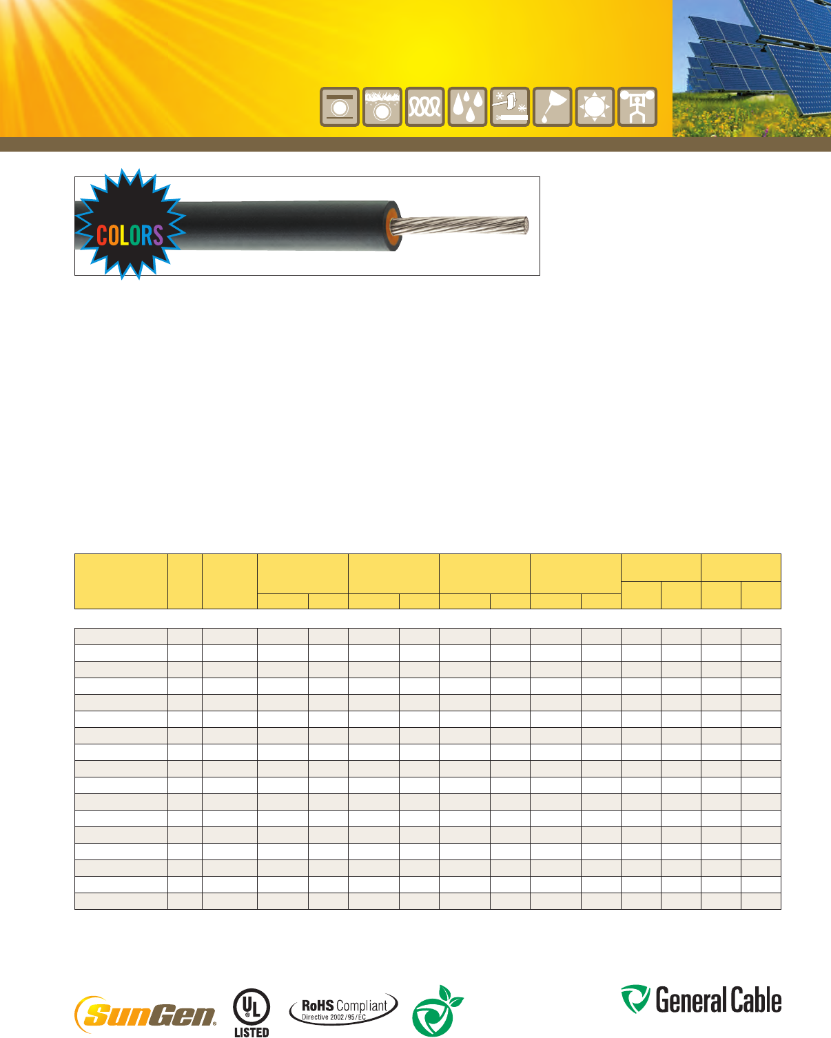
Phone: 888-593-3355
www.generalcable.com
SPEC 5810A
October, 2012
SunGen
®
Dual-LayerEPR/XL-CPE,PhotovoltaicWire,2000V,ULTypePV/RHH
or RHW-2 or 600 V USE-2
SingleConductor,Aluminum
NOW
AVAILABLE IN
SUN-RESISTANT
CATALOG
NUMBER
COND.
SIZE
(AWG/
kcmil)
COND.
STRAND (1)
NOMINAL COND. O.D.
MINIMUM AVG.
INSULATION
THICKNESS
MINIMUM AVG.
JACKET THICKNESS
NOMINAL CABLE
DIAMETER
ALUMINUM
WEIGHT NET WEIGHT
LBS/
1000 FT kg/km
LBS/
1000 FT kg/kmINCHES mm INCHES mm INCHES mm INCHES mm
8 AWG - 1000 kcmil CONDUCTORS
12221.710800A*
8 7/.0486 0.134 3.40 0.055 1.40 0.030 0.76 0.308 7.82 16 23 53 79
12221.710600A*
6 7/.0612 0.169 4.29 0.055 1.40 0.045 1.14 0.377 9.58 25 37 81 121
12221.710400A*
4 7/.0772 0.213 5.41 0.055 1.40 0.045 1.14 0.421 10.69 39 58 105 156
12221.710200A*
2 7/.0974 0.268 6.81 0.055 1.40 0.045 1.14 0.476 12.09 63 93 139 207
12221.710100A*
1 19/.0664 0.299 7.59 0.065 1.65 0.060 1.52 0.559 14.20 79 117 190 282
12221.715100A*
1/0 19/.0745 0.336 8.53 0.065 1.65 0.060 1.52 0.596 15.14 99 148 220 328
12221.715200A*
2/0 19/.0837 0.376 9.55 0.065 1.65 0.060 1.52 0.636 16.15 125 186 256 381
12221.715300A*
3/0 19/.0940 0.423 10.74 0.065 1.65 0.060 1.52 0.683 17.35 158 235 302 449
12221.715400A*
4/0 19/.1055 0.475 12.07 0.065 1.65 0.060 1.52 0.735 18.67 199 296 356 530
12221.716250A*
250 37/.0822 0.520 13.21 0.075 1.91 0.080 2.03 0.844 21.44 262 390 484 720
12221.716300A*
300 37/.0900 0.570 14.48 0.075 1.91 0.080 2.03 0.894 22.71 282 420 520 774
12221.716350A*
350 37/.0972 0.616 15.65 0.075 1.91 0.080 2.03 0.940 23.88 329 490 582 867
12221.716400A*
400 37/.1040 0.659 16.74 0.075 1.91 0.080 2.03 0.983 24.97 376 560 644 958
12221.716500A*
500 37/.1159 0.736 18.69 0.075 1.91 0.080 2.03 1.060 26.92 471 701 764 1137
12221.716600A*
600 61/.0992 0.813 20.65 0.090 2.29 0.080 2.03 1.169 29.69 565 841 918 1366
12221.716750A*
750 61/.1109 0.908 23.06 0.090 2.29 0.080 2.03 1.264 32.11 706 1051 1094 1628
12221.717000A*
1000 61/.1280 1.060 26.92 0.090 2.29 0.080 2.03 1.416 35.97 914 1360 1357 2019
Dimensions and weights are nominal; subject to industry tolerances.
*Non-stockitem;minimumrunsapply.PleasecontactCustomerServiceforpriceanddelivery.
(1)Forcompactstrandedconstructions,thenumberofwiresmaybereducedasfollows:
19-Wire Constructions — 18 wires minimum
37-Wire Constructions — 35 wires minimum
61-Wire Constructions — 58 wires minimum
Product Construction:
Conductor:
•8AWGthru1000kcmilcompactaluminumACM
(8000series)
Insulation:
•Lead-freeEthylenePropyleneRubber(EPR)
coloredforcontrastwithblackjacket
Jacket:
•Black,lead-free,flame-retardant,oil-,chemical-
andsunlight-resistantCross-linkedChlorinated
Polyethylene(XL-CPE)
Print:
•GENERALCABLE®(PLANTOFMFG)SUNGEN®
2000 V PV WIRE DIR BUR OR RHH OR RHW-2
OR600VUSE-2(SIZE)ALACM90°CWETOR
DRYSUNRES(UL)-40°CVW-1c(UL)RWU90
1000VMONTH/YEAROFMFGSEQUENTIAL
FOOTAGEMARK
Options:
•Otherstrandingoptionsareavailableuponrequest
•Nowavailableincolors
Applications:
•Singleconductor,sunlight-resistant,direct
burialphotovoltaicwirerated90°Cwetordry,
2000 V for interconnection wiring of grounded
andungroundedphotovoltaicpowersystems
asdescribedinSection690.31(A)andother
applicablepartsoftheNationalElectricalCode
(NEC),NFPA70
Features:
•Rated90°Cwetanddry
•Ratedfordirectburial
•Deformation-resistantathightemperatures
•Excellentmoistureresistance,exceedsUL44
•Stableelectricalpropertiesoverabroad
temperature range
Features (cont’d.):
•Extratough,mechanicallyruggeddual-layer
construction
•Increasedflexibility
•Resistanttomostoilsandchemicals
•UV/sunlight-resistant
•Meetscoldbendandcoldimpacttestsat-40°C
Compliances:
Industry Compliances:
•UL4703TypePV,ULFile#E323451
•NationalElectricalCode(NEC)
•ICEAS-95-658/NEMAWC70
•UL44TypeRHHorRHW-2,ULFile#E90494
or E54260
•UL854TypeUSE-2for600V,ULFile#E90499
or E86307
•LimitedSmokeRatingperUL
•RoHSCompliant
Flame Test Compliances:
•UL1581VW-1
•Forsizes1/0andlarger:IEEE383,
IEEE1202/CSAFT4
Other Compliances:
•EPA40CFR,Part261forleachablelead
content per TCLP
•OSHAAcceptable
Packaging:
•Materialcuttolengthandshippedon
non-returnable wood reels
Phone: 888-593-3355
www.generalcable.com
Product Construction:
Conductor:
•18AWGthru2AWGtinnedcoatedcompressed
copper.ClassCstrandingperASTMB33andB8
•1AWGthru1000kcmiltinnedcoated
compressedcopper.ClassBstrandingperASTM
B33 and B8
Insulation:
•Flame-retardantCross-linkedPolyethylene
(XLPE),black
Print:
•18AWGand16AWG:GENERALCABLE®(PLANT
OFMFG)SUNGEN® 600 V PV WIRE DIR BUR
90°CWETORDRYSUNRES(UL)-40°CVW-1
MONTH/YEAROFMFGSEQUENTIALFOOTAGE
MARK
•14AWGthru1000kcmil:GENERALCABLE®
(PLANTOFMFG)SUNGEN® 600 V PV WIRE DIR
BUR OR 2000 V RHH OR RHW-2 OR 600 V USE-2
(SIZE)90°CWETORDRYSUNRES(UL)-40°C
VW-1(CSA)RPVU901000VMONTH/YEAROF
MFGSEQUENTIALFOOTAGEMARK
Options:
•Barecopperconductor
•Otherstrandingoptionsareavailableupon
request
•Nowavailableincolors
Applications:
•Singleconductor,sunlight-resistant,direct
burialphotovoltaicwirerated90°Cwetordry,
600 V for interconnection wiring of grounded
andungroundedphotovoltaicpowersystems
asdescribedinSection690.31(A)andother
applicablepartsoftheNationalElectricalCode
(NEC),NFPA70
Features:
•Rated90°Cwetanddry
•Ratedfordirectburial
•Deformation-resistantathightemperatures
•Excellentmoistureresistance,exceedsUL44
•Stableelectricalpropertiesoverabroad
temperature range
•Increasedflexibility
•Excellentresistancetocrushandcompression
cuts
•Resistanttomostoilsandchemicals
•UV/sunlight-resistant
•Meetscoldbendandcoldimpacttestsat-40°C
Compliances:
Industry Compliances:
•UL4703TypePV,ULFile#E323451
•NationalElectricalCode(NEC)
•ICEAS-95-658/NEMAWC70
•UL44TypeRHHorRHW-2,ULFile#E90494
•UL854TypeUSE-2,ULFile#E90499
•CSAC22.2No.271RPVU90
Flame Test Compliances:
•UL1581VW-1
•Forsizes1/0andlarger:IEEE383,
IEEE1202/CSAFT4
Other Compliances:
•EPA40CFR,Part261forleachablelead
content per TCLP
•OSHAAcceptable
Packaging:
•Materialcuttolengthandshippedon
non-returnable wood reels
SPEC 5840
May, 2012
SunGen
®
XLPE,PhotovoltaicWire,600V,ULTypePV/USE-2or2000VRHHor
RHW-2orCSARPVU90,1000V
Single Conductor, Copper
CATALOG
NUMBER
COND.
SIZE
(AWG/
kcmil)
COND.
STRAND
NOMINAL COND. O.D.
MINIMUM AVG.
INSULATION THICKNESS
NOMINAL CABLE
DIAMETER
COPPER
WEIGHT NET WEIGHT
LBS/
1000 FT kg/km
LBS/
1000 FT kg/kmINCHES mm INCHES mm INCHES mm
18 AWG - 1000 kcmil CONDUCTORS
12411.711800* 18 19/.0092 0.045 1.14 0.060 1.52 0.169 4.29 5 7 14 21
12411.711600* 16 19/.0117 0.056 1.42 0.060 1.52 0.180 4.57 8 12 18 27
12411.711400 14 19/.0142 0.070 1.78 0.060 1.52 0.194 4.93 13 19 27 40
12411.711200 12 19/.0185 0.088 2.23 0.060 1.52 0.214 5.43 20 30 36 54
12411.711100 10 19/.0234 0.112 2.84 0.060 1.52 0.238 6.04 32 48 51 76
12411.710800* 8 19/.0295 0.143 3.63 0.080 2.03 0.307 7.80 50 74 85 126
12411.710600* 6 19/.0372 0.184 4.67 0.080 2.03 0.348 8.84 81 121 123 183
12411.710400* 4 19/.0469 0.234 5.94 0.080 2.03 0.398 10.11 129 192 180 268
12411.710200* 2 19/.0526 0.296 7.52 0.080 2.03 0.460 11.68 205 305 267 397
12411.710100* 1 19/.0664 0.323 8.20 0.095 2.41 0.515 13.08 258 384 333 495
12411.715100* 1/0 19/.0740 0.370 9.40 0.095 2.41 0.563 14.30 326 485 410 610
12411.715200* 2/0 19/.0837 0.410 10.41 0.095 2.41 0.608 15.44 411 611 502 747
12411.715300* 3/0 19/.0940 0.460 11.68 0.095 2.41 0.658 16.71 518 771 620 922
12411.715400* 4/0 19/.1055 0.520 13.21 0.095 2.41 0.714 18.13 653 972 767 1141
12411.716250* 250 37/.0822 0.558 14.17 0.110 2.79 0.784 19.91 772 1149 923 1374
12411.716300* 300 37/.0900 0.611 15.52 0.110 2.79 0.837 21.26 926 1378 1090 1622
12411.716350* 350 37/.0972 0.661 16.79 0.110 2.79 0.887 22.53 1063 1582 1240 1845
12411.716400* 400 37/.1040 0.706 17.93 0.110 2.79 0.932 23.67 1235 1838 1423 2117
12411.716500* 500 37/.1159 0.789 20.04 0.110 2.79 1.015 25.78 1509 2246 1718 2557
12411.716600* 600 61/.0992 0.866 22.00 0.125 3.18 1.122 28.50 1883 2802 2136 3179
12411.716750* 750 61/.1109 0.968 24.59 0.125 3.18 1.224 31.09 2316 3447 2597 3865
12411.717000* 1000 61/.1280 1.117 28.37 0.125 3.18 1.373 34.87 3088 4595 3411 5076
Dimensions and weights are nominal; subject to industry tolerances.
*Non-stockitem;minimumrunsapply.PleasecontactCustomerServiceforpriceanddelivery.
NOW
AVAILABLE IN
SUN-RESISTANT

Phone: 888-593-3355
www.generalcable.com
SPEC 5840A
October, 2012
SunGen
®
XLPE,PhotovoltaicWire,600V,ULTypePV/USE-2or2000VRHHor
RHW-2orCSARPVU90,1000V
SingleConductor,Aluminum
CATALOG
NUMBER
COND.
SIZE
(AWG/
kcmil)
COND.
STRAND (1)
NOMINAL COND. O.D.
MINIMUM AVG.
INSULATION THICKNESS
NOMINAL CABLE
DIAMETER
ALUMINUM
WEIGHT NET WEIGHT
LBS/
1000 FT kg/km
LBS/
1000 FT kg/kmINCHES mm INCHES mm INCHES mm
8 AWG - 1000 kcmil CONDUCTORS
12411.710800A* 8 7/.0486 0.134 3.40 0.080 2.03 0.298 7.57 16 23 49 73
12411.710600A* 6 7/.0612 0.169 4.29 0.080 2.03 0.333 8.46 25 37 64 95
12411.710400A* 4 7/.0772 0.213 5.41 0.080 2.03 0.377 9.58 39 58 85 127
12411.710200A* 2 7/.0974 0.268 6.81 0.080 2.03 0.432 10.97 63 93 117 174
12411.710100A* 1 19/.0664 0.299 7.59 0.095 2.41 0.495 12.57 79 117 153 227
12411.715100A* 1/0 19/.0745 0.336 8.53 0.095 2.41 0.532 13.51 99 148 180 268
12411.715200A* 2/0 19/.0837 0.376 9.55 0.095 2.41 0.572 14.53 125 186 214 318
12411.715300A* 3/0 19/.0940 0.423 10.74 0.095 2.41 0.619 15.72 158 235 256 380
12411.715400A* 4/0 19/.1055 0.475 12.07 0.095 2.41 0.671 17.04 199 296 307 456
12411.716250A* 250 37/.0822 0.520 13.21 0.110 2.79 0.746 18.95 262 390 399 594
12411.716300A* 300 37/.0900 0.570 14.48 0.110 2.79 0.796 20.22 282 420 430 640
12411.716350A* 350 37/.0972 0.616 15.65 0.110 2.79 0.842 21.39 329 490 487 725
12411.716400A* 400 37/.1040 0.659 16.74 0.110 2.79 0.885 22.48 376 560 544 810
12411.716500A* 500 37/.1159 0.736 18.69 0.110 2.79 0.962 24.43 471 701 656 977
12411.716600A* 600 61/.0992 0.813 20.65 0.125 3.18 1.069 27.15 565 841 798 1187
12411.716750A* 750 61/.1109 0.908 23.06 0.125 3.18 1.164 29.57 706 1051 963 1433
12411.717000A* 1000 61/.1280 1.060 26.92 0.125 3.18 1.316 33.43 914 1360 1210 1801
Dimensions and weights are nominal; subject to industry tolerances.
*Non-stockitem;minimumrunsapply.PleasecontactCustomerServiceforpriceanddelivery.
(1)Forcompactstrandedconstructions,thenumberofwiresmaybereducedasfollows:
19-Wire Constructions — 18 wires minimum
37-Wire Constructions — 35 wires minimum
61-Wire Constructions — 58 wires minimum
Product Construction:
Conductor:
•8AWGthru1000kcmilcompactaluminumACM
(8000series)
Insulation:
•Flame-retardantCross-linkedPolyethylene
(XLPE),black
Print:
•GENERALCABLE®(PLANTOFMFG)SUNGEN®
600 V PV WIRE DIR BUR OR 2000 V RHH
ORRHW-2OR600VUSE-2(SIZE)ALACM
90°CWETORDRYSUNRES(UL)-40°CVW-1
CSARPVU901000VMONTH/YEAROFMFG
SEQUENTIALFOOTAGEMARK
Options:
•Otherstrandingoptionsareavailableuponrequest
•Nowavailableincolors
Applications:
•Singleconductor,sunlight-resistant,direct
burialphotovoltaicwirerated90°Cwetordry,
600 V for interconnection wiring of grounded
andungroundedphotovoltaicpowersystems
asdescribedinSection690.31(A)andother
applicablepartsoftheNationalElectricalCode
(NEC),NFPA70
Features:
•Rated90°Cwetanddry
•Ratedfordirectburial
•Deformation-resistantathightemperatures
•Excellentmoistureresistance,exceedsUL44
•Stableelectricalpropertiesoverabroad
temperature range
•Increasedflexibility
•Excellentresistancetocrushandcompression
cuts
•Resistanttomostoilsandchemicals
•UV/sunlight-resistant
•Meetscoldbendandcoldimpacttestsat-40°C
Compliances:
Industry Compliances:
•UL4703TypePV,ULFile#E323451
•NationalElectricalCode(NEC)
•ICEAS-95-658/NEMAWC70
•UL44TypeRHHorRHW-2,ULFile#E90494
•UL854TypeUSE-2,ULFile#E90499
•CSAC22.2No.271RPVU90
Flame Test Compliances:
•UL1581VW-1
•Forsizes1/0andlarger:IEEE383,
IEEE1202/CSAFT4
Other Compliances:
•EPA40CFR,Part261forleachablelead
content per TCLP
•OSHAAcceptable
Packaging:
•Materialcuttolengthandshippedon
non-returnable wood reels
NOW
AVAILABLE IN
SUN-RESISTANT

Phone: 888-593-3355
www.generalcable.com
Product Construction:
Conductor:
•18AWGthru1000kcmilbarecompressed
copper.ClassBperASTMB8
Insulation:
•Flame-retardantCross-linkedPolyethylene
(XLPE),black
Print:
•18AWGand16AWG:GENERALCABLE®
(PLANTOFMFG)SUNGEN® 600 V PV WIRE DIR
BUR90°CWETORDRYSUNRES(UL)-40°C
VW-1MONTH/YEAROFMFGSEQUENTIAL
FOOTAGEMARK
•14AWGthru1000kcmil:GENERALCABLE®
(PLANTOFMFG)SUNGEN® 600 V PV WIRE
DIR BUR OR 2000 V RHH OR RHW-2 OR 600 V
USE-2(SIZE)90°CWETORDRYSUNRES(UL)
-40°CVW-1(CSA)RPVU901000VMONTH/
YEAROFMFGSEQUENTIALFOOTAGEMARK
Options:
•Tinnedcopperconductor
•Otherstrandingoptionsareavailableupon
request
•Nowavailableincolors
Applications:
•Singleconductor,sunlight-resistant,direct
burialphotovoltaicwirerated90°Cwetordry,
600 V for interconnection wiring of grounded
andungroundedphotovoltaicpowersystems
asdescribedinSection690.31(A)andother
applicablepartsoftheNationalElectricalCode
(NEC),NFPA70
Features:
•Rated90°Cwetanddry
•Ratedfordirectburial
•Deformation-resistantathightemperatures
•Excellentmoistureresistance,exceedsUL44
•Stableelectricalpropertiesoverabroad
temperature range
•Excellentresistancetocrushandcompression
cuts
•Resistanttomostoilsandchemicals
•UV/sunlight-resistant
•Meetscoldbendandcoldimpacttestsat-40°C
Compliances:
Industry Compliances:
•UL4703TypePV,ULFile#E323451
•NationalElectricalCode(NEC)
•ICEAS-95-658/NEMAWC70
•UL44TypeRHHorRHW-2,ULFile#E90494
•UL854TypeUSE-2,ULFile#E90499
•CSAC22.2No.271RPVU90
Flame Test Compliances:
•UL1581VW-1
•Forsizes1/0andlarger:IEEE383,
IEEE1202/CSAFT4
Other Compliances:
•EPA40CFR,Part261forleachablelead
content per TCLP
•OSHAAcceptable
Packaging:
•Materialcuttolengthandshippedon
non-returnable wood reels
SPEC 5845
May, 2012
SunGen
®
IC
XLPE,PhotovoltaicWire,600V,ULTypePV/USE-2or2000V
RHHorRHW-2orCSARPVU90
1000 V, Single Conductor, Copper
CATALOG
NUMBER
COND.
SIZE
(AWG/
kcmil)
COND.
STRAND
NOMINAL COND. O.D.
MINIMUM AVG.
INSULATION THICKNESS
NOMINAL CABLE
DIAMETER
COPPER
WEIGHT NET WEIGHT
LBS/
1000 FT kg/km
LBS/
1000 FT kg/kmINCHES mm INCHES mm INCHES mm
18 AWG - 1000 kcmil CONDUCTORS
12431.711800* 18 7/.0152 0.045 1.14 0.060 1.52 0.169 4.29 5 7 14 21
12431.711600* 16 7/.0192 0.056 1.42 0.060 1.52 0.180 4.57 8 12 18 27
12431.711400* 14 7/.0240 0.070 1.78 0.060 1.52 0.194 4.93 13 19 27 40
12431.711200 12 7/.0305 0.088 2.23 0.060 1.52 0.214 5.43 20 30 36 54
12431.711100 10 7/.0385 0.112 2.84 0.060 1.52 0.238 6.04 32 48 51 76
12431.710800 8 7/.0486 0.143 3.63 0.080 2.02 0.313 7.95 50 74 88 131
12431.710600* 6 7/.0612 0.184 4.67 0.080 2.02 0.356 9.04 81 121 126 186
12431.710400* 4 7/.0772 0.234 5.94 0.080 2.02 0.405 10.29 129 192 183 272
12431.710200* 2 7/.0974 0.296 7.52 0.080 2.02 0.466 11.84 205 305 269 401
12431.710100* 1 19/.0664 0.323 8.20 0.095 2.41 0.515 13.08 258 384 333 495
12431.715100* 1/0 19/.0740 0.370 9.40 0.095 2.41 0.563 14.30 326 485 410 610
12431.715200* 2/0 19/.0837 0.410 10.41 0.095 2.41 0.608 15.44 411 611 502 747
12431.715300* 3/0 19/.0940 0.460 11.68 0.095 2.41 0.658 16.71 518 771 620 922
12431.715400* 4/0 19/.1055 0.520 13.21 0.095 2.41 0.714 18.13 653 972 767 1141
12431.716250* 250 37/.0822 0.558 14.17 0.110 2.79 0.784 19.91 772 1149 923 1374
12431.716300* 300 37/.0900 0.611 15.52 0.110 2.79 0.837 21.26 926 1378 1090 1622
12431.716350* 350 37/.0972 0.661 16.79 0.110 2.79 0.887 22.53 1063 1582 1240 1845
12431.716400* 400 37/.1040 0.706 17.93 0.110 2.79 0.932 23.67 1235 1838 1423 2117
12431.716500* 500 37/.1159 0.789 20.04 0.110 2.79 1.015 25.78 1509 2246 1718 2557
12431.716600* 600 61/.0992 0.866 22.00 0.125 3.18 1.122 28.50 1883 2802 2136 3179
12431.716750* 750 61/.1109 0.968 24.59 0.125 3.18 1.224 31.09 2316 3447 2597 3865
12431.717000* 1000 61/.1280 1.117 28.37 0.125 3.18 1.373 34.87 3088 4595 3411 5076
Dimensions and weights are nominal; subject to industry tolerances.
*Non-stockitem;minimumrunsapply.PleasecontactCustomerServiceforpriceanddelivery.
NOW
AVAILABLE IN
SUN-RESISTANT

Phone: 888-593-3355
www.generalcable.com
Product Construction:
Conductor:
•18AWGthru2AWGtinnedcoatedcompressed
copper.ClassCstrandingperASTMB33andB8
•1AWGthru1000kcmiltinnedcoated
compressedcopper.ClassBstrandingperASTM
B33 and B8
Insulation:
•Flame-retardantCross-linkedPolyethylene
(XLPE),black
Print:
•18AWGand16AWG:GENERALCABLE®
(PLANTOFMFG)SUNGEN® 2000 V PV
WIREDIRBUR90°CWETORDRYSUNRES
(UL)-40°CVW-1MONTH/YEAROFMFG
SEQUENTIALFOOTAGEMARK
•14AWGthru1000kcmil:GENERALCABLE®
(PLANTOFMFG)SUNGEN® 2000 V PV WIRE
DIR BUR OR RHH OR RHW-2 OR 600 V USE-2
Print (cont’d.):
(SIZE)90°CWETORDRYSUNRES(UL)-40°C
VW-1(CSA)RPVU901000VMONTH/YEAROF
MFGSEQUENTIALFOOTAGEMARK
Options:
•Barecopperconductor
•Otherstrandingoptionsareavailableupon
request
•Nowavailableincolors
Applications:
•Singleconductor,sunlight-resistant,direct
burialphotovoltaicwirerated90°Cwetordry,
2000 V for interconnection wiring of grounded
andungroundedphotovoltaicpowersystems
asdescribedinSection690.31(A)andother
applicablepartsoftheNationalElectricalCode
(NEC),NFPA70
Features:
•Rated90°Cwetanddry
•Ratedfordirectburial
Features (cont’d.):
•Deformation-resistantathightemperatures
•Excellentmoistureresistance,exceedsUL44
•Stableelectricalpropertiesoverabroad
temperature range
•Increasedflexibility
•Excellentresistancetocrushandcompression
cuts
•Resistanttomostoilsandchemicals
•UV/sunlight-resistant
•Meetscoldbendandcoldimpacttestsat-40°C
Compliances:
Industry Compliances:
•UL4703TypePV,ULFile#E323451
•NationalElectricalCode(NEC)
•ICEAS-95-658/NEMAWC70
•UL44TypeRHHorRHW-2,ULFile#E90494
•UL854TypeUSE-2for600V,ULFile#E90499
•CSAC22.2No.271RPVU90
Flame Test Compliances:
•UL1581VW-1
•Forsizes1/0andlarger:IEEE383,
IEEE1202/CSAFT4
Other Compliances:
•EPA40CFR,Part261forleachablelead
content per TCLP
•OSHAAcceptable
Packaging:
•Materialcuttolengthandshippedon
non-returnable wood reels
SPEC 5850
May, 2012
SunGen
®
XLPE,PhotovoltaicWire,2000V,ULTypePV/RHHorRHW-2or600V
USE-2orCSARPVU90,1000V
Single Conductor, Copper
CATALOG
NUMBER
COND.
SIZE
(AWG/
kcmil)
COND.
STRAND
NOMINAL COND. O.D.
MINIMUM AVG.
INSULATION THICKNESS
NOMINAL CABLE
DIAMETER
COPPER
WEIGHT NET WEIGHT
LBS/
1000 FT kg/km
LBS/
1000 FT kg/kmINCHES mm INCHES mm INCHES mm
18 AWG - 1000 kcmil CONDUCTORS
12421.711800* 18 19/.0092 0.045 1.14 0.075 1.90 0.199 5.05 5 7 16 24
12421.711600* 16 19/.0117 0.056 1.42 0.075 1.90 0.210 5.33 8 12 21 31
12421.711400 14 19/.0142 0.070 1.78 0.075 1.90 0.224 5.69 13 19 32 48
12421.711200 12 19/.0185 0.088 2.23 0.075 1.90 0.244 6.20 20 30 42 62
12421.711100 10 19/.0234 0.112 2.84 0.075 1.90 0.268 6.81 32 48 57 85
12421.710800* 8 19/.0295 0.143 3.63 0.085 2.16 0.326 8.28 50 74 87 129
12421.710600* 6 19/.0372 0.184 4.67 0.085 2.16 0.363 9.22 81 121 123 183
12421.710400* 4 19/.0469 0.234 5.94 0.085 2.16 0.406 10.31 129 192 181 269
12421.710200* 2 19/.0526 0.296 7.52 0.085 2.16 0.474 12.04 205 305 266 396
12421.710100* 1 19/.0664 0.323 8.20 0.105 2.67 0.538 13.66 258 384 350 521
12421.715100* 1/0 19/.0740 0.370 9.40 0.105 2.67 0.586 14.88 326 485 429 638
12421.715200* 2/0 19/.0837 0.410 10.41 0.105 2.67 0.631 16.03 411 611 527 784
12421.715300* 3/0 19/.0940 0.460 11.68 0.105 2.67 0.674 17.12 518 771 647 963
12421.715400* 4/0 19/.1055 0.520 13.21 0.105 2.67 0.737 18.72 653 972 796 1184
12421.716250* 250 37/.0822 0.558 14.17 0.120 3.05 0.804 20.42 772 1149 938 1396
12421.716300* 300 37/.0900 0.611 15.52 0.120 3.05 0.857 21.77 926 1378 1106 1646
12421.716350* 350 37/.0972 0.661 16.79 0.120 3.05 0.907 23.04 1063 1582 1257 1870
12421.716400* 400 37/.1040 0.706 17.93 0.120 3.05 0.952 24.18 1235 1838 1441 2144
12421.716500* 500 37/.1159 0.789 20.04 0.120 3.05 1.035 26.29 1509 2246 1737 2585
12421.716600* 600 61/.0992 0.866 22.00 0.135 3.43 1.142 29.01 1883 2802 2157 3211
12421.716750* 750 61/.1109 0.968 24.59 0.135 3.43 1.244 31.60 2316 3447 2620 3900
12421.717000* 1000 61/.1280 1.117 28.37 0.135 3.43 1.393 35.38 3088 4595 3437 5115
Dimensions and weights are nominal; subject to industry tolerances.
*Non-stockitem;minimumrunsapply.PleasecontactCustomerServiceforpriceanddelivery.
NOW
AVAILABLE IN
SUN-RESISTANT
Phone: 888-593-3355
www.generalcable.com
SPEC 5850A
October, 2012
SunGen
®
XLPE,PhotovoltaicWire,2000V,ULTypePV/RHHorRHW-2or600V
USE-2orCSARPVU90,1000V
SingleConductor,Aluminum
NOW
AVAILABLE IN
SUN-RESISTANT
CATALOG
NUMBER
COND.
SIZE
(AWG/
kcmil)
COND.
STRAND (1)
NOMINAL COND. O.D.
MINIMUM AVG.
INSULATION THICKNESS
NOMINAL CABLE
DIAMETER
ALUMINUM
WEIGHT NET WEIGHT
LBS/
1000 FT kg/km
LBS/
1000 FT kg/kmINCHES mm INCHES mm INCHES mm
8 AWG - 1000 kcmil CONDUCTORS
12421.710800A* 8 7/.0486 0.134 3.40 0.085 2.16 0.310 7.87 16 23 52 78
12421.710600A* 6 7/.0612 0.169 4.29 0.085 2.16 0.345 8.76 25 37 67 100
12421.710400A* 4 7/.0772 0.213 5.41 0.085 2.16 0.389 9.88 39 58 90 133
12421.710200A* 2 7/.0974 0.268 6.81 0.085 2.16 0.444 11.28 63 93 122 182
12421.710100A* 1 19/.0664 0.299 7.59 0.105 2.67 0.515 13.08 79 117 162 241
12421.715100A* 1/0 19/.0745 0.336 8.53 0.105 2.67 0.552 14.02 99 148 191 284
12421.715200A* 2/0 19/.0837 0.376 9.55 0.105 2.67 0.592 15.04 125 186 225 334
12421.715300A* 3/0 19/.0940 0.423 10.74 0.105 2.67 0.639 16.23 158 235 267 398
12421.715400A* 4/0 19/.1055 0.475 12.07 0.105 2.67 0.691 17.55 199 296 319 475
12421.716250A* 250 37/.0822 0.520 13.21 0.120 3.05 0.766 19.46 262 390 413 615
12421.716300A* 300 37/.0900 0.570 14.48 0.120 3.05 0.816 20.73 282 420 445 663
12421.716350A* 350 37/.0972 0.616 15.65 0.120 3.05 0.862 21.89 329 490 503 749
12421.716400A* 400 37/.1040 0.659 16.74 0.120 3.05 0.905 22.99 376 560 561 835
12421.716500A* 500 37/.1159 0.736 18.69 0.120 3.05 0.982 24.94 471 701 675 1004
12421.716600A* 600 61/.0992 0.813 20.65 0.135 3.43 1.089 27.66 565 841 818 1217
12421.716750A* 750 61/.1109 0.908 23.06 0.135 3.43 1.184 30.07 706 1051 985 1466
12421.717000A* 1000 61/.1280 1.060 26.92 0.135 3.43 1.336 33.93 914 1360 1235 1838
Dimensions and weights are nominal; subject to industry tolerances.
*Non-stockitem;minimumrunsapply.PleasecontactCustomerServiceforpriceanddelivery.
(1)Forcompactstrandedconstructions,thenumberofwiresmaybereducedasfollows:
19-Wire Constructions — 18 wires minimum
37-Wire Constructions — 35 wires minimum
61-Wire Constructions — 58 wires minimum
Product Construction:
Conductor:
•8AWGthru1000kcmilcompactaluminumACM
(8000series)
Insulation:
•Flame-retardantCross-linkedPolyethylene
(XLPE),black
Print:
•GENERALCABLE®(PLANTOFMFG)SUNGEN®
2000 V PV WIRE DIR BUR OR RHH OR RHW-2
OR600VUSE-2(SIZE)ALACM90°CWETOR
DRYSUNRES(UL)-40°CVW-1CSARPVU90
1000VMONTH/YEAROFMFGSEQUENTIAL
FOOTAGEMARK
Options:
•Otherstrandingoptionsareavailableuponrequest
•Nowavailableincolors
Applications:
•Singleconductor,sunlight-resistant,direct
burialphotovoltaicwirerated90°Cwetordry,
2000 V for interconnection wiring of grounded
andungroundedphotovoltaicpowersystems
asdescribedinSection690.31(A)andother
applicablepartsoftheNationalElectricalCode
(NEC),NFPA70
Features:
•Rated90°Cwetanddry
•Ratedfordirectburial
•Deformation-resistantathightemperatures
•Excellentmoistureresistance,exceedsUL44
•Stableelectricalpropertiesoverabroad
temperature range
•Increasedflexibility
•Excellentresistancetocrushandcompression
cuts
•Resistanttomostoilsandchemicals
•UV/sunlight-resistant
•Meetscoldbendandcoldimpacttestsat-40°C
Compliances:
Industry Compliances:
•UL4703TypePV,ULFile#E323451
•NationalElectricalCode(NEC)
•ICEAS-95-658/NEMAWC70
•UL44TypeRHHorRHW-2,ULFile#E90494
•UL854TypeUSE-2,ULFile#E90499
•CSAC22.2No.271RPVU90
Flame Test Compliances:
•UL1581VW-1
•Forsizes1/0andlarger:IEEE383,
IEEE1202/CSAFT4
Other Compliances:
•EPA40CFR,Part261forleachablelead
content per TCLP
•OSHAAcceptable
Packaging:
•Materialcuttolengthandshippedon
non-returnable wood reels
Phone: 888-593-3355
www.generalcable.com
Product Construction:
Conductor:
•18AWGthru1000kcmilbarecompressed
copper.ClassBperASTMB8
Insulation:
•Flame-retardantCross-linkedPolyethylene
(XLPE),black
Print:
•18AWGand16AWG:GENERALCABLE®
(PLANTOFMFG)SUNGEN® 2000 V PV
WIREDIRBUR90°CWETORDRYSUNRES
(UL)-40°CVW-1MONTH/YEAROFMFG
SEQUENTIALFOOTAGEMARK
•14AWGthru1000kcmil:GENERALCABLE®
(PLANTOFMFG)SUNGEN® 2000 V PV WIRE
DIR BUR OR RHH OR RHW-2 OR 600 V USE-2
(SIZE)90°CWETORDRYSUNRES(UL)-40°C
VW-1(CSA)RPVU901000VMONTH/YEAROF
MFGSEQUENTIALFOOTAGEMARK
Options:
•Tinnedcopperconductor
•Otherstrandingoptionsareavailableupon
request
•Nowavailableincolors
Applications:
•Singleconductor,sunlight-resistant,direct
burialphotovoltaicwirerated90°Cwetordry,
2000 V for interconnection wiring of grounded
andungroundedphotovoltaicpowersystems
asdescribedinSection690.31(A)andother
applicablepartsoftheNationalElectricalCode
(NEC),NFPA70
Features:
•Rated90°Cwetanddry
•Ratedfordirectburial
•Deformation-resistantathightemperatures
•Excellentmoistureresistance,exceedsUL44
•Stableelectricalpropertiesoverabroad
temperature range
Features (cont’d.):
•Excellentresistancetocrushandcompression
cuts
•Resistanttomostoilsandchemicals
•UV/sunlight-resistant
•Meetscoldbendandcoldimpacttestsat-40°C
Compliances:
Industry Compliances:
•UL4703TypePV,ULFile#E323451
•NationalElectricalCode(NEC)
•ICEAS-95-658/NEMAWC70
•UL44TypeRHHorRHW-2,ULFile#E90494
or E54260
•UL854TypeUSE-2for600V,ULFile#E90499
or E86307
•CSAC22.2No.271RPVU90
Flame Test Compliances:
•UL1581VW-1
•Forsizes1/0andlarger:IEEE383,
IEEE1202/CSAFT4
Other Compliances:
•EPA40CFR,Part261forleachablelead
content per TCLP
•OSHAAcceptable
Packaging:
•Materialcuttolengthandshippedon
non-returnable wood reels
SPEC 5855
May, 2012
SunGen
®
IC
XLPE,PhotovoltaicWire,2000V,ULTypePV/RHHorRHW-2or
600VUSE-2orCSARPVU90
1000 V, Single Conductor, Copper
CATALOG
NUMBER
COND.
SIZE
(AWG/
kcmil)
COND.
STRAND
NOMINAL COND. O.D.
MINIMUM AVG.
INSULATION THICKNESS
NOMINAL CABLE
DIAMETER
COPPER
WEIGHT NET WEIGHT
LBS/
1000 FT kg/km
LBS/
1000 FT kg/kmINCHES mm INCHES mm INCHES mm
18 AWG - 1000 kcmil CONDUCTORS
12441.711800* 18 7/.0152 0.045 1.14 0.075 1.90 0.199 5.05 5 7 16 24
12441.711600* 16 7/.0192 0.056 1.42 0.075 1.90 0.210 5.33 8 12 21 31
12441.711400* 14 7/.0240 0.070 1.78 0.075 1.90 0.224 5.69 13 19 32 48
12441.711200 12 7/.0305 0.088 2.23 0.075 1.90 0.244 6.20 20 30 42 62
12441.711100 10 7/.0385 0.112 2.84 0.075 1.90 0.268 6.81 32 48 57 85
12441.710800 8 7/.0486 0.143 3.63 0.085 2.16 0.326 8.28 50 74 87 129
12441.710600* 6 7/.0612 0.184 4.67 0.085 2.16 0.363 9.22 81 121 123 183
12441.710400* 4 7/.0772 0.234 5.94 0.085 2.16 0.406 10.31 129 192 181 269
12441.710200* 2 7/.0974 0.296 7.52 0.085 2.16 0.474 12.04 205 305 266 396
12441.710100* 1 19/.0664 0.323 8.20 0.105 2.67 0.538 13.66 258 384 350 521
12441.715100* 1/0 19/.0740 0.370 9.40 0.105 2.67 0.586 14.88 326 485 429 638
12441.715200* 2/0 19/.0837 0.410 10.41 0.105 2.67 0.631 16.03 411 611 527 784
12441.715300* 3/0 19/.0940 0.460 11.68 0.105 2.67 0.674 17.12 518 771 647 963
12441.715400* 4/0 19/.1055 0.520 13.21 0.105 2.67 0.737 18.72 653 972 796 1184
12441.716250* 250 37/.0822 0.558 14.17 0.120 3.05 0.804 20.42 772 1149 938 1396
12441.716300* 300 37/.0900 0.611 15.52 0.120 3.05 0.857 21.77 926 1378 1106 1646
12441.716350* 350 37/.0972 0.661 16.79 0.120 3.05 0.907 23.04 1063 1582 1257 1870
12441.716400* 400 37/.1040 0.706 17.93 0.120 3.05 0.952 24.18 1235 1838 1441 2144
12441.716500* 500 37/.1159 0.789 20.04 0.120 3.05 1.035 26.29 1509 2246 1737 2585
12441.716600* 600 61/.0992 0.866 22.00 0.135 3.43 1.142 29.01 1883 2802 2157 3211
12441.716750* 750 61/.1109 0.968 24.59 0.135 3.43 1.244 31.60 2316 3447 2620 3900
12441.717000* 1000 61/.1280 1.117 28.37 0.135 3.43 1.393 35.38 3088 4595 3437 5115
Dimensions and weights are nominal; subject to industry tolerances.
*Non-stockitem;minimumrunsapply.PleasecontactCustomerServiceforpriceanddelivery.
NOW
AVAILABLE IN
SUN-RESISTANT
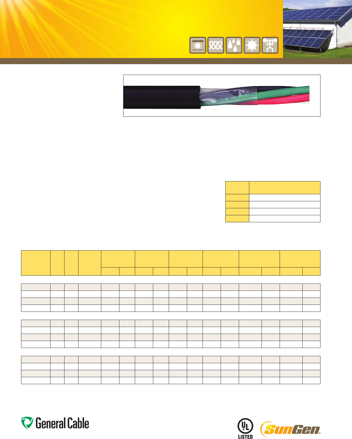
Phone: 888-593-3355
www.generalcable.com
Product Construction:
Conductor:
•14AWGthru10AWGfullyannealedstrandedbare
copperperASTMB3
•ClassCstrandingperASTMB8
Insulation:
•Flame-retardantCross-linkedPolyethylene(XLPE)
•Colorcode:Seechartbelow
Jacket:
•Lead-free, flame-retardant, sunlight-resistant
PolyvinylChloride(PVC)
Print:
•GENERALCABLE®(PLANTOFMFG)SUNGEN®
MIXX/CXXAWGFR-XLP/PVC(UL)TYPETC-ER
XHHW-2CDRSDIRBURSUNRES90
˚
C WET
ORDRY600VDAY/MONTH/YEAROFMFG
SEQUENTIALFOOTAGEMARK
Options:
•Overallshieldedmulti-conductors
•Otherconstructionsavailableuponrequest
Applications:
•Infreeair,racewaysanddirectburial
•Inwetordrylocations
•Approvedfordirectburial,ClassI,Division2
industrialhazardouslocationsperNEC
•PermittedforExposedRun(ER)usein
accordancewithNECfor3ormoreconductors
Features:
•Ratedat90˚Cwetordry
•Fillersasrequiredtoprovidearoundcabledesign
•Ripcordappliedunderjackettofacilitatestripping
Features (cont’d.):
•Excellentphysicalandelectricalproperties
•Increasedflexibility
•Excellentmoistureresistance
•Excellentresistancetocompressionandimpact
•Abrasion-andchemical-resistant
•Sunlight-andweather-resistant
•Meetscoldbendtestat-25˚C
•MeetsthecrushandimpactrequirementsofType
MCcablefor3ormoreconductors
Compliances:
Industry Compliances:
•UL44TypeXHHW-2
•UL1277TypeTC-ERfor3ormoreconductors,
ULFile#E57179
•UL1581
•ICEAS-73-532
•ICEAS-95-658/NEMAWC70
Flame Test Compliances:
•UL1581VW-1
•UL1277
•IEEE383
•IEEE1202
•ICEAT-29-520(210,000BTU/hr)
•CSAFT4
Compliances (cont’d.):
Other Compliances:
•EPA40CFR,Part261forleachablelead
content per TCLP
•OSHAAcceptable
Packaging:
•Materialcuttolengthandshippedon
non-returnable wood reels
CATALOG
NUMBER
NO.
OF
COND.
COND.
SIZE
(AWG)
COND.
STRAND
NOMINAL COND.
O.D.
MINIMUM AVG.
INSULATION
THICKNESS
MINIMUM AVG.
JACKET THICKNESS
NOMINAL
CABLE O.D. COPPER WEIGHT NET WEIGHT
INCHES mm INCHES mm INCHES mm INCHES mm LBS/1000 FT kg/km LBS/1000 FT kg/km
14 AWG MULTI-CONDUCTORS
395410* 2 14 19/.0142 0.070 1.77 0.030 0.76 0.045 1.14 0.365 9.27 25 37 73 109
395420 3 14 19/.0142 0.070 1.77 0.030 0.76 0.045 1.14 0.390 9.91 40 59 93 138
395430* 4 14 19/.0142 0.070 1.77 0.030 0.76 0.045 1.14 0.425 10.80 53 79 116 173
395440* 5 14 19/.0142 0.070 1.77 0.030 0.76 0.045 1.14 0.465 11.81 66 99 140 208
12 AWG MULTI-CONDUCTORS
395450 2 12 19/.0185 0.088 2.23 0.030 0.76 0.045 1.14 0.410 10.41 41 61 96 143
395460 3 12 19/.0185 0.088 2.23 0.030 0.76 0.045 1.14 0.435 11.05 65 96 125 186
395470* 4 12 19/.0185 0.088 2.23 0.030 0.76 0.045 1.14 0.475 12.07 86 128 157 234
395480* 5 12 19/.0185 0.088 2.23 0.030 0.76 0.045 1.14 0.515 13.08 108 160 191 284
10 AWG MULTI-CONDUCTORS
395490* 2 10 19/.0234 0.112 2.84 0.030 0.76 0.045 1.14 0.455 11.56 67 100 130 193
395500* 3 10 19/.0234 0.112 2.84 0.030 0.76 0.045 1.14 0.485 12.32 101 150 173 257
395510* 4 10 19/.0234 0.112 2.84 0.030 0.76 0.060 1.52 0.560 14.22 135 200 236 351
395520* 5 10 19/.0234 0.112 2.84 0.030 0.76 0.060 1.52 0.615 15.62 167 249 287 427
Dimensions and weights are nominal; subject to industry tolerances.
*Non-stockitem;minimumrunsapply.PleasecontactCustomerServiceforpriceanddelivery.
¹ApprovedasTYPETC-ERforExposedRunapplicationsof3ormoreconductorsasdefinedbyNEC.
COLOR CODE CHART
NO. OF
CONDUCTORS
COLOR SEQUENCE
2
Black,White
3
Black,White,Green
4
Black,White,Red,Green
5
Black,White,Red,Orange,Green
Greeninsulatedconductorindicatesuseforgroundwire
onlyperNEC.
SPEC 5880
May, 2012
SunGen
®
MI
XLPE/PVC,ACMicro-InverterCable
600 V, UL Type TC-ER¹
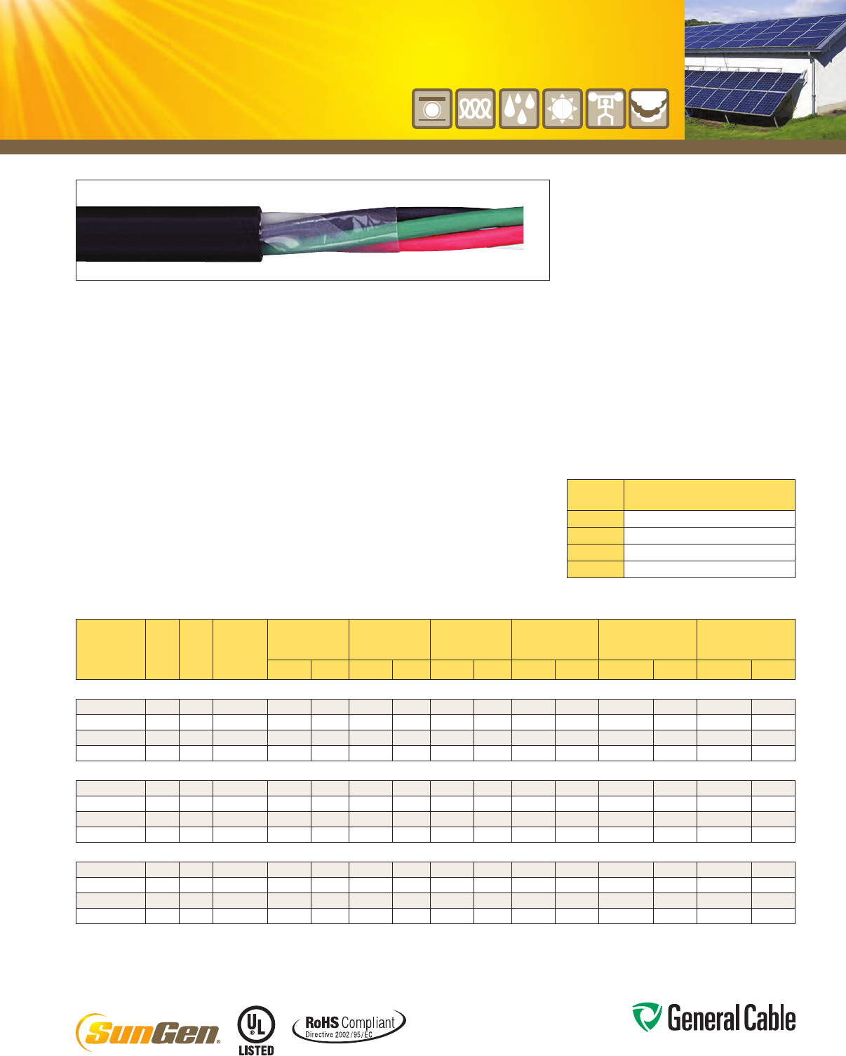
Phone: 888-593-3355
www.generalcable.com
CATALOG
NUMBER
NO.
OF
COND.
COND.
SIZE
(AWG)
COND.
STRAND
NOMINAL COND.
O.D.
MINIMUM AVG.
INSULATION
THICKNESS
MINIMUM AVG.
JACKET THICKNESS
NOMINAL
CABLE O.D. COPPER WEIGHT NET WEIGHT
INCHES mm INCHES mm INCHES mm INCHES mm LBS/1000 FT kg/km LBS/1000 FT kg/km
14 AWG MULTI-CONDUCTORS
395530* 2 14 19/.0142 0.070 1.77 0.030 0.76 0.045 1.14 0.370 9.40 25 37 71 106
395540 3 14 19/.0142 0.070 1.77 0.030 0.76 0.045 1.14 0.390 9.91 40 59 92 137
395550* 4 14 19/.0142 0.070 1.77 0.030 0.76 0.045 1.14 0.425 10.80 53 79 115 171
395560* 5 14 19/.0142 0.070 1.77 0.030 0.76 0.045 1.14 0.465 11.81 66 99 139 207
12 AWG MULTI-CONDUCTORS
395570 2 12 19/.0185 0.088 2.23 0.030 0.76 0.045 1.14 0.410 10.41 41 61 94 140
395580 3 12 19/.0185 0.088 2.23 0.030 0.76 0.045 1.14 0.435 11.05 65 96 124 185
395590* 4 12 19/.0185 0.088 2.23 0.030 0.76 0.045 1.14 0.475 12.07 86 128 157 234
395600* 5 12 19/.0185 0.088 2.23 0.030 0.76 0.045 1.14 0.515 13.08 108 160 191 284
10 AWG MULTI-CONDUCTORS
395610* 2 10 19/.0234 0.112 2.84 0.030 0.76 0.045 1.14 0.455 11.56 67 100 128 190
395620* 3 10 19/.0234 0.112 2.84 0.030 0.76 0.045 1.14 0.485 12.32 101 150 172 256
395630* 4 10 19/.0234 0.112 2.84 0.030 0.76 0.060 1.52 0.560 14.22 135 200 234 348
395640* 5 10 19/.0234 0.112 2.84 0.030 0.76 0.060 1.52 0.615 15.62 167 249 284 423
Dimensions and weights are nominal; subject to industry tolerances.
*Non-stockitem;minimumrunsapply.PleasecontactCustomerServiceforpriceanddelivery.
¹ApprovedasTYPETC-ERforExposedRunapplicationsof3ormoreconductorsasdefinedbyNEC.
Product Construction:
Conductor:
•14AWGthru10AWGfullyannealedstrandedbare
copperperASTMB3
•ClassCstrandingperASTMB8
Insulation:
•Lead-free,flame-retardant,low-smoke
Cross-linkedPolyolefin(XLPO)
•Colorcode:Seechartbelow
Jacket:
•Lead-free,flame-retardant,sunlight-resistant
Low-Smoke,Zero-HalogenPolyolefin(LSZH)
Print:
•GENERALCABLE®(PLANTOFMFG)SUNGEN®
MI-LSXX/CXXAWGXLPO/LSZH(UL)TYPE
TC-LS-ER XHHW-2 CDRS 90°C WET OR DRY 600
V DIR BUR SUNRESROHSDAY/MONTH/YEAR
OFMFGSEQUENTIALFOOTAGEMARK
Options:
•Overallshieldedmulti-conductor
•Otherconstructionsavailableuponrequest
Applications:
•Infreeair,raceways,aerialordirectburial
•Inwetordrylocations
•PermittedforuseinClassI,Division2industrial
hazardouslocationsperNEC
•PermittedforExposedRun(ER)usein
accordancewiththeNECfor3ormore
conductors
Features:
•Ratedat90˚Cwetordry
•Fillersasrequiredtoprovidearoundcabledesign
•Ripcordappliedunderjackettofacilitatestripping
•Excellentphysicalandelectricalproperties
•Increasedflexibility
•Excellentmoistureresistance
•Excellentresistancetocompressionandimpact
•Abrasion-andchemical-resistant
•Lowcoefficientoffrictionforeasypulling
•Sunlight-andweather-resistant
•Meetscoldbendtestat-30˚C
•Low-Smoke,Zero-Halogenjacketis
environmentallysafe
•Low-Smoke,Zero-Halogenjacketreducesthe
amountoftoxicandcorrosivegasesemitted
duringcombustion,providingasaferenvironment
forpersonnelandequipmentduringthehazards
of fire
Features (cont’d.):
•MeetsthecrushandimpactrequirementsofType
MCcablefor3ormoreconductors
Compliances:
Industry Compliances:
•UL44TypeXHHW-2
•UL1277TypeTC-LS-ER,ULFile#E57179
•UL1581
•RoHSCompliant
Flame Test Compliances:
•UL1581
•UL1277
•UL1685
•IEEE1202
Other Compliances:
•EPA40CFR,Part261forleachablelead
content per TCLP
•OSHAAcceptable
Packaging:
•Materialcuttolengthandshippedon
non-returnable wood reels
SunGen
®
MI-LS
XLPO/LSZH,ACMicro-InverterCable
600 V, UL Type TC-LS-ER¹
SPEC 5890
May, 2012
COLOR CODE CHART
NO. OF
CONDUCTORS
COLOR SEQUENCE
2
Black,White
3
Black,White,Green
4
Black,White,Red,Green
5
Black,White,Red,Orange,Green
Greeninsulatedconductorindicatesuseforgroundwire
onlyperNEC.
Phone: 888-593-3355
www.generalcable.com
Date of Issue 06/13
Section 6 Industrial Cables
2.4 kV — 35 kV Industrial Medium-Voltage Cables
SPECIFICATION NO. PRODUCT DESCRIPTION REVISION DATE
6050†DuraSheath®EPR/XL-CPE, Medium-Voltage Power, Nonshielded
2400 V, UL Type MV-90
Aug. 2011
6100†UniShield®EPR/Copper Wire Shield/CPE, Medium-Voltage Power, Shielded
5 kV and 8 kV, UL Type MV-105, 133%/100% Ins. Levels, 115 Mils
Jun. 2013
6150 Uniblend®EPR/Copper Tape Shield/PVC, Medium-Voltage Power, Shielded
5 kV and 8 kV, UL Type MV-105, 133%/100% Ins. Levels, 115 Mils
Mar. 2012
6155†Uniblend® LF EPR/Copper Tape Shield/PVC, Medium-Voltage Power, Shielded
5 kV and 8 kV, UL Type MV-105, 133%/100% Ins. Levels, 115 Mils
Mar. 2012
6160†Aluminum Uniblend® LF EPR/Copper Tape Shield/PVC, Medium-Voltage Power, Shielded
5 kV and 8 kV, UL Type MV-105, 133%/100% Ins. Levels, 115 Mils
Mar. 2012
6175 Uniblend®EPR/Copper Tape Shield/CPE, Medium-Voltage Power, Shielded
5 kV and 8 kV, UL Type MV-105, 133%/100% Ins. Levels, 115 Mils
Mar. 2012
6180†GenFree®
Uniblend®
EPR/Copper Tape Shield/LSZH, Medium-Voltage Power, Shielded
5 kV and 8 kV, UL Type MV-105/ST1, 133%/100% Ins. Levels, 115 Mils
Mar. 2012
6200 Copper Wire Shield TRXLPE/Copper Wire Shield/PVC, Medium-Voltage Power
5 kV, UL Type MV-105, 100% Ins. Level, 90 Mils
Jan. 2011
6250 Uniblend®EPR/Copper Tape Shield with Overall PVC Jacket
Medium-Voltage Power, Shielded, 5 kV and 8 kV, UL Type MV-105
133%/100% Ins. Levels, 115 Mils, Three Conductor
Mar. 2012
6255†Uniblend® LF EPR/Copper Tape Shield with Overall PVC Jacket
Medium-Voltage Power, Shielded, 5 kV and 8 kV, UL Type MV-105
133%/100% Ins. Levels, 115 Mils, Three Conductor
Mar. 2012
6275 Uniblend®EPR/Copper Tape Shield with Overall CPE Jacket
Medium-Voltage Power, Shielded, 5 kV and 8 kV, UL Type MV-105
133%/100% Ins. Levels, 115 Mils, Three Conductor
Mar. 2012
6280 GenFree®
Uniblend®
EPR/Copper Tape Shield with Overall LSZH Jacket
Medium-Voltage Power, Shielded, 5 kV and 8 kV, UL Type MV-105
133%/100% Ins. Levels, 115 Mils, Three Conductor
Mar. 2012
†Indicates these products are stocked by General Cable
SPECIFICATION NO. PRODUCT DESCRIPTION REVISION DATE
6300†UniShield®EPR/Copper Wire Shield/CPE, Medium-Voltage Power, Shielded
15 kV, UL Type MV-105, 133% Ins. Level, 220 Mils
Jun. 2013
6350 Uniblend®EPR/Copper Tape Shield/PVC, Medium-Voltage Power, Shielded
15 kV, UL Type MV-105, 133% Ins. Level, 220 Mils
Mar. 2012
6355†Uniblend® LF EPR/Copper Tape Shield/PVC, Medium-Voltage Power, Shielded
15 kV, UL Type MV-105, 133% Ins. Level, 220 Mils
Apr. 2011
6360†Aluminum Uniblend® LF EPR/Copper Tape Shield/PVC, Medium-Voltage Power, Shielded
15 kV, UL Type MV-105, 133% Ins. Level, 220 Mils
Apr. 2011
6375 Uniblend®EPR/Copper Tape Shield/CPE, Medium-Voltage Power, Shielded
15 kV, UL Type MV-105, 133% Ins. Level, 220 Mils
Apr. 2011
6380†GenFree®
Uniblend®
EPR/Copper Tape Shield/LSZH, Medium-Voltage Power, Shielded
15 kV, UL Type MV-105/ST1, 133% Ins. Level, 220 Mils
Mar. 2012
6400 Copper Wire Shield TRXLPE/Copper Wire Shield/PVC, Medium-Voltage Power
15 kV, UL Type MV-105, 133% Ins. Level, 220 Mils
Jan. 2011
6450 Uniblend®EPR/Copper Tape Shield with Overall PVC Jacket
Medium-Voltage Power, Shielded, 15 kV, UL Type MV-105
133% Ins. Level, 220 Mils, Three Conductor
Mar. 2012
6455†Uniblend® LF EPR/Copper Tape Shield with Overall PVC Jacket
Medium-Voltage Power, Shielded, 15 kV, UL Type MV-105
133% Ins. Level, 220 Mils, Three Conductor
Mar. 2012
6475 Uniblend®EPR/Copper Tape Shield with Overall CPE Jacket
Medium-Voltage Power, Shielded, 15 kV, UL Type MV-105
133% Ins. Level, 220 Mils, Three Conductor
Mar. 2012
†Indicates these products are stocked by General Cable
Date of Issue 06/13
Industrial Cables Section 6
Phone: 888-593-3355
www.generalcable.com
2.4 kV — 35 kV Industrial Medium-Voltage Cables
Phone: 888-593-3355
www.generalcable.com
Date of Issue 06/13
Section 6 Industrial Cables
2.4 kV — 35 kV Industrial Medium-Voltage Cables
SPECIFICATION NO. PRODUCT DESCRIPTION REVISION DATE
6480 GenFree®
Uniblend®
EPR/Copper Tape Shield with Overall LSZH Jacket
Medium-Voltage Power, Shielded, 15 kV, UL Type MV-105
133% Ins. Level, 220 Mils, Three Conductor
Mar. 2012
6500 UniShield®EPR/Copper Wire Shield/CPE, Medium-Voltage Power, Shielded
25 kV and 35 kV, UL Type MV-105, 133%/100% Ins. Levels, 345 Mils
Jun. 2013
6550 Uniblend®EPR/Copper Tape Shield/PVC, Medium-Voltage Power, Shielded
25 kV and 35 kV, UL Type MV-105, 133%/100% Ins. Levels, 345 Mils
Mar. 2012
6555†Uniblend® LF EPR/Copper Tape Shield/PVC, Medium-Voltage Power, Shielded
25 kV and 35 kV, UL Type MV-105, 133%/100% Ins. Levels, 345 Mils
Mar. 2012
6560 Aluminum Uniblend® LF EPR/Copper Tape Shield/PVC, Medium-Voltage Power, Shielded
25 kV and 35 kV, UL Type MV-105, 133%/100% Ins. Levels, 345 Mils
Mar. 2012
6575 Uniblend®EPR/Copper Tape Shield/CPE, Medium-Voltage Power, Shielded
25 kV and 35 kV, UL Type MV-105, 133%/100% Ins. Levels, 345 Mils
Mar. 2012
6580 GenFree®
Uniblend®
EPR/Copper Tape Shield/LSZH, Medium-Voltage Power, Shielded
25 kV and 35 kV, UL Type MV-105/ST1, 133%/100% Ins. Levels, 345 Mils
Mar. 2012
6600 Uniblend®EPR/Copper Tape Shield with Overall PVC Jacket
Medium-Voltage Power, Shielded, 25 kV and 35 kV, UL Type MV-105
133%/100% Ins. Levels, 345 Mils, Three Conductor
Mar. 2012
6605 Uniblend® LF EPR/Copper Tape Shield with Overall PVC Jacket
Medium-Voltage Power, Shielded, 25 kV and 35 kV, UL Type MV-105
133%/100% Ins. Levels, 345 Mils, Three Conductor
Mar. 2012
6650 Uniblend®EPR/Copper Tape Shield/PVC, Medium-Voltage Power, Shielded
35 kV, UL Type MV-105, 133% Ins. Levels, 420 Mils
Apr. 2011
6655 Uniblend® LF EPR/Copper Tape Shield/PVC, Medium-Voltage Power, Shielded
35 kV, UL Type MV-105, 133% Ins. Levels, 420 Mils
Apr. 2011
6660 Aluminum Uniblend® LF EPR/Copper Tape Shield/PVC, Medium-Voltage Power, Shielded
35 kV, UL Type MV-105, 133% Ins. Levels, 420 Mils
Apr. 2011
†Indicates these products are stocked by General Cable
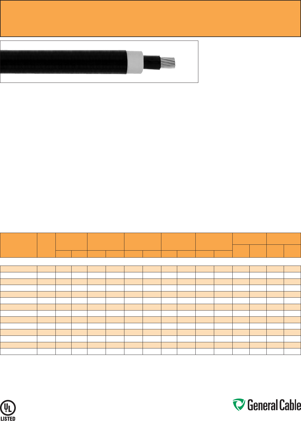
Phone: 888-593-3355
www.generalcable.com
SPEC 6050
August, 2011
Product Construction
Conductor:
• 8 AWG thru 1000 kcmil annealed bare copper
compact Class B strand
Extruded Strand Shield (ESS):
• Extruded thermoset semi-conducting stress-
control layer over conductor
Insulation:
• Ethylene Propylene Rubber (EPR) insulation,
colored to contrast with the black jacket material
Jacket:
• Lead-Free Cross-linked Chlorinated Polyethylene
(XL-CPE )
Print:
• GENERAL CABLE
®
(MI) SIZE (AWG or KCMIL)
COMPACT CU DURASHEATH
®
2400 VOLTS
NONSHIELDED EP TYPE MV-90 WET OR DRY
FOR CT USE OIL RES I (UL) MONTH/YEAR OF
MFG SEQUENTIAL FOOTAGE MARK
* Sizes smaller than 1/0 AWG do not include
“FOR CT USE”
Options:
• Multi-conductor constructions
• Other constructions available upon request
Applications:
• Proven record of reliable performance through
extensive use in these applications: pulp and
paper mills, petrochemical plants, sewage
treatment facilities, water treatment plants,
steel mills, textile mills, utility power generating
stations, scrubbers and other environmental
protection systems, railroad and mining facilities
• For use in industrial and utility applications where
ease of installation is a major concern because
of limited space and exposure to personnel is
minimal
• For use in wet or dry locations when installed in
accordance with NEC
• For use in aerial, conduit, open tray and
underground duct installations
Features:
• Rated at 90
˚
C
• Excellent heat and moisture resistance
• Flexibility for easy handling
• High dielectric strength
• Low moisture absorption
• Electrical stability under stress
• Low dielectric loss
• Chemical- and sunlight-resistant
• Simplification of splicing and terminating by
elimination of need to handle cable shield
• Extra-tough, mechanically rugged composite
insulation and jacket construction
• Meets cold bend test at -35
˚
C
Compliances:
• National Electric Code (NEC)
• ICEA S-96-659/NEMA WC71
• UL 1072
• UL listed as Type MV-90 for use in accordance
with NEC, UL File # E90501
• Sizes 1/0 AWG and larger are listed and marked
“FOR CT USE” in accordance with NEC and also
meet IEEE 383 (70,000 BTU/hr)
• Listed “oil-resistant I”
• Meets EPA 40 CFR, Part 261 for leachable lead
content per TCLP method
• OSHA acceptable
Packaging:
• Material cut to length and shipped on
non-returnable wood reels
DuraSheath
®
EPR/XL-CPE, Medium-Voltage Power, Nonshielded
2400 V, UL Type MV-90
CATALOG
NUMBER
COND.
SIZE
(AWG/
kcmil)
NOMINAL
CONDUCTOR
DIAMETER
NOMINAL EXTRUDED
STRAND SHIELD
DIAMETER
NOMINAL
INSULATION
THICKNESS
NOMINAL
INSULATION
DIAMETER
NOMINAL
CABLE
O.D.
COPPER
WEIGHT NET WEIGHT
LBS/
1000 FT
kg/
km
LBS/
1000 FT
kg/
kmINCHES mm INCHES mm INCHES mm INCHES mm INCHES mm
2400 V, UL TYPE MV-90
14901.410800* 80.14 3.56 0.15 3.81 0.125 3.18 0.41 10.41 0.58 14.73 51 76 196 292
14901.410600 60.17 4.32 0.19 4.83 0.125 3.18 0.44 11.18 0.62 15.75 81 121 241 359
14901.410400 40.22 5.59 0.23 5.84 0.125 3.18 0.49 12.45 0.66 16.76 129 192 308 458
14901.410200 20.27 6.86 0.29 7.37 0.125 3.18 0.55 13.97 0.72 18.29 205 305 408 607
14901.410100* 10.31 7.87 0.33 8.38 0.125 3.18 0.58 14.73 0.76 19.30 259 385 476 708
14901.415100 1/0 0.34 8.64 0.36 9.14 0.125 3.18 0.62 15.75 0.79 20.07 326 485 562 836
14901.415200 2/0 0.38 9.65 0.41 10.41 0.125 3.18 0.66 16.76 0.84 21.34 411 612 666 991
14901.415300* 3/0 0.43 10.92 0.45 11.43 0.125 3.18 0.71 18.03 0.92 23.37 518 771 823 1225
14901.415400 4/0 0.48 12.19 0.50 12.70 0.125 3.18 0.76 19.30 0.97 24.64 653 972 983 1463
14901.416000 250 0.53 13.46 0.55 13.97 0.140 3.56 0.84 21.34 1.08 27.43 772 1149 1183 1761
14901.416200 350 0.62 15.75 0.64 16.26 0.140 3.56 0.93 23.62 1.17 29.72 1080 1607 1545 2299
14901.416500 500 0.74 18.80 0.77 19.56 0.140 3.56 1.06 26.92 1.30 33.02 1544 2298 2077 3091
14901.417000 750 0.91 23.11 0.94 23.88 0.155 3.94 1.26 32.00 1.54 39.12 2316 3447 3040 4524
14901.417500* 1000 1.06 26.92 1.09 27.69 0.155 3.94 1.42 36.07 1.70 43.18 3086 4593 3913 5823
Dimensions and weights are nominal; subject to industry tolerances.
*Non-stock item; minimum runs apply. Please consult Customer Service for price and delivery.
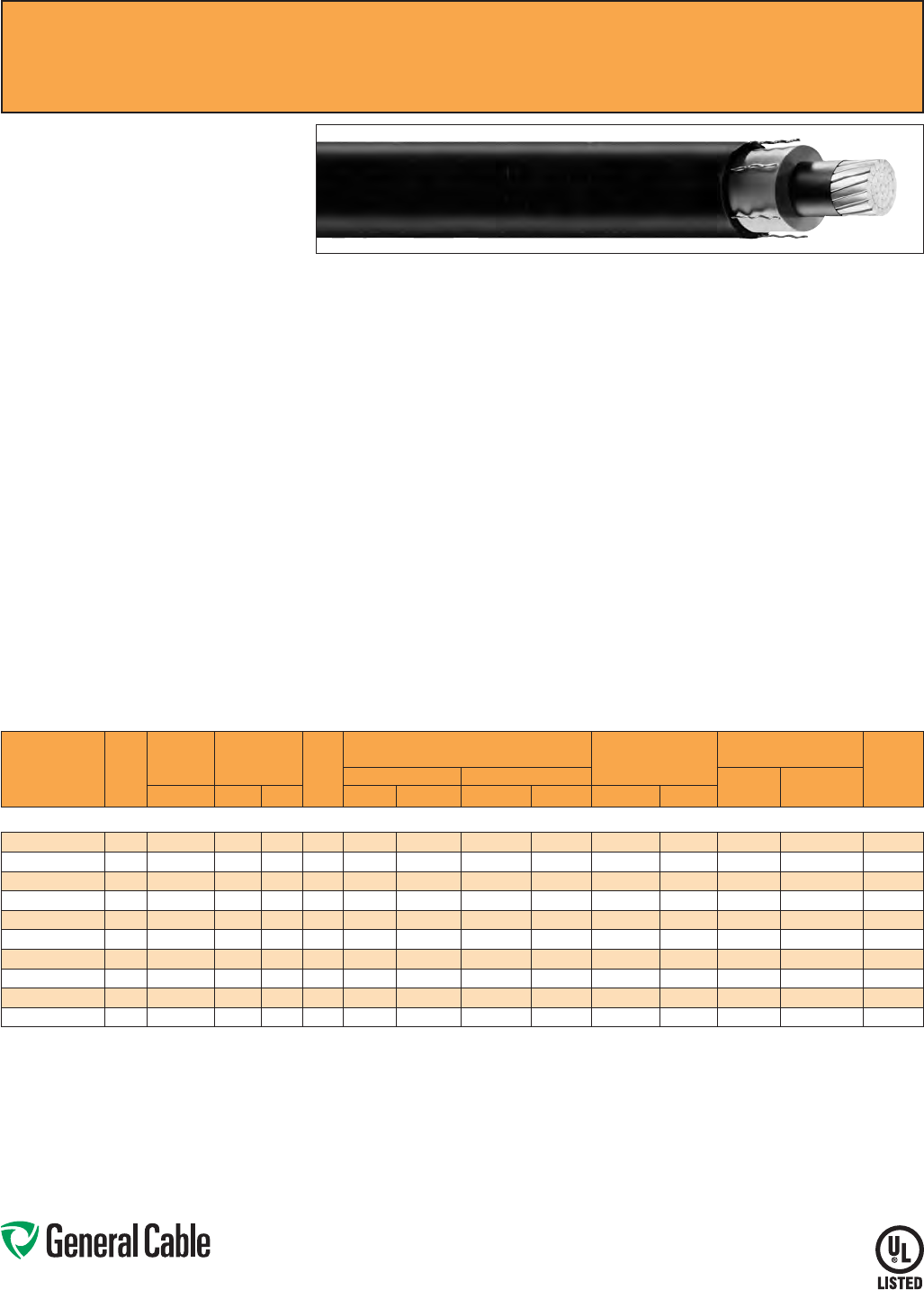
Phone: 888-593-3355
www.generalcable.com
SPEC 6100
June, 2013
Product Construction:
Conductor:
• 2 AWG thru 1000 kcmil annealed bare copper
compact Class B strand
Extruded Strand Shield (ESS):
• Extruded thermoset semi-conducting stress-
control layer over conductor
Insulation:
• Ethylene Propylene Rubber (EPR) insulation,
colored to contrast with black conducting shield
layers
Composite Insulation Shield
and Jacket:
• Six corrugated copper drain wires embedded in
composite layers of semi-conducting thermoset
copolymer and semi-conducting black flame-
retardant Chlorinated Polyethylene (CPE)
Print:
• GENERAL CABLE
®
(PLANT OF MFG) (MO/YR
OF MANUFACTURE) LIGHTNING BOLT SYMBOL
1/C SIZE (AWG OR KCMIL) COMPACT CU
UNISHIELD
®
(INSULATION THICKNESS) EPR
DRTP SEMI-CON CPE JKT TYPE MV-
105 (VOLTAGE) KV% INSULATION LEVEL
SUN RES FOR CT USE (UL) SEQUENTIAL
FOOTAGE MARK
* Sizes smaller than 1/0 AWG do not include
“FOR CT USE”.
Applications:
• Installed in a broad range of commercial,
industrial and utility projects such as pulp
and paper mills, petrochemical plants, steel
mills, textile mills, water and sewage treatment
facilities, environmental protection systems,
railroads, mines and fossil fuel utility generating
stations
• Suitable for use in wet or dry locations when
installed in accordance with NEC
Applications (cont’d.):
• For use in aerial, conduit, open tray and
underground duct installations
• For use in direct burial if installed in a system with
a ground conductor that is in close proximity, and
conforms with NEC 250.4(A)(5)
Features:
• Rated at 105
˚
C
• Reduced conductor size and shield system
provides the smallest premium medium-voltage
shielded power cable with full insulation
• Smaller outside dimensions reduce the size of
duct needed or increase the ampacity
per duct
• All features contribute to faster and
easier installation
• Superior cold bend and cold impact
performance
• Stable and constant shield short
circuit performance
• Excellent heat and moisture resistance
• Outstanding corona resistance
• Flexibility for easy handling
• High dielectric strength
• Low dielectric loss
• Low moisture absorption
• Electrical stability under stress
• Chemical-resistant
• Sunlight-resistant
• Meets cold bend test at -55
˚
C
Compliances:
• National Electrical Code (NEC)
• UL 1072
• ICEA S-93-639/NEMA WC74
• ICEA S-97-682
• AEIC CS8
• UL listed as Type MV-105 for use in accordance
with NEC, UL File # E90501
• UL 1685 (Sizes 1/0 AWG and larger) UL Flame
Exposure Test
• Sizes 1/0 AWG and larger are listed and marked
“Sunlight-Resistant FOR CT USE” in accordance
with NEC
• IEEE 1202 (70,000 BTU/hr)/CSA FT4
• EPA 40 CFR, Part 261 for leachable lead content
per TCLP method
• OSHA Acceptable
Optional Flame Tests:
• ICEA T-29-520 (210,000 BTU/hr)
Packaging:
• Material cut to length and shipped on non-
returnable wood reels. Lengths in excess of
10,000 lbs. are provided on returnable steel reels
that require a deposit
• Extra charges apply for cuts less than
1000 ft., lagging, pulling eyes, paralleling
and triplexing
NOTE: Due to the semi-conducting properties of the
cable jacket, multi-point grounding is recommended for
all UniShield® installations.
UniShield
®
EPR/Copper Wire Shield/CPE, Medium-Voltage Power, Shielded
5 kV and 8 kV, UL Type MV-105, 133%/100% Ins. Levels, 115 Mils
CATALOG
NUMBER
COND.
SIZE
(AWG/
kcmil)
NOMINAL
CONDUCTOR
DIAMETER
INSULATION
DIAMETER
INCHES
DRAIN
WIRE
SIZE
(AWG)
NOMINAL CABLE
COPPER WEIGHT
AMPACITY CONDUIT
SIZING (3)
(INCHES)
DIAMETER WEIGHT CONDUIT
IN AIR (1)
UNDERGROUND
DUCT (2)INCHES MIN. MAX. INCHES mm LBS/1000 FT kg/km LBS/1000 FT kg/km
5 kV AND 8 kV, UL TYPE MV-105, 133%/100% INS. LEVELS, 115 MILS
19101.650200 20.27 0.510 0.590 20 0.71 18.03 404 601 225 335 165 165 2.5
19101.655100 1/0 0.34 0.580 0.655 20 0.78 19.81 555 825 346 515 215 215 2.5
19101.665200 2/0 0.38 0.620 0.695 19 0.83 21.08 666 990 436 649 255 245 3
19101.665300* 3/0 0.43 0.665 0.745 19 0.88 22.35 791 1177 562 808 290 275 3
19101.665400 4/0 0.48 0.720 0.795 19 0.93 23.62 951 1415 678 1010 330 315 3
19101.676000 250 0.53 0.770 0.850 18 1.01 25.65 1112 1655 804 1196 365 345 3.5
19101.676200 350 0.62 0.870 0.945 18 1.11 28.19 1463 2176 1113 1656 440 415 3.5
19101.686500 500 0.74 0.990 1.065 17 1.24 31.50 2003 2980 1585 2358 535 500 4
19101.687000 750 0.91 1.170 1.250 17 1.44 36.57 2875 4278 2357 3507 655 610 5
19101.667500* 1000 1.06 1.320 1.400 16 1.61 40.89 3746 5574 3138 4669 755 690 5
Dimensions and weights are nominal; subject to industry tolerances.
* Non-stock item; minimum runs apply. Please consult Customer Service for price and delivery.
(1) Ampacities are in accordance with Table 310.60(C)(73) of the NEC for triplexed or three single conductor copper cable in isolated conduit in air, based on a conductor temperature of 105˚C (221˚F) and an
ambient air temperature of 40˚C (104˚F).
(2) Ampacities are in accordance with Table 310.60(C)(77) of the NEC for triplexed or three single conductor copper cable in underground ducts (three conductors per duct), based on a conductor temperature
of 105˚C (221˚F) and an ambient earth temperature of 20˚C (68˚F), electrical duct arrangement per Figure 310.60 Detail 1, 100% load factor, and earth thermal resistance (rho) of 90.
(3) Based on nominal cable diameters, three single cables in the duct (PVC Schedule 40) with no ground wire and a maximum of 40% fill. Jam ratio has been considered, but it should be checked for individual
installations.
Note: a) Sizes smaller than 1/0 AWG do not include “FOR CT USE”.
b) The NESC Lightning bolt symbol is on all UniShield® constructions.
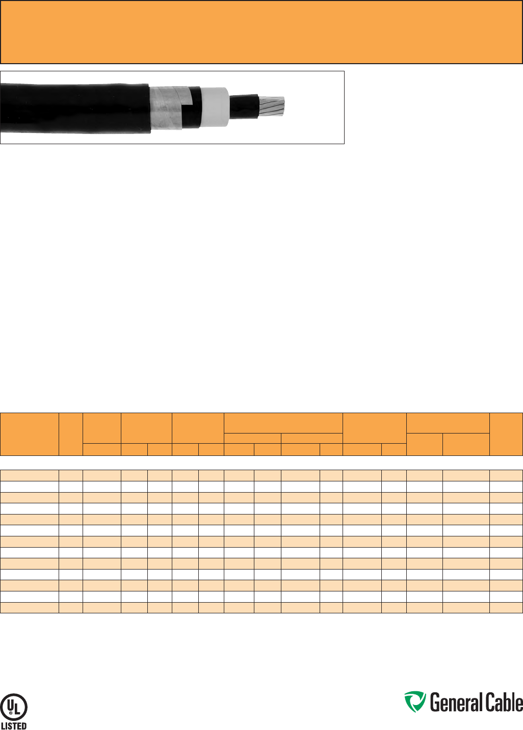
Phone: 888-593-3355
www.generalcable.com
SPEC 6150
March, 2012
Uniblend
®
EPR/Copper Tape Shield/PVC, Medium-Voltage Power, Shielded
5 kV and 8 kV, UL Type MV-105, 133%/100% Ins. Levels, 115 Mils
Product Construction:
Conductor:
• 6 AWG thru 1000 kcmil annealed bare copper
compact Class B strand
Extruded Strand Shield (ESS):
• Extruded thermoset semi-conducting stress-
control layer over conductor
Insulation:
• Ethylene Propylene Rubber (EPR) insulation,
colored to contrast with the black conducting
shield layers
Extruded Insulation Shield (EIS):
• Thermoset semi-conducting polymeric layer free
stripping from insulation
Metallic Shield:
• 5 mil annealed copper tape with an
overlap of 25%
Jacket:
• Lead-free, flame-retardant, moisture- and
sunlight-resistant Polyvinyl Chloride (PVC)
Print:
• GENERAL CABLE
®
(PLANT OF MFG) (MO/YR
OF MANUFACTURE) LIGHTNING BOLT SYMBOL
1/C SIZE (AWG OR KCMIL) COMPACT CU
UNIBLEND
®
PVC JKT (INSULATION THICKNESS)
EPR TYPE MV-105 (VOLTAGE) KV% INSULATION
LEVEL SUN RES FOR CT USE (UL) SEQUENTIAL
FOOTAGE MARK
* Sizes smaller than 1/0 AWG do not include
“FOR CT USE”.
Options:
• Other jacket options available upon request
• STRANDFILL
®
– blocked conductor. Tested in
accordance with ICEA T-31-610
Applications:
• Superior performance in petrochemical plants,
pulp and paper mills, sewage and water
treatment plants, environmental protection
systems, railroads, mines, utility power
generating stations, steel mills, textile plants and
other industrial three-phase applications
• For use in wet or dry locations when installed in
accordance with NEC
• For use in aerial, conduit, open tray and
underground duct installations
• For use in direct burial if installed in a system with
a ground conductor that is in close proximity, and
conforms with NEC 250.4(A)(5)
Features:
• Rated at 105
˚
C
• Excellent heat and moisture resistance
• Excellent flame resistance
• Outstanding corona resistance
• Flexibility for easy handling
• High dielectric strength
• Low moisture absorption
• Electrical stability under stress
• Low dielectric loss
• Chemical-resistant
• Meets cold bend test at -35
˚
C
Compliances:
• National Electrical Code (NEC)
• UL 1072
• ICEA S-93-639/NEMA WC74
• ICEA S-97-682
• AEIC CS8
• UL listed as Type MV-105 for use in accordance
with NEC, UL File # E90501
• UL 1685 (Sizes 1/0 AWG and larger) UL Flame
Exposure Test
• Sizes 1/0 AWG and larger are listed and marked
“Sunlight-Resistant FOR CT USE” in accordance
with NEC
• IEEE 1202 (70,000 BTU/hr)/CSA FT4
• EPA 40 CFR, Part 261 for leachable lead content
per TCLP method
• OSHA Acceptable
Optional Flame Tests:
• ICEA T-29-520 (210,000 BTU/hr)
Packaging:
• Material cut to length and shipped on
non-returnable wood reels. Lengths in excess of
10,000 lbs. are provided on returnable steel reels
that require a deposit
• Extra charges apply for cuts less than 1000 ft.,
lagging, pulling eyes, paralleling and triplexing
CATALOG
NUMBER
COND.
SIZE
(AWG/
kcmil)
NOMINAL
CONDUCTOR
DIAMETER
INSULATION
DIAMETER
INCHES
NOMINAL
JACKET
THICKNESS
NOMINAL CABLE
COPPER WEIGHT
AMPACITY CONDUIT
SIZING (3)
(INCHES)
DIAMETER WEIGHT CONDUIT
IN AIR (1)
UNDERGROUND
DUCT (2)INCHES MIN. MAX. INCHES mm INCHES mm LBS/1000 FT kg/km LBS/1000 FT kg/km
5 kV AND 8 kV, UL TYPE MV-105, 133%/100% INS. LEVELS, 115 MILS
17001.120600* 60.17 0.415 0.490 0.060 1.52 0.65 16.51 295 439 126 188 93 97 2
17001.120400* 4 0.22 0.455 0.535 0.060 1.52 0.70 17.15 365 543 178 265 120 125 2.5
17001.120200* 20.27 0.510 0.590 0.060 1.52 0.76 19.05 471 701 259 385 165 165 2.5
17001.120100* 1 0.31 0.545 0.620 0.060 1.52 0.79 20.07 539 802 315 468 190 185 2.5
17001.125100* 1/0 0.34 0.580 0.655 0.060 1.52 0.82 21.08 623 927 386 575 215 215 3
17001.125200* 2/0 0.38 0.620 0.695 0.060 1.52 0.86 22.10 728 1083 474 706 255 245 3
17001.125300* 3/0 0.43 0.665 0.745 0.080 2.03 0.94 24.38 886 1318 585 871 290 275 3
17001.135400* 4/0 0.48 0.720 0.795 0.080 2.03 1.00 25.65 1053 1567 725 1080 330 315 3
17001.136000* 250 0.53 0.770 0.850 0.080 2.03 1.05 27.18 1199 1784 849 1263 365 345 3.5
17001.136200* 350 0.62 0.870 0.945 0.080 2.03 1.14 29.72 1559 2320 1165 1735 440 415 3.5
17001.136500* 500 0.74 0.990 1.065 0.080 2.03 1.27 33.53 2088 3107 1639 2439 535 500 4
17001.137000* 750 0.91 1.170 1.250 0.080 2.03 1.45 38.35 2962 4407 2427 3611 655 610 5
17001.637500* 1000 1.06 1.320 1.400 0.080 2.03 1.60 42.42 3815 5677 3210 4777 755 690 5
Dimensions and weights are nominal; subject to industry tolerances.
* Non-stock item; minimum runs apply. Please consult Customer Service for price and delivery.
(1) Ampacities are in accordance with Table 310.60(C)(73) of the NEC for triplexed or three single conductor copper cable in isolated conduit in air, based on a conductor temperature of 105˚C (221˚F) and an
ambient air temperature of 40˚C (104˚F).
(2) Ampacities are in accordance with Table 310.60(C)(77) of the NEC for triplexed or three single conductor copper cable in underground ducts (three conductors per duct), based on a conductor temperature
of 105˚C (221˚F) and an ambient earth temperature of 20˚C (68˚F), electrical duct arrangement per Figure 310.60 Detail 1, 100% load factor, and earth thermal resistance (rho) of 90.
(3) Based on nominal cable diameters, three single cables in the duct (PVC Schedule 40) with no ground wire and a maximum of 40% fill. Jam ratio has been considered, but it should be checked for individual
installations.
Note: a) Sizes smaller than 1/0 AWG do not include “FOR CT USE”.
b) The NESC Lightning bolt symbol is on all Uniblend® constructions.

Phone: 888-593-3355
www.generalcable.com
SPEC 6155
March, 2012
Uniblend
®
LF
EPR/Copper Tape Shield/PVC, Medium-Voltage Power, Shielded
5 kV and 8 kV, UL Type MV-105, 133%/100% Ins. Levels, 115 Mils
Product Construction:
Conductor:
• 6 AWG thru 1000 kcmil annealed bare copper
compact Class B strand
Extruded Strand Shield (ESS):
• Extruded thermoset semi-conducting stress-
control layer over conductor
Insulation:
• Ethylene Propylene Rubber (EPR) insulation,
colored to contrast with the black conducting
shield layers
Extruded Insulation Shield (EIS):
• Thermoset semi-conducting polymeric layer free
stripping from insulation
Metallic Shield:
• 5 mil annealed copper tape with an
overlap of 25%
Jacket:
• Low-friction, lead-free, flame-retardant, moisture-
and sunlight-resistant Polyvinyl Chloride (PVC)
Print:
• GENERAL CABLE
®
(PLANT OF MFG) (MO/YR
OF MANUFACTURE) LIGHTNING BOLT SYMBOL
1/C SIZE (AWG OR KCMIL) COMPACT CU
UNIBLEND
®
LF PVC JKT (INSULATION
THICKNESS) EPR TYPE MV-105 (VOLTAGE) KV%
INSULATION LEVEL SUN RES FOR CT USE (UL)
SEQUENTIAL FOOTAGE MARK
* Sizes smaller than 1/0 AWG do not include
“FOR CT USE”.
Options:
• STRANDFILL
®
– blocked conductor. Tested in
accordance with ICEA T-31-610
Applications:
• Superior performance in petrochemical plants,
pulp and paper mills, sewage and water
treatment plants, environmental protection
systems, railroads, mines, utility power
generating stations, steel mills, textile plants and
other industrial three-phase applications
• For use in wet or dry locations when installed in
accordance with NEC
• For use in aerial, conduit, open tray and
underground duct installations
• For use in direct burial if installed in a system
with a ground conductor that is in close
proximity, and conforms with NEC 250.4(A)(5)
Features:
• Rated at 105
˚
C
• Lower coefficient of friction for ease of
installation
• Excellent heat and moisture resistance
• Excellent flame resistance
• Outstanding corona resistance
• Flexibility for easy handling
• High dielectric strength
• Low moisture absorption
• Electrical stability under stress
• Low dielectric loss
• Chemical-resistant
• Meets cold bend test at -35
˚
C
Compliances:
• National Electrical Code (NEC)
• UL 1072
• ICEA S-93-639/NEMA WC74
• ICEA S-97-682
• AEIC CS8
• UL listed as Type MV-105 for use in accordance
with NEC, UL File # E90501
• UL 1685 (Sizes 1/0 AWG and larger) UL Flame
Exposure Test
• Sizes 1/0 AWG and larger are listed and marked
“Sunlight-Resistant FOR CT USE” in accordance
with NEC
• IEEE 1202 (70,000 BTU/hr)/CSA FT4
• EPA 40 CFR, Part 261 for leachable lead content
per TCLP method
• OSHA Acceptable
Optional Flame Tests:
• ICEA T-29-520 (210,000 BTU/hr)
Packaging:
• Material cut to length and shipped on
non-returnable wood reels. Lengths in excess of
10,000 lbs. are provided on returnable steel reels
that require a deposit
• Extra charges apply for cuts less than 1000 ft.,
lagging, pulling eyes, paralleling and triplexing
CATALOG
NUMBER
COND.
SIZE
(AWG/
kcmil)
NOMINAL
CONDUCTOR
DIAMETER
INSULATION
DIAMETER
INCHES
NOMINAL
JACKET
THICKNESS
NOMINAL CABLE
COPPER WEIGHT
AMPACITY CONDUIT
SIZING (3)
(INCHES)
DIAMETER WEIGHT CONDUIT
IN AIR (1)
UNDERGROUND
DUCT (2)INCHES MIN. MAX. INCHES mm INCHES mm LBS/1000 FT kg/km LBS/1000 FT kg/km
5 kV AND 8 kV, UL TYPE MV-105, 133%/100% INS. LEVELS, 115 MILS
17001.120605 60.17 0.415 0.490 0.060 1.52 0.65 16.51 295 439 126 188 93 97 2
17001.120405 4 0.22 0.455 0.535 0.060 1.52 0.70 17.15 365 543 178 265 120 125 2.5
17001.120205 20.27 0.510 0.590 0.060 1.52 0.76 19.05 471 701 259 385 165 165 2.5
17001.120105* 1 0.31 0.545 0.620 0.060 1.52 0.79 20.07 539 802 315 468 190 185 2.5
17001.125105 1/0 0.34 0.580 0.655 0.060 1.52 0.82 21.08 623 927 386 575 215 215 3
17001.125205 2/0 0.38 0.620 0.695 0.060 1.52 0.86 22.10 728 1083 474 706 255 245 3
17001.125305* 3/0 0.43 0.665 0.745 0.080 2.03 0.94 24.38 886 1318 585 871 290 275 3
17001.135405 4/0 0.48 0.720 0.795 0.080 2.03 1.00 25.65 1053 1567 725 1080 330 315 3
17001.136005 250 0.53 0.770 0.850 0.080 2.03 1.05 27.18 1199 1784 849 1263 365 345 3.5
17001.136205 350 0.62 0.870 0.945 0.080 2.03 1.14 29.72 1559 2320 1165 1735 440 415 3.5
17001.136505 500 0.74 0.990 1.065 0.080 2.03 1.27 33.53 2088 3107 1639 2439 535 500 4
17001.137005 750 0.91 1.170 1.250 0.080 2.03 1.45 38.35 2962 4407 2427 3611 655 610 5
17001.637505 1000 1.06 1.320 1.400 0.080 2.03 1.60 42.42 3815 5677 3210 4777 755 690 5
Dimensions and weights are nominal; subject to industry tolerances.
* Non-stock item; minimum runs apply. Please consult Customer Service for price and delivery.
(1) Ampacities are in accordance with Table 310.60(C)(73) of the NEC for triplexed or three single conductor copper cable in isolated conduit in air, based on a conductor temperature of 105˚C (221˚F) and an
ambient air temperature of 40˚C (104˚F).
(2) Ampacities are in accordance with Table 310.60(C)(77) of the NEC for triplexed or three single conductor copper cable in underground ducts (three conductors per duct), based on a conductor temperature
of 105˚C (221˚F) and an ambient earth temperature of 20˚C (68˚F), electrical duct arrangement per Figure 310.60 Detail 1, 100% load factor, and earth thermal resistance (rho) of 90.
(3) Based on nominal cable diameters, three single cables in the duct (PVC Schedule 40) with no ground wire and a maximum of 40% fill. Jam ratio has been considered, but it should be checked for individual
installations.
Note: a) Sizes smaller than 1/0 AWG do not include “FOR CT USE”.
b) The NESC Lightning bolt symbol is on all Uniblend® constructions.

Phone: 888-593-3355
www.generalcable.com
SPEC 6160
March, 2012
Aluminum Uniblend
®
LF
EPR/Copper Tape Shield/PVC, Medium-Voltage Power, Shielded
5 kV and 8 kV, UL Type MV-105, 133%/100% Ins. Levels, 115 Mils
Product Construction:
Conductor:
• 6 AWG thru 1000 kcmil 1350 aluminum compact
Class B STRANDFILL
®
blocked conductor
Extruded Strand Shield (ESS):
• Extruded thermoset semi-conducting stress-
control layer over conductor
Insulation:
• Ethylene Propylene Rubber (EPR) insulation,
colored to contrast with the black conducting
shield layers
Extruded Insulation Shield (EIS):
• Thermoset semi-conducting polymeric layer free
stripping from insulation
Metallic Shield:
• 5 mil annealed copper tape with an
overlap of 25%
Jacket:
• Low-friction, lead-free, flame-retardant, moisture-
and sunlight-resistant Polyvinyl Chloride (PVC)
Print:
• GENERAL CABLE
®
(PLANT OF MFG) (MO/YR
OF MANUFACTURE) LIGHTNING BOLT SYMBOL
1/C SIZE (AWG OR KCMIL) COMPACT AL
UNIBLEND
®
LF PVC JKT (INSULATION
Print (cont’d.):
THICKNESS) EPR TYPE MV-105 (VOLTAGE) KV%
INSULATION LEVEL SUN RES FOR CT USE (UL)
SEQUENTIAL FOOTAGE MARK
* Sizes smaller than 1/0 AWG do not include
“FOR CT USE”.
Applications:
• Superior performance in petrochemical plants,
pulp and paper mills, sewage and water
treatment plants, environmental protection
systems, railroads, mines, utility power
generating stations, steel mills, textile plants and
other industrial three-phase applications
• For use in wet or dry locations when installed in
accordance with NEC
• For use in aerial, conduit, open tray and
underground duct installations
• For use in direct burial if installed in a system with
a ground conductor that is in close proximity, and
conforms with NEC 250.4(A)(5)
Features:
• Rated at 105
˚
C
• Lower coefficient of friction for ease of
installation
• Meets longitudinal water penetration resistance
• Excellent heat and moisture resistance
• Excellent flame resistance
• Outstanding corona resistance
• Flexibility for easy handling
Features (cont’d.):
• High dielectric strength
• Low moisture absorption
• Electrical stability under stress
• Low dielectric loss
• Chemical-resistant
• Meets cold bend test at -35
˚
C
Compliances:
• National Electrical Code (NEC)
• UL 1072
• ICEA S-93-639/NEMA WC74
• ICEA S-97-682
• AEIC CS8
• UL listed as Type MV-105 for use in accordance
with NEC, UL File # E90501
• UL 1685 (Sizes 1/0 AWG and larger) UL Flame
Exposure Test
• Sizes 1/0 AWG and larger are listed and marked
“Sunlight-Resistant FOR CT USE” in accordance
with NEC
• IEEE 1202 (70,000 BTU/hr)/CSA FT4
• EPA 40 CFR, Part 261 for leachable lead content
per TCLP method
• OSHA Acceptable
Optional Flame Tests:
• ICEA T-29-520 (210,000 BTU/hr)
Packaging:
• Material cut to length and shipped on
non-returnable wood reels. Lengths in excess of
10,000 lbs. are provided on returnable steel reels
that require a deposit
• Extra charges apply for cuts less than 1000 ft.,
lagging, pulling eyes, paralleling and triplexing
CATALOG
NUMBER
COND.
SIZE
(AWG/
kcmil)
NOMINAL
CONDUCTOR
DIAMETER
INSULATION
DIAMETER
INCHES
NOMINAL
JACKET
THICKNESS
NOMINAL CABLE
ALUMINUM WEIGHT COPPER WEIGHT
AMPACITY CONDUIT
SIZING
(3)
(INCHES)
DIAMETER WEIGHT CONDUIT
IN AIR (1)
UNDERGROUND
DUCT (2)INCHES MIN. MAX. INCHES mm INCHES mm LBS/1000 FT kg/km LBS/1000 FT kg/km LBS/1000 FT kg/km
5 kV AND 8 kV, UL TYPE MV-105, 133%/100% INS. LEVELS, 115 MILS
17001.120608*
60.17 0.415 0.490 0.060 1.52 0.65 16.51 239 356 25 37 45 67 72 75 2
17001.120408*
4 0.22 0.455 0.535 0.060 1.52 0.70 17.15 275 409 39 58 49 73 94 98 2.5
17001.120208*
20.27 0.510 0.590 0.060 1.52 0.76 19.05 328 488 62 92 54 81 130 130 2.5
17001.120108*
1 0.31 0.545 0.620 0.060 1.52 0.79 20.07 359 534 78 116 57 84 150 145 2.5
17001.125108*
1/0 0.34 0.580 0.655 0.060 1.52 0.82 21.08 396 590 99 147 60 90 170 165 3
17001.125208*
2/0 0.38 0.620 0.695 0.060 1.52 0.86 22.10 442 658 125 186 63 94 200 190 3
17001.125308*
3/0 0.43 0.665 0.745 0.080 2.03 0.94 24.38 526 783 158 235 67 100 225 215 3
17001.135408*
4/0 0.48 0.720 0.795 0.080 2.03 1.00 25.65 599 891 199 296 72 107 260 245 3
17001.136008*
250 0.53 0.770 0.850 0.080 2.03 1.05 27.18 661 984 234 348 77 115 290 270 3.5
17001.136208
350 0.62 0.870 0.945 0.080 2.03 1.14 29.72 807 1201 329 490 84 125 350 330 3.5
17001.136508
500 0.74 0.990 1.065 0.080 2.03 1.27 33.53 1012 1506 468 696 95 141 430 400 4
17001.137008
750 0.91 1.170 1.250 0.080 2.03 1.45 38.35 1349 2008 703 1046 111 165 540 490 5
17001.137508
1000 1.06 1.320 1.400 0.080 2.03 1.60 42.42 1664 2476 937 1394 122 182 640 565 5
Dimensions and weights are nominal; subject to industry tolerances.
* Non-stock item; minimum runs apply. Please consult Customer Service for price and delivery.
(1) Ampacities are in accordance with Table 310.60(C)(74) of the NEC for triplexed or three single conductor aluminum cables in isolated conduit in air based on a conductor temperature of 105°C (221°F) and
an ambient air temperature of 40°C (104°F).
(2) Ampacities are in accordance with Table 310.60(C)(78) of the NEC for triplexed or three single conductor aluminum cables in underground ducts (three conductors per duct), based on a conductor
temperature of 105°C (221°F) and an ambient earth temperature of 20°C (68°F), electrical duct arrangement per Figure 310.60 Detail 1, 100% load factor, and earth thermal resistance (rho) of 90.
(3) Based on nominal cable diameters, three single cables in the duct (PVC Schedule 40) with no ground wire and a maximum of 40% fill. Jam ratio has been considered, but it should be checked for individual
installations.
Note: a) Sizes smaller than 1/0 AWG do not include “FOR CT USE”.
b) The NESC Lightning bolt symbol is on all Uniblend® constructions.
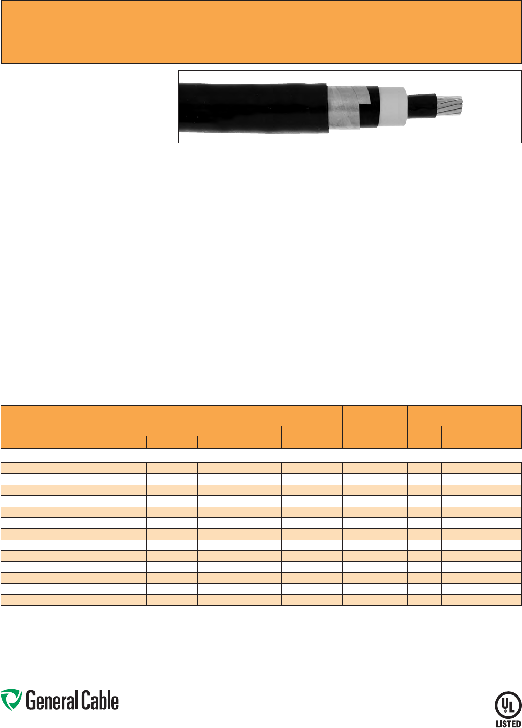
Phone: 888-593-3355
www.generalcable.com
S P E C 6175
March, 2012
Uniblend
®
EPR/Copper Tape Shield/CPE, Medium-Voltage Power, Shielded
5 kV and 8 kV, UL Type MV-105, 133%/100% Ins. Levels, 115 Mils
Product Construction:
Conductor:
• 6 AWG thru 1000 kcmil annealed bare copper
compact Class B strand
Extruded Strand Shield (ESS):
• Extruded thermoset semi-conducting stress-
control layer over conductor
Insulation:
• Ethylene Propylene Rubber (EPR) insulation,
colored to contrast with the black conducting
shield layers
Extruded Insulation Shield (EIS):
• Thermoset semi-conducting polymeric layer free
stripping from insulation
Metallic Shield:
• 5 mil annealed copper tape with an
overlap of 25%
Jacket:
• Flame-retardant, moisture- and sunlight-resistant
Chlorinated Polyethylene (CPE)
Print:
• GENERAL CABLE
®
(PLANT OF MFG) (MO/YR
OF MANUFACTURE) LIGHTNING BOLT SYMBOL
1/C SIZE (AWG OR KCMIL) COMPACT CU
UNIBLEND
®
CPE JKT (INSULATION THICKNESS)
EPR TYPE MV-105 (VOLTAGE) KV% INSULATION
LEVEL SUN RES FOR CT USE (UL) SEQUENTIAL
FOOTAGE MARK
* Sizes smaller than 1/0 AWG do not include
“FOR CT USE”.
Options:
• Other jacket options available upon request
• STRANDFILL
®
– blocked conductor. Tested in
accordance with ICEA T-31-610
Applications:
• Superior performance in petrochemical plants,
pulp and paper mills, sewage and water
treatment plants, environmental protection
systems, railroads, mines, utility power
generating stations, steel mills, textile plants and
other industrial three-phase applications
• For use in wet or dry locations when installed in
accordance with NEC
• For use in aerial, conduit, open tray and
underground duct installations
• For use in direct burial if installed in a system with
a ground conductor that is in close proximity, and
conforms with NEC 250.4(A)(5)
Features:
• Rated at 105
˚
C
• Excellent heat and moisture resistance
• Excellent flame resistance
• Outstanding corona resistance
• Flexibility for easy handling
• High dielectric strength
• Low moisture absorption
• Electrical stability under stress
• Low dielectric loss
• Chemical-resistant
• Meets cold bend test at -35
˚
C
Compliances:
• National Electrical Code (NEC)
• UL 1072
• ICEA S-93-639/NEMA WC74
• ICEA S-97-682
• AEIC CS8
• UL listed as Type MV-105 for use in accordance
with NEC, UL File # E90501
• UL 1685 (Sizes 1/0 AWG and larger) UL Flame
Exposure Test
• Sizes 1/0 AWG and larger are listed and marked
“Sunlight-Resistant FOR CT USE” in accordance
with NEC
• IEEE 1202 (70,000 BTU/hr)/CSA FT4
• EPA 40 CFR, Part 261 for leachable lead content
per TCLP method
• OSHA Acceptable
Optional Flame Tests:
• ICEA T-29-520 (210,000 BTU/hr)
Packaging:
• Material cut to length and shipped on
non-returnable wood reels. Lengths in excess of
10,000 lbs. are provided on returnable steel reels
that require a deposit
• Extra charges apply for cuts less than 1000 ft.,
lagging, pulling eyes, paralleling and triplexing
CATALOG
NUMBER
COND.
SIZE
(AWG/
kcmil)
NOMINAL
CONDUCTOR
DIAMETER
INSULATION
DIAMETER
INCHES
NOMINAL
JACKET
THICKNESS
NOMINAL CABLE
COPPER WEIGHT
AMPACITY CONDUIT
SIZING (3)
(INCHES)
DIAMETER WEIGHT CONDUIT
IN AIR (1)
UNDERGROUND
DUCT (2)INCHES MIN. MAX. INCHES mm IN mm LBS/1000 FT kg/km LBS/1000 FT kg/km
5 kV AND 8 kV, UL TYPE MV-105, 133%/100% INS. LEVELS, 115 MILS
17101.120600* 60.17 0.415 0.490 0.060 1.52 0.65 16.51 293 436 126 188 93 97 2
17101.120400* 4 0.22 0.455 0.535 0.060 1.52 0.70 17.15 363 540 178 265 120 125 2.5
17101.120200* 20.27 0.510 0.590 0.060 1.52 0.76 19.05 469 698 259 385 165 165 2.5
17101.120100* 1 0.31 0.545 0.620 0.060 1.52 0.79 20.07 537 799 315 468 190 185 2.5
17101.125100* 1/0 0.34 0.580 0.655 0.060 1.52 0.82 21.08 621 924 386 575 215 215 3
17101.125200* 2/0 0.38 0.620 0.695 0.060 1.52 0.86 22.10 726 1080 474 706 255 245 3
17101.125300* 3/0 0.43 0.665 0.745 0.080 2.03 0.94 24.38 883 1314 585 871 290 275 3
17101.135400* 4/0 0.48 0.720 0.795 0.080 2.03 1.00 25.65 1049 1561 725 1080 330 315 3
17101.136000* 250 0.53 0.770 0.850 0.080 2.03 1.05 27.18 1195 1778 849 1263 365 345 3.5
17101.136200* 350 0.62 0.870 0.945 0.080 2.03 1.14 29.72 1555 2314 1165 1735 440 415 3.5
17101.136500* 500 0.74 0.990 1.065 0.080 2.03 1.27 33.53 2083 3100 1639 2439 535 500 4
17101.137000* 750 0.91 1.170 1.250 0.080 2.03 1.45 38.35 2981 4436 2427 3611 655 610 5
17101.137500* 1000 1.06 1.320 1.400 0.080 2.03 1.60 42.42 3808 5666 3210 4777 755 690 5
Dimensions and weights are nominal; subject to industry tolerances.
* Non-stock item; minimum runs apply. Please consult Customer Service for price and delivery.
(1) Ampacities are in accordance with Table 310.60(C)(73) of the NEC for triplexed or three single conductor copper cable in isolated conduit in air, based on a conductor temperature of 105˚C (221˚F) and an
ambient air temperature of 40˚C (104˚F).
(2) Ampacities are in accordance with Table 310.60(C)(77) of the NEC for triplexed or three single conductor copper cable in underground ducts (three conductors per duct), based on a conductor temperature
of 105˚C (221˚F) and an ambient earth temperature of 20˚C (68˚F), electrical duct arrangement per Figure 310.60 Detail 1, 100% load factor, and earth thermal resistance (rho) of 90.
(3) Based on nominal cable diameters, three single cables in the duct (PVC Schedule 40) with no ground wire and a maximum of 40% fill. Jam ratio has been considered, but it should be checked for individual
installations.
Note: a) Sizes smaller than 1/0 AWG do not include “FOR CT USE”.
b) The NESC Lightning bolt symbol is on all Uniblend® constructions.
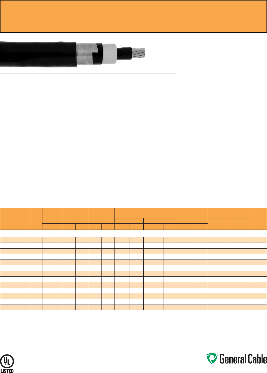
Phone: 888-593-3355
www.generalcable.com
GenFree
®
Uniblend
®
EPR/Copper Tape Shield/LSZH, Medium-Voltage Power, Shielded
5 kV and 8 kV, UL Type MV-105/ST1, 133%/100% Ins. Levels, 115 Mils
Product Construction:
Conductor:
• 6 AWG thru 1000 kcmil annealed bare copper
compact Class B strand
Extruded Strand Shield (ESS):
• Extruded thermoset semi-conducting stress-
control layer over conductor
Insulation:
• Ethylene Propylene Rubber (EPR) insulation,
colored to contrast with the black conducting
shield layers
Extruded Insulation Shield (EIS):
• Thermoset semi-conducting polymeric layer free
stripping from insulation
Metallic Shield:
• 5 mil annealed copper tape with an
overlap of 25%
Overall Jacket:
• Lead-free, moisture- and sunlight-resistant
Low-Smoke, Zero-Halogen Polyolefin (LSZH)
Print:
• GENERAL CABLE
®
(PLANT OF MFG) (MO/YR
OF MANUFACTURE) LIGHTNING BOLT SYMBOL
1/C SIZE (AWG OR KCMIL) COMPACT CU
GENFREE
®
UNIBLEND
®
LSZH JKT (INSULATION
Print (cont’d.):
THICKNESS) EPR TYPE MV-105/ST1 (VOLTAGE)
KV% INSULATION LEVEL SUN RES FOR CT USE
(UL) SEQUENTIAL FOOTAGE MARK
* Sizes smaller than 1/0 AWG do not include
“FOR CT USE”.
Options:
• STRANDFILL
®
– blocked conductor. Tested in
accordance with ICEA T-31-610
Applications:
• Superior performance in petrochemical plants,
pulp and paper mills, sewage and water
treatment plants, environmental protection
systems, railroads, mines, utility power
generating stations, steel mills, textile plants and
other industrial three-phase applications
• For use in wet or dry locations when installed in
accordance with NEC
• For use in aerial, conduit, open tray and
underground duct installations
• For use in direct burial if installed in a system with
a ground conductor that is in close proximity, and
conforms with NEC 250.4(A)(5)
Features:
• Rated at 105
˚
C
• Excellent heat and moisture resistance
• Excellent flame resistance
• Outstanding corona resistance
Features (cont’d.):
• Flexibility for easy handling
• High dielectric strength
• Low moisture absorption
• Electrical stability under stress
• Low dielectric loss
• Chemical-resistant
• Meets cold bend test at -35
˚
C
Compliances:
• National Electrical Code (NEC)
• UL 1072
• ICEA S-93-639/NEMA WC74
• ICEA S-97-682
• ICEA T-33-655
• AEIC CS8
• UL listed as Type MV-105 for use in accordance
with NEC, UL File # E90501
• UL 1685 (Sizes 1/0 AWG and larger) UL Flame
Exposure Test
• UL 1685 Vertical Flame and Smoke Release Test
• Sizes 1/0 AWG and larger are listed and marked
“Sunlight-Resistant FOR CT USE” in accordance
with NEC
• IEEE 1202 (70,000 BTU/hr)/CSA FT4
• EPA 40 CFR, Part 261 for leachable lead content
per TCLP method
• OSHA Acceptable
Optional Flame Tests:
• ICEA T-29-520 (210,000 BTU/hr)
Packaging:
• Material cut to length and shipped on
non-returnable wood reels. Lengths in excess of
10,000 lbs. are provided on returnable steel reels
that require a deposit
• Extra charges apply for cuts less than 1000 ft.,
lagging, pulling eyes, paralleling and triplexing
SPEC 6180
March, 2012
CATALOG
NUMBER
COND.
SIZE
(AWG/
kcmil)
NOMINAL
CONDUCTOR
DIAMETER
INSULATION
DIAMETER
INCHES
NOMINAL
JACKET
THICKNESS
NOMINAL CABLE
COPPER WEIGHT
AMPACITY CONDUIT
SIZING (3)
(INCHES)
DIAMETER WEIGHT CONDUIT
IN AIR (1)
UNDERGROUND
DUCT (2)INCHES MIN. MAX. INCHES mm INCHES mm LBS/1000 FT kg/km LBS/1000 FT kg/km
5 kV AND 8 kV, UL TYPE MV-105/ST1, 133%/100% INS. LEVELS, 115 MILS
17201.120600* 60.17 0.415 0.490 0.060 1.52 0.65 16.51 295 439 126 188 93 97 2
17201.120400* 4 0.22 0.455 0.535 0.060 1.52 0.70 17.15 365 543 178 265 120 125 2.5
17201.120200 20.27 0.510 0.590 0.060 1.52 0.76 19.05 471 701 259 385 165 165 2.5
17201.120100* 1 0.31 0.545 0.620 0.060 1.52 0.79 20.07 539 802 315 468 190 185 2.5
17201.125100 1/0 0.34 0.580 0.655 0.060 1.52 0.82 21.08 623 927 386 575 215 215 3
17201.125200 2/0 0.38 0.620 0.695 0.060 1.52 0.86 22.10 728 1083 474 706 255 245 3
17201.125300* 3/0 0.43 0.665 0.745 0.080 2.03 0.94 24.38 886 1318 585 871 290 275 3
17201.135400 4/0 0.48 0.720 0.795 0.080 2.03 1.00 25.65 1053 1567 725 1080 330 315 3
17201.136000* 250 0.53 0.770 0.850 0.080 2.03 1.05 27.18 1199 1784 849 1263 365 345 3.5
17201.136200 350 0.62 0.870 0.945 0.080 2.03 1.14 29.72 1559 2320 1165 1735 440 415 3.5
17201.136500 500 0.74 0.990 1.065 0.080 2.03 1.27 33.53 2088 3107 1639 2439 535 500 4
17201.137000 750 0.91 1.170 1.250 0.080 2.03 1.45 38.35 2962 4407 2427 3611 655 610 5
17201.637500* 1000 1.06 1.320 1.400 0.080 2.03 1.60 42.42 3815 5677 3210 4777 755 690 5
Dimensions and weights are nominal; subject to industry tolerances.
* Non-stock item; minimum runs apply. Please consult Customer Service for price and delivery.
(1) Ampacities are in accordance with Table 310.60(C)(73) of the NEC for triplexed or three single conductor copper cable in isolated conduit in air, based on a conductor temperature of 105˚C (221˚F) and an
ambient air temperature of 40˚C (104˚F).
(2) Ampacities are in accordance with Table 310.60(C)(77) of the NEC for triplexed or three single conductor copper cable in underground ducts (three conductors per duct), based on a conductor temperature
of 105˚C (221˚F) and an ambient earth temperature of 20˚C (68˚F), electrical duct arrangement per Figure 310.60 Detail 1, 100% load factor, and earth thermal resistance (rho) of 90.
(3) Based on nominal cable diameters, three single cables in the duct (PVC Schedule 40) with no ground wire and a maximum of 40% fill. Jam ratio has been considered, but it should be checked for individual
installations.
Note: a) Sizes smaller than 1/0 AWG do not include “FOR CT USE”.
b) The NESC Lightning bolt symbol is on all Uniblend® constructions.
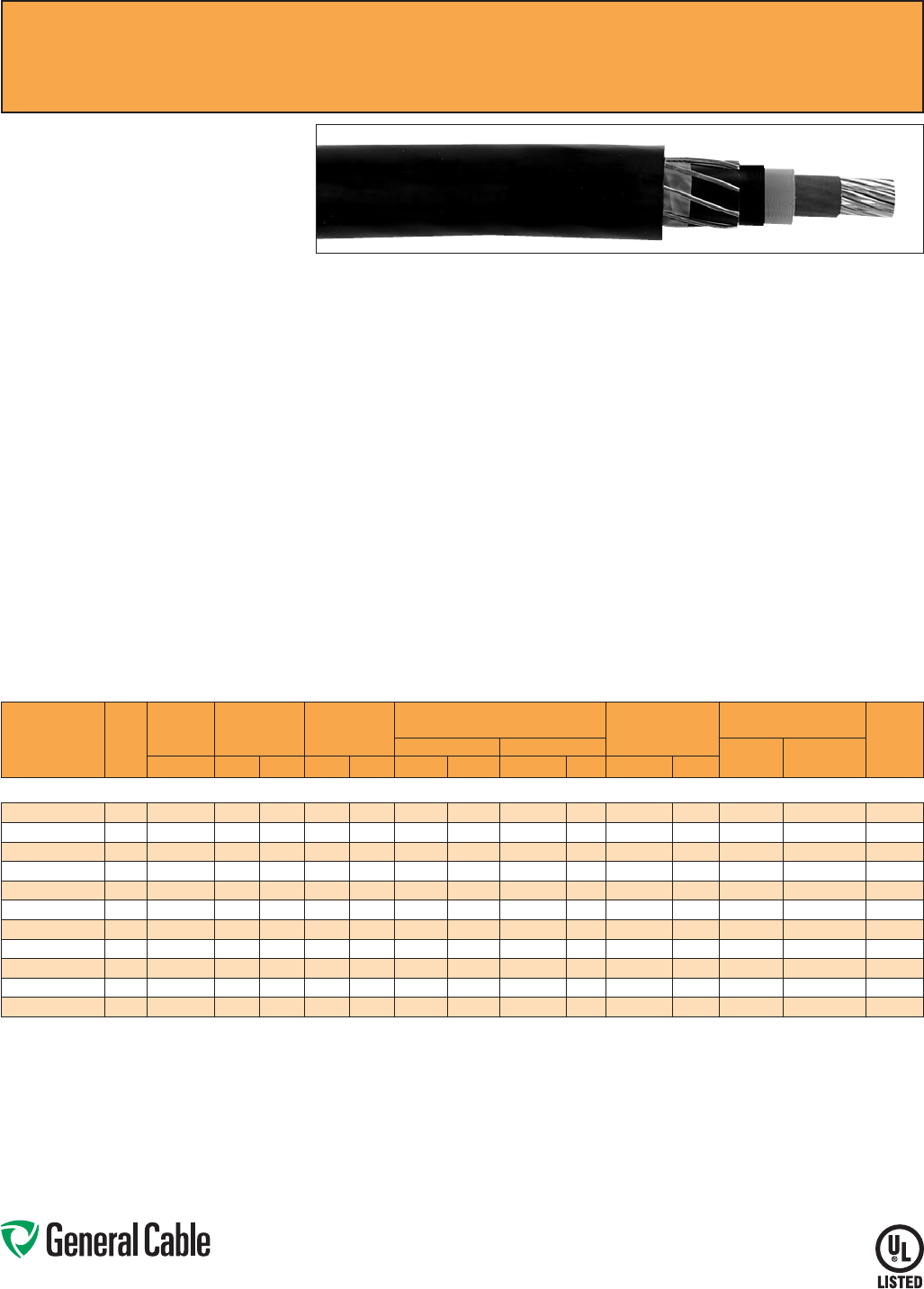
Phone: 888-593-3355
www.generalcable.com
SPEC 6200
January, 2011
Copper Wire Shield
TRXLPE/Copper Wire Shield/PVC, Medium-Voltage Power
5 kV, UL Type MV-105, 100% Ins. Level, 90 Mils
Product Construction:
Conductor:
• 6 AWG thru 1000 kcmil annealed bare copper
Class B compressed strand in accordance with
ASTM B3 and B8
Extruded Strand Shield (ESS):
• Extruded thermoset semi-conducting stress
control layer over conductor
Insulation:
• Tree-Retardant Cross-linked Polyethylene
(TRXLPE)
Extruded Insulation Shield (EIS):
• Thermoset semi-conducting polymeric layer free
stripping from insulation
Metallic Shield:
• A concentric serve of 24 AWG annealed solid
bare copper wires over which shall be applied a
lapped non-metallic tape
Jacket:
• Lead-free, flame-retardant, moisture- and
sunlight-resistant Polyvinyl Chloride (PVC)
Print:
• GENERAL CABLE
®
(PLANT OF MFG) (MO/YR
OF MANUFACTURE) LIGHTNING BOLT SYMBOL
1/C SIZE (AWG OR KCMIL) CU (INSULATION
THICKNESS) TRXLPE TYPE MV-105 (VOLTAGE)
KV% INSULATION LEVEL SUN RES (UL)
SEQUENTIAL FOOTAGE MARK
Options:
• Sizes 1/0 AWG and larger are listed and marked
“Sunlight-Resistant FOR CT USE” in accordance
with NEC and in accordance with UL 1685
(70,000 BTU/hr)
• STRANDFILL
®
– blocked conductor. Tested in
accordance with ICEA T-31-610
Applications:
• For use in wet or dry locations when installed in
accordance with NEC
• For use in aerial, conduit, open tray and
underground duct installations where cost
effectiveness is a factor
• For use in direct burial if installed in a system with
a ground conductor that is in close proximity, and
conforms with NEC 250.4(A)(5)
Features:
• Rated at 105
˚
C
• Triple tandem extrusion of the strand shield,
insulation and insulation shield provides a
virtually perfect cable core
• Excellent resistance to electro-chemical treeing,
heat, moisture and a wide variety of industrial
chemicals
Features (cont’d.):
• PVC jacket provides mechanical protection of the
shielding system during installation, as well as
protection from many industrial chemicals
• Sunlight-resistant
• Meets cold bend test at -35
˚
C
Compliances:
• National Electrical Code (NEC)
• ICEA S-93-639/NEMA WC74
• ICEA S-97-682
• AEIC CS8
• UL 1072
• UL listed as Type MV-105 for use in accordance
with NEC, UL File # E90501
• EPA 40 CFR, Part 261 for leachable lead content
per TCLP method
• OSHA Acceptable
Packaging:
• Material cut to length and shipped on
non-returnable wood reels. Lengths in excess of
10,000 lbs. are provided on returnable steel reels
that require a deposit
• Extra charges apply for cuts less than 1000 ft.,
lagging, pulling eyes, paralleling and plexing
CATALOG
NUMBER
COND.
SIZE
(AWG/
kcmil)
NOMINAL
CONDUCTOR
DIAMETER
INSULATION
DIAMETER
INCHES
NOMINAL
JACKET
THICKNESS
NOMINAL CABLE
COPPER WEIGHT
AMPACITY CONDUIT
SIZING (3)
(INCHES)
DIAMETER WEIGHT CONDUIT
IN AIR (1)
UNDERGROUND
DUCT (2)INCHES MIN. MAX. INCHES mm INCHES mm LBS/1000 FT kg/km LBS/1000 FT kg/km
5 kV, UL TYPE MV-105, 100% INS. LEVELS, 90 MILS
17241.010600* 60.18 0.370 0.445 0.060 1.52 0.67 17.02 250 372 93 138 84 92 2.5
17241.010400* 4 0.23 0.420 0.495 0.060 1.52 0.72 18.29 317 472 141 210 110 120 2.5
17241.010200* 20.29 0.475 0.555 0.060 1.52 0.77 19.55 420 625 217 323 145 155 2.5
17241.015100* 1/0 0.37 0.555 0.630 0.060 1.52 0.85 21.59 580 863 338 503 200 210 3
17241.015200* 2/0 0.41 0.600 0.675 0.060 1.52 0.89 22.61 670 997 427 635 225 235 3
17241.015400* 4/0 0.52 0.705 0.780 0.080 2.03 1.04 26.42 1000 1488 669 996 305 310 3.5
17241.016000* 250 0.56 0.760 0.835 0.080 2.03 1.10 28.19 1155 1719 788 1173 355 345 3.5
17241.016200* 350 0.67 0.865 0.940 0.080 2.03 1.20 30.48 1505 2240 1097 1632 430 415 4
17241.016500* 500 0.80 0.990 1.070 0.080 2.03 1.36 34.54 2060 3066 1563 2325 530 505 5
17241.017000* 750 0.97 1.180 1.255 0.080 2.03 1.53 38.86 2868 4268 2340 3482 665 630 5
17241.017500* 1000 1.12 1.325 1.405 0.080 2.03 1.66 42.16 3684 5482 3113 4632 770 720 6
Dimensions and weights are nominal; subject to industry tolerances.
* Non-stock item; minimum runs apply. Please consult Customer Service for price and delivery.
(1) Ampacities are in accordance with Table 310.60(C)(73) of the NEC for triplexed or three single conductor copper cable in isolated conduit in air, based on a conductor temperature of 105˚C (221˚F) and an
ambient air temperature of 40˚C (104˚F).
(2) Ampacities are in accordance with Table 310.60(C)(77) of the NEC for triplexed or three single conductor copper cable in underground ducts (three conductors per duct), based on a conductor temperature
of 105˚C (221˚F) and an ambient earth temperature of 20˚C (68˚F), electrical duct arrangement per Figure 310.60 Detail 1, 100% load factor, and earth thermal resistance (rho) of 90.
(3) Based on nominal cable diameters, three single cables in the duct (PVC Schedule 40) with no ground wire and a maximum of 40% fill. Jam ratio has been considered, but it should be checked for individual
installations.
Note: The NESC Lighting bolt symbol is on all Uniblend® constructions.
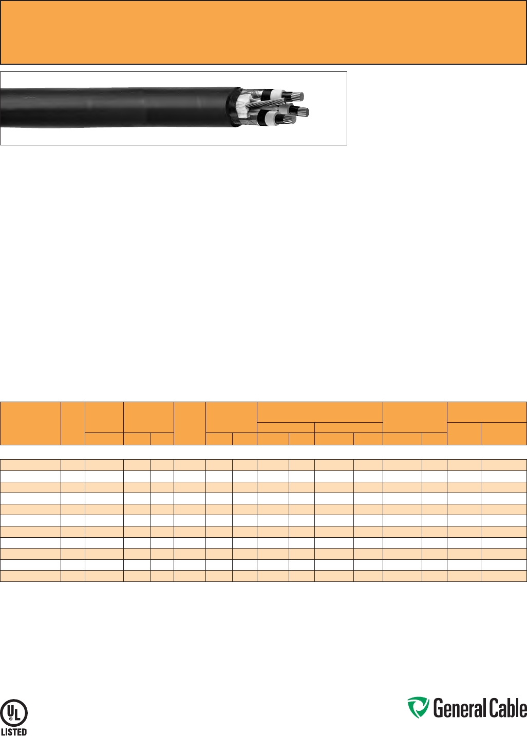
Phone: 888-593-3355
www.generalcable.com
SPEC 6250
March, 2012
Uniblend
®
EPR/Copper Tape Shield with Overall PVC Jacket, Medium-Voltage Power, Shielded
5 kV and 8 kV, UL Type MV-105, 133%/100% Ins. Levels, 115 Mils, Three Conductor
Product Construction:
Conductor:
• 6 AWG thru 1000 kcmil annealed bare copper
compact Class B strand
Extruded Strand Shield (ESS):
• Extruded thermoset semi-conducting stress-
control layer over conductor
Insulation:
• Ethylene Propylene Rubber (EPR) insulation,
colored to contrast with the black conducting
shield layers
Extruded Insulation Shield (EIS):
• Thermoset semi-conducting polymeric layer free
stripping from insulation
Metallic Shield:
• 5 mil annealed copper tape with an
overlap of 25%
Grounding Conductor:
• 1 bare grounding conductor may be in contact
with metallic shielding tape
Overall Jacket:
• Lead-free, flame-retardant, moisture- and
sunlight-resistant Polyvinyl Chloride (PVC)
Print:
• GENERAL CABLE
®
(PLANT OF MFG) (MO/YR
OF MANUFACTURE) LIGHTNING BOLT SYMBOL
3/C SIZE (AWG OR KCMIL) COMPACT CU
UNIBLEND
®
PVC JKT (INSULATION THICKNESS)
EPR TYPE MV-105 (VOLTAGE) KV% INSULATION
LEVEL DIR BUR SUN RES FOR CT USE (UL)
SEQUENTIAL FOOTAGE MARK
Options:
• Other jacket options available upon request
• Jacketed singles
• UniShield
®
singles
• STRANDFILL
®
– blocked conductor. Tested in
accordance with ICEA T-31-610
• 3 bare copper ground wires
• Covered ground wires
Applications:
• Suited for use in a broad range of commercial,
industrial and utility applications, where reliability
is the major concern, space is limited and ease of
installation is critical
• In wet or dry locations when installed in
accordance with NEC
• In aerial, direct burial, conduit, open tray and
underground duct installations
Features:
• Rated at 105
˚
C
• Excellent heat and moisture resistance
• Outstanding corona resistance
• Flexibility for easy handling
• High dielectric strength
• Low moisture absorption
• Electrical stability under stress
• Low dielectric loss
• Chemical-resistant
• Meets cold bend test at -35
˚
C
Compliances:
• National Electrical Code (NEC)
• UL 1072
• ICEA S-93-639/NEMA WC74
• ICEA S-97-682
• AEIC CS8
• UL listed as Type MV-105 for use in accordance
with NEC, UL File # E90501
• UL 1685 (70,000 BTU/hr)
• EPA 40 CFR, Part 261 for leachable lead content
per TCLP method
• OSHA Acceptable
Optional Flame Tests:
• IEEE 1202 (70,000 BTU/hr)/CSA FT4
• ICEA T-29-520 (210,000 BTU/hr)
Packaging:
• Material cut to length and shipped on
non-returnable wood reels. Lengths in excess of
10,000 lbs. are provided on returnable steel reels
that require a deposit
• Extra charges apply for cuts less than
1000 ft., lagging, pulling eyes, paralleling
and plexing
CATALOG
NUMBER
COND.
SIZE
(AWG/
kcmil)
NOMINAL
CONDUCTOR
DIAMETER
INSULATION
DIAMETER
INCHES GROUND
WIRE
(AWG)
NOMINAL
OVERALL JKT.
THICKNESS
NOMINAL CABLE
COPPER WEIGHT
AMPACITY
DIAMETER WEIGHT CONDUIT
IN AIR (1)
UNDERGROUND
DUCT (2)INCHES MIN. MAX. INCHES mm INCHES mm LBS/1000 FT kg/km LBS/1000 FT kg/km
5 kV AND 8 kV, UL TYPE MV-105, 133%/100% INS. LEVELS, 115 MILS, THREE CONDUCTOR
15493.400600* 60.17 0.415 0.490 60.080 2.03 1.29 32.77 939 1397 460 685 92 95
15493.400400* 4 0.22 0.455 0.535 60.080 2.03 1.39 35.31 1158 1723 616 917 120 125
15493.400200* 20.27 0.510 0.590 60.080 2.03 1.51 38.35 1511 2249 860 1279 165 160
15493.405100* 1/0 0.34 0.580 0.655 40.080 2.03 1.67 42.42 2030 3021 1290 1919 215 210
15493.405200* 2/0 0.38 0.620 0.695 40.080 2.03 1.82 46.23 2449 3645 1556 2315 245 235
15493.405400* 4/0 0.48 0.720 0.795 3 0.110 2.79 2.07 52.58 3438 5116 2344 3488 320 305
15493.406000* 250 0.53 0.770 0.850 2 0.110 2.79 2.15 54.61 3968 5904 2759 4105 350 335
15493.406200* 350 0.62 0.870 0.945 2 0.110 2.79 2.36 59.94 5009 7454 3713 5525 430 400
15493.406500* 500 0.74 0.990 1.065 1 0.110 2.79 2.64 67.06 6793 10065 5191 7724 525 485
15493.407000* 750 0.91 1.170 1.250 1/0 0.140 3.56 3.14 79.76 9833 14633 7629 11352 635 585
15493.407500* 1000 1.06 1.320 1.400 2/0 0.140 3.56 3.48 88.39 12601 18753 10070 14985 725 660
Dimensions and weights are nominal; subject to industry tolerances.
* Non-stock item; minimum runs apply. Please consult Customer Service for price and delivery.
(1) Ampacities are in accordance with Table 310.60(C)(75) of the NEC for three conductor copper cable in isolated conduit in air, based on a conductor temperature of 105˚C (221˚F) and an ambient air
temperature of 40˚C (104˚F).
(2) Ampacities are in accordance with Table 310.60(C)(79) of the NEC for three conductor copper cable in underground ducts (three conductors per duct), based on a conductor temperature of 105˚C (221˚F)
and an ambient earth temperature of 20˚C (68˚F), electrical duct arrangement per Figure 310.60 Detail 1, 100% load factor, and earth thermal resistance (rho) of 90.
Note: a) All sizes are “FOR CT USE”.
b) The NESC Lightning bolt symbol is on all Uniblend® constructions.
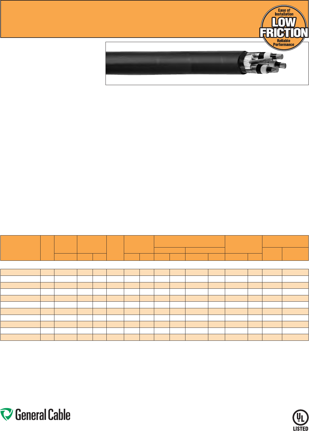
Phone: 888-593-3355
www.generalcable.com
SPEC 6255
March, 2012
Uniblend
®
LF
EPR/Copper Tape Shield with Overall PVC Jacket
Medium-Voltage Power, Shielded, 5 kV and 8 kV, UL Type MV-105
133%/100% Ins. Levels, 115 Mils, Three Conductor
Product Construction:
Conductor:
• 6 AWG thru 1000 kcmil annealed bare copper
compact Class B strand
Extruded Strand Shield (ESS):
• Extruded thermoset semi-conducting stress-
control layer over conductor
Insulation:
• Ethylene Propylene Rubber (EPR) insulation,
colored to contrast with the black conducting
shield layers
Extruded Insulation Shield (EIS):
• Thermoset semi-conducting polymeric layer free
stripping from insulation
Metallic Shield:
• 5 mil annealed copper tape with an
overlap of 25%
Grounding Conductor:
• 1 bare grounding conductor may be in contact
with metallic shielding tape
Overall Jacket:
• Low-friction, lead-free, flame-retardant, moisture-
and sunlight-resistant Polyvinyl Chloride (PVC)
Print:
•
GENERAL CABLE
®
(PLANT OF MFG) (MO/
YR OF MANUFACTURE) LIGHTNING BOLT
SYMBOL 3/C SIZE (AWG OR KCMIL) COMPACT
CU UNIBLEND
®
LF PVC JKT (INSULATION
THICKNESS) EPR TYPE MV-105 (VOLTAGE) KV%
INSULATION LEVEL DIR BUR SUN RES FOR CT
USE (UL) SEQUENTIAL FOOTAGE MARK
Options:
• STRANDFILL
®
– blocked conductor. Tested in
accordance with ICEA T-31-610
• 3 bare copper ground wires
• Covered ground wires
Applications:
• Suited for use in a broad range of commercial,
industrial and utility applications, where reliability
is the major concern, space is limited and ease of
installation is critical
• In wet or dry locations when installed in
accordance with NEC
• In aerial, direct burial, conduit, open tray and
underground duct installations
Features:
• Rated at 105
˚
C
• Lower coefficient of friction for ease of
installation
• Excellent heat and moisture resistance
• Outstanding corona resistance
• Flexibility for easy handling
• High dielectric strength
• Low moisture absorption
• Electrical stability under stress
• Low dielectric loss
• Chemical-resistant
• Meets cold bend test at -35
˚
C
Compliances:
• National Electrical Code (NEC)
• UL 1072
• ICEA S-93-639/NEMA WC74
• ICEA S-97-682
• AEIC CS8
• UL listed as Type MV-105 for use in accordance
with NEC, UL File # E90501
• UL 1685 (70,000 BTU/hr)
• EPA 40 CFR, Part 261 for leachable lead content
per TCLP method
• OSHA Acceptable
Optional Flame Tests:
• IEEE 1202 (70,000 BTU/hr)/CSA FT4
• ICEA T-29-520 (210,000 BTU/hr)
Packaging:
• Material cut to length and shipped on
non-returnable wood reels. Lengths in excess of
10,000 lbs. are provided on returnable steel reels
that require a deposit
• Extra charges apply for cuts less than
1000 ft., lagging, pulling eyes, paralleling
and plexing
CATALOG
NUMBER
COND.
SIZE
(AWG/
kcmil)
NOMINAL
CONDUCTOR
DIAMETER
INSULATION
DIAMETER
INCHES GROUND
WIRE
(AWG)
NOMINAL
OVERALL JKT.
THICKNESS
NOMINAL CABLE
COPPER WEIGHT
AMPACITY
DIAMETER WEIGHT CONDUIT
IN AIR (1)
UNDERGROUND
DUCT (2)INCHES MIN. MAX. INCHES mm INCHES mm LBS/1000 FT kg/km LBS/1000 FT kg/km
5 kV AND 8 kV, UL TYPE MV-105, 133%/100% INS. LEVELS, 115 MILS, THREE CONDUCTOR
15493.400605 60.17 0.415 0.490 60.080 2.03 1.29 32.77 939 1397 460 685 92 95
15493.400405 4 0.22 0.455 0.535 60.080 2.03 1.39 35.31 1158 1723 616 917 120 125
15493.400205 20.27 0.510 0.590 60.080 2.03 1.51 38.35 1511 2249 860 1279 165 160
15493.405105 1/0 0.34 0.580 0.655 40.080 2.03 1.67 42.42 2030 3021 1290 1919 215 210
15493.405205 2/0 0.38 0.620 0.695 40.080 2.03 1.82 46.23 2449 3645 1556 2315 245 235
15493.405405 4/0 0.48 0.720 0.795 3 0.110 2.79 2.07 52.58 3438 5116 2344 3488 320 305
15493.406005* 250 0.53 0.770 0.850 2 0.110 2.79 2.15 54.61 3968 5904 2759 4105 350 335
15493.406205 350 0.62 0.870 0.945 2 0.110 2.79 2.36 59.94 5009 7454 3713 5525 430 400
15493.406505 500 0.74 0.990 1.065 1 0.110 2.79 2.64 67.06 6793 10065 5191 7724 525 485
15493.407005* 750 0.91 1.170 1.250 1/0 0.140 3.56 3.14 79.76 9833 14633 7629 11352 635 585
15493.407505* 1000 1.06 1.320 1.400 2/0 0.140 3.56 3.48 88.39 12601 18753 10070 14985 725 660
Dimensions and weights are nominal; subject to industry tolerances.
* Non-stock item; minimum runs apply. Please consult Customer Service for price and delivery.
(1) Ampacities are in accordance with Table 310.60(C)(75) of the NEC for three conductor copper cable in isolated conduit in air, based on a conductor temperature of 105˚C (221˚F) and an ambient air
temperature of 40˚C (104˚F).
(2) Ampacities are in accordance with Table 310.60(C)(79) of the NEC for three conductor copper cable in underground ducts (three conductors per duct), based on a conductor temperature of 105˚C (221˚F)
and an ambient earth temperature of 20˚C (68˚F), electrical duct arrangement per Figure 310.60 Detail 1, 100% load factor, and earth thermal resistance (rho) of 90.
Note: a) All sizes are “FOR CT USE”.
b) The NESC Lightning bolt symbol is on all Uniblend® constructions.
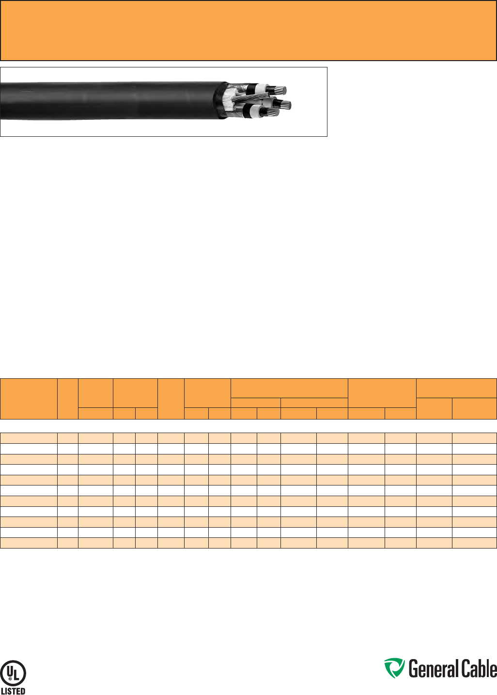
Phone: 888-593-3355
www.generalcable.com
SPEC 6275
March, 2012
Uniblend
®
EPR/Copper Tape Shield with Overall CPE Jacket, Medium-Voltage Power, Shielded
5 kV and 8 kV, UL Type MV-105, 133%/100% Ins. Levels, 115 Mils, Three Conductor
Product Construction:
Conductor:
• 6 AWG thru 1000 kcmil annealed bare copper
compact Class B strand
Extruded Strand Shield (ESS):
• Extruded thermoset semi-conducting stress-
control layer over conductor
Insulation:
• Ethylene Propylene Rubber (EPR) insulation,
colored to contrast with the black conducting
shield layers
Extruded Insulation Shield (EIS):
• Thermoset semi-conducting polymeric layer free
stripping from insulation
Metallic Shield:
• 5 mil annealed copper tape with an
overlap of 25%
Grounding Conductor:
• 1 bare grounding conductor may be in contact
with metallic shielding tape
Overall Jacket:
• Flame-retardant, moisture- and sunlight-resistant
Chlorinated Polyethylene (CPE)
Print:
• GENERAL CABLE
®
(PLANT OF MFG) (MO/YR
OF MANUFACTURE) LIGHTNING BOLT SYMBOL
3/C SIZE (AWG OR KCMIL) COMPACT CU
UNIBLEND
®
CPE JKT (INSULATION THICKNESS)
EPR TYPE MV-105 (VOLTAGE) KV% INSULATION
LEVEL DIR BUR SUN RES FOR CT USE (UL)
SEQUENTIAL FOOTAGE MARK
Options:
• Other jacket options available upon request
• Jacketed singles
• UniShield
®
singles
• STRANDFILL
®
– blocked conductor. Tested in
accordance with ICEA T-31-610
• 3 bare copper ground wires
• Covered ground wires
Applications:
• Suited for use in a broad range of commercial,
industrial and utility applications, where reliability
is the major concern, space is limited and ease of
installation is critical
• In wet or dry locations when installed in
accordance with NEC
• In aerial, direct burial, conduit, open tray and
underground duct installations
Features:
• Rated at 105
˚
C
• Excellent heat and moisture resistance
• Outstanding corona resistance
• Flexibility for easy handling
• High dielectric strength
• Low moisture absorption
• Electrical stability under stress
• Low dielectric loss
• Chemical-resistant
• Meets cold bend test at -35
˚
C
Compliances:
• National Electrical Code (NEC)
• UL 1072
• ICEA S-93-639/NEMA WC74
• ICEA S-97-682
• AEIC CS8
• UL listed as Type MV-105 for use in accordance
with NEC, UL File # E90501
• UL 1685 (70,000 BTU/hr)
• OSHA Acceptable
Optional Flame Tests:
• IEEE 1202 (70,000 BTU/hr)/CSA FT4
• ICEA T-29-520 (210,000 BTU/hr)
Packaging:
• Material cut to length and shipped on
non-returnable wood reels. Lengths in excess of
10,000 lbs. are provided on returnable steel reels
that require a deposit
• Extra charges apply for cuts less than
1000 ft., lagging, pulling eyes, paralleling
and plexing
CATALOG
NUMBER
COND.
SIZE
(AWG/
kcmil)
NOMINAL
CONDUCTOR
DIAMETER
INSULATION
DIAMETER
INCHES GROUND
WIRE
(AWG)
NOMINAL
OVERALL JKT.
THICKNESS
NOMINAL CABLE
COPPER WEIGHT
AMPACITY
DIAMETER WEIGHT CONDUIT
IN AIR (1)
UNDERGROUND
DUCT (2)INCHES MIN. MAX. INCHES mm INCHES mm LBS/1000 FT kg/km LBS/1000 FT kg/km
5 kV AND 8 kV, UL TYPE MV-105, 133%/100% INS. LEVELS, 115 MILS, THREE CONDUCTOR
15593.400600* 60.17 0.415 0.490 60.080 2.03 1.29 32.77 939 1397 460 685 92 95
15593.400400* 4 0.22 0.455 0.535 60.080 2.03 1.39 35.31 1158 1723 616 917 120 125
15593.400200* 20.27 0.510 0.590 60.080 2.03 1.51 38.35 1511 2249 860 1279 165 160
15593.405100* 1/0 0.34 0.580 0.655 40.080 2.03 1.67 42.42 2030 3021 1290 1919 215 210
15593.405200* 2/0 0.38 0.620 0.695 40.080 2.03 1.82 46.23 2449 3645 1556 2315 245 235
15593.405400* 4/0 0.48 0.720 0.795 3 0.110 2.79 2.07 52.58 3438 5116 2344 3488 320 305
15593.406000* 250 0.53 0.770 0.850 2 0.110 2.79 2.15 54.61 3968 5904 2759 4105 350 335
15593.406200* 350 0.62 0.870 0.945 2 0.110 2.79 2.36 59.94 5009 7454 3713 5525 430 400
15593.406500* 500 0.74 0.990 1.065 1 0.110 2.79 2.64 67.06 6793 10065 5191 7724 525 485
15593.407000* 750 0.91 1.170 1.250 1/0 0.140 3.56 3.14 79.76 9833 14633 7629 11352 635 585
15593.407500* 1000 1.06 1.320 1.400 2/0 0.140 3.56 3.48 88.39 12601 18753 10070 14985 725 660
Dimensions and weights are nominal; subject to industry tolerances.
* Non-stock item; minimum runs apply. Please consult Customer Service for price and delivery.
(1) Ampacities are in accordance with Table 310.60(C)(75) of the NEC for three conductor copper cable in isolated conduit in air, based on a conductor temperature of 105˚C (221˚F) and an ambient air
temperature of 40˚C (104˚F).
(2) Ampacities are in accordance with Table 310.60(C)(79) of the NEC for three conductor copper cable in underground ducts (three conductors per duct), based on a conductor temperature of 105˚C (221˚F)
and an ambient earth temperature of 20˚C (68˚F), electrical duct arrangement per Figure 310.60 Detail 1, 100% load factor, and earth thermal resistance (rho) of 90.
Note: a) Sizes smaller than 4/0 AWG do not include “FOR CT USE”.
b) The NESC Lightning bolt symbol is on all Uniblend® constructions.
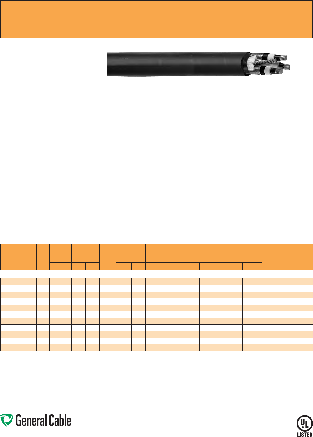
Phone: 888-593-3355
www.generalcable.com
GenFree
®
Uniblend
®
EPR/Copper Tape Shield with Overall LSZH Jacket, Medium-Voltage Power, Shielded
5 kV and 8 kV, UL Type MV-105, 133%/100% Ins. Levels, 115 Mils, Three Conductor
Product Construction:
Conductor:
• 6 AWG thru 1000 kcmil annealed bare copper
compact Class B strand
Extruded Strand Shield (ESS):
• Extruded thermoset semi-conducting stress-
control layer over conductor
Insulation:
• Ethylene Propylene Rubber (EPR) insulation,
colored to contrast with the black conducting
shield layers
Extruded Insulation Shield (EIS):
• Thermoset semi-conducting polymeric layer free
stripping from insulation
Metallic Shield:
• 5 mil annealed copper tape with an overlap
of 25%
Grounding Conductor:
• 1 bare grounding conductor may be in contact
with metallic shielding tape
Overall Jacket:
• Lead-free, moisture- and sunlight-resistant
Low-Smoke, Zero-Halogen Polyolefin (LSZH)
Print:
• GENERAL CABLE
®
(PLANT OF MFG) (MO/YR
OF MANUFACTURE) LIGHTNING BOLT SYMBOL
3/C SIZE (AWG OR KCMIL) COMPACT CU
GENFREE
®
UNIBLEND
®
LSZH JKT (INSULATION
THICKNESS) EPR TYPE MV-105 (VOLTAGE) KV%
INSULATION LEVEL DIR BUR SUN RES FOR CT
USE (UL) SEQUENTIAL FOOTAGE MARK
Options:
• STRANDFILL
®
– blocked conductor. Tested in
accordance with ICEA T-31-610
• 3 bare copper ground wires
• Covered ground wires
Applications:
• Suited for use in a broad range of commercial,
industrial and utility applications, where reliability
is the major concern, space is limited and ease of
installation is critical
• In wet or dry locations when installed in
accordance with NEC
• In aerial, direct burial, conduit, open tray and
underground duct installations
Features:
• Rated at 105
˚
C
• Excellent heat and moisture resistance
• Outstanding corona resistance
• Flexibility for easy handling
• High dielectric strength
• Low moisture absorption
• Electrical stability under stress
• Low dielectric loss
• Chemical-resistant
• Meets cold bend test at -35
˚
C
Compliances:
• National Electrical Code (NEC)
• UL 1072
• ICEA S-93-639/NEMA WC74
• ICEA S-97-682
• ICEA T-33-655
• AEIC CS8
• UL listed as Type MV-105 for use in accordance
with NEC, UL File # E90501
• UL 1685 (70,000 BTU/hr)
• OSHA Acceptable
Optional Flame Tests:
• IEEE 1202 (70,000 BTU/hr)/CSA FT4
• ICEA T-29-520 (210,000 BTU/hr)
Packaging:
• Material cut to length and shipped on
non-returnable wood reels. Lengths in excess of
10,000 lbs. are provided on returnable steel reels
that require a deposit
• Extra charges apply for cuts less than
1000 ft., lagging, pulling eyes, paralleling
and plexing
SPEC 6280
March, 2012
CATALOG
NUMBER
COND.
SIZE
(AWG/
kcmil)
NOMINAL
CONDUCTOR
DIAMETER
INSULATION
DIAMETER
INCHES GROUND
WIRE
(AWG)
NOMINAL
OVERALL JKT.
THICKNESS
NOMINAL CABLE
COPPER WEIGHT
AMPACITY
DIAMETER WEIGHT CONDUIT
IN AIR (1)
UNDERGROUND
DUCT (2)INCHES MIN. MAX. INCHES mm INCHES mm LBS/1000 FT kg/km LBS/1000 FT kg/km
5 kV AND 8 kV, UL TYPE MV-105, 133%/100% INS. LEVELS, 115 MILS, THREE CONDUCTOR
15693.400600* 60.17 0.415 0.490 60.080 2.03 1.29 32.77 939 1397 460 685 92 95
15693.400400* 4 0.22 0.455 0.535 60.080 2.03 1.39 35.31 1158 1723 616 917 120 125
15693.400200* 20.27 0.510 0.590 60.080 2.03 1.51 38.35 1511 2249 860 1279 165 160
15693.405100* 1/0 0.34 0.580 0.655 40.080 2.03 1.67 42.42 2030 3021 1290 1919 215 210
15693.405200* 2/0 0.38 0.620 0.695 40.080 2.03 1.82 46.23 2449 3645 1556 2315 245 235
15693.405400* 4/0 0.48 0.720 0.795 3 0.110 2.79 2.07 52.58 3438 5116 2344 3488 320 305
15693.406000* 250 0.53 0.770 0.850 2 0.110 2.79 2.15 54.61 3968 5904 2759 4105 350 335
15693.406200* 350 0.62 0.870 0.945 2 0.110 2.79 2.36 59.94 5009 7454 3713 5525 430 400
15693.406500* 500 0.74 0.990 1.065 1 0.110 2.79 2.64 67.06 6793 10065 5191 7724 525 485
15693.407000* 750 0.91 1.170 1.250 1/0 0.140 3.56 3.14 79.76 9833 14633 7629 11352 635 585
15693.407500* 1000 1.06 1.320 1.400 2/0 0.140 3.56 3.48 88.39 12601 18753 10070 14985 725 660
Dimensions and weights are nominal; subject to industry tolerances.
* Non-stock item; minimum runs apply. Please consult Customer Service for price and delivery.
(1) Ampacities are in accordance with Table 310.60(C)(75) of the NEC for three conductor copper cable in isolated conduit in air, based on a conductor temperature of 105˚C (221˚F) and an ambient air
temperature of 40˚C (104˚F).
(2) Ampacities are in accordance with Table 310.60(C)(79) of the NEC for three conductor copper cable in underground ducts (three conductors per duct), based on a conductor temperature of 105˚C (221˚F)
and an ambient earth temperature of 20˚C (68˚F), electrical duct arrangement per Figure 310.60 Detail 1, 100% load factor, and earth thermal resistance (rho) of 90.
Note: a) Sizes smaller than 1/0 AWG do not include “FOR CT USE”.
b) The NESC Lightning bolt symbol is on all Uniblend® constructions.
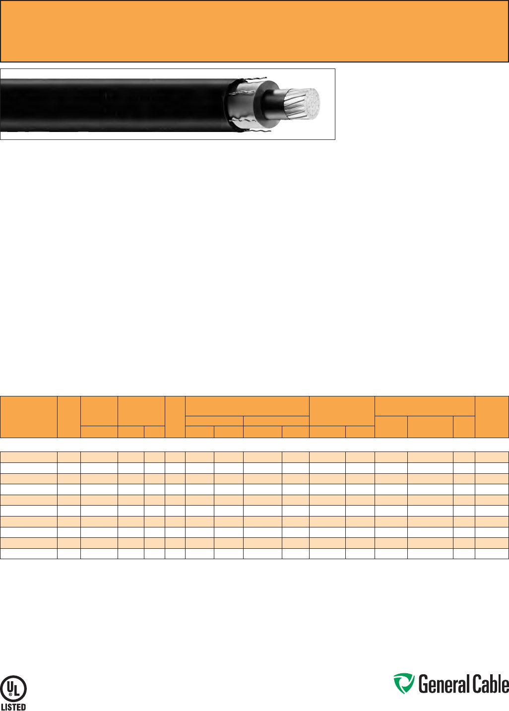
Phone: 888-593-3355
www.generalcable.com
SPEC 6300
June, 2013
Product Construction:
Conductor:
• 2 AWG thru 1000 kcmil annealed bare copper
compact Class B strand
Extruded Strand Shield (ESS):
• Extruded thermoset semi-conducting stress-
control layer over conductor
Insulation:
• Ethylene Propylene Rubber (EPR) insulation,
colored to contrast with black conducting shield
layers
Composite Insulation Shield
and Jacket:
• Six corrugated copper drain wires embedded in
composite layers of semi-conducting thermoset
copolymer and semi-conducting black flame-
retardant Chlorinated Polyethylene (CPE)
Print:
• GENERAL CABLE
®
(PLANT OF MFG) (MO/
YR OF MANUFACTURE) LIGHTNING BOLT
SYMBOL 1/C SIZE (AWG OR KCMIL) COMPACT
CU UNISHIELD
®
(INSULATION THICKNESS)
EPR DRTP SEMI-CON CPE JKT TYPE MV-105
(VOLTAGE) KV% INSULATION LEVEL SUN RES
FOR CT USE (UL) SEQUENTIAL FOOTAGE MARK
* Sizes smaller than 1/0 AWG do not include
“FOR CT USE”.
Applications:
• Installed in a broad range of commercial,
industrial and utility projects such as pulp
and paper mills, petrochemical plants, steel
mills, textile mills, water and sewage treatment
facilities, environmental protection systems,
railroads, mines and fossil fuel utility generating
stations
• Suitable for use in wet or dry locations when
installed in accordance with NEC
• For use in aerial, conduit, open tray and
underground duct installations
• For use in direct burial if installed in a system
with a ground conductor that is in close
proximity, and conforms with NEC 250.4(A)(5)
Features:
• Rated at 105
˚
C
• Reduced conductor size and shield system
provides the smallest premium medium-voltage
shielded power cable with full insulation
• Smaller outside dimensions reduce the size of
duct needed or increase the ampacity per duct
• All features contribute to faster and
easier installation
• Superior cold bend and cold impact
performance
• Stable and constant shield short
circuit performance
• Excellent heat and moisture resistance
• Outstanding corona resistance
Features (cont’d.):
• Flexibility for easy handling
• High dielectric strength
• Low dielectric loss
• Low moisture absorption
• Electrical stability under stress
• Chemical-resistant
• Sunlight-resistant
• Meets cold bend test at -55
˚
C
Compliances:
• National Electrical Code (NEC)
• UL 1072
• ICEA S-93-639/NEMA WC74
• ICEA S-97-682
• AEIC CS8
• UL listed as Type MV-105 for use in accordance
with NEC, UL File # E90501
• UL 1685 (Sizes 1/0 AWG and larger) UL Flame
Exposure Test
• Sizes 1/0 AWG and larger are listed and marked
“Sunlight-Resistant FOR CT USE” in accordance
with NEC
• IEEE 1202 (70,000 BTU/hr)/CSA FT4
• EPA 40 CFR, Part 261 for leachable lead content
per TCLP method
• OSHA Acceptable
Optional Flame Tests:
• ICEA T-29-520 (210,000 BTU/hr)
Packaging:
• Material cut to length and shipped on non-
returnable wood reels. Lengths in excess of
10,000 lbs. are provided on returnable steel reels
that require a deposit
• Extra charges apply for cuts less than
1000 ft., lagging, pulling eyes, paralleling
and triplexing
NOTE: Due to the semi-conducting properties of the
cable jacket, multi-point grounding is recommended for
all UniShield® installations.
UniShield
®
EPR/Copper Wire Shield/CPE, Medium-Voltage Power, Shielded
15 kV, UL Type MV-105, 133% Ins. Level, 220 Mils
CATALOG
NUMBER
COND.
SIZE
(AWG/
kcmil)
NOMINAL
CONDUCTOR
DIAMETER
INSULATION
DIAMETER
INCHES
DRAIN
WIRE
SIZE
(AWG)
NOMINAL CABLE
COPPER WEIGHT
AMPACITY CONDUIT
SIZING (4)
(INCHES)
DIAMETER WEIGHT CONDUIT
IN AIR (1)
UNDERGROUND
DUCT (2)
TRAY
(3)INCHES MIN. MAX. INCHES mm LBS/1000 FT kg/km LBS/1000 FT kg/km
15 kV¥, UL TYPE MV-105, 133% INS. LEVEL, 220 MILS
19161.660200 20.27 0.710 0.800 19 0.93 23.88 555 835 230 342 165 165 - 3
19161.675100 1/0 0.34 0.780 0.865 18 1.01 25.91 734 1102 358 533 215 215 220 3.5
19161.675200 2/0 0.38 0.820 0.905 18 1.05 27.18 844 1259 443 659 255 245 250 3.5
19161.665300* 3/0 0.43 0.865 0.955 18 1.10 28.45 978 1458 550 818 290 275 290 3.5
19161.675400 4/0 0.48 0.920 1.005 18 1.16 29.72 1151 1716 685 1019 330 315 335 4
19161.686000 250 0.53 0.970 1.060 17 1.23 31.50 1325 1984 813 1210 365 345 370 4
19161.686200 350 0.62 1.070 1.155 17 1.33 33.78 1691 2530 1122 1669 440 415 460 5
19161.686500 500 0.74 1.190 1.275 17 1.46 37.08 2238 3344 1585 2358 535 500 575 5
19161.697000 750 0.91 1.370 1.460 16 1.67 42.42 3174 4739 2368 3523 655 610 745 6
19161.307500* 1000 1.06 1.520 1.610 16 1.86 47.24 4122 6133 3138 4669 755 690 890 6
Dimensions and weights are nominal; subject to industry tolerances.
* Non-stock item; minimum runs apply. Please consult Customer Service for price and delivery.
(1) Ampacities are in accordance with Table 310.60(C)(73) of the NEC for triplexed or three single conductor copper cable in isolated conduit in air, based on a conductor temperature of 105˚C (221˚F) and an
ambient air temperature of 40˚C (104˚F).
(2) Ampacities are in accordance with Table 310.60(C)(77) of the NEC for triplexed or three single conductor copper cable in underground ducts (three conductors per duct), based on a conductor temperature
of 105˚C (221˚F) and an ambient earth temperature of 20˚C (68˚F), electrical duct arrangement per Figure 310.60 Detail 1, 100% load factor, and earth thermal resistance (rho) of 90.
(3) Ampacities are based on single conductor Type MV-105 sizes #1/0 AWG and larger in an uncovered tray in accordance with Section 392.80(B)(2) of the NEC at an ambient air temperature of 40˚C (104˚F);
the ampacities are based on 75% of the values per Table 310.60(C)(69). For cable trays with unventilated covers for more than 6 feet, the ampacities shall not exceed 70% of the values shown above.
(4) Based on nominal cable diameters, three single cables in the duct (PVC Schedule 40) with no ground wire and a maximum of 40% fill. Jam ratio has been considered, but it should be checked for individual
installations.
¥100% insulation level is available upon request
Note: a) Sizes smaller than 1/0 AWG do not include “FOR CT USE”.
b) The NESC Lightning bolt symbol is on all UniShield® constructions.
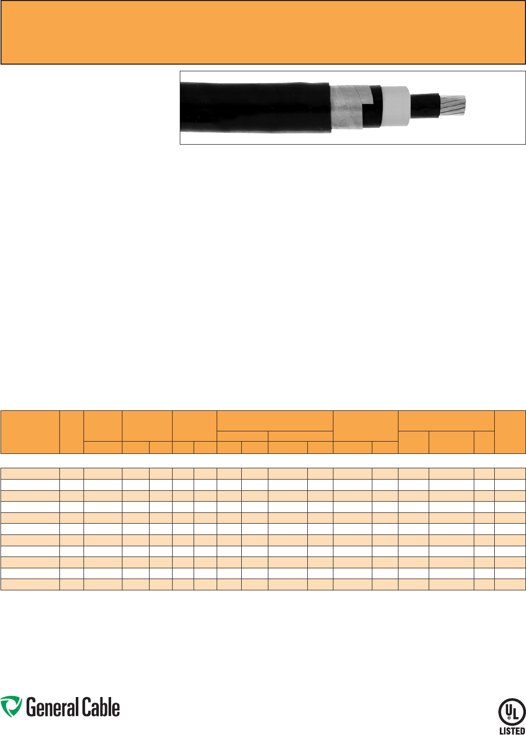
Phone: 888-593-3355
www.generalcable.com
SPEC 6350
March, 2012
Uniblend
®
EPR/Copper Tape Shield/PVC, Medium-Voltage Power, Shielded
15 kV, UL Type MV-105, 133% Ins. Level, 220 Mils
Product Construction:
Conductor:
• 2 AWG thru 1000 kcmil annealed bare copper
compact Class B strand
Extruded Strand Shield (ESS):
• Extruded thermoset semi-conducting stress-
control layer over conductor
Insulation:
• Ethylene Propylene Rubber (EPR) insulation,
colored to contrast with the black conducting
shield layers
Extruded Insulation Shield (EIS):
• Thermoset semi-conducting polymeric layer free
stripping from insulation
Metallic Shield:
• 5 mil annealed copper tape with an
overlap of 25%
Jacket:
• Lead-free, flame-retardant, moisture- and
sunlight-resistant Polyvinyl Chloride (PVC)
Print:
• GENERAL CABLE
®
(PLANT OF MFG) (MO/YR
OF MANUFACTURE) LIGHTNING BOLT SYMBOL
1/C SIZE (AWG OR KCMIL) COMPACT CU
UNIBLEND
®
PVC JKT (INSULATION THICKNESS)
EPR TYPE MV-105 (VOLTAGE) KV% INSULATION
LEVEL SUN RES FOR CT USE (UL) SEQUENTIAL
FOOTAGE MARK
* Sizes smaller than 1/0 AWG do not include
“FOR CT USE”.
Options:
• Other jacket options available upon request
• STRANDFILL
®
– blocked conductor. Tested in
accordance with ICEA T-31-610
• 100% insulation level
Applications:
• Superior performance in petrochemical plants,
pulp and paper mills, sewage and water
treatment plants, environmental protection
systems, railroads, mines, utility power
generating stations, steel mills, textile plants and
other industrial three-phase applications
• For use in wet or dry locations when installed in
accordance with NEC
• For use in aerial, conduit, open tray and
underground duct installations
• For use in direct burial if installed in a system with
a ground conductor that is in close proximity, and
conforms with NEC 250.4(A)(5)
Features:
• Rated at 105
˚
C
• Excellent heat and moisture resistance
• Excellent flame resistance
• Outstanding corona resistance
• Flexibility for easy handling
• High dielectric strength
• Low moisture absorption
• Electrical stability under stress
• Low dielectric loss
• Chemical-resistant
• Meets cold bend test at -35
˚
C
Compliances:
• National Electrical Code (NEC)
• UL 1072
• ICEA S-93-639/NEMA WC74
• ICEA S-97-682
• AEIC CS8
• UL listed as Type MV-105 for use in accordance
with NEC, UL File # E90501
• UL 1685 (Sizes 1/0 AWG and larger) UL Flame
Exposure Test
• Sizes 1/0 AWG and larger are listed and marked
“Sunlight-Resistant FOR CT USE” in accordance
with NEC
• IEEE 1202 (70,000 BTU/hr)/CSA FT4
• EPA 40 CFR, Part 261 for leachable lead content
per TCLP method
• OSHA Acceptable
Optional Flame Tests:
• ICEA T-29-520 (210,000 BTU/hr)
Packaging:
• Material cut to length and shipped on
non-returnable wood reels. Lengths in excess of
10,000 lbs. are provided on returnable steel reels
that require a deposit
• Extra charges apply for cuts less than 1000 ft.,
lagging, pulling eyes, paralleling and triplexing
CATALOG
NUMBER
COND.
SIZE
(AWG/
kcmil)
NOMINAL
CONDUCTOR
DIAMETER
INSULATION
DIAMETER
INCHES
NOMINAL
JACKET
THICKNESS
NOMINAL CABLE
COPPER WEIGHT
AMPACITY CONDUIT
SIZING (4)
(INCHES)
DIAMETER WEIGHT CONDUIT
IN AIR (1)
UNDERGROUND
DUCT (2)
TRAY
(3)INCHES MIN. MAX. INCHES mm INCHES mm LBS/1000 FT kg/km LBS/1000 FT kg/km
15 kV¥, UL TYPE MV-105, 133% INS. LEVEL, 220 MILS
17031.130200* 20.27 0.710 0.800 0.080 2.03 0.99 25.14 658 979 276 411 165 165 - 3
17031.130100* 1 0.31 0.745 0.830 0.080 2.03 1.02 25.91 733 1090 332 494 190 185 - 3.5
17031.135100* 1/0 0.34 0.780 0.865 0.080 2.03 1.06 26.92 825 1228 403 600 215 215 220 3.5
17031.135200* 2/0 0.38 0.820 0.905 0.080 2.03 1.10 27.94 938 1396 492 732 255 245 250 3.5
17031.135300* 3/0 0.43 0.865 0.955 0.080 2.03 1.14 28.95 1078 1604 603 897 290 275 290 3.5
17031.135400* 4/0 0.48 0.920 1.005 0.080 2.03 1.21 30.73 1261 1876 743 1105 330 315 335 3.5
17031.136000* 250 0.53 0.970 1.060 0.080 2.03 1.25 31.75 1407 2093 866 1289 365 345 370 4
17031.136200* 350 0.62 1.070 1.155 0.080 2.03 1.35 34.29 1783 2653 1184 1761 440 415 460 5
17031.136500* 500 0.74 1.190 1.275 0.080 2.03 1.47 37.34 2331 3468 1657 2466 535 500 575 5
17031.137000* 750 0.91 1.370 1.460 0.080 2.03 1.65 41.91 3234 4812 2445 3638 655 610 745 6
17031.137500* 1000 1.06 1.520 1.610 0.110 2.79 1.86 47.24 4219 6278 3228 4803 755 690 890 6
Dimensions and weights are nominal; subject to industry tolerances.
* Non-stock item; minimum runs apply. Please consult Customer Service for price and delivery.
(1) Ampacities are in accordance with Table 310.60(C)(73) of the NEC for triplexed or three single conductor copper cable in isolated conduit in air, based on a conductor temperature of 105˚C (221˚F) and an
ambient air temperature of 40˚C (104˚F).
(2) Ampacities are in accordance with Table 310.60(C)(77) of the NEC for triplexed or three single conductor copper cable in underground ducts (three conductors per duct), based on a conductor temperature
of 105˚C (221˚F) and an ambient earth temperature of 20˚C (68˚F), electrical duct arrangement per Figure 310.60 Detail 1, 100% load factor, and earth thermal resistance (rho) of 90.
(3) Ampacities are based on single conductor Type MV-105 sizes #1/0 AWG and larger in an uncovered tray in accordance with Section 392.80(B)(2) of the NEC at an ambient air temperature of 40˚C (104˚F);
the ampacities are based on 75% of the values per Table 310.60(C)(69). For cable trays with unventilated covers for more than 6 feet, the ampacities shall not exceed 70% of the values shown above.
(4) Based on nominal cable diameters, three single cables in the duct (PVC Schedule 40) with no ground wire and a maximum of 40% fill. Jam ratio has been considered, but it should be checked for individual
installations.
¥100% insulation level is available upon request
Note: a) Sizes smaller than 1/0 AWG do not include “FOR CT USE”.
b) The NESC Lightning bolt symbol is on all Uniblend® constructions.
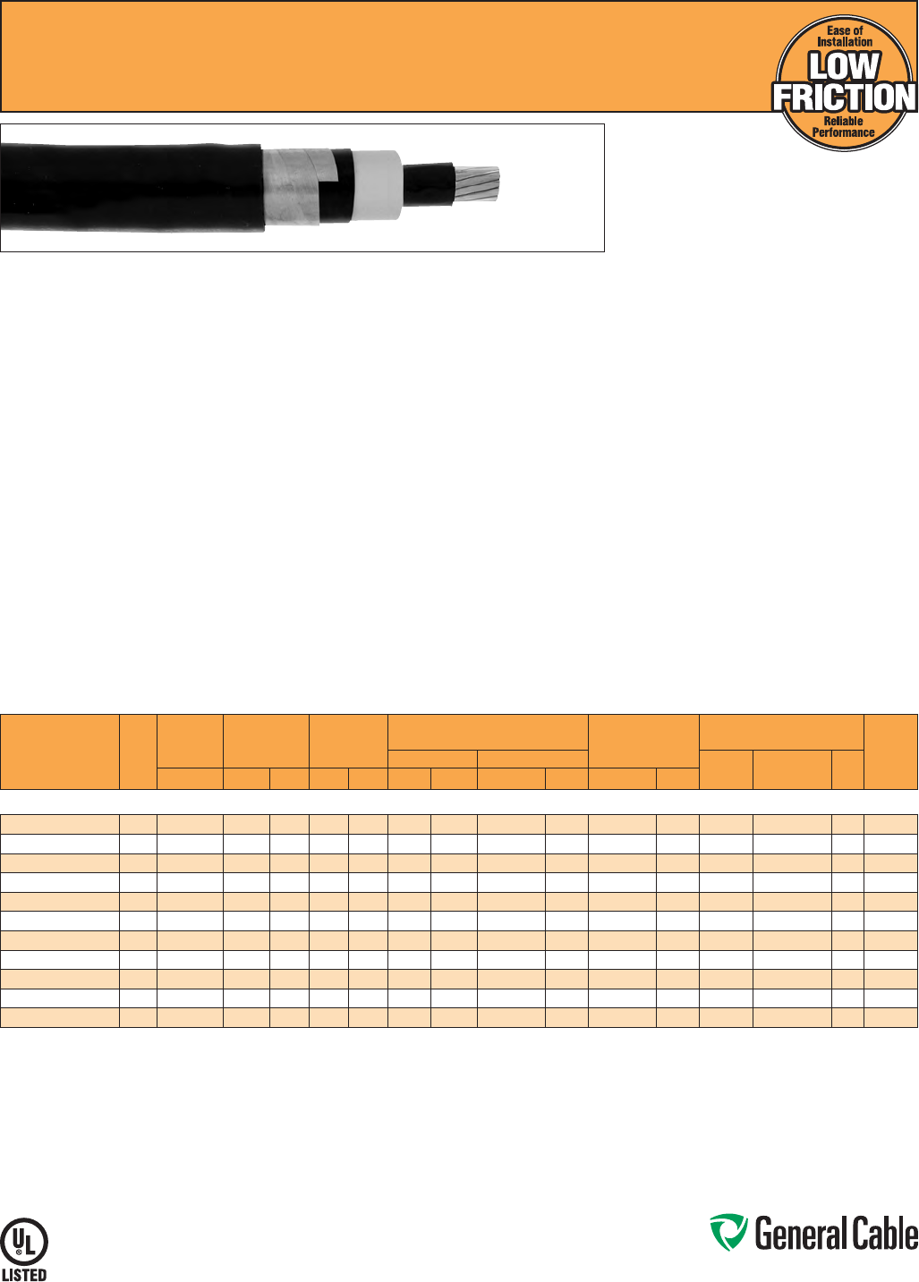
Phone: 888-593-3355
www.generalcable.com
SPEC 6355
April, 2011
Uniblend
®
LF
EPR/Copper Tape Shield/PVC, Medium-Voltage Power, Shielded
15 kV, UL Type MV-105, 133% Ins. Level, 220 Mils
Product Construction:
Conductor:
• 2 AWG thru 1000 kcmil annealed bare copper
compact Class B strand
Extruded Strand Shield (ESS):
• Extruded thermoset semi-conducting stress-
control layer over conductor
Insulation:
• Ethylene Propylene Rubber (EPR) insulation,
colored to contrast with the black conducting
shield layers
Extruded Insulation Shield (EIS):
• Thermoset semi-conducting polymeric layer free
stripping from insulation
Metallic Shield:
• 5 mil annealed copper tape with an
overlap of 25%
Jacket:
• Low-friction, lead-free, flame-retardant, moisture-
and sunlight-resistant Polyvinyl Chloride (PVC)
Print:
• GENERAL CABLE
®
(PLANT OF MFG) (MO/YR
OF MANUFACTURE) LIGHTNING BOLT SYMBOL
1/C SIZE (AWG OR KCMIL) COMPACT CU
UNIBLEND
®
LF PVC JKT (INSULATION
Print (cont’d.):
THICKNESS) EPR TYPE MV-105 (VOLTAGE) KV%
INSULATION LEVEL SUN RES FOR CT USE (UL)
SEQUENTIAL FOOTAGE MARK
* Sizes smaller than 1/0 AWG do not include
“FOR CT USE”.
Options:
• STRANDFILL
®
– blocked conductor. Tested in
accordance with ICEA T-31-610
• 100% insulation level
Applications:
• Superior performance in petrochemical plants,
pulp and paper mills, sewage and water
treatment plants, environmental protection
systems, railroads, mines, utility power
generating stations, steel mills, textile plants and
other industrial three-phase applications
• For use in wet or dry locations when installed in
accordance with NEC
• For use in aerial, conduit, open tray and
underground duct installations
• For use in direct burial if installed in a system with
a ground conductor that is in close proximity, and
conforms with NEC 250.4(A)(5)
Features:
• Rated at 105
˚
C
• Lower coefficient of friction for ease of
installation
• Excellent heat and moisture resistance
Features (cont’d.):
• Excellent flame resistance
• Outstanding corona resistance
• Flexibility for easy handling
• High dielectric strength
• Low moisture absorption
• Electrical stability under stress
• Low dielectric loss
• Chemical-resistant
• Meets cold bend test at -35
˚
C
Compliances:
• National Electrical Code (NEC)
• UL 1072
• ICEA S-93-639/NEMA WC74
• ICEA S-97-682
• AEIC CS8
• UL listed as Type MV-105 for use in accordance
with NEC, UL File # E90501
• UL 1685 (Sizes 1/0 AWG and larger) UL Flame
Exposure Test
• Sizes 1/0 AWG and larger are listed and marked
“Sunlight-Resistant FOR CT USE” in accordance
with NEC
• IEEE 1202 (70,000 BTU/hr)/CSA FT4
• EPA 40 CFR, Part 261 for leachable lead content
per TCLP method
• OSHA Acceptable
Optional Flame Tests:
• ICEA T-29-520 (210,000 BTU/hr)
Packaging:
• Material cut to length and shipped on
non-returnable wood reels. Lengths in excess of
10,000 lbs. are provided on returnable steel reels
that require a deposit
• Extra charges apply for cuts less than 1000 ft.,
lagging, pulling eyes, paralleling and triplexing
CATALOG
NUMBER
COND.
SIZE
(AWG/
kcmil)
NOMINAL
CONDUCTOR
DIAMETER
INSULATION
DIAMETER
INCHES
NOMINAL
JACKET
THICKNESS
NOMINAL CABLE
COPPER WEIGHT
AMPACITY CONDUIT
SIZING (4)
(INCHES)
DIAMETER WEIGHT CONDUIT
IN AIR (1)
UNDERGROUND
DUCT (2)
TRAY
(3)INCHES MIN. MAX. INCHES mm INCHES mm LBS/1000 FT kg/km LBS/1000 FT kg/km
15 kV¥, UL TYPE MV-105, 133% INS. LEVEL, 220 MILS
17031.130205 20.27 0.710 0.800 0.080 2.03 0.99 25.14 658 979 276 411 165 165 - 3
17031.130105* 1 0.31 0.745 0.830 0.080 2.03 1.02 25.91 733 1090 332 494 190 185 - 3.5
17031.135105 1/0 0.34 0.780 0.865 0.080 2.03 1.06 26.92 825 1228 403 600 215 215 220 3.5
17031.135205 2/0 0.38 0.820 0.905 0.080 2.03 1.10 27.94 938 1396 492 732 255 245 250 3.5
17031.135305* 3/0 0.43 0.865 0.955 0.080 2.03 1.14 28.95 1078 1604 603 897 290 275 290 3.5
17031.135405 4/0 0.48 0.920 1.005 0.080 2.03 1.21 30.73 1261 1876 743 1105 330 315 335 3.5
17031.136005 250 0.53 0.970 1.060 0.080 2.03 1.25 31.75 1407 2093 866 1289 365 345 370 4
17031.136205 350 0.62 1.070 1.155 0.080 2.03 1.35 34.29 1783 2653 1184 1761 440 415 460 5
17031.136505 500 0.74 1.190 1.275 0.080 2.03 1.47 37.34 2331 3468 1657 2466 535 500 575 5
17031.137005 750 0.91 1.370 1.460 0.080 2.03 1.65 41.91 3234 4812 2445 3638 655 610 745 6
17031.137505 1000 1.06 1.520 1.610 0.110 2.79 1.86 47.24 4219 6278 3228 4803 755 690 890 6
Dimensions and weights are nominal; subject to industry tolerances.
* Non-stock item; minimum runs apply. Please consult Customer Service for price and delivery.
(1) Ampacities are in accordance with Table 310.60(C)(73) of the NEC for triplexed or three single conductor copper cable in isolated conduit in air, based on a conductor temperature of 105˚C (221˚F) and an
ambient air temperature of 40˚C (104˚F).
(2) Ampacities are in accordance with Table 310.60(C)(77) of the NEC for triplexed or three single conductor copper cable in underground ducts (three conductors per duct), based on a conductor temperature
of 105˚C (221˚F) and an ambient earth temperature of 20˚C (68˚F), electrical duct arrangement per Figure 310.60 Detail 1, 100% load factor, and earth thermal resistance (rho) of 90.
(3) Ampacities are based on single conductor Type MV-105 sizes #1/0 AWG and larger in an uncovered tray in accordance with Section 392.80(B)(2) of the NEC at an ambient air temperature of 40˚C (104˚F);
the ampacities are based on 75% of the values per Table 310.60(C)(69). For cable trays with unventilated covers for more than 6 feet, the ampacities shall not exceed 70% of the values shown above.
(4) Based on nominal cable diameters, three single cables in the duct (PVC Schedule 40) with no ground wire and a maximum of 40% fill. Jam ratio has been considered, but it should be checked for individual
installations.
¥100% insulation level is available upon request
Note: a) Sizes smaller than 1/0 AWG do not include “FOR CT USE”.
b) The NESC Lightning bolt symbol is on all Uniblend® constructions.

Phone: 888-593-3355
www.generalcable.com
SPEC 6360
April, 2011
Aluminum Uniblend
®
LF
EPR/Copper Tape Shield/PVC, Medium-Voltage Power, Shielded
15 kV, UL Type MV-105, 133% Ins. Level, 220 Mils
Product Construction:
Conductor:
• 2 AWG thru 1000 kcmil 1350 aluminum compact
Class B STRANDFILL® blocked conductor
Extruded Strand Shield (ESS):
• Extruded thermoset semi-conducting stress-
control layer over conductor
Insulation:
• Ethylene Propylene Rubber (EPR) insulation,
colored to contrast with the black conducting
shield layers
Extruded Insulation Shield (EIS):
• Thermoset semi-conducting polymeric layer free
stripping from insulation
Metallic Shield:
• 5 mil annealed copper tape with an
overlap of 25%
Jacket:
• Low-friction, lead-free, flame-retardant, moisture-
and sunlight-resistant Polyvinyl Chloride (PVC)
Print:
• GENERAL CABLE
®
(PLANT OF MFG) (MO/
YR OF MANUFACTURE) LIGHTNING BOLT
SYMBOL 1/C SIZE (AWG OR KCMIL) COMPACT
AL UNIBLEND
®
LF PVC JKT (INSULATION
THICKNESS) EPR TYPE MV-105 (VOLTAGE) KV%
INSULATION LEVEL SUN RES FOR CT USE (UL)
SEQUENTIAL FOOTAGE MARK
* Sizes smaller than 1/0 AWG do not include
“FOR CT USE”.
Options:
• 100% insulation level
Applications:
• Superior performance in petrochemical plants,
pulp and paper mills, sewage and water
treatment plants, environmental protection
systems, railroads, mines, utility power
generating stations, steel mills, textile plants and
other industrial three-phase applications
• For use in wet or dry locations when installed in
accordance with NEC
• For use in aerial, conduit, open tray and
underground duct installations
• For use in direct burial if installed in a system with
a ground conductor that is in close proximity, and
conforms with NEC 250.4(A)(5)
Features:
• Rated at 105
˚
C
• Lower coefficient of friction for ease of
installation
• Meets longitudinal water penetration resistance
• Excellent heat and moisture resistance
• Excellent flame resistance
• Outstanding corona resistance
• Flexibility for easy handling
• High dielectric strength
• Low moisture absorption
• Electrical stability under stress
• Low dielectric loss
• Chemical-resistant
• Meets cold bend test at -35
˚
C
Compliances:
• National Electrical Code (NEC)
• UL 1072
• ICEA S-93-639/NEMA WC74
• ICEA S-97-682
• AEIC CS8
• UL listed as Type MV-105 for use in accordance
with NEC, UL File # E90501
• UL 1685 (Sizes 1/0 AWG and larger) UL Flame
Exposure Test
• Sizes 1/0 AWG and larger are listed and marked
“Sunlight-Resistant FOR CT USE” in accordance
with NEC
• IEEE 1202 (70,000 BTU/hr)/CSA FT4
• EPA 40 CFR, Part 261 for leachable lead content
per TCLP method
• OSHA Acceptable
Optional Flame Tests:
• ICEA T-29-520 (210,000 BTU/hr)
Packaging:
• Material cut to length and shipped on
non-returnable wood reels. Lengths in excess of
10,000 lbs. are provided on returnable steel reels
that require a deposit
• Extra charges apply for cuts less than 1000 ft.,
lagging, pulling eyes, paralleling and triplexing
CATALOG
NUMBER
COND.
SIZE
(AWG/
kcmil)
NOMINAL
CONDUCTOR
DIAMETER
INSULATION
DIAMETER
INCHES
NOMINAL
JACKET
THICKNESS
NOMINAL CABLE
ALUMINUM WEIGHT COPPER WEIGHT
AMPACITY CONDUIT
SIZING
(4)
(INCHES)
DIAMETER WEIGHT
CONDUIT
IN AIR (1)
UNDERGROUND
DUCT (2)
TRAY
(3)INCHES MIN. MAX. INCHES mm INCHES mm LBS/1000 FT kg/km LBS/1000 FT kg/km LBS/1000 FT kg/km
15 kV¥, UL TYPE MV-105, 133% INS. LEVEL, 220 MILS
17031.130208*
20.27 0.710 0.800 0.080 2.03 0.99 25.14 515 767 62 92 71 106 130 130 — 3
17031.130108*
1 0.31 0.745 0.830 0.080 2.03 1.02 25.91 553 822 78 116 74 110 150 145 —3.5
17031.135108*
1/0 0.34 0.780 0.865 0.080 2.03 1.06 26.92 598 890 99 147 77 115 170 165 170 3.5
17031.135208*
2/0 0.38 0.820 0.905 0.080 2.03 1.10 27.94 652 970 125 186 81 121 200 190 195 3.5
17031.135308*
3/0 0.43 0.865 0.955 0.080 2.03 1.14 28.95 718 1068 158 235 85 126 225 215 225 3.5
17031.135408*
4/0 0.48 0.920 1.005 0.080 2.03 1.21 30.73 807 1201 199 296 90 134 260 245 265 3.5
17031.136008*
250 0.53 0.970 1.060 0.080 2.03 1.25 31.75 869 1293 234 348 94 140 290 270 290 4
17031.136208
350 0.62 1.070 1.155 0.080 2.03 1.35 34.29 1031 1534 329 490 103 153 350 330 360 5
17031.136508
500 0.74 1.190 1.275 0.080 2.03 1.47 37.34 1255 1868 468 696 113 168 430 400 450 5
17031.137008
750 0.91 1.370 1.460 0.080 2.03 1.65 41.91 1621 2412 703 1046 129 192 540 490 585 6
17031.137508
1000 1.06 1.520 1.610 0.110 2.79 1.86 47.24 2068 3078 937 1394 140 208 640 565 705 6
Dimensions and weights are nominal; subject to industry tolerances.
* Non-stock item; minimum runs apply. Please consult Customer Service for price and delivery.
(1) Ampacities are in accordance with Table 310.60(C)(74) of the NEC for triplexed or three single conductor aluminum cables in isolated conduit in air based on a conductor temperature of 105°C (221°F) and
an ambient air temperature of 40°C (104°F).
(2) Ampacities are in accordance with Table 310.60(C)(78) of the NEC for triplexed or three single conductor aluminum cables in underground ducts (three conductors per duct), based on a conductor
temperature of 105°C (221°F) and an ambient earth temperature of 20°C (68°F), electrical duct arrangement per Figure 310.60 Detail 1, 100% load factor, and earth thermal resistance (rho) of 90.
(3) Ampacities are based on single conductor Type MV-105 sizes #1/0 AWG and larger in an uncovered tray in accordance with Section 392.80(B)(2) of the NEC at an ambient air temperature of 40°C (104°F);
the ampacities are based on 75% of the values per Table 310.60(C)(70). For cable trays with unventilated covers for more than 6 feet, the ampacities shall not exceed 70% of the values shown above.
(4) Based on nominal cable diameters, three single cables in the duct (PVC Schedule 40) with no ground wire and a maximum of 40% fill. Jam ratio has been considered, but it should be checked for individual
installations.
¥100% insulation level is available upon request.
Note: a) Sizes smaller than 1/0 AWG do not include “FOR CT USE”.
b) The NESC Lightning bolt symbol is on all Uniblend® constructions.
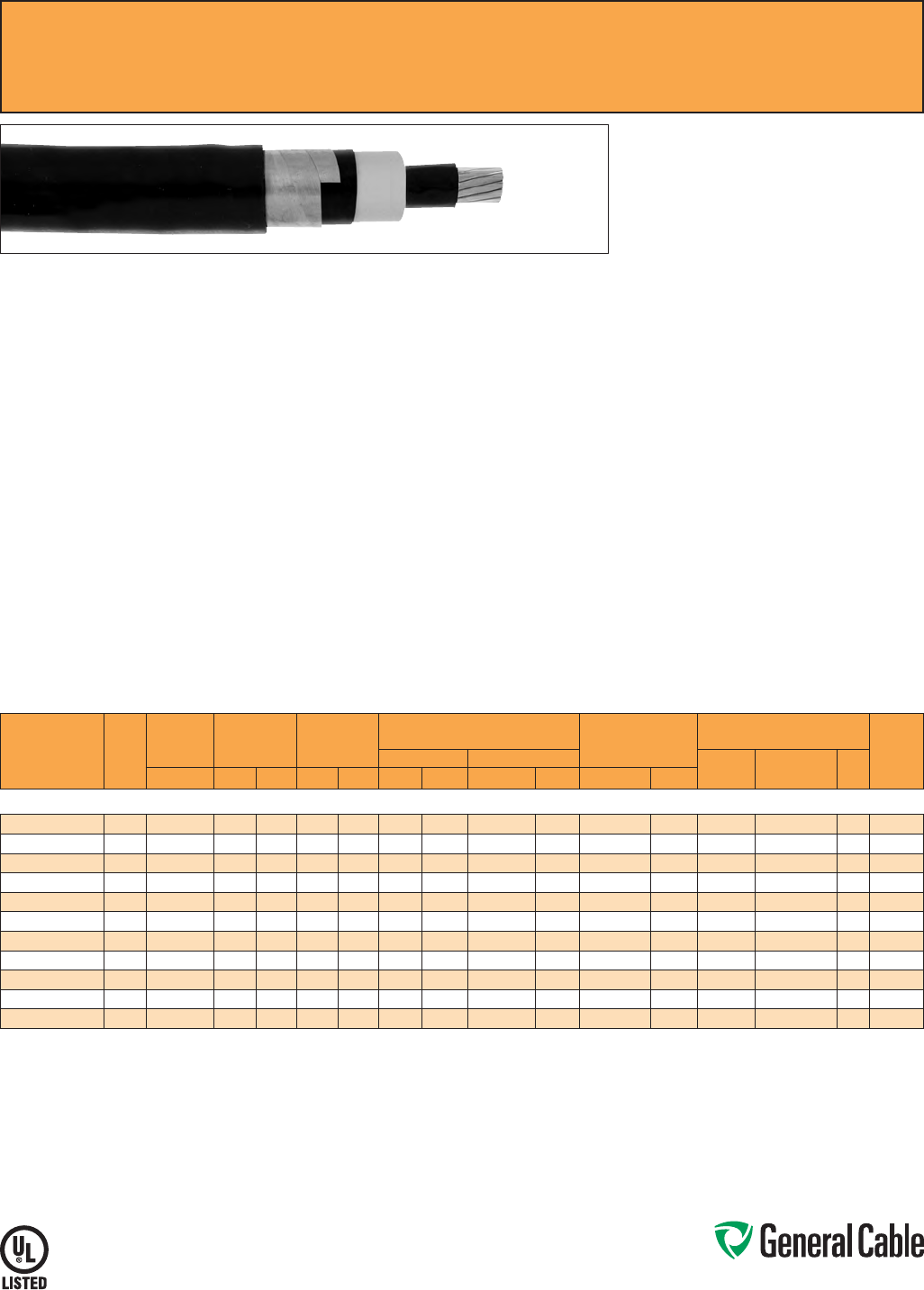
Phone: 888-593-3355
www.generalcable.com
SPEC 6375
April, 2011
CATALOG
NUMBER
COND.
SIZE
(AWG/
kcmil)
NOMINAL
CONDUCTOR
DIAMETER
INSULATION
DIAMETER
INCHES
NOMINAL
JACKET
THICKNESS
NOMINAL CABLE
COPPER WEIGHT
AMPACITY CONDUIT
SIZING (4)
(INCHES)
DIAMETER WEIGHT CONDUIT
IN AIR (1)
UNDERGROUND
DUCT (2)
TRAY
(3)INCHES MIN. MAX. INCHES mm INCHES mm LBS/1000 FT kg/km LBS/1000 FT kg/km
15 kV¥, UL TYPE MV-105, 133% INS. LEVEL, 220 MILS
17131.130200* 20.27 0.710 0.800 0.080 2.03 0.99 25.14 655 975 276 411 165 165 - 3
17131.130100* 1 0.31 0.745 0.830 0.080 2.03 1.02 25.91 730 1086 332 494 190 185 - 3.5
17131.135100* 1/0 0.34 0.780 0.865 0.080 2.03 1.06 26.92 820 1220 403 600 215 215 220 3.5
17131.135200* 2/0 0.38 0.820 0.905 0.080 2.03 1.10 27.94 933 1388 492 732 255 245 250 3.5
17131.135300* 3/0 0.43 0.865 0.955 0.080 2.03 1.14 28.95 1072 1595 603 897 290 275 290 3.5
17131.135400* 4/0 0.48 0.920 1.005 0.080 2.03 1.21 30.73 1248 1857 743 1105 330 315 335 3.5
17131.136000* 250 0.53 0.970 1.060 0.080 2.03 1.25 31.75 1402 2086 866 1289 365 345 370 4
17131.136200* 350 0.62 1.070 1.155 0.080 2.03 1.35 34.29 1778 2646 1184 1761 440 415 460 5
17131.136500* 500 0.74 1.190 1.275 0.080 2.03 1.47 37.34 2325 3460 1657 2466 535 500 575 5
17131.137000* 750 0.91 1.370 1.460 0.080 2.03 1.65 41.91 3250 4836 2445 3638 655 610 745 6
17131.637500* 1000 1.06 1.520 1.610 0.110 2.79 1.86 47.24 4209 6263 3228 4803 755 690 890 6
Dimensions and weights are nominal; subject to industry tolerances.
* Non-stock item; minimum runs apply. Please consult Customer Service for price and delivery.
(1) Ampacities are in accordance with Table 310.60(C)(73) of the NEC for triplexed or three single conductor copper cable in isolated conduit in air, based on a conductor temperature of 105˚C (221˚F) and an
ambient air temperature of 40˚C (104˚F).
(2) Ampacities are in accordance with Table 310.60(C)(77) of the NEC for triplexed or three single conductor copper cable in underground ducts (three conductors per duct), based on a conductor temperature
of 105˚C (221˚F) and an ambient earth temperature of 20˚C (68˚F), electrical duct arrangement per Figure 310.60 Detail 1, 100% load factor, and earth thermal resistance (rho) of 90.
(3) Ampacities are based on single conductor Type MV-105 sizes #1/0 AWG and larger in an uncovered tray in accordance with Section 392.80(B)(2) of the NEC at an ambient air temperature of 40˚C (104˚F);
the ampacities are based on 75% of the values per Table 310.60(C)(69). For cable trays with unventilated covers for more than 6 feet, the ampacities shall not exceed 70% of the values shown above.
(4) Based on nominal cable diameters, three single cables in the duct (PVC Schedule 40) with no ground wire and a maximum of 40% fill. Jam ratio has been considered, but it should be checked for individual
installations.
¥100% insulation level is available upon request
Note: a) Sizes smaller than 1/0 AWG do not include “FOR CT USE”.
b) The NESC Lightning bolt symbol is on all Uniblend® constructions.
Uniblend
®
EPR/Copper Tape Shield/CPE, Medium-Voltage Power, Shielded
15 kV, UL Type MV-105, 133% Ins. Level, 220 Mils
Product Construction:
Conductor:
• 2 AWG thru 1000 kcmil annealed bare copper
compact Class B strand
Extruded Strand Shield (ESS):
• Extruded thermoset semi-conducting stress-
control layer over conductor
Insulation:
• Ethylene Propylene Rubber (EPR) insulation,
colored to contrast with the black conducting
shield layers
Extruded Insulation Shield (EIS):
• Thermoset semi-conducting polymeric layer free
stripping from insulation
Metallic Shield:
• 5 mil annealed copper tape with an
overlap of 25%
Jacket:
• Flame-retardant, moisture- and sunlight-resistant
Chlorinated Polyethylene (CPE)
Print:
• GENERAL CABLE
®
(PLANT OF MFG) (MO/YR
OF MANUFACTURE) LIGHTNING BOLT SYMBOL
1/C SIZE (AWG OR KCMIL) COMPACT CU
Print (cont’d.):
UNIBLEND
®
CPE JKT (INSULATION THICKNESS)
EPR TYPE MV-105 (VOLTAGE) KV% INSULATION
LEVEL SUN RES FOR CT USE (UL) SEQUENTIAL
FOOTAGE MARK
* Sizes smaller than 1/0 AWG do not include
“FOR CT USE”.
Options:
• Other jacket options available upon request
• STRANDFILL
®
– blocked conductor. Tested in
accordance with ICEA T-31-610
• 100% insulation level
Applications:
• Superior performance in petrochemical plants,
pulp and paper mills, sewage and water
treatment plants, environmental protection
systems, railroads, mines, utility power
generating stations, steel mills, textile plants and
other industrial three-phase applications
• For use in wet or dry locations when installed in
accordance with NEC
• For use in aerial, conduit, open tray and
underground duct installations
• For use in direct burial if installed in a system with
a ground conductor that is in close proximity, and
conforms with NEC 250.4(A)(5)
Features:
• Rated at 105
˚
C
• Excellent heat and moisture resistance
• Excellent flame resistance
• Outstanding corona resistance
• Flexibility for easy handling
• High dielectric strength
• Low moisture absorption
• Electrical stability under stress
• Low dielectric loss
• Chemical-resistant
• Meets cold bend test at -35
˚
C
Compliances:
• National Electrical Code (NEC)
• UL 1072
• ICEA S-93-639/NEMA WC74
• ICEA S-97-682
• AEIC CS8
• UL listed as Type MV-105 for use in accordance
with NEC, UL File # E90501
• UL 1685 (Sizes 1/0 AWG and larger) UL Flame
Exposure Test
• Sizes 1/0 AWG and larger are listed and marked
“Sunlight-Resistant FOR CT USE” in accordance
with NEC
• IEEE 1202 (70,000 BTU/hr)/CSA FT4
• EPA 40 CFR, Part 261 for leachable lead content
per TCLP method
• OSHA Acceptable
Optional Flame Tests:
• ICEA T-29-520 (210,000 BTU/hr)
Packaging:
• Material cut to length and shipped on
non-returnable wood reels. Lengths in excess of
10,000 lbs. are provided on returnable steel reels
that require a deposit
• Extra charges apply for cuts less than 1000 ft.,
lagging, pulling eyes, paralleling and triplexing
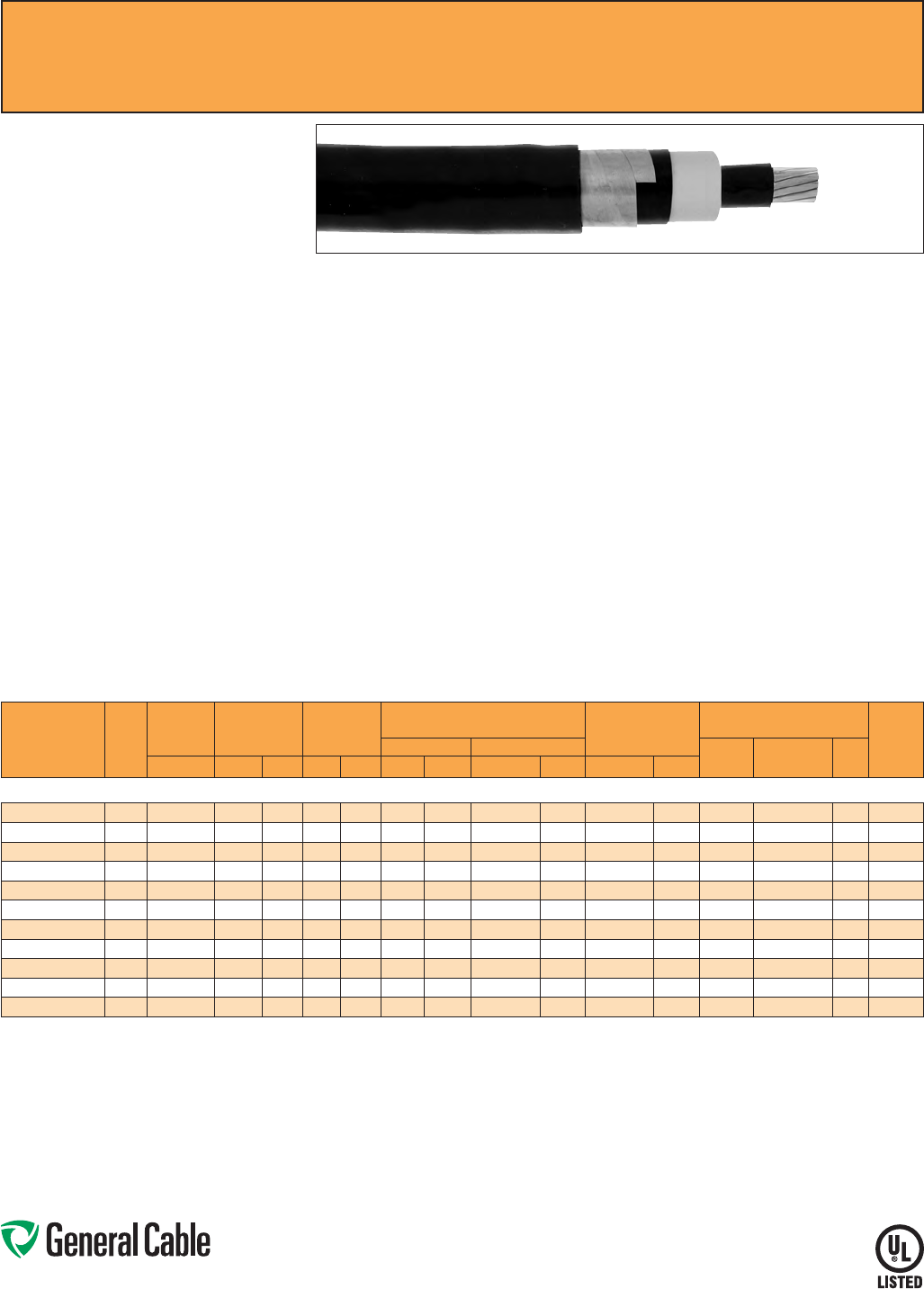
Phone: 888-593-3355
www.generalcable.com
GenFree
®
Uniblend
®
EPR/Copper Tape Shield/LSZH, Medium-Voltage Power, Shielded
15 kV, UL Type MV-105/ST1, 133% Ins. Level, 220 Mils
Product Construction:
Conductor:
• 2 AWG thru 1000 kcmil annealed bare copper
compact Class B strand
Extruded Strand Shield (ESS):
• Extruded thermoset semi-conducting stress-
control layer over conductor
Insulation:
• Ethylene Propylene Rubber (EPR) insulation,
colored to contrast with the black conducting
shield layers
Extruded Insulation Shield (EIS):
• Thermoset semi-conducting polymeric layer free
stripping from insulation
Metallic Shield:
• 5 mil annealed copper tape with an
overlap of 25%
Overall Jacket:
• Lead-free, moisture- and sunlight-resistant
Low-Smoke, Zero-Halogen Polyolefin (LSZH)
Print:
• GENERAL CABLE
®
(PLANT OF MFG) (MO/YR
OF MANUFACTURE) LIGHTNING BOLT SYMBOL
1/C SIZE (AWG OR KCMIL) COMPACT CU
GENFREE
®
UNIBLEND
®
LSZH JKT (INSULATION
THICKNESS) EPR TYPE MV-105/ST1 (VOLTAGE)
KV% INSULATION LEVEL SUN RES FOR CT USE
(UL) SEQUENTIAL FOOTAGE MARK
* Sizes smaller than 1/0 AWG do not include
“FOR CT USE”.
Options:
• STRANDFILL
®
– blocked conductor. Tested in
accordance with ICEA T-31-610
• 100% insulation level
Applications:
• Superior performance in petrochemical plants,
pulp and paper mills, sewage and water
treatment plants, environmental protection
systems, railroads, mines, utility power
generating stations, steel mills, textile plants and
other industrial three-phase applications
• For use in wet or dry locations when installed in
accordance with NEC
• For use in aerial, conduit, open tray and
underground duct installations
• For use in direct burial if installed in a system with
a ground conductor that is in close proximity, and
conforms with NEC 250.4(A)(5)
Features:
• Rated at 105
˚
C
• Excellent heat and moisture resistance
• Excellent flame resistance
• Outstanding corona resistance
• Flexibility for easy handling
• High dielectric strength
• Low moisture absorption
• Electrical stability under stress
• Low dielectric loss
• Chemical-resistant
• Meets cold bend test at -35
˚
C
Compliances:
• National Electrical Code (NEC)
• UL 1072
• ICEA S-93-639/NEMA WC74
• ICEA S-97-682
• ICEA T-33-655
• AEIC CS8
• UL listed as Type MV-105 for use in accordance
with NEC, UL File # E90501
• UL 1685 (Sizes 1/0 AWG and larger) UL Flame
Exposure Test
• UL 1685 Vertical Flame and Smoke Release Test
• Sizes 1/0 AWG and larger are listed and marked
“Sunlight-Resistant FOR CT USE” in accordance
with NEC
• IEEE 1202 (70,000 BTU/hr)/CSA FT4
• EPA 40 CFR, Part 261 for leachable lead content
per TCLP method
• OSHA Acceptable
Optional Flame Tests:
• ICEA T-29-520 (210,000 BTU/hr)
Packaging:
• Material cut to length and shipped on
non-returnable wood reels. Lengths in excess of
10,000 lbs. are provided on returnable steel reels
that require a deposit
• Extra charges apply for cuts less than 1000 ft.,
lagging, pulling eyes, paralleling and triplexing
SPEC 6380
March, 2012
CATALOG
NUMBER
COND.
SIZE
(AWG/
kcmil)
NOMINAL
CONDUCTOR
DIAMETER
INSULATION
DIAMETER
INCHES
NOMINAL
JACKET
THICKNESS
NOMINAL CABLE
COPPER WEIGHT
AMPACITY CONDUIT
SIZING (4)
(INCHES)
DIAMETER WEIGHT CONDUIT
IN AIR (1)
UNDERGROUND
DUCT (2)
TRAY
(3)INCHES MIN. MAX. INCHES mm INCHES mm LBS/1000 FT kg/km LBS/1000 FT kg/km
15 kV¥, UL TYPE MV-105/ST1, 133% INS. LEVEL, 220 MILS
17231.130200 20.27 0.710 0.800 0.080 2.03 0.99 25.14 658 979 276 411 165 165 - 3
17231.130100* 1 0.31 0.745 0.830 0.080 2.03 1.02 25.91 733 1090 332 494 190 185 - 3.5
17231.135100* 1/0 0.34 0.780 0.865 0.080 2.03 1.06 26.92 825 1228 403 600 215 215 220 3.5
17231.135200 2/0 0.38 0.820 0.905 0.080 2.03 1.10 27.94 938 1396 492 732 255 245 250 3.5
17231.135300* 3/0 0.43 0.865 0.955 0.080 2.03 1.14 28.95 1078 1604 603 897 290 275 290 3.5
17231.135400 4/0 0.48 0.920 1.005 0.080 2.03 1.21 30.73 1261 1876 743 1105 330 315 335 3.5
17231.136000* 250 0.53 0.970 1.060 0.080 2.03 1.25 31.75 1407 2093 866 1289 365 345 370 4
17231.136200 350 0.62 1.070 1.155 0.080 2.03 1.35 34.29 1783 2653 1184 1761 440 415 460 5
17231.136500 500 0.74 1.190 1.275 0.080 2.03 1.47 37.34 2331 3468 1657 2466 535 500 575 5
17231.137000 750 0.91 1.370 1.460 0.080 2.03 1.65 41.91 3234 4812 2445 3638 655 610 745 6
17231.137500* 1000 1.06 1.520 1.610 0.110 2.79 1.86 47.24 4219 6278 3228 4803 755 690 890 6
Dimensions and weights are nominal; subject to industry tolerances.
* Non-stock item; minimum runs apply. Please consult Customer Service for price and delivery.
(1) Ampacities are in accordance with Table 310.60(C)(73) of the NEC for triplexed or three single conductor copper cable in isolated conduit in air, based on a conductor temperature of 105˚C (221˚F) and an
ambient air temperature of 40˚C (104˚F).
(2) Ampacities are in accordance with Table 310.60(C)(77) of the NEC for triplexed or three single conductor copper cable in underground ducts (three conductors per duct), based on a conductor temperature
of 105˚C (221˚F) and an ambient earth temperature of 20˚C (68˚F), electrical duct arrangement per Figure 310.60 Detail 1, 100% load factor, and earth thermal resistance (rho) of 90.
(3) Ampacities are based on single conductor Type MV-105 sizes #1/0 AWG and larger in an uncovered tray in accordance with Section 392.80(B)(2) of the NEC at an ambient air temperature of 40˚C (104˚F);
the ampacities are based on 75% of the values per Table 310.60(C)(69). For cable trays with unventilated covers for more than 6 feet, the ampacities shall not exceed 70% of the values shown above.
(4) Based on nominal cable diameters, three single cables in the duct (PVC Schedule 40) with no ground wire and a maximum of 40% fill. Jam ratio has been considered, but it should be checked for individual
installations.
¥100% insulation level is available upon request
Note: a) Sizes smaller than 1/0 AWG do not include “FOR CT USE”.
b) The NESC Lightning bolt symbol is on all Uniblend® constructions.
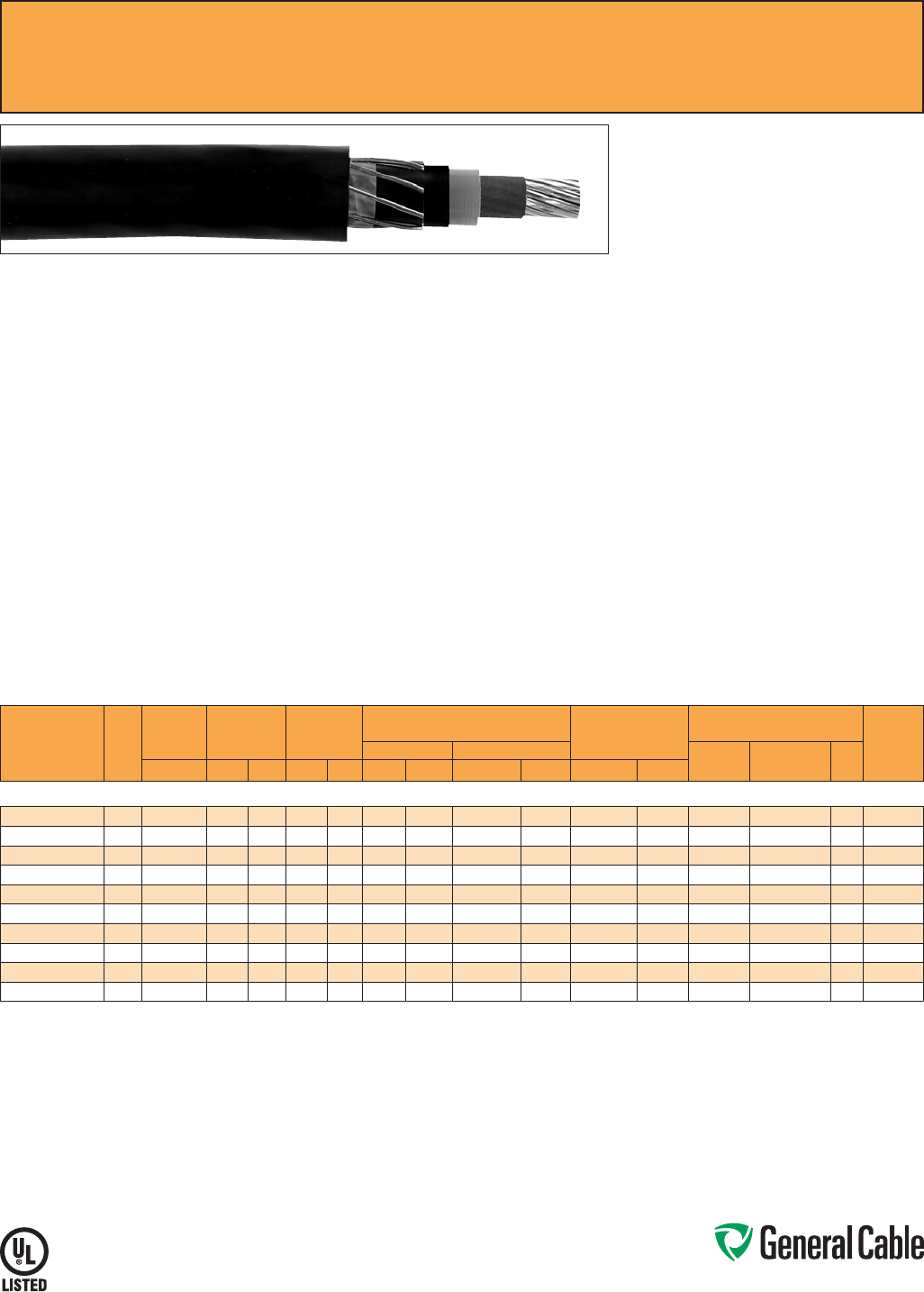
Phone: 888-593-3355
www.generalcable.com
SPEC 6400
January, 2011
Product Construction:
Conductor:
• 2 AWG thru 1000 kcmil annealed bare copper,
Class B compressed strand in accordance with
ASTM B3 and B8
Extruded Strand Shield (ESS):
• Extruded thermoset semi-conducting stress-
control layer over conductor
Insulation:
• Tree-Retardant Cross-linked Polyethylene
(TRXLPE)
Extruded Insulation Shield (EIS):
• Thermoset semi-conducting polymeric layer free
stripping from insulation
Metallic Shield:
• A concentric serve of 24 AWG annealed solid
bare copper wires over which shall be applied a
lapped non-metallic tape
Jacket:
• Lead-free, flame-retardant, moisture- and
sunlight-resistant Polyvinyl Chloride (PVC)
Print:
• GENERAL CABLE
®
(PLANT OF MFG) (MO/YR
OF MANUFACTURE) LIGHTNING BOLT SYMBOL
1/C SIZE (AWG OR KCMIL) CU (INSULATION
THICKNESS) TRXLPE TYPE MV-105 (VOLTAGE)
KV% INSULATION LEVEL SUN RES (UL)
SEQUENTIAL FOOTAGE MARK
Options:
• Sizes 1/0 AWG and larger are listed and marked
“Sunlight-Resistant FOR CT USE” in accordance
with NEC and in accordance with UL 1685
(70,000 BTU/hr)
• STRANDFILL
®
– blocked conductor. Tested in
accordance with ICEA T-31-610
Applications:
• For use in wet or dry locations when installed in
accordance with NEC
• For use in aerial, conduit, open tray and
underground duct installations where cost
effectiveness is a factor
• For use in direct burial if installed in a system with
a ground conductor that is in close proximity, and
conforms with NEC 250.4(A)(5)
Features:
• Rated at 105
˚
C
• Triple tandem extrusion of the strand shield,
insulation and insulation shield provides a
virtually perfect cable core
• Excellent resistance to electro-chemical treeing,
heat, moisture and a wide variety of industrial
chemicals
• PVC jacket provides mechanical protection of
the shielding system during installation as well as
protection from many industrial chemicals
• Sunlight-resistant
• Meets cold bend test at -35
˚
C
Compliances:
• National Electrical Code (NEC)
• ICEA S-93-639/NEMA WC74
• ICEA S-97-682
• AEIC CS8
• UL 1072
• UL listed as Type MV-105 for use in accordance
with NEC, UL File # E90501
• EPA 40 CFR, Part 261 for leachable lead content
per TCLP method
• OSHA Acceptable
Packaging:
• Material cut to length and shipped on non-
returnable wood reels. Lengths in excess of
10,000 lbs. are provided on returnable steel reels
that require a deposit
• Extra charges apply for cuts less than
1000 ft., lagging, pulling eyes, paralleling
and triplexing
Copper Wire Shield
TRXLPE/Copper Wire Shield/PVC, Medium-Voltage Power
15 kV, UL Type MV-105, 133% Ins. Level, 220 Mils
CATALOG
NUMBER
COND.
SIZE
(AWG/
kcmil)
NOMINAL
CONDUCTOR
DIAMETER
INSULATION
DIAMETER
INCHES
NOMINAL
JACKET
THICKNESS
NOMINAL CABLE
COPPER WEIGHT
AMPACITY CONDUIT
SIZING (4)
(INCHES)
DIAMETER WEIGHT CONDUIT IN
AIR (1)
UNDERGROUND
DUCT (2)
TRAY
(3)INCHES MIN. MAX. INCHES mm INCHES mm LBS/1000 FT kg/km LBS/1000 FT kg/km
15 kV¥, UL TYPE MV-105, 133% INS. LEVEL, 220 MILS
17245.010200* 20.29 0.725 0.815 0.080 2.03 1.05 26.67 600 893 221 329 165 165 - 3.5
17245.010100* 1 0.33 0.765 0.855 0.080 2.03 1.09 27.68 671 998 274 408 190 185 - 3.5
17245.015100* 1/0 0.37 0.805 0.895 0.080 2.03 1.13 28.27 761 1132 342 509 215 215 220 3.5
17245.015200* 2/0 0.41 0.850 0.935 0.080 2.03 1.18 29.97 871 1296 427 635 255 245 250 4
17245.015400* 4/0 0.52 0.955 1.045 0.080 2.03 1.29 32.76 1179 1754 672 1000 330 315 335 4
17245.016000* 250 0.56 1.010 1.100 0.080 2.03 1.34 34.03 1327 1974 791 1177 365 345 370 5
17245.016200* 350 0.67 1.115 1.200 0.080 2.03 1.45 36.83 1700 2529 1105 1644 440 415 460 5
17245.016500* 500 0.80 1.240 1.330 0.080 2.03 1.57 39.87 2236 3327 1568 2333 535 500 575 5
17245.017000* 750 0.97 1.430 1.520 0.110 2.79 1.82 46.23 3225 4798 2344 3488 655 610 745 6
17245.017500* 1000 1.12 1.575 1.670 0.110 2.79 1.97 50.04 4090 6086 3114 4634 755 690 890 6
Dimensions and weights are nominal; subject to industry tolerances.
* Non-stock item; minimum runs apply. Please consult Customer Service for price and delivery.
(1) Ampacities are in accordance with Table 310.60(C)(73) of the NEC for triplexed or three single conductor copper cable in isolated conduit in air, based on a conductor temperature of 105˚C (221˚F) and an
ambient air temperature of 40˚C (104˚F).
(2) Ampacities are in accordance with Table 310.60(C)(77) of the NEC for triplexed or three single conductor copper cable in underground ducts (three conductors per duct), based on a conductor temperature
of 105˚C (221˚F) and an ambient earth temperature of 20˚C (68˚F), electrical duct arrangement per Figure 310.60 Detail 1, 100% load factor, and earth thermal resistance (rho) of 90.
(3) Ampacities are based on single conductor Type MV-105 sizes #1/0 AWG and larger in an uncovered tray in accordance with Section 392.80(B)(2) of the NEC at an ambient air temperature of 40˚C (104˚F);
the ampacities are based on 75% of the values per Table 310.60(C)(69). For cable trays with unventilated covers for more than 6 feet, the ampacities shall not exceed 70% of the values shown above.
(4) Based on nominal cable diameters, three single cables in the duct (PVC Schedule 40) with no ground wire and a maximum of 40% fill. Jam ratio has been considered, but it should be checked for individual
installations.
¥100% insulation level is available upon request
Note: The NESC Lightning bolt symbol is on all Uniblend® constructions.
Phone: 888-593-3355
www.generalcable.com
SPEC 6450
March, 2012
Uniblend
®
EPR/Copper Tape Shield with Overall PVC Jacket, Medium-Voltage Power, Shielded
15 kV, UL Type MV-105, 133% Ins. Level, 220 Mils, Three Conductor
Product Construction:
Conductor:
• 2 AWG thru 1000 kcmil annealed bare copper
compact Class B strand
Extruded Strand Shield (ESS):
• Extruded thermoset semi-conducting stress-
control layer over conductor
Insulation:
• Ethylene Propylene Rubber (EPR) insulation,
colored to contrast with the black conducting
shield layers
Extruded Insulation Shield (EIS):
• Thermoset semi-conducting polymeric layer free
stripping from insulation
Metallic Shield:
• 5 mil annealed copper tape with an
overlap of 25%
Grounding Conductor:
• 1 bare grounding conductor may be in contact
with metallic shielding tape
Overall Jacket:
• Lead-free, flame-retardant, moisture- and
sunlight-resistant Polyvinyl Chloride (PVC)
Print:
• GENERAL CABLE
®
(PLANT OF MFG) (MO/YR
OF MANUFACTURE) LIGHTNING BOLT SYMBOL
3/C SIZE (AWG OR KCMIL) COMPACT CU
UNIBLEND
®
PVC JKT (INSULATION THICKNESS)
EPR TYPE MV-105 (VOLTAGE) KV% INSULATION
LEVEL DIR BUR SUN RES FOR CT USE (UL)
SEQUENTIAL FOOTAGE MARK
Options:
• Other jacket options available upon request
• Jacketed singles
• UniShield
®
singles
• STRANDFILL
®
– blocked conductor. Tested in
accordance with ICEA T-31-610
• 3 bare copper ground wires
• Covered ground wires
Applications:
• Suited for use in a broad range of commercial,
industrial and utility applications, where reliability
is the major concern, space is limited and ease of
installation is critical
• In wet or dry locations when installed in
accordance with NEC
• In aerial, direct burial, conduit, open tray and
underground duct installations
Features:
• Rated at 105˚C
• Excellent heat and moisture resistance
• Outstanding corona resistance
• Flexibility for easy handling
• High dielectric strength
• Low moisture absorption
• Electrical stability under stress
• Low dielectric loss
• Chemical-resistant
• Meets cold bend test at -35
˚
C
Compliances:
• National Electrical Code (NEC)
• UL 1072
• ICEA S-93-639/NEMA WC74
• ICEA S-97-682
• AEIC CS8
• UL listed as Type MV-105 for use in accordance
with NEC, UL File # E90501
• UL 1685 (70,000 BTU/hr)
• EPA 40 CFR, Part 261 for leachable lead content
per TCLP method
• OSHA Acceptable
Optional Flame Tests:
• IEEE 1202 (70,000 BTU/hr)/CSA FT4
• ICEA T-29-520 (210,000 BTU/hr)
Packaging:
• Material cut to length and shipped on
non-returnable wood reels. Lengths in excess of
10,000 lbs. are provided on returnable steel reels
that require a deposit
• Extra charges apply for cuts less than
1000 ft., lagging, pulling eyes, paralleling
and plexing
CATALOG
NUMBER
COND.
SIZE
(AWG/
kcmil)
NOMINAL
CONDUCTOR
DIAMETER
INSULATION
DIAMETER
INCHES GROUND
WIRE
(AWG)
NOMINAL
OVERALL JKT.
THICKNESS
NOMINAL CABLE
COPPER WEIGHT
AMPACITY
DIAMETER WEIGHT CONDUIT
IN AIR (1)
UNDERGROUND
DUCT (2) TRAY (3)INCHES MIN. MAX. INCHES mm INCHES mm LBS/1000 FT kg/km LBS/1000 FT kg/km
15 kV¥, UL TYPE MV-105, 133% INS. LEVEL, 220 MILS, THREE CONDUCTOR
15493.440200* 20.27 0.710 0.800 6 0.110 2.79 2.04 51.82 2226 3313 913 1358 165 160 185
15493.445100* 1/0 0.34 0.780 0.865 4 0.110 2.79 2.20 55.88 2811 4183 1343 1998 215 210 240
15493.445200* 2/0 0.38 0.820 0.905 4 0.110 2.79 2.30 58.42 3163 4707 1609 2394 245 235 275
15493.445400* 4/0 0.48 0.920 1.005 3 0.110 2.79 2.52 64.01 4203 6255 2398 3567 320 305 360
15493.446000* 250 0.53 0.970 1.060 2 0.110 2.79 2.66 67.56 4775 7106 2812 4184 350 335 400
15493.446200* 350 0.62 1.070 1.155 2 0.110 2.79 2.94 74.68 6182 9200 3766 5604 430 400 490
15493.446500* 500 0.74 1.190 1.275 1 0.140 3.56 3.21 81.53 7686 11438 5244 7803 525 485 600
15493.447000* 750 0.91 1.370 1.460 1/0 0.140 3.56 3.61 91.69 10978 16337 7682 11431 635 585 745
15493.447500* 1000 1.06 1.520 1.610 2/0 0.140 3.56 3.99 101.35 13983 20810 10124 15064 725 660 860
Dimensions and weights are nominal; subject to industry tolerances.
* Non-stock item; minimum runs apply. Please consult Customer Service for price and delivery.
(1) Ampacities are in accordance with Table 310.60(C)(75) of the NEC for three conductor copper cable in isolated conduit in air, based on a conductor temperature of 105˚C (221˚F) and an ambient air
temperature of 40˚C (104˚F).
(2) Ampacities are in accordance with Table 310.60(C)(79) of the NEC for three conductor copper cable in underground ducts (three conductors per duct), based on a conductor temperature of 105˚C (221˚F)
and an ambient earth temperature of 20˚C (68˚F), electrical duct arrangement per Figure 310.60 Detail 1, 100% load factor, and earth thermal resistance (rho) of 90.
(3) The ampacities are based on three conductor Type MV-105 in an uncovered tray in accordance with Section 392.80(B)(1) of the NEC at an ambient air temperature of 40˚C (104˚F); the ampacities are per
Table 310.60(C)(71). For cable tray with unventilated covers for more than 6 feet, the ampacities shall not exceed 95% of the values in NEC Table 310.60(C)(75).
¥100% insulation level is available upon request
Note: a) All sizes are “FOR CT USE”.
b) The NESC Lightning bolt symbol is on all Uniblend® constructions.
Phone: 888-593-3355
www.generalcable.com
SPEC 6455
March, 2012
Uniblend
®
LF
EPR/Copper Tape Shield with Overall PVC Jacket
Medium-Voltage Power, Shielded, 15 kV, UL Type MV-105, 133% Ins.
Level, 220 Mils, Three Conductor
Product Construction:
Conductor:
• 2 AWG thru 1000 kcmil annealed bare copper
compact Class B strand
Extruded Strand Shield (ESS):
• Extruded thermoset semi-conducting stress-
control layer over conductor
Insulation:
• Ethylene Propylene Rubber (EPR) insulation,
colored to contrast with the black conducting
shield layers
Extruded Insulation Shield (EIS):
• Thermoset semi-conducting polymeric layer free
stripping from insulation
Metallic Shield:
• 5 mil annealed copper tape with an
overlap of 25%
Grounding Conductor:
• 1 bare grounding conductor may be in contact
with metallic shielding tape
Overall Jacket:
• Low-friction, lead-free, flame-retardant, moisture-
and sunlight-resistant Polyvinyl Chloride (PVC)
Print:
• GENERAL CABLE
®
(PLANT OF MFG) (MO/
YR OF MANUFACTURE) LIGHTNING BOLT
SYMBOL 3/C SIZE (AWG OR KCMIL) COMPACT
CU UNIBLEND
®
LF PVC JKT (INSULATION
THICKNESS) EPR TYPE MV-105 (VOLTAGE) KV%
INSULATION LEVEL DIR BUR SUN RES FOR CT
USE (UL) SEQUENTIAL FOOTAGE MARK
Options:
• STRANDFILL
®
– blocked conductor. Tested in
accordance with ICEA T-31-610
• 3 bare copper ground wires
• Covered ground wires
Applications:
• Suited for use in a broad range of commercial,
industrial and utility applications, where reliability
is the major concern, space is limited and ease of
installation is critical
• In wet or dry locations when installed in
accordance with NEC
• In aerial, direct burial, conduit, open tray and
underground duct installations
Features:
• Rated at 105
˚
C
• Lower coefficient of friction
for ease of installation
• Excellent heat and moisture resistance
• Outstanding corona resistance
• Flexibility for easy handling
• High dielectric strength
• Low moisture absorption
• Electrical stability under stress
• Low dielectric loss
• Chemical-resistant
• Meets cold bend test at -35
˚
C
Compliances:
• National Electrical Code (NEC)
• UL 1072
• ICEA S-93-639/NEMA WC74
• ICEA S-97-682
• AEIC CS8
• UL listed as Type MV-105 for use in accordance
with NEC, UL File # E90501
• UL 1685 (70,000 BTU/hr)
• EPA 40 CFR, Part 261 for leachable lead content
per TCLP method
• OSHA Acceptable
Optional Flame Tests:
• IEEE 1202 (70,000 BTU/hr)/CSA FT4
• ICEA T-29-520 (210,000 BTU/hr)
Packaging:
• Material cut to length and shipped on
non-returnable wood reels. Lengths in excess of
10,000 lbs. are provided on returnable steel reels
that require a deposit
• Extra charges apply for cuts less than
1000 ft., lagging, pulling eyes, paralleling
and plexing
CATALOG
NUMBER
COND.
SIZE
(AWG/
kcmil)
NOMINAL
CONDUCTOR
DIAMETER
INSULATION
DIAMETER
INCHES GROUND
WIRE
(AWG)
NOMINAL
OVERALL JKT.
THICKNESS
NOMINAL CABLE
COPPER WEIGHT
AMPACITY
DIAMETER WEIGHT CONDUIT
IN AIR (1)
UNDERGROUND
DUCT (2) TRAY (3)INCHES MIN. MAX. INCHES mm INCHES mm LBS/1000 FT kg/km LBS/1000 FT kg/km
15 kV¥, UL TYPE MV-105, 133% INS. LEVEL, 220 MILS, THREE CONDUCTOR
15493.440205 20.27 0.710 0.800 6 0.110 2.79 2.04 51.82 2226 3313 913 1358 165 160 185
15493.445105 1/0 0.34 0.780 0.865 4 0.110 2.79 2.20 55.88 2811 4183 1343 1998 215 210 240
15493.445205 2/0 0.38 0.820 0.905 4 0.110 2.79 2.30 58.42 3163 4707 1609 2394 245 235 275
15493.445405 4/0 0.48 0.920 1.005 3 0.110 2.79 2.52 64.01 4203 6255 2398 3567 320 305 360
15493.446005* 250 0.53 0.970 1.060 2 0.110 2.79 2.66 67.56 4775 7106 2812 4184 350 335 400
15493.446205 350 0.62 1.070 1.155 2 0.110 2.79 2.94 74.68 6182 9200 3766 5604 430 400 490
15493.446505 500 0.74 1.190 1.275 1 0.140 3.56 3.21 81.53 7686 11438 5244 7803 525 485 600
15493.447005* 750 0.91 1.370 1.460 1/0 0.140 3.56 3.61 91.69 10978 16337 7682 11431 635 585 745
15493.447505* 1000 1.06 1.520 1.610 2/0 0.140 3.56 3.99 101.35 13983 20810 10124 15064 725 660 860
Dimensions and weights are nominal; subject to industry tolerances.
* Non-stock item; minimum runs apply. Please consult Customer Service for price and delivery.
(1) Ampacities are in accordance with Table 310.60(C)(75) of the NEC for three conductor copper cable in isolated conduit in air, based on a conductor temperature of 105˚C (221˚F) and an ambient air
temperature of 40˚C (104˚F).
(2) Ampacities are in accordance with Table 310.60(C)(79) of the NEC for three conductor copper cable in underground ducts (three conductors per duct), based on a conductor temperature of 105˚C (221˚F)
and an ambient earth temperature of 20˚C (68˚F), electrical duct arrangement per Figure 310.60 Detail 1, 100% load factor, and earth thermal resistance (rho) of 90.
(3) The ampacities are based on three conductor Type MV-105 cables in single layer in an uncovered tray with maintained spacing of not less than one cable diameter between cables, in accordance with
Section 392.80(B)(1) of the NEC at an ambient air temperature of 40˚C (104˚F); the ampacities are per Table 310.60(C)(71). For cable tray with unventilated covers for more than 6 feet, the ampacities shall not
exceed 95% of the values in NEC Table 310.60(C)(75).
¥100% insulation level is available upon request
Note: a) All sizes are “FOR CT USE”.
b) The NESC Lightning bolt symbol is on all Uniblend® constructions.
Phone: 888-593-3355
www.generalcable.com
SPEC 6475
March, 2012
Uniblend
®
EPR/Copper Tape Shield with Overall CPE Jacket, Medium-Voltage Power, Shielded
15 kV, UL Type MV-105, 133% Ins. Level, 220 Mils, Three Conductor
Product Construction:
Conductor:
• 2 AWG thru 1000 kcmil annealed bare copper
compact Class B strand
Extruded Strand Shield (ESS):
• Extruded thermoset semi-conducting stress-
control layer over conductor
Insulation:
• Ethylene Propylene Rubber (EPR) insulation,
colored to contrast with the black conducting
shield layers
Extruded Insulation Shield (EIS):
• Thermoset semi-conducting polymeric layer free
stripping from insulation
Metallic Shield:
• 5 mil annealed copper tape with an
overlap of 25%
Grounding Conductor:
• 1 bare grounding conductor may be in contact
with metallic shielding tape
Overall Jacket:
• Flame-retardant, moisture- and sunlight-resistant
Chlorinated Polyethylene (CPE)
Print:
• GENERAL CABLE
®
(PLANT OF MFG) (MO/YR
OF MANUFACTURE) LIGHTNING BOLT SYMBOL
3/C SIZE (AWG OR KCMIL) COMPACT CU
UNIBLEND
®
CPE JKT (INSULATION THICKNESS)
EPR TYPE MV-105 (VOLTAGE) KV% INSULATION
LEVEL DIR BUR SUN RES FOR CT USE (UL)
SEQUENTIAL FOOTAGE MARK
Options:
• Other jacket options available upon request
• Jacketed singles
• UniShield
®
singles
• STRANDFILL
®
– blocked conductor. Tested in
accordance with ICEA T-31-610
• 3 bare copper ground wires
• Covered ground wires
Applications:
• Suited for use in a broad range of commercial,
industrial and utility applications, where reliability
is the major concern, space is limited and ease of
installation is critical
• In wet or dry locations when installed in
accordance with NEC
• In aerial, direct burial, conduit, open tray and
underground duct installations
Features:
• Rated at 105
˚
C
• Excellent heat and moisture resistance
• Outstanding corona resistance
• Flexibility for easy handling
• High dielectric strength
• Low moisture absorption
• Electrical stability under stress
• Low dielectric loss
• Chemical-resistant
• Meets cold bend test at -35
˚
C
Compliances:
• National Electrical Code (NEC)
• UL 1072
• ICEA S-93-639/NEMA WC74
• ICEA S-97-682
• AEIC CS8
• UL listed as Type MV-105 for use in accordance
with NEC, UL File # E90501
• UL 1685 (70,000 BTU/hr)
• OSHA Acceptable
Optional Flame Tests:
• IEEE 1202 (70,000 BTU/hr)/CSA FT4
• ICEA T-29-520 (210,000 BTU/hr)
Packaging:
• Material cut to length and shipped on
non-returnable wood reels. Lengths in excess of
10,000 lbs. are provided on returnable steel reels
that require a deposit
• Extra charges apply for cuts less than
1000 ft., lagging, pulling eyes, paralleling
and plexing
CATALOG
NUMBER
COND.
SIZE
(AWG/
kcmil)
NOMINAL
CONDUCTOR
DIAMETER
INSULATION
DIAMETER
INCHES GROUND
WIRE
(AWG)
NOMINAL
OVERALL JKT.
THICKNESS
NOMINAL CABLE
COPPER WEIGHT
AMPACITY
DIAMETER WEIGHT CONDUIT
IN AIR (1)
UNDERGROUND
DUCT (2) TRAY (3)INCHES MIN. MAX. INCHES mm INCHES mm LBS/1000 FT kg/km LBS/1000 FT kg/km
15 kV¥, UL TYPE MV-105, 133% INS. LEVEL, 220 MILS, THREE CONDUCTOR
15593.440200* 20.27 0.710 0.800 6 0.110 2.79 2.04 51.82 2226 3313 913 1358 165 160 185
15593.445100* 1/0 0.34 0.780 0.865 4 0.110 2.79 2.20 55.88 2811 4183 1343 1998 215 210 240
15593.445200* 2/0 0.38 0.820 0.905 4 0.110 2.79 2.30 58.42 3163 4707 1609 2394 245 235 275
15593.445400* 4/0 0.48 0.920 1.005 3 0.110 2.79 2.52 64.01 4203 6255 2398 3567 320 305 360
15593.446000* 250 0.53 0.970 1.060 2 0.110 2.79 2.66 67.56 4775 7106 2812 4184 350 335 400
15593.446200* 350 0.62 1.070 1.155 2 0.110 2.79 2.94 74.68 6182 9200 3766 5604 430 400 490
15593.446500* 500 0.74 1.190 1.275 1 0.140 3.56 3.21 81.53 7686 11438 5244 7803 525 485 600
15593.447000* 750 0.91 1.370 1.460 1/0 0.140 3.56 3.61 91.69 10978 16337 7682 11431 635 585 745
15593.447500* 1000 1.06 1.520 1.610 2/0 0.140 3.56 3.99 101.35 13983 20810 10124 15064 725 660 860
Dimensions and weights are nominal; subject to industry tolerances.
* Non-stock item; minimum runs apply. Please consult Customer Service for price and delivery.
(1) Ampacities are in accordance with Table 310.60(C)(75) of the NEC for three conductor copper cable in isolated conduit in air, based on a conductor temperature of 105˚C (221˚F) and an ambient air
temperature of 40˚C (104˚F).
(2) Ampacities are in accordance with Table 310.60(C)(79) of the NEC for three conductor copper cable in underground ducts (three conductors per duct), based on a conductor temperature of 105˚C (221˚F)
and an ambient earth temperature of 20˚C (68˚F), electrical duct arrangement per Figure 310.60 Detail 1, 100% load factor, and earth thermal resistance (rho) of 90.
(3) The ampacities are based on three conductor Type MV-105 in an uncovered tray in accordance with Section 392.80(B)(1) of the NEC at an ambient air temperature of 40˚C (104˚F); the ampacities are per
Table 310.60(C)(71). For cable tray with unventilated covers for more than 6 feet, the ampacities shall not exceed 95% of the values in NEC Table 310.60(C)(75).
¥100% insulation level is available upon request
Note: a) Sizes smaller than 4/0 AWG do not include “FOR CT USE”.
b) The NESC Lightning bolt symbol is on all Uniblend® constructions.
Phone: 888-593-3355
www.generalcable.com
GenFree
®
Uniblend
®
EPR/Copper Tape Shield with Overall LSZH Jacket, Medium-Voltage Power, Shielded
15 kV, UL Type MV-105, 133% Ins. Level, 220 Mils, Three Conductor
Product Construction:
Conductor:
• 2 AWG thru 1000 kcmil annealed bare copper
compact Class B strand
Extruded Strand Shield (ESS):
• Extruded thermoset semi-conducting stress-
control layer over conductor
Insulation:
• Ethylene Propylene Rubber (EPR) insulation,
colored to contrast with the black conducting
shield layers
Extruded Insulation Shield (EIS):
• Thermoset semi-conducting polymeric layer free
stripping from insulation
Metallic Shield:
• 5 mil annealed copper tape with an
overlap of 25%
Grounding Conductor:
• 1 bare grounding conductor may be in contact
with metallic shielding tape
Overall Jacket:
• Lead-free, moisture- and sunlight-resistant
Low-Smoke, Zero-Halogen Polyolefin (LSZH)
Print:
• GENERAL CABLE
®
(PLANT OF MFG) (MO/YR
OF MANUFACTURE) LIGHTNING BOLT SYMBOL
3/C SIZE (AWG OR KCMIL) COMPACT CU
GENFREE
®
UNIBLEND
®
LSZH JKT (INSULATION
THICKNESS) EPR TYPE MV-105 (VOLTAGE) KV%
INSULATION LEVEL DIR BUR SUN RES FOR CT
USE (UL) SEQUENTIAL FOOTAGE MARK
Options:
• STRANDFILL
®
– blocked conductor. Tested in
accordance with ICEA T-31-610
• 3 bare copper ground wires
• Covered ground wires
Applications:
• Suited for use in a broad range of commercial,
industrial and utility applications, where reliability
is the major concern, space is limited and ease of
installation is critical
• In wet or dry locations when installed in
accordance with NEC
• In aerial, direct burial, conduit, open tray and
underground duct installations
Features:
• Rated at 105
˚
C
• Excellent heat and moisture resistance
• Outstanding corona resistance
• Flexibility for easy handling
• High dielectric strength
• Low moisture absorption
• Electrical stability under stress
• Low dielectric loss
• Chemical-resistant
• Meets cold bend test at -35
˚
C
Compliances:
• National Electrical Code (NEC)
• UL 1072
• ICEA S-93-639/NEMA WC74
• ICEA S-97-682
• ICEA T-33-655
• AEIC CS8
• UL listed as Type MV-105 for use in accordance
with NEC, UL File # E90501
• UL 1685 (70,000 BTU/hr)
• OSHA Acceptable
Optional Flame Tests:
• IEEE 1202 (70,000 BTU/hr)/CSA FT4
• ICEA T-29-520 (210,000 BTU/hr)
Packaging:
• Material cut to length and shipped on
non-returnable wood reels. Lengths in excess of
10,000 lbs. are provided on returnable steel reels
that require a deposit
• Extra charges apply for cuts less than
1000 ft., lagging, pulling eyes, paralleling
and plexing
SPEC 6480
March, 2012
CATALOG
NUMBER
COND.
SIZE
(AWG/
kcmil)
NOMINAL
CONDUCTOR
DIAMETER
INSULATION
DIAMETER
INCHES GROUND
WIRE
(AWG)
NOMINAL
OVERALL JKT.
THICKNESS
NOMINAL CABLE
COPPER WEIGHT
AMPACITY
DIAMETER WEIGHT CONDUIT
IN AIR (1)
UNDERGROUND
DUCT (2) TRAY (3)INCHES MIN. MAX. INCHES mm INCHES mm LBS/1000 FT kg/km LBS/1000 FT kg/km
15 kV¥, UL TYPE MV-105, 133% INS. LEVEL, 220 MILS, THREE CONDUCTOR
15793.440200* 20.27 0.710 0.800 6 0.110 2.79 2.04 51.82 2226 3313 913 1358 165 160 185
15793.445100* 1/0 0.34 0.780 0.865 4 0.110 2.79 2.20 55.88 2811 4183 1343 1998 215 210 240
15793.445200* 2/0 0.38 0.820 0.905 4 0.110 2.79 2.30 58.42 3163 4707 1609 2394 245 235 275
15793.445400* 4/0 0.48 0.920 1.005 3 0.110 2.79 2.52 64.01 4203 6255 2398 3567 320 305 360
15793.446000* 250 0.53 0.970 1.060 2 0.110 2.79 2.66 67.56 4775 7106 2812 4184 350 335 400
15793.446200* 350 0.62 1.070 1.155 2 0.110 2.79 2.94 74.68 6182 9200 3766 5604 430 400 490
15793.446500* 500 0.74 1.190 1.275 1 0.140 3.56 3.21 81.53 7686 11438 5244 7803 525 485 600
15793.447000* 750 0.91 1.370 1.460 1/0 0.140 3.56 3.61 91.69 10978 16337 7682 11431 635 585 745
15793.447500* 1000 1.06 1.520 1.610 2/0 0.140 3.56 3.99 101.35 13983 20810 10124 15064 725 660 860
Dimensions and weights are nominal; subject to industry tolerances.
* Non-stock item; minimum runs apply. Please consult Customer Service for price and delivery.
(1) Ampacities are in accordance with Table 310.60(C)(75) of the NEC for three conductor copper cable in isolated conduit in air, based on a conductor temperature of 105˚C (221˚F) and an ambient air
temperature of 40˚C (104˚F).
(2) Ampacities are in accordance with Table 310.60(C)(79) of the NEC for three conductor copper cable in underground ducts (three conductors per duct), based on a conductor temperature of 105˚C (221˚F)
and an ambient earth temperature of 20˚C (68˚F), electrical duct arrangement per Figure 310.60 Detail 1, 100% load factor, and earth thermal resistance (rho) of 90.
(3) The ampacities are based on three conductor Type MV-105 in an uncovered tray in accordance with Section 392.80(B)(1) of the NEC at an ambient air temperature of 40˚C (104˚F); the ampacities are per
Table 310.60(C)(71). For cable tray with unventilated covers for more than 6 feet, the ampacities shall not exceed 95% of the values in NEC Table 310.60(C)(75).
¥100% insulation level is available upon request
Note: a) Sizes smaller than 1/0 AWG do not include “FOR CT USE”.
b) The NESC Lightning bolt symbol is on all Uniblend® constructions.
Phone: 888-593-3355
www.generalcable.com
SPEC 6500
June, 2013
Product Construction:
Conductor:
• 1/0 AWG thru 1000 kcmil annealed bare copper
compact Class B strand
Extruded Strand Shield (ESS):
• Extruded thermoset semi-conducting stress-
control layer over conductor
Insulation:
• Ethylene Propylene Rubber (EPR) insulation,
colored to contrast with black conducting shield
layers
Composite Insulation Shield
and Jacket:
• Six corrugated copper drain wires embedded in
composite layers of semi-conducting thermoset
copolymer and semi-conducting black flame-
retardant Chlorinated Polyethylene (CPE)
Print:
• GENERAL CABLE
®
(PLANT OF MFG) (MO/
YR OF MANUFACTURE) LIGHTNING BOLT
SYMBOL 1/C SIZE (AWG OR KCMIL) COMPACT
CU UNISHIELD
®
(INSULATION THICKNESS)
EPR DRTP SEMI-CON CPE JKT TYPE MV-105
(VOLTAGE) KV% INSULATION LEVEL SUN RES
FOR CT USE (UL) SEQUENTIAL FOOTAGE MARK
* Sizes smaller than 1/0 AWG do not include
“FOR CT USE”.
Options:
• 25 kV 100% insulation level
• 35 kV 133% insulation level
Applications:
• Installed in a broad range of commercial, industrial
and utility projects such as pulp and paper
mills, petrochemical plants, steel mills, textile
mills, water and sewage treatment facilities,
environmental protection systems, railroads,
mines and fossil fuel utility generating stations
Applications (cont’d.):
• Suitable for use in wet or dry locations when
installed in accordance with NEC
• For use in aerial, conduit, open tray and
underground duct installations
• For use in direct burial if installed in a system with
a ground conductor that is in close proximity, and
conforms with NEC 250.4(A)(5)
Features:
• Rated at 105
˚
C
• Reduced conductor size and shield system
provide the smallest premium medium-voltage
shielded power cable with full insulation
• Smaller outside dimensions reduce the size of
duct needed or increase the ampacity
per duct
• All features contribute to faster and
easier installation
• Superior cold bend and cold impact
performance
• Stable and constant shield short
circuit performance
• Excellent heat and moisture resistance
• Outstanding corona resistance
• Flexibility for easy handling
• High dielectric strength
• Low dielectric loss
• Low moisture absorption
• Electrical stability under stress
• Chemical-resistant
• Sunlight-resistant
• Meets cold bend test at -55
˚
C
Compliances:
• National Electrical Code (NEC)
• UL 1072
• ICEA S-93-639/NEMA WC74
• ICEA S-97-682
• AEIC CS8
• UL listed as Type MV-105 for use in accordance
with NEC, UL File # E90501
• UL 1685 (Sizes 1/0 AWG and larger) UL Flame
Exposure Test
• Sizes 1/0 AWG and larger are listed and marked
“Sunlight-Resistant FOR CT USE” in accordance
with NEC
• IEEE 1202 (70,000 BTU/hr)/CSA FT4
• EPA 40 CFR, Part 261 for leachable lead content
per TCLP method
• OSHA Acceptable
Optional Flame Tests:
• ICEA T-29-520 (210,000 BTU/hr)
Packaging:
• Material cut to length and shipped on non-
returnable wood reels. Lengths in excess of
10,000 lbs. are provided on returnable steel reels
that require a deposit
• Extra charges apply for cuts less than
1000 ft., lagging, pulling eyes, paralleling
and triplexing
NOTE: Due to the semi-conducting properties of the
cable jacket, multi-point grounding is recommended for
all UniShield® installations.
UniShield
®
EPR/Copper Wire Shield/CPE, Medium-Voltage Power, Shielded
25 kV and 35 kV, UL Type MV-105, 133%/100% Ins. Levels, 345 Mils
CATALOG
NUMBER
COND.
SIZE
(AWG/
kcmil)
NOMINAL
CONDUCTOR
DIAMETER
INSULATION
DIAMETER
INCHES
DRAIN
WIRE
SIZE
(AWG)
NOMINAL CABLE
COPPER WEIGHT
AMPACITY CONDUlT
SIZING (4)
(INCHES)
DIAMETER WEIGHT CONDUIT IN
AIR (1)
UNDERGROUND
DUCT (2)
DIRECT
BURIAL (3)INCHES MIN. MAX. INCHES mm LBS/1000 FT kg/km LBS/1000 FT kg/km
25 kV¥ & 35 kV¥¥, UL TYPE MV-105, 133%/100% INS. LEVEL, 345 MILS
19261.685100* 1/0 0.34 1.020 1.120 17 1.29 32.77 1014 1509 367 546 215 215 295 4
19261.685200* 2/0 0.38 1.060 1.160 17 1.36 34.54 1163 1731 452 672 255 245 335 5
19261.685300* 3/0 0.43 1.105 1.205 17 1.41 35.81 1310 1949 559 832 290 275 380 5
19261.685400* 4/0 0.48 1.160 1.260 17 1.43 36.32 1442 2146 694 1033 330 315 435 5
19261.686000* 250 0.53 1.210 1.315 16 1.51 38.35 1645 2448 824 1226 365 345 475 5
19261.686200* 350 0.62 1.310 1.410 16 1.60 40.64 2024 3012 1133 1685 440 415 575 5
19261.686500* 500 0.74 1.430 1.530 16 1.74 44.20 2608 3881 1596 2374 535 500 700 6
19261.687000* 750 0.91 1.610 1.710 16 1.95 49.78 3596 5351 2368 3523 655 610 865 6
19261.687500* 1000 1.06 1.760 1.865 16 2.11 53.59 4513 6715 3138 4669 755 690 1005 8
Dimensions and weights are nominal; subject to industry tolerances.
* Non-stock item; minimum runs apply. Please consult Customer Service for price and delivery.
(1) Ampacities are in accordance with Table 310.60(C)(73) of the NEC for triplexed or three single conductor copper cable in isolated conduit in air, based on a conductor temperature of 105˚C (221˚F) and an
ambient air temperature of 40˚C (104˚F).
(2) Ampacities are in accordance with Table 310.60(C)(77) of the NEC for triplexed or three single conductor copper cable in underground ducts (three conductors per duct), based on a conductor temperature
of 105˚C (221˚F) and an ambient earth temperature of 20˚C (68˚F), electrical duct arrangement per Figure 310.60 Detail 1, 100% load factor, and earth thermal resistance (rho) of 90.
(3) Ampacities are in accordance with Table 310.60(C)(81) of the NEC for single insulated copper conductors directly buried in earth, based on a conductor temperature of 105˚C (221˚F) and an ambient earth
temperature of 20˚C (68˚F), arrangement per Figure 310.60 Detail 9, 100% load factor, and earth thermal resistance (rho) of 90.
(4) Based on nominal cable diameters, three single cables in the duct (PVC Schedule 40) with no ground wire and a maximum of 40% fill. Jam ratio has been considered, but it should be checked for individual
installations.
¥100% insulation level is available upon request
¥¥133% insulation level is available upon request
Note: a) Sizes smaller than 1/0 AWG do not include “FOR CT USE”.
b) The NESC Lightning bolt symbol is on all UniShield® constructions.
Phone: 888-593-3355
www.generalcable.com
SPEC 6550
March, 2012
CATALOG
NUMBER
COND.
SIZE
(AWG/
kcmil)
NOMINAL
CONDUCTOR
DIAMETER
INSULATION
DIAMETER
INCHES
NOMINAL
JACKET
THICKNESS
NOMINAL CABLE
COPPER WEIGHT
AMPACITY CONDUIT
SIZING (4)
(INCHES)
DIAMETER WEIGHT CONDUIT
IN AIR (1)
UNDERGROUND
DUCT (2)
DIRECT
BURIAL (3)INCHES MIN. MAX. INCHES mm INCHES mm LBS/1000 FT kg/km LBS/1000 FT kg/km
25 kV¥ AND 35 kV¥¥, UL TYPE MV-105, 133%/100% INS. LEVELS, 345 MILS
17061.135100* 1/0 0.34 1.020 1.120 0.080 2.03 1.31 33.27 1090 1622 425 633 215 215 295 5
17061.135200* 2/0 0.38 1.060 1.160 0.080 2.03 1.35 34.29 1211 1802 514 765 255 245 335 5
17061.135300* 3/0 0.43 1.105 1.205 0.080 2.03 1.40 35.56 1360 2024 625 930 290 275 380 5
17061.135400* 4/0 0.48 1.160 1.260 0.080 2.03 1.45 36.83 1547 2302 765 1138 330 315 435 5
17061.136000* 250 0.53 1.210 1.315 0.080 2.03 1.51 38.35 1712 2547 888 1322 365 345 475 5
17061.136200* 350 0.62 1.310 1.410 0.080 2.03 1.60 40.64 2108 3137 1206 1794 440 415 575 5
17061.136500* 500 0.74 1.430 1.530 0.080 2.03 1.7245.21 2650 4141 1679 2498 535 500 700 6
17061.137000* 750 0.91 1.610 1.710 0.110 2.79 1.96 49.78 3733 5555 2467 3670 655 610 865 6
17061.137500* 1000 1.06 1.760 1.865 0.110 2.79 2.10 53.59 4651 6921 3250 4836 755 690 1005 8
Dimensions and weights are nominal; subject to industry tolerances.
* Non-stock item; minimum runs apply. Please consult Customer Service for price and delivery.
(1) Ampacities are in accordance with Table 310.60(C)(73) of the NEC for triplexed or three single conductor copper cable in isolated conduit in air, based on a conductor temperature of 105˚C (221˚F) and an
ambient air temperature of 40˚C (104˚F).
(2) Ampacities are in accordance with Table 310.60(C)(77) of the NEC for triplexed or three single conductor copper cable in underground ducts (three conductors per duct), based on a conductor temperature
of 105˚C (221˚F) and an ambient earth temperature of 20˚C (68˚F), electrical duct arrangement per Figure 310.60 Detail 1, 100% load factor, and earth thermal resistance (rho) of 90.
(3) Ampacities are in accordance with Table 310.60(C)(81) of the NEC for single insulated copper conductors directly buried in earth, based on a conductor temperature of 105˚C (221˚F) and an ambient earth
temperature of 20˚C (68˚F), arrangement per Figure 310.60 Detail 9, 100% load factor, and earth thermal resistance (rho) of 90.
(4) Based on nominal cable diameters, three single cables in the duct (PVC Schedule 40) with no ground wire and a maximum of 40% fill. Jam ratio should be checked for individual installations.
¥100% insulation level is available upon request
¥¥133% insulation level is available upon request
Note: a) Sizes smaller than 1/0 AWG do not include “FOR CT USE”.
b) The NESC Lightning bolt symbol is on all Uniblend® constructions.
Uniblend
®
EPR/Copper Tape Shield/PVC, Medium-Voltage Power, Shielded
25 kV and 35 kV, UL Type MV-105, 133%/100% Ins. Levels, 345 Mils
Product Construction:
Conductor:
• 1/0 AWG thru 1000 kcmil annealed bare copper
compact Class B strand
Extruded Strand Shield (ESS):
• Extruded thermoset semi-conducting stress-
control layer over conductor
Insulation:
• Ethylene Propylene Rubber (EPR) insulation,
colored to contrast with the black conducting
shield layers
Extruded Insulation Shield (EIS):
• Thermoset semi-conducting polymeric layer free
stripping from insulation
Metallic Shield:
• 5 mil annealed copper tape with an
overlap of 25%
Jacket:
• Lead-free, flame-retardant, moisture- and
sunlight-resistant Polyvinyl Chloride (PVC)
Print:
• GENERAL CABLE
®
(PLANT OF MFG) (MO/YR
OF MANUFACTURE) LIGHTNING BOLT SYMBOL
1/C SIZE (AWG OR KCMIL) COMPACT CU
Print (cont’d.):
UNIBLEND
®
PVC JKT (INSULATION THICKNESS)
EPR TYPE MV-105 (VOLTAGE) KV% INSULATION
LEVEL SUN RES FOR CT USE (UL) SEQUENTIAL
FOOTAGE MARK
* Sizes smaller than 1/0 AWG do not include
“FOR CT USE”.
Options:
• Other jacket options available upon request
• STRANDFILL
®
- blocked conductor. Tested in
accordance with ICEA T-31-610
• 25 kV 100% insulation level
• 35 kV 133% insulation level
Applications:
• Superior performance in petrochemical plants,
pulp and paper mills, sewage and water
treatment plants, environmental protection
systems, railroads, mines, utility power
generating stations, steel mills, textile plants and
other industrial three-phase applications
• For use in wet or dry locations when installed in
accordance with NEC
• For use in aerial, conduit, open tray and
underground duct installations
• For use in direct burial if installed in a system with
a ground conductor that is in close proximity, and
conforms with NEC 250.4(A)(5)
Features:
• Rated at 105
˚
C
• Excellent heat and moisture resistance
• Excellent flame resistance
• Outstanding corona resistance
• Flexibility for easy handling
• High dielectric strength
• Low moisture absorption
• Electrical stability under stress
• Low dielectric loss
• Chemical-resistant
• Meets cold bend test at -35
˚
C
Compliances:
• National Electrical Code (NEC)
• UL 1072
• ICEA S-93-639/NEMA WC74
• ICEA S-97-682
• AEIC CS8
• UL listed as Type MV-105 for use in accordance
with NEC, UL File # E90501
• UL 1685 (Sizes 1/0 AWG and larger) UL Flame
Exposure Test
• Sizes 1/0 AWG and larger are listed and marked
“Sunlight-Resistant FOR CT USE” in accordance
with NEC
• IEEE 1202 (70,000 BTU/hr)/CSA FT4
• EPA 40 CFR, Part 261 for leachable lead content
per TCLP method
• OSHA Acceptable
Optional Flame Tests:
• ICEA T-29-520 (210,000 BTU/hr)
Packaging:
• Material cut to length and shipped on
non-returnable wood reels. Lengths in excess of
10,000 lbs. are provided on returnable steel reels
that require a deposit
• Extra charges apply for cuts less than 1000 ft.,
lagging, pulling eyes, paralleling and triplexing
Phone: 888-593-3355
www.generalcable.com
SPEC 6555
March, 2012
CATALOG
NUMBER
COND.
SIZE
(AWG/
kcmil)
NOMINAL
CONDUCTOR
DIAMETER
INSULATION
DIAMETER
INCHES
NOMINAL
JACKET
THICKNESS
NOMINAL CABLE
COPPER WEIGHT
AMPACITY CONDUIT
SIZING (4)
(INCHES)
DIAMETER WEIGHT CONDUIT
IN AIR (1)
UNDERGROUND
DUCT (2)
DIRECT
BURIAL (3)INCHES MIN. MAX. INCHES mm INCHES mm LBS/1000 FT kg/km LBS/1000 FT kg/km
25 kV¥ AND 35 kV¥¥, UL TYPE MV-105, 133%/100% INS. LEVELS, 345 MILS
17061.135105 1/0 0.34 1.020 1.120 0.080 2.03 1.31 33.27 1090 1622 425 633 215 215 295 5
17061.135205* 2/0 0.38 1.060 1.160 0.080 2.03 1.35 34.29 1211 1802 514 765 255 245 335 5
17061.135305* 3/0 0.43 1.105 1.205 0.080 2.03 1.40 35.56 1360 2024 625 930 290 275 380 5
17061.135405 4/0 0.48 1.160 1.260 0.080 2.03 1.45 36.83 1547 2302 765 1138 330 315 435 5
17061.136005* 250 0.53 1.210 1.315 0.080 2.03 1.51 38.35 1712 2547 888 1322 365 345 475 5
17061.136205 350 0.62 1.310 1.410 0.080 2.03 1.60 40.64 2108 3137 1206 1794 440 415 575 5
17061.136505 500 0.74 1.430 1.530 0.080 2.03 1.7245.21 2650 4141 1679 2498 535 500 700 6
17061.137005* 750 0.91 1.610 1.710 0.110 2.79 1.96 49.78 3733 5555 2467 3670 655 610 865 6
17061.137505* 1000 1.06 1.760 1.865 0.110 2.79 2.10 53.59 4651 6921 3250 4836 755 690 1005 8
Dimensions and weights are nominal; subject to industry tolerances.
* Non-stock item; minimum runs apply. Please consult Customer Service for price and delivery.
(1) Ampacities are in accordance with Table 310.60(C)(73) of the NEC for triplexed or three single conductor copper cable in isolated conduit in air, based on a conductor temperature of 105˚C (221˚F) and an
ambient air temperature of 40˚C (104˚F).
(2) Ampacities are in accordance with Table 310.60(C)(77) of the NEC for triplexed or three single conductor copper cable in underground ducts (three conductors per duct), based on a conductor temperature
of 105˚C (221˚F) and an ambient earth temperature of 20˚C (68˚F), electrical duct arrangement per Figure 310.60 Detail 1, 100% load factor, and earth thermal resistance (rho) of 90.
(3) Ampacities are in accordance with Table 310.60(C)(81) of the NEC for single insulated copper conductors directly buried in earth, based on a conductor temperature of 105˚C (221˚F) and an ambient earth
temperature of 20˚C (68˚F), arrangement per Figure 310.60 Detail 9, 100% load factor, and earth thermal resistance (rho) of 90.
(4) Based on nominal cable diameters, three single cables in the duct (PVC Schedule 40) with no ground wire and a maximum of 40% fill. Jam ratio should be checked for individual installations.
¥100% insulation level is available upon request
¥¥133% insulation level is available upon request
Note: The NESC Lightning bolt symbol is on all Uniblend® constructions.
Uniblend
®
LF
EPR/Copper Tape Shield/PVC, Medium-Voltage Power, Shielded
25 kV and 35 kV, UL Type MV-105, 133%/100% Ins. Levels, 345 Mils
Product Construction:
Conductor:
• 1/0 AWG thru 1000 kcmil annealed bare copper
compact Class B strand
Extruded Strand Shield (ESS):
• Extruded thermoset semi-conducting stress-
control layer over conductor
Insulation:
• Ethylene Propylene Rubber (EPR) insulation,
colored to contrast with the black conducting
shield layers
Extruded Insulation Shield (EIS):
• Thermoset semi-conducting polymeric layer free
stripping from insulation
Metallic Shield:
• 5 mil annealed copper tape with an
overlap of 25%
Jacket:
• Low-friction, lead-free, flame-retardant, moisture-
and sunlight-resistant Polyvinyl Chloride (PVC)
Print:
• GENERAL CABLE
®
(PLANT OF MFG) (MO/
YR OF MANUFACTURE) LIGHTNING BOLT
SYMBOL 1/C SIZE (AWG OR KCMIL) COMPACT
CU UNIBLEND
®
LF PVC JKT (INSULATION
THICKNESS) EPR TYPE MV-105 (VOLTAGE) KV%
INSULATION LEVEL SUN RES FOR CT USE (UL)
SEQUENTIAL FOOTAGE MARK
Options:
• STRANDFILL
®
- blocked conductor. Tested in
accordance with ICEA T-31-610
• 25 kV 100% insulation level
• 35 kV 133% insulation level
Applications:
• Superior performance in petrochemical plants,
pulp and paper mills, sewage and water
treatment plants, environmental protection
systems, railroads, mines, utility power
generating stations, steel mills, textile plants and
other industrial three-phase applications
• For use in wet or dry locations when installed in
accordance with NEC
• For use in aerial, conduit, open tray and
underground duct installations
• For use in direct burial if installed in a system with
a ground conductor that is in close proximity, and
conforms with NEC 250.4(A)(5)
Features:
• Rated at 105
˚
C
• Lower coefficient of friction for ease of
installation
• Excellent heat and moisture resistance
• Excellent flame resistance
• Outstanding corona resistance
• Flexibility for easy handling
• High dielectric strength
• Low moisture absorption
• Electrical stability under stress
• Low dielectric loss
• Chemical-resistant
• Meets cold bend test at -35
˚
C
Compliances:
• National Electrical Code (NEC)
• UL 1072
• ICEA S-93-639/NEMA WC74
• ICEA S-97-682
• AEIC CS8
• UL listed as Type MV-105 for use in accordance
with NEC, UL File # E90501
• UL 1685 UL Flame Exposure Test
• IEEE 1202 (70,000 BTU/hr)/CSA FT4
• EPA 40 CFR, Part 261 for leachable lead content
per TCLP method
• OSHA Acceptable
Optional Flame Tests:
• ICEA T-29-520 (210,000 BTU/hr)
Packaging:
• Material cut to length and shipped on
non-returnable wood reels. Lengths in excess of
10,000 lbs. are provided on returnable steel reels
that require a deposit
• Extra charges apply for cuts less than 1000 ft.,
lagging, pulling eyes, paralleling and triplexing
Phone: 888-593-3355
www.generalcable.com
SPEC 6560
March, 2012
Aluminum Uniblend
®
LF
EPR/Copper Tape Shield/PVC, Medium-Voltage Power, Shielded
25 kV and 35 kV, UL Type MV-105, 133%/100% Ins. Levels, 345 Mils
Product Construction:
Conductor:
• 1/0 AWG thru 1000 kcmil 1350 aluminum
compact Class B STRANDFILL® blocked
conductor
Extruded Strand Shield (ESS):
• Extruded thermoset semi-conducting stress-
control layer over conductor
Insulation:
• Ethylene Propylene Rubber (EPR) insulation,
colored to contrast with the black conducting
shield layers
Extruded Insulation Shield (EIS):
• Thermoset semi-conducting polymeric layer free
stripping from insulation
Metallic Shield:
• 5 mil annealed copper tape with an
overlap of 25%
Jacket:
• Low-friction, lead-free, flame-retardant, moisture-
and sunlight-resistant Polyvinyl Chloride (PVC)
Print:
• GENERAL CABLE
®
(PLANT OF MFG) (MO/
YR OF MANUFACTURE) LIGHTNING BOLT
SYMBOL 1/C SIZE (AWG OR KCMIL) COMPACT
AL UNIBLEND
®
LF PVC JKT (INSULATION
THICKNESS) EPR TYPE MV-105 (VOLTAGE) KV%
INSULATION LEVEL SUN RES FOR CT USE (UL)
SEQUENTIAL FOOTAGE MARK
Options:
• 25 kV 100% insulation level
• 35 kV 133% insulation level
Applications:
• Superior performance in petrochemical plants,
pulp and paper mills, sewage and water
treatment plants, environmental protection
systems, railroads, mines, utility power
generating stations, steel mills, textile plants and
other industrial three-phase applications
• For use in wet or dry locations when installed in
accordance with NEC
• For use in aerial, conduit, open tray and
underground duct installations
• For use in direct burial if installed in a system with
a ground conductor that is in close proximity, and
conforms with NEC 250.4(A)(5)
Features:
• Rated at 105
˚
C
• Lower coefficient of friction
for ease of installation
• Meets longitudinal water penetration resistance
• Excellent heat and moisture resistance
• Excellent flame resistance
• Outstanding corona resistance
• Flexibility for easy handling
• High dielectric strength
• Low moisture absorption
• Electrical stability under stress
• Low dielectric loss
• Chemical-resistant
• Meets cold bend test at -35
˚
C
Compliances:
• National Electrical Code (NEC)
• UL 1072
• ICEA S-93-639/NEMA WC74
• ICEA S-97-682
• AEIC CS8
• UL listed as Type MV-105 for use in accordance
with NEC, UL File # E90501
• UL 1685 UL Flame Exposure Test
• IEEE 1202 (70,000 BTU/hr)/CSA FT4
• EPA 40 CFR, Part 261 for leachable lead content
per TCLP method
• OSHA Acceptable
Optional Flame Tests:
• ICEA T-29-520 (210,000 BTU/hr)
Packaging:
• Material cut to length and shipped on
non-returnable wood reels. Lengths in excess of
10,000 lbs. are provided on returnable steel reels
that require a deposit
• Extra charges apply for cuts less than 1000 ft.,
lagging, pulling eyes, paralleling and triplexing
CATALOG
NUMBER
COND.
SIZE
(AWG/
kcmil)
NOMINAL
CONDUCTOR
DIAMETER
INSULATION
DIAMETER
INCHES
NOMINAL
JACKET
THICKNESS
NOMINAL CABLE
ALUMINUM WEIGHT COPPER WEIGHT
AMPACITY CONDUIT
SIZING
(4)
(INCHES)
DIAMETER WEIGHT
CONDUIT
IN AIR
(1)
UNDERGROUND
DUCT (2)
DIRECT
BURIAL
(3)INCHES MIN. MAX. INCHES mm INCHES mm LBS/1000 FT kg/km LBS/1000 FT kg/km LBS/1000 FT kg/km
25 kV¥ AND 35 kV¥¥, UL TYPE MV-105, 133%/100% INS. LEVEL, 345 MILS
17061.135108* 1/0 0.34 1.020 1.120 0.080 2.03 1.31 33.27 863 1285 99 147 99 147 170 165
230
5
17061.135208* 2/0 0.38 1.060 1.160 0.080 2.03 1.35 34.29 925 1377 125 186 103 153 200 190
260
5
17061.135308* 3/0 0.43 1.105 1.205 0.080 2.03 1.40 35.56 1000 1488 158 235 107 159 225 215
295
5
17061.135408* 4/0 0.48 1.160 1.260 0.080 2.03 1.45 36.83 1093 1626 199 296 112 167 260 245
340
5
17061.136008* 250 0.53 1.210 1.315 0.080 2.03 1.51 38.35 1174 1747 234 348 116 173 290 270
370
5
17061.136208* 350 0.62 1.310 1.410 0.080 2.03 1.60 40.64 1356 2018 329 490 125 186 350 330
450
5
17061.136508* 500 0.74 1.430 1.530 0.080 2.03 1.7245.21 1707 2540 468 696 135 201 430 400
545
6
17061.137008* 750 0.91 1.610 1.710 0.110 2.79 1.96 49.78 2120 3155 703 1046 151 225 540 490
680
6
17061.137508* 1000 1.06 1.760 1.865 0.110 2.79 2.10 53.59 2500 3720 937 1394 162 241 640 565
795
8
Dimensions and weights are nominal; subject to industry tolerances.
* Non-stock item; minimum runs apply. Please consult Customer Service for price and delivery.
(1) Ampacities are in accordance with Table 310.60(C)(74) of the NEC for triplexed or three single conductor aluminum cables in isolated conduit in air based on a conductor temperature of 105°C (221°F) and
an ambient air temperature of 40°C (104°F).
(2) Ampacities are in accordance with Table 310.60(C)(78) of the NEC for triplexed or three single conductor aluminum cables in underground ducts (three conductors per duct), based on a conductor
temperature of 105°C (221°F) and an ambient earth temperature of 20°C (68°F), electrical duct arrangement per Figure 310.60 Detail 1, 100% load factor, and earth thermal resistance (rho) of 90.
(3) Ampacities are in accordance with Table 310.60(C)(82) of the NEC for single insulated aluminum conductors directly buried in earth, based on a conductor temperature of 105°C (221°F) and an ambient
earth temperature of 20°C (68°F), arrangement per Figure 310.60 Detail 9, 100% load factor, and earth thermal resistance (rho) of 90.
(4) Based on nominal cable diameters, three single cables in the duct (PVC Schedule 40) with no ground wire and a maximum of 40% fill. Jam ratio has been considered, but it should be checked for individual
installations.
¥100% insulation level is available upon request.
¥¥133% insulation level is available upon request.
Note: The NESC Lightning bolt symbol is on all Uniblend® constructions.

Phone: 888-593-3355
www.generalcable.com
SPEC 6575
March, 2012
CATALOG
NUMBER
COND.
SIZE
(AWG/
kcmil)
NOMINAL
CONDUCTOR
DIAMETER
INSULATION
DIAMETER
INCHES
NOMINAL
JACKET
THICKNESS
NOMINAL CABLE
COPPER WEIGHT
AMPACITY CONDUIT
SIZING (4)
(INCHES)
DIAMETER WEIGHT CONDUIT
IN AIR (1)
UNDERGROUND
DUCT (2)
DIRECT
BURIAL (3)INCHES MIN. MAX. INCHES INCHES mm LBS/1000 FT kg/km LBS/1000 FT kg/km
25 kV¥ AND 35 kV¥¥, UL TYPE MV-105, 133%/100% INS. LEVELS, 345 MILS
17161.135100* 1/0 0.340 1.020 1.120 0.080 1.31 33.27 1066 1586 425 633 215 215 295 5
17161.135200* 2/0 0.380 1.060 1.160 0.080 1.35 34.29 1187 1766 514 765 255 245 335 5
17161.135300* 3/0 0.430 1.105 1.205 0.080 1.40 35.56 1335 1986 625 930 290 275 380 5
17161.135400* 4/0 0.480 1.160 1.260 0.080 1.45 36.83 1516 2256 765 1138 330 315 435 5
17161.136000* 250 0.530 1.210 1.315 0.080 1.51 38.35 1681 2501 888 1322 365 345 475 5
17161.136200* 350 0.630 1.310 1.410 0.080 1.60 40.64 2075 3088 1206 1794 440 415 575 5
17161.136500* 500 0.740 1.430 1.530 0.080 1.7245.21 2650 3934 1679 2498 535 500 700 6
17161.137000* 750 0.910 1.610 1.710 0.110 1.96 49.78 3687 5486 2467 3670 655 610 865 6
17161.137500* 1000 1.060 1.760 1.865 0.110 2.10 53.59 4603 6849 3250 4836 755 690 1005 8
Dimensions and weights are nominal; subject to industry tolerances.
* Non-stock item; minimum runs apply. Please consult Customer Service for price and delivery.
(1) Ampacities are in accordance with Table 310.60(C)(73) of the NEC for triplexed or three single conductor copper cable in isolated conduit in air, based on a conductor temperature of 105˚C (221˚F) and an
ambient air temperature of 40˚C (104˚F).
(2) Ampacities are in accordance with Table 310.60(C)(77) of the NEC for triplexed or three single conductor copper cable in underground ducts (three conductors per duct), based on a conductor temperature
of 105˚C (221˚F) and an ambient earth temperature of 20˚C (68˚F), electrical duct arrangement per Figure 310.60 Detail 1, 100% load factor, and earth thermal resistance (rho) of 90.
(3) Ampacities are in accordance with Table 310.60(C)(81) of the NEC for single insulated copper conductors directly buried in earth, based on a conductor temperature of 105˚C (221˚F) and an ambient earth
temperature of 20˚C (68˚F), arrangement per Figure 310.60 Detail 9, 100% load factor, and earth thermal resistance (rho) of 90.
(4) Based on nominal cable diameters, three single cables in the duct with no ground wire and a maximum of 40% fill. Jam ratio should be checked for individual installations.
¥100% insulation level is available upon request
¥¥133% insulation level is available upon request
Note: a) Sizes smaller than 1/0 AWG do not include “FOR CT USE”.
b) The NESC Lightning bolt symbol is on all Uniblend® constructions.
Uniblend
®
EPR/Copper Tape Shield/CPE, Medium-Voltage Power, Shielded
25 kV and 35 kV, UL Type MV-105, 133%/100% Ins. Levels, 345 Mils
Product Construction:
Conductor:
• 1/0 AWG thru 1000 kcmil annealed bare copper
compact Class B strand
Extruded Strand Shield (ESS):
• Extruded thermoset semi-conducting stress-
control layer over conductor
Insulation:
• Ethylene Propylene Rubber (EPR) insulation,
colored to contrast with the black conducting
shield layers
Extruded Insulation Shield (EIS):
• Thermoset semi-conducting polymeric layer free
stripping from insulation
Metallic Shield:
• 5 mil annealed copper tape with an
overlap of 25%
Jacket:
• Flame-retardant, moisture- and sunlight-resistant
Chlorinated Polyethylene (CPE)
Print:
• GENERAL CABLE
®
(PLANT OF MFG) (MO/YR
OF MANUFACTURE) LIGHTNING BOLT SYMBOL
1/C SIZE (AWG OR KCMIL) COMPACT CU
UNIBLEND
®
CPE JKT (INSULATION THICKNESS)
EPR TYPE MV-105 (VOLTAGE) KV% INSULATION
LEVEL SUN RES FOR CT USE (UL) SEQUENTIAL
FOOTAGE MARK
* Sizes smaller than 1/0 AWG do not include
“FOR CT USE”.
Options:
• Other jacket options available upon request
• STRANDFILL
®
- blocked conductor. Tested in
accordance with ICEA T-31-610
• 25 kV 100% insulation level
• 35 kV 133% insulation level
Applications:
• Superior performance in petrochemical plants,
pulp and paper mills, sewage and water
treatment plants, environmental protection
systems, railroads, mines, utility power
generating stations, steel mills, textile plants and
other industrial three-phase applications
• For use in wet or dry locations when installed in
accordance with NEC
• For use in aerial, conduit, open tray and
underground duct installations
• For use in direct burial if installed in a system with
a ground conductor that is in close proximity, and
conforms with NEC 250.4(A)(5)
Features:
• Rated at 105
˚
C
• Excellent heat and moisture resistance
• Excellent flame resistance
• Outstanding corona resistance
• Flexibility for easy handling
• High dielectric strength
• Low moisture absorption
• Electrical stability under stress
• Low dielectric loss
• Chemical-resistant
• Meets cold bend test at -35
˚
C
Compliances:
• National Electrical Code (NEC)
• UL 1072
• ICEA S-93-639/NEMA WC74
• ICEA S-97-682
• AEIC CS8
• UL listed as Type MV-105 for use in accordance
with NEC, UL File # E90501
• UL 1685 (Sizes 1/0 AWG and larger) UL Flame
Exposure Test
• Sizes 1/0 AWG and larger are listed and marked
“Sunlight-Resistant FOR CT USE” in accordance
with NEC
• IEEE 1202 (70,000 BTU/hr)/CSA FT4
• EPA 40 CFR, Part 261 for leachable lead content
per TCLP method
• OSHA Acceptable
Optional Flame Tests:
• ICEA T-29-520 (210,000 BTU/hr)
Packaging:
• Material cut to length and shipped on
non-returnable wood reels. Lengths in excess of
10,000 lbs. are provided on returnable steel reels
that require a deposit
• Extra charges apply for cuts less than 1000 ft.,
lagging, pulling eyes, paralleling and triplexing
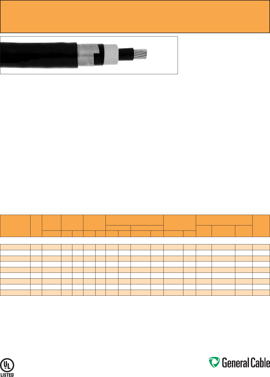
Phone: 888-593-3355
www.generalcable.com
CATALOG
NUMBER
COND.
SIZE
(AWG/
kcmil)
NOMINAL
CONDUCTOR
DIAMETER
INSULATION
DIAMETER
INCHES
NOMINAL
JACKET
THICKNESS
NOMINAL CABLE
COPPER WEIGHT
AMPACITY CONDUIT
SIZING (4)
(INCHES)
DIAMETER WEIGHT CONDUIT
IN AIR (1)
UNDERGROUND
DUCT (2)
DIRECT
BURIAL (3)INCHES MIN. MAX. INCHES mm INCHES mm LBS/1000 FT kg/km LBS/1000 FT kg/km
25 kV¥ AND 35 kV¥¥, UL TYPE MV-105/ST1, 133%/100% INS. LEVELS, 345 MILS
17261.135100* 1/0 0.34 1.020 1.120 0.080 2.03 1.31 33.27 1090 1622 425 633 215 215 295 5
17261.135200* 2/0 0.38 1.060 1.160 0.080 2.03 1.35 34.29 1211 1802 514 765 255 245 335 5
17261.135300* 3/0 0.43 1.105 1.205 0.080 2.03 1.40 35.56 1360 2024 625 930 290 275 380 5
17261.135400* 4/0 0.48 1.160 1.260 0.080 2.03 1.45 36.83 1547 2302 765 1138 330 315 435 5
17261.136000* 250 0.53 1.210 1.315 0.080 2.03 1.51 38.35 1712 2547 888 1322 365 345 475 5
17261.136200* 350 0.62 1.310 1.410 0.080 2.03 1.60 40.64 2108 3137 1206 1794 440 415 575 5
17261.136500* 500 0.74 1.430 1.530 0.080 2.03 1.7245.21 2650 4141 1679 2498 535 500 700 6
17261.137000* 750 0.91 1.610 1.710 0.110 2.79 1.96 49.78 3733 5555 2467 3670 655 610 865 6
17261.137500* 1000 1.06 1.760 1.865 0.110 2.79 2.10 53.59 4651 6921 3250 4836 755 690 1005 8
Dimensions and weights are nominal; subject to industry tolerances.
* Non-stock item; minimum runs apply. Please consult Customer Service for price and delivery.
(1) Ampacities are in accordance with Table 310.60(C)(73) of the NEC for triplexed or three single conductor copper cable in isolated conduit in air, based on a conductor temperature of 105˚C (221˚F) and an
ambient air temperature of 40˚C (104˚F).
(2) Ampacities are in accordance with Table 310.60(C)(77) of the NEC for triplexed or three single conductor copper cable in underground ducts (three conductors per duct), based on a conductor temperature
of 105˚C (221˚F) and an ambient earth temperature of 20˚C (68˚F), electrical duct arrangement per Figure 310.60 Detail 1, 100% load factor, and earth thermal resistance (rho) of 90.
(3) Ampacities are in accordance with Table 310.60(C)(81) of the NEC for single insulated copper conductors directly buried in earth, based on a conductor temperature of 105˚C (221˚F) and an ambient earth
temperature of 20˚C (68˚F), arrangement per Figure 310.60 Detail 9, 100% load factor, and earth thermal resistance (rho) of 90.
(4) Based on nominal cable diameters, three single cables in the duct (PVC Schedule 40) with no ground wire and a maximum of 40% fill. Jam ratio should be checked for individual installations.
¥100% insulation level is available upon request
¥¥133% insulation level is available upon request
Note: a) Sizes smaller than 1/0 AWG do not include “FOR CT USE”.
b) The NESC Lightning bolt symbol is on all Uniblend® constructions.
GenFree
®
Uniblend
®
EPR/Copper Tape Shield/LSZH, Medium-Voltage Power, Shielded
25 kV and 35 kV, UL Type MV-105/ST1, 133%/100% Ins. Levels, 345 Mils
Product Construction:
Conductor:
• 1/0 AWG thru 1000 kcmil annealed bare copper
compact Class B strand
Extruded Strand Shield (ESS):
• Extruded thermoset semi-conducting stress-
control layer over conductor
Insulation:
• Ethylene Propylene Rubber (EPR) insulation,
colored to contrast with the black conducting
shield layers
Extruded Insulation Shield (EIS):
• Thermoset semi-conducting polymeric layer free
stripping from insulation
Metallic Shield:
• 5 mil annealed copper tape with an
overlap of 25%
Overall Jacket:
• Lead-free, moisture- and sunlight-resistant
Low-Smoke, Zero-Halogen Polyolefin (LSZH)
Print:
• GENERAL CABLE
®
(PLANT OF MFG) (MO/YR OF
MANUFACTURE) LIGHTNING BOLT SYMBOL 1/C
SIZE (AWG OR KCMIL) COMPACT CU GENFREE
®
UNIBLEND
®
LSZH JKT (INSULATION THICKNESS)
EPR TYPE MV-105/ST1 (VOLTAGE) KV%
Print (cont’d.):
INSULATION LEVEL SUN RES FOR CT USE (UL)
SEQUENTIAL FOOTAGE MARK
* Sizes smaller than 1/0 AWG do not include
“FOR CT USE”.
Options:
• STRANDFILL
®
- blocked conductor. Tested in
accordance with ICEA T-31-610
• 25 kV 100% insulation level
• 35 kV 133% insulation level
Applications:
• Superior performance in petrochemical plants,
pulp and paper mills, sewage and water
treatment plants, environmental protection
systems, railroads, mines, utility power
generating stations, steel mills, textile plants and
other industrial three-phase applications
• For use in wet or dry locations when installed in
accordance with NEC
• For use in aerial, conduit, open tray and
underground duct installations
• For use in direct burial if installed in a system with
a ground conductor that is in close proximity, and
conforms with NEC 250.4(A)(5)
Features:
• Rated at 105
˚
C
• Excellent heat and moisture resistance
• Excellent flame resistance
Features (cont’d.):
• Outstanding corona resistance
• Flexibility for easy handling
• High dielectric strength
• Low moisture absorption
• Electrical stability under stress
• Low dielectric loss
• Chemical-resistant
• Meets cold bend test at -35
˚
C
Compliances:
• National Electrical Code (NEC)
• UL 1072
• ICEA S-93-639/NEMA WC74
• ICEA S-97-682
• ICEA T-33-655
• AEIC CS8
• UL listed as Type MV-105 for use in accordance
with NEC, UL File # E90501
• UL 1685 (Sizes 1/0 AWG and larger) UL Flame
Exposure Test
• UL 1685 Vertical Flame and Smoke Release Test
• Sizes 1/0 AWG and larger are listed and marked
“Sunlight-Resistant FOR CT USE” in accordance
with NEC
• IEEE 1202 (70,000 BTU/hr)/CSA FT4
• EPA 40 CFR, Part 261 for leachable lead content
per TCLP method
• OSHA Acceptable
Optional Flame Tests:
• ICEA T-29-520 (210,000 BTU/hr)
Packaging:
• Material cut to length and shipped on
non-returnable wood reels. Lengths in excess of
10,000 lbs. are provided on returnable steel reels
that require a deposit
• Extra charges apply for cuts less than 1000 ft.,
lagging, pulling eyes, paralleling and triplexing
SPEC 6580
March, 2012
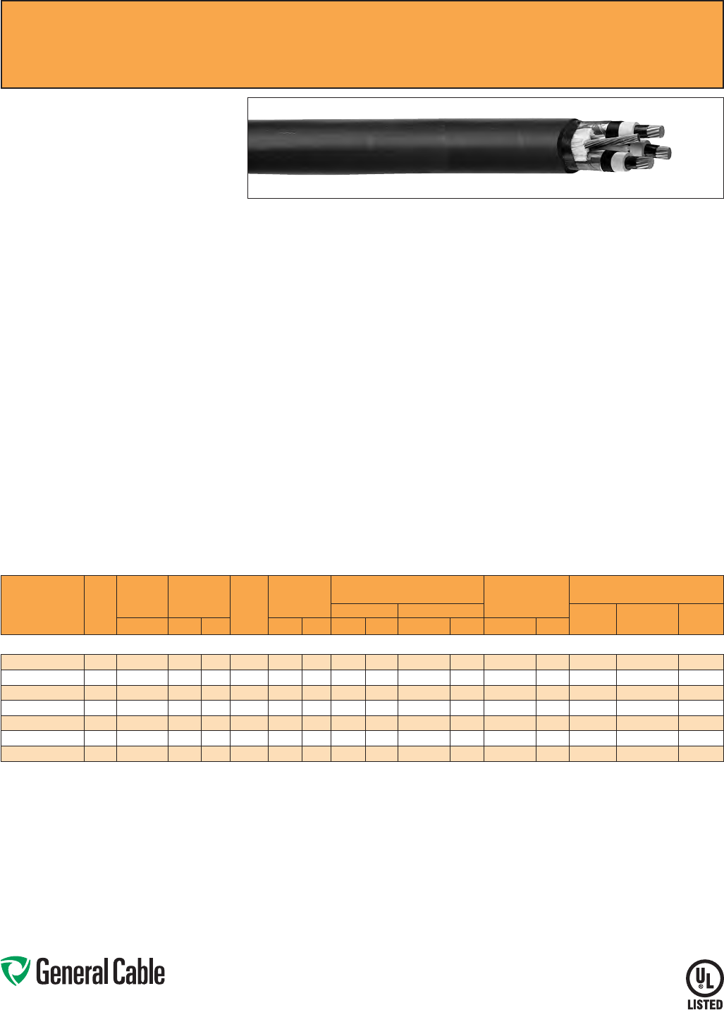
Phone: 888-593-3355
www.generalcable.com
SPEC 6600
March, 2012
CATALOG
NUMBER
COND.
SIZE
(AWG/
kcmil)
NOMINAL
CONDUCTOR
DIAMETER
INSULATION
DIAMETER
INCHES GROUND
WIRE
(AWG)
NOMINAL
OVERALL JKT.
THICKNESS
NOMINAL CABLE
COPPER WEIGHT
AMPACITY
DIAMETER WEIGHT CONDUIT IN
AIR (1)
UNDERGROUND
DUCT (2)
DIRECT
BURIAL (3)INCHES MIN. MAX. INCHES mm INCHES mm LBS/1000 FT kg/km LBS/1000 FT kg/km
25 kV¥ AND 35 kV¥¥, UL TYPE MV-105, 133%/100% INS. LEVELS, 345 MILS, THREE CONDUCTOR
15493.485100* 1/0 0.34 1.020 1.120 4 0.110 2.79 2.73 69.34 3672 5464 1410 2098 215 210 255
15493.485200* 2/0 0.38 1.060 1.160 4 0.110 2.79 2.81 71.37 4061 6042 1675 2492 245 235 290
15493.485400* 4/0 0.48 1.160 1.260 3 0.140 3.56 3.10 78.74 5313 7906 2465 3668 320 305 375
15493.486000* 250 0.53 1.210 1.315 2 0.140 3.56 3.21 81.53 6214 9246 2879 4284 350 335 410
15493.486200* 350 0.62 1.310 1.410 2 0.140 3.56 3.42 86.86 7138 10621 3834 5705 430 400 495
15493.486500* 500 0.74 1.430 1.530 1 0.140 3.56 3.68 93.47 9012 13410 5312 7904 525 485 590
15493.487000* 750 0.91 1.610 1.710 1/0 0.140 3.56 4.10 104.14 12030 17901 7750 11532 635 585 720
Dimensions and weights are nominal; subject to industry tolerances.
* Non-stock item; minimum runs apply. Please consult Customer Service for price and delivery.
(1) Ampacities are in accordance with Table 310.60(C)(75) of the NEC for three conductor copper cable in isolated conduit in air, based on a conductor temperature of 105˚C (221˚F) and an ambient air
temperature of 40˚C (104˚F).
(2) Ampacities are in accordance with Table 310.60(C)(79) of the NEC for three conductor copper cable in underground ducts (three conductors per duct), based on a conductor temperature of 105˚C (221˚F)
and an ambient earth temperature of 20˚C (68˚F), electrical duct arrangement per Figure 310.60 Detail 1, 100% load factor, and earth thermal resistance (rho) of 90.
(3) Ampacities are in accordance with Table 310.60(C)(83) of the NEC for single insulated copper conductors directly buried in earth, based on a conductor temperature of 105˚C (221˚F) and an ambient earth
temperature of 20˚C (68˚F), arrangement per Figure 310.60 Detail 5, 100% load factor, and earth thermal resistance (rho) of 90.
¥100% insulation level is available upon request
¥¥133% insulation level is available upon request
Note: a) All sizes are “FOR CT USE”.
b) The NESC Lightning bolt symbol is on all Uniblend® constructions.
Product Construction:
Conductor:
• 1/0 AWG thru 750 kcmil annealed bare copper
compact Class B strand
Extruded Strand Shield (ESS):
• Extruded thermoset semi-conducting stress
control layer over conductor
Insulation:
• Ethylene Propylene Rubber (EPR) insulation,
colored to contrast with black conducting shield
layers
Extruded Insulation Shield (EIS):
• Thermoset semi-conducting polymeric layer free
stripping from insulation
Metallic Shield:
• 5 mil annealed copper tape with an overlap
of 25%
Grounding Conductor:
• 1 bare grounding conductor may be in contact
with metallic shielding tape
Overall Jacket:
• Lead-free, flame-retardant, moisture- and
sunlight-resistant Polyvinyl Chloride (PVC)
Print:
• GENERAL CABLE
®
(PLANT OF MFG) (MO/YR
OF MANUFACTURE) LIGHTNING BOLT SYMBOL
3/C SIZE (AWG OR KCMIL) COMPACT CU
UNIBLEND
®
PVC JKT (INSULATION THICKNESS)
EPR TYPE MV-105 (VOLTAGE) KV% INSULATION
LEVEL DIR BUR SUN RES FOR CT USE (UL)
SEQUENTIAL FOOTAGE MARK
Options:
• Other jacket options available upon request
• Jacketed singles
• UniShield
®
singles
Options (cont’d.):
• STRANDFILL
®
- blocked conductor. Tested in
accordance with ICEA T-31-610
• 3 bare copper ground wires
• Covered ground wires
• 25 kV 100% insulation level
• 35 kV 133% insulation level
Applications:
• Suited for use in a broad range of commercial,
industrial and utility applications, where reliability
is the major concern, space is limited and ease of
installation is critical
• Suitable for use in wet or dry locations when
installed in accordance with NEC
• In aerial, direct burial, conduit, open tray and
underground duct installations
Features:
• Rated at 105
˚
C
• Excellent heat and moisture resistance
• Outstanding corona resistance
• Flexibility for easy handling
• High dielectric strength
• Low moisture absorption
• Electrical stability under stress
• Low dielectric loss
• Chemical-resistant
• Meets cold bend test at -35
˚
C
Compliances:
• National Electrical Code (NEC)
• UL 1072
• ICEA S-93-639/NEMA WC74
• ICEA S-97-682
• AEIC CS8
• UL listed as Type MV-105 for use in accordance
with NEC, UL File # E90501
• UL 1685 (70,000 BTU/hr)
• EPA 40 CFR, Part 261 for leachable lead content
per TCLP method
• OSHA Acceptable
Optional Flame Tests:
• IEEE 1202 (70,000 BTU/hr)/CSA FT4
• ICEA T-29-520 (210,000 BTU/hr)
Packaging:
• Material cut to length and shipped on non-
returnable wood reels. Lengths in excess of
10,000 lbs. are provided on returnable steel reels
that require a deposit
• Extra charges apply for cuts less than
1000 ft., lagging, pulling eyes, paralleling
and triplexing
Uniblend
®
EPR/Copper Tape Shield with Overall PVC Jacket, Medium-Voltage Power, Shielded
25 kV and 35 kV, UL Type MV-105, 133%/100% Ins. Levels, 345 Mils, Three Conductor
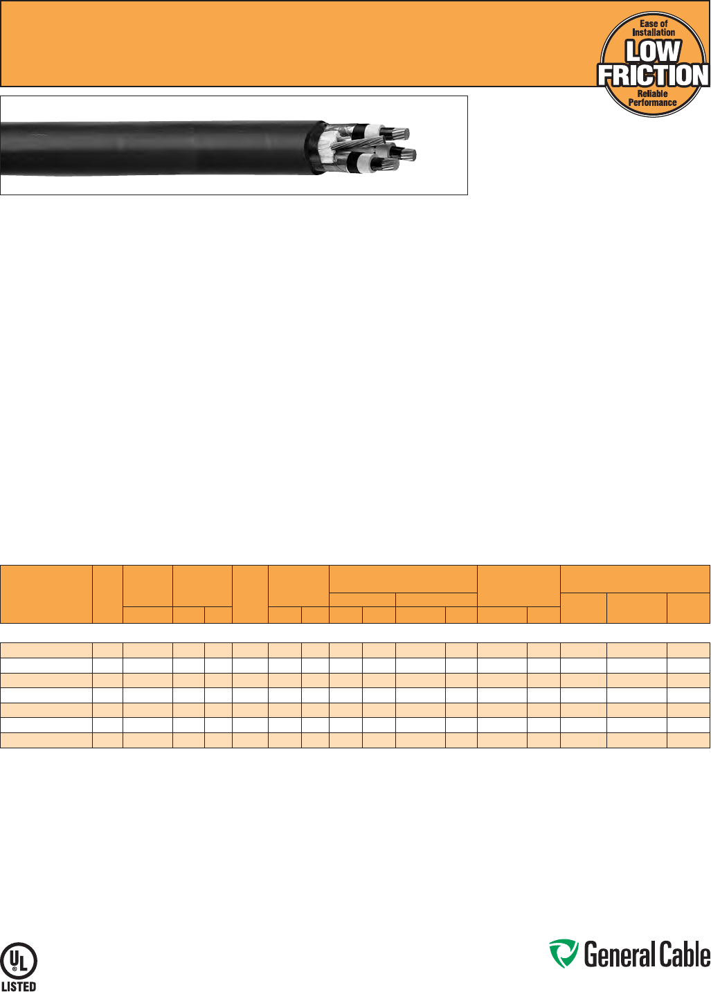
Phone: 888-593-3355
www.generalcable.com
SPEC 6605
March, 2012
CATALOG
NUMBER
COND.
SIZE
(AWG/
kcmil)
NOMINAL
CONDUCTOR
DIAMETER
INSULATION
DIAMETER
INCHES GROUND
WIRE
(AWG)
NOMINAL
OVERALL JKT.
THICKNESS
NOMINAL CABLE
COPPER WEIGHT
AMPACITY
DIAMETER WEIGHT CONDUIT IN
AIR (1)
UNDERGROUND
DUCT (2)
DIRECT
BURIAL (3)INCHES MIN. MAX. INCHES mm INCHES mm LBS/1000 FT kg/km LBS/1000 FT kg/km
25 kV¥ AND 35 kV¥¥, UL TYPE MV-105, 133%/100% INS. LEVELS, 345 MILS, THREE CONDUCTOR
15493.485105* 1/0 0.34 1.020 1.120 4 0.110 2.79 2.73 69.34 3672 5464 1410 2098 215 210 255
15493.485205* 2/0 0.38 1.060 1.160 4 0.110 2.79 2.81 71.37 4061 6042 1675 2492 245 235 290
15493.485405* 4/0 0.48 1.160 1.260 3 0.140 3.56 3.10 78.74 5313 7906 2465 3668 320 305 375
15493.486005* 250 0.53 1.210 1.315 2 0.140 3.56 3.21 81.53 6214 9246 2879 4284 350 335 410
15493.486205* 350 0.62 1.310 1.410 2 0.140 3.56 3.42 86.86 7138 10621 3834 5705 430 400 495
15493.486505* 500 0.74 1.430 1.530 1 0.140 3.56 3.68 93.47 9012 13410 5312 7904 525 485 590
15493.487005* 750 0.91 1.610 1.710 1/0 0.140 3.56 4.10 104.14 12030 17901 7750 11532 635 585 720
Dimensions and weights are nominal; subject to industry tolerances.
*Non-stock item; minimum runs apply. Please consult Customer Service for price and delivery.
(1) Ampacities are in accordance with Table 310.60(C)(75) of the NEC for three conductor copper cable in isolated conduit in air, based on a conductor temperature of 105˚C (221˚F) and an ambient air
temperature of 40˚C (104˚F).
(2) Ampacities are in accordance with Table 310.60(C)(79) of the NEC for three conductor copper cable in underground ducts (three conductors per duct), based on a conductor temperature of 105˚C (221˚F)
and an ambient earth temperature of 20˚C (68˚F), electrical duct arrangement per Figure 310.60 Detail 1, 100% load factor, and earth thermal resistance (rho) of 90.
(3) Ampacities are in accordance with Table 310.60(C)(83) of the NEC for single insulated copper conductors directly buried in earth, based on a conductor temperature of 105˚C (221˚F) and an ambient earth
temperature of 20˚C (68˚F), arrangement per Figure 310.60 Detail 5, 100% load factor, and earth thermal resistance (rho) of 90.
¥100% insulation level is available upon request
¥¥133% insulation level is available upon request
Note: a) All sizes are “FOR CT USE”.
b) The NESC Lightning bolt symbol is on all Uniblend® constructions.
Product Construction:
Conductor:
• 1/0 AWG thru 750 kcmil annealed bare copper
compact Class B strand
Extruded Strand Shield (ESS):
• Extruded thermoset semi-conducting stress
control layer over conductor
Insulation:
• Ethylene Propylene Rubber (EPR) insulation,
colored to contrast with black conducting shield
layers
Extruded Insulation Shield (EIS):
• Thermoset semi-conducting polymeric layer free
stripping from insulation
Metallic Shield:
• 5 mil annealed copper tape with an overlap
of 25%
Grounding Conductor:
• 1 bare grounding conductor may be in contact
with metallic shielding tape
Overall Jacket:
• Low-friction, lead-free, flame-retardant, moisture-
and sunlight-resistant Polyvinyl Chloride (PVC)
Print:
• GENERAL CABLE
®
(PLANT OF MFG) (MO/
YR OF MANUFACTURE) LIGHTNING BOLT
SYMBOL 3/C SIZE (AWG OR KCMIL) COMPACT
CU UNIBLEND
®
LF PVC JKT (INSULATION
THICKNESS) EPR TYPE MV-105 (VOLTAGE) KV%
INSULATION LEVEL DIR BUR SUN RES FOR CT
USE (UL) SEQUENTIAL FOOTAGE MARK
Options:
• STRANDFILL
®
- blocked conductor. Tested in
accordance with ICEA T-31-610
• 3 bare copper ground wires
• Covered ground wires
• 25 kV 100% insulation level
• 35 kV 133% insulation level
Applications:
• Suited for use in a broad range of commercial,
industrial and utility applications, where reliability
is the major concern, space is limited and ease of
installation is critical
• Suitable for use in wet or dry locations when
installed in accordance with NEC
• In aerial, direct burial, conduit, open tray and
underground duct installations
Features:
• Rated at 105
˚
C
• Lower coefficient of friction
for ease of installation
• Excellent heat and moisture resistance
• Outstanding corona resistance
• Flexibility for easy handling
• High dielectric strength
• Low moisture absorption
• Electrical stability under stress
• Low dielectric loss
• Chemical-resistant
• Meets cold bend test at -35
˚
C
Compliances:
• National Electrical Code (NEC)
• UL 1072
• ICEA S-93-639/NEMA WC74
• ICEA S-97-682
• AEIC CS8
• UL listed as Type MV-105 for use in accordance
with NEC, UL File # E90501
• UL 1685 (70,000 BTU/hr)
• EPA 40 CFR, Part 261 for leachable lead content
per TCLP method
• OSHA Acceptable
Optional Flame Tests:
• IEEE 1202 (70,000 BTU/hr)/CSA FT4
• ICEA T-29-520 (210,000 BTU/hr)
Packaging:
• Material cut to length and shipped on non-
returnable wood reels. Lengths in excess of
10,000 lbs. are provided on returnable steel reels
that require a deposit
• Extra charges apply for cuts less than
1000 ft., lagging, pulling eyes, paralleling
and triplexing
Uniblend
®
LF
EPR/Copper Tape Shield with Overall PVC Jacket
Medium-Voltage Power, Shielded, 25 kV and 35 kV, UL Type MV-105
133%/100% Ins. Levels, 345 Mils, Three Conductor
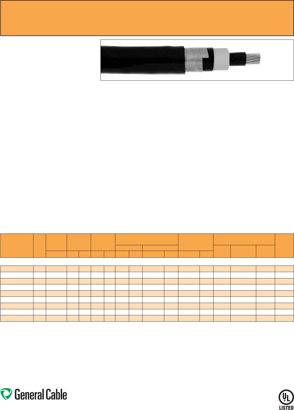
Phone: 888-593-3355
www.generalcable.com
SPEC 6650
November, 2013
Uniblend
®
EPR/Copper Tape Shield/PVC, Medium-Voltage Power, Shielded
35 kV, UL Type MV-105, 133% Ins. Levels, 420 Mils
CATALOG
NUMBER
COND.
SIZE
(AWG/
kcmil)
NOMINAL
CONDUCTOR
DIAMETER
INSULATION
DIAMETER
INCHES
NOMINAL
JACKET
THICKNESS
NOMINAL CABLE
COPPER WEIGHT
AMPACITY CONDUIT
SIZING (4)
(INCHES)
DIAMETER WEIGHT CONDUIT
IN AIR (1)
UNDERGROUND
DUCT (2)
DIRECT
BURIAL (3)INCHES MIN. MAX. INCHES mm INCHES mm LBS/1000 FT kg/km LBS/1000 FT kg/km
35 kV, UL TYPE MV-105, 133% INS. LEVELS, 420 MILS
17071.135100* 1/0 0.34 1.060 1.265 0.080 2.03 1.47 37.34 1253 1864 437 650 215 215 295 5
17071.135200* 2/0 0.38 1.200 1.305 0.080 2.03 1.49 37.8 5 1378 2050 525 781 255 245 335 5
17071.135300* 3/0 0.43 1.245 1.355 0.080 2.03 1.53 38.86 1532 2280 636 946 290 275 380 5
17071.135400* 4/0 0.48 1.300 1.405 0.080 2.03 1.59 40.39 1716 2553 776 1155 330 315 435 5
17071.136000* 250 0.53 1.350 1.460 0.080 2.03 1.64 41.66 1888 2809 899 1338 365 345 475 6
17071.136200* 350 0.62 1.450 1.555 0.110 2.79 1.79 45.47 2396 3565 1217 1811 440 415 575 6
17071.136500* 500 0.74 1.570 1.675 0.110 2.79 1.91 48.5 2986 4443 1690 2515 535 500 700 6
17071.137000* 750 0.91 1.750 1.860 0.110 2.79 2.09 53.09 3954 5884 2477 3685 655 610 865 6
17071.137500* 1000 1.06 1.9002.010 0.110 2.79 2.25 57.15 4885 7269 3263 4855 755 690 1005 8
Dimensions and weights are nominal; subject to industry tolerances.
* Non-stock item; minimum runs apply. Please consult Customer Service for price and delivery.
(1) Ampacities are in accordance with Table 310.60(C)(73) of the NEC for triplexed or three single conductor copper cable in isolated conduit in air, based on a conductor temperature of 105˚C (221˚F) and an
ambient air temperature of 40˚C (104˚F).
(2) Ampacities are in accordance with Table 310.60(C)(77) of the NEC for triplexed or three single conductor copper cable in underground ducts (three conductors per duct), based on a conductor temperature
of 105˚C (221˚F) and an ambient earth temperature of 20˚C (68˚F), electrical duct arrangement per Figure 310.60 Detail 1, 100% load factor, and earth thermal resistance (rho) of 90.
(3) Ampacities are in accordance with Table 310.60(C)(81) of the NEC for single insulated copper conductors directly buried in earth, based on a conductor temperature of 105˚C (221˚F) and an ambient earth
temperature of 20˚C (68˚F), arrangement per Figure 310.60 Detail 9, 100% load factor, and earth thermal resistance (rho) of 90.
(4) Based on nominal cable diameters, three single cables in the duct (PVC Schedule 40) with no ground wire and a maximum of 40% fill. Jam ratio should be checked for individual installations.
Note: The NESC Lightning bolt symbol is on all Uniblend® constructions.
Product Construction:
Conductor:
•1/0AWGthru1000kcmilannealedbarecopper
compact Class B strand
Extruded Strand Shield (ESS):
•Extrudedthermosetsemi-conductingstress-
control layer over conductor
Insulation:
•EthylenePropyleneRubber(EPR)insulation,
colored to contrast with the black conducting
shield layers
Extruded Insulation Shield (EIS):
•Thermosetsemi-conductingpolymericlayerfree
stripping from insulation
Metallic Shield:
•5milannealedcoppertapewithan
overlap of 25%
Jacket:
•Lead-free,flame-retardant,moisture-and
sunlight-resistant Polyvinyl Chloride (PVC)
Print:
•GENERALCABLE
®
(PLANTOFMFG)(MO/YR
OFMANUFACTURE)LIGHTNINGBOLTSYMBOL
1/CSIZE(AWGORKCMIL)COMPACTCU
UNIBLEND
®
PVCJKT(INSULATIONTHICKNESS)
EPRTYPEMV-105(VOLTAGE)KV%INSULATION
LEVEL SUN RES FOR CT USE (UL) SEQUENTIAL
FOOTAGEMARK
Options:
•Otherjacketoptionsavailableuponrequest
•STRANDFILL
®
- blocked conductor. Tested in
accordance with ICEA T-31-610
Applications:
•Superiorperformanceinpetrochemicalplants,
pulp and paper mills, sewage and water
treatment plants, environmental protection
systems, railroads, mines, utility power
generating stations, steel mills, textile plants and
other industrial three-phase applications
•Foruseinwetordrylocationswheninstalledin
accordance with NEC
•Foruseinaerial,conduit,opentrayand
underground duct installations
•Foruseindirectburialifinstalledinasystemwith
a ground conductor that is in close proximity, and
conforms with NEC 250.4(A)(5)
Features:
•Ratedat105
˚
C
•Excellentheatandmoistureresistance
•Excellentflameresistance
•Outstandingcoronaresistance
•Flexibilityforeasyhandling
•Highdielectricstrength
•Lowmoistureabsorption
•Electricalstabilityunderstress
•Lowdielectricloss
•Chemical-resistant
•Meetscoldbendtestat-35
˚
C
Compliances:
•NationalElectricalCode(NEC)
•UL1072
•ICEAS-93-639/NEMAWC74
•ICEAS-97-682
•AEICCS8
•ULlistedasTypeMV-105foruseinaccordance
with NEC, UL File # E90501
•Sizes1/0AWGandlargerarelistedandmarked
“Sunlight-Resistant FOR CT USE” in accordance
with NEC
•IEEE1202(70,000BTU/hr)/CSAFT4
•EPA40CFR,Part261forleachableleadcontent
per TCLP method
•OSHAAcceptable
Optional Flame Tests:
•ICEAT-29-520(210,000BTU/hr)
Packaging:
•Materialcuttolengthandshippedon
non-returnable wood reels. Lengths in excess of
10,000 lbs. are provided on returnable steel reels
thatrequireadeposit
•Extrachargesapplyforcutslessthan1000ft.,
lagging, pulling eyes, paralleling and triplexing
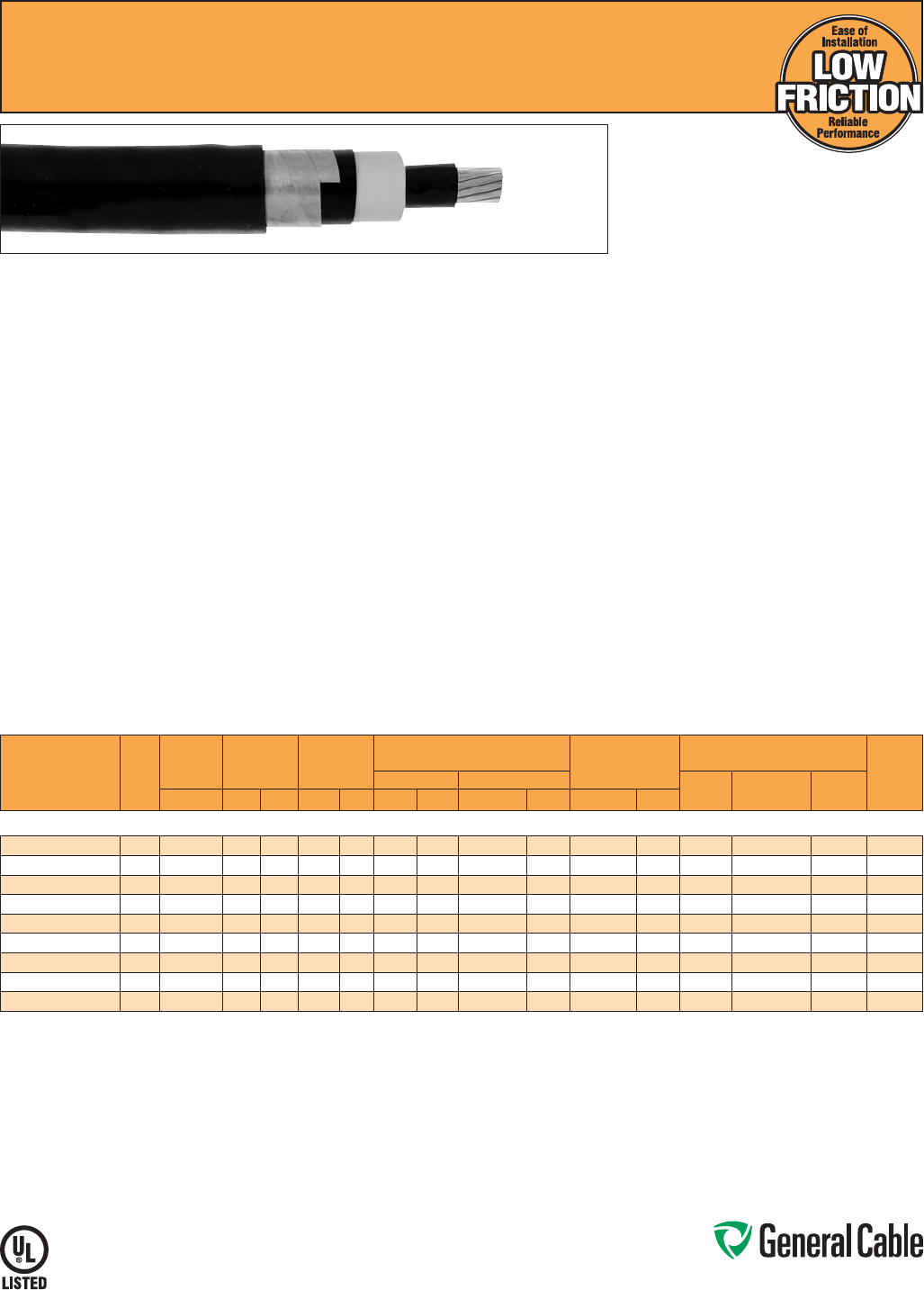
Phone: 888-593-3355
www.generalcable.com
SPEC 6655
November, 2013
Uniblend
®
LF
EPR/Copper Tape Shield/PVC, Medium-Voltage Power, Shielded
35 kV, UL Type MV-105, 133% Ins. Levels, 420 Mils
CATALOG
NUMBER
COND.
SIZE
(AWG/
kcmil)
NOMINAL
CONDUCTOR
DIAMETER
INSULATION
DIAMETER
INCHES
NOMINAL
JACKET
THICKNESS
NOMINAL CABLE
COPPER WEIGHT
AMPACITY CONDUIT
SIZING (4)
(INCHES)
DIAMETER WEIGHT CONDUIT
IN AIR (1)
UNDERGROUND
DUCT (2)
DIRECT
BURIAL (3)INCHES MIN. MAX. INCHES mm INCHES mm LBS/1000 FT kg/km LBS/1000 FT kg/km
35 kV, UL TYPE MV-105, 133% INS. LEVELS, 420 MILS
17071.135105* 1/0 0.34 1.060 1.265 0.080 2.03 1.47 37.34 1253 1864 437 650 215 215 295 5
17071.135205* 2/0 0.38 1.200 1.305 0.080 2.03 1.49 37.8 5 1378 2050 525 781 255 245 335 5
17071.135305* 3/0 0.43 1.245 1.355 0.080 2.03 1.53 38.86 1532 2280 636 946 290 275 380 5
17071.135405* 4/0 0.48 1.300 1.405 0.080 2.03 1.59 40.39 1716 2553 776 1155 330 315 435 5
17071.136005* 250 0.53 1.350 1.460 0.080 2.03 1.64 41.66 1888 2809 899 1338 365 345 475 6
17071.136205* 350 0.62 1.450 1.555 0.110 2.79 1.79 45.47 2396 3565 1217 1811 440 415 575 6
17071.136505* 500 0.74 1.570 1.675 0.110 2.79 1.91 48.5 2986 4443 1690 2515 535 500 700 6
17071.137005* 750 0.91 1.750 1.860 0.110 2.79 2.09 53.09 3954 5884 2477 3685 655 610 865 6
17071.137505* 1000 1.06 1.9002.010 0.110 2.79 2.25 57.15 4885 7269 3263 4855 755 690 1005 8
Dimensions and weights are nominal; subject to industry tolerances.
* Non-stock item; minimum runs apply. Please consult Customer Service for price and delivery.
(1) Ampacities are in accordance with Table 310.60(C)(73) of the NEC for triplexed or three single conductor copper cable in isolated conduit in air, based on a conductor temperature of 105˚C (221˚F) and an
ambient air temperature of 40˚C (104˚F).
(2) Ampacities are in accordance with Table 310.60(C)(77) of the NEC for triplexed or three single conductor copper cable in underground ducts (three conductors per duct), based on a conductor temperature
of 105˚C (221˚F) and an ambient earth temperature of 20˚C (68˚F), electrical duct arrangement per Figure 310.60 Detail 1, 100% load factor, and earth thermal resistance (rho) of 90.
(3) Ampacities are in accordance with Table 310.60(C)(81) of the NEC for single insulated copper conductors directly buried in earth, based on a conductor temperature of 105˚C (221˚F) and an ambient earth
temperature of 20˚C (68˚F), arrangement per Figure 310.60 Detail 9, 100% load factor, and earth thermal resistance (rho) of 90.
(4) Based on nominal cable diameters, three single cables in the duct (PVC Schedule 40) with no ground wire and a maximum of 40% fill. Jam ratio should be checked for individual installations.
Note: The NESC Lightning bolt symbol is on all Uniblend® constructions.
Product Construction:
Conductor:
•1/0AWGthru1000kcmilannealedbarecopper
compact Class B strand
Extruded Strand Shield (ESS):
•Extrudedthermosetsemi-conductingstress-
control layer over conductor
Insulation:
•EthylenePropyleneRubber(EPR)insulation,
colored to contrast with the black conducting
shield layers
Extruded Insulation Shield (EIS):
•Thermosetsemi-conductingpolymericlayerfree
stripping from insulation
Metallic Shield:
•5milannealedcoppertapewithan
overlap of 25%
Jacket:
•Low-friction,lead-free,flame-retardant,moisture-
and sunlight-resistant Polyvinyl Chloride (PVC)
Print:
•GENERALCABLE
®
(PLANTOFMFG)(MO/YR
OFMANUFACTURE)LIGHTNINGBOLT
SYMBOL1/CSIZE(AWGORKCMIL)COMPACT
CU UNIBLEND
®
LFPVCJKT(INSULATION
THICKNESS)EPRTYPEMV-105(VOLTAGE)KV%
INSULATION LEVEL SUN RES FOR CT USE (UL)
SEQUENTIALFOOTAGEMARK
Options:
•STRANDFILL
®
- blocked conductor. Tested in
accordance with ICEA T-31-610
Applications:
•Superiorperformanceinpetrochemicalplants,
pulp and paper mills, sewage and water
treatment plants, environmental protection
systems, railroads, mines, utility power
generating stations, steel mills, textile plants and
other industrial three-phase applications
•Foruseinwetordrylocationswheninstalledin
accordance with NEC
•Foruseinaerial,conduit,opentrayand
underground duct installations
•Foruseindirectburialifinstalledinasystemwith
a ground conductor that is in close proximity, and
conforms with NEC 250.4(A)(5)
Features:
•Ratedat105
˚
C
•Lowercoefficientoffriction
for ease of installation
•Excellentheatandmoistureresistance
•Excellentflameresistance
•Outstandingcoronaresistance
•Flexibilityforeasyhandling
•Highdielectricstrength
•Lowmoistureabsorption
•Electricalstabilityunderstress
•Lowdielectricloss
•Chemical-resistant
•Meetscoldbendtestat-35
˚
C
Compliances:
•NationalElectricalCode(NEC)
•UL1072
•ICEAS-93-639/NEMAWC74
•ICEAS-97-682
•AEICCS8
•ULlistedasTypeMV-105foruseinaccordance
with NEC, UL File # E90501
•IEEE1202(70,000BTU/hr)/CSAFT4
•EPA40CFR,Part261forleachableleadcontent
per TCLP method
•OSHAAcceptable
Optional Flame Tests:
•ICEAT-29-520(210,000BTU/hr)
Packaging:
•Materialcuttolengthandshippedon
non-returnable wood reels. Lengths in excess of
10,000 lbs. are provided on returnable steel reels
that require a deposit
•Extrachargesapplyforcutslessthan1000ft.,
lagging, pulling eyes, paralleling and triplexing

Phone: 888-593-3355
www.generalcable.com
SPEC 6660
April, 2011
Aluminum Uniblend
®
LF
EPR/Copper Tape Shield/PVC, Medium-Voltage Power, Shielded
35 kV, UL Type MV-105, 133% Ins. Levels, 420 Mils
Product Construction:
Conductor:
• 1/0 AWG thru 1000 kcmil 1350 aluminum
compact Class B STRANDFILL® blocked
conductor
Extruded Strand Shield (ESS):
• Extruded thermoset semi-conducting stress-
control layer over conductor
Insulation:
• Ethylene Propylene Rubber (EPR) insulation,
colored to contrast with the black conducting
shield layers
Extruded Insulation Shield (EIS):
• Thermoset semi-conducting polymeric layer free
stripping from insulation
Metallic Shield:
• 5 mil annealed copper tape with an
overlap of 25%
Jacket:
• Low-friction, lead-free, flame-retardant, moisture-
and sunlight-resistant Polyvinyl Chloride (PVC)
Print:
• GENERAL CABLE
®
(PLANT OF MFG) (MO/YR
OF MANUFACTURE) LIGHTNING BOLT
SYMBOL 1/C SIZE (AWG OR KCMIL) COMPACT
AL UNIBLEND
®
LF PVC JKT (INSULATION
THICKNESS) EPR TYPE MV-105 (VOLTAGE) KV%
INSULATION LEVEL SUN RES FOR CT USE (UL)
SEQUENTIAL FOOTAGE MARK
Applications:
• Superior performance in petrochemical plants,
pulp and paper mills, sewage and water
treatment plants, environmental protection
systems, railroads, mines, utility power
generating stations, steel mills, textile plants and
other industrial three-phase applications
• For use in wet or dry locations when installed in
accordance with NEC
• For use in aerial, conduit, open tray and
underground duct installations
• For use in direct burial if installed in a system with
a ground conductor that is in close proximity, and
conforms with NEC 250.4(A)(5)
Features:
• Rated at 105
˚
C
• Lower coefficient of friction for ease of
installation
• Meets longitudinal water penetration resistance
• Excellent heat and moisture resistance
• Excellent flame resistance
• Outstanding corona resistance
• Flexibility for easy handling
• High dielectric strength
• Low moisture absorption
• Electrical stability under stress
• Low dielectric loss
• Chemical-resistant
• Meets cold bend test at -35
˚
C
Compliances:
• National Electrical Code (NEC)
• UL 1072
• ICEA S-93-639/NEMA WC74
• ICEA S-97-682
• AEIC CS8
• UL listed as Type MV-105 for use in accordance
with NEC, UL File # E90501
• IEEE 1202 (70,000 BTU/hr)/CSA FT4
• EPA 40 CFR, Part 261 for leachable lead content
per TCLP method
• OSHA Acceptable
Optional Flame Tests:
• ICEA T-29-520 (210,000 BTU/hr)
Packaging:
• Material cut to length and shipped on
non-returnable wood reels. Lengths in excess of
10,000 lbs. are provided on returnable steel reels
that require a deposit
• Extra charges apply for cuts less than 1000 ft.,
lagging, pulling eyes, paralleling and triplexing
CATALOG
NUMBER
COND.
SIZE
(AWG/
kcmil)
NOMINAL
CONDUCTOR
DIAMETER
INSULATION
DIAMETER
INCHES
NOMINAL
JACKET
THICKNESS
NOMINAL CABLE
ALUMINUM WEIGHT COPPER WEIGHT
AMPACITY CONDUIT
SIZING
(4)
(INCHES)
DIAMETER WEIGHT
CONDUIT
IN AIR
(1)
UNDERGROUND
DUCT (2)
DIRECT
BURIAL
(3)INCHES MIN. MAX. INCHES mm INCHES mm LBS/1000 FT kg/km LBS/1000 FT kg/km LBS/1000 FT kg/km
35 kV, UL TYPE MV-105, 133% INS. LEVEL, 420 MILS
17071.135108*
1/0 0.34 1.060 1.265 0.080 2.03 1.47 37.34 1026 1527 99 147 111 165 170 165 230 5
17071.135208*
2/0 0.38 1.200 1.305 0.080 2.03 1.49 37.85 1092 1625 125 186 114 170 200 190 260 5
17071.135308*
3/0 0.43 1.245 1.355 0.080 2.03 1.53 38.86 1172 1744 158 235 118 175 225 215 295 5
17071.135408*
4/0 0.48 1.300 1.405 0.080 2.03 1.59 40.39 1262 1878 199 296 123 183 260 245 340 6
17071.136008*
250 0.53 1.350 1.460 0.080 2.03 1.64 41.66 1350 2009 234 348 127 189 290 270 370 6
17071.136208*
350 0.62 1.450 1.555 0.110 2.79 1.79 45.47 1644 2447 329 490 136 202 350 330 450 6
17071.136508*
500 0.74 1.570 1.675 0.110 2.79 1.91 48.50 1910 2842 468 696 146 217 430 400 545 6
17071.137008*
750 0.91 1.750 1.860 0.110 2.79 2.09 53.09 2341 3484 703 1046 161 240 540 490 680 6
17071.137508*
1000 1.06 1.900 2.010 0.110 2.79 2.25 57.15 2734 4069 937 1394 175 260 640 565 795 8
Dimensions and weights are nominal; subject to industry tolerances.
* Non-stock item; minimum runs apply. Please consult Customer Service for price and delivery.
(1) Ampacities are in accordance with Table 310.60(C)(74) of the NEC for triplexed or three single conductor aluminum cables in isolated conduit in air based on a conductor temperature of 105°C (221°F) and
an ambient air temperature of 40°C (104°F).
(2) Ampacities are in accordance with Table 310.60(C)(78) of the NEC for triplexed or three single conductor aluminum cables in underground ducts (three conductors per duct), based on a conductor
temperature of 105°C (221°F) and an ambient earth temperature of 20°C (68°F), electrical duct arrangement per Figure 310.60 Detail 1, 100% load factor, and earth thermal resistance (rho) of 90.
(3) Ampacities are in accordance with Table 310.60(C)(82) of the NEC for single insulated aluminum conductors directly buried in earth, based on a conductor temperature of 105°C (221°F) and an ambient
earth temperature of 20°C (68°F), arrangement per Figure 310.60 Detail 9, 100% load factor, and earth thermal resistance (rho) of 90.
(4) Based on nominal cable diameters, three single cables in the duct (PVC Schedule 40) with no ground wire and a maximum of 40% fill. Jam ratio has been considered, but it should be checked for individual
installations.
Note: The NESC Lightning bolt symbol is on all Uniblend® constructions.
Phone: 888-593-3355
www.generalcable.com
Date of Issue 06/13
Industrial Cables Section 7
SPECIFICATION NO. PRODUCT DESCRIPTION REVISION DATE
7050†Duralox®XLPE/AIA/PVC, Control, Armored
600 V, UL Type MC, Multi-Conductor
Jan. 2010
7100†Duralox®XLPE/AIA/PVC, Power, Armored
600 V, UL Type MC, Three and Four Conductor (8 AWG - 4/0 AWG)
Jun. 2013
7150†Duralox®XLPE/AIA/PVC, Power, Armored
600 V, UL Type MC, Three and Four Conductor (250 kcmil - 1000 kcmil)
Jun. 2013
7160†Duralox®XLPE/AIA/PVC, Power, Armored, with Enhanced Ground Wires (50%)
600 V, UL Type MC, Three Conductor (1/0 AWG - 1000 kcmil)
Jun. 2013
7200†Duralox®EPR/AIA/PVC, Power, Nonshielded, Armored
2400 V, UL Type MV-90 or MC, Three Conductor
Jan. 2010
7250†Duralox® Uniblend®EPR/AIA/PVC, Power, Shielded, Armored
5 kV/8 kV, UL Type MV-105 or MC, 133%/100% Ins. Levels, 115 Mils, Three Conductor
Aug. 2010
7300†Duralox® Uniblend®EPR/AIA/PVC, Power, Shielded, Armored
15 kV, UL Type MV-105 or MC, 133% Ins. Level, 220 Mils, Three Conductor
Aug. 2010
7310†Duralox® Uniblend®EPR/AIA/PVC, Power, Shielded, Armored, with Enhanced Ground Wires (50%)
15 kV, UL Type MV-105 or MC, 133% Ins. Level, 220 Mils, Three Conductor
Aug. 2010
7350 Duralox® Uniblend®EPR/AIA/PVC, Power, Shielded, Armored
25 kV, UL Type MV-105 or MC, 100% Ins. Level, 260 Mils, Three Conductor
Aug. 2010
7400 Duralox® Uniblend®EPR/AIA/PVC, Power, Shielded, Armored
35 kV, UL Type MV-105 or MC, 100% Ins. Level, 345 Mils, Three Conductor
Aug. 2010
†Indicates these products are stocked by General Cable
600 V – 35 kV Industrial Armored Cables
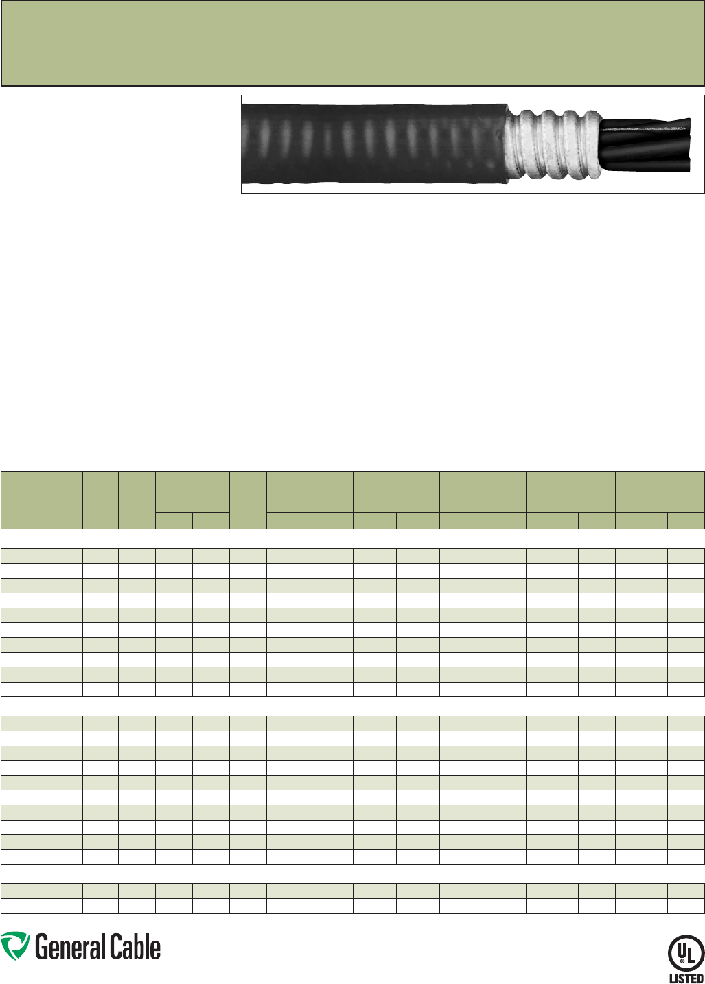
Phone: 888-593-3355
www.generalcable.com
SPEC 7050
January, 2010
Compliances:
Industry Compliances:
•UL1569
•UL44
•ICEAS-95-658/NEMAWC70
•ULTypeMC-600volts,ULFile#E69797
•NECTypeXHHW-2conductors
Flame Test Compliances:
•IEEE383(70,000BTU/hr)
•UL1581(70,000BTU/hr)
•IEEE1202(70,000BTU/hr)CSAFT4
•ICEAT-29-520(210,000BTU/hr)
Other Compliances:
•EPA40CFR,Part261forleachable
leadcontentperTCLPmethod
•OSHAAcceptable
Packaging:
•Materialcuttolengthandshippedon
non-returnablewoodreels,whilelengthsin
excessof10,000lbs.areprovidedonreturnable
steelreelsthatrequireadeposit.Extracharges
applyforcutslessthan1000ft.,lagging,pulling
eyes,parallelingandplexing
Duralox
®
XLPE/AIA/PVC,Control,Armored
600V,ULTypeMC,Multi-Conductor
Product Construction:
Conductor:
•14AWGthru10AWGbarecompressed
copper
•ClassBstrandingperASTMB3andB8
Insulation:
•Flame-retardantCross-linkedPolyethylene
(XLPE)
•Color-codedperICEAMethod1,TableE-2
(doesnotincludewhiteorgreen)
Ground:
•AnnealedbarecopperClassBstrandingper
ASTMB8
Armor:
•AluminumInterlockedArmor(AIA)
Jacket:
•Flame-retardant,moisture-andsunlight-resistant
PolyvinylChloride(PVC),black
Print:
•GENERALCABLE
®
XX/CXXAWG(UL)TYPEMC
XHHW-2CDRSDIRBURSUNRESFORCTUSE
600VMONTH-YEARSEQUENTIALFOOTAGE
MARK
Options:
•Tinnedcopperconductors
•E-1colorcode
•Coppertapeshieldoraluminum/polymertape
shieldwithtinnedcopperdrainwireover
cable core
Options (cont’d.):
•Innerjacketonly,outerjacketonly,orboth
•GalvanizedSteelInterlockedArmor(GSIA)
•Otherconstructionsavailableuponrequest
Applications:
•Inallracewaysordirectburial
•Inwetordrylocations
•PermittedforuseinClassI,Division2;ClassII,
Division2;andClassIII,Division1and2perNEC
Article334
Features:
•Ratedat90˚Cwetordry
•Sunlight-resistant
•Providesexcellentoilandchemicalresistance
•Excellentcrushresistance
•Providesalongservicelife
•Flame-retardantandresistanttomoisture
•Cost-effectivealternativetoinstallations
in conduit
•Meetscoldbendtestat-25˚C
CATALOG
NUMBER
NO.
OF
COND.
COND.
SIZE
(AWG)
MINIMUM
INSULATION
THICKNESS
GRND.
WIRE
SIZE
(AWG)
NOM. DIA.
(OVER)
ARMOR
NOMINAL
JACKET
THICKNESS
NOMINAL
CABLE
O.D.
COPPER
WEIGHT
NET
WEIGHT
INCHES mm INCHES mm INCHES mm INCHES mm
LBS/1000 FT
kg/km
LBS/1000 FT
kg/km
14 AWG - MULTI-CONDUCTOR - 600 V
346410* 2 14 0.030 0.76 14 0.49 12.5 0.050 1.27 0.60 15.3 39 58 175 261
346420 314 0.030 0.76 14 0.52 13.2 0.050 1.27 0.63 16.0 52 78 183 273
346430* 4 14 0.030 0.76 14 0.55 14.0 0.050 1.27 0.66 16.8 65 97 233 347
346440 5 14 0.030 0.76 14 0.59 15.0 0.050 1.27 0.69 17.6 79 118 246 367
346450 714 0.030 0.76 14 0.64 16.3 0.050 1.27 0.74 18.8 104 155 297 443
346460* 9 14 0.030 0.76 14 0.72 18.3 0.050 1.27 0.83 21.1 130 193 379 564
346470* 12 14 0.030 0.76 14 0.80 20.3 0.050 1.27 0.90 22.9 168 250 460 685
346480* 19 14 0.030 0.76 14 0.99 25.2 0.050 1.27 1.02 25.9 259 385 621 924
346490* 25 14 0.030 0.76 14 1.07 27.2 0.050 1.27 1.17 29.7 337 502 776 1155
346500* 37 14 0.030 0.76 14 1.19 30.3 0.050 1.27 1.29 32.8 492 732 1043 1533
12 AWG - MULTI-CONDUCTOR - 600 V
346510* 2 12 0.030 0.76 12 0.53 13.5 0.050 1.27 0.64 16.3 64 96 218 324
346520 312 0.030 0.76 12 0.56 14.3 0.050 1.27 0.66 16.8 83 124 227 338
346530 4 12 0.030 0.76 12 0.60 15.3 0.050 1.27 0.71 18.1 103 154 272 405
346540 5 12 0.030 0.76 12 0.64 16.3 0.050 1.27 0.75 19.1 129 192 336 500
346550 712 0.030 0.76 12 0.70 17.8 0.050 1.27 0.81 20.6 165 246 380 566
346560* 9 12 0.030 0.76 12 0.78 19.8 0.050 1.27 0.89 22.6 214 319 479 713
346570* 12 12 0.030 0.76 12 0.86 21.9 0.050 1.27 0.97 24.7 279 416 596 887
346580* 19 12 0.030 0.76 12 0.99 25.2 0.050 1.27 1.10 28.0 428 637 830 1235
346590* 25 12 0.030 0.76 12 1.18 30.0 0.050 1.27 1.28 32.5 557 829 1058 1575
346600* 37 12 0.030 0.76 12 1.31 33.3 0.050 1.27 1.41 35.8 793 1180 1403 2088
10 AWG - MULTI-CONDUCTOR - 600 V
346610 3 10 0.030 0.76 10 0.61 15.5 0.050 1.27 0.72 18.3 131 195 301 448
346620 410 0.030 0.76 10 0.66 16.8 0.050 1.27 0.77 19.6 164 244 355 529
Dimensionsandweightsarenominal;subjecttoindustrytolerances.
*Non-stockitem;minimumrunsapply.PleaseconsultCustomerServiceforpriceanddelivery.
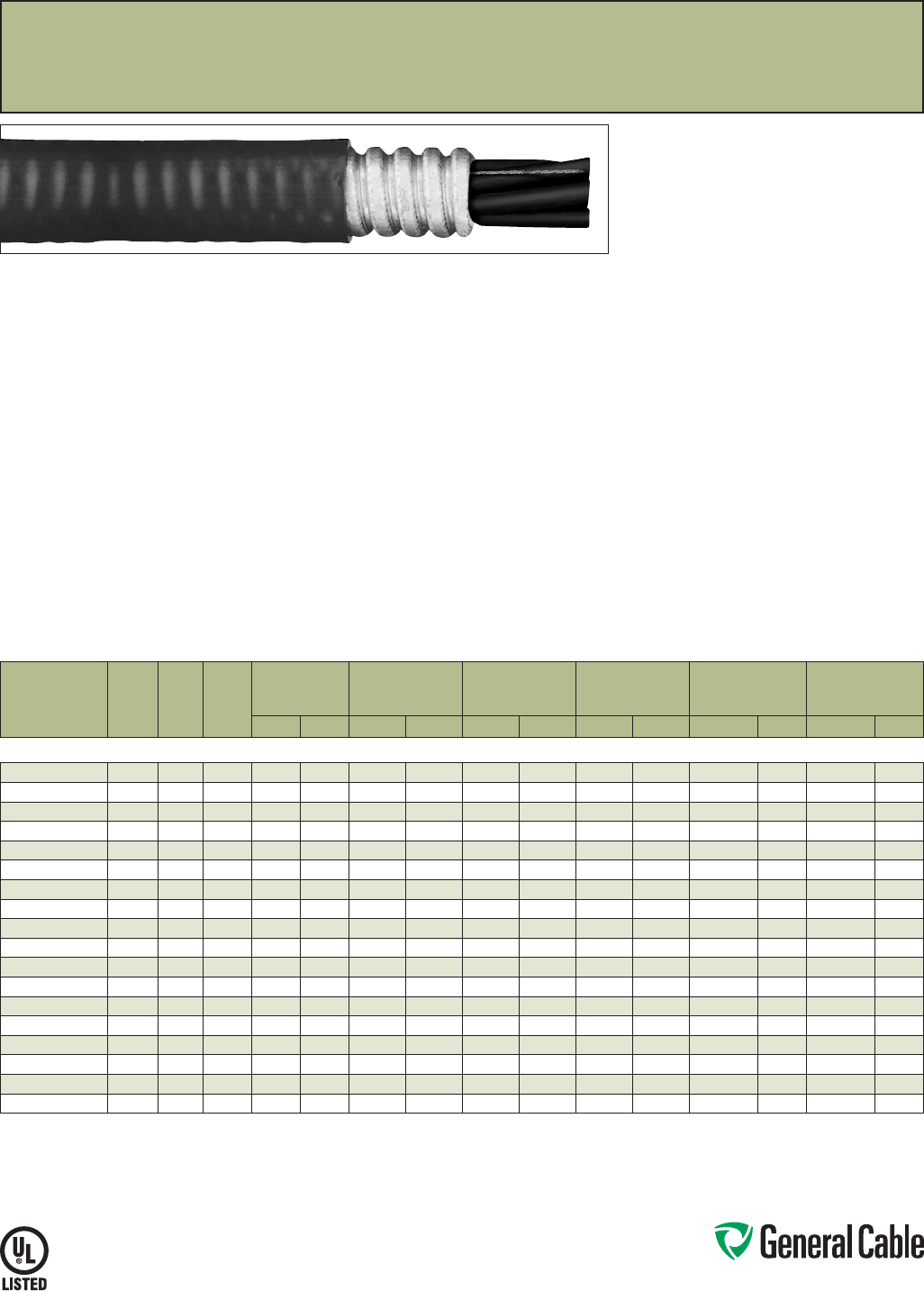
Phone: 888-593-3355
www.generalcable.com
SPEC 7100
June, 2013
Duralox
®
XLPE/AIA/PVC,Power,Armored
600V,ULTypeMC,ThreeandFourConductor(8AWG—4/0AWG)
Product Construction:
Conductors:
•8AWGthru4/0AWGbarecompressedcopper
•ClassBstrandingperASTMB8
Insulation:
•Cross-linkedPolyethylene(XLPE)
•Color-codedperICEAMethod3,TableE-2
Ground:
•AnnealedbarecopperClassBstrandingper
ASTMB8
Armor:
•AluminumInterlockedArmor(AIA)
Jacket:
•Flame-retardant,moisture-andsunlight-resistant
PolyvinylChloride(PVC),black
Print:
•GENERALCABLE
®
SIZE(AWGORKCMIL)3/C
OR4/C(ASAPPLICABLE)TYPEMCXHHW-2
CDRS1/CSIZEAWGGRDSUNRESFORCTUSE
DIRBUR600V(UL)MONTH/YEARSEQUENTIAL
FOOTAGEMARK
Options:
•Otherconstructionsavailableuponrequest
Applications:
•Ideallysuitedforuseinabroadrangeof
commercial,industrialandutilityapplications,
wheremaximumperformanceisdemanded,
ease of installation desired and fire resistance is
critical
•PermittedforuseinClassI;ClassII,Division2;
andClassIII,Division1and2hazardous
locationspertheNEC
•Installedinbothexposedorconcealedwork,wet
ordrylocations,indoorsoroutdoorsandcable
trays
Features:
•Ratedat90˚Cwetordry
•Providesexcellentoilandchemicalresistance
•Excellentcrushresistance
•Providesalongservicelife
•Cost-effectivealternativetoinstallations
in conduit
•Meetscoldbendtestat-25˚C
Compliances:
Industry Compliances:
•UL1569
•UL44
•ICEAS-95-658/NEMAWC70
•ULTypeMC-600volts,ULFile#E69797
•NECTypeXHHW-2conductors
Flame Test Compliances:
•IEEE383(70,000BTU/hr)
•UL1581(70,000BTU/hr)
•IEEE1202(70,000BTU/hr)CSAFT4
•ICEAT-29-520(210,000BTU/hr)
Other Compliances:
•EPA40CFR,Part261forleachable
leadcontentperTCLPmethod
•OSHAAcceptable
Packaging:
•ForU.S.customers,materialcuttolengthand
shippedonnon-returnablewoodreels,while
lengthsinexcessof10,000lbs.areprovidedon
returnablesteelreelsthatrequireadeposit.Extra
chargesapplyforcutslessthan1000ft.,lagging,
pullingeyes,parallelingandplexing
CATALOG
NUMBER
NO.
OF
COND.
COND.
SIZE
(AWG)
GRND.
WIRE
SIZE
(AWG)
MINIMUM
INSULATION
THICKNESS
NOM. DIA.
(OVER)
ARMOR
NOMINAL
JACKET
THICKNESS
NOMINAL
CABLE
O.D.
COPPER
WEIGHT
NET
WEIGHT
INCHES mm INCHES mm INCHES mm INCHES mm
LBS/1000 FT
kg/km
LBS/1000 FT
kg/km
8 AWG - 4/0 AWG - THREE AND FOUR CONDUCTOR - 600 V
346630 3810 0.045 1.14 0.74 18.8 0.050 1.27 0.84 21.4 189 281 420 625
346640* 4 8 10 0.045 1.14 0.80 20.3 0.050 1.27 0.90 22.9 241 359 507 755
11298.030600 3 6 8 0.045 1.14 0.84 21.4 0.050 1.27 0.95 24.2 300 446 567 844
11298.040600* 468 0.045 1.14 0.91 23.1 0.050 1.27 1.01 25.6 383 570 670 997
11298.030400 34 8 0.045 1.14 0.94 23.9 0.050 1.27 1.05 26.7 447 665 757 1127
11298.040400* 4 4 8 0.045 1.14 1.03 26.2 0.050 1.27 1.13 28.7 577 859 912 1357
11298.030200 3260.045 1.14 1.07 27.2 0.050 1.27 1.18 30.0 710 1057 1075 1600
11298.040200* 4 2 60.045 1.14 1.18 30.0 0.050 1.27 1.28 32.5 919 1368 1295 1927
11298.030100* 3 1 6 0.055 1.40 1.19 30.3 0.050 1.27 1.29 32.8 873 1299 1269 1889
11298.040100* 41 6 0.055 1.40 1.31 33.3 0.050 1.27 1.41 35.9 1136 1691 1596 2375
11298.035100 3 1/0 6 0.055 1.40 1.27 32.3 0.050 1.27 1.38 35.1 1081 1609 1528 2274
11298.045100* 41/0 6 0.055 1.40 1.40 35.6 0.050 1.27 1.50 38.1 1512 2250 1913 2847
11298.035200 32/0 60.055 1.40 1.37 34.8 0.050 1.27 1.48 37.6 1341 1996 1860 2768
11298.045200* 4 2/0 60.055 1.40 1.51 38.2 0.050 1.27 1.61 40.9 1760 2619 2345 3490
11298.035300 3 3/0 4 0.055 1.40 1.48 37.6 0.050 1.27 1.59 40.4 1717 2555 2259 3362
11298.045300* 43/0 4 0.055 1.40 1.66 42.2 0.050 1.27 1.78 45.3 2245 3341 2878 4283
11298.035400 34/0 4 0.055 1.40 1.66 42.2 0.060 1.52 1.79 45.5 2130 3170 2840 4226
11298.045400* 4 4/0 4 0.055 1.40 1.78 45.2 0.060 1.52 1.90 48.3 2796 4161 3586 5336
Dimensionsandweightsarenominal;subjecttoindustrytolerances.
*Non-stockitem;minimumrunsapply.PleaseconsultCustomerServiceforpriceanddelivery.
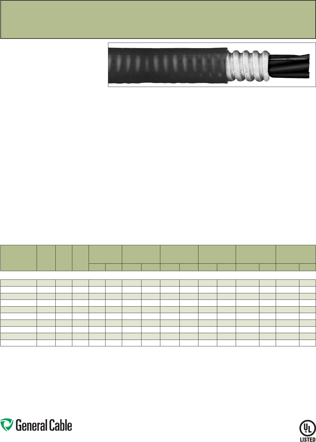
Phone: 888-593-3355
www.generalcable.com
SPEC 7150
June, 2013
Duralox
®
XLPE/AIA/PVC,Power,Armored
600V,ULTypeMC,ThreeandFourConductor(250kcmil—1000kcmil)
Product Construction:
Conductors:
•250kcmilthru1000kcmilbarecompressed
copper
•ClassBstrandingperASTMB8
Insulation:
•Cross-linkedPolyethylene(XLPE)
•Color-codedperICEAMethod3,TableE-2
Ground:
•AnnealedbarecopperClassBstrandingper
ASTMB8
Armor:
•AluminumInterlockedArmor(AIA)
Jacket:
•Flame-retardant,moisture-andsunlight-resistant
PolyvinylChloride(PVC),black
Print:
•GENERALCABLE
®
SIZE(AWGORKCMIL)3/C
OR4/C(ASAPPLICABLE)TYPEMCXHHW-2
CDRS1/CSIZEAWGGRDSUNRESFORCTUSE
DIRBUR600V(UL)MONTH/YEARSEQUENTIAL
FOOTAGEMARK
Options:
•Otherconstructionsavailableuponrequest
Applications:
•Ideallysuitedforuseinabroadrangeof
commercial,industrialandutilityapplications,
wheremaximumperformanceisdemanded,
ease of installation desired and fire resistance
is critical
•PermittedforuseinClassI;ClassII,Division2;
andClassIII,Division1and2hazardous
locationspertheNEC
•Installedinbothexposedorconcealedwork,wet
ordrylocations,indoorsoroutdoorsandcable
trays
Features:
•Ratedat90˚Cwetordry
•Providesexcellentoilandchemicalresistance
•Excellentcrushresistance
•Providesalongservicelife
•Cost-effectivealternativetoinstallations
in conduit
•Meetscoldbendtestat-25˚C
Compliances:
Industry Compliances:
•UL1569
•UL44
•ICEAS-95-658/NEMAWC70
•ULTypeMC-600volts,ULFile#E90496
•NECTypeXHHW-2conductors
Flame Test Compliances:
•IEEE383(70,000BTU/hr)
•UL1581(70,000BTU/hr)
•IEEE1202(70,000BTU/hr)CSAFT4
•ICEAT-29-520(210,000BTU/hr)
Other Compliances:
•EPA40CFR,Part261forleachable
leadcontentperTCLPmethod
•OSHAAcceptable
Packaging:
•ForU.S.customers,materialcuttolengthand
shippedonnon-returnablewoodreels,while
lengthsinexcessof10,000lbs.areprovidedon
returnablesteelreelsthatrequireadeposit.Extra
chargesapplyforcutslessthan1000ft.,lagging,
pullingeyes,parallelingandplexing
CATALOG
NUMBER
NO.
OF
COND.
COND.
SIZE
(AWG)
GRND.
WIRE
SIZE
(AWG)
MINIMUM
INSULATION
THICKNESS
NOM. DIA.
(OVER)
ARMOR
NOMINAL
JACKET
THICKNESS
NOMINAL
CABLE
O.D.
COPPER
WEIGHT
NET
WEIGHT
INCHES mm INCHES mm INCHES mm INCHES mm
LBS/1000 FT
kg/km
LBS/1000 FT
kg/km
250 kcmil - 1000 kcmil - THREE AND FOUR CONDUCTOR - 600 V
11298.036000 3250 4 0.065 1.65 1.81 46.0 0.060 1.52 1.94 49.3 2495 3713 3295 4903
11298.046000* 4 250 4 0.065 1.65 1.95 49.5 0.060 1.52 2.07 52.6 3282 4884 4174 6211
11298.036200 3350 30.065 1.65 2.03 51.6 0.060 1.52 2.16 54.9 3474 5170 4400 6548
11298.046200* 4 350 30.065 1.65 2.20 55.9 0.060 1.52 2.32 59.0 4576 6810 5608 8345
11298.036500 3500 2 0.065 1.65 2.30 58.5 0.075 1.91 2.46 62.5 4934 7343 6126 9116
11298.046500* 4 500 2 0.065 1.65 2.51 63.8 0.075 1.91 2.66 67.6 6509 9687 7825 11644
11298.037000* 3750 10.080 2.03 2.74 69.6 0.075 1.91 2.89 73.4 7351 10940 8806 13104
11298.047000* 4 750 10.080 2.03 3.04 77.2 0.075 1.91 3.21 81.6 9713 14455 11494 17104
11298.037500* 3 1000 1/0 0.080 2.03 3.07 78.0 0.075 1.91 3.24 82.3 9783 14559 11476 17077
11298.047500* 41000 1/0 0.080 2.03 3.41 86.6 0.075 1.91 3.58 91.0 12932 19245 14931 22218
Dimensionsandweightsarenominal;subjecttoindustrytolerances.
*Non-stockitem;minimumrunsapply.PleaseconsultCustomerServiceforpriceanddelivery.
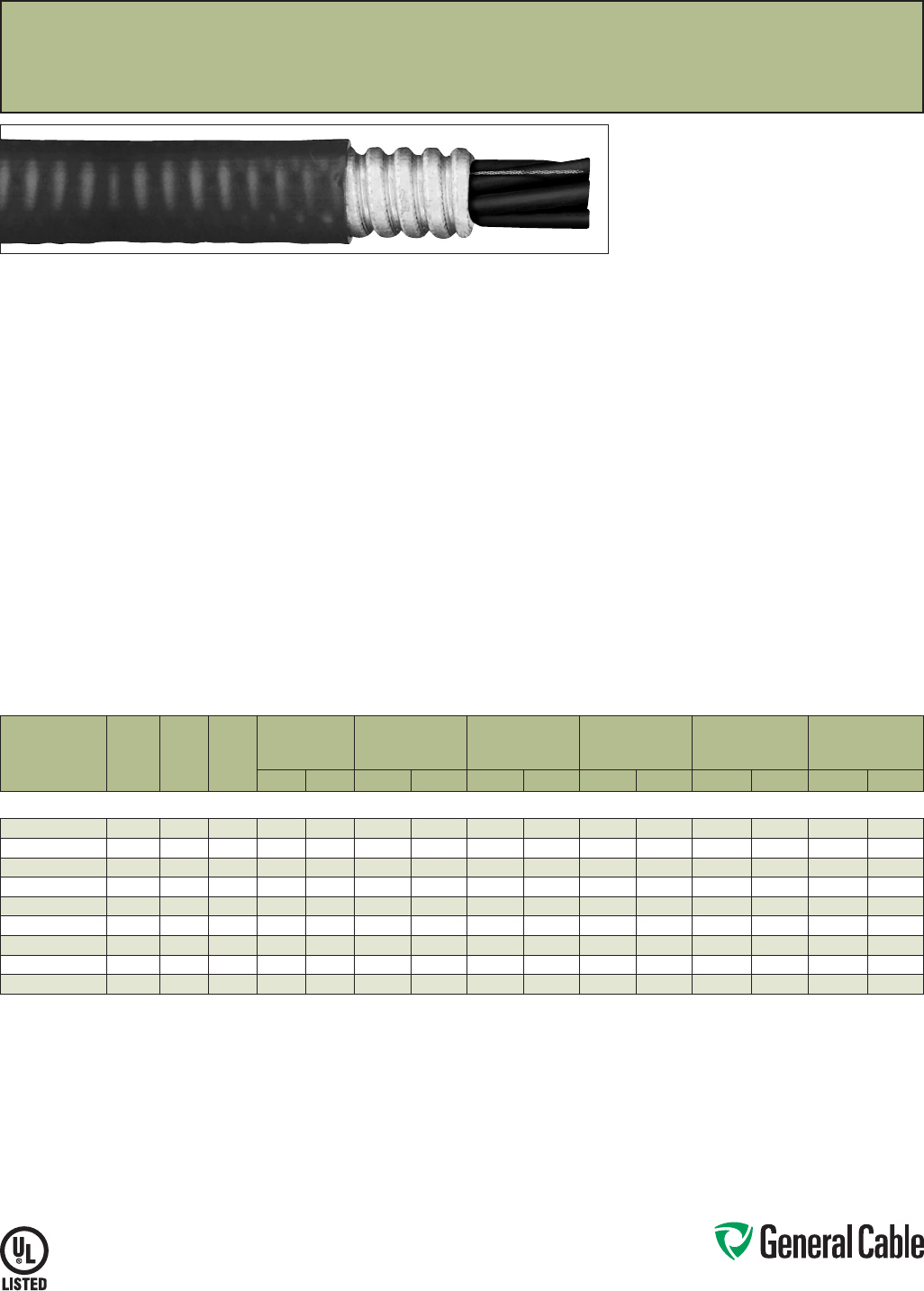
Phone: 888-593-3355
www.generalcable.com
SPEC 7160
June, 2013
Duralox
®
XLPE/AIA/PVC,Power,Armored,withEnhancedGroundWires(50%)
600V,ULTypeMC,ThreeConductor(1/0AWG—1000kcmil)
Product Construction:
Conductors:
•1/0AWGthru1000kcmilbarecompressed
copper
•ClassBstrandingperASTMB8
Insulation:
•Cross-linkedPolyethylene(XLPE)
•Color-codedperICEAMethod3,TableE-2
Ground:
•AnnealedbarecopperClassBstrandingper
ASTMB8
Armor:
•AluminumInterlockedArmor(AIA)
Jacket:
•Flame-retardant,moisture-andsunlight-resistant
PolyvinylChloride(PVC),black
Print:
•GENERALCABLE
®
SIZE(AWGORKCMIL)3/C
TYPEMCXHHW-2CDRS1/CSIZEAWGGRD
SUNRESFORCTUSEDIRBUR600V(UL)
MONTH/YEARSEQUENTIALFOOTAGEMARK
Options:
•Otherconstructionsavailableuponrequest
Applications:
•Ideallysuitedforuseinabroadrangeof
commercial,industrialandutilityapplications,
wheremaximumperformanceisdemanded,
ease of installation desired and fire resistance
is critical
•PermittedforuseinClassI;ClassII,Division
2;andClassIII,Division1and2hazardous
locationspertheNEC
•Installedinbothexposedorconcealedwork,wet
ordrylocations,indoorsoroutdoorsandcable
trays
Features:
•Ratedat90˚Cwetordry
•Providesexcellentoilandchemicalresistance
•Excellentcrushresistance
•Providesalongservicelife
•Cost-effectivealternativetoinstallations
in conduit
•Meetscoldbendtestat-25˚C
Compliances:
Industry Compliances:
•UL1569
•UL44
•ICEAS-95-658/NEMAWC70
•ULTypeMC-600volts,ULFile#E90496
•NECTypeXHHW-2conductors
Flame Test Compliances:
•IEEE383(70,000BTU/hr)
•UL1581(70,000BTU/hr)
•IEEE1202(70,000BTU/hr)CSAFT4
•ICEAT-29-520(210,000BTU/hr)
Other Compliances:
•EPA40CFR,Part261forleachable
leadcontentperTCLPmethod
•OSHAAcceptable
Packaging:
•ForU.S.customers,materialcuttolengthand
shippedonnon-returnablewoodreels,while
lengthsinexcessof10,000lbs.areprovidedon
returnablesteelreelsthatrequireadeposit.Extra
chargesapplyforcutslessthan1000ft.,lagging,
pullingeyes,parallelingandplexing
CATALOG
NUMBER
NO.
OF
COND.
COND.
SIZE
(AWG)
GRND.
WIRE
SIZE
(AWG)
MINIMUM
INSULATION
THICKNESS
NOM. DIA.
(OVER)
ARMOR
NOMINAL
JACKET
THICKNESS
NOMINAL
CABLE
O.D.
COPPER
WEIGHT
NET
WEIGHT
INCHES mm INCHES mm INCHES mm INCHES mm
LBS/1000 FT
kg/km
LBS/1000 FT
kg/km
1/0 AWG - 1000 kcmil - THREE CONDUCTOR - 600 V
11298.515100* 3 1/0 3x6 0.055 1.40 1.27 32.3 0.050 1.27 1.38 35.1 1247 1858 1694 2524
11298.515200* 32/0 3x6 0.055 1.40 1.37 34.8 0.050 1.27 1.48 37.6 1507 2245 2026 3019
11298.515300* 3 3/0 3x5 0.055 1.40 1.48 37.6 0.050 1.27 1.59 40.4 1939 2889 2481 3697
11298.515400* 34/0 3x4 0.055 1.40 1.66 42.2 0.060 1.52 1.79 45.5 2395 3569 3105 4626
11298.516000* 3250 3x4 0.065 1.65 1.81 46.0 0.060 1.52 1.94 49.3 2760 4112 3560 5304
11298.516200* 3350 3x2 0.065 1.65 2.03 51.6 0.060 1.52 2.16 54.9 3944 5877 4870 7256
11298.516500 3500 3x1 0.065 1.65 2.30 58.5 0.075 1.91 2.46 62.5 5473 8155 6665 9931
11298.517000* 3750 3x2/0 0.080 2.03 2.74 69.6 0.075 1.91 2.89 73.4 8022 11953 9477 14121
11298.517500* 3 1000 3x3/0 0.080 2.03 3.07 78.0 0.075 1.91 3.24 82.3 10629 15837 12322 18360
Dimensionsandweightsarenominal;subjecttoindustrytolerances.
*Non-stockitem;minimumrunsapply.PleaseconsultCustomerServiceforpriceanddelivery.
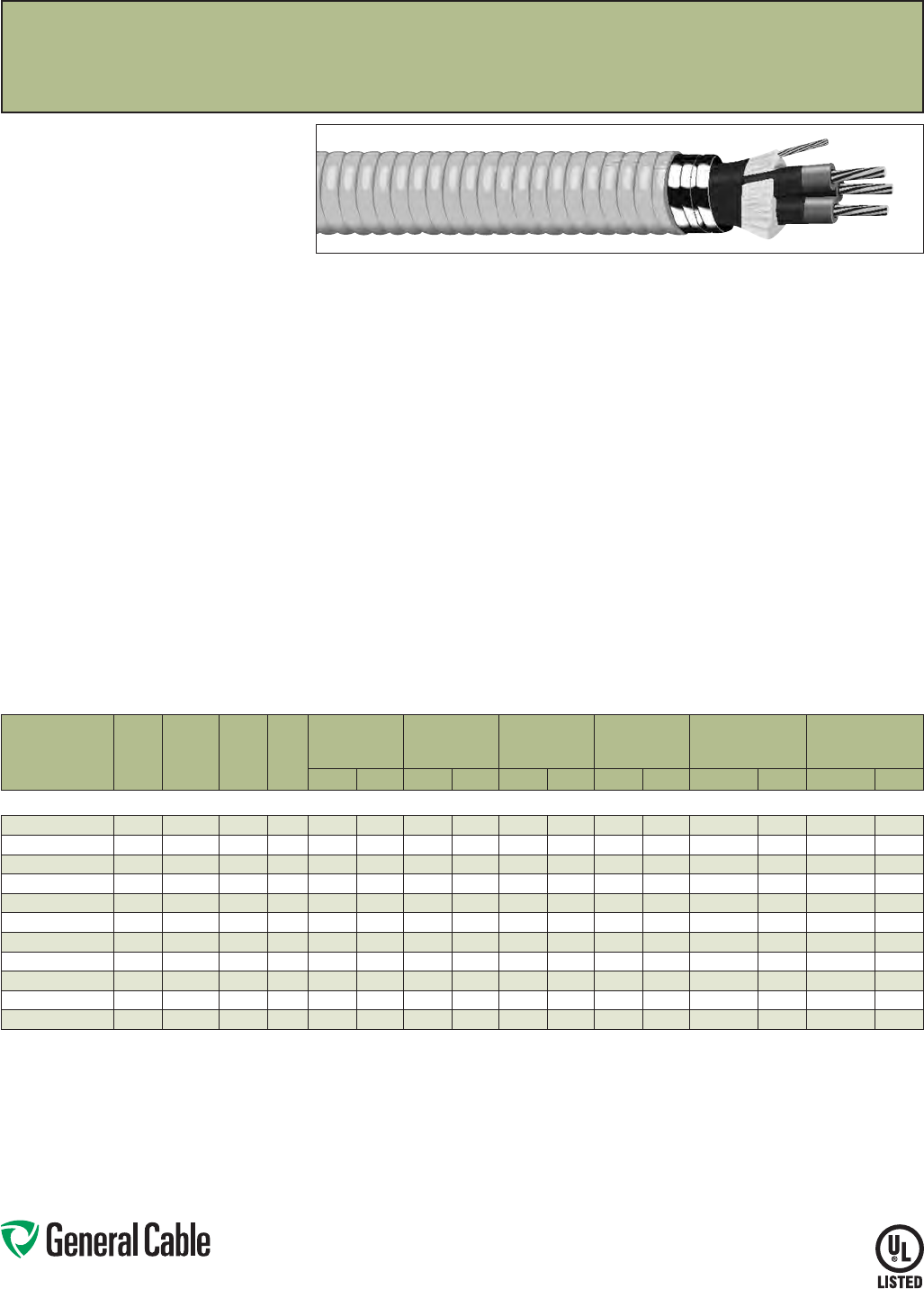
Phone: 888-593-3355
www.generalcable.com
SPEC 7200
January, 2010
Duralox
®
EPR/AIA/PVC,Power,Nonshielded,Armored
2400V,ULTypeMV-90orMC,ThreeConductor
Product Construction:
Conductors:
•6AWGthru1000kcmilbarecopper,compact
ClassBstrand
Extruded Strand Shield (ESS):
•Extrudedthermosetsemi-conductingstress
controllayeroverconductor
Insulation:
•EthylenePropyleneRubber(EPR),coloredto
contrastwithblackconductingshieldlayer
Ground:
•AnnealedbarecopperClassBstrandingper
ASTMB8
Armor:
•AluminumInterlockedArmor(AIA)
Jacket:
•Flame-retardant,moisture-andsunlight-resistant
PolyvinylChloride(PVC),yellow
Print:
•GENERALCABLE
®
SIZE(KCMILORAWG)
COMPACTCU3/CGENERALCABLE115MILS
EPRTYPEMV-90ORMC3/CSIZEAWGGRD
SUNRESFORCTUSEDIRBUR2400VNON-
SHIELDED(UL)MONTH-YEARLIGHTNINGBOLT
SYMBOLSEQUENTIALFOOTAGEMARK
Options:
•Otherconstructionsavailableuponrequest
Applications:
•Ideallysuitedforuseinabroadrangeof
commercial,industrialandutilityapplications
wherereliabilityisthemajorconcern,maximum
performancewillbedemanded,spaceislimited,
ease of installation is critical and fire resistance
isnecessary
•Maybeinstalledinwetordrylocations,indoors
oroutdoorsandinexposedorconcealedwork
•Maybeusedincabletraysoronapproved
supportsinprotectedareas
•PermittedforuseinClassI;ClassII,Division2;
andClassIII,Divisions1and2hazardous
locationspertheNEC
Features:
•Ratedat90˚Cwetordry
•Excellentheatandmoistureresistance
•Outstandingcoronaresistance
•Flexibilityforeasyhandling
•Highdielectricstrength
•Lowmoistureabsorption
•Electricalstabilityunderstress
•Lowdielectricloss
•Chemical-andradiation-resistant
•Excellentcrushresistance
•Flameorsunlightresistance
•Cost-effectivealternativetoinstallations
in conduit
•Meetsthecoldbendtestat-25˚C
Compliances:
Industry Compliances:
•UL1569
•UL1072
•ICEAS-96-659/NEMAWC71
•ULTypeMV-90,ULFile#E90501
•ULTypeMC,ULFile#E90496
Flame Test Compliances:
•IEEE383(70,000BTU/hr)
•UL1581(70,000BTU/hr)
•IEEE1202(70,000BTU/hr)CSAFT4
•ICEAT-29-520(210,000BTU/hr)
•ICEAT-30-520(70,000BTU/hr)
Other Compliances:
•EPA40CFR,Part261forleachable
leadcontentperTCLPmethod
•OSHAAcceptable
Packaging:
•Materialcuttolengthandshippedon
non-returnablewoodreels,whilelengthsin
excessof10,000lbs.areprovidedonreturnable
steelreelsthatrequireadeposit.Extracharges
applyforcutslessthan1000ft.,lagging,pulling
eyes,parallelingandplexing
CATALOG
NUMBER
NO.
OF
COND.
COND.
SIZE
(AWG)
COND.
DIA.
INCHES
GRND.
WIRE
SIZE
(AWG)
MINIMUM
INSULATION
THICKNESS
NOM. DIA.
(OVER)
ARMOR
NOMINAL
JACKET
THICKNESS
NOMINAL
CABLE
O.D.
COPPER
WEIGHT
NET
WEIGHT
INCHES mm INCHES mm INCHES mm INCHES mm
LBS/1000 FT
kg/km
LBS/1000 FT
kg/km
6 AWG - 1000 kcmil - THREE CONDUCTOR - 115 MILS INS. (2.92 mm) - 2400 V
17471.580600 3 6 0.17 60.115 2.92 1.16 29.4 0.050 1.27 1.27 32.2 327 487 854 1272
17471.580400 34 0.21 60.115 2.92 1.26 31.9 0.050 1.27 1.37 34.7 473 704 1056 1572
17471.580200 32 0.27 60.115 2.92 1.37 34.8 0.050 1.27 1.48 37.6 703 1047 1363 2030
17471.585100* 3 1/0 0.34 4 0.115 2.92 1.61 41.0 0.060 1.52 1.74 44.3 1118 1665 2003 2982
17471.585200 32/0 0.38 4 0.115 2.92 1.71 43.3 0.060 1.52 1.84 46.6 1376 2049 2326 3463
17471.585400 34/0 0.48 30.115 2.92 1.92 48.7 0.060 1.52 2.05 52.0 2143 3191 3256 4848
17471.586000* 3250 0.52 30.115 2.92 2.00 50.7 0.060 1.52 2.13 54.1 2503 3727 3689 5493
17471.586200 3350 0.62 2 0.115 2.92 2.21 56.0 0.060 1.52 2.34 59.3 3479 5180 4825 7184
17471.586500 3500 0.74 10.115 2.92 2.46 62.6 0.075 1.91 2.63 66.7 4933 7345 6567 9778
17471.587000* 3750 0.91 1/0 0.115 2.92 2.83 72.0 0.075 1.91 3.00 76.1 7347 10940 9320 13877
17471.587500* 3 1000 1.07 1/0 0.115 2.92 3.16 80.3 0.085 2.16 3.35 85.0 9680 14414 12023 17902
Dimensionsandweightsarenominal;subjecttoindustrytolerances.
*Non-stockitem;minimumrunsapply.PleaseconsultCustomerServiceforpriceanddelivery.
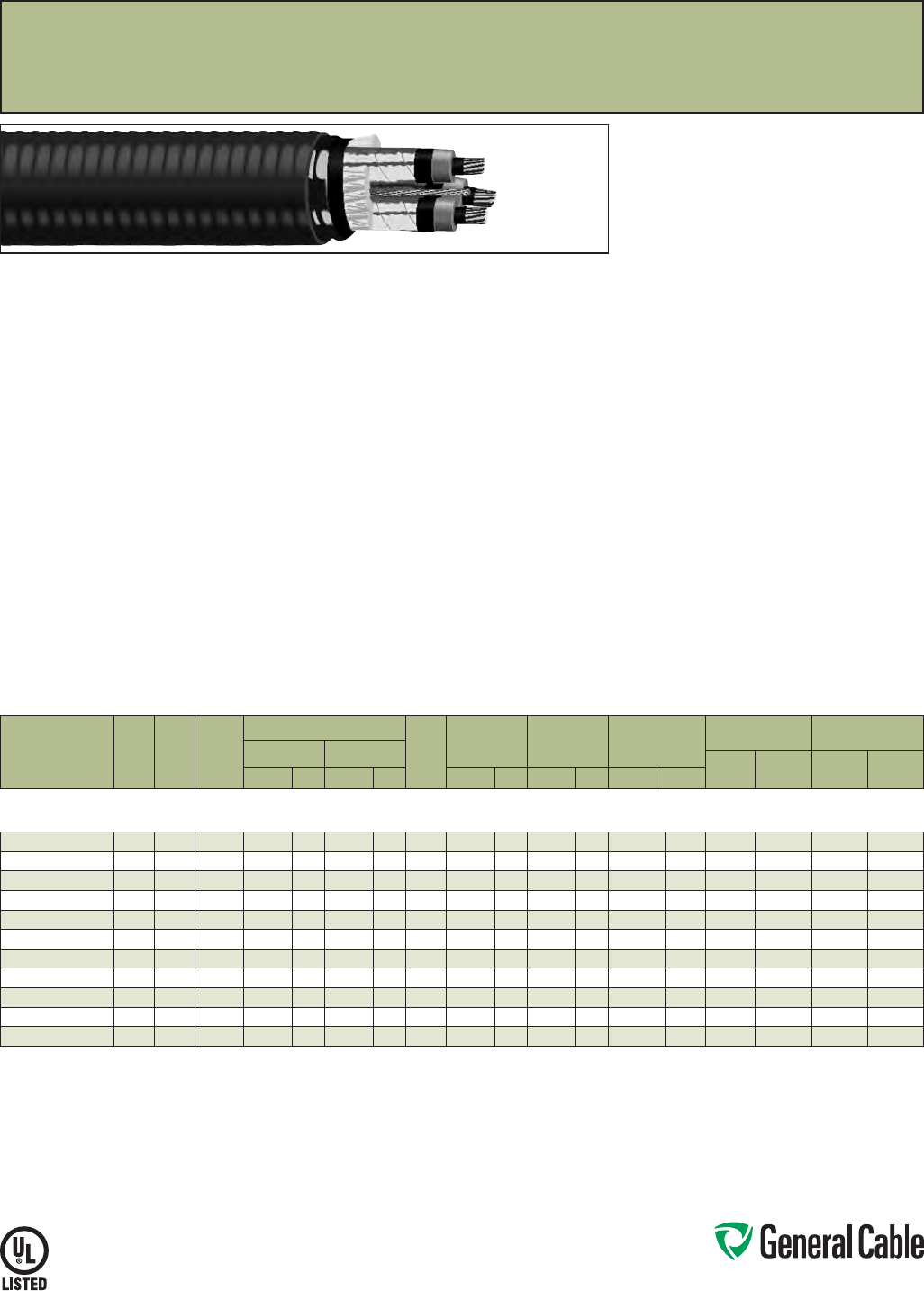
Phone: 888-593-3355
www.generalcable.com
SPEC 7250
August, 2010
Duralox
®
Uniblend
®
EPR/AIA/PVC,Power,Shielded,Armored
5kV/8kV,ULTypeMV-105orMC,133%/100%Ins.Levels,115Mils,ThreeConductor
Product Construction:
Conductors:
•6AWGthru1000kcmilbare,coppercompact
ClassBstrand
Extruded Strand Shield (ESS):
•Thermosetsemi-conductingextrudedstress
controllayeroverconductor
Insulation:
•EthylenePropyleneRubber(EPR)insulation,
coloredtocontrastwithblackconductinglayers
Extruded Insulation Shield (EIS):
•Thermosetsemi-conductingpolymericlayerfree
strippingfrominsulation
Shield:
•5milannealedcoppertapewithaminimum25%
overlap
Ground:
•AnnealedbarecopperClassBstrandingper
ASTMB8
Armor:
•AluminumInterlockedArmor(AIA)
Jacket:
•Flame-retardant,moisture-andsunlight-resistant
PolyvinylChloride(PVC),yellow
Print:
•GENERALCABLE
®
SIZE(KCMILORAWG)
COMPACTCU3/C(INSTHICKNESS)MILS
EPRTYPEMV-105ORMC3/CSIZEAWGGRD
VOLTAGEkV%INSLEVELSUNRESFORCT
USEDIRBUR(UL)LIGHTINGBOLTSYMBOL
MONTH-YEARSEQUENTIALFOOTAGEMARK
Options:
•Otherconstructionsavailableuponrequest
Applications:
•Ideallysuitedforuseinabroadrangeof
commercial,industrialandutilityapplications
wherereliabilityisthemajorconcern,maximum
performanceisdemanded,spaceislimited,ease
of installation is critical and fire resistance is
necessary
•Installedinwetordrylocations,indoors
oroutdoors,inexposedorconcealedwork
•Maybeusedincabletraysoronapproved
supportinprotectedareas
•PermittedforuseinClassI;ClassII,Division2;
andClassIII,Divisions1and2hazardous
locationspertheNEC
Features:
•Ratedat105˚Cwetordry
•Excellentheatandmoistureresistance
•Outstandingcoronaresistance
•Flexibilityforeasyhandling
•Highdielectricstrength
•Lowmoistureabsorption
•Electricalstabilityunderstress
•Lowdielectricloss
•Chemical-andradiation-resistant
•Excellentcrushresistance
•Cost-effectivealternativetoinstallations
in conduit
•Meetscoldbendtestat-25˚C
Compliances:
Industry Compliances:
•UL1072
•ICEAS-93-639/NEMAWC74
•AEICCS8
•ULTypeMV-105,ULFile#E90501
•ULTypeMC,ULFile#E90496
Flame Test Compliances:
•IEEE383(70,000BTU/hr)
•UL1581(70,000BTU/hr)
•IEEE1202(70,000BTU/hr)CSAFT4
•ICEAT-29-520(210,000BTU/hr)
•ICEAT-30-520(70,000BTU/hr)
Other Compliances:
•EPA40CFR,Part261forleachable
leadcontentperTCLPmethod
•OSHAAcceptable
Packaging:
•Materialcuttolengthandshippedon
non-returnablewoodreels,whilelengthsin
excessof10,000lbs.areprovidedonreturnable
steelreelsthatrequireadeposit.Extracharges
applyforcutslessthan1000ft.,lagging,pulling
eyes,parallelingandplexing
CATALOG
NUMBER
NO.
OF
COND.
COND.
SIZE
(AWG)
COND.
DIA.
INCHES
INSULATION DIAMETER GRND.
WIRE
SIZE
(AWG)
NOM. DIA.
(OVER)
ARMOR
NOMINAL
JACKET
THICKNESS
NOMINAL
CABLE
O.D.
COPPER
WEIGHT
NET WEIGHT
W/AL ARMOR
MIN. MAX.
LBS/
1000 FT
kg/
km
LBS/
1000 FT
kg/
kmINCHES mm INCHES mm INCHES mm INCHES mm INCHES mm
6 AWG - 1000 kcmil - THREE CONDUCTOR -
W/JACKET OVER ARMOR, 5 kV, 133% INS. LEVEL OR 8 kV, 100% INS. LEVEL, 115 MILS INS. (2.92 mm)
17473.530600* 3 6 0.17 0.42 10.5 0.49 12.5 61.33 33.8 0.050 1.27 1.44 36.6 462 688 1133 1687
17473.530400* 34 0.21 0.46 11.6 0.54 13.7 61.43 36.2 0.050 1.27 1.54 39.1 619 922 1354 2016
17473.530200 32 0.27 0.51 13.0 0.59 14.9 61.64 41.6 0.060 1.52 1.77 44.9 864 1286 1819 2708
17473.535100* 3 1/0 0.34 0.58 14.7 0.66 16.7 4 1.79 45.3 0.060 1.52 1.92 48.6 1298 1933 2364 3520
17473.535200 32/0 0.38 0.62 15.7 0.70 17.7 4 1.87 47.5 0.060 1.52 2.00 50.8 1566 2332 2696 4014
17473.535400 34/0 0.48 0.72 18.3 0.80 20.3 32.09 53.2 0.060 1.52 2.22 56.5 2360 3514 3687 5490
17473.536000* 3250 0.52 0.77 19.6 0.85 21.5 32.21 56.0 0.060 1.52 2.34 59.3 2735 4072 4165 6202
17473.536200 3350 0.62 0.87 22.1 0.95 24.1 2 2.41 61.3 0.075 1.91 2.57 65.4 3736 5563 5436 8094
17473.536500 3500 0.74 0.99 25.1 1.07 27.1 12.64 67.0 0.075 1.91 2.84 72.0 5222 7776 7170 10676
17473.537000* 3750 0.91 1.17 29.7 1.25 31.8 1/0 3.06 77.8 0.085 2.16 3.25 82.4 7684 11441 10084 15015
17473.537500* 3 1000 1.07 1.33 33.8 1.40 35.6 1/0 3.39 86.1 0.085 2.16 3.57 90.8 10057 14975 12793 19049
Dimensionsandweightsarenominal;subjecttoindustrytolerances.
*Non-stockitem;minimumrunsapply.PleaseconsultCustomerServiceforpriceanddelivery.
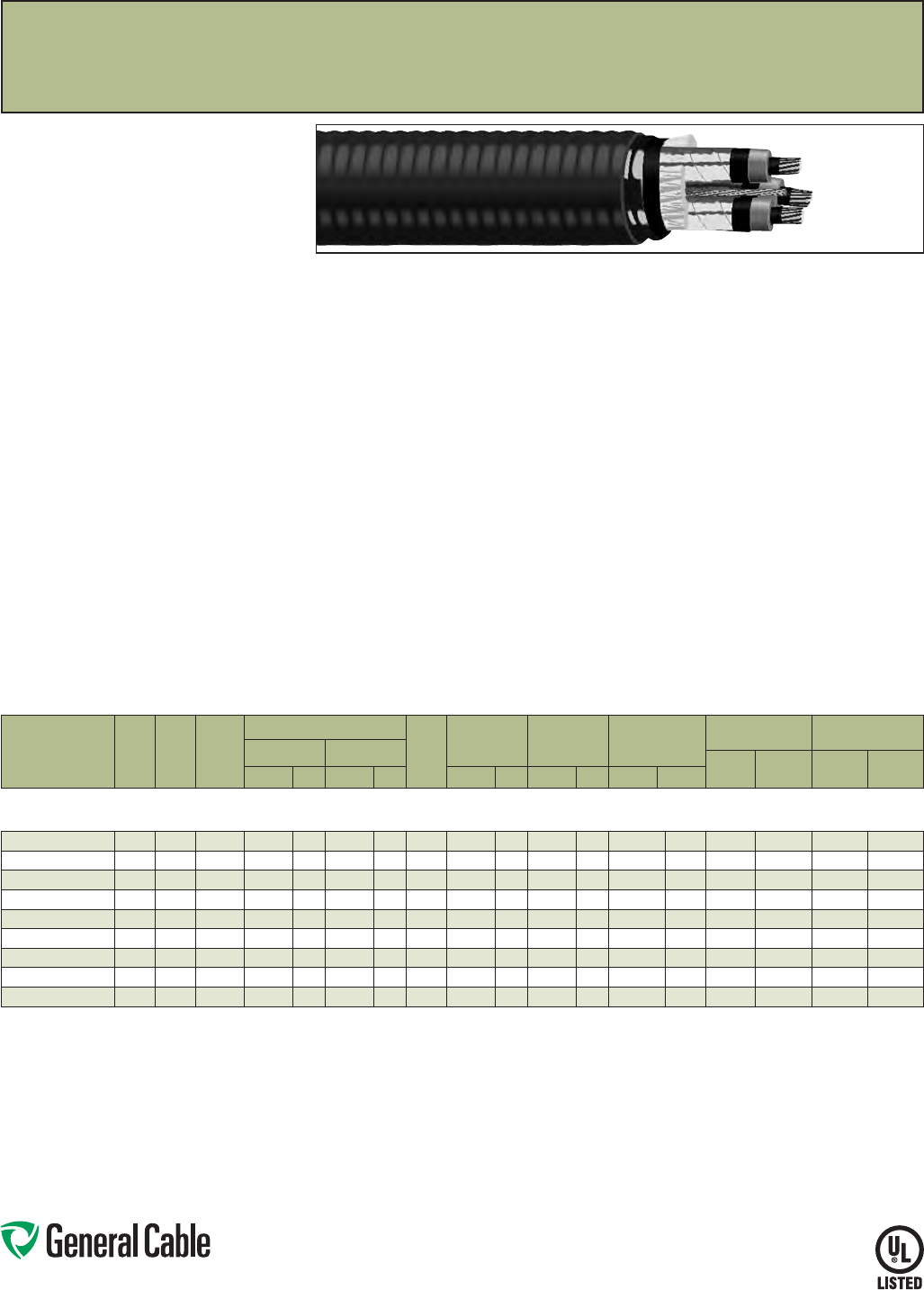
Phone: 888-593-3355
www.generalcable.com
SPEC 7300
August, 2010
Duralox
®
Uniblend
®
EPR/AIA/PVC,Power,Shielded,Armored
15kV,ULTypeMV-105orMC,133%Ins.Level,220Mils,ThreeConductor
Product Construction:
Conductors:
•2AWGthru1000kcmilbare,coppercompact
ClassBstrand
Extruded Strand Shield (ESS):
•Thermosetsemi-conductingextrudedstress
controllayeroverconductor
Insulation:
•EthylenePropyleneRubber(EPR)insulation,
coloredtocontrastwithblackconductinglayers
Extruded Insulation Shield (EIS):
•Thermosetsemi-conductingpolymericlayerfree
strippingfrominsulation
Shield:
•5milannealedcoppertapewithaminimum25%
overlap
Ground:
•AnnealedbarecopperClassBstrandingper
ASTMB8
Armor:
•AluminumInterlockedArmor(AIA)
Jacket:
•Flame-retardant,moisture-andsunlight-resistant
PolyvinylChloride(PVC),red
Print:
•GENERALCABLE
®
SIZE(KCMILORAWG)
COMPACTCU3/C(INSTHICKNESS)MILS
EPRTYPEMV-105ORMC3/CSIZEAWGGRD
VOLTAGEkV%INSLEVELSUNRESFORCT
USEDIRBUR(UL)LIGHTINGBOLTSYMBOL
MONTH-YEARSEQUENTIALFOOTAGEMARK
Options:
•Otherconstructionsavailableuponrequest
Applications:
•Ideallysuitedforuseinabroadrangeof
commercial,industrialandutilityapplications
wherereliabilityisthemajorconcern,maximum
performanceisdemanded,spaceislimited,ease
of installation is critical and fire resistance is
necessary
•Installedinwetordrylocations,indoors
oroutdoors,inexposedorconcealedwork
•Maybeusedincabletraysoronapproved
supportinprotectedareas
•PermittedforuseinClassI;ClassII,Division2;
andClassIII,Divisions1and2hazardous
locationspertheNEC
Features:
•Ratedat105˚Cwetordry
•Excellentheatandmoistureresistance
•Outstandingcoronaresistance
•Flexibilityforeasyhandling
•Highdielectricstrength
•Lowmoistureabsorption
•Electricalstabilityunderstress
•Lowdielectricloss
•Chemical-andradiation-resistant
•Excellentcrushresistance
•Cost-effectivealternativetoinstallations
in conduit
•Meetscoldbendtestat-25˚C
Compliances:
Industry Compliances:
•UL1072
•ICEAS-93-639/NEMAWC74
•AEICCS8
•ULTypeMV-105,ULFile#E90501
•ULTypeMC,ULFile#E90496
Flame Test Compliances:
•IEEE383(70,000BTU/hr)
•UL1581(70,000BTU/hr)
•IEEE1202(70,000BTU/hr)CSAFT4
•ICEAT-29-520(210,000BTU/hr)
•ICEAT-30-520(70,000BTU/hr)
Other Compliances:
•EPA40CFR,Part261forleachable
leadcontentperTCLPmethod
•OSHAAcceptable
Packaging:
•Materialcuttolengthandshippedon
non-returnablewoodreels,whilelengthsin
excessof10,000lbs.areprovidedonreturnable
steelreelsthatrequireadeposit.Extracharges
applyforcutslessthan1000ft.,lagging,pulling
eyes,parallelingandplexing
CATALOG
NUMBER
NO.
OF
COND.
COND.
SIZE
(AWG/)
kcmil
COND.
DIA.
INCHES
INSULATION DIAMETER GRND.
WIRE
SIZE
(AWG)
NOM. DIA.
(OVER)
ARMOR
NOMINAL
JACKET
THICKNESS
NOMINAL
CABLE
O.D.
COPPER
WEIGHT
NET WEIGHT
W/AL ARMOR
MIN. MAX.
LBS/
1000 FT
kg/
km
LBS/
1000 FT
kg/
kmINCHES mm INCHES mm INCHES mm INCHES mm INCHES mm
2 AWG - 1000 kcmil - THREE CONDUCTOR -
W/JACKET OVER ARMOR, 15 kV, 133% INS. LEVEL, 220 MILS INS. (5.59 mm)
17476.530200 32 0.27 0.71 18.0 0.80 20.3 62.08 52.8 0.060 1.52 2.21 56.1 919 1368 2416 3597
17476.535100* 3 1/0 0.34 0.78 19.8 0.87 22.0 4 2.22 56.5 0.060 1.52 2.35 59.8 1352 2013 2997 4463
17476.535200 32/0 0.38 0.82 20.8 0.91 24.3 4 2.31 58.7 0.060 1.52 2.44 62.0 1620 2412 3371 5019
17476.535400 34/0 0.48 0.92 23.4 1.01 25.6 32.53 64.3 0.075 1.91 2.70 68.5 2114 3594 4502 6703
17476.536000* 3250 0.53 0.97 24.6 1.06 26.9 32.65 67.2 0.075 1.91 2.81 71.3 2789 4153 5005 7452
17476.536200 3350 0.62 1.07 27.2 1.16 29.4 2 2.85 72.4 0.075 1.91 3.01 76.6 3790 5643 6252 9309
17476.536500 3500 0.74 1.19 30.2 1.28 32.4 13.11 79.0 0.085 2.16 3.30 83.7 5276 7856 8091 12047
17476.537000* 3750 0.91 1.37 34.8 1.46 37.1 1/0 3.50 89.0 0.085 2.16 3.69 93.6 7738 11522 11086 16507
17476.537500* 3 1000 1.06 1.52 38.6 1.61 40.9 1/0 3.83 97.3 0.085 2.16 4.01 101.9 10111 15055 13870 20652
Dimensionsandweightsarenominal;subjecttoindustrytolerances.
*Non-stockitem;minimumrunsapply.PleaseconsultCustomerServiceforpriceanddelivery.
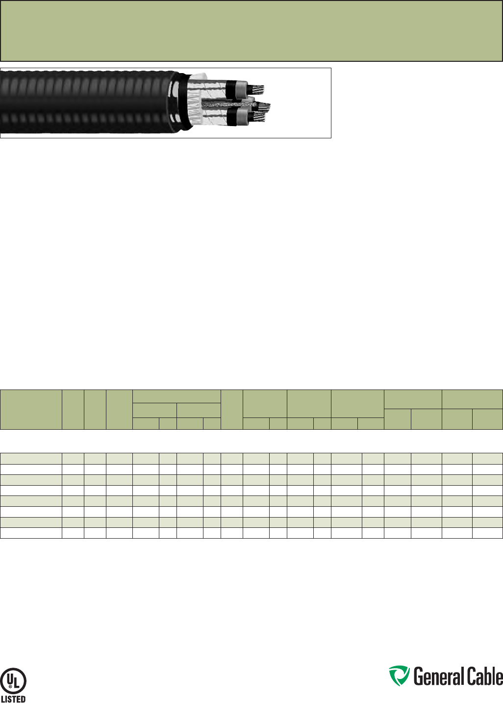
Phone: 888-593-3355
www.generalcable.com
SPEC 7310
December, 2013
Duralox
®
Uniblend
®
EPR/AIA/PVC, Power, Shielded, Armored, with Enhanced Ground Wires (50%)
15 kV, UL Type MV-105 or MC, 133% Ins. Level, 220 Mils, Three Conductor
Product Construction:
Conductors:
•1/0AWGthru1000kcmilbare,coppercompact
Class B strand
Extruded Strand Shield (ESS):
•Thermosetsemi-conductingextrudedstress
control layer over conductor
Insulation:
•EthylenePropyleneRubber(EPR)insulation,
coloredtocontrastwithblackconductinglayers
Extruded Insulation Shield (EIS):
•Thermosetsemi-conductingpolymericlayerfree
strippingfrominsulation
Shield:
•5milannealedcoppertapewithaminimum25%
overlap
Ground:
•AnnealedbarecopperClassBstrandingper
ASTM B8
Armor:
•AluminumInterlockedArmor(AIA)
Jacket:
•Flame-retardant,moisture-andsunlight-resistant
Polyvinyl Chloride (PVC), red
Print:
•GENERAL CABLE
®
SIZE (KCMIL OR AWG)
COMPACT CU 3/C (INS THICKNESS) MILS
EPR TYPE MV-105 OR MC 3/C SIZE AWG GRD
VOLTAGEkV%INSLEVELSUNRESFORCT
USE DIR BUR (UL) LIGHTING BOLT SYMBOL
MONTH-YEAR SEQUENTIALFOOTAGEMARK
Options:
•Otherconstructionsavailableuponrequest
Applications:
•Ideallysuitedforuseinabroadrangeof
commercial, industrial and utility applications
wherereliabilityisthemajorconcern,maximum
performanceisdemanded,spaceislimited,ease
ofinstallationiscriticalandfireresistanceis
necessary
•Installedinwetordrylocations,indoors
oroutdoors,inexposedorconcealedwork
•Maybeusedincabletraysoronapproved
support in protected areas
•PermittedforuseinClassI;ClassII,Division2;
and Class III, Divisions 1 and 2 hazardous
locations per the NEC
Features:
•Ratedat105˚Cwetordry
•Excellentheatandmoistureresistance
•Outstandingcoronaresistance
•Flexibilityforeasyhandling
•Highdielectricstrength
•Lowmoistureabsorption
•Electricalstabilityunderstress
•Lowdielectricloss
•Chemical-andradiation-resistant
•Excellentcrushresistance
•Cost-effectivealternativetoinstallations
in conduit
•Meetscoldbendtestat-25˚C
Compliances:
Industry Compliances:
•UL1072
•ICEAS-93-639/NEMAWC74
•AEICCS8
•ULTypeMV-105,ULFile#E90501
•ULTypeMC,ULFile#E90496
Flame Test Compliances:
•IEEE383(70,000BTU/hr)
•UL1581(70,000BTU/hr)
•IEEE1202(70,000BTU/hr)CSAFT4
•ICEAT-29-520(210,000BTU/hr)
•ICEAT-30-520(70,000BTU/hr)
Other Compliances:
•EPA40CFR,Part261forleachable
lead content per TCLP method
•OSHAAcceptable
Packaging:
•Materialcuttolengthandshippedon
non-returnablewoodreels,whilelengthsin
excessof10,000lbs.areprovidedonreturnable
steelreelsthatrequireadeposit.Extracharges
applyforcutslessthan1000ft.,lagging,pulling
eyes,parallelingandplexing
CATALOG
NUMBER
NO.
OF
COND.
COND.
SIZE
(AWG/)
kcmil
COND.
DIA.
INCHES
INSULATION DIAMETER GRND.
WIRE
SIZE
(AWG)
NOM. DIA.
(OVER)
ARMOR
NOMINAL
JACKET
THICKNESS
NOMINAL
CABLE
O.D.
COPPER
WEIGHT
NET WEIGHT
W/AL ARMOR
MIN. MAX.
LBS/
1000FT
kg/
km
LBS/
1000FT
kg/
kmINCHES mm INCHES mm INCHES mm INCHES mm INCHES mm
1/0 AWG - 1000 kcmil - THREE CONDUCTOR -
W/JACKET OVER ARMOR, 15 kV, 133% INS. LEVEL, 220 MILS INS. (5.59 mm)
17476.515100* 3 1/0 0.34 0.78 19.8 0.87 22.0 3x6 2.22 56.5 0.060 1.52 2.35 59.8 1469 2187 3119 4644
17476.515200* 3 2/0 0.38 0.82 20.8 0.91 24.3 3x6 2.31 58.7 0.060 1.52 2.44 62.0 1748 2603 3499 5210
17476.515400* 34/0 0.48 0.92 23.4 1.01 25.6 3x4 2.53 64.3 0.075 1.91 2.70 68.5 2661 3962 4752 7076
17476.516000* 3 250 0.53 0.97 24.6 1.06 26.9 3x4 2.65 67.2 0.075 1.91 2.81 71.3 3145 4683 5265 7840
17476.516200* 3 350 0.62 1.07 27.2 1.16 29.4 3x2 2.85 72.4 0.075 1.91 3.01 76.6 4212 6272 6674 9938
17476.516500* 3 500 0.74 1.19 30.2 1.28 32.4 3x1 3.11 79.0 0.085 2.16 3.30 83.7 5807 8647 8550 12731
17476.517000* 3750 0.91 1.37 34.8 1.46 37.1 3x2/0 3.50 89.0 0.085 2.16 3.69 93.6 8574 12767 11932 17767
17476.517500* 3 1000 1.06 1.52 38.6 1.61 40.9 3x3/0 3.83 97.3 0.085 2.16 4.01 101.9 11198 16674 14957 22271
Dimensionsandweightsarenominal;subjecttoindustrytolerances.
*Non-stockitem;minimumrunsapply.PleaseconsultCustomerServiceforpriceanddelivery.
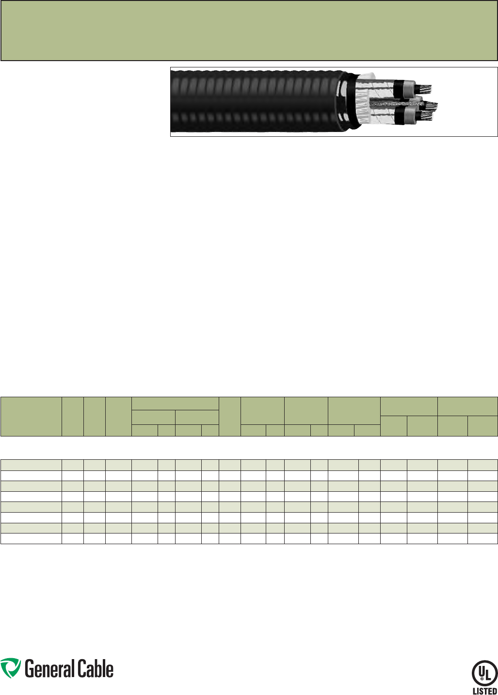
Phone: 888-593-3355
www.generalcable.com
SPEC 7350
August, 2010
Duralox
®
Uniblend
®
EPR/AIA/PVC,Power,Shielded,Armored
25kV,ULTypeMV-105orMC,100%Ins.Level,260Mils,ThreeConductor
Product Construction:
Conductors:
•1/0AWGthru1000kcmilbare,coppercompact
ClassBstrand
Extruded Strand Shield (ESS):
•Thermosetsemi-conductingextrudedstress
controllayeroverconductor
Insulation:
•EthylenePropyleneRubber(EPR)insulation,
coloredtocontrastwithblackconductinglayers
Extruded Insulation Shield (EIS):
•Thermosetsemi-conductingpolymericlayerfree
strippingfrominsulation
Shield:
•5milannealedcoppertapewithaminimum25%
overlap
Ground:
•AnnealedbarecopperClassBstrandingper
ASTMB8
Armor:
•AluminumInterlockedArmor(AIA)
Jacket:
•Flame-retardant,moisture-andsunlight-resistant
PolyvinylChloride(PVC),red
Print:
•GENERALCABLE
®
SIZE(KCMILORAWG)
COMPACTCU3/C(INSTHICKNESS)MILS
EPRTYPEMV-105ORMC3/CSIZEAWGGRD
VOLTAGEkV%INSLEVELSUNRESFORCT
USEDIRBUR(UL)LIGHTINGBOLTSYMBOL
MONTH-YEARSEQUENTIALFOOTAGEMARK
Options:
•Otherconstructionsavailableuponrequest
Applications:
•Ideallysuitedforuseinabroadrangeof
commercial,industrialandutilityapplications
wherereliabilityisthemajorconcern,where
maximumperformanceisdemanded,spaceis
limited,easeofinstallationiscriticalandfire
resistanceisnecessary
•Installedinwetordrylocations,indoors
oroutdoors,inexposedorconcealedwork
•Maybeusedincabletraysoronapproved
supportinprotectedareas
•PermittedforuseinClassI;ClassII,Division
2;andClassIII,Divisions1and2hazardous
locationspertheNEC
Features:
•Ratedat105˚Cwetordry
•Excellentheatandmoistureresistance
•Outstandingcoronaresistance
•Flexibilityforeasyhandling
•Highdielectricstrength
•Lowmoistureabsorption
•Electricalstabilityunderstress
•Lowdielectricloss
•Chemical-andradiation-resistant
•Excellentcrushresistance
•Cost-effectivealternativetoinstallations
in conduit
•Meetscoldbendtestat-25˚C
Compliances:
Industry Compliances:
•UL1072
•ICEAS-93-639/NEMAWC74
•AEICCS8
•ULTypeMV-105,ULFile#E90501
•ULTypeMC,ULFile#E90496
Flame Test Compliances:
•IEEE383(70,000BTU/hr)
•UL1581(70,000BTU/hr)
•IEEE1202(70,000BTU/hr)CSAFT4
•ICEAT-29-520(210,000BTU/hr)
•ICEAT-30-520(70,000BTU/hr)
Other Compliances:
•EPA40CFR,Part261forleachable
leadcontentperTCLPmethod
•OSHAAcceptable
Packaging:
•Materialcuttolengthandshippedon
non-returnablewoodreels,whilelengthsin
excessof10,000lbs.areprovidedonreturnable
steelreelsthatrequireadeposit.Extracharges
applyforcutslessthan1000ft.,lagging,pulling
eyes,parallelingandplexing
CATALOG
NUMBER
NO.
OF
COND.
COND.
SIZE
(AWG/)
kcmil
COND.
DIA.
INCHES
INSULATION DIAMETER GRND.
WIRE
SIZE
(AWG)
NOM. DIA.
(OVER)
ARMOR
NOMINAL
JACKET
THICKNESS
NOMINAL
CABLE
O.D.
COPPER
WEIGHT
NET WEIGHT
W/AL ARMOR
MIN. MAX.
LBS/
1000 FT
kg/
km
LBS/
1000 FT
kg/
kmINCHES mm INCHES mm INCHES mm INCHES mm INCHES mm
1/0 AWG - 1000 kcmil - THREE CONDUCTOR -
W/JACKET OVER ARMOR, 25 kV, 100% INS. LEVEL, 260 MILS INS. (6.60 mm)
17477.535100* 3 1/0 0.34 0.85 21.6 0.94 23.9 4 2.39 60.8 0.075 1.91 2.56 64.9 1372 2043 3358 5000
17477.535200* 32/0 0.38 0.89 22.6 0.98 24.9 4 2.48 63.0 0.075 1.91 2.64 67.1 1641 2443 3743 5573
17477.535400* 34/0 0.48 0.99 25.1 1.08 27.4 32.70 68.6 0.075 1.91 2.86 72.7 2435 3626 4807 7158
17477.536000* 3250 0.53 1.04 26.4 1.14 28.8 32.81 71.5 0.075 1.91 2.98 75.6 2810 4184 5307 7902
17477.536200* 3350 0.62 1.14 29.0 1.23 31.2 2 3.02 76.7 0.075 1.91 3.18 80.8 3811 5675 6595 9820
17477.536500* 3500 0.74 1.26 32.0 1.35 34.3 13.28 83.3 0.085 2.16 3.46 88.0 5297 7887 8485 12634
17477.537000* 3750 0.91 1.44 36.6 1.54 39.0 1/0 3.67 93.2 0.085 2.16 3.85 97.9 7758 11552 11491 17110
17477.517500* 3 1000 1.06 1.59 40.4 1.69 42.8 1/0 4.00 101.5 0.085 2.16 4.18 106.2 10132 15087 14303 21297
Dimensionsandweightsarenominal;subjecttoindustrytolerances.
*Non-stockitem;minimumrunsapply.PleaseconsultCustomerServiceforpriceanddelivery.
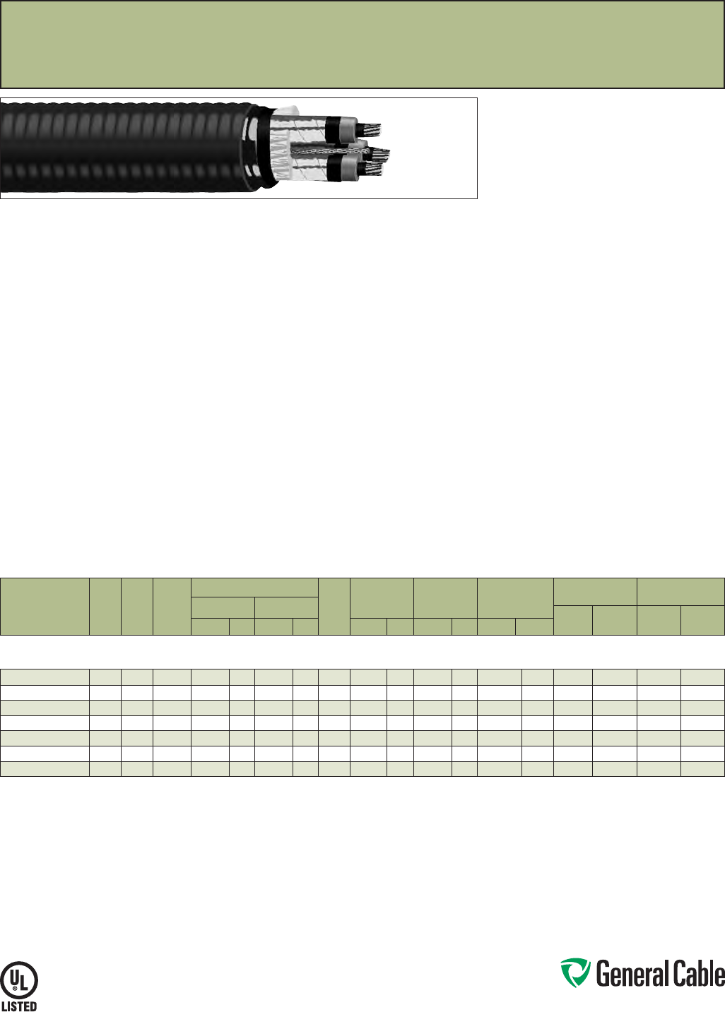
Phone: 888-593-3355
www.generalcable.com
SPEC 7400
August, 2010
Duralox
®
Uniblend
®
EPR/AIA/PVC,Power,Shielded,Armored
35kV,ULTypeMV-105orMC,100%Ins.Level,345Mils,ThreeConductor
Product Construction:
Conductors:
•1/0AWGthru750kcmilbare,coppercompact
ClassBstrand
Extruded Strand Shield (ESS):
•Thermosetsemi-conductingextrudedstress
controllayeroverconductor
Insulation:
•EthylenePropyleneRubber(EPR)insulation,
coloredtocontrastwithblackconductinglayers
Extruded Insulation Shield (EIS):
•Thermosetsemi-conductingpolymericlayerfree
strippingfrominsulation
Shield:
•5milannealedcoppertapewithaminimum25%
overlap
Ground:
•AnnealedbarecopperClassBstrandingper
ASTMB8
Armor:
•AluminumInterlockedArmor(AIA)
Jacket:
•Flame-retardant,moisture-andsunlight-resistant
PolyvinylChloride(PVC),red
Print:
•GENERALCABLE
®
SIZE(KCMILORAWG)
COMPACTCU3/C(INSTHICKNESS)MILS
EPRTYPEMV-105ORMC3/CSIZEAWGGRD
VOLTAGEkV%INSLEVELSUNRESFORCT
USEDIRBUR(UL)LIGHTINGBOLTSYMBOL
MONTH-YEARSEQUENTIALFOOTAGEMARK
Options:
•Otherconstructionsavailableuponrequest
Applications:
•Ideallysuitedforuseinabroadrangeof
commercial,industrialandutilityapplications
wherereliabilityisthemajorconcern,maximum
performanceisdemanded,spaceislimited,ease
of installation is critical and fire resistance
isnecessary
•Installedinwetordrylocations,indoors
oroutdoors,inexposedorconcealedwork
•Maybeusedincabletraysoronapproved
supportinprotectedareas
•PermittedforuseinClassI;ClassII,Division2;
andClassIII,Divisions1and2hazardous
locationspertheNEC
Features:
•Ratedat105˚Cwetordry
•Excellentheatandmoistureresistance
•Outstandingcoronaresistance
•Flexibilityforeasyhandling
•Highdielectricstrength
•Lowmoistureabsorption
•Electricalstabilityunderstress
•Lowdielectricloss
•Chemical-andradiation-resistant
•Excellentcrushresistance
•Cost-effectivealternativetoinstallations
in conduit
•Meetscoldbendtestat-25˚C
Compliances:
Industry Compliances:
•UL1072
•ICEAS-93-639/NEMAWC74
•AEICCS8
•ULTypeMV-105,ULFile#E90501
•ULTypeMC,ULFile#E90496
Flame Test Compliances:
•IEEE383(70,000BTU/hr)
•UL1581(70,000BTU/hr)
•IEEE1202(70,000BTU/hr)CSAFT4
•ICEAT-29-520(210,000BTU/hr)
•ICEAT-30-520(70,000BTU/hr)
Other Compliances:
•EPA40CFR,Part261forleachable
leadcontentperTCLPmethod
•OSHAAcceptable
Packaging:
•Materialcuttolengthandshippedon
non-returnablewoodreels,whilelengthsin
excessof10,000lbs.areprovidedonreturnable
steelreelsthatrequireadeposit.Extracharges
applyforcutslessthan1000ft.,lagging,pulling
eyes,parallelingandplexing
CATALOG
NUMBER
NO.
OF
COND.
COND.
SIZE
(AWG/)
kcmil
COND.
DIA.
INCHES
INSULATION DIAMETER GRND.
WIRE
SIZE
(AWG)
NOM. DIA.
(OVER)
ARMOR
NOMINAL
JACKET
THICKNESS
NOMINAL
CABLE
O.D.
COPPER
WEIGHT
NET WEIGHT
W/AL ARMOR
MIN. MAX.
LBS/
1000 FT
kg/
km
LBS/
1000 FT
kg/
kmINCHES mm INCHES mm INCHES mm INCHES mm INCHES mm
1/0 AWG - 750 kcmil - THREE CONDUCTOR -
W/JACKET OVER ARMOR, 35 kV, 100% INS. LEVEL, 345 MILS INS. (8.76 mm)
17480.535100* 3 1/0 0.34 1.02 25.9 1.12 28.4 4 2.77 70.4 0.075 1.91 2.93 74.5 1419 2113 4063 6050
17480.535200* 32/0 0.38 1.06 26.9 1.16 29.5 4 2.86 72.6 0.075 1.91 3.02 76.7 1687 2512 4441 6613
17480.535400* 34/0 0.48 1.16 29.5 1.26 32.0 33.08 78.2 0.075 1.91 3.24 82.3 2482 3696 5572 8297
17480.536000* 3250 0.53 1.21 30.7 1.32 33.4 33.19 81.1 0.085 2.16 3.38 85.7 2856 4253 6165 9180
17480.536200* 3350 0.62 1.31 33.3 1.41 35.8 2 3.40 86.3 0.085 2.16 3.58 91.0 3858 5745 7499 11166
17480.536500* 3500 0.74 1.43 36.3 1.53 38.9 13.66 93.0 0.085 2.16 3.83 97.3 5344 7957 9400 13997
17480.537000* 3750 0.91 1.61 40.9 1.71 43.4 1/0 4.05 102.9 0.085 2.16 4.23 107.5 7805 11622 12843 19123
Dimensionsandweightsarenominal;subjecttoindustrytolerances.
*Non-stockitem;minimumrunsapply.PleaseconsultCustomerServiceforpriceanddelivery.

Phone: 888-593-3355
www.generalcable.com
Date of Issue 06/13
Section 8 Industrial Cables
600 V – 28 kV TECK90 Armored Control and Power Cables
SPECIFICATION NO. PRODUCT DESCRIPTION REVISION DATE
8025†TECK90 XLPE/PVC/AIA/PVC, Control, Armored
600 V, CSA TECK90, Multi-Conductor, 14 AWG
Mar. 2012
8050†TECK90 XLPE/PVC/AIA/PVC, Control, Armored
600 V, CSA TECK90, Multi-Conductor, 12 AWG
Mar. 2012
8075†TECK90 XLPE/PVC/AIA/PVC, Control, Armored
600 V, CSA TECK90, Multi-Conductor, 10 AWG
Mar. 2012
8100 TECK90 XLPE/PVC/AIA/PVC, Power, Armored
1000 V, CSA TECK90, Single Conductor
Mar. 2012
8125 TECK90 XLPE/PVC/AIA/PVC, Control and Power, Armored
1000 V, CSA TECK90, Two Conductor
Mar. 2012
8150†TECK90 XLPE/PVC/AIA/PVC, Control and Power, Armored
1000 V, CSA TECK90, Three Conductor
Mar. 2012
8175†TECK90 XLPE/PVC/AIA/PVC, Control and Power, Armored
1000 V, CSA TECK90, Four Conductor
Mar. 2012
8200 TECK90 XLPE/PVC/AIA/PVC, Power/Control Composite
600 V, CSA TECK90, Three Power and Three 14 AWG Control Conductors
Mar. 2012
8225 TECK90 TRXLPE/PVC/AIA/PVC, Power, Unshielded, Armored
5 kV, CSA TECK90, 100%/133% Ins. Levels, Single Conductor
Oct. 2012
8250†TECK90 TRXLPE/PVC/AIA/PVC, Power, Unshielded, Armored
5 kV, CSA TECK90, 100%/133% Ins. Levels, Three Conductor
Jun. 2013
8275 HVTECK TRXLPE/Wire Shield/PVC/AIA/PVC, Power, Shielded, Armored
5 kV, CSA HVTECK, 100%/133% Ins. Levels, 90 Mils, Single Conductor
Oct. 2012
8300 HVTECK TRXLPE/Wire Shield/PVC/AIA/PVC, Power, Shielded, Armored
5 kV, CSA HVTECK, 133% Ins. Level, 115 Mils, Single Conductor
Oct. 2012
8325 HVTECK TRXLPE/Tape Shield/PVC/AIA/PVC, Power, Shielded, Armored
5 kV, CSA HVTECK, 100%/133% Ins. Levels, 90 Mils, Three Conductor
Oct. 2012
8350 HVTECK TRXLPE/Tape Shield/PVC/AIA/PVC, Power, Shielded, Armored
5 kV, CSA HVTECK, 133% Ins. Level, 115 Mils, Three Conductor
Oct. 2012
8375 HVTECK TRXLPE/Wire Shield/PVC/AIA/PVC, Power, Shielded, Armored
15 kV, CSA HVTECK, 100% Ins. Level, 175 Mils, Single Conductor
Oct. 2012
8400 HVTECK TRXLPE/Wire Shield/PVC/AIA/PVC, Power, Shielded, Armored
15 kV, CSA HVTECK, 133% Ins. Level, 220 Mils, Single Conductor
Oct. 2012
8425 HVTECK TRXLPE/Tape Shield/PVC/AIA/PVC, Power, Shielded, Armored
15 kV, CSA HVTECK, 100% Ins. Level, 175 Mils, Three Conductor
Oct. 2012
†Indicates these products are stocked by General Cable
Phone: 888-593-3355
www.generalcable.com
Date of Issue 06/13
Industrial Cables Section 8
600 V – 28 kV TECK90 Armored Control and Power Cables
SPECIFICATION NO. PRODUCT DESCRIPTION REVISION DATE
8450†HVTECK TRXLPE/Tape Shield/PVC/AIA/PVC, Power, Shielded, Armored
15 kV, CSA HVTECK, 133% Ins. Level, 220 Mils, Three Conductor
Oct. 2012
8475 HVTECK TRXLPE/Tape Shield/PVC/AIA/PVC, Power, Shielded, Armored
25 kV, CSA HVTECK, 100% Ins. Level, 260 Mils, Three Conductor
Oct. 2012
8500 HVTECK TRXLPE/Tape Shield/PVC/AIA/PVC, Power, Shielded, Armored
25 kV, CSA HVTECK, 133% Ins. Level, 320 Mils, Three Conductor
Oct. 2012
8525 HVTECK TRXLPE/Tape Shield/PVC/AIA/PVC, Power, Shielded, Armored
28 kV, CSA HVTECK, 133% Ins. Level, 345 Mils, Three Conductor
Oct. 2012
8550 VERTITECK® TECK90 XLPE/PVC/GSIA/PVC, Power, Unshielded, Armored
1 kV, CSA TECK90, Three Conductor
Jan. 2010
8575 VERTITECK® TECK90 XLPE/PVC/GSIA/PVC, Power, Unshielded, Armored
5 kV, CSA TECK90, 90 Mils, Three Conductor
Oct. 2012
8600
VERTITECK
®
HVTECK
TRXLPE/Tape Shield/PVC/GSIA/PVC, Power, Shielded, Armored
15 kV, CSA HVTECK, 133% Ins. Level, 220 Mils, Three Conductor
Oct. 2012
8625
VERTITECK
®
HVTECK
TRXLPE/Tape Shield/PVC/GSIA/PVC, Power, Shielded, Armored
15 kV, CSA HVTECK, 100% Ins. Level, 175 Mils, Three Conductor
Oct. 2012
8700†ACWU XLPE/AIA/PVC, Control, Armored
600 V, CSA ACWU90 (-40˚C), Single Conductor
Mar. 2012
8750†ACWU XLPE/AIA/PVC, Control, Armored
600 V, CSA ACWU90 (-40˚C), Three Conductor
Mar. 2012
8775†ACWU XLPE/AIA/PVC, Control, Armored
600 V, CSA ACWU90 (-40˚C), Four Conductor
Mar. 2012
†Indicates these products are stocked by General Cable
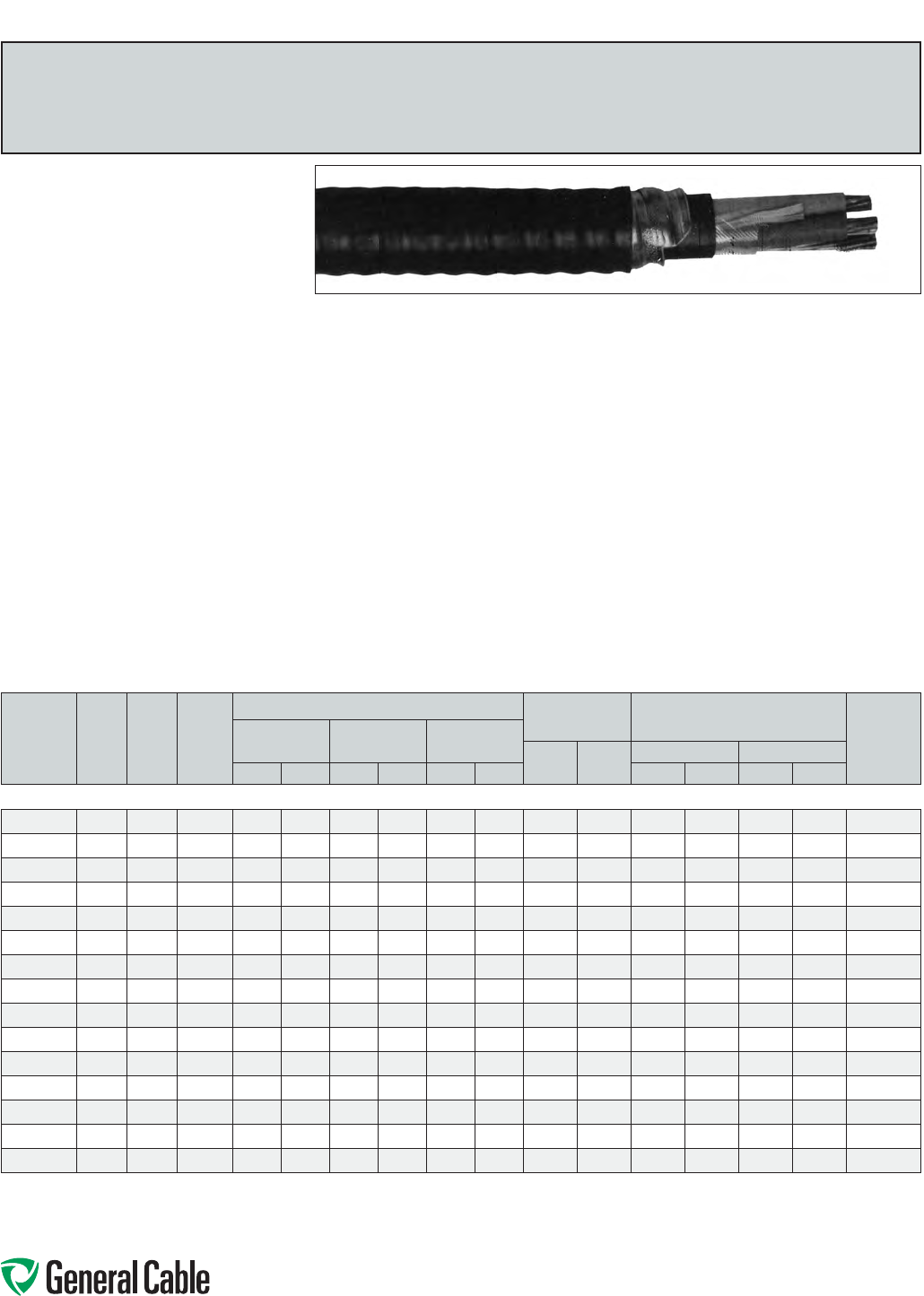
Phone: 888-593-3355
www.generalcable.com
SPEC 8025
March, 2012
Product Construction:
Conductors:
•14AWGbarecopperClassBcompressed
concentricroundtoASTMB8
Insulation:
•Cross-linkedPolyethylene(XLPE),TypeRW90
•Color-coded:1to4conductors—black,red,
blueandwhite;over4conductors—perICEA
Method4,individualconductorscoloredblack
withconductornumbersurfaceprintedin
contrastingink
Ground (Bonding) Conductor:
•Theconductorconsistsofoneuninsulated
strandedbarecopperconductor
Inner Jacket:
•Lead-free,flame-retardant,moisture-and
sunlight-resistantPolyvinylChloride(PVC),black
Armor:
•AluminumInterlockedArmor(AIA)
Overall Jacket:
•Lead-free,ACID-FLAME-CHECK ✓✓
®
flame-
retardant,moisture-andsunlight-resistant
PolyvinylChloride(PVC),black
Print:
•GENERALCABLE
®
ACID-FLAME-CHECK✓✓
®
AG14FT1FT4HLTECK90XLPE(-40˚C)#/C
SIZE(14AWG)600VDIRBURSUNRESCSA
MONTH-YEARSEQUENTIALLENGTHMARK
Options:
•GalvanizedSteelInterlockedArmor(GSIA)
•Otherconstructionsavailableuponrequest
Applications:
•Forexposedandconcealedwiringindry,damp
or wet locations
•Foruseinventilated,non-ventilatedandladder-
typecabletraysindry,damporwetlocations
•Fordirectearthburial(withprotectionasrequired
byinspectionauthority)
•Forwiringinallhazardouslocationswhenused
withcertifiedHLcableglands
Features:
•Ratedat90˚Cwetordry
•Excellentcrush,oilandchemicalresistance
•Provideslongservicelife
•Meetscoldbendandimpacttestsat-40˚C
Compliances:
Industry Compliances:
•CSAStandardC22.2No.131andNo.174
Flame Test Compliances:
•CSAFT1andFT4
•IEEE383(70,000BTU/hr)
•UL1581(70,000BTU/hr)
•IEEE1202(70,000BTU/hr)CSAFT4
•ICEAT-30-520(70,000BTU/hr)
Other Compliances:
•HazardousLocationRating:HL
•EPA40CFR,Part261forleachablelead
contentperTCLPmethod
•OSHAAcceptable
Packaging:
•ForCanadiancustomers,lengthsareprovided
onreturnablewoodorsteelreelsthatrequirea
deposit.Extrachargesapplyforlagging,pulling
eyes,parallelingandplexing
•ForU.S.customers,materialcuttolengthand
shippedonnon-returnablewoodreels,while
lengthsinexcessof10,000lbs.areprovidedon
returnablesteelreelsthatrequireadeposit.Extra
chargesapplyforcutslessthan1000ft.,lagging,
pullingeyes,parallelingandplexing
TECK90
XLPE/PVC/AIA/PVC,Control,Armored
600V,CSATECK90,Multi-Conductor,14AWG
CATALOG
NUMBER
NO.
OF
COND.
COND.
SIZE
(AWG)
GROUND
WIRE
SIZE
(AWG)
NOMINAL DIAMETER (OVER) COPPER
WEIGHT NET WEIGHT W/ARMOR
AMPACITY**
(30˚C
AMBIENT)
INSULATION ARMOR CABLE
LBS/
1000 FT
kg/
km
LBS/1000 FT kg/km
INCHES mm INCHES mm INCHES mm AL STEEL AL STEEL
14 AWG—MULTI-CONDUCTOR—30 MILS INS. (.76 mm), 600 V
780220
2 14 14 0.13 3.4 0.58 14.8 0.67 16.9 39 58 195 310 290 462 25
780250
314 14 0.13 3.4 0.60 15.4 0.69 17.4 52 78 226 346 336 515 25
780280
4 14 14 0.13 3.4 0.64 16.2 0.72 18.3 68 101 256 385 381 573 25
794540
5 14 14 0.13 3.4 0.68 17.3 0.76 19.3 81 121 290 430 432 640 20
792940
614 14 0.13 3.4 0.72 18.3 0.80 20.3 95 142 316 464 471 691 20
780310
7 14 14 0.13 3.4 0.74 18.8 0.82 20.8 104 155 338 490 503 730 17.5
330090
814 14 0.13 3.4 0.79 20.1 0.87 22.2 117 174 373 537 555 799 17.5
792960
10 14 14 0.13 3.4 0.88 22.3 0.96 24.3 149 222 451 637 671 948 17.5
792980
12 14 14 0.13 3.4 0.90 23.0 0.99 25.0 176 262 511 702 761 1045 17.5
793000
15 14 14 0.13 3.4 0.96 24.3 1.04 26.3 217 323 586 791 872 1177 17.5
780290
20 14 14 0.13 3.4 1.13 28.7 1.21 30.8 285 424 789 1117 1174 1662 17.5
308190*
25 14 14 0.13 3.4 1.22 30.9 1.30 33.0 337 502 958 1315 1426 1957 15
333750*
30 14 14 0.13 3.4 1.28 32.5 1.36 34.6 402 599 1015 1390 1511 2069 15
330280*
40 14 14 0.13 3.4 1.40 35.6 1.48 37.7 531 791 1234 1649 1837 2454 15
299980*
50 14 14 0.13 3.4 1.52 38.5 1.60 40.6 661 984 1463 1916 2178 2851 12.5
Dimensionsandweightsarenominal;subjecttoindustrytolerances.
*Non-stockitem;minimumrunsapply.PleaseconsultCustomerServiceforpriceanddelivery.
**AmpacityisbasedonCECodePart1,Table2for3conductorsinraceway(conduit).Ampacityof4conductorcableisbasedon3current-carryingconductorsand1neutral.
Ampacityat5ormoreconductorsismodiedbyTable5C.
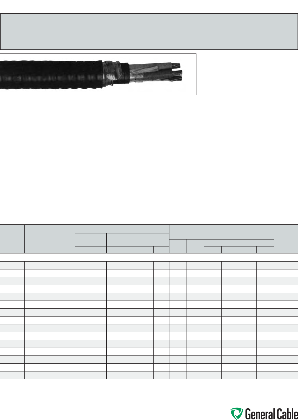
Phone: 888-593-3355
www.generalcable.com
SPEC 8050
March, 2012
TECK90
XLPE/PVC/AIA/PVC,Control,Armored
600V,CSATECK90,Multi-Conductor,12AWG
Product Construction:
Conductor:
•12AWGbarecopperClassBcompressed
concentricroundtoASTMB8
Insulation:
•Cross-linkedPolyethylene(XLPE),TypeRW90
•Color-coded:1to4conductors—black,red,
blueandwhite;over4conductors—perICEA
Method4,individualconductorscoloredblack
withconductornumbersurfaceprintedin
contrastingink
Ground (Bonding) Conductor:
•Theconductorconsistsofoneuninsulated
strandedbarecopperconductor
Inner Jacket:
•Lead-free,flame-retardant,moisture-and
sunlight-resistantPolyvinylChloride(PVC),black
Armor:
•AluminumInterlockedArmor(AIA)
Overall Jacket:
•Lead-free,ACID-FLAME-CHECK✓✓
®
flame-
retardant,moisture-andsunlight-resistant
PolyvinylChloride(PVC),black
Print:
•GENERALCABLE
®
ACID-FLAME-CHECK✓✓
®
AG14FT1FT4HLTECK90XLPE(-40˚C)#/C
SIZE(12AWG)600VDIRBURSUNRESCSA
MONTH-YEARSEQUENTIALLENGTHMARK
Options:
•GalvanizedSteelInterlockedArmor(GSIA)
•Otherconstructionsavailableuponrequest
Applications:
•Forexposedandconcealedwiringindry,damp
or wet locations
•Foruseinventilated,non-ventilatedandladder-
typecabletraysindry,damporwetlocations
•Fordirectearthburial(withprotectionasrequired
byinspectionauthority)
•Forwiringinallhazardouslocationswhenused
withcertifiedHLcableglands
Features:
•Ratedat90˚Cwetordry
•Excellentcrush,oilandchemicalresistance
•Provideslongservicelife
•Meetscoldbendandimpacttestsat-40˚C
Compliances:
Industry Compliances:
•CSAStandardC22.2No.131andNo.174
Flame Test Compliances:
•CSAFT1andFT4
•IEEE383(70,000BTU/hr)
•UL1581(70,000BTU/hr)
•IEEE1202(70,000BTU/hr)CSAFT4
•ICEAT-30-520(70,000BTU/hr)
Other Compliances:
•HazardousLocationRating:HL
•EPA40CFR,Part261forleachablelead
contentperTCLPmethod
•OSHAAcceptable
Packaging:
•ForCanadiancustomers,lengthsareprovided
onreturnablewoodorsteelreelsthatrequirea
deposit.Extrachargesapplyforlagging,pulling
eyes,parallelingandplexing
•ForU.S.customers,materialcuttolengthand
shippedonnon-returnablewoodreels,while
lengthsinexcessof10,000lbs.areprovidedon
returnablesteelreelsthatrequireadeposit.Extra
chargesapplyforcutslessthan1000ft.,lagging,
pullingeyes,parallelingandplexing
CATALOG
NUMBER
NO.
OF
COND.
COND.
SIZE
(AWG)
GROUND
WIRE
SIZE
(AWG)
NOMINAL DIAMETER (OVER) COPPER
WEIGHT NET WEIGHT W/ARMOR
AMPACITY**
(30˚C
AMBIENT)
INSULATION ARMOR CABLE
LBS/
1000 FT
kg/
km
LBS/1000 FT kg/km
INCHES mm INCHES mm INCHES mm AL STEEL AL STEEL
12 AWG—MULTI-CONDUCTOR—30 MILS INS. (.76 mm), 600 V
780210
2 12 14 0.15 3.9 0.62 15.8 0.70 17.9 55 82 228 352 340 524 30
780240
312 14 0.15 3.9 0.65 16.4 0.73 18.5 75 112 254 386 378 575 30
780320
4 12 14 0.15 3.9 0.69 17.4 0.77 19.5 96 143 293 434 436 646 30
312910
5 12 14 0.15 3.9 0.73 18.5 0.81 20.6 116 173 350 501 521 746 24
331190*
612 14 0.15 3.9 0.81 20.5 0.89 22.5 137 204 416 585 619 871 24
315020*
7 12 14 0.15 3.9 0.83 21.0 0.91 23.1 157 234 443 616 660 917 21
311560*
812 14 0.15 3.9 0.86 21.7 0.94 23.8 177 264 492 673 732 1002 21
304030*
10 12 14 0.15 3.9 0.95 24.2 1.04 26.2 219 326 555 757 826 1127 21
331130*
12 12 14 0.15 3.9 1.01 25.7 1.10 27.8 261 389 653 942 972 1402 21
312990*
15 12 14 0.15 3.9 1.07 27.2 1.16 29.3 322 480 757 1065 1127 1585 21
299950*
20 12 14 0.15 3.9 1.23 31.3 1.32 33.4 424 631 986 1346 1468 2003 21
307470*
25 12 14 0.15 3.9 1.33 33.8 1.42 35.9 527 785 1210 1602 1801 2384 18
318730*
30 12 14 0.15 3.9 1.40 35.6 1.49 37.7 630 938 1320 1735 1965 2582 18
346880*
40 12 14 0.15 3.9 1.54 39.1 1.64 41.6 837 1246 1725 2185 2567 3252 18
346890*
50 12 14 0.15 3.9 1.67 42.4 1.77 44.9 1044 1553 2055 2556 3058 3804 15
Dimensionsandweightsarenominal;subjecttoindustrytolerances.
*Non-stockitem;minimumrunsapply.PleaseconsultCustomerServiceforpriceanddelivery.
**AmpacityisbasedonCECodePart1,Table2for3conductorsinraceway(conduit).Ampacityof4conductorcableisbasedon3current-carryingconductorsand1neutral.
Ampacityat5ormoreconductorsismodiedbyTable5C.
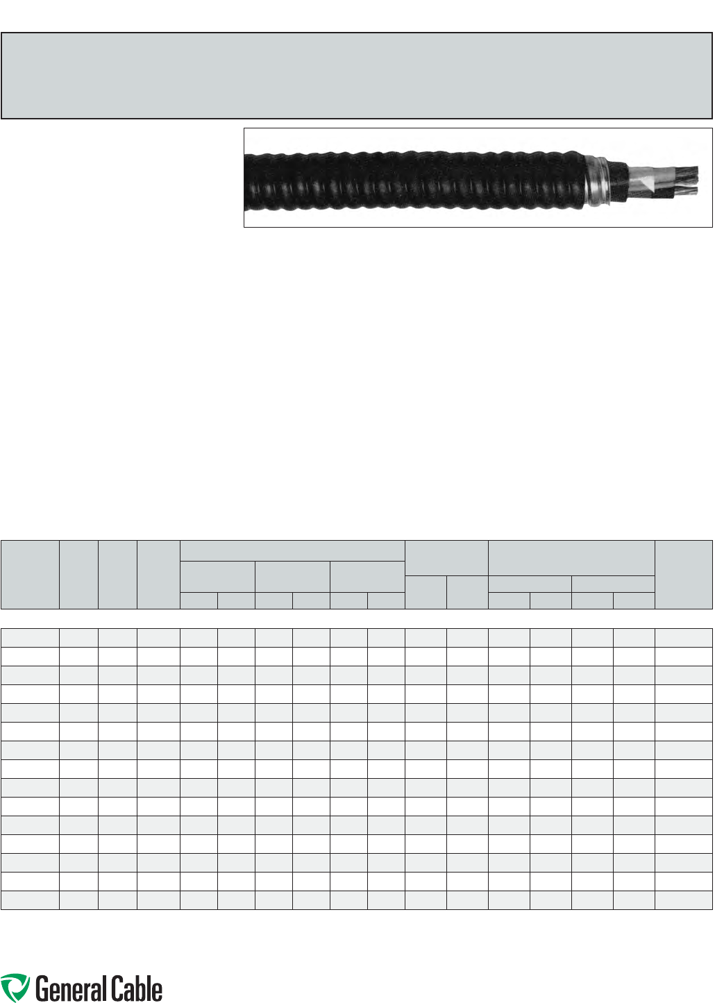
Phone: 888-593-3355
www.generalcable.com
SPEC 8075
March, 2012
Product Construction:
Conductor:
•10AWGbarecopperClassBcompressed
concentricroundtoASTMB8
Insulation:
•Cross-linkedPolyethylene(XLPE),TypeRW90
•Color-coded:1to4conductors—black,red,
blueandwhite;over4conductors—perICEA
Method4,individualconductorscoloredblack
withconductornumbersurfaceprintedin
contrastingink
Ground (Bonding) Conductor:
•Theconductorconsistsofoneuninsulated
strandedbarecopperconductor
•Color-codedperICEAMethod4;individual
conductorscoloredblackwithconductornumber
surfaceprintedincontrastingink
Inner Jacket:
•Lead-free,flame-retardant,moisture-and
sunlight-resistantPolyvinylChloride(PVC),black
Armor:
•AluminumInterlockedArmor(AIA)
Overall Jacket:
•Lead-free,ACID-FLAME-CHECK✓✓®flame-
retardant,moisture-andsunlight-resistant
PolyvinylChloride(PVC),black
Print:
•GENERALCABLE
®
ACID-FLAME-CHECK✓✓®
AG14FT1FT4HLTECK90XLPE(-40˚C)#/C
SIZE(10AWG)600VDIRBURSUNRESCSA
MONTH-YEARSEQUENTIALLENGTHMARK
Options:
•GalvanizedSteelInterlockedArmor(GSIA)
•Otherconstructionsavailableuponrequest
Applications:
•Forexposedandconcealedwiringindry,damp
or wet locations
•Foruseinventilated,non-ventilatedandladder-
typecabletraysindry,damporwetlocations
•Fordirectearthburial(withprotectionasrequired
byinspectionauthority)
•Forwiringinallhazardouslocationswhenused
withcertifiedHLcableglands
Features:
•Ratedat90˚Cwetordry
•Excellentcrush,oilandchemicalresistance
•Provideslongservicelife
•Meetscoldbendandimpacttestsat-40˚C
Compliances:
Industry Compliances:
•CSAStandardC22.2No.131andNo.174
Flame Test Compliances:
•CSAFT1andFT4
•IEEE383(70,000BTU/hr)
•UL1581(70,000BTU/hr)
•IEEE1202(70,000BTU/hr)CSAFT4
•ICEAT-30-520(70,000BTU/hr)
Other Compliances:
•HazardousLocationRating:HL
•EPA40CFR,Part261forleachablelead
contentperTCLPmethod
•OSHAAcceptable
Packaging:
•ForCanadiancustomers,lengthsareprovided
onreturnablewoodorsteelreelsthatrequirea
deposit.Extrachargesapplyforlagging,pulling
eyes,parallelingandplexing
•ForU.S.customers,materialcuttolengthand
shippedonnon-returnablewoodreels,while
lengthsinexcessof10,000lbs.areprovidedon
returnablesteelreelsthatrequireadeposit.Extra
chargesapplyforcutslessthan1000ft.,lagging,
pullingeyes,parallelingandplexing
TECK90
XLPE/PVC/AIA/PVC,Control,Armored
600V,CSATECK90,Multi-Conductor,10AWG
CATALOG
NUMBER
NO.
OF
COND.
COND.
SIZE
(AWG)
GROUND
WIRE
SIZE
(AWG)
NOMINAL DIAMETER (OVER) COPPER
WEIGHT NET WEIGHT W/ARMOR
AMPACITY**
(30˚C
AMBIENT)
INSULATION ARMOR CABLE
LBS/
1000 FT
kg/
km
LBS/1000 FT kg/km
INCHES mm INCHES mm INCHES mm AL STEEL AL STEEL
10 AWG—MULTI-CONDUCTOR—30 MILS INS. (.76 mm), 600 V
780200
210 12 0.18 4.5 0.67 17.0 0.75 19.0 87 130 275 411 410 612 40
780230
3 10 12 0.18 4.5 0.70 17.7 0.78 19.7 119 177 327 470 487 700 40
780270
410 12 0.18 4.5 0.74 18.8 0.83 20.9 150 223 413 565 615 841 40
319480*
510 12 0.18 4.5 0.82 20.9 0.91 22.9 184 274 473 644 704 959 32
333160*
6 10 12 0.18 4.5 0.88 22.2 0.96 24.3 217 323 515 717 766 1066 32
346870*
710 12 0.18 4.5 0.90 22.9 0.99 25.0 248 369 552 754 821 1122 28
318740*
8 10 12 0.18 4.5 0.93 23.6 1.02 25.7 282 420 613 830 912 1235 28
311570*
10 10 12 0.18 4.5 1.08 27.3 1.16 29.4 348 518 828 1181 1232 1757 28
317890*
12 10 12 0.18 4.5 1.15 29.2 1.23 31.3 414 617 916 1276 1363 1899 28
318750*
15 10 12 0.18 4.5 1.22 30.9 1.30 33.0 512 762 1084 1481 1613 2203 28
308180*
20 10 12 0.18 4.5 1.36 34.4 1.44 36.5 675 1005 1316 1750 1958 2604 28
307450*
25 10 12 0.18 4.5 1.47 37.3 1.55 39.4 835 1243 1612 2099 2399 3124 24
293570*
30 10 12 0.18 4.5 1.55 39.4 1.65 41.8 998 1493 1821 2323 2709 3457 24
307460*
40 10 12 0.18 4.5 1.71 43.4 1.81 45.9 1321 1966 2278 2837 3390 4222 24
346900*
50 10 12 0.18 4.5 1.87 47.5 1.97 49.9 1648 2453 2820 3557 4196 5293 20
Dimensionsandweightsarenominal;subjecttoindustrytolerances.
*Non-stockitem;minimumrunsapply.PleaseconsultCustomerServiceforpriceanddelivery.
**AmpacityisbasedonCECodePart1,Table2for3conductorsinraceway(conduit).Ampacityof4conductorcableisbasedon3current-carryingconductorsand1neutral.
Ampacityat5ormoreconductorsismodiedbyTable5C.
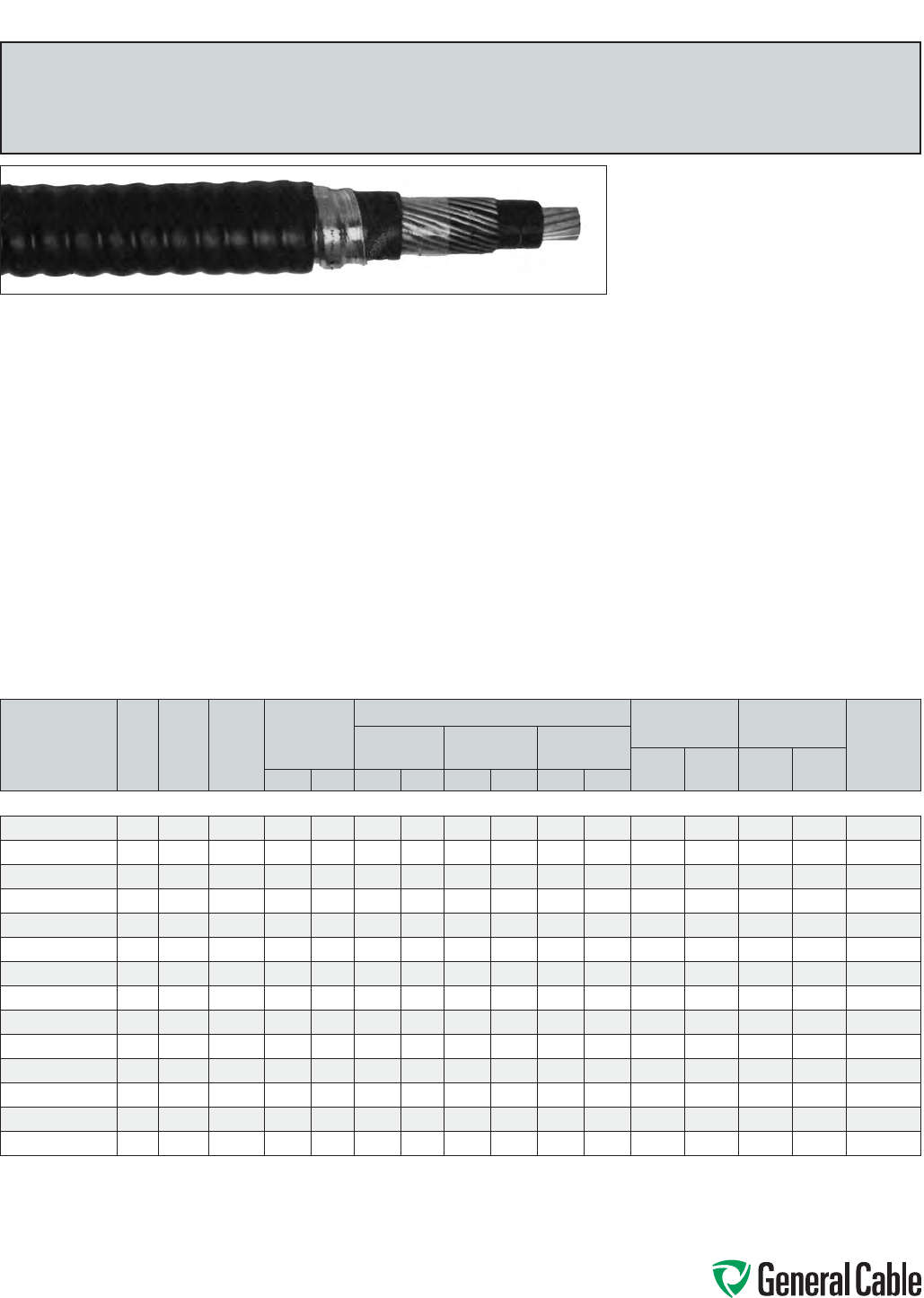
Phone: 888-593-3355
www.generalcable.com
SPEC 8100
March, 2012
TECK90
XLPE/PVC/AIA/PVC,Power,Armored
1000V,CSATECK90,SingleConductor
Product Construction:
Conductor:
•6AWGthru1000kcmilbarecoppercompact
ClassBstrand
Insulation:
•Cross-linkedPolyethylene(XLPE),TypeRW90
•Color-coded:black
Ground (Bonding) Conductor:
•Theconductorisaconcentricservingofsolid
barecopperwiresappliedovertheinsulation
Inner Jacket:
•Lead-free,flame-retardant,moisture-and
sunlight-resistantPolyvinylChloride(PVC),black
Armor:
•AluminumInterlockedArmor(AIA)
Overall Jacket:
•Lead-free,ACID-FLAME-CHECK✓✓®flame-
retardant,moisture-andsunlight-resistant
PolyvinylChloride(PVC),black
Print:
•GENERALCABLE
®
ACID-FLAME-CHECK✓✓®
AG14FT1FT4HLTECK90XLPE(-40˚C)1/C
SIZE(AWGORKCMIL)1000VDIRBURSUN
RESCSAMONTH-YEARSEQUENTIALLENGTH
MARK
Options:
•Otherconstructionsavailableuponrequest
Applications:
•Forexposedandconcealedwiringindry,damp
or wet locations
•Foruseinventilated,non-ventilatedandladder-
typecabletraysindry,damporwetlocations
•Fordirectearthburial(withprotectionasrequired
byinspectionauthority)
•Forwiringinallhazardouslocationswhenused
withcertifiedHLcableglands
Features:
•Ratedat90˚Cwetordry
•Excellentcrush,oilandchemicalresistance
•Provideslongservicelife
•Costeffectivealternativetoinstallationsin
conduit
•Meetscoldbendandimpacttestsat-40˚C
Compliances:
Industry Compliances:
•CSAStandardC22.2No.131andNo.174
Flame Test Compliances:
•CSAFT1andFT4
•IEEE383(70,000BTU/hr)
•UL1581(70,000BTU/hr)
•IEEE1202(70,000BTU/hr)CSAFT4
•ICEAT-30-520(70,000BTU/hr)
Other Compliances:
•HazardousLocationRating:HL
•EPA40CFR,Part261forleachablelead
contentperTCLPmethod
•OSHAAcceptable
Packaging:
•ForCanadiancustomers,lengthsareprovided
onreturnablewoodorsteelreelsthatrequirea
deposit.Extrachargesapplyforlagging,pulling
eyes,parallelingandplexing
•ForU.S.customers,materialcuttolengthand
shippedonnon-returnablewoodreels,while
lengthsinexcessof10,000lbs.areprovidedon
returnablesteelreelsthatrequireadeposit.Extra
chargesapplyforcutslessthan1000ft.,lagging,
pullingeyes,parallelingandplexing
CATALOG
NUMBER
NO.
OF
COND.
COND.
SIZE
(AWG/
kcmil)
GROUND
WIRE
SIZE
(AWG)
MIN. AVG. INS.
THICKNESS
NOMINAL DIAMETER (OVER) COPPER
WEIGHT NET WEIGHT
AMPACITY**
(30˚C
AMBIENT)
INSULATION ARMOR CABLE
LBS/
1000 FT
kg/
km
LBS/1000
FT kg/kmINCHES mm INCHES mm INCHES mm INCHES mm
6 AWG THRU 1000 kcmil—SINGLE CONDUCTOR—1000 V
11288.040600*
1 6 8 .060 1.52 0.31 7.8 0.68 17.3 0.77 19.6 137 204 320 470 105
11288.050400*
146.060 1.52 0.35 8.8 0.73 18.6 0.81 20.6 211 314 410 610 140
11288.030300*
1 3 6 .060 1.52 0.38 9.8 0.76 19.3 0.84 21.4 244 363 450 680 165
11288.050200*
126.060 1.52 0.42 10.5 0.78 19.8 0.87 22.1 286 426 510 760 190
11288.050100*
1 1 4 .080 2.03 0.49 12.5 0.88 22.4 0.96 24.4 390 581 680 1010 220
11288.035100*
1 1/0 4 .080 2.03 0.53 13.5 0.91 23.2 1.00 25.4 458 682 760 1130 260
11288.035200*
12/0 4 .080 2.03 0.58 14.7 0.95 24.1 1.04 26.4 544 810 860 1280 300
11288.035300*
1 3/0 3 .080 2.03 0.63 15.9 1.03 26.2 1.12 28.5 685 1020 1080 1610 350
11288.025400*
14/0 3.080 2.03 0.69 17.5 1.08 27.5 1.17 29.7 820 1220 1270 1890 405
11288.026000*
1250 2 .090 2.29 0.75 19.2 1.21 30.8 1.29 32.8 980 1459 1490 2210 455
11288.036200*
1350 1.090 2.29 0.86 21.7 1.30 33.0 1.39 35.3 1340 1994 1910 2840 570
11288.026500*
1500 1/0 .090 2.29 0.99 25.0 1.42 36.1 1.51 38.4 1750 2604 2510 3740 700
11288.027000*
1750 2/0 .090 2.29 1.16 29.4 1.59 40.4 1.69 43.0 2570 3825 3510 5230 885
11288.027500*
1 1000 2/0 .090 2.29 1.31 33.2 1.81 46.0 1.90 48.3 3340 4970 4430 6590 1055
Dimensionsandweightsarenominal;subjecttoindustrytolerances.
*Non-stockitem;minimumrunsapply.PleaseconsultCustomerServiceforpriceanddelivery.
**AmpacityisbasedonCECodePart1,Table1(singleconductorinfreeair)andRule4-004.
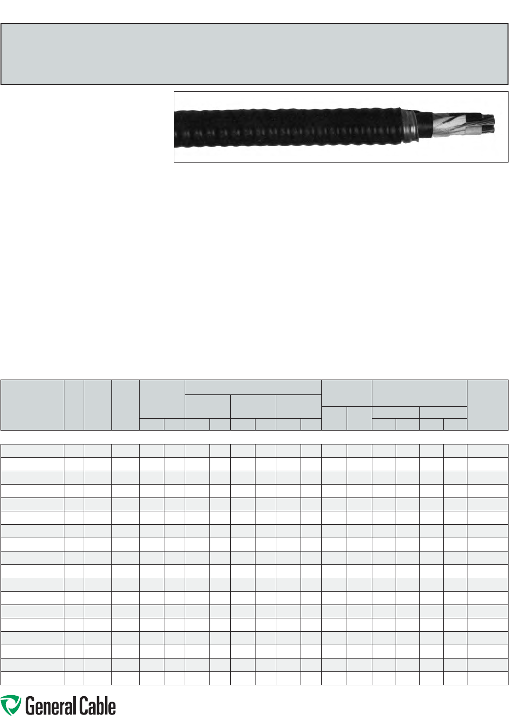
Phone: 888-593-3355
www.generalcable.com
SPEC 8125
March, 2012
TECK90
XLPE/PVC/AIA/PVC,ControlandPower,Armored
1000V,CSATECK90,TwoConductor
Product Construction:
Conductor:
•14AWGthru8AWGbarecopperClassB
compressedconcentricroundtoASTMB8
•6AWGthru1000kcmilbarecoppercompact
ClassBstrand
Insulation:
•Cross-linkedPolyethylene(XLPE),TypeRW90
•Color-coded:14AWGto2AWG—blackand
white;1AWGto1000kcmil—printednumbers
Ground (Bonding) Conductor:
•Theconductorconsistsofoneuninsulated
strandedbarecopperconductor
Inner Jacket:
•Lead-free,flame-retardant,moisture-and
sunlight-resistantPolyvinylChloride(PVC),black
Armor:
•AluminumInterlockedArmor(AIA)
Overall Jacket:
•Lead-free,ACID-FLAME-CHECK✓✓®flame-
retardant,moisture-andsunlight-resistant
PolyvinylChloride(PVC),black
Print:
•GENERALCABLE
®
ACID-FLAME-CHECK✓✓®
AG14FT1FT4HLTECK90XLPE(-40˚C)2/C
SIZE(AWGORKCMIL)1000VDIRBURSUN
RESCSAMONTH-YEARSEQUENTIALLENGTH
MARK
Options:
•GalvanizedSteelInterlockedArmor(GSIA)
•Otherconstructionsavailableuponrequest
Applications:
•Forexposedandconcealedwiringindry,damp
or wet locations
•Foruseinventilated,non-ventilatedandladder-
typecabletraysindry,damporwetlocations
•Fordirectearthburial(withprotectionasrequired
byinspectionauthority)
•Forwiringinallhazardouslocationswhenused
withcertifiedHLcableglands
Features:
•Ratedat90˚Cwetordry
•Excellentcrush,oilandchemicalresistance
•Provideslongservicelife
•Meetscoldbendandimpacttestsat-40˚C
Compliances:
Industry Compliances:
•CSAStandardC22.2No.131andNo.174
Flame Test Compliances:
•CSAFT1andFT4
•IEEE383(70,000BTU/hr)
•UL1581(70,000BTU/hr)
•IEEE1202(70,000BTU/hr)CSAFT4
•ICEAT-30-520(70,000BTU/hr)
Other Compliances:
•HazardousLocationRating:HL
•EPA40CFR,Part261forleachablelead
contentperTCLPmethod
•OSHAAcceptable
Packaging:
•ForCanadiancustomers,lengthsareprovided
onreturnablewoodorsteelreelsthatrequirea
deposit.Extrachargesapplyforlagging,pulling
eyes,parallelingandplexing
•ForU.S.customers,materialcuttolengthand
shippedonnon-returnablewoodreels,while
lengthsinexcessof10,000lbs.areprovidedon
returnablesteelreelsthatrequireadeposit.Extra
chargesapplyforcutslessthan1000ft.,lagging,
pullingeyes,parallelingandplexing
CATALOG
NUMBER
NO.
OF
COND.
COND.
SIZE
(AWG/
kcmil)
GROUND
WIRE
SIZE
(AWG)
MIN. AVG. INS.
THICKNESS
NOMINAL DIAMETER (OVER) COPPER
WEIGHT NET WEIGHT W/ARMOR
AMPACITY**
(30˚C
AMBIENT)
INSULATION ARMOR CABLE
LBS/
1000 FT
kg/
km
LBS/1000 FT kg/km
INCHES mm INCHES mm INCHES mm INCHES mm AL STEEL AL STEEL
14 AWG THRU 1000 kcmil—TWO CONDUCTOR—1000 V
794520*
2 14 14 .045 1.14 0.17 4.2 0.65 16.5 0.73 18.5 39 58 219 350 326 521 25
308550*
2 12 14 .045 1.14 0.18 4.6 0.69 17.6 0.77 19.6 55 82 255 412 380 613 30
793140*
210 12 .045 1.14 0.21 5.3 0.73 18.5 0.81 20.6 86 128 291 441 433 657 40
331260*
28 10 .045 1.14 0.24 6.1 0.82 20.8 0.90 22.9 137 204 392 564 584 840 55
11206.332083*
26 8 .060 1.52 0.31 7.8 0.94 23.9 1.02 25.9 215 320 556 758 827 1128 75
11288.040400*
2 4 8.060 1.52 0.35 8.8 1.07 27.2 1.16 29.5 312 464 744 1052 1107 1565 95
11288.220300*
23 6 .060 1.52 0.38 9.8 1.15 29.2 1.23 31.3 415 618 905 1239 1347 1844 115
11288.040200*
2 2 6.060 1.52 0.42 10.5 1.20 30.5 1.28 32.5 502 747 1030 1380 1533 2054 130
11288.020100*
21 6 .080 2.03 0.49 12.5 1.34 34.0 1.42 36.1 612 911 1235 1630 1838 2425 145
11288.045100*
21/0 6 .080 2.03 0.53 13.5 1.45 36.8 1.53 38.9 740 1101 1425 1854 2120 2759 170
11288.045200*
2 2/0 6.080 2.03 0.58 14.8 1.50 38.1 1.58 40.1 922 1372 1660 2107 2470 3135 195
11288.045300*
23/0 4 .080 2.03 0.63 15.9 1.59 40.4 1.69 42.9 1190 1771 1995 2471 2969 3677 225
11288.145400*
2 4/0 4 .080 2.03 0.69 17.5 1.70 43.2 1.79 45.5 1466 2182 2350 2862 3497 4259 260
11288.226000*
2 250 4 .090 2.29 0.75 19.2 1.84 46.8 1.93 49.0 1709 2543 2779 3332 4135 4958 290
11288.226200*
2 350 3.090 2.29 0.86 21.7 2.09 53.1 2.18 55.4 2373 3561 3650 4285 5431 6376 350
11288.226500*
2 500 3.090 2.29 0.99 25.0 2.33 59.2 2.45 62.2 3316 4935 4895 5607 7284 8343 430
11288.227000*
2 750 2 .090 2.29 1.16 29.4 2.67 67.8 2.79 70.9 4941 7353 6872 7695 10226 11450 535
11288.227500*
21000 1 .090 2.29 1.31 33.2 2.98 75.7 3.10 78.8 6562 9766 8993 10376 13382 15439 615
Dimensionsandweightsarenominal;subjecttoindustrytolerances.
*Non-stockitem;minimumrunsapply.PleaseconsultCustomerServiceforpriceanddelivery.
**AmpacityisbasedonCECodePart1,Table2(Threeconductorsinraceway[conduit])andRule4-004.
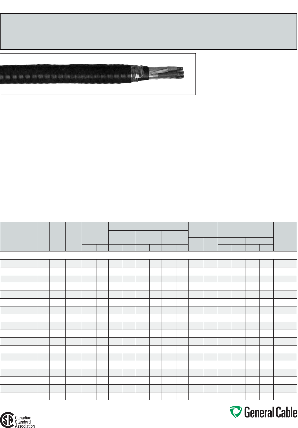
Phone: 888-593-3355
www.generalcable.com
SPEC 8150
November, 2013
Product Construction:
Conductor:
•14AWGthru8AWGbarecopperClassB
compressedconcentricroundtoASTMB8
•6AWGthru1000kcmilbarecoppercompact
ClassBstrand
Insulation:
•Cross-linkedPolyethylene(XLPE),TypeRW90
•Color-coded:14AWGto2AWG—black,redand
blue;1AWGto1000kcmil—printednumbers
Ground (Bonding) Conductor:
•Theconductorconsistsofoneuninsulated
strandedbarecopperconductor
Inner Jacket:
•Lead-free,flame-retardant,moisture-and
sunlight-resistantPolyvinylChloride(PVC),black
Armor:
•AluminumInterlockedArmor(AIA)
Overall Jacket:
•Lead-free,ACID-FLAME-CHECK✓✓®flame-
retardant,moisture-andsunlight-resistant
PolyvinylChloride(PVC),black
Print:
•GENERALCABLE
®
ACID-FLAME-CHECK✓✓®AG14
FT1FT4HLTECK90XLPE(-40˚C)3/CSIZE(AWGOR
KCMIL)1000VDIRBURSUNRESCSAMONTH-
YEARSEQUENTIALLENGTHMARK
Options:
•GalvanizedSteelInterlockedArmor(GSIA)
•Otherconstructionsavailableuponrequest
Applications:
•Forexposedandconcealedwiringindry,damp
orwetlocations
•Foruseinventilated,non-ventilatedandladder-
typecabletraysindry,damporwetlocations
•Fordirectearthburial(withprotectionasrequired
byinspectionauthority)
•Forwiringinallhazardouslocationswhenused
withcertifiedHLcableglands
Features:
•Ratedat90˚Cwetordry
•Excellentcrushresistance,oilandchemical
resistance
•Provideslongservicelife
•Meetscoldbendandimpacttestsat-40˚C
Compliances:
Industry Compliances:
•CSAStandardC22.2No.131andNo.174
Flame Test Compliances:
•CSAFT1andFT4
•IEEE383(70,000BTU/hr)
•UL1581(70,000BTU/hr)
•IEEE1202(70,000BTU/hr)CSAFT4
•ICEAT-30-520(70,000BTU/hr)
Other Compliances:
•HazardousLocationRating:HL
•EPA40CFR,Part261forleachablelead
contentperTCLPmethod
•OSHAAcceptable
Packaging:
•ForCanadiancustomers,lengthsareprovided
onreturnablewoodorsteelreelsthatrequirea
deposit.Extrachargesapplyforlagging,pulling
eyes,parallelingandplexing
•ForU.S.customers,materialcuttolengthand
shippedonnon-returnablewoodreels,while
lengthsinexcessof10,000lbs.areprovidedon
returnablesteelreelsthatrequireadeposit.Extra
chargesapplyforcutslessthan1000ft.,lagging,
pullingeyes,parallelingandplexing
TECK90
XLPE/PVC/AIA/PVC,ControlandPower,Armored
1000V,CSATECK90,ThreeConductor
CATALOG
NUMBER
NO.
OF
COND.
COND.
SIZE
(AWG/
kcmil)
GROUND
WIRE
SIZE
(AWG)
MIN. AVG. INS.
THICKNESS
NOMINAL DIAMETER (OVER) COPPER
WEIGHT NET WEIGHT W/ARMOR
AMPACITY**
(30˚C
AMBIENT)
INSULATION ARMOR CABLE
LBS/
1000 FT
kg/
km
LBS/1000 FT kg/km
INCHES mm INCHES mm INCHES mm INCHES mm AL STEEL AL STEEL
14 AWG THRU 1000 kcmil—THREE CONDUCTOR—1000 V
330520*
3 14 14 .045 1.14 0.17 4.2 0.67 17.0 0.76 19.3 52 77 261 398 388 592 25
780260
3 12 14 .045 1.14 0.18 4.6 0.72 18.3 0.80 20.3 75 112 299 445 445 662 30
331120
3 10 12 .045 1.14 0.21 5.3 0.79 20.1 0.88 22.4 124 185 374 539 557 802 40
793200
3 8 10 .045 1.14 0.24 6.1 0.86 21.9 0.94 23.9 189 281 486 666 723 991 55
11288.010600
3 6 8 .060 1.52 0.31 7.8 1.03 26.2 1.13 28.7 300 447 724 836 1078 1244 75
11288.010400
3 4 8 .060 1.52 0.35 8.8 1.16 29.5 1.25 31.8 447 665 970 1327 1444 1975 95
11288.010300
3 3 6 .060 1.52 0.38 9.8 1.22 31.0 1.30 33.0 582 866 1136 1509 1691 2246 115
11288.010200
3 2 6 .060 1.52 0.42 10.5 1.28 32.5 1.37 34.8 710 1056 1311 1702 1951 2533 130
11288.010100
3 1 6 .080 2.03 0.49 12.5 1.44 36.6 1.54 39.1 866 1288 1593 2045 2371 3043 145
11288.015100
3 1/0 6 .080 2.03 0.53 13.5 1.56 39.6 1.68 42.7 1069 1590 1906 2389 2837 3555 170
11288.015200
3 2/0 6 .080 2.03 0.58 14.8 1.65 41.9 1.77 45.0 1327 1974 2225 2732 3311 4066 195
11288.015300
3 3/0 4 .080 2.03 0.63 15.9 1.75 44.5 1.87 47.5 1670 2485 2666 3261 3967 4853 225
11288.015400
3 4/0 4 .080 2.03 0.69 17.5 1.86 47.2 1.98 50.3 2109 3138 3207 3806 4772 5664 260
11288.016000
3 250 4 .090 2.29 0.75 19.2 2.05 52.1 2.17 55.1 2470 3675 3800 4513 5655 6716 290
11288.016200
3 350 3 .090 2.29 0.86 21.7 2.26 57.4 2.40 61.0 3437 5114 4979 5906 7409 8789 350
11288.016500
3 500 3 .090 2.29 0.99 25.0 2.52 64.0 2.66 67.6 4839 7200 6586 7627 9798 11349 430
11270.891327
3 750 2 .090 2.29 1.16 29.4 2.89 73.4 3.03 77.0 7225 10751 9267 10470 13790 15580 535
11288.017500*
3 1000 1 .090 2.29 1.31 33.2 3.28 83.3 3.44 87.4 9612 14303 12184 13566 18130 20187 615
Dimensionsandweightsarenominal;subjecttoindustrytolerances.
*Non-stockitem;minimumrunsapply.PleaseconsultCustomerServiceforpriceanddelivery.
**AmpacityisbasedonCECodePart1,Table2(Threeconductorsinraceway[conduit])andRule4-004.
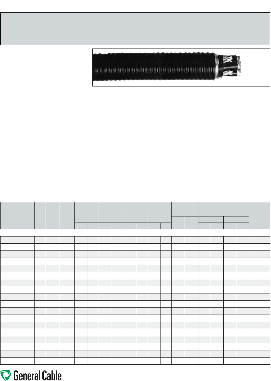
Phone: 888-593-3355
www.generalcable.com
S P E C 8175
March, 2012
TECK90
XLPE/PVC/AIA/PVC,ControlandPower,Armored
1000V,CSATECK90,FourConductor
Product Construction:
Conductor:
•14AWGthru8AWGbarecopperClassB
compressedconcentricroundtoASTMB8
•6AWGthru1000kcmilbarecoppercompact
ClassBstrand
Insulation:
•Cross-linkedPolyethylene(XLPE),TypeRW90
•Color-coded:14AWGto2AWG—black,red,
blueandwhite;1AWGto1000kcmil—printed
numbers
Ground (Bonding) Conductor:
•Theconductorconsistsofoneuninsulated
strandedbarecopperconductor
Inner Jacket:
•Lead-free,flame-retardant,moisture-and
sunlight-resistantPolyvinylChloride(PVC),black
Armor:
•AluminumInterlockedArmor(AIA)
Overall Jacket:
•Lead-free,ACID-FLAME-CHECK✓✓
®
flame-
retardant,moisture-andsunlight-resistant
PolyvinylChloride(PVC),black
Print:
•GENERALCABLE
®
ACID-FLAME-CHECK✓✓
®
AG14FT1FT4HLTECK90XLPE(-40˚C)4/C
SIZE(AWGORKCMIL)1000VDIRBUR
SUNRESCSAMONTH-YEARSEQUENTIAL
LENGTHMARK
Options:
•GalvanizedSteelInterlockedArmor(GSIA)
•Otherconstructionsavailableuponrequest
Applications:
•Forexposedandconcealedwiringindry,damp
or wet locations
•Foruseinventilated,non-ventilatedandladder-
typecabletraysindry,damporwetlocations
•Fordirectearthburial(withprotectionasrequired
byinspectionauthority)
•Forwiringinallhazardouslocationswhenused
withcertifiedHLcableglands
Features:
•Ratedat90˚Cwetordry
•Excellentcrush,oilandchemicalresistance
•Provideslongservicelife
•Meetscoldbendandimpacttestsat-40˚C
Compliances:
Industry Compliances:
•CSAStandardC22.2No.131andNo.174
Flame Test Compliances:
•CSAFT1andFT4
•IEEE383(70,000BTU/hr)
•UL1581(70,000BTU/hr)
•IEEE1202(70,000BTU/hr)CSAFT4
•ICEAT-30-520(70,000BTU/hr)
Other Compliances:
•HazardousLocationRating:HL
•EPA40CFR,Part261forleachablelead
contentperTCLPmethod
•OSHAAcceptable
Packaging:
•ForCanadiancustomers,lengthsareprovided
onreturnablewoodorsteelreelsthatrequirea
deposit.Extrachargesapplyforlagging,pulling
eyes,parallelingandplexing
•ForU.S.customers,materialcuttolengthand
shippedonnon-returnablewoodreels,while
lengthsinexcessof10,000lbs.areprovidedon
returnablesteelreelsthatrequireadeposit.Extra
chargesapplyforcutslessthan1000ft.,lagging,
pullingeyes,parallelingandplexing
CATALOG
NUMBER
NO.
OF
COND.
COND.
SIZE
(AWG/
kcmil)
GROUND
WIRE
SIZE
(AWG)
MIN. AVG. INS.
THICKNESS
NOMINAL DIAMETER (OVER) COPPER
WEIGHT NET WEIGHT W/ARMOR
AMPACITY**
(30˚C
AMBIENT)
INSULATION ARMOR CABLE
LBS/
1000 FT
kg/
km
LBS/1000 FT kg/km
INCHES mm INCHES mm INCHES mm INCHES mm AL STEEL AL STEEL
14 AWG THRU 1000 kcmil—FOUR CONDUCTOR—1000 V
321940*
4 14 14 .045 1.14 0.17 4.2 0.72 18.3 0.80 20.3 68 101 290 440 430 660 25
793180*
4 12 14 .045 1.14 0.18 4.6 0.79 20.1 0.88 22.4 96 143 357 521 531 776 30
793160*
410 12 .045 1.14 0.21 5.3 0.85 21.6 0.93 23.6 150 223 455 632 677 941 40
331250
48 10 .045 1.14 0.24 6.1 0.92 23.4 1.00 25.4 241 359 548 736 816 1096 55
11288.030600
46 8 .060 1.52 0.31 7.8 1.15 29.2 1.25 31.8 383 570 907 1261 1350 1877 75
11288.020400
4 4 8.060 1.52 0.35 8.8 1.26 32.0 1.35 34.3 579 862 1168 1558 1738 2319 95
11288.020300
43 6 .060 1.52 0.38 9.8 1.31 33.3 1.40 35.6 748 1113 1373 1782 2043 2652 115
11288.020200
4 2 6.060 1.52 0.42 10.5 1.37 34.8 1.46 37.1 919 1368 1583 2013 2356 2996 130
11288.040100
41 6 .080 2.03 0.49 12.5 1.60 40.6 1.72 43.7 1128 1679 2032 2551 3024 3796 145
11288.025100
41/0 6 .080 2.03 0.53 13.5 1.69 42.9 1.81 46.0 1398 2081 2365 2914 3520 4336 170
11288.025200
4 2/0 6.080 2.03 0.58 14.8 1.79 45.5 1.91 48.5 1742 2593 2745 3331 4085 4957 195
11288.025300
43/0 4 .080 2.03 0.63 15.9 1.91 48.5 2.03 51.6 2223 3308 3398 4135 5057 6153 225
11288.045400
4 4/0 4 .080 2.03 0.69 17.5 2.09 53.1 2.21 56.1 2769 4121 4170 4983 6205 7415 260
11288.046000
4 250 4 .090 2.29 0.75 19.2 2.23 56.7 2.35 59.7 3249 4835 4789 5661 7126 8424 290
11288.026200
4 350 3.090 2.29 0.86 21.7 2.46 62.5 2.60 66.0 4528 6738 6307 7264 9385 10809 350
11288.036500*
4 500 3.090 2.29 0.99 25.0 2.76 70.1 2.90 73.7 6395 9516 8438 9515 12556 14159 430
11288.057000*
4 750 2 .090 2.29 1.16 29.4 3.24 82.3 3.42 86.9 9564 14232 12411 13683 18468 20360 535
11288.037500*
41000 1 .090 2.29 1.31 33.2 3.65 92.7 3.84 97.6 12885 19173 15800 23510 23500 34968 615
Dimensionsandweightsarenominal;subjecttoindustrytolerances.
*Non-stockitem;minimumrunsapply.PleaseconsultCustomerServiceforpriceanddelivery.
**AmpacityisbasedonCECodePart1,Table2(Threeconductorsinraceway[conduit])andRule4-004.
Ampacityof4conductorcableisbasedon3current-carryingconductorsand1neutral.
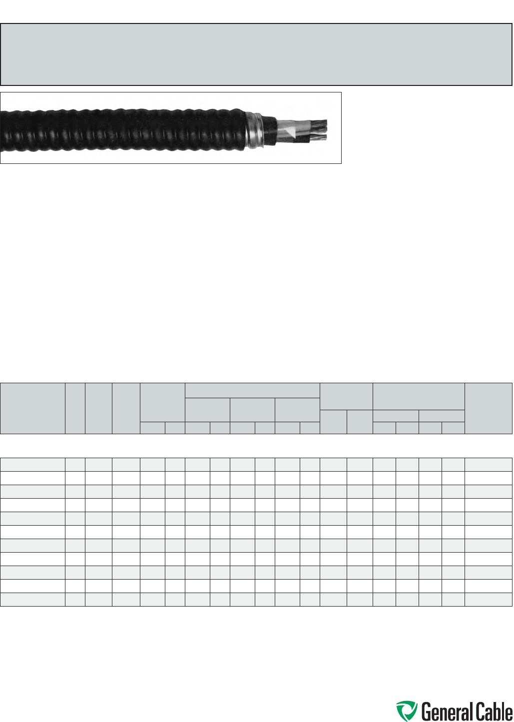
Phone: 888-593-3355
www.generalcable.com
SPEC 8200
March, 2012
TECK90
XLPE/PVC/AIA/PVC,Power/ControlComposite
600V,CSATECK90,ThreePowerandThree14AWGControlConductors
Product Construction:
Conductor:
•12AWGthru8AWGbarecopperClassB
compressedconcentricroundtoASTMB8
•6AWGthru4/0AWGbarecoppercompact
ClassBstrand
Insulation:
•Cross-linkedPolyethylene(XLPE),TypeRW90
•Color-coded:14AWGto2AWG—black,redand
blue;1AWGto4/0AWG—printednumbers
Ground (Bonding) Conductor:
•Theconductorconsistsofoneuninsulated
strandedbarecopperconductor
Inner Jacket:
•Lead-free,flame-retardant,moisture-and
sunlight-resistantPolyvinylChloride(PVC),black
Armor:
•AluminumInterlockedArmor(AIA)
Overall Jacket:
•Lead-free,ACID-FLAME-CHECK✓✓
®
flame-
retardant,moisture-andsunlight-resistant
PolyvinylChloride(PVC),black
Print:
•GENERALCABLE
®
ACID-FLAME-CHECK✓✓
®
AG14FT1FT4HLTECK90XLPE(-40˚C)3/C
SIZE(AWG)+3/C#14AWG600VDIRBURSUN
RESCSAMONTH-YEARSEQUENTIALLENGTH
MARK
Options:
•GalvanizedSteelInterlockedArmor(GSIA)
•Otherconstructionsavailableuponrequest
Applications:
•Forexposedandconcealedwiringindry,damp
or wet locations
•Foruseinventilated,non-ventilatedandladder-
typecabletraysindry,damporwetlocations
•Fordirectearthburial(withprotectionas
requiredbyinspectionauthority)
•Forwiringinallhazardouslocationswhenused
withcertifiedHLcableglands
Features:
•Ratedat90˚Cwetordry
•Excellentcrush,oilandchemicalresistance
•Provideslongservicelife
•Meetscoldbendandimpacttestsat-40˚C
Compliances:
Industry Compliances:
•CSAStandardC22.2No.131andNo.174
Flame Test Compliances:
•CSAFT1andFT4
•IEEE383(70,000BTU/hr)
•UL1581(70,000BTU/hr)
•IEEE1202(70,000BTU/hr)CSAFT4
•ICEAT-30-520(70,000BTU/hr)
Other Compliances:
•HazardousLocationRating:HL
•EPA40CFR,Part261forleachablelead
contentperTCLPmethod
•OSHAAcceptable
Packaging:
•ForCanadiancustomers,lengthsareprovided
onreturnablewoodorsteelreelsthatrequirea
deposit.Extrachargesapplyforlagging,pulling
eyes,parallelingandplexing
•ForU.S.customers,materialcuttolengthand
shippedonnon-returnablewoodreels,while
lengthsinexcessof10,000lbs.areprovided
onreturnablesteelreelsthatrequireadeposit.
Extrachargesapplyforcutslessthan1000ft.,
lagging,pullingeyes,parallelingandplexing
CATALOG
NUMBER
NO.
OF
COND.
COND.
SIZE
(AWG/
kcmil)
GROUND
WIRE
SIZE
(AWG)
MIN. AVG. INS.
THICKNESS
NOMINAL DIAMETER (OVER) COPPER
WEIGHT NET WEIGHT W/ARMOR AMPACITY**
POWER COND.
(30˚C
AMBIENT)
INSULATION ARMOR CABLE
LBS/
1000 FT
kg/
km
LBS/1000 FT kg/km
INCHES mm INCHES mm INCHES mm INCHES mm AL STEEL AL STEEL
12 AWG THRU 4/0 AWG—THREE POWER CONDUCTORS AND
THREE 14 AWG CONTROL CONDUCTORS—30 MILS (.76 mm)—600 V
333410*†
312 14 .030 0.76 0.15 3.9 0.78 19.8 0.86 21.8 114 170 356 519 530 789 30
311320*†
3 10 12 .030 0.76 0.18 4.5 0.81 20.6 0.89 22.6 158 235 416 586 619 921 40
311330*†
3 8 10 .045 1.14 0.24 6.1 0.95 24.0 1.00 25.4 208 310 541 729 805 1198 55
11288.210600*
3 6 8 .045 1.14 0.28 7.0 0.99 25.0 1.20 30.5 338 503 696 896 1035 1540 75
11288.210400*
348.045 1.14 0.32 8.2 1.14 28.8 1.25 31.8 485 722 972 1293 1446 2151 95
11288.210200*
326.045 1.14 0.38 9.7 1.27 32.3 1.39 35.2 747 1112 1295 1662 1927 2868 130
11288.210100*
3 1 6 .055 1.40 0.44 11.1 1.39 35.2 1.50 38.1 911 1356 1539 1941 2290 3408 145
11288.215100*
3 1/0 6 .055 1.40 0.48 12.2 1.47 37.3 1.59 40.3 1117 1662 1798 2227 2676 3982 170
11288.215200*
32/0 6.055 1.40 0.53 13.3 1.57 39.8 1.71 43.3 1378 2051 2150 2609 3199 4760 195
11288.215300*
3 3/0 4 .055 1.40 0.58 17.1 1.68 42.5 1.82 46.1 1753 2609 2592 3087 3857 5740 225
11288.215400*
34/0 4 .055 1.40 0.63 16.0 1.80 45.7 1.94 49.1 2167 3225 3080 3615 4583 6820 260
Dimensionsandweightsarenominal;subjecttoindustrytolerances.
*Non-stockitem;minimumrunsapply.PleaseconsultCustomerServiceforpriceanddelivery.
†ContactCustomerServiceforsteelcatalognumber.
**AmpacityisbasedonCECodePart1,Table2(Threeconductorsinraceway[conduit])andRule4-004.
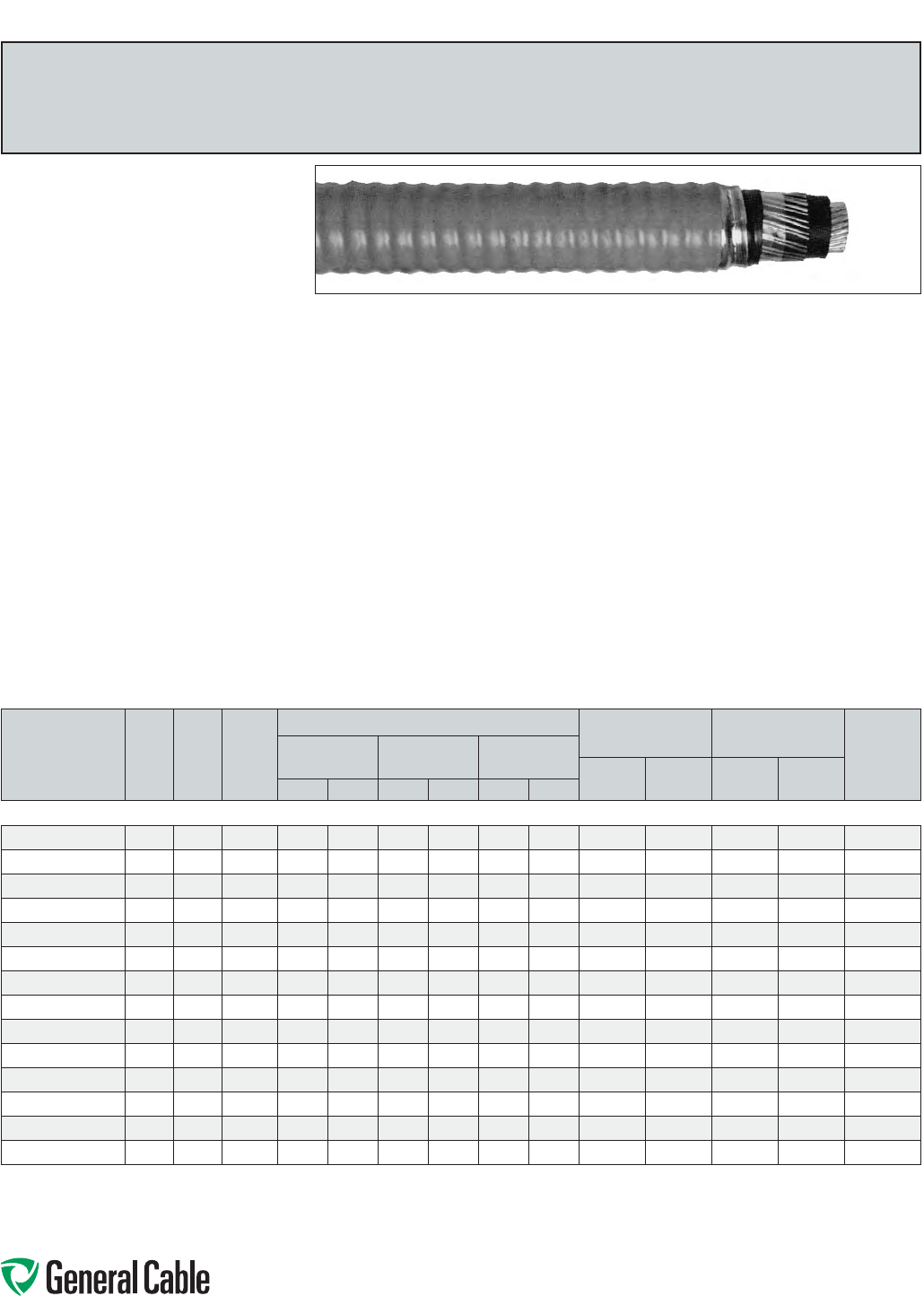
Phone: 888-593-3355
www.generalcable.com
SPEC 8225
October, 2012
TECK90
TRXLPE/PVC/AIA/PVC,Power,Unshielded,Armored
5kV,CSATECK90,100%/133%Ins.Levels,SingleConductor
Product Construction:
Conductor:
•6AWGthru1000kcmilbarecoppercompact
ClassBstrand
Strand Shield:
•Athermosetsemi-conductingshieldisextruded
overtheconductor
Insulation:
•Tree-RetardantCross-linkedPolyethylene
(TRXLPE),TypeRW90
Ground (Bonding) Conductor:
•Theconductorisaconcentricservingofsolid
barecopperwiresappliedovertheinsulation
Inner Jacket:
•Lead-free,flame-retardant,moisture-and
sunlight-resistantPolyvinylChloride(PVC),black
Armor:
•AluminumInterlockedArmor(AIA)
Overall Jacket:
•Lead-free,ACID-FLAME-CHECK✓✓
®
flame-
retardant,moisture-andsunlight-resistant
PolyvinylChloride(PVC),orange
Print:
•GENERALCABLE
®
ACID-FLAME-CHECK✓✓
®
AG14FT1FT4HLTECK90TRXLPE(-40˚C)1/C
SIZE(AWGORKCMIL)5kVDIRBURSUNRES
CSAMONTH-YEARSEQUENTIALLENGTH
MARK
Options:
•Otherconstructionsavailableuponrequest
Applications:
•Forexposedandconcealedwiringindry,damp
or wet locations
•Foruseinventilated,non-ventilatedandladder-
typecabletraysindry,damporwetlocations
•Fordirectearthburial(withprotectionas
requiredbyinspectionauthority)
•Forwiringinallhazardouslocationswhenused
withcertifiedHLcableglands
Features:
•Ratedat90˚Cwetordry
•Excellentcrush,oilandchemicalresistance
•Provideslongservicelife
•Meetscoldbendandimpacttestsat-40˚C
Compliances:
Industry Compliances:
•CSAStandardC22.2No.131andNo.174
Flame Test Compliances:
•CSAFT1andFT4
•IEEE383(70,000BTU/hr)
•UL1581(70,000BTU/hr)
•IEEE1202(70,000BTU/hr)CSAFT4
•ICEAT-30-520(70,000BTU/hr)
Other Compliances:
•HazardousLocationRating:HL
•EPA40CFR,Part261forleachablelead
contentperTCLPmethod
•OSHAAcceptable
Packaging:
•ForCanadiancustomers,lengthsareprovided
onreturnablewoodorsteelreelsthatrequirea
deposit.Extrachargesapplyforlagging,pulling
eyes,parallelingandplexing
•ForU.S.customers,materialcuttolengthand
shippedonnon-returnablewoodreels,while
lengthsinexcessof10,000lbs.areprovidedon
returnablesteelreelsthatrequireadeposit.Extra
chargesapplyforcutslessthan1000ft.,lagging,
pullingeyes,parallelingandplexing
CATALOG
NUMBER
NO.
OF
COND.
COND.
SIZE
(AWG/
kcmil)
GROUND
WIRE
SIZE
(AWG)
NOMINAL DIAMETER (OVER) COPPER
WEIGHT
NET WEIGHT
W/AL ARMOR
AMPACITY**
(30˚C
AMBIENT)
INSULATION ARMOR CABLE
LBS/
1000 FT
kg/
km
LBS/
1000 FT
kg/
kmINCHES mm INCHES mm INCHES mm
6 AWG THRU 1000 kcmil—SINGLE CONDUCTOR—UNSHIELDED—90 MILS INS. (2.29 mm)—5 kV
17496.100600*
1 6 8 0.39 10.0 0.76 19.3 0.85 21.6 143 213 370 550 105
17496.100400*
1460.43 10.5 0.84 21.4 0.93 23.7 223 332 490 730 140
17496.100300*
1 3 6 0.46 11.7 0.86 21.9 0.95 24.2 229 341 540 800 165
17496.100200*
1260.49 12.5 0.89 22.6 0.98 24.9 301 448 590 890 190
17496.100100*
1 1 4 0.52 13.3 0.93 23.6 1.02 25.9 405 603 720 1060 220
17496.105100*
1 1/0 4 0.56 14.2 0.96 24.4 1.06 26.9 474 705 800 1190 260
17496.105200*
12/0 4 0.60 15.2 1.03 26.2 1.13 28.7 561 835 900 1350 300
17496.105300*
1 3/0 3 0.64 16.3 1.08 27.5 1.18 30.0 708 1054 1130 1680 350
17496.105400*
14/0 30.70 17.8 1.16 29.5 1.26 32.0 847 1261 1330 1970 405
17496.106000*
1250 2 0.75 19.1 1.24 31.5 1.34 34.1 1012 1506 1530 2280 455
17496.106200*
1350 10.85 21.5 1.34 34.0 1.44 36.6 1388 2066 1960 2910 570
17496.106500*
1500 1/0 0.97 24.6 1.49 37.9 1.59 40.4 1548 2304 2570 3830 700
17496.107000*
1750 2/0 1.15 29.2 1.68 42.7 1.78 45.2 2243 3338 3900 5800 885
17496.107500*
1 1000 2/0 1.30 33.0 1.86 47.3 1.96 49.8 2819 4195 4930 7340 1055
Dimensionsandweightsarenominal;subjecttoindustrytolerances.
*Non-stockitem;minimumrunsapply.PleaseconsultCustomerServiceforpriceanddelivery.
**AmpacityisbasedonCECodePart1,Table1(singleconductorinfreeair)andRule4-004.
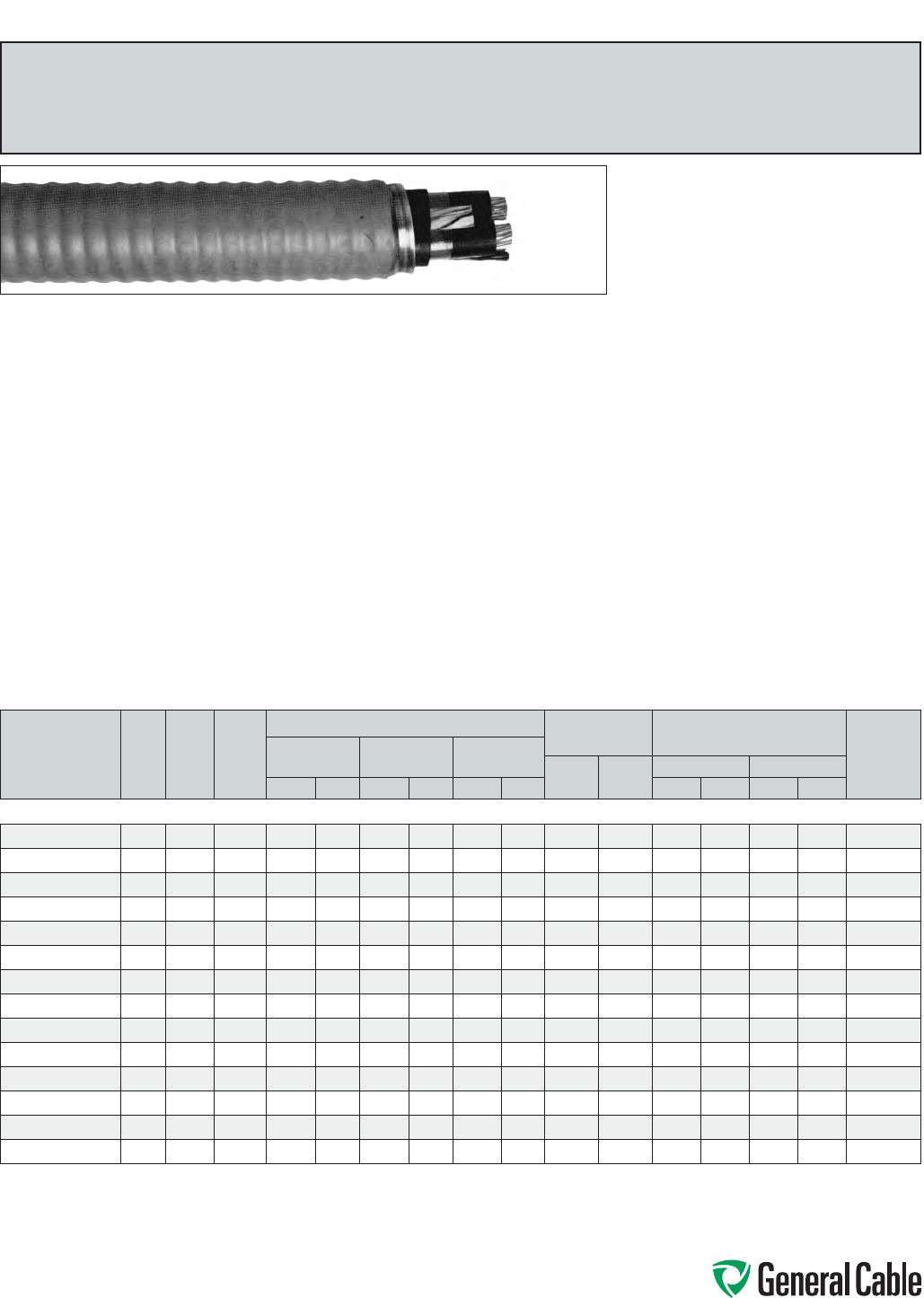
Phone: 888-593-3355
www.generalcable.com
SPEC 8250
June, 2013
TECK90
TRXLPE/PVC/AIA/PVC,Power,Unshielded,Armored
5kV,CSATECK90,100%/133%Ins.Levels,ThreeConductor
Product Construction:
Conductor:
•6AWGthru1000kcmilbarecoppercompact
ClassBstrand
Strand Shield:
•Athermosetsemi-conductingshieldisextruded
overtheconductor
Insulation:
•Tree-RetardantCross-linkedPolyethylene
(TRXLPE),TypeRW90
•Color-coded:Blackwithprintednumbers
Ground (Bonding) Conductor:
•Theconductorconsistsofoneuninsulated
strandedbarecopperconductor
Inner Jacket:
•Lead-free,flame-retardant,moisture-and
sunlight-resistantPolyvinylChloride(PVC),black
Armor:
•AluminumInterlockedArmor(AIA)
Overall Jacket:
•Lead-free,ACID-FLAME-CHECK✓✓
®
flame-
retardant,moisture-andsunlight-resistant
PolyvinylChloride(PVC),orange
Print:
•GENERALCABLE
®
ACID-FLAME-CHECK✓✓
®
AG14FT1FT4HLTECK90TRXLPE(-40˚C)3/C
SIZE(AWGORKCMIL)5kVDIRBURSUNRES
CSAMONTH-YEARSEQUENTIALLENGTH
MARK
Options:
•GalvanizedSteelInterlockedArmor(GSIA)
•Otherconstructionsavailableuponrequest
Applications:
•Forexposedandconcealedwiringindry,damp
or wet locations
•Foruseinventilated,non-ventilatedandladder-
typecabletraysindry,damporwetlocations
•Fordirectearthburial(withprotectionasrequired
byinspectionauthority)
•Forwiringinallhazardouslocationswhenused
withcertifiedHLcableglands
Features:
•Ratedat90˚Cwetordry
•Excellentcrush,oilandchemicalresistance
•Provideslongservicelife
•Meetscoldbendandimpacttestsat-40˚C
Compliances:
Industry Compliances:
•CSAStandardC22.2No.131andNo.174
Flame Test Compliances:
•CSAFT1andFT4
•IEEE383(70,000BTU/hr)
•UL1581(70,000BTU/hr)
•IEEE1202(70,000BTU/hr)CSAFT4
•ICEAT-30-520(70,000BTU/hr)
Other Compliances:
•HazardousLocationRating:HL
•EPA40CFR,Part261forleachablelead
contentperTCLPmethod
•OSHAAcceptable
Packaging:
•ForCanadiancustomers,lengthsareprovided
onreturnablewoodorsteelreelsthatrequirea
deposit.Extrachargesapplyforlagging,pulling
eyes,parallelingandplexing
•ForU.S.customers,materialcuttolengthand
shippedonnon-returnablewoodreels,while
lengthsinexcessof10,000lbs.areprovidedon
returnablesteelreelsthatrequireadeposit.Extra
chargesapplyforcutslessthan1000ft.,lagging,
pullingeyes,parallelingandplexing
CATALOG
NUMBER
NO.
OF
COND.
COND.
SIZE
(AWG/
kcmil)
GROUND
WIRE
SIZE
(AWG)
NOMINAL DIAMETER (OVER) COPPER
WEIGHT NET WEIGHT W/ARMOR
AMPACITY**
(30˚C
AMBIENT)
INSULATION ARMOR CABLE
LBS/
1000 FT
kg/
km
LBS/1000 FT kg/km
INCHES mm INCHES mm INCHES mm AL STEEL AL STEEL
6 AWG THRU 1000 kcmil—THREE CONDUCTOR—UNSHIELDED—90 MILS INS. (2.29 mm)—5 kV
17496.020600
3 6 8 0.39 10.0 1.27 32.3 1.37 34.8 301 448 927 1340 1380 2000 75
17496.020400
3480.43 10.5 1.37 34.8 1.47 37.4 442 658 1138 1590 1694 2370 95
17496.010300*
3 3 6 0.46 11.7 1.42 36.1 1.52 38.6 583 868 1310 1780 1950 2640 115
17496.020200
3260.49 12.5 1.49 37.9 1.59 40.4 703 1046 1476 1980 2197 2940 130
17496.020100*
3 1 6 0.52 13.3 1.59 40.4 1.69 43.0 970 1444 1752 2230 2607 3350 145
17496.025100*
3 1/0 6 0.56 14.2 1.67 42.4 1.77 45.0 1082 1610 2012 2540 2994 3780 170
17496.025200
32/0 60.60 15.2 1.76 44.7 1.86 47.3 1343 1999 2334 2880 3473 4290 195
17496.035300*
3 3/0 4 0.64 16.3 1.87 47.5 1.97 50.1 1720 2560 2835 3370 4219 5010 225
17496.025400
34/0 4 0.70 17.8 1.98 50.3 2.08 52.9 2315 3445 3328 4090 4952 6090 260
17496.056000*
3250 4 0.75 19.1 2.15 54.6 2.25 57.2 2469 3674 3910 4780 5819 7110 290
17496.026200
3350 30.85 21.5 2.36 60.0 2.49 63.3 3476 5173 5102 6100 7592 9070 350
17496.046500
3500 30.97 24.6 2.62 66.6 2.75 69.9 4837 7198 6721 7880 10001 11720 430
17496.077000*
3750 2 1.15 29.2 3.01 76.5 3.14 79.8 7224 10750 9469 11750 14090 17480 535
17496.017500*
3 1000 1 1.30 33.0 3.39 86.1 3.54 89.9 9715 14458 13790 15220 20520 22650 615
Dimensionsandweightsarenominal;subjecttoindustrytolerances.
*Non-stockitem;minimumrunsapply.PleaseconsultCustomerServiceforpriceanddelivery.
**AmpacityisbasedonCECodePart1,Table2(Threeconductorsinraceway[conduit])andRule4-004.
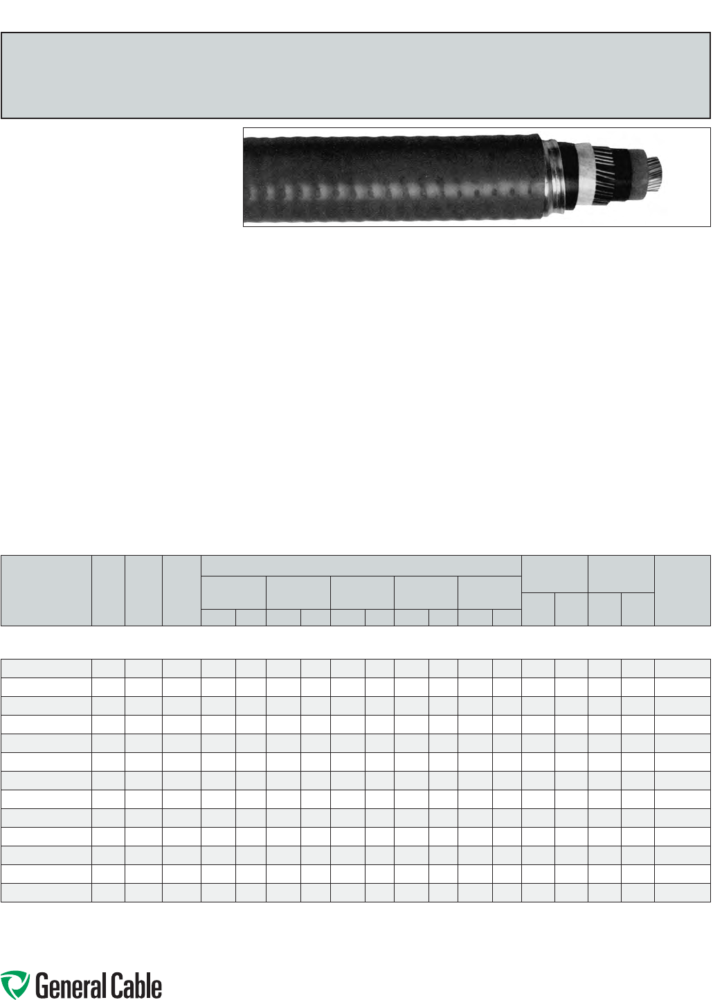
Phone: 888-593-3355
www.generalcable.com
SPEC 8275
October, 2012
Product Construction:
Conductor:
•6AWGthru1000kcmilbarecoppercompact
ClassBstrand
Strand Shield:
•Athermosetsemi-conductingstrandshieldis
extrudedovertheconductor
Insulation:
•Tree-RetardantCross-linkedPolyethylene
(TRXLPE)
Insulation Shield:
•Blacksemi-conductingthermosettinglayer,
appliedinatripleextrusiveprocess,plusa
concentricservingofsolidcopperwiresacting
asbothadrainwireshieldandagrounding
(bonding)conductor
Ground (Bonding) Conductor:
•Theconductorisaconcentricservingofsolid
copperwiresappliedoverthethermosetting
insulationshield
Inner Jacket:
•Lead-free,flame-retardant,moisture-and
sunlight-resistantPolyvinylChloride(PVC),black
Armor:
•AluminumInterlockedArmor(AIA)
Overall Jacket:
•Lead-free,ACID-FLAME-CHECK✓✓
®
flame-
retardant,moisture-andsunlight-resistant
PolyvinylChloride(PVC),orange
Print:
•GENERALCABLE
®
1/CSIZE(AWGORKCMIL)
COPPERCPTTRXLPE5kV(100%OR133%
INSLEVEL)ACID-FLAME-CHECK✓✓
®
CSA
HLHVTECK(-40˚C)FT4DIRBURSUNRES
MONTH/YEAR(LIGHTNINGBOLTSYMBOL)
SEQUENTIALLENGTHMARK
Options:
•Otherconstructionsavailableuponrequest
Applications:
•Forwiringinallhazardouslocationswhenused
withcertifiedHLcableglands
•Forexposedandconcealedwiringindry,damp
or wet locations
•Foruseinventilated,non-ventilatedandladder-
typecabletraysindry,damporwetlocations
•Fordirectearthburial(withprotectionasrequired
byinspectionauthority)
Features:
•Ratedat90˚Cwetordry
•Excellentcrush,oilandchemicalresistance
•Provideslongservicelife
•Cost-effectivealternativetoinstallations
in conduit
•Meetscoldbendandimpacttestsat-40˚C
Compliances:
Industry Compliances:
•CSAStandardC22.2No.131andNo.174
•CSAStandardC68.3
Flame Test Compliances:
•CSAFT1andFT4
•IEEE383(70,000BTU/hr)
•UL1581(70,000BTU/hr)
•IEEE1202(70,000BTU/hr)CSAFT4
•ICEAT-30-520(70,000BTU/hr)
•ICEAT-29-520(210,000BTU/hr)
Other Compliances:
•HazardousLocationRating:HL
•EPA40CFR,Part261forleachablelead
contentperTCLPmethod
•OSHAAcceptable
Packaging:
•ForCanadiancustomers,lengthsareprovided
onreturnablewoodorsteelreelsthatrequirea
deposit.Extrachargesapplyforlagging,pulling
eyes,parallelingandplexing
•ForU.S.customers,materialcuttolengthand
shippedonnon-returnablewoodreels,while
lengthsinexcessof10,000lbs.areprovidedon
returnablesteelreelsthatrequireadeposit.Extra
chargesapplyforcutslessthan1000ft.,lagging,
pullingeyes,parallelingandplexing
HVTECK
TRXLPE/WireShield/PVC/AIA/PVC,Power,Shielded,Armored
5kV,CSAHVTECK,100%/133%Ins.Levels,90Mils,SingleConductor
CATALOG
NUMBER
NO.
OF
COND.
COND.
SIZE
(AWG/
kcmil)
GROUND
WIRE
SIZE
(AWG)
NOMINAL DIAMETER (OVER) COPPER
WEIGHT
NET WEIGHT
W/AL ARMOR
AMPACITY**
(40˚C
AMBIENT)
INSULATION INSULATION
SHIELD
INNER
JACKET ARMOR CABLE
LBS/
1000 FT
kg/
km
LBS/
1000 FT
kg/
kmINCHES mm INCHES mm INCHES mm INCHES mm INCHES mm
6 AWG THRU 1000 kcmil—SINGLE CONDUCTOR—SHIELDED,
100%/133% INS. LEVELS, 90 MILS INS. (2.29 mm)—5 kV
17496.700600*
1 6 8 0.39 10.0 0.47 11.9 0.68 17.3 0.90 22.9 0.99 25.2 144 214 510 770 112
17496.700400*
1460.43 10.5 0.51 13.0 0.72 18.3 0.94 23.9 1.03 26.2 224 333 590 880 148
17496.700200*
1260.49 12.5 0.57 14.5 0.78 19.8 1.03 26.2 1.12 28.5 302 449 750 1120 195
17496.700100*
1 1 4 0.52 13.3 0.60 15.3 0.81 20.6 1.06 27.0 1.15 29.2 406 604 870 1300 225
17496.705100*
1 1/0 4 0.56 14.2 0.63 16.0 0.88 22.4 1.13 28.7 1.22 31.0 475 707 1010 1500 260
17496.705200*
12/0 4 0.60 15.2 0.67 17.0 0.92 23.4 1.17 29.7 1.26 32.0 562 836 1120 1670 299
17496.705300*
1 3/0 3 0.64 16.3 0.71 18.1 0.97 24.7 1.22 31.0 1.31 33.3 709 1055 1300 1930 345
17496.705400*
14/0 30.70 17.8 0.76 19.3 1.02 25.9 1.27 32.3 1.36 34.6 843 1255 1470 2180 400
17496.706000*
1250 2 0.75 19.1 0.82 20.8 1.10 28.0 1.38 35.1 1.48 37.6 1013 1508 1680 2500 444
17496.706200*
1350 10.85 21.5 0.96 24.4 1.24 31.5 1.52 38.6 1.62 41.2 1389 2067 2120 3150 549
17496.706500*
1500 1/0 0.97 24.6 1.04 26.4 1.34 34.0 1.62 41.2 1.72 43.7 1928 2869 2770 4130 688
17496.707000*
1750 2/0 1.15 29.2 1.24 31.5 1.54 39.1 1.83 46.5 1.93 49.0 2820 4197 3780 5760 889
17496.707500*
1 1000 2/0 1.30 33.0 1.39 35.3 1.76 44.7 2.05 52.1 2.15 54.6 3607 5368 5010 7460 1061
Dimensionsandweightsarenominal;subjecttoindustrytolerances.
*Non-stockitem;minimumrunsapply.PleaseconsultCustomerServiceforpriceanddelivery.
**AmpacityisbasedonICEAPublicationP46-426for8kVcables.Opencircuit(shield/armor)isassumed.Ampacitiesatothervoltagelevelsdonotvarysignicantly.
Specialapprovalbylocalelectricalinspectionauthoritiesmayberequired(Ref.CECodePart1,AppendixB,Rule4-004).
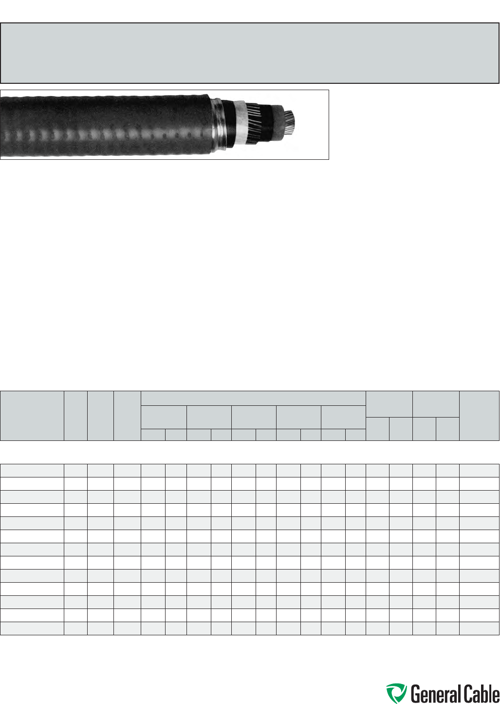
Phone: 888-593-3355
www.generalcable.com
SPEC 8300
October, 2012
Product Construction:
Conductor:
•6AWGthru1000kcmilbarecoppercompact
ClassBstrand
Strand Shield:
•Athermosetsemi-conductingstrandshieldis
extrudedovertheconductor
Insulation:
•Tree-RetardantCross-linkedPolyethylene
(TRXLPE)
Insulation Shield:
•Blacksemi-conductingthermosettinglayer,
appliedinatripleextrusionprocess,plusa
concentricservingofsolidcopperwiresacting
asbothadrainwireshieldandagrounding
(bonding)conductor
Ground (Bonding) Conductor:
•Theconductorisaconcentricservingofsolid
copperwiresappliedoverthethermosetting
insulationshield
Inner Jacket:
•Lead-free,flame-retardant,moisture-and
sunlight-resistantPolyvinylChloride(PVC),black
Armor:
•AluminumInterlockedArmor(AIA)
Overall Jacket:
•Lead-free,ACID-FLAME-CHECK✓✓
®
flame-
retardant,moisture-andsunlight-resistant
PolyvinylChloride(PVC),orange
Print:
•GENERALCABLE
®
1/CSIZE(AWGORKCMIL)
COPPERCPTTRXLPE5kV(133%INSLEVEL)
ACID-FLAME-CHECK✓✓
®
CSAHLHVTECK
(-40˚C)FT4DIRBURSUNRESMONTH/YEAR
(LIGHTNINGBOLTSYMBOL)SEQUENTIAL
LENGTHMARK
Options:
•Otherconstructionsavailableuponrequest
Applications:
•Forwiringinallhazardouslocationswhenused
withcertifiedHLcableglands
•Forexposedandconcealedwiringindry,damp
or wet locations
•Foruseinventilated,non-ventilatedandladder-
typecabletraysindry,damporwetlocations
•Fordirectearthburial(withprotectionasrequired
byinspectionauthority)
Features:
•Ratedat90˚Cwetordry
•Excellentcrush,oilandchemicalresistance
•Providelongservicelife
•Cost-effectivealternativetoinstallations
in conduit
•Meetscoldbendandimpacttestsat-40˚C
Compliances:
Industry Compliances:
•CSAStandardC22.2No.131andNo.174
•CSAStandardC68.3
Flame Test Compliances:
•CSAFT1andFT4
•IEEE383(70,000BTU/hr)
•UL1581(70,000BTU/hr)
•IEEE1202(70,000BTU/hr)CSAFT4
•ICEAT-30-520(70,000BTU/hr)
•ICEAT-29-520(210,000BTU/hr)
Other Compliances:
•HazardousLocationRating:HL
•EPA40CFR,Part261forleachablelead
contentperTCLPmethod
•OSHAAcceptable
Packaging:
•ForCanadiancustomers,lengthsareprovided
onreturnablewoodorsteelreelsthatrequirea
deposit.Extrachargesapplyforlagging,pulling
eyes,parallelingandplexing
•ForU.S.customers,materialcuttolengthand
shippedonnon-returnablewoodreels,while
lengthsinexcessof10,000lbs.areprovidedon
returnablesteelreelsthatrequireadeposit.Extra
chargesapplyforcutslessthan1000ft.,lagging,
pullingeyes,parallelingandplexing
HVTECK
TRXLPE/WireShield/PVC/AIA/PVC,Power,Shielded,Armored
5kV,CSAHVTECK,133%Ins.Level,115Mils,SingleConductor
CATALOG
NUMBER
NO.
OF
COND.
COND.
SIZE
(AWG/
kcmil)
GROUND
WIRE
SIZE
(AWG)
NOMINAL DIAMETER (OVER) COPPER
WEIGHT
NET WEIGHT
W/AL ARMOR
AMPACITY**
(40˚C
AMBIENT)
INSULATION INSULATION
SHIELD
INNER
JACKET ARMOR CABLE
LBS/
1000 FT
kg/
km
LBS/
1000 FT
kg/
kmINCHES mm INCHES mm INCHES mm INCHES mm INCHES mm
6 AWG THRU 1000 kcmil—SINGLE CONDUCTOR—SHIELDED,
133% INS. LEVEL, 115 MILS INS. (2.92 mm) (TO AEIC)—5 kV
17496.710600*
1 6 8 0.44 11.2 0.51 13.0 0.73 18.6 0.95 24.2 1.04 26.4 145 216 550 820 112
17496.710400*
1460.48 12.3 0.55 13.9 0.77 19.6 0.99 25.2 1.08 27.5 225 335 680 1010 148
17496.710200*
1260.54 13.7 0.61 15.5 0.83 21.1 1.08 27.5 1.17 29.7 303 451 840 1250 195
17496.710100*
1 1 4 0.57 14.5 0.64 16.3 0.91 23.0 1.16 29.5 1.25 31.8 407 606 960 1430 225
17496.715100*
1 1/0 4 0.61 15.4 0.68 17.3 0.94 23.9 1.19 30.3 1.28 32.5 407 606 1060 1570 260
17496.715200*
12/0 4 0.65 16.4 0.72 18.3 0.98 25.0 1.23 31.3 1.32 33.6 476 708 1170 1740 299
17496.715300*
1 3/0 3 0.70 17.7 0.76 19.3 1.03 26.3 1.31 33.3 1.40 35.6 563 838 1350 2000 345
17496.715400*
14/0 30.75 18.9 0.81 20.6 1.08 27.5 1.36 34.6 1.45 36.9 710 1057 1520 2260 400
17496.716000*
1250 2 0.80 20.3 0.87 22.1 1.16 29.6 1.44 36.6 1.53 38.9 849 1263 1730 2580 444
17496.716200*
1350 10.94 23.9 1.01 25.7 1.29 32.8 1.57 39.9 1.67 42.4 1169 1740 2170 3230 549
17496.716500*
1500 1/0 1.02 26.0 1.11 28.2 1.41 35.8 1.69 43.0 1.79 45.6 1390 2069 2860 4260 688
17496.717000*
1750 2/0 1.20 30.6 1.29 32.8 1.60 40.7 1.89 48.0 1.99 50.6 2821 4198 3940 5860 889
17496.717500*
1 1000 2/0 1.35 34.3 1.44 36.6 1.81 46.0 2.10 53.4 2.20 55.9 3608 5369 5090 7570 1061
Dimensionsandweightsarenominal;subjecttoindustrytolerances.
*Non-stockitem;minimumrunsapply.PleaseconsultCustomerServiceforpriceanddelivery.
**AmpacityisbasedonICEAPublicationP46-426for8kVcables.Opencircuit(shield/armor)isassumed.Ampacitiesatothervoltagelevelsdonotvarysignicantly.
Specialapprovalbylocalelectricalinspectionauthoritiesmayberequired(Ref.CECodePart1,AppendixB,Rule4-004).
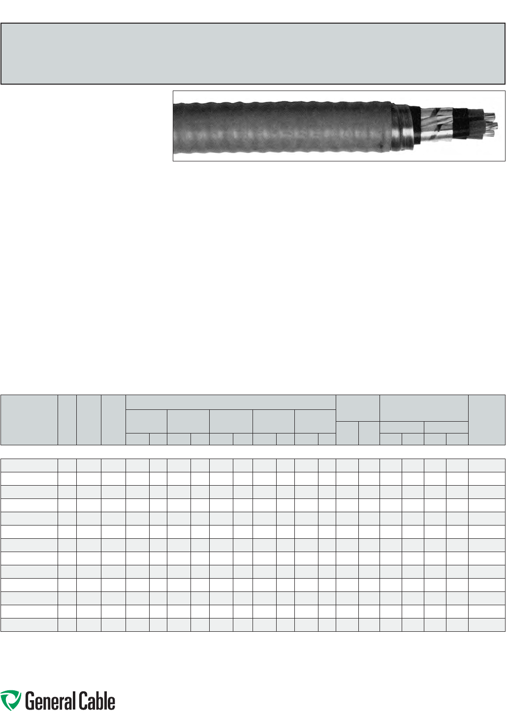
Phone: 888-593-3355
www.generalcable.com
SPEC 8325
October, 2012
Product Construction:
Conductor:
•6AWGthru1000kcmilbarecoppercompact
ClassBstrand
Strand Shield:
•Athermosetsemi-conductingstrandshieldis
extrudedovertheconductor
Insulation:
•Tree-RetardantCross-linkedPolyethylene
(TRXLPE)
Insulation Shield:
•Asemi-conductingthermosettinglayer,appliedin
atripleextrusionprocess,plusahelicallyapplied
gappedcoppertape
•Color-coded:black,redorbluecoloredtape
placedlongitudinallyunderthecoppertape
shield
Ground (Bonding) Conductor:
•Theconductorconsistsofoneuninsulated
strandedbarecopperconductor
Inner Jacket:
•Lead-free,flame-retardant,moisture-and
sunlight-resistantPolyvinylChloride(PVC),black
Armor:
•AluminumInterlockedArmor(AIA)
Overall Jacket:
•Lead-free,ACID-FLAME-CHECK✓✓
®
flame-
retardant,moisture-andsunlight-resistant
PolyvinylChloride(PVC),orange
Print:
•GENERALCABLE
®
3/CSIZE(AWGORKCMIL)
COPPERCPTTRXLPE5kV(100%OR133%
INSLEVEL)ACID-FLAME-CHECK✓✓®CSA
HLHVTECKFT4(-40˚C)DIRBURSUNRES
MONTH/YEAR(LIGHTNINGBOLTSYMBOL)
SEQUENTIALLENGTHMARK
Options:
•GalvanizedSteelInterlockedArmor(GSIA)
•Otherconstructionsavailableuponrequest
Applications:
•Forwiringinallhazardouslocationswhenused
withcertifiedHLcableglands
•Forexposedandconcealedwiringindry,damp
or wet locations
•Foruseinventilated,non-ventilatedandladder-
typecabletraysindry,damporwetlocations
•Fordirectearthburial(withprotectionasrequired
byinspectionauthority)
Features:
•Ratedat90˚Cwetordry
•Excellentcrush,oilandchemicalresistance
•Provideslongservicelife
•Cost-effectivealternativetoinstallations
in conduit
•Meetscoldbendandimpacttestsat-40˚C
Compliances:
Industry Compliances:
•CSAStandardC22.2No.131andNo.174
•CSAStandardC68.3
Flame Test Compliances:
•CSAFT1andFT4
•IEEE383(70,000BTU/hr)
•UL1581(70,000BTU/hr)
•IEEE1202(70,000BTU/hr)CSAFT4
•ICEAT-30-520(70,000BTU/hr)
•ICEAT-29-520(210,000BTU/hr)
Other Compliances:
•HazardousLocationRating:HL
•EPA40CFR,Part261forleachablelead
contentperTCLPmethod
•OSHAAcceptable
Packaging:
•ForCanadiancustomers,lengthsareprovided
onreturnablewoodorsteelreelsthatrequirea
deposit.Extrachargesapplyforlagging,pulling
eyes,parallelingandplexing
•ForU.S.customers,materialcuttolengthand
shippedonnon-returnablewoodreels,while
lengthsinexcessof10,000lbs.areprovidedon
returnablesteelreelsthatrequireadeposit.Extra
chargesapplyforcutslessthan1000ft.,lagging,
pullingeyes,parallelingandplexing
HVTECK
TRXLPE/TapeShield/PVC/AIA/PVC,Power,Shielded,Armored
5kV,CSAHVTECK,100%/133%Ins.Levels,90Mils,ThreeConductor
CATALOG
NUMBER
NO.
OF
COND.
COND.
SIZE
(AWG/
kcmil)
GROUND
WIRE
SIZE
(AWG)
NOMINAL DIAMETER (OVER) COPPER
WEIGHT
NET WEIGHT
W/ARMOR
AMPACITY**
(40˚C
AMBIENT)
INSULATION INSULATION
SHIELD
INNER
JACKET ARMOR CABLE
LBS/
1000 FT
kg/
km
LBS/1000 FT kg/km
INCHES mm INCHES mm INCHES mm INCHES mm INCHES mm AL STEEL AL STEEL
6 AWG THRU 1000 kcmil—THREE CONDUCTOR—SHIELDED, 100%/133% INS. LEVELS, 90 MILS INS. (2.29 mm)—5 kV
17496.740600*
3 6 8 0.39 10.0 0.47 11.9 1.17 29.7 1.45 36.9 1.54 39.2 349 519 1120 1590 1670 2360 93
17496.740400*
3480.43 10.5 0.51 13.0 1.26 32.0 1.54 39.1 1.63 41.4 503 749 1350 1850 1670 2760 122
17496.740200*
3260.49 12.5 0.57 14.5 1.39 35.3 1.67 42.4 1.77 45.0 771 1147 1740 2290 2590 3410 159
17496.740100*
3 1 6 0.52 13.3 0.60 15.3 1.45 36.9 1.73 43.9 1.83 46.5 939 1397 1960 2540 2920 3780 184
17496.745100*
3 1/0 6 0.56 14.2 0.63 16.0 1.53 38.9 1.81 46.0 1.91 48.5 1148 1708 2290 3010 3410 4490 211
17496.745200*
32/0 60.60 15.2 0.67 17.0 1.62 41.2 1.91 48.5 2.01 51.1 1414 2104 2620 3380 3900 5030 243
17496.745300*
3 3/0 4 0.64 16.3 0.71 18.1 1.78 45.2 2.07 52.6 2.17 55.1 1798 2668 3210 4040 4780 6020 279
17496.745400*
34/0 4 0.70 17.8 0.76 19.3 1.90 48.3 2.19 55.6 2.29 58.2 2212 3292 3720 4600 5530 6840 321
17496.746000*
3250 4 0.75 19.1 0.82 20.8 2.01 51.1 2.30 58.4 2.43 61.8 2583 3844 4300 5240 6400 7800 355
17496.746200*
3350 30.85 21.5 0.96 24.4 2.32 58.9 2.61 66.3 2.74 69.6 3569 5311 5480 6520 8160 9700 435
17496.746500*
3500 30.97 24.6 1.04 26.4 2.48 63.0 2.77 70.4 2.90 73.7 4998 7438 7130 8280 10610 12320 536
17496.747000*
3750 2 1.15 29.2 1.24 31.5 2.98 75.7 3.27 83.1 3.42 86.9 7440 11072 10330 11700 15370 17410 668
17496.747500*
3 1000 1 1.30 33.0 1.39 35.3 3.31 84.1 3.60 91.5 3.75 95.3 9860 14674 13080 14600 19460 21730 768
Dimensionsandweightsarenominal;subjecttoindustrytolerances.
*Non-stockitem;minimumrunsapply.PleaseconsultCustomerServiceforpriceanddelivery.
**AmpacityisbasedonICEAPublicationP46-426for8kVcables.Ampacitiesatothervoltagelevelsdonotvarysignicantly.
Specialapprovalbylocalelectricalinspectionauthoritiesmayberequired(Ref.CECodePart1,AppendixB,Rule4-004).
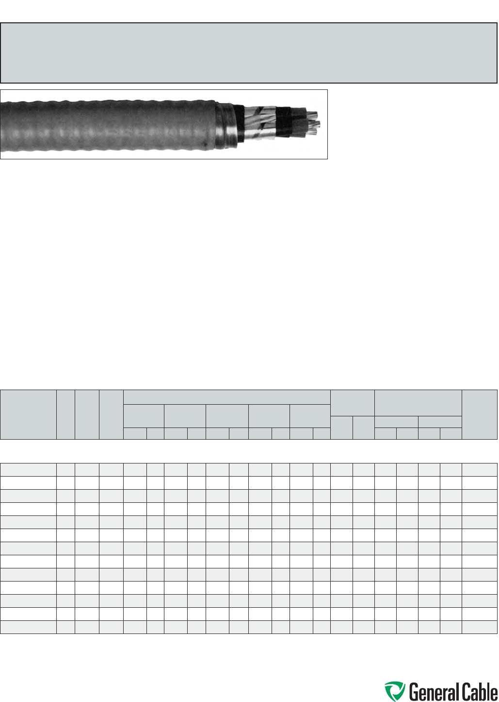
Phone: 888-593-3355
www.generalcable.com
SPEC 8350
October, 2012
HVTECK
TRXLPE/TapeShield/PVC/AIA/PVC,Power,Shielded,Armored
5kV,CSAHVTECK,133%Ins.Level,115Mils,ThreeConductor
Product Construction:
Conductor:
•6AWGthru1000kcmilbarecoppercompact
ClassBstrand
Strand Shield:
•Athermosetsemi-conductingstrandshieldis
extrudedovertheconductor
Insulation:
•Tree-RetardantCross-linkedPolyethylene
(TRXLPE)
Insulation Shield:
•Asemi-conductingthermosettinglayer,appliedin
atripleextrusionprocess,plusahelicallyapplied
gappedcoppertape
•Color-coded:black,redorbluecoloredtape
placedlongitudinallyunderthecoppertape
shield
Ground (Bonding) Conductor:
•Theconductorconsistsofoneuninsulated
strandedbarecopperconductor
Inner Jacket:
•Lead-free,flame-retardant,moisture-and
sunlight-resistantPolyvinylChloride(PVC),black
Armor:
•AluminumInterlockedArmor(AIA)
Overall Jacket:
•Lead-free,ACID-FLAME-CHECK✓✓®flame-
retardant,moisture-andsunlight-resistant
PolyvinylChloride(PVC),orange
Print:
•GENERALCABLE
®
3/CSIZE(AWGORKCMIL)
COPPERCPTTRXLPE5kV(133%INSLEVEL)
ACID-FLAME-CHECK✓✓
®
CSAHLHVTECK
FT4(-40˚C)DIRBURSUNRESMONTH/YEAR
(LIGHTNINGBOLTSYMBOL)SEQUENTIAL
LENGTHMARK
Options:
•GalvanizedSteelInterlockedArmor(GSIA)
•Otherconstructionsavailableuponrequest
Applications:
•Forwiringinallhazardouslocationswhenused
withcertifiedHLcableglands
•Forexposedandconcealedwiringindry,damp
or wet locations
•Foruseinventilated,non-ventilatedandladder-
typecabletraysindry,damporwetlocations
•Fordirectearthburial(withprotectionasrequired
byinspectionauthority)
Features:
•Ratedat90˚Cwetordry
•Excellentcrush,oilandchemicalresistance
•Provideslongservicelife
•Cost-effectivealternativetoinstallations
in conduit
•Meetscoldbendandimpacttestsat-40˚C
Compliances:
Industry Compliances:
•CSAStandardC22.2No.131andNo.174
•CSAStandardC68.3
Flame Test Compliances:
•CSAFT1andFT4
•IEEE383(70,000BTU/hr)
•UL1581(70,000BTU/hr)
•IEEE1202(70,000BTU/hr)CSAFT4
•ICEAT-30-520(70,000BTU/hr)
•ICEAT-29-520(210,000BTU/hr)
Other Compliances:
•HazardousLocationRating:HL
•EPA40CFR,Part261forleachablelead
contentperTCLPmethod
•OSHAAcceptable
Packaging:
•ForCanadiancustomers,lengthsareprovided
onreturnablewoodorsteelreelsthatrequirea
deposit.Extrachargesapplyforlagging,pulling
eyes,parallelingandplexing
•ForU.S.customers,materialcuttolengthand
shippedonnon-returnablewoodreels,while
lengthsinexcessof10,000lbs.areprovidedon
returnablesteelreelsthatrequireadeposit.Extra
chargesapplyforcutslessthan1000ft.,lagging,
pullingeyes,parallelingandplexing
CATALOG
NUMBER
NO.
OF
COND.
COND.
SIZE
(AWG/
kcmil)
GROUND
WIRE
SIZE
(AWG)
NOMINAL DIAMETER (OVER) COPPER
WEIGHT
NET WEIGHT
W/ARMOR
AMPACITY**
(40˚C
AMBIENT)
INSULATION INSULATION
SHIELD
INNER
JACKET ARMOR CABLE
LBS/
1000 FT
kg/
km
LBS/1000 FT kg/km
INCHES mm INCHES mm INCHES mm INCHES mm INCHES mm AL STEEL AL STEEL
6 AWG THRU 1000 kcmil—THREE CONDUCTOR—SHIELDED, 133% INS. LEVEL,
115 MILS INS. (2.92 mm) (TO AEIC)—5 kV
17496.750600*
3 6 8 0.44 11.2 0.51 13.0 1.27 32.3 1.55 39.4 1.65 41.9 352 524 1270 1780 1890 2650 93
17496.750400*
3480.48 12.3 0.55 13.9 1.37 34.8 1.65 41.9 1.75 44.5 505 752 1500 2040 2230 3040 122
17496.750200*
3260.54 13.7 0.61 15.5 1.50 38.2 1.78 45.2 1.88 47.8 774 1152 1930 2630 2870 3910 159
17496.750100*
3 1 6 0.57 14.5 0.64 16.3 1.57 39.9 1.86 47.3 1.96 49.8 943 1403 2150 2880 3200 2490 184
17496.755100*
3 1/0 6 0.61 15.4 0.68 17.3 1.65 41.9 1.94 49.3 2.04 51.8 1151 1713 2430 3200 3620 4760 211
17496.755200*
32/0 60.65 16.4 0.72 18.3 1.80 45.6 2.09 53.1 2.19 55.7 1417 2109 2890 3720 4300 5540 243
17496.755300*
3 3/0 4 0.70 17.7 0.76 19.3 1.90 48.3 2.19 55.7 2.29 58.2 1796 2673 3360 4240 5000 6310 279
17496.755400*
34/0 4 0.75 18.9 0.81 20.6 2.01 51.0 2.30 58.5 2.43 61.8 2215 3296 3940 4870 5860 7240 321
17496.756000*
3250 4 0.80 20.3 0.87 22.1 2.13 54.1 2.42 61.5 2.55 64.8 2583 3844 4470 5450 6650 8120 355
17496.756200*
3350 30.94 23.9 1.01 25.7 2.43 61.8 2.72 69.1 2.85 72.4 3572 5316 5650 6730 8400 10020 435
17496.756500*
3500 31.02 26.0 1.11 28.2 2.64 67.1 2.93 74.5 3.06 77.8 5004 7447 7440 8660 11070 12880 536
17496.757000*
3750 2 1.20 30.6 1.29 32.8 3.10 78.8 3.39 86.1 3.54 89.9 7431 11059 10560 11980 15710 17830 668
17496.757500*
3 1000 1 1.35 34.3 1.44 36.6 3.42 86.9 3.71 94.3 3.86 98.1 9863 14678 13300 14870 19790 22130 768
Dimensionsandweightsarenominal;subjecttoindustrytolerances.
*Non-stockitem;minimumrunsapply.PleaseconsultCustomerServiceforpriceanddelivery.
**AmpacityisbasedonICEAPublicationP46-426for8kVcables.Ampacitiesatothervoltagelevelsdonotvarysignicantly.
Specialapprovalbylocalelectricalinspectionauthoritiesmayberequired(Ref.CECodePart1,AppendixB,Rule4-004).

Phone: 888-593-3355
www.generalcable.com
SPEC 8375
October, 2012
Product Construction:
Conductor:
•2AWGthru1000kcmilbarecoppercompact
ClassBstrand
Strand Shield:
•Athermosetsemi-conductingstrandshieldis
extrudedovertheconductor
Insulation:
•Tree-RetardantCross-linkedPolyethylene
(TRXLPE)
Insulation Shield:
•Blacksemi-conductingthermosettinglayer,
appliedinatripleextrusionprocess,plusa
concentricservingofsolidcopperwiresacting
asbothadrainwireshieldandagrounding
(bonding)conductor
Ground (Bonding) Conductor:
•Theconductorisaconcentricservingofsolid
copperwiresappliedoverthethermosetting
insulationshield
Inner Jacket:
•Lead-free,flame-retardant,moisture-and
sunlight-resistantPolyvinylChloride(PVC),black
Armor:
•AluminumInterlockedArmor(AIA)
Overall Jacket:
•Lead-free,ACID-FLAME-CHECK✓✓
®
flame-
retardant,moisture-andsunlight-resistant
PolyvinylChloride(PVC),red
Print:
•GENERALCABLE
®
1/CSIZE(AWGORKCMIL)
COPPERCPTTRXLPE15kV(100%INSLEVEL)
ACID-FLAME-CHECK✓✓
®
CSAHLHVTECK
FT4(-40˚C)DIRBURSUNRESMONTH/YEAR
(LIGHTNINGBOLTSYMBOL)SEQUENTIAL
LENGTHMARK
Options:
•Otherconstructionsavailableuponrequest
Applications:
•Forwiringinallhazardouslocationswhenused
withcertifiedHLcableglands
•Forexposedandconcealedwiringindry,damp
or wet locations
•Foruseinventilated,non-ventilatedandladder-
typecabletraysindry,damporwetlocations
•Fordirectearthburial(withprotectionasrequired
byinspectionauthority)
Features:
•Ratedat90˚Cwetordry
•Excellentcrush,oilandchemicalresistance
•Provideslongservicelife
•Cost-effectivealternativetoinstallations
in conduit
•Meetscoldbendandimpacttestsat-40˚C
Compliances:
Industry Compliances:
•CSAStandardC22.2No.131andNo.174
•CSAStandardC68.3
Flame Test Compliances:
•CSAFT1andFT4
•IEEE383(70,000BTU/hr)
•UL1581(70,000BTU/hr)
•IEEE1202(70,000BTU/hr)CSAFT4
•ICEAT-30-520(70,000BTU/hr)
•ICEAT-29-520(210,000BTU/hr)
Other Compliances:
•HazardousLocationRating:HL
•EPA40CFR,Part261forleachablelead
contentperTCLPmethod
•OSHAAcceptable
Packaging:
•ForCanadiancustomers,lengthsareprovided
onreturnablewoodorsteelreelsthatrequirea
deposit.Extrachargesapplyforlagging,pulling
eyes,parallelingandplexing
•ForU.S.customers,materialcuttolengthand
shippedonnon-returnablewoodreels,while
lengthsinexcessof10,000lbs.areprovidedon
returnablesteelreelsthatrequireadeposit.Extra
chargesapplyforcutslessthan1000ft.,lagging,
pullingeyes,parallelingandplexing
HVTECK
TRXLPE/WireShield/PVC/AIA/PVC,Power,Shielded,Armored
15kV,CSAHVTECK,100%Ins.Level,175Mils,SingleConductor
CATALOG
NUMBER
NO.
OF
COND.
COND.
SIZE
(AWG/
kcmil)
GROUND
WIRE
SIZE
(AWG)
NOMINAL DIAMETER (OVER) COPPER
WEIGHT
NET WEIGHT
W/AL ARMOR
AMPACITY**
(40˚C
AMBIENT)
INSULATION INSULATION
SHIELD
INNER
JACKET ARMOR CABLE
LBS/
1000 FT
kg/
km
LBS/
1000 FT
kg/
kmINCHES mm INCHES mm INCHES mm INCHES mm INCHES mm
2 AWG THRU 1000 kcmil—SINGLE CONDUCTOR—100% INS. LEVELS, 175 MILS INS. (4.45 mm)—15 kV
17496.810200*
1260.66 16.7 0.73 18.6 0.99 25.3 1.24 31.5 1.33 33.8 259 385 950 1420 195
17496.810100*
1 1 4 0.69 17.5 0.76 19.3 1.03 26.1 1.28 32.5 1.37 34.8 391 582 1080 1600 225
17496.815100*
1 1/0 4 0.73 18.5 0.80 20.3 1.06 27.0 1.31 33.3 1.40 35.6 460 685 1170 1750 259
17496.815200*
12/0 4 0.77 19.5 0.84 21.3 1.10 27.9 1.35 34.3 1.44 36.6 545 811 1290 1920 298
17496.815300*
1 3/0 3 0.82 20.8 0.88 22.4 1.15 29.2 1.40 35.6 1.49 37.9 688 1024 1470 2190 343
17496.815400*
14/0 30.87 22.0 0.94 23.9 1.21 30.6 1.46 37.1 1.55 39.4 824 1226 1640 2450 397
17496.816000*
1250 2 0.93 23.5 0.99 25.2 1.28 32.5 1.53 38.9 1.63 41.4 944 1405 1900 2830 440
17496.816200*
1350 11.07 27.2 1.15 29.2 1.43 36.3 1.71 43.5 1.81 46.0 1352 2012 2370 3530 543
17496.816500*
1500 1/0 1.14 29.0 1.23 31.2 1.54 39.1 1.83 46.5 1.93 49.1 1887 2808 3080 4590 678
17496.817000*
1750 2/0 1.32 33.6 1.41 35.9 1.78 45.2 2.07 52.6 2.17 55.2 2754 4099 4240 6320 872
17496.817500*
1 1000 2/0 1.48 37.6 1.57 39.9 1.93 49.0 2.22 56.4 2.32 59.0 3532 5256 5280 7860 1040
Dimensionsandweightsarenominal;subjecttoindustrytolerances.
*Non-stockitem;minimumrunsapply.PleaseconsultCustomerServiceforpriceanddelivery.
**AmpacityisbasedonICEAPublicationP46-426for15kVcables.Opencircuit(shield/armor)isassumed.Ampacitiesatothervoltagelevelsdonotvarysignicantly.
Specialapprovalbylocalelectricalinspectionauthoritiesmayberequired(Ref.CECodePart1,AppendixB,Rule4-004).

Phone: 888-593-3355
www.generalcable.com
SPEC 8400
October, 2012
HVTECK
TRXLPE/WireShield/PVC/AIA/PVC,Power,Shielded,Armored
15kV,CSAHVTECK,133%Ins.Level,220Mils,SingleConductor
Product Construction:
Conductor:
•2AWGthru1000kcmilbarecoppercompact
ClassBstrand
Strand Shield:
•Athermosetsemi-conductingstrandshieldis
extrudedovertheconductor
Insulation:
•Tree-RetardantCross-linkedPolyethylene
(TRXLPE)
Insulation Shield:
•Blacksemi-conductingthermosettinglayer,
appliedinatripleextrusionprocess,plusa
concentricservingofsolidcopperwiresacting
asbothadrainwireshieldandagrounding
(bonding)conductor
Ground (Bonding) Conductor:
•Theconductorisaconcentricservingofsolid
copperwiresappliedoverthethermosetting
insulationshield
Inner Jacket:
•Lead-free,flame-retardant,moisture-and
sunlight-resistantPolyvinylChloride(PVC),black
Armor:
•AluminumInterlockedArmor(AIA)
Overall Jacket:
•Lead-free,ACID-FLAME-CHECK✓✓
®
flame-
retardant,moisture-andsunlight-resistant
PolyvinylChloride(PVC),red
Print:
•GENERALCABLE
®
1/CSIZE(AWGORKCMIL)
COPPERCPTTRXLPE15kV(133%INSLEVEL)
ACID-FLAME-CHECK✓✓
®
CSAHLHVTECK
FT4(-40˚C)DIRBURSUNRESMONTH/YEAR
(LIGHTNINGBOLTSYMBOL)SEQUENTIAL
LENGTHMARK
Options:
•Otherconstructionsavailableuponrequest
Applications:
•Forwiringinallhazardouslocationswhenused
withcertifiedHLcableglands
•Forexposedandconcealedwiringindry,damp
or wet locations
•Foruseinventilated,non-ventilatedandladder-
typecabletraysindry,damporwetlocations
•Fordirectearthburial(withprotectionasrequired
byinspectionauthority)
Features:
•Ratedat90˚Cwetordry
•Excellentcrush,oilandchemicalresistance
•Provideslongservicelife
•Cost-effectivealternativetoinstallations
in conduit
•Meetscoldbendandimpacttestsat-40˚C
Compliances:
Industry Compliances:
•CSAStandardC22.2No.131andNo.174
•CSAStandardC68.3
Flame Test Compliances:
•CSAFT1andFT4
•IEEE383(70,000BTU/hr)
•UL1581(70,000BTU/hr)
•IEEE1202(70,000BTU/hr)CSAFT4
•ICEAT-30-520(70,000BTU/hr)
•ICEAT-29-520(210,000BTU/hr)
Other Compliances:
•HazardousLocationRating:HL
•EPA40CFR,Part261forleachablelead
contentperTCLPmethod
•OSHAAcceptable
Packaging:
•ForCanadiancustomers,lengthsareprovided
onreturnablewoodorsteelreelsthatrequirea
deposit.Extrachargesapplyforlagging,pulling
eyes,parallelingandplexing
•ForU.S.customers,materialcuttolengthand
shippedonnon-returnablewoodreels,while
lengthsinexcessof10,000lbs.areprovidedon
returnablesteelreelsthatrequireadeposit.Extra
chargesapplyforcutslessthan1000ft.,lagging,
pullingeyes,parallelingandplexing
CATALOG
NUMBER
NO.
OF
COND.
COND.
SIZE
(AWG/
kcmil)
GROUND
WIRE
SIZE
(AWG)
NOMINAL DIAMETER (OVER) COPPER
WEIGHT
NET WEIGHT
W/AL ARMOR
AMPACITY**
(40˚C
AMBIENT)
INSULATION INSULATION
SHIELD
INNER
JACKET ARMOR CABLE
LBS/
1000 FT
kg/
km
LBS/
1000 FT
kg/
kmINCHES mm INCHES mm INCHES mm INCHES mm INCHES mm
2 AWG THRU 1000 kcmil—SINGLE CONDUCTOR—133% INS. LEVELS, 220 MILS INS. (5.59 mm)—15 kV
17496.216500*
1260.76 19.3 0.83 21.1 1.09 27.7 1.34 34.1 1.43 36.4 286 426 1028 1530 195
17496.820100*
1 1 4 0.79 20.1 0.86 21.9 1.12 28.4 1.37 34.8 1.46 37.1 391 582 1170 1740 225
17496.825100*
1 1/0 4 0.83 21.1 0.89 22.6 1.16 29.4 1.41 35.8 1.50 38.1 459 683 1270 1890 259
17496.825200*
12/0 4 0.86 21.8 0.93 23.6 1.20 30.4 1.45 36.9 1.54 39.2 546 813 1390 2060 298
17496.825300*
1 3/0 3 0.91 23.0 0.98 24.9 1.25 31.7 1.50 38.1 1.59 40.4 693 1031 1570 2340 343
17496.825400*
14/0 30.96 24.3 1.03 26.2 1.30 33.0 1.58 40.2 1.68 42.7 830 1235 1780 2650 397
17496.826000*
1250 2 1.02 25.8 1.08 27.5 1.38 35.0 1.66 42.2 1.76 44.7 989 1472 2010 2990 440
17496.826200*
1350 11.12 28.3 1.20 30.5 1.50 38.0 1.78 45.2 1.88 47.8 1228 1827 2490 3700 543
17496.826500*
1500 1/0 1.24 31.5 1.32 33.6 1.65 41.8 1.94 49.3 2.04 51.9 1896 2821 3220 4790 678
17496.827000*
1750 2/0 1.42 36.0 1.51 38.3 1.89 48.0 2.18 55.4 2.28 57.9 2766 4116 4390 6530 872
17496.827500*
1 1000 2/0 1.57 39.9 1.68 42.6 2.05 52.1 2.34 59.5 2.48 63.0 3552 5286 5550 8260 1040
Dimensionsandweightsarenominal;subjecttoindustrytolerances.
*Non-stockitem;minimumrunsapply.PleaseconsultCustomerServiceforpriceanddelivery.
**AmpacityisbasedonICEAPublicationP46-426for15kVcables.Opencircuit(shield/armor)isassumed.Ampacitiesatothervoltagelevelsdonotvarysignicantly.
Specialapprovalbylocalelectricalinspectionauthoritiesmayberequired(Ref.CECodePart1,AppendixB,Rule4-004).
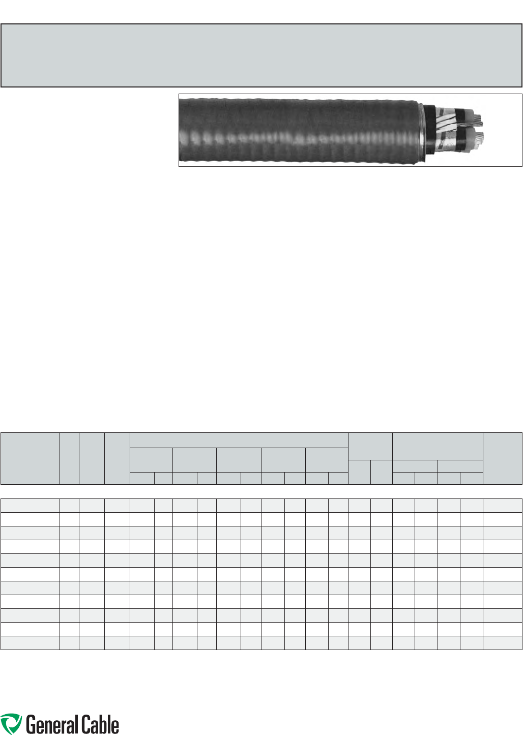
Phone: 888-593-3355
www.generalcable.com
SPEC 8425
October, 2012
HVTECK
TRXLPE/TapeShield/PVC/AIA/PVC,Power,Shielded,Armored
15kV,CSAHVTECK,100%Ins.Level,175Mils,ThreeConductor
Product Construction:
Conductor:
•2AWGthru1000kcmilbarecoppercompact
ClassBstrand
Strand Shield:
•Athermosetsemi-conductingstrandshieldis
extrudedovertheconductor
Insulation:
•Tree-RetardantCross-linkedPolyethylene
(TRXLPE)
Insulation Shield:
•Thisconsistsofasemi-conductingthermosetting
layer,appliedinatripleextrusionprocess,plusa
helicallyappliedgappedcoppertape
•Color-coded:black,redorbluecoloredtape
placedlongitudinallyunderthecoppertape
shield
Ground (Bonding) Conductor:
•Theconductorconsistsofoneuninsulated
strandedbarecopperconductor
Inner Jacket:
•Lead-free,flame-retardant,moisture-and
sunlight-resistantPolyvinylChloride(PVC),black
Armor:
•AluminumInterlockedArmor(AIA)
Overall Jacket:
•Lead-free,ACID-FLAME-CHECK✓✓
®
flame-
retardant,moisture-andsunlight-resistant
PolyvinylChloride(PVC),red
Print:
•GENERALCABLE
®
3/CSIZE(AWGORKCMIL)
COPPERCPTTRXLPE15kV(100%INSLEVEL)
ACID-FLAME-CHECK✓✓
®
CSAHLHVTECK
FT4(-40˚C)DIRBURSUNRESMONTH/YEAR
(LIGHTNINGBOLTSYMBOL)SEQUENTIAL
LENGTHMARK
Options:
•GalvanizedSteelInterlockedArmor(GSIA)
•Otherconstructionsavailableuponrequest
Applications:
•Forwiringinallhazardouslocationswhenused
withcertifiedHLcableglands
•Forexposedandconcealedwiringindry,damp
or wet locations
•Foruseinventilated,non-ventilatedandladder-
typecabletraysindry,damporwetlocations
•Fordirectearthburial(withprotectionasrequired
byinspectionauthority)
Features:
•Ratedat90˚Cwetordry
•Excellentcrush,oilandchemicalresistance
•Provideslongservicelife
•Cost-effectivealternativetoinstallations
in conduit
•Meetscoldbendandimpacttestsat-40˚C
Compliances:
Industry Compliances:
•CSAStandardC22.2No.131andNo.174
•CSAStandardC68.3
Flame Test Compliances:
•CSAFT1andFT4
•IEEE383(70,000BTU/hr)
•UL1581(70,000BTU/hr)
•IEEE1202(70,000BTU/hr)CSAFT4
•ICEAT-30-520(70,000BTU/hr)
•ICEAT-29-520(210,000BTU/hr)
Other Compliances:
•HazardousLocationRating:HL
•EPA40CFR,Part261forleachablelead
contentperTCLPmethod
•OSHAAcceptable
Packaging:
•ForCanadiancustomers,lengthsareprovided
onreturnablewoodorsteelreelsthatrequirea
deposit.Extrachargesapplyforlagging,pulling
eyes,parallelingandplexing
•ForU.S.customers,materialcuttolengthand
shippedonnon-returnablewoodreels,while
lengthsinexcessof10,000lbs.areprovidedon
returnablesteelreelsthatrequireadeposit.Extra
chargesapplyforcutslessthan1000ft.,lagging,
pullingeyes,parallelingandplexing
CATALOG
NUMBER
NO.
OF
COND.
COND.
SIZE
(AWG/
kcmil)
GROUND
WIRE
SIZE
(AWG)
NOMINAL DIAMETER (OVER) COPPER
WEIGHT
NET WEIGHT
W/ARMOR
AMPACITY**
(40˚C
AMBIENT)
INSULATION INSULATION
SHIELD
INNER
JACKET ARMOR CABLE
LBS/
1000 FT
kg/
km
LBS/1000 FT kg/km
INCHES mm INCHES mm INCHES mm INCHES mm INCHES mm AL STEEL AL STEEL
2 AWG THRU 1000 kcmil—THREE CONDUCTOR—100% INS. LEVELS, 175 MILS INS. (4.45 mm)—15 kV
17496.030200*
3260.66 16.7 0.73 18.6 1.82 46.3 2.11 53.6 2.21 56.2 787 1171 2370 3220 3530 4790 164
17496.830100*
3 1 6 0.69 17.5 0.76 19.3 1.89 48.0 2.18 55.4 2.27 57.7 955 1421 2620 3490 3890 5190 187
17496.835100*
3 1/0 6 0.73 18.5 0.79 20.1 1.97 50.0 2.26 57.4 2.35 59.7 1163 1731 2900 3810 4320 5670 215
17496.835200*
32/0 60.77 19.5 0.84 21.3 2.06 52.3 2.34 59.5 2.46 62.5 1429 2127 3330 4280 4960 6370 246
17496.835300*
3 3/0 4 0.82 20.8 0.88 22.4 2.16 54.9 2.44 62.0 2.57 65.3 1812 2697 3840 4840 5720 7200 283
17496.835400*
34/0 4 0.87 22.0 0.93 23.7 2.27 57.7 2.56 65.1 2.68 68.1 2228 3316 4360 5410 6490 8050 325
17496.836000*
3250 4 0.93 23.5 0.99 25.2 2.38 60.5 2.68 68.1 2.79 70.9 2598 3866 4880 5990 7260 8910 359
17496.836200*
3350 31.06 26.9 1.15 29.2 2.73 69.4 3.02 76.7 3.14 79.8 3587 5338 6210 7430 9240 11060 438
17496.536500*
3500 31.14 29.0 1.23 31.2 2.97 75.5 3.26 82.8 3.40 86.4 5013 7460 8549 9550 12721 14200 536
17496.837000*
3750 2 1.32 33.6 1.41 35.9 3.35 85.1 3.64 92.5 3.77 95.8 7446 11081 11100 12640 16520 18810 669
17496.837500*
3 1000 1 1.47 37.4 1.56 39.6 3.72 94.5 3.97 100.8 4.17 105.9 9376 13953 13890 15580 20670 23180 770
Dimensionsandweightsarenominal;subjecttoindustrytolerances.
*Non-stockitem;minimumrunsapply.PleaseconsultCustomerServiceforpriceanddelivery.
**AmpacityisbasedonICEAPublicationP46-426for15kVcables.Ampacitiesatothervoltagelevelsdonotvarysignicantly.
Specialapprovalbylocalelectricalinspectionauthoritiesmayberequired(Ref.CECodePart1,AppendixB,Rule4-004).
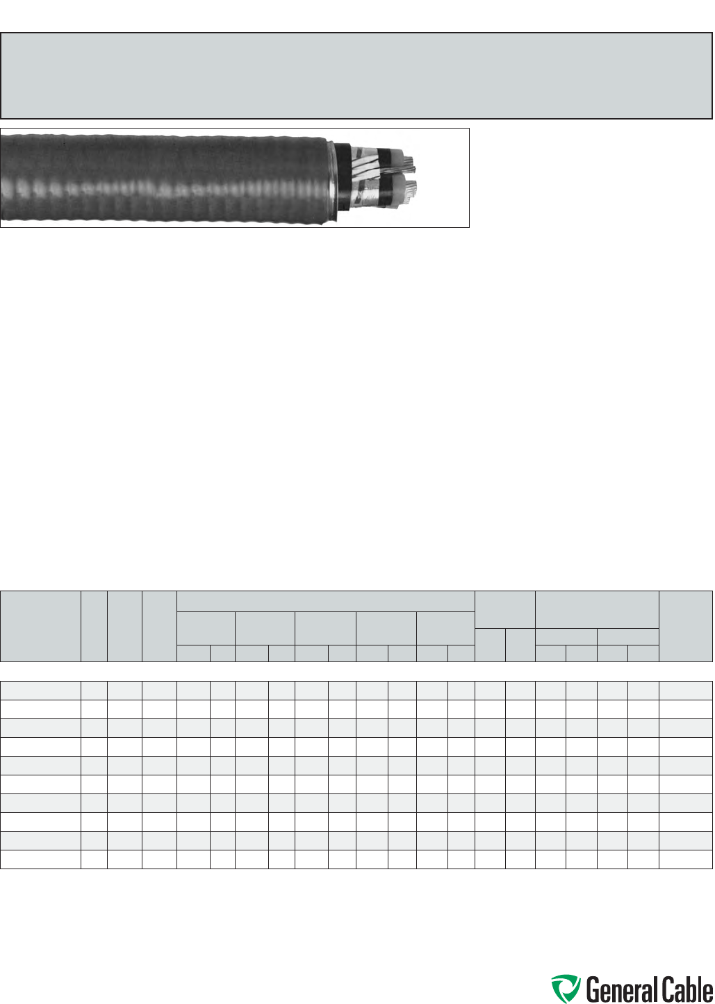
Phone: 888-593-3355
www.generalcable.com
SPEC 8450
October, 2012
HVTECK
TRXLPE/TapeShield/PVC/AIA/PVC,Power,Shielded,Armored
15kV,CSAHVTECK,133%Ins.Level,220Mils,ThreeConductor
Product Construction:
Conductor:
•2AWGthru750kcmilbarecoppercompact
ClassBstrand
Strand Shield:
•Athermosetsemi-conductingstrandshieldis
extrudedovertheconductor
Insulation:
•Tree-RetardantCross-linkedPolyethylene
(TRXLPE)
Insulation Shield:
•Thisconsistsofasemi-conductingthermosetting
layer,appliedinatripleextrusionprocess,plusa
helicallyappliedgappedcoppertape
•Color-coded:black,redorbluecoloredtape
placedlongitudinallyunderthecoppertape
shield
Ground (Bonding) Conductor:
•Theconductorconsistsofoneuninsulated
strandedbarecopperconductor
Inner Jacket:
•Lead-free,flame-retardant,moisture-and
sunlight-resistantPolyvinylChloride(PVC),black
Armor:
•AluminumInterlockedArmor(AIA)
Overall Jacket:
•Lead-free,ACID-FLAME-CHECK✓✓
®
flame-
retardant,moisture-andsunlight-resistant
PolyvinylChloride(PVC),red
Print:
•GENERALCABLE
®
3/CSIZE(AWGORKCMIL)
COPPERCPTTRXLPE15kV(133%INSLEVEL)
ACID-FLAME-CHECK✓✓
®
CSAHLHVTECK
FT4(-40˚C)DIRBURSUNRESMONTH/YEAR
(LIGHTNINGBOLTSYMBOL)SEQUENTIAL
LENGTHMARK
Options:
•GalvanizedSteelInterlockedArmor(GSIA)
•Otheroptionsavailableuponrequest
Applications:
•Forwiringinallhazardouslocationswhenused
withcertifiedHLcableglands
•Forexposedandconcealedwiringindry,damp
or wet locations
•Foruseinventilated,non-ventilatedandladder-
typecabletraysindry,damporwetlocations
•Fordirectearthburial(withprotectionasrequired
byinspectionauthority)
Features:
•Ratedat90˚Cwetordry
•Excellentcrush,oilandchemicalresistance
•Provideslongservicelife
•Cost-effectivealternativetoinstallations
in conduit
•Meetscoldbendandimpacttestsat-40˚C
Compliances:
Industry Compliances:
•CSAStandardC22.2No.131andNo.174
•CSAStandardC68.3
Flame Test Compliances:
•CSAFT1andFT4
•IEEE383(70,000BTU/hr)
•UL1581(70,000BTU/hr)
•IEEE1202(70,000BTU/hr)CSAFT4
•ICEAT-30-520(70,000BTU/hr)
•ICEAT-29-520(210,000BTU/hr)
Other Compliances:
•HazardousLocationRating:HL
•EPA40CFR,Part261forleachablelead
contentperTCLPmethod
•OSHAAcceptable
Packaging:
•ForCanadiancustomers,lengthsareprovided
onreturnablewoodorsteelreelsthatrequirea
deposit.Extrachargesapplyforlagging,pulling
eyes,parallelingandplexing
•ForU.S.customers,materialcuttolengthand
shippedonnon-returnablewoodreels,while
lengthsinexcessof10,000lbs.areprovidedon
returnablesteelreelsthatrequireadeposit.Extra
chargesapplyforcutslessthan1000ft.,lagging,
pullingeyes,parallelingandplexing
CATALOG
NUMBER
NO.
OF
COND.
COND.
SIZE
(AWG/
kcmil)
GROUND
WIRE
SIZE
(AWG)
NOMINAL DIAMETER (OVER) COPPER
WEIGHT
NET WEIGHT
W/ARMOR
AMPACITY**
(40˚C
AMBIENT)
INSULATION INSULATION
SHIELD
INNER
JACKET ARMOR CABLE
LBS/
1000 FT
kg/
km
LBS/1000 FT kg/km
INCHES mm INCHES mm INCHES mm INCHES mm INCHES mm AL STEEL AL STEEL
2 AWG THRU 750 kcmil—THREE CONDUCTOR—133% INS. LEVEL, 220 MILS INS. (5.59 mm)—15 kV
17496.230200*
3260.76 19.3 0.83 21.1 2.02 51.3 2.31 58.7 2.43 61.7 793 1180 2665 3518 3966 5235 164
17496.010100*
3 1 6 0.79 20.1 0.86 21.9 2.10 53.3 2.37 60.2 2.49 63.3 964 1435 3089 3930 4597 5850 187
17451.316781*
3 1/0 6 0.83 21.1 0.89 22.6 2.17 55.1 2.46 62.5 2.58 65.6 1175 1749 3300 4300 4900 6390 215
17496.015200*
32/0 60.86 21.8 0.93 23.6 2.26 57.3 2.55 64.8 2.67 67.8 1438 2140 3650 4690 5430 6980 246
17496.025300*
3 3/0 4 0.91 23.0 0.98 24.9 2.36 60.0 2.65 67.3 2.77 70.4 1821 2710 4140 5230 6160 7780 283
17496.035400*
34/0 4 0.96 24.3 1.03 26.2 2.47 62.8 2.76 70.1 2.88 73.2 2248 3345 4680 5810 6960 8650 325
17496.026000*
3250 4 1.02 25.8 1.08 27.5 2.59 65.8 2.88 73.2 3.00 76.2 2607 3880 5275 6440 7850 9580 359
17496.046200
3350 31.12 28.3 1.20 30.5 2.90 73.7 3.19 81.0 3.33 84.6 3597 5353 6842 8170 10181 12160 438
17496.056500
3500 31.24 31.5 1.32 33.6 3.16 80.3 3.45 87.6 3.59 91.2 5022 7474 8513 10050 12668 14950 536
17496.037000
3750 2 1.42 36.0 1.51 38.3 3.57 90.7 3.85 97.8 4.00 101.6 7452 11090 11507 13160 17122 19580 669
Dimensionsandweightsarenominal;subjecttoindustrytolerances.
*Non-stockitem;minimumrunsapply.PleaseconsultCustomerServiceforpriceanddelivery.
**AmpacityisbasedonICEAPublicationP46-426for15kVcables.Ampacitiesatothervoltagelevelsdonotvarysignicantly.
Specialapprovalbylocalelectricalinspectionauthoritiesmayberequired(Ref.CECodePart1,AppendixB,Rule4-004).
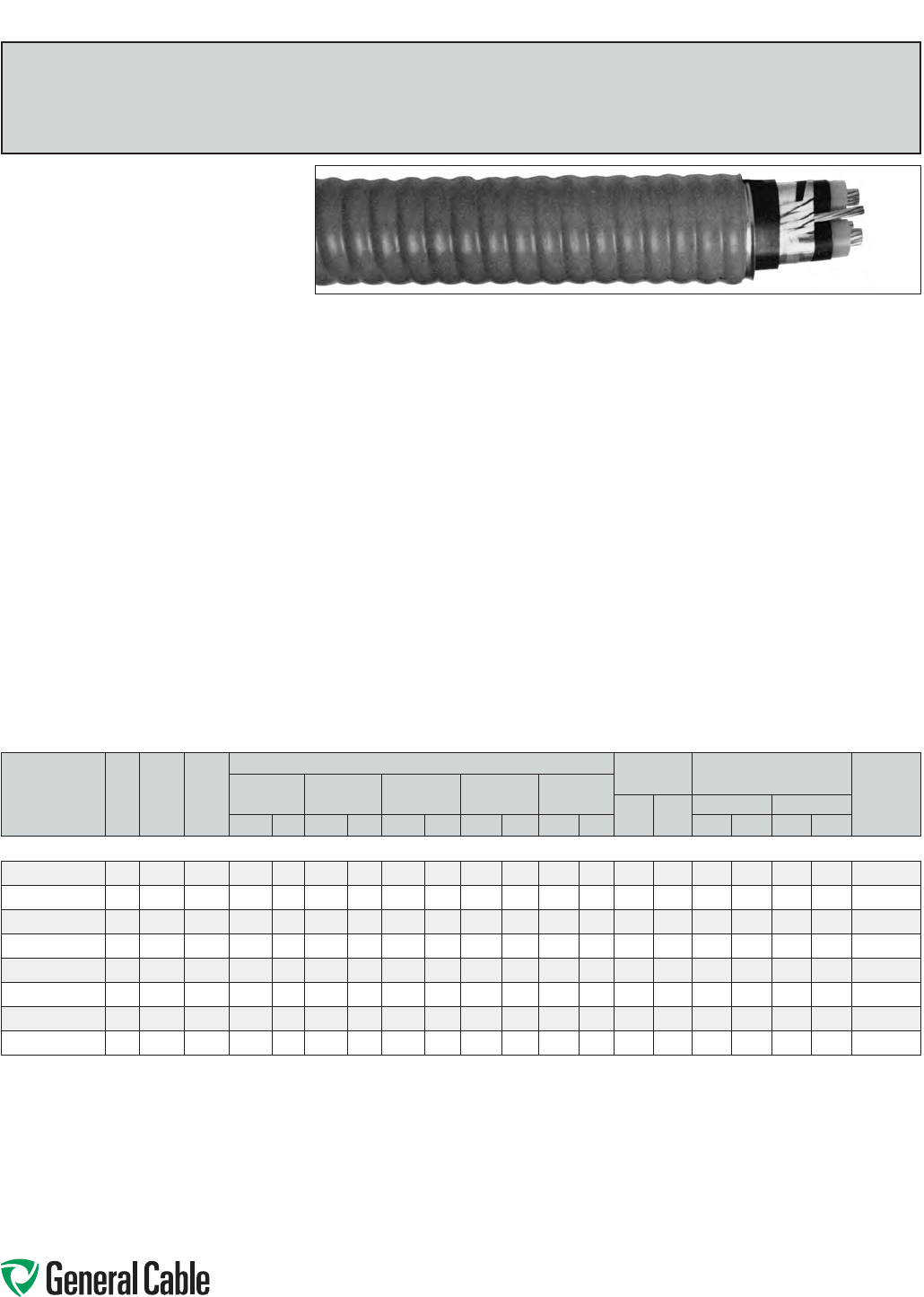
Phone: 888-593-3355
www.generalcable.com
SPEC 8475
October, 2012
HVTECK
TRXLPE/TapeShield/PVC/AIA/PVC,Power,Shielded,Armored
25kV,CSAHVTECK,100%Ins.Level,260Mils,ThreeConductor
Product Construction:
Conductor:
•1AWGthru500kcmilbarecoppercompact
ClassBstrand
Strand Shield:
•Athermosetsemi-conductingstrandshieldis
extrudedovertheconductor
Insulation:
•Tree-RetardantCross-linkedPolyethylene
(TRXLPE)
Insulation Shield:
•Thisconsistsofasemi-conductingthermosetting
layer,appliedinatripleextrusionprocess,plusa
helicallyappliedgappedcoppertape
•Color-coded:black,redorbluecoloredtape
placedlongitudinallyunderthecoppertape
shield
Ground (Bonding) Conductor:
•Theconductorconsistsofoneuninsulated
strandedbarecopperconductor
Inner Jacket:
•Lead-free,flame-retardant,moisture-and
sunlight-resistantPolyvinylChloride(PVC),black
Armor:
•AluminumInterlockedArmor(AIA)
Overall Jacket:
•Lead-free,ACID-FLAME-CHECK✓✓
®
flame-
retardant,moisture-andsunlight-resistant
PolyvinylChloride(PVC),blackorasrequested
Print:
•GENERALCABLE
®
3/CSIZE(AWGORKCMIL)
COPPERCPTTRXLPE25kV(100%INSLEVEL)
ACID-FLAME-CHECK✓✓
®
CSAHLHVTECK
FT4(-40˚C)DIRBURSUNRESMONTH/YEAR
(LIGHTNINGBOLTSYMBOL)SEQUENTIAL
LENGTHMARK
Options:
•GalvanizedSteelInterlockedArmor(GSIA)
•Otherconstructionsavailableuponrequest
Applications:
•Forwiringinallhazardouslocationswhenused
withcertifiedHLcableglands
•Forexposedandconcealedwiringindry,damp
or wet locations
•Foruseinventilated,non-ventilatedandladder-
typecabletraysindry,damporwetlocations
•Fordirectearthburial(withprotectionasrequired
byinspectionauthority)
Features:
•Ratedat90˚Cwetordry
•Excellentcrush,oilandchemicalresistance
•Provideslongservicelife
•Cost-effectivealternativetoinstallations
in conduit
•Meetscoldbendandimpacttestsat-40˚C
Compliances:
Industry Compliances:
•CSAStandardC22.2No.131andNo.174
•CSAStandardC68.3
Flame Test Compliances:
•CSAFT1andFT4
•IEEE383(70,000BTU/hr)
•UL1581(70,000BTU/hr)
•IEEE1202(70,000BTU/hr)CSAFT4
•ICEAT-30-520(70,000BTU/hr)
•ICEAT-29-520(210,000BTU/hr)
Other Compliances:
•HazardousLocationRating:HL
•EPA40CFR,Part261forleachablelead
contentperTCLPmethod
•OSHAAcceptable
Packaging:
•ForCanadiancustomers,lengthsareprovided
onreturnablewoodorsteelreelsthatrequirea
deposit.Extrachargesapplyforlagging,pulling
eyes,parallelingandplexing
•ForU.S.customers,materialcuttolengthand
shippedonnon-returnablewoodreels,while
lengthsinexcessof10,000lbs.areprovided
onreturnablesteelreelsthatrequireadeposit.
Extrachargesapplyforcutslessthan1000ft.,
lagging,pullingeyes,parallelingandplexing
CATALOG
NUMBER
NO.
OF
COND.
COND.
SIZE
(AWG/
kcmil)
GROUND
WIRE
SIZE
(AWG)
NOMINAL DIAMETER (OVER) COPPER
WEIGHT
NET WEIGHT
W/ARMOR
AMPACITY**
(40˚C
AMBIENT)
INSULATION INSULATION
SHIELD
INNER
JACKET ARMOR CABLE
LBS/
1000 FT
kg/
km
LBS/1000 FT kg/km
INCHES mm INCHES mm INCHES mm INCHES mm INCHES mm AL STEEL AL STEEL
1 AWG THRU 500 kcmil—THREE CONDUCTOR—100% INS. LEVEL, 260 MILS INS. (6.60 mm)—25 kV
17496.850100*
3 1 6 0.87 22.1 0.94 23.9 2.26 57.5 2.55 64.8 2.67 67.8 973 1448 3250 4300 4840 6390 187
17496.855100*
3 1/0 6 0.91 23.1 0.97 24.6 2.34 59.5 2.63 66.8 2.74 69.6 1181 1758 3550 4630 5290 6890 215
17496.855200*
32/0 60.95 24.1 1.01 25.7 2.43 61.7 2.72 69.1 2.84 72.2 1446 2152 3930 5040 5850 7500 246
17496.855300*
3 3/0 4 0.99 25.1 1.06 26.9 2.54 64.5 2.82 71.6 2.94 74.7 1827 2719 4440 5600 6610 8340 283
17496.855400*
34/0 4 1.04 26.4 1.13 28.7 2.70 68.5 2.98 75.7 3.10 78.8 2249 3347 5090 6320 7580 9410 325
17496.856000*
3250 4 1.10 27.9 1.18 30.1 2.87 72.9 3.16 80.3 3.29 83.6 2619 3898 5900 7220 8790 10750 359
17496.856200*
3350 31.24 31.5 1.33 33.8 3.17 80.5 3.46 87.9 3.60 91.5 3606 5366 7180 8590 10680 12780 438
17496.856500*
3500 31.32 33.5 1.41 35.8 3.34 84.9 3.63 92.2 3.76 95.5 5032 7489 8950 10480 13320 15590 536
Dimensionsandweightsarenominal;subjecttoindustrytolerances.
*Non-stockitem;minimumrunsapply.PleaseconsultCustomerServiceforpriceanddelivery.
**AmpacityisbasedonICEAPublicationP46-426for15kVcables.Ampacitiesatothervoltagelevelsdonotvarysignicantly.
Specialapprovalbylocalelectricalinspectionauthoritiesmayberequired(Ref.CECodePart1,AppendixB,Rule4-004).
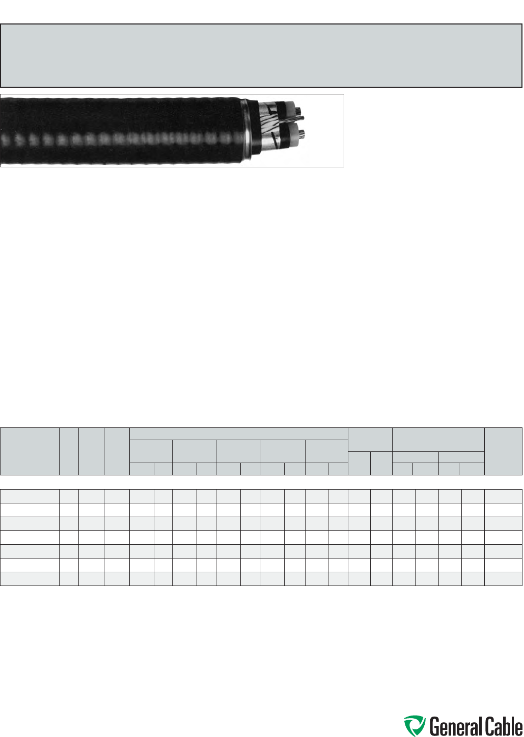
Phone: 888-593-3355
www.generalcable.com
SPEC 8500
October, 2012
HVTECK
TRXLPE/TapeShield/PVC/AIA/PVC,Power,Shielded,Armored
25kV,CSAHVTECK,133%Ins.Level,320Mils,ThreeConductor
Product Construction:
Conductor:
•1AWGthru350kcmilbarecoppercompact
ClassBstrand
Strand Shield:
•Athermosetsemi-conductingstrandshieldis
extrudedovertheconductor
Insulation:
•Tree-RetardantCross-linkedPolyethylene
(TRXLPE)
Insulation Shield:
•Thisconsistsofasemi-conductingthermosetting
layer,appliedinatripleextrusionprocess,plusa
helicallyappliedgappedcoppertape
•Color-coded:black,redorbluecoloredtape
placedlongitudinallyunderthecoppertape
shield
Ground (Bonding) Conductor:
•Theconductorconsistsofoneuninsulated
strandedbarecopperconductor
Inner Jacket:
•Lead-free,flame-retardant,moisture-and
sunlight-resistantPolyvinylChloride(PVC),black
Armor:
•AluminumInterlockedArmor(AIA)
Overall Jacket:
•Lead-free,ACID-FLAME-CHECK✓✓
®
flame-
retardant,moisture-andsunlight-resistant
PolyvinylChloride(PVC),blackorasrequested
Print:
•GENERALCABLE
®
3/CSIZE(AWGORKCMIL)
COPPERCPTTRXLPE25kV(133%INSLEVEL)
ACID-FLAME-CHECK✓✓
®
CSAHLHVTECK
FT4(-40˚C)DIRBURSUNRESMONTH/YEAR
(LIGHTNINGBOLTSYMBOL)SEQUENTIAL
LENGTHMARK
Options:
•GalvanizedSteelInterlockedArmor(GSIA)
•Otherconstructionsavailableuponrequest
Applications:
•Forwiringinallhazardouslocationswhenused
withcertifiedHLcableglands
•Forexposedandconcealedwiringindry,damp
or wet locations
•Foruseinventilated,non-ventilatedandladder-
typecabletraysindry,damporwetlocations
•Fordirectearthburial(withprotectionasrequired
byinspectionauthority)
Features:
•Ratedat90˚Cwetordry
•Excellentcrush,oilandchemicalresistance
•Provideslongservicelife
•Cost-effectivealternativetoinstallations
in conduit
•Meetscoldbendandimpacttestsat-40˚C
Compliances:
Industry Compliances:
•CSAStandardC22.2No.131andNo.174
•CSAStandardC68.3
Flame Test Compliances:
•CSAFT1andFT4
•IEEE383(70,000BTU/hr)
•UL1581(70,000BTU/hr)
•IEEE1202(70,000BTU/hr)CSAFT4
•ICEAT-30-520(70,000BTU/hr)
•ICEAT-29-520(210,000BTU/hr)
Other Compliances:
•HazardousLocationRating:HL
•EPA40CFR,Part261forleachablelead
contentperTCLPmethod
•OSHAAcceptable
Packaging:
•ForCanadiancustomers,lengthsareprovided
onreturnablewoodorsteelreelsthatrequirea
deposit.Extrachargesapplyforlagging,pulling
eyes,parallelingandplexing
•ForU.S.customers,materialcuttolengthand
shippedonnon-returnablewoodreels,while
lengthsinexcessof10,000lbs.areprovidedon
returnablesteelreelsthatrequireadeposit.Extra
chargesapplyforcutslessthan1000ft.,lagging,
pullingeyes,parallelingandplexing
CATALOG
NUMBER
NO.
OF
COND.
COND.
SIZE
(AWG/
kcmil)
GROUND
WIRE
SIZE
(AWG)
NOMINAL DIAMETER (OVER) COPPER
WEIGHT
NET WEIGHT
W/ARMOR AMPACITY**
(40˚C
AMBIENT)
INSULATION INSULATION
SHIELD
INNER
JACKET ARMOR CABLE
LBS/
1000 FT
kg/
km
LBS/1000 FT kg/km
INCHES mm INCHES mm INCHES mm INCHES mm INCHES mm AL STEEL AL STEEL
1 AWG THRU 350 kcmil—THREE CONDUCTOR—133% INS. LEVEL, 320 MILS INS. (8.13 mm)—25 kV
17496.860100*
3 1 6 0.99 25.2 1.06 26.9 2.53 64.2 2.82 71.6 2.94 74.7 985 1466 3690 4850 5490 7210 187
17496.865100*
3 1/0 6 1.03 26.2 1.12 28.5 2.65 67.3 2.94 74.7 3.06 77.7 1193 1775 4110 5330 6120 7930 215
17496.865200*
32/0 61.07 27.2 1.16 29.5 2.74 69.6 3.03 77.0 3.15 80.0 1460 2173 4490 5740 6680 8540 246
17496.865300*
3 3/0 4 1.12 28.5 1.21 30.8 2.91 73.9 3.19 81.1 3.33 84.6 1842 2741 5270 6600 7840 9820 283
17496.865400*
34/0 4 1.17 29.8 1.26 32.0 3.02 76.7 3.31 84.1 3.44 87.4 2261 3365 5840 7220 8700 10740 325
17496.866000*
3250 4 1.22 30.9 1.31 33.2 3.15 80.0 3.43 87.1 3.58 90.9 2629 3912 6440 7880 9590 11720 359
17496.866200*
3350 31.37 34.8 1.45 36.9 3.44 87.4 3.73 94.8 3.88 98.6 3615 5380 7720 9250 11490 13770 438
Dimensionsandweightsarenominal;subjecttoindustrytolerances.
*Non-stockitem;minimumrunsapply.PleaseconsultCustomerServiceforpriceanddelivery.
**AmpacityisbasedonICEAPublicationP46-426for15kVcables.Ampacitiesatothervoltagelevelsdonotvarysignicantly.
Specialapprovalbylocalelectricalinspectionauthoritiesmayberequired(Ref.CECodePart1,AppendixB,Rule4-004).

Phone: 888-593-3355
www.generalcable.com
SPEC 8525
August, 2013
HVTECK
TRXLPE/Tape Shield/PVC/AIA/PVC, Power, Shielded, Armored
28 kV (133% Ins. Level) / 35 kV (100% Ins. Level), 345 Mils, CSA HVTECK, Three Conductor
Product Construction:
Conductor:
• 1 AWG thru 350 kcmil bare copper compact
Class B strand
Strand Shield:
• A thermoset semi-conducting strand shield is
extruded over the conductor
Insulation:
• Tree-Retardant Cross-linked Polyethylene
(TRXLPE)
Insulation Shield:
• This consists of a semi-conducting thermosetting
layer, applied in a triple extrusion process, plus a
helically applied gapped copper tape
• Color-coded: black, red or blue colored tape
placed longitudinally under the copper tape
shield
Ground (Bonding) Conductor:
• The conductor consists of one uninsulated
stranded bare copper conductor
Inner Jacket:
• Lead-free, flame-retardant, moisture- and
sunlight-resistant Polyvinyl Chloride (PVC), black
Armor:
• Aluminum Interlocked Armor (AIA)
Overall Jacket:
• Lead-free, ACID-FLAME-CHECK ✓✓
®
flame-
retardant, moisture- and sunlight-resistant
Polyvinyl Chloride (PVC), black or as requested
Print:
• GENERAL CABLE
®
3/C SIZE (AWG OR KCMIL)
COPPER CPT TRXLPE 28 kV (133% INS
LEVEL) / 35 kV (100% INS LEVEL) ACID-FLAME-
CHECK ✓✓
®
CSA HL HVTECK FT4 (-40˚C) DIR
BUR SUN RES MONTH/YEAR (LIGHTNING BOLT
SYMBOL) SEQUENTIAL LENGTH MARK
Options:
• Galvanized Steel Interlocked Armor (GSIA)
• Other constructions available upon request
Applications:
• For wiring in all hazardous locations when used
with certified HL cable glands
• For exposed and concealed wiring in dry, damp
or wet locations
• For use in ventilated, non-ventilated and ladder-
type cable trays in dry, damp or wet locations
• For direct earth burial (with protection as required
by inspection authority)
Features:
• Rated at 90˚C wet or dry
• Excellent crush, oil and chemical resistance
• Provides long service life
• Cost-effective alternative to installations
in conduit
• Meets cold bend and impact tests at -40˚C
Compliances:
Industry Compliances:
• CSA Standard C22.2 No. 131 and No. 174
• CSA Standard C68.3
Flame Test Compliances:
• CSA FT1 and FT4
• IEEE 383 (70,000 BTU/hr)
• UL 1581 (70,000 BTU/hr)
• IEEE 1202 (70,000 BTU/hr) CSA FT4
• ICEA T-30-520 (70,000 BTU/hr)
• ICEA T-29-520 (210,000 BTU/hr)
Other Compliances:
• Hazardous Location Rating: HL
• EPA 40 CFR, Part 261 for leachable lead
content per TCLP method
• OSHA Acceptable
Packaging:
• For Canadian customers, lengths are provided
on returnable wood or steel reels that require a
deposit. Extra charges apply for lagging, pulling
eyes, paralleling and plexing
• For U.S. customers, material cut to length and
shipped on non-returnable wood reels, while
lengths in excess of 10,000 lbs. are provided on
returnable steel reels that require a deposit. Extra
charges apply for cuts less than 1000 ft., lagging,
pulling eyes, paralleling and plexing
CATALOG
NUMBER
NO.
OF
COND.
COND.
SIZE
(AWG/
kcmil)
GROUND
WIRE
SIZE
(AWG)
NOMINAL DIAMETER (OVER) COPPER
WEIGHT
NET WEIGHT
W/ARMOR
AMPACITY**
(40˚C
AMBIENT)
INSULATION INSULATION
SHIELD
INNER
JACKET ARMOR CABLE
LBS/
1000 FT
kg/
km
LBS/1000 FT kg/km
INCHES mm INCHES mm INCHES mm INCHES mm INCHES mm AL STEEL AL STEEL
1 AWG THRU 350 kcmil—THREE CONDUCTOR— 28 kV (133% INS. LEVEL) / 35 kV (100% INS. LEVEL), 345 MILS INS. (8.76 mm)
17496.890100*
3 1 6 1.04 26.4 1.13 28.7 2.68 68.2 2.97 75.5 3.10 78.8 988 1470 3980 5210 5930 7750 187
17496.895100*
3 1/0 6 1.08 27.5 1.17 29.7 2.76 70.2 3.05 77.5 3.18 80.8 1200 1786 4360 5620 6490 8370 215
17496.895200*
3 2/0 6 1.12 28.5 1.21 30.8 2.92 74.2 3.21 81.6 3.36 85.4 1466 2182 4950 6280 7370 9350 246
17496.895300*
3 3/0 4 1.17 29.7 1.26 32.0 3.02 76.7 3.31 84.1 3.46 87.9 1848 2750 5490 6860 8160 10210 283
17496.895400*
3 4/0 4 1.22 31.0 1.31 33.3 3.14 79.6 3.43 87.2 3.58 90.9 2264 3369 6090 7510 9060 11180 325
17496.896000*
3 250 4 1.27 32.3 1.37 34.8 3.26 82.9 3.55 90.2 3.70 94.0 2635 3921 6660 8140 9910 12120 359
17496.896200*
3 350 3 1.42 36.1 1.51 38.4 3.56 90.5 3.85 97.8 4.00 101.6 3621 5389 7960 9540 11840 14190 438
Dimensions and weights are nominal; subject to industry tolerances.
*Non-stock item; minimum runs apply. Please consult Customer Service for price and delivery.
** Ampacity is based on ICEA Publication P 46-426 for 15 kV cables. Ampacities at other voltage levels do not vary significantly.
Special approval by local electrical inspection authorities may be required (Ref. CE Code Part 1, Appendix B, Rule 4-004).
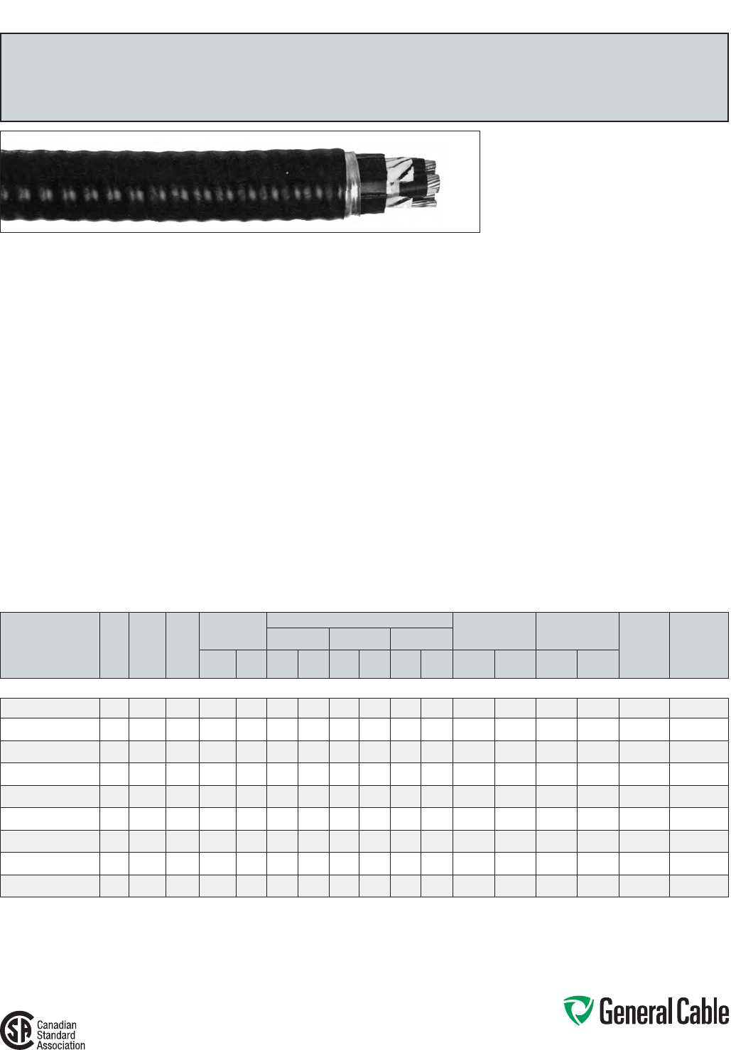
Phone: 888-593-3355
www.generalcable.com
SPEC 8550
September, 2013
VERTITECK
®
TECK90
XLPE/PVC/GSIA/PVC, Power, Unshielded, Armored
1 kV, CSA TECK90, Three Conductor
Product Construction:
Conductor:
•1/0AWGthru1000kcmilbarecoppercompact
ClassBstrand
Insulation:
•Cross-linkedPolyethylene(XLPE),TypeRW90
•Color-coded:printednumbers
Ground (Bonding) Conductor:
•Theconductorconsistsofoneuninsulated
strandedbarecopperconductor
Inner Jacket:
•Lead-free,flame-retardant,moisture-and
sunlight-resistantPolyvinylChloride(PVC),black
Armor:
•GalvanizedSteelInterlockedArmor(GSIA)
Overall Jacket:
•Lead-free,ACID-FLAME-CHECK✓✓
®
flame-
retardant,moisture-andsunlight-resistant
PolyvinylChloride(PVC),black
Print:
•GENERALCABLE
®
ACID-FLAME-CHECK✓✓
®
AG14FT1FT4HLVERTITECK
®
GSIA XLPE
(-40˚C)3/CSIZE(AWGORKCMIL)1000VDIR
BURSUNRESCSAMONTH-YEARSEQUENTIAL
LENGTHMARK
Options:
•Threeground(bonding)conductors
•Otherconstructionsavailableuponrequest
Applications:
•Forexposedandconcealedwiringindry,damp
orwetlocations
•Foruseinventilated,non-ventilatedandladder-
typecabletraysindry,damp,orwetlocations
•Fordirectearthburial(withprotectionasrequired
byinspectionauthority)
•Forwiringinallhazardouslocationswhenused
withcertifiedHLcableglands
•Cost-effectivealternativetoinstallation
in conduit
•Typicalverticalinstallationsincludemineshafts,
tallcommercialbuildings,inclinedtunnelsand
verticalcabletrays
(Notethattheoveralljacketisrequiredforall
dampandwetlocationsandforallcorrosive
environments:CECodePart1,Rules12-708and
22-200)
Features:
•Ratedat90˚Cwetordry
•Thejacketunderthearmor(innerjacket)is
designedwithlongitudinalraisedribs.The
armoristhenappliedandbitesintotheseribsto
provideasolidlylockedconstruction.Thisfeature
enablesthecabletobeself-supporting(corewill
notslip)duringverticalinstallationwhencable
weightissupportedbythecopperconductors
Features (cont’d.):
•Lighterthanmineshaftcablewithconventional
steelwirearmor(SWA)
•MoreflexiblethanSWAcables,resultingineasier
handlingduringinstallation
•Terminationsandconnectionstoelectrical
cabinetsaresimilartostandardTECK90cables
•Meetscoldbendandimpacttestsat-40˚C
Compliances:
Industry Compliances:
•CSAStandardC22.2No.131andNo.174
Flame Test Compliances:
•CSAFT1andFT4
•IEEE383(70,000BTU/hr)
•UL1581(70,000BTU/hr)
•IEEE1202(70,000BTU/hr)CSAFT4
•ICEAT-30-520(70,000BTU/hr)
Other Compliances:
•HazardousLocationRating:HL
•EPA40CFR,Part261forleachablelead
contentperTCLPmethod
•OSHAAcceptable
Packaging:
•ForCanadiancustomers,lengthsareprovided
onreturnablewoodorsteelreelsthatrequirea
deposit.Extrachargesapplyforlagging,pulling
eyes,parallelingandplexing
•ForU.S.customers,materialcuttolengthand
shippedonnon-returnablewoodreels,while
lengthsinexcessof10,000lbs.areprovidedon
returnablesteelreelsthatrequireadeposit.Extra
chargesapplyforcutslessthan1000ft.,lagging,
pullingeyes,parallelingandplexing
CATALOG NUMBER
NO. OF
COND.
COND.
SIZE
(AWG/
kcmil)
GROUND
WIRE
SIZE
(AWG)
MIN. AVG.
INSULATION
THICKNESS
NOMINAL DIAMETER (OVER) COPPER WEIGHT NET WEIGHT
W/STEEL ARMOR AMPACITY**
(30°C
AMBIENT)
MAXIMUM
SELF-
SUPPORTING
LENGTH***(m)
INSULATION ARMOR CABLE
INCHES mm INCHES mm INCHES mm INCHES mm
LBS/
1000 FT kg/km
LBS/
1000 FT kg/km
1/0 AWG THRU 1000 kcmil—THREE CONDUCTOR—1000 V
11289.415100*
31/0 6 0.080 2.03 0.36 9.0 1.66 42.2 1.78 45.2 1082 1610 2520 3760 170 212
11289.415200*
3 2/0 6 0.080 2.03 0.54 13.8 1.75 44.5 1.87 47.5 1342 1997 2880 4280 195 232
11289.415300*
3 3/0 40.080 2.03 0.59 15.0 1.85 47.0 1.97 50.1 1719 2558 3360 5000 225 254
11289.415400*
34/0 4 0.080 2.03 0.64 16.3 1.96 49.8 2.08 52.9 2133 3174 4080 6080 260 260
11289.416000*
3 250 40.090 2.29 0.71 18.0 2.15 54.6 2.27 57.7 2498 3718 4790 7130 290 270
11289.416200*
3 350 3 0.090 2.29 0.81 20.4 2.36 60.0 2.50 63.5 2475 5171 6100 9080 350 288
11289.416500*
3 500 2 0.090 2.29 0.93 23.5 2.62 66.6 2.76 70.1 4891 7279 7900 11760 430 ***
11289.417000*
3 750 2 0.090 2.29 1.10 27.9 2.99 76.0 3.13 79.5 7306 10873 10830 16110 535 ***
11289.417500*
31000 1 0.090 2.29 1.25 31.8 3.38 85.6 3.54 89.9 9714 14456 13970 20780 615 ***
Dimensionsandweightarenominal;subjecttoindustrytolerances.
*Non-stockitem;minimumrunsapply.PleaseconsultCustomerServiceforpriceanddelivery.
**AmpacityisbasedonCECodePart1,Table2(threeconductorsinraceway[conduit])andRule4-004.
***Maximumself-supportinglengthsarebasedonsafetyfactorof5andatensilestrengthof37,000psiforsoftdrawncopper.
Highersafetyfactorsorlowertensilestrengthvaluesmayberequiredtoaddressmorestringentsafetyregulations.
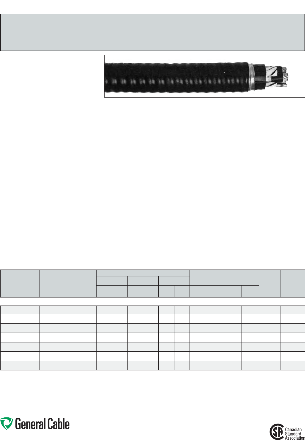
Phone: 888-593-3355
www.generalcable.com
SPEC 8575
September, 2013
VERTITECK
®
TECK90
TRXLPE/PVC/GSIA/PVC, Power, Unshielded, Armored
5 kV, CSA TECK90, 90 Mils, Three Conductor
Product Construction:
Conductor:
•1/0AWGthru500kcmilbarecopper
compactstrand
Strand Shield:
•Athermosetsemi-conductingstrandshieldis
extruded over the conductor
Insulation:
•Tree-RetardantCross-linkedPolyethylene
(TRXLPE),TypeRW90
•Color-coded:printednumbers
Ground (Bonding) Conductor:
•Theconductorconsistsofoneuninsulated
strandedbarecopperconductor
Inner Jacket:
•Lead-free,flame-retardant,moisture-and
sunlight-resistantPolyvinylChloride(PVC),black
Armor:
•GalvanizedSteelInterlockedArmor(GSIA)
Jacket:
•Lead-free,ACID-FLAME-CHECK✓✓
®
flame-
retardant,moisture-andsunlight-resistant
PolyvinylChloride(PVC),orange
Print:
•GENERAL CABLE
®
ACID-FLAME-CHECK✓✓
®
AG14FT1FT4HLVERTITECK
®
GSIA TRXLPE
(-40˚C)3/CSIZE(AWGORKCMIL)5000V
DIRBURSUNRESCSAMONTH-YEAR
SEQUENTIALLENGTHMARK
Options:
•Threeground(bonding)conductors
•Otherconstructionsavailableuponrequest
Applications:
•Forexposedandconcealedwiringindry,damp
orwetlocations
•Foruseinventilated,non-ventilatedandladder-
typecabletraysindry,damp,orwetlocations
Applications (cont’d.):
•Fordirectearthburial(withprotectionasrequired
byinspectionauthority)
•Forwiringinallhazardouslocationswhenused
withcertifiedHLcableglands
•Cost-effectivealternativetoinstallation
in conduit
•Typicalverticalinstallationsincludemineshafts,
tallcommercialbuildings,inclinedtunnelsand
verticalcabletrays
(Notethattheoveralljacketisrequiredforall
dampandwetlocationsandforallcorrosive
environments:CECodePart1,Rules12-708and
22-200)
Features:
•Ratedat90˚Cwetordry
•Thejacketunderthearmor(innerjacket)is
designedwithlongitudinalraisedribs.The
armoristhenappliedandbitesintotheseribsto
provideasolidlylockedconstruction.Thisfeature
enablesthecabletobeself-supporting(corewill
notslip)duringverticalinstallationwhencable
weightissupportedbythecopperconductors
•Lighterthanmineshaftcablewithconventional
steelwirearmor(SWA)
•MoreflexiblethanSWAcables,resultingineasier
handlingduringinstallation
•Terminationsandconnectionstoelectrical
cabinetsaresimilartostandardTECK90cables
•Meetscoldbendandimpacttestsat-40˚C
Compliances:
Industry Compliances:
•CSAStandardC22.2No.131andNo.174
Flame Test Compliances:
•CSAFT1andFT4
•IEEE383(70,000BTU/hr)
•UL1581(70,000BTU/hr)
•IEEE1202(70,000BTU/hr)CSAFT4
•ICEAT-30-520(70,000BTU/hr)
Other Compliances:
•HazardousLocationRating:HL
•EPA40CFR,Part261forleachablelead
contentperTCLPmethod
•OSHAAcceptable
Packaging:
•ForCanadiancustomers,lengthsareprovided
onreturnablewoodorsteelreelsthatrequirea
deposit.Extrachargesapplyforlagging,pulling
eyes,parallelingandplexing
•ForU.S.customers,materialcuttolengthand
shippedonnon-returnablewoodreels,while
lengthsinexcessof10,000lbs.areprovidedon
returnablesteelreelsthatrequireadeposit.Extra
chargesapplyforcutslessthan1000ft.,lagging,
pullingeyes,parallelingandplexing
CATALOG NUMBER
NO. OF
COND.
COND.
SIZE
(AWG/
kcmil)
GROUND
WIRE
SIZE
(AWG)
NOMINAL DIAMETER (OVER) COPPER WEIGHT NET WEIGHT
W/STEEL ARMOR AMPACITY**
(30°C
AMBIENT)
MAXIMUM
SELF-
SUPPORTING
LENGTH***(m)
INSULATION ARMOR CABLE
INCHES mm INCHES mm INCHES mm
LBS/
1000 FT kg/km
LBS/
1000 FT kg/km
1/0 AWG THRU 500 kcmil—THREE CONDUCTOR—UNSHIELDED, 90 MILS INS. (2.29 mm)—5 kV
17497.055100*
3 1/0 6 0.56 14.2 1.77 45.0 1.87 47.5 1082 1610 2700 4020 170 200
17497.055200*
3 2/0 6 0.60 15.2 1.86 47.3 1.96 49.8 1343 1999 3060 4550 195 221
17497.055300*
3 3/0 4 0.65 16.4 1.97 50.0 2.07 52.6 1720 2560 3550 5280 225 240
17497.055400*
3 4/0 4 0.70 17.8 2.08 52.9 2.18 55.4 2315 3445 4290 6380 260 249
17497.056000*
3 250 4 0.75 19.1 2.25 57.2 2.35 59.7 2469 3674 4990 7430 290 251
17497.056200*
3 350 3 0.85 21.8 2.46 62.5 2.59 65.8 3476 5173 6340 9430 350 278
17497.056500*
3500 2 0.98 24.9 2.72 69.1 2.85 72.4 4837 7198 8130 12100 430 230
Dimensionsandweightarenominal;subjecttoindustrytolerances.
*Non-stockitem;minimumrunsapply.PleaseconsultCustomerServiceforpriceanddelivery.
**AmpacityisbasedonCECodePart1,Table2(threeconductorsinraceway[conduit])andRule4-004.
***Maximumself-supportinglengthsarebasedonsafetyfactorof5andatensilestrengthof37,000psiforsoftdrawncopper.Highersafetyfactorsorlowertensilestrengthvaluesmayberequiredtoaddressmore
stringentsafetyregulations.
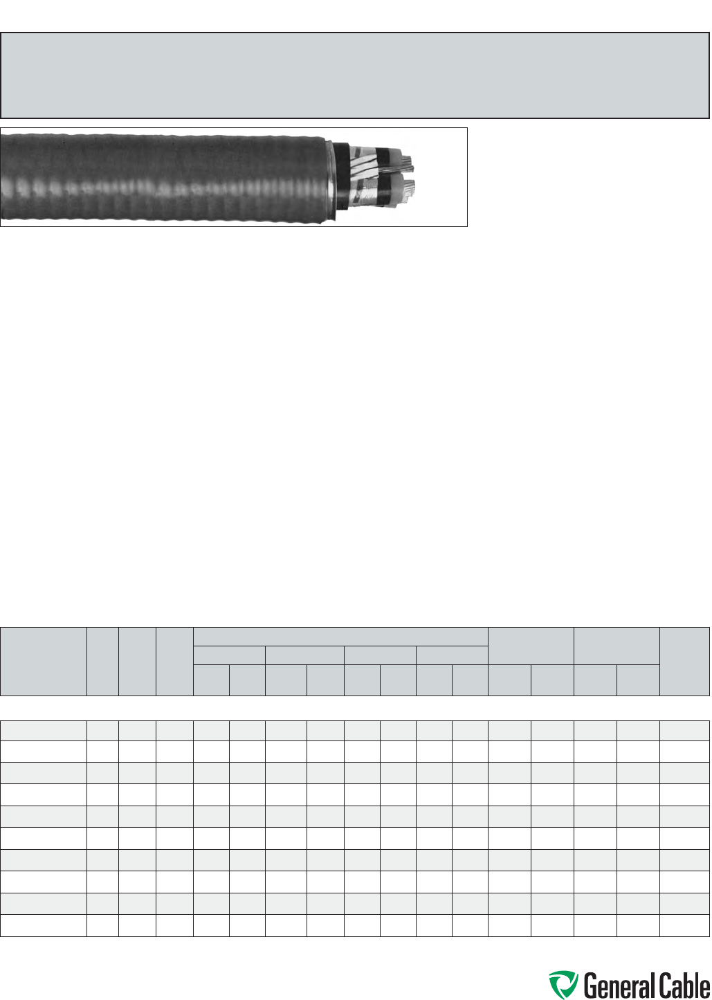
Phone: 888-593-3355
www.generalcable.com
Product Construction:
Conductor:
•2AWGthru750kcmilbarecoppercompact
ClassBstrand
Strand Shield:
•Athermosetsemi-conductingstrandshieldis
extrudedovertheconductor
Insulation:
•Tree-RetardantCross-linkedPolyethylene
(TRXLPE)
Insulation Shield:
•Thisconsistsofasemi-conductingthermosetting
layer,appliedinatripleextrusionprocess,plusa
helicallyappliedgappedcoppertape
•Colorcode:black,red,orbluecoloredtape
placedlongitudinallyunderthecoppertape
shield
Ground (Bonding) Conductor:
•Theconductorconsistsofoneuninsulated
strandedbarecopperconductor
Inner Jacket:
•Lead-free,flame-retardant,moisture-and
sunlight-resistantPolyvinylChloride(PVC),black
Armor:
•GalvanizedSteelInterlockedArmor(GSIA)
Overall Jacket:
•Lead-free,ACID-FLAME-CHECK✓✓
®
flame-
retardant,moisture-andsunlight-resistant
PolyvinylChloride(PVC),red
Print:
•GENERALCABLE
®
ACID-FLAME-CHECK✓✓
®
AG14FT1FT4HLVERTITECK
®
GSIATRXLPE
(-40˚C)3/CSIZE(AWGORKCMIL)15,000V
DIRBURSUNRESCSAMONTH-YEAR-
SEQUENTIALPRINT
Options:
•Threeground(bonding)conductors
Applications:
•Forexposedandconcealedwiringindry,damp
or wet locations
•Foruseinventilated,non-ventilatedandladder-
typecabletraysindry,damporwetlocations
•Fordirectearthburial(withprotectionasrequired
byinspectionauthority)
•Forwiringinallhazardouslocationswhenused
withcertifiedHLcableglands
•Cost-effectivealternativetoinstallation
in conduit
•Typicalverticalinstallationsincludemineshafts,
tallcommercialbuildings,inclinedtunnelsand
verticalcabletrays
(Notethattheoveralljacketisrequiredforall
dampandwetlocationsandforallcorrosive
environments:CECodePart1,Rules12-708and
22-200)
Features:
•Ratedat90˚Cwetordry
•Thejacketunderthearmor(innerjacket)is
designedwithlongitudinalraisedribs.The
armoristhenappliedandbitesintotheseribsto
provideasolidlylockedconstruction.Thisfeature
enablesthecabletobeself-supporting(corewill
notslip)duringverticalinstallationwhencable
weightissupportedbythecopperconductors
•Lighterthanmineshaftcablewithconventional
steelwirearmor(SWA)
•MoreflexiblethanSWAcables,resultingineasier
handlingduringinstallation
•Terminationsandconnectionstoelectrical
cabinetsaresimilartostandardTECK90cables
•Meetscoldbendandimpacttestsat-40˚C
Compliances:
Industry Compliances:
•CSAStandardC22.2No.131andNo.174
•CSAStandardC68.3
Flame Test Compliances:
•CSAFT1andFT4
•IEEE383(70,000BTU/hr)
•UL1581(70,000BTU/hr)
•IEEE1202(70,000BTU/hr)CSAFT4
•ICEAT-30-520(70,000BTU/hr)
•ICEAT-29-520(210,000BTU/hr)
Other Compliances:
•HazardousLocationRating:HL
•EPA40CFR,Part261forleachablelead
contentperTCLPmethod
•OSHAAcceptable
Packaging:
•ForCanadiancustomers,lengthsareprovided
onreturnablewoodorsteelreelsthatrequirea
deposit.Extrachargesapplyforlagging,pulling
eyes,parallelingandplexing
•ForU.S.customers,materialcuttolengthand
shippedonnon-returnablewoodreels,while
lengthsinexcessof10,000lbs.areprovidedon
returnablesteelreelsthatrequireadeposit.Extra
chargesapplyforcutslessthan1000ft.,lagging,
pullingeyes,parallelingandplexing
SPEC 8600
October, 2012
CATALOG
NUMBER
NO.
OF
COND.
COND.
SIZE
(AWG/
kcmil)
GROUND
WIRE
SIZE
(AWG)
NOMINAL DIAMETER (OVER)
COPPER WEIGHT NET WEIGHT
MAXIMUM
SELF-
SUPPORTING
LENGTH**
(M)
INSULATION INSULATION SHIELD ARMOR CABLE
INCHES mm INCHES mm INCHES mm INCHES mm
LBS/
1000 FT kg/km
LBS/
1000 FT kg/km
2 AWG THRU 750 kcmil—THREE CONDUCTOR—133% INS. LEVEL, 220 MILS INS. (5.59 mm)—15 kV
17497.540200*
3260.76 19.3 0.82 20.8 2.50 63.5 2.66 67.6 862 1283 4138 6157 85
17497.540100*
3 1 6 0.79 20.1 0.85 21.6 2.57 65.3 2.73 69.3 1034 1539 4424 6583 100
17497.545100*
3 1/0 6 0.83 21.1 0.89 22.6 2.65 67.3 2.81 71.4 1245 1853 4765 7090 118
17497.545200*
32/0 60.87 22.1 0.93 23.6 2.74 69.6 2.90 73.7 1513 2251 5181 7709 137
17497.545300*
3 3/0 4 0.92 23.4 0.98 24.9 2.84 72.1 3.00 76.2 1899 2826 5757 8566 155
17497.545400*
34/0 4 0.97 24.6 1.03 26.2 2.95 74.9 3.12 79.2 2321 3454 6392 9511 176
17497.546000*
3250 4 1.01 25.7 1.09 27.7 3.08 78.2 3.27 83.1 2697 4013 7096 10559 188
17497.546200*
3350 31.12 28.4 1.18 30.0 3.36 85.3 3.54 89.9 3692 5494 8674 12907 215
17497.546500*
3500 31.23 31.2 1.30 33.0 3.62 91.9 3.80 96.5 5218 7764 10646 15841 250
17497.547000*
3750 2 1.41 35.8 1.48 37.6 4.00 101.6 4.19 106.4 8124 12089 14417 21452 277
Dimensionsandweightsarenominal;subjecttoindustrytolerances.
*Non-stockitem;minimumrunsapply.PleaseconsultCustomerServiceforpriceanddelivery.
**Maximumself-supportinglengthsarebasedonsafetyfactorof5andatensilestrengthof37,000psiforsoftdrawncopper.Highersafetyfactorsorlowertensilestrengthvaluesmayberequiredtoaddressmore
stringentsafetyregulations.
VERTITECK
®
HVTECK
TRXLPE/TapeShield/PVC/GSIA/PVC,Power,Shielded,Armored
15kV,CSAHVTECK,133%Ins.Level,220Mils,ThreeConductor
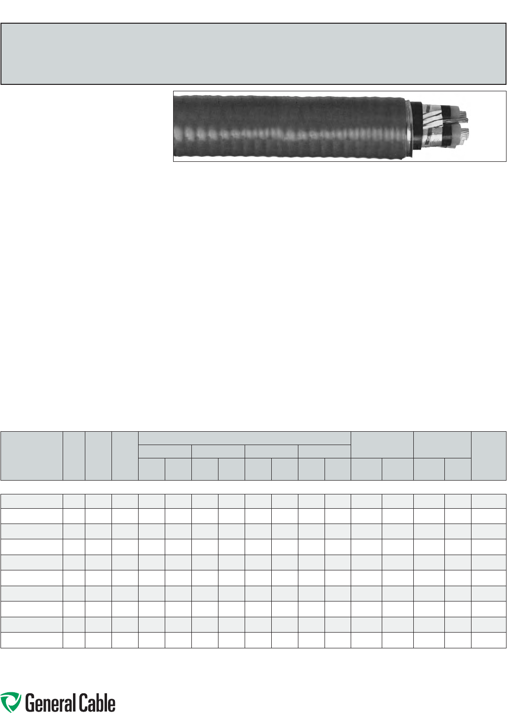
Phone: 888-593-3355
www.generalcable.com
SPEC 8625
October, 2012
VERTITECK
®
HVTECK
TRXLPE/TapeShield/PVC/GSIA/PVC,Power,Shielded,Armored
15kV,CSAHVTECK,100%Ins.Level,175Mils,ThreeConductor
Product Construction:
Conductor:
•2AWGthru750kcmilbarecoppercompact
ClassBstrand
Strand Shield:
•Athermosetsemi-conductingstrandshieldis
extrudedovertheconductor
Insulation:
•Tree-RetardantCross-linkedPolyethylene
(TRXLPE)
Insulation Shield:
•Thisconsistsofasemi-conductingthermosetting
layer,appliedinatripleextrusionprocess,plusa
helicallyappliedgappedcoppertape
•Colorcode:black,red,orbluecoloredtape
placedlongitudinallyunderthecoppertape
shield
Ground (Bonding) Conductor:
•Theconductorconsistsofoneuninsulated
strandedbarecopperconductor
Inner Jacket:
•Lead-free,flame-retardant,moisture-and
sunlight-resistantPolyvinylChloride(PVC),black
Armor:
•GalvanizedSteelInterlockedArmor(GSIA)
Overall Jacket:
•Lead-free,ACID-FLAME-CHECK✓✓
®
flame-
retardant,moisture-andsunlight-resistant
PolyvinylChloride(PVC),red
Print:
•GENERALCABLE
®
ACID-FLAME-CHECK✓✓
®
AG14FT1FT4HLVERTITECK
®
GSIATRXLPE
(-40˚C)3/CSIZE(AWGORKCMIL)15,000V
DIRBURSUNRESCSAMONTH-YEAR
SEQUENTIALLENGTHMARK
Options:
•Threeground(bonding)conductors
Applications:
•Forexposedandconcealedwiringindry,damp
or wet locations
•Foruseinventilated,non-ventilatedandladder-
typecabletraysindry,damporwetlocations
•Fordirectearthburial(withprotectionasrequired
byinspectionauthority)
•Forwiringinallhazardouslocationswhenused
withcertifiedHLcableglands
•Cost-effectivealternativetoinstallation
in conduit
•Typicalverticalinstallationsincludemineshafts,
tallcommercialbuildings,inclinedtunnelsand
verticalcabletrays
(Notethattheoveralljacketisrequiredforall
dampandwetlocationsandforallcorrosive
environments:CECodePart1,Rules12-708and
22-200)
Features:
•Ratedat90˚Cwetordry
•Thejacketunderthearmor(innerjacket)is
designedwithlongitudinalraisedribs.The
armoristhenappliedandbitesintotheseribsto
provideasolidlylockedconstruction.Thisfeature
enablesthecabletobeself-supporting(corewill
notslip)duringverticalinstallationwhencable
weightissupportedbythecopperconductors
•Lighterthanmineshaftcablewithconventional
steelwirearmor(SWA)
•MoreflexiblethanSWAcables,resultingineasier
handlingduringinstallation
Features (cont’d.):
•Terminationsandconnectionstoelectrical
cabinetsaresimilartostandardTECK90cables
•Meetscoldbendandimpacttestsat-40˚C
Compliances:
Industry Compliances:
•CSAStandardC22.2No.131andNo.174
•CSAStandardC68.3
Flame Test Compliances:
•CSAFT1andFT4
•IEEE383(70,000BTU/hr)
•UL1581(70,000BTU/hr)
•IEEE1202(70,000BTU/hr)CSAFT4
•ICEAT-30-520(70,000BTU/hr)
•ICEAT-29-520(210,000BTU/hr)
Other Compliances:
•HazardousLocationRating:HL
•EPA40CFR,Part261forleachablelead
contentperTCLPmethod
•OSHAAcceptable
Packaging:
•ForCanadiancustomers,lengthsareprovided
onreturnablewoodorsteelreelsthatrequirea
deposit.Extrachargesapplyforlagging,pulling
eyes,parallelingandplexing
•ForU.S.customers,materialcuttolengthand
shippedonnon-returnablewoodreels,while
lengthsinexcessof10,000lbs.areprovidedon
returnablesteelreelsthatrequireadeposit.Extra
chargesapplyforcutslessthan1000ft.,lagging,
pullingeyes,parallelingandplexing
CATALOG
NUMBER
NO.
OF
COND.
COND.
SIZE
(AWG/
kcmil)
GROUND
WIRE
SIZE
(AWG)
NOMINAL DIAMETER (OVER)
COPPER WEIGHT NET WEIGHT
MAXIMUM
SELF-
SUPPORTING
LENGTH**
(M)
INSULATION INSULATION SHIELD ARMOR CABLE
INCHES mm INCHES mm INCHES mm INCHES mm
LBS/
1000 FT kg/km
LBS/
1000 FT kg/km
2 AWG THRU 750 kcmil—THREE CONDUCTOR—100% INS. LEVEL, 175 MILS INS. (4.45 mm)—15 kV
17497.440200*
3260.67 17.0 0.72 18.3 2.30 58.4 2.46 62.5 845 1257 3761 5596 94
17497.440100*
3 1 6 0.70 17.8 0.76 19.3 2.37 60.2 2.53 64.3 1017 1513 4022 5985 110
17497.445100*
3 1/0 6 0.74 18.8 0.80 20.3 2.46 62.5 2.61 66.3 1229 1829 4385 6525 128
17497.445200*
32/0 60.78 19.8 0.84 21.3 2.55 64.8 2.71 68.8 1497 2228 4800 7142 147
17497.445300*
3 3/0 4 0.83 21.1 0.89 22.6 2.67 67.8 2.83 71.9 1882 2800 5354 7967 166
17497.445400*
34/0 4 0.88 22.4 0.94 23.9 2.79 70.9 2.95 74.9 2304 3428 5979 8897 188
17497.446000*
3250 4 0.92 23.4 0.98 24.9 2.89 73.4 3.05 77.5 2677 3983 6518 9699 204
17497.446200*
3350 31.02 25.9 1.09 27.7 3.15 80.0 3.33 84.6 3675 5468 8043 11968 231
17497.446500*
3500 31.14 29.0 1.21 30.7 3.47 88.1 3.66 93.0 5111 7605 10132 15076 262
17497.447000*
3750 2 1.32 33.5 1.39 35.3 3.86 98.0 4.04 102.6 7555 11242 13403 19944 298
Dimensionsandweightarenominal;subjecttoindustrytolerances.
*Non-stockitem;minimumrunsapply.PleaseconsultCustomerServiceforpriceanddelivery.
**Maximumself-supportinglengthsarebasedonsafetyfactorof5andatensilestrengthof37,000psiforsoftdrawncopper.Highersafetyfactorsorlowertensilestrengthvaluesmayberequiredtoaddressmore
stringentsafetyregulations.
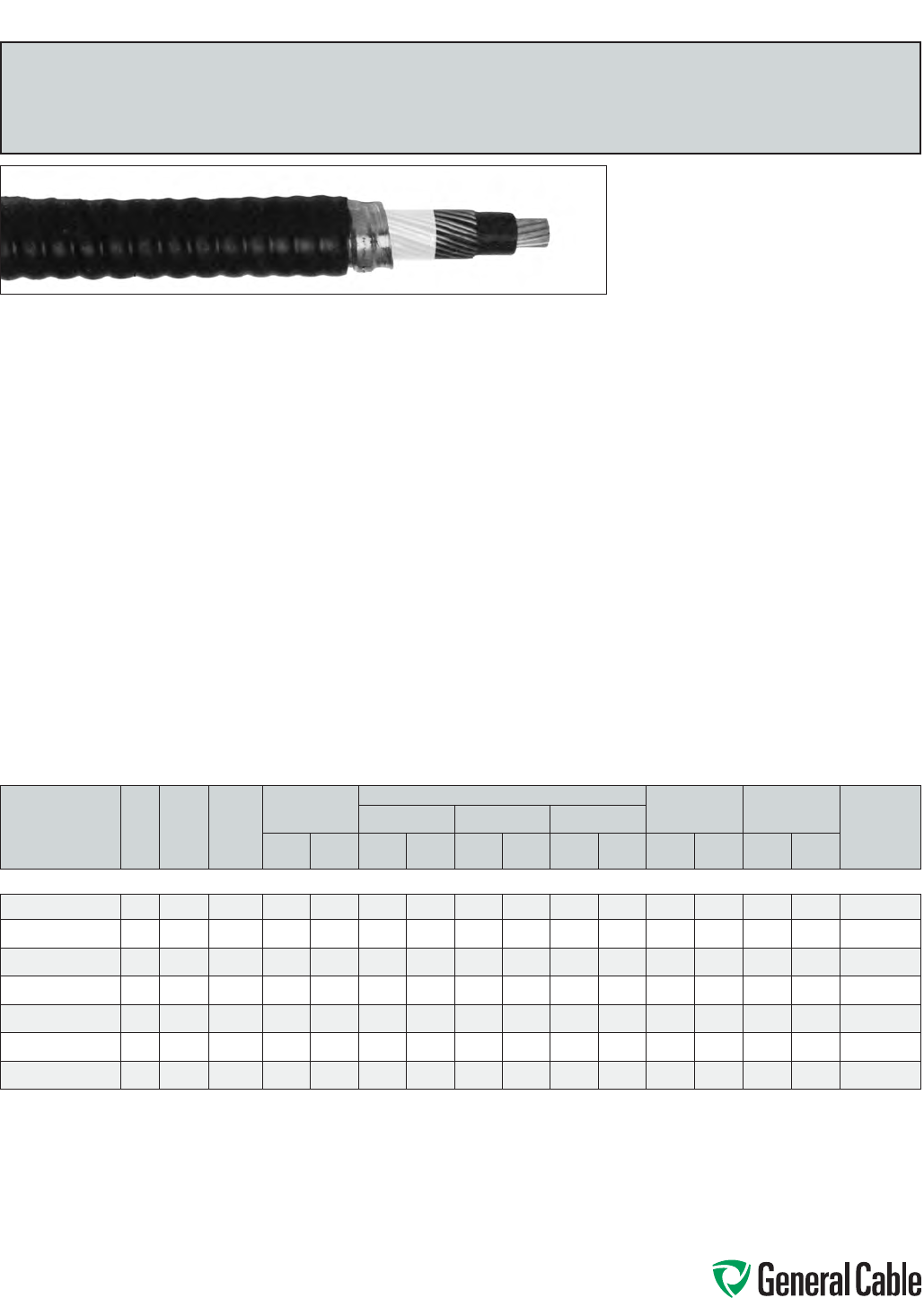
Phone: 888-593-3355
www.generalcable.com
ACWU
XLPE/AIA/PVC,Control,Armored
600V,CSAACWU90(-40°C),SingleConductor
Product Construction:
Conductor:
•4/0AWGthru1000kcmilbareACMaluminum
(8000seriesaluminum)compactClassBstrand
Insulation:
•Cross-linkedPolyethylene(XLPE),TypeRW90
•Color-coded:black,marked“SR”
Ground (Bonding) Conductor:
•Theconductorisaconcentricservingofsolid
barealuminum(ACM)wiresappliedoverthe
insulation
Armor:
•AluminumInterlockedArmor(AIA)
Jacket:
•ACID-FLAME-CHECK✓✓
®
flame-retardant,
moisture-andsunlight-resistantPolyvinyl
Chloride(PVC),black
Print:
•GENERALCABLE
®
MIACID-FLAME-
CHECK✓✓
®
AG14FT4HLACWU90XLPE
(-40°C)1/CSIZE(AWGORKCMIL)AL600V
DIRBURSUNRESCSAMONTH-YEAR
SEQUENTIALLENGTHMARK
Applications:
•Forexposedandconcealedwiringindry,damp
or wet locations
•Foruseinventilated,non-ventilatedandladder-
typecabletraysindry,damporwetlocations
•Fordirectearthburial(withprotectionasrequired
byinspectionauthority)
•Forwiringinallhazardouslocationswhenused
withcertifiedHLcableglands
•Forserviceentranceinstallations
Features:
•Ratedat90°Cwetordry
•Excellentcrush,oilandchemicalresistance
•Provideslongservicelife
•Cost-effectivealternativetoinstallationsin
conduit
•Meetscoldbendandimpacttestsat-40°C
Compliances:
Industry Compliances:
•CSAStandardC22.2No.51andNo.174
Flame Test Compliances:
•CSAFT1andFT4
•IEEE383(70,000BTU/hr)
•UL1581(70,000BTU/hr)
•IEEE1202(70,000BTU/hr)CSAFT4
•ICEAT-30-520(70,000BTU/hr)
Other Compliances:
•HazardousLocationRating:HL
•EPA40CFR,Part261forleachablelead
contentperTCLPmethod
•OSHAAcceptable
Packaging:
•ForCanadiancustomers,nominalstandard
lengthsareprovidedonreturnablewoodorsteel
reelsthatrequireadeposit.Extrachargesapply
forcuttolength,lagging,pullingeyes,paralleling
andplexing
Note:NotforsaleintheU.S.
CATALOG NUMBER
NO.
OF
COND.
COND.
SIZE
(AWG/
kcmil)
GROUND
WIRE
SIZE
(AWG)
MIN. AVG.
INSULATION
THICKNESS
NOMINAL DIAMETER (OVER) ALUMINUM
WEIGHT**
NET
WEIGHT
AMPACITY***
(30°C AMBIENT)
INSULATION ARMOR CABLE
INCHES mm INCHES mm INCHES mm INCHES mm
LBS/
1000 FT kg/km
LBS/
1000 FT kg/km
4/0 AWG THRU 1000 kcmil—ONE CONDUCTOR—600 V
11281.015400
14/0 2 0.055 1.40 0.591 15.01 0.940 23.88 1.036 26.31 260 387 504 750 315
11281.016000
1250 10.065 1.65 0.658 16.71 1.007 25.58 1.103 28.02 312 464 600 893 355
11281.016200
1350 1/0 0.065 1.65 0.754 19.15 1.103 28.02 1.199 30.45 423 630 745 1107 445
11281.016500
1500 2/0 0.065 1.65 0.872 22.15 1.221 31.01 1.317 33.45 594 884 952 1417 545
11281.016700
1 600 2/0 0.080 2.03 0.985 25.02 1.334 33.88 1.430 36.32 686 1021 1099 1635 690
11281.017000
1750 3/0 0.080 2.03 1.080 27.43 1.429 36.30 1.525 38.74 848 1262 1305 1942 785
11281.017500
1 1000 3/0 0.080 2.03 1.230 31.42 1.667 42.34 1.779 45.19 1093 1627 1704 2536 845
Dimensionsandweightarenominal;subjecttoindustrytolerances.
*Non-stockitem;minimumrunsapply.PleaseconsultCustomerServiceforpriceanddelivery.
**Conductorandgroundweight.
***AmpacityisbasedonCECodePart1,Table3(singleconductorinfreeair)andRule4-004.
SPEC 8700
March, 2012
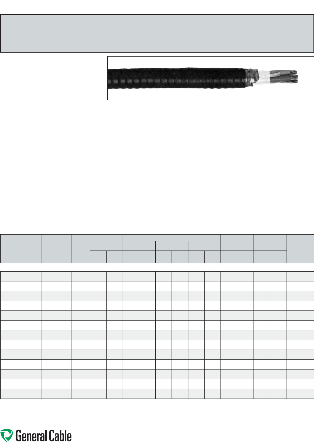
Phone: 888-593-3355
www.generalcable.com
CATALOG NUMBER
NO.
OF
COND.
COND.
SIZE
(AWG/
kcmil)
GROUND
WIRE
SIZE
(AWG)
MIN. AVG.
INSULATION
THICKNESS
NOMINAL DIAMETER (OVER) ALUMINUM
WEIGHT*
NET
WEIGHT AMPACITY**
(30°C
AMBIENT)
INSULATION ARMOR CABLE
INCHES mm INCHES mm INCHES mm INCHES mm
LBS/
1000 FT kg/km
LBS/
1000 FT kg/km
6 AWG THRU 750 kcmil—THREE CONDUCTOR—600 V
11281.030600
3 6 8 0.045 1.14 0.266 6.76 0.783 19.89 0.879 22.33 92 137 325 484 55
11281.030400
3460.045 1.14 0.310 7.87 0.918 23.32 1.014 25.76 145 216 441 657 75
11281.030200
3260.045 1.14 0.365 9.27 1.044 26.52 1.140 28.96 212 316 564 840 100
11281.030100
3 1 4 0.045 1.14 0.418 10.62 1.165 29.59 1.261 32.03 275 409 677 1008 115
11281.035100
3 1/0 4 0.055 1.40 0.456 11.58 1.252 31.80 1.348 34.24 336 500 783 1166 135
11281.035200
32/0 4 0.055 1.40 0.496 12.60 1.343 34.11 1.439 36.55 414 616 897 1336 150
11281.035300
3 3/0 4 0.055 1.40 0.543 13.79 1.450 36.83 1.546 39.27 512 762 1047 1559 175
11281.035400
34/0 4 0.055 1.40 0.593 15.06 1.565 39.75 1.661 42.19 636 947 1215 1809 205
11281.036000
3250 2 0.065 1.65 0.662 16.81 1.812 46.02 1.924 48.87 770 1146 1551 2309 230
11281.036200
3350 2 0.065 1.65 0.757 19.23 2.029 51.54 2.141 54.38 1050 1563 1951 2905 280
11281.036500
3500 10.065 1.65 0.878 22.30 2.306 58.57 2.418 61.42 1494 2224 2562 3815 350
11281.036700
3 600 1 0.080 2.03 0.984 24.99 2.424 61.57 2.563 65.10 1791 2667 3035 4519 385
11281.037000
3750 1/0 0.080 2.03 1.077 27.36 2.706 68.73 2.902 73.71 2221 3307 3703 5513 435
Dimensionsandweightarenominal;subjecttoindustrytolerances.
*Conductorandgroundweight.
**AmpacityisbasedonCECodePart1,Table4(threeconductorsinraceway[conduit])andRule4-004.
SPEC 8750
March, 2012
Product Construction:
Conductor:
•6AWGthru750kcmilbareACMaluminum(8000
seriesaluminum)compactClassBstrand
Insulation:
•Cross-linkedPolyethylene(XLPE),TypeRW90
•Color-coded:4AWGto2AWG—black,white
andred;1/0AWGto750kcmil—perICEA
Method4,individualconductorscoloredblack
withconductornumbersurfaceprintedin
contrastingink
Ground (Bonding) Conductor:
•Theconductorconsistsofoneuninsulated
strandedbarealuminum(ACM)conductor
Armor:
•AluminumInterlockedArmor(AIA)
Jacket:
•ACID-FLAME-CHECK✓✓
®
flame-retardant,
moisture-andsunlight-resistantPolyvinyl
Chloride(PVC),black
Print:
•GENERALCABLE
®
MIACID-FLAME-CHECK✓✓
®
AG14FT4HLACWU90XLPE(-40°C)3/C
SIZE(AWGORKCMIL)AL600VDIRBUR
SUNRESCSAMONTH-YEAR SEQUENTIAL
LENGTHMARK
Applications:
•Forexposedandconcealedwiringindry,damp
or wet locations
•Foruseinventilated,non-ventilatedandladder-
typecabletraysindry,damporwetlocations
•Fordirectearthburial(withprotectionasrequired
byinspectionauthority)
•Forwiringinallhazardouslocationswhenused
withcertifiedHLcableglands
•Forserviceentranceinstallations
Features:
•Ratedat90°Cwetordry
•Excellentcrush,oilandchemicalresistance
•Provideslongservicelife
•Cost-effectivealternativetoinstallationsin
conduit
•Meetscoldbendandimpacttestsat-40°C
Compliances:
Industry Compliances:
•CSAStandardC22.2No.51andNo.174
Flame Test Compliances:
•CSAFT1andFT4
•IEEE383(70,000BTU/hr)
•UL1581(70,000BTU/hr)
•IEEE1202(70,000BTU/hr)CSAFT4
•ICEAT-30-520(70,000BTU/hr)
Other Compliances:
•HazardousLocationRating:HL
•EPA40CFR,Part261forleachablelead
contentperTCLPmethod
•OSHAAcceptable
Packaging:
•ForCanadiancustomers,nominalstandard
lengthsareprovidedonreturnablewoodorsteel
reelsthatrequireadeposit.Extrachargesapply
forcuttolength,laggingandpullingeyes
Note:NotforsaleintheU.S.
ACWU
XLPE/AIA/PVC,Control,Armored
600V,CSAACWU90(-40°C),ThreeConductor
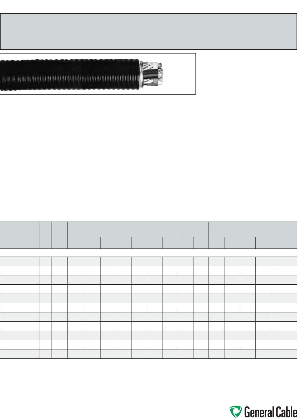
Phone: 888-593-3355
www.generalcable.com
CATALOG NUMBER
NO.
OF
COND.
COND.
SIZE
(AWG/
kcmil)
GROUND
WIRE
SIZE
(AWG)
MIN. AVG.
INSULATION
THICKNESS
NOMINAL DIAMETER (OVER) ALUMINUM
WEIGHT** NET WEIGHT
AMPACITY***
(30°C
AMBIENT)
INSULATION ARMOR CABLE
INCHES mm INCHES mm INCHES mm INCHES mm
LBS/
1000 FT kg/km
LBS/
1000 FT kg/km
2 AWG THRU 750 kcmil—FOUR CONDUCTOR—600 V
11281.040200
4 2 60.045 1.14 0.365 9.27 1.091 27.71 1.187 30.15 275 410 634 943 100
11281.040100
414 0.055 1.40 0.418 10.62 1.219 30.96 1.315 33.40 364 542 772 1149 115
11281.045100
41/0 4 0.055 1.40 0.456 11.58 1.311 33.30 1.407 35.74 435 648 869 1323 135
11281.045200
4 2/0 4 0.055 1.40 0.496 12.60 1.407 35.74 1.503 38.18 540 804 1037 1543 150
11281.045300
43/0 4 0.055 1.40 0.543 13.79 1.611 40.92 1.723 43.76 671 998 1337 1990 175
11281.045400
4 4/0 4 0.055 1.40 0.593 15.06 1.732 43.99 1.844 46.84 835 1243 1556 2316 205
11281.046000
4 250 2 0.065 1.65 0.662 16.81 1.898 48.21 2.010 51.05 1006 1497 1836 2732 230
11281.046200
4 350 2 0.065 1.65 0.757 19.23 2.127 54.03 2.239 56.87 1379 2052 2335 3475 280
11281.046500
4 500 10.065 1.65 0.878 22.30 2.419 61.44 2.561 65.05 1966 2925 3165 4710 350
11281.046700*
4600 1 0.080 2.03 0.984 24.99 2.678 68.02 2.817 71.55 2362 3515 3773 5615 385
11281.047000
4 750 1/0 0.080 2.03 1.077 27.36 2.900 73.66 3.042 77.27 2929 4358 4482 6670 435
Dimensionsandweightarenominal;subjecttoindustrytolerances.
*Non-stockitem;minimumrunsapply.PleaseconsultCustomerServiceforpriceanddelivery.
**Conductorandgroundweight.
***AmpacityisbasedonCECodePart1,Table4(threeconductorsinraceway[conduit])andRule4-004.
Ampacityof4conductorcableisbasedon3current-carryingconductorsand1neutral.
SPEC 8775
March, 2012
Product Construction:
Conductor:
•2AWGthru750kcmilbareACMaluminum(8000
seriesaluminum)compactClassBstrand
Insulation:
•Cross-linkedPolyethylene(XLPE),TypeRW90
•Color-coded:2AWG—black,whiteandred;
1AWGto750kcmil—perICEAMethod4,
individualconductorscoloredblackwith
conductornumbersurfaceprintedin
contrastingink
Ground (Bonding) Conductor:
•Theconductorconsistsofoneuninsulated
strandedbarealuminum(ACM)conductor
Armor:
•AluminumInterlockedArmor(AIA)
Jacket:
•ACID-FLAME-CHECK✓✓
®
flame-retardant,
moisture-andsunlight-resistantPolyvinyl
Chloride(PVC),black
Print:
•GENERALCABLE
®
MIACID-FLAME-CHECK
✓✓
®
AG14FT4HLACWU90XLPE(-40°C)4/C
SIZE(AWGORKCMIL)AL600VDIRBURSUN
RESCSAMONTH-YEAR SEQUENTIALLENGTH
MARK
Applications:
•Forexposedandconcealedwiringindry,damp
or wet locations
•Foruseinventilated,non-ventilatedandladder-
typecabletraysindry,damporwetlocations
•Fordirectearthburial(withprotectionasrequired
byinspectionauthority)
•Forwiringinallhazardouslocationswhenused
withcertifiedHLcableglands
•Forserviceentranceinstallations
Features:
•Ratedat90°Cwetordry
•Excellentcrush,oilandchemicalresistance
•Provideslongservicelife
•Cost-effectivealternativetoinstallationsin
conduit
•Meetscoldbendandimpacttestsat-40°C
Compliances:
Industry Compliances:
•CSAStandardC22.2No.51andNo.174
Flame Test Compliances:
•CSAFT1andFT4
•IEEE383(70,000BTU/hr)
•UL1581(70,000BTU/hr)
•IEEE1202(70,000BTU/hr)CSAFT4
•ICEAT-30-520(70,000BTU/hr)
Other Compliances:
•HazardousLocationRating:HL
•EPA40CFR,Part261forleachablelead
contentperTCLPmethod
•OSHAAcceptable
Packaging:
•ForCanadiancustomers,nominalstandard
lengthsareprovidedonreturnablewoodorsteel
reelsthatrequireadeposit.Extrachargesapply
forcutlengths,laggingandpullingeyes
Note:NotforsaleintheU.S.
ACWU
XLPE/AIA/PVC,Control,Armored
600V,CSAACWU90(-40°C),FourConductor
Phone: 888-593-3355
www.generalcable.com
Date of Issue 06/13
Section 9 Industrial Cables
300 V – 35 kV CCW® Armored Cables
for Hazardous Locations
SPECIFICATION NO. PRODUCT DESCRIPTION REVISION DATE
9025 CCW®
Armor
Thermocouple Extension, Single Pair, Overall Shield (OS)
UL Type ITC-HL/PLTC, PVC, 105°C, ABS CWCMC
Apr. 2011
9050 CCW®
Armor
Thermocouple Extension, Pairs, Overall Shield (OS)
UL Type ITC-HL/PLTC, PVC, 105°C, ABS CWCMC
Apr. 2011
9075 CCW®
Armor
Thermocouple Extension, Pairs, Individual and Overall Shield (IS-OS)
UL Type ITC-HL/PLTC, PVC, 105°C, ABS CWCMC
Apr. 2011
9125 CCW®
Armor
300 V Instrumentation, Pairs/Triads, Overall Shield (OS)
UL Type ITC-HL/PLTC, XLPE, 90°C, ABS CWCMC
Apr. 2011
9150 CCW®
Armor
300 V Instrumentation, Pairs/Triads, Individual and Overall Shield (IS-OS)
UL Type ITC-HL/PLTC, XLPE, 90°C, ABS CWCMC
Apr. 2011
9225 CCW®
Armor
300 V Instrumentation, Pairs/Triads, Overall Shield (OS)
UL Type ITC-HL/PLTC, PVC, 105°C, ABS CWCMC
Apr. 2011
9250 CCW®
Armor
300 V Instrumentation, Pairs/Triads, Individual and Overall Shield (IS-OS)
UL Type ITC-HL/PLTC, PVC, 105°C, ABS CWCMC
Apr. 2011
9325 CCW®
Armor
600 V Instrumentation, Pairs/Triads, Overall Shield (OS)
UL Type MC-HL, PVC/Nylon, 90°C, ABS CWCMC
Feb. 2011
9350 CCW®
Armor
600 V Instrumentation, Pairs/Triads, Individual and Overall Shield (IS-OS)
UL Type MC-HL, PVC/Nylon, 90°C, ABS CWCMC
Feb. 2011
9500 CCW®
Armor
600 V Control With Grounding Conductor
UL Type MC-HL, XLPE, 90°C, ABS CWCMC
Feb. 2011
9510 CCW®
Armor
600 V Control With Bare Grounding Conductor
UL Type MC-HL, XLPE, 90°C, ABS CWCMC
Feb. 2011
9525 CCW®
Armor
600 V Control Without Grounding Conductor
UL Type MC, XLPE, 90°C, ABS CWCMC
Feb. 2011
9600 CCW®
Armor
600 V Power, 3/C VFD and 4/C
UL Type MC-HL, XLPE, 90°C, ABS CWCMC
Feb. 2011
9615 CCW®
Armor
2000 V Power, 3/C VFD
UL Type MC-HL, XLPE, 90°C, ABS CWCMC
Feb. 2011
9625 CCW®
Armor
600 V Composite Power and Control
UL Type MC-HL, XLPE, 90°C, ABS CWCMC
Jan. 2011
9650 CCW®
Armor
600 V Composite Power and Control Without Ground
UL Type MC, XLPE, 90°C, ABS CWCMC
Feb. 2011
Phone: 888-593-3355
www.generalcable.com
Date of Issue 06/13
Industrial Cables Section 9
300 V – 35 kV CCW® Armored Cables
for Hazardous Locations
SPECIFICATION NO. PRODUCT DESCRIPTION REVISION DATE
9675 CCW®
Armor
1000 V Power, 3/C VFD
CSA Type RA90, HL, XLPE, 90°C
Mar. 2012
9700 CCW®
Armor
2.4 kV Power, Nonshielded, 3/C VFD
UL Type MC-HL or MV-90, EPR, 90°C, ABS CWCMC
Feb. 2011
9800 CCW®
Armor
5 kV 133%/8 kV 100% Power, Shielded, 3/C VFD
UL Type MC-HL or MV-105, EPR, 105°C, ABS CWCMC
May 2012
9815 CCW®
Armor
8 kV 133% Power, Shielded, 3/C VFD
UL Type MC-HL or MV-105, EPR, 105°C, ABS CWCMC
May 2012
9825 CCW®
Armor
15 kV 100% Power, Shielded, 3/C
UL Type MC-HL or MV-105, EPR, 105°C, ABS CWCMC
May 2012
9835 CCW®
Armor
15 kV 133% Power, Shielded, 3/C
UL Type MC-HL or MV-105, EPR, 105°C, ABS CWCMC
May 2012
9845 CCW®
Armor
25 kV 100% Power, Shielded, 3/C
UL Type MC-HL or MV-105, EPR, 105°C, ABS CWCMC
May 2012
9855 CCW®
Armor
25 kV 133%/35 kV 100% Power, Shielded, 3/C
UL Type MC-HL or MV-105, EPR, 105°C, ABS CWCMC
Feb. 2011
9875 CCW®
Armor
35 kV 133% Power, Shielded, 3/C
UL Type MC-HL or MV-105, EPR, 105°C, ABS CWCMC
Feb. 2011
9900 CCW®
Armor
CCW® Armored Cable Tool Kit Jan. 2010
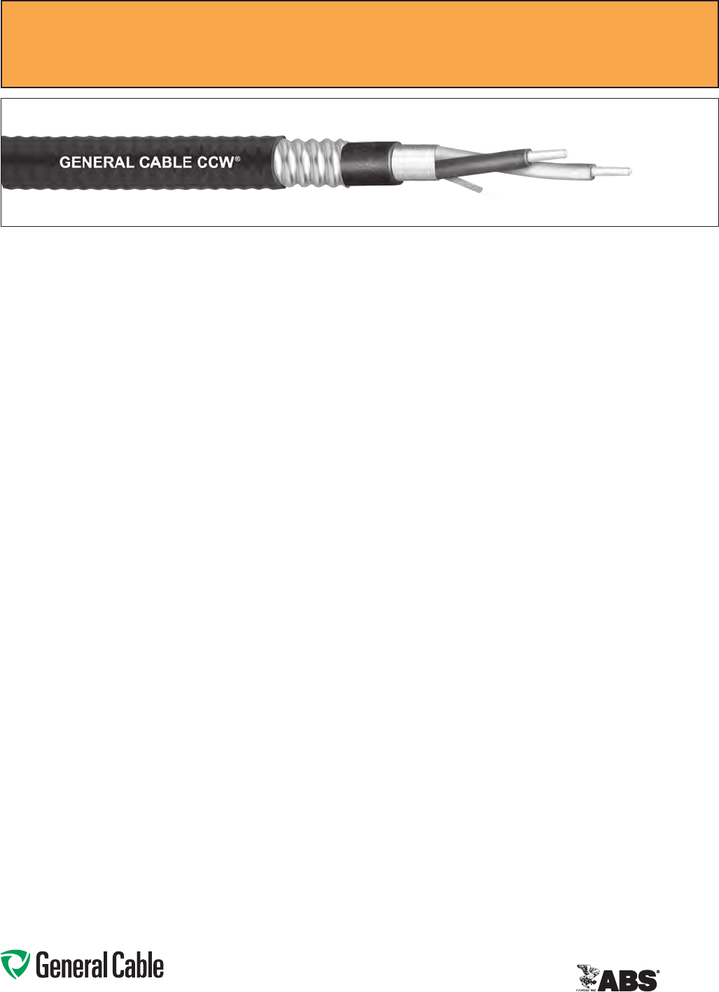
Phone: 888-593-3355
www.generalcable.com
SPEC 9025
April, 2011
Overall Jacket:
•Flame-retardant,moisture-and
sunlight-resistantPolyvinylChloride
(PVC)perULStandards13and2250
•ANSIcolor-coded
•Lowtemperatureperformancemeets
ASTMD746brittlenesstemperatureat
orbelow-40°C
Applications:
•CCWarmoredThermocouple
Extensioncablesprovidesuperior
protectionandreliabilityagainst
physicaldamageforusein
instrumentationandprocesscontrol
applicationsrequiringITC-HLorPLTC
wiringmethods
•ForuseasPowerLimitedTrayCable
oncircuitsrated150Vorlessand
5ampsorlessinClass2orClass3
circuitsinaccordancewithNECArticle
725
•ForuseasInstrumentationTrayCable
oncircuitsrated150Vorlessand
5ampsorlessinaccordancewith
NECArticle727
•RecognizedforuseinClassI,II,and
III,Divisions1and2;orClassI,Zones
1and2hazardouslocationsperNEC
Articles501,502,503,and505
•Installedindoorsoroutdoors,inwetor
drylocations,inaraceway,asaerial
cableonamessenger,incabletrays,
or for direct burial
•Recognizedforuseonfixedor
floatingoffshorepetroleumfacilities
asrecommendedbytheAmerican
PetroleumInstitute
Product Construction:
Conductor:
•16AWGsolidalloywireperANSI
MC 96.1
Insulation:
•Flame-retardantPolyvinylChloride
(PVC),rated105°CperULStandards
13and2250
•Color-codedperANSI
Pair Assembly:
•Insulatedconductorsarecabled
togetherwithaleft-handlay
Overall Shield:
•Flexfoil®aluminum/polyestertape
shieldproviding100%coverage
•Strandedtinnedcopperdrainwire,
samesizeasinsulatedconductors
Inner Jacket:
•Flame-retardantPolyvinylChloride
(PVC)perULStandards13and2250,
black
•Lowtemperatureperformancemeets
ASTMD746brittlenesstemperatureat
orbelow-40°C
•Nylonripcordtofacilitatejacket
removal
CCW Armor:
•Impervious,continuouslyweldedand
corrugatedaluminumalloysheathper
UL1569
•CCWarmorconductivitymeetsthe
groundingrequirementsofNEC
Article250
CCW
®
Armored Thermocouple, Single Pair, Overall Shield
ULTypeITC-HL/PLTC,PVC,105°C,Sunlight-Resistant,DirectBurial
ULMarineShipboardCable,ABSCWCMC
Features:
•CCWarmorprovidessuperior
mechanicalprotectionandan
imperviousbarriertomoisture,gas
andliquids
•CCWarmorprovidesEMIshielding
performance
•Meetscoldimpactat-40°C
Specifications:
Design Adherence:
•UL13Power-LimitedCircuitCables
•UL2250InstrumentationTrayCable
•UL1569MetalCladCables
•UL1309/CSAC22.2No.245Marine
ShipboardCable
Flame Tests:
•ICEAT-29-520(210,000BTU/hr)
•IEEE383(70,000BTU/hr)
•CSAFT4
•IEEE1202(70,000BTU/hr)
•UL1581(70,000BTU/hr)
•IEC60332-3Cat.A
Compliances:
•ULTypePLTC,SUNRES,DIRBUR,
-40°C,ULFile#E36118
•ULTypeITC-HL,ULFile#E177408
•ULListedMarineShipboard,ULFile
#E85994
•AmericanBureauofShipping(ABS)
ListedforCWCMC
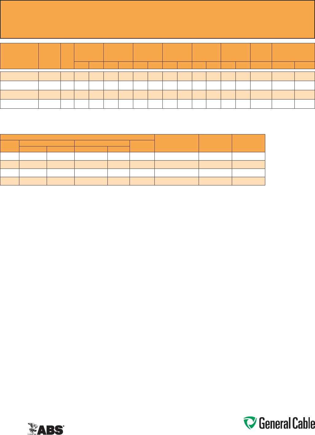
Phone: 888-593-3355
www.generalcable.com
CCW
®
Armored Thermocouple, Single Pair, Overall Shield
ULTypeITC-HL/PLTC,PVC,105°C,Sunlight-Resistant,DirectBurial
ULMarineShipboardCable,ABSCWCMC
SPEC 9025
April, 2011
ANSI MC 96.1 CONDUCTOR ALLOY AND COLOR CODE
TEMP. RANGE LIMITS OF ERROR
NOM. LOOP
RESISTANCE PER
100 FT @ 20°C
COND.
TYPE
POSITIVE WIRE NEGATIVE WIRE OUTER
JACKETALLOY COLOR ALLOY COLOR
EX
Chromel Purple Constantan Red Purple 0°CTo+200°C +/-1.7°C 27.8 O hms
JX
Iron White Constantan Red Black 0°CTo+200°C +/-2.2°C 13.9Ohms
KX
Chromel Yellow Alumel Red Yellow 0°CTo+200°C +/-2.2°C 23.6Ohms
TX
Copper Blue Constantan Red Blue -60°CTo+100°C +/-1.0°C 12.0Ohms
CATALOG
NUMBER
WIRE TYPE/
SIZE
(AWG)
NO. OF
PAIRS
INSULATION
THICKNESS
INNER JACKET
THICKNESS
NOMINAL
CORE O.D.
NOMINAL
ARMOR O.D.
JACKET
THICKNESS
NOMINAL
OVERALL O.D.
CROSS-
SECTIONAL
AREA¹
APPROXIMATE NET
WEIGHT
mils mm mils mm INCHES mm INCHES mm mils mm INCHES mm SQ. IN. LBS/1000 FT kg/1000 m
9025.16010001 EX / 16 115 0.38 35 0.89 0.25 6.4 0.45 11.4 50 1.27 0.56 14.2 0.25 132 196
9025.16010002 JX / 16 115 0.38 35 0.89 0.25 6.4 0.45 11.4 50 1.27 0.56 14.2 0.25 132 196
9025.16010003 KX / 16 115 0.38 35 0.89 0.25 6.4 0.45 11.4 50 1.27 0.56 14.2 0.25 132 196
9025.16010004 TX / 16 115 0.38 35 0.89 0.25 6.4 0.45 11.4 50 1.27 0.56 14.2 0.25 132 196
Dimensionsandweightsarenominal;subjecttoindustrytolerances.
¹ Cross-sectionalareaforcabletrayfillisinaccordancewithNEC®Section392.22.

Phone: 888-593-3355
www.generalcable.com
Overall Jacket:
•Flame-retardant,moisture-and
sunlight-resistantPolyvinylChloride
(PVC)perULStandards13and2250
•ANSIcolor-coded
•Lowtemperatureperformancemeets
ASTMD746brittlenesstemperatureat
orbelow-40°C
Applications:
•CCWarmoredThermocouple
Extensioncablesprovidesuperior
protectionandreliabilityagainst
physicaldamageforusein
instrumentationandprocesscontrol
applicationsrequiringITC-HLorPLTC
wiringmethods
•ForuseasPowerLimitedTrayCable
oncircuitsrated150Vorlessand
5ampsorlessinClass2orClass3
circuitsinaccordancewithNEC
Article725
•ForuseasInstrumentationTrayCable
oncircuitsrated150Vorlessand
5ampsorlessinaccordancewith
NECArticle727
•RecognizedforuseinClassI,II,and
III,Divisions1and2;orClassI,Zones
1and2hazardouslocationsperNEC
Articles501,502,503,and505
•Installedindoorsoroutdoors,inwetor
drylocations,inaraceway,asaerial
cableonamessenger,incabletrays,
or for direct burial
•Recognizedforuseonfixedor
floatingoffshorepetroleumfacilities
asrecommendedbytheAmerican
PetroleumInstitute
Features:
•CCWarmorprovidessuperior
mechanicalprotectionandan
imperviousbarriertomoisture,gas
andliquids
•CCWarmorprovidesEMIshielding
performance
•Meetscoldimpactat-40°C
Specifications:
Design Adherence:
•UL13Power-LimitedCircuitCables
•UL2250InstrumentationTrayCable
•UL1569MetalCladCables
•UL1309/CSAC22.2No.245Marine
ShipboardCable
Flame Tests:
•ICEAT-29-520(210,000BTU/hr)
•IEEE383(70,000BTU/hr)
•CSAFT4
•IEEE1202(70,000BTU/hr)
•UL1581(70,000BTU/hr)
•IEC60332-3Cat.A
Compliances:
•ULTypePLTC,SUNRES,DIRBUR,
-40°C,ULFile#E36118
•ULTypeITC-HL,ULFile#E177408
•ULListedMarineShipboard,ULFile
#E85994
•AmericanBureauofShipping(ABS)
ListedforCWCMC
Product Construction:
Conductor:
•20AWGsolidalloywireperANSIMC
96.1
Insulation:
•Flame-retardantPolyvinylChloride
(PVC),rated105°CperULStandards
13and2250
•Color-codedperANSIwithone
conductorineachpairprinted
alphanumericallyforeasyidentification
Cable Assembly:
•Individualpairsandcommunication
wirearecabledtogetherwithaleft-
handlay
•Communicationwire:22AWGsolid
barecopper,flame-retardantPolyvinyl
Chloride(PVC),rated105°C,orange
Overall Shield:
•Flexfoil®aluminum/polyestertape
shieldproviding100%coverage
•Strandedtinnedcopperdrainwire,
samesizeasinsulatedconductors
Inner Jacket:
•Flame-retardantPolyvinylChloride
(PVC)perULStandards13and2250
•ANSIcolor-coded
•Lowtemperatureperformancemeets
ASTMD746brittlenesstemperatureat
orbelow-40°C
•Nylonripcordtofacilitatejacket
removal
CCW Armor:
•Impervious,continuouslyweldedand
corrugatedaluminumalloysheathper
UL1569
•CCWarmorconductivitymeetsthe
groundingrequiermentsofNEC
Article250
CCW
®
Armored Thermocouple, Pairs, Overall Shield
ULTypeITC-HL/PLTC,PVC,105°C,Sunlight-Resistant,DirectBurial
ULMarineShipboardCable,ABSCWCMC
SPEC 9050
April, 2011
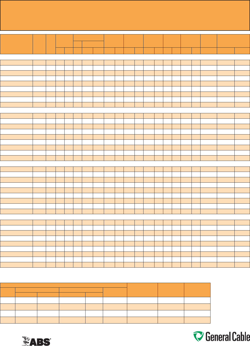
Phone: 888-593-3355
www.generalcable.com
CCW
®
Armored Thermocouple, Pairs, Overall Shield
ULTypeITC-HL/PLTC,PVC,105°C,Sunlight-Resistant,DirectBurial
ULMarineShipboardCable,ABSCWCMC
SPEC 9050
April, 2011
CATALOG
NUMBER
WIRE
TYPE/
SIZE
(AWG)
NO.
OF
PAIRS
INSULATION
THICKNESS
COMMUNICATION WIRE INNER JACKET
THICKNESS
NOMINAL
CORE O.D.
NOMINAL
ARMOR O.D.
JACKET
THICKNESS
NOMINAL
OVERALL O.D.
CROSS-
SECTIONAL
AREA¹
APPROXIMATE
NET WEIGHTSIZE INS. THICKNESS
mils mm AWG mils mm mils mm INCHES mm INCHES mm mils mm INCHES mm SQ. IN. LBS/1000 FT kg/1000 m
20 AWG TYPE EX MULTIPLE PAIRS OVERALL SHIELDED THERMOCOUPLE EXTENSION CABLE
9050.20041221
EX/20 4 15 0.38 22 12 0.30 40 1.02 0.36 9.1 0.58 14.7 50 1.27 0.69 17.5 0.38 195 290
9050.20081221
EX/20 8 15 0.38 22 12 0.30 50 1.27 0.49 12.4 0.71 18.0 50 1.27 0.82 20.8 0.54 277 413
9050.20101221
EX/20 10 15 0.38 22 12 0.30 50 1.27 0.53 13.5 0.75 19.1 50 1.27 0.86 21.8 0.59 337 501
9050.20121221
EX/20 12 15 0.38 22 12 0.30 50 1.27 0.58 14.7 0.80 20.3 50 1.27 0.91 23.1 0.66 354 527
9050.20161221
EX/20 16 15 0.38 22 12 0.30 50 1.27 0.62 15.7 0.84 21.3 50 1.27 0.95 24.1 0.72 422 628
9050.20201221
EX/20 20 15 0.38 22 12 0.30 60 1.52 0.75 19.1 0.97 24.6 50 1.27 1.08 27.4 0.93 485 721
9050.20241221
EX/20 24 15 0.38 22 12 0.30 60 1.52 0.77 19.6 1.02 25.9 50 1.27 1.13 28.7 1.02 552 821
9050.20361221
EX/20 36 15 0.38 22 12 0.30 70 1.78 0.94 23.9 1.19 30.2 50 1.27 1.30 33.0 1.34 738 1,099
9050.20501221
EX/20 50 15 0.38 22 12 0.30 70 1.78 1.09 27.7 1.34 34.0 50 1.27 1.45 36.8 1.67 925 1,377
20 AWG TYPE JX MULTIPLE PAIRS OVERALL SHIELDED THERMOCOUPLE EXTENSION CABLE
9050.20041222
JX/20 4 15 0.38 22 12 0.30 40 1.02 0.36 9.1 0.58 14.7 50 1.27 0.69 17.5 0.38 194 288
9050.20081222
JX/20 8 15 0.38 22 12 0.30 50 1.27 0.49 12.4 0.71 18.0 50 1.27 0.82 20.8 0.54 276 411
9050.20101222
JX/20 10 15 0.38 22 12 0.30 50 1.27 0.53 13.5 0.75 19.1 50 1.27 0.86 21.8 0.59 335 498
9050.20121222
JX/20 12 15 0.38 22 12 0.30 50 1.27 0.58 14.7 0.80 20.3 50 1.27 0.91 23.1 0.66 352 524
9050.20161222
JX/20 16 15 0.38 22 12 0.30 50 1.27 0.62 15.7 0.84 21.3 50 1.27 0.95 24.1 0.72 419 624
9050.20201222
JX/20 20 15 0.38 22 12 0.30 60 1.52 0.75 19.1 0.97 24.6 50 1.27 1.08 27.4 0.93 480 715
9050.20241222
JX/20 24 15 0.38 22 12 0.30 60 1.52 0.77 19.6 1.02 25.9 50 1.27 1.13 28.7 1.02 547 814
9050.20361222
JX/20 36 15 0.38 22 12 0.30 70 1.78 0.94 23.9 1.19 30.2 50 1.27 1.30 33.0 1.34 731 1,088
9050.20501222
JX/20 50 15 0.38 22 12 0.30 70 1.78 1.09 27.7 1.34 34.0 50 1.27 1.45 36.8 1.67 914 1,360
20 AWG TYPE KX MULTIPLE PAIRS OVERALL SHIELDED THERMOCOUPLE EXTENSION CABLE
9050.20041223
KX/20 4 15 0.38 22 12 0.30 40 1.02 0.36 9.1 0.58 14.7 50 1.27 0.69 17.5 0.38 195 290
9050.20081223
KX/20 8 15 0.38 22 12 0.30 50 1.27 0.49 12.4 0.71 18.0 50 1.27 0.82 20.8 0.54 277 413
9050.20101223
KX/20 10 15 0.38 22 12 0.30 50 1.27 0.53 13.5 0.75 19.1 50 1.27 0.86 21.8 0.59 337 501
9050.20121223
KX/20 12 15 0.38 22 12 0.30 50 1.27 0.58 14.7 0.80 20.3 50 1.27 0.91 23.1 0.66 354 527
9050.20161223
KX/20 16 15 0.38 22 12 0.30 50 1.27 0.62 15.7 0.84 21.3 50 1.27 0.95 24.1 0.72 422 628
9050.20201223
KX/20 20 15 0.38 22 12 0.30 60 1.52 0.75 19.1 0.97 24.6 50 1.27 1.08 27.4 0.93 485 721
9050.20241223
KX/20 24 15 0.38 22 12 0.30 60 1.52 0.77 19.6 1.02 25.9 50 1.27 1.13 28.7 1.02 552 821
9050.20361223
KX/20 36 15 0.38 22 12 0.30 70 1.78 0.94 23.9 1.19 30.2 50 1.27 1.30 33.0 1.34 738 1,099
9050.20501223
KX/20 50 15 0.38 22 12 0.30 70 1.78 1.09 27.7 1.34 34.0 50 1.27 1.45 36.8 1.67 925 1,377
20 AWG TYPE TX MULTIPLE PAIRS OVERALL SHIELDED THERMOCOUPLE EXTENSION CABLE
9050.20041224
TX/20 4 15 0.38 22 12 0.30 40 1.02 0.36 9.1 0.58 14.7 50 1.27 0.69 17.5 0.38 196 291
9050.20081224
TX/20 8 15 0.38 22 12 0.30 50 1.27 0.49 12.4 0.71 18.0 50 1.27 0.82 20.8 0.54 279 416
9050.20101224
TX/20 10 15 0.38 22 12 0.30 50 1.27 0.53 13.5 0.75 19.1 50 1.27 0.86 21.8 0.59 339 504
9050.20121224
TX/20 12 15 0.38 22 12 0.30 50 1.27 0.58 14.7 0.80 20.3 50 1.27 0.91 23.1 0.66 354 527
9050.20161224
TX/20 16 15 0.38 22 12 0.30 50 1.27 0.62 15.7 0.84 21.3 50 1.27 0.95 24.1 0.72 426 634
9050.20201224
TX/20 20 15 0.38 22 12 0.30 60 1.52 0.75 19.1 0.97 24.6 50 1.27 1.08 27.4 0.93 489 727
9050.20241224
TX/20 24 15 0.38 22 12 0.30 60 1.52 0.77 19.6 1.02 25.9 50 1.27 1.13 28.7 1.02 557 829
9050.20361224
TX/20 36 15 0.38 22 12 0.30 70 1.78 0.94 23.9 1.19 30.2 50 1.27 1.30 33.0 1.34 747 1,111
9050.20501224
TX/20 50 15 0.38 22 12 0.30 70 1.78 1.09 27.7 1.34 34.0 50 1.27 1.45 36.8 1.67 935 1,392
Dimensionsandweightsarenominal;subjecttoindustrytolerances.
¹Cross-sectionalareaforcabletrayfillisinaccordancewithNEC®Section392.22.
ANSI MC 96.1 CONDUCTOR ALLOY AND COLOR CODE
TEMP. RANGE
LIMITS OF
ERROR
NOM. LOOP
RESISTANCE PER
100 FT @ 20°C
COND.
TYPE
POSITIVE WIRE NEGATIVE WIRE OVERALL
JACKET COLORALLOY COLOR ALLOY COLOR
EX Chromel Purple Constantan Red Purple
0°C To +200°C +/- 1.7°C 70.7 Ohms
JX Iron White Constantan Red Black
0°C To +200°C +/- 2.2°C 35.7 Ohms
KX Chromel Yellow Alumel Red Yellow
0°C To +200°C +/- 2.2°C 59.0 Ohms
TX Copper Blue Constantan Red Blue
-60°C To +100°C +/- 1.0°C 29.8 Ohms
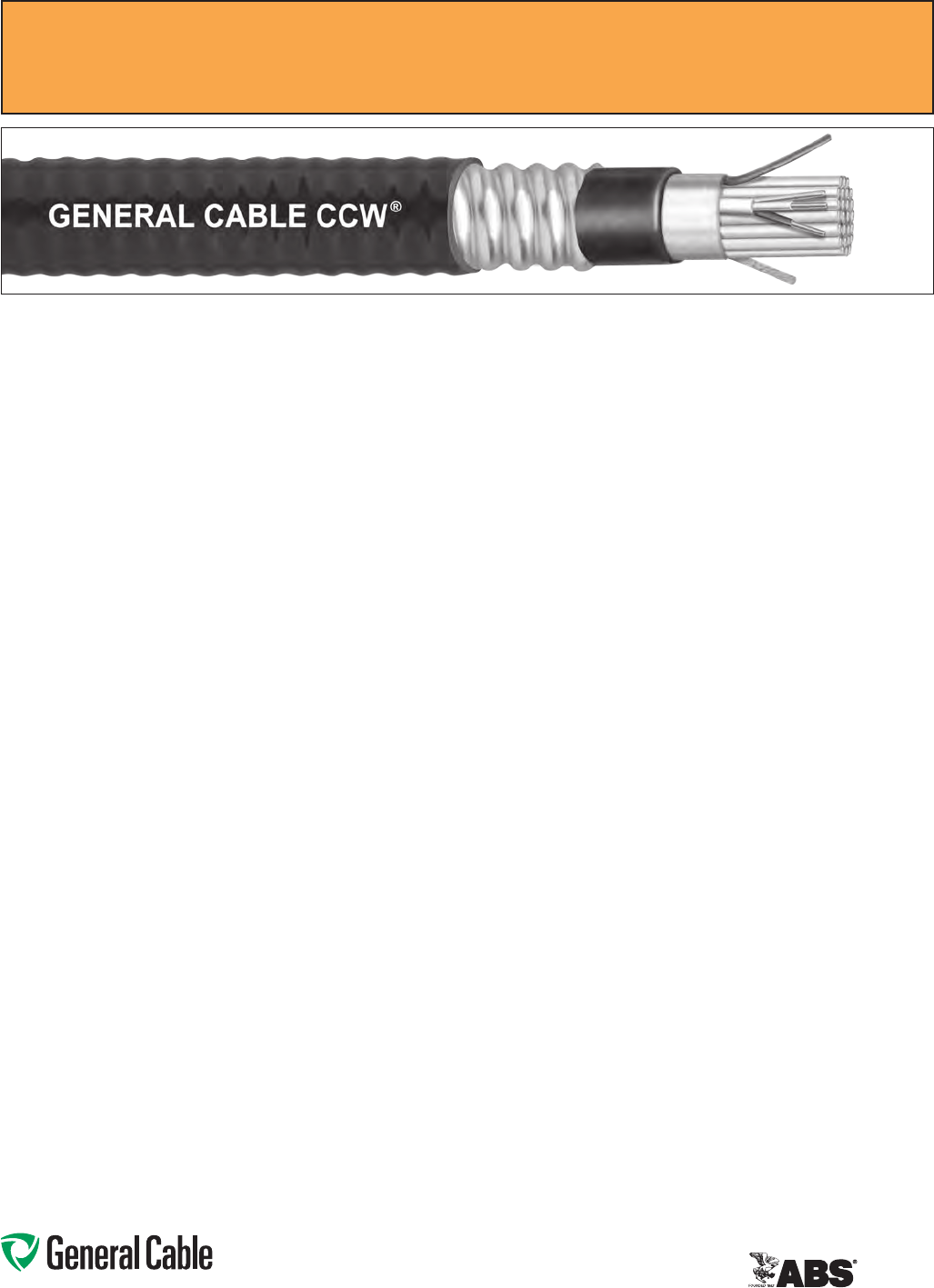
Phone: 888-593-3355
www.generalcable.com
CCW Armor:
•Impervious,continuouslyweldedand
corrugatedaluminumalloysheathper
UL1569
•CCWarmorconductivitymeetsthe
groundingrequirementsofNEC
Article250
Overall Jacket:
•Flame-retardant,moisture-and
sunlight-resistantPolyvinylChloride
(PVC)perULStandards13and2250
•ANSIcolor-codedoveralljacket
•Lowtemperatureperformancemeets
ASTMD746brittlenesstemperature
atorbelow-40°C
Applications:
•CCWarmoredThermocouple
Extensioncableswithindividually
shieldedpairsandanoverallshield
providesuperiorprotectionand
reliabilityagainstphysicaldamagefor
useininstrumentationandprocess
controlapplicationsrequiringITC-HL
orPLTCwiringmethodswhere
shieldingagainstbothexternalEMI
andEMIbetweenpairsisrequired
•ForuseasPowerLimitedTrayCable
oncircuitsrated150Vorlessand
5ampsorlessinClass2orClass3
circuitsinaccordancewithNEC
Article725
•ForuseasInstrumentationTrayCable
oncircuitsrated150Vorlessand5
ampsorlessinaccordancewithNEC
Article727
•RecognizedforuseinClassI,II,and
III,Divisions1and2;orClassI,Zones
1and2hazardouslocationsperNEC
Articles501,502,503,and505
Applications: (cont’d)
•Installedindoorsoroutdoors,inwet
ordrylocations,inaraceway,as
aerialcableonamessenger,incable
trays,orfordirectburial
•Recognizedforuseonfixedor
floatingoffshorepetroleumfacilities
asrecommendedbytheAmerican
PetroleumInstitute
Features:
•CCWarmorprovidessuperior
mechanicalprotectionandan
imperviousbarriertomoisture,gas
andliquids
•CCWarmorprovidesEMIshielding
performance
•Meetscoldimpactat-40°C
Specifications:
Design Adherence:
•UL13Power-LimitedCircuitCables
•UL2250InstrumentationTrayCable
•UL1569MetalCladCables
•UL1309/CSAC22.2No.245Marine
ShipboardCable
Flame Tests:
•ICEAT-29-520(210,000BTU/hr)
•IEEE383(70,000BTU/hr)
•CSAFT4
•IEEE1202(70,000BTU/hr)
•UL1581(70,000BTU/hr)
•IEC60332-3Cat.A
Compliances:
•ULTypePLTC,SUNRES,DIRBUR,
-40°C,ULFile#
E36118
•ULTypeITC-HL,ULFile#E177408
•ULListedMarineShipboard,ULFile
#E85994
•AmericanBureauofShipping(ABS)
ListedforCWCMC
Product Construction:
Conductor:
•20AWGsolidalloywireperANSIMC
96.1
Insulation:
•Flame-retardantPolyvinylChloride
(PVC),rated105°CperULStandards
13and2250
•ANSIcolor-codedinsulation,withone
conductorineachpairprintedalpha
numericallyforeasyidentification
Shielded Pairs:
•Isolatedandindividuallytwistedpairs
withaFlexfoil®aluminum/polyester
tapeshieldproviding100%coverage
•Strandedtinnedcopperdrainwire,
twosizessmallerthaninsulated
conductors
Cable Assembly:
•Individuallyshieldedpairsand
communicationwirearecabled
togetherwithaleft-handlay
•Communicationwire:22AWG
solidbarecopper,flame-retardant
PolyvinylChloride(PVC),rated105°C,
orange
Overall Shield:
•Flexfoil®aluminum/polyestertape
shieldproviding100%coverage
•Strandedtinnedcopperdrainwire,
samesizeasinsulatedconductors
Inner Jacket:
•Flame-retardantPolyvinylChloride
(PVC)perULStandards13and2250
•ANSIcolor-codedinnerjacket
•Lowtemperatureperformancemeets
ASTMD746brittlenesstemperature
atorbelow-40°C
•Nylonripcordtofacilitatejacket
removal
CCW
®
Armored Thermocouple, Pairs, Individual and Overall Shield
ULTypeITC-HL/PLTC,PVC,105°C,Sunlight-Resistant,DirectBurial
ULMarineShipboardCable,ABSCWCMC
SPEC 9075
April, 2011
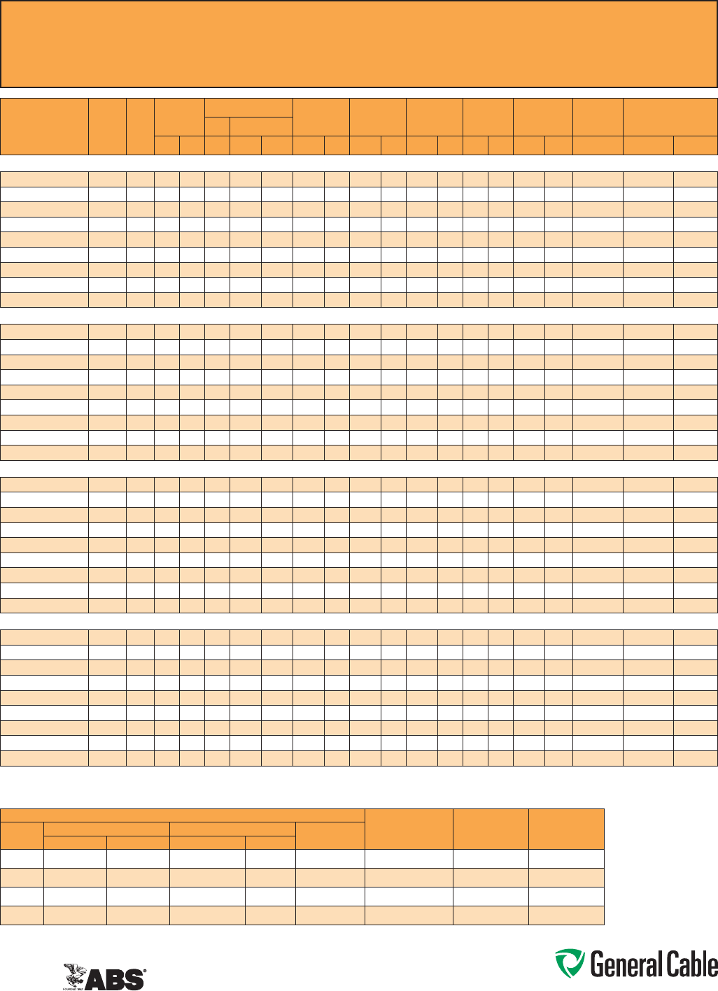
Phone: 888-593-3355
www.generalcable.com
CCW
®
Armored Thermocouple, Pairs, Individual and Overall Shield
ULTypeITC-HL/PLTC,PVC,105°C,Sunlight-Resistant,DirectBurial
ULMarineShipboardCable,ABSCWCMC
SPEC 9075
April, 2011
CATALOG
NUMBER
WIRE
TYPE/
SIZE
(AWG)
NO.
OF
PAIRS
INSULATION
THICKNESS
COMMUNICATION WIRE INNER JACKET
THICKNESS
NOMINAL
CORE O.D.
NOMINAL
ARMOR O.D.
JACKET
THICKNESS
NOMINAL
OVERALL O.D.
CROSS-
SECTIONAL
AREA¹
APPROXIMATE
NET WEIGHTSIZE INS. THICKNESS
mils mm AWG mils mm mils mm INCHES mm INCHES mm mils mm INCHES mm SQ. IN. LBS/1000 FT kg/1000 m
20 AWG TYPE EX MULTIPLE PAIRS INDIVIDUAL AND OVERALL SHIELDED THERMOCOUPLE EXTENSION CABLE
9075.20041221
EX/20 4 15 0.38 22 12 0.30 50 1.27 0.40 10.2 0.62 15.7 50 1.27 0.73 18.5 0.42 235 349
9075.20081221
EX/20 8 15 0.38 22 12 0.30 50 1.27 0.53 13.5 0.75 19.1 50 1.27 0.86 21.8 0.59 313 466
9075.20101221
EX/20 10 15 0.38 22 12 0.30 50 1.27 0.58 14.7 0.80 20.3 50 1.27 0.91 23.1 0.66 388 577
9075.20121221
EX/20 12 15 0.38 22 12 0.30 50 1.27 0.62 15.7 0.84 21.3 50 1.27 0.95 24.1 0.72 417 621
9075.20161221
EX/20 16 15 0.38 22 12 0.30 60 1.52 0.75 19.1 0.97 24.6 50 1.27 1.08 27.4 0.93 494 735
9075.20201221
EX/20 20 15 0.38 22 12 0.30 60 1.52 0.81 20.6 1.06 26.9 50 1.27 1.17 29.7 1.09 571 850
9075.20241221
EX/20 24 15 0.38 22 12 0.30 60 1.52 0.90 22.9 1.15 29.2 50 1.27 1.26 32.0 1.26 681 1,014
9075.20361221
EX/20 36 15 0.38 22 12 0.30 70 1.78 1.09 27.7 1.34 34.0 50 1.27 1.45 36.8 1.67 877 1,305
9075.20501221
EX/20 50 15 0.38 22 12 0.30 70 1.78 1.22 31.0 1.47 37.3 50 1.27 1.58 40.1 1.99 1,201 1,787
20 AWG TYPE JX MULTIPLE PAIRS INDIVIDUAL AND OVERALL SHIELDED THERMOCOUPLE EXTENSION CABLE
9075.20041222
JX/20 4 15 0.38 22 12 0.30 50 1.27 0.40 10.2 0.62 15.7 50 1.27 0.73 18.5 0.42 234 348
9075.20081222
JX/20 8 15 0.38 22 12 0.30 50 1.27 0.53 13.5 0.75 19.1 50 1.27 0.86 21.8 0.59 311 463
9075.20101222
JX/20 10 15 0.38 22 12 0.30 50 1.27 0.58 14.7 0.80 20.3 50 1.27 0.91 23.1 0.66 386 574
9075.20121222
JX/20 12 15 0.38 22 12 0.30 50 1.27 0.62 15.7 0.84 21.3 50 1.27 0.95 24.1 0.72 413 615
9075.20161222
JX/20 16 15 0.38 22 12 0.30 60 1.52 0.75 19.1 0.97 24.6 50 1.27 1.08 27.4 0.93 491 730
9075.20201222
JX/20 20 15 0.38 22 12 0.30 60 1.52 0.81 20.6 1.06 26.9 50 1.27 1.17 29.7 1.09 567 844
9075.20241222
JX/20 24 15 0.38 22 12 0.30 60 1.52 0.90 22.9 1.15 29.2 50 1.27 1.26 32.0 1.26 676 1,006
9075.20361222
JX/20 36 15 0.38 22 12 0.30 70 1.78 1.09 27.7 1.34 34.0 50 1.27 1.45 36.8 1.67 870 1,295
9075.20501222
JX/20 50 15 0.38 22 12 0.30 70 1.78 1.22 31.0 1.47 37.3 50 1.27 1.58 40.1 1.99 1,190 1,771
20 AWG TYPE KX MULTIPLE PAIRS INDIVIDUAL AND OVERALL SHIELDED THERMOCOUPLE EXTENSION CABLE
9075.20041223
KX/20 4 15 0.38 22 12 0.30 50 1.27 0.40 10.2 0.62 15.7 50 1.27 0.73 18.5 0.42 235 349
9075.20081223
KX/20 8 15 0.38 22 12 0.30 50 1.27 0.53 13.5 0.75 19.1 50 1.27 0.86 21.8 0.59 313 466
9075.20101223
KX/20 10 15 0.38 22 12 0.30 50 1.27 0.58 14.7 0.80 20.3 50 1.27 0.91 23.1 0.66 388 577
9075.20121223
KX/20 12 15 0.38 22 12 0.30 50 1.27 0.62 15.7 0.84 21.3 50 1.27 0.95 24.1 0.72 417 621
9075.20161223
KX/20 16 15 0.38 22 12 0.30 60 1.52 0.75 19.1 0.97 24.6 50 1.27 1.08 27.4 0.93 494 735
9075.20201223
KX/20 20 15 0.38 22 12 0.30 60 1.52 0.81 20.6 1.06 26.9 50 1.27 1.17 29.7 1.09 571 850
9075.20241223
KX/20 24 15 0.38 22 12 0.30 60 1.52 0.90 22.9 1.15 29.2 50 1.27 1.26 32.0 1.26 681 1,014
9075.20361223
KX/20 36 15 0.38 22 12 0.30 70 1.78 1.09 27.7 1.34 34.0 50 1.27 1.45 36.8 1.67 877 1,305
9075.20501223
KX/20 50 15 0.38 22 12 0.30 70 1.78 1.22 31.0 1.47 37.3 50 1.27 1.58 40.1 1.99 1,201 1,787
20 AWG TYPE TX MULTIPLE PAIRS INDIVIDUAL AND OVERALL SHIELDED THERMOCOUPLE EXTENSION CABLE
9075.20041224
TX/20 4 15 0.38 22 12 0.30 50 1.27 0.40 10.2 0.62 15.7 50 1.27 0.73 18.5 0.42 236 351
9075.20081224
TX/20 8 15 0.38 22 12 0.30 50 1.27 0.53 13.5 0.75 19.1 50 1.27 0.86 21.8 0.59 315 469
9075.20101224
TX/20 10 15 0.38 22 12 0.30 50 1.27 0.58 14.7 0.80 20.3 50 1.27 0.91 23.1 0.66 391 581
9075.20121224
TX/20 12 15 0.38 22 12 0.30 50 1.27 0.62 15.7 0.84 21.3 50 1.27 0.95 24.1 0.72 418 622
9075.20161224
TX/20 16 15 0.38 22 12 0.30 60 1.52 0.75 19.1 0.97 24.6 50 1.27 1.08 27.4 0.93 497 739
9075.20201224
TX/20 20 15 0.38 22 12 0.30 60 1.52 0.81 20.6 1.06 26.9 50 1.27 1.17 29.7 1.09 575 856
9075.20241224
TX/20 24 15 0.38 22 12 0.30 60 1.52 0.90 22.9 1.15 29.2 50 1.27 1.26 32.0 1.26 686 1,022
9075.20361224
TX/20 36 15 0.38 22 12 0.30 70 1.78 1.09 27.7 1.34 34.0 50 1.27 1.45 36.8 1.67 884 1,316
9075.20501224
TX/20 50 15 0.38 22 12 0.30 70 1.78 1.22 31.0 1.47 37.3 50 1.27 1.58 40.1 1.99 1,211 1,802
Dimensionsandweightsarenominal;subjecttoindustrytolerances.
¹Cross-sectionalareaforcabletrayfillisinaccordancewithNEC®Section392.22.
ANSI MC 96.1 CONDUCTOR ALLOY AND COLOR CODE
TEMP. RANGE
LIMITS OF
ERROR
NOM. LOOP
RESISTANCE PER
100 FT @ 20°C
COND.
TYPE
POSITIVE WIRE NEGATIVE WIRE OVERALL
JACKET COLORALLOY COLOR ALLOY COLOR
EX Chromel Purple Constantan Red Purple
0°C To +200°C +/- 1.7°C 70.7 Ohms
JX Iron White Constantan Red Black
0°C To +200°C +/- 2.2°C 35.7 Ohms
KX Chromel Yellow Alumel Red Yellow
0°C To +200°C +/- 2.2°C 59.0 Ohms
TX Copper Blue Constantan Red Blue
-60°C To +100°C +/- 1.0°C 29.8 Ohms
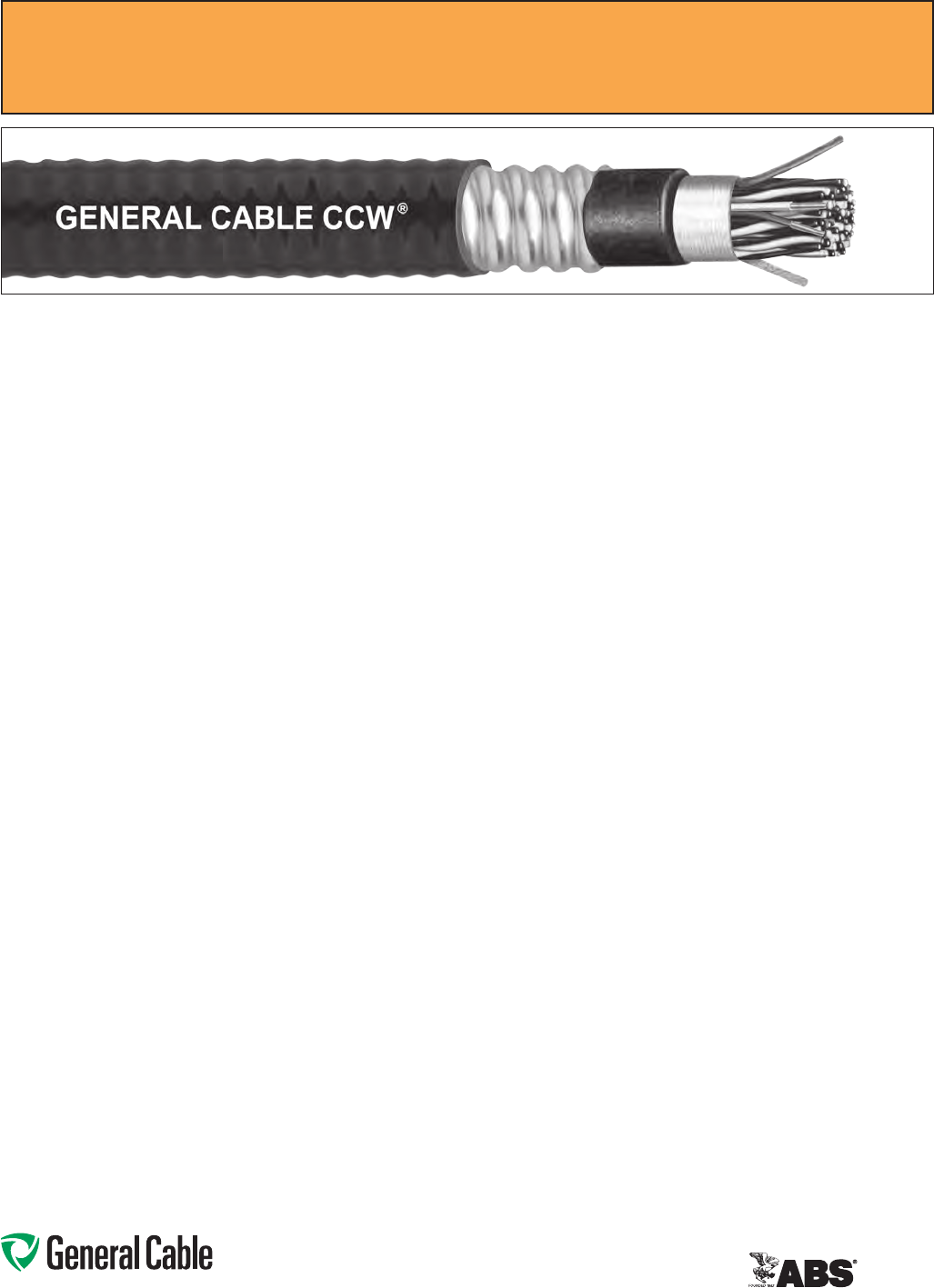
Phone: 888-593-3355
www.generalcable.com
CCW Armor:
•Impervious,continuouslyweldedand
corrugatedaluminumalloysheathper
UL1569
•CCWarmorconductivitymeetsthe
groundingrequirementsofNEC
Article250
Overall Jacket:
•Flame-retardant,moisture-and
sunlight-resistantPolyvinylChloride
(PVC)perULStandards13and2250,
black
•Lowtemperatureperformancemeets
ASTMD746brittlenesstemperatureat
orbelow-40°C
Applications:
•CCWarmoredInstrumentation
cableswithanoverallshieldprovide
superiorprotectionandreliability
againstphysicaldamageforusein
instrumentationandprocesscontrol
applicationsrequiringITC-HLorPLTC
wiringmethodswhereshieldingagainst
externalEMIisrequired
•ForuseasPowerLimitedTrayCableon
circuitsrated150Vorlessand5amps
orlessinClass2orClass3circuitsin
accordancewithNECArticle725
•ForuseasInstrumentationTrayCable
oncircuitsrated150Vorlessand
5ampsorlessinaccordancewithNEC
Article727
•RecognizedforuseinClassI,II,and
III,Divisions1and2;orClassI,Zones
1and2hazardouslocationsperNEC
Articles501,502,503,and505
•Installedindoorsoroutdoors,inwetor
drylocations,inaraceway,asaerial
cableonamessenger,incabletrays,or
for direct burial
Applications: (cont’d)
•Recognizedforuseonfixedor
floatingoffshorepetroleumfacilities
asrecommendedbytheAmerican
PetroleumInstitute
Features:
•CCWarmorprovidessuperior
mechanicalprotectionandan
imperviousbarriertomoisture,gas
andliquids
•CCWarmorprovidesEMIshielding
performance
•Meetscoldimpactat-40°C
Specifications:
Design Adherence:
•UL13Power-LimitedCircuitCables
•UL2250InstrumentationTrayCable
•UL1569MetalCladCables
•UL1309/CSAC22.2No.245Marine
ShipboardCable
Flame Tests:
•ICEAT-29-520(210,000BTU/hr)
•IEEE383(70,000BTU/hr)
•CSAFT4
•IEEE1202(70,000BTU/hr)
•UL1581(70,000BTU/hr)
•IEC60332-3Cat.A
Compliances:
•ULTypePLTC,SUNRES,DIRBUR,
-40°C,ULFile#E36118
•ULTypeITC-HL,ULFile#E177408
•ULListedMarineShipboard,ULFile#
E85994
•AmericanBureauofShipping(ABS)
ListedforCWCMC
Product Construction:
Conductor:
•BareannealedcopperperASTMB3
•ClassBstrandingperASTMB8
Insulation:
•Cross-linkedPolyethylene(XLPE),rated
90°CperULStandards13and2250
•Color-codedperICEAMethod1:
pairs–blackandwhite;triads–black,
whiteandred.Eachconductorineach
pairortriadisprintedalphanumerically
foreasyidentification
Cable Assembly:
•Individualpairsortriadsand
communicationwirearecabled
togetherwithalefthandlay
•Communicationwire:20AWGsolid
barecopper,Cross-linkedPolyethylene
(XLPE),rated90°C,orange
•Communicationwireisnotincludedon
singlepairorsingletriadcables
Overall Shield:
•Flexfoil®aluminum/polyestertapeshield
providing100%coverage
•Strandedtinnedcopperdrainwire,
samesizeasinsulatedconductors
Inner Jacket:
•Flame-retardantPolyvinylChloride
(PVC)perULStandards13and2250,
black
•Lowtemperatureperformancemeets
ASTMD746brittlenesstemperatureat
orbelow-40°C
•Nylonripcordtofacilitatejacket
removal
CCW
®
Armored Instrumentation, Pairs/Triads, Overall Shield
ULTypeITC-HL/PLTC,XLPE,300V,90°C,Sunlight-Resistant,DirectBurial
ULMarineShipboardCable,ABSCWCMC
SPEC 9125
April, 2011

Phone: 888-593-3355
www.generalcable.com
CCW
®
Armored Instrumentation, Pairs/Triads, Overall Shield
ULTypeITC-HL/PLTC,XLPE,300V,90°C,Sunlight-Resistant,DirectBurial
ULMarineShipboardCable,ABSCWCMC
SPEC 9125
April, 2011
CATALOG
NUMBER
COND.
SIZE
(AWG)
NO.
OF
PAIRS
INSULATION
THICKNESS
COMMUNICATION WIRE INNER JACKET
THICKNESS
NOMINAL
CORE O.D.
NOMINAL
ARMOR O.D.
JACKET
THICKNESS
NOMINAL
OVERALL O.D.
CROSS-
SECTIONAL
AREA¹
APPROXIMATE
NET WEIGHTSIZE INS. THICKNESS
mils mm AWG mils mm mils mm INCHES mm INCHES mm mils mm INCHES mm SQ. IN. LBS/1000 FT kg/1000 m
16 AWG 7W (1.31 mm²) OVERALL SHIELDED PAIRS
9125.16010001 16 1 15 0.38 — — — 35 0.89 0.26 6.6 0.43 10.9 50 1.27 0.54 13.7 0.23 135 201
9125.16021201 16 2 15 0.38 20 15 0.38 40 1.02 0.37 9.4 0.58 14.7 50 1.27 0.69 17.5 0.38 235 350
9125.16041201 16 4 15 0.38 20 15 0.38 50 1.27 0.49 12.4 0.71 18.0 50 1.27 0.82 20.8 0.54 298 443
9125.16081201 16 8 15 0.38 20 15 0.38 60 1.52 0.65 16.5 0.89 22.6 50 1.27 1.00 25.4 0.80 412 613
9125.16121201 16 12 15 0.38 20 15 0.38 60 1.52 0.76 19.3 1.02 25.9 50 1.27 1.13 28.7 1.02 562 836
9125.16161201 16 16 15 0.38 20 15 0.38 60 1.52 0.87 22.1 1.11 28.2 50 1.27 1.22 31.0 1.18 665 990
9125.16241201 16 24 15 0.38 20 15 0.38 70 1.78 1.01 25.7 1.34 34.0 50 1.27 1.45 36.8 1.67 934 1,390
9125.16361201 16 36 15 0.38 20 15 0.38 70 1.78 1.24 31.5 1.56 39.6 60 1.52 1.69 42.9 2.27 1,236 1,840
9125.16501201 16 50 15 0.38 20 15 0.38 80 2.03 1.47 37.3 1.83 46.5 60 1.52 1.96 49.8 3.06 1,734 2,580
16 AWG 7W (1.31 mm²) OVERALL SHIELDED TRIADS
9125.16010002 16 1 15 0.38 — — — 35 0.89 0.27 6.9 0.49 12.4 50 1.27 0.60 15.2 0.29 158 235
9125.16021202 16 2 15 0.38 20 15 0.38 40 1.02 0.39 9.9 0.62 15.7 50 1.27 0.73 18.5 0.42 265 394
9125.16041202 16 4 15 0.38 20 15 0.38 50 1.27 0.52 13.2 0.75 19.1 50 1.27 0.86 21.8 0.59 358 533
9125.16081202 16 8 15 0.38 20 15 0.38 60 1.52 0.69 17.5 0.93 23.6 50 1.27 1.04 26.4 0.86 565 841
9125.16121202 16 12 15 0.38 20 15 0.38 60 1.52 0.81 20.6 1.06 26.9 50 1.27 1.17 29.7 1.09 793 1,179
9125.16161202 16 16 15 0.38 20 15 0.38 70 1.78 0.95 24.1 1.24 31.5 50 1.27 1.35 34.3 1.45 965 1,436
9125.16241202 16 24 15 0.38 20 15 0.38 70 1.78 1.14 29.0 1.42 36.1 50 1.27 1.53 38.9 1.86 1,446 2,152
9125.16361202 16 36 15 0.38 20 15 0.38 80 2.03 1.34 34.0 1.64 41.7 60 1.52 1.78 45.2 2.52 1,913 2,846
9125.16501202 16 50 15 0.38 20 15 0.38 80 2.03 1.57 39.9 1.92 48.8 60 1.52 2.05 52.1 3.34 2,585 3,846
Dimensionsandweightsarenominal;subjecttoindustrytolerances.
¹Cross-sectionalareaforcabletrayfillisinaccordancewithNEC®Section392.22.
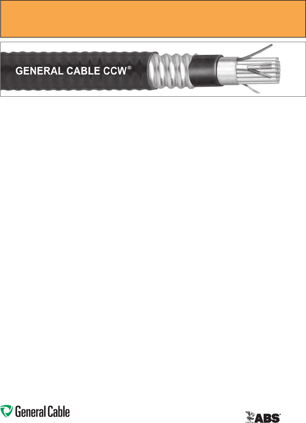
Phone: 888-593-3355
www.generalcable.com
CCW Armor:
•Impervious,continuouslyweldedand
corrugatedaluminumalloysheathper
UL1569
•CCWarmorconductivitymeetsthe
groundingrequirementsofNEC
Article250
Overall Jacket:
•Flame-retardant,moisture-and
sunlight-resistantPolyvinylChloride
(PVC)perULStandards13and2250,
black
•Lowtemperatureperformancemeets
ASTMD746brittlenesstemperatureat
orbelow-40°C
Applications:
•CCWarmoredInstrumentationcables
withindividuallyshieldedpairsor
triadsandanoverallshieldprovide
superiorprotectionandreliability
againstphysicaldamageforusein
instrumentationandprocesscontrol
applicationsrequiringITC-HLor
PLTCwiringmethodswhereshielding
againstbothexternalEMIandEMI
betweengroupsisrequired
•ForuseasPowerLimitedTrayCable
oncircuitsrated150Vorlessand
5ampsorlessinClass2orClass3
circuitsinaccordancewithNECArticle
725
•ForuseasInstrumentationTrayCable
oncircuitsrated150Vorlessand
5ampsorlessinaccordancewith
NECArticle727
•RecognizedforuseinClassI,II,and
III,Divisions1and2;orClassI,Zones
1and2hazardouslocationsperNEC
Articles501,502,503,and505
Applications: (cont’d)
•Installedindoorsoroutdoors,inwetor
drylocations,inaraceway,asaerial
cableonamessenger,incabletrays,
or for direct burial
•Recognizedforuseonfixedor
floatingoffshorepetroleumfacilities
asrecommendedbytheAmerican
PetroleumInstitute
Features:
•CCWarmorprovidessuperior
mechanicalprotectionandan
imperviousbarriertomoisture,
gasandliquids
•CCWarmorprovidesEMIshielding
performance
•Meetscoldimpactat-40°C
Specifications:
Design Adherence:
•UL13Power-LimitedCircuitCables
•UL2250InstrumentationTrayCable
•UL1569MetalCladCables
•UL1309/CSAC22.2No.245Marine
ShipboardCable
Flame Tests:
•ICEAT-29-520(210,000BTU/hr)
•IEEE383(70,000BTU/hr)
•CSAFT4
•IEEE1202(70,000BTU/hr)
•UL1581(70,000BTU/hr)
•IEC60332-3Cat.A
Compliances:
•ULTypePLTC,SUNRES,DIRBUR,
-40°C,ULFile#E36118
•ULTypeITC-HL,ULFile#E177408
•ULListedMarineShipboard,ULFile#
E85994
•AmericanBureauofShipping(ABS)
ListedforCWCMC
Product Construction:
Conductor:
•BareannealedcopperperASTMB3
•ClassBstrandingperASTMB8
Insulation:
•
Cross-linkedPolyethylene
(XLPE),
rated90°CperULStandards13and
2250
•Color-codedperICEAMethod1:
pairs–blackandwhite;triads–black,
whiteandred.Eachconductorineach
pairortriadisprintedalphanumerically
foreasyidentification
Shielded Pairs/Triads:
•Isolatedandindividuallytwistedpairs
ortriadswithaFlexfoil®aluminum/
polyestertapeshieldproviding100%
coverage
•Strandedtinnedcopperdrainwire,two
sizessmallerthaninsulatedconductors
Cable Assembly:
•Individuallyshieldedpairsortriads
andcommunicationwirearecabled
togetherwithaleft-handlay
•Communicationwire:20AWGsolid
barecopper,Cross-linkedPolyethylene
(XLPE),rated90°C,orange
Overall Shield:
•Flexfoil®aluminum/polyestertapeshield
providing100%coverage
•Strandedtinnedcopperdrainwire,
samesizeasinsulatedconductors
Inner Jacket:
•Flame-retardantPolyvinylChloride
(PVC)perULStandards13and2250,
black
•Lowtemperatureperformancemeets
ASTMD746brittlenesstemperatureat
orbelow-40°C
•Nylonripcordtofacilitatejacket
removal
CCW
®
Armored Instrumentation, Pairs/Triads, Individual and Overall Shield
ULTypeITC-HL/PLTC,XLPE,300V,90°C,Sunlight-Resistant,DirectBurial
ULMarineShipboardCable,ABSCWCMC
SPEC 9150
April, 2011
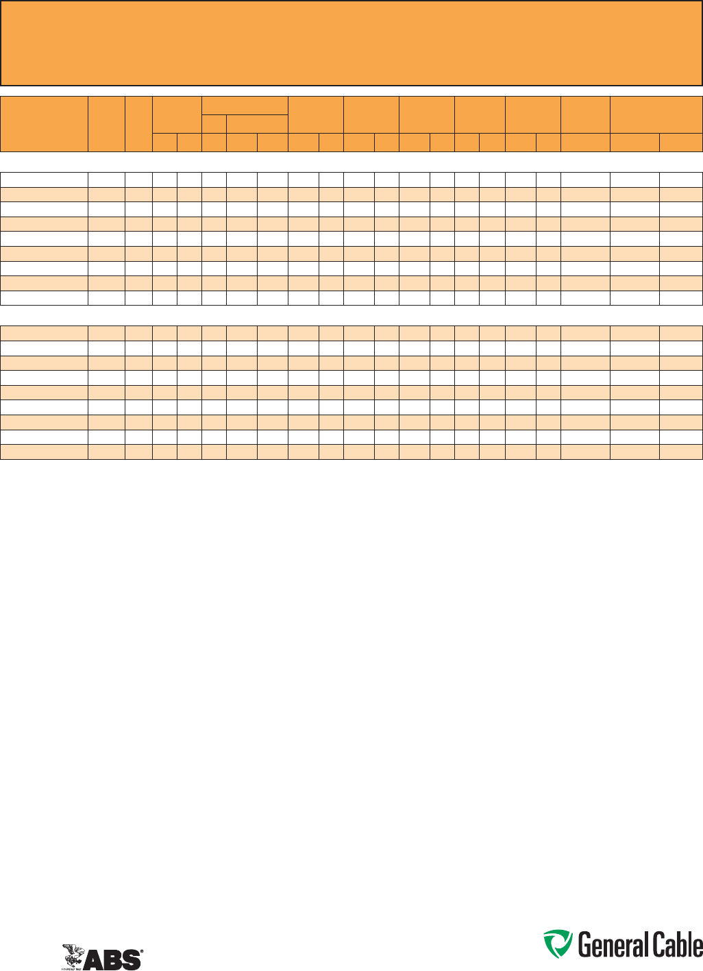
Phone: 888-593-3355
www.generalcable.com
CCW
®
Armored Instrumentation, Pairs/Triads, Individual and Overall Shield
ULTypeITC-HL/PLTC,XLPE,300V,90°C,Sunlight-Resistant,DirectBurial
ULMarineShipboardCable,ABSCWCMC
SPEC 9150
April, 2011
CATALOG
NUMBER
COND.
SIZE
(AWG)
NO.
OF
PAIRS
INSULATION
THICKNESS
COMMUNICATION WIRE INNER JACKET
THICKNESS
NOMINAL
CORE O.D.
NOMINAL
ARMOR O.D.
JACKET
THICKNESS
NOMINAL
OVERALL O.D.
CROSS-
SECTIONAL
AREA¹
APPROXIMATE
NET WEIGHTSIZE INS. THICKNESS
mils mm AWG mils mm mils mm INCHES mm INCHES mm mils mm INCHES mm SQ. IN. LBS/1000 FT kg/1000 m
16 AWG 7W (1.31 mm²) OVERALL SHIELDED PAIRS
9150.16010001 16 1 15 0.38 — — — 35 0.89 0.26 6.6 0.43 10.9 50 1.27 0.54 13.7 0.23 135 201
9150.16021201 16 2 15 0.38 20 15 0.38 40 1.02 0.37 9.4 0.58 14.7 50 1.27 0.69 17.5 0.38 235 350
9150.16041201 16 4 15 0.38 20 15 0.38 50 1.27 0.49 12.4 0.71 18.0 50 1.27 0.82 20.8 0.54 298 443
9150.16081201 16 8 15 0.38 20 15 0.38 60 1.52 0.65 16.5 0.89 22.6 50 1.27 1.00 25.4 0.80 412 613
9150.16121201 16 12 15 0.38 20 15 0.38 60 1.52 0.76 19.3 1.02 25.9 50 1.27 1.13 28.7 1.02 562 836
9150.16161201 16 16 15 0.38 20 15 0.38 60 1.52 0.87 22.1 1.11 28.2 50 1.27 1.22 31.0 1.18 665 990
9150.16241201 16 24 15 0.38 20 15 0.38 70 1.78 1.01 25.7 1.34 34.0 50 1.27 1.45 36.8 1.67 934 1,390
9150.16361201 16 36 15 0.38 20 15 0.38 70 1.78 1.24 31.5 1.56 39.6 60 1.52 1.69 42.9 2.27 1,236 1,840
9150.16501201 16 50 15 0.38 20 15 0.38 80 2.03 1.47 37.3 1.83 46.5 60 1.52 1.96 49.8 3.06 1,734 2,580
16 AWG 7W (1.31 mm²) OVERALL SHIELDED TRIADS
9150.16010002 16 1 15 0.38 — — — 35 0.89 0.27 6.9 0.49 12.4 50 1.27 0.60 15.2 0.29 158 235
9150.16021202 16 2 15 0.38 20 15 0.38 40 1.02 0.39 9.9 0.62 15.7 50 1.27 0.73 18.5 0.42 265 394
9150.16041202 16 4 15 0.38 20 15 0.38 50 1.27 0.52 13.2 0.75 19.1 50 1.27 0.86 21.8 0.59 358 533
9150.16081202 16 8 15 0.38 20 15 0.38 60 1.52 0.69 17.5 0.93 23.6 50 1.27 1.04 26.4 0.86 565 841
9150.16121202 16 12 15 0.38 20 15 0.38 60 1.52 0.81 20.6 1.06 26.9 50 1.27 1.17 29.7 1.09 793 1,179
9150.16161202 16 16 15 0.38 20 15 0.38 70 1.78 0.95 24.1 1.24 31.5 50 1.27 1.35 34.3 1.45 965 1,436
9150.16241202 16 24 15 0.38 20 15 0.38 70 1.78 1.14 29.0 1.42 36.1 50 1.27 1.53 38.9 1.86 1,446 2,152
9150.16361202 16 36 15 0.38 20 15 0.38 80 2.03 1.34 34.0 1.64 41.7 60 1.52 1.78 45.2 2.52 1,913 2,846
9150.16501202 16 50 15 0.38 20 15 0.38 80 2.03 1.57 39.9 1.92 48.8 60 1.52 2.05 52.1 3.34 2,585 3,846
Dimensionsandweightsarenominal;subjecttoindustrytolerances.
¹Cross-sectionalareaforcabletrayfillisinaccordancewithNEC®Section392.22.

Phone: 888-593-3355
www.generalcable.com
Product Construction:
Conductor:
•BareannealedcopperperASTMB3
•ClassBstrandingperASTMB8
Insulation:
•Flame-retardantPolyvinylChloride
(PVC),rated105°CperULStandards
13and2250
•Color-codedperICEAMethod1:
pairs–blackandwhite;triads–black,
whiteandred.Eachconductorineach
pairortriadisprintedalphanumerically
foreasyidentification
Cable Assembly:
•Individualpairsortriadsand
communicationwirearecabled
togetherwithaleft-handlay
•Communicationwire:22AWGsolid
barecopper,flame-retardantPolyvinyl
Chloride(PVC),rated105°C,orange
•Communicationwireisnotincludedon
singlepairorsingletriadcables
Overall Shield:
•Flexfoil®aluminum/polyestertape
shieldproviding100%coverage
•Strandedtinnedcopperdrainwire,
samesizeasinsulatedconductors
Inner Jacket:
•Flame-retardantPolyvinylChloride
(PVC)perULStandards13and2250,
black
•Lowtemperatureperformancemeets
ASTMD746brittlenesstemperatureat
orbelow-40°C
•Nylonripcordtofacilitatejacket
removal
CCW Armor:
•Impervious,continuouslyweldedand
corrugatedaluminumalloysheathper
UL1569
•CCWarmorconductivitymeetsthe
groundingrequirementsofNEC
Article250
CCW
®
Armored Instrumentation, Pairs/Triads, Overall Shield
ULTypeITC-HL/PLTC,PVC,300V,105°C,Sunlight-Resistant,DirectBurial
ULMarineShipboardCable,ABSCWCMC
SPEC 9225
April, 2011
Overall Jacket:
•Flame-retardant,moisture-and
sunlight-resistantPolyvinylChloride
(PVC)perULStandards13and2250,
black
•Lowtemperatureperformancemeets
ASTMD746brittlenesstemperatureat
orbelow-40°C
Applications:
•CCWarmoredInstrumentation
cableswithanoverallshieldprovide
superiorprotectionandreliability
againstphysicaldamageforusein
instrumentationandprocesscontrol
applicationsrequiringITC-HLor
PLTCwiringmethodswhereshielding
againstexternalEMIisrequired
•ForuseasPowerLimitedTrayCable
oncircuitsrated150Vorlessand
5ampsorlessinClass2orClass3
circuitsinaccordancewithNECArticle
725
•ForuseasInstrumentationTrayCable
oncircuitsrated150Vorlessand
5ampsorlessinaccordancewith
NECArticle727
•RecognizedforuseinClassI,II,and
III,Divisions1and2;orClassI,Zones
1and2hazardouslocationsperNEC
Articles501,502,503,and505
•Installedindoorsoroutdoors,inwetor
drylocations,inaraceway,asaerial
cableonamessenger,incabletrays,
or for direct burial
•Recognizedforuseonfixedor
floatingoffshorepetroleumfacilities
asrecommendedbytheAmerican
PetroleumInstitute
Features:
•CCWarmorprovidessuperior
mechanicalprotectionandan
imperviousbarriertomoisture,gas
andliquids
•CCWarmorprovidesEMIshielding
performance
•Meetscoldimpactat-40°
Specifications:
Design Adherence:
•UL13Power-LimitedCircuitCables
•UL2250InstrumentationTrayCable
•UL1569MetalCladCables
•UL1309/CSAC22.2No.245Marine
ShipboardCable
Flame Tests:
•ICEAT-29-520(210,000BTU/hr)
•IEEE383(70,000BTU/hr)
•CSAFT4
•IEEE1202(70,000BTU/hr)
•UL1581(70,000BTU/hr)
•IEC60332-3Cat.A
Compliances:
•ULTypePLTC,SUNRES,DIRBUR,
-40°C,ULFile#E36118
•ULTypeITC-HL,ULFile#E177408
•ULListedMarineShipboard,ULFile#
E85994
•AmericanBureauofShipping(ABS)
ListedforCWCMC
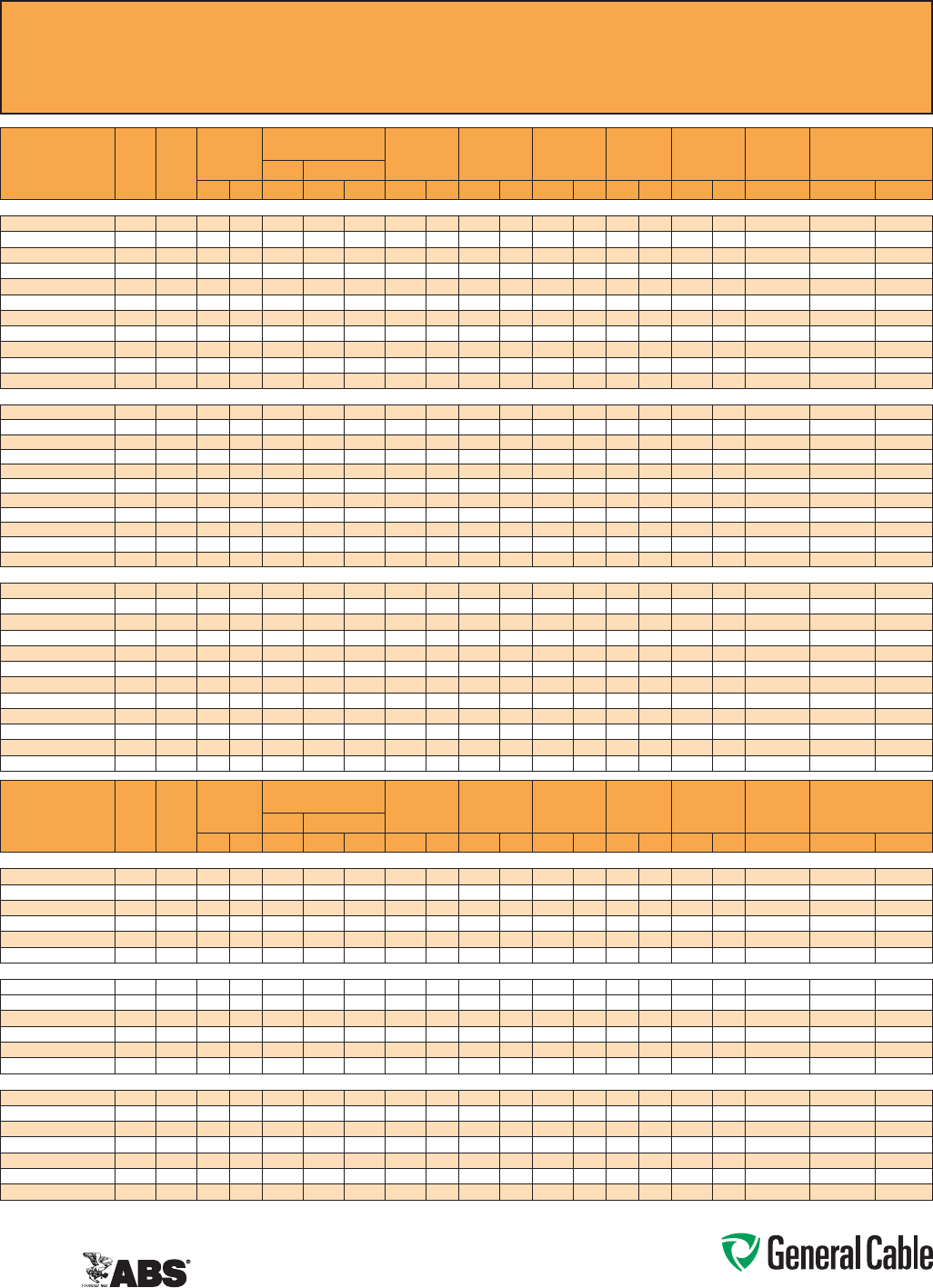
Phone: 888-593-3355
www.generalcable.com
CCW
®
Armored Instrumentation, Pairs/Triads, Overall Shield
ULTypeITC-HL/PLTC,PVC,300V,105°C,Sunlight-Resistant,DirectBurial
ULMarineShipboardCable,ABSCWCMC
SPEC 9225
April, 2011
CATALOG
NUMBER
COND.
SIZE
(AWG)
NO.
OF
PAIRS
INSULATION
THICKNESS
COMMUNICATION WIRE INNER JACKET
THICKNESS
NOMINAL
CORE O.D.
NOMINAL
ARMOR O.D.
JACKET
THICKNESS
NOMINAL
OVERALL O.D.
CROSS-
SECTIONAL
AREA¹
APPROXIMATE
NET WEIGHTSIZE INS. THICKNESS
mils mm AWG mils mm mils mm INCHES mm INCHES mm mils mm INCHES mm SQ. IN. LBS/1000 FT kg/1000 m
20 AWG 7W (0.52 mm²) OVERALL SHIELDED PAIRS
9225.20021221 20 2 15 0.38 22 12 0.30 40 1.02 0.35 8.9 0.58 14.7 50 1.27 0.69 17.5 0.38 174 260
9225.20041221 20 4 15 0.38 22 12 0.30 50 1.27 0.41 10.4 0.62 15.7 50 1.27 0.73 18.5 0.42 198 294
9225.20061221 20 615 0.38 22 12 0.30 50 1.27 0.45 11.4 0.67 17.0 50 1.27 0.78 19.8 0.48 250 372
9225.20081221 20 8 15 0.38 22 12 0.30 50 1.27 0.49 12.4 0.71 18.0 50 1.27 0.82 20.8 0.54 283 420
9225.20101221 20 10 15 0.38 22 12 0.30 50 1.27 0.53 13.5 0.75 19.1 50 1.27 0.86 21.8 0.59 330 492
9225.20121221 20 12 15 0.38 22 12 0.30 50 1.27 0.56 14.2 0.80 20.3 50 1.27 0.91 23.1 0.66 353 525
9225.20161221 20 16 15 0.38 22 12 0.30 60 1.52 0.66 16.8 0.89 22.6 50 1.27 1.00 25.4 0.80 432 644
9225.20201221 20 20 15 0.38 22 12 0.30 60 1.52 0.73 18.5 0.97 24.6 50 1.27 1.08 27.4 0.93 500 744
9225.20241221 20 24 15 0.38 22 12 0.30 60 1.52 0.79 20.1 1.06 26.9 50 1.27 1.17 29.7 1.09 556 827
9225.20361221 20 36 15 0.38 22 12 0.30 70 1.78 0.94 23.9 1.24 31.5 50 1.27 1.35 34.3 1.45 711 1,058
9225.20501221 20 50 15 0.38 22 12 0.30 70 1.78 1.06 26.9 1.34 34.0 50 1.27 1.45 36.8 1.67 949 1,412
18 AWG 7W (0.82 mm²) OVERALL SHIELDED PAIRS
9225.18021221 18 2 15 0.38 22 12 0.30 40 1.02 0.37 9.4 0.58 14.7 50 1.27 0.69 17.5 0.38 206 307
9225.18041221 18 4 15 0.38 22 12 0.30 50 1.27 0.44 11.2 0.67 17.0 50 1.27 0.78 19.8 0.48 249 370
9225.18061221 18 615 0.38 22 12 0.30 50 1.27 0.50 12.7 0.71 18.0 50 1.27 0.82 20.8 0.54 294 437
9225.18081221 18 8 15 0.38 22 12 0.30 50 1.27 0.55 14.0 0.80 20.3 50 1.27 0.91 23.1 0.66 337 501
9225.18101221 18 10 15 0.38 22 12 0.30 60 1.52 0.65 16.5 0.89 22.6 50 1.27 1.00 25.4 0.80 417 621
9225.18121221 18 12 15 0.38 22 12 0.30 60 1.52 0.68 17.3 0.93 23.6 50 1.27 1.04 26.4 0.86 449 668
9225.18161221 18 16 15 0.38 22 12 0.30 60 1.52 0.77 19.6 1.02 25.9 50 1.27 1.13 28.7 1.02 536 797
9225.18201221 18 20 15 0.38 22 12 0.30 60 1.52 0.83 21.1 1.06 26.9 50 1.27 1.17 29.7 1.09 623 927
9225.18241221 18 24 15 0.38 22 12 0.30 60 1.52 0.86 21.8 1.11 28.2 50 1.27 1.22 31.0 1.18 698 1,038
9225.18361221 18 36 15 0.38 22 12 0.30 70 1.78 0.99 25.1 1.29 32.8 50 1.27 1.40 35.6 1.56 965 1,436
9225.18501221 18 50 15 0.38 22 12 0.30 70 1.78 1.15 29.2 1.47 37.3 50 1.27 1.58 40.1 1.99 1,280 1,905
16 AWG 7W (1.31 mm²) OVERALL SHIELDED PAIRS
9225.16010001 16 1 15 0.38 – – – 35 0.89 0.26 6.6 0.43 10.9 50 1.27 0.54 13.7 0.23 135 201
9225.16021221 16 2 15 0.38 22 12 0.30 40 1.02 0.36 9.1 0.58 14.7 50 1.27 0.69 17.5 0.38 239 355
9225.16041221 16 4 15 0.38 22 12 0.30 50 1.27 0.48 12.2 0.71 18.0 50 1.27 0.82 20.8 0.54 296 440
9225.16061221 16 6 15 0.38 22 12 0.30 50 1.27 0.57 14.5 0.80 20.3 50 1.27 0.91 23.1 0.66 366 545
9225.16081221 16 8 15 0.38 22 12 0.30 60 1.52 0.63 16.0 0.84 21.3 50 1.27 0.95 24.1 0.72 424 631
9225.16101221 16 10 15 0.38 22 12 0.30 60 1.52 0.69 17.5 0.93 23.6 50 1.27 1.04 26.4 0.86 522 777
9225.16121221 16 12 15 0.38 22 12 0.30 60 1.52 0.74 18.8 0.97 24.6 50 1.27 1.08 27.4 0.93 570 849
9225.16161221 16 16 15 0.38 22 12 0.30 60 1.52 0.85 21.6 1.11 28.2 50 1.27 1.22 31.0 1.18 687 1,023
9225.16201221 16 20 15 0.38 22 12 0.30 70 1.78 0.96 24.4 1.24 31.5 50 1.27 1.35 34.3 1.45 849 1,263
9225.16241221 16 24 15 0.38 22 12 0.30 70 1.78 1.04 26.4 1.34 34.0 50 1.27 1.45 36.8 1.67 956 1,422
9225.16361221 16 36 15 0.38 22 12 0.30 70 1.78 1.20 30.5 1.51 38.4 60 1.52 1.65 41.9 2.17 1,283 1,910
9225.16501221 16 50 15 0.38 22 12 0.30 80 2.03 1.33 33.8 1.64 41.7 60 1.52 1.78 45.2 2.52 1,786 2,658
CATALOG
NUMBER
COND.
SIZE
(AWG)
NO.
OF
TRIADS
INSULATION
THICKNESS
COMMUNICATION WIRE INNER JACKET
THICKNESS
NOMINAL
CORE O.D.
NOMINAL
ARMOR O.D.
JACKET
THICKNESS
NOMINAL
OVERALL O.D.
CROSS-
SECTIONAL
AREA¹
APPROXIMATE
NET WEIGHT
SIZE INS. THICKNESS
mils mm AWG mils mm mils mm INCHES mm INCHES mm mils mm INCHES mm SQ. IN. LBS/1000 FT kg/1000 m
20 AWG 7W (0.52 mm²) OVERALL SHIELDED TRIADS
9225.20041222 20 4 15 0.38 22 12 0.30 50 1.27 0.43 10.9 0.67 17.0 50 1.27 0.78 19.8 0.48 247 367
9225.20081222 20 8 15 0.38 22 12 0.30 50 1.27 0.52 13.2 0.75 19.1 50 1.27 0.86 21.8 0.59 336 499
9225.20121222 20 12 15 0.38 22 12 0.30 50 1.27 0.60 15.2 0.84 21.3 50 1.27 0.95 24.1 0.72 427 636
9225.20161222 20 16 15 0.38 22 12 0.30 60 1.52 0.70 17.8 0.93 23.6 50 1.27 1.04 26.4 0.86 528 786
9225.20241222 20 24 15 0.38 22 12 0.30 60 1.52 0.84 21.3 1.11 28.2 50 1.27 1.22 31.0 1.18 694 1,032
9225.20361222 20 36 15 0.38 22 12 0.30 70 1.78 1.00 25.4 1.29 32.8 50 1.27 1.40 35.6 1.56 955 1,421
18 AWG 7W (0.82 mm²) OVERALL SHIELDED TRIADS
9225.18041222 18 4 15 0.38 22 12 0.30 50 1.27 0.49 12.4 0.71 18.0 50 1.27 0.82 20.8 0.54 291 433
9225.18081222 18 8 15 0.38 22 12 0.30 50 1.27 0.59 15.0 0.80 20.3 50 1.27 0.91 23.1 0.66 409 609
9225.18121222 18 12 15 0.38 22 12 0.30 60 1.52 0.72 18.3 0.97 24.6 50 1.27 1.08 27.4 0.93 554 824
9225.18161222 18 16 15 0.38 22 12 0.30 60 1.52 0.82 20.8 1.06 26.9 50 1.27 1.17 29.7 1.09 671 999
9225.18241222 18 24 15 0.38 22 12 0.30 70 1.78 0.97 24.6 1.24 31.5 50 1.27 1.35 34.3 1.45 936 1,393
9225.18361222 18 36 15 0.38 22 12 0.30 70 1.78 1.06 26.9 1.34 34.0 50 1.27 1.45 36.8 1.67 1,256 1,869
16 AWG 7W (1.31 mm²) OVERALL SHIELDED TRIADS
9225.16010002 16 1 15 0.38 - - - 35 0.89 0.28 7.1 0.43 10.9 50 1.27 0.54 13.7 0.23 160 238
9225.16041222 16 4 15 0.38 22 12 0.30 50 1.27 0.51 13.0 0.75 19.1 50 1.27 0.86 21.8 0.58 353 525
9225.16081222 16 8 15 0.38 22 12 0.30 60 1.52 0.67 17.0 0.89 22.6 50 1.27 1.00 25.4 0.80 540 803
9225.16121222 16 12 15 0.38 22 12 0.30 60 1.52 0.79 20.1 1.06 26.9 50 1.27 1.17 29.7 1.09 727 1,082
9225.16161222 16 16 15 0.38 22 12 0.30 70 1.78 0.92 23.4 1.19 30.2 50 1.27 1.30 33.0 1.34 922 1,372
9225.16241222 16 24 15 0.38 22 12 0.30 70 1.78 1.11 28.2 1.42 36.1 50 1.27 1.53 38.9 1.86 1,254 1,866
9225.16361222 16 36 15 0.38 22 12 0.30 80 2.03 1.31 33.3 1.60 40.6 60 1.52 1.73 43.9 2.38 1,792 2,667
Dimensionsandweightsarenominal;subjecttoindustrytolerances.
¹Cross-sectionalareaforcabletrayfillisinaccordancewithNEC®Section392.22.

Phone: 888-593-3355
www.generalcable.com
CCW
®
Armored Instrumentation, Pairs/Triads, Individual and Overall Shield
ULTypeITC-HL/PLTC,PVC,300V,105°C,Sunlight-Resistant,DirectBurial
ULMarineShipboardCable,ABSCWCMC
SPEC 9250
April, 2011
CCW Armor:
•Impervious,continuouslyweldedand
corrugatedaluminumalloysheathper
UL1569
•CCWarmorconductivitymeetsthe
groundingrequirementsofNEC
Article250
Overall Jacket:
•Flame-retardant,moisture-and
sunlight-resistantPolyvinylChloride
(PVC)perULStandards13and2250,
black
•Lowtemperatureperformancemeets
ASTMD746brittlenesstemperatureat
orbelow-40°C
Applications:
•CCWarmoredInstrumentationcables
withindividuallyshieldedpairsor
triadsandanoverallshieldprovide
superiorprotectionandreliability
againstphysicaldamageforusein
instrumentationandprocesscontrol
applicationsrequiringITC-HLor
PLTCwiringmethodswhereshielding
againstbothexternalEMIandEMI
betweengroupsisrequired
•ForuseasPowerLimitedTrayCable
oncircuitsrated150Vorlessand
5ampsorlessinClass2orClass3
circuitsinaccordancewithNECArticle
725
•ForuseasInstrumentationTrayCable
oncircuitsrated150Vorlessand
5ampsorlessinaccordancewith
NECArticle727
•RecognizedforuseinClassI,II,and
III,Divisions1and2;orClassI,Zones
1and2hazardouslocationsperNEC
Articles501,502,503,and505
Applications: (cont’d)
•Installedindoorsoroutdoors,inwetor
drylocations,inaraceway,asaerial
cableonamessenger,incabletrays,
or for direct burial
•Recognizedforuseonfixedor
floatingoffshorepetroleumfacilities
asrecommendedbytheAmerican
PetroleumInstitute
Features:
•CCWarmorprovidessuperior
mechanicalprotectionandan
imperviousbarriertomoisture,gas
andliquids
•CCWarmorprovidesEMIshielding
performance
•Meetscoldimpactat-40°C
Specifications:
Design Adherence:
•UL13Power-LimitedCircuitCables
•UL2250InstrumentationTrayCable
•UL1569MetalCladCables
•UL1309/CSAC22.2No.245Marine
ShipboardCable
Flame Tests:
•ICEAT-29-520(210,000BTU/hr)
•IEEE383(70,000BTU/hr)
•CSAFT4
•IEEE1202(70,000BTU/hr)
•UL1581(70,000BTU/hr)
•IEC60332-3Cat.A
Compliances:
•ULTypePLTC,SUNRES,DIRBUR,
-40°C,ULFile#E36118
•ULTypeITC-HL,ULFile#E177408
•ULListedMarineShipboard,ULFile
#E85994
•AmericanBureauofShipping(ABS)
ListedforCWCMC
Product Construction:
Conductor:
•BareannealedcopperperASTMB3
•ClassBstrandingperASTMB8
Insulation:
•Flame-retardantPolyvinylChloride
(PVC),rated105°CperULStandards
13and2250
•Color-codedperICEAMethod1:
pairs–blackandwhite;triads–black,
whiteandred.Eachconductorineach
pairortriadisprintedalphanumerically
foreasyidentification
Shielded Pairs/Triads:
•Isolatedandindividuallytwistedpairs
ortriadswithaFlexfoil®aluminum/
polyestertapeshieldproviding100%
coverage
•Strandedtinnedcopperdrainwire,
twosizessmallerthaninsulated
conductors
Cable Assembly:
•Individuallyshieldedpairsortriads
andcommunicationwirearecabled
togetherwithalefthandlay
•Communicationwire:22AWGsolid
barecopper,flame-retardantPolyvinyl
Chloride(PVC),rated105°C,orange
Overall Shield:
•Flexfoil®aluminum/polyestertape
shieldproviding100%coverage
•Strandedtinnedcopperdrainwire,
samesizeasinsulatedconductors
Inner Jacket:
•Flame-retardantPolyvinylChloride
(PVC)perULStandards13and2250,
black
•Lowtemperatureperformancemeets
ASTMD746brittlenesstemperatureat
orbelow-40°C
•Nylonripcordtofacilitatejacket
removal
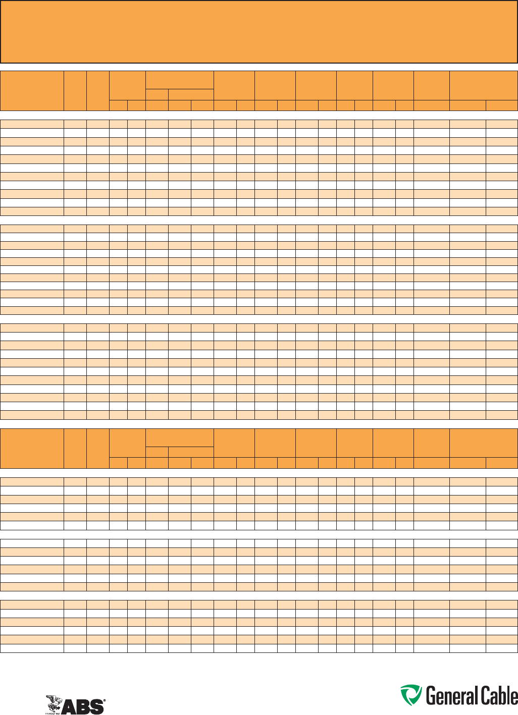
Phone: 888-593-3355
www.generalcable.com
CCW
®
Armored Instrumentation, Pairs/Triads, Individual and Overall Shield
ULTypeITC-HL/PLTC,PVC,300V,105°C,Sunlight-Resistant,DirectBurial
ULMarineShipboardCable,ABSCWCMC
SPEC 9250
April, 2011
CATALOG
NUMBER
COND.
SIZE
(AWG)
NO.
OF
PAIRS
INSULATION
THICKNESS
COMMUNICATION WIRE INNER JACKET
THICKNESS
NOMINAL
CORE O.D.
NOMINAL
ARMOR O.D.
JACKET
THICKNESS
NOMINAL
OVERALL O.D.
CROSS-
SECTIONAL
AREA¹
APPROXIMATE
NET WEIGHTSIZE INS. THICKNESS
mils mm AWG mils mm mils mm INCHES mm INCHES mm mils mm INCHES mm SQ. IN. LBS/1000 FT kg/1000 m
20 AWG 7W (0.52 mm²) INDIVIDUAL AND OVERALL SHIELDED PAIRS
9250.20021221 20 2 15 0.38 22 12 0.30 40 1.02 0.36 9.1 0.58 14.7 50 1.27 0.69 17.5 0.38 202 301
9250.20041221 20 4 15 0.38 22 12 0.30 50 1.27 0.43 10.9 0.62 15.7 50 1.27 0.73 18.5 0.42 239 355
9250.20061221 20 615 0.38 22 12 0.30 50 1.27 0.48 12.2 0.71 18.0 50 1.27 0.82 20.8 0.54 292 434
9250.20081221 20 8 15 0.38 22 12 0.30 50 1.27 0.53 13.5 0.75 19.1 50 1.27 0.86 21.8 0.59 323 481
9250.20101221 20 10 15 0.38 22 12 0.30 50 1.27 0.57 14.5 0.80 20.3 50 1.27 0.91 23.1 0.66 401 597
9250.20121221 20 12 15 0.38 22 12 0.30 60 1.52 0.63 16.0 0.84 21.3 50 1.27 0.95 24.1 0.72 439 653
9250.20161221 20 16 15 0.38 22 12 0.30 60 1.52 0.72 18.3 0.97 24.6 50 1.27 1.08 27.4 0.93 511 760
9250.20201221 20 20 15 0.38 22 12 0.30 60 1.52 0.81 20.6 1.06 26.9 50 1.27 1.17 29.7 1.09 593 882
9250.20241221 20 24 15 0.38 22 12 0.30 70 1.78 0.90 22.9 1.15 29.2 50 1.27 1.26 32.0 1.26 718 1,069
9250.20361221 20 36 15 0.38 22 12 0.30 70 1.78 1.04 26.4 1.34 34.0 50 1.27 1.45 36.8 1.67 925 1,377
9250.20501221 20 50 15 0.38 22 12 0.30 70 1.78 1.19 30.2 1.51 38.4 60 1.52 1.65 41.9 2.17 1,255 1,867
18 AWG 7W (0.82 mm²) INDIVIDUAL AND OVERALL SHIELDED PAIRS
9250.18021221 18 2 15 0.38 22 12 0.30 40 1.02 0.38 9.7 0.58 14.7 50 1.27 0.69 17.5 0.38 216 322
9250.18041221 18 4 15 0.38 22 12 0.30 50 1.27 0.49 12.4 0.71 18.0 50 1.27 0.82 20.8 0.54 278 414
9250.18061221 18 615 0.38 22 12 0.30 50 1.27 0.55 14.0 0.75 19.1 50 1.27 0.86 21.8 0.59 345 513
9250.18081221 18 8 15 0.38 22 12 0.30 50 1.27 0.60 15.2 0.80 20.3 50 1.27 0.92 23.4 0.67 397 590
9250.18101221 18 10 15 0.38 22 12 0.30 60 1.52 0.67 17.0 0.89 22.6 50 1.27 1.00 25.4 0.80 489 727
9250.18121221 18 12 15 0.38 22 12 0.30 60 1.52 0.71 18.0 0.93 23.6 50 1.27 1.04 26.4 0.86 540 803
9250.18161221 18 16 15 0.38 22 12 0.30 60 1.52 0.79 20.1 1.06 26.9 50 1.27 1.17 29.7 1.09 645 959
9250.18201221 18 20 15 0.38 22 12 0.30 60 1.52 0.88 22.4 1.15 29.2 50 1.27 1.26 32.0 1.26 794 1,181
9250.18241221 18 24 15 0.38 22 12 0.30 70 1.78 0.98 24.9 1.24 31.5 50 1.27 1.35 34.3 1.45 907 1,349
9250.18361221 18 36 15 0.38 22 12 0.30 70 1.78 1.15 29.2 1.47 37.3 50 1.27 1.58 40.1 1.99 1,227 1,826
9250.18501221 18 50 15 0.38 22 12 0.30 80 2.03 1.36 34.5 1.69 42.9 60 1.52 1.82 46.2 2.64 1,662 2,473
16 AWG 7W (1.31 mm²) INDIVIDUAL AND OVERALL SHIELDED PAIRS
9250.16021221 16 2 15 0.38 22 12 0.30 50 1.27 0.44 11.2 0.67 17.0 50 1.27 0.78 19.8 0.48 260 387
9250.16041221 16 4 15 0.38 22 12 0.30 50 1.27 0.52 13.2 0.71 18.0 50 1.27 0.82 20.8 0.54 334 496
9250.16061221 16 6 15 0.38 22 12 0.30 50 1.27 0.59 15.0 0.84 21.3 50 1.27 0.95 24.1 0.72 443 659
9250.16081221 16 8 15 0.38 22 12 0.30 60 1.52 0.69 17.5 0.93 23.6 50 1.27 1.04 26.4 0.86 515 767
9250.16101221 16 10 15 0.38 22 12 0.30 60 1.52 0.75 19.1 1.02 25.9 50 1.27 1.13 28.7 1.02 616 917
9250.16121221 16 12 15 0.38 22 12 0.30 60 1.52 0.81 20.6 1.06 26.9 50 1.27 1.17 29.7 1.09 684 1,019
9250.16161221 16 16 15 0.38 22 12 0.30 70 1.78 0.95 24.1 1.24 31.5 50 1.27 1.35 34.3 1.45 872 1,298
9250.16201221 16 20 15 0.38 22 12 0.30 70 1.78 1.03 26.2 1.34 34.0 50 1.27 1.45 36.8 1.67 1,024 1,524
9250.16241221 16 24 15 0.38 22 12 0.30 70 1.78 1.10 27.9 1.37 34.8 50 1.27 1.48 37.6 1.74 1,270 1,890
9250.16361221 16 36 15 0.38 22 12 0.30 80 2.03 1.29 32.8 1.60 40.6 60 1.52 1.73 43.9 2.38 1,712 2,547
9250.16501221 16 50 15 0.38 22 12 0.30 80 2.03 1.53 38.9 1.87 47.5 60 1.52 2.00 50.8 3.18 2,215 3,297
CATALOG
NUMBER
COND.
SIZE
(AWG)
NO.
OF
TRIADS
INSULATION
THICKNESS
COMMUNICATION WIRE INNER JACKET
THICKNESS
NOMINAL
CORE O.D.
NOMINAL
ARMOR O.D.
JACKET
THICKNESS
NOMINAL
OVERALL O.D.
CROSS-
SECTIONAL
AREA¹
APPROXIMATE
NET WEIGHT
SIZE INS. THICKNESS
mils mm AWG mils mm mils mm INCHES mm INCHES mm mils mm INCHES mm SQ. IN. LBS/1000 FT kg/1000 m
20 AWG 7W (0.52 mm²) INDIVIDUAL AND OVERALL SHIELDED TRIADS
9250.20041222 20 4 15 0.38 22 12 0.30 50 1.27 0.45 11.4 0.67 17.0 50 1.27 0.78 19.8 0.48 263 392
9250.20081222 20 8 15 0.38 22 12 0.30 50 1.27 0.56 14.2 0.80 20.3 50 1.27 0.91 23.1 0.66 376 560
9250.20121222 20 12 15 0.38 22 12 0.30 60 1.52 0.67 17.0 0.89 22.6 50 1.27 1.00 25.4 0.80 514 765
9250.20161222 20 16 15 0.38 22 12 0.30 60 1.52 0.77 19.6 1.02 25.9 50 1.27 1.13 28.7 1.02 616 917
9250.20241222 20 24 15 0.38 22 12 0.30 70 1.78 0.96 24.4 1.24 31.5 50 1.27 1.35 34.3 1.45 869 1,293
9250.20361222 20 36 15 0.38 22 12 0.30 70 1.78 1.11 28.2 1.42 36.1 50 1.27 1.53 38.9 1.86 1,139 1,696
18 AWG 7W (0.82 mm²) INDIVIDUAL AND OVERALL SHIELDED TRIADS
9250.18041222 18 4 15 0.38 22 12 0.30 50 1.27 0.54 13.7 0.75 19.1 50 1.27 0.86 21.8 0.59 320 477
9250.18081222 18 8 15 0.38 22 12 0.30 60 1.52 0.69 17.5 0.93 23.6 50 1.27 1.04 26.4 0.86 485 721
9250.18121222 18 12 15 0.38 22 12 0.30 60 1.52 0.79 20.1 1.06 26.9 50 1.27 1.17 29.7 1.09 645 959
9250.18161222 18 16 15 0.38 22 12 0.30 70 1.78 0.90 22.9 1.15 29.2 50 1.27 1.26 32.0 1.26 797 1,185
9250.18241222 18 24 15 0.38 22 12 0.30 70 1.78 1.06 26.9 1.34 34.0 50 1.27 1.45 36.8 1.67 1,119 1,665
9250.18361222 18 36 15 0.38 22 12 0.30 80 2.03 1.29 32.8 1.60 40.6 60 1.52 1.73 43.9 2.38 1,570 2,336
16 AWG 7W (1.31 mm²) INDIVIDUAL AND OVERALL SHIELDED TRIADS
9250.16041222 16 4 15 0.38 22 12 0.30 50 1.27 0.58 14.7 0.80 20.3 50 1.27 0.91 23.1 0.58 392 583
9250.16081222 16 8 15 0.38 22 12 0.30 60 1.52 0.79 20.1 1.02 25.9 50 1.27 1.13 28.7 1.02 621 924
9250.16121222 16 12 15 0.38 22 12 0.30 70 1.78 0.95 24.1 1.19 30.2 50 1.27 1.30 33.0 1.34 879 1,308
9250.16161222 16 16 15 0.38 22 12 0.30 70 1.78 1.04 26.4 1.34 34.0 50 1.27 1.45 36.8 1.67 1,074 1,598
9250.16241222 16 24 15 0.38 22 12 0.30 80 2.03 1.27 32.3 1.60 40.6 60 1.52 1.73 43.9 2.38 1,605 2,389
9250.16361222 16 36 15 0.38 22 12 0.30 80 2.03 1.49 37.8 1.83 46.5 60 1.52 1.96 49.8 3.06 2,161 3,216
Dimensionsandweightsarenominal;subjecttoindustrytolerances.
¹Cross-sectionalareaforcabletrayfillisinaccordancewithNEC®Section392.22.
Phone: 888-593-3355
www.generalcable.com
Overall Jacket:
•Flame-retardant,moisture-and
sunlight-resistantPolyvinylChloride
(PVC)perULStandard1569,black
•Lowtemperatureperformancemeets
ASTMD746brittlenesstemperatureat
orbelow-40°C
Applications:
•CCWarmored600voltInstrumentation
cableswithanoverallshieldprovide
superiorprotectionandreliability
againstphysicaldamageforusein
instrumentationandprocesscontrol
applicationswhereshieldingagainst
externalEMIisrequired
•ForuseinClass1remote-controland
signalcircuitsinaccordancewithNEC
Article725
•RecognizedforuseinClassI,IIand
III,Divisions1and2;orClassI,Zones
1and2hazardouslocationsperNEC
Articles501,502,503and505
•Installedindoorsoroutdoors,inwetor
drylocations,inaraceway,asaerial
cableonamessenger,incabletrays,
or for direct burial
•Recognizedforuseonfixedor
floatingoffshorepetroleumfacilities
asrecommendedbytheAmerican
PetroleumInstitute
Features:
•CCWarmorprovidessuperior
mechanicalprotectionandan
imperviousbarriertomoisture,gas
andliquids
•CCWarmorprovidesEMIshielding
performance
•Meetscoldimpactat-40°C
Specifications:
Design Adherence:
•UL83ThermoplasticInsulatedWire
and Cables
•UL1569MetalCladCables
•UL2225CablesandCableFittingsfor
UseinHazardousLocations
•UL1309/CSAC22.2No.245Marine
ShipboardCable
Flame Tests:
•ICEAT-29-520(210,000BTU/hr)
•IEEE383(70,000BTU/hr)
•CSAFT4
•IEEE1202(70,000BTU/hr)
•UL1581(70,000BTU/hr)
•IEC60332-3Cat.A
Compliances:
•ULTypeMC-HL,CTUSE,SUNRES,
DIRBUR,-40°C,ULFile#E69797
•ULListedMarineShipboard,ULFile#
E85994
•AmericanBureauofShipping(ABS)
ListedforCWCMC
Product Construction:
Conductor:
•BareannealedcopperperASTMB3
•ClassBstrandingperASTMB8
Insulation:
•Flame-retardantPolyvinylChloride
(PVC)insulationandnyloncovering,
rated90°CperULStandard83
•Color-codedperICEAMethod1:
pairs–blackandwhite;triads–black,
whiteandred.Eachconductorineach
pairortriadisprintedalphanumerically
foreasyidentification
Cable Assembly:
•Individualpairsortriadsarecabled
togetherwithaleft-handlay
Overall Shield:
•Flexfoil®aluminum/polyestertapeshield
providing100%coverage
•Strandedtinnedcopperdrainwire,
samesizeasinsulatedconductors
Inner Jacket:
•Flame-retardantPolyvinylChloride
(PVC)perULStandard1569,black
•Lowtemperatureperformancemeets
ASTMD746brittlenesstemperatureat
orbelow-40°C
•Nylonripcordtofacilitatejacket
removal
CCW Armor:
•Impervious,continuouslyweldedand
corrugatedaluminumalloysheathper
ULStandards1569and2225
•CCWarmorconductivitymeetsthe
groundingrequirementsofNECArticle
250
CCW
®
Armored Instrumentation, Pairs/Triads, Overall Shield
ULTypeMC-HL,PVC/Nylon,600V,90°C,CableTrayUse,Sunlight-Resistant,DirectBurial
ULMarineShipboardCable,ABSCWCMC
SPEC 9325
February, 2011
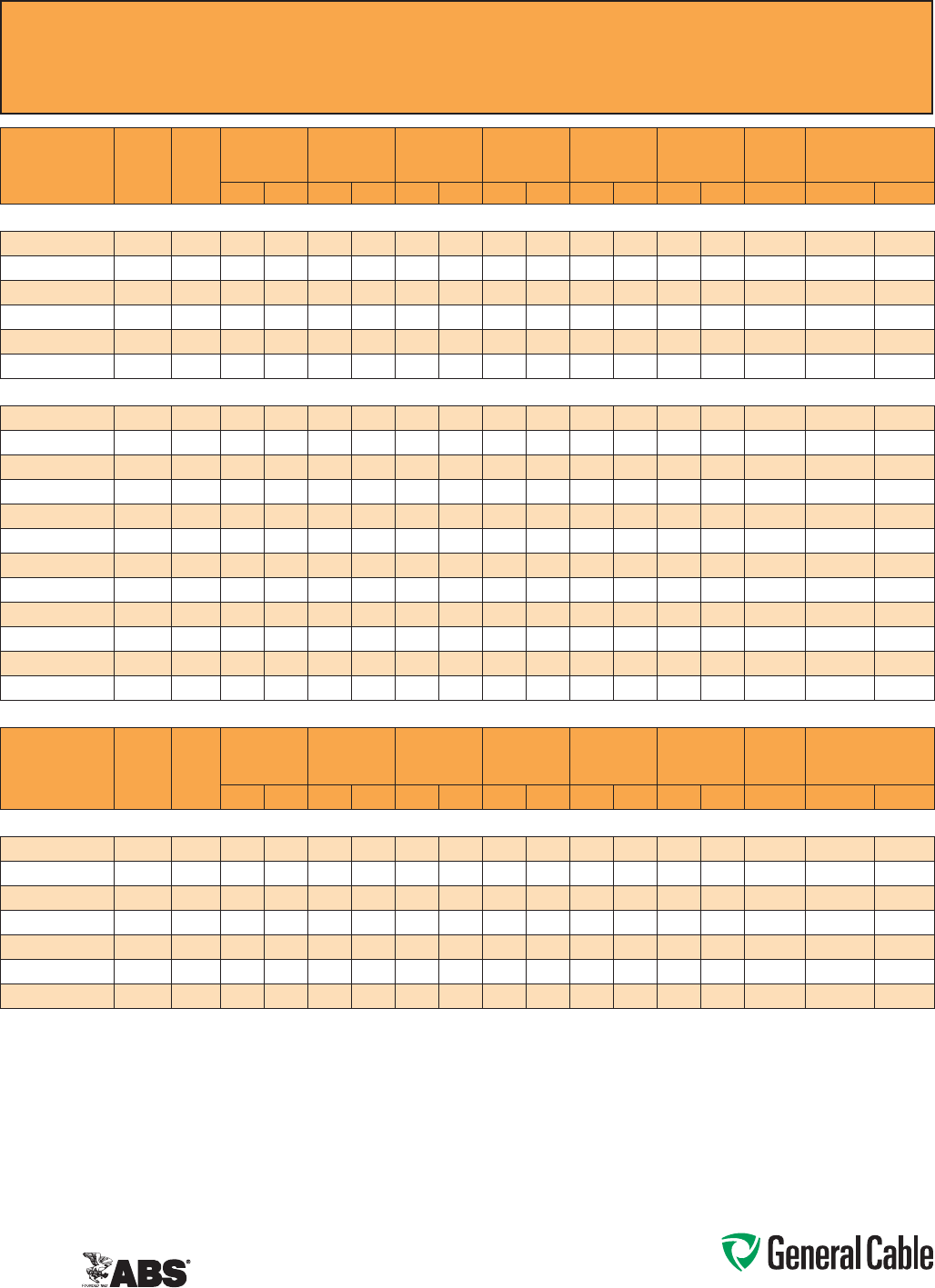
Phone: 888-593-3355
www.generalcable.com
CCW
®
Armored Instrumentation, Pairs/Triads, Overall Shield
ULTypeMC-HL,PVC/Nylon,600V,90°C,CableTrayUse,Sunlight-Resistant,DirectBurial
ULMarineShipboardCable,ABSCWCMC
SPEC 9325
February, 2011
CATALOG
NUMBER
COND.
SIZE
(AWG)
NO. OF
PAIRS
INSULATION
THICKNESS
INNER JACKET
THICKNESS
NOMINAL
CORE O.D.
NOMINAL
ARMOR O.D.
JACKET
THICKNESS
NOMINAL
OVERALL O.D.
CROSS-
SECTIONAL
AREA¹
APPROXIMATE NET
WEIGHT
mils mm mils mm INCHES mm INCHES mm mils mm INCHES mm SQ. IN. LBS/1000 FT kg/1000 m
18 AWG 7W (0.82 mm²) OVERALL SHIELDED PAIRS
9325.18020001 18 2 19 0.48 40 1.02 0.41 10.4 0.59 15.0 50 1.27 0.70 17.8 0.39 222 330
9325.18040001 18 4 19 0.48 40 1.02 0.48 12.2 0.65 16.5 50 1.27 0.75 19.1 0.45 268 399
9325.18080001 18 8 19 0.48 50 1.27 0.60 15.2 0.82 20.8 50 1.27 0.92 23.4 0.67 420 625
9325.18120001 18 12 19 0.48 50 1.27 0.78 19.8 1.00 25.4 50 1.27 1.10 27.9 0.96 560 833
9325.18160001 18 16 19 0.48 50 1.27 0.81 20.6 1.12 28.4 50 1.27 1.23 31.2 1.20 706 1,051
9325.18240001 18 24 19 0.48 50 1.27 1.08 27.4 1.39 35.3 50 1.27 1.49 37.8 1.77 969 1,442
16 AWG 7W (1.31 mm²) OVERALL SHIELDED PAIRS
9325.16010001 16 1 19 0.48 60 1.52 0.35 8.9 0.53 13.5 50 1.27 0.64 16.3 0.33 185 275
9325.16020001 16 219 0.48 40 1.02 0.38 9.7 0.58 14.7 50 1.27 0.69 17.5 0.38 246 366
9325.16040001 16 419 0.48 40 1.02 0.47 11.9 0.71 18.0 50 1.27 0.82 20.8 0.54 333 495
9325.16060001 16 6 19 0.48 50 1.27 0.58 14.7 0.80 20.3 50 1.27 0.91 23.1 0.66 405 603
9325.16080001 16 819 0.48 50 1.27 0.66 16.8 0.89 22.6 50 1.27 1.00 25.4 0.80 466 694
9325.16100001 16 10 19 0.48 50 1.27 0.76 19.3 1.02 25.9 50 1.27 1.13 28.7 1.02 556 827
9325.16120001 16 12 19 0.48 50 1.27 0.80 20.3 1.06 26.9 50 1.27 1.17 29.7 1.09 604 899
9325.16160001 16 16 19 0.48 50 1.27 0.87 22.1 1.15 29.2 50 1.27 1.26 32.0 1.26 799 1,189
9325.16200001 16 20 19 0.48 50 1.27 0.98 24.9 1.29 32.8 50 1.27 1.40 35.6 1.56 929 1,383
9325.16240001 16 24 19 0.48 50 1.27 1.08 27.4 1.37 34.8 50 1.27 1.48 37.6 1.74 1,040 1,548
9325.16360001 16 36 19 0.48 50 1.27 1.32 33.5 1.64 41.7 60 1.52 1.78 45.2 2.52 1,445 2,151
9325.16500001 16 50 19 0.48 50 1.27 1.48 37.6 1.83 46.5 60 1.52 1.96 49.8 3.06 1,897 2,823
CATALOG
NUMBER
COND.
SIZE
(AWG)
NO. OF
TRIADS
INSULATION
THICKNESS
INNER JACKET
THICKNESS
NOMINAL
CORE O.D.
NOMINAL
ARMOR O.D.
OVERALL
JACKET
THICKNESS
NOMINAL
OVERALL O.D.
CROSS-
SECTIONAL
AREA¹
APPROXIMATE NET
WEIGHT
mils mm mils mm INCHES mm INCHES mm mils mm INCHES mm SQ. IN. LBS/1000 FT kg/1000 m
16 AWG 7W (1.31 mm²) OVERALL SHIELDED TRIADS
9325.16010002 16 1 19 0.48 50 1.27 0.35 8.9 0.53 13.5 50 1.27 0.64 16.3 0.33 195 290
9325.16040002 16 419 0.48 40 1.02 0.51 13.0 0.71 18.0 50 1.27 0.82 20.8 0.54 407 606
9325.16080002 16 819 0.48 50 1.27 0.71 18.0 0.93 23.6 50 1.27 1.04 26.4 0.86 617 918
9325.16120002 16 12 19 0.48 50 1.27 0.85 21.6 1.11 28.2 50 1.27 1.22 31.0 1.18 897 1,334
9325.16160002 16 16 19 0.48 50 1.27 0.93 23.6 1.19 30.2 50 1.27 1.30 33.0 1.34 1,161 1,727
9325.16240002 16 24 19 0.48 50 1.27 1.16 29.5 1.47 37.3 50 1.27 1.58 40.1 1.99 1,581 2,353
9325.16360002 16 36 19 0.48 50 1.27 1.42 36.1 1.74 44.2 60 1.52 1.87 47.5 2.78 2,142 3,188
Dimensionsandweightsarenominal;subjecttoindustrytolerances.
¹Cross-sectionalareaforcabletrayfillisinaccordancewithNEC®Section392.22.
Phone: 888-593-3355
www.generalcable.com
CCW
®
Armored Instrumentation, Pairs/Triads, Individual and Overall Shield
ULTypeMC-HL,PVC/Nylon,600V,90°C,CableTrayUse,Sunlight-Resistant,DirectBurial
ULMarineShipboardCable,ABSCWCMC
SPEC 9350
February, 2011
CCW Armor:
•Impervious,continuouslyweldedand
corrugatedaluminumalloysheathper
ULStandards1569and2225
•CCWarmorconductivitymeetsthe
groundingrequirementsofNECArticle
250
Overall Jacket:
•Flame-retardant,moisture-and
sunlight-resistantPolyvinylChloride
(PVC)perULStandard1569,black
•Lowtemperatureperformancemeets
ASTMD746brittlenesstemperatureat
orbelow-40°C
Applications:
•CCWarmored600voltInstrumentation
cableswithindividuallyshieldedpairs
ortriadsandanoverallshieldprovide
superiorprotectionandreliability
againstphysicaldamageforusein
instrumentationandprocesscontrol
applicationswhereshieldingagainst
bothexternalEMIandEMIbetween
groupsisrequired
•ForuseinClass1remote-controland
signalcircuitsinaccordancewithNEC
Article725
•RecognizedforuseinClassI,IIand
III,Divisions1and2;orClassI,Zones
1and2hazardouslocationsperNEC
Articles501,502,503and505
•Installedindoorsoroutdoors,inwetor
drylocations,inaraceway,asaerial
cableonamessenger,incabletrays,
or for direct burial
•Recognizedforuseonfixedor
floatingoffshorepetroleumfacilities
asrecommendedbytheAmerican
PetroleumInstitute
Features:
•CCWarmorprovidessuperior
mechanicalprotectionandan
imperviousbarriertomoisture,gas
andliquids
•CCWarmorprovidesEMIshielding
performance
•Meetscoldimpactat-40°C
Specifications:
Design Adherence:
•UL83ThermoplasticInsulatedWire
and Cables
•UL1569MetalCladCables
•UL2225CablesandCableFittingsfor
UseinHazardousLocations
•UL1309/CSAC22.2No.245Marine
ShipboardCable
Flame Tests:
•ICEAT-29-520(210,000BTU/hr)
•IEEE383(70,000BTU/hr)
•CSAFT4
•IEEE1202(70,000BTU/hr)
•UL1581(70,000BTU/hr)
•IEC60332-3Cat.A
Compliances:
•ULTypeMC-HL,CTUSE,SUNRES,
DIRBUR,-40°C,ULFile#E69797
•ULListedMarineShipboard,ULFile#
E85994
•AmericanBureauofShipping(ABS)
ListedforCWCMC
Product Construction:
Conductor:
•BareannealedcopperperASTMB3
•ClassBstrandingperASTMB8
Insulation:
•Flame-retardantPolyvinylChloride
(PVC)insulationandnyloncovering,
rated90°CperULStandard83
•Color-codedperICEAMethod1:
pairs–blackandwhite;triads–black,
whiteandred.Eachconductorineach
pairortriadisprintedalphanumerically
foreasyidentification
Shielded Pairs/Triads:
•Isolatedandindividuallytwistedpairs
ortriadswithaFlexfoil®aluminum/
polyestertapeshieldproviding100%
coverage
•Strandedtinnedcopperdrainwire,two
sizessmallerthaninsulatedconductors
Cable Assembly:
•Individuallyshieldedpairsortriadsare
cabledtogetherwithaleft-handlay
Overall Shield:
•Flexfoil®aluminum/polyestertapeshield
providing100%coverage
•Strandedtinnedcopperdrainwire,
samesizeasinsulatedconductors
Inner Jacket:
•Flame-retardantPolyvinylChloride
(PVC)perULStandard1569,black
•Lowtemperatureperformancemeets
ASTMD746brittlenesstemperatureat
orbelow-40°C
•Nylonripcordtofacilitatejacket
removal
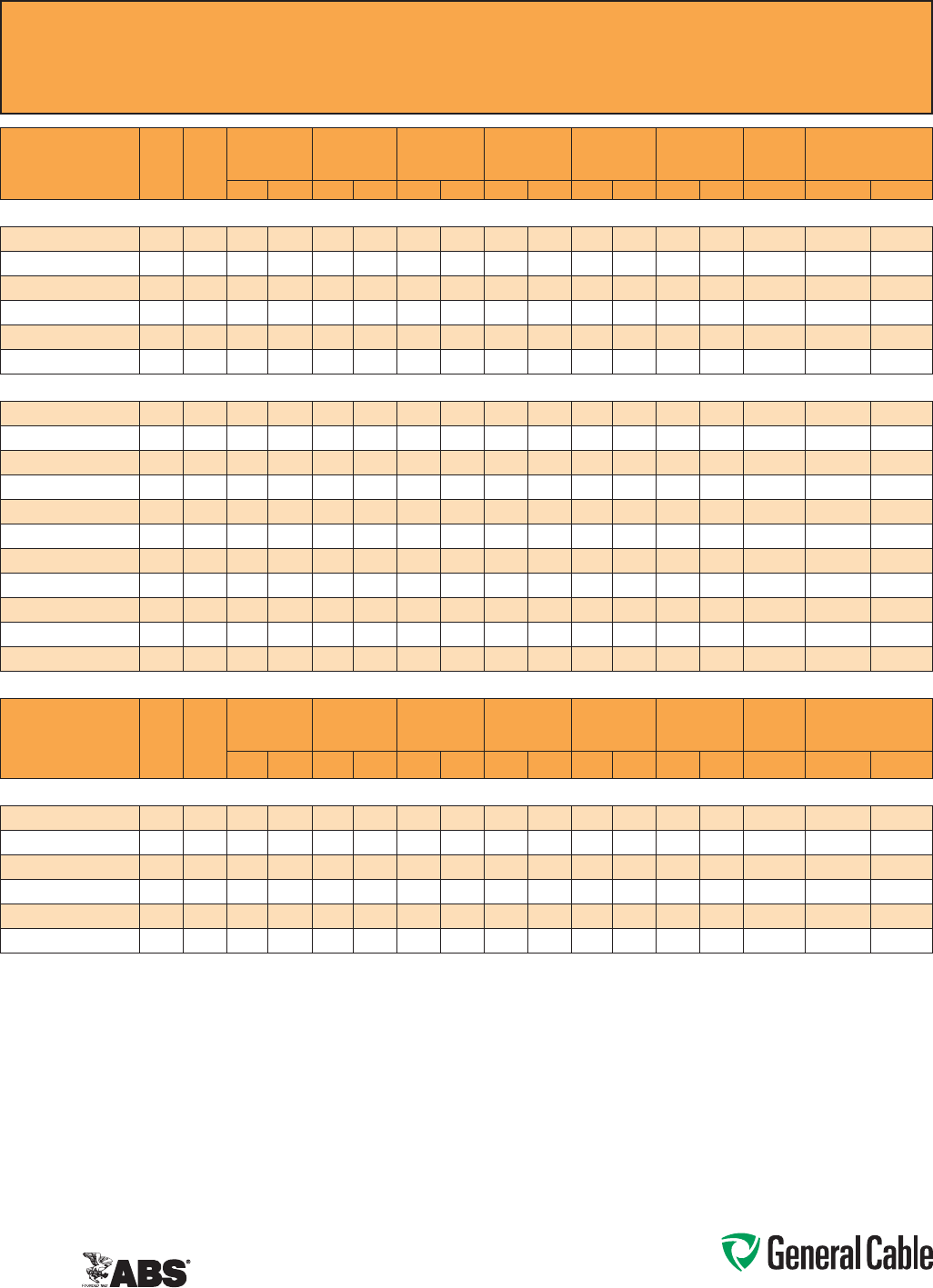
Phone: 888-593-3355
www.generalcable.com
CCW
®
Armored Instrumentation, Pairs/Triads, Individual and Overall Shield
ULTypeMC-HL,PVC/Nylon,600V,90°C,CableTrayUse,Sunlight-Resistant,DirectBurial
ULMarineShipboardCable,ABSCWCMC
SPEC 9350
February, 2011
CATALOG
NUMBER
COND.
SIZE
(AWG)
NO. OF
PAIRS
INSULATION
THICKNESS
INNER JACKET
THICKNESS
NOMINAL
CORE O.D.
NOMINAL
ARMOR O.D.
OVERALL
JACKET
THICKNESS
NOMINAL
OVERALL O.D.
CROSS-
SECTIONAL
AREA¹
APPROXIMATE
NET WEIGHT
mils mm mils mm INCHES mm INCHES mm mils mm INCHES mm SQ. IN. LBS/1000 FT kg/1000 m
18 AWG 7W (0.82 mm²) INDIVIDUAL AND OVERALL SHIELDED PAIRS
9350.18020001 18 2 19 0.48 40 1.02 0.41 10.4 0.59 15.0 50 1.27 0.70 17.8 0.39 225 335
9350.18040001 18 4 19 0.48 40 1.02 0.48 12.2 0.65 16.5 50 1.27 0.75 19.1 0.45 300 446
9350.18080001 18 8 19 0.48 50 1.27 0.60 15.2 0.82 20.8 50 1.27 0.92 23.4 0.67 450 670
9350.18120001 18 12 19 0.48 50 1.27 0.78 19.8 1.00 25.4 50 1.27 1.10 27.9 0.96 580 863
9350.18160001 18 16 19 0.48 50 1.27 0.81 20.6 1.12 28.4 50 1.27 1.23 31.2 1.20 760 1,131
9350.18240001 18 24 19 0.48 50 1.27 1.08 27.4 1.39 35.3 50 1.27 1.49 37.8 1.77 1,050 1,563
16 AWG 7W (1.31 mm²) INDIVIDUAL AND OVERALL SHIELDED PAIRS
9350.16020001 16 219 0.48 40 1.02 0.45 11.4 0.67 17.0 50 1.27 0.78 19.8 0.48 239 355
9350.16040001 16 419 0.48 50 1.27 0.56 14.2 0.80 20.3 50 1.27 0.91 23.1 0.66 342 509
9350.16060001 16 6 19 0.48 50 1.27 0.66 16.8 0.89 22.6 50 1.27 1.00 25.4 0.80 429 639
9350.16080001 16 819 0.48 50 1.27 0.70 17.8 0.93 23.6 50 1.27 1.04 26.4 0.86 502 747
9350.16100001 16 10 19 0.48 50 1.27 0.79 20.1 1.06 26.9 50 1.27 1.17 29.7 1.09 613 912
9350.16120001 16 12 19 0.48 50 1.27 0.85 21.6 1.11 28.2 50 1.27 1.22 31.0 1.18 687 1,023
9350.16160001 16 16 19 0.48 50 1.27 0.98 24.9 1.29 32.8 50 1.27 1.40 35.6 1.56 859 1,278
9350.16200001 16 20 19 0.48 50 1.27 1.06 26.9 1.34 34.0 50 1.27 1.45 36.8 1.67 997 1,483
9350.16240001 16 24 19 0.48 50 1.27 1.12 28.4 1.42 36.1 50 1.27 1.53 38.9 1.86 1,140 1,697
9350.16360001 16 36 19 0.48 50 1.27 1.37 34.8 1.69 42.9 60 1.52 1.82 46.2 2.64 1,618 2,407
9350.16500001 16 50 19 0.48 50 1.27 1.57 39.9 1.92 48.8 60 1.52 2.05 52.1 3.34 2,166 3,224
CATALOG
NUMBER
COND.
SIZE
(AWG)
NO. OF
TRIADS
INSULATION
THICKNESS
INNER JACKET
THICKNESS
NOMINAL
CORE O.D.
NOMINAL
ARMOR O.D.
OVERALL
JACKET
THICKNESS
NOMINAL
OVERALL O.D.
CROSS-
SECTIONAL
AREA¹
APPROXIMATE
NET WEIGHT
mils mm mils mm INCHES mm INCHES mm mils mm INCHES mm SQ. IN. LBS/1000 FT kg/1000 m
16 AWG 7W (1.31 mm²) INDIVIDUAL AND OVERALL SHIELDED TRIADS
9350.16040002 16 419 0.48 50 1.27 0.61 15.5 0.84 21.3 50 1.27 0.95 24.1 0.72 403 600
9350.16080002 16 819 0.48 50 1.27 0.82 20.8 1.06 26.9 50 1.27 1.17 29.7 1.09 650 967
9350.16120002 16 12 19 0.48 50 1.27 0.98 24.9 1.24 31.5 50 1.27 1.35 34.3 1.45 853 1,269
9350.16160002 16 16 19 0.48 50 1.27 1.10 27.9 1.37 34.8 50 1.27 1.48 37.6 1.74 1,079 1,606
9350.16240002 16 24 19 0.48 50 1.27 1.33 33.8 1.64 41.7 60 1.52 1.78 45.2 2.52 1,515 2,254
9350.16360002 16 36 19 0.48 50 1.27 1.58 40.1 1.96 49.8 60 1.52 2.09 53.1 3.48 2,184 3,250
Dimensionsandweightsarenominal;subjecttoindustrytolerances.
¹Cross-sectionalareaforcabletrayfillisinaccordancewithNEC®Section392.22.

Phone: 888-593-3355
www.generalcable.com
SPEC 9500
February, 2011
Applications:
•CCWarmoredControlcablesoffer
aneconomical,ruggedandreliable
alternativetolabor-intensivecablein
conduitwiringmethods
•ForuseinClassI,IIandIII,Divisions
1and2;andClassI,Zones1and2
hazardouslocationsperNECArticles
501,502,503and505
•Foruseasservices,feedersand
branchcircuitsforpower,lighting,
control,andsignalcircuitsin
accordancewithNECArticles330
and725
•Installedindoorsoroutdoors,wet
ordrylocations,directlyburied,
embeddedinconcrete,inaraceway,
asaerialcableonamessenger,
incabletrays,orasexposedruns
securedtosupportsinaccordance
withNECArticle330
•Recognizedforuseonfixedor
floatingoffshorepetroleumfacilities
asrecommendedbytheAmerican
PetroleumInstitute
Features:
•CCWarmorprovidesanimpervious
barriertomoisture,gasandliquids
•CCWarmorprovidesEMIshielding
performance
•Factoryassembledandtestedcable
foruseasanalternativetocablein
conduitwiringsystems
•Meetscoldimpactat-40°C
•90˚Ccontinuousoperating
temperature,wetordry
•130˚Cemergencyrating
•250˚Cshortcircuitrating
CCW
®
Armored Control With Grounding Conductor
ULTypeMC-HL,XLPE,600V,90°C,CableTrayUse,Sunlight-Resistant,DirectBurial
ULMarineShipboardCable,ABSCWCMC
Product Construction:
Conductor:
•BareannealedcopperperASTMB3
•CompressedClassBstrandingper
ASTMB8
Insulation:
•Cross-linkedPolyethylene(XLPE)
insulationperICEAS-73-532andUL
44,ListedXHHW-2
•Color-codedperICEAMethod1,Table
E2,full-coloredinsulationwithstripes
•Color-codedperCSAC22.2No.123
whereapplicable
Grounding Conductor:
•ClassBstrandedbareannealed
copperperASTMB3andB8
•Cross-linkedPolyethylene(XLPE)
insulation,green
•SizedinaccordancewithNECTable
250.122
Cable Assembly:
•Insulatedconductorsandgrounding
wirearecabledtogetherwithnon-
hygroscopicfillerswhenrequired
•Abindertape,whenrequired,is
appliedoverthecabledcore
CCW Armor:
•Impervious,continuouslyweldedand
corrugatedaluminumalloysheathper
UL1569andUL2225
•CCWarmorconductivitymeetsthe
groundingrequirementsofNEC
Article250
Jacket:
•Flame-retardant,moisture-and
sunlight-resistantPolyvinylChloride
(PVC),black
•Lowtemperatureperformancemeets
ASTMD746brittlenesstemperatureat
orbelow-40°C
•MeetsCSALowAcidGas
requirements
Specifications:
Design Adherence:
•ICEAS-73-532/WC57Standardfor
Control,ThermocoupleExtensionand
InstrumentationCables
•UL44RubberInsulatedWiresand
Cables
•UL1569MetalCladCables
•UL2225CablesandCableFittingsfor
UseinHazardousLocations
•UL1309MarineShipboardCable
•CSAC22.2No.123MetalSheathed
Cables
•CSAC22.2No.174CablesandCable
GlandsforUseinHazardousLocations
Flame Tests:
•ICEAT-29-520(210,000BTU/hr)
•IEEE383(70,000BTU/hr)
•CSAFT4
•IEEE1202(70,000BTU/hr)
•UL1581(70,000BTU/hr)
•IEC60332-3Cat.A
Compliances:
•ULTypeMC-HL,XHHW-2,SUNRES,
CTUSE,DIRBUR,-40°C,ULFile
#E69797
•ULListedMarineShipboard,ULFile
#E85994
•AmericanBureauofShipping(ABS)
ListedforCWCMC
•CSACertifiedTypeRA90,XLPE,
HL,SR,FT4,and-40°C,CSAFile
#7319
1
StandardcablesarealsomarkedCSATypeRA90,
exceptfour(4)conductorcableswhichrequireadifferent
colorcode,whichmaybespecial-ordered.
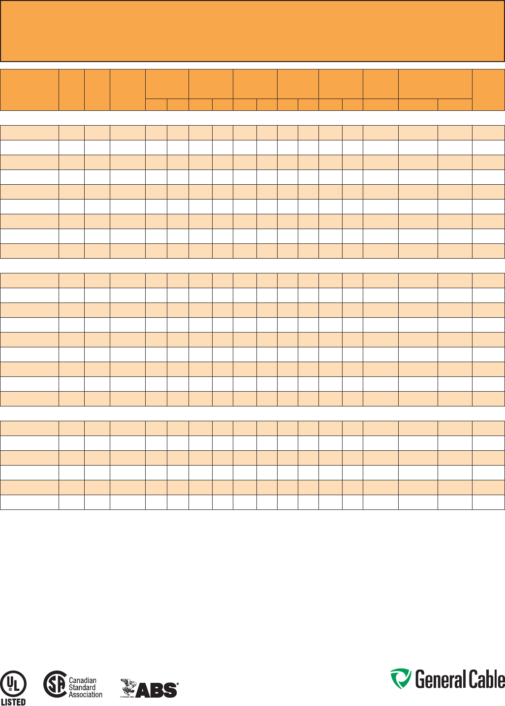
Phone: 888-593-3355
www.generalcable.com
SPEC 9500
February, 2011
CATALOG
NUMBER
COND.
SIZE
(AWG)
NO. OF
COND.
GREEN
INSULATED
GROUND
(AWG)
INSULATION
THICKNESS
NOMINAL
CORE O.D.
NOMINAL
ARMOR O.D.
JACKET
THICKNESS
NOMINAL
OVERALL O.D.
CROSS-
SECTIONAL
AREA¹
APPROXIMATE NET
WEIGHT
90°C
AMPACITY
@ 30°C
AMBIENT²mils mm INCHES mm INCHES mm mils mm INCHES mm SQ. IN. LBS/1000 FT kg/1000 m
14 AWG 7W (2.08 mm²) MULTI-CONDUCTOR CONTROL CABLE WITH GREEN INSULATED GROUNDING CONDUCTOR
9500.01402114 14 2 14 30 0.76 0.30 7.6 0.49 12.4 50 1.27 0.60 15.2 0.29 163 243 15
9500.01403114 14 314 30 0.76 0.33 8.4 0.53 13.5 50 1.27 0.64 16.3 0.33 192 286 15
9500.01404114 14 4 14 30 0.76 0.37 9.4 0.58 14.7 50 1.27 0.69 17.5 0.38 222 330 15
9500.01405114 14 5 14 30 0.76 0.39 9.9 0.60 15.2 50 1.27 0.71 18.0 0.40 245 365 15
9500.01406114 14 614 30 0.76 0.41 10.4 0.62 15.7 50 1.27 0.73 18.5 0.42 267 397 15
9500.01408114 14 8 14 30 0.76 0.49 12.4 0.71 18.0 50 1.27 0.82 20.8 0.54 321 478 15
9500.01411114 14 11 14 30 0.76 0.57 14.5 0.80 20.3 50 1.27 0.91 23.1 0.66 395 588 12
9500.01418114 14 18 14 30 0.76 0.69 17.5 0.93 23.6 50 1.27 1.04 26.4 0.86 554 824 12
9500.01436114 14 36 14 30 0.76 0.97 24.6 1.24 31.5 50 1.27 1.35 34.3 1.45 948 1,411 10
12 AWG 7W (3.31 mm²) MULTI-CONDUCTOR CONTROL CABLE WITH GREEN INSULATED GROUNDING CONDUCTOR
9500.01202112 12 2 12 30 0.76 0.34 8.6 0.53 13.5 50 1.27 0.64 16.3 0.33 200 298 20
9500.01203112 12 312 30 0.76 0.37 9.4 0.58 14.7 50 1.27 0.69 17.5 0.38 239 356 20
9500.01204112 12 4 12 30 0.76 0.45 11.4 0.67 17.0 50 1.27 0.78 19.8 0.48 310 461 20
9500.01205112 12 5 12 30 0.76 0.46 11.7 0.67 17.0 50 1.27 0.78 19.8 0.48 324 482 20
9500.01206112 12 612 30 0.76 0.47 11.9 0.67 17.0 50 1.27 0.78 19.8 0.48 338 503 20
9500.01208112 12 8 12 30 0.76 0.56 14.2 0.80 20.3 50 1.27 0.91 23.1 0.66 426 634 20
9500.01211112 12 11 12 30 0.76 0.65 16.5 0.89 22.6 50 1.27 1.00 25.4 0.80 519 772 15
9500.01218112 12 18 12 30 0.76 0.78 19.8 1.02 25.9 50 1.27 1.13 28.7 1.02 739 1,100 15
9500.01236112 12 36 12 30 0.76 1.10 27.9 1.37 34.8 50 1.27 1.48 37.6 1.74 1,302 1,938 12
10 AWG 7W (5.26 mm²) MULTI-CONDUCTOR CONTROL CABLE WITH GREEN INSULATED GROUNDING CONDUCTOR
9500.01002110 10 210 30 0.76 0.39 9.9 0.58 14.7 50 1.27 0.69 17.5 0.38 253 377 30
9500.01003110 10 3 10 30 0.76 0.41 10.4 0.62 15.7 50 1.27 0.73 18.5 0.42 303 451 30
9500.01004110 10 410 30 0.76 0.45 11.4 0.67 17.0 50 1.27 0.78 19.8 0.48 348 518 30
9500.01006110 10 6 10 30 0.76 0.54 13.7 0.75 19.1 50 1.27 0.86 21.8 0.59 451 671 28
9500.01008110 10 810 30 0.76 0.65 16.5 0.89 22.6 50 1.27 1.00 25.4 0.80 568 845 28
9500.01011110 10 11 10 30 0.76 0.75 19.1 0.97 24.6 50 1.27 1.08 27.4 0.93 704 1,048 20
Dimensionsandweightsarenominal;subjecttoindustrytolerances.
¹Cross-sectionalareaforcabletrayfillisinaccordancewithNECSection392.22.
²AmpacitiesinaccordancewithNECArticle310andTable310.15(B)(16).
Note:Standardcableswithuptoandincludingsix(6)conductorsarealsomarkedCSATypeRA90.Allothersarespecialorder.
CCW
®
Armored Control With Grounding Conductor
ULTypeMC-HL,XLPE,600V,90°C,CableTrayUse,Sunlight-Resistant,DirectBurial
ULMarineShipboardCable,ABSCWCMC

Phone: 888-593-3355
www.generalcable.com
SPEC 9510
February, 2011
Applications:
•CCWarmoredControlcablesoffer
aneconomical,ruggedandreliable
alternativetolabor-intensivecablein
conduitwiringmethods
•ForuseinClassI,IIandIII,Divisions
1and2;andClassI,Zones1and2
hazardouslocationsperNECArticles
501,502,503and505
•Foruseasservices,feedersand
branchcircuitsforpower,lighting,
control,andsignalcircuitsin
accordancewithNECArticles330
and725
•Installedindoorsoroutdoors,wet
ordrylocations,directlyburied,
embeddedinconcrete,inaraceway,
asaerialcableonamessenger,
incabletrays,orasexposedruns
securedtosupportsinaccordance
withNECArticle330
•Recognizedforuseonfixedor
floatingoffshorepetroleumfacilities
asrecommendedbytheAmerican
PetroleumInstitute
Features:
•CCWarmorprovidesanimpervious
barriertomoisture,gasandliquids
•CCWarmorprovidesEMIshielding
performance
•Factoryassembledandtestedcable
foruseasanalternativetocablein
conduitwiringsystems
•Meetscoldimpactat-40°C
•90˚Ccontinuousoperating
temperature,wetordry
•130˚Cemergencyrating
•250˚Cshortcircuitrating
CCW
®
Armored Control With Bare Grounding Conductor
ULTypeMC-HL,XLPE,600V,90°C,CableTrayUse,Sunlight-Resistant,DirectBurial
ULMarineShipboardCable,ABSCWCMC
Product Construction:
Conductor:
•BareannealedcopperperASTMB3
•CompressedClassBstrandingper
ASTMB8
Insulation:
•Cross-linkedPolyethylene(XLPE)
insulationperICEAS-73-532andUL
44,ListedXHHW-2
•Color-codedperICEAMethod1,Table
E2,full-coloredinsulationwithstripes
•Color-codedperCSAC22.2No.123
whereapplicable
Grounding Conductor:
•ClassBstrandedbareannealed
copperperASTMB3andB8
•SizedinaccordancewithNECTable
250.122
Cable Assembly:
•Insulatedconductorsandgrounding
wirearecabledtogetherwithnon-
hygroscopicfillerswhenrequired
•Abindertape,whenrequired,is
appliedoverthecabledcore
CCW Armor:
•Impervious,continuouslyweldedand
corrugatedaluminumalloysheathper
UL1569andUL2225
•CCWarmorconductivitymeetsthe
groundingrequirementsofNEC
Article250
Jacket:
•Flame-retardant,moisture-and
sunlight-resistantPolyvinylChloride
(PVC),black
•Lowtemperatureperformancemeets
ASTMD746brittlenesstemperatureat
orbelow-40°C
•MeetsCSALowAcidGas
requirements
Specifications:
Design Adherence:
•ICEAS-73-532/WC57Standardfor
Control,ThermocoupleExtensionand
InstrumentationCables
•UL44RubberInsulatedWiresand
Cables
•UL1569MetalCladCables
•UL2225CablesandCableFittingsfor
UseinHazardousLocations
•UL1309MarineShipboardCable
•CSAC22.2No.123MetalSheathed
Cables
Flame Tests:
•ICEAT-29-520(210,000BTU/hr)
•IEEE383(70,000BTU/hr)
•CSAFT4
•IEEE1202(70,000BTU/hr)
•UL1581(70,000BTU/hr)
•IEC60332-3Cat.A
Compliances:
•ULTypeMC-HL,XHHW-2,SUNRES,
CTUSE,DIRBUR,-40°C,ULFile
#E69797
•ULListedMarineShipboard,ULFile
#E85994
•AmericanBureauofShipping(ABS)
ListedforCWCMC
•CSACertified1TypeRA90,XLPE,SR,
FT4,and-40°C,CSAFile#7319
1
StandardcablesarealsomarkedCSATypeRA90,
exceptfour(4)conductorcableswhichrequireadifferent
colorcode,whichmaybespecial-ordered.
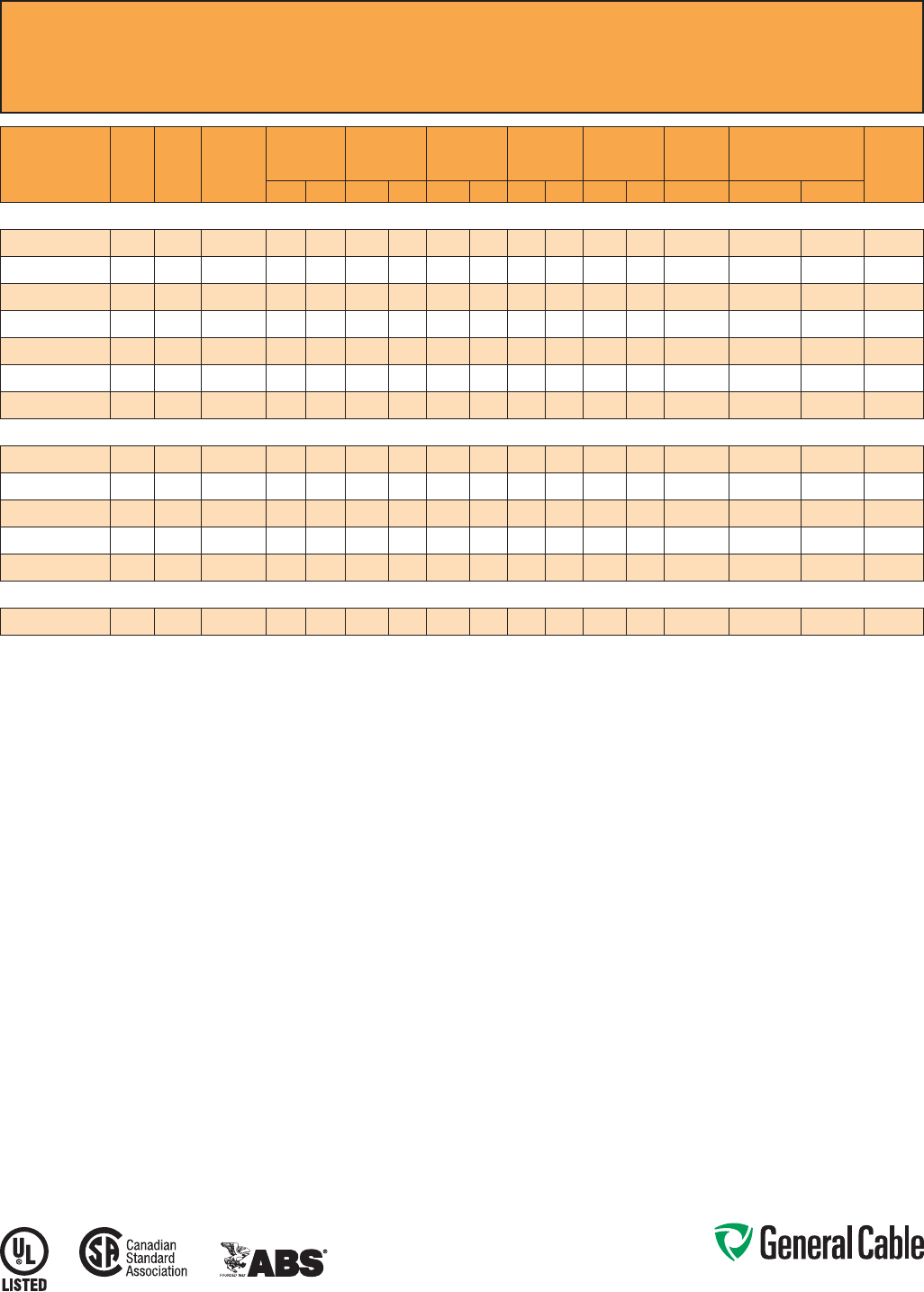
Phone: 888-593-3355
www.generalcable.com
SPEC 9510
February, 2011
CCW
®
Armored Control With Bare Grounding Conductor
ULTypeMC-HL,XLPE,600V,90°C,CableTrayUse,Sunlight-Resistant,DirectBurial
ULMarineShipboardCable,ABSCWCMC
CATALOG
NUMBER
COND.
SIZE
(AWG)
NO. OF
COND.
BARE
INSULATED
GROUND
(AWG)
INSULATION
THICKNESS
NOMINAL
CORE O.D.
NOMINAL
ARMOR O.D.
JACKET
THICKNESS
NOMINAL
OVERALL O.D.
CROSS-
SECTIONAL
AREA¹
APPROXIMATE NET
WEIGHT
90°C
AMPACITY
@ 30°C
AMBIENT²mils mm INCHES mm INCHES mm mils mm INCHES mm SQ. IN. LBS/1000 FT kg/1000 m
14 AWG 7W (2.08 mm²) MULTI-CONDUCTOR CONTROL CABLE WITH BARE GROUNDING CONDUCTOR
9510.01404114 14 4 14 30 0.76 0.35 8.8 0.52 13.3 50 1.27 0.63 16.0 0.62 203 302 20
9510.01405114 14 5 14 30 0.76 0.38 9.7 0.53 13.5 50 1.27 0.63 16.0 0.62 224 333 20
9510.01407114 14 7 14 30 0.76 0.43 10.9 0.60 15.2 50 1.27 0.71 18.0 0.79 287 427 17.5
9510.01409114 14 914 30 0.76 0.51 13.0 0.75 19.1 50 1.27 0.86 21.8 1.16 368 548 17.5
9510.01412114 14 12 14 30 0.76 0.56 14.2 0.79 20.1 50 1.27 0.89 22.6 1.24 425 632 12.5
9510.01419114 14 19 14 30 0.76 0.67 17.0 0.92 23.4 50 1.27 1.02 25.9 1.63 594 884 12.5
9510.01437114 14 37 14 30 0.76 0.94 23.9 1.22 31.0 50 1.27 1.32 33.5 2.74 1,030 1,533 10
12 AWG 7W (3.31 mm²) MULTI-CONDUCTOR CONTROL CABLE WITH BARE GROUNDING CONDUCTOR
9510.01204112 12 4 12 30 0.76 0.38 9.7 0.55 14.0 50 1.27 0.65 16.5 0.66 246 366 24
9510.01205112 12 5 12 30 0.76 0.43 10.9 0.61 15.5 50 1.27 0.71 18.0 0.79 302 449 24
9510.01207112 12 7 12 30 0.76 0.49 12.4 0.64 16.3 50 1.27 0.74 18.8 0.86 362 539 21
9510.01209112 12 912 30 0.76 0.58 14.7 0.79 20.1 50 1.27 0.90 22.9 1.21 458 682 21
9510.012121112
12 12 12 30 0.76 0.64 16.3 0.83 21.1 50 1.27 0.94 23.9 1.39 545 811 15
10 AWG 7W (5.26 mm²) MULTI-CONDUCTOR CONTROL CABLE WITH BARE GROUNDING CONDUCTOR
9510.01004110 10 410 30 0.76 0.46 11.7 0.63 16.0 50 1.27 0.73 18.5 0.84 343 510 32
Dimensionsandweightsarenominal;subjecttoindustrytolerances.
¹Cross-sectionalareaforcabletrayfillisinaccordancewithNECSection392.22.
²AmpacitiesinaccordancewithNECArticle310andTable310.15(B)(16).
Phone: 888-593-3355
www.generalcable.com
SPEC 9525
February, 2011
Applications:
•CCWarmoredControlcablesoffer
aneconomical,ruggedandreliable
alternativetolabor-intensivecablein
conduitwiringmethods
•ForuseinClassIandII,Division2;
ClassIII,Divisions1and2;andClass
I,Zone2hazardouslocationsperNEC
Articles501,502,503and505
•Foruseasservices,feedersand
branchcircuitsforpower,lighting,
control,andsignalcircuitsin
accordancewithNECArticles330
and725
•Installedindoorsoroutdoors,wet
ordrylocations,directlyburied,
embeddedinconcrete,inaraceway,
asaerialcableonamessenger,
incabletrays,orasexposedruns
securedtosupportsinaccordance
withNECArticle330
•Recognizedforuseonfixedor
floatingoffshorepetroleumfacilities
asrecommendedbytheAmerican
PetroleumInstitute
Features:
•CCWarmorprovidesanimpervious
barriertomoisture,gasandliquids
•CCWarmorprovidesEMIshielding
performance
•Factoryassembledandtestedcable
foruseasanalternativetocablein
conduitwiringsystems
•Meetscoldimpactat-40°C
Features: (cont’d)
•90˚Ccontinuousoperating
temperature,wetordry
•130˚Cemergencyrating
•250˚Cshortcircuitrating
Specifications:
Design Adherence:
•ICEAS-73-532/WC57Standardfor
Control,ThermocoupleExtensionand
InstrumentationCables
•UL44RubberInsulatedWiresand
Cables
•UL1569MetalCladCables
•UL1309MarineShipboardCable
•CSAC22.2No.123MetalSheathed
Cables
Flame Tests:
•ICEAT-29-520(210,000BTU/hr)
•IEEE383(70,000BTU/hr)
•CSAFT4
•IEEE1202(70,000BTU/hr)
•UL1581(70,000BTU/hr)
•IEC60332-3Cat.A
Compliances:
•ULTypeMC,XHHW-2,SUNRES,
CTUSE,DIRBUR,-40°C,ULFile
#E69797
•ULListedMarineShipboard,ULFile
#E85994
•AmericanBureauofShipping(ABS)
ListedforCWCMC
•CSACertified1TypeRA90,XLPE,SR,
FT4,and-40°C,CSAFile#7319
1
StandardcablesarealsomarkedCSATypeRA90,
exceptfour(4)conductorcableswhichrequireadifferent
colorcode,whichmaybespecial-ordered.
Product Construction:
Conductor:
•BareannealedcopperperASTMB3
•ClassBstrandingperASTMB8
Insulation:
•Cross-linkedPolyethylene(XLPE)
insulationperICEAS-73-532andUL
44,ListedXHHW-2
•Color-codedperICEAMethod1,Table
E2,full-coloredinsulationwithstripes
•Color-codedperCSAC22.2No.123
whereapplicable
Cable Assembly:
•Insulatedconductorsarecabled
togetherwithnon-hygroscopicfillers
whenrequired
•Abindertape,whenrequired,is
appliedoverthecabledcore
CCW Armor:
•Impervious,continuouslyweldedand
corrugatedaluminumalloysheathper
UL1569
•CCWarmorconductivitymeetsthe
groundingrequirementsofNEC
Article250
Jacket:
•Flame-retardant,moisture-and
sunlight-resistantPolyvinylChloride
(PVC),black
•Lowtemperatureperformancemeets
ASTMD746brittlenesstemperatureat
orbelow-40°C
•MeetsCSALowAcidGas
requirements
CCW
®
Armored Control Without Grounding Conductor
ULTypeMC,XLPE,600V,90°C,CableTrayUse,Sunlight-Resistant,DirectBurial
ULMarineShipboardCable,ABSCWCMC
Phone: 888-593-3355
www.generalcable.com
CCW
®
Armored Control Without Grounding Conductor
ULTypeMC,XLPE,600V,90°C,CableTrayUse,Sunlight-Resistant,DirectBurial
ULMarineShipboardCable,ABSCWCMC
SPEC 9525
February, 2011
CATALOG
NUMBER
COND.
SIZE
(AWG)
NO.
OF
COND.
INSULATION
THICKNESS
NOMINAL
CORE O.D.
NOMINAL
ARMOR O.D.
JACKET
THICKNESS
NOMINAL
OVERALL O.D.
CROSS-
SECTIONAL
AREA¹
APPROXIMATE
NET WEIGHT 90˚C
AMPACITY @
30˚C AMBIENT²
mils mm INCHES mm INCHES mm mils mm INCHES mm SQ. IN. LBS/1000 FT kg/1000 m
14 AWG 7W (2.08 mm²) MULTI-CONDUCTOR CONTROL CABLE WITHOUT GROUNDING CONDUCTOR
9525.01402000 14 2 30 0.76 0.28 7.1 0.49 12.4 50 1.27 0.60 15.2 0.29 144 214 15
9525.01403000 14 3 30 0.76 0.30 7.6 0.49 12.4 50 1.27 0.60 15.2 0.29 155 231 15
9525.01404000 14 4 30 0.76 0.33 8.4 0.53 13.5 50 1.27 0.64 16.3 0.33 183 273 15
9525.01405000 14 5 30 0.76 0.37 9.4 0.58 14.7 50 1.27 0.69 17.5 0.38 213 317 15
9525.01407000 14 7 30 0.76 0.41 10.4 0.62 15.7 50 1.27 0.73 18.5 0.42 257 383 15
9525.01409000 14 9 30 0.76 0.50 12.7 0.71 18.0 50 1.27 0.82 20.8 0.54 312 465 15
9525.01412000 14 12 30 0.76 0.57 14.5 0.80 20.3 50 1.27 0.91 23.1 0.66 386 575 12
9525.01419000 14 19 30 0.76 0.69 17.5 0.93 23.6 50 1.27 1.04 26.4 0.86 544 810 12
9525.01437000 14 37 30 0.76 0.96 24.4 1.24 31.5 50 1.27 1.35 34.3 1.45 959 1,427 10
12 AWG 7W (3.31 mm²) MULTI-CONDUCTOR CONTROL CABLE WITHOUT GROUNDING CONDUCTOR
9525.01202000 12 2 30 0.76 0.31 7.9 0.53 13.5 50 1.27 0.64 16.3 0.33 166 247 20
9525.01203000 12 3 30 0.76 0.34 8.6 0.53 13.5 50 1.27 0.64 16.3 0.33 192 285 20
9525.01204000 12 4 30 0.76 0.38 9.7 0.58 14.7 50 1.27 0.69 17.5 0.38 229 341 20
9525.01205000 12 5 30 0.76 0.42 10.7 0.62 15.7 50 1.27 0.73 18.5 0.42 266 395 20
9525.01207000 12 7 30 0.76 0.47 11.9 0.67 17.0 50 1.27 0.78 19.8 0.48 328 489 20
9525.01209000 12 9 30 0.76 0.56 14.2 0.80 20.3 50 1.27 0.91 23.1 0.66 410 611 20
9525.01212000 12 12 30 0.76 0.65 16.5 0.89 22.6 50 1.27 0.99 25.1 0.78 510 759 15
9525.01219000 12 19 30 0.76 0.78 19.8 1.02 25.9 50 1.27 1.13 28.7 1.02 731 1,087 15
9525.01237000 12 37 30 0.76 1.08 27.4 1.37 34.8 50 1.27 1.48 37.6 1.74 1,318 1,962 12
10 AWG 7W (5.26 mm²) MULTI-CONDUCTOR CONTROL CABLE WITHOUT GROUNDING CONDUCTOR
9525.01002000 10 230 0.76 0.36 9.1 0.58 14.7 50 1.27 0.69 17.5 0.38 205 305 30
9525.01003000 10 3 30 0.76 0.39 9.9 0.58 14.7 50 1.27 0.69 17.5 0.38 241 359 30
9525.01004000 10 430 0.76 0.44 11.2 0.67 17.0 50 1.27 0.78 19.8 0.48 301 448 30
9525.01005000 10 530 0.76 0.48 12.2 0.71 18.0 50 1.27 0.82 20.8 0.54 353 525 30
9525.01007000 10 730 0.76 0.54 13.7 0.75 19.1 50 1.27 0.86 21.8 0.59 442 658 28
9525.01009000 10 9 30 0.76 0.65 16.5 0.89 22.6 50 1.27 1.00 25.4 0.80 551 820 28
9525.01012000 10 12 30 0.76 0.74 18.8 0.97 24.6 50 1.27 1.08 27.4 0.93 693 1,032 20
Dimensionsandweightsarenominal;subjecttoindustrytolerances.
¹Cross-sectionalareaforcabletrayfillisinaccordancewithNEC®Section392.22.
²AmpacitiesinaccordancewithNEC®Article310andTable310.15(B)(16).
Note:Standardcableswithuptoandincludingsix(6)conductorsarealsomarkedCSATypeRA90.Allothersarespecialorder.
Phone: 888-593-3355
www.generalcable.com
SPEC 9600
February, 2011
Applications:
•VariableFrequencyDrives:
3-conductorCCWarmoredcables
withthree(3)symmetricalgrounding
wiresarethepreferredwiringmethod
forusewithACmotorscontrolledby
pulse-widthmodulatedinvertersin
VFDapplications
•CCWarmoredcablesofferan
economical,ruggedandreliable
alternativetolabor-intensivecablein
conduitwiringmethods
•ForuseinClassI,IIandIII,Divisions
1and2;andClassI,Zones1and2
hazardouslocationsperNECArticles
501,502,503and505
•Foruseasservices,feedersand
branchcircuitsforpower,lighting,
control,andsignalcircuitsin
accordancewithNECArticles330
and725
•Installedindoorsoroutdoors,wet
ordrylocations,directlyburied,
embeddedinconcrete,inaraceway,
asaerialcableonamessenger,
incabletrays,orasexposedruns
securedtosupportsinaccordance
withNECArticle330
•Recognizedforuseonfixedor
floatingoffshorepetroleumfacilities
asrecommendedbytheAmerican
PetroleumInstitute
Features:
•3-conductorCCWpowercables
withthreegroundingwiresare
recommendedforusewithpulse-width
modulatedACdrives
•CCWarmorprovidesanimpervious
barriertomoisture,gasandliquids
•CCWarmorprovidesEMIshielding
performance
•Factoryassembledandtestedcable
foruseasanalternativetocablein
conduitwiringsystems
Features: (cont’d)
•Meetscoldimpactat-40°C
•90˚Ccontinuousoperating
temperature,wetordry
•130˚Cemergencyrating
•250˚Cshortcircuitrating
Specifications:
Design Adherence:
•ICEAS-95-658/WC70Standardfor
NonshieldedPowerCable,2kV
orLess
•UL44RubberInsulatedWires
and Cables
•UL1569MetalCladCables
•UL2225CablesandCableFittingsfor
UseinHazardousLocations
•UL1309MarineShipboardCable
•CSAC22.2No.123MetalSheathed
Cables
•CSAC22.2No.174CablesandCable
GlandsforUseinHazardousLocations
Flame Tests:
•ICEAT-29-520(210,000BTU/hr)
•IEEE383(70,000BTU/hr)
•CSAFT4
•IEEE1202(70,000BTU/hr)
•UL1581(70,000BTU/hr)
•IEC60332-3Cat.A
Compliances:
•ULTypeMC-HL,XHHW-2,SUNRES,
CTUSE,DIRBUR,-40°C,ULFile
#E69797
•ULListedMarineShipboard,ULFile
#E85994
•AmericanBureauofShipping(ABS)
ListedforCWCMC
•CSACertifiedTypeRA90,XLPE,
HL,SR,FT4,and-40°C,CSAFile
#7319
1
StandardcablesarealsomarkedCSATypeRA90,
exceptfour(4)conductorcableswhichrequireadifferent
colorcode,whichmaybespecial-ordered.
Product Construction:
•BareannealedcopperperASTMB3
•10AWGandsmallerareClassB
compressedstrandingperASTMB8
•8AWGandlargerarecompact
strandingperASTMB496
Insulation:
•Cross-linkedPolyethylene(XLPE)
insulationperICEAS-95-658andUL
44,ListedXHHW-2
•6AWGandsmallerarecolor-coded
perICEAMethod1,TableE2
•4AWGandlargerareblackwith
printednumbersperICEAMethod4
•Color-codedperCSAC22.2No.123
whereapplicable
Grounding Conductor(s):
•ClassBstrandedbareannealed
copperperASTMB3andB8
•Wherespecified,singleorthree
splitgroundingwiresaresizedin
accordancewithNECTable250.122
Cable Assembly:
•Insulatedconductorsandgrounding
wire(s)arecabledtogetherwithnon-
hygroscopicfillerswhenrequired
•Abindertapeisappliedoverthe
cabled core
CCW Armor:
•Impervious,continuouslyweldedand
corrugatedaluminumalloysheathper
UL1569andUL2225
•CCWarmorconductivitymeetsthe
groundingrequirementsofNEC
Article250
Jacket:
•Flame-retardant,moisture-and
sunlight-resistantPolyvinylChloride
(PVC),black
•Lowtemperatureperformancemeets
ASTMD746brittlenesstemperatureat
orbelow-40°C
•MeetsCSALowAcidGas
requirements
CCW
®
Armored Power, 3/C VFD and 4/C
ULTypeMC-HL,XLPE,600V,90°C,CableTrayUse,Sunlight-Resistant,DirectBurial
ULMarineShipboardCable,ABSCWCMC
Phone: 888-593-3355
www.generalcable.com
CATALOG
NUMBER
COND.
SIZE
(AWG/kcmil)
NO. OF
COND.
INSULATION
THICKNESS BARE
GROUND
(AWG)
NOMINAL
CORE O.D.
NOMINAL
ARMOR O.D.
JACKET
THICKNESS
NOMINAL
OVERALL O.D.
CROSS-
SECTIONAL
AREA¹
APPROXIMATE NET
WEIGHT
90°C
AMPACITY
@ 30°C
AMBIENT²mils mm INCHES mm INCHES mm mils mm INCHES mm SQ. IN. LBS/1000 FT kg/1000 m
9600.01403318
14(7/W)
(2.08mm²)
3 30 0.76 3x#18 0.33 8.4 0.53 13.5 50 1.27 0.64 16.3 0.33 163 242 15
9600.01404318
430 0.76 3x#18 0.37 9.4 0.58 14.7 50 1.27 0.69 17.5 0.38 226 336 15
9600.01203316
12(7/W)
(3.31mm²)
3 30 0.76 3x#16 0.37 9.4 0.58 14.7 50 1.27 0.69 17.5 0.38 243 362 20
9600.01204316
430 0.76 3x#16 0.45 11.4 0.67 17.0 50 1.27 0.78 19.8 0.48 291 433 20
9600.01003314
10(7/W)
(5.26mm²)
3 30 0.76 3x#14 0.41 10.4 0.62 15.7 50 1.27 0.73 18.5 0.42 305 454 30
9600.01004314
430 0.76 3x#14 0.45 11.4 0.67 17.0 50 1.27 0.78 19.8 0.48 354 527 30
9600.00803314
8(7/W)
(8.36mm²)
345 1.14 3x#14 0.50 12.7 0.71 18.0 50 1.27 0.81 20.6 0.52 392 583 55
9600.00804110
4 45 1.14 1x#10 0.58 14.7 0.80 20.3 50 1.27 0.90 22.9 0.64 473 704 44
9600.00603312
6(7/W)
(13.3mm²)
345 1.14 3x#12 0.58 14.7 0.80 20.3 50 1.27 0.90 22.9 0.64 534 795 75
9600.00604108
4 45 1.14 1x#8 0.66 16.8 0.89 22.6 50 1.27 0.99 25.1 0.78 641 954 60
9600.00403312
4(7/W)
(21.2mm²)
345 1.14 3x#12 0.68 17.3 0.89 22.6 50 1.27 0.99 25.1 0.78 716 1,066 95
9600.00404108
4 45 1.14 1x#8 0.77 19.6 0.97 24.6 50 1.27 1.08 27.4 0.93 860 1,280 76
9600.00203310
2(7/W)
(33.6mm²)
345 1.14 3x#10 0.80 20.3 1.02 25.9 50 1.27 1.13 28.7 1.02 1,013 1,507 130
9600.00204106
4 45 1.14 1x#6 0.92 23.4 1.15 29.2 50 1.27 1.26 32.0 1.26 1,267 1,885 104
9600.00103310
1(19/W)
(42.4mm²)
355 1.40 3x#10 0.92 23.4 1.15 29.2 50 1.27 1.26 32.0 1.26 1,119 1,666 150
9600.00104106
4 55 1.40 1x#6 1.04 26.4 1.29 32.8 50 1.27 1.40 35.6 1.56 1,526 2,272 120
9600.11003310
1/0(19/W)
(53.5mm²)
355 1.40 3x#10 1.00 25.4 1.24 31.5 50 1.27 1.34 34.0 1.43 1,496 2,226 170
9600.11004106
4 55 1.40 1x#6 1.12 28.4 1.37 34.8 50 1.27 1.48 37.6 1.74 1,862 2,771 136
9600.21003310
2/0(19/W)
(67.4mm²)
355 1.40 3x#10 1.09 27.7 1.34 34.0 50 1.27 1.44 36.6 1.65 1,801 2,681 195
9600.21004106
4 55 1.40 1x#6 1.23 31.2 1.51 38.4 60 1.52 1.64 41.7 2.14 2,351 3,498 156
9600.31003308
3/0(19/W)
(85.0mm²)
355 1.40 3x#8 1.21 30.7 1.47 37.3 60 1.52 1.58 40.1 1.99 2,262 3,367 225
9600.31004104
4 55 1.40 1x#4 1.36 34.5 1.65 41.9 60 1.52 1.78 45.2 2.52 2,921 4,346 180
9600.41003308
4/0(19/W)
(107mm²)
355 1.40 3x#8 1.33 33.8 1.60 40.6 60 1.52 1.73 43.9 2.38 2,722 4,051 260
9600.41004104
4 55 1.40 1x#4 1.49 37.8 1.78 45.2 60 1.52 1.91 48.5 2.90 3,491 5,194 208
9600.25003308
250(37/W)
(127mm²)
365 1.65 3x#8 1.48 37.6 1.74 44.2 60 1.52 1.87 47.5 —3,195 4,755 290
9600.25004104
4 65 1.65 1x#4 1.64 41.7 1.96 49.8 60 1.52 2.09 53.1 —4,142 6,164 232
9600.35003307
350(37/W)
(177mm²)
365 1.65 3x#7 1.66 42.2 1.96 49.8 60 1.52 2.09 53.1 —4,284 6,376 350
9600.35004103
4 65 1.65 1x#3 1.89 48.0 2.19 55.6 75 1.91 2.35 59.7 —5,536 8,238 280
9600.50003306
500(37/W)
(253mm²)
365 1.65 3x#6 1.94 49.3 2.28 57.9 75 1.91 2.44 62.0 —6,035 8,981 430
9600.50004102
4 65 1.65 1x#2 2.14 54.4 2.49 63.2 75 1.91 2.65 67.3 —7,704 11,464 344
9600.75003305
750(61/W)
(380mm²)
380 2.03 3x#5 2.37 60.2 2.75 69.9 75 1.91 2.92 74.2 —8,854 13,176 535
9600.75004101
4 80 2.03 1x#1 2.61 66.3 3.03 77.0 85 2.16 3.21 81.5 —11,449 17,037 428
9600.100031110
1000(61/W)
(507mm²)
380 2.03 1x#1/0 2.67 67.8 3.11 79.0 85 2.16 3.30 83.8 —11,611 17,280 615
9600.100041110
4 80 2.03 1x#1/0 3.07 78.0 3.63 92.2 85 2.16 3.81 96.8 —15,377 22,883 492
Dimensionsandweightsarenominal;subjecttoindustrytolerances.
¹Cross-sectionalareaforcabletrayfillisinaccordancewithNECSection392.22.
²AmpacitiesinaccordancewithNECArticle310andTable310.15(B)(16).
Note:Three(3)conductors,6AWGandsmallerarealsomarkedCSATypeRA90.One(1)AWGandlargerarealsomarkedCSATypeRA90.
CCW
®
Armored Power, 3/C VFD and 4/C
ULTypeMC-HL,XLPE,600V,90°C,CableTrayUse,Sunlight-Resistant,DirectBurial
ULMarineShipboardCable,ABSCWCMC
SPEC 9600
February, 2011
Phone: 888-593-3355
www.generalcable.com
SPEC 9615
September, 2013
Applications:
•VariableFrequencyDrives:
3-conductorCCWarmoredcables
withthree(3)symmetricalgrounding
wiresisthepreferredwiringmethod
forusewithACmotorscontrolledby
pulse-widthmodulatedInvertersin
VFDapplications
•CCWarmoredcablesofferan
economical,ruggedandreliable
alternativetolabor-intensivecablein
conduitwiringmethods
•ForuseinClassI,IIandIII,Divisions
1and2;andClassI,Zones1and2
hazardouslocationsperNECArticles
501,502and503
•Foruseasservices,feedersand
branchcircuitsforpower,lighting,
control,andsignalcircuitsin
accordancewithNECArticles330
and725
•Installedindoorsoroutdoors,wet
ordrylocations,directlyburied,
embeddedinconcrete,inaraceway,
asaerialcableonamessenger,
incabletrays,orasexposedruns
securedtosupportsinaccordance
withNECArticle330
•Recognizedforuseonfixedor
floatingoffshorepetroleumfacilities
asrecommendedbytheAmerican
PetroleumInstitute
Features:
•90°C,2000VratedXLPEinsulation
withadielectricconstantlessthan3.0
towithstandmomentaryvoltagespikes
commonincertainVFDapplications
•Three(3)oversized,symmetrical
groundingwiresrecommendedforuse
withpulse-widthmodulatedACdrives
•CCWarmorprovidesanimpervious
barriertomoisture,gasandliquids
Features: (cont’d)
•CCWarmorprovidesEMIshielding
performance
•Factoryassembledandtestedcable
foruseasanalternativetocablein
conduitwiringsystems
•Meetscoldimpactat-40°C
•90˚Ccontinuousoperating
temperature,wetordry
•130˚Cemergencyrating
•250˚Cshortcircuitrating
Specifications:
Design Adherence:
•ICEAS-95-658/WC-70Standard
forNon-ShieldedPowerCable,2kV
orLess
•UL44RubberInsulatedWiresand
Cables
•UL1569MetalCladCables
•UL2225CablesandCableFittingsfor
UseinHazardousLocations
•UL1309MarineShipboardCable
Flame Tests:
•ICEAT-29-520(210,000BTU/hr)
•IEEE383(70,000BTU/hr)
•CSAFT4
•IEEE1202(70,000BTU/hr)
•UL1581(70,000BTU/hr)
•IEC332-3Cat.A
Compliances:
•ULTypeMC-HL,SUNRES,CTUSE,
DIRBUR,-40°C,ULFile#E69797
•ULListedMarineShipboard,ULFile
#E85994
•AmericanBureauofShipping(ABS)
ListedforCWCMC
Product Construction:
Conductor:
•BareannealedcopperperASTMB3
•10AWGandsmallerareClassB
compressedstrandingperASTMB8
•8AWGandlargerarecompact
standingperASTMB496
Insulation:
•Cross-LinkedPolyethylene(XLPE)
insulation,2000Vthicknessesper
ICEAS-95-658
•Color-codedblackwithprinted
numbersperICEAMethod4
Grounding Conductors:
•ClassBstrandedbareannealed
copperperASTMB3andB8
•Three(3)splitgroundingwires
perspecification9615exceedthe
minimumrequiredinNECTable
250.122
Cable Assembly:
•Insulatedconductorsandgrounding
wiresarecabledtogetherwithnon-
hygroscopicfillerswhenrequired
•Abindertapeisappliedoverthe
cabledcore
CCW Armor:
•Impervious,continuouslyweldedand
corrugatedaluminumalloysheathper
UL1569andUL2225
•CCWarmorconductivitymeetsthe
groundingrequirementsofNEC
Article250
Jacket:
•Flame-retardant,moisture-and
sunlight-resistantPolyvinylChloride
(PVC)—Black
•Lowtemperatureperformancemeets
ASTMD746brittlenesstemperatureat
orbelow-40°C
CCW
®
Armored Power, 3/C VFD
ULTypeMC-HL,XLPE,2000V,90°C,CableTrayUse,Sunlight-Resistant,DirectBurial
ULMarineShipboardCable,ABSCWCMC
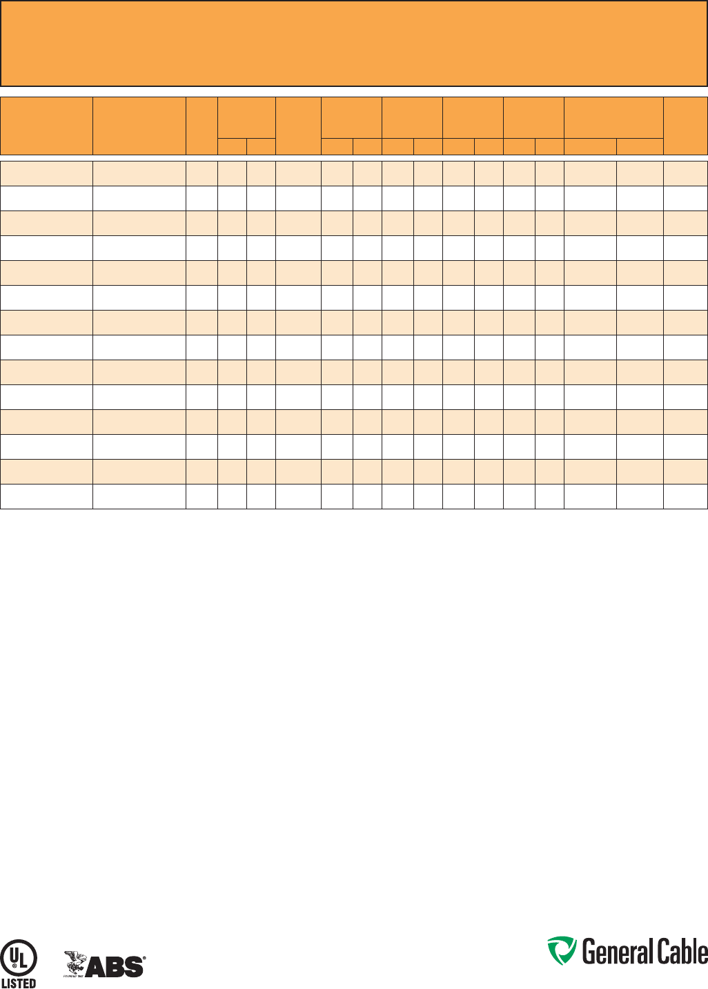
Phone: 888-593-3355
www.generalcable.com
CCW
®
Armored Power, 3/C VFD
ULTypeMC-HL,XLPE,2000V,90°C,CableTrayUse,Sunlight-Resistant,DirectBurial
ULMarineShipboardCable,ABSCWCMC
SPEC 9615
September, 2013
CATALOG
NUMBER
COND.
SIZE
(AWG/kcmil)
NO. OF
COND.
INSULATION
THICKNESS BARE
GROUND
(AWG)
NOMINAL
CORE O.D.
NOMINAL
ARMOR O.D.
JACKET
THICKNESS
NOMINAL
OVERALL O.D.
APPROXIMATE NET
WEIGHT
90°C
AMPACITY
@ 30°C
AMBIENT¹mils mm INCHES mm INCHES mm mils mm INCHES mm LBS/1000 FT kg/1000 m
9615.01403318
14(7/W)(2.08mm²)
360 1.52 3x#18 0.44 11.1 0.62 15.2 50 1.27 0.73 17.9 267 397 15
9615.01203316
12(7/W)(3.31mm²)
360 1.52 3x#16 0.47 11.9 0.66 16.2 50 1.27 0.77 18.9 324 482 20
9615.01003314
10(7/W)(5.26mm²)
360 1.52 3x#14 0.53 13.3 0.73 17.8 50 1.27 0.84 20.5 400 595 30
9615.00803314
8(7/W)(8.36mm²)
370 1.78 3x#14 0.65 16.5 0.86 21.1 50 1.27 0.97 23.8 524 780 55
9615.00603312
6(7/W)(13.3mm²)
370 1.78 3x#12 0.71 18.0 0.96 23.4 50 1.27 1.07 26.1 697 1,037 75
9615.00403312
4(7/W)(21.2mm²)
370 1.78 3x#12 0.81 20.6 1.09 26.6 50 1.27 1.23 30.1 1,000 1,488 95
9615.00203310
2(7/W)(33.6mm²)
370 1.78 3x#10 0.94 23.9 1.25 30.6 50 1.27 1.36 33.3 1,285 1,912 130
9615.00103310
1(19/W)(42.4mm²)
390 2.29 3x#10 1.13 28.7 1.48 36.1 50 1.27 1.59 38.8 1,595 2,374 150
9615.11003310
1/0(19/W)(53.5mm²)
390 2.29 3x#10 1.21 30.6 1.55 38.0 60 1.52 1.68 41.2 1,930 2,872 170
9615.21003306
2/0(19/W)(67.4mm²)
390 2.29 3x#6 1.30 32.9 1.68 41.0 60 1.52 1.81 44.2 2,507 3,731 195
9615.41003304
4/0(19/W)(107mm²)
390 2.29 3x#4 1.53 38.7 1.91 46.7 60 1.52 2.04 49.9 3,590 5,342 260
9615.25003304
250(37/W)(127mm²)
3105 2.67 3x#4 1.71 43.4 2.12 51.8 60 1.52 2.25 55.1 4,150 6,176 290
9615.35003302
350(37/W)(177mm²)
3105 2.67 3x#2 1.93 48.9 2.41 58.9 75 1.91 2.57 62.8 5,214 7,759 350
9615.50003301
500(37/W)(253mm²)
3105 2.67 3x#1 2.20 55.8 2.68 65.5 75 1.91 2.84 69.5 6,977 10,382 430
Dimensionsandweightsarenominal;subjecttoindustrytolerances.
¹AmpacitiesinaccordancewithNECArticle310andTable310.15(B)(16).
Phone: 888-593-3355
www.generalcable.com
SPEC 9625
January, 2011
CCW
®
Armored Composite Power and Control
ULTypeMC-HL,XLPE,600V,90°C,CableTrayUse,Sunlight-Resistant,DirectBurial
ULMarineShipboardCable,ABSCWCMC
Product Construction:
Conductor:
•BareannealedcopperperASTMB3
•10AWGandsmallerareClassB
compressedstrandingperASTMB8
•8AWGandlargerarecompact
strandingperASTMB496
Insulation:
•Cross-linkedPolyethylene(XLPE)
insulationperICEAS-95-658andUL
44,ListedXHHW-2
•Powerconductors6AWGandsmaller
arecolor-codedperICEAMethod1,
TableE2
•Powerconductors4AWGandlarger
areblackwithprintednumbersper
ICEAMethod4
•Controlconductorsarecolor-coded
black,red,blueandyellow
Grounding Conductor:
•ClassBstrandedbareannealed
copperperASTMB3andB8
•SizedinaccordancewithNECTable
250.122
Cable Assembly:
•Insulatedconductorsandgrounding
wirearecabledtogetherwithnon-
hygroscopicfillerswhenrequired
•Abindertapeisappliedoverthe
cabled core
CCW Armor:
•Impervious,continuouslyweldedand
corrugatedaluminumalloysheathper
UL1569andUL2225
•CCWarmorconductivitymeetsthe
groundingrequirementsofNEC
Article250
Jacket:
•Flame-retardant,moisture-and
sunlight-resistantPolyvinylChloride
(PVC),black
•Lowtemperatureperformancemeets
ASTMD746brittlenesstemperatureat
orbelow-40°C
Applications:
•CCWarmoredCompositePowerand
Controlcablesofferaneconomical,
ruggedandreliablealternativeto
labor-intensivecableinconduitwiring
methods
•ForuseinClassI,IIandIII,Divisions
1and2;andClassI,Zones1and2
hazardouslocationsperNECArticles
501,502,503and505
•Foruseasservices,feedersand
branchcircuitsforpower,lighting,
control,andsignalcircuitsin
accordancewithNECArticles330
and725
•Installedindoorsoroutdoors,wet
ordrylocations,directlyburied,
embeddedinconcrete,inaraceway,
asaerialcableonamessenger,
incabletrays,orasexposedruns
securedtosupportsinaccordance
withNECArticle330
•Recognizedforuseonfixedor
floatingoffshorepetroleumfacilities
asrecommendedbytheAmerican
PetroleumInstitute
Features:
•CCWarmorprovidesanimpervious
barriertomoisture,gasandliquids
•CCWarmorprovidesEMIshielding
performance
•Factoryassembledandtestedcable
foruseasanalternativetocablein
conduitwiringsystems
•Meetscoldimpactat-40°C
•90˚Ccontinuousoperating
temperature,wetordry
•130˚Cemergencyrating
•250˚Cshortcircuitrating
Specifications:
Design Adherence:
•ICEAS-95-658/WC70Standard
forNonshieldedPowerCables,
2kVorLess
•UL44RubberInsulatedWiresand
Cables
•UL1569MetalCladCables
•UL2225CablesandCableFittingsfor
UseinHazardousLocations
•UL1309MarineShipboardCable
Flame Tests:
•ICEAT-29-520(210,000BTU/hr)
•IEEE383(70,000BTU/hr)
•CSAFT4
•IEEE1202(70,000BTU/hr)
•UL1581(70,000BTU/hr)
•IEC60332-3Cat.A
Compliances:
•ULTypeMC-HL,XHHW-2,SUNRES,
CTUSE,DIRBUR,-40°C,ULFile
#E69797
•ULListedMarineShipboard,ULFile
#E85994
•AmericanBureauofShipping(ABS)
ListedforCWCMC
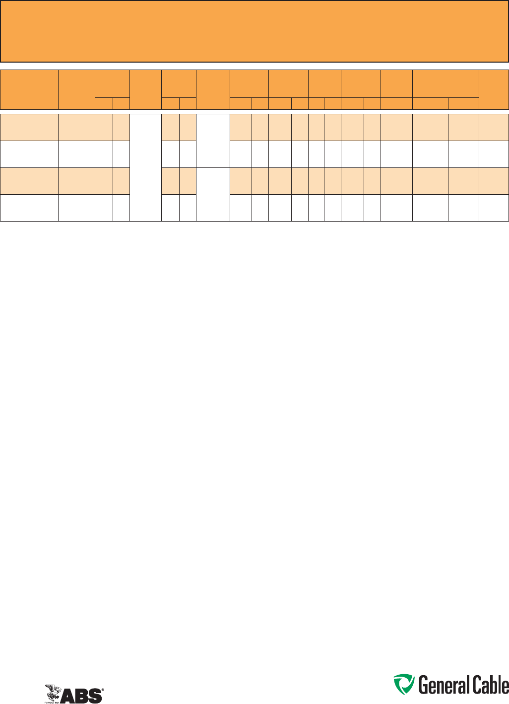
Phone: 888-593-3355
www.generalcable.com
SPEC 9625
January, 2011
CCW
®
Armored Composite Power and Control
ULTypeMC-HL,XLPE,600V,90°C,CableTrayUse,Sunlight-Resistant,DirectBurial
ULMarineShipboardCable,ABSCWCMC
CATALOG
NUMBER
POWER
COND. SIZE
(AWG)
POWER
INSULATION
THICKNESS
CONTROL
COND.
SIZE
(AWG)
CONTROL
INSULATION
THICKNESS BARE
GROUNDING
(AWG)
NOMINAL
CORE O.D.
NOMINAL
ARMOR O.D.
JACKET
THICKNESS
NOMINAL
OVERALL O.D.
CROSS-
SECTIONAL
AREA¹
APPROXIMATE NET
WEIGHT
90°C
AMPACITY
@ 30°C
AMBIENT²mils mm mils mm INCHES mm INCHES mm mils mm INCHES mm SQ. IN. LBS/1000 FT kg/1000 m
9625.103124110
3x#10(7/W)
(5.26 mm²)
30 0.76
4x#12
(7/W)
(3.31 mm²)
30 0.76
10(7/W)
(5.2 mm²)
0.53 13.5 0.75 19.1 50 1.27 0.86 21.8 0.59 430 640 30
9625.083124110
3x#8(7/W)
(8.36 mm²)
45 1.14 30 0.76 0.65 16.5 0.89 22.6 50 1.27 0.99 25.1 0.78 535 796 55
9625.063124108
3x#6(7/W)
(13.3 mm²)
45 1.14 30 0.76
8(7/W)
(8.36 mm²)
0.69 17.5 0.93 23.6 50 1.27 1.03 26.2 0.84 660 982 75
9625.043124108
3x#4(7/W)
(21.2 mm²)
45 1.14 30 0.76 0.74 18.8 0.97 24.6 50 1.27 1.08 27.4 0.93 815 1,213 95
Dimensionsandweightsarenominal;subjecttoindustrytolerances.
¹Cross-sectionalareaforcabletrayfillisinaccordancewithNECSection392.22.
²AmpacitiesinaccordancewithNECArticle310andTable310.15(B)(16).
Phone: 888-593-3355
www.generalcable.com
SPEC 9650
February, 2011
CCW
®
Armored Composite Power and Control Without Ground
ULTypeMC,XLPE,600V,90°C,CableTrayUse,Sunlight-Resistant,DirectBurial
ULMarineShipboardCable,ABSCWCMC
Product Construction:
Conductor:
•BareannealedcopperperASTMB3
•Sizes10AWGandsmallerareClassB
compressedstrandingperASTMB8
•Sizes8AWGandlargerarecompact
strandingperASTMB496
Insulation:
•Cross-linkedPolyethylene(XLPE)
insulationperICEAS-95-658and
UL44,ListedXHHW-2
•Powerconductorssizes6AWGand
smallerarecolor-codedperICEA
Method1,TableE2
•Powerconductorssizes4AWGand
largerareblackwithprintednumbers
perICEAMethod4
•Controlconductorsarecolor-coded
black,red,blueandyellow
Cable Assembly:
•Insulatedconductorsarecabled
togetherwithnon-hygroscopicfillers
whenrequired
•Abindertape,whenrequired,is
appliedoverthecabledcore
CCW Armor:
•Impervious,continuouslyweldedand
corrugatedaluminumalloysheathper
UL1569
•CCWarmorconductivitymeetsthe
groundingrequirementsofNEC
Article250
Jacket:
•Flame-retardant,moisture-and
sunlight-resistantPolyvinylChloride
(PVC),black
•Lowtemperatureperformancemeets
ASTMD746brittlenesstemperatureat
orbelow-40°C
Applications:
•CCWarmoredCompositePowerand
Controlcablesofferaneconomical,
ruggedandreliablealternativeto
labor-intensivecableinconduitwiring
methods
•ForuseinClassIandII,Division2;
ClassIII,Divisions1and2;andClass
I,Zone2hazardouslocationsperNEC
Articles501,502,503and505
•Foruseasservices,feedersand
branchcircuitsforpower,lighting,
control,andsignalcircuitsin
accordancewithNECArticles330
and725
•Installedindoorsoroutdoors,wet
ordrylocations,directlyburied,
embeddedinconcrete,inaraceway,
asaerialcableonamessenger,
incabletrays,orasexposedruns
securedtosupportsinaccordance
withNECArticle330
•Recognizedforuseonfixedor
floatingoffshorepetroleumfacilities
asrecommendedbytheAmerican
PetroleumInstitute
Features:
•CCWarmorprovidesanimpervious
barriertomoisture,gasandliquids
•CCWarmorprovidesEMIshielding
performance
•Factoryassembledandtestedcable
foruseasanalternativetocablein
conduitwiringsystems
Features: (cont’d)
•Meetscoldimpactat-40°C
•90˚Ccontinuousoperating
temperature,wetordry
•130˚Cemergencyrating
•250˚Cshortcircuitrating
Specifications:
Design Adherence:
•ICEAS-95-658/WC70Standard
forNonshieldedPowerCable,2kV
orLess
•UL44RubberInsulatedWiresand
Cables
•UL1569MetalCladCables
•UL1309MarineShipboardCable
Flame Tests:
•ICEAT-29-520(210,000BTU/hr)
•IEEE383(70,000BTU/hr)
•CSAFT4
•IEEE1202(70,000BTU/hr)
•UL1581(70,000BTU/hr)
•IEC60332-3Cat.A
Compliances:
•ULTypeMC,XHHW-2,SUNRES,
CTUSE,DIRBUR,-40°C,ULFile#
E69797
•ULListedMarineShipboard,ULFile#
E85994
•AmericanBureauofShipping(ABS)
ListedforCWCMC
Phone: 888-593-3355
www.generalcable.com
SPEC 9650
February, 2011
CCW
®
Armored Composite Power and Control Without Ground
ULTypeMC,XLPE,600V,90°C,CableTrayUse,Sunlight-Resistant,DirectBurial
ULMarineShipboardCable,ABSCWCMC
CATALOG
NUMBER
POWER COND. SIZE
(AWG)
POWER
INSULATION
THICKNESS CONTROL COND.
SIZE
(AWG)
CONTROL
INSULATION
THICKNESS
NOMINAL
CORE O.D.
NOMINAL
ARMOR O.D.
JACKET
THICKNESS
NOMINAL
OVERALL O.D.
CROSS-
SECTIONAL
AREA¹
APPROXIMATE NET
WEIGHT
90°C
AMPACITY
@ 30°C
AMBIENT²mils mm mils mm INCHES mm INCHES mm mils mm INCHES mm SQ. IN. LBS/1000 FT kg/1000 m
9650.123143000
3x#12(7/W)(3.31mm²)
30 0.76
3x#14(7/W)(2.08mm²)
30 0.76 0.49 12.4 0.71 18.0 50 1.27 0.82 20.8 0.54 307 457 20
9650.123144000
3x#12(7/W)(3.31mm²)
30 0.76
4x#14(7/W)(2.08mm²)
30 0.76 0.49 12.4 0.71 18.0 50 1.27 0.82 20.8 0.54 323 481 20
9650.124143000
4x#12(7/W)(3.31mm²)
30 0.76
3x#14(7/W)(2.08mm²)
30 0.76 0.49 12.4 0.71 18.0 50 1.27 0.82 20.8 0.54 365 543 20
9650.124144000
4x#12(7/W)(3.31mm²)
30 0.76
4x#14(7/W)(2.08mm²)
30 0.76 0.53 13.5 0.75 19.1 50 1.27 0.86 21.8 0.59 388 577 20
9650.103143000
3x#10(7/W)(5.26mm²)
30 0.76
3x#14(7/W)(2.08mm²)
30 0.76 0.53 13.5 0.75 19.1 50 1.27 0.86 21.8 0.59 384 571 30
9650.103144000
3x#10(7/W)(5.26mm²)
30 0.76
4x#14(7/W)(2.08mm²)
30 0.76 0.58 14.7 0.80 20.3 50 1.27 0.91 23.1 0.66 392 583 30
9650.103123000
3x#10(7/W)(5.26mm²)
30 0.76
3x#12(7/W)(3.31mm²)
30 0.76 0.53 13.5 0.75 19.1 50 1.27 0.86 21.8 0.59 410 610 30
9650.104143000
4x#10(7/W)(5.26mm²)
30 0.76
3x#14(7/W)(2.08mm²)
30 0.76 0.58 14.7 0.80 20.3 50 1.27 0.91 23.1 0.66 412 613 30
9650.104144000
4x#10(7/W)(5.26mm²)
30 0.76
4x#14(7/W)(2.08mm²)
30 0.76 0.58 14.7 0.80 20.3 50 1.27 0.91 23.1 0.66 428 637 30
9650.104123000
4x#10(7/W)(5.26mm²)
30 0.76
3x#12(7/W)(3.31mm²)
30 0.76 0.58 14.7 0.80 20.3 50 1.27 0.91 23.1 0.66 436 649 30
9650.104124000
4x#10(7/W)(5.26mm²)
30 0.76
4x#12(7/W)(3.31mm²)
30 0.76 0.58 14.7 0.80 20.3 50 1.27 0.91 23.1 0.66 460 685 30
9650.083143000
3x#8(7/W)(8.36mm²)
45 1.14
3x#14(7/W)(2.08mm²)
30 0.76 0.58 14.7 0.80 20.3 50 1.27 0.91 23.1 0.66 424 631 55
9650.083144000
3x#8(7/W)(8.36mm²)
45 1.14
4x#14(7/W)(2.08mm²)
30 0.76 0.62 15.7 0.84 21.3 50 1.27 0.91 23.1 0.66 455 677 55
9650.083123000
3x#8(7/W)(8.36mm²)
45 1.14
3x#12(7/W)(3.31mm²)
30 0.76 0.58 14.7 0.80 20.3 50 1.27 0.95 24.1 0.72 455 677 55
9650.083124000
3x#8(7/W)(8.36mm²)
45 1.14
4x#12(7/W)(3.31mm²)
30 0.76 0.62 15.7 0.84 21.3 50 1.27 0.91 23.1 0.66 495 737 55
9650.084143000
4x#8(7/W)(8.36mm²)
45 1.14
3x#14(7/W)(2.08mm²)
30 0.76 0.62 15.7 0.84 21.3 50 1.27 0.95 24.1 0.72 505 752 44
9650.084144000
4x#8(7/W)(8.36mm²)
45 1.14
4x#14(7/W)(2.08mm²)
30 0.76 0.67 17.0 0.89 22.6 50 1.27 1.00 25.4 0.80 530 789 44
9650.084123000
4x#8(7/W)(8.36mm²)
45 1.14
3x#12(7/W)(3.31mm²)
30 0.76 0.67 17.0 0.89 22.6 50 1.27 1.00 25.4 0.80 535 796 44
9650.084124000
4x#8(7/W)(8.36mm²)
45 1.14
4x#12(7/W)(3.31mm²)
30 0.76 0.71 18.0 0.93 23.6 50 1.27 1.04 26.4 0.86 576 857 44
9650.063143000
3x#6(7/W)(13.3mm²)
45 1.14
3x#14(7/W)(2.08mm²)
30 0.76 0.62 15.7 0.84 21.3 50 1.27 0.95 24.1 0.72 525 781 75
9650.063144000
3x#6(7/W)(13.3mm²)
45 1.14
4x#14(7/W)(2.08mm²)
30 0.76 0.62 15.7 0.84 21.3 50 1.27 0.95 24.1 0.72 545 811 75
9650.063123000
3x#6(7/W)(13.3mm²)
45 1.14
3x#12(7/W)(3.31mm²)
30 0.76 0.62 15.7 0.84 21.3 50 1.27 0.95 24.1 0.72 556 827 75
9650.063124000
3x#6(7/W)(13.3mm²)
45 1.14
4x#12(7/W)(3.31mm²)
30 0.76 0.71 18.0 0.93 23.6 50 1.27 1.03 26.2 0.84 606 902 75
9650.064143000
4x#6(7/W)(13.3mm²)
45 1.14
3x#14(7/W)(2.08mm²)
30 0.76 0.71 18.0 0.93 23.6 50 1.27 1.04 26.4 0.86 657 978 60
9650.064144000
4x#6(7/W)(13.3mm²)
45 1.14
4x#14(7/W)(2.08mm²)
30 0.76 0.71 18.0 0.93 23.6 50 1.27 1.04 26.4 0.86 667 993 60
9650.064123000
4x#6(7/W)(13.3mm²)
45 1.14
3x#12(7/W)(3.31mm²)
30 0.76 0.75 19.1 0.97 24.6 50 1.27 1.08 27.4 0.93 687 1,022 60
9650.064124000
4x#6(7/W)(13.3mm²)
45 1.14
4x#12(7/W)(3.31mm²)
30 0.76 0.75 19.1 0.97 24.6 50 1.27 1.08 27.4 0.93 717 1,067 60
9650.043143000
3x#4(7/W)(21.2mm²)
45 1.14
3x#14(7/W)(2.08mm²)
30 0.76 0.71 18.0 0.93 23.6 50 1.27 1.04 26.4 0.86 707 1,052 95
9650.043144000
3x#4(7/W)(21.2mm²)
45 1.14
4x#14(7/W)(2.08mm²)
30 0.76 0.71 18.0 0.93 23.6 50 1.27 1.04 26.4 0.86 727 1,082 95
9650.043123000
3x#4(7/W)(21.2mm²)
45 1.14
3x#12(7/W)(3.31mm²)
30 0.76 0.71 18.0 0.93 23.6 50 1.27 1.04 26.4 0.86 727 1,082 95
9650.043124000
3x#4(7/W)(21.2mm²)
45 1.14
4x#12(7/W)(3.31mm²)
30 0.76 0.75 19.1 0.97 24.6 50 1.27 1.08 27.4 0.93 768 1,143 95
9650.044143000
4x#4(7/W)(21.2mm²)
45 1.14
3x#14(7/W)(2.08mm²)
30 0.76 0.81 20.6 1.06 26.9 50 1.27 1.17 29.7 1.09 899 1,338 76
9650.044144000
4x#4(7/W)(21.2mm²)
45 1.14
4x#14(7/W)(2.08mm²)
30 0.76 0.81 20.6 1.06 26.9 50 1.27 1.17 29.7 1.09 929 1,383 76
9650.044123000
4x#4(7/W)(21.2mm²)
45 1.14
3x#12(7/W)(3.31mm²)
30 0.76 0.81 20.6 1.06 26.9 50 1.27 1.17 29.7 1.09 929 1,383 76
9650.044124000
4x#4(7/W)(21.2mm²)
45 1.14
4x#12(7/W)(3.31mm²)
30 0.76 0.81 20.6 1.06 26.9 50 1.27 1.17 29.7 1.09 960 1,429 76
9650.023143000
3x#2(7/W)(33.6mm²)
45 1.14
3x#14(7/W)(2.08mm²)
30 0.76 0.81 20.6 1.06 26.9 50 1.27 1.17 29.7 1.09 995 1,481 130
9650.023144000
3x#2(7/W)(33.6mm²)
45 1.14
4x#14(7/W)(2.08mm²)
30 0.76 0.81 20.6 1.06 26.9 50 1.27 1.17 29.7 1.09 1,010 1,503 130
9650.023123000
3x#2(7/W)(33.6mm²)
45 1.14
3x#12(7/W)(3.31mm²)
30 0.76 0.81 20.6 1.06 26.9 50 1.27 1.17 29.7 1.09 1,020 1,518 130
9650.023124000
3x#2(7/W)(33.6mm²)
45 1.14
4x#12(7/W)(3.31mm²)
30 0.76 0.81 20.6 1.06 26.9 50 1.27 1.17 29.7 1.09 1,050 1,563 130
9650.024143000
4x#2(7/W)(33.6mm²)
45 1.14
3x#14(7/W)(2.08mm²)
30 0.76 0.90 22.9 1.15 29.2 50 1.27 1.26 32.0 1.26 1,242 1,848 104
9650.024144000
4x#2(7/W)(33.6mm²)
45 1.14
4x#14(7/W)(2.08mm²)
30 0.76 0.90 22.9 1.15 29.2 50 1.27 1.26 32.0 1.26 1,263 1,880 104
9650.024123000
4x#2(7/W)(33.6mm²)
45 1.14
3x#12(7/W)(3.31mm²)
30 0.76 0.90 22.9 1.15 29.2 50 1.27 1.26 32.0 1.26 1,273 1,894 104
9650.024124000
4x#2(7/W)(33.6mm²)
45 1.14
4x#12(7/W)(3.31mm²)
30 0.76 0.90 22.9 1.15 29.2 50 1.27 1.26 32.0 1.26 1,293 1,924 104
Dimensionsandweightsarenominal;subjecttoindustrytolerances.
¹Cross-sectionalareaforcabletrayfillisinaccordancewithNECSection392.22.
²AmpacitiesinaccordancewithNECArticle310andTable310.15(B)(16).
Phone: 888-593-3355
www.generalcable.com
SPEC 9675
March, 2012
CCW
®
Armored Power, 1000 V, 3/C VFD
CSATypeRA90,XLPE,1000V,90°C,CableTrayUse,Sunlight-Resistant
DirectBurial,FT4,-40°C,AG14,HL
Product Construction:
Conductor:
•BareannealedcopperperASTMB3
•Sizes10AWGandsmallerareClassB
compressedstrandingperASTMB8
•Sizes8AWGandlargerarecompact
strandingperASTMB496
Insulation:
•Cross-linkedPolyethylene(XLPE)
insulationrated1000Volts,RW90per
CSAC22.2No.38
•Sizes2AWGandsmallerutilizea
singlecolorinsulation:black,red
and blue
•Sizes1AWGandlargerutilizeblack
insulationwithprintednumber/color,
1-black,2-red,3-blue
Bonding/Grounding Conductors:
•ClassBstrandedbareannealed
copperperASTMB3andB8
•Three(3)symmetricalgroundingwires
aresizedinaccordancewithCEC
Table16
Cable Assembly:
•Threesymmetricalgroundingwires
arecabledwithintheintersticesofthe
phaseconductors
•Non-hygroscopicfillerswhenrequired
•Abindertapeisappliedoverthe
cabled core
CCW Armor:
•Impervious,continuouslyweldedand
corrugatedaluminumalloysheathper
C22.2No.123
Jacket:
•Flame-retardant,moisture-and
sunlight-resistantPolyvinylChloride
(PVC),black
•MeetsCSALowGasEmission
requirements,AG14
Applications:
•VariableFrequencyDrives:
3-conductorCCWarmoredcables
withthree(3)symmetricalgrounding
wiresarethepreferredwiringmethod
forusewithACmotorscontrolledby
pulse-widthmodulatedinvertersin
VFDapplications
•CCWarmoredcablesofferan
economical,ruggedandreliable
alternativetolabor-intensivecablein
conduitwiringmethods
•Foruseinindustrialandcommercial
installationsincludinghazardous
locationsinaccordancewiththeCEC
•Canbeinstalledinwetordry
locations,indoorsoroutdoors,incable
trays,inaraceway,ordirectburiedin
accordancewiththeCEC
Features:
•90°C,1000VwetordryXLPE
insulationandthree(3)symmetrical
groundingwires,recommended
forusewithpulse-widthmodulated
ACdrives
•XLPEinsulationhasadielectric
constantlessthan3.0towithstand
momentaryvoltagespikescommon
withVFDapplications
Features: (cont’d)
•CCWarmorprovidesanimpervious
barriertomoisture,gasandliquids
•CCWarmorprovidesEMIshielding
performance
•Factoryassembledandtestedcable
foruseasanalternativetocablein
conduitwiringsystems
•Meetscoldimpactat-40°C
•90˚Ccontinuousoperating
temperature,wetordry
•130˚Cemergencyrating
•250˚Cshortcircuitrating
Specifications:
Design Adherence:
•CSAC22.2No.38Thermoset-
InsulatedWiresandCables
•CSAC22.2No.123MetalSheathed
Cables
•CSAC22.2No.174CablesandCable
GlandsforUseinHazardousLocations
Flame Tests:
•CSAFT4
•ICEAT-29-520(210,000BTU/hr)
•IEEE383(70,000BTU/hr)
•IEEE1202(70,000BTU/hr)
Compliances:
•CSACertifiedTypeRA90,XLPE,
HL,SR,FT4,AG14and-40°C,
CSAFile#7319
Phone: 888-593-3355
www.generalcable.com
SPEC 9675
March, 2012
CCW
®
Armored Power, 1000 V, 3/C VFD
CSATypeRA90,XLPE,1000V,90°C,CableTrayUse,Sunlight-Resistant
DirectBurial,FT4,-40°C,AG14,HL
CATALOG
NUMBER
COND.
SIZE
(
AWG
(kcmil
)
NO. OF
COND.
INSULATION
THICKNESS
BARE
GROUND
COND.
(AWG)
NOMINAL
CORE O.D.
NOMINAL
ARMOR O.D.
JACKET
THICKNESS
NOMINAL
OVERALL O.D.
APPROXIMATE NET
WEIGHT MIN. BEND RADIUS¹
90°C
AMPACITY
@ 30°C
AMBIENT²mils mm INCHES mm INCHES mm mils mm INCHES mm LBS/1000 FT kg/1000 m INCHES mm
9675.01203318
12(7/W)
(3.31mm²)
345 1.14 3x#18 0.40 10.2 0.60 15.3 50 1.27 0.70 17.8 249 370 7.0 178 30
9675.01003316
10(7/W)
(5.26mm²)
345 1.14 3x#16 0.45 11.5 0.63 16.1 50 1.27 0.73 18.6 299 445 7.3 185 40
9675.00803314
8(7/W)
(8.36mm²)
345 1.14 3x#14 0.50 12.7 0.76 19.2 50 1.27 0.86 21.9 417 620 8.6 218 55
9675.00603312
6(7/W)
(13.3mm²)
3 60 1.52 3x#12 0.64 16.3 0.91 23.2 50 1.27 1.02 26.0 601 895 12.2 311 75
9675.00403312
4(7/W)
(21.2mm²)
3 60 1.52 3x#12 0.74 18.7 0.98 24.8 50 1.27 1.08 27.4 763 1,135 12.9 329 95
9675.00203310
2(7/W)
(33.6mm²)
3 60 1.52 3x#10 0.86 21.8 1.18 29.9 50 1.27 1.28 32.5 1,122 1,670 15.4 390 130
9675.00103310
1(19/W)
(42.4mm²)
380 2.03 3x#10 1.01 25.7 1.36 34.6 50 1.27 1.46 37.1 1,404 2,090 17.5 445 145
9675.11003310
1/0(19/W)
(53.5mm²)
380 2.03 3x#10 1.09 27.8 1.42 36.0 50 1.27 1.52 38.6 1,623 2,415 18.2 462 170
9675.21003310
2/0(19/W)
(67.4mm²)
380 2.03 3x#10 1.18 30.0 1.56 39.6 50 1.27 1.66 42.2 2,043 3,040 20.0 506 195
9675.41003308
4/0(19/W)
(107mm²)
380 2.03 3x#8 1.40 35.5 1.75 44.4 50 1.27 1.85 47.0 2,950 4,390 22.2 564 260
9675.25003308
250(37/W)
(127mm²)
3 90 2.29 3x#8 1.49 37.8 1.90 48.2 50 1.27 2.01 51.1 3,380 5,030 24.1 612 290
9675.35003308
350(37/W)
(177mm²)
3 90 2.29 3x#8 1.74 44.3 2.22 56.4 50 1.27 2.33 59.2 4,465 6,645 27.9 710 350
9675.50003306
500(37/W)
(253mm²)
3 90 2.29 3x#6 2.00 50.9 2.48 63.0 50 1.27 2.59 65.8 6,152 9,155 31.0 789 430
Dimensionsandweightsarenominal;subjecttoindustrytolerances.
¹MinimumbendradiusperCanadianElectricalCode,PartI,Section12-712.
²AmpacityperTable#2,CanadianElecticalCode.
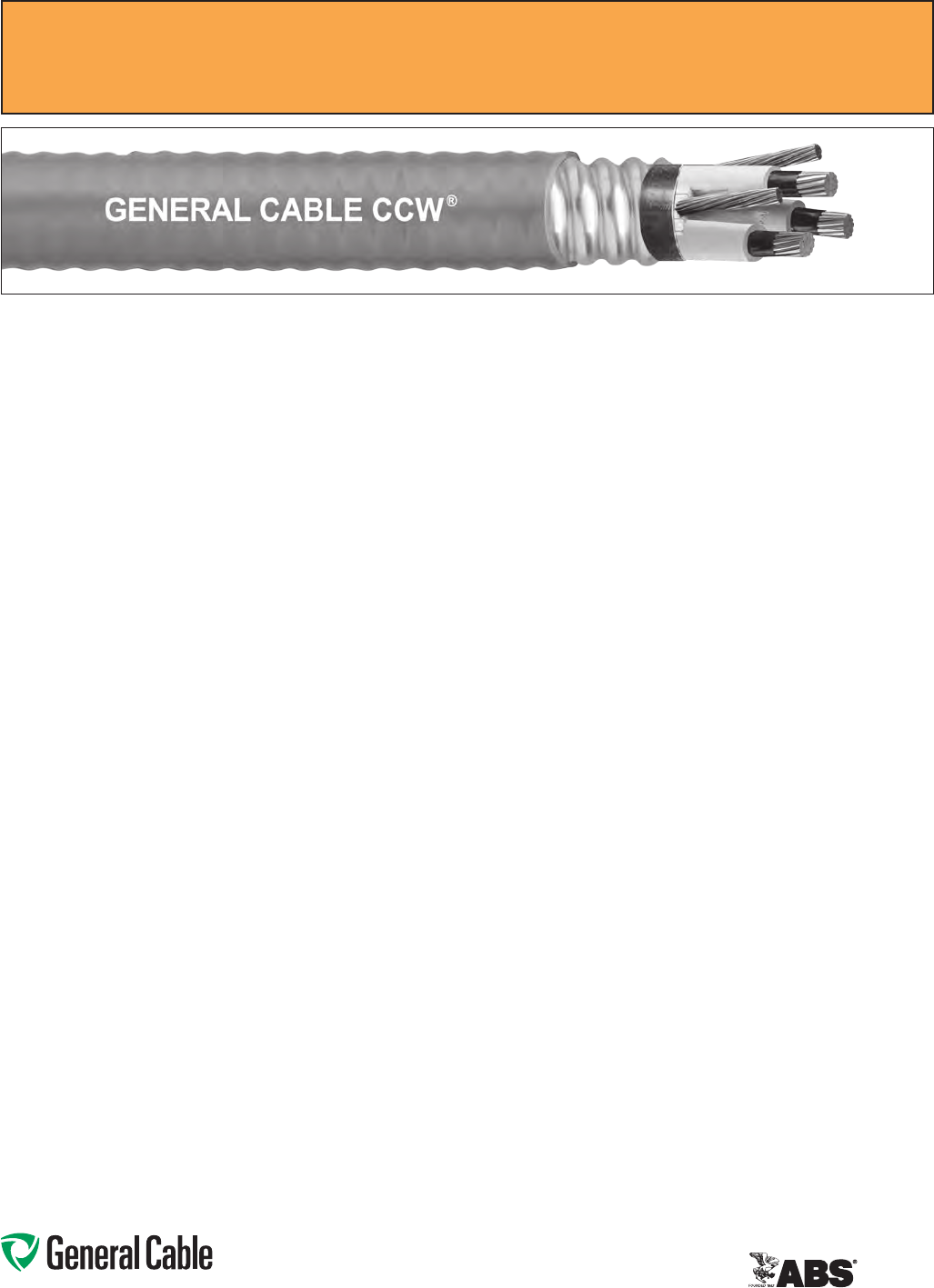
Phone: 888-593-3355
www.generalcable.com
Applications:
•VariableFrequencyDrives:
3-conductorCCWarmoredcables
withthree(3)symmetricalgrounding
wiresarethepreferredwiringmethod
forusewithACmotorscontrolledby
pulse-widthmodulatedinvertersin
VFDapplications
•CCWarmoredMedium-Voltage
powercablesofferaneconomical,
ruggedandreliablealternativeto
labor-intensivecableinconduitwiring
methods
•Foruseonfeedersandbranchcircuits
inindustrialpowerdistributionsystems
perNECArticles328and330
•ForuseinClassI,IIandIII,Divisions
1and2;andClassI,Zones1and2
hazardouslocationsperNECArticles
501,502,503and505
•Installedonmetalracks,troughs,in
raceways,incabletraysorsecured
tosupportsspacednotmorethansix
feetapart
•Installedinbothexposedand
concealedwork,wetordrylocations,
directlyburiedorembeddedin
concrete
•Recognizedforuseonfixedor
floatingoffshorepetroleumfacilities
asrecommendedbytheAmerican
PetroleumInstitute
Features:
•CCWarmorprovidesanimpervious
barriertomoisture,gasandliquids
andmeetsthegroundingrequirements
ofUL1072andtheNEC
•Factoryassembledandtestedcable
foruseasanalternativetocablein
conduitwiringsystems
Features: (cont’d)
•GeneralCable’sEPRinsulationsystem
has outstanding corona resistance and
highdielectricstrength,anditprovides
electricalstabilityunderstress
•Cablemeetscoldimpactat-40°C
•90˚Ccontinuousoperating
temperature,wetordry
•140˚Cemergencyrating
•250˚Cshortcircuitrating
Specifications:
Design Adherence:
•ICEAS-96-659/WC71Standardfor
NonshieldedCablesRated2001–
5000Volts
•UL1072Medium-VoltagePower
Cables
•UL1569MetalCladCables
•UL2225CablesandCableFittingsfor
UseinHazardousLocations
•UL1309MarineShipboardCable
Flame Tests:
•ICEAT-29-520(210,000BTU/hr)
•IEEE383(70,000BTU/hr)
•CSAFT4
•IEEE1202(70,000BTU/hr)
•UL1072
•IEC60332-3CategoryA
Compliances:
•ULTypeMV-90,ULFile#E90501
•ULTypeMC-HL,SUNRES,CT
USE,DIRBUR,-40°C,FT4,ULFile#
E90496
•ULListedMarineShipboard,ULFile#
E85994
•AmericanBureauofShipping(ABS)
ListedforCWCMC
Product Construction:
Conductor:
•BareannealedcopperperASTMB3
•CompactstrandingperASTMB496
Extruded Strand Shield (ESS):
•Extrudedthermosetsemi-conductor
stresscontrollayeroverconductorper
ICEAS-96-659andUL1072
Insulation:
•90milsEthylenePropyleneRubber
(EPR)insulationperICEAS-96-659
andUL1072
•Insulationisprinted1-black,2-redand
3-blueforphaseidentification
Grounding Conductors:
•Three(3)splitClassBstranded
bareannealedcoppergrounding
conductors
•SizedinaccordancewithUL1072and
NECTable250.122
Cable Assembly:
•Insulatedandgroundingconductors
arecabledtogetherwithnon-
hygroscopicfillerswhenrequired
•Bindertapeisappliedoverthecabled
core
CCW Armor:
•Impervious,continuouslyweldedand
corrugatedaluminumalloysheathper
UL1072andUL1569
•CCWarmorconductivitymeets
thegroundingrequirementsofNEC
Article250
Jacket:
•Flame-retardant,moisture-and
sunlight-resistantPolyvinylChloride
(PVC),yellow
•Lowtemperatureperformancemeets
ASTMD746brittlenesstemperatureat
orbelow-40°C
CCW
®
Armored Power, 2.4 kV, Nonshielded, 3/C VFD
ULTypeMC-HLorMV-90,EPR,90°C,CableTrayUse,Sunlight-Resistant
DirectBurial,ABSCWCMC
SPEC 9700
February, 2011
Phone: 888-593-3355
www.generalcable.com
CCW
®
Armored Power, 2.4 kV, Nonshielded, 3/C VFD
ULTypeMC-HLorMV-90,EPR,90°C,CableTrayUse,Sunlight-Resistant
DirectBurial,ABSCWCMC
SPEC 9700
February, 2011
CATALOG
NUMBER
COND.
SIZE
NO.
OF
COND.
INSULATION
THICKNESS
NOMINAL O.D.
OVER
INSULATION
BARE
GROUND
NOMINAL
CORE O.D.
NOMINAL
ARMOR O.D.
JACKET
THICKNESS
NOMINAL
OVERALL O.D.
APPROXIMATE NET
WEIGHT AMPACITY
AWG
(kcmil) mils mm INCHES mm AWG INCHES mm INCHES mm mils mm INCHES mm
LBS/
1000 FT
kg/
1000 m IN AIR¹
DIRECT
BURIAL²
3/C WITH GROUND MC-HL OR MV-90, 90 MILS EPR, 2.4 kV, YELLOW JACKET
9700.00803312
8(7/W)
(8.36mm²)
3 90 2.3 0.36 9.1 3x#12 0.77 19.6 0.97 24.6 50 1.27 1.08 27.4 570 848 59 85
9700.00603310
6(7/W)
(13.3mm²)
3 90 2.3 0.38 9.6 3x#10 0.85 21.6 1.06 26.9 50 1.27 1.17 29.7 745 1,109 79 105
9700.00403310
4(7/W)
(21.2mm²)
3 90 2.3 0.43 10.8 3x#10 0.97 24.6 1.19 30.2 50 1.27 1.30 33.0 965 1,436 105 135
9700.00203310
2(7/W)
(33.6mm²)
3 90 2.3 0.48 12.1 3x#10 1.10 27.9 1.34 34.0 50 1.27 1.45 36.8 1,275 1,897 140 180
9700.00103308
1(19/W)
(42.4mm²)
3 90 2.3 0.52 13.1 3x#8 1.16 29.5 1.42 36.1 50 1.27 1.53 38.9 1,525 2,269 160 200
9700.11003308
1/0(19/W)
(53.5mm²)
3 90 2.3 0.55 13.9 3x#8 1.23 31.2 1.51 38.4 60 1.52 1.65 41.9 1,840 2,738 185 230
9700.21003308
2/0(19/W)
(67.4mm²)
3 90 2.3 0.59 14.9 3x#8 1.33 33.8 1.60 40.6 60 1.52 1.73 43.9 2,165 3,222 215 260
9700.41003307
4/0(19/W)
(107mm²)
3 90 2.3 0.69 17.4 3x#7 1.53 38.9 1.83 46.5 60 1.52 1.96 49.8 3,080 4,584 285 335
9700.25003307
250(37/W)
(127mm²)
3 90 2.3 0.74 18.7 3x#7 1.64 41.7 1.96 49.8 60 1.52 2.09 53.1 3,475 5,171 320 365
9700.35003306
350(37/W)
(177mm²)
3 90 2.3 0.83 21.0 3x#6 1.86 47.2 2.19 55.6 60 1.52 2.32 58.9 4,710 7,009 395 440
9700.50003305
500(37/W)
(253mm²)
3 90 2.3 0.95 24.0 3x#5 2.10 53.3 2.45 62.2 75 1.91 2.61 66.3 6,410 9,539 485 530
9700.75003304
750(61/W)
(380mm²)
3 90 2.3 1.12 28.3 3x#4 2.51 63.8 2.93 74.4 75 1.91 3.10 78.7 9,225 13,728 615 650
9700.10003304
1000(61/W)
(507mm²)
3 90 2.3 1.27 32.2 3x#4 2.90 73.7 3.41 86.6 80 2.03 3.59 91.2 12,080 17,977 705 730
Dimensionsandweightsarenominal,subjecttoindustrytolerances.
¹In-airampacitiesareperNECTable310.60(C)(71)forthreeinsulatedcopperconductorsrated90°C,cabledwithanoverallcoveringandisolatedinairat40°Cambienttemperature.
²DirectburialampacitiesareperNECTable310.60(C)(83)forthreeinsulatedcopperconductorsrated90°C,cabledwithinanoverallcoveringanddirectlyburiedinearthat20°C
ambientearthtemperature.
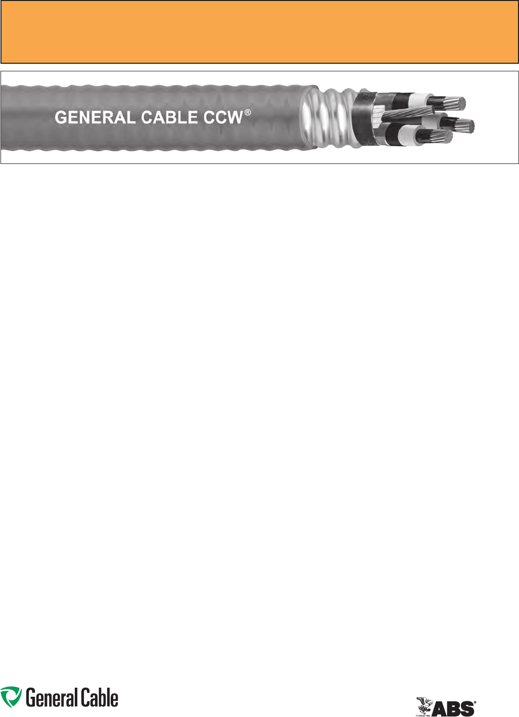
Phone: 888-593-3355
www.generalcable.com
Jacket:
•Flame-retardant,moisture-and
sunlight-resistantPolyvinylChloride
(PVC),yellow
•Lowtemperatureperformancemeets
ASTMD746brittlenesstemperatureat
orbelow-40°C
Applications:
•VariableFrequencyDrives:
3-conductorCCWarmoredcables
withthree(3)symmetricalgrounding
wiresarethepreferredwiringmethod
forusewithACmotorscontrolledby
pulse-widthmodulatedinvertersin
VFDapplications
•CCWarmoredMedium-Voltage
powercablesofferaneconomical,
ruggedandreliablealternativeto
labor-intensivecableinconduitwiring
methods
•Foruseonfeedersandbranchcircuits
inindustrialpowerdistributionsystems
perNECArticles328and330
•ForuseinClassI,IIandIII,Divisions
1and2;andClassI,Zones1and2
hazardouslocationsperNECArticles
501,502,503and505
•Installedonmetalracks,troughs,in
raceways,incabletraysorsecured
tosupportsspacednotmorethansix
feetapart
•Installedinbothexposedand
concealedwork,wetordrylocations,
directlyburiedorembeddedin
concrete
•Recognizedforuseonfixedor
floatingoffshorepetroleumfacilities
asrecommendedbytheAmerican
PetroleumInstitute
Features:
•CCWarmorprovidesanimpervious
barriertomoisture,gasandliquids
andmeetsthegroundingrequirements
ofUL1072andtheNEC
Features: (cont’d)
•TripleExtrusion:Thestrandshield,
EPRinsulationandinsulationshield
areallextrudedinoneoperation
•GeneralCable’sEPRinsulationsystem
has outstanding corona resistance and
highdielectricstrength,anditprovides
electricalstabilityunderstress
•Cablemeetscoldimpactat-40°C
•105˚Ccontinuousoperating
temperature,wetordry
•140˚Cemergencyrating
•250˚Cshortcircuitrating
Specifications:
Design Adherence:
•ICEAS-93-639/WC-74,5-46kV
ShieldedPowerCable
•AEICCS8SpecificationforShielded
PowerCable,5-46kV
•UL1072Medium-VoltagePower
Cables
•UL1569MetalCladCables
•UL2225CablesandCableFittingsfor
UseinHazardousLocations
•UL1309MarineShipboardCable
•CSAC68.3
Flame Tests:
•ICEAT-29-520(210,000BTU/hr)
•IEEE383(70,000BTU/hr)
•CSAFT4
•IEEE1202(70,000BTU/hr)
•UL1072
•IEC60332-3CategoryA
Compliances:
•ULTypeMV-105,ULFile#E90501
•ULTypeMC-HL,SUNRES,CT
USE,DIRBUR,-40°C,FT4,ULFile#
E90496
•ULListedMarineShipboard,ULFile#
E85994
•AmericanBureauofShipping(ABS)
ListedforCWCMC
Product Construction:
Conductor:
•BareannealedcopperperASTMB3
•CompactstrandingperASTMB496
Extruded Strand Shield (ESS):
•Extrudedthermosetsemi-conductor
stresscontrollayerovertheconductor
perICEAS-93-639andUL1072
Insulation:
•115milsEthylenePropyleneRubber
(EPR)insulationperICEAS-93-639
andUL1072
Extruded Insulation Shield (EIS):
•Thermosetsemi-conductingpolymeric
layer,freestrippingfromtheinsulation
perICEAS-93-639andUL1072
Shield:
•5milannealedbarecoppertapewith
25%overlap
Phase Identification:
•Color-codedpolymericidentification
tapelaidundertheshield—black,red
and blue
Grounding Conductors:
•Three(3)splitClassBstranded
bareannealedcoppergrounding
conductors
•SizedinaccordancewithUL1072and
NECArticle250
Cable Assembly:
•Insulatedandgroundingconductors
arecabledtogetherwithnon-
hygroscopicfillerswhenrequired
•Bindertapeisappliedoverthecabled
core
CCW Armor:
•Impervious,continuouslyweldedand
corrugatedaluminumalloysheathper
UL1072andUL1569
•CCWarmorconductivitymeets
thegroundingrequirementsofNEC
Article250
CCW
®
Armored Power, 5 kV 133%/8 kV 100%, Shielded, 3/C VFD
ULTypeMC-HLorMV-105,EPR,105°C,CableTrayUse,Sunlight-Resistant
DirectBurial,ABSCWCMC
SPEC 9800
May, 2012

Phone: 888-593-3355
www.generalcable.com
CCW
®
Armored Power, 5 kV 133%/8 kV 100%, Shielded, 3/C VFD
ULTypeMC-HLorMV-105,EPR,105°C,CableTrayUse,Sunlight-Resistant
DirectBurial,ABSCWCMC
SPEC 9800
May, 2012
CATALOG
NUMBER
COND.
SIZE
NO. OF
COND.
INSULATION
THICKNESS
NOMINAL O.D.
OVER
INSULATION
BARE
GROUND
NOMINAL
CORE O.D.
NOMINAL
ARMOR O.D.
JACKET
THICKNESS
NOMINAL
OVERALL O.D.
APPROXIMATE NET
WEIGHT
5 kV³
AMPACITY
AWG (kcmil) mils mm INCHES mm AWG INCHES mm INCHES mm mils mm INCHES mm
LBS/
1000 FT
kg/
1000 m IN AIR¹
DIRECT
BURIAL²
3/C WITH GROUND MC-HL OR MV-105, 115 MILS EPR, 5 kV 133% AND 8 kV 100% INSULATION LEVEL
9800.00603310 6(7/W)
(13.3mm²) 3115 2.9 0.43 10.9 3x#10 1.15 29.2 1.37 34.8 50 1.27 1.48 37.6 1,121 1,668 88 115
9800.00403310 4(7/W)
(21.2mm²) 3115 2.9 0.48 12.2 3x#10 1.24 31.5 1.51 38.4 60 1.52 1.65 41.9 1,418 2,110 115 150
9800.00203310 2(7/W)
(33.6mm²) 3115 2.9 0.53 13.5 3x#10 1.37 34.8 1.64 41.7 60 1.52 1.78 45.2 1,731 2,576 154 190
9800.00103308 1(19/W)
(42.4mm²) 3115 2.9 0.57 14.5 3x#8 1.47 37.3 1.69 42.9 60 1.52 1.82 46.2 1,978 2,944 180 215
9800.11003308 1/0(19/W)
(53.5mm²) 3115 2.9 0.60 15.2 3x#8 1.56 39.6 1.78 45.2 60 1.52 1.91 48.5 2,259 3,362 205 245
9800.21003308 2/0(19/W)
(67.4mm²) 3115 2.9 0.64 16.3 3x#8 1.61 40.9 1.92 48.8 60 1.52 2.05 52.1 2,626 3,908 240 280
9800.41003307 4/0(19/W)
(107mm²) 3115 2.9 0.74 18.8 3x#7 1.82 46.2 2.15 54.6 60 1.52 2.28 57.9 3,650 5,432 320 360
9800.25003306 250(37/W)
(127mm²) 3115 2.9 0.80 20.3 3x#62.01 51.1 2.23 56.6 60 1.52 2.36 59.9 4,060 6,042 355 395
9800.35003306 350(37/W)
(177mm²) 3115 2.9 0.89 22.6 3x#6 2.10 53.3 2.45 62.2 75 1.91 2.61 66.3 5,045 7,508 440 475
9800.50003305 500(37/W)
(253mm²) 3115 2.9 1.01 25.7 3x#5 2.39 60.7 2.75 69.9 75 1.91 2.92 74.2 7,137 10,621 545 570
9800.75003304 750(61/W)
(380mm²) 3115 2.9 1.19 30.2 3x#4 3.07 78.0 3.32 84.3 85 2.16 3.50 88.9 10,268 15,280 685 700
9800.10003304 1000(61/W)
(507mm²) 3115 2.9 1.34 34.0 3x#4 3.43 87.1 3.76 95.5 85 2.16 3.94 100.1 13,051 19,422 790 785
Dimensionsandweightsarenominal;subjecttoindustrytolerances.
¹In-airampacitiesareperNECTable310.60(C)(71)forthreeinsulatedcopperconductorsrated105°C,cabledwithanoverallcoveringandisolatedinairat40°Cambienttemperature.
²DirectburialampacitiesareperNECTable310.60(C)(83)forthreeinsulatedcopperconductorsrated105°C,cabledwithinanoverallcoveringanddirectlyburiedinearthat20°C
ambientearthtemperature.
³For8kVampacities,refertoNECTables310.60(C)(71)and310.60(C)(83)forcableslisted5001-35,000volts.
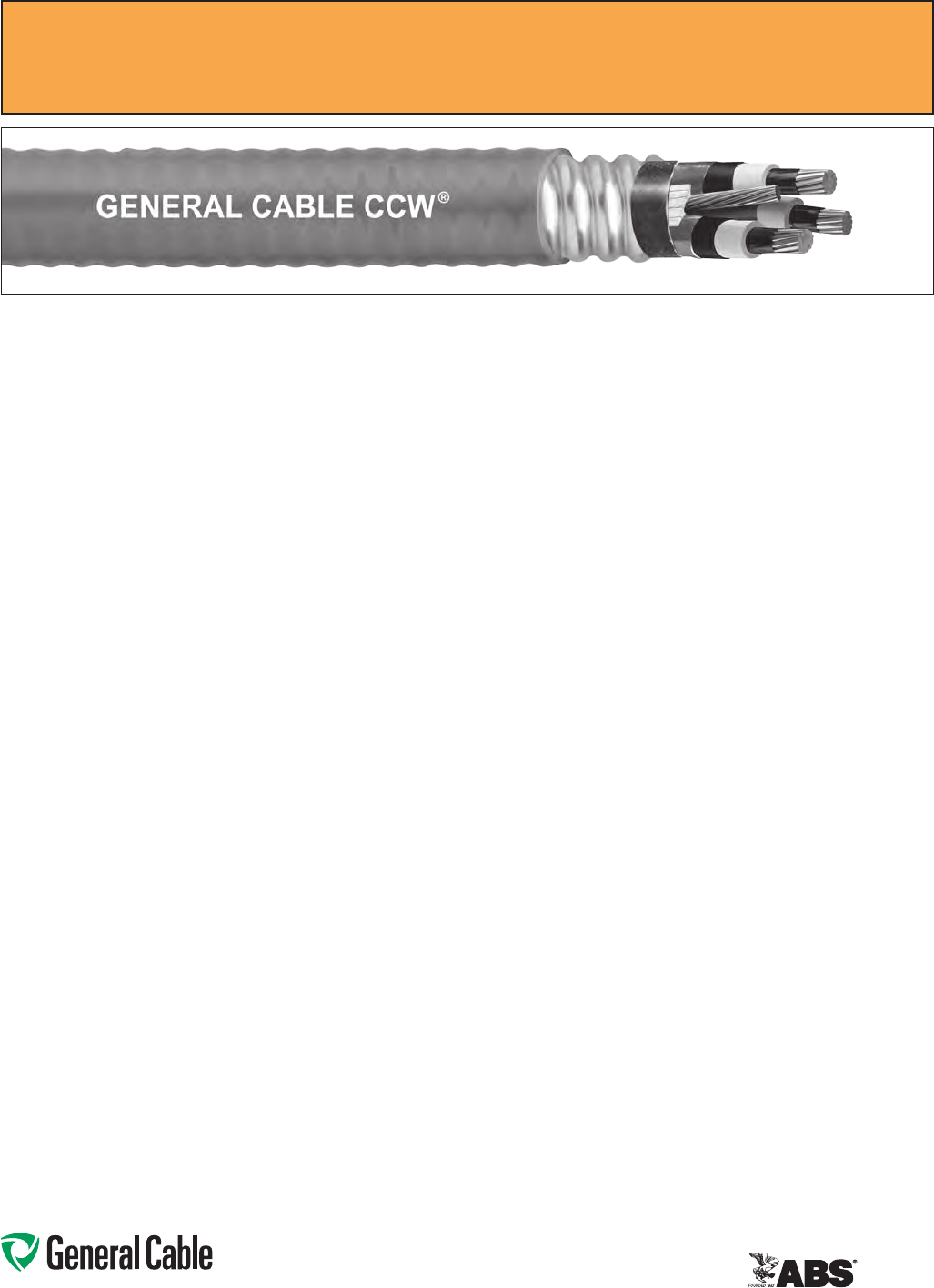
Phone: 888-593-3355
www.generalcable.com
Jacket:
•Flame-retardant,moisture-and
sunlight-resistantPolyvinylChloride
(PVC),yellow
•Lowtemperatureperformancemeets
ASTMD746brittlenesstemperatureat
orbelow-40°C
Applications:
•VariableFrequencyDrives:
3-conductorCCWarmoredcables
withthree(3)symmetricalgrounding
wiresarethepreferredwiringmethod
forusewithACmotorscontrolledby
pulse-widthmodulatedinvertersin
VFDapplications
•CCWarmoredMedium-Voltage
powercablesofferaneconomical,
ruggedandreliablealternativeto
labor-intensivecableinconduitwiring
methods
•Foruseonfeedersandbranchcircuits
inindustrialpowerdistributionsystems
perNECArticles328and330
•ForuseinClassI,IIandIII,Divisions
1and2;andClassI,Zones1and2
hazardouslocationsperNECArticles
501,502,503and505
•Installedonmetalracks,troughs,in
raceways,incabletraysorsecured
tosupportsspacednotmorethansix
feetapart
•Installedinbothexposedand
concealedwork,wetordrylocations,
directlyburiedorembeddedin
concrete
•Recognizedforuseonfixedor
floatingoffshorepetroleumfacilities
asrecommendedbytheAmerican
PetroleumInstitute
Features:
•CCWarmorprovidesanimpervious
barriertomoisture,gasandliquids
andmeetsthegroundingrequirements
ofUL1072andtheNEC
Features: (cont’d)
•TripleExtrusion:Thestrandshield,
EPRinsulationandinsulationshield
areallextrudedinoneoperation
•GeneralCable’sEPRinsulationsystem
has outstanding corona resistance and
highdielectricstrength,anditprovides
electricalstabilityunderstress
•Cablemeetscoldimpactat-40°C
•105˚Ccontinuousoperating
temperature,wetordry
•140˚Cemergencyrating
•250˚Cshortcircuitrating
Specifications:
Design Adherence:
•ICEAS-93-639/WC74,5-46kV
ShieldedPowerCable
•AEICCS8SpecificationforShielded
PowerCable,5-46kV
•UL1072Medium-VoltagePower
Cables
•UL1569MetalCladCables
•UL2225CablesandCableFittingsfor
UseinHazardousLocations
•UL1309MarineShipboardCable
•CSAC68.3
Flame Tests:
•ICEAT-29-520(210,000BTU/hr)
•IEEE383(70,000BTU/hr)
•CSAFT4
•IEEE1202(70,000BTU/hr)
•UL1072
•IEC60332-3CategoryA
Compliances:
•ULTypeMV-105,ULFile#E90501
•ULTypeMC-HL,SUNRES,CT
USE,DIRBUR,-40°C,FT4,ULFile#
E90496
•ULListedMarineShipboard,ULFile#
E85994
•AmericanBureauofShipping(ABS)
ListedforCWCMC
Product Construction:
Conductor:
•BareannealedcopperperASTMB3
•CompactstrandingperASTMB496
Extruded Strand Shield (ESS):
•Extrudedthermosetsemi-conductor
stresscontrollayerovertheconductor
perICEAS-93-639andUL1072
Insulation:
•140milsEthylenePropyleneRubber
(EPR)insulationperICEAS-93-639
andUL1072
Extruded Insulation Shield (EIS):
•Thermosetsemi-conductingpolymeric
layer,freestrippingfromtheinsulation
perICEAS-93-639andUL1072
Shield:
•5milannealedbarecoppertapewith
25%overlap
Phase Identification:
•Color-codedpolymericidentification
tapelaidundertheshield-black,red
and blue
Grounding Conductors:
•Three(3)splitClassBstranded
bareannealedcoppergrounding
conductors
•SizedinaccordancewithUL1072and
NECArticle250
Cable Assembly:
•Insulatedandgroundingconductors
arecabledtogetherwithnon-
hygroscopicfillerswhenrequired
•Bindertapeisappliedoverthecabled
core
CCW Armor:
•Impervious,continuouslyweldedand
corrugatedaluminumalloysheathper
UL1072andUL1569
•CCWarmorconductivitymeetsthe
groundingrequirementsoftheNEC
CCW
®
Armored Power, 8 kV 133%, Shielded, 3/C VFD
ULTypeMC-HLorMV-105,EPR,105°C,CableTrayUse,Sunlight-Resistant
DirectBurial,ABSCWCMC
SPEC 9815
May, 2012
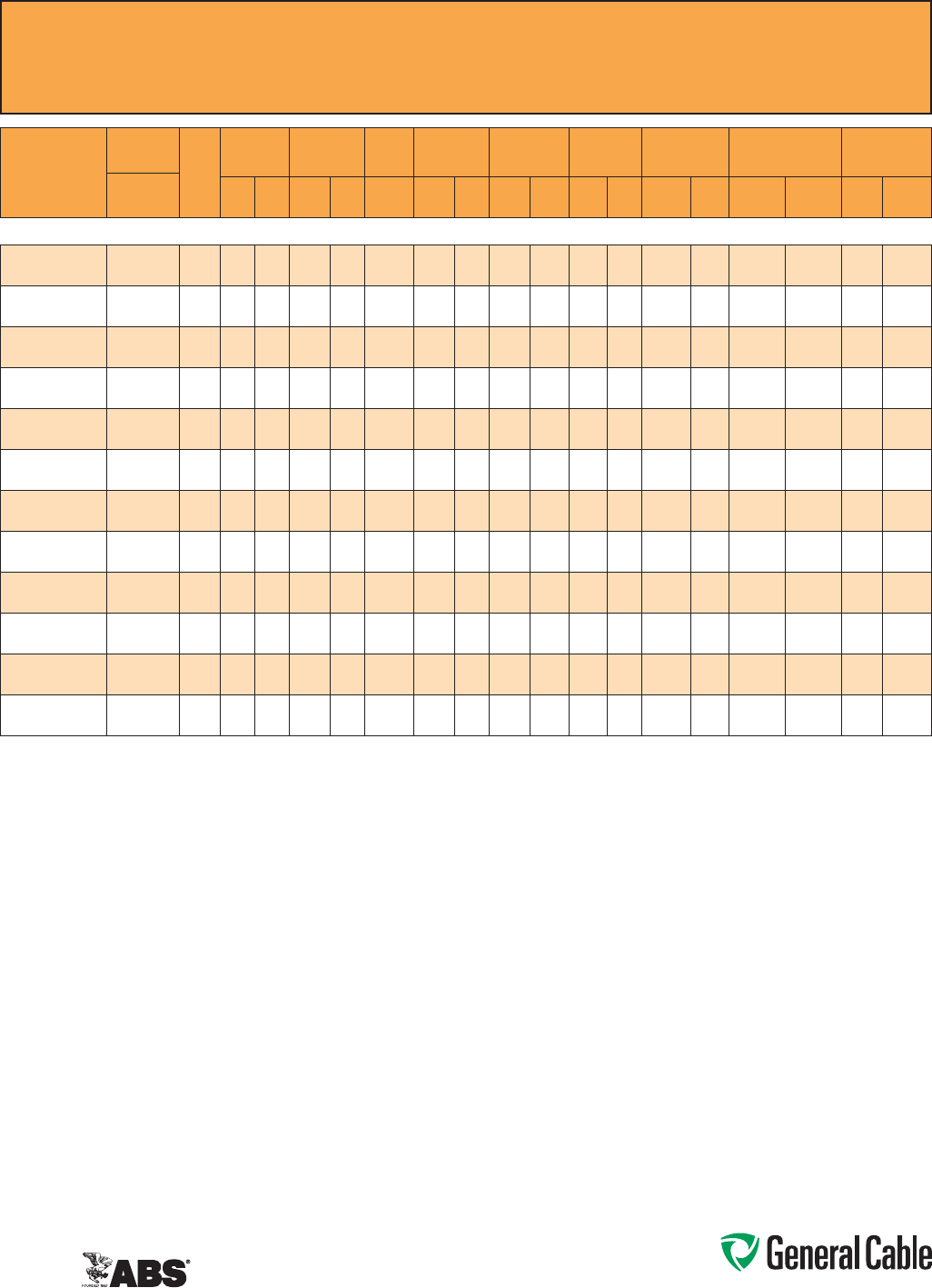
Phone: 888-593-3355
www.generalcable.com
CCW
®
Armored Power, 8 kV 133%, Shielded, 3/C VFD
ULTypeMC-HLorMV-105,EPR,105°C,CableTrayUse,Sunlight-Resistant
DirectBurial,ABSCWCMC
SPEC 9815
May, 2012
CATALOG
NUMBER
COND.
SIZE
NO. OF
COND.
INSULATION
THICKNESS
NOMINAL O.D.
OVER
INSULATION
BARE
GROUND
NOMINAL
CORE O.D.
NOMINAL
ARMOR O.D.
JACKET
THICKNESS
NOMINAL
OVERALL O.D.
APPROXIMATE NET
WEIGHT AMPACITY
AWG (kcmil) mils mm INCHES mm AWG INCHES mm INCHES mm mils mm INCHES mm
LBS/
1000 FT
kg/
1000 m IN AIR¹
DIRECT
BURIAL²
3/C WITH GROUND MC-HL OR MV-105, 140 MILS EPR, 8 kV 133% INSULATION LEVEL
9815.00603310 6(7/W)
(13.3mm²) 3140 3.6 0.48 12.2 3x#10 1.20 30.5 1.60 40.6 60 1.52 1.73 43.9 1,350 2,009 105 120
9815.00403310 4(7/W)
(21.2mm²) 3140 3.6 0.53 13.5 3x#10 1.29 32.8 1.70 43.2 60 1.52 1.83 46.5 1,600 2,381 135 155
9815.00203310 2(7/W)
(33.6mm²) 3140 3.6 0.58 14.7 3x#10 1.42 36.1 1.85 47.0 60 1.52 1.98 50.3 2,000 2,976 185 200
9815.00103308 1(19/W)
(42.4mm²) 3140 3.6 0.62 15.7 3x#8 1.52 38.6 1.93 49.0 60 1.52 2.06 52.3 2,275 3,386 210 225
9815.11003308 1/0(19/W)
(53.5mm²) 3140 3.6 0.65 16.5 3x#8 1.61 40.9 2.03 51.6 60 1.52 2.16 54.9 2,600 3,869 240 255
9815.21003308 2/0(19/W)
(67.4mm²) 3140 3.6 0.69 17.5 3x#8 1.66 42.2 2.14 54.4 60 1.52 2.27 57.7 2,950 4,390 275 290
9815.41003307 4/0(19/W)
(107mm²) 3140 3.6 0.79 20.1 3x#7 1.87 47.5 2.40 61.0 75 1.91 2.56 65.0 4,025 5,990 360 375
9815.25003306 250(37/W)
(127mm²) 3140 3.6 0.85 21.6 3x#62.06 52.3 2.59 65.8 75 1.91 2.75 69.9 4,600 6,846 400 410
9815.35003306 350(37/W)
(177mm²) 3140 3.6 0.94 23.9 3x#6 2.15 54.6 2.85 72.4 75 1.91 3.01 76.5 5,800 8,631 490 495
9815.50003305 500(37/W)
(253mm²) 3140 3.6 1.06 26.9 3x#5 2.44 62.0 3.19 81.0 85 2.16 3.37 85.6 7,800 11,608 600 590
9815.75003304 750(61/W)
(380mm²) 3140 3.6 1.26 32.0 3x#4 3.19 81.0 3.68 93.5 85 2.16 3.86 98.0 10,750 15,998 745 720
9815.10003304 1000(61/W)
(507mm²) 3140 3.6 1.42 36.1 3x#4 3.48 88.4 3.98 101.1 85 2.16 4.16 105.7 13,550 20,165 860 810
Dimensionsandweightsarenominal;subjecttoindustrytolerances.
¹In-airampacitiesareperNECTable310.60(C)(71)forthreeinsulatedcopperconductorsrated105°C,cabledwithanoverallcoveringandisolatedinairat40°Cambienttemperature.
²DirectburialampacitiesareperNECTable310.60(C)(83)forthreeinsulatedcopperconductorsrated105°C,cabledwithinanoverallcoveringanddirectlyburiedinearthat20°C
ambientearthtemperature.
Phone: 888-593-3355
www.generalcable.com
Jacket:
•Flame-retardant,moisture-and
sunlight-resistantPolyvinylChloride
(PVC),red
•Lowtemperatureperformancemeets
ASTMD746brittlenesstemperatureat
orbelow-40°C
Applications:
•CCWarmoredMedium-Voltage
powercablesofferaneconomical,
ruggedandreliablealternativeto
labor-intensivecableinconduitwiring
methods
•Foruseonfeedersandbranchcircuits
inindustrialpowerdistributionsystems
perNECArticles328and330
•ForuseinClassI,IIandIII,Divisions
1and2;andClassI,Zones1and2
hazardouslocationsperNECArticles
501,502,503and505
•Installedonmetalracks,troughs,in
raceways,incabletraysorsecured
tosupportsspacednotmorethansix
feetapart
•Installedinbothexposedand
concealedwork,wetordrylocations,
directlyburiedorembeddedin
concrete
•Recognizedforuseonfixedor
floatingoffshorepetroleumfacilities
asrecommendedbytheAmerican
PetroleumInstitute
Features:
•CCWarmorprovidesanimpervious
barriertomoisture,gasandliquids
andmeetsthegroundingrequirements
ofUL1072andtheNEC
•TripleExtrusion:Thestrandshield,
EPRinsulationandinsulationshield
areallextrudedinoneoperation
Features: (cont’d)
•GeneralCable’sEPRinsulationsystem
has outstanding corona resistance and
highdielectricstrength,anditprovides
electricalstabilityunderstress
•Cablemeetscoldimpactat-40°C
•105˚Ccontinuousoperating
temperature,wetordry
•140˚Cemergencyrating
•250˚Cshortcircuitrating
Specifications:
Design Adherence:
•ICEAS-93-639/WC-74,5-46kV
ShieldedPowerCable
•AEICCS8SpecificationforShielded
PowerCable,5-46kV
•UL1072Medium-VoltagePower
Cables
•UL1569MetalCladCables
•UL2225CablesandCableFittingsfor
UseinHazardousLocations
•UL1309MarineShipboardCable
Flame Tests:
•ICEAT-29-520(210,000BTU/hr)
•IEEE383(70,000BTU/hr)
•CSAFT4
•IEEE1202(70,000BTU/hr)
•UL1072
•IEC60332-3CategoryA
Compliances:
•ULTypeMV-105,ULFile#E90501
•ULTypeMC-HL,SUNRES,CT
USE,DIRBUR,-40°C,FT4,ULFile#
E90496
•ULListedMarineShipboard,ULFile#
E85994
•AmericanBureauofShipping(ABS)
ListedforCWCMC
Product Construction:
Conductor:
•BareannealedcopperperASTMB3
•CompactstrandingperASTMB496
Extruded Strand Shield (ESS):
•Extrudedthermosetsemi-conductor
stresscontrollayerovertheconductor
perICEAS-93-639andUL1072
Insulation:
•175milsEthylenePropyleneRubber
(EPR)insulationperICEAS-93-639
andUL1072
Extruded Insulation Shield (EIS):
•Thermosetsemi-conductingpolymeric
layer,freestrippingfromtheinsulation
perICEAS-93-639andUL1072
Shield:
•5milannealedbarecoppertapewith
25%overlap
Phase Identification:
•Color-codedpolymericidentification
tapelaidundertheshield-black,red
and blue
Grounding Conductor:
•ClassBstrandedbareannealed
coppergroundingconductor
•SizedinaccordancewithUL1072and
NECArticle250
Cable Assembly:
•Insulatedandgroundingconductors
arecabledtogetherwithnon-
hygroscopicfillerswhenrequired
•Bindertapeisappliedoverthecabled
core
CCW Armor:
•Impervious,continuouslyweldedand
corrugatedaluminumalloysheathper
UL1072andUL1569
•CCWarmorconductivitymeetsthe
groundingrequirementsoftheNEC
CCW
®
Armored Power, 15 kV 100%, Shielded, 3/C
ULTypeMC-HLorMV-105,EPR,105°C,CableTrayUse,Sunlight-Resistant
DirectBurial,ABSCWCMC
SPEC 9825
May, 2012
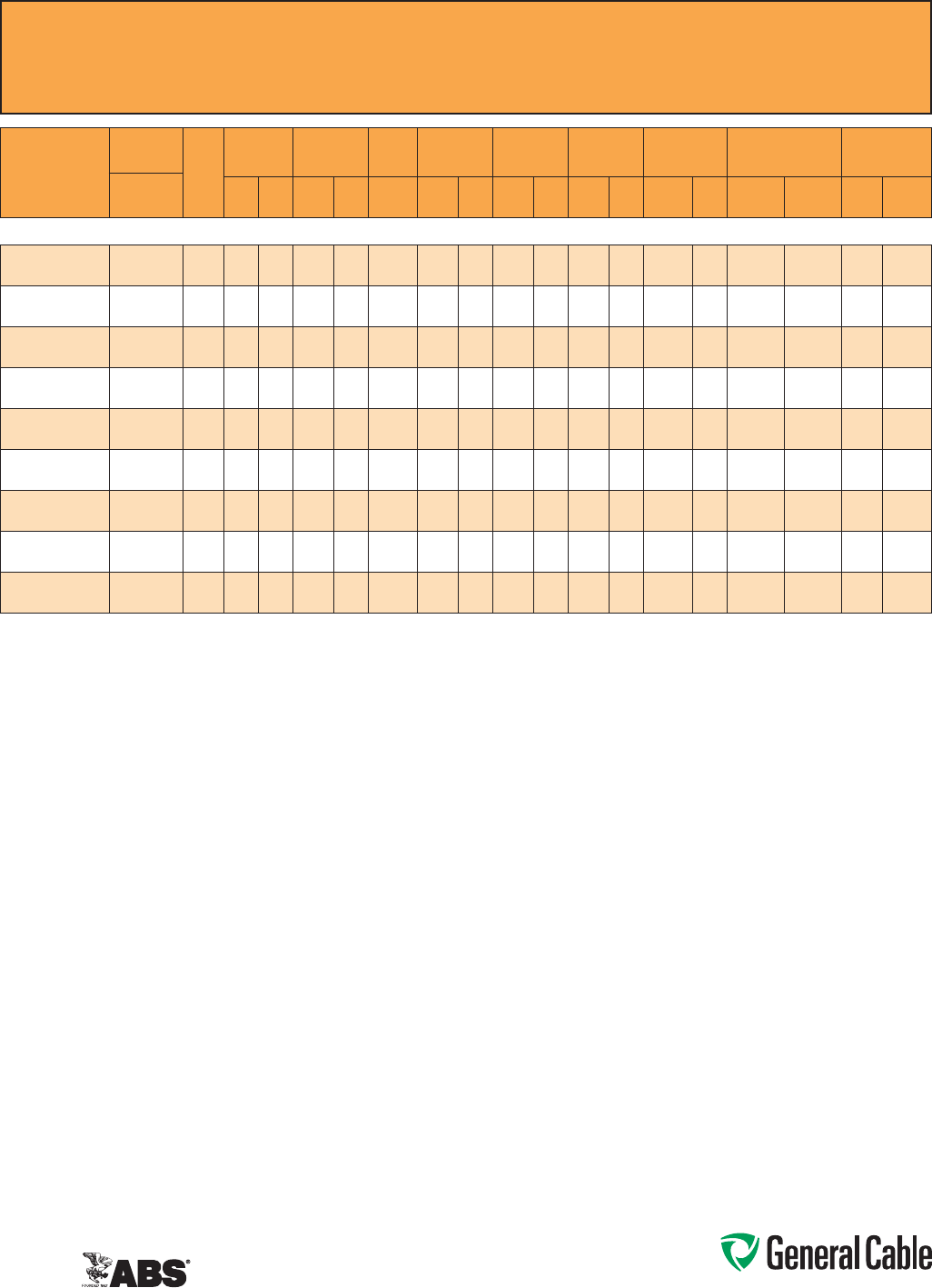
Phone: 888-593-3355
www.generalcable.com
SPEC 9825
May, 2012
CCW
®
Armored Power, 15 kV 100%, Shielded, 3/C
ULTypeMC-HLorMV-105,EPR,105°C,CableTrayUse,Sunlight-Resistant
DirectBurial,ABSCWCMC
CATALOG
NUMBER
COND.
SIZE
NO. OF
COND.
INSULATION
THICKNESS
NOMINAL O.D.
OVER
INSULATION
BARE
GROUND
NOMINAL
CORE O.D.
NOMINAL
ARMOR O.D.
JACKET
THICKNESS
NOMINAL
OVERALL O.D.
APPROXIMATE NET
WEIGHT AMPACITY
AWG (kcmil) mils mm INCHES mm AWG INCHES mm INCHES mm mils mm INCHES mm
LBS/
1000 FT
kg/
1000 m IN AIR¹
DIRECT
BURIAL²
3/C WITH GROUND MC-HL OR MV-105, 175 MILS EPR, 15 kV 100% INSULATION LEVEL
9825.00203106 2(7/W)
(33.6mm²)
3175 4.4 0.65 16.5 61.61 40.9 1.96 49.8 60 1.52 2.05 52.1 2,077 3,091 185 200
9825.00103104 1(19/W)
(42.4mm²)
3175 4.4 0.69 17.5 4 1.68 42.7 2.01 51.1 60 1.52 2.15 54.6 2,469 3,674 210 225
9825.11003104 1/0(19/W)
(53.5mm²)
3175 4.4 0.72 18.3 4 1.78 45.2 2.10 53.3 60 1.52 2.24 56.9 2,760 4,107 240 255
9825.21003104 2/0(19/W)
(67.4mm²)
3175 4.4 0.76 19.3 4 1.88 47.8 2.19 55.6 60 1.52 2.36 59.9 3,130 4,658 275 290
9825.41003103 4/0(19/W)
(107mm²)
3175 4.4 0.86 21.8 32.09 53.1 2.45 62.2 75 1.91 2.61 66.3 4,290 6,384 360 375
9825.25003102 250(37/W)
(127mm²)
3175 4.4 0.92 23.4 2 2.19 55.6 2.58 65.5 75 1.91 2.74 69.6 4,775 7,106 400 410
9825.35003102 350(37/W)
(177mm² )
3175 4.4 1.01 25.7 2 2.45 62.2 2.85 72.4 75 1.91 3.01 76.5 6,132 9,125 490 495
9825.50003101 500(37/W)
(253mm²)
3175 4.4 1.13 28.7 12.71 68.8 3.16 80.3 85 2.16 3.34 84.8 8,052 11,983 600 590
9825.750 031110 750(61/W)
(380mm²)
3175 4.4 1.31 33.3 1/0 3.12 79.2 3.67 93.2 85 2.16 3.85 97.8 11,098 16,516 745 720
Dimensionsandweightsarenominal;subjecttoindustrytolerances.
¹AmpacitiesinairareperNECTable310.60(C)(71)foraninsulatedthree-conductorcoppercableisolatedinairwith105°Cratedconductorsata40°Cambienttemperature.
²DirectburialampacitiesareperNECTable310.60(C)(83)forthreeinsulatedcopperconductorscabledwithinanoverallcovering,directlyburiedinearthwith105°Cratedconductors
at20°Cambientearthtemperature.
Phone: 888-593-3355
www.generalcable.com
Jacket:
•Flame-retardant,moisture-and
sunlight-resistantPolyvinylChloride
(PVC),red
•Lowtemperatureperformancemeets
ASTMD746brittlenesstemperatureat
orbelow-40°C
Applications:
•CCWarmoredMedium-Voltage
powercablesofferaneconomical,
ruggedandreliablealternativeto
labor-intensivecableinconduitwiring
methods
•Foruseonfeedersandbranchcircuits
inindustrialpowerdistributionsystems
perNECArticles328and330
•ForuseinClassI,IIandIII,Divisions
1and2;andClassI,Zones1and2
hazardouslocationsperNECArticles
501,502,503and505
•Installedonmetalracks,troughs,in
raceways,incabletraysorsecured
tosupportsspacednotmorethansix
feetapart
•Installedinbothexposedand
concealedwork,wetordrylocations,
directlyburiedorembeddedin
concrete
•Recognizedforuseonfixedor
floatingoffshorepetroleumfacilities
asrecommendedbytheAmerican
PetroleumInstitute
Features:
•CCWarmorprovidesanimpervious
barriertomoisture,gasandliquids
andmeetsthegroundingrequirements
ofUL1072andtheNEC
•TripleExtrusion:Thestrandshield,
EPRinsulationandinsulationshield
areallextrudedinoneoperation
Features: (cont’d)
•GeneralCable’sEPRinsulationsystem
has outstanding corona resistance and
highdielectricstrength,anditprovides
electricalstabilityunderstress
•Cablemeetscoldimpactat-40°C
•105˚Ccontinuousoperating
temperature,wetordry
•140˚Cemergencyrating
•250˚Cshortcircuitrating
Specifications:
Design Adherence:
•ICEAS-93-639/WC-74,5-46kV
ShieldedPowerCable
•AEICCS8SpecificationforShielded
PowerCable,5-46kV
•UL1072Medium-VoltagePower
Cables
•UL1569MetalCladCables
•UL2225CablesandCableFittingsfor
UseinHazardousLocations
•UL1309MarineShipboardCable
Flame Tests:
•ICEAT-29-520(210,000BTU/hr)
•IEEE383(70,000BTU/hr)
•CSAFT4
•IEEE1202(70,000BTU/hr)
•UL1072
•IEC60332-3CategoryA
Compliances:
•ULTypeMV-105,ULFile#E90501
•ULTypeMC-HL,SUNRES,CT
USE,DIRBUR,-40°C,FT4,ULFile#
E90496
•ULListedMarineShipboard,ULFile#
E85994
•AmericanBureauofShipping(ABS)
ListedforCWCMC
Product Construction:
Conductor:
•BareannealedcopperperASTMB3
•CompactstrandingperASTMB496
Extruded Strand Shield (ESS):
•Extrudedthermosetsemi-conductor
stresscontrollayerovertheconductor
perICEAS-93-639andUL1072
Insulation:
•220milsEthylenePropyleneRubber
(EPR)insulationperICEAS-93-639
andUL1072
Extruded Insulation Shield (EIS):
•Thermosetsemi-conductingpolymeric
layer,freestrippingfromtheinsulation
perICEAS-93-639andUL1072
Shield:
•5milannealedbarecoppertapewith
25%overlap
Phase Identification:
•Color-codedpolymericidentification
tapelaidundertheshield-black,red
and blue
Grounding Conductor:
•ClassBstrandedbareannealed
coppergroundingconductor
•SizedinaccordancewithUL1072and
NECArticle250
Cable Assembly:
•Insulatedandgroundingconductors
arecabledtogetherwithnon-
hygroscopicfillerswhenrequired
•Bindertapeisappliedoverthecabled
core
CCW Armor:
•Impervious,continuouslyweldedand
corrugatedaluminumalloysheathper
UL1072andUL1569
•CCWarmorconductivitymeetsthe
groundingrequirementsoftheNEC
CCW
®
Armored Power, 15 kV 133%, Shielded, 3/C
ULTypeMC-HLorMV-105,EPR,105°C,CableTrayUse,Sunlight-Resistant
DirectBurial,ABSCWCMC
SPEC 9835
May, 2012
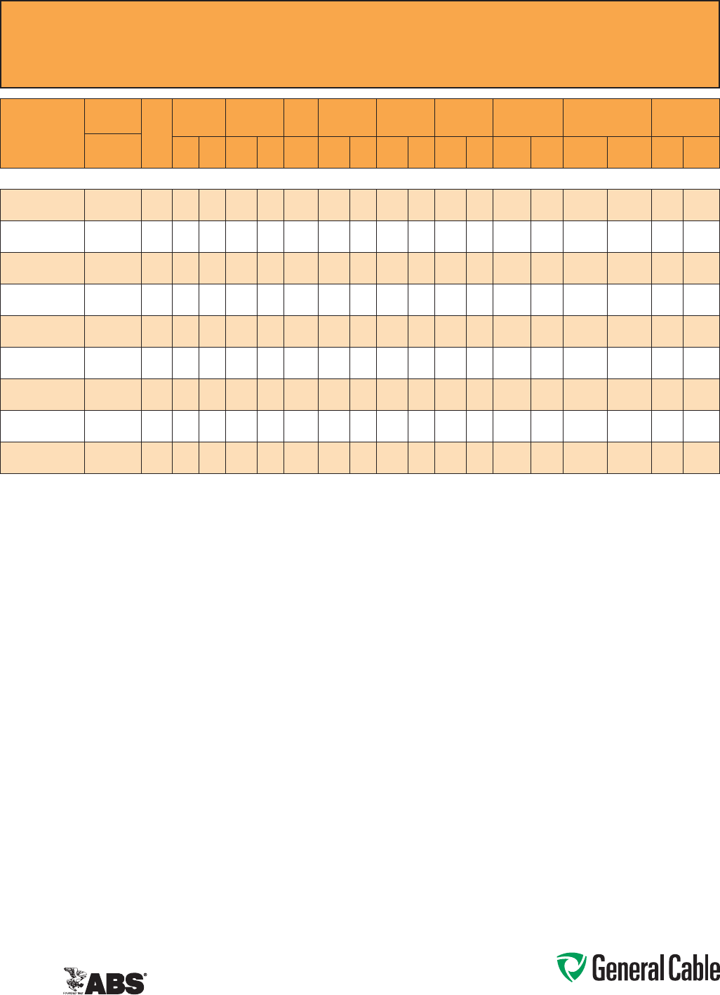
Phone: 888-593-3355
www.generalcable.com
CCW
®
Armored Power, 15 kV 133%, Shielded, 3/C
ULTypeMC-HLorMV-105,EPR,105°C,CableTrayUse,Sunlight-Resistant
DirectBurial,ABSCWCMC
SPEC 9835
May, 2012
CATALOG
NUMBER
COND.
SIZE
NO. OF
COND.
INSULATION
THICKNESS
NOMINAL O.D.
OVER
INSULATION
BARE
GROUND
NOMINAL
CORE O.D.
NOMINAL
ARMOR O.D.
JACKET
THICKNESS
NOMINAL
OVERALL O.D.
APPROXIMATE NET
WEIGHT AMPACITY
AWG (kcmil) mils mm INCHES mm AWG INCHES mm INCHES mm mils mm INCHES mm
LBS/
1000 FT
kg/
1000 m IN AIR¹
DIRECT
BURIAL²
3/C WITH GROUND MC-HL OR MV-105, 220 MILS EPR, 15 kV 133% INSULATION LEVEL
9835.00203106 2(7/W)
(33.6mm²)
3220 5.6 0.76 19.3 61.82 46.2 2.15 54.6 60 1.52 2.28 57.9 2,473 3,680 185 200
9835.00103104 1(19/W)
(42.4mm²)
3220 5.6 0.79 20.1 4 1.88 47.8 2.23 56.6 60 1.52 2.36 59.9 2,811 4,183 210 225
9835.11003104 1/0(19/W)
(53.5mm²)
3220 5.6 0.83 21.1 4 1.96 49.8 2.32 58.9 75 1.91 2.48 63.0 3,190 4,747 240 255
9835.21003104 2/0(19/W)
(67.4mm²)
3220 5.6 0.87 22.1 4 2.06 52.3 2.40 61.0 75 1.91 2.56 65.0 3,630 5,402 275 290
9835.41003103 4/0(19/W)
(107mm²)
3220 5.6 0.97 24.6 32.26 57.4 2.62 66.5 75 1.91 2.79 70.9 4,435 6,600 360 345
9835.25003102 250(37/W)
(127mm²)
3220 5.6 1.03 26.2 2 2.36 59.9 2.75 69.9 75 1.91 2.92 74.2 5,086 7,569 400 410
9835.35003102 350(37/W)
(177mm²)
3220 5.6 1.12 28.4 2 2.61 66.3 3.03 77.0 85 2.16 3.21 81.5 6,445 9,591 490 495
9835.50003101 500(37/W)
(253mm²)
3220 5.6 1.24 31.5 12.86 72.6 3.32 84.3 85 2.16 3.50 88.9 8,376 12,465 600 590
9835.750031110 750(61/W)
(380mm²)
3220 5.6 1.41 35.8 1/0 3.25 82.6 3.80 96.5 85 2.16 3.98 101.1 11,431 17,011 745 720
Dimensionsandweightsarenominal;subjecttoindustrytolerances.
¹AmpacitiesinairareperNECTable310.60(C)(71)foraninsulatedthree-conductorcoppercableisolatedinairwith105°Cratedconductorsata40°Cambienttemperature.
²DirectburialampacitiesareperNECTable310.60(C)(83)forthreeinsulatedcopperconductorscabledwithinanoverallcovering,directlyburiedinearthwith105°Cratedconductors
at20°Cambientearthtemperature.
Phone: 888-593-3355
www.generalcable.com
Jacket:
•Flame-retardant,moisture-and
sunlight-resistantPolyvinylChloride
(PVC)perUL1072,orange
•Lowtemperatureperformancemeets
ASTMD746brittlenesstemperatureat
orbelow-40°C
Applications:
•CCWarmoredMedium-Voltage
powercablesofferaneconomical,
ruggedandreliablealternativeto
labor-intensivecableinconduitwiring
methods
•Foruseonfeedersandbranchcircuits
inindustrialpowerdistributionsystems
perNECArticles328and330
•ForuseinClassI,IIandIII,Divisions
1and2;andClassI,Zones1and2
hazardouslocationsperNECArticles
501,502,503and505
•Installedonmetalracks,troughs,in
raceways,incabletraysorsecured
tosupportsspacednotmorethansix
feetapart
•Installedinbothexposedand
concealedwork,wetordrylocations,
directlyburiedorembeddedin
concrete
•Recognizedforuseonfixedor
floatingoffshorepetroleumfacilities
asrecommendedbytheAmerican
PetroleumInstitute
Features:
•CCWarmorprovidesanimpervious
barriertomoisture,gasandliquids
andmeetsthegroundingrequirements
ofUL1072andtheNEC
•TripleExtrusion:Thestrandshield,
EPRinsulationandinsulationshield
areallextrudedinoneoperation
Features: (cont’d)
•GeneralCable’sEPRinsulationsystem
has outstanding corona resistance and
highdielectricstrength,anditprovides
electricalstabilityunderstress
•Cablemeetscoldimpactat-40°C
•105˚Ccontinuousoperating
temperature,wetordry
•140˚Cemergencyrating
•250˚Cshortcircuitrating
Specifications:
Design Adherence:
•ICEAS-93-639/WC-74,5-46kV
ShieldedPowerCable
•AEICCS8SpecificationforShielded
PowerCable,5-46kV
•UL1072Medium-VoltagePower
Cables
•UL1569MetalCladCables
•UL2225CablesandCableFittingsfor
UseinHazardousLocations
•UL1309MarineShipboardCable
Flame Tests:
•ICEAT-29-520(210,000BTU/hr)
•IEEE383(70,000BTU/hr)
•CSAFT4
•IEEE1202(70,000BTU/hr)
•UL1072
•IEC60332-3CategoryA
Compliances:
•ULTypeMV-105,ULFile#E90501
•ULTypeMC-HL,SUNRES,CT
USE,DIRBUR,-40°C,FT4,ULFile#
E90496
•ULListedMarineShipboard,ULFile#
E85994
•AmericanBureauofShipping(ABS)
ListedforCWCMC
Product Construction:
Conductor:
•BareannealedcopperperASTMB3
•CompactstrandingperASTMB496
Extruded Strand Shield (ESS):
•Extrudedthermosetsemi-conductor
stresscontrollayerovertheconductor
perICEAS-93-639andUL1072
Insulation:
•260milsEthylenePropyleneRubber
(EPR)insulationperICEAS-93-639
andUL1072
Extruded Insulation Shield (EIS):
•Thermosetsemi-conductingpolymeric
layer,freestrippingfromtheinsulation
perICEAS-93-639andUL1072
Shield:
•5milannealedbarecoppertapewith
25%overlap
Phase Identification:
•Color-codedpolymericidentification
tapelaidundertheshield-black,red
and blue
Grounding Conductor:
•ClassBstrandedbareannealed
coppergroundingconductor
•SizedinaccordancewithUL1072and
NECArticle250
Cable Assembly:
•Insulatedandgroundingconductors
arecabledtogetherwithnon-
hygroscopicfillerswhenrequired
•Bindertapeisappliedoverthecabled
core
CCW Armor:
•Impervious,continuouslyweldedand
corrugatedaluminumalloysheathper
UL1072andUL1569
•CCWarmorconductivitymeetsthe
groundingrequirementsoftheNEC
CCW
®
Armored Power, 25 kV 100%, Shielded, 3/C
ULTypeMC-HLorMV-105,EPR,105°C,CableTrayUse,Sunlight-Resistant
DirectBurial,ABSCWCMC
SPEC 9845
May, 2012
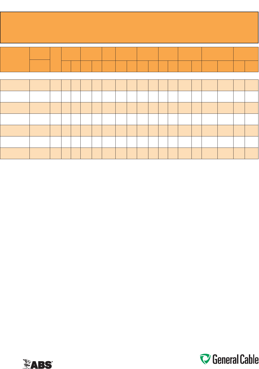
Phone: 888-593-3355
www.generalcable.com
CCW
®
Armored Power, 25 kV 100%, Shielded, 3/C
ULTypeMC-HLorMV-105,EPR,105°C,CableTrayUse,Sunlight-Resistant
DirectBurial,ABSCWCMC
SPEC 9845
May, 2012
CATALOG
NUMBER
COND.
SIZE
NO. OF
COND.
INSULATION
THICKNESS
NOMINAL O.D.
OVER
INSULATION
BARE
GROUND
NOMINAL
CORE O.D.
NOMINAL
ARMOR O.D.
JACKET
THICKNESS
NOMINAL
OVERALL O.D.
APPROXIMATE NET
WEIGHT AMPACITY
AWG (kcmil) mils mm INCHES mm AWG INCHES mm INCHES mm mils mm INCHES mm
LBS/
1000 FT
kg/
1000 m IN AIR¹
DIRECT
BURIAL²
3/C WITH GROUND MC-HL OR MV-105, 260 MILS EPR, 25 kV 100% INSULATION LEVEL
9845.00103104
1(19/W)
(42.4mm²)
3260 6.6 0.87 22.1 4 2.07 52.6 2.45 62.2 75 1.91 2.61 66.3 3,189 4,746 210 225
9845.11003104
1/0(19/W)
(53.5mm²)
3260 6.6 0.90 22.9 4 2.15 54.6 2.53 64.3 75 1.91 2.69 68.3 3,536 5,262 240 255
9845.21003104
2/0(19/W)
(67.4mm²)
3260 6.6 0.94 23.9 4 2.24 56.9 2.62 66.5 75 1.91 2.79 70.9 3,939 5,862 275 290
9845.41003103
4/0(19/W)
(107mm²)
3260 6.6 1.04 26.4 32.51 63.8 2.93 74.4 75 1.91 3.10 78.7 5,122 7,622 360 345
9845.25003102
250(37/W)
(127mm²)
3260 6.6 1.10 27.9 2 2.61 66.3 3.07 78.0 85 2.16 3.25 82.6 5,819 8,660 400 410
9845.35003102
350(37/W)
(177mm²)
3260 6.6 1.19 30.2 2 2.82 71.6 3.32 84.3 85 2.16 3.50 88.9 7,115 10,588 490 495
9845.50003101
500(37/W)
(253mm²)
3260 6.6 1.31 33.3 13.08 78.2 3.62 91.9 85 2.16 3.81 96.8 9,125 13,579 600 590
Dimensionsandweightsarenominal;subjecttoindustrytolerances.
¹In-airampacitiesareperNECTable310.60(C)(71)forthreeinsulatedcopperconductorsrated105°C,cabledwithanoverallcoveringandisolatedinairat40°Cambienttemperature.
²DirectburialampacitiesareperNECTable310.60(C)(83)forthreeinsulatedcopperconductorsrated105°C,cabledwithinanoverallcoveringanddirectlyburiedinearthat20°C
ambientearthtemperature.

Phone: 888-593-3355
www.generalcable.com
Jacket:
•Flame-retardant,moisture-and
sunlight-resistantPolyvinylChloride
(PVC)perUL1072,orange
•Lowtemperatureperformancemeets
ASTMD746brittlenesstemperatureat
orbelow-40°C
Applications:
•CCWarmoredMedium-Voltage
powercablesofferaneconomical,
ruggedandreliablealternativeto
labor-intensivecableinconduitwiring
methods
•Foruseonfeedersandbranchcircuits
inindustrialpowerdistributionsystems
perNECArticles328and330
•ForuseinClassI,IIandIII,Divisions
1and2;andClassI,Zones1and2
hazardouslocationsperNECArticles
501,502,503and505
•Installedonmetalracks,troughs,in
raceways,incabletraysorsecured
tosupportsspacednotmorethansix
feetapart
•Installedinbothexposedand
concealedwork,wetordrylocations,
directlyburiedorembeddedin
concrete
•Recognizedforuseonfixedor
floatingoffshorepetroleumfacilities
asrecommendedbytheAmerican
PetroleumInstitute
Features:
•CCWarmorprovidesanimpervious
barriertomoisture,gasandliquids
andmeetsthegroundingrequirements
ofUL1072andtheNEC
•TripleExtrusion:Thestrandshield,
EPRinsulationandinsulationshield
areallextrudedinoneoperation
Features: (cont’d)
•GeneralCable’sEPRinsulationsystem
has outstanding corona resistance and
highdielectricstrength,anditprovides
electricalstabilityunderstress
•Cablemeetscoldimpactat-40°C
•105˚Ccontinuousoperating
temperature,wetordry
•140˚Cemergencyrating
•250˚Cshortcircuitrating
Specifications:
Design Adherence:
•ICEAS-93-639/WC74,5-46kV
ShieldedPowerCable
•AEICCS8SpecificationforShielded
PowerCable,5-46kV
•UL1072Medium-VoltagePower
Cables
•UL1569MetalCladCables
•UL2225CablesandCableFittingsfor
UseinHazardousLocations
•UL1309MarineShipboardCable
Flame Tests:
•ICEAT-29-520(210,000BTU/hr)
•IEEE383(70,000BTU/hr)
•CSAFT4
•IEEE1202(70,000BTU/hr)
•UL1072
•IEC60332-3CategoryA
Compliances:
•ULTypeMV-105,ULFile#E90501
•ULTypeMC-HL,SUNRES,CT
USE,DIRBUR,-40°C,FT4,ULFile#
E90496
•ULListedMarineShipboard,ULFile#
E85994
•AmericanBureauofShipping(ABS)
ListedforCWCMC
Product Construction:
Conductor:
•BareannealedcopperperASTMB3
•CompactstrandingperASTMB496
Extruded Strand Shield (ESS):
•Extrudedthermosetsemi-conductor
stresscontrollayerovertheconductor
perICEAS-93-639andUL1072
Insulation:
•345milsEthylenePropyleneRubber
(EPR)insulationperICEAS-93-639
andUL1072
Extruded Insulation Shield (EIS):
•Thermosetsemi-conductingpolymeric
layer,freestrippingfromtheinsulation
perICEAS-93-639andUL1072
Shield:
•5milannealedbarecoppertapewith
25%overlap
Phase Identification:
•Color-codedpolymericidentification
tapelaidundertheshield-black,red
and blue
Grounding Conductor:
•ClassBstrandedbareannealed
coppergroundingconductor
•SizedinaccordancewithUL1072and
NECArticle250
Cable Assembly:
•Insulatedandgroundingconductors
arecabledtogetherwithnon-
hygroscopicfillerswhenrequired
•Bindertapeisappliedoverthecabled
core
CCW Armor:
•Impervious,continuouslyweldedand
corrugatedaluminumalloysheathper
UL1072andUL1569
•CCWarmorconductivitymeetsthe
groundingrequirementsoftheNEC
CCW
®
Armored Power, 25 kV 133%/35 kV 100%, Shielded, 3/C
ULTypeMC-HLorMV-105,EPR,105°C,CableTrayUse,Sunlight-Resistant
DirectBurial,ABSCWCMC
SPEC 9855
February, 2011
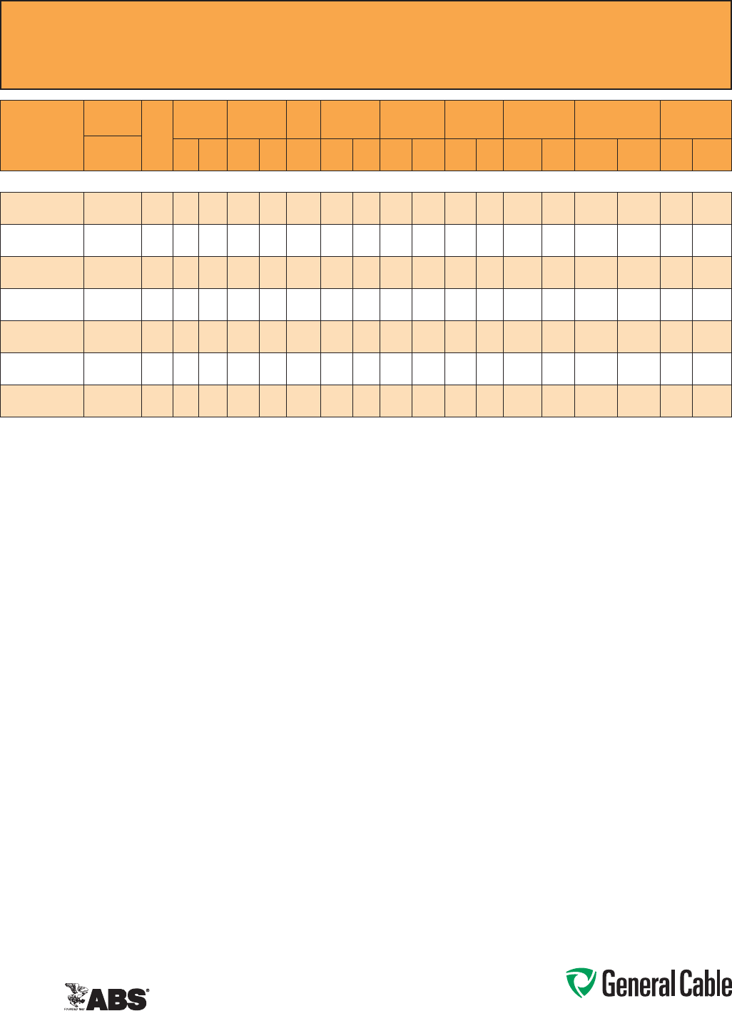
Phone: 888-593-3355
www.generalcable.com
CCW
®
Armored Power, 25 kV 133%/35 kV 100%, Shielded, 3/C
ULTypeMC-HLorMV-105,EPR,105°C,CableTrayUse,Sunlight-Resistant
DirectBurial,ABSCWCMC
SPEC 9855
February, 2011
CATALOG
NUMBER
COND.
SIZE
NO. OF
COND.
INSULATION
THICKNESS
NOMINAL O.D.
OVER
INSULATION
BARE
GROUND
NOMINAL
CORE O.D.
NOMINAL
ARMOR O.D.
JACKET
THICKNESS
NOMINAL
OVERALL O.D.
APPROXIMATE NET
WEIGHT AMPACITY
AWG
(kcmil) mils mm INCHES mm AWG INCHES mm INCHES mm mils mm INCHES mm
LBS/
1000 FT
kg/
1000 m IN AIR¹
DIRECT
BURIAL²
3/C WITH GROUND MC-HL OR MV-105, 345 MILS EPR, 25 kV 133% AND 35 kV 100% INSULATION LEVEL³
9855.00103104
1(19/W)
(42.4mm²)
3345 8.8 1.04 26.4 4 2.48 63.0 2.89 73.4 75 1.91 3.05 77.5 4,100 6,101 210 225
9855.11003104
1/0(19/W)
(53.5mm²)
3345 8.8 1.07 27.2 4 2.56 65.0 2.98 75.7 75 1.91 3.14 79.8 4,500 6,697 240 255
9855.21003104
2/0(19/W)
(67.4mm²)
3345 8.8 1.11 28.2 4 2.65 67.3 3.11 79.0 85 2.16 3.30 83.8 4,950 7,366 275 290
9855.41003103
4/0(19/W)
(107mm²)
3345 8.8 1.22 31.0 32.88 73.2 3.41 86.6 85 2.16 3.60 91.4 6,200 9,227 360 345
9855.25003103
250(37/W)
(127mm²)
3345 8.8 1.27 32.3 32.97 75.4 3.63 92.2 85 2.16 3.81 96.8 6,800 10,119 400 410
9855.35003102
350(37/W)
(177mm²)
3345 8.8 1.36 34.5 2 3.20 81.3 3.76 95.5 85 2.16 3.94 100.1 8,000 11,905 490 495
9855.50003101
500(37/W)
(253mm²)
3345 8.8 1.48 37.6 13.45 87.6 4.10 104.1 85 2.16 4.23 107.4 10,150 15,105 600 590
Dimensionsandweightsarenominal;subjecttoindustrytolerances.
¹In-airampacitiesareperNECTable310.60(C)(71)forthreeinsulatedcopperconductorsrated105°C,cabledwithanoverallcoveringandisolatedinairat40°Cambienttemperature.
²DirectburialampacitiesareperNECTable310.60(C)(83)forthreeinsulatedcopperconductorsrated105°C,cabledwithinanoverallcoveringanddirectlyburiedinearthat20°C
ambientearthtemperature.
³Catalognumber9855.00103104,1AWG,3conductorisonlylisted25kV133%insulationlevelinaccordancewithUL1072.

Phone: 888-593-3355
www.generalcable.com
Jacket:
•Flame-retardant,moisture-and
sunlight-resistantPolyvinylChloride
(PVC)perUL1072,orange
•Lowtemperatureperformancemeets
ASTMD746brittlenesstemperatureat
orbelow-40°C
Applications:
•CCWarmoredMedium-Voltage
powercablesofferaneconomical,
ruggedandreliablealternativeto
labor-intensivecableinconduitwiring
methods
•Foruseonfeedersandbranchcircuits
inindustrialpowerdistributionsystems
perNECArticles328and330
•ForuseinClassI,IIandIII,Divisions
1and2;andClassI,Zones1and2
hazardouslocationsperNECArticles
501,502,503and505
•Installedonmetalracks,troughs,in
raceways,incabletraysorsecured
tosupportsspacednotmorethansix
feetapart
•Installedinbothexposedand
concealedwork,wetordrylocations,
directlyburiedorembeddedin
concrete
•Recognizedforuseonfixedor
floatingoffshorepetroleumfacilities
asrecommendedbytheAmerican
PetroleumInstitute
Features:
•CCWarmorprovidesanimpervious
barriertomoisture,gasandliquids
andmeetsthegroundingrequirements
ofUL1072andtheNEC
•TripleExtrusion:Thestrandshield,
EPRinsulationandinsulationshield
areallextrudedinoneoperation
Features: (cont’d)
•GeneralCable’sEPRinsulationsystem
has outstanding corona resistance and
highdielectricstrength,anditprovides
electricalstabilityunderstress
•Cablemeetscoldimpactat-40°C
•105˚Ccontinuousoperating
temperature,wetordry
•140˚Cemergencyrating
•250˚Cshortcircuitrating
Specifications:
Design Adherence:
•ICEAS-93-639/WC74,5-46kV
ShieldedPowerCable
•AEICCS8SpecificationforShielded
PowerCable,5-46kV
•UL1072Medium-VoltagePower
Cables
•UL1569MetalCladCables
•UL2225CablesandCableFittingsfor
UseinHazardousLocations
•UL1309MarineShipboardCable
Flame Tests:
•ICEAT-29-520(210,000BTU/hr)
•IEEE383(70,000BTU/hr)
•CSAFT4
•IEEE1202(70,000BTU/hr)
•UL1072
•IEC60332-3CategoryA
Compliances:
•ULTypeMV-105,ULFile#E90501
•ULTypeMC-HL,SUNRES,CT
USE,DIRBUR,-40°C,FT4,ULFile#
E90496
•ULListedMarineShipboard,ULFile#
E85994
•AmericanBureauofShipping(ABS)
ListedforCWCMC
Product Construction:
Conductor:
•BareannealedcopperperASTMB3
•CompactstrandingperASTMB496
Extruded Strand Shield (ESS):
•Extrudedthermosetsemi-conductor
stresscontrollayerovertheconductor
perICEAS-93-639andUL1072
Insulation:
•420milsEthylenePropyleneRubber
(EPR)insulationperICEAS-93-639
andUL1072
Extruded Insulation Shield (EIS):
•Thermosetsemi-conductingpolymeric
layer,freestrippingfromtheinsulation
perICEAS-93-639andUL1072
Shield:
•5milannealedbarecoppertapewith
25%overlap
Phase Identification:
•Color-codedpolymericidentification
tapelaidundertheshield-black,red
and blue
Grounding Conductor:
•ClassBstrandedbareannealed
coppergroundingconductor
•SizedinaccordancewithUL1072and
NECArticle250
Cable Assembly:
•Insulatedandgroundingconductors
arecabledtogetherwithnon-
hygroscopicfillerswhenrequired
•Bindertapeisappliedoverthecabled
core
CCW Armor:
•Impervious,continuouslyweldedand
corrugatedaluminumalloysheathper
UL1072andUL1569
•CCWarmorconductivitymeetsthe
groundingrequirementsoftheNEC
CCW
®
Armored Power, 35 kV 133%, Shielded, 3/C
ULTypeMC-HLorMV-105,EPR,105°C,CableTrayUse,Sunlight-Resistant
DirectBurial,ABSCWCMC
SPEC 9875
February, 2011
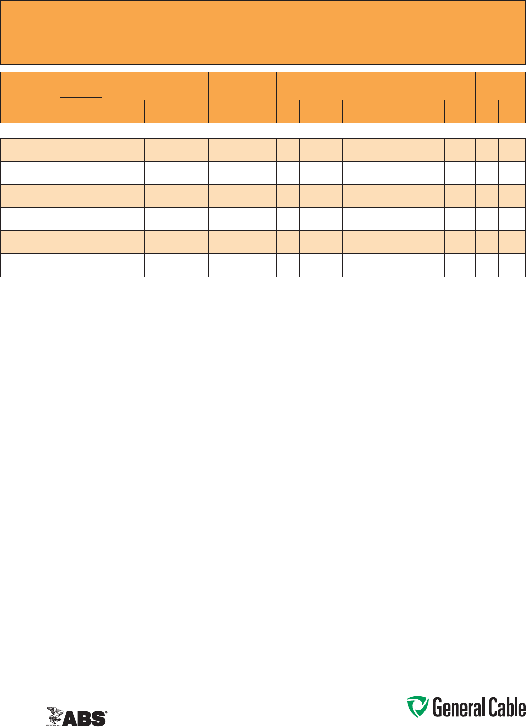
Phone: 888-593-3355
www.generalcable.com
CCW
®
Armored Power, 35 kV 133%, Shielded, 3/C
ULTypeMC-HLorMV-105,EPR,105°C,CableTrayUse,Sunlight-Resistant
DirectBurial,ABSCWCMC
SPEC 9875
February, 2011
CATALOG
NUMBER
COND.
SIZE
NO. OF
COND.
INSULATION
THICKNESS
NOMINAL O.D.
OVER
INSULATION
BARE
GROUND
NOMINAL
CORE O.D.
NOMINAL
ARMOR O.D.
JACKET
THICKNESS
NOMINAL
OVERALL O.D.
APPROXIMATE NET
WEIGHT AMPACITY
AWG
(kcmil) mils mm INCHES mm AWG INCHES mm INCHES mm mils mm INCHES mm
LBS/
1000 FT
kg/
1000 m IN AIR¹
DIRECT
BURIAL²
3/C WITH GROUND MC-HL OR MV-105, 420 MILS EPR, 35 kV 133% INSULATION LEVEL
9875.11003104
1/0(19/W)
(53.5mm²)
3420 10.7 1.24 31.5 4 2.91 73.9 3.41 86.6 85 2.16 3.59 91.2 5,300 7,887 240 255
9875.21003104
2/0(19/W)
(67.4mm²)
3420 10.7 1.27 32.3 4 3.02 76.7 3.63 92.2 85 2.16 3.81 96.8 6,000 8,929 275 290
9875.41003103
4/0(19/W)
(107mm²)
3420 10.7 1.38 35.1 33.23 82.0 3.80 96.5 85 2.16 3.98 101.1 7,100 10,566 360 345
9875.25003103
250(37/W)
(127mm²)
3420 10.7 1.43 36.3 33.40 86.4 3.98 101.1 85 2.16 4.16 105.7 8,100 12,054 400 410
9875.35003102
350(37/W)
(177mm²)
3420 10.7 1.52 38.6 2 3.51 89.2 4.10 104.1 85 2.16 4.29 109.0 9,000 13,393 490 495
9875.50003101
500(37/W)
(253mm²)
3420 10.7 1.64 41.7 13.81 96.8 4.45 113.0 85 2.16 4.63 117.6 11,100 16,519 600 590
Dimensionsandweightsarenominal;subjecttoindustrytolerances.
¹In-airampacitiesareperNECTable310.60(C)(71)forthreeinsulatedcopperconductorsrated105°C,cabledwithanoverallcoveringandisolatedinairat40°Cambienttemperature.
²DirectburialampacitiesareperNECTable310.60(C)(83)forthreeinsulatedcopperconductorsrated105°C,cabledwithinanoverallcoveringanddirectlyburiedinearthat20°C
ambientearthtemperature.
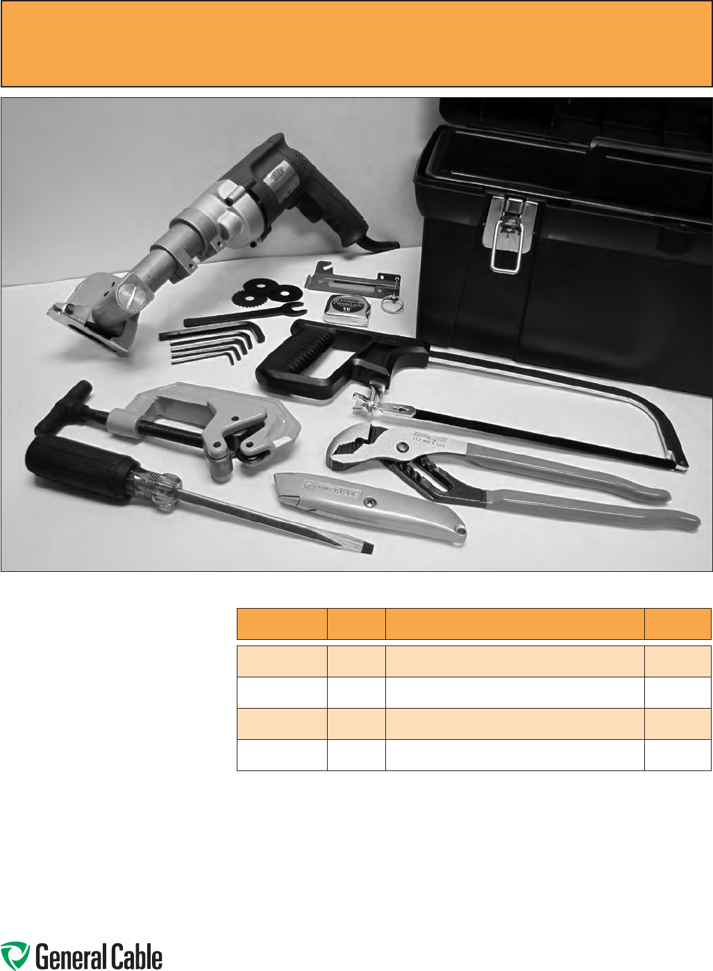
Phone: 888-593-3355
www.generalcable.com
CCW
®
Armored Cable Tool Kit
ForRemovalofCCWArmorSheath
IncludingAccessories
SPEC 9900
January, 2010
Tool Kit Contents:
• 1ea.Kett-ToolMetalCladCableSaw
• 12pcs.2"/44teethCuttingBlades
• CableSawSpindleandAllenWrenches
• 1ea.MCCableGuide
• 1ea.TubingandPipeCutter
• 1ea.12"V-JawChannel-LockPliers
• 1ea.10"HacksawFrame
• 3ea.10"/24teeth/in.HacksawBlades
• 1ea.10ft.TapeMeasure
• 1ea.UtilityKnifewithBlades
• 1ea.5/16"Screwdriver
• 1ea.ToolBox
CATALOG NUMBER QUANTITY DESCRIPTION
APPROXIMATE
WEIGHT
9900.KS226
1CCWTOOLKITWITH120VAC,
60HzELECTRICCUTTINGSAW 22.0LBS
9900.PS526
1CCWTOOLKITWITH90PSI
PNEUMATICCUTTINGSAW 20.0LBS
9900.15744
12",44TREPLACEMENTCUTTINGBLADES
(12BLADESPERPACK) 1.0LBS
9900.27901
1MCCABLEGUIDE 0.5LBS

Phone: 888-593-3355
www.generalcable.com
Industrial Cables Date of Issue 06/13
Technical Information
Section A General Technical Information
SPECIFICATION NO. DESCRIPTION REVISION DATE
A005 Glossary Jan. 2010
A025 Reference Standards Jan. 2010
A050 Checklist for Specifications Jan. 2010
A075 NEC and CSA Designations Jan. 2010
A100 Common Color Sequence May 2013
A150 Metric Conversion Factors Sept. 2010
A200 Reel Capacity Chart Jan. 2012
Section B Conductor Data
SPECIFICATION NO. DESCRIPTION REVISION DATE
B005 Conductor Reference Jan. 2010
B025 Class B Conductors for General Wiring Mar. 2012
B030 Class C Conductors for General Wiring Feb. 2011
B035 Class H Conductors for General Wiring Feb. 2011
B040 Class I Conductors for General Wiring Mar. 2012
B045 Class K Conductors for General Wiring Mar. 2012
Section C Material Properties
SPECIFICATION NO. DESCRIPTION REVISION DATE
C005 Thermoplastic Jacket and Insulation Material Properties Sept. 2012
C010 Thermoset Jacket and Insulation Material Properties Jan. 2010
Section D Handling and Storage Recommendations
SPECIFICATION NO. DESCRIPTION REVISION DATE
D005 Recommended Reel Handling Practices May 2013
D025 Recommended Cable Handling Practices Oct. 2011
D050 Recommended Cable Storage Practices May 2013
Phone: 888-593-3355
www.generalcable.com
Date of Issue 06/13 Industrial Cables
Technical Information
Section E Cable Installation Guidelines
SPECIFICATION NO. DESCRIPTION REVISION DATE
E005 Pre-Installation Instructions Apr. 2010
E025 Installation — Overview and Checklist Jan. 2011
E050 Installation — Feed-In Setups Apr. 2010
E075 Installation — Conductor Maximum Pulling Tensions Oct. 2012
E100 Installation — Training and Bending Limitations Apr. 2010
E125 Installation — Maximum Sidewall Pressure Oct. 2012
Section F Cable Testing
SPECIFICATION NO. DESCRIPTION REVISION DATE
F005 DC “HI-POT” Pre-Test Guidelines for MV Cables Apr. 2010
F025 DC “HI-POT” Testing Guidelines for MV Cables Apr. 2010
F075 Field Electrical “HI-POT” Testing Guidelines Apr. 2010
F100 Emergency Overload Current Guidelines Jan. 2010
F125 Short Circuit Current Calculation Overview Jan. 2010
F150 Short Circuit Current for Copper Shields Jan. 2010
F175 AC Resistance & Inductive Reactance Jun. 2013

Phone: 888-593-3355
www.generalcable.com
SPEC A005
January, 2010
Glossary
Abrasion Resistance: Ability of a wire,
cable or material to resist surface
wear.
Accelerated Aging: A test in which
voltage, temperature, etc. are
increased above normal operating
values to obtain observable
deterioration in a relatively short
period of time. The plotted results
give expected service life under
normal conditions.
ACM: Aluminum conductor material.
Accelerator: A chemical additive that
hastens a chemical reaction under
specific conditions.
Admittance: The measure of the ease
with which an alternating current
flows in a circuit. The reciprocal of
impedance.
AEIC: Association of Edison Illuminating
Companies
Aerial Cable: A cable suspended in the
air on poles or another overhead
structure.
Aging: The change in properties of a
material with time under specific
conditions.
AIA: Aluminum Interlocked Armor.
Alloy: A metal formed by combining two
or more different metals to obtain
desirable properties.
Alternating Current: Electric current that
continually reverses its direction. It
is expressed in cycles per second
(hertz or Hz).
Ambient Temperature: The temperature
of the medium surrounding an object.
Generally a lower temperature than
the temperature at which the cable is
operating.
American Wire Gauge (AWG): A
standard North American system for
designating wire diameter.
Ampacity: See Current Carrying Capacity.
Ampere: The unit of current. One ampere
is the current flowing through
one ohm of resistance at one volt
potential.
Analog: A data format using continuous
physical variables such as voltage
amplitude or frequency variations.
Anneal (Soften): Relief of mechanical
stress through heat and gradual
cooling. Annealing copper renders it
less brittle.
Armor: A protective metal covering
commonly in the form of flexible
interlocking aluminum or steel tape,
steel wires or aluminum sheath.
ASTM: American Society for Testing and
Materials.
Attenuation: The general term used to
denote the decrease of power from
one point to another. In fiber optics,
the optical power loss per unit
length is expressed logarithmically in
decibels per kilometer (dB/km) at a
specific wavelength.
Audio Frequency: The range of
frequencies audible to the human ear.
Usually 20-20,000 Hz.
AWM: Designation for appliance wiring
material.
Balanced Circuit: One utilizing cables
having two or more identical
conductors with the same
electromagnetic characteristics in
relation to each other and to ground.
Band Marking: A continuous
circumferential band applied to a
conductor at regular intervals for
identification.
Bandwidth: (1) The difference between
the upper and lower limits of a given
band of frequencies. Expressed in
Hertz. (2) A measure of the maximum
frequency range over which light
intensity exiting a waveguide one kilo-
meter in length can be varied before
the attenuation varies 3 dB from the
mean. The greater the bandwidth,
the greater the information-carrying
capacity. Bandwidth is expressed in
Megahertz (MHz)–Kilometer (km).
Bending Radius: Radius of curvature that
a cable can be safely bent without
any adverse effects.
Binder: A spirally served tape used
for holding assembled cable
components in place awaiting
subsequent manufacturing
operations.
Bonding Conductor: An insulated or
uninsulated conductor forming part
of the cable assembly which is used
for the purpose of connecting non-
current carrying parts of electrical
equipment to a system grounding
conductor.
Braid: A fibrous or metallic group of
filaments interwoven in cylindrical
shape to form a covering over one or
more wires.
Braid Angle: The smaller of the two
angles formed by the shielding
strand and the axis of the cable
being shielded.
Braid Carrier: A spool or bobbin on
a braider that holds one group of
strands or filaments consisting of a
specific number of ends. The carrier
revolves during braiding operations.
Braid Ends: The number of strands used
to make up one carrier. The strands
are wound side-by-side on the carrier
bobbin and lie parallel in the finished
braid.
Breakdown Voltage: The voltage at
which the insulation between two
conductors breaks down.
B & S Gauge: The same as American
Wire Gauge (AWG).
Buffer: A protective coating over an
optical fiber.
Building Wire: A general term used for
light and power wiring products,
1000 volts or less.
Bunch Stranding: A group of wires of
the same diameter twisted together
without a predetermined pattern.
Used in flexible cords and cables.
Buried Cable: A cable installed directly in
the earth without use of underground
conduit. Also called “direct burial
cable.”
Butyl Rubber: A synthetic rubber with
good insulating properties (i.e. low
voltage cords).

Phone: 888-593-3355
www.generalcable.com
SPEC A005
January, 2010
Cable: An insulated conductor, or group
of individually insulated conductors
in one assembly.
Cabling: The twisting together of two or
more insulated conductors to form a
cable.
Capacitance: The ratio of the
electrostatic charge on a conductor
to the potential difference between
the conductors required to maintain
that charge. Units expressed in
Farads.
Capacitive Coupling: Electrical
interaction between two conductors
caused by the capacitance between
them.
Capacitive Reactance (Xc): The
opposition to alternating current due
to the capacitance of the cable or
circuit. Measured in ohms.
CE Code, CEC: Canadian Electrical Code
Certified Test Report (CTR): A report
providing actual test data on a
cable. Tests are normally conducted
by the Quality Control Department
to confirm that the product being
shipped conforms to specifications.
Characteristic Impedance: The
impedance that, when connected to
the output terminals of a transmission
line of any length, makes the line
appear infinitely long. The ratio of
voltage to current at every point along
a transmission line on which there are
no standing waves.
Circular Mil (cmil): The area of a circle
one mil (.001") in diameter (7.854 x
10-7 sq in). Used in expressing wire
cross-sectional area.
Circuit Sizes: A popular term for building
wire sizes 14 through 10 AWG.
Cladding: (1) A method of applying a
layer of metal over another metal
whereby the junction of the two
metals is continuously welded. (2)
A low refractive index material that
surrounds the core of an optical fiber
causing the transmitted light to travel
down the core and protects against
surface contaminant scattering.
Coaxial Cable: A cable consisting of two
cylindrical conductors with a common
axis, separated by a dielectric.
Cold Flow: Permanent deformation of the
insulation or jacket due to mechanical
force or pressure (not due to heat
softening).
Color Code: A system for circuit
identification through use of solid
colors and contrasting tracers.
Composite Cable: One containing
more than one type or gauge size of
conductors (e.g. power and control
conductors in one assembly).
Compound: An insulating or jacketing
material made by mixing two or more
polymeric ingredients.
Concentric Stranded Conductors:
Manufactured to ASTM, ICEA and
CSA standards. The most common
fixed installation type conductors are:
1) Round—no diameter reduction;
2) Compressed—approximately 3%
diameter reduction; 3) Compact—
approximately 10% diameter
reduction.
Concentric Stranding: A central wire
surrounded by one or more layers
of helically wound strands in a fixed
round geometric arrangement.
Concentricity: The measurement of
the location of the center of the
conductor with respect to the
geometric center of the surrounding
insulation.
Conductivity: The capacity of a material
to carry electrical current—usually
expressed as a percentage of copper
conductivity (copper being 100%).
Conductor: An uninsulated wire suitable
for carrying electrical current.
Conductor Shield: An extrusion of black
semi-conducting thermoses material
over the conductor to provide a
smooth interface with the insulation
for even distribution of electrical
stress.
Conduit (Electrical Raceway): A tube
or pipe in which insulated wires and
cables are run.
Connector: A device used to physically
and electrically connect two or more
conductors. Also used to physically
connect cable to equipment.
Continuity Check: A test to determine
whether electrical current flows
continuously throughout the length
of a single wire or individual wires in
a cable.
Continuous Vulcanization: Simultaneous
extrusion and vulcanization of rubber-
like (thermoset) coating materials.
Often referred to as CV.
Control Cable: A multi-conductor cable
made for operation in control of
signal circuits.
Copolymer: A compound resulting from
the polymerization of two different
monomers.
Copperweld®: The trade name of Flexo
Wire Division (Copper weld Steel
Corp.) for its copper-clad steel
conductors.
Cord: A small, flexible, insulated wire or
cable.
Core: In cables, a component or
assembly of components over which
additional components (shield,
sheath, etc.) are applied.
Corona: A discharge due to ionization
of air around a conductor due to a
potential gradient exceeding a certain
critical value.
Coverage: The percent of completeness
with which a metal serving covers the
underlying surface.
CPE: Chlorinated polyethylene can be
used as either a thermoplastic or
thermoset. It is a tough chemical- and
oil-resistant material and makes an
excellent jacket for industrial control
cable. As a thermoset, it can be used
as an oil-resistant cord jacket. Typical
temperature ratings range from -35˚C
to 90˚C. Other outstanding properties
include low water absorption and
super crush resistance, which are
important attributes in industrial
control applications.
Creep:
The dimensional change with time
of a material under a mechanical
load.
Glossary
Phone: 888-593-3355
www.generalcable.com
SPEC A005
January, 2010
Glossary
Cross-linked: Inter-molecular bonds
between long-chain thermoplastic
polymers by chemical or electron
bombardment means. The properties
of the resulting thermosetting material
are usually improved (e.g. XLPE).
Crosstalk: Signal interference between
nearby conductors caused by pickup
of stray energy.
CSA: Canadian Standards Association
Current Carrying Capacity (Ampacity):
The maximum current an insulated
conductor can safely carry without
exceeding its insulation and jacket
temperature limitations.
Cut-Through Resistance: The ability of
a material to withstand cutting from
a sharp edge or small radius under
pressure.
Decibel (dB): A unit to express differences
of power level. Used to express power
gain in amplifiers or power loss in
passive circuits or cables. The units in
which the ratio of two power levels, P1
and P2, are expressed. The ratio in
dB is given as - 10 log10 (P1/P2).
P2 → → P1
Delay Line: A cable made to provide very
low velocity of propagation with long
electrical delay for transmitted signals.
Derating Factor: A factor used to reduce
the current carrying capacity of a wire
when used in environments other
than that for which the value was
established.
Dielectric: Any insulating material
between two conductors that permits
electrostatic attraction and repulsion
to take place across it.
Dielectric Constant (K): The ratio of the
capacitance of a condenser with
dielectric between the electrodes to
the capacitance when air is between
the electrodes. Also called Permittivity
and Specific Inductive Capacity (SIC).
Dielectric Strength: The voltage which
an insulation can withstand before
breakdown occurs. Usually expressed
as a voltage gradient (such as volts
per mil).
Dielectric Test: A test in which a voltage
higher than the rated voltage is
applied for a specified time to
determine the adequacy of the
insulation under normal conditions.
Sometimes called a “Hi-Pot” test (high
potential).
Digital: A data format that uses discrete
or separate physical levels to contain
information.
Direct Burial Cable: A cable installed
directly in the earth.
Direct Current: An electric current that
flows in only one direction.
Direction of Lay: The lateral direction in
which the strands of a conductor run
over the top of the cable conductor as
they recede from an observer looking
along the axis of the conductor or
cable. Also applies to twisted cable.
Dissipation Factor: The tangent of the
loss angle of the insulating material.
(Also referred to as loss tangent, tan
d and approximate power factor.)
Drain Wire: The uninsulated wire
in contact with an electrostatic
shield throughout its length, in an
instrumentation or control cable,
used to discharge unwanted signals.
Also provides a means of terminating
laminated shields. Sometimes used
to describe the metallic shielding
wires of a power cable insulation
shield.
Drawing: In wire manufacturing, pulling
the metal through a die or series
of dies to reduce diameter to a
specified size.
Earth: British terminology for zero-
reference “ground.”
Eccentricity: Like concentricity,
a measure of the center of a
conductor’s location with respect
to the circular cross section of
the insulation. Expressed as a
percentage of displacement of one
circle within the other.
EEMAC: Electrical and Electronic
Manufacturers Association of Canada
(U.S. counterpart is NEMA).
Elastomer: A rubber-like substance. Any
material that will return to its original
dimensions after being stretched or
distorted.
Electrostatic Shield: A copper or
laminated aluminum/Mylar® tape wrap
around a signal or instrumentation
circuit (pair, triad, etc.) to protect
from the electric field radiated by a
voltage source. The grounded shield
intercepts static interference and
carries it off to ground.
Elongation: The fractional increase in
length of material stressed in tension.
EMI: Abbreviation for electromagnetic
interference.
EMRC: Energy Mines and Resources
Canada
EPDM: Ethylene-propylene-diene
monomer rubber. A material with
good electrical insulating properties.
EPR: Ethylene-propylene copolymer
rubber. A material with good
electrical insulating properties.
Equal Load Sharing: An even distribution
of current between the parallel
cables in a power circuit.
Equilay: See Unilay: More than one layer
of helically laid wires with the length
of the lay the same for each layer.
Farad: A unit of electrical capacity.
Fatigue Resistance: Resistance to
metal crystallization which leads to
conductors or wires breaking from
flexing.
Ferrous: Composed of and/or containing
iron. A ferrous metal exhibits
magnetic characteristics (e.g. steel
armor).
FEP: Fluorinated ethylene propylene
insulated wire (see Teflon®).
Fiber: A single, separate optical
transmission element characterized
by core and cladding.
Fiber Optics: Light transmission through
optical fibers for communication and
signaling.

Phone: 888-593-3355
www.generalcable.com
SPEC A005
January, 2010
Filled Cable: Cable construction in which
the cable core is filled with a material
that will prevent moisture or gasses
from entering or passing through the
cable.
Filler: 1) A material used in multi-
conductor cables to occupy large
interstices formed by the assembled
conductors; 2) An inert substance
added to a compound to improve
properties.
Flat Cable: A cable with two essentially
flat surfaces (e.g., NMD90).
Flat Conductor: A wire having a
rectangular cross section as
opposed to round or square
conductors.
Flame Resistance: The ability of a
material not to propagate flame
once the heat source is removed (see
FT1).
Flammability: The measure of the
material’s ability to support
combustion.
Flex Life: The measurement of the ability
of a conductor or cable to withstand
repeated bending before breaking.
Flexibility: The ease with which a cable
may be bent without sustaining
damage.
FT1: One of several CSA flame test
designations for wires and cables
which pass the C22.2 No. 0.3 test
requirements. (Other designations
include FT2, FT4, etc.).
Fusion Splice: A splice accomplished
by the application of localized heat
sufficient to fuse or melt the ends of
two lengths of optical fiber, forming a
continuous single fiber.
Gauge: A term used to denote the
physical size of a wire.
GND: Abbreviation for ground.
Graded-Index: A type of optical fiber in
which the refractive index of the core
is in the form of a parabolic curve,
decreasing toward the cladding. This
type of fiber provides high bandwidth
capabilities.
Ground (GND): 1) A conducting
connection between an electrical
circuit and the earth, or other large
conducting body, to serve as an
earth thus making a complete
electrical circuit; 2) Term used for
non-current carrying conductor in a
cable (see Bonding Conductor).
Halogen: A term used to identify any of
the four elements chlorine, fluorine,
bromine and iodine, grouped
together because their chemical
properties are similar.
Hard Drawn Copper Wire: Copper wire
that has not been annealed after
drawing.
Heat Shock: A test to determine stability
of a material by sudden exposure to
a high temperature for a short period
of time.
Henry: The unit of inductance.
Hertz (Hz): A term replacing cycles-per-
second as an indication of frequency.
Hi-Pot (High Potential): A test
designated to determine the highest
voltage that can be applied to a
conductor without breaking down the
insulation (see Dielectric Test).
High Voltage (HV): Generally, a wire or
cable with an operating voltage of
over 600 volts.
Hook-Up Wire: A wire used for low
current, low voltage (under 1000
volts) applications within enclosed
electronic equipment.
Hygroscopic: A material capable of
absorbing moisture from the air.
Hypalon®: DuPont’s trade name for their
chlorosulfonated polyethylene, an
ozone-resistant synthetic rubber.
ICEA (formerly IPCEA): Insulated Cable
Engineers Association.
IEEE: Institute of Electrical and
Electronics Engineers.
Impact Strength: A test for determining
the mechanical punishment a cable
can withstand without physical or
electrical breakdown by impacting
with a given weight, dropped a given
distance, in a controlled environment.
Impedance: The total opposition that a
circuit offers to the flow of alternating
current or any other varying current
at a particular frequency. It is a
combination of resistance R and
reactance X, measured in ohms.
Inductance: The property of a circuit
or circuit element that opposes a
change in current flow, thus causing
current changes to lag behind voltage
changes. It is measured in henrys.
Insulation: A material having good
dielectric properties permitting close
assembly of conductors in cable and
equipment.
Insulation Level: A designation used
to identify the insulation thickness
required to protect a high voltage
cable under ground fault conditions.
Expressed as a percentage (e.g.
100% level, 133% level).
Insulation Shield (HV Cable): A two-
part shield consisting of a non-
metallic component and a metallic
component. The first component
is an extrusion of black semi-
conducting thermoset material over
the insulation, which provides uniform
radial stress distribution across the
insulation. The second component
is a metallic shield which is typically
copper tape or wire that functions
as a bonding (grounding) conductor
and/or a neutral conductor. The
metallic shield also serves to conduct
ground fault current in the event of
insulation failure. See also Drain Wire.
Insulation Stress: High voltage stress
which causes molecular separation
in the insulation at sharp projections
in the conductor. Controlled by
conductor and insulation shielding,
called a stress relief shield. Measured
in volts per mil.
Interaxial Spacing: Center-to-center
conductor spacing.
Interstices: Voids or valleys between
individual strands in a conductor or
between insulated conductors in a
multi-conductor cable (intersticial
spaces).
Glossary

Phone: 888-593-3355
www.generalcable.com
SPEC A005
January, 2010
Irradiation: In insulations, the exposure of
the material to high energy emissions
for the purpose of favorably
altering the molecular structure by
crosslinking.
Jacket: An outer covering, usually non-
metallic, mainly used for protection
against the environment.
kcmil: One thousand circular mils (MCM).
kilo: A prefix denoting 1000 (103).
kV: Kilovolt (1000 volts).
Laminated Tape: A tape consisting
of two or more layers of different
materials bonded together (e.g.
aluminum/Mylar®).
Lay: The length measured along the axis
of a wire or cable required for a single
strand (in stranded wire) or conductor
(in cable) to make one complete turn
about the axis of the conductor or
cable.
Lay Direction: The twist in the cable as
indicated by the top strands while
looking along the axis of the cable
away from the observer. Described as
“right hand” or “left hand.”
Leakage Current: The undesirable flow
of current through or over the surface
of an insulation.
Line Drop (Voltage Drop): A voltage loss
occurring between any two points in
a power circuit. Such loss, or drop,
is due to the resistance, reactance or
leakage of the circuit, type of cable
and configuration.
Line Voltage: The value of the potential
existing on a supply or power line.
Rated voltage of cables.
LOCA: Abbreviation for loss of coolant
accident, a system malfunction
associated with nuclear generating
stations.
Longitudinal Shield: A tape shield, flat
or corrugated, applied longitudinally
with the axis of the core being
shielded.
Loss Factor: The product of the
dissipation and dielectric constant of
an insulating material.
µA. Microampere: One-millionth of an
ampere (10-6).
mA. Milliampere: One-thousandth of an
ampere (10-3).
Magnetic Noise: Caused by current
frequency. An AC powerline creates a
magnetic field around that cable, this
magnetic field causes the magnetic
noise in neighboring control or
instrumentation circuits.
MCM: One thousand circular mils (kcmil).
meg or mega: A prefix denoting
1,000,000 (106).
Megarad: A unit for measuring radiation
dosage.
Messenger: The linear supporting
member, usually a high-strength steel
wire, used as the supporting element
of a suspended aerial cable. The
messenger may be an integral part of
the cable, or exterior to it.
Mho: The unit of conductivity. The
reciprocal of an ohm.
micro: A prefix denoting one-millionth
(10-6).
micron: (m) Millionth of a meter = 10-6
meter.
Mil: A unit of length equal to one-
thousandth of an inch (.001").
Common unit for insulation
thickness.
Milli: A prefix denoting one-thousandth
(10-6).
Modulus of Elasticity: The ratio of stress
to strain in an elastic material.
Moisture Absorption: The amount
of moisture, in percentage, that a
material will absorb under specified
conditions.
Moisture Resistance: The ability of a
material to resist absorbing moisture
from the air or when immersed in
water.
Multi-Conductor Cable: A cable
consisting of two or more
conductors, either cabled or laid in
a flat parallel construction, with or
without a common overall covering.
Multi-Plexed Conductors:
Three or more
completed cables together without
fillers or common overall jacket.
(Triplexed, 3-1|C; Quadruplet, 4-1|C)
Mutual Capacitance: Capacitance
between two conductors when all
other conductors, including ground,
are connected together.
Mylar®: DuPont trade name for a
polyester material.
Nano: A numerical prefix denoting one-
billionth (10-9).
National Electrical Code (NEC): A U.S.
consensus standard published by the
National Fire Protection Association
(NFPA) and incorporated in OSHA
regulations. (Canadian Counterpart is
the CE Code).
NEMA: National Electrical Manufacturers
Association. (Canadian counterpart
is EEMAC).
Neoprene: A synthetic rubber with good
resistance to oil, chemicals and
flame. Also called polychloroprene.
Nomex®: DuPont trademark for a
temperature-resistant, flame-
retardant nylon.
Non Hygroscopic: A material incapable
of taking up or absorbing moisture
from the air.
Nylon®: An abrasion-resistant
thermoplastic with good chemical
resistance. A DuPont registered
trademark.
OHM: The electrical unit of resistance.
OSHA: Abbreviation for the U.S.
Occupational Safety and Health Act.
Overlap: The amount the trailing edge
laps over the leading edge of a spiral
tape wrap.
Oxygen Index: Percentage of oxygen
necessary to support combustion
in a gas mixture. Flame-retardant
materials have a higher oxygen index.
Pair: Two insulated wires of a single
circuit twisted together or laid
parallel.
Parallel Cable: Two or more cables used
to share the current in heavily loaded
power circuits which permits the use
of smaller conductors.
Glossary

Phone: 888-593-3355
www.generalcable.com
SPEC A005
January, 2010
Percentage Conductivity: Conductivity
of a material expressed as a
percentage of that of copper. Also
used to indicate ratio of conductance
between the phase conductor and
the neutral in power cables.
Pick: Distance between two adjacent
crossover points of braid filaments.
The measurement in picks per inch
indicates the degree of coverage.
pico: A prefix denoting one-millionth of
one-millionth (10-12).
Pitch: In flat cable, the nominal distance
between the index edges of two
adjacent conductors.
Pitch Diameter: Diameter of a circle
passing through the center of the
conductors in any layer of a multi-
conductor cable.
Plastic Deformation: Change in
dimensions under load that is not
recovered when the load is removed.
Plasticizer: A chemical agent added to
plastics to make them softer and
more pliable.
Plenum Cable: Cable approved for
installation in plenums (e.g.,
suspended ceiling) without the need
for conduit.
Polyester: Polyethylene terephthalate
which is used extensively in the
production of a high-strength,
moisture-resistant film used as a
cable core wrap (see Mylar®).
Polyethylene (PE): A thermoplastic
material having excellent electrical
and physical properties.
Polymer: A material of high molecular
weight formed by the chemical union
of monomers.
Polyolefin: A family of thermoplastics
based upon the unsaturated
hydrocarbons know as olefins. When
combined with butylene or styrene
polymers, they form compounds such
as polyethylene and polypropylene.
Polypropylene (PPE): A thermoplastic
similar to polyethylene but stiffer
and having a higher softening point
(temperature).
Polyurethane/PUR: This thermoplastic
material is used primarily as a cable
jacket material. It has excellent
oxidation, oil and ozone resistance.
Some formulations also have good
flame resistance. It is a hard material
with excellent abrasion resistance.
It has outstanding “memory”
properties, making it an ideal jacket
material for retractile cords.
Polyvinyl Chloride (PVC): A general-
purpose thermoplastic used for low
voltage wire and cable insulation, and
for jackets.
Power Factor: The ratio of resistance to
impedance. The ratio of the actual
power of an alternating current to
apparent power. Mathematically,
the cosine of the angle between
the voltage applied and the current
resulting.
Primary Insulation: The first layer of non-
conductive material applied over a
conductor, whose prime function is to
act as electrical insulation.
Pulling Eye: A device fastened to a cable
to which a hook may be attached in
order to pull the cable.
Quad: Four insulated wires of a single
circuit.
REA: Rural Electrification Administration.
A branch of the U.S. Department of
Agriculture.
Reactance: The opposition offered to
the flow of alternating current by
inductance or capacitance of a
component or circuit.
Reel Drum Diameter: Diameter of the
drum (or hub) of the reel.
Reel Flange Diameter (Reel Height):
Diameter of the reel flanges.
Reel Traverse: Width of space between
reel flanges.
Reel Width: Overall width of reel.
Ridge Marker: One or more ridges
running laterally along the outer
surface of a insulated wire or cable
for purposes of identification.
Root Mean Square (RMS): The effective
value of an alternating current or
voltage.
Rope Lay Conductor: A conductor
composed of a central core
surrounded by one or more layers of
helically laid groups of wires used in
portable cables.
Rubber: A general term used to describe
wire insulation and jackets made of
thermosetting elastomers, such as
natural or synthetic rubbers, EPR,
neoprene, Hypalon, butyl rubber and
others.
SBR: A copolymer of styrene and
butadiene. Also GR-S or Buna-S.
Most commonly used type of
synthetic rubber.
Self-Extinguishing: The characteristic
of a material whose flame is
extinguished after the igniting flame
is removed.
Semi-Conductor: In wire industry
terminology, a material possessing
electrical conductivity that falls
somewhere between that of
conductors and insulators. Usually
made by adding carbon particles to
an insulator (e.g. conductor shield
and insulation shield). Not the same
as semi-conductor materials such
as silicon, germanium, etc. used for
making transistors and diodes.
Separator: Pertaining to wire and cable,
a layer of insulating material such
as textile paper, Mylar®, etc. which
is placed between a conductor and
its dielectric, between a cable jacket
and the components it covers or
between various components of a
multi- conductor cable. It can be
utilized to improve stripping qualities,
flexibility or can offer additional
mechanical or electrical protection to
the components it separates.
Served Wire Armor (SWA): Spiral wrap
of galvanized steel wires applied
around a cable to afford mechanical
protection and increase the cable
pulling tension characteristics
(mineshaft, submarine cable, etc.).
Also used to denote steel wire armor.
Sheath: The outer covering or jacket of a
multi-conductor cable. Usually non-
metallic.
Glossary

Phone: 888-593-3355
www.generalcable.com
SPEC A005
January, 2010
Shield (Electrostatic): In cables, a
metallic layer placed around a
conductor or group of conductors
to prevent electrostatic interference
between the enclosed wires and
external fields. Also see Insulation
Shield.
Shrink Tubing: Tubing which has
been extruded, crosslinked and
mechanically expanded which, when
reheated, will return to its original
diameter.
SIA: Steel Interlocked Armor.
Side Wall Bearing Pressure (SWBP):
A term used in reference to the
pressure on a cable which is being
pulled around a curved surface
under tension. If excessive, SWBP
can damage cable components and
reduce the life of the cable.
Signal Cable: A cable designed to carry
current of usually less than one
ampere per conductor to operate
signal circuit devices.
Silicone: A material made from silicone
and oxygen. Can be in thermosetting
elastomer or liquid form. The
thermosetting elastomer form is
noted for high heat resistance.
Skin Effect: The tendency of alternating
current to concentrate and to travel
only on the surface of a conductor.
Tendency increases with increase in
frequency.
Sleeving: An extruded tube.
Spark Test: A test designed to locate
imperfections (usually pin-holes) in
the insulation of a wire or cable by
application of voltage for a very short
period of time while the wire is being
drawn through the electrode field.
Specific Gravity: The ratio of the density
(mass per unit volume) of a material
to that of water.
Specific Inductive Capacity (SIC):
Same as dielectric constant. See
Dielectric Constant.
Tank Test: A voltage insulation test in
which the insulated wire or cable is
submerged in water and voltage is
applied between the conductor and
water serving as ground. Shielded
cables are generally not tank tested
due to the possibility of introducing
contaminants on the outer surface of
the insulation.
Teflon®: DuPont Company trademark for
fluorocarbon resins. See FEP and
TFE.
Temperature Rating: The maximum
temperature at which an insulating
material may be used in continuous
operation without loss of its basic
properties (i.e. operating, overload,
short circuit). The minimum
temperature for safe handling.
Tensile Strength: The pull stress
required to break a given specimen.
Measured in pounds per square inch.
Also referred to as Ultimate Tensile
Strength.
TFE: Tetrafluoroethylene. A thermoplastic
material with good electrical
insulating properties and chemical
and heat resistance.
Thermoplastic: A material that can
be softened repeatedly by heating
and hardened by cooling through a
temperature range characteristic of
the plastic, and that in the softened
state can be shaped by molding or
extrusion.
Thermoset: A material that has been
vulcanized by heat or other means
and is substantially infusible and
insoluble.
Three-Conductor Cable: Three insulated
conductors assembled with other
necessary cable components (shield,
filler, etc.) to form a core, protected
by an overall jacket.
Tinned Copper: Tin coating added to
copper to aid in soldering and inhibit
corrosion.
Tray: A cable tray system is a unit or
assembly of units or sections, and
associated fittings, made of non-
combustible materials forming a
rigid structural system used to
support cables. Cable tray systems
(previously termed Continuous Rigid
Cable Supports) include ladders,
troughs, channels, solid bottom trays
and similar structures.
Tray Cable: A factory-assembled multi-
conductor or multi-
pair control, signal or power cable
specifically approved under the
Canadian Electrical Code for
installation in trays.
Triad: Three insulated wires of a single
circuit forming a unit. (Two or more
units are cabled to form a multi-triad
cable.)
Triplexed Cable: Three individual cables
twisted together without fillers or a
common overall jacket.
UL: Underwriters Laboratories. A non-
profit independent organization,
which operates a listing service for
electrical and electronic materials
and equipment. (Canadian counter-
part is CSA).
UHF: Abbreviation for ultra high
frequency, 300 to 3,000 MHz.
Unilay: A conductor with more than one
layer of helically laid wires with the
direction of lay and length of lay the
same for all layers.
Velocity of Propagation: The speed of
an electrical signal down a length
of cable compared to speed in free
space expressed as a percent. It is
the reciprocal of the square root of
the dielectric constant of the cable
insulation.
VHF: Abbreviation for very high
frequency, 30 to 300 MHz.
Voltage: The term most often used
in place of electromotive force,
potential, potential difference or
voltage drop to designate the electric
pressure that exists between two
points and is capable of producing
a current when a closed circuit is
connected between two points.
Glossary

Phone: 888-593-3355
www.generalcable.com
SPEC A005
January, 2010
Voltage Rating: 1) The highest voltage
that can be continuously applied
to a wire in conformance with the
standard or specification; 2) The
“system” voltage printed on the wire
or cable.
Volume Resistivity: The electrical
resistance between opposite faces of
a one cm. cube of insulating material,
commonly expressed in ohms-meter.
Vulcanization: An irreversible process
during which a compound, through a
change in its chemical structure (e.g.
cross-linking), becomes less plastic
and more resistant to swelling by
organic liquids and elastic properties
are conferred, improved or extended
over a greater range of temperatures.
VW-1: A flammability rating established
by Underwriters Laboratories
for wires and cables that pass a
specially designed vertical flame test,
formerly designated FR-1. Similar to
CSA designation FT1.
Watt: A unit of electric power.
Wicking: The longitudinal flow of a liquid
in a wire or cable due to capillary
action.
Wire: A conductor; bare or insulated.
Yield Strength: The minimum stress
at which a material will start to
physically deform without further
increase in load.
Glossary

Phone: 888-593-3355
www.generalcable.com
SPEC A025
January, 2010
* These standards or specifications have been rescinded by their organizations.
Reference Standards
AAR S-501: Specification for Wire and
Cables
AAR 581.3: Specification for Single
Conductor, Clean Stripping Rubber
Insulated, 0–600 Volts, Neoprene
Jacketed Cable for Locomotive and Car
Equipment
AAR 589: Specification for Single
Conductor Chloro sulfonated Polyethylene
Integral Insulated-Jacketed, 0-300 V,
0-600 V Cable for Locomotive and Car
Equipment
AEIC CS 1: Specifications for Solid-Type
Impregnated-Paper-Insulated Metallic
Sheathed Cable
AEIC CS2: Specifications for
Impregnated-Paper and Laminated
Paper-Polypropylene Insulated Cable,
High-Pressure Pipe-Type
AEIC CS3: Specifications for
Impregnated-Paper-Insulated, Metallic
Sheathed Cable, Low Pressure Gas-Filled
Type
AEIC CS4: Specifications for
Impregnated-Paper-Insulated Low and
Medium Pressure Self Contained Liquid
Filled Cable
*AEIC CS5: Specifications for
Thermoplastic and Crosslinked
Polyethylene Insulated Shielded Power
Cables Rated 5 Through 69 kV
*AEIC CS6: Specifications for Ethylene
Propylene Rubber Insulated Shielded
Power Cables Rated 5 Through 69 kV
AEIC CS7: Specifications for Crosslinked
Poly ethylene Insulated Shielded Power
Cables Rated 46 Through 138 kV
AEIC CS8: Specification for Extended
Dielectric, Shielded Power Cables Rated
5 through 46 kV
ANSI C2: National Electrical Safety Code
ANSI MC96.1: Thermocouple Extension
Wire Calibration
ANSI N45.2: Packaging, Shipping,
Receiving, Storage and Handling of Items
for Nuclear Power Plants
ASTM B 1: Standard Specification for
Hard-Drawn Copper Wire
ASTM B 2: Standard Specification for
Medium-Hard-Drawn Copper Wire
ASTM B 3: Standard Specification for
Soft or Annealed Copper Wire
ASTM B 8: Standard Specification
for Concentric-Lay Stranded Copper
Conductors, Hard, Medium-Hard or Soft
ASTM B 33: Standard Specification for
Tinned Soft or Annealed Copper Wire for
Electrical Purposes
ASTM B 105: Standard Specification
for Hard-Drawn Copper Alloy Wires for
Electrical Conductors
ASTM B 170: Standard Specification for
Oxygen-Free Electrolytic Copper
ASTM B 172: Standard Specification for
Rope-Lay-Stranded Copper Conductors
Having Bunch-Stranded Members, for
Electrical Conductors
ASTM B 173: Standard Specification for
Rope-Lay-Stranded Copper Conductors
Having Concentric-Stranded Members, for
Electrical Conductors
ASTM B 174: Standard Specification for
Bunch-Stranded Copper Conductors for
Electrical Conductors
ASTM B 189: Standard Specification for
Lead-Coated and Lead-Alloy-Coated Soft
Copper Wire for Electrical Purposes
ASTM B 193: Standard Test Method
for Resistivity of Electrical Conductor
Materials
ASTM B 226: Standard Specification for
Cored, Annular, Concentric-Lay-Stranded
Copper Conductors
ASTM B 227: Standard Specification for
Hard-Drawn Copper-Clad Steel Wire
ASTM B 228: Standard Specification for
Concentric-Lay-Stranded Copper-Clad
Steel Conductors
ASTM B 229: Standard Specification for
Concentric-Lay-Stranded Copper and
Copper-Clad Steel Composite Conductors
ASTM B 230: Standard Specification for
Aluminum 1350-H19 Wire for Electrical
Purposes
ASTM B 230M: Standard Specification
for Aluminum 1350-H19 Wire for Electrical
Purposes [Metric]
ASTM B 231: Standard Specification for
Concentric-Lay-Stranded Aluminum 1350
Conductors
ASTM B 231 M: Standard Specification
for Concentric-Lay-Stranded Aluminum
1350 Conductors [Metric]
ASTM B 232: Standard Specification
for Concentric-Lay-Stranded Aluminum
Conductors, Coated Steel-Reinforced
(ACACARSR)
ASTM B 232M: Standard Specification
for Concentric-Lay-Stranded Alumi num
Conductors, Coated Steel-Reinforced
(ACSR) [Metric]
ASTM B 233: Standard Specification
for Aluminum 1350 Drawing Stock for
Electrical Purposes
ASTM B 246: Standard Specification
for Tinned Hard-Drawn and Medium-
Hard-Drawn Copper Wire for Electrical
Purposes
ASTM B 258: Standard Specification
for Standard Nominal Diameters and
Cross-Sectional Areas of AWG Sizes of
Solid Round Wires Used as Electrical
Conductors
ASTM B 263: Standard Test Method for
Determination of Cross-Sectional Area of
Stranded Conductors
ASTM B 286: Standard Specification for
Copper Conductors for Use in Hookup
Wire for Electronic Equipment
ASTM B 298: Standard Specification for
Silver-Coated Soft or Annealed Copper
Wire
ASTM B 324: Standard Specification for
Nickel-Coated Soft or Annealed Copper
Wire
ASTM B 341: Standard Specification for
Aluminum-Coated (Aluminized) Steel Core
Wire for Aluminum Conductors, Steel-
Reinforced (ACSR/AZ)
ASTM B 341M: Standard Specification
for Aluminum-Coated (Aluminized) Steel
Core Wire for Aluminum Conductors,
Steel-Reinforced (ACSR/AZ) [Metric]
ASTM B 355: Standard Specification for
Nickel-Coated Soft or Annealed Copper
Wire
ASTM B 397: Standard Specification for
Concentric-Lay-Stranded Aluminum-Alloy
5005-H19 Conductors

Phone: 888-593-3355
www.generalcable.com
SPEC A025
January, 2010
ASTM B 398: Standard Specification
for Aluminum-Alloy 6201-T81 Wire for
Electrical Purposes
ASTM B 398M: Standard Specification
for Aluminum-Alloy 6201-T81 Wire for
Electrical Purposes [Metric]
ASTM B 399: Standard Specification for
Concentric-Lay-Stranded Aluminum-Alloy
6201-T81 Conductors
ASTM B 399M: Standard Specification
for Concentric-Lay-Stranded Aluminum-
Alloy 6201-T81 Conductors [Metric]
ASTM B 400: Standard Specification
for Compact Round Concentric-Lay-
Stranded Aluminum 1350 Conductors
ASTM B 401: Standard Specification
for Compact Round Concentric-Lay-
Stranded Aluminum Conductors, Steel-
Reinforced (ACSR/COMP)
ASTM B 416: Standard Specification for
Concentric-Lay-Stranded Aluminum-Clad
Steel Conductors
ASTM B 452: Standard Specification for
Copper-Clad Steel Wire for Electronic
Application
ASTM B 470: Standard Specification for
Bonded Copper Conductors for Use in
Hookup Wires for Electronic Equipment
ASTM B 496: Standard Specification
for Compact Round Concentric-Lay-
Stranded Copper Conductors
ASTM B 498: Standard Specification
for Zinc-Coated (Galvanized) Steel Core
Wire for Aluminum Conductors, Steel-
Reinforced (ACSR)
ASTM B 498M: Standard Specification
for Zinc-Coated (Galvanized) Steel Core
Wire for Aluminum Conductors, Steel-
Reinforced (ACSR) [Metric]
ASTM B 500: Standard Specification
for Zinc-Coated (Galvanized), Zinc-5%
Aluminum Mischmetal Alloy-Coated, and
Aluminum-Coated (Aluminized) Stranded
Steel Core for Aluminum Conductors,
Steel-Reinforced (ACSR)
ASTM B 501: Standard Specification for
Silver-Coated, Copper-Clad Steel Wire for
Electronic Application
ASTM B 502: Standard Specification
for Aluminum-Clad Steel Core Wire for
Aluminum Conductors, Aluminum-Clad
Steel Reinforced
ASTM B 520: Standard Specification for
Tin-Coated, Copper-Clad Steel Wire for
Electronic Application
ASTM B 524: Standard Specification
for Concentric-Lay-Stranded Aluminum
Conductors, Aluminum-Alloy Reinforced
(ACAR, 1350/6201)
ASTM B 524M: Standard Specification
for Concentric-Lay-Stranded Aluminum
Conductors, Aluminum-Alloy Reinforced
(ACAR, 1350/6201) [Metric]
ASTM B 549: Standard Specification
for Concentric-Lay-Stranded Aluminum
Conductors, Aluminum-Clad Steel
Reinforced (ACSR/AW)
ASTM B 559: Standard Specification for
Nickel-Coated, Copper-Clad Steel Wire
for Electronic Application
ASTM B 606: Standard Specification for
High-Strength Zinc-Coated (Galvanized)
Steel Core Wire for Aluminum and
Aluminum Alloy Conductors, Steel
Reinforced
ASTM B 609: Standard Specification for
Aluminum 1350 Round Wire, Annealed
and Intermediate Tempers, for Electrical
Purposes
ASTM B 609M: Standard Specification
for Aluminum 1350 Round Wire, Annealed
and Intermediate Tempers, for Electrical
Purposes [Metric]
ASTM B 624: Standard Specification for
High-Strength, High-Conductivity Copper-
Alloy Wire for Electronic Application
ASTM B 682: Standard Specification
for Standard Metric Sizes of Electrical
Conductors
ASTM B 701: Standard Specification for
Concentric-Lay-Stranded Self-Damping
Aluminum Conductors, Steel-Reinforced
(ACSR/SD)
ASTM B 711: Standard Specification for
Concentric-Lay-Stranded Aluminum-Alloy
Con ductors, Steel Reinforced (AACSR)
(6201)
ASTM B 738: Standard Specification for
Fine-Wire Bunch-Stranded and Rope-Lay
Bunch Stranded Copper Conductors for
Use as Electrical Conductors
ASTM B 778: Standard Specification for
Shaped Wire Compact Concentric-Lay-
Stranded Aluminum Conductors (AAC/
TW)
ASTM B 779: Standard Specification for
Shaped Wire Compact Concentric-Lay-
Stranded Aluminum Conductors, Steel
Reinforced (ACSR/TW)
ASTM B 784: Standard Specification
for Modified Concentric-Lay-Stranded
Copper Conductors for Use in Insulated
Electrical Cables
ASTM B 785: Standard Specification for
Compact Round Modified Concentric-
Lay-Stranded Copper Conductors for Use
in Insulated Electrical Cables
ASTM B 786: Standard Specification
for 19 Wire Combination Unilay-
Stranded Aluminum 1350 Conductors for
Subsequent Insulation
ASTM B 787: Standard Specification for
19 Wire Combination Unilay-Stranded
Copper Conductors for Subsequent
Insulation
ASTM B 801: Standard Specification for
Concentric-Lay-Stranded Conductors
of 8000 Series Aluminum Alloy for
Subsequent Covering or Insulation
ASTM B 802: Standard Specification for
Zinc-5% Aluminum-Mischmetal Alloy-
Coated Steel Core Wire for Aluminum
Conductors, Steel Reinforced (ACSR)
ASTM B 803: Standard Specification
for High-Strength Zinc-5 % Aluminum-
Mischmetal Alloy Coated Steel Core
Wire for Aluminum and Aluminum-Alloy
Conductors, Steel Reinforced
ASTM D 149: Standard Test Method
for Dielectric Break down Voltage and
Dielectric Strength of Solid Electrical
Insulating Materials at Commercial Power
Frequencies
ASTM D 470: Method of Testing
Crosslinked Insula tions and Jackets for
Wire and Cable
ASTM D 866: Specification for Styrene-
Butadiene (SBR) Synthetic Rubber Jacket
for Wire and Cable
Reference Standards

Phone: 888-593-3355
www.generalcable.com
SPEC A025
January, 2010
ASTM D 1047: Specification for Polyvinyl
Chloride (PVC) Jacket for Wire and Cable
ASTM D 1351: Specification for
Polyethylene Insulation for Wire and Cable
ASTM D 1352: Specification for Ozone-
Resisting Butyl Rubber Insulation for Wire
and Cable
ASTM D 1523: Method for Synthetic
Rubber Insulation for Wire and Cable, 90°
Operation
ASTM D 1679: Specification for Synthetic
Rubber Heat and Moisture-Resisting
Insulation for Wire and Cable, 75°C
Operation
ASTM D 2219: Specification for Polyvinyl
Chloride (PVC) Insulation for Wire and
Cable, 60° Operation
ASTM D 2220: Specification for Polyvinyl
Chloride (PVC) Insulation for Wire and
Cable, 75° Operation
ASTM D 2308: Specification for
Polyethylene Jacket for Electrical Insulated
Wire and Cable
ASTM D 2526: Specification for Ozone-
Resisting Silicone Rubber Insulation for
Wire and Cable
ASTM D 2655: Specification for
Crosslinked Polyethylene Insulation for
Wire and Cable Rated 0 to 2000 V
ASTM D 2656: Specification for
Crosslinked Polyethylene Insulation for
Wire and Cable Rated 2001 to 35000 V
ASTM D 2768: Specification for General-
Purpose Ethylene-Propylene Rubber
Jacket for Wire and Cable
ASTM D 2770: Specification for Ozone-
Resisting Ethylene-Propylene Rubber
Integral Insulation and Jacket for Wire and
Cable
ASTM D 2802: Specification for Ozone-
Resistant Ethylene-Propylene Rubber
Insulation for Wire and Cable
ASTM D 3004: Specification for Extruded
Thermo set ting and Thermoplastic Semi-
Conduct ing Conductor and Insulation
Shields
ASTM D 3485: Specification for Smooth-
Wall Coilable Polyethylene (PE) Conduit
(Duct) for Preassembled Wire and Cable
ASTM D 3554: Specification for Track-
Resistant Black Thermoplastic High
Density Poly ethylene Insulation for Wire
and Cable
ASTM D 3555: Specification for Track-
Resistant Black Crosslinked Thermosetting
Poly ethylene Insulation for Wire and Cable
ASTM D 4244: Specification for General-
Purpose, Heavy-Duty and Extra-Heavy
Duty Acrylonitrile-Butadiene/ Polyvinyl
Chloride (NBR/PVC) Jackets for Wire and
Cable
ASTM D 4245: Specification for Ozone-
Resistant Thermoplastic Elastomer
Insulation for Wire and Cable, 90°C Dry -
75°C Wet Operation
ASTM D 4246: Specification for Ozone-
Resistant Thermoplastic Elastomer
Insulation for Wire and Cable, 90°C
Operation
ASTM D 4247: Specification for General-
Purpose Black Heavy-Duty and Black
Extra-Heavy Duty Polychloroprene
Jackets for Wire and Cable
ASTM D 4313: Specification for General
Purpose Heavy-Duty and Extra-Heavy-
Duty Crosslinked Chlorinated Poly-
ethylene Jackets for Wire and Cable
ASTM D 4314: Specification for General
Purpose Heavy-Duty and Extra-Heavy-
Duty Crosslinked Chlorosulfonated Poly-
ethylene Jackets for Wire and Cable
ASTM D 4363: Specification for
Thermoplastic Chlorinated Polyethylene
Jacket for Wire and Cable
ASTM D 4496: Test Method of DC
Resistance or Conductance of Moderately
Conductive Materials
ASTM D 4568: Test Methods for
Evaluating Compatibility Between Cable
Filling and Flooding Compounds and
Polyolefin Cable Materials
ASTM D 4967: Guide for Selecting
Materials to Be Used for Insulation,
Jacketing, and Strength Components in
Fiber Optic Cables
CAN3-Z299.0: Guide for Selecting and
Implement ing the CAN3-Z299 Quality
Assurance Program Standards
CAN3-Z299.1: Standard for Quality
Assurance Program - Category 1
CAN3-Z299.2: Standard for Quality
Assurance Program - Category 2
CAN3-Z299.3: Standard for Quality
Assurance Program - Category 3
CAN3-Z299.4: Standard for Quality
Assurance Program - Category 4
CAN/CSA C22.2 No. 211: Standard for
Cord Sets and Power-Supply Cords
CAN/CSA C22.2 No. 48: Standard for
Nonmetallic Sheathed Cable
CAN/CSA C22.2 No. 49: Standard for
Flexible Cords and Cables
CAN/CSA C22.2 No. 51: Standard for
Armored Cable
CAN/CSA C22.2 No. 96: Standard for
Portable Power Cables
CAN/CSA C22.2 No. 130.1: Standard for
Heat-Tracing Cable Systems for Use in
Industrial Locations
CAN/CSA C22.2 No. 131: Standard for
Type TECK 90 Cable
CAN/CSA C22.2 No. 203: Standard
for Modular Wiring Systems for Office
Furniture
CAN/CSA C22.2 No. 210.2: Standard for
Appliance Wiring Material Products
CAN/CSA C22.2 No. 214: Standard for
Communications Cables
CAN/CSA C22.2 No. 233: Standard for
Cords and Cord Sets for Communication
Systems
CAN/CSA C22.2 No. 239: Standard for
Control and Instrumentation Cables
CAN/CSA C22.2 No. 241: IEEE Standard
for Cable Joints for Use with Extruded
Dielectric Cable Rated 5,000V Through
46,000V, and Cable Joints for Use with
Laminated Dielectric Cable Rated 2,500 V
Through 500,000 V (Adopted IEEE 404-
1986)
CAN/CSA C22.3 No. 1: Standard for
Overhead Systems
CAN/CSA C22.3 No. 8: Standard for
Railway Electrifi ca tion Guidelines
CAN/CSA C49.1: Standard for Round
Wire, Concentric Lay, Overhead Electrical
Conductors
Reference Standards

Phone: 888-593-3355
www.generalcable.com
SPEC A025
January, 2010
CAN/CSA C68.3: Standard for Shielded
and Concentric Neutral Power Cables
Rated 5-46 kV
CAN/CSA T529: Standard Design Guide
for Tele communi cations Wiring Systems
in Commercial Buildings
CSA C22.1: Canadian Electrical Code,
Part 1, Safety Standard for Electrical
Installations
CSA C22.2 No. 0.3: Standard for Test
Methods for Electrical Wires and Cables
CSA C22.2 No. 16: Standard for
Insulated Conductors for Power-Operated
Electronic Devices
CSA C22.2 No. 35: Standard for Extra-
Low-Voltage Control Circuit Cables, Low-
Energy Control Cable, and Extra-Low-
Voltage Control Cable
CSA C22.2 No. 38: Standard for
Thermoset Insulated Wires and Cables
CSA C22.2 No. 52: Standard for Service-
Entrance Cables
CSA C22.2 No. 75: Standard for
Thermoplastic-Insulated Wires and
Cables
CSA C22.2 No. 116: Standard for Coil-
Lead Wires
CSA C22.2 No. 123: Standard for
Aluminum Sheathed Cables
CSA C22.2 No. 124: Standard for
Mineral-Insulated Cable
CSA C22.2 No. 127: Standard for
Equipment Wires
CSA C22.2 No. 129: Standard for Neutral
Supported Cable
CSA C22.2 No. 130: Standard for
Heating Cables and Heating Cable Sets
CSA C22.2 No. 138: Standard for Heat
Tracing Cable and Cable Sets for Use in
Hazardous Locations
CSA C22.2 No. 174: Standard for Cables
and Cable Glands for Use in Hazardous
Locations
CSA C22.2 No. 179: Standard for Airport
Series Lighting Cables
CSA C22.2 No. 188: Standard for
Splicing Wire and Cable Connectors
CSA C22.2 No. 198.2: Standard for
Underground Cable Splicing Kits
CSA C22.2 No. 208: Standard for Fire
Alarm and Signal Cable
CSA C22.2 No. 222: Standard for Type
FCC Under-Carpet Wiring System
CSA C22.2 No. 230: Standard for Tray
Cable
CSA C22.2 No. 232: Standard for Optical
Fiber Cables
CSA/CAN3 C22.3 No. 7: Standard for
Underground Systems
CSA C49.2: Standard for Compact
Aluminum Conductors Steel Reinforced
(ACSR)
CSA C49.3: Standard for Aluminum
Alloy 1350 Round Wire, All Tempers, for
Electrical Purposes
CSA C49.4: Standard for Concentric-Lay
Alumi num Stranded Conductors (ASC)
CSA C49.5: Standard for Compact Round
Concentric-Lay Aluminum Stranded
Conductors (Compact ASC)
CSA CAN3-C49.6: Standard for Zinc-
Coated Steel Wires for Use in Overhead
Electrical Conductors
CSA CAN3-C49.7: Standard for
Aluminum Round Wires for Use in
Overhead Electrical Conductors
CSA C68.1: Standard Specifications for
Impreg nated Paper-Insulated, Metallic-
Sheathed Cable, Solid-Type
CSA C170.2: Standard for Polyethylene
Protective Covering on Paper-Insulated
Metallic Sheathed Power Cable
CSA C170.3: Standard for Polyvinyl-
Chloride (PVC) Protective Covering on
Paper-Insulated Metallic-Sheathed Power
Cable
CSA M421: Standard for Use of
Electricity in Mines
EIA/TIA-568: Commercial Building
Telecom muni ca tions Wiring Standard
EIA/TIA-569: Commercial Building
Standard for Telecom munications
Pathways and Spaces
EIA/TIA-606: Administration Standard for
the Tele com mu ni cations Infrastructure of
Commercial Buildings
EIA/TIA TSB-36: Additional Cable
Specifications for Un shielded Twisted Pair
Cables (Technical Systems Bulletin 36)
EIA/TIA TSB-40: Additional Transmission
Specifications for Unshielded Twisted Pair
Connecting Hardware (Technical Systems
Bulletin 40)
FP-4: TM-4 CSA CBC and UL CMR
(Riser) Cable
FP-16 : TD-16 Plastic Insulated, Two
Parallel Conductor, Telephone Drop Wire
FP-28: Air Core, Solid PIC, ALPETH-
DCAS Cable and PAP-DCAS Cable
FP-67: PHD Plastic Insulated and
Jacketed, Four Conductor, Telephone
Drop Wire
FP-68: TM-68 CSA PCC FT4, Shielded
Inside Wiring Cable
FP-71: TM-28 CSA PCC FT4, Inside
Wiring Cable
FP-75 : PHILPLAST CSA PCC FT4, PVC
Insulated and Jacketed, Switchboard
Cable
FP-81: TM-81 CSA ZSW FT1, Telephone
Station Wire
FP-90: CONCEL Cellular Polyethylene
Insulated, Air Core, ALPETH-DCAS
Sheathed, Telephone Cable
FP-93: TM-91, TM-92, TM-93 and TM-97,
Filled, Buried Wire
FP-95: Quasi-Solid Polyethylene
Insulated, Filled, Regular and Twin Core,
ALPETH-DCAS Sheathed Cable
FP-98: CELSEAL Cellular Polyethylene
Insulated, Filled, ALPETH-DCAS
Sheathed Cable
FP-99: DUCTCEL Cellular Polyethylene
Insulated, Air Core, ALPETH-DCAS
Sheathed Telephone Cable
FP-8859: PHILSYM UL 444 CMR and
CSA PCC FT4 Switchboard Cable
HP: See NEMA listing
ICEA P-32-382: ICEA Standards
Publication for Short Circuit
Characteristics of Insulated Cable
Reference Standards

Phone: 888-593-3355
www.generalcable.com
SPEC A025
January, 2010
ICEA P-45-482: ICEA Standards
Publication for Short-Circuit Performance
of Metallic Shields and Sheaths of
Insulated Cable
ICEA P-53-426: ICEA/NEMA Standards
Publication for Ampacities, Including
Effect of Shield Losses for Single-
Conductor Solid-Dielectric Power Cable
15 kV through 69 kV (NEMA WC50)
ICEA P-54-440: ICEA/NEMA Standards
Publication for Ampacities of Cables in
Open-Top Cable Trays (NEMA WC51)
ICEA P-79-561: ICEA Guide for Selecting
Aerial Cable Messengers and Lashing
Wires
ICEA S-56-434: ICEA/ANSI Standards
Publication for Poly olefin Insulated
Communica tions Cables for Outdoor Use
ICEA S-67-401: ICEA/NEMA Standards
Publication for Steel Armor and
Associated Coverings for Impregnated-
Paper-Insulated Cables (NEMA WC2)
ANSI/ICEA S-70-547: ICEA/ANSI
Standards Publication for Weather-
Resistant Polyolefin-Covered Wire
and Cable
ICEA S-73-532 : ICEA/NEMA/ANSI Standards
Publi ca tion for Control Cables (NEMA WC57)
ICEA S-75-381: ICEA/NEMA/ANSI
Standards Publication for Portable and
Power Feeder Cables for Use in Mines and
Similar Applications (NEMA WC58)
ANSI/ICEA S-76-474: ICEA/ANSI
Standards Publication for Neutral-
Supported Power Cable Assemblies with
Weather-Resistant Extruded Insulation,
600 Volts
ICEA S-77-528: ICEA/ANSI Standards
Publication for Outside Plant
Communications Cables, Specifying
Metric Wire Sizes
ICEA S-80-576: ICEA/ANSI Standards
Publication for Communications Wire and
Cable for Wiring of Premises
ANSI/ICEA S-81-570: Standard for 600
volt rated cables of Ruggedized Design
For Direct Burial installations of single
conductors or assemblies of single
conductors.
ICEA S-82-552: ICEA/NEMA Standards
Publication for Instru mentation Cables and
Thermocouple Wire (NEMA WC55)
ICEA S-83-596: ICEA/ANSI Standards
Publication for Fiber Optic Premises
Distribution Cable
ICEA S-84-608: ICEA/ANSI Standards
Publication for Telecommunications
Cable, Filled Polyolefin Insulated, Copper
Conductor
ICEA S-85-625: ICEA/ANSI Standards
Publication for Aircore, Polyolefin
Insulated, Copper Conductor
Telecommuni cations Cable
ICEA S-86-634: ICEA/ANSI Standards
Publication for Buried Distribution and
Service Wire, Filled Polyolefin Insulated,
Copper Conductor
ICEA S-87-640 : ICEA/ANSI Standards
Publication for Fiber Optic Outside Plant
Communication Cable
ICEA-S-93-639: ICEA/NEMA Standard for
Shielded Power Cables Rated 5-46 kV for
the Distribution of Electrical Energy (NEMA
WC74)
ANSI/ICEA-S-94-649: Standard for
Concentric Neutral Cables Rated 5-46 kV
ICEA S-95-658: ICEA/NEMA Standard
for Non-shielded Power Cables Rated
2000 Volts or Less for the Distribution of
Electrical Energy (NEMA WC70)
ICEA S-96-659: ICEA/NEMA Standard
for Non-shielded Cables Rated 2001-5000
Volts for use in the Distribution of Electrical
Energy (NEMA WC71)
ANSI/ICEA S-97-682: Standard for Utility
Shielded Power Cable Rated 5-46 kV
ANSI/ICEA S-105-692: Standard for 600
Volt Single Layer Thermoset Insulated
Utility Underground Distribution Cable
ICEA T-22-294: ICEA Standard Test
Procedures for Extended Time-Testing of
Wire and Cable Insulations for Service in
Wet Locations
ICEA T-25-425: ICEA Guide for
Establishing Stability of Volume Resistivity
for Conducting Polymeric Components of
Power Cables
ICEA T-26-465: ICEA/NEMA Guide for
Frequency of Sampling Extruded Dielectric
Power, Control, Instru mentation and Port-
able Cables for Test (NEMA WC54)
ICEA T-27-581: ICEA/NEMA Standard
Test Methods for Extruded Dielectric
Power, Control, Instrumentation and
Portable Cables (NEMA WC53)
ANSI/ICEA T-28-562: ICEA Standard
Test Method for Measurement of Hot
Creep of Polymeric Insulations
ICEA T-29-520: ICEA Standard for
Vertical Tray Flame Tests at 210,000 Btu
ICEA T-30-520: ICEA Standard for
Vertical Tray Flame Tests at 70,000 Btu
ICEA T-31-610 : ICEA Standard for Water
Penetration Resistance Test, Sealed
Conductor
ICEA T-32-645: ICEA Standards
Publication for Compatibility of Sealed
Conductor Filer Compounds
IEC 92-3: International Electrotechnical
Commission Electrical Installation in Ships
- Part 3 Cables (Constructions, Testing
and Installations)
IEEE 45: IEEE Recommended Practice
for Electric Installations on Shipboard
IEEE 48: IEEE Standard Test Procedures
and Requirements for High-Voltage Alter -
nating Current Cable Terminations
IEEE 100: IEEE Standard Dictionary of
Electrical and Electronics Terms
IEEE 141: IEEE Recommended Practice
for Electric Power Distribution for
Industrial Plants (“IEEE Red Book”)
IEEE 142: IEEE Recommended
Practice for Grounding of Industrial and
Commercial Power Systems (“IEEE
Green Book”)
IEEE 241: IEEE Recommended Practice
for Electric Power Systems in Com mercial
Buildings (“IEEE Gray Book”)
IEEE 242: IEEE Recommended Practice
for Protection and Coordination of
Industrial and Commercial Power
Systems (“IEEE Buff Book”)
IEEE 323: IEEE Standard for Qualifying
Class 1E Equipment for Nuclear Power
Generating Stations
IEEE 383: IEEE Standard for Type Test
of Class 1E Electric Cables, Field Splices
and Connections for Nuclear Power
Generating Stations
Reference Standards

Phone: 888-593-3355
www.generalcable.com
SPEC A025
January, 2010
IEEE 400: IEEE Guide for Making High-
Direct-Voltage Tests on Power Cable
Systems in the Field
IEEE 404: IEEE Standard for Cable Joints
for Use with Extruded Dielectric Cable
Rated 5,000 V Through 46,000 V, and
Cable Joints for Use with Laminated
Dielectric Cable Rated 2,500 V Through
500,000 V (Adopted as a National
Standard of Canada, CAN/CSA-C22.2
No. 241)
IEEE 446: IEEE Recommended Practice
for Emergency and Standby Power
Systems for Industrial and Commercial
Applications (“IEEE Orange Book”)
IEEE 493: IEEE Recommended Practice
for the Design of Reliable Industrial and
Commercial Power Systems (“IEEE Gold
Book”)
IEEE 515: IEEE Recommended Practice
for the Testing, Design, Installation, and
Maintenance of Electrical Resistance Heat
Tracing for Industrial Applications
IEEE 524:
IEEE Guide to the Installation of
Over head Transmission Line Conductors
IEEE 525: IEEE Guide for the Design
and Install ation of Cable Systems in
Substations
IEEE 575: IEEE Guide for the Application
of Sheath-Bonding Methods for Single-
Conductor Cables and the Calcula tion of
Induced Voltages and Currents in Cable
Sheaths
IEEE 576: IEEE Recommended Practice
for Installation, Termination, and Testing
of Insulated Power Cable as Used in the
Petroleum and Chemical Industry
IEEE 590: IEEE Cable Plowing Guide
IEEE 602: IEEE Recommended Practice
for Electric Systems in Health Care
Facilities (“IEEE White Book”)
IEEE 635: IEEE Guide for Selection and
Design of Aluminum Sheaths for Power
Cables
IEEE 644:
IEEE Standard Procedures for
Measurement of Power Frequency Electric
and Magnetic Fields from AC Power Lines
IEEE 738: IEEE Standard for Calculation
of Bare Overhead Conductor Temperature
and Ampacity Under Steady-State
Conditions
IEEE 789: IEEE Standard Performance
Requirements for Communications and
Control Cables for Application in High
Voltage Environments
IEEE 802.3: IEEE Standard for
Information Processing Systems - Local
and Metropolitan Area Networks - Part
3: Carrier Sense Multiple Access with
Collision Detection (CSMA/CD) Access
Method and Physical Layer Specifications
(ISO/IEC) (ANSI/IEEE Std 802.3)
IEEE 802.5: IEEE Standard for
Information Technology - Local and
Metropolitan Area Networks - Part 5:
Token Ring Access Method and Physical
Layer Specifications (ISO/IEC) (ANSI/IEEE
Std 802.5)
IEEE 816: IEEE Guide for Determining
the Smoke Generation of Solid Materials
Used for Insulations and Coverings of
Electric Wire and Cable
IEEE 844: IEEE Recommended Practice
for Electrical Impedance, Induction, and
Skin Effect Heating of Pipelines and
Vessels
IEEE 1017: IEEE Recommended Practice
for Field Testing Electric Submersible
Pump Cable
IEEE 1018: IEEE Recommended Practice
for Specifying Electric Submersible Pump
Cable – Ethylene-Propylene Rubber
Insulation
IEEE 1019: IEEE Recommended Practice
for Specifying Electric Submersible Pump
Cable – Polypropylene Insulation
IEEE 1120: IEEE Guide to the Factors to
Be Considered in the Planning, Design,
and Installation of Submarine Power and
Communications Cables
IEEE 1202: IEEE Standard for Flame
Testing of Cables for Use in Cable Tray in
Indus trial and Commercial Occupancies
IEEE/ICEA S-135: Power Cable
Ampacities
Mil-C-17: General Specifications for
Flexible and Semirigid Radio Frequency
Cables
Mil-C-915F: General Specification for
Electrical Cable and Conductors for
Shipboard Use
Mil-C-13777: General Specification for
Special Purpose Electrical Cable
Mil-C-24640: General Specification for
Lightweight Electrical Cable for Shipboard
Use
Mil-C-24643: General Specification
for Low Smoke Electrical Cable and
Conductors for Shipboard Use
Mil-C-27500: General Specification for
Shielded and Unshielded Electrical Power
Cable and Special Purpose Cable
Mil-C-85045: General Specification for
Fiber Optic Cables [Metric]
Mil-W-16878 : General Specification for
Insulated Electrical Wire
Mil-W-22759: General Specification for
Copper or Copper Alloy Fluoropolymer-
Insulated Electrical Wire
Mil-W-81044: General Specification for
Copper or Copper Alloy, Crosslinked
Polyalkene, Crosslinked Alkane-Imide
Polymer or Polyalkene Insulated Electrical
Wire
Mil-W-81381: General Specification for
Replacement Wire
Mil-W-85485: General Specification for
Radio Frequency Absorptive Filter Line
Electrical Cable
NAVSEA 6710782: Fiber Optic and
Multimode Cable
NEMA HP 3: Electrical and Electronic
PTFE (Polytetra fluoro-ethylene) Insulated
High Temperature Hook-Up Wire; Types
(600 Volt), EE (1000 Volt), and ET (250 Volt)
NEMA HP 4: Electrical and Electronic FEP
Insulated High Temperature Hook-Up Wire;
Types K, KK, and KT
NEMA HP 100: High Temperature
Instrumentation and Control Cables
NEMA HP 100.1: High Temperature
Instrumentation and Control Cables
Insulated and Jacketed with FEP
Fluorocarbons
NEMA HP 100.2: High Temperature
Instrumentation and Control Cables
Insulated and Jacketed with ETFE
Fluoropolymers
NEMA HP 100.3: High Temperature
Instrumentation and Control Cables
Insulated and Jacketed with Cross-Linked
(Thermoset) Polyolefin (XLPO)
Reference Standards

Phone: 888-593-3355
www.generalcable.com
SPEC A025
January, 2010
NEMA HP 100.4: High Temperature
Instrumentation and Control Cables
Insulated and Jacketed with ECTFE
Fluoropolymers
NEMA WC2: Steel Armor and Associated
Coverings for Impregnated-Paper-
Insulated Cables (ICEA S-67-401)
NEMA WC3: Rubber-Insulated Wire
and Cable for the Transmission and
Distribution of Electrical Energy
(ICEA S-19-81)
NEMA WC5: Thermoplastic-Insulated
Wire and Cable for the Transmission and
Distribution of Electrical Energy
(ICEA S-61-402)
NEMA WC7: Cross-Linked-
Thermosetting-Polyethylene-Insulated
Wire and Cable for the Transmission and
Distribution of Electrical Energy
(ICEA S-66-524)
NEMA WC8: Ethylene-Propylene-
Rubber-Insulated Wire and Cable for the
Transmission and Distribution of Electrical
Energy (ICEA S-68-516)
NEMA WC26: Wire and Cable Packaging
NEMA WC50: Ampacities, Including
Effect of Shield Losses for Single-
Conductor Solid Dielectric Power Cable
15 kV through 69 kV (ICEA P-53-426)
NEMA WC51: Ampacities of Cables in
Open-Top Cable Trays (ICEA P-54-440)
NEMA WC52: High Temperature and
Electronic Insulated Wire-Impulse
Dielectric Testing
NEMA WC53: Standard Test Methods
for Extruded Dielectric Power, Control,
Instru menta tion, and Portable Cables
(ICEA T-27-581)
NEMA WC54: Guide for Frequency of
Sampling Extruded Dielectric Power,
Control, Instrumentation, and Portable
Cables for Test (ICEA T26-465)
NEMA WC55: Instrumentation Cables
and Thermocouple Wire (ICEA S-82-552)
NEMA WC56: 3.0 kHz Insulation
Continuity Proof Testing of Hook-Up Wire
NEMA WC57: Standard for Control Cables
(ICEA S-73-532)
NEMA WC58: Standard for Portable and
Power Feeder Cables for Use in Mines and
Similar Applications (ICEA-S-75-381)
NEMA WC61: Transfer Impedance Testing
NEMA WC62: Repeated Spark/Impulse
Dielectric Testing
NEMA WC70: Standard for Non-shielded
Power Cables Rated 2000 Volts or Less for
the Distribution of Electrical Energy
(ICEA S-95-658)
NEMA WC71: Standard for Non-shielded
Cables Rated 2001-5000 Volts for Use in
the Distribution of Electrical Energy
(ICEA S-96-659)
NEMA WC74: Standard for Shielded
Power Cables Rated 5-46 kV for the
Distribution of Electrical Energy
(ICEA S-93-639)
NFPA 70: National Electrical Code
NFPA 70HB: National Electrical Code
Handbook
NFPA 262: Test for Fire and Smoke
Characteristics of Wires and Cables
ONT M-302-84: Cable, Secondary, for
Direct Burial
ONT M-355-82: Cable, Primary Submarine
ONT M-538-84: Cable, For Use in
Generating Stations (5 kV and Above)
ONT M-570-84: Cable, For Use in
Generating Stations (600 V)
ONT M-695-88: Cable, Primary and
Subtransmission Submarine, Concentric
Neutral
SAE 1560 : Low Tension, Thin Wall Primary
Cable
SAE J1127: Battery Cable
SAE J1128 : Low Tension Primary Cable
TIA: See EIA/TIA
UL 4: Standard for Armored Cable
UL 13: Standard for Power-Limited Circuit
Cables
UL 44: Standard for Rubber-Insulated
Wires and Cables
UL 62: Standard for Flexible Cord and
Fixture Wire
UL 83: Standard for Thermoplastic-
Insulated Wires and Cables
UL 183: Standard for Manufactured Wiring
Systems
UL 444: Standard for Communications
Cables
UL 486A: Standard for Wire Connectors
and Soldering Lugs for Use With Copper
Conductors
UL 486B: Standard for Wire Connectors
and Soldering Lugs for Use With Aluminum
Conductors
UL 486C: Standard for Splicing Wire
Connectors
UL 486D: Standard for Insulated Wire
Connectors for Use With Underground
Conductors
UL 486E: Standard for Equipment Wiring
Terminals for Use With Aluminum and/or
Copper Conductors
UL 493: Standard for Thermoplastic-
Insulated Underground Feeder and
Branch-Circuit Cables
UL 498: Standard for Attachment Plugs
and Receptacles
UL 514B: Standard for Fittings for Conduit
and Outlet Boxes
UL 719: Standard for Nonmetallic-
Sheathed Cables
UL 758: Standard for Appliance Wiring
Material - Component
UL 814: Standard for Gas-Tube-Sign and
Ignition Cable
UL 817: Standard for Cord Sets and
Power-Supply Cords
UL 854: Standard for Service-Entrance
Cables
UL 910: Standard for Test for Flame-
Propagation and Smoke-Density Values for
Electrical and Optical-Fiber Cables Used in
Spaces Transporting Environmental Air
UL 1023: Standard for Household Burglar-
Alarm System Units
UL 1063: Standard for Machine-Tool Wires
and Cables
UL 1072: Standard for Medium-Voltage
Power Cables
UL 1084: Standard for Hoistway Cables
UL 1263: Standard for Irrigation Cables
Reference Standards
Phone: 888-593-3355
www.generalcable.com
SPEC A025
January, 2010
UL 1277: Standard for Electrical Power
and Control Tray Cables With Optional
Optical Fiber Members
UL 1309: Standard for Marine Shipboard
Cable
UL 1424: Standard for Cables for Power-
Limited Fire-Protective-Signaling Circuits
UL 1426: Standard for Cables for Boats
UL 1446: Standard for Systems of
Insulating Materials—General
UL 1462: Standard for Mobile Home Pipe
Heating Cable
UL 1569: Standard for Metal-Clad Cables
UL 1581: Reference Standard for
Electrical Wires, Cables and Flexible
Cords
UL 1588: Standard for Roof and Gutter
De-Icing Cable Units
UL 1666: Standard Test for Flame
Propagation Height of Electrical and
Optical-Fiber Cables Installed Vertically
in Shafts
UL 1673: Standard for Electric Space
Heating Cables
UL 1685: Standard for Vertical-Tray Fire-
Propagation and Smoke-Release Test for
Electrical and Optical-Fiber Cables
UL 1690: Standard for Data Processing
(DP) Cables
UL 1712: Standard Tests for Ampacity of
Insulated Electrical Conductors Installed
in the Fire Protective System
UL 1807: Standard for Fire Resistant
Cable Coating Materials
UL 2023: Standard Test Method for
Flame and Smoke Characteristics of
Nonmetallic Wiring Systems (Raceway
and Conductors) for Environmental Air-
Handling Spaces
UL 2029: Standard for Gas/Vapor-
Blocked Cable Classified for Use in Class
1 Hazardous (Classified) Locations
UL 2049: Standard for Residential Pipe
Heating Cable
UL 2556: Wire and Cable Test Methods
WC: See NEMA listing
Reference Standards
Phone: 888-593-3355
www.generalcable.com
SPEC A050
January, 2010
Checklist for Specifications
Control Cable
Conductor Tape
AWG
Solid
___ Class B, concentric
___ Flexible
Bare/Coated
Insulation
Jacket
Temperature rating
Voltage rating
Individual Conductor Listings
Number of Conductors
Identification Method
___ Color code
___ Numbering
___ Tags
Grounding
___ Bare/Coated
___ Size
___ Insulated
Power Cable
Size, AWG or kcmil
Conductor Type (metal)
Stranding
___ Class B, compact
___ Class B, concentric
___ Class C
___ Other
Bare/Coated
Conductor Shielding
___ Extruded
___ Tape
Insulation
___ EPR
___ EVA
___ FEP
___ FR-EP
___ LSZH
___ Polyethylene/PVC
___ PVC/Nylon
___ Silicone
___ XLPE
___ Other
Insulation Level
___ 100%
___ 133%
Insulation Shielding
___ Extruded
___ Tape
Metallic Shielding
___ Bare/Coated
___ Helical copper tapes
___ Helical wires
___ Longitudinal drain wires
___ Other
Jacket
___ CPE
___ CSPE
___ LSZH/XLPO
___ Neoprene
___ Polyurethane
___ PVC
___ XLPE
___ XL-CPE
___ XL-LSZH
___ Other
Cable Assembly
___ Cabled
___ Multiconductor
___ Other
Grounding Conductors
___ Bare/Coated
___ Insulated/Uninsulated
___ Quantity
___ Size
Neutral Conductors
___ Bare/Coated
___ Fillers
___ Flame-retardant
___ Fiber
___ Quantity
___ Insulated
___ Paper
___ Other
___ Size
Covering
___ Corrugated continuous
welded armor
___ Interlocked armor
___ Lead
___ Nonmetallic
___ Other
Color
Voltage rating
Temperature rating
Approvals
General Checklist
Standards
___ AEIC
___ CANENA
___ CSA
___ ICEA
___ IEC
___ IEEE
___ UL
___ Other
Testing Procedures
___ AEIC
___ CAN ENA
___ CSA
___ ICEA
___ IEC
___ IEEE
___ UL
___ Other
Special Requirements
___ Cold bend
___ Direct burial
___ Flame-retardant
___ Oil-resistant
___ Sunlight-resistant
___ Other
Documentation
___ Certificates of Compliance
___ Certified Test Reports
___ Drawings
___ Warranties
___ Other
System Characteristics
Shipping Details
___ Cut lengths
___ Installation recommendation
___ Lagging
___ Returnable reels
___ Other
Identification
___ Cable
___ Circuit
___ Reel
Note: This checklist must be
accompanied by exact system
details about the environment and
electrical characteristics.

Phone: 888-593-3355
www.generalcable.com
SPEC A075
January, 2010
NEC and CSA Designations
CSA WIRE
TYPE
DESCRIPTION
AC-90
600 Volt XLPE Insulation, Aluminum or Steel Interlocked Armored Cable
ACIC
300 or 600 Volt Armored Instrument and Control Cable. A CSA-type designation used to describe Armored Instrumentation and
Control Cable. Available in either 300 Volt or 600 Volt with thermoset or thermoplastic insulation, this cable can be supplied with an
overall shield, shielded pairs, shielded triads or unshielded in multi-conductor constructions from 2 to 72 conductors. The overall
interlocked armor and PVC jacket provide a (-40ºC), HL, FT4 product (CSA Standard C22.2 No. 239).
ACWU90 (-40ºC)
600 Volt XLPE Insulation, Aluminum or Steel Interlocked Armored Cable with PVC Jacket
HL (Hazardous
Locations)
Designation for Hazardous Locations (CSA
Standard
C22.2 No. 174)
NMD90
300 Volt Non-Metallic Sheath Cable with XLPE or PVC/Nylon Insulation
NMWU
300 Volt Non-Metallic Sheath Cable with PVC Insulation
RA90 (-40ºC)
600 and 5000 Volt Single and Multiple Conductor with Seamless Corrugated Aluminum Armor. A CSA-type designation for single-
conductor or multi-conductor constructions similar to AC90 and ACWU90, except no bonding (grounding) conductor is required in
the cable assembly. Also, the armor is a corrugated aluminum sheath, which serves as a bonding (grounding) conductor. The overall
PVC covering on RA90 is required for wet or direct burial applications (CSA Standard C22.2 No. 123).
RW90 XLPE (-40ºC)
600 and 5000 Volt Thermoset Insulation, 90ºC Rating, Wet or Dry Locations
RWU90 XLPE (-40ºC)
600 and 1000 Volt Thermoset Insulation, 90ºC Rating, Direct Burial
SEW-2
600 Volt Silicone Rubber Insulated Equipment Wire, Solid or 7-Strand
SEWF-2
600 Volt Silicone Rubber Insulated Equipment Wire with Flexible Strand
TECK90 (-40ºC)
600 and 5000 Volt Single and Multiple Conductor Cable with Inner Jacket, Aluminum or Steel Interlocked Armor with PVC Jacket
TC
Tray Cable Certified for Use in Class 1, Division 2 Areas
TW75
600 Volt Thermoplastic (PVC) Insulated Cable Suitable for Wet Locations
TWU (-40ºC)
600 Volt Thermoplastic (PVC) Insulated Cable Suitable for Direct Burial
NEC WIRE
TYPE
DESCRIPTION
AWM
Appliance Wiring Material, Thermoplastic Insulation (PVC), With or Without Nylon, 105ºC, Dry Locations
MC-HL
Suffix “-HL” Indicates Acceptable for Hazardous Locations
ITC
Instrumentation Tray Cable, Several Combinations for Insulations and Jacket Compounds, CCW
MV-LS
Suffix “-LS” Indicates Acceptable for Limited Smoke Applications
MC
Metal-Clad Cable, THHN or XHHW Individual Conductors, Aluminum or Steel Interlocked Armor, CCW
MTW
Machine Tool Wire, Thermoplastic Insulation (PVC), With or Without Nylon, 90ºC, Dry Locations
MV-90
Medium-Voltage Cable Rated at 90ºC
MV-105
Medium-Voltage Cable Rated at 105ºC
PLTC
Power-Limited Tray Cable, Several Combinations of Insulations and Jacket Compounds, CCW
RHH
Rubber Equivalent Insulation (XLPE), High Heat-Resistant, 90ºC Rating, Dry or Damp Locations
RHW-2
Rubber Equivalent Insulation (XLPE), Heat-Resistant, 90ºC Rating, Wet Locations
SF-2
Silicone Insulated Fixture Wire, Solid or 2-Strand
SFF-2
Silicone Insulated Fixture Wire, Flexible Strand
SIS
Flame-Retardant Thermoset Switchboard Wire
TC - ER
Tray Cable, Several Combinations of Insulation and Jacket Compounds, Cable Tray Use, Exposed Run
TFFN
Thermoplastic Insulation (PVC), Flexible Fixture Wire, 90ºC Rating, Dry Locations, Nylon Jacket
TFN
Thermoplastic Insulation (PVC), Fixture Wire, 90ºC Rating, Dry Locations, Nylon Jacket
THHN
Thermoplastic Insulation (PVC), High Heat-Resistant, 90ºC Rating, Dry or Damp Locations, Nylon Jacket
THWN
Thermoplastic Insulation (PVC), Heat-Resistant, 75ºC Rating, Wet Locations, Nylon Jacket
USE-2
Underground Service Entrance, Cross-Linked Polyethylene Insulation (XLPE), Direct Burial, 90ºC Rating
XHHW-2
Cross-Linked Polyethylene Insulation (XLPE), High Heat-Resistant, 90ºC Rating, Wet and Dry Locations
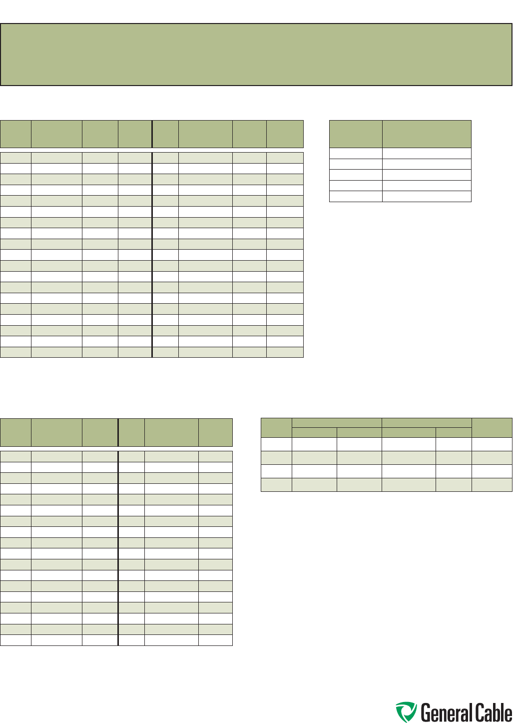
Phone: 888-593-3355
www.generalcable.com
S P E C A100
May, 2013
Common Color Sequence
Method 1 -
Table E1 Color Sequence
COND.
NO.
BACKGROUND
OR BASE
COLOR
FIRST
TRACER
COLOR
SECOND
TRACER
COLOR
COND.
NO.
BACKGROUND
OR BASE
COLOR
FIRST
TRACER
COLOR
SECOND
TRACER
COLOR
1
Black - -
20
Red Green -
2
White - -
21
Orange Green -
3
Red - -
22
Black White Red
4
Green - -
23
White Black Red
5
Orange - -
24
Red Black White
6
Blue - -
25
Green Black White
7
White Black -
26
Orange Black White
8
Red Black -
27
Blue Black White
9
Green Black -
28
Black Red Green
10
Orange Black -
29
White Red Green
11
Blue Black -
30
Red Black Green
12
Black White -
31
Green Black Orange
13
Red White -
32
Orange Black Green
14
Green White -
33
Blue White Orange
15
Blue White -
34
Black White Orange
16
Black Red -
35
White Red Orange
17
White Red -
36
Orange White Blue
18
Orange Red -
37
White Red Blue
19
Blue Red -
Pair cables are Black, White and numbered. Triad cables are Black, White, Red and numbered.
Method 1 -
Table E2 Color Sequence
COND.
NO.
BACKGROUND
OR BASE
COLOR
TRACER
COLOR
COND.
NO.
BACKGROUND
OR BASE
COLOR
TRACER
COLOR
1
Black -
19
Orange Blue
2
Red -
20
Yellow Blue
3
Blue -
21
Brown Blue
4
Orange -
22
Black Orange
5
Yellow -
23
Red Orange
6
Brown -
24
Blue Orange
7
Red Black
25
Yellow Orange
8
Blue Black
26
Brown Orange
9
Orange Black
27
Black Yellow
10
Yellow Black
28
Red Yellow
11
Brown Black
29
Blue Yellow
12
Black Red
30
Orange Yellow
13
Blue Red
31
Brown Yellow
14
Orange Red
32
Black Brown
15
Yellow Red
33
Red Brown
16
Brown Red
34
Blue Brown
17
Black Blue
35
Orange Brown
18
Red Blue
36
Yellow Brown
Pair cables are Black, Red and numbered. Triad cables are Black, Red, Blue and numbered.
Colors repeat after 36 conductors. There are no Green or White conductors or stripes.
Method 4 -
All Conductors Black
COND. CONDUCTOR PRINTING
1st
“1-One”
2nd
“2-Two”
3rd
“3-Three”
4th
“4-Four”
5th
“5-Five”
ANSI MC 96.1 Conductor Alloy and Color Code
COND.
TYPE
POSITIVE WIRE NEGATIVE WIRE OUTER
JACKETALLOY COLOR ALLOY COLOR
EX
Chromel Purple Constantan Red Purple
JX
Iron White Constantan Red Black
KX
Chromel Yellow Alumel Red Yellow
TX
Copper Blue Constantan Red Blue

Phone: 888-593-3355
www.generalcable.com
S P E C A150
September, 2010
Metric Conversion Factors
To Convert From To Multiply By
Inches Millimeters 25.4
Millimeters Inches 0.03937
Inches Centimeters 2.54
Centimeters Inches 0.3937
Length
Feet Meters 0.3048
Meters Feet 3.2808
Kilofeet (1000 feet) Kilometers 0.3048
Kilometers Kilofeet (1000 feet) 3.2808
Square Inches Square Millimeters 645.16
Square Millimeters Square Inches 0.00155
Square Inches Square Centimeters 6.4516
Square Centimeters Square Inches 0.155
Area Square Inches Circular Mils 1,273,240
Circular Mils Square Inches 7.854 x 10⁻⁷
Circular Mils Square Millimeters 5.066 x 10⁴
Square Millimeters Circular Mils 1973.51
Square Feet Square Meters 0.0929
Square Meters Square Feet 10.764
Pounds Kilograms 0.4536
Kilograms Pounds 2.2046
Weight
Pound/Kilofeet Kilograms/Kilometer 1.4882
Kilograms/Kilometer Pounds/Kilofeet 0.6720
Ohms/Kilofeet Ohms/Kilometer 3.2808
Ohms/Kilometer Ohms/Kilofeet 0.3048
Microfarads/Kilofeet Microfarads/Kilometer 3.2808
Electrical Microfarads/Kilometer Microfarads/Kilofeet 0.3048
Insulation Resistance:
Megohms—Kilofeet Megohms—Kilometer 0.3048
Megohms—Kilometer Megohms—Kilofeet 3.2808
Pounds/Square Inch Kilo Pascal* 6.895
Mechanical Kilo Pascal* Pounds/Square Inch 0.1432
Pounds (force) Newtons 4.448
* 1 Pascal = 1 Newton/square meters
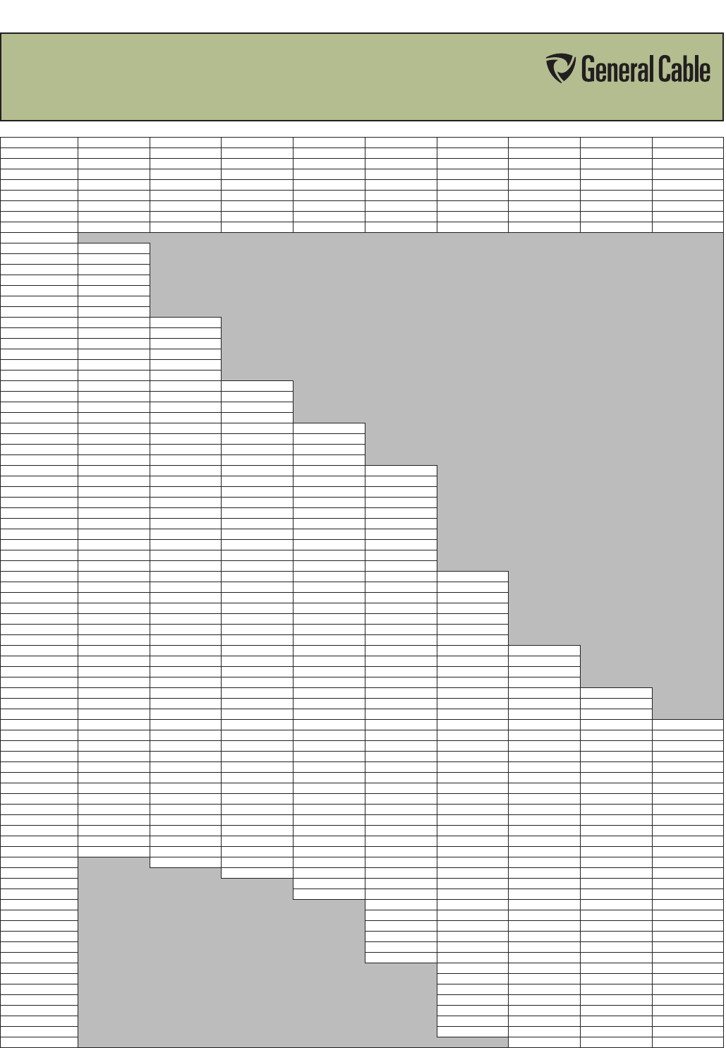
SPEC A200
January, 2012
Phone: 888-593-3355
www.generalcable.com
Reel Capacity Chart
WOOD REELS
Reel (FxTxD) 30x18x12 36x24x17 40x24x17 45x28x21 50x32x24 58x32x28 72x36x36 84x36x48 90x36x48
RM Code 61-1215 61-1659 61-1808 61-2056 61-2253 61-2764 61-3655 61-4265 61-4366
Arbor Hole 2.75 3.06 3.06 3.06 3.06 3.06 3.06 3.5 3.5
Drive Hole 1111.5 1.5 1.5 1.5 1.5 1.5
Drive Hole Radius 4.5 6 6 8.5 10 10 10 10 10
Clearance 1.5 22222223
Factor 509.3 1155.4 1582.8 2274.2 3227.7 4468.6 7847.4 9658.4 11205. 2
Max Weight 750 1500 2000 3000 4800 6500 8000 9000 10,000
Net Weight 47 91 110 142 208 271 513 744 821
Cable OD
.241 - .250 11040
.251 - .260 10200
.261 - .270 9460
.271 - .280 8800
.281 - .290 8200
.291 - .300 7660
.301 - .310 7180
.311 - .320 6740 10790
.321 - .330 6330 10110
.331 - .340 5970 9610
.341 - .350 5630 9030
.351 - .360 6320 8490
.361 - .370 5040 8100
.371 - .380 4780 7620 10520
.381 - .390 4530 7300 9940
.391 - .400 4310 6880 9540
.401 - .410 4100 6600 9030
.411 - .420 3910 6230 8550 12580
.421 - .430 3730 6000 8220 11940
.431 - .440 3560 5660 7790 11330
.441 - .450 3410 5450 7510 10910
.451 - .460 3260 5250 7120 10370 15010
.461 - .470 3120 4970 6880 10000 14290
.471 - .480 2990 4700 6530 9510 13790
.481 - .490 2870 4630 6310 9180 13150
.491 - .500 2760 4390 6110 8880 12700
.501 - .525 2500 4040 5530 8050 11540
.526 - .550 2280 3650 5030 7330 10510
.551 - .575 2090 3310 4580 6680 9610
.576 - .600 1920 3080 4180 6110 8800
.601 - .625 1770 2810 3910 5590 8050
.626 - .650 1630 2630 3580 5240 7430 10420
.651 - .675 1510 2400 3280 4820 6970 9630
.676 - .700 1410 2260 3090 4530 6430 8900
.701 - .725 1310 2070 2840 4180 5940 8260
.726 - .750 1230 1950 2690 3950 5610 7800
.751 - .775 1150 1840 2480 3650 5190 7250
.776 - .800 1080 1690 2350 3460 4920 6870
.801 - .825 1010 1610 2230 3200 4670 6400 11530
.826 - .850 950 1530 2060 3040 4340 6090 10860
.851 - .875 900 1450 1970 2900 4130 5680 10250
.876 - .900 850 1340 1880 2690 3850 5420 9690
.901 - .925 810 1280 1735 2570 3670 5060 9170 11290
.926 - .950 760 1220 1660 2460 3510 4840 8700 10700
.951 - .975 730 1170 1590 2280 3270 4630 8250 10160
.976 - 1.000 690 1075 1525 2190 3130 4340 7850 9660 11210
1.001 - 1.050 630 990 1360 2010 2880 3990 7120 8760 10160
1.051 - 1.100 570 910 1260 1800 2590 3600 6490 7980 9260
1.101 - 1.150 520 810 1120 1670 2400 3250 5930 7300 8470
1.151 - 1.200 480 750 1040 1500 2160 3030 5450 6710 7780
1.201 - 1.250 440 700 980 1400 2020 2740 5020 6180 7170
1.251 - 1.300 410 650 870 1310 1820 2570 4640 5720 6630
1.301 - 1.350 380 580 820 1180 1710 2410 4320 5300 6150
1.351 - 1.400 350 550 770 1110 1610 2190 4000 4930 5720
1.401 - 1.450 330 520 690 1040 1460 2070 3730 4590 5330
1.451 - 1.500 310 490 650 990 1370 1950 3490 4290 4980
1.501 - 1.600 270 410 590 840 1230 1690 3070 3770 4380
1.601 - 1.700 240 370 500 760 1060 1520 2720 3340 3880
1.701 - 1.800 330 450 650 960 1325 2420 2980 3460
1.801 - 1.900 420 600 880 1210 2170 2680 3100
1.091 - 2.000 540 760 1060 1960 2410 2800
2.001 - 2.100 500 700 970 1740 2190 2540
2.101 - 2.200 650 900 1620 2000 2320
2.201 - 2.300 600 790 1480 1830 2120
2.301 - 2.400 520 740 1360 1680 1950
2.401 - 2.500 490 690 1260 1550 1790
2.501 - 2.600 460 640 1160 1430 1660
2.601 - 2.700 430 600 1080 1320 1540
2.701 - 2.800 530 1000 1230 1430
2.801 - 2.900 500 930 1150 1330
2.901 - 3.000 470 870 1070 1250
3.001 - 3.100 440 820 1010 1170
3.101 - 3.200 420 770 940 1090
3.201 - 3.300 400 720 890 1030
3.301 - 3.400 380 680 840 970
3.401 - 3.500 640 790 910
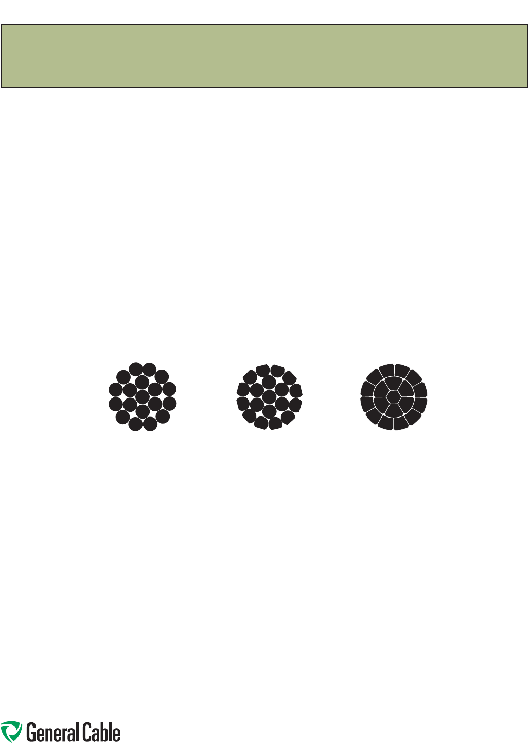
Phone: 888-593-3355
www.generalcable.com
SPEC B005
January, 2010
Conductor Reference
Concentric Stranding
TABLE 1 – Conductor Reference Table – Stranded Bare Copper
Conductor and Aluminum (ACM) Conductor
Stranded Bare Copper Conductor Standards
Conforms to: ASTM B3 Soft or annealed copper wire
ASTM B8 Concentric lay stranded
copper conductors Class B, C and D
ASTM B33 Tinned soft or annealed copper wire
ASTM B172 Rope lay stranded copper conductors
having bunch stranded members
Classes I, K and M
ASTM B173 Rope lay stranded copper conductors
having concentric stranded members
Classes G and H
ASTM B174 Bunch stranded copper conductors
ASTM B496 Compact round concentric lay stranded
copper conductors
Round
100%
Compressed
97%
Compact
90%
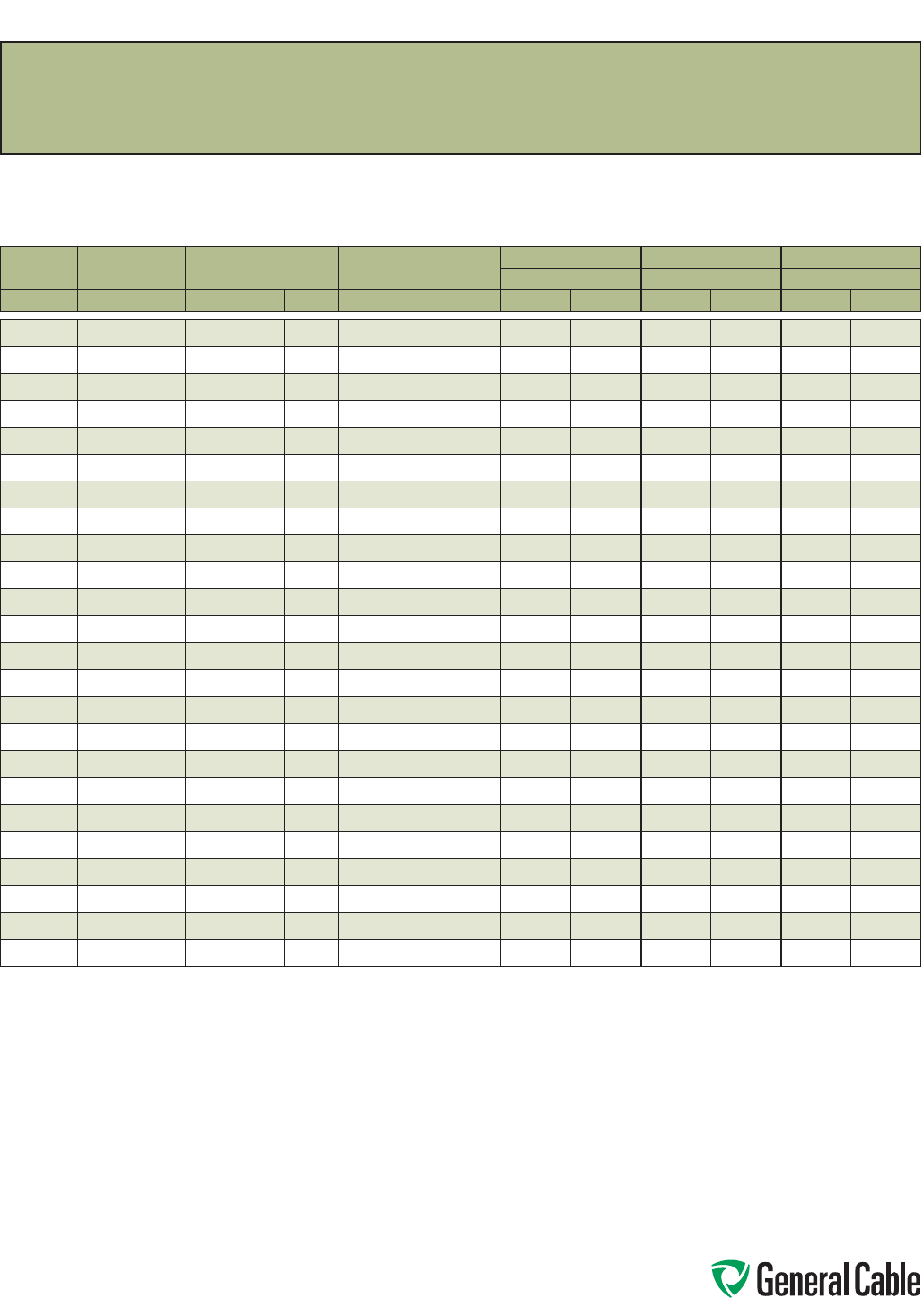
Phone: 888-593-3355
www.generalcable.com
SPEC B025
March, 2012
Class B Conductors for General Wiring
Copper Conductor
ASTM CLASS B
COND. SIZE STRANDING NOMINAL AREA NOMINAL WEIGHT
CONCENTRIC COMPRESSED COMPACT
NOMINAL O.D. NOMINAL O.D. NOMINAL O.D.
AWG/kcmil INCHES CIRCULAR MILS mm² LBS/1000 FT¹ kg/km INCHES mm INCHES mm INCHES mm
22 7/.0096 640 0.32 1.99 2.96 0.029 0.74 — — — —
20 7/.0121 1,020 0.52 3.15 4.69 0.036 0.91 — — — —
18 7/.0152 1,620 0.82 5.10 7.59 0.046 1.17 — — — —
16 7/.0192 2,580 1.31 7.74 11.52 0.058 1.47 — — — —
14 7/.0242 4,110 2.08 12.70 18.90 0.073 1.84 0.071 1.80 — —
12 7/.0305 6,530 3.31 20.20 30.10 0.092 2.32 0.089 2.26 — —
10 7/.0385 10,380 5.26 32.10 47.80 0.116 2.95 0.113 2.87 — —
8 7/.0486 16,510 8.36 51 75.90 0.146 3.71 0.142 3.60 0.134 3.40
6 7/.0612 26,240 13.30 81.10 120.70 0.184 4.67 0.178 4.53 0.169 4.29
4 7/.0772 41,740 21.20 129 192 0.232 5.89 0.225 5.72 0.213 5.41
2 7/.0974 66,360 33.60 205 305.10 0.292 7.42 0.283 7.19 0.268 6.81
1 19/.0664 83,690 42.40 258 383.90 0.332 8.43 0.322 8.18 0.299 7.59
1/0 19/.0745 105,600 53.50 326 485.10 0.373 9.47 0.362 9.19 0.336 8.53
2/0 19/.0837 133,100 67.40 411 611.60 0.419 10.64 0.406 10.32 0.376 9.55
3/0 19/.0940 167,800 85 518 770.90 0.470 11.94 0.456 11.58 0.423 10.74
4/0 19/.1055 211,600 107 653 971.80 0.528 13.41 0.512 13.01 0.475 12.07
250 37/.0822 250,000 127 772 1148.90 0.575 14.61 0.558 14.17 0.520 13.21
300 37/.0900 300,000 152 926 1378 0.630 16.00 0.611 15.52 0.570 14.48
350 37/.0973 350,000 177 1,081 1609 0.681 17.30 0.661 16.78 0.616 15.65
400 37/.1040 400,000 203 1,235 1838 0.728 18.49 0.706 17.94 0.659 16.74
500 37/.1162 500,000 253 1,544 2298 0.813 20.65 0.789 20.03 0.736 18.69
600 61/.0992 600,000 304 1,883 2802 0.893 22.68 0.866 22.00 0.813 20.65
750 61/.1109 750,000 380 2,316 3447 0.998 25.35 0.968 24.59 0.908 23.06
1000 61/.1280 1,000,000 507 3,088 4595 1.152 29.26 1.117 28.38 1.060 26.92
Dimensions and weights are nominal; subject to industry tolerances.
¹ Nominal conductor weights are applicable for Concentric Class B and Compressed Stranding per ASTM B8.
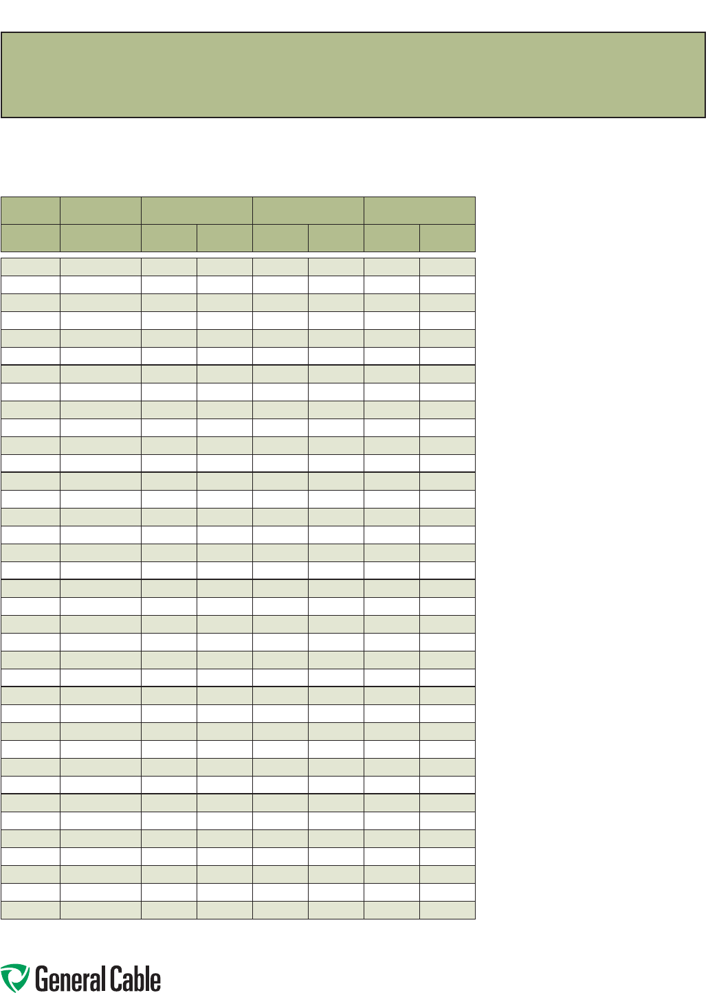
Phone: 888-593-3355
www.generalcable.com
SPEC B030
February, 2011
Class C Conductors for General Wiring
Copper Conductor
ASTM CLASS C
SIZE STRANDING NOMINAL AREA NOMINAL DIAMETER NOMINAL WEIGHT
AWG/kcmil INCHES
CIRCULAR
MILS mm2INCHES mm LBS/KFT kg/km
22 19/.0063 640 0.32 0.031 0.79 2.34 3.48
20 19/.0080 1,020 0.52 0.038 0.97 3.71 5.52
18 19/.0092 1,620 0.82 0.044 1.12 5.00 7.40
16 19/.0117 2,580 1.31 0.056 1.42 7.97 11.86
14 19/.0147 4,110 2.08 0.070 1.80 12.70 18.90
12 19/.0185 6,530 3.31 0.089 2.24 20.20 30.10
10 19/.0234 10,380 5.26 0.112 2.85 32.05 47.80
9 19/.0262 13,090 6.63 0.126 3.20 40.40 60.10
8 19/.0295 16,510 8.37 0.143 3.63 51.00 74.40
7 19/.0331 20,820 10.50 0.162 4.11 64.30 95.70
6 19/.0372 26,240 13.30 0.184 4.67 81.00 121
5 19/.0417 33,090 16.80 0.203 5.16 102 152
4 19/.0469 41,740 21.20 0.235 5.97 129 192
3 19/.0526 52,620 26.70 0.263 6.68 163 243
2 19/.0591 66,360 33.60 0.296 7.52 205 305
1 37/.0476 83,690 42.40 0.323 8.20 258 384
1/0 37/.0534 105,600 53.50 0.362 9.20 326 485
2/0 37/.0600 133,100 67.40 0.407 10.33 411 612
3/0 37/.0673 167,800 85 0.457 11.60 518 771
4/0 37/.0756 211,600 107 0.513 13.03 653 972
250 31/.0640 250,000 127 0.558 14.17 774 1150
262.6 — — — — — — —
300 61/.0701 300,000 152 0.612 15.54 927 1380
313.1 — — — — — — —
350 61/.0757 350,000 177 0.661 16.79 1082 1610
373.7 — — — — — — —
400 61/.0810 400,000 203 0.711 18.10 1235 1838
444.4 — — — — — — —
500 61/.0905 500,000 253 0.791 20.10 1545 2299
535.3 — — — — — — —
592 — — — — — — —
600 91/.0812 600,000 304 0.893 22.70 1853 2757
646.4 — — — — — — —
750 91/.0908 750,000 380 0.999 25.40 2316 3446
777.7 — — — — — — —
1000 91/.1048 1,000,000 507 1.153 29.30 3088 4595
1111 — — — — — — —
Dimensions and weights are nominal; subject to industry tolerances.
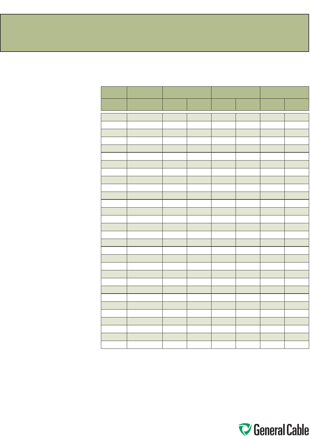
Phone: 888-593-3355
www.generalcable.com
SPEC B035
February, 2011
Class H Conductors for General Wiring
Copper Conductor
ASTM CLASS H
SIZE STRANDING NOMINAL AREA NOMINAL DIAMETER NOMINAL WEIGHT
AWG/kcmil INCHES
CIRCULAR
MILS mm²INCHES mm LBS/KFT kg/km
9 — — — — — — —
8 133/.0111 16,510 8.37 0.164 4.17 52 77
7 133/.0126 20,820 10.50 0.190 4.83 67 100
6 133/.0140 26,240 13.30 0.204 5.18 82 122
5 133/.0158 33,090 16.80 0.231 5.87 105 156
4 133/.0177 41,740 21.20 0.260 6.60 132 196
3 133/.0199 52,620 26.70 0.292 7.42 167 248
2 133/.0223 66,360 33.60 0.327 8.31 208 310
1 259/.0180 83,690 42.40 0.363 9.22 266 396
1/0 259/.0202 105,600 53.50 0.407 10.30 334 497
2/0 259/.0227 133,100 67.40 0.458 11.60 422 628
3/0 259/.0255 167,800 85 0.515 13.10 533 793
4/0 259/.0286 211,600 107 0.579 14.70 670 997
250 427/.0242 250,000 127 0.627 15.90 795 1183
262.6 — — — — — — —
300 427/.0265 300,000 152 0.702 17.80 953 1418
313.1 — — — — — — —
350 427/.0286 350,000 177 0.740 18.80 1110 1652
373.7 — — — — — — —
400 427/.0306 400,000 203 0.809 20.50 1270 1890
444.4 — — — — — — —
500 427/.0342 500,000 253 0.900 22.90 1590 2366
535.3 — — — — — — —
592 — — — — — — —
600 703/.0292 600,000 304 1.022 26.00 1920 2857
646.4 — — — — — — —
750 703/.0327 750,000 380 1.122 28.50 2410 3586
777.7 — — — — — — —
1000 703/.0377 1,000,000 507 1.294 32.90 3205 4769
1111 — — — — — — —
Dimensions and weights are nominal; subject to industry tolerances.
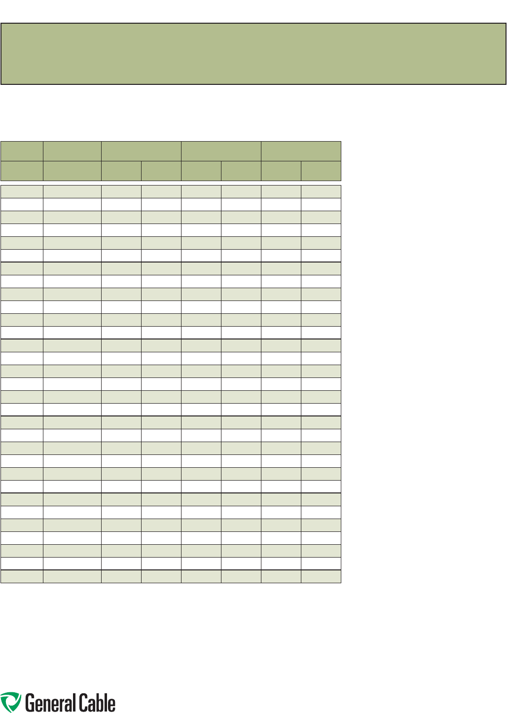
Phone: 888-593-3355
www.generalcable.com
SPEC B040
March, 2012
Class I Conductors for General Wiring
Copper Conductor
ASTM CLASS I
SIZE STRANDING NOMINAL AREA NOMINAL DIAMETER NOMINAL WEIGHT
AWG/kcmil INCHES
CIRCULAR
MILS mm2INCHES mm LBS/KFT kg/km
10 27/.0201 10,910 5.53 0.117 2.97 33.70 50
9 — ——————
8 37/.0201 14,950 7.57 0.135 3.43 46 68
7 — ——————
6 61/.0201 24,640 12.50 0.174 4.42 77 114
5 91/.0201 36,760 19 0.242 6.15 116 173
4 105/.0201 42,420 21 0.262 6.60 137 204
3 126/.0201 50,500 25 0.285 7.24 167 249
2 147/.0201 60,600 31 0.307 7.80 190 283
1 224/.0201 90,900 46 0.380 9.65 287 427
1/0 273/.0201 111,100 56 0.410 10.41 351 522
2/0 323/.0201 131,300 66 0.470 11.90 407 606
3/0 456/.0201 184,200 92 0.549 13.94 594 884
4/0 551/.0201 222,600 112 0.593 14.70 696 1035
250 — — — — — — —
262.6 646/.0201 261,000 133 0.630 16 820 1220
300 — — — — — — —
313.1 777/.0201 313,900 159 0.685 17.40 987 1469
350 — — — — — — —
373.7 925/.0201 373,700 189 0.750 19 1176 1750
400 — — — — — — —
444.4 1110/.0201 448,400 225 0.820 20.80 1413 2103
500 — — — — — — —
535.3 1332/.0201 538,100 271 0.895 22.70 1697 2525
592 1480/.0201 597,900 303 0.972 24.70 1858 2765
600 — — — — — — —
646.4 1591/.0201 642,800 327 0.980 24.90 2020 3006
750 — — — — — — —
777.7 1924/.0201 777,700 394 1.075 27.30 2435 3624
1000 — — — — — — —
1111 2745/.0201 1,111,000 563 1.328 33.70 3400 5059
Dimensions and weights are nominal; subject to industry tolerances.
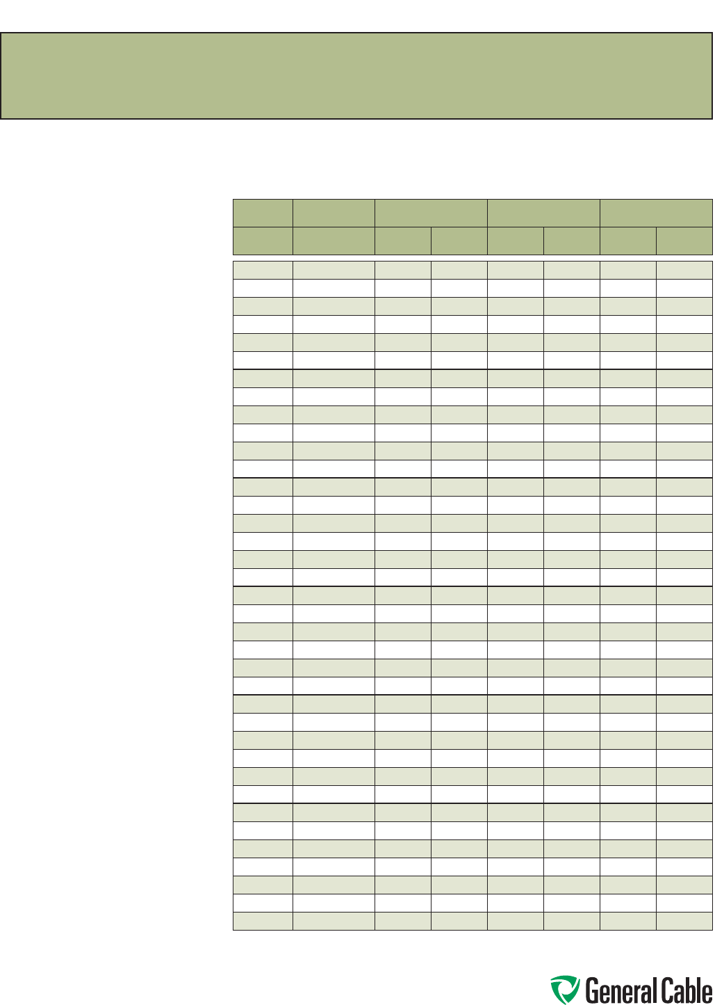
Phone: 888-593-3355
www.generalcable.com
SPEC B045
March, 2012
Class K Conductors for General Wiring
Copper Conductor
ASTM CLASS K
SIZE STRANDING NOMINAL AREA NOMINAL DIAMETER NOMINAL WEIGHT
AWG/kcmil INCHES
CIRCULAR
MILS mm2INCHES mm LBS/KFT kg/km
22 — — — — — — —
20 10/.010 1,020 0.52 0.036 0.91 3.2 4.8
18 16/.010 1,620 0.82 0.046 1.20 5 7.4
16 26/.010 2,580 1.31 0.057 1.40 7.97 12
14 41/.010 4,110 2.08 0.071 1.80 12.8 19
12 65/.010 6,530 3.31 0.088 2.20 20.3 30.2
10 105/.010 10,380 5.26 0.112 2.80 33.3 49.6
9 133/.010 13,090 6.63 0.150 3.80 42.4 63.1
8 168/.010 16,510 8.37 0.164 4 53.2 80.8
7 210/.010 20,820 10.50 0.175 4.40 66.8 99.4
6 266/.010 26,240 13.30 0.198 5.00 84.2 125
5 336/.010 33,090 16.80 0.261 6.60 106 158
4 420/.010 41,740 21.20 0.249 6.30 132 196
3 532/.010 52,620 26.70 0.298 7.60 169 251
2 665/.010 66,360 33.60 0.317 8.10 211 314
1 836/.010 83,690 42.40 0.356 9 266 396
1/0 1064/.010 105,600 53.50 0.401 10 338 503
2/0 1323/.010 133,100 67.40 0.501 13 425 632
3/0 1666/.010 167,800 85 0.562 14 535 796
4/0 2107/.010 211,600 107 0.627 15.93 676 1006
250 2499/.010 250,000 127 0.688 17 802 1193
262.6 2220/.010 222,000 112 0.680 17 824 1226
300 2989/.010 300,000 152 0.753 19 960 1428
313.1 3136/.010 313,600 159 0.750 19 969 1442
350 3458/.010 350,000 177 0.818 21 1120 1667
373.7 3737/.010 373,700 189 0.790 20 1210 1800
400 3990/.010 400,000 203 0.878 22 1290 1920
444.4 — — — — — — —
500 5054/.010 500,000 253 0.990 25 1635 2433
535.3 5320/.010 532,000 270 0.950 24 1641 2442
592 — — — — — — —
600 5985/.010 600,000 340 1.125 29 1950 2902
646.4 6466/.010 646,600 328 1.040 26 1987 2957
750 7448/.010 750,000 380 1.276 32 2427 3611
777.7 — — — — — — —
1000 9975/.010 1,000,000 507 1.498 38 3250 4769
1111 — — — — — — —
Dimensions and weights are nominal; subject to industry tolerances.
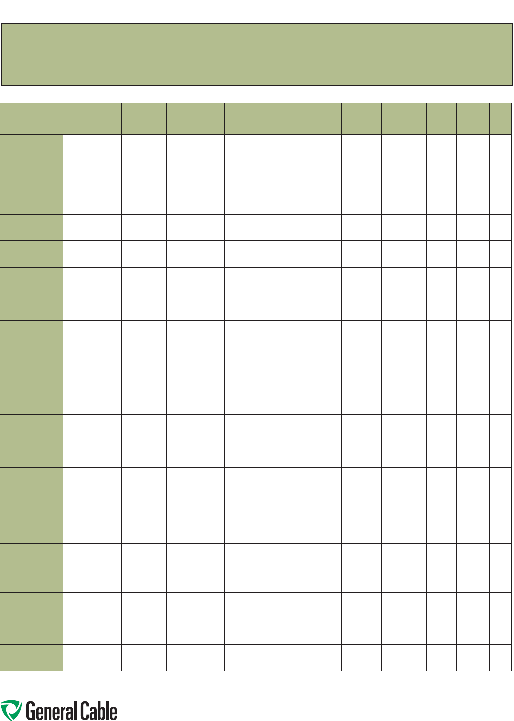
Phone: 888-593-3355
www.generalcable.com
SPEC C005
September, 2012
Thermoplastic Properties
INSULATION
OR JACKET
MATERIAL
CHLORINATED
POLYETHYLENE
(CPE)
POLYVINYL
CHLORIDE
(PVC)
LOW-DENSITY
POLYETHYLENE
CELLULAR
POLYETHYLENE
HIGH-
DENSITY
POLYETHYLENE
POLY-
URETHANE
POLY-
PROPYLENE NYLON TEFLON®TPE
Oxidation
Resistance E E E E E E E E O E
Heat
Resistance G-E G-E GG-E E E G E O G
Oil
Resistance E E G-E G-E G-E E E E O P
Low Temp.
Flexibility GP-G G-E E E E G G O E
Weather,
Sun Resistance EG-E E E E E F-G E O —
Ozone
Resistance E E E E E E E E E E
Abrasion
Resistance EF-G F-G G E F-G O E G-E F
Electrical
Properties GF-G E E E E P-F F E G
Flame
Resistance E G P P P P P P O F
Nuclear
Radiation
Resistance
G-E P-F G G G F G F-G P-F F
Water
Resistance EG-E E E E E P P-F E E
Acid
Resistance G-E G-E G-E G-E G-E E F P-F E G
Alkali
Resistance G-E G-E G-E G-E G-E E F E E G
Gasoline,
Kerosene, Etc.
(Alaphatic
Hydrocarbons)
Resistance
G G P-F P-F P-F P-F F G E P
Benzol,
Toluol, Etc.
(Aromatic
Hydrocarbons)
Resistance
GP-F PPPP-F P G E P
Degreaser
Solvents
(Halogenated
Hydrocarbons)
Resistance
FP-F P P P P P G E P
Alcohol
Resistance GG-E E E E E P P E E
P = Poor
F = Fair
G = Good
E = Excellent
O = Outstanding
Any given property can usually be improved by the use of selective compounding.
Dimensions and weights are nominal; subject to industry tolerance.
Jacket and Insulation Material Properties
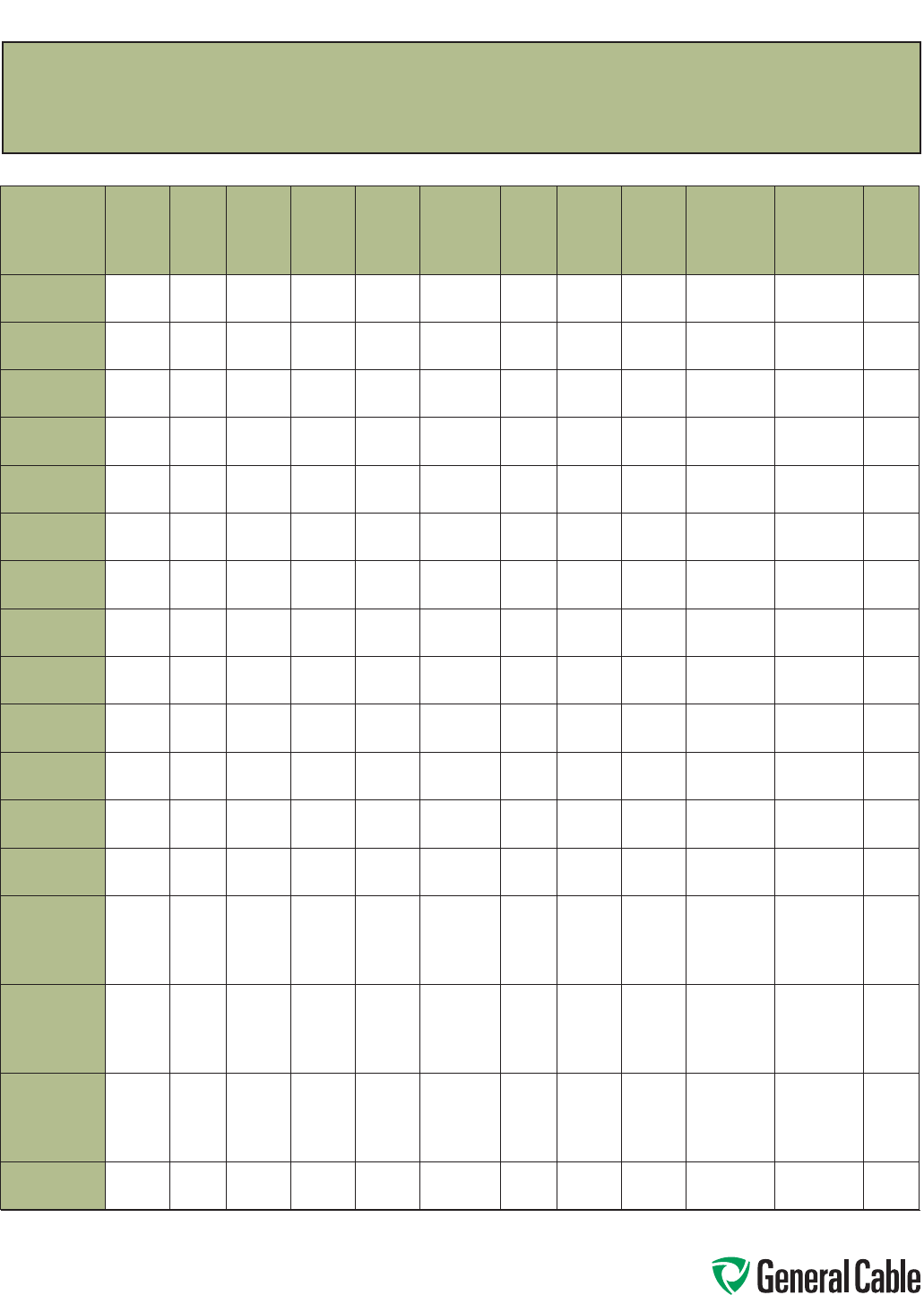
Phone: 888-593-3355
www.generalcable.com
SPEC C010
January, 2010
Thermoset Properties
INSULATION
OR JACKET
MATERIAL
STYRENE
BUTADIENE
RUBBER
(SBR)
NATURAL
RUBBER
SYNTHETIC
RUBBER
POLY-
BUTADIENE NEOPRENE
HYPALON®
CHLORO-
SULFONATED
POLYETHYLENE
(CSPE)
NITRILE
OR
RUBBER
BUTADINE
NITRILE
(NBR)
NITRILE/
POLY-
CHLORIDE
(NBR/PVC)
ETHYLENE
PROPYLENE
RUBBER
(EPR)
CROSS-LINKED
POLYETHYLENE
(XLPE)
CHLORINATED
POLYETHYLENE
(CPE)
SILICONE
RUBBER
Oxidation
Resistance F F G G G E F E G E E E
Heat
Resistance F-G F F F G E G G E G E G
Oil
Resistance P P P P G G G-E G F G G-E F-G
Low Temp.
Flexibility F-G G E E F-G F F F G-E O F O
Weather, Sun
Resistance F F F F G E F-G G E G E O
Ozone
Resistance P P P P G E P G E E G-E O
Abrasion
Resistance G-E E E E G-E GG-E E G F-G G-E F
Electrical
Properties E E E E F G P F E E F-G O
Flame
Resistance P P P P G G P G P F-G GF-G
Nuclear
Radiation
Resistance
F-G F-G F-G PF-G GF-G P G E G E
Water
Resistance G-E G-E E E G G-E G-E EG-E G-E G-E G-E
Acid
Resistance F-G F-G F-G F-G G E G G G-E G-E EF-G
Alkali
Resistance F-G F-G F-G F-G G E F-G GG-E G-E EF-G
Gasoline,
Kerosene, Etc.
(Alaphatic
Hydrocarbons)
Resistance
P P P P G F E G-E P F F P-F
Benzol,
Toluol, Etc.
(Aromatic
Hydrocarbons)
Resistance
P P P P P-F F G G F F F P
Degreaser
Solvents
(Halogenated
Hydrocarbons)
Resistance
P P P P P P-F P G P F P P-G
Alcohol
Resistance F G G F-G F G E G P E G-E G
P = Poor
F = Fair
G = Good
E = Excellent
O = Outstanding
Any given property can usually be improved by the use of selective compounding.
Dimensions and weights are nominal; subject to industry tolerance.
Jacket and Insulation Material Properties
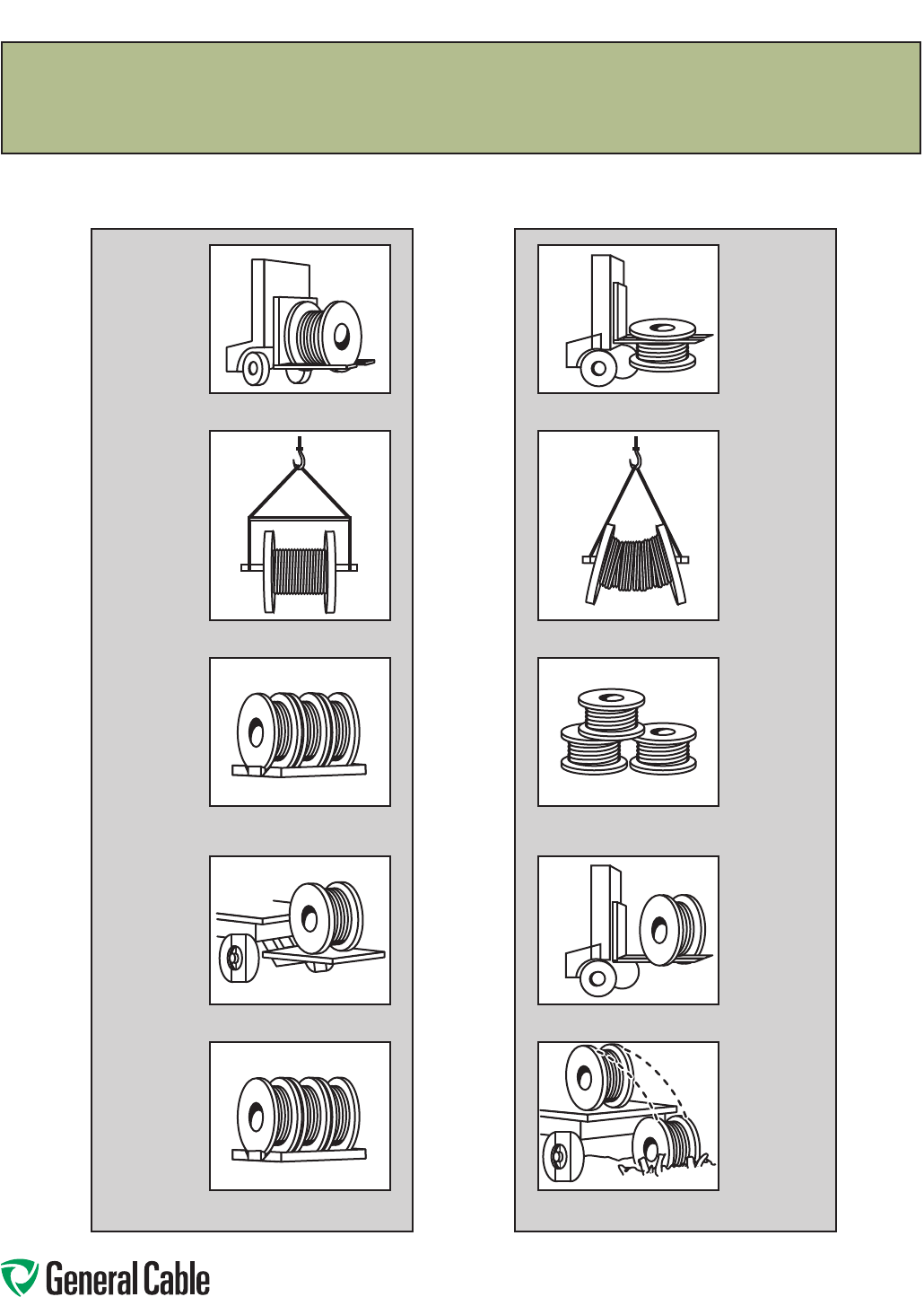
Phone: 888-593-3355
www.generalcable.com
SPEC D005
May, 2013
Recommended Reel Handling Practices
How to Handle Cable Reels
.
Cradle both reel flanges between forks.
Reels can be hoisted with a shaft
extended through both flanges.
Lower reels from truck using hydraulic
gate, hoist or fork lift. LOWER CAREFULLY.
Always load with flanges on edge and
chock and block securely.
Always load with flanges on edge and
chock and block securely.
YES
Do not lift by top flange. Cable or reel
will be damaged
Use a spreader bar to prevent bending
the reel flanges and mashing the cable.
Upended heavy reels will often arrive
damaged. Refuse or receive subject to
inspection for hidden damage.
Never allow forks to touch cable surface
or reel wrap.
Never drop reels.
NO
.
Phone: 888-593-3355
www.generalcable.com
SPEC D025
October, 2011
Recommended Cable Handling Practices
Unloading and Moving of Reels:
Cable reels are never shipped upended (flat side down). Cable reels that arrive in this manner should be rejected
or received only after a thorough inspection for damage.
See “Recommended Reel Handling Practices” page.
Upon receipt, a cable’s protective covering and/or lagging should be inspected for evidence of damage during
shipment. If evidence of damage is found, a report should immediately be made to the carrier.
Under no circumstances should reels be dropped from the delivering vehicle to the ground.
Unloading and reel handling should be accomplished so that the equipment used does not contact the cable
surface, and in the case of protective wrap, that the equipment does not contact the protective wrap.
If unloading and reel handling is accomplished by crane, either a cradle supporting the reel flanges or a shaft
through the arbor hole should be used. If a fork lift is utilized, the forks must lift the reel at 90˚ to the flanges
and the forks must be long enough to make complete lifting contact with both flanges. Under no circumstances
should the forks come into contact with the cable surface or the protective wraps.
When a reel of cable is rolled from one point to another, care must be taken to see that there are no objects on
the surface area which could contact or damage the cable surface or protective wrap.
If an inclined ramp is used for unloading, the ramp must be wide enough to contact both flanges completely.
The stopping of the reels at the bottom shall be accomplished by using the reel flanges and not the surface of
the cable.
Minimum Drum Diameters for Packaging Cables
Type of Cable Minimum Drum Diameter as a
Multiple of Outside
Diameter of Cable
1. Single and multiple conductor cable - unshielded 0-2000 V 10
2. Single and multiple conductor cable - unshielded 2400 V 12
3. Single and multiple conductor cable - wire shield (UniShield®)
5-35 kV
12
4. Single and multiple conductor cable - helically applied tape shield
(Uniblend®) 5-35 kV
14
5. Single and multiple conductor cable - longitudinally applied flat
tape shield (Type TC)
20
6.
Single and multiple conductor cable - Interlocked Armor (Duralox®)
600 V-35 kV
14
7. Triplexed single conductors cabled together. The circumscribing
overall diameter* shall be multiplied by the factor in 1 - 6 and then
by the reduction factor.
.75
*Single conductor times 2.155 times
NEMA WC26 EEMAC201-2007 Binational Wire and Cable Packaging Standard

Phone: 888-593-3355
www.generalcable.com
SPEC D050
May, 2013
Recommended Cable Storage Practices
Storage and Storage Maintenance:
Finished cables have no established shelf-life. Moisture and atmospheric conditions can cause exposed
conductors to oxidize and discolor. Uncovered/unsheltered cable will degrade due to exposure to direct sunlight
and/or the elements. If the cables are protected, there should be no degradation of the insulation.
In general, any cable for use indoors should be stored indoors. Any cable suitable for installation outdoors is
suitable for storage outdoors. Cables stored outdoors should have the ends sealed to prevent moisture ingress
into the cable and should be used within two years or less.
Cables should be stored in a sheltered area. The cable conductor should not be exposed to water.
Cables with a cold temperature marking, e.g. –10˚C, –25˚C, or –40˚C, may be stored outdoors. Cables without a
cold temperature marking must be stored indoors.
Cable reels must remain in the upright position. Cable reels must not be stored on their sides. Reels must not be
stacked.
Cable reels should be stored with the protective covering or lagging in place. If a length of cable has been cut
from the reel, the cable end should be immediately resealed to prevent the entrance of moisture. If a part length
is returned to storage, the reel’s protective covering should be restored.
Wooden reels should be stored off the ground to prevent rotting. Reels should be stored on a flat, hard surface
so that flanges do not sink into the earth. The weight of the reel and cable must be carried at all times by the reel
flanges.
Cable reels and lagging must not be stored for an extended time period sitting in direct contact with water or
dampness. Timbers or metal supports must be placed under the reel flanges to provide elevated storage of the
reels away from the direct contact with water or damp soil.
Reels should be stored in an area where construction equipment, falling or flying objects or other materials will
not contact the cable.
Cable should be stored in an area where chemicals or petroleum products will not be spilled or sprayed on the
cable.
Cable should be stored in an area away from open fires or sources of high heat.
If the reels are relocated, they should be handled as suggested in the “Recommended Reel Handling Practices”
section, and inspection made on each reel during the relocation.
If the cables are stored in a secure area and not exposed to the effects of the weather, an annual inspection
should be satisfactory.
Where the reels are exposed to the weather, a bimonthly inspection should be performed to observe any sign of
deterioration.
If the reels are exposed in a non-secure area, policing of the area at frequent intervals may be required
depending on circumstances.
Records of delivery date, manufacturer, installation date, any extenuating circumstances, along with all test
reports, should be kept on file.

Phone: 888-593-3355
www.generalcable.com
SPEC E005
April, 2010
Pre-Installation Instructions
Overview
To ensure safety during cable installation
and reliability once the cable is installed,
you should confirm the following prior to
installation:
• Thecableselectedisproperforyour
application
• Thecablehasnotbeendamagedin
transit or storage
Review all applicable state and national codes
to verify that the cable chosen is appropriate
for the job. Also, consult your local building
authority.
Next, you must identify any existing cable
damage and prevent any further damage
from occurring. This is done through proper
cable inspection, handling and storage.
Cable Inspection
Inspect every cable reel for damage before
accepting the shipment. Be particularly alert
for cable damage if:
• Areelislayingflatonitsside
• Severalreelsarestacked
• Otherfreightisstackedonareel
• Nailshavebeendrivenintoreelflangesto
secure shipping blocks
• Areelflangeisdamaged
• Acablecoveringisremoved,stainedor
damaged
• Acableendsealisremovedor
damaged
• Areelhasbeendropped
(hidden damage likely)
Cabling Handling
Remove all nails and staples from the reel
flanges before moving a reel, and avoid all
objects that could crush, gouge or impact
the cable when moving. NEVER use the
cable as a means to move a reel.
When unreeling, observe recommended
bending radii, use swivels to prevent
twisting and avoid overruns.
Pre-Installation
Phone: 888-593-3355
www.generalcable.com
SPEC E025
January, 2011
Overview
Most cables are subjected to more
mechanical stress during installation than
they ever experience in actual operation.
Needless to say, handling and pulling your
cable according to manufacturer’s recom-
mendations is extremely important.
There are six main considerations in any
cable installation:
• Ambienttemperature
• Equipment
• Conduitfill
• Mechanicalfitinraceway
• Physicallimitations
• Knowledgeableinstallers
For more information, reference
IEEE 1185 Recommended Practices for
Cable Installations in Generating Stations
and Industrial Facilities.
Installation Temperature
Low temperatures are a cause for
concern when installing cable. Cable
should not be installed when temperatures
are less than the cold bend temperature
rating of the cable product plus 15°C (i.e.,
minimum installation temperature = cold
bend temperature rating + 15°C). The cold
bend temperature rating is indicated on
the catalog Spec sheet.
Prior to performing a low temperature
(less than 10°F or -12˚C) cable installation,
cable should be stored for a minimum of
24 hours at a temperature of 55°F (13˚C)
or higher.
Cable should be pulled more slowly
and trained in place the same day it is
removed from storage. Do not impact,
drop, kink or bend cable sharply in low
temperatures.
Equipment
The proper use of appropriate equipment
is crucial to a successful cable installation.
The equipment needed for most installa-
tions is detailed in the following checklist:
0-1/5/10 kip dynamometer
basket grip pullers
cable cutter
cable end seals
cable pulling lubricant
cable tray bend sheaves
cable tray rollers
capstan-type puller
diameter tape
duct cleaning mandrels
electric safety blankets and clamps
extension cords and GFCI protection
fish tape or string blower/vacuum
floodlights
gang rollers: with at least 4 ft.
effective radius
gloves
guide-in flexible tubing (elephant trunks)
hand winches (come-a-long)
HI-POT tester
lint-free rags
make-up air blower & hose
manhole edge sheave
measuring tape
personal protection equipment (PPE)
plywood sheets
portable electric generator
pre-lubing devices
pulling rope
pump, diaphragm
radios or telephones
reel arbor
reel brakes
reel jacks
several wire rope slings of various
lengths
shackles/clevis
short ropes for temp tie-offs
swivels
warning flags, signs
Installation
Installation – Overview and Checklist
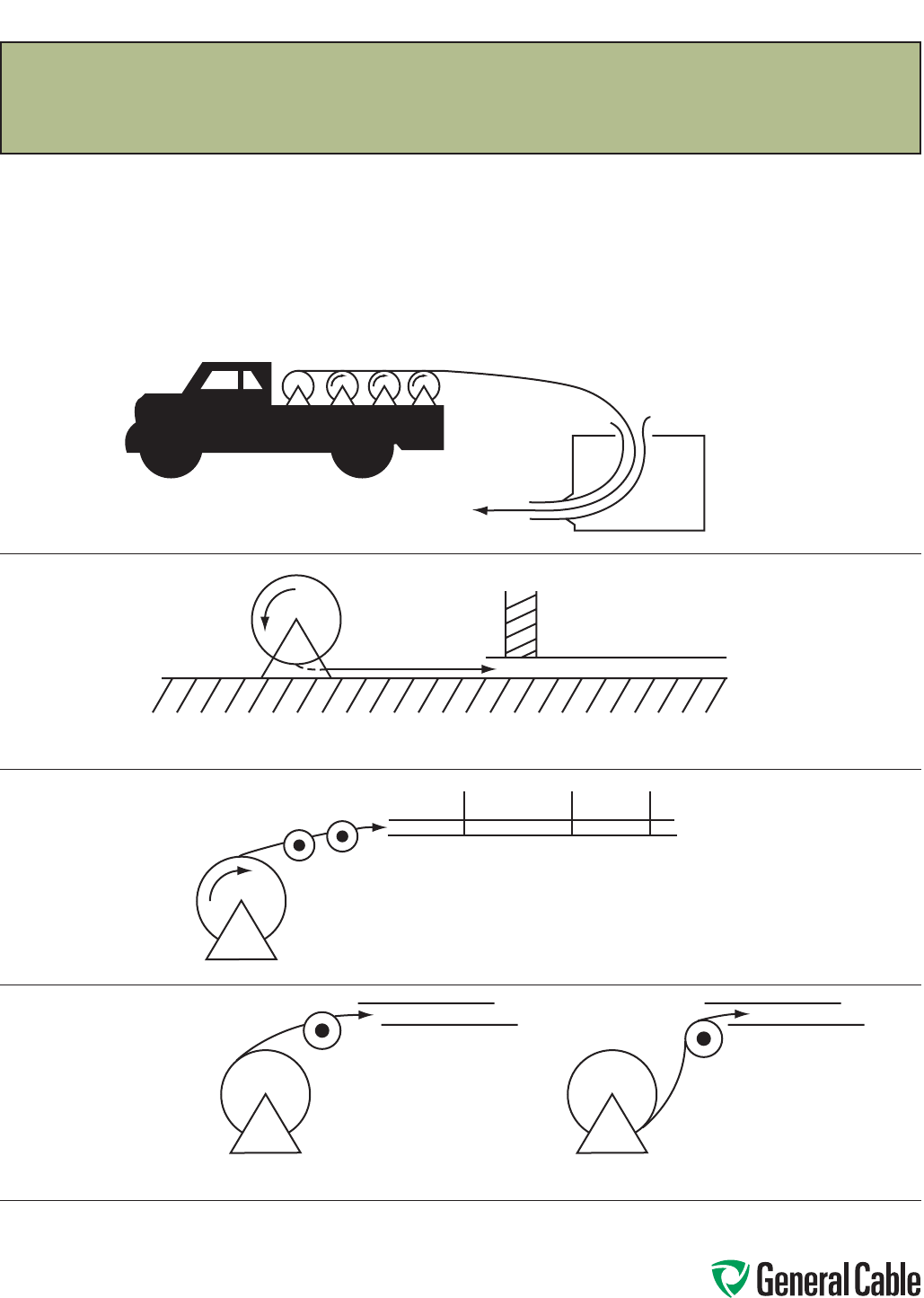
Phone: 888-593-3355
www.generalcable.com
SPEC E050
April, 2010
Installation – Feed-In Setups
The following diagrams illustrate various cable feed-in setups:
Cable Feed-In Setups
The feed-in setup should unreel the
cable with a natural curvature
(Figure 1) as opposed to a reverse
“S” curvature (Figure 2).
Reels on truck
Apply lube here
Guide-in tube
Setup for duct close to floor
Setup for overhead, into tray
IMPROPER
Figure 2
PROPER
Figure 1
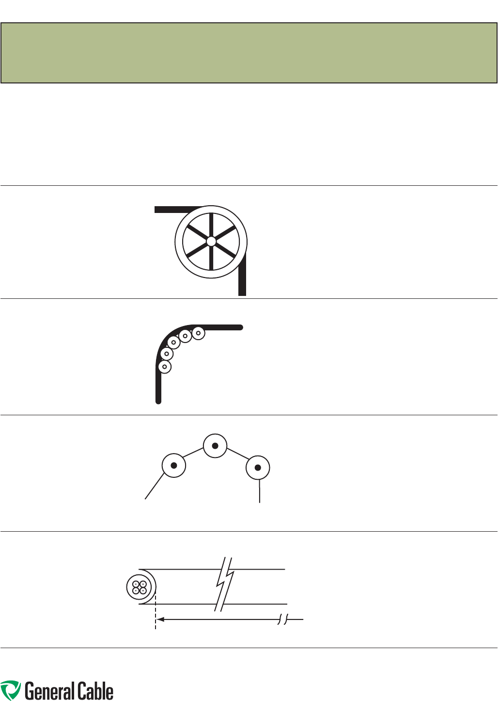
Phone: 888-593-3355
www.generalcable.com
SPEC E050
April, 2010
Installation – Feed-In Setups
Remember to use the radius of the
surface over which the cable is bent,
not the outside flange diameter of
the pulley. A “10 inch” cable sheave
typically has a 10 inch outside flange
diameter with a 6 inch inside diameter
that provides an inside (bending)
radius of 3 inches.
Single sheaves should only be
used for GUIDING cables. Arrange
multiple blocks to maintain bending
radii whenever cable changes
direction or elevation.
For pulling around bends,
use conveyor sheave
assemblies of the
appropriate radius series.
The pulleys must be positioned to ensure that
the effective curvature is smooth and changes
direction or elevation evenly at each pulley.
Never allow a polygon curvature to occur
(Figure 3).
The fit of a pulley around the cable is also
important when pulling heavy weights
(i.e. pulleys at the top of a vertical drop).
Cable Feed-In Setups (continued)
Single Sheave
Sheave Assembly
NEVER ALLOW
Figure 3
Radius
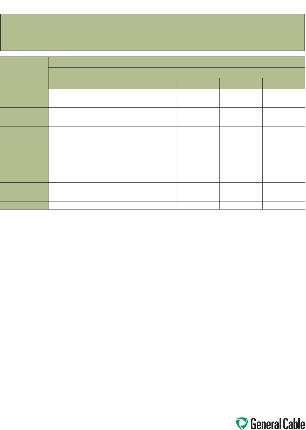
Phone: 888-593-3355
www.generalcable.com
SPEC E075
October, 2012
Installation – Conductor Maximum Pulling Tensions
Multi-Conductor Cables Having Equal-Sized Conductors;
In Parallel or as Multiplexed Assemblies
AWG/kcmil
MAXIMUM ALLOWABLE PULLING TENSION (LBS)
NUMBER OF CONDUCTORS
123456
18
16
14
13
20
33
26
40
66
39
60
99
41
65
105
52
81
132
62
97
158
12
10
8
52
83
132
104
166
264
157
249
396
167
266
423
209
332
528
251
399
634
6
4
2
210
334
531
420
668
1062
630
1002
1593
672
1069
1699
840
1336
2124
1008
1603
2548
1
1/0
2/0
670
845
1065
1339
1690
2130
2009
2534
3194
2142
2703
3407
2678
3379
4259
3214
4055
5111
3/0
4/0
250
1342
1693
2000
2685
3386
4000
4027
5078
6000
4296
5417
6400
5370
6771
8000
6444
8125
9600
350
500
750
2800
4000
6000
5600
8000
10000
8400
10000
10000
8960
10000
10000
10000
10000
10000
10000
10000
10000
1000 8000 10000 10000 10000 10000 10000
The maximum allowable pulling tensions are for direct attachment to the conductor.
T = 0.008 x cmil x n, if n ≤ 3
T = 0.008 x cmil x n x 0.8, if n > 3
When more than two conductors are pulled in parallel in an installation containing bends, the maximun allowable pulling tension is limited
to the two conductor column, regardless of the number of conductors that are being pulled.
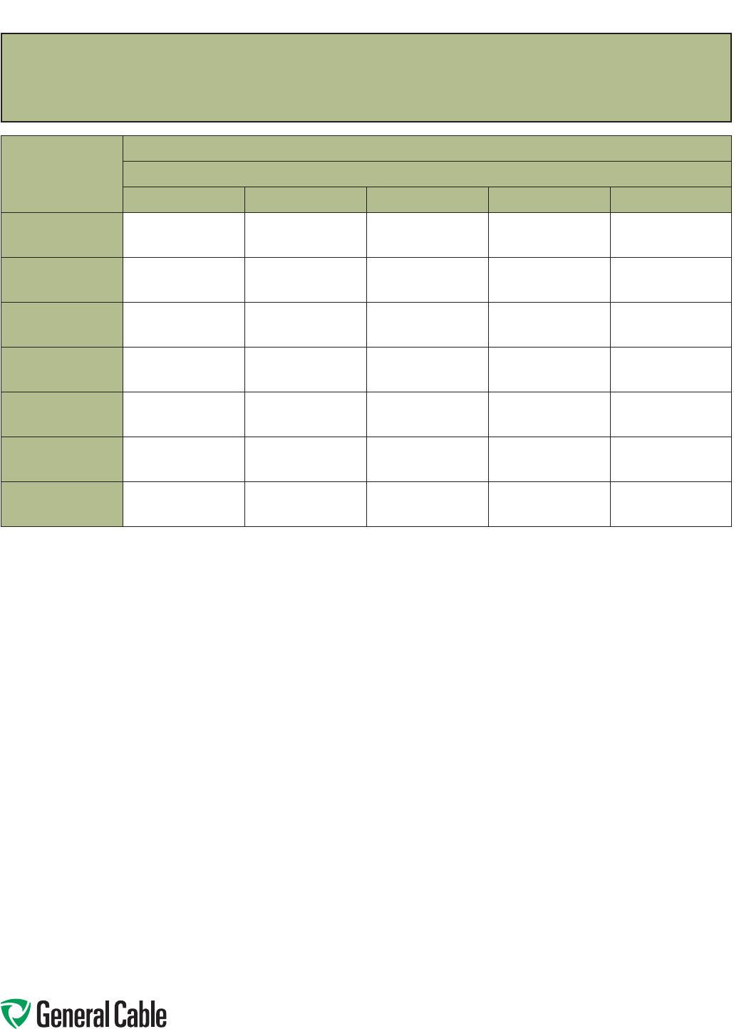
Phone: 888-593-3355
www.generalcable.com
SPEC E075
October, 2012
Installation – Conductor Maximum Pulling Tensions
Multi-Conductor Cables Having Equal-Sized Conductors, without Subassemblies
NUMBER OF
CONDUCTORS
MAXIMUM ALLOWABLE PULLING TENSION (LBS)
CONDUCTOR SIZE (AWG/kcmil)
18 16 14 12 10
2
3
4
26
39
41
40
60
65
66
99
105
104
157
167
166
249
266
5
6
7
52
62
73
81
97
113
132
158
184
209
251
293
332
399
465
8
9
10
83
93
104
129
145
161
210
237
263
334
376
418
531
598
664
12
14
15
124
145
156
194
226
242
316
368
395
502
585
627
797
930
996
16
18
19
166
187
197
258
290
306
421
473
500
669
752
794
1000
1000
1000
20
22
24
207
228
249
323
355
387
526
549
631
836
919
1000
1000
1000
1000
25
30
37
259
311
383
403
484
596
658
789
974
1000
1000
1000
1000
1000
1000
The maximum allowable pulling tensions are for multi-conductor cables pulled into a raceway or cable tray using a basket grip or similar
device secured directly to the cable jacket. It is recommended that a combination of basket grips and pulling eyes be used whenever possible.
T = 0.008 x cmil x n, if n ≤ 3
T = 0.008 x cmil x n x 0.8, if n > 3
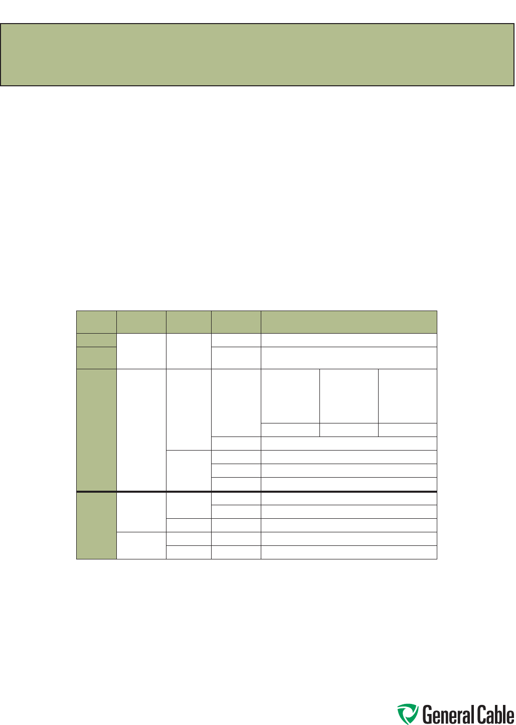
Phone: 888-593-3355
www.generalcable.com
SPEC E100
April, 2010
Installation – Training and Bending Limitations
Overview
Training is the positioning of cable when
it is not under tension. Bending is the
positioning of cable when it is under
tension. When installing cable, the object
is to limit the mechanical forces so that
the cable’s physical and electrical
characteristics are maintained for the
expected service life. Bends in conductors,
multi-conductor cables or assemblies of
conductors shall be made so that the cable
will not be damaged.
Physical Limitations Training and Bending
A nonshielded cable can tolerate a sharper
bend than a shielded cable. This is
especially true for cables having helically
applied metallic shielding tapes which,
when bent too sharply, can separate or
buckle and cut into the insulation.
Remember that offsets are bends.
The problem is compounded by the fact
that most tapes are under jackets that
conceal such damage. The extruded
polymers used for insulation shields have
sufficient conductivity and coverage
initially to pass acceptance testing, then
fail prematurely due to corona at the
shield/insulation interface.
Minimum Bending Radius in Accordance with National Electric Code
Voltage Conductors Shielding Cable Types Minimum Bending Radius as a Multiple
of Conductor/Assembly Diameter
600 V Single Nonshielded All 5X
601-
2000 V All 8X
600 V
or
2000 V
Multi-
conductor
or
Multiplexed
Nonshielded TC or TC-ER
1 in. (25 mm)
or less
Over 1 in. to 2 in.
(>25 mm to 50
mm)
Over 2 in.
(>50 mm)
4X 5X 6X
MC37X
Shielded
All 12X
TC or TC-ER 12X
MC 12X/7X1
Over
2000 V
Single Nonshielded MV 8X
MC37X
Shielded MC and MV 12X2
Multi-
conductor or
Multiplexed
Nonshielded MC and MV 8X
Shielded MC and MV 12X/7X1,2
1 12 times the diameter of an individual shielded conductor or 7 times the overall cable diameter, whichever is greater.
2 Since UniShield® is a unique construction, there are no applicable values for the bending radius in the NEC. However,
General Cable recommends 8 times for single conductors, and for multiplexed or multi-conductor cables, it is 8 times
the diameter of the individual conductors or 5 times the overall diameter, whichever is greater, in accordance with
ANSI/ICEA S-93-639 5-46 kV Shielded Power Cable for Use in the Transmission and Distribution of Electric Energy.
3 Per 330.24B Interlocked-Type Armor or Continuously Corrugated Metallic Sheath.
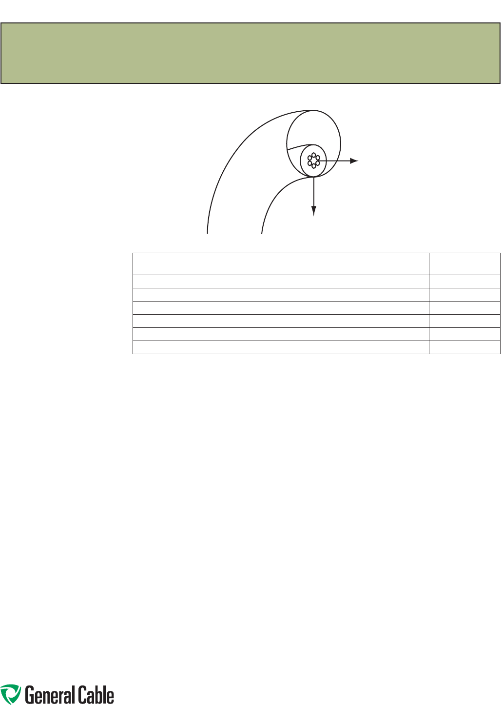
Phone: 888-593-3355
www.generalcable.com
SPEC E125
October, 2012
Installation – Maximum Sidewall Pressure
Overview
Sidewall bearing pressure (SWBP), or sidewall
loading, is the radial force exerted on a cable being
pulled around a conduit bend or sheave. Excessive
SWBP can crush a cable and is, therefore, one of
the most restrictive factors in installations having
bends and requiring high pulling tensions. SWBP is
reduced by increasing the radius of bends.
The maximum tension that can safely be applied
to the cable during installation can be calculated
using the maximum SWBP for the cable and the
radius of the bend it is traversing.
For example, a cable having a maximum SWBP of
300 lb/ft that is being pulled around a bend having
a radius of 2 feet should have no more than 300
lbs/ft x 2 ft or 600 lbs tension applied to it as the
cable exits the bend.
*Yellow 77 not recommended for use with UniShield® cables.
For LSZH jacketed cable, consult with pulling compound manufacturers.
Other wire pulling compounds may be suitable for use with General Cable constructions. Contact the wire pulling compound manufacturer regarding the
suitability of their products with specific General Cable products.
General Cable’s Approval List of Cable Pulling Lubricants
The following manufacturers, who are listed in the 2006 UL Electrical Construction Equipment Directory, provide wire pulling compounds intended for
use as lubricants in installing electrical conductors in raceways. These manufacturers have had some of their products evaluated by Underwriters
Laboratories (UL) to determine their compatibility with conductor insulation and coverings.
Since it is not feasible to test every possible combination of cable material with every wire pulling compound, the installer should check with the pulling
compound manufacturer or the cable manufacturer to determine compatibility between specific cable materials and the pulling compound.
The Listing Mark for these products includes the UL symbol, together with the word “LISTED,” a control number and the product name “Wire Pulling
Compound.” Refer to the latest edition of the UL Electrical Construction Equipment Directory for the current listing of manufacturers of wire pulling
compounds and their control numbers.
J. C. Whitlam Mfg. Co.
Klein Tools Inc.
Madison Electric Products Inc.
Rainbow Technology Corp.
Rectorseal
Thomas & Betts Corp.
3M Company
American Bentonite International Inc.
American Polywater Corp.
Arnco Corp.
Dura-Line Corp.
Greenlee Textron
Ideal Industries Inc.*
CABLE TYPE SWBP (LBS/FT)
300 V Nonshielded, 300 V and 600 V Shielded Control & Instrumentation 500
600 V Nonshielded Control & Instrumentation 500
600 V and 2400 V Nonshielded Power 1000
5 kV-35 kV Shielded Power 1000
Interlocked Armored Cable (all voltage) 300
CCW® MC-HL Armored Cable 500
Sidewall Load
Tension

Phone: 888-593-3355
www.generalcable.com
SPEC F005
April, 2010
The test voltage should be increased in steps of 10 kV, or minimum of 5 steps. The duration at each step
should be long enough for the current to reach a steady value (1 minute suggested). The test current will
momentarily increase for each voltage increment due to charging of the capacitance and the dielectric absorption
characteristics of the insulation. Stabilized current should be recorded at each step.
The maximum test voltage should be maintained for 15 minutes (new cable, shielded) / 5 minutes (nonshielded).
Leakage current should be recorded each minute after the maximum test voltage has been reached.
Increase of leakage current at any step may be an indication of a cable insulation problem. Failure of the cable or
cable accessories may result unless the voltage is rapidly reduced.
Otherwise, the leakage current should stabilize after about 5 minutes. Leakage current is essentially a function of
the construction and length of cable, but it can be influenced by the test conditions (wind and humidity) as well as
the test apparatus (leads).
Typical leakage currents in the order of 100 – 150 microamperes or higher are not unusual. A defective installation
is identified by increasing leakage current with time, at a fixed DC voltage.
All testing should be performed by qualified personnel taking all appropriate safety precautions.
DC “HI-POT” Pre-Test Guidelines for MV Cables
Phone: 888-593-3355
www.generalcable.com
SPEC F025
April, 2010
DC High Potential (HI-POT) Testing of Medium-Voltage Power Cable
Overview
This procedure is intended to provide
general guidelines for high potential
DC testing of power cables.
All tests made after cable installation
and during the guarantee period
shall be made in accordance with
applicable specifications.
All safety precautions must be
observed during testing at
high voltage.
Read, understand and follow the
Operator’s Manual for the particular
test set being used!
Test Equipment
Direct current test equipment
is available commercially with a
wide range of voltages. Accessory
equipment necessary to safely
conduct high voltage tests—such as
safety barriers, rubber gloves and
nonconducting hard hats—must be
used; consult appropriate
safety officer.
Test Procedures
See IEEE Standard 400 Article 5
Direct Voltage Testing. Acceptable
procedures, although varying slightly
in technique, have more or less been
standardized as either a “withstand
test” or a “time-leaking current test.”
Before performing any DC
over potential tests:
•Allequipmentmustbe
disconnected from the cable
circuit, i.e., taps, motors, circuit
breakers, surge arrestors, etc.
This will preclude damage to such
equipment and will prevent test
interruptions due to flashovers
and/or trip-outs resulting from
excessive leakage current.
•Establishadequateclearance
between the circuit test ends and
any grounded object, and to other
equipment not under test (about
2.5 feet).
•Groundallcircuitconductorsnot
under test with all cable shields
including nearby equipment.
•Consultterminationmanufacturers
for maximum test voltage
recommendations and
time limitations.
The direct current test voltage may
be applied either continuously or in
predetermined steps to the maximum
value in accordance with applicable
specifications.
•ContinuousMethod– Apply
test voltage at an approximate
rise rate of 1 kV per second or
75% of the rated current output
of the equipment, whichever is
less. Some equipment will take
longer to reach the maximum test
voltage because of the amount of
charging current.
•StepMethod– Apply test voltage
slowly in 5 to 7 increments of
equal value to the maximum
specified. Allow sufficient time at
each stop for the leakage current
to stabilize.
HI-POT TESTING PROCEDURES
Normally this requires only a few
seconds unless cable circuits of high
capacitance are involved.
Record leakage current at each step.
Maintain the test voltage at
the prescribed value for the
time designated in applicable
specifications. The following times
are usually considered adequate. At
the end of the test period, set the
test set voltage control to zero, allow
the residual voltage on the circuit to
decay, then ground the conductor just
tested.
CAUTION
It should be recognized that DC
charges on cable can build up to
potentially dangerous levels if grounds
are removed too quickly. Maintain
solid grounds after the test on the
cable for at least 4 times the duration
of the test. On exceptionally long
cable lengths, it may be necessary
to increase the grounding time.
It is advantageous to maintain
these grounds longer and while
reconnecting circuit components.
•AcceptanceTesting–After
installation and before the cable
is placed in regular service, the
specified test voltage shall be
applied for 15 consecutive
minutes.
•ProofTesting–At any time during
the period of guarantee, the cable
circuit may be removed from
service and tested at a reduced
voltage (normally 65 percent of the
original acceptance value) for 5
consecutive minutes.
•Recordtheleakagecurrentatone
minute intervals for the duration of
the test time involved.
DC “HI-POT” Testing Guidelines for MV Cables

Phone: 888-593-3355
www.generalcable.com
SPEC F025
April, 2010
DC High Potential (HI-POT) Testing of Medium-Voltage Power Cable
Comments
The significance of conducting DC
high-voltage tests on nonshielded,
nonmetallic-sheathed cable is
dependent upon the environment
in which it is installed because the
characteristics of the return circuits
are unknown. The environment must
be carefully considered, or test results
may not be significant. In fact, these
tests can result in damage to the
cable insulation.
Humidity, condensation and actual
precipitation on the surface of a
cable termination can increase the
leakage current by several orders of
magnitude. Humidity also increases
the corona current, which indication is
included in the total leakage current.
Wind prevents the accumulation of
space charges at all bare energized
terminals.
This results in an increase of
corona. It is most desirable to
reduce or eliminate corona current
at the bare metal extremities of
cable or terminations. This may be
accomplished by covering these areas
with plastic envelopes, plastic or glass
containers, plastic wrap or suitable
electrical putty.
Routine periodic DC maintenance
testing of cable for the evaluation of
the insulation strength is not a common
practice. Some power cable users
have adopted a program of testing
circuits during planned outages,
preferring possible breakdowns during
testing rather than experiencing a
service outage. It is nearly impossible
to recommend test voltage values for
those maintenance tests with the history
of the cable circuit. An arbitrary test
voltage level could break down a cable
circuit that would otherwise render long
trouble-free service at normal operating
AC voltage.
The main usefulness of DC high-voltage
testing is to detect conducting particles
left on the creepage surface during
splicing or termination.
Test equipment should be supplied
from a stable, constant voltage
source. Do not use the same source
that is supplying arc welders or
other equipment causing line voltage
fluctuations. The output voltage of the
test set must be filtered and regulated.
Consider using a portable, motor-driven
alter nator to energize the test set.
The gradual decrease or non-increase of
leakage current with respect to time at
maximum test voltage is the acceptance
criteria for DC HI-POT testing.
Testing Problems
Extra Leakage Current:
•Failuretoguardagainstcorona
•Failuretocleaninsulationsurface
•Failuretokeepcableendsdry
•Failuretoprovideadequate
clearance to ground
•Impropershieldtermination
Erratic Readings:
•Fluctuatingvoltagetotestset
•Impropertestleads
Environmental Influences:
•Highrelativehumidity
•Dampness,dew,fog
•Wind,snow
Results vs. Cable Life
To date there is no basis for
correlation between DC test
results and cable life expectancy.
DC “HI-POT” Testing Guidelines for MV Cables
Phone: 888-593-3355
www.generalcable.com
SPEC F075
April, 2010
Acceptance Testing
Acceptance testing is performed to detect any defects in cable insulation and terminations which may have resulted from poor
workmanship or mechanical damage. This proof test confirms the integrity of the insulation and accessories before the cable is
placed into service.
After installation and before the cable is placed in regular service, the test voltages specified in the ICEA S-97-682 Table should
be applied for 15 consecutive minutes. Record the leakage current at one minute intervals for the duration of the test.
Field Electrical “HI-POT” Testing Guidelines
ICEA DC Field Test Voltages
ICEA S-97-682 Utility Shielded Power Cables Rated 5,000-46,000 Volts
Rated
Voltage Phase-
to-Phase (kV)
Conductor Size Nominal Insulation Thickness
(Insulation Level)
Maximum DC Field
Test Voltages (kV)
During or After
Installation First 5 Years
AWG/kcmil mm2
100% 133% 100% 133% 100% 133%
mils mm mils mm
58 - 1000 8.4 - 507 90 2.29 115 2.92 28 36 911
> 1000 > 507 140 3.56 140 3.56
86 - 1000 13.3 - 507 115 2.92 140 3.56 36 44 11 14
> 1000 > 507 175 4.45 175 4.45
15 2 - 1000 33.6 - 507 175 4.45 220 5.59 56 64 18 20
> 1000 > 507 220 5.59
25 1 - 2000 42.4 - 1013 260 6.60 320 8.13 80 96 25 30
28 1 - 2000 42.4 - 1013 280 7.11 345 8.76 84 100 26 31
35 1/0 - 2000 53.5 - 1013 345 8.76 420 10.7 100 124 31 39
46 4/0 - 2000 107.2 - 1013 445 11.3 580 14.7 132 172 41 54
DC test voltages are applied to discover gross problems such as improperly installed accessories or mechanical damage. DC testing is not expected to reveal deterioration due
to aging in service. There is some evidence that DC testing of aged cross-linked polyethylene cables can lead to early cable failures. Information on this subject is available in EPRI
project report TR-101245, “Effect of DC Testing in Extruding Cross-Linked Polyethylene Insulated Cables.”
Dimensions and weights are nominal; subject to industry tolerances.

Phone: 888-593-3355
www.generalcable.com
SPEC F100
January, 2010
The increase or decrease of the load current is not associated with an instantaneous change of the cable
temperature. Hence, during emergency conditions, the cable may be overloaded for short periods of time at the
maximum overload temperature of 130°C/140°C for cable rated at 90°C/105˚C continuous.
Operations at the emergency overload temperature shall not exceed 1500 cumulative hours during the lifetime of
the cable. Lower temperature for emergency overload conditions may be required due to the type of material used
in the cable splices and terminations or environmental conditions.
Emergency Overload Current Guidelines
Phone: 888-593-3355
www.generalcable.com
SPEC F125
January, 2010
Copper Conductor t = 0.0297 log10
Aluminum Conductor t = 0.0125 log10
Which simplify to:
Copper Conductor amperes for MV-90
Copper Conductor amperes for MV-105
Aluminum Conductor amperes for MV-90
Aluminum Conductor amperes for MV-105
0.06773 A
I =
t
The maximum short circuit current which is permitted to flow in the insulated conductor, or the metallic shielding
and bonding (grounding) components, is dependent on the duration of the short circuit and the material used in
the cable.
Insulated Conductors Formula
The graphs on the following pages show the short circuit capability of 10 AWG to 1000 kcmil, copper and
aluminum, XLPE and EPR insulated conductors for various periods of time. These graphs are in accordance with
ICEA publication P-32-382. The equations are based on the assumption that the duration of the short circuit is so
short that the heat generated is contained within the conductor, taking into consideration the temperature limit of
the insulation.
The graphs are derived from the following formula:
Where: I = Short circuit current (amperes)
A = Conductor cross-sectional area (circular mils)
t = Short circuit duration (seconds)
T1 = Maximum normal operating temperature, 90°C for MV-90 or 105°C
for MV-105
T2 = Maximum short circuit temperature, 250°C
0.07195 A
I =
t
0.0470 A
I =
t
0.044 A
I =
t
[ ]
T2 + 234
——————
T1 + 234
[ ]
T2 + 228
——————
T1 + 228
[ ]2
I
—
A
[ ]2
I
—
A
Short Circuit Current Calculation Overview
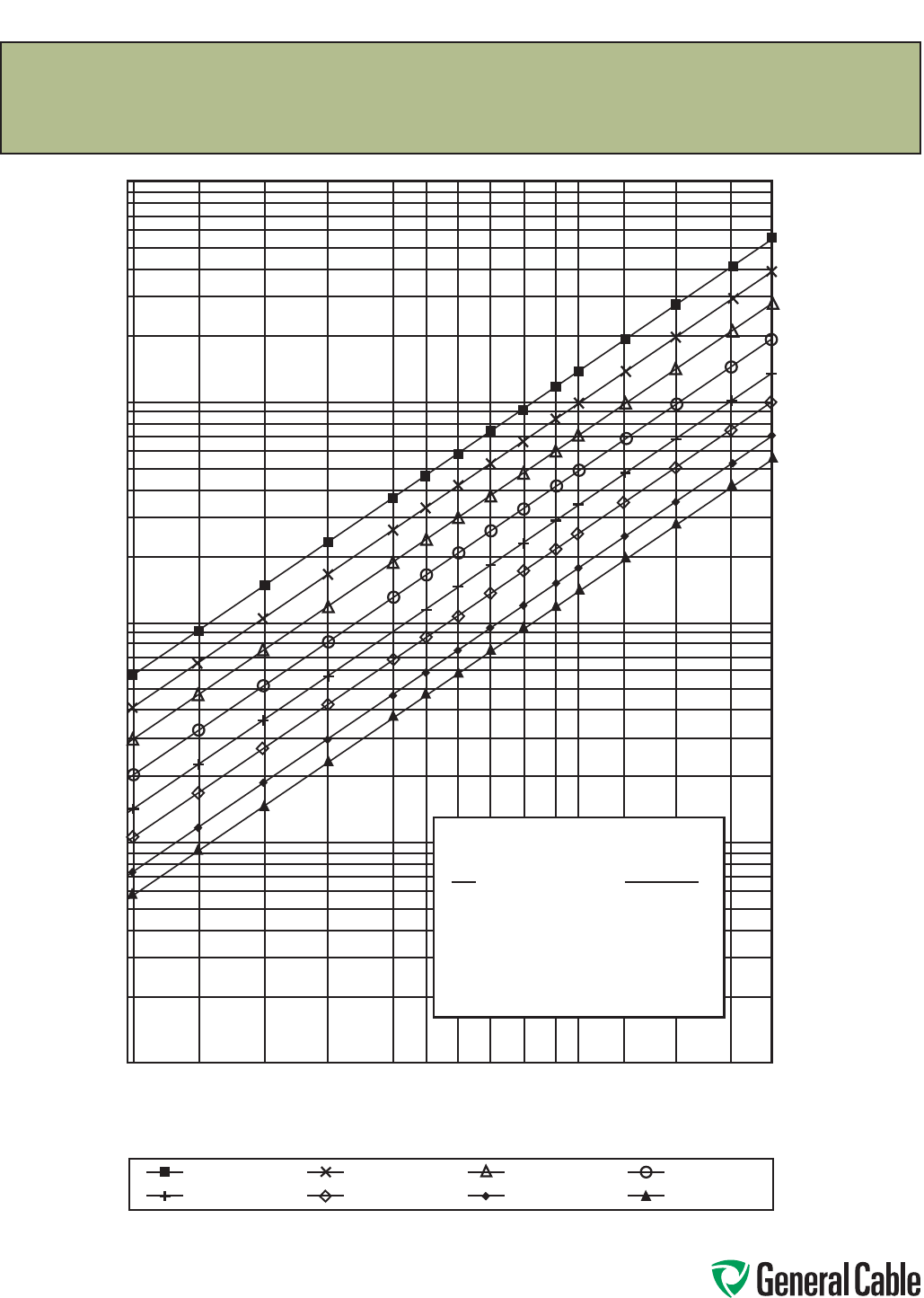
Phone: 888-593-3355
www.generalcable.com
SPEC F125
January, 2010
Reference P-32-382-2007, reprinted in part with permission of ICEA. This excerpt is not intended to replace the standard in its entirety.
ICEA standards are subject to periodic review and revision. Complete texts of this and all ICEA standards are available at IHS.
Short Circuit Currents
Allowable Short Circuit Currents For Thermoset Insulated Copper Conductors
Rated For 90°C Maximum Continuous Operation
Short Circuit Current—Amperes
1 Cycles
16 Cycles
2 Cycles
30 Cycles
4 Cycles
60 Cycles
8 Cycles
100 Cycles
Conductor Size (AWG/kcmil)
10 8 6 4 2 1 1/0 2/0 3/0 4/0 250 350 500 750 1000
1000000
100000
10000
1000
100
I = Short Circuit Current–Amperes
A = Conductor Area–Circular Mils
t = Time of Short Circuit–Seconds
T1 = Maximum Operating Temperature–90°C
T2 = Maximum Short Circuit Temperature–250°C
Curves Based on the Formula
t = 0.0297 log10
[ ]
I
A[ ]
T2 + 234
T1 + 234
2
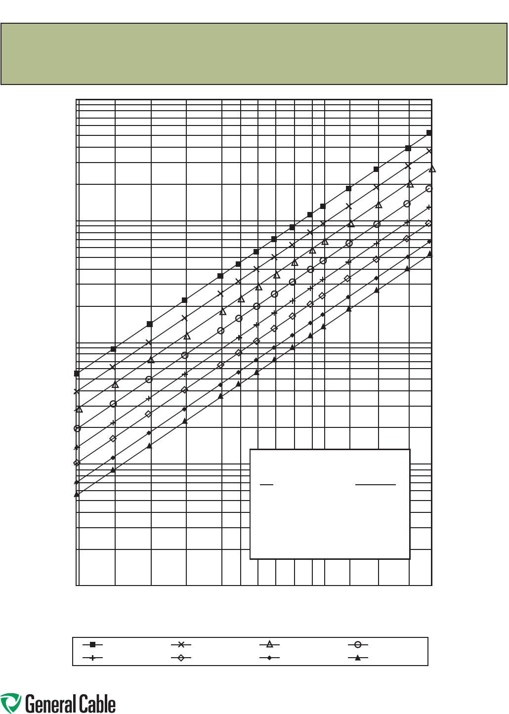
Phone: 888-593-3355
www.generalcable.com
SPEC F125
January, 2010
Short Circuit Currents
Allowable Short Circuit Currents For Thermoset Insulated Copper Conductors
Rated For 105°C Maximum Continuous Operation
Reference P-32-382-2007, reprinted in part with permission of ICEA. This excerpt is not intended to replace the standard in its entirety.
ICEA standards are subject to periodic review and revision. Complete texts of this and all ICEA standards are available at IHS.
1 Cycles
16 Cycles
2 Cycles
30 Cycles
4 Cycles
60 Cycles
8 Cycles
100 Cycles
Short Circuit Current—Amperes
Conductor Size (AWG/kcmil)
10 8 6 4 2 1 1/0 2/0 3/0 4/0 250 350 500 750 1000
1000000
100000
10000
1000
100
I = Short Circuit Current–Amperes
A = Conductor Area–Circular Mils
t = Time of Short Circuit–Seconds
T1 = Maximum Operating Temperature–105°C
T2 = Maximum Short Circuit Temperature–250°C
Curves Based on the Formula
t = 0.0297 log10
[ ]
I
A[ ]
T2 + 234
T1 + 234
2
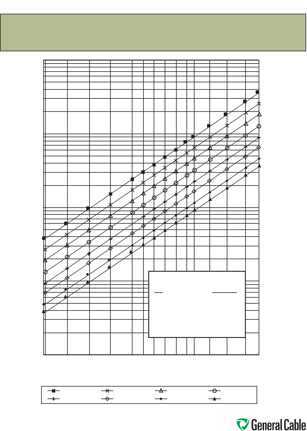
Phone: 888-593-3355
www.generalcable.com
SPEC F125
January, 2010
Short Circuit Currents
Allowable Short Circuit Currents For Thermoset Insulated Aluminum Conductors
Rated For 90°C Maximum Continuous Operation
1 Cycles
16 Cycles
2 Cycles
30 Cycles
4 Cycles
60 Cycles
8 Cycles
100 Cycles
Short Circuit Current—Amperes
Conductor Size (AWG/kcmil)
Reference P-32-382-2007, reprinted in part with permission of ICEA. This excerpt is not intended to replace the standard in its entirety.
ICEA standards are subject to periodic review and revision. Complete texts of this and all ICEA standards are available at IHS.
1000000
100000
10000
1000
100
I = Short Circuit Current–Amperes
A = Conductor Area–Circular Mils
t = Time of Short Circuit–Seconds
T1 = Maximum Operating Temperature–90°C
T2 = Maximum Short Circuit Temperature–250°C
Curves Based on the Formula
t = 0.0125 log10
[ ]
I
A[ ]
T2 + 228
T1 + 228
2
10 8 6 4 2 1 1/0 2/0 3/0 4/0 250 350 500 750 1000
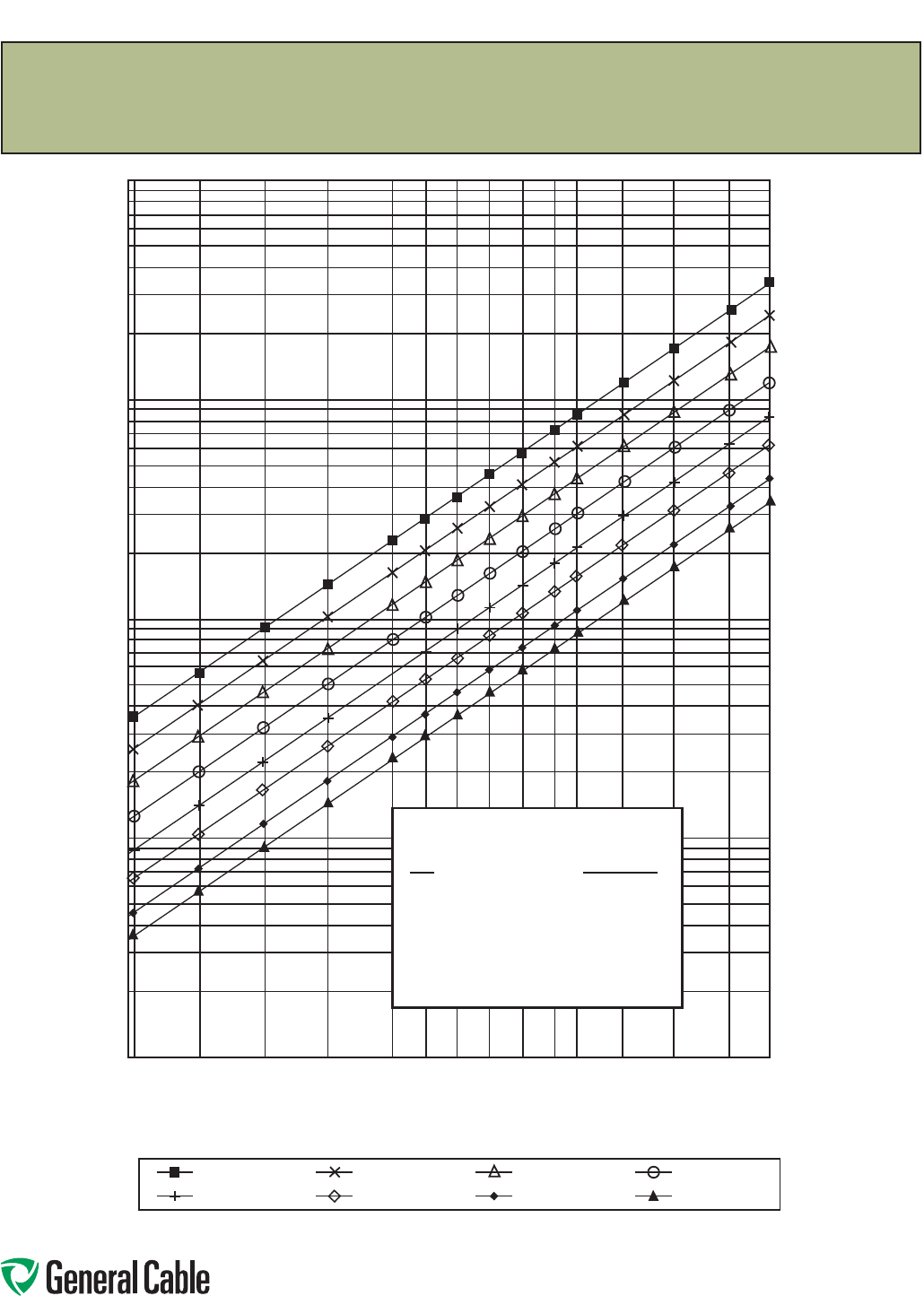
Phone: 888-593-3355
www.generalcable.com
SPEC F125
January, 2010
Short Circuit Currents
Allowable Short Circuit Currents For Thermoset Insulated Aluminum Conductors
Rated For 105°C Maximum Continuous Operation
Reference P-32-382-2007, reprinted in part with permission of ICEA. This excerpt is not intended to replace the standard in its entirety.
ICEA standards are subject to periodic review and revision. Complete texts of this and all ICEA standards are available at IHS.
1 Cycles
16 Cycles
2 Cycles
30 Cycles
4 Cycles
60 Cycles
8 Cycles
100 Cycles
Short Circuit Current—Amperes
Conductor Size (AWG/kcmil)
1000000
100000
10000
1000
100
I = Short Circuit Current–Amperes
A = Conductor Area–Circular Mils
t = Time of Short Circuit–Seconds
T1 = Maximum Operating Temperature–105°C
T2 = Maximum Short Circuit Temperature–250°C
Curves Based on the Formula
t = 0.0125 log10
[ ]
I
A[ ]
T2 + 228
T1 + 228
2
10 8 6 4 2 1 1/0 2/0 3/0 4/0 250 350 500 750 1000
Phone: 888-593-3355
www.generalcable.com
SPEC F150
January, 2010
Formula—Short Circuit Current for Copper Shields
In the three conductor cables, a copper tape is applied over each extruded semi-conducting insulation shield with
a helical gap. Because the three copper tape shields are cabled in intimate contact with the bonding (grounding)
conductor, their combined total cross-sectional areas may be considered an integral shielding system for the pur-
pose of calculating short circuit capacity. It is not possible however, to determine the contact resistance between
the components, due to possible oxides or film which may form on the components or movement of the cable
core during handling. It may be advisable to consider the short circuit capacity of the individual shields indepen-
dently. Because the insulation shields are in thermal contact with the inner PVC jacket, the maximum short circuit
temperature T2 is 200°C. Refer to ICEA P-45-482, “Short Circuit Performance of Metallic Shields and Sheaths on
Insulated Cable,” for calculations involving cables that have other operating parameters.
Under these temperature conditions the short circuit current formula is: I = amperes
M . A
_________
t
Meaning of Symbols: A = Effective cross-sectional area, shield or sheath
B = Tape overlap (mils) (usually 375)
b = Thickness of tape (mils)
dis = Diameter over semiconducting insulation shields (mils)
dm = Mean diameter of shield or sheath (mils)
ds = Diameter of wires (mils)
I = Short circuit current (amperes)
w = Width of tape (mils)
n = Number of serving or braid wires or tapes
L = Overlap of tape (percent)
t = Short circuit duration (seconds)
M = 0.058 for 5-15 kV cables
0.060 for 25-46 kV cables
FORMULA FOR
TYPE OF SHIELD OR SHEATH CALCULATING A
1. Wires applied either helically, as a braid or serving;
or longitudinally with corrugations nds
2. Helically applied tape, not overlapped 1.27 nwb
3. Helically applied flat tape, overlapped 4 bdm x 100
2(100-L)
4. Corrugated tape, longitudinally applied 1.27[π(dis+50)+B]b
5. Tubular sheath 4 bdm
2
Short Circuit Current for Copper Shields
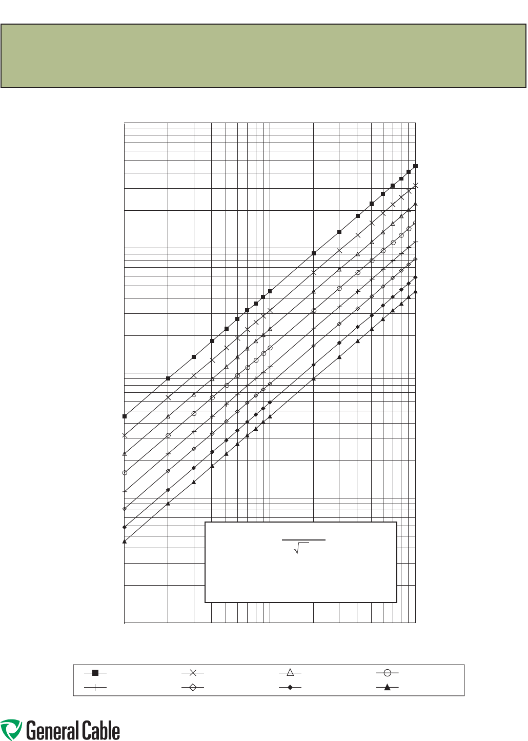
Phone: 888-593-3355
www.generalcable.com
SPEC F150
January, 2010
Effective Cross-Sectional Area in kcmil
Short Circuit Current—Kilo Amperes
1 Cycles
16 Cycles
2 Cycles
30 Cycles
4 Cycles
60 Cycles
8 Cycles
100 Cycles
Allowable Copper Shield Short Circuit Currents for 5–15 kV
1 10 100
0.01
0.1
100
10
1
0.058 . A
I = _______
t
A= Effective cross-sectional area (circular mils)
t= Short circuit duration (seconds)
I= Short circuit current (amperes)
Temperature excursion range 100°C–200°C
Formula – Short Circuit Currents for Copper Shields
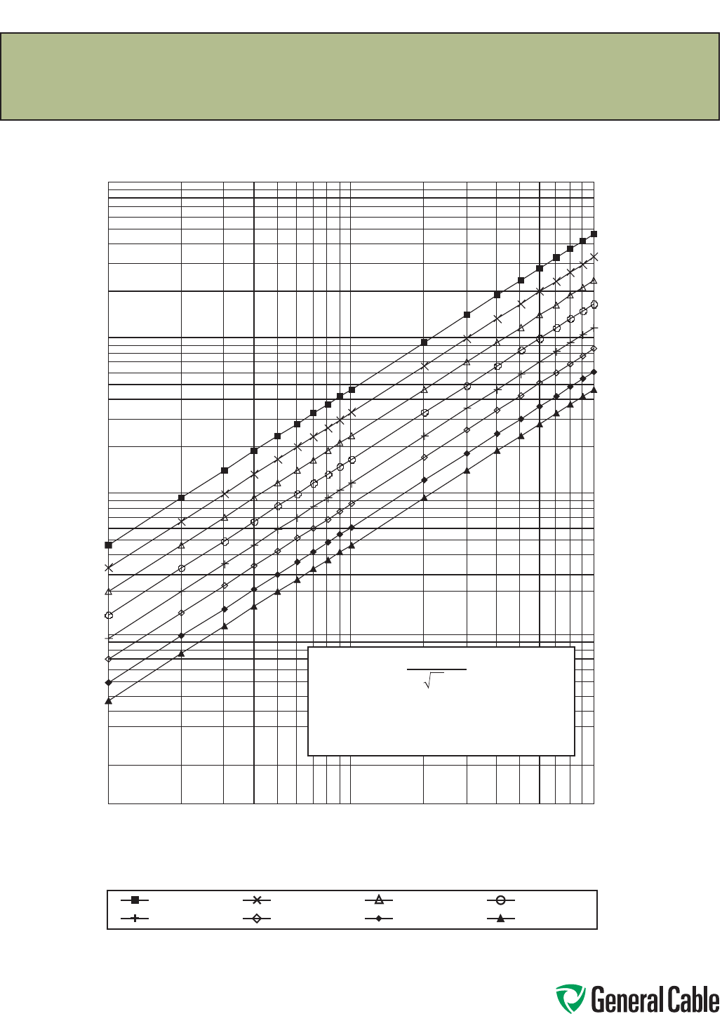
Phone: 888-593-3355
www.generalcable.com
SPEC F150
January, 2010
Short Circuit Current—Kilo Amperes
1 10 100
1 Cycles
16 Cycles
2 Cycles
30 Cycles
4 Cycles
60 Cycles
8 Cycles
100 Cycles
0.01
0.1
100
10
1
Allowable Copper Shield Short Circuit Currents for 25–46 kV
Effective Cross-Sectional Area in kcmil
A= Effective cross-sectional area (circular mils)
t= Short circuit duration (seconds)
I= Short circuit current (amperes)
Temperature excursion range 95°C–200°C
0.060 . A
I = _______
t
Formula – Short Circuit Currents for Copper Shields

Phone: 888-593-3355
www.generalcable.com
AC Resistance & Inductive Reactance
S P E C F175
June, 2013
Inductive Reactance ohms/km (at 60 hertz) 600 Volt & 1000 Volt
CONDUCTOR
SIZE
A
VOLTAGE
W
3 SINGLE CABLES 3 CONDUCTOR CABLE
ONE CABLE DIAMETER SPACING IN ALUMINUM ALUMINUM ARMOR* CONDUIT*
G O R kcmil VOLTS
RW90 RA90 TECK90 RW90 AC9O, ACWU90 TECK90
14
12
10
8
6
600
600
600
1000
1000
—
—
—
—
—
—
—
—
—
—
—
—
—
—
—
.1480
.1395
.1315
.1455
.1370
.1230
.1160
.1095
.1225
.1140
.1230
.1155
.1090
.1145
.1175
4
3
2
1
1000
1000
1000
1000
—
—
—
—
—
—
—
—
—
—
—
—
.1290
.1255
.1230
.1280
.1075
.1045
.1025
.1065
.1105
.1070
.1045
.1060
1/0
2/0
3/0
4/0
1000
1000
1000
1000
.1695
.1660
.1650
.1630
.2040
.2010
.1970
.1960
.2190
.2140
.2130
.2080
.1200
.1165
.1135
.1110
.1000
.0970
.0945
.0925
.1020
.0995
.0965
.0945
250
300
350
400
1000
1000
1000
1000
.1620
.1600
.1595
.1570
.1925
.1895
.1875
.1875
.2085
.2045
.2010
.1990
.1105
.1085
.1070
.1055
.0920
.0905
.0895
.0880
.0950
.0930
.0915
.0910
500
600
750
1000
1000
1000
1000
1000
.1565
.1550
.1535
.1520
.1865
.1820
.1800
.1770
.1955
.1950
.1915
.1875
.1035
.1015
.1000
.0985
.0865
.0845
.0835
.0820
.0890
.0910
.0900
.0880
Note: Values shown are based on nominal cable dimensions, which are influenced by changes in materials and conductor design. Except for the most
critical cases, such variations are of little consequence.
Formula XL = 0.17362 log10 GMD ohms/km. XL = Inductive reactance ohms/km. GMD = Geometric mean distance between conductors. GMR = Geometric
mean radius of conductors.
For 3 conductors in steel conduit or steel armor, multiply table values by 1.25.
Multiply ohms/km by 0.3048 to obtain ohms/1000 ft. Dimensions and weights are nominal; subject to industry tolerance.
ABC
ABCA
BC
GMR
AC Resistance ohms/km (at operating temperature)
CONDUCTOR
SIZE
AWG OR
kcmil
SINGLE STRANDED CONDUCTOR* 3 CONDUCTOR CABLE**
COPPER ALUMINUM (ACM) FACTOR
60°C 75°C 90°C 75°C 90°C CU AL
14
12
10
8
6
9.7550
6.1480
3.8680
2.4320
1.5300
10.2630
6.4660
4.0690
2.5580
1.6090
10.7550
6.7780
4.2650
2.6810
1.6870
—
10.6730
6.7010
4.2130
2.6520
—
11.1880
7.0240
4.4160
2.7800
1.00
1.00
1.00
1.00
1.00
—
1.00
1.00
1.00
1.00
4
3
2
1
.9614
.7630
.6055
.4797
1.0110
.8025
.6369
.5046
1.0600
.8412
.6676
.5289
1.6670
1.3210
1.0480
.8313
1.7470
1.3850
1.0990
.8714
1.00
1.00
1.01
1.01
1.00
1.00
1.00
1.00
1/0
2/0
3/0
4/0
.3803
.3018
.2393
.1898
.4000
.3174
.2517
.1997
.4193
.3327
.2638
.2093
.6591
.5234
.4154
.3292
.6909
.5486
.4354
.3451
1.02
1.03
1.04
1.05
1.00
1.00
1.01
1.01
250
300
350
400
.1613
.1346
.1157
.1015
.1696
.1416
.1217
.1068
.1778
.1485
.1276
.1119
.2789
.2325
.1997
.1748
.2923
.2439
.2093
.1833
1.06
1.06
1.07
1.09
1.02
1.02
1.03
1.03
500
600
750
1000
.0818
.0677
.0557
.0428
.0861
.0712
.0586
.0450
.0902
.0746
.0614
.0472
.1402
.1171
.0943
.0716
.1470
.1227
.0988
.0750
1.11
1.13
1.16
—
1.05
1.07
1.10
1.16
*Except for the most critical cases, these values may be used for 2 or 3 conductors in non-metallic or aluminum conduit.
**Multiply the single conductor values by these factors to determine the AC resistance of 3 conductor cable.
Impedance (Z, ohms/km) is obtained using the following formula: Z = √R2 + XL2 (neglecting capacitance).
R = AC Resistance ohm/km
Multiply ohms/km by 0.3048 to obtain ohms/1000 ft. Dimensions and weights are nominal; subject to industry tolerance.
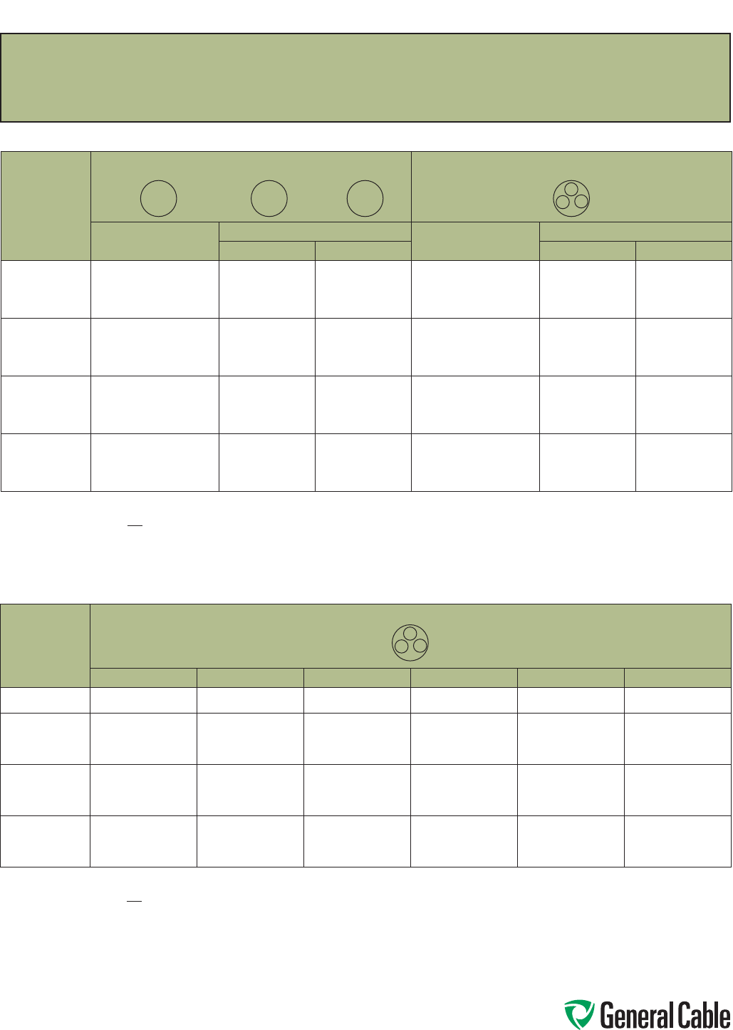
Phone: 888-593-3355
www.generalcable.com
AC Resistance & Inductive Reactance
S P E C F175
June, 2013
Inductive Reactance ohms/km (at 60 hertz) 15 kV, 25 kV & 28 kV - HVTECK (Aluminum Armored)
CONDUCTOR
SIZE
AWG OR
kcmil
3 CONDUCTOR*
15 kV (100%) 15 kV (133%) 25 kV (100%) 25 kV (133%) 28 kV (100%) 28 kV (133%)
2
1.1510
.1425 -
.1500 -
.1575 -
.1700 -
.1605 -
.1725
1/0
2/0
3/0
4/0
.1365
.1315
.1265
.1225
.1435
.1385
.1330
.1285
.1510
.1455
.1405
.1360
.1640
.1580
.1510
.1465
.1540
.1485
.1440
.1385
.1665
.1605
.1540
.1490
250
300
350
400
.1205
.1170
.1155
.1140
.1275
.1235
.1205
.1190
.1335
.1290
.1260
.1240
.1430
.1390
.1350
.1325
.1360
.1320
.1290
.1270
.1450
.1410
.1370
.1350
500
600
750
1000
.1105
.1100
.1080
.1045
.1150
.1155
.1120
-
.1200
.1205
-
-
-
-
-
-
.1220
-
-
-
-
-
-
-
Note: Values shown are based on nominal cable dimensions, which are influenced by changes in materials and conductor design. Except for the most
critical cases, such variations are of little consequence.
Formula XL = 0.17362 log10 GMD ohms/km. XL = Inductive reactance ohms/km. GMD = Geometric mean distance between conductors. GMR = Geometric mean
radius of conductors.
For 3 conductors in steel conduit or steel armor, multiply table values by 1.25.
Multiply ohms/km by 0.3048 to obtain ohms/1000 ft. Dimensions and weights are nominal; subject to industry tolerance.
GMR
A
BC
Inductive Reactance ohms/km (at 60 hertz) 5 kV – TECK90 and HVTECK (Aluminum Armored)
CONDUCTOR
SIZE
AWG OR
kcmil
SINGLE CONDUCTOR
ONE CABLE DIAMETER SPACING
3 CONDUCTOR*
TECK 90
5 kV UNSHIELDED
HVTECK SHIELDED TECK 90
5 kV UNSHIELDED
HVTECK SHIELDED
5 kV (100%) 5 kV (133%) 5 kV (100%) 5 kV (133%)
6
4
2
1
.2630
.2530
.2400
.2310
.2770
.2630
.2540
.2440
.2810
.2710
.2600
.2500
.1385
.1290
.1205
.1145
.1495
.1400
.1305
.1220
.1660
.1490
.1390
.1310
1/0
2/0
3/0
4/0
.2240
.2225
.2165
.2130
.2330
.2270
.2205
.2170
.2440
.2370
.2310
.2250
.1100
.1065
.1030
.1010
.1185
.1150
.1100
.1075
.1270
.1220
.1180
.1150
250
300
350
400
.2110
.2075
.2040
.2010
.2150
.2110
.2075
.2045
.2220
.2170
.2140
.2110
.1000
.0980
.0960
.0950
.1060
.1038
.1020
.1010
.1120
.1090
.1070
.1050
500
600
750
1000
.1980
.1970
.1935
.1895
.2015
.2000
.1975
.1920
.2090
.2030
.2010
.1960
.0925
.0945
.0935
.0910
.0980
.1010
.0990
.0955
.1040
.1060
.0980
.0950
Note: Values shown are based on nominal cable dimensions, which are influenced by changes in materials and conductor design. Except for the most
critical cases, such variations are of little consequence.
Formula XL = 0.17362 log10 GMD ohms/km. XL = Inductive reactance ohms/km. GMD = Geometric mean distance between conductors. GMR = Geometric mean
radius of conductors.
For 3 conductors in steel conduit or steel armor, multiply table values by 1.25.
Multiply ohms/km by 0.3048 to obtain ohms/1000 ft. Dimensions and weights are nominal; subject to industry tolerance.
ABC
A
BC
GMR

Phone: 888-593-3355
www.generalcable.com
Catalog Number Index
Index Industrial
CATALOG
NUMBER PAGE
CATALOG
NUMBER PAGE
CATALOG
NUMBER PAGE
CATALOG
NUMBER PAGE
06591.210200..................SPEC 5150
06591.215100..................SPEC 5150
06591.215200..................SPEC 5150
06591.215300..................SPEC 5150
06591.215400..................SPEC 5150
06591.216000..................SPEC 5150
06591.216200..................SPEC 5150
06591.216500..................SPEC 5150
06591.217000..................SPEC 5150
06591.217500..................SPEC 5150
06790.047000..................SPEC 4550
06790.077000..................SPEC 4550
06790.086500..................SPEC 4550
4775.03016......................SPEC 4775
4775.03018......................SPEC 4775
4775.04016......................SPEC 4775
4775.04018......................SPEC 4775
4775.05016......................SPEC 4775
4775.05018......................SPEC 4775
4775.07016......................SPEC 4775
4775.07018......................SPEC 4775
4775.09016......................SPEC 4775
4775.09018......................SPEC 4775
4775.12016......................SPEC 4775
4775.12018......................SPEC 4775
4775.16016......................SPEC 4775
4775.16018......................SPEC 4775
4775.19016......................SPEC 4775
4775.19018......................SPEC 4775
4775.25016......................SPEC 4775
4775.25018......................SPEC 4775
4775.30016......................SPEC 4775
4775.30018......................SPEC 4775
4775.37016......................SPEC 4775
4775.37018......................SPEC 4775
4780.03010......................SPEC 4780
4780.03012......................SPEC 4780
4780.03014......................SPEC 4780
4780.04010......................SPEC 4780
4780.04012......................SPEC 4780
4780.04014......................SPEC 4780
4780.05010......................SPEC 4780
4780.05012......................SPEC 4780
4780.05014......................SPEC 4780
4780.07010......................SPEC 4780
4780.07012......................SPEC 4780
4780.07014......................SPEC 4780
4780.09010......................SPEC 4780
4780.09012......................SPEC 4780
4780.09014......................SPEC 4780
4780.12010......................SPEC 4780
4780.12012......................SPEC 4780
4780.12014......................SPEC 4780
4780.19010......................SPEC 4780
4780.19012......................SPEC 4780
4780.19014......................SPEC 4780
4780.25010......................SPEC 4780
4780.25012......................SPEC 4780
4780.25014......................SPEC 4780
4780.30010......................SPEC 4780
4780.30012......................SPEC 4780
4780.30014......................SPEC 4780
4780.37012......................SPEC 4780
4780.37014......................SPEC 4780
4785.03016......................SPEC 4785
4785.03018......................SPEC 4785
4785.04016......................SPEC 4785
4785.04018......................SPEC 4785
4785.05016......................SPEC 4785
4785.05018......................SPEC 4785
4785.07016......................SPEC 4785
4785.07018......................SPEC 4785
4785.09016......................SPEC 4785
4785.09018......................SPEC 4785
4785.12016......................SPEC 4785
4785.12018......................SPEC 4785
4785.19016......................SPEC 4785
4785.19018......................SPEC 4785
4785.25016......................SPEC 4785
4785.25018......................SPEC 4785
4785.30016......................SPEC 4785
4785.30018......................SPEC 4785
4785.37016......................SPEC 4785
4785.37018......................SPEC 4785
4790.03010......................SPEC 4790
4790.03012......................SPEC 4790
4790.03014......................SPEC 4790
4790.04002......................SPEC 4790
4790.04004......................SPEC 4790
4790.04006......................SPEC 4790
4790.04008......................SPEC 4790
4790.04010......................SPEC 4790
4790.04012......................SPEC 4790
4790.04014......................SPEC 4790
4790.05010......................SPEC 4790
4790.05012......................SPEC 4790
4790.05014......................SPEC 4790
4790.07010......................SPEC 4790
4790.07012......................SPEC 4790
4790.07014......................SPEC 4790
4790.09010......................SPEC 4790
4790.09012......................SPEC 4790
4790.09014......................SPEC 4790
4790.12010......................SPEC 4790
4790.12012......................SPEC 4790
4790.12014......................SPEC 4790
4790.19010......................SPEC 4790
4790.19012......................SPEC 4790
4790.19014......................SPEC 4790
4790.25010......................SPEC 4790
4790.25012......................SPEC 4790
4790.25014......................SPEC 4790
4790.30010......................SPEC 4790
4790.30012......................SPEC 4790
4790.30014......................SPEC 4790
4790.37012......................SPEC 4790
4790.37014......................SPEC 4790
5125.001..........................SPEC 5125
5125.002..........................SPEC 5125
5125.004..........................SPEC 5125
5125.006..........................SPEC 5125
5125.008..........................SPEC 5125
5125.010..........................SPEC 5125
5125.012..........................SPEC 5125
5125.014..........................SPEC 5125
5125.110..........................SPEC 5125
5125.210..........................SPEC 5125
5125.250..........................SPEC 5125
5125.310..........................SPEC 5125
5125.350..........................SPEC 5125
5125.410..........................SPEC 5125
5125.500..........................SPEC 5125
5125.600..........................SPEC 5125
5125.750..........................SPEC 5125
5175.001..........................SPEC 5175
5175.002..........................SPEC 5175
5175.004..........................SPEC 5175
5175.006..........................SPEC 5175
5175.008..........................SPEC 5175
5175.110..........................SPEC 5175
5175.210..........................SPEC 5175
5175.250..........................SPEC 5175
5175.310..........................SPEC 5175
5175.350..........................SPEC 5175
5175.410..........................SPEC 5175
5175.500..........................SPEC 5175
5175.600..........................SPEC 5175
5175.750..........................SPEC 5175
5310.01001......................SPEC 5310
5310.01002......................SPEC 5310
5310.01004......................SPEC 5310
5310.01006......................SPEC 5310
5310.01008......................SPEC 5310
5310.01010......................SPEC 5310
5310.01012......................SPEC 5310
5310.01014......................SPEC 5310
5310.01110......................SPEC 5310
5310.01111......................SPEC 5310
5310.01210......................SPEC 5310
5310.01262......................SPEC 5310
5310.01310......................SPEC 5310
5310.01313......................SPEC 5310
5310.01373......................SPEC 5310
5310.01410......................SPEC 5310
5310.01444......................SPEC 5310
5310.01535......................SPEC 5310
5310.01646......................SPEC 5310
5310.01777......................SPEC 5310
5310.01929......................SPEC 5310
9025.16010001................SPEC 9025
9025.16010002................SPEC 9025
9025.16010003................SPEC 9025
9025.16010004................SPEC 9025
9050.20041221................SPEC 9050
9050.20041222................SPEC 9050
9050.20041223................SPEC 9050
9050.20041224................SPEC 9050
9050.20081221................SPEC 9050
9050.20081222................SPEC 9050
9050.20081223................SPEC 9050
9050.20081224................SPEC 9050
9050.20101221................SPEC 9050
9050.20101222................SPEC 9050
9050.20101223................SPEC 9050
9050.20101224................SPEC 9050
9050.20121221................SPEC 9050
9050.20121222................SPEC 9050
9050.20121223................SPEC 9050
9050.20121224................SPEC 9050
9050.20161221................SPEC 9050
9050.20161222................SPEC 9050
9050.20161223................SPEC 9050
9050.20161224................SPEC 9050
9050.20201221................SPEC 9050
9050.20201222................SPEC 9050
9050.20201223................SPEC 9050
9050.20201224................SPEC 9050
9050.20241221................SPEC 9050
9050.20241222................SPEC 9050
9050.20241223................SPEC 9050
9050.20241224................SPEC 9050
9050.20361221................SPEC 9050
9050.20361222................SPEC 9050
9050.20361223................SPEC 9050
9050.20361224................SPEC 9050
9050.20501221................SPEC 9050
9050.20501222................SPEC 9050
9050.20501223................SPEC 9050
9050.20501224................SPEC 9050
9075.20041221................SPEC 9075
9075.20041222................SPEC 9075
9075.20041223................SPEC 9075
9075.20041224................SPEC 9075
9075.20081221................SPEC 9075
9075.20081222................SPEC 9075
9075.20081223................SPEC 9075
9075.20081224................SPEC 9075
9075.20101221................SPEC 9075
9075.20101222................SPEC 9075
9075.20101223................SPEC 9075
9075.20101224................SPEC 9075
9075.20121221................SPEC 9075
9075.20121222................SPEC 9075
9075.20121223................SPEC 9075
9075.20121224................SPEC 9075
9075.20161221................SPEC 9075
9075.20161222................SPEC 9075
9075.20161223................SPEC 9075
9075.20161224................SPEC 9075
9075.20201221................SPEC 9075
9075.20201222................SPEC 9075
9075.20201223................SPEC 9075
9075.20201224................SPEC 9075
9075.20241221................SPEC 9075
9075.20241222................SPEC 9075
9075.20241223................SPEC 9075
9075.20241224................SPEC 9075
9075.20361221................SPEC 9075
9075.20361222................SPEC 9075
9075.20361223................SPEC 9075
9075.20361224................SPEC 9075
9075.20501221................SPEC 9075
9075.20501222................SPEC 9075
9075.20501223................SPEC 9075
9075.20501224................SPEC 9075
9125.16010001................SPEC 9125
9125.16010002................SPEC 9125
9125.16021201................SPEC 9125
9125.16021202................SPEC 9125
9125.16041201................SPEC 9125
9125.16041202................SPEC 9125
9125.16081201................SPEC 9125
9125.16081202................SPEC 9125
9125.16121201................SPEC 9125
9125.16121202................SPEC 9125
9125.16161201................SPEC 9125
9125.16161202................SPEC 9125
9125.16241201................SPEC 9125
9125.16241202................SPEC 9125
9125.16361201................SPEC 9125
9125.16361202................SPEC 9125
9125.16501201................SPEC 9125
9125.16501202................SPEC 9125
9150.16010001................SPEC 9150
9150.16010002................SPEC 9150
9150.16021201................SPEC 9150
9150.16021202................SPEC 9150
9150.16041201................SPEC 9150
9150.16041202................SPEC 9150
9150.16081201................SPEC 9150
9150.16081202................SPEC 9150
9150.16121201................SPEC 9150
9150.16121202................SPEC 9150
9150.16161201................SPEC 9150
9150.16161202................SPEC 9150
9150.16241201................SPEC 9150
9150.16241202................SPEC 9150
9150.16361201................SPEC 9150
9150.16361202................SPEC 9150
9150.16501201................SPEC 9150
9150.16501202................SPEC 9150
9225.16010001................SPEC 9225
9225.16010002................SPEC 9225
9225.16021221................SPEC 9225
9225.16041221................SPEC 9225
9225.16041222................SPEC 9225
9225.16061221................SPEC 9225
9225.16081221................SPEC 9225
9225.16081222................SPEC 9225
9225.16101221................SPEC 9225
9225.16121221................SPEC 9225
9225.16121222................SPEC 9225

Phone: 888-593-3355
www.generalcable.com
Catalog Number Index
Industrial Index
CATALOG
NUMBER PAGE
CATALOG
NUMBER PAGE
CATALOG
NUMBER PAGE
CATALOG
NUMBER PAGE
9225.16161221................SPEC 9225
9225.16161222................SPEC 9225
9225.16201221................SPEC 9225
9225.16241221................SPEC 9225
9225.16241222................SPEC 9225
9225.16361221................SPEC 9225
9225.16361222................SPEC 9225
9225.16501221................SPEC 9225
9225.18021221................SPEC 9225
9225.18041221................SPEC 9225
9225.18041222................SPEC 9225
9225.18061221................SPEC 9225
9225.18081221................SPEC 9225
9225.18081222................SPEC 9225
9225.18101221................SPEC 9225
9225.18121221................SPEC 9225
9225.18121222................SPEC 9225
9225.18161221................SPEC 9225
9225.18161222................SPEC 9225
9225.18201221................SPEC 9225
9225.18241221................SPEC 9225
9225.18241222................SPEC 9225
9225.18361221................SPEC 9225
9225.18361222................SPEC 9225
9225.18501221................SPEC 9225
9225.20021221................SPEC 9225
9225.20041221................SPEC 9225
9225.20041222................SPEC 9225
9225.20061221................SPEC 9225
9225.20081221................SPEC 9225
9225.20081222................SPEC 9225
9225.20101221................SPEC 9225
9225.20121221................SPEC 9225
9225.20121222................SPEC 9225
9225.20161221................SPEC 9225
9225.20161222................SPEC 9225
9225.20201221................SPEC 9225
9225.20241221................SPEC 9225
9225.20241222................SPEC 9225
9225.20361221................SPEC 9225
9225.20361222................SPEC 9225
9225.20501221................SPEC 9225
9250.16021221................SPEC 9250
9250.16041221................SPEC 9250
9250.16041222................SPEC 9250
9250.16061221................SPEC 9250
9250.16081221................SPEC 9250
9250.16081222................SPEC 9250
9250.16101221................SPEC 9250
9250.16121221................SPEC 9250
9250.16121222................SPEC 9250
9250.16161221................SPEC 9250
9250.16161222................SPEC 9250
9250.16201221................SPEC 9250
9250.16241221................SPEC 9250
9250.16241222................SPEC 9250
9250.16361221................SPEC 9250
9250.16361222................SPEC 9250
9250.16501221................SPEC 9250
9250.18021221................SPEC 9250
9250.18041221................SPEC 9250
9250.18041222................SPEC 9250
9250.18061221................SPEC 9250
9250.18081221................SPEC 9250
9250.18081222................SPEC 9250
9250.18101221................SPEC 9250
9250.18121221................SPEC 9250
9250.18121222................SPEC 9250
9250.18161221................SPEC 9250
9250.18161222................SPEC 9250
9250.18201221................SPEC 9250
9250.18241221................SPEC 9250
9250.18241222................SPEC 9250
9250.18361221................SPEC 9250
9250.18361222................SPEC 9250
9250.18501221................SPEC 9250
9250.20021221................SPEC 9250
9250.20041221................SPEC 9250
9250.20041222................SPEC 9250
9250.20061221................SPEC 9250
9250.20081221................SPEC 9250
9250.20081222................SPEC 9250
9250.20101221................SPEC 9250
9250.20121221................SPEC 9250
9250.20121222................SPEC 9250
9250.20161221................SPEC 9250
9250.20161222................SPEC 9250
9250.20201221................SPEC 9250
9250.20241221................SPEC 9250
9250.20241222................SPEC 9250
9250.20361221................SPEC 9250
9250.20361222................SPEC 9250
9250.20501221................SPEC 9250
9325.16010001................SPEC 9325
9325.16010002................SPEC 9325
9325.16020001................SPEC 9325
9325.16040001................SPEC 9325
9325.16040002................SPEC 9325
9325.16060001................SPEC 9325
9325.16080001................SPEC 9325
9325.16080002................SPEC 9325
9325.16100001................SPEC 9325
9325.16120001................SPEC 9325
9325.16120002................SPEC 9325
9325.16160001................SPEC 9325
9325.16160002................SPEC 9325
9325.16200001................SPEC 9325
9325.16240001................SPEC 9325
9325.16240002................SPEC 9325
9325.16360001................SPEC 9325
9325.16360002................SPEC 9325
9325.16500001................SPEC 9325
9325.18020001................SPEC 9325
9325.18040001................SPEC 9325
9325.18080001................SPEC 9325
9325.18120001................SPEC 9325
9325.18160001................SPEC 9325
9325.18240001................SPEC 9325
9350.16020001................SPEC 9350
9350.16040001................SPEC 9350
9350.16040002................SPEC 9350
9350.16060001................SPEC 9350
9350.16080001................SPEC 9350
9350.16080002................SPEC 9350
9350.16100001................SPEC 9350
9350.16120001................SPEC 9350
9350.16120002................SPEC 9350
9350.16160001................SPEC 9350
9350.16160002................SPEC 9350
9350.16200001................SPEC 9350
9350.16240001................SPEC 9350
9350.16240002................SPEC 9350
9350.16360001................SPEC 9350
9350.16360002................SPEC 9350
9350.16500001................SPEC 9350
9350.18020001................SPEC 9350
9350.18040001................SPEC 9350
9350.18080001................SPEC 9350
9350.18120001................SPEC 9350
9350.18160001................SPEC 9350
9350.18240001................SPEC 9350
9500.01002110................SPEC 9500
9500.01003110................SPEC 9500
9500.01004110................SPEC 9500
9500.01006110................SPEC 9500
9500.01008110................SPEC 9500
9500.01011110................SPEC 9500
9500.01202112................SPEC 9500
9500.01203112................SPEC 9500
9500.01204112................SPEC 9500
9500.01205112................SPEC 9500
9500.01206112................SPEC 9500
9500.01208112................SPEC 9500
9500.01211112................SPEC 9500
9500.01218112................SPEC 9500
9500.01236112................SPEC 9500
9500.01402114................SPEC 9500
9500.01403114................SPEC 9500
9500.01404114................SPEC 9500
9500.01405114................SPEC 9500
9500.01406114................SPEC 9500
9500.01408114................SPEC 9500
9500.01411114................SPEC 9500
9500.01418114................SPEC 9500
9500.01436114................SPEC 9500
9510.01004110................SPEC 9510
9510.01204112................SPEC 9510
9510.01205112................SPEC 9510
9510.01207112................SPEC 9510
9510.01209112................SPEC 9510
9510.01404114................SPEC 9510
9510.01405114................SPEC 9510
9510.01407114................SPEC 9510
9510.01409114................SPEC 9510
9510.01412114................SPEC 9510
9510.01419114................SPEC 9510
9510.01437114................SPEC 9510
9510.012121112..............SPEC 9510
9525.01002000................SPEC 9525
9525.01003000................SPEC 9525
9525.01004000................SPEC 9525
9525.01005000................SPEC 9525
9525.01007000................SPEC 9525
9525.01009000................SPEC 9525
9525.01012000................SPEC 9525
9525.01202000................SPEC 9525
9525.01203000................SPEC 9525
9525.01204000................SPEC 9525
9525.01205000................SPEC 9525
9525.01207000................SPEC 9525
9525.01209000................SPEC 9525
9525.01212000................SPEC 9525
9525.01219000................SPEC 9525
9525.01237000................SPEC 9525
9525.01402000................SPEC 9525
9525.01403000................SPEC 9525
9525.01404000................SPEC 9525
9525.01405000................SPEC 9525
9525.01407000................SPEC 9525
9525.01409000................SPEC 9525
9525.01412000................SPEC 9525
9525.01419000................SPEC 9525
9525.01437000................SPEC 9525
9600.00103310................SPEC 9600
9600.00104106................SPEC 9600
9600.00203310................SPEC 9600
9600.00204106................SPEC 9600
9600.00403312................SPEC 9600
9600.00404108................SPEC 9600
9600.00603312................SPEC 9600
9600.00604108................SPEC 9600
9600.00803314................SPEC 9600
9600.00804110................SPEC 9600
9600.01003314................SPEC 9600
9600.01004314................SPEC 9600
9600.01203316................SPEC 9600
9600.01204316................SPEC 9600
9600.01403318................SPEC 9600
9600.01404318................SPEC 9600
9600.11003310................SPEC 9600
9600.11004106................SPEC 9600
9600.21003310................SPEC 9600
9600.21004106................SPEC 9600
9600.25003308................SPEC 9600
9600.25004104................SPEC 9600
9600.31003308................SPEC 9600
9600.31004104................SPEC 9600
9600.35003307................SPEC 9600
9600.35004103................SPEC 9600
9600.41003308................SPEC 9600
9600.41004104................SPEC 9600
9600.50003306................SPEC 9600
9600.50004102................SPEC 9600
9600.75003305................SPEC 9600
9600.75004101................SPEC 9600
9600.100031110..............SPEC 9600
9600.100041110..............SPEC 9600
9615.00103310................SPEC 9615
9615.00203310................SPEC 9615
9615.00403312................SPEC 9615
9615.00603312................SPEC 9615
9615.00803314................SPEC 9615
9615.01003314................SPEC 9615
9615.01203316................SPEC 9615
9615.01403318................SPEC 9615
9615.11003310................SPEC 9615
9615.21003306................SPEC 9615
9615.25003304................SPEC 9615
9615.35003302................SPEC 9615
9615.41003304................SPEC 9615
9615.50003301................SPEC 9615
9625.043124108..............SPEC 9625
9625.063124108..............SPEC 9625
9625.083124110..............SPEC 9625
9625.103124110..............SPEC 9625
9650.023123000..............SPEC 9650
9650.023124000..............SPEC 9650
9650.023143000..............SPEC 9650
9650.023144000..............SPEC 9650
9650.024123000..............SPEC 9650
9650.024124000..............SPEC 9650
9650.024143000..............SPEC 9650
9650.024144000..............SPEC 9650
9650.043123000..............SPEC 9650
9650.043124000..............SPEC 9650
9650.043143000..............SPEC 9650
9650.043144000..............SPEC 9650
9650.044123000..............SPEC 9650
9650.044124000..............SPEC 9650
9650.044143000..............SPEC 9650
9650.044144000..............SPEC 9650
9650.063123000..............SPEC 9650
9650.063124000..............SPEC 9650
9650.063143000..............SPEC 9650
9650.063144000..............SPEC 9650
9650.064123000..............SPEC 9650
9650.064124000..............SPEC 9650
9650.064143000..............SPEC 9650
9650.064144000..............SPEC 9650
9650.083123000..............SPEC 9650
9650.083124000..............SPEC 9650
9650.083143000..............SPEC 9650
9650.083144000..............SPEC 9650
9650.084123000..............SPEC 9650
9650.084124000..............SPEC 9650
9650.084143000..............SPEC 9650
9650.084144000..............SPEC 9650
9650.103123000..............SPEC 9650
9650.103143000..............SPEC 9650
9650.103144000..............SPEC 9650
9650.104123000..............SPEC 9650
9650.104124000..............SPEC 9650

Phone: 888-593-3355
www.generalcable.com
Catalog Number Index
Index Industrial
CATALOG
NUMBER PAGE
CATALOG
NUMBER PAGE
CATALOG
NUMBER PAGE
CATALOG
NUMBER PAGE
9650.104143000..............SPEC 9650
9650.104144000..............SPEC 9650
9650.123143000..............SPEC 9650
9650.123144000..............SPEC 9650
9650.124143000..............SPEC 9650
9650.124144000..............SPEC 9650
9675.00103310................SPEC 9675
9675.00203310................SPEC 9675
9675.00403312................SPEC 9675
9675.00603312................SPEC 9675
9675.00803314................SPEC 9675
9675.01003316................SPEC 9675
9675.01203318................SPEC 9675
9675.11003310................SPEC 9675
9675.21003310................SPEC 9675
9675.25003308................SPEC 9675
9675.35003308................SPEC 9675
9675.41003308................SPEC 9675
9675.50003306................SPEC 9675
9700.00103308................SPEC 9700
9700.00203310................SPEC 9700
9700.00403310................SPEC 9700
9700.00603310................SPEC 9700
9700.00803312................SPEC 9700
9700.10003304................SPEC 9700
9700.11003308................SPEC 9700
9700.21003308................SPEC 9700
9700.25003307................SPEC 9700
9700.35003306................SPEC 9700
9700.41003307................SPEC 9700
9700.50003305................SPEC 9700
9700.75003304................SPEC 9700
9800.00103308................SPEC 9800
9800.00203310................SPEC 9800
9800.00403310................SPEC 9800
9800.00603310................SPEC 9800
9800.10003304................SPEC 9800
9800.11003308................SPEC 9800
9800.21003308................SPEC 9800
9800.25003306................SPEC 9800
9800.35003306................SPEC 9800
9800.41003307................SPEC 9800
9800.50003305................SPEC 9800
9800.75003304................SPEC 9800
9815.00103308................SPEC 9815
9815.00203310................SPEC 9815
9815.00403310................SPEC 9815
9815.00603310................SPEC 9815
9815.10003304................SPEC 9815
9815.11003308................SPEC 9815
9815.21003308................SPEC 9815
9815.25003306................SPEC 9815
9815.35003306................SPEC 9815
9815.41003307................SPEC 9815
9815.50003305................SPEC 9815
9815.75003304................SPEC 9815
9825.00103104................SPEC 9825
9825.00203106................SPEC 9825
9825.11003104................SPEC 9825
9825.21003104................SPEC 9825
9825.25003102................SPEC 9825
9825.35003102................SPEC 9825
9825.41003103................SPEC 9825
9825.50003101................SPEC 9825
9825.750031110..............SPEC 9825
9835.00103104................SPEC 9835
9835.00203106................SPEC 9835
9835.11003104................SPEC 9835
9835.21003104................SPEC 9835
9835.25003102................SPEC 9835
9835.35003102................SPEC 9835
9835.41003103................SPEC 9835
9835.50003101................SPEC 9835
9835.750031110..............SPEC 9835
9845.00103104................SPEC 9845
9845.11003104................SPEC 9845
9845.21003104................SPEC 9845
9845.25003102................SPEC 9845
9845.35003102................SPEC 9845
9845.41003103................SPEC 9845
9845.50003101................SPEC 9845
9855.00103104................SPEC 9855
9855.11003104................SPEC 9855
9855.21003104................SPEC 9855
9855.25003103................SPEC 9855
9855.35003102................SPEC 9855
9855.41003103................SPEC 9855
9855.50003101................SPEC 9855
9875.11003104................SPEC 9875
9875.21003104................SPEC 9875
9875.25003103................SPEC 9875
9875.35003102................SPEC 9875
9875.41003103................SPEC 9875
9875.50003101................SPEC 9875
9900.15744......................SPEC 9900
9900.27901......................SPEC 9900
9900.KS226 .....................SPEC 9900
9900.PS526 ..................... SPEC 9900
11206.332083..................SPEC 8125
11281.015400..................SPEC 8700
11281.016000..................SPEC 8700
11281.016200..................SPEC 8700
11281.016500..................SPEC 8700
11281.016700..................SPEC 8700
11281.017000..................SPEC 8700
11281.017500..................SPEC 8700
11281.030100..................SPEC 8750
11281.030200..................SPEC 8750
11281.030400..................SPEC 8750
11281.030600..................SPEC 8750
11281.035100..................SPEC 8750
11281.035200..................SPEC 8750
11281.035300..................SPEC 8750
11281.035400..................SPEC 8750
11281.036000..................SPEC 8750
11281.036200..................SPEC 8750
11281.036500..................SPEC 8750
11281.036700..................SPEC 8750
11281.037000..................SPEC 8750
11281.040100..................SPEC 8775
11281.040200..................SPEC 8775
11281.045100..................SPEC 8775
11281.045200..................SPEC 8775
11281.045300..................SPEC 8775
11281.045400..................SPEC 8775
11281.046000..................SPEC 8775
11281.046200..................SPEC 8775
11281.046500..................SPEC 8775
11281.046700..................SPEC 8775
11281.047000..................SPEC 8775
11288.010100..................SPEC 8150
11288.010200..................SPEC 8150
11288.010300..................SPEC 8150
11288.010400..................SPEC 8150
11288.010600..................SPEC 8150
11288.015100..................SPEC 8150
11288.015200..................SPEC 8150
11288.015300..................SPEC 8150
11288.015400..................SPEC 8150
11288.016000..................SPEC 8150
11288.016200..................SPEC 8150
11288.016500..................SPEC 8150
11288.017000..................SPEC 8150
11288.017500..................SPEC 8150
11288.020100..................SPEC 8125
11288.020200..................SPEC 8175
11288.020300..................SPEC 8175
11288.020400..................SPEC 8175
11288.025100..................SPEC 8175
11288.025200..................SPEC 8175
11288.025300..................SPEC 8175
11288.025400..................SPEC 8100
11288.026000..................SPEC 8100
11288.026200..................SPEC 8175
11288.026500..................SPEC 8100
11288.027000..................SPEC 8100
11288.027500..................SPEC 8100
11288.030300..................SPEC 8100
11288.030600..................SPEC 8175
11288.035100..................SPEC 8100
11288.035200..................SPEC 8100
11288.035300..................SPEC 8100
11288.036200..................SPEC 8100
11288.036500..................SPEC 8175
11288.037500..................SPEC 8175
11288.040100..................SPEC 8175
11288.040200..................SPEC 8125
11288.040400..................SPEC 8125
11288.040600..................SPEC 8100
11288.045100..................SPEC 8125
11288.045200..................SPEC 8125
11288.045300..................SPEC 8125
11288.045400..................SPEC 8175
11288.046000..................SPEC 8175
11288.050100..................SPEC 8100
11288.050200..................SPEC 8100
11288.050400..................SPEC 8100
11288.057000..................SPEC 8175
11288.145400..................SPEC 8125
11288.210100..................SPEC 8200
11288.210200..................SPEC 8200
11288.210400..................SPEC 8200
11288.210600..................SPEC 8200
11288.215100..................SPEC 8200
11288.215200..................SPEC 8200
11288.215300..................SPEC 8200
11288.215400..................SPEC 8200
11288.220300..................SPEC 8125
11288.226000..................SPEC 8125
11288.226200..................SPEC 8125
11288.226500..................SPEC 8125
11288.227000..................SPEC 8125
11288.227500..................SPEC 8125
11289.415100..................SPEC 8550
11289.415200..................SPEC 8550
11289.415300..................SPEC 8550
11289.415400..................SPEC 8550
11289.416000..................SPEC 8550
11289.416200..................SPEC 8550
11289.416500..................SPEC 8550
11289.417000..................SPEC 8550
11289.417500..................SPEC 8550
11298.030100..................SPEC 7100
11298.030200..................SPEC 7100
11298.030400..................SPEC 7100
11298.030600..................SPEC 7100
11298.035100..................SPEC 7100
11298.035200..................SPEC 7100
11298.035300..................SPEC 7100
11298.035400..................SPEC 7100
11298.036000..................SPEC 7150
11298.036200..................SPEC 7150
11298.036500..................SPEC 7150
11298.037000..................SPEC 7150
11298.037500..................SPEC 7150
11298.040100..................SPEC 7100
11298.040200..................SPEC 7100
11298.040400..................SPEC 7100
11298.040600..................SPEC 7100
11298.045100..................SPEC 7100
11298.045200..................SPEC 7100
11298.045300..................SPEC 7100
11298.045400..................SPEC 7100
11298.046000..................SPEC 7150
11298.046200..................SPEC 7150
11298.046500..................SPEC 7150
11298.047000..................SPEC 7150
11298.047500..................SPEC 7150
11298.515100..................SPEC 7160
11298.515200..................SPEC 7160
11298.515300..................SPEC 7160
11298.515400..................SPEC 7160
11298.516000..................SPEC 7160
11298.516200..................SPEC 7160
11298.516500..................SPEC 7160
11298.517000..................SPEC 7160
11298.517500..................SPEC 7160
12211.710100..................SPEC 5800
12211.710100A .............SPEC 5800A
12211.710200..................SPEC 5800
12211.710200A .............SPEC 5800A
12211.710400..................SPEC 5800
12211.710400A .............SPEC 5800A
12211.710600..................SPEC 5800
12211.710600A .............SPEC 5800A
12211.710800..................SPEC 5800
12211.710800A .............SPEC 5800A
12211.711100..................SPEC 5800
12211.711200..................SPEC 5800
12211.711400..................SPEC 5800
12211.715100..................SPEC 5800
12211.715100A .............SPEC 5800A
12211.715200..................SPEC 5800
12211.715200A .............SPEC 5800A
12211.715300..................SPEC 5800
12211.715300A .............SPEC 5800A
12211.715400..................SPEC 5800
12211.715400A .............SPEC 5800A
12211.716250..................SPEC 5800
12211.716250A .............SPEC 5800A
12211.716300..................SPEC 5800
12211.716300A .............SPEC 5800A
12211.716350..................SPEC 5800
12211.716350A .............SPEC 5800A
12211.716400..................SPEC 5800
12211.716400A .............SPEC 5800A
12211.716500..................SPEC 5800
12211.716500A .............SPEC 5800A
12211.716600..................SPEC 5800
12211.716600A .............SPEC 5800A
12211.716750..................SPEC 5800
12211.716750A .............SPEC 5800A
12211.717000..................SPEC 5800
12211.717000A .............SPEC 5800A
12221.710100..................SPEC 5810
12221.710100A .............SPEC 5810A
12221.710200..................SPEC 5810
12221.710200A .............SPEC 5810A
12221.710400..................SPEC 5810
12221.710400A .............SPEC 5810A
12221.710600..................SPEC 5810
12221.710600A .............SPEC 5810A
12221.710800..................SPEC 5810
12221.710800A .............SPEC 5810A
12221.711100..................SPEC 5810
12221.711200..................SPEC 5810
12221.711400..................SPEC 5810
12221.715100..................SPEC 5810
12221.715100A .............SPEC 5810A
12221.715200..................SPEC 5810
12221.715200A .............SPEC 5810A
12221.715300..................SPEC 5810

Phone: 888-593-3355
www.generalcable.com
Catalog Number Index
Industrial Index
CATALOG
NUMBER PAGE
CATALOG
NUMBER PAGE
CATALOG
NUMBER PAGE
CATALOG
NUMBER PAGE
12221.715300A .............SPEC 5810A
12221.715400..................SPEC 5810
12221.715400A .............SPEC 5810A
12221.716250..................SPEC 5810
12221.716250A .............SPEC 5810A
12221.716300..................SPEC 5810
12221.716300A .............SPEC 5810A
12221.716350..................SPEC 5810
12221.716350A .............SPEC 5810A
12221.716400..................SPEC 5810
12221.716400A .............SPEC 5810A
12221.716500..................SPEC 5810
12221.716500A .............SPEC 5810A
12221.716600..................SPEC 5810
12221.716600A .............SPEC 5810A
12221.716750..................SPEC 5810
12221.716750A .............SPEC 5810A
12221.717000..................SPEC 5810
12221.717000A .............SPEC 5810A
12411.710100..................SPEC 5840
12411.710100A .............SPEC 5840A
12411.710200..................SPEC 5840
12411.710200A .............SPEC 5840A
12411.710400..................SPEC 5840
12411.710400A .............SPEC 5840A
12411.710600..................SPEC 5840
12411.710600A .............SPEC 5840A
12411.710800..................SPEC 5840
12411.710800A .............SPEC 5840A
12411.711100..................SPEC 5840
12411.711200..................SPEC 5840
12411.711400..................SPEC 5840
12411.711600..................SPEC 5840
12411.711800..................SPEC 5840
12411.715100..................SPEC 5840
12411.715100A .............SPEC 5840A
12411.715200..................SPEC 5840
12411.715200A .............SPEC 5840A
12411.715300..................SPEC 5840
12411.715300A .............SPEC 5840A
12411.715400..................SPEC 5840
12411.715400A .............SPEC 5840A
12411.716250..................SPEC 5840
12411.716250A .............SPEC 5840A
12411.716300..................SPEC 5840
12411.716300A .............SPEC 5840A
12411.716350..................SPEC 5840
12411.716350A .............SPEC 5840A
12411.716400..................SPEC 5840
12411.716400A .............SPEC 5840A
12411.716500..................SPEC 5840
12411.716500A .............SPEC 5840A
12411.716600..................SPEC 5840
12411.716600A .............SPEC 5840A
12411.716750..................SPEC 5840
12411.716750A .............SPEC 5840A
12411.717000..................SPEC 5840
12411.717000A .............SPEC 5840A
12421.710100..................SPEC 5850
12421.710100A .............SPEC 5850A
12421.710200..................SPEC 5850
12421.710200A .............SPEC 5850A
12421.710400..................SPEC 5850
12421.710400A .............SPEC 5850A
12421.710600..................SPEC 5850
12421.710600A .............SPEC 5850A
12421.710800..................SPEC 5850
12421.710800A .............SPEC 5850A
12421.711100..................SPEC 5850
12421.711200..................SPEC 5850
12421.711400..................SPEC 5850
12421.711600..................SPEC 5850
12421.711800..................SPEC 5850
12421.715100..................SPEC 5850
12421.715100A .............SPEC 5850A
12421.715200..................SPEC 5850
12421.715200A .............SPEC 5850A
12421.715300..................SPEC 5850
12421.715300A .............SPEC 5850A
12421.715400..................SPEC 5850
12421.715400A .............SPEC 5850A
12421.716250..................SPEC 5850
12421.716250A .............SPEC 5850A
12421.716300..................SPEC 5850
12421.716300A .............SPEC 5850A
12421.716350..................SPEC 5850
12421.716350A .............SPEC 5850A
12421.716400..................SPEC 5850
12421.716400A .............SPEC 5850A
12421.716500..................SPEC 5850
12421.716500A .............SPEC 5850A
12421.716600..................SPEC 5850
12421.716600A .............SPEC 5850A
12421.716750..................SPEC 5850
12421.716750A .............SPEC 5850A
12421.717000..................SPEC 5850
12421.717000A .............SPEC 5850A
12431.710100..................SPEC 5845
12431.710200..................SPEC 5845
12431.710400..................SPEC 5845
12431.710600..................SPEC 5845
12431.710800..................SPEC 5845
12431.711100..................SPEC 5845
12431.711200..................SPEC 5845
12431.711400..................SPEC 5845
12431.711600..................SPEC 5845
12431.711800..................SPEC 5845
12431.715100..................SPEC 5845
12431.715200..................SPEC 5845
12431.715300..................SPEC 5845
12431.715400..................SPEC 5845
12431.716250..................SPEC 5845
12431.716300..................SPEC 5845
12431.716350..................SPEC 5845
12431.716400..................SPEC 5845
12431.716500..................SPEC 5845
12431.716600..................SPEC 5845
12431.716750..................SPEC 5845
12431.717000..................SPEC 5845
12441.710100..................SPEC 5855
12441.710200..................SPEC 5855
12441.710400..................SPEC 5855
12441.710600..................SPEC 5855
12441.710800..................SPEC 5855
12441.711100..................SPEC 5855
12441.711200..................SPEC 5855
12441.711400..................SPEC 5855
12441.711600..................SPEC 5855
12441.711800..................SPEC 5855
12441.715100..................SPEC 5855
12441.715200..................SPEC 5855
12441.715300..................SPEC 5855
12441.715400..................SPEC 5855
12441.716250..................SPEC 5855
12441.716300..................SPEC 5855
12441.716350..................SPEC 5855
12441.716400..................SPEC 5855
12441.716500..................SPEC 5855
12441.716600..................SPEC 5855
12441.716750..................SPEC 5855
12441.717000..................SPEC 5855
14101.210200..................SPEC 5100
14101.210400..................SPEC 5100
14101.210600..................SPEC 5100
14101.210800..................SPEC 5100
14101.211000..................SPEC 5100
14101.211200..................SPEC 5100
14101.211400..................SPEC 5100
14101.215100..................SPEC 5100
14101.215200..................SPEC 5100
14101.215400..................SPEC 5100
14101.216000..................SPEC 5100
14101.216200..................SPEC 5100
14101.216500..................SPEC 5100
14101.217000..................SPEC 5100
14101.217500..................SPEC 5100
14311.010100..................SPEC 5350
14311.010200..................SPEC 5350
14311.010400..................SPEC 5350
14311.010600..................SPEC 5350
14311.010800..................SPEC 5350
14311.011000..................SPEC 5350
14311.011200..................SPEC 5350
14311.011400..................SPEC 5350
14311.015100..................SPEC 5350
14311.015200..................SPEC 5350
14311.015300..................SPEC 5350
14311.015400..................SPEC 5350
14311.016000..................SPEC 5350
14311.016200..................SPEC 5350
14311.016500..................SPEC 5350
14311.017000..................SPEC 5350
14315.010100..................SPEC 5400
14315.010200..................SPEC 5400
14315.010400..................SPEC 5400
14315.010600..................SPEC 5400
14315.010800..................SPEC 5400
14315.011000..................SPEC 5400
14315.011200..................SPEC 5400
14315.011400..................SPEC 5400
14315.015100..................SPEC 5400
14315.015200..................SPEC 5400
14315.015300..................SPEC 5400
14315.015400..................SPEC 5400
14315.016000..................SPEC 5400
14315.016200..................SPEC 5400
14315.016500..................SPEC 5400
14315.017000..................SPEC 5400
14407.247000..................SPEC 4350
14407.546500..................SPEC 4350
14407.547000..................SPEC 4350
14428.030100..................SPEC 4950
14428.030200..................SPEC 4950
14428.030400..................SPEC 4950
14428.030600..................SPEC 4950
14428.030800..................SPEC 4950
14428.035100..................SPEC 4950
14428.035200..................SPEC 4950
14428.035300..................SPEC 4950
14428.035400..................SPEC 4950
14428.036000..................SPEC 4950
14428.036200..................SPEC 4950
14428.036500..................SPEC 4950
14428.037000..................SPEC 4950
14428.040100..................SPEC 4950
14428.040200..................SPEC 4950
14428.040400..................SPEC 4950
14428.040600..................SPEC 4950
14428.040800..................SPEC 4950
14428.045100..................SPEC 4950
14428.045200..................SPEC 4950
14428.045300..................SPEC 4950
14428.045400..................SPEC 4950
14428.046000..................SPEC 4950
14428.046200..................SPEC 4950
14428.046500..................SPEC 4950
14428.047000..................SPEC 4950
14511.410400..................SPEC 5050
14511.410600..................SPEC 5050
14511.410800..................SPEC 5050
14511.411000..................SPEC 5050
14511.411200..................SPEC 5050
14511.411400..................SPEC 5050
14511.710200..................SPEC 5050
14511.715100..................SPEC 5050
14511.715200..................SPEC 5050
14511.715400..................SPEC 5050
14511.716000..................SPEC 5050
14511.716200..................SPEC 5050
14511.716500..................SPEC 5050
14511.717000..................SPEC 5050
14511.717500..................SPEC 5050
14711.410400..................SPEC 5075
14711.410600..................SPEC 5075
14711.410800..................SPEC 5075
14711.411000..................SPEC 5075
14711.411200..................SPEC 5075
14711.411400..................SPEC 5075
14711.710200..................SPEC 5075
14711.715100..................SPEC 5075
14711.715200..................SPEC 5075
14711.715400..................SPEC 5075
14711.716000..................SPEC 5075
14711.716200..................SPEC 5075
14711.716500..................SPEC 5075
14711.717000..................SPEC 5075
14711.717500..................SPEC 5075
14901.410100..................SPEC 6050
14901.410200..................SPEC 6050
14901.410400..................SPEC 6050
14901.410600..................SPEC 6050
14901.410800..................SPEC 6050
14901.415100..................SPEC 6050
14901.415200..................SPEC 6050
14901.415300..................SPEC 6050
14901.415400..................SPEC 6050
14901.416000..................SPEC 6050
14901.416200..................SPEC 6050
14901.416500..................SPEC 6050
14901.417000..................SPEC 6050
14901.417500..................SPEC 6050
15493.400200..................SPEC 6250
15493.400205..................SPEC 6255
15493.400400..................SPEC 6250
15493.400405..................SPEC 6255
15493.400600..................SPEC 6250
15493.400605..................SPEC 6255
15493.405100..................SPEC 6250
15493.405105..................SPEC 6255
15493.405200..................SPEC 6250
15493.405205..................SPEC 6255
15493.405400..................SPEC 6250
15493.405405..................SPEC 6255
15493.406000..................SPEC 6250
15493.406005..................SPEC 6255
15493.406200..................SPEC 6250
15493.406205..................SPEC 6255
15493.406500..................SPEC 6250
15493.406505..................SPEC 6255
15493.407000..................SPEC 6250
15493.407005..................SPEC 6255
15493.407500..................SPEC 6250
15493.407505..................SPEC 6255
15493.440200..................SPEC 6450
15493.440205..................SPEC 6455
15493.445100..................SPEC 6450
15493.445105..................SPEC 6455
15493.445200..................SPEC 6450
15493.445205..................SPEC 6455
15493.445400..................SPEC 6450
15493.445405..................SPEC 6455
15493.446000..................SPEC 6450

Phone: 888-593-3355
www.generalcable.com
Catalog Number Index
Index Industrial
CATALOG
NUMBER PAGE
CATALOG
NUMBER PAGE
CATALOG
NUMBER PAGE
CATALOG
NUMBER PAGE
15493.446005..................SPEC 6455
15493.446200..................SPEC 6450
15493.446205..................SPEC 6455
15493.446500..................SPEC 6450
15493.446505..................SPEC 6455
15493.447000..................SPEC 6450
15493.447005..................SPEC 6455
15493.447500..................SPEC 6450
15493.447505..................SPEC 6455
15493.485100..................SPEC 6600
15493.485105..................SPEC 6605
15493.485200..................SPEC 6600
15493.485205..................SPEC 6605
15493.485400..................SPEC 6600
15493.485405..................SPEC 6605
15493.486000..................SPEC 6600
15493.486005..................SPEC 6605
15493.486200..................SPEC 6600
15493.486205..................SPEC 6605
15493.486500..................SPEC 6600
15493.486505..................SPEC 6605
15493.487000..................SPEC 6600
15493.487005..................SPEC 6605
15593.400200..................SPEC 6275
15593.400400..................SPEC 6275
15593.400600..................SPEC 6275
15593.405100..................SPEC 6275
15593.405200..................SPEC 6275
15593.405400..................SPEC 6275
15593.406000..................SPEC 6275
15593.406200..................SPEC 6275
15593.406500..................SPEC 6275
15593.407000..................SPEC 6275
15593.407500..................SPEC 6275
15593.440200..................SPEC 6475
15593.445100..................SPEC 6475
15593.445200..................SPEC 6475
15593.445400..................SPEC 6475
15593.446000..................SPEC 6475
15593.446200..................SPEC 6475
15593.446500..................SPEC 6475
15593.447000..................SPEC 6475
15593.447500..................SPEC 6475
15693.400200..................SPEC 6280
15693.400400..................SPEC 6280
15693.400600..................SPEC 6280
15693.405100..................SPEC 6280
15693.405200..................SPEC 6280
15693.405400..................SPEC 6280
15693.406000..................SPEC 6280
15693.406200..................SPEC 6280
15693.406500..................SPEC 6280
15693.407000..................SPEC 6280
15693.407500..................SPEC 6280
15793.440200..................SPEC 6480
15793.445100..................SPEC 6480
15793.445200..................SPEC 6480
15793.445400..................SPEC 6480
15793.446000..................SPEC 6480
15793.446200..................SPEC 6480
15793.446500..................SPEC 6480
15793.447000..................SPEC 6480
15793.447500..................SPEC 6480
16602.210200..................SPEC 5250
16602.210400..................SPEC 5250
16602.210600..................SPEC 5250
16602.210800..................SPEC 5250
16602.215100..................SPEC 5250
16602.215200..................SPEC 5250
16602.215400..................SPEC 5250
16602.216000..................SPEC 5250
16602.216200..................SPEC 5250
16602.216500..................SPEC 5250
16602.217000..................SPEC 5250
16602.217500..................SPEC 5250
17001.120100..................SPEC 6150
17001.120105..................SPEC 6155
17001.120108..................SPEC 6160
17001.120200..................SPEC 6150
17001.120205..................SPEC 6155
17001.120208..................SPEC 6160
17001.120400..................SPEC 6150
17001.120405..................SPEC 6155
17001.120408..................SPEC 6160
17001.120600..................SPEC 6150
17001.120605..................SPEC 6155
17001.120608..................SPEC 6160
17001.125100..................SPEC 6150
17001.125105..................SPEC 6155
17001.125108..................SPEC 6160
17001.125200..................SPEC 6150
17001.125205..................SPEC 6155
17001.125208..................SPEC 6160
17001.125300..................SPEC 6150
17001.125305..................SPEC 6155
17001.125308..................SPEC 6160
17001.135400..................SPEC 6150
17001.135405..................SPEC 6155
17001.135408..................SPEC 6160
17001.136000..................SPEC 6150
17001.136005..................SPEC 6155
17001.136008..................SPEC 6160
17001.136200..................SPEC 6150
17001.136205..................SPEC 6155
17001.136208..................SPEC 6160
17001.136500..................SPEC 6150
17001.136505..................SPEC 6155
17001.136508..................SPEC 6160
17001.137000..................SPEC 6150
17001.137005..................SPEC 6155
17001.137008..................SPEC 6160
17001.137508..................SPEC 6160
17001.637500..................SPEC 6150
17001.637505..................SPEC 6155
17031.130100..................SPEC 6350
17031.130105..................SPEC 6355
17031.130108..................SPEC 6360
17031.130200..................SPEC 6350
17031.130205..................SPEC 6355
17031.130208..................SPEC 6360
17031.135100..................SPEC 6350
17031.135105..................SPEC 6355
17031.135108..................SPEC 6360
17031.135200..................SPEC 6350
17031.135205..................SPEC 6355
17031.135208..................SPEC 6360
17031.135300..................SPEC 6350
17031.135305..................SPEC 6355
17031.135308..................SPEC 6360
17031.135400..................SPEC 6350
17031.135405..................SPEC 6355
17031.135408..................SPEC 6360
17031.136000..................SPEC 6350
17031.136005..................SPEC 6355
17031.136008..................SPEC 6360
17031.136200..................SPEC 6350
17031.136205..................SPEC 6355
17031.136208..................SPEC 6360
17031.136500..................SPEC 6350
17031.136505..................SPEC 6355
17031.136508..................SPEC 6360
17031.137000..................SPEC 6350
17031.137005..................SPEC 6355
17031.137008..................SPEC 6360
17031.137500..................SPEC 6350
17031.137505..................SPEC 6355
17031.137508..................SPEC 6360
17061.135100..................SPEC 6550
17061.135105..................SPEC 6555
17061.135108..................SPEC 6560
17061.135200..................SPEC 6550
17061.135205..................SPEC 6555
17061.135208..................SPEC 6560
17061.135300..................SPEC 6550
17061.135305..................SPEC 6555
17061.135308..................SPEC 6560
17061.135400..................SPEC 6550
17061.135405..................SPEC 6555
17061.135408..................SPEC 6560
17061.136000..................SPEC 6550
17061.136005..................SPEC 6555
17061.136008..................SPEC 6560
17061.136200..................SPEC 6550
17061.136205..................SPEC 6555
17061.136208..................SPEC 6560
17061.136500..................SPEC 6550
17061.136505..................SPEC 6555
17061.136508..................SPEC 6560
17061.137000..................SPEC 6550
17061.137005..................SPEC 6555
17061.137008..................SPEC 6560
17061.137500..................SPEC 6550
17061.137505..................SPEC 6555
17061.137508..................SPEC 6560
17071.135100..................SPEC 6650
17071.135105..................SPEC 6655
17071.135108..................SPEC 6660
17071.135200..................SPEC 6650
17071.135205..................SPEC 6655
17071.135208..................SPEC 6660
17071.135300..................SPEC 6650
17071.135305..................SPEC 6655
17071.135308..................SPEC 6660
17071.135400..................SPEC 6650
17071.135405..................SPEC 6655
17071.135408..................SPEC 6660
17071.136000..................SPEC 6650
17071.136005..................SPEC 6655
17071.136008..................SPEC 6660
17071.136200..................SPEC 6650
17071.136205..................SPEC 6655
17071.136208..................SPEC 6660
17071.136500..................SPEC 6650
17071.136505..................SPEC 6655
17071.136508..................SPEC 6660
17071.137000..................SPEC 6650
17071.137005..................SPEC 6655
17071.137008..................SPEC 6660
17071.137500..................SPEC 6650
17071.137505..................SPEC 6655
17071.137508..................SPEC 6660
17101.120100..................SPEC 6175
17101.120200..................SPEC 6175
17101.120400..................SPEC 6175
17101.120600..................SPEC 6175
17101.125100..................SPEC 6175
17101.125200..................SPEC 6175
17101.125300..................SPEC 6175
17101.135400..................SPEC 6175
17101.136000..................SPEC 6175
17101.136200..................SPEC 6175
17101.136500..................SPEC 6175
17101.137000..................SPEC 6175
17101.137500..................SPEC 6175
17131.130100..................SPEC 6375
17131.130200..................SPEC 6375
17131.135100..................SPEC 6375
17131.135200..................SPEC 6375
17131.135300..................SPEC 6375
17131.135400..................SPEC 6375
17131.136000..................SPEC 6375
17131.136200..................SPEC 6375
17131.136500..................SPEC 6375
17131.137000..................SPEC 6375
17131.637500..................SPEC 6375
17161.135100..................SPEC 6575
17161.135200..................SPEC 6575
17161.135300..................SPEC 6575
17161.135400..................SPEC 6575
17161.136000..................SPEC 6575
17161.136200..................SPEC 6575
17161.136500..................SPEC 6575
17161.137000..................SPEC 6575
17161.137500..................SPEC 6575
17201.120100..................SPEC 6180
17201.120200..................SPEC 6180
17201.120400..................SPEC 6180
17201.120600..................SPEC 6180
17201.125100..................SPEC 6180
17201.125200..................SPEC 6180
17201.125300..................SPEC 6180
17201.135400..................SPEC 6180
17201.136000..................SPEC 6180
17201.136200..................SPEC 6180
17201.136500..................SPEC 6180
17201.137000..................SPEC 6180
17201.637500..................SPEC 6180
17231.130100..................SPEC 6380
17231.130200..................SPEC 6380
17231.135100..................SPEC 6380
17231.135200..................SPEC 6380
17231.135300..................SPEC 6380
17231.135400..................SPEC 6380
17231.136000..................SPEC 6380
17231.136200..................SPEC 6380
17231.136500..................SPEC 6380
17231.137000..................SPEC 6380
17231.137500..................SPEC 6380
17241.010200..................SPEC 6200
17241.010400..................SPEC 6200
17241.010600..................SPEC 6200
17241.015100..................SPEC 6200
17241.015200..................SPEC 6200
17241.015400..................SPEC 6200
17241.016000..................SPEC 6200
17241.016200..................SPEC 6200
17241.016500..................SPEC 6200
17241.017000..................SPEC 6200
17241.017500..................SPEC 6200
17245.010100..................SPEC 6400
17245.010200..................SPEC 6400
17245.015100..................SPEC 6400
17245.015200..................SPEC 6400
17245.015400..................SPEC 6400
17245.016000..................SPEC 6400
17245.016200..................SPEC 6400
17245.016500..................SPEC 6400
17245.017000..................SPEC 6400
17245.017500..................SPEC 6400
17261.135100..................SPEC 6580
17261.135200..................SPEC 6580
17261.135300..................SPEC 6580
17261.135400..................SPEC 6580
17261.136000..................SPEC 6580
17261.136200..................SPEC 6580
17261.136500..................SPEC 6580
17261.137000..................SPEC 6580
17261.137500..................SPEC 6580
17451.316781..................SPEC 8450
17471.580200..................SPEC 7200
17471.580400..................SPEC 7200
17471.580600..................SPEC 7200

Phone: 888-593-3355
www.generalcable.com
Catalog Number Index
Industrial Index
CATALOG
NUMBER PAGE
CATALOG
NUMBER PAGE
CATALOG
NUMBER PAGE
CATALOG
NUMBER PAGE
17471.585100..................SPEC 7200
17471.585200..................SPEC 7200
17471.585400..................SPEC 7200
17471.586000..................SPEC 7200
17471.586200..................SPEC 7200
17471.586500..................SPEC 7200
17471.587000..................SPEC 7200
17471.587500..................SPEC 7200
17473.530200..................SPEC 7250
17473.530400..................SPEC 7250
17473.530600..................SPEC 7250
17473.535100..................SPEC 7250
17473.535200..................SPEC 7250
17473.535400..................SPEC 7250
17473.536000..................SPEC 7250
17473.536200..................SPEC 7250
17473.536500..................SPEC 7250
17473.537000..................SPEC 7250
17473.537500..................SPEC 7250
17476.515100..................SPEC 7310
17476.515200..................SPEC 7310
17476.515400..................SPEC 7310
17476.516000..................SPEC 7310
17476.516200..................SPEC 7310
17476.516500..................SPEC 7310
17476.517000..................SPEC 7310
17476.517500..................SPEC 7310
17476.530200..................SPEC 7300
17476.535100..................SPEC 7300
17476.535200..................SPEC 7300
17476.535400..................SPEC 7300
17476.536000..................SPEC 7300
17476.536200..................SPEC 7300
17476.536500..................SPEC 7300
17476.537000..................SPEC 7300
17476.537500..................SPEC 7300
17477.517500..................SPEC 7350
17477.535100..................SPEC 7350
17477.535200..................SPEC 7350
17477.535400..................SPEC 7350
17477.536000..................SPEC 7350
17477.536200..................SPEC 7350
17477.536500..................SPEC 7350
17477.537000..................SPEC 7350
17480.535100..................SPEC 7400
17480.535200..................SPEC 7400
17480.535400..................SPEC 7400
17480.536000..................SPEC 7400
17480.536200..................SPEC 7400
17480.536500..................SPEC 7400
17480.537000..................SPEC 7400
17496.010100..................SPEC 8450
17496.010300..................SPEC 8250
17496.015200..................SPEC 8450
17496.017500..................SPEC 8250
17496.020100..................SPEC 8250
17496.020200..................SPEC 8250
17496.020400..................SPEC 8250
17496.020600..................SPEC 8250
17496.025100..................SPEC 8250
17496.025200..................SPEC 8250
17496.025300..................SPEC 8450
17496.025400..................SPEC 8250
17496.026000..................SPEC 8450
17496.026200..................SPEC 8250
17496.030200..................SPEC 8425
17496.035300..................SPEC 8250
17496.035400..................SPEC 8450
17496.037000..................SPEC 8450
17496.046200..................SPEC 8450
17496.046500..................SPEC 8250
17496.056000..................SPEC 8250
17496.056500..................SPEC 8450
17496.077000..................SPEC 8250
17496.100100..................SPEC 8225
17496.100200..................SPEC 8225
17496.100300..................SPEC 8225
17496.100400..................SPEC 8225
17496.100600..................SPEC 8225
17496.105100..................SPEC 8225
17496.105200..................SPEC 8225
17496.105300..................SPEC 8225
17496.105400..................SPEC 8225
17496.106000..................SPEC 8225
17496.106200..................SPEC 8225
17496.106500..................SPEC 8225
17496.107000..................SPEC 8225
17496.107500..................SPEC 8225
17496.216500..................SPEC 8400
17496.230200..................SPEC 8450
17496.536500..................SPEC 8425
17496.700100..................SPEC 8275
17496.700200..................SPEC 8275
17496.700400..................SPEC 8275
17496.700600..................SPEC 8275
17496.705100..................SPEC 8275
17496.705200..................SPEC 8275
17496.705300..................SPEC 8275
17496.705400..................SPEC 8275
17496.706000..................SPEC 8275
17496.706200..................SPEC 8275
17496.706500..................SPEC 8275
17496.707000..................SPEC 8275
17496.707500..................SPEC 8275
17496.710100..................SPEC 8300
17496.710200..................SPEC 8300
17496.710400..................SPEC 8300
17496.710600..................SPEC 8300
17496.715100..................SPEC 8300
17496.715200..................SPEC 8300
17496.715300..................SPEC 8300
17496.715400..................SPEC 8300
17496.716000..................SPEC 8300
17496.716200..................SPEC 8300
17496.716500..................SPEC 8300
17496.717000..................SPEC 8300
17496.717500..................SPEC 8300
17496.740100..................SPEC 8325
17496.740200..................SPEC 8325
17496.740400..................SPEC 8325
17496.740600..................SPEC 8325
17496.745100..................SPEC 8325
17496.745200..................SPEC 8325
17496.745300..................SPEC 8325
17496.745400..................SPEC 8325
17496.746000..................SPEC 8325
17496.746200..................SPEC 8325
17496.746500..................SPEC 8325
17496.747000..................SPEC 8325
17496.747500..................SPEC 8325
17496.750100..................SPEC 8350
17496.750200..................SPEC 8350
17496.750400..................SPEC 8350
17496.750600..................SPEC 8350
17496.755100..................SPEC 8350
17496.755200..................SPEC 8350
17496.755300..................SPEC 8350
17496.755400..................SPEC 8350
17496.756000..................SPEC 8350
17496.756200..................SPEC 8350
17496.756500..................SPEC 8350
17496.757000..................SPEC 8350
17496.757500..................SPEC 8350
17496.810100..................SPEC 8375
17496.810200..................SPEC 8375
17496.815100..................SPEC 8375
17496.815200..................SPEC 8375
17496.815300..................SPEC 8375
17496.815400..................SPEC 8375
17496.816000..................SPEC 8375
17496.816200..................SPEC 8375
17496.816500..................SPEC 8375
17496.817000..................SPEC 8375
17496.817500..................SPEC 8375
17496.820100..................SPEC 8400
17496.825100..................SPEC 8400
17496.825200..................SPEC 8400
17496.825300..................SPEC 8400
17496.825400..................SPEC 8400
17496.826000..................SPEC 8400
17496.826200..................SPEC 8400
17496.826500..................SPEC 8400
17496.827000..................SPEC 8400
17496.827500..................SPEC 8400
17496.830100..................SPEC 8425
17496.835100..................SPEC 8425
17496.835200..................SPEC 8425
17496.835300..................SPEC 8425
17496.835400..................SPEC 8425
17496.836000..................SPEC 8425
17496.836200..................SPEC 8425
17496.837000..................SPEC 8425
17496.837500..................SPEC 8425
17496.850100..................SPEC 8475
17496.855100..................SPEC 8475
17496.855200..................SPEC 8475
17496.855300..................SPEC 8475
17496.855400..................SPEC 8475
17496.856000..................SPEC 8475
17496.856200..................SPEC 8475
17496.856500..................SPEC 8475
17496.860100..................SPEC 8500
17496.865100..................SPEC 8500
17496.865200..................SPEC 8500
17496.865300..................SPEC 8500
17496.865400..................SPEC 8500
17496.866000..................SPEC 8500
17496.866200..................SPEC 8500
17496.890100..................SPEC 8525
17496.895100..................SPEC 8525
17496.895200..................SPEC 8525
17496.895300..................SPEC 8525
17496.895400..................SPEC 8525
17496.896000..................SPEC 8525
17496.896200..................SPEC 8525
17497.055100..................SPEC 8575
17497.055200..................SPEC 8575
17497.055300..................SPEC 8575
17497.055400..................SPEC 8575
17497.056000..................SPEC 8575
17497.056200..................SPEC 8575
17497.056500..................SPEC 8575
17497.440100..................SPEC 8625
17497.440200..................SPEC 8625
17497.445100..................SPEC 8625
17497.445200..................SPEC 8625
17497.445300..................SPEC 8625
17497.445400..................SPEC 8625
17497.446000..................SPEC 8625
17497.446200..................SPEC 8625
17497.446500..................SPEC 8625
17497.447000..................SPEC 8625
17497.540100..................SPEC 8600
17497.540200..................SPEC 8600
17497.545100..................SPEC 8600
17497.545200..................SPEC 8600
17497.545300..................SPEC 8600
17497.545400..................SPEC 8600
17497.546000..................SPEC 8600
17497.546200..................SPEC 8600
17497.546500..................SPEC 8600
17497.547000..................SPEC 8600
17602.210010..................SPEC 5275
17602.210012..................SPEC 5275
17602.210014..................SPEC 5275
17602.210200..................SPEC 5275
17602.210400..................SPEC 5275
17602.210600..................SPEC 5275
17602.210800..................SPEC 5275
17602.215100..................SPEC 5275
17602.215200..................SPEC 5275
17602.215400..................SPEC 5275
17602.216000..................SPEC 5275
17602.216200..................SPEC 5275
17602.216500..................SPEC 5275
17602.217000..................SPEC 5275
17602.217500..................SPEC 5275
17946.895100..................SPEC 8525
17946.895200..................SPEC 8525
19101.650200..................SPEC 6100
19101.655100..................SPEC 6100
19101.665200..................SPEC 6100
19101.665300..................SPEC 6100
19101.665400..................SPEC 6100
19101.667500..................SPEC 6100
19101.676000..................SPEC 6100
19101.676200..................SPEC 6100
19101.686500..................SPEC 6100
19101.687000..................SPEC 6100
19161.307500..................SPEC 6300
19161.660200..................SPEC 6300
19161.665300..................SPEC 6300
19161.675100..................SPEC 6300
19161.675200..................SPEC 6300
19161.675400..................SPEC 6300
19161.686000..................SPEC 6300
19161.686200..................SPEC 6300
19161.686500..................SPEC 6300
19161.697000..................SPEC 6300
19261.685100..................SPEC 6500
19261.685200..................SPEC 6500
19261.685300..................SPEC 6500
19261.685400..................SPEC 6500
19261.686000..................SPEC 6500
19261.686200..................SPEC 6500
19261.686500..................SPEC 6500
19261.687000..................SPEC 6500
19261.687500..................SPEC 6500
23010...............................SPEC 5290
23012...............................SPEC 5290
23014...............................SPEC 5290
24010...............................SPEC 5290
24012...............................SPEC 5290
24014...............................SPEC 5290
25001...............................SPEC 5290
25002...............................SPEC 5290
25003...............................SPEC 5290
25004...............................SPEC 5290
25006...............................SPEC 5290
25008...............................SPEC 5290
26110...............................SPEC 5290
26210...............................SPEC 5290
26310...............................SPEC 5290
26410...............................SPEC 5290
27250...............................SPEC 5290
27300...............................SPEC 5290
27350...............................SPEC 5290
27400...............................SPEC 5290
27500...............................SPEC 5290
27600...............................SPEC 5290
27750...............................SPEC 5290
81901...............................SPEC 5300

Phone: 888-593-3355
www.generalcable.com
Catalog Number Index
Index Industrial
CATALOG
NUMBER PAGE
CATALOG
NUMBER PAGE
CATALOG
NUMBER PAGE
CATALOG
NUMBER PAGE
81902...............................SPEC 5300
81904...............................SPEC 5300
81906...............................SPEC 5300
81908...............................SPEC 5300
81910...............................SPEC 5300
81911...............................SPEC 5300
81912...............................SPEC 5300
81914...............................SPEC 5300
81920...............................SPEC 5300
81926...............................SPEC 5300
81929...............................SPEC 5300
81930...............................SPEC 5300
81931...............................SPEC 5300
81937...............................SPEC 5300
81940...............................SPEC 5300
81944...............................SPEC 5300
81953...............................SPEC 5300
81964...............................SPEC 5300
81977...............................SPEC 5300
81999...............................SPEC 5300
149512M .........................SPEC 5700
219580.............................SPEC 4750
219610.............................SPEC 4750
219630.............................SPEC 4750
221560.............................SPEC 4750
222490.............................SPEC 4750
222510.............................SPEC 4750
222570.............................SPEC 4550
222710.............................SPEC 4550
223640.............................SPEC 4050
223650.............................SPEC 4050
223670.............................SPEC 4050
223750.............................SPEC 4050
223760.............................SPEC 4050
223770.............................SPEC 4050
223780.............................SPEC 4050
223790.............................SPEC 4050
223910.............................SPEC 4050
223920.............................SPEC 4050
223930.............................SPEC 4050
224070.............................SPEC 4050
224080.............................SPEC 4050
224090.............................SPEC 4050
224100.............................SPEC 4050
224110.............................SPEC 4050
224120.............................SPEC 4050
224130.............................SPEC 4050
226410.............................SPEC 4750
226420.............................SPEC 4650
226430.............................SPEC 4750
226500.............................SPEC 4650
229600.............................SPEC 4700
230750.............................SPEC 2450
230760.............................SPEC 2450
230780.............................SPEC 2450
230790.............................SPEC 2450
230800.............................SPEC 2450
230810.............................SPEC 2450
230820.............................SPEC 2450
230830.............................SPEC 2450
230840.............................SPEC 2450
231980.............................SPEC 4750
232560.............................SPEC 2050
232850.............................SPEC 4050
233270.............................SPEC 4600
233310.............................SPEC 4075
233320.............................SPEC 4075
233330.............................SPEC 4075
234250.............................SPEC 4750
234260.............................SPEC 4750
234580.............................SPEC 4650
234590.............................SPEC 4650
234600.............................SPEC 4650
234620.............................SPEC 4650
234640.............................SPEC 4650
234680.............................SPEC 4650
235020.............................SPEC 2450
235040.............................SPEC 4650
235050.............................SPEC 4650
235060.............................SPEC 4650
235070.............................SPEC 4650
235080.............................SPEC 4650
235090.............................SPEC 4650
235110.............................SPEC 4650
235130.............................SPEC 4650
235150.............................SPEC 4650
235160.............................SPEC 4650
235170.............................SPEC 4650
235680.............................SPEC 4075
235750.............................SPEC 2500
235900.............................SPEC 2500
235910.............................SPEC 2450
235970.............................SPEC 2500
235980.............................SPEC 2450
235990.............................SPEC 2500
236090.............................SPEC 4600
236100.............................SPEC 4600
236120.............................SPEC 4600
236130.............................SPEC 4600
236140.............................SPEC 4600
236150.............................SPEC 4600
236160.............................SPEC 4600
236170.............................SPEC 4600
236180.............................SPEC 4600
236190.............................SPEC 4600
236210.............................SPEC 4600
236230.............................SPEC 4600
236240.............................SPEC 4600
236260.............................SPEC 4600
236280.............................SPEC 4600
236290.............................SPEC 4600
236300.............................SPEC 4650
236310.............................SPEC 4650
236320.............................SPEC 4650
236330.............................SPEC 4650
236340.............................SPEC 4650
236350.............................SPEC 4650
236370.............................SPEC 4750
236380.............................SPEC 4750
236400.............................SPEC 4750
236410.............................SPEC 4750
236420.............................SPEC 4750
236430.............................SPEC 4750
236440.............................SPEC 4750
237130.............................SPEC 2500
237160.............................SPEC 2500
237180.............................SPEC 2500
237490.............................SPEC 2450
237500.............................SPEC 4075
238410.............................SPEC 2450
238800.............................SPEC 3300
239200.............................SPEC 2450
239210.............................SPEC 2450
239620.............................SPEC 4075
239630.............................SPEC 4075
239640.............................SPEC 4075
239650.............................SPEC 4075
239660.............................SPEC 4075
239670.............................SPEC 4075
239680.............................SPEC 4075
239700.............................SPEC 4075
240990.............................SPEC 2050
241000.............................SPEC 2050
241010.............................SPEC 2050
241020.............................SPEC 2500
241030.............................SPEC 2500
241420.............................SPEC 4050
241430.............................SPEC 4050
241440.............................SPEC 4050
241510.............................SPEC 2050
242860.............................SPEC 2500
242870.............................SPEC 2500
243530.............................SPEC 4075
243540.............................SPEC 4075
243560.............................SPEC 4700
243570.............................SPEC 4700
243580.............................SPEC 4700
243600.............................SPEC 4650
243610.............................SPEC 4650
243620.............................SPEC 4650
243630.............................SPEC 4650
243640.............................SPEC 4600
243650.............................SPEC 4700
243660.............................SPEC 4700
243670.............................SPEC 4700
243690.............................SPEC 4700
243710.............................SPEC 4700
243720.............................SPEC 4700
243740.............................SPEC 4700
243760.............................SPEC 4750
243770.............................SPEC 4700
243810.............................SPEC 4700
243820.............................SPEC 4700
243840.............................SPEC 4700
243880.............................SPEC 2500
243890.............................SPEC 2500
244160.............................SPEC 4075
244590.............................SPEC 2450
244600.............................SPEC 2500
244610.............................SPEC 2450
244650.............................SPEC 4600
244660.............................SPEC 4600
244670.............................SPEC 4600
244680.............................SPEC 4600
244720.............................SPEC 4600
245310.............................SPEC 3300
245320.............................SPEC 3300
245330.............................SPEC 3300
245340.............................SPEC 3300
245350.............................SPEC 3300
245360.............................SPEC 3300
245370.............................SPEC 3300
245380.............................SPEC 3300
245390.............................SPEC 3300
245400.............................SPEC 3300
245410.............................SPEC 3300
245420.............................SPEC 3300
245440.............................SPEC 3300
245450.............................SPEC 3300
245580.............................SPEC 4600
245590.............................SPEC 4650
245920.............................SPEC 4600
247620.............................SPEC 4700
248240.............................SPEC 4200
248290.............................SPEC 4200
252230.............................SPEC 4075
252360.............................SPEC 4075
252370.............................SPEC 2050
252400.............................SPEC 4075
252410.............................SPEC 4075
255080.............................SPEC 4650
255090.............................SPEC 4650
256260.............................SPEC 4075
256300.............................SPEC 2500
256750.............................SPEC 4850
257730.............................SPEC 4850
257740.............................SPEC 4850
257750.............................SPEC 4850
257760.............................SPEC 4850
257770.............................SPEC 4850
257780.............................SPEC 4850
257790.............................SPEC 4850
257800.............................SPEC 4850
257810.............................SPEC 4850
259980.............................SPEC 4700
260000.............................SPEC 4700
260150.............................SPEC 4650
260730.............................SPEC 4050
261000.............................SPEC 4250
261010.............................SPEC 4250
261130.............................SPEC 4700
261140.............................SPEC 4700
261150.............................SPEC 4700
261160.............................SPEC 4700
261690.............................SPEC 4850
262130.............................SPEC 4200
262140.............................SPEC 4200
262150.............................SPEC 4200
262160.............................SPEC 4200
262190.............................SPEC 4200
262200.............................SPEC 4200
262680.............................SPEC 4075
264570.............................SPEC 4600
264990.............................SPEC 4200
265940.............................SPEC 4050
266580.............................SPEC 4700
267830.............................SPEC 4850
267840.............................SPEC 4850
267860.............................SPEC 4850
267950.............................SPEC 4850
269080.............................SPEC 4850
270720.............................SPEC 4850
270730.............................SPEC 4850
270970.............................SPEC 2450
271740.............................SPEC 4850
272260.............................SPEC 4050
272270.............................SPEC 4050
277460.............................SPEC 4650
277820.............................SPEC 2500
279560.............................SPEC 4300
279570.............................SPEC 4300
279580.............................SPEC 4300
279590.............................SPEC 4300
279600.............................SPEC 4300
279610.............................SPEC 4300
279620.............................SPEC 4300
279630.............................SPEC 4300
279640.............................SPEC 4300
279650.............................SPEC 4300
279660.............................SPEC 4350
279670.............................SPEC 4350
279680.............................SPEC 4300
279690.............................SPEC 2100
279700.............................SPEC 2150
279710.............................SPEC 2150
279720.............................SPEC 2150
279730.............................SPEC 2150
279740.............................SPEC 2150
279750.............................SPEC 2150
279760.............................SPEC 2150
279770.............................SPEC 2150
279840.............................SPEC 4300
279850.............................SPEC 4310
279870.............................SPEC 4300
279880.............................SPEC 4300
279890.............................SPEC 4300
279900.............................SPEC 4300
279910.............................SPEC 4310
279920.............................SPEC 4310
279930.............................SPEC 4310
280170.............................SPEC 4300
280180.............................SPEC 4300
Phone: 888-593-3355
www.generalcable.com
Catalog Number Index
Industrial Index
CATALOG
NUMBER PAGE
CATALOG
NUMBER PAGE
CATALOG
NUMBER PAGE
CATALOG
NUMBER PAGE
280190.............................SPEC 4300
280200.............................SPEC 4300
280210.............................SPEC 4300
280230.............................SPEC 4310
280240.............................SPEC 4310
280250.............................SPEC 4310
280260.............................SPEC 4310
280270.............................SPEC 4310
280280.............................SPEC 4310
280290.............................SPEC 4310
280300.............................SPEC 4300
280310.............................SPEC 4300
280320.............................SPEC 4300
280330.............................SPEC 4300
280340.............................SPEC 4300
280350.............................SPEC 4310
280360.............................SPEC 4310
280370.............................SPEC 4310
280380.............................SPEC 4310
280390.............................SPEC 4310
280400.............................SPEC 4310
280410.............................SPEC 4300
280420.............................SPEC 4310
280430.............................SPEC 4310
280470.............................SPEC 4325
280490.............................SPEC 4325
280500.............................SPEC 2150
280520.............................SPEC 2150
280530.............................SPEC 2150
280540.............................SPEC 2150
280590.............................SPEC 4310
280600.............................SPEC 4310
280950.............................SPEC 2200
280960.............................SPEC 2200
280970.............................SPEC 2200
280980.............................SPEC 4325
280990.............................SPEC 2150
282570.............................SPEC 4100
282580.............................SPEC 4100
282590.............................SPEC 4100
282600.............................SPEC 4100
282610.............................SPEC 4100
282620.............................SPEC 4100
282630.............................SPEC 4100
282640.............................SPEC 4100
282650.............................SPEC 4100
282660.............................SPEC 4100
282670.............................SPEC 4100
282680.............................SPEC 4100
282690.............................SPEC 4100
282710.............................SPEC 4100
283170.............................SPEC 2100
283180.............................SPEC 2100
283190.............................SPEC 2100
283200.............................SPEC 4350
283210.............................SPEC 4350
283220.............................SPEC 4350
283530.............................SPEC 4800
283540.............................SPEC 4800
284560.............................SPEC 4350
285150.............................SPEC 2050
285890.............................SPEC 4350
286130.............................SPEC 4850
287410.............................SPEC 2200
287650.............................SPEC 2100
288250.............................SPEC 2150
288260.............................SPEC 2150
292410.............................SPEC 4100
292686M .........................SPEC 5700
293570.............................SPEC 8075
293600.............................SPEC 4350
294530.............................SPEC 4350
294540.............................SPEC 2200
294580.............................SPEC 2100
295320.............................SPEC 4500
295360.............................SPEC 4350
295390.............................SPEC 4350
295400.............................SPEC 4300
295890.............................SPEC 4350
296440.............................SPEC 4350
296450.............................SPEC 4350
297050.............................SPEC 4750
297060.............................SPEC 4750
297730.............................SPEC 4350
298020.............................SPEC 4350
298830.............................SPEC 1250
298880.............................SPEC 1300
298890.............................SPEC 1300
299950.............................SPEC 8050
299980.............................SPEC 8025
300380.............................SPEC 4350
300780.............................SPEC 4350
301870.............................SPEC 4300
304030.............................SPEC 8050
305300.............................SPEC 4325
305320.............................SPEC 4300
305340.............................SPEC 4300
305360.............................SPEC 4325
307450.............................SPEC 8075
307460.............................SPEC 8075
307470.............................SPEC 8050
307690.............................SPEC 4300
308180.............................SPEC 8075
308190.............................SPEC 8025
308550.............................SPEC 8125
309340.............................SPEC 4100
309520.............................SPEC 1050
309540.............................SPEC 1100
309550.............................SPEC 1100
309560.............................SPEC 1100
309570.............................SPEC 1100
309580.............................SPEC 1100
309660.............................SPEC 1050
309670.............................SPEC 1050
309680.............................SPEC 1050
309690.............................SPEC 1050
309700.............................SPEC 1050
311320.............................SPEC 8200
311330.............................SPEC 8200
311560.............................SPEC 8050
311570.............................SPEC 8075
311640.............................SPEC 1050
311900.............................SPEC 4325
311910.............................SPEC 4325
312500.............................SPEC 4050
312510.............................SPEC 4050
312520.............................SPEC 4050
312910.............................SPEC 8050
312990.............................SPEC 8050
313406M .........................SPEC 5700
314960.............................SPEC 2100
315020.............................SPEC 8050
317890.............................SPEC 8075
318050.............................SPEC 4600
318730.............................SPEC 8050
318740.............................SPEC 8075
318750.............................SPEC 8075
319250.............................SPEC 2200
319260.............................SPEC 2200
319270.............................SPEC 2150
319480.............................SPEC 8075
319740.............................SPEC 2450
319810.............................SPEC 2350
319820.............................SPEC 2400
319840.............................SPEC 2400
319850.............................SPEC 2400
319870.............................SPEC 2350
321720.............................SPEC 4650
321940.............................SPEC 8175
324820.............................SPEC 3150
325110.............................SPEC 4350
325120.............................SPEC 4350
325250.............................SPEC 2100
325610.............................SPEC 4550
325700.............................SPEC 4350
325770.............................SPEC 1250
325780.............................SPEC 1250
325790.............................SPEC 1250
325800.............................SPEC 1300
325810.............................SPEC 1250
325820.............................SPEC 1300
325830.............................SPEC 1250
325840.............................SPEC 1250
325850.............................SPEC 1250
325860.............................SPEC 1300
325870.............................SPEC 1350
325880.............................SPEC 1250
325890.............................SPEC 1300
325900.............................SPEC 1250
325910.............................SPEC 1250
325920.............................SPEC 1250
325930.............................SPEC 1300
325940.............................SPEC 1250
325950.............................SPEC 1300
326640.............................SPEC 4325
326650.............................SPEC 4325
326660.............................SPEC 4325
326670.............................SPEC 4325
328540.............................SPEC 4550
329240.............................SPEC 4750
330090.............................SPEC 8025
330280.............................SPEC 8025
330520.............................SPEC 8150
330580.............................SPEC 4075
330800.............................SPEC 4310
330990.............................SPEC 4310
331120.............................SPEC 8150
331130.............................SPEC 8050
331150.............................SPEC 4100
331190.............................SPEC 8050
331250.............................SPEC 8175
331260.............................SPEC 8125
332010.............................SPEC 3300
333160.............................SPEC 8075
333410.............................SPEC 8200
333750.............................SPEC 8025
334630.............................SPEC 1250
336830.............................SPEC 2450
336840.............................SPEC 2450
336850.............................SPEC 2450
336860.............................SPEC 2450
336870.............................SPEC 2450
336880.............................SPEC 2450
336890.............................SPEC 2450
336900.............................SPEC 2500
336910.............................SPEC 2500
336920.............................SPEC 2500
336930.............................SPEC 2500
336940.............................SPEC 2500
336950.............................SPEC 2500
336960.............................SPEC 2500
337010.............................SPEC 2100
337020.............................SPEC 2100
337030.............................SPEC 2100
337040.............................SPEC 2100
337050.............................SPEC 2100
337060.............................SPEC 2100
337070.............................SPEC 2100
337080.............................SPEC 2100
337090.............................SPEC 2100
337100.............................SPEC 2100
337110.............................SPEC 2100
337120.............................SPEC 2100
337130.............................SPEC 2100
337140.............................SPEC 2100
337150.............................SPEC 2200
337160.............................SPEC 2200
337170.............................SPEC 2200
337180.............................SPEC 2200
337190.............................SPEC 2200
337200.............................SPEC 2200
337210.............................SPEC 2200
337220.............................SPEC 2200
337230.............................SPEC 2200
337240.............................SPEC 2150
337250.............................SPEC 2150
337260.............................SPEC 2150
337270.............................SPEC 2350
337280.............................SPEC 2350
337290.............................SPEC 2350
337300.............................SPEC 2350
337310.............................SPEC 2350
337320.............................SPEC 2350
337330.............................SPEC 2350
337340.............................SPEC 2350
337350.............................SPEC 2350
337360.............................SPEC 2350
337370.............................SPEC 2350
337390.............................SPEC 2350
337400.............................SPEC 2350
337410.............................SPEC 2350
337420.............................SPEC 2350
337430.............................SPEC 2350
337440.............................SPEC 2350
337450.............................SPEC 2350
337460.............................SPEC 2400
337470.............................SPEC 2400
337480.............................SPEC 2400
337490.............................SPEC 2400
337500.............................SPEC 2400
337510.............................SPEC 2400
337520.............................SPEC 2400
337530.............................SPEC 2400
337540.............................SPEC 2400
337550.............................SPEC 2400
337560.............................SPEC 2400
337570.............................SPEC 2400
337580.............................SPEC 2400
337590.............................SPEC 2400
337600.............................SPEC 2400
337620.............................SPEC 2050
337630.............................SPEC 2050
337640.............................SPEC 2050
337650.............................SPEC 2050
337660.............................SPEC 2050
337670.............................SPEC 2050
337680.............................SPEC 2050
337690.............................SPEC 2050
337700.............................SPEC 2050
337710.............................SPEC 2050
337720.............................SPEC 2050
337730.............................SPEC 2050
337740.............................SPEC 2050
337750.............................SPEC 2050
337760.............................SPEC 2050
337770.............................SPEC 1050
337780.............................SPEC 1050
337790.............................SPEC 1050
337800.............................SPEC 1050
337810.............................SPEC 1050
337820.............................SPEC 1050
337830.............................SPEC 1050

Phone: 888-593-3355
www.generalcable.com
Catalog Number Index
Index Industrial
CATALOG
NUMBER PAGE
CATALOG
NUMBER PAGE
CATALOG
NUMBER PAGE
CATALOG
NUMBER PAGE
337840.............................SPEC 1050
337850.............................SPEC 1050
337860.............................SPEC 1050
337870.............................SPEC 1050
337880.............................SPEC 1050
337890.............................SPEC 1050
337900.............................SPEC 1050
337910.............................SPEC 1050
337920.............................SPEC 1050
337930.............................SPEC 1050
337940.............................SPEC 1050
337950.............................SPEC 1050
337960.............................SPEC 1050
337970.............................SPEC 1050
337980.............................SPEC 1050
337990.............................SPEC 1050
338000.............................SPEC 1050
338010.............................SPEC 1050
338020.............................SPEC 1050
338030.............................SPEC 1100
338040.............................SPEC 1100
338050.............................SPEC 1100
338060.............................SPEC 1100
338070.............................SPEC 1100
338080.............................SPEC 1100
338090.............................SPEC 1100
338100.............................SPEC 1100
338110.............................SPEC 1100
338120.............................SPEC 1100
338130.............................SPEC 1100
338140.............................SPEC 1100
338150.............................SPEC 1100
338160.............................SPEC 1100
338170.............................SPEC 1100
338180.............................SPEC 1100
338190.............................SPEC 1100
338200.............................SPEC 1100
338210.............................SPEC 1100
338220.............................SPEC 1100
338230.............................SPEC 1100
338240.............................SPEC 1100
338310.............................SPEC 4250
338670.............................SPEC 4250
338680.............................SPEC 4250
338690.............................SPEC 4250
338700.............................SPEC 4250
338710.............................SPEC 4250
338720.............................SPEC 4250
338730.............................SPEC 4250
338740.............................SPEC 4250
338750.............................SPEC 4250
338770.............................SPEC 4250
338780.............................SPEC 4250
338790.............................SPEC 4250
338800.............................SPEC 4250
338820.............................SPEC 4250
338830.............................SPEC 4250
338860.............................SPEC 4100
338880.............................SPEC 4100
338890.............................SPEC 4100
338900.............................SPEC 4100
338910.............................SPEC 4100
339170.............................SPEC 3250
339180.............................SPEC 3250
339190.............................SPEC 3250
339200.............................SPEC 3250
339210.............................SPEC 3250
339220.............................SPEC 3250
339230.............................SPEC 3250
339240.............................SPEC 3250
339250.............................SPEC 3250
339260.............................SPEC 3250
339270.............................SPEC 3250
339280.............................SPEC 3250
339290.............................SPEC 3250
339300.............................SPEC 3250
339310.............................SPEC 3250
339320.............................SPEC 3250
339330.............................SPEC 3250
339340.............................SPEC 3250
339350.............................SPEC 3250
339360.............................SPEC 3250
339370.............................SPEC 3250
339380.............................SPEC 3250
339390.............................SPEC 3250
339400.............................SPEC 3250
339410.............................SPEC 3250
339420.............................SPEC 3250
339430.............................SPEC 3250
339440.............................SPEC 3250
339450.............................SPEC 3250
339460.............................SPEC 3250
339470.............................SPEC 4550
339480.............................SPEC 4550
339500.............................SPEC 4550
339520.............................SPEC 4550
339530.............................SPEC 4550
339540.............................SPEC 4550
339550.............................SPEC 4550
339560.............................SPEC 4550
339570.............................SPEC 4550
339590.............................SPEC 4550
339600.............................SPEC 4550
339620.............................SPEC 1250
339650.............................SPEC 1250
339660.............................SPEC 1250
339670.............................SPEC 1250
339680.............................SPEC 1250
339690.............................SPEC 1250
339700.............................SPEC 1250
339710.............................SPEC 1250
339720.............................SPEC 1250
339730.............................SPEC 1250
339740.............................SPEC 1250
339750.............................SPEC 1300
339760.............................SPEC 1300
339770.............................SPEC 1300
339780.............................SPEC 1300
339800.............................SPEC 1300
339810.............................SPEC 1300
339820.............................SPEC 1300
339830.............................SPEC 1300
339840.............................SPEC 1300
339850.............................SPEC 1300
339860.............................SPEC 1300
339870.............................SPEC 1350
339880.............................SPEC 1350
339890.............................SPEC 1350
339900.............................SPEC 1350
339910.............................SPEC 1350
339920.............................SPEC 1350
339930.............................SPEC 1350
339940.............................SPEC 1350
339960.............................SPEC 1350
339980.............................SPEC 1350
339990.............................SPEC 1350
340000.............................SPEC 1350
340010.............................SPEC 1350
340020.............................SPEC 1350
340030.............................SPEC 1350
340040.............................SPEC 1350
340050.............................SPEC 1350
340060.............................SPEC 1350
340070.............................SPEC 1350
340080.............................SPEC 1350
340090.............................SPEC 1350
341790.............................SPEC 1300
342930.............................SPEC 1150
342940.............................SPEC 1150
342950.............................SPEC 1150
342960.............................SPEC 1150
342970.............................SPEC 1150
342980.............................SPEC 1150
342990.............................SPEC 1150
343000.............................SPEC 1150
343010.............................SPEC 1150
343020.............................SPEC 1150
343030.............................SPEC 1150
343040.............................SPEC 1150
343050.............................SPEC 1150
343060.............................SPEC 1150
343070.............................SPEC 1150
343080.............................SPEC 1150
343090.............................SPEC 1150
343100.............................SPEC 1150
343110.............................SPEC 1150
343120.............................SPEC 1150
343140.............................SPEC 1200
343150.............................SPEC 1200
343160.............................SPEC 1200
343170.............................SPEC 1200
343180.............................SPEC 1200
343190.............................SPEC 1200
343200.............................SPEC 1200
343210.............................SPEC 1200
343220.............................SPEC 1200
343240.............................SPEC 1200
343250.............................SPEC 1200
343260.............................SPEC 1200
343270.............................SPEC 1200
343280.............................SPEC 1200
343290.............................SPEC 1200
343300.............................SPEC 1200
343310.............................SPEC 1200
343320.............................SPEC 1200
343330.............................SPEC 4150
343340.............................SPEC 4150
343350.............................SPEC 4150
343360.............................SPEC 4150
343370.............................SPEC 4150
343380.............................SPEC 4150
343390.............................SPEC 4150
343400.............................SPEC 4150
343410.............................SPEC 4150
343420.............................SPEC 4150
343430.............................SPEC 4150
343440.............................SPEC 4150
343450.............................SPEC 4150
343460.............................SPEC 4150
343470.............................SPEC 4150
343480.............................SPEC 4150
343490.............................SPEC 4150
343500.............................SPEC 4150
343510.............................SPEC 4150
343520.............................SPEC 4150
343530.............................SPEC 4150
343540.............................SPEC 4150
343550.............................SPEC 4150
343560.............................SPEC 4150
343570.............................SPEC 4150
343580.............................SPEC 4150
343590.............................SPEC 4200
343600.............................SPEC 4200
343630.............................SPEC 4200
343640.............................SPEC 4200
343650.............................SPEC 4200
343660.............................SPEC 4200
343670.............................SPEC 4200
343680.............................SPEC 4200
343690.............................SPEC 4200
343700.............................SPEC 4200
343710.............................SPEC 4200
343730.............................SPEC 4200
343750.............................SPEC 4200
343760.............................SPEC 4200
343770.............................SPEC 4200
343780.............................SPEC 4200
343790.............................SPEC 4200
343800.............................SPEC 4200
343810.............................SPEC 4200
343820.............................SPEC 4200
343830.............................SPEC 4200
343840.............................SPEC 4200
343860.............................SPEC 4200
346410.............................SPEC 7050
346420.............................SPEC 7050
346430.............................SPEC 7050
346440.............................SPEC 7050
346450.............................SPEC 7050
346460.............................SPEC 7050
346470.............................SPEC 7050
346480.............................SPEC 7050
346490.............................SPEC 7050
346500.............................SPEC 7050
346510.............................SPEC 7050
346520.............................SPEC 7050
346530.............................SPEC 7050
346540.............................SPEC 7050
346550.............................SPEC 7050
346560.............................SPEC 7050
346570.............................SPEC 7050
346580.............................SPEC 7050
346590.............................SPEC 7050
346600.............................SPEC 7050
346610.............................SPEC 7050
346620.............................SPEC 7050
346630.............................SPEC 7100
346640.............................SPEC 7100
346870.............................SPEC 8075
346880.............................SPEC 8050
346890.............................SPEC 8050
346900.............................SPEC 8075
346920.............................SPEC 4500
346930.............................SPEC 4500
346980.............................SPEC 4350
346990.............................SPEC 4350
347000.............................SPEC 4350
347050.............................SPEC 4050
347060.............................SPEC 4050
347070.............................SPEC 4050
347080.............................SPEC 4300
347100.............................SPEC 4300
347110.............................SPEC 4500
347120.............................SPEC 4500
347130.............................SPEC 4500
347140.............................SPEC 4600
347150.............................SPEC 4450
347160.............................SPEC 4450
347170.............................SPEC 4450
347180.............................SPEC 4450
347190.............................SPEC 4450
347200.............................SPEC 4450
347210.............................SPEC 4450
347220.............................SPEC 4450
347230.............................SPEC 4450
347240.............................SPEC 4450
347250.............................SPEC 4450
347260.............................SPEC 4450
347270.............................SPEC 4450
347280.............................SPEC 4450
347290.............................SPEC 4450
347300.............................SPEC 4450

Phone: 888-593-3355
www.generalcable.com
Catalog Number Index
Industrial Index
CATALOG
NUMBER PAGE
CATALOG
NUMBER PAGE
CATALOG
NUMBER PAGE
CATALOG
NUMBER PAGE
347310.............................SPEC 4450
347320.............................SPEC 4450
347330.............................SPEC 4450
347340.............................SPEC 4400
347350.............................SPEC 4400
347360.............................SPEC 4400
347370.............................SPEC 4400
347380.............................SPEC 4400
347390.............................SPEC 4400
347400.............................SPEC 4400
347410.............................SPEC 4400
347420.............................SPEC 4400
347430.............................SPEC 4400
347440.............................SPEC 4400
347450.............................SPEC 4400
347460.............................SPEC 4400
347470.............................SPEC 4400
347480.............................SPEC 4400
347490.............................SPEC 4400
347500.............................SPEC 4400
347510.............................SPEC 4400
347520.............................SPEC 4400
347530.............................SPEC 4400
347540.............................SPEC 4400
347550.............................SPEC 4400
347560.............................SPEC 4400
347570.............................SPEC 4400
347580.............................SPEC 4400
347590.............................SPEC 4400
347600.............................SPEC 4400
347610.............................SPEC 4400
347620.............................SPEC 4400
347630.............................SPEC 2250
347640.............................SPEC 2250
347650.............................SPEC 2250
347660.............................SPEC 2250
347670.............................SPEC 2250
347680.............................SPEC 2250
347690.............................SPEC 2250
347700.............................SPEC 2250
347710.............................SPEC 2250
347720.............................SPEC 2250
347730.............................SPEC 2250
347740.............................SPEC 2250
347750.............................SPEC 2250
347760.............................SPEC 2250
347770.............................SPEC 2250
347780.............................SPEC 2250
347790.............................SPEC 2250
347800.............................SPEC 2250
347810.............................SPEC 2250
347820.............................SPEC 2250
347830.............................SPEC 2300
347840.............................SPEC 2300
347850.............................SPEC 2300
347860.............................SPEC 2300
347870.............................SPEC 2300
347880.............................SPEC 2300
347890.............................SPEC 2300
347900.............................SPEC 2300
347910.............................SPEC 2300
347920.............................SPEC 2300
347930.............................SPEC 2300
347940.............................SPEC 2300
347950.............................SPEC 2300
347960.............................SPEC 2300
347970.............................SPEC 2300
347980.............................SPEC 2300
347990.............................SPEC 2300
348000.............................SPEC 2300
348010.............................SPEC 1350
348020.............................SPEC 1250
348030.............................SPEC 1250
348040.............................SPEC 1250
348060.............................SPEC 1300
348070.............................SPEC 1300
348090.............................SPEC 1250
348100.............................SPEC 1250
348110.............................SPEC 1300
348120.............................SPEC 1300
352150.............................SPEC 4550
354800.............................SPEC 4325
354810.............................SPEC 4325
354820.............................SPEC 4325
354830.............................SPEC 4325
355210.............................SPEC 4050
356740.............................SPEC 4350
360990.............................SPEC 4250
361350.............................SPEC 4050
363310.............................SPEC 4800
364830.............................SPEC 5250
364840.............................SPEC 5250
364850.............................SPEC 5250
365240.............................SPEC 4850
365290.............................SPEC 4800
365300.............................SPEC 4800
365320.............................SPEC 4800
365330.............................SPEC 4800
365340.............................SPEC 4800
365350.............................SPEC 4800
365360.............................SPEC 4800
365370.............................SPEC 4800
365380.............................SPEC 4800
365390.............................SPEC 4800
365400.............................SPEC 4800
365410.............................SPEC 4850
365430.............................SPEC 4850
365680.............................SPEC 3300
365720.............................SPEC 4500
365750.............................SPEC 4350
366070.............................SPEC 4100
366080.............................SPEC 4100
366090.............................SPEC 4100
366100.............................SPEC 4100
366140.............................SPEC 1150
366150.............................SPEC 1150
366160.............................SPEC 2350
366170.............................SPEC 2250
366180.............................SPEC 2250
366190.............................SPEC 4150
366200.............................SPEC 4150
366210.............................SPEC 4250
366220.............................SPEC 4250
366230.............................SPEC 4250
366240.............................SPEC 4250
366250.............................SPEC 4250
367120.............................SPEC 4325
367130.............................SPEC 4325
367140.............................SPEC 4325
367150.............................SPEC 4325
367160.............................SPEC 4325
367170.............................SPEC 4325
367180.............................SPEC 4325
367190.............................SPEC 4325
367200.............................SPEC 4325
367210.............................SPEC 4325
367220.............................SPEC 4325
367230.............................SPEC 4325
367240.............................SPEC 4325
367250.............................SPEC 4325
367260.............................SPEC 4325
367270.............................SPEC 4325
371250.............................SPEC 4550
371260.............................SPEC 4550
371270.............................SPEC 4550
371280.............................SPEC 4450
371290.............................SPEC 4450
371300.............................SPEC 4450
371310.............................SPEC 4450
375010.............................SPEC 4075
375470.............................SPEC 4075
381500.............................SPEC 5150
381510.............................SPEC 5150
381520.............................SPEC 5150
381530.............................SPEC 5150
381540.............................SPEC 5150
381550.............................SPEC 5150
381560.............................SPEC 5150
381570.............................SPEC 5150
382260.............................SPEC 2350
382880.............................SPEC 4310
383230.............................SPEC 4550
383790.............................SPEC 4100
383800.............................SPEC 4250
383810.............................SPEC 4250
383820.............................SPEC 4250
383830.............................SPEC 4350
383840.............................SPEC 4350
383860.............................SPEC 4550
383870.............................SPEC 4550
383880.............................SPEC 4550
383890.............................SPEC 4750
383930.............................SPEC 4310
383940.............................SPEC 4310
383950.............................SPEC 4310
383970.............................SPEC 4310
383980.............................SPEC 4075
383990.............................SPEC 4075
384000.............................SPEC 4075
384010.............................SPEC 4075
384020.............................SPEC 4075
384030.............................SPEC 4075
384040.............................SPEC 4075
384730.............................SPEC 4575
384740.............................SPEC 4575
384750.............................SPEC 4575
384760.............................SPEC 4575
384770.............................SPEC 4575
384780.............................SPEC 4575
384790.............................SPEC 4575
384800.............................SPEC 4575
384810.............................SPEC 4575
384820.............................SPEC 4575
384830.............................SPEC 4575
384840.............................SPEC 4575
384850.............................SPEC 4575
384860.............................SPEC 4575
385350........................... SPEC 4310
385360.............................SPEC 4310
385370.............................SPEC 4310
386700.............................SPEC 4750
389710.............................SPEC 4800
391070.............................SPEC 5175
391080.............................SPEC 5175
391090.............................SPEC 5175
393710.............................SPEC 2600
393720.............................SPEC 2600
393730.............................SPEC 2600
393740.............................SPEC 2600
393750.............................SPEC 2600
393760.............................SPEC 2600
393770.............................SPEC 2600
393780.............................SPEC 2600
393790.............................SPEC 2600
393800.............................SPEC 2600
393810.............................SPEC 2600
393820.............................SPEC 2600
393830.............................SPEC 2600
393840.............................SPEC 2600
393850.............................SPEC 2600
393860.............................SPEC 2600
393870.............................SPEC 2600
393880.............................SPEC 2600
393890.............................SPEC 2600
393900.............................SPEC 2600
393910.............................SPEC 2600
393920.............................SPEC 2600
393930.............................SPEC 2625
393940.............................SPEC 2625
393950.............................SPEC 2625
393960.............................SPEC 2625
393970.............................SPEC 2625
393980.............................SPEC 2625
393990.............................SPEC 2625
394000.............................SPEC 2625
394010.............................SPEC 2625
394020.............................SPEC 2625
394030.............................SPEC 2625
394040.............................SPEC 2625
394050.............................SPEC 2625
394060.............................SPEC 2625
394070.............................SPEC 2625
394080.............................SPEC 2625
394090.............................SPEC 2625
394100.............................SPEC 2625
394110.............................SPEC 2625
394120.............................SPEC 2650
394130.............................SPEC 2650
394140.............................SPEC 2650
394150.............................SPEC 2650
394160.............................SPEC 2650
394170.............................SPEC 2650
394180.............................SPEC 2650
394190.............................SPEC 2650
394200.............................SPEC 2650
394210.............................SPEC 2650
394220.............................SPEC 2650
394230.............................SPEC 2650
394240.............................SPEC 2650
394250.............................SPEC 2650
394260.............................SPEC 2650
394270.............................SPEC 2650
394280.............................SPEC 4900
394290.............................SPEC 4900
394300.............................SPEC 4900
394310.............................SPEC 4900
394320.............................SPEC 4900
394330.............................SPEC 4900
394340.............................SPEC 4900
394350.............................SPEC 4900
394360.............................SPEC 4900
394370.............................SPEC 4900
394380.............................SPEC 4900
394390.............................SPEC 4900
394400.............................SPEC 4900
394410.............................SPEC 4900
394420.............................SPEC 4900
394430.............................SPEC 4900
394440.............................SPEC 4900
394450.............................SPEC 4900
394460.............................SPEC 4900
394470.............................SPEC 4900
394480.............................SPEC 4900
394490.............................SPEC 4900
394500.............................SPEC 4900
394510.............................SPEC 4900
394520.............................SPEC 4900
394530.............................SPEC 4900
394540.............................SPEC 4900
394550.............................SPEC 4900
394560.............................SPEC 4900
394570.............................SPEC 4900

Phone: 888-593-3355
www.generalcable.com
Catalog Number Index
Index Industrial
CATALOG
NUMBER PAGE
CATALOG
NUMBER PAGE
CATALOG
NUMBER PAGE
CATALOG
NUMBER PAGE
394580.............................SPEC 4900
394590.............................SPEC 4900
394600.............................SPEC 4900
394610.............................SPEC 4900
394630.............................SPEC 4925
394640.............................SPEC 4925
394650.............................SPEC 4925
394660.............................SPEC 4925
394670.............................SPEC 4925
394680.............................SPEC 4925
394690.............................SPEC 4925
394700.............................SPEC 4925
394710.............................SPEC 4925
394720.............................SPEC 4925
394730.............................SPEC 4925
394740.............................SPEC 4925
394750.............................SPEC 4925
394760.............................SPEC 4925
394770.............................SPEC 4925
394780.............................SPEC 4925
394790.............................SPEC 4925
394800.............................SPEC 4925
394810.............................SPEC 4925
394820.............................SPEC 4925
394830.............................SPEC 4925
394840.............................SPEC 4925
394850.............................SPEC 4925
394860.............................SPEC 4925
394870.............................SPEC 4925
394880.............................SPEC 4925
394890.............................SPEC 4925
394900.............................SPEC 4925
394910.............................SPEC 4925
394920.............................SPEC 4925
394930.............................SPEC 4950
394940.............................SPEC 4950
394950.............................SPEC 4950
394960.............................SPEC 4925
395070V ..........................SPEC 4580
395080V ..........................SPEC 4580
395090V ..........................SPEC 4580
395100V ..........................SPEC 4580
395110V ..........................SPEC 4580
395120V ..........................SPEC 4580
395130V ..........................SPEC 4580
395140V ..........................SPEC 4580
395150V ..........................SPEC 4580
395160V ..........................SPEC 4580
395170V ..........................SPEC 4580
395180V ..........................SPEC 4580
395190V ..........................SPEC 4580
395200V ..........................SPEC 4580
395370.............................SPEC 5790
395380.............................SPEC 5790
395390.............................SPEC 5790
395400.............................SPEC 5790
395410.............................SPEC 5880
395420.............................SPEC 5880
395430.............................SPEC 5880
395440.............................SPEC 5880
395450.............................SPEC 5880
395460.............................SPEC 5880
395470.............................SPEC 5880
395480.............................SPEC 5880
395490.............................SPEC 5880
395500.............................SPEC 5880
395510.............................SPEC 5880
395520.............................SPEC 5880
395530.............................SPEC 5890
395540.............................SPEC 5890
395550.............................SPEC 5890
395560.............................SPEC 5890
395570.............................SPEC 5890
395580.............................SPEC 5890
395590.............................SPEC 5890
395600.............................SPEC 5890
395610.............................SPEC 5890
395620.............................SPEC 5890
395630.............................SPEC 5890
395640.............................SPEC 5890
396093.............................SPEC 5200
397310.............................SPEC 4460
397320.............................SPEC 4460
397330.............................SPEC 4460
397340.............................SPEC 4460
397350.............................SPEC 4460
397360.............................SPEC 4460
397370.............................SPEC 4460
397380.............................SPEC 4460
397390.............................SPEC 4460
397400.............................SPEC 4460
397410.............................SPEC 4460
397420.............................SPEC 4460
397430.............................SPEC 4460
397440.............................SPEC 4460
397450.............................SPEC 4460
397460.............................SPEC 4460
397470.............................SPEC 4460
397480.............................SPEC 4460
397490.............................SPEC 4460
397500.............................SPEC 4460
397510.............................SPEC 4460
397520.............................SPEC 4480
397530.............................SPEC 4480
397540.............................SPEC 4480
397550.............................SPEC 4480
397560.............................SPEC 4480
397570.............................SPEC 4480
397580.............................SPEC 4480
397590.............................SPEC 4480
403990.............................SPEC 3300
404000.............................SPEC 3300
404010.............................SPEC 3300
404020.............................SPEC 3300
404030.............................SPEC 3300
404040.............................SPEC 3300
404050.............................SPEC 3300
404060.............................SPEC 3300
404070.............................SPEC 3300
404080.............................SPEC 3300
404090.............................SPEC 3300
404330.............................SPEC 3300
406320.............................SPEC 3300
419630.............................SPEC 3300
434680.............................SPEC 3300
506887M .........................SPEC 5700
522582M .........................SPEC 5700
526839M .........................SPEC 5700
543640.............................SPEC 4800
547230.............................SPEC 4800
554420.............................SPEC 3150
589692M .........................SPEC 5700
607078M .........................SPEC 5700
614607M .........................SPEC 5700
624010.............................SPEC 3150
624740.............................SPEC 3150
624750.............................SPEC 3150
624760.............................SPEC 3150
624780.............................SPEC 3150
624790.............................SPEC 3150
624850.............................SPEC 3150
624860.............................SPEC 3150
624870.............................SPEC 3150
624890.............................SPEC 3150
624900.............................SPEC 3150
624910.............................SPEC 3150
624920.............................SPEC 3150
624950.............................SPEC 3150
624980.............................SPEC 3150
624990.............................SPEC 3150
625000.............................SPEC 3150
625020.............................SPEC 3150
625030.............................SPEC 3150
625040.............................SPEC 3150
625050.............................SPEC 3150
625160.............................SPEC 3150
625200.............................SPEC 3150
625220.............................SPEC 3150
625230.............................SPEC 3150
625250.............................SPEC 3150
625270.............................SPEC 3150
625280.............................SPEC 3150
625290.............................SPEC 3150
647530.............................SPEC 4800
647550.............................SPEC 4800
647560.............................SPEC 4850
647590.............................SPEC 4850
647600.............................SPEC 4850
647650.............................SPEC 4850
650981M .........................SPEC 5700
686890.............................SPEC 3150
759610.............................SPEC 1250
759770.............................SPEC 1300
759780.............................SPEC 1300
760300.............................SPEC 1350
760420.............................SPEC 1300
760530.............................SPEC 1250
763699M .........................SPEC 5700
770370.............................SPEC 4500
770380.............................SPEC 4500
770390.............................SPEC 4500
770400.............................SPEC 4500
770410.............................SPEC 4500
770420.............................SPEC 4500
770430.............................SPEC 4500
770450.............................SPEC 4500
770460.............................SPEC 4500
770470.............................SPEC 4500
770480.............................SPEC 4500
770490.............................SPEC 4500
770520.............................SPEC 4500
770530.............................SPEC 4500
770540.............................SPEC 4500
770550.............................SPEC 4500
770560.............................SPEC 4500
770570.............................SPEC 4500
770580.............................SPEC 4500
770590.............................SPEC 4500
770600.............................SPEC 4500
770610.............................SPEC 4500
770670.............................SPEC 4500
770700.............................SPEC 4500
770900.............................SPEC 4500
770950.............................SPEC 4500
771080.............................SPEC 4500
780200.............................SPEC 8075
780210.............................SPEC 8050
780220.............................SPEC 8025
780230.............................SPEC 8075
780240.............................SPEC 8050
780250.............................SPEC 8025
780260.............................SPEC 8150
780270.............................SPEC 8075
780280.............................SPEC 8025
780290.............................SPEC 8025
780310.............................SPEC 8025
780320.............................SPEC 8050
783160.............................SPEC 4550
783190.............................SPEC 4550
783230.............................SPEC 4550
783330.............................SPEC 4550
791720.............................SPEC 1250
792940.............................SPEC 8025
792960.............................SPEC 8025
792980.............................SPEC 8025
793000.............................SPEC 8025
793140.............................SPEC 8125
793160.............................SPEC 8175
793180.............................SPEC 8175
793200.............................SPEC 8150
794520.............................SPEC 8125
794540.............................SPEC 8025
827197M .........................SPEC 5700
861898M .........................SPEC 5700
883753M .........................SPEC 5700
977766M .........................SPEC 5700


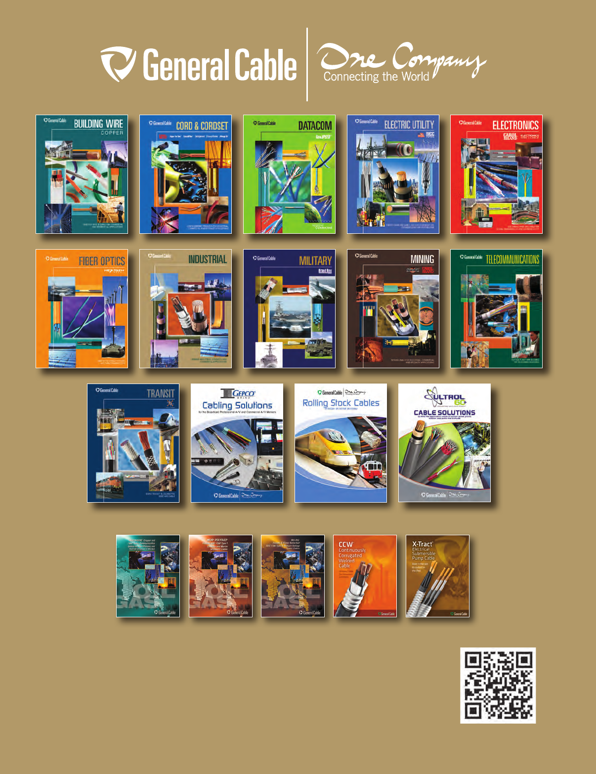
INDUSTRIAL JUNE 2013
Use your smartphone to view
Interactive Catalog online
General Cable
4 Tesseneer Drive
Highland Heights,
Kentucky 41076-9753
U.S.A.
info@generalcable.com
Form No. INS-0043-R0613
41809
Telephone (888) 593-3355
Fax (800) 335-1270
International Telephone +1 905 494 5300
International Fax +1 905 791 5328
www.generalcable.com
General Cable Canada
156 Parkshore Drive
Brampton, Ontario L6T 5M1
Telephone (800) 561-0649
Fax (800) 565-2529
infoca@generalcable.com
COMMODORE®
CATALOG
MOR® POLYRAD®
CATALOG
MV-RIG®
CATALOG
CCW®
CATALOG
X-TRACT® ESP
CATALOG
Other General Cable Products Offered
