673347 Catalog
2014-09-05
: Pdf 673347-Catalog 673347-Catalog 782051 Batch7 unilog
Open the PDF directly: View PDF ![]() .
.
Page Count: 420 [warning: Documents this large are best viewed by clicking the View PDF Link!]
Cable Tray
CT-13
Cable tray systems


i
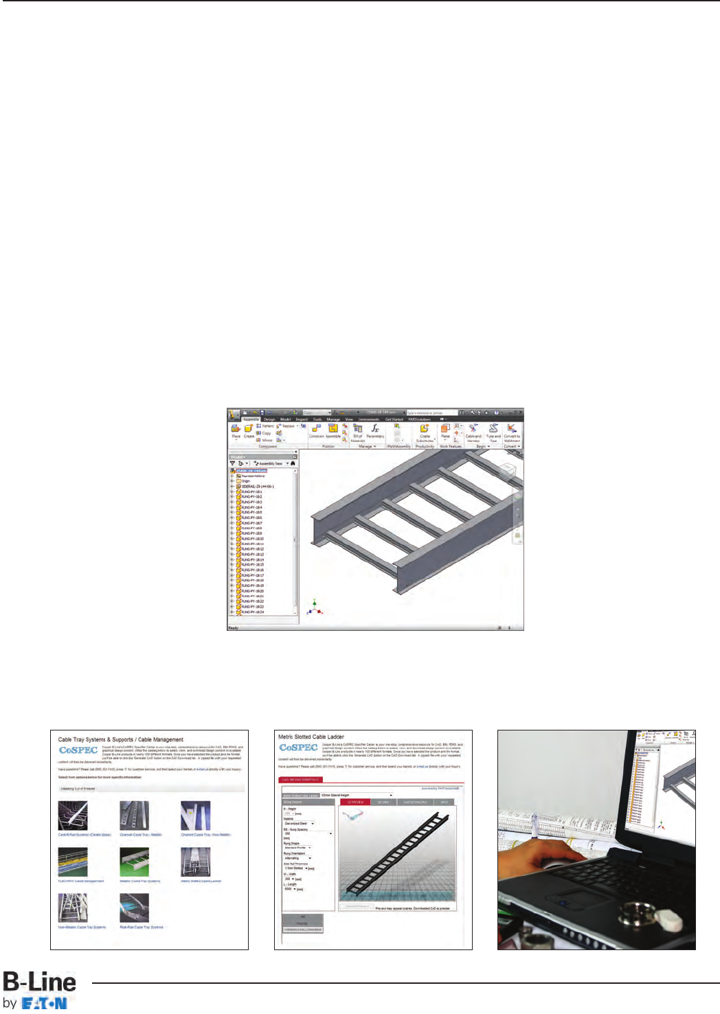
CoSPEC™
Cable Tray Systems
CoSPEC, the Specifier Center, is designed to help you easily SELECT, VIEW and DOWNLOAD B-Line
product design content in any one of nearly one hundred non-proprietary and proprietary CAD, BIM,
PDMS, and graphics formats, which helps speed the integration of the content into your design
project.
Features
• Easy integration and configuration
• Comprehensive library of 2D drawings and 3D models for CAD, BIM, PDMS, SP3D, and
graphics output
• The most up to date software versions and product data information are always available
• Submittals and specification sheets in PDF format
• Proprietary file format outputs are native to the chosen software
Nearly a Hundred Download Options
• Aveva PDMS and Intergraph SmartPlant SP3D (on select products) content
• Autodesk Revit output available
• Proprietary formats from AutoCAD to SolidWorks to Catia
• Non-proprietary formats like DXF and STEP, and more
• Graphics files in a number of formats including EPS
To get started planning your next project,
visit www.cooperbline.com/CoSPEC
Select View Download
ii
CoSPEC™B-Line Specifier Center - Available Outputs
Cable Tray Systems
To get started, visit www.cooperbline.com/CoSPEC
2D Native
• Allplan 2008
• AutoCAD >=V14
• Cadkey CDL >=V19
• Catia IUA - V4
• HP ME 10 >=V9
• Medusa >=2000i
• Microstation (DGN) >=V8
• SolidEdge >=V17
• VX (Varimetrix) >=V5.0
2D Neutral & Graphics
• BMP (2D & 3D View)
• DWF-ASCII 5.5, Binary 5.5 and
Compressed 5.5
• DWG >=V14
• DXF-V12\HPGL-V2
• IGES >=V5.0
• JPEG (2D & 3D Views)
• Metafile 2D-V1, & PS2-V2
• MI >=V8
• PDF Datasheet
• Postscript EPS
• SVG
• TIFF (2D & 3D View)
3D Native
• Autodesk 3D Studio MAX
• Allplan = 2008
• AutoCAD >=V14
• AVEVA PDMS/Marine (Equipment Spec)
• Caddy++ via SAT-V4.2
• Catis >=V5 R8 and IUA-V4
• EMS
• Google SketchUp
• Autodesk Inventor >=R5.3, R10, R11
• Mechanical Desktop >=V5
• Nupas/Cadmatic
• One Space Modeling >=2007
• Pro/E Wildfire >=I
• PRO-Desktop
• Autodesk Revit >= 2009* (coming soon)
• SolidEdge >=V17
• SolidWorks >=2001+
• Think3 >=2006.2
• Tribon M3
• Unigraphics >=NX3
• VX (Varimetrix) >=V5
3D Neutral
• CIP
• DWG >=V14
• DXF V14
• IGES
• JT
• Metafile 3D (PS3)-V2
• Parasolid-Binary V15 and Text V15
• PDF 3D-7.01
• SAT - V2.0 through V6.0
• STEP-AP203, AP215a & AP214b
• STL
• U3D (Universal 3D)
• VRML >=V1.0
• XGL
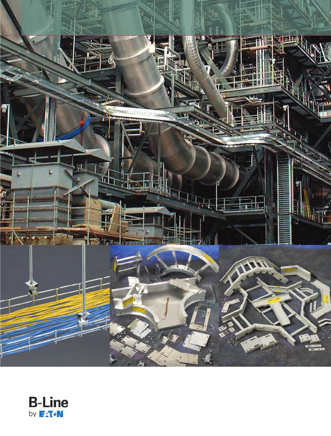
For over 50 years, Eaton’s B-Line Business has been the leader in cable management systems. Today, B-Line has state
of the art manufacturing facilities to support our customers around the globe. This coupled with our knowledgeable
customerservice, sales and sales engineering team, we are positioned to support cable management requirements from
small to large scale commercial, industrial, and datacomm applications.
For more information, visit www.bline.com or contact us at www.cooperbline.com/contactus
B-Line cable trays conform to the
requirements of IEC Standard
61537, 2001 Ed.
Important notice: No warranty, either expressed or implied, is made as to either its applicability to or its compatibility with
specific requirements of this information, nor for damages consequential to its use. All design characteristics,
specifications, tolerances and similar information are subject to change without notice.
NOTICE
B-Line reserves the right to change the specifications, materials, equipment, prices or the availability of products at any time without
prior notice. While every effort has been made to assure the accuracy of information contained in this catalog at the time of
publication, B-Line is not responsible for inaccuracies resulting from undetected errors or omissions.
iii
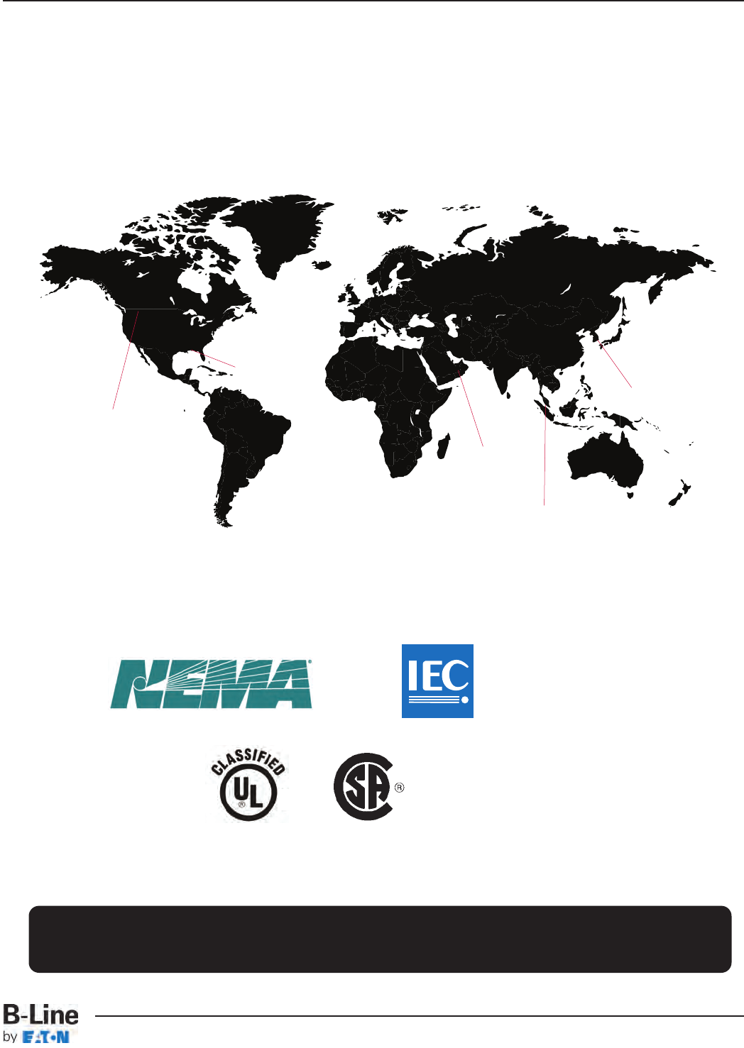
Introduction
Cable Tray Systems
H
H
H
United
States
South Korea
H
Malaysia
Kingdom of
Saudi Arabia
Eaton’s B-Line Business
Manufacturing Locations
H
Canada
B-Line Cable Tray Information
General Information . . . . . . . . . . . . . . . . . . . . . . . . . . . . . . . . . . . . . . . . . . . . CTI-1 & CTI-2
Tray Selection Charts . . . . . . . . . . . . . . . . . . . . . . . . . . . . . . . . . . . . . . . . . . CTI-3 – CTI-6
Cable Tray System . . . . . . . . . . . . . . . . . . . . . . . . . . . . . . . . . . . . . . . . . . . . . . . . . . . . . . CTI-7
The B-Line Advantage
The Company . . . . . . . . . . . . . . . . . . . . . . . . . . . . . . . . . . . . . . . . . . . . . . . . . . . . . . . . . . BLA-1
The Product . . . . . . . . . . . . . . . . . . . . . . . . . . . . . . . . . . . . . . . . . . . . . . . . . . BLA-2 & BLA-3
The Extras . . . . . . . . . . . . . . . . . . . . . . . . . . . . . . . . . . . . . . . . . . . . . . . . . . . . . . . . . . . . . . BLA-4
Cable Tray Selection
Selection Process . . . . . . . . . . . . . . . . . . . . . . . . . . . . . . . . . . . . . . . . . . . . . . . . . . . . . . CTS-1
Materials and Finishes
Material Standards . . . . . . . . . . . . . . . . . . . . . . . . . . . . . . . . . . . . . . . . . . . . . . . . CTS-2
Finish Standards . . . . . . . . . . . . . . . . . . . . . . . . . . . . . . . . . . . . . . . . . . . . . . . . . . . CTS-3
Coatings . . . . . . . . . . . . . . . . . . . . . . . . . . . . . . . . . . . . . . . . . . . . . . . . . . . . . . . . . . . CTS-4
Corrosion . . . . . . . . . . . . . . . . . . . . . . . . . . . . . . . . . . . . . . . . . . . . . . . . . CTS-5 – CTS-7
Thermal Contraction & Expansion . . . . . . . . . . . . . . . . . . . . . . . . . . . . . . . . CTS-8
Installation Considerations (Electrical Grounding) . . . . . . . . . . . . . . . CTS-9
Strength
Environmental Loads . . . . . . . . . . . . . . . . . . . . . . . . . . . . . . . . . CTS-10 & CTS-11
Support Span . . . . . . . . . . . . . . . . . . . . . . . . . . . . . . . . . . . . . . . . . . . . . . . . . . . CTS-121
Deflection . . . . . . . . . . . . . . . . . . . . . . . . . . . . . . . . . . . . . . . . . . . . . . . . . . . . . . . . . CTS-13
Load Capacity
(NEMA & CSA Load Classes) . . . . . . . . . . . . . . . . . . . . . . . . CTS-14 & CTS-15
Cable Data . . . . . . . . . . . . . . . . . . . . . . . . . . . . . . . . . . . . . . . . . . . . . . . . . . . . . . . . CTS-16
Width and Depth Cable Fill Per 1999 NEC 318 . . . . . . . . . . . . CTS-17 & CTS-22
Straight Section Length . . . . . . . . . . . . . . . . . . . . . . . . . . . . . . . . . . . . . . . . . . . . . . CTS-23
Loading Possibilities . . . . . . . . . . . . . . . . . . . . . . . . . . . . . . . . . . . . . . . . . . . . . . . . . . CTS-24
Bottom Type . . . . . . . . . . . . . . . . . . . . . . . . . . . . . . . . . . . . . . . . . . . . . . . . . . . . . . . . . . CTS-25
Fitting Bend Radius . . . . . . . . . . . . . . . . . . . . . . . . . . . . . . . . . . . . . . . . . . . . . . . . . . . CTS-25
FLEXTRAY™
Finishes . . . . . . . . . . . . . . . . . . . . . . . . . . . . . . . . . . . . . . . . . . . . . . . . . . . . . . . . . . . . . . . . . FLX-3
Load & Fill Charts . . . . . . . . . . . . . . . . . . . . . . . . . . . . . . . . . . . . . . . . . . . . . . . . . . . . . . FLX-4
Straight Sections . . . . . . . . . . . . . . . . . . . . . . . . . . . . . . . . . . . . . . . . . . . . . . FLX-5 & FLX-6
Splicing Accessories . . . . . . . . . . . . . . . . . . . . . . . . . . . . . . . . . . . . . . . . . FLX-8 – FLX-16
Ceiling Support Methods . . . . . . . . . . . . . . . . . . . . . . . . . . . . . . . . . . . FLX-18 – FLX-24
Wall Support Methods . . . . . . . . . . . . . . . . . . . . . . . . . . . . . . . . . . . . . . FLX-26 – FLX-30
FAST System . . . . . . . . . . . . . . . . . . . . . . . . . . . . . . . . . . . . . . . . . . . . . . . . FLX-32 – FLX-38
Accessories . . . . . . . . . . . . . . . . . . . . . . . . . . . . . . . . . . . . . . . . . . . . . . . . . FLX-40 – FLX-48
Installation . . . . . . . . . . . . . . . . . . . . . . . . . . . . . . . . . . . . . . . . . . . . . . . . . . FLX-50 – FLX-58
Channel Type Cable Tray
Straight Sections . . . . . . . . . . . . . . . . . . . . . . . . . . . . . . . . . . . . . . . . . . . . . . . . . . . . . . CCT-3
Accessories . . . . . . . . . . . . . . . . . . . . . . . . . . . . . . . . . . . . . . . . . . . . . . . . . . CCT-4 – CCT-7
Fittings . . . . . . . . . . . . . . . . . . . . . . . . . . . . . . . . . . . . . . . . . . . . . . . . . . . . . . CCT-8 – CCT-15
Specifications . . . . . . . . . . . . . . . . . . . . . . . . . . . . . . . . . . . . . . . . . . . . . . . . . . . . . . . . . CCT-16
REDI-RAIL™Cable Tray (Aluminum)
Straight Sections . . . . . . . . . . . . . . . . . . . . . . . . . . . . . . . . . . . . . . . . . . . . . RER-3 & RER-4
Accessories . . . . . . . . . . . . . . . . . . . . . . . . . . . . . . . . . . . . . . . . . . . . . . . . . RER-5 – RER-16
Specifications . . . . . . . . . . . . . . . . . . . . . . . . . . . . . . . . . . . . . . . . . . . . . RER-17 & RER-18
Fittings . . . . . . . . . . . . . . . . . . . . . . . . . . . . . . . . . . . . . . . . . . . . . . . . . . . . . RER-19 – RER-29
Series 1 Cable Tray (Steel)
Straight Sections . . . . . . . . . . . . . . . . . . . . . . . . . . . . . . . . . . . . . . . . . . . . . . LST-3 – LST-6
Accessories . . . . . . . . . . . . . . . . . . . . . . . . . . . . . . . . . . . . . . . . . . . . . . . . . . LST-7 – LST-13
Specifications . . . . . . . . . . . . . . . . . . . . . . . . . . . . . . . . . . . . . . . . . . . . . . . . . . . . . . . . . LST-14
Fittings . . . . . . . . . . . . . . . . . . . . . . . . . . . . . . . . . . . . . . . . . . . . . . . . . . . . . . LST-15 – LST-23
Series 2,3 & 4 Cable Tray - Aluminum
Straight Sections . . . . . . . . . . . . . . . . . . . . . . . . . . . . . . . . . . . . . . . . . . . . HAT-3 – HAT-11
Accessories . . . . . . . . . . . . . . . . . . . . . . . . . . . . . . . . . . . . . . . . . . . . . . . . HAT-13 – HAT-23
Specifications . . . . . . . . . . . . . . . . . . . . . . . . . . . . . . . . . . . . . . . . . . . . . . . . . . . . . . . . . HAT-24
Cable Tray
Information
B-Line Advantage
Cable Tray
Selection
Flextray
Cable
Channel
Redi-Rail
continued on page 2
Series 1
Steel
TOC-1
Table of Contents
Cable Tray Systems
Series
2, 3, 4, & 5
Aluminum
Series 2,3,4 & 5 Cable Tray - Steel
Straight Sections . . . . . . . . . . . . . . . . . . . . . . . . . . . . . . . . . . . . . . . . . . . . HST-3 – HST-10
Accessories . . . . . . . . . . . . . . . . . . . . . . . . . . . . . . . . . . . . . . . . . . . . . . . . HST-11 – HST-21
Specifications . . . . . . . . . . . . . . . . . . . . . . . . . . . . . . . . . . . . . . . . . . . . . . . . . . . . . . . . . HST-22
Series 3, 4, & 5 Cable Tray - Stainless Steel
Straight Sections . . . . . . . . . . . . . . . . . . . . . . . . . . . . . . . . . . . . . . . . . . . . . . SST-3 – SST-5
Accessories . . . . . . . . . . . . . . . . . . . . . . . . . . . . . . . . . . . . . . . . . . . . . . . . . . SST-6 – SST-13
Specifications . . . . . . . . . . . . . . . . . . . . . . . . . . . . . . . . . . . . . . . . . . . . . . . . . . . . . . . . . SST-14
Series 2, 3, 4, & 5 Fittings - Aluminum, Steel, Stainless Steel
Fitting Numbering System . . . . . . . . . . . . . . . . . . . . . . . . . . . . . . . . . . . . . . . . . . . . . FTS-3
Horizontal Bends . . . . . . . . . . . . . . . . . . . . . . . . . . . . . . . . . . . . . . . . . . . . . . FTS-4 & FTS-5
Tees & Crosses . . . . . . . . . . . . . . . . . . . . . . . . . . . . . . . . . . . . . . . . . . . . . . . . . . . . . . . . . FTS-6
Reducers . . . . . . . . . . . . . . . . . . . . . . . . . . . . . . . . . . . . . . . . . . . . . . . . . . . . . . . . . . . . . . . FTS-7
Horizontal Reducing & Expanding Tees . . . . . . . . . . . . . . . . . . . . . . FTS-8 & FTS-9
Horizontal Reducing & Expanding Crosses . . . . . . . . . . . . . . . . . . . . . . . . . . FTS-10
Horizontal Wyes . . . . . . . . . . . . . . . . . . . . . . . . . . . . . . . . . . . . . . . . . . . . . . . . . . . . . . . FTS-11
Vertical Bends . . . . . . . . . . . . . . . . . . . . . . . . . . . . . . . . . . . . . . . . . . . . . . FTS-12 – FTS-15
Vertical Tees - Up & Down . . . . . . . . . . . . . . . . . . . . . . . . . . . . . . . . . . . . . . . . . . . . FTS-16
Cable Support Fittings . . . . . . . . . . . . . . . . . . . . . . . . . . . . . . . . . . . . . . . . . . . . . . . . FTS-17
Fiberglass Cable Tray System
Technical Information . . . . . . . . . . . . . . . . . . . . . . . . . . . . . . . . . . . . . . . FCT-3 – FCT-12
Specifications . . . . . . . . . . . . . . . . . . . . . . . . . . . . . . . . . . . . . . . . . . . . . . FCT-13 – FCT-19
Straight Sections . . . . . . . . . . . . . . . . . . . . . . . . . . . . . . . . . . . . . . . . . . . FCT-20 – FCT-26
Fittings . . . . . . . . . . . . . . . . . . . . . . . . . . . . . . . . . . . . . . . . . . . . . . . . . . . . . . FCT-27 – FCT-44
Covers & Cover Accessories . . . . . . . . . . . . . . . . . . . . . . . . . . . . . . . . . . . . . . . . . FCT-45
Accessories . . . . . . . . . . . . . . . . . . . . . . . . . . . . . . . . . . . . . . . . . . . . . . . . . FCT-46 – FCT-48
Cable Channel
Straight Sections . . . . . . . . . . . . . . . . . . . . . . . . . . . . . . . . . . . . . . . . . . . . . . . . . FCT-49
Fittings . . . . . . . . . . . . . . . . . . . . . . . . . . . . . . . . . . . . . . . . . . . . . . . . . FCT-49 & FCT-50
Accessories . . . . . . . . . . . . . . . . . . . . . . . . . . . . . . . . . . . . . . . . . . . . FCT-50 & FCT-51
Appendix . . . . . . . . . . . . . . . . . . . . . . . . . . . . . . . . . . . . . . . . . . . . . . . . . . . . . . . . . . . . . . FCT-52
Barrier Bridge
Components . . . . . . . . . . . . . . . . . . . . . . . . . . . . . . . . . . . . . . . . . . . . . . . . . . . . . . . . . . . BBA-1
Numbering System . . . . . . . . . . . . . . . . . . . . . . . . . . . . . . . . . . . . . . . . . . . . . . . . . . . . BBA-2
Horizontal Tee, Two Cable Runs . . . . . . . . . . . . . . . . . . . . . . . . . . . . BBA-3 & BBA-4
Horizontal Tee, Three Cable Runs . . . . . . . . . . . . . . . . . . . . . . . . . . . BBA-5 & BBA-6
Horizontal Cross, Two Cable Runs . . . . . . . . . . . . . . . . . . . . . . . . . . BBA-7 & BBA-8
Horizontal Cross, Three Cable Runs . . . . . . . . . . . . . . . . . . . . . . . BBA-9 & BBA-10
Hardware Kits . . . . . . . . . . . . . . . . . . . . . . . . . . . . . . . . . . . . . . . . . . . . . . . . . . . . . . . . BBA-11
Cable Cleats
Products . . . . . . . . . . . . . . . . . . . . . . . . . . . . . . . . . . . . . . . . . . . . . . . . . . . . . . CFX-2 & CFX-3
Selection . . . . . . . . . . . . . . . . . . . . . . . . . . . . . . . . . . . . . . . . . . . . . . . . . . . . . . CFX-4 & CFX-5
Firestop
Products . . . . . . . . . . . . . . . . . . . . . . . . . . . . . . . . . . . . . . . . . . . . . . . . . . . . . . . FSA-2 – FSA-6
Appendix
Special Applications . . . . . . . . . . . . . . . . . . . . . . . . . . . . . . . . . . . . . . . . . . APP-1 – APP-5
Side Rails (Aluminum & Steel) . . . . . . . . . . . . . . . . . . . . . . . . . . . . . . . . . . . . . . . . . APP-6
Cable Tray Weights . . . . . . . . . . . . . . . . . . . . . . . . . . . . . . . . . . . . . . . . . . APP-7 & APP-8
Metric Conversion Charts . . . . . . . . . . . . . . . . . . . . . . . . . . . . . . . . . . APP-9 & APP-10
Master Cable Tray Systems Specifications . . . . . . . . . . . . . . . APP-11 – APP-14
Cable Tray Sizing Requirements . . . . . . . . . . . . . . . . . . . . . . . . . . . . . . . . . . . . . APP-15
Installation Data . . . . . . . . . . . . . . . . . . . . . . . . . . . . . . . . . . . . . . . . . . . . . . . . . . . . . . APP-16
Support Channels & Channel Nuts . . . . . . . . . . . . . . . . . . . . . . . . . . . . . . . . . . . APP-17
Concrete Inserts & Channel Fittings . . . . . . . . . . . . . . . . . . . . . . . . . . . . . . . . . APP-18
Series
2, 3, 4, & 5
Stainless Steel
Fiberglass
Cable Tray
Barrier Bridge
Cable Fixing
Firestop
Series
2, 3, 4, & 5 Fittings
Series
2, 3, 4, & 5
Steel
Appendix
continued on page 3
TOC-2
Table of Contents
Cable Tray Systems
Index
Cable Tray Manual
2005 Cable Tray Manual Based on 2005 National Electrical Code
. .
MAN-1 – MAN-53
Part Number Index
Straight Sections
Cable Tray
REDI-RAIL™Aluminum . . . . . . . . . . . . . . . . . . . . . . . . . . . . . . . . . . . . . . . . IDX-1
Series 2, 3, 4 & 5 Aluminum . . . . . . . . . . . . . . . . . . . . . . . . . . . . . . . . . . . . IDX-1
Series 1 Steel . . . . . . . . . . . . . . . . . . . . . . . . . . . . . . . . . . . . . . . . . . . . . . . . . . . IDX-1
Series 2, 3, 4 & 5 Steel . . . . . . . . . . . . . . . . . . . . . . . . . . . . . . . . . . . . . . . . . IDX-1
Series 2, 3, 4 & 5 Stainless Steel . . . . . . . . . . . . . . . . . . . . . . . . . . . . . . . IDX-1
Fiberglass . . . . . . . . . . . . . . . . . . . . . . . . . . . . . . . . . . . . . . . . . . . . . . . . . . . . . . IDX-1
Cable Channel
Aluminum . . . . . . . . . . . . . . . . . . . . . . . . . . . . . . . . . . . . . . . . . . . . . . . . . . . . . . . IDX-2
Steel . . . . . . . . . . . . . . . . . . . . . . . . . . . . . . . . . . . . . . . . . . . . . . . . . . . . . . . . . . . . IDX-2
Stainless Steel . . . . . . . . . . . . . . . . . . . . . . . . . . . . . . . . . . . . . . . . . . . . . . . . . IDX-2
Fiberglass . . . . . . . . . . . . . . . . . . . . . . . . . . . . . . . . . . . . . . . . . . . . . . . . . . . . . . IDX-2
FLEXTRAY™ . . . . . . . . . . . . . . . . . . . . . . . . . . . . . . . . . . . . . . . . . . . . . . . . . . . . . . . . IDX-2
Fittings
Cable Tray
REDI-RAIL Aluminum . . . . . . . . . . . . . . . . . . . . . . . . . . . . . . . . . . . . . . . . . . IDX-3
Series 2, 3, 4 & 5 Aluminum . . . . . . . . . . . . . . . . . . . . . . . . . . . . . . . . . . . . IDX-3
Series 1 Steel . . . . . . . . . . . . . . . . . . . . . . . . . . . . . . . . . . . . . . . . . . . . . . . . . . . IDX-3
Series 2, 3, 4 & 5 Steel . . . . . . . . . . . . . . . . . . . . . . . . . . . . . . . . . . . . . . . . . IDX-3
Series 2, 3, 4 & 5 Stainless Steel . . . . . . . . . . . . . . . . . . . . . . . . . . . . . . . IDX-3
Fiberglass . . . . . . . . . . . . . . . . . . . . . . . . . . . . . . . . . . . . . . . . . . . . . . . . . . . . . . IDX-4
Cable Channel
Aluminum . . . . . . . . . . . . . . . . . . . . . . . . . . . . . . . . . . . . . . . . . . . . . . . . . . . . . . . IDX-4
Steel . . . . . . . . . . . . . . . . . . . . . . . . . . . . . . . . . . . . . . . . . . . . . . . . . . . . . . . . . . . . IDX-4
Stainless Steel . . . . . . . . . . . . . . . . . . . . . . . . . . . . . . . . . . . . . . . . . . . . . . . . . IDX-4
Fiberglass . . . . . . . . . . . . . . . . . . . . . . . . . . . . . . . . . . . . . . . . . . . . . . . . . . . . . . IDX-4
Covers
Cable Tray
REDI-RAIL Aluminum . . . . . . . . . . . . . . . . . . . . . . . . . . . . . . . . . . . . . . . . . . IDX-5
Series 2, 3, 4 & 5 Aluminum . . . . . . . . . . . . . . . . . . . . . . . . . . . . . . . . . . . . IDX-5
Series 1 Steel . . . . . . . . . . . . . . . . . . . . . . . . . . . . . . . . . . . . . . . . . . . . . . . . . . . IDX-5
Series 2, 3, 4 & 5 Steel . . . . . . . . . . . . . . . . . . . . . . . . . . . . . . . . . . . . . . . . . IDX-5
Series 2, 3, 4 & 5 Stainless Steel . . . . . . . . . . . . . . . . . . . . . . . . . . . . . . . IDX-5
Fiberglass . . . . . . . . . . . . . . . . . . . . . . . . . . . . . . . . . . . . . . . . . . . . . . . . . . . . . . IDX-5
Cable Channel
Aluminum . . . . . . . . . . . . . . . . . . . . . . . . . . . . . . . . . . . . . . . . . . . . . . . . . . . . . . . IDX-6
Steel . . . . . . . . . . . . . . . . . . . . . . . . . . . . . . . . . . . . . . . . . . . . . . . . . . . . . . . . . . . . IDX-6
Stainless Steel . . . . . . . . . . . . . . . . . . . . . . . . . . . . . . . . . . . . . . . . . . . . . . . . . IDX-6
FLEXTRAY . . . . . . . . . . . . . . . . . . . . . . . . . . . . . . . . . . . . . . . . . . . . . . . . . . . . . . . . . . IDX-6
Accessories
Cable Tray
REDI-RAIL Aluminum . . . . . . . . . . . . . . . . . . . . . . . . . . . . . . . . . . . . . . . . . . IDX-7
Series 2, 3, 4 & 5 Aluminum . . . . . . . . . . . . . . . . . . . . . . . . . . . IDX-8 – IDX-9
Series 1 Steel . . . . . . . . . . . . . . . . . . . . . . . . . . . . . . . . . . . . . . . . . IDX-9 – IDX-10
Series 2, 3, 4 & 5 Steel . . . . . . . . . . . . . . . . . . . . . . . . . . . . . . IDX-11 – IDX-12
Series 2, 3, 4 & 5 Stainless Steel . . . . . . . . . . . . . . . . . . . IDX-13 – IDX-14
Fiberglass . . . . . . . . . . . . . . . . . . . . . . . . . . . . . . . . . . . . . . . . . . . . . . . . . . . . . IDX-14
Cable Channel
Aluminum . . . . . . . . . . . . . . . . . . . . . . . . . . . . . . . . . . . . . . . . . . . . . . . . . . . . . IDX-15
Steel . . . . . . . . . . . . . . . . . . . . . . . . . . . . . . . . . . . . . . . . . . . . . . . . . . . . . . . . . . . IDX-15
Stainless Steel . . . . . . . . . . . . . . . . . . . . . . . . . . . . . . . . . . . . . . . . . . . . . . . . IDX-16
Fiberglass . . . . . . . . . . . . . . . . . . . . . . . . . . . . . . . . . . . . . . . . . . . . . . . . . . . . . . . . . IDX-16
FLEXTRAY . . . . . . . . . . . . . . . . . . . . . . . . . . . . . . . . . . . . . . . . . . . . . . . IDX-17 – IDX-18
Barrier Bridges . . . . . . . . . . . . . . . . . . . . . . . . . . . . . . . . . . . . . . . . . . . . . . . . . . . . IDX-19
Cable Fixing . . . . . . . . . . . . . . . . . . . . . . . . . . . . . . . . . . . . . . . . . . . . . . . . . . . . . . . IDX-19
Firestop . . . . . . . . . . . . . . . . . . . . . . . . . . . . . . . . . . . . . . . . . . . . . . . . . . . . . . . . . . . IDX-19
Cable Tray Manual
TOC-3
Table of Contents
Cable Tray Systems

Cable tray is a mechanical support system that can support cables and raceways. Cable tray is not a raceway.
Cable tray systems are required to be electrically continuous but not mechanically continuous.
Advantages of B-Line Cable Tray Systems
Advantages of B-Line Cable Tray Systems
• Safety
• Dependability
• Space Savings
• Cost Savings
• Design Cost Savings
• Material Savings
• Installation Cost & Time Savings
• Maintenance Savings
For more information refer to B-Line’s Cable Tray Manual (Pages MAN-1 thru MAN-53)
or call B-Line at 1-800-851-7415
Quick List Selection Process
Quick List Selection Process
See pages CTS-20 & CTS-21 for expanded selection process.
1. Support Span Issues are: Strength and Length
• Very important to first consider the support span as it affects the strength of the system and the length
of the straight sections required.
• Short Span, 6 to 8 foot support spacing - use 12 foot sections.
• Intermediate Span, 8 to 12 foot support spacing - use 12 foot sections.
• Long Span, 16 to 20 foot support spacing - use 20 foot sections.
• Extra Long Span, over 20 foot to 30 foot support spacing - use 24 or 30 foot sections.
2. Working Load Issues are: Size (Width, Loading Depth, and Strength)
Cable Load
• Types and numbers of cables to support - Total cable load in lbs. per linear foot (lbs/ft)
• Power - is single layer - issue width (refer to local electrical code)
• Low Voltage - is stacked - issue loading depth and width (refer to affecting code)
• See chart of listed cable load guidelines (refer to page CTS-24)
Additional Loads
200 lb. concentrated load - Industrial installations
Ice, Wind, Snow loads - Outdoor installations
Select a Cable Tray system that meets the working load for the support span required and a straight
section length that fits the installation. NEMA VE 2 - Straight sections equal to or larger than span.
www.cabletrays.com
3. Installation Environment Issues are: Material and Finish
• Indoor Dry - Institutional, Office, Commercial, Light Industrial
Aluminum, Pre-Galvanized Steel
• Indoor Industrial - Automotive, Pulp and Paper, Power Plants
Aluminum, Pre-Galvanized Steel, Possibly Hot-Dipped Galvanized After Fabrication (HDGAF)
• Outdoor Industrial - Petrochemical, Automotive, Power Plants
Aluminum, Hot-Dipped Galvanized After Fabrication (HDGAF)
• Outdoor Marine - Off Shore Platforms
Aluminum, Stainless Steel, Fiberglass
• Special - Petrochemical, Pulp and Paper, Environmental Air
Contact B-Line (1-800-851-7415)
Cable Tray Information
CTI-1
B-Line Cable Tray Systems
Cable Tray Systems

Important notice: The information herein has been carefully checked for accuracy and is believed to be correct and current. No warranty, either expressed or implied, is
made as to either its applicability to or its compatibility with specific requirements of this information, nor for damages consequential to its use. All design characteristics,
specifications, tolerances and similar information are subject to change without notice.
Cable Tray Information
B-Line Cable Tray Product Offering
B-Line Cable Tray Product Offering
• Two Side Rail Systems
Aluminum, Pre-Galvanized Steel, Hot Dip Galvanized After Fabrication Steel, 304 and
316L Stainless Steel, Fiberglass in Polyester Resin, Vinyl Ester, Zero Halogen, and Dis-Stat
Redi-Rail Systems loaded with special installation and cable friendly features.
Systems tested to 173 lbs/ft on a 30 foot span
Special bottom options and splices
Highest quality fittings
Unmatched accessories supplied with attachment hardware
• Cable Channel (See Cable Channel Section - pages CCT-1 – CCT-6)
3, 4, and 6 inch widths in Aluminum, Pre-Galvanized Steel, Hot Dip Galvanized after
Fabrication Steel and 304 or 316L Stainless Steel
3, 4, 6, and 8 inch widths in Fiberglass in Polyester Resin, Vinyl Ester, Zero Halogen, and Dis-Stat
Unmatched fitting and accessory offering
Special bottom options and splices
Highest quality fittings
Unmatched accessories supplied with attachment hardware
• Wire FLEXTRAY™Tray (See FLEXTRAY Section - pages FLX-1 – FLX-56)
Best finish in the industry, ASTM B633, SC2 (ZN)
Strong straight top wire design maximizes strength and minimizes weight
Unmatched accessory package
Advantage of Using B-Line Cable Tray?
Advantage of Using B-Line Cable Tray?
Selection!
Selection!
What kind of B-Line Cable Tray will work for your project?
First, answer three questions.
1. Location: Where will the project be located?
A. Is the installation inside or outside?
(decision dealing with thermal and weather conditions)
B. Any contact of corrosive materials?
(decision on cable tray material or finish)
C. Is the location for the cable tray confined or open?
(decision on the size and type of cable tray)
2. Span: What would be the longest and shortest spans between supporting locations for the
installation of cables? (decision on type or combination of types of cable tray design
needed to be the most efficient and economical)
3. Cables: How many and what type of cables are involved in the support installation?
(decision on the strength of the cable tray)
All these variables are important to the cost savings and safety
of your B-Line Cable Tray installation project.
CTI-2
B-Line Cable Tray Systems
Cable Tray Systems
FLEXTRAY™
Cable Tray Information
FT2X2X10 2.380” 2.000” 28 20 2” S FLX-5 & FLX-8 – FLX-56 --
FT2X4X10 2.380” 2.000” 43 27 4” S FLX-5 & FLX-8 – FLX-56 --
FT2X6X10 2.380” 2.000” 47 27 6” S FLX-5 & FLX-8 – FLX-56 --
FT2X8X10 2.380” 2.000” 47 27 8” S FLX-5 & FLX-8 – FLX-56 --
FT2X12X10 2.380” 2.000” 47 27 12” S FLX-5 & FLX-8 – FLX-56 --
FT2X18X10 2.380” 2.000” 47 27 18” S FLX-5 & FLX-8 – FLX-56 --
FT2X20X10 2.380” 2.000” 47 27 20” S FLX-5 & FLX-8 – FLX-56 --
FT2X24X10 2.380” 2.000” 47 27 24” S FLX-5 & FLX-8 – FLX-56 --
FT4X4X10 4.380” 4.000” 49 36 4” S FLX-6 & FLX-8 – FLX-56 --
FT4X8X10 4.380” 4.000” 77 46 8” S FLX-6 & FLX-8 – FLX-56 --
FT4X12X10 4.380” 4.000” 83 47 12” S FLX-6 & FLX-8 – FLX-56 --
FT4X18X10 4.380” 4.000” 83 47 18” S FLX-6 & FLX-8 – FLX-56 --
FT4X20X10 4.380” 4.000” 83 47 20” S FLX-6 & FLX-8 – FLX-56 --
FT4X24X10 4.380” 4.000” 89 50 24” S FLX-6 & FLX-8 – FLX-56 --
FT6X12X10 6.380” 6.000” 86 48 12” S FLX-6 & FLX-8 – FLX-56 --
FT6X18X10 6.380” 6.000” 89 50 18” S FLX-6 & FLX-8 – FLX-56 --
FT6X20X10 6.380” 6.000” 98 55 20” S FLX-6 & FLX-8 – FLX-56 --
FT6X24X10 6.380” 6.000” 107 60 24” S FLX-6 & FLX-8 – FLX-56 --
ACC-03 1.250” 1.250” 15 10 3” A CCT-3 & CCT-4 – CCT-7 CCT-8 – CCT-15
ACC-04 1.750” 1.750” 33 20.5 4” A CCT-3 & CCT-4 – CCT-7 CCT-8 – CCT-15
ACC-06 1.750” 1.750” 36 22.5 6” A CCT-3 & CCT-4 – CCT-7 CCT-8 – CCT-15
†CC-03 1.250” 1.250” 17 11.5 3” S, SS_ CCT-3 & CCT-4 – CCT-7 CCT-8 – CCT-15
†CC-04 1.750” 1.750” 36 24.5 4” S, SS_ CCT-3 & CCT-4 – CCT-7 CCT-8 – CCT-15
†CC-06 1.750” 1.750” 41 28 6” S, SS_ CCT-3 & CCT-4 – CCT-7 CCT-8 – CCT-15
FCC-03 1.000” 1.000” 8 -- 3” F FCT-49 FCT-48 & FCT-50
FCC-04 1.125” 1.125” 12 -- 4” F FCT-49 353 & 354
FCC-06 1.625” 1.625” 58 -- 6” F FCT-49 353 & 354
FCC-08 2.188” 2.188” 87 -- 8” F FCT-49 353 & 354
RSI04A 3.540” 2.680” 108 75 6” - 36” A RER-3 & RER-4 – RER-14
RER-19 – RER-29
RSI05A 4.530” 3.660” 119 83 6” - 36” A RER-3 & RER-4 – RER-14
RER-19 – RER-29
RSI06A 5.510” 4.640” 118 82 6” - 36” A RER-4 & RER-4 – RER-14
RER-19 – RER-29
RSI07A 6.500” 5.630” 176 122 6” - 36” A RER-4 & RER-4 – RER-14
RER-19 – RER-29
148 3.625” 3.077” 204 115 6” - 36” S LST-3 & LST-7 – LST-13 LST-15 – LST-23
156 4.188” 3.628” 304 171 6” - 36” S LST-4 & LST-7 – LST-13 LST-15 – LST-23
166 5.188” 4.628” 308 173 6” - 36” S LST-5 & LST-7 – LST-13 LST-15 – LST-23
176 6.188” 5.628” - 194 6” - 36” S LST-6 & LST-7 – LST-13 LST-15 – LST-23
13F 3.000” 2.000” 257 145 6” - 24” F
FCT-21 & FCT-45 – FCT-48
FCT-21 – FCT-44
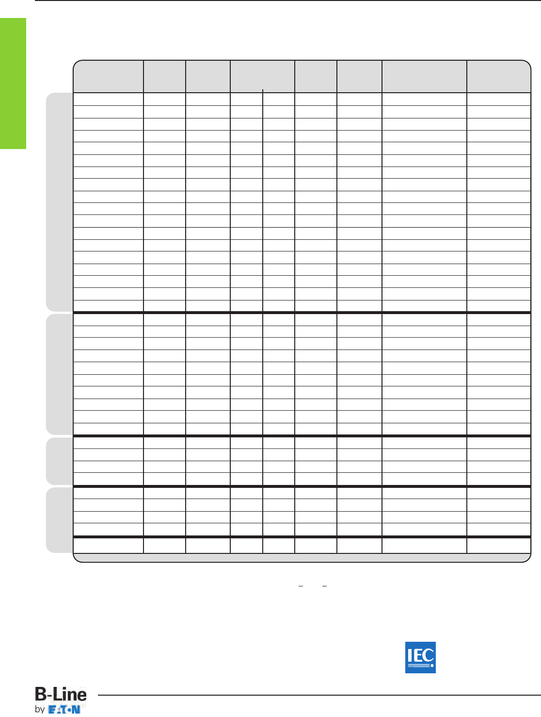
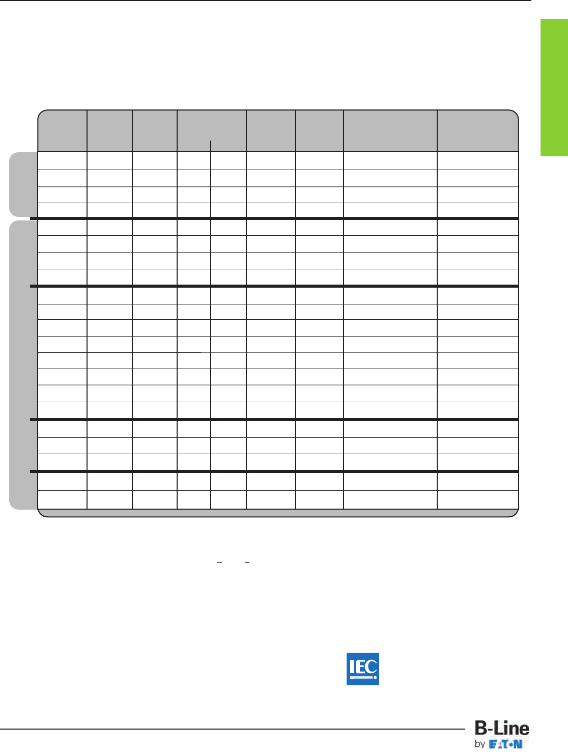
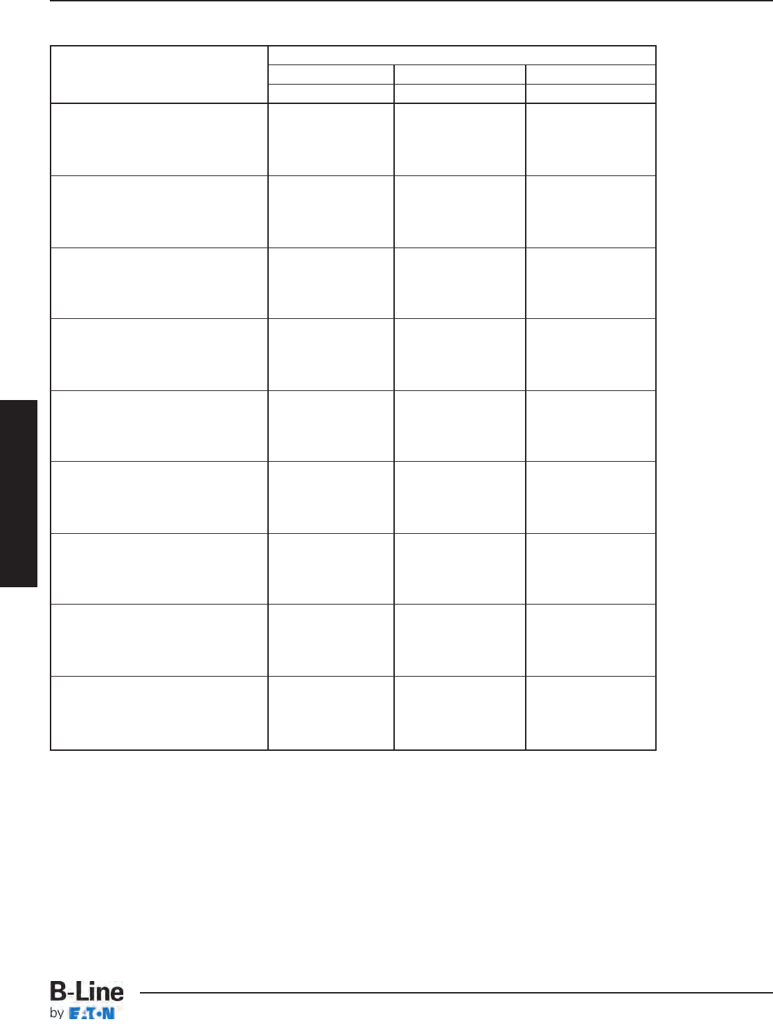
Recommended Short Span
Cable Tray Selection
Use 10 ft or 12 ft Sections
Span Load Straight Sections
Catalog Rail Load lbs/ft Available & Accessories Fittings
Number Height Depth 6’ 8’ Widths Material* Pages Pages
Cable Channel
REDI-
RAIL™
Cable Tray
Fiber Steel
Short Span 6 - 8 Foot
(distance between the supports)
*Material: A = Aluminum • S = Steel • SS_ = Stainless Steel Type 304 or 316 • F = Fiberglass
† = G for HDGAF • P for Pre-Galvanized • SS4 for 304 or SS6 for 316 Stainless Steel
¨Insert 2, 3, 4, 5 or 6 for number of tiers • ¡Insert 2, 3 or 4 for number of tiers
B-Line cable trays conform
to the requirements of IEC
Standard 61537, 2001 Ed.
CTI-3
Cable Tray Selection Charts
Cable Tray Systems
REDI-RAIL™
Cable Tray Information
RSI04A 3.540” 2.680” 108 75 6” - 36” A RER-3 & RER-4 – RER-14
RER-19 – RER-29
RSI05A 4.530” 3.660” 119 83 6” - 36” A RER-3 & RER-4 – RER-14
RER-19 – RER-29
RSI06A 5.510” 4.640” 118 82 6” - 36” A RER-4 & RER-4 – RER-14
RER-19 – RER-29
RSI07A 6.500” 5.630” 176 122 6” - 36” A RER-4 & RER-4 – RER-14
RER-19 – RER-29
24A 4.120” 3.050” 181 126 6” - 36” A HAT-3 & HAT-13 – HAT-23 FTS-3 – FTS-17
25A 5.000” 3.930” 200 139 6” - 36” A HAT-5 & HAT-13 – HAT-23 FTS-3 – FTS-17
26A 6.120” 5.040” 204 142 6” - 36” A HAT-7 & HAT-13 – HAT-23 FTS-3 – FTS-17
37A 7.140” 6.050” -- 222 6” - 36” A HAT-9 & HAT-13 – HAT-23 FTS-3 – FTS-17
148 3.625” 3.077” 73 51 6” - 36” S LST-3 & LST-7 – LST-13 LST-15 – LST-23
156 4.188” 3.628” 109 76 6” - 36” S LST-4 & LST-7 – LST-13 LST-15 – LST-23
166 5.188” 4.628” 111 77 6 ”- 36” S LST-5 & LST-7 – LST-13 LST-15 – LST-23
176 6.188” 5.628” 124 86 6” - 36” S LST-6 & LST-7 – LST-13 LST-15 – LST-23
248 4.188” 3.140” 148 103 6” - 36” S
HDS-3 & HDS-11 – HDS-21
FTS-3 – FTS-17
258 5.188” 4.140” 157 109 6” - 36” S
HDS-5 & HDS-11 – HDS-21
FTS-3 – FTS-17
268 6.188” 5.140” 158 110 6” - 36” S
HDS-7 & HDS-11 – HDS-21
FTS-3 – FTS-17
378 7.188” 6.140” 204 142 6” - 36” S
HDS-9 & HDS-11 – HDS-21
FTS-3 – FTS-17
348 4.188” 3.130” 180 125 6” - 36” SS_ SST-3 & SST-6 – SST-13 FTS-3 – FTS-17
358 5.188” 4.130” 248 172 6” - 36” SS_ SST-4 & SST-6 – SST-13 FTS-3 – FTS-17
368 6.188” 5.130” 236 164 6” - 36” SS_ SST-5 & SST-6 – SST-13 FTS-3 – FTS-17
13F 3.000” 2.000” 93 64 6” - 24” F FCT-21 & FCT-45 – FCT-48 FCT-27 – FCT-44
24F 4.000” 3.000” 226 157 6” - 36” F FCT-22 & FCT-45 – FCT-48 FCT-27 – FCT-44
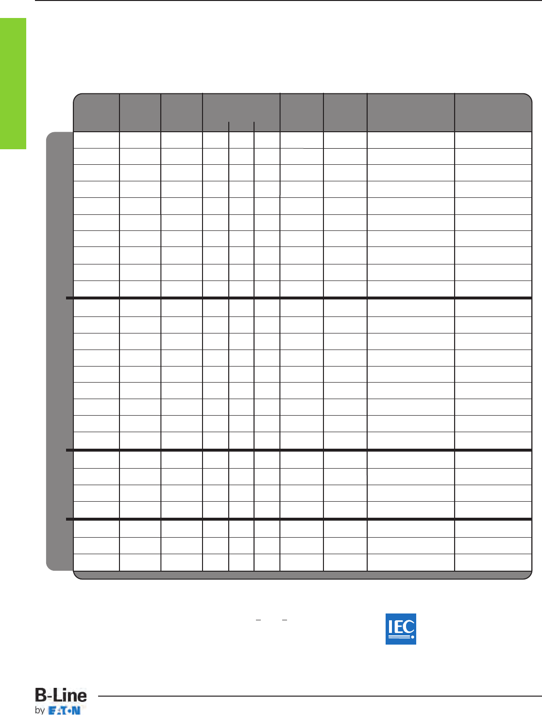
Recommended Intermediate Span Cable Tray Selection
Use 12 ft Sections
Span Load Straight Sections
Catalog Rail Load lbs/ft Available & Accessories Fittings
Number Height Depth 10’ 12’ Widths Material* Pages Pages
Intermediate Span 10 - 12 Foot
(distance between the supports)
*Material A = Aluminum
S = Steel
SS_ = Stainless Steel Type 304 or 316
F = Fiberglass
B-Line cable trays conform
to the requirements of IEC
Standard 61537, 2001 Ed.
Cable Tray
Fiberglass Stainless Steel Steel Aluminum
CTI-4
Cable Tray Selection Charts
Cable Tray Systems
Cable Tray Information
25A 5.000” 3.930” 78 62 50 6” - 36” A HAT-5 & HAT-13 – HAT-23 FTS-3 – FTS-17
34A 4.200” 3.080” 125 99 80 6” - 36” A HAT-3 & HAT-13 – HAT-23 FTS-3 – FTS-17
35A 5.060” 3.960” 121 96 77 6” - 36” A HAT-5 & HAT-13 – HAT-23 FTS-3 – FTS-17
26A 6.120” 5.040” 80 63 51 6” - 36” A HAT-7 & HAT-13 – HAT-23 FTS-3 – FTS-17
36A 6.170” 5.060” 131 104 84 6” - 36” A HAT-7 & HAT-13 – HAT-23 FTS-3 – FTS-17
37A 7.140” 6.050” 125 99 80 6” - 36” A HAT-9 & HAT-13 – HAT-23 FTS-3 – FTS-17
46A 6.190” 5.080” 161 127 103 6” - 36” A HAT-7 & HAT-13 – HAT-23 FTS-3 – FTS-17
47A 7.240” 6.130” 156 123 100 6” - 36” A HAT-9 & HAT-13 – HAT-23 FTS-3 – FTS-17
H46A 6.240” 5.090” 261 206 167 6” - 36” A HAT-7 & HAT-13 – HAT-23 FTS-3 – FTS-17
H47A 7.240” 6.090” 233 184 149 6” - 36” A HAT-9 & HAT-13 – HAT-23 FTS-3 – FTS-17
346 4.188” 3.130” 98 78 63 6” - 36” S
HDS-3 & HDS-11 – HDS-21
FTS-3 – FTS-17
356 5.188” 4.130” 108 85 69 6” - 36” S
HDS-5 & HDS-11 – HDS-21
FTS-3 – FTS-17
366 6.188” 5.140” 117 93 75 6” - 36” S
HDS-7 & HDS-11 – HDS-21
FTS-3 – FTS-17
378 7.188” 6.140” 80 63 51 6” - 36” S
HDS-9 & HDS-11 – HDS-21
FTS-3 – FTS-17
444 4.188” 3.110” 142 112 91 6” - 36” S
HDS-3 & HDS-11 – HDS-21
FTS-3 – FTS-17
454 5.188” 4.110” 166 131 106 6” - 36” S
HDS-5 & HDS-11 – HDS-21
FTS-3 – FTS-17
464 6.188” 5.110” 192 152 51 6” - 36” S
HDS-7 & HDS-11 – HDS-21
FTS-3 – FTS-17
476 7.188” 6.130” 120 95 77 6” - 36” S
HDS-9 & HDS-11 – HDS-21
FTS-3 – FTS-17
574 7.188” 6.110” 203 160 130 6” - 36” S
HDS-9 & HDS-11 – HDS-21
FTS-3 – FTS-17
348 4.188” 3.130” 70 56 45 6” - 36” SS_ SST-3 & SST-6 – SST-13 FTS-3 – FTS-17
358 5.188” 4.130” 97 77 62 6” - 36” SS_ SST-4 & SST-6 – SST-13 FTS-3 – FTS-17
368 6.188” 5.130” 92 73 59 6” - 36” SS_ SST-5 & SST-6 – SST-13 FTS-3 – FTS-17
464 6.188” 5.110” 192 152 123 6” - 36” SS_ SST-6 & SST-6 – SST-13 FTS-3 – FTS-17
36F 6.000” 5.000” 139 109 89 6” - 36” F FCT-23 & FCT-45 – FCT-48 FCT-27 – FCT-44
46F 6.000” 5.000” 221 174 141 6” - 36” F FCT-24 & FCT-45 – FCT-48 FCT-27 – FCT-44
H46F 6.000” 5.000” 239 188 153 6” - 36” F FCT-25 & FCT-45 – FCT-48 FCT-27 – FCT-44
Recommended Intermediate Span Cable Tray Selection
Use 20 ft Sections
Span Load Straight Sections
Catalog Rail Load lbs/ft Available & Accessories Fittings
Number Height Depth 16’ 18’ 20’ Widths Material* Pages Pages
Long 16 - 20 Foot
(distance between the supports)
*Material A = Aluminum
S = Steel
SS_ = Stainless Steel Type 304 or 316
F = Fiberglass
B-Line cable trays conform
to the requirements of IEC
Standard 61537, 2001 Ed.
Cable Tray
Fiberglass Stainless Steel Steel Aluminum
CTI-5
Cable Tray Selection Charts
Cable Tray Systems
Cable Tray
Steel Aluminum
46A 6.190” 5.080” 72 - 6” - 36” A
HAT-7 & HAT-13 – HAT-23
FTS-3 – FTS-17
47A 7.240” 6.130” 69 - 6” - 36” A
HAT-9 & HAT-13 – HAT-23
FTS-3 – FTS-17
57A 7.400” 6.230” 161 102 12” - 36” A
HAT-9 & HAT-13 – HAT-23
FTS-3 – FTS-17
H46A 6.240” 5.090” 116 - 6” - 36” A
HAT-7 & HAT-13 – HAT-23
FTS-3 – FTS-17
H47A 7.240” 6.090” 103 - 6” - 36” A
HAT-9 & HAT-13 – HAT-23
FTS-3 – FTS-17
S8A 8.000” 6.200” 252 161 12” - 36” A
HAT-11 & HAT-13 – HAT-23
FTS-3 – FTS-17
444 4.188” 2.110” 63 - 6” - 36” S
HDS-3 & HDS-11 – HDS-21
FTS-3 – FTS-17
454 5.188” 4.110” 74 - 6” - 36” S
HDS-5 & HDS-11 – HDS-21
FTS-3 – FTS-17
464 6.188” 5.110” 85 - 6” - 36” S
HDS-7 & HDS-11 – HDS-21
FTS-3 – FTS-17
476 7.188” 6.130” 53 - 6” - 36” S
HDS-9 & HDS-11 – HDS-21
FTS-3 – FTS-17
574 7.188” 6.110” 90 - 6” - 36” S
HDS-9 & HDS-11 – HDS-21
FTS-3 – FTS-17
464 6.188” 5.110” 85 - 6” - 36” SS_ SST-5 & SST-6 – SST-13 FTS-3 – FTS-17
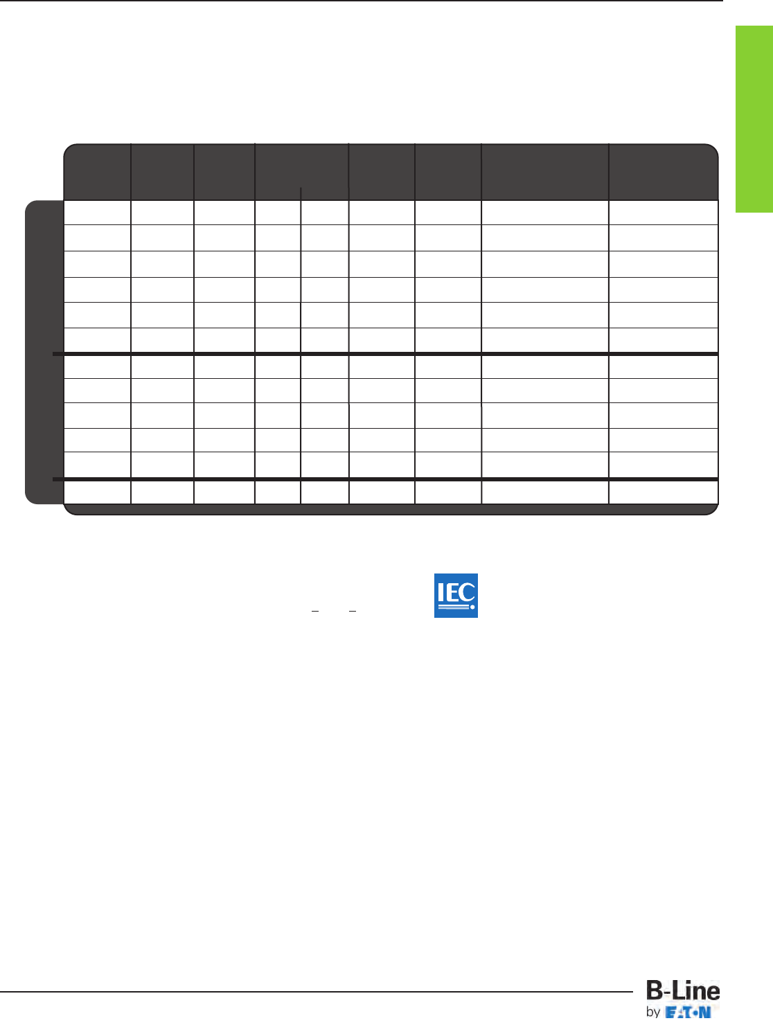
Recommended Extra Long Span Cable Tray Selection
Use 24 ft or 30 ft Sections
Span Load Straight Sections
Catalog Rail Load lbs/ft Available & Accessories Fittings
Number Height Depth 24’ 30’ Widths Material* Pages Pages
Extra Long Span 24 - 30 Foot
(distance between the supports)xx
*Material A = Aluminum
S = Steel
SS_ = Stainless Steel Type 304 or 316
Cable Tray Information
SS
B-Line cable trays conform
to the requirements of IEC
Standard 61537, 2001 Ed.
CTI-6
Cable Tray Selection Charts
Cable Tray Systems
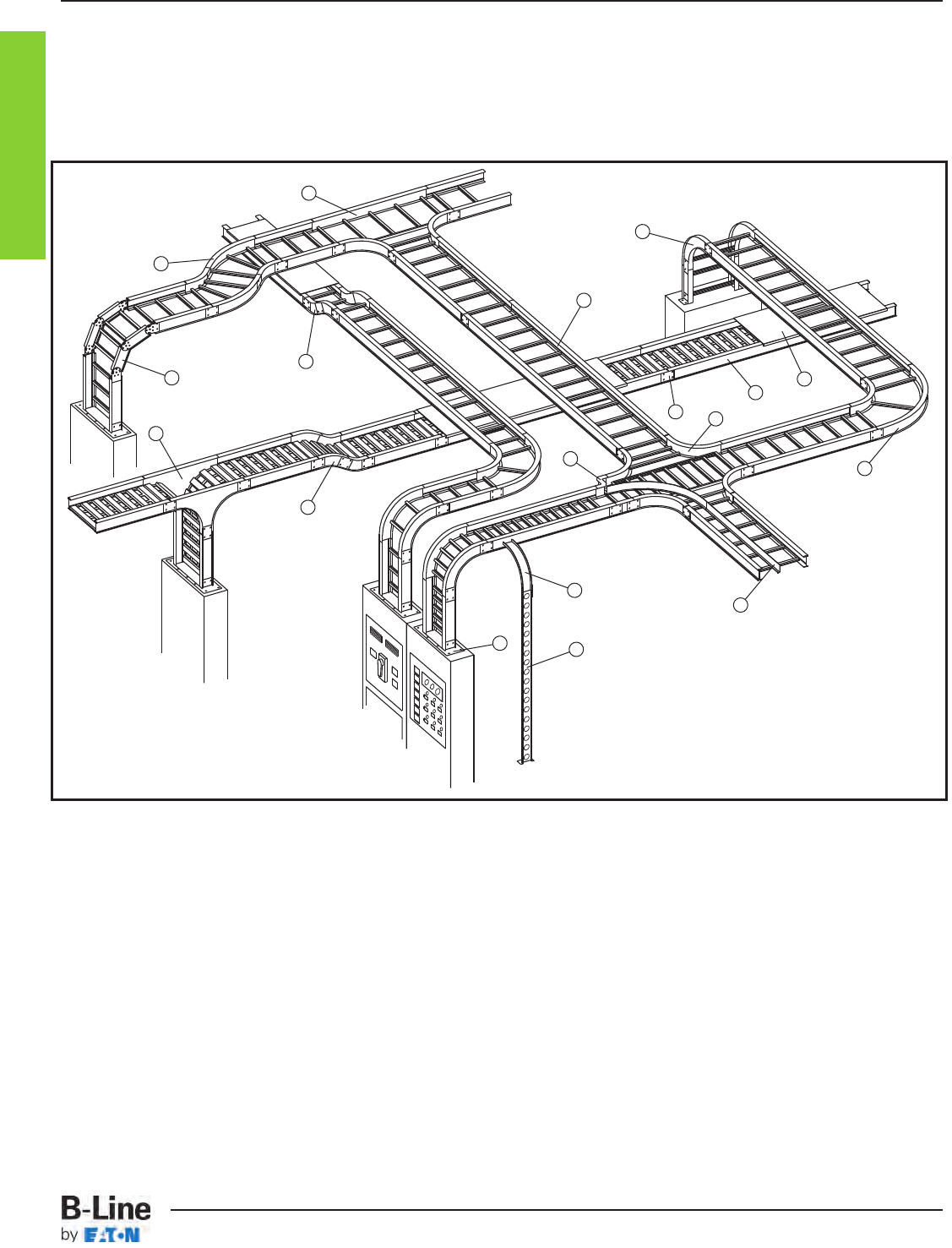
B-Line Cable Trays -
Designed for Your Cable Support Requirements
Nomenclature
1. Ladder Type Cable Tray 10. 30° Vertical Inside Bend, Ladder Type Cable Tray
2. Ventilated Trough Type Cable Tray 11. Vertical Bend Segment (VBS)
3. Straight Splice Plate 12. Vertical Tee Down, Ventilated Trough Type Cable Tray
4. 90° Horizontal Bend, Ladder Type Cable Tray 13. Left Hand Reducer, Ladder Type Cable Tray
5. 45° Horizontal Bend, Ladder Type Cable Tray 14. Frame Type Box Connector
6. Horizontal Tee, Ladder Type Cable Tray 15. Barrier Strip Straight Section
7. Horizontal Cross, Ladder Type Cable Tray 16. Solid Flanged Tray Cover
8. 90° Vertical Outside Bend, Ladder Type Cable Tray 17. Ventilated Channel Straight Section
9. 45° Vertical Outside Bend, Ventilated Type Cable Tray 18. Channel Cable Tray, 90° Vertical Outside Bend
6
5
11
12
10
1
8
16
7
2
3
4
15
14 17
18
9
13
Cable Tray Information
CTI-7
Cable Tray Systems
Cable Tray Systems
• Committed to the Success of its Customers through Manufacturing,
Engineering and Service.
• Positioned to Serve.
• Five United States cable tray fabrication sites: (H)
Troy, IL Sherman, TX Pinckneyville, IL
Alum Bank, PA Reno, NV
• Sixteen factory inventories (u)
• A Proven Industry Leader.
• Over thirty years experience
• Industry Involvement.
- NEMA - 5VE Member -- Metallic Cable Tray Section
- NEMA - 5FG Member -- Nonmetallic Cable Tray Section
- Cable Tray Institute (CTI) -- A Founding Member
- B-Line cable trays conform to the requirements of IEC Standard 61537, 2001 Ed.
• Unmatched Cable Support Systems.
- Cable Tray -- Two Side Rail (Metallic)
- Cable Tray -- Two Side Rail (Metallic) REDI-RAIL™ Design
- Cable Tray -- Two Side Rail (Nonmetallic)
- Cable Tray -- FLEXTRAY™ Cable Support Systems
- Cable Runways -- B-Line Telecom
- NEMA Wireways
B-Line Advantage
BLA-1
The B-Line Advantage
Cable Tray Systems
H
H
H
H
H
u
u
u
u
u
u
u
u
uu
u
u
u
u
u
u
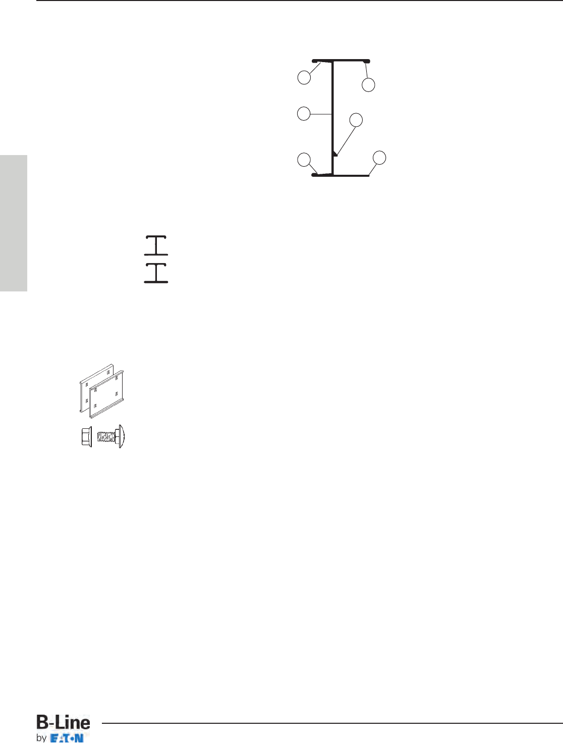
Aluminum Cable Tray, Series 2, 3 & 4
•Side Rails
Our I-Beam -- the most
efficient structural shape
Using “Copper-free”
6063-T6 Aluminum Alloy
•Rungs -- provide system integrity
The rungs can represent 40% of your cable tray system.
Rung A - Standard for widths through 24"
Rung B - Standard for widths greater than 24"
- For industrial applications -- 200 lb. concentrated loads
- New P-Rung design allows P-Clamp cable fastening at any location.
•Splices -- provide system integrity
With the unique Wedge Lock splice system:
- Channel-shaped for extra strength
- Snaps into the side rail
- Positions and holds for bolting, a labor-saving feature
- Four bolt patterns, a labor-saving feature
- 316 Stainless Steel hardware is available as an option
•Fittings -- provide system integrity
Surpasses NEMA VE 1 requirements
3" straight tangents for splice integrity
•A 200 lb. Concentrated Load -- providing system integrity
Side rails engineered to support a 200 lb. concentrated load + cable load
Rungs engineered to support a 200 lb. concentrated load + cable load
• Reliable time-tested products.
1. I-beam side rail design
- maximize strength-to-weight ratio
2. Added material to top flange to
increase cable tray stiffness
3. Welding bead
- positive rung lock
- added material disperses heat
4. Bottom flange inside
- positive rung support
5. Bottom flange outside
- strong lower flange for hold down
clamps and expansion guides
6. Top flange outside
- strong upper flange for securing
the tray cover or the conduit-to-
tray adapter
2
13
4
5
6
B-Line Advantage
BLA-2
The B-Line Advantage - The Product
Cable Tray Systems
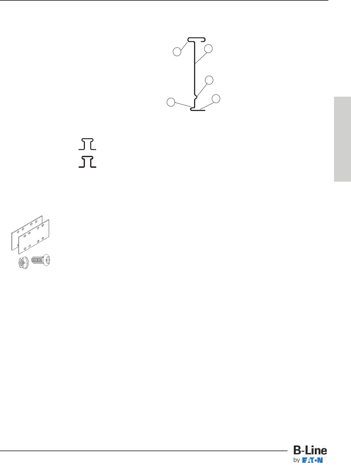
Steel Cable Tray, Series 2, 3, 4 & 5
•Side Rails
Our I-Beam -- the most
efficient structural shape
•Rungs -- provide system integrity
The rungs can represent 40% of your cable tray system.
Rung A - Standard for widths through 24"
Rung B - Standard for widths greater than 24"
- For industrial applications -- 200 lb. concentrated loads.
- Both Rung A and Rung B are roll formed from traceable structural grade steel
•Splices -- provide system integrity
The Splices -- the engineered connection:
- Special high strength eleven gauge steel
- Eight bolt connection for required strength
- Finish and hardware options
•Hot Dip Galvanized After Fabrication (HDGAF)
providing system integrity
- ASTM A123/CSA Type I
- In plant post-dip inspection and deburr
- ASTM F-1136-88 Grade 3 Splice hardware exceeds NEMA requirements.
- ASTM A123 Covers available - system compatibility
•Pre-Galvanized- Hot Dip Mill Galvanized
providing system integrity
- ASTM A653SS Gr.33 G90/ CSA Type II
- Anti-corrosive silicon bronze welds eliminate cosmetic painting
•Reliable time-tested products
- 200 lb. Concentrated Load- side rail and rungs
- Splice integrity - 3" fitting tangents
1. Roll formed for extra strength
2. Enlarged top flange for stiffness
3. Structural grade traceable steel
4. Rung top lock
5. Rung bottom rest
Side rails and rungs are
stamped every 18" with:
• Company Name
• Part Number
• Material
• Heat Trace Number
2
1
3
4
5
B-Line Advantage
BLA-3
The B-Line Advantage
Cable Tray Systems
•Special Packaging
- For less than truckload (LTL) shipments
- Reduced freight claims over 50%
- A positive package for all
•New Mid Span Aluminum Splice
- The standard splice for H46A, H47A and 57A systems
- Optional availability for other systems
- See appendix page APP-2 for details
•Special Aluminum Long Span Systems
- 57A12-36-360 Tested to 102 lbs./ft. on 30' span - safety factor 1.5
(Page HAT-9 & HAT-10)
- S8A12-36-360 Tested to 161 lbs./ft. on 30' span - safety factor 1.5
(Page HAT-11 & HAT-12)
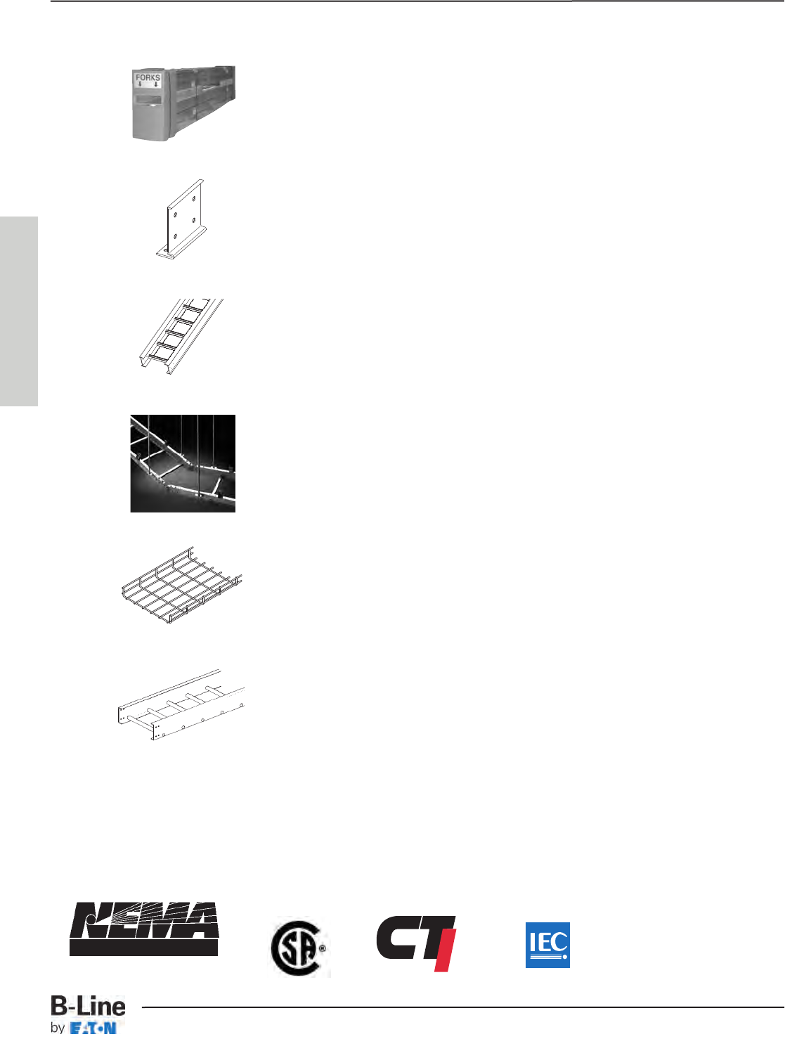
•REDI-RAIL™ Aluminum Cable Tray Systems (See REDI-RAILl Section)
- 2, 3, 4, 5 and 6 inch cable fill depths
- NEMA classes to 12C
- Unique fabrication method provides unmatched installation options
- Industry leading accessory package
•Wire Basket Cable Support Systems (See FLEXTRAY™ Section)
- Field adaptable - no fittings to order
- Low profile in 2", 4” and 6" loading depths
- Rugged welded steel, wire mesh construction
•Non-Metallic Cable Tray (See Fiberglass Section)
- For corrosive environments
- For voltage isolation
- A complete line offering
- Request latest catalog
MEMBER
®
B-Line Advantage
B-Line cable trays conform
to the requirements of IEC
Standard 61537, 2001 Ed.
BLA-4
The B-Line Advantage
Cable Tray Systems

The following factors should be considered when
determining the appropriate cable tray system.
1. Material & Finish
• Standards Available (Pages CTS-2 – CTS-4)
• Corrosion (Pages CTS-5 – CTS-7)
• Thermal Contraction and Expansion (Page CTS-8)
• Installation Considerations and Electrical Grounding Capacity (Page CTS-9)
2. Strength
• Environmental Loads (Pages CTS-10 & CTS-11)
• Concentrated Loads (Page CTS-11)
• Support Span (Page CTS-11)
• Deflection (Page CTS-12)
• Rung/Trough Data (Page CTS-13)
• Load Capacity (NEMA & CSA Classes) (Pags CTS-14 & CTS-15)
• Cable Data (Page CTS-16)
3. Width & Available Loading Depth
• Cable Diameter (Page CTS-16)
• Allowable Cable Fill (Pages CTS-17 – CTS-21)
• Barrier Requirements (Page CTS-22)
• Future Expansion Requirements (Page CTS-22)
• Space Limitations (Page CTS-22)
4. Length
• Lengths Available (Page CTS-23)
• Support Spans (Not to exceed the length of straight sections) (Page CTS-23)
• Space Limitations (Page CTS-23)
• Installation (Page CTS-23)
5. Loading Possibilities
• Power Application (Page CTS-24)
• Data/Communication Cabling (Page CTS-24)
• Other Factors to Consider (Page CTS-24)
6. Bottom Type
• Type of Cable (Page CTS-25)
• Cost vs. Strength (Page CTS-25)
• Cable Exposure (Page CTS-25)
• Cable Attachment (Page CTS-25)
7. Fitting Radius
• Cable Flexibility (Page CTS-25)
• Space Limitations (Page CTS-25)
Cable Tray Selection
CTS-1
Cable Tray Selection - Selection Process
Cable Tray Systems
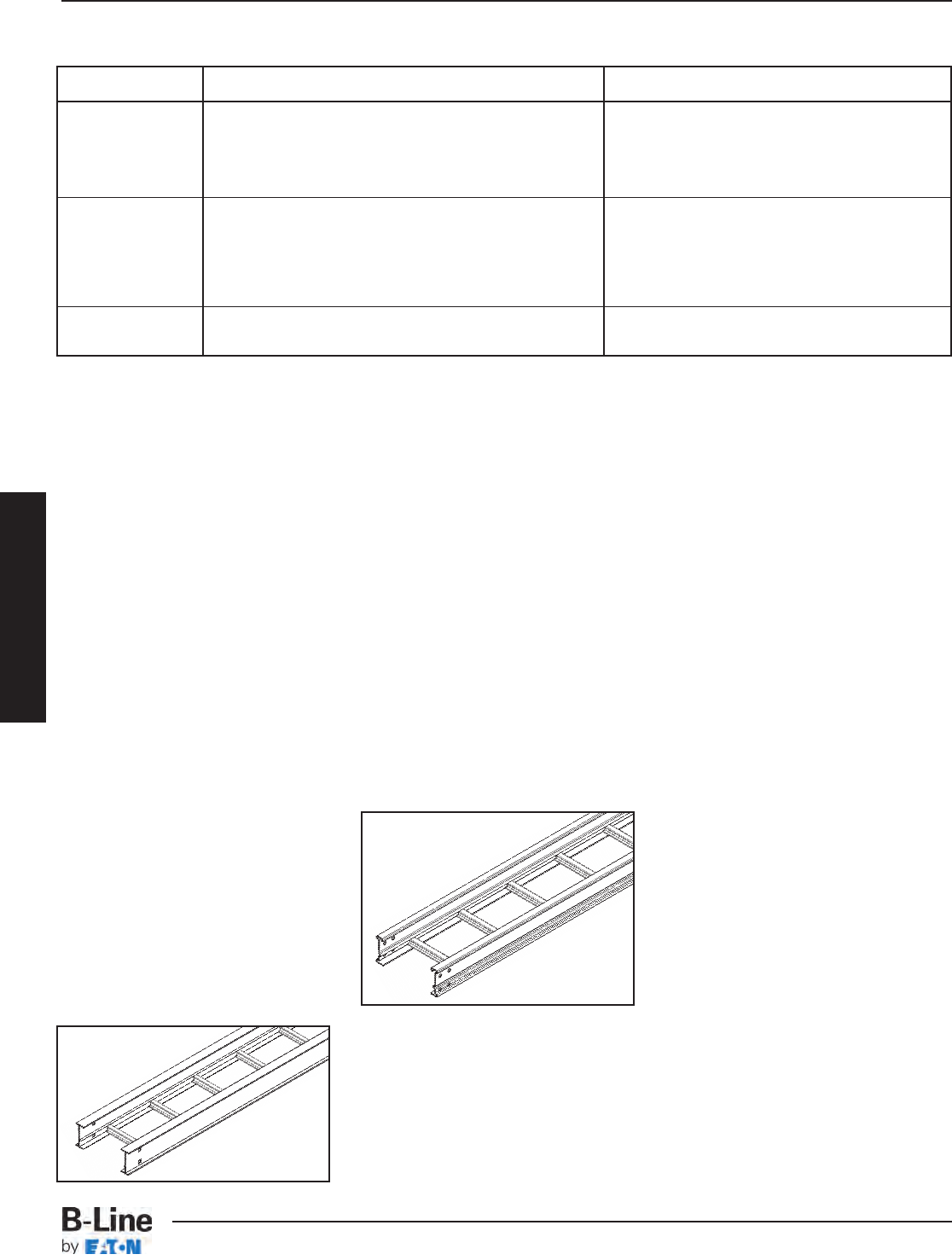
MATERIAL MATERIAL SPECIFICATION ADVANTAGES
6063-T6 (Side rails, Rungs and Splice Plates) • Corrosion Resistance
• Easy Field Fabrication & Installation
Aluminum 5052-H32 (Trough Bottoms, Covers and Accessories) • Excellent Strength to Weight Ratio
• Excellent Grounding Conductor
ASTM A1011 SS Gr. 33 (14 Gauge Plain Steel) • Electric Shielding
Steel ASTM A1008 Gr. 33 Type 2 • Finish Options
(16 & 18 Gauge Plain) • Low Thermal Expansion
ASTM A653SS Gr. 33 G90 (Pre-Galvanized) • Limited Deflection
ASTM A510 Gr. 1008 (FLEXTRAY) (plain wire)
Stainless Steel AISI Type 304 or AISI Type 316 • Superior Corrosion Resistance
ASTM A240 • Withstands High Temperatures
Steel
Steel cable trays are fabricated from
continuous roll-formed structural
quality steel. By roll-forming steel, the
mechanical properties are increased
allowing the use of a lighter gauge
steel to carry the required load. This
reduces the dead weight that must be
carried by the supports and the
installers. Using structural quality
steel, B-Line assures that the material
will meet the minimum yield and
tensile strengths of applicable ASTM
standards. All cable tray side rails,
rungs and splice plates are numbered
for material traceability. The corrosion
resistance of steel varies widely with
coating and alloy.
Steel and Stainless Steel Cable Tray
Note:
For help choosing proper cable tray
material, see B-Line Technical Paper
Series.
(bline.com/engineer/Technical.asp)
Stainless Steel
Stainless Steel cable trays are
fabricated from continuous roll-formed
AISI Type 304 or AISI Type 316/316L
stainless steel. Both are non-magnetic
and belong to the group called
austenitic stainless steels. Like carbon
steel, they exhibit increased strength
when cold worked by roll-forming or
bending.
Several important conditions could
make the use of stainless steel
imperative. These include long term
maintenance costs, corrosion
resistance, appearance and locations
where product contamination is
undesirable. Stainless steel exhibits
stable structural properties such as
yield strength and high creep strength
at elevated temperatures.
B-Line stainless steel cable trays
are welded using stainless steel
welding wire to ensure each weldment
exhibits the same corrosion resistant
characteristic as the base metal.
Localized staining in the weld area or
heat affected zone may occur in severe
environments. Specialized shielding
gases and low carbon materials are
used to minimize carbon contamination
during welding and reduce staining and
stress corrosion. Specify passivation
after fabrication per ASTM A380 to
minimize staining, improve aesthetics
and further improve corrosion
resistance.
A detailed study of the corrosive
environment is recommended when
considering a stainless steel design
(see pages CTS-6 & CTS-7).
Aluminum
Aluminum cable trays are fabricated
from structural grade “copper free”
(marine grade) aluminum extrusions.
Aluminum’s excellent corrosion
resistance is due to its ability to form
an aluminum oxide film that when
scratched or cut reforms the original
protective film. Aluminum has excellent
resistance to "weathering” in most
outdoor applications. Aluminum cable
tray has excellent corrosion resistance
in many chemical environments and
has been used for over thirty years in
petro-chemical plants and paper mills
along the gulf coast from Texas to
Florida. Typically, aluminum cable trays
can perform indefinitely, with little or no
degradation over time, making it ideal
for many chemical and marine
environments. The resistance to
chemicals, indoor and outdoor, can
best be determined by tests conducted
by the user with exposure to the
specific conditions for which it is
intended. For further information,
contact B-Line or the Aluminum
Association.
Some common chemicals which
aluminum resists are shown on pages
CTS-6 & CTS-7.
Aluminum Cable Tray
Standards Available
Cable Tray Selection
Note: Fiberglass available - see page 308
CTS-2
Cable Tray Selection - Material & Finish
Cable Tray Systems
FINISH SPECIFICATION RECOMMENDED USE
Electrogalvanized Zinc ASTM B633 Indoor
(For Cable Tray Hardware and Accessories, Alum. and Pre-Galv.)
(For Flextray Standard is B633 SC2)
Chromium Zinc ASTM F-1136-88 Indoor/Outdoor
(Hardware for Hot Dip Galvanized Cable Tray)
Pre-Galvanized Zinc ASTM A653SS Gr.33 G90 (CSA Type 2) Indoor
(Steel Cable Tray and Fittings)
Hot Dip Galvanized Zinc ASTM A123 (CSA Type 1) Indoor/Outdoor
After Fabrication (Steel Cable Tray and Fittings)
Special Paint Per Customer Specification Indoor
(Aluminum or Steel Cable Tray & Fittings)
Zinc Coatings
Zinc protects steel in two ways. First
it protects the steel as a coating and
second as a sacrificial anode to repair
bare areas such as cut edges,
scratches, and gouges. The corrosion
protection of zinc is directly related to
its thickness and the environment.
This means a .2 mil coating will last
twice as long as a .1 mil coating in the
same environment.
Galvanizing also protects cut and drilled edges.
Electrogalvanized Zinc
Electrogalvanized Zinc (also known
as zinc plated or electroplated) is the
process by which a coating of zinc is
deposited on the steel by electrolysis
from a bath of zinc salts. This finish is
standard for cable tray hardware and
some accessories for aluminum and
pre-galvanized systems.
A rating of SC3, B-Line standard,
provides a minimum zinc coating
thickness of .5 mils (excluding
threaded rod, which is SC1 = .2 mils)
When exposed to air and moisture,
zinc forms a tough, adherent,
protective film consisting of a mixture
of zinc oxides, hydroxides, and
carbonates. This film is in itself a barrier
coating which slows subsequent
corrosive attack on the zinc. This
coating is usually recommended for
indoor use in relatively dry areas, as it
provides ninety-six hours protection in
salt spray testing per ASTM B117.
allowing only a small heat affected
zone to be exposed. This small area
quickly repairs itself by the same
process as cut edges.
Hot Dip Galvanized After
Fabrication
(Hot dip galvanized or batch hot dip
galvanized)
Hot Dip Galvanized After Fabrication
cable tray products are fabricated from
steel and then completely immersed in
a bath of molten zinc. A metallic bond
occurs resulting in a zinc coating that
completely coats all surfaces, including
edges and welds.
Another advantage of this method is
coating thickness. Cable, trays hot dip
galvanized after fabrication, have a
minimum thickness of 1.50 ounces per
square foot on each side, or a total 3.0
ounces per square foot of steel,
according to ASTM A123.
The zinc thickness is controlled by
the amount of time each part is
immersed in the molten zinc bath as
well as the speed at which it is
removed. The term "double dipping"
refers to parts too large to fit into the
galvanizing kettle and, therefore, must
be dipped one end at a time. It does
not refer to extra coating thickness.
The layer of zinc which bonds to steel
provides a dual protection against
corrosion. It protects first as an overall
barrier coating. If this coating happens
to be scratched or gouged, zinc's
secondary defense is called upon to
protect the steel by galvanic action.
Hot dip galvanized after fabrication is
recommended for prolonged outdoor
exposure and will protect steel for
many years in most outdoor
environments and in many aggressive
industrial environments (see charts on
page CTS-4).
Chromium/Zinc
Chromium/Zinc is a corrosion
resistant composition, which was
developed to protect fasteners and
small bulk items for automotive use.
The coating applications have since
been extended to larger parts and
other markets.
Chromium/Zinc composition is an
aqueous coating dispersion containing
chromium, proprietary organics, and
zinc flake.
This finish provides 1000 hours
protection in salt spray testing per
ASTM B117, exceeding NEMA VE-1
requirements by 300%.
Pre-Galvanized Zinc
(Mill galvanized, hot dip mill galvanized
or continuous hot dip galvanized)
Pre-Galvanized steel is produced by
coating coils of sheet steel with zinc by
continuously rolling the material
through molten zinc at the mills. This is
also known as mill galvanized or hot
dip mill galvanized. These coils are
then slit to size and fabricated by roll
forming, shearing, punching, or forming
to produce B-Line pre-galvanized
cable tray products.
The G90 specification calls for a
coating of .90 ounces of zinc per
square foot of steel. This results in a
coating of .45 ounces per square foot
on each side of the sheet. This is
important when comparing this finish
to hot dip galvanized after fabrication.
During fabrication, cut edges and
welded areas are not normally zinc
coated; however, the zinc near the
uncoated metal becomes a sacrificial
anode to protect the bare areas after a
short period of time.
To further insure a quality product,
B-Line welds all pre-galvanized cable
trays with a silicon bronze welding wire
Zn
Fe
ZnFe
ZnO
Standards Available
Cable Tray Selection
CTS-3
Cable Tray Selection - Material & Finish
Cable Tray Systems
Catalog Material
Number to be
Prefix Furnished
A Aluminum
P Pre-Galvanized
G Hot Dip Galvanized
ZN Zinc Plated
S Plain Steel
SS4 Type 304 Stainless Steel
SS6 Type 316 Stainless Steel
PVC Coating
PVC coating aluminum or steel cable
tray is not recommended and has been
removed from B-Line cable tray line.
The application of a 15 mil PVC
coating to aluminum or steel cable tray
was a somewhat popular finish option
15 or more years ago. The soft PVC
coating must be completely intact for
the finish to be effective. In a caustic
atmosphere, a pinhole in the coating
can render it useless and corrode the
cable tray. The shipment of the cable
tray consistently damages the coating,
as does installation. The splice
hardware, splice plates and ground
straps require field removal of the
coating to ensure connections. PVC
coated cable tray drastically increases
the product’s cost and delivery time.
B-Line recommends using fiberglass
- See Fiberglass section, or stainless
steel cable tray systems in highly
corrosive areas.
Painting Cable Tray
B-Line offers painted cable tray to
any color specified by the customer. It
is important to note that there are key
advantages and disadvantages to
ordering factory painted cable tray.
B-Line typically does not recommend
factory painted cable tray for most
applications.
Painted cable tray is often used in
“open ceiling” applications, where all
the overhead equipment and structure
is painted the same color. In this type
of application, additional painting is
often necessary in the field, after
installation, to ensure all of the
supporting components, such as
hanger rods, clamps and attaching
hardware have been painted uniformly.
Pre-painted cable tray interferes with
common grounding practices, requiring
the paint to be removed at splice
locations, and/or the addition of
bonding jumpers that were otherwise
unnecessary. This additional field
modification not only increases the
installation cost, but causes potential
damage to the special painted finish.
It is typically more cost effective to
use an Aluminum or Pre-Galvanized
Steel cable tray and paint it after
installation, along with the other
un-painted building components.
Consult painting contractor for proper
surface preparation.
Special Paint
B-Line cable tray and supports can
be painted or primed to meet the
customers requirements. B-Line has
several colors available, consult the
factory.
If a non-standard color is required the
following information needs to be
specified:
1. Type of material preparation
(primer, etc.)
2. Type of paint, manufacturer and
paint number or type of paint with
chip.
3. Dry film thickness.
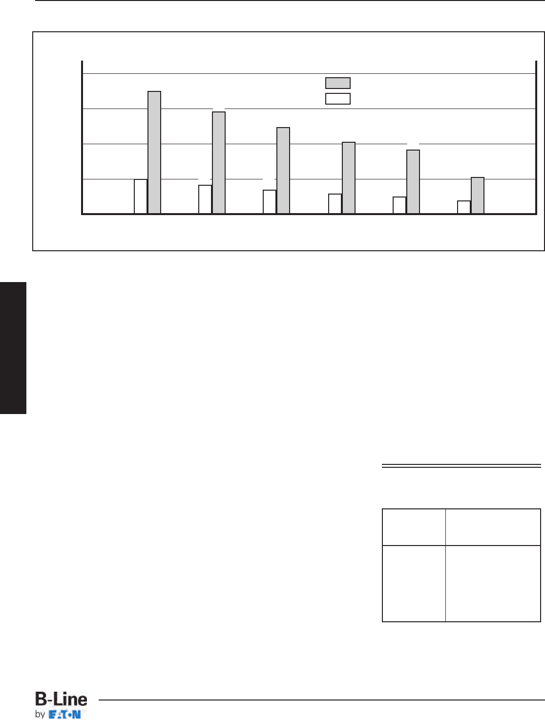
Service Life is defined as the time to 5% rusting of the steel surface.
Anticipated Life of Zinc Coatings In Various Atmospheric Environments
40
30
20
10
= Zinc Coating 1.50 Oz./Ft.2(.0026" Thick)
Hot Dip
= Zinc Coating 0.45 Oz./Ft.2(.00075" Thick)
Pre-Galvanized
Life
in
Years
10 87653
11
18
29
21
25
36
Rural Tropical Temperate Suburban Urban Highly
Marine Marine Industrial
Environment
Material/Finish
Prefix Designation Chart
Standards Available
Cable Tray Selection
CTS-4
Cable Tray Selection - Material & Finish
Cable Tray Systems
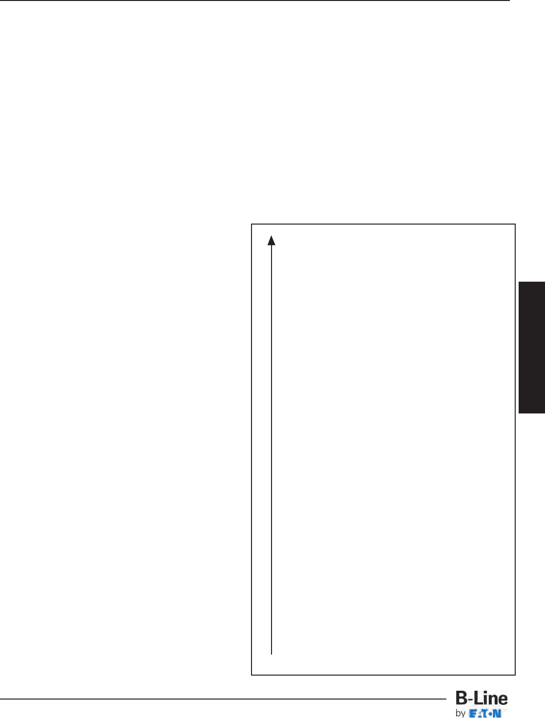
Magnesium
Magnesium Alloys
Zinc
Beryllium
Aluminum - Zinc Alloys (7000 series)
Aluminum - Magnesium Alloys (5000 series)
Aluminum (1000 series)
Aluminum - Magnesium Alloys (3000 series)
Aluminum - Magnesium - Silicon Alloys (6000 series)
Cadmium
Aluminum - Copper Alloys (2000 series)
Cast Iron, Wrought Iron, Mild Steel
Austenitic Nickel Cast Iron
Type 410 Stainless Steel (active)
Type 316 Stainless Steel (active)
Type 304 Stainless Steel (active)
Naval Brass, Yellow Brass, Red Brass
Tin
Copper
Lead-Tin Solders
Admiralty Brass, Aluminum Brass
Manganese Bronze
Silicon Bronze
Tin Bronze
Type 410 Stainless Steel (passive)
Nickel - Silver
Copper Nickel Alloys
Lead
Nickel - Aluminum Bronze
Silver Solder
Nickel 200
Silver
Type 316 Stainless Steel (passive)
Type 304 Stainless Steel (passive)
Incoloy 825
Hastelloy B
Titanium
Hastelloy C
Platinum
Graphite
Galvanic Series In Sea Water
More Anodic
Corrosion
Anodic End
Cathodic End
Cable Tray Selection
All metal surfaces are affected by corrosion. Depending on
the physical properties of the metal and the environment
to which it is exposed, chemical or electromechanical
corrosion may occur.
Atmospheric Corrosion
Atmospheric corrosion occurs when metal is exposed to
airborne liquids, solids or gases. Some sources of
atmospheric corrosion are moisture, salt, dirt and
sulphuric acid. This form of corrosion is typically worse
outdoors, especially near marine environments.
Chemical Corrosion
Chemical corrosion takes place when metal comes in
direct contact with a corrosive solution. Some factors
which affect the severity of chemical corrosion include:
chemical concentration level, duration of contact,
frequency of washing, and operating temperature.
Storage Corrosion
Wet storage stain (White rust) is caused by the entrapment
of moisture between surfaces of closely packed and
poorly ventilated material for an extended period. Wet
storage stain is usually superficial, having no affect on the
properties of the metal.
Light staining normally disappears with weathering.
Medium to heavy buildup should be removed, in order to
allow the formation of normal protective film.
Proper handling and storage will help to assure stain-free
material. If product arrives wet, it should be unpacked and
dried before storage. Dry material should be stored in a
well ventilated “low moisture” environment to avoid
condensation formation. Outdoor storage is undesirable,
and should be avoided whenever possible.
Galvanic Corrosion
Galvanic corrosion occurs when two or more dissimilar
metals are in contacts in the presence of an electrolyte (ie.
moisture). An electrolytic cell is created and the metals
form an anode or a cathode depending on their relative
position on the Galvanic Series Table. The anodic material
will be the one to corrode. Whether a material is anodic
depends on the relative position of the other material. For
example: If zinc and steel are in contact, the zinc acts as
the anode and will corrode; the steel acts as the cathode,
and will be protected. If steel and copper are in contact,
the steel is now the anode and will corrode.
The rate at which galvanic corrosion occurs depends on
several factors:
1. The amount and concentration of electrolyte present-
An indoor, dry environment will have little or no galvanic
corrosion compared to a wet atmosphere.
2. The relative size of the materials- A small amount of
anodic material in contact with a large cathodic material
will result in greater corrosion. Likewise, a large anode
in contact with a small cathode will decrease the rate of
attack.
3. The relative position on the Galvanic Series Table - The
further apart in the Galvanic Series Table, the greater
the potential for corrosion of the anodic material.
CTS-5
Cable Tray Selection - Material & Finish
Cable Tray Systems
Cable Tray Material
Chemical Aluminum Stainless Type 304 Stainless Type 316
Cold Warm Hot Cold Warm Hot Cold Warm Hot
Acteone RRR RRR RRR
Aluminum Chloride Solution NR NR NR NR -- -- F -- --
Anhydrous Aluminum Chloride RRRNR -- -- F -- --
Aluminum Sulfate RRR RRR RRR
Ammonium Chloride 10% FFNR RRR RRR
Ammonium Hydroxide FFFRRRRRR
Ammonium Phosphate FFNR R -- -- R -- --
Ammonium Sulfate F -- -- RRR RRR
Ammonium Thiocyanate RRR R-- -- RRR
Amyl Acetate RRR RRR RRR
Amyl Alcohol RRR R-- -- RRR
Arsenic Acid FFFRR-- RRR
Barium Chloride FFNR RRR RRR
Barium Sulfate RRR RR-- RR--
Barium Sulfide NR NR NR RR-- RR--
Benzene RRR RRR RRR
Benzoic Acid FFNR RRR RRR
Boric Acid RRF RRR RRR
Bromine Liquid or Vapor NR NR NR NR NR NR NR NR NR
Butyl Acetate RRR R-- -- RRR
Butyl Alcohol RRR RRR RRR
Butyric Acid FFFRRRRRR
Calcium Chloride 20% FFNR R -- -- R -- --
Calcium Hydroxide N -- -- RRF RRR
Calcium Hypochlorite 2 - 3% F -- -- R -- -- R -- --
Calcium Sulfate RR-- RR-- RR--
Carbon Monoxide Gas RRR RRR RRR
Carbon Tetrachloride FFNR FFFRRR
Chloroform Dry R NR NR RR-- RR--
Chloroform Solution R NR NR -- -- -- -- -- --
Chromic Acid 10% CP RR-- RRF RRR
Citric Acid FFFRRNR RRR
Copper Cyanide NR NR NR RRR RRR
Copper Sulfate 5% NR NR NR RRR RRR
Ethyl Alcohol RRR RRR RRR
Ethylene Glycol RRF RR-- RRR
Ferric Chloride NR NR NR NR NR NR NR NR NR
Ferrous Sulfate 10% R NR NR RR-- RR--
Formaldehyde 37% RRR RRR RRR
Formic Acid 10% RR-- RRNR RRR
Gallic Acid 5% RRNR RRR RRR
Hydrochloride Acid 25% NR NR NR NR NR NR NR NR NR
Hydrofluoric Acid 10% NR NR NR NR NR NR NR NR NR
Hydrogen Peroxide 30% RRR RRR RRR
Hydrogen Sulfide Wet R -- -- NR NR NR RRR
R= Recommended
F= May be used under some conditions
NR = Not Recommended
-- = Information not available
The corrosion data given in this table is for general comparison only. (Reference Corrosion Resistance Tables, Second Edition)
The presence of contaminates in chemical environments can greatly affect the corrosion rate of any material.
B-Line strongly suggests that field service tests or simulated laboratory tests using actual environmental conditions be conducted in order to
determine the proper materials and finishes to be selected.
For questionable environments see Fiberglass Cable Tray Corrosion Guide (Pages FCT-3 & FCT-4).
Cold = 50 - 80°F Warm = 130 - 170°F Hot = 200 - 212°F
Corrosion Guide
Cable Tray Selection
CTS-6
Cable Tray Selection - Material & Finish
Cable Tray Systems
Cable Tray Material
Chemical Aluminum Stainless Type 304 Stainless Type 316
Cold Warm Hot Cold Warm Hot Cold Warm Hot
Lactic Acid 10% RFNR RRF RRR
Lead Acetate 5% NR NR NR RRR RRR
Magnesium Chloride 1% NR NR NR R -- FR-- R
Magnesium Hydroxide RRRRR-- RR--
Magnesium Nitrate 5% R -- -- RRR RRR
Nickel Chloride NR NR NR R -- -- R -- --
Nitric Acid 15% NR NR NR RRR RRR
Oleic Acid RRF RRF RRR
Oxalic Acid 10% RFNR NR NR NR RRR
Phenol CP RRRRRR RRR
Phosphoric Acid 50% NR NR NR RRR RFNR
Potassium Bromide 100% RFNR RR-- RRR
Potassium Carbonate 100% FF-- RRRRRR
Potassium Chloride 5% RRRRRR RRR
Potassium Dichromate RRR RRR RRR
Potassium Hydroxide 50% NR NR NR RRR RRR
Potassium Nitrate 50% RRR RRR RRR
Potassium Sulfate 5% RRRRRR RRR
Propyl Alcohol RRRRRR RRR
Sodium Acetate 20% RFF RRRRRR
Sodium Bisulfate 10% RFF RRRRRR
Sodium Borate RFF RRRRRR
Sodium Carbonate 18% RFF RRRRRR
Sodium Chloride 5% R NR NR RRR RRR
Sodium Hydroxide 50% NR NR NR RRR RRR
Sodium Hypochlorite 5% RFF F-- -- R -- --
Sodium Nitrate 100% RRRRRR RRR
Sodium Nitrite 100% RRRRRR RRR
Sodium Sulfate 100% RRF RRR RRR
Sodium Thiosulfate RRRRRR RRR
Sulfur Dioxide (Dry) RRRRRR RRR
Sulfuric Acid 5% NR NR -- F NR NR R -- --
Sulfuric Acid 10% NR NR NR NR NR NR NR NR NR
Sulfuric Acid 50% NR NR NR NR NR NR NR NR NR
Sulfuric Acid 75 - 98% NR NR NR NR NR NR NR NR NR
Sulfuric Acid 98 - 100% NR NR -- R -- -- RRF
Tannic Acid 10 & 50% NR NR NR RRR RRR
Tartaric Acid 10 & 50% F NR NR RRR RRR
Vinegar FFFRRRRRR
Zinc Chloride 5 & 20% F NR NR RFNR RRR
Zinc Nitrate F NR NR RRR RRR
Zinc Sulfate F NR NR RRR RRR
R = Recommended
F = May be used under some conditions
NR = Not Recommended
-- = Information not available
The corrosion data given in this table is for general comparison only. (Reference Corrosion Resistance Tables, Second Edition)
The presence of contaminates in chemical environments can greatly affect the corrosion rate of any material.
B-Line strongly suggests that field service tests or simulated laboratory tests using actual environmental conditions be conducted in
order to determine the proper materials and finishes to be selected.
For questionable environments see Fiberglass Cable Tray Corrosion Guide (Pages FCT-3 & FCT-4).
Cold = 50 - 80°F Warm = 130 - 170°F Hot = 200 - 212°F
Corrosion Guide
Cable Tray Selection
CTS-7
Cable Tray Selection - Material & Finish
Cable Tray Systems
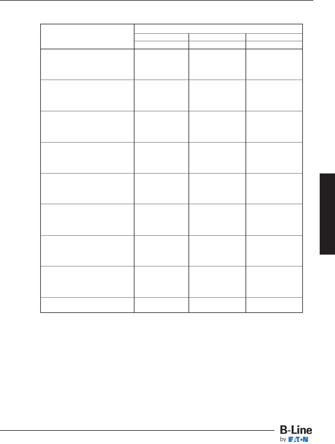
Maximum Spacing Between Expansion Joints For 1" Movement
Temperature Stainless Steel
Differential Steel Aluminum 304 316
˚F ˚C Feet m Feet m Feet m Feet m
25 -4 512 156.0 260 79.2 347 105.7 379 115.5
50 10 256 78.0 130 39.6 174 53.0 189 57.6
75 24 171 52.1 87 26.5 116 35.4 126 38.4
100 38 128 39.0 65 19.8 87 26.5 95 29.0
125 51 102 31.1 52 15.8 69 21.0 76 23.2
150 65 85 25.9 43 13.1 58 17.7 63 19.2
175 79 73 22.2 37 11.3 50 15.2 54 16.4
Note: every pair of expansion splice plates requires two bonding jumpers for grounding continuity.
1
2
3
4
It is important that thermal contraction
and expansion be considered when
installing cable tray systems. The
length of the straight cable tray runs
and the temperature differential
govern the number of expansion splice
plates required (see Table 2 below).
The cable tray should be anchored
at the support nearest to its midpoint
between the expansion splice plates
and secured by expansion guides at all
other support locations (see Figure 1).
The cable tray should be permitted
longitudinal movement in both
directions from that fixed point. When
used, covers should be overlapped at
expansion splices.
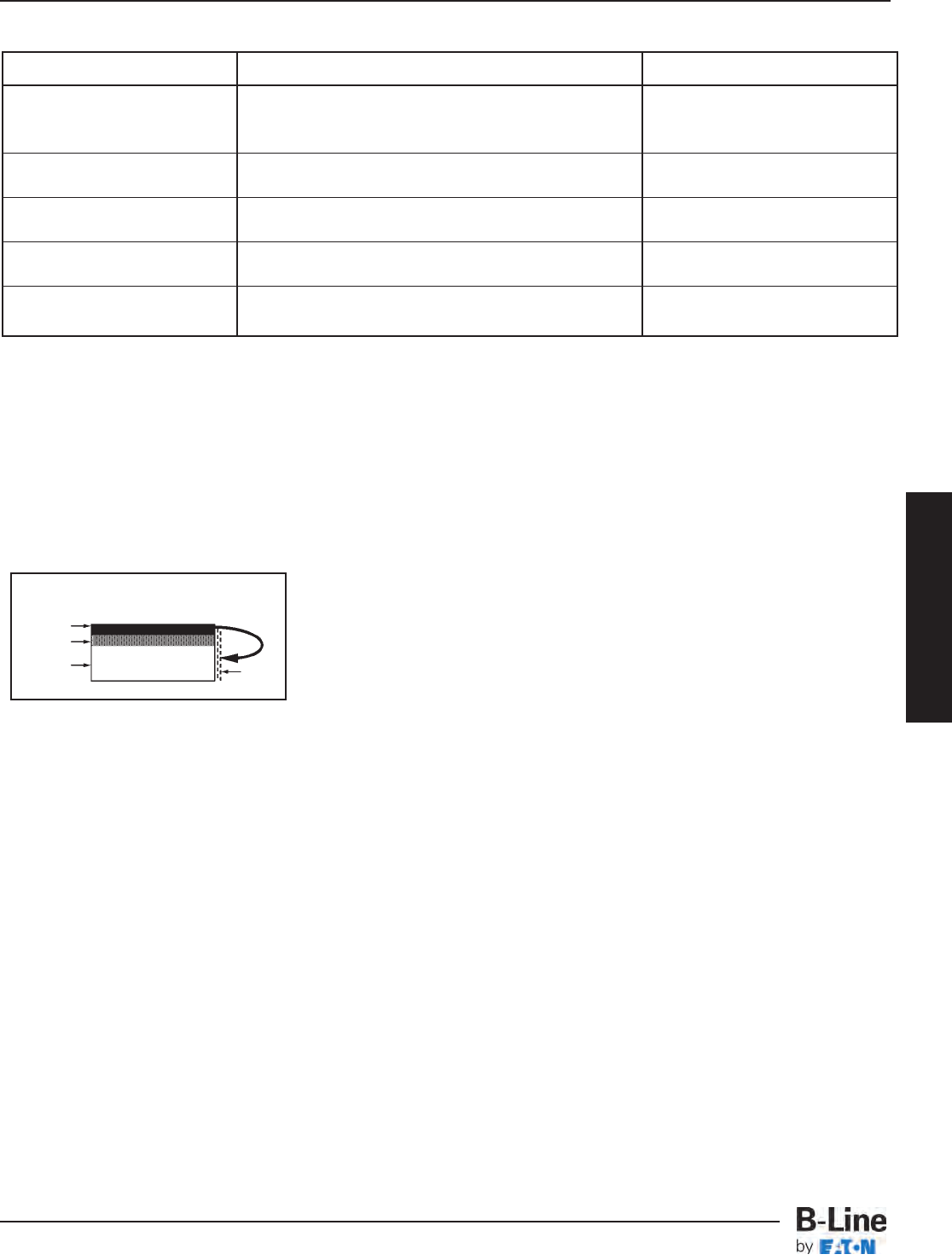
Accurate gap settings at the time of
installation are necessary for the proper
operation of the expansion splice
plates. The following procedure should
assist the installer in determining the
correct gap: (see Figure 2)
Plot the highest expected metal
temperature on the maximum
temperature line.
Plot the lowest expected metal
temperature on the minimum
temperature line.
Draw a line between the maximum
and minimum points.
Plot the metal temperature at the
time of installation to determine
the gap setting.
Refer to page FCT-8 for thermal
contraction and expansion of
fiberglass cable trays.
Thermal Contraction and Expansion
C°F°F° C°
Maximum Minimum
Temperature Temperature
130
70
50
30
10
-10
-30
90
110
130
110
90
70
50
30
10
-10
-30
50
40
30
20
10
0
-10
-20
-30
-40
50
40
30
20
10
0
-10
-20
-30
-40
1/8
(3.2)
1/4
(6.3)
3/8
(9.5)
1/2
(12.7)
5/8
(15.9)
3/4
(19.0)
7/8
(22.2)
0
(0.0)
1
(25.4)
GAP SETTING Inches (mm)
Metal Temperature At Time Of Installation
X -- -- -- -- X -- -- -- -- X
X -- -- -- -- X -- -- -- -- X
X :Denotes hold-down clamp
(anchor) at support.
_: Denotes expansion guide
clamp at support.
Expansion Splice Plates
(Bonding Jumpers Required
On Each Side of Tray)
Figure 2
Table 2
Figure 1
1
2
3
4
Typical Cable Tray Installation
Cable Tray Selection
CTS-8
Cable Tray Selection - Material & Finish
Cable Tray Systems
Weight
The weight of an aluminum cable tray is approximately half that of a comparable steel tray. Some factors to
consider include: shipping costs, material, handling, project weight restrictions and the strength of support members.
Field Modifications
Aluminum cable tray is easier to cut and drill than steel cable tray since it is a “softer” material. Similarly,
galvanized steel cable tray is easier to cut and drill than stainless steel cable tray. B-Line aluminum cable tray uses
a four bolt splice, resulting in half as much drilling and hardware installation as most steel cable tray, which uses an
eight bolt splice. Hot dip galvanized and painted steel cable tray finishes must be repaired when field cutting or
drilling. Failure to repair coatings will impair the cable tray’s corrosion resistance.
Availability
Aluminum, pre-galvanized, stainless steel and fiberglass cable tray can normally be shipped from the factory in
a short period of time. Hot dip galvanized and painted cable tray requires an additional coating process, adding
several days of preparation before final shipment. Typically, a coated cable tray will be sent to an outside source
for coating, requiring additional packing and shipping.
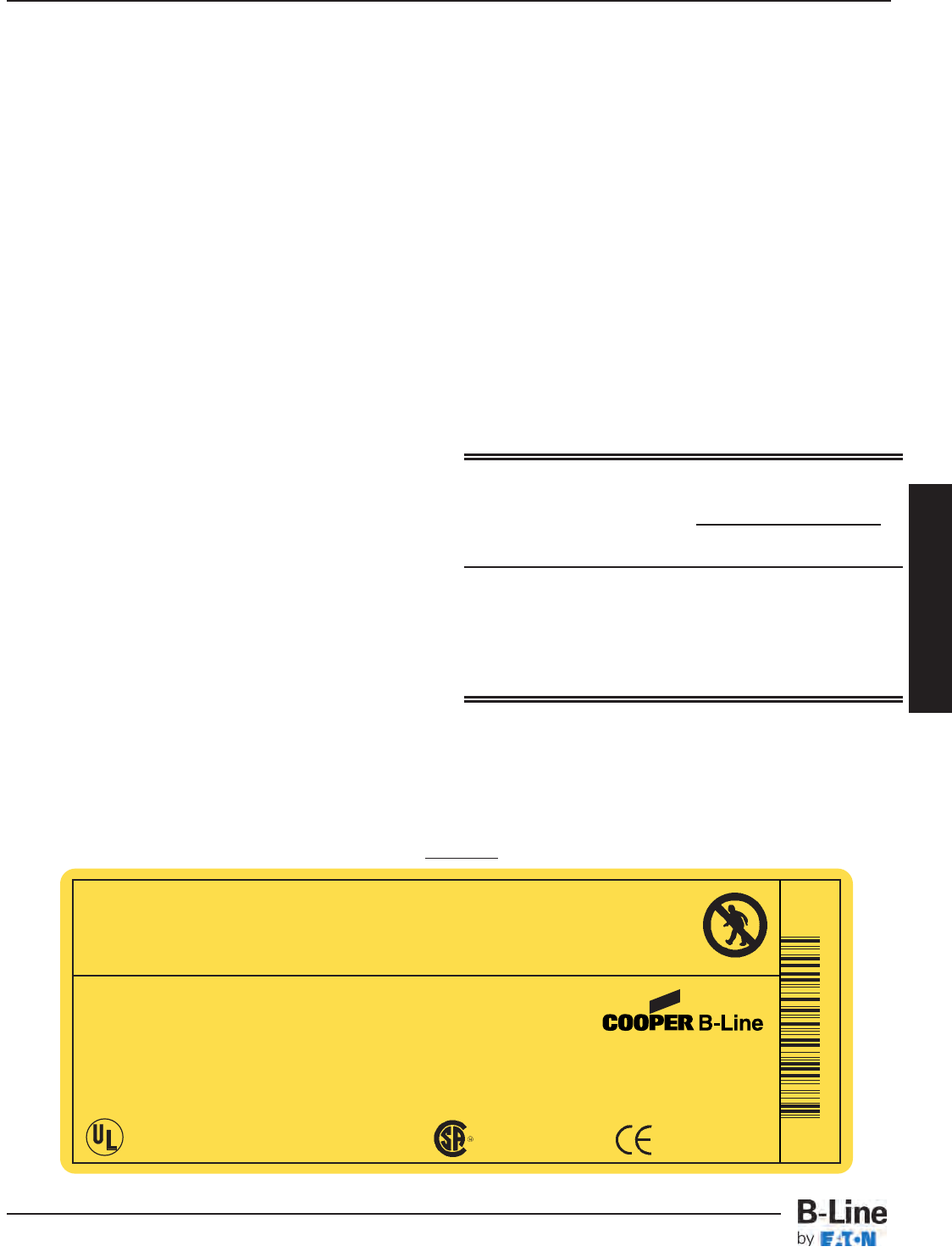
Electrical Grounding Capacity
The National Electrical Code, Article 392.7 allows
cable tray to be used as an equipment grounding
conductor. All B-Line standard steel and aluminum
cable trays are classified by Underwriter’s
Laboratories per NEC Table 392.7 based on their
cross-sectional area.
The corresponding cross-sectional area for each
side rail design (2 side rails) is listed on a fade
resistant UV stabilized label (see Figure 3). This
cable tray label is attached to each straight section
and fitting that is U.L. classified. U.L. assigned
cross-sectional area is also stated in the loading
charts in this catalog for each system.
NEMA Installation Guide
The new NEMA VE 2 is a cable tray installation
guideline and is available from NEMA, CTI or B-Line.
For free download see www.cabletrays.com.
Table 392.7(B)(2)
Metal Area Requirements for Cable Trays
Used as Equipment Grounding Conductors
Maximum Fuse Ampere Rating,
Circuit Breaker Ampere Trip
Setting, or Circuit Breaker Minimum Cross-Sectional Area of
Protective Relay Ampere Trip Metal* In Square Inches
Setting for Ground Fault
Protection of any Cable Circuit Steel Aluminum
in the Cable Tray System Cable Trays Cable Trays
60 0.20 0.20
100 0.40 0.20
200 0.70 0.20
400 1.00 0.40
600 1.50** 0.40
1000 -- 0.60
1200 -- 1.00
1600 -- 1.50
2000 -- 2.00**
For SI units: one square inch = 645 square millimeters.
* Total cross-sectional area of both side rails for ladder or trough-type cable trays; or
the minimum cross-sectional area of metal in channel-type cable trays or cable
trays of one-piece construction.
** Steel cable trays shall not be used as equipment grounding conductors for circuits
with ground-fault protection above 600 amperes. Aluminum cable trays shall not be
used as equipment grounding conductors for circuits with ground-fault protection
above 2000 amperes.
For larger ampere ratings an additional grounding conductor must be used.
Installation Considerations
Figure 3
C
L
A
S
S
I
F
I
E
D
®
Use Only As A Mechanical Support For Cables, Tubing and Raceways.
Do Not Use As A Walkway, Ladder,
Or Support For Personnel.
www.cooperbline.com
(618) 654-2184
Catalog Number: 24A09-12-144 STR SECTION
Shipping Ticket: 260203 00 001
Mark Number: 78101115400
Purchase Order: D798981
Minimum Area: 1.000 SQ. IN.
Load Class: D1 179 KG/M 3 METER SPAN
30781011154005
1 of 1
09/15/2005
000291745
Cable Tray Selection
WARNING!
This product is classified by Underwriters Laboratories, Inc. as
to its suitability as an equipment grounding conductor only. 556E
NON-VENTILATED
Reference File #LR36026
CTS-9
Cable Tray Selection - Material & Finish
Cable Tray Systems
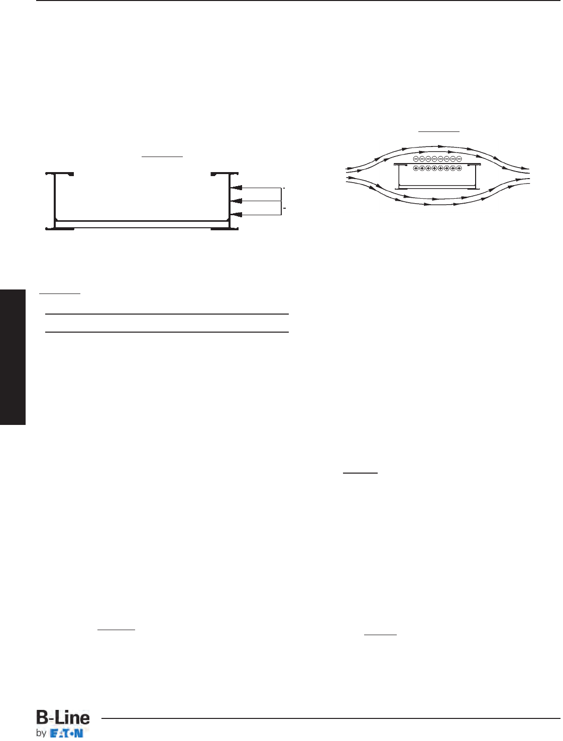
Cable Tray Selection
Wind Loads
Wind loads need to be determined for all outdoor
cable tray installations. Most outdoor cable trays are
ladder type trays, therefore the most severe loading
to be considered is impact pressure normal to the
cable tray side rails (see detail 1).
The impact pressure corresponding to several wind
velocities are given below in Table 1.
Table 1
Impact Pressures
V(mph) P(lbs/ft2) V(mph) P(lbs/ft2)
15 0.58 85 18.5
20 1.02 90 20.7
25 1.60 95 23.1
30 2.30 100 25.6
35 3.13 105 28.2
40 4.09 110 30.9
45 5.18 115 33.8
50 6.39 120 36.8
55 7.73 125 40.0
60 9.21 130 43.3
65 10.80 135 46.6
70 12.50 140 50.1
75 14.40 145 53.8
80 16.40 150 57.6
V= Wind Velocity
P= Impact Pressure
Note: These values are for an air density of 0.07651 lbs/ft3
corresponding to a temperature of 60˚ F and barometric
pressure of 14.7 lbs/in2.
Example Calculation:
Side load for 6" side rail with 100 mph wind
25.6 x 6 = 12.8 lbs/ft
12
When covers are installed on outdoor cable trays,
another factor to be considered is the aerodynamic
effect which can produce a lift strong enough to
separate a cover from a tray. Wind moving across
a covered tray (see detail 2) creates a positive
pressure inside the tray and a negative pressure
above the cover. This pressure difference can lift the
cover off the tray.
B-Line recommends the use of heavy duty wrap-
around cover clamps when covered trays are
installed in an area where strong winds occur.
Special Notice:
Covers on wide cable tray and/or cable tray installed
at elevations high off the ground may require
additional heavy duty clamps or thicker cover
material.
Ice Loads
Glaze ice is the most commonly seen form of ice
build-up. It is the result of rain or drizzle freezing on
impact with an exposed object. Generally, only the
top surface (or the cover) and the windward side of
a cable tray system is significantly coated with ice.
The maximum design load to be added due to ice
should be calculated as follows:
LI = (W xTI)x DIwhere;
144
LI= Ice Load (lbs/linear foot)
W= Cable Tray Width (inches)
TI= Maximum Ice Thickness (inches)
DI= Ice Density = 57 lbs/ft3
the maximum ice thickness will vary depending on
location. A thickness of 1/2" can be used as a
conservative standard.
Example Calculation:
Ice Loads for 24" wide tray with 1/2" thick ice;
24 x .5 x 57 = 4.75 lbs/ft
144
Detail 1
Detail 2
Environmental Loads
CTS-10
Cable Tray Selection - Strength
Cable Tray Systems

Cable Tray Selection
Environmental Loads
Snow Loads
Snow is measured by density and thickness. The density of snow varies almost as much as its thickness.
The additional design load from snowfall should be determined using the building codes which apply for each
installation.
Seismic Loads
A great deal of seismic testing and evaluation of cable tray systems, and their supports, has been performed.
The conclusions reached from these evaluations is that cable tray is stronger laterally than vertically, since it
acts as a truss in the lateral direction. Other factors that contribute to the stability of cable tray are the energy
dissipating motion of the cables within the tray, and the high degree of ductility of the cable tray and the
support material. These factors, working in conjunction with a properly designed cable tray system, should
afford reasonable assurance to withstand even strong motion earthquakes.
When seismic bracing is required for a cable tray system, it should be applied to the supports and not the
cable tray itself. B-Line’s “Seismic Restraints” brochure provides OSHPD approved methods of bracing cable
tray supports using standard B-Line products. Contact B-Line to receive a copy of this brochure.
Concentrated Loads
A concentrated static load represents a static weight applied at a single point between the side rails. Tap
boxes, conduit attachments and long cable drops are just some of the many types of concentrated loads.
When so specified, these concentrated static loads may be converted to an equivalent, uniform load (We) by
using the following formula:
We = 2 x (concentrated Static Load)
span length
B-Line cable tray side rails, rungs and bottoms will withstand a 200 lb. static load without collapse (series
14 excluded)*. However, it should be noted that per NEMA Standard Publication VE1 cable tray is designed as
a support for power or control cables, or both, and is not intended or designed to be a walkway for personnel.
Each section of B-Line Cable Tray has a label stating the following message:
Warning! Not to be used as a walkway, ladder or support for personnel. To be used only as a
mechanical support for cables and raceway.
CTS-11
Cable Tray Selection - Strength
Cable Tray Systems

Cable Tray Selection
Support Span
The strength of a cable tray is largely determined by the strength of its side rails. The strength of a cable tray
side rail is proportionate to the distance between the supports on which it is installed, commonly referred to as
the “support span”. Therefore, the strength of a cable tray system can be altered by changing the support
span. However, there is a limit to how much the strength of a cable tray system can be increased by reducing
the support span, because the strength of the cable tray bottom members could become the determining
factor of strength.
Once the load requirement of a cable tray system has been established, the following factors should be
considered:
1. Sometimes the location of existing structural beams will dictate the cable tray support span.
This is typical with outdoor installations where adding intermediate supports could be financially
prohibitive. For this situation the appropriate cable tray must be selected to accommodate the
existing span.
2. When cable tray supports are randomly located, the added cost of a higher strength cable tray
system should be compared to the cost of additional supports. Typically, adding supports is
more costly than installing a stronger series of cable tray. The stronger cable tray series (e.g.
from 75 lbs./ft. on 20’ span to 100 lbs./ft. on 20’ span) will increase the price of the cable tray
system minimally, possibly less than $1/ft., with little or no additional labor cost for installation.
Alternately, one extra support may cost $100.00 (material and labor) for a simple trapeze. Future
cable additions or the capability of supporting equipment, raceways for example, also favor
stronger cable tray systems. In summary, upgrading to a stronger cable tray series is
typically more cost-effective than using the recommended additional supports for a lighter
duty cable tray series.
3. The support span lengths should be equal to or less than unspliced straight section lengths, to
ensure that no more than one splice is placed between supports as stated in the NEMA VE 2
Cable Tray Installation Guideline.
CTS-12
Cable Tray Selection - Strength
Cable Tray Systems
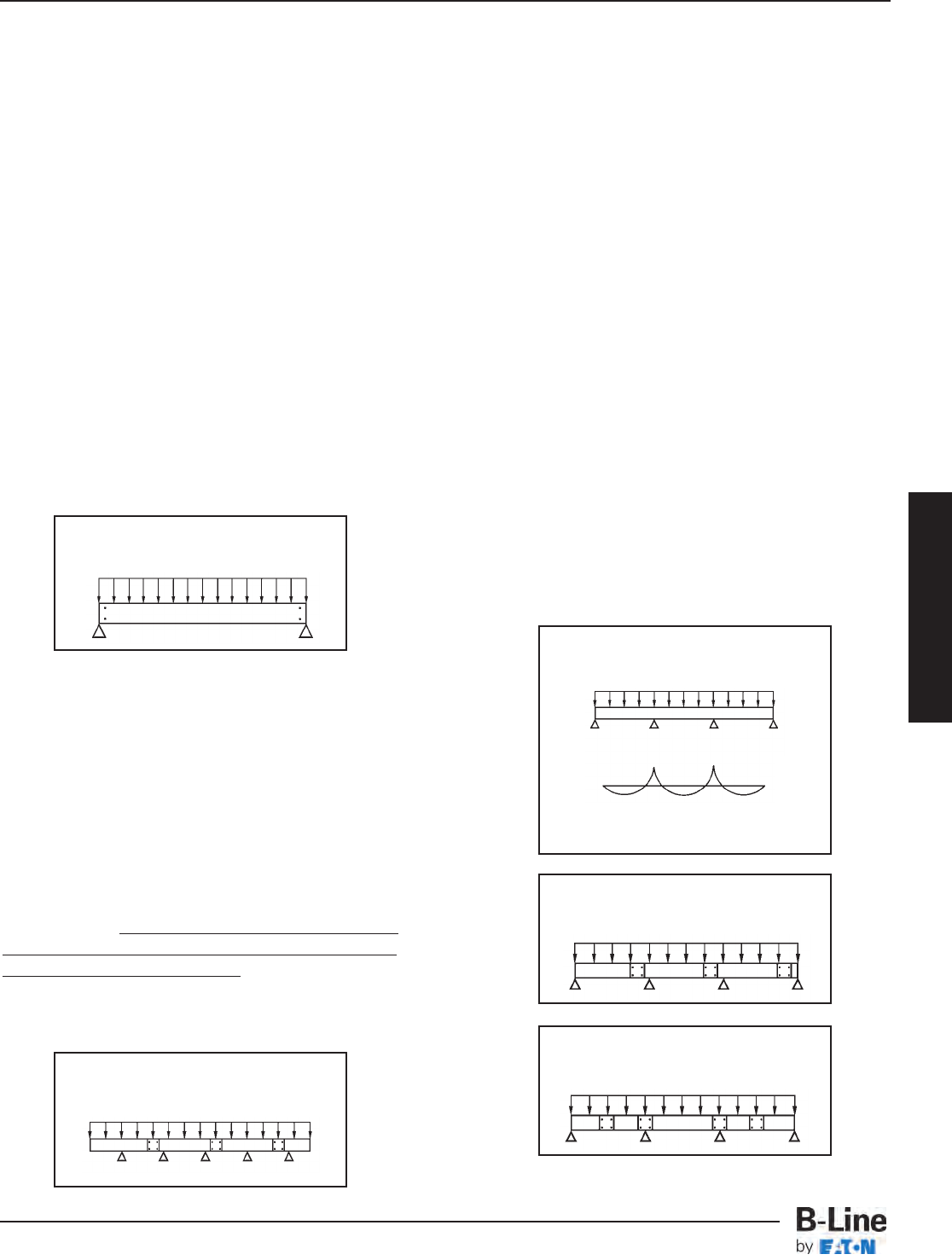
Cable Tray Selection
Deflection
Deflection in a cable tray system is primarily an
aesthetic consideration. When a cable tray system is
installed in a prominent location, a maximum simple
beam deflection of 1/200 of support span can be
used as a guideline to minimize visual deflection.
It is important at this point to mention that there
are two typical beam configurations, simple beam
and continuous beam, and to clarify the difference.
A good example of a simple beam is a single
straight section of cable tray supported, but not
fastened at either end. When the tray is loaded the
cable tray is allowed to flex. Simple beam analysis is
used almost universally for beam comparisons even
though it is seldom practical in the field installations.
The three most prominent reasons for using a simple
beam analysis are: calculations are simplified; it
represents the worst case loading; and testing is
simple and reliable. The published load data in the
B-Line cable tray catalog is based on the simple
beam analysis per NEMA & CSA Standards.
Continuous beam is the beam configuration most
commonly used in cable tray installations. An
example of this configuration is where cable trays are
installed across several supports to form a number of
spans. The continuous beam possesses traits of
both the simple and fixed beams. When equal loads
are applied to all spans simultaneously, the counter-
balancing effect of the loads on both sides of a
support restricts the movement of the cable tray at
the support. The effect is similar to that of a fixed
beam. The end spans behave substantially like
simple beams. When cable trays of identical design
are compared, the continuous beam installation will
typically have approximately half the deflection of a
simple beam of the same span. Therefore simple
beam data should be used only as a general
comparison. The following factors should be
considered when addressing cable tray deflection:
1. Economic consideration must be considered
when addressing cable deflection criteria.
2. Deflection in a cable tray system can be reduced
by decreasing the support span, or by using a
taller or stronger cable tray.
3. When comparing cable trays of equivalent
strength, a steel cable tray will typically exhibit
less deflection than an aluminum cable tray since
the modulus of elasticity of steel is nearly three
times that of aluminum.
4. The location of splices in a continuous span will
affect the deflection of the cable tray system. The
splices should be located at points of minimum
stress whenever practical. NEMA Standards VE 1
limits the use of splice plates as follows:
Unspliced straight sections should be used on all
simple spans and on end spans of continuous span
runs. Straight section lengths should be equal to or
greater than the span length to ensure not more
than one splice between supports.
See the figures below for splicing configuration
samples.
Simple Beam
Continuous Beam
Typical Continuous
Span Configuration
Preferred Splice
Plate Locations
Undesirable Splice
Plate Locations
+ Maximum Positive Moment
- Maximum Negative Moment
+
0
-
CTS-13
Cable Tray Selection - Strength
Cable Tray Systems
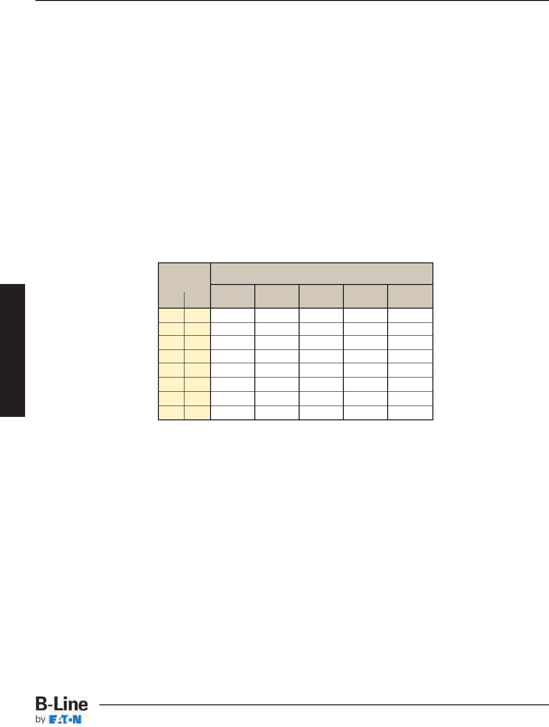
Cable Tray Selection
Load Capacity
Calculate each anticipated load factor, then add them to obtain a total load.
(Example: Working Load = Cable + Concentrated + Wind + Snow + Ice Loads).
The Working Load should be used, along with the maximum support spacing, to select a span/load
class designation from Table 3. Table 4 (page CTS-15) contains the most common load/span class
designations per the US and Canadian metallic cable tray standard, CSA, C22.2 No. 126.1-98 First
Addition, NEMA VE 1-1998.
Class Designations for lengths of
lb/ft kg/m ft m ft m ft m ft m ft m
8 (2.4) 10 (3.0) 12 (3.7) 16 (4.9) 20 (6.0)
25 37 –– A –– –– ––
45 67 –– –– –– –– D
50 74 8A –– 12A 16A 20A
65 97 –– C –– –– ––
75 112 8B –– 12B 16B E or 20B
100 149 8C –– 12C 16C 20C
120 179 –– D –– –– ––
200 299 –– E –– –– ––
Load
Class
Table 3 - These Loading Classes Are
Historical and Supplied For Reference Only
Note: 8A/B/C, 12A/B/C, 16A/B/C, and 20A/B/C were the traditional
NEMA designations. A, C, D, and E were the conventional CSA designations.
Actual tested loadings per span will be stated on the product labels.
CTS-14
Cable Tray Selection - Strength
Cable Tray Systems
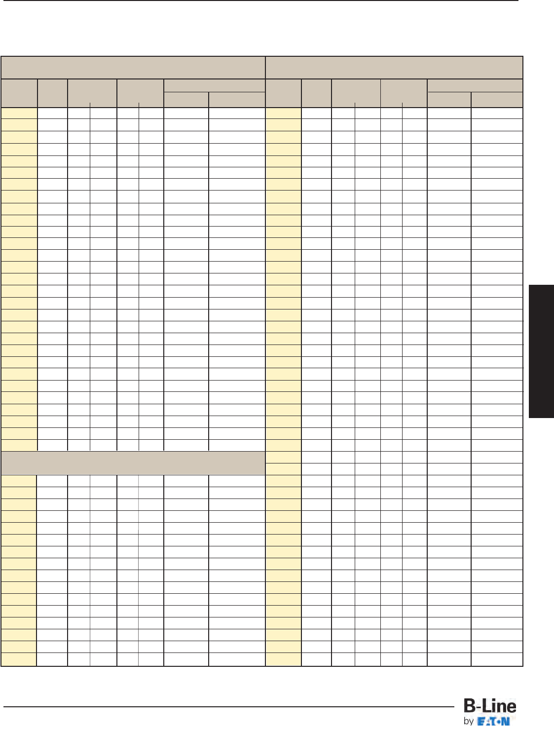
Cable Tray Selection
Table 4 - B-Line Cable Tray Load Classes
Aluminum Steel
Copper free HDGAF/Pre-Galvanized
Series Load Load Span Former Classes Series Load Load Span Former Classes
Depth
lb/ft (kg/m)
ft (m) NEMA CSA Depth
lb/ft (kg/m)
ft (m) NEMA CSA
RSI04A 2.68 75 (112) 12 (3.7) 12B C (3m) 148* 3 51 (76) 12 (3.7) 12A C1(3m)
24A 3 126 (187) 12 (3.7) 12C D1(3m) 248* 3 103 (153) 12 (3.7) 12C D1(3m)
34A 3 80 (119) 20 (6.1) 20B E (6m) 346* 3 63 (94) 20 (6.1) 20A D1(6m)
RSI05A 3.66 83 (123) 12 (3.7) 12B C (3m) 444* 3 91 (135) 20 (6.1) 20B E (3m)
25A 4 50 (74) 20 (6.1) 16B D1(6m) 156* 4 76 (113) 12 (3.7) 12B C1(3m)
35A 4 121 (180) 16 (4.9) 20B E (3m) 258* 4 109 (162) 12 (3.7) 12C D1(3m)
RSI06A 4.64 82 (121) 12 (3.7) 12C D1(3m) 356* 4 69 (103) 20 (6.1) 16C D1(6m)
26A 5 51 (76) 20 (6.1) 20A D1(6m) 358* 4 62 (92) 20 (6.1) 20A D1(6m)
36A 5 84 (125) 20 (6.1) 20B E (6m) 454* 4 106 (158) 20 (6.1) 20C E (6m)
46A 5 103 (153) 20 (6.1) 20C E (6m) 166* 5 77 (115) 12 (3.7) 12B C1(3m)
H46A 5 167 (248) 20 (6.1) 167# @ 20'
131 kg/m(7.6m)
268* 5 110 (164) 12 (3.7) 12C D1(3m)
RSI07A 5.63 122 (182) 12 (3.7) 12C D1(3m) 368† 5 59 (88) 20 (6.1) 20A D1(3m)
37A 6 80 (119) 20 (6.1) 20B 366* 5 75 (112) 20 (6.1) 20B E (6m)
47A 6 100 (149) 20 (6.1) 20C 464* †5123 (183) 20 (6.1) 119# @ 20' E (6m)
H47A 6 149 (222) 20 (6.1) 149# @ 20' 176* 6 86 (128) 12 (3.7) 12B
137 kg/m(3.7m)
57A 6 102 (152) 30 (9.1) 102# @ 30'
152 kg/m(9.1m)
378* 6 51 (76) 20 (6.1) 20A D1(3m)
S8A 6 161 (240) 30 (9.1) 161# @ 30'
240 kg/m(9.1m)
476* 6 77 (115) 20 (6.1) 20B D1(6m)
574* 6 130 (193) 20 (6.1) 117# @ 20' E (6m)
348† 3 125 (186) 12 (3.7) 12C C1(3m)
358† 4 62 (92) 20 (6.1) 20A 89 kg/m(6.1m)
FT1.5X12 11/211 (16) 8 (2.4)
FT2X2 2 20 (30) 8 (2.4)
FT2X4 2 27 (40) 8 (2.4)
FT2X6 2 27 (40) 8 (2.4)
FT2X8 2 27 (40) 8 (2.4)
FT2X12 2 27 (40) 8 (2.4)
FT2X16 2 27 (40) 8 (2.4)
FT2X18 2 27 (40) 8 (2.4)
FT2X20 2 27 (40) 8 (2.4)
FT2X24 2 27 (40) 8 (2.4)
Fiberglass FT2X30 2 27 (40) 8 (2.4)
13F
2 145 (216) 8 (2.4) 8C FT2X36 2 27 (40) 8 (2.4)
24F
3 156 (232) 12 (3.7) FT4X4 4 36 (53) 8 (2.4)
36F
5 88 (131) 20 (6.1) FT4X6 4 46 (68) 8 (2.4)
46F
5 141 (210) 20 (6.1) FT4X8 4 47 (70) 8 (2.4)
H46F
5 152 (226) 20 (6.1) FT4X12 4 47 (70) 8 (2.4)
48F
7 125 (187) 20 (6.1) FT4X16 4 47 (70) 8 (2.4)
FT4X18 4 47 (70) 8 (2.4)
FT4X20 4 47 (70) 8 (2.4)
FT4X24 4 50 (74) 8 (2.4) 8A
FT4X30 4 50 (74) 8 (2.4) 8A
FT6X8 6 43 (64) 8 (2.4) 8A
FT6X12 6 48 (71) 8 (2.4) 8A
FT6X16 6 50 (74) 8 (2.4) 8A
FT6X18 6 50 (74) 8 (2.4) 8A
FT6X20 6 55 (82) 8 (2.4) 8A
FT6X24 6 60 (89) 8 (2.4) 8A
*G denotes CSA Type 1 (HDGAF) or P denotes CSA Type 2 (Mill-Galvanized) †SS4 (Type 304 Stainless) or SS6 (Type 316 Stainless)
CTS-15
Cable Tray Selection - Strength
Cable Tray Systems
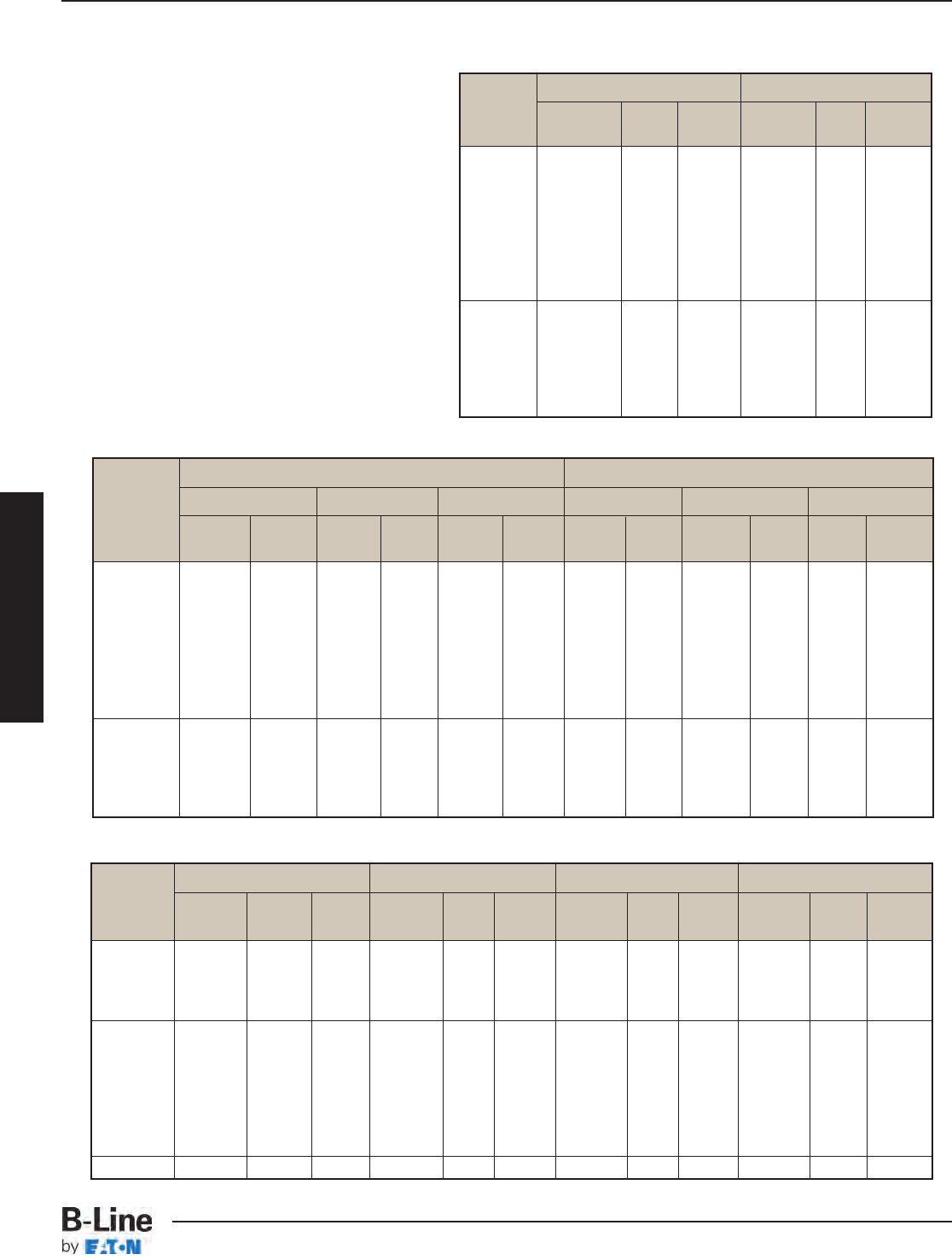
Cable Tray Selection
3 conductors with ground 4 conductors with ground
Diameter Area Weight Diameter Area Weight
Size in. in.2lbs/ft in. in.2lbs/ft
8 0.66 0.34 0.33 0.72 0.41 0.42
6 0.74 0.43 0.45 0.81 0.52 0.58
4 0.88 0.61 0.66 0.96 0.72 0.84
2 1.00 0.79 0.96 1.10 0.95 1.20
1 1.13 1.00 1.17 1.25 1.23 1.55
1/0 1.22 1.17 1.43 1.35 1.43 1.84
2/0 1.31 1.35 1.72 1.45 1.65 2.20
3/0 1.42 1.58 2.14 1.58 1.96 2.80
4/0 1.55 2.64 1.77 3.46
250 1.76 3.18 1.93 4.04
350 1.98 4.29 2.18 5.48
500 2.26 5.94 2.50 7.64
750 2.71 9.01 3.12 11.40
1000 3.10 11.70
XHHW THHN, THWN TW, THW USE, RHH, RHW
Diameter Area Weight Diameter Area Weight Diameter Area Weight Diameter Area Weight
Size in. in.2lbs/ft in. in.2lbs/ft in. in.2lbs/ft in. in.2lbs/ft
1/0 0.48 0.37 0.50 0.37 0.53 0.39 0.53 0.39
2/0 0.52 0.46 0.54 0.46 0.57 0.48 0.57 0.49
3/0 0.58 0.57 0.60 0.57 0.62 0.60 0.63 0.60
4/0 0.63 0.71 0.66 0.71 0.68 0.74 0.68 0.75
250 0.70 0.38 0.85 0.72 0.41 0.85 0.75 0.44 0.88 0.76 0.45 0.89
300 0.75 0.44 1.02 0.77 0.47 1.02 0.81 0.52 1.04 0.81 0.52 1.05
350 0.80 0.50 1.17 0.83 0.54 1.17 0.86 0.58 1.21 0.86 0.58 1.22
400 0.85 0.57 1.33 0.87 0.59 1.33 0.90 0.64 1.37 0.91 0.65 1.38
500 0.93 0.68 1.64 0.96 0.72 1.64 0.98 0.75 1.69 0.99 0.77 1.70
600 1.04 0.85 2.03 1.06 0.88 2.01 1.09 0.93 2.03 1.10 0.95 2.07
750 1.14 1.02 2.24 1.17 1.08 2.48 1.19 1.11 2.51 1.20 1.13 2.55
1000 1.29 2.52 1.32 3.30 1.34 3.31 1.35 3.33
3 conductors with ground 4 conductors with ground
Diameter (in.) Area (in.2) Weight (lbs/ft) Diameter (in.) Area (in.2) Weight (lbs/ft)
Without With Without With Alum. Steel Without With Without With Alum. Steel
Size Jacket Jacket Jacket Jacket Armor Armor Jacket Jacket Jacket Jacket Armor Armor
8 0.70 0.80 0.38 0.50 0.41 0.57 0.76 0.86 0.45 0.58 0.51 0.68
6 0.78 0.88 0.48 0.61 0.55 0.74 0.85 0.95 0.57 0.71 0.69 0.87
4 0.89 0.99 0.62 0.77 0.74 0.95 0.97 1.07 0.74 0.90 0.93 1.15
2 1.01 1.12 0.80 0.99 1.08 1.32 1.10 1.22 0.95 1.17 1.29 1.56
1 1.16 1.27 1.06 1.27 1.38 1.63 1.25 1.36 1.23 1.45 1.61 1.91
1/0 1.23 1.34 1.19 1.41 1.56 1.86 1.35 1.46 1.43 1.67 1.94 2.27
2/0 1.32 1.43 1.37 1.61 1.85 2.20 1.46 1.56 1.67 1.91 2.36 2.72
3/0 1.46 1.57 1.67 1.94 2.35 2.67 1.58 1.71 1.96 2.30 2.94 3.33
4/0 1.56 1.68 2.82 3.21 1.75 1.88 3.64 3.97
250 1.74 1.86 3.31 3.94 1.92 2.04 4.21 4.64
350 1.96 2.10 4.48 4.97 2.16 2.30 5.71 6.12
500 2.24 2.37 6.08 6.58 2.47 2.63 7.91 8.39
750 2.68 2.84 8.96 9.70 3.03 3.22 11.48 12.17
Multiconductor Cable Type MC, 600V with XHHW Conductors, Copper
Single Conductor Cable 600V
The cable load is simply the total
weight of all the cables to be placed in
the tray. This load should be expressed
in lbs/ft.
The data on this page provides
average weights for common cable
sizes.
Cable Data Multiconductor Cable Type TC, 600V with XHHW
Conductors, Copper
CTS-16
Cable Tray Selection - Strength
Cable Tray Systems
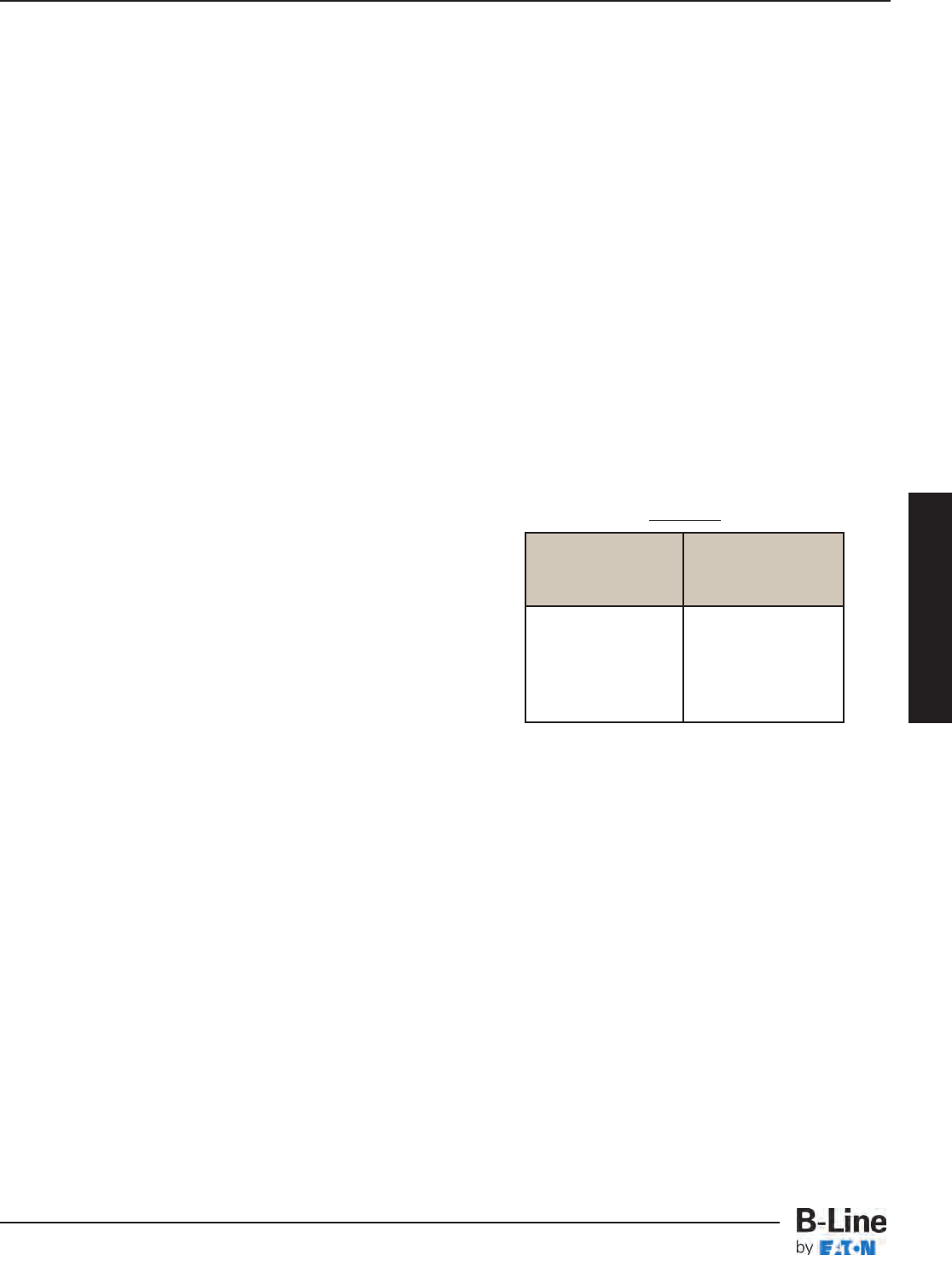
Cable Tray Selection
Allowable Cable Fill
For allowable cable types see the Appendix page 383.
The following guidelines are based on the 2002 National Electrical Code, Article 392.
I) Number of Multiconductor Cables rated 2000 volts or less in the Cable Tray
(1) 4/0 or Larger Cables
The ladder cable tray must have an inside available width equal to or greater than the sum of the
diameters (Sd) of the cables, which must be installed in a single layer. When using solid bottom
cable tray, the sum of the cable diameters is not to exceed 90% of the available cable tray width.
Example: Cable Tray width is obtained as follows:
List (D) (N) Multiply (D) x (N) = Subtotal
Cable Sizes List Cable List Number of the Sum of the
Outside Diameter of Cables Cable Diameters
3/C - #500 kcmil 2.26 inches 1 2.26 inches
3/C - #250 kcmil 1.76 inches 2 3.52 inches
3/C - #4/0 AWG 1.55 inches 4 6.20 inches
The sum of the diameters (Sd) of all cables = 2.26 + 3.52 + 6.20 = 11.98 inches; therefore
a cable tray with an available width of at least 12 inches is required.
(2) Cables Smaller Than 4/0
The total sum of the cross-sectional areas of all
the cables to be installed in the cable tray must be
equal to or less than the allowable cable area for
the tray width, as indicated in Table 5.
When using solid bottom cable tray, the allowable
cable area is reduced by 22%.
Example: The cable tray width is obtained as follows:
(A) (N) Multiply (A) x (N) + Total
List List Cable Cross List Number of the Cross-Sectional
Cable Sizes Sectional Areas of Cables Area for each Size
3/C - #12 AWG 0.167 sq. in. 10 1.67 sq. in.
4/C - #12 AWG 0.190 sq. in. 8 1.52 sq. in.
3/C - # 6 AWG 0.430 sq. in. 6 2.58 sq. in.
3/C - # 2 AWG 0.800 sq. in. 9 7.20 sq. in.
The sum of the total areas is 1.67 + 1.52 + 2.58 + 7.20 = 12.97 inches.
Using Table 4, a 12-inch wide tray with an allowable cable area of 14 sq. inches should be used.
Note: Increasing the cable tray loading depth does not permit an increase in allowable cable area
for power and lighting cables. The maximum allowable cable area for all cable tray with a 3
inch or greater loading depth is limited to the allowable cable area for a 3 inch loading depth.
(3) 4/0 or Larger Cables Installed with Cables Smaller than 4/0
The ladder cable tray needs to be divided into two zones (a barrier or divider is not required but
one can be used if desired) so that the No. 4/0 and larger cables have a dedicated zone, as
they are to be placed in a single layer. continued on CTS-18
Inside Width Allowable
of Cable Tray Cable Area
inches square inches
6 7.0
9 10.5
12 14.0
18 21.0
24 28.0
Table 5
CTS-17
Cable Tray Selection - Width and Available Loading Depth
Cable Tray Systems
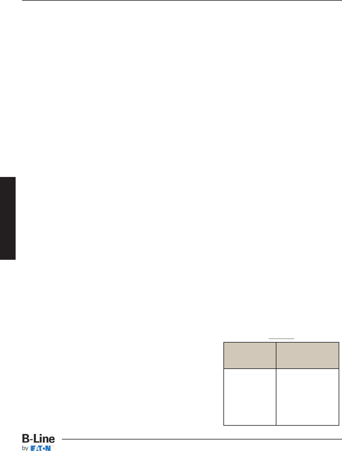
Allowable Cable Fill
Cable Tray Selection
A direct method to determine the correct cable tray width is to figure the cable tray widths
required for each of the cable combinations per steps (2) & (3).
Then add the widths in order to select the proper cable tray width.
Example: The cable tray width is obtained as follows:
Part A- Width required for #4/0 AWG and larger multiconductor cables
(D) (N) Multiply (D) x (N) = Subtotal
List List Cable List Number of the Sum of the
Cable Size Outside Diameter of Cables Cable Diameters (Sd)
3/C - #500 kcmil 2.26 inches 1 2.26 inches
3/C - #4/0 AGW 1.55 inches 2 3.10 inches
Cable tray width (inches) required for large cables = 2.26 + 3.10 = 5.36 inches.
Part B- Width required for multiconductor cables smaller than #4/0 AWG
(A) (N) Multiply (A) x (N) = Total
List List Cable Cross List Number of the Cross-Sectional
Cable Sizes Sectional Areas of Cables Area for each Size
3/C - #12 AWG 0.167 sq. in. 10 1.67 sq. in.
3/C - #6 AWG 0.430 sq. in. 8 3.44 sq. in.
3/C - #2 AWG 0.800 sq. in. 2 1.60 sq. in.
The sum of the total areas (inches) = 1.67 + 3.44 + 1.60 = 6.71 sq. inches.
From Table 5 (page 33), the cable tray width required for small cables is 6 inches.
The total cable tray width (inches) = 5.36 + 6.00 = 11.36 inches. A 12-inch wide
cable tray is required.
(4) Multiconductor Control and/or Signal Cables Only
A ladder cable tray containing only control and/or signal cables, may have 50% of its total
available cable area filled with cable. When using solid bottom cable tray pans, the allowable
cable area is reduced from 50% to 40%.
Example: Cable tray width is obtained as follows:
2/C- #16 AWG instrumentation cable cross sectional area = 0.04 sq. in.
Total cross sectional area for 300 Cables = 12.00 sq. in.
Minimum available cable area needed = 12.00 x 2 = 24.00 sq. in.; therefore the cable tray
width required for 4 inch available loading depth tray = 24.00/4 = 6 inches.
II) Number of Single Conductor Cables Rated
2000 Volts or Less in the Cable Tray
All single conductor cables to be installed in the cable tray
must be 1/0 or larger, and are not to be installed with
continuous bottom pans.
(1) 1000 KCMIL or Larger Cables
The sum of the diameters (Sd) for all single conductor
cables to be installed shall not exceed the cable
tray width. See Table 6.
Inside Width Allowable
of Cable Tray Cable Area
inches square inches
6 6.50
9 9.50
12 13.00
18 19.50
24 26.00
30 32.50
36 39.00
Table 6
CTS-18
Cable Tray Selection - Width and Available Loading Depth
Cable Tray Systems
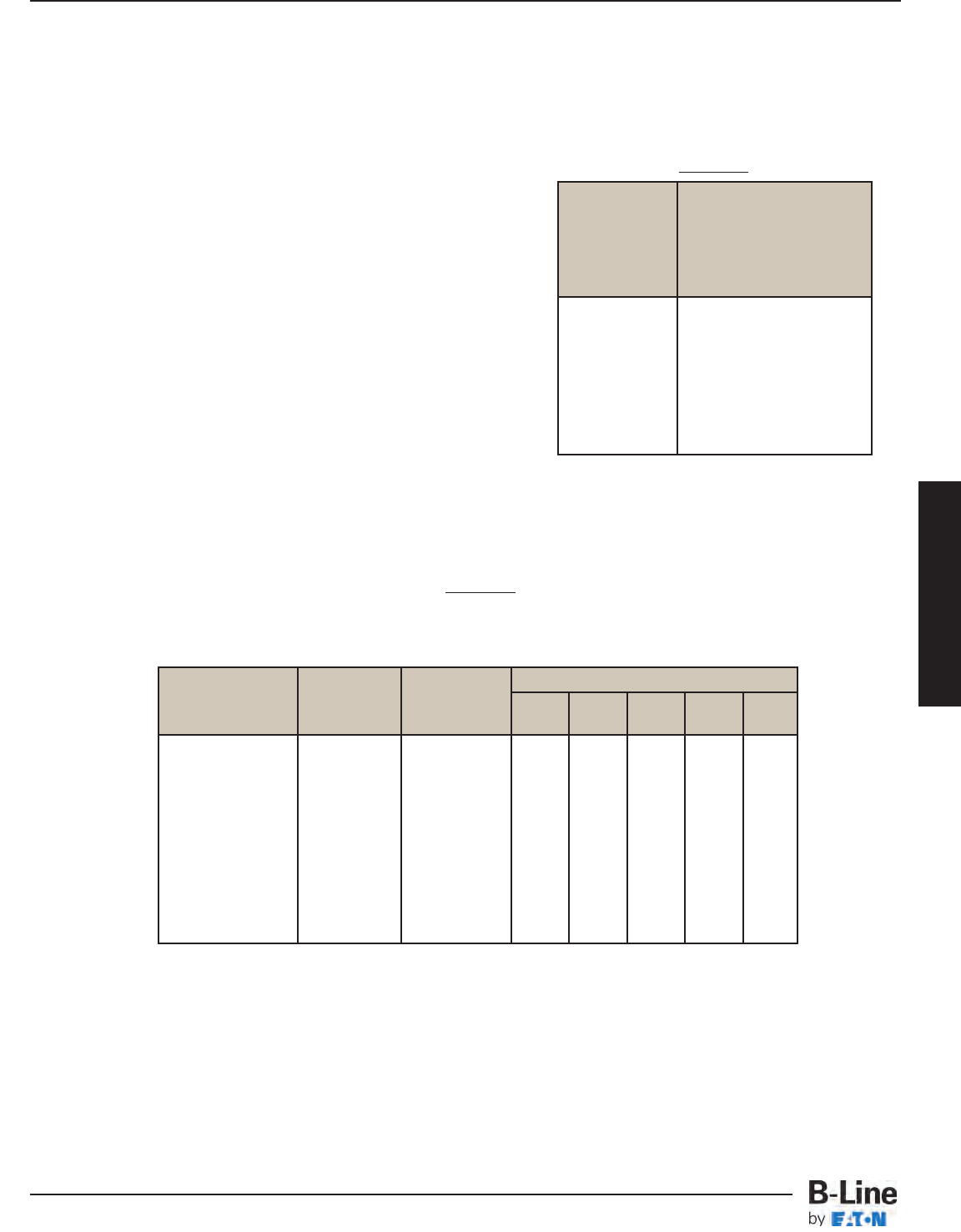
Allowable Cable Fill
Cable Tray Selection
(2) 250 KCMIL to 1000 KCMIL Cables
The total sum of the cross-sectional areas of all the single conductor cables to be installed in the
cable tray must be equal to or less than the allowable cable area for the tray width, as indicated
in Table 6 (page 34). (Reference Table 8)
(3) 1000 KCMIL or Larger Cables Installed with
Cables Smaller Than 1000 KCMIL
The total sum of the cross-sectional areas of all
the single conductor cables to be installed in
the cable tray must be equal to or less than the
allowable cable area for the tray width, as
indicated in Table 7.
(4) Single Conductor Cables 1/0 through 4/0
These single conductors must be installed in a
single layer. See Table 8.
Note: It is the opinion of some that this practice may
cause problems with unbalanced voltages. To avoid
these potential problems, the individual conductors for this type of cable tray wiring system should
be bundled with ties. The bundle should contain all of the three-phase conductors for the circuit,
plus the neutral if used. The single conductor cables bundle should be firmly tied to the cable tray
assembly at least every 6 feet.
Table 8
Number of 600 Volt Single Conductor Cables
That May Be Installed in Ladder Cable Tray
Cable diameters used are those for Oknite-Okolon 600 volt single conductor power cables.
III) Number of Type MV and MC Cables
Rated 2001 Volts or Over in the Cable Tray
The sum of the diameters (Sd) of all cables, rated 2001 volts or over, is not to exceed the cable
tray width.
Inside Allowable
Width Cable
of Cable Area
Tray
inches square inches
6 6.50 - (1.1 Sd)
9 9.50 - (1.1 Sd)
12 13.00 - (1.1 Sd)
18 19.50 - (1.1 Sd)
24 26.00 - (1.1 Sd)
30 32.50 - (1.1 Sd)
36 39.00 - (1.1 Sd)
Table 7
Single Outside Area Cable Tray Width
Conductor Diameter 6912 18 24
Size in. sq. in. in. in. in. in. in.
1/0 0.58 - 10 15 20 31 41
2/0 0.62 -914 19 29 38
3/0 0.68 -813 17 26 35
4/0 0.73 -812 16 24 32
250 Kcmil 0.84 .55 11 18 24 35 47
350 Kcmil 0.94 .69 9 14 19 28 38
500 Kcmil 1.07 .90 7 11 14 22 29
750 Kcmil 1.28 1.29 5810 15 20
1000 Kcmil 1.45 -46812 16
CTS-19
Cable Tray Selection - Width and Available Loading Depth
Cable Tray Systems
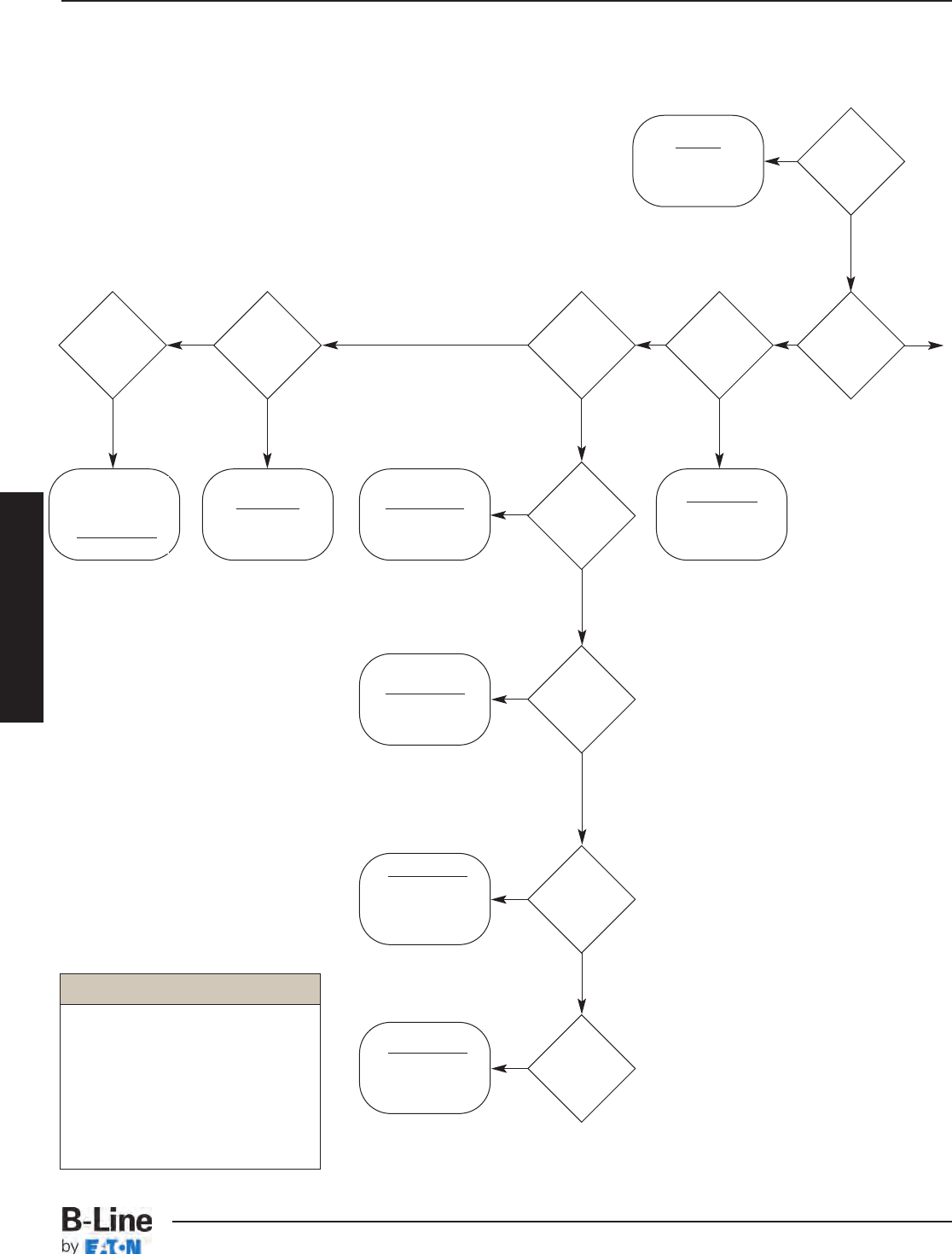
Sizing Cable Tray Per 2002 NEC 392
392.12
W ≥ Sd
(single layer)
392.3(B)(1)
Not recognized
by the NEC®
See
Exception
392.11(B)(3)
392.10(B)
W ≥ Sd
392.10(A)(1)
W ≥ Sd
392.10(A)(2)
W ≥ A/1.1
Note: The value “A”
only applies to cables
250 up to 1000 kcmil.
The value “Sd” only
applies to 1000 kcmil
and larger cables.
Note: Use when mixing
250 thru 1000 kcmil
cables with cables
larger than 1000 kcmil.
392.10(A)(3)
392.10(A)(4)
W ≥ Sd
(9” max. RS)
2000V
or less
cables
Multi-
conductor
cables
S/C 1/0
or larger
Ladder
or Vented
Trough
Tray
S/C
1000
kcmil or
larger
S/C
250
kcmil up
to 1000
kcmil
S/C
250 kcmil
and
larger
S/C 1/0
thru 4/0
Vented
Channel
Tray
Solid
Bottom
Tray
W ≥ A/1.1 +Sd
No
No
No
No
No No No
No
Yes
Yes
Yes
Yes
YesYes Yes
Yes
Yes
Continued
on following
page
Yes
Legend
W = Cable Tray Width
D = Cable Tray Load Depth
Sd = Sum of Cable Diameters
A = Sum of Cable Areas
S/C = Single Conductor
M/C = Multiconductor Cables
RS = Ladder Rung Spacing
Start
Here
Cable Tray Selection
CTS-20
Cable Tray Selection - Width and Available Loading Depth
Cable Tray Systems
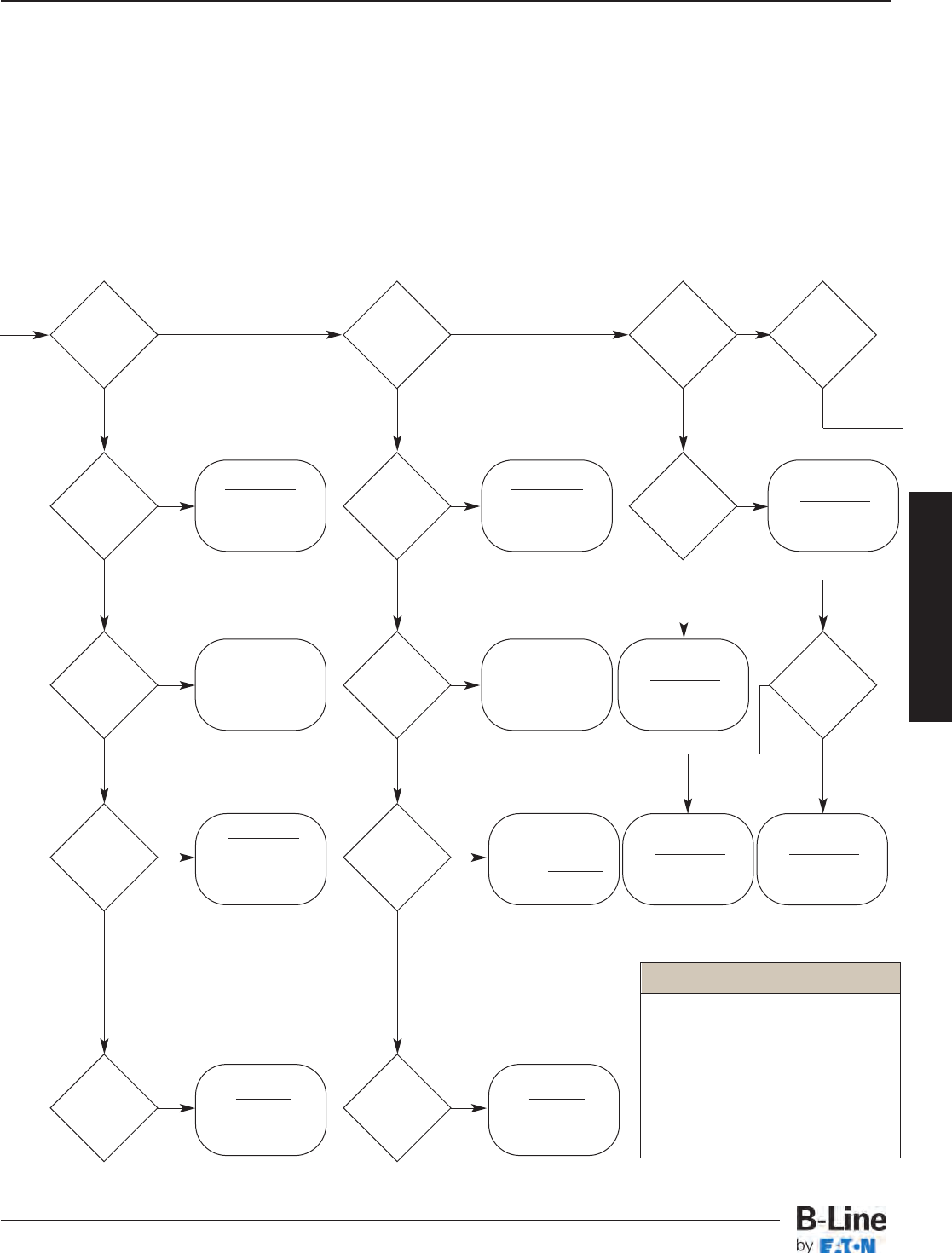
Note: See appendix on page APP-15 for additional information regarding
cable ampacity and hazardous (classified) location requirements which might
affect the cable tray sizing flow chart.
392.9(E)(1)
W x D ≥ 1.6A
392.9(A)(1)
W ≥ Sd
(single layer)
392.9(C)(1)
W ≥ Sd/0.9
(single layer)
Note: The value “A”
only applies to cables
smaller than 4/0.
The value “Sd” only
applies to 4/0 and
larger cables, which
must be single layer.
Note: The value “A”
only applies to cables
smaller than 4/0.
The value “Sd” only
applies to 4/0 and
larger cables, which
must be single layer.
392.9(A)(3)
Vented
Channel
Tray
Solid
Channel
Tray
Solid
Bottom
Tray
Ladder
or Vented
Trough
Tray
One M/C
only
M/C 4/0
or larger
M/C 4/0
or larger
392.9(E)(2)
W x D ≥ 2.9A
392.9(F)(1)
W x D ≥ 1.9A
392.9(A)(2)
W ≥ A/1.2
392.9(C)(2)
W ≥ A/0.9
M/C
smaller
than 4/0
M/C
smaller
than 4/0
M/C
smaller than
4/0, with 4/0
or
larger
M/C
control
and/or
signal
W ≥ A/1.2 + Sd
No NoNo
NoNo
NoNo
No No No
392.9(B)
W x D ≥ 2A
392.9(C)(3)
A + Sd
0.9
M/C
smaller than
4/0, with 4/0
or
larger
M/C
control
and/or
signal
W ≥
392.9(D)
W x D ≥ 2.5A
YesYes
YesYes
YesYes
YesYes
Yes
Yes Yes Yes
Yes
Legend
W = Cable Tray Width
D = Cable Tray Load Depth
Sd = Sum of Cable Diameters
A = Sum of Cable Areas
S/C = Single Conductor
M/C = Multiconductor Cables
RS = Ladder Rung Spacing
One M/C
only
No
392.9(F)(2)
W x D ≥ 3.2A
Yes
Continued
from previous
page
Cable Tray Selection
CTS-21
Cable Tray Selection - Width and Available Loading Depth
Cable Tray Systems
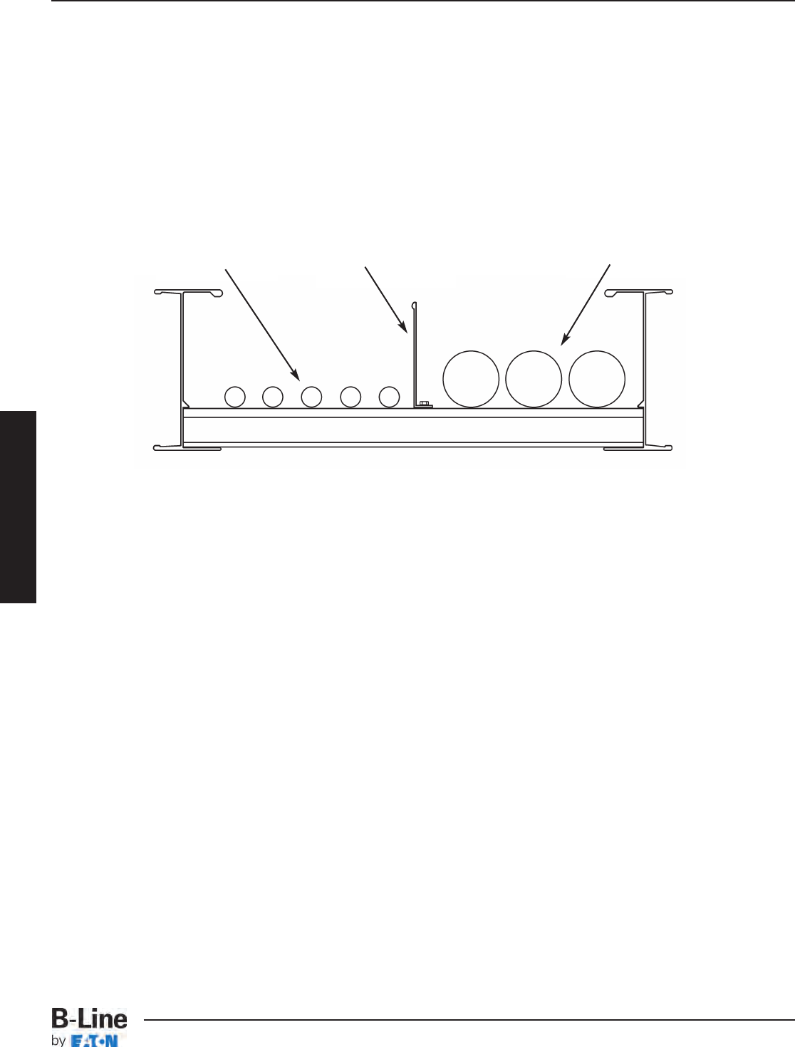
Barrier Requirements
Barrier strips are used to separate cable systems, such as when cables above
and below 600
volts per NEC 392.6(F) are installed in the same cable tray.
However, when MC type cables
rated over 600 volts are installed in the same cable tray with cables rated 600 volts or less, no
barriers are required. The barriers should be made of the same material type as the cable tray.
When ordering the barrier, the height must match the loading depth of the cable tray into which
it is being installed.
Future Expansion Requirements
One of the many features of cable tray is the ease of adding cables to an existing system. Future
expansion should always be considered when selecting a cable tray, and allowance should be
made for additional fill area and load capacity. A minimum of 50% expansion allowance is
recommended.
Space Limitations
Any obstacles which could interfere with a cable tray installation should be considered when
selecting a cable tray width and height. Adequate clearances should be allowed for installation of
supports and for cable accessibility.
Note: The overall cable tray dimensions typically exceed the nominal tray width and loading depth.
300 & 600
Volt Cables
Fixed Solid Barrier
Comparable Material
Cables Rated
Over 600 Volts
Cable Tray Selection
CTS-22
Cable Tray Selection - Width and Available Loading Depth
Cable Tray Systems

Cable Tray Selection
Lengths Available
The current Cable Tray Standard, NEMA VE 1 and C22.2 No. 126.1-98, lists typical lengths as
3000 mm (10 ft), 3660 mm (12 ft), 6000 mm (20 ft), and 7320 mm (24 ft). It is impractical to
manufacture either lighter systems in the longer lengths or heavier systems in the shorter lengths.
For that reason, B-Line has introduced a primary and secondary length for each system.
These straight section lengths were selected to direct the user to lengths that best suit support
span demands and practical loading requirements. The primary length is the one that is the most
appropriate for the strength of the system and that will provide the fastest service levels. The
secondary lengths will be made available to service additional requirements. Special lengths are
available with extended lead times.
Support Span
Per the NEMA VE 2, the support span on which a cable tray is installed should not exceed the
length of the unspliced straight section. Thus installations with support spans greater than 12 feet
should use 240" (20 feet) or 288" (24 feet) cable tray lengths.
Space Limitations
Consideration should be given to the space available for moving the cable tray from delivery to it’s
final installation location. Obviously, shorter cable tray allows for more maneuverability in tight
spaces.
Installation
Shorter cable tray lengths are typically easier to maneuver on the job site during installation. Two
people may be needed to manipulate longer cable tray sections, while shorter sections might be
handled by one person. Although longer cable tray lengths are more difficult to maneuver, they
can reduce installation time due to the fact that there are fewer splice connections. This trade-off
should be evaluated for each set of job site restrictions.
CTS-23
Cable Tray Selection - Length
Cable Tray Systems
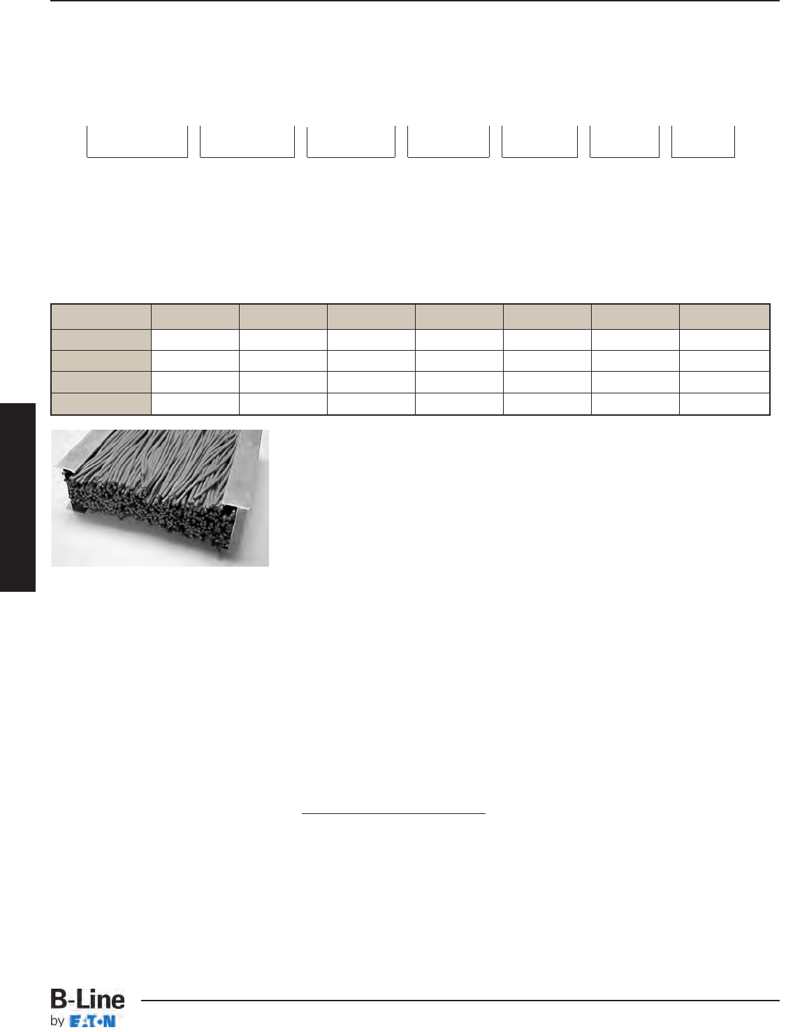
36" Wide 30" Wide 24" Wide 18" Wide 12" Wide 9" Wide 6" Wide
6" Fill 81 64 52 41 27 20 14
5" Fill 68 53 43 34 23 17 12
4" Fill 54 43 35 27 18 13 9
3" Fill 41 32 26 21 14 10 7
Data/Communication Cabling:
Low voltage cables can be stacked as there is no heat generation problems. The NEC employs a calculation
of the total cross sectional area of the cables not exceeding 50% of the fill area of the cable tray. As the
cable fill area of the cable tray system affects the possible loading, both the loading depth and width of the
systems must be considered. For this example 4UTP category 5 cable (O.D. = .21, .026 lbs./ft.) were used.
Calculated Cable Weight in Lbs/Ft
The picture shows a 12" cable tray with a 3" load depth. The tray contains
520 4 UTP Category 5 cables with a .21" diameter.
The National Electrical Code allows for 50% fill of ventilated and ladder
cable tray for control or signal wiring (Article 392.9(B)). ANSI/EIA/TIA 569-A
Section 4.5* also requires that the fill ratio of cable tray is not to exceed
50%.
Calculation Tray Area = 12 in. x 3 in. = 36 sq. in.
Example: 50% Fill = 36 sq. in. x .5 = 18 sq. in.
Cable Area = (.21 in.)2x 3.14/4 = .0346 sq. in.
Number of Cables = 18 sq. in. / .0346 sq. in. = 520 cables
*Section 4.5 is currently under review.
Cable Tray Selection
Other Factors To Consider
• Support Span - The distance between the supports
affects the loading capabilities exponentially. To
calculate loading values not cataloged use:
• Other Loads - Ice, wind, snow for outdoor systems see page 26 and 27 for information.
A 200 lb. concentrated load for industrial systems. The affect of a concentrated load can be calculated
as follows 2 x (concentrated static load)
span in feet
When considering concentrated loads the rung strength should be considered.
• Length Of The Straight Sections:
The VE 2, Cable Tray Installation Guide, states that the
support span shall not be greater than the straight section
length. If a 20C system is manufactured in 12 foot sections
the greatest span for supports would be 12 feet. This
dramatically affects the loading of the system.
W1L12= W2L22
W1- tested loading
L1- span in feet, a tested span
W2- loading in question
L2- known span for new loading
W1L12= W2L22
100 (202) = W2(122)
40,000 = 144 W2
W2= 277 lbs. per foot
Power Application:
Power application can create the heaviest loading. The heaviest cable combination found was for large
diameter cables (i.e. steel armor, 600V, 4 conductor 750 kcmil). The cables weigh less than 3.8 lbs. per inch
width of cable tray. As power cables are installed in a single layer, the width of the cable affects the
possible loading.
36" Wide
140 lbs/ft
30" Wide
115 lbs/ft
24" Wide
90 lbs/ft
18" Wide
70 lbs/ft
12" Wide
45 lbs/ft
9" Wide
35 lbs/ft
6" Wide
23 lbs/ft
CTS-24
Cable Tray Selection - Loading Possibilities
Cable Tray Systems

Cable Tray Selection
Type of Cable
According to NEC Article 392, multiconductor tray cable may be installed in any standard cable
tray bottom type. According to the 2005 NEC Article 392.11(8)(3), single conductor tray cable may
be installed in any standard cable tray bottom type. Solid bottom cable trays are not allowed to
be installed in Class II, Division 2 locations (2002 NEC Section 502.4(B)). In general, small, highly
flexible cables should be installed in solid bottom, vented bottom or 6" rung spacing ladder type
cable trays. Sensitive cables (e.g. fiberoptic) are typically installed in flat, solid bottom cable trays,
instead of corrugated trough bottoms. Larger, less flexible cables are typically installed in ladder
type cable trays having 9" or 12" rung spacing. Ladder type cable trays having 18" rung spacing
should be used for large, stiff cables to reduce cost and facilitate cable drop-outs.
Cost vs Strength
Often more than one bottom type is acceptable. In this case the economic difference should
be considered. Ladder cable trays have a lower cost than either non-ventilated or ventilated
bottom configurations. Typically, the cost of ladder type cable tray decreases as rung spacing
increases. However, the effect of rung spacing on load capacity for ladder type cable trays with
18" rung spacing should be evaluated, since NEMA published load capacities are based on 12"
rung spacing. Rung spacing can affect individual rung and side rail loading as well as system load
capacity. Rung loads applied during cable installation
should also be considered.
Cable Exposure
Tray cables are manufactured to withstand the environment without additional protection, favoring
the use of the ladder type cable tray. Some areas may benefit from the limited exposure of solid
or vented bottom cable tray. Solid Bottom metal cable tray with solid metal covers can be utilized
in other spaces used for environmental air to support non plenum rated tray cables (2002 NEC®
300.22(C)(1)).
Cable Attachment
The major advantage of ladder type cable tray is the freedom of entry and exit of the cables.
Another advantage of ladder type cable tray is the ability to secure cables in the cable tray. With
standard rungs the cables may be attached with either cable ties or cable clamps. The ladder
type cable tray is also available with special purpose, slotted marine or strut rungs to facilitate
banding or clamping cables. Cable attachment is particularly important on vertical runs or when
the tray is installed on its side. Ladder rung spacing should be chosen to provide adequate cable
attachment points while allowing the cables to exit the system.
Cable Flexibility
The proper bend radius for cable tray fittings is usually determined by the bend radius and
stiffness of the tray cables to be installed. Typically, the tray cable manufacturer will recommend
a minimum bend allowance for each cable. The fitting radius should be equal to or larger than
the minimum bend radius of the largest cable which may ever be installed in the system. When
several cables are to be installed in the same cable tray, a larger bend radius may be desirable to
ease cable installation.
Space Limitations
The overall dimensions for a cable tray fitting will increase as the bend radius increases. Size and
cost make the smallest acceptable fitting radius most desirable. When large radius fittings are
required, the system layout must be designed to allow adequate space.
Cable Tray Selection - Fitting Radius
CTS-25
Cable Tray Selection - Bottom Type
Cable Tray Systems
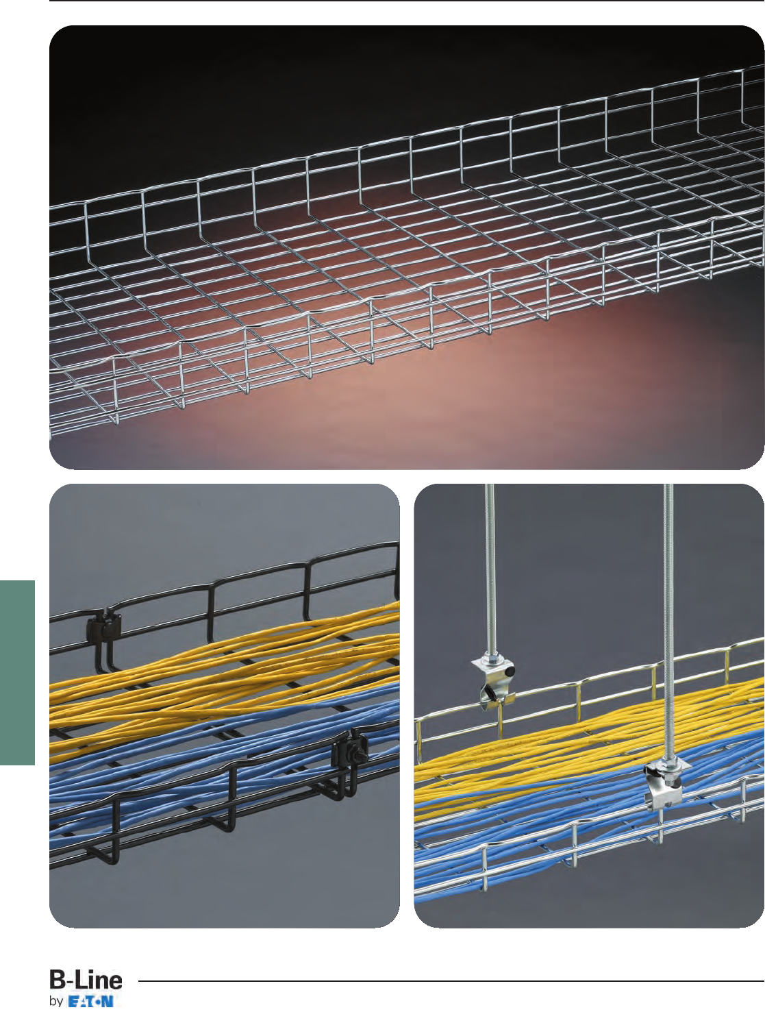
FLEXTRAY
FLX-1
FLEXTRAY™
Cable Tray Systems
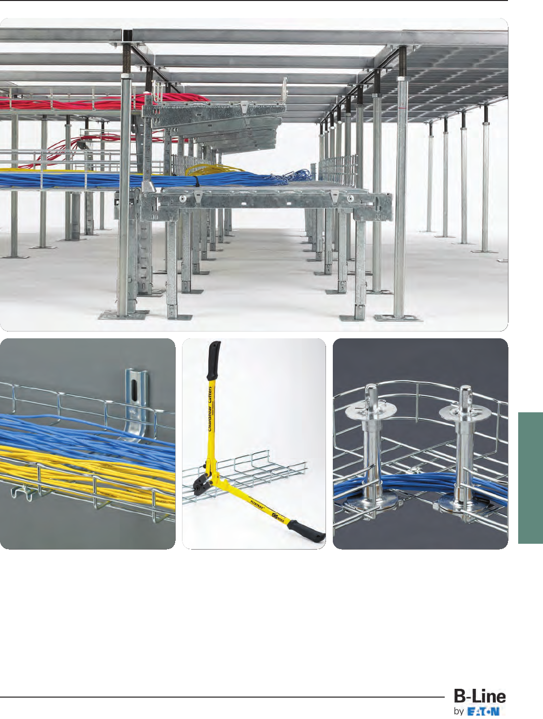
FLEXTRAY
Flextray is a flexible, field-adaptable way to manage cables throughout your project. The tray itself can be cut
and bent to the needs of the installer on the jobsite, allowing cable runs to be adjusted as needed. The wide
range of sizes offered by B-Line makes Flextray a great choice for everything from a small cable drop to a large
trunk of cables. Our tray has the market-preferred "T" weld safety edge, protecting both the cable and the
installer during cable installation. Flextray is also UL Classified as an equipment grounding conductor.
The F.A.S.T.™System is Foldable, Adjustable, Stackable, and Tool-less, providing many options to manage
cables inside your raised floor space. With only a few parts, you can create everything from a basic single
layer installation to a cantilevered, multiple-tier cable run. Make the most of your raised floor space and your
time with the F.A.S.T. System!
FLX-2
FLEXTRAY™
Cable Tray Systems

FLEXTRAY
Finish Information
Flextray Cable Tray and Accessories are available in a wide variety of finishes to meet the
environmental or aesthetic requirements of customer installations. Use the list below to find the
finish and suffix that will meet your needs.
Available product finishes will be listed on individual pages throughout the catalog.
Finish codes shown in bold type are the standard for that product.
Plain wire: ASTM A510, Grade 1008
EG Electroplated Zinc Galvanized Finish applied after fabrication
(ELG) Recommended applications: Controlled interior
UL/CSA Classified as an equipment ground conductor when spliced as recommended
ASTM B633 - Average thickness of 0.3 mils (8 microns)
GS Pre-Galvanized Zinc Finish applied before fabrication
(GLV) Recommended applications: Limited industrial & interior
UL/CSA Classified as an equipment ground conductor when spliced as recommended
ASTM A641
BLE Black Powder Coat Finish applied after fabrication
Recommended applications: Controlled interior
UL/CSA Classified as an equipment ground conductor when coating has been
removed at splice contact points
Average paint thickness of 1.2 mils (30 microns) to 3.0 mils (75 microns)
HD Hot Dip Galvanized Finish applied after fabrication
(HDG) Recommended applications: Exterior, corrosive. Not intended for clean room applications.
UL/CSA Classified as an equipment ground conductor when spliced as recommended
ASTM A123 - Average thickness of 2.4 mils (60 microns) to 3.2 mils (80 microns)
304S 304L Stainless Steel
(SS4) Recommended applications: Food preparation, wash-down areas
ASTM A580
316S 316L Stainless Steel
(SS6) Recommended applications: Highly corrosive applications & marine environments
ASTM A580
Custom Powder Coat Finish applied after fabrication
Recommended applications: Controlled interior
UL/CSA Classified as an equipment ground conductor when coating has been
removed at splice contact points
No Specification
Grounding Information
Statement for all UL Classified products:
This product is classified by Underwriters Laboratories, Inc. as to its
suitability as an equipment grounding conductor only. 556E
Most sizes of FLEXTRAY are UL Classified to serve as an Equipment Ground Conductor. The ground
path can be achieved in one of two ways listed on page FLX-4:
FLX-3
FLEXTRAY™- Technical Data
Cable Tray Systems
FLEXTRAY
FLEXTRAY Series Support Span / Loading Capacity* Cable Fill (50% fill)**
Part Size Lbs/Ft (max) Actual Area Inside Number of CAT Number of
Number height x width 5'-0” 6'-0” 7'-0” 8'-0” Tray (in2) 5e Cables*** CAT 6 Cables***
FT1.5X12 11/2” x 12” 29 17 14 11 12.2 176 124
FT2X2 2” x 2” 34 28 24 20 4.3 61 43
FT2X4 2” x 4” 52 43 35 27 8.2 118 83
FT2X6 2” x 6” 66 47 35 27 12.1 175 123
FT2X8 2” x 8” 66 47 35 27 16.1 231 163
FT2X12 2” x 12” 68 47 35 27 23.9 345 243
FT2X16 2” x 16” 68 47 35 27 31.8 459 324
FT2X18 2” x 18” 68 47 35 27 35.8 516 364
FT2X20 2” x 20” 68 47 35 27 39.7 573 404
FT2X24 2” x 24” 68 47 35 27 47.5 686 484
FT2X30 2” x 30” 68 47 35 27 59.8 862 608
FT2X32 2” x 32” 77 53 39 30 63.3 914 645
FT4X4 4” x 4” 58 49 42 36 15.8 227 160
FT4X6 4” x 6” 93 77 60 46 23.6 341 240
FT4X8 4” x 8” 94 78 61 47 31.5 454 321
FT4X12 4” x 12” 119 83 61 47 47.5 686 484
FT4X16 4” x 16” 119 83 61 47 63.5 917 647
FT4X18 4” x 18” 119 83 61 47 71.5 1032 728
FT4X20 4” x 20” 119 83 61 47 79.5 1148 810
FT4X24 4” x 24” 128 89 65 50 95.5 1379 973
FT4X30 4” x 30” 128 89 65 50 119.5 1725 1217
FT6X8 6” x 8” 111 77 57 43 47.3 682 481
FT6X12 6” x 12” 124 86 63 48 71.6 1034 729
FT6X16 6” x 16” 128 89 65 50 95.3 1375 970
FT6X18 6” x 18” 128 89 65 50 107.3 1549 1092
FT6X20 6” x 20” 141 98 72 55 118.9 1716 1211
FT6X24 6” x 24” 154 107 78 60 143.3 2068 1459
Grounding Information (cont.)
Load & Fill Chart
*Published load chart has not been tested with Flexmate splice. Please consult the factory for load information when using the
Flexmate option.
** FLEXTRAY fill capacity is based on NEC allowable fill of 50%. The NEC rule requires that the cable cross-sectional areas together
may not exceed 50% of the tray area (width x depth = fill). Cables will nearly completely fill the cable tray when reaching the
50% cable fill, due to empty space between the surface of the cables. TIA recommends 40% fill ratio. Flextray loads shown in
the loading chart will not be exceeded at 50% fill.
*** CAT 5e 4-pr non-plenum approximated at .21 in. diameter, CAT 6 4-pr non-plenum approximated at .25 in. diameter. Actual
diameters vary by cable manufacturer.
1. Use the recommended quantity of UL Classified splices to connect sections and at
places where the tray is cut.
2. Run an appropriately sized ground wire alongside the tray and attach it to each tray
section and on both sides of a cut in the tray. (This method is recommended by
NEMA VE-2 Installation Manual.)
FLX-4
FLEXTRAY™- Technical Data
Cable Tray Systems
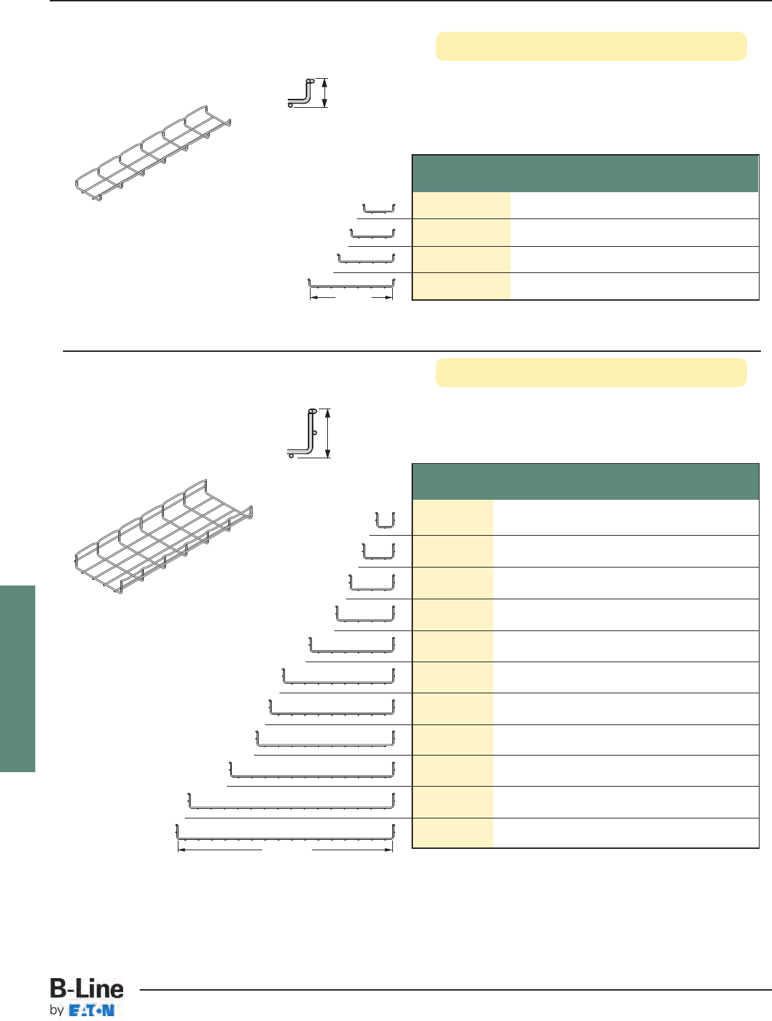
FLEXTRAY
See page FLX-3 for finish information
Part Width Wt. Per Pc.
Number in. mm lbs. kg
FT2X2X10 250 6.6 2.99
FT2X4X10 4100 8.2 3.72
FT2X6X10 6150 9.7 4.40
FT2X8X10 8200 11.2 5.08
FT2X12X10 12 300 14.3 6.48
FT2X16X10 16 400 17.4 7.89
FT2X18X10 18 450 18.9 8.57
FT2X20X10 20 500 20.4 9.25
FT2X24X10 24 600 23.5 10.66
FT2X30X10 30 750 28.1 12.74
FT2X32X10 32 800 29.7 13.47
2” Deep FLEXTRAY
Height: 2.38" (60 mm)
Length: 118.312" (3 meter)
Wire Dia. Minimum: .196" (5.0 mm)
Finishes:
EG, GS, BLE, HD, 304S, 316S
2.38" (60 mm)
Part Width Wt. Per Pc.
Number in. mm lbs. kg
FT1.5X4X10 4 100 5.8 2.63
FT1.5X6X10 6 150 7.4 3.35
FT1.5X8X10 8 200 9.0 4.08
FT1.5X12X10 12 300 12.1 5.49
1.5” Deep FLEXTRAY
Width
Height: 1.38" (35 mm)
Length: 118.312" (3 meter)
Wire Dia. Minimum: .196" (5.0 mm)
Finishes:
EG, GS, BLE, HD, 304S, 316S
1.38" (35 mm)
Width
Only FT1.5X12 (12” wide) is UL Classified
FT2X6 (6” wide) through FT2X32 (32” wide) are UL Classified
FLX-5
FLEXTRAY™- Straight Sections
Cable Tray Systems
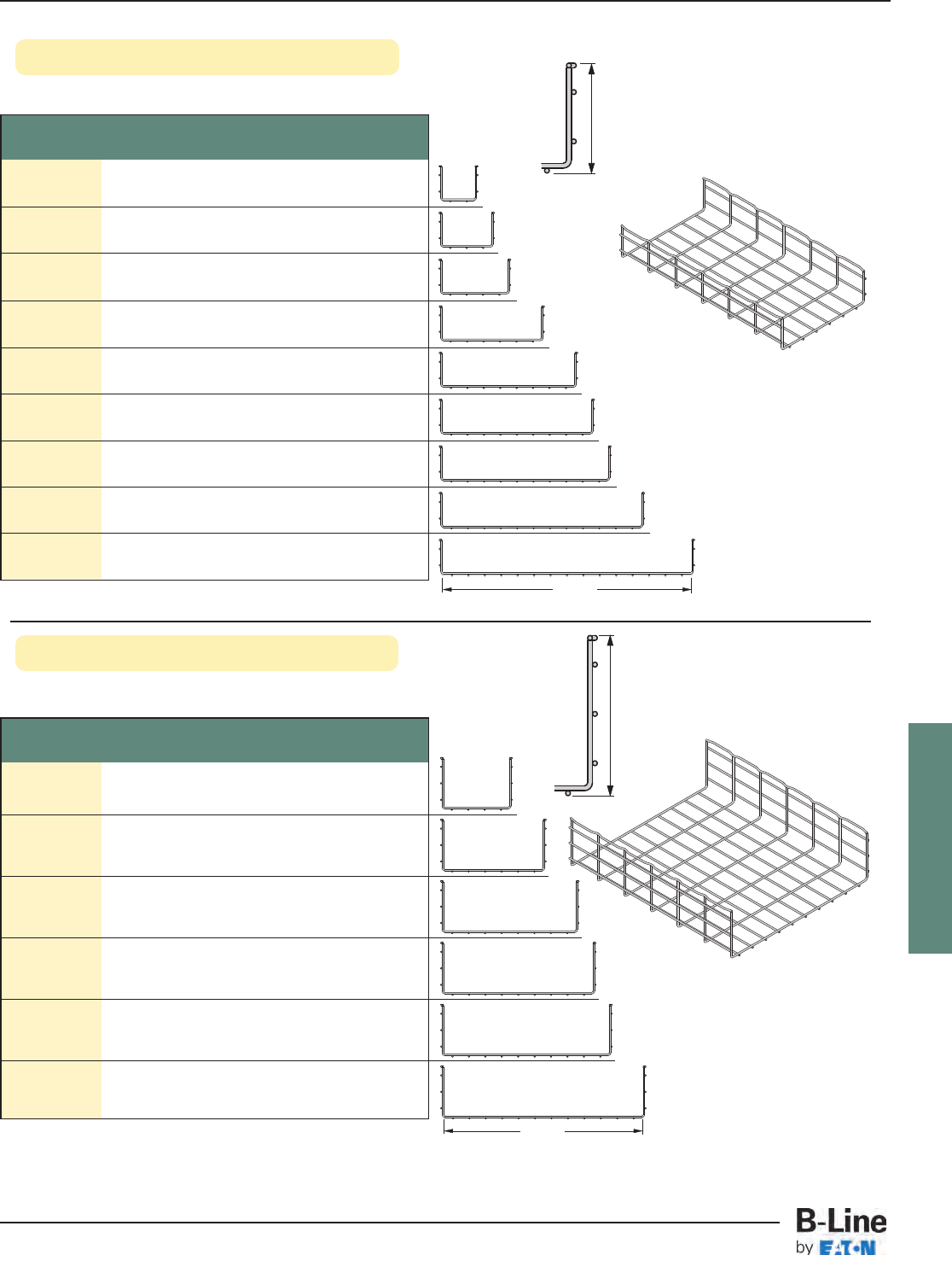
FLEXTRAY
See page FLX-3 for finish information
6” Deep FLEXTRAY
6.38"
(162 mm)
4” Deep FLEXTRAY
Height: 4.38" (111 mm)
Length: 118.312" (3 meter)
Wire Diameter Minimum:
.196" (5.0 mm)
Finishes:
EG, GS, BLE, HD,
304S, 316S
Part Width Wt. Per Pc.
Number in. mm lbs. kg
FT4X4X10 4 100 11.25 5.10
FT4X6X10 6 150 12.79 5.80
FT4X8X10 8 200 14.32 6.49
FT4X12X10 12 300 17.39 7.89
FT4X16X10 16 400 20.45 9.27
FT4X18X10 18 450 21.99 9.97
FT4X20X10 20 500 23.52 10.67
FT4X24X10 24 600 26.59 12.06
FT4X30X10 30 750 31.19 14.15
4.38"
(111 mm)
Width
Height: 6.38" (162 mm)
Length: 118.312" (3 meter)
Wire Diameter Minimum:
.196" (5.0 mm)
Finishes:
EG, GS, BLE, HD,
304S, 316S
Part Width Wt. Per Pc.
Number in. mm lbs. kg
FT6X8X10 8 200 17.39 7.89
FT6X12X10 12 300 20.45 9.27
FT6X16X10 16 400 23.52 10.67
FT6X18X10 18 450 25.06 11.37
FT6X20X10 20 500 26.59 12.06
FT6X24X10 24 600 29.66 13.45
Width
All 6” deep Flextrays are UL Classified
All 4” deep Flextrays are UL Classified
FLX-6
FLEXTRAY™- Straight Sections
Cable Tray Systems
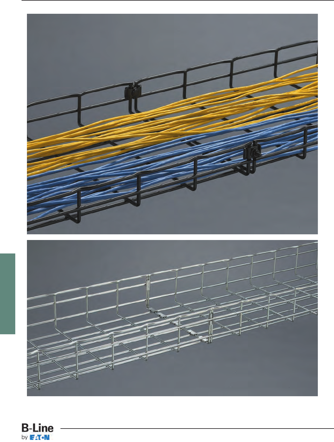
FLEXTRAY
FLX-7
FLEXTRAY™- Splicing Accessories
Cable Tray Systems
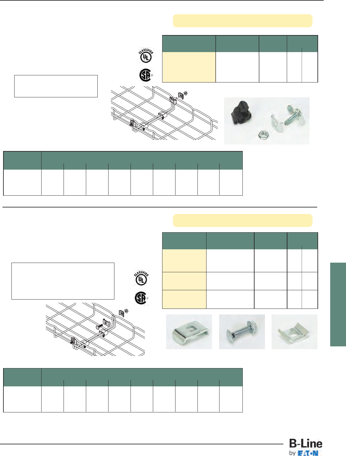
FLEXTRAY
Splice Hardware Components
Washer Splice Kit
See page FLX-3 for finish and grounding information
Part Description Qty./Box Wt./Box
Number lbs. kg
WASHER SPL KIT__ Assembly of 50 4.5 2.04
Staked Washer
Stud/Washer
& Finned Nut
• Washer is staked to bolt, holding part stationary
during installation
• Fewer parts to handle
• For use with all tray widths and sizes
• Finishes __: EG, BLE
Part Description Qty./Box Wt./Box
Number lbs. kg
1/4” x 1”
FTHDWE 1/4__ Carriage Bolt & 50 1.2 0.54
Finned nut
1” Square
TOP WASHER__ Splice Washer 50 1.4 0.63
13/16” Square
BTM WASHER __ Splice Washer 50 2.0 0.91
• Works with all splicing needs
• For use with all tray widths and sizes
• Components are sold separately
• Finishes __: EG, BLE-BLO, 304S, 316S
Tray Height Tray Width - number of splices
2” 4” 6” 8” 12” 16” 18” 20” 24”
(50mm) (100mm) (150mm) (200mm) (300mm) (400mm) (450mm) (500mm) (600mm)
2” NC NC 4444455
4” NM 45 6 6 7 77 8
6” NM NM NM 667778
Splicing Chart (number of splices required for UL Classification)
FTHDWE1/4
BTM WASHER TOP WASHER
BLE suffix indicates black zinc
finish for this part only
FTHDWE 1/4 not available in BLE.
TOP WASHER & BTM WASHER not
available in BLO.
Tray Height Tray Width - number of splices
2” 4” 6” 8” 12” 16” 18” 20” 24”
(50mm) (100mm) (150mm) (200mm) (300mm) (400mm) (450mm) (500mm) (600mm)
2” NC NC 4444455
4” NM 45 6 6 7 77 8
6” NM NM NM 667778
Splicing Chart (number of splices required for UL Classification)
NC = Not UL Classified in this size NM = FLEXTRAY is not manufactured in this size
NC = Not UL Classified in this size NM = FLEXTRAY is not manufactured in this size
FLX-8
FLEXTRAY™- Splicing Accessories
Cable Tray Systems
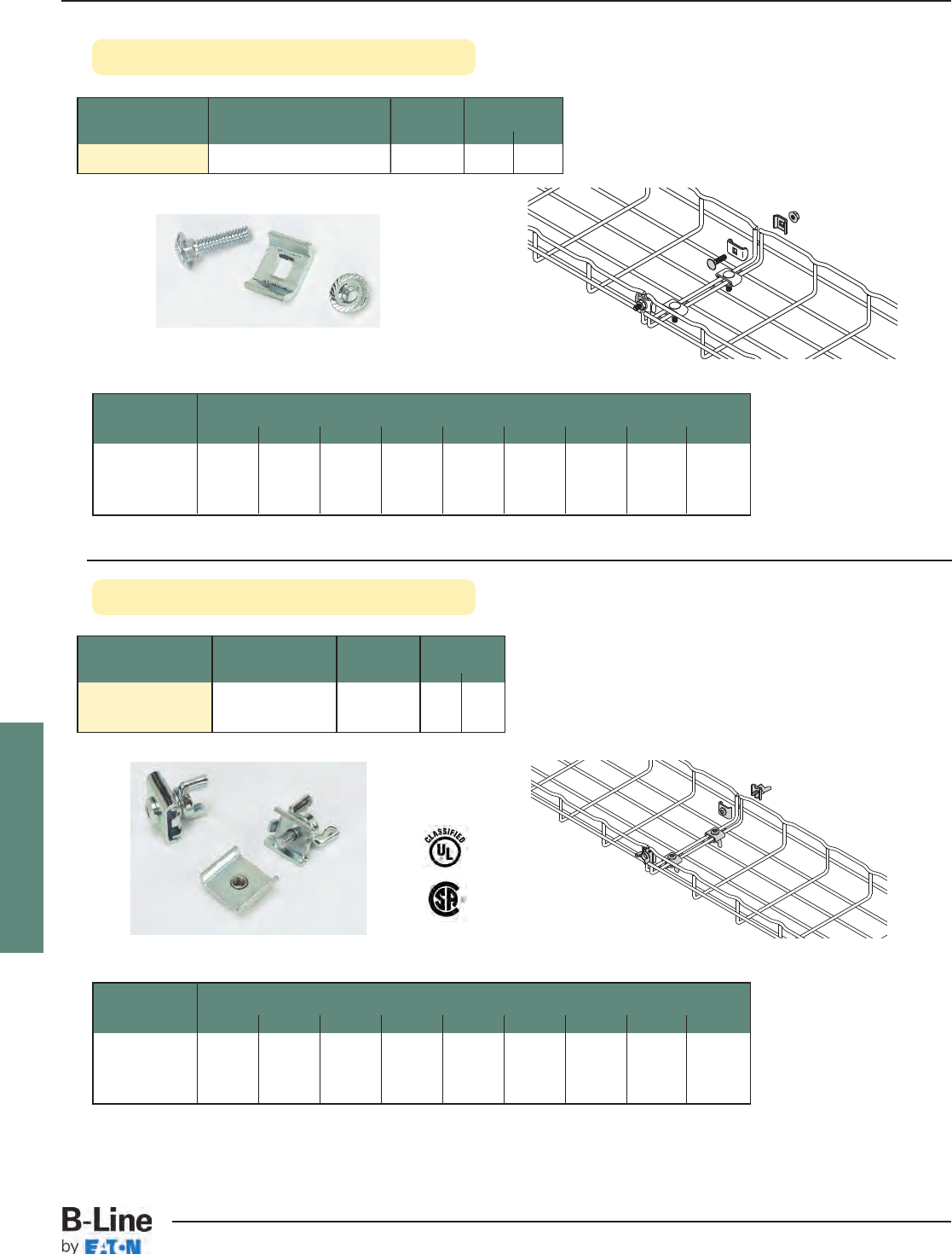
FLEXTRAY
Wing Splice™
Connecting Hardware • Adaptable and designed for use with
splice plate (FTS3SP), SPLICE BAR, and
long splice bar (FTS36SB).
• Finishes __: EG, BLE-BLO, 304S, 316S
Part Description Qty./Box Wt./Box
Number lbs. kg
FTSWN__ Wing Splice 50 3.0 1.38
• Two piece design for easy handling
• Tool-less installation
• Reduces installation time, especially when used on
fittings and bends
• Finish__: ZN
Part Description Qty./Box Wt./Box
Number lbs. kg
FTSCH__ Connecting Hardware 50 2.0 0.91
Tray Height Tray Width - number of splices
2” 4” 6” 8” 12” 16” 18” 20” 24”
(50mm) (100mm) (150mm) (200mm) (300mm) (400mm) (450mm) (500mm) (600mm)
2” NC NC 4444455
4” NM 45 6 6 7 77 8
6” NM NM NM 667778
Splicing Chart (number of splices required for UL Classification)
NC = Not UL Classified in this size NM = FLEXTRAY is not manufactured in this size
See page FLX-3 for finish and grounding information
FLX-9
FLEXTRAY™- Splicing Accessories
Cable Tray Systems
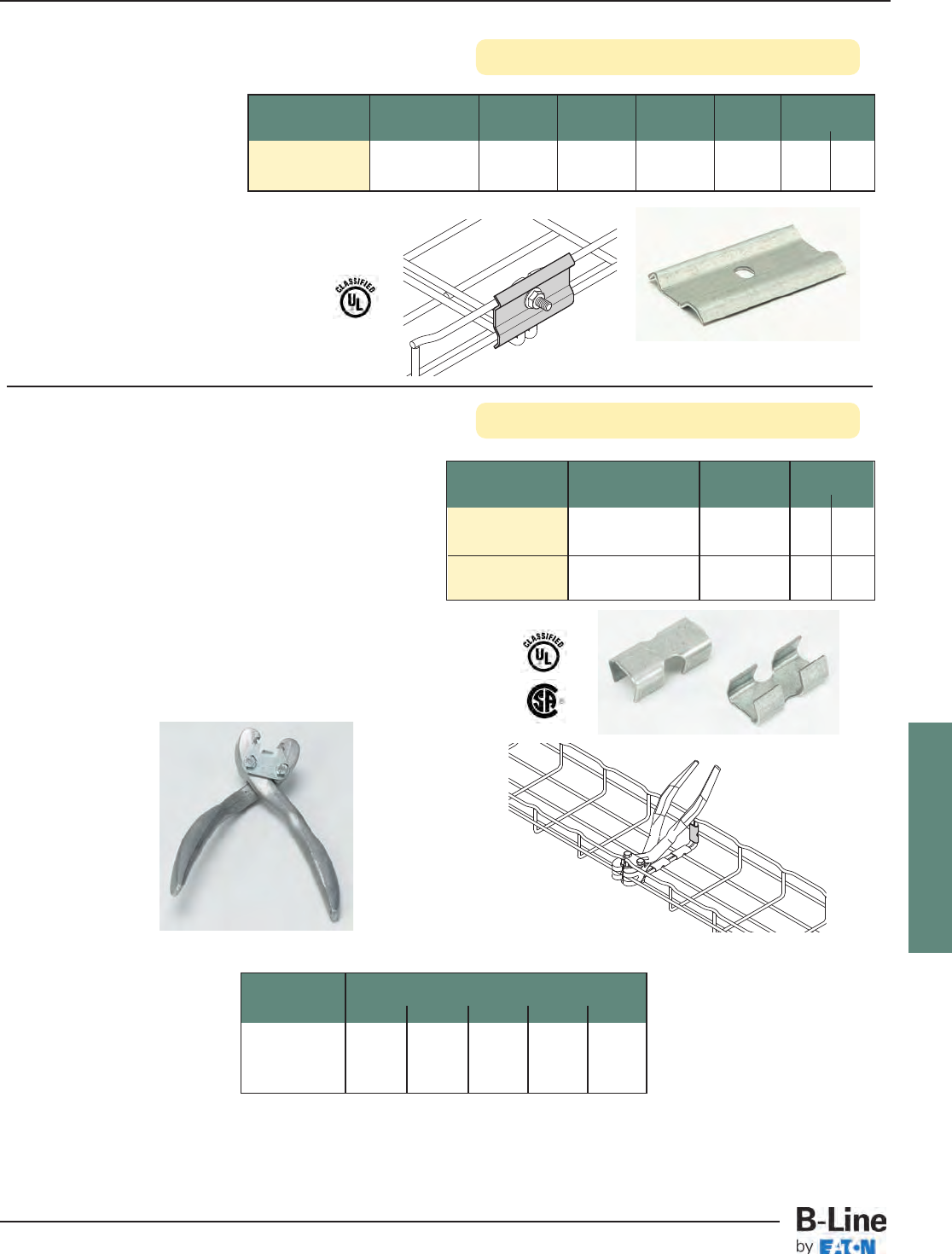
FLEXTRAY
Splice Plate (only)
FLEXMATE™Splice System
Part Description Qty./Box Wt./Box
Number lbs. kg
FLEXMATE2__ Flexmate 100 1.0 0.45
Splice Clips
FLEXMATE TOOL Flexmate 1 0.7 0.32
Splice Tool
Tray Height Tray Width - number of splices
2” 4” 6” 8” 12”
(50mm) (100mm) (150mm) (200mm) (300mm)
2” NC NC 555
4” NM 56 77
6” NM NM NM 77
• Fastest splice connection method available
in the industry
• For use with 4” (100mm) to 12” (300mm) wide tray
• FLEXMATE clips and tool sold separately
• Finishes __: GS, BLE
Note: Please contact B-Line when using Flexmates
on tray widths larger than 12” (300mm)
for specific requirements.
B-Line recommends that splice/supports
comply with NEMA VE-2 installation requirements
Splicing Chart (number of splices required for UL Classification)
Flexmate Tool is used to
install splices quickly.
Position clip inside
tool, pointing to
outside of tray.
Squeeze to secure
splice.
FLEXMATE2
FLEXMATE TOOL
NC = Not UL Classified in this size
NM = FLEXTRAY is not manufactured in this size
Part Description Length Height Hole Qty./Box Wt./Box
Number Diameter lbs. kg
FTS3SP__ Splice Plate 2.7” 1.6” 0.27” 50 6.1 2.76
• Splice plate is designed for use with connecting
hardware (FTSCH) to provide added stability of
splice connections
• Hardware sold separately
• Finish__: ZN, SS6
See page FLX-3 for finish and grounding information
FLX-10
FLEXTRAY™- Splicing Accessories
Cable Tray Systems
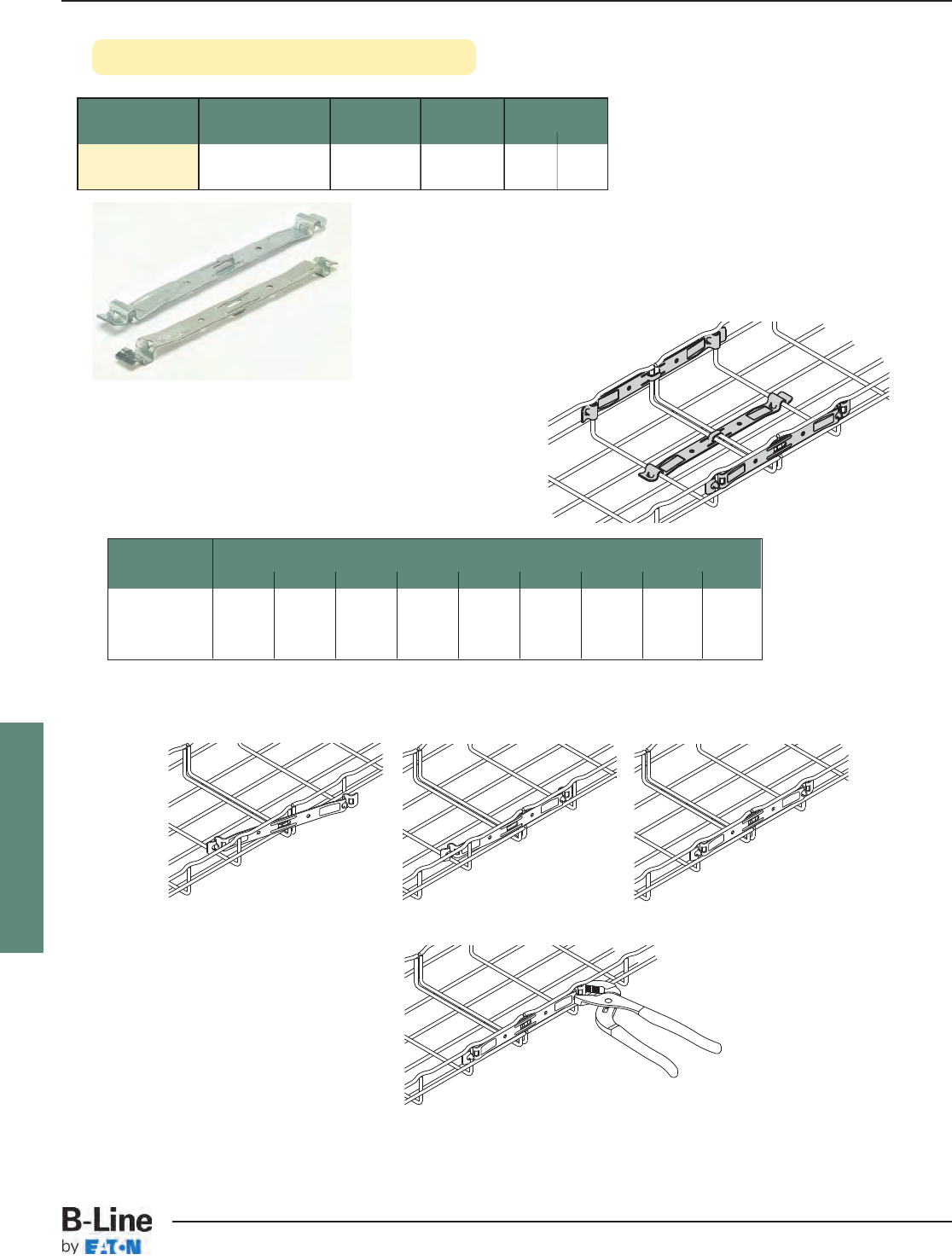
FLEXTRAY
Tab-Loc Connector
Part Description Length Qty./Box Wt./Box
Number lbs. kg
FTSTLC__ Tab-Loc 9.29” 50 7.2 3.26
Connectors
• Fast splice for straight runs of tray
• For use with 2” (50mm) to 32” (800mm) wide tray
to connect straight sections only
• Finishes __: ZN, SS6
Application Requirements
Tab-Loc security without
special tools.
Step 1 Step 3
Step 2
Step 4
The recommendations listed are equal for all depths
(except as noted).
Installation
Screwdriver can also be used to bend
tab-locs (hold connector ends while
bending).
Tray Height Tray Width - number of splices
2” 4” 6” 8” 12” 16” 18” 20” 24”
(50mm) (100mm) (150mm) (200mm) (300mm) (400mm) (450mm) (500mm) (600mm)
2” 224444455
4” NM 45 6 6 7 77 8
6” NM NM NM 667778
Splicing Chart
NM = FLEXTRAY is not manufactured in this size
See page FLX-3 for finish and grounding information
FLX-11
FLEXTRAY™- Splicing Accessories
Cable Tray Systems
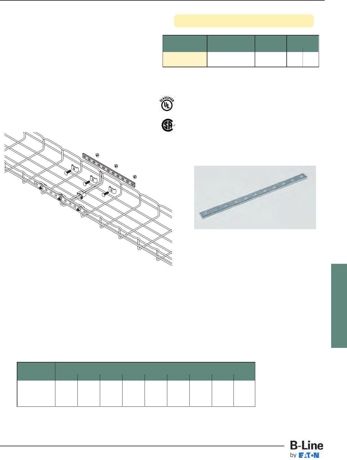
FLEXTRAY
See page FLX-3 for finish and grounding information
Splice Bar
Part Description Qty./Box Wt./Box
Number lbs. kg
SPLICE BAR__ 1013/16” Long Bar 50 14.0 6.35
• Adds rigidity to washer splice methods
• Used on side rails only (not for use in tray bottom)
• For use on trays when using splice hardware FTSCH
• Hardware sold separately
• Finishes __: EG, BLE, HD, 304S, 316S
Each splice bar requires three (3) each of Hardware Splice Components -
TOP WASHER, and FTHDWE 1/4 to complete connection.
These items must be ordered separately.
Washer Splice Kits (WASHER SPL KIT) are required for connections on bottom of tray.
Hardware is not sold with
splice bar.
Tray Height Tray Width - number of splices
2” 4” 6” 8” 12” 16” 18” 20” 24”
(50mm) (100mm) (150mm) (200mm) (300mm) (400mm) (450mm) (500mm) (600mm)
2” NC NC 2222222
4” NM 44 4 4 4 44 4
6” NM NM NM 444444
Splicing Chart (number of splices required for UL Classification)
NC = Not UL Classified in this size NM = FLEXTRAY is not manufactured in this size
FLX-12
FLEXTRAY™- Splicing Accessories
Cable Tray Systems
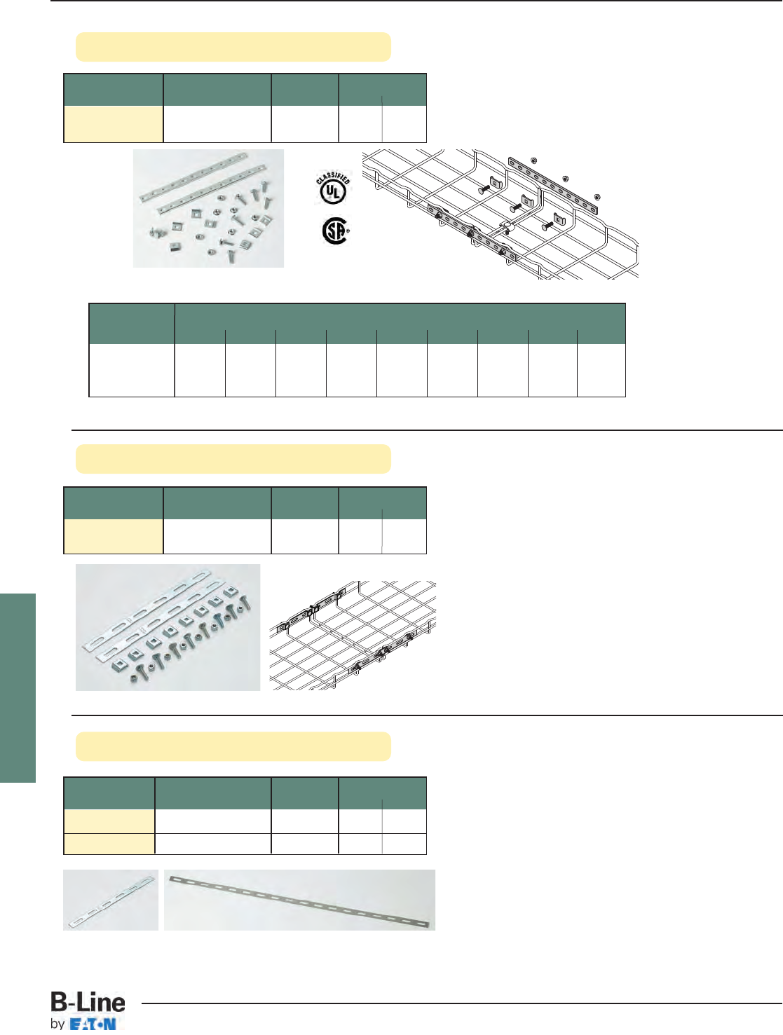
FLEXTRAY
Long Splice Bar (only)
See page FLX-3 for finish and grounding information
Part Description Qty./Box Wt./Box
Number lbs. kg
FTS12SB__ 12” Long - 6 Slots 1 0.13 0.06
FTS36SB__ 36” Long - 18 Slots 1 0.40 0.18
• FTS36SB long splice bar is used for assembly of
large radius horizontal bends or field cut into short
splice bars
• Splice Bars are designed for use with connecting
hardware (FTSCH)
• Hardware sold separately
• Finishes __: ZN, FB, SS6
Expansion Splice Kit
Part Description Qty./Box Wt./Box
Number lbs. kg
FTS12ESK__ 12” Long 1 Kit 0.45 0.20
Expansion Splice Kit
• Allows 13/4” (44mm) of expansion between two pieces
of Flextray at expansion joints.
• To install, tighten nylon loc-nut until nut comes into
contact with splice bar, then loosen approximately
1/4turn.
• Includes two (2) splice bars and eight (8) sets of
hardware
• Finishes __: ZN
Splice Bar Kit
• Adds rigidity
• Includes two (2) SPLICE BAR and hardware
• Finishes __: ZN, FB, SS6
Tray Height Tray Width - number of splices
2” 4” 6” 8” 12” 16” 18” 20” 24”
(50mm) (100mm) (150mm) (200mm) (300mm) (400mm) (450mm) (500mm) (600mm)
2” NC NC 2222222
4” NM 44 4 4 4 44 4
6” NM NM NM 444444
Splicing Chart (number of splices required for UL Classification)
NC = Not UL Classified in this size NM = FLEXTRAY is not manufactured in this size
Part Description Qty./Box Wt./Box
Number lbs. kg
FTSBK__ 12” Long 5 Sets 6.4 2.90
Splice Bar Kit
FTS12SB FTS36SB
FLX-13
FLEXTRAY™- Splicing Accessories
Cable Tray Systems
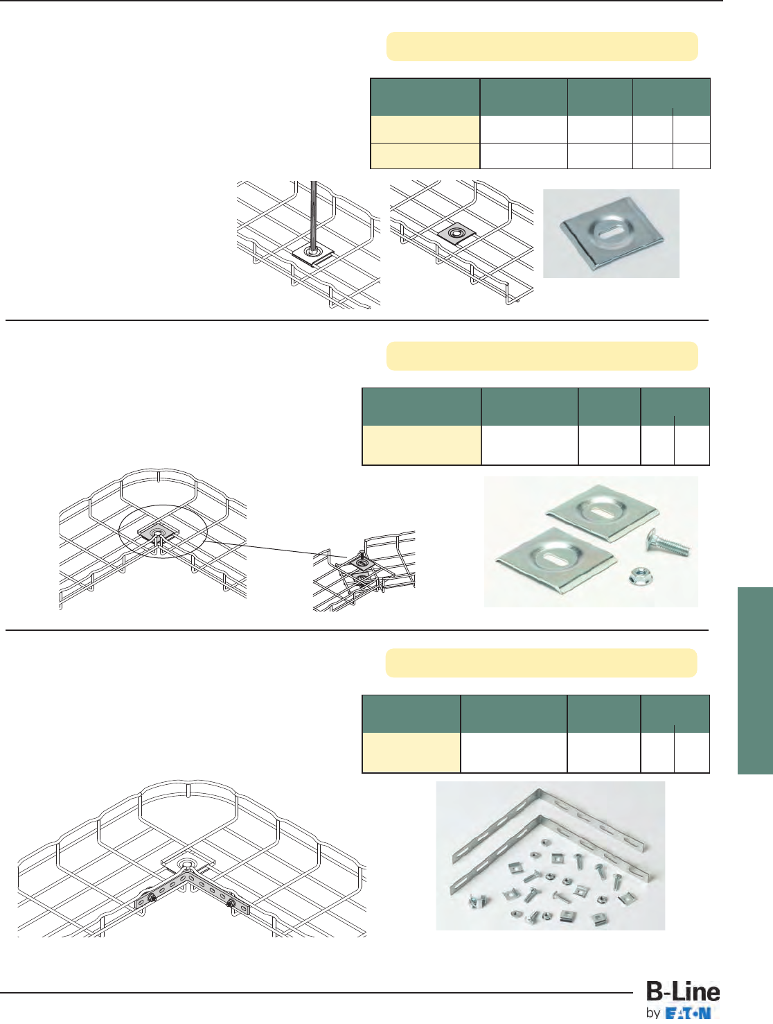
FLEXTRAY
Hold Down Plate
See page FLX-3 for finish and grounding information
Horizontal Adjustable Kit
• Horizontal adjustable kit can be used to create
horizontal angles from prepared FLEXTRAY straight
sections
• Conveniently poly-bagged
• Finishes __: EG, BLE, 316S
Part Description Qty./Box Wt./Box
Number lbs. kg
FTSHAK__ Horizontal 10 2.4 1.09
Adjustable Kit
90 Degree Kit
• For fast assembly of 90° turns and tee fittings
• For use with all tray widths and sizes
• One kit will make two 90° turns or one tee fitting
• 90 DEGREE KIT: includes: two (2) 90° splice bars
and eight (8) FTSCH
• Finishes __: EG, BLE, 316S
Part Description Qty./Box Wt./Box
Number lbs. kg
90 degree splice
90 DEGREE KIT__ bar & hardware 1 1.3 0.59
Part Slot Size Qty./Box Wt./Box
Number lbs. kg
SUPT WASHER__ .28” x .70” 50 4.7 2.13
FTA6HD__ .40” x .70” 50 3.5 1.59
• Easy way to mount 4" (100mm) wide tray for
raceway run.
• Use 1/4" screws to attach SUPT WASHER to your
specific wall/stud application (hardware sold
separately).
• FTA6HD can be used in pairs to create a center-hung
support using 3/8" rod.
• To protect cables use threaded
rod protector (page FLX-20).
• To complete 3/8" center hanger
assembly use:
2 - FTA6HD
2 - HN 3/8"-16 hex nuts
• Finish: ZN, SS6
FLX-14
FLEXTRAY™- Splicing Accessories
Cable Tray Systems
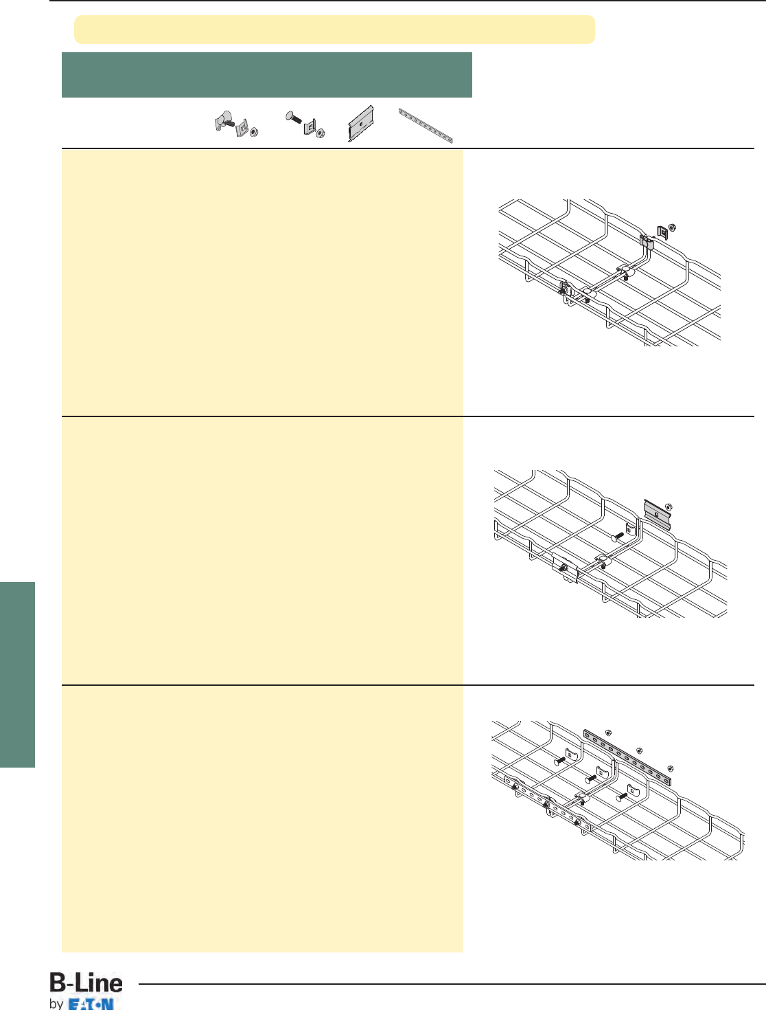
FLEXTRAY
FT2X2 2” 50 2---
FT2X4 4” 100 2---
FT2X6 6” 150 41-- -
FT2X8 8” 200 41-- -
FT2X12 12” 300 41-- -
FT2X16 16” 400 41-- -
FT2X18 18” 450 41-- -
FT2X20 20” 500 51-- -
FT2X24 24” 600 51-- -
FT2X30 30” 750 71-- -
FT2X32 32” 800 71-- -
FT4X4 4” 100 41-- -
FT4X6 6” 150 51-- -
FT4X8 8” 200 62-- -
FT(*)X12 12” 300 62-- -
FT(*)X16 16” 400 72-- -
FT(*)X18 18” 450 72-- -
FT(*)X20 20” 500 72-- -
FT(*)X24 24” 600 82-- -
FT(*)X30 30” 750 82-- -
FT2X2 2” 50 -22-
FT2X4 4” 100 -22-
FT2X6 6” 150 122-
FT2X8 8” 200 122-
FT2X12 12” 300 222-
FT2X16 16” 400 222-
FT2X18 18” 450 222-
FT2X20 20” 500 222-
FT2X24 24” 600 222-
FT2X30 30” 750 422-
FT2X32 32” 800 422-
FT4X4 4” 100 122-
FT4X6 6” 150 222-
FT4X8 8” 200 222-
FT(*)X12 12” 300 322-
FT(*)X16 16” 400 422-
FT(*)X18 18” 450 422-
FT(*)X20 20” 500 422-
FT(*)X24 24” 600 422-
FT(*)X30 30” 750 522-
FT2X2 2” 50 -2-2
FT2X4 4” 100 -2-2
FT2X6 6” 150 12-2
FT2X8 8” 200 12-2
FT2X12 12” 300 22-2
FT2X16 16” 400 22-2
FT2X18 18” 450 22-2
FT2X20 21” 500 22-2
FT2X24 24” 600 22-2
FT2X30 30” 750 36-2
FT2X32 32” 800 36-2
FT4X4 4” 100 12-2
FT4X6 6” 150 22-2
FT4X8 8” 200 26-2
FT(*)X12 12” 300 26-2
FT(*)X16 16” 400 36-2
FT(*)X18 18” 450 36-2
FT(*)X20 20” 500 36-2
FT(*)X24 24” 600 36-2
FT(*)X30 30” 750 46-2
Install splice bars on sides and
WASHER SPL KIT on bottom.
Install splice plates on sides and
WASHER SPL KIT on bottom.
1Install one kit on each side and remaining kit(s) on bottom.
2Install two kits on each side and remaining kits on bottom.
Washer Splice Kits
Splice Plates
Splice Bars
System System Connector Connecting Splice Splice
Part Width Assembly Hardware Plate Bar
Number in. mm WASHER SPL KIT FTSCH FTS3SP SPLICE BAR
(*) 4 for 4” Deep FLEXTRY
6 for 6” Deep FLEXTRY
Components Required to Connect Two Sections of FLEXTRAY
FLX-15
FLEXTRAY™- Splicing Accessories
Cable Tray Systems
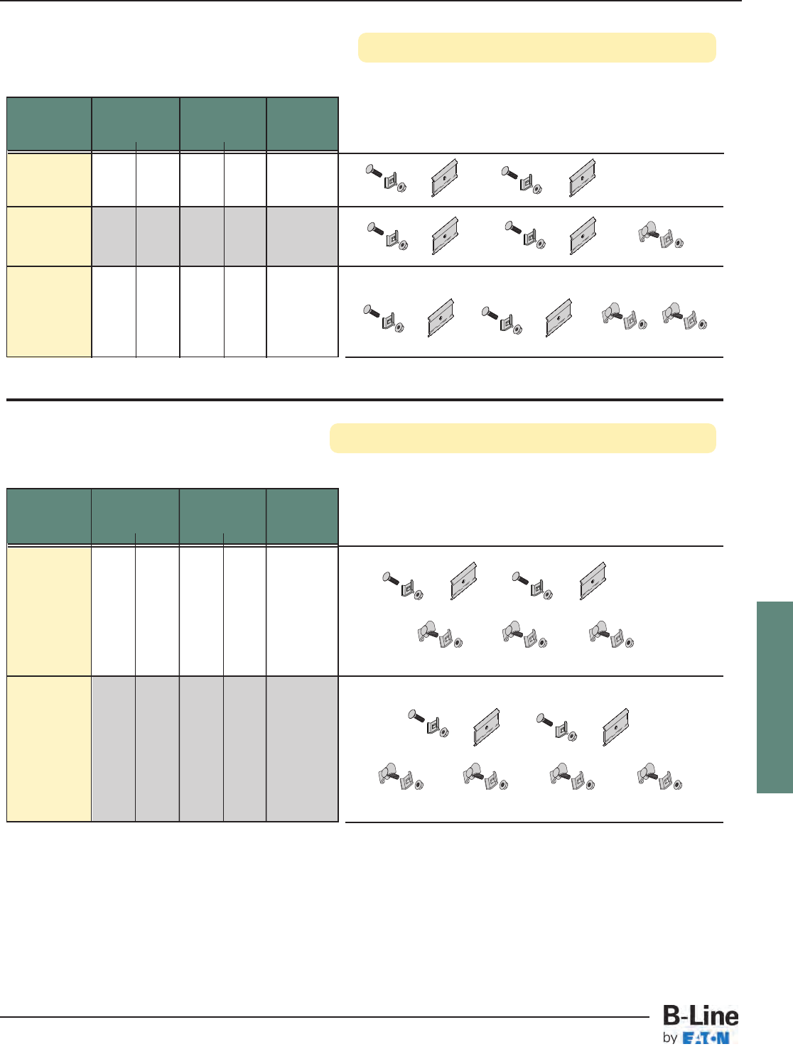
FLEXTRAY
Part System Weight Box
Number Width Per 100 Quantity
in. mm lbs. kg
FTS20SK 2” 50 2.91 1.32 10
4” 100
FTS21SK 6” 150 3.63 1.64 10
8” 200
12” 300
FTS22SK 18” 450 4.35 1.97 10
20” 500
24” 600
Conveniently poly-bagged for use with
2" Deep FLEXTRAY
Conveniently poly-bagged for use with
4" & 6” Deep FLEXTRAY
Part System Weight Box
Number Width Per 100 Quantity
in. mm lbs. kg
4” 100
6” 150
FTS23SK 8” 200 5.07 2.30 10
12” 300
18” 450
FTS24SK 20” 500 5.79 2.62 10
24” 600
Splice Plate Kits for 2" Deep FLEXTRAY
Splice Plate Kits for 4" & 6” Deep FLEXTRAY
FLX-16
FLEXTRAY™- Splicing Accessories
Cable Tray Systems
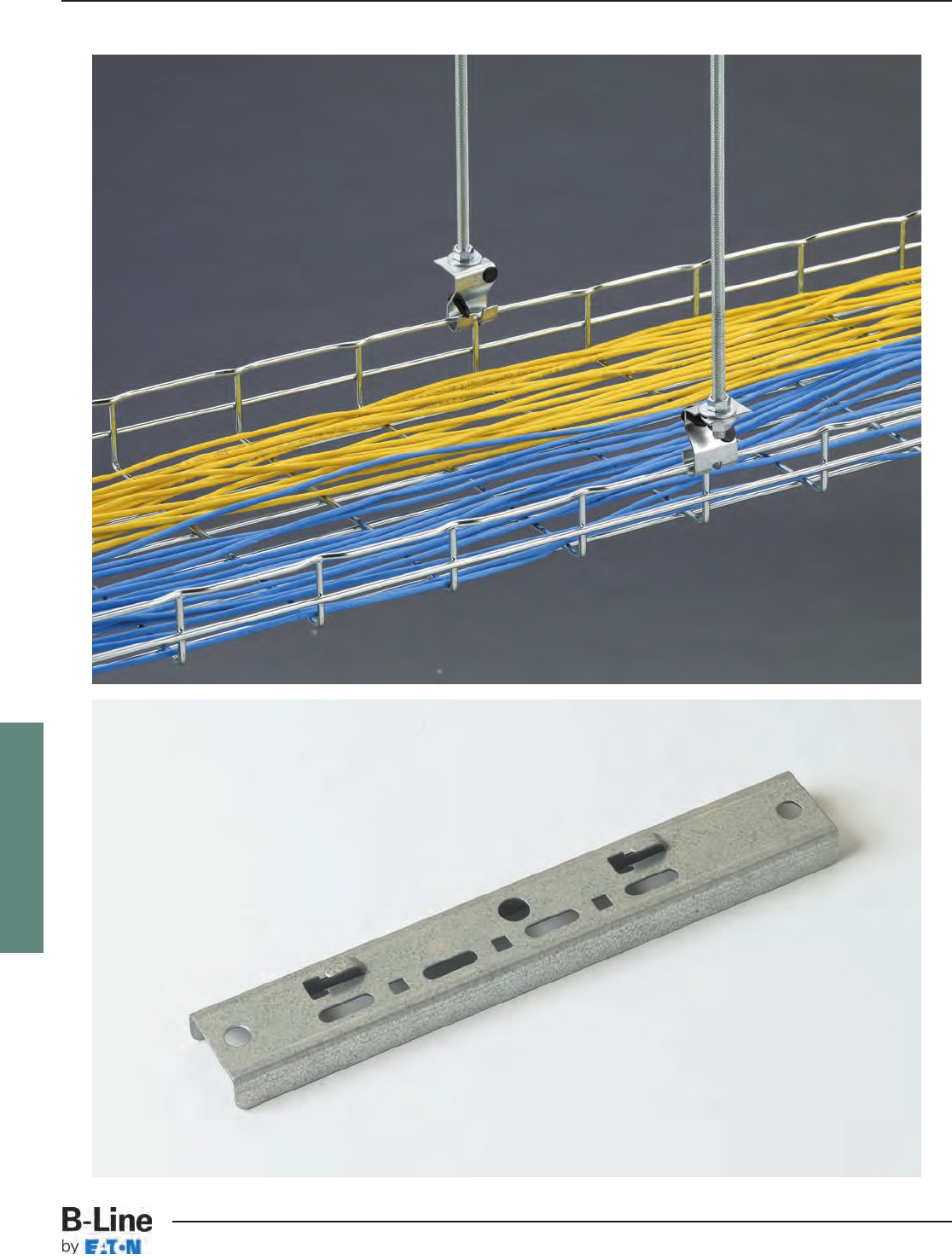
FLEXTRAY
FLX-17
FLEXTRAY™- Ceiling Support Methods
Cable Tray Systems
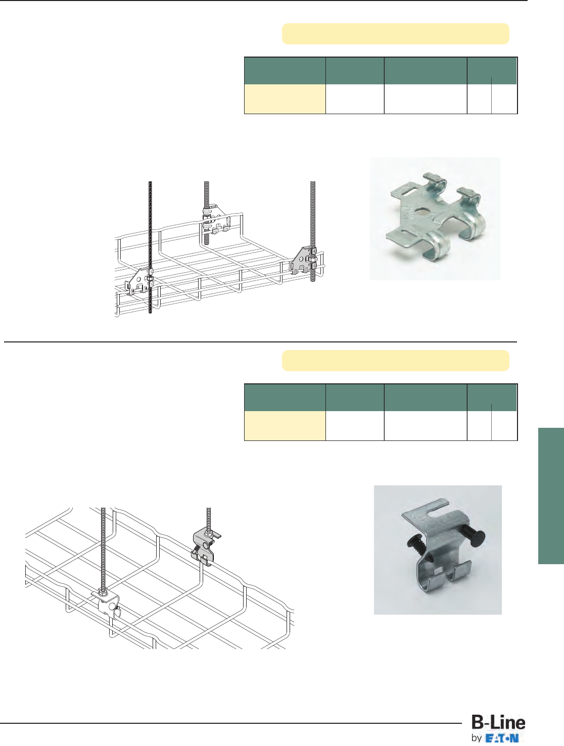
FLEXTRAY
Flip Clip™
Part Description Qty./Box Wt./Box
Number lbs. kg
WB46H__ Flip Clip 50 5.2 2.36
• Accommodates 1/4" and 3/8" rod sizes
• Installs quickly with a screwdriver or pliers thus
reducing installation time
• Requires only one hex nut (not included) to hang
and level the FLEXTRAY
• Retainer tabs can be bent over to lock-in the
threaded rod and wire basket
• Finishes __: ZN, FB, SS6
See page FLX-3 for finish information
Snap retainer stops in
place after cable is
loaded.
Trapeze Support
Part Description Qty./Box Wt./Box
Number lbs. kg
TRAPEZE SUPT2__ Trapeze 50 trapeze clips 7.0 3.17
Support Clip 100 retainer stops
• Trapeze Clip installs fast
• For use with trays up to 4” (100mm) deep,
12” (300mm) wide, and spans up to 8’-0” (2.44m)
• Tray can be released from support to allow side
cable loading
• Accepts 1/4” and 3/8” threaded rod sizes
• Finishes __: GS, BLE
Snap retainer stops in
place after cable is
loaded.
FLX-18
FLEXTRAY™- Ceiling Support Methods
Cable Tray Systems
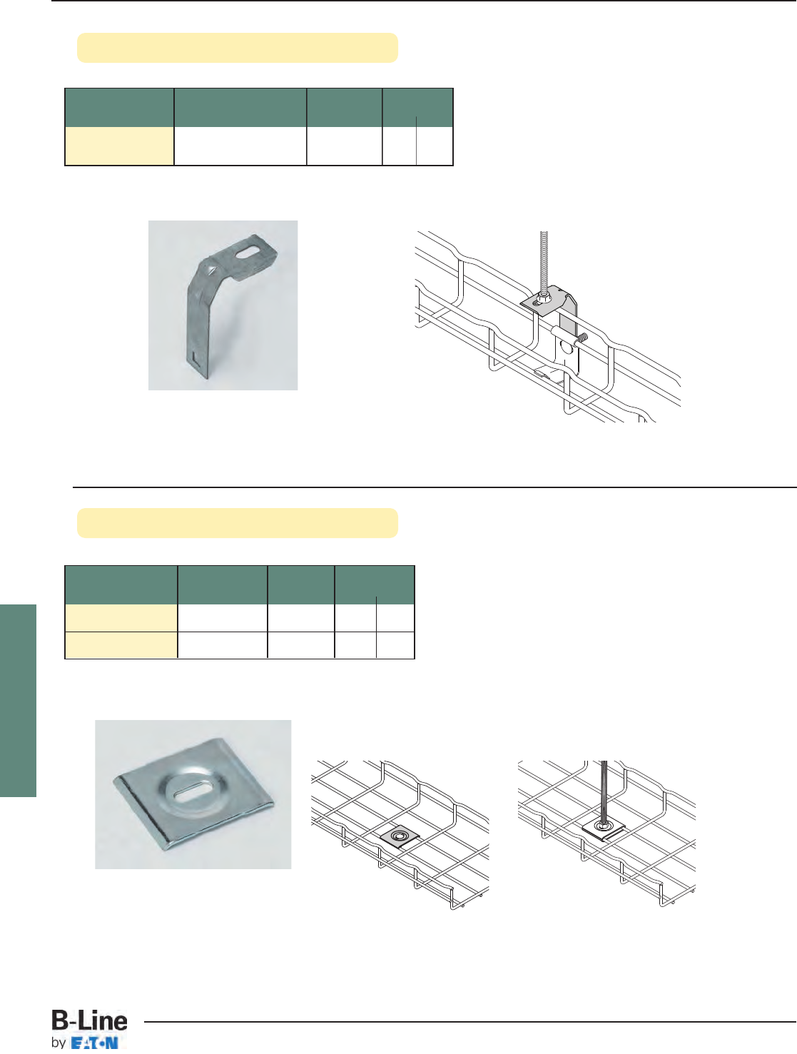
FLEXTRAY
2” Center Hanger
See page FLX-3 for finish information
Hold Down Plate
Part Slot Size Qty./Box Wt./Box
Number lbs. kg
SUPT WASHER__ .28” x .70” 50 4.7 2.13
FTA6HD__ .40” x .70” 50 3.5 1.59
• Easy way to mount 4" (100mm) wide tray for raceway
run.
• Use 1/4" screws to attach SUPT WASHER to your
specific wall/stud application (hardware sold separately).
• FTA6HD can be used in pairs to create a center-hung
support using 3/8" rod.
• To protect cables use threaded rod protector (page FLX-20).
• To complete 3/8" center hanger assembly use:
2 - FTA6HD
2 - HN 3/8"-16 hex nuts
• Finish: ZN, SS6
Part Description Qty./Box Wt./Box
Number lbs. kg
2 IN CTR SUPT__ Center Support 50 5.0 2.27
Hanger for FT2x2
• For use with 2” (50mm) tray widths only
• Accepts 1/4” threaded rod
• Hardware sold separately
• Finishes __: GS, BLE
Assemble with
ATTACHMENT CLP
& FTHDWE 1/4
hardware.
FLX-19
FLEXTRAY™- Ceiling Support Methods
Cable Tray Systems
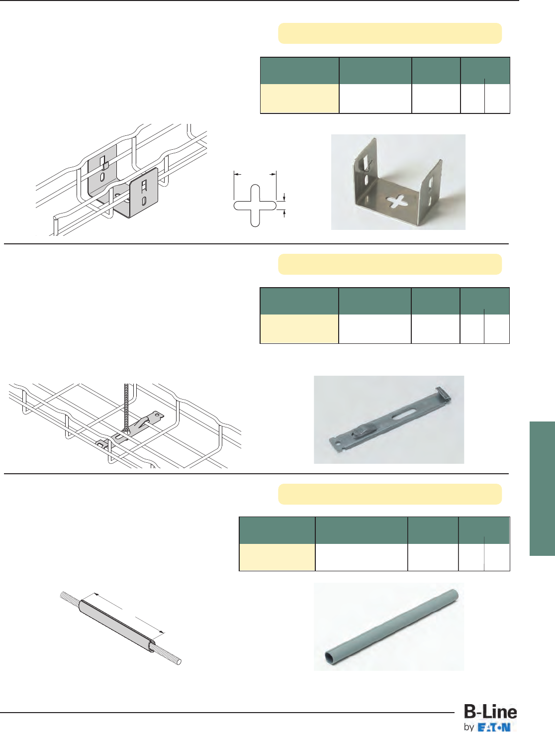
FLEXTRAY
Mounting Bracket
See page FLX-3 for finish information
Center Hung Clip
Threaded Rod Protector
Part Description Qty./Box Wt./Box
Number lbs. kg
SB301-1/2x8__ Rod Protector 1 0.03 0.013
• Use to protect cables from 1/4” to 1/2”
threaded rod
• PVC UL94V-O material
• Color: Gray
• Not plenum rated
8”
Part Description Qty./Box Wt./Box
Number lbs. kg
Light Duty
CTR HUNG CLP__ Center Hanger 50 4.0 1.81
• Use for light duty cabling applications
• For use with 11/2” (38mm) & 2” (51mm) deep tray with
4” (100mm) and 6” (150mm) widths
• When hanging 4” (100mm) wide tray, center hung clip
must be run parallel with the tray
• Built-in hold down tab
• Accepts 1/4” threaded rod
• Threaded rod and nuts sold separately
• Finishes __: GS, BLE
Assemble with 1/4” threaded
rod and finned nut
Part Description Qty./Box Wt./Box
Number lbs. kg
Light Duty
FTB2UB__ Wall/Rack Bracket 10 2.1 0.95
• Designed to support FT2X2X10 Flextray
• Click tabs for FLEXTRAY attachment
• Use 1/4” hardware and washer (not included) to
mount bracket
• Finishes __: SS6
.26" typ.
(6.6 mm)
1" typ.
(25 mm)
FLX-20
FLEXTRAY™- Ceiling Support Methods
Cable Tray Systems
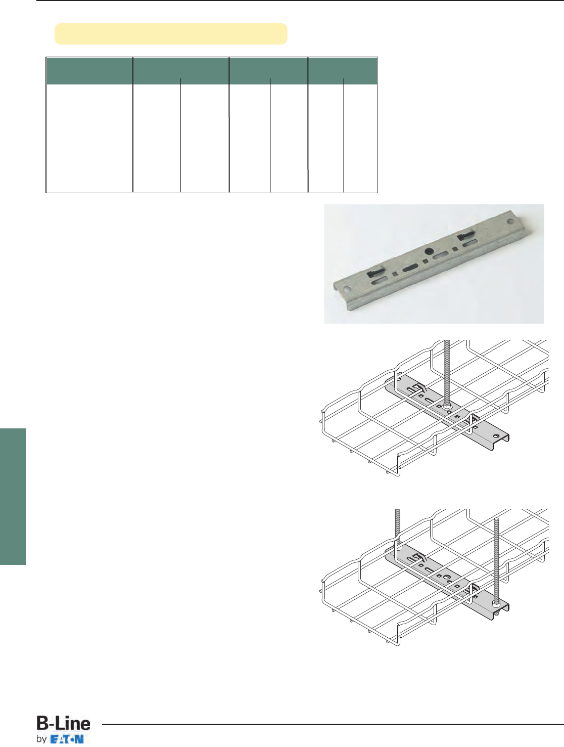
FLEXTRAY
Center Trapeze Hanger
See page FLX-3 for finish information
• Can be installed as center-hung or traditional
trapeze hanger
• Multiple options to secure FLEXTRAY to hanger
- Built in hold down tabs (use screwdriver to
bend down tab)
- Compatible with TOOLLESS CLIP with
snap-in locking pin
- Compatible with WBUHD hold down clip when
tray crosswire is aligned over top of hanger
- Slots and holes for optional hardware
attachment
• Corrosion resistant pre-galvanized zinc finish
(other finishes available upon request)
• Center hole for up to 1/2” rod
• Hole on each end for up to 3/8” rod
• Threaded rod protector available (SB301-1/2x 8)
• When 1/2” trapeze rods are required, add -1/2 to end
of part number when ordering Center Hung
Trapeze
Part Number Maximum Tray Width Actual Length Wt./Pc.
in. mm in. mm lbs. kg
FTB06CT 6” 150 9.78” 248 0.61 0.27
FTB08CT 8” 200 11.75” 298 0.74 0.33
FTB12CT 12” 300 15.69” 398 0.98 0.44
FTB16CT 16” 400 19.63” 498 1.61 0.73
FTB18CT 18” 450 21.59” 548 1.77 0.80
FTB20CT 20” 500 23.56” 598 1.93 0.87
FTB24CT 24” 600 27.50” 698 2.25 1.02
FLX-21
FLEXTRAY™- Ceiling Support Methods
Cable Tray Systems
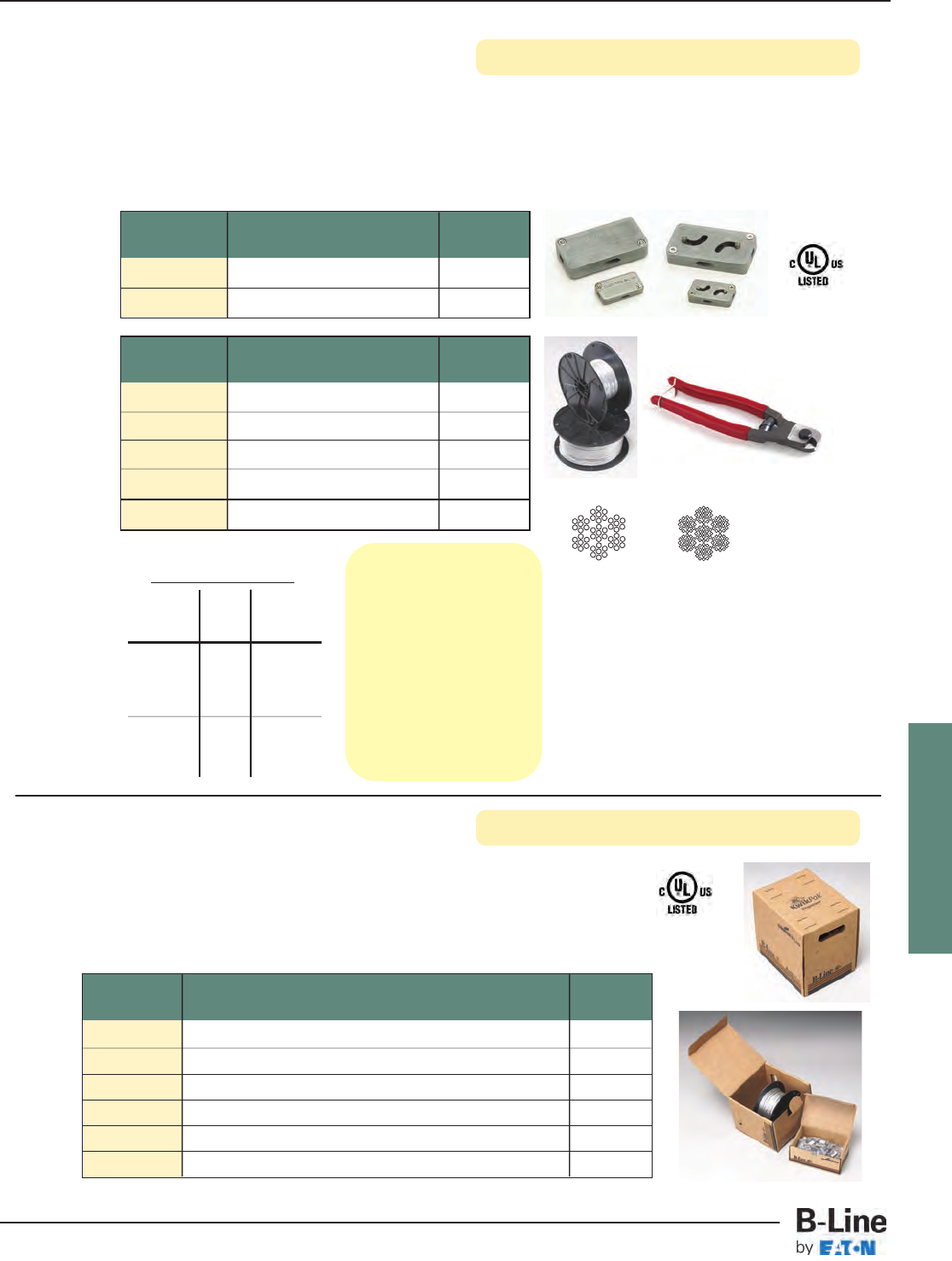
FLEXTRAY
KwikWire™ Clamps & Wire Rope
See page FLX-3 for finish information
Part Clamp Description Qty./Box
Number For Use With Rope Diameter
BKC100 1/32”, 1/16” & 3/32” 100
BKC200 3/32”, 1/8” & 3/16” 50
• KwikWire system replaces jack chain or ATR to support lighting, ductwork, and FLEXTRAY.
• Can be quickly installed around beams - No drilling required.
• Ideal for sloped ceilings - can hang objects at up to 60° angles.
• Simple height adjustments are made by releasing locking tab, no tools required.
• Spools of wire can be cut to length in field, reducing waste and up front planning.
(1) 7 x 7
Wire Rope Construction
(2) 7 x 19
Part Rope Diameter Qty./Spool
Number - Working Load
BKW063 (1) 1/16” - 96 lbs. 500 ft.
BKW094 (1) 3/32” - 184 lbs. 500 ft.
BKW125 (1) 1/8” - 340 lbs. 500 ft.
BKW188 (2) 3/16” - 840 lbs. 250 ft.
BKCC Wire Rope Cutter 1
KwikWire™ Clamp
Working Loads*
Clamp Wire Lbs.
Part No. Rope Safety
Dia. Factor 5
BKC100 1/32” 0-22
BKC100 1/16” 0-75
BKC100 3/32” 25-150
BKC200 3/32” 25-150
BKC200 1/8” 25-250
BKC200 3/16” 50-640
* Working loads shown
are for hanging vertically.
For suspending at
15°, 30°, 45° or 60°
angles from vertical, use
the following percentage
of the working loads from
the chart:
15° = 96%
30° = 86%
45° = 70%
60° = 50%
FLX-22
FLEXTRAY™- Ceiling Support Methods
Cable Tray Systems
KwikPak™ Wire Rope & Clamps
KwikPak™ makes handling KwikWire™ a breeze!
• Refill your starter kit with a B-Line KwikPak™.
• KwikPaks include KwikWire clamps and a spool of wire rope.
• KwikPaks are shipped in a specially designed dispenser box to ease field cutting of wire.
Part Kit Includes Qty./Box
Number - Working Load
BKP10063 BKC100 (100 pcs.), Cable Cutter, 1/16ӯWire Rope (500 ft.) 1
BKP10094 BKC100 (100 pcs.), Cable Cutter, 3/32ӯWire Rope (500 ft.) 1
BKP15094 BKC150 (100 pcs.), Cable Cutter, 3/32ӯWire Rope (500 ft.) 1
BKP15125 BKC150 (100 pcs.), Cable Cutter, 1/8ӯWire Rope (500 ft.) 1
BKP20125 BKC200 (50 pcs.), Cable Cutter, 1/8ӯWire Rope (500 ft.) 1
BKP20188 BKC200 (50 pcs.), Cable Cutter, 3/16ӯWire Rope (250 ft.) 1
FLEXTRAY
See page FLX-3 for finish information
FLX-23
FLEXTRAY™- Ceiling Support Methods
Cable Tray Systems
KwikWire Accessory Numbering System
Product Assembly Leg Leg Wire Rope Straight Assembly
Line Configuration Termination Length Diameter Length or Kit
Blank =
Single Leg
Y = 2 Legs
3 - 3 Legs
A = Angle
Bracket w/Pin
H = Hook
L = Loop
T = Toggle
W = Fuse Cut
B25 = Bolt w/ 1/4”-20 Thread
B38 = Bolt w/ 3/8”-16 Thread
BM6 = Bolt w/ M6 Thread
BM8 = Bolt w/ M8 Thread
BM10 = Bolt w/ M10 Thread
Blank = See
Straight Length
18 = 18” Leg
30 = 30” Leg
063 = 1/16”
094 = 3/32”
Blank =
Loop w/
Plastic Tube
18 = 18”
30 = 30”
40 = 40”
80 = 80”
120 = 120”
180 = 180”
240 = 240”
360 = 360”
Blank =
Assembly
Only
K = Kit
(Assembly &
BKC100 Clamp)
BK =
KwikWire
Examples BKYT18-094-120K
BK Y T 18 -094 -120 K
KwikWire Accessory
2 legs - toggle leg termination - 18” legs - 3/32” diameter wire - 120” straight length - kit with clamp
BKL-063-120K
BK L -063 -120 K
KwikWire Accessory
single leg - looped leg termination - 1/16” diameter wire - 120” straight length - kit with clamp
KwikWire™Accessory Features
•Reduces on the job installation time
•Can be installed quickly without drilling into existing structure
•Increases versatility in the field
•KwikWire accessory system reduces inventory and shipping costs
•No more sawing, filing, or fixing nuts
•Designed for use with cable tray, lighting, and HVAC
•Eliminates the need for all threaded rod
•Cost effective solution for jack chain
•“Y” style accessories require 50% less drilling
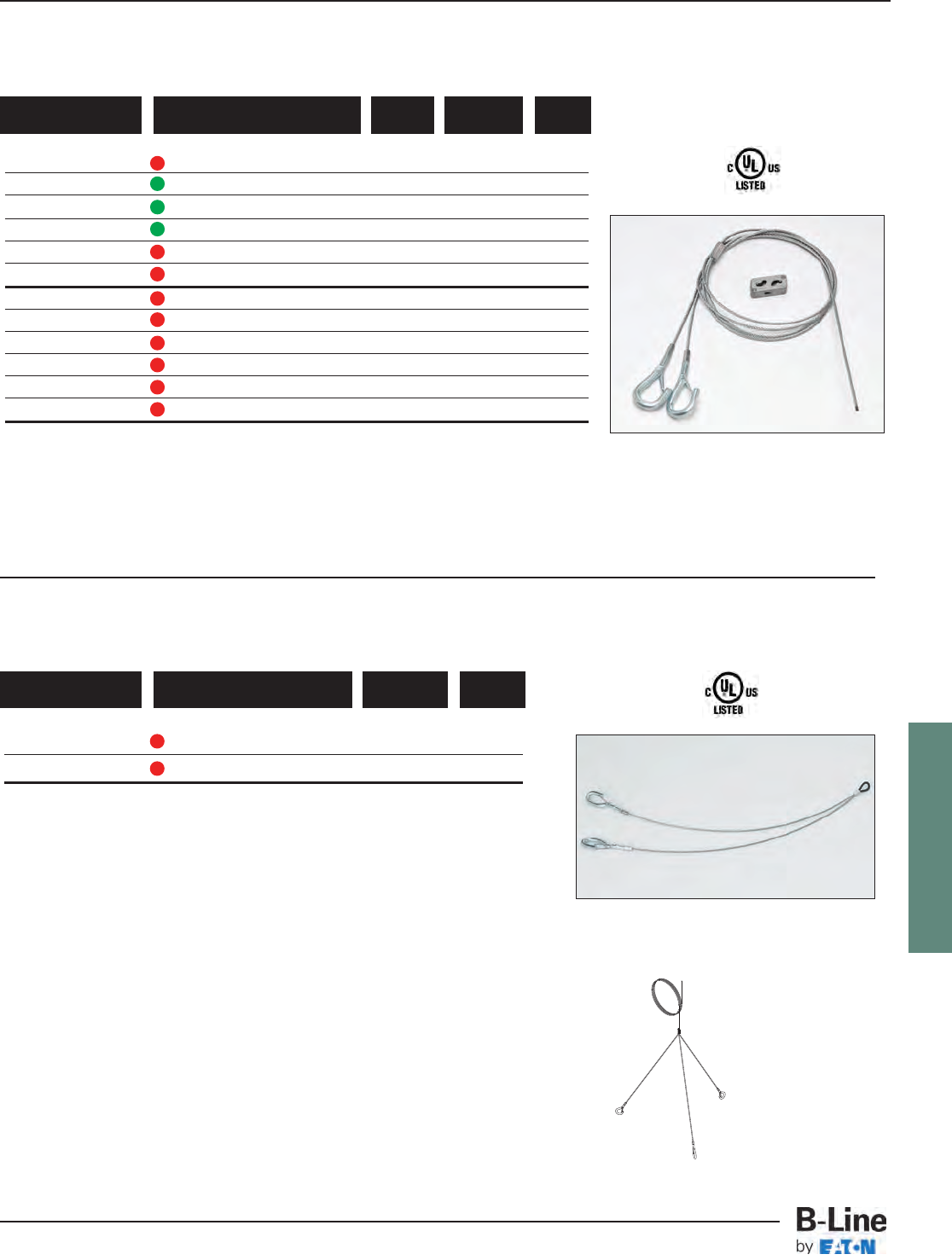
FLEXTRAY
See page FLX-3 for finish information
FLX-24
FLEXTRAY™- Ceiling Support Methods
Cable Tray Systems
•Hook designed to c up to 3/8” diameter wire.
•Available as a wire rope with hook termination only or as
a ready-to-use kit with a BKC100 clamp.
•Available in lengths of 40”, 80”, 120”, 180”, 240”, and 360”.
•Available in single, double (Y), and triple (3) leg styles
78205167341 BKYH18-094 3/32” 18”
78205168978 BKYH30-094 3/32” 30”
UPC/Part Number Wire Rope
Diameter LengthCatalog Number
KwikWire™‘Y’ Style Hook Termination With Loop
Triple (3) leg style
Box Quantity - 10
5 bags containing 2 pieces per bag
78205167342 BKYH18-094-40K 18” 3/32” 40”
78205167343 BKYH18-094-80K 18” 3/32” 80”
78205167344 BKYH18-094-120K 18” 3/32” 120”
78205168856 BKYH18-094-180K 18” 3/32” 180”
78205168945 BKYH18-094-240K 18” 3/32” 240”
78205167345 BKYH18-094-360K 18” 3/32” 360”
78205168946 BKYH30-094-40K 30” 3/32” 40”
78205168948 BKYH30-094-80K 30” 3/32” 80”
78205168949 BKYH30-094-120K 30” 3/32” 120”
78205168950 BKYH30-094-180K 30” 3/32” 180”
78205168951 BKYH30-094-240K 30” 3/32” 240”
78205168952 BKYH30-094-360K 30” 3/32” 360”
UPC/Part Number Wire Rope
Diameter
Leg
Length LengthCatalog Number
KwikWire™‘Y’ Style Hook Termination
Box Quantity - 10
5 bags containing 2 pieces per bag
For more information on KwikWire accessories
see the KwikWire catalog.
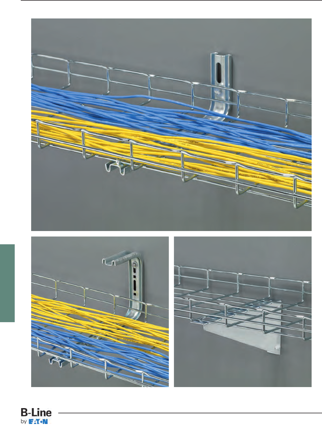
FLEXTRAY
FLX-25
FLEXTRAY™- Wall Support Methods
Cable Tray Systems
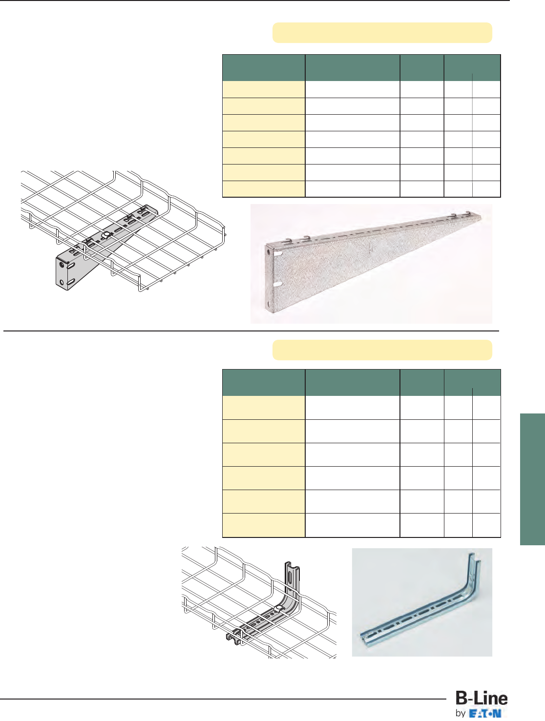
FLEXTRAY
Shelf Brackets
L Brackets
Part Use With Qty./Box Wt./Box
Number Tray Width lbs. kg
FTB06CS__ 6” (150mm) 1 0.5 0.22
FTB08CS__ 8” (200mm) 1 0.6 0.27
FTB12CS__ 12” (300mm) 1 1.2 0.54
FTB16CS __ 16” (400mm) 1 1.7 0.77
FTB18CS __ 18” (450mm) 1 1.9 0.86
FTB20CS __ 20” (500mm) 1 2.6 1.18
FTB24CS __ 24” (600mm) 1 3.2 1.45
• Heavy-duty support bracket
• For use with 6” (150mm) to
24” (600mm) wide trays
• Built-in tab for hold down
• Optional hardware (FTSCH) sold separately
• Finishes __: GLV, HDG, SS6
See page FLX-3 for finish information
FTB24CS shown
• Installs tray to wall cleanly
• Built-in tab for hold down
(not available in stainless steel)
• For use with 4” (100mm) to 24” (600mm)
wide trays
• Use with pedestal clamp in raised
floor applications
• Optional hardware (FTSCH) sold separately
• Finishes __: EG, HD, BLE, 316S
Part Use With Qty./Box Wt./Box
Number Tray Width lbs. kg
4 L BRKT__ 4” (150mm) 1 0.6 0.27
8 L BRKT__ 6” (150mm) &1 0.8 0.36
8” (200mm)
12 L BRKT__ 12” (300mm) 1 1.3 0.59
16 L BRKT__ 16” (400mm) 1 1.4 0.63
20 L BRKT__ 18” & 20” (450 & 500mm) 1 2.0 0.91
24 L BRKT__ 24” (600mm) 1 2.3 1.04
12 L BRKT
Tab can be bent over
for hold down.
FLX-26
FLEXTRAY™- Wall Support Methods
Cable Tray Systems
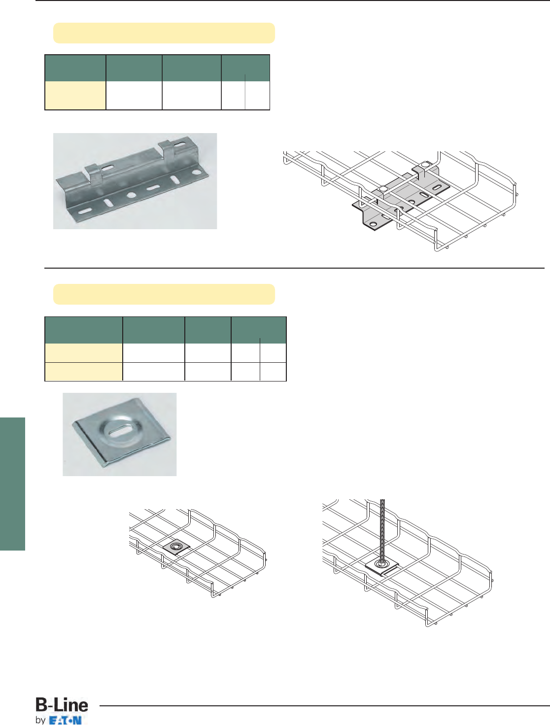
FLEXTRAY
Z Brackets
See page FLX-3 for finish information
Part Description Qty./Box Wt./Box
Number lbs. kg
Z BRKT__ Z Bracket 25 14.0 6.35
• Used for horizontal and/or vertical mounting
• 8” (200mm) wide bracket foror use with 4” (100mm)
to 32” (800mm) wide trays
• Can be used to offset trays from floor
• Can be used to terminate tray run at wall
• Multiple brackets can be used for wider tray widths
• Finishes __: GS, BLE
Use with two (2) FTSCH
(sold separately)
Hold Down Plate
Part Slot Size Qty./Box Wt./Box
Number lbs. kg
SUPT WASHER__ .28” x .70” 50 4.7 2.13
FTA6HD__ .40” x .70” 50 3.5 1.59
• Easy way to mount 4" (100mm) wide tray for raceway run.
• Use 1/4" screws to attach SUPT WASHER to your
specific wall/stud application (hardware sold separately).
• FTA6HD can be used in pairs to create a center-hung
support using 3/8" rod.
• To protect cables use threaded rod protector (page FLX-20).
• To complete 3/8" center hanger assembly use:
2 - FTA6HD
2 - HN 3/8"-16 hex nuts
• Finish: ZN, SS6
FLX-27
FLEXTRAY™- Wall Support Methods
Cable Tray Systems
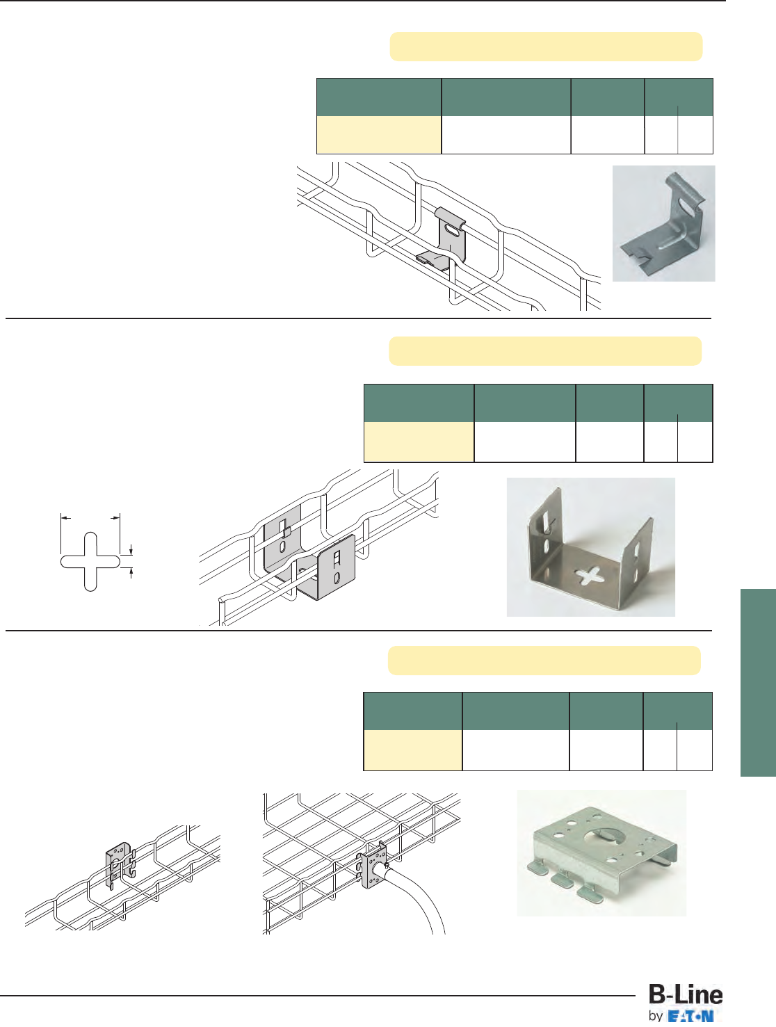
FLEXTRAY
Wall Supports
See page FLX-3 for finish information
Attachment Clips
Part Description Qty./Box Wt./Box
Number lbs. kg
ATTACHMENT CLP__ Attachment Clip 50 3.4 1.54
Support for FT2x2x10
• Wall attachment for 2” (50mm) wide
tray only (FT2X2X10)
• Low-profile appearance
• Built-in tab to hold down tray
• Can also be used with 2” (50mm) Center
Hanger (see page 60)
• Hardware sold separately
• Finishes __: GS, BLE
Part Description Qty./Box Wt./Box
Number lbs. kg
Wall Support
FTA050CC__ Bracket 1 0.8 0.36
• Used to attach 2” (50mm) or 4” (100mm) wide trays
to walls, struts or cabinets
• Use for raceway mounting
• Mount to metal framing for vertical support
• Tabs are built in for tray hold down
• Mount to side rail for electrical box connection
• Finishes __: GLV
Mounting Bracket
Part Description Qty./Box Wt./Box
Number lbs. kg
Light Duty
FTB2UB__ Wall/Rack Bracket 10 2.1 0.95
• Designed to support FT2X2X10 Flextray
• Click tabs for FLEXTRAY attachment
• Use 1/4” hardware and washer (not included) to
mount bracket
• Finishes __: SS6
.26" typ.
(6.6 mm)
1" typ.
(25 mm)
FLX-28
FLEXTRAY™- Wall Support Methods
Cable Tray Systems
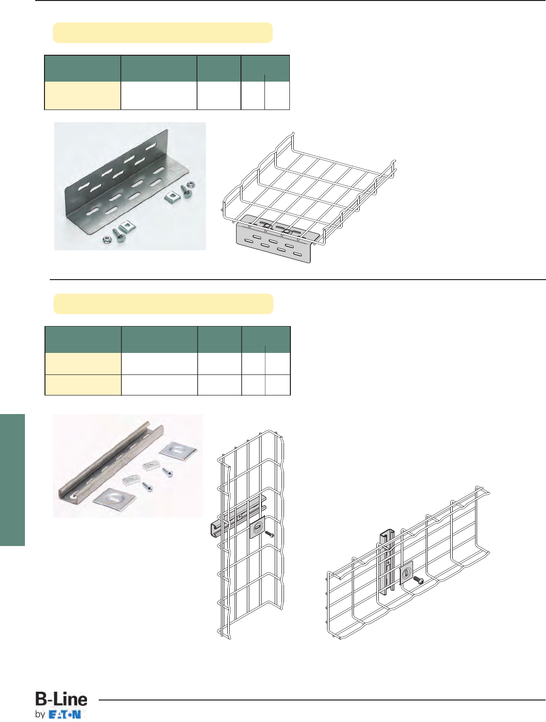
FLEXTRAY
Wall Termination Kit
Part Length Qty./Box Wt./Box
Number lbs. kg
FTA9WTK__ 9” 1 1.3 0.59
• Kit includes all hardware necessary to support
FLEXTRAY when terminated at a wall
• Mount slotted angle to wall with up to 3/8"
hardware (not included)
• Finishes __: ZN, FB, SS6
See page FLX-3 for finish information
Vertically Mounted
Horizontally Mounted
Wall Termination Kit includes:
1 - Angle with Slots
2 -
FTSCH
Wall Mount Kit
Part Length Qty./Box Wt./Box
Number lbs. kg
WB48WMK__ 8” 1 0.76 0.35
WB1224WMK__ 12” 1 1.22 0.55
• Kit includes all components necessary to mount
FLEXTRAY to a wall horizontally or vertically
• Mount strut to wall with up to 1/2" hardware
(not included)
• Finish: Channel - GLV
Hardware - ZN
Available in SS6
Wall Mount Kit includes:
WB48WMK WB1224WMK
11B54SH Strut
12SUPT WASHER Hold Downs
12
1/4"
-20
x 1" Slotted Head Screw
12N224WO Channel Nut
WB1224WMK shown
FLX-29
FLEXTRAY™- Wall Support Methods
Cable Tray Systems
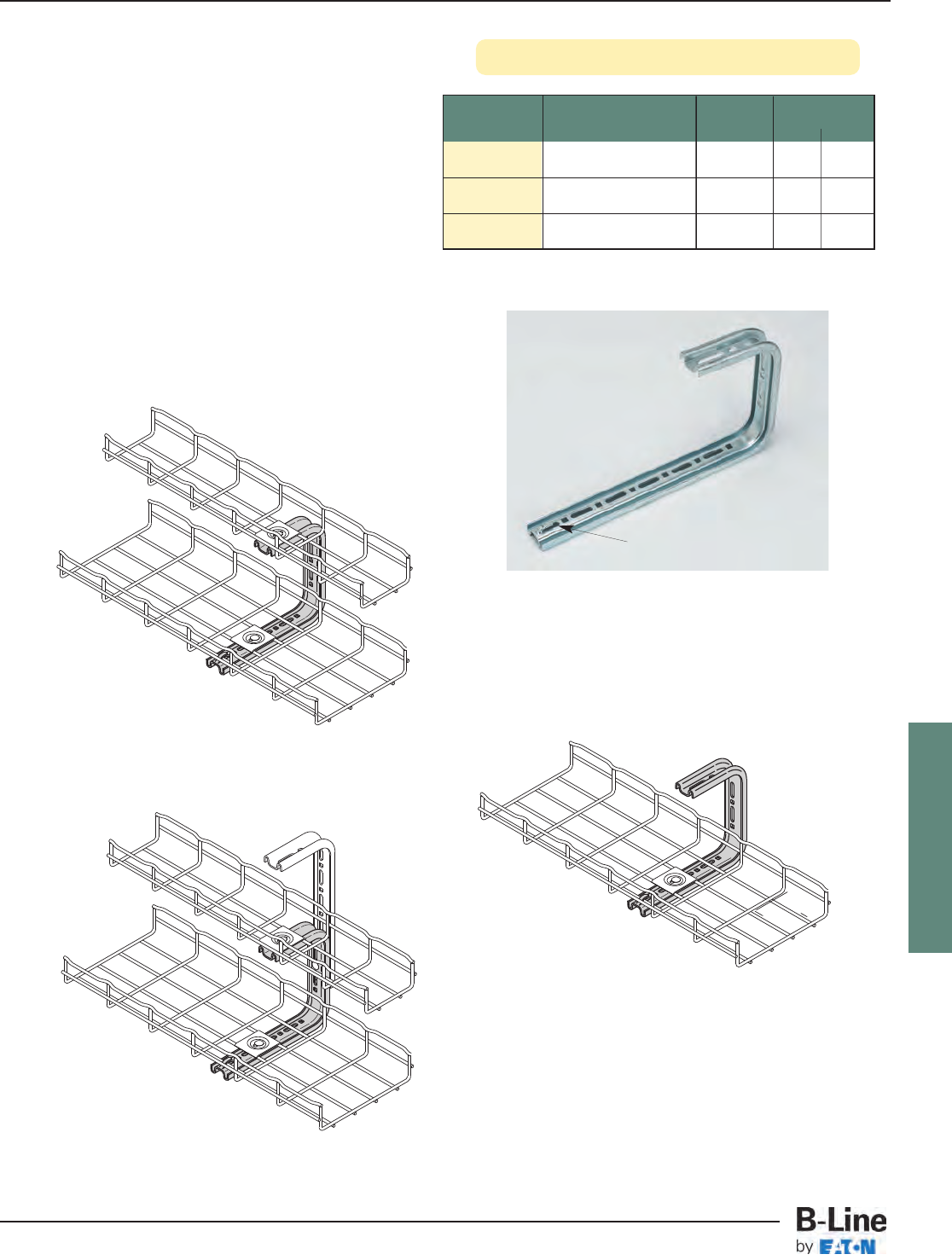
FLEXTRAY
C Brackets
Part Description Qty./Box Wt./Box
Number lbs. kg
4 C BRKT__ 4” (100mm) C Bracket 1 1.2 0.54
8 C BRKT__ 8” (200mm) C Bracket 1 1.4 0.63
12 C BRKT__ 12” (300mm) C Bracket 1 1.9 0.86
• Tab can be used for hold down
(stainless steel will not have these tabs)
• For use with 4” (100mm) to 12” (300mm) wide trays
• C Bracket attaches to hard ceiling types
• All brackets are 77/8” (200mm) tall
• Cables can be side loaded
• L Brackets (page FLX-26) and C Brackets can be
combined for layered tray runs
• Finishes __: EG, BLE, HD
See page FLX-3 for finish information
Hold down tab.
Assemble with
SUPT WASHER &
FTHDWE 1/4.
FLX-30
FLEXTRAY™- Wall Support Methods
Cable Tray Systems
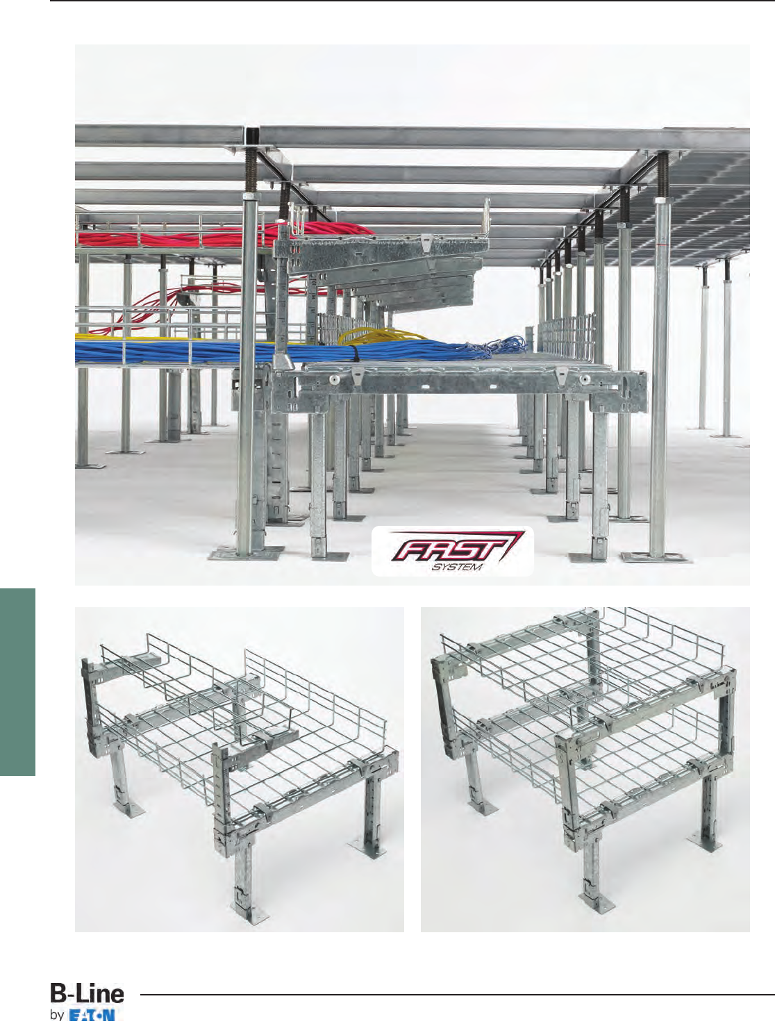
FLEXTRAY
The F.A.S.T. System is an innovative and flexible way to support and manage cables in raised floor applications. This Foldable, Adjustable,
Stackable, Tool-less System uses FLEXTRAY, stands, and accessories to provide a variety of options for your project and the fastest
installation time on the market. Best of all, it does not attach to the raised floor structure and can be installed either before or after floor
is in place.
FLX-31
FLEXTRAY™- F.A.S.T.™Underfloor System
Cable Tray Systems
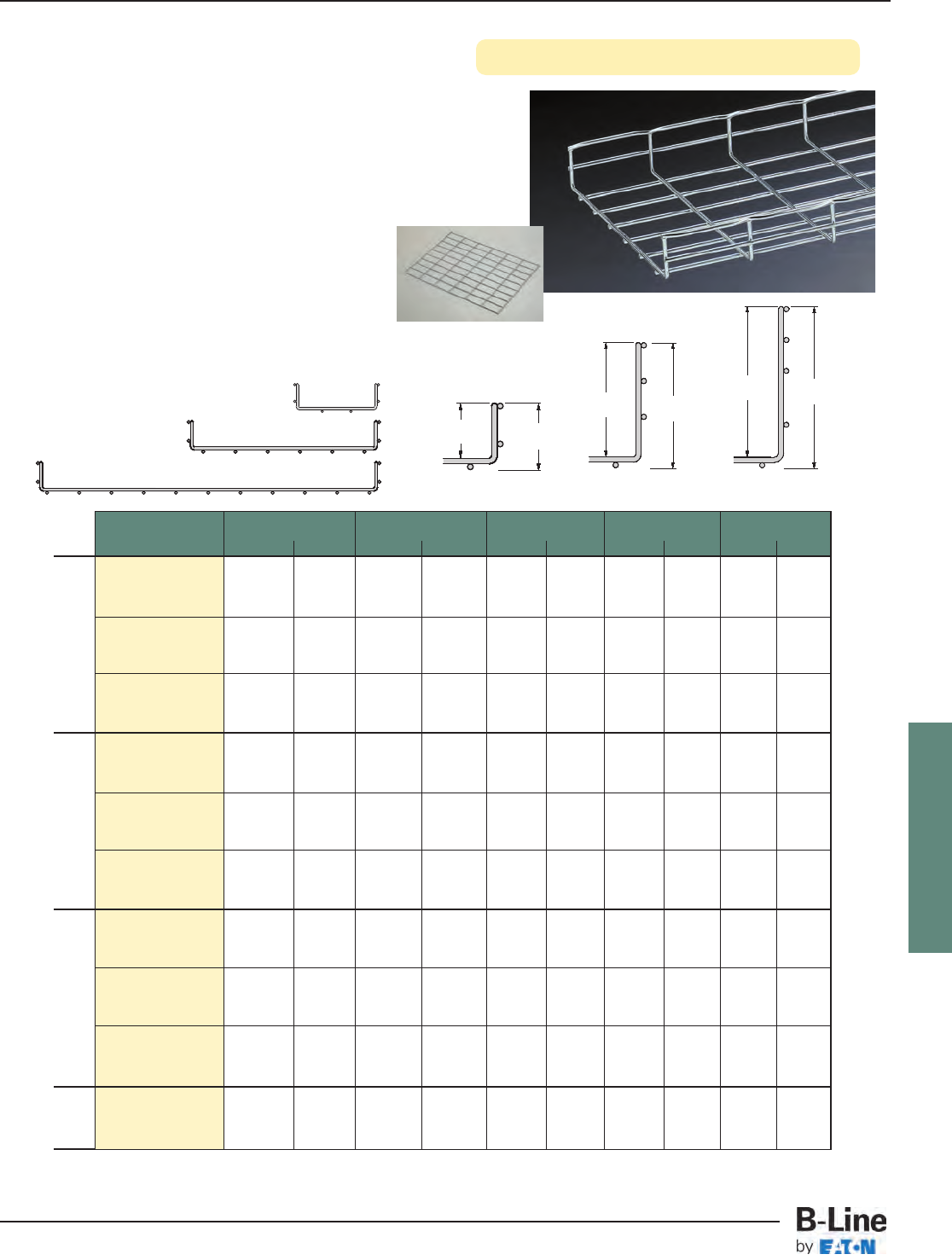
FLEXTRAY
See page FLX-3 for finish information
6” (150 mm)
2” deep 4” deep 6” deep
12” (300 mm)
20” (500 mm)
Widths
Depths
LD H
Part Width Length LD H Wt. Per Pc.
Number in. mm in. mm in. mm in. mm lbs. kg
FTU2X6X2 6150 23.9 603 2.38 60 2.77 70 2.03 0.92
FTU2X6X4 6150 47.5 1206 2.38 60 2.77 70 3.95 1.79
FTU2X6X10 6150 118.4 3008 2.38 60 2.77 70 9.72 4.41
FTU2X12X2 12 300 23.9 603 2.38 60 2.77 70 2.99 1.36
FTU2X12X4 12 300 47.5 1206 2.38 60 2.77 70 5.82 2.64
FTU2X12X10 12 300 118.4 3008 2.38 60 2.77 70 14.32 6.50
FTU2X20X2 20 500 23.9 603 2.38 60 2.77 70 4.28 1.94
FTU2X20X4 20 500 47.5 1206 2.38 60 2.77 70 8.33 3.78
FTU2X20X10 20 500 118.4 3008 2.38 60 2.77 70 20.45 9.28
FTU4X6X2 6150 23.9 603 4.38 111 4.77 121 2.67 1.21
FTU4X6X4 6150 47.5 1206 4.38 111 4.77 121 5.20 2.36
FTU4X6X10 6150 118.4 3008 4.38 111 4.77 121 12.79 5.80
FTU4X12X2 12 300 23.9 603 4.38 111 4.77 121 3.64 1.65
FTU4X12X4 12 300 47.5 1206 4.38 111 4.77 121 7.08 3.21
FTU4X12X10 12 300 118.4 3008 4.38 111 4.77 121 17.39 7.89
FTU4X20X2 20 500 23.9 603 4.38 111 4.77 121 4.93 2.24
FTU4X20X4 20 500 47.5 1206 4.38 111 4.77 121 9.58 4.35
FTU4X20X10 20 500 118.4 3008 4.38 111 4.77 121 23.52 10.67
FTU6X6X2 6150 23.9 603 6.38 162 6.77 172 3.32 1.51
FTU6X6X4 6150 47.5 1206 6.38 162 6.77 172 6.45 2.93
FTU6X6X10 6150 118.4 3008 6.38 162 6.77 172 15.85 7.19
FTU6X12X2 12 300 23.9 603 6.38 162 6.77 172 4.28 1.94
FTU6X12X4 12 300 47.5 1206 6.38 162 6.77 172 8.33 3.78
FTU6X12X10 12 300 118.4 3008 6.38 162 6.77 172 20.45 9.28
FTU6X20X2 20 500 23.9 603 6.38 162 6.77 172 5.57 2.53
FTU6X20X4 20 500 47.5 1206 6.38 162 6.77 172 10.83 4.91
FTU6X20X10 20 500 118.4 3008 6.38 162 6.77 172 26.59 12.06
WBUFLT 20 500 24 604 ----2.96 1.34
WBUFLT-12 12 250 24 604 ----1.50 0.68
WBUFLT-06 6150 24 604 ----1.00 0.45
LD H
LD H
2” (50mm) deep
4” (100mm) deep6” (150mm) deep
Flats
Flat Fitting
• Rounded ends on all wires
• UL Classified (see technical data for details)
• Depths: 2”, 4”, & 6” nominal
• Lengths: 24”, 48”, & 118”
• Use flat fitting (WBUFLT) for turns
• Wire Diameter: 0.191” (4.9mm)
• Standard finishes: GLV
Consult customer service for other
available finishes
F.A.S.T. System Flextray
FLX-32
FLEXTRAY™- F.A.S.T.™Underfloor System
Cable Tray Systems
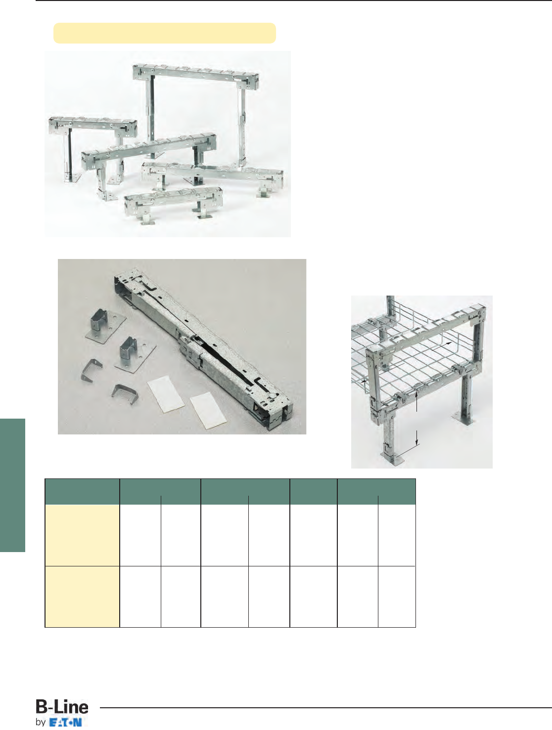
FLEXTRAY
See page FLX-3 for finish information
Part Max. Basket Width Height Adjustment Stands Wt. Per Box
Number in. mm in. mm Per Box lbs. kg
FTU120404 12 300 4101 2 1.82 0.82
FTU120608 12 300 6-8 152-203 2 2.79 1.26
WBU1216 12 300 10-16 254-406 2 7.44 3.37
WBU1224 * 12 300 18-24 457-609 2 9.06 4.11
WBU1231 * 12 300 25-31 635-787 2 10.52 4.77
FTU200404 20 500 4101 2 2.34 1.06
FTU200608 20 500 6-8 152-203 2 3.36 1.52
WBU2016 20 500 10-16 254-406 2 8.56 3.88
WBU2024 20 500 18-24 457-609 2 10.20 4.62
WBU2031 * 20 500 25-31 635-787 2 11.64 5.28
WBU2016
WBU2016 shown
WBU1216
FTU200608
FTU200404
FTU120404
* Legs are packed separately in box and not inserted in stand.
WBU2016 stands shown in double tier application.
Feet and adhesive pads not required for second tier assembly.
Height
Adjustment
Max. Basket
Width
• No tools required for installation
• Formed top surface free of protrusions or
sharp edges
• Up to 6” height adjustment
• Inside and outside leg positioning
• Folded and boxed for ease in shipping
• Patent Pending
• Stand part number includes:
one (1) stand
two (2) feet
two (2) adhesive pads
two (2) hold down clips
• Standard finish: Pre-Galvanized
Stands
FLX-33
FLEXTRAY™- F.A.S.T.™Underfloor System
Cable Tray Systems
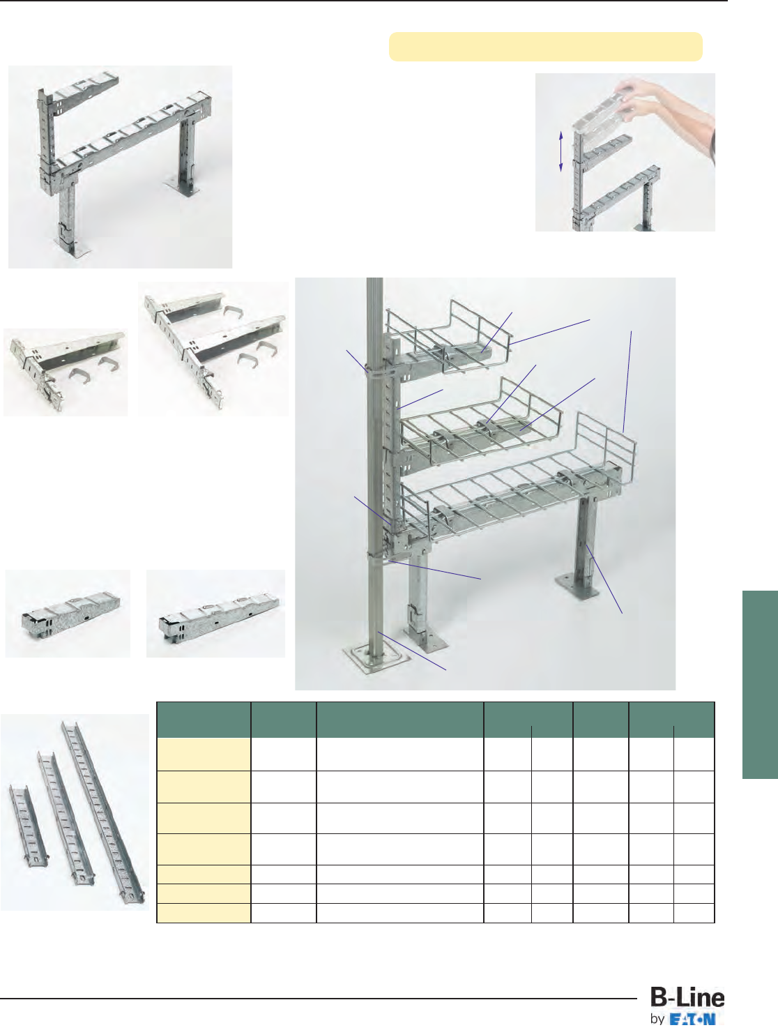
FLEXTRAY
See page FLX-3 for finish information
WBUCK12 - Single Tier
Cantilever Kit
Includes
(1) WBUCB12
(1) WBUL16
(1) WBUCF
(2) WBUHD
WBUCB8 WBUCB12
WBUCK812 - Double Tier
Cantilever Kit
Includes
(1) WBUCB8
(1) WBUCB12
(1) WBUL24
(1) WBUCF
(3) WBUHD
Part Item # Description Max Height †Box Qty. Wt. Per Box
Number in. mm lbs. kg
WBUCK12 * 1 ΔCantilever Kit - Single Tier 7.30 185 10 15.62 7.08
with 12” Bracket
WBUCK812 2 ΔCantilever Kit - Double Tier 15.25 387 10 25.40 11.52
with 8” & 12” Brackets
WBUCB8 38” Cantilever Bracket --10 5.51 2.50
for 6” Flextray
WBUCB12 412” Cantilever Bracket --10 9.16 4.15
for up to 12” Flextray
WBUL16 5Short Vertical Support 7.30 185 10 4.37 1.98
WBUL24 6Medium Vertical Support 15.25 387 10 8.45 3.83
WBUL31 7Tall Vertical Support 22.25 565 10 12.07 5.47
*For use with 2” and 4” deep Flextray on the lower level. †Height - from top of stand ΔStand not included
1
WBUCK812 Double Tier Cantilever Kit Shown with WBU2016 Stand
Flextray
(See pg. 73)
Adjustability of shelf brackets
Stand
(Sold Separately
See pg. 74)
Flooring Post
2
34
3
4
5
7
5, 6 or 7
8 (See pg. 76)
10
(See pg. 76)
9
(See pg. 76)
6
9
(See pg. 76)
• No tools required for installation
• Simple design for tiered applications
• Available in kits or individual parts
• Adjustable shelf height
• Formed top surface has no sharp edges
• Can be installed independent of raised floor
• Standard finish: Pre-Galvanized
Cantilever Kits & Accessories
FLX-34
FLEXTRAY™- F.A.S.T.™Underfloor System
Cable Tray Systems
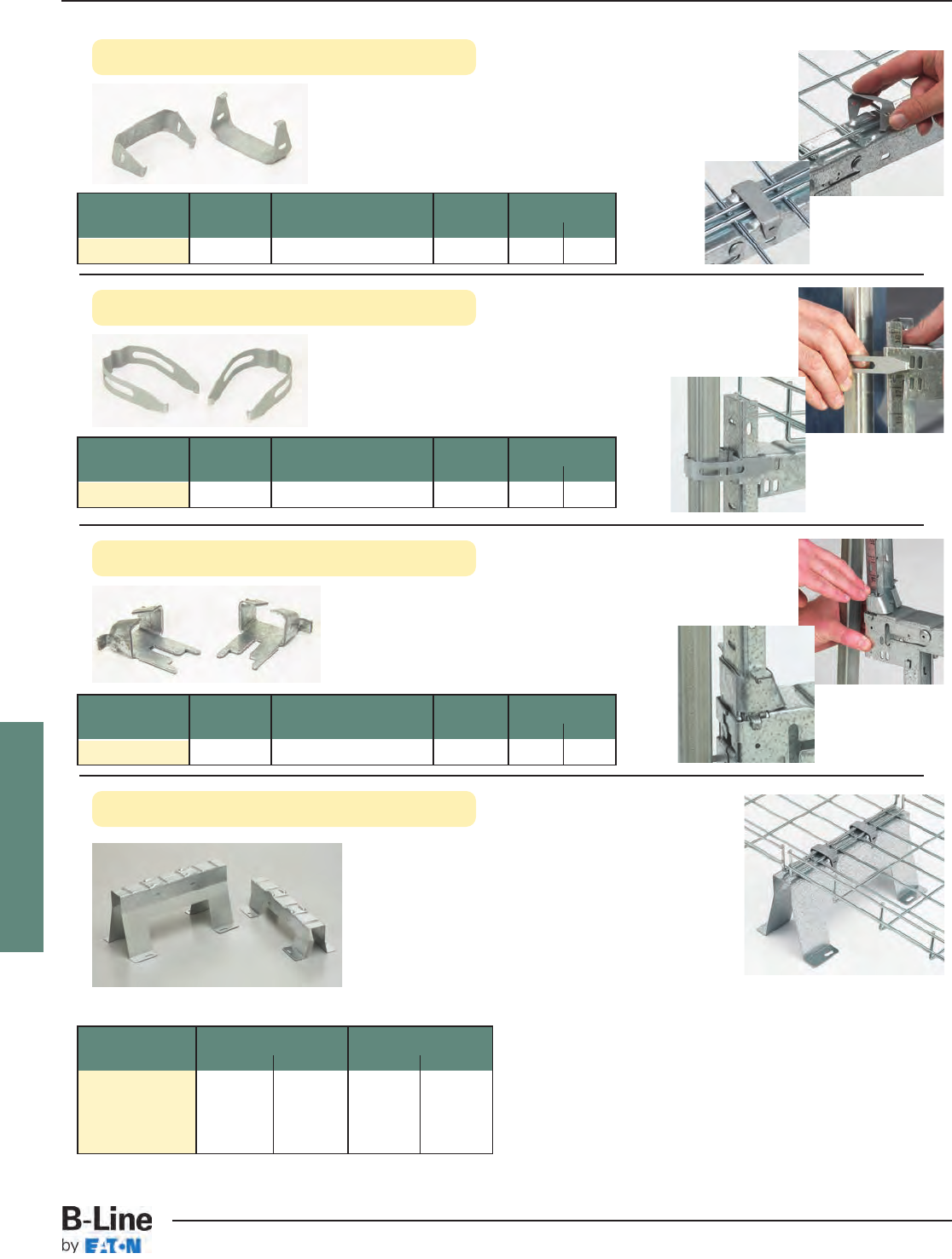
FLEXTRAY
See page FLX-3 for finish information
Part Overall Height Wt. Per Each
Number in. mm lbs. kg
WBU1203 376 1.32 0.60
WBU1204 4101 1.60 0.72
WBU1205 5127 1.88 0.85
WBU1206 6152 2.17 0.98
Part Item # Description Box Qty. Wt. Per Box
Number lbs. kg
WBUHD 8Basket Clip 50 1.10 0.50
Part Item # Description Box Qty. Wt. Per Box
Number lbs. kg
WBUPC 9Pedestal Clip 50 1.65 0.75
Part Item # Description Box Qty. Wt. Per Box
Number lbs. kg
WBUCF 10 Cantilever Foot 50 8.65 3.92
• Heights of 3”, 4”, 5” or 6”
• Leg cutout allows for airflow
• No tools required to mount FLEXTRAY to stand
• Use WBUHD hold down clips to secure basket
• Stand width is 12”
• Fasten to floor for maximum stability
• Floor mounting slot size: .313” (7.9mm) x .813” (20.6mm) for 1/4” hardware
• Secures vertical support into stand top
• Only required when stand legs are in the
inner position
• Optional spring steel clip to give added rigidity
to system
• Works with stands and cantilever brackets
• Spring steel clip to attach Flextray to stands
• No tools required for installation
• Holds both continuous and spliced wire sections securely
• Works with stands and cantilever brackets
Hold Down Clip
Pedestal Clip
Cantilever Foot
Under Floor Stand
FLX-35
FLEXTRAY™- F.A.S.T.™Underfloor System
Cable Tray Systems
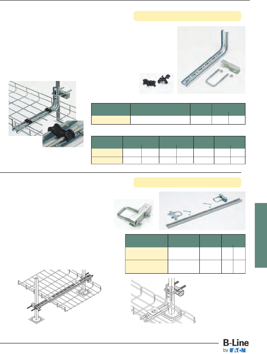
FLEXTRAY
See page FLX-3 for finish information
Part System Width Length Box Qty. Wt. Per Box
Number in. mm in. mm lbs. kg
8 L BRKT 6-8 150-200 8200 1 0.80 0.36
12 L BRKT 12 300 12 300 1 1.30 0.59
Part Description Qty. Wt. Per Box
Number lbs. kg
TOOLLESS CLIP Tool-less Hold-Down Clip 50/Box 1.00 0.45
• For use when access to ground floor is limited
• Use with round post sizes 0.9” (25mm) through 1.2” (30mm)
• Use with square posts
• Order clamps and brackets separately
• Built-in tab for hold down
• Tool-less Clip (plenum-rated material) - Snap-in locking pin
securely holds basket to bracket
Brackets (Zinc Plated)
12 L BRKT
shown
PEDESTAL CLAMP
TOOLLESS CLIP
L Bracket & Toolless Clip
Pedestal Clamp & Kit
Part Description Qty./Box Wt./Box
Number lbs. kg
Pedestal
PEDESTAL CLAMP__ Clamp 1 0.6 0.27
Pedestal
PEDESTAL KIT__ Clamp Kit 1* 3.3 1.49
• Clamps to existing raised-access floor
stanchion
• Use L BRKT (shown above) or full pedestal
kit to support trays under the raised access
floor (sold separately)
• For tray widths 2” (50mm) to 20” (500mm)
• *Pedestal Clamp Kit includes two (2)
pedestal clamps, 28” (711mm) profile
section, bolts & nuts
• Kits include hardware
• SUPTWASHER & FTHDWE 1/4 sold separately
• Finishes __: EG
Pedestal kits are recommended for
tray widths of 16” (400mm) or
greater
Illustration photos.
All parts are sold separately.
FLX-36
FLEXTRAY™- F.A.S.T.™Underfloor System
Cable Tray Systems
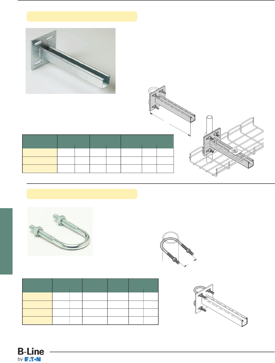
FLEXTRAY
See page FLX-3 for finish information
• Under Floor Support Bracket provides rugged support for
FLEXTRAY System from access floor post.
• To complete the installation, the following hardware
must be ordered separately.
(2) - B501 U-Bolts
(1) - SUPT WASHER Hold Down
(1) - 1/4"
-20
x 1" Slotted Head Screw
(1) - N224WO Channel Nut
• Finish: ZN
• Designed for attachment of Under Floor Support Brackets to
access floor post. Each U-Bolt includes two (2) hex nuts.
• Finish: ZN
Part ‘A’ Thread Box Wt. Per Box
Number in. mm Size Quantity lbs. kg
B501-1 13/8”30 5/16”-18 50 7.0 3.17
B501-11/22” 50 5/16”-18 50 8.0 3.63
B501-2 27/16”62 3/8”-16 20 5.4 2.45
B501-21/2215/16”75 3/8”-16 25 8.0 3.63
‘A’
‘A’
Part ‘A’ Thread Box Wt. Per Box
Number in. mm in. mm Quantity lbs. kg
B409UF-12 12” 300 12” 300 1 3.6 1.63
B409UF-18 18” 450 18” 450 1 4.5 2.04
B409UF-21 21” 533 21” 533 1 5.4 2.45
Under Floor Support Bracket
U-Bolts
FLX-37
FLEXTRAY™- F.A.S.T.™Underfloor System
Cable Tray Systems
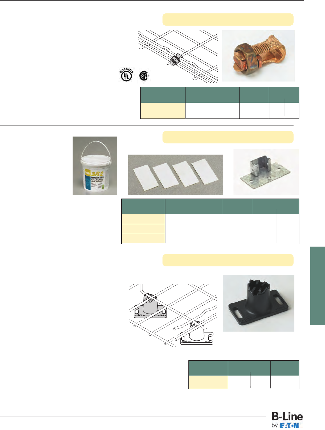
FLEXTRAY
See page FLX-3 for finish information
Part Description Box Qty. Wt. Per Box
Number lbs. kg
WBUF Stand Foot 10 2.36 1.07
WBUTAPE Double-Sided Tape 50 2.50 1.13
WBUFA Floor Adhesive 1 Gallon 10.78 4.89
WBUF
WBUTAPE
• WBUTAPE - Double-sided adhesive pads
for temporary positioning of floor stands
Pad Size: 2” (50mm) x 4” (100mm)
• WBUFA - Adhesive to secure stand to floor
Ground Bolt
Adhesive & Feet
Part Description Qty./Box Wt./Box
Number lbs. kg
GROUND BOLT Ground Bolt 1 0.11 0.05
• Attaches up to #1 ground wire to each tray
section when separate ground wire is required
• Used for UL grounding compliance.
• When using color powder coated finish or
paint, coating must be removed at the points
of contact.
• Finish: Copper Plated
Floor Stand
• Non-metallic snap lock floor stand is
designed for use under access floors.
• Floor stand elevates FLEXTRAY System
15/8" (41.3mm) above the floor.
• To attach floor stand, use Liquid Nails™
or anchors.
• Elevation increments of 13/8" (35mm)
can be obtained by stacking floor
stands.
• Sized for 1/4" hardware
(order separately).
• Material: Black Plenum-rated Plastic
Part Wt. Per Pc. Box
Number lbs. kg Quantity
FTA2FS 0.44 0.20 10
FLX-38
FLEXTRAY™- F.A.S.T.™Underfloor System
Cable Tray Systems
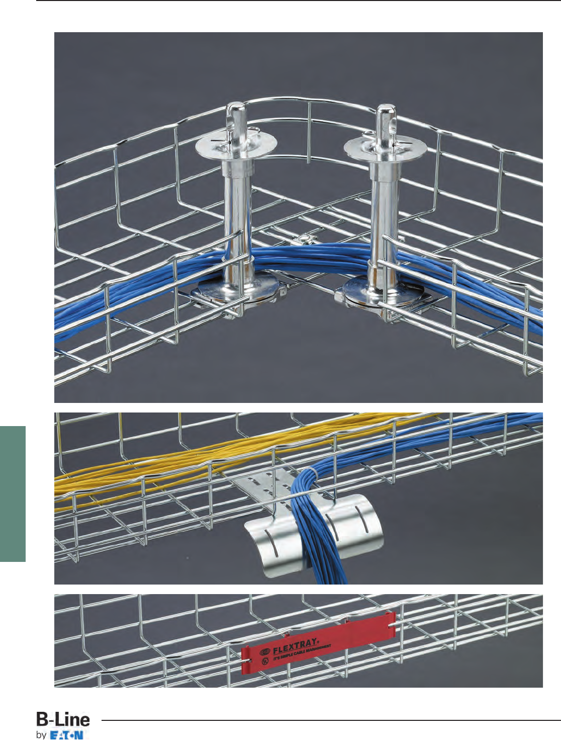
FLEXTRAY
FLX-39
FLEXTRAY™- Accessories
Cable Tray Systems
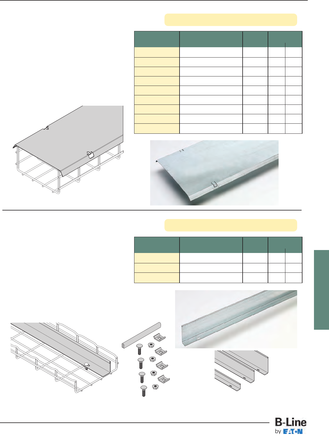
FLEXTRAY
Covers
Dividers
Part Use With Qty./Box Wt./Box
Number Tray Width lbs. kg
2 IN COVER__ 2” (50mm) 1 3.8 1.72
4 IN COVER__ 4” (100mm) 1 5.7 2.58
6 IN COVER__ 6” (150mm) 1 6.7 3.04
8 IN COVER__ 8” (200mm) 1 8.7 3.94
12 IN COVER__ 12” (300mm) 1 11.6 5.26
16 IN COVER__ 16” (400mm) 1 15.6 7.07
18 IN COVER__ 18” (450mm) 1 17.0 7.71
20 IN COVER__ 20” (500mm) 1 18.5 8.39
24 IN COVER__ 24” (600mm) 1 22.0 9.98
• Protects cable from debris and dust
• Adds security to cable installation
• Easy bend-over tabs secure cover to trays
• Available for 2” (50mm) to 24” (600mm) wide
trays
• Comes in 118” (2997mm) length
• Finishes __: GS, BLE, 304S, 316S
See page FLX-3 for finish information
• Allows cable separation within a single tray
• Hemmed/rounded edge provides cable
jacket safety
• Hardware included
• Field miter for bends and turns
• Dual slots every 24” (609mm) for field cutting
• Available in 2” (50mm), 4” (100mm) and
6” (150mm) heights
• Comes in 118.125” (3000mm) length
• Finishes __: GS, BLE, 304S, 316S
Part Use With Qty./Box Wt./Box
Number Tray Depth lbs. kg
2 IN DIVIDER__ 2” (50mm) Deep 1 3.5 1.59
4 IN DIVIDER __ 4” (100mm) Deep 1 9.6 4.35
6 IN DIVIDER __ 6” (150mm) Deep 1 14.5 6.58
2” 4”
6”
Dividers include
hardware shown
below
FLX-40
FLEXTRAY™- Accessories
Cable Tray Systems
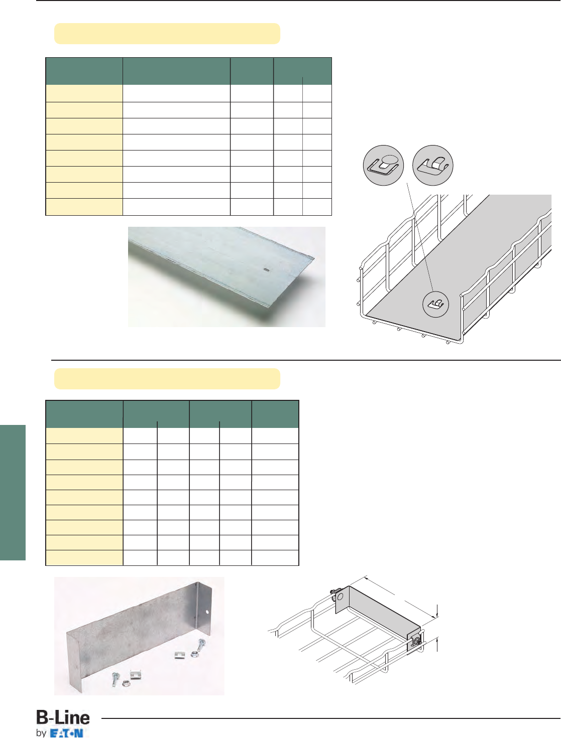
FLEXTRAY
Blind Ends
Solid Bottom Inserts • Continuous support for sensitive cables
• Security of cable in high-traffic areas
• Hardware included
• Available for 2” (50mm) to 24” (600mm) wide
trays
• Comes in 118” (2997mm) length
• Finishes __: GS, BLE, 304S, 316S
See page FLX-3 for finish information
Attach with
FTHDWE 1/4 &
Top Washer
Part Use With Qty./Box Wt./Box
Number Tray Width lbs. kg
INSERT 4X118__ 4” (100mm) 1 6.8 3.08
INSERT 6X118__ 6” (150mm) 1 9.8 4.44
INSERT 8X118__ 8” (200mm) 1 13.3 6.03
INSERT 12X118__ 12” (300mm) 1 21.6 9.80
INSERT 16X118__ 16” (400mm) 1 26.4 11.97
INSERT 18X118__ 18” (450mm) 1 32.4 14.69
INSERT 20X118__ 20” (500mm) 1 32.9 14.92
INSERT 24X118__ 24” (600mm) 1 39.3 17.82
‘A’
Height
• Forms a closure for a dead-end FLEXTRAY
• Hardware included
• Finish: GLV, SS6
(*) Insert: 2 = 2" (50 mm), 4 = 4" (100 mm) for height
(**) Insert: 2 = 2" (50 mm), 4 = 4" (100 mm),
6 = 6" (150 mm) for height
Part ‘A’ Height Box
Number in. mm in. mm Quantity
FT BE 2X2 2” 50 2” 50 1
FT BE (*)X4 4” 100 (*) (*) 1
FT BE (*)X6 6” 150 (*) (*) 1
FT BE (**)X8 8” 200 (*) (*) 1
FT BE (**)X12 12” 300 (**) (**) 1
FT BE (**)X16 16” 400 (**) (**) 1
FT BE (**)X18 18” 450 (**) (**) 1
FT BE (**)X20 20” 500 (**) (**) 1
FT BE (**)X24 24” 600 (**) (**) 1
FLX-41
FLEXTRAY™- Accessories
Cable Tray Systems
Attachment
methods
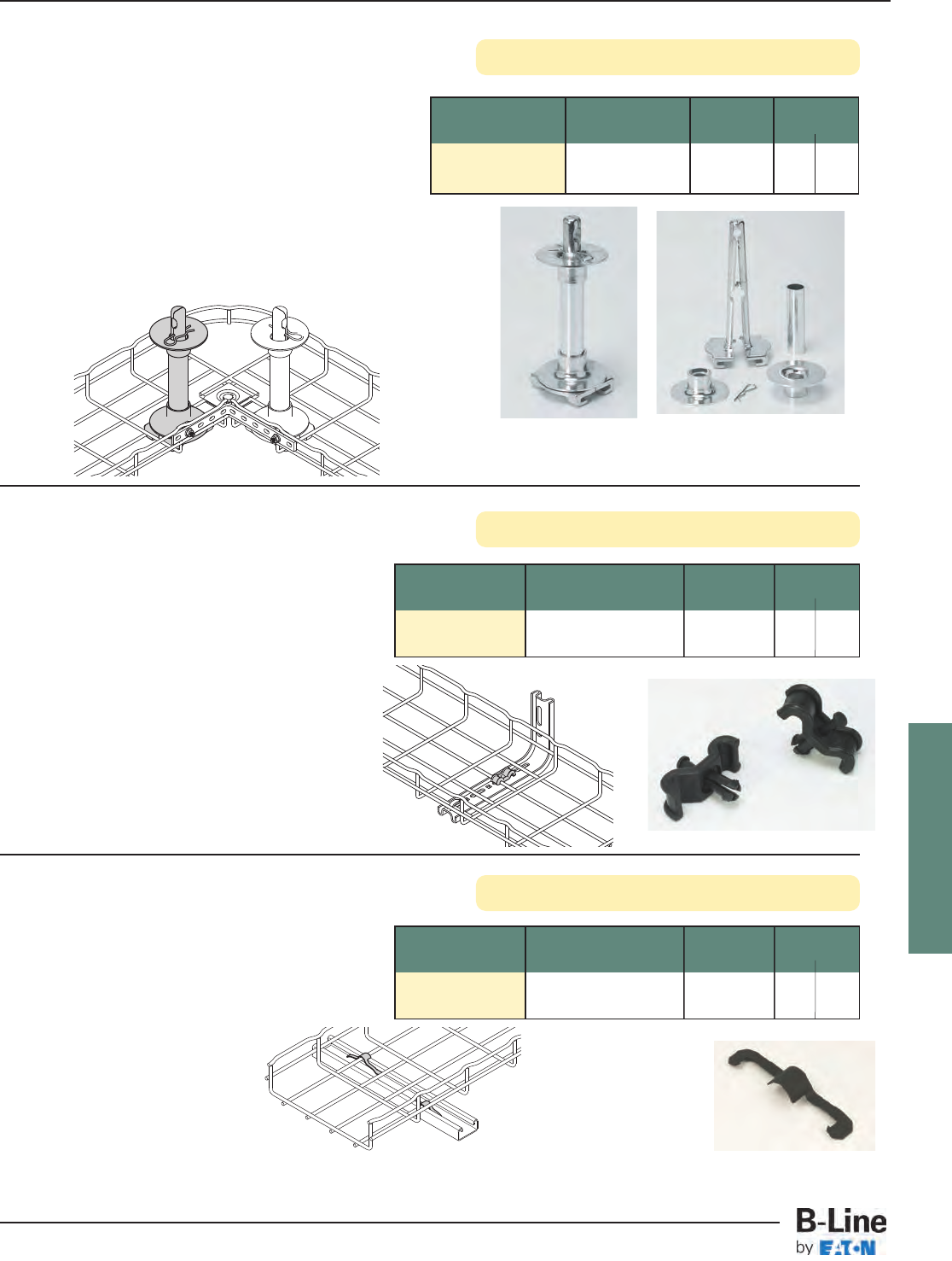
FLEXTRAY
Cable Roller
Toolless Clip
See page FLX-3 for finish information
Part Description Qty./Box Wt./Box
Number lbs. kg
CABLE ROLLER Cable Roller 1 1.0 0.45
• Protects and maintains recommended cable radii
for Cat 5, Cat 5E, Cat 6, Cat 6A, Fiber, etc.
• Height of roller can be adjusted to tray depth
• Installs in seconds with no tools
• Reduces cable installation time
• Prevents migration of cables
• For use with 4” (100mm) to 32” (800mm) tray widths
• Finish: Cast Aluminum
Quick, snap-together design
Part Description Qty./Box Wt./Box
Number lbs. kg
TOOLLESS CLIP Toolless 50 1.0 0.45
Hold-Down Clip
• Securely holds tray to support
• Snap-in locking pin
• No tools or fastening required
• Fastest hold-down method available
• For use with the following:
FTB__CS (see pg. 67)
L BRKT (see pg. 67)
C BRKT (see pg. 71)
• Finish: Plenum rated resin (black)
Strut Mounting Clip
Part Description Qty./Box Wt./Box
Number lbs. kg
BW4 Strut Mounting Clip 100 0.9 0.41
• Use to secure FLEXTRAY to horizontal strut
support
• Designed for use as shown in drawing
(no load rating)
• Finish: Black Zinc Phosphate
FLX-42
FLEXTRAY™- Accessories
Cable Tray Systems
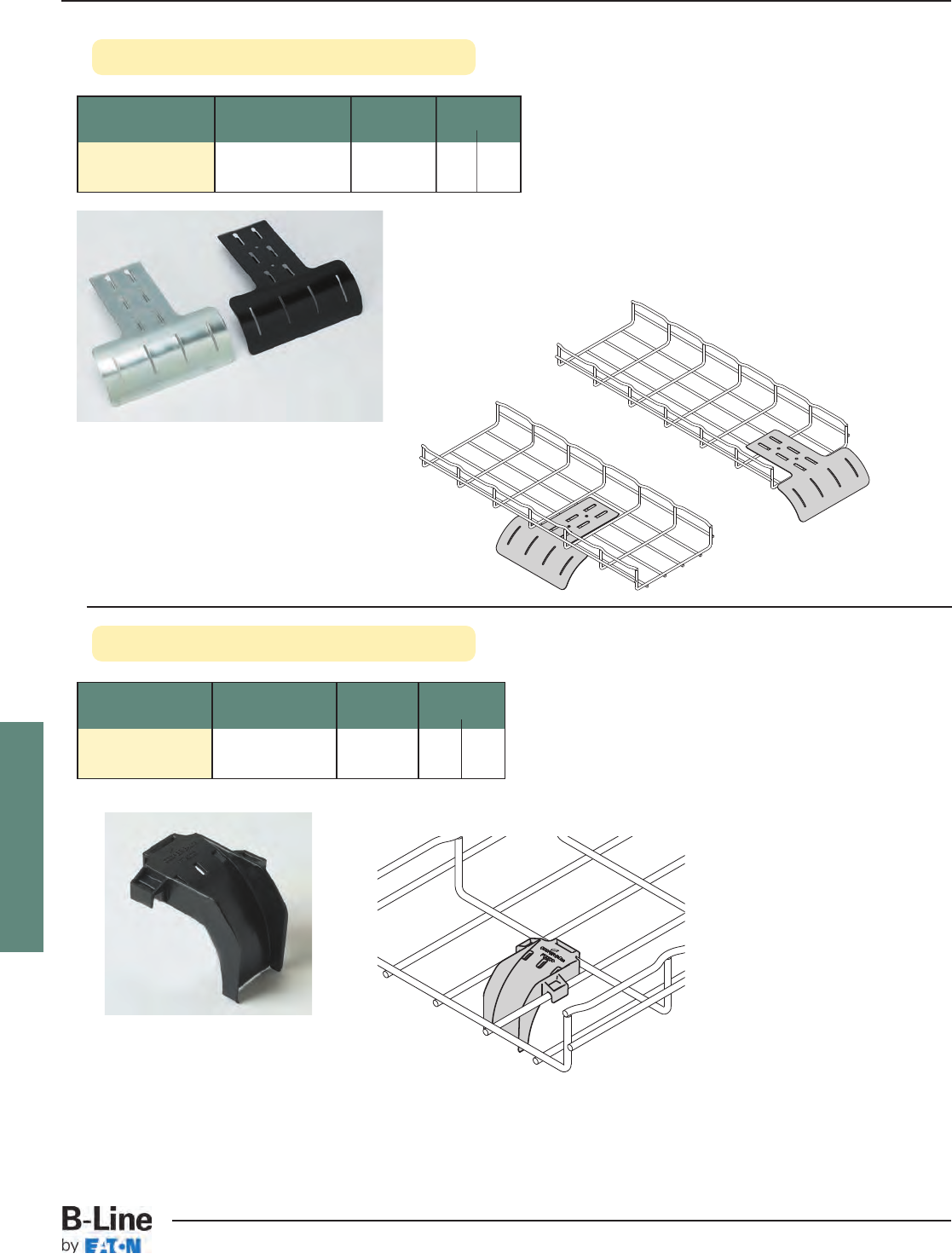
FLEXTRAY
Cable Drop Out
Drop Out Fitting
Part Description Qty./Box Wt./Box
Number lbs. kg
FTA2DO Cable Drop Out 10 0.17 0.08
• Non-metallic 2" (50mm) radius Cable Drop-Out
snap locks into mesh bottom and protects cables
from sharp bend
• Material: Black Plenum-rated Plastic
See page FLX-3 for finish information
Part Description Qty./Box Wt./Box
Number lbs. kg
DROP OUT__ Drop Out Fitting 50 15.0 6.8
• Keeps cable radius secure at drop point
• For use with 4” (100mm) to 32” (800mm) wide trays
• Attaches to tray without hardware
• Drop outs can be attached at bottom, side or
ends of tray
• Hold down tabs on bottom of drop out to secure tray
• Finishes __: EG, BLE, SS6
FLX-43
FLEXTRAY™- Accessories
Cable Tray Systems
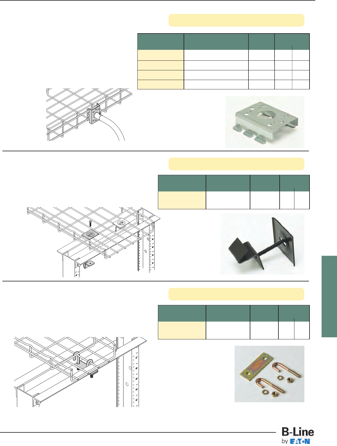
FLEXTRAY
Rack Clamp
Conduit Connector
See page FLX-3 for finish information
• Conduit connector is designed to connect
conduit to the side or bottom of FLEXTRAY
• Conduit bushing will remain outside of tray
to keep cable pathway clear
• Bend tabs to secure connector to tray
• No hardware included
• Finishes __: GLV
Part Description Qty./Box Wt./Box
Number lbs. kg
FTA050CC__ 1/2” (15mm) Conduit Clip 10 2.0 0.91
FTA075CC __ 3/4” (20mm) Conduit Clip 10 2.0 0.91
FTA100CC __ 1” (25mm) Conduit Clip 10 2.0 0.91
FTA125CC __ 11/4” (32mm) Conduit Clip 10 2.0 0.91
Part Description Qty./Box Wt./Box
Number lbs. kg
RACK CLAMP__ Rack Clamp 4 4.7 2.13
• Securely holds tray down to rack
• Installs without drilling
• Black-painted finish to match rack
• Finish__: BLE
Adaptor Kit
Part Description Qty./Box Wt./Box
Number lbs. kg
SB2204__ Adaptor Kit 1 0.37 0.17
• Adaptor kit includes all hardware necessary to
connect Flextray system to top of relay rack at
right angle or parallel position
• Finish__: YZN (Yellow Zinc Chromate)
Adaptor Kit includes:
(1) - Mounting Plate
(2) - 5/16"
-18
x 2" “J”-Bolts
(2) - HN 5/16"
-18
Hex Nuts
(2) - LW 5/16" Lock Washers
FLX-44
FLEXTRAY™- Accessories
Cable Tray Systems
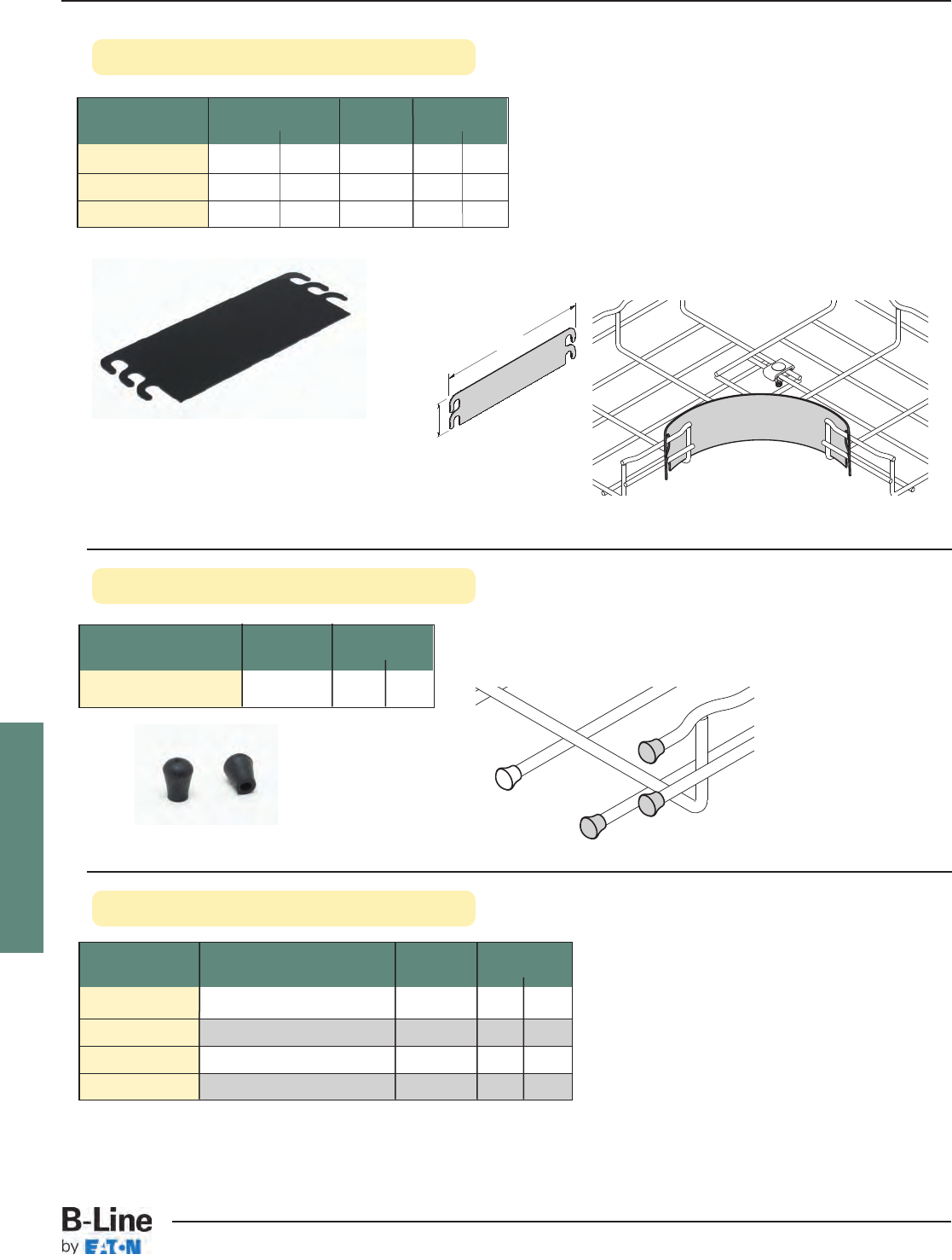
FLEXTRAY
Rubber Cap
Radius Shield
See page FLX-3 for finish information
Part Description Qty./Box Wt./Box
Number in. mm lbs. kg
FTA2RS 2.5 63 50 4.0 1.8
FTA4RS 4.3 110 50 7.0 3.2
FTA6RS 5.9 150 25 5.0 2.3
• Provides a smooth inside radius surface.
• No tools or fasteners needed to install.
• Sizes for 2", 4" & 6" deep FLEXTRAY; 90°
horizontal bends, tees, and crosses.
• Installs in seconds. Simply hold in place and
bend back tabs.
• Slick surface to reduce cable friction.
• Material: Black Polycarbonate
‘A’
11"
(279 mm)
Part Color Box Wt. Per Pc.
Number Quantity lbs. kg
SB420ATG
Gray Lacquer 1 0.9 0.41
SB420AFB
Flat Black Lacquer 1 0.9 0.41
SB420ACW Computer White Lacquer
1 0.9 0.41
B999
Silver Zinc-Rich Paint 1 0.9 0.41
• Install on wire ends if required. Fits all wire diameters
Part Box Wt. Per 100
Number Quantity lbs. kg
B719EB 100 0.20 0.10
Touch-Up Paint
• Size: 12 ounce aerosol can
• Cannot ship air freight
FLX-45
FLEXTRAY™- Accessories
Cable Tray Systems
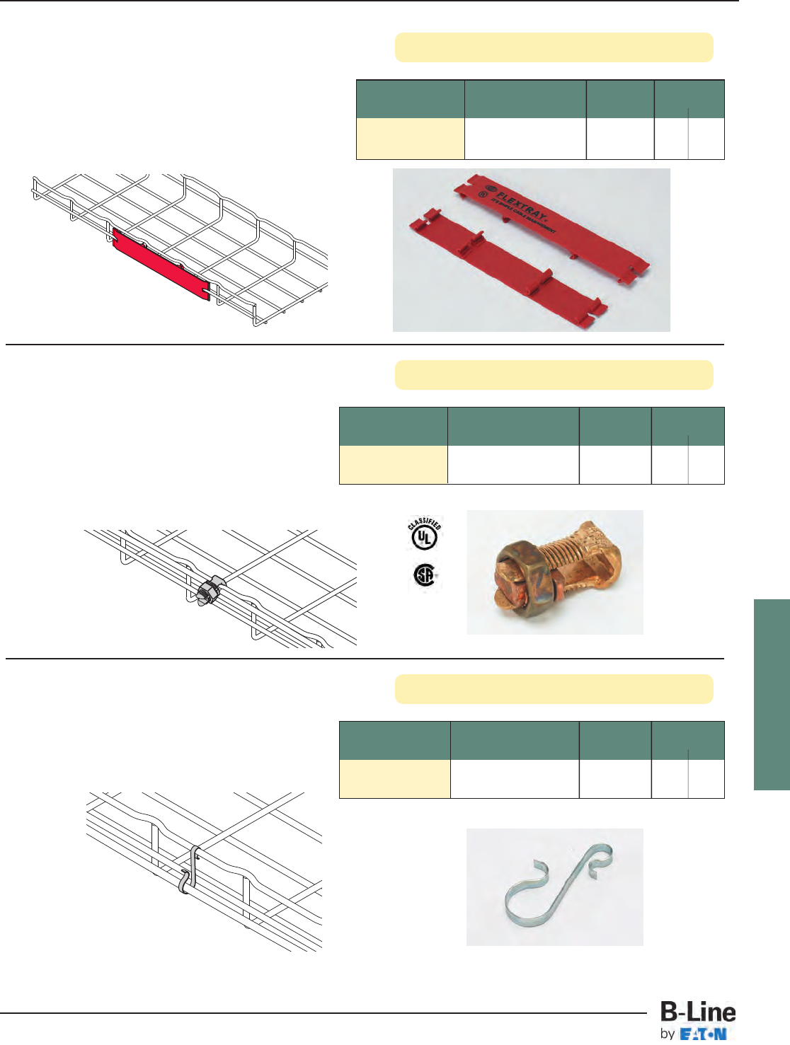
FLEXTRAY
Ground Bolt
Label Clip
Part Description Qty./Box Wt./Box
Number lbs. kg
LABEL CLIP 101/2” (267mm) Long 10 0.6 0.27
• Clips easily into trays
• Use for identifying your cable pathways
• Can be used on all tray sizes
• Will not fit on side of 11/2” deep FLEXTRAY
• Finish: Non-plenum-rated resins
Part Description Qty./Box Wt./Box
Number lbs. kg
GROUND BOLT Ground Bolt 100 1.0 0.45
• Attaches up to #1 ground wire to each tray
section when separate ground wire is required
• Used for UL grounding compliance.
• When using color powder coated finish or paint,
coating must be removed at the points of
contact.
• Finish: Copper Plated
Ground Wire Supports
Part Description Qty./Box Wt./Box
Number lbs. kg
GROUND SUPT GL Ground Wire Support 100 0.6 0.27
• Supports ground wire along side of tray
• Can be used on all trays
• Finish __: Zinc Plated
See page FLX-3 for finish information
FLX-46
FLEXTRAY™- Accessories
Cable Tray Systems
FLEXTRAY
• Complete source of hardware for ceiling connections
• Available in stock
• Strut can be purchased in pre-cut lengths and various colors
• All hardware is zinc plated
See page FLX-3 for finish information
Threaded Rod
Part Size Qty. Wt./Qty.
Number lbs. kg
ATR1/4x72 1/4” x 72” (1828mm) 1 0.7 0.31
ATR1/4x120 1/4” x 120” (3048mm) 1 1.2 0.54
ATR1/4x144 1/4” x 144” (3657mm) 1 1.4 0.63
ATR3/8x72 3/8” x 72” (1828mm) 1 1.7 0.77
ATR3/8x120 3/8” x 120” (3048mm) 1 2.9 1.31
ATR3/8x144 3/8” x 144” (3657mm) 1 3.5 1.58
ATR1/2x72 1/2” x 72” (1828mm) 1 3.2 1.45
ATR1/2x120 1/2” x 120” (3048mm) 1 5.4 2.45
ATR1/2x144 1/2” x 144” (3657mm) 1 6.5 2.95
Rod Couplings
Part Size Qty. Wt./Qty.
Number lbs. kg
B655-1/4 1/4”-20 50 2.0 0.91
B655-3/8 3/8”-16 50 5.5 2.49
B655-1/2 1/2”-13 50 6.0 2.72
Hex Nuts
Part Size Qty. Wt./Qty.
Number lbs. kg
1/4HN 1/4”-20 100 0.6 0.27
3/8HN 3/8”-16 100 1.6 0.72
1/2HN 1/2”-13 100 4.3 1.95
Lock Washers
Part Size Qty. Wt./Qty.
Number lbs. kg
1/4LW 1/4” 200 0.6 0.27
3/8LW 3/8” 200 1.6 0.72
1/2LW 1/2” 200 2.0 0.91
Flat Washers
Part Size Qty. Wt./Qty.
Number lbs. kg
1/4FW 1/4” 200 1.2 0.54
3/8FW 3/8” 200 3.0 1.36
1/2FW 1/2” 200 6.6 2.99
Square Washers
Part Hole Size Qty. Wt./Qty.
Number lbs. kg
B201 7/16 50 6.0 2.72
B202 9/16 50 7.0 3.17
Beam Clamps
Part Size Qty. Wt./Qty.
Number lbs. kg
B3036L-3/8 3/8”-16 100 60.0 27.2
B3036L-1/2 1/2”-13 100 140.0 63.5
FLX-47
FLEXTRAY™- Accessories
Cable Tray Systems
FLEXTRAY
Spring Nuts
Part Thread Size Qty. Wt./Qty.
Number lbs. kg
N224 1/4”-20 100 6.5 2.95
N228 3/8”-16 100 9.3 4.22
N225 1/2”-13 100 11.3 5.12
Bolted Framing
Part Channel Qty. Wt./Qty.
Number Size lbs. kg
B22SGALV120 15/8” x 120” - 12 ga. 1 6.0 2.72
B22SHGALV120 15/8” x 120” - 12 ga. 1 6.0 2.72
B56SGALV120 13/16” x 120” - 15 ga. 1 7.0 3.17
B56SHGALV120 13/16” x 120” - 15 ga. 1 6.0 2.72
Concrete
Rapid Rod Hanger
Part Rod Shank Qty. Wt./Qty.
Number Size Size lbs. kg
ARC-37-150 3/8”1/4” x 11/2” 100 3.4 1.54
Wood
Rapid Rod Hanger
Part Rod Shank Qty. Wt./Qty.
Number Size Size lbs. kg
ARW-37-200 3/8”1/4” x 2” 100 3.4 1.54
ARW-37-200SW 3/8”1/4” x 2” 100 3.4 1.54
Steel
Rapid Rod Hanger
Part Rod Shank Qty. Wt./Qty.
Number Size Size lbs. kg
ARS-37-150 3/8”1/4” x 11/2” 100 3.4 1.54
ARS-37-150SW 3/8”1/4” x 1” 100 3.4 1.54
Sockets for
Rapid Rod Hangers
Part Hole Size Qty. Wt./Qty.
Number lbs. kg
7187 Universal Steel & Wood 1 4.5 2.04
Socket
7197 3/8” Concrete Socket 1 4.5 2.04
Beam Clamps
Part Size Qty. Wt./Qty.
Number lbs. kg
B444-1/4 1/4”-20 100 160 72.5
B444-3/8 3/8”-16 100 430 195.0
B444-1/2 1/2”-13 100 430 195.0
U-Bolt Clamps
Part Size Qty. Wt./Qty.
Number lbs. kg
B441-22 3/8”-16 x 33/8” long 100 160 72.5
B22 B56
SSSH SH
ARW-SW
ARW
ARS-SW
ARS
SW = Side Mount
SW = Side Mount
See page FLX-3 for finish information
FLX-48
FLEXTRAY™- Accessories
Cable Tray Systems
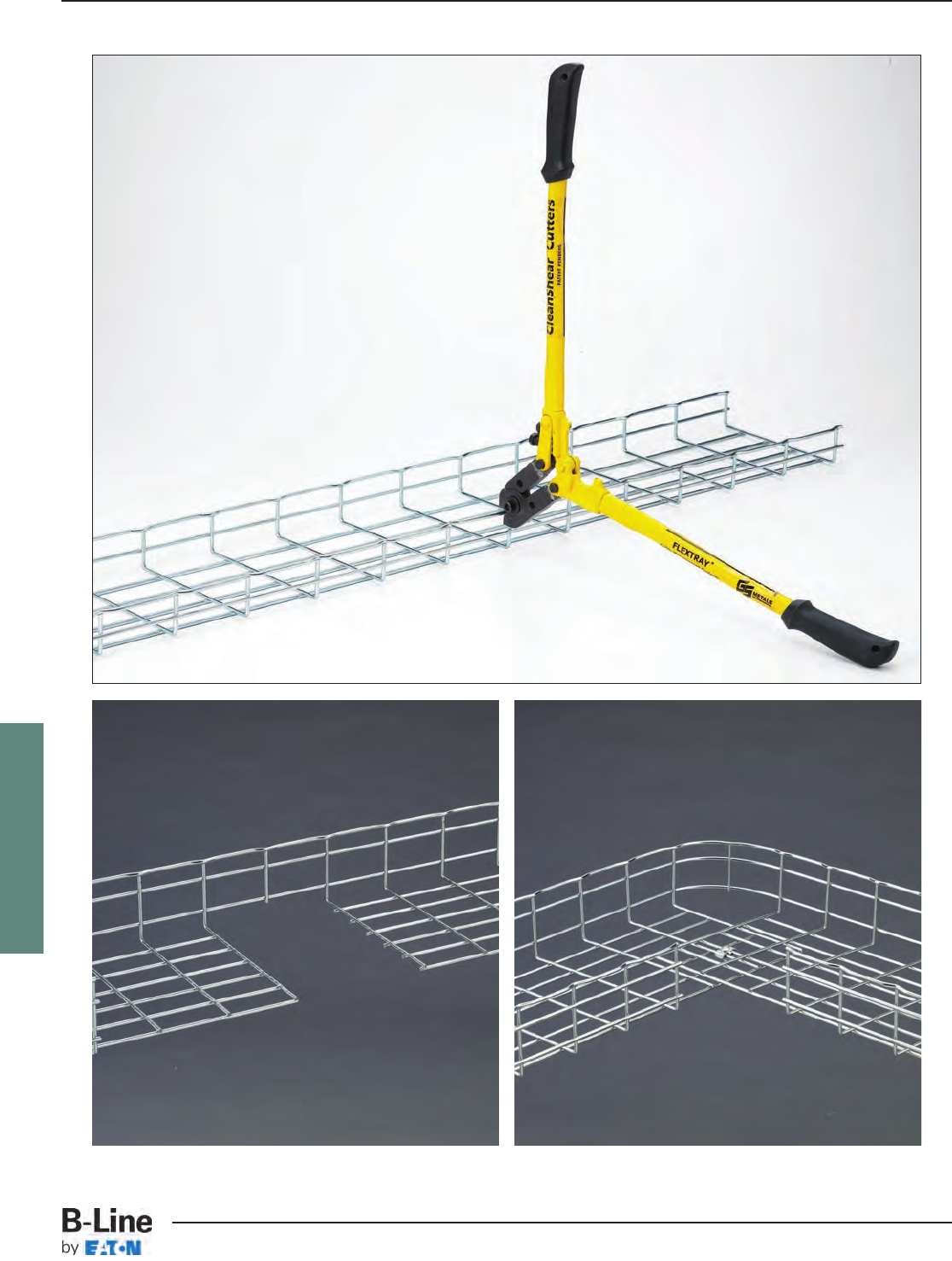
FLEXTRAY
FLX-49
FLEXTRAY™- Installation
Cable Tray Systems
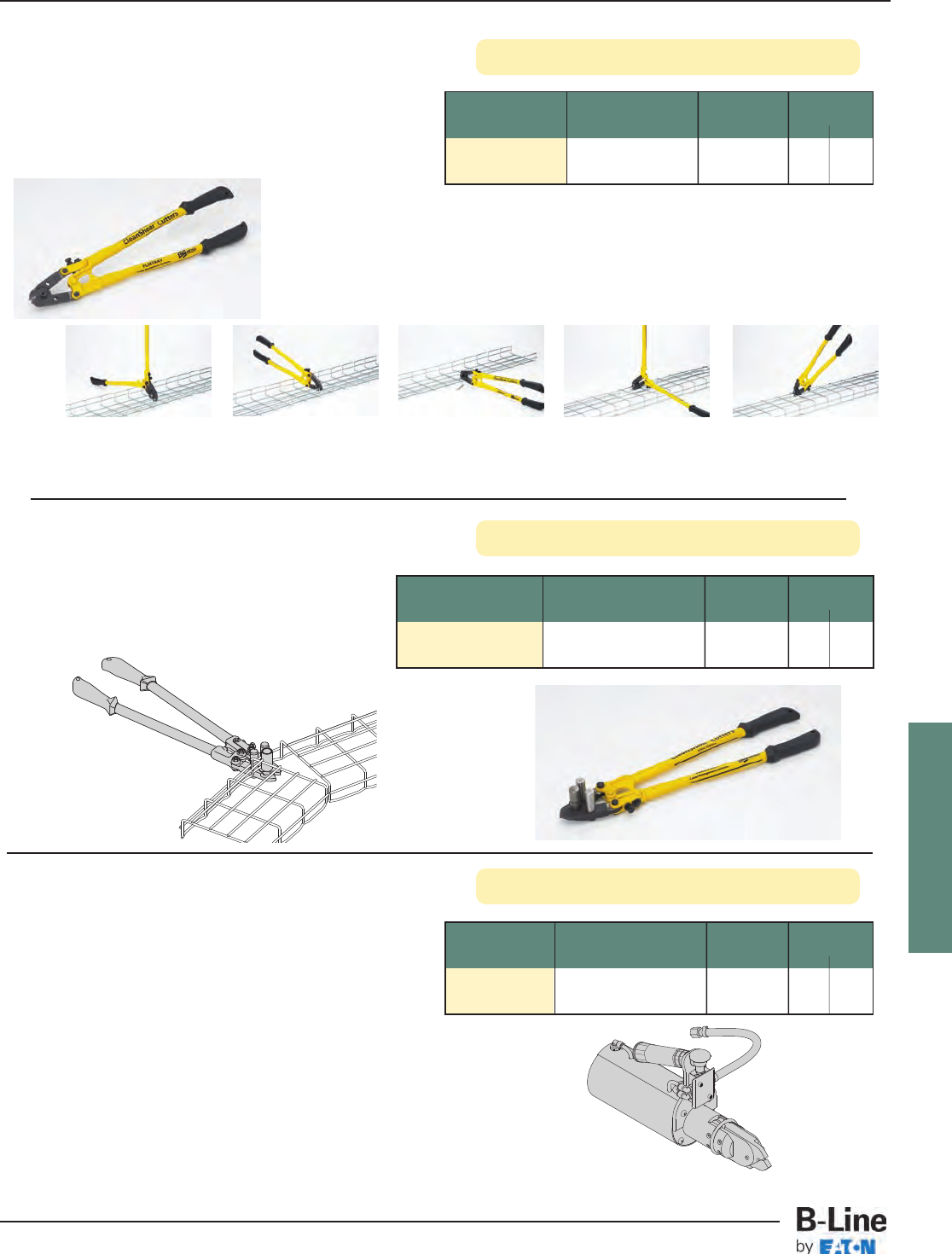
FLEXTRAY
Flextray Bender
Airshear Cutter
Flextray Cutters
Part Description Qty./Box Wt./Box
Number lbs. kg
CLEANSHEAR CLEANSHEAR 1 4.3 1.95
Cutting Tool
• Exclusive, patented CLEANSHEAR™cuts tray fast
• No sharp edges
• Designed specifically for cutting Flextray
• Safely cut and bend Flextray into any configuration
1Face tray up. Slide
cutter next to vertical
wire and cut.
2Turn tray to the side
with open side facing
you. Repeat step 1 to
cut wire.
Patented
Part Description Qty./Box Wt./Box
Number lbs. kg
AIRSHEAR Pneumatic CLEANSHEAR 1 9.0 4.08
Cutting Tool
• Fastest wire mesh cutter available
• 57% time savings over regular CLEANSHEAR
• Airshear is available when you have a large project
to install. Call us for details.
Part Description Qty./Box Wt./Box
Number lbs. kg
CLEANSHEAR BEND CLEANSHEAR Cutting Tool 1 5.4 2.45
With Bender Attachment
• CLEANSHEAR Bender has our exclusive
bending attachment
• Makes bending larger trays easy
• Recommended for bending tray widths of
16” (400mm) or greater
Patented
Patented
3Finish cutting all side
wires.
4Turn tray open-side
down and cut wires
from bottom of tray.
5Finish cutting by
moving to other side
of tray to cut
remaining wires,
FLX-50
FLEXTRAY™- Installation
Cable Tray Systems
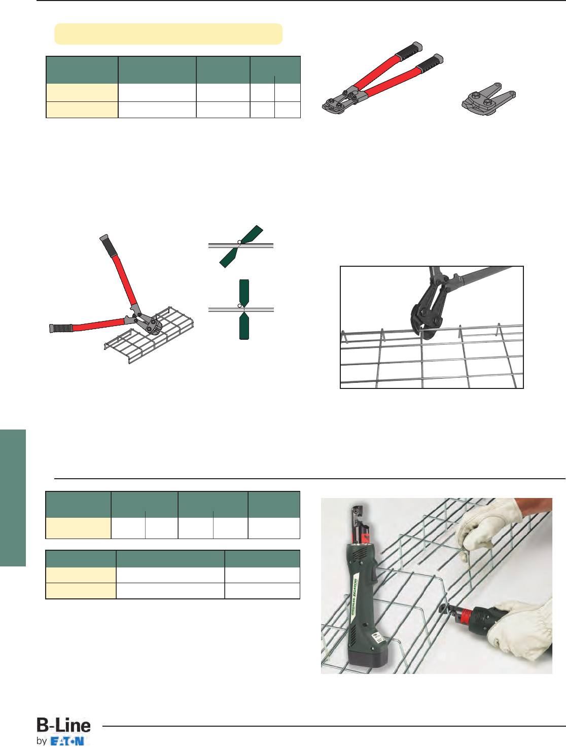
FLEXTRAY
X
Completely adaptable, B-Line Flextray is designed to
accommodate jobsite changes. Cut wires with B-Line
Angular Bolt Cutter, bend to create a bend, tee, or reducer.
For the best results, use a WB30BC Angular Blade Offset
Bolt Cutter with 24" (600 mm) long handles. The Offset Blade
Cutter produces a clean cut. Position bolt cutter blades near
the cross wire and perpendicular to wire to be cut (see
illustration above). Proper cut will make the assembly faster,
easier and safer while minimizing grinding.
Cut and remove each wire as illustrated below. Follow
cutting pattern and blade positioning. Placing Flextray
open side down provides the optimum cutting angle.
Cutting Order
The Greenlee cable wire cutter makes flush cuts without burrs.
Will cut .191" diameter wire in 2 seconds. Cutting head rotates
330° for ease of positioning and the tool automatically retracts
when cut is complete.
Comes with 2 batteries, charger, and carrying case.
Approximately 250 cuts per charge.
WB30RB
Replacement Blade
WB30BC
Angular Bolt Cutter
≠
ÆØ
∞±
≤ ≥
Offset Cut
Do not use center
cut blades.
Part Length Wt. Per Cutter Box
Number in. mm lbs. kg Quantity
WB50WC 123/4”325 3.0 1.3 1
Part Number Description Box Quantity
WB50RB Replacement Blade 1
WB50BA Replacement Battery 1
See page FLX-3 for finish information
Angular Bolt Cutter
Part Description Qty./Box Wt./Box
Number lbs. kg
WB30BC Bolt Cutter 1 6.8 3.1
WB30RB Replacement Blade 1 1.3 0.6
FLX-51
FLEXTRAY™- Installation
Cable Tray Systems
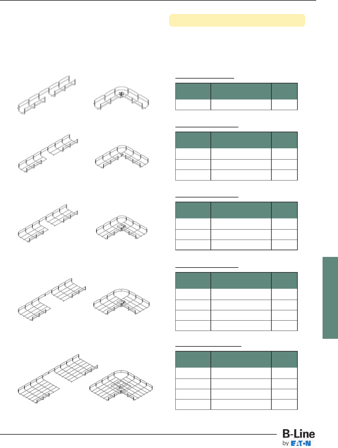
FLEXTRAY
90° Horizontal Bends (Short Radius)
2” (50mm) Tray Width
• Make your own field cut horizontal bends using CLEANSHEAR™to make safe, smooth cuts
• Can be made from any tray width and depth with any available finish
• SUPT WASHER & FTHDWE 1/4 hardware may be used on bottom of tray instead of WASHER SPL KIT
where desired
Flextray Required Hardware Quantity
Depth Description
2” (50mm) WASHER SPL KIT 1
4” (100mm) Tray Width
Flextray Required Hardware Quantity
Depth Description
11/2” (38mm) WASHER SPL KIT 1
2” (50mm) WASHER SPL KIT 1
4” (100mm) WASHER SPL KIT 1
6” (150mm) Tray Width
Flextray Required Hardware Quantity
Depth Description
11/2” (38mm) WASHER SPL KIT 1
2” (50mm) WASHER SPL KIT 1
4” (100mm) WASHER SPL KIT 1
8” (200mm) Tray Width
Flextray Required Hardware Quantity
Depth Description
11/2” (38mm) WASHER SPL KIT 1
2” (50mm) WASHER SPL KIT 1
4” (100mm) WASHER SPL KIT 1
6” (150mm) WASHER SPL KIT 1
12” (300mm) Tray Width
Flextray Required Hardware Quantity
Depth Description
11/2” (38mm) WASHER SPL KIT 1
2” (50mm) WASHER SPL KIT 1
4” (100mm) WASHER SPL KIT 1
6” (150mm) WASHER SPL KIT 1
FLX-52
FLEXTRAY™- Installation
Cable Tray Systems
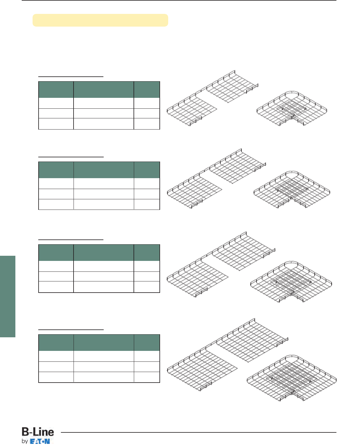
FLEXTRAY
90° Horizontal Bends (Short Radius)
• Make your own field cut horizontal bends using CLEANSHEAR™to make safe, smooth cuts
• Can be made from any tray width and depth with any available finish
• SUPT WASHER & FTHDWE 1/4 hardware may be used on bottom of tray instead of WASHER SPL KIT
where desired
16” (400mm) Tray Width
Flextray Required Hardware Quantity
Depth Description
2” (50mm) WASHER SPL KIT 3
4” (100mm) WASHER SPL KIT 3
6” (150mm) WASHER SPL KIT 3
18” (450mm) Tray Width
Flextray Required Hardware Quantity
Depth Description
2” (50mm) WASHER SPL KIT 3
4” (100mm) WASHER SPL KIT 3
6” (150mm) WASHER SPL KIT 3
20” (500mm) Tray Width
Flextray Required Hardware Quantity
Depth Description
2” (50mm) WASHER SPL KIT 3
4” (100mm) WASHER SPL KIT 3
6” (150mm) WASHER SPL KIT 3
24” (600mm) Tray Width
Flextray Required Hardware Quantity
Depth Description
2” (50mm) WASHER SPL KIT 3
4” (100mm) WASHER SPL KIT 3
6” (150mm) WASHER SPL KIT 3
FLX-53
FLEXTRAY™- Installation
Cable Tray Systems
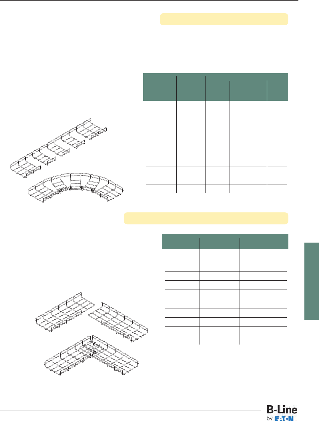
FLEXTRAY
90° Horizontal Bends (Long Radius)
90° Horizontal Bend From (2) Straight Sections
• Make your own field cut horizontal sweeps using CLEANSHEAR™to make safe, smooth cuts
• Can be made from any tray width and depth with any available finish
• Cut as many segments as required to control sweep radius (use chart for recommendations)
• One (1) WASHER SPL KIT is required to connect each cut segment minus one, this segment
uses one (1) SPLICE BAR, two (2) FTHDWE 1/4 and two (2) BTM WASHER
Flextray Side Sections WASHER SPL KIT
Width To Be Removed Qty.
4” (100mm) 12
6” (150mm) 22
8” (200mm) 22
12” (300mm) 32
16” (400mm) 43
18” (450mm) 53
20” (500mm) 53
24” (600mm) 64
30” (750mm) 84
32” (800mm) 84
• Cut required number of wire side sections listed in
chart per the illustration below
(Illustration is for a 8” (200mm) width)
• 1.5” deep FLEXTRAY has only one (1) side wire
2” deep FLEXTRAY has two (2) side wires - shown
4” deep FLEXTRAY has three (3) side wires
6” deep FLEXTRAY has four (4) side wires
• Illustration shown below is for a 8” (200mm) width
• 1.5” deep FLEXTRAY has only one (1) side wire
2” deep FLEXTRAY has two (2) side wires - shown
4” deep FLEXTRAY has three (3) side wires
6” deep FLEXTRAY has four (4) side wires
Component Qty.
Segments FTHDWE 1/4
Flextray To Be WASHER & SPLICE
Width Removed SPL KIT BTM WASHER BAR
4” (100mm) 21 2 1
6” (150mm) 32 2 1
8” (200mm) 43 2 1
12” (300mm) 65 2 1
16” (400mm) 76 2 1
18” (450mm) 87 2 1
20” (500mm) 10 921
24” (600mm) 11 10 21
30” (750mm) 13 12 21
32” (800mm) 13 12 21
FLX-54
FLEXTRAY™- Installation
Cable Tray Systems
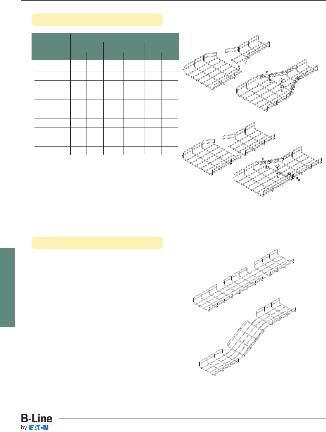
FLEXTRAY
Reducers
Vertical Inside & Outside Bends
Component Qty.
Large WASHER FTHDWE 1/4 SPLICE
Flextray SPL KIT & BTM WASHER BAR
Width (SR) (LRR) (SR) (LRR) (SR) (LRR)
4” (100mm) -1 - 2 -1
6” (150mm) -2 - 2 -1
8” (200mm) 12 4 2 21
12” (300mm) 23 4 2 21
16” (400mm) 23 4 2 21
18” (450mm) 23 4 2 21
20” (500mm) 33 4 2 21
24” (600mm) 33 4 2 21
30” (750mm) 33 4 2 21
32” (800mm) 33 4 2 21
• 1.5” deep FLEXTRAY has only one (1) side wire
2” deep FLEXTRAY has two (2) side wires - shown
4” deep FLEXTRAY has three (3) side wires
6” deep FLEXTRAY has four (4) side wires
Straight Reducers
(SR)
Left & Right
Reducers
(LRR)
• Cut wire section as shown and bend to desired angle
• 1.5” deep FLEXTRAY has only one (1) side wire
2” deep FLEXTRAY has two (2) side wires - shown
4” deep FLEXTRAY has three (3) side wires
6” deep FLEXTRAY has four (4) side wires
FLX-55
FLEXTRAY™- Installation
Cable Tray Systems
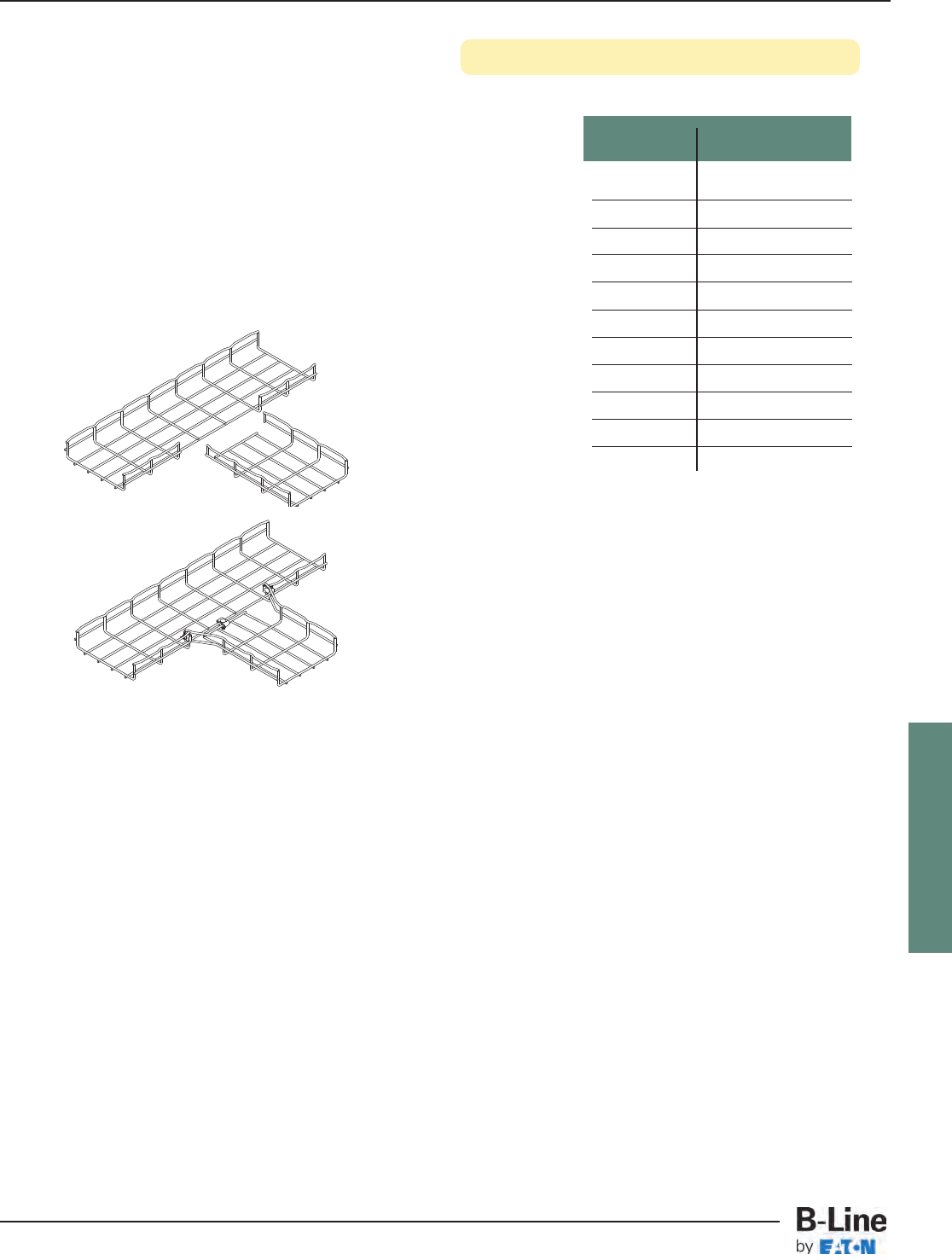
FLEXTRAY
Horizontal Tees (and crosses)
Flextray WASHER SPL KIT
Width Qty.
2” (50mm) 2
4” (100mm) 2
6” (150mm) 3
8” (200mm) 3
12” (300mm) 4
16” (400mm) 4
18” (450mm) 4
20” (500mm) 4
24” (600mm) 4
30” (750mm) 5
32” (800mm) 5
• Cut wire side sections as shown in the illustration below
(Illustration is for a 8” (200mm) width)
• 1.5” deep FLEXTRAY has only one (1) side wire
2” deep FLEXTRAY has two (2) side wires - shown
4” deep FLEXTRAY has three (3) side wires
6” deep FLEXTRAY has four (4) side wires
• For crosses, duplicate process on opposite side
FLX-56
FLEXTRAY™- Installation
Cable Tray Systems
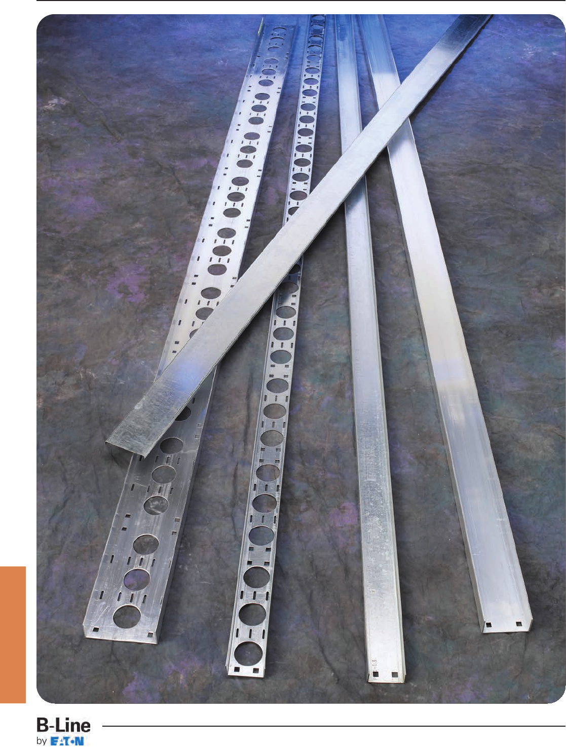
Cable Channel
CCT-1
Channel Cable Tray - Straight Sections
Cable Tray Systems
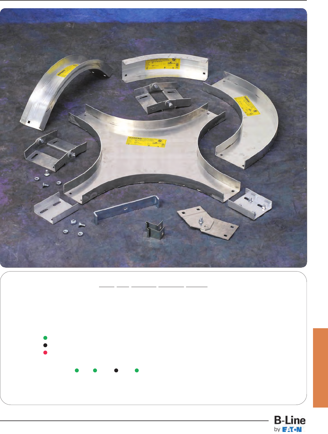
Cable Channel
How The Service Advisor Works
B-Line knows that your time is important! That’s why the color-coding system in this catalog is designed to help you select
products that fit your service needs. Products are marked to indicate the typical lead time for orders of 50 pieces or less.
Customer: How do I select my cable channel product so that I get the quickest turnaround?
Service Advisor: Each part of our selection chart is shown in colors. If any section of a part number is a different color, the
part will typically ship with the longer lead time represented by the colors.
Green = Fastest shipped items
Black = Normal lead-time items
Red = Normally long lead-time items
Example: A CC 03 - 144 Part will have a normal lead time
because of the 03 width.
Changing the part number to 04 width instead of 03 will reduce the lead time.
CCT-2
Channel Cable Tray - Accessories
Cable Tray Systems
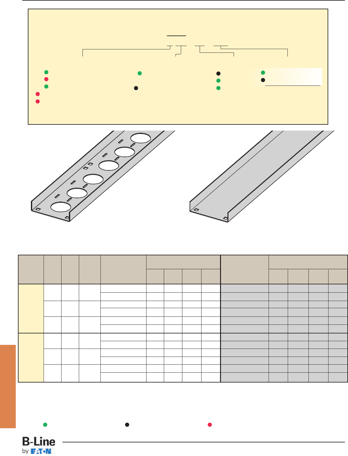
Material Width Depth UL Area Load Data * Support Span (Ft) Load Data * Support Span (m)
Type in. in. in.2Safety Factor = 1.5 5610 12 Safety Factor = 1.5 1.5 1.8 3.0 3.7
31.25 0.6 Load (lbs/ft) 22 15 54 Load (kg/m) 33 22 76
(75) (32) Deflection Multiplier 0.025 0.051 0.395 0.820 Deflection Multiplier .427 0.871 6.743 13.997
Aluminum 41.75 0.6 Load (lbs/ft) 48 33 12 8 Load (kg/m) 71 49 18 12
(100) (44) Deflection Multiplier 0.0071 0.015 0.114 0.236 Deflection Multiplier 0.121 0.256 1.946 4.028
61.75 1.00 Load (lbs/ft) 52 36 13 9 Load (kg/m) 77 54 19 13
(150) (44) Deflection Multiplier 0.0055 0.011 0.088 0.183 Deflection Multiplier 0.094 0.188 1.502 3.124
31.25 0.20 Load (lbs/ft) 24 17 64 Load (kg/m) 36 25 96
(75) (32) Deflection Multiplier 0.013 0.028 0.216 0.447 Deflection Multiplier 0.222 0.478 3.687 7.630
Steel 41.75 0.40 Load (lbs/ft) 52 36 13 9 Load (kg/m) 77 54 19 13
14 Gauge (100) (44) Deflection Multiplier 0.0039 0.0082 0.063 0.130 Deflection Multiplier 0.067 0.140 1.075 2.219
61.75 0.40 Load (lbs/ft) 59 41 15 10 Load (kg/m) 88 61 22 15
(150) (44) Deflection Multiplier 0.003 0.0063 0.049 0.101 Deflection Multiplier 0.051 0.108 0.836 1.724
Straight Section Part Numbering
Prefix
Example: A CC - 04 - 120
Material
A= Aluminum 6063-T4
G= Type 1 - HDGAF
P= Type 2 - Pre-Galvanized
SS4 = 304 Stainless Steel
SS6 = 316 Stainless Steel
Type
CC = Ventilated Cable
Channel
CCN = Non-Ventilated
Cable Channel
Width
03 = 3"
04 = 4"
06 = 6"
To calculate simple Beam Deflection in inches, multiply the design load (lbs/ft) by the Deflection Multiplier shown for the span.
To calculate simple Beam Deflection in millimeters, multiply the design load (kg/m) by the Deflection Multiplier shown for the span.
All dimensions in parentheses are millimeters unless otherwise specified.
* Load data is determined by realistic deflection, not by failure.
Ventilated straight sections contain 21/4" diameter holes and 3/16" x 7/8" slots for cable attachment.
Ventilated straight sections also have splice holes repeating every 12" to simplify field modifications.
Ventilated Non-Ventilated
See page CTS-23 for
explanation of lengths.
Length
¨144 = 12 ft.
¡120 = 10 ft.
¨Primary Length.
¡Secondary Length.
Cable Channel
Green = Fastest shipped items Black = Normal lead-time items Red = Normally long lead-time items
CCT-3
Channel Cable Tray - Straight Sections
Cable Tray Systems
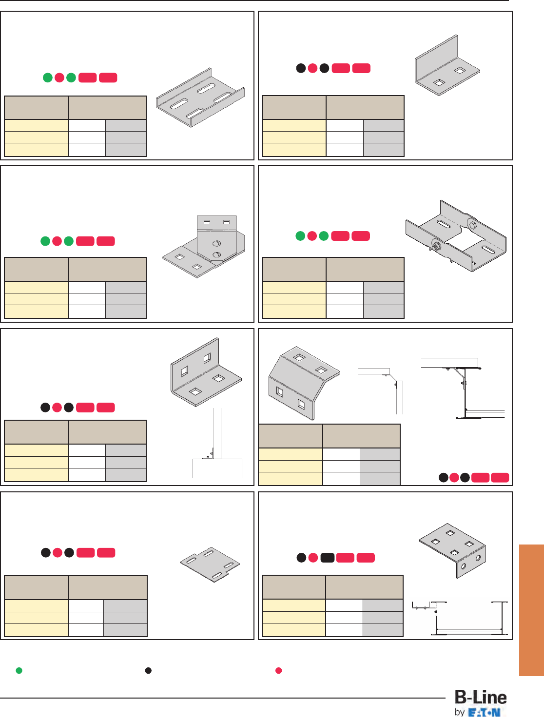
Catalog No. Channel Width
in. mm
9(*)-1543 3 76
9(*)-1544 4 101
9(*)-1546 6 152
Catalog No. Channel Width
in. mm
9(*)-1261-3 3 76
9(*)-1261-4 4 101
9(*)-1261-6 6 152
Channel To Tray or Channel To
Channel Reducer Plate
The Channel Reducer Plate is used to join cable channel
sections of different widths.
• Furnished as one plate with hardware.
• (*) Insert
Box Connector
The Box Connector is used to attach the
end of a cable channel run to a distribution
box or a control center.
• Furnished as one connector with
hardware.
• (*) Insert
Vertical Adjustable Splice Plate
The Adjustable Splice Plate allows
changes in elevation where standard
vertical fittings are not applicable.
• Furnished as one plate with hardware.
• (*) Insert
Horizontal Adjustable Splice Plate
The Horizontal Adjustable Splice Plate
adapts to changes in direction in a
horizontal plane, beyond the capability
of the standard horizontal fittings.
• Furnished as one plate with hardware.
• (*) Insert
Blind End Plate
The Blind End Plate forms a closure
for any cable channel dead end.
• Furnished as one plate with hardware.
• (*) Insert
Splice Plate
The Splice Plate has the standard
4-hole pattern for all cable channel.
• Provided with straight sections and fittings.
• Furnished as one plate with hardware.
• (*) Insert
Mounting Bracket - Channel To Tray
The Mounting Bracket allows a parallel run of cable channel to be
attached to the side of a cable tray. It can
also serve as a support splice connection.
• Furnished as one bracket.
• Order hardware separately.
• (*) Insert
Channel to Tray
Channel to
Channel
All dimensions in shaded areas are millimeters unless otherwise specified.
The Channel Connector is
used to link a cable channel
to a cable tray, or a cable
channel to cable channel.
• Furnished as one plate with
hardware.
• (*) Insert
Cable Channel
AGP SS4 SS6
AGP SS4 SS6
AGP SS4 SS6
AGP SS4 SS6
AGP SS4 SS6
AGP SS4 SS6
AG SS4 SS6
AGP SS4 SS6
ZN
Requires supports within
24” on both sides, per
NEMA VE 2.
Requires supports within
24” on both sides, per
NEMA VE 2.
Catalog No. Channel Width
in. mm
9(*)-1043 3 76
9(*)-1044 4 101
9(*)-1044-6 6 152
Catalog No. Channel Width
in. mm
9(*)-1583 3 76
9(*)-1584 4 101
9(*)-1586 6 152
Catalog No. Channel Width
in. mm
9(*)-1643 3 76
9(*)-1644 4 101
9(*)-1646 6 152
Catalog No. Channel Width
in. mm
9(*)-1743 3 76
9(*)-1744 4 101
9(*)-1746 6 152
Catalog No. Channel Width
in. mm
9(*)-1237-3 3 76
9(*)-1237-4 4 101
9(*)-1237-6 6 152
Catalog No. Channel Width
in. mm
9(*)-1843 4 to 3 101 to 76
9(*)-1863 6 to 3 152 to 76
9(*)-1864 6 to 4 152 to 101
Green = Fastest shipped items Black = Normal lead-time items Red = Normally long lead-time items
CCT-4
Channel Cable Tray - Accessories
Cable Tray Systems
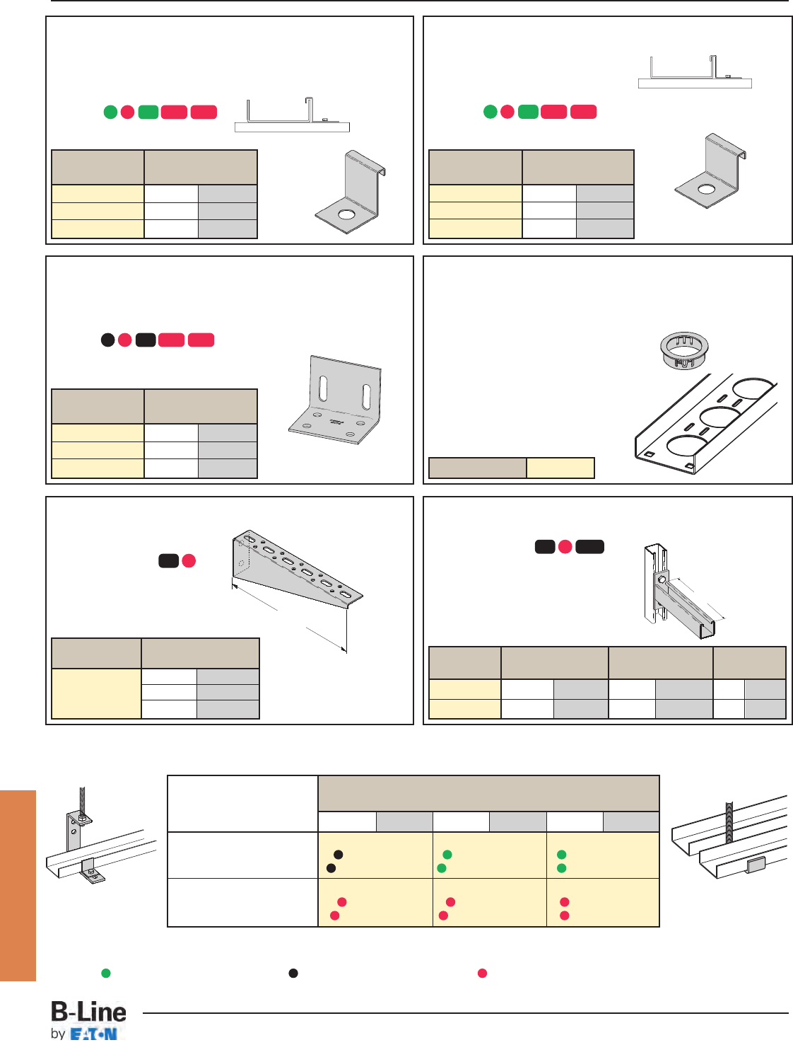
Channel Width
in. mm in. mm in. mm
3 76 4 101 6 152
Zinc Plated Steel
Double Channel 9ZN-1232-3 9ZN-1232-4 9ZN-1232-6
Single Channel 9ZN-1231-3 & 4 9ZN-1231-3 & 4 9ZN-1231-6
HDGAF Steel (18 Ga.)
Double Channel 9G-1232-3 9G-1232-4 9G-1232-6
Single Channel 9G-1231-3 & 4 9G-1231-3 & 4 9G-1231-6
Catalog No. Channel Width
in. mm
3 76
4 101
6 152
Catalog No. Channel Width
in. mm
9(*)-3305-3 3 76
9(*)-3305-4 4 101
9(*)-3305-6 6 152 Catalog No. 99-1125
Catalog No. Channel Width
in. mm
9(*)-1245 3 76
9(*)-1246 4 101
9(*)-1246 6 152
Catalog No. Channel Width
in. mm
9(*)-1243 3 76
9(*)-1244 4 101
9(*)-1244 6 152
Single Cable Channel
Hanger and Wall Mount
Double Cable
Channel Hanger
Cable Channel Hanger
Expansion Guide Clamp
The Expansion Guide Clamp allows cable channel to expand and
contract in the horizontal plane, but not in the transverse plane.
• Furnished as one clamp.
• Order 1/2" hardware separately.
• (*) Insert
Hold-Down Clamp
The Hold-Down Clamp secures cable
channel to a support member.
• Furnished as one clamp.
• Order 1/2" hardware separately.
• (*) Insert
Channel To Floor Base Plate
The Channel to Floor Base Plate is used to attach the end of a
cable channel run to the floor or to an equipment mounting pad.
• Anchors and hardware are ordered separately.
• (*) Insert
Cable Channel Bushing
The Cable Channel Bushing is a snap-in
plastic bushing used to protect cable
insulation from mechanical wear.
Cable Channel Bracket
A
Cable Channel Bracket
• Uniform Load: 225 lbs (1.00 kN)
Safety Factor of 2.5
• Finishes available:
B185CCL
• Safety Factor of 2.5
• Finishes available:
Material
150 lb.
Safety Factor 3.0
265 lb.
Safety Factor 3.0
Designed for 1/2" Threaded Rod, Double Nut Installation
8"
(203mm)
All dimensions in shaded areas are millimeters unless otherwise specified.
Cable Channel
AG SS4 SS6ZN
AG SS4 SS6ZN
AG SS4 SS6ZN
GZN
G GRNZN
Catalog Channel Width Uniform Load A
No. in. mm lbs kN in. mm
B409-6 3 76 1920 8.54 6 152
B409-9 4, 6 101, 152 1280 5.69 9 228
Green = Fastest shipped items Black = Normal lead-time items Red = Normally long lead-time items
CCT-5
Channel Cable Tray - Accessories
Cable Tray Systems
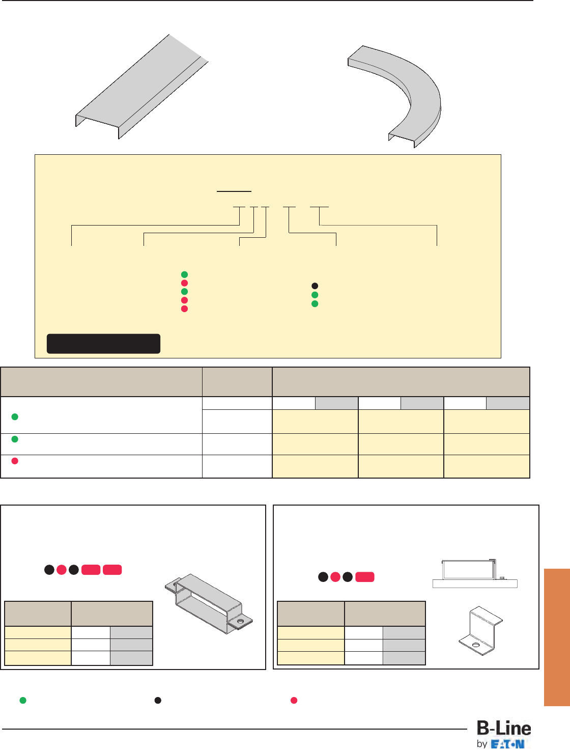
Catalog No. Channel Width
in. mm
9(*)-9033 3 76
9(*)-9034 4 101
9(*)-9036 6 152
Catalog No. Channel Width
in. mm
9(*)-9023 3 76
9(*)-9024 4 101
9(*)-9024 6 152
Wrap-Around Cover Clamp
Wrap-Around Cover Clamps are used to securely hold a cover on
cable channel in locations where strong winds can prevail.
• Furnished as one clamp with hardware.
• (*) Insert
All dimensions in shaded areas are millimeters unless otherwise specified.
Combination Hold-Down & Cover Clamp
This clamp is used to hold both the cable channel
and cover in place at the same time.
• Furnished as one clamp.
• Order 1/4" hardware separately.
• (*) Insert
Straight Section
Fitting covers are available. To order, use the cover prefix followed by the fitting description. Ex: 808A40 - 03 - 90HB12.
Covers Part Numbering
Prefix
Example: 80 8 A - 04 - 144
Detail
8 = Flanged
Cover
Type
80 = Solid
Tray
Width
03 = 3"
04 = 4"
06 = 6"
90° HB
Cable Channel Covers
Cable Channel
AGP SS4 SS6 AGP SS6
All items normal lead time
except for those indicated
Material
A = Aluminum
G = Type 1 HDGAF
P = Type 2 Pre-Galvanized
SS4 = 304 Stainless Steel
SS6 = 316 Stainless Steel
Item Description
For Straight Section Cover:
Pre-Galv & Aluminum Only:
144 = 12 ft.
120 = 10 ft.
Pre-Galv, HDGAF & Alum
72 = 6 ft.
60 = 5 ft.
For fitting covers: Insert suffix
of fitting to be covered.
Straight Section Part Number Channel Width
Material Length in. mm in. mm in. mm
3 76 4 101 6 152
Aluminum (.040) 12' (3.56m) 808A-03-144 808A-04-144 808A-06-144
Solid 10' (3.05m) 808A-03-120 808A-04-120 808A-06-120
Type II Pre-Galvanized Steel (20 Ga.) 12' (3.56m) 808P-03-144 808P-04-144 808P-06-144
Solid 10' (3.05m) 808P-03-120 808P-04-120 808P-06-120
Type I Hot Dip Galvanized Steel (18 Ga.) 12' (3.56m) 808G-03-72 808G-04-72 808G-06-72
Solid 10' (3.05m) 808G-03-60 808G-04-60 808G-06-60
Green = Fastest shipped items Black = Normal lead-time items Red = Normally long lead-time items
CCT-6
Channel Cable Tray - Accessories
Cable Tray Systems
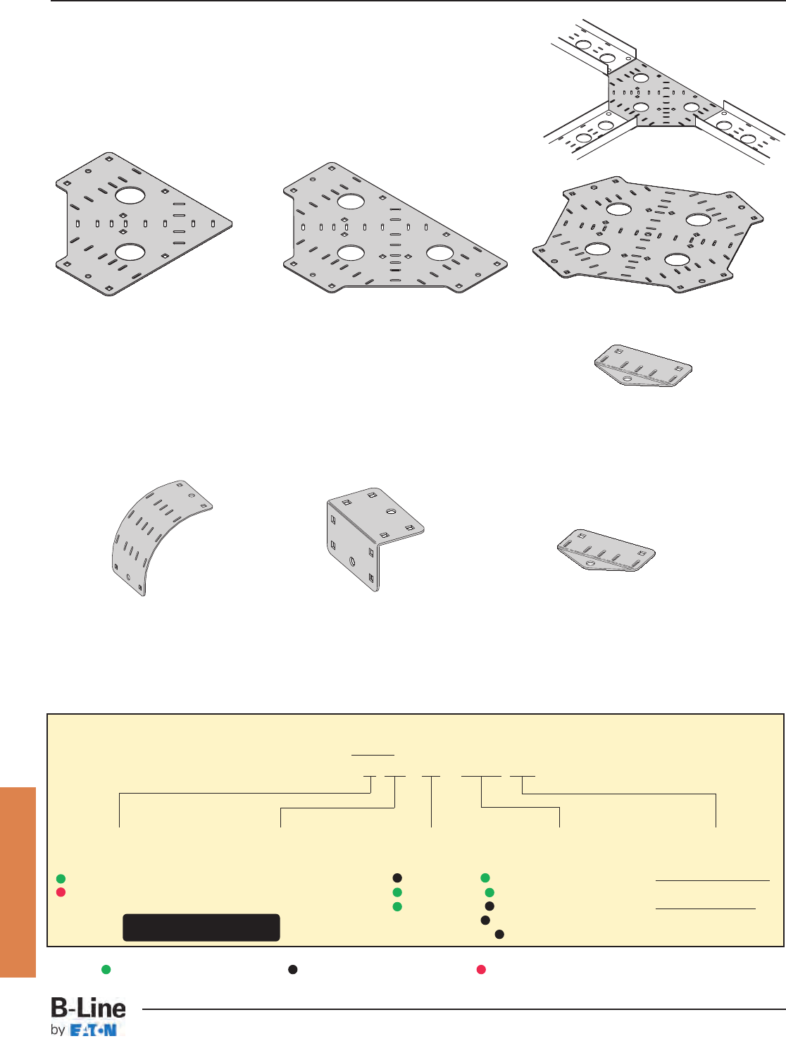
Channel Cable Tray Connectors
Fast, economical, space saving Channel Cable Tray Connectors
Patent No. 5,628,481; 5,782,439. Other patents pending.
Horizontal:
• Provides 0 or 6-inch radius connection for Cable Channel
• The Pivot Connector is available for custom angle adjustment
• up to +/– 45˚ angle adjustment
• order the desired quantity separately
• Slotted for easy cable fastening
• Shipped with the required hardware
Vertical:
• Use the same part for VO and VI applications
• Slotted for easy cable fastening
• The Pivot Connector is available for custom angle adjustment (order separately)
• Shipped with the required hardware
90˚ Bend Tee Cross
Pivot
Connector
90˚ Bend
6-inch radius
90˚ Vertical
Square Connector
0-inch radius Pivot
Connector
Cable Channel
Green = Fastest shipped items Black = Normal lead-time items Red = Normally long lead-time items
Connector Part Numbering
Prefix
Example: A CC - 04 - 90HC 060
Width
03 = 3"
04 = 4"
06 = 6"
Radius
Horizontal Connectors
060 = 0" & 6" Radii
Vertical Connectors
00 = 0" Radius
06 = 6" Radius
Connector Type
90HC = 90˚ Horizontal
HTC = Horizontal Tee
HXC = Horizontal Cross
90VC = 90˚ Vertical
PC = Pivot Connector
Tray Type
CC = Ventilated
Cable Channel
All items normal lead time
except for those indicated
Material
A = Aluminum
G = Type 1 HDGAF
CCT-7
Channel Cable Tray - Accessories
Cable Tray Systems
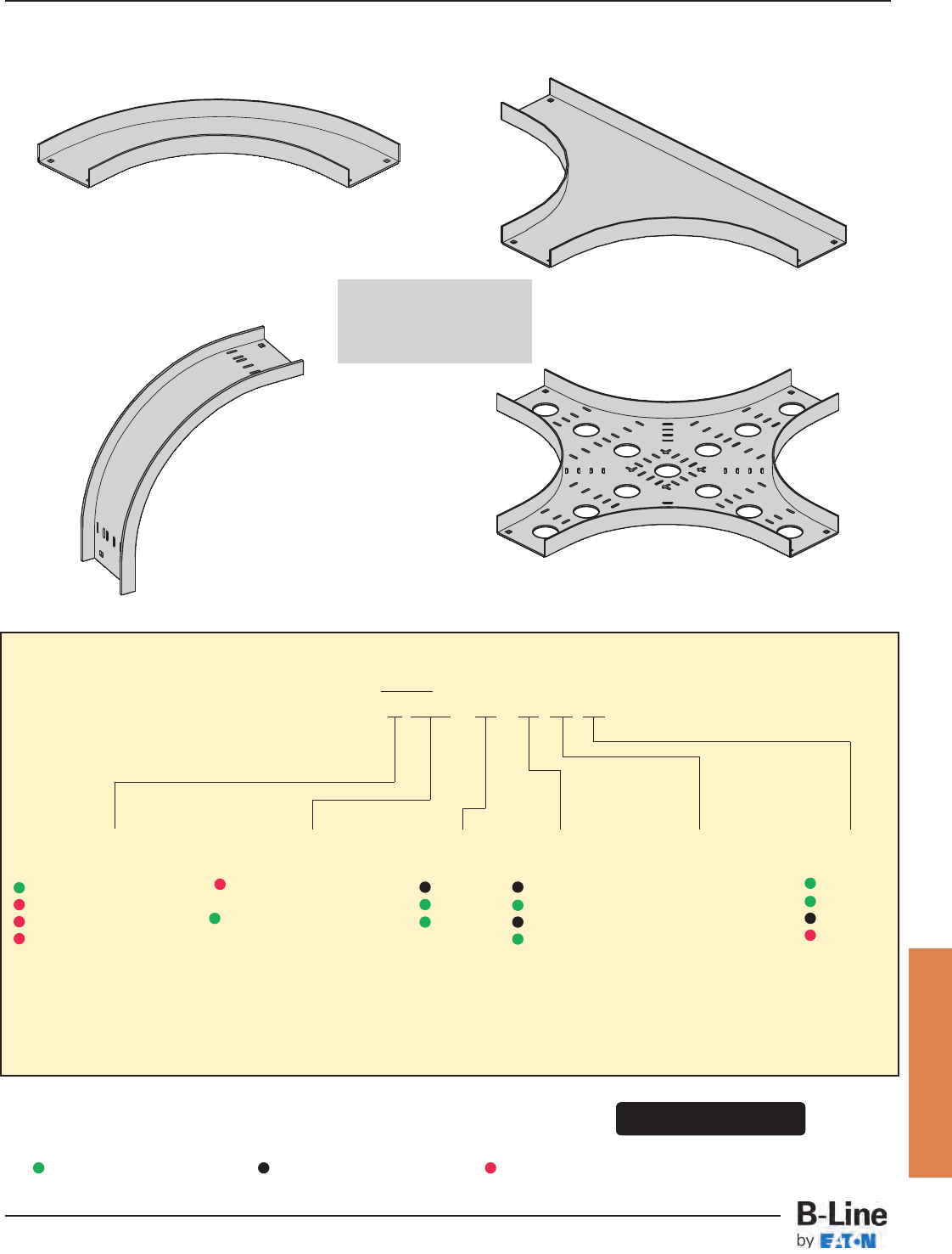
Fittings Part Numbering
Prefix
Example: A CCN - 04 - 90 HB 24
Fittings engineered
with 3" tangents for
splicing integrity.
Angle
30 = 30°
45 = 45°
60 = 60°
90 = 90°
ACCN-04-90HB12
Non-Ventilated Horizontal Bend ACCN-04-HT12
Non-Ventilated Tee
ACC-04-90VO12
Ventilated Vertical Bend
ACC-04-HX12
Ventilated Horizontal Cross
Cable Channel
All items normal lead time
except for those indicated
Width
03 = 3"
04 = 4"
06 = 6"
Radius
12 = 12"
24 = 24"
36 = 36"
48 = 48"
Material
A = Aluminum
G = Type 1 HDGAF
SS4 = 304 Stainless Steel
SS6 = 316 Stainless Steel
P = †
Tray Type
*CC = Ventilated Cable
Channel
CCN = Non-ventilated
Cable Channel
* Ventilated Cable Channel Fittings are available only in 12" and 24" radii.
† - Due to multiple piece welded construction, P fittings are not available - substitute G.
Fitting Type
HB = Horizontal Bend
HT = Horizontal Tee
HX = Horizontal Cross
VI = Vertical Inside Bend
VO = Vertical Outside Bend
Green = Fastest shipped items Black = Normal lead-time items Red = Normally long lead-time items
CCT-8
Channel Cable Tray - Fittings
Cable Tray Systems
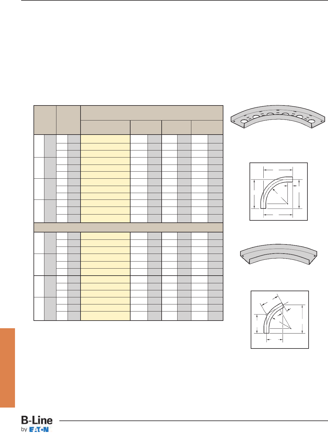
Bend Tray 90˚ Horizontal Bend
Radius Width Dimensions
R Catalog No. ABC
in. mm in. mm in. mm in. mm in. mm
3 76 (Pre)-03-90HB12 161
/2419 161
/2419 161
/2419
12 305 4 101 (Pre)-04-90HB12 17 432 17 432 17 432
6 152 (Pre)-06-90HB12 18 457 18 457 18 457
3 76 (Pre)-03-90HB24 281
/2723 281
/2723 281
/2723
24 609 4 101 (Pre)-04-90HB24 29 737 29 737 29 737
6 152 (Pre)-06-90HB24 30 762 30 762 30 762
3 76 (Pre)-03-90HB36 401/21029 401/21029 401/21029
36 915 4 101 (Pre)-04-90HB36 41 1041 41 1041 41 1041
6 152 (Pre)-06-90HB36 42 1067 42 1067 42 1067
3 76 (Pre)-03-90HB48 521/21334 521/21334 521/21334
48 1218 4 101 (Pre)-04-90HB48 53 1346 53 1346 53 1346
6 152 (Pre)-06-90HB48 54 1372 54 1372 54 1372
3 76 (Pre)-03-60HB12 161
/4412 93
/8239 103
/4273
12 305 4 101 (Pre)-04-60HB12 165
/8422 95
/8245 111
/8283
6 152 (Pre)-06-60HB12 171
/2445 10 254 115
/8296
3 76 (Pre)-03-60HB24 265
/8819 153
/8391 173
/4451
24 609 4 101 (Pre)-04-60HB24 27 686 155
/8397 18 450
6 152 (Pre)-06-60HB24 277
/8708 16 406 185
/8466
3 76 (Pre)-03-60HB36 37 940 213/8543 245/8625
36 915 4 101 (Pre)-04-60HB36 373/8949 215/8549 25 635
6 152 (Pre)-03-60HB36 381/4972 22 559 251/2648
3 76 (Pre)-03-60HB48 473/81203 273/8695 315/8803
48 1218 4 101 (Pre)-04-60HB48 477/81216 275/8702 317/8810
6 152 (Pre)-06-60HB48 485/81235 28 711 321/2826
All dimensions in shaded areas are millimeters unless otherwise specified.
(Pre) See page CCT-8 for catalog number prefix.
A
C
CR
3" (76)
B
A
C
CR
3" (76)
B
90˚
HB
60˚
HB
Horizontal Bends 90°, 60° (HB)
1 splice plate with hardware included.
60˚ Horizontal Bend
90° Horizontal Bend
Ventilated Horizontal Bend
60° Horizontal Bend
Non-Ventilated Horizontal Bend
Cable Channel
CCT-9
Channel Cable Tray - Fittings
Cable Tray Systems
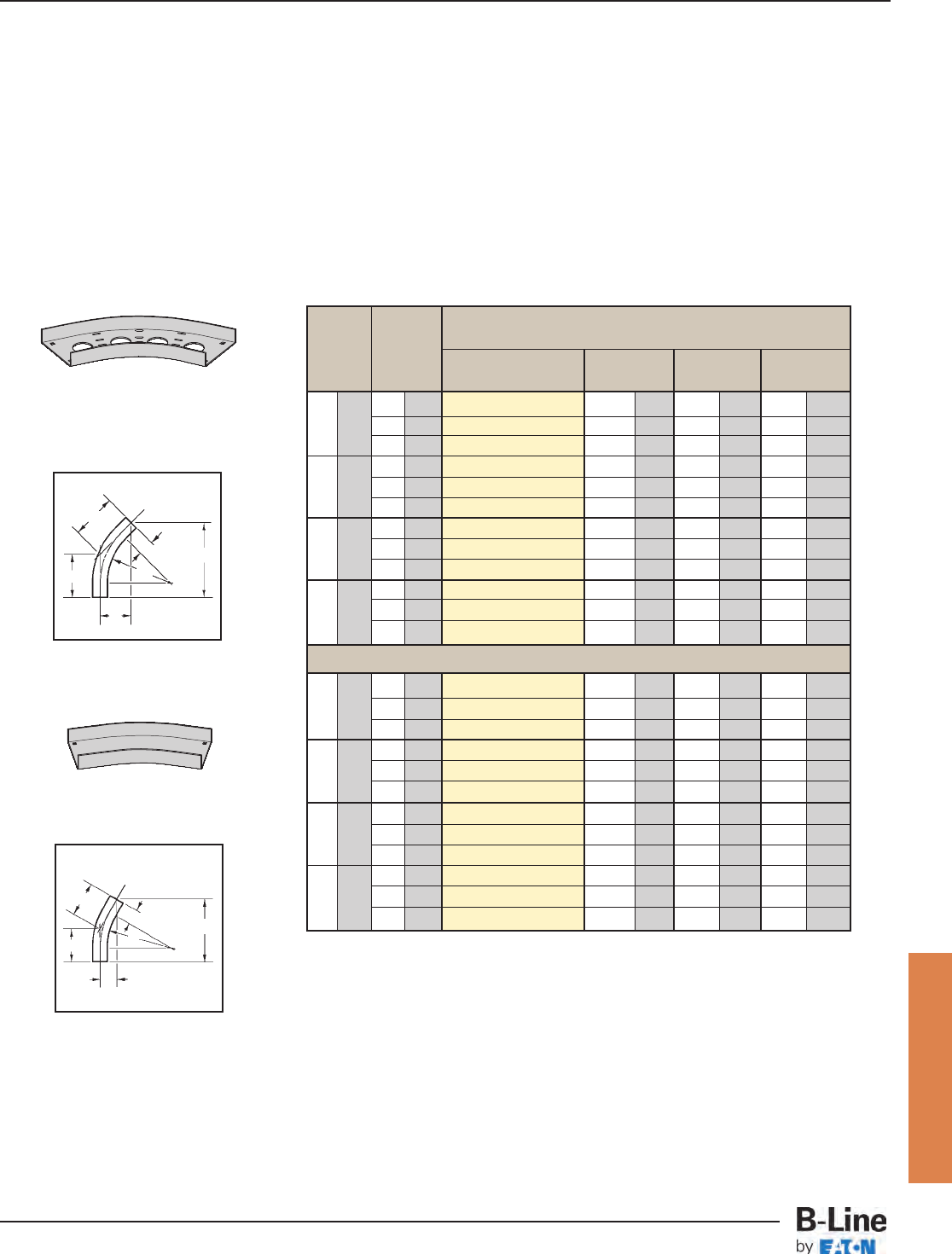
A
A
C
CR
B
45˚
HB
C
CR
3” (76)
B
30˚
HB
Horizontal Bends 45°, 30° (HB)
1 splice plate with hardware included.
All dimensions in shaded areas are millimeters unless otherwise specified.
(Pre) See page CCT-8 for catalog number prefix.
45° Horizontal Bend
Ventilated Horizontal Bend
3” (76)
30° Horizontal Bend
Non-Ventilated Horizontal Bend
Bend Tray 45˚ Horizontal Bend
Radius Width Dimensions
R Catalog No. ABC
in. mm in. mm in. mm in. mm in. mm
3 76 (Pre)-03-45HB12 145/8371 61/8156 85/8219
12 305 4 101 (Pre)-04-45HB12 15 381 61/4159 87/8225
6 152 (Pre)-06-45HB12 153/4400 61/2165 91/4235
3 76 (Pre)-03-45HB24 231/8587 95/8244 135/8346
24 609 4 101 (Pre)-04-45HB24 231/2597 93/4248 133/4249
6 152 (Pre)-06-45HB24 241/8613 10 254 141/8359
3 76 (Pre)-03-45HB36 315/8803 131/8334 185/8473
36 915 4 101 (Pre)-04-45HB36 32 813 131/4337 183/4476
6 152 (Pre)-06-45HB36 323/4832 131/2343 191/8486
3 76 (Pre)-03-45HB48 401/81019 165/8422 231/2597
48 1218 4 101 (Pre)-04-45HB48 401/21029 163/4425 233/4603
6 152 (Pre)-06-45HB48 411/81045 17 432 241/8613
3
76 (Pre)-03-30HB12 123/8314 31/483 65/8168
12 305 4 101 (Pre)-04-30HB12 125/8321 33/886 63/4171
6 152 (Pre)-06-30HB12 131/8334 31/289 7 178
3 76 (Pre)-03-30HB24 183/8467 47/8124 97/8251
24 609 4 101 (Pre)-04-30HB24 185/8473 5 127 10 254
6 152 (Pre)-06-30HB24 191/8486 51/8130 101/4260
3 76 (Pre)-03-30HB36 243/8619 61/2165 13 330
36 915 4 101 (Pre)-04-30HB36 245/8626 65/8168 131/8334
6 152 (Pre)-06-30HB36 251/8638 63/4171 131/2343
3 76 (Pre)-03-30HB48 303/8772 81/8207 161/4413
48 1218 4 101 (Pre)-04-30HB48 305/8778 81/4210 163/8416
6 152 (Pre)-06-30HB48 311/8791 83/8213 165/8422
30˚ Horizontal Bend
Cable Channel
CCT-10
Channel Cable Tray - Fittings
Cable Tray Systems
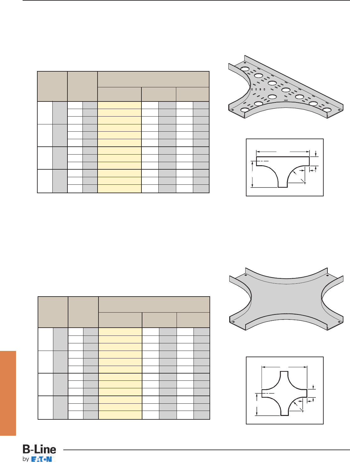
Bend Tray Horizontal Cross
Radius Width Dimensions
R Catalog No. AB
in. mm in. mm in. mm in. mm
3 76 (Pre)-03-HX12 161
/2419 33 838
12 305 4 101 (Pre)-04-HX12 17 432 34 864
6 152 (Pre)-06-HX12 18 457 36 914
3 76 (Pre)-03-HX24 281
/2723 57 1448
24 609 4 101 (Pre)-04-HX24 29 737 58 1473
6 152 (Pre)-06-HX24 30 762 60 1524
3 76 (Pre)-03-HX36 401/21029 81 2057
36 915 4 101 (Pre)-04-HX36 41 1041 82 2083
6 152 (Pre)-06-HX36 42 1067 84 2134
3 76 (Pre)-03-HX48 521/21334 105 2667
48 1218 4 101 (Pre)-04-HX48 53 1346 106 2692
6 152 (Pre)-06-HX48 54 1372 108 2743
Bend Tray Horizontal Tee
Radius Width Dimensions
R Catalog No. AB
in. mm in. mm in. mm in. mm
3 76 (Pre)-03-HT12 161
/2419 33 838
12 305 4 101 (Pre)-04-HT12 17 432 34 864
6 152 (Pre)-06-HT12 18 457 36 914
3 76 (Pre)-03-HT24 281
/2723 57 1448
24 609 4 101 (Pre)-04-HT24 29 737 58 1473
6 152 (Pre)-06-HT24 30 762 60 1524
3 76 (Pre)-03-HT36 401/21029 81 2057
36 915 4 101 (Pre)-04-HT36 41 1041 82 2083
6 152 (Pre)-06-HT36 42 1067 84 2134
3 76 (Pre)-03-HT48 521/21334 105 2667
48 1218 4 101 (Pre)-04-HT48 53 1346 106 2692
6 152 (Pre)-06-HT48 54 1372 108 2743
Horizontal Tee (HT)
2 splice plates with hardware included.
Horizontal Cross (HX)
3 splice plates with hardware included.
A
W
R
3” (76) 3” (76)
B
A
W
B
Horizontal Cross
Non-Ventilated Horizontal Cross
All dimensions in shaded areas are millimeters unless otherwise specified.
(Pre) See page CCT-8 for catalog number prefix.
All dimensions in shaded areas are millimeters unless otherwise specified.
(Pre) See page CCT-8 for catalog number prefix.
HX
HT
Horizontal Tee
Ventilated Horizontal Tee
R
Cable Channel
CCT-11
Channel Cable Tray - Fittings
Cable Tray Systems
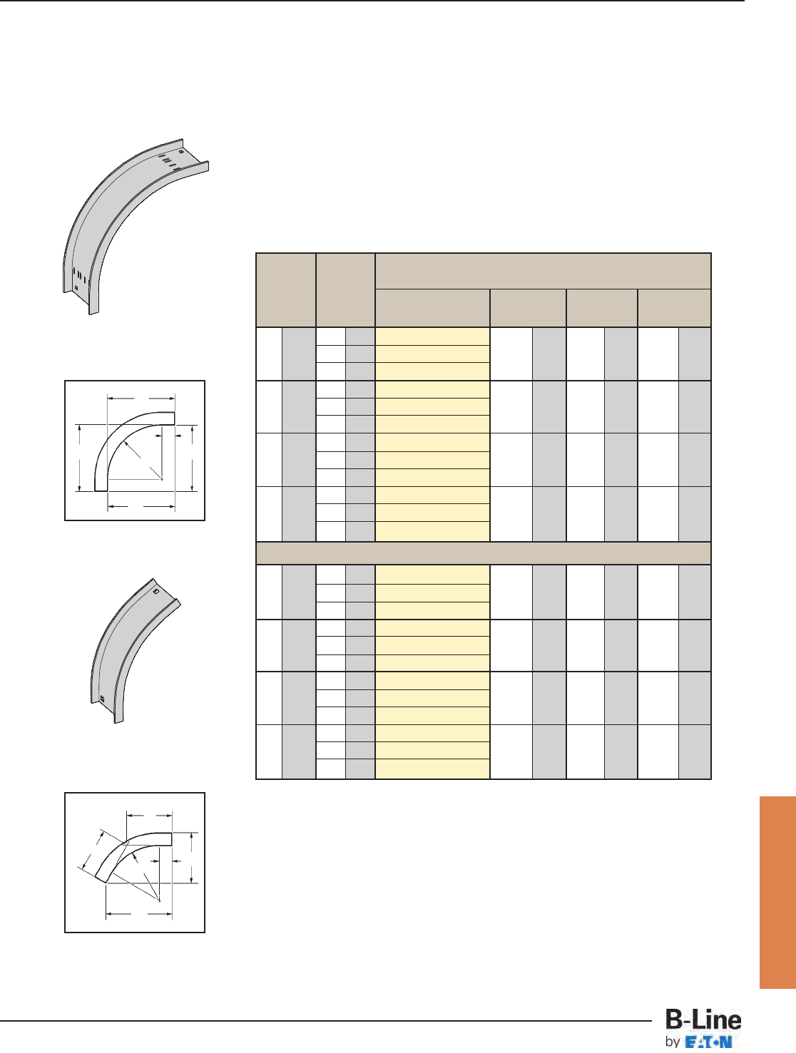
Bend Tray 90˚ Vertical Outside Bend
Radius Width Dimensions
R Catalog No. ABC
in. mm in. mm in. mm in. mm in. mm
3 76 (Pre)-03-90VO12
12 305 4 101 (Pre)-04-90VO12 15 381 15 381 15 381
6 152 (Pre)-06-90VO12
3 76 (Pre)-03-90VO24
24 609 4 101 (Pre)-04-90VO24 27 686 27 686 27 686
6 152 (Pre)-06-90VO24
3 76 (Pre)-03-90VO36
36 915 4 101 (Pre)-04-90VO36 39 991 39 991 39 991
6 152 (Pre)-06-90VO36
3 76 (Pre)-03-90VO48
48 1218 4 101 (Pre)-04-90VO48 51 1295 51 1295 51 1295
6 152 (Pre)-06-90VO48
3 76 (Pre)-03-60VO12
12 305 4 101 (Pre)-04-60VO12 147/8378 81/2216 97/8251
6 152 (Pre)-06-60VO12
3 76 (Pre)-03-60VO24
24 609 4 101 (Pre)-04-60VO24 253/8645 145
/8372 167/8428
6 152 (Pre)-06-60VO24
3 76 (Pre)-03-60VO36
36 915 4 101 (Pre)-04-60VO36 355
/8905 205
/8524 233/4603
6 152 (Pre)-06-60VO36
3 76 (Pre)-03-60VO48
48 1218 4 101 (Pre)-04-60VO48 461/81172 265/8676 303/4781
6 152 (Pre)-06-60VO48
Vertical Outside Bends 90°, 60° (VO)
1 splice plate with hardware included.
A
C
C
R
3” (76)
B
A
C
C
R
3” (76)
B
90˚
VO
60˚
VO
60˚ Vertical Outside Bend
All dimensions in shaded areas are millimeters unless otherwise specified.
(Pre) See page CCT-8 for catalog number prefix.
90° Vertical Outside Bend
Ventilated Vertical Outside Bend
60° Vertical Outside Bend
Non-Ventilated Vertical Outside Bend
Cable Channel
CCT-12
Channel Cable Tray - Fittings
Cable Tray Systems
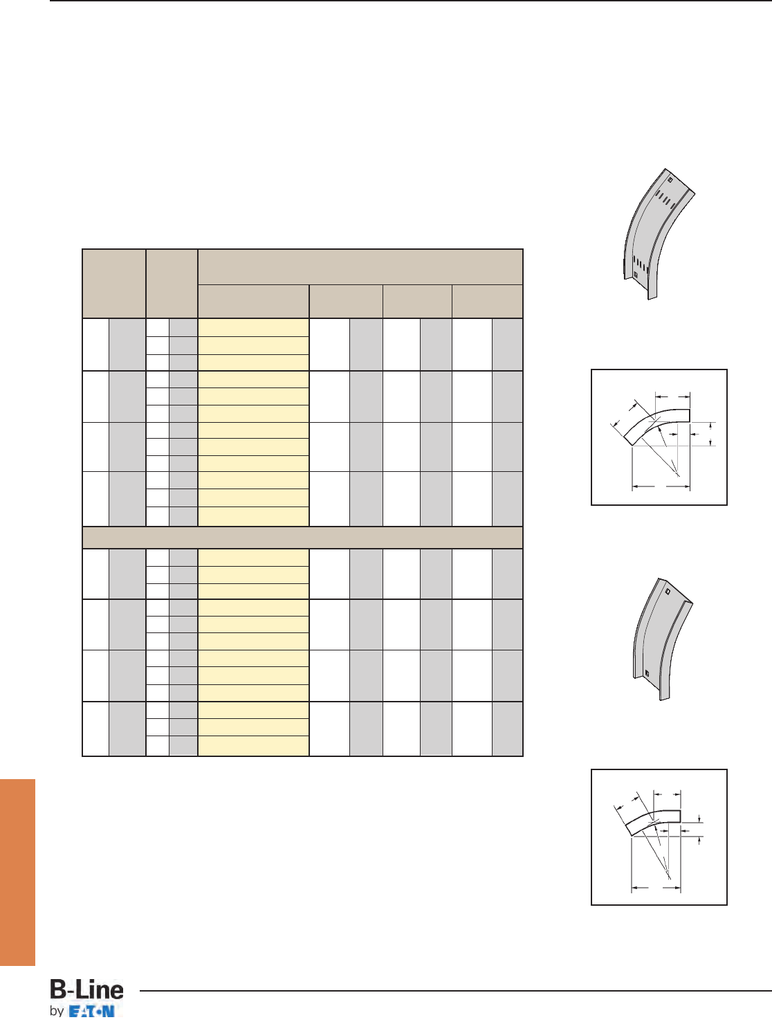
Bend Tray 45˚ Vertical Outside Bend
Radius Width Dimensions
R Catalog No. ABC
in. mm in. mm in. mm in. mm in. mm
3 76 (Pre)-03-45VO12
12 305 4 101 (Pre)-04-45VO12 135
/8346 55/8143 8 203
6 152 (Pre)-06-45VO12
3 76 (Pre)-03-45VO24
24 609 4 101 (Pre)-04-45VO24 221
/4565 91/4235 13 330
6 152 (Pre)-06-45VO24
3 76 (Pre)-03-45VO36
36 915 4 101 (Pre)-04-45VO36 301/2775 125/8321 177/8454
6 152 (Pre)-06-45VO36
3 76 (Pre)-03-45VO48
48 1218 4 101 (Pre)-04-45VO48 39 991 161/8410 227/8581
6 152 (Pre)-06-45VO48
3 76 (Pre)-03-30VO12
12 305 4 101 (Pre)-04-30VO12 115/8296 31/879 61/4158
6 152 (Pre)-06-30VO12
3 76 (Pre)-03-30VO24
24 609 4 101 (Pre)-04-30VO24 171/2445 47/8124 93/8238
6 152 (Pre)-06-30VO24
3 76 (Pre)-03-30VO36
36 915 4 101 (Pre)-04-30VO36 231/2597 63/8162 125/8321
6 152 (Pre)-06-30VO36
3 76 (Pre)-03-30VO48
48 1218 4 101 (Pre)-04-30VO48 295/8753 8 203 157/8403
6 152 (Pre)-06-30VO48
Vertical Outside Bends 45°, 30° (VO)
1 splice plate with hardware included.
A
C
C
R
3” (76)
B
45˚
VO
A
CC
R
3” (76)
B
30˚
VO
30˚ Vertical Outside Bend
All dimensions in shaded areas are millimeters unless otherwise specified.
(Pre) See page CCT-8 for catalog number prefix.
45° Vertical Outside Bend
Ventilated Vertical Outside Bend
30° Vertical Outside Bend
Non-Ventilated Vertical Outside Bend
Cable Channel
CCT-13
Channel Cable Tray - Fittings
Cable Tray Systems
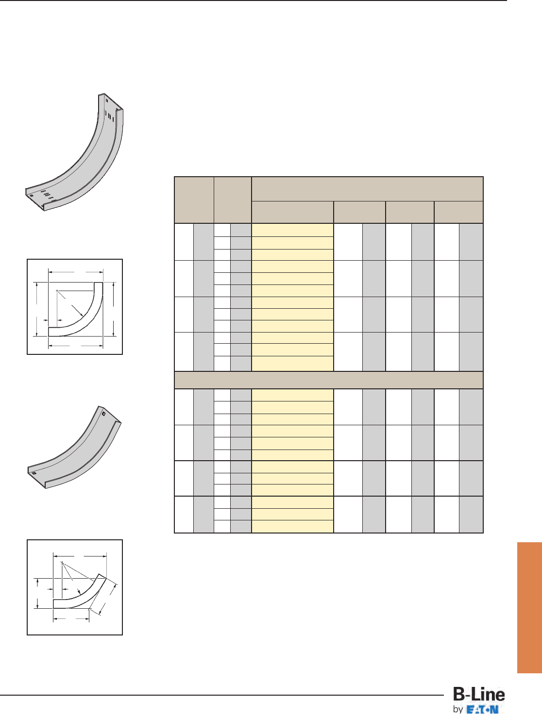
Bend Tray 90˚ Vertical Inside Bend
Radius Width Dimensions
RCatalog No. ABC
in. mm in. mm in. mm in. mm in. mm
3 76 (Pre)-03-90VI12 161/4413 161/4413 161/4413
12 305 4 101 (Pre)-04-90VI12 163/4425 163/4425 163/4425
6 152 (Pre)-06-90VI12 163/4425 163/4425 163/4425
3 76 (Pre)-03-90VI24 281/4718 281/4718 281/4718
24 609 4 101 (Pre)-04-90VI24 283/4730 283/4730 283/4730
6 152 (Pre)-06-90VI24 283/4730 283/4730 283/4730
3 76 (Pre)-03-90VI36 401/41024 401/41024 401/41024
36 915 4 101 (Pre)-04-90VI36 403/41035 403/41035 403/41035
6 152 (Pre)-06-90VI36 403/41035 403/41035 403/41035
3 76 (Pre)-03-90VI48 521/41327 521/41327 521/41327
48 1218 4 101 (Pre)-04-90VI48 523/41340 523/41340 523/41340
6 152 (Pre)-06-90VI48 523/41340 523/41340 523/41340
3 76 (Pre)-03-60VI12 16 406 91/4235 105/8270
12 305 4 101 (Pre)-04-60VI12 161/2419 91/2241 11 280
6 152 (Pre)-06-60VI12 161/2419 91/2241 11 280
3 76 (Pre)-03-60VI24 261/2673 151/4387 175/8448
24 609 4 101 (Pre)-04-60VI24 267/8683 151/2394 177/8454
6 152 (Pre)-06-60VI24 267/8683 151/2394 177/8454
3 76 (Pre)-03-60VI36 363/4933 211/4540 241/2622
36 915 4 101 (Pre)-04-60VI36 371/8943 213/8543 243/4629
6 152 (Pre)-06-60VI36 371/8943 213/8543 243/4629
3 76 (Pre)-03-60VI48 471/81197 271/8689 313/8797
48 1218 4 101 (Pre)-04-60VI48 475/81210 271/2699 313/4806
6 152 (Pre)-06-60VI48 475/81210 271/2699 313/4806
Vertical Inside Bends 90°, 60° (VI)
1 splice plate with hardware included.
A
C
C
R
3” (76)
B
A
C
C
R
3” (76)
B
90˚
VI
60˚
VI
60˚ Vertical Inside Bend
All dimensions in shaded areas are millimeters unless otherwise specified.
(Pre) See page CCT-8 for catalog number prefix.
60° Vertical Inside Bend
Non-Ventilated Vertical Inside Bend
90° Vertical Inside Bend
Ventilated Vertical Inside Bend
Cable Channel
CCT-14
Channel Cable Tray - Fittings
Cable Tray Systems
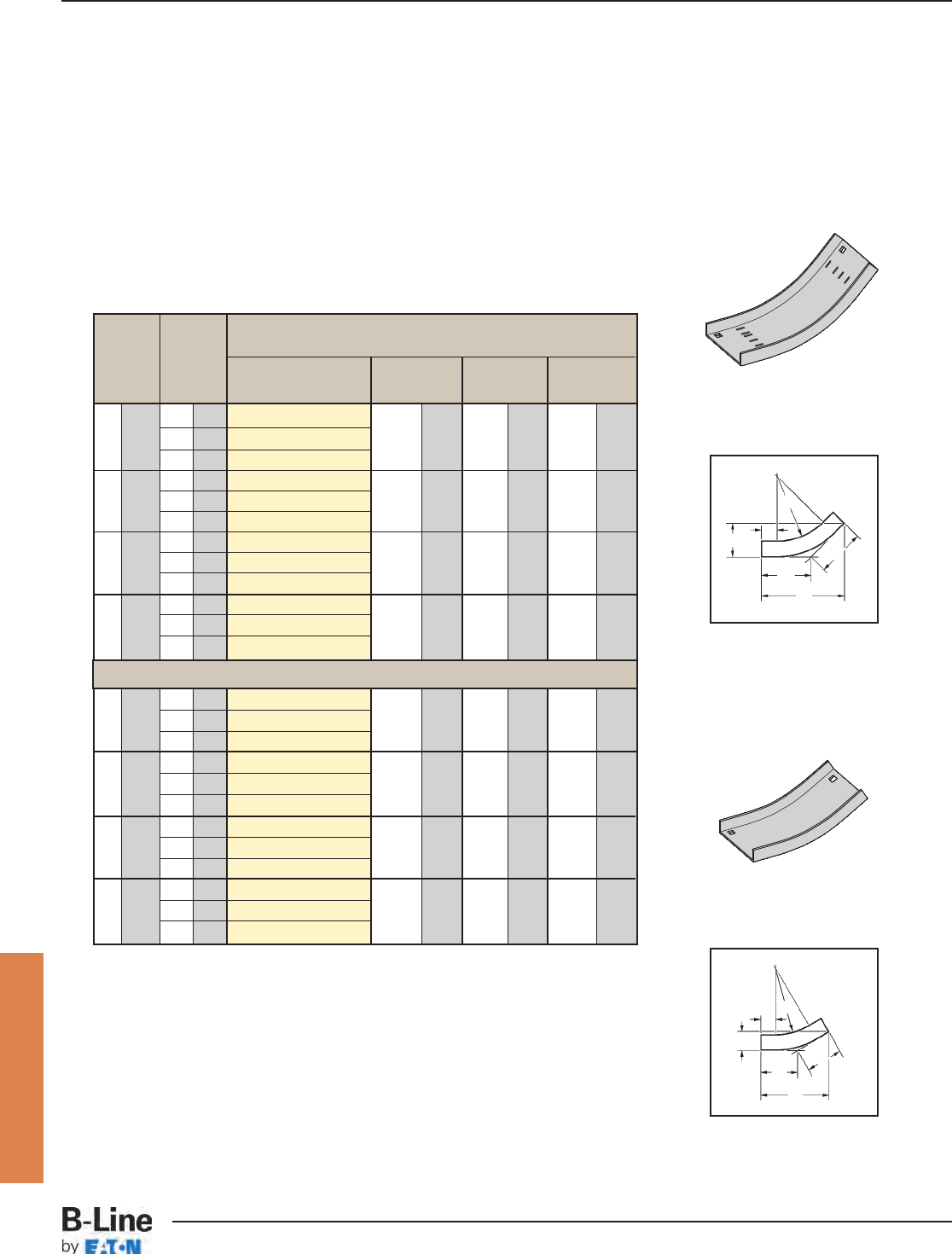
Bend Tray 45˚ Vertical Inside Bend
Radius Width Dimensions
RCatalog No. ABC
in. mm in. mm in. mm in. mm in. mm
3 76 (Pre)-03-45VI12 141/2368 6 152 81/2216
12 305 4 101 (Pre)-04-45VI12 147/8373 61/8156 83/4222
6 152 (Pre)-06-45VI12 147/8378 61/8156 83/4222
3 76 (Pre)-03-45VI24 23 584 91/2241 131/2343
24 609 4 101 (Pre)-04-45VI24 231/4591 95/8245 135/8346
6 152 (Pre)-06-45VI24 231/4591 95/8245 135/8346
3 76 (Pre)-03-45VI36 313/8797 13 330 183/8467
36 915 4 101 (Pre)-04-45VI36 313/4806 131/8330 185/8467
6 152 (Pre)-06-45VI36 313/4806 131/8334 185/8473
3 76 (Pre)-03-45VI48 397/81013 161/2419 233/8594
48 1218 4 101 (Pre)-04-45VI48 403/81026 163/4425 235/8600
6 152 (Pre)-06-45VI48 403/81026 163/4425 235/8600
3 76 (Pre)-03-30VI12 121/8308 31/883 61/2165
12 305 4 101 (Pre)-04-30VI12 123/8314 33/886 65/8163
6 152 (Pre)-06-30VI12 123/8314 33/886 65/8163
3 76 (Pre)-03-30VI24 181/8461 43/4121 93/4248
24 609 4 101 (Pre)-04-30VI24 183/8467 47/886 97/8163
6 152 (Pre)-06-30VI24 183/8314 47/886 97/8163
3 76 (Pre)-03-30VI36 241/4616 61/2165 13 330
36 415 4 101 (Pre)-04-30VI36 241/2622 65/8168 131/8334
6 152 (Pre)-06-30VI36 241/2622 65/8168 131/8334
3 76 (Pre)-03-30VI48 303/8772 81/8207 161/4413
48 1218 4 101 (Pre)-04-30VI48 305/8778 81/4210 163/8416
6 152 (Pre)-06-30VI48 305/8778 81/4210 163/8416
Vertical Inside Bends 45°, 30° (VI)
1 splice plate with hardware included.
A
C
C
R
3” (76)
B
45˚
VI
A
CC
R
3” (76)
B
30˚
VI
30˚ Vertical Inside Bend
All dimensions in shaded areas are millimeters unless otherwise specified.
(Pre) See page CCT-8 for catalog number prefix.
30° Vertical Inside Bend
Non-Ventilated Vertical Inside Bend
45° Vertical Inside Bend
Ventilated Vertical Inside Bend
Cable Channel
CCT-15
Channel Cable Tray - Fittings
Cable Tray Systems

Section 1- Acceptable Manufacturers
1.01 Manufacturer: Subject to compliance with these specifications, channel cable tray systems
shall be as manufactured by B-Line.
Section 2- Selection and Components
2.01 General: Except as otherwise indicated, provide ventilated metal channel cable trays, of
types, classes and sizes indicated with splice connectors, fittings and all other necessary
accessories for a complete system. Provide channel cable tray with rounded edges and
smooth surfaces in compliance with applicable standards, and with the following additional
requirements.
2.02 Materials and finishes: Material and finishes specifications for each channel cable tray are
as follows:
1. Aluminum: Extruded components shall be made from Aluminum Association
Alloy 6063. All fabricated parts shall be made from Aluminum Association
Alloy 5052.
2. Pre-Galvanized Steel: Straight sections and fittings shall be made from structural
quality mill galvanized 14 gauge steel meeting the properties of ASTM A653SS,
coating designation G90.
3. Hot Dip Galvanized Steel: Straight sections and fittings shall be made from
14 gauge structural quality steel meeting the minimum mechanical properties of
ASTM A1011 SS, Grade 33 and shall be hot-dip galvanized after fabrication in
accordance with ASTM A123.
All hot dip galvanized after fabrication cable trays must be returned to point of
manufacture after coating for inspection, conditioning and labeling.
4. Stainless Steel: Straight sections and fittings shall be AISI Type [304] [316].
2.03 Channel cable tray straight sections shall be constructed with ventilated flat bottom.
Ventilated bottom shall be perforated with 2.25" diameter holes and have slots to facilitate
the use of cable ties to secure the cables.
2.04 Straight sections shall be supplied in standard [12 foot] [10 foot (3 m)] lengths, except
where shorter lengths are permitted to facilitate tray assembly as shown on drawings.
2.05 Ventilated straight sections shall have splice holes every 12 inches to simplify field
modifications.
2.06 Channel cable tray width shall be [3] [4] [6] inches with a minimum loading depth of 11/4".
2.07 Fittings will have a minimum radius of [12] [24] [36] [48] inches.
2.08 Splice plates and hardware shall be included with each straight section and fitting.
Cable Channel
CCT-16
Channel Cable Tray - Specifications
Cable Tray Systems
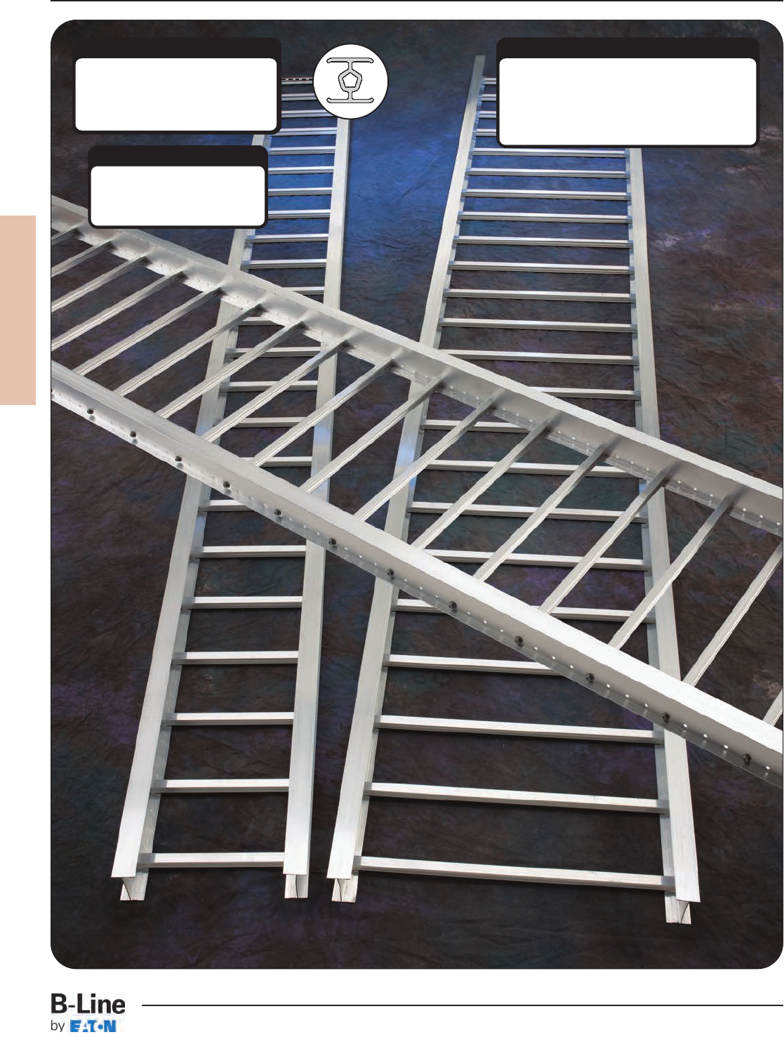
Act as holes for splice plate hardware: allow
for field cutting to any length, no field-drilling
necessary. Holes also allow rungs to be
repositioned. Holes allow for easy attachment
of accessory items requiring 1/4" hardware (or
smaller).
Multi-Functional Pre-Punched Holes
An “I”-Beam shaped rung provides a
great strength-to-weight ratio.
Patented fastener hole is designed to
provide maximum grip for the fastener
threads.
REDI-RAIL Rung
Specially designed and finished
rung fastener. Rung pullout
tested to over 3000 lbs. Vibration
tested for your confidence.
REDI-RAIL
Rung Fastener
Patent Information
U.S. Patent D361982; 5,580,014
Canada 2,137,879
UK Patent 2,285,343
Other United States and foreign patents are pending.
REDI-RAIL
RER-1
REDI-RAIL™
Cable Tray Systems
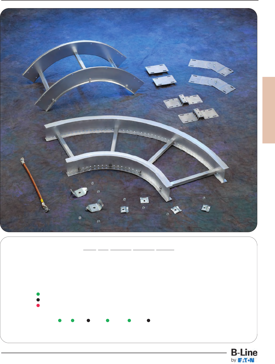
REDI-RAIL
How The Service Advisor Works
B-Line knows that your time is important! That’s why the color-coding system in this catalog is designed to help you select
products that fit your service needs. Products are marked to indicate the typical lead time for orders of 50 pieces or less.
Customer: How do I select my straight sections. covers, or fittings so that I get the quickest turnaround?
Service Advisor: Each part of our selection chart is shown in colors. If any section of a part number is a different
color, the part will typically ship with the longer lead time represented by the colors.
Green = Fastest shipped items
Black = Normal lead-time items
Red = Normally long lead-time items
Example: RSI 04A 075KO 09SL - 12 - 120 Part will have a normal
lead time because of the
075KO knockout type.
RER-2
REDI-RAIL™- Straight Sections
Cable Tray Systems
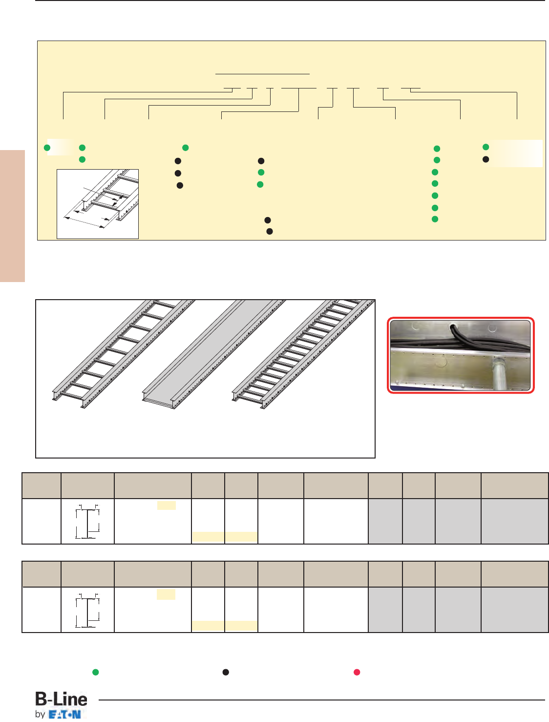
B-Line Side Rail NEMA, CSA & UL Span Load Deflection Design Factors Span Load Deflection Design Factors
Series Dimensions Classifications ft lbs/ft Multiplier for Two Rails meters kg/m Multiplier for Two Rails
NEMA: 12B 6 224 0.0008 Area=1.08 in21.8 333 0.014 Area=6.95 cm2
RSI05A CSA: 123kg/m 3.7m 8 187 0.0026 Sx=1.55 in32.4 278 0.045 Sx=25.40 cm3
UL Cross-Sectional 10 119 0.0064 Ix=3.53 in43.0 178 0.109 Ix=147.00 cm4
Area: 0.60 in212 83 0.0132 3.7 123 0.225
B-Line Side Rail NEMA, CSA & UL Span Load Deflection Design Factors Span Load Deflection Design Factors
Series Dimensions Classifications ft lbs/ft Multiplier for Two Rails meters kg/m Multiplier for Two Rails
NEMA: 12B 6 224 0.0015 Area=0.93 in21.8 333 0.025 Area=5.99 cm2
RSI04A CSA: 112kg/m 3.7m 8 169 0.0047 Sx=1.11 in32.4 252 0.080 Sx=18.10 cm3
UL Cross-Sectional 10 108 0.0115 Ix=1.96 in43.0 161 0.196 Ix=81.70 cm4
Area: 0.40 in212 75 0.0238 3.7 112 0.406
1.71
REDI-RAIL
¨Primary
¡Secondary
Values are based on simple beam tests per VE-1 on 36" wide cable tray with rungs spaced on 12" centers. The published load safety
factor is 1.5. To convert 1.5 safety factor to 2.0, multiply the published load by 0.75. To obtain mid-span deflection, multiply a load by the
deflection multiplier. Cable tray must be supported on spans shorter than or equal to the length of the tray. These systems will support
without collapse a 200 lb. concentrated load.
Straight Section Part Numbering
Prefix
Example: RSI 04 A 075KO 09 SL - 12 - 120
Series Height Material Knockout Type Bottom Type Construction Width Length
RSI 04 = 4" A = Blank = None Ladder- SL = 06 = 6" ¨144 = 12 ft.
05 = 5" Aluminum 050KO = 1/2” KO 06 = 6" rung spacing Straight 09 = 9" ¡120 = 10 ft.
075KO = 3/4” KO 09 = 9" rung spacing Ladder 12 = 12"
100KO = 1” KO 12 = 12" rung spacing 18 = 18"
24 = 24"
Trough- 30 = 30"
VB = Vented Bottom 36 = 36"
SB = Solid Bottom
• Splices included with straight sections
Ladder Type
(Specify Rung Spacing)
Solid Bottom Vented Bottom
When cable trays are used in continuous spans, the deflection of the cable tray is reduced by as much as 50%.
Design factors: Ix = Moment of Inertia, Sx = Section Modulus.
3.54 2.68
1.71
4.53 3.66
REDI-RAIL with knockouts.
RSI04A and RSI05A Straight Sections
Green = Fastest shipped items Black = Normal lead-time items Red = Normally long lead-time items
Width
(Inside)
Rung
Spacing
Overall Width
(Width + 11/2”)
RER-3
REDI-RAIL™- Straight Sections
Cable Tray Systems
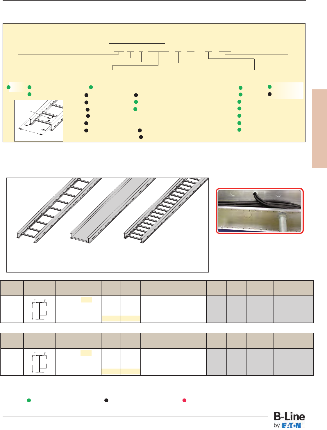
REDI-RAIL
B-Line Side Rail NEMA, CSA & UL Span Load Deflection Design Factors Span Load Deflection Design Factors
Series Dimensions Classifications ft lbs/ft Multiplier for Two Rails meters kg/m Multiplier for Two Rails
NEMA: 12C 6 224 0.0003 Area=1.50 in21.8 333 0.006 Area=9.68 cm2
RSI07A CSA: 182kg/m 3.7m 8 224 0.0010 Sx=2.69 in32.4 333 0.018 Sx=44.10 cm3
UL Cross-Sectional 10 176 0.0026 Ix=8.79 in43.0 262 0.044 Ix=366.00 cm4
Area: 0.60 in212 122 0.0053 3.7 182 0.091
B-Line Side Rail NEMA, CSA & UL Span Load Deflection Design Factors Span Load Deflection Design Factors
Series Dimensions Classifications ft lbs/ft Multiplier for Two Rails meters kg/m Multiplier for Two Rails
NEMA: 12B 6 224 0.0005 Area=1.18 in21.8 333 0.009 Area=7.59 cm2
RSI06A CSA: 121kg/m 3.7m 8 184 0.0017 Sx=1.98 in32.4 273 0.029 Sx=32.50 cm3
UL Cross-Sectional 10 118 0.0041 Ix=5.51 in43.0 175 0.070 Ix=230.00 cm4
Area: 0.60 in212 82 0.0085 3.7 121 0.144
Values are based on simple beam tests per VE-1 on 36" wide cable tray with rungs spaced on 12" centers. The published load safety
factor is 1.5. To convert 1.5 safety factor to 2.0, multiply the published load by 0.75. To obtain mid-span deflection, multiply a load by the
deflection multiplier. Cable tray must be supported on spans shorter than or equal to the length of the tray. These systems will support
without collapse a 200 lb. concentrated load.
• Splices included with straight sections
Ladder Type
(Specify Rung Spacing)
Solid Bottom Vented Bottom
When cable trays are used in continuous spans, the deflection of the cable tray is reduced by as much as 50%.
Design factors: Ix = Moment of Inertia, Sx = Section Modulus.
RSI06A and RSI07A Straight Sections
Green = Fastest shipped items Black = Normal lead-time items Red = Normally long lead-time items
REDI-RAIL with knockouts.
1.71
5.51 4.64
1.71
6.50 5.63
¨Primary
¡Secondary
Straight Section Part Numbering
Prefix
Example: RSI 06 A 075KO 09 SL - 12 - 120
Series Height Material Knockout Type Bottom Type Construction Width Length
RSI 06 = 6" A = Blank = None Ladder- SL = 06 = 6" ¨144 = 12 ft.
07 = 7" Aluminum 050KO = 1/2” KO 06 = 6" rung spacing Straight 09 = 9" ¡120 = 10 ft.
075KO = 3/4” KO 09 = 9" rung spacing Ladder 12 = 12"
100KO = 1” KO 12 = 12" rung spacing 18 = 18"
100KO = 1” KO 24 = 24"
125KO = 11/4” KO Trough- 30 = 30"
150KO = 11/2” KO VB = Vented Bottom 36 = 36"
SB = Solid Bottom
Width
(Inside)
Rung
Spacing
Overall Width
(Width + 11/2”)
RER-4
REDI-RAIL™- Straight Sections
Cable Tray Systems
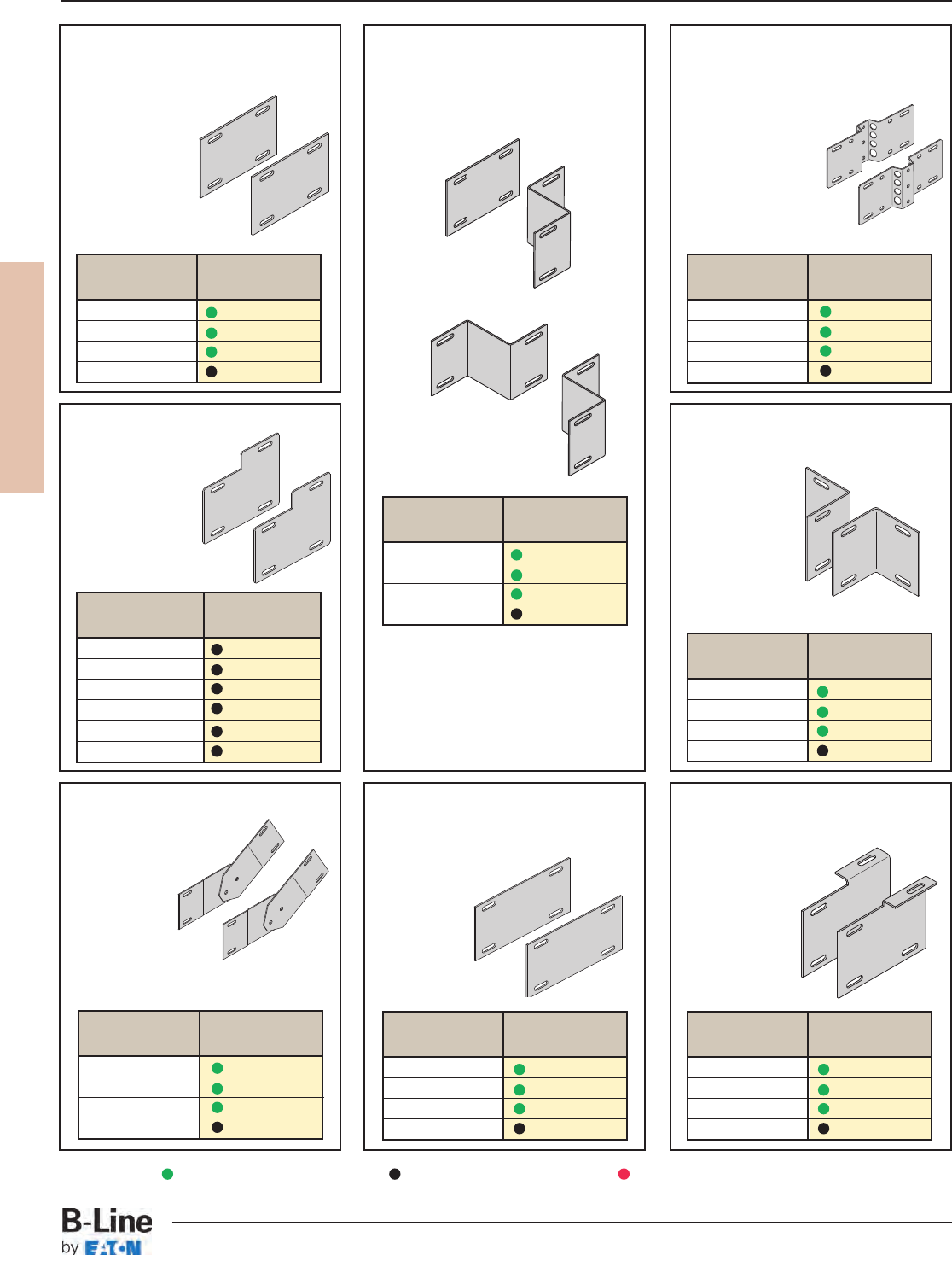
REDI-RAIL
FLEX-MOUNT™Adjustable
Splice Plates
• Furnished in pairs with 1/4" hardware.
• Horizontally adjustable
to 90°.
• Vertically
adjustable to 15°.
• UL Classified.
• For optional rung,
see page RER-12.
Offset Reducing Splice Plates
• Furnished in pairs with
1/4" hardware.
• UL Classified.
Standard Splice Plates
• Furnished in pairs with
1/4" hardware.
• UL Classified.
• One pair
including
hardware
provided with
each straight
section.
Tray To Box Splice Plates
• Furnished in pairs with
1/4" hardware.
• UL Classified.
Step Down Splice Plates
• Furnished in
pairs with 1/4"
hardware.
• UL Classified.
Adaptor Splice Plates
• Furnished in pairs with
1/4" hardware.
• UL Classified.
• For connecting
to old Redi-Rail
system.
Expansion Splice Plates
• Furnished in pairs with
1/4" hardware.
• Bonding jumper
required.
Vertical Adjustable Splice Plates
• Furnished in pairs with
1/4" hardware.
• UL Classified.
Right (or Left)
Reducer
Center Reducer
Specify the following:
† C = center reducer
S = side reducer
r (tray reduction) 3”, 6”, 9”, 12”,
15”, 18”, 21”, 24”, 27”, or 30”
Tray
Series Catalog No.
RSI04A R4A-FSP
RSI05A R5A-FSP
RSI06A R6A-FSP
RSI07A R7A-FSP
Tray
Series Catalog No.
RSI04A R4A-TTB
RSI05A R5A-TTB
RSI06A R6A-TTB
RSI07A R7A-TTB
Tray
Series Catalog No.
RSI04A R4A-RSP-†r
RSI05A R5A-RSP-†r
RSI06A R6A-RSP-†r
RSI07A R7A-RSP-†r
Tray
Series Catalog No.
RSI04A R4A-ESP
RSI05A R5A-ESP
RSI06A R6A-ESP
RSI07A R7A-ESP
Tray
Series Catalog No.
RSI04A R4A-ASP
RSI05A R5A-ASP
RSI06A R6A-ASP
RSI07A R7A-ASP
Tray
Series Catalog No.
RSI04A R4A-VSP
RSI05A R5A-VSP
RSI06A R6A-VSP
RSI07A R7A-VSP
Tray
Series Catalog No.
RSI04A R4A-SSP
RSI05A R5A-SSP
RSI06A R6A-SSP
RSI07A R7A-SSP
Tray
Series Catalog No.
RSI05A to RSI04A RAA-DSP-45
RSI06A to RSI04A RAA-DSP-46
RSI07A to RSI04A RAA-DSP-47
RSI06A to RSI05A RAA-DSP-56
RSI07A to RSI05A RAA-DSP-57
RSI07A to RSI06A RAA-DSP-67
Requires supports within 24” on
both sides, per NEMA VE 2.
Requires supports within
24” on both sides, per NEMA VE 2.
Green = Fastest shipped items Black = Normal lead-time items Red = Normally long lead-time items
RER-5
REDI-RAIL™- Accessories
Cable Tray Systems
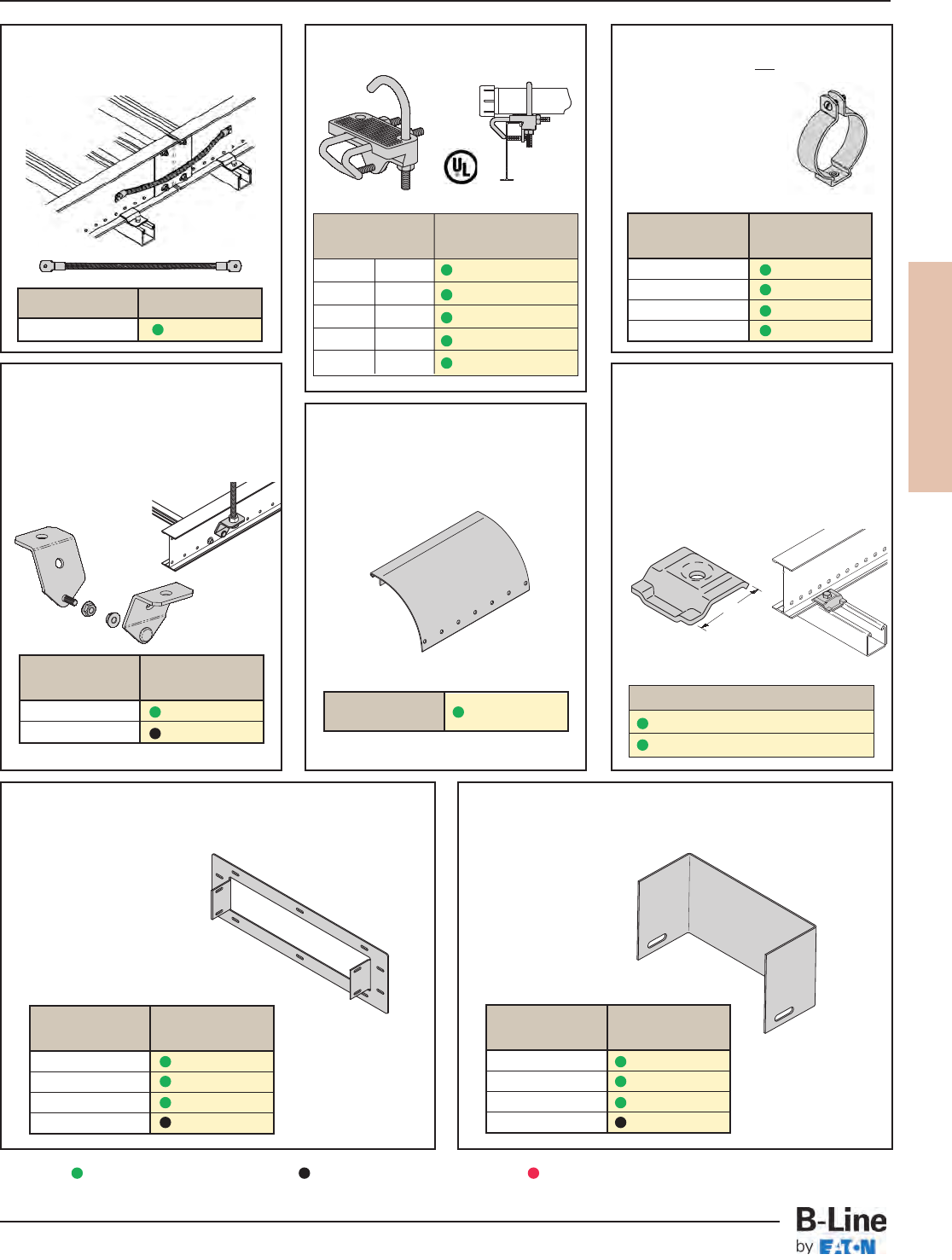
REDI-RAIL
Conduit to Tray Adaptors
• Mounting hardware not included.
Conduit to Tray Adaptors
Redi-Rail™ Clamp/Guide
• Features a no-twist design.
• Has four times the strength of the
traditional design.
• Each side is labeled to ensure
proper installation.
• Designed for 1/4” hardware.
• Furnished in pairs with or without
hardware.
Bonding Jumper
• Furnished with 1/4" hardware.
• UL Classified.
Hanger Rod Bracket
• Furnished as pair of studded clamps
with 1/4” serrated flanged lock nuts.
• Loading is 1,000 lbs. (4.45kN) per
pair with safety factor of 3.
• Position ATR 3” (76mm) wider than
cable tray.
Drop-Out
• Provides 4” (101mm) radius.
• Holes provided to secure cables.
Frame Type Box Connector
• Furnished with 1/4" hardware for
tray connection.
Blind End
• Furnished as one plate with 1/4" hardware.
Conduit
Size Catalog No.
1/2BL1400
3/4BL1410
1 BL1420
11/2BL1430
Catalog No. RAA-OUT-†
Tray
Series Catalog No.
RSI04A R4A-END-†
RSI05A R5A-END-†
RSI06A R6A-END-†
RSI07A R7A-END-†
Tray
Series Catalog No.
RSI04A R4A-FTB-†
RSI05A R5A-FTB-†
RSI06A R6A-FTB-†
RSI07A R7A-FTB-†
Support
ATR Size Catalog No.
3/8” 9(*)-R238
1/2”9(*)-R250
Ampacity Catalog No.
1200 99-30
Conduit Size
in mm Catalog No.
1/2
,
3/4
15, 20 9G-1158-
1/2
,
3/4
1, 1
1/4
25, 32 9G-1158-1, 1
1/4
1
1/2
, 2 40, 50 9G-1158-1
1/2
, 2
2
1/2
, 3 65, 80 9G-1158-2
1/2
, 3
3
1/2
, 4 90, 100 9G-1158-3
1/2
, 4
Catalog No.
9ZN-1204 (without hardware)
9ZN-1204NB (with hardware)
† = tray width
† = tray width
(*) Insert ZN or SS
Patent No.
RE35479
1.5”
(38mm)
† = tray width
Green = Fastest shipped items Black = Normal lead-time items Red = Normally long lead-time items
RER-6
REDI-RAIL™- Accessories
Cable Tray Systems
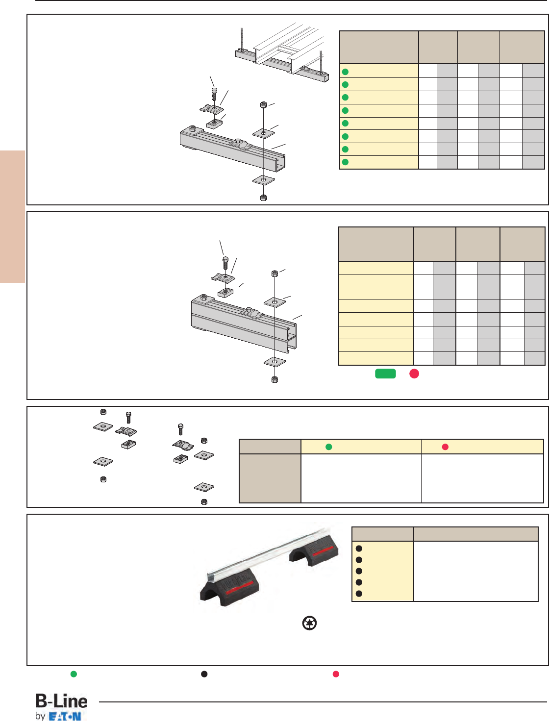
REDI-RAIL
RER-7
REDI-RAIL™- Accessories
Cable Tray Systems
Trapeze
Hardware
Kit
Heavy Duty Trapeze Support Kit
B-Line trapeze kits provide the
components required for a single trapeze
support in one package. These kits are
available in Dura-Green™epoxy coated steel
with zinc-plated hardware or hot dip
galvanized steel with 316 stainless steel
hardware.
The SH channel provides the convenience
of pre-punched slots, which eliminates the
need for field drilling.
The illustrated hardware is sealed in a
plastic bag and boxed with the channel,
which is pre-cut to the appropriate length
as shown in the chart.
Designed for use with 1/2" threaded rod.
Order rod separately.
Catalog Tray Channel Uniform
No. Width Length Load
in. mm in. mm lbs kN
9(*)-5506-22SHA 6 152 16 406 1350 6.01
9(*)-5509-22SHA 9 229 18 457 1350 6.01
9(*)-5512-22SHA 12 305 22 559 1350 6.01
9(*)-5518-22SHA 18 457 28 711 1350 6.01
9(*)-5524-22SHA 24 610 34 864 1350 6.01
9(*)-5530-22SHA 30 762 40 1016 1350 6.01
9(*)-5536-22SHA 36 914 46 1168 1350 6.01
9(*)-5542-22SHA 42 1067 52 1321 1350 6.01
Trapeze Support Kit
B-Line trapeze kits provide the components
required for a single trapeze support in one
package. These kits are available in pre-
galvanized steel with zinc-plated hardware
or hot dip galvanized steel with 316
stainless steel hardware.
The SH channel provides the convenience
of pre-punched slots, which eliminate the
need for field drilling.
The illustrated hardware is sealed in a
plastic bag and boxed with the channel,
which is pre-cut to the appropriate length
as shown in the chart.
Designed for use with 1/2" threaded rod.
Order rod separately.
Catalog Tray Channel Uniform
No. Width Length Load
in. mm in. mm lbs kN
9P-5506-22SH(†) 6 152 16 406 1600 7.11
9P-5509-22SH(†) 9 229 18 457 1250 5.56
9P-5512-22SH(†) 12 305 22 559 1125 5.00
9P-5518-22SH(†) 18 457 28 711 865 3.85
9P-5524-22SH(†) 24 610 34 864 700 3.11
9P-5530-22SH(†) 30 762 40 1016 590 2.62
9P-5536-22SH(†) 36 914 46 1168 510 2.27
9P-5542-22SH(†) 42 1067 52 1321 450 2.00
• (†) Insert 3/8for 3/8" threaded rod hardware.
Safety factor of 3.0 on all loads.
• (*) Insert or
Safety factor of 3.0 on all loads.
(1) B22 Channel
cut to the
required length
(2) 9ZN-1205
Hold-Down
Guide Clamp
(4) B202
Square Washer
(2) N525WO
Channel Nut
(2) 1/2" x 7/8" Hex
Head Cap Screw
(4) 1/2" Hex Nut
(1) Channel
cut to the
required
length
(2) 9ZN-1205
Hold-Down
Guide Clamp
(4) B202
Square Washer
(2) N525WO
Channel Nut
(2) 1/2" x 7/8" Hex
Head Cap Screw
(4) 1/2" Hex Nut
Catalog No. 9ZN-5500-1/2 9G-5500-1/2
1 pr. 9ZN-1205 1 pr. 9G-1205
2 HHC Screw 1/2x 7/8ZN 2 HHC Screw 1/2x 7/8SS6
2 N525 WO ZN 2 N525 WO SS6
4 B202 ZN 1/2" sq washer 4 B202 HDG 1/2" sq washer
4 HN 1/2ZN 4 HN 1/2SS6
In plastic bag
GRN G
Rooftop Support Bases
with B22 Channel Catalog No. Height x Width x Length
DB10-28 55/8” x 6” x 28.0”
DB10-36 55/8” x 6” x 36.0”
DB10-42 55/8” x 6” x 42.0”
DB10-50 55/8” x 6” x 50.0”
DB10-60 55/8” x 6” x 60.0”
Designed as a superior rooftop support
for cable tray,
UV resistant and approved for most
roofing material or other flat surfaces.
Can be used with any of B-Line cable
tray clamps and guides.
Ultimate Load Capacity:
1,000 lbs. (uniform load) LEEDS credit available, base made from 100% recycled material.
General Note: Consult roofing manufacturer or engineer for roof load
capacity. The weakest point may be the insulation board beneath
the rubber membrane.
Green = Fastest shipped items Black = Normal lead-time items Red = Normally long lead-time items
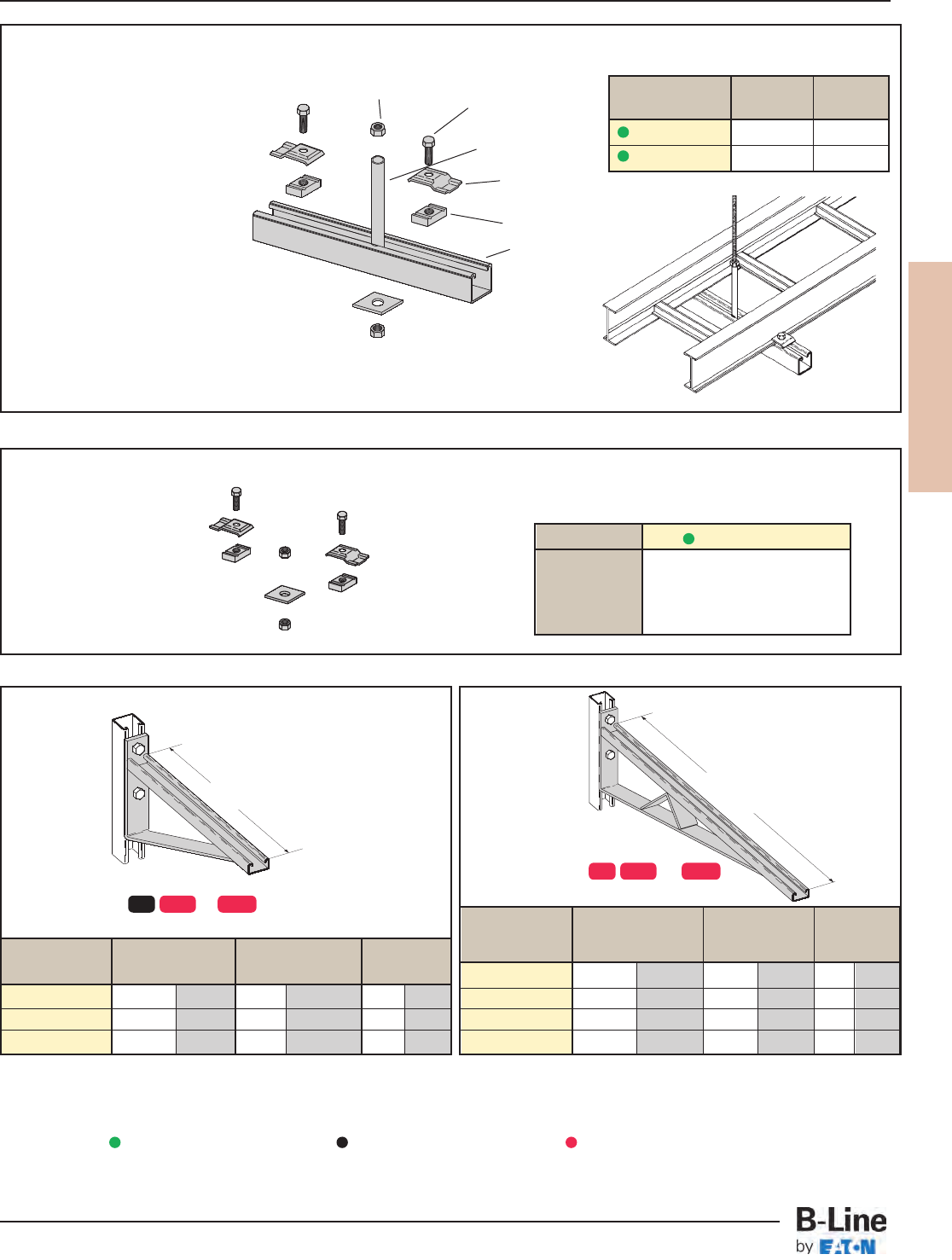
REDI-RAIL
RER-8
REDI-RAIL™- Accessories
Cable Tray Systems
Bracket
Catalog No. Uniform Load Tray Width 'A'
lbs kN in. mm in. mm
B494-12 1580 7.02 6 & 9 152 & 229 12 305
B494-18 1000 4.45 12 305 18 457
B494-24 996 4.43 18 457 24 610
Center Hung Tray Support
• Center Hung Cable Tray Support allows
cable to be laid-in from both sides.
• Eliminates costly cable pulling and field
cutting of cable tray supports. Labor
costs are dramatically reduced.
• Required hardware and threaded rod
material for trapeze assemblies are
reduced by 50%.
• Designed for use with 1/2" threaded
rod. (Order rod separately)
• Use with all aluminum and steel
cable trays through 24" width.
• Load capacity is 700 lbs. per support.
Safety factor of 3.0.
Eccentric loading is not to exceed a
60% vs. 40% load differential.
• The maximum recommended unsupported
span length is 144"/12 ft. (3.66 m).
• Hardware shown is furnished.
Catalog Tray Channel
No. Width Length
9ZN-5212 6", 9", 12" 18"
9ZN-5224 18", 24" 30"
Bracket
Catalog No. Uniform Load Tray Width 'A'
lbs kN in. mm in. mm
B494-30 924 4.11 24 610 30 762
B494-36 864 3.84 30 762 36 914
B494-42 580 2.58 36 914 42 1067
B494-48 500 2.22 42 1067 48 1219
(2) 1/2" x 7/8"
Hex Head Cap Screws
(2) 1/2" Hex Nut
(1) B202
Square Washer
(2) 9ZN-1205
Hold Down
Guide Clamp
(2) N525WO
(1) B22 Channel cut to
the required length
(1) 9/16" Inside diameter
steel tubing welded to strut
Finishes available: or
Safety Load Factor 2.5
AA
Finishes available: or
Safety Load Factor 2.5
Center Hung Support Hardware Kit
Catalog No. 9ZN-5200
1 pr. 9ZN-1205
2 HHC Screw 1/2x 7/8ZN
2 N525 WO ZN
1 B202 ZN 1/2" sq washer
2 HN 1/2ZN
In plastic bag
ZN = Zinc Plated
ZN GRN HDG
ZN GRN HDG
Green = Fastest shipped items Black = Normal lead-time items Red = Normally long lead-time items
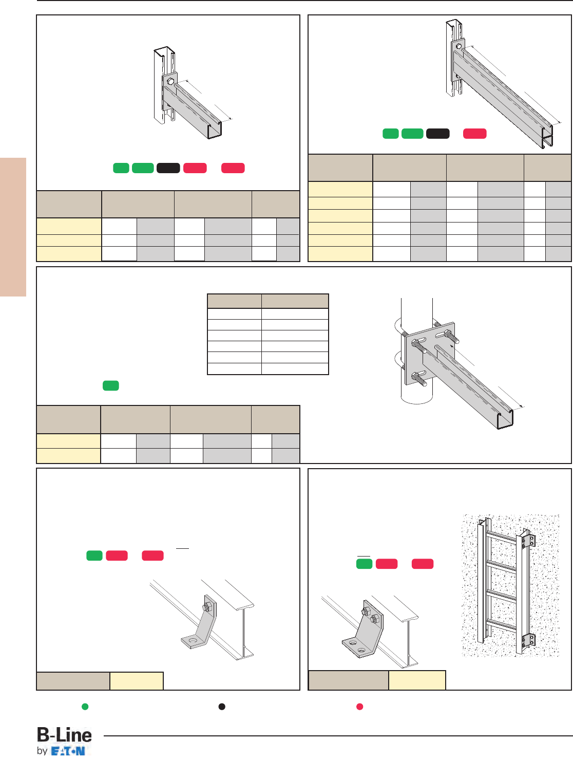
REDI-RAIL
RER-9
REDI-RAIL™- Accessories
Cable Tray Systems
Cantilever Bracket
Catalog No. Uniform Load Tray Width 'A'
lbs kN in. mm in. mm
B297-12 1660 7.38 6 & 9 152 & 229 12 305
B297-18 1100 4.89 12 305 18 457
B297-24 835 3.71 18 457 24 610
B297-30 665 2.95 24 610 30 762
B297-36 550 2.44 30 762 36 914
B297-42 465 2.06 36 914 42 1067
Underfloor Support (U-Bolts not included)
Cantilever Bracket
Catalog No. Uniform Load Tray Width 'A'
lbs kN in. mm in. mm
B409-12 960 4.27 6 & 9 152 & 229 12 305
B409-18 640 2.84 12 305 18 457
B409-24 480 2.13 18 457 24 610
Heavy Duty Hold-Down Bracket
• Design load is 4000 lbs/pair.
• Four bolt design.
• Sold in pairs.
•3/8" cable tray attachment
hardware provided
•1/2" support attachment
hardware not provided.
• (*) Insert or
Heavy Duty Hold
Down Bracket
• Design load is 2000 lbs/pair.
• Two bolt design.
• Sold in pairs.
•3/8" cable tray attachment hardware provided.
•1/2" support attachment hardware not provided.
• (*) Insert or
Catalog No. 9(*)-1241 Catalog No. 9(*)-1242
A
A
A
Finishes available: or
Safety Load Factor 2.5
Finishes available: or
Safety Load Factor 2.5
Finish available:
Safety Load Factor 2.5
U-Bolt Size Fits Pipe O.D.
B501-3/4.841 - 1.050
B501-1 1.051 - 1.315
B501-11/41.316 - 1.660
B501-11/21.661 - 1.900
B501-2 1.901 - 2.375
B501-21/22.376 - 2.875
• Order properly sized U-Bolts
separately.
Catalog No.
Uniform Load
Tray Width 'A'
lbs kN in. mm in. mm
B409UF-12 800 3.55 6 & 9 152 & 229 12 305
B409UF-21 450 2.00 12 & 18 305 & 457 21 533
ZN SS4 SS6 ZN SS4 SS6
ZN GRN HDG SS4 SS6
ZN GRN HDG SS4
ZN
Green = Fastest shipped items Black = Normal lead-time items Red = Normally long lead-time items
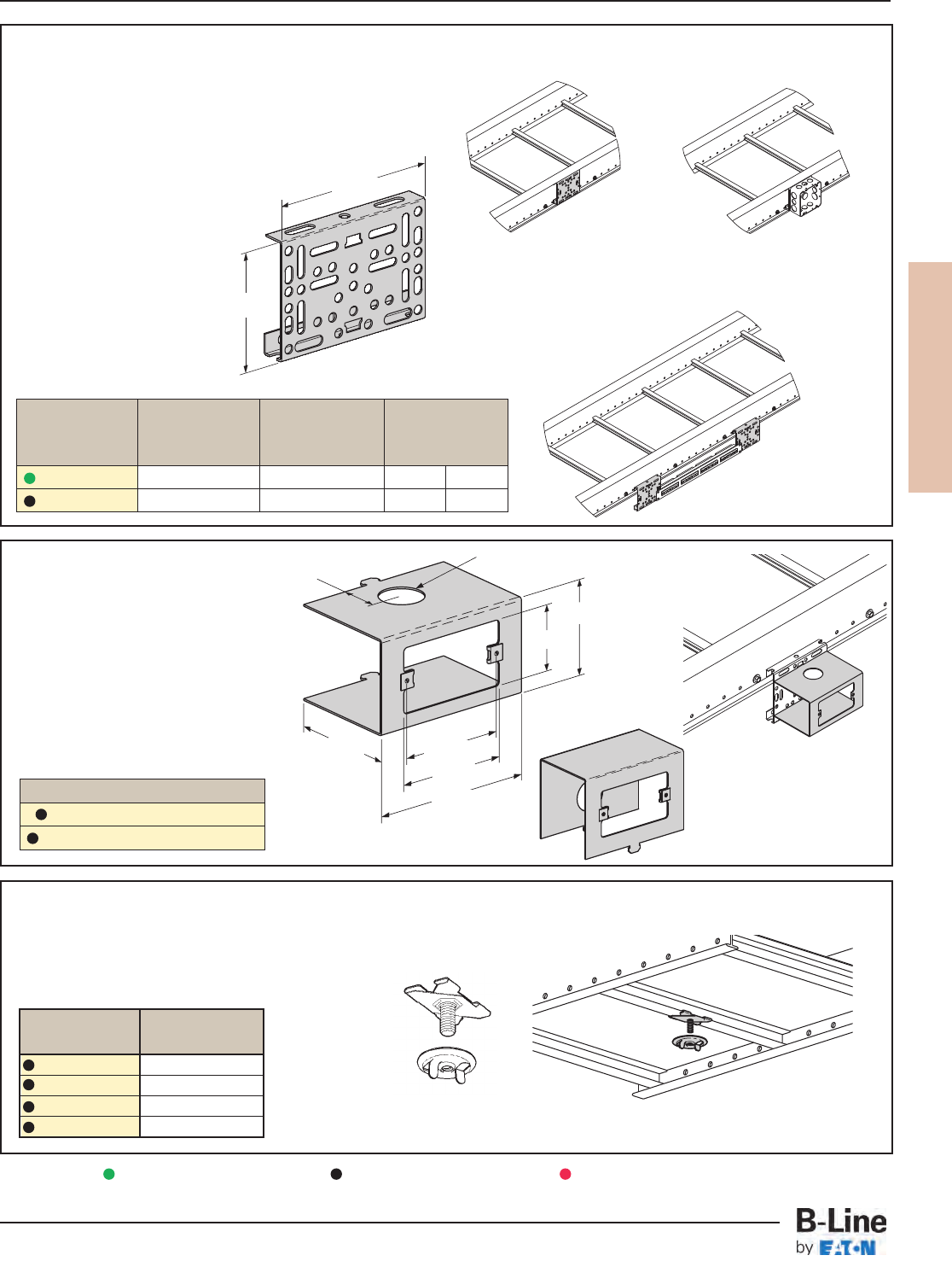
REDI-RAIL
RER-10
REDI-RAIL™- Accessories
Cable Tray Systems
Inside Side Rail Flange Application
Mounting Bracket
• Furnished with 1/4" hardware.
• #12-24 U-Nuts sold separately.
• Attaches to REDI-RAIL in over 20 positions.
• EIA/TIA panel mounting holes - both sides.
• Mounting holes for NEMA outlet/junction boxes.
• Zinc plated steel.
• Includes mounting screws.
• Inside flange application bracket
must match side rail height.
• See page RER-16 for Voice/Data/
Video and Power Options.
Low Voltage Adapter
• Mounting for low voltage wall plates.
• Snaps into mounting bracket
9ZN-MB1-4 or 9ZN-MB1-5.
• Zinc plated steel.
• #6 - 32 U-nuts included.
• See page RER-16 for Voice/Data/
Video and Power Options.
Under Rung Fastener Attachment
• Supports electrical fixtures from bottom of rung or siderails.
• Wing nut included.
• Various 1/4"-20 stud lengths available.
• Static Load Capacity: 75 Lbs. (34kg).
Stud
Catalog No. Length
BAX-4-16 5/8” (16mm)
BAX-4-16-24 11/2” (38mm)
BAX-4-16-32 2” (51mm)
BAX-4-16-48 3” (76mm)
∅ 1.344
1.250"
2.938"
2.030"
3.500" 3.28" Ref
3.500"
5.125"
9ZN-LV1-1
9ZN-LV1A-1
9ZN-LV1-1 shown
5.125"
A
9ZN-MB1-4 mounting bracket
shown with 4" electrical box.
9ZN-MB1-4 mounting
bracket shown.
9ZN-MB1-4 mounting
bracket shown with
patch panels.
Outside Side Rail Flange Application
Inside Outside
Flange Flange A
Catalog No. Application Application
in (mm)
9ZN-MB1-4 4" for RSI04 4" or 5" as desired 35/892
9ZN-MB1-5 5" for RSI05 4" or 5" as desired 45/8117
Catalog No.
9ZN-LV1-1 (cutout on front)
9ZN-LV1A-1 (cutout on bottom)
Green = Fastest shipped items Black = Normal lead-time items Red = Normally long lead-time items
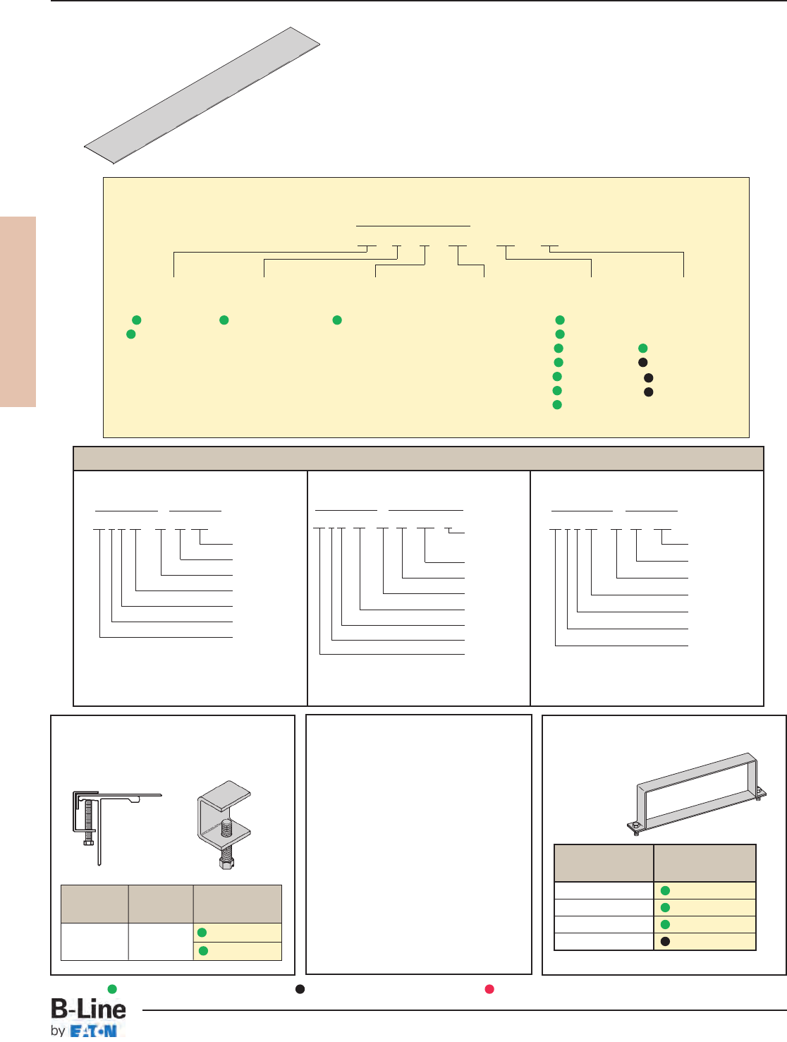
REDI-RAIL
RER-11
REDI-RAIL™- Accessories
Cable Tray Systems
Aluminum Cover Part Numbering
Prefix
Example: 86 7 A SL - 1 2 - 72
Cover Cover Tray Item
Type Detail Material Style Width Description
86 = Solid 7 = Flanged Aluminum SL = 06 = 6" For Straight
87 = Vented Straight 09 = 9" Section Cover:
Ladder 12 = 12" 144 = 12 ft.
Section 18 = 18" 120 = 10 ft.
24 = 24" 72 = 6 ft.
30 = 30" 60 = 5 ft.
36 = 36"
For fitting covers: Insert suffix of fitting to be covered. See examples below.
Examples of Catalog Numbers for Fitting Covers:
Vertical Outside Bend Cover
Prefix Suffix
86 7 A VO - 24 - 90 R24 - 4
Side Rail
Height
Radius
Angle
Width
Fitting
Material
Detail
Cover Type
Horizontal Bend Cover
Prefix Suffix
86 7 A HB - 18 - 90 R24
Radius
Angle
Width
Fitting
Material
Detail
Cover Type
Horizontal Expanding Cross Cover
Prefix Suffix
86 7 A RX - 24 - 12 - R24
Radius
Width2
Width1
Fitting
Material
Detail
Cover Type
Covers for
RSI04A, RSI05A, RSI06A, and RSI07A
Heavy Duty Cover Clamp
• For heavy duty application.
• Sold per piece.
Standard Cover Clamp
• Setscrew included.
• For indoor service only.
• Sold each.
Quantity of Standard
Cover Clamps Required
Straight Section
60” or 72” . . . . . . . . . . . . . . . . . . . . . . . . . . . 4 pcs.
Straight Section
120” or 144” . . . . . . . . . . . . . . . . . . . . . . . . 6 pcs.
Horizontal/Vertical
Bends . . . . . . . . . . . . . . . . . . . . . . . . . . . . . . . . 4 pcs.
Tees . . . . . . . . . . . . . . . . . . . . . . . . . . . . . . . . . . 6 pcs.
Crosses . . . . . . . . . . . . . . . . . . . . . . . . . . . . . . 8 pcs.
Note: When using the Heavy Duty Cover
Clamp, only one-half the number of
clamps stated above are required.
Tray
Series Catalog No.
RSI04A R4A-HDCC-†
RSI05A R5A-HDCC-†
RSI06A R6A-HDCC-†
RSI07A R7A-HDCC-†
† = tray width
Tray Side Rail
Type Height Catalog No.
Aluminum All Sizes 9ZN-9012
9A-9012
Green = Fastest shipped items Black = Normal lead-time items Red = Normally long lead-time items
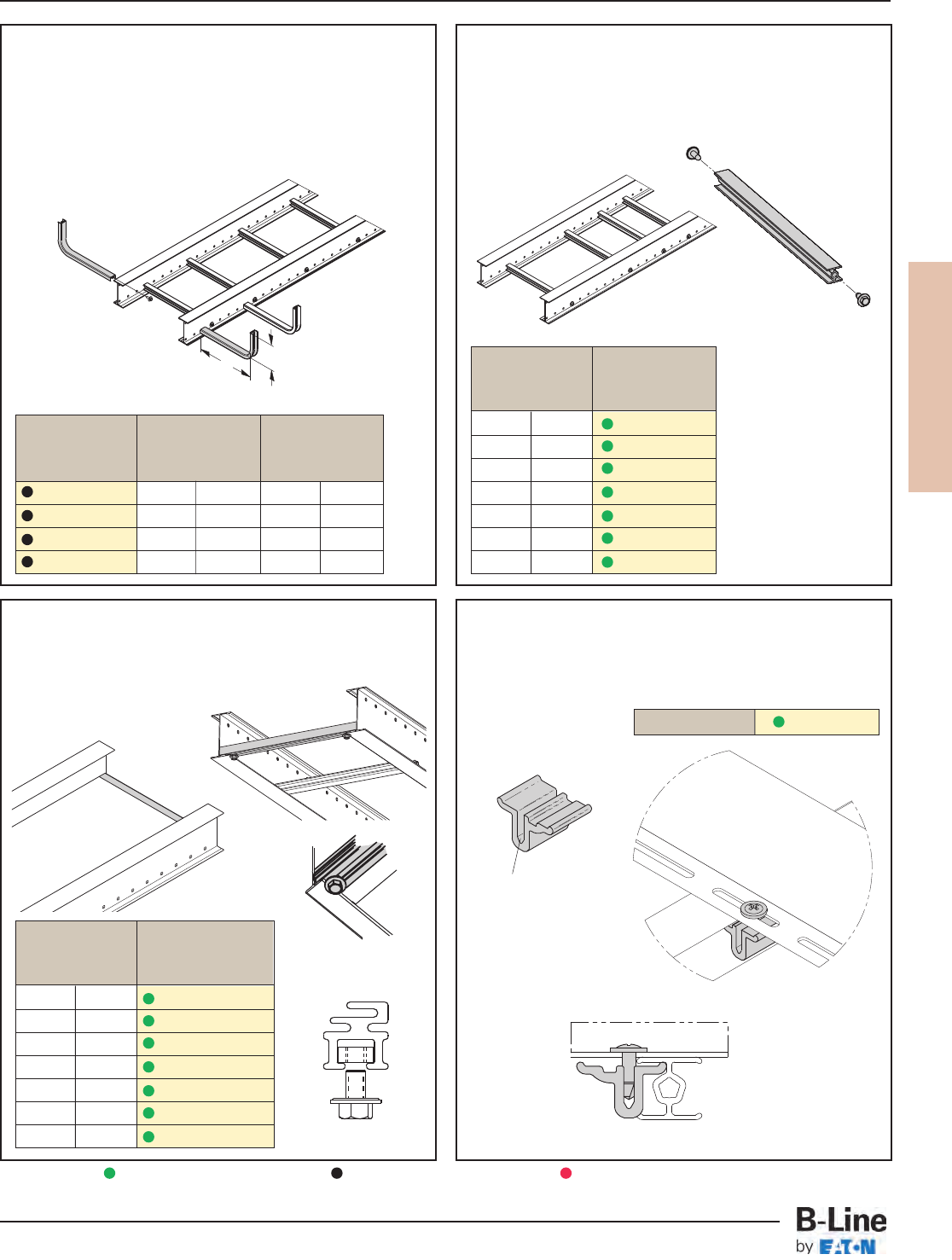
REDI-RAIL
RER-12
REDI-RAIL™- Accessories
Cable Tray Systems
Fill Depth For Tray
'H' Width 'W'
Catalog No.
in (mm) in (mm)
9A-SR0406 4 101 6 152
9A-SR0409 4 101 9 226
9A-SR0506 5 127 6 152
9A-SR0509 5 127 9 226
Out Board Rungs
• Formed aluminum rung with attachment screw.
• Field installs as required.
• Torque rung fasteners to 6 ft•lbs.
• See page RER-16 for Voice/Data/Video and
Power Options.
• Uniform load capacity on rung: 10 lbs.
Add-A-Rung™Kit
• Kit allows an additional rung to be added to
a desired location throughout the tray system.
• Pre-cut rung sections supplied.
• Attachment hardware is included.
• Torque rung fasteners to 18 ft•lbs.
Barrier Strip Clip
• Provides attachment to Redi-Rail rung.
• Allows for installed barrier adjustment.
•
Asymmetrical clip provides a wide range for screw location.
• Barriers strip clips and hardware are included with all
barriers.
End Rung Kit For Solid Bottom
• Special rung captures solid bottom plate when
required at field cuts.
• Pre-cut rung sections supplied.
• Attachment hardware is included.
Tray
Width
in (mm)
Catalog No.
6 152 9A-R06SBERK
9 226 9A-R09SBERK
12 305 9A-R12SBERK
18 452 9A-R18SBERK
24 609 9A-R24SBERK
30 762 9A-R30SBERK
36 914 9A-R36SBERK
Tray
Width
in (mm)
Catalog No.
6 152 9A-R06RK
9 226 9A-R09RK
12 305 9A-R12RK
18 452 9A-R18RK
24 609 9A-R24RK
30 762 9A-R30RK
36 914 9A-R36RK
WH
Catalog No. 9A-RBC
Screw slot for
sheet metal screw
Rung
Barrier
Flange
Green = Fastest shipped items Black = Normal lead-time items Red = Normally long lead-time items
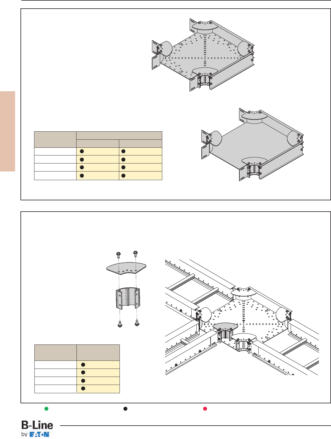
REDI-RAIL
RER-13
REDI-RAIL™- Accessories
Cable Tray Systems
Universal Fitting
• Aluminum construction.
• 3" smooth radius.
• UL Classified.
• Shipped as a 90° horizontal bend.
• Field modify to create a tee or cross.
• Includes four pairs of splice plates.
• Accommodates Rail-Riser™.
• Patent Pending.
Tray Catalog No.
Series Punched Solid
RSI04A R4A-UF-(†) R4ASB-UF-(†)
RSI05A R5A-UF-(†) R5ASB-UF-(†)
RSI06A R6A-UF-(†) R6ASB-UF-(†)
RSI07A R7A-UF-(†) R7ASB-UF-(†)
Corner Post For Universal Fitting
• Use to create reducing fittings.
• Furnished with hardware.
• 3" inside radius.
• Used on punched bottom only.
• UL Classified.
Punched Bottom
Solid Bottom
(†) Insert Tray Width 6" to 24”)
Green = Fastest shipped items Black = Normal lead-time items Red = Normally long lead-time items
Universal Fitting Shown
as a Reducing Tee
Loading
Depth Catalog No.
3" R4A-CP
4" R5A-CP
5" R6A-CP
6" R7A-CP
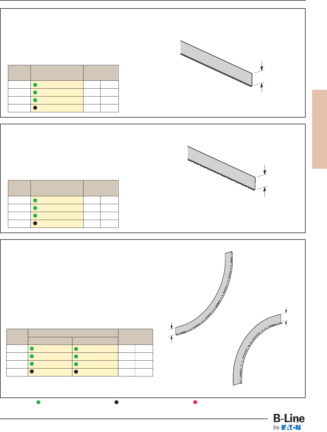
REDI-RAIL
RER-14
REDI-RAIL™- Accessories
Cable Tray Systems
Straight Section Barrier Strip
• Furnished with four (4) barrier strip clips,
mounting hardware and splice.
• Standard lengths are 144" (12 ft) & 120" (10 ft).
• Order catalog number based on loading depth ‘H’.
Green = Fastest shipped items Black = Normal lead-time items Red = Normally long lead-time items
H
Tray H
Series Catalog No.
in (mm)
RSI04A R4A-DSL-Length 3 76
RSI05A R5A-DSL-Length 4 101
RSI06A R6A-DSL-Length 5 127
RSI07A R7A-DSL-Length 6 152
Horizontal Bend Barrier Strip
• Furnished with three (3) barrier strip clips,
mounting hardware and splice.
• Standard length is 72" (6 ft).
• Flexible to fit desired angles.
• Order catalog number based on loading depth ‘H’.
Tray H
Series Catalog No.
in (mm)
RSI04A R4A-DHB 3 76
RSI05A R5A-DHB 4 101
RSI06A R6A-DHB 5 127
RSI07A R7A-DHB 6 152
Vertical Bend Barrier Strip
• Furnished with three (3) barrier strip clips,
mounting hardware and splice.
Outside Bend
(VO)
H
Inside Bend
(VI)
H
Tray Catalog No. H
Series Inside Bend Outside Bend
in (mm)
RSI04A R4A-DVI-(**)R(†) R4A-DVO-(**)R(†) 3 76
RSI05A R5A-DVI-(**)R(†) R5A-DVO-(**)R(†) 4 101
RSI06A R6A-DVI-(**)R(†) R6A-DVO-(**)R(†) 5 127
RSI07A R7A-DVI-(**)R(†) R7A-DVO-(**)R(†) 6 152
(**) Insert 30°, 45°, 60°, 90° for angles
(†) Insert 12, 24 for radius
H
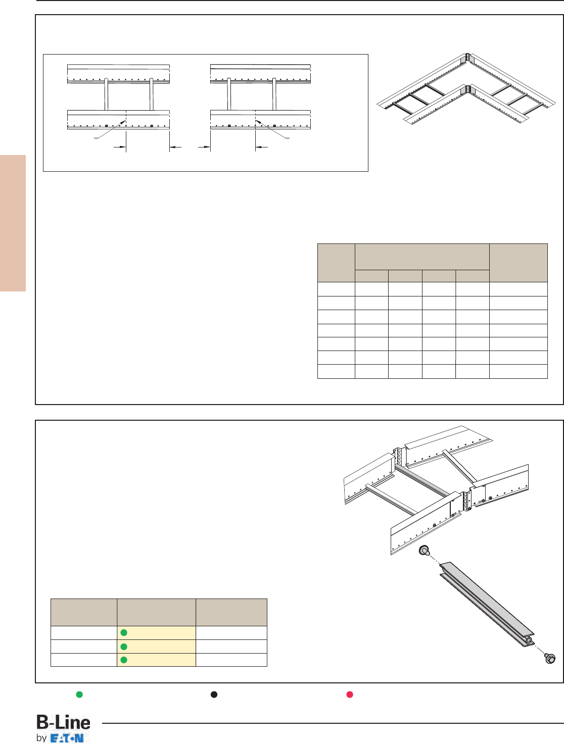
REDI-RAIL
RER-15
REDI-RAIL™- Accessories
Cable Tray Systems
How to miter cut REDI-RAIL cable tray for use
with FLEX-MOUNT™ splice plates.
Example: For a 12" wide 90° bend, the cuts must be made through the eighth hole from the end.
Number Of Holes For Angle
Tray Desired Angle Adjustment
Width 30° 45° 60° 90° Allowed
61224 ± 14.5
9 2236 ± 9.7
12 2348 ± 7.3
18 35711 ± 4.9
24 46915 ± 3.6
30 5811 19 ± 2.9
36 6 10 13 23 ± 2.4
• Mark desired hole/cut locations per chart.
• Remove any rungs (if necessary) affected by cuts.
• Cut side rails through center of required holes per chart.
• Mount outside FLEX-MOUNT splice plate with provided
hardware and bend REDI-RAIL sections to desired angle.
• Form inside FLEX-MOUNT splice plate to fit contour of inner
rails and bolt into place.
• Reinstall (if necessary) appropriate rungs.
Torque to 18 ft•lbs.
• If Splice Rung Kit (see below) is required, order
separately.
• Recommend adding one to the value in the chart if the
first hole is less than 3/8" from the end of tray.
RSI05A09SL-12-144 Straight Section shown with required side rail removed to form 90° fitting.
Cut location
Cut location Count over
number of
holes
specified in
chart
Count over
number of
holes
specified in
chart
FLEX-MOUNT Splice Rung Kit
• Kit allows a support rung to be added to flex-mount splice
plates so that cables may be supported through a bend.
• The support rung is available in three lengths
and should be ordered based upon tray width.
• The rung length is sized so that it will fit a maximum tray width
when FLEX-MOUNT splices are used to make a bend up to 90°.
• Once the FLEX-MOUNT splices are installed in the cable tray system,
the distance between the splice mounting surfaces should be
measured.
Cut support rung to the measured distance and install using the
hardware included. Torque to 18 ft•lbs.
Example: Flex connectors are installed
on an 18" wide tray with approximately a
45° bend. The correct support rung kit is
9A-RFM-24RK. The tray width is 24" or
less and the angle is less than 90°.
For Tray Actual
Width Catalog No. Rung Length
Up to 12" 9A-RFM-12RK 20"
18" & 24" 9A-RFM-24RK 37"
30" & 36" 9A-RFM-36RK 54"
Green = Fastest shipped items Black = Normal lead-time items Red = Normally long lead-time items
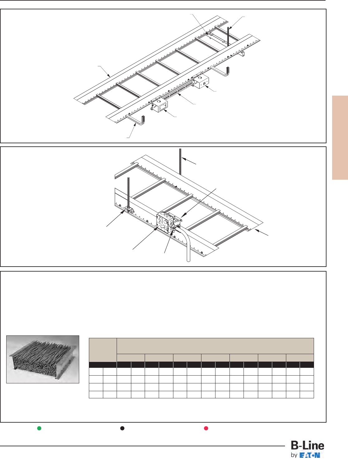
REDI-RAIL
RER-16
REDI-RAIL™- Accessories
Cable Tray Systems
RSI04A09SL-12-144
9A-SR0406
Out-Board Rung
9ZN-LV1-1 with
low voltage adapter
1/2" ATR
9ZN-5112
as center hung
Single patch panel mounted
in center of 9ZN-MB1-4
9ZN-LV1-1 with low voltage
adapter and wall plate
Voice / Data / Video Options
Power Options
3/8" ATR
RSI04A09SL-12-144
9ZN-MB1-4
BL1400
Electrical Box
9ZN-R238
The National Electrical Code allows for 50% fill of ventilated cable tray for control or signal wiring (Article 392-9(b)). This rule requires that all
the individual cable cross-sectional areas added up may not exceed one half the cable tray area. The cable tray area is equal to the width
times the load depth.
In actual practice with data cables, however, the cable tray becomes completely full in reaching the "50% cable fill". See the picture below.
The tray is completely full, but the sum of the cable areas is only 50% of the tray area, due to the empty spaces between the cables.
"50%" Fill Per NEC
Cross Sectional Area
Calculation
This chart was based on 50% fill of 4 UTP Category 5, 5e, or 6 cables (O.D. = .21" .026 lbs/ft).
In the above loading grid, the weight of the cables is not the issue. The volume capacity of the tray
governs. For example, the worst case (6" load depth, 36" wide) has a total cable weight of 81 lbs/ft.
Data Cables
Tray Tray
Depth Width
in mm 6" 9" 12" 18" 24" 30" 36"
Cables lbs/ft Cables lbs/ft Cables lbs/ft Cables lbs/ft Cables lbs/ft Cables lbs/ft Cables lbs/ft
3” 76 260 7 390 10 520 14 780 21 1040 26 1299 32 1559 41
4” 101 347 9 520 13 693 18 1040 27 1386 35 1733 43 2079 54
5” 127 433 12 650 17 866 23 1299 34 1733 43 2166 53 2599 68
6” 152 520 14 780 20 1040 27 1559 41 2079 52 2599 64 3119 81
Data Cable Fill and Weight Chart
Number of Category 5/5e/6 Cables and Calculated Cable Weight in Lbs/Ft
Green = Fastest shipped items Black = Normal lead-time items Red = Normally long lead-time items
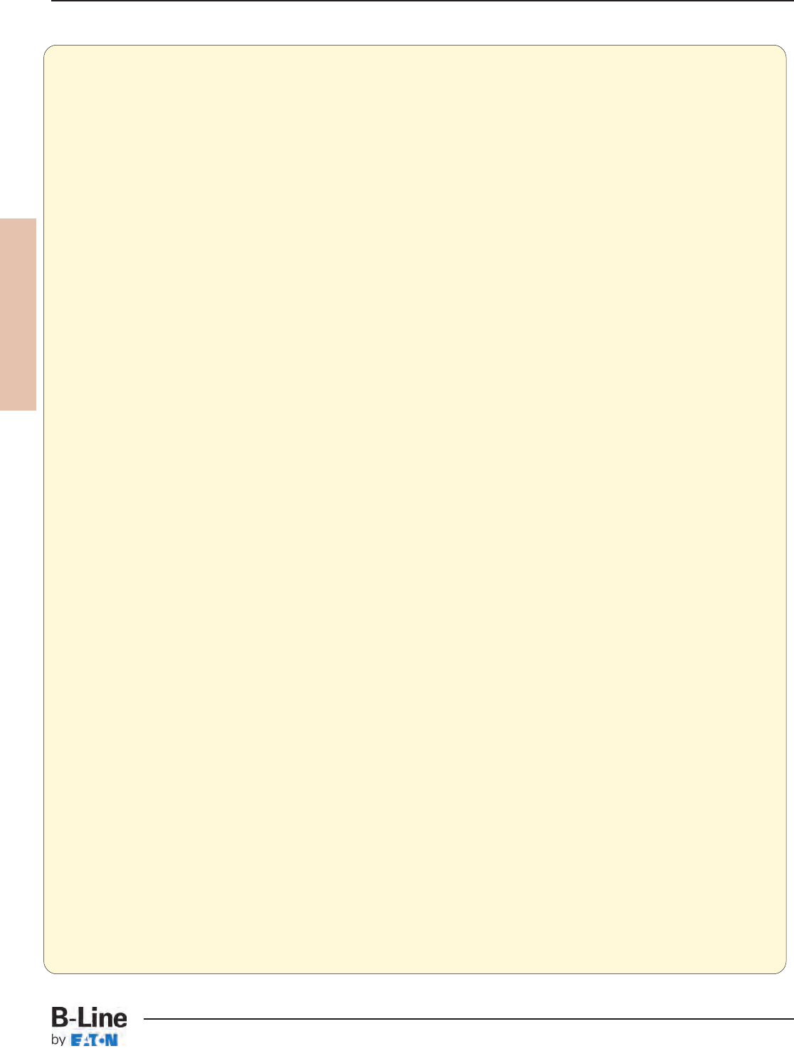
REDI-RAIL
RER-17
REDI-RAIL™- Specifications
Cable Tray Systems
Section 161xx - REDI-RAIL™ Cable Tray
Part 1 - General
1.01 Section Includes
A. The work covered under this section consists of the furnishing of all necessary labor, supervision,
materials, equipment, tests and services to install complete cable tray systems as shown on the drawings.
B. Cable tray systems are defined to include, but are not limited to straight sections of [ladder type] [vented
bottom type] [solid bottom type] cable trays, bends, tees, elbows, drop-outs, supports and accessories.
1.02 References
A. ANSI/NFPA 70 - National Electrical Code
B. NEMA VE 1-2009 - Metallic Cable Tray Systems
C. NEMA VE 2-2006 - Cable Tray installation Guidelines
1.03 Drawings
A. The drawings, which constitute a part of these specifications, indicate the general route of the cable tray
systems. Data presented on these drawings are as accurate as preliminary surveys and planning can
determine until final equipment selection is made. Accuracy is not guaranteed and field verification, of
all dimensions, routing, etc., is directed.
B. Specifications and drawings are for assistance and guidance, but exact routing, locations, distances and
levels will be governed by actual field conditions. Contractor is directed to make field surveys as part of
his work prior to submitting system layout drawings.
1.04 Submittals
A. Submittal Drawings: Submit drawings of cable tray and accessories including clamps, brackets, hanger rods,
splice plate connectors, expansion joint assemblies, and fittings, showing accurately scaled components.
B. Product Data: Submit manufacturer’s data on cable tray including, but not limited to, types, materials,
finishes, rung spacings, inside depths and fitting radii. For side rails and rungs, submit cross sectional
properties including Section Modulus (Sx) and Moment of Inertia (Ix).
1.05 Quality Assurance
A. Manufacturers: Firms regularly engaged in manufacture of cable trays and fittings of types and capacities
required, whose products have been in satisfactory use in similar service for not less than 5 years.
B. NEMA Compliance: Comply with NEMA Standards Publication Number VE 1, “Cable Tray Systems”.
C. NEC Compliance: Comply with NEC, as applicable to construction and installation of cable tray and cable
channel systems (Article 392, NEC).
D. UL Compliance: Provide products that are UL-classified and labeled.
E. NFPA Compliance: Comply with NFPA 70B, “Recommended Practice for Electrical Equipment
Maintenance” pertaining to installation of cable tray systems.
1.06 Delivery, Storage and Handling
A. Deliver cable tray systems and components carefully to avoid breakage, denting and scoring finishes.
Do not install damaged equipment.
B. Store cable trays and accessories in original cartons and in clean dry space; protect from weather and
construction traffic. Wet materials should be unpacked and dried before storage.
Part 2 - Products
2.01 Acceptable Manufacturers
A. Subject to compliance with these specifications, cable tray systems shall be as manufactured by
B-Line.
2.02 Cable Tray Sections and Components
A. General: Except as otherwise indicated, provide metal cable trays, of types, classes, and sizes indicated;
with splice plates, bolts, nuts and washers or connecting units. Construct units with rounded edges and
smooth surfaces; in compliance with applicable standards; and with the following additional construction
features. Cable tray shall be installed according to the latest revision of NEMA VE-2.
B. Material and Finish: Straight sections, fitting side rails, rungs and splice plates shall be extruded from
Aluminum Association Alloy 6063. All fabricated parts shall be made from Aluminum Association
Alloy 5052.
(continued on page RER-18)
REDI-RAIL
RER-18
REDI-RAIL™- Specifications
Cable Tray Systems
2.03 Type of Tray System
A. Ladder Cable Trays shall consist of two longitudinal members (side rails) with transverse members
(rungs) mechanically fastened to the side rails. Rungs shall be spaces [6] [9] [12] inches on center. Rung
spacing in radiused fittings shall be industry standard 9” and measured at the center of the tray’s width.
Each rung must be capable of supporting 1 200 lb. concentrated load at the center of a 18” wide cable
tray with a safety factor of 1.5. Rungs shall be capable of easy removal, reinstallation, or replacement if
necessary.
B. Ventilated Bottom Cable Trays shall consist of two longitudinal members (side rails) with rungs spaced
4” on center.
C. Solid Bottom Cable Trays shall consist of two longitudinal members (side rails) with a solid sheet over
rungs spaced on 12” centers.
D. Cable tray loading depth shall be [3] [4] [5] [6] inched per NEMA VE-1.
E. Straight sections shall be supplied in standard [10 foot (3.05m)] [12 foot (3.65m)] lengths.
F. Cable tray widths shall be [6] [9] [12] [18] [24] [30] [36] inches or as shown on drawings.
G. Splice plates shall have (4) four nuts and bolts per plate. The resistance of fixed splice connections
between adjacent sections of tray shall not exceed 0.00033 ohms. Splice plates shall be furnished with
straight sections and fittings.
H. All fittings must have a minimum radius of [12] [24] inches.
2.04 Loading Capacities
A. Cable trays shall meet NEMA class designation: [75 lbs./ft. on 12 ft. span].
Or
A. Cable tray shall be capable of carrying a uniformly distributed load of ________ lbs./ft on a ______ foot
support span with a safety factor of 1.5 when supported as a simple span and tested per NEMA VE 1
Section 5.2.
Part 3 - Execution
3.01 Installation
A. Install cable trays as indicated: Installation shall be in accordance with equipment manufacturer’s
instructions, and with recognized industry practices to ensure that cable tray equipment comply with
requirements of NEC and applicable portions of NFPA 70B. Reference NEMA VE-2 for general cable tray
installation guidelines.
B. Coordinate cable tray with other electrical work as necessary to properly integrate installation of cable
tray work with other work.
C. Provide sufficient space encompassing cable trays to permit access for installing and maintaining cables.
D. Cable tray fitting supports shall be located such that they meet the strength requirements of straight
sections. Install fitting supports per NEMA VE-2 guidelines, or in accordance with manufacturer’s
instructions.
3.02 Testing
A. Test cable trays to ensure electrical continuity of bonding and grounding connections, and to demonstrate
compliance with specified maximum grounding resistance. See NFPA 70B, Chapter 18, for testing and
test methods.
B. Manufacturer shall provide test reports witnessed by an independent testing laboratory of the “worst case”
loading conditions outlined in this specification and performed in accordance with the latest revision of
NEMA VE-1-2002/CSA C22.2 No. 126.1-02.
End Of Section.
(continued from page 189)
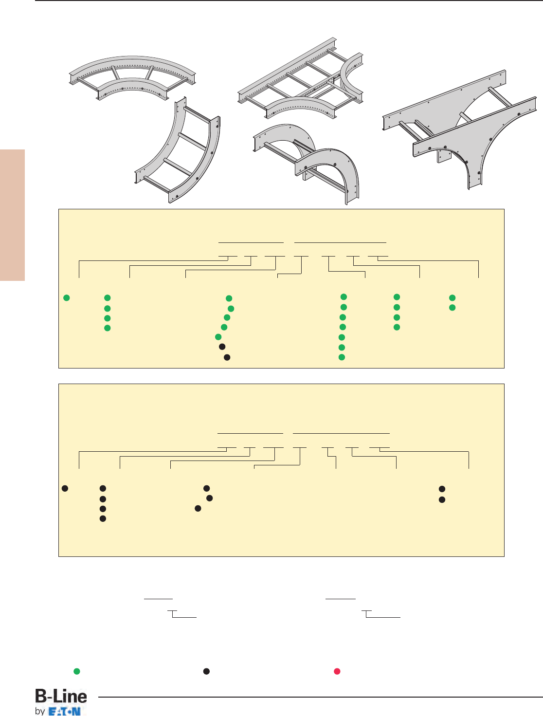
REDI-RAIL
RER-19
REDI-RAIL™- Fittings
Cable Tray Systems
Fittings For RSI04A, RSI05A, RSI06A and RSI07A
Fittings Part Numbering
Prefix Suffix
Example: RSI 04 A09 HB - 09 - 30 R12
Series Height Material Fitting Type Width Angle Radius
RSI 04 = 4" Aluminum HB = Horizontal Bend 06 = 6" 30 = 30° R12 = 12"
05 = 5" 9” Rung *HT = Horizontal Tee 09 = 9" 45 = 45° R24 = 24"
06 = 6" Spacing *HX = Horizontal Cross 12 = 12" 60 = 60°
07 = 7" VI = Vertical Inside Bend 18 = 18" 90 = 90°
VO = Vertical Outside Bend 24 = 24"
*VTD = Vertical Tee Down 30 = 30"
*VTU = Vertical Tee Up 36 = 36"
For aluminum 4", 5", 6", 7" vented or non-ventilated bottom add VB or SB as shown below.
Prefix Prefix
RSI05AVBHB - 24 - 90R24 RSI05ASBHB - 24 - 90R24
Vented Bottom Non-Ventilated Bottom
Horizontal Tee
*Angle not required in part number
Horizontal Reducing / Expanding Tee or Cross
Fittings Part Numbering
Prefix Suffix
Example: RSI 04 A09 ET - 09 - 12 - R12
Series Height Material Fitting Type Width1Width2Radius
RSI 04 = 4" Aluminum ET = Expanding Tee 06 = 6" 06 = 6" R12 = 12"
05 = 5" 9” Rung RT = Reducing Tee 09 = 9" 09 = 9" R24 = 24"
06 = 6" Spacing RX = Expanding/Reducing 12 = 12" 12 = 12"
07 = 7" Cross 18 = 18" 18 = 18"
24 = 24" 24 = 24"
30 = 30" 30 = 30"
36 = 36" 36 = 36"
Width2
Width1
Vertical Inside
Vertical Outside
Horizontal Bend
Vertical Tee
Down shown
• Furnished with
splice plates.
Green = Fastest shipped items Black = Normal lead-time items Red = Normally long lead-time items
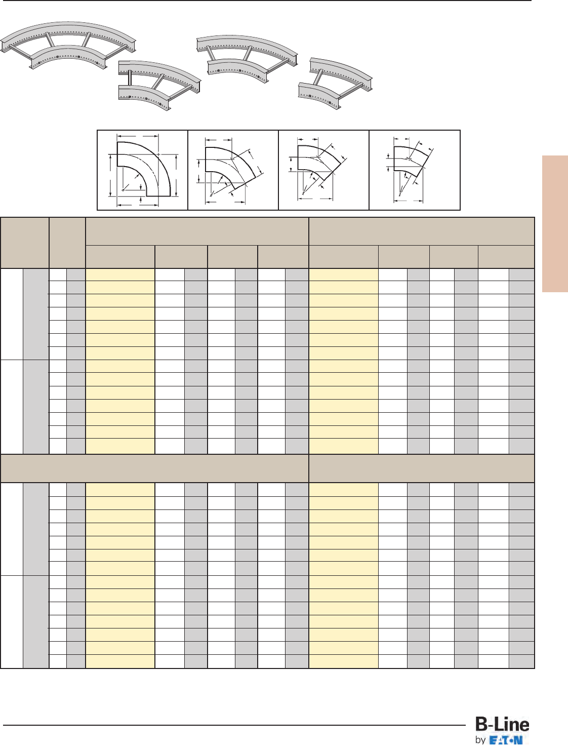
REDI-RAIL
RER-20
REDI-RAIL™- Fittings
Cable Tray Systems
Bend Tray 90˚ Horizontal Bend 60˚ Horizontal Bend
Radius Width Dimensions Dimensions
R Catalog No. ABCCatalog No. ABC
in. (mm) in. (mm) in. (mm) in. (mm) in. (mm) in. (mm) in. (mm) in. (mm)
6 152
(Pre)HB-06-90R12
181
/16 459 181
/16 459 181
/16 459
(
Pre)HB-06-60R12
179/16 445 101
/8258 1111/16 297
9 228
(
Pre)HB-09-90R12
199/16 497 199/16 497 199/16 497
(
Pre)HB-09-60R12
1813
/16 478 107
/8277 129/16 319
12 305
(
Pre)HB-12-90R12
211
/16 535 211
/16 535 211
/16 535
(
Pre)HB-12-60R12
201
/8511 115
/8296 137/16 341
12 305 18 457
(
Pre)HB-19-90R12
241
/16 611 241
/16 611 241
/16 611
(
Pre)HB-18-60R12
2234577 131
/8334 153/16 385
24 609
(
Pre)HB-24-90R12
271
/16 687 271
/16 687 271
/16 687
(
Pre)HB-24-60R12
255
/16 643 145
/8372 167
/8429
30 762
(
Pre)HB-30-90R12
301
/16 763 301
/16 763 301
/16 763
(
Pre)HB-30-60R12
2715/16 709 161/8410 185/8473
36 914
(
Pre)HB-36-90R12
331
/16 840 331
/16 840 331
/16 840
(
Pre)HB-36-60R12
301
/2775 175
/8448 203/8517
6 152
(
Pre)HB-06-90R24
301
/16 763 301
/16 763 301
/16 763
(
Pre)HB-06-60R24
2715/16 709 161
/8410 185/8473
9 228
(
Pre)HB-09-90R24
319/16 802 319/16 802 319/16 802
(
Pre)HB-09-60R24
291/4742 167
/8429 191/2495
12 305
(
Pre)HB-12-90R24
331
/16 840 331
/16 840 331
/16 840
(
Pre)HB-12-60R24
301
/2775 175
/8448 203/8517
24 609 18 457
(
Pre)HB-18-90R24
361
/16 916 361
/16 916 361
/16 916
(
Pre)HB-18-60R24
331
/8841 191
/8486 221
/8561
24 609
(
Pre)HB-24-90R24
391
/16 992 391
/16 992 391
/16 992
(
Pre)HB-24-60R24
353/4907 205
/8524 2313/16 605
30 762
(
Pre)HB-30-90R24
421
/16 1068 421
/16 1068 421
/16 1068
(
Pre)HB-30-60R24
385/16 973 221/8562 259/16 649
36 914
(
Pre)HB-36-90R24
451
/16 1144 451
/16 1144 451
/16 1144
(
Pre)HB-36-60R24
4015/16 1039 235
/8600 275/16 693
6 152
(
Pre)HB-06-45R12
153
/4400 61/2165 93/16 233
(
Pre)HB-06-30R12
133/16 338 39/16 90 71/16 180
9 228
(
Pre)HB-09-45R12
1613/16 427 615/16 176 913/16 249
(
Pre)HB-09-30R12
1315/16 354 33/495 71/2190
12 305
(
Pre)HB-12-45R12
177/8454 77/16 189 101
/2267
(
Pre)HB-12-30R12
1411/16 373 315
/16 100 77/8200
12 305 18 457
(
Pre)HB-18-45R12
201
/2521 85/16 211 113/4298
(
Pre)HB-18-30R12
163/16 411 45
/16 110 811/16 220
24 609
(
Pre)HB-24-45R12
221
/16 560 93/16 233 1215/16 328
(
Pre)HB-24-30R12
1711/16 449 43/4120 91/2241
30 762
(
Pre)HB-30-45R12
245/16 617 101
/16 255 141/4362
(
Pre)HB-30-30R12
193/16 487 51
/8131 105/16 261
36 914
(
Pre)HB-36-45R12
267/16 671 1015
/16 278 157
/16 392
(
Pre)HB-36-30R12
2011/16 525 59/16 141 111
/16 282
6 152
(
Pre)HB-06-45R24
245/16 617 101
/16 255 143
/16 360
(
Pre)HB-06-30R24
193/16 487 51
/8131 105/16 261
9 228
(
Pre)HB-09-45R24
251
/4641 101
/2267 1413/16 376
(
Pre)HB-09-30R24
1915/16 506 55
/16 136 1011/16 271
12 305
(
Pre)HB-12-45R24
267/16 671 1015
/16 278 157
/16 392
(
Pre)HB-12-30R24
2011/16 525 59/16 141 111
/16 282
24 609 18 457
(
Pre)HB-18-45R24
289/16 725 1113/16 300 1611/16 424
(
Pre)HB-18-30R24
223/16 563 515
/16 151 117/8302
24 609
(
Pre)HB-24-45R24
3011/16 779 1211/16 322 1715
/16 456
(
Pre)HB-24-30R24
2311/16 601 63/8161 1211/16 322
30 762
(
Pre)HB-30-45R24
3213/16 833 139/16 345 193/16 487
(
Pre)HB-30-30R24
253/16 640 63/4171 131/2343
36 914
(
Pre)HB-36-45R24
3415/16 887 147/16 367 207/16 519
(
Pre)HB-36-30R24
2611/16 678 71/8182 145/16 363
(Pre) See page RER-19 for catalog number prefix.
Width dimensions are to inside wall. Manufacturing tolerances apply to all dimensions.
45˚ Horizontal Bend 30˚ Horizontal Bend
Horizontal Bends 90° 60° 45° 30° (HB)
90˚ Horizontal Bend
45˚ Horizontal Bend
AA
C
C
C
C
R
3" (76)
R
3" (76)
B
A
C
C
R
3" (76)
B
C
C
B
1 pair splice plates with hardware included.
60˚ Horizontal Bend
30˚ Horizontal Bend
90˚
HB
60˚
HB
45˚
HB
30˚
HB
Bottoms manufactured:
09 = 9" Rung Spacing
VB = 4" Rung Spacing
SB = Flat sheet over
12" Rung Spacing
BR
A
3" (76)
All dimensions in parentheses are millimeters unless otherwise specified.
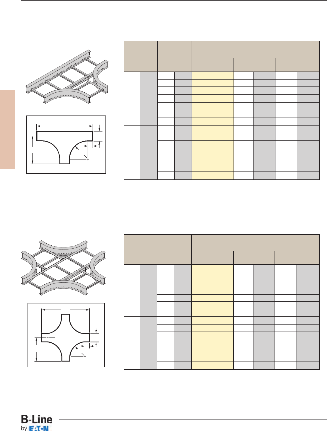
REDI-RAIL
RER-21
REDI-RAIL™- Fittings
Cable Tray Systems
Bend Tray Horizontal Cross
Radius Width Dimensions
RWCatalog No. AB
in. (mm) in. (mm) in. (mm) in. (mm)
6 152
(Prefix)HX-06-R12
181
/16 458 363/4933
9 228
(Prefix)HX-09-R12
199/16 497 397/81013
12 305
(Prefix)HX-12-R12
211
/16 535 421/41073
12 305 18 457
(Prefix)HX-18-R12
241
/16 611 481/21232
24 609
(Prefix)HX-24-R12
271
/16 687 5413/16 1392
30 762
(Prefix)HX-30-R12
301
/16 763 601/41530
36 914
(Prefix)HX-36-R12
331
/16 839 669/16 1691
6 152
(Prefix)HX-06-R24
301
/16 763 601
/16 1551
9 228
(Prefix)HX-09-R24
319/16 801 631
/41606
12 305
(Prefix)HX-12-R24
331
/16 839 669/16 1691
24 609 18 457
(Prefix)HX-18-R24
361
/16 916 721
/16 1830
24 609
(Prefix)HX-24-R24
391
/16 992 783/81991
30 762
(Prefix)HX-30-R24
421
/16 1068 845/82150
36 914
(Prefix)HX-36-R24
451
/16 1144 9015/16 2310
Bend Tray Horizontal Tee
Radius Width Dimensions
R W Catalog No. AB
in. (mm) in. (mm) in. (mm) in. (mm)
6 152
(Prefix)HT-06-R12
181
/16 458 363/4933
9 228
(Prefix)HT-09-R12
199/16 497 397/81013
12 305
(Prefix)HT-12-R12
211
/16 535 421
/41073
12 305 18 457
(Prefix)HT-18-R12
241
/16 611 481
/21232
24 609
(Prefix)HT-24-R12
271
/16 687 5413/16 1392
30 762
(Prefix)HT-30-R12
301
/16 763 601
/41530
36 914
(Prefix)HT-36-R12
331
/16 839 669/16 1691
6 152
(Prefix)HT-06-R24
301
/16 763 601
/16 1525
9 228
(Prefix)HT-09-R24
319/16 801 631
/41606
12 305
(Prefix)HT-12-R24
331
/16 839 669/16 1691
24 609 18 457
(Prefix)HT-18-R24
361
/16 916 721
/16 1830
24 609
(Prefix)HT-24-R24
391
/16 992 783/81991
30 762
(Prefix)HT-30-R24
421
/16 1068 845/82150
36 914
(Prefix)HT-36-R24
451
/16 1144 9015/16 2310
A
W
R
B
A
W
R
B
2 pair splice plates with hardware included.
3 pair splice plates with hardware included.
Width dimensions are to inside wall. Manufacturing tolerances apply to all dimensions.
Horizontal Tee (HT)
Horizontal Cross (HX)
3" (76)
3" (76)
(Prefix) See page RER-19 for catalog number prefix.
(Prefix) See page RER-19 for catalog number prefix.
HX
HT
All dimensions in parentheses are millimeters unless otherwise specified.
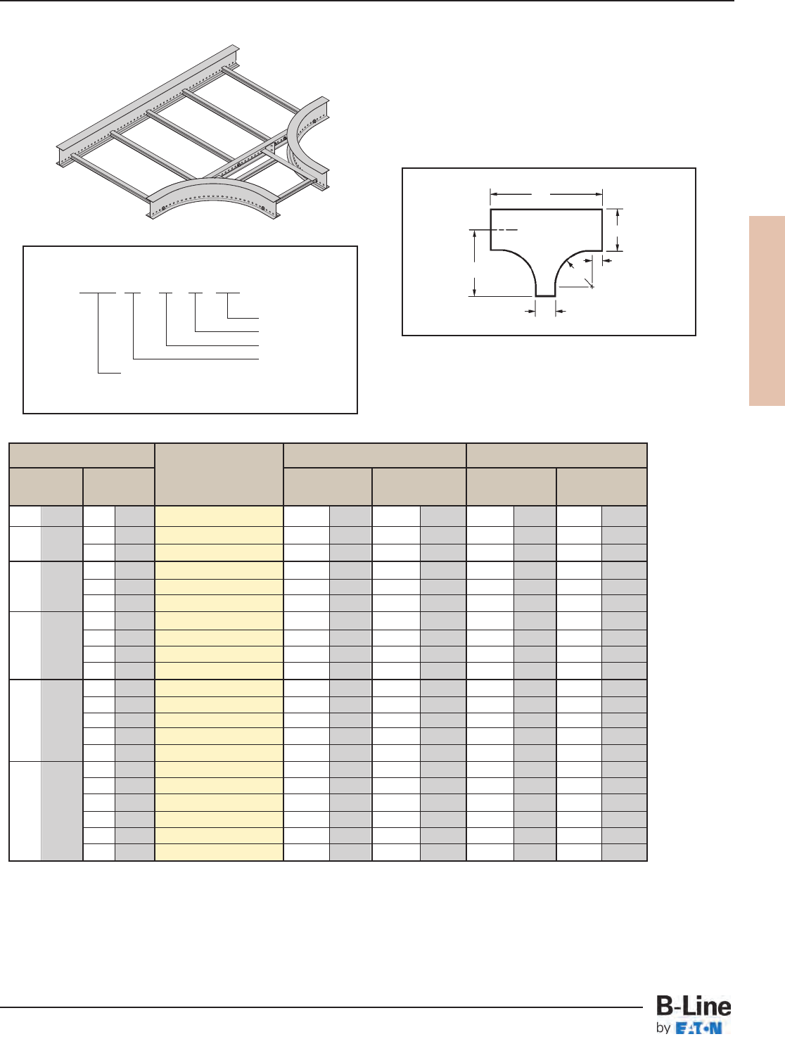
REDI-RAIL
RER-22
REDI-RAIL™- Fittings
Cable Tray Systems
All dimensions in parentheses are millimeters unless otherwise specified.
Tray Width * Insert Radius 12" Radius 24" Radius
(12 for 12" or 24 for 24")
W1W2Catalog No. AB AB
in. (mm) in. (mm) in. (mm) in. (mm) in. (mm) in. (mm)
9 228 6 152
(Prefix)RT-09-06-R*
199/16 497 363/4933 319/16 801 611/16 1551
6 152
(Prefix)RT-12-06-R*
211/16 535 363/4933 331/16 839 611/16 1551
12 305 9 228
(Prefix)RT-12-09-R*
211/16 535 397/81013 331/16 839 641/41631
6 152
(Prefix)RT-18-06-R*
241/16 611 363/4933 361/16 916 611/16 1551
18 475 9 228
(Prefix)RT-18-09-R*
241/16 611 397/81013 361/16 916 641/41631
12 305
(Prefix)RT-18-12-R*
241/16 611 421/41073 361/16 916 669/16 1691
6 152
(Prefix)RT-24-06-R*
271/16 687 363/4933 391/16 992 611/16 1551
9 228
(Prefix)RT-24-09-R*
271/16 687 397/81013 391/16 992 641/41631
24 609 12 305
(Prefix)RT-24-12-R*
271/16 687 421/41073 391/16 992 669/16 1691
18 457
(Prefix)RT-24-18-R*
271/16 687 481/21232 391/16 992 721/16 1830
6 152
(Prefix)RT-30-06-R*
301/16 763 363/4933 421/16 1068 611/16 1551
9 228
(Prefix)RT-30-09-R*
301/16 763 397/81013 421/16 1068 641/41631
30 762 12 305
(Prefix)RT-30-12-R*
301/16 763 421/41073 421/16 1068 669/16 1691
18 457
(Prefix)RT-30-18-R*
301/16 763 481/21232 421/16 1068 721/16 1830
24 609
(Prefix)RT-30-24-R*
301/16 763 5413/16 1392 421/16 1068 783/81991
6 152
(Prefix)RT-36-06-R*
331/16 839 363/4933 451/16 1144 611/16 1551
9 228
(Prefix)RT-36-09-R*
331/16 839 397/81013 451/16 1144 641/41631
12 305
(Prefix)RT-36-12-R*
331/16 839 421/41073 451/16 1144 669/16 1691
36 914 18 457
(Prefix)RT-36-18-R*
331/16 839 481/21232 451/16 1144 721/16 1830
24 609
(Prefix)RT-36-24-R*
331/16 839 5413/16 1392 451/16 1144 783/81991
30 762
(Prefix)RT-36-30-R*
331/16 839 601/41532 451/16 1144 845/82150
Prefix RT - 36 - 18 - R24
Radius
Width W2
Width W1
Fitting
To complete catalog number, insert
fitting prefix.
R = Radius
Horizontal Reducing Tee (RT)
2 pair splice plates with hardware included.
B
A
W2
R
W1
RT
(Prefix) See page RER-19 for catalog number prefix.
Width dimensions are to inside wall.
Manufacturing tolerances apply to all dimensions.
3" (76)
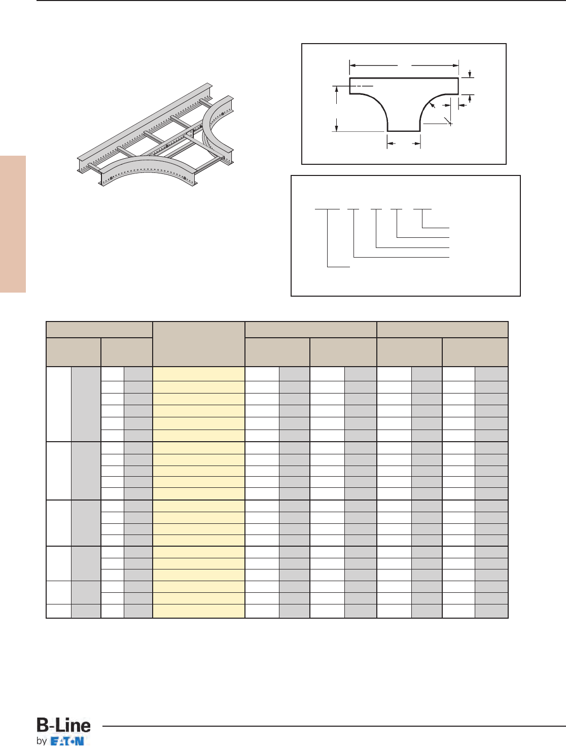
REDI-RAIL
RER-23
REDI-RAIL™- Fittings
Cable Tray Systems
All dimensions in parentheses are millimeters unless otherwise specified.
Tray Width *Insert Radius 12" Radius 24" Radius
(12 for 12", 24 for 24”)
W1W2Catalog No. ABAB
in. (mm) in. (mm) in. (mm) in. (mm) in. (mm) in. (mm)
9 228
(Prefix)ET-06-09-R*
181/16 458 397/81013 301/16 763 641/41631
12 305
(Prefix)ET-06-12-R*
181/16 458 421/41073 301/16 763 669/16 1691
18 457
(Prefix)ET-06-18-R*
181/16 458 481/21232 301/16 763 721/16 1830
6 152 24 609
(Prefix)ET-06-24-R*
181/16 458 5413/16 1392 301/16 763 783/81991
30 762
(Prefix)ET-06-30-R*
181/16 458 601/41532 301/16 763 845/82150
36 914
(Prefix)ET-06-36-R*
181/16 458 669/16 1691 301/16 763 9015/16 2310
12 305
(Prefix)ET-09-12-R*
199/16 497 421/41073 319/16 801 669/16 1691
18 457
(Prefix)ET-09-18-R*
199/16 497 481/21232 319/16 801 721/16 1830
9 228 24 609
(Prefix)ET-09-24-R*
199/16 497 5413/16 1392 319/16 801 783/81991
30 762
(Prefix)ET-09-30-R*
199/16 497 601/41532 319/16 801 845/82150
36 914
(Prefix)ET-09-36-R*
199/16 497 669/16 1691 319/16 801 9015/16 2310
18 457
(Prefix)ET-12-18-R*
211/16 535 481/21232 331/16 839 721/16 1830
24 609
(Prefix)ET-12-24-R*
211/16 535 5413/16 1392 331/16 839 783/81991
12 305 30 762
(Prefix)ET-12-30-R*
211/16 535 601/41532 331/16 839 845/82150
36 914
(Prefix)ET-12-36-R*
211/16 535 669/16 1691 331/16 839 9015/16 2310
24 609
(Prefix)ET-18-24-R*
241/16 611 5413/16 1392 361/16 916 783/81991
18 457 30 762
(Prefix)ET-18-30-R*
241/16 611 601/41532 361/16 916 845/82150
36 914
(Prefix)ET-18-36-R*
241/16 611 669/16 1691 361/16 916 9015/16 2310
30 762
(Prefix)ET-24-30-R*
271/16 687 601/41532 391/16 992 845/82150
24 609 36 914
(Prefix)ET-24-36-R*
271/16 687 669/16 1691 391/16 992 9015/16 2310
30 762 36 914
(Prefix)ET-30-36-R*
301/16 763 669/16 1691 421/16 1068 9015/16 2310
Prefix ET - 09 - 30 - R12
Radius
Width W2
Width W1
Fitting
To complete catalog number, insert
fitting prefix.
Horizontal Expanding Tee (ET)
2 pair splice plates with hardware included.
B
A
W2
R
W1
(Prefix) See page RER-19 for catalog number prefix.
Width dimensions are to inside wall.
Manufacturing tolerances apply to all dimensions.
ET
3" (76)
R = Radius
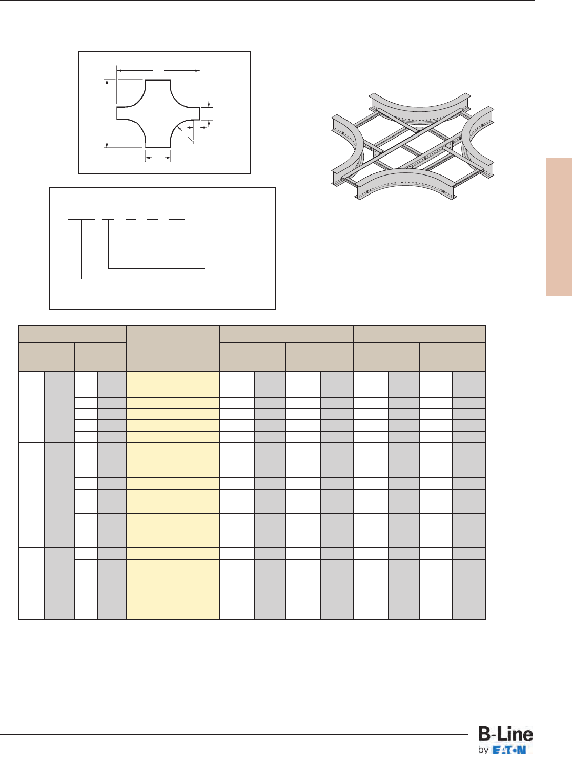
REDI-RAIL
RER-24
REDI-RAIL™- Fittings
Cable Tray Systems
All dimensions in parentheses are millimeters unless otherwise specified.
Prefix RX - 09 - 24 - R24
Radius
Width W2
Width W1
Fitting
To complete catalog number, insert
fitting prefix.
B
A
W1
3" (76)
R
W2
RX
(Prefix) See page RER-19 for catalog number prefix.
Width dimensions are to inside wall.
Manufacturing tolerances apply to all dimensions.
Horizontal Expanding/Reducing Cross (RX)
3 pair splice plates with hardware included.
Tray Width * Insert Radius 12" Radius 24" Radius
(12 for 12", 24 for 24”)
W1W2Catalog No. ABAB
in. (mm) in. (mm) in. (mm) in. (mm) in. (mm) in. (mm)
9 228
(Prefix)RX-06-09-R*
363/4933 397/81013 601/16 1525 641/41631
12 305
(Prefix)RX-06-12-R*
363/4933 421/41073 601/16 1525 669/16 1691
18 457
(Prefix)RX-06-18-R*
363/4933 481/21232 601/16 1525 721/16 1830
6 152 24 609
(Prefix)RX-06-24-R*
363/4933 5413/16 1392 601/16 1525 783/81991
30 762
(Prefix)RX-06-30-R*
363/4933 601/41532 601/16 1525 845/82150
36 914
(Prefix)RX-06-36-R*
363/4933 669/16 1691 601/16 1525 9015/16 2310
12 305
(Prefix)RX-09-12-R*
397/81013 421/41073 641/41632 669/16 1691
18 457
(Prefix)RX-09-18-R*
397/81013 481/21232 641/41632 721/16 1830
9 228 24 609
(Prefix)RX-09-24-R*
397/81013 5413/16 1392 641/41632 783/81991
30 762
(Prefix)RX-09-30-R*
397/81013 601/41532 641/41632 845/82150
36 914
(Prefix)RX-09-36-R*
397/81013 669/16 1691 641/41632 9015/16 2310
18 457
(Prefix)RX-12-18-R*
421/41073 481/21232 669/16 1691 721/16 1830
24 609
(Prefix)RX-12-24-R*
421/41073 5413/16 1392 669/16 1691 783/81991
12 305 30 762
(Prefix)RX-12-30-R*
421/41073 601/41532 669/16 1691 845/82150
36 914
(Prefix)RX-12-36-R*
421/41073 669/16 1691 669/16 1691 9015/16 2310
24 609
(Prefix)RX-18-24-R*
481/21232 5413/16 1392 721/16 1830 783/81991
18 457 30 762
(Prefix)RX-18-30-R*
481/21232 601/41532 721/16 1830 845/82150
36 914
(Prefix)RX-18-36-R*
481/21232 669/16 1691 721/16 1830 9015/16 2310
30 762
(Prefix)RX-24-30-R*
5413/16 1392 601/41532 783/81991 845/82150
24 609 36 914
(Prefix)RX-24-36-R*
5413/16 1392 669/16 1691 783/81991 9015/16 2310
30 762 36 914
(Prefix)RX-30-36-R*
601/41530 669/16 1691 845/82149 9015/16 2310
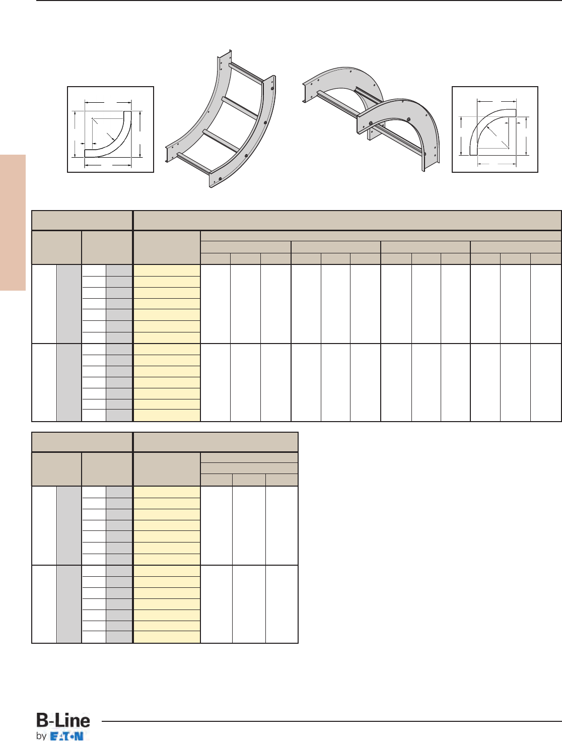
REDI-RAIL
RER-25
REDI-RAIL™- Fittings
Cable Tray Systems
All dimensions in parentheses are millimeters unless otherwise specified.
90° Vertical Inside (VI) Bend
Siderail Height
Bend Radius Width 4” 5” 6” 7”
R
in. (mm) in. (mm) Catalog No. ABCABCABCABC
6 152
(Pre)VI-06-90R12
9 228
(Pre)VI-09-90R12
12 305
(Pre)VI-12-90R12
181/2" 181/2" 181/2" 191/2" 191/2" 191/2" 201/2" 201/2" 201/2" 211/2" 211/2" 211/2"
12 305 18 457
(Pre)VI-18-90R12
24 609
(Pre)VI-24-90R12
(470) (470) (470) (495) (495) (495) (521) (521) (521) (546) (546) (546)
30 762
(Pre)VI-30-90R12
36 914
(Pre)VI-36-90R12
6 152
(Pre)VI-06-90R24
9 228
(Pre)VI-09-90R24
12 305
(Pre)VI-12-90R24
301/2" 301/2" 301/2" 311/2" 311/2" 311/2" 321/2" 321/2" 321/2" 331/2" 331/2" 331/2"
24 609 18 457
(Pre)VI-18-90R24
24 609
(Pre)VI-24-90R24
(851) (851) (851) (800) (800) (800) (825) (825) (825) (851) (851) (851)
30 762
(Pre)VI-30-90R24
36 914
(Pre)VI-36-90R24
A
C
C
B
R
3" (76)
C
C
BR
3" (76)
A
90°
VI
90° Vertical Outside
Vertical Bend 90° (VO, VI)
1 pair splice plates with hardware included.
(Pre) See page RER-19 for catalog number prefix.
Manufacturing tolerances apply to all dimensions.
90° Vertical Outside (VO) Bend
Siderail Height
Bend Radius Width 4” - 7”
R
in. (mm) in. (mm) Catalog No. ABC
6 152
(Pre)VO-06-90R12
9 228
(Pre)VO-09-90R12
12 305
(Pre)VO-12-90R12
15" 15" 15"
12 305 18 457
(Pre)VO-18-90R12
24 609
(Pre)VO-24-90R12
(381) (381) (381)
30 762
(Pre)VO-30-90R12
36 914
(Pre)VO-36-90R12
6 152
(Pre)VO-06-90R24
9 228
(Pre)VO-09-90R24
12 305
(Pre)VO-12-90R24
27" 27" 27"
24 609 18 457
(Pre)VO-18-90R24
24 609
(Pre)VO-24-90R24
(686) (686) (686)
30 762
(Pre)VO-30-90R24
36 914
(Pre)VO-36-90R24
90° Vertical Inside
90˚
VO
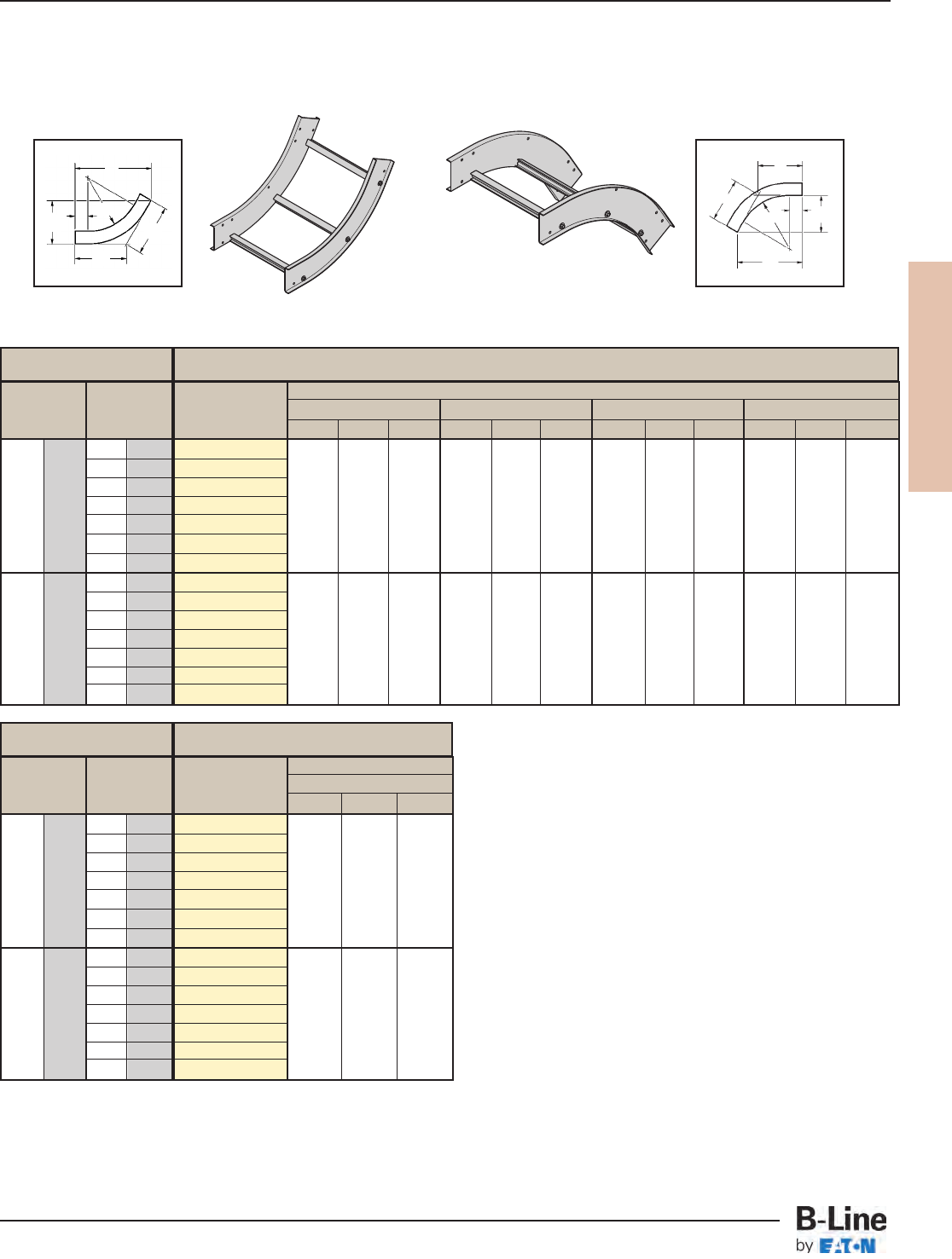
REDI-RAIL
RER-26
REDI-RAIL™- Fittings
Cable Tray Systems
All dimensions in parentheses are millimeters unless otherwise specified.
60˚
VO
A
C
C
R
Vertical Bend 60° (VO, VI)
1 pair splice plates with hardware included.
3" (76)
B
(Pre) See page RER-19 for catalog number prefix.
Manufacturing tolerances apply to all dimensions.
60° Vertical Outside
60° Vertical Inside
60˚
VI
C
C
B
3" (76)
A
R
60° Vertical Inside (VI) Bend
Siderail Height
Bend Radius Width 4” 5” 6” 7”
R
in. (mm) in. (mm) Catalog No. ABCABCABCABC
6 152
(Pre)VI-06-60R12
9 228
(Pre)VI-09-60R12
12 305
(Pre)VI-12-60R12
18" 103/8" 12" 1813/16" 107/8" 129/16" 1911/16" 113/8" 131/8" 209/16" 117/8" 1311/16"
12 305 18 457
(Pre)VI-18-60R12
24 609
(Pre)VI-24-60R12
(457) (263) (305) (478) (276) (319) (500) (289) (333) (522) (301) (347)
30 762
(Pre)VI-30-60R12
36 914
(Pre)VI-36-60R12
6 152
(Pre)VI-06-60R24
9 228
(Pre)VI-09-60R24
12 305
(Pre)VI-12-60R24
283/8" 163/8" 1815/16" 291/4" 167/8" 191/2" 301/16" 173/8" 201/16" 3015/16" 177/8" 205/8"
24 609 18 457
(Pre)VI-18-60R24
24 609
(Pre)VI-24-60R24
(721) (416) (481) (743) (428) (495) (763) (441) (509) (786) (454) (524)
30 762
(Pre)VI-30-60R24
36 914
(Pre)VI-36-60R24
60° Vertical Outside (VO) Bend
Siderail Height
Bend Radius Width 4” - 7”
R
in. (mm) in. (mm) Catalog No. ABC
6 152
(Pre)VO-06-60R12
9 228
(Pre)VO-09-60R12
12 305
(Pre)VO-12-60R12
147/8"8
5/8"9
15/16"
12 305 18 457
(Pre)VO-18-60R12
24 609
(Pre)VO-24-60R12
(378) (219) (252)
30 762
(Pre)VO-30-60R12
36 914
(Pre)VO-36-60R12
6 152
(Pre)VO-06-60R24
9 228
(Pre)VO-09-60R24
12 305
(Pre)VO-12-60R24
255/16" 145/8" 167/8"
24 609 18 457
(Pre)VO-18-60R24
24 609
(Pre)VO-24-60R24
(643) (371) (428)
30 762
(Pre)VO-30-60R24
36 914
(Pre)VO-36-60R24
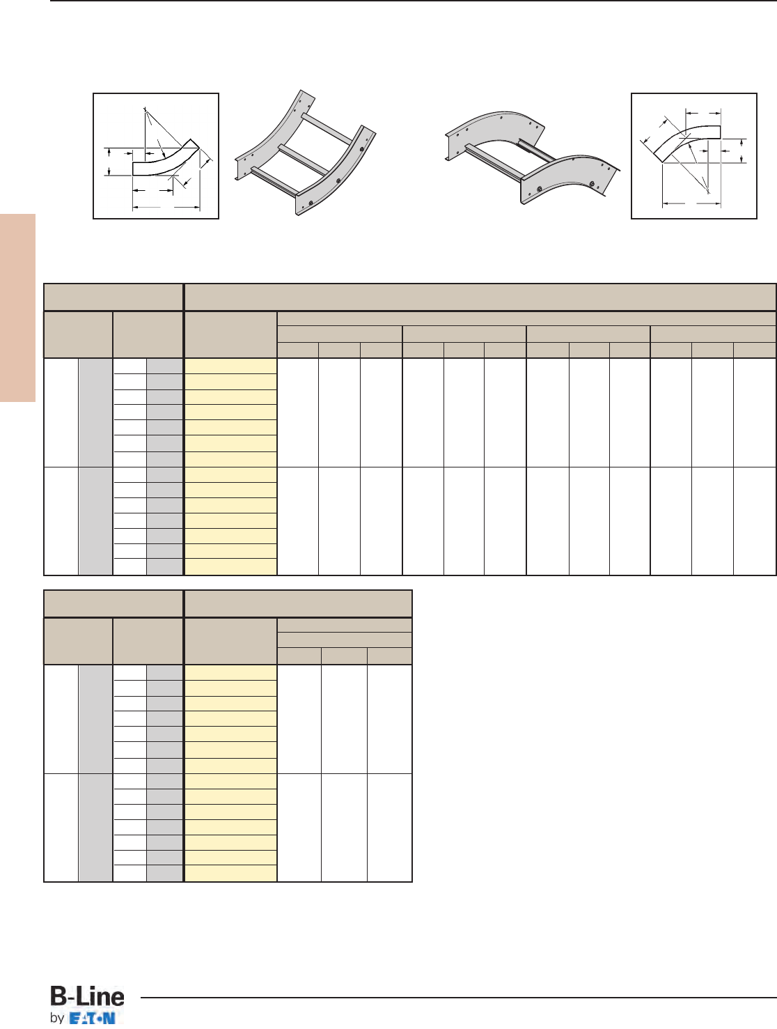
REDI-RAIL
RER-27
REDI-RAIL™- Fittings
Cable Tray Systems
All dimensions in parentheses are millimeters unless otherwise specified.
Vertical Bend 45° (VO, VI)
1 pair splice plates with hardware included.
A
C
C
B
R
3" (76)
C
C
B
R
3" (76)
A
45˚
VO
45°
VI
(Pre) See page RER-19 for catalog number prefix.
Manufacturing tolerances apply to all dimensions.
45° Vertical Outside
45° Vertical Inside
45° Vertical Inside (VI) Bend
Siderail Height
Bend Radius Width 4” 5” 6” 7”
R
in. (mm) in. (mm) Catalog No. ABCABCABCABC
6 152
(Pre)VI-06-45R12
9 228
(Pre)VI-09-45R12
12 305
(Pre)VI-12-45R12
161/8"6
11/16"9
7/16" 167/8" 7" 97/8" 179/16"7
1/4" 101/4" 181/4"7
9/16" 1011/16"
12 305 18 457
(Pre)VI-18-45R12
24 609
(Pre)VI-24-45R12
(409) (170) (239) (428) (178) (251) (446) (184) (260) (463) (192) (271)
30 762
(Pre)VI-30-45R12
36 914
(Pre)VI-36-45R12
6 152
(Pre)VI-06-45R24
9 228
(Pre)VI-09-45R24
12 305
(Pre)VI-12-45R24
245/8" 103/16" 147/16" 255/16" 101/2" 1413/16" 26" 103/4" 151/4" 263/4" 111/16" 155/8"
24 609 18 457
(Pre)VI-18-45R24
24 609
(Pre)VI-24-45R24
(625) (259) (366) (643) (267) (376) (660) (273) (387) (679) (281) (397)
30 762
(Pre)VI-30-45R24
36 914
(Pre)VI-36-45R24
45° Vertical Outside (VO) Bend
Siderail Height
Bend Radius Width 4” - 7”
R
in. (mm) in. (mm) Catalog No. ABC
6 152
(Pre)VO-06-45R12
9 228
(Pre)VO-09-45R12
12 305
(Pre)VO-12-45R12
135/8"5
5/8" 8"
12 305 18 457
(Pre)VO-18-45R12
24 609
(Pre)VO-24-45R12
(346) (136) (203)
30 762
(Pre)VO-30-45R12
36 914
(Pre)VO-36-45R12
6 152
(Pre)VO-06-45R24
9 228
(Pre)VO-09-45R24
12 305
(Pre)VO-12-45R24
221/8"9
3/16" 1215/16"
24 609 18 457
(Pre)VO-18-45R24
24 609
(Pre)VO-24-45R24
(562) (233) (328)
30 762
(Pre)VO-30-45R24
36 914
(Pre)VO-36-45R24
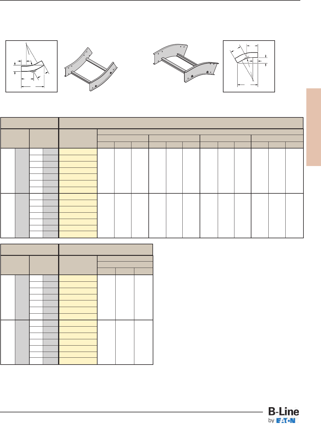
REDI-RAIL
RER-28
REDI-RAIL™- Fittings
Cable Tray Systems
All dimensions in parentheses are millimeters unless otherwise specified.
Vertical Bend 30° (VO, VI)
1 pair splice plates with hardware included.
A
CC
B
R
3" (76)
C
C
B
R
3" (76)
A
30˚
VI
30˚
VO
(Pre) See page RER-19 for catalog number prefix.
Manufacturing tolerances apply to all dimensions.
30° Vertical Outside
30° Vertical Inside
30° Vertical Inside (VI) Bend
Siderail Height
Bend Radius Width 4” 5” 6” 7”
R
in. (mm) in. (mm) Catalog No. ABCABCABCABC
6 152
(Pre)VI-06-30R12
9 228
(Pre)VI-09-30R12
12 305
(Pre)VI-12-30R12
137/16"3
5/8"7
3/16" 1315/16"3
3/4"7
7/16" 147/16"3
7/8"7
3/4" 147/8" 4" 8"
12 305 18 457
(Pre)VI-18-30R12
24 609
(Pre)VI-24-30R12
(341) (92) (182) (354) (95) (189) (366) (98) (197) (378) (101) (203)
30 762
(Pre)VI-30-30R12
36 914
(Pre)VI-36-30R12
6 152
(Pre)VI-06-30R24
9 228
(Pre)VI-09-30R24
12 305
(Pre)VI-12-30R24
197/16"5
3/16" 107/16" 1915/16"5
5/16" 1011/16" 207/16"5
7/16" 1015/16" 207/8"5
5/8" 113/16"
24 609 18 457
(Pre)VI-18-30R24
24 609
(Pre)VI-24-30R24
(493) (132) (265) (506) (135) (271) (519) (138) (278) (530) (143) (284)
30 762
(Pre)VI-30-30R24
36 914
(Pre)VI-36-30R24
30° Vertical Outside (VO) Bend
Siderail Height
Bend Radius Width 4” - 7”
R
in. (mm) in. (mm) Catalog No. ABC
6 152
(Pre)VO-06-30R12
9 228
(Pre)VO-09-30R12
12 305
(Pre)VO-12-30R12
115/8"3
1/8"6
1/4"
12 305 18 457
(Pre)VO-18-30R12
24 609
(Pre)VO-24-30R12
(295) (79) (159)
30 762
(Pre)VO-30-30R12
36 914
(Pre)VO-36-30R12
6 152
(Pre)VO-06-30R24
9 228
(Pre)VO-09-30R24
12 305
(Pre)VO-12-30R24
175/8"4
3/4"9
7/16"
24 609 18 457
(Pre)VO-18-30R24
24 609
(Pre)VO-24-30R24
(447) (120) (239)
30 762
(Pre)VO-30-30R24
36 914
(Pre)VO-36-30R24
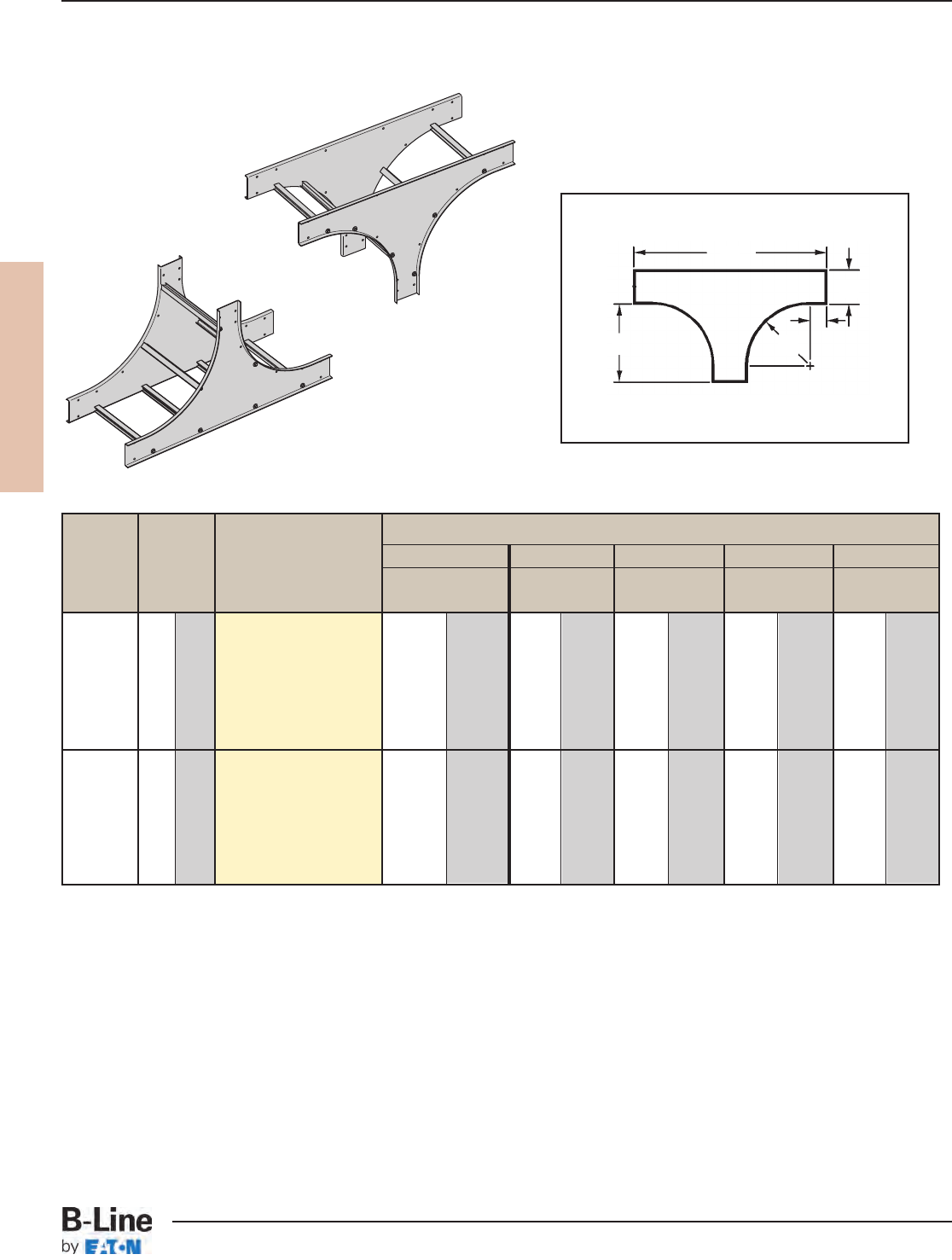
REDI-RAIL
RER-29
REDI-RAIL™- Fittings
Cable Tray Systems
All dimensions in parentheses are millimeters unless otherwise specified.
Bend Tray
(*) Insert U for Tee Up
Side Rail Height "H"
Radius Width
Insert D for Tee Down
4" - 7” 4” 5" 6" 7"
RABBBB
in. in. (mm) Catalog No. in. (mm) in. (mm) in. (mm) in. (mm) in. (mm)
6 152 (Prefix)VT(*)-06-R12
9 228 (Prefix)VT(*)-09-R12
12” 12 305 (Prefix)VT(*)-12-R12
(305) 18 457 (Prefix)VT(*)-18-R12
15 381 337/16 849 343/8874 353/8899 363/8924
24 609 (Prefix)VT(*)-24-R12
30 762 (Prefix)VT(*)-30-R12
36 914 (Prefix)VT(*)-36-R12
6 152 (Prefix)VT(*)-06-R24
9 228 (Prefix)VT(*)-09-R24
24” 12 305 (Prefix)VT(*)-12-R24
(609) 18 457 (Prefix)VT(*)-18-R24
27 686 577/16 1458 583/81483 593/81508 603/81533
24 609 (Prefix)VT(*)-24-R24
30 762 (Prefix)VT(*)-30-R24
36 914 (Prefix)VT(*)-36-R24
B
H
AR
Vertical Tee Up/Down (VTU/VTD)
2 pair splice plates with hardware included.
VT
(Prefix) See page RER-19 for catalog number prefix.
Manufacturing tolerances apply to all dimensions.
3" (76)
VTU
VTD

REDI-RAIL
RER-30
REDI-RAIL™
Cable Tray Systems
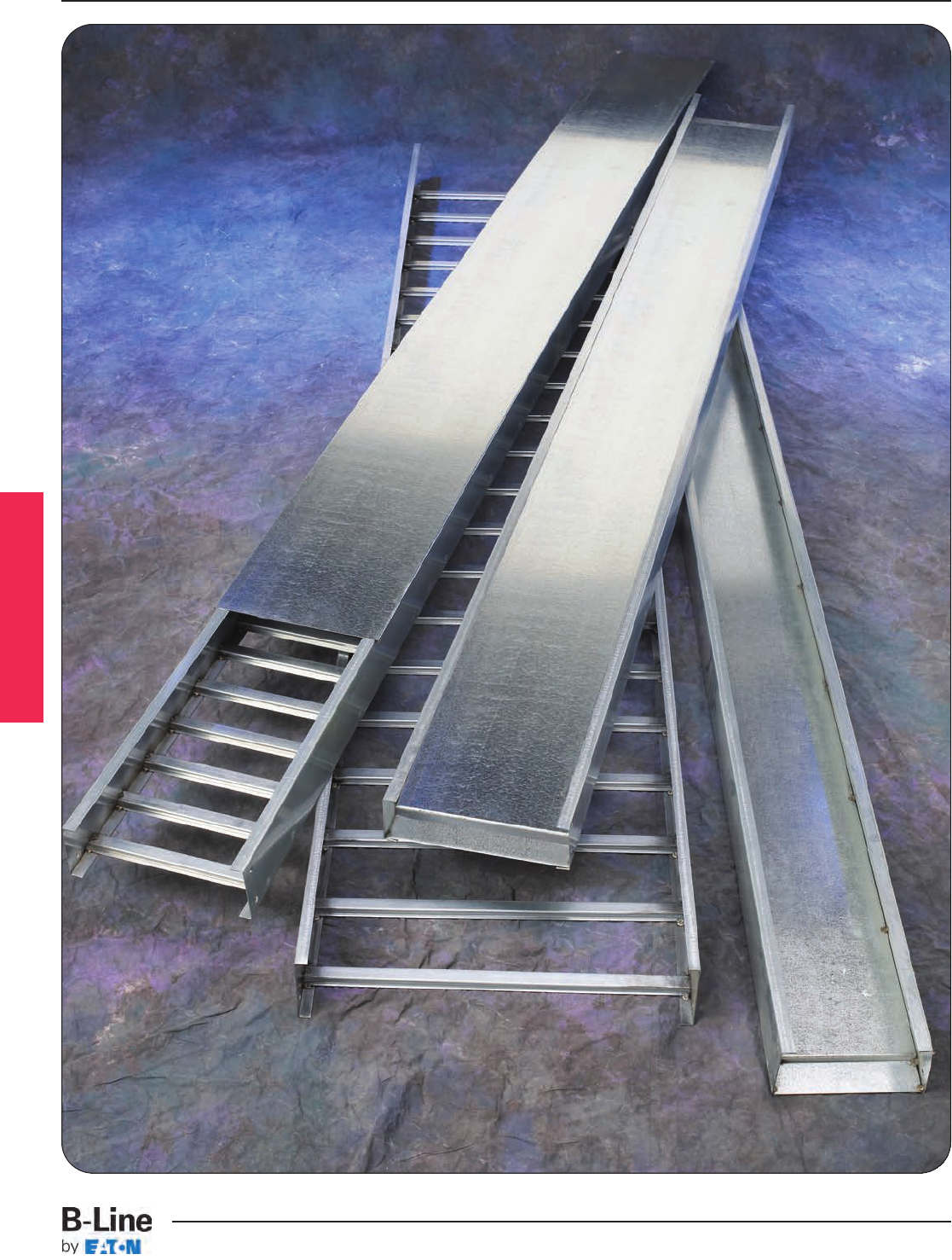
Series 1 Steel
LST-1
Series 1 Steel
Cable Tray Systems
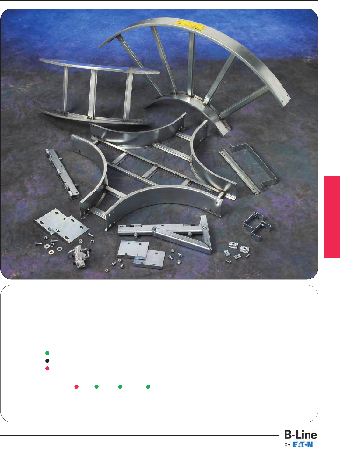
Series 1 Steel
How The Service Advisor Works
B-Line knows that your time is important! That’s why the color-coding system in this catalog is designed to help you
select products that fit your service needs. Products are marked to indicate the typical lead time for orders of 50
pieces or less.
Customer: How do I select my straight sections. covers, or fittings so that I get the quickest turnaround?
Service Advisor: Each part of our selection chart is shown in colors. If any section of a part number is a different
color, the part will typically ship with the longer lead time represented by the colors.
Green = Fastest shipped items
Black = Normal lead-time items
Red = Normally long lead-time items
Example: 156G 09 - 24 - 144 Part will have a long
lead time because of the
156G material.
Changing the part number from 156G to 156P will change the coding to black for all sections and reduce lead time.
LST-2
Series 1 Steel - Straight Sections
Cable Tray Systems
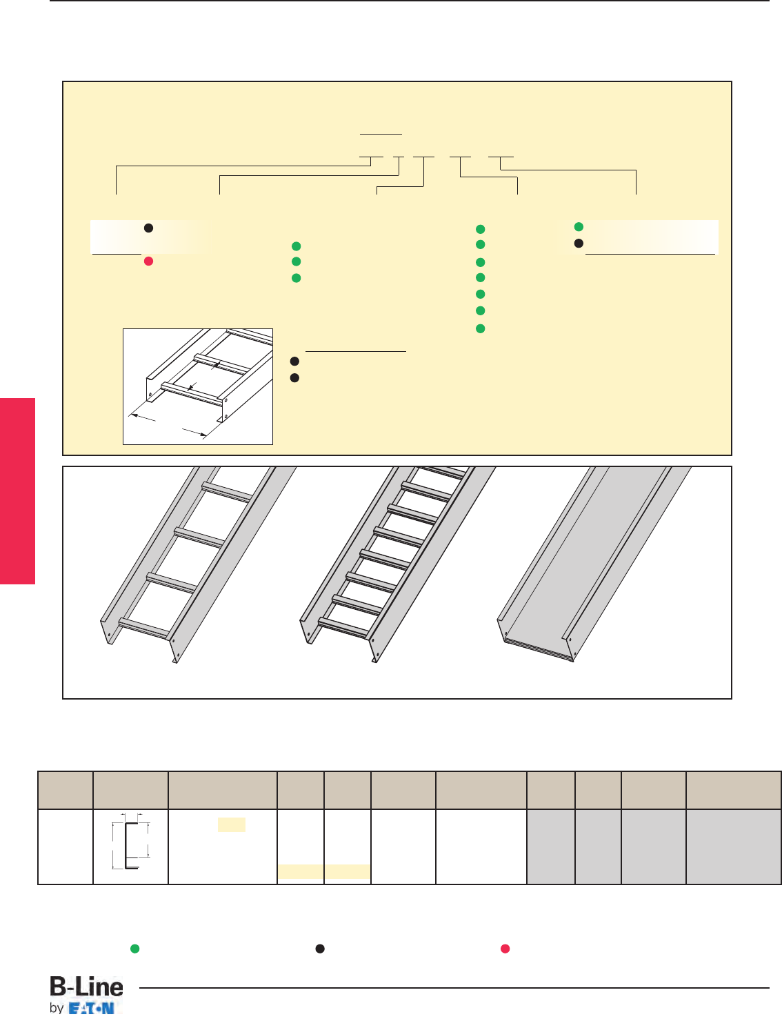
B-Line Side Rail NEMA, CSA & UL Span Load Deflection Design Factors Span Load Deflection Design Factors
Series Dimensions Classifications ft lbs/ft Multiplier for Two Rails meters kg/m Multiplier for Two Rails
NEMA: 12A, 8C 6 204* 0.0011 Area=0.51 in21.8 304* 0.019 Area=3.29 cm2
148 CSA: C1-3m 8 115 0.0036 Sx=0.48 in32.4 171 0.061 Sx=7.87 cm3
UL Cross-Sectional 10 73 0.0087 Ix=0.89 in43.0 109 0.149 Ix=37.04 cm4
Area: 0.40 in212 51 0.0181 3.7 76 0.309
*When using 12" rung spacing load capacity is limited to 195 lbs/ft (290.16 kg/m) for 36" tray width. When cable trays are used in
continuous spans, the deflection of the cable tray is reduced by as much as 50%. Design factors: Ix = Moment of Inertia,
Sx = Section Modulus.
Values are based on simple beam tests per NEMA VE 1 on 36" wide cable tray with rungs spaced on 12" centers. The published
load safety factor is 1.5. To convert 1.5 safety factor to 2.0, multiply the published load by 0.75. To obtain mid-span deflection,
multiply a load by the deflection multiplier. Cable tray must be supported on spans shorter than or equal to the length of the
cable tray being installed.
.875
3.625 3.077
18 gauge
3" NEMA VE 1 Loading Depth
Actual Loading Depth = 3.077"
Overall Width
(Width + 1/8”)
For
side rail
& rung data,
see chart on
pages AP-5 & AP-6
Rung
Spacing
Straight Section Part Numbering
Prefix
Example: 148 P 09 - 24 - 144
Series Material Type Width Length
148 P= Pre-Galvanized Ladder- 06 = 6" ¨144 = 12 ft. 148
Steel 06 = 6" rung spacing 09 = 9" ¡120 = 10 ft.
G= Hot Dip 09 = 9" rung spacing 12 = 12"
Galvanized 12 = 12" rung spacing 18 = 18"
After Fabrication 24 = 24"
Steel 30 = 30"
Trough- 36 = 36"
6" thru 24" wide
04 = Vented Bottom
SB = Non-Ventilated Bottom
See page APP-1 for additional rung options. *SB available for all widths.
Series 1 Steel
¨Primary Length.
¡Secondary Length.
See page CTS-23 for
explanation of lengths.
Green = Fastest shipped items Black = Normal lead-time items Red = Normally long lead-time items
Ladder Type
(Specify Rung Spacing)
Ventilated Bottom Non-Ventilated
LST-3
Series 1 Steel - Straight Sections
Cable Tray Systems

B-Line Side Rail NEMA, CSA & UL Span Load Deflection Design Factors Span Load Deflection Design Factors
Series Dimensions Classifications ft lbs/ft Multiplier for Two Rails meters kg/m Multiplier for Two Rails
NEMA: 12B, 8C 6 304* 0.0007 Area=0.68 in21.8 452* 0.011 Area=4.39 cm2
156 CSA: C1-3m 8 171 0.0021 Sx=0.724 in32.4 254 0.036 Sx=11.86 cm3
UL Cross-Sectional 10 109 0.0051 Ix=1.517 in43.0 163 0.087 Ix=63.14 cm4
Area: 0.40 in212 76 0.011 3.7 113 0.181
.875
3.628
Values are based on simple beam tests per NEMA VE 1 on 36" wide cable tray with rungs spaced on 12" centers. Cable trays will
support without collapse a 200 lb. (90.7 kg) concentrated load over and above the published loads. The published load safety factor
is 1.5. To convert 1.5 safety factor to 2.0, multiply the published load by 0.75. To obtain mid-span deflection, multiply a load by the
deflection multiplier. Cable tray must be supported on spans shorter than or equal to the length of the cable tray being installed.
*When using 12" rung spacing, load capacity is limited to 234 lbs/ft (348.192 kg/m) for 30" tray width and 195 lbs/ft (290.16 kg/m)
for 36" tray width. When trays are used in continuous spans, the deflection of the tray is reduced by as much as 50%. Design
factors: Ix = Moment of Inertia, Sx = Section Modulus.
4.188
16 gauge
Series 1 Steel
4" NEMA VE 1 Loading Depth
Actual Loading Depth = 3.628"
Overall Width
(Width + 1/8”)
For
side rail
& rung data,
see chart on
pages AP-5 & AP-6
Rung
Spacing
Ladder Type
(Specify Rung Spacing)
Ventilated Bottom Non-Ventilated
Straight Section Part Numbering
Prefix
Example: 156 P 09 - 24 - 144
Series Material Type Width Length
156 P= Pre-Galvanized Ladder- 06 = 6" ¨144 = 12 ft. 156
Steel 06 = 6" rung spacing 09 = 9" ¡120 = 10 ft.
G= Hot Dip 09 = 9" rung spacing 12 = 12"
Galvanized 12 = 12" rung spacing 18 = 18"
After Fabrication 24 = 24"
Steel 30 = 30"
Trough- 36 = 36"
04 = Vented Bottom
SB = Non-Ventilated Bottom
See page APP-1 for additional rung options. *SB available for all widths.
¨Primary Length.
¡Secondary Length.
See page CTS-23 for
explanation of lengths.
Green = Fastest shipped items Black = Normal lead-time items Red = Normally long lead-time items
LST-4
Series 1 Steel - Straight Sections
Cable Tray Systems
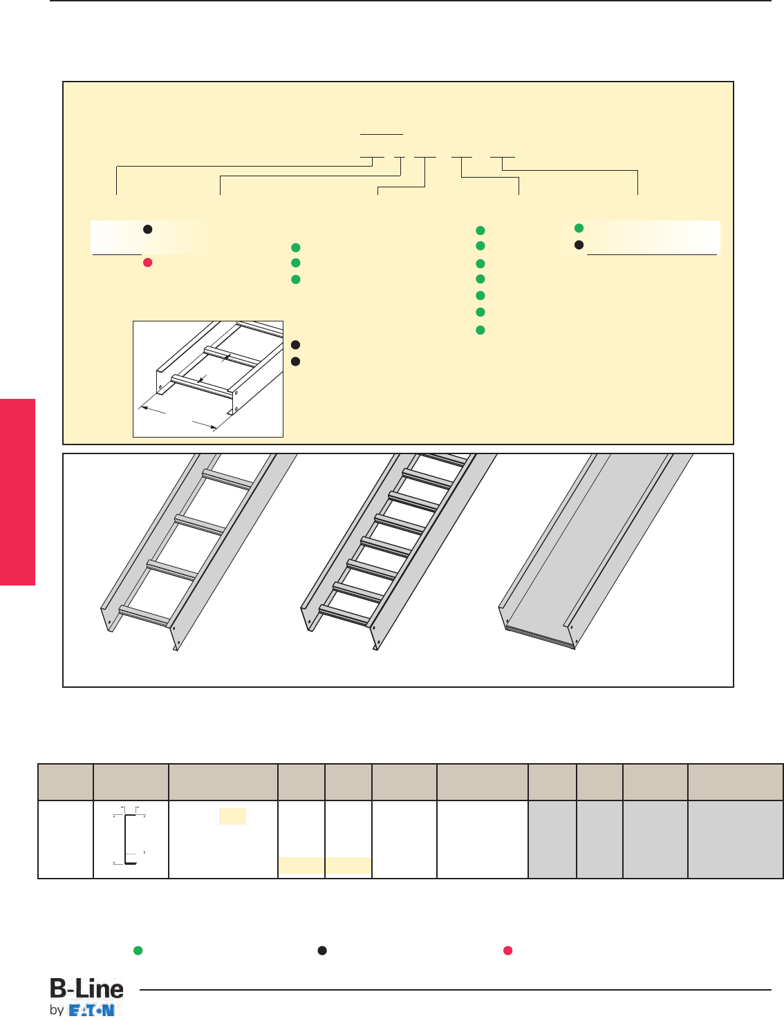
B-Line Side Rail NEMA, CSA & UL Span Load Deflection Design Factors Span Load Deflection Design Factors
Series Dimensions Classifications ft lbs/ft Multiplier for Two Rails meters kg/m Multiplier for Two Rails
NEMA: 12B, 8C 6 308* 0.0004 Area=0.77 in21.8 458* 0.007 Area=4.97 cm2
166 CSA: C1-3m 8 173 0.0013 Sx=0.93 in32.4 258 0.023 Sx=15.24 cm3
UL Cross-Sectional 10 111 0.0032 Ix=2.40 in43.0 165 0.055 Ix=99.90 cm4
Area: 0.70 in212 77 0.0067 3.7 115 0.114
4.628
5.188
.750
Values are based on simple beam tests per NEMA VE 1 on 36" wide cable tray with rungs spaced on 12" centers. Cable trays will
support without collapse a 200 lb. (90.7 kg) concentrated load over and above published loads. The published load safety factor is
1.5. To convert 1.5 safety factor to 2.0, multiply the published load by 0.75. To obtain mid-span deflection, multiply a load by the
deflection multiplier. Cable tray must be supported on spans shorter than or equal to the length of the cable tray being installed.
*When using 12" rung spacing, the load capacity is limited to 234 lbs/ft (348.192 kg/m) for 30" tray width and 195 lbs/ft
(290.16 kg/m) for 36" tray width. When trays are used in continuous spans, the deflection of the tray is reduced by as much
as 50%. Design factors: Ix = Moment of Inertia, Sx = Section Modulus.
16 gauge
5" NEMA VE 1 Loading Depth
Actual Loading Depth = 4.628"
Overall Width
(Width + 1/8”)
For
side rail
& rung data,
see chart on
pages AP-5 & AP-6
Rung
Spacing
Straight Section Part Numbering
Prefix
Example: 166 P 09 - 24 - 144
Series Material Type Width Length
166 P= Pre-Galvanized Ladder- 06 = 6" ¨144 = 12 ft. 166
Steel 06 = 6" rung spacing 09 = 9" ¡120 = 10 ft.
G= Hot Dip 09 = 9" rung spacing 12 = 12"
Galvanized 12 = 12" rung spacing 18 = 18"
After Fabrication 24 = 24"
Steel 30 = 30"
Trough- 36 = 36"
04 = Vented Bottom
SB = Non-Ventilated Bottom
See page APP-1 for additional rung options. *SB available for all widths.
Ladder Type
(Specify Rung Spacing)
Ventilated Bottom Non-Ventilated
Series 1 Steel
¨Primary Length.
¡Secondary Length.
See page CTS-23 for
explanation of lengths.
Green = Fastest shipped items Black = Normal lead-time items Red = Normally long lead-time items
LST-5
Series 1 Steel - Straight Sections
Cable Tray Systems
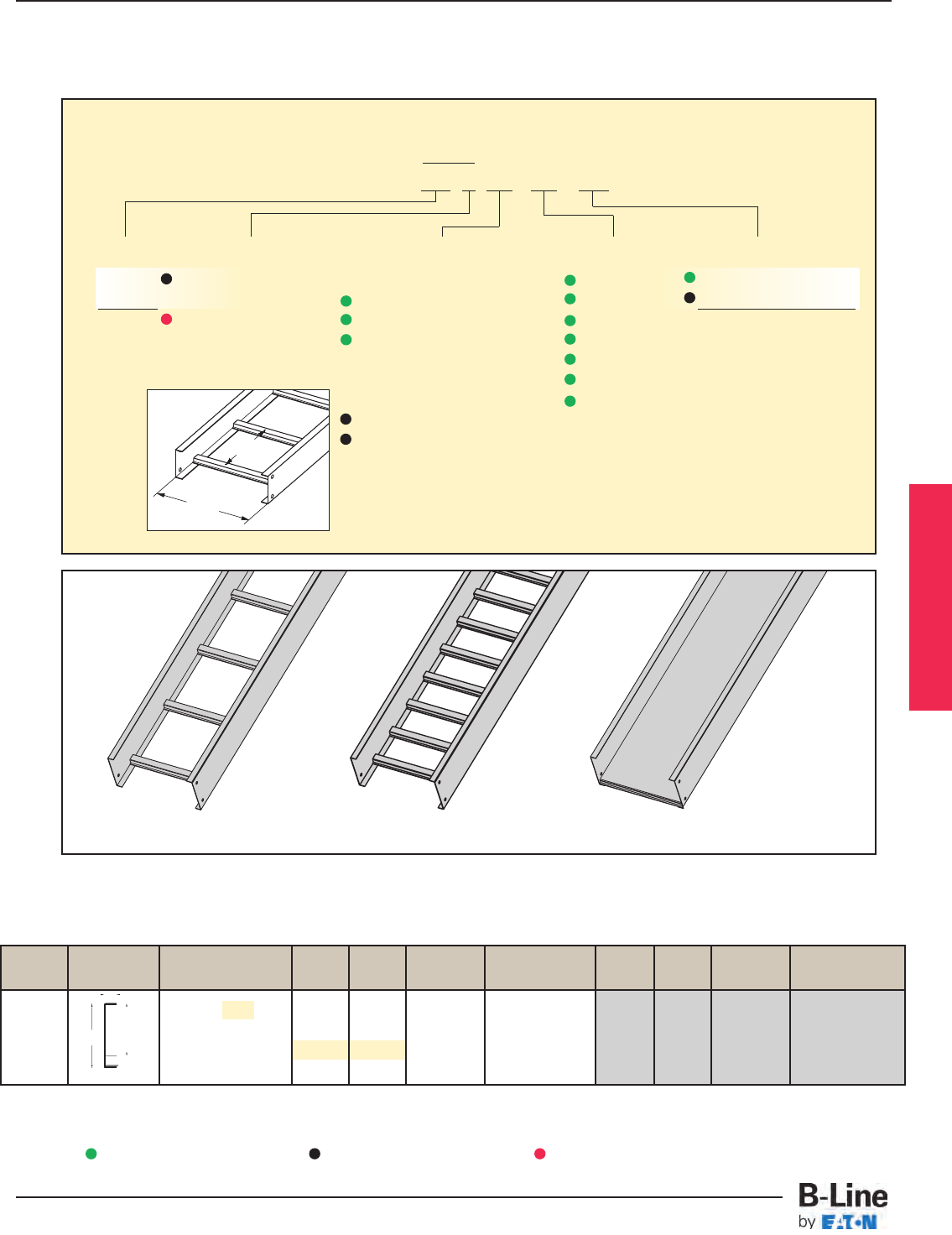
B-Line Side Rail NEMA, CSA & UL Span Load Deflection Design Factors Span Load Deflection Design Factors
Series Dimensions Classifications ft lbs/ft Multiplier for Two Rails meters kg/m Multiplier for Two Rails
NEMA: 12B, 8C 8 194 0.0008 Area=0.89 in22.4 288 0.014 Area=5.74 cm2
CSA: 137 kg/m3.7m 10 124 0.0020 Sx=1.23 in33.0 184 0.035 Sx=20.16 cm3
UL Cross-Sectional 12 86 0.0042 Ix=3.80 in43.7 128 0.072 lx=158.2 cm4
Area: 0.70 in2
.750
6.188 5.628
When cable trays are used in continuous spans, the deflection of the tray is reduced by as much as 50%. Design factors:
Ix = Moment of Inertia, Sx = Section Modulus.
Values are based on simple beam tests per NEMA VE 1 on 36" wide cable tray with rungs spaced on 12" centers. Cable trays will
support without collapse a 200 lb. (90.7 kg) concentrated load over and above published loads. The published load safety factor
is 1.5. To convert 1.5 safety factor to 2.0, multiply published load by 0.75. To obtain mid-span deflection, multiply a load by the
deflection multiplier. Cable tray must be supported on spans shorter than or equal to the length of the cable tray being installed.
16 gauge
176
6" NEMA VE 1 Loading Depth
Actual Loading Depth = 5.628"
Overall Width
(Width + 1/8”)
For
side rail
& rung data,
see chart on
pages AP-5 & AP-6
Rung
Spacing
Straight Section Part Numbering
Prefix
Example: 176 P 09 - 24 - 144
Series Material Type Width Length
176 P= Pre-Galvanized Ladder- 06 = 6" ¨144 = 12 ft. 176
Steel 06 = 6" rung spacing 09 = 9" ¡120 = 10 ft.
G= Hot Dip 09 = 9" rung spacing 12 = 12"
Galvanized 12 = 12" rung spacing 18 = 18"
After Fabrication 24 = 24"
Steel 30 = 30"
Trough- 36 = 36"
04 = Vented Bottom
SB = Non-Ventilated Bottom
See page APP-1 for additional rung options. *SB available for all widths.
Ladder Type
(Specify Rung Spacing)
Ventilated Bottom Non-Ventilated
Series 1 Steel
¨Primary Length.
¡Secondary Length.
See page CTS-23 for
explanation of lengths.
Green = Fastest shipped items Black = Normal lead-time items Red = Normally long lead-time items
LST-6
Series 1 Steel - Straight Sections
Cable Tray Systems
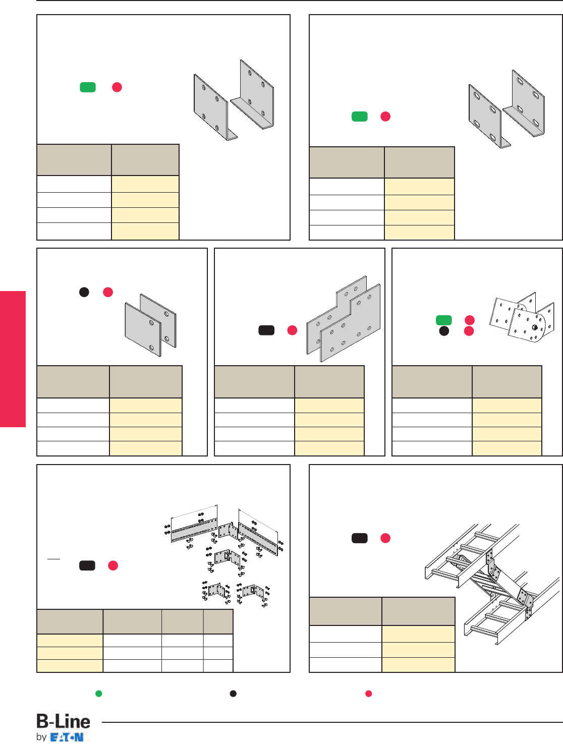
Branch Pivot Connectors
• Branch from existing cable tray runs at any point.
• Pivot to any required angle.
• UL Classified for grounding
(bonding jumper not required).
• Furnished in pairs with hardware.
• (*) Insert or
Expansion (L-Shaped) Splice Plates
• Expansion plates allow for one inch expansion
or contraction of the cable tray, or where
expansion joints occur in the supporting
structure.
•Bonding Jumpers are required.
Order Separately.
• L-shaped lay-in design.
• Furnished in pairs with hardware.
• (*) Insert or
Horizontal Adjustable Splice Plates
• Offered to adjust a cable tray run for
changes in direction in a horizontal
plane that do not conform to
standard horizontal fittings.
• Furnished in pairs
with hardware.
• New design bonding jumpers
not required.
• (*) Insert or
• (X) Insert 4 for series 148 or 156
5 for series 166
6 for series 176
Catalog Cable Tray Tray
No. End Cut Width 'L'
9(*)-803(X) Mitered Thru 36" N/A
9(*)-803(X)-12 Not mitered Thru 12" 16"
9(*)-803(X)-36 Not mitered Thru 36" 41"
Tray
Series Catalog No.
156 to 148 9(*)-8004
166 to 156 or 148 9(*)-8045
176 to 156 or 148 9(*)-8046
176 to 166 9(*)-8060
Standard (L-Shaped) Splice Plates
• One pair including hardware provided with each section.
• Furnished in pairs with hardware.
• Prepackaged in pairs in a plastic bag, with hardware.
• 4-hole pattern L-shaped splice plates.
• L-shaped lay-in design.
• (*) Insert or
Tray
Series Catalog No.
156 to148 9(*)-8244
166 9(*)-8245
176 9(*)-8246
Tray
Series Catalog No.
148 9(*)-2004-1/2
156 9(*)-2005-1/2
166 9(*)-2006-1/2
176 9(*)-2007-1/2
Tray
Series Catalog No.
148 9(**)-7024
156 9(*)-8024
166 9(*)-8025
176 9(*)-8026
9(*)-803(X)-12 or 9(*)-803(X)-36
One pair splice plates with extensions.
9(*)-803(X)
Splices only
L
L
Vertical Adjustable Splice Plates
• These plates provide for changes in elevation
that do not conform to standard vertical
fittings.
• Furnished in pairs with
hardware.
• (*) Insert or
• (**) Insert or
Step Down Splice Plates
• These splice plates are offered for
connecting cable tray sections
having side rails of different
heights.
• Furnished in pairs with
hardware.
• (*) Insert or
Universal Splice Plates
• Used to splice to existing cable tray systems.
• Furnished in pairs with hardware.
• (*) Insert or
Tray
Series Catalog No.
148 9(*)-4004
156 9(*)-4005
166 9(*)-4006
176 9(*)-4007
Tray
Series Catalog No.
148 9(*)-4014
156 9(*)-4015
166 9(*)-4016
176 9(*)-4017
Series 1 Steel
G
G
G
P
G
P
ZN
ZN
G
ZN
G
ZN
G
ZN
G
ZN
Requires supports within 24” on
both sides, per NEMA VE 2.
Requires
supports
within 24”
on both
sides, per
NEMA VE 2.
Green = Fastest shipped items Black = Normal lead-time items Red = Normally long lead-time items
LST-7
Series 1 Steel - Accessories
Cable Tray Systems
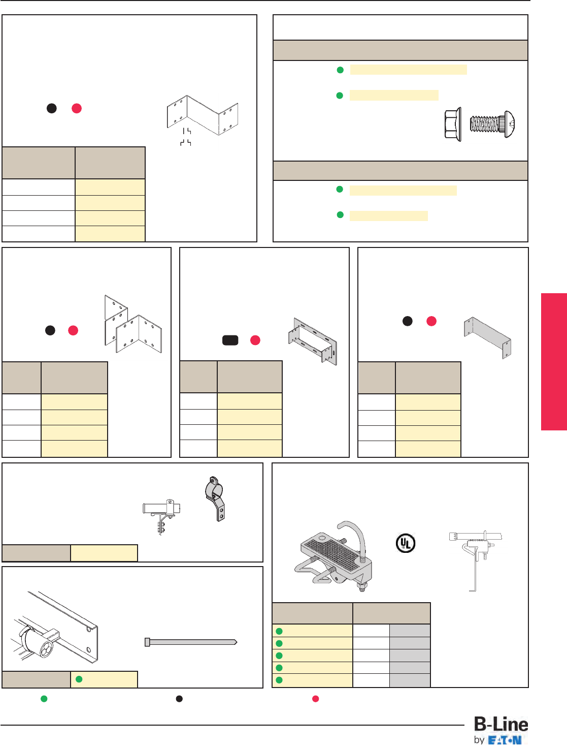
Conduit to Tray Adaptor
• Assembly required.
• Mounting hardware included.
• Conduit clamp included
• (‡) = Conduit size
(1/2" thru 4").
Conduit to Tray Adaptor
• For easy attachment of conduit terminating at a cable tray.
• Use on aluminum or steel cable trays.
Catalog No. Conduit Size
in. (mm)
9G-1158-1
/2, 3
/41
/2, 3
/415, 20
9G-1158-1, 11
/41, 11
/425, 32
9G-1158-11
/2, 2 11
/2, 2 40, 50
9G-1158-21
/2, 3 21
/2, 3 65, 80
9G-1158-31
/2, 4 31
/2, 4 90, 100
Tray
Series Catalog No.
148 9(*)-8054
156 9(*)-8054
166 9(*)-8055
176 9(*)-8056
Tray
Series Catalog No.
148 9(*)-8074-(‡)
156 9(*)-8074-(‡)
166 9(*)-8075-(‡)
176 9(*)-8076-(‡)
Frame Type Box Connector
• Designed to attach the end of a cable
tray run to a distribution cabinet or control
center to help reinforce the box at the
point of entry.
• Furnished with tray
connection hardware.
• (‡) Insert tray width
• (*) Insert or
Tray Hardware
Blind End
• This plate forms a closure for a
dead end cable tray.
• Furnished as one plate
with hardware.
• (‡) Insert tray width
• (*) Insert or
Tray
Series Catalog No.
148 9(*)-8084-(‡)
156 9(*)-8084-(‡)
166 9(*)-8085-(‡)
176 9(*)-8086-(‡)
Cable Tie (Ladder Tray)
Nylon ties provide easy attachment of
cable to ladder rungs; maximum
cable O.D. of 3" (76 mm).
Catalog No. 99-2125-15
Pre-Galvanized Tray Hardware
Catalog No. RNCB 3/8"-16 x 3/4" Znplt
Ribbed Neck Carriage Bolt ASTM A307 Grade A
Catalog No. SFHN 3/8"-16 Znplt
Serrated Flange Hex Nut ASTM A563
Grade A
Finish: Zinc Plated ASTM B633, SC1
Hot Dip Galvanized Tray Hardware
Catalog No. RNCB 3/8"-16 x 3/4" CZ Ribbed Neck
Carriage Bolt Chromium Zinc ASTM F-1136-88
Catalog No. SFHN 3/8"-16 CZ Serrated Flange Hex Nut
Chromium Zinc ASTM F-1136-88
Overall Length 15"
Tray to Box Splice Plates
• Used to attach the
end of a cable tray
run to a distribution
box or control panel.
• Furnished in pairs with
hardware.
• (*) Insert or
Offset Reducing Splice Plate
• This plate is used for joining cable trays
having different widths. When used in
pairs they form a straight reduction;
when used singly with a standard splice
plate they form an offset reduction.
• Furnished as one plate with hardware.
• (‡) Insert reduction
• (*) Insert or
Tray
Series Catalog No.
148 9(*)-8064-(‡)
156 9(*)-8064-(‡)
166 9(*)-8065-(‡)
176 9(*)-8066-(‡)
Catalog No. 9ZN-1150-(‡)
Series 1 Steel
G
P
G
P
G
P
G
ZN
Green = Fastest shipped items Black = Normal lead-time items Red = Normally long lead-time items
LST-8
Series 1 Steel - Accessories
Cable Tray Systems
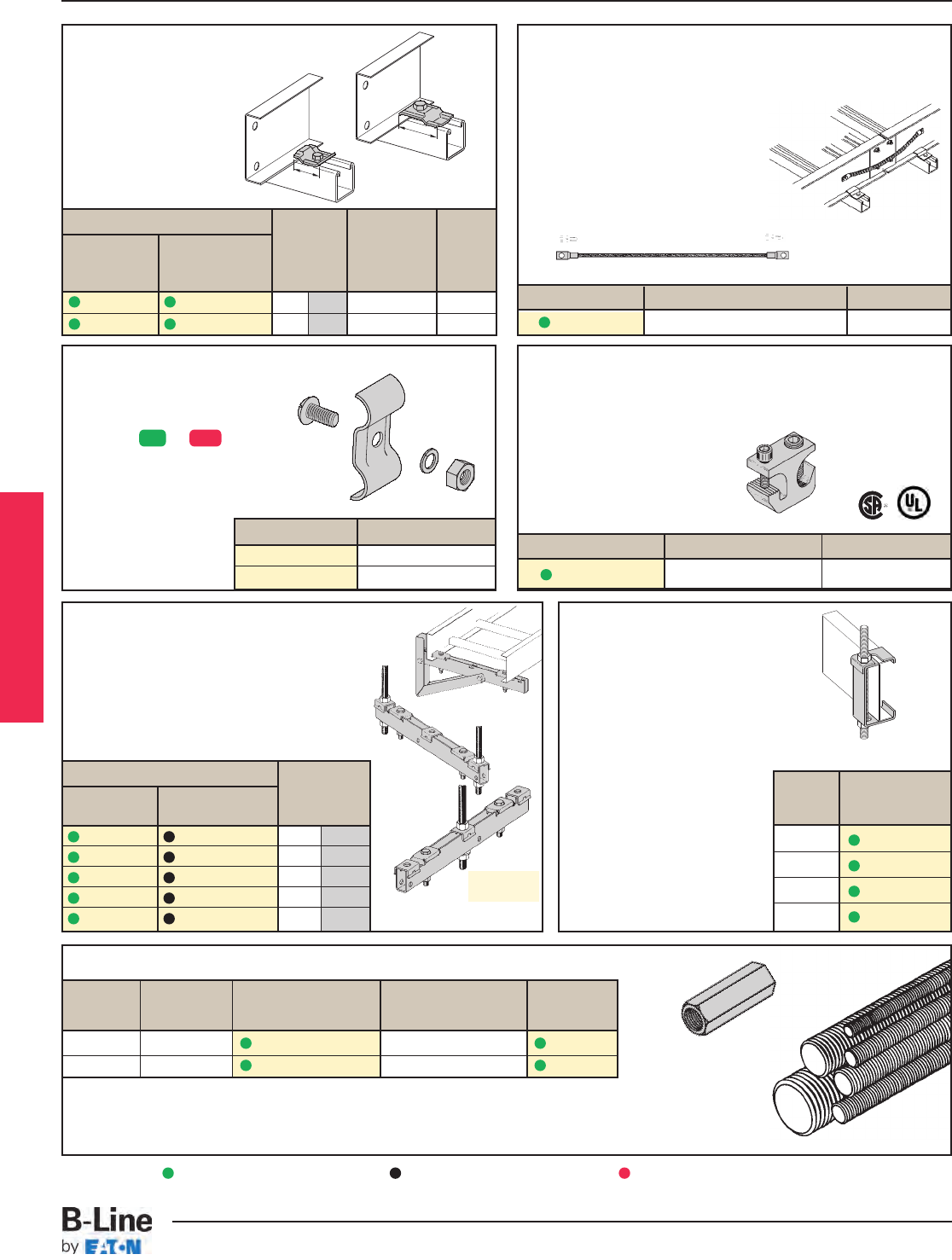
Support Bracket
•
Designed for center hung or trapeze supports.
•
Used with ladder or vented bottom tray only.
• Can be purchased as a wall mounted bracket.
• Load capacity is 600 lbs. (272.1 kg),
safety factor 3.
• All components are zinc plated.
•
1/2"
threaded rod and
1/2"
hex nuts not included.
Cable Tray Clamp/Guide
• Features a no-twist design.
• Has four times the strength
of the traditional design.
• Each side is labeled to
ensure proper installation.
• Furnished in pairs, with or
without hardware.
Threaded Rod (ATR) & Rod Coupling
Loading Catalog Available Coupling
Size lbs. No. Lengths Cat. No.
3/8-16 730 ATR 3/8x Length 36", 72", 120", 144" B655-3/8
1/2-13 1350 ATR 1/2x Length 36", 72", 120", 144" B655-1/2
Loading based on safety factor 5.
Standard Finish: Zinc plated
See B-Line Strut Systems Catalog for other sizes and finishes.
Bonding Jumper
Use at each expansion splice and where the cable tray is not
mechanically/electrically continuous to ground.
Sold individually.
• Hardware included.
• See table 392.7(B)(2) on page CTS-9
for amperage ratings required to
match the UL cross-sectional area of
the tray.
• 600 amp rating.
• Bonding jumper is 16" long.
Catalog No.
Center Hung Wall
or Trapeze Mount
9ZN-5106 9ZN-5106-WB 6 152
9ZN-5109 9ZN-5109-WB 9 226
9ZN-5112 9ZN-5112-WB 12 305
9ZN-5118 9ZN-5118-WB 18 452
9ZN-5124 9ZN-5124-WB 24 609
Grounding Clamp
B-Line Cable Tray is UL®classified as to its suitability as an equipment
grounding conductor. If a separate conductor for additional grounding
capability is desired, B-Line offers this clamp for bolting the conductor
at least once to each tray section.
• Accepts #6 AWG to 250 MCM.
Catalog No. Material Item
9A-2130 Tin Plated Aluminum Grounding Clamp
Ground Clamp
• Mechanically attaches grounding
cables to cable tray.
• Hardware included.
• (*) Insert or
Catalog No. Cable Size
9(*)-2351 #1 thru 2/0
9(*)-2352 3/0 thru 250 MCM
Patent No.
5,100,086
9ZN-1204 shown.
Installed as a guide.
9ZN-1208
shown.
Installed as
a clamp.
For
Cable Tray
Width
in. (mm)
Hanger Rod Clamp
• For 1/2" ATR.
• Furnished in pairs.
• Order ATR and hex nuts separately.
• Two piece "J"-hanger design.
• 9ZN-1113 has 275 lbs./pair
safety factor 3.
• 9ZN-532(X) has 1500 lbs./pair
safety factor 3.
Patent # RE35479
Catalog No.
Without With Overall Hardware
Hardware Hardware Length Size Finish
in. (mm)
9ZN-1204 9ZN-1204NB 11/238 1/4" G90
9ZN-1208 9ZN-1208NB 21/457 3/8" G90
Catalog No. Copper Wire Size Ampacity
99-N1 #1 600
Tray
Series Catalog No.
148 9ZN-1113
156 9ZN-5324
166 9ZN-5325
176 9ZN-5326
11/2"
(39mm)
21/4"
(57mm)
Series 1 Steel
ZN SS4
Green = Fastest shipped items Black = Normal lead-time items Red = Normally long lead-time items
LST-9
Series 1 Steel - Accessories
Cable Tray Systems
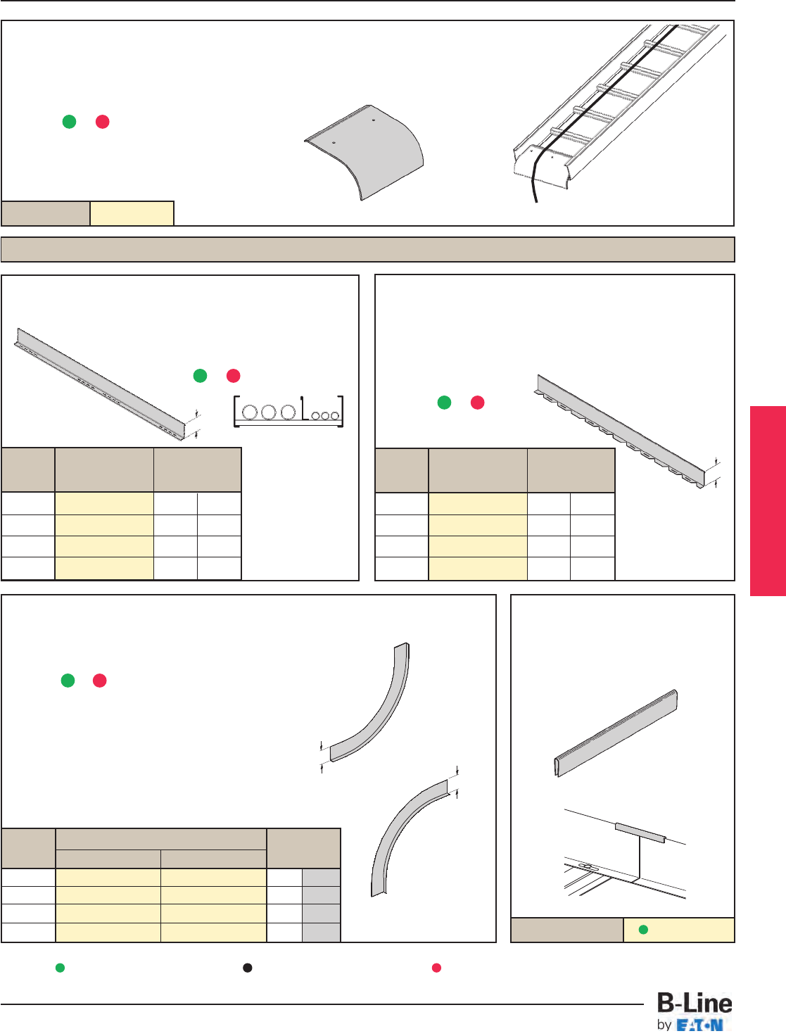
Horizontal Bend
• Horizontal Bend Barriers are flexible in order to conform to any
horizontal fitting radius. Cut to length.
• Order catalog number based on loading depth.
• Furnished with three #10 x 1/2" zinc plated self-drilling screws and
a 99-9982 Barrier Strip Splice.
• Standard length is 72"
(6 ft.), sold individually.
• (*) Insert or
Vertical Bend Barriers
• Vertical Bend Barriers are preformed to conform to a specific
vertical fitting.
• Furnished with three #10 x 1
/2" plated self-drilling screws
and a 99-9982 Barrier Strip Splice.
• (*) Insert or
• (**) Insert 30, 45, 60 or 90 for degrees
• (†) Insert 12, 24, or 36 for radius
99-9982
Catalog No.
Barrier Strip Splice
• Plastic splice holds adjoining
barrier strips in straight alignment.
• 5” (127mm) long
Straight Section
• Standard length: 120" (3 m) 144" (12 ft.).
• Order catalog number based on loading
depth.
• Furnished with four #10 x 1/2" plated self-
drilling screws and a 99-9982 splice.
• (*) Insert or
Outside
Bend
(VO)
Inside
Bend
(VI)
H
H
Barriers
Length =
144 for 12'
or
120 for 10'
H
H
Catalog No. 9(*)-1104T-(‡)
Ladder Drop-Out
• This special designed, easy to install drop-out provides a
4" (101.6 mm) radius to protect cables exiting the cable tray
from damage.
• Attaches to a ladder rung.
• Hardware included.
• (*) Insert or
• (‡) Insert tray width
Tray H
Series Catalog No.
in. (mm)
148 72(*)-90HBFL 2.8 58
156 737(*)-90HBFL 3.4 70
166 747(*)-90HBFL 4.4 91
176 757(*)-90HBFL 5.4 112
Tray H
Series Catalog No.
in. (mm)
148 72(*)-Length 2.8 58
156 737(*)-Length 3.4 70
166 747(*)-Length 4.4 91
176 757(*)-Length 5.4 112
Tray Catalog No. H
Series Inside Bend Outside Bend
in. (mm)
148 72(*)-(**)VI(†) 72(*)-(**)VO(†) 2.8 58
156 737(*)-(**)VI(†) 737(*)-(**)VO(†) 3.4 70
166 747(*)-(**)VI(†) 747(*)-(**)VO(†) 4.4 91
176 757(*)-(**)VI(†) 757(*)-(**)VO(†) 5.4 112
Series 1 Steel
G
G
P
G
P
G
P
Green = Fastest shipped items Black = Normal lead-time items Red = Normally long lead-time items
P
LST-10
Series 1 Steel - Accessories
Cable Tray Systems
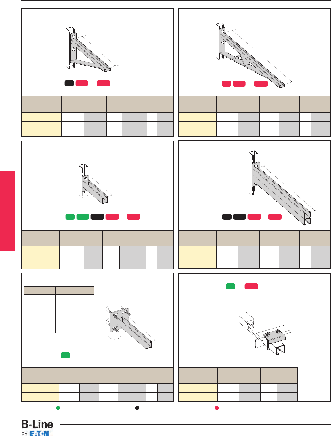
Underfloor Support (U-Bolts not included)
Cantilever Bracket
Catalog No. Uniform Load Tray Width 'A'
lbs (kN) in. (mm) in. (mm)
B409-12 960 4.27 6 & 9 152 & 228 12 304.8
B409-18 640 2.84 12 305 18 457.2
B409-24 480 2.13 18 457 24 609.6
Cantilever Bracket
Catalog No. Uniform Load Tray Width 'A'
lbs (kN) in. (mm) in. (mm)
B494-30 924 4.11 24 609.6 30 762.0
B494-36 864 3.84 30 762.0 36 914.4
B494-42 580 2.58 36 914.4 42 1066.8
Cantilever Bracket
Catalog No. Uniform Load Tray Width 'A'
lbs (kN) in. (mm) in. (mm)
B297-30 665 2.95 24 609.6 30 762.0
B297-36 550 2.44 30 762.0 36 914.4
B297-42 465 2.06 36 914.4 42 1066.8
Beam Clamp
• Finishes available: or
• Sold in pieces with hardware.
Catalog No. Design Load* 'A'
lbs (kN) in. (mm)
B441-22 1200 5.34 33/8 86
B441-22A 1200 5.34 5 127
Cantilever Bracket
Catalog No. Uniform Load Tray Width 'A'
lbs (kN) in. (mm) in. (mm)
B494-12 1580 7.02 6 & 9 152 & 229 12 304.8
B494-18 1000 4.45 12 305 18 457.2
B494-24 996 4.43 18 457 24 609.6
A
A
A
A
A
Finishes available: or
Safety Load Factor 2.5
Finishes available: or
Safety Load Factor 2.5
Finishes available: or
Safety Load Factor 2.5
Finishes available: or
Safety Load Factor 2.5
Finish available:
Safety Load Factor 2.5
U-Bolt Size Fits Pipe O.D.
B501-3/4.841 - 1.050
B501-1 1.051 - 1.315
B501-11/41.316 - 1.660
B501-11/21.661 - 1.900
B501-2 1.901 - 2.375
B501-21/22.376 - 2.875
• Order properly sized U-Bolts
separately.
Catalog No.
Uniform Load
Tray Width 'A'
lbs (kN) in. (mm) in. (mm)
B409UF-12 800 3.55 6 & 9 152 & 229 12 305
B409UF-21 450 2.00 12 & 18 305 & 457 21 533
Design load when used in pairs.
Safety Load Factor 5.0
A
Series 1 Steel
ZN GRN HDG
ZN
ZN
GRN HDG
ZN HDG
SS4 ZN GRN HDG SS4SS6
ZN GRN HDG
Green = Fastest shipped items Black = Normal lead-time items Red = Normally long lead-time items
LST-11
Series 1 Steel - Accessories
Cable Tray Systems
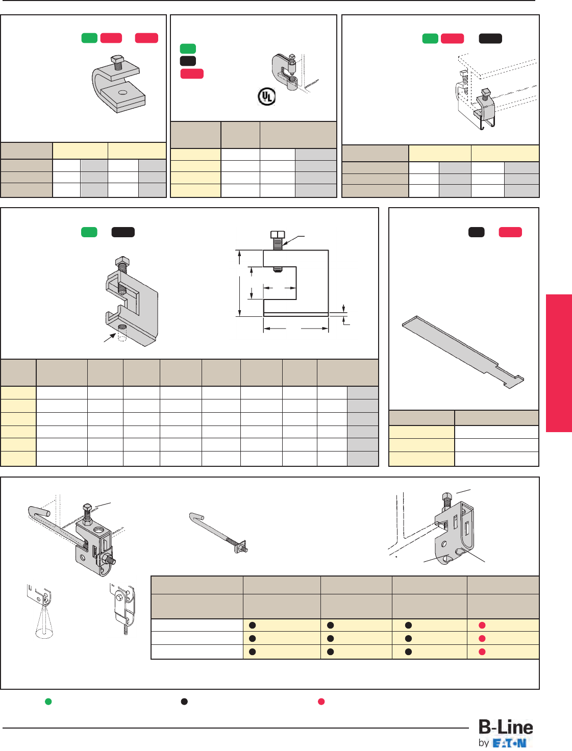
Steel C-Clamp With Locknut
• Finishes available:
for 3/8& 1/2
for 5/8& 3/4
all sizes
Safety Load Factor 5.0
Catalog Rod Design Load
Number Size lbs (kN)
B351L-3/83/8"-16 300 0.89
B351L-1/21/2"-13 380 1.69
B351L-5/85/8"-11 550 2.44
B351L-3/43/4"-10 630 2.80
Cat. No. B210 B210A
Design Load 800 lbs. 3.56 kN 300 lbs. 1.33 kN
Tap Size 1/2"-13 - 3/8"-16 -
Mat'l. Thickness 3/8" 9.5 mm 1/4" 6.4 mm
B751 Bottom Beam Clamp and Accessories
Setscrew included Finish available: ZN
Loading position A - 500 lbs.
Loading position B - 300 lbs.
Safety Load Factor 5.0
Assembly No. B751 B701J_ B752 B753
To Fit Clamp,Setscrew J-Hook,Clip Swivel & Bolt Swivel Nut
Flange Sizes & J-Hook & Square Nut Only Only
4"-5 7/8"B751-J4-3/8* B701-J4-3/8B752 B753-**
6"-8 7/8"B751-J6-3/8* B701-J6-3/8B752 B753-**
9"-11 7/8"B751-J9-3/8* B701-J9-3/8B752 B753-**
B312 Anchor Strap
• Finishes available: or
• For a maximum beam thickness
of 3/4".
• For thicker beams, step up one
flange width size.
Cat. No. Flange Width
B312-6 Up to 6"
B312-9 6" - 9"
B312-12 9" - 12"
B305 Thru B308 & B321 Series Beam Clamps
• Finishes available: or
• Setscrew included.
• Safety Load Factor 5.0
Cat. Rod Design Load
No. Size A BC D E F T
lbs (kN)
B305 3/8"-16 3/8"-16 2 5/16"7/8" 1 1/8" 2 1/2" 11 Ga. 600 2.67
B306 3/8"-16 1/2"-13 2 7/16"7/8" 1 1/8" 2 1/2" 7 Ga. 1100 4.90
B307 1/2"-13 1/2"-13 2 7/16"7/8" 1 1/8" 2 1/2" 7 Ga. 1100 4.90
B308 1/2"-13 1/2"-13 2 9/16"7/8" 1 1/8" 2 1/2"1/4" 1500 6.68
B321-1 3/8"-16 1/2"-13 3 9/16" 1 11/16" 1 5/8" 3 1/4"1/4" 1300 5.79
B321-2 1/2"-13 1/2"-13 3 9/16" 1 11/16" 1 5/8" 3 1/4"1/4" 1400 6.23
* Clamp Assembly complete with J-Hook Assembly. Setscrew included.
** Insert 1/4, 3/8or 1/2for the desired rod size.
B753
Position A
B701-J_-3/8
B752
B751
Position B
Provides a full 15° swivel
in any direction. (State
the desired rod size.)
B
E
D
C
FT
B751-J_-3/8*
Setscrew included
A
Beam Clamp
• Finishes available: or
• Setscrew included.
Design load when used in pairs.
Safety Load Factor 5.0
Cat. No.
Design Load 600 lbs. 2.67 kN 1000 lbs. 4.45 kN
Max. Flange Thick 3/4" 19 mm 11/8" 28.6 mm
Mat’l. Thickness 1/4" 6.3 mm 3/8" 9.5 mm
Beam Clamp
• Finishes available: or
• Sold in pieces.
Design load when used in pairs.
Safety Load Factor 5.0
B212-1/4B212-3/8
Series 1 Steel
ZN HDG ZN HDG
ZN
ZN
ZN
GRN HDG
SS4
ZN HDG
GRN
Green = Fastest shipped items Black = Normal lead-time items Red = Normally long lead-time items
LST-12
Series 1 Steel - Accessories
Cable Tray Systems
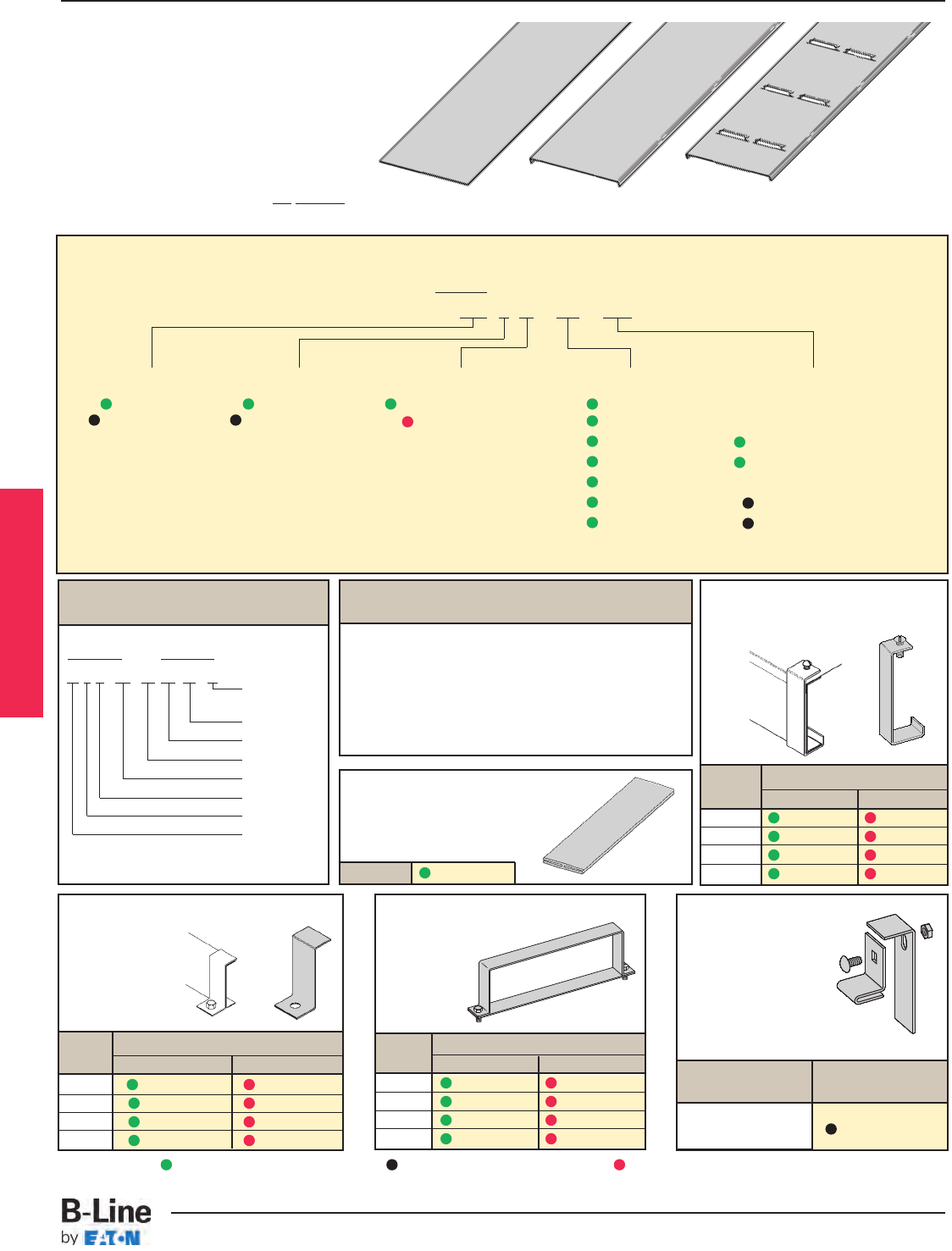
Cat. No. 99-9980-(‡)
Quantity of Standard
Cover Clamps Required
Straight Section 60" or 72" . . . . . . . . . . . . . . . . . 4 pcs.
Straight Section 120" or 144" . . . . . . . . . . . . . . 6 pcs.
Horizontal/Vertical Bends . . . . . . . . . . . . . . . . . . 4 pcs.
Tees . . . . . . . . . . . . . . . . . . . . . . . . . . . . . . . . . . . . . . . . . . . 6 pcs.
Crosses . . . . . . . . . . . . . . . . . . . . . . . . . . . . . . . . . . . . . . . . 8 pcs.
Note: When using the Heavy Duty Cover Clamp, only
one-half the number of clamps stated above is required.
Standard Cover Clamp
• Sold per piece
• For indoor service only
Tray Catalog No.
Series Znplt HDGAF
148 9ZN-9019 9G-9019
156 9ZN-9014 9G-9014
166 9ZN-9015 9G-9015
176 9ZN-9016 9G-9016
Combination Hold Down & Cover
Clamp
• Sold per piece
• For indoor
service only
Tray Catalog No.
Series Znplt/Pre-Galv. HDGAF
148 9ZN-9243 9G-9243
156 9P-9043 9G-9043
166 9P-9053 9G-9053
176 9P-9063 9G-9063
Heavy Duty Cover Clamp
• (‡) Insert
tray width
Tray Catalog No.
Series Pre-Galv. HDGAF
148 9P-(‡)-9040 9G-(‡)-9040
156 9P-(‡)-9044 9G-(‡)-9044
166 9P-(‡)-9054 9G-(‡)-9054
176 9P-(‡)-9064 9G-(‡)-9064
Example of Catalog Number for
Fitting Cover:
Solid covers should be used when maximum enclosure of the
cables is desired and no accumulation of heat is expected.
Ventilated covers provide an overhead cable shield yet
allow heat to escape.
B-Line recommends that covers on vertical cable tray
runs to a height of 6 ft. (1.83 m) to 8 ft. (2.44 m)
above the floor to isolate both cables and
personnel. Flanged covers have a .30 in.
(7.6 mm) flange. Cover clamps are not included with
the cover and must be ordered separately.
Solid Flanged Ventilated Flanged
Vertical Bend Cover
Prefix Suffix
80 1 P - 24 - 90 VO 24 - 4*
Side Rail*
Height
Radius
Fitting
Angle
Width
Material
Detail
Cover Type
Solid Non-Flanged
Covers Part Numbering
Prefix
Example: 80 1 P - 24 - 144
Cover Type Detail Material Tray Width Item Description
80 = Solid 1 = Flanged P = Pre-Galvanized
06 = 6"
For Straight Section Cover:
81 = Ventilated 9 = Non-Flanged
G = HDGAF 09 = 9" Pre-Galvanized Only:
12 = 12" 144 = 12 ft. (3.66 m)
18 = 18" 120 = 10 ft. (3.05 m)
24 = 24"
Pre-Galvanized & HDGAF
30 = 30"
72 = 6 ft. (1.83 m)
36 = 36"
60 = 5 ft. (1.52 m)
For fitting covers: Insert suffix of fitting
to be covered. See example below.
Covers
* Required for VO fittings only.
Cover Joint Strip
• Used to join covers
• Plastic
• (‡) Insert tray width
Raised Cover Clamp
• For indoor
service only.
• Sold per piece
• For use with flanged
covers only.
Tray Catalog
Series No.
Series 1 9ZN-910†
† Specify gap of 1", 2", 3" or 4".
Covers 30" and 36" wide have reinforcing ridges.
Series 1 Steel
Green = Fastest shipped items Black = Normal lead-time items Red = Normally long lead-time items
LST-13
Series 1 Steel - Accessories
Cable Tray Systems
Section 1- Acceptable Manufacturers
1.01 Manufacturer: Subject to compliance with these specifications, cable tray systems shall be as
manufactured by B-Line.
Section 2- Cable Tray Sections and Components
2.01 General: Except as otherwise indicated, provide metal cable trays, of types, classes and sizes indicated;
with splice plates, bolts, nuts and washers for connecting units. Construct units with rounded edges and
smooth surfaces; in compliance with applicable standards; and with the following additional construction
features. Cable tray shall be installed according to the latest revision of NEMA VE 2.
2.02 Pre-Galvanized Steel: Straight sections, fitting side rails, rungs, and covers shall be made from
structural quality steel meeting the minimum mechanical properties and mill galvanized in accordance
with ASTM A653 SS, Grade 33, coating designation G90. Hardware finish shall be electro-galvanized
zinc per ASTM B633.
2.03 Hot dip Galvanized Steel: All side rails, covers, splice plates, and rungs shall be made from structural
quality steel meeting the minimum mechanical properties of ASTM A1011 SS, Grade 33 for 14 gauge
and heavier, ASTM A1008, Grade 33 Type 2 for 16 gauge and lighter, and shall be hot dip galvanized
after fabrication in accordance with ASTM A123. Mill galvanized covers are not acceptable for hot dipped
galvanized cable tray. Hardware finish shall be chromium zinc per ASTM F-1136-88.
2.04 Ladder Cable Trays shall consist of two longitudinal members (side rails) with transverse members (rungs)
welded to the side rails. Rungs shall be spaced [6] [9] [12] inches on center. Rung spacing in radiused
fittings shall be industry standard 9" and measured at the center of the tray’s width. No portion of the
rungs shall protrude below the bottom plane of the side rails.
2.05 Ventilated Trough Cable Trays shall consist of two longitudinal members (side rails) with a corrugated
bottom welded to the side rails or rungs spaced 4" on center. The peaks of the corrugated bottom
shall have a minimum flat cable bearing surface of 23/4" and shall be spaced on 6" centers. To
provide ventilation in the tray, the valleys of the corrugated bottom shall have 21/4" x 4" rectangular
holes punched along the width of the bottom.
2.06 Non-Ventilated Bottom Trough Cable Trays shall consist of two longitudinal members (side rails) with a
corrugated bottom welded to the side rails or a solid sheet over rungs. The peaks of the corrugated
bottom shall have a minimum flat cable bearing surface of 23/4" and shall be spaced on 6" centers.
2.07 Cable tray loading depth shall be [3] [4] [5] [6] inches per NEMA VE 1.
2.08 Straight sections shall be supplied in standard [12 foot] [10 foot (3 m)] lengths.
2.09 Cable tray widths shall be [6] [9] [12] [18] [24] [30] [36] inches or as shown on drawings.
2.10 Splice plates shall be L-shaped with 4 nuts and bolts per plate. The resistance of fixed splice
connections between an adjacent section of tray shall not exceed 0.00033 ohm.
2.11 All fittings must have a minimum radius of [12] [24] inches.
Section 3- Loading Capacities and Testing
3.01 Cable tray shall be capable of carrying a uniformly distributed load of ______ lbs./ft. on a _______ ft.
support span with a safety factor of 1.5 when supported as a simple span and tested per
NEMA VE 1 5.2. Cable tray shall be made to manufacturing tolerances as specified by NEMA.
3.02 Upon request, manufacturer shall provide test reports in accordance with the latest revision of
NEMA VE 1 or CSA C22.2 No. 126.
Series 1 Steel
LST-14
Series 1 Steel - Specification
Cable Tray Systems
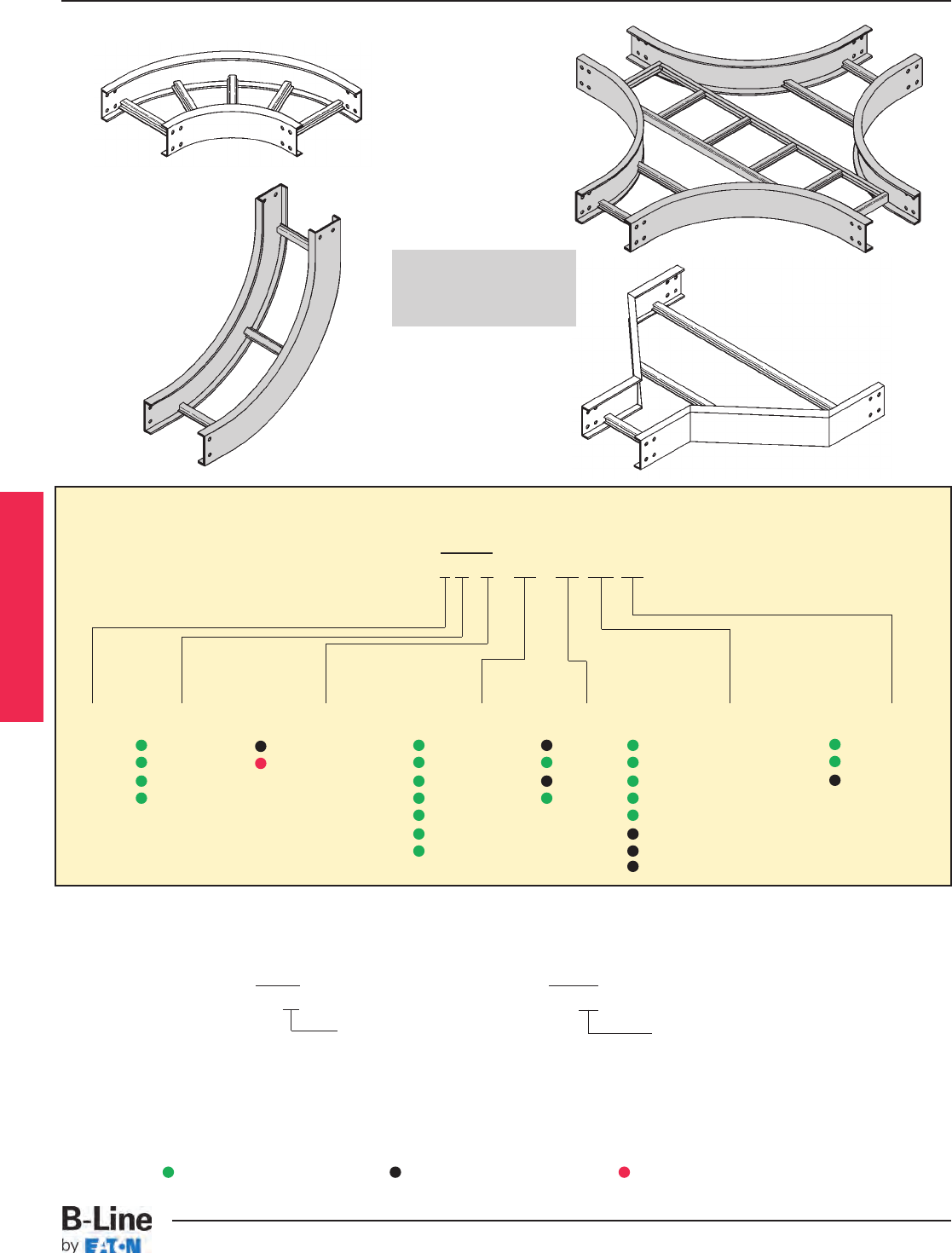
For steel 4”, 5", 6", 7" vented or non-ventilated add 04 or SB as shown below.
Prefix Prefix
15P04 - 24 - 90HB24 15PSB - 24 - 90HB24
Vented Bottom Non-Ventilated
Fittings Part Numbering
Prefix
Example: 1 4 P - 24 - 90 HB 24
Height
4 = 148
5 = 156
6 = 166
7 = 176
Series
1
Material
P = Pre-Galvanized
G = HDGAF
Width
06 = 6" (152)
09 = 9" (228)
12 = 12" (305)
18 = 18" (457)
24 = 24" (609)
30 = 30" (762)
36 = 36" (914)
Angle
30 = 30°
45 = 45°
60 = 60°
90 = 90°
Radius
12 = 12" (305)
24 = 24" (609)
36 = 36" (914)
Type
HB = Horizontal Bend
HT = Horizontal Tee
HX = Horizontal Cross
VI = Vertical Inside Bend
VO = Vertical Outside Bend
LR = Left Reducer
RR = Right Reducer
SR = Straight Reducer
(9" rung spacing is standard)
Fittings engineered
with 3" tangents for
splicing integrity.
Series 1 Fittings
Green = Fastest shipped items Black = Normal lead-time items Red = Normally long lead-time items
LST-15
Series 1 Steel - Fittings
Cable Tray Systems
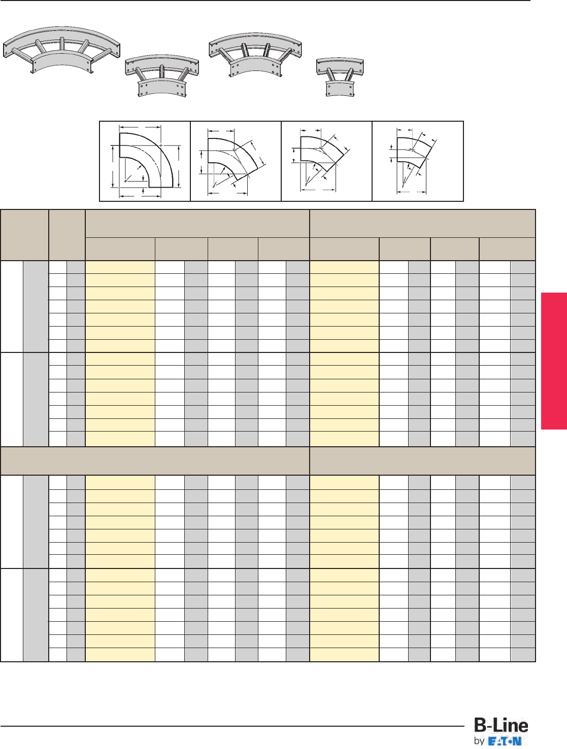
Series 1 Fittings
Bend Tray 90˚ Horizontal Bend 60˚ Horizontal Bend
Radius Width Dimensions Dimensions
R Catalog No. ABCCatalog No. ABC
in. (mm) in. (mm) in. (mm) in. (mm) in. (mm) in. (mm) in. (mm) in. (mm)
6 152
(Pre)-06-90HB12
18 450 18 450 18 450
(Pre)-06-60HB12
171
/2445 101
/8257 1111/16 297
9 228
(Pre)-09-90HB12
191
/2495 191
/2495 191
/2495
(Pre)-09-60HB12
1813/16 478 107
/8276 121
/2318
12 305
(Pre)-12-90HB12
21 533 21 533 21 533
(Pre)-12-60HB12
201
/16 510 115
/8295 133
/8340
12 305 18 457
(Pre)-18-90HB12
24 600 24 600 24 600
(Pre)-18-60HB12
2211/16 576 131
/8333 151
/8384
24 609
(Pre)-24-90HB12
27 686 27 686 27 686
(Pre)-24-60HB12
255
/16 643 145
/8372 167
/8429
30 762
(Pre)-30-90HB12
30 750 30 750 30 750
(Pre)-30-60HB12
277/8708 161/8410 189
/16 472
36 914
(Pre)-36-90HB12
33 838 33 838 33 838
(Pre)-36-60HB12
301
/2775 175
/8448 205
/16 516
6 152
(Pre)-06-90HB24
30 750 30 750 30 750
(Pre)-06-60HB24
277
/8708 161
/8410 189
/16 472
9 228
(Pre)-09-90HB24
311
/2800 311
/2800 311
/2800
(Pre)-09-60HB24
293
/16 741 167
/8429 197
/16 494
12 305
(Pre)-12-90HB24
33 838 33 838 33 838
(Pre)-12-60HB24
301
/2775 175
/8448 205
/16 516
24 609 18 457
(Pre)-18-90HB24
36 914 36 914 36 914
(Pre)-18-60HB24
331
/16 840 191
/8486 221
/16 560
24 609
(Pre)-24-90HB24
39 991 39 991 39 991
(Pre)-24-60HB24
3511/16 907 205
/8524 2313/16 605
30 762
(Pre)-30-90HB24
42 1067 42 1067 42 1067
(Pre)-30-60HB24
381/4972 221/8562 251/2648
36 914
(Pre)-36-90HB24
45 1143 45 1143 45 1143
(Pre)-36-60HB24
407/81038 235
/8600 271/4692
6 152
(Pre)-06-45HB12
153
/4400 61
/2165 93
/16 233
(Pre)-06-30HB12
131
/8333 31
/289 7 175
9 228
(Pre)-09-45HB12
1613
/16 427 615
/16 176 913/16 249
(Pre)-09-30HB12
137
/8352 311/16 94 77
/16 189
12 305
(Pre)-12-45HB12
177
/8454 73
/8187 107
/16 265
(Pre)-12-30HB12
145
/8372 315
/16 100 713/16 198
12 305 18 457
(Pre)-18-45HB12
20 500 81
/4210 1111/16 297
(Pre)-18-30HB12
161
/8410 45
/16 135 85
/8219
24 609
(Pre)-24-45HB12
221
/16 560 91
/8232 1215
/16 329
(Pre)-24-30HB12
175
/8448 411/16 119 97
/16 240
30 762
(Pre)-30-45HB12
243
/16 614 10 250 143
/16 360
(Pre)-30-30HB12
191
/8486 51
/8130 101
/4260
36 914
(Pre)-36-45HB12
265
/16 668 1015
/16 278 157
/16 392
(Pre)-36-30HB12
205
/8524 51
/2140 111
/16 281
6 152
(Pre)-06-45HB24
243
/16 614 10 250 143
/16 360
(Pre)-06-30HB24
191
/8486 51
/8130 101
/4260
9 228
(Pre)-09-45HB24
251
/4641 101
/2267 1413/16 376
(Pre)-09-30HB24
197
/8505 55
/16 135 105
/8270
12 305
(Pre)-12-45HB24
265
/16 668 1015
/16 278 157
/16 392
(Pre)-12-30HB24
205
/8524 51
/2140 111
/16 281
24 609 18 457
(Pre)-18-45HB24
287
/16 722 1113/16 300 1611/16 424
(Pre)-18-30HB24
221
/8562 515
/16 151 1113/16 300
24 609
(Pre)-24-45HB24
309
/16 776 1211/16 322 1715
/16 456
(Pre)-24-30HB24
235
/8600 65
/16 160 125
/8321
30 762
(Pre)-30-45HB24
3211/16 830 139/16 345 191/8486
(Pre)-30-30HB24
251/8638 63/4172 137/16 341
36 914
(Pre)-36-45HB24
3413/16 884 147/16 367 203/8518
(Pre)-36-30HB24
265
/8676 71/8181 141/4362
(Pre) See page LST-15 for catalog number prefix.
Width dimensions are to inside wall. Manufacturing tolerances apply to all dimensions.
All dimensions in parentheses are millimeters unless otherwise specified.
45˚ Horizontal Bend 30˚ Horizontal Bend
Horizontal Bends 90° 60° 45° 30° (HB)
90˚ Horizontal Bend
45˚ Horizontal Bend
AA
C
C
C
C
R
3" (76)
R
3" (76)
B
A
C
C
R
3" (76)
B
C
C
B
1 pair splice plates with hardware included.
60˚ Horizontal Bend
30˚ Horizontal Bend
90˚
HB
60˚
HB
45˚
HB
30˚
HB
Bottoms manufactured:
Ladder = 9" Rung Spacing
04 = 4" Rung Spacing
SB = Flat sheet over 12”
Rung Spacing
BR
A
3" (76)
LST-16
Series 1 Steel - Fittings
Cable Tray Systems
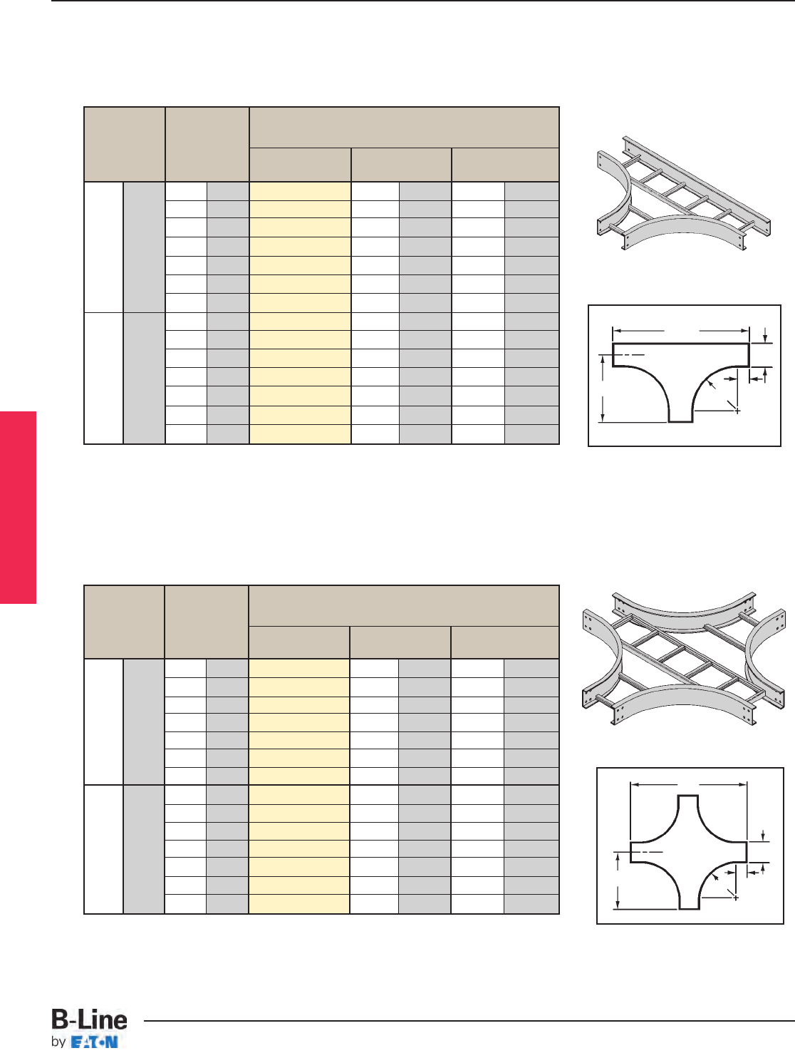
Bend Horizontal Cross
Radius Tray Dimensions
R Width Catalog No. AB
in. (mm) in. (mm) in. (mm) in. (mm)
6 152 (Prefix)-06-HX12 18 457 36 914
9 228 (Prefix)-09-HX12 191
/2495 39 991
12 305 (Prefix)-12-HX12 21 533 42 1067
12 305 18 457 (Prefix)-18-HX12 24 610 48 1219
24 609 (Prefix)-24-HX12 27 686 54 1372
30 762 (Prefix)-30-HX12 30 762 60 1524
36 914 (Prefix)-36-HX12 33 838 66 1676
6 152 (Prefix)-06-HX24 30 762 60 1524
9 228 (Prefix)-09-HX24 311
/2800 63 1600
12 305 (Prefix)-12-HX24 33 838 66 1676
24 609 18 457 (Prefix)-18-HX24 36 914 72 1829
24 609 (Prefix)-24-HX24 39 991 78 1981
30 762 (Prefix)-30-HX24 42 1067 84 2134
36 914 (Prefix)-36-HX24 45 1143 90 2286
Bend Tray Horizontal Tee
Radius Width Dimensions
RCatalog No. AB
in. (mm) in. (mm) in. (mm) in. (mm)
6 152 (Prefix)-06-HT12 18 457 36 914
9 228 (Prefix)-09-HT12 191
/2495 39 991
12 305 (Prefix)-12-HT12 21 533 42 1067
12 305 18 457 (Prefix)-18-HT12 24 610 48 1219
24 609 (Prefix)-24-HT12 27 686 54 1372
30 762 (Prefix)-30-HT12 30 762 60 1524
36 914 (Prefix)-36-HT12 33 838 66 1676
6 152 (Prefix)-06-HT24 30 762 60 1524
9 228 (Prefix)-09-HT24 311
/2800 63 1600
12 305 (Prefix)-12-HT24 33 838 66 1676
24 609 18 457 (Prefix)-18-HT24 36 914 72 1829
24 609 (Prefix)-24-HT24 39 991 78 1981
30 762 (Prefix)-30-HT24 42 1067 84 2134
36 914 (Prefix)-36-HT24 45 1143 90 2286
A
W
R
B
A
W
R
B
2 pair splice plates with hardware included.
3 pair splice plates with hardware included.
Width dimensions are to inside wall. Manufacturing tolerances apply to all dimensions.
Horizontal Tee (HT)
Horizontal Cross (HX)
3" (76)
3" (76)
(Prefix) See page LST-15 for catalog number prefix.
(Prefix) See page LST-15 for catalog number prefix.
HX
HT
Series 1 Fittings
LST-17
Series 1 Steel - Fittings
Cable Tray Systems
All dimensions in parentheses are millimeters unless otherwise specified.
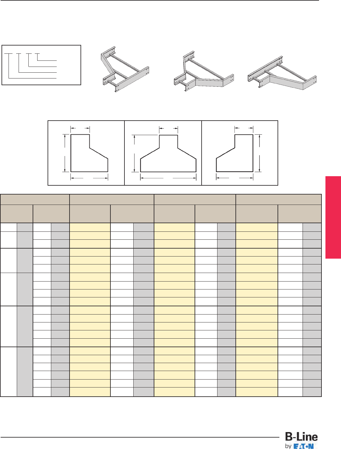
Tray Width Left Hand Reducer Straight Reducer Right Hand Reducer
W1W2Catalog No. A Catalog No. A Catalog No. A
in. (mm) in. (mm) in. (mm) in. (mm) in. (mm)
9 228 6 152 (Prefix)-09-LR06 93/4248 (Prefix)-09-SR06 87/8225 (Prefix)-09-RR06 93/4248
12 305 6 152 (Prefix)-12-LR06 111/2292 (Prefix)-12-SR06 93/4248 (Prefix)-12-RR06 111/2292
9 228 (Prefix)-12-LR09 93/4248 (Prefix)-12-SR09 87/8225 (Prefix)-12-RR09 93/4248
6 152 (Prefix)-18-LR06 1415/16 379 (Prefix)-18-SR06 111/2292 (Prefix)-18-RR06 1415/16 379
18 457 9 228 (Prefix)-18-LR09 133/16 340 (Prefix)-18-SR09 105/8270 (Prefix)-18-RR09 133/16 340
12 305 (Prefix)-18-LR12 111/2292 (Prefix)-18-SR12 93/4248 (Prefix)-18-RR12 111/2292
6 152 (Prefix)-24-LR06 183/8467 (Prefix)-24-SR06 133/16 340 (Prefix)-24-RR06 183/8467
24 609 9 228 (Prefix)-24-LR09 1611/16 424 (Prefix)-24-SR09 123/8314 (Prefix)-24-RR09 1611/16 424
12 305 (Prefix)-24-LR12 1415/16 379 (Prefix)-24-SR12 111/2292 (Prefix)-24-RR12 1415/16 379
18 457 (Prefix)-24-LR18 111/2292 (Prefix)-24-SR18 93/4248 (Prefix)-24-RR18 111/2292
6 152 (Prefix)-30-LR06 217/8555 (Prefix)-30-SR06 1415/16 380 (Prefix)-30-RR06 217/8555
9 228 (Prefix)-30-LR09 201/8511 (Prefix)-30-SR09 141/16 358 (Prefix)-30-RR09 201/8511
30 762 12 305 (Prefix)-30-LR12 183/8462 (Prefix)-30-SR12 133/16 335 (Prefix)-30-RR12 183/8462
18 459 (Prefix)-30-LR18 1415/16 380 (Prefix)-30-SR18 111/2292 (Prefix)-30-RR18 1415/16 380
24 609 (Prefix)-30-LR24 111/2292 (Prefix)-30-SR24 93/4248 (Prefix)-30-RR24 111/2292
6 152 (Prefix)-36-LR06 255/16 643 (Prefix)-36-SR06 1611/16 424 (Prefix)-36-RR06 255/16 643
9 228 (Prefix)-36-LR09 239/16 598 (Prefix)-36-SR09 1513/16 402 (Prefix)-36-RR09 239/16 598
36 914 12 305 (Prefix)-36-LR12 217/8555 (Prefix)-36-SR12 1415/16 380 (Prefix)-36-RR12 217/8555
18 457 (Prefix)-36-LR18 183/8462 (Prefix)-36-SR18 133/16 335 (Prefix)-36-RR18 183/8462
24 609 (Prefix)-36-LR24 1415/16 380 (Prefix)-36-SR24 111/2292 (Prefix)-36-RR24 1415/16 380
30 762 (Prefix)-36-LR30 111/2292 (Prefix)-36-SR30 93/4248 (Prefix)-36-RR30 111/2292
14P - 24 - RR 18
Width2
Fitting
Width1
Prefix
Right ReducerStraight Reducer
Left Reducer
Reducers (LR, SR, RR)
1 pair splice plates with hardware included.
Width dimensions are to inside wall. Manufacturing tolerances apply to all dimensions.
A
W2
W1
LR
A
W2
W1
SR
A
W2
W1
RR
(Prefix) See page LST-15 for catalog number prefix.
Reducer Part Numbering
Series 1 Fittings
LST-18
Series 1 Steel - Fittings
Cable Tray Systems
All dimensions in parentheses are millimeters unless otherwise specified.
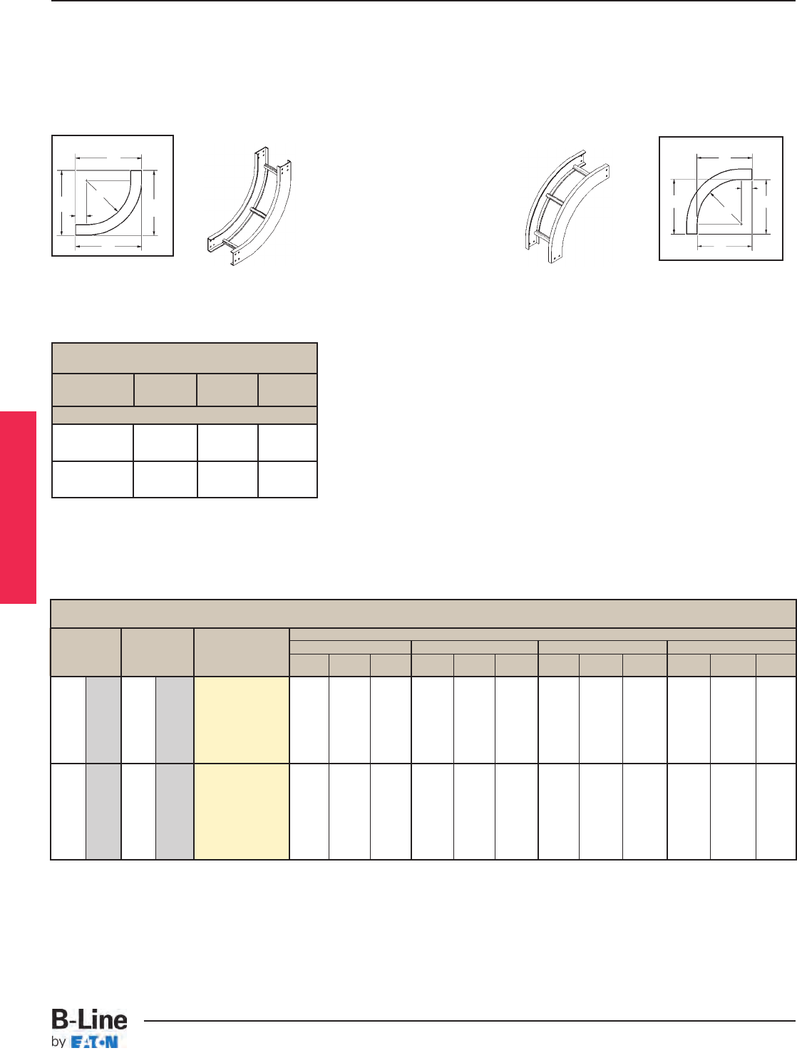
90° Vertical Inside Bend
Bend VI Dimensions
Radius Width Series 14 Steel Series 15 Steel Series 16 Steel Series 17 Steel
R
in. (mm) in. (mm)
Catalog No. ABC AB C A B C A B C
6 152 (Pre)-06-90(*)12
9 228 (Pre)-09-90(*)12
12 305 (Pre)-12-90(*)12 187/16"18
7/16"18
7/16"19
3/16"19
3/16"19
3/16"20
3/16"20
3/16"20
3/16"21
3/16"21
3/16"21
3/16"
12 305 18 457 (Pre)-18-90(*)12
24 609 (Pre)-24-90(*)12 (468) (468) (468) (487) (487) (487) (513) (513) (513) (538) (538) (538)
30 762 (Pre)-30-90(*)12
36 914 (Pre)-36-90(*)12
6 152 (Pre)-06-90(*)24
9 228 (Pre)-09-90(*)24
12 305 (Pre)-12-90(*)24 307/16"30
7/16"30
7/16"31
3/16"31
3/16"31
3/16"32
3/16"32
3/16"32
3/16"33
3/16"33
3/16"33
3/16"
24 609 18 457 (Pre)-18-90(*)24
24 609 (Pre)-24-90(*)24 (773) (773) (773) (792) (792) (792) (817) (817) (817) (843) (843) (843)
30 762 (Pre)-30-90(*)24
36 914 (Pre)-36-90(*)24
A
C
C
B
R
3" (76)
C
C
B
R
3" (76)
A
90°
VI
90° Vertical Outside
Vertical Bend 90° (VO, VI)
1 pair splice plates with hardware included.
(Pre) See page LST-15 for catalog number prefix.
(*) = Insert VI for Vertical Inside Bend. Insert VO for Vertical Outside Bend.
Manufacturing tolerances apply to all dimensions.
90° Vertical Inside
90˚
VO
Series 1 Fittings
12" 15" 15" 15"
(305) (381) (381) (381)
24" 27" 27" 27"
(609) (686) (686) (686)
VO Dimensions
All Series 1
Bend
Radius R ABC
90° Vertical Bend
LST-19
Series 1 Steel - Fittings
Cable Tray Systems
All dimensions in parentheses are millimeters unless otherwise specified.
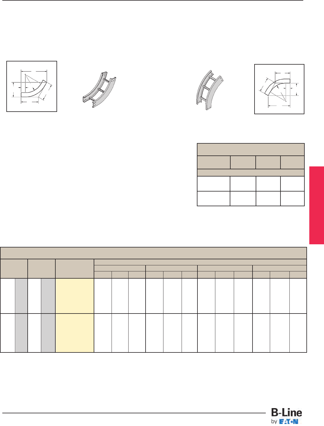
Bend Tray VI Dimensions
Radius Width Catalog Series 14 Steel Series 15 Steel Series 16 Steel Series 17 Steel
R No.
in. (mm) in. (mm)
ABC A BCA B CA B C
6 152 (Pre)-06-60(*)12
9 228 (Pre)-09-60(*)12
12 305 (Pre)-12-60(*)12 181/16"10
7/16" 12" 181/2"10
11/16"12
3/8"19
3/8"11
3/16"12
15/16"20
1/4"11
11/16"13
1/2"
12 305 18 457 (Pre)-18-60(*)12
24 609 (Pre)-24-60(*)12 (459) (265) (305) (470) (271) (314) (492) (284) (328) (514) (297) (343)
30 762 (Pre)-30-60(*)12
36 914 (Pre)-36-60(*)12
6 152 (Pre)-06-60(*)24
9 228 (Pre)-09-60(*)24
12 305 (Pre)-12-60(*)24 287/16"16
7/16"18
15/16"28
15/16"16
11/16"19
1/4"29
3/4"17
3/16"19
7/8"30
5/8"17
11/16"20
7/16"
24 609 18 457 (Pre)-18-60(*)24
24 609 (Pre)-24-60(*)24 (722) (417) (481) (735) (424) (489) (755) (436) (505) (778) (449) (519)
30 762 (Pre)-30-60(*)24
36 914 (Pre)-36-60(*)24
60° Vertical Inside Bend
60˚
VO
60˚
VI
A
C
C
R
C
C
B
R
3" (76)
A
(Pre) See page LST-15 for catalog number prefix.
(*) = Insert VI for Vertical Inside Bend. Insert VO for Vertical Outside Bend.
Manufacturing tolerances apply to all dimensions.
60° Vertical Inside 60° Vertical Outside
Vertical Bend 60° (VO, VI)
1 pair splice plates with hardware included.
3" (76)
B
Series 1 Fittings
12" 147/8"8
5/8"9
15/16"
(305) (378) (219) (252)
24" 255/16" 145/8" 167/8"
(609) (643) (371) (428)
VO Dimensions
All Series 1
Bend
Radius R ABC
60° Vertical Bend
LST-20
Series 1 Steel - Fittings
Cable Tray Systems
All dimensions in parentheses are millimeters unless otherwise specified.
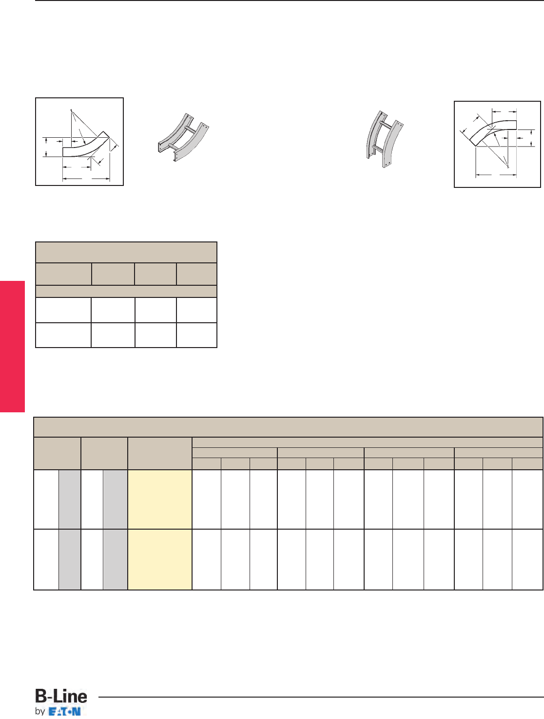
Bend Tray Catalog VI Dimensions
Radius Width No. Series 14 Steel Series 15 Steel Series 16 Steel Series 17 Steel
R
in. (mm) in. (mm)
ABCA BCA B C ABC
6 152 (Pre)-06-45(*)12
9 228 (Pre)-09-45(*)12
12 305 (Pre)-12-45(*)12 163/16"6
11/16"9
1/2"16
9/16"6
7/8"9
11/16"17
1/4"7
3/16"10
1/8" 18" 77/16"10
9/16"
12 305 18 457 (Pre)-18-45(*)12
24 609 (Pre)-24-45(*)12 (411) (170) (241) (420) (174) (246 (438) (182) (257 (457) (189) (268)
30 762 (Pre)-30-45(*)12
36 914 (Pre)-36-45(*)12
6 152 (Pre)-06-45(*)24
9 228 (Pre)-09-45(*)24
12 305 (Pre)-12-45(*)24 2411/16"10
3/16"14
7/16"25
1/16"10
3/8"11
14/16"25
3/4"10
11/16"15
1/16"26
1/2" 11" 151/2"
24 609 18 457 (Pre)-18-45(*)24
24 609 (Pre)-24-45(*)24 (627) (259) (367) (662) (263) (373) (654) (271) (382 (673) (279) (394)
30 762 (Pre)-30-45(*)24
36 914 (Pre)-36-45(*)24
45° Vertical Inside Bend
45° Vertical Outside
Vertical Bend 45° (VO, VI)
1 pair splice plates with hardware included.
(Pre) See page LST-15 for catalog number prefix.
(*) = Insert VI for Vertical Inside Bend. Insert VO for Vertical Outside Bend.
Manufacturing tolerances apply to all dimensions.
45° Vertical Inside
A
C
C
B
R
3" (76)
C
C
B
R
3" (76)
A
45˚
VO
45°
VI
Series 1 Fittings
12" 135/8"5
5/8" 8"
(305) (346) (143) (203)
24" 221/16"9
1/8" 1215/16"
(609) (560) (232) (328)
VO Dimensions
All Series 1
Bend
Radius R ABC
45° Vertical Bend
LST-21
Series 1 Steel - Fittings
Cable Tray Systems
All dimensions in parentheses are millimeters unless otherwise specified.
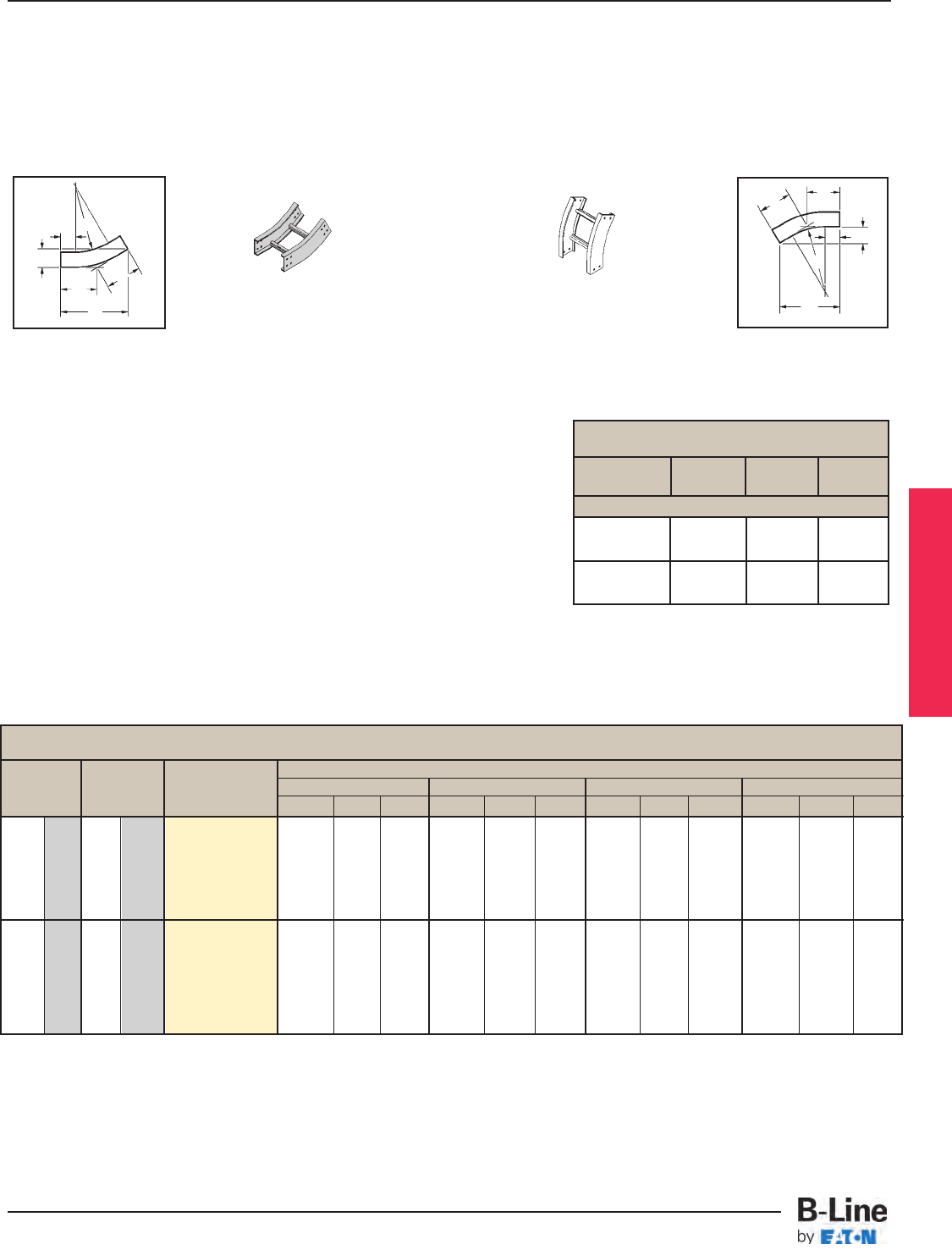
Bend Tray VI Dimensions
Radius Width Catalog Series 14 Steel Series 15 Steel Series 16 Steel Series 17 Steel
R No.
in. (mm) n. (mm) ABC ABCABC A BC
6 152 (Pre)-06-30(*)12
9 228 (Pre)-09-30(*)12
12 305 (Pre)-12-30(*)12 137/16"3
5/8"7
3/16"13
11/16"3
11/16"7
5/16"14
3/16"3
13/16"7
5/8"14
11/16"3
15/16"7
7/8"
12 305 18 457 (Pre)-18-30(*)12
24 609 (Pre)-24-30(*)12 (341) (92) (182) (347) (93) (186.2) (360) (97) (193) (373) (100) (200)
30 762 (Pre)-30-30(*)12
36 914 (Pre)-36-30(*)12
6 152 (Pre)-06-30(*)24
9 228 (Pre)-09-30(*)24
12 305 (Pre)-12-30(*)24 197/16"5
3/16"10
7/16"19
11/16"5
5/16"10
9/16"20
3/16"5
7/16"10
13/16"20
11/16"5
9/16"11
1/16"
24 609 18 457 (Pre)-18-30(*)24
24 609 (Pre)-24-30(*)24 (494) (132) (265) (500) (135) (268) (513) (138) (274) (525) (141) (281)
30 762 (Pre)-30-30(*)24
36 914 (Pre)-36-30(*)24
12" 115/8"3
1/8"6
3/16"
(305) (295) (79) (157)
24" 175/8"4
11/16"9
7/16"
(609) (448) (119) (240)
30° Vertical Inside Bend
VO Dimensions
All Series 1
Bend
Radius R ABC
30° Vertical Bend
(Pre) See page LST-15 for catalog number prefix.
(*) = Insert VI for Vertical Inside Bend. Insert VO for Vertical Outside Bend.
All dimensions in parentheses are millimeters unless otherwise specified.
Manufacturing tolerances apply to all dimensions.
30° Vertical Inside 30° Vertical Outside
Vertical Bend 30° (VO, VI)
1 pair splice plates with hardware included.
A
CC
B
R
3" (76)
C
C
B
R
3" (76)
A
30˚
VI
30˚
VO
Series 1 Fittings
LST-22
Series 1 Steel - Fittings
Cable Tray Systems
All dimensions in parentheses are millimeters unless otherwise specified.
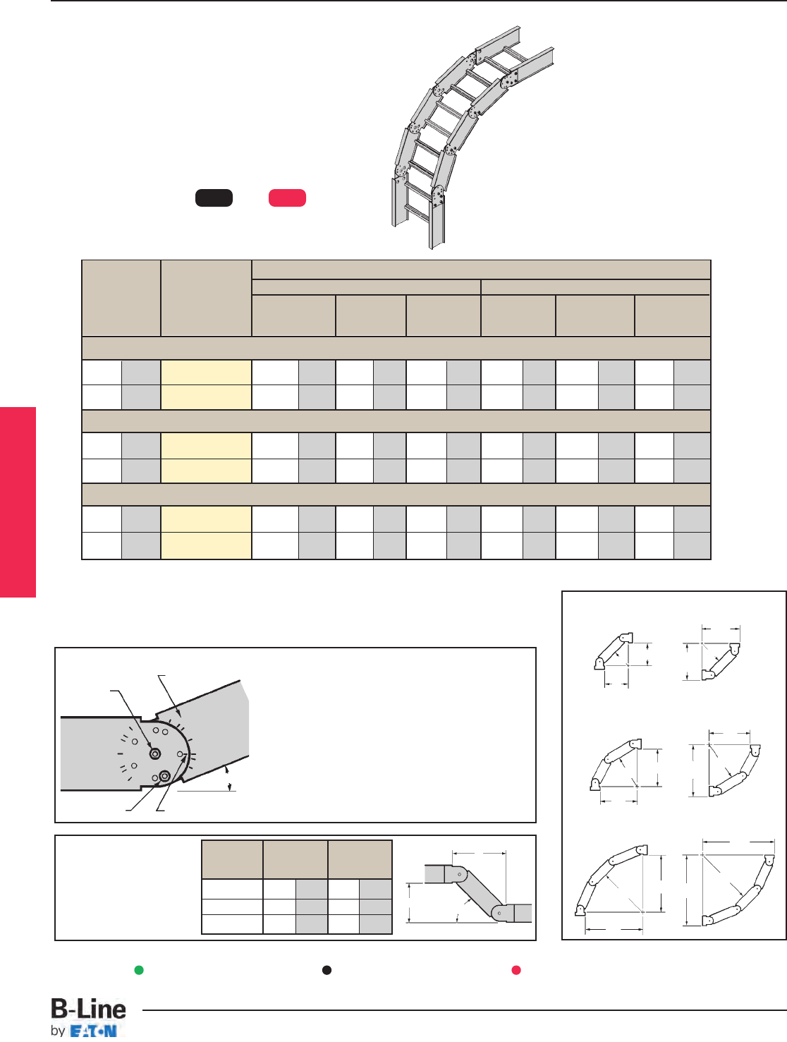
12 305 14(*)†-(‡)-VBS-1 81
/4210 81
/4210 61
/2165 121
/8303 121
/8303 101
/2267
24
609
14(*)†-(‡)-VBS-3 24 610 24 610 221
/4565 277
/8708 277
/8708 261
/4667
12 305 14(*)†-(‡)-VBS-1 113
/4298 61
/2165 12 305 143
/4375 81
/2216 16 406
24 609 14(*)†-(‡)-VBS-2 113
/4298 61
/2165 12 305 143
/4375 81
/2216 16 406
12 305 14(*)†-(‡)-VBS-1 123
/4324 51
/4133 171
/8435 151
/2394 67
/8175 21 540
24 609 14(*)†-(‡)-VBS-1 123
/4324 51
/4133 171
/8435 151
/2394 67
/8175 21 540
Nominal Dimensions
Bend
Catalog
VO VI
Radius
No.
ABR A B R
in. (mm) in. (mm) in. (mm) in. (mm) in. (mm) in. (mm) in. (mm)
90˚ Vertical Inside or Outside
Angle ø AB
in. (mm) in. (mm)
45˚ 12 305 81
/2216
30˚ 14 355 53
/4146
221
/2˚ 141
/4362 5 127
Adjustable Vertical Bends are made up of one or
more vertical bend segments and can be used as a
vertical inside (VI) or vertical outside (VO) bend. This
design provides for vertical changes in direction with angles
of 45˚, 60˚ and 90˚ for 12" (305 mm) or 24" (609 mm) radius.
The chart below shows the number of segments required for
the various combinations of angles and radii. The VBS-1, VBS-2
and VBS-3 include one, two or three segments respectively with
splice plates and hardware. Holes for setting standard angles
are pre-punched in each segment. Other angles can be set by
field drilling another hole for the locking bolt.
Vertical Bend Segments (VBS)
Notes:
1. (*) Insert material type: P=Pre Galvanized, G=HDGAF
2. (†) Contact home office for information on
Ventilated Trough and Solid Trough availability
3. (‡) Insert width 6, 9, 12, 18, 24, 30, 36
Setting the Angle
To find correct angle setting, divide angle of offset
by the number of segments plus one. The result is
equal to the angle setting stamped on the vertical
bend segment and the splice plate. After inserting
center pivot bolt, align the mark at the end of the
segment or splice plate with the angle and insert
locking bolt in the pre-punched hole.
Example: 90˚ bend, 24" radius requires 3 segments
3 segments + 1 = 4
90˚ divided by 4 = 221
/2˚
Set all vertical segments at 221
/2˚
45
45
22
1
/
2
0
Locking Bolt
Pivot Bolt
Center Mark
Angle Settings
30
45
45
22
1
/
2
22
1
/
2
221/2
0
30
30
30
22
1
/
2
Fitting Hole Pattern
Offset Dimensions
One vertical bend segment
can be used to complete a
vertical offset. Offset
dimensions are shown.
VO
R
A
R
A
B
R
A
BR
A
B
R
A
B
R
B
VO
VO
VI
VI
VI
VBS-1 (1 Segment)
VBS-2 (2 Segments)
A
ø
B
All dimensions in parentheses are millimeters unless otherwise specified.
Available for 148P and 148G only.
A
60˚ Vertical Inside or Outside
45˚ Vertical Inside or Outside
B
VBS-3 (3 Segments)
Series 1 Fittings
Green = Fastest shipped items Black = Normal lead-time items Red = Normally long lead-time items
LST-23
Series 1 Steel - Fittings
Cable Tray Systems
Series 1 Fittings
LST-24
Notes
Cable Tray Systems
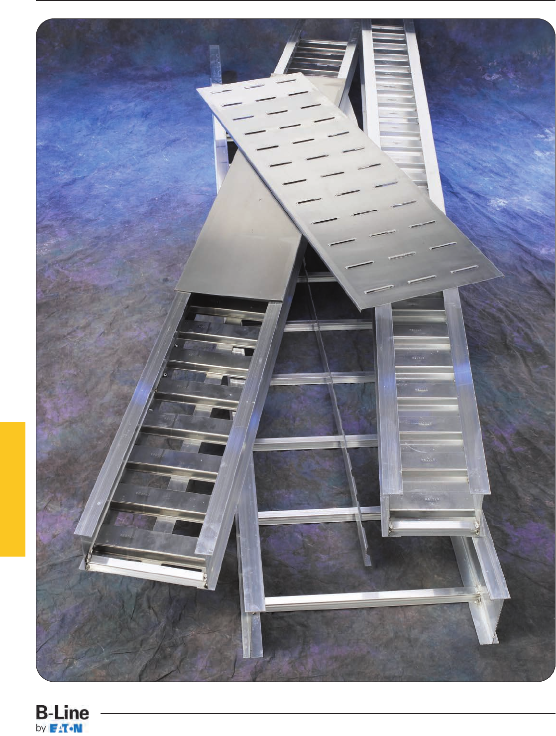
Series 2, 3, 4, & 5 Aluminum
HAT-1
Series 2, 3, 4, & 5 Aluminum
Cable Tray Systems
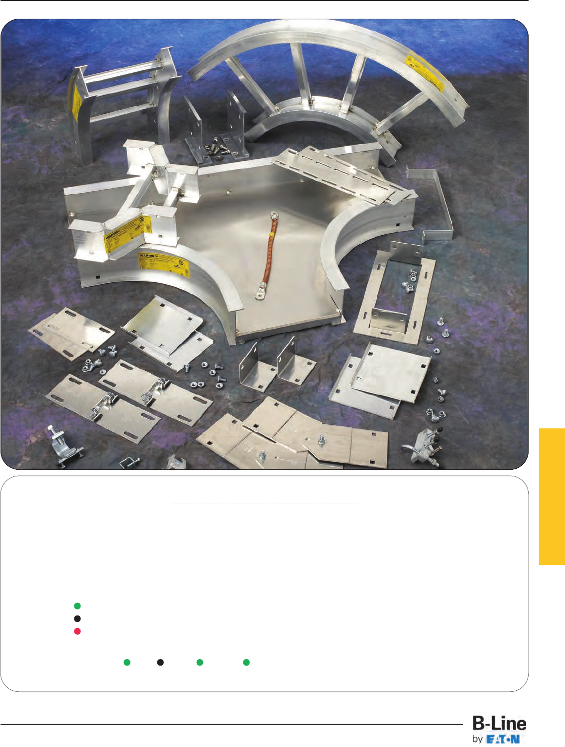
Series 2, 3, 4, & 5 Aluminum
How The Service Advisor Works
B-Line knows that your time is important! That’s why the color-coding system in this catalog is designed to help you select
products that fit your service needs. Products are marked to indicate the typical lead time for orders of 50 pieces or less.
Customer: How do I select my straight sections. covers, or fittings so that I get the quickest turnaround?
Customer: How do I select my straight sections. covers, or fittings so that I get the quickest turnaround?
Service Advisor: Each part of our selection chart is shown in colors. If any section of a part number is a different
color, the part will typically ship with the longer lead time represented by the colors.
Green = Fastest shipped items
Black = Normal lead-time items
Red = Normally long lead-time items
Example: 34A VT - 24 - 144 Part will have a normal
lead time because of the
VT bottom type.
For Aluminum Fittings
see fittings section pages
FTS-1 thru FTS-17
All dimensions in parentheses are millimeters unless otherwise specified.
HAT-2
Series 2, 3, 4, & 5 Aluminum
Cable Tray Systems
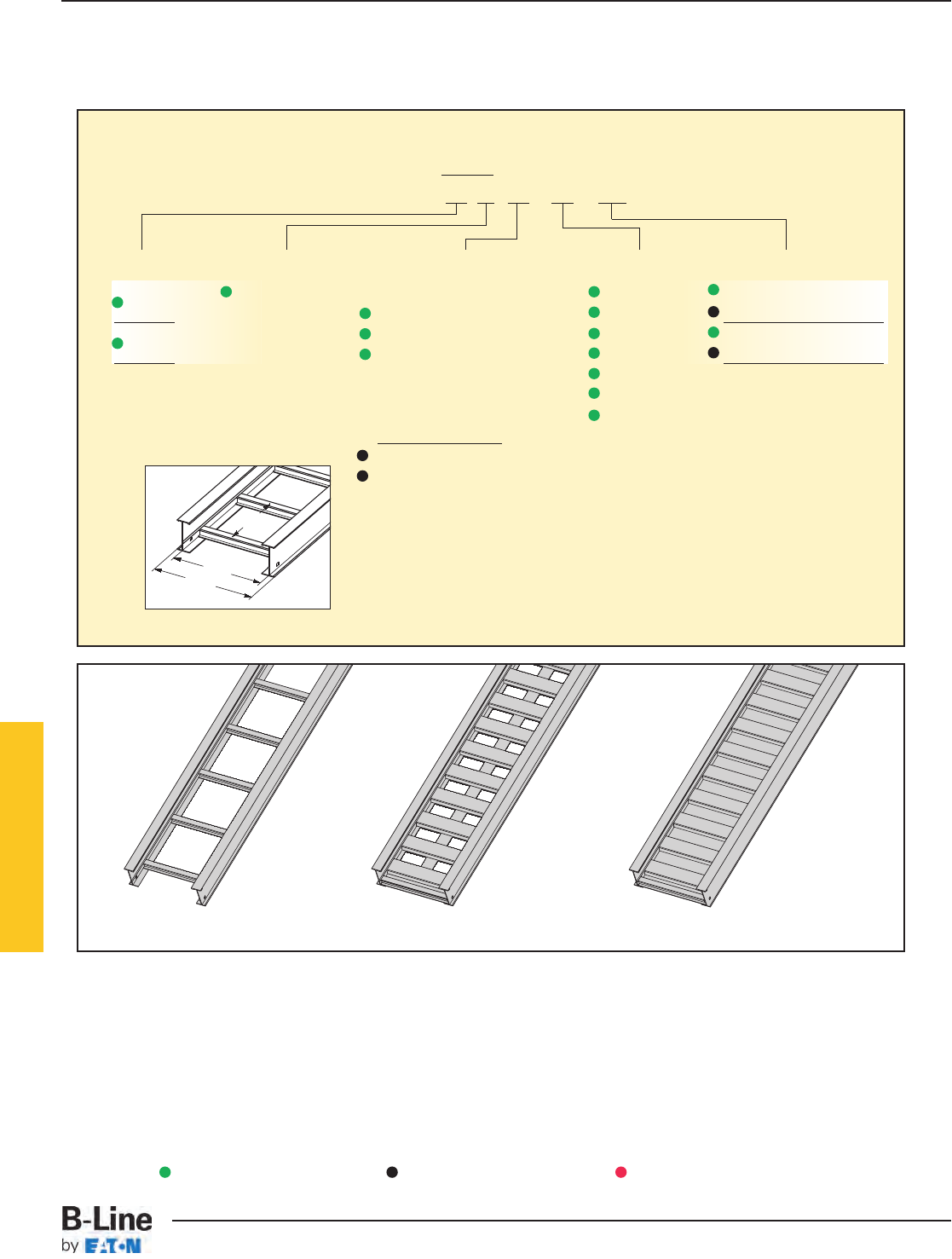
3" NEMA VE 1 Loading Depth
4" Side Rail Height
Ladder Type
(Specify Rung Spacing)
Ventilated Trough Non-Ventilated Trough
Overall Width
(Width + 11/2")
For
side rail
& rung data,
see chart on
pages AP-5 & AP-6
Rung
Spacing
Width
(Inside)
Straight Section Part Numbering
Prefix
Example: 24 A 09 - 24 - 144
Series Material *Type *Width Length
24 A= Aluminum Ladder- 06 = 6" ¨144 = 12 ft. 24
06 = 6" rung spacing 09 = 9" ¡120 = 10 ft.
34 09 = 9" rung spacing 12 = 12" ¨240 = 20 ft. 34
12 = 12" rung spacing 18 = 18" ¡144 = 12 ft.
24 = 24"
30 = 30"
Trough- 36 = 36"
6" thru 36" wide
VT = Vented Trough
ST = Non-Ventilated Trough
See page APP-1 for additional rung options. *Special sizes available.
Series 2, 3, 4, & 5 Aluminum
¨Primary Length.
¡Secondary Length.
See page CTS-23 for
explanation of lengths.
Green = Fastest shipped items Black = Normal lead-time items Red = Normally long lead-time items
HAT-3
Series 2, 3, 4, & 5 Aluminum - Straight Sections
Cable Tray Systems
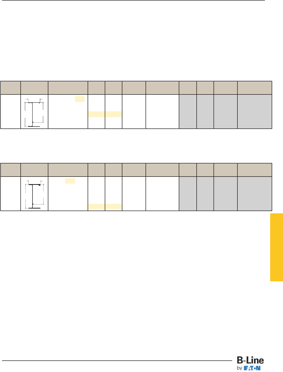
B-Line Side Rail NEMA, CSA & UL Span Load Deflection Design Factors Span Load Deflection Design Factors
Series Dimensions Classifications ft lbs/ft Multiplier for Two Rails meters kg/m Multiplier for Two Rails
NEMA: 16A, 12C 6 487* 0.001 1.8 725* 0.017
CSA: D1-3m 8 284 0.003 Area=1.05 in22.4 422 0.055 Area=6.77 cm2
10 181 0.008 Sx=1.34 in33.0 270 0.135 Sx=21.96 cm3
UL Cross-Sectional 12 126 0.016 Ix=2.85 in43.7 187 0.279 Ix=118.63 cm4
Area:1.00 in214 93 0.030 4.3 138 0.518
16 71 0.052 4.9 105 0.883
B-Line Side Rail NEMA, CSA & UL Span Load Deflection Design Factors Span Load Deflection Design Factors
Series Dimensions Classifications ft lbs/ft Multiplier for Two Rails meters kg/m Multiplier for Two Rails
NEMA: 20B, 16C 10 320 0.005 3.0 476 0.077
CSA: E-6m 12 222 0.009 Area=1.82 in23.7 331 0.160 Area=11.74 cm2
14 163 0.017 Sx=2.10 in34.3 243 0.296 Sx=34.41 cm3
UL Cross-Sectional 16 125 0.030 Ix=4.98 in44.9 186 0.505 Ix=207.28 cm4
Area: 1.50 in218 99 0.047 5.5 147 0.810
20 80 0.072 6.1 119 1.234
1.75
4.20 3.08
Values are based on simple beam tests per NEMA VE 1 on 36" wide cable tray with rungs spaced on 12" centers. Cable trays will
support without collapse a 200 lb. (90.7 kg) concentrated load over and above published loads. Published load safety factor is 1.5.
To convert 1.5 safety factor to 2.0, multiply the published load by 0.75. To obtain mid-span deflection, multiply a load by the deflection
multiplier. Cable tray must be supported on spans shorter than or equal to the length of the cable tray being installed.
Individual rungs will support without collapse a 200 lb. (90.7 kg) concentrated load applied at the mid-span of the rung, over and
above the NEMA rated cable load with a 1.5 safety factor for highlighted NEMA spans and loads.
When trays are used in continuous spans, the deflection of the tray is reduced by as much as 50%. Design factors: Ix = Moment
of Inertia, Sx = Section Modulus.
1.75
4.12 3.05
3" NEMA VE 1 Loading Depth
4" Side Rail Height
When trays are used in continuous spans, the deflection of the tray is reduced by as much as 50%. Design factors: Ix = Moment
of Inertia, Sx = Section Modulus.
* When using 18" rung spacing, load capacity is limited to 394 lbs/ft (586.27 kg/m) for 30" tray width and 325 lbs/ft (483.6 kg/m)
for 36" tray width.
34
24
Series 2, 3, 4, & 5 Aluminum
HAT-4
Series 2, 3, 4, & 5 Aluminum - Straight Sections
Cable Tray Systems
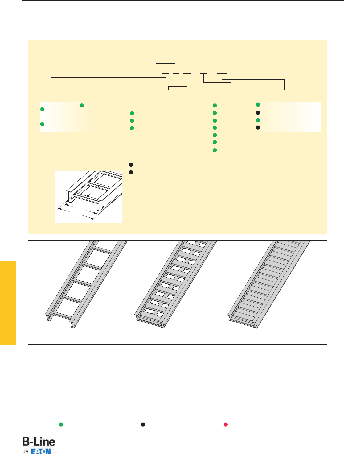
4" NEMA VE 1 Loading Depth
5" Side Rail Height
Overall Width
(Width + 11/2")
For
side rail
& rung data,
see chart on
pages AP-5 & AP-6
Rung
Spacing
Width
(Inside)
Straight Section Part Numbering
Prefix
Example: 25 A 09 - 24 - 144
Series Material *Type *Width Length
25 A= Aluminum Ladder- 06 = 6" ¨144 = 12 ft. 25
06 = 6" rung spacing 09 = 9" ¡240 = 20 ft.
35 09 = 9" rung spacing 12 = 12" ¨240 = 20 ft. 35
12 = 12" rung spacing 18 = 18" ¡144 = 12 ft.
24 = 24"
30 = 30"
Trough- 36 = 36"
6" thru 36" wide
VT = Vented Trough
ST = Non-Ventilated Trough
See page APP-1 for additional rung options. *Special sizes available.
Ladder Type
(Specify Rung Spacing)
Ventilated Trough Non-Ventilated Trough
Series 2, 3, 4, & 5 Aluminum
¨Primary Length.
¡Secondary Length.
See page CTS-23 for
explanation of lengths.
Green = Fastest shipped items Black = Normal lead-time items Red = Normally long lead-time items
HAT-5
Series 2, 3, 4, & 5 Aluminum - Straight Sections
Cable Tray Systems
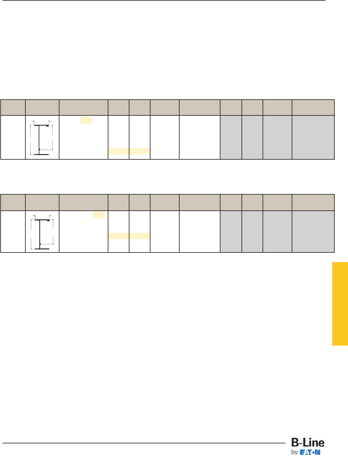
B-Line Side Rail NEMA, CSA & UL Span Load Deflection Design Factors Span Load Deflection Design Factors
Series Dimensions Classifications ft lbs/ft Multiplier for Two Rails meters kg/m Multiplier for Two Rails
NEMA: 20B, 16C 10 310 0.0035 3.0 461 0.060
CSA: E-3m 12 215 0.0073 Area=1.67 in23.7 320 0.125 Area=10.77 cm2
14 158 0.014 Sx=2.35 in34.3 235 0.232 Sx=38.51 cm3
UL Cross-Sectional 16 121 0.023 Ix=6.37 in44.9 180 0.395 Ix=265.14 cm4
Area: 1.50 in218 96 0.037 5.5 142 0.633
20 77 0.057 6.1 115 0.965
B-Line Side Rail NEMA, CSA & UL Span Load Deflection Design Factors Span Load Deflection Design Factors
Series Dimensions Classifications ft lbs/ft Multiplier for Two Rails meters kg/m Multiplier for Two Rails
NEMA: 20A, 12C 10 200 0.0049 3.0 298 0.083
CSA: D1-6m 12 139 0.010 Area=1.24 in23.7 207 0.172 Area=8.00 cm2
14 102 0.019 Sx=1.80 in34.3 152 0.319 Sx=29.50 cm3
UL Cross-Sectional 16 78 0.032 Ix=4.62 in44.9 116 0.545 Ix=192.30 cm4
Area: 1.00 in218 62 0.051 5.5 92 0.873
20 50 0.078 6.1 74 1.330
Values are based on simple beam tests per NEMA VE 1 on 36" wide cable tray with rungs spaced on 12" centers. Cable trays will
support without collapse a 200 lb. (90.7 kg) concentrated load over and above published loads. Published load safety factor is 1.5.
To convert 1.5 safety factor to 2.0, multiply published load by 0.75. To obtain mid-span deflection, multiply a load by the deflection
multiplier. Cable tray must be supported on spans shorter than or equal to the length of the cable tray being installed.
Individual rungs will support without collapse a 200 lb. (90.7 kg) concentrated load applied at the mid-span of the rung, over and
above the NEMA rated cable load with a 1.5 safety factor for highlighted NEMA spans and loads.
1.75
5.00 3.93
1.75
5.06 3.96
When trays are used in continuous spans, the deflection of the tray is reduced by as much as 50%. Design factors: Ix = Moment
of Inertia, Sx = Section Modulus.
When trays are used in continuous spans, the deflection of the tray is reduced by as much as 50%. Design factors: Ix = Moment
of Inertia, Sx = Section Modulus.
4" NEMA VE 1 Loading Depth
5" Side Rail Height
25
35
Series 2, 3, 4, & 5 Aluminum
HAT-6
Series 2, 3, 4, & 5 Aluminum - Straight Sections
Cable Tray Systems
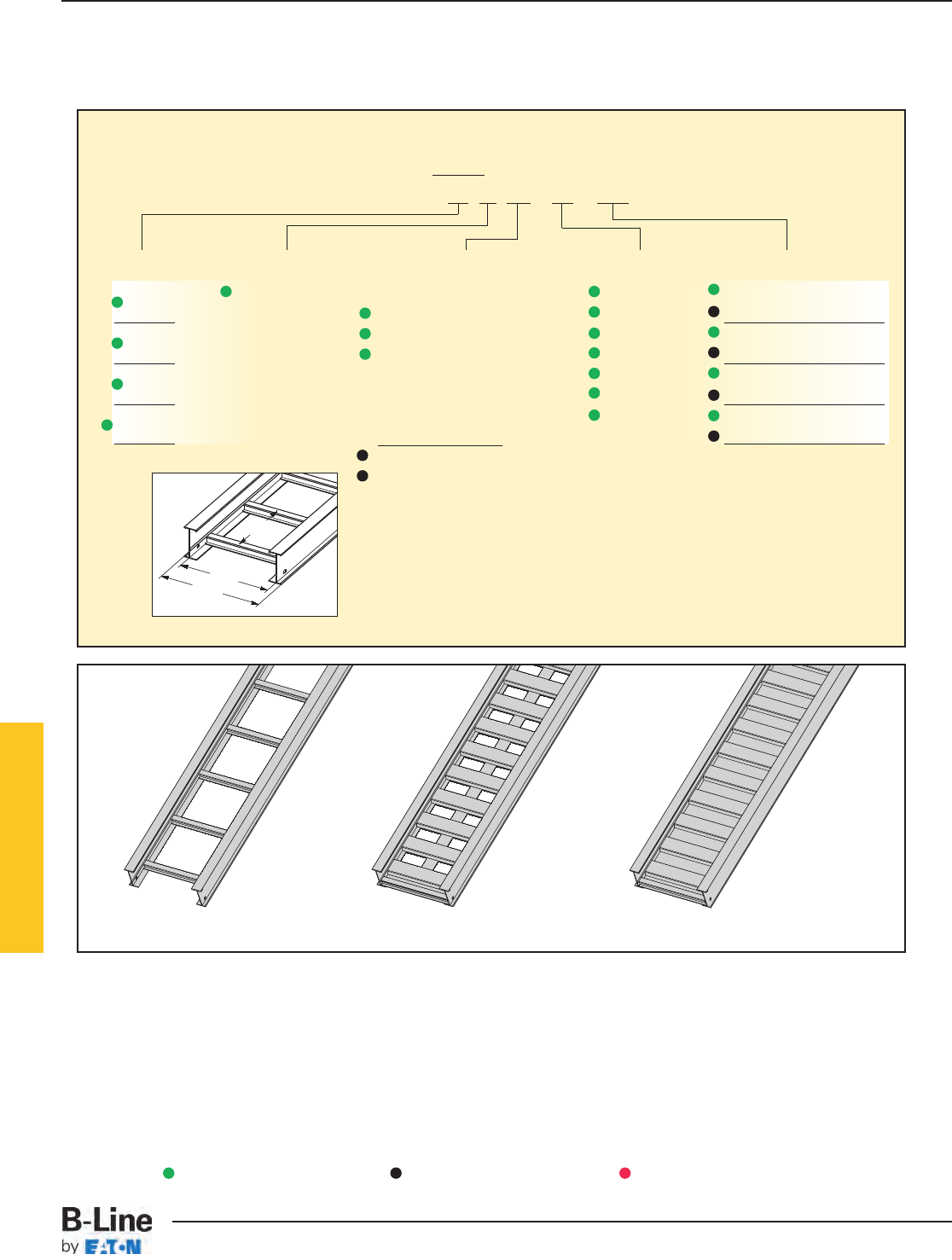
5" NEMA VE 1 Loading Depth
6" Side Rail Height
Overall Width
(Width + 11/2")
For
side rail
& rung data,
see chart on
pages AP-5 & AP-6
Rung
Spacing
Width
(Inside)
Straight Section Part Numbering
Prefix
Example: 26 A 09 - 24 - 144
Series Material *Type *Width Length
26 A= Aluminum Ladder- 06 = 6" ¨144 = 12 ft. 26
06 = 6" rung spacing 09 = 9" ¡240 = 20 ft.
36 09 = 9" rung spacing 12 = 12" ¨240 = 20 ft. 36
12 = 12" rung spacing 18 = 18" ¡144 = 12 ft.
46 24 = 24" ¨240 = 20 ft. 46
30 = 30" ¡288 = 24 ft.
H46† Trough- 36 = 36" ¨240 = 20 ft. H46
6" thru 36" wide ¡300 = 25 ft.
VT = Vented Trough
ST = Non-Ventilated Trough
† H46A only available in ladder
type 9” and 12” rung spacing
See page APP-2.
See page APP-1 for additional rung options. *Special sizes available.
Ladder Type
(Specify Rung Spacing)
Ventilated Trough Non-Ventilated Trough
Series 2, 3, 4, & 5 Aluminum
¨Primary Length.
¡Secondary Length.
See page CTS-23 for
explanation of lengths.
Green = Fastest shipped items Black = Normal lead-time items Red = Normally long lead-time items
HAT-7
Series 2, 3, 4, & 5 Aluminum - Straight Sections
Cable Tray Systems
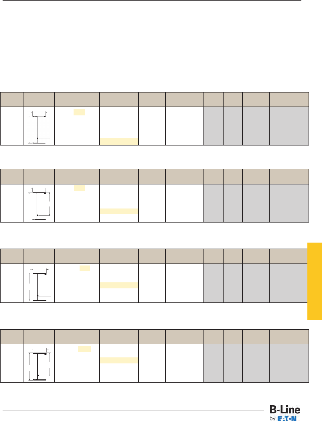
B-Line Side Rail NEMA, CSA & UL Span Load Deflection Design Factors Span Load Deflection Design Factors
Series Dimensions Classifications ft lbs/ft Multiplier for Two Rails meters kg/m Multiplier for Two Rails
NEMA: 20C+ 16 261 0.0085 4.9 388 0.145
CSA: 131 kg/m7.6m 18 206 0.014 Area=2.95 in25.5 307 0.233 Area=19.03 cm2
20 167 0.021 Sx=5.33 in36.1 248 0.355 Sx=87.34 cm3
UL Cross-Sectional 22 138 0.030 Ix=17.30 in46.7 205 0.520 Ix=720.08 cm4
Area: 2.00 in224 116 0.043 7.3 173 0.737
25 88 0.051 7.6 131 0.867
B-Line Side Rail NEMA, CSA & UL Span Load Deflection Design Factors Span Load Deflection Design Factors
Series Dimensions Classifications ft lbs/ft Multiplier for Two Rails meters kg/m Multiplier for Two Rails
NEMA: 20C 14 210 0.0071 4.3 313 0.121
CSA: E-6m 16 161 0.012 Area=2.06 in24.9 239 0.207 Area=13.29 cm2
18 127 0.019 Sx=3.59 in35.5 189 0.331 Sx=58.83 cm3
UL Cross-Sectional 20 103 0.030 Ix=12.18 in46.1 153 0.505 Ix=506.97 cm4
Area: 1.50 in222 85 0.043 6.7 127 0.739
24 72 0.061 7.3 106 1.046
B-Line Side Rail NEMA, CSA & UL Span Load Deflection Design Factors Span Load Deflection Design Factors
Series Dimensions Classifications ft lbs/ft Multiplier for Two Rails meters kg/m Multiplier for Two Rails
NEMA: 20B, 16C 12 233 0.0043 3.7 347 0.073
CSA: E-6m 14 171 0.008 Area=1.81 in24.3 255 0.136 Area=11.68 cm2
16 131 0.014 Sx=3.36 in34.9 195 0.232 Sx=55.06 cm3
UL Cross-Sectional 18 104 0.022 Ix=10.85 in45.5 154 0.372 Ix=451.61 cm4
Area: 1.50 in220 84 0.033 6.1 125 0.566
22 69 0.049 6.7 103 0.829
B-Line Side Rail NEMA, CSA & UL Span Load Deflection Design Factors Span Load Deflection Design Factors
Series Dimensions Classifications ft lbs/ft Multiplier for Two Rails meters kg/m Multiplier for Two Rails
NEMA: 20A, 16B 10 204 0.0028 3.0 304 0.049
CSA: D1-6m 12 142 0.006 Area=1.41 in23.7 211 0.101 Area=9.10 cm2
14 104 0.011 Sx=2.53 in34.3 155 0.186 Sx=41.46 cm3
UL Cross-Sectional 16 80 0.019 Ix=7.915 in44.9 119 0.318 Ix=329.45 cm4
Area: 1.00 in218 63 0.030 5.5 94 0.509
20 51 0.045 6.1 76 0.776
2.00
2.00
Values are based on simple beam tests per NEMA VE 1 on 36" wide cable tray with rungs spaced on 12" centers. Cable trays will
support, without collapse, a 200 lb. (90.7 kg) concentrated load over and above published loads. Published load safety factor is 1.5.
To convert 1.5 safety factor to 2.0, multiply the published load by 0.75. To obtain mid-span deflection, multiply a load by the deflection
multiplier. Cable tray must be supported on spans shorter than or equal to the length of the cable tray being installed.
Individual rungs will support without collapse a 200 lb. (90.7 kg) concentrated load applied at the mid-span of the rung, over and
above the NEMA rated cable load with a 1.5 safety factor for highlighted NEMA spans and loads.
When trays are used in continuous spans, the deflection of the tray is reduced by as much as 50%. Design factors: Ix = Moment
of Inertia, Sx = Section Modulus.
6.12 5.04
6.17
2.00
6.19 5.08
5" NEMA VE 1 Loading Depth
6" Side Rail Height
26
36
46
H46
5.06
2.00
6.24 5.09
When trays are used in continuous spans, the deflection of the tray is reduced by as much as 50%. Design factors: Ix = Moment
of Inertia, Sx = Section Modulus.
When trays are used in continuous spans, the deflection of the tray is reduced by as much as 50%. Design factors: Ix = Moment
of Inertia, Sx = Section Modulus.
When trays are used in continuous spans, the deflection of the tray is reduced by as much as 50%. Design factors: Ix = Moment
of Inertia, Sx = Section Modulus.
Series 2, 3, 4, & 5 Aluminum
HAT-8
Series 2, 3, 4, & 5 Aluminum - Straight Sections
Cable Tray Systems
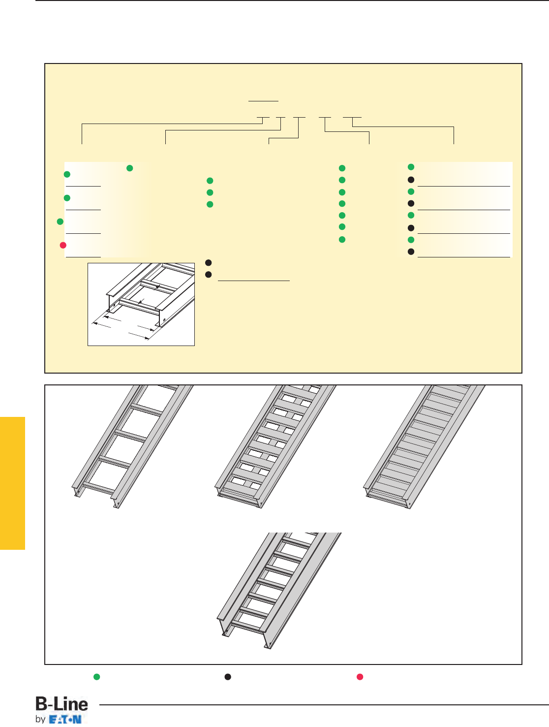
6" NEMA VE 1 Loading Depth
7" Side Rail Height
Overall Width
(Width + 11/2")
For
side rail
& rung data,
see chart on
pages AP-5 & AP-6
Rung
Spacing
Width
(Inside)
Straight Section Part Numbering
Prefix
Example: 37 A 09 - 24 - 240
Series Material *Type *Width Length
37 A= Aluminum Ladder- 06 = 6" ¨240 = 20 ft. 37
06 = 6" rung spacing 09 = 9" ¡144 = 12 ft.
47 09 = 9" rung spacing 12 = 12" ¨240 = 20 ft. 47
12 = 12" rung spacing 18 = 18" ¡288 = 24 ft.
H47† 24 = 24" ¨240 = 20 ft. H47
30 = 30" ¡300 = 25 ft.
57† 36 = 36" ¨360 = 30 ft. 57
¡300 = 25 ft.
Trough-
6" thru 36" wide
VT = Vented Trough
ST = Non-Ventilated Trough
† H47A & 57A only available in ladder
type 9” and 12” rung spacing.
See page APP-2.
See page APP-1 for additional rung options. *Special sizes available.
Ladder Type
(Specify Rung Spacing)
57A available in
(9” & 12” rung spacing in
12” to 36” widths)
Ventilated Trough Non-Ventilated Trough
Series 2, 3, 4, & 5 Aluminum
¨Primary Length.
¡Secondary Length.
See page CTS-23 for
explanation of lengths.
Green = Fastest shipped items Black = Normal lead-time items Red = Normally long lead-time items
HAT-9
Series 2, 3, 4, & 5 Aluminum - Straight Sections
Cable Tray Systems
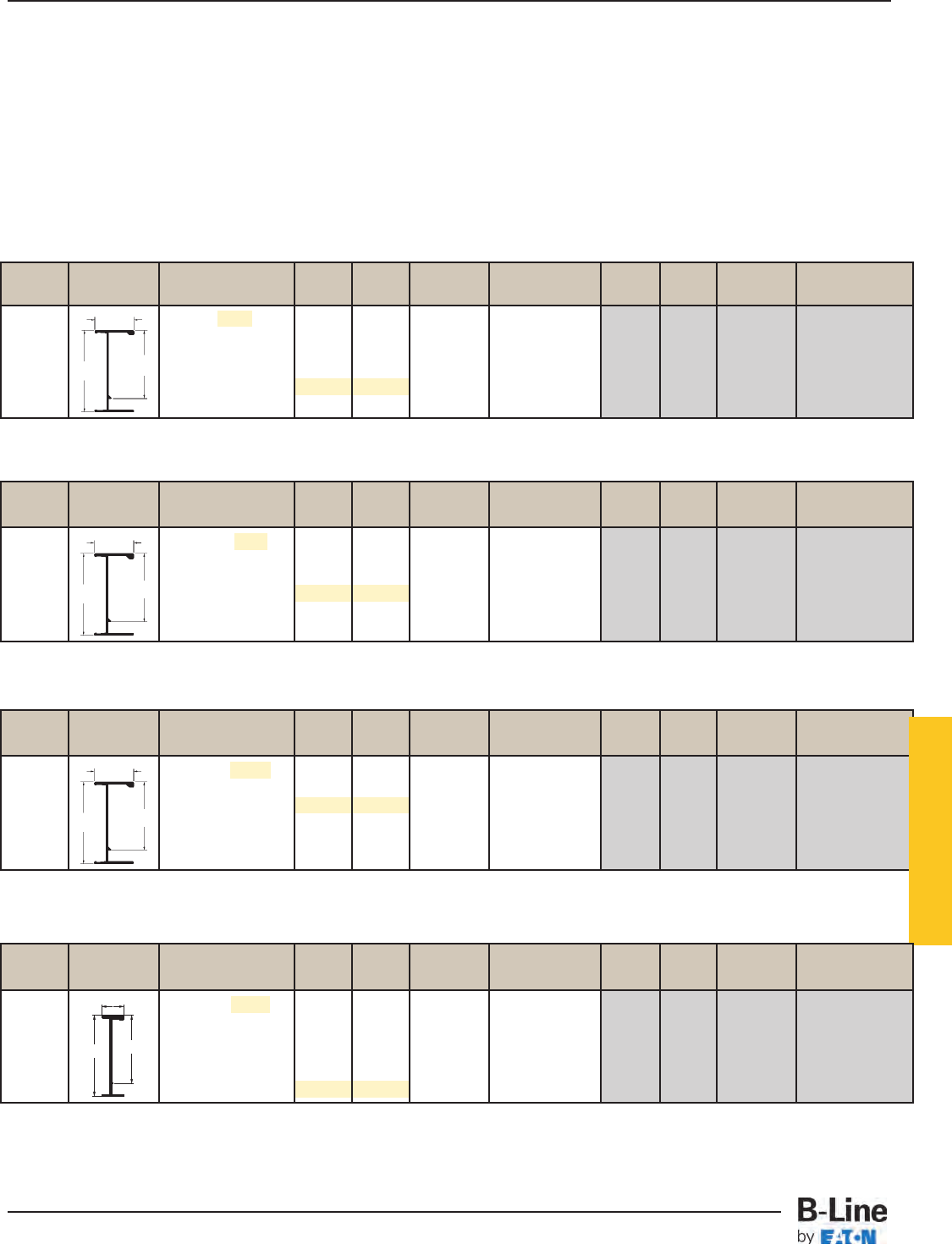
B-Line Side Rail NEMA, CSA & UL Span Load Deflection Design Factors Span Load Deflection Design Factors
Series Dimensions Classifications ft lbs/ft Multiplier for Two Rails meters kg/m Multiplier for Two Rails
NEMA: 20C 14 204 0.0048 4.3 304 0.083
CSA: 142 kg/m6.1m 16 156 0.0082 Area=2.38 in24.9 233 0.141 Area=15.35 cm2
18 123 0.0132 Sx=4.94 in35.5 184 0.225 Sx=80.95 cm3
UL Cross-Sectional 20 100 0.0201 Ix=17.88 in46.1 149 0.344 Ix=744.22 cm4
Area: 2.00 in^222 83 0.0295 6.7 123 0.503
24 69 0.0418 7.3 103 0.713
B-Line Side Rail NEMA, CSA & UL Span Load Deflection Design Factors Span Load Deflection Design Factors
Series Dimensions Classifications ft lbs/ft Multiplier for Two Rails meters kg/m Multiplier for Two Rails
NEMA: 20B, 16C 12 222 0.0035 3.7 331 0.059
CSA: 106 kg/m6.1m 14 163 0.0064 Area=1.81 in24.3 243 0.109 Area=11.68 cm2
16 125 0.011 Sx=3.77 in34.9 186 0.186 Sx=61.78 cm3
UL Cross-Sectional 18 99 0.017 Ix=13.50 in45.5 147 0.299 Ix=561.91 cm4
Area: 1.50 in220 80 0.027 6.1 119 0.455
22 66 0.039 6.7 98 0.666
Values are based on simple beam tests per NEMA VE 1 on 36" wide cable tray with rungs spaced on 12" centers. Cable trays will
support without collapse a 200 lb. (90.7 kg) concentrated load over and above published loads. Published load safety factor is 1.5.
To convert 1.5 safety factor to 2.0, multiply the published load by 0.75. To obtain mid-span deflection, multiply a load by the
deflection multiplier. Cable tray must be supported on spans shorter than or equal to the length of the cable tray being installed.
Individual rungs will support without collapse a 200 lb. (90.7 kg) concentrated load applied at the mid-span of the rung, over and
above the NEMA rated cable load with a 1.5 safety factor for highlighted NEMA spans and loads.
When trays are used in continuous spans, the deflection of the tray is reduced by as much as 50%. Design factors: Ix = Moment
of Inertia, Sx = Section Modulus.
2.00
7.14 6.05
2.00
7.24 6.13
6" NEMA VE 1 Loading Depth
7" Side Rail Height
37
When trays are used in continuous spans, the deflection of the tray is reduced by as much as 50%. Design factors: Ix = Moment
of Inertia, Sx = Section Modulus.
47
B-Line Side Rail NEMA, CSA & UL Span Load Deflection Design Factors Span Load Deflection Design Factors
Series Dimensions Classifications ft lbs/ft Multiplier for Two Rails meters kg/m Multiplier for Two Rails
NEMA: 20C+ 16 233 0.0064 4.9 346 0.110
CSA: 241 kg/m6.1m 18 184 0.010 Area=3.04 in25.5 274 0.176 Area=19.61 cm2
20 149 0.016 Sx=6.10 in36.1 222 0.268 Sx=99.96 cm3
UL Cross-Sectional 22 123 0.023 Ix=22.91 in46.7 183 0.393 Ix=953.59 cm4
Area: 2.00 in224 103 0.033 7.3 154 0.556
25 95 0.038 7.6 142 0.655
When trays are used in continuous spans, the deflection of the tray is reduced by as much as 50%. Design factors: Ix = Moment
of Inertia, Sx = Section Modulus.
When trays are used in continuous spans, the deflection of the tray is reduced by as much as 50%. Design factors: Ix = Moment
of Inertia, Sx = Section Modulus.
2.00
7.24 6.09
H47
Series 2, 3, 4, & 5 Aluminum
B-Line Side Rail NEMA, CSA & UL Span Load Deflection Design Factors Span Load Deflection Design Factors
Series Dimensions Classifications ft lbs/ft Multiplier for Two Rails meters kg/m Multiplier for Two Rails
NEMA: 20C+ 20 232 0.011 6.1 345 0.187
CSA: 152 kg/m9.1m 22 192 0.016 Area=4.22 in26.7 285 0.274 Area=27.23 cm2
24 161 0.023 Sx=7.73 in37.3 240 0.388 Sx=126.67 cm3
UL Cross-Sectional 26 136 0.031 Ix=32.86 in47.9 202 0.534 Ix=1367.74 cm4
Area: 2.00 in228 117 0.042 8.5 174 0.718
30 102 0.055 9.1 152 0.947
7.40 6.23
57
2.00
HAT-10
Series 2, 3, 4, & 5 Aluminum - Straight Sections
Cable Tray Systems
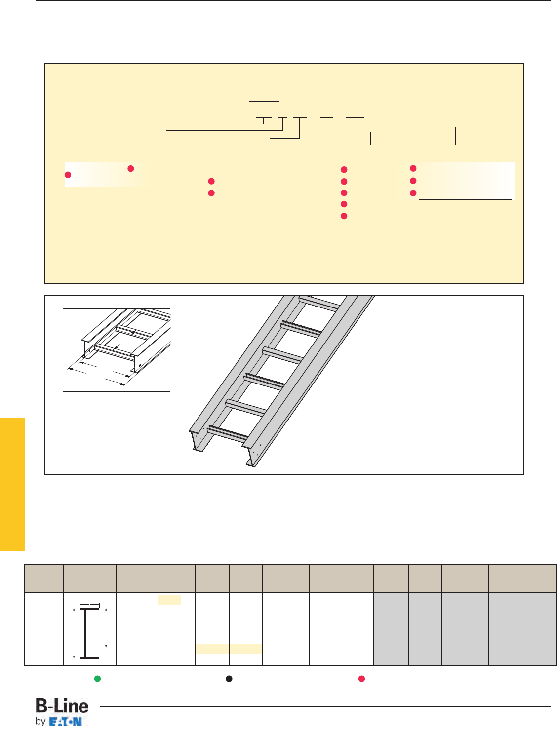
6" NEMA VE 1 Loading Depth
8" Side Rail Height
Straight Section Part Numbering
Prefix
Example: S8 A 09 - 24 - 240
Series Material *Type *Width Length
S8 A= Aluminum Ladder- 12 = 12" 480 = 40 ft.
09 = 9" rung spacing 18 = 18" ¨360 = 30 ft. S8
12 = 12" rung spacing 24 = 24" ¡300 = 25 ft.
30 = 30"
36 = 36"
See page APP-1 for additional rung options. *Special sizes available.
Series 2, 3, 4, & 5 Aluminum
* Alternated rung
unless indicated.
B-Line Side Rail NEMA, CSA & UL Span Load Deflection Design Factors Span Load Deflection Design Factors
Series Dimensions Classifications ft lbs/ft Multiplier for Two Rails meters kg/m Multiplier for Two Rails
NEMA: 20C+ 20 363 0.007 6.1 540 0.111
CSA: 240 kg/m9.1m 22 300 0.010 6.7 446 0.163
24 252 0.013 Area=5.50 in27.3 375 0.230 Area=35.48 cm2
UL Cross-Sectional 26 215 0.019 Sx=15.39 in37.9 320 0.317 Sx=252.20 cm3
Area: 2.00 in228 185 0.025 Ix=55.35 in48.5 276 0.427 Ix=2303.84 cm4
30 161 0.033 9.1 240 0.562
40 101 0.146 12.2 151 2.488
3.00
8.00 6.175
S8A
Overall Width
(Width + 1.80")
For
side rail
& rung data,
see chart on
pages AP-5 & AP-6
Rung
Spacing
Width
(Inside)
Values are based on simple beam tests per NEMA VE 1 on 36" wide cable tray with rungs spaced on 12" centers. Cable trays will
support without collapse a 200 lb. (90.7 kg) concentrated load over and above published loads. Published load safety factor is 1.5.
To convert 1.5 safety factor to 2.0, multiply the published load by 0.75. To obtain mid-span deflection, multiply a load by the
deflection multiplier. Cable tray must be supported on spans shorter than or equal to the length of the cable tray being installed.
Individual rungs will support without collapse a 200 lb. (90.7 kg) concentrated load applied at the mid-span of the rung, over and
above the NEMA rated cable load with a 1.5 safety factor for highlighted NEMA spans and loads. See table on page 385 for rung
capacities.
¨Primary Length.
¡Secondary Length.
See page CTS-23 for
explanation of lengths.
Green = Fastest shipped items Black = Normal lead-time items Red = Normally long lead-time items
HAT-11
Series 2, 3, 4, & 5 Aluminum - Straight Sections
Cable Tray Systems
Series 2, 3, 4, & 5 Aluminum
The following is a list of accessories and fittings
that can be provided with S8A tray.
For more information on these items, contact
Engineering Department.
Fittings
Horizontal Bends
30° Bends with 24”, 36”, or 48” radius
45° Bends with 24”, 36”, or 48” radius
60° Bends with 24”, 36”, or 48” radius
90° Bends with 24”, 36”, or 48” radius
Horizontal Tees
With 24”, 36”, or 48” radius
Vertical Outside Bends
30° Bends with 24”, 36”, or 48” radius
45° Bends with 24”, 36”, or 48” radius
60° Bends with 24”, 36”, or 48” radius
90° Bends with 24”, 36”, or 48” radius
Vertical Inside Bends
30° Bends with 24”, 36”, or 48” radius
45° Bends with 24”, 36”, or 48” radius
60° Bends with 24”, 36”, or 48” radius
90° Bends with 24”, 36”, or 48” radius
Reducing Fittings
Accessories
Splice Plate - 9A-1008
Expansion Splice Plate - 9A-1018
Horizontal Adjustable Splice Plate - 9A-1038
Vertical Adjustable Splice Plate - 9A-1028
Hold Down Clamps - 9ZN-1281, 9G-1281, 9A-1281
Guides - S9ZN-1202, S9G-1202
Step Down Splice Plate - 9A-1050, 9A-1078, 9A-1048
Other Accessories Include:
Offset Splice Plates
Blind Ends
Covers - Standard aluminum cover number with S in front (Example: S807A40)
Green = Fastest shipped items Black = Normal lead-time items Red = Normally long lead-time items
HAT-12
Series 2, 3, 4, & 5 Aluminum - Straight Sections
Cable Tray Systems
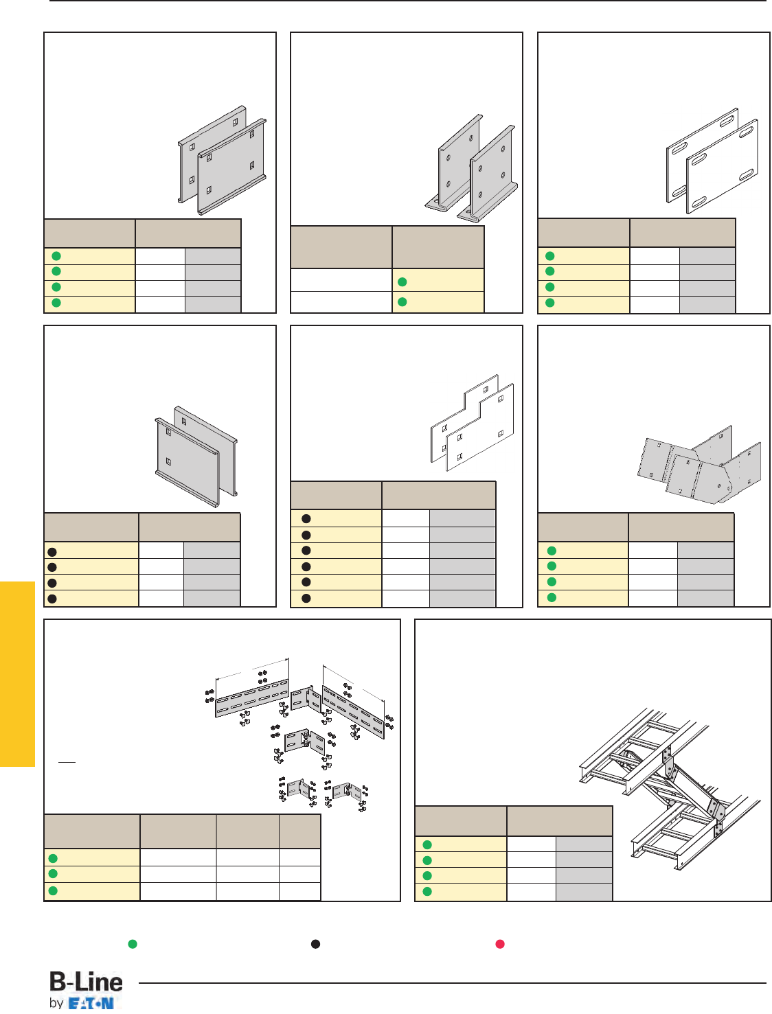
H46A, H47A and 57A Mid-Span
Splice
• Standard for H46A, H47A and 57A
straight sections.
• Six bolt design 1/2" Stainless Steel
Type 316 hardware standard.
• Available on ladder bottoms
only. 09 and 12" rung
spacing.
• Furnished in pairs
with hardware.
Branch Pivot Connectors
• Branch from existing cable tray runs at any point.
• Pivot to any required angle.
• UL Classified for grounding
(bonding jumper not required).
• Furnished in pairs with hardware.
Catalog No. Height
in. mm
9A-1004 4 101
9A-1005 5 127
9A-1006 6 152
9A-1007 7 178
Wedge Lock Splice Plates
• Standard 4-hole pattern.
• Furnished in pairs, with hardware.
• One pair including hardware
provided with each section.
• Boxed in pairs
with hardware.
•
For field installation
drill 13/32" hole.
Horizontal Adjustable
Splice Plates
• Offered to adjust a cable tray
run for changes in direction
in a horizontal plane that do
not conform to standard
horizontal fittings.
• Furnished in pairs with hardware.
• New design bonding jumpers
not required.
• (X) Insert 4, 5, 6 or 7 for
side rail height.
Catalog Cable Tray Tray
No. End Cut Width 'L'
9A-103(X) Mitered Thru 36" N/A
9A-103(X)-12 Not mitered Thru 12" 16"
9A-103(X)-36 Not mitered Thru 36" 41"
Catalog No. Height
in. mm
9A-1045 5 to 4 127 to 101
9A-1046 6 to 4 152 to 101
9A-1060 6 to 5 152 to 127
9A-1047 7 to 4 178 to 101
9A-1061 7 to 5 178 to 127
9A-1062 7 to 6 178 to 152
Catalog No. Height
in. mm
9A-1004-1/24 101
9A-1005-1/25 127
9A-1006-1/26 152
9A-1007-1/27 178
Catalog No. Height
in. mm
9A-2044 4 101
9A-2045 5 127
9A-2046 6 152
9A-2047 7 178
Catalog No. Height
in. mm
9A-1014 4 101
9A-1015 5 127
9A-1016 6 152
9A-1017 7 178
9A-103(X)
Splice only
9A-103(X)-12 or 9A-103(X)-36
One pair splice plates with extensions.
L
L
Expansion Splice Plates
• Expansion plates allow for one inch expansion
or contraction of the cable tray, or where
expansion joints occur in the supporting structure.
• Furnished in pairs with hardware.
•Bonding Jumpers are required
on each siderail.
Order Separately.
For heavy duty
expansion splice plates
see page APP-3.
Universal Splice Plates
• Used to splice to existing cable tray
systems.
• Furnished in pairs with hardware.
Catalog No. Height
in. mm
9A-1024 4 101
9A-1025 5 127
9A-1026 6 152
9A-1027 7 178
Step Down Splice Plates
• These splice plates are
offered for connecting cable
tray sections having side rails
of different heights.
• Furnished in pairs with
hardware.
Vertical Adjustable Splice Plates
• These plates provide for changes in
elevation that do not conform to standard
vertical fittings.
• Furnished in pairs with hardware.
•Bonding Jumper not required.
Tray
Series Catalog No.
H46A 9A-6006
H47A, 57A 9A-6007
Series 2, 3, 4, & 5 Aluminum
Requires
supports within
24” on both
sides, per
NEMA VE 2.
Requires
supports
within 24”
on both
sides, per
NEMA VE 2.
Green = Fastest shipped items Black = Normal lead-time items Red = Normally long lead-time items
HAT-13
Series 2, 3, 4, & 5 Aluminum - Accessories
Cable Tray Systems
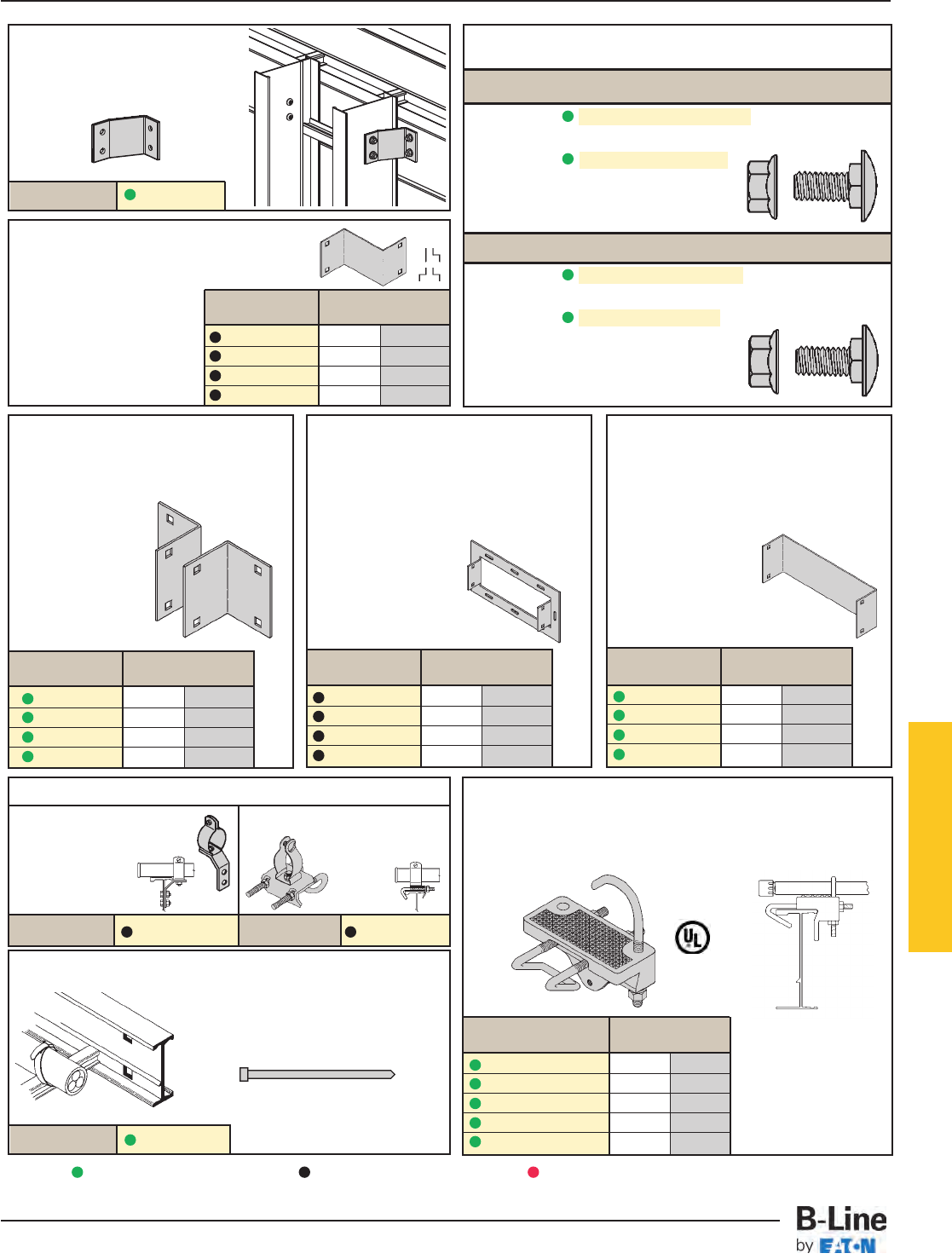
9A-1240
Catalog No.
Cross Connector Bracket
• For field connecting crossing section.
• Furnished in pairs with 3/8"
hardware.
Offset Reducing Splice Plate
• This plate is used for joining cable trays having
different widths. When used in pairs they form
a straight reduction; when
used singly with a standard
splice plate, they form an
offset reduction.
• Furnished as one plate
with hardware.
• (‡) Insert reduction
Catalog No. 9ZN-1150-(‡) Catalog No. 9ZN-1155-(‡)
Catalog No. Height
in. mm
9A-1064-(‡) 4 101
9A-1065-(‡) 5 127
9A-1066-(‡) 6 152
9A-1067-(‡) 7 178
Conduit to Cable Tray Adaptor
• For easy attachment of conduit terminating at a cable tray.
• Use on aluminum or steel cable trays.
Catalog No. Conduit Size
in. mm
9G-1158-1/2, 3/41/2, 3/415, 20
9G-1158-1, 11/41, 11/425, 32
9G-1158-11/2, 2 11/2, 2 40, 50
9G-1158-21/2, 3 21/2, 3 65, 80
9G-1158-31/2, 4 31/2, 4 90, 100
Tray Hardware
For field installation drill 13/32" hole.
Standard Tray Hardware
Catalog No. SNCB 3/8" x 3/4" Znplt Square
Neck Carriage Bolt ASTM A307 Grade A
Catalog No. SFHN 3/8"-16 Znplt
Serrated Flange Hex Nut ASTM A563
Grade A
Finish: Zinc Plated ASTM B633, SC1
Optional Tray Hardware
Catalog No. SNCB 3/8" x 3/4" SS6 Square
Neck Carriage Bolt AISI 316 Stainless Steel
Catalog No. SFHN 3/8"-16 SS6 Serrated
Flange Hex Nut AISI 316 Stainless Steel
To order optional 316 Stainless Steel
hardware add SS6 suffix to part number
Example: 9A-1004SS6
Aluminum I-Beam
Cable Tie (Ladder Tray)
Nylon ties provide easy attachment of
cable to ladder rungs; maximum cable
O.D. is 3" (76mm).
Overall Length 15"
Catalog No. 99-2125-15
• Assembly required.
• Mounting hardware
included.
• Conduit clamps
provided.
• (‡) = Conduit size
(1/2" thru 4").
• Assembly required.
• Conduit clamp included.
• (‡) = Conduit size
(1/2" thru 4").
Conduit to Cable Tray Adaptors
Catalog No. Height
in. mm
9A-1084-(‡) 4 101
9A-1085-(‡) 5 127
9A-1086-(‡) 6 152
9A-1087-(‡) 7 178
Catalog No. Height
in. mm
9A-1074-(‡) 4 101
9A-1075-(‡) 5 127
9A-1076-(‡) 6 152
9A-1077-(‡) 7 178
Catalog No. Height
in. mm
9A-1054 4 101
9A-1055 5 127
9A-1056 6 152
9A-1057 7 178
Frame Type Box Connector
• Designed to attach the end of a cable
tray run to a distribution cabinet or
control center to help reinforce the box
at the point of entry.
• Furnished with tray
connection hardware.
• (‡) Insert tray width
Blind End
• This plate forms a
closure for a dead
end cable tray.
• Furnished as one
plate with hardware.
• (‡) Insert tray width
Tray to Box Splice Plates
• Used to attach the
end of a cable tray
run to a distribution
box or control
panel.
• Furnished in pairs
with hardware.
Series 2, 3, 4, & 5 Aluminum
Green = Fastest shipped items Black = Normal lead-time items Red = Normally long lead-time items
All dimensions in parentheses are millimeters unless otherwise specified.
HAT-14
Series 2, 3, 4, & 5 Aluminum - Accessories
Cable Tray Systems
Inside Bend Outside Bend Side Rail Loading
Catalog No. Catalog No. Height Depth 'H'
in. mm in. mm
73A-(*)VI(†) 73A-(*)VO(†) 4 101 3 76
74A-(*)VI(†) 74A-(*)VO(†) 5 127 4 101
75A-(*)VI(†) 75A-(*)VO(†) 6 152 5 127
76A-(*)VI(†) 76A-(*)VO(†) 7 178 6 152
Vertical Bend Barriers
• Vertical Bend Barriers are preformed to conform to a
specific vertical fitting.
• Furnished with three #10 x 1
/2" plated self-drilling
screws and a 99-9982 Barrier Strip Splice.
• (*) Insert 30, 45, 60 or 90 for degrees
• (†) Insert 12, 24, 36 or 48 for radius
Straight Section
• Standard length: 120" (3 m) 144" (12 ft.).
• Order catalog number based on loading
depth.
• Furnished with four #10 x 1
/2" plated self-
drilling screws and a 99-9982 splice.
Trough Drop-Out & Drop-Out Bushing
• These devices provide a rounded surface to protect cable as it exits
from the trough-type cable tray.
• Hardware is included for attachment of the trough bottom drop-out.
• (‡) Insert tray width
Catalog No.
9A-1104T-(‡)
9A-RBC
Catalog No.
Barrier Strip Clip
• Provides attachment to rung.
• Allows for installed barrier adjustment.
•
Asymmetrical clip provides a wide range for screw location.
• Barriers strip clips not included with barriers.
(Must be ordered separately)
Horizontal Bend
• Horizontal Bend Barriers are flexible in order
to conform to any horizontal fitting radius.
Cut to length.
• Order catalog number based on loading depth.
• Furnished with three #10 x 1/2" zinc plated
self-drilling screws and a 99-9982 Barrier
Strip Splice.
• Standard length is 72" (6 ft.), sold individually.
Catalog Side Rail Loading
No. Height Depth 'H'
in. mm in. mm
73A-90HBFL 4 101 3 76
74A-90HBFL 5 127 4 101
75A-90HBFL 6 152 5 127
76A-90HBFL 7 178 6 152
Catalog Side Rail Loading
No. Height Depth 'H'
in. mm in. mm
73A-Length 4 101 3 76
74A-Length 5 127 4 101
75A-Length 6 152 5 127
76A-Length 7 178 6 152
9A-1104-(‡)
Catalog No.
Ladder Drop-Out
• Specially-designed Ladder Drop-Outs provide a rounded surface with
4" (101 mm) radius to protect cable as it exits from the cable tray,
preventing damage to insulation. The drop-out will attach to any
desired rung.
• (‡) Insert tray width
Snap-In Plastic Bushing
Trough-Type Drop-Out
Outside Bend
(VO)
Inside Bend
(VI)
H
Length =
144 for 12'
or
120 for 10'
Barriers
H
H
H
Catalog No.
99-1124
Series 2, 3, 4, & 5 Aluminum
Green = Fastest shipped items Black = Normal lead-time items Red = Normally long lead-time items
Screw slot for
sheet metal screw
Rung
Barrier
Flange
HAT-15
Series 2, 3, 4, & 5 Aluminum - Accessories
Cable Tray Systems
Threaded Rod (ATR) & Rod Coupling
Hanger Rod Clamp
• For 1/2" ATR.
• Furnished in pairs.
• Order ATR and hex nuts separately.
• Two-piece "J"-hanger design.
• 1500 lbs./pair capacity safety factor 3.
• (*) Insert or
Catalog No. Rail Height
in. mm
9(*)-5324 4 101
9(*)-5325 5 127
9(*)-5326 6 152
9(*)-5327 7 178
Stainless Steel Cable Clamp "P"
• Fits with series 2, 3, & 4 rungs.
• Attaches to rung at any point.
• 14 gauge Type 316 stainless steel
material to minimize corrosion and
induction heating.
• Plated steel and aluminum
also available.
Ground Clamp
• Mechanically attaches grounding
cables to cable tray.
• Hardware included.
• (*) Insert or
Catalog No. Cable Size
9(*)-2351 #1 thru 2/0
9(*)-2352 3/0 thru 250 MCM
3/8"-16 730 ATR 3/8" x Length 36", 72", 120", 144" B655-3/8
1/2"-13 1350 ATR 1/2" x Length 36", 72", 120", 144" B655-1/2
Grounding Clamp
B-Line Cable Tray is UL®classified as to its suitability as an
equipment grounding conductor. If a separate conductor for
additional grounding capability is desired, B-Line offers this clamp
for bolting the conductor at least once to each cable tray section.
• Accepts #6 AWG to
250 MCM.
Catalog No. Material
9A-2130 Tin Plated Aluminum
Bonding Jumper
Use at each expansion splice and where the cable tray is not
mechanically/electrically continuous to ground.
Sold individually.
• Hardware included.
• See table 392.7(B)(2) on page CTS-9 for
amperage ratings required to match
the UL cross-sectional area of the tray.
• See tray loading chart for UL
cross-sectional area.
• Bonding jumper is 16" long.
Catalog No. Copper Wire Size Ampacity
99-N1 #1 600
99-40 4/0 1600
99-1620 250 MCM 2000
Loading Catalog Available Coupling
Size lbs No. Lengths Cat. No.
All dimensions in shaded areas are millimeters unless otherwise specified.
Loading based on safety factor 5.
Standard Finish: Zinc plated
See B-Line Strut Systems Catalog for other sizes and finishes.
Catalog No. Cable Size
in. mm
BP081SS .250 - .840 6.4 - 21.3
BP110SS .810 - 1.100 20.6 - 28.0
BP135SS .850 - 1.350 21.6 - 34.8
BP175SS 1.250 - 1.750 31.8 - 44.5
BP205SS 1.550 - 2.050 39.4 - 52.1
BP250SS 2.000 - 2.500 50.8 - 63.5
BP300SS 2.500 - 3.000 63.5 - 76.2
BP325SS 2.750 - 3.250 69.9 - 82.6
BP375SS 3.250 - 3.750 82.6 - 95.3
BP425SS 3.750 - 4.250 95.3 - 108.0
BP475SS 4.250 - 4.750 108.0 - 120.7
Series 2, 3, 4, & 5 Aluminum
ZN SS4
ZN G
Refer to Section CF
Cable Fixing
Green = Fastest shipped items Black = Normal lead-time items Red = Normally long lead-time items
Catalog No.
99-9982
Barrier Strip Splice
•
Plastic splice holds adjoining barrier strips in straight alignment.
• 5” (127mm) long.
All dimensions in parentheses are millimeters unless otherwise specified.
HAT-16
Series 2, 3, 4, & 5 Aluminum - Accessories
Cable Tray Systems
Catalog No. Finish
9ZN-1249 Znplt
9G-1249 HDGAF
Cable Tray Guide
• Expansion guide for single or double cable tray runs.
• Guide allows for longitudinal movement of the cable tray.
• No field drilling of support I-beam or channel is required.
• Guides are required on both sides of cable
tray to prevent lateral movement - can be
placed on either the inside or outside
flange of cable tray.
• Guides are sold in pieces - two guides are
required per tray.
• Maximum flange thickness 11/8" (28.58 mm).
Neoprene Roll
• Use for material isolation.
•1/8" x 2" x 25' roll.
• Hardness: Shore A60.
• Good weatherability.
Nylon Pad
• Use for friction reduction.
• Hardness: Shore D80.
• Low friction coefficient.
• UV resistant.
• Excellent weatherability.
• UL - 94HB.
Catalog No. 99-PE36
Catalog No. Finish
9ZN-1249HD Znplt
9G-1249HD HDGAF
Cable Tray Clamp
• Hold-down clamps for single or double cable tray runs.
• No drilling of support I-beam or channel is required.
• Sold in pieces
- two clamps are required per tray.
• Maximum beam flange thickness 11/8" (28.58 mm).
Cable Tray Clamp/Guide
• Features a no-twist design.
• Has four times the strength
of the traditional design.
• Each side is labeled to
ensure proper installation.
• Furnished in pairs, with or
without hardware.
• Not recommended
for vertical support.
Catalog No. 99-NP300
1/8"
(3mm)
3"
(76mm)
6"
(152mm)
Note: For heavy duty or vertical applications
see 9(*)-1241 or 9(*)-1242 page HAT-20
Catalog No.
Without With Overall Hardware
Hardware Hardware Length Size Finish
in. mm
9ZN-1204 9ZN-1204NB 11/238 1/4" G90
9ZN-1208 9ZN-1208NB 21/457 3/8" G90
9A-1205 -- 21/457 1/2" Alum.
9G-1205 -- 21/457 1/2" HDGAF
9SS6-1205 -- 21/457 1/2" 316SS
9ZN-1205 -- 21/457 1/2" G90
9ZN-1204 shown.
Installed as a guide.
9ZN-1208 shown.
Installed as a clamp.
Patent # RE35479 11/2"
(39mm)
21/4"
(57mm)
Isolator Pad
• Use as a friction reducer and/or as
a dissimilar metal isolator barrier.
• UV resistant HDPE.
• Temperature range: -100 to 160° F.
• Designed to use with
9(*)-1205 or 9(*)-1208 clamp/guide.
• Color - White.
Catalog No. 99-PE34
Isolation pad shown as
when used with a guide. Isolation pad shown with top
flange doubled under for
clamp application.
Series 2, 3, 4, & 5 Aluminum
Green = Fastest shipped items Black = Normal lead-time items Red = Normally long lead-time items
HAT-17
Series 2, 3, 4, & 5 Aluminum - Accessories
Cable Tray Systems
Trapeze
Hardware
Kit
Heavy Duty Trapeze Support Kit
B-Line trapeze kits provide the
components required for a single trapeze
support in one package. These kits are
available in Dura-Green™epoxy coated steel
with zinc-plated hardware or hot dip
galvanized steel with 316 stainless steel
hardware.
The SH channel provides the convenience
of pre-punched slots, which eliminates the
need for field drilling.
The illustrated hardware is sealed in a
plastic bag and boxed with the channel,
which is pre-cut to the appropriate length
as shown in the chart.
Designed for use with 1/2" threaded rod.
Order rod separately.
Catalog Tray Channel Uniform
No. Width Length Load
in. mm in. mm lbs kN
9(*)-5506-22SHA 6 152 16 406 1350 6.01
9(*)-5509-22SHA 9 229 18 457 1350 6.01
9(*)-5512-22SHA 12 305 22 559 1350 6.01
9(*)-5518-22SHA 18 457 28 711 1350 6.01
9(*)-5524-22SHA 24 610 34 864 1350 6.01
9(*)-5530-22SHA 30 762 40 1016 1350 6.01
9(*)-5536-22SHA 36 914 46 1168 1350 6.01
9(*)-5542-22SHA 42 1067 52 1321 1350 6.01
Trapeze Support Kit
B-Line trapeze kits provide the components
required for a single trapeze support in one
package. These kits are available in pre-
galvanized steel with zinc-plated hardware
or hot dip galvanized steel with 316
stainless steel hardware.
The SH channel provides the convenience
of pre-punched slots, which eliminate the
need for field drilling.
The illustrated hardware is sealed in a
plastic bag and boxed with the channel,
which is pre-cut to the appropriate length
as shown in the chart.
Designed for use with 1/2" threaded rod.
Order rod separately.
Catalog Tray Channel Uniform
No. Width Length Load
in. mm in. mm lbs kN
9P-5506-22SH(†) 6 152 16 406 1600 7.11
9P-5509-22SH(†) 9 229 18 457 1250 5.56
9P-5512-22SH(†) 12 305 22 559 1125 5.00
9P-5518-22SH(†) 18 457 28 711 865 3.85
9P-5524-22SH(†) 24 610 34 864 700 3.11
9P-5530-22SH(†) 30 762 40 1016 590 2.62
9P-5536-22SH(†) 36 914 46 1168 510 2.27
9P-5542-22SH(†) 42 1067 52 1321 450 2.00
• (†) Insert 3/8for 3/8" threaded rod hardware.
Safety factor of 3.0 on all loads.
• (*) Insert or
Safety factor of 3.0 on all loads.
(1) B22 Channel
cut to the
required length
(2) 9ZN-1205
Hold-Down
Guide Clamp
(4) B202
Square Washer
(2) N525WO
Channel Nut
(2) 1/2" x 7/8" Hex
Head Cap Screw
(4) 1/2" Hex Nut
(1) Channel
cut to the
required
length
(2) 9ZN-1205
Hold-Down
Guide Clamp
(4) B202
Square Washer
(2) N525WO
Channel Nut
(2) 1/2" x 7/8" Hex
Head Cap Screw
(4) 1/2" Hex Nut
Catalog No. 9ZN-5500-1/2 9G-5500-1/2
1 pr. 9ZN-1205 1 pr. 9G-1205
2 HHC Screw 1/2x 7/8ZN 2 HHC Screw 1/2x 7/8SS6
2 N525 WO ZN 2 N525 WO SS6
4 B202 ZN 1/2" sq washer 4 B202 HDG 1/2" sq washer
4 HN 1/2ZN 4 HN 1/2SS6
In plastic bag
Series 2, 3, 4, & 5 Aluminum
GRN G
Rooftop Support Bases
with B22 Channel Catalog No. Height x Width x Length
DB10-28 55/8” x 6” x 28.0”
DB10-36 55/8” x 6” x 36.0”
DB10-42 55/8” x 6” x 42.0”
DB10-50 55/8” x 6” x 50.0”
DB10-60 55/8” x 6” x 60.0”
Designed as a superior rooftop support
for cable tray,
UV resistant and approved for most
roofing material or other flat surfaces.
Can be used with any of B-Line cable
tray clamps and guides.
Ultimate Load Capacity:
1,000 lbs. (uniform load) LEEDS credit available, base made from 100% recycled material.
General Note: Consult roofing manufacturer or engineer for roof load
capacity. The weakest point may be the insulation board beneath
the rubber membrane.
Green = Fastest shipped items Black = Normal lead-time items Red = Normally long lead-time items
All dimensions in parentheses are millimeters unless otherwise specified.
HAT-18
Series 2, 3, 4, & 5 Aluminum - Accessories
Cable Tray Systems
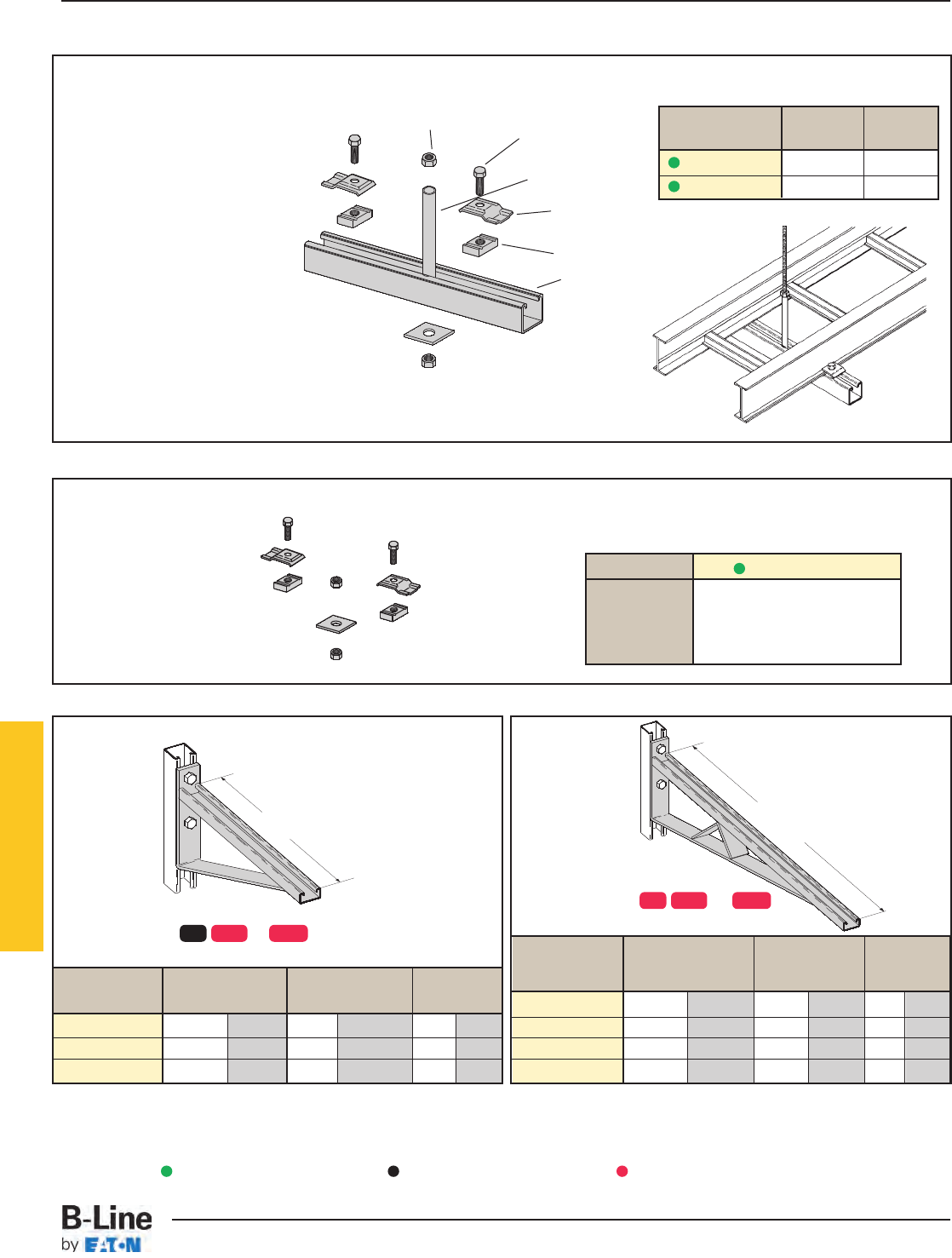
Bracket
Catalog No. Uniform Load Tray Width 'A'
lbs kN in. mm in. mm
B494-12 1580 7.02 6 & 9 152 & 229 12 305
B494-18 1000 4.45 12 305 18 457
B494-24 996 4.43 18 457 24 610
Center Hung Tray Support
• Center Hung Cable Tray Support allows
cable to be laid-in from both sides.
• Eliminates costly cable pulling and field
cutting of cable tray supports. Labor
costs are dramatically reduced.
• Required hardware and threaded rod
material for trapeze assemblies are
reduced by 50%.
• Designed for use with 1/2" threaded
rod. (Order rod separately)
• Use with all aluminum and steel
cable trays through 24" width.
• Load capacity is 700 lbs. per support.
Safety factor of 3.0.
Eccentric loading is not to exceed a
60% vs. 40% load differential.
• The maximum recommended unsupported
span length is 144"/12 ft. (3.66 m).
• Hardware shown is furnished.
Catalog Tray Channel
No. Width Length
9ZN-5212 6", 9", 12" 18"
9ZN-5224 18", 24" 30"
Bracket
Catalog No. Uniform Load Tray Width 'A'
lbs kN in. mm in. mm
B494-30 924 4.11 24 610 30 762
B494-36 864 3.84 30 762 36 914
B494-42 580 2.58 36 914 42 1067
B494-48 500 2.22 42 1067 48 1219
(2) 1/2" x 7/8"
Hex Head Cap Screws
(2) 1/2" Hex Nut
(1) B202
Square Washer
(2) 9ZN-1205
Hold Down
Guide Clamp
(2) N525WO
(1) B22 Channel cut to
the required length
(1) 9/16" Inside diameter
steel tubing welded to strut
Finishes available: or
Safety Load Factor 2.5
AA
Finishes available: or
Safety Load Factor 2.5
Center Hung Support Hardware Kit
Catalog No. 9ZN-5200
1 pr. 9ZN-1205
2 HHC Screw 1/2x 7/8ZN
2 N525 WO ZN
1 B202 ZN 1/2" sq washer
2 HN 1/2ZN
In plastic bag
ZN = Zinc Plated
Series 2, 3, 4, & 5 Aluminum
ZN GRN HDG
ZN GRN HDG
Green = Fastest shipped items Black = Normal lead-time items Red = Normally long lead-time items
HAT-19
Series 2, 3, 4, & 5 Aluminum - Accessories
Cable Tray Systems
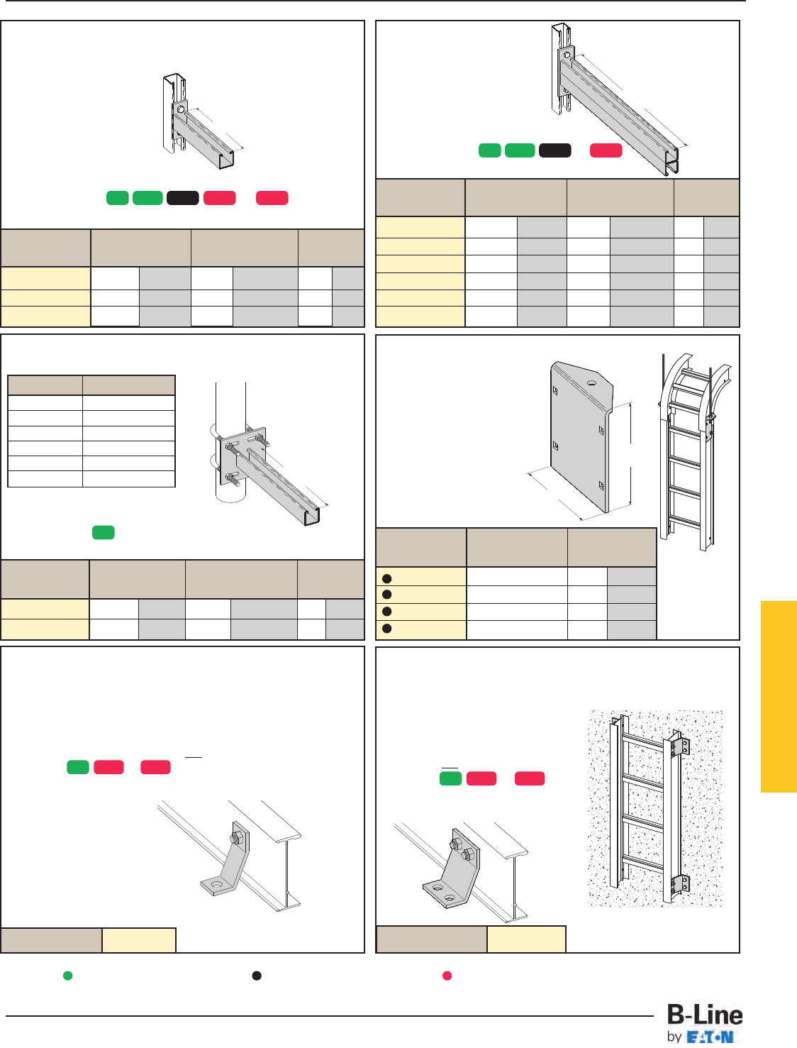
Cantilever Bracket
Catalog No. Uniform Load Tray Width 'A'
lbs kN in. mm in. mm
B297-12 1660 7.38 6 & 9 152 & 229 12 305
B297-18 1100 4.89 12 305 18 457
B297-24 835 3.71 18 457 24 610
B297-30 665 2.95 24 610 30 762
B297-36 550 2.44 30 762 36 914
B297-42 465 2.06 36 914 42 1067
Underfloor Support (U-Bolts not included) Vertical Hanger Splice Plates
• Design load is 1500 lbs/pair.
Safety Factor of 2.5
• Furnished in pairs.
• Hole size: 9/16” (14mm)
for 1/2” threaded rod.
Cantilever Bracket
Catalog No. Uniform Load Tray Width 'A'
lbs kN in. mm in. mm
B409-12 960 4.27 6 & 9 152 & 229 12 305
B409-18 640 2.84 12 305 18 457
B409-24 480 2.13 18 457 24 610
Heavy Duty Hold-Down Bracket
• Design load is 4000 lbs/pair.
• Four bolt design.
• Sold in pairs.
•3/8" cable tray attachment
hardware provided
•1/2" support attachment
hardware not provided.
• (*) Insert or
• Recommended for support
of vertical trays.
Heavy Duty Hold
Down Bracket
• Design load is 2000 lbs/pair.
• Two bolt design.
• Sold in pairs.
•3/8" cable tray attachment hardware provided.
•1/2" support attachment hardware not provided.
• (*) Insert or
• Recommended for support
of vertical trays.
Catalog No. 9(*)-1241 Catalog No. 9(*)-1242
A
A
A
71/2"
(178mm)
A
Finishes available: or
Safety Load Factor 2.5
Finishes available: or
Safety Load Factor 2.5
Finish available:
Safety Load Factor 2.5 Catalog No. Outside 'A'
Cable Tray Ht. in. mm
9A-1224 4" 3.84 97.54
9A-1225 5" 4.73 120.14
9A-1226 6" 5.84 148.34
9A-1227 7" 6.84 173.74
U-Bolt Size Fits Pipe O.D.
B501-3/4.841 - 1.050
B501-1 1.051 - 1.315
B501-11/41.316 - 1.660
B501-11/21.661 - 1.900
B501-2 1.901 - 2.375
B501-21/22.376 - 2.875
• Order properly sized U-Bolts
separately.
Catalog No.
Uniform Load
Tray Width 'A'
lbs kN in. mm in. mm
B409UF-12 800 3.55 6 & 9 152 & 229 12 305
B409UF-21 450 2.00 12 & 18 305 & 457 21 533
Series 2, 3, 4, & 5 Aluminum
ZN SS4 SS6
ZN SS4 SS6
ZN GRN HDG SS4 SS6
ZN GRN HDG SS4
ZN
Green = Fastest shipped items Black = Normal lead-time items Red = Normally long lead-time items
All dimensions in parentheses are millimeters unless otherwise specified.
HAT-20
Series 2, 3, 4, & 5 Aluminum - Accessories
Cable Tray Systems
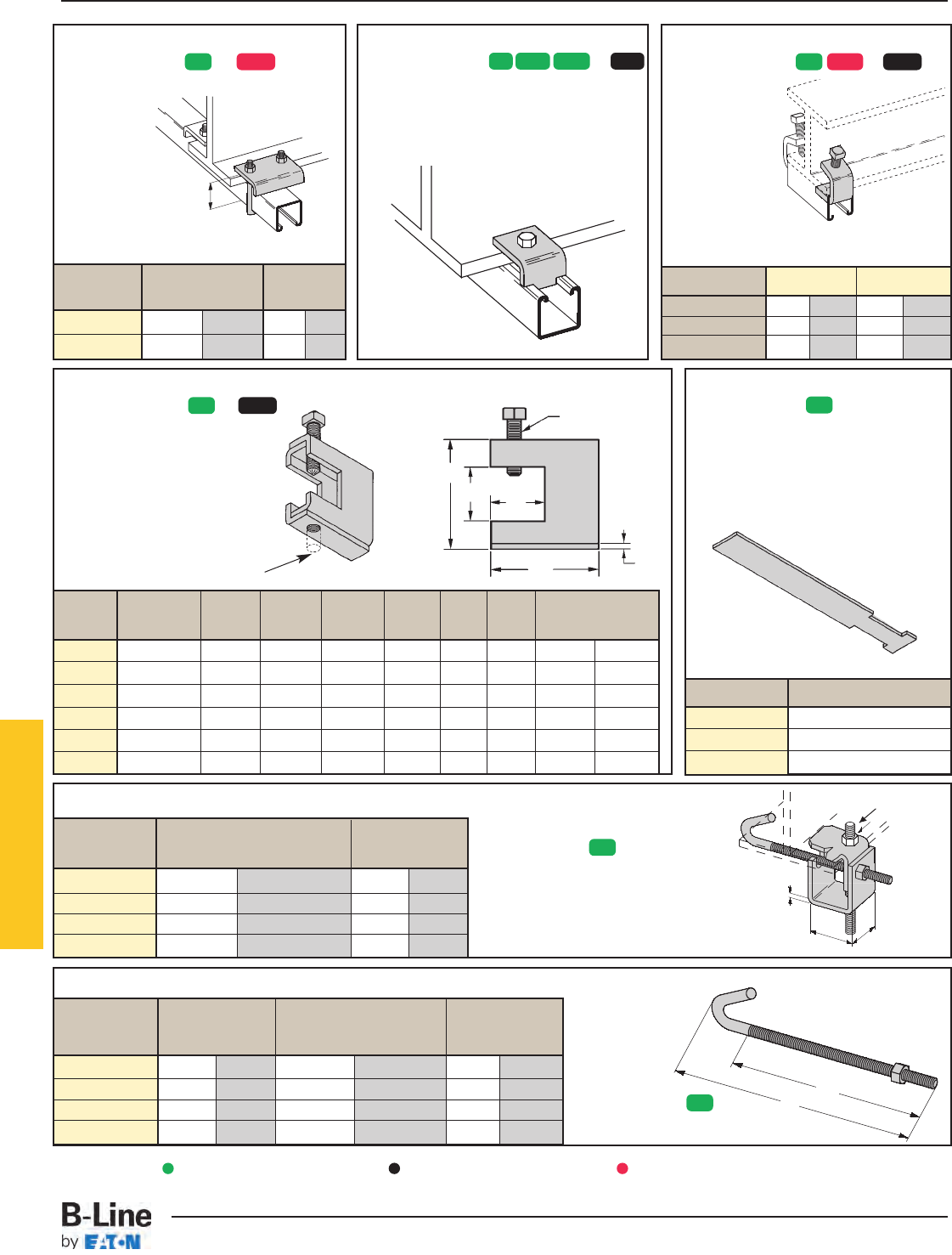
Beam Clamp
Beam Clamp
B312 Anchor Strap
• Finish available:
• For a maximum beam
thickness of 3/4".
• For thicker beams, step up
one flange width size.
Cat. No. Flange Width
B312-6 Up to 6"
B312-9 6" - 9"
B312-12 9" - 12"
Beam Clamp
• Finishes available: or
• Sold in pieces.
Design load when used in pairs.
Safety Load Factor 5.0
Catalog 'A' Thread Length 'TL' Wt./C
No. in. mm in. mm lbs kg
B700-J4 81/2" 215.9 5" 127.0 44 19.9
B700-J6 111/2" 292.1 6" 152.4 53 24.0
B700-J9 121/4" 368.3 6" 152.4 63 28.6
B700-J12 171/2" 444.5 6" 152.4 78 35.4
B305 Thru B308 & B321 Series Beam Clamps
• Finishes available: or
• Setscrew included.
• Safety Load Factor 5.0
Cat. Rod Design Load
No. Size A BC DEFT
lbs kN
B305 3/8"-16 3/8"-16 2 5/16"7/8" 1 1/8" 2 1/2" 11 Ga. 600 2.67
B306 3/8"-16 1/2"-13 2 7/16"7/8" 1 1/8" 2 1/2" 7 Ga. 1100 4.90
B307 1/2"-13 1/2"-13 2 7/16"7/8" 1 1/8" 2 1/2" 7 Ga. 1100 4.90
B308 1/2"-13 1/2"-13 2 9/16"7/8" 1 1/8" 2 1/2"1/4" 1500 6.68
B321-1 3/8"-16 1/2"-13 3 9/16" 1 11/16" 1 5/8" 3 1/4"1/4" 1300 5.79
B321-2 1/2"-13 1/2"-13 3 9/16" 1 11/16" 1 5/8" 3 1/4"1/4" 1400 6.23
Beam Clamp
• Finishes available: or
• Sold in pieces.
Design load when used in pairs.
Safety Load Factor 5.0
Cat. No. B212-1/4B212-3/8
Design Load * 600 lbs. 2.67 kN 1000 lbs. 4.45 kN
Max. Flange Thick 3/4"19 mm 1 1/8"28.6 mm
Mat'l. Thickness 1/4"6.3 mm 3/8"9.5 mm
Beam Clamp B355
• Finishes available: or
• Sold in pieces.
• Design load is 1200 lbs. when used in pairs.
• Safety Load Factor 5.0
• Order HHCS and
Channel Nuts separately.
B
E
D
C
FT
• Finish available:
• Design Load 500 lbs. (2.22 kN)
• Safety Load Factor 5.0
• Recommended torque:
'J'-Hook Nut 125 In.-Lbs. (14.1 kN/m)
• Maximum flange thickness of 3/4"
• Finish available:
• Hex Nut included.
A
A
Material:
7 Gauge (4.6)
1/2"-13 Rod & Hex
Nut Sold Separately
1/2"-13 Threads
1 1/2"
(38.1)
“A’
‘TL’
1 7/8"
(47.6)
J-Hook & Hex
Nut Included
Catalog For Flange Width Wt./C
No. in. mm lbs kg
B750-J4 3"- 6" 76.2 - 152.4 109 49.4
B750-J6 5"- 9" 127.0 - 288.6 124 56.2
B750-J9 8"- 12" 203.2 - 304.8 135 61.2
B750-J12 11"- 15" 279.4 - 381.0 147 66.7
Catalog Design Load* 'A'
lbs kN in. mm
B441-22 1200 5.34 33/8 86
B441-22A 1200 5.34 5 127
Series 2, 3, 4, & 5 Aluminum
ZN HDG ZN GRN HDG SS4 ZN GRN HDG
ZN
ZN HDG
ZN
ZN
Green = Fastest shipped items Black = Normal lead-time items Red = Normally long lead-time items
HAT-21
Series 2, 3, 4, & 5 Aluminum - Accessories
Cable Tray Systems
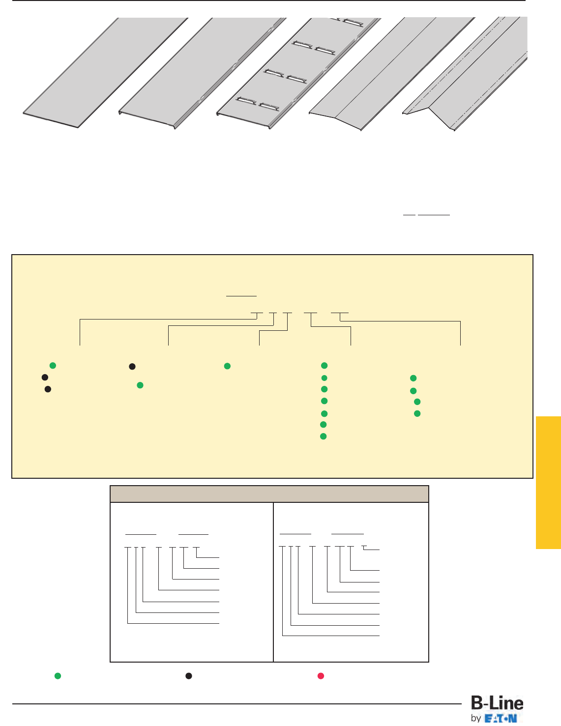
Aluminum Cover Part Numbering
Prefix
Example: 80 7 A - 24 - 144
Cover Type Detail Material Tray Width Item Description
80 = Solid 6 = Non-Flanged A = Aluminum
06 = 6"
For Straight Section Cover:
81 = Ventilated (80 & 81 type only)
09 = 9" 144 = 12 ft. (3.66 m)
82 = Peaked 7 = Flange 12 = 12" 120 = 10 ft. (3.05 m)
18 = 18"
72 = 6 ft. (1.83 m)
24 = 24"
60 = 5 ft. (1.52 m)
30 = 30"
For fitting covers: Insert suffix of
36 = 36"
fitting to be covered.
See example below.
Examples of Catalog Numbers for Fitting Covers:
A full range of covers is available for straight sections and fittings.
Solid covers should be used when maximum enclosure of the cable is desired and no accumulation of heat is expected.
Ventilated covers provide an overhead cable shield, yet allow heat to escape.
B-Line recommends that covers be placed on vertical cable tray runs to a height of 6 ft. (1.83 m) to 8 ft. (2.44 m) above the floor
to isolate both cables and personnel. Flanged covers have a 1/2in. (13 mm) flange. Cover clamps are not included with the cover and
must be ordered separately. All peaked covers are flanged. Standard peaked covers have 1/2" peak. Special purpose peaked covers,
having a 2 to 3 pitch, provide additional slope and material thickness. The 2 to 3 pitch fitting covers are of multiple piece, welded
construction.
Solid Flanged Ventilated Flanged Peaked Flanged 2 to 3 Pitch
Peaked Flanged
(See page APP-4)
Vertical Bend Cover
Prefix Suffix
80 7 A - 24 - 90 VO 24 - 4*
Side Rail*
Height
Radius
Fitting
Angle
Width
Material
Detail
Cover Type
Solid Non-Flanged
Covers
Horizontal Bend Cover
Prefix Suffix
80 7 A - 18 - 90 HB 24
Radius
Fitting
Angle
Width
Material
Detail
Cover Type
* Required for VO fittings only
Covers 30" and 36" wide have reinforcing ridges.
Series 2, 3, 4, & 5 Aluminum
Green = Fastest shipped items Black = Normal lead-time items Red = Normally long lead-time items
HAT-22
Series 2, 3, 4, & 5 Aluminum - Accessories
Cable Tray Systems
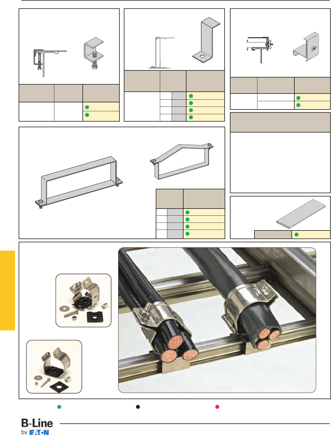
Cover Joint Strip
• Used to join covers
• Plastic
• (‡) Insert tray
width
Raised Cover Clamp
• For indoor service only.
• For use with flanged covers only.
† Specify gap of 1", 2", 3" or 4".
Tray Side Rail Catalog
Type Height No.
4" & 5" Deep 9ZN-9112-†
6" & 7" Deep 9ZN-9113-†
Combination Cover and
Hold Down Clamp
• Sold per piece.
• For indoor service only.
Tray Side Rail Catalog
Type Height No.
in. mm
4 101 9A-9043
5 127 9A-9053
6 152 9A-9063
7 178 9A-9073
Heavy Duty Cover Clamp
• Recommended for outdoor service.
Aluminum
Standard Cover Clamp
• For indoor service only.
• Setscrew included.
• Sold per piece.
Tray Side Rail Catalog
Type Height No.
Aluminum All Sizes 9ZN-9012
9A-9012
Aluminum
Quantity of Standard
Cover Clamps Required
Straight Section 60" or 72" .............4 pcs.
Straight Section 120" or 144" .........6 pcs.
Horizontal/Vertical Bends ................4 pcs.
Tees .................................................6 pcs.
Crosses............................................8 pcs.
Note: When using the Heavy Duty Cover
Clamp, only one-half the number of clamps
stated above is required.
Peaked Cover Clamp
(‡) Insert tray width
† Add P to Catalog
No. for peaked
cover clamp.
4 101 9A-(‡)-9044†
5 127 9A-(‡)-9054†
6 152 9A-(‡)-9064†
7 178 9A-(‡)-9074†
Side Rail Catalog
Height No.
in. mm
Catalog No. 99-9980-(‡)
†
Cable Cleats
(see pages CFX-1 thru CFX-5)
Series 2, 3, 4, & 5 Aluminum
Trefoil
Cable
Cleats
Single
Cable
Cleats
248
Green = Fastest shipped items Black = Normal lead-time items Red = Normally long lead-time items
HAT-23
Series 2, 3, 4, & 5 Aluminum - Accessories
Cable Tray Systems
Section 1- Acceptable Manufacturers
1.01 Manufacturer: Subject to compliance with these specifications, cable tray systems shall be as
manufactured by B-Line.
Section 2- Cable Tray Sections and Components
2.01 General: Except as otherwise indicated, provide metal cable trays, of types, classes and sizes indicated;
with splice plates, bolts, nuts and washers for connecting units. Construct units with rounded edges
and smooth surfaces; in compliance with applicable standards; and with the following additional
construction features. Cable tray shall be installed according to the latest revision of NEMA VE 2.
2.02 Materials and Finish: Straight section and fitting side rails and rungs shall be extruded from Aluminum
Association Alloy 6063. All fabricated parts shall be made from Aluminum Association Alloy 5052.
2.03 Ladder Cable Trays shall consist of two longitudinal members (side rails) with transverse members
(rungs) welded to the side rails. Rungs shall be spaced [6] [9] [12] inches on center. Rung spacing in
radiused fittings shall be industry standard 9" and measured at the center of the tray’s width. Each
rung must be capable of supporting a 200 lb. concentrated load at the center of the cable tray over
and above the cable load with a safety factor of 1.5.
2.04 Ventilated Trough Cable Trays shall consist of two longitudinal members (side rails) with a corrugated
bottom welded to the side rails or rungs spaced 4" on center. The peaks of the corrugated bottom
shall have a minimum flat cable bearing surface of 23/4" and shall be spaced on 6" centers. To
provide ventilation in the tray, the valleys of the corrugated bottom shall have 21/4" x 4" rectangular
holes punched along the width of the bottom.
2.05 Non-Ventilated Bottom Trough Cable Trays shall consist of two longitudinal members (side rails) with a
corrugated bottom welded to the side rails or a solid sheet over rungs. The peaks of the corrugated
bottom shall have a minimum flat cable bearing surface of 23/4" and shall be spaced on 6" centers.
2.06 Cable tray loading depth shall be [3] [4] [5] [6] inches per NEMA VE 1.
2.07 Straight sections shall have side rails fabricated as I-beams. Straight sections shall be supplied in
standard [12 foot] [24 foot] [10 foot (3 m)] [20 foot (6 m)] lengths.
2.08 Cable tray widths shall be [6] [9] [12] [18] [24] [30] [36] inches or as shown on drawings.
2.09 Splice plates shall be the Wedge-Lock design with 4 nuts and bolts per plate. The resistance of fixed
splice connections between an adjacent section of tray shall not exceed 0.00033 ohm.
2.10 All fittings must have a minimum radius of [12] [24] [36] [48] inches.
Section 3- Loading Capacities and Testing
3.01 Cable tray shall be capable of carrying a uniformly distributed load of ______ lbs./ft. on a _______ ft.
support span with a safety factor of 1.5 when supported as a simple span and tested per NEMA
VE 1 5.2. In addition to the uniformly distributed load the cable tray shall support 200 lbs.
concentrated load at mid-point of span. Load and safety factors specified are applicable to both the
side rails and rung capacities. Cable tray shall be made to manufacturing tolerances as specified by
NEMA.
3.02 Upon request, manufacturer shall provide test reports in accordance with the latest revision of NEMA
VE 1 or CSA C22.2 No. 126.
Series 2, 3, 4, & 5 Aluminum
HAT-24
Series 2, 3, 4, & 5 Aluminum - Specifications
Cable Tray Systems
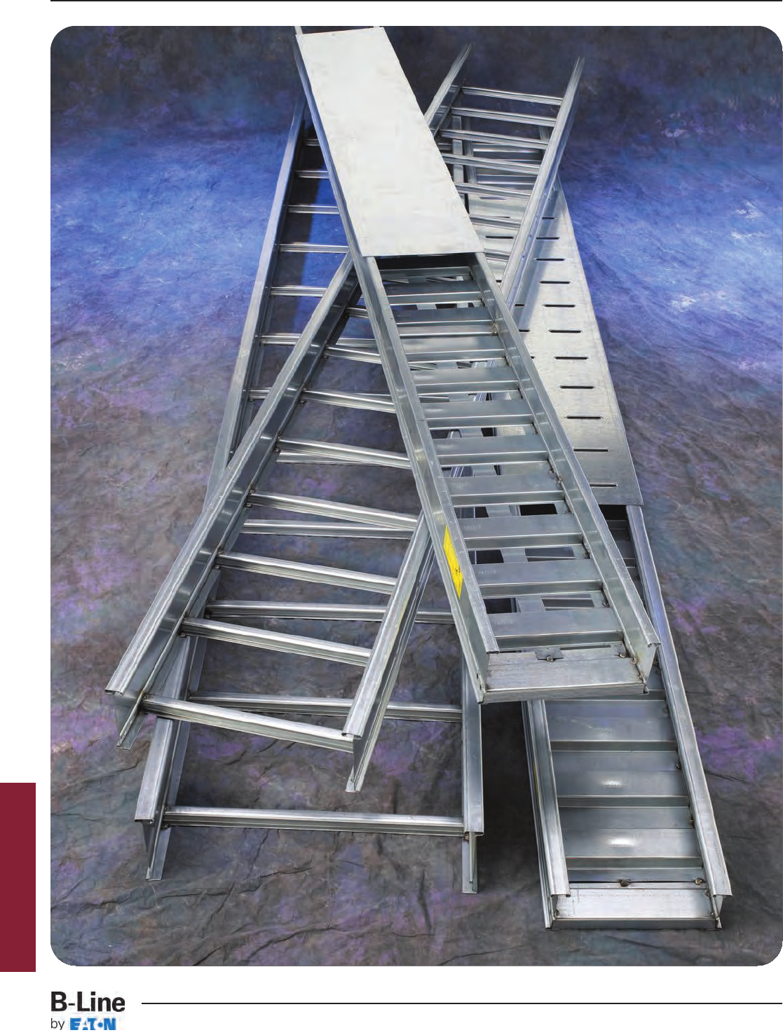
Series 2, 3, 4, & 5 Steel
HST-1
Series 2, 3, 4, & 5 Steel
Cable Tray Systems
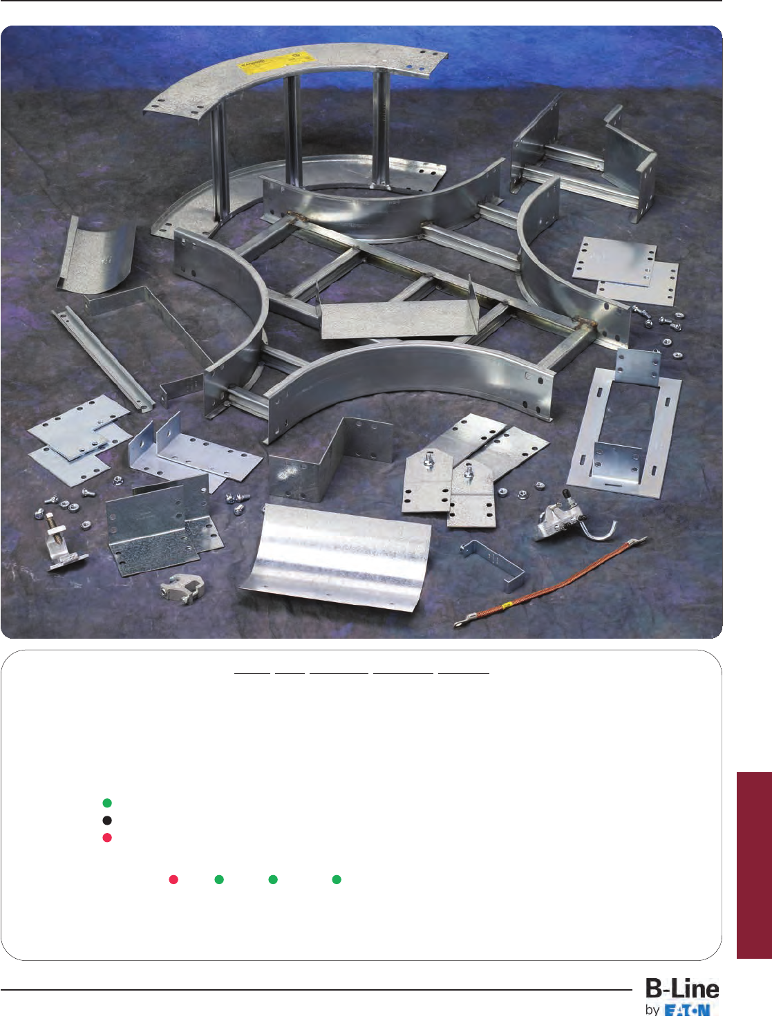
Series 2, 3, 4, & 5 Steel
How The Service Advisor Works
B-Line knows that your time is important! That’s why the color-coding system in this catalog is designed to help you
select products that fit your service needs. Products are marked to indicate the typical lead time for orders of 50 pieces
or less.
Customer: How do I select my straight sections. covers, or fittings so that I get the quickest turnaround?
Service Advisor: Each part of our selection chart is shown in colors. If any section of a part number is a different
color, the part will typically ship with the longer lead time represented by the colors.
Green = Fastest shipped items
Black = Normal lead-time items
Red = Normally long lead-time items
Example: 258G 12 - 24 - 144 Part will have a long
lead time because of the
258G material.
Changing the part number from 258G to 258P will change the coding to black and reduce lead time.
For Steel Fittings
see fittings section pages
FTS-1 thru FTS-17
HST-2
Series 2, 3, 4, & 5 Steel
Cable Tray Systems
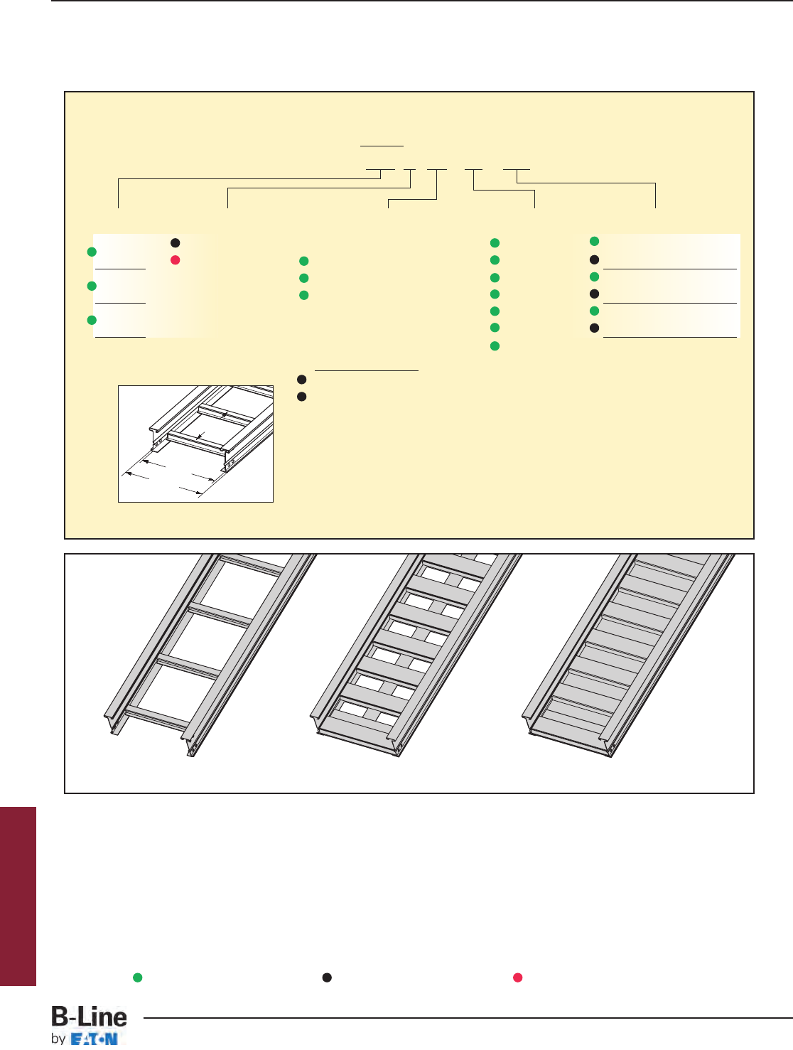
3" NEMA VE 1 Loading Depth
4" Side Rail Height
Ladder Type
(Specify Rung Spacing)
Ventilated Trough Non-Ventilated Trough
Rung
Spacing
Width
(Inside)
Overall Width
(Width + (*))
For side rail & rung
data, see chart on
pages AP-5 &
AP-6
(*)=13/16” (Series 2)
13/8” (Series 3,4,5)
Straight Section Part Numbering
Prefix
Example: 248 P 09 - 24 - 144
Series Material *Type *Width Length
248 P= Pre-Galvanized Ladder- 06 = 6" ¨144 = 12 ft. 248
G= HDGAF 06 = 6" rung spacing 09 = 9" ¡120 = 10 ft.
346 09 = 9" rung spacing 12 = 12" ¨240 = 20 ft. 346
12 = 12" rung spacing 18 = 18" ¡144 = 12 ft.
444 24 = 24" ¨240 = 20 ft. 444
30 = 30" ¡288 = 24 ft.
Trough- 36 = 36"
6" thru 36" wide
VT = Vented Trough
ST = Non-Ventilated Trough
See page APP-1 for additional rung options. *Special sizes available.
Series 2, 3, 4, & 5 Steel
¨Primary Length.
¡Secondary Length.
See page CTS-23 for
explanation of lengths.
Green = Fastest shipped items Black = Normal lead-time items Red = Normally long lead-time items
HST-3
Series 2, 3, 4, & 5 Steel - Straight Sections
Cable Tray Systems

B-Line Side Rail NEMA, CSA & UL Span Load Deflection Design Factors Span Load Deflection Design Factors
Series Dimensions Classifications ft lbs/ft Multiplier for Two Rails meters kg/m Multiplier for Two Rails
NEMA: 20A, 16B 10 252 0.0035 3.0 375 0.060
CSA: D1-6m 12 175 0.0072 Area=0.89 in23.7 260 0.124 Area=5.74 cm2
14 129 0.013 Sx=0.96 in34.3 191 0.229 Sx=15.73 cm3
UL Cross-Sectional 16 98 0.023 Ix=2.22 in44.9 146 0.391 Ix=92.40 cm4
Area: 0.70 in218 78 0.037 5.5 116 0.626
20 63 0.056 6.1 94 0.955
B-Line Side Rail NEMA, CSA & UL Span Load Deflection Design Factors Span Load Deflection Design Factors
Series Dimensions Classifications ft lbs/ft Multiplier for Two Rails meters kg/m Multiplier for Two Rails
NEMA: 20B, 16C 12 253 0.0055 3.7 376 0.093
CSA: E-3m 16 142 0.017 Area=1.19 in24.9 212 0.295 Area=7.68 cm2
18 112 0.028 Sx=1.27 in35.5 167 0.473 Sx=20.81 cm3
UL Cross-Sectional 20 91 0.042 Ix=2.94 in46.1 135 0.721 Ix=122.37 cm4
Area: 1.00 in222 75 0.062 6.7 112 1.055
24 63 0.088 7.3 94 1.495
B-Line Side Rail NEMA, CSA & UL Span Load Deflection Design Factors Span Load Deflection Design Factors
Series Dimensions Classifications ft lbs/ft Multiplier for Two Rails meters kg/m Multiplier for Two Rails
NEMA: 16A, 12C 6 412* 0.0007 1.8 613* 0.012
CSA: D1-3m 8 232 0.0022 Area=0.62 in22.4 345 0.038 Area=4.00 cm2
10 148 0.0054 Sx=0.64 in33.0 221 0.093 Sx=10.49 cm3
UL Cross-Sectional 12 103 0.011 Ix=1.43 in43.7 153 0.192 Ix=59.52 cm4
Area: 0.40 in214 76 0.021 4.3 113 0.356
16 58 0.036 4.9 86 0.607
Values are based on simple beam tests per NEMA VE 1 on 36" wide cable tray with rungs spaced on 12" centers. Cable trays will
support without collapse a 200 lb. (90.7 kg) concentrated load over and above published loads. Published load safety factor is 1.5.
To convert 1.5 safety factor to 2.0, multiply publish load by 0.75. To obtain mid-span deflection, multiply a load by the deflection
multiplier. Cable tray must be supported on spans shorter than or equal to the length of the cable tray being installed.
Individual rungs will support without collapse a 200 lb. (90.7 kg) concentrated load applied at the mid-span of the rung, over and
above the NEMA rated cable load with a 1.5 safety factor for highlighted NEMA spans and loads.
*When using 18" rung spacing, load capacity is limited to 394 lbs/ft (586.272 kg/m) for 30" cable tray width and 325 lbs/ft
(483.6 kg/m) for 36" cable tray width. When cable trays are used in continuous spans, the deflection of the cable tray is reduced
by as much as 50%. Design factors: Ix = Moment of Inertia, Sx = Section Modulus.
1.00
4.188
18 gauge
3.14
1.50
4.188 3.13
1.50
4.188 3.11
16 gauge
14 gauge
3" NEMA VE 1 Loading Depth
4" Side Rail Height
346
444
248
Series 2, 3, 4, & 5 Steel
HST-4
Series 2, 3, 4, & 5 Steel - Straight Sections
Cable Tray Systems

4" NEMA VE 1 Loading Depth
5" Side Rail Height
Rung
Spacing
Width
(Inside)
Overall Width
(Width + (*))
For side rail & rung
data, see chart on
pages AP-5 &
AP-6
(*)=13/16” (Series 2)
13/8” (Series 3,4,5)
Straight Section Part Numbering
Prefix
Example: 258 P 09 - 24 - 144
Series Material *Type *Width Length
258 P= Pre-Galvanized Ladder- 06 = 6" ¨144 = 12 ft. 258
G= HDGAF 06 = 6" rung spacing 09 = 9" ¡120 = 10 ft.
356 09 = 9" rung spacing 12 = 12" ¨240 = 20 ft. 356
12 = 12" rung spacing 18 = 18" ¡144 = 12 ft.
454 24 = 24" ¨240 = 20 ft. 454
30 = 30" ¡288 = 24 ft.
Trough- 36 = 36"
6" thru 36" wide
VT = Vented Trough
ST = Non-Ventilated Trough
See page APP-1 for additional rung options. *Special sizes available.
Ladder Type
(Specify Rung Spacing)
Ventilated Trough Non-Ventilated Trough
Series 2, 3, 4, & 5 Steel
¨Primary Length.
¡Secondary Length.
See page CTS-23 for
explanation of lengths.
Green = Fastest shipped items Black = Normal lead-time items Red = Normally long lead-time items
HST-5
Series 2, 3, 4, & 5 Steel - Straight Sections
Cable Tray Systems
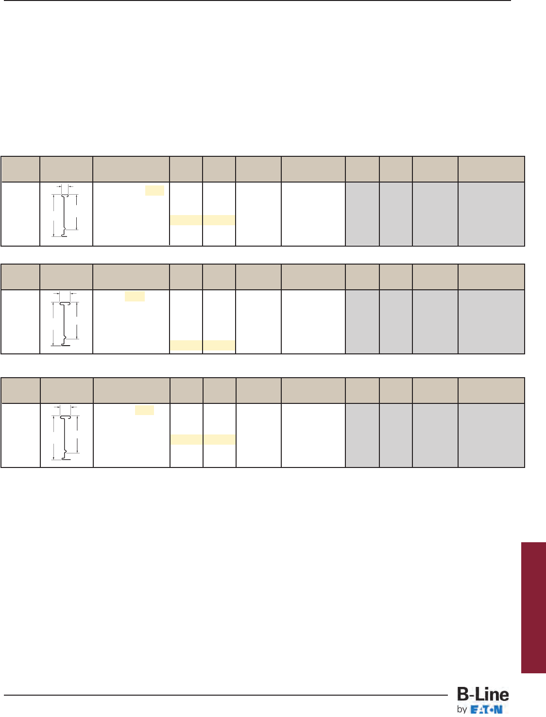
B-Line Side Rail NEMA, CSA & UL Span Load Deflection Design Factors Span Load Deflection Design Factors
Series Dimensions Classifications ft lbs/ft Multiplier for Two Rails meters kg/m Multiplier for Two Rails
NEMA: 20C 12 294 0.0032 3.7 438 0.055
CSA: E-6m 16 166 0.010 Area=1.34 in24.9 246 0.175 Area=8.65 cm2
18 131 0.016 Sx=1.75 in35.5 195 0.280 Sx=28.68 cm3
UL Cross-Sectional 20 106 0.025 Ix=4.96 in46.1 158 0.427 Ix=206.45 cm4
Area: 1.00 in222 88 0.037 6.7 130 0.625
24 74 0.052 7.3 110 0.886
B-Line Side Rail NEMA, CSA & UL Span Load Deflection Design Factors Span Load Deflection Design Factors
Series Dimensions Classifications ft lbs/ft Multiplier for Two Rails meters kg/m Multiplier for Two Rails
NEMA: 20A, 16C 10 276 0.0021 3.0 411 0.036
CSA: D1-6m 12 192 0.0043 Area=1.00 in23.7 285 0.074 Area=6.45 cm2
14 141 0.0080 Sx=1.31 in34.3 210 0.136 Sx=21.47 cm3
UL Cross-Sectional 16 108 0.014 Ix=3.73 in44.9 160 0.233 Ix=155.25 cm4
Area: 0.70 in218 85 0.022 5.5 127 0.373
20 69 0.033 6.1 103 0.568
B-Line Side Rail NEMA, CSA & UL Span Load Deflection Design Factors Span Load Deflection Design Factors
Series Dimensions Classifications ft lbs/ft Multiplier for Two Rails meters kg/m Multiplier for Two Rails
NEMA: 16A, 12C 6 436* 0.0004 1.8 649* 0.007
CSA: D1-3m 8 245 0.0013 Area=0.71 in22.4 365 0.022 Area=4.58 cm2
10 157 0.0032 Sx=0.89 in33.0 234 0.054 Sx=14.58 cm3
UL Cross-Sectional 12 109 0.0066 Ix=2.44 in43.7 162 0.113 Ix=101.56 cm4
Area: 0.40 in214 80 0.012 4.3 119 0.209
16 61 0.021 4.9 91 0.356
Values are based on simple beam tests per NEMA VE 1 on 36" wide cable tray with rungs spaced on 12" centers. Cable trays will
support without collapse a 200 lb. (90.7 kg) concentrated load over and above published loads. Published load safety factor is 1.5.
To convert 1.5 safety factor to 2.0, multiply published load by 0.75. To obtain mid-span deflection, multiply a load by the deflection
multiplier. Cable tray must be supported on spans shorter than or equal to the length of the cable tray being installed.
Individual rungs will support without collapse a 200 lb. (90.7 kg) concentrated load applied at the mid-span of the rung, over and
above the NEMA rated cable load with a 1.5 safety factor for highlighted NEMA spans and loads.
* When using 18" rung spacing, load capacity is limited to 394 lbs/ft (586.272 kg/m) for 30" cable tray width and 325 lbs/ft
(483.6 kg/m) for 36" cable tray width. When cable trays are used in continuous spans, the deflection of the cable tray is reduced
by as much as 50%. Design factors: Ix = Moment of Inertia, Sx = Section Modulus.
1.00
5.188 4.14
1.50
5.188 4.13
1.50
5.188 4.11
18 gauge
14 gauge
16 gauge
4" NEMA VE 1 Loading Depth
5" Side Rail Height
258
356
454
Series 2, 3, 4, & 5 Steel
HST-6
Series 2, 3, 4, & 5 Steel - Straight Sections
Cable Tray Systems

5" NEMA VE 1 Loading Depth
6" Side Rail Height
Rung
Spacing
Width
(Inside)
Overall Width
(Width + (*))
For side rail & rung
data, see chart on
pages AP-5 &
AP-6
(*)=13/16” (Series 2)
13/8” (Series 3,4,5)
Straight Section Part Numbering
Prefix
Example: 268 P 09 - 24 - 144
Series Material *Type *Width Length
268 P= Pre-Galvanized Ladder- 06 = 6" ¨144 = 12 ft. 268
G= HDGAF 06 = 6" rung spacing 09 = 9" ¡120 = 10 ft.
366 09 = 9" rung spacing 12 = 12" ¨240 = 20 ft. 366
12 = 12" rung spacing 18 = 18" ¡144 = 12 ft.
464 24 = 24" ¨240 = 20 ft. 464
30 = 30" ¡288 = 24 ft.
Trough- 36 = 36"
6" thru 36" wide
VT = Vented Trough
ST = Non-Ventilated Trough
See page APP-1 for additional rung options. *Special sizes available.
Ladder Type
(Specify Rung Spacing)
Ventilated Trough Non-Ventilated Trough
Series 2, 3, 4, & 5 Steel
¨Primary Length.
¡Secondary Length.
See page CTS-23 for
explanation of lengths.
Green = Fastest shipped items Black = Normal lead-time items Red = Normally long lead-time items
HST-7
Series 2, 3, 4, & 5 Steel - Straight Sections
Cable Tray Systems
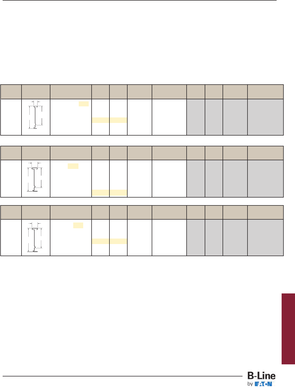
B-Line Side Rail NEMA, CSA & UL Span Load Deflection Design Factors Span Load Deflection Design Factors
Series Dimensions Classifications ft lbs/ft Multiplier for Two Rails meters kg/m Multiplier for Two Rails
NEMA: 20C 12 342* 0.002 3.7 508* 0.036
CSA: E-6m 16 192 0.007 Area=1.49 in24.9 286 0.113 Area=9.61 cm2
18 152 0.011 Sx=2.28 in35.5 226 0.182 Sx=37.36 cm3
UL Cross-Sectional 20 123 0.016 Ix=7.65 in46.1 183 0.277 Ix=318.42 cm4
Area: 1.00 in222 102 0.024 6.7 151 0.406
24 85 0.034 7.3 127 0.574
B-Line Side Rail NEMA, CSA & UL Span Load Deflection Design Factors Span Load Deflection Design Factors
Series Dimensions Classifications ft lbs/ft Multiplier for Two Rails meters kg/m Multiplier for Two Rails
NEMA: 20B, 16C 10 300 0.0014 3.0 446 0.023
CSA: E-6m 12 208 0.0028 Area=1.11 in23.7 310 0.048 Area=7.16 cm2
14 153 0.0052 Sx=1.71 in34.3 228 0.089 Sx=28.02 cm3
UL Cross-Sectional 16 117 0.0089 Ix=5.74 in44.9 174 0.151 Ix=238.92 cm4
Area: 1.00 in218 93 0.014 5.5 138 0.242
20 75 0.022 6.1 112 0.369
B-Line Side Rail NEMA, CSA & UL Span Load Deflection Design Factors Span Load Deflection Design Factors
Series Dimensions Classifications ft lbs/ft Multiplier for Two Rails meters kg/m Multiplier for Two Rails
NEMA: 16A, 12C 6 440* 0.0003 1.8 655* 0.005
CSA: D1-3m 8 248 0.0008 Area=0.80 in22.4 368 0.014 Area=5.16 cm2
10 158 0.0020 Sx=1.18 in33.0 236 0.035 Sx=19.34 cm3
UL Cross-Sectional 12 110 0.0042 Ix=3.81 in43.7 164 0.072 Ix=158.58 cm4
Area: 0.70 in214 81 0.0078 4.3 120 0.134
16 62 0.013 4.9 92 0.228
Values are based on simple beam tests per NEMA VE 1 on 36" wide cable tray with rungs spaced on 12" centers. Cable trays will
support without collapse a 200 lb. (90.7 kg) concentrated load over and above published loads. Published load safety factor is 1.5.
To convert 1.5 safety factor to 2.0, multiply published load by 0.75. To obtain mid-span deflection, multiply a load by the deflection
multiplier. Cable tray must be supported on spans shorter than or equal to the length of the cable tray being installed.
Individual rungs will support without collapse a 200 lb. (90.7 kg) concentrated load applied at the mid-span of the rung, over and
above the NEMA rated cable load with a 1.5 safety factor for highlighted NEMA spans and loads.
* When using 18" rung spacing, load capacity is limited to 394 lbs/ft (586.272 kg/m) for 30" cable tray width and 325 lbs/ft
(483.6 kg/m) for 36" cable tray width. When cable trays are used in continuous spans, the deflection of the cable tray is reduced
by as much as 50%. Design factors: Ix = Moment of Inertia, Sx = Section Modulus.
1.00
6.188 5.14
1.50
6.188 5.14
1.50
6.188 5.11
18 gauge
16 gauge
14 gauge
5" NEMA VE 1 Loading Depth
6" Side Rail Height
268
366
464
Series 2, 3, 4, & 5 Steel
HST-8
Series 2, 3, 4, & 5 Steel - Straight Sections
Cable Tray Systems
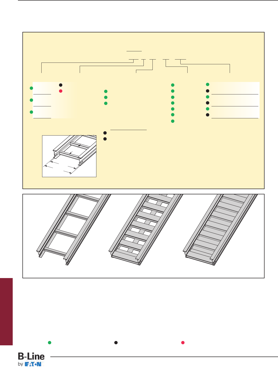
6" NEMA VE 1 Loading Depth
7" Side Rail Height
Overall Width
(Width + 13/8")
For side rail & rung
data, see chart on
pages AP-5 &
AP-6
Rung
Spacing
Width
(Inside)
Straight Section Part Numbering
Prefix
Example: 378 P 09 - 24 - 240
Series Material *Type *Width Length
378 P= Pre-Galvanized Ladder- 06 = 6" ¨144 = 12 ft. 378
G= HDGAF 06 = 6" rung spacing 09 = 9" ¡240 = 20 ft.
476 09 = 9" rung spacing 12 = 12" ¨240 = 20 ft. 476
12 = 12" rung spacing 18 = 18" ¡288 = 24 ft.
574 24 = 24" ¨240 = 20 ft. 574
30 = 30" ¡288 = 24 ft.
Trough- 36 = 36"
6" thru 36" wide
VT = Vented Trough
ST = Non-Ventilated Trough
See page APP-1 for additional rung options. *Special sizes available.
Ladder Type
(Specify Rung Spacing)
Ventilated Trough Non-Ventilated Trough
Series 2, 3, 4, & 5 Steel
¨Primary Length.
¡Secondary Length.
See page CTS-23 for
explanation of lengths.
Green = Fastest shipped items Black = Normal lead-time items Red = Normally long lead-time items
HST-9
Series 2, 3, 4, & 5 Steel - Straight Sections
Cable Tray Systems
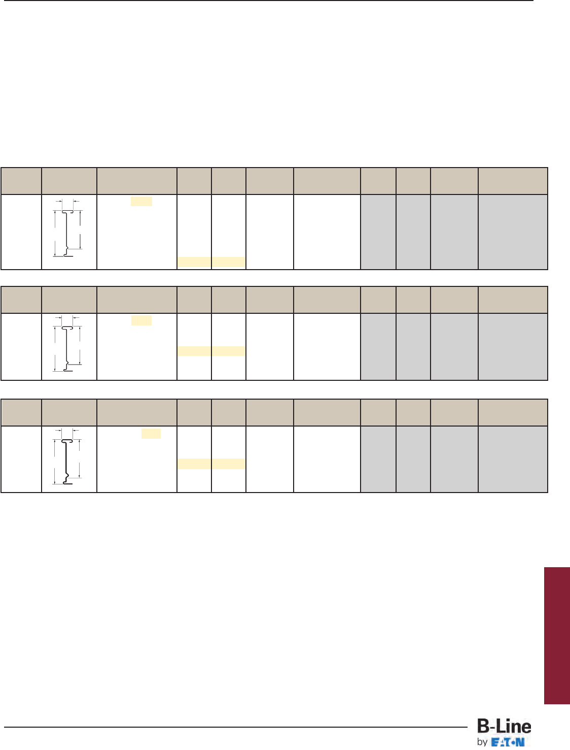
B-Line Side Rail NEMA, CSA & UL Span Load Deflection Design Factors Span Load Deflection Design Factors
Series Dimensions Classifications ft lbs/ft Multiplier for Two Rails meters kg/m Multiplier for Two Rails
NEMA: 20C 12 361 0.0014 3.7 537 0.025
CSA: E-6m 16 203 0.0046 Area=1.64 in24.9 302 0.078 Area=10.58 cm2
18 160 0.0073 Sx=2.87 in35.5 239 0.125 Sx=47.03 cm3
UL Cross-Sectional 20 130 0.011 Ix=11.10 in46.1 193 0.191 Ix=462.02 cm4
Area: 1.50 in222 107 0.016 6.7 160 0.280
24 90 0.023 7.3 134 0.396
B-Line Side Rail NEMA, CSA & UL Span Load Deflection Design Factors Span Load Deflection Design Factors
Series Dimensions Classifications ft lbs/ft Multiplier for Two Rails meters kg/m Multiplier for Two Rails
NEMA: 20B, 16C 12 214 0.0019 3.7 318 0.033
CSA: D1-6m 16 120 0.0061 Area=1.22 in24.9 179 0.105 Area=7.87 cm2
18 95 0.010 Sx=2.14 in35.5 141 0.168 Sx=35.07 cm3
UL Cross-Sectional 20 77 0.015 Ix=8.30 in46.1 115 0.255 Ix=345.47 cm4
Area: 1.00 in222 64 0.022 6.7 95 0.374
24 53 0.031 7.3 80 0.529
B-Line Side Rail NEMA, CSA & UL Span Load Deflection Design Factors Span Load Deflection Design Factors
Series Dimensions Classifications ft lbs/ft Multiplier for Two Rails meters kg/m Multiplier for Two Rails
NEMA: 20A, 16B 8 319 0.0006 2.4 474 0.009
CSA: D1-3m 10 204 0.0014 3.0 304 0.023
12 142 0.0028 Area=1.01 in23.7 211 0.048 Area=6.52 cm2
14 104 0.0052 Sx=1.77 in34.3 155 0.089 Sx=29.01 cm3
UL Cross-Sectional 16 80 0.0089 Ix=6.90 in44.9 119 0.151 Ix=287.20 cm4
Area: 0.70 in218 63 0.014 5.5 94 0.242
20 51 0.022 6.1 76 0.369
7.188
Values are based on simple beam tests per NEMA VE 1 on 36" wide cable tray with rungs spaced on 12" centers. Cable trays will
support without collapse a 200 lb. (90.7 kg) concentrated load over and above published loads. Published load safety factor is 1.5.
To convert 1.5 safety factor to 2.0, multiply published load by 0.75. To obtain mid-span deflection, multiply a load by the deflection
multiplier. Cable tray must be supported on spans shorter than or equal to the length of the cable tray being installed.
Individual rungs will support without collapse a 200 lb. (90.7 kg) concentrated load applied at the mid-span of the rung, over and
above the NEMA rated cable load with a 1.5 safety factor for highlighted NEMA spans and loads.
When cable trays are used in continuous spans, the deflection of the cable tray is reduced by as much as 50%. Design factors:
Ix = Moment of Inertia, Sx = Section Modulus.
1.50
7.188 6.14
1.50
6.13
1.50
7.188 6.11
18 gauge
16 gauge
14 gauge
6" NEMA VE 1 Loading Depth
7" Side Rail Height
378
476
574
Series 2, 3, 4, & 5 Steel
HST-10
Series 2, 3, 4, & 5 Steel - Straight Sections
Cable Tray Systems
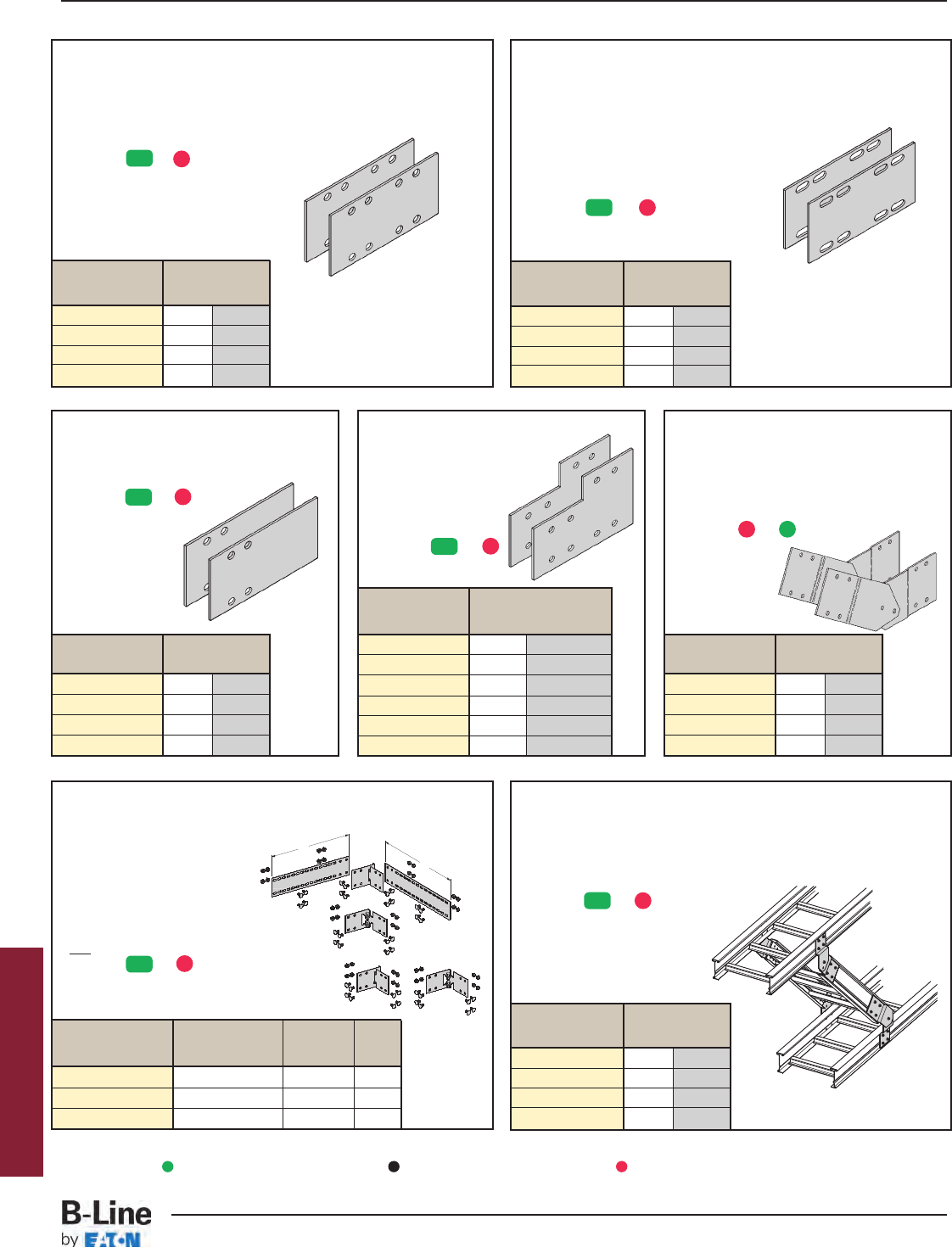
Catalog No. Height
in. mm
9(*)-8014 4 101
9(*)-8015 5 127
9(*)-8016 6 152
9(*)-8017 7 178
Catalog No. Height
in. mm
9(*)-8045 5 to 4 127 to 101
9(*)-8046 6 to 4 152 to 101
9(*)-8060 6 to 5 152 to 127
9(*)-8047 7 to 4 178 to 101
9(*)-8061 7 to 5 178 to 127
9(*)-8062 7 to 6 178 to 152
Splice Plates
• Standard 8-hole pattern for all steel splice plates.
• Furnished in pairs with hardware.
• One pair including hardware
provided with straight section.
• Boxed in pairs with hardware.
• (*) Insert or
Catalog No. Height
in. mm
9(*)-8004 4 101
9(*)-8005 5 127
9(*)-8006 6 152
9(*)-8007 7 178
Catalog No. Height
in. mm
9(*)-8004-1/24 101
9(*)-8005-1/25 127
9(*)-8006-1/26 152
9(*)-8007-1/27 178
Branch Pivot Connectors
• Branch from existing cable tray runs at any point.
• Pivot to any required angle.
• UL Classified for grounding
(bonding jumper not required).
• Furnished in pairs with hardware.
• (*) Insert or
Catalog No. Height
in. mm
9(*)-8244 4 101
9(*)-8245 5 127
9(*)-8246 6 152
9(*)-8247 7 178
Catalog Cable Tray Tray
No. End Cut Width 'L'
9(*)-803(X) Mitered Thru 36" N/A
9(*)-803(X)-12 Not mitered Thru 12" 16"
9(*)-803(X)-36 Not mitered Thru 36" 41"
9(*)-803(X)-12 or 9(*)-803(X)-36
One pair splice plates with extensions.
9(*)-803(X)
Splice only
L
L
Horizontal Adjustable Splice Plates
• Offered to adjust a cable tray run
for changes in direction in
a horizontal plane that do
not conform to standard
horizontal fittings.
• Furnished in pairs
with hardware.
• New design bonding jumpers
not required.
• (*) Insert or
• (X) Insert 4, 5, 6 or 7 for
side rail height.
Expansion Splice Plates
• Expansion plates allow for one inch
expansion or contraction of the cable tray,
or where expansion joints occur in
the support structure.
• Furnished in pairs with hardware.
•Bonding Jumpers are require
on each siderail.
Order Separately.
• (*) Insert or
For heavy duty expansion
splice plates see page APP-3.
Universal Splice Plates
• Used to splice to existing cable tray
systems.
• Furnished in pairs with hardware.
• (*) Insert or
Catalog No. Height
in. mm
9(*)-8024 4 101
9(*)-8025 5 127
9(*)-8026 6 152
9(*)-8027 7 178
Step Down Splice Plates
• These splice plates are offered
for connecting cable tray
sections having side rails
of different heights.
• Furnished in pairs
with hardware.
• (*) Insert or
Vertical Adjustable Splice Plates
• These plates provide for changes
in elevation that do not conform to
standard vertical fittings.
• Furnished in pairs with hardware.
•Bonding Jumpers not required.
• (*) Insert or
Series 2, 3, 4, & 5 Steel
ZN
ZN
ZN
ZN
ZN
ZN
Requires
supports
within 24”
on both
sides, per
NEMA VE 2.
Requires
supports within
24” on both
sides, per
NEMA VE 2.
Green = Fastest shipped items Black = Normal lead-time items Red = Normally long lead-time items
G
G
G
G
G
G
G P
HST-11
Series 2, 3, 4, & 5 Steel - Accessories
Cable Tray Systems
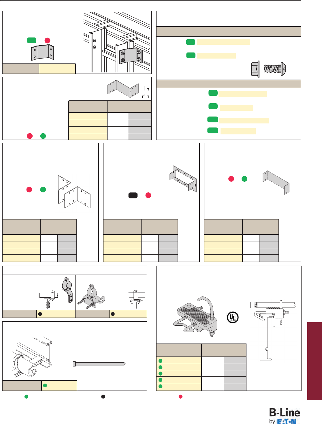
Conduit to Tray Adaptor
• For easy attachment of conduit terminating at a cable tray.
• Use on aluminum or steel cable trays.
Catalog No. Conduit Size
in. mm
9G-1158-1
/2, 3
/41
/2, 3
/415, 20
9G-1158-1, 11
/41, 11
/425, 32
9G-1158-11
/2, 2 11
/2, 2 40, 50
9G-1158-21
/2, 3 21
/2, 3 65, 80
9G-1158-31
/2, 4 31
/2, 4 90, 100
Cable Tie (Ladder Tray)
Nylon ties provide easy attachment of
cable to ladder rungs; maximum
cable O.D. of 3" (76mm).
Tray Hardware
Pre-Galvanized Tray Hardware
Catalog No. RNCB 3/8"-16 x 3/4" Znplt Ribbed Neck
Carriage Bolt ASTM A307 Grade A
Catalog No. SFHN 3/8"-16 Znplt Serrated Flange Hex Nut
ASTM A563 Grade A
Finish: Zinc Plated ASTM B633, SC1
Hot Dip Galvanized Tray Hardware
Standard: Catalog No. RNCB 3/8"-16 x 3/4" CZ Ribbed Neck
Carriage Bolt ASTM F1136-88 Grade 3 Chromium Zinc
Catalog No. SFHN 3/8"-16 CZ Serrated Flange Hex Nut
ASTM F1136-88 Grade A Chromium Zinc
Optional: Catalog No. RNCB 3/8"-16 x 3/4" SS6 AISI 316
Stainless Steel
Catalog No. SFHN 3/8"-16 SS6 AISI 316 Stainless Steel
Steel I-Beam
Overall Length 15"
Example: 9G-8004SS6
Catalog No. 99-2125-15
Catalog No. Height
in. mm
9(*)-8084-(‡) 4 101
9(*)-8085-(‡) 5 127
9(*)-8086-(‡) 6 152
9(*)-8087-(‡) 7 178
Catalog No. Height
in. mm
9(*)-8074-(‡) 4 101
9(*)-8075-(‡) 5 127
9(*)-8076-(‡) 6 152
9(*)-8077-(‡) 7 178
Catalog No. Height
in. mm
9(*)-8054 4 101
9(*)-8055 5 127
9(*)-8056 6 152
9(*)-8057 7 178
Tray to Box Splice Plates
• Used to attach the
end of a cable tray
run to a distribution
box or control panel.
• Furnished in pairs
with hardware.
• (*) Insert or
Blind End
• This plate forms a closure for a dead
end cable tray.
• Furnished as one plate
with hardware.
• (*) Insert or
• (‡) Insert tray width
Frame Type Box Connector
• Designed to attach the end of a cable tray
run to a distribution cabinet
or control center to help
reinforce the box at the
point of entry.
• Furnished with tray
connection hardware.
• (*) Insert or
• (‡) Insert tray width
Conduit to Tray Adaptors
• Assembly required. • Assembly required.
• Mounting hardware included. • Conduit clamp included.
• Conduit clamps provided. •
(‡)
=Conduit size.
•
(‡)
=Conduit size
(1/2" thru 4").
(1/2" thru 4").
Catalog No. 9ZN-1150-(‡) Catalog No. 9ZN-1155-(‡)
9(*)-1240
Catalog No.
Cross Connector Bracket
• For field connecting crossing section.
• Furnished in pairs with 3/8"
hardware.
• (*) Insert or
Offset Reducing Splice Plate
• This plate is used for joining cable trays having
different widths. When used in pairs they form
a straight reduction; when
used singly with a standard
splice plate, they form an
offset reduction.
• Furnished as one plate
with hardware.
• (‡) Insert reduction
• (*) Insert or
Catalog No. Height
in. mm
9(*)-8064-(‡) 4 101
9(*)-8065-(‡) 5 127
9(*)-8066-(‡) 6 152
9(*)-8067-(‡) 7 178
Series 2, 3, 4, & 5 Steel
ZN
ZN
CZ
CZ
SS6
SS6
ZN
ZN
Green = Fastest shipped items Black = Normal lead-time items Red = Normally long lead-time items
G
G
P
G
G
P
G P
HST-12
Series 2, 3, 4, & 5 Steel - Accessories
Cable Tray Systems
Trough Drop-Out & Drop-Out Bushing
• These devices provide a rounded surface to protect cable as it
exits from the trough-type cable tray.
• Hardware is included for attachment to the trough bottom.
• (*) Insert or
• (‡) Insert tray width
Catalog No. 9(*)-1104-(‡)
Ladder Drop-Out
• Specially-designed Ladder Drop-Outs provide a rounded surface with
4" (101 mm) radius to protect cable as it exits from the cable tray,
preventing damage to insulation. The drop-out will attach to any
desired rung.
• (*) Insert or
• (‡) Insert tray width
Horizontal Bend
• Horizontal Bend Barriers are flexible in order to conform to any
horizontal fitting radius. Cut to length.
• Order catalog number based on loading depth.
• Furnished with three #10 x 1/2" zinc plated self-drilling screws and
a 99-9982 Barrier Strip Splice.
• Standard length is 72"
(6 ft.), sold individually.
• (*) Insert or
Catalog Side Rail Loading
No. Height Depth 'H'
in. mm in. mm
73(*)-90HBFL 4 101 3 76
74(*)-90HBFL 5 127 4 101
75(*)-90HBFL 6 152 5 127
76(*)-90HBFL 7 178 6 152
Vertical Bend Barriers
• Vertical Bend Barriers are preformed to conform to a
specific vertical fitting.
• Furnished with three #10 x 1
/2" plated self-drilling
screws and a 99-9982 Barrier Strip Splice.
• (*) Insert or
• (**) Insert 30, 45, 60 or 90 for degrees
• (†) Insert 12, 24, 36 or 48 for radius
Inside Bend Outside Bend Side Rail Loading
Catalog No. Catalog No. Height Depth 'H'
in. mm in. mm
73(*)-(**)VI(†) 73(*)-(**)VO(†) 4 101 3 76
74(*)-(**)VI(†) 74(*)-(**)VO(†) 5 127 4 101
75(*)-(**)VI(†) 75(*)-(**)VO(†) 6 152 5 127
76(*)-(**)VI(†) 76(*)-(**)VO(†) 7 178 6 152 99-9982
Catalog No.
Barrier Strip Splice
• Plastic splice holds adjoining
barrier strips in straight alignment.
• 5” (127mm) long.
9ZN-9002
Catalog No.
Straight Section
• Standard length: 120" (3 m) 144" (12 ft.).
• Order catalog number based on loading
depth.
• Furnished with four #10 x 1/2" plated self-
drilling screws and a 99-9982 splice.
• (*) Insert or
Catalog Side Rail Loading
No. Height Depth 'H'
in. mm in. mm
73(*)-Length 4 101 3 76
74(*)-Length 5 127 4 101
75(*)-Length 6 152 5 127
76(*)-Length 7 178 6 152
Snap-In Plastic Bushing Trough-Type Drop-Out
Outside Bend
(VO)
Inside Bend
(VI)
H
H
Catalog No.
9(*)-1104T-(‡)
Barriers
Length =
144 for 12'
or
120 for 10'
H
H
Catalog No.
99-1124
Barrier Strip Clip
• Zinc plated steel barrier clip fastens to
either aluminum or steel ladder rung.
• Furnished with one #10 x 1/2" zinc
plated self-drilling screw.
Series 2, 3, 4, & 5 Steel
Green = Fastest shipped items Black = Normal lead-time items Red = Normally long lead-time items
GP
GP
GP
GP
GP
HST-13
Series 2, 3, 4, & 5 Steel - Accessories
Cable Tray Systems
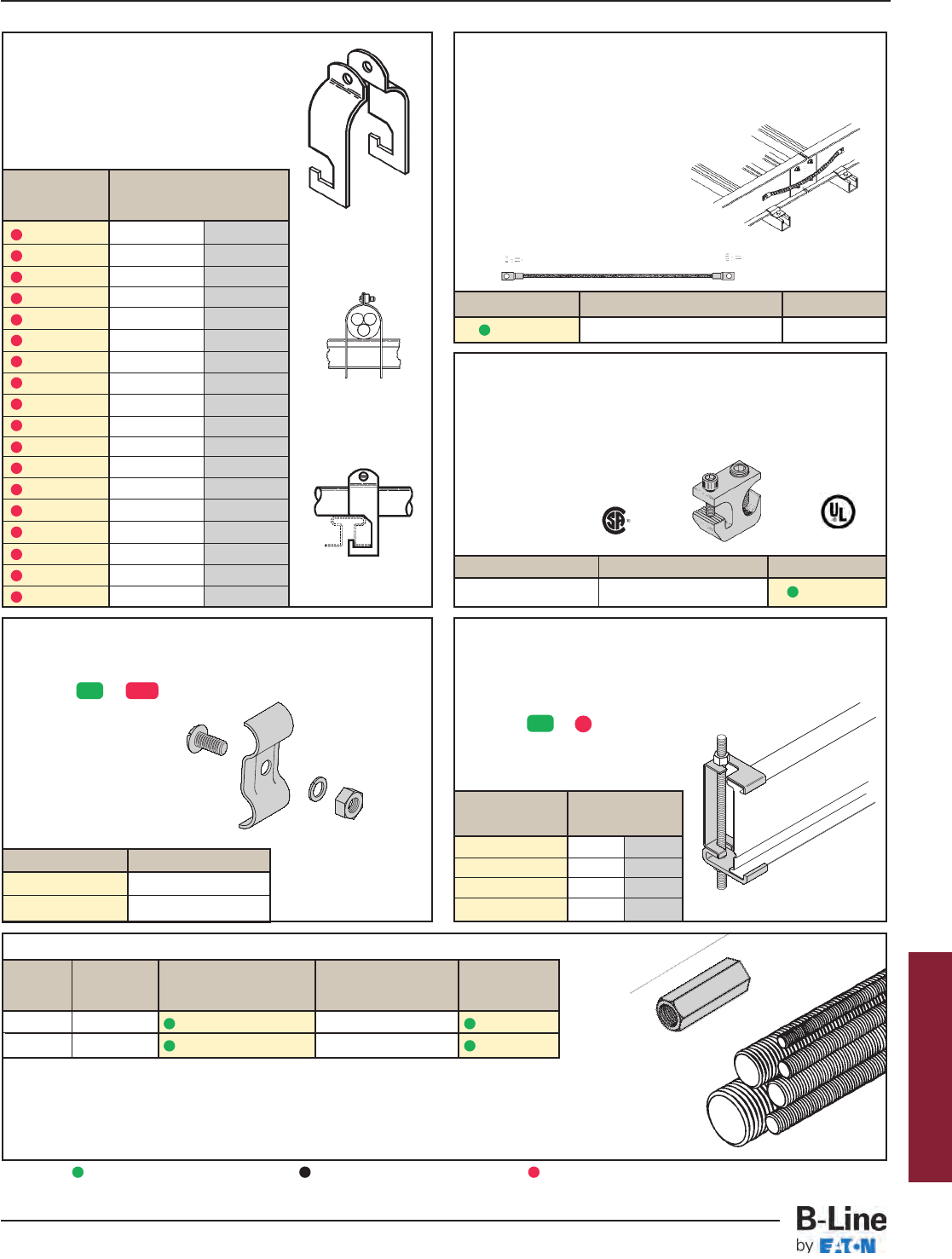
Stainless Steel Cable Clamp
• Fits with series 2, 3, 4 & 5 standard steel
rungs.
• Shipped flat. Field form around the cable
at the time of installation.
Hanger Rod Clamp
• For 1/2" ATR.
• Furnished in pairs.
• Order ATR and hex nuts separately.
• Two-piece “J”-hanger design.
• (*) Insert or
• 1500 lbs./pair capacity safety factor 3.
Catalog No. Rail Height
in. mm
9(*)-5324 4 101
9(*)-5325 5 127
9(*)-5326 6 152
9(*)-5327 7 178
Ground Clamp
• Mechanically attaches grounding cables to cable tray.
• Hardware included.
• (*) Insert or
Catalog No. Cable Size
9(*)-2351 #1 thru 2/0
9(*)-2352 3/0 thru 250 MCM
Bonding Jumper
Use at each expansion splice and where the cable tray is not
mechanically/electrically continuous to ground.
Sold individually.
• Hardware included.
• See table 392.7(B)(2) on page CTS-9
for amperage ratings required to
match the UL cross-sectional area
of the tray.
• See tray loading chart for UL
cross-sectional area.
• Bonding jumper is 16" long.
Catalog No. Copper Wire Size Ampacity
99-N1 #1 600
Grounding Clamp
B-Line Cable Tray is UL®classified as to its suitability as an
equipment grounding conductor. If a separate conductor for
additional grounding capability is desired, B-Line offers this clamp
for bolting the conductor at least once to each cable tray section.
• Accepts #6 AWG to 250 MCM.
Item Material Catalog No.
Grounding Clamp Tin Plated Aluminum 9A-2130
Threaded Rod (ATR) & Rod Coupling
Loading Catalog Available Coupling
Size lbs No. Lengths Cat. No.
3/8-16 730 ATR 3/8x Length 36", 72", 120", 144" B655-3/8
1/2-13 1350 ATR 1/2x Length 36", 72", 120", 144" B655-1/2
Loading based on safety factor 5.
Standard Finish: Zinc Plated.
See B-Line Strut Systems Catalog for other sizes and finishes.
Catalog No. Cable Size
in. mm
9SS4-4050 0.50 - 0.75 13 - 19
9SS4-4075 0.75 - 1.00 19 - 25
9SS4-4100 1.00 - 1.25 25 - 32
9SS4-4125 1.25 - 1.50 32 - 38
9SS4-4150 1.50 - 1.75 38 - 45
9SS4-4175 1.75 - 2.00 45 - 51
9SS4-4200 2.00 - 2.25 51 - 57
9SS4-4225 2.25 - 2.50 57 - 64
9SS4-4250 2.50 - 2.75 64 - 70
9SS4-4275 2.75 - 3.00 70 - 76
9SS4-4300 3.00 - 3.25 76 - 82
9SS4-4325 3.25 - 3.50 82 - 89
9SS4-4350 3.50 - 3.75 89 - 95
9SS4-4375 3.75 - 4.00 95 - 102
9SS4-4400 4.00 - 4.25 100 - 106
9SS4-4425 4.25 - 4.50 106 - 113
9SS4-4450 4.50 - 4.75 113 - 121
9SS4-4475 4.75 - 5.00 121 - 125
Series 2, 3, 4, & 5 Steel
ZN
ZN SS4
Refer to Section CF
Cable Fixing
Green = Fastest shipped items Black = Normal lead-time items Red = Normally long lead-time items
G
HST-14
Series 2, 3, 4, & 5 Steel - Accessories
Cable Tray Systems
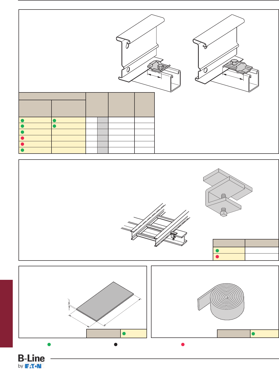
Cable Tray Clamp/Guide
• Features a no-twist design.
• Has four times the strength
of the traditional design.
• Each side is labeled to
ensure proper installation.
• Furnished in pairs, with or
without hardware.
• Not recommended for
vertical support.
Cable Tray Guide
• Expansion guide for single or double cable tray runs.
• Guide allows for longitudinal movement of the
cable tray.
• No field drilling of support I-beam or channel is required.
• Guides are required on both sides of cable tray to
prevent lateral movement - can be placed on either the
inside or outside flange of cable tray.
• Guides are sold in pieces - two guides are
required per tray.
• Maximum flange thickness 11/8" (28.58 mm).
Catalog No. Finish
9ZN-1249 Zinc Plated
9G-1249 HDGAF
Neoprene Roll
• Used for material isolation.
• 1/8" x 2" x 25' roll.
• Hardness: Shore A60.
• Good weatherability.
Nylon Pad
• Use for friction reduction.
• Hardness: Shore D80.
• Low friction coefficient.
• UV resistant.
• Excellent weatherability.
• UL-94HB.
Catalog No. 99-NP300
Catalog No. 99-PE36
When installing this device as an expansion
guide on the outside flange of Steel Side Rail,
use the Catalog No. B202 Square Washer
in order to properly elevate the guide.
1/8"
(3mm)
6"
(152mm)
3"
(76mm)
Note: For heavy duty or vertical applications
see 9(*)-1241 or 9(*)-1242 page HDS-18.
Catalog No.
Without With Overall Hardware
Hardware Hardware Length Size Finish
in. mm
9ZN-1204 9ZN-1204NB 11/238 1/4" G90
9ZN-1208 9ZN-1208NB 21/457 3/8" G90
9A-1205 -- 21/457 1/2" Alum.
9G-1205 -- 21/457 1/2" HDGAF
9SS6-1205 -- 21/457 1/2" 316SS
9ZN-1205 -- 21/457 1/2" G90
9ZN-1204 shown.
Installed as a
guide.
Patent #
RE35479
11/2"
(39mm) 21/4"
(57mm)
9ZN-1208 shown.
Installed as a
clamp.
Series 2, 3, 4, & 5 Steel
Green = Fastest shipped items Black = Normal lead-time items Red = Normally long lead-time items
HST-15
Series 2, 3, 4, & 5 Steel - Accessories
Cable Tray Systems
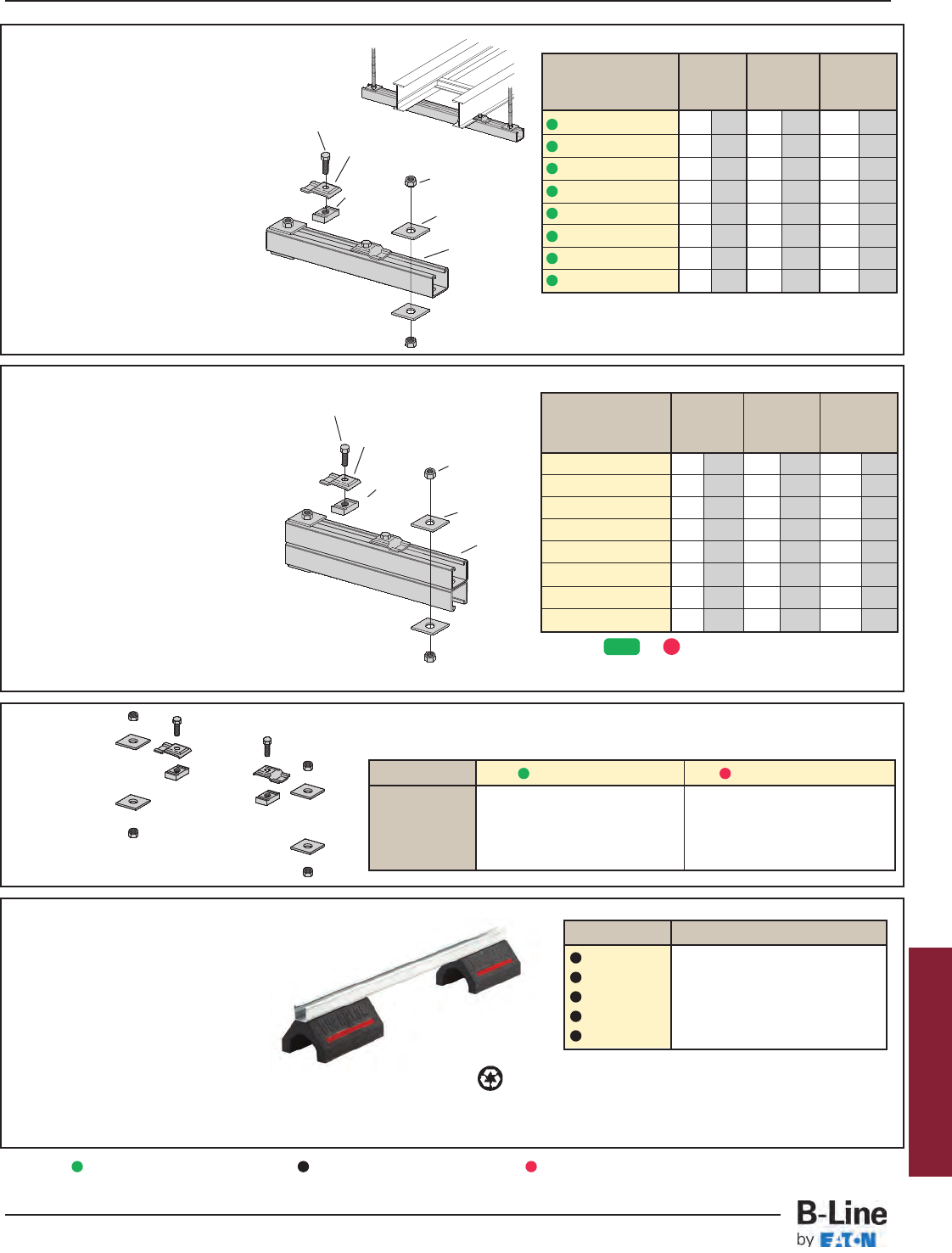
Series 2, 3, 4, & 5 Steel
Trapeze
Hardware
Kit
Heavy Duty Trapeze Support Kit
B-Line trapeze kits provide the
components required for a single trapeze
support in one package. These kits are
available in Dura-Green®epoxy coated
steel with zinc-plated hardware or hot dip
galvanized steel with 316 stainless steel
hardware.
The SH channel provides the convenience
of pre-punched slots, which eliminates the
need for field drilling.
The illustrated hardware is sealed in a
plastic bag and boxed with the channel,
which is pre-cut to the appropriate length
as shown in the chart.
Designed for use with 1/2" threaded rod.
Order rod separately.
Catalog Tray Channel Uniform
No. Width Length Load
in. mm in. mm lbs kN
9(*)-5506-22SHA 6 152 16 406 1350 6.01
9(*)-5509-22SHA 9 229 18 457 1350 6.01
9(*)-5512-22SHA 12 305 22 559 1350 6.01
9(*)-5518-22SHA 18 457 28 711 1350 6.01
9(*)-5524-22SHA 24 610 34 864 1350 6.01
9(*)-5530-22SHA 30 762 40 1016 1350 6.01
9(*)-5536-22SHA 36 914 46 1168 1350 6.01
9(*)-5542-22SHA 42 1067 52 1321 1350 6.01
Trapeze Support Kit
B-Line trapeze kits provide the components
required for a single trapeze support in one
package. These kits are available in pre-
galvanized steel with zinc-plated hardware
or hot dip galvanized steel with 316
stainless steel hardware.
The SH channel provides the convenience
of pre-punched slots, which eliminate the
need for field drilling.
The illustrated hardware is sealed in a
plastic bag and boxed with the channel,
which is pre-cut to the appropriate length
as shown in the chart.
Designed for use with 1/2" threaded rod.
Order rod separately.
Catalog Tray Channel Uniform
No. Width Length Load
in. mm in. mm lbs kN
9P-5506-22SH(†) 6 152 16 406 1600 7.11
9P-5509-22SH(†) 9 229 18 457 1250 5.56
9P-5512-22SH(†) 12 305 22 559 1125 5.00
9P-5518-22SH(†) 18 457 28 711 865 3.85
9P-5524-22SH(†) 24 610 34 864 700 3.11
9P-5530-22SH(†) 30 762 40 1016 590 2.62
9P-5536-22SH(†) 36 914 46 1168 510 2.27
9P-5542-22SH(†) 42 1067 52 1321 450 2.00
• (†) Insert 3/8for 3/8" threaded rod hardware.
Safety factor of 3.0 on all loads.
• (*) Insert or
Safety factor of 3.0 on all loads.
(1) B22 Channel
cut to the
required length
(2) 9ZN-1205
Hold-Down
Guide Clamp
(4) B202
Square Washer
(2) N525WO
Channel Nut
(2) 1/2" x 7/8" Hex
Head Cap Screw
(4) 1/2" Hex Nut
(1) Channel
cut to the
required
length
(2) 9ZN-1205
Hold-Down
Guide Clamp
(4) B202
Square Washer
(2) N525WO
Channel Nut
(2) 1/2" x 7/8" Hex
Head Cap Screw
(4) 1/2" Hex Nut
Catalog No. 9ZN-5500-1/2 9G-5500-1/2
1 pr. 9ZN-1205 1 pr. 9G-1205
2 HHC Screw 1/2x 7/8ZN 2 HHC Screw 1/2x 7/8SS6
2 N525 WO ZN 2 N525 WO SS6
4 B202 ZN 1/2" sq washer 4 B202 HDG 1/2" sq washer
4 HN 1/2ZN 4 HN 1/2SS6
In plastic bag
GRN G
Rooftop Support Bases
with B22 Channel Catalog No. Height x Width x Length
DB10-28 55/8” x 6” x 28.0”
DB10-36 55/8” x 6” x 36.0”
DB10-42 55/8” x 6” x 42.0”
DB10-50 55/8” x 6” x 50.0”
DB10-60 55/8” x 6” x 60.0”
Designed as a superior rooftop
support for cable tray, UV resistant
and approved for most roofing
material or other flat surfaces.
Can be used with any of B-Line cable
tray clamps and guides.
Ultimate Load Capacity:
1,000 lbs. (uniform load) LEEDS credit available, base made from 100% recycled material.
General Note: Consult roofing manufacturer or engineer for roof load
capacity. The weakest point may be the insulation board beneath
the rubber membrane.
Green = Fastest shipped items Black = Normal lead-time items Red = Normally long lead-time items
HST-16
Series 2, 3, 4, & 5 Steel - Accessories
Cable Tray Systems
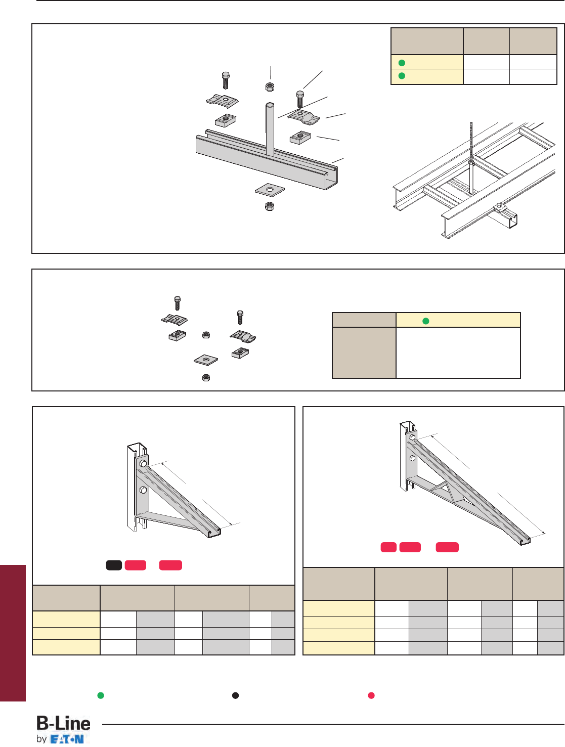
Center Hung Support Hardware Kit
Bracket
Catalog No. Uniform Load Tray Width 'A'
lbs kN in. mm in. mm
B494-12 1580 7.02 6 & 9 152 & 229 12 305
B494-18 1000 4.45 12 305 18 457
B494-24 996 4.43 18 457 24 610
Bracket
Catalog No. Uniform Load Tray Width 'A'
lbs kN in. mm in. mm
B494-30 924 4.11 24 610 30 762
B494-36 864 3.84 30 762 36 914
B494-42 580 2.58 36 914 42 1067
B494-48 500 2.22 42 1067 48 1219
Center Hung Cable Tray Support
• Center Hung Cable Tray Support allows
cable to be laid-in from both sides.
• Eliminates costly cable pulling and field
cutting of cable tray supports. Labor
costs are dramatically reduced.
• Required hardware and threaded rod
material for trapeze assemblies are
reduced by 50%.
• Designed for use with 1/2" threaded rod.
(Order rod separately)
• Use with all aluminum and steel
cable trays through 24" width.
• Load capacity is 700 lbs. per support.
Safety factor of 3.0.
Eccentric loading is not to exceed a
60% vs. 40% load differential.
• The maximum recommended unsupported
span length is 144"/12 ft. (3.66 m).
• Hardware shown is furnished.
Catalog Tray Channel
No. Width Length
9ZN-5212 6", 9", 12" 18"
9ZN-5224 18", 24" 30"
(2) 1/2" x 7/8"
Hex Head Cap Screws
(2) 1/2" Hex Nut
(1) B202
Square Washer
(2) 9ZN-1205
Hold Down
Guide Clamp
(2) N525WO
(1) B22 Channel cut to
required length
(1) 9/16" Inside diameter
steel tubing welded to strut
Finishes available: or
Safety Load Factor 2.5
Finishes available: or
A
A
Catalog No. 9ZN-5200
1 pr. 9ZN-1205
2 HHC Screw 1/2x 7/8ZN
2 N525 WO ZN
1 B202 ZN 1/2" sq washer
2 HN 1/2ZN
In plastic bag
ZN = Zinc Plated
Series 2, 3, 4, & 5 Steel
ZN GRN HDG
ZN GRN HDG
Green = Fastest shipped items Black = Normal lead-time items Red = Normally long lead-time items
HST-17
Series 2, 3, 4, & 5 Steel - Accessories
Cable Tray Systems
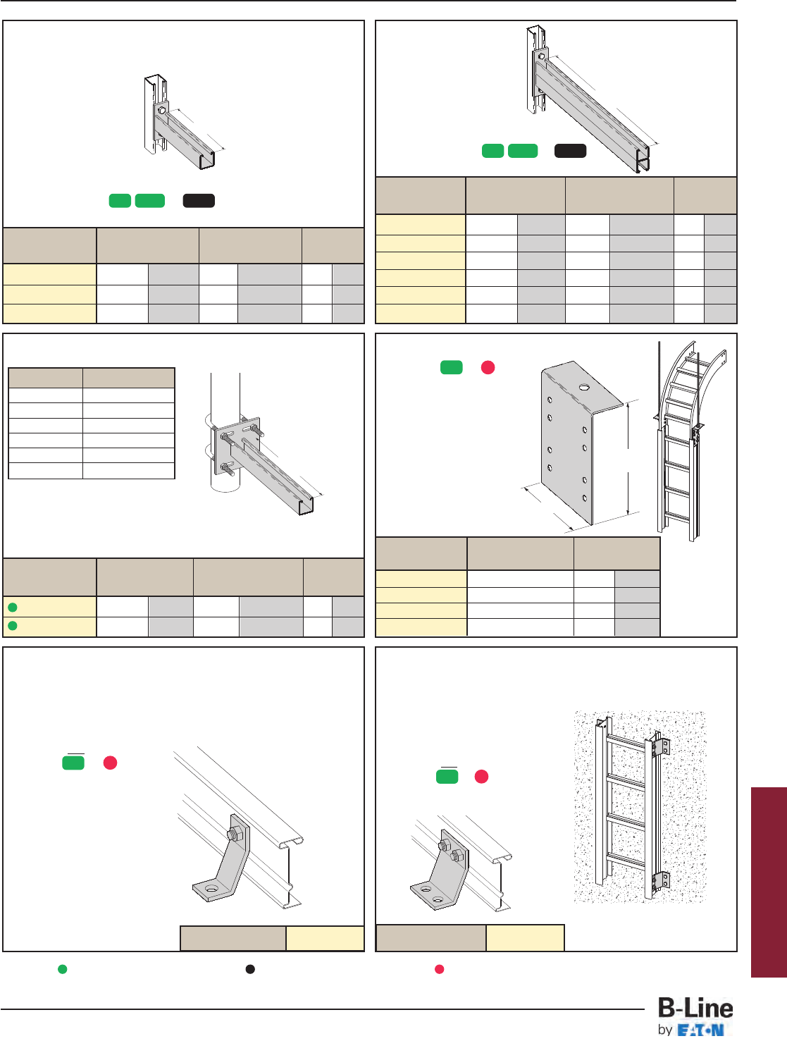
Vertical Hanger Splice Plates
• (*) Insert or
• Design load is 1500 lbs/pair.
Safety Factor of 2.5
• Furnished in pairs.
• Hole size: 9/16” (14mm)
for 1/2” threaded rod.
Catalog No. Outside 'A'
Cable Tray Ht. in. mm
9(*)-8224 4" 2.84 85.34
9(*)-8225 5" 3.73 110.74
9(*)-8226 6" 4.84 136.14
9(*)-8227 7" 5.84 161.54
Underfloor Support (U-Bolts not included)
Cantilever Bracket
Catalog No. Uniform Load Tray Width 'A'
lbs kN in. mm in. mm
B297-12 1660 7.37 6 & 9 152 & 229 12 305
B297-18 1100 4.88 12 305 18 457
B297-24 835 3.71 18 457 24 610
B297-30 625 2.78 24 610 30 762
B297-36 550 2.44 30 762 36 914
B297-42 465 2.06 36 914 42 1067
Cantilever Bracket
Catalog No. Uniform Load Tray Width 'A'
lbs kN in. mm in. mm
B409-12 960 4.27 6 & 9 152 & 229 12 305
B409-18 640 2.84 12 305 18 457
B409-24 480 2.13 18 457 24 610
Heavy Duty Hold-Down Bracket
• Design load is 2000 lbs/pair.
• Two bolt design.
• Sold in pairs.
•3/8" cable tray attachment hardware provided.
•1/2" support attachment
hardware not provided.
• (*) Insert or
• Recommended for the
support of vertical trays.
Catalog No. 9(*)-1241
A
Finishes available: or
Safety Load Factor 2.5
A
A
7"
(178mm)
A
Finish available: ZN
Safety Load Factor 2.5
U-Bolt Size Fits Pipe O.D.
B501-3/4.841 - 1.050
B501-1 1.051 - 1.315
B501-11/41.316 - 1.660
B501-11/21.661 - 1.900
B501-2 1.901 - 2.375
B501-21/22.376 - 2.875
• Order properly sized U-Bolts
separately.
Catalog No.
Uniform Load
Tray Width 'A'
lbs kN in. mm in. mm
B409UF-12 800 3.55 6 & 9 152 & 229 12 305
B409UF-21 450 2.00 12 & 18 305 & 457 21 533
Finishes available: or
Safety Load Factor 2.5
Series 2, 3, 4, & 5 Steel
ZN GRN HDG
ZN GRN HDG
ZN
ZN
Heavy Duty Hold-Down Bracket
• Design load is 4000 lbs/pair.
• Four bolt design.
• Sold in pairs.
•3/8" cable tray attachment
hardware provided
•1/2" support attachment
hardware not provided.
• (*) Insert or
• Recommended for the
support of vertical trays.
Catalog No. 9(*)-1242
ZN
Green = Fastest shipped items Black = Normal lead-time items Red = Normally long lead-time items
G
G
G
HST-18
Series 2, 3, 4, & 5 Steel - Accessories
Cable Tray Systems
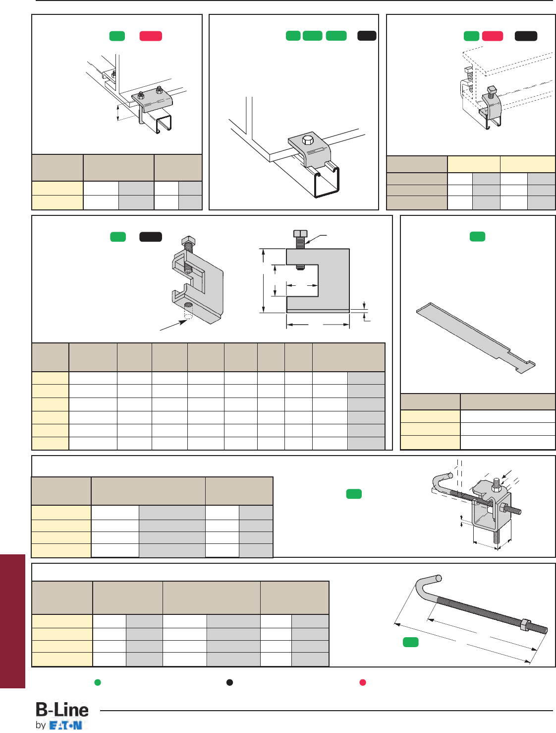
Series 2, 3, 4, & 5 Steel
Beam Clamp
Beam Clamp
B312 Anchor Strap
• Finish available:
• For a maximum beam
thickness of 3/4".
• For thicker beams, step up
one flange width size.
Cat. No. Flange Width
B312-6 Up to 6"
B312-9 6" - 9"
B312-12 9" - 12"
Beam Clamp
• Finishes available: or
• Sold in pieces.
Design load when used in pairs.
Safety Load Factor 5.0
Catalog 'A' Thread Length 'TL' Wt./C
No. in. mm in. mm lbs kg
B700-J4 81/2" 215.9 5" 127.0 44 19.9
B700-J6 111/2" 292.1 6" 152.4 53 24.0
B700-J9 121/4" 368.3 6" 152.4 63 28.6
B700-J12 171/2" 444.5 6" 152.4 78 35.4
B305 Thru B308 & B321 Series Beam Clamps
• Finishes available: or
• Setscrew included.
• Safety Load Factor 5.0
Cat. Rod Design Load
No. Size A BC D EFT
lbs kN
B305 3/8"-16 3/8"-16 2 5/16"7/8" 1 1/8" 2 1/2" 11 Ga. 600 2.67
B306 3/8"-16 1/2"-13 2 7/16"7/8" 1 1/8" 2 1/2" 7 Ga. 1100 4.90
B307 1/2"-13 1/2"-13 2 7/16"7/8" 1 1/8" 2 1/2" 7 Ga. 1100 4.90
B308 1/2"-13 1/2"-13 2 9/16"7/8" 1 1/8" 2 1/2"1/4" 1500 6.68
B321-1 3/8"-16 1/2"-13 3 9/16" 1 11/16" 1 5/8" 3 1/4"1/4" 1300 5.79
B321-2 1/2"-13 1/2"-13 3 9/16" 1 11/16" 1 5/8" 3 1/4"1/4" 1400 6.23
Beam Clamp
• Finishes available: or
• Sold in pieces.
Design load when used in pairs.
Safety Load Factor 5.0
Cat. No. B212-1/4B212-3/8
Design Load * 600 lbs. 2.67 kN 1000 lbs. 4.45 kN
Max. Flange Thick 3/4"19 mm 1 1/8"28.6 mm
Mat'l. Thickness 1/4"6.3 mm 3/8"9.5 mm
Beam Clamp B355
• Finishes available: or
• Sold in pieces.
• Design load is 1200 lbs. when used in pairs.
• Safety Load Factor 5.0
• Order HHCS and
Channel Nuts separately.
B
E
D
C
FT
• Finish available:
• Design Load 500 lbs. (2.22 kN)
• Safety Load Factor 5.0
• Recommended torque:
'J'-Hook Nut 125 In.-Lbs. (14.1 kN/m)
• Maximum flange thickness of 3/4"
• Finish available:
• Hex Nut included.
A
A
Material:
7 Gauge (4.6)
1/2"-13 Rod & Hex
Nut Sold Separately
1/2"-13 Threads
1 1/2"
(38.1)
“A’
‘TL’
1 7/8"
(47.6)
J-Hook & Hex
Nut Included
Catalog For Flange Width Wt./C
No. in. mm lbs kg
B750-J4 3"- 6" 76.2 - 152.4 109 49.4
B750-J6 5"- 9" 127.0 - 288.6 124 56.2
B750-J9 8"- 12" 203.2 - 304.8 135 61.2
B750-J12 11"- 15" 279.4 - 381.0 147 66.7
Catalog Design Load* 'A'
lbs kN in. mm
B441-22 1200 5.34 33/8 86
B441-22A 1200 5.34 5 127
ZN HDG ZN GRN HDG SS4 ZN GRN HDG
ZN
ZN HDG
ZN
ZN
Green = Fastest shipped items Black = Normal lead-time items Red = Normally long lead-time items
HST-19
Series 2, 3, 4, & 5 Steel - Accessories
Cable Tray Systems
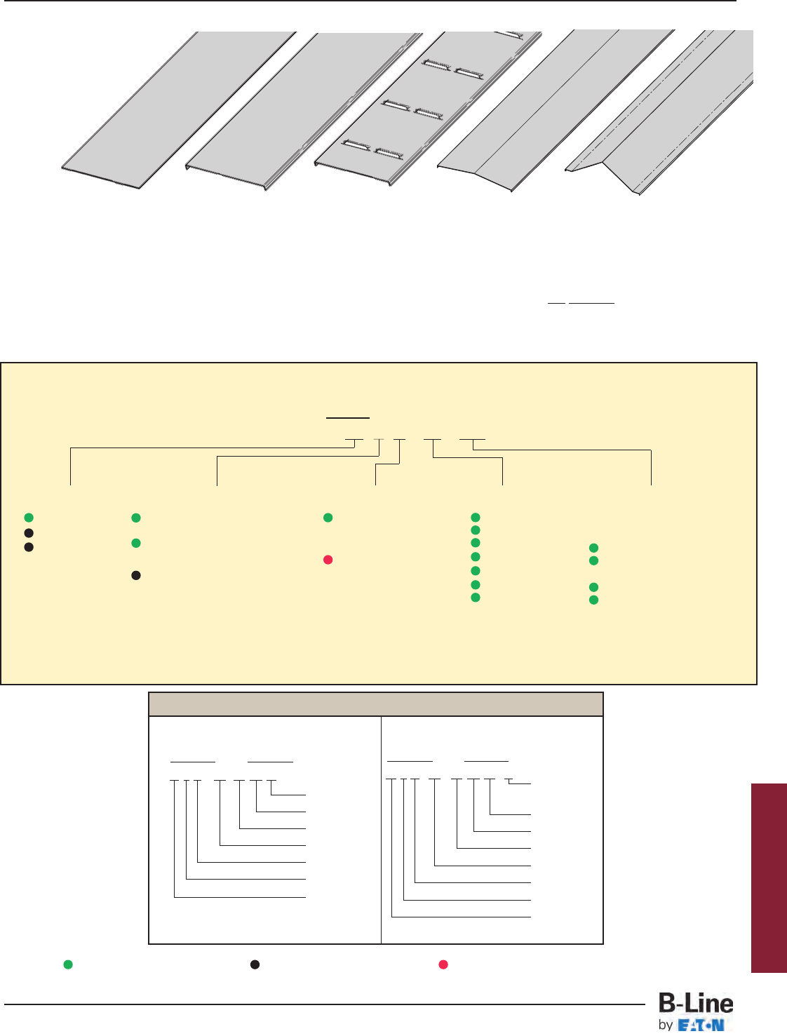
Examples of Catalog Numbers for Fitting Covers:
A full range of covers is available for straight sections and fittings.
Solid covers should be used when maximum enclosure of the cable is desired and no accumulation of heat is expected.
Ventilated covers provide an overhead cable shield yet allow heat to escape.
B-Line recommends that covers be placed on vertical cable tray runs to a height of 6 ft. (1.83 m) to 8 ft. (2.44 m) above the floor to
isolate both cables and personnel. Flanged covers have a 1/2in. (13 mm) flange. Cover clamps are not included with the cover and
must be ordered separately. All peaked covers are flanged. Standard peaked covers have 1/2” peak. Special purpose peaked covers,
having a 2 to 3 pitch, provide additional slope and material thickness. The 2 to 3 pitch fitting covers are of multiple piece, welded
construction.
Solid Flanged Ventilated Flanged Peaked Flanged 2 to 3 Pitch Peaked Flanged
(See page APP-4)
Vertical Bend Cover
Prefix Suffix
80 2 G - 24 - 90 VO 24 - 4*
Side Rail*
Height
Radius
Fitting
Angle
Width
Material
Detail
Cover Type
Solid Non-Flanged
Steel Cover Part Numbering
Prefix
Example: 80 2 P - 24 - 144
Cover Type Detail Material Tray Width Item Description
Covers
Horizontal Bend Cover
Prefix Suffix
80 2 P - 18 - 90 HB 24
Radius
Fitting
Angle
Width
Material
Detail
Cover Type
80 = Solid
81 = Ventilated
82 = Peaked
2= Flanged Steel (248, 258, 268
straight sections and all fittings)
3= Flanged Steel (All straight
sections except 248, 258, 268)
4= Non-Flanged Steel (80 & 81
type only)
06 = 6"
09 = 9"
12 = 12"
18 = 18"
24 = 24"
30 = 30"
36 = 36"
For Straight Section Covers:
Pre-Galvanized Only:
144 = 12 ft. (3.66 m)
120 = 10 ft. (3.05 m)
Pre-Galvanized & HDGAF
72 = 6 ft. (1.83 m)
60 = 5 ft. (1.52 m)
For fitting covers: Insert suffix
of fitting to be covered.
See example below.
P= Pre-Galvanized
(Not available in
Type 83)
G= HDGAF
* Required for VO fittings only
Covers 30" and 36" wide have reinforcing ridges.
Series 2, 3, 4, & 5 Steel
Green = Fastest shipped items Black = Normal lead-time items Red = Normally long lead-time items
HST-20
Series 2, 3, 4, & 5 Steel - Accessories
Cable Tray Systems
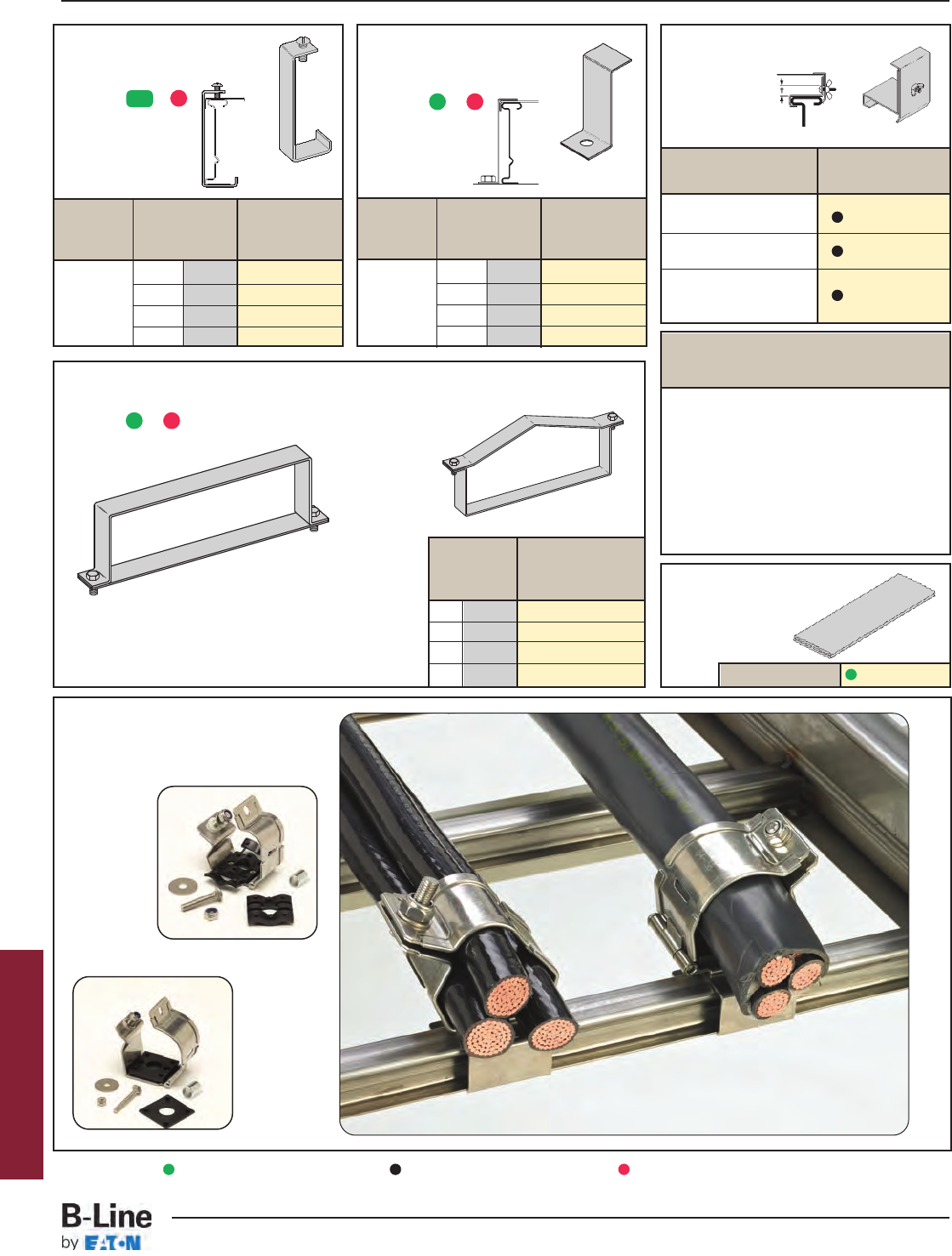
Combination Cover and
Hold-Down Clamp
• Sold per piece.
• (*) Insert or
• For indoor
service only.
Tray Side Rail Catalog
Type Height No.
in. mm
4 101 9(*)-9043
5 127 9(*)-9053
6 152 9(*)-9063
7 178 9(*)-9073
Steel
Heavy Duty Cover Clamp
• Recommended for outdoor service.
• (*) Insert or
Side Rail Catalog
Height No.
in. mm
Raised Cover Clamp
• For indoor service only.
• For use with
flanged covers
only.
† Specify gap of 1", 2", 3" or 4".
Tray Catalog
Type No.
Series 2 Steel 9ZN-9114-†
Straight Section
Series 3 & 4 Steel 9ZN-9115-†
Straight Section
All Steel Fittings
(Also Series 1 Steel 9ZN-910†
Straight Sections)
Tray Side Rail Catalog
Type Height No.
in. mm
4 101 9(*)-9014
5 127 9(*)-9015
6 152 9(*)-9016
7 178 9(*)-9017
Standard Cover Clamp
• For indoor service only.
• Sold per piece.
• (*) Insert or
Quantity of Standard
Cover Clamps Required
Straight Section 60" or 72" .............4 pcs.
Straight Section 120" or 144" .........6 pcs.
Horizontal/Vertical Bends ................4 pcs.
Tees .................................................6 pcs.
Crosses............................................8 pcs.
Note: When using the Heavy Duty Cover
Clamp, only one-half the number of clamps
stated above is required.
4 101 9(*)-(‡)-9044†
5 127 9(*)-(‡)-9054†
6 152 9(*)-(‡)-9064†
7 178 9(*)-(‡)-9074†
(‡) Insert tray width
† Add P to Catalog
No. for 1/2" peaked
cover clamp.
Peaked Cover Clamp
Steel
Cover Joint Strip
• Used to join covers
• Plastic
• (‡) Insert tray
width
Catalog No. 99-9980-(‡)
Series 2, 3, 4, & 5 Steel
ZN
Cable Cleats
(see pages CFX-1 thru CFX-5)
Trefoil
Cable
Cleats
Single
Cable
Cleats
Green = Fastest shipped items Black = Normal lead-time items Red = Normally long lead-time items
GP
G
G
P
HST-21
Series 2, 3, 4, & 5 Steel - Accessories
Cable Tray Systems

Section 1- Acceptable Manufacturers
1.01 Manufacturer: Subject to compliance with these specifications, cable tray systems shall be as
manufactured by B-Line.
Section 2- Cable Tray Sections and Components
2.01 General: Except as otherwise indicated, provide metal cable trays, of types, classes and sizes indicated;
with splice plates, bolts, nuts and washers for connecting units. Construct units with rounded edges
and smooth surfaces; in compliance with applicable standards; and with the following additional
construction features. Cable tray shall be installed according to the latest revision of NEMA VE 2.
2.02 Pre-Galvanized Steel: Straight sections, fitting side rails, rungs, and covers shall be made from
structural quality steel meeting the minimum mechanical properties and mill galvanized in accordance
with ASTM A653 SS, Grade 33, coating designation G90. Hardware finish shall be electrogalvanized
zinc per ASTM B633.
2.03 Hot Dip Galvanized Steel: All side rails, covers, splice plates, and rungs shall be made from structural
quality steel meeting the minimum mechanical properties of ASTM A1011 SS, Grade 33 for 14 gauge
and heavier, ASTM A1008, Grade 33 Type 2 for 16 gauge and lighter, and shall be hot dip galvanized
after fabrication in accordance with ASTM A123. Mill galvanized covers are not acceptable for hot dip
galvanized cable tray. Hardware finish shall be chromium zinc per ASTM F-1136-88.
2.04 Ladder Cable Trays shall consist of two longitudinal members (side rails) with transverse members
(rungs) welded to the side rails. Rungs shall be spaced [6] [9] [12] inches on center. Rung spacing in
radiused fittings shall be industry standard 9" and measured at the center of the tray’s width. No
portion of the rungs shall protrude below the bottom plane of the side rails. Each rung must be
capable of supporting a 200 lb. concentrated load at the center of the cable tray over and above the
cable load with a safety factor of 1.5.
2.05 Ventilated Trough Cable Trays shall consist of two longitudinal members (side rails) with a corrugated
bottom welded to the side rails or rungs spaced 4" on center. The peaks of the corrugated bottom
shall have a minimum flat cable bearing surface of 23/4" and shall be spaced on 6" centers. To
provide ventilation in the tray, the valleys of the corrugated bottom shall have 21/4" x 4" rectangular
holes punched along the width of the bottom.
2.06 Non-Ventilated Bottom Trough Cable Trays shall consist of two longitudinal members (side rails) with a
corrugated bottom welded to the side rails or a solid sheet over rungs. The peaks of the corrugated
bottom shall have a minimum flat cable bearing surface of 23/4" and shall be spaced on 6" centers.
2.07 Cable tray loading depth shall be [3] [4] [5] [6] inches per NEMA VE 1.
2.08 Straight sections shall have side rails fabricated as I-beams. Straight sections shall be supplied in
standard [12 foot] [24 foot] [10 foot (3 m)] [20 foot (6 m)] lengths.
2.09 Cable tray widths shall be [6] [9] [12] [18] [24] [30] [36] inches or as shown on drawings.
2.10
Splice plates shall be manufactured of high strength steel, meeting the minimum mechanical properties
of ASTM A1011 HSLAS, Grade 50, Class 1 and be secured with 8 nuts and bolts per plate. The
resistance of fixed splice connections between an adjacent section of tray shall not exceed 0.00033 ohm.
2.11 All fittings must have a minimum radius of [12] [24] [36] [48] inches.
Section 3- Loading Capacities and Testing
3.01 Cable tray shall be capable of carrying a uniformly distributed load of ______ lbs./ft. on a _______ ft.
support span with a safety factor of 1.5 when supported as a simple span and tested per NEMA
VE 1 5.2. In addition to the uniformly distributed load the cable tray shall support 200 lbs. concentrated
load at mid-point of span. Load and safety factors specified are applicable to both the side rails and
rung capacities. Cable tray shall be made to manufacturing tolerances as specified by NEMA.
3.02 Upon request, manufacturer shall provide test reports in accordance with the latest revision of
NEMA VE 1 or CSA C22.2 No. 126.
Series 2, 3, 4, & 5 Steel
HST-22
Series 2, 3, 4, & 5 Steel - Specifications
Cable Tray Systems
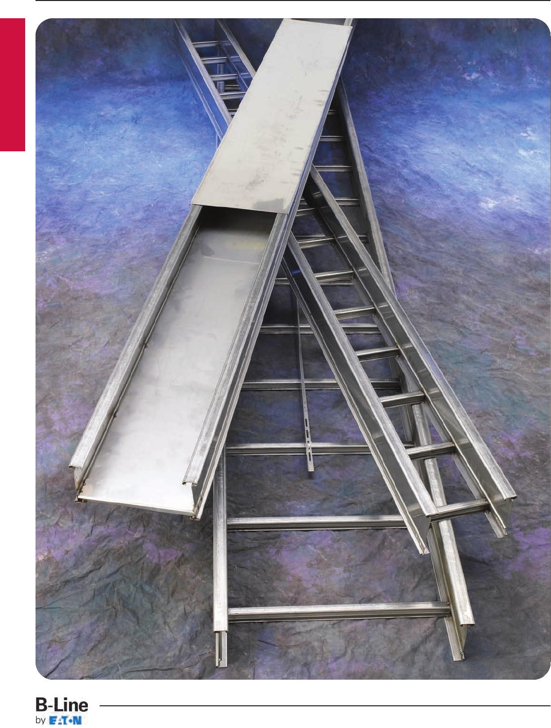
Series 3 & 4 Stainless Steel
SST-1
Series 3 & 4 Stainless Steel
Cable Tray Systems
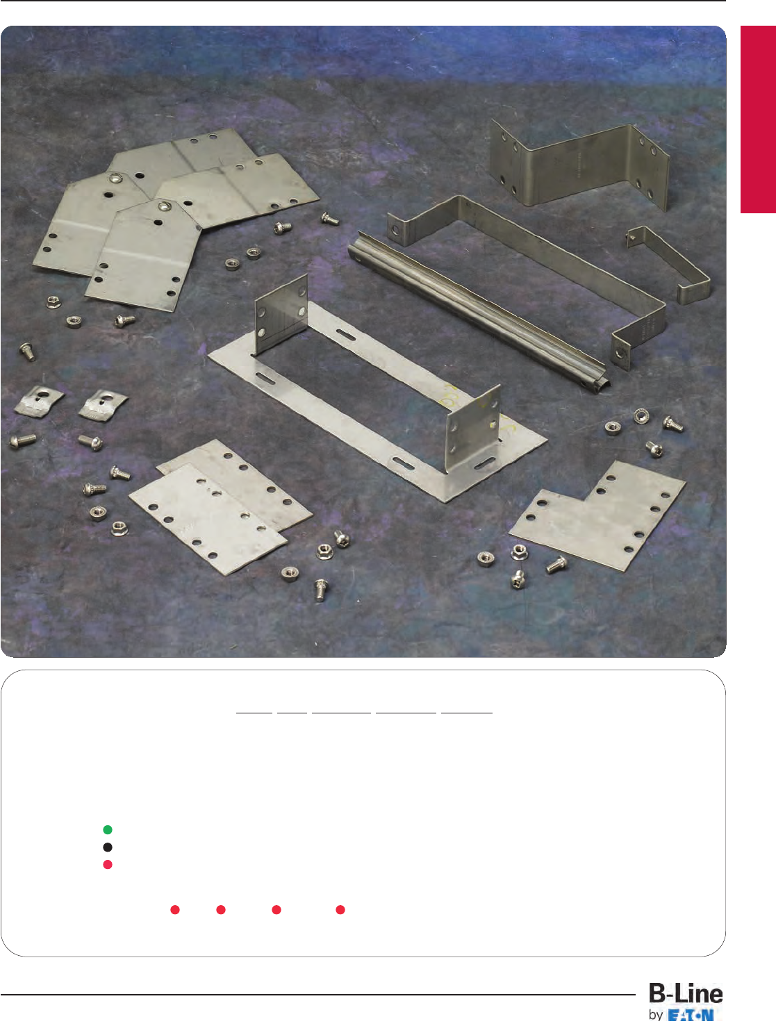
Series 3 & 4 Stainless Steel
How The Service Advisor Works
B-Line knows that your time is important! That’s why the color-coding system in this catalog is designed to help you select
products that fit your service needs. Products are marked to indicate the typical lead time for orders of 50 pieces or less.
Customer: How do I select my straight sections. covers, or fittings so that I get the quickest turnaround?
Service Advisor: Each part of our selection chart is shown in colors. If any section of a part number is a different
color, the part will typically ship with the longer lead time represented by the colors.
Green = Fastest shipped items
Black = Normal lead-time items
Red = Normally long lead-time items
Example: 348SS4 09 - 12 - 144 Part will have a long
lead time.
For Stainless Steel Fittings
see fittings section pages FTS-1 thru FTS-17
SST-2
Series 3 & 4 Stainless Steel
Cable Tray Systems
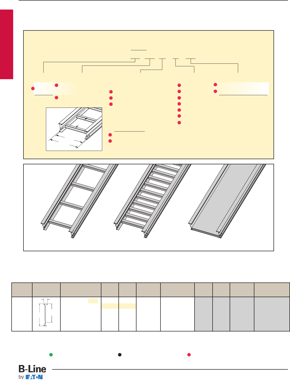
B-Line Side Rail NEMA, CSA Span Load Deflection Design Factors Span Load Deflection Design Factors
Series Dimensions Classifications ft lbs/ft Multiplier for Two Rails meters kg/m Multiplier for Two Rails
NEMA: 16A, 12C 10 180 0.0042 3.0 268 0.072
CSA: C1-3m 12 125 0.009 Area=0.74 in23.7 186 0.148 Area=4.77 cm2
14 92 0.016 Sx=0.79 in34.3 137 0.275 Sx=12.95 cm3
UL Cross-Sectional 16 70 0.027 Ix=1.85 in44.9 105 0.469 Ix=77.00 cm4
Area: 0.40 in218 56 0.044 5.5 83 0.752
20 45 0.067 6.1 67 1.145
Values are based on simple beam tests per NEMA VE 1 on 36" wide cable tray rungs spaced on 12" centers. Cable trays will
support without collapse a 200 lb. (90.7 kg) concentrated load over and above published loads. Published load safety factor is
1.5. To convert 1.5 safety factor to 2.0, multiply published load by 0.75. To obtain mid-span deflection, multiply a load by the
deflection multiplier. Cable tray must be supported on spans shorter than or equal to the length of the cable being installed.
When cable trays are used in continuous spans, the deflection of the cable tray is reduced by as much as 50%. Design factors:
Ix = Moment of Inertia, Sx = Section Modulus. † Insert 4 for 304 stainless steel or 6 for 316 stainless steel.
1.50
4.19
3.13
18 gauge
348
SS†
3" NEMA VE 1 Loading Depth
4" Side Rail Height
¨Primary Length.
¡Secondary Length.
Ladder Type
(Specify Rung Spacing)
Vented Bottom Non-Ventilated
Overall Width
(Width + 13/8")
For
side rail
& rung data,
see chart on
pages AP-5 & AP-6
Rung
Spacing
Width
(Inside)
Straight Section Part Numbering
Prefix
Example: 348 SS6 09 - 24 - 240
Series Material *Type *Width Length
348 SS4 = 304 Stainless Ladder- 06 = 6" ¨144 = 12 ft. 348
Steel 06 = 6" rung spacing 09 = 9" ¡120 = 10 ft.
SS6 = 316 Stainless 09 = 9" rung spacing 12 = 12"
Steel 12 = 12" rung spacing 18 = 18"
24 = 24"
30 = 30"
Trough- 36 = 36"
6" and Wider
04 = Vented Bottom
SB = Non-Ventilated
See page APP-1 for additional rung options. *Special sizes available.
Series 3 & 4 Stainless Steel
See page CTS-23 for
explanation of lengths.
Passivation available
see page CTS-2.
Green = Fastest shipped items Black = Normal lead-time items Red = Normally long lead-time items
SST-3
Series 3 & 4 Stainless Steel - Straight Sections
Cable Tray Systems
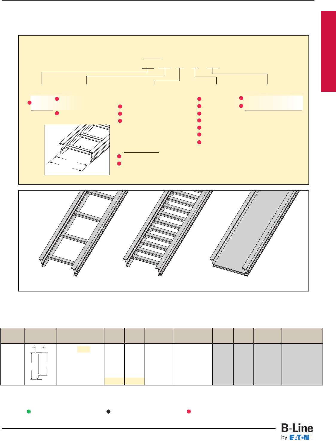
B-Line Side Rail NEMA, CSA & UL Span Load Deflection Design Factors Span Load Deflection Design Factors
Series Dimensions Classifications ft lbs/ft Multiplier for Two Rails meters kg/m Multiplier for Two Rails
NEMA: 20A, 16B 10 248 0.0025 3.0 369 0.043
CSA: 89 kg/m6.1m 12 172 0.0052 Area=0.83 in23.7 256 0.089 Area=5.35 cm2
14 127 0.010 Sx=1.09 in34.3 188 0.164 Sx=17.86 cm3
UL Cross-Sectional 16 97 0.016 Ix=3.10 in44.9 144 0.280 Ix=129.03 cm4
Area: 0.70 in218 77 0.026 5.5 114 0.448
20 62 0.040 6.1 92 0.684
Values are based on simple beam tests per NEMA VE 1 on 36" wide cable tray rungs spaced on 12" centers. Cable trays will
support without collapse a 200 lb. (90.7 kg) concentrated load over and above published loads. Published load safety factor is
1.5. To convert 1.5 safety factor to 2.0, multiply published load by 0.75. To obtain mid-span deflection, multiply a load by the
deflection multiplier. Cable tray must be supported on spans shorter than or equal to the length of the cable being installed.
When cable trays are used in continuous spans, the deflection of the cable tray is reduced by as much as 50%. Design factors:
Ix = Moment of Inertia, Sx = Section Modulus. † Insert 4 for 304 stainless steel or 6 for 316 stainless steel.
1.50
5.19 4.13
18 gauge
358
SS†
4" NEMA VE 1 Loading Depth
5" Side Rail Height
Overall Width
(Width + 13/8")
For
side rail
& rung data,
see chart on
pages AP-5 & AP-6
Rung
Spacing
Width
(Inside)
Straight Section Part Numbering
Prefix
Example: 358 SS6 09 - 24 - 240
Series Material *Type *Width Length
358 SS4 = 304 Stainless Ladder- 06 = 6" ¨144 = 12 ft. 358
Steel 06 = 6" rung spacing 09 = 9" ¡240 = 20 ft.
SS6 = 316 Stainless 09 = 9" rung spacing 12 = 12"
Steel 12 = 12" rung spacing 18 = 18"
24 = 24"
30 = 30"
Trough- 36 = 36"
6" and Wider
04 = Vented Bottom
SB = Non-Ventilated
See page APP-1 for additional rung options. *Special sizes available.
Ladder Type
(Specify Rung Spacing)
Vented Bottom Non-Ventilated
Series 3 & 4 Stainless Steel
¨Primary Length.
¡Secondary Length.
See page CTS-23 for
explanation of lengths.
Passivation available
see page CTS-2.
Green = Fastest shipped items Black = Normal lead-time items Red = Normally long lead-time items
SST-4
Series 3 & 4 Stainless Steel - Straight Sections
Cable Tray Systems
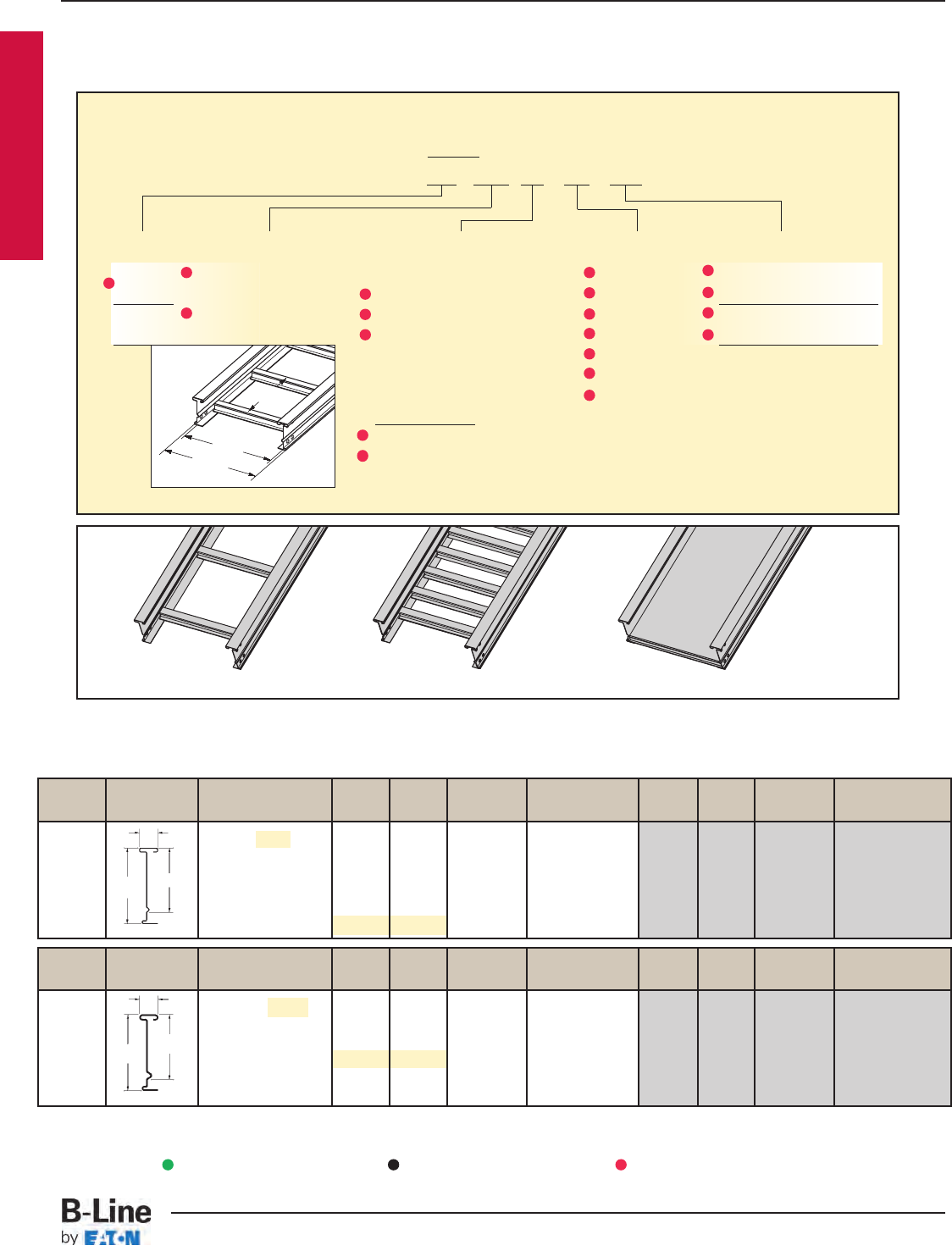
B-Line Side Rail NEMA, CSA Span Load Deflection Design Factors Span Load Deflection Design Factors
Series Dimensions Classifications ft lbs/ft Multiplier for Two Rails meters kg/m Multiplier for Two Rails
NEMA: 20C+ 12 342 0.002 3.7 508 0.036
CSA: E-6m 16 192 0.007 Area=1.49 in24.9 286 0.113 Area=9.61 cm2
18 152 0.011 Sx=2.28 in35.5 226 0.182 Sx=37.36 cm3
UL Cross-Sectional 20 123 0.016 Ix=7.65 in46.1 183 0.277 Ix=318.42 cm4
Area: 1.00 in222 102 0.024 6.7 151 0.406
24 85 0.034 7.3 127 0.574
B-Line Side Rail NEMA, CSA Span Load Deflection Design Factors Span Load Deflection Design Factors
Series Dimensions Classifications ft lbs/ft Multiplier for Two Rails meters kg/m Multiplier for Two Rails
NEMA: 20A, 16B 10 236 0.0016 3.0 351 0.028
CSA: D1-3m 12 164 0.0034 Area=0.92 in23.7 244 0.058 Area=5.94 cm2
14 120 0.0062 Sx=1.41 in34.3 179 0.107 Sx=23.11 cm3
UL Cross-Sectional 16 92 0.011 Ix=4.77 in44.9 137 0.182 Ix=198.54 cm4
Area: 0.70 in218 73 0.017 5.5 108 0.291
20 59 0.026 6.1 88 0.444
Values are based on simple beam tests per NEMA VE 1 on 36" wide cable tray rungs spaced on 12" centers. Cable trays will
support without collapse a 200 lb. (90.7 kg) concentrated load over and above published loads. Published load safety factor is
1.5. To convert 1.5 safety factor to 2.0, multiply published load by 0.75. To obtain mid-span deflection, multiply a load by the
deflection multiplier. Cable tray must be supported on spans shorter than or equal to the length of the cable being installed.
When cable trays are used in continuous spans, the deflection of the cable tray is reduced by as much as 50%. Design factors:
Ix = Moment of Inertia, Sx = Section Modulus. † Insert 4 for 304 stainless steel or 6 for 316 stainless steel.
1.50
6.19 5.13
18 gauge
1.50
6.19 5.11
14 gauge
368
SS†
464
SS†
5" NEMA VE 1 Loading Depth
6" Side Rail Height
Overall Width
(Width + 13/8")
For
side rail
& rung data,
see chart on
pages AP-5 & AP-6
Rung
Spacing
Width
(Inside)
Straight Section Part Numbering
Prefix
Example: 368 SS6 09 - 24 - 240
Series Material *Type *Width Length
368 SS4 = 304 Stainless Ladder- 06 = 6" ¨240 = 20 ft. 368
Steel 06 = 6" rung spacing 09 = 9" ¡144 = 12 ft.
464 SS6 = 316 Stainless 09 = 9" rung spacing 12 = 12" ¨240 = 20 ft. 464
Steel 12 = 12" rung spacing 18 = 18" ¡288 = 24 ft.
24 = 24"
30 = 30"
Trough- 36 = 36"
6" and Wider
04 = Vented Bottom
SB = Non-Ventilated
See page APP-1 for additional rung options. *Special sizes available.
Series 3 & 4 Stainless Steel
Ladder Type
(Specify Rung Spacing)
Vented Bottom Non-Ventilated
¨Primary Length.
¡Secondary Length.
See page CTS-23 for
explanation of lengths.
Passivation available
see page CTS-2.
Green = Fastest shipped items Black = Normal lead-time items Red = Normally long lead-time items
SST-5
Series 3 & 4 Stainless Steel - Straight Sections
Cable Tray Systems
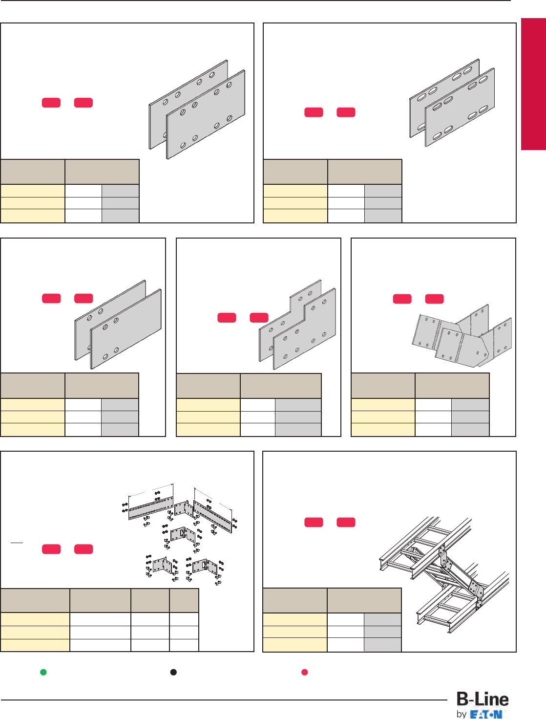
Catalog No. Height
in. mm
9(*)-8014 4 101
9(*)-8015 5 127
9(*)-8016 6 152
Catalog No. Height
in. mm
9(*)-8004 4 101
9(*)-8005 5 127
9(*)-8006 6 152
Splice Plates
• Standard 8-hole pattern for all stainless
steel splice plates.
• Furnished in pairs with hardware.
• One pair including hardware provided
with straight section.
• Boxed in pairs with hardware.
• (*) Insert or
Catalog No. Cable Tray Tray
No. End Cut Width 'L'
9(*)-803(X) Mitered Thru 36" N/A
9(*)-803(X)-12 Not Mitered Thru 12" 16"
9(*)-803(X)-36 Not Mitered Thru 36" 41"
Catalog No. Height
in. mm
9(*)-8045 5 to 4 127 to 101
9(*)-8046 6 to 4 152 to 101
9(*)-8060 6 to 5 152 to 127
Catalog No. Height
in. mm
9(*)-8004-1/24 101
9(*)-8005-1/25 127
9(*)-8006-1/26 152
Catalog No. Height
in. mm
9(*)-8244 4 101
9(*)-8245 5 127
9(*)-8246 6 152
9(*)-803(X)
Splice only
9(*)-803(X)-12 or 9(*)-803(X)-36
One pair splice plates with extensions.
Universal Splice Plates
• Used to splice to existing cable
tray systems.
• Furnished in pairs with
hardware.
• (*) Insert or
Catalog No. Height
in. mm
9(*)-8024 4 101
9(*)-8025 5 127
9(*)-8026 6 152
Horizontal Adjustable Splice Plates
• Offered to adjust a cable tray run
for changes in direction in
a horizontal plane that do
not conform to standard
horizontal fittings.
• Furnished in pairs with hardware.
• New design bonding jumpers
not required.
• (*) Insert or
• (X) Insert 4, 5 or 6 for
side rail height.
Step Down Splice Plates
• These splice plates are offered
for connecting cable tray
sections having side rails of
different heights.
• Furnished in pairs
with hardware.
• (*) Insert or
Expansion Splice Plates
• Expansion plates allow for one inch
expansion or contraction of the cable tray,
or where expansion joints occur in
the support structure.
• Furnished in pairs with hardware.
•Bonding Jumpers are required.
Order Separately.
• (*) Insert or
For heavy duty expansion
splice plates see page APP-3.
Vertical Adjustable Splice Plates
• These plates provide for changes in
elevation that do not conform to
standard vertical fittings.
• Furnished in pairs with hardware.
• (*) Insert or
Branch Pivot Connectors
• Branch from existing cable tray runs at any point.
• Pivot to any required angle.
• UL Classified for grounding
(bonding jumper not required).
• Furnished in pairs with hardware.
• (*) Insert or
L
L
Series 3 & 4 Stainless Steel
SS4 SS6
SS4 SS6
SS4 SS6
SS4 SS6
SS4 SS6
SS4 SS6
SS4 SS6
Requires
supports
within 24”
on both
sides, per
NEMA VE 2.
Requires
supports within
24” on both
sides, per
NEMA VE 2.
Green = Fastest shipped items Black = Normal lead-time items Red = Normally long lead-time items
SST-6
Series 3 & 4 Stainless Steel - Accessories
Cable Tray Systems
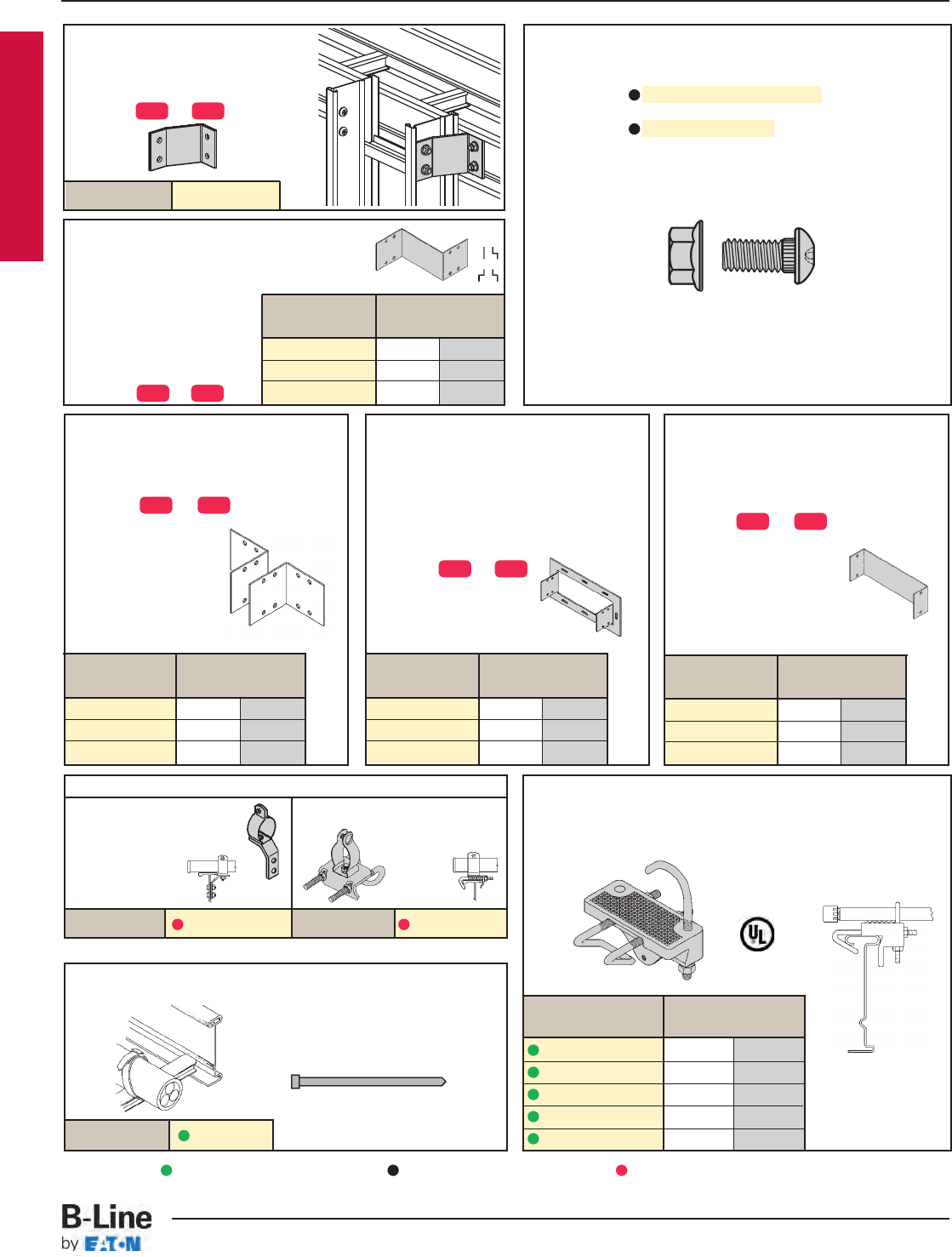
Conduit to Tray Adaptor
• For easy attachment of conduit terminating at a cable tray.
• Use on aluminum or steel cable trays.
Catalog No. Conduit Size
in. mm
9G-1158-1/2, 3/41/2, 3/415, 20
9G-1158-1, 11/41, 11/425, 32
9G-1158-11/2, 2 11/2, 2 40, 50
9G-1158-21/2, 3 21/2, 3 65, 80
9G-1158-31/2, 4 31/2, 4 90, 100
Catalog No. 9SS4-1150-(‡) Catalog No. 9SS4-1155-(‡)
Cable Tie (Ladder Tray)
Nylon ties provide easy attachment of
cable to ladder rungs; maximum
cable O.D. of 3" (76mm).
Catalog No. 99-2125-15
Blind End
• This plate forms a closure for a dead
end cable tray.
• Furnished as one plate with hardware.
• (‡) Insert tray width
• (*) Insert or
Frame Type Box Connector
• Designed to attach the end of a cable tray
run to a distribution cabinet or control
center to help reinforce the box at the
point of entry.
• Furnished with cable tray connection
hardware.
• (‡) Insert tray width
• (*) Insert or
Type 316 Tray Hardware
Catalog No. RNCB 3/8"-16 x 3/4" SS6
Ribbed Neck Carriage Bolt, 316 Stainless Steel
Catalog No. SFHN 3/8"-16 SS6
Hex Nut , 316 Stainless Steel
Steel I-Beam
Overall Length 15"
• Assembly required.
• Mounting hardware
included.
• Conduit clamps
provided.
• (‡) = Conduit size
(1/2" thru 4").
• Assembly required.
• Conduit clamp included.
• (‡) = Conduit size
(1/2" thru 4").
Conduit to Tray Adaptors
Catalog No. Height
in. mm
9(*)-8054 4 101
9(*)-8055 5 127
9(*)-8056 6 152
Catalog No. Height
in. mm
9(*)-8074-(‡) 4 101
9(*)-8075-(‡) 5 127
9(*)-8076-(‡) 6 152
Catalog No. Height
in. mm
9(*)-8084-(‡) 4 101
9(*)-8085-(‡) 5 127
9(*)-8086-(‡) 6 152
Tray to Box Splice Plates
• Used to attach the end of a cable tray
run to a distribution box or control panel.
• Furnished in pairs with hardware.
• (*) Insert or
9(*)-1240
Catalog No.
Cross Connector Bracket
• For field connecting crossing section.
• Furnished in pairs with 3/8"
hardware.
• (*) Insert or
Catalog No. Height
in. mm
9(*)-8064-(‡) 4 101
9(*)-8065-(‡) 5 127
9(*)-8066-(‡) 6 152
Offset Reducing Splice Plate
• This plate is used for joining cable trays having
different widths. When used in pairs they form
a straight reduction; when
used singly with a standard
splice plate, they form an
offset reduction.
• Furnished as one plate
with hardware.
• (‡) Insert reduction
• (*) Insert or
Series 3 & 4 Stainless Steel
SS4 SS6
SS4 SS6
SS4 SS6
SS4 SS6
SS4 SS6
Green = Fastest shipped items Black = Normal lead-time items Red = Normally long lead-time items
SST-7
Series 3 & 4 Stainless Steel - Accessories
Cable Tray Systems
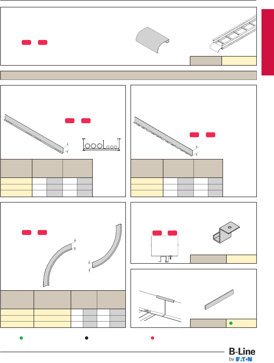
9(*)-1104-(‡)
Catalog No.
Ladder Drop-Out
• Specially-designed Ladder Drop-Outs provide a rounded surface with
4" (101 mm) radius to protect cable as it exits from the cable tray,
preventing damage to insulation. The drop-out will attach to any
desired rung.
• (‡) Insert tray width
• (*) Insert or
Catalog No.
Inside Bend Outside Bend Side Rail Loading
Catalog No. Catalog No. Height Depth 'H'
in. mm in. mm
73(*)-(**)VI(†) 73(*)-(**)VO(†) 4 101 3 76
74(*)-(**)VI(†) 74(*)-(**)VO(†) 5 127 4 101
75(*)-(**)VI(†) 75(*)-(**)VO(†) 6 152 5 127 Catalog No. 99-9982
Barrier Strip Splice
• Plastic splice holds adjoining
barrier strips in straight alignment.
9(*)-9002
Barrier Strip Clip
• Zinc plated steel barrier clip fastens to
either aluminum or steel ladder rung.
• Furnished with one #10 x 1/2" SS4
plated self-drilling screw.
• (*) Insert or
Vertical Bend Barriers
• Vertical Bend Barriers are preformed to conform to a
specific vertical fitting.
• Furnished with three #10 x 1
/2" SS4 self-drilling
screws and a 99-9982 Barrier Strip Splice.
• (*) Insert or
• (**) Insert 30, 45, 60 or 90 for degrees
• (†) Insert 12, 24, 36 or 48 for radius
Horizontal Bend
• Horizontal Bend Barriers are flexible in order
to conform to any horizontal fitting radius. Cut
to length.
• Order catalog number based on loading depth.
• Furnished with three #10 x 1/2" SS4
self-drilling screws and a 99-9982 Barrier
Strip Splice.
• Standard length is 72" (6 ft.), sold individually.
• (*) Insert or
Catalog Side Rail Loading
No. Height Depth 'H'
in. mm in. mm
73(*)-90HBFL 4 101 3 76
74(*)-90HBFL 5 127 4 101
75(*)-90HBFL 6 152 5 127
Straight Section
• Standard length: 120" (3 m) 144" (12 ft.).
• Order catalog number based on loading
depth.
• Furnished with four #10 x 1/2" SS4 self-
drilling screws and a 99-9982 splice.
• (*) Insert or
Outside Bend
(VO)
Inside Bend
(VI)
HH
Length =
144 for 12'
or
120 for 10'
Barriers
Catalog Side Rail Loading
No. Height Depth 'H'
in. mm in. mm
73(*)-Length 4 101 3 76
74(*)-Length 5 127 4 101
75(*)-Length 6 152 5 127
H
H
Series 3 & 4 Stainless Steel
SS4 SS6
SS4 SS6
SS4 SS6 SS4 SS6
SS4 SS6
Green = Fastest shipped items Black = Normal lead-time items Red = Normally long lead-time items
SST-8
Series 3 & 4 Stainless Steel - Accessories
Cable Tray Systems
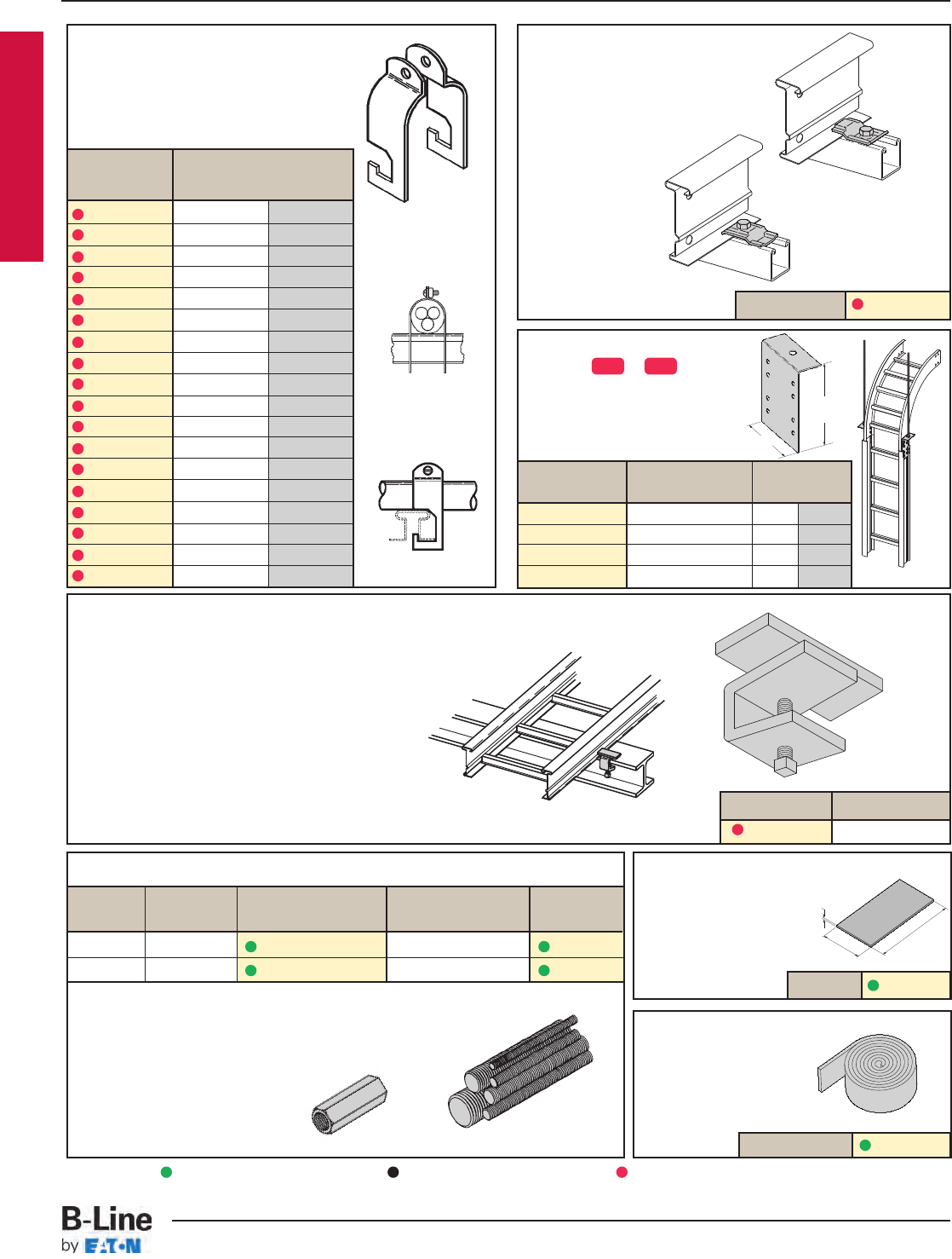
Cable Tray Guide
• Expansion guide for single or double cable tray runs.
• Guide allows for longitudinal movement of the
cable tray.
• No field drilling of support I-beam or channel is required.
• Guides are required on both sides of cable tray
to prevent lateral movement - can be placed on
either the inside or outside flange of cable tray.
• Guides are sold in pieces - two guides are
required per tray.
• Maximum flange thickness 11/8" (28.58 mm).
Nylon Pad
• Use for friction reduction.
• Hardness: Shore D80.
• Low friction coefficient.
• UV resistant.
• Excellent weatherability.
• UL - 94HB.
Cat. No. 99-PE36
Neoprene Roll
• Use for material isolation.
•1/8" x 2" x 25' roll.
• Hardness: Shore A60.
• Good weatherability.
Catalog No. Finish
9G-1249 HDGAF
Stainless Steel Cable Clamp
• Fits with series 3 & 4 rungs.
• Shipped flat. Field form around the cable
at the time of installation.
Threaded Rod (ATR) & Rod Coupling
Loading Catalog Available Coupling
Size lbs No. Lengths Cat. No.
3/8-16 730 ATR 3/8x Length 36", 72", 144" B655-3/8
1/2-13 1350 ATR 1/2x Length 36", 72", 144" B655-1/2
Loading based on safety factor 5.
Standard Finish: SS4 or SS6
See B-Line Strut Systems Catalog for other sizes and finishes.
Cable Tray Clamp/Guide
• Features a no-twist design.
• Has four times the strength
of the traditional design.
• Each side is labeled to
ensure proper installation.
•1/2" hardware size.
• Furnished in pairs
without hardware.
Vertical Tray Hanger
• (*) Insert or
• Design load 1500 lbs/pair.
Safety Factor of 2.5
• Furnished in pairs.
• Hole size: 9/16” (14mm)
for 1/2” threaded rod.
Catalog No. Outside 'A'
Cable Tray Ht. in. mm
9(*)-8224 4" 3.36 85.34
9(*)-8225 5" 4.36 110.74
9(*)-8226 6" 5.36 136.14
9(*)-8227 7" 6.36 161.54
Catalog No. 9SS6-1205
Catalog No. 99-NP300
Installed as
a guide.
7"
(178mm)
A
6"
(152mm)
3"
(76mm)
1/8"
(3mm)
Patent #
RE35479
Installed as
a clamp.
Catalog No. Cable Size
in. mm
9SS4-4050 0.50 - 0.75 13 - 19
9SS4-4075 0.75 - 1.00 19 - 25
9SS4-4100 1.00 - 1.25 25 - 32
9SS4-4125 1.25 - 1.50 32 - 38
9SS4-4150 1.50 - 1.75 38 - 45
9SS4-4175 1.75 - 2.00 45 - 51
9SS4-4200 2.00 - 2.25 51 - 57
9SS4-4225 2.25 - 2.50 57 - 64
9SS4-4250 2.50 - 2.75 64 - 70
9SS4-4275 2.75 - 3.00 70 - 76
9SS4-4300 3.00 - 3.25 76 - 82
9SS4-4325 3.25 - 3.50 82 - 89
9SS4-4350 3.50 - 3.75 89 - 95
9SS4-4375 3.75 - 4.00 95 - 102
9SS4-4400 4.00 - 4.25 100 - 106
9SS4-4425 4.25 - 4.50 106 - 113
9SS4-4450 4.50 - 4.75 113 - 121
9SS4-4475 4.75 - 5.00 121 - 125
Series 3 & 4 Stainless Steel
SS4 SS6
Refer to Section CF
Cable Fixing
Green = Fastest shipped items Black = Normal lead-time items Red = Normally long lead-time items
SST-9
Series 3 & 4 Stainless Steel - Accessories
Cable Tray Systems
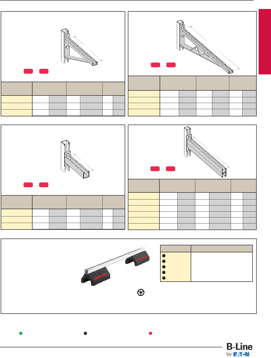
Cantilever Bracket
Catalog No. Uniform Load Tray Width 'A'
lbs kN in. mm in. mm
B494-30(*) 924 4.11 24 610 30 762
B494-36(*) 864 3.84 30 762 36 914
B494-42(*) 580 2.58 36 914 42 1067
B494-48(*) 500 2.22 42 1067 48 1219
Cantilever Bracket
Catalog No. Uniform Load Tray Width 'A'
lbs kN in. mm in. mm
B297-12(*) 1660 7.37 6 & 9 152 & 229 12 305
B297-18(*) 1100 4.88 12 305 18 457
B297-24(*) 835 3.71 18 457 24 610
B297-30(*) 665 2.95 24 610 30 762
B297-36(*) 550 2.44 30 762 36 914
B297-42(*) 465 2.06 36 914 42 1067
Cantilever Bracket
Catalog No. Uniform Load Tray Width 'A'
lbs kN in. mm in. mm
B494-12(*) 1580 7.02 6 & 9 152 & 229 12 305
B494-18(*) 1000 4.45 12 305 18 457
B494-24(*) 996 4.43 18 457 24 610
AA
A
Series 3 & 4 Stainless Steel
Cantilever Bracket
Catalog No. Uniform Load Tray Width 'A'
lbs kN in. mm in. mm
B409-12(*) 960 4.27 6 & 9 152 & 229 12 305
B409-18(*) 640 2.84 12 305 18 457
B409-24(*) 480 2.13 18 457 24 610
A
Rooftop Support Bases
with B22 Channel Catalog No. Height x Width x Length
DB10-28 55/8” x 6” x 28.0”
DB10-36 55/8” x 6” x 36.0”
DB10-42 55/8” x 6” x 42.0”
DB10-50 55/8” x 6” x 50.0”
DB10-60 55/8” x 6” x 60.0”
Designed as a superior rooftop support
for cable tray,
UV resistant and approved for most
roofing material or other flat surfaces.
Can be used with any of B-Line cable
tray clamps and guides.
Ultimate Load Capacity:
1,000 lbs. (uniform load) LEEDS credit available, base made from 100% recycled material.
General Note: Consult roofing manufacturer or engineer for roof load
capacity. The weakest point may be the insulation board beneath
the rubber membrane.
• (*) Insert or
• Safety Load Factor 2.5
SS4 SS6
• (*) Insert or
• Safety Load Factor 2.5
SS4 SS6
• (*) Insert or
• Safety Load Factor 2.5
SS4 SS6
• (*) Insert or
• Safety Load Factor 2.5
SS4 SS6
Green = Fastest shipped items Black = Normal lead-time items Red = Normally long lead-time items
SST-10
Series 3 & 4 Stainless Steel - Accessories
Cable Tray Systems
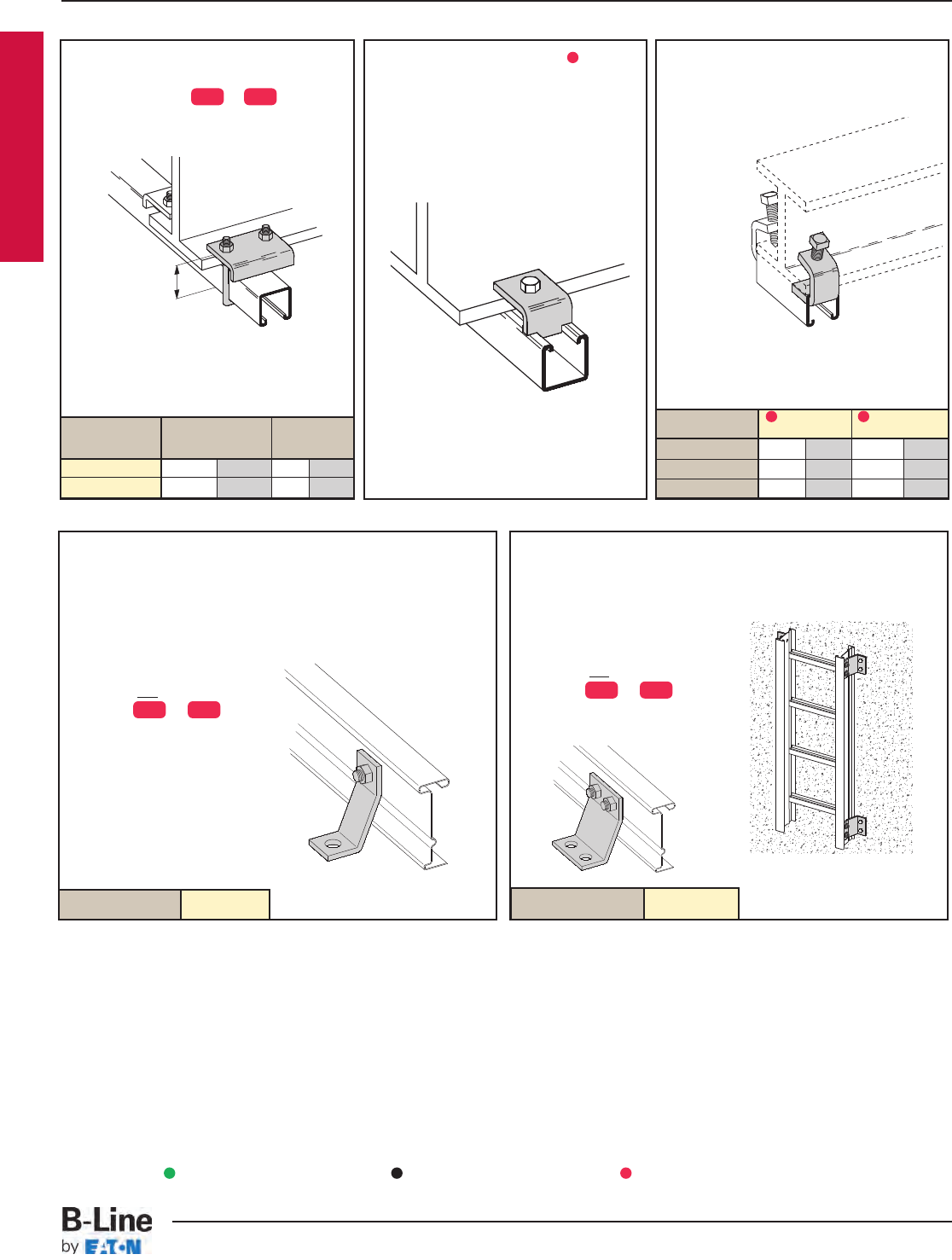
Series 3 & 4 Stainless Steel
Beam Clamp B355SS4
• Sold in pieces.
• Design load is 1200 lbs. when used
in pairs.
• Safety Load Factor 5.0
• Order HHCS and
Channel Nuts separately.
Beam Clamp
• Sold in pieces with hardware.
• Finishes available: or
Design load when used in pairs.
Safety Load Factor 5.0
Catalog No. Design Load* 'A'
lbs kN in. mm
B441-22(*) 1200 5.34 33/886
B441-22A(*) 1200 5.34 5 127
Beam Clamp
• Sold in pieces.
• 304 stainless steel
Design load when used in pairs.
Safety Load Factor 5.0
Cat. No. B212-1/4SS4 B212-3/8SS4
Design Load * 600 lbs. 2.67 kN 1000 lbs. 4.45 kN
Max. Flange Thick 3/4" 19 mm 1 1/8"
28.6 mm
Mat'l. Thickness 1/4" 6.3 mm 3/8" 9.5 mm
A
SS4 SS6
Heavy Duty Hold-Down Bracket
• Design load is 4000 lbs/pair.
• Four bolt design.
• Sold in pairs.
•3/8" cable tray attachment
hardware provided
•1/2" support attachment
hardware not provided.
• (*) Insert or
• Recommended for support
of vertical trays.
Heavy Duty Hold
Down Bracket
• Design load is 2000 lbs/pair.
• Two bolt design.
• Sold in pairs.
•3/8" cable tray attachment
hardware provided.
•1/2" support attachment
hardware not provided.
• (*) Insert or
• Recommended for support
of vertical trays.
Catalog No. 9(*)-1241 Catalog No. 9(*)-1242
SS4 SS6
SS4 SS6
Green = Fastest shipped items Black = Normal lead-time items Red = Normally long lead-time items
SST-11
Series 3 & 4 Stainless Steel - Accessories
Cable Tray Systems
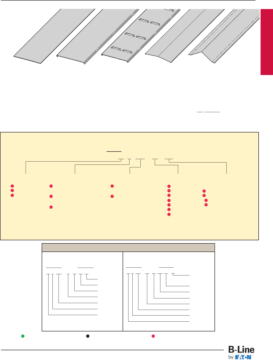
Series 3 & 4 Stainless Steel
Examples of Catalog Numbers for Fitting Covers:
A full range of covers is available for straight sections and fittings.
Solid covers should be used when maximum enclosure of the cable is desired and no accumulation of heat is expected.
Ventilated covers provide an overhead cable shield yet allow heat to escape.
B-Line recommends that covers be placed on vertical cable tray runs to a height of 6 ft. (1.83 m) to 8 ft. (2.44 m) above the floor
to isolate both cables and personnel. Flanged covers have a 1/2in. (13 mm) flange. Cover clamps are not included with the cover and
must be ordered separately. All peaked covers are flanged. Standard peaked covers have 1/2" peak. Special purpose peaked covers,
having a 2 to 3 pitch, provide additional slope and material thickness. The 2 to 3 pitch fitting covers are of multiple piece, welded
construction.
Solid Flanged Ventilated Flanged Peaked Flanged 2 to 3 Pitch Peaked Flanged
(See page APP-4)
Vertical Bend Cover
Prefix Suffix
80 2 SS4 - 24 - 90 VO 24 - 4*
Side Rail*
Height
Radius
Fitting
Angle
Width
Material
Detail
Cover Type
Solid Non-Flanged
Stainless Steel Cover Part Numbering
Prefix
Example: 80 3 SS4 - 24 - 144
Cover Type Detail Material Tray Width Item Description
Covers
Horizontal Bend Cover
Prefix Suffix
80 2 SS4 - 18 - 90 HB 24
Radius
Fitting
Angle
Width
Material
Detail
Cover Type
80 = Solid
81 = Ventilated
82 = Peaked
2= Flanged Stainless Steel
(All fittings)
3= Flanged Stainless Steel
(All straight sections)
4= Non-Flanged Stainless Steel
(80 & 81 type only)
06 = 6"
09 = 9"
12 = 12"
18 = 18"
24 = 24"
30 = 30"
36 = 36"
For Straight Section Cover:
144 = 12 ft. (3.66 m)
120 = 10 ft. (3.05 m)
72 = 6 ft. (1.83 m)
60 = 5 ft. (1.52 m)
For fitting covers: Insert suffix
of fitting to be covered.
See example below.
SS4 = 304 Stainless
Steel
SS6 = 316 Stainless
Steel
* Required for VO fittings only
Covers 30" and 36" wide have reinforcing ridges.
Green = Fastest shipped items Black = Normal lead-time items Red = Normally long lead-time items
SST-12
Series 3 & 4 Stainless Steel - Accessories
Cable Tray Systems
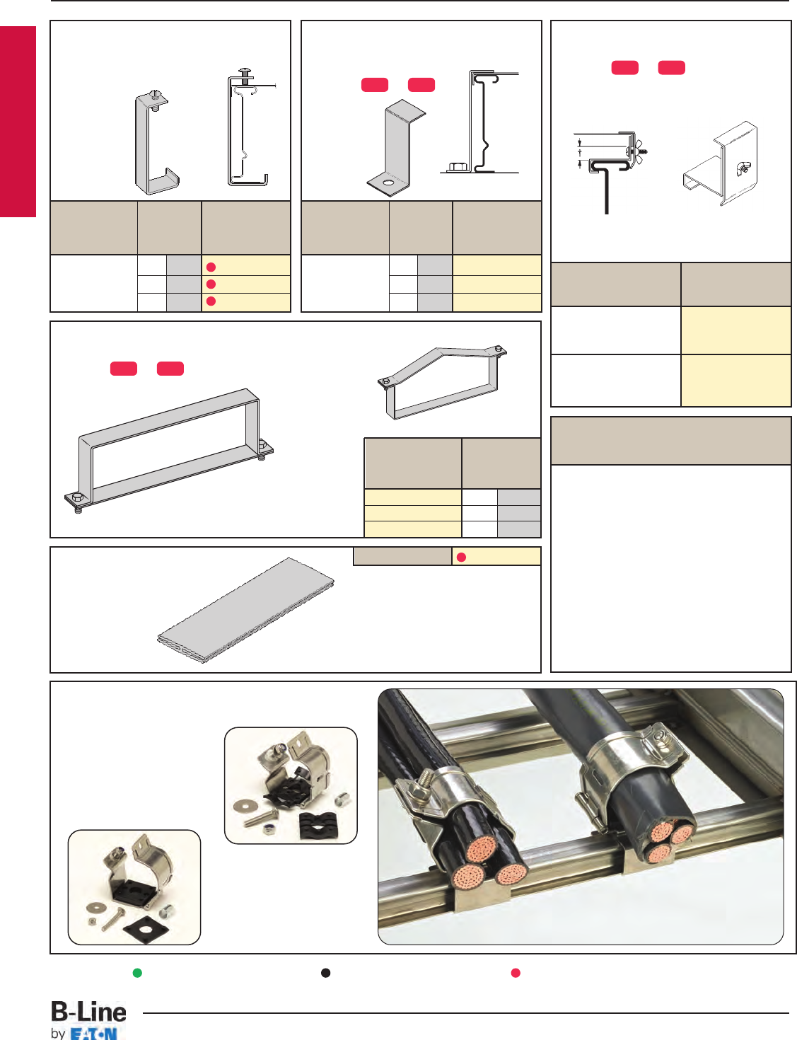
Series 3 & 4 Stainless Steel
Cover Joint Strip Catalog No. 99-9980-(‡)
• Used to join Covers
• Plastic
• (‡) Insert tray width
Raised Cover Clamp
• For indoor service only.
• (*) Insert or
• For use with flanged covers only.
† Specify gap of 1", 2", 3" or 4".
Tray Catalog
Type No.
Series 3 & 4 Steel 9(*)-9115-†
Straight Section
All Steel Fittings 9(*)-910†
Combination Cover and
Hold Down Clamp
• Sold per piece.
• (*) Insert or
• For indoor
service only.
Standard Cover Clamp
• For indoor service only.
• Sold per piece.
Tray
Side Rail
Catalog
Type Height No.
in. mm
4 101 9SS6-9014
5 127 9SS6-9015
6 152 9SS6-9016
Quantity of Standard
Cover Clamps Required
Straight Section 60" or 72" .............4 pcs.
Straight Section 120" or 144" .........6 pcs.
Horizontal/Vertical Bends ................4 pcs.
Tees .................................................6 pcs.
Crosses............................................8 pcs.
Note: When using the Heavy Duty Cover
Clamp, only one-half the number of clamps
stated above is required.
Peaked Cover Clamp
Stainless
Steel
Tray
Side Rail
Catalog
Type Height No.
in. mm
4 101 9(*)-9043
5 127 9(*)-9053
6 152 9(*)-9063
Stainless
Steel
Heavy Duty Cover Clamp
• Recommended for outdoor service.
• (*) Insert or
SS4 SS6
SS4 SS6
SS4 SS6
(‡) Insert tray width
† Add P to Catalog No. for
1/2" peaked cover clamp.
Cable Cleats
(see pages CFX-1 thru CFX-5)
Trefoil
Cable
Cleats
Single
Cable
Cleats
Green = Fastest shipped items Black = Normal lead-time items Red = Normally long lead-time items
SST-13
Series 3 & 4 Stainless Steel - Accessories
Cable Tray Systems
Catalog Side Rail
No. Height
in. mm
9(*)-(‡)-9044† 4 101
9(*)-(‡)-9054† 5 127
9(*)-(‡)-9064† 6 152
Series 3 & 4 Stainless Steel
Section 1- Acceptable Manufacturers
1.01 Manufacturer: Subject to compliance with these specifications, cable tray systems shall be as
manufactured by B-Line.
Section 2- Cable Tray Sections and Components
2.01 General: Except as otherwise indicated, provide metal cable trays, of types, classes and sizes indicated;
with splice plates, bolts, nuts and washers for connecting units. Construct units with rounded edges
and smooth surfaces; in compliance with applicable standards; and with the following additional
construction features. Cable tray shall be installed according to the latest revision of NEMA VE 2.
2.02 Stainless Steel: Straight section and fitting side rails and rungs shall be made of AISI Type [304]
[316] stainless steel. Transverse members (rungs) or corrugated bottoms shall be welded to the side
rails with Type 316 stainless steel welding wire. Hardware shall be AISI Type 316 stainless steel.
2.03 Ladder Cable Trays shall consist of two longitudinal members (side rails) with transverse members
(rungs) welded to the side rails. Rungs shall be spaced [6] [9] [12] inches on center. Rung spacing in
radiused fittings shall be industry standard 9" and measured at the center of the tray’s width. Each rung
must be capable of supporting a 200 lb. concentrated load at the center of the cable tray with a safety
factor of 1.5.
2.04 Ventilated Trough Cable Trays shall consist of two longitudinal members (side rails) with a corrugated
bottom welded to the side rails or rungs spaced 4" on center. The peaks of the corrugated bottom
shall have a minimum flat cable bearing surface of 23/4" and shall be spaced on 6" centers. To
provide ventilation in the tray, the valleys of the corrugated bottom shall have 21/4" x 4" rectangular
holes punched along the width of the bottom.
2.05 Non-Ventilated Bottom Trough Cable Trays shall consist of two longitudinal members (side rails) with a
corrugated bottom welded to the side rails or a solid sheet over rungs. The peaks of the corrugated
bottom shall have a minimum flat cable bearing surface of 23/4" and shall be spaced on 6" centers.
2.06 Cable tray loading depth shall be [3] [4] [5] inches per NEMA VE 1.
2.07 Straight sections shall be fabricated as I-beams. Straight sections shall be supplied in standard
[12 foot] [24 foot] [10 foot (3 m)] [20 foot (6 m)] lengths.
2.08 Cable tray widths shall be [6] [9] [12] [18] [24] [30] [36] inches or as shown on drawings.
2.09 Splice plates shall be manufactured of high strength steel and be secured with 8 nuts and bolts per
plate. The resistance of fixed splice connections between an adjacent section of tray shall not exceed
0.00033 ohm.
2.11 All fittings must have a minimum radius of [12] [24] [36] [48] inches.
Section 3- Loading Capacities and Testing
3.01 Cable tray shall be capable of carrying a uniformly distributed load of ______ lbs./ft. on a _______ ft.
support span with a safety factor of 1.5 when supported as a simple span and tested per NEMA
VE 1 5.2. In addition to the uniformly distributed load the cable tray shall support 200 lbs.
concentrated load at mid-point of span. Load and safety factors specified are applicable to both the
side rails and rung capacities. Cable tray shall be made to manufacturing tolerances as specified
by NEMA.
3.02 Upon request, manufacturer shall provide test reports in accordance with the latest revision of
NEMA VE 1 or CSA C22.2 No. 126.
SST-14
Series 3 & 4 Stainless Steel - Specifications
Cable Tray Systems
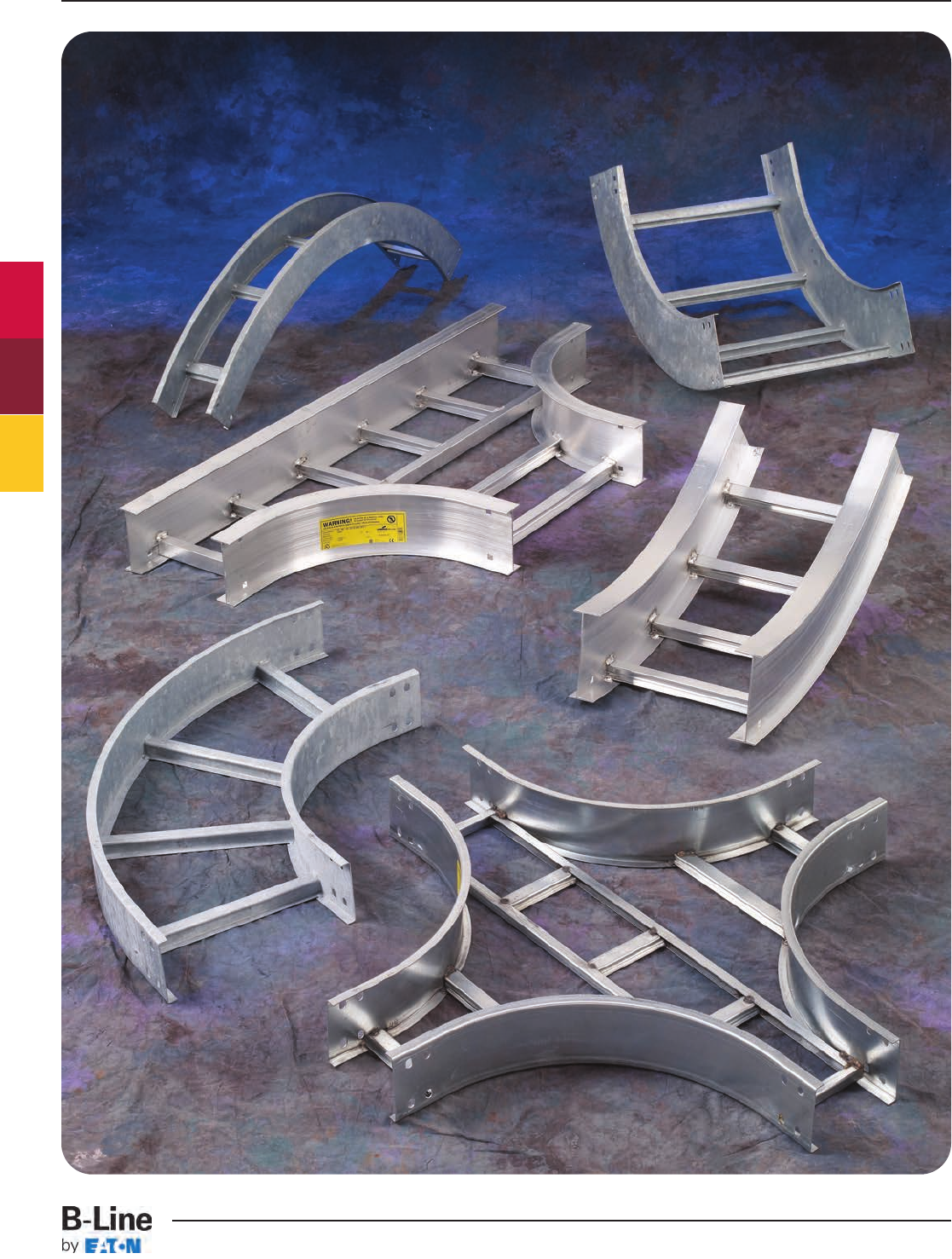
Series 2, 3, 4, & 5 Fittings
FTS-1
Series 2, 3, 4 & 5 - Fittings
Cable Tray Systems
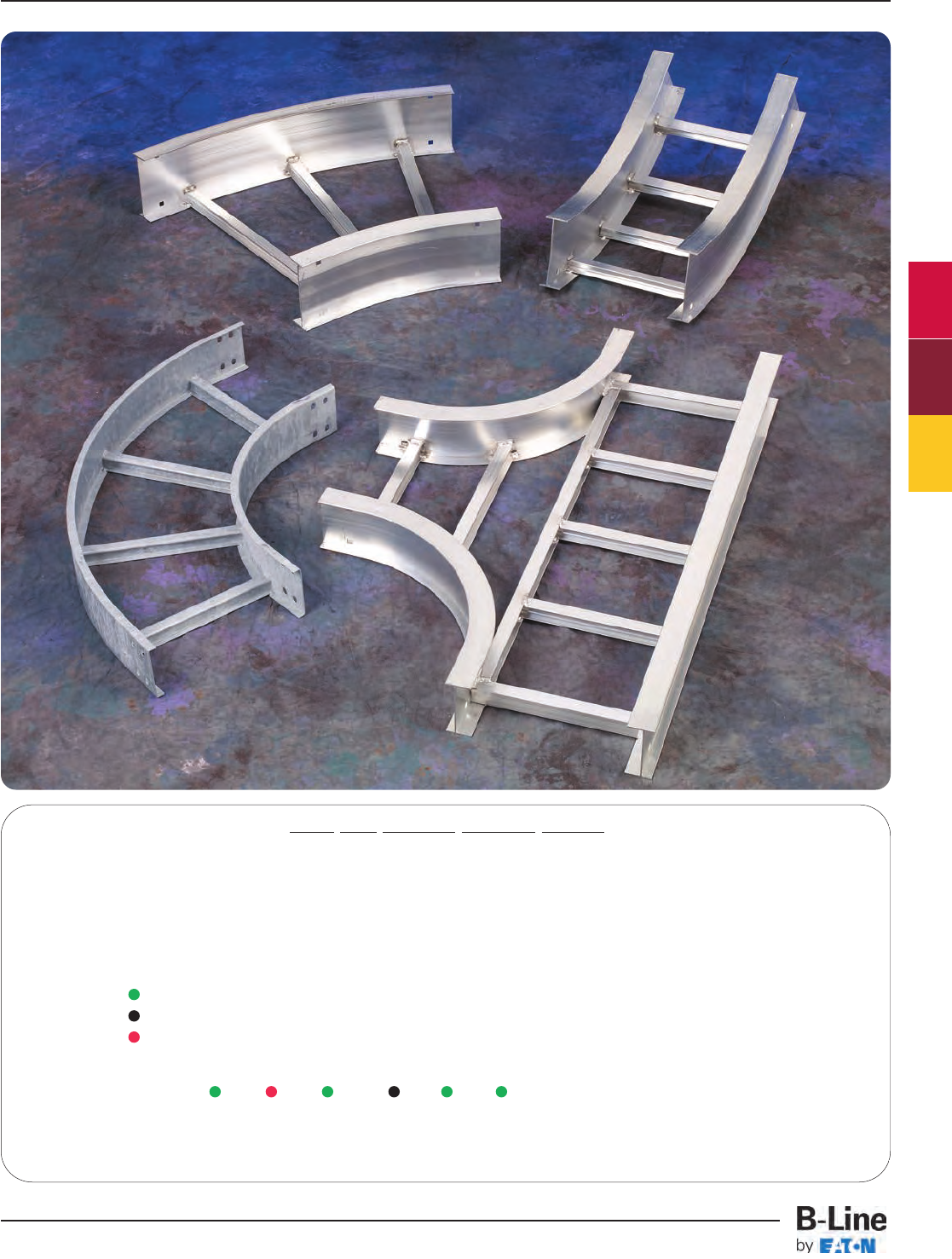
How The Service Advisor Works
B-Line knows that your time is important! That’s why the color-coding system in this catalog is designed to help you
select products that fit your service needs. Products are marked to indicate the typical lead time for orders of 50 pieces
or less.
Customer: How do I select my fittings so that I get the quickest turnaround?
Service Advisor: Each part of our selection chart is shown in colors. If any section of a part number is a different
color, the part will typically ship with the longer lead time represented by the colors.
Green = Fastest shipped items
Black = Normal lead-time items
Red = Normally long lead-time items
Example: 5G-09 - 90 HB 24 Part will have a long
lead time because of the
G material.
Changing the part number from G to A or P will change the coding to black and reduce lead time.
Series 2, 3, 4, & 5 Fittings
FTS-2
Series 2, 3, 4 & 5 - Fittings
Cable Tray Systems
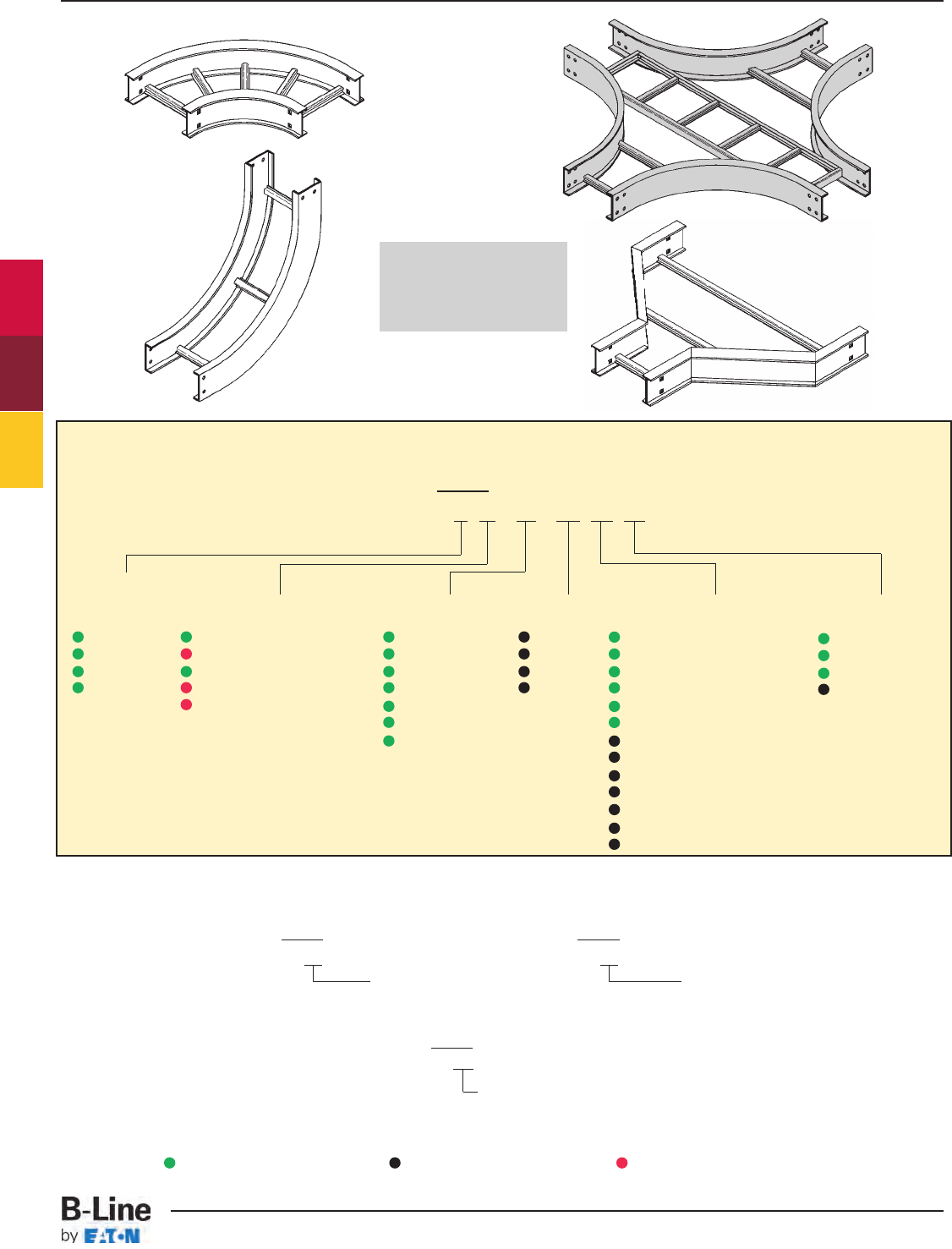
For flat non-ventilated: Available 6" and Wider
Prefix
5PSB - 24 - 90HB24
Non-Ventilated
Fittings Part Numbering
Prefix
Example: 4 A - 24 - 90 HB 24
Side Rail
Height
4 = 4" (101)
5 = 5" (127)
6 = 6" (152)
7 = 7" (178)
Material
A= Aluminum
G=HDGAF
P= Pre-Galvanized
SS4= 304 Stainless Steel
SS6= 316 Stainless Steel
Width
06 = 6" (152)
09 = 9" (228)
12 = 12" (305)
18 = 18" (457)
24 = 24" (609)
30 = 30" (762)
36 = 36" (914)
Angle
30 = 30°
45 = 45°
60 = 60°
90 = 90°
Radius
12 = 12" (305)
24 = 24" (609)
36 = 36" (914)
48 = 48" (1219)
Type
HB = Horizontal Bend
HT = Horizontal Tee
HX = Horizontal Cross
VI = Vertical Inside Bend
VO = Vertical Outside Bend
VT = Vertical Tee
VTU = Vertical Tee, Up
HYR = Horizontal Wye, Right
HYL = Horizontal Wye, Left
CSF = Cable Support Fitting
LR = Left Reducer Fitting
RR = Right Reducer Fitting
SR = Straight Reducer Fitting
For ventilated trough, solid trough, ventilated bottom or solid bottom,
add VT, ST, 04 or SB as shown below: Available 6" thru 36"
Prefix Prefix
4AVT - 24 - 90HB24 4PST - 24 - 90HB24
Vented Trough Non-Ventilated Trough
Fittings engineered
with 3” tangents for
splicing integrity.
(9" rung spacing is standard)
Note: Horizontal crosses and tees 30" or wider, with a radius of 36" or larger, will be of two-piece construction.
See page 385 for 6” fittings with 9A-6006 and 9A-6007 splice plates.
Series 2, 3, 4, & 5 Fittings
Green = Fastest shipped items Black = Normal lead-time items Red = Normally long lead-time items
FTS-3
Series 2, 3, 4 & 5 - Fittings
Cable Tray Systems
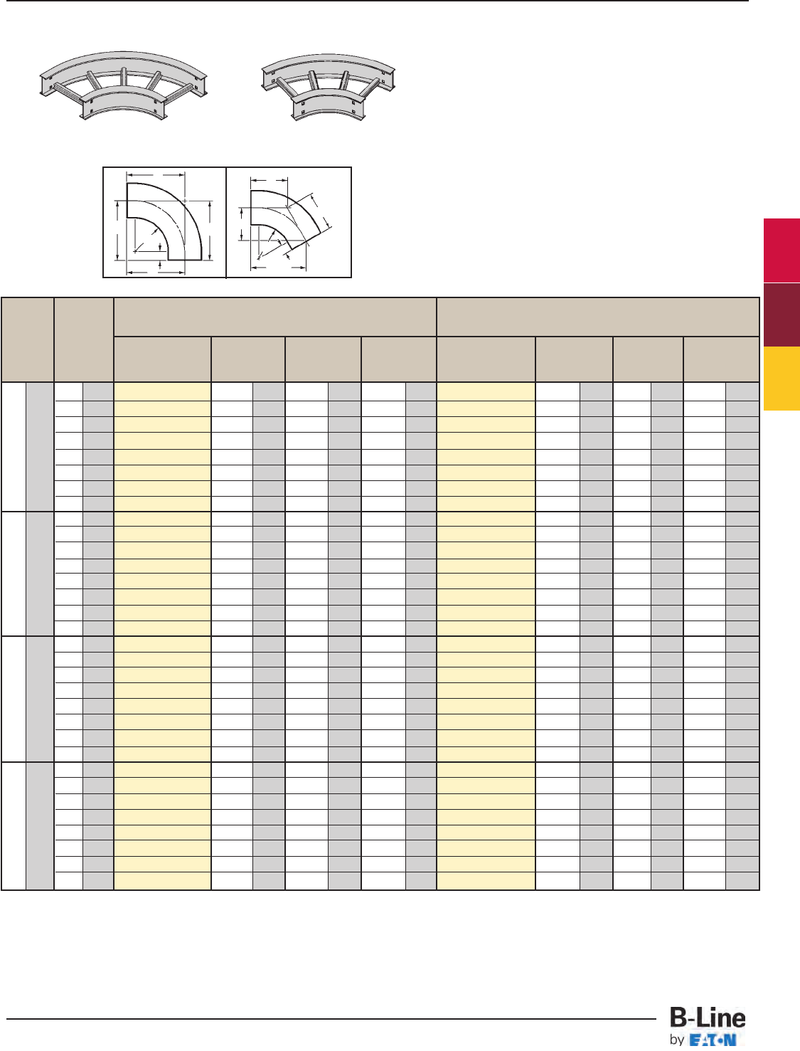
All dimensions in parentheses are in millimeters unless otherwise specified.
Bend Tray 90˚ Horizontal Bend 60˚ Horizontal Bend
Radius Width Dimensions Dimensions
R Catalog No. ABCCatalog No. ABC
in. mm in. mm in. mm in. mm in. mm in. mm in. mm in. mm
6 152 (Pre)-06-90HB12 18 457 18 457 18 457 (Pre)-06-60HB12 171/2445 101/8257 1111/16 297
9 228 (Pre)-09-90HB12 191/2495 191/2495 191/2495 (Pre)-09-60HB12 1813/16 478 107/8276 121/2318
12 305 (Pre)-12-90HB12 21 533 21 533 21 533 (Pre)-12-60HB12 201/16 510 115/8295 133/8340
12 305 18 457 (Pre)-18-90HB12 24 610 24 610 24 610 (Pre)-18-60HB12 2211/16 576 131/8333 151/8384
24 609 (Pre)-24-90HB12 27 686 27 686 27 686 (Pre)-24-60HB12 255/16 643 145/8372 167/8429
30 762 (Pre)-30-90HB12 30 762 30 762 30 762 (Pre)-30-60HB12 277/8708 161/8410 189/16 472
36 914 (Pre)-36-90HB12 33 838 33 838 33 838 (Pre)-36-60HB12 301/2775 175/8448 205/16 516
42 1218 (Pre)-42-90HB12 36 914 36 914 36 914 (Pre)-42-60HB12 331/16 840 191/8486 221/16 560
6 152 (Pre)-06-90HB24 30 762 30 762 30 762 (Pre)-06-60HB24 277/8708 161/8410 189/16 472
9 228 (Pre)-09-90HB24 311/2800 311/2800 311/2800 (Pre)-09-60HB24 293/16 741 167/8429 197/16 494
12 305 (Pre)-12-90HB24 33 838 33 838 33 838 (Pre)-12-60HB24 301/2775 175/8448 205/16 516
24 610 18 457 (Pre)-18-90HB24 36 914 36 914 36 914 (Pre)-18-60HB24 331/16 708 191/8486 221/16 560
24 609 (Pre)-24-90HB24 39 991 39 991 39 991 (Pre)-24-60HB24 3511/16 907 205/8524 2313/16 605
30 762 (Pre)-30-90HB24 42 1067 42 1067 42 1067 (Pre)-30-60HB24 381/4972 221/8564 251/2648
36 914 (Pre)-36-90HB24 45 1143 45 1143 45 1143 (Pre)-36-60HB24 407/81038 235/8600 271/4692
42 1218 (Pre)-42-90HB24 48 1219 48 1219 48 1219 (Pre)-42-60HB24 431/21105 251/8638 29 737
6 152 (Pre)-06-90HB36 42 1067 42 1067 42 1067 (Pre)-06-60HB36 381/4971 221/8562 251/2648
9 228 (Pre)-09-90HB36 431/21105 431/21105 431/21105 (Pre)-09-60HB36 399/16 1005 227/8581 263/8670
12 305 (Pre)-12-90HB36 45 1143 45 1143 45 1143 (Pre)-12-60HB36 407/81038 235/8600 271/4692
36 915 18 457 (Pre)-18-90HB36 48 1219 48 1219 48 1219 (Pre)-18-60HB36 431/21105 251/8638 29 737
24 609 (Pre)-24-90HB36 51 1295 51 1295 51 1295 (Pre)-24-60HB36 461/16 1170 265/8676 3011/16 780
30 762 (Pre)-30-90HB36 54 1372 54 1375 54 1372 (Pre)-30-60HB36 481/16 1237 281/8714 327/16 824
36 914 (Pre)-36-90HB36 57 1448 57 1488 57 1448 (Pre)-36-60HB36 511/41302 295/8753 343/16 869
42 1218 (Pre)-42-90HB36 60 1524 60 1524 60 1524 (Pre)-42-60HB36 537/81368 311/8791 3515/16 913
6 152 (Pre)-06-90HB48 54 1372 54 1372 54 1372 (Pre)-06-60HB48 481/16 1221 281/8715 3211/16 830
9 228 (Pre)-09-90HB48 551/21410 551/21410 551/21410 (Pre)-09-60HB48 4915/16 1268 287/8734 335/16 846
12 305 (Pre)-12-90HB48 57 1448 57 1448 57 1448 (Pre)-12-60HB48 511/41302 295/8753 343/16 868
48 1220 18 457 (Pre)-18-90HB48 60 1524 60 1524 60 1524 (Pre)-18-60HB48 537/81368 311/8791 3515/16 913
24 609 (Pre)-24-90HB48 63 1600 63 1600 63 1600 (Pre)-24-60HB48 567/16 1434 325/8829 375/8956
30 762 (Pre)-30-90HB48 66 1676 66 1676 66 1676 (Pre)-30-60HB48 591/16 1500 341/8867 393/81000
36 914 (Pre)-36-90HB48 69 1753 69 1753 69 1753 (Pre)-36-60HB48 6111/16 1567 355/8905 411/81045
42 1218 (Pre)-42-90HB48 72 1829 72 1829 72 1829 (Pre)-42-60HB48 641/41632 371/8943 4213/16 1087
90˚ Horizontal Bend
CC
C
R
3" (76)
R
B
60˚ Horizontal Bend
B
90˚
HB
60˚
HB
Bottoms manufactured:
Ladder = 9" Rung Spacing
VT & 04 = 4" Rung Spacing
ST & SB = Flat sheet over
12" Rung Spacing
1 pair splice plates with hardware included.
Horizontal Bend 90° 60° (HB)
(Pre) See page FTS-3 for catalog number prefix.
Width dimensions are to inside wall. For aluminum fittings add 1.5 inches for total outside width.
Manufacturing tolerances apply to all dimensions.
A
3" (76)
A
C
Series 2, 3, 4, & 5 Fittings
FTS-4
Series 2, 3, 4 & 5 - Fittings
Cable Tray Systems
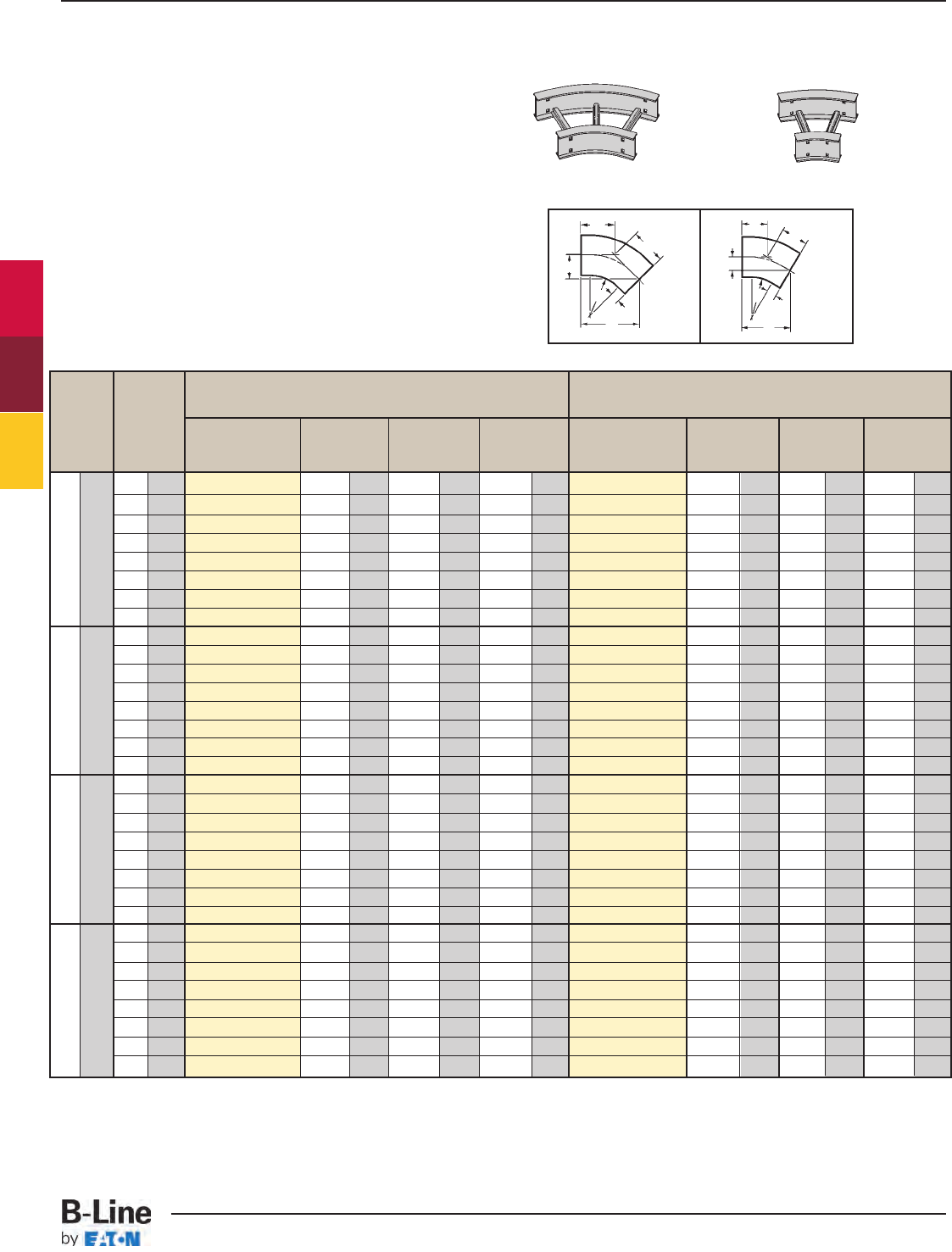
Bend Tray 45˚ Horizontal Bend 30˚ Horizontal Bend
Radius Width Dimensions Dimensions
R Catalog No. ABCCatalog No. ABC
in. mm in. mm in. mm in. mm in. mm in. mm in. mm in. mm
6 152 (Pre)-06-45HB12 153/4400 61/2165 93/16 233 (Pre)-06-30HB12 131/8333 31/289 7 179
9 228 (Pre)-09-45HB12 1613/16 427 615/16 176 913/16 249 (Pre)-09-30HB12 137/8352 311/16 94 77/16 189
12 305 (Pre)-12-45HB12 177/8454 73/8187 107/16 265 (Pre)-12-30HB12 145/8372 315/16 100 713/16 198
12 305 18 457 (Pre)-18-45HB12 20 508 81/4210 1111/16 297 (Pre)-18-30HB12 161/8410 45/16 135 85/8219
24 609 (Pre)-24-45HB12 221/16 560 91/8232 1215/16 329 (Pre)-24-30HB12 175/8448 411/16 119 97/16 240
30 762 (Pre)-30-45HB12 243/16 614 10 254 143/16 360 (Pre)-30-30HB12 191/8486 51/8130 101/4260
36 914 (Pre)-36-45HB12 265/16 668 1015/16 278 157/16 392 (Pre)-36-30HB12 205/8524 51/2140 111/16 281
42 1218 (Pre)-42-45HB12 287/16 722 1113/16 300 1611/16 424 (Pre)-42-30HB12 221/8562 515/16 151 1113/16 300
6 152 (Pre)-06-45HB24 243/16 614 10 254 143/16 360 (Pre)-06-30HB24 191/8486 51/8130 10/4260
9 228 (Pre)-09-45HB24 251/4641 101/2267 1413/16 376 (Pre)-09-30HB24 197/8505 55/16 135 105/8270
12 305 (Pre)-12-45HB24 265/16 668 1015/16 278 157/16 392 (Pre)-12-30HB24 205/8524 51/2140 111/16 281
24 610 18 457 (Pre)-18-45HB24 287/16 722 1113/16 300 1611/16 424 (Pre)-18-30HB24 221/8562 515/16 151 1113/16 300
24 609 (Pre)-24-45HB24 309/16 766 1211/16 322 1715/16 456 (Pre)-24-30HB24 235/8600 65/16 160 125/8321
30 762 (Pre)-30-45HB24 3211/16 830 139/16 344 191/8486 (Pre)-30-30HB24 251/8638 63/4172 137/16 341
36 914 (Pre)-36-45HB24 3413/16 884 147/16 367 203/8518 (Pre)-36-30HB24 265/8676 71/8181 141/4362
42 1218 (Pre)-42-45HB24 3615/16 938 155/16 389 215/8549 (Pre)-42-30HB24 281/8715 71/2191 151/16 383
6 152 (Pre)-06-45HB36 3211/16 830 139/16 344 191/8486 (Pre)-06-30HB36 251/8638 63/4171 137/16 341
9 228 (Pre)-09-45HB36 333/4857 14 356 193/4502 (Pre)-09-30HB36 257/8657 615/16 176 137/8352
12 305 (Pre)-12-45HB36 3413/16 884 147/16 367 203/8518 (Pre)-12-30HB36 265/8676 71/8181 141/4362
36 915 18 457 (Pre)-18-45HB36 3615/16 938 155/16 389 215/8549 (Pre)-18-30HB36 281/8114 71/2191 151/16 383
24 609 (Pre)-24-45HB36 391/6992 163/16 411 227/8581 (Pre)-24-30HB36 295/8753 715/16 202 157/8403
30 762 (Pre)-30-45HB36 413/61046 171/16 433 241/8613 (Pre)-30-30HB36 311/8790 85/16 211 1611/16 424
36 914 (Pre)-36-45HB36 435/61100 1715/16 456 253/8645 (Pre)-36-30HB36 325/8829 83/4222 171/2445
42 1218 (Pre)-42-45HB36 457/16 1154 1813/16 478 265/8676 (Pre)-42-30HB36 341/8867 91/8232 181/4464
6 152 (Pre)-06-45HB48 413/16 1046 171/16 433 241/8613 (Pre)-06-30HB48 311/8791 85/16 211 1611/16 424
9 228 (Pre)-09-45HB48 421/41073 171/2445 243/4629 (Pre)-09-30HB48 317/8810 89/16 218 171/16 433
12 305 (Pre)-12-45HB48 435/16 1100 1715/16 456 253/8645 (Pre)-12-30HB48 325/8829 83/4222 171/2445
48 1220 18 457 (Pre)-18-45HB48 457/16 1154 1813/16 487 265/8676 (Pre)-18-30HB48 341/8867 91/8232 181/4464
24 609 (Pre)-24-45HB48 479/16 1208 1911/16 500 277/8708 (Pre)-24-30HB48 355/8905 99/16 243 191/16 484
30 762 (Pre)-30-45HB48 4911/16 1262 209/16 522 291/8740 (Pre)-30-30HB48 371/8943 915/16 252 197/8505
36 914 (Pre)-36-45HB48 5113/16 1316 217/16 545 305/16 770 (Pre)-36-30HB48 385/8981 105/16 262 2011/16 525
42 1218 (Pre)-42-45HB48 5415/16 1395 225/16 567 319/16 802 (Pre)-42-30HB48 401/81019 103/4273 211/2546
45˚ Horizontal Bend
C
C
R
3" (76)
B
C
C
R
B
30˚ Horizontal Bend
45˚
HB
30˚
HB
Bottoms manufactured:
Ladder = 9" Rung Spacing
VT & 04 = 4" Rung Spacing
ST & SB = Flat sheet over
12" Rung Spacing
Horizontal Bend 45° 30° (HB)
(Pre) See page FTS-3 for catalog number prefix.
Width dimensions are to inside wall. For aluminum fittings add 1.5 inches for total outside width.
Manufacturing tolerances apply to all dimensions.
All dimensions in parentheses are in millimeters unless otherwise specified.
1 pair splice plates with hardware included.
3" (76)
AA
Series 2, 3, 4, & 5 Fittings
FTS-5
Series 2, 3, 4 & 5 - Fittings
Cable Tray Systems
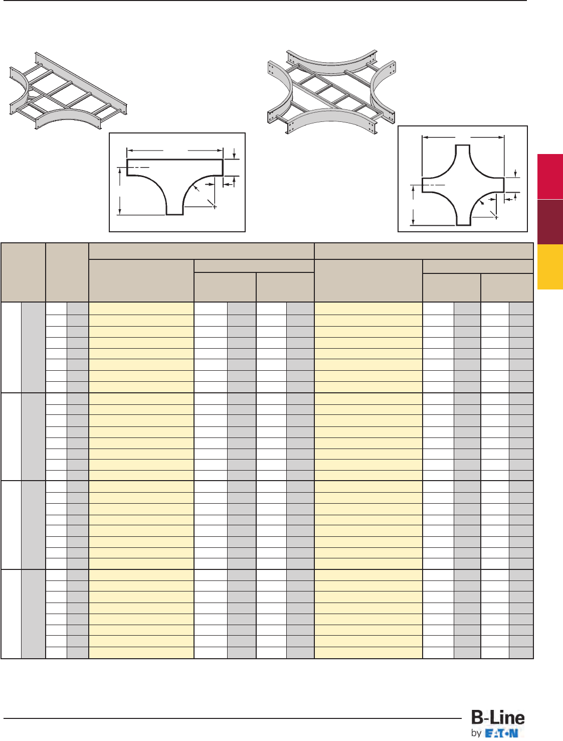
Bend Tray Horizontal Tee Horizontal Cross
Radius Width Dimensions Dimensions
R Catalog Number ABCatalog Number AB
in. mm in. mm in. mm in. mm in. mm in. mm
6 152 (Prefix)-06-HT12 18 457 36 914 (Prefix)-06-HX12 18 457 36 914
9 229 (Prefix)-09-HT12 191/2496 39 991 (Prefix)-09-HX12 191/2496 39 991
12 305 (Prefix)-12-HT12 21 533 42 1067 (Prefix)-12-HX12 21 533 42 1067
18 457 (Prefix)-18-HT12 24 609 48 1219 (Prefix)-18-HX12 24 609 48 1219
24 609 (Prefix)-24-HT12 27 686 54 1372 (Prefix)-24-HX12 27 686 54 1372
30 762 (Prefix)-30-HT12 30 762 60 1524 (Prefix)-30-HX12 30 762 60 1524
36 914 (Prefix)-36-HT12 33 838 66 1676 (Prefix)-36-HX12 33 838 66 1676
42 1067 (Prefix)-42-HT12 36 914 72 1829 (Prefix)-42-HX12 36 914 72 1829
6 152 (Prefix)-06-HT24 30 762 60 1542 (Prefix)-06-HX24 30 762 60 1524
9 229 (Prefix)-09-HT24 311/2800 63 1600 (Prefix)-09-HX24 311/2800 63 1600
12 305 (Prefix)-12-HT24 33 838 66 1676 (Prefix)-12-HX24 33 838 66 1676
18 457 (Prefix)-18-HT24 36 914 72 1828 (Prefix)-18-HX24 36 914 72 1828
24 609 (Prefix)-24-HT24 39 991 78 1982 (Prefix)-24-HX24 39 991 78 1982
30 762 (Prefix)-30-HT24 42 1067 84 2134 (Prefix)-30-HX24 42 1067 84 2134
36 914 (Prefix)-36-HT24 45 1143 90 2286 (Prefix)-36-HX24 45 1143 90 2286
42 1067 (Prefix)-42-HT24 48 1219 96 2438 (Prefix)-42-HX24 48 1219 96 2438
6 152 (Prefix)-06-HT36 42 1067 84 2134 (Prefix)-06-HX36 42 1067 84 2134
9 229 (Prefix)-09-HT36 431/21105 87 2210 (Prefix)-09-HX36 431/21105 87 2210
12 305 (Prefix)-12-HT36 45 1143 90 2286 (Prefix)-12-HX36 45 1143 90 2286
18 457 (Prefix)-18-HT36 48 1219 96 2438 (Prefix)-18-HX36 48 1219 96 2438
24 609 (Prefix)-24-HT36 51 1295 102 2590 (Prefix)-24-HX36 51 1295 102 2590
30 762 (Prefix)-30-HT36 54 1372 108 2744 (Prefix)-30-HX36 54 1372 108 2744
36 914 (Prefix)-36-HT36 57 1488 114 2896 (Prefix)-36-HX36 57 1448 114 2896
42 1067 (Prefix)-42-HT36 60 1524 120 3048 (Prefix)-42-HX36 60 1524 120 3048
6 152 (Prefix)-06-HT48 54 1372 108 2743 (Prefix)-06-HX48 54 1372 108 2743
9 229 (Prefix)-09-HT48 551/21410 111 2820 (Prefix)-09-HX48 551/21410 111 2820
12 305 (Prefix)-12-HT48 57 1448 114 2896 (Prefix)-12-HX48 57 1448 114 2896
18 457 (Prefix)-18-HT48 60 1524 120 3048 (Prefix)-18-HX48 60 1524 120 3048
24 609 (Prefix)-24-HT48 63 1600 126 3200 (Prefix)-24-HX48 63 1600 126 3200
30 762 (Prefix)-30-HT48 66 1676 132 3353 (Prefix)-30-HX48 66 1676 132 3353
36 914 (Prefix)-36-HT48 69 1753 138 3535 (Prefix)-36-HX48 69 1753 138 3505
42 1067 (Prefix)-42-HT48 72 1829 144 3658 (Prefix)-42-HX48 72 1829 144 3658
A
B
R
A
R
B
2 pair splice plates with hardware included. 3 pair splice plates with hardware included.
3" (76)
3" (76)
12 305
24 610
36 915
48 1220
(Prefix) See page FTS-3 for catalog number prefix.
Width dimensions are to inside wall. For aluminum fittings add 1.5 inches for total outside width. Manufacturing tolerances apply to all dimensions.
Horizontal Tee (HT) Horizontal Cross (HX)
HT HX
W
W
Series 2, 3, 4, & 5 Fittings
All dimensions in parentheses are in millimeters unless otherwise specified.
FTS-6
Series 2, 3, 4 & 5 - Fittings
Cable Tray Systems
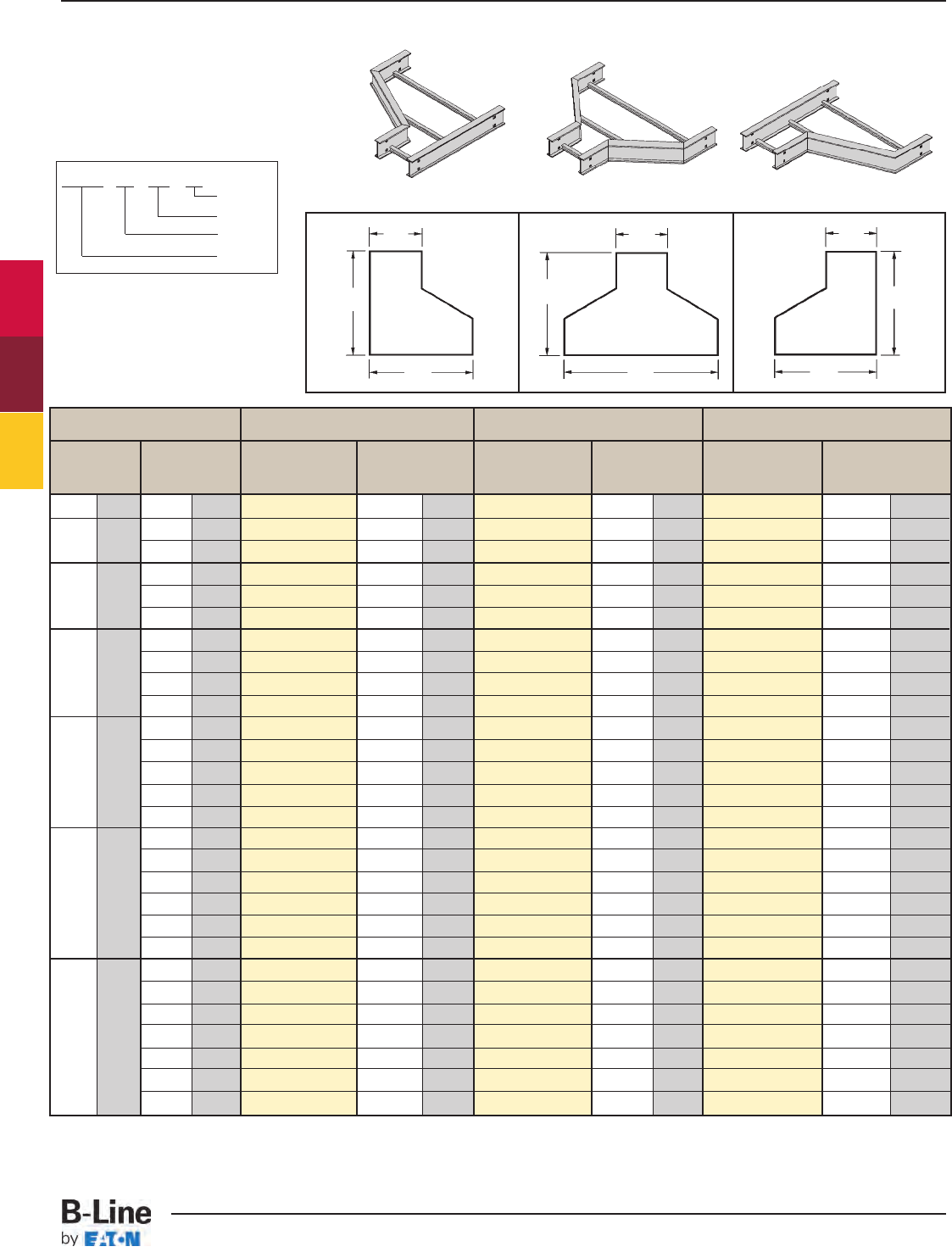
Prefix - 24 - RR - 18
Width2
Fitting
Width1
Prefix
Tray Width Left Hand Reducer Straight Reducer Right Hand Reducer
W1W2Catalog No. A Catalog No. A Catalog No. A
in. mm in. mm in. mm in. mm in. mm
9 228 6 152 (Prefix)-09-LR06 93/4248 (Prefix)-09-SR06 87/8225 (Prefix)-09-RR06 93/4248
12 305 6 152 (Prefix)-12-LR06 111/2292 (Prefix)-12-SR06 93/4248 (Prefix)-12-RR06 111/2292
9 228 (Prefix)-12-LR09 93/4248 (Prefix)-12-SR09 87/8225 (Prefix)-12-RR09 93/4248
6 152 (Prefix)-18-LR06 1415/16 379 (Prefix)-18-SR06 111/2292 (Prefix)-18-RR06 1415/16 379
18 457 9 228 (Prefix)-18-LR09 133/16 340 (Prefix)-18-SR09 105/8270 (Prefix)-18-RR09 133/16 340
12 305 (Prefix)-18-LR12 111/2292 (Prefix)-18-SR12 93/4248 (Prefix)-18-RR12 111/2292
6 152 (Prefix)-24-LR06 183/8467 (Prefix)-24-SR06 133/16 340 (Prefix)-24-RR06 183/8467
24 609 9 228 (Prefix)-24-LR09 1611/16 424 (Prefix)-24-SR09 123/8314 (Prefix)-24-RR09 1611/16 424
12 305 (Prefix)-24-LR12 1415/16 379 (Prefix)-24-SR12 111/2292 (Prefix)-24-RR12 1415/16 379
18 457 (Prefix)-24-LR18 111/2292 (Prefix)-24-SR18 93/4248 (Prefix)-24-RR18 111/2292
6 152 (Prefix)-30-LR06 217/8555 (Prefix)-30-SR06 1415/16 380 (Prefix)-30-RR06 217/8555
9 228 (Prefix)-30-LR09 201/8511 (Prefix)-30-SR09 141/16 358 (Prefix)-30-RR09 201/8511
30 762 12 305 (Prefix)-30-LR12 183/8462 (Prefix)-30-SR12 133/16 335 (Prefix)-30-RR12 183/8462
18 459 (Prefix)-30-LR18 1415/16 380 (Prefix)-30-SR18 111/2292 (Prefix)-30-RR18 1415/16 380
24 609 (Prefix)-30-LR24 111/2292 (Prefix)-30-SR24 93/4248 (Prefix)-30-RR24 111/2292
6 152 (Prefix)-36-LR06 255/16 643 (Prefix)-36-SR06 1611/16 424 (Prefix)-36-RR06 235/16 643
9 228 (Prefix)-36-LR09 239/16 598 (Prefix)-36-SR09 1513/16 402 (Prefix)-36-RR09 239/16 598
36 914 12 305 (Prefix)-36-LR12 217/8555 (Prefix)-36-SR12 1415/16 380 (Prefix)-36-RR12 217/8555
18 457 (Prefix)-36-LR18 183/8462 (Prefix)-36-SR18 133/16 335 (Prefix)-36-RR18 183/8462
24 609 (Prefix)-36-LR24 1415/16 380 (Prefix)-36-SR24 111/2292 (Prefix)-36-RR24 1415/16 380
30 762 (Prefix)-36-LR30 111/2292 (Prefix)-36-SR30 93/4248 (Prefix)-36-RR30 111/2292
6 152 (Prefix)-42-LR06 283/4730 (Prefix)-42-SR06 183/8467 (Prefix)-42-RR06 283/4 732
9 228 (Prefix)-42-LR09 271/16 687 (Prefix)-42-SR09 171/2445 (Prefix)-42-RR09 271/16 687
12 305 (Prefix)-42-LR12 255/16 643 (Prefix)-42-SR12 1611/16 424 (Prefix)-42-RR12 2515/16 643
42 1067 18 457 (Prefix)-42-LR18 217/8556 (Prefix)-42-SR18 1415/16 379 (Prefix)-42-RR18 217/8556
24 609 (Prefix)-42-LR24 183/8467 (Prefix)-42-SR24 133/16 335 (Prefix)-42-RR24 183/8467
30 762 (Prefix)-42-LR30 1415/16 379 (Prefix)-42-SR30 111/2292 (Prefix)-42-RR30 1415/16 379
36 914 (Prefix)-42-LR36 111/2292 (Prefix)-42-SR36 93/4249 (Prefix)-42-RR36 111/2292
Right ReducerStraight Reducer
Left Reducer
Reducers (LR, SR, RR)
1 pair splice plates with hardware
included.
A
W2
W1
LR
A
W2
W1
SR
A
W2
W1
RR
(Prefix) See page FTS-3 for catalog number prefix.
Width dimensions are to inside wall. For aluminum fittings add 1.5 inches for total outside width. Manufacturing tolerances apply to all dimensions.
Reducer Part Numbering
Series 2, 3, 4, & 5 Fittings
All dimensions in parentheses are in millimeters unless otherwise specified.
FTS-7
Series 2, 3, 4 & 5 - Fittings
Cable Tray Systems
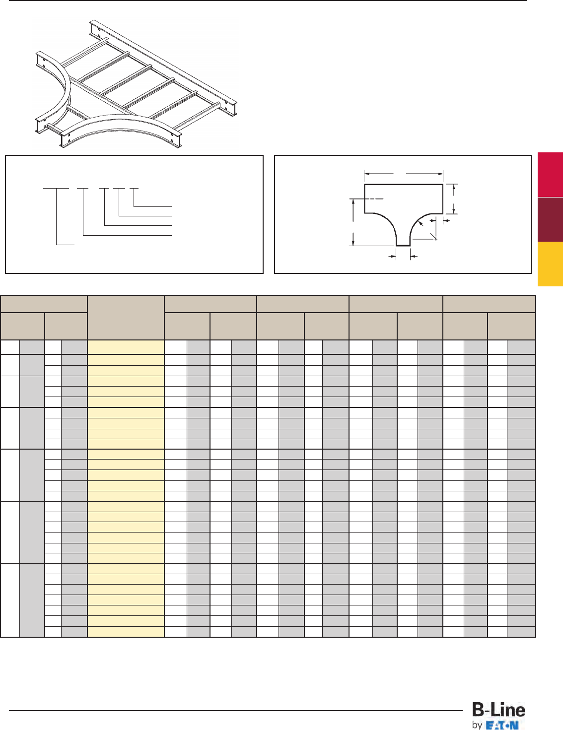
Tray Width * Insert Radius 12" Radius 24" Radius 36" Radius 48" Radius
(12", 24", 36", or 48")
W1W2Catalog No. ABABABAB
in. mm in. mm in. mm in. mm in. mm in. mm in. mm in. mm in. mm in. mm
9 228 6 152 (Prefix)-09-06-HT* 191/2496 36 914 311/2800 60 1524 43 1092 84 2134 551/21410 108 2743
6 152 (Prefix)-12-06-HT* 21 533 36 914 33 838 60 1524 45 1143 84 2134 57 1448 108 2743
9 228 (Prefix)-12-09-HT* 21 533 39 991 33 838 63 1600 45 1143 87 2210 57 1448 111 2819
6 152 (Prefix)-18-06-HT* 24 609 36 914 36 914 60 1524 48 1219 84 2134 60 1524 108 2743
18 475 9 228 (Prefix)-18-09-HT* 24 609 39 991 36 914 63 1600 48 1219 87 2210 60 1524 111 2819
12 305 (Prefix)-18-12-HT* 24 609 42 1067 36 914 66 1676 48 1219 90 2286 60 1524 114 2496
6 152 (Prefix)-24-06-HT* 27 686 36 914 39 991 60 1524 51 1295 84 2134 63 1600 108 2743
9 228 (Prefix)-24-09-HT* 27 686 39 991 39 991 63 1600 51 1295 87 2210 63 1600 111 2819
12 305 (Prefix)-24-12-HT* 27 686 42 1067 39 991 66 1676 51 1295 90 2286 63 1600 114 2496
18 457 (Prefix)-24-18-HT* 27 686 48 1219 39 991 72 1829 51 1295 96 2438 63 1600 120 3048
6 152 (Prefix)-30-06-HT* 30 762 36 914 42 1067 60 1524 54 1372 84 2134 66 1676 108 2743
9 228 (Prefix)-30-09-HT* 30 762 39 991 42 1067 63 1600 54 1372 87 2210 66 1676 111 2819
30 762 12 305 (Prefix)-30-12-HT* 30 762 42 1067 42 1067 66 1676 54 1372 90 2286 66 1676 114 2496
18 457 (Prefix)-30-18-HT* 30 762 48 1219 42 1067 72 1829 54 1372 96 2438 66 1676 120 3048
24 609 (Prefix)-30-24-HT* 30 762 54 1372 42 1067 78 1981 54 1372 102 2591 66 1676 126 3200
6 152 (Prefix)-36-06-HT* 33 838 36 914 45 1143 60 1524 57 1448 84 2134 69 1753 108 2743
9 228 (Prefix)-36-09-HT* 33 838 39 991 45 1143 63 1600 57 1448 87 2210 69 1753 111 2819
12 305 (Prefix)-36-12-HT* 33 838 42 1067 45 1143 66 1676 57 1448 90 2286 69 1753 114 2496
18 457 (Prefix)-36-18-HT* 33 838 48 1219 45 1143 72 1829 57 1448 96 2438 69 1753 120 3048
24 609 (Prefix)-36-24-HT* 33 838 54 1372 45 1143 78 1981 57 1448 102 2591 69 1753 126 3200
30 762 (Prefix)-36-30-HT* 33 838 60 1524 45 1143 84 2134 57 1448 108 2743 69 1753 132 3353
6 152 (Prefix)-42-06-HT* 36 914 36 914 48 1219 60 1524 60 1524 84 2134 72 1829 108 2743
9 228 (Prefix)-42-09-HT* 36 914 39 991 48 1219 63 1600 60 1524 87 2210 72 1829 111 2819
12 305 (Prefix)-42-12-HT* 36 914 42 1067 48 1219 66 1676 60 1524 90 2286 72 1829 114 2496
42 1067 18 457 (Prefix)-42-18-HT* 36 914 48 1219 48 1219 72 1829 60 1524 96 2438 72 1829 120 3048
24 609 (Prefix)-42-24-HT* 36 914 54 1372 48 1219 78 1981 60 1524 102 2591 72 1829 126 3200
30 762 (Prefix)-42-30-HT* 36 914 60 1524 48 1219 84 2134 60 1524 108 2743 72 1829 132 3353
36 914 (Prefix)-42-36-HT* 36 914 66 1676 48 1219 90 2286 60 1524 114 2895 72 1829 138 3505
Prefix - 36 - 18 HT 24
Radius
Fitting
Width W2
Width W1
To complete catalog number, insert
fitting prefix. R = Radius
Horizontal Reducing Tee (HT)
2 pair splice plates with hardware included.
B
A
W2
R
W1
HT
(Prefix) See page FTS-3 for catalog number prefix.
Width dimensions are to inside wall. For aluminum fittings add 1.5 inches for total outside width.
Manufacturing tolerances apply to all dimensions.
3" (76)
12 305
24 609
36 914
Series 2, 3, 4, & 5 Fittings
All dimensions in parentheses are in millimeters unless otherwise specified.
FTS-8
Series 2, 3, 4 & 5 - Fittings
Cable Tray Systems
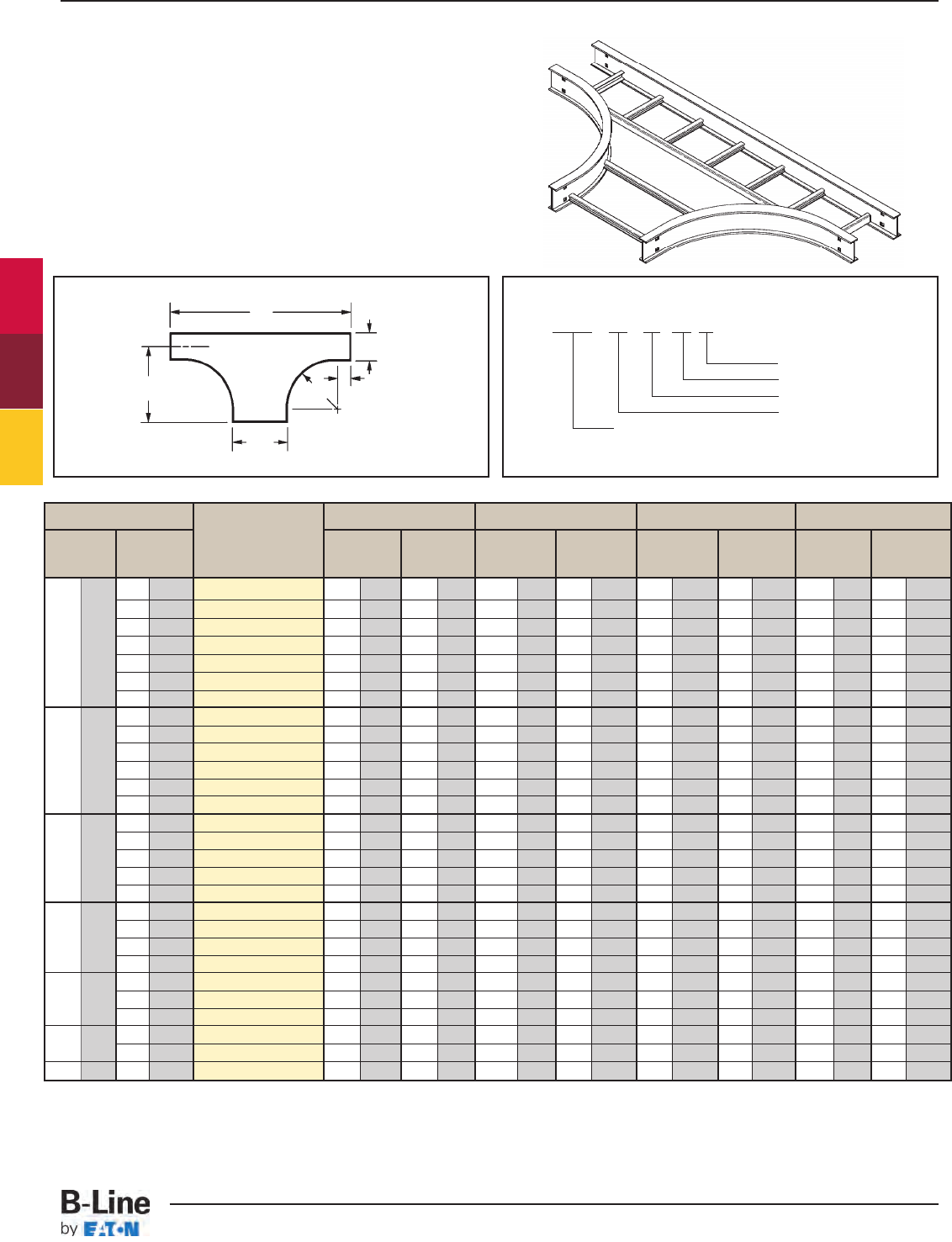
Tray Width *Insert Radius 12" Radius 24" Radius 36" Radius 48" Radius
(12", 24", 36", or 48")
W1W2Catalog No. AB A B A BAB
in. mm in. mm in. mm in. mm in. mm in. mm in. mm in. mm in. mm in. mm
9 228 (Prefix)-06-09-HT* 18 457 39 991 30 762 63 1600 42 1067 87 2210 54 1372 111 2819
12 305 (Prefix)-06-12-HT* 18 457 42 1067 30 762 66 1676 42 1067 90 2286 54 1372 114 2496
18 457 (Prefix)-06-18-HT* 18 457 48 1219 30 762 72 1829 42 1067 96 2438 54 1372 120 3048
6 152 24 609 (Prefix)-06-24-HT* 18 457 54 1372 30 762 78 1981 42 1067 102 2591 54 1372 126 3200
30 762 (Prefix)-06-30-HT* 18 457 60 1524 30 762 84 2134 42 1067 108 2743 54 1372 132 3353
36 914 (Prefix)-06-36-HT* 18 457 66 1676 30 762 90 2286 42 1067 114 2895 54 1372 138 3503
42 1067 (Prefix)-06-42-HT* 18 457 72 1829 30 762 96 2438 42 1067 120 3048 54 1372 144 3658
12 305 (Prefix)-09-12-HT* 191/2496 42 1067 311/2800 66 1676 431/21105 90 2286 551/21410 114 2496
18 457 (Prefix)-09-18-HT* 191/2496 48 1219 311/2800 72 1829 431/21105 96 2438 551/21410 120 3048
24 609 (Prefix)-09-24-HT* 191/2496 54 1372 311/2800 78 1981 431/21105 102 2591 551/21410 126 3200
30 762 (Prefix)-09-30-HT* 191/2496 60 1524 311/2800 84 2134 431/21105 108 2743 551/21410 132 3353
36 914 (Prefix)-09-36-HT* 191/2496 66 1676 311/2800 90 2286 431/21105 114 2895 551/21410 138 3503
42 1067 (Prefix)-09-42-HT* 191/2496 72 1829 311/2800 96 2438 431/21105 120 3048 551/21410 144 3658
18 457 (Prefix)-12-18-HT* 21 533 48 1219 33 838 72 1829 45 1143 96 2438 57 1448 120 3048
24 609 (Prefix)-12-24-HT* 21 533 54 1372 33 838 78 1981 45 1143 102 2591 57 1448 126 3200
12 305 30 762 (Prefix)-12-30-HT* 21 533 60 1524 33 838 84 2134 45 1143 108 2743 57 1448 132 3353
36 914 (Prefix)-12-36-HT* 21 533 66 1676 33 838 90 2286 45 1143 114 2895 57 1448 138 3503
42 1067 (Prefix)-12-42-HT* 21 533 72 1829 33 838 96 2438 45 1143 120 3048 57 1448 144 3658
24 609 (Prefix)-18-24-HT* 24 609 54 1372 36 914 78 1981 48 1219 102 2591 60 1524 126 3200
30 762 (Prefix)-18-30-HT* 24 609 60 1524 36 914 84 2134 48 1219 108 2743 60 1524 132 3353
36 914 (Prefix)-18-36-HT* 24 609 66 1676 36 914 90 2286 48 1219 114 2895 60 1524 138 3503
42 1067 (Prefix)-18-42-HT* 24 609 72 1829 36 914 96 2438 48 1219 120 3048 60 1524 144 3658
30 762 (Prefix)-24-30-HT* 27 686 60 1524 39 991 84 2134 51 1295 108 2743 63 1600 132 3353
24 609 36 914 (Prefix)-24-36-HT* 27 686 66 1676 39 991 90 2286 51 1295 114 2895 63 1600 138 3503
42 1067 (Prefix)-24-42-HT* 27 686 72 1829 39 991 96 2438 51 1295 120 3048 63 1600 144 3658
36 914 (Prefix)-30-36-HT* 30 762 66 1676 42 1067 90 2286 54 1372 114 2895 66 1676 138 3503
42 1067 (Prefix)-30-42-HT* 30 762 72 1829 42 1067 96 2438 54 1372 120 3048 66 1676 144 3658
36 914 42 1067 (Prefix)-36-42-HT* 33 838 72 1829 45 1143 96 2438 57 1448 120 3048 69 1753 144 3658
Prefix - 09 - 30 HT 12
Radius
Fitting
Width W2
Width W1
To complete catalog number, insert
fitting prefix.
Horizontal Expanding Tee (HT)
2 pair splice plates with hardware included.
B
A
W2
R
W1
(Prefix) See page FTS-3 for catalog number prefix.
Width dimensions are to inside wall. For aluminum fittings add 1.5 inches for total outside width.
Manufacturing tolerances apply to all dimensions.
HT
3" (76)
R = Radius
30 762
18 457
9 228
Series 2, 3, 4, & 5 Fittings
All dimensions in parentheses are in millimeters unless otherwise specified.
FTS-9
Series 2, 3, 4 & 5 - Fittings
Cable Tray Systems
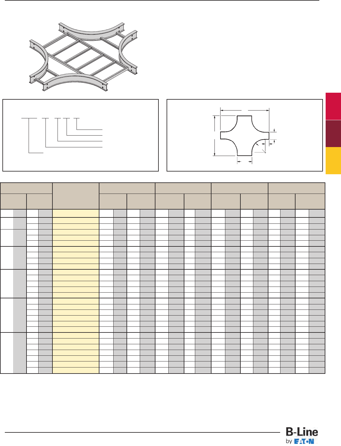
Tray Width * Insert Radius 12" Radius 24" Radius 36" Radius 48" Radius
(12", 24", 36", or 48")
W1W2Catalog No. ABABABAB
in. mm in. mm in. mm in. mm in. mm in. mm in. mm in. mm in. mm in. mm
9 228 6 152 (Prefix)-09-06-HX* 39 991 36 914 63 1600 60 1372 87 2210 84 2134 111 2819 108 2743
6 152 (Prefix)-12-06-HX* 42 1067 36 914 66 1676 60 1372 90 2286 84 2134 114 2896 108 2743
9 228 (Prefix)-12-09-HX* 42 1067 39 991 66 1676 63 1600 90 2286 87 2210 114 2896 111 2819
6 152 (Prefix)-18-06-HX* 48 1219 36 914 72 1829 60 1372 96 2438 84 2134 120 3048 108 2743
18 457 9 228 (Prefix)-18-09-HX* 48 1219 39 991 72 1829 63 1600 96 2438 87 2210 120 3048 111 2819
12 305 (Prefix)-18-12-HX* 48 1219 42 1067 72 1829 66 1676 96 2438 90 2286 120 3048 114 2896
6 152 (Prefix)-24-06-HX* 54 1372 36 914 78 1981 60 1372 102 2591 84 2134 126 3200 108 2743
9 228 (Prefix)-24-09-HX* 54 1372 39 991 78 1981 63 1600 102 2591 87 2210 126 3200 111 2819
12 305 (Prefix)-24-12-HX* 54 1372 42 1067 78 1981 66 1676 102 2591 90 2286 126 3200 114 2896
18 457 (Prefix)-24-18-HX* 54 1372 48 1219 78 1981 72 1829 102 2591 96 2438 126 3200 120 3048
6 152 (Prefix)-30-06-HX* 60 1524 36 914 84 2134 60 1372 108 2743 84 2134 132 3353 108 2743
9 228 (Prefix)-30-09-HX* 60 1524 39 991 84 2134 63 1600 108 2743 87 2210 132 3353 111 2819
30 762 12 305 (Prefix)-30-12-HX* 60 1524 42 1067 84 2134 66 1676 108 2743 90 2286 132 3353 114 2896
18 457 (Prefix)-30-18-HX* 60 1524 48 1219 84 2134 72 1829 108 2743 96 2438 132 3353 120 3048
24 609 (Prefix)-30-24-HX* 60 1524 54 1372 84 2134 78 1981 108 2743 102 2591 132 3353 126 3200
6 152 (Prefix)-36-06-HX* 66 1676 36 914 90 2286 60 1372 114 2896 84 2134 138 3505 108 2743
9 228 (Prefix)-36-09-HX* 66 1676 39 991 90 2286 63 1600 114 2896 87 2210 138 3505 111 2819
12 305 (Prefix)-36-12-HX* 66 1676 42 1067 90 2286 66 1676 114 2896 90 2286 138 3505 114 2896
18 457 (Prefix)-36-18-HX* 66 1676 48 1219 90 2286 72 1829 114 2896 96 2438 138 3505 120 3048
24 609 (Prefix)-36-24-HX* 66 1676 54 1372 90 2286 78 1981 114 2896 102 2591 138 3505 126 3200
30 762 (Prefix)-36-30-HX* 66 1676 60 1524 90 2286 84 2134 114 2896 108 2743 138 3505 132 3353
6 152 (Prefix)-42-06-HX* 72 1829 36 914 96 2438 60 1372 120 3048 84 2134 144 3658 108 2743
9 228 (Prefix)-42-09-HX* 72 1829 39 991 96 2438 63 1600 120 3048 87 2210 144 3658 111 2819
12 305 (Prefix)-42-12-HX* 72 1829 42 1067 96 2438 66 1676 120 3048 90 2286 144 3658 114 2896
42 1067 18 457 (Prefix)-42-18-HX* 72 1829 48 1219 96 2438 72 1829 120 3048 96 2438 144 3658 120 3048
24 609 (Prefix)-42-24-HX* 72 1829 54 1372 96 2438 78 1981 120 3048 102 2591 144 3658 126 3200
30 762 (Prefix)-42-30-HX* 72 1829 60 1524 96 2438 84 2134 120 3048 108 2743 144 3658 132 3353
36 914 (Prefix)-42-36-HX* 72 1829 66 1676 96 2438 90 2286 120 3048 114 2896 144 3658 138 3505
Prefix - 36 - 18 HX 24
Radius
Fitting
Width W2
Width W1
To complete catalog number, insert
fitting prefix.
B
A
W2
3" (76)
R
W1
HX
(Prefix) See page FTS-3 for catalog number prefix.
Width dimensions are to inside wall. For aluminum fittings add 1.5 inches for total outside width.
Manufacturing tolerances apply to all dimensions.
12 305
24 609
36 914
Horizontal Expanding/Reducing Cross (HX)
3 pair splice plates with hardware included.
Series 2, 3, 4, & 5 Fittings
All dimensions in parentheses are in millimeters unless otherwise specified.
FTS-10
Series 2, 3, 4 & 5 - Fittings
Cable Tray Systems
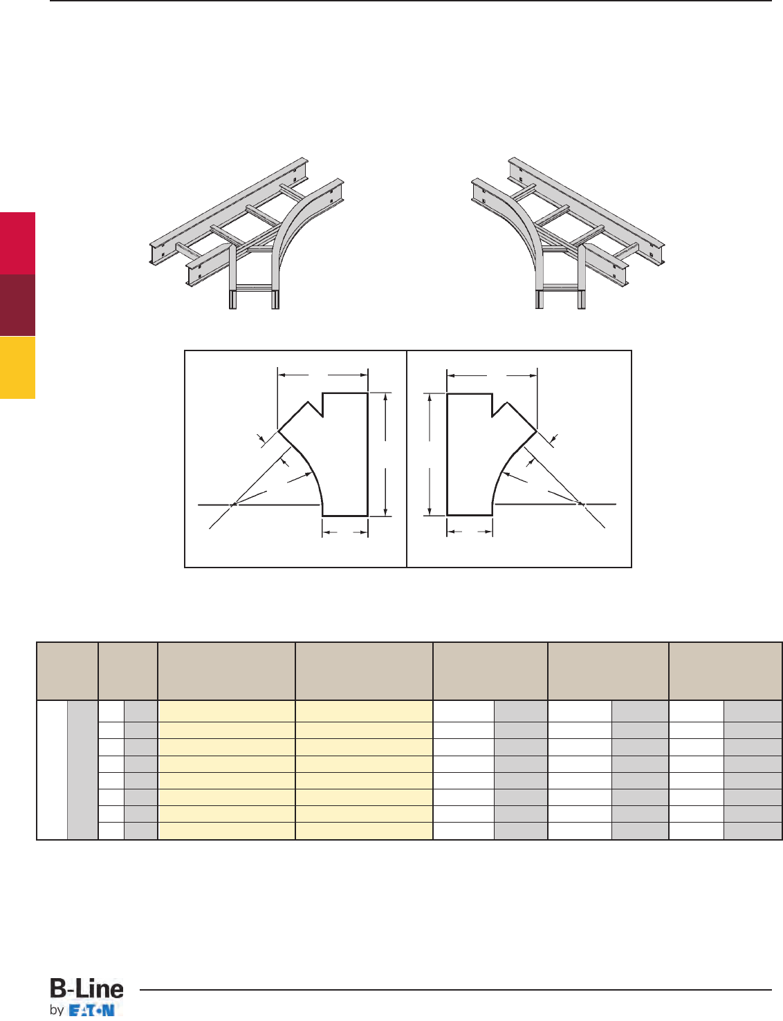
Bend Tray Left Hand Wye Right Hand Wye
Radius Width Catalog No. Catalog No. ABC
in. mm in. mm in. mm in. mm in. mm
6 152 (Prefix)-06-HYL (Prefix)-06-HYR 28 7/16 722 15 3/16 386 3 1/16 77
9 228 (Prefix)-09-HYL (Prefix)-09-HYR 32 11/16 831 20 5/16 516 6 1/16 154
12 305 (Prefix)-12-HYL (Prefix)-12-HYR 36 15/16 938 25 7/16 646 9 1/16 231
18 457 (Prefix)-18-HYL (Prefix)-18-HYR 45 3/81153 35 13/16 910 15 1/16 383
24 609 (Prefix)-24-HYL (Prefix)-24-HYR 53 7/81368 45 15/16 1167 21 1/16 535
30 762 (Prefix)-30-HYL (Prefix)-30-HYR 62 3/81585 56 3/16 1427 27 1/16 688
36 914 (Prefix)-36-HYL (Prefix)-36-HYR 70 7/81800 66 7/16 1687 33 1/16 993
42 1067 (Prefix)-42-HYL (Prefix)-42-HYR 79 3/82016 76 5/81946 39 1/16 992
Left Hand Wye R = Radius R = Radius Right Hand Wye
Left Hand Wye Right Hand Wye
Horizontal Wye (HYL, HYR)
2 pair splice plates with hardware included.
B
A
C
45˚
R
W
B
AC
45˚
R
W
HYL HYR
(Prefix) See page FTS-3 for catalog number prefix.
Width dimensions are to inside wall. For aluminum fittings add 1.5 inches for total outside width. Manufacturing tolerances apply to all dimensions.
24 609
Series 2, 3, 4, & 5 Fittings
All dimensions in parentheses are in millimeters unless otherwise specified.
FTS-11
Series 2, 3, 4 & 5 - Fittings
Cable Tray Systems
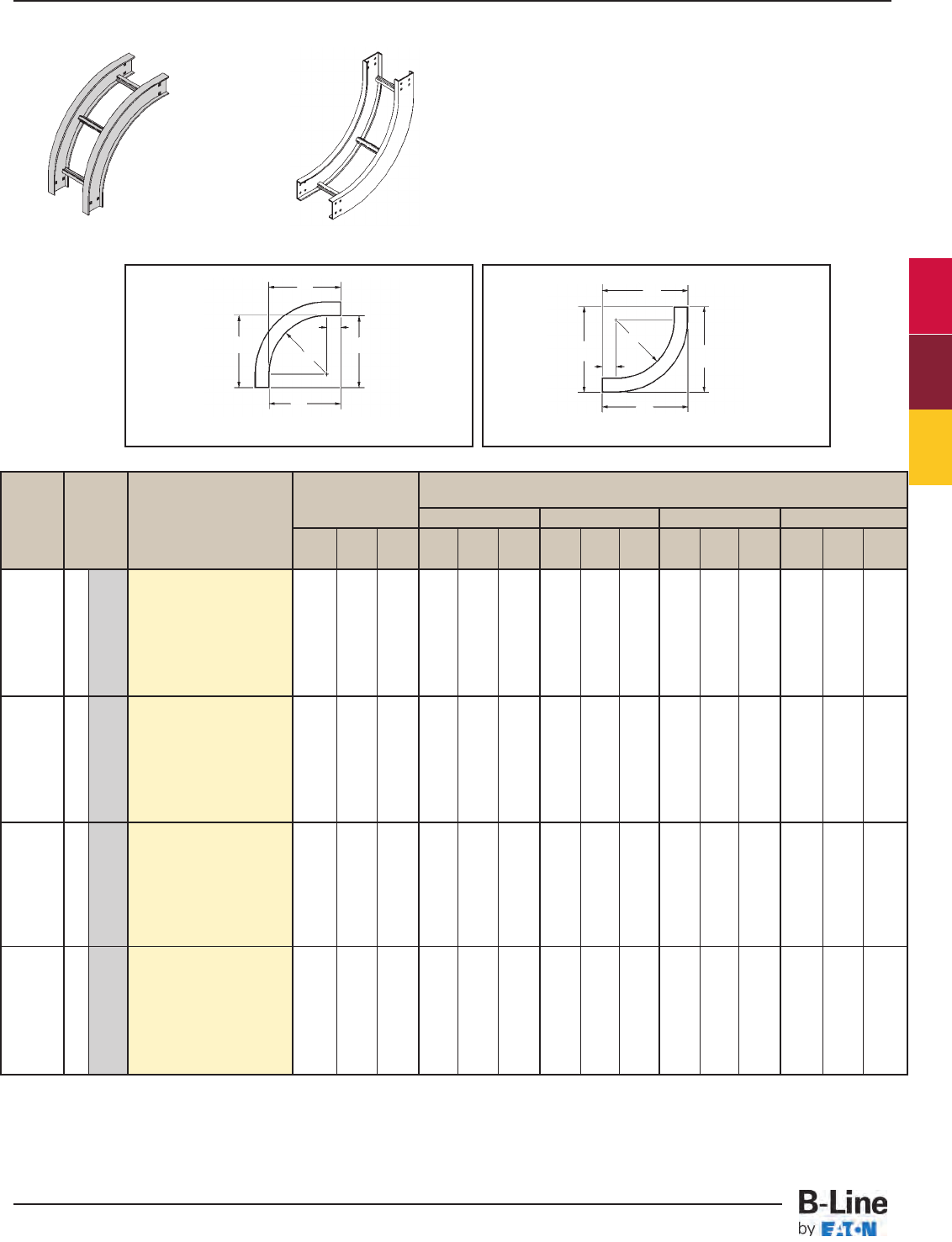
Bend Tray (*) Insert "VO" for VO Side Rail VI Side Rail Height
Radius Width Vert. Outside Bend Height
R Insert "VI" for 4" - 7" 4" 5" 6" 7"
Vert. Inside Bend AB C AB CABC ABC A BC
in . in. mm Catalog No. in. in. in. in. in. in. in. in. in. in. in. in. in. in. in.
6 152 (Prefix)-06-90(*)12
9 228 (Prefix)-09-90(*)12
12 305 (Prefix)-12-90(*)12
18 457 (Prefix)-18-90(*)12
24 609 (Prefix)-24-90(*)12
30 762 (Prefix)-30-90(*)12
36 914 (Prefix)-36-90(*)12
42 1067 (Prefix)-42-90(*)12
6 152 (Prefix)-06-90(*)24
9 228 (Prefix)-09-90(*)24
12 305 (Prefix)-12-90(*)24
18 457 (Prefix)-18-90(*)24
24 609 (Prefix)-24-90(*)24
30 762 (Prefix)-30-90(*)24
36 914 (Prefix)-36-90(*)24
42 1067 (Prefix)-42-90(*)24
6 152 (Prefix)-06-90(*)36
9 228 (Prefix)-09-90(*)36
12 305 (Prefix)-12-90(*)36
18 457 (Prefix)-18-90(*)36
24 609 (Prefix)-24-90(*)36
30 762 (Prefix)-30-90(*)36
36 914 (Prefix)-36-90(*)36
42 1067 (Prefix)-42-90(*)36
6 152 (Prefix)-06-90(*)48
9 228 (Prefix)-09-90(*)48
12 305 (Prefix)-12-90(*)48
18 457 (Prefix)-18-90(*)48
24 609 (Prefix)-24-90(*)48
30 762 (Prefix)-30-90(*)48
36 914 (Prefix)-36-90(*)48
42 1067 (Prefix)-42-90(*)48
39 39 39 43 43 43 44 44 44 45 45 45 46 46 46
(991) (991) (991) (1092) (1092) (1092) (1118) (1118) (1118) (1143) (1143) (1143) (1168) (1168) (1168)
90˚ Vertical Inside 90˚ Vertical Outside
15 15 15 19 19 19 20 20 20 21 21 21 22 22 22
(381) (381) (381) (483) (483) (483) (508) (508) (508) (533) (533) (533) (559) (559) (559)
51 51 51 55 55 55 56 56 56 57 57 57 58 58 58
(1295) (1295) (1295) (1397) (1397) (1397) (1422) (1422) (1422) (1448) (1448) (1448) (1473) (1473) (1473)
27 27 27 31 31 31 32 32 32 33 33 33 34 34 34
(686) (686) (686) (787) (787) (787) (813) (813) (813) (838) (838) (838) (864) (864) (864)
12
(305)
24
(609)
36
(914)
48
(1219)
Vertical Bend 90˚ (VO, VI)
1 pair splice plates with hardware included.
B
A
C
C
3" (76)
RB
A
C
C
3" (76)
R
90˚
VI
90˚
VO
(Prefix) See page FTS-3 for catalog number prefix.
Manufacturing tolerances apply to all dimensions.
Series 2, 3, 4, & 5 Fittings
All dimensions in parentheses are in millimeters unless otherwise specified.
FTS-12
Series 2, 3, 4 & 5 - Fittings
Cable Tray Systems
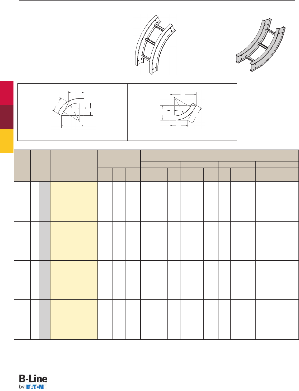
Bend Tray (*) Insert "VO" for VO Side Rail VI Side Rail Height
Radius Width Vert. Outside Bend Height
R Insert "VI" for 4" - 7" 4" 5" 6" 7"
Vert. Inside Bend ABC ABCABC ABC ABC
in . in. mm Catalog No. in. in. in. in. in. in. in. in. in. in. in. in. in. in. in.
6 152 (Prefix)-06-60(*)12
9 228 (Prefix)-09-60(*)12
12 305 (Prefix)-12-60(*)12
18 457 (Prefix)-18-60(*)12
24 609 (Prefix)-24-60(*)12
30 762 (Prefix)-30-60(*)12
36 914 (Prefix)-36-60(*)12
42 1067 (Prefix)-42-60(*)12
6 152 (Prefix)-06-60(*)24
9 228 (Prefix)-09-60(*)24
12 305 (Prefix)-12-60(*)24
18 457 (Prefix)-18-60(*)24
24 609 (Prefix)-24-60(*)24
30 762 (Prefix)-30-60(*)24
36 914 (Prefix)-36-60(*)24
42 1067 (Prefix)-42-60(*)24
6 152 (Prefix)-06-60(*)36
9 228 (Prefix)-09-60(*)36
12 305 (Prefix)-12-60(*)36
18 457 (Prefix)-18-60(*)36
24 609 (Prefix)-24-60(*)36
30 762 (Prefix)-30-60(*)36
36 914 (Prefix)-36-60(*)36
42 1067 (Prefix)-42-60(*)36
6 152 (Prefix)-06-60(*)48
9 228 (Prefix)-09-60(*)48
12 305 (Prefix)-12-60(*)48
18 457 (Prefix)-18-60(*)48
24 609 (Prefix)-24-60(*)48
30 762 (Prefix)-30-60(*)48
36 914 (Prefix)-36-60(*)48
42 1067 (Prefix)-42-60(*)48
60˚ Vertical Inside
35
11
/
16
20
5
/
8
23
13
/
16
39
1
/
8
22
5
/
8
26
1
/
8
40 23
1
/
8
26
11
/
16
40
7
/
8
23
5
/
8
27
1
/
4
41
3
/
4
24
1
/
8
27
13
/
16
(907) (524) (605) (994) (575) (663) (1016) (587) (687) (1038) (600) (692) (1060) (613) (706)
14
7
/
8
8
5
/
8
9
15
/
16
18
3
/
8
10
5
/
8
12
1
/
4
19
1
/
4
11
1
/
8
12
13
/
16
20
1
/
16
11
5
/
8
13
3
/
8
21
15
/
16
12
1
/
8
14
(378) (219) (253) (467) (270) (311) (489 (283) (326) (510) (296) (340) (557) (308) (356)
46
1
/
16
26
5
/
8
30
11
/
16
49
9
/
16
28
5
/
8
33 50
3
/
8
29
1
/
8
33
5
/
8
51
1
/
4
29
5
/
8
34
3
/
16
52
1
/
8
30
1
/
8
34
3
/
4
(1170) (676) (780) (1259) (727) (838) (1280) (740) (854) (1302) (753) (868) (1324) (765) (883)
25
5
/
16
14
5
/
8
16
7
/
8
28
3
/
4
16
5
/
8
19
3
/
16
29
5
/
8
17
1
/
8
19
3
/
4
30
1
/
2
17
5
/
8
20
5
/
16
31
3
/
8
18
1
/
8
20
7
/
8
(643) (372) (428) (730) (422) (488) (753) (435) (502) (775) (448) (516) (797) (461) (530)
12
(305)
24
(609)
36
(914)
48
(1219)
Vertical Bend 60˚ (VO, VI)
1 pair splice plates with hardware included.
60˚ Vertical Outside
A
C
C
3" (76)
RB
A
C
C
3" (76)
R
60˚
VI
60˚
VO
(Prefix) See page FTS-3 for catalog number prefix.
Manufacturing tolerances apply to all dimensions.
B
Series 2, 3, 4, & 5 Fittings
All dimensions in parentheses are in millimeters unless otherwise specified.
FTS-13
Series 2, 3, 4 & 5 - Fittings
Cable Tray Systems
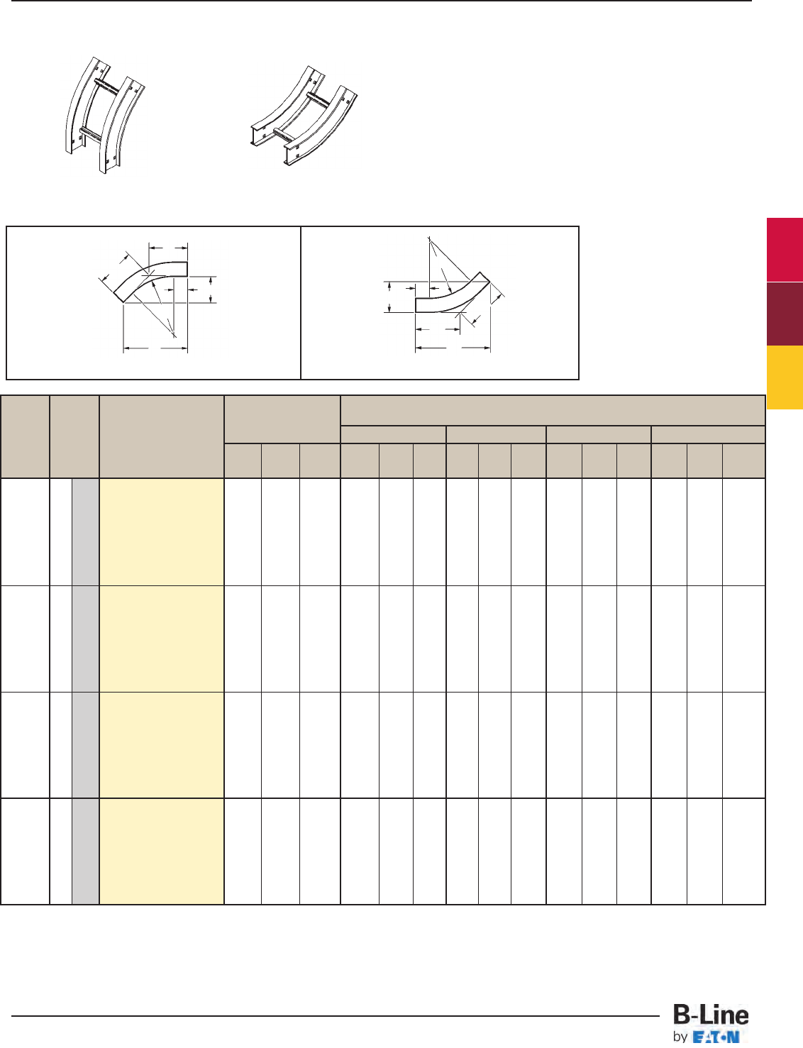
Bend Tray (*) Insert "VO" for VO Side Rail VI Side Rail Height
Radius Width Vert. Outside Bend Height
R Insert "VI" for 4" - 7" 4" 5" 6" 7"
Vert. Inside Bend ABC ABCABC ABC ABC
in . in. mm Catalog No. in. in. in. in. in. in. in. in. in. in. in. in. in. in. in.
6 152 (Prefix)-06-45(*)12
9 228 (Prefix)-09-45(*)12
12 305 (Prefix)-12-45(*)12
18 457 (Prefix)-18-45(*)12
24 609 (Prefix)-24-45(*)12
30 762 (Prefix)-30-45(*)12
36 914 (Prefix)-36-45(*)12
42 1067 (Prefix)-42-45(*)12
6 152 (Prefix)-06-45(*)24
9 228 (Prefix)-09-45(*)24
12 305 (Prefix)-12-45(*)24
18 457 (Prefix)-18-45(*)24
24 609 (Prefix)-24-45(*)24
30 762 (Prefix)-30-45(*)24
36 914 (Prefix)-36-45(*)24
42 1067 (Prefix)-42-45(*)24
6 152 (Prefix)-06-45(*)36
9 228 (Prefix)-09-45(*)36
12 305 (Prefix)-12-45(*)36
18 457 (Prefix)-18-45(*)36
24 609 (Prefix)-24-45(*)36
30 762 (Prefix)-30-45(*)36
36 914 (Prefix)-36-45(*)36
42 1067 (Prefix)-42-45(*)36
6 152 (Prefix)-06-45(*)48
9 228 (Prefix)-09-45(*)48
12 305 (Prefix)-12-45(*)48
18 457 (Prefix)-18-45(*)48
24 609 (Prefix)-24-45(*)48
30 762 (Prefix)-30-45(*)48
36 914 (Prefix)-36-45(*)48
42 1067 (Prefix)-42-45(*)48
45˚ Vertical Inside 45˚ Vertical Outside
30
9
/
16
12
11
/
16
17
15
/
16
33
3
/
8
13
13
/
16
19
9
/
16
34
1
/
8
14
1
/
8
20 34
13
/
16
14
7
/
16
20
3
/
8
35
1
/
2
14
11
/
16
20
13
/
16
(776) (323) (456) (848) (351) (497) (867) (359) (508) (885) (367) (518) (902) (284) (402)
13
5
/
8
5
5
/
8
8 16
7
/
16
6
13
/
16
9
5
/
8
17
1
/
8
7
1
/
8
10
1
/
16
17
7
/
8
7
3
/
8
10
7
/
16
18
9
/
16
7
11
/
16
10
7
/
8
(346) (143) (203) (417) (173) (245) (435) (181) (256) (454) (188) (265) (471) (195) (2176)
39
1
/
16
16
3
/
16
22
7
/
8
41
7
/
8
17
3
/
8
24
9
/
16
42
5
/
8
17
5
/
8
24
15
/
16
43
5
/
16
17
15
/
16
25
3
/
8
44 18
1
/
4
25
13
/
16
(992) (411) (581) (1064) (441) (624) (1083) (448) (633) (1100) (456) (645) (1118) (464) (656)
22
1
/
16
9
1
/
8
12
15
/
16
24
15
/
16
10
5
/
16
14
5
/
8
25
5
/
8
10
5
/
8
15 26
5
/
16
10
15
/
16
15
7
/
16
27
1
/
16
11
3
/
16
15
13
/
16
(561) (232) (329) (634) (262) (372) (651) (270) (381) (668) (278) (392) (687) (284) (402)
12
(305)
24
(609)
36
(924)
48
(1219)
Vertical Bend 45˚ (VO, VI)
1 pair splice plates with hardware included.
B
A
C
C
3" (76)
R
B
A
C
C
3" (76)
R
45˚
VO
45˚
VI
(Prefix) See page FTS-3 for catalog number prefix.
Manufacturing tolerances apply to all dimensions.
Series 2, 3, 4, & 5 Fittings
All dimensions in parentheses are in millimeters unless otherwise specified.
FTS-14
Series 2, 3, 4 & 5 - Fittings
Cable Tray Systems
Bend Tray (*) Insert "VO" for VO Side Rail VI Side Rail Height
Radius Width Vert. Outside Bend Height
R Insert "VI" for 4" - 7" 4" 5" 6" 7"
Vert. Inside Bend ABC ABCABC ABC ABC
in . in. mm Catalog No. in. in. in. in. in. in. in. in. in. in. in. in. in. in. in.
6 152 (Prefix)-06-30(*)12
9 228 (Prefix)-09-30(*)12
12 305 (Prefix)-12-30(*)12
18 457 (Prefix)-18-30(*)12
24 609 (Prefix)-24-30(*)12
30 762 (Prefix)-30-30(*)12
36 914 (Prefix)-36-30(*)12
42 1067 (Prefix)-42-30(*)12
6 152 (Prefix)-06-30(*)24
9 228 (Prefix)-09-30(*)24
12 305 (Prefix)-12-30(*)24
18 457 (Prefix)-18-30(*)24
24 609 (Prefix)-24-30(*)24
30 762 (Prefix)-30-30(*)24
36 914 (Prefix)-36-30(*)24
42 1067 (Prefix)-42-30(*)24
6 152 (Prefix)-06-30(*)36
9 228 (Prefix)-09-30(*)36
12 305 (Prefix)-12-30(*)36
18 457 (Prefix)-18-30(*)36
24 609 (Prefix)-24-30(*)36
30 762 (Prefix)-30-30(*)36
36 914 (Prefix)-36-30(*)36
42 1067 (Prefix)-42-30(*)36
6 152 (Prefix)-06-30(*)48
9 228 (Prefix)-09-30(*)48
12 305 (Prefix)-12-30(*)48
18 457 (Prefix)-18-30(*)48
24 609 (Prefix)-24-30(*)48
30 762 (Prefix)-30-30(*)48
36 914 (Prefix)-36-30(*)48
42 1067 (Prefix)-42-30(*)48
30˚ Vertical Outside 30˚ Vertical Inside
23
5
/
8
6
5
/
16
12
5
/
8
25
5
/
8
6
7
/
8
13
11
/
16
26
1
/
8
7 14 26
5
/
8
7
1
/
8
14
1
/
4
27
1
/
8
7
1
/
4
14
1
/
2
(600) (160) (321) (651) (174) (348) (663) (175) (356) (676) (181) (362) (689) (184) (287)
11
5
/
8
3
1
/
8
6
3
/
16
13
5
/
8
3
5
/
8
7
5
/
16
14
1
/
8
3
3
/
4
7
9
/
16
14
5
/
8
3
15
/
16
7
13
/
16
15
1
/
8
4
1
/
16
8
1
/
16
(296) (79) (157) (346) (92) (186) (359) (95) (192) (372) (100) (199) (384) (103) (205)
29
5
/
8
7
15
/
16
15
7
/
8
31
5
/
8
8
7
/
16
16
15
/
16
32
1
/
8
8
5
/
8
17
3
/
16
32
5
/
8
8
3
/
4
17
1
/
2
33
1
/
8
8
7
/
8
17
3
/
4
(753) (202) (403) (803) (214) (430) (816) (219) (437) (829) (222) (445) (842) (226) (451)
17
5
/
8
4
11
/
16
9
7
/
16
19
5
/
8
5
1
/
4
10
1
/
2
20
1
/
8
5
3
/
8
10
3
/
4
20
5
/
8
5
1
/
2
11
1
/
16
21
1
/
8
5
5
/
8
11
5
/
16
(448) (120) (240) (499) (133) (267) (511 (137) (273) (524) (140) (282) (537) (143) (287)
12
(305)
24
(609)
36
(914)
48
(1219)
Vertical Bend 30˚ (VO, VI)
1 pair splice plates with hardware included.
B
A
C
C
R
B
A
CC
3" (76)
R
30˚
VO
30˚
VI
(Prefix) See page FTS-3 for catalog number prefix.
Manufacturing tolerances apply to all dimensions.
3" (76)
Series 2, 3, 4, & 5 Fittings
All dimensions in parentheses are in millimeters unless otherwise specified.
FTS-15
Series 2, 3, 4 & 5 - Fittings
Cable Tray Systems
Bend Tray Vertical Tee Down Vertical Tee Up Side Rail Height "H"
Radius Width 4" 5" 6" 7"
RCatalog No. Catalog No. AB A BA BAB
in. in. mm in. in. in. in. in. in. in. in.
6 152 (Prefix)-06-VT12 (Prefix)-06-VTU12
9 228 (Prefix)-09-VT12 (Prefix)-09-VTU12
12 305 (Prefix)-12-VT12 (Prefix)-12-VTU12
18 457 (Prefix)-18-VT12 (Prefix)-18-VTU12
24 609 (Prefix)-24-VT12 (Prefix)-24-VTU12
30 762 (Prefix)-30-VT12 (Prefix)-30-VTU12
36 914 (Prefix)-36-VT12 (Prefix)-36-VTU12
42 1067 (Prefix)-42-VT12 (Prefix)-42-VTU12
6 152 (Prefix)-06-VT24 (Prefix)-06-VTU24
9 228 (Prefix)-09-VT24 (Prefix)-09-VTU24
12 305 (Prefix)-12-VT24 (Prefix)-12-VTU24
18 457 (Prefix)-18-VT24 (Prefix)-18-VTU24
24 609 (Prefix)-24-VT24 (Prefix)-24-VTU24
30 762 (Prefix)-30-VT24 (Prefix)-30-VTU24
36 914 (Prefix)-36-VT24 (Prefix)-36-VTU24
42 1067 (Prefix)-42-VT24 (Prefix)-42-VTU24
6 152 (Prefix)-06-VT36 (Prefix)-06-VTU36
9 228 (Prefix)-09-VT36 (Prefix)-09-VTU36
12 305 (Prefix)-12-VT36 (Prefix)-12-VTU36
18 457 (Prefix)-18-VT36 (Prefix)-18-VTU36
24 609 (Prefix)-24-VT36 (Prefix)-24-VTU36
30 762 (Prefix)-30-VT36 (Prefix)-30-VTU36
36 914 (Prefix)-36-VT36 (Prefix)-36-VTU36
42 1067 (Prefix)-42-VT36 (Prefix)-42-VTU36
6 152 (Prefix)-06-VT48 (Prefix)-06-VTU48
9 228 (Prefix)-09-VT48 (Prefix)-09-VTU48
12 305 (Prefix)-12-VT48 (Prefix)-12-VTU48
18 457 (Prefix)-18-VT48 (Prefix)-18-VTU48
24 609 (Prefix)-24-VT48 (Prefix)-24-VTU48
30 762 (Prefix)-30-VT48 (Prefix)-30-VTU48
36 914 (Prefix)-36-VT48 (Prefix)-36-VTU48
42 1067 (Prefix)-42-VT48 (Prefix)-42-VTU48
Up
Down
51 106 51 107 51 108 51 109
(1295) (2692) (1295) (2718) (1295) (2743) (1295) (2769)
39 82 39 83 39 84 39 85
(991) (2083) (991) (2108) (991) (2134) (991) (2159)
27 58 27 59 27 60 27 61
(6867) (1473) (686) (1498) (686) (1524) (686) (1549)
15 34 15 35 15 36 15 37
(381) (846) (381) (889) (381) (914) (381) (940)
36
(914)
12
(305)
48
(1219)
B
A
H
R
Vertical Tee Up/Down (VTU/VT)
2 pair splice plates with hardware included.
VT
(Prefix) See page FTS-3 for catalog number prefix.
Manufacturing tolerances apply to all dimensions.
24
(609)
3" (76)
Series 2, 3, 4, & 5 Fittings
All dimensions in parentheses are in millimeters unless otherwise specified.
FTS-16
Series 2, 3, 4 & 5 - Fittings
Cable Tray Systems
Bend Tray Side Rail Height "H"
Radius Width 4" 5" 6" 7"
RCatalog No. ABABABAB
in. in. mm in. in. in. in. in. in. in. in.
6 152 (Prefix)-06-CSF12
9 228 (Prefix)-09-CSF12
12 305 (Prefix)-12-CSF12
18 457 (Prefix)-18-CSF12
24 609 (Prefix)-24-CSF12
30 762 (Prefix)-30-CSF12
36 914 (Prefix)-36-CSF12
42 1067 (Prefix)-42-CSF12
6 152 (Prefix)-06-CSF24
9 228 (Prefix)-09-CSF24
12 305 (Prefix)-12-CSF24
18 457 (Prefix)-18-CSF24
24 609 (Prefix)-24-CSF24
30 762 (Prefix)-30-CSF24
36 914 (Prefix)-36-CSF24
42 1067 (Prefix)-42-CSF24
6 152 (Prefix)-06-CSF36
9 228 (Prefix)-09-CSF36
12 305 (Prefix)-12-CSF36
18 457 (Prefix)-18-CSF36
24 609 (Prefix)-24-CSF36
30 762 (Prefix)-30-CSF36
36 914 (Prefix)-36-CSF36
42 1067 (Prefix)-42-CSF36
6 152 (Prefix)-06-CSF48
9 228 (Prefix)-09-CSF48
12 305 (Prefix)-12-CSF48
18 457 (Prefix)-18-CSF48
24 609 (Prefix)-24-CSF48
30 762 (Prefix)-30-CSF48
36 914 (Prefix)-36-CSF48
42 1067 (Prefix)-42-CSF48
This fitting is recommended for use
at the top of vertical runs to support
the weight of the cables. The top
cross brace is drilled for installing
eyebolts, ordered separately.
55 51 56 51 57 51 58 51
(1397) (1295) (1422) (1295) (1448) (1295) (1473) (1295)
43 39 44 39 45 39 46 39
(1092) (991) (1118) (991) (1143) (991) (1168) (991)
31 27 32 27 33 27 34 27
(787) (686) (813) (686) (838) (686) (864) (686)
19 15 20 15 21 15 22 15
(483) (381) (508) (381) (533) (381) (559) (381)
36
(914)
24
(609)
12
(305)
48
(1219)
B
A
H
3" (76)
R
Cable Support Fittings (CSF)
1 pair splice plates with hardware included.
CSF
(Prefix) See page FTS-3 for catalog number prefix.
Manufacturing tolerances apply to all dimensions.
Series 2, 3, 4, & 5 Fittings
All dimensions in parentheses are in millimeters unless otherwise specified.
FTS-17
Series 2, 3, 4 & 5 - Fittings
Cable Tray Systems
Series 2, 3, 4, & 5 Fittings
FTS-18
Notes
Cable Tray Systems
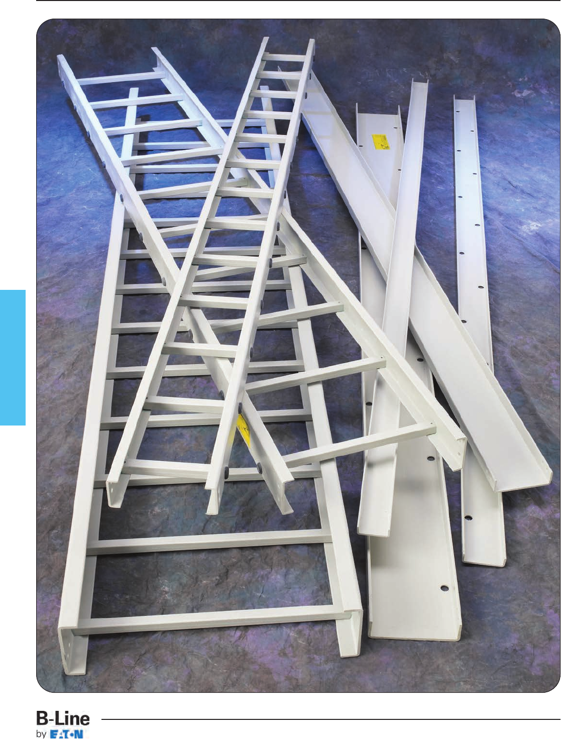
Fiberglass
FCT-1
Fiberglass
Cable Tray Systems
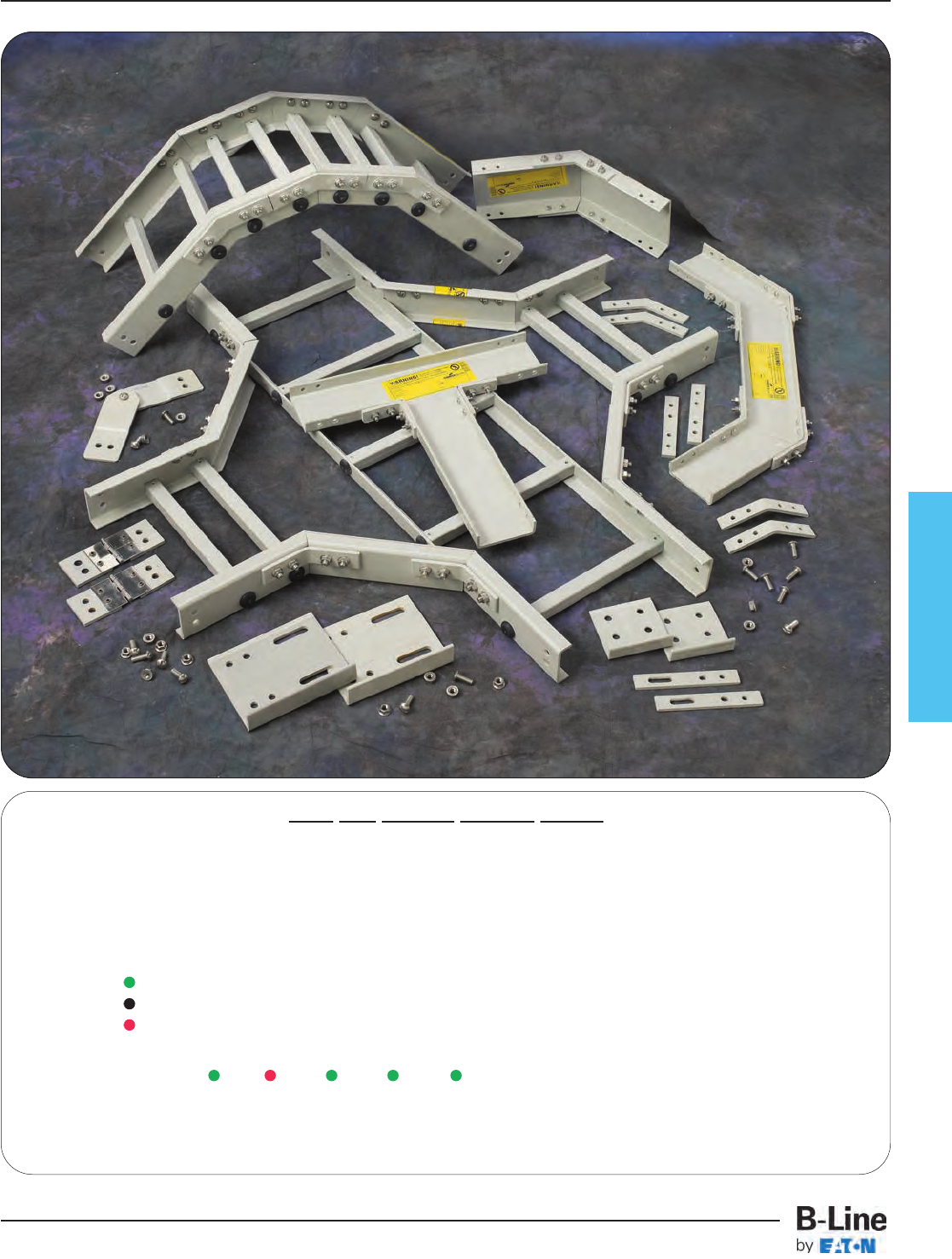
Fiberglass
How The Service Advisor Works
B-Line knows that your time is important! That’s why the color-coding system in this catalog is designed to help you
select products that fit your service needs. Products are marked to indicate the typical lead time for orders of 50 pieces
or less.
Customer: How do I select my straight sections. covers, or fittings so that I get the quickest turnaround?
Service Advisor: Each part of our selection chart is shown in colors. If any section of a part number is a different
color, the part will typically ship with the longer lead time represented by the colors.
Green = Fastest shipped items
Black = Normal lead-time items
Red = Normally long lead-time items
Example: 13 FA - 09 - 24 - 144 Part will have a long
lead time because of the
3-5 15 3-5 3-5 3-5 FA material.
Changing the part number from 13FA to 13F will change the coding to black for all sections and reduce the lead time.
FCT-2
Fiberglass
Cable Tray Systems
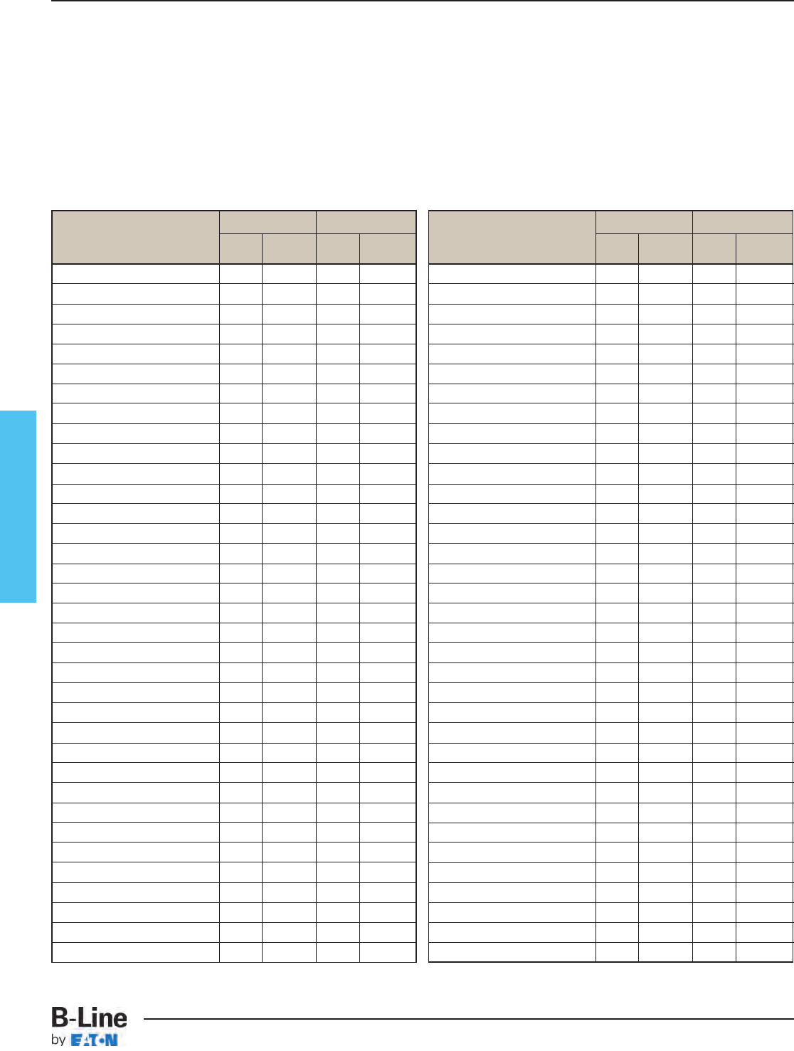
Fiberglass
Acetic Acid 10 190 10 210
Acetic Acid 50 125 50 180
Acetone N/R N/R 100 75
Aluminum Chloride SAT 170 SAT 200
Aluminum Hydroxide SAT 160 SAT 170
Aluminum Nitrate SAT 150 SAT 170
Aluminum Sulfate SAT 180 SAT 200
Ammonium Chloride SAT 170 SAT 190
Ammonium Hydroxide 1 100 10 150
Ammonium Hydroxide 28 N/R 28 100
Ammonium Carbonate N/R N/R SAT 150
Ammonium Bicarbonate 15 125 SAT 130
Ammonium Nitrate SAT 160 SAT 190
Ammonium Persulfate SAT N/R SAT 150
Ammonium Sulfate SAT 170 SAT 200
Amyl Alcohol ALL N/R ALL 90
Amyl Alcohol Vapor - 140 - 120
Benzene N/R N/R 100 140
Benzene Sulfonic Acid 25 110 SAT 200
Benzoic Acid SAT 150 SAT 200
Benzoyl Alcohol 100 N/R 100 N/R
Borax SAT 170 SAT 200
Calcium Carbonate SAT 170 SAT 200
Calcium Chloride SAT 170 SAT 200
Calcium Hydroxide 25 70 25 165
Calcium Nitrate SAT 180 SAT 200
Calcium Sulfate SAT 180 SAT 200
Carbon Disulfide N/R N/R N/R N/R
Carbonic Acid SAT 130 SAT 180
Carbon Dioxide Gas - 200 - 200
Carbon Monoxide Gas - 200 - 200
Carbon Tetrachloride N/R N/R 100 75
Chlorine, Dry Gas - 140 - 170
Chlorine, Wet Gas - N/R - 180
Chlorine Water SAT 80 SAT 180
POLYESTER VINYL ESTER
CHEMICAL
Max Max Oper. Max Max Oper.
ENVIRONMENT Wt. % Temp ˚F Wt. % Temp ˚F
Corrosion Guide
The information shown in this corrosion guide is based on full immersion laboratory tests and data generated from resin manufacturer's
data. It should be noted that in some of the environments listed, splashes and spill situations may result in a more corrosive situation
than indicated due to the evaporation of water. Regular wash down is recommended in these situations.
All data represents the best available information and is believed to be correct. The data should not be construed as a warranty of
performance for that product as presented in these tables. User tests should be performed to determine suitability of service if there is
any doubt or concern. Such variables as concentration, temperature, time and combined chemical effects of mixtures of chemicals
make it impossible to specify the exact suitability of fiber reinforced plastics in all environments. B-Line will be happy to supply
material samples for testing. These recommendations should only be used as a guide and B-Line does not take responsibility for
design or suitability of materials for service intended. In no event will B-Line be liable for any consequential or special damages for
any defective material or workmanship including without limitation, labor charge, other expense or damage to properties resulting
from loss of materials or profits or increased expenses of operations.
Chromic Acid 5 70 10 120
Citric Acid SAT 170 SAT 200
Copper Chloride SAT 170 SAT 200
Copper Cyanide SAT 170 SAT 200
Copper Nitrate SAT 170 SAT 200
Crude Oil, Sour 100 170 100 200
Cyclohexane N/R N/R N/R N/R
Cyclohexane, Vapor ALL 100 ALL 130
Diesel Fuel 100 160 100 180
Diethyl Ether N/R N/R N/R N/R
Dimethyl Phthalate N/R N/R N/R N/R
Ethanol 50 75 50 90
Ethyl Acetate N/R N/R N/R N/R
Ethylene Chloride N/R N/R N/R N/R
Ethylene Glycol 100 90 100 200
Fatty Acids SAT 180 SAT 200
Ferric Chloride SAT 170 SAT 200
Ferric Nitrate SAT 170 SAT 200
Ferric Sulfate SAT 170 SAT 200
Ferrous Chloride SAT 170 SAT 200
Fluoboric Acid N/R N/R SAT 165
Fluosilicic Acid N/R N/R SAT 70
Formaldehyde 50 75 50 100
Formic Acid N/R N/R 50 100
Gasoline 100 80 100 150
Glucose 100 170 100 200
Glycerine 100 150 100 200
Heptane 100 110 100 120
Hexane 100 90 100 130
Hydrobromic Acid 50 120 50 120
Hydrochloric Acid 10 150 10 200
Hydrochloric Acid 20 140 20 190
Hydrochloric Acid 37 75 37 95
Hydrofluoric Acid N/R N/R 15 80
Hydrogen Bromide, Dry 100 190 100 200
POLYESTER VINYL ESTER
CHEMICAL
Max Max Oper. Max Max Oper.
ENVIRONMENT Wt. % Temp ˚F Wt. % Temp ˚F
- : No Information Available N/R: Not Recommended SAT: Saturated Solution FUM: Fumes
FCT-3
Fiberglass - Technical Data
Cable Tray Systems
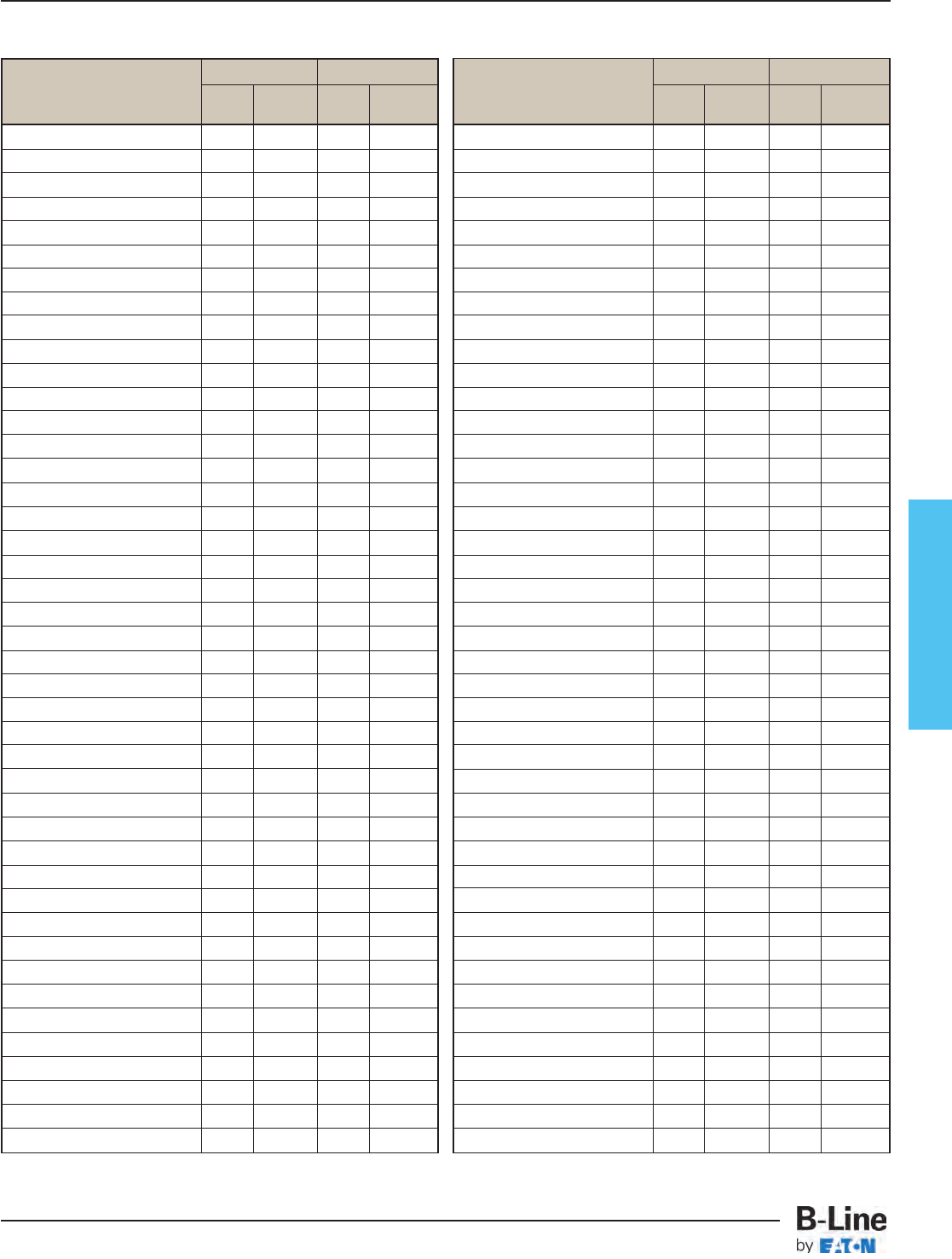
Fiberglass
Corrosion Guide
Hydrogen Bromide, Wet 100 75 100 130
Hydrogen Chloride - 120 - 200
Hydrogen Peroxide 5 100 30 100
Hydrogen Sulfide, Dry 100 170 100 210
Hydrogen Sulfide, Wet 100 170 100 210
Hypochlorous Acid 20 80 20 150
Isopropyl Alcohol N/R N/R 15 80
Kerosene 100 140 100 180
Lactic Acid SAT 170 SAT 200
Lead Acetate SAT 170 SAT 200
Lead Chloride SAT 140 SAT 200
Lead Nitrate SAT - SAT 200
Linseed Oil 100 150 100 190
Lithium Chloride SAT 150 SAT 190
Magnesium Carbonate SAT 140 SAT 170
Magnesium Chloride SAT 170 SAT 200
Magnesium Hydroxide SAT 150 SAT 190
Magnesium Nitrate SAT 140 SAT 180
Magnesium Sulfate SAT 170 SAT 190
Mercuric Chloride SAT 150 SAT 190
Mercurous Chloride SAT 140 SAT 180
Methyl Ethyl Ketone N/R N/R N/R N/R
Mineral Oils 100 170 100 200
Monochlorobenzene N/R N/R N/R N/R
Naphtha 100 140 100 170
Nickel Chloride SAT 170 SAT 200
Nickel Nitrate SAT 170 SAT 200
Nickel Sulfate SAT 170 SAT 200
Nitric Acid 5 140 5 150
Nitric Acid 20 70 20 100
Oleic Acid 100 170 100 190
Oxalic Acid ALL 75 ALL 120
Paper Mill Liquors - 100 - 120
Perchlorethylene 100 N/R 100 N/R
Perchloric Acid N/R N/R 10 150
Perchloric Acid N/R N/R 30 80
Phosphoric Acid 10 160 10 200
Phosphoric Acid 100 120 100 200
Potassium Aluminum Sulfate SAT 170 SAT 200
Potassium Bicarbonate 50 80 50 140
Potassium Carbonate 10 N/R 10 120
Potassium Chloride SAT 170 SAT 200
Potassium Dichromate SAT 170 SAT 200
Potassium Hydroxide N/R N/R 25 150
Potassium Nitrate SAT 170 SAT 200
Potassium Permanganate 100 80 100 210
Potassium Sulfate SAT 170 SAT 200
Propylene Glycol ALL 170 ALL 200
Phthalic Acid --SAT 200
Sodium Acetate SAT 160 SAT 200
Sodium Benzoate SAT 170 SAT 200
Sodium Bicarbonate SAT 160 SAT 175
Sodium Bisulfate ALL 170 ALL 200
Sodium Bromide ALL 170 ALL 200
Sodium Carbonate 10 80 35 160
Sodium Chloride SAT 170 SAT 200
Sodium Cyanide SAT 170 SAT 200
Sodium Hydroxide N/R N/R 50 150
Sodium Hydroxide N/R N/R 25 80
Sodium Hypochloride N/R N/R 10 150
Sodium Monophosphate SAT 170 SAT 200
Sodium Nitrate SAT 170 SAT 200
Sodium Sulfate SAT 170 SAT 200
Sodium Thiosulfate ALL 100 ALL 120
Stannic Chloride SAT 160 SAT 190
Styrene N/R N/R N/R N/R
Sulfated Detergent 0/50 170 0/50 200
Sulfur Dioxide 100 80 100 200
Sulfur Trioxide 100 80 100 200
Sulfuric Acid 93 N/R 93 N/R
Sulfuric Acid 50 N/R 50 180
Sulfuric Acid 25 75 25 190
Sulfurous Acid SAT 80 N/R N/R
Tartaric Acid SAT 170 SAT 200
Tetrachloroethylene N/R N/R FUM 75
Toluene N/R N/R N/R N/R
Trisodium Phosphate N/R N/R SAT 175
Urea SAT 130 SAT 140
Vinegar 100 170 100 200
Water, Distilled 100 170 100 190
Water, Tap 100 170 100 190
Water, Sea SAT 170 SAT 190
Xylene N/R N/R N/R N/R
Zinc Chloride SAT 170 SAT 200
Zinc Nitrate SAT 170 SAT 200
Zinc Sulfate SAT 170 SAT 200
POLYESTER VINYL ESTER
CHEMICAL
Max Max Oper. Max Max Oper.
ENVIRONMENT Wt. % Temp ˚F Wt. % Temp ˚F
POLYESTER VINYL ESTER
CHEMICAL
Max Max Oper. Max Max Oper.
ENVIRONMENT Wt. Temp ˚F Wt. % Temp ˚F
- : No Information Available N/R: Not Recommended SAT: Saturated Solution FUM: Fumes
FCT-4
Fiberglass - Technical Data
Cable Tray Systems
Fiberglass
NEMA Standard 8-10-1986
If unusual temperature conditions exist,
the manufacturer should be consulted.
Authorized Engineering information 8-20-1986
Typical Properties of Pultruded Components
B-Line Fiberglass Cable Tray systems are manufactured from glass fiber-
reinforced plastic shapes that meet ASTM E-84, Smoke Density rating for
polyester of 680, for vinyl ester 1025, Class 1 Flame Rating and self-
extinguishing requirements of ASTM D-635. A surface veil is applied during
pultrusion to insure a resin-rich surface and ultraviolet resistance.
Test Unit/ 6
"
Cable Tray
Properties Method Value Longitudinal Transverse Longitudinal Transverse
Density ASTM D1505 lbs/in3.058-.062 - .072 - .076 -
Coefficient of Thermal Expansion ASTM D696 in/in/˚F 5.0 x 10⁻⁶ - 5.0 x 10⁻⁶ -
Water Absorption ASTM D570 Max % 0.5 - 0.5 -
Dielectic Strength ASTM D149 V/mil (vpm) 200 - 200 -
Flammability Classification UL94 VO ----
Flame Spread ASTM E-84 20 Max ----
Load Data
Flame Resistance (FTMS 406-2023)
ign/burn, seconds 75/75
Intermittent Flame Test (HLT-15), rating 100
Flammability Test (ASTM D635)
Ignition none
Burning Time 0 sec.
3
" & 4"Cable Tray,
Cable Channel
Effect of Temperature
Strength properties of reinforced plastics are reduced when continuously exposed
to elevated temperatures. Working loads shall be reduced based on the following:
Temperature in Approximate
Degrees F Percent of Strength
75 100
100 90
125 78
150 68
175 60
200 52
Fiberglass Cable Tray and Cable Channel are offered in four versions for applications as follows:
Standard Series Resin Type Color Meets
13F, 24F, 36F, 46F, H46F, 48F Fire Retardant Polyester Gray ASTM E-84 Class 1 - UL94 VO
FCC-03, FCC-04, FCC-06, FCC-08 Good Corrosion Resistance
in most environments
High Performance
13FV, 24FV, 36FV, 46FV, H46FV, 48FV Fire Retardant Vinyl Ester Beige ASTM E-84 Class 1 - UL94 VO
FCCV-03, FCCV-04, FCCV-06, FCCV-08 Improved Corrosion Resistance
For more severe environments
Higher Heat Distortion Temperature
Dis-Stat/Low Smoke
13FA, 24FA, 36FA, 46FA, H46FA, 48FA Fire Retardant Black ASTM E-84 Class 1 - UL94 VO
FCCA-03, FCCA-04, FCCA-06, FCCA-08 Zero Halogen/Dis-Stat ASTM D257-99
Dissipates Static Charge
Smoke Generation and Toxicity
for Mass Transit Requirements
and Off Shore application
FCT-5
Fiberglass - Technical Data
Cable Tray Systems
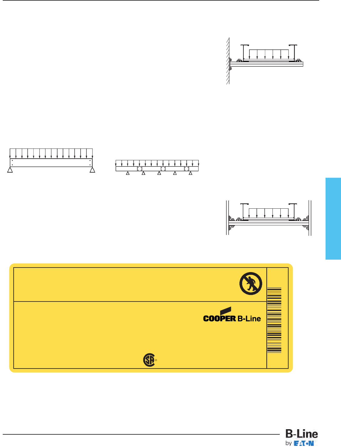
Fiberglass
Warning! Walkways
It should be noted that cable tray is designed as a support for power or control cables, or both and is not intended or designed to be a
walkway for personnel, the user is urged to display appropriate warnings cautioning against the use of this support as a walkway. The
following language is suggested:
WARNING! Not to be used as a walkway, ladder or support for personnel. To be used only as a mechanical support
for cables and tubing. Authorized Engineering Information 8-20-1986
Standard B-Line Label
Structural Characteristics of Cable Tray and Supports
When viewed in its installed condition, any
cable tray system performs functionally as
a beam under a uniformly distributed load.
There are four basic beam configurations
typically found in a cable tray installation.
All four types of beams support cable tray
but each differ in the way that the beam is
attached to the support.
The first two beam configurations, simple
and continuous, apply to the cable tray
itself. The second two beam configurations,
cantilever and fixed, apply more to the
cable tray supports than to the cable tray
itself.
Simple Beam
A good example of simple beam is a single
straight section of cable tray supported but
not fastened at either end. When the tray is
loaded the cable tray is allowed to deflect.
Simple beam analysis is used almost
universally for beam comparisons even
though it is seldom practical in field
installations. The three most prominent
reasons for using a simple beam analysis
are: calculations are simplified; it represents
the worst case loading; and testing is
simple and reliable. The published load data
in the B-Line cable tray catalog is based on
the simple beam analysis per NEMA
Standard FG-1.
Continuous Beam
Continuous beam is the beam configuration
most commonly used in cable tray
installations. An example of this configuration
is where cable trays are installed across
several supports to form a number of spans.
The continuous beam possesses traits of
both the simple and fixed beams.
When equal loads are applied to all spans
simultaneously, the counterbalancing effect
of the loads on both sides of a support
restricts the movement of the cable tray at
the support. The effect is similar to that of
a fixed beam. The end spans behave
substantially like simple beams. When cable
trays of identical design are compared,
continuous beam installations will typically
have approximately half the deflection of a
simple beam of the same span. Therefore,
simple beam data should be used for a
general comparison only.
Cantilever Beam
A cantilever beam configuration occurs
when one end of the beam is rigidly attached
to the support and the other end is
unsupported.
This type of configuration is typically used
when wall mounting a bracket to support
cable tray. Since one end is unsupported,
the cantilever beam will hold considerably
less load than a comparable simple beam.
Fixed Beam
A fixed beam configuration has both
ends of the beam rigidly attached to the
supports. A good example of a fixed beam
is the rung of a cable tray. By attaching the
ends of the rung to the side rails, the ends
are not free to move, bend or twist. This
restriction in end movement effectively
increases the load carrying capacity of the
member.
Fixed beam configurations are also typically
found in strut rack type support systems.
These types of racks are found extensively
in tunnel applications for support of pipe
and cable tray.
FCT-6
Fiberglass - Technical Data
Cable Tray Systems
Use Only As A Mechanical Support For Cables, Tubing and Raceways.
Do Not Use As A Walkway, Ladder,
Or Support For Personnel.
www.cooperbline.com
(618) 654-2184
Catalog Number: 24F09-18-120 STR SECTION
Shipping Ticket: 260203 00 001
Mark Number: 78101115400
Purchase Order: D798981
Minimum Area:
Load Class: 232 KG/M 3.7 METER SPAN
30781011154005
1 of 1
09/15/2012
000291745
WARNING!
VENTILATED
LR36026
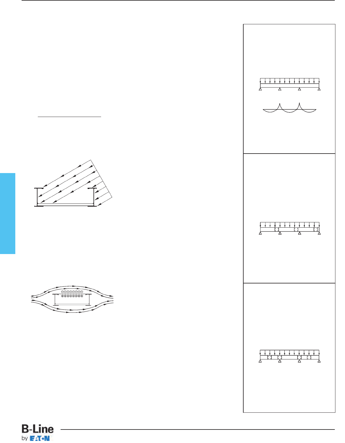
Fiberglass
Cable Loads
The cable load is simply the total weight of
all the cables to be placed in the tray. This
load should be expressed in lbs./ft.
Concentrated Loads
A concentrated static load represents a
static weight applied between the side rails.
Tap boxes, conduit attachments and long
cable drops are just some of the many types
of concentrated loads. When so specified,
these concentrated static loads may be
converted to an equivalent, uniform load
(We) in pounds per linear foot by using the
following formula:
We: = 2x (concentrated static load)
span length (ft.)
Wind Loads
Wind loads need to be determined for all
outdoor cable tray installations. Most
outdoor cable trays are ladder type trays,
therefore the most severe loading to be
considered is pressure on the tray side rails
(see Detail 1).
When covers are installed on outdoor cable
trays, another factor to be considered is the
aerodynamic effect which can produce a lift
strong enough to separate a cover from a
tray. Wind moving across a covered tray
(see Detail 2) creates a positive pressure
inside the tray and a negative pressure
above the cover. This pressure difference
can lift the cover off the tray.
B-Line recommends the use of heavy duty
wrap-around cover clamps when covered
trays are installed in an area where strong
winds occur.
Ice Loads
Glaze ice is the most commonly seen form
of ice build-up. It is the result of rain or
drizzle freezing on impact with an exposed
object. Generally, only the top surface (or
the cover) and the windward side of a cable
tray system is significantly coated with ice.
The maximum design load to be added due
to ice should be determined from local and
federal weather bureau information.
Snow Loads
Snow is measured by density and thickness.
The density of snow varies almost as much
as its thickness. The additional design load
from snowfall should be determined using
local snowfall records which can be
obtained from local and federal weather
bureaus.
Seismic Loads
In recent years a great deal of testing and
evaluation of cable tray systems, and their
supports, has been performed. The
conclusions reached from these evaluations
have shown the cable tray/strut support
system exhibited more seismic capacity
than originally expected. One of the factors
contributing to this is the energy dissipating
motion of the cables within the tray. Another
factor is the high degree of ductility of the
cable tray and the support material. These
factors, working in conjunction with a
properly designed cable tray system, should
afford reasonable assurance to withstand
even strong motion earthquakes. Please
consult the factory with your specific
seismic specifications and request a seismic
brochure.
Splices
A lot of attention has been given to the
strength of the side rails. These load
bearing side rails must be spliced to form a
continuous system, therefore the design of
the splice plate is very important. The splice
plate needs to be both strong and simple to
install. These characteristics have been
designed into B-Line’s splice plates.
B-Line’s new high strength “L" shaped LAY-
IN splice plate offers several advantages:
1) stronger than flat plate splices.
2) time saving - holds tray in position before
fasteners are inserted.
3) provides base for an expansion splice to
function - no vertical binding.
4) discourages splice on support-position-
ing, over the support is the worst place to
splice - Fig 3.
The location of splices in a continuous span
cable tray system is also very important. The
splices should be located at points of
minimum stress whenever practical. NEMA
standards FG-1 limits the use of splice
plates as follows:
Unspliced straight section should be
used on a simple span and on end
spans of continuous runs. Straight
section lengths should be equal to or
greater than the span length to ensure
not more than one splice between
supports. See Figures 1 through 3 for
examples on splicing configurations.
Typical Continuous
Span Configuration
Figure 1
+ Maximum positive moment
- Maximum negative moment
Undesired location:
• over supports
• mid spans
Preferred splice location:
• 1⁄4 span
Preferred Splice
Plate Locations
Figure 2
Undesirable Splice
Plate Locations
Figure 3
Structural Characteristics of Cable Tray and Supports
Detail 1
Detail 2
FCT-7
Fiberglass - Technical Data
Cable Tray Systems
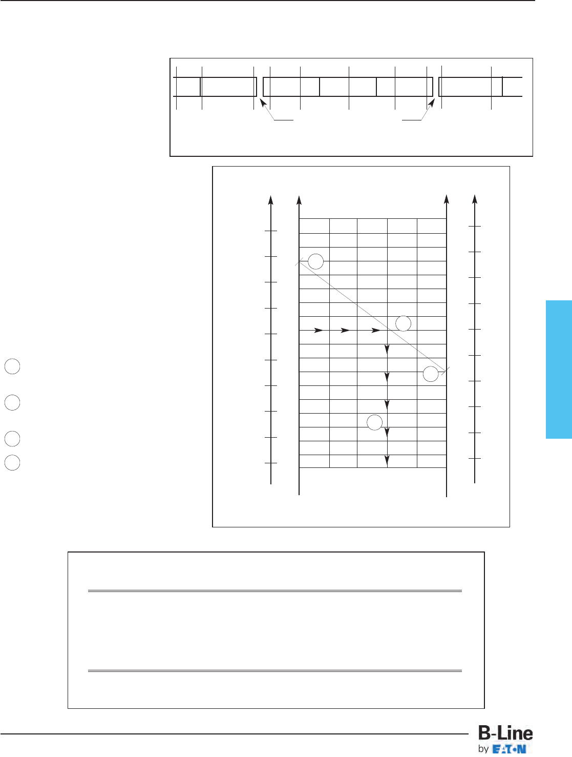
Fiberglass
Cable Tray Thermal Contraction and Expansion
Expansion or Contraction for Various Temperature Differences
Temperature Cable Tray Length Tray Length for
Differential for 1" Expansion Each Expansion Connector*
25°F (13.9°C) 667 Feet (203.3m) 417 Feet (127.1m)
50°F (27.8°C) 333 Feet (101.5m) 208 Feet (63.4m)
75°F (41.7°C) 222 Feet (67.6m) 139 Feet (42.3m)
100°F (55.6°C) 167 Feet (50.9m) 104 Feet (31.7m)
125°F (69.4°C) 133 Feet (40.5m) 83 Feet (25.3m)
150°F (83.3°C) 111 Feet (33.8m) 69 Feet (21.0m)
175°F (97.2°C) 95 Feet (28.9m) 59 Feet (18.0m)
Note for gap set and hold down/guide location, see installation instruction above.
*1" (25.4mm) slotted holes in each expansion connector allow 5⁄8" (15.9mm) total expansion or contraction.
Authorized Engineering Information 8-20-1986
1
2
3
4
It is important that thermal contraction
and expansion be considered when
installing cable tray systems. The
length of the straight cable tray runs
and the temperature differential
govern the number of expansion
splice plates required (see Table 1
below).
The cable tray should be anchored at
the support nearest to its midpoint
between the expansion splice plates
and secured by expansion guides at
all other support locations (see Figure
1 - Typical Cable Tray Installation).
The cable tray should be permitted
longitudinal movement in both
directions from that fixed point.
Accurate gap settings at the time of
installation is necessary for the proper
operation of the expansion splice
plates. The following procedure
should assist the installer in
determining the correct gap: (see
Figure 2 - Gap Setting)
Plot the highest expected tray
temperature on the maximum
temperature line.
Plot the lowest expected tray
temperature on the minimum
temperature line.
Draw a line between the
maximum and minimum points.
Plot the tray temperature at the
time of installation to determine
the gap setting.
C°F°F° C°
Maximum Minimum
Temperature Temperature
130
70
50
30
10
-10
-30
90
110
130
110
90
70
50
30
10
-10
-30
50
40
30
20
10
0
-10
-20
-30
-40
50
40
30
20
10
0
-10
-20
-30
-40
1/8
(3.2)
1/4
(6.3)
3/8
(9.5)
1/2
(12.7)
0
(0.0)
5/8
(15.9)
GAP SETTING
Inches (mm)
Tray Temperature At Time Of Installation
X -- -- -- -- X -- -- -- -- X
X -- -- -- -- X -- -- -- -- X
Typical Cable Tray Installation
X : Denotes hold-down clamp (anchor) at support.
_: Denotes expansion guide clamp at support.
Expansion Splice Plates
Figure 2
Table 1
Figure 1
1
2
3
4
FCT-8
Fiberglass - Technical Data
Cable Tray Systems
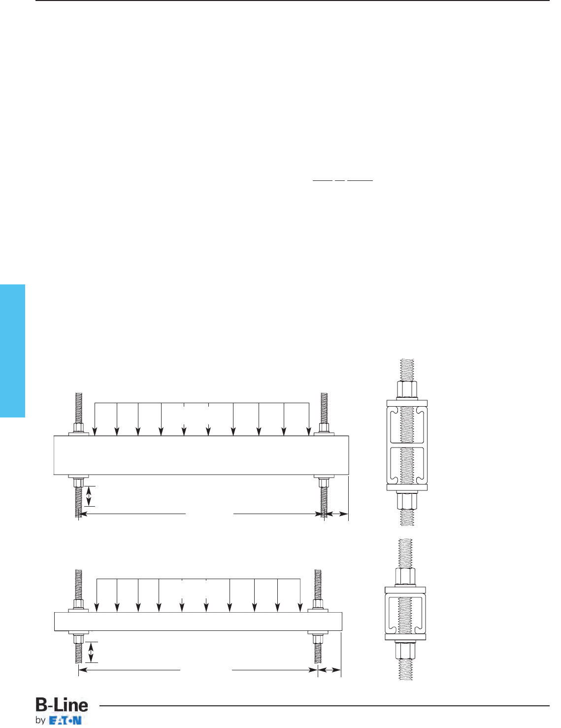
Fiberglass
Recommended Fiberglass Trapeze Hanging Systems
Notes:
1) A snug three to four ft.-lbs. torque is sufficient for all thread rod nuts.
2) When supporting cable tray, the spacing between each trapeze should not exceed the distance between splice plates.
3) When hanging from beam, B-Line BFPU751 series clamps provide extra thread engagement necessary for load ratings. All thread
rod must be fully engaged in the clamp.
4) Design load safety factor is 3:1
BF22A Strut:
2" max between material being supported and rod
BF22 Strut:
2" max between material being supported and rod
Installation of B-Line fiberglass cable tray should be made in accordance with the standards set by NEMA
Publication VE-2, Cable Tray Installation Guide, and National Electrical Code, Article 318.
- Always observe common safety practices when assembling tray and fittings. Installations generally require some field cutting.
Dust created during fabrication presents no serious health hazard, but skin irritation may be experienced by some workers.
- Operators of saws and drills should wear masks, long sleeve shirts or coveralls.
- Fabrication with fiberglass is relatively easy and comparable to working with wood. Ordinary hand tools may be used in most cases.
- Avoid excessive pressure when sawing or drilling. Too much force can rapidly dull tools and also produce excessive heat which
softens the bonding resin in the fiberglass resulting in a ragged edge rather than a clean-cut edge.
- Field cutting is simple and can be accomplished with a circular power saw with an abrasive cut-off wheel (masonry type) or
hack saw (24 to 32 teeth per inch).
- Drill fiberglass as you would drill hard wood. Standard twist drills are more than adequate.
- Any surface that has been drilled, cut, sanded or otherwise broken, must be sealed with a compatible resin. (see page FCT-48)
- Carbide tipped saw blades and drill bits are recommended when cutting large quantities.
- Support the fiberglass material firmly during cutting operations to keep material from shifting which may cause chipping at the
cut edge.
- Each tray section length should be equal to or greater than the support span.
- When possible, the splice should be located at quarter span.
- Fittings should be supported as per NEMA FG-1.
Cable Tray Installation Guide
maximum uniform load
1,500 lbs.
maximum uniform load
500 lbs.
1⁄2" (13mm) Min.
40" (1016mm)
Max.
2" (51mm)
Min.
1⁄2" (13mm) Min.
40" (1016mm)
Max.
2" (51mm)
Min.
1⁄2" fiberglass all-thread rod (BFVATR 1⁄2)
fiberglass ATR nut (BFVATRHN 1⁄2)
fiberglass spacer (BFV202)
BF22A fiberglass strut
fiberglass spacer (BFV202)
fiberglass ATR nut (BFVATRHN 1⁄2)
1⁄2" fiberglass all-thread rod (BFVATR 1⁄2)
fiberglass ATR nut (BFVATRHN 1⁄2)
fiberglass spacer (BFV202)
BF22 fiberglass strut
fiberglass spacer (BFV202)
fiberglass ATR nut (BFVATRHN 1⁄2)
For vinyl ester resin, ‘V’ must be added appropriately to part number. Example: BFV22A.
FCT-9
Fiberglass - Technical Data
Cable Tray Systems
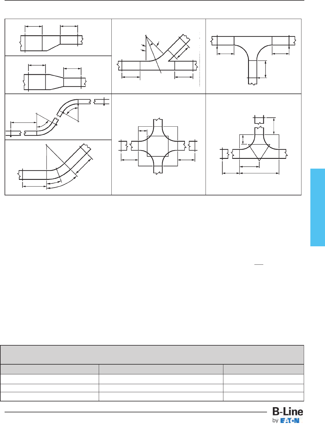
Fiberglass
Horizontal Cross
Horizontal Elbows
Horizontal Tee
Vertical Elbows
L
1/2L
2 ft. (.6M)
2 ft. (.6M)
2 ft. (.6M) 2 ft. (.6M)
2 ft. (.6M)
2 ft. (.6M)
2 ft. (.6M)
ø
ø
1/2ø
2/3R
2/3R
ø = 30˚, 45˚, 60˚, 90˚
ø = 30˚, 45˚, 60˚, 90˚
2 ft. (.6M)
2 ft. (.6M)
2 ft. (.6M)
2 ft. (.6M)
2 ft. (.6M)
2 ft. (.6M)
22.5˚
45˚
2 ft. (.6M)
2 ft. (.6M)
2 ft. (.6M)
2 ft. (.6M)
Based on the National Electrical Code - 1993, Section 318
The National Electrical Code Article 318 was written primarily for verifying the cable fill in cable trays but little has been done to convert this
information into a design procedure.
In the development of a complete cable tray support system, B-Line established a simple method of determining the right size tray to
support any given amount of cables. The following tables cover our method for determining cable tray widths based on tray design and
system voltage.
Table I
Table I is subdivided into two categories covering electrical service of 2000 volts or less. The first, Category A, is for any mixture of power
or lighting cables with any mixture of control or signal cables. Category B is used when control and/or signal cables only are being used.
Control Circuit - the circuit of a control apparatus or system that carries the electric signals
directing the performance of the controller, but does not carry the main power (NEC Article 100).
Signaling Circuit - any electric circuit that energizes signaling equipment (NEC Article 100).
Table II
Table II has only one category of electrical service and that is 2001 volts and over for types MV and MC cables both single and
multiconductor.
Type MV is a single or multiconductor solid dielectric insulated cable rated 2001 volts or higher (NEC Article 326).
Type MC cable is a factory assembly of one or more conductors, each individually insulated and enclosed in a metallic sheath or
interlocking tape, or a smooth or corrugated tube (NEC Article 334). Cables other than Types MV and MC can be installed provided they
are "specifically approved for installation in cable trays."
Table III
Table III covers 3, 4 and 6 inch ventilated cable channels.
Tray Sizing Procedure
Step 1.Select proper cable tray table below based on cable voltage and tray type.
Cable Voltage Cable Tray Type Use:
2000 Volts or less Ladder, Cable Tray Table I
2001 Volts or more Ladder, Cable Tray Table II
2001 Volts or less Cable Channel, ventilated Table III
Cable Tray Support Locations For Fittings - per NEMA VE-2 Installation Guide
How To Size Cable Tray
FCT-10
Fiberglass - Technical Data
Cable Tray Systems
Fiberglass
Tables I - Ladder Cable Tray - for cables rated 2000 volts or less
For power or lighting or any mixture of power, lighting, control or signal cables:
1. Multiconductor Cable
Conductor sizes 4/0 and larger* tray width ≥ Sd NEC 318-9(a) (1)
Conductor sizes 3/0 and smaller tray width ≥ 0.857 Sa NEC 318-9(a) (2)
Example: Calculate width of cable tray required for the following Type TC Cables.
6 4/c 500 kcmil Power: Diameter = 3.14 6 x 3.14 = 18.84
21 4/c #8 AWG Lighting: Area = 0.407 .857 (21 x 0.407) = 7.32
20 5/c #12 AWG Control: Area = 0.170 .857 (20 x 0.170) = 2.91
29.07
Solution: Use 30 inch wide tray
2. Single Conductor Cable
Conductor sizes 250 MCM thru 900 MCM† only tray width ≥ 0.023 Sa* NEC 318-10(a) (2)
Conductor sizes 3/0 and smaller tray width ≥ 0.857 Sa NEC 318-10(a) (4)
Example: Calculate width of cable tray required for the following Type THW Wires.
6 1/c 4/0 AWG Power: Diameter = 0.710 (6 x 0.71) = 4.26
9 1/c 500 kcmil Power: Area = 0.83 .923 (9 x 0.83) = 6.89
6 1/c 250 kcmil Power: Area = 0.49 .923 (6 x 0.49) = 2.71
13.86
Solution: Use 18 inch wide tray
3. Mixture of Single and Multiconductor Cable
Example: Calculate width of cable tray required for the following mix of cables. Use guidelines from (1) & (2) above.
2 3/c 250 kcmil Type MC Power: Diameter = 1.84 2 x 1.84 = 3.68
12 4/c #8 AWG Type TC Lighting: Area = 0.41 .857 (12 x 0.41) = 4.22
60 4/c #12 AWG Type TC Control: Area = 0.12 .857 (60 x 0.12) = 6.17
4 1/c 1/0AWG Type THW Power: Diameter = 0.55 (4 x 0.55) = 2.20
6 1/c 500kc mil Type THW Power: Area = 0.83 .923 (6 x 0.83) = 4.60
20.87
Solution: Use 24 inch wide tray
For control and/or signal duty cable only:
1. Multiconductor Cable
All conductor sizes**
Example: Calculate width of cable tray required for the following Type TC Cables in 4 inch deep tray.
24 16/c 16 AWG Control: Area = 0.29 2(24 x 0.29) ÷ 4 = 3.48
42 4/c 12 AWG Control: Area = 0.13 2(42 x 0.13) ÷ 4 = 2.73
18 4/c 10 AWG Control: Area = 0.20 2(18 x 0.20) ÷ 4 = 1.80
8.01
Solution: Use 24 inch wide tray
* The 4/0 and larger cable shall be installed in a single layer and no other cables shall be placed on them.
** For computation only depth D can not exceed 6 inches.
† For 1000 MCM and larger single conductor cable, refer to NEC 318-10(a)1 for sizing information.
Sd = the sum of the diameters, in inches, of all cables in the same ladder cable tray.
Sa = the sum of the cross-sectional areas, in square inches, of all cables in the same ladder cable tray.
How To Size Cable Tray
tray width ≥ 2Sa NEC 318-9(b)
D
FCT-11
Fiberglass - Technical Data
Cable Tray Systems
Fiberglass
Table II - Ladder - for cables rated 2000 volts or less
For MV or MC cables:
1. Mixture of Single and Multiconductor Cable NEC 318-12
All conductor sizes† tray width ≥ Sd
Example: Calculate width of cable tray required for the following cables.
4 1/c 500 kcmil Type MV Diameter = 1.05 4 x 1.05 = 4.20
10 3/c 2/0 AWG Type MC Diameter = 1.55 10 x 1.55 = 15.50
4 3/c 4/0 AWG Type MV Diameter = 1.78 4 x 1.78 = 7.12
26.82
Solution: Use 30 inch wide tray
Table III - Cable Channel, Ventilated - for cables rated 2000 volts or less
For power, lighting, control and/or signal duty cables:
1. Multiconductor Cable (all size cables)NEC 318-9(E)
3 inch wide 4 inch wide 6 inch wide
One cable only Sa ≤ 2.3 in2Sa ≤ 4.5 in2Sa ≤ 7.0 in2
Two or more cables Sa ≤ 1.3 in2Sa ≤ 2.5 in2Sa ≤ 3.8 in2
Example: Calculate width of cable channel required for the following Type TC Cables.
1 3/c 1/0 AWG Area = 1.17 which is less than 1.3. Use 3 inch wide.
1 4/c 300 kcmil Area = 3.77 which is less than 4.5. Use 3 inch wide.
6 4/c #10 AWG Area = 6 x 0.20 = 1.20 which is less than 1.3. Use 3 inch wide.
2 3/c 1/0 AWG Area = 2 x 1.17 = 2.34 which is less than 2.5. Use 4 inch wide.
2. Single Conductor (1/0 AWG or larger) NEC 318-10(b)
3 inch wide 4 inch wide 6 inch wide
Any number of cables Sd ≤ 3.0 Sd ≤ 4.0 Sd ≤ 6.0
Example: Type THW Cables.
3 1/c 500 kcmil Type THW Diameter = 3 x 1.029 = 3.09 which is less than 4.0. Use 4 inch wide.
8 1/c 4/0 kcmil Type THW Diameter = 8 x 0.71 = 5.68 which is less than 6.0. Use 6 inch wide.
† Cables shall be installed in a single layer. Where single conductor cables are triplexed, quadruplexed or bound together in circuit groups, the sum of the
diameters of the single conductors shall not exceed the cable tray width and these groups shall be installed in single layer arrangement.
Sd = the sum of the diameters, in inches, of all cables in the same ladder cable tray.
Sa = the sum of the cross-sectional areas, in square inches, of all cables in the same ladder cable tray.
How To Size Cable Tray
Covers (Derating)
When cable trays are continuously covered for more than
six feet with solid unventilated covers, the ampacity of the
installed cables must be reduced per NEC-1993.
2000 volts or less
• MULTICONDUCTOR CABLES
- use 95% of tables 310-16 and 310-18
• SINGLE CONDUCTOR CABLES
- 600 MCM and larger use 70% of tables 310-17 and
310-19 1/0 AWG thru 500 kc mil use 60% of tables
310-17 and 310-19
2001 volts and over
• MULTICONDUCTOR CABLES
- use 95% of tables 310-75 and 310-76
• SINGLE CONDUCTOR CABLES
- use 70% of tables 310-69 and 310-70
Cross-Sectional Area
Rarely is the cross-sectional area of
a multiconductor cable given in
manufacturers literature or the
National Electrical Code. To
calculate the cross-sectional area
simply square the diameter and
multiply by 0.7854. The diameter
used in the calculations is the
overall outside diameter (O.D.) of the
cable including insulation and/or
armor.
Cross Sectional Area (Square Inches)
= 0.7854 (O.D.)2
Multipliers Used in Tables
The multipliers used in all tables are
mathematical equivalents of Tables
318-9 and 318-10 of the National
Electrical Code-1993.
An example can be found in column
1 of Table 318-9. The proportion of
cable tray width (size inches) to
allowable fill (seven square inches) is
0.857 for 3/0 and smaller
multiconductor cables in ladder type
trays. Therefore the product of 0.857
and the cross-sectional area of
cables is the tray width.
FCT-12
Fiberglass - Technical Data
Cable Tray Systems

Fiberglass
SECTION 161xx
NON-METALLIC CABLE TRAY
POLYESTER, VINYL ESTER
PART 1 - GENERAL
1.01 SECTION INCLUDES
A. The work covered under this section consists of the furnishing of all necessary labor,
supervision, materials, equipment, tests and services to install complete cable tray systems
as shown on the drawings.
B. Cable tray systems are defined to include, but are not limited to straight sections of [ladder
type] [vented bottom type] [solid bottom type] cable trays, bends, tees, elbows, drop-outs,
supports and accessories.
1.02 REFERENCES
A. ANSI/NFPA 70 – National Electrical Code
B. NEMA FG 1-2002 – Non-Metallic Cable Tray Systems
C. NEMA VE 2-2002 – Cable Tray Installation Guidelines
1.03 DRAWINGS
A. The drawings, which constitute a part of these specifications, indicate the general route of
the cable tray systems. Data presented on these drawings are as accurate as preliminary
surveys and planning can determine until final equipment selection is made. Accuracy is not
guaranteed and field verification, of all dimensions, routing, etc., is directed.
B. Specifications and drawings are for assistance and guidance, but exact routing, locations,
distances and levels will be governed by actual field conditions. Contractor is directed to
make field surveys as part of his work prior to submitting system layout drawings.
1.04 SUBMITTALS
A. Submittal Drawings: Submit drawings of cable tray and accessories including clamps,
brackets, hanger rods, splice plate connectors, expansion joint assemblies, and fittings,
showing accurately scaled components.
B. Product Data: Submit manufacturer's data on cable tray including, but not limited to, types,
materials, finishes, rung spacings, inside depths and fitting radii. For side rails and rungs,
submit cross sectional properties including Section Modulus (Sx) and Moment of Inertia (Ix).
1.05 QUALITY ASSURANCE
A. Manufacturers: Firms regularly engaged in manufacture of cable trays and fittings of types
and capacities required, whose products have been in satisfactory use in similar service for
not less than 5 years.
B. NEMA Compliance: Comply with NEMA Standards Publication Number FG-1,
"Non-Metallic Cable Tray Systems".
C. NEC Compliance: Comply with NEC, as applicable to construction and installation of cable
tray and cable channel systems (Article 318, NEC).
1.06 DELIVERY, STORAGE AND HANDLING
A. Deliver cable tray systems and components carefully to avoid breakage, denting and scoring
finishes. Do not install damaged equipment.
B. Store cable trays and accessories in original cartons and in clean dry space; protect from
weather and construction traffic. Wet materials should be unpacked and dried before storage.
continued on page FCT-14
FCT-13
Fiberglass - Recommended Tray Specification
Cable Tray Systems
Fiberglass
PART 2 - PRODUCTS
2.01 ACCEPTABLE MANUFACTURERS
A. Subject to compliance with these specifications, cable tray systems shall be as
manufactured by B-Line [or engineer approved equal].
2.02 CABLE TRAY SECTIONS AND COMPONENTS
A. General: Except as otherwise indicated, provide non-metallic cable trays, of types, classes,
and sizes indicated; with splice plates, bolts, nuts and washers for connecting units.
Construct units with rounded edges and smooth surfaces; in compliance with applicable
standards; and with the following additional construction features. Cable tray shall be
installed according to the latest revision of NEMA VE 2.
B. Material and Finish: Straight section structural elements; side rails, rungs and splice plates
shall be pultruded from glass fiber reinforced polyester resin, vinyl ester resin or dis-stat.
C. Pultruded shapes shall be constructed with a surface veil to insure a resin-rich surface and
ultraviolet resistance.
D. Pultruded shapes shall meet ASTM E-84, Class 1 flame rating and self-extinguishing
requirements of ASTM D-635.
2.03 TYPE OF TRAY SYSTEM
A. Ladder Cable Trays shall consist of two longitudinal members (side rails) with transverse
members (rungs) mechanically fastened and adhesively bonded to the side rails. Rungs
shall be spaced [6] [9] [12] inches on center. Rung spacing in radiused fittings shall be
industry standard 9" and measured at the center of the tray’s width. Each rung must be
capable of supporting a 200 lb. concentrated load at the center of the cable tray with a
safety factor of 1.5 (See following rung loading table).
B. Ventilated Bottom Cable Trays shall consist of two longitudinal members (side rails) with
rungs spaced 4" on center.
C. Solid Bottom Cable Trays shall consist of two longitudinal members (side rails) with a solid
sheet over rungs spaced on 12" centers.
D. Cable tray loading depth shall be [2] [3] [5] inches per NEMA FG 1.
E. Straight sections shall be supplied in standard [10 foot (3m)] [20 foot (6m)] lengths.
F. Cable tray inside widths shall be [6] [9] [12] [18] [24] [30] [36] inches or as shown on
drawings. Outside width shall not exceed inside by more than a total of 2".
G. Straight and expansion splice plates will be of "L" shaped lay-in design with an eight-bolt
pattern in 5" fill systems and four-bolt pattern in 3" and 2" fill systems. Splice plates shall
be furnished with straight sections and fittings.
H. All fittings must have a minimum radius of [12] [24] [36].
I. Fittings shall be of mitered construction.
J. Dimension tolerances will be per NEMA FG 1.
continued on page FCT-15
FCT-14
Fiberglass - Recommended Tray Specification
Cable Tray Systems
Fiberglass
2.04 LOADING CAPACITIES
A. Cable trays shall meet NEMA class designation: [8C] [12C] [20B] [20C].
Or
A. Cable tray shall be capable of carrying a uniformly distributed load of _______ lbs./ft on
a _______ foot support span with a safety factor of 1.5 when supported as a simple span
and tested per NEMA VE 1 Section 5.2.
PART 3 - EXECUTION
3.01 INSTALLATION
A. Install cable trays as indicated: Installation shall be in accordance with equipment
manufacturer's instructions, and with recognized industry practices to ensure that cable tray
equipment comply with requirements of NEC and applicable portions of NFPA 70B.
Reference NEMA VE 2 for general cable tray installation guidelines.
B. Coordinate cable tray with other electrical work as necessary to properly integrate
installation of cable tray work with other work.
C. Provide sufficient space encompassing cable trays to permit access for installing and
maintaining cables.
D. Cable tray fitting supports shall be located such that they meet the strength requirements
of straight sections. Install fitting supports per NEMA VE 2 guidelines, or in accordance
with manufacturer's instructions.
3.02 TESTING
A. Upon request manufacturer shall provide test reports witnessed by an independent testing
laboratory of the "worst case" loading conditions outlined in this specification and performed
in accordance with the latest revision of NEMA FG 1.
FCT-15
Fiberglass - Recommended Tray Specification
Cable Tray Systems
Fiberglass
SECTION 161xx
LOW SMOKE, ZERO HALOGEN,
NON-METALLIC CABLE TRAY
PART 1 - GENERAL
1.01 SECTION INCLUDES
A. The work covered under this section consists of the furnishing of all necessary labor,
supervision, materials, equipment, tests and services to install complete cable tray systems
as shown on the drawings.
B. Cable tray systems are defined to include, but are not limited to straight sections of ladder
type cable trays, bends, tees, elbows, drop-outs, supports and accessories.
1.02 REFERENCES
A. ANSI/NFPA 70 – National Electrical Code
B. NEMA FG 1-2002 – Non-Metallic Cable Tray Systems
C. NEMA VE 2-2002 – Cable Tray Installation Guidelines
1.03 DRAWINGS
A. The drawings, which constitute a part of these specifications, indicate the general route of
the cable tray systems. Data presented on these drawings are as accurate as preliminary
surveys and planning can determine until final equipment selection is made. Accuracy is not
guaranteed and field verification, of all dimensions, routing, etc., is directed.
B. Specifications and drawings are for assistance and guidance, but exact routing, locations,
distances and levels will be governed by actual field conditions. Contractor is directed to
make field surveys as part of his work prior to submitting system layout drawings.
1.04 SUBMITTALS
A. Submittal Drawings: Submit drawings of cable tray and accessories including clamps,
brackets, hanger rods, splice plate connectors, expansion joint assemblies, and fittings,
showing accurately scaled components.
B. Product Data: Submit manufacturer's data on cable tray including, but not limited to, types,
materials, finishes, rung spacings, inside depths and fitting radii. For side rails and rungs,
submit cross sectional properties including Section Modulus (Sx) and Moment of Inertia (Ix).
1.05 QUALITY ASSURANCE
A. Manufacturers: Firms regularly engaged in manufacture of cable trays and fittings of types
and capacities required, whose products have been in satisfactory use in similar service for
not less than 5 years.
B. NEMA Compliance: Comply with NEMA Standards Publication Number FG-1, "Non-Metallic
Cable Tray Systems".
C. NEC Compliance: Comply with NEC, as applicable to construction and installation of cable
tray and cable channel systems (Article 392, NEC).
continued on page FCT-17
FCT-16
Fiberglass - Recommended Tray Specification
Cable Tray Systems
Fiberglass
1.06 DELIVERY, STORAGE AND HANDLING
A. Deliver cable tray systems and components carefully to avoid breakage, denting and scoring
finishes. Do not install damaged equipment.
B. Store cable trays and accessories in original cartons and in clean dry space; protect from
weather and construction traffic. Wet materials should be unpacked and dried before
storage.
PART 2 - PRODUCTS
2.01 ACCEPTABLE MANUFACTURERS
A. Subject to compliance with these specifications, cable tray systems shall be part number
24FA09-12-240 as manufactured by B-Line, Inc. [or engineer approved equal].
2.02 CABLE TRAY SECTIONS AND COMPONENTS
A. General: Except as otherwise indicated, provide non-metallic cable trays, of types, classes,
and sizes indicated; with splice plates, bolts, nuts and washers for connecting units.
Construct units with rounded edges and smooth surfaces; in compliance with applicable
standards; and with the following additional construction features. Cable tray shall be
installed according to the latest revision of NEMA VE 2.
B. Material and Finish: Straight section structural elements; side rails, rungs and splice plates
shall be pultruded from glass fiber reinforced zero halogen resin.
C. Pultruded shapes shall be constructed with a surface veil to insure a resin-rich surface and
ultraviolet resistance.
D. Pultruded shapes shall meet the following criteria shown in Table 1:
Table 1
Test Performed Specified Requirement
Flexural Strength 25,000 psi, Min.
Flexural Modulus 1,000,000 psi, Min.
Tensile Strength 17,000 psi, Min.
Tensile Modulus 900,000 psi, Min.
Impact Strength 25 ft-lb./in., Min.
Dielectric Strength 170 volts/mil, Min.
Arc Resistance 180 seconds, Min.
Water Absorption 0.2%, Max.
Thermal Expansion 0.000007 in./in./°F., Max.
Flame Spread Index 60, Max.
Flame Resistance UL 94 V-0, Min.
Tracking Resistance 600 minutes, Min. at 2500V
Specific Optical 200 Max. within 4 minutes
Smoke Density after start of test.
continued on page FCT-18
FCT-17
Fiberglass - Recommended Tray Specification
Cable Tray Systems
Fiberglass
SMOKE TOXICITY
Gases Maximum Quantities
Hydrogen Chloride 10 ppm
Hydrogen Bromide 10 ppm
Hydrogen Cyanide 10 ppm
Hydrogen Sulfide 10 ppm
Vinyl Chloride 10 ppm
Ammonia 500 ppm
Aldehydes 30 ppm
Oxides of Nitrogen 100 ppm
Carbon Dioxide 15,000 ppm
Carbon Monoxide 1,000 ppm
Fiberglass pultruded shapes are manufactured per Creative Pultrusions Inc. Fiberglass
Transportation Products-130 specifications.
2.03 TYPE OF TRAY SYSTEM
A. Ladder Cable Trays shall consist of two longitudinal members (side rails) with transverse
members (rungs) mechanically fastened and adhesively bonded to the side rails. Ladder
Cable Tray shall be B-Line part number 24FT09-12-240 [or engineered approved equal].
Rung spacing in radiused fittings shall be industry standard 9" and measured at the center
of the tray’s width.
B. Straight and expansion splice plates will be of "L" shaped lay-in design with a four-bolt
pattern. Splice plates shall be furnished with straight sections and fittings.
C. All fittings must have a minimum radius of [12] [24] [36].
D. All fittings shall be of mitered construction.
E. Dimension tolerances will be per NEMA FG 1.
2.04 LOADING CAPACITIES
A. Cable tray shall be capable of carrying a uniformly distributed load of ______ lbs./ft on
a ______-foot support span with a safety factor of 1.5 when supported as a simple span
and tested per NEMA VE 1 Section 5.2.
continued on page FCT-19
FCT-18
Fiberglass - Recommended Tray Specification
Cable Tray Systems

Fiberglass
PART 3 - EXECUTION
3.01 INSTALLATION
A. Install cable trays as indicated: Installation shall be in accordance with equipment
manufacturer's instructions, and with recognized industry practices to ensure that cable tray
equipment comply with requirements of NEC and applicable portions of NFPA 70B.
Reference NEMA VE 2 for general cable tray installation guidelines.
B. Coordinate cable tray with other electrical work as necessary to properly integrate
installation of cable tray work with other work.
C. Provide sufficient space encompassing cable trays to permit access for installing and
maintaining cables.
D. Cable tray fitting supports shall be located such that they meet the strength requirements
of straight sections. Install fitting supports per NEMA VE 2 guidelines, or in accordance
with manufacturer's instructions.
3.02 TESTING
A. Upon request manufacturer shall provide test reports witnessed by an independent testing
laboratory of the "worst case" loading conditions outlined in this specification and performed
in accordance with the latest revision of NEMA FG 1.
FCT-19
Fiberglass - Recommended Tray Specification
Cable Tray Systems
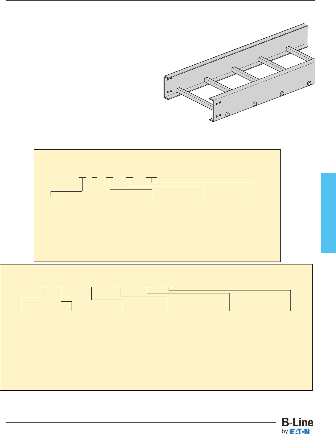
Fiberglass
To order a Fiberglass straight section of cable tray, select the
appropriate size and material from the charts below and place
those symbols in the sequence shown to form the complete
catalog number.
Procedure:
1. Select the correct B-Line series Fiberglass tray using the Load
Data for straight sections shown on page FCT-21 for 3
",
page
FCT-22 for 4
", page FCT-23 – FCT-25 for 6" and page
FCT-26 for 8" fittings
.
2. Select the resin required. Polyester, Vinyl Ester, or Zero
Halogen/Dis-Stat. Refer to Corrosion Guide on pages FCT-3
and FCT-4, for the effect of environmental conditions on the
desired material and the effective temperature range on page
FCT-5.
3. The tray prefix is completed by inserting the rung spacing.
4. Select the desired width in inches. Refer to How To Size Cable
Tray Section if width has to be computed based on number
and size of cables. See pages FCT-10 thru FCT-12.
5. Finally select the straight section length in inches.
Fiberglass 120 [10'] (3m) or 240 [20'] (6m)
Straight Section Part Numbering
Prefix
Example: 24 F 09 - 24 - 120
Note: One pair of splice plates with SS6 hardware included.
Series
13
24
36
46
H46
48
Width
6" (152)
9" (228)
12" (305)
18" (457)
24" (609)
30" (762)
36" (914)
Rung Spacing
6" (152)
9" (228)
12" (305)
*See page 355
for Marine Rung
option.
Material
F - Fiberglass (Gray)
Polyester Resin
FV - Fiberglass (Beige)
Vinyl Ester Resin
FA - Zero Halogen/
Dis-Stat (Black)
Length
120 [10 ft] (3m)
240 [20 ft] (6m)
Fitting Section Part Selector
Prefix
Example: 4F-24 - 90 HB 24
Height
3" (76)
4" (101)
6" (152)
8" (203)
Width
6" (152)
9" (228)
12" (305)
18" (457)
24" (609)
30" (762)
36" (914)
Radius
12" (305)
24" (609)
36" (914)
Angle
45˚
90˚
Type
HB - Horizontal Bend
HT - Horizontal Tee
HX - Horizontal Cross
VI - Vertical Inside Bend
VO - Vertical Outside Bend
VT - Vertical Tee
VTU - Vertical Tee, Up
RR - Right Reducer
LR - Left Reducer
SR - Straight Reducer
Material
F - Fiberglass (Gray)
Polyester Resin
FV - Fiberglass (Beige)
Vinyl Ester Resin
FA - Zero Halogen/
Dis-Stat (Black)
Notes: Standard rung spacing on fittings is 9" (225).
Splice plates with SS6 hardware included.
FCT-20
Fiberglass - Cable Tray Numbering System
Cable Tray Systems
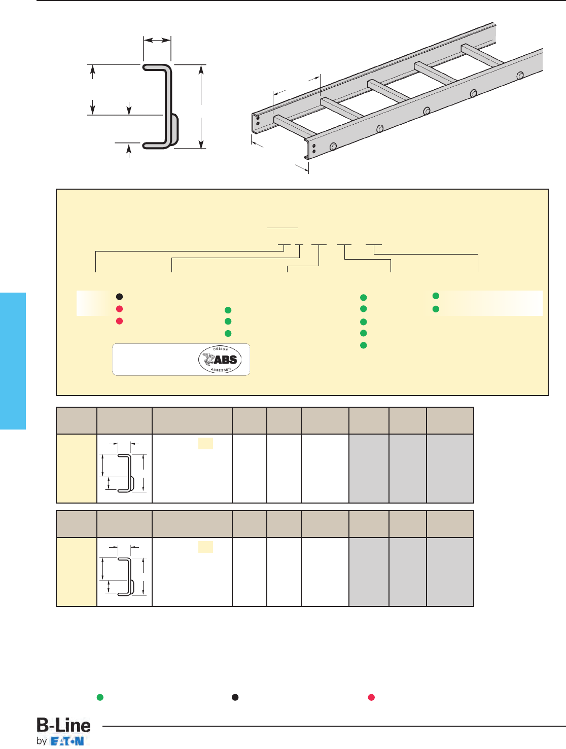
Fiberglass
When trays are used in continuous spans, the deflection of the tray is reduced by as much as 50%.
B-Line Side Rail NEMA & CSA Span Load Span Load
Series Dimensions Classifications ft lbs/ft meters kg/m
NEMA: 8C 6 178 1.8 264
8 100 2.4 149
10 64 3.0 95
12 44 3.7 65
1.00
NEMA
2” fill
1.00
13FA 3.00
B-Line Side Rail NEMA & CSA Span Load Deflection Span Load Deflection
Series Dimensions Classifications ft lbs/ft Multiplier meters kg/m Multiplier
NEMA: 8C 6 257 0.005 1.8 382 0.086
8 145 0.016 2.4 216 0.267
10 93 0.040 3.0 138 0.681
12 64 0.083 3.7 95 1.411
14 47 0.153 4.3 70 2.614
1.00
NEMA
2” fill
1.00
13F
13FV 3.00
Series 13 Fiberglass Straight Section Part Numbering
Prefix
Example: 13 F 09 - 24 - 120
Series Material Type Width Length
13 F= Polyester Ladder - 06 = 6" ¨120 = 10 ft. 13
FV = Vinyl Ester 06 = 6" rung spacing 09 = 9" ¡240 = 20 ft.
FA = Zero Halogen/ 09 = 9" rung spacing 12 = 12"
Dis-Stat 12 = 12" rung spacing 18 = 18"
24 = 24"
See page FCT-52 for additional rung options.
¨Primary Length.
¡Secondary Length.
See page CTS-23 for
explanation of lengths.
Overall Width
(Width + 7/8”)
For side rail data, see
charts on pages APP-8
Rung
Spacing
1" (25)
1" (25)
NEMA
2" Fill
3" (76)
One pair of splice plates with SS6
(316 Stainless Steel) hardware included
Values are based on simple beam tests per NEMA VFG-1 on 24" wide cable tray rungs spaced on 12" centers. Published load
safety factor is 1.5. To convert 1.5 safety factor to 2.0, multiply published load by 0.75. To obtain mid-span deflection, multiply a
load by the deflection multiplier. Cable tray must be supported on spans shorter than or equal to the length of the cable being
installed.
Green = Fastest shipped items Black = Normal lead-time items Red = Normally long lead-time items
Dimensions shown in parentheses are in millimeters, unless otherwise specified.
FA = Zero Halogen/
Dis-Stat is
FCT-21
Fiberglass - 3” Straight Section
Cable Tray Systems
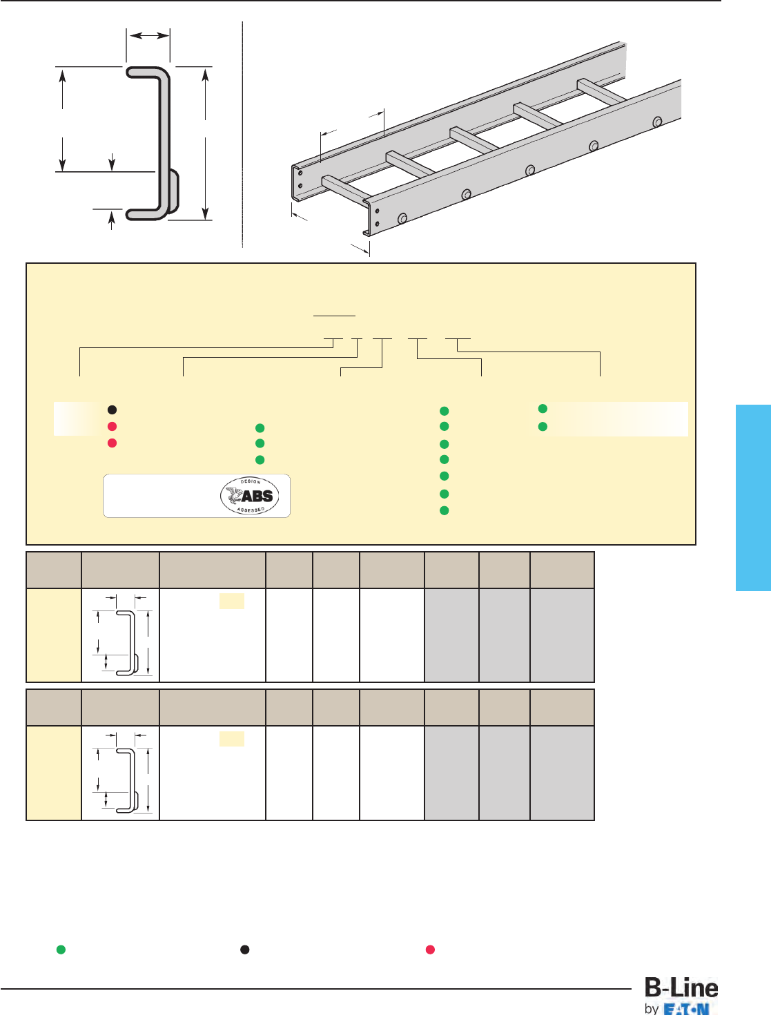
Fiberglass
11⁄8" (28)
1" (25)
NEMA
3"
4" (101)
Series 24 Fiberglass Straight Section Part Numbering
Prefix
Example: 24 F 09 - 24 - 120
Series Material Type Width Length
24 F= Polyester Ladder - 06 = 6" ¨120 = 10 ft. 24
FV = Vinyl Ester 06 = 6" rung spacing 09 = 9" ¡240 = 20 ft.
FA = Zero Halogen/ 09 = 9" rung spacing 12 = 12"
Dis-Stat 12 = 12" rung spacing 18 = 18"
24 = 24"
30 = 30"
36 = 36"
See page FCT-52 for additional rung options.
¨Primary Length.
¡Secondary Length.
See page CTS-23 for
explanation of lengths.
One pair of splice plates with SS6
(316 Stainless Steel) hardware included
When trays are used in continuous spans, the deflection of the tray is reduced by as much as 50%.
Values are based on simple beam tests per NEMA VFG-1 on 36" wide cable tray rungs spaced on 12" centers. Published load
safety factor is 1.5. To convert 1.5 safety factor to 2.0, multiply published load by 0.75. To obtain mid-span deflection, multiply a
load by the deflection multiplier. Cable tray must be supported on spans shorter than or equal to the length of the cable being
installed.
B-Line Side Rail NEMA & CSA Span Load Span Load
Series Dimensions Classifications ft lbs/ft meters kg/m
NEMA: 12C 6 400 1.8 595
CSA: E-3m 8 226 2.4 336
10 144 3.0 214
12 100 3.7 149
24FA
1.00
4.00
1.125
NEMA
3” fill
B-Line Side Rail NEMA & CSA Span Load Deflection Span Load Deflection
Series Dimensions Classifications ft lbs/ft Multiplier meters kg/m Multiplier
NEMA: 12C 6 627 0.001 1.8 933 0.023
CSA: E-3m 8 353 0.004 2.4 525 0.074
10 226 0.011 3.0 336 0.182
12 157 0.022 3.7 233 0.378
24F
24FV
1.00
4.00
1.125
NEMA
3” fill
Overall Width
(Width + 7/8”)
Rung
Spacing
Green = Fastest shipped items Black = Normal lead-time items Red = Normally long lead-time items
FCT-22
Fiberglass - 4” Straight Section
Cable Tray Systems
Dimensions shown in parentheses are in millimeters, unless otherwise specified.
For side rail data, see
charts on pages APP-8
FA = Zero Halogen/
Dis-Stat is
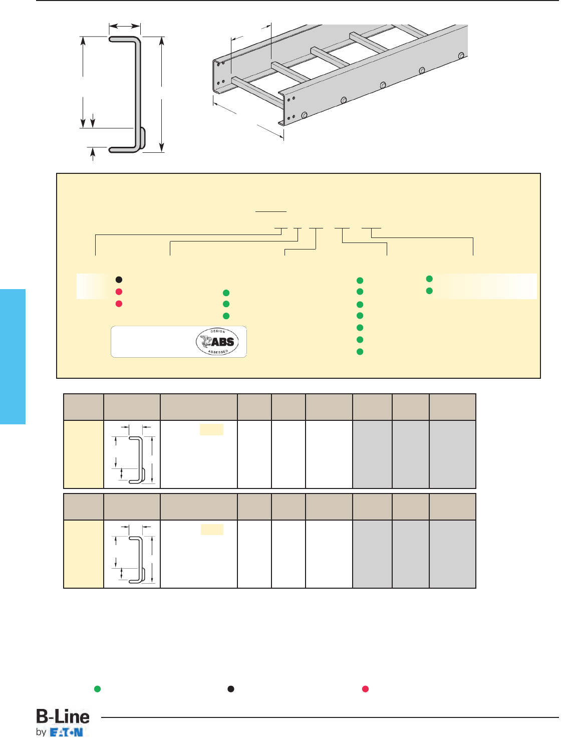
Fiberglass
1" (25)
NEMA
5" fill
15⁄8" (41)
6" (152)
Series 36 Fiberglass Straight Section Part Numbering
Prefix
Example: 36 F 09 - 24 - 120
Series Material Type Width Length
36 F= Polyester Ladder - 06 = 6" ¨120 = 10 ft. 36
FV = Vinyl Ester 06 = 6" rung spacing 09 = 9" ¡240 = 20 ft.
FA = Zero Halogen/ 09 = 9" rung spacing 12 = 12"
Dis-Stat 12 = 12" rung spacing 18 = 18"
24 = 24"
30 = 30"
36 = 36"
See page FCT-52 for additional rung options.
See page CTS-23 for
explanation of lengths.
One pair of splice plates with SS6
(316 Stainless Steel) hardware included
¨Primary Length.
¡Secondary Length.
When trays are used in continuous spans, the deflection of the tray is reduced by as much as 50%.
Values are based on simple beam tests per NEMA VFG-1 on 36" wide cable tray rungs spaced on 12" centers. Published load
safety factor is 1.5. To convert 1.5 safety factor to 2.0, multiply published load by 0.75. To obtain mid-span deflection, multiply a
load by the deflection multiplier. Cable tray must be supported on spans shorter than or equal to the length of the cable being
installed.
B-Line Side Rail NEMA & CSA Span Load Span Load
Series Dimensions Classifications ft lbs/ft meters kg/m
NEMA: 20B 12 208 3.7 309
CSA: E-6m 14 153 4.3 227
16 117 4.9 174
18 93 5.5 138
20 75 6.1 111
36FA
1.00
6.00
1.625
NEMA
5” fill
B-Line Side Rail NEMA & CSA Span Load Deflection Span Load Deflection
Series Dimensions Classifications ft lbs/ft Multiplier meters kg/m Multiplier
NEMA: 20B 12 246 0.006 3.7 367 0.104
CSA: E-6m 14 181 0.011 4.3 269 0.193
16 139 0.019 4.9 206 0.330
18 109 0.031 5.5 163 0.528
20 89 0.047 6.1 132 0.811
36F
36FV
1.00
6.00
1.625
NEMA
5” fill
Overall Width
(Width + 7/8”)
Rung
Spacing
Green = Fastest shipped items Black = Normal lead-time items Red = Normally long lead-time items
Dimensions shown in parentheses are in millimeters, unless otherwise specified.
FCT-23
Fiberglass - 6” Straight Section
Cable Tray Systems
For side rail data, see
charts on pages APP-8
FA = Zero Halogen/
Dis-Stat is
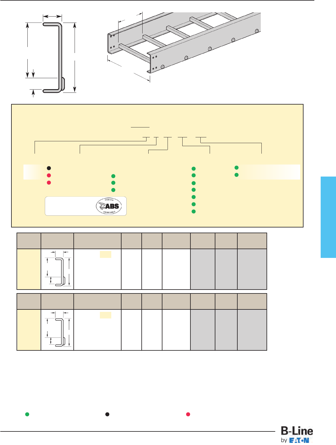
B-Line Side Rail NEMA & CSA Span Load Deflection Span Load Deflection
Series Dimensions Classifications ft lbs/ft Multiplier meters kg/m Multiplier
NEMA: 20C+ 12 393 0.005 3.7 584 0.079
CSA: E-6m 14 288 0.009 4.3 429 0.145
16 221 0.015 4.9 329 0.246
18 174 0.023 5.5 260 0.396
20 141 0.035 6.1 210 0.605
1.00
46F
46FV 6.00
1.625
NEMA
5” fill
B-Line Side Rail NEMA & CSA Span Load Span Load
Series Dimensions Classifications ft lbs/ft meters kg/m
NEMA: 20C+ 12 278 3.7 413
CSA: E-6m 14 204 4.3 303
16 156 4.9 232
18 123 5.5 183
20 100 6.1 149
1.00
46FA 6.00
1.625
NEMA
5” fill
Series 46 Fiberglass Straight Section Part Numbering
Prefix
Example: 46 F 09 - 24 - 120
Series Material Type Width Length
46 F= Polyester Ladder - 06 = 6" ¨120 = 10 ft. 46
FV = Vinyl Ester 06 = 6" rung spacing 09 = 9" ¡240 = 20 ft.
FA = Zero Halogen/ 09 = 9" rung spacing 12 = 12"
Dis-Stat 12 = 12" rung spacing 18 = 18"
24 = 24"
30 = 30"
36 = 36"
See page FCT-52 for additional rung options.
See page CTS-23 for
explanation of lengths.
¨Primary Length.
¡Secondary Length.
When trays are used in continuous spans, the deflection of the tray is reduced by as much as 50%.
Values are based on simple beam tests per NEMA VFG-1 on 36" wide cable tray rungs spaced on 12" centers. Published load
safety factor is 1.5. To convert 1.5 safety factor to 2.0, multiply published load by 0.75. To obtain mid-span deflection, multiply a
load by the deflection multiplier. Cable tray must be supported on spans shorter than or equal to the length of the cable being
installed.
Fiberglass
1" (25)
NEMA
5" fill
15⁄8" (41)
6" (152)
One pair of splice plates with SS6
(316 Stainless Steel) hardware included
Overall Width
(Width + 1”)
Rung
Spacing
Green = Fastest shipped items Black = Normal lead-time items Red = Normally long lead-time items
FCT-24
Fiberglass - 6” Straight Section
Cable Tray Systems
Dimensions shown in parentheses are in millimeters, unless otherwise specified.
For side rail data, see
charts on pages APP-8
FA = Zero Halogen/
Dis-Stat is

Fiberglass
1" (25)
NEMA
5" fill
15⁄8" (41)
6" (152)
Series H46 Fiberglass Straight Section Part Numbering
Prefix
Example: H46 F 09 - 24 - 120
Series Material Type Width Length
H46 F= Polyester Ladder - 06 = 6" ¨120 = 10 ft. H46
FV = Vinyl Ester 06 = 6" rung spacing 09 = 9" ¡240 = 20 ft.
FA = Zero Halogen/ 09 = 9" rung spacing 12 = 12"
Dis-Stat 12 = 12" rung spacing 18 = 18"
24 = 24"
30 = 30"
36 = 36"
See page FCT-52 for additional rung options.
See page CTS-23 for
explanation of lengths.
One pair of splice plates with SS6
(316 Stainless Steel) hardware included
¨Primary Length.
¡Secondary Length.
When trays are used in continuous spans, the deflection of the tray is reduced by as much as 50%.
Values are based on simple beam tests per NEMA VFG-1 on 36" wide cable tray rungs spaced on 12" centers. Published load
safety factor is 1.5. To convert 1.5 safety factor to 2.0, multiply published load by 0.75. To obtain mid-span deflection, multiply a
load by the deflection multiplier. Cable tray must be supported on spans shorter than or equal to the length of the cable being
installed.
B-Line Side Rail NEMA & CSA Span Load Span Load
Series Dimensions Classifications ft lbs/ft meters kg/m
NEMA: 20C+ 12 306 3.7 455
CSA: E-6m 14 224 4.3 333
16 172 4.9 245
18 136 5.5 202
20 110 6.1 163
H46FA
1.00
6.00
1.625
NEMA
5” fill
B-Line Side Rail NEMA & CSA Span Load Deflection Span Load Deflection
Series Dimensions Classifications ft lbs/ft Multiplier meters kg/m Multiplier
NEMA: 20C+ 12 424 0.005 3.7 631 0.079
CSA: E-6m 14 312 0.009 4.3 464 0.144
16 239 0.015 4.9 355 0.248
18 188 0.023 5.5 280 0.396
20 153 0.035 6.1 227 0.608
H46F
H46FV
1.00
6.00
1.625
NEMA
5” fill
Overall Width
(Width + 1”)
Rung
Spacing
Green = Fastest shipped items Black = Normal lead-time items Red = Normally long lead-time items
Dimensions shown in parentheses are in millimeters, unless otherwise specified.
FCT-25
Fiberglass - 6” Straight Section
Cable Tray Systems
For side rail data, see
charts on pages APP-8
FA = Zero Halogen/
Dis-Stat is
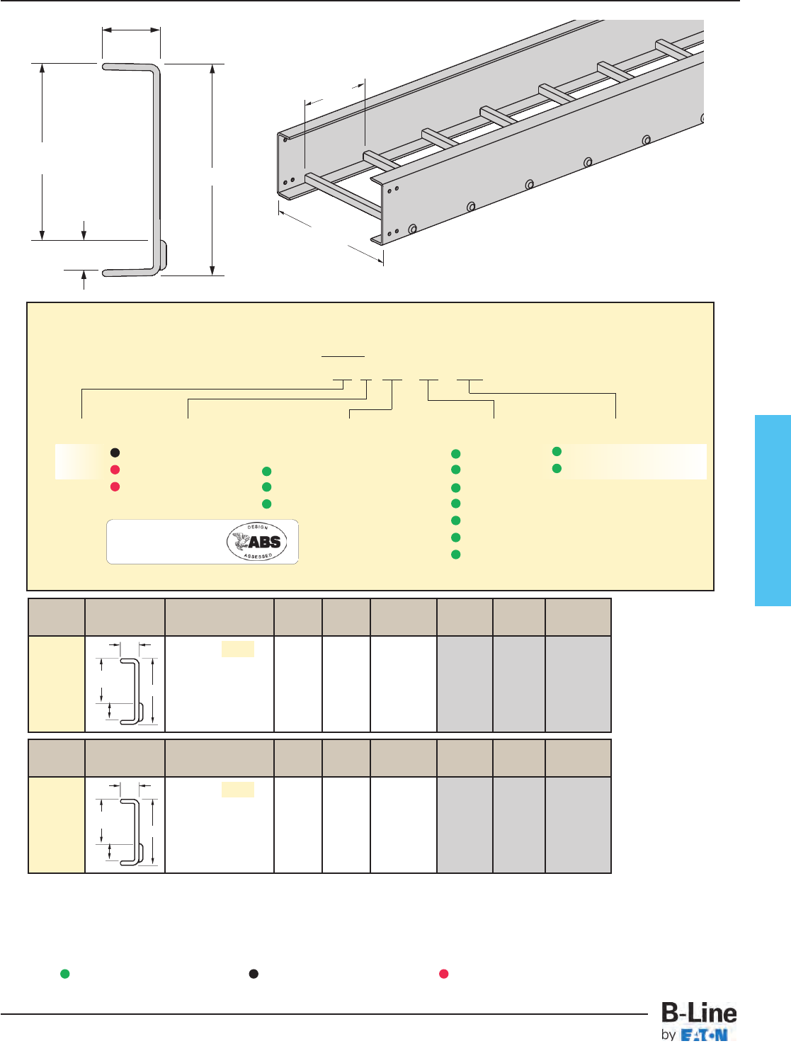
Fiberglass
23/16" (55)
1" (25)
NEMA
7" fill
8" (203)
When trays are used in continuous spans, the deflection of the tray is reduced by as much as 50%.
Series 48 Fiberglass Straight Section Part Numbering
Prefix
Example: 48 F 09 - 24 - 120
Series Material Type Width Length
48 F= Polyester Ladder - 06 = 6" ¨120 = 10 ft. 48
FV = Vinyl Ester 06 = 6" rung spacing 09 = 9" ¡240 = 20 ft.
FA = Zero Halogen 09 = 9" rung spacing 12 = 12"
Dis-Stat 12 = 12" rung spacing 18 = 18"
24 = 24"
30 = 30"
36 = 36"
See page FCT-52 for additional rung options.
¨Primary Length.
¡Secondary Length.
See page CTS-23 for
explanation of lengths.
One pair of splice plates with SS6
(316 Stainless Steel) hardware included
B-Line Side Rail NEMA & CSA Span Load Span Load
Series Dimensions Classifications ft lbs/ft meters kg/m
NEMA: 20C+ 12 278 3.7 413
14 204 4.3 303
16 156 4.9 232
18 123 5.5 183
20 100 6.1 149
48FA
Values are based on simple beam tests per NEMA VFG-1 on 36" wide cable tray rungs spaced on 12" centers. Published load safety
factor is 1.5. To convert 1.5 safety factor to 2.0, multiply published load by 0.75. To obtain mid-span deflection, multiply a load by
the deflection multiplier. Cable tray must be supported on spans shorter than or equal to the length of the cable being installed.
1.00
8.00
2.188
NEMA
7” fill
B-Line Side Rail NEMA & CSA Span Load Deflection Span Load Deflection
Series Dimensions Classifications ft lbs/ft Multiplier meters kg/m Multiplier
NEMA: 20C+ 12 348 0.003 3.7 518 0.052
14 256 0.006 4.3 381 0.097
16 196 0.010 4.9 291 0.165
18 155 0.015 5.5 231 0.210
20 125 0.024 6.1 187 0.401
48F
48FV
1.00
8.00
2.188
NEMA
7” fill
Overall Width
(Width + 7/8”)
Rung
Spacing
Green = Fastest shipped items Black = Normal lead-time items Red = Normally long lead-time items
FCT-26
Fiberglass - 8” Straight Section
Cable Tray Systems
Dimensions shown in parentheses are in millimeters, unless otherwise specified.
For side rail data, see
charts on pages APP-8
FA = Zero Halogen/
Dis-Stat is
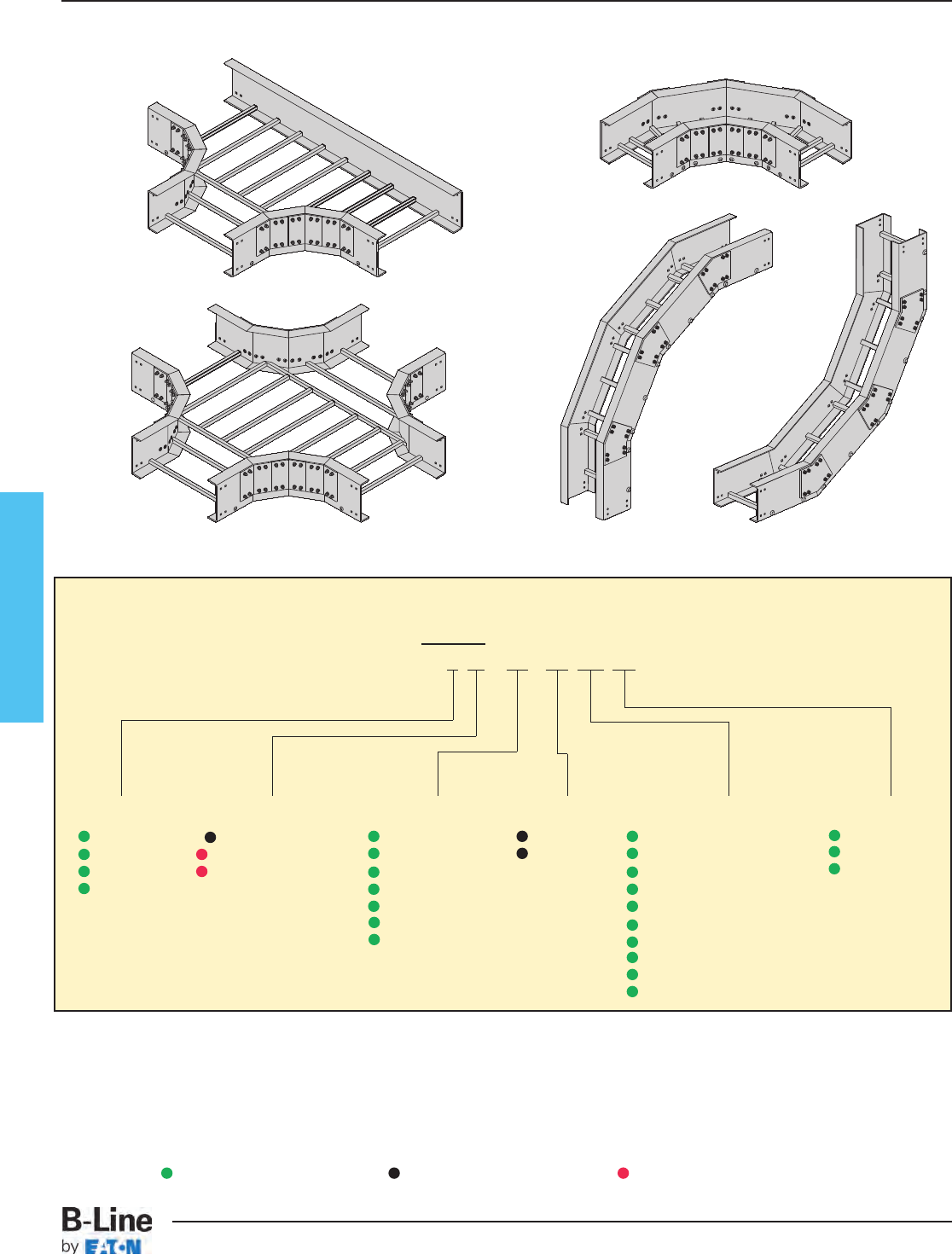
Fiberglass
Fiberglass Fittings Part Numbering
Prefix
Example: 4 F - 12 - 90 HB 12
Height
3= 3” **
4= 4”
6= 6”
8= 8”
Material
F= Polyester
FV = Vinyl Ester
FA = Zero Halogen
Dis-Stat
Width
06 = 6" (152)
09 = 9" (228)
12 = 12" (305)
18 = 18" (457)
24 = 24" (609)
30 = 30" (762)
36 = 36" (914)
Angle
45 = 45°
90 = 90°
Radius
12 = 12" (305)
24 = 24" (609)
36 = 36" (914)
Type
HB
= Horizontal Bend
HT
= Horizontal Tee
HX
= Horizontal Cross
VI
= Vertical Inside Bend
VO
= Vertical Outside Bend
LR
= Left Reducer
RR
= Right Reducer
SR
= Straight Reducer
VT
= Vertical Tee Down
VTU
= Vertical Tee Up
(9" rung spacing is standard)
** 3” deep fittings are only available in
6” thru 24” widths and 12” radius only.
Green = Fastest shipped items Black = Normal lead-time items Red = Normally long lead-time items
FCT-27
Fiberglass - Fitting Numbering System
Cable Tray Systems
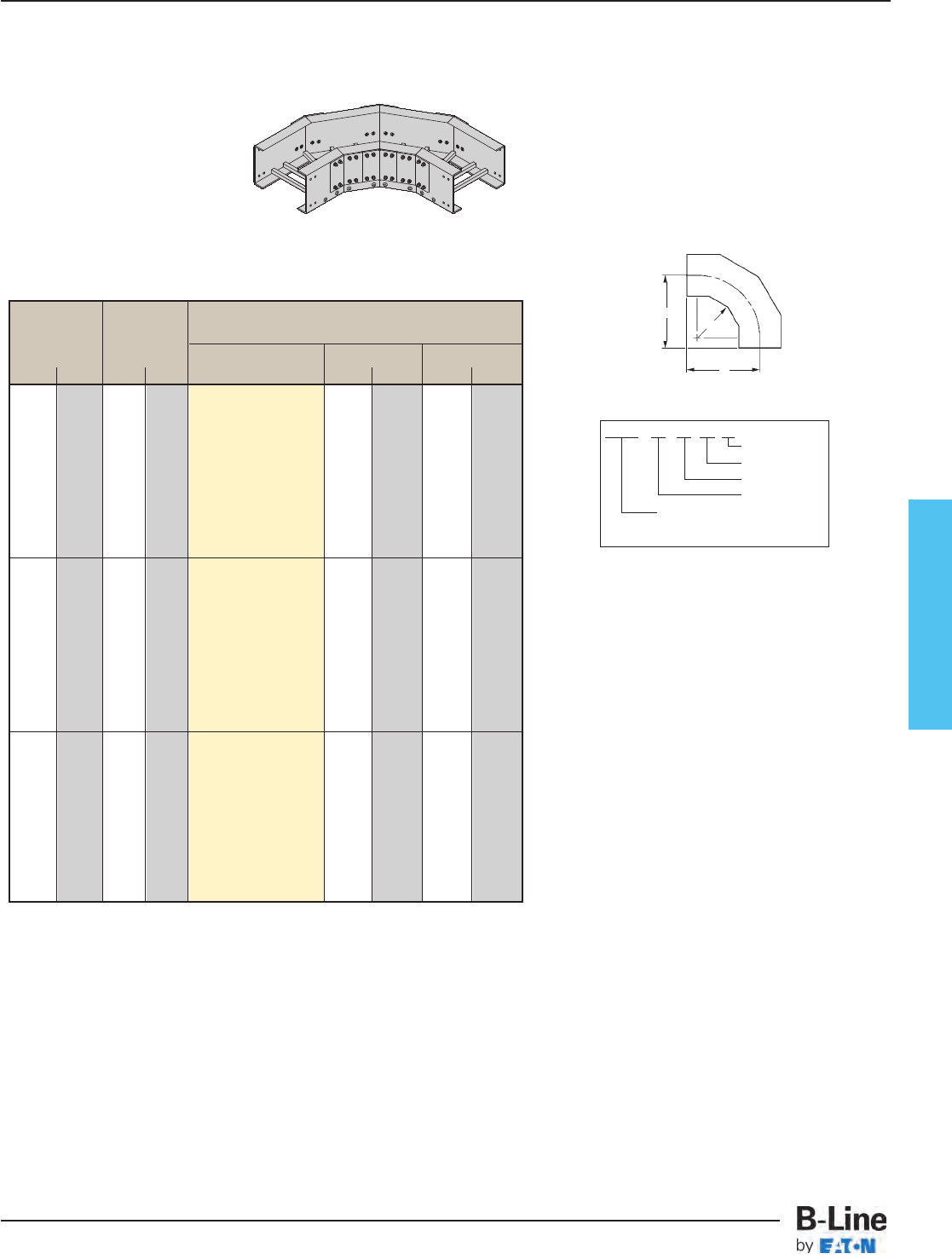
Fiberglass
Horizontal Bend
90° (HB)
- R - 90˚ Horizontal Bend - Mitered
Bend Tray Dimensions
Radius Width Catalog No. AB
in. mm in. mm in. mm in. mm
6 152 (Prefix)-06-90HB12 203⁄8517 203⁄8517
9 228 (Prefix)-09-90HB12 217⁄8555 217⁄8555
12 305 (Prefix)-12-90HB12 223⁄4578 223⁄4578
12 305 18 457 (Prefix)-18-90HB12 265⁄16 668 265⁄16 668
24 609 (Prefix)-24-90HB12 293⁄8746 293⁄8746
30 762 (Prefix)-30-90HB12 323⁄8822 323⁄8822
36 914 (Prefix)-36-90HB12 353⁄8898 353⁄8898
6 152 (Prefix)-06-90HB24 321⁄2826 321⁄2826
9 228 (Prefix)-09-90HB24 34 864 34 864
12 305 (Prefix)-12-90HB24 351⁄2902 351⁄2902
24 609 18 457 (Prefix)-18-90HB24 381⁄2978 381⁄2978
24 609 (Prefix)-24-90HB24 411⁄21054 411⁄21054
30 762 (Prefix)-30-90HB24 441⁄21130 441⁄21130
36 914 (Prefix)-36-90HB24 471⁄21207 471⁄21207
6 152 (Prefix)-06-90HB36 445⁄81133 445⁄81133
9 228 (Prefix)-09-90HB36 461⁄81171 461⁄81171
12 305 (Prefix)-12-90HB36 475⁄81209 475⁄81209
36 914 18 457 (Prefix)-18-90HB36 505⁄81286 505⁄81286
24 609 (Prefix)-24-90HB36 535⁄81362 535⁄81362
30 762 (Prefix)-30-90HB36 565⁄81438 565⁄81438
36 914 (Prefix)-36-90HB36 595⁄81514 595⁄81514
A
B
R
90˚ Mitered
One pair of splice plates with SS6 hardware included.
Dimensions for reference only, when critical contact factory.
(Prefix) See page FCT-27 for catalog number prefix.
(Tray Widths - 6” thru 24” • Radius 12” only)
Polyester, Vinyl Ester, Zero Halogen/Dis-Stat
All are mitered
For 3” Fittings
(Tray Widths - 6” thru 36” • Radius 12”, 24” & 36”)
Polyester, Vinyl Ester, Zero Halogen/Dis-Stat
All radius are mitered
For 4” Fittings
(Tray Widths - 6” thru 36” • Radius 12”, 24” & 36”)
Polyester, Vinyl Ester, Zero Halogen/Dis-Stat
All radius are mitered
For 6” Fittings
(Tray Widths - 6” thru 36” • Radius 12”, 24” & 36”)
Polyester, Vinyl Ester, Zero Halogen/Dis-Stat
All radius are mitered
For 8” Fittings
Prefix - 06 - 90 HB 12
Radius
Fitting
Angle
Width
To complete catalog
number, insert fitting prefix.
FCT-28
Fiberglass - Fittings
Cable Tray Systems
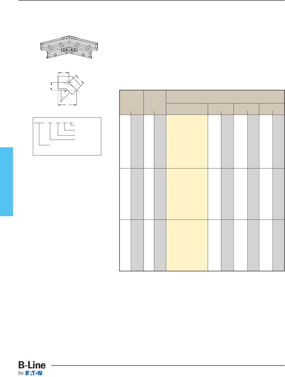
Fiberglass
Horizontal Bend 45°
(HB)
B
C
C
R
A
45˚ Mitered
Dimensions for reference only, when critical
contact factory.
(Prefix) See page FCT-27 for catalog number prefix.
Prefix - 06 - 45 HB 12
Radius
Fitting
Angle
Width
To complete catalog
number, insert fitting prefix.
(Tray Widths - 6” thru 24” • Radius 12” only)
Polyester, Vinyl Ester, Zero Halogen/Dis-Stat
All are mitered
For 3” Fittings
(Tray Widths - 6” thru 36”
Radius 12”, 24” & 36”)
Polyester, Vinyl Ester, Zero Halogen/Dis-Stat
All radius are mitered
For 4” Fittings
(Tray Widths - 6” thru 36”
Radius 12”, 24” & 36”)
Polyester, Vinyl Ester, Zero Halogen/Dis-Stat
All radius are mitered
For 6” Fittings
(Tray Widths - 6” thru 36”
Radius 12”, 24” & 36”)
Polyester, Vinyl Ester, Zero Halogen/Dis-Stat
All radius are mitered
For 8” Fittings
One pair of splice plates with SS6 hardware included.
- R - 45˚ Horizontal Bend - Mitered
Bend Tray Dimensions
Radius Width Catalog No. AB C
in. mm in mm in. mm in. mm in. mm
6 152 (Prefix)-06-45HB12 2213⁄16 579 97⁄16 240 133⁄8340
9 228 (Prefix)-09-45HB12 237⁄8606 97⁄8251 14 355
12 305 (Prefix)-12-45HB12 247⁄8632 105⁄16 262 145⁄8371
12 305 18 457 (Prefix)-18-45HB12 27 686 113⁄16 284 157⁄8403
24 609 (Prefix)-24-45HB12 291⁄8740 121⁄16 306 171⁄16 433
30 762 (Prefix)-30-45HB12 311⁄4794 1215⁄16 328 185⁄16 465
36 914 (Prefix)-36-45HB12 333⁄8 848 1313⁄16 351 199⁄16 497
6 152 (Prefix)-06-45HB12 2213⁄16 579 97⁄16 240 133⁄8340
9 228 (Prefix)-09-45HB12 237⁄8606 97⁄8251 14 355
12 305 (Prefix)-12-45HB12 247⁄8632 105⁄16 262 145⁄8371
24 609 18 457 (Prefix)-18-45HB12 27 686 113⁄16 284 157⁄8403
24 609 (Prefix)-24-45HB12 291⁄8740 121⁄16 306 171⁄16 433
30 762 (Prefix)-30-45HB12 311⁄4794 1215⁄16 328 185⁄16 465
36 914 (Prefix)-36-45HB12 333⁄8 848 1313⁄16 351 199⁄16 497
6 152 (Prefix)-06-45HB12 2213⁄16 579 97⁄16 240 133⁄8340
9 228 (Prefix)-09-45HB12 237⁄8606 97⁄8251 14 355
12 305 (Prefix)-12-45HB12 247⁄8632 105⁄16 262 145⁄8371
36 014 18 457 (Prefix)-18-45HB12 27 686 113⁄16 284 157⁄8403
24 609 (Prefix)-24-45HB12 291⁄8740 121⁄16 306 171⁄16 433
30 762 (Prefix)-30-45HB12 311⁄4794 1215⁄16 328 185⁄16 465
36 914 (Prefix)-36-45HB12 333⁄8 848 1313⁄16 351 199⁄16 497
FCT-29
Fiberglass - Fittings
Cable Tray Systems
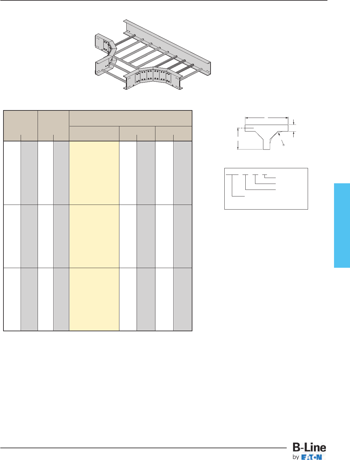
Fiberglass
Horizontal Tee
(HT)
- R - Horizontal Tee - Mitered
Bend Tray Dimensions
Radius Width Catalog No. AB
in. mm in. mm in. mm in. mm
6 152 (Prefix)-06-HT12 191⁄4489 38 965
9 228 (Prefix)-09-HT12 203⁄4527 41 1041
12 305 (Prefix)-12-HT12 221⁄4565 44 1117
12 305 18 457 (Prefix)-18-HT12 251⁄4641 50 1270
24 609 (Prefix)-24-HT12 281⁄4717 56 1422
30 762 (Prefix)-30-HT12 311⁄4794 62 1575
36 914 (Prefix)-36-HT12 341⁄4870 68 1727
6 152 (Prefix)-06-HT24 311⁄4794 621⁄41581
9 228 (Prefix)-09-HT24 323⁄4832 651⁄41657
12 305 (Prefix)-12-HT24 341⁄4870 681⁄41734
24 609 18 457 (Prefix)-18-HT24 371⁄4946 741⁄41886
24 609 (Prefix)-24-HT24 401⁄41022 801⁄42038
30 762 (Prefix)-30-HT24 431⁄41098 861⁄42191
36 914 (Prefix)-36-HT24 461⁄41175 921⁄42343
6 152 (Prefix)-06-HT36 431⁄41098 861⁄22191
9 228 (Prefix)-09-HT36 443⁄41136 891⁄22273
12 305 (Prefix)-12-HT36 461⁄41175 921⁄22343
36 914 18 457 (Prefix)-18-HT36 491⁄41251 981⁄22502
24 609 (Prefix)-24-HT36 521⁄41327 1041⁄22654
30 762 (Prefix)-30-HT36 551⁄41403 1101⁄22807
36 914 (Prefix)-36-HT36 581⁄41479 1161⁄22959
(Tray Widths - 6” thru 24” • Radius 12” only)
Polyester, Vinyl Ester, Zero Halogen/Dis-Stat
All are mitered
For 3” Fittings
(Tray Widths - 6” thru 36” • Radius 12”, 24” & 36”)
Polyester, Vinyl Ester, Zero Halogen/Dis-Stat
All radius are mitered
For 4” Fittings
(Tray Widths - 6” thru 36” • Radius 12”, 24” & 36”)
Polyester, Vinyl Ester, Zero Halogen/Dis-Stat
All radius are mitered
For 6” Fittings
(Tray Widths - 6” thru 36” • Radius 12”, 24” & 36”)
Polyester, Vinyl Ester, Zero Halogen/Dis-Stat
All radius are mitered
For 8” Fittings
R
W
B
A
Mitered Tee
Two pair of splice plates with SS6 hardware included.
Dimensions for reference only, when critical contact factory.
(Prefix) See page FCT-27 for catalog number prefix.
Prefix - 06 - HT 12
Radius
Fitting
Width
To complete catalog
number, insert fitting prefix.
FCT-30
Fiberglass - Fittings
Cable Tray Systems
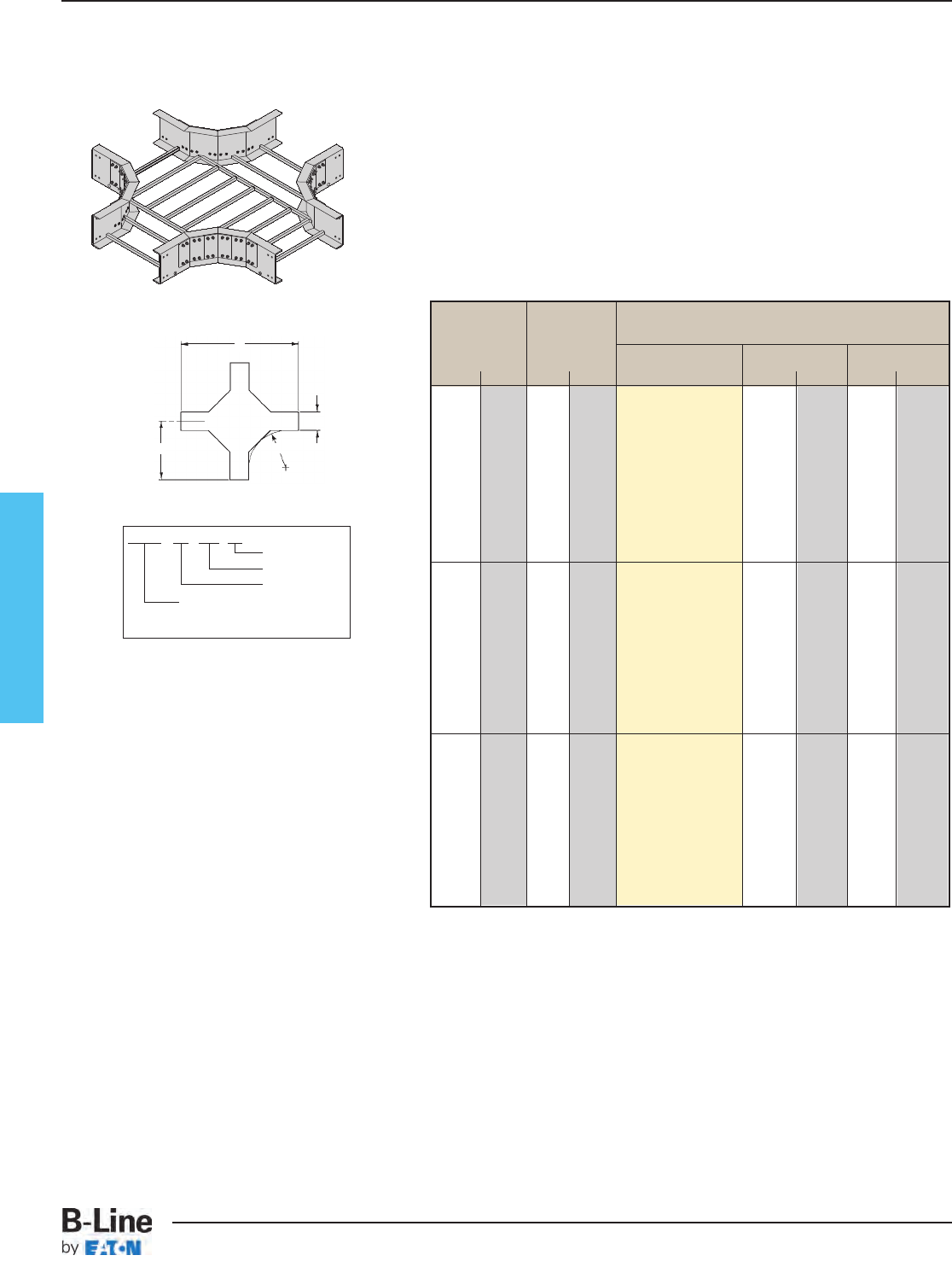
Fiberglass
Horizontal Cross (HX)
(Tray Widths - 6” thru 24” • Radius 12” only)
Polyester, Vinyl Ester, Zero Halogen/Dis-Stat
All are mitered
For 3” Fittings
(Tray Widths - 6” thru 36”
Radius 12”, 24” & 36”)
Polyester, Vinyl Ester, Zero Halogen/Dis-Stat
All radius are mitered
For 4” Fittings
(Tray Widths - 6” thru 36”
Radius 12”, 24” & 36”)
Polyester, Vinyl Ester, Zero Halogen/Dis-Stat
All radius are mitered
For 6” Fittings
(Tray Widths - 6” thru 36”
Radius 12”, 24” & 36”)
Polyester, Vinyl Ester, Zero Halogen/Dis-Stat
All radius are mitered
For 8” Fittings
Three pair of splice plates with SS6 hardware included.
R
W
B
A
Mitered Cross
Dimensions for reference only, when critical contact factory.
(Prefix) See page FCT-27 for catalog number prefix.
Prefix - 06 - HX 12
Radius
Fitting
Width
To complete catalog
number, insert fitting prefix.
- R - Horizontal Cross - Mitered
Bend Tray Dimensions
Radius Width Catalog No. AB
in. mm in. mm in. mm in. mm
6 152 (Prefix)-06-HX12 191⁄4489 38 965
9 228 (Prefix)-09-HX12 203⁄4527 41 1041
12 305 (Prefix)-12-HX12 221⁄4565 44 1117
12 305 18 457 (Prefix)-18-HX12 251⁄4641 50 1270
24 609 (Prefix)-24-HX12 281⁄4717 56 1422
30 762 (Prefix)-30-HX12 311⁄4794 62 1575
36 914 (Prefix)-36-HX12 341⁄4870 68 1727
6 152 (Prefix)-06-HX24 311⁄4794 621⁄41581
9 228 (Prefix)-09-HX24 323⁄4832 651⁄41657
12 305 (Prefix)-12-HX24 341⁄4870 681⁄41734
24 609 18 457 (Prefix)-18-HX24 371⁄4946 741⁄41886
24 609 (Prefix)-24-HX24 401⁄41022 801⁄42038
30 762 (Prefix)-30-HX24 431⁄41098 861⁄42191
36 914 (Prefix)-36-HX24 461⁄41175 921⁄42343
6 152 (Prefix)-06-HX36 431⁄41098 861⁄22191
9 228 (Prefix)-09-HX36 443⁄41136 891⁄22273
12 305 (Prefix)-12-HX36 461⁄41175 921⁄22343
36 914 18 457 (Prefix)-18-HX36 491⁄41251 981⁄22502
24 609 (Prefix)-24-HX36 521⁄41327 1041⁄22654
30 762 (Prefix)-30-HX36 551⁄41403 1101⁄22807
36 914 (Prefix)-36-HX36 581⁄41479 1161⁄22959
FCT-31
Fiberglass - Fittings
Cable Tray Systems
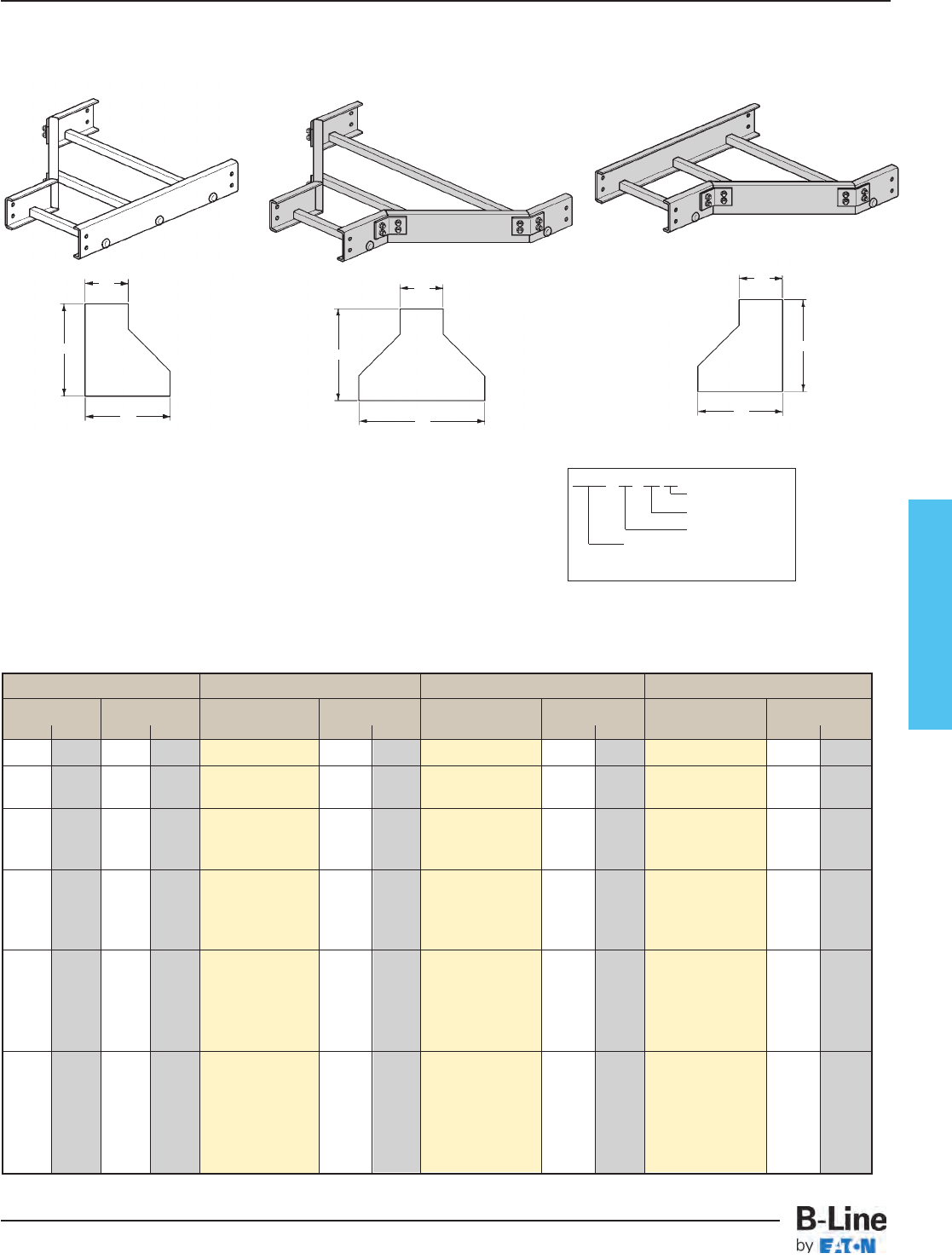
Fiberglass
Prefix - 12 - SR 09
Width2W2
Fitting
Width1W1
To complete catalog
number, insert fitting prefix.
Tray Width Left Hand Reducer Straight Reducer Right Hand Reducer
W1W2Catalog No. ACatalog No. ACatalog No. A
in. mm in. mm in. mm in. mm in. mm
9 228 6 152 (Prefix)-09-LR06 171⁄2444 (Prefix)-09-SR06 16 406 (Prefix)-09-RR06 171⁄2444
12 305 6 152 (Prefix)-12-LR06 201⁄2521 (Prefix)-12-SR06 171⁄2444 (Prefix)-12-RR06 201⁄2521
9 228 (Prefix)-12-LR09 171⁄2444 (Prefix)-12-SR09 16 406 (Prefix)-12-RR09 171⁄2444
6 152 (Prefix)-18-LR06 261⁄2673 (Prefix)-18-SR06 201⁄2521 (Prefix)-18-RR06 261⁄2673
18 457 9 228 (Prefix)-18-LR09 231⁄2597 (Prefix)-18-SR09 19 482 (Prefix)-18-RR09 231⁄2597
12 305 (Prefix)-18-LR12 201⁄2521 (Prefix)-18-SR12 171⁄2444 (Prefix)-18-RR12 201⁄2521
6 152 (Prefix)-24-LR06 321⁄2825 (Prefix)-24-SR06 231⁄2597 (Prefix)-24-RR06 321⁄2825
24 609 9 228 (Prefix)-24-LR09 291⁄2749 (Prefix)-24-SR09 22 559 (Prefix)-24-RR09 291⁄2749
12 305 (Prefix)-24-LR12 261⁄2673 (Prefix)-24-SR12 201⁄2521 (Prefix)-24-RR12 261⁄2673
18 457 (Prefix)-24-LR18 201⁄2521 (Prefix)-24-SR18 171⁄2444 (Prefix)-24-RR18 201⁄2521
6 152 (Prefix)-30-LR06 381⁄2978 (Prefix)-30-SR06 261⁄2673 (Prefix)-30-RR06 381⁄2978
9 228 (Prefix)-30-LR09 351⁄2902 (Prefix)-30-SR09 25 635 (Prefix)-30-RR09 351⁄2902
30 762 12 305 (Prefix)-30-LR12 321⁄2825 (Prefix)-30-SR12 231⁄2597 (Prefix)-30-RR12 321⁄2825
18 457 (Prefix)-30-LR18 261⁄2673 (Prefix)-30-SR18 201⁄2521 (Prefix)-30-RR18 261⁄2673
24 609 (Prefix)-30-LR24 201⁄2521 (Prefix)-30-SR24 171⁄2444 (Prefix)-30-RR24 201⁄2521
6 152 (Prefix)-36-LR06 441⁄21130 (Prefix)-36-SR06 291⁄2749 (Prefix)-36-RR06 441⁄21130
9 228 (Prefix)-36-LR09 411⁄21054 (Prefix)-36-SR09 28 711 (Prefix)-36-RR09 411⁄21054
36 914 12 305 (Prefix)-36-LR12 381⁄2978 (Prefix)-36-SR12 261⁄2673 (Prefix)-36-RR12 381⁄2978
18 457 (Prefix)-36-LR18 321⁄2825 (Prefix)-36-SR18 231⁄2597 (Prefix)-36-RR18 321⁄2825
24 609 (Prefix)-36-LR24 261⁄2673 (Prefix)-36-SR24 201⁄2521 (Prefix)-36-RR24 261⁄2673
30 762 (Prefix)-36-LR30 201⁄2521 (Prefix)-36-SR30 171⁄2444 (Prefix)-36-RR30 201⁄2521
W2
W1
A
W2
W1
A
W2
W1
A
Left Reducer Straight Reducer Right Reducer
Reducers are all of mitered construction.
One pair of splice plates with SS6
hardware included.
Dimensions for reference only, when critical contact factory.
(Prefix) See page FCT-27 for catalog number prefix.
Reducers (LR) (SR) (RR)
3” Fittings
(Only available in W1widths of 9”, 12”, 18” & 24”)
4”, 6” & 8” Fittings
(Available in all W1widths shown in chart)
FCT-32
Fiberglass - Fittings
Cable Tray Systems
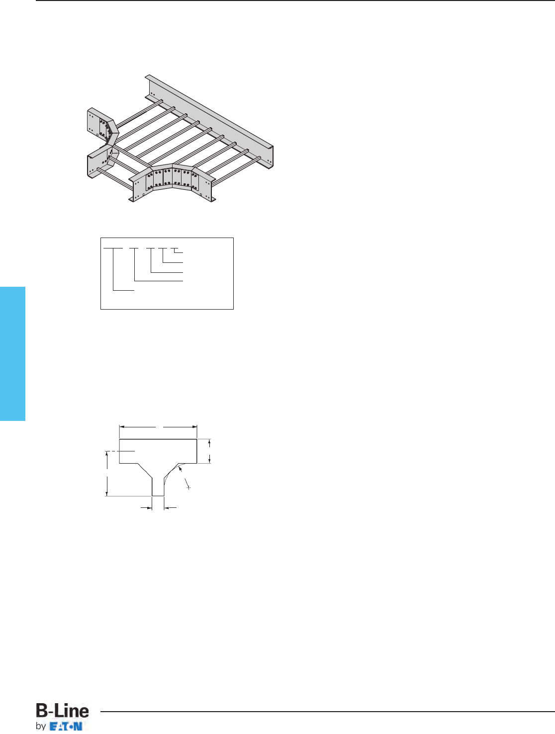
Fiberglass
R
W2
B
W1
A
Mitered
(For dimensions, see chart on page 337)
Two pair of splice plates with SS6 hardware included.
Dimensions for reference only, when critical contact factory.
(Prefix) See page FCT-27 for catalog number prefix.
Horizontal Reducing Tee (HT)
Prefix - 36 - 18 HT 24
Radius
Fitting
Width2 W2
Width1 W1
To complete catalog
number, insert fitting prefix.
(Radius 12” only
W1tray widths - 9”, 12”, 18” & 24” )
Polyester, Vinyl Ester, Zero Halogen/Dis-Stat
All are mitered
For 3” Fittings
(Radius 12”, 24” & 36”
W1tray widths - 9” thru 36”)
Polyester, Vinyl Ester, Zero Halogen/Dis-Stat
All radius are mitered
For 4” Fittings
(Radius 12”, 24” & 36”
W1tray widths - 9” thru 36”)
Polyester, Vinyl Ester, Zero Halogen/Dis-Stat
All radius are mitered
For 6” Fittings
(Radius 12”, 24” & 36”
W1tray widths - 9” thru 36”)
Polyester, Vinyl Ester, Zero Halogen/Dis-Stat
All radius are mitered
For 8” Fittings
FCT-33
Fiberglass - Fittings
Cable Tray Systems

Fiberglass
Horizontal Reducing Tee (HT)
Tray Width Catalog No. 12" Radius (305) 24" Radius (609) 36" Radius (914)
W1W2ABABAB
in. mm in. mm in. mm in. mm in. mm in. mm in. mm in. mm
9 228 6 152 (Prefix)-09-06-HT* 203⁄4527 381⁄2978 323⁄4832 621⁄21587 443⁄41137 861⁄22197
12 305 6 152 (Prefix)-12-06-HT* 221⁄4565 381⁄2978 341⁄4870 621⁄21587 461⁄41175 861⁄22197
9 228 (Prefix)-12-09-HT* 221⁄4565 411⁄21054 341⁄4870 651⁄21664 461⁄41175 891⁄22273
6 152 (Prefix)-18-06-HT* 251⁄4641 381⁄2978 371⁄4946 621⁄21587 491⁄41251 861⁄22197
18 457 9 228 (Prefix)-18-09-HT* 251⁄4641 411⁄21054 371⁄4946 651⁄21664 491⁄41251 891⁄22273
12 305 (Prefix)-18-12-HT* 251⁄4641 441⁄21130 371⁄4946 681⁄21740 491⁄41251 921⁄22350
6 152 (Prefix)-24-06-HT* 281⁄4717 381⁄2978 401⁄41022 621⁄21587 521⁄41327 861⁄22197
24 609 9 228 (Prefix)-24-09-HT* 281⁄4717 411⁄21054 401⁄41022 651⁄21664 521⁄41327 891⁄22273
12 305 (Prefix)-24-12-HT* 281⁄4717 441⁄21130 401⁄41022 681⁄21740 521⁄41327 921⁄22350
18 457 (Prefix)-24-18-HT* 281⁄4717 501⁄21283 401⁄41022 741⁄21892 521⁄41327 981⁄22502
6 152 (Prefix)-30-06-HT* 311⁄4794 381⁄2978 431⁄41098 621⁄21587 551⁄41403 861⁄22197
9 228 (Prefix)-30-09-HT* 311⁄4794 411⁄21054 431⁄41098 651⁄21664 551⁄41403 891⁄22273
30 762 12 305 (Prefix)-30-12-HT* 311⁄4794 441⁄21130 431⁄41098 681⁄21740 551⁄41403 921⁄22350
18 457 (Prefix)-30-18-HT* 311⁄4794 501⁄21283 431⁄41098 741⁄21892 551⁄41403 981⁄22502
24 609 (Prefix)-30-24-HT* 311⁄4794 561⁄21435 431⁄41098 801⁄22045 551⁄41403 1041⁄22654
6 152 (Prefix)-36-06-HT* 341⁄4870 381⁄2978 461⁄41175 621⁄21587 581⁄41480 861⁄22197
9 228 (Prefix)-36-09-HT* 341⁄4870 411⁄21054 461⁄41175 651⁄21664 581⁄41480 891⁄22273
36 914 12 305 (Prefix)-36-12-HT* 341⁄4870 441⁄21130 461⁄41175 681⁄21740 581⁄41480 921⁄22350
18 457 (Prefix)-36-18-HT* 341⁄4870 501⁄21283 461⁄41175 741⁄21892 581⁄41480 981⁄22502
24 609 (Prefix)-36-24-HT* 341⁄4870 561⁄21435 461⁄41175 801⁄22045 581⁄41480 1041⁄22654
30 762 (Prefix)-36-30-HT* 341⁄4870 621⁄21587 461⁄41175 861⁄22197 581⁄41480 1101⁄22807
* Insert radius
(12", 24” or 36")
Mitered Fittings
FCT-34
Fiberglass - Fittings
Cable Tray Systems
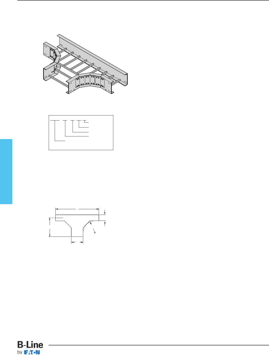
Fiberglass
Mitered
(For dimensions, see chart on page 339)
Two pair of splice plates with SS6 hardware included.
Dimensions for reference only, when critical contact factory.
(Prefix) See page FCT-27 for catalog number prefix.
Horizontal Expanding Tee (HT)
Prefix - 18 - 36 HT 24
Radius
Fitting
Width2 W2
Width1 W1
To complete catalog
number, insert fitting prefix.
(Radius 12” only
W1tray widths - 6” thru 18”
W2tray widths - 9” thru 24”)
Polyester, Vinyl Ester, Zero Halogen/Dis-Stat
All are mitered
For 3” Fittings
(Radius 12”, 24” & 36”
W1tray widths - 6” thru 30”)
W2tray widths - 9” thru 36”)
Polyester, Vinyl Ester, Zero Halogen/Dis-Stat
All radius are mitered
For 4” Fittings
(Radius 12”, 24” & 36”
W1tray widths - 6” thru 30”)
W2tray widths - 9” thru 36”)
Polyester, Vinyl Ester, Zero Halogen/Dis-Stat
All radius are mitered
For 6” Fittings
(Radius 12”, 24” & 36”
W1tray widths - 6” thru 30”)
W2tray widths - 9” thru 36”)
Polyester, Vinyl Ester, Zero Halogen/Dis-Stat
All radius are mitered
For 8” Fittings
W1
R
B
W2
A
FCT-35
Fiberglass - Fittings
Cable Tray Systems
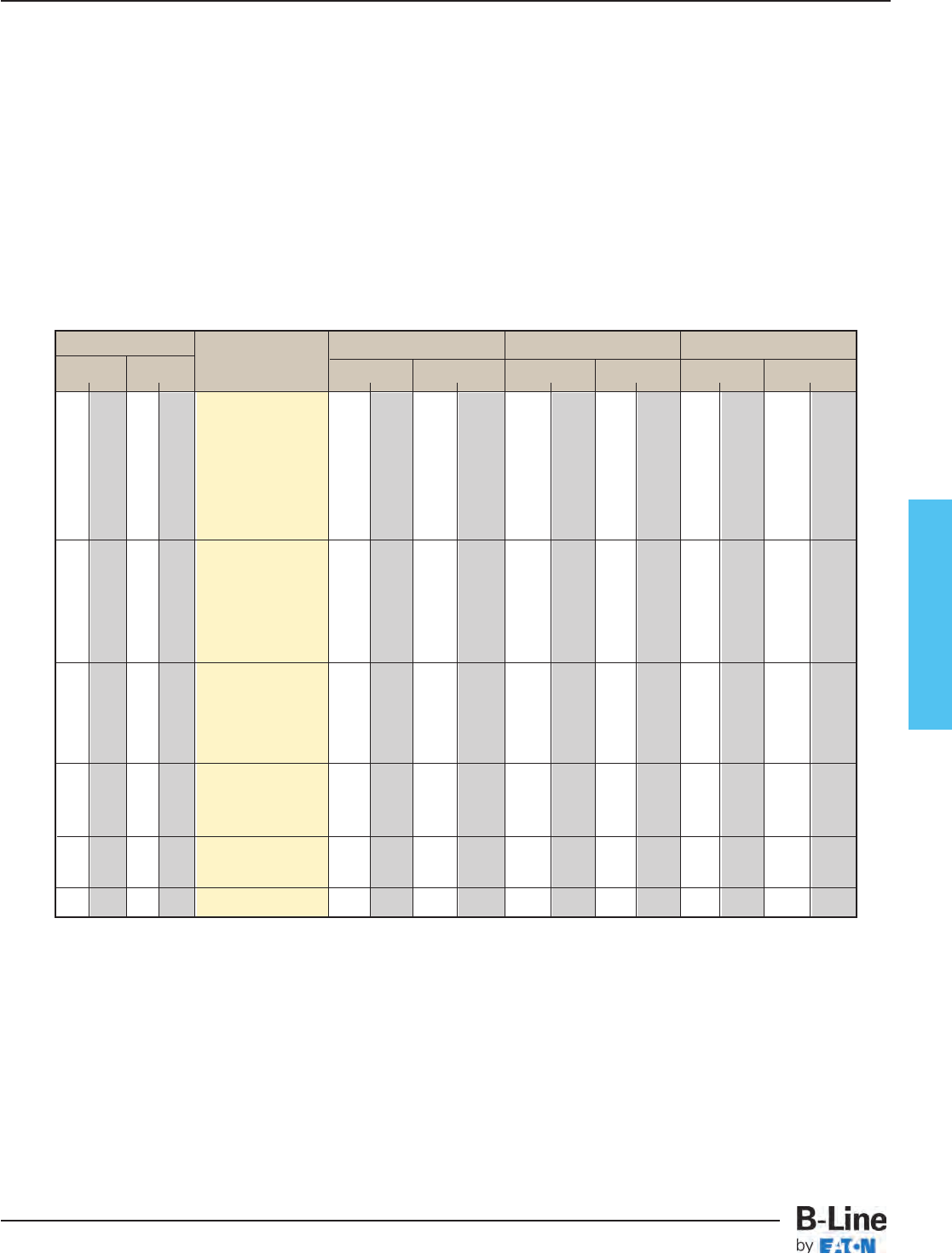
Fiberglass
Horizontal Expanding Tee (HT)
Tray Width Catalog No. 12" Radius (305) 24" Radius (609) 36" Radius (914)
W1W2ABABAB
in. mm in. mm in. mm in. mm in. mm in. mm in. mm in. mm
9 228 (Prefix)-06-09-HT* 191⁄4489 411⁄21054 311⁄4794 651⁄21664 431⁄41098 891⁄22273
12 305 (Prefix)-06-12-HT* 191⁄4489 441⁄21130 311⁄4794 681⁄21740 431⁄41098 921⁄22349
6 152 18 457 (Prefix)-06-18-HT* 191⁄4489 501⁄21283 311⁄4794 741⁄21892 431⁄41098 981⁄22502
24 609 (Prefix)-06-24-HT* 191⁄4489 561⁄21435 311⁄4794 801⁄22045 431⁄41098 1041⁄22654
30 762 (Prefix)-06-30-HT* 191⁄4489 621⁄21587 311⁄4794 861⁄22197 431⁄41098 1101⁄22807
36 914 (Prefix)-06-36-HT* 191⁄4489 681⁄21740 311⁄4794 921⁄22349 431⁄41098 1161⁄22959
12 305 (Prefix)-09-12-HT* 203⁄4527 441⁄21130 323⁄4832 681⁄21740 443⁄4136 921⁄22349
18 457 (Prefix)-09-18-HT* 203⁄4527 501⁄21283 323⁄4832 741⁄21892 443⁄4136 981⁄22502
9 228 24 609 (Prefix)-09-24-HT* 203⁄4527 561⁄21435 323⁄4832 801⁄22045 443⁄4136 1041⁄22654
30 762 (Prefix)-09-30-HT* 203⁄4527 621⁄21587 323⁄4832 861⁄22197 443⁄4136 1101⁄22807
36 914 (Prefix)-09-36-HT* 203⁄4527 681⁄21740 323⁄4832 921⁄22349 443⁄4136 1161⁄22959
18 457 (Prefix)-12-18-HT* 221⁄4565 501⁄21283 341⁄4870 741⁄21892 461⁄41175 981⁄22502
12 305 24 609 (Prefix)-12-24-HT* 221⁄4565 561⁄21435 341⁄4870 801⁄22045 461⁄41175 1041⁄22654
30 762 (Prefix)-12-30-HT* 221⁄4565 621⁄21587 341⁄4870 861⁄22197 461⁄41175 1101⁄22807
36 914 (Prefix)-12-36-HT* 221⁄4565 681⁄21740 341⁄4870 921⁄22349 461⁄41175 1161⁄22959
24 609 (Prefix)-18-24-HT* 251⁄4641 561⁄21435 371⁄4946 801⁄22045 491⁄41251 1041⁄22654
18 457 30 762 (Prefix)-18-30-HT* 251⁄4641 621⁄21587 371⁄4946 861⁄22197 491⁄41251 1101⁄22807
36 914 (Prefix)-18-36-HT* 251⁄4641 681⁄21740 371⁄4946 921⁄22349 491⁄41251 1221⁄23111
24 609 30 762 (Prefix)-24-30-HT* 281⁄4717 621⁄21587 401⁄41022 861⁄22197 521⁄41327 1101⁄22807
36 914 (Prefix)-24-36-HT* 281⁄4717 681⁄21740 401⁄41022 921⁄22349 521⁄41327 1161⁄22959
30 762 36 914 (Prefix)-30-36-HT* 311⁄4794 681⁄21740 431⁄41098 921⁄22349 551⁄41403 1161⁄22959
* Insert radius
(12", 24” or 36")
Mitered Fittings
FCT-36
Fiberglass - Fittings
Cable Tray Systems
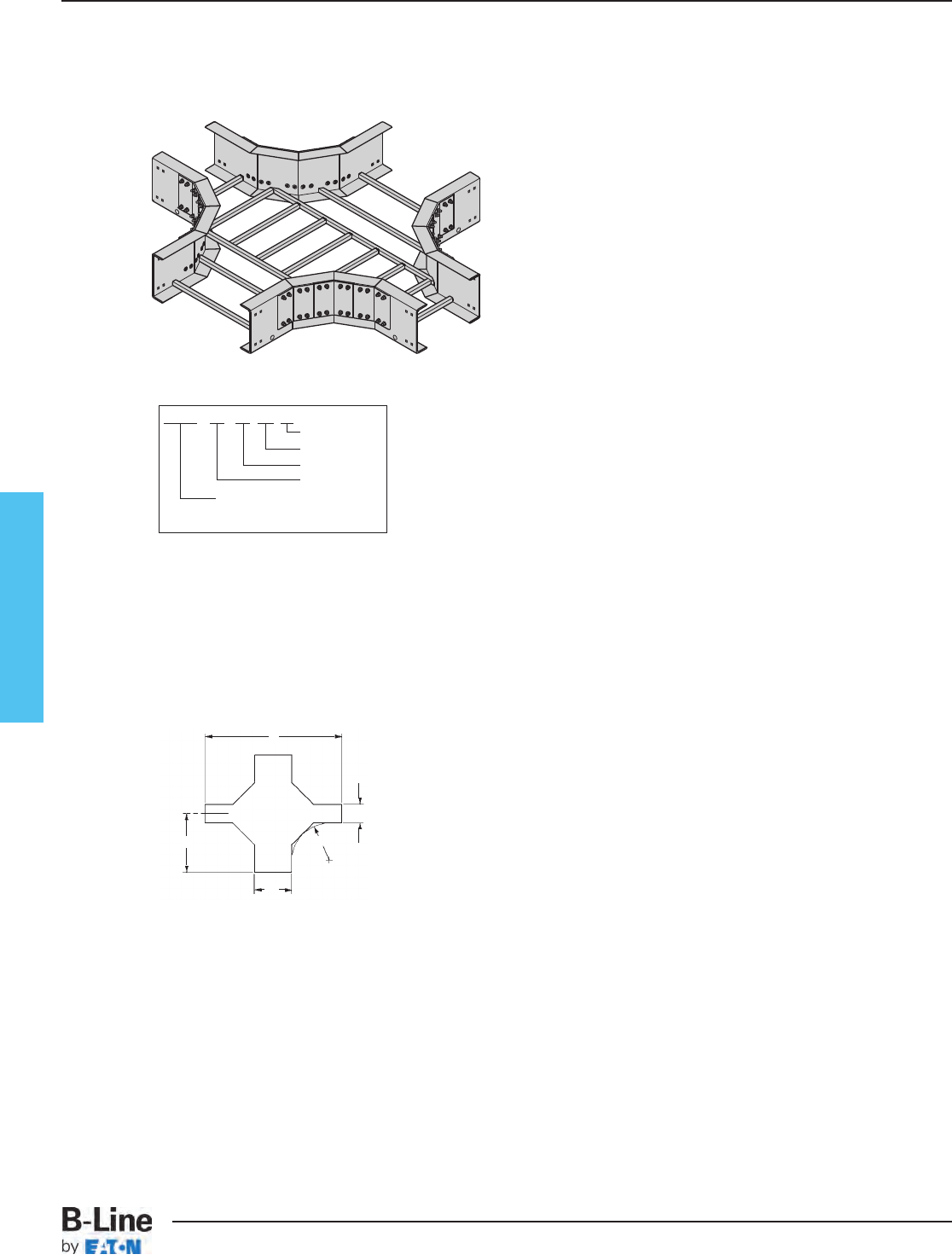
Fiberglass
Mitered
(For dimensions, see chart on page 341)
Dimensions for reference only, when critical contact factory.
(Prefix) See page FCT-27 for catalog number prefix.
Horizontal Expanding/Reducing Cross (HX)
(Radius 12” only
W1tray widths - 9” thru 24”
W2tray widths - 6” thru 18”)
Polyester, Vinyl Ester, Zero Halogen/Dis-Stat
All are mitered
For 3” Fittings
(Radius 12”, 24” & 36”
W1tray widths - 9” thru 36”)
W2tray widths - 6” thru 30”)
Polyester, Vinyl Ester, Zero Halogen/Dis-Stat
All radius are mitered
For 4” Fittings
(Radius 12”, 24” & 36”
W1tray widths - 9” thru 36”)
W2tray widths - 6” thru 30”)
Polyester, Vinyl Ester, Zero Halogen/Dis-Stat
All radius are mitered
For 6” Fittings
(Radius 12”, 24” & 36”
W1tray widths - 9” thru 36”)
W2tray widths - 6” thru 30”)
Polyester, Vinyl Ester, Zero Halogen/Dis-Stat
All radius are mitered
For 8” Fittings
B
R
W2
W1
A
Three pair of splice plates with SS6 hardware included.
Prefix - 18 - 12 HX 12
Radius
Fitting
Width2 W2
Width1 W1
To complete catalog
number, insert fitting prefix.
FCT-37
Fiberglass - Fittings
Cable Tray Systems
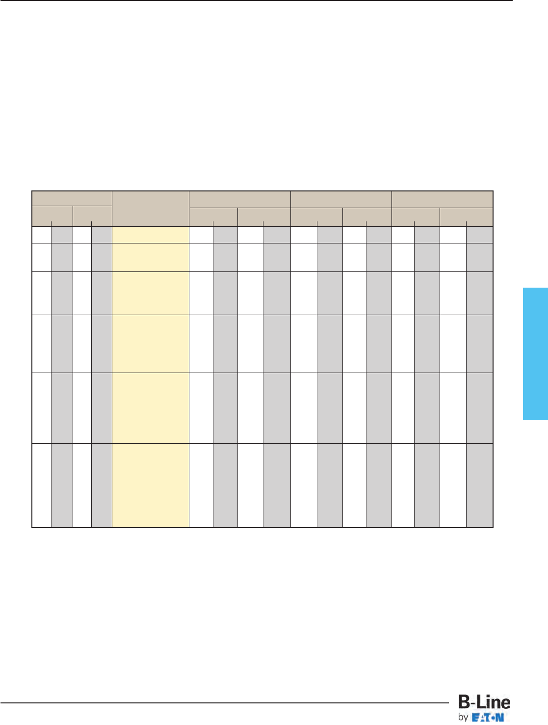
Fiberglass
Horizontal Expanding/Reducing Cross (HX)
Tray Width Catalog No. 12" Radius (305) 24" Radius (609) 36" Radius (914)
W1W2ABABAB
in. mm in. mm in. mm in. mm in. mm in. mm in. mm in. mm
9 228 6 152 (Prefix)-09-06-HX* 191⁄4489 411⁄21054 311⁄4794 651⁄21664 431⁄41098 891⁄22273
12 305 6 152 (Prefix)-12-06-HX* 191⁄4489 441⁄21130 311⁄4794 681⁄21740 431⁄41098 921⁄22350
9 228 (Prefix)-12-09-HX* 203⁄4527 441⁄21130 323⁄4832 681⁄21740 443⁄41136 921⁄22350
6 152 (Prefix)-18-06-HX* 191⁄4489 501⁄21283 311⁄4794 741⁄21892 431⁄41098 981⁄22502
18 457 9 228 (Prefix)-18-09-HX* 203⁄4527 501⁄21283 323⁄4832 741⁄21892 443⁄41136 981⁄22502
12 305 (Prefix)-18-12-HX* 221⁄4565 501⁄21283 341⁄4870 741⁄21892 461⁄41175 981⁄22502
6 152 (Prefix)-24-06-HX* 191⁄4489 561⁄21435 311⁄4794 801⁄22045 431⁄41098 1041⁄22654
24 609 9 228 (Prefix)-24-09-HX* 203⁄4527 561⁄21435 323⁄4832 801⁄22045 443⁄41136 1041⁄22654
12 305 (Prefix)-24-12-HX* 221⁄4565 561⁄21435 341⁄4870 801⁄22045 461⁄41175 1041⁄22654
18 457 (Prefix)-24-18-HX* 251⁄4641 561⁄21435 371⁄4946 801⁄22045 491⁄41251 1041⁄22654
6 152 (Prefix)-30-06-HX* 191⁄4489 621⁄21587 311⁄4794 861⁄22197 431⁄41098 1101⁄22807
9 228 (Prefix)-30-09-HX* 203⁄4527 621⁄21587 323⁄4832 861⁄22197 443⁄41136 1101⁄22807
30 762 12 305 (Prefix)-30-12-HX* 221⁄4565 621⁄21587 341⁄4870 861⁄22197 461⁄41175 1101⁄22807
18 457 (Prefix)-30-18-HX* 251⁄4641 621⁄21587 371⁄4946 861⁄22197 491⁄41251 1101⁄22807
24 609 (Prefix)-30-24-HX* 281⁄4717 621⁄21587 401⁄41022 861⁄22197 521⁄41327 1101⁄22807
6 152 (Prefix)-36-06-HX* 191⁄4489 681⁄21740 311⁄4794 1041⁄22654 431⁄41098 1281⁄23264
9 228 (Prefix)-36-09-HX* 203⁄4527 681⁄21740 323⁄4832 1041⁄22654 443⁄41136 1281⁄23264
36 914 12 305 (Prefix)-36-12-HX* 221⁄4565 681⁄21740 341⁄4870 1041⁄22654 461⁄41175 1281⁄23264
18 457 (Prefix)-36-18-HX* 251⁄4641 681⁄21740 371⁄4946 1041⁄22654 491⁄41251 1281⁄23264
24 609 (Prefix)-36-24-HX* 281⁄4717 681⁄21740 401⁄41022 1041⁄22654 521⁄41327 1281⁄23264
30 762 (Prefix)-36-30-HX* 311⁄4794 681⁄21740 431⁄41098 1041⁄22654 551⁄41403 1281⁄23264
* Insert radius
(12", 24” or 36")
Mitered Fittings
FCT-38
Fiberglass - Fittings
Cable Tray Systems
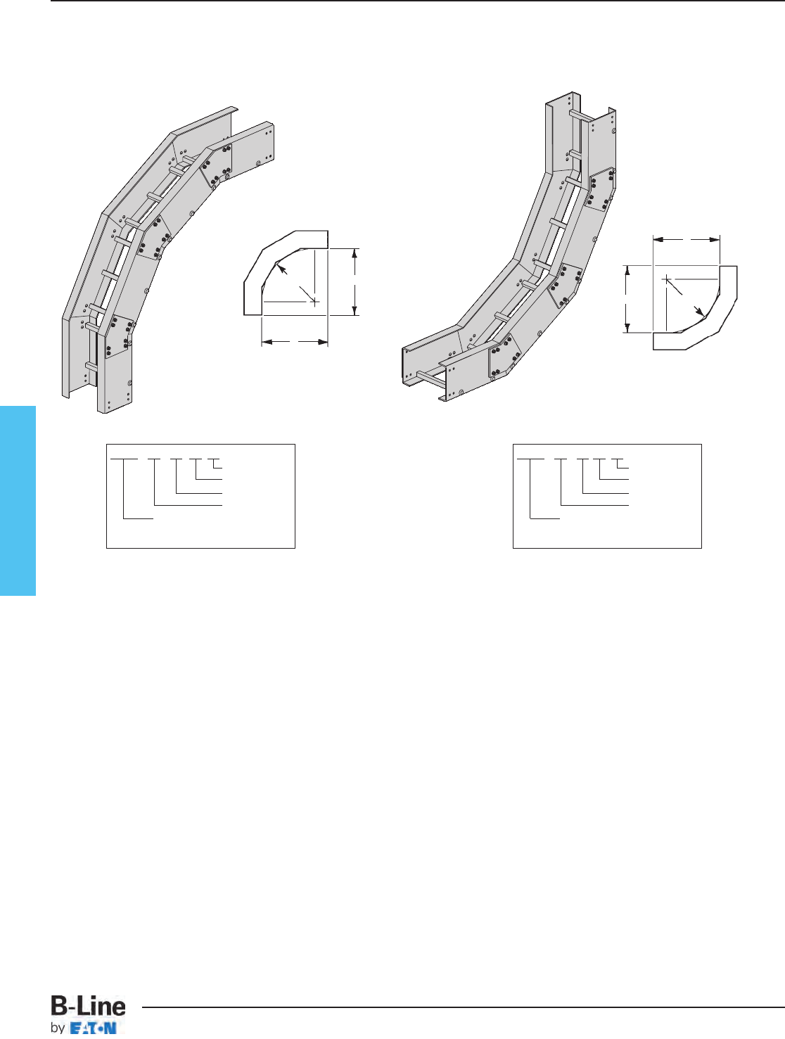
Fiberglass
Vertical Bends 90° (VO) (VI)
(Radius 12” only • Tray widths - 6” thru 24”)
Polyester, Vinyl Ester, Zero Halogen/Dis-Stat
All are mitered
For 3” Fittings
(Radius 12”, 24” & 36”
Tray widths - 6” thru 36”)
Polyester, Vinyl Ester, Zero Halogen/Dis-Stat
All radius are mitered
For 4” Fittings
(Radius 12”, 24” & 36”
Tray widths - 6” thru 36”)
Polyester, Vinyl Ester, Zero Halogen/Dis-Stat
All radius are mitered
For 6” Fittings
(Radius 12”, 24” & 36”
Tray widths - 6” thru 36”)
Polyester, Vinyl Ester, Zero Halogen/Dis-Stat
All radius are mitered
For 8” Fittings
Vertical
Inside Bend
B
A
R
A
B
R
90˚ (VI)
Mitered
90˚ (VO)
Mitered
Vertical
Outside Bend
VO VI
Prefix - 06 - 90 VI 24
Radius
Fitting
Angle
Width
To complete catalog
number, insert fitting prefix.
Prefix - 06 - 90 VO 24
Radius
Fitting
Angle
Width
To complete catalog
number, insert fitting prefix.
One pair of splice plates with SS6 hardware included.
Dimensions for reference only, when critical contact factory.
(Prefix) See page FCT-27 for catalog number prefix.
FCT-39
Fiberglass - Fittings
Cable Tray Systems
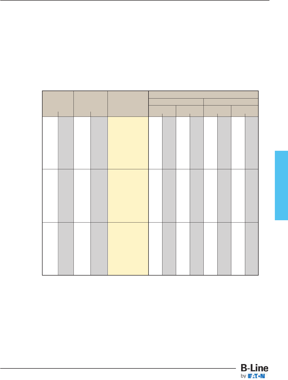
Fiberglass
Vertical Bends 90° (VO) (VI)
- R - 90˚ Mitered
Bend Tray Vertical Outside Bend Vertical Inside Bend
Radius Width Catalog No. ABAB
in. mm in. mm in. mm in. mm in. mm in. mm
6 152 (Prefix)-06-90(*)12
9 228 (Prefix)-09-90(*)12
12 305 (Prefix)-12-90(*)12
12 305 18 457 (Prefix)-18-90(*)12 205⁄8524 205⁄8524 205⁄8524 205⁄8524
24 609 (Prefix)-24-90(*)12
30 762 (Prefix)-30-90(*)12
36 914 (Prefix)-36-90(*)12
6 152 (Prefix)-06-90(*)24
9 228 (Prefix)-09-90(*)24
12 305 (Prefix)-12-90(*)24
24 609 18 457 (Prefix)-18-90(*)24 2831⁄32 735 2831⁄32 735 2831⁄32 735 2831⁄32 735
24 609 (Prefix)-24-90(*)24
30 762 (Prefix)-30-90(*)24
36 914 (Prefix)-36-90(*)24
6 152 (Prefix)-06-90(*)36
9 228 (Prefix)-09-90(*)36
12 305 (Prefix)-12-90(*)36
36 914 18 457 (Prefix)-18-90(*)36 3715⁄16 963 3715⁄16 963 3715⁄16 963 3715⁄16 963
24 609 (Prefix)-24-90(*)36
30 762 (Prefix)-30-90(*)36
36 914 (Prefix)-36-90(*)36
(*) Insert ‘VO’ for Vertical Outside Bend or ‘VI’ for Vertical Inside Bend.
FCT-40
Fiberglass - Fittings
Cable Tray Systems

Fiberglass
Vertical Bends 45° (VO) (VI)
(Radius 12” only • Tray widths - 6” thru 24”)
Polyester, Vinyl Ester, Zero Halogen/Dis-Stat
All are mitered
For 3” Fittings
(Radius 12”, 24” & 36”
Tray widths - 6” thru 36”)
Polyester, Vinyl Ester, Zero Halogen/Dis-Stat
All radius are mitered
For 4” Fittings
(Radius 12”, 24” & 36”
Tray widths - 6” thru 36”)
Polyester, Vinyl Ester, Zero Halogen/Dis-Stat
All radius are mitered
For 6” Fittings
(Radius 12”, 24” & 36”
Tray widths - 6” thru 36”)
Polyester, Vinyl Ester, Zero Halogen/Dis-Stat
All radius are mitered
For 8” Fittings
Vertical
Inside Bend
Vertical
Outside Bend
VO VI
Prefix - 06 - 45 VI 24
Radius
Fitting
Angle
Width
To complete catalog
number, insert fitting prefix.
Prefix - 06 - 45 VO 24
Radius
Fitting
Angle
Width
To complete catalog
number, insert fitting prefix.
One pair of splice plates with SS6 hardware included.
Dimensions for reference only, when critical contact factory.
(Prefix) See page FCT-27 for catalog number prefix.
R
B
A
C
CR
A
B
C
C
45˚ (VI) Mitered
45˚ (VO) Mitered
FCT-41
Fiberglass - Fittings
Cable Tray Systems
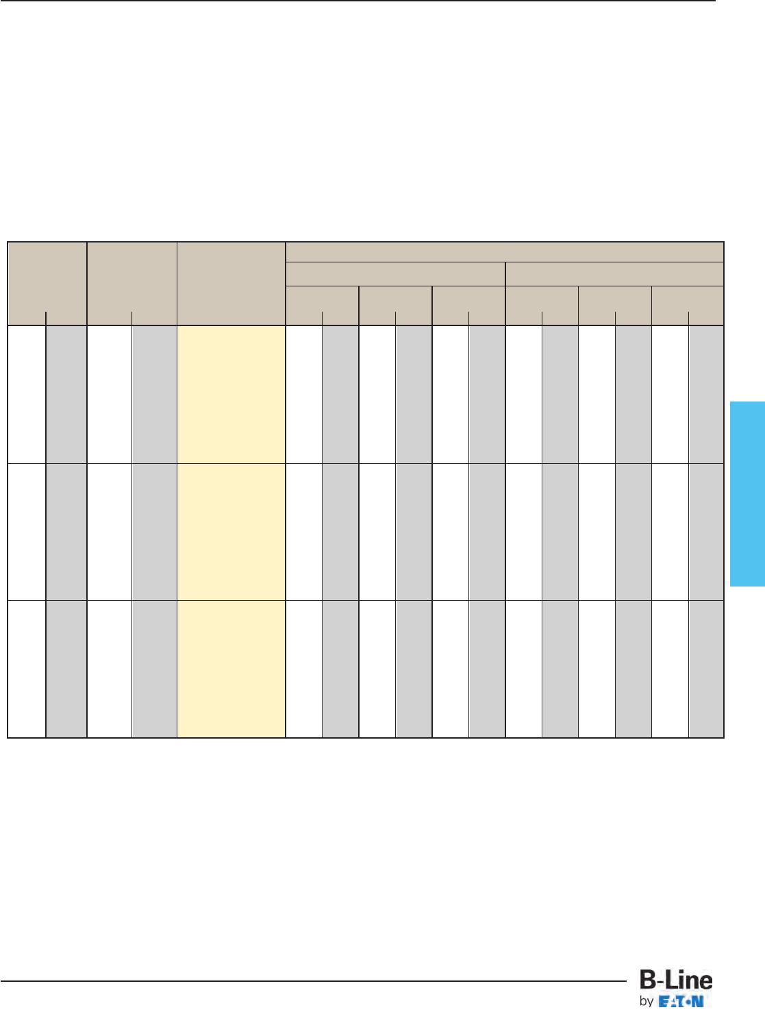
Fiberglass
Vertical Bends 45° (VO) (VI)
45˚ Mitered
- R -
Bend Tray Vertical Outside Bend Vertical Inside Bend
Radius Width Catalog No. ABCA BC
in. mm in. mm in. mm in. mm in. mm in. mm in. mm in. mm
6 152 (Prefix)-06-45(*)12
9 228 (Prefix)-09-45(*)12
12 305 (Prefix)-12-45(*)12
12 305 18 457 (Prefix)-18-45(*)12 201⁄2521 81⁄2216 12 305 265⁄32 664 1027⁄32 275 155⁄16 389
24 609 (Prefix)-24-45(*)12
30 762 (Prefix)-30-45(*)12
36 914 (Prefix)-36-45(*)12
6 152 (Prefix)-06-45(*)24
9 228 (Prefix)-09-45(*)24
12 305 (Prefix)-12-45(*)24
24 609 18 457 (Prefix)-18-45(*)24 2831⁄32 736 12 305 1631⁄32 431 361⁄16 916 1415⁄16 379 211⁄8537
24 609 (Prefix)-24-45(*)24
30 762 (Prefix)-30-45(*)24
36 914 (Prefix)-36-45(*)24
6 152 (Prefix)-06-45(*)36
9 228 (Prefix)-09-45(*)36
12 305 (Prefix)-12-45(*)36
36 914 18 457 (Prefix)-18-45(*)36 377⁄16 951 151⁄2394 2115⁄16 557 46 1168 191⁄32 483 2615⁄16 684
24 609 (Prefix)-24-45(*)36
30 762 (Prefix)-30-45(*)36
36 914 (Prefix)-36-45(*)36
(*) Insert ‘VO’ for Vertical Outside Bend or ‘VI’ for Vertical Inside Bend.
60
˚ and 30˚ vertical bends available in mitered construction.
FCT-42
Fiberglass - Fittings
Cable Tray Systems
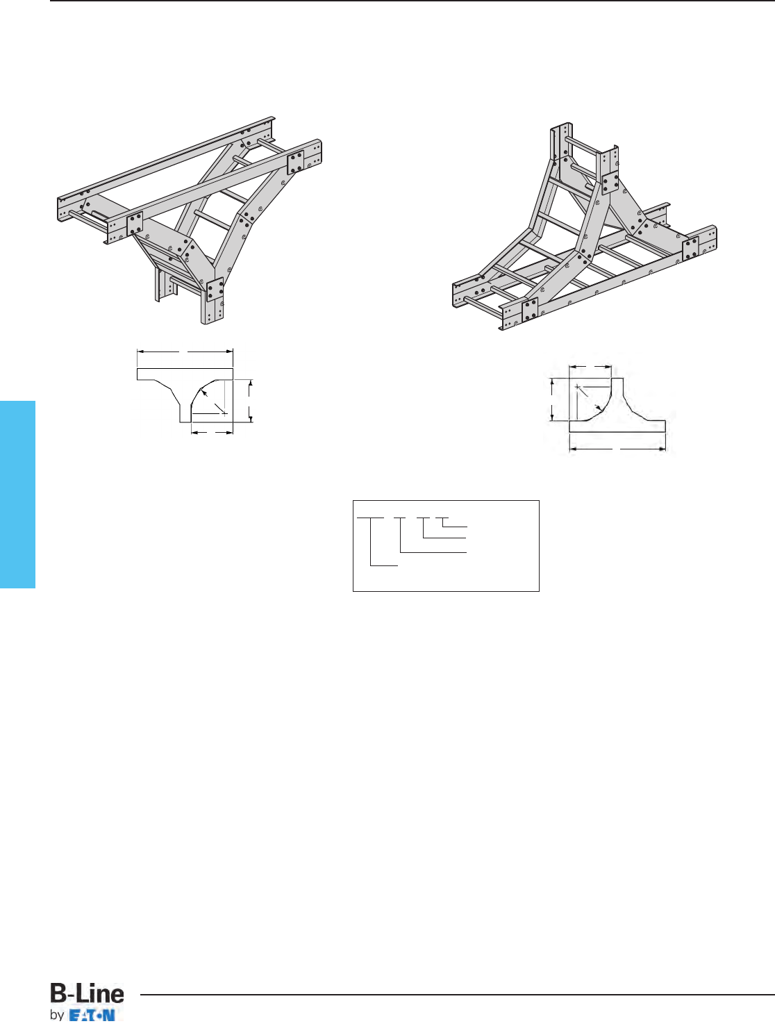
Fiberglass
Vertical Tee Up
R
RA
C
B
(VTU) Mitered
(VT) Mitered
Vertical Tee Down
Prefix - 06 - VT 24
Radius
Fitting
Width
To complete catalog
number, insert fitting prefix.
Two pair of splice plates with
SS6 hardware included.
Dimensions for reference only, when critical contact factory.
(Prefix) See page FCT-27 for catalog number prefix.
C Dimension =
2 x B + Side Rail Height
C Dimension =
2 x B + Side Rail Height
Vertical Tee Up (VTU)
Vertical Tee Down (VT)
(Radius 12” only • Tray widths - 6” thru 24”)
Polyester, Vinyl Ester, Zero Halogen/Dis-Stat
All are mitered
For 3” Fittings
(Radius 12”, 24” & 36”
Tray widths - 6” thru 36”)
Polyester, Vinyl Ester, Zero Halogen/Dis-Stat
All radius are mitered
For 4” Fittings
(Radius 12”, 24” & 36”
Tray widths - 6” thru 36”)
Polyester, Vinyl Ester, Zero Halogen/Dis-Stat
All radius are mitered
For 6” Fittings
(Radius 12”, 24” & 36”
Tray widths - 6” thru 36”)
Polyester, Vinyl Ester, Zero Halogen/Dis-Stat
All radius are mitered
For 8” Fittings
A
C
B
FCT-43
Fiberglass - Fittings
Cable Tray Systems
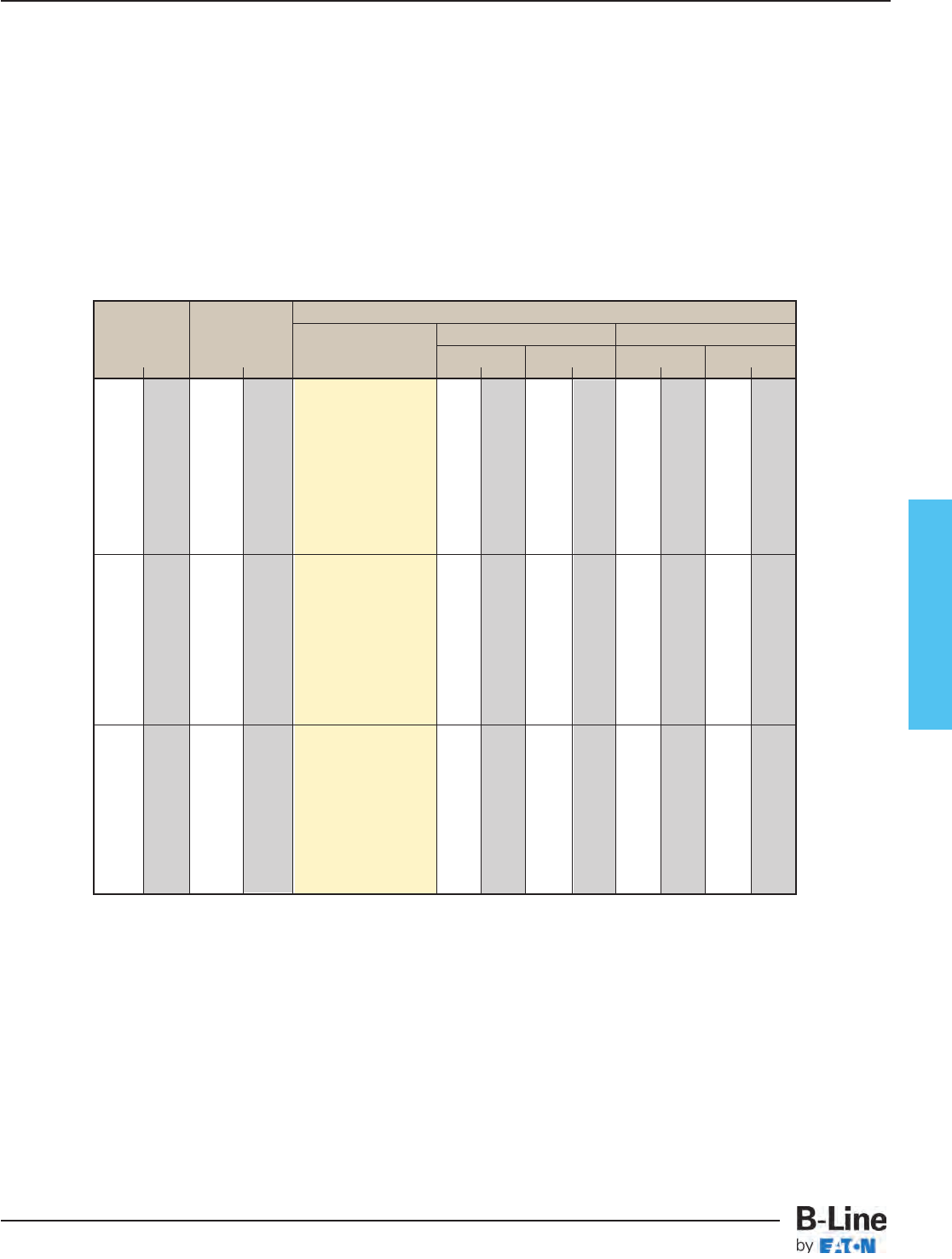
Fiberglass
- R - Mitered
Bend Tray Vertical Tee Down Vertical Tee Up
Radius Width Catalog No. ABAB
in. mm in. mm in. mm in. mm in. mm in. mm
6 152 (Prefix)-06-(*)12
9 228 (Prefix)-09-(*)12
12 305 (Prefix)-12-(*)12
12 305 18 457 (Prefix)-18-(*)12 205⁄8524 205⁄8524 205⁄8524 205⁄8524
24 609 (Prefix)-24-(*)12
30 762 (Prefix)-30-(*)12
36 914 (Prefix)-36-(*)12
6 152 (Prefix)-06-(*)24
9 228 (Prefix)-09-(*)24
12 305 (Prefix)-12-(*)24
24 609 18 457 (Prefix)-18-(*)24 29 736 29 736 29 736 29 736
24 609 (Prefix)-24-(*)24
30 762 (Prefix)-30-(*)24
36 914 (Prefix)-36-(*)24
6 152 (Prefix)-06-(*)36
9 228 (Prefix)-09-(*)36
12 305 (Prefix)-12-(*)36
36 914 18 457 (Prefix)-18-(*)36 37
15
⁄
16
963 37
15
⁄
16
963 37
15
⁄
16
963 37
15
⁄
16
963
24 609 (Prefix)-24-(*)36
30 762 (Prefix)-30-(*)36
36 914 (Prefix)-36-(*)36
(*) Insert ‘VT’ for Vertical Tee Down or ‘VTU’ for Vertical Tee Up.
Vertical Tee Up (VTU)
Vertical Tee Down (VT)
FCT-44
Fiberglass - Fittings
Cable Tray Systems
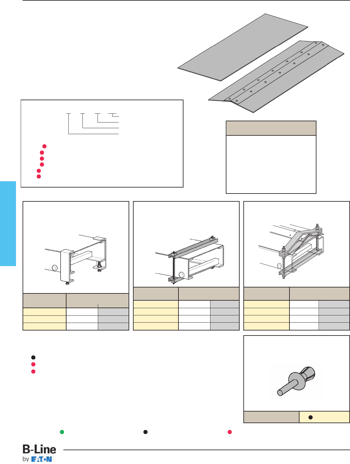
Fiberglass
Covers
Material Thickness:
1⁄8" (3)
Cover Length: 10
' (3m)
Standard Mounting Hardware:
(10 each)
#10 x 1⁄2" stainless, self drilling screws provided
with each section
Covers FC-24 - 120
Length or fitting description
Width
Rail design
Material
FC-24 - 120 = Flat polyester
FV C-24 - 120 = Flat vinyl ester
FA C-24 - 120 = Flat zero halogen/Dis-Stat
FP C-24 - 120 = Peaked polyester
FVP C-24 - 120 = Peaked vinyl ester
FAP C-24 - 120 = Peaked zero halogen/Dis-Stat
Peaked Cover
provides
1 to 5 pitch
Peaked covers available for straight sections only.
Quantity of Standard
Cover Clamps Required
Straight Section 60" or 72" ........4 pcs.
Straight Section 120" or 144" ....6 pcs.
Horizontal/Vertical Bends............4 pcs.
Tees ............................................6 pcs.
Crosses ......................................8 pcs.
Note: When using the Heavy Duty
Cover Clamp, only one-half the number
of clamps stated above is required.
Catalog No. Side Rail Height
in. mm
9(Δ)-9013 3 76
9(Δ)-9014 4 101
9(Δ)-9016 6 152
Catalog No. Side Rail Height
in. mm
9F-W-9034 3 76
9F-W-9044 4 101
9F-W-9064 6 152
9F-W-9084 8 203
Heavy Duty Cover Clamp
Recommended for outdoor service.
• W = tray width
• Heavy duty cover clamp available
for flat covers only
Catalog No. Side Rail Height
in. mm
9F-W-9034P 3 76
9F-W-9044P 4 101
9F-W-9064P 6 152
9F-W-9084P 8 203
Peaked Cover Clamp
• W = tray width
Thermo Plastic Drive Rivet
Sold individually.
Shipped in packages of 25 pcs.
Standard Cover Clamp
• Furnished in pairs with hardware.
Catalog No.
TPDR
Material Designations
(
Δ
) Insert one of the following material designations when required.
F = Polyester Resin (Example: 9F-9013)
FV = Vinyl Ester Resin (Example: 9FV-9013)
FA = Zero Halogen/Dis-Stat Resin (Example: 9FA-9013)
Green = Fastest shipped items Black = Normal lead-time items Red = Normally long lead-time items
FCT-45
Fiberglass - Covers & Cover Accessories
Cable Tray Systems
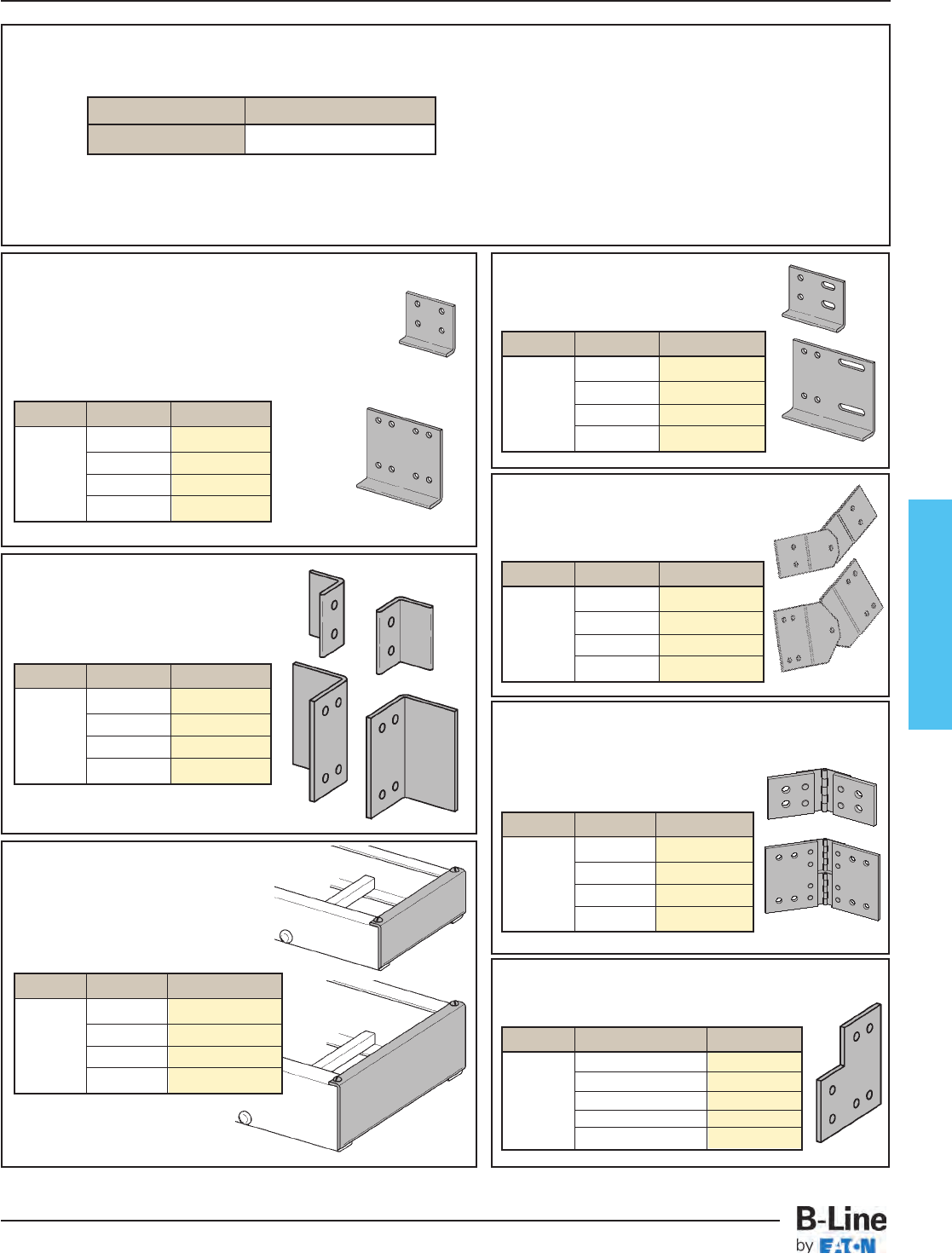
Fiberglass
Part Number with Hardware Explanation
Note: All hardware is 3/8”
Example: 9F-4004 SS6: pair of 4-hole splice plates for 4" (101) system with stainless steel hardware
9FV-8006 SS6: pair of 8-hole vinyl ester splice plates for 6" (152) system with stainless steel hardware
Vertical Adjustable Splice Plates
These plates provide for changes in elevation that
do not conform to standard vertical fittings.
• Furnished in pairs
Blind End Plate
This plate forms a closure for any tray that dead ends.
• Furnished as one plate
• W = tray width
Tray to Box Splice Plates
These plates are used to attach the end of a
tray run to a distribution box or control center.
• Furnished in pairs
Horizontal Adjustable Splice Plates
These plates provide for changes in the horizontal direction
that do not conform to standard fittings.
• Furnished in pairs
• Stainless steel hinges, FRP body
Standard Lay-In Splice Plates
Included in needed quantities with tray section.
• Furnished in pairs
• Order only pairs of splice plates needed for field fabrication.
• SS6 hardware supplied as standard - use SS6 suffix.
• Other hardware available, specify by hardware suffix.
Hardware other than SS6 is considered special.
Expansion Splice Plate
L-shaped, lay-in style
• Furnished in pairs
Step Down Splice Plates
These splice plates provide for changes in side rail heights.
• Furnished in pairs
Hardware Option 316 Stainless Steel
SS6
Material Height Catalog No.
8" to 6" (203 to 152) 9
(Δ)
-8086SS6
8" to 4" (203 to 101) 9
(Δ)
-8084SS6
Fiberglass 6" to 3" (152 to 76) 9
(Δ)
-8063SS6
6" to 4" (152 to 101) 9
(Δ)
-8064SS6
4" to 3" (101 to 76) 9
(Δ)
-4043SS6
Material Height Catalog No.
3" (76) 9
(Δ)
-4053SS6
Fiberglass 4" (101) 9
(Δ)
-4054SS6
6" (152) 9
(Δ)
-8056SS6
8" (203) 9
(Δ)
-8058SS6
Material Height Catalog No.
3" (76) 9
(Δ)
-4013SS6
Fiberglass 4" (101) 9
(Δ)
-4014SS6
6" (152) 9
(Δ)
-8016SS6
8" (203) 9
(Δ)
-8018SS6
Material Height Catalog No.
3" (76) 9
(Δ)
-4023SS6
Fiberglass 4" (101) 9
(Δ)
-4024SS6
6" (152) 9
(Δ)
-8026SS6
8" (203) 9
(Δ)
-8028SS6
Material Height Catalog No.
3" (76) 9
(Δ)
-4033SS6
Fiberglass 4" (101) 9
(Δ)
-4034SS6
6" (152) 9
(Δ)
-8036SS6
8" (203) 9
(Δ)
-8038SS6
Material Height Catalog No.
3" (76) 9
(Δ)
-4003SS6
Fiberglass 4" (101) 9
(Δ)
-4004SS6
6" (152) 9
(Δ)
-8006SS6
8" (203) 9
(Δ)
-8008SS6
Dimensions shown in parentheses are in millimeters, unless otherwise specified.
Material Height Catalog No.
3" (76) 9
(Δ)
-1083-WSS6
Fiberglass 4" (101) 9
(Δ)
-1084-WSS6
6" (152) 9
(Δ)
-1086-WSS6
8" (203) 9
(Δ)
-1088-WSS6
(
Δ
)See page 352 for material selection
FCT-46
Fiberglass Tray - Accessories
Cable Tray Systems
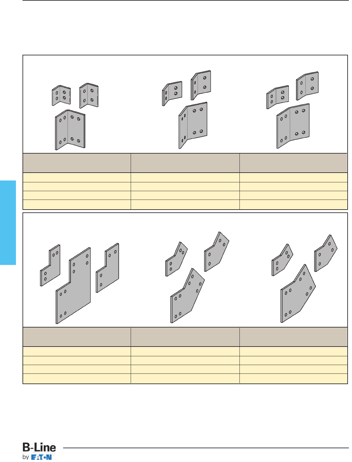
Fiberglass
Horizontal Splice Plates
• Furnished in pairs
Catalog No. Catalog No. Catalog No.
90˚ 45˚ 30˚
9
(Δ)
-4903HSS6 9
(Δ)
-4453HSS6 9
(Δ)
-4303HSS6
9
(Δ)
-4904HSS6 9
(Δ)
-4454HSS6 9
(Δ)
-4304HSS6
9
(Δ)
-8906HSS6 9
(Δ)
-8456HSS6 9
(Δ)
-8306HSS6
9
(Δ)
-8908HSS6 9
(Δ)
-8458HSS6 9
(Δ)
-8308HSS6
Vertical Splice Plates
• Furnished in pairs
Catalog No. Catalog No. Catalog No.
90˚ 45˚ 30˚
9
(Δ)
-4903VSS6 9
(Δ)
-4453VSS6 9
(Δ)
-4303VSS6
9
(Δ)
-4904VSS6 9
(Δ)
-4454VSS6 9
(Δ)
-4304VSS6
9
(Δ)
-8906VSS6 9
(Δ)
-8456VSS6 9
(Δ)
-8306VSS6
9
(Δ)
-8908VSS6 9
(Δ)
-8458VSS6 9
(Δ)
-8308VSS6
Horizontal and Vertical Splice Plates
All splice plate hardware is 3⁄8 ".
All hardware is SS6 (Stainless Steel 316).
Standard lay-in splice plates with SS6 hardware included with tray sections.
Splice Plates are available in pairs and are a separate order item. They are not automatically supplied with tray sections.
(
Δ
)See page FCT-45 for
material selection
FCT-47
Fiberglass Tray - Accessories
Cable Tray Systems
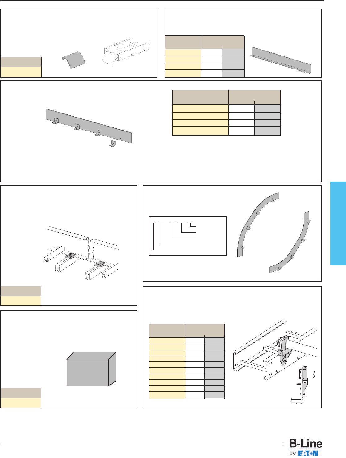
Fiberglass
Resin Seal Kit
To reseal fiberglass after field modifications.
• 1 pint (473ml)
Contents: Sealant and Applicator.
Vertical Bend Barriers
One kit allows up to a 36" (914) radius position of the barrier. Catalog Side Rail Height
No.
in. mm
72
(Δ)
-90HBFL 3" (76)
73
(Δ)
-90HBFL 4" (101)
75
(Δ)
-90HBFL 6" (152)
77
(Δ)
-90HBFL 8" (203)
Clamp/Guide - Fiberglass
Nonmetallic
• Designed for 3⁄8" hardware - not included
• Combination hold down clamp and guide
• Material: Glass reinforced polyurathane
• Sold in pairs
Ladder Drop-Out
Specially-designed Ladder Drop-Outs provide a rounded surface with
adequate radius to protect cable as it exits from the tray, preventing
damage to insulation.
• 4" (101) radius
• W = tray width
Dimensions shown in parentheses are in millimeters, unless otherwise specified.
Barriers
• Furnished with #10 x 1⁄2" self-drilling stainless steel screws
Flexible Horizontal Barrier Kit
VO
VI
Resin
Seal Kit
7* (Δ) - 90 VO 24
Radius
VI or VO
Angle
Material
Barrier Size
Fiberglass Conduit to Cable Tray Adapter
• For rigid or PVC conduit
• Standard hardware is 316 stainless steel
• Add ‘N’ to end of part number if non-metallic hardware is preferred
Catalog Conduit Size
No. in. mm
9
FV
-2008 0.50 15
9
FV
-2009 0.75 20
9
FV
-2010 1.00 25
9
FV
-2011 1.25 32
9
FV
-2012 1.50 40
9
FV
-2013 2.00 50
9
FV
-2014 2.50 65
9
FV
-2015 3.00 80
9
FV
-2016 3.50 90
9
FV
-2017 4.00 100
Kit Contents:
1 pc — 72" (1829) Straight Barrier
4 pc — 9F-9002 Barrier Strip Clip
8 pc — Thermo Plastic Drive Rivet
4 pc — #10 x 3⁄4" Stainless Steel Self-Drilling Screw
Assembly required — directions included.
Catalog Side Rail Height
No.
in. mm
72
(Δ)
-120 3" (76)
73
(Δ)
-120 4" (101)
75
(Δ)
-120 6" (152)
77
(Δ)
-120 8" (203)
Catalog No.
9
(Δ)
-1104-W
* Insert 2 for 3" (76) siderail height
3 for 4" (101) siderail height
5 for 6" (152) siderail height
Catalog No.
9F-1208
Catalog No.
RSK-010
FCT-48
Fiberglass Tray - Accessories
Cable Tray Systems
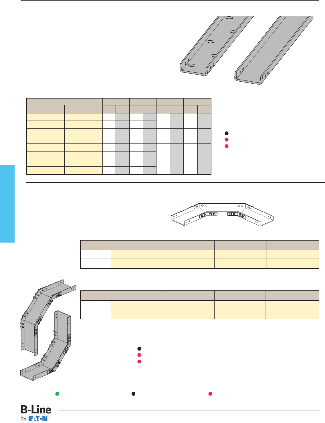
Fiberglass
Cable Channel Fittings
FCC Fiberglass
Cable Channel Ventilated
FCCN Fiberglass Cable
Channel Non-Ventilated
Horizontal 3" series 4" series 6" series 8" series
90˚ (†)N-03-90HB12 (†)N-04-90HB12 (†)N-06-90HB12 (†)N-08-90HB12
45˚ (†)N-03-45HB12 (†)N-04-45HB12 (†)N-06-45HB12 (†)N-08-45HB12
Catalog No. Width Length Height Load
Ventilated Non-Ventilated in. mm ft. min. mm Lbs/Ft kg/m
(*)-03-120 (*)N-03-120 3 76 10 3 1 25 8 12
(*)-03-240 (*)N-03-240 3 76 20 6
(*)-04-120 (*)N-04-120 4 101 10 3 11⁄828 12 18
(*)-04-240 (*)N-04-240 4 101 20 6
(*)-06-120 (*)N-06-120 6 152 10 3 15⁄835 58 86
(*)-06-240 (*)N-06-240 6 152 20 6
(*)-08-120 (*)N-08-120 8 203 10 3 23⁄16 55 87 129
(*)-08-240 (*)N-08-240 8 203 20 6
All fittings are of mitered construction with 12" (305) radius.
Straight Section
(†) Insert material type for fittings
FCC for Polyester Resin
FCCV for Vinyl Ester Resin
FCCA for Zero Halogen/Dis-Stat Resin
VO
VI
Vertical 3" series 4" series 6" series 8" series
90˚ (†)N-03-90V*12 (†)N-04-90V*12 (†)N-06-90V*12 (†)N-08-90V*12
45˚ (†)N-03-45V*12 (†)N-04-45V*12 (†)N-06-45V*12 (†)N-08-45V*12
One pair of splice plates included
with each straight section.
One pair of splice plates included.
One pair of splice plates included.
• Load data was interpolated from CSA testing.
• Loads shown are for FCCN series.
• Loads shown are for 6 ft. (1.83m) span with deflection
of .7 (18.26) inches.
(*) Insert material type straight sections
FCC for Polyester Resin
FCCV for Vinyl Ester Resin
FCCA for Zero Halogen/Dis-Stat Resin
Green = Fastest shipped items Black = Normal lead-time items Red = Normally long lead-time items
FCT-49
Fiberglass - Cable Channel & Fittings
Cable Tray Systems
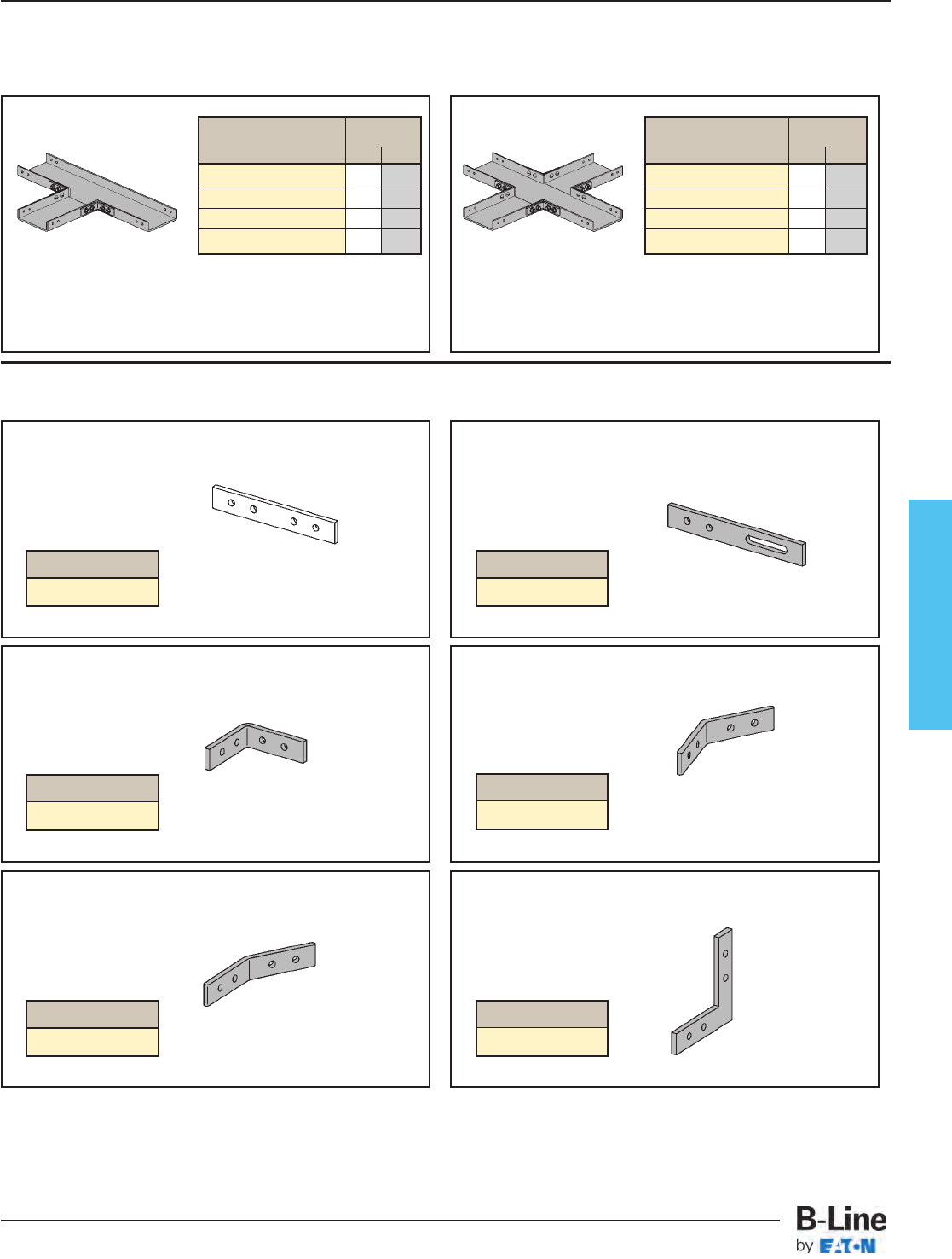
Fiberglass
Cable Channel Splice Plates
Horizontal Tees Horizontal Crosses
Splice plates included with cable channel sections.
Standard hardware for splice plates is 1/4”-20 (316SS).
Catalog Width
No. in. mm
FCC(†)N-03-HT12 3 76
FCC(†)N-04-HT12 4 101
FCC(†)N-06-HT12 6 152
FCC(†)N-08-HT12 8 203
Catalog Width
No. in. mm
FCC(†)N-03-HX12 3 76
FCC(†)N-04-HX12 4 101
FCC(†)N-06-HX12 6 152
FCC(†)N-08-HX12 8 203
Two pair of splice
plates included.
Three pair of splice
plates included.
Splice Plates
(pairs)
Included with tray sections.
Expansion Splice Plates
(pairs)
Horizontal 90˚ Splice Plates
(pairs)
Horizontal 45˚ Splice Plates
(pairs)
Horizontal 30˚ Splice Plates
(pairs)
Catalog No.
9(Δ)-1013 SS6
Catalog No.
9(Δ)-1001 SS6
Catalog No.
9(Δ)-1901H SS6
Catalog No.
9(Δ)-1301H SS6
Catalog No.
9(Δ)-1451H SS6
Vertical 90˚ Splice Plates
(pairs)
Cable Channel Fittings
All fittings are of mitered construction with 12" (305) radius.
Catalog No.
9(Δ)-1901V SS6
(
Δ
)See page FCT-49 for
material selection
(
†
)See page fitting material
selection bottom of page FCT-49
(
†
)See page fitting material
selection bottom of page FCT-49
FCT-50
Fiberglass - Cable Channel Fittings & Accessories
Cable Tray Systems
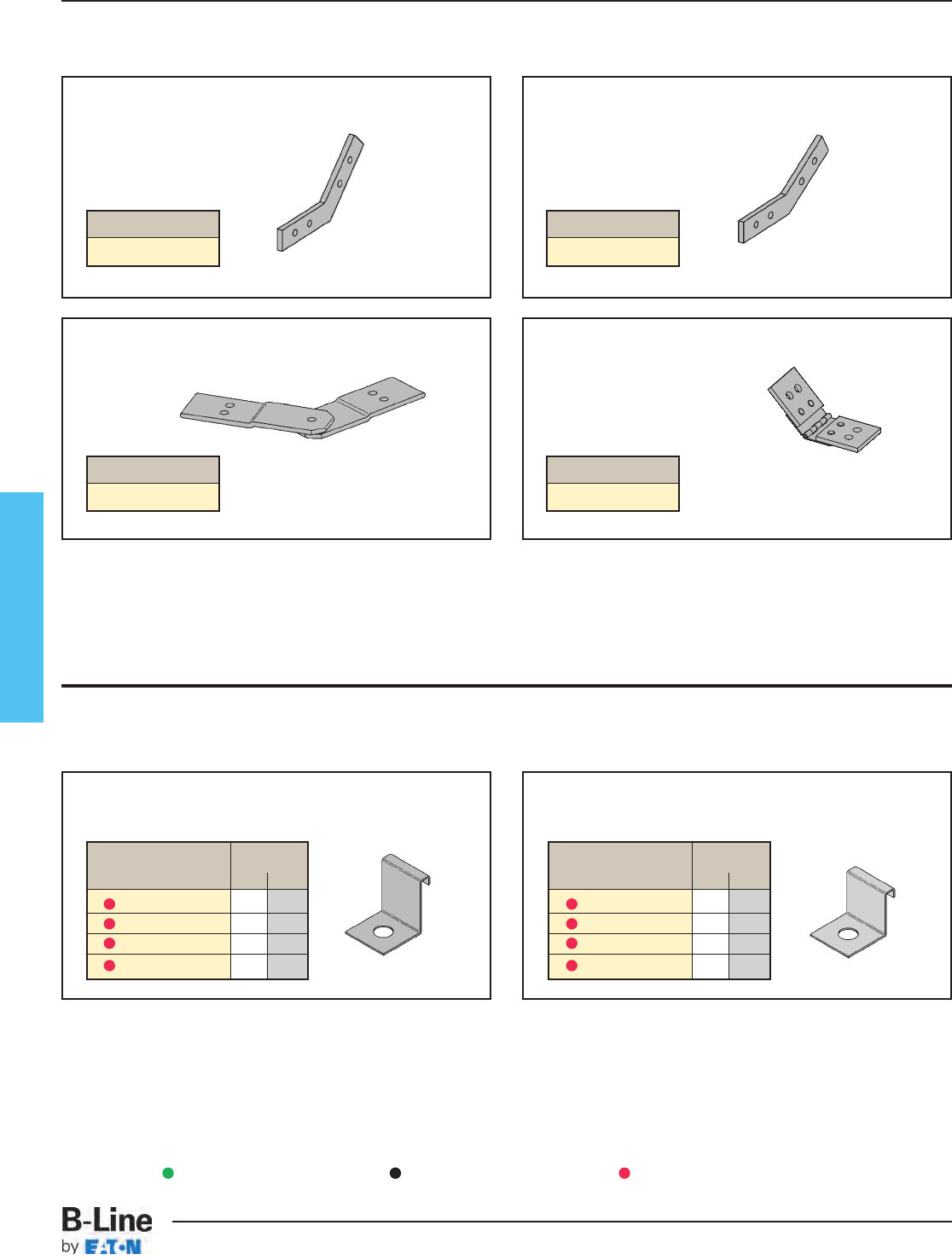
Fiberglass
Expansion Guide Clamp
(one clamp)
• Order 1/2" hardware separately
Hold-Down Clamp
(one clamp)
• Order 1/2" hardware separately
Vertical 45˚ Splice Plates
(pairs)
Vertical 30˚ Splice Plates
(pairs)
Cable Channel Clamps
Horizontal Adjustable Splice Plates
Uses 3/8”-16 hardware.
Vertical Adjustable Splice Plates
Uses 3/8”-16 hardware.
Stainless steel hinge FRP body
Splice plates included with cable channel sections.
Standard hardware for splice plates is 1/4”-20 (316SS). Hardware for adjustable splice plates is 3/8”-16 (316SS).
Cable Channel Splice Plates
Catalog No.
9(Δ)-1301V SS6
Catalog No.
9(Δ)-1033 SS6
Catalog No.
9(Δ)-1451V SS6
Catalog No.
9(Δ)-1023 SS6
Catalog Width
No. in. mm
9SS6-1247-3 3 76
9SS6-1247-4 4 101
9SS6-1247-6 6 152
9SS6-1247-8 8 203
Catalog Width
No. in. mm
9SS6-1248-3 3 76
9SS6-1248-4 4 101
9SS6-1248-6 6 152
9SS6-1248-8 8 203
(
Δ
)See page FCT-49 for
material selection
Green = Fastest shipped items Black = Normal lead-time items Red = Normally long lead-time items
FCT-51
Fiberglass - Cable Channel Accessories
Cable Tray Systems
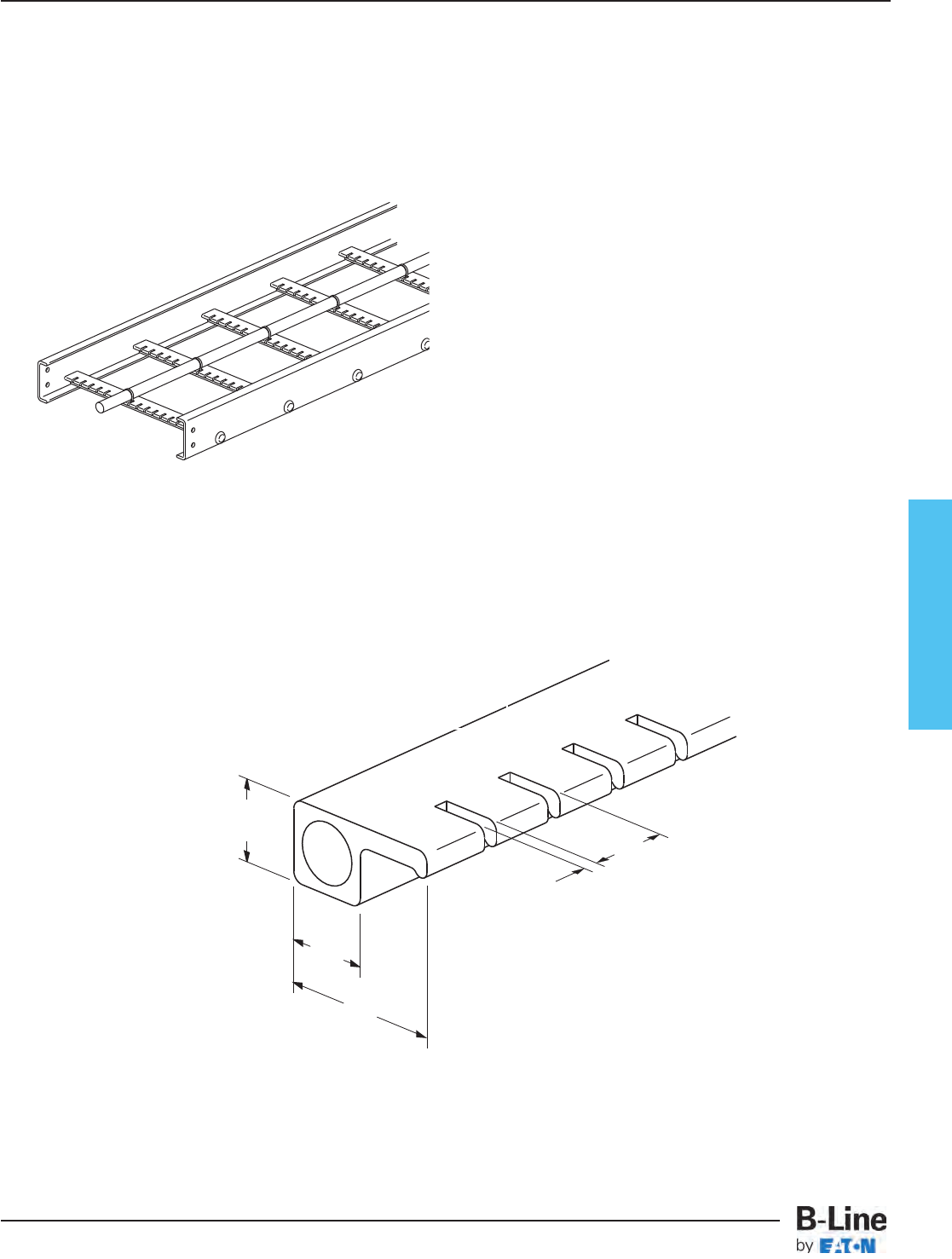
Fiberglass
Rung design provides:
- 2" (50.80) cable support surface
- Both mechanical and adhesive rung
to side rail connection
Marine Rung Cable Tray/Fiberglass
Features:
• For Coast Guard Requirements
- Allows stainless steel banding of cables
-5/32" (15.88) slots 1” (25.40) on centers
- Accommodates up to 5/8" (.625) banding
• Has applications on land
- Vertical installation
- Any location where extra cable positioning is required
• Designed for B-Line Fiberglass Series Cable Trays
• Part Number Indication
- Add MR after rung spacing
- Example: 46F09MR-36-240
Patent Pending
1"
(25.40)
1"
(25.40)
2"
(50.80)
5/32"
(3.97)
1"
(25.40)
FCT-52
Fiberglass - Appendix
Cable Tray Systems
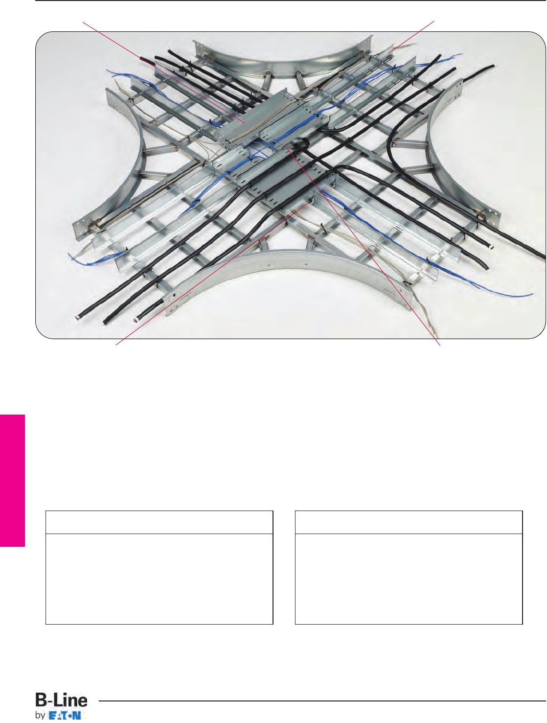
Barrier Bridge
The Barrier Bridge System is made up of four key components: the Elevation Brace, the Cable
Bridge, the Straight Section Barrier, and Hardware Kit(s).
Cable Bridge
Elevation Brace Hardware Kit
Straight Section Barrier
To build a Barrier Bridge, you need to know about your cable tray and your cable runs. Most of
the information is already known when you order your tray system.
Here is what you need to know:
Use the tables on pages BBA-3 through BBA-10 to select your parts. Also select a hardware kit from
page BBA-11.
Cable Tray
• Height or Loading Depth
• Material
• Width
• Fitting Type (HT / HX)
• Fitting Radius
Cable Runs
• Number of Runs
• Approximate Width and Relative
Location of Each Run
BBA-1
Barrier Bridge
Cable Tray Systems
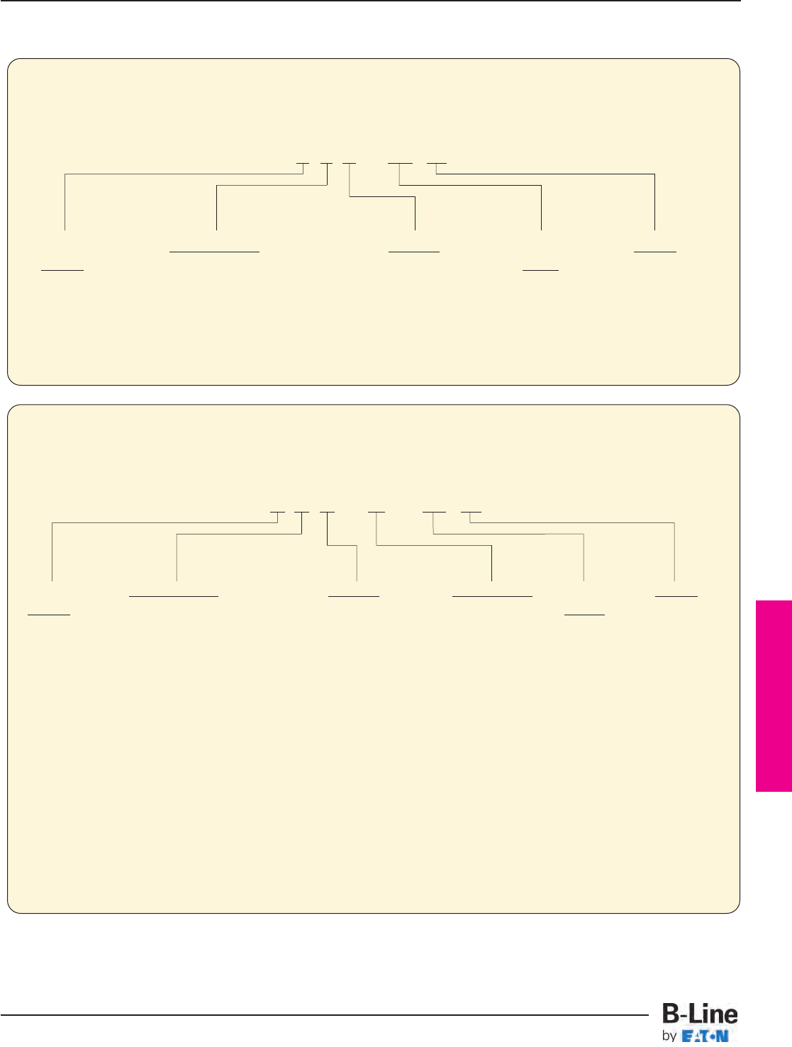
Barrier Bridge
B-Line Sales Engineers are available to assist you in selecting parts for a Barrier Bridge System.
Phone (800) 851-7415 ext. 366
Elevation Brace
The Elevation Brace divides the lower level of cables, much like a standard divider/barrier strip.
It also supports the Cable Bridge.
7 3 A - EB 24
Cable Tray Loading Depth Material Elevation Length
Barrier 3 = 3” (76mm) (4” Siderail) A = Aluminum Brace 24 = 24” (609mm)
4 = 4” (101mm) (5” Siderail) P = Pre-Galvanized 60 = 60” (1524mm)
5 = 5” (127mm) (6” Siderail) G = Hot Dip
6 = 6” (152mm) (7” or 8” Siderail) Galvanized
SS6 = Stainless Steel
Type 316
Cable Bridge
The Cable Bridge supports and retains the upper level of cables.
7 3 A - 12 - CB 20
Cable Tray Loading Depth Material Bridge Width Cable Length
Barrier 3 = 3” (76mm) (4” Siderail) A = Aluminum 03 = 3” (76mm) Bridge 05 = 4.5” (114mm)
4 = 4” (101mm) (5” Siderail) P = Pre-Galvanized 06 = 6” (152mm) 08 = 7.5” (190mm)
5 = 5” (127mm) (6” Siderail) G = Hot Dip 09 = 9” (228mm) 11 = 10.5” (267mm)
6 = 6” (152mm) (7” or 8” Siderail) Galvanized 12 = 12” (305mm) 14 = 13.5” (343mm)
SS6 = Stainless Steel 18 = 18” (457mm) 17 = 16.5” (419mm)
Type 316 24 = 24” (609mm) 20 = 19.5” (495mm)
30 = 30” (762mm) 23 = 22.5” (571mm)
36 = 36” (914mm) 26 = 25.5” (648mm)
42 = 42” (1067mm) 29 = 28.5” (724mm)
32 = 31.5” (800mm)
35 = 34.5” (976mm)
38 = 37.5” (952mm)
44 = 43.5” (1105mm)
50 = 49.5” (1257mm)
53 = 52.5” (1333mm)
Component Numbering System
BBA-2
Barrier Bridge
Cable Tray Systems
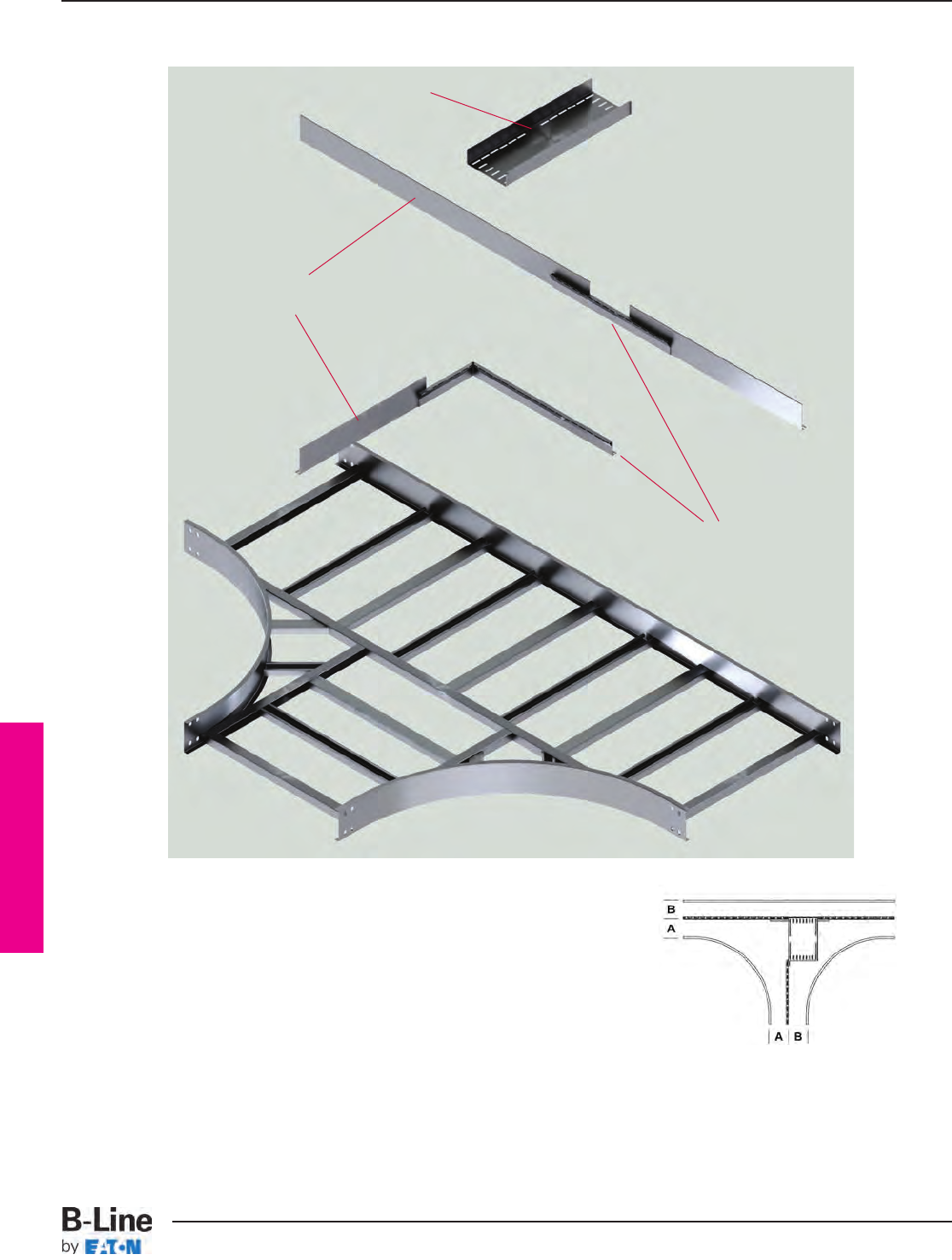
Barrier Bridge
Use the table on page BBA-4 to select parts needed to build your Barrier Bridge
1. On the left, find the width of your tray system.
2. In the second column, select the width of you cable runs within the tray.
B-Line recommends that thicker cables are the ‘A’ run.
3. Move across the chart until you reach the column that is labeled with the radius of your fitting.
The box contains both the quantity and the catalog number of the parts needed for the Barrier Bridge
4. Then select a hardware kit from page BBA-11.
Cable Bridge
for ‘B’ Run
Elevation Brace
Tee Fitting
Straight Section Barrier
Horizontal Tee, Two Cable Runs
BBA-3
Barrier Bridge
Cable Tray Systems
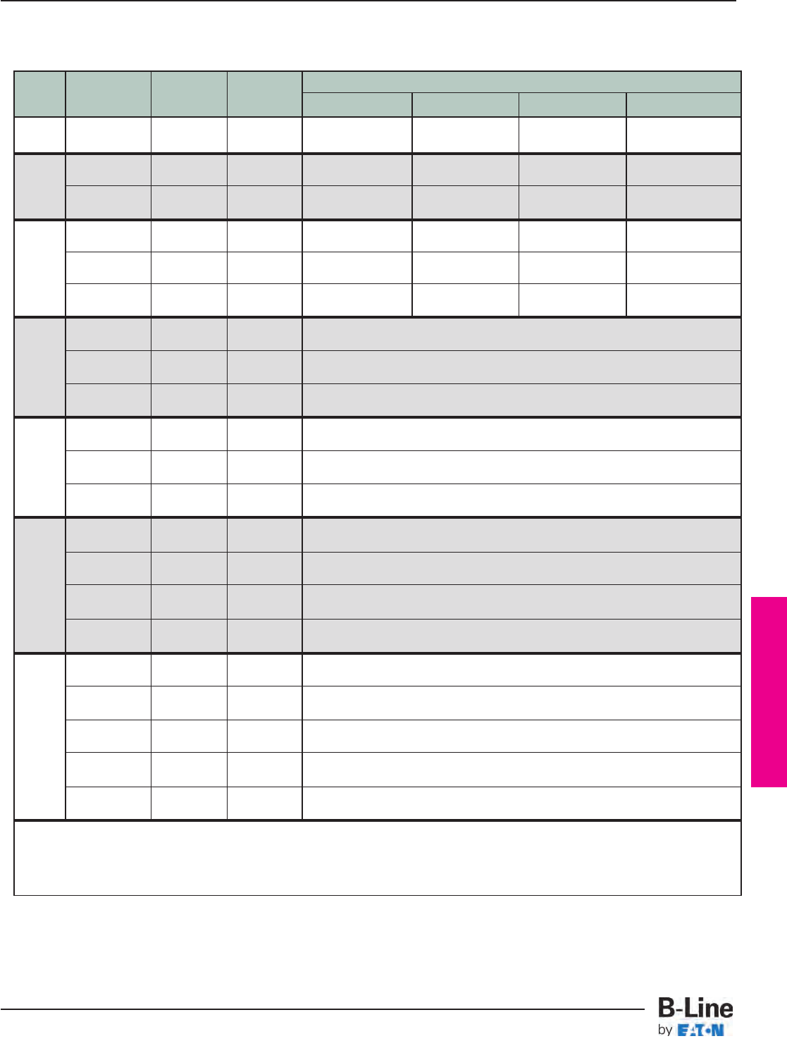
Barrier Bridge
Tray
‘A’ Larger ‘B’ Smaller
Radius
Width Description
Cable Run Cable Run
12" (305mm) 24" (609mm) 36" (914mm) 48" (1219mm)
6” 2 runs 03 03 (1) : 7 # *-03-CB11 (1) : 7 # *-06-CB11 (1) : 7 # *-09-CB11 (1) : 7 # *-12-CB14
(152mm) 03" and 03" (2) : 7 # *-EB24 (2) : 7 # *-EB24 (2) : 7 # *-EB24 (2) : 7 # *-EB24
2 runs 06 03 (1) : 7 # *-03-CB14 (1) : 7 # *-06-CB14 (1) : 7 # *-09-CB14 (1) : 7 # *-12-CB17
9” 06" and 03" (2) : 7 # *-EB24 (2) : 7 # *-EB24 (2) : 7 # *-EB24 (2) : 7 # *-EB24
(228mm) 2 runs 03 06 (1) : 7 # *-06-CB11 (1) : 7 # *-09-CB11 (1) : 7 # *-12-CB11 (1) : 7 # *-18-CB14
03" and 06" (2) : 7 # *-EB24 (2) : 7 # *-EB24 (2) : 7 # *-EB24 (3) : 7 # *-EB24
2 runs 03 09 (1) : 7 # *-03-CB17 (1) : 7 # *-06-CB17 (1) : 7 # *-09-CB17 (1) : 7 # *-12-CB20
03" and 09" (2) : 7 # *-EB24 (2) : 7 # *-EB24 (3) : 7 # *-EB24 (2) : 7 # *-EB24
12” 2 runs 09 03 (1) : 7 # *-09-CB11 (1) : 7 # *-12-CB11 (1) : 7 # *-18-CB11 (1) : 7 # *-24-CB14
(305mm) 09" and 03" (2) : 7 # *-EB24 (2) : 7 # *-EB24 (2) : 7 # *-EB24 (3) : 7 # *-EB24
2 runs 06 06 (1) : 7 # *-06-CB14 (1) : 7 # *-09-CB14 (1) : 7 # *-12-CB14 (1) : 7 # *-18-CB17
06" and 06" (2) : 7 # *-EB24 (2) : 7 # *-EB24 (2) : 7 # *-EB24 (3) : 7 # *-EB24
2 runs 12 06 (1) : 7 # *-06-CB14
12" and 06" (2) : 7 # *-EB24
18” 2 runs 06 12 (1) : 7 # *-12-CB08
(457mm) 06" and 12" (2) : 7 # *-EB24
2 runs 09 09 (1) : 7 # *-09-CB11
09" and 09" (2) : 7 # *-EB24
2 runs 18 06 (1) : 7 # *-06-CB20
18" and 06" (2) : 7 # *-EB24
24” 2 runs 06 18 (1) : 7 # *-18-CB08
(609mm) 06" and 18" (3) : 7 # *-EB24
2 runs 12 12 (1) : 7 # *-12-CB14
12" and 12" (2) : 7 # *-EB24
2 runs 24 06 (1) : 7 # *-06-CB26
24" and 06" (2) : 7 # *-EB24
2 runs 06 24 (1) : 7 # *-24-CB08
30” 06" and 24" (3) : 7 # *-EB24
(762mm) 2 runs 18 12 (1) : 7 # *-12-CB20
18" and 12" (2) : 7 # *-EB24
2 runs 12 18 (1) : 7 # *-18-CB14
12" and 18" (3) : 7 # *-EB24
2 runs 30 06 (1) : 7 # *-06-CB32
30" and 06" (2) : 7 # *-EB24
2 runs 06 30 (1) : 7 # *-30-CB08
06" and 30" (3) : 7 # *-EB24
36” 2 runs 24 12 (1) : 7 # *-12-CB26
(914mm) 24" and 12" (2) : 7 # *-EB24
2 runs 12 24 (1) : 7 # *-24-CB14
12" and 24" (3) : 7 # *-EB24
2 runs 18 18 (1) : 7 # *-18-CB20
18" and 18" (3) : 7 # *-EB24
# = Loading Depth of Tray System – 3", 4", 5", 6"
* = Material (A = aluminum, P = pregalvanized steel, G = hot dip galvanized steel, SS6 = stainless steel 316)
(1, 2, 3, 4 or 5) = Quantity
Horizontal Tee, Two Cable Runs
BBA-4
Barrier Bridge
Cable Tray Systems
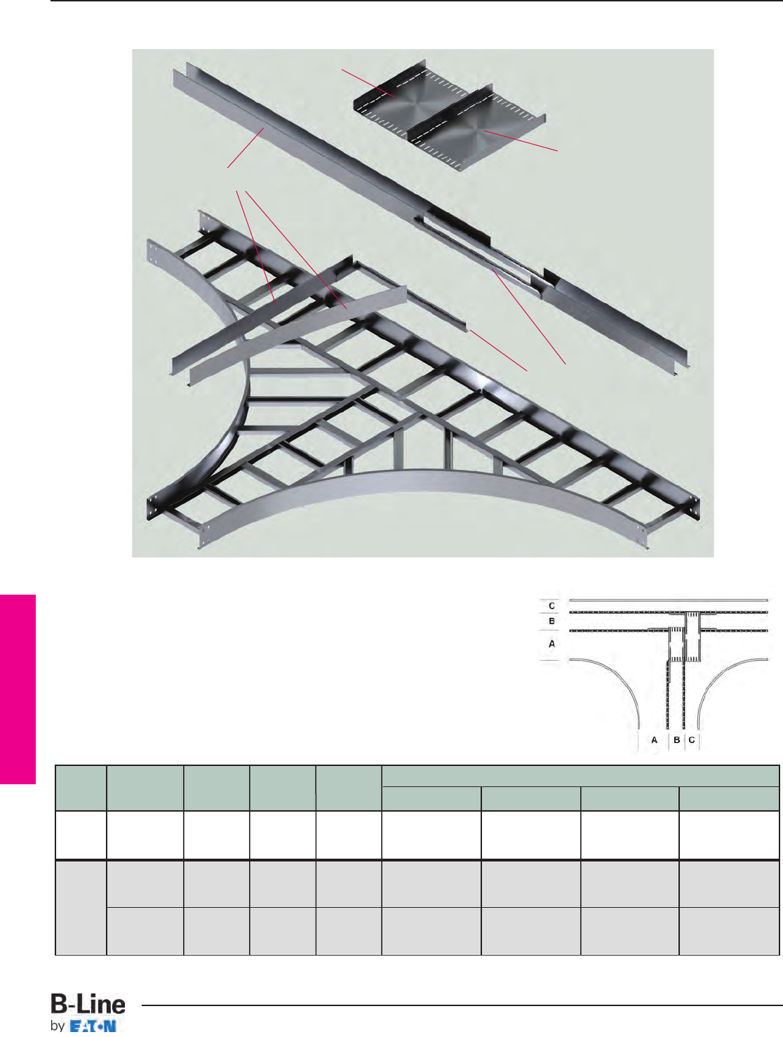
Barrier Bridge
Tray
‘A’ Larger ‘B’ Medium ‘C’ Smaller
Radius
Width Description
Cable Run Cable Run Cable Run
12" (305mm) 24" (609mm) 36" (914mm) 48" (1219mm)
9” 3 runs (1) : 7 # *-03-CB14 (1) : 7 # *-06-CB14 (1) : 7 # *-09-CB14 (1) : 7 # *-12-CB17
(228mm) 03" / 03" / 03” 03 03 03 (1) : 7 # *-03-CB11 (1) : 7 # *-06-CB11 (1) : 7 # *-09-CB11 (1) : 7 # *-12-CB14
(2) : 7 # *-EB24 (3) : 7 # *-EB24 (4) : 7 # *-EB24 (4) : 7 # *-EB24
3 runs (1) : 7 # *-03-CB17 (1) : 7 # *-06-CB17 (1) : 7 # *-09-CB17 (1) : 7 # *-12-CB20
06" / 03" / 03” 06 03 03 (1) : 7 # *-03-CB14 (1) : 7 # *-06-CB14 (1) : 7 # *-09-CB14 (1) : 7 # *-12-CB17
(2) : 7 # *-EB24 (3) : 7 # *-EB24 (4) : 7 # *-EB24 (4) : 7 # *-EB24
12”
(305mm) 3 runs (1) : 7 # *-06-CB14 (1) : 7 # *-09-CB14 (1) : 7 # *-12-CB14 (1) : 7 # *-18-CB17
03" / 03" / 06” 03 03 06 (1) : 7 # *-03-CB11 (1) : 7 # *-06-CB11 (1) : 7 # *-09-CB11 (1) : 7 # *-12-CB14
(3) : 7 # *-EB24 (4) : 7 # *-EB24 (4) : 7 # *-EB24 (4) : 7 # *-EB60
Use the tables below and on page BBA-6 to select parts needed to build your
Barrier Bridge
1. On the left, find the width of your tray system.
2. In the second column, select the width of you cable runs within the tray.
B-Line recommends that thicker cables are the ‘A’ run.
3. Move across the chart until you reach the column that is labeled
with the radius of your fitting.
The box contains both the quantity and the catalog number of the parts
needed for the Barrier Bridge
4. Then select a hardware kit from page BBA-1.
Cable Bridge
for ‘B’ Run
Elevation Brace
Tee Fitting
Straight Section Barrier
Cable Bridge
for ‘C’ Run
Horizontal Tee, Three Cable Runs
BBA-5
Barrier Bridge
Cable Tray Systems
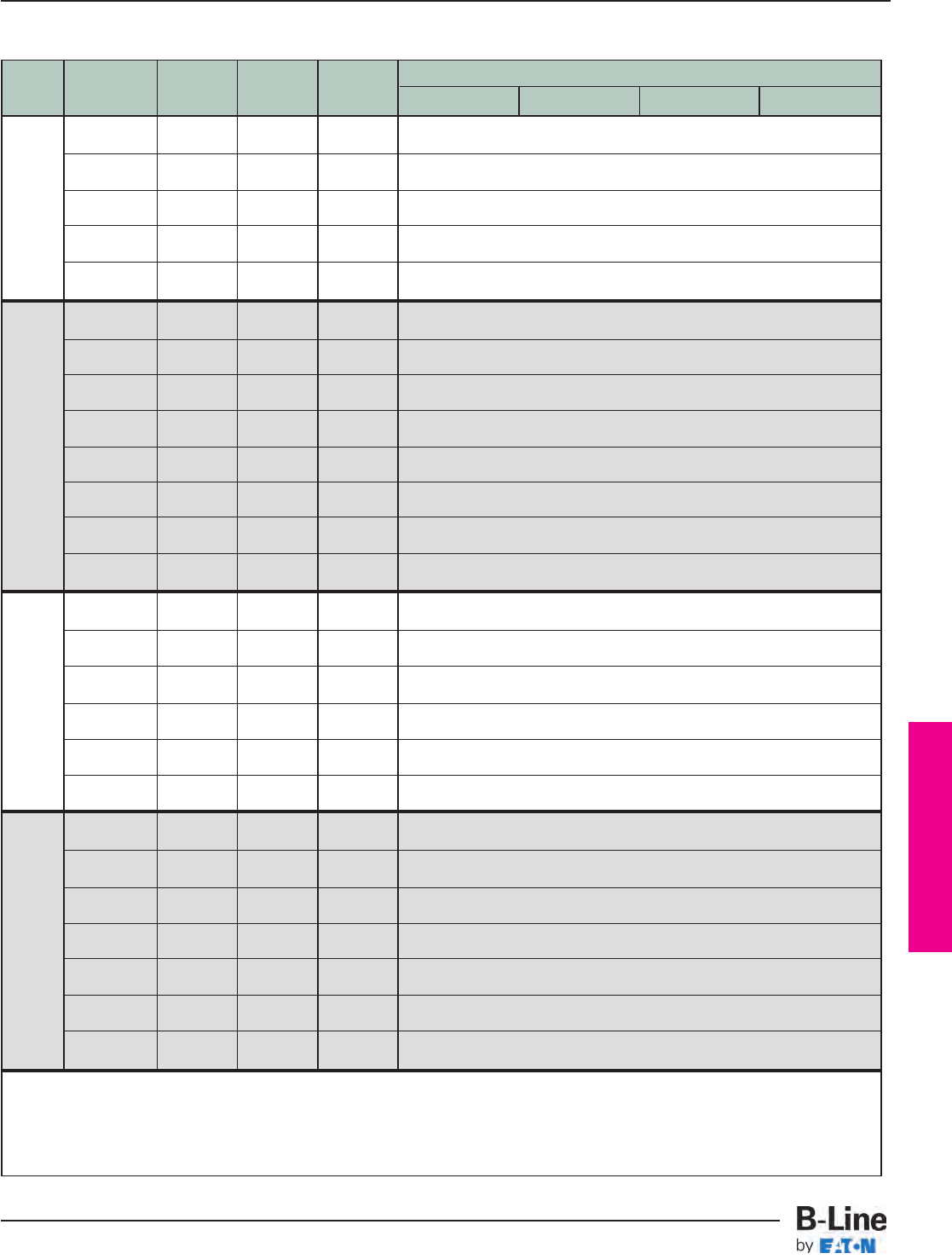
Barrier Bridge
Tray
‘A’ Larger ‘B’ Medium ‘C’ Smaller
Radius
Width Description
Cable Run Cable Run Cable Run
12" (305mm) 24" (609mm) 36" (914mm) 48" (1219mm)
3 runs 12 03 03 (1) : 7 # *-03-CB17 (1) : 7 # *-03-CB14 (2) : 7 # *-EB24
12" / 03" / 03”
3 runs 03 03 12 (1) : 7 # *-12-CB08 (1) : 7 # *-03-CB05 (4) : 7 # *-EB24
03" / 03" / 12”
18” 3 runs 09 06 03 (1) : 7 # *-03-CB17 (1) : 7 # *-06-CB11 (3) : 7 # *-EB24
(457mm) 09" / 06" / 03”
3 runs 03 06 09 (1) : 7 # *-09-CB11 (1) : 7 # *-06-CB05 (4) : 7 # *-EB24
03" / 06" / 09”
3 runs 06 06 06 (1) : 7 # *-06-CB14 (1) : 7 # *-06-CB08 (3) : 7 # *-EB24
06" / 06" / 06”
3 runs 18 03 03 (1) : 7 # *-03-CB23 (1) : 7 # *-03-CB20 (2) : 7 # *-EB24
18" / 03" / 03”
3 runs 03 03 18 (1) : 7 # *-18-CB08 (1) : 7 # *-03-CB05 (4) : 7 # *-EB24
03" / 03" / 18”
3 runs 12 09 03 (1) : 7 # *-03-CB23 (1) : 7 # *-09-CB14 (3) : 7 # *-EB24
12" / 09" / 03”
3 runs 03 09 12 (1) : 7 # *-12-CB14 (1) : 7 # *-09-CB05 (4) : 7 # *-EB24
24” 03" / 09" / 12”
(609mm) 3 runs 12 06 06 (1) : 7 # *-06-CB20 (1) : 7 # *-06-CB14 (3) : 7 # *-EB24
12" / 06" / 06”
3 runs 06 06 12 (1) : 7 # *-12-CB14 (1) : 7 # *-06-CB08 (4) : 7 # *-EB24
06" / 06" / 12”
3 runs 09 09 06 (1) : 7 # *-06-CB20 (1) : 7 # *-09-CB11 (4) : 7 # *-EB24
09" / 09" / 06”
3 runs 06 09 09 (1) : 7 # *-09-CB17 (1) : 7 # *-09-CB08 (4) : 7 # *-EB24
06" / 09" / 09”
3 runs 18 06 06 (1) : 7 # *-06-CB26 (1) : 7 # *-06-CB20 (3) : 7 # *-EB24
18" / 06" / 06”
3 runs 06 06 18 (1) : 7 # *-18-CB14 (1) : 7 # *-06-CB08 (4) : 7 # *-EB24
06" / 06" / 18”
3 runs 12 12 06 (1) : 7 # *-06-CB26 (1) : 7 # *-12-CB14 (4) : 7 # *-EB24
30” 12" / 12" / 06”
(762mm) 3 runs 06 12 12 (1) : 7 # *-12-CB20 (1) : 7 # *-12-CB08 (4) : 7 # *-EB24
06" / 12" / 12”
3 runs 12 09 09 (1) : 7 # *-09-CB23 (1) : 7 # *-09-CB14 (4) : 7 # *-EB24
12" / 09" / 09”
3 runs 09 09 12 (1) : 7 # *-12-CB20 (1) : 7 # *-09-CB11 (4) : 7 # *-EB24
09" / 09" / 12”
3 runs 24 06 06 (1) : 7 # *-06-CB32 (1) : 7 # *-06-CB26 (3) : 7 # *-EB24
24" / 06" / 06”
3 runs 06 06 24 (1) : 7 # *-24-CB14 (1) : 7 # *-06-CB08 (4) : 7 # *-EB24
06" / 06" / 24”
3 runs 18 12 06 (1) : 7 # *-06-CB32 (1) : 7 # *-12-CB20 (4) : 7 # *-EB24
36” 18" / 12" / 06”
(914mm) 3 runs 06 12 18 (1) : 7 # *-18-CB20 (1) : 7 # *-12-CB08 (4) : 7 # *-EB24
06" / 12" / 18”
3 runs 18 09 09 (1) : 7 # *-09-CB29 (1) : 7 # *-09-CB20 (4) : 7 # *-EB24
18" / 09" / 09”
3 runs 09 09 18 (1) : 7 # *-18-CB20 (1) : 7 # *-09-CB11 (4) : 7 # *-EB24
09" / 09" / 18”
3 runs 12 12 12 (1) : 7 # *-12-CB26 (1) : 7 # *-12-CB14 (4) : 7 # *-EB24
12" / 12" / 12”
# = Loading Depth of Tray System – 3", 4", 5", 6"
* = Material (A = aluminum, P = pregalvanized steel, G = hot dip galvanized steel, SS6 = stainless steel 316)
(1, 2, 3, 4 or 5) = Quantity
Horizontal Tee, Three Cable Runs
BBA-6
Barrier Bridge
Cable Tray Systems
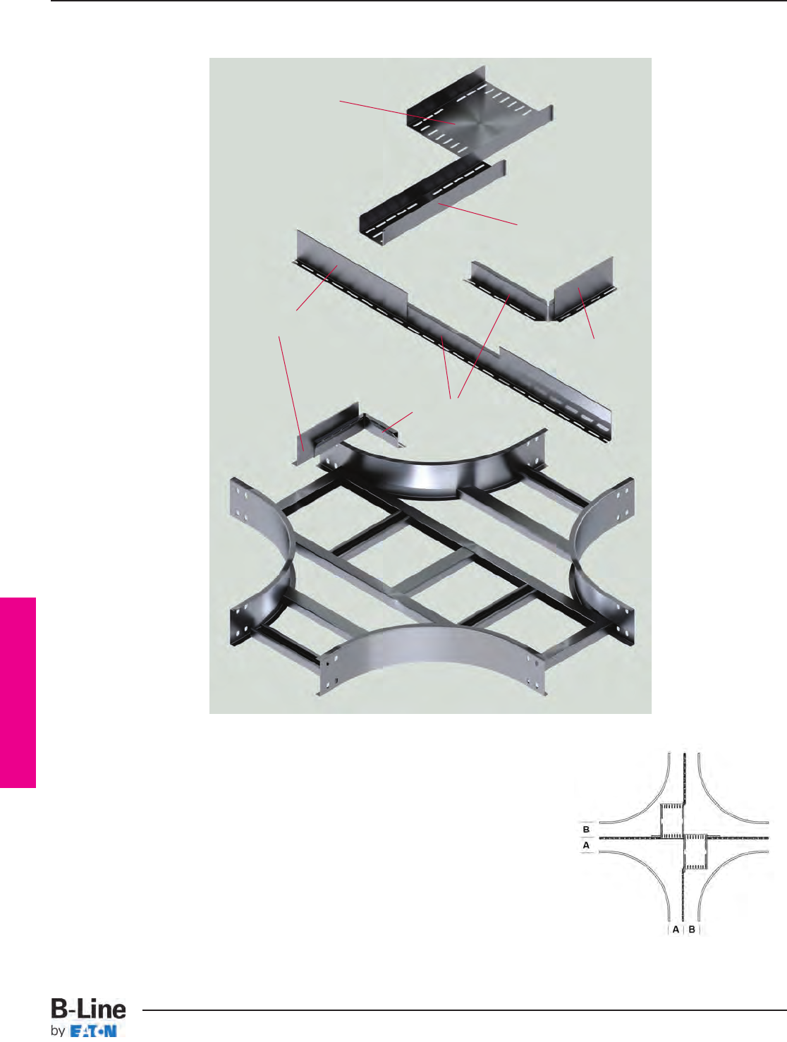
Barrier Bridge
Use the table on page BBA-8 to select parts needed to build your Barrier Bridge
1. On the left, find the width of your tray system.
2. In the second column, select the width of you cable runs within the tray.
B-Line recommends that thicker cables are the ‘A’ run.
3. Move across the chart until you reach the column that is labeled with
the radius of your fitting. The box contains both the quantity and the
catalog number of the parts needed for the Barrier Bridge
4. Then select a hardware kit from page BBA-7.
Cable Bridge
for ‘B’ Run
Elevation Brace
Cross Fitting
Straight Section Barrier
Straight Section
Barrier
Cable Bridge
for ‘B’ Run
Horizontal Cross, Two Cable Runs
BBA-7
Barrier Bridge
Cable Tray Systems
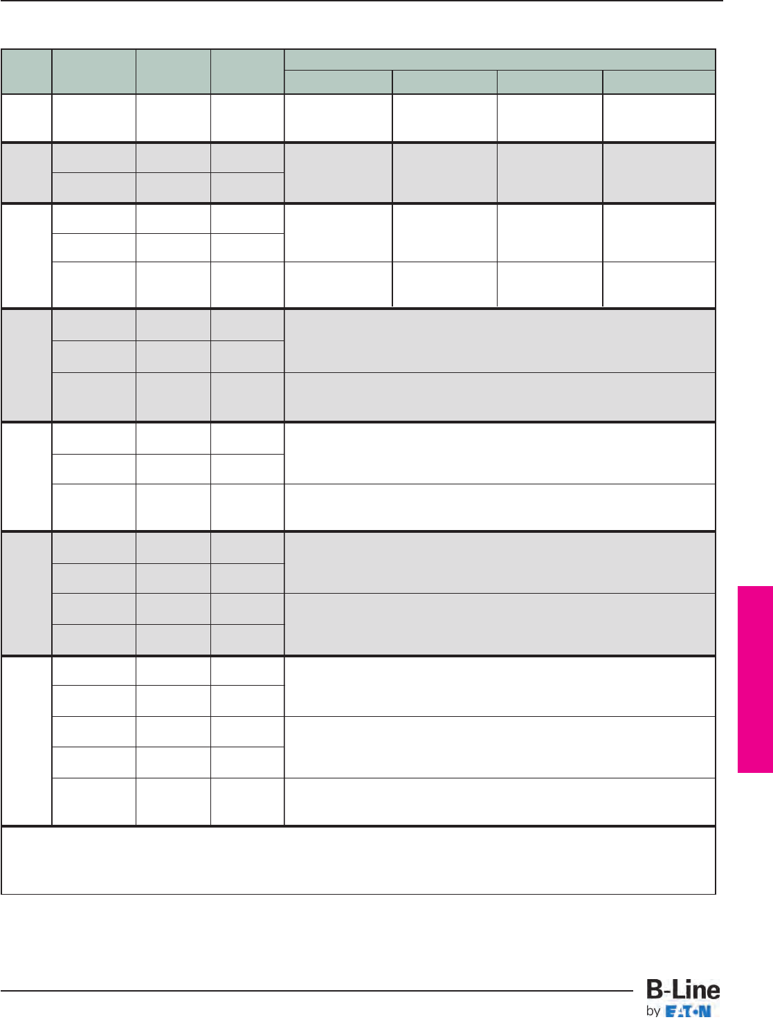
Barrier Bridge
Tray
‘A’ Larger ‘B’ Smaller
Radius
Width Description
Cable Run Cable Run
12" (305mm) 24" (609mm) 36" (914mm) 48" (1219mm)
6” 2 runs (1) : 7 # *-03-CB11 (1) : 7 # *-06-CB11 (1) : 7 # *-09-CB11 (1) : 7 # *-12-CB14
(152mm) 03" and 03" 03 03 (1) : 7 # *-03-CB11 (1) : 7 # *-06-CB11 (1) : 7 # *-09-CB11 (1) : 7 # *-12-CB14
(2) : 7 # *-EB24 (3) : 7 # *-EB24 (4) : 7 # *-EB24 (4) : 7 # *-EB24
2 runs 06 03 (1) : 7 # *-06-CB11 (1) : 7 # *-09-CB11 (1) : 7 # *-12-CB11 (1) : 7 # *-18-CB14
9” 06" and 03"
(228mm) 2 runs 03 06
(1) : 7 # *-03-CB14 (1) : 7 # *-06-CB14 (1) : 7 # *-09-CB14 (1) : 7 # *-12-CB17
03" and 06" (3) : 7 # *-EB24 (4) : 7 # *-EB24 (4) : 7 # *-EB24 (4) : 7 # *-EB60
2 runs 09 03 (1) : 7 # *-09-CB11 (1) : 7 # *-12-CB11 (1) : 7 # *-18-CB11 (1) : 7 # *-24-CB14
09" and 03"
12” 2 runs 03 09
(1) : 7 # *-03-CB17 (1) : 7 # *-06-CB17 (1) : 7 # *-09-CB17 (1) : 7 # *-12-CB20
03" and 09" (3) : 7 # *-EB24 (4) : 7 # *-EB24 (4) : 7 # *-EB60 (4) : 7 # *-EB60
(305mm)
2 runs (1) : 7 # *-06-CB14 (1) : 7 # *-09-CB14 (1) : 7 # *-12-CB14 (1) : 7 # *-18-CB17
06 06 (1) : 7 # *-06-CB14 (1) : 7 # *-09-CB14 (1) : 7 # *-12-CB14 (1) : 7 # *-18-CB17
06" and 06" (3) : 7 # *-EB24 (4) : 7 # *-EB24 (4) : 7 # *-EB24 (4) : 7 # *-EB60
2 runs 12 06 (1) : 7 # *-12-CB08
12" and 06" (1) : 7 # *-06-CB14
18” 2 runs 06 12 (4) : 7 # *-EB24
(457mm) 06" and 12"
2 runs (1) : 7 # *-09-CB11
09" and 09" 09 09 (1) : 7 # *-09-CB11
(4) : 7 # *-EB24
2 runs 18 06 (1) : 7 # *-18-CB08
18" and 06" (1) : 7 # *-06-CB20
24” 2 runs 06 18 (4) : 7 # *-EB24
(609mm) 06" and 18"
2 runs (1) : 7 # *-12-CB14
12" and 12" 12 12 (1) : 7 # *-12-CB14
(4) : 7 # *-EB24
2 runs 24 06 (1) : 7 # *-24-CB08
24" and 06" (1) : 7 # *-06-CB26
2 runs 06 24 (4) : 7 # *-EB60
30” 06" and 24"
(762mm) 2 runs 18 12 (1) : 7 # *-18-CB14
18" and 12" (1) : 7 # *-12-CB20
2 runs 12 18 (4) : 7 # *-EB60
12" and 18"
2 runs 30 06 (1) : 7 # *-30-CB08
30" and 06" (1) : 7 # *-06-CB32
2 runs 06 30 (4) : 7 # *-EB60
06" and 30"
36” 2 runs 24 12 (1) : 7 # *-24-CB14
(914mm) 24" and 12" (1) : 7 # *-12-CB26
2 runs 12 24 (4) : 7 # *-EB60
12" and 24"
2 runs (1) : 7 # *-18-CB20
18" and 18" 18 18 (1) : 7 # *-18-CB20
(4) : 7 # *-EB60
# = Loading Depth of Tray System – 3", 4", 5", 6"
* = Material (A = aluminum, P = pregalvanized steel, G = hot dip galvanized steel, SS6 = stainless steel 316)
(1, 2, 3, 4 or 5) = Quantity
Horizontal Cross, Two Cable Runs
BBA-8
Barrier Bridge
Cable Tray Systems
Barrier Bridge
Tray
‘A’ Larger ‘B’ Medium ‘C’ Smaller
Radius
Width Description
Cable Run Cable Run Cable Run
12" (305mm) 24" (609mm) 36" (914mm) 48" (1219mm)
(1) : 7 # *-03-CB14 (1) : 7 # *-06-CB14 (1) : 7 # *-09-CB14 (1) : 7 # *-12-CB17
9” 3 runs (1) : 7 # *-03-CB11 (1) : 7 # *-06-CB11 (1) : 7 # *-09-CB11 (1) : 7 # *-12-CB14
(228mm) 03" / 03" / 03” 03 03 03 (1) : 7 # *-03-CB11 (1) : 7 # *-06-CB11 (1) : 7 # *-09-CB11 (1) : 7 # *-12-CB14
(1) : 7 # *-03-CB14 (1) : 7 # *-06-CB14 (1) : 7 # *-09-CB14 (1) : 7 # *-12-CB17
(3) : 7 # *-EB24 (5) : 7 # *-EB24 (5) : 7 # *-EB60 (5) : 7 # *-EB60
3 runs (1) : 7 # *-06-CB14 (1) : 7 # *-09-CB14 (1) : 7 # *-12-CB14 (1) : 7 # *-18-CB17
12” 06" / 03" / 03” 06 03 03 (1) : 7 # *-03-CB11 (1) : 7 # *-06-CB11 (1) : 7 # *-09-CB11 (1) : 7 # *-12-CB14
(305mm) 3 runs (1) : 7 # *-03-CB14 (1) : 7 # *-06-CB14 (1) : 7 # *-09-CB14 (1) : 7 # *-12-CB17
03" / 03" / 06” 03 03 06 (1) : 7 # *-03-CB17 (1) : 7 # *-06-CB17 (1) : 7 # *-09-CB17 (1) : 7 # *-12-CB20
(3) : 7 # *-EB24 (5) : 7 # *-EB24 (5) : 7 # *-EB60 (5) : 7 # *-EB60
Use the tables below and on page BBA-10 to select parts needed to build your
Barrier Bridge
1. On the left, find the width of your tray system.
2. In the second column, select the width of you cable runs within the tray.
B-Line recommends that thicker cables are the ‘A’ run.
3. Move across the chart until you reach the column that is labeled
with the radius of your fitting.
The box contains both the quantity and the catalog number of the
parts needed for the Barrier Bridge
4. Then select a hardware kit from page BBA-9.
Cable Bridge
for ‘A’ Run
Elevation Brace
Cross Fitting
Straight Section
Barrier
Straight Section
Barrier
Cable Bridge
for ‘C’ Runs
Cable Bridge 1
for ‘B’ Run
Cable Bridge 2
for ‘B’ Run
Horizontal Cross, Three Cable Runs
BBA-9
Barrier Bridge
Cable Tray Systems
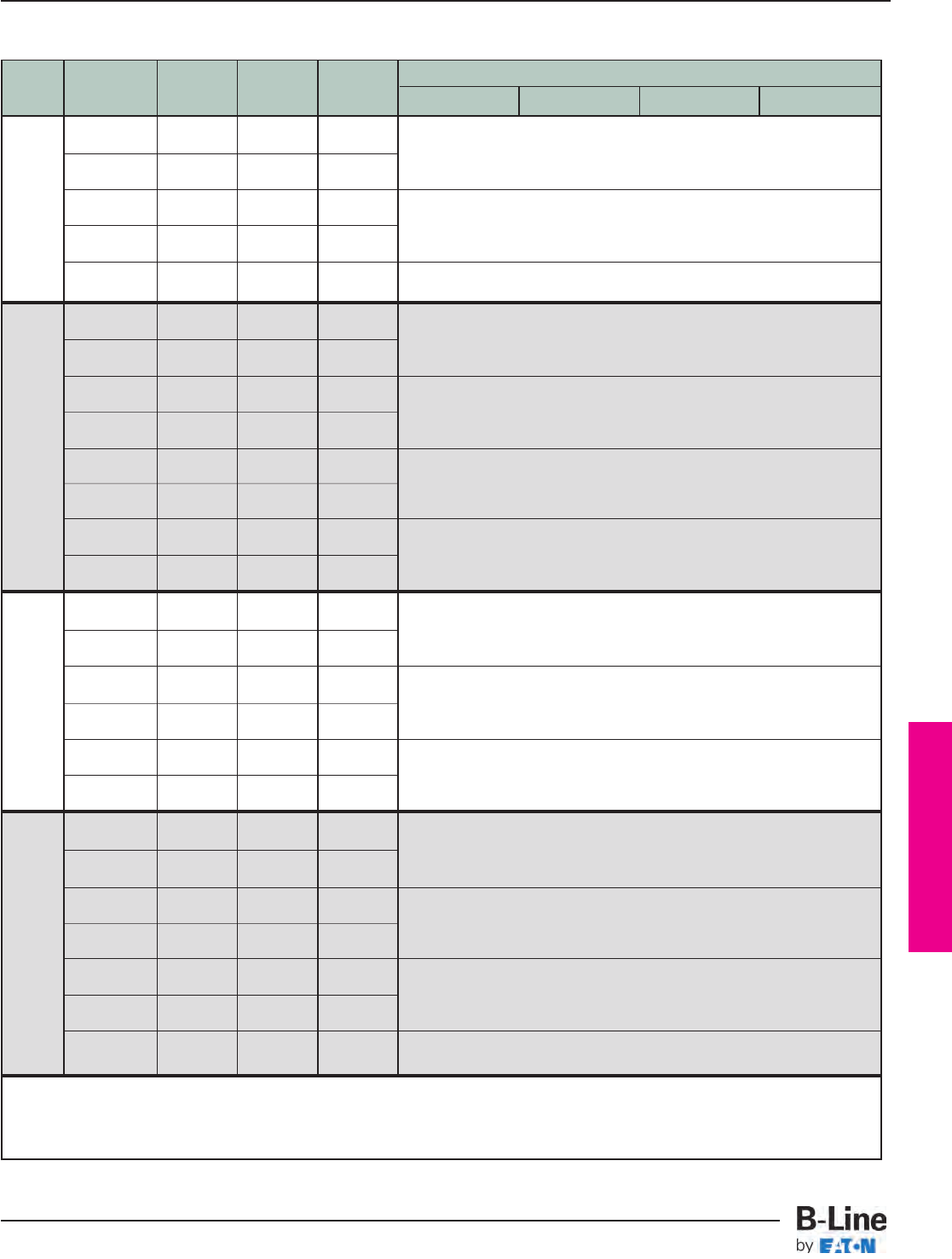
Barrier Bridge
Tray
‘A’ Larger ‘B’ Medium ‘C’ Smaller
Radius
Width Description
Cable Run Cable Run Cable Run
12" (305mm) 24" (609mm) 36" (914mm) 48" (1219mm)
3 runs 12 03 03
12" / 03" / 03” (1) : 7 # *-12-CB08 (1) : 7 # *-03-CB05 (1) : 7 # *-03-CB14
3 runs 03 03 12 (1) : 7 # *-03-CB17 (5) : 7 # *-EB24
03" / 03" / 12”
18” 3 runs 09 06 03
(457mm) 09" / 06" / 03” (1) : 7 # *-09-CB11 (1) : 7 # *-06-CB05 (1) : 7 # *-06-CB11
3 runs 03 06 09 (1) : 7 # *-03-CB17 (5) : 7 # *-EB24
03" / 06" / 09”
3 runs 06 06 06 (1) : 7 # *-06-CB14 (1) : 7 # *-06-CB08 (1) : 7 # *-06-CB08
06" / 06" / 12” (1) : 7 # *-06-CB14 (5) : 7 # *-EB24
3 runs 18 03 03
18" / 03" / 03” (1) : 7 # *-18-CB08 (1) : 7 # *-03-CB05 (1) : 7 # *-03-CB20
3 runs 03 03 18 (1) : 7 # *-03-CB23 (5) : 7 # *-EB24
03" / 03" / 18”
3 runs 12 09 03
12" / 09" / 03” (1) : 7 # *-12-CB14 (1) : 7 # *-09-CB05 (1) : 7 # *-09-CB14
3 runs 03 09 12 (1) : 7 # *-03-CB23 (5) : 7 # *-EB24
24” 03" / 09" / 12”
(609mm) 3 runs 12 06 06
12" / 06" / 06” (1) : 7 # *-12-CB14 (1) : 7 # *-06-CB08 (1) : 7 # *-06-CB14
3 runs 06 06 12 (1) : 7 # *-06-CB20 (5) : 7 # *-EB24
06" / 06" / 12”
3 runs 09 09 06
09" / 09" / 06” (1) : 7 # *-09-CB17 (1) : 7 # *-09-CB08 (1) : 7 # *-09-CB11
3 runs 06 09 09 (1) : 7 # *-06-CB20 (5) : 7 # *-EB24
06" / 09" / 09”
3 runs 18 06 06
18" / 06" / 06” (1) : 7 # *-18-CB14 (1) : 7 # *-06-CB08 (1) : 7 # *-06-CB20
3 runs 06 06 18 (1) : 7 # *-06-CB26 (5) : 7 # *-EB60
06" / 06" / 18”
3 runs 12 12 06
30” 12" / 12" / 06” (1) : 7 # *-12-CB20 (1) : 7 # *-12-CB08 (1) : 7 # *-12-CB14
(762mm) 3 runs 06 12 12 (1) : 7 # *-06-CB26 (5) : 7 # *-EB60
06" / 12" / 12”
3 runs 12 09 09
12" / 09" / 09” (1) : 7 # *-12-CB20 (1) : 7 # *-09-CB11 (1) : 7 # *-09-CB14
3 runs 09 09 12 (1) : 7 # *-09-CB23 (5) : 7 # *-EB60
09" / 09" / 12”
3 runs 24 06 06
24" / 06" / 06” (1) : 7 # *-24-CB14 (1) : 7 # *-06-CB08 (1) : 7 # *-06-CB26
3 runs 06 06 24 (1) : 7 # *-06-CB32 (5) : 7 # *-EB60
06" / 06" / 24”
3 runs 18 12 06
18" / 12" / 06” (1) : 7 # *-18-CB20 (1) : 7 # *-12-CB11 (1) : 7 # *-12-CB20
36” 3 runs 06 12 18 (1) : 7 # *-06-CB32 (5) : 7 # *-EB60
(914mm) 06" / 12" / 18”
3 runs 18 09 09
18" / 09" / 09” (1) : 7 # *-18-CB20 (1) : 7 # *-09-CB11 (1) : 7 # *-09-CB20
3 runs 09 09 18 (1) : 7 # *-09-CB29 (5) : 7 # *-EB60
09" / 09" / 18”
3 runs 12 12 12 (1) : 7 # *-12-CB26 (1) : 7 # *-12-CB14 (1) : 7 # *-12-CB14
12" / 12" / 12” (1) : 7 # *-12-CB26 (5) : 7 # *-EB60
# = Loading Depth of Tray System – 3", 4", 5", 6"
* = Material (A = aluminum, P = pregalvanized steel, G = hot dip galvanized steel, SS6 = stainless steel 316)
(1, 2, 3, 4 or 5) = Quantity
Horizontal Cross, Three Cable Runs
BBA-10
Barrier Bridge
Cable Tray Systems
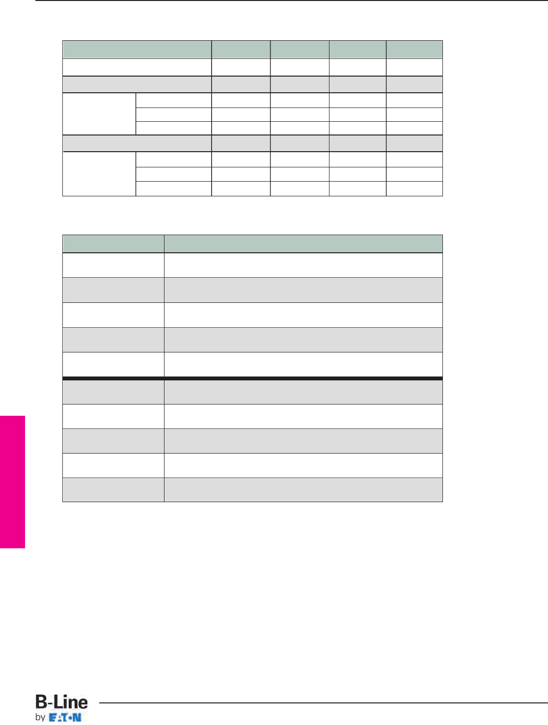
Barrier Bridge
Visit the Barrier Bridge webpage for additional tools and resources:
• Installation instructions
• CAD details
• Submittal sheets
www.cooperbline.com/barrier-bridge
Fitting HX - 2 runs HX - 3 runs HT - 2 runs HT - 3 runs
Redi-Rail/Series 2-5 Aluminum 7ZN-HK1 7ZN-HK1 7ZN-HK1 7ZN-HK1
Series 1 Pre-Galv 7ZN-HK1 7ZN-HK1 7ZN-HK1 7ZN-HK1
Series 2-5
Alternating Strut Rung
7ZN-HK2 7ZN-HK3 7ZN-HK4 7ZN-HK5
Pre-Galv
Up Strut Rung
7ZN-HK2 7ZN-HK3 7ZN-HK4 7ZN-HK5
Down Strut Rung
7ZN-HK1 7ZN-HK1 7ZN-HK1 7ZN-HK1
Series 1 HDG 7SS-HK1 7SS-HK1 7SS-HK1 7SS-HK1
Series 2-5
Alternating Strut Rung
7SS-HK2 7SS-HK3 7SS-HK4 7SS-HK5
HDG &
Up Strut Rung
7SS-HK2 7SS-HK3 7SS-HK4 7SS-HK5
Stainless Steel
Down Strut Rung
7SS-HK1 7SS-HK1 7SS-HK1 7SS-HK1
Catalog Number Hardware
7ZN-HK1 (60) PPHSD #10 x 1/2ZN Self-Drilling Phillips Head Screws
7ZN-HK2 (60) PPHSD #10 x 1/2ZN Self-Drilling Phillips Head Screws
(7) 9ZN-1204NB Hold-Down Clamps
7ZN-HK3 (60) PPHSD #10 x 1/2ZN Self-Drilling Phillips Head Screws
(10) 9ZN-1204NB Hold-Down Clamps
7ZN-HK4 (60) PPHSD #10 x 1/2ZN Self-Drilling Phillips Head Screws
(5) 9ZN-1204NB Hold-Down Clamps
7ZN-HK5 (60) PPHSD #10 x 1/2ZN Self-Drilling Phillips Head Screws
(8) 9ZN-1204NB Hold-Down Clamps
7SS-HK1 (60) PPHSD #10 x 1/2SS410 Self-Drilling Phillips Head Screws
7SS-HK2 (60) PPHSD #10 x 1/2SS410 Self-Drilling Phillips Head Screws
(7) 9SS6-1204NB Hold-Down Clamps
7SS-HK3 (60) PPHSD #10 x 1/2SS410 Self-Drilling Phillips Head Screws
(10) 9SS6-1204NB Hold-Down Clamps
7SS-HK4 (60) PPHSD #10 x 1/2SS410 Self-Drilling Phillips Head Screws
(5) 9SS6-1204NB Hold-Down Clamps
7SS-HK5 (60) PPHSD #10 x 1/2SS410 Self-Drilling Phillips Head Screws
(8) 9SS6-1204NB Hold-Down Clamps
Hardware Kits
BBA-11
Barrier Bridge
Cable Tray Systems
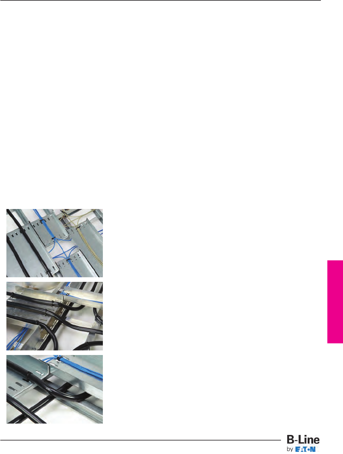
Barrier Bridge
Barrier Bridge is an ideal solution for keeping cable runs divided at horizontal tees and
crosses. Cables are separated for code compliance, protection, and organization. Keeping
cables separate at fittings has always been a challenge, but the process is now simplified
with the Barrier Bridge.
Benefits of the product include:
• Code Compliance:
Eliminate questions on the jobsite with an obvious and visible solid metal barrier
between cable types.
• Cable Protection:
Minimize the potential for signal interference at the weakest link – the intersection.
• Design Simplicity:
Make your design intention clear with available CAD details, template specifications,
and submittal data sheets.
• Labor Savings:
Speed up your installation by having a plan for intersections and having the right
pieces and parts for each fitting.
In addition, the Barrier Bridge solution offers the
following features:
• Slots for easy attachment of cable ties
• Raised sides of top level to retain cables
• Smooth, hemmed edges to protect cable
• Pre-engineered products for two (2) or
three (3) cable runs
• Installation steps that use standard tools
The Barrier Bridge Solution
BBA-12
Barrier Bridge
Cable Tray Systems
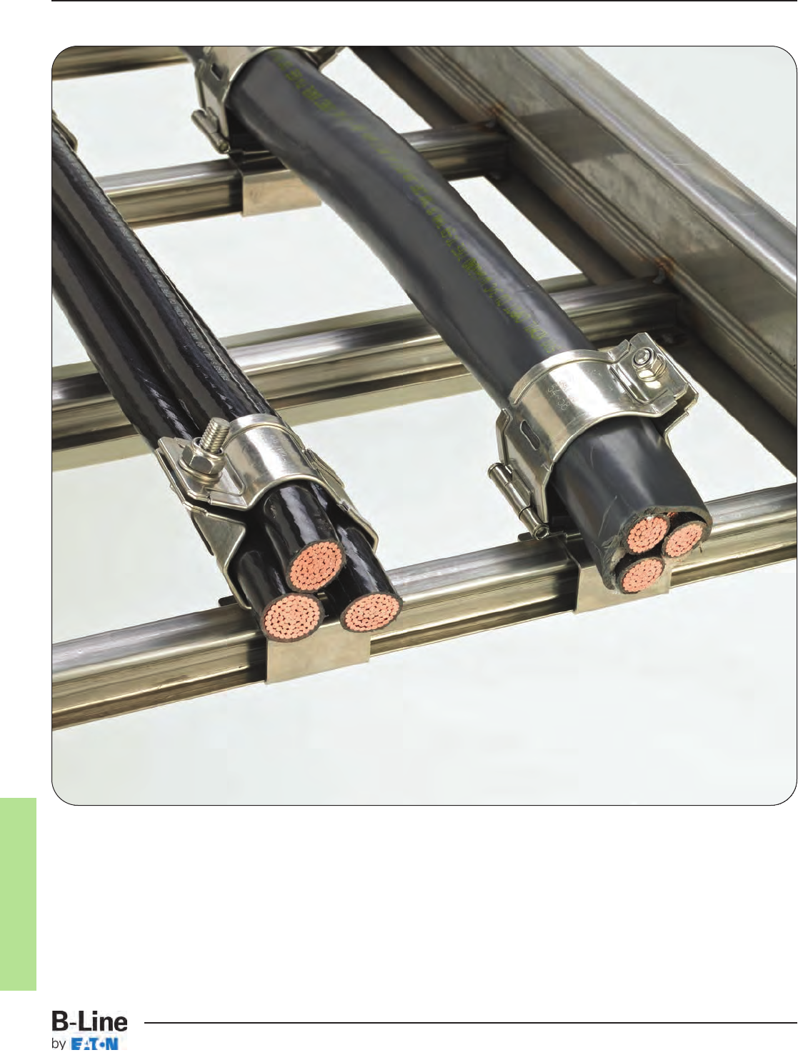
Cable Cleats
CFX-1
Cable Cleats
Cable Tray Systems
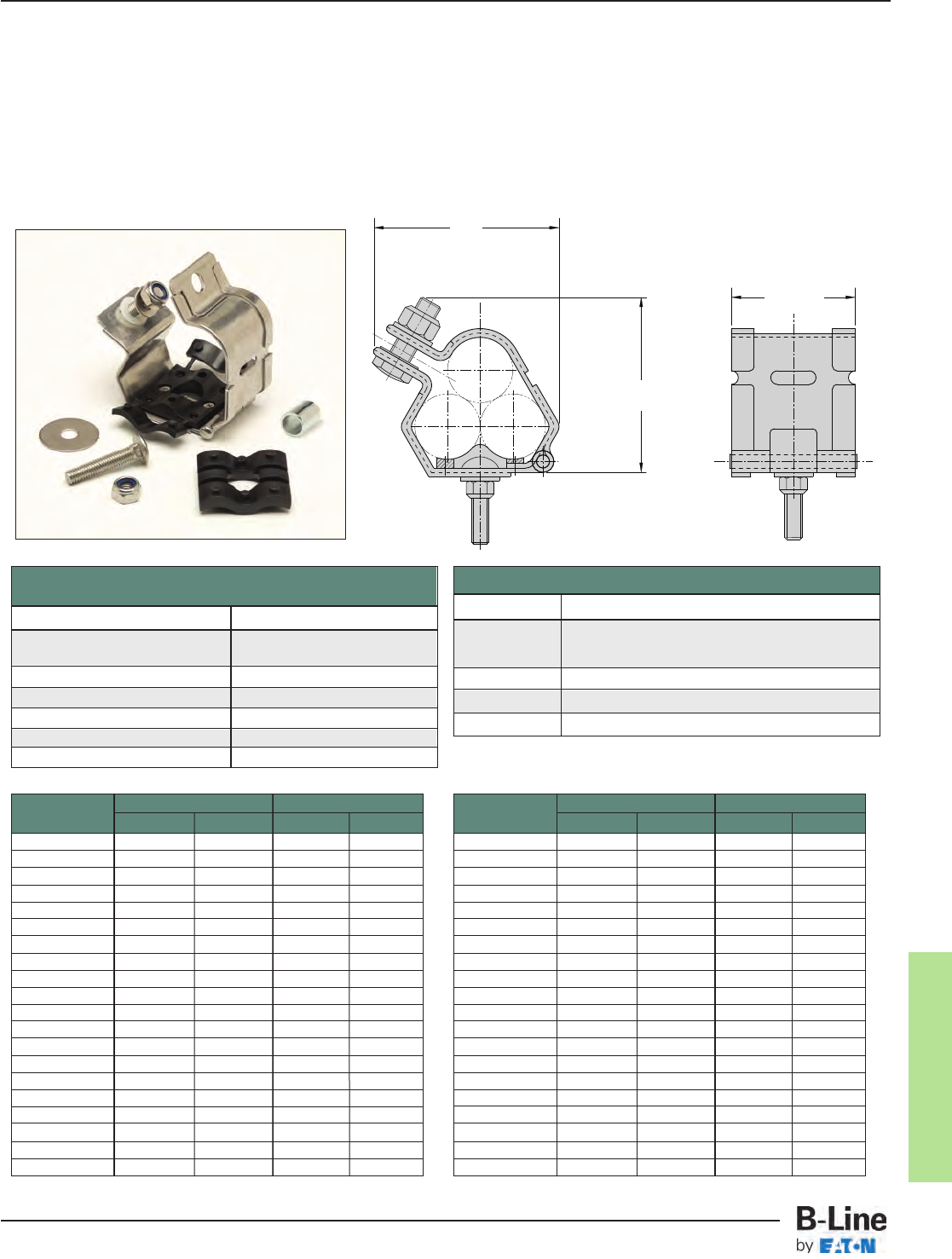
Cable Cleats
BS EN 50368:2003 (Cable Cleats for Electric Installations)
Classification
Cleat Type Composite
Resistance to 130 kA peak / 50 kA RMS
Electromechanical Force 600 mm spacing
Lateral Load Test 3.439 kg average
Axial Load Test Pass
Operating Temperature Range -40°C to +60°C
Impact Resistance Very Heavy
Needle Flame Test 30 seconds
Technical Specifications
Frame 50mm x 2mm Marine grade, Non-magnetic 316L
Closure Hardware Captive 316 Stainless Steel M8 or M10 (M12 available)
bolt and nylon-lock nut (Optional Hex Flange
Lock Nut available)
Integral Pad Low Smoke, Low Fume, Zero Halogen
Tools Required Impact Wrench
Mounting Bolt Provided with Cable Cleat
Cable Range (mm) Dimensions (mm)
Part No. Min. Dia. Max. Dia. HW
9SS6-CCT1323 13 22 74 66
9SS6-CCT2125 21 25 77 70
9SS6-CCT2329 23 29 81 78
9SS6-CCT2531 25 31 84 81
9SS6-CCT2733 27 33 86 83
9SS6-CCT2935 29 35 90 89
9SS6-CCT3238 32 38 94 95
9SS6-CCT3541 35 41.5 98 100
9SS6-CCT3844 38 44.5 101 104
9SS6-CCT4248 42 48 105 111
9SS6-CCT4551 45 51 109 117
9SS6-CCT4753 47 53 111 120
9SS6-CCT4955 49 55 114 124
9SS6-CCT5157 51 57 116 127
9SS6-CCT5359 53 59 119 133
9SS6-CCT5561 55 61 127 137
9SS6-CCT5763 57 63 126 140
9SS6-CCT5965 59 65 128 144
9SS6-CCT6167 61 67 132 147
9SS6-CCT6369 63 69 136 150
Cable Range (mm) Dimensions (mm)
Part No. Min. Dia. Max. Dia. HW
9SS6-CCT6571 65 71 140 153
9SS6-CCT6773 67 73 143 156
9SS6-CCT6975 69 75 147 160
9SS6-CCT7177 71 77 151 163
9SS6-CCT7379 73 79 154 166
9SS6-CCT7581 75 81 158 169
9SS6-CCT7783 77 83 161 173
9SS6-CCT7985 79 85 164 176
9SS6-CCT8187 81 87 169 179
9SS6-CCT8389 83 89 173 182
9SS6-CCT8692 86 92 177 187
9SS6-CCT8896 88 96 181 192
9SS6-CCT9199 91 99 185 196
9SS6-CCT96103 96 103 190 201
9SS6-CCT99107 99 107 194 202
9SS6-CCT103111 103 111 199 204
9SS6-CCT107115 107 115 203 208
9SS6-CCT111119 111 119 208 213
9SS6-CCT115123 115 123 213 217
9SS6-CCT119128 119 128 217 221
Trefoil Cable Cleat with LSF Pad
1. Recommended for installations where the highest levels of short circuit withstand are required.
2. Short circuit current tested in accordance with BS EN 50368:2003 standard.
3. Available for single and trefoil cable applications.
4. LSF-pad incorporates an integral low smoke, low fume, zero halogen pad.
5. Hardware to attach cleat to rung attachment bracket is included with cleat. Bracket must be ordered separately.
W
H
55mm
CFX-2
Cable Cleats
Cable Tray Systems
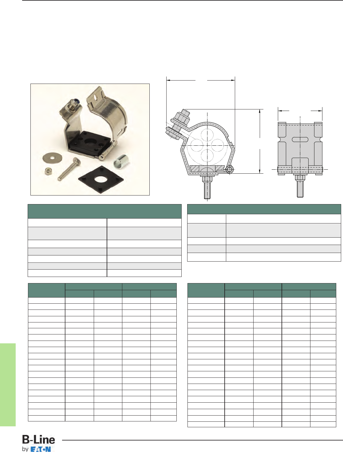
Cable Cleats
Cable Range (mm) Dimensions (mm)
Part No. Min. Dia. Max. Dia. HW
9SS6-CCS2832 28 32 61 55
9SS6-CCS3034 30 34 63 57
9SS6-CCS3236 32 36 65 59
9SS6-CCS3438 34 38 67 61
9SS6-CCS3640 36 40 71 63
9SS6-CCS3842 38 42 69 65
9SS6-CCS4044 40 44 71 67
9SS6-CCS4246 42 46 72 69
9SS6-CCS4448 44 48 74 71
9SS6-CCS4650 46 50 75 73
9SS6-CCS4852 48 52 77 75
9SS6-CCS5054 50 54 79 77
9SS6-CCS5256 52 56 80 79
9SS6-CCS5458 54 58 81 81
9SS6-CCS5660 56 60 83 83
9SS6-CCS5862 58 62 85 85
9SS6-CCS6064 60 64 86 87
9SS6-CCS6266 62 66 88 89
9SS6-CCS6468 64 68 90 91
9SS6-CCS6670 66 70 91 93
Cable Range (mm) Dimensions (mm)
Part No. Min. Dia. Max. Dia. HW
9SS6-CCS6872 68 72 93 95
9SS6-CCS7074 70 74 95 97
9SS6-CCS7276 72 76 97 99
9SS6-CCS7478 74 78 99 101
9SS6-CCS7680 76 80 101 103
9SS6-CCS7882 76 82 103 105
9SS6-CCS8084 80 84 105 107
9SS6-CCS8286 82 86 107 109
9SS6-CCS8488 84 88 109 111
9SS6-CCS8690 86 90 110 113
9SS6-CCS8892 88 192 113 117
9SS6-CCS9094 90 94 116 120
9SS6-CCS9296 92 96 126 127
9SS6-CCS94106 94 106 135 133
9SS6-CCS100112 100 112 140 139
9SS6-CCS106118 106 118 145 145
9SS6-CCS112124 112 124 153 155
9SS6-CCS118130 118 130 162 165
9SS6-CCS127139 127 139 161 167
9SS6-CCS132144 132 144 165 173
9SS6-CCS138150 138 150 170 179
Single Cable Cleat with LSF Pad
1. Recommended for installations where the highest levels of short circuit withstand are required.
2. Short circuit current tested in accordance with BS EN 50368:2003 standard.
3. Available for single and trefoil cable applications.
4. LSF-pad incorporates an integral low smoke, low fume, zero halogen pad.
5. Hardware to attach cleat to rung attachment bracket is included with cleat. Bracket must be ordered separately.
W
H
55mm
BS EN 50368:2003 (Cable Cleats for Electric Installations)
Classification
Cleat Type Composite
Resistance to 130 kA peak / 50 kA RMS
Electromechanical Force 600 mm spacing
Lateral Load Test 3.439 kg average
Axial Load Test Pass
Operating Temperature Range -40°C to +60°C
Impact Resistance Very Heavy
Needle Flame Test 30 seconds
Technical Specifications
Frame 50mm x 2mm Marine grade, Non-magnetic 316L
Closure Hardware Captive 316 Stainless Steel M8 or M10 (M12 available) bolt
and nylon-lock nut (Optional Hex Flange Lock Nut available)
Integral Pad Low Smoke, Low Fume, Zero Halogen
Tools Required Impact Wrench
Mounting Bolt Provided with Cable Cleat
CFX-3
Cable Cleats
Cable Tray Systems
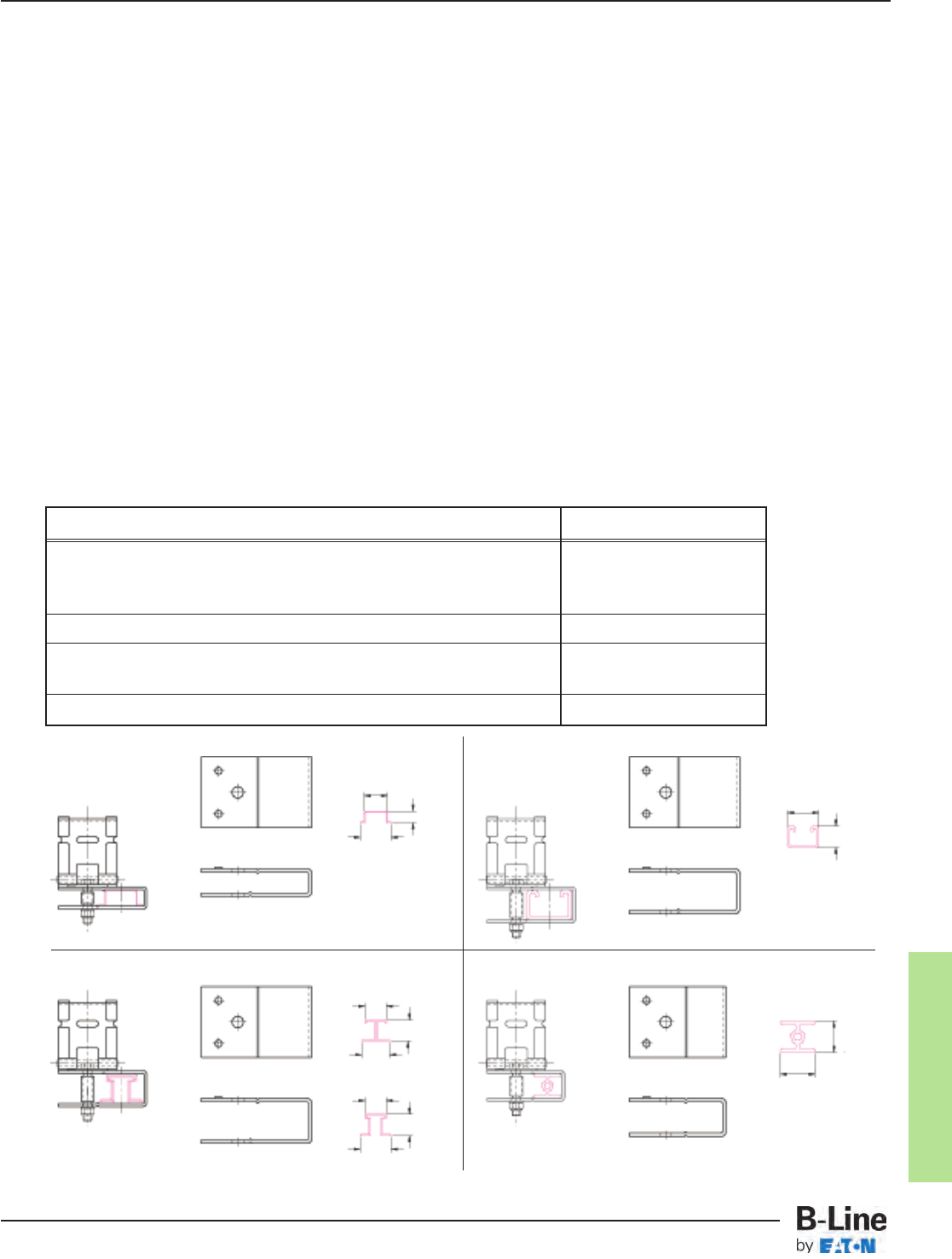
Cable Cleats
Step 1: Know Your Cables
nWhat type of cable is being used?
•Single or Multi-conductor
nWhat is the outside diameter of the cable(s)?
nWhat is the cable arrangement (single conductor cables only)?
•Flat or Trefoil
nIf a ground wire will be installed within the cleat, you will need the ground wire
outside diameter.
Step 2: Know Your System
nWhat is the available short circuit current (RMS or ip(peak))?
nWhat type of B-Line cable tray is installed?
Step 3: Select Your Cable Cleats
nSee Pages CFX-2 & CFX-3
Step 4: Select Your Mounting Bracket
Mounting brackets are used to attach cable cleats to the rungs of the ladder type cable trays.
Your tray type will determine the mounting bracket used.
B-Line Tray Types Mounting Bracket
Aluminum welded rung trays with standard rungs.
Steel Series 2, 3, 4 or 5, trays with standard rungs 9SS6-CCB-C
Fiberglass trays with standard rungs
REDI-Rail™ Cable Tray 9SS6-CCB-D
Steel trays with strut rungs
Aluminum trays with “Marine Rungs” 9SS6-CCB-B
Steel Series 1 trays with standard rungs 9SS6-CCB-A
9SS6-CCB-A
Use with rungs
9SS6-CCB-C
1”
1/2”
11/2”
Use with rungs
1”
1”
11/2”
9SS6-CCB-D Use with rungs
3/4”
9SS6-CCB-B
Use with rungs
15/8”
1”
25/32”
1”
1”
11/2”
CFX-4
Cable Cleats
Cable Tray Systems
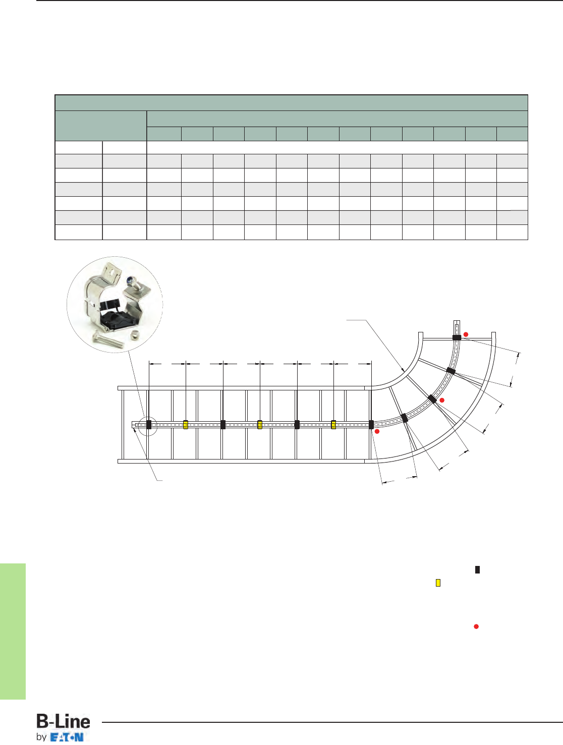
Cable Cleats
Step 5: Determine Cleat Spacing for Installation
Your cable diameter is equal to the spacing between conductor centers shown below.
Find your cable diameter at the top of the table and look down at the column below it.
Find the value equal to or greater than the available short circuit for your system.
Single Conductor Short Circuit Withstand Table
Max. Cable Cleat Spacing Between Conductor Centers (mm)
Spacing (A) 23 25 27 29 31 33 35 37 39 41 43 45
mm In. ippeak (kA)
225 9 179 187 194 203 209 216 220 229 234 240 246 250
300 12 155 163 168 174 181 187 192 198 203 209 214 215
450 18 128 133 137 144 148 152 157 161 165 170 174 178
600 24 110 115 119 124 128 132 135 139 143 148 150 153
675 27 104 108 113 117 121 124 128 132 135 139 143 147
900 36 89 93 97 102 104 108 110 115 117 121 124 127
IMPORTANT: Recommended Installation Procedures
It is important that the cleats are installed properly to secure your cables:
• It is not necessary for every cleat to be attached to the tray. Every other cleat ( ) must be
attached to the tray system to mount cable in tray. Unattached cleats ( ) provide additional
restraint to keep cables bundled.
• The bend radius should be 8 to 12 times the cable diameter.
• Cleats should always be installed at the beginning, middle and end of a bend ( ), and at no
time should the distance between cleats on a bend be more than 0.3M center to center.
Changes of Direction
Trefoil Cables
A A A
0.3M
max
(linear)
0.3M
max
(linear)
0.3M
max
(linear)
0.3M
max
(linear)
A A A
CFX-5
Cable Cleats
Cable Tray Systems
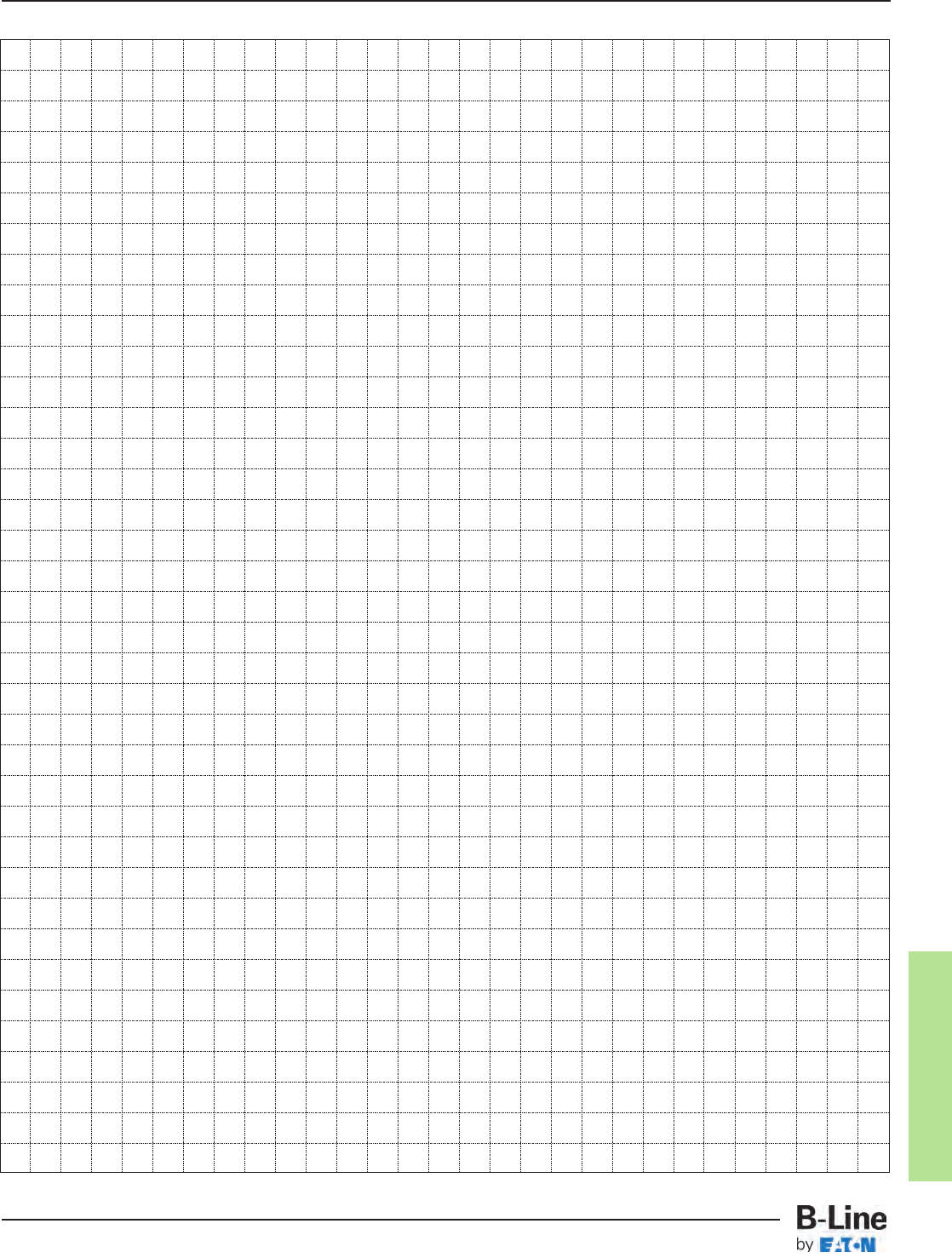
Cable Cleats
CFX-6
Notes
Cable Tray Systems
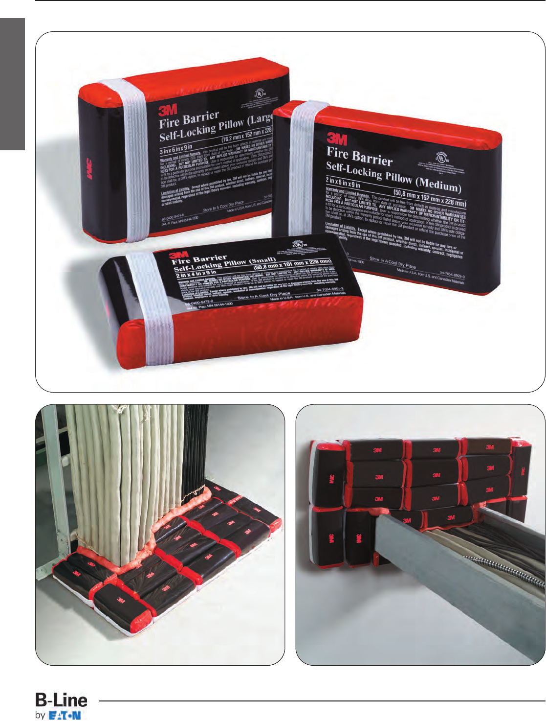
Firestop
FSA-1
Firestop
Cable Tray Systems
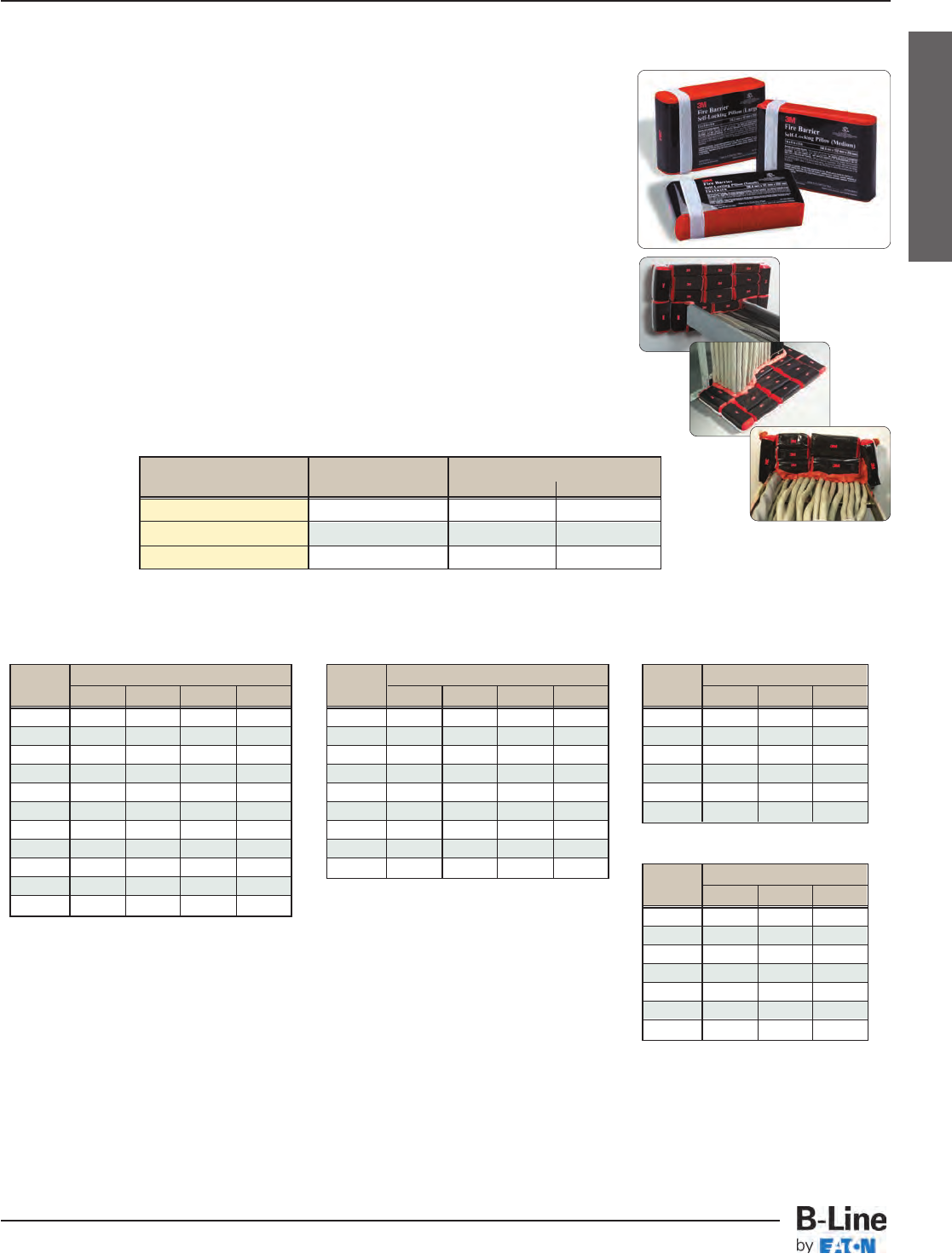
Firestop
Features & Benefits
• Extremely easy to install - saves time and labor
• Easy removal and fully reusable - with no blocking or fusing of
materials
• No cutting required, no left over debris
• Up to three-hour UL Listed F-Rating
• UL Listed systems up to 540 sq. in. opening
• Passes hose stream test without cumbersome wire mesh
• Smoke seal tested and listed
• Listed for blank or filled openings in gypsum wallboard or concrete
• Available in three (3) sizes
• One (1) or two (2) cable trays per opening
3M™Fire Barrier Self-Locking Pillows
This product will intumesce and lock tightly into place eliminating the prep
work of cutting or leaving any messy debris. The resulting barrier retards
the transmission of smoke, fire, and toxic gases from spreading between
adjacent rooms and floors for the rated time period.
The following charts give the number of 3M pillows needed to completely firestop an opening that cable tray passes through.*
Two (2) sticks of moldable putty (part number FSP-MPS) are also needed for each opening.
* Number of pillows refers to 3M’s medium self-locking pillows (part number FSP-SLP-M) and are based
on an opening that is 1.5” larger than the tray on all sides.
Example: For a 4” x 12” tray the recommended opening would be 7” x 15”.
UL Listed Systems
Concrete Wall - C-AJ-4056 3 HR F-Rating, 3/4HR T-Rating
Gypsum Wall - W-L-4037 1 HR and 2 HR F-Ratings, 0 HR and 1/2HR
T-Ratings
For tray larger than 4” x 24”, or a tray style other than ladder tray call
1-800-328-1687 then option 8 to obtain a free engineering judgement letter.
Width Height
4567
68910 11
911 12 14 15
12 13 15 17 19
18 18 21 24 26
24 24 27 30 34
30 29 33 37 41
36 34 39 44 49
42 39 45 51 56
48 45 51 57 64
Two (2) Side Rail Cable Tray
Width Height
346
3557
67810
99 11 14
12 11 13 17
18 16 18 24
24 20 24 30
Cent-R-Rail: Data Track & Half Rack
Width Height
456
68910
911 12 14
12 13 15 17
18 18 21 24
24 24 27 30
30 29 33 37
36 34 39 44
Pan Tray
Width Height
1.5 246
2-- 4 -- --
4457--
6568--
87710 13
12 8 10 13 17
16 -- 12 17 21
18 -- 13 18 24
20 -- 15 20 26
24 -- 17 24 30
30 -- 21 29 --
36 -- 22 -- --
Flextray
Catalog Number Pillow Type Pillow Size
in. mm
FSP-SLP-S Small 2” x 4” x 9” 51 x 101 x 228
FSP-SLP-M Medium 2” x 6” x 9” 51 x 152 x 228
FSP-SLP-L Large 3” x 6” x 9” 76 x 152 x 228
FSA-2
Firestop
Cable Tray Systems
3M™is a registered trademark of the 3M Company
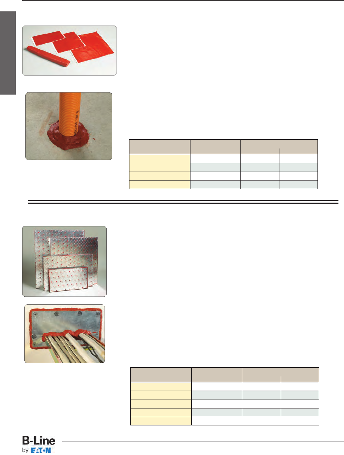
Firestop
Features & Benefits
• Pliable. Easy to mold into any shape
• Adheres. Sticks well to most surfaces but not to the applicator’s hands
• Conformable. Pads easily conform and adhere to a wide variety of
metallic and non-metallic electrical outlet boxes
• UL Listed. Wide range of UL Listed systems
• Ages Well. Excellent aging properties
3M™Fire Barrier Moldable Putty+
3M Fire Barrier Moldable Putty+ is a one-part, halogen-free product
designed to firestop electrical outlet boxes and a wide variety of
through-penetrations including cable, conduit, insulated pipe and
metal pipe, which penetrate fire-rated construction.
Features & Benefits
• Ideal for fire-stopping blank openings and through-penetrations of
multiple cable, pipe ducts, buss ducts and cable trays
• Intumescent
• Lightweight and easy to handle - just cut and form to fit
• Easy to install using common trade tools
• Easy to fasten - bolt punch or drill through and use self-tapping
screws or anchor bolts
• Bottom-of-floor applications available
• No mixing or damming required
• Re-enterable
• Documented aging properties
3M™Fire Barrier CS-195+ Composite Sheets
This organic/inorganic elastomeric sheet is bonded on one side to a
layer of 28-gauge galvanized steel. The other side is reinforced with
a steel-wire mesh and covered with aluminum foil.
Catalog Number Type Size
in. mm
FSP-MPS Stick 11/2” x 11” 38 x 279
FSP-MPP-4x8 Small Pad 4” x 8” 101 x 203
FSP-MPP-7x7 Medium Pad 7” x 7” 178 x 178
FSP-MPP-9x9 Large Pad 91/2” x 91/2” 241 x 241
Catalog Number Type Size
in. mm
FSP-CS-16x28 Sheet 16” x 28” 406 x 711
FSP-CS-28x52 Sheet 28” x 52” 711 x 1320
FSP-CS-36x24 Sheet 36” x 24” 914 x 609
FSP-CS-36x36 Sheet 36” x 36” 914 x 914
FSP-CS-36x41 Sheet 36” x 41” 914 x 1041
FSA-3
Firestop
Cable Tray Systems
3M™is a registered trademark of the 3M Company
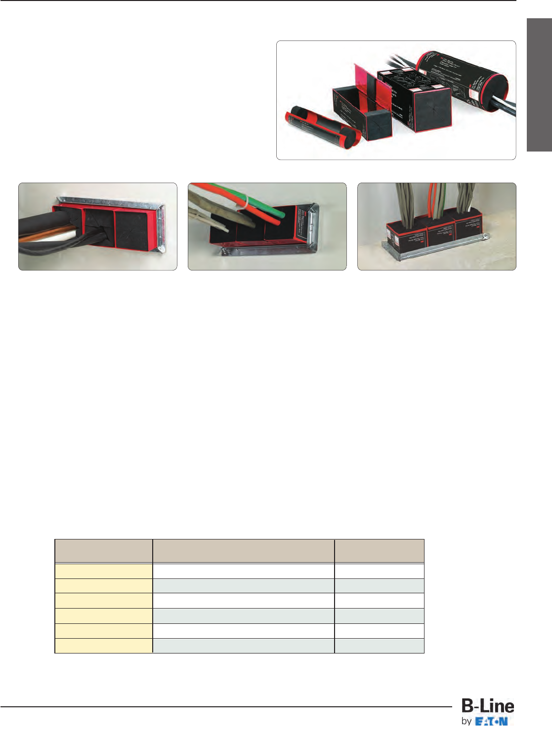
Firestop
Features & Benefits
• Hinged for existing cables
• Stackable for multiple penetrations
• Optional mounting brackets - single or triplex
• Install before or after gypsum wall assembly
• Easily identified red color
• Quick to pass cables
• JCAHO and NFPA Life Safety Code 101 compliant
• UL Classified 1, 2 and 3 hour fire (F) and temperature (T) rating
• UL Classified L rating, Hot and Cold Smoke Seal
• ULC
3M™Fire Barrier Quick Pass Devices
The Quick Pass Device makes installation and retrofitting a snap. Simply follow the instructions
located on the product. Use this product in new construction or update your fire protection in a
renovation - the optional mounting bracket opens easily allowing retrofit installations. As your
needs change, reuse the device for additional cables and wiring.
Catalog Number Type Size
FSP-QPS-2 Square Device 21/2” (63mm) Square
FSP-QPS-2BRK Optional Mounting Bracket for FSP-QPS-2 --
FSP-QPS-4 Square Device 4” (101mm) Square
FSP-QPS-4BRK Optional Mounting Bracket for FSP-QPS-4 --
FSP-QPR-4 Square Device 4” (101mm) Round
FSP-QPR-4BRK Optional Mounting Bracket for FSP-QPR-4 --
FSA-4
Firestop
Cable Tray Systems
3M™is a registered trademark of the 3M Company
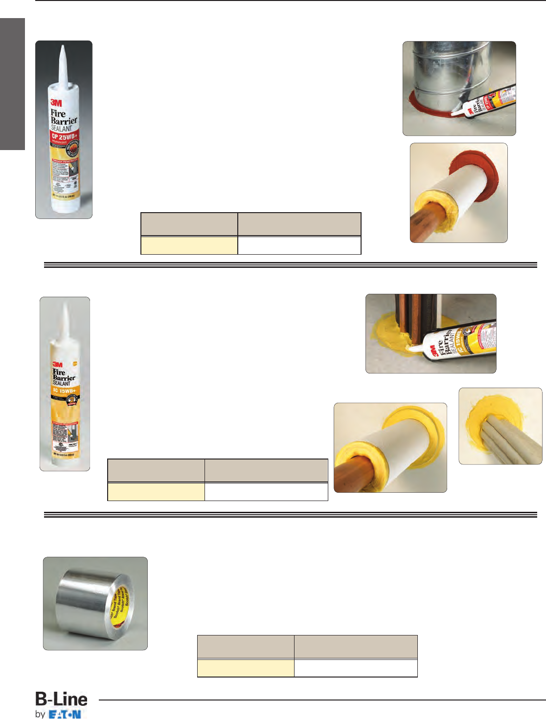
Firestop
Features & Benefits
• Water based - easy cleanup and routine disposal with no
special handling
• One-part system - no mixing or measuring required
• Intumescent and endothermic
• No-sag, non-halogen formula
• Fast drying - tack-free in approximately 10 to 15 minutes
• Water-resistant seal
• Paintable
• Documented aging properties
3M™Fire Barrier CP-25WB+ Caulk
Our premium, intumescent latex/water-based caulk.
CP 25WB Caulk can be installed with a standard caulking gun
Catalog Number Type
FSP-BC-25 10.1 ounce Tube
Features & Benefits
• Cost effective
• UL tested
• Distinctive yellow color makes inspections easier
• For use as a one-part fire, smoke,
noxious gas and water sealant
3M™Fire Barrier IC-15WB+ Caulk
This is an affordable firestop caulk that helps you
stay on budget. Its unique intumescent property
allows IC 15WB Caulk to effectively contain fire
and smoke at its origin. IC 15WB Caulk can be
installed with a standard caulking gun
Catalog Number Type
FSP-BC-15 10.1 ounce Tube
Features & Benefits
• 3-mil aluminum foil
• Acrylic adhesive performs in high temperatures
3M™Interam™T-49 Tape
Designed to seal the cut edges of 3M™ Interam
Mats to complete the total encapsulation.
Catalog Number Type
FSP-AT-4 4” (101mm) x 180’ (27.5m) Roll
FSA-5
Firestop
Cable Tray Systems
3M™and Interam™are registered trademarks of the 3M Company
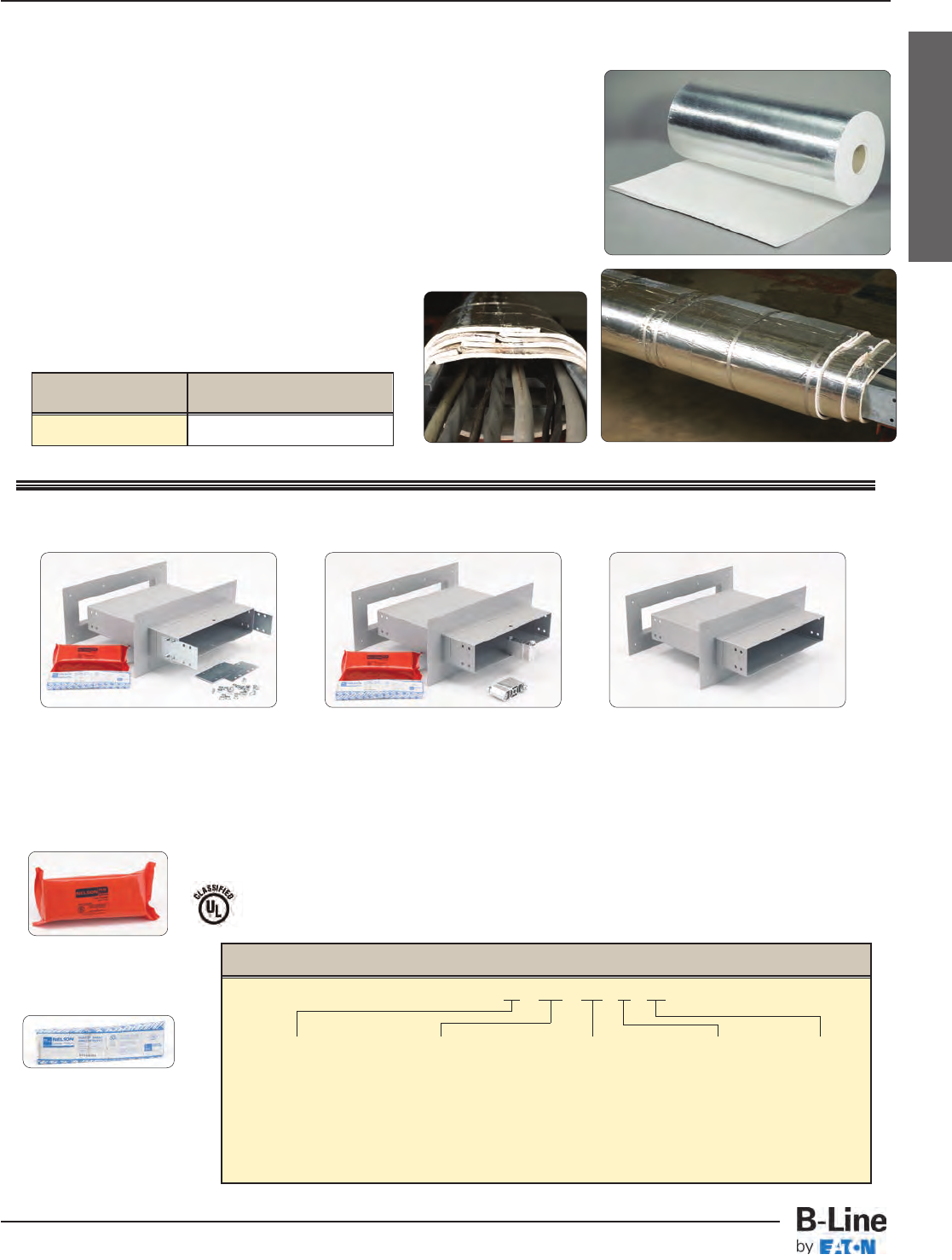
Firestop
Features & Benefits
• Provides up to three (3) hours of electrical circuit protection
• Made of a combination of organic/inorganic materials
• Outdoor durable
• Endothermic
• Available with a stainless-steel or aluminum backing
• Outstanding performance in high-intensity fires
• Easy to install in new applications or directly over existing
fire protection
3M™Interam™E-5 Series Mat
Wall & Fire Wall Sleeve Kits & Accessories
Blocks heat penetration by chemically
absorbing heat energy to protect
structural steel and cable trays.
Catalog Number Type
FSP-EMAT 241/2” (622mm) x 20’ (3.05m) Roll
FSP-1043
Fire Stop Pillow
3” thick, 4” wide, 9.6”long
(orange bag)
‘CT’ Type Fire Wall Sleeve
FWS (Fire Wall Sleeve) Shown
Sleeve is 20” long
FSP-1043 and FSP-1312
can be ordered separately
if required.
‘D’ Type Fire Wall Sleeve
FWS (Fire Wall Sleeve) Shown
Sleeve is 20” long
‘U’ Type Wall Sleeve
WS (Wall Sleeve) Shown
Sleeve is 20” long
FSP-1312
Fire Stop Putty
1” thick, 3” wide, 12”long
(wrapped in paper)
Through-Penetration products for use in Through-Penetration firestop systems. See UL Fire Resistance Director. 23XP
Classified by Underwriters Laboratories, Inc. as to it’s suitability as an equipment grounding conductor only. 556E
• "CT" Type tray includes two (2) pair 9ZN-800* splice plates with 3/8" zinc plated hardware.
• "D" Type tray includes two (2) pieces of CAC-UFB pivot connectors with zinc plated hardware.
• "U" Type tray does not include splices. Example uses include Wire Basket or Half-Rack.
* Insert tray height.
Wall & Fire Wall Sleeve Part Numbering
Example: 9P - xxx - CT - 4 - 12
Finish Type Tray Type Tray Height Tray Width
P = Pregalvanized WS = Wall Sleeve CT = Cable Tray †4 06 = 6"
FWS = Fire Wall Sleeve** D = Data-Track 5 09 = 9"
U = Universal 6 12 = 12"
7 18 = 18"
24 = 24"
30 = 30"
36 = 36"
** Includes Nelson Fire Stop Pillows & Putty
† ‘CT’ Type furnished with steel splice plates (9ZN-800*). For aluminum
cable trays use the furnished splice plates and field drill 13/32” diameter holes
in the aluminum side rails.
FSA-6
Firestop
Cable Tray Systems
3M™and Interam™are registered trademarks of the 3M Company
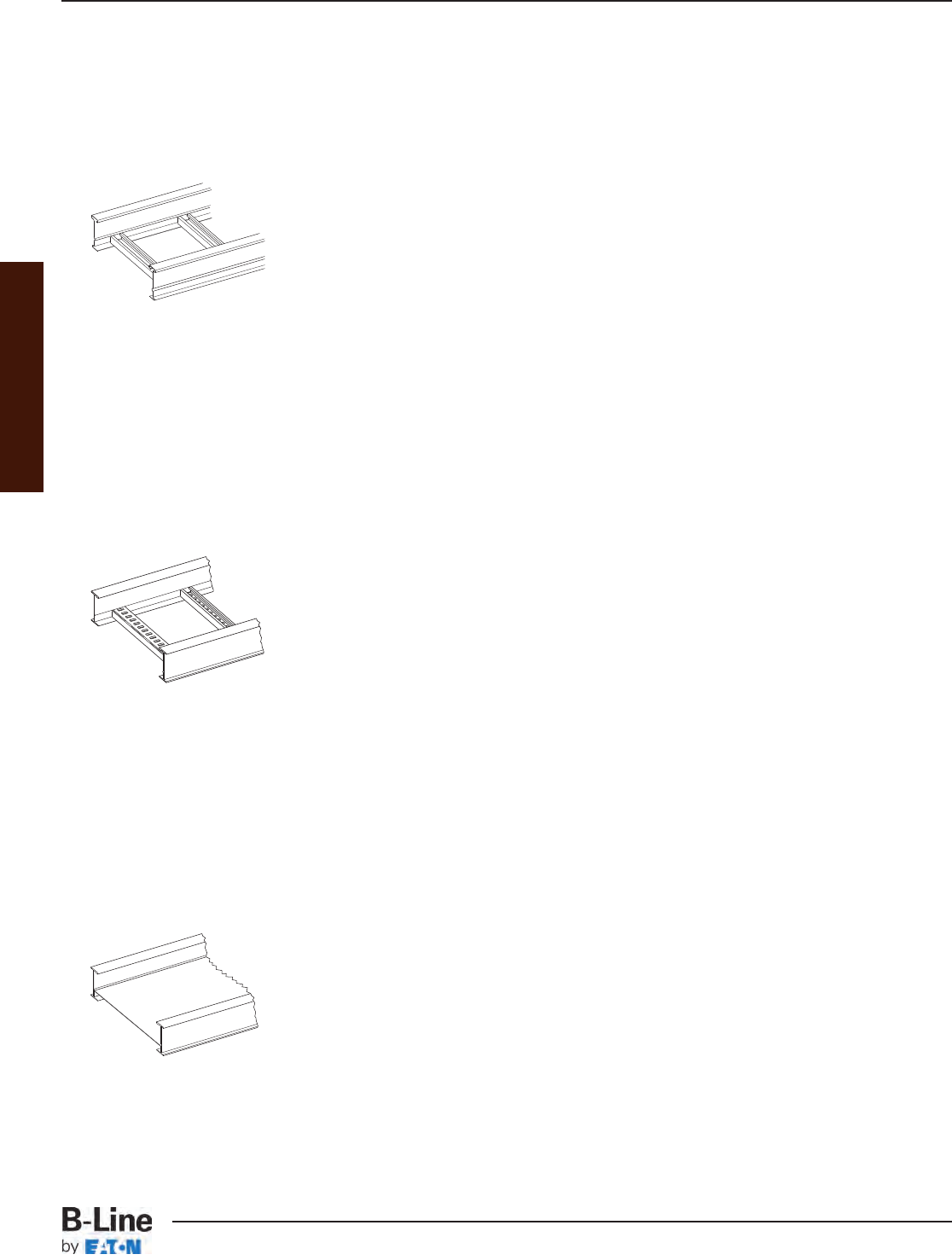
These options are in addition to the
Standard Ladder Rungs, Ventilated Trough and
Solid Trough type Cable Trays.
Ladder with Strut Rungs
• B44 strut installed as rungs.
• Strut orientation may be channel opening up, channel opening
down, or alternating - standard is alternating unless specified otherwise.
• Strut may be solid back or with slotted hole pattern "SH".
• The B-Line strut rung system offers additional cable clamping
options relative to the chosen slot orientation.
Examples: 248G09B44-12-144
Strut rung on 9" centers with alternating
slot orientation.
248G12B44SHDN-12-144
"SH" Strut rung on 12" centers with channel
opening down (Note: replace "DN" with "UP" for
channel opening up.)
Marine Rung (Available in Aluminum, HDGAF Steel and Stainless Steel)
• Designed for Series 2 or heavier systems.
• Special rung design to accommodate stainless steel banding
of cables (U.S. Coast Guard requirement) with .25" x .69" slots.
• Has applications on land, vertical installation, any location
where extra cable positioning/attachment is required.
• Rung strength - Aluminum supports 499 lbs. per rung on 36" wide
system with a 1.5 safety factor. Steel supports 755 lbs. per rung on
36" wide system with a 1.5 safety factor.
• New design provides combination of strut fastening and marine rung
fastening.
Example: 46A12MR-36-288 or 464G12MR-36-288
Special Rung Spacings: 4" & 18" rung spacing available upon request.
Non-Ventilated
• Solid flat sheet welded into the Cable Tray above the rungs.
• Standard rung spacing is 12 inches.
• The flat sheet may be installed under the rungs, if preferred.
• The flat sheet may be installed over B54 rungs “slot down”.
Examples: 24ASB-36-144
Flat sheet bottom over standard rung on
12" spacing.
24ASBB54-36-144
Flat sheet bottom over B54 strut rung
slot down on 12" spacing.
(Aluminum Shown)
Appendix
APP-1
Appendix - Bottom Design Options
Cable Tray Systems
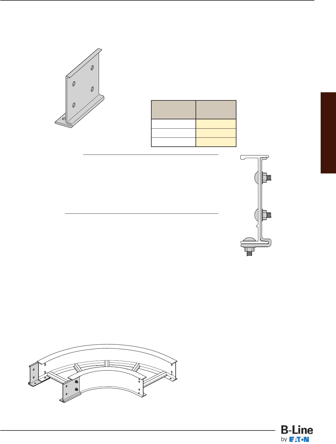
Appendix
B-Line 9A-6006 and 9A-6007
Aluminum Mid-Span Splice
Features
• Standard for H46A, H47A and 57A straight sections.
• Allows random splice location.
• Six bolt design 1/2" Stainless Steel Type 316
hardware standard.
• Available on ladder bottoms only.
• 09" and 12" rung spacing.
Options: The 9A-6006 and 9A-6007 splice is also available
with B-Line 46A and 47A series cable tray systems
• Available on ladder bottoms only (09" and 12" rung spacing).
• Available on 240" (20’) or longer span straight sections.
• To order add “MS” to part number: Ex. 46AMS09-24-288.
• For standard 6A or 7A fittings with H46A or H47A systems an
additional pair of standard splice plates is required (9A-1006 or 9A-1007).
One pair 9A-6006 or 9A-6007 included.
Cable Tray:
H46A H47A
Tested to: Tested to:
• 167 lbs/ft (safety factor 1.5) • 149 lbs/ft (safety factor 1.5)
• 125 lbs/ft (safety factor 2.0) • 112 lbs/ft (safety factor 2.0)
• 20 ft. simple beam test • 20 ft. simple beam test
• 12" rung spacing • 36" wide • 12" rung spacing • 36" wide
Splice:
9A-6006 9A-6007
Tested to: Tested to:
• 135 lbs/ft (safety factor 1.5) • 143 lbs/ft (safety factor 1.5)
• 101 lbs/ft (safety factor 2.0) • 107 lbs/ft (safety factor 2.0)
• 20 ft. simple beam test • 20 ft. simple beam test
• mid-span splice • mid-span splice
Tray
Series Catalog No.
H46A 9A-6006
H47A 9A-6007
57A 9A-6007
Also available:
H6A and H7A Fittings
• Ladder bottom only (09" RS).
• Incorporates the 9A-6006
or 9A-6007 splice.
• Example: H6A-12-90HB24
or H7A-12-90HB24
APP-2
Appendix - Mid Span Splice
Cable Tray Systems
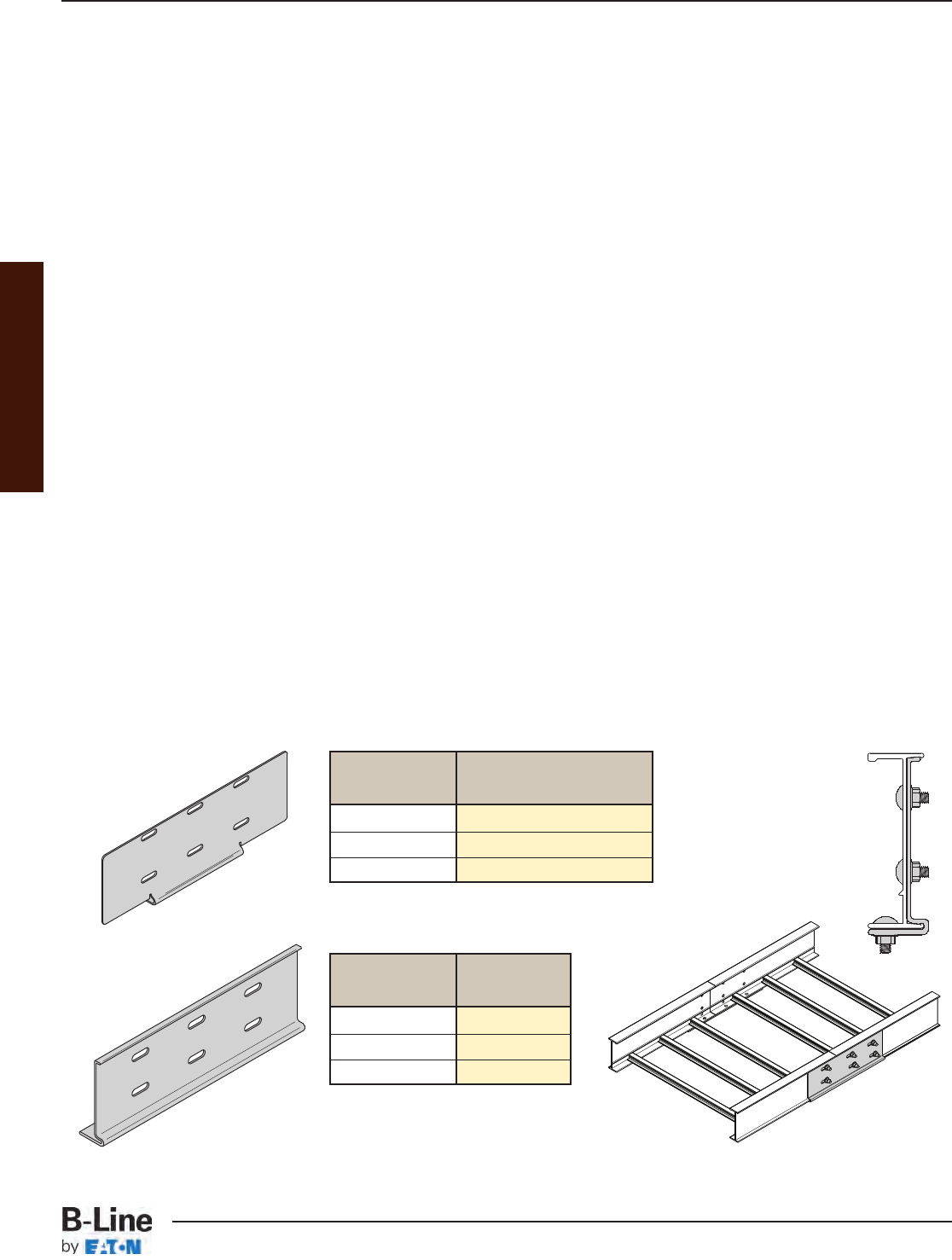
Appendix
Heavy Duty Expansion Splice Plates
9A-6016 and 9A-6017 (aluminum)
9G-6016 and 9G-6017 (HDG steel)
9SS6-6016 (stainless steel)
The Heavy Duty Expansion Splice Plate is engineered to eliminate the NEMA recommended additional supports
at each expansion joint where expansion splice plates are utilized. Expansion splices are common in long-run
outdoor applications, where temperature variations result in thermal expansion and contraction of the cable tray
system. The installer using the traditional expansion splice would be required to install two supports, one on
either side of the expansion splice. By utilizing the B-Line Heavy Duty Expansion Splice Plate, no additional
supports are required when the splice is placed at quarter span.
• NEMA VE 2 Compliant
• Lowest total cost of installation solution
• “Wrap around” design that supports the side rail on the bottom of each tray section
• Available in lightweight, marine-grade 6063-T6 aluminum material, hot dip galvanized steel,
and stainless steel 316 for easy installation in a variety of applications
• Visit www.cooperbline.com/expansion for detailed installation instructions
• Splice plate hardware included
Heavy Duty Expansion Splice Plates are currently available with aluminum (H46A, H47A & 57A), steel (464, 476
& 574), and stainless steel (464) tray systems. These tray systems are heavy duty ladders that are ideal for
long-span, outdoor applications.
Patent Pending
Aluminum heavy-duty expansion splice plates shown.
Aluminum
Tray Series Catalog No.
H46A 9A-6016
H47A 9A-6017
57A 9A-6017
Steel
Tray Series Catalog No.
464 9G-6016 or 9SS6-6016
476 9G-6017
574 9G-6017
Steel
Aluminum
APP-3
Appendix - Heavy Duty Expansion Splice
Cable Tray Systems
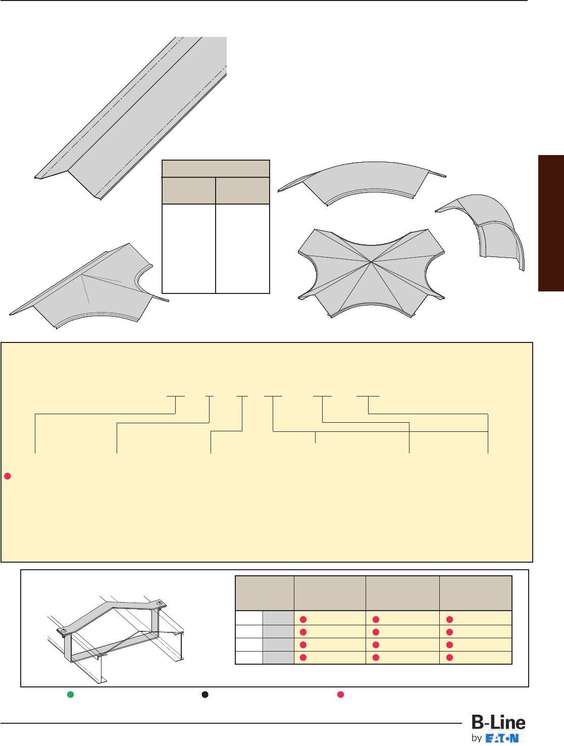
Appendix
Features
• 33° slope to shed precipitants.
• Heavy construction - made for the industrial environment.
• Available in aluminum and steel; hot dip
galvanized after fabrication (HDGAF ASTM A-123),
304 stainless and 316 stainless.
• Available in flanged design only.
• Fittings are in multiple piece welded construction.
• Expanding/Reducing HT and HX covers are not available.
Horizontal Bend
Vertical Outside
Bend
Horizontal
Cross
Horizontal
Tee
Cover Type
83 = 2 to 3
Pitch
Peaked
Detail
7 = Flanged Aluminum
2 = Flanged Steel
(248, 258, 268
straight sections
&fittings
3 = Flanged Steel
(All straight
sections except
248, 258, 268)
Material
A=Aluminum
G = HDGAF ASTM
A-123
SS4 = 304 Stainless
Steel
SS6 = 316 Stainless
Steel
Tray Width
06 = 6"
09 = 9"
12 = 12"
18 = 18"
24 = 24"
30 = 30"
36 = 36"
Item Description
144 = 12 ft. (3.66 m)
120 = 10 ft. (3.05 m)
72 = 6 ft. (1.83 m)
60 = 5 ft. (1.52 m)
Catalog Number Selector
Special Purpose 2 to 3 Pitch Peaked Covers
These covers are not
available for Series 1
system or in steel with
a pre-galvanized finish.
2 to 3 Pitch Cover Clamp
• Recommended for outdoor service.
(‡) Insert tray width (**) Insert SS4 or SS6
2 to 3 Pitch
Peak
Height
Tray
Width
6" 2"
9" 3"
12" 4"
18" 6"
24" 8"
30" 10"
36" 12"
Side Rail Catalog Catalog Catalog
Height No. No. No.
in. mm Aluminum Steel Stainless Steel
4 101 9A-(‡)-9P44 9G-(‡)-9P44 9**-(‡)-9P44
5 127 9A-(‡)-9P54 9G-(‡)-9P54 9**-(‡)-9P54
6 152 9A-(‡)-9P64 9G-(‡)-9P64 9**-(‡)-9P64
7 178 9A-(‡)-9P74 9G-(‡)-9P74 9**-(‡)-9P74
Green = Fastest shipped items Black = Normal lead-time items Red = Normally long lead-time items
Material
Thickness
80 = .080 Aluminum straight
section
125 = .125 Aluminum fittings
16 = 16 Ga. Steel straight
sections.
18 = 18 Ga. Steel fittings.
83 7 A 80 - 24 - 144
Example:
APP-4
Appendix - Special Purpose Peaked Covers
Cable Tray Systems
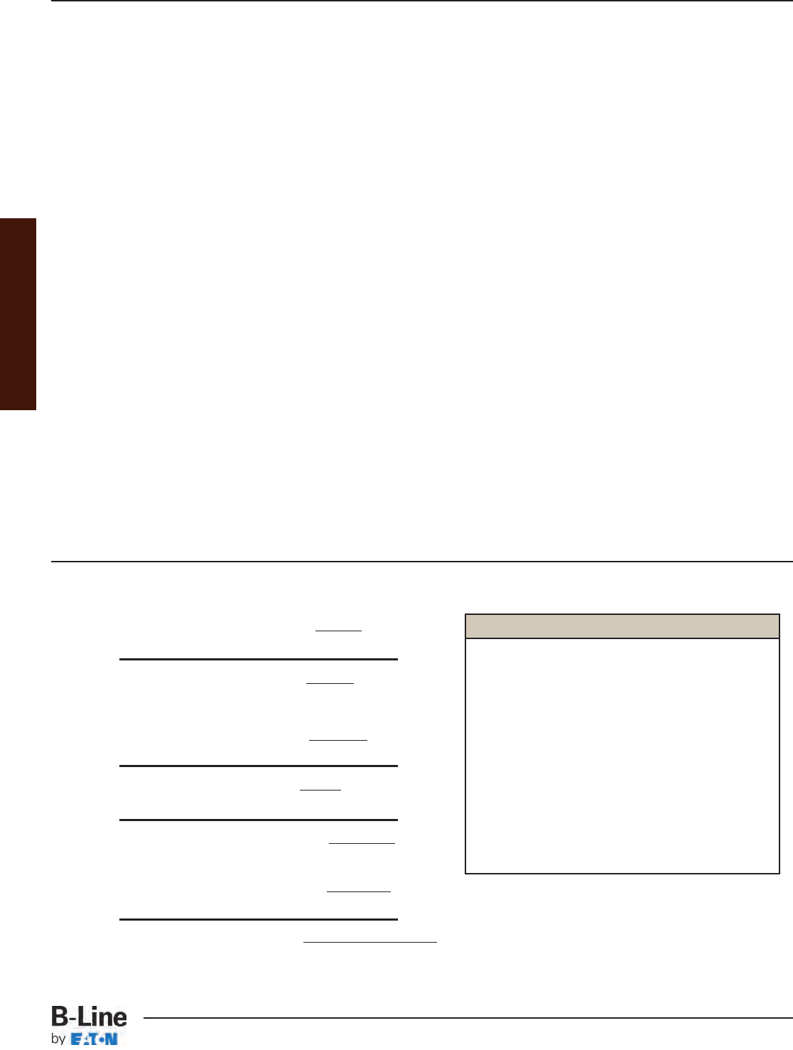
Appendix
1. Armored cable . . . . . . . . . . . . . . . . . . . . . . . . . . . . . . . . . . . . . . . . . . . . . . . . . . . . . . . . . . . . . . . . . . . . . . . . . . (Article 320)
2. Electrical metallic tubing . . . . . . . . . . . . . . . . . . . . . . . . . . . . . . . . . . . . . . . . . . . . . . . . . . . . . . . . . . . . . . . (Article 358)
3. Electrical nonmetallic tubing . . . . . . . . . . . . . . . . . . . . . . . . . . . . . . . . . . . . . . . . . . . . . . . . . . . . . . . . . . . (Article 362)
4. Fire alarm cables . . . . . . . . . . . . . . . . . . . . . . . . . . . . . . . . . . . . . . . . . . . . . . . . . . . . . . . . . . . . . . . . . . . . . . . . (Article 760)
5. Flexible metal conduit . . . . . . . . . . . . . . . . . . . . . . . . . . . . . . . . . . . . . . . . . . . . . . . . . . . . . . . . . . . . . . . . . . (Article 348)
6. Flexible metallic tubing . . . . . . . . . . . . . . . . . . . . . . . . . . . . . . . . . . . . . . . . . . . . . . . . . . . . . . . . . . . . . . . . . (Article 360)
7. Instrumentation tray cable . . . . . . . . . . . . . . . . . . . . . . . . . . . . . . . . . . . . . . . . . . . . . . . . . . . . . . . . . . . . . (Article 727)
8. Intermediate metal conduit . . . . . . . . . . . . . . . . . . . . . . . . . . . . . . . . . . . . . . . . . . . . . . . . . . . . . . . . . . . . (Article 342)
9. Liquidtight flexible metal conduit . . . . . . . . . . . . . . . . . . . . . . . . . . . . . . . . . . . . . . . . . . . . . . . . . . . . . . (Article 350)
10. Liquidtight flexible nonmetallic conduit . . . . . . . . . . . . . . . . . . . . . . . . . . . . . . . . . . . . . . . . . . . . . . . (Article 356)
11. Metal-clad cable . . . . . . . . . . . . . . . . . . . . . . . . . . . . . . . . . . . . . . . . . . . . . . . . . . . . . . . . . . . . . . . . . . . . . . . . (Article 330)
12. Mineral-insulated, metal-sheathed cable . . . . . . . . . . . . . . . . . . . . . . . . . . . . . . . . . . . . . . . . . . . . (Article 332)
13. Multiconductor service-entrance cable . . . . . . . . . . . . . . . . . . . . . . . . . . . . . . . . . . . . . . . . . . . . . . . (Article 338)
14. Multiconductor underground feeder and branch-circuit cable . . . . . . . . . . . . . . . . . . . . . (Article 340)
15. Multipurpose and communications cables . . . . . . . . . . . . . . . . . . . . . . . . . . . . . . . . . . . . . . . . . . . (Article 800)
16. Nonmetallic-sheathed cable . . . . . . . . . . . . . . . . . . . . . . . . . . . . . . . . . . . . . . . . . . . . . . . . . . . . . . . . . . . (Article 334)
17. Power and control tray cable . . . . . . . . . . . . . . . . . . . . . . . . . . . . . . . . . . . . . . . . . . . . . . . . . . . . . . . . . (Article 336)
18. Power-limited tray cable . . . . . . . . . . . . . . . . . . . . . . . . . . . . . . . . . . . . . . . (Section 725.61(C) and 725.71(E)
19. Optical fiber cables . . . . . . . . . . . . . . . . . . . . . . . . . . . . . . . . . . . . . . . . . . . . . . . . . . . . . . . . . . . . . . . . . . . . . (Article 770)
20. Other factory-assembled, multiconductor control, signal, or power
cables that are specifically approved for installation in cable trays
21. Rigid metal conduit . . . . . . . . . . . . . . . . . . . . . . . . . . . . . . . . . . . . . . . . . . . . . . . . . . . . . . . . . . . . . . . . . . . . . (Article 344)
22. Rigid nonmetallic conduit . . . . . . . . . . . . . . . . . . . . . . . . . . . . . . . . . . . . . . . . . . . . . . . . . . . . . . . . . . . . . . (Article 352)
Wiring methods permitted in cable tray per the 2005 NEC®
Appendix - Reference Material - Formulas Formulas
Formulas
• Allowable load: w = F96Sx
L2
w = load (lbs/ft)
W = total load across span (lbs)
F = design stress (lbs/in2)
L = span (inches)
Sx = section modulus for 2 rails (in3)
(see page APP-6 for Sx values)
• Deflection: Δ=5WL3
384EIx
E=10 million for Alum. (lb/in.2)
29 million for Steel (lb/in.2)
Ix = moment of inertia for 2 rails (in4)
(see page APP-6 for Ix values)
Δ=5wL4
4608EIx
• Stress: F = wL2
96Sx
• Deflection Multiplier (K) = deflection
w
= 5L4
4608EIx
• Max. Working Load = Max. deflection
Deflection Multiplier
Legend
APP-5
Appendix - Reference Material - Methods Permitted
Cable Tray Systems
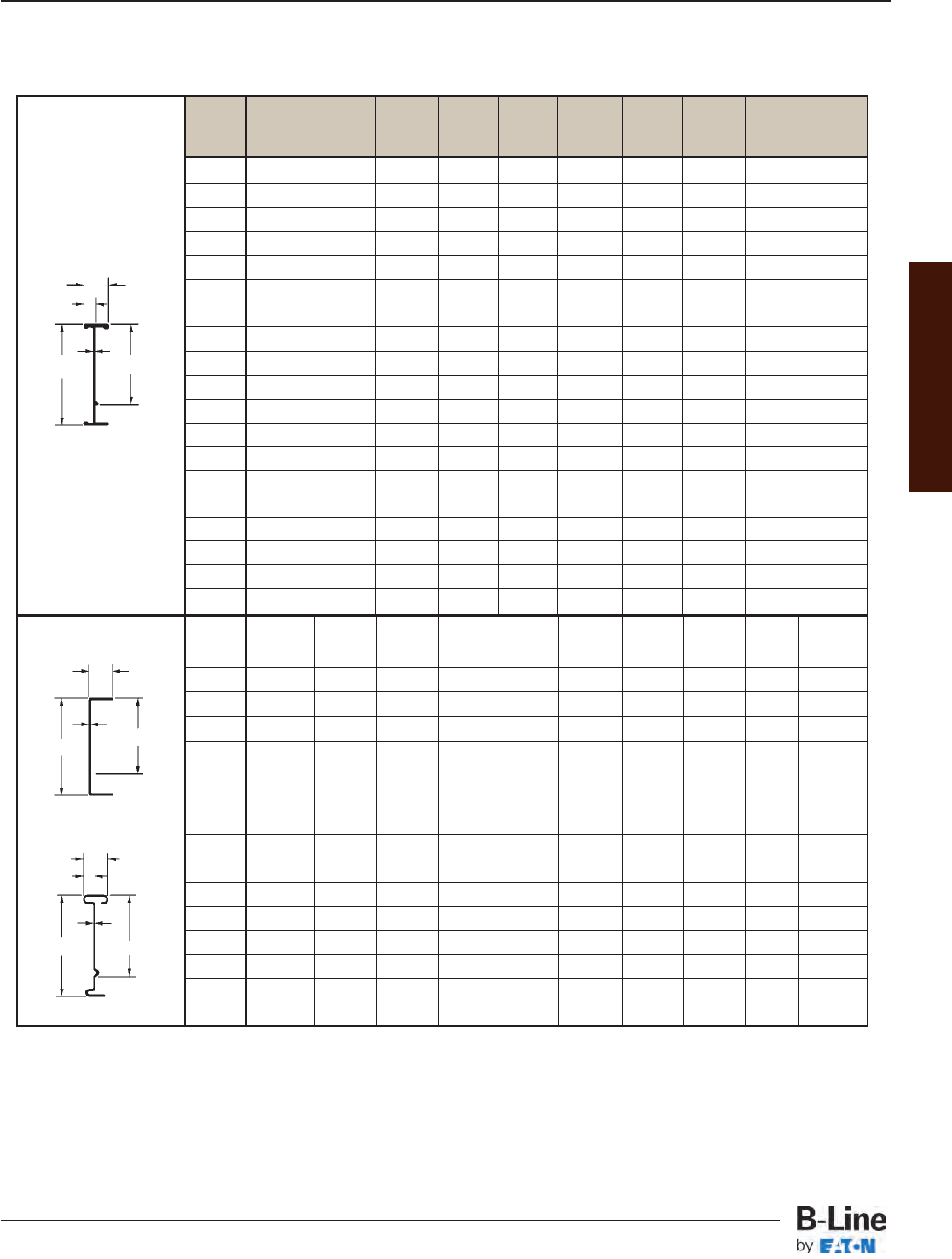
Appendix
A - Side Rail Height B - Loading Depth C - Web Thickness D - Flange Width
Design Factors: Ix = Moment of Inertia, Sx = Section Modulus
148 4 3.625 3.125 .048 .875 -- .25 .45 .251 .84
156 5 4.188 3.688 .060 .875 -- .36 .76 .340 1.16
166 6 5.188 4.688 .060 .750 -- .46 1.20 .385 1.31
176 7 6.188 5.688 .060 .750 -- .64 1.90 .444 1.52
248 4 4.188 3.14 .048 1.000 .392 .32 .72 .313 1.17
346 4 4.188 3.13 .060 1.500 .655 .48 1.11 .449 1.64
444 4 4.188 3.11 .075 1.500 .670 .64 1.47 .561 2.02
258 5 5.188 4.14 .048 1.000 .392 .45 1.22 .361 1.34
356 5 5.188 4.13 .060 1.500 .655 .66 1.86 .509 1.86
454 5 5.188 4.11 .075 1.500 .670 .87 2.48 .636 2.29
268 6 6.188 5.14 .048 1.000 .392 .59 1.90 .409 1.52
368 6 6.188 5.13 .048 1.500 .643 .71 2.39 .457 1.70
366 6 6.188 5.14 .060 1.500 .655 .85 2.87 .569 2.08
464 6 6.188 5.11 .075 1.500 .670 1.14 3.83 .711 2.56
378 7 7.188 6.14 .048 1.500 .643 .89 3.45 .505 1.88
476 7 7.188 6.13 .060 1.500 .655 1.07 4.15 .629 2.30
574 7 7.188 6.11 .075 1.500 .670 1.43 5.55 .792 2.83
Steel
Series 148-176 Rail Only
All Other Steel Rails
D
A
C
D
E
A
C
B
B
Cable Tray Side Rails
B-Line Side Rail ABCD ESx Ix Area Weight
Series Height (in.) (in.) (in.) (in.) (in.) (in.3) (in.4) (in.2) (lbs./ft.)
RSI04 4 3.54 2.68 .059 1.71 .768 0.55 0.98 .465 .54
RSI05 5 4.53 3.66 .061 1.71 .770 0.75 1.76 .540 .63
RSI06 6 5.51 4.64 .059 1.71 .768 0.99 2.75 .559 .69
RSI07 7 6.50 5.63 .075 1.71 .784 1.34 4.39 .750 .88
24 4 4.12 3.05 .060 1.75 .740 0.67 1.43 .525 .62
M24 4 4.18 3.09 .080 1.75 .760 0.84 1.93 .750 .83
34 4 4.20 3.08 .100 1.75 .750 1.05 2.49 .902 1.06
25 5 5.00 3.93 .068 1.75 .748 0.90 2.31 .620 .72
35 5 5.06 3.96 .090 1.75 .745 1.18 3.19 .857 .98
26 6 6.12 5.04 .065 2.00 .745 1.26 3.95 .698 .82
36 6 6.17 5.06 .075 2.00 .725 1.68 5.42 .903 1.05
46 6 6.19 5.08 .085 2.00 .650 1.79 6.09 .989 1.17
M46 6 6.20 5.09 .100 2.00 .750 1.89 6.36 1.116 1.30
H46 6 6.24 5.09 .130 2.00 .750 2.67 8.65 1.473 1.74
37 7 7.14 6.05 .075 2.00 .750 1.88 6.75 .904 1.06
47 7 7.24 6.13 .100 2.00 .675 2.47 8.94 1.189 1.40
H47 7 7.24 6.09 .125 2.00 .675 3.05 11.46 1.520 1.77
57 7 7.40 6.23 .160 2.00 .875 3.86 16.43 2.114 2.46
S8A 8 8.0 6.17 .170 3.00 1.000 7.69 27.67 2.754 3.20
Aluminum
D
E
C
B
A
Design Data For One Rail
APP-6
Appendix - Reference Material - Side Rails
Cable Tray Systems
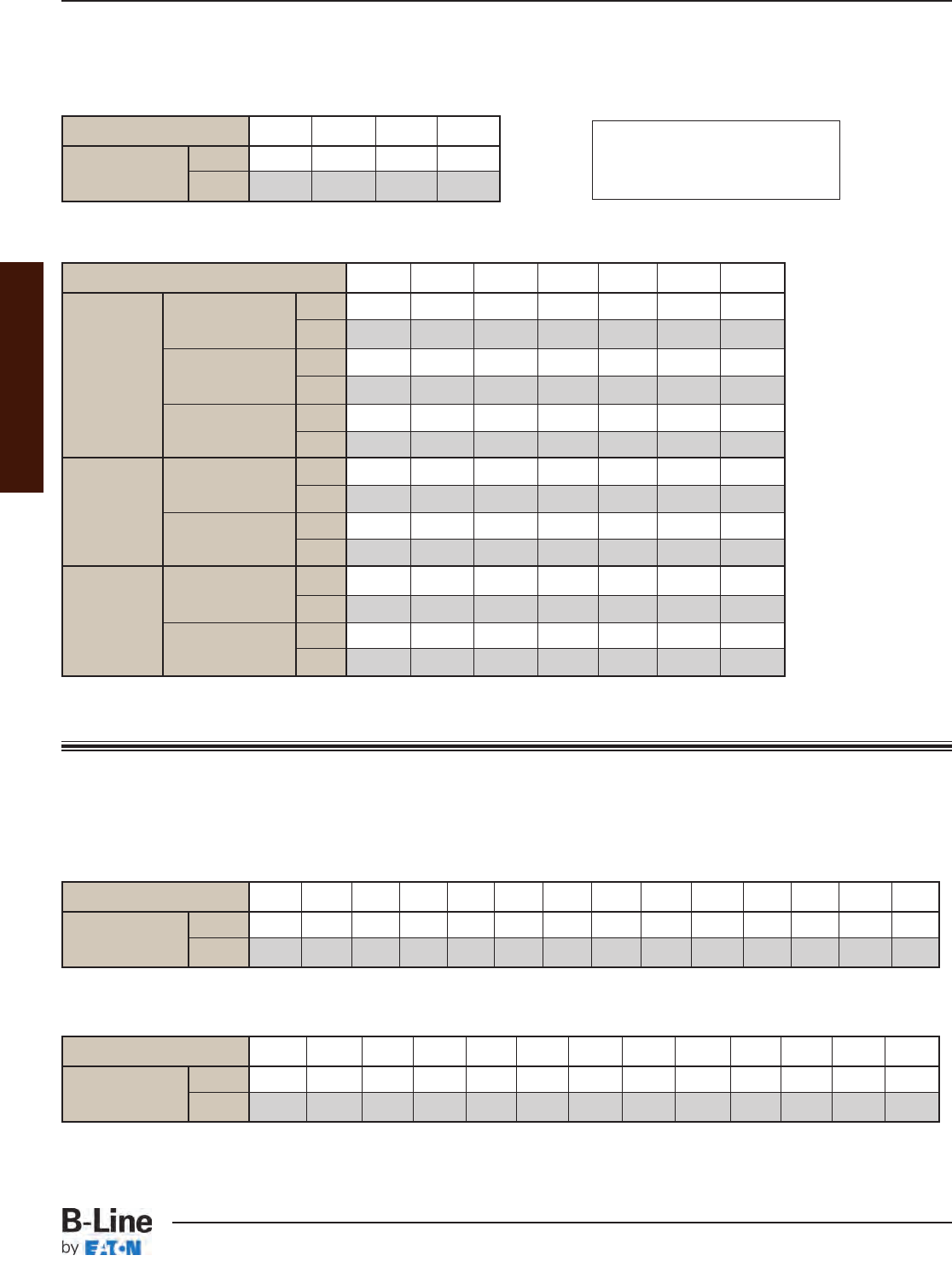
Tray Series 148 156 166 176
Weight for lbs/ft 1.68 2.32 2.62 3.03
2 Side Rails kg/m 2.50 3.45 3.90 4.51
Steel Side Rail Weights
6912 18 24 30 36
6" Spacing lbs/ft 0.38 0.57 0.76 1.14 1.52 2.25 2.70
Rung Weight kg/m 0.57 0.85 1.13 1.70 2.26 3.35 4.02
9" Spacing lbs/ft 0.25 0.38 0.51 0.76 1.01 1.50 1.80
Rung Weight kg/m 0.38 0.57 0.75 1.13 1.51 2.23 2.68
12" Spacing lbs/ft 0.19 0.29 0.38 0.57 0.76 1.13 1.35
Rung Weight kg/m 0.29 0.43 0.57 0.85 1.13 1.68 2.01
Vented Trough lbs/ft 0.48 0.72 0.95 1.43 1.91 2.39 2.86
Weight kg/m 0.71 1.06 1.42 2.13 2.84 3.55 4.26
Solid Trough lbs/ft 0.60 0.90 1.20 1.80 2.39 2.99 3.59
Weight kg/m 0.89 1.34 1.78 2.67 3.56 4.45 5.34
4" Vented lbs/ft 0.57 0.86 1.14 1.71 2.28 3.37 3.42
Rung Weight kg/m 0.85 1.27 1.70 2.54 3.39 5.02 5.09
Solid Bottom lbs/ft 1.01 1.51 2.01 3.02 4.02 5.20 6.25
Weight kg/m 1.50 2.24 2.99 4.49 5.98 7.74 9.29
Tray Bottom Weights
All
Series
1
Steel
Tray Width (inches)
Series
148
Steel
Series
156, 166
& 176
Steel
When using steel tray that is hot dip galvanized after fabrication add 9.6% to weights.
Series 1
Example:
Weight for 148P09-12-144
= 1.68 lbs/ft + .51 lbs/ft = 2.19 lbs/ft
= (2.19 lbs/ft) (12 ft) = 26.28 lbs.
Appendix
Aluminum Side Rail Weights
Tray Series 24 M24 34 25 35 26 36 46 M46 H46 37 47 H47 57
Weight for lbs/ft 1.23 1.66 2.12 1.44 1.96 1.64 2.09 2.33 2.60 3.47 2.12 2.80 3.54 4.92
2 Side Rails kg/m 1.83 2.47 3.15 2.14 2.92 2.44 3.11 3.47 3.87 5.16 3.15 4.16 5.27 7.32
Steel Side Rail Weights
Tray Series 248 346 444 258 356 454 268 368 366 464 378 476 574
Weight for lbs/ft 2.34 3.28 4.04 2.68 3.72 4.58 3.04 3.40 4.16 5.12 3.76 4.60 5.66
2 Side Rails kg/m 3.48 4.88 6.01 3.99 5.54 6.82 4.52 5.06 6.19 7.62 5.59 6.84 8.42
Series 2, 3, 4 or 5
Series 2, 3, 4 or 5 weights continued on page 387.
APP-7
Appendix - Reference Material - Cable Tray Weights
Cable Tray Systems
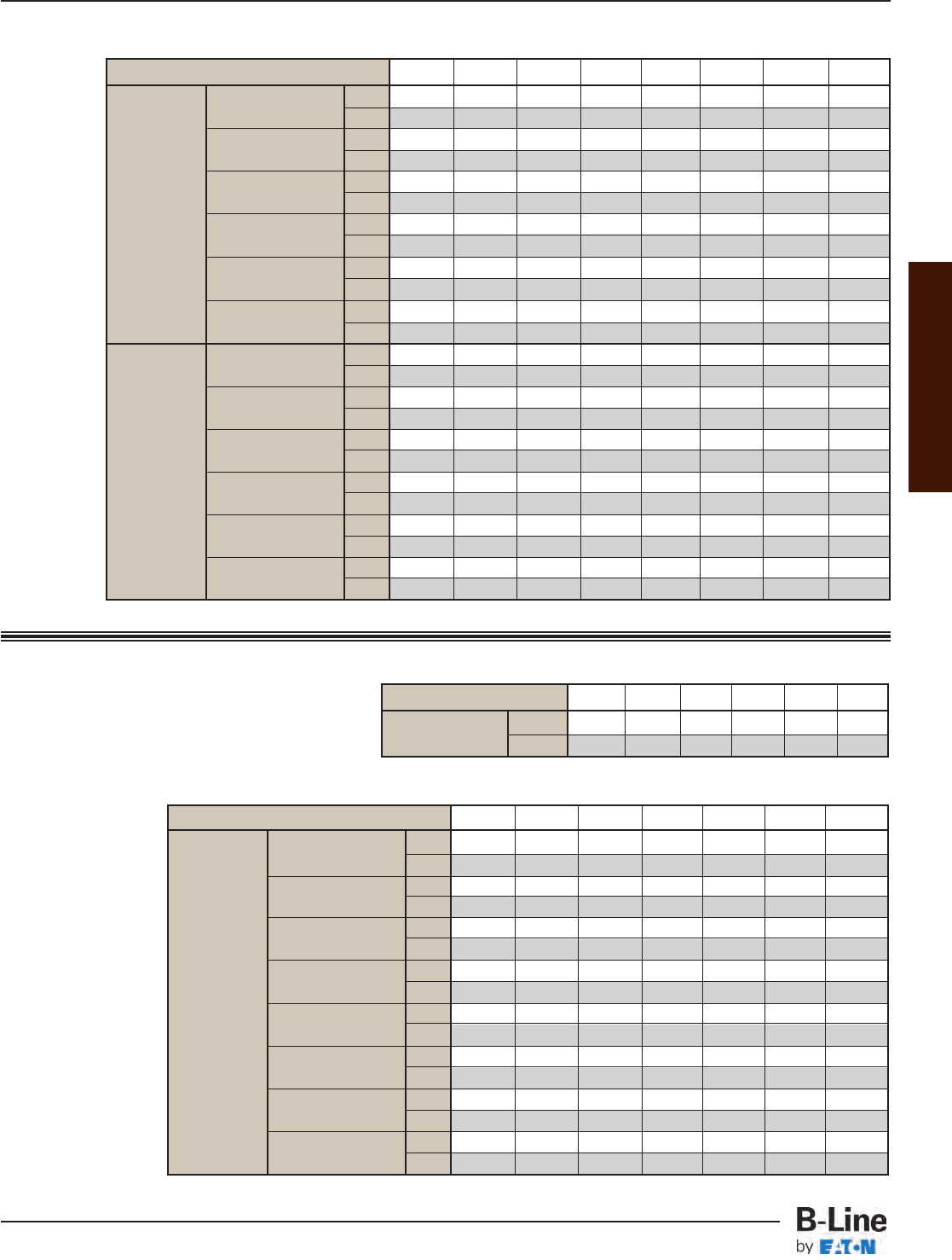
6912 18 24 30 36
6" Spacing lbs/ft 0.54 0.81 1.08 1.62 2.16 2.70 3.23
Rung Weight kg/m 0.80 1.20 1.60 2.41 3.21 4.01 4.81
9" Spacing lbs/ft 0.35 .053 0.70 1.05 1.40 1.75 2.10
Rung Weight kg/m 0.52 0.78 1.04 1.56 2.09 2.61 3.13
12" Spacing lbs/ft 0.27 0.40 0.54 0.81 1.08 1.35 1.62
Rung Weight kg/m 0.40 0.60 0.80 1.20 1.60 2.01 2.41
18" Spacing lbs/ft 0.19 0.28 0.38 0.57 0.75 0.94 1.13
Rung Weight kg/m 0.28 0.42 0.56 0.84 1.12 1.40 1.68
6" Spacing lbs/ft 0.75 1.12 1.49 2.24 2.98 3.73 4.48
Marine Rung Wt.
kg/m 1.11 1.67 2.,22 3.33 4.44 5.55 6.66
9" Spacing lbs/ft 0.48 0.73 0.97 1.45 1.94 2.42 2.91
Marine Rung Wt.
kg/m 0.,72 1.08 1.44 2.16 2.89 3.61 4.33
12" Spacing lbs/ft 0.37 0.56 0.75 1.12 1.49 1.87 2.24
Marine Rung Wt.
kg/m 0.56 0.83 1.11 1.67 2.22 2.78 3.33
18" Spacing lbs/ft 0.26 0.39 0.52 0.78 1.04 1.31 1.57
Marine Rung Wt.
kg/m 0.39 0.58 0.78 1.17 1.55 1.94 2.33
Tray Bottom Weights
All
Series
Fiberglass
Tray Width (inches)
Fiberglass Side Rail Weights
Tray Series 13 24 36 46 H46 48
Weight for lbs/ft 1.40 1.78 2.82 3.72 3.72 4.66
2 Side Rails kg/m 2.08 2.65 4.20 5.54 5.54 6.93
6912 18 24 30 36 42
6" Spacing lbs/ft 0.30 0.44 0.59 0.89 1.18 1.70 2.04 2.38
Rung Weight kg/m 0.44 0.66 0.88 1.32 1.76 2.53 3.04 3.54
9" Spacing lbs/ft 0.20 0.29 0.39 0.59 0.78 1.13 1.36 1.58
Rung Weight kg/m 0.29 0.44 0.58 0.87 1.16 1.68 2.02 2.35
12" Spacing lbs/ft 0.15 0.22 0.29 0.44 0.58 0.85 1.02 1.19
Rung Weight kg/m 0.22 0.32 0.43 0.65 0.86 1.26 1.52 1.77
18" Spacing lbs/ft 0.10 0.15 0.20 0.30 0.40 0.57 0.68 0.80
Rung Weight kg/m 0.15 0.22 0.30 0.45 0.60 0.85 1.02 1.19
Vented Trough lbs/ft 0.25 0.38 0.50 0.75 1.00 1.25 1.50 1.75
Weight kg/m 0.37 0.56 0.74 1.12 1.49 1.86 2.23 2.60
Solid Trough lbs/ft 0.31 0.46 0.61 0.92 1.22 1.53 1.83 2.14
Weight kg/m 0.45 0.68 0.91 1.36 1.82 2.27 2.72 3.18
6" Spacing lbs/ft 0.62 0.92 1.23 1.85 2.46 3.67 4.40 5.14
Rung Weight kg/m 0.92 1.37 1.83 2.75 3.66 5.46 6.55 7.65
9" Spacing lbs/ft 0.41 0.62 0.82 1.23 1.64 2.45 2.94 3.43
Rung Weight kg/m 0.61 0.92 1.22 1.83 2.44 3.65 4.37 5.10
12" Spacing lbs/ft 0.31 0.47 0.62 0.93 1.24 1.84 2.21 2.58
Rung Weight kg/m 0.46 0.69 0.92 1.38 1.85 2.74 3.29 3.83
18" Spacing lbs/ft 0.21 0.31 0.41 0.62 0.82 1.22 1.46 1.71
Rung Weight kg/m 0.31 0.46 0.61 0.92 1.22 1.82 2.18 2.54
Vented Trough lbs/ft 0.53 0.80 1.06 1.59 2.12 2.65 3.18 3.71
Weight kg/m 0.79 1.18 1.58 2.37 3.15 3.94 4.73 5.52
Solid Trough lbs/ft 0.67 1.00 1.33 2.00 2.66 3.33 3.99 4.66
Weight kg/m 0.99 1.48 1.98 2.97 3.96 4.95 5.94 6.93
Fiberglass Bottom Weights
All
Series
2,3,4
Aluminum
Tray Width (inches)
All
Series
2,3,4,5
Steel
When using steel tray that is hot dip galvanized after fabrication add 9.6% to weights.
Series 2, 3, 4 or 5
Fiberglass
Appendix
APP-8
Appendix - Reference Material - Cable Tray Weights
Cable Tray Systems
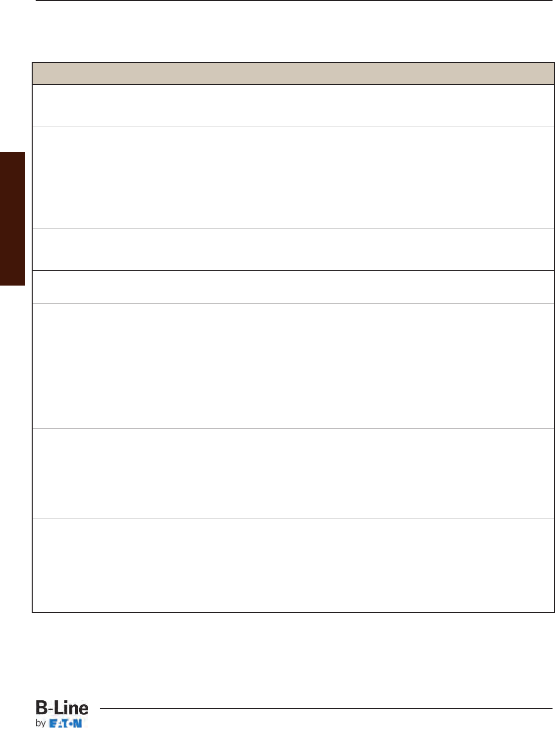
To Convert From To Multiply By
Angle
degree radian (rad) 0.01745329
radian (rad) degree 57.295780
Area
foot2square meter (m2) 0.09290304
inch2square meter (m2) 0.0064516 x 10⁻²
circular mil square meter (m2) 0.00005067075 x 10⁻⁵
sq. centimeter (cm2) square inch (in2) 0.15500030
square meter (m2) foot210.763910
square meter (m2) inch21550.0030
square meter (m2) circular mil 1973523000.0
Temperature
degree Fahrenheit degree Celsius t°C= (t°F- 32) / 1.8
degree Celsius degree Fahrenheit t°F= 1.8t°C+ 32
Force
pounds - force (lbf) newtons (N) 4.4482220
Length
foot (ft) meter (m) 0.30480
inch (in) meter (m) 0.02540
mil meter (m) 0.002540 x 10⁻³
inch micrometer (μm) 25400.0
millimeters inch (in) 0.039370
meter (m) foot (ft) 3.280840
meter (m) inch (in) 39.370080
meter (m) mil 39370.0080
micrometer (μm) inch (in) 0.039370080 x 10⁻³
Volume
foot3cubic meter (m3) 0.028316850
inch3cubic meter (m3) 0.016387060 x 10⁻³
cubic centimeter (cm3) cubic inch (in3) 0.061023740
cubic meter (m3) foot335.314660
cubic meter (m3) inch361023.760
gallon (U.S. liquid) cubic meter (m3) 0.0037854120
Section Properties
section modulus S (in3) S (m3) 0.016387060 x 10⁻³
moment of inertia I (in4) I (m4) 0.00041623140 x 10⁻³
modulus of elasticity E (psi) E (Pa) 6894.7570
section modulus S (m3) S (in3) 61023.740
moment of inertia I (m4) I (in4) 2402510.0
modulus of elasticity E (Pa) E (psi) 0.014503770 x 10⁻²
Metric Conversion Chart
Appendix
APP-9
Appendix - Reference Material - Metric Conversion
Cable Tray Systems
To Convert From To Multiply By
Bending Moment or Torque
lbf • ft newton meter (N•m) 1.3558180
lbf • in newton meter (N•m) 0.11298480
N•m lbf • ft 0.73756210
N•m lbf • in 8.8507480
Mass
ounce (avoirdupois) kilogram (kg) 0.028349520
pound (avoirdupois) kilogram (kg) 0.45359240
ton (short, 2000 lb) kilogram (kg) 907.18470
ton (long, 2240 lb) kilogram (kg) 1016.0470
kilogram (kg) ounce (avoirdupois) 35.273960
kilogram (kg) pound (avoirdupois) 2.2046220
kilogram (kg) ton (short, 2000 lb) 0.0011023110
kilogram (kg) ton (long, 2240 lb) 0.98420640 x 10⁻³
Mass Per Unit Length
lb/ft kilogram per meter (kg/m) 1.4881640
lb/in kilogram per meter (kg/m) 17.857970
kilogram per meter (kg/m) lb/ft 0.67196890
kilogram per meter (kg/m) lb/in 0.55997410
Mass Per Unit Volume
lb/ft3kilogram per cubic meter (kg/m3) 16.018460
lb/in3kilogram per cubic meter (kg/m3) 27679.90
kilogram per cubic meter (kg/m3) lb/ft30.062427970
kilogram per cubic meter (kg/m3) lb/in30.03612730 x 10-3
lb/ft3lb/in31728.0
Mass Per Unit Area
lb/ft2kilogram per square meter (kg/m2) 4.8824280
kg/m2pound per square foot (lb/ft2) 0.20481610
Pressure or Stress
lbf/in2(psi) pascal (Pa) 6894.7570
kip/in3(ksi) pascal (Pa) 6894757.0
lbf/in2(psi) megapascals (MPa) 0.0068947570
pascal (Pa) pound-force per square inch (psi) 0.0014503770 x 10⁻¹
pascal (Pa) kip per square inch (ksi) 0.0014503770 x 10⁻⁴
megapascals (MPa) lbf/in2(psi) 145.03770
Metric Symbols
m = meter N = newton
cm = centimeter kN = kilonewton
mm = millimeter Pa = pascal
µm = micrometer MPa = megapascal
kg = kilogram
Metric Conversion Chart (Cont.)
Appendix
APP-10
Appendix - Reference Material - Metric Conversion
Cable Tray Systems

SECTION 16114
CABLE TRAYS
PART I - GENERAL
1.01 SECTION INCLUDES
A. The work covered under this section consists of the furnishing of all necessary labor, supervision,
materials, equipment, tests and services to install complete cable tray systems as shown on the drawings.
B. Cable tray systems are defined to include, but are not limited to straight sections of [ladder type]
[trough type] [solid bottom type] [channel type] cable trays, bends, tees, elbows, drop-outs, supports
and accessories.
1.02 REFERENCES
A. ANSI/NFPA 70 - National Electrical Code.
B. ASTM A123 - Specification for Zinc (Hot Galvanized) Coatings on Products Fabricated from Rolled,
Pressed, and Forged Steel Shapes, Plates, Bars, and Strip.
C. ASTM A653 - Specification for Steel Sheet, Zinc-Coated (Galvanized) by the Hot Dip Process,
Structural (Physical) Quality.
D. ASTM A1011 - Specification for Steel, Sheet and Strip, Hot-Rolled, Carbon, Structural,
High-Strength Low-Alloy and High Strength Low Alloy with Improved Formability.
E. ASTM A1008 - Specification for Steel, Sheet, Cold-Rolled, Carbon, Structural, High-Strength
Low-Alloy and High-Strength Low-Alloy with Improved Formability.
F. ASTM B633 - Specification for Electrodeposited Coatings of Zinc on Iron and Steel.
G. NEMA VE 1 - Metallic Cable Tray Systems.
H. NEMA VE 2 - Cable Tray Installation Guidelines.
1.03 DRAWINGS
A. The drawings which constitute a part of these specifications indicate the general route of the cable tray
systems. Data presented on these drawings is as accurate as preliminary surveys and planning can
determine until final equipment selection is made. Accuracy is not guaranteed and field verification of
all dimensions, routing, etc., is required.
B. Specifications and drawings are for assistance and guidance, but exact routing, locations, distances and
levels will be governed by actual field conditions. Contractor is directed to make field surveys as part
of his work prior to submitting system layout drawings.
1.04 SUBMITTALS
A. Submittal Drawings: Submit drawings of cable tray and accessories including clamps, brackets, hanger
rods, splice plate connectors, expansion joint assemblies, and fittings, showing accurately scaled
components.
B. Product Data: Submit manufacturer's data on cable tray including, but not limited to, types, materials,
finishes, rung spacings, inside depths and fitting radii. For side rails and rungs, submit cross sectional
properties including Section Modulus (Sx) and Moment of Inertia (Ix).
1.05 QUALITY ASSURANCE
A. Manufacturers: Firms regularly engaged in manufacture of cable trays and fittings of types and capacities
required, whose products have been in satisfactory use in similar service for not less than 5 years.
B. NEMA Compliance: Comply with NEMA Standards Publication Number VE 1, "Cable Tray Systems".
C. NEC Compliance: Comply with NEC, as applicable to construction and installation of cable tray and
cable channel systems (Article 392, NEC).
D. UL Compliance: Provide products which are UL classified and labeled.
E. NFPA Compliance: Comply with NFPA 70B, "Recommended Practice for Electrical Equipment
Maintenance" pertaining to installation of cable tray systems.
Appendix
APP-11
Appendix - Full Cable Tray Systems Specification
Cable Tray Systems

1.06 DELIVERY, STORAGE AND HANDLING
A. Deliver cable tray systems and components carefully to avoid breakage, denting and scoring finishes.
Do not install damaged equipment.
B. Store cable trays and accessories in original cartons and in clean dry space; protect from weather and
construction traffic.
PART 2 - PRODUCTS
2.01 ACCEPTABLE MANUFACTURERS
A. Manufacturer: Subject to compliance with these specifications, cable tray and cable channel, systems
to be installed shall be as manufactured by B-Line [or engineer approved equal.]
2.02 CABLE TRAY SECTIONS AND COMPONENTS
A. General: Except as otherwise indicated, provide metal cable trays, of types, classes and sizes indicated;
with splice plates, bolts, nuts and washers for connecting units. Construct units with rounded edges and
smooth surfaces; in compliance with applicable standards; and with the following additional construction
features.
B. Materials and Finish: Material and finish specifications for each tray type are as follows:
1. Aluminum: Straight section and fitting side rails and rungs shall be extruded from Aluminum
Association Alloy 6063. All fabricated parts shall be made from Aluminum Association
Alloy 5052.
2. Pre-Galvanized Steel: Straight sections, fitting side rails, rungs, and covers shall be made from
structural quality steel meeting the minimum mechanical properties and mill galvanized in
accordance with ASTM A653 SS, Grade 33, coating designation G90. Covers for all steel trays
will also be furnished from mill galvanized steel in accordance with ASTM A653 G90.
3. Hot Dip Galvanized Steel: Straight section and fitting side rails and rungs shall be made from
structural quality steel meeting the minimum mechanical properties of ASTM A1011 SS, Grade
33 for 14 gauge and heavier, ASTM A1008, Grade 33, Type 2 for 16 gauge and lighter, and
shall be hot dip galvanized after fabrication in accordance with ASTM A123. All covers and
splice plates must also be hot dip galvanized after fabrication; mill galvanized covers are not
acceptable for hot dipped galvanized cable tray. All hot dip galvanized after fabrication steel
cable trays must be returned to point of manufacture after coating for inspection and removal
of all icicles and excess zinc. Failure to do so can cause damage to cables and/or injury to
installers.
4. Stainless Steel: Straight section and fitting side rails and rungs shall be made of AISI Type 304
or Type 316 stainless steel. Transverse members (rungs) shall be welded to the side rails with
Type 316 stainless steel welding wire.
2.03 TYPE OF TRAY SYSTEM
A. Ladder type trays shall consist of two longitudinal members (side rails) with transverse members (rungs)
welded to the side rails. Rungs shall be spaced [6] [9] [12] inches on center. Spacing in radiused fittings
shall be 9 inches and measured at the center of the tray's width. Rungs shall have a minimum cable
bearing surface of 7/8" with radiused edges. No portion of the rungs shall protrude below the bottom
plane of the side rails.** Each rung must be capable of supporting the cable load, with a safety factor of
1.5, and a 200 lb. concentrated load when tested in accordance with NEMA VE 1, section 5.4.
**Omit text for Series 1 cable tray systems.
B. Ventilated trough type trays shall consist of two longitudinal members (side rails) with a corrugated bottom
welded to the side rails. The peaks of the corrugated bottom shall have a minimum flat cable bearing
surface of 23/4" and shall be spaced on 6" centers. To provide ventilation in the tray, the valleys of the
corrugated bottom shall have 21/4" x 4" rectangular holes punched along the width of the bottom.
Appendix
APP-12
Appendix - Full Cable Tray Systems Specification
Cable Tray Systems

C. Non-Ventilated bottom trough type trays shall consist of two longitudinal members (side rails) with a
corrugated bottom welded to the side rails. The peaks of the corrugated bottom shall have a minimum
flat cable bearing surface of 23/4" and shall be spaced on 6" centers.
D. Tray Sizes shall have [3] [4] [5] [6] inch minimum usable load depth, or as noted on the drawing.
E. Straight tray sections shall have side rails fabricated as I-Beams. All straight sections shall be supplied in
standard [10] [12] [20] [24] foot lengths, except where shorter lengths are permitted to facilitate tray
assembly lengths as shown on drawings.
F. Tray widths shall be [6] [9] [12] [18] [24] [30] [36] inches or as shown on drawings.
G. All fittings must have a three inch tangent and a minimum radius of [12] [24] [36] [48] inches.
H. Splice plates shall be the bolted type made as indicated below for each tray type. The resistance of fixed
splice connections between an adjacent section of tray shall not exceed .00033 ohm. Splice plate
construction shall be such that a splice may be located anywhere within a continuously supported span
without diminishing rated loading capacity of the cable tray.
1. Aluminum Tray - Splice plates shall be made of 6063-T6 aluminum, using four square neck
carriage bolts and serrated flange locknuts. Hardware shall be zinc plated in accordance with
ASTM B633, SC1. If aluminum cable tray is to be used outdoors, then hardware shall be
Type 316 stainless steel.
2. Steel (including Pre-Galvanized and Hot Dip Galvanized) - Splice plates shall be manufactured of
high strength steel, meeting the minimum mechanical properties of ASTM A1011 HSLAS,
Grade 50, Class 1. Each splice plate shall be attached with ribbed neck carriage bolts and
serrated flange locknuts. Hardware shall be zinc plated in accordance with ASTM B633 SC1 for
pre-galvanized cable trays, or Chromium Zinc in accordance with ASTM F-1136-88 for hot dip
galvanized cable trays.
Splice plates shall be furnished with straight sections and fittings.
I. Cable Tray Supports: Shall be placed so that the support spans do not exceed the maximum span
indicated on drawings. Supports shall be constructed from 12 gauge steel formed shape channel
members 15/8" x 15/8" with necessary hardware such as Trapeze Support Kits (9G-55XX-22SH) as
manufactured by B-Line [or engineer approved equal]. Cable trays installed adjacent to walls
shall be supported on wall mounted brackets such as B409 as manufactured by B-Line [or engineer-
approved equal].
J. Trapeze hangers and center hung supports shall be supported by 1/2" (minimum) diameter rods.
K. Barrier Strips: Shall be placed as specified on drawings and be fastened into the tray with self drilling
screws.
L. Accessories: Special accessories shall be furnished as required to protect, support, and install a cable
tray system. Accessories shall consist of, but are not limited to; section splice plates, expansion plates,
blind-end plates, specially-designed ladder drop-outs, barriers, etc.
2.04 LOADING CAPACITIES
A. Cable tray shall be capable of carrying a uniformly distributed load of _______ lbs./ft. on a ________ ft.
support span with a safety factor of 1.5 when supported as a simple span and tested per NEMA VE 1,
section 5.2. **In addition to the uniformly distributed load the cable tray shall support 200 lbs.
concentrated load at mid-point of span.** Load and safety factors specified are applicable to both the side
rails and rung capacities. Cable tray shall be made to manufacturing tolerances as specified by NEMA.
**Omit text for Series 1 cable tray systems.
Appendix
APP-13
Appendix - Full Cable Tray Systems Specification
Cable Tray Systems

PART 3 - EXECUTION
3.01 INSTALLATION
A. Install cable trays as indicated; in accordance with equipment manufacturer's instructions, and with
recognized industry practices (NEMA VE 2), to ensure that the cable tray equipment complies with
requirements of NEC, and applicable portions of NFPA 70B and NECA's "Standards of Installation"
pertaining to general electrical installation practices.
B. Coordinate cable tray with other electrical work as necessary to properly interface installation of cable
tray work with other work.
C. Provide sufficient space encompassing cable trays to permit access for installing and maintaining cables.
3.02 TESTING
A. Test cable trays to ensure electrical continuity of bonding and grounding connections, and to demonstrate
compliance with specified maximum grounding resistance. See NFPA 70B, Chapter 18, for testing and
test methods.
B. Manufacturer shall provide test reports witnessed by an independent testing laboratory of the "worst case"
loading conditions outlined in this specification and performed in accordance with the latest revision of
NEMA VE 1.
END OF SECTION
Appendix
APP-14
Appendix - Full Cable Tray Systems Specification
Cable Tray Systems
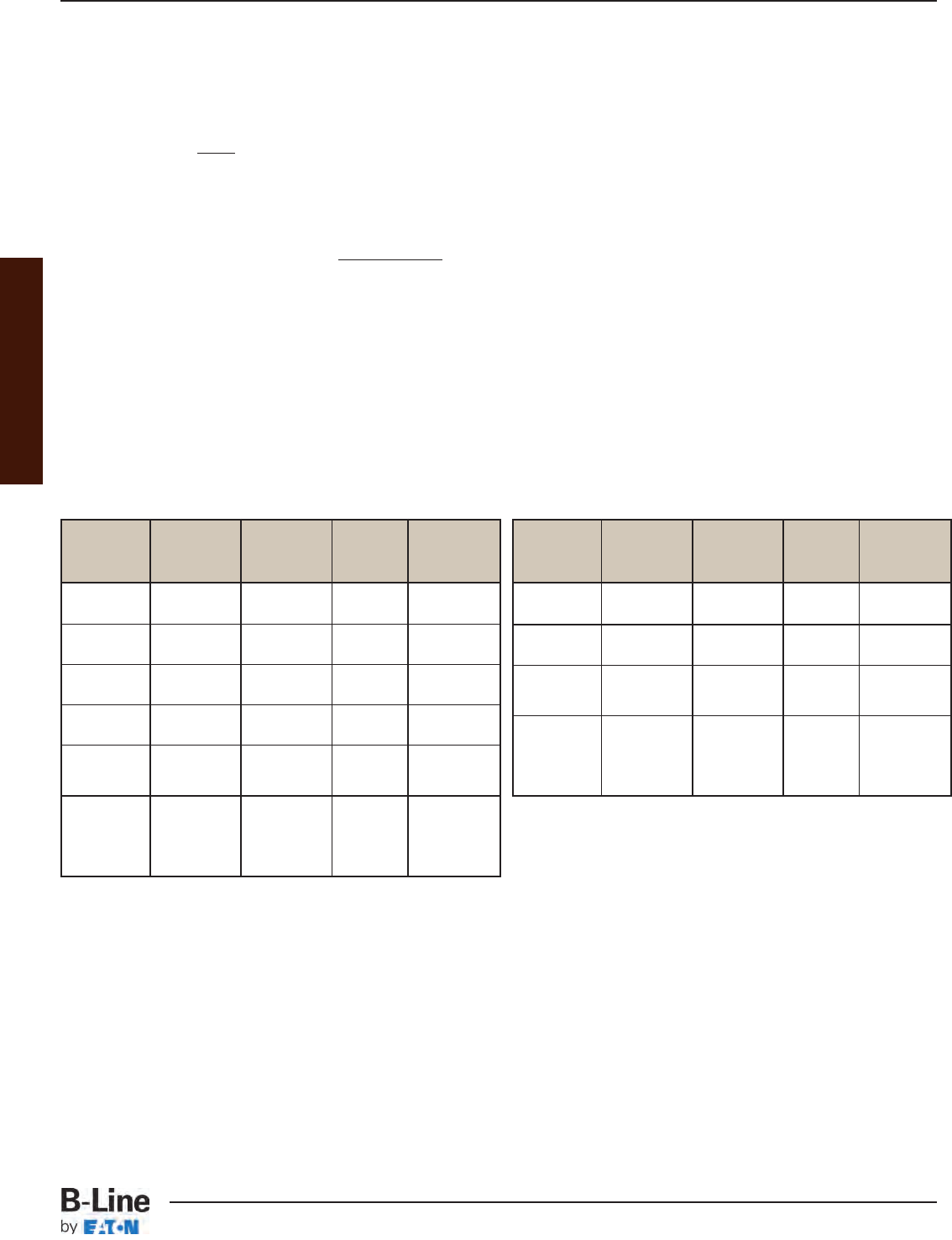
Appendix
AMPACITY:
Multiconductor Cables (2000V or Less)
Cable ampacities shall comply with Tables 310.16 and 310.18 of the NEC®subject to the provisions below:
1. If there are more than 3 current carrying conductors in a cable, derate cable ampacity per section
310.15(B)(2)(A).
2. If tray has solid covers, use 95% of the ampacity values shown in Tables 310.16 and 310.18.
3. If cables are placed in a single layer, with a maintained spacing of not less than 1 cable diameter between
cables, the ampacity of the cables shall not exceed the allowable ambient temperature-corrected ampacities
of multiconductor cables with not more than 3 insulated conductors in free air in accordance with Section
310.15(C) and Table B.310.3. You must use the ambient ampacity correction factors, found below Table
B.310.3, for ambient temperatures other than 40°C (104°F).
Multiconductor Cables (2001 Volts and over) Type MV and Type MC Cables
1. Where cable trays are covered for more than 6 ft. with solid, unventilated covers, use not more than 95% of
the ampacity values of Tables 310.75 and 310.76.
2. Where cables are installed in a single layer in uncovered trays with a maintained spacing of not less than one
cable diameter between cables, you can use the ampacity values listed in Tables 310.71 and 310.72.
Single Conductor Cables
Cable Fill in Hazardous (Classified) Locations:
Section 392.3 of the NEC regulates the use of cable tray wiring systems in hazardous (classified) locations. This
section states that if cable tray wiring systems are installed in hazardous (classified) locations, the cables that they
support must be suitable for installation in those hazardous (classified) locations. The cable carries the installation
restriction, not the cable tray except that the cable tray installation must comply with Section 392.4.
Some hazardous (classified) locations require special spacing of the cables. When installing Type MC, MI & TC cables
in cable tray in Class II, Division 2 Hazardous (classified) areas, (combustible dusts), the cables are limited to a single
layer with spacing between cables equal to the diameter of the largest adjacent cable. This is the only hazardous
(classified) location where the spacing of the cables is required although it is recommended that this wiring method
also be employed in Class III, Division I, and Class III, Division 2 (Ignitable Fibers & Flyings). Please note that this
will alter the cable tray sizing information obtained from the sizing flow chart on page CTS-20 & CTS-21 of this
catalog.
Ampacity of Type MV and Type MC Cables
(2001 volts or over) in Cable Trays (single conductor cables)
Ampacity of Cables Rated 2000 Volts or Less
in Cable Tray (single conductor cables)
Solid Applicable Mult. Amp.
Cable Unventilated Ampacity Table Special
Sizes Cable Tray Tables Values Conditions
Cover ? (*) By
1/0 AWG 310.69
and No (**) and 0.75
Larger 310.70
1/0 AWG 310.69
and Yes and 0.70
Larger 310.70
1/0 AWG Maintained
& Larger 310.69 Spacing Of
In Single No (**) and 1.00 One Cable
Layer 310.70 Diameter
Single
Conductors Spacing Of
In Triangle 310.67 2.15 x One
Config. No (**) and 1.05 Conductor
1/0 AWG 310.68 O.D. Between
and Larger Cables
(*) The ambient ampacity correction factors must be used.
(**) At a specific position, where it is determined that the tray cables require mechanical
protection, a single cable tray cover of six feet or less in length can be installed.
Solid Applicable Mult. Amp.
Cable Unventilated Ampacity Table Special
Sizes Cable Tray Tables Values Conditions
Cover ? (*) By
600 kcmil 310.17
and No (**) and 0.75
Larger 310.19
600 kcmil 310.17
and Yes and 0.70
Larger 310.19
1/0 AWG 310.17
through No (**) and 0.65
500 kcmil 310.19
1/0 AWG 310.17
through Yes and 0.60
500 kcmil 310.19
1/0 AWG Maintained
& Larger 310.17 1.00 Spacing Of
In Single No (**) and One Cable
Layer 310.19 Diameter
Single
Conductors 310.20 Spacing Of
In Triangle [See NEC 2.15 x One
Config. No (**) Section 1.00 Conductor
1/0 AWG 310.15(B)] O.D. Between
and Larger Cables
APP-15
Appendix - Additional Cable Tray Sizing Requirements
Cable Tray Systems
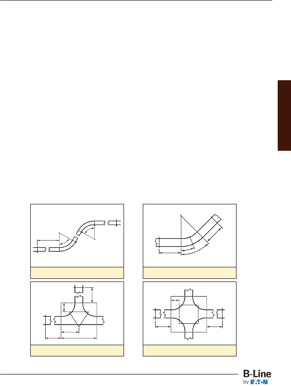
Appendix
Supports - B-Line Cable Tray shall be sized and installed as a complete cable support system appropriate for the cable
types installed. Recommended cable tray support locations are as shown below. Do not exceed the maximum support
spacing and design load as printed on the side rail label. Refer to Canadian Electrical Code (CEC) section 12-2202 for
minimum cable tray clearances.
Splice Plates - Use factory supplied splice plates only. Splice plates located at the quarter span between supports are
preferred. Avoid placing splices at midspan and directly above supports. Torque all splice plate fasteners to 19 ft. - lbs. for
3/8" and 50 ft. - lbs. for 1/2". Expansion splice plate fasteners should be loosened 1
/2turn after reaching full torque to allow
for travel. Set the side rail gap for expansion plates according to the chart on page CTS-8 and ensure that a support is
located within 2 feet on each side of the expansion splice.
Conductors - The Cable Tray system installation shall be completed prior to pulling conductors. Cable support distances
for conductor size should be referenced in CEC Part 1, Table 21. Single conductor cables placed one diameter or more
apart in ventilated or ladder type tray are allowed to use the free air rating per the CEC. Any conductor in vertical runs of
cable tray and all single conductor cables must be fastened to the rungs with nylon cable ties or stainless steel clamps.
Carbon steel cable clamps should not be used due to induction heating, per CEC section 12-2204 (5).
Covers - Vertical cable trays which penetrate dry floors must be covered for 2m (two meter) above the floor level. All cable
tray dead ends must be closed with blind ends per CEC sec 12-2202( 6).
Handling - Cable tray is shipped without exterior crating, therefore careful material handling practices should be used.
Cable tray straight sections should be lifted with wide slings and an overhead crane. If a crane is not available and a fork lift
is to be used, only single bundles should be lifted. Ensure that each bundle is properly centered. Cable tray fittings that are
not crated should be unbanded and off-loaded by hand.
Storage - All cable tray materials are subject to storage stain (white rust) if improperly stored. If cable tray is stored as
shipped, it must be stored indoors. If the cable tray material must be stored outside, it must be unbanded and loosely
stacked on an angle to minimize the components' contact area as well as provide for adequate drainage.
Vertical Elbows
NEMA RECOMMENDED SUPPORT LOCATIONS FOR FITTINGS
.6M
2 ft.
ø
ø
Horizontal Elbows
.6M
2 ft.
.6M
2 ft.
1/2
ø
ø
Horizontal Tee
.6M
2 ft.
.6M
2 ft.
Horizontal Cross
L
1/2L
2/3R
2/3R
16.9mm
16.9mm
.6M
2 ft.
.6M
2 ft.
Please reference NEMA VE 2, metal cable tray installation guideline, for more complete information.
www.cabletrays.com/technica.htm
APP-16
Appendix - Installation Data
Cable Tray Systems
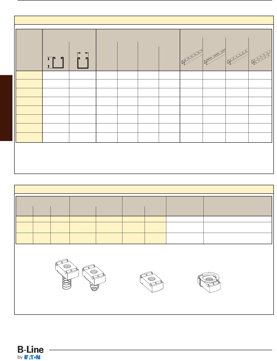
Channel Nuts
Channel Nut With Spring Channel Nut Without Spring Twirl Nut
With Spring Without Spring Twirl Nut
B11 B22 B42 B11 B22 B42 B11 B22 B42
B12 B24 B52 B12 B24 B52 B12 B24 B52
B32 B54 B32 B54 B32 B54
N728 N228 N528 N228WO N228WO TN228 TN228 3/8"-16 3/8" for all nuts
N725 N225 N525 N225WO N525WO TN225 TN525 1/2"-13 1/2" for N725,N225,N225WO,TN225
3/8" for N525,N525WO,TN525
N755 N255 N555 N255WO N555WO -- -- 5/8"-11 1/2" for N755,N255,N255WO
3/8" for N555,N555WO
Thread
Size
Channel Sizes & Hole Patterns Selection Chart
Channel Material & Thickness Channel Hole Patterns **
Dimensions Stainless SH S H17/8 TH
Steel
123 4
B11 3 1/4" 1 5/8" 12 Ga. -- -- -- 111--
B12 2 7/16" 1 5/8" 12 Ga. .105 -- -- 1,2 1 1,2 --
B22 1 5/8" 1 5/8" 12 Ga. .105 12 Ga. 12 Ga. 1,2,3,4 1 1,2,3,4 1
B24 1 5/8" 1 5/8" 14 Ga. .080 14 Ga. 14 Ga. 1,2,3,4 1 1,2,3,4 --
B32 1 3/8" 1 5/8" 12 Ga. -- 12 Ga. -- 1,3 1 1,3 --
B42 1 " 1 5/8" 12 Ga. -- 12 Ga. -- 1,3 1 1,3 --
B52 13/16" 1 5/8" 12 Ga. -- 12 Ga. -- 1,3 1 1,3 --
B54 13/16" 1 5/8" 14 Ga. .080 14 Ga. 14 Ga. 1,2,3,4 1 1,2,3,4 --
Thickness
For other channels, channel nuts, and fittings see B-Line Strut Systems Catalog.
Channel
Type
Height Width
Available Finishes on Steel: Plain (Oil Coated), Dura-Green Epoxy, Pre-Galvanized, and Hot Dip Galvanized are standard.
Steel
Aluminum
Type 304
Type 316
** 1 - Steel
2 - Aluminum
3 - Type 304 Stainless Steel
4 - Type 316 Stainless Steel
Appendix
APP-17
Appendix - Support Channels & Channel Nuts
Cable Tray Systems
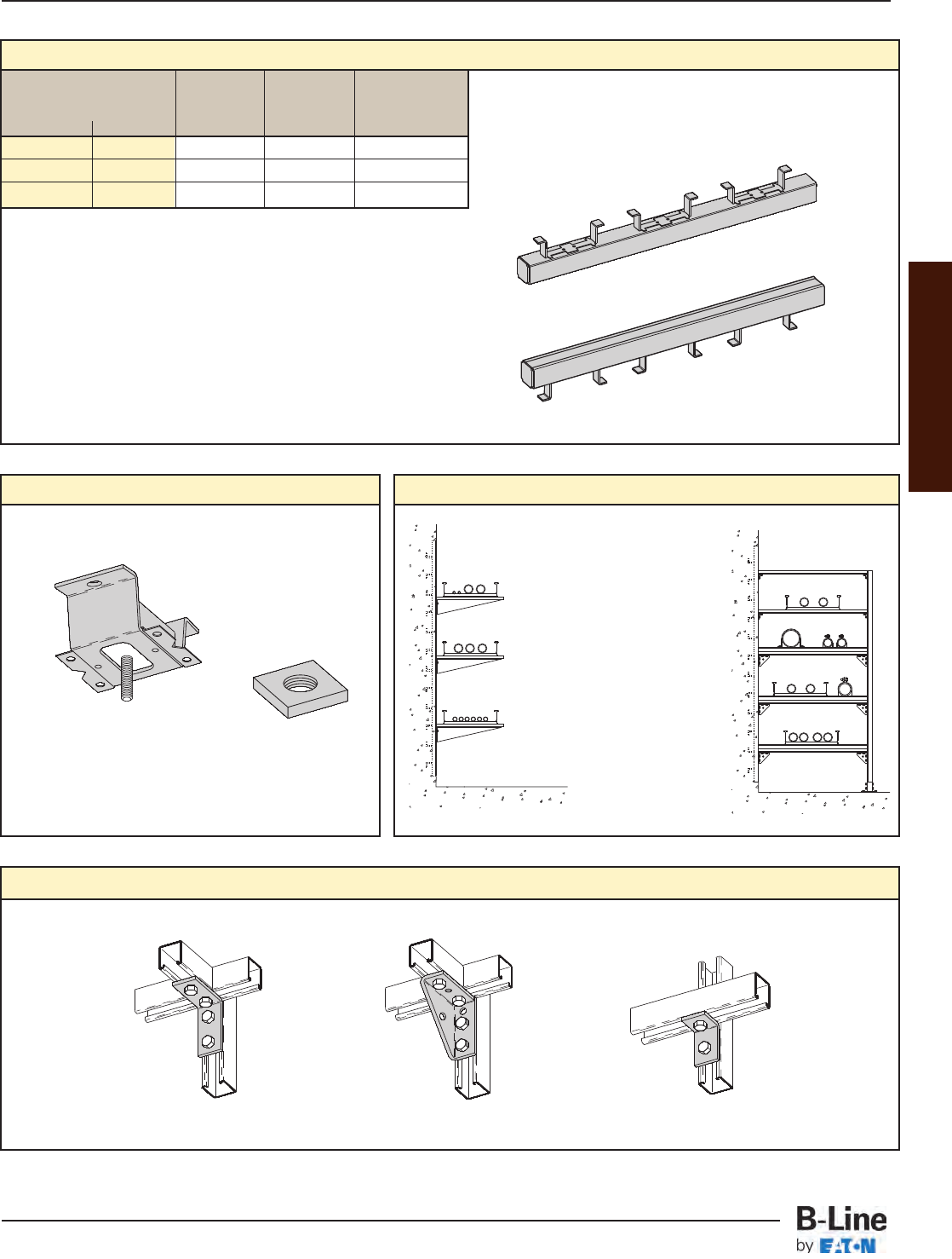
Continuous Concrete Insert
Catalog
Number for Channel Channel Maximum
120" (10 ft.) 240" (20 ft.) Size Depth Load
B22I-120 B22I-240 B22 1 5/8" 2000 lbs./ft.
B32I-120 B32I-240 B32 1 3/8" 2000 lbs./ft.
B52I-120 B52I-240 B52 13/16" 1500 lbs./ft.
Safety factor of 3 on loading.
Other lengths available upon request.
Furnished with end caps and styrofoam filler installed.
Standard finishes:
Plain (Oil Coated)
Dura Green Epoxy
Pre-Galvanized
Hot Dip Galvanized
Square Nuts for Spot Inserts
Angle Fittings
B2500 Spot Insert & N2500 Insert Nut
N2500 Insert Nut
Insert rod size behind part
number.
B2500 Insert
Standard Finish: Zinc Plated
Concrete Insert Applications
Continuous
inserts used
vertically are ideal
mounting bases
for cable tray
brackets.
For multi-tiered tray
assemblies, inserts
function as the
anchors for each
stanchion.
B104 B844 B101
Appendix
APP-18
Appendix - Concrete Inserts & Threaded Rod
Cable Tray Systems

Appendix
APP-19
Notes
Cable Tray Systems

CABLE TRAY MANUAL
Based on the
2011 National Electrical Code®
Cable Tray Manual
MAN-1
Cable Tray Manual
Cable Tray Systems
2011

Table of Contents
Page No.
Introduction ......................................................................................................................................................................................................... MAN-3
Why Cable Tray?
Safety ................................................................................................................................................................................................ MAN-4
Dependability .............................................................................................................................................................. MAN-4 – MAN-5
Space Savings ................................................................................................................................................................................ MAN-5
Cost Savings ............................................................................................................................................................... MAN-5 – MAN-8
An In-depth Look at the 2011 NEC®, Section 392
Types of Cable Trays (NEC®392.1 Scope) ............................................................................................... MAN-9 – MAN-10
EMI/RFI Cable Tray .................................................................................................................................................................... MAN-10
Cable Tray Materials .................................................................................................................................................................. MAN-11
392.2 Definition of Cable Tray System ............................................................................................................................ MAN-11
392.10 Uses for Cable Tray ........................................................................................................................... MAN-11 – MAN-16
(A) Wiring Methods and Cable Types ..................................................................................... MAN-12 – MAN-13
(B) Industrial Usage ......................................................................................................................... MAN-13 – MAN-14
(1) Single Conductor Cable .............................................................................................. MAN-13 – MAN-14
(2) Medium Voltage Cable ........................................................................................................................ MAN-14
(C) Hazardous (Classified) Locations ..................................................................................... MAN-14 – MAN-16
(D) Usage of Nonmetallic Tray ........................................................................................................................... MAN-16
392.12 Uses Not Permitted ................................................................................................................................................... MAN-16
392.18 Cable Tray Installation ......................................................................................................................... MAN-6 – MAN-20
(A) Complete System ......................................................................................................................... MAN-6 – MAN-18
(B) Completed Before Installation .................................................................................................................... MAN-18
(C) Covers ..................................................................................................................................................................... MAN-19
(D) Through Partitions & Walls ........................................................................................................................... MAN-19
(E) Exposed & Accessible .................................................................................................................................... MAN-19
(F) Adequate Access ............................................................................................................................................... MAN-19
(G)
Raceways, Cables, Boxes, and Conduit Bodies Supported
from Cable Tray Systems
........................................................................................................ MAN-19 – MAN-20
392.20 Cables and Conduit Installation .................................................................................................. MAN-21 – MAN-22
(A) Multiconductor Cables, 600V or less ...................................................................................................... MAN-21
(B) Cables Rated over 600V ................................................................................................................................ MAN-21
(C) Connected in Parallel .............................................................................................................. MAN-21 – MAN-22
(D) Single Conductor .............................................................................................................................................. MAN-22
392.22 Number of Conductor of Cable ................................................................................................... MAN-23 – MAN-26
392.30 Securing and Supporting Cables and Conductors .................................................................................. MAN-26
392.46 Bushed Conduit and Tubing ................................................................................................................................. MAN-27
392.56 Cable Splices ................................................................................................................................................................ MAN-27
392.60 Grounding and Bonding .................................................................................................................. MAN-28 – MAN-31
392.80 Ampacity of Conductors ................................................................................................................. MAN-31 – MAN-33
392.100 Construction Specifications ....................................................................................................... MAN-33 – MAN-35
(A) Strength and Rigidity ............................................................................................................... MAN-33 – MAN-35
(B) Smooth Edges .................................................................................................................................................... MAN-35
(C) Corrosion Protection ....................................................................................................................................... MAN-35
(D) Siderails .................................................................................................................................................................. MAN-35
(E) Fittings ..................................................................................................................................................................... MAN-35
(F) Nonmetallic Cable Tray ................................................................................................................................... MAN-35
Cable Tray Wiring System Design and Installation Hints ....................................................................................... MAN-36
Cable Tray Accessories ........................................................................................................................................................... MAN-37
Fireproofing Tray .......................................................................................................................................................................... MAN-37
Cable Tray Maintenance & Repair ...................................................................................................................................... MAN-37
Expansion and Contraction ........................................................................................................................... MAN-38 – MAN-39
Appendix Index & Appendix Sheets ........................................................................................................................ MAN-40 – MAN-47
Cable Tray Sizing Flowchart ........................................................................................................................................ MAN-48 – MAN-49
Cable Tray Installation & Specification Checklists ....................................................................................... MAN-50 – MAN-51
Footnotes ........................................................................................................................................................................................................... MAN-52
Cable Tray Manual
MAN-2
Cable Tray Manual
Cable Tray Systems

INTRODUCTION
The B-Line Cable Tray Manual was produced by B-Line's technical staff. B-Line has recognized
the need for a complete cable tray reference source for electrical engineers and designers. The
following pages address the 2011 National Electrical Code®requirements for cable tray systems as
well as design solutions from practical experience. The information has been organized for use as a
reference guide for both those unfamiliar and those experienced with cable tray.
Nearly every aspect of cable tray design and installation has been explored for the use of the
reader. If a topic has not been covered sufficiently to answer a specific question or if additional
information is desired, contact the engineering department at B-Line. We sincerely hope you will find
the B-Line Cable Tray Manual a helpful and informative addition to your technical library.
The information contained herein has been carefully checked for accuracy and is believed to be
correct and current. No warranty, either expressed or implied, is made as to either its applicability
to, or its compatibility with, specific requirements, of this information, nor for damages consequent
to its use. All design characteristics, specifications, tolerances and similar information are subject to
change without notice.
Eaton’s B-Line Business
509 West Monroe Street
Highland, IL 62249-0326
Tel: (800) 851-7415
www.bline.com
NFPA 70®- 2008, National Electrical Code®and NEC®are registered trademarks of the
National Fire Protection Association, Quincy, MA.
Cable Tray Manual
Reproduced with permission from NFPA 70®-2011, National Electrical Code®, Copyright © 2010, National Fire Protection
Association, Quincy, MA. This reprinted material is not the complete and official position of the NFPA on the referenced sub-
ject, which is represented only by the standard in its entirety.
MAN-3
Cable Tray Manual
Cable Tray Systems

Large numbers of electrical engineers have limited
detail knowledge concerning wiring systems. There is
the tendency by engineers to avoid becoming involved
in the details of wiring systems, leaving the wiring
system selection and design to designers or
contractors. Certain decisions must be made for any
wiring system installation, and these decisions should
be made in the design and construction activities' chain
where maximum impact is achieved at the lowest
possible cost. Deferring design decisions to
construction can result in increased costs and wiring
systems incompatible with the owner's future
requirements. Early in the project's design life, the costs
and features of various applicable wiring systems
should be objectively evaluated in detail. Unfortunately,
such evaluations are often not made because of the
time and money involved. It is important to realize that
these initial evaluations are important and will save time
and money in the long run. The evaluation should
include the safety, dependability, space and cost
requirements of the project. Many industrial and
commercial electrical wiring systems have excessive
initial capital costs, unnecessary power outages and
require excessive maintenance. Moreover, the wiring
system may not have the features to easily
accommodate system changes and expansions, or
provide the maximum degree of safety for the personnel
and the facilities.
Cable tray wiring systems are the preferred wiring
system when they are evaluated against equivalent
conduit wiring systems in terms of safety, dependability,
space and cost. To properly evaluate a cable tray wiring
system vs. a conduit wiring system, an engineer must
be knowledgeable of both their installation and the
system features. The advantages of cable tray
installations are listed below and explained in the
following paragraphs.
• Safety Features
• Dependability
• Space Savings
• Cost Savings
• Design Cost Savings
• Material Cost Savings
• Installation Cost & Time Savings
• Maintenance Savings
CABLE TRAY SAFETY FEATURES
A properly engineered and installed cable tray wiring
system provides some highly desirable safety features
that are not obtainable with a conduit wiring system.
• Tray cables do not provide a significant path for the
transmission of corrosive, explosive, or toxic gases
while conduits do. There have been explosions in
industrial facilities in which the conduit systems were a
link in the chain of events that set up the conditions for
the explosions. These explosions would not have
occurred with a cable tray wiring system since the
explosive gas would not have been piped into a critical
area. This can occur even though there are seals in the
conduits. There does have to be some type of an
equipment failure or abnormal condition for the gas to
get into the conduit, however this does occur. Conduit
seals prevent explosions from traveling down the
conduit (pressure piling) but they do not seat tight
enough to prevent moisture or gas migration until an
explosion or a sudden pressure increase seats them.
The October 6, 1979 Electrical Substation Explosion at
the Cove Point, Maryland Columbia Liquefied Natural
Gas Facility is a very good example of where explosive
gas traveled though a two hundred foot long conduit
with a seal in it. The substation was demolished, the
foreman was killed and an operator was badly burned.
This explosion wouldn’t have occurred if a cable tray
wiring system had been installed instead of a conduit
wiring system. A New Jersey chemical plant had the
instrumentation and electrical equipment in one of its
control rooms destroyed in a similar type incident.
• In addition to explosive gases, corrosive gases and
toxic gases from chemical plant equipment failures can
travel through the conduits to equipment or control
rooms where the plant personnel and the sensitive
equipment will be exposed to the gases.
• In facilities where cable tray may be used as the
equipment grounding conductor in accordance with
NEC®Sections 392.60(A) & 392.60(B), the grounding
equipment system components lend themselves to visual
inspection as well as electrical continuity checks.
CABLE TRAY DEPENDABILITY
A properly designed and installed cable tray system
with the appropriate cable types will provide a wiring
system of outstanding dependability for the control,
communication, data handling, instrumentation, and
power systems. The dependability of cable tray wiring
systems has been proven by a 40 year track record of
excellent performance.
• Cable tray wiring systems have an outstanding
record for dependable service in industry. It is the most
common industrial wiring system in Europe. In
continuous process systems, an electrical system failure
can cost millions of dollars and present serious process
safety problems for the facility, its personnel and the
people in the surrounding communities. A properly
designed and installed cable tray system with the
appropriate cable types will provide a wiring system of
outstanding dependability for process plants.
WHY CABLE TRAY?
BECAUSE A CABLE TRAY WIRING SYSTEM PROVIDES
SAFE AND DEPENDABLE WAYS TO SAVE NOW AND LATER
Cable Tray Manual
MAN-4
Cable Tray Manual
Cable Tray Systems

• Television broadcast origination facilities and
studios make use of cable tray to support and route the
large volumes of cable needed for their operations with
a high degree of dependability. It would be impossible
to have the wiring system flexibility they need with a
conduit wiring system.
• Large retail and warehouse installations use cable
tray to support their data communication cable
systems. Such systems must be dependable so that
there are no outages of their continuous inventory
control systems.
• Cable tray wiring systems have been widely used
to support cabling in both commercial and industrial
computer rooms overhead and beneath the floor to
provide orderly paths to house and support the cabling.
These types of installations need a high degree of
dependability which can be obtained using cable tray
wiring systems.
CABLE TRAY SPACE SAVINGS
When compared to a conduit wiring system, an
equivalent cable tray wiring system installation requires
substantially less space.
Increasing the size of a structure or a support system
to handle a high space volume conduit wiring system is
unnecessary when this problem can be avoided by the
selection of a cable tray wiring system.
• Facilities with high density wiring systems devoted
to control, instrumentation, data handling and branch
circuit wiring have the choice of selecting cable tray or
conduit wiring systems. A conduit wiring system is often
a poor choice because large conduit banks require
significant space, competing with other systems and
equipment. Choosing a cable tray wiring system greatly
reduces this problem.
• Financial institutions with large computer
installations have high density wiring systems under
floors or in overhead plenum areas that are best handled
by cable tray wiring systems.
• Airport facilities have extensive cable tray wiring
systems to handle the ever expanding needs of the
airline industry.
• Cable tray is used in many facilities because of the
ever present need of routing more and more cables in
less space at lower costs.
• Large health care facilities have high density wiring
systems that are ideal candidates for cable tray.
CABLE TRAY WIRING SYSTEM
COST SAVINGS
Usually, the initial capital cost is the major factor in
selecting a project's wiring system when an evaluation
is made comparing cable tray wiring systems and
conduit wiring systems. Such an evaluation often covers
just the conductors, material, and installation labor
costs. The results of these initial cost evaluations usually
show that the installed cable tray wiring system will cost
10 to 60 percent less than an equivalent conduit wiring
system. The amount of cost savings depends on the
complexity and size of the installation.
There are other savings in addition to the initial
installation cost savings for cable tray wiring systems
over conduit wiring systems. They include reduced
engineering costs, reduced maintenance costs, reduced
expansion costs, reduced production losses due to
power outages, reduced environmental problems due
to continuity of power and reduced data handling
system costs due to the continuity of power. The
magnitudes of many of these costs savings are difficult
to determine until the condition exists which makes
them real instead of potential cost savings.
DESIGN COST SAVINGS
• Most projects are roughly defined at the start of
design. For projects that are not 100 percent defined
before design start, the cost of and time used in coping
with continuous changes during the engineering and
drafting design phases will be substantially less for
cable tray wiring systems than for conduit wiring
systems. A small amount of engineering is required to
change the width of a cable tray to gain additional wiring
space capacity. Change is a complex problem when
conduit banks are involved.
• The final drawings for a cable tray wiring system
may be completed and sent out for bid or construction
more quickly than for a conduit wiring system. Cable
tray simplifies the wiring system design process and
reduces the number of details.
• Cable tray wiring systems are well suited for
computer aided design drawings. A spread sheet based
wiring management program may be used to control the
cable fills in the cable tray. While such a system may
also be used for controlling conduit fill, large numbers
of individual conduits must be monitored. For an equal
capacity wiring system, only a few cable tray runs would
have to be monitored.
• Dedicated cable tray installation zones alert other
engineering disciplines to avoid designs that will
produce equipment and material installation conflicts in
these areas. As more circuits are added, the cable tray
installation zone will increase only a few inches; the
space required for the additional conduits needed
would be much greater.
• The fact that a cable can easily enter and exit
cable tray anywhere along its route, allows for some
unique opportunities that provide highly flexible designs.
• Fewer supports have to be designed and less
coordination is required between the design disciplines
for the cable tray supports compared to conduit
supports.
Cable Tray Manual
MAN-5
Cable Tray Manual
Cable Tray Systems
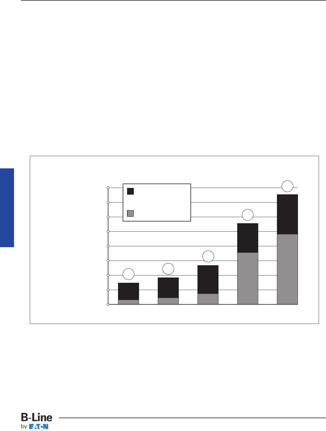
• Excluding conductors, the cost of the cable trays,
supports, and miscellaneous materials will provide a
savings of up to 80% as compared to the cost of the
conduits, supports, pull boxes, and miscellaneous
materials. An 18 inch wide cable tray has an allowable
fill area of 21 square inches. It would take 7 - 3 inch
conduits to obtain this allowable fill area (7 x 2.95 square
inches = 20.65 square inches).
• The cost of 600 volt insulated multiconductor cables
listed for use in cable tray is greater than the cost of 600
volt insulated individual conductors used in conduit. The
cost differential depends on the insulation systems,
jacket materials and cable construction.
• For some electrical loads, parallel conductors are
installed in conduit and the conductors must be derated,
requiring larger conductors to make up for the deration.
If these circuits were installed in cable tray, the conductor
sizes would not need to be increased since the parallel
conductor derating factors do not apply to three
conductor or single conductor cables in cable tray.
• Typical 300 volt insulated multiconductor
instrumentation tray cables (ITC) and power limited tray
cables (PLTC) cost the same for both cable tray and
conduit wiring systems. This applies for instrumentation
circuits, low level analog and digital signal circuits, logic
input/output (I/O) circuits, etc. There are other cable tray
installations which require a higher cost cable than the
equivalent conduit installation. Such installations are
limited to areas where low smoke emission and/or low
flame spread ITC or PLTC cables must be used.
• Conduit banks often require more frequent and
higher strength supports than cable trays. 3 inch and
larger rigid metal conduits are the only sizes allowed to
be supported on 20 foot spans.
• When a cable tray width is increased 6 inches, the
cable tray cost increase is less than 10 percent. This
substantially increases the cable tray’s wiring capacity
for a minimal additional cost. To obtain such an increase
in capacity for a conduit wiring system would be very
costly.
40000
35000
30000
25000
20000
15000
10000
5000
0
Total
Installed
Cost ($)
COST - Cable Tray vs. Conduit
(Equivalent Conductor Fill Areas)
Material Cost
Labor Cost @
$60/hr per NECA
labor units.
Aluminum Ladder
Cable Tray
Steel Ladder
Cable Tray
Solid Bottom
Cable Tray
EMT Rigid Steel
Conduit
Installation: 200 linear feet of cable supported with four 90° direction changes and all
trapeze supports on 8 ft. spans.
1. Aluminum, 18" wide, ladder cable tray (9" rung spacing) with all hardware.
2. Hot dip galvanized steel, 18" wide, ladder cable tray (9" rung spacing) with all hardware.
3. Hot dip galvanized steel, 18" wide, solid bottom cable tray and all hardware.
4. 7 parallel runs of 3" diameter EMT with concentric bends.
5. 7 parallel runs of 3" diameter galvanized conduit with concentric bends.
Note: Above costs do not include cable and cable pulling costs. Cable costs differ per installation and
cable/conductor pulling costs have been shown to be considerably less for cable tray than for conduit.
Cable Tray Manual
12
3
4
5
MAN-6
Cable Tray Manual
Cable Tray Systems

INSTALLATION COST AND TIME SAVINGS
• Depending on the complexity and magnitude of
the wiring system, the total cost savings for the initial
installation (labor, equipment and material) may be up to
75 percent for a cable tray wiring system over a conduit
wiring system. When there are banks of conduit to be
installed that are more than 100 feet long and consist of
four or more 2 inch conduits or 12 or more smaller
conduits, the labor cost savings obtained using cable
tray wiring systems are very significant.
• Many more individual components are involved in
the installation of a conduit system and its conductors
compared to the installation of a cable tray system and
its cables. This results in the handling and installing of
large amounts of conduit items vs. small amounts of
cable tray items for the same wiring capacity.
• The higher the elevation of the wiring system, the
more important the number of components required to
complete the installation. Many additional man-hours will
be required just moving the components needed for the
conduit system up to the work location.
• Conduit wiring systems require pull boxes or splice
boxes when there is the equivalent of more than 360
degrees of bends in a run. For large conductors, pull or
junction boxes may be required more often to facilitate
the conductor’s installation. Cable tray wiring systems
do not require pull boxes or splice boxes.
• Penetrating a masonry wall with cable tray requires
a smaller hole and limited repair work.
• More supports are normally required for rigid steel
conduit due to the requirements of NEC®Table
344.30(B)(2).
• Concentric conduit bends for direction changes in
conduit banks are very labor intensive and difficult to
make. However if they are not used, the installation will
be unattractive. The time required to make a concentric
bend is increased by a factor of 3-6 over that of a single
shot bend. This time consuming practice is eliminated
when cable tray wiring systems are used.
• Conductor pulling is more complicated and time
consuming for conduit wiring systems than for cable tray
wiring systems. Normally, single conductor wire pulls for
conduit wiring systems require multiple reel setups. For
conduit wiring systems, it is necessary to pull from
termination equipment enclosure to termination
equipment enclosure. Tray cables being installed in cable
trays do not have to be pulled into the termination
equipment enclosures. Tray cable may be pulled from
near the first termination enclosure along the cable tray
route to near the second termination enclosure. Then,
the tray cable is inserted into the equipment enclosures
for termination. For projects with significant numbers of
large conductors terminating in switchgear, this may be
a very desirable feature that can save hours of an
electrician's time. Unnecessary power outages can be
eliminated since tray cable pulls may be made without
de-energizing the equipment. For conduit installations,
the equipment will have to be de-energized for rubber
safety blanketing to be installed, otherwise the conductor
pulls might have to be made on a weekend or on a
holiday at premium labor costs to avoid shutting down
production or data processing operations during normal
working hours.
• Conductor insulation damage is common in
conduits since jamming can occur when pulling the
conductors. Jamming is the wedging of conductors in a
conduit when three conductors lay side by side in a flat
plane. This may occur when pulling around bends or
when the conductors twist. Ninety-two percent of all
conductor failures are the result of the conductor’s
insulation being damaged during the conductor’s
installation. Many common combinations of conductors
and conduits fall into critical jam ratio values. Critical jam
ratio (J.R.= Conduit ID/Conductor OD) values range from
2.8 to 3.2. The J. R. for 3 single conductor THHN/THWN
insulated 350 kcmil conductors in a 21/2inch conduit
would be 3.0 (2.469 inches/ 0.816 inches). If conductor
insulation damage occurs, additional costs and time are
required for replacing the conductors. This cannot occur
in a cable tray wiring system.
• Smaller electrician crews may be used to install the
equivalent wiring capacity in cable tray. This allows for
manpower leveling, the peak and average crew would be
almost the same number, and the electrician experience
level required is lower for cable tray installations.
• Since the work is completed faster there is less
work space conflict with the other construction
disciplines. This is especially true if installations are
elevated and if significant amounts of piping are being
installed on the project.
MAINTENANCE SAVINGS
• One of the most important features of cable tray is
that tray cable can easily be installed in existing trays if
there is space available. Cable tray wiring systems allow
wiring additions or modifications to be made quickly with
minimum disruption to operations. Any conceivable
change that is required in a wiring system can be done
at lower cost and in less time for a cable tray wiring
system than for a conduit wiring system.
• Moisture is a major cause of electrical equipment
and material failures. Breathing due to temperature
cycling results in the conduits accumulating relatively
large amounts of moisture. The conduits then pipe this
moisture into the electrical equipment enclosures which
over a period of time results in the deterioration of the
equipment insulation systems and their eventual failure.
Also, moisture may become a factor in the corrosion
failure of some of the critical electrical equipment's
metallic components. Conduit seals are not effective in
blocking the movement of moisture. The conduit
systems may be designed to reduce the moisture
Cable Tray Manual
MAN-7
Cable Tray Manual
Cable Tray Systems

problems but not to completely eliminate it. Few
designers go into the design detail necessary to reduce
the effects of moisture in the conduit systems. Tray
cables do not provide internal moisture paths as do
conduits.
• In the event of external fires in industrial
installations, the damage to the tray cable and cable tray
is most often limited to the area of the flame contact plus
a few feet on either side of the flame contact area. For
such a fire enveloping a steel conduit bank, the steel
conduit is a heat sink and the conductor insulation will
be damaged for a considerable distance inside the
conduit. Thermoplastic insulation may be fused to the
steel conduit and the conduit will need to be replaced for
many feet. This occurred in an Ohio chemical plant and
the rigid steel conduits had to be replaced for 90 feet.
Under such conditions, the repair cost for fire damage
would normally be greater for a conduit wiring system
than for cable tray and tray cable. In the Ohio chemical
plant fire, there were banks of conduits and runs of cable
tray involved. The cable tray wiring systems were
repaired in two days. The conduit wiring systems were
repaired in six days and required a great deal more
manpower.
• In the event of an external fire, the conduit becomes
a heat sink and an oven which decreases the time
required for the conductor insulation systems to fail. The
heat decomposes the cable jackets and the conductor
insulation material. If these materials contain PVC as do
most cables, hydrogen chloride vapors will come out the
ends of the conduits in the control rooms. These fumes
are very corrosive to the electronic equipment. They are
also hazardous to personnel. A flame impingement on a
cable tray system will not result in the fumes going into
the control room as there is no containment path for
them. They will be dispersed into the atmosphere.
IN MOST CASES AN OBJECTIVE EVALUATION OF
THE REQUIREMENTS FOR MOST HIGH DENSITY
WIRING SYSTEMS WILL SHOW THAT A CABLE TRAY
WIRING SYSTEM PROVIDES A WIRING SYSTEM
SUPERIOR TO A CONDUIT WIRING SYSTEM.
Abandoned Cables
Easily identified, marked, or removed - all possible from
an open Cable Tray System
For the 2002 National Electrical Code, several
proposals were submitted to the NFPA to revise the 1999
NEC®for Articles 300, 640, 645, 725, 760, 770, 800, 820,
and 830 to require all abandoned cables to be removed
from plenum spaces.
The purpose of the proposals is to remove the cables
as a source of excess combustibles from plenums and
other confined spaces such as raised floors and drop
ceilings. All of the Code Making Panels agreed that this
should be acceptable practice except Code Making
Panel 3, which oversees Article 300.
Because Article 300 is exempt from this requirement
only low-voltage and communication cables are affected.
Each Article adopted a definition of abandoned cables
and the rule for removal. The general consensus is that
abandoned cable is cable that is not terminated at
equipment or connectors and is not identified for future
use with a tag. Please refer to each individual NEC®
Article for specifics.
Having to tag, remove, or rearrange cables within an
enclosed raceway can be a time consuming and difficult
job. Without being able to clearly see the cables and
follow their exact routing throughout a facility, identifying
abandoned cables would be very difficult and expensive.
With the open accessibility of cable tray, these
changes can be implemented with ease. Abandoned
cables can be identified, marked, rearranged, or removed
with little or no difficulty.
Cable Tray Manual
MAN-8
Cable Tray Manual
Cable Tray Systems
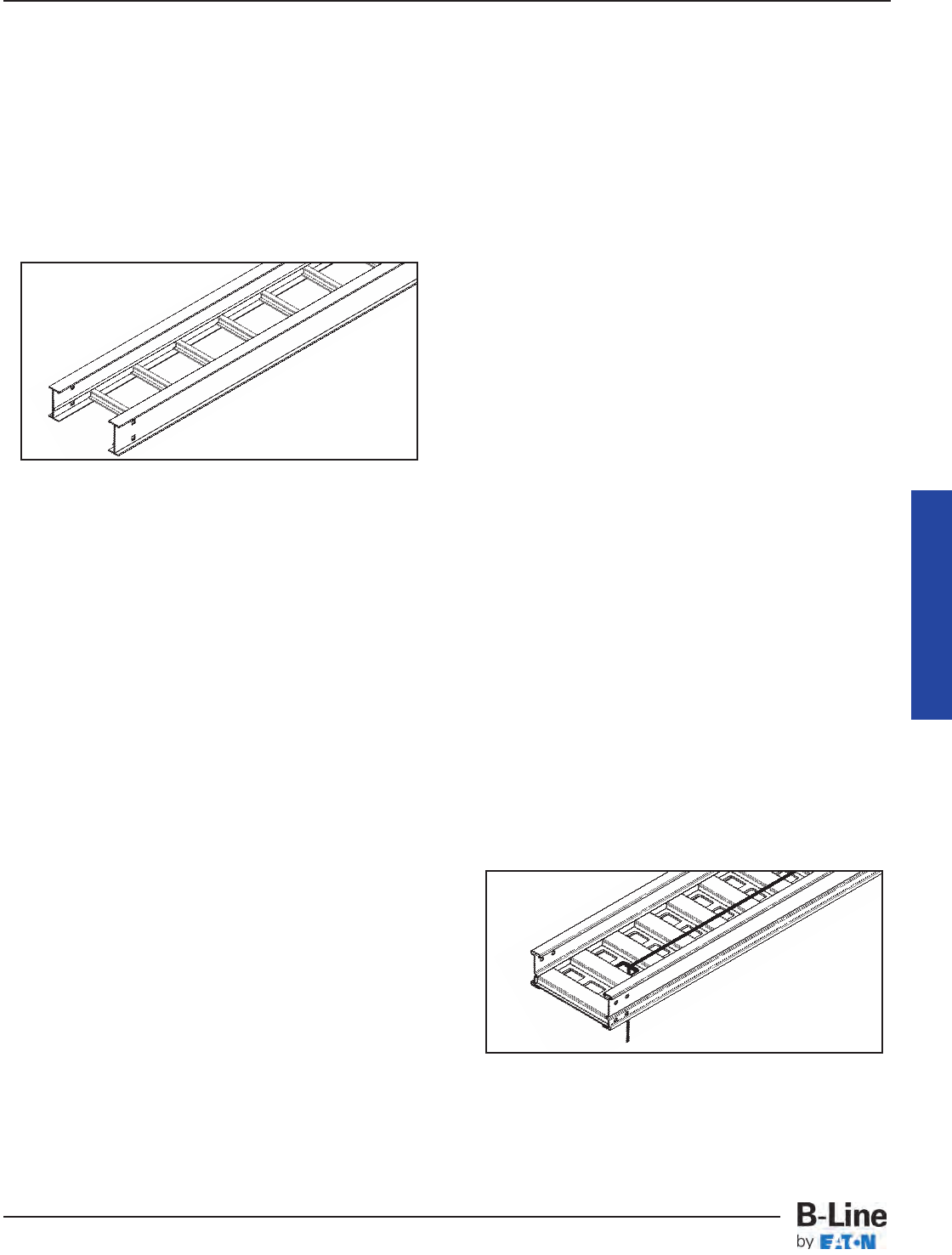
392.1. Scope.
Of the types of cable trays listed in this section, ladder
cable tray is the most widely used type of cable tray due
to several very desirable features.
• The rungs provide a convenient anchor for tying
down cables in vertical runs or where the positions of the
cables must be maintained in horizontal runs.
• Cables may exit or enter through the top or the
bottom of the tray.
• A ladder cable tray without covers provides for the
maximum free flow of air, dissipating heat produced in
current carrying conductors.
• Moisture cannot accumulate in ladder cable trays
and be piped into electrical equipment as happens in
conduit systems.
• Ladder cable tray cannot pipe hazardous or
explosive gases from one area to another as happens
with conduit systems.
• In areas where there is the potential for dust to
accumulate, ladder cable trays should be installed. The
dust buildup in ladder cable trays will be less than the
dust buildup in ventilated trough or solid bottom cable
trays.
Ladder cable trays are available in widths of 6, 9, 12,
18, 24, 30, 36, and 42 inches with rung spacings of 6, 9,
12, or 18 inches. Wider rung spacings and wider cable
tray widths decrease the overall strength of the cable
tray. Specifiers should be aware that some cable tray
manufacturers do not account for this load reduction in
their published cable tray load charts. B-Line uses
stronger rungs in wider cable trays to safely bear the
loads published.
With one exception, the specifier selects the rung
spacing that he or she feels is the most desirable for the
installation. The exception is that 9 inches is the
maximum allowable rung spacing for a ladder cable tray
supporting any 1/0 through 4/0 single conductor cables
[See Section 392.10(B)(1)(a)].
Where the ladder cable tray supports small diameter
multiconductor control and instrumentation cables; 6, 9,
or 12 inch rung spacings should be specified. Quality
Type TC, Type PLTC, or Type ITC small diameter
multiconductor control and instrumentation cables will
not be damaged due to the cable tray rung spacing
selected, but the installation may not appear neat if there
is significant drooping of the cables between the rungs.
For ladder cable trays supporting large power cables,
9 inch or wider rung spacings should be selected. For
many installations, the cable trays are routed over the
top of a motor control center (MCC) or switchgear
enclosure. Cables exit out the bottom of the cable trays
and into the top of the MCC or switchgear enclosure. For
these installations, the cable manufacturer's
recommended minimum bending radii for the specific
cables must not be violated. If the rung spacing is too
close, it may be necessary to remove some rungs in
order to maintain the proper cable bending radii. This
construction site modification can usually be avoided by
selecting a cable tray with 12 or 18 inch rung spacing.
If you are still uncertain as to which rung spacing to
specify, 9 inch rung spacing is the most common and is
used on 80% of the ladder cable tray sold.
The 1999 NEC®added the word ‘ventilated’ in front of
trough to clear up some confusion that solid trough is
treated the same as ventilated trough. It is not. Solid
trough is recognized as solid bottom cable tray.
AN IN-DEPTH LOOK AT 2011 NEC®
ARTICLE 392 - CABLE TRAY
(The following code explanations are to be used with a copy of the 2011 NEC®.)
To obtain a copy of the NEC®contact:
National Fire Protection Association®
1 Batterymarch Park • P.O. Box 9101
Quincy, Massachusetts 02269-9101
1-800-344-3555
Standard Aluminum Ladder
Steel Ventilated Trough
Cable Tray Manual
MAN-9
Cable Tray Manual
Cable Tray Systems
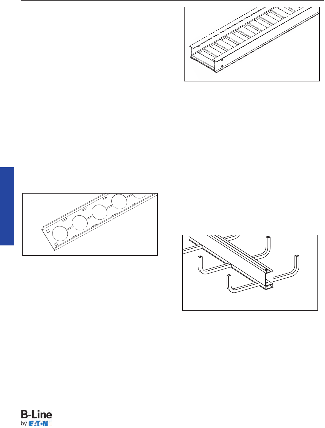
Ventilated trough cable tray is often used when the
specifier does not want to use ladder cable tray to
support small diameter multiconductor control and
instrumentation cables. As no drooping of the small
diameter cables is visible, ventilated trough cable trays
provide neat appearing installations. Small diameter
cables may exit the ventilated trough cable tray through
the bottom ventilation holes as well as out the top of the
cable tray. For installations where the cables exit the
bottom of the cable tray and the system is subject to
some degree of vibration, it is advisable to use B-Line
Trough Drop-Out Bushings (Cat. No. 99-1124). These
snap-in bushings provide additional abrasion protection
for the cable jackets. Just as for ladder cable tray,
ventilated trough cable tray will not pipe moisture into
electrical equipment.
Standard widths for ventilated trough cable tray
systems are 6, 9, 12, 18, 24, 30, and 36 inches. The
standard bottom configuration for ventilated trough cable
tray is a corrugated bottom with 27/8inch bearing
surfaces - 6 inches on centers and 21/4inch x 4 inch
ventilation openings. Since a corrugated bottom cannot
be bent horizontally, the standard bottom configuration
for horizontal bend fittings consists of rungs spaced on
4 inch centers. This difference in bottom construction
may be objectionable to some owners, so be sure you
are aware of the owner's sensitivity to aesthetics for the
cable tray installation.
Channel cable tray systems (B-Line cable channel) are
available in 3, 4, and 6 inch widths with ventilated or
solid bottoms. The NEC®now recognizes solid bottom
cable channel. Prior to the 2002 Code, the NEC®did not
have any specific provisions for the use of solid cable
channel.
Instead of large conduits, cable channel may be used
very effectively to support cable drops from the cable
tray run to the equipment or device being serviced and
is ideal for cable tray runs involving a small number of
cables. Cable channel may also be used to support push
buttons, field mounted instrumentation devices, etc.
Small diameter cables may exit ventilated cable channel
through the bottom ventilation holes, out the top or
through the end. For installations where the cables exit
through the ventilation openings and the cable channel
or the cables are subject to some degree of vibration, it
is advisable to use B-Line Cable Channel Bushings (Cat.
No. 99-1125). These snap-in plastic bushings provide
additional abrasion protection for the cable jackets.
Some specifiers prefer solid bottom cable tray to
support large numbers of small diameter control and
multiconductor instrumentation cables. Solid bottom
steel cable trays with solid covers and wrap around
cover clamps can be used to provide EMI/RFI shielding
protection for sensitive circuits.
Unlike ladder and ventilated trough cable trays, solid
bottom cable trays can collect and retain moisture.
Where they are installed outdoors or indoors in humid
locations and EMI/RFI shielding protection is not
required, it is recommended that 1/4inch weep holes be
drilled in their bottoms at the sides and in the middle
every 3 feet to limit water accumulation.
The words "and other similar structures." were
incorporated in Section 392.1 for future types of cable
tray that might be developed, such as center supported
type cable tray. All the technical information developed
by the 1973 NEC®Technical Subcommittee on Cable
Tray for Article 318 - Cable Trays was based on cable
trays with side rails and this technical information is still
the basis for the 2011 NEC®Article 392 - Cable Trays.
The standard lengths for cable trays are 10, 12, 20 and
24 feet (consult B-Line for the availability of nonstandard
cable tray lengths). Selecting a cable tray length is based
on several criteria. Some of these criteria include the
required load that the cable tray must support, the
distance between the cable tray supports, and ease of
handling and installation. One industry standard that is
strongly recommended is that only one cable tray
splice be placed between support spans and, for long
span trays, that they ideally be place at 1/4-span. This
automatically limits the length of tray you choose, as the
tray must be longer than or equal to the support span
you have selected. Matching the tray length to your
Vent. Channel Cable Tray
(B-Line Cable Channel)
Aluminum Solid Bottom Trough
Center Supported Cable Tray
(B-Line Cent-R-Rail System)
Cable Tray Manual
MAN-10
Cable Tray Manual
Cable Tray Systems
support span can help ensure that your splice locations
are controlled.
Cable trays can be organized into 4 categories: Short
Span, Intermediate Span, Long Span, and Extra-Long
Span.
Short Span trays, typically used for non-industrial
indoor installations, are usually supported every 6 to 8
feet, while Intermediate Span trays are typically
supported every 10 to 12 feet. A 10 or 12 foot cable tray
is usually used for both of these types of installations. To
keep from allowing two splices to occur between
supports, a 12 foot tray should be used for any support
span greater than 10 feet, up to 12 feet. Placing the cable
tray splices at 1/4-span is not critical in a short or
intermediate span application given that most trays have
sufficiently strong splice plates.
In an indoor industrial installation 10 or 12 foot tray
sections may be easier to handle and install as you may
have piping or ducting to maneuver around. However,
using 20 foot instead of 12 foot straight sections may
provide labor savings during installation by reducing the
number of splice joints. If this is done, the selected tray
system should meet the loading requirements for the
support span you are using. If you are interested in
supporting 100 lbs/ft and you are buying 20 foot tray
sections while supporting it every 12 feet, it isn’t
necessary to specify a NEMA 20C tray (100 lbs/ft on a
20 foot span). A NEMA 20A tray (50 lbs/ft on a 20 foot
span) will support over 130 lbs/ft when supported on a
12 ft span with a safety factor of 1.5. Specifying a 20C
tray is not an economical use of product. If you desire to
use 20 foot sections of cable tray, it makes more sense
to increase your support span up to 20 feet. This not only
saves labor by decreasing the number of splices, but
also by decreasing the number of supports that must be
installed.
Long Span trays are typically supported anywhere
from 14 to 20 foot intervals with 20 feet being the most
popular. In long span situations, the placement of the
splice locations at 1/4-span becomes much more
important. Matching the tray length to your support span
can help control your splice locations.
Extra-Long Span trays are supported on spans
exceeding 20 feet. Some outdoor cable tray installations
may have to span anywhere from 20 to 30 feet to cross
roads or to reduce the number of expensive outdoor
supports. The distance between supports affects the tray
strength exponentially; therefore the strength of the cable
tray system selected should be designed around the
specific support span chosen for that run.
[See Section 392.100(A) on page 431 for additional
information on cable tray strength and rigidity.]
B-Line has many cataloged fittings and accessory
items for ladder, ventilated trough, ventilated channel,
and solid bottom cable trays which eliminate the need
for the costly field fabrication of such items. When prop-
erly selected and installed, these factory fabricated
fittings and accessories improve the appearance of the
cable tray system in addition to reducing labor costs.
Cable Tray Materials
Metallic cable trays are readily available in aluminum,
pregalvanized steel, hot-dip galvanized after fabrication,
and stainless steel. Aluminum cable tray should be used
for most installations unless specific corrosion problems
prohibit its use. Aluminum's light weight significantly
reduces the cost of installation when compared to steel.
A fine print note is included in the 2005 NEC®that
references the National Electrical Manufacturers
Association (NEMA) documents for further information
on cable tray. These documents: ANSI/NEMA VE-1,
Metal Cable Tray Systems; NEMA VE-2, Cable Tray
Installation Guidelines; and NEMA FG-1, Non Metallic
Cable Tray Systems, are an excellent industry resource
in the application, selection, and installation of cable
trays both metallic and non metallic. Contact B-Line for
more information concerning these helpful documents.
392.2. Definition. Cable Tray System.
This section states that cable tray is a rigid structural
support system used to securely fasten or support
cables and raceways. Cable trays are not raceways.
Cable trays are mechanical supports just as strut
systems are mechanical supports. NEC®Article 392 -
Cable Trays is an article dedicated to a type of
mechanical support. It is very important that the
personnel involved with engineering and installing cable
tray utilize it as a mechanical support system and not
attempt to utilize it as a raceway system. There are items
in the NEC®that apply to raceways and not to cable tray.
There are also items in the NEC®that apply to cable tray
and not to raceways. These differences will be covered
at the appropriate locations in this manual.
392.10. Uses Permitted. Cable tray installations
shall not be limited to industrial establishments.
The text in Section 392.10 clearly states that cable tray
may be used in non-industrial establishments. The use
of cable tray should be based on sound engineering and
economic decisions.
For clarity, the NEC®now lists all types of circuits to
explicitly permit their use in cable trays. These circuit
types include: services, feeders, branch circuits,
communication circuits, control circuits, and signaling
circuits.
The 2002 NEC®also added a new requirement that
where cables in tray are exposed to the direct rays of the
sun, they shall be identified as sunlight resistant for all
occupancies, not just industrial.
Cable Tray Manual
MAN-11
Cable Tray Manual
Cable Tray Systems

392.10. Uses Permitted. (A) Wiring Methods.
This section identifies the 300 & 600 volt multi-
conductor cables that may be supported by cable tray.
The "Uses Permitted" or "Uses Not Permitted" sections
in the appropriate NEC®cable articles provide the details
as to where that cable type may be used. Where the
cable type may be used, cable tray may be installed to
support it except as per Section 392.12 which states that
cable trays shall not be installed in hoistways or where
subject to severe physical damage. Where not subject to
severe physical damage, cable tray may be used in any
hazardous (classified) area to support the appropriate
cable types in accordance with the installation
requirements of the various Articles that make up NEC®
Chapter 5 or in any non-hazardous (unclassified) area.
It should be noted that Section 300.8 of the NEC®
states that cable trays containing electric conductors
cannot contain any other service that is not electrical.
This includes any pipe or tube containing steam,
water, air, gas or drainage.
For commercial and industrial cable tray wiring
systems: Type ITC, Type MC, Type TC, and Type PLTC
multiconductor cables are the most commonly used
cables. Type MI and Optical-Fiber cables are special
application cables that are desirable cables for use in
some cable tray wiring systems. The following
paragraphs provide information and comments about
these cable types.
Type MI Cable: Mineral-Insulated, Metal Sheathed
Cable (Article 332). This cable has a liquid and gas tight
continuous copper sheath over its copper conductors
and magnesium oxide insulation. Developed in the late
1920's by the French Navy for submarine electrical wiring
systems, properly installed MI cable is the safest electrical
wiring system available. In Europe, Type MI cable has had
a long, successful history of being installed (with PVC
jackets for corrosion protection) in cable trays as
industrial wiring systems. This cable may be installed in
hazardous (classified) areas or in non-hazardous
(unclassified) areas. The single limitation on the use of
Type MI cable is that it may not be used where it is
exposed to destructive corrosive conditions unless
protected by materials suitable for the conditions. Type
MI cable without overall nonmetallic coverings may be
installed in ducts or plenums used for environmental air
and in other space used for environmental air in
accordance with Sections 300.22(B) and (C). Cable tray
may be installed as a support for Type MI cable in any
location except where the cable is installed in a hoistway.
Section 332-30 states that MI cable shall be securely
supported at intervals not exceeding 6 feet (1.83 m). Type
MI cable has a UL two hour fire resistive rating when
properly installed. An installation requirement for this
rating is that the cable be securely supported every 3 feet.
Steel or stainless steel cable trays should be used to
support Type MI cable being used for critical circuit
service. During severe fire conditions, steel or stainless
steel cable tray will remain intact and provide support
longer than aluminum or fiberglass reinforced plastic
cable trays.
Type MC Cable: Metal-clad cable (Article 330). There
are large amounts of Type MC cable installed in industrial
plant cable tray systems. This cable is often used for
feeder and branch circuit service and provides excellent
service when it is properly installed. The metallic sheath
may be interlocking metal tape or it may be a smooth or
corrugated metal tube. A nonmetallic jacket is often
extruded over the aluminum or steel sheath as a
corrosion protection measure. Regular MC cable, without
nonmetallic sheath, may be supported by cable tray in
any hazardous (classified) area except Class I and Class
II, Division 1 areas. For Type MC cables to qualify for
installation in Class I and Class II Division I areas (Section
501-4(A) (1) (c & d), they must have a gas/vapor tight
continuous corrugated aluminum sheath with a suitable
plastic jacket over the sheath. They must also contain
equipment grounding conductors and listed termination
fittings must be used where the cables enter equipment.
Type MC Cable employing an impervious metal sheath
without overall nonmetallic coverings may be installed in
ducts or plenums used for environmental air in
accordance with Section 300.22(B) and may be installed
in other space used for environmental air in accordance
with Section 300.22(C). The maximum support spacing
is 6 feet (1.83 m).
Type TC Cable: Power and control tray cable (Article
336). This cable type was added to the 1975 NEC®(as
an item associated with the revision of Article 318-Cable
Trays). Type TC cable is a multiconductor cable with a
flame retardant nonmetallic sheath that is used for power,
lighting, control, and signal circuits. It is the most
common cable type installed in cable tray for 480 volt
feeders, 480 volt branch circuits, and control circuits.
Where Type TC cables comply with the crush and impact
requirements of Type MC cable and is identified for such
use, they are permitted as open wiring between a cable
tray and the utilization equipment or device. In these
instances where the cable exits the tray, the cable must
be supported and secured at intervals not exceeding 6
feet (See Section 336.10(6)). The service record of UL
listed Type TC cable where properly applied and installed
has been excellent.
For those installations where the NEC®allows its use,
a cost savings is realized by using Type TC cables
instead of Type MC cables. Type TC cable may be
installed in cable tray in hazardous (classified) industrial
plant areas as permitted in Articles 392, 501, 502, 504
and 505 provided the conditions of maintenance and
supervision assure that only qualified persons will service
the installation [See Section 336.10(3)].
Where a cable tray wiring system containing Type TC
cables will be exposed to any significant amount of hot
metal splatter from welding or the torch cutting of metal
during construction or maintenance activities, temporary
metal or plywood covers should be installed on the cable
tray in the exposure areas to prevent cable jacket and
conductor insulation damage. It is desirable to use only
quality Type TC cables that will pass the IEEE 383 and
UL Vertical Flame Tests (70,000 BTU/hr). Type TC cable
assemblies may contain optical fiber members as per the
UL 1277 standard.
Cable Tray Manual
MAN-12
Cable Tray Manual
Cable Tray Systems

Type ITC Cable: Instrumentation Tray Cable (Article
727). Although this was a new cable article in the 1996
NEC®, it is not a new type of cable. Thousands of miles
of ITC cable have been installed in industrial situations
since the early 1960’s. This is a multiconductor cable
that most often has a nonmetallic jacket. The No. 22
through No. 12 insulated conductors in the cables are
300 volt rated. A metallic shield or a metallized foil shield
with a drain wire usually encloses the cable’s conductors.
These cables are used to transmit the low energy level
signals associated with the industrial instrumentation and
data handling systems. These are very critical circuits
that impact on facility safety and on product quality. Type
ITC cable must be supported and secured at intervals
not exceeding 6 feet [See Section 727.4].
Type ITC Cable may be installed in cable trays in
hazardous (classified) areas as permitted in Articles 392,
501, 502, 504 and 505. It states in Article 727 that Type
ITC cables that comply with the crush and impact
requirements of Type MC cable and are identified for
such use, are permitted as open wiring in lengths not to
exceed 50 ft. between a cable tray and the utilization
equipment or device. Where a cable tray wiring system
containing Type ITC cables will be exposed to any
significant amount of hot metal splatter from welding or
the torch cutting of metal during construction or
maintenance activities, temporary metal or plywood
covers should be installed on the cable tray to prevent
cable jacket or conductor insulation damage. It is
desirable to use only quality Type ITC cables that will
pass the IEEE 383 and UL Vertical Flame Tests
(70,000BTU/hr).
Type PLTC Cable: Power-Limited Tray Cable (Sections
725-154(C), and 725-154(E)). This is a multiconductor
cable with a flame retardant nonmetallic sheath. The No.
22 through No. 12 insulated conductors in the cables
are 300 volt rated. A metallic shield or a metallized foil
shield with drain wire usually encloses the cable's
conductors. This cable type has high usage in
communication, data processing, fire protection,
signaling, and industrial instrumentation wiring systems.
There are versions of this cable with insulation and
jacket systems made of materials with low smoke
emission and low flame spread properties which make
them desirable for use in plenums. In Industrial
Establishments where the conditions of maintenance and
supervision ensure that only qualified persons service the
installation and where the cable is not subject to physical
damage Type PLTC cable may be installed in cable trays
hazardous (classified) areas as permitted in Section
501.10(B)(1), 501.10(B)(4) and 504.20. Type PLTC cables
that comply with the crush and impact requirements of
Type MC cable and are identified for such use, are
permitted as open wiring in lengths not to exceed a total
of 50 ft. between a cable tray and the utilization
equipment or device. In this situation, the cable needs to
be supported and secured at intervals not exceeding 6
ft. Where a cable tray wiring system containing Type
PLTC cables will be exposed to any significant amount
of hot metal splatter from welding or the torch cutting of
metal during construction or maintenance activities,
temporary metal or plywood covers should be installed
on the cable tray to prevent cable jacket and conductor
insulation damage. It is desirable to use only quality Type
PLTC cables that will pass the IEEE 383 and UL Vertical
Flame Tests (70,000 BTU/hr). Type PLTC cable
assemblies may contain optical fiber members as per the
UL 1277 standard.
Optical Fiber Cables (Article 770). The addition of
optical fiber cables in the Section 392.10(A) cable list for
the 1996 NEC was not a technical change. Optical fiber
cables have been allowed to be supported in cable trays
as per Section 770.6. Optical fibers may also be present
in Type TC cables as per UL Standard 1277.
For the 1999 NEC®code, Article 760 - Fire Alarm
Cables and Articles 800 - Multipurpose and
Communications Cables were added to the list of cables
permitted to be installed in cable tray systems.
For the 1993 NEC®, the general statement in the 1990
NEC®which allowed all types of raceways to be
supported by cable trays was replaced by individual
statements for each of the ten specific raceway types
that may now be supported by cable tray. The chances
of any such installations being made are very low, since
strut is a more convenient and economic choice than
cable tray to support raceway systems.
392.10. Uses Permitted. (B) In Industrial
Establishments.
This section limits the installation of single conductor
cables and Type MV multiconductor cables in cable trays
to qualifying industrial establishments as defined in this
section.
Per the 2002 NEC®solid bottom cable trays are now
permitted to support single conductor cables only in
industrial establishments where conditions of
maintenance and supervision ensure that only qualified
persons will service the installed cable tray system.
However, at this time, no fill rules for single conductor
cables in solid bottom cable tray have been established.
[see Section 392.10(B)]
392.10. Uses Permitted. (B) In Industrial
Establishments. (1) Single Conductor.
Section 392.10(B)(1) covers 600 volt and Type MV
single conductor cables.
There are several sections which cover the
requirements for the use of single conductor cables in
cable tray even though they only comprise a small
percentage of cable tray wiring systems. Such
installations are limited to qualifying industrial facilities
[See Section 392.10(B)]. Many of the facility engineers
prefer to use three conductor power cables. Normally,
three conductor power cables provide more desirable
electrical wiring systems than single conductor power
cables in cable tray (See Section 392.20. Cable and
conductor installation - three conductor vs. single
conductor cables).
Cable Tray Manual
MAN-13
Cable Tray Manual
Cable Tray Systems

392.10(B)(1)(a)
Single conductor cable shall be No. 1/0 or larger and
shall be of a type listed and marked on the surface for
use in cable trays. Where Nos. 1/0 through 4/0 single
conductor cables are used, the maximum allowable rung
spacing for ladder cable tray is 9 inches.
392.10(B)(1)(b)
Welding cables shall comply with Article 630, Part IV
which states that the cable tray must provide support at
intervals not to exceed 6 inches. A permanent sign must
be attached to the cable tray at intervals not to exceed
20 feet. The sign must read “CABLE TRAY FOR
WELDING CABLES ONLY”.
392.10(B)(1)(c)
This section states that single conductors used as
equipment grounding conductors (EGCs) in cable trays
shall be No. 4 or larger insulated, covered or bare.
The use of a single conductor in a cable tray as the
EGC is an engineering design option. Section 300.3(B)
states that all conductors of the same circuit and the
EGC, if used, must be contained within the same cable
tray.
The other options are to use multiconductor cables
that each contain their own EGC or to use the cable tray
itself as the EGC in qualifying installations [see Section
392.60(A)]
If an aluminum cable tray is installed in a moist
environment where the moisture may contain materials
that can serve as an electrolyte, a bare copper EGC
should not be used. Under such conditions, electrolytic
corrosion of the aluminum may occur. For such
installations, it is desirable to use a low cost 600 volt
insulated conductor and remove the insulation where
connections to equipment or to equipment grounding
conductors are made. (See Section 392.60. Grounding
and Bonding, for additional information on single
conductors used as the EGC for cable tray systems).
392.10. Uses Permitted. (B) In Industrial
Establishment (2) Medium Voltage.
Single and multiconductor type MV cables must be
sunlight resistant if exposed to direct sunlight. Single
conductors shall be installed in accordance with
392.10(B)(1)
392.10. Uses Permitted. (C) Hazardous
(Classified) Locations.
This section states that if cable tray wiring systems are
installed in hazardous (classified) areas, the cables that
they support must be suitable for installation in those
hazardous (classified) areas. The cable carries the
installation restriction. The installation restriction is not
on the cable tray except that the cable tray installations
must comply with Section 392.12. The following is an
explanation of the parts of the code which affect the use
of cable tray in hazardous locations.
501.10. Wiring Methods - Listed Termination Fittings. (A)
Class I, Division 1 (Gases or Vapors). 501.10(A)(1)(b) Type
MI cable may be installed in cable tray in this type of
hazardous (classified) area.
501.10(A)(1)(c) allows Type MC-HL cables to be
installed in Class I, Division I areas if they have a
gas/vapor tight continuous corrugated aluminum sheath
with a suitable plastic jacket over the sheath. They must
also contain equipment grounding conductors sized as
per Section 250.122 and listed termination fittings must
be used where the cables enter equipment.
501.10(A)(1)(d) allows Type ITC-HL cable to be installed
in Class I, Division I areas if they have a gas/vapor tight
continuous corrugated aluminum sheath with a suitable
plastic jacket over the sheath and provided with
termination fittings listed for the application.
501.10. Wiring Methods. (B) Class I, Division 2 (Gases or
Vapors). Types ITC, PLTC, MI, MC, MV, or TC cables may
be installed in cable tray in this type of hazardous
(classified) area. Under the conditions specified in
Section 501.15(E), Cable seals are required in Class 1,
Division 2 areas. Cable seals should be used only when
absolutely necessary.
501.15. Sealing and Drainage. (E) Cable Seals, Class 1,
Division 2. (1) Cables will be required to be sealed only
where they enter certain types of enclosures used in
Class 1, Division 2 areas. Factory sealed push buttons
are an example of enclosures that do not require a cable
seal at the entrance of the cable into the enclosure.
501.15. Sealing and Drainage. (E) Cable Seals, Class 1,
Division 2. (2) Gas blocked cables are available from
some cable manufacturers but they have not been widely
used. For gas to pass through the jacketed multi-
conductor cable's core, a pressure differential must be
maintained from one end of the cable to the other end or
to the point where there is a break in the cable's jacket.
The existence of such a condition is extremely rare and
would require that one end of the cable be in a pressure
vessel or a pressurized enclosure and the other end be
exposed to the atmosphere. The migration of any
significant volume of gas or vapor though the core of a
multiconductor cable is very remote. This is one of the
safety advantages that cable tray wiring systems have
over conduit wiring systems. There are documented
cases of industrial explosions caused by the migration
of gases and vapors through conduits when they came
in contact with an ignition source. There are no known
cases of cables in cable tray wiring systems providing a
path for gases or vapors to an ignition source which
produced an industrial explosion.
Cable Tray Manual
MAN-14
Cable Tray Manual
Cable Tray Systems
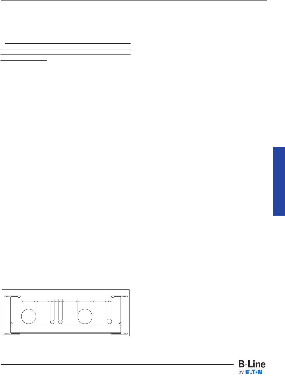
501.15. Sealing and Drainage. (E) Cable Seals, Class 1,
Division 2. (3)
Exception: Cables with an unbroken gas/vapor-tight
continuous sheath shall be permitted to pass through a
Class 1, Division 2 location without seals.
This is an extremely important exception stating that
cable seals are not required when a cable goes from an
unclassified area through a classified area then back to
an unclassified area.
501.15. Sealing and Drainage. (E) Cable Seals, Class 1,
Division 2. (4)
If you do not have a gas/vapor-tight continuous sheath,
cable seals are required at the boundary of the Division
2 and unclassified location.
The sheaths mentioned above may be fabricated of
metal or a nonmetallic material.
502.10. Wiring Methods. (A) Class II, Division 1
(Combustible Dusts).
Type MI cable may be installed in cable tray in this type
of hazardous (classified) area.
The Exception allows Type MC cables to be installed in
Class II, Division 1 areas if they have a gas/vapor tight
continuous corrugated aluminum sheath with a suitable
plastic jacket over the sheath. They must also contain
equipment grounding conductors sized as per Section
250.122 and listed termination fittings must be used
where the cables enter equipment.
502.10. Wiring Methods. (B) Class II, Division 2
(Combustible Dusts).
This section states:
Type ITC and PLTC cables may be installed in ladder
or ventilated cable trays following the same practices as
used in non-hazardous (unclassified) areas. No spacing
is required between the ITC or PLTC cables. This is
logical as the ITC and PLTC cable circuits are all low
energy circuits which do not produce any significant heat
or heat dissipation problems.
Type MC, MI and TC [See Section 336.4(3)] cables may
be installed in ladder, ventilated trough, or ventilated
cable channel, but they are not allowed to be installed in
solid bottom cable trays.
Required Spacing in Cable Trays for Type MC, MI & TC
Cables in Class II, Division 2 Hazardous (Classified) Areas
Note 1. The cables are limited to a single layer with
spacing between cables equal to the diameter of the
largest adjacent cable. This means that the cables must
be tied down at frequent intervals in horizontal as well as
vertical cable trays to maintain the cable spacing. A
reasonable distance between ties in the horizontal cable
tray would be approximately 6 feet (See Section
392.30(B).
Note 2. Spacing the cables a minimum of 1 inch from
the side rails to prevent dust buildup is recommended.
This is not an NEC requirement but a recommended
practice.
Where cable tray wiring systems with current carrying
conductors are installed in a dust environment, ladder
type cable trays should be used since there is less
surface area for dust buildup than in ventilated trough
cable trays. The spacing of the cables in dust areas will
prevent the cables from being totally covered with a solid
dust layer. In dusty areas, the top surfaces of all
equipment, raceways, supports, or cable jacket surfaces
where dust layers can accumulate will require cleanup
housekeeping at certain time intervals. Good house-
keeping is required for personnel health, personnel safety
and facility safety. Excessive amounts of dust on
raceways or cables will act as a thermal barrier which
may not allow the power and lighting insulated
conductors in a raceway or cable to safely dissipate
internal heat. This condition may result in the accelerated
aging of the conductor insulation. A cable tray system
that is properly installed and maintained will provide a
safe dependable wiring system in dust environments.
Exception: Type MC cable listed for use in Class II,
Division I locations shall be permitted to be installed
without the above spacing limitations. This was a new
exception for the 1999 NEC®code.
For this type of wiring there is no danger of the cables
being overheated when covered with dust. The current
flow in these circuits is so low that the internally
generated heat is insufficient to heat the cables and
cable spacing is not a necessity. Even under such
conditions, layers of dust should not be allowed to
accumulate to critical depths as they may be ignited or
explode as the result of problems caused by other than
the electrical system.
502.10(B)(3). Nonincendive Field Wiring
Wiring in nonincendive circuits shall be permitted using
any of the wiring methods suitable for wiring in ordinary
locations.
503.10. Wiring Methods. (A) Class III, Division 1 and (B)
Class III, Division 2 (Ignitable Fibers or Flyings). Type MI
or MC cables may be installed in cable tray in these
types of hazardous (classified) areas. The installations
should be made using practices that minimize the
build-up of materials in the trays. This can be done by
using ladder cable tray with a minimum spacing between
the cables equal to the diameter of the largest adjacent
cable. In some cases, a greater spacing between cables
D1 D1 D2 D2 D3
D2 D1 D1 D1
Cable Tray Manual
MAN-15
Cable Tray Manual
Cable Tray Systems
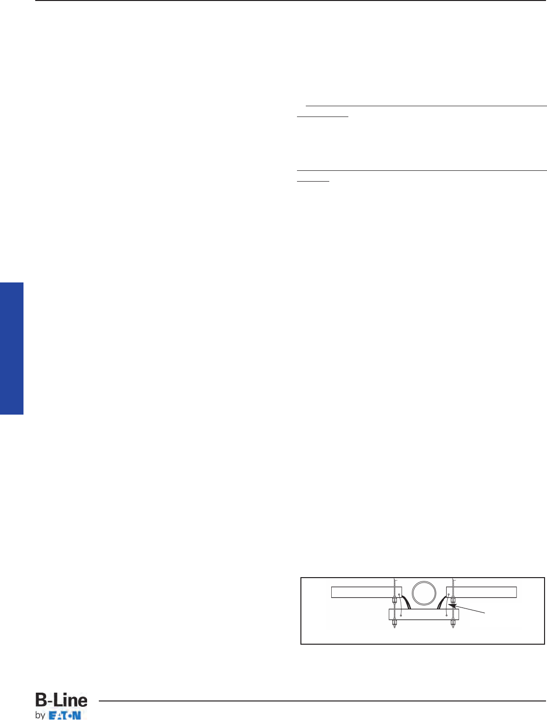
than that based on the cable diameters might be
desirable depending on the characteristics of the
material that requires the area to be classified. Here
again, it must be emphasized that good housekeeping
practices are required for all types of wiring systems to
insure the safety of the personnel and the facility.
504.20. Wiring Methods. This section allows intrinsically
safe wiring systems to be installed in cable trays in
hazardous (classified) areas. Section 504.30 specifies the
installation requirements for intrinsically safe wiring
systems that are installed in cable trays. Section 504.70
specifies the sealing requirements for cables that may be
part of a cable tray wiring system. Section 504.80(B)
states that cable trays containing intrinsically safe wiring
must be identified with permanently affixed labels.
Cable trays are ideal for supporting both intrinsically
safe and nonintrinsically safe cable systems as the
cables may be easily spaced and tied in position or a
standard metallic barrier strip may be installed between
the intrinsically and nonintrinsically safe circuits.
505.15. Wiring Methods. This section was added to the
2002 NEC®to explicitly permit cable trays in hazardous
areas classified by the international zone system, if the
cables comply with the cable requirements for zone
locations.
392.10. Uses Permitted. (D) Nonmetallic
Cable Tray.
There are limited numbers of applications where
nonmetallic cable trays might be preferred over metallic
cable trays for electrical safety reasons and/or for some
corrosive conditions. An example of an electrical safety
application would be in an electrolytic cell room. Here,
the amperages are very high and significant stray current
paths are present. Under such conditions, there is the
possibility for a high amperage short circuit if a low
resistance metallic path (metallic cable tray or metallic
raceway) is present [See information under Section
392.5(F) Nonmetallic Cable Trays].
392.12. Uses Not Permitted.
This is the only place in the NEC®where all the various
types of cable tray have limitations on their place of use.
No cable trays can be used in hoistways or where
subject to severe physical damage. The designer must
identify the zones of installation where a cable tray might
be subjected to severe physical damage. Usually such
areas are limited and provisions can be made to protect
the cable tray by relocating it to a more desirable location
or as a last resort to provide protection using the
appropriate structural members.
Metallic cable trays may support cable types approved
for installation in ducts, plenums, and other air-handling
spaces as per Section 300.22(B) and the cable types
approved for installation in Other Space Used for
Environmental Air as per Section 300.22(C).
The second sentence of Section 300.22(C)(1) is as
follows:
Other types of cables and conductors shall be
installed in electrical metallic tubing, flexible metallic
tubing, intermediate metal conduit, rigid metal
conduit without an overall nonmetallic covering,
flexible metal conduit, or, where accessible, surface
metal raceway or metal wireway with metal covers or
solid bottom metal cable tray with solid metal
covers.
Reprinted with permission from NFPA 70-2011, the
National Electrical Code®, Copyright© 2010, National
Fire Protection Association, Quincy, MA 02169. This
reprinted material is not the complete and official
position of the National Fire Protection Association,
on the referenced subject which is represented only
by the standard in its entirety.
This part of Section 300.22(C) is confusing. The
statement as underlined in the above paragraph leads
some to assume, for installations in Other Spaces Used
for Environmental Air, that the types of insulated single
conductors which are installed in raceway installations
may also be installed in solid bottom metal cable trays
with metal covers. This is not so. Only the appropriate
multiconductor cable types as per Section 392.10(A) may
be installed in solid bottom cable trays.
Cable tray may be used to support data process wiring
systems in air handling areas below raised floors as per
Sections 300.22(D) and 800.52(D).
392.18. Cable Tray Installation. (A) Complete
System.
This section states that cable tray systems can have
mechanically discontinuous segments, and that the
mechanically discontinuous segment cannot be greater
than 6 feet. A bonding jumper sized per Section 250.102
is necessary to connect across any discontinuous
segment. The bonding of the system should be in
compliance with Section 250.96.
Cable Tray Manual
Cable Tray Elevation Change Without Fittings
Bonding
Jumper
MAN-16
Cable Tray Manual
Cable Tray Systems
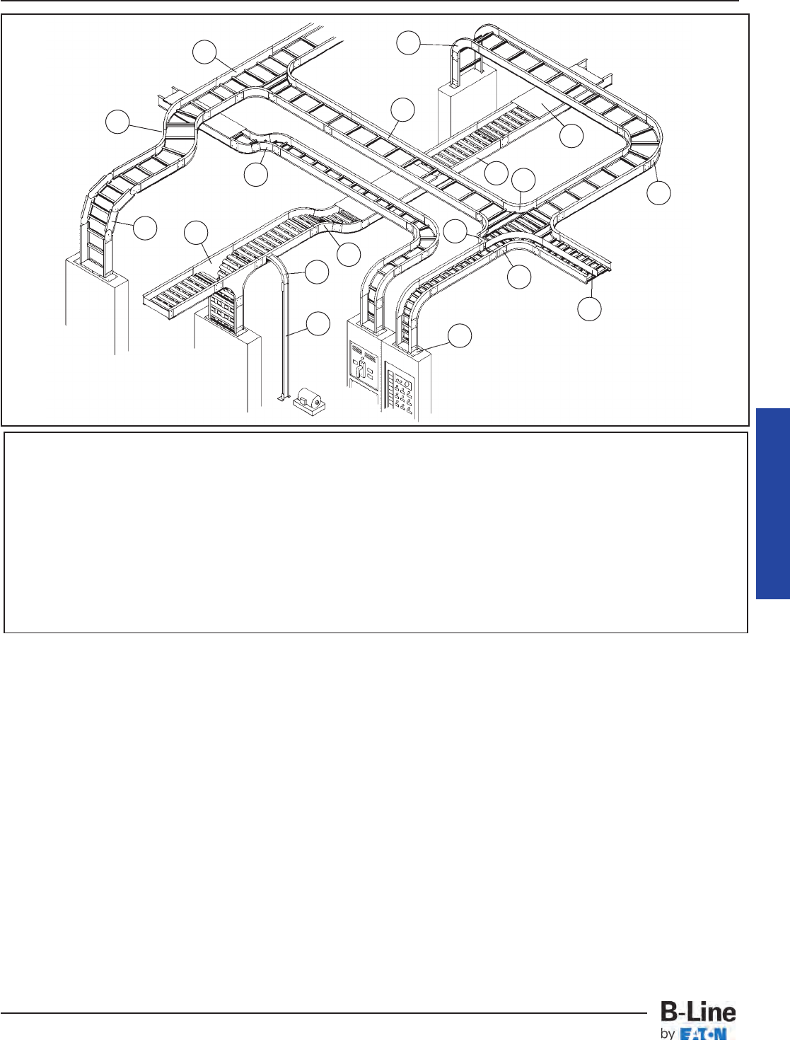
There are some designers, engineers, and inspectors
that do not think that cable tray is a mechanical support
system just as strut is a mechanical support system.
Cable tray is not a raceway in the NEC®but some
designers, engineers, and inspectors attempt to apply the
requirements for raceway wiring systems to cable tray
wiring systems even when they are not applicable. Cable
tray wiring systems have been used by American industry
for over 35 years with outstanding safety and continuity
of service records. The safety service record of cable tray
wiring systems in industrial facilities has been significantly
better than those of conduit wiring systems. There have
been industrial fires and explosions that have occurred
as a direct result of the wiring system being a conduit
wiring system. In these cases, cable tray wiring systems
would not have provided the fires and explosions that the
conduit systems did by providing as explosion gas flow
path to the ignition source even though the conduit
systems contained seals.
The most significant part of this section is that the
metallic cable tray system must have electrical continuity
over its entire length and that the support for the cables
must be maintained. These requirements can be
adequately met even though there will be installation
conditions where the cable tray is mechanically
discontinuous, such as at a firewall penetration, at an
expansion gap in a long straight cable tray run, where
there is a change in elevation of a few feet between two
horizontal cable tray sections of the same run, or where
the cables drop from an overhead cable tray to enter
equipment. In all these cases, adequate bonding jumpers
must be used to bridge the mechanical discontinuity.
Cable Tray Manual
Nomenclature
1. Ladder Type Cable Tray 10. 30° Vertical Inside Bend, Ladder Type Tray
2. Ventilated Trough Type Cable Tray 11. Vertical Bend Segment (VBS)
3. Splice Plate 12. Vertical Tee Down, Ventilated Trough Type Tray
4. 90° Horizontal Bend, Ladder Type Tray 13. Left Hand Reducer, Ladder Type Tray
5. 45° Horizontal Bend, Ladder Type Tray 14. Frame Type Box Connector
6. Horizontal Tee, Ladder Type Tray 15. Barrier Strip Straight Section
7. Horizontal Cross, Ladder Type Tray 16. Solid Flanged Tray Cover
8. 90° Vertical Outside Bend, Ladder Type Tray 17. Cable Channel Straight Section, Ventilated
9. 45° Vertical Outside Bend, Ventilated Type Tray 18. Cable Channel, 90° Vertical Outside Bend
1
2
3
4
6
7
8
10
11 12 13
14
15
16
17
18
Typical Cable Tray
Layout
5
9
MAN-17
Cable Tray Manual
Cable Tray Systems
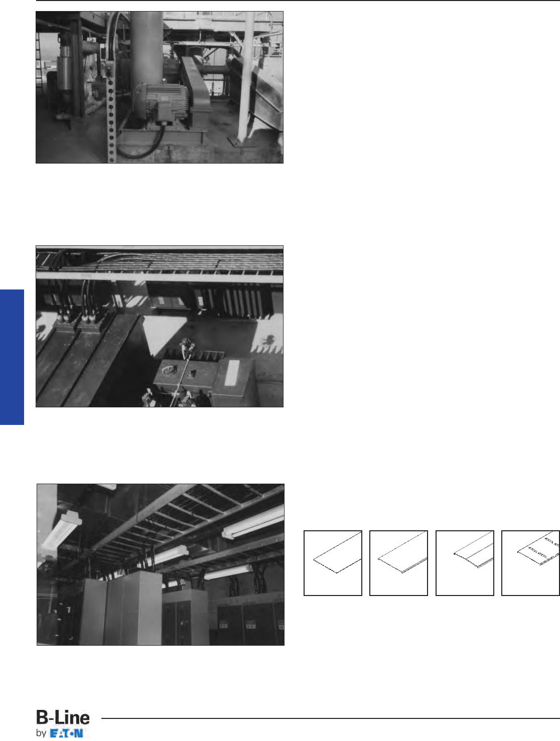
Cable Entering Motor Terminal Box from 6 Inch Chan-
nel Cable Tray System (Bottom entries provide drip
loops to prevent moisture flow into enclosures.)
Cables Exiting 480 Volt Outdoor Switchgear and
Entering Cable Tray System (Cable fittings with clamp-
ing glands are required to prevent moisture flow into
equipment due to the cable's overhead entry into the
switchgear enclosure).
Cables Entering and Exiting Motor Control Centers
from Cable Tray Systems.
392.18. Cable Tray Installation. (B) Completed
Before Installation.
This means that the final cable tray system must be
in place before the cables are installed. It does not
mean that the cable tray must be 100% mechanically
continuous. The electrical bonding of the metallic cable
tray system must be complete before any of the circuits
in the cable tray system are energized whether the cable
tray system is being utilized as the equipment grounding
conductor in qualifying installations or if the bonding is
being done to satisfy the requirements of Section 250.96.
392.18. Cable Tray Installation. (C) Covers.
Cable tray covers provide protection for cables where
cable trays are subject to mechanical damage. The most
serious hazard to cable in cable trays is when the cables
are exposed to significant amounts of hot metal spatter
during construction or maintenance from torch cutting of
metal and welding activities. For these exposure areas,
the cable tray should be temporarily covered with
plywood sheets. If such exposure is to be a frequent
occurrence, cable tray covers should be installed in the
potential exposure areas. Where cable trays contain
power and lighting conductors, raised or ventilated
covers are preferable to solid covers since the raised or
ventilated covers allow the cable heat to be vented from
the cable tray.
When covers are installed outdoors, they should be
attached to the cable trays with heavy duty wrap around
clamps instead of standard duty clips. During high winds,
the light duty clips are not capable of restraining the
covers. Outdoor cover installations should be overlapped
at expansion joint locations to eliminate cover buckling.
Covers which fly off the cable tray create a serious
hazard to personnel, as was the case at a Texas gulf
coast chemical plant where operators would not leave
their control room because hurricane force winds had
stripped many light gauge stainless steel covers off a
large cable tray system. These sharp edged metal covers
were flying though the air all during the high wind period,
posing a serious threat to the worker's safety.
Cable Tray Manual
Solid
Non-Flanged
Solid
Flanged
Ventilated
Flanged
Peaked
Flanged
MAN-18
Cable Tray Manual
Cable Tray Systems
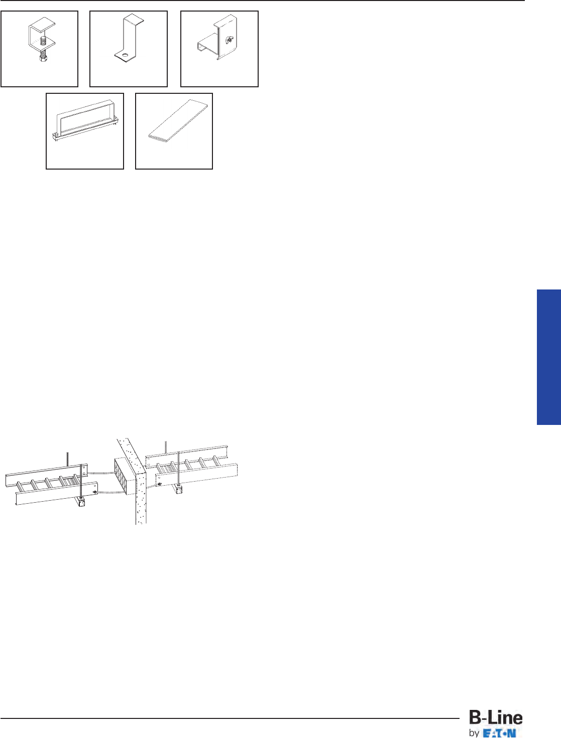
Aluminum Cable Tray Cover Accessories
Equivalent items are available for Steel Cable Trays.
392.18. Cable Tray Installation. (D) Through
Partitions and Walls.
Whether penetrating fire rated walls with tray cable only
or cable tray and tray cable, the designer should review
with the local building inspector the method he proposes
to use to maintain the fire rating integrity of the wall at
the penetration. Many methods for sealing fire wall
penetrations are available, including bag or pillow, caulk,
cementitious, foam, putty and mechanical barrier
systems.
Many designers prefer to run only the tray cable
through fire rated walls. Sealing around the cables is
easier than sealing around the cables and the cable tray.
Also, should the cable tray or its supports become
damaged, the tray will not exert forces which could
damage the wall or the penetration.
392.18. Cable Tray Installation. (E) Exposed and
Accessible.
Article 100 - Definitions.
Exposed: (as applied to wiring methods) on or
attached to the surface or behind panels designed to
allow access.
Accessible: (As applied to wiring methods) Capable
of being removed or exposed without damaging the
building structure or finish, or not permanently closed
in by the structure or finish of the building.
Reproduced with permission from NFPA 70®-2011,
National Electrical Code®, Copyright ©2010, National
Fire Protection Association, Quincy, MA. This
reprinted material is not the complete and official
position of the NFPA on the referenced subject, which
is represented only by the standard in its entirety.
392.18. Cable Tray Installation. (F) Adequate Access.
Cable tray wiring systems should be designed and
installed with adequate room around the cable tray to
allow for the set up of cable pulling equipment. Also,
space around the cable tray provides easy access for
installation of additional cables or the removal of surplus
cables. Where cable trays are mounted one above the
other, a good rule to follow is to allow 12 to 18 inches
between the underside and the top of adjacent cable
trays or between the structure's ceiling and the top of the
cable tray.
392.18. Cable Tray Installation. (G) Raceways,
Cables, Boxes, and Conduit Bodies Supported from
Cable Tray Systems.
For the 1996 NEC®, a significant change was made in
this section. The installations covered in this section may
now only be made in qualifying industrial facilities.
In Section 392.6(J) of the 1993 NEC®, cable tray
installations that supplied support for conduits were not
restricted to qualifying industrial facilities. The 1996
NEC®, Section 392.6(J) text restricts the use of such
installations even though there is no documented history
of problems in non-industrial installations.
As a result of the change in this section, identical
functional installations in non-qualifying installations
(commercial and industrial) and qualifying industrial
installations have different physical requirements. In a
qualifying industrial installation, a conduit terminated on
a cable tray may be supported from the cable tray. In a
commercial or non-qualifying industrial installation, the
conduit that is terminated on the cable tray must be
securely fastened to a support that is within 3 feet of the
cable tray or securely fastened to a support that is within
5 feet of the cable tray where structural members don’t
readily permit a secure fastening within 3 feet. The
conduit of the non-qualifying installation still needs to be
bonded to the cable tray. A fitting may be used for this
bonding even though it will not count as a mechanical
support.
Cable Tray Manual
Standard
Cover Clamp
Combination Cover
& Hold Down Clamp
Heavy Duty
Cover Clamp Cover Joint Strip
Raised
Cover Clamp
MAN-19
Cable Tray Manual
Cable Tray Systems
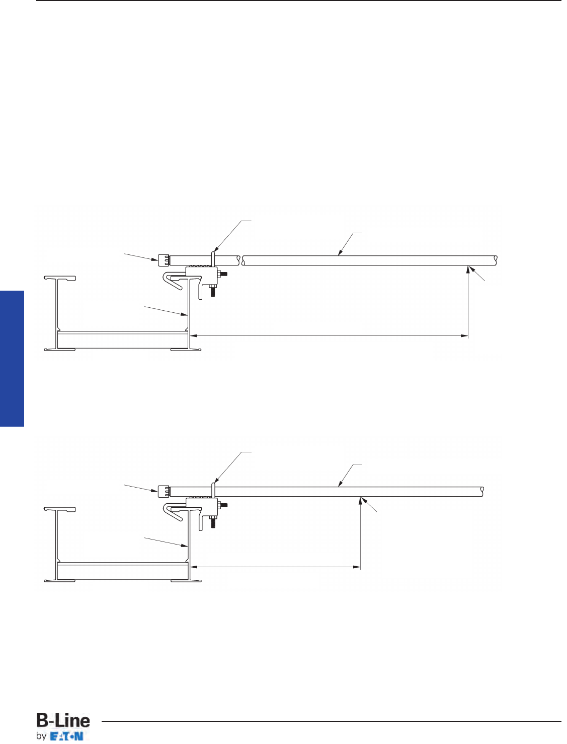
Over 99 percent of the conduits supported on cable
trays are the result of conduits being terminated on the
cable tray side rails [See Section 392.46]. For over 40
years, it has been common practice to house the cables
exiting the cable tray in conduits or cable channel where
the distance from the cable tray system to the cable
terminations requires the cable be supported. Several
manufacturers supply UL approved cable tray to conduit
clamps such as the B-Line 9ZN-1158.
In addition to conduit and cables being supported from
cable tray; industrial companies have been mounting
instrumentation devices, push buttons, etc. on cable tray
and cable channel for over 40 years. This section once
lead some to believe that only conduit or cables may be
supported from cable trays which is not correct as cable
tray is a mechanical support just as strut is a mechanical
support. Because of this, the wording in Section 392.6(J)
of the 2002 NEC®was changed. Instead of allowing only
cable and conduit to be supported from cable tray, the
code now states that raceways, cables, boxes and
conduit bodies are now permitted to be supported from
the cable tray. Where boxes or conduit bodies are
attached to the bottom or side of the cable tray, they must
be fastened and supported in accordance with Section
314.23.
Cable Tray Manual
UL Listed Conduit To
Cable Tray Clamp
See NEC®Table 344.30(B)(2) To Obtain The
Support Requirements For Other Conduit Sizes.
Conduit Terminated On And Supported By The Cable Tray Side Rail.
Installation For Qualifying Industrial Facilities As Per 392.18(G).
16 Feet
2 Inch Rigid Metal Conduit
Position Of The First
Conduit Support
From The Cable Tray
(Conduit Must Be
Securely Fastened To
The Support)
Conduit Bushing
Cable Tray
Side Rail
Cable Tray
UL Listed Conduit To
Cable Tray Clamp
See Section 344.30
Conduit Terminated On The Cable Tray Side Rail.
Installation For Commercial And Non-Qualifying Industrial Facilities As Per 392.18(G).
3 Feet or 5 Feet
Any Size Of Rigid Metal Conduit
Position Of The First
Conduit Support
From The Cable Tray
(Conduit Must Be
Securely Fastened To
The Support)
Conduit Bushing
Cable Tray
Side Rail
Cable Tray
MAN-20
Cable Tray Manual
Cable Tray Systems
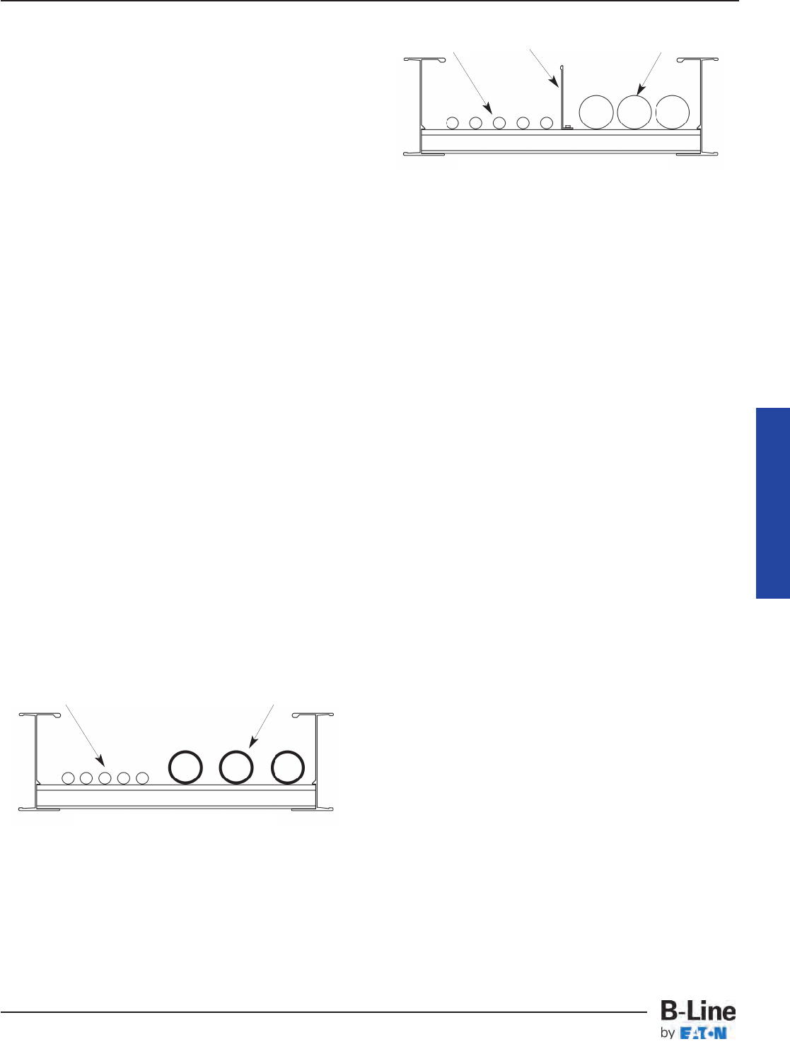
392.20. Cables and Conductor Installation. (A)
Multiconductor Cables Rated 600 Volts or Less.
Cables containing 300 or 600 volt insulated conductors
may be installed intermingled in the same cable tray
which is different from the requirements for raceways.
This is a reasonable arrangement because a person may
safely touch a 300 or 600 volt cable which is in good
condition, so having the cables come into contact with
each other is not a problem either. Many cable tray users
separate the instrumentation cables from the power and
control cables by installing them in separate cable trays
or by installing barriers in the cable trays. Often, because
of the volume of the instrumentation cable, using
separate cable trays is the most desirable installation
practice.
Numerous cable tray systems have been installed
where the instrumentation cables and branch circuit
cables are installed in the same cable trays with and
without barriers with excellent performance and
reliability. Most problems that occur involving
instrumentation circuits are due to improper grounding
practices. For analog and digital instrumentation circuits,
good quality twisted pair Type ITC and Type PLTC cables
with a cable shield and a shield drain wire should be
used. Do not purchase this type of cable on price alone,
it should be purchased because of it's high quality.
Engineers specifying cables should be knowledgeable of
the cable's technical details in order to design systems
which will provide trouble free operation.
392.20. Cable and Conductor Installation. (B)
Cables Rated Over 600 Volts.
Cables with insulation rated 600 volts or less may be
installed with cables rated over 600 volts if either of the
following provisions are met.
No. 1: Where the cables over 600 volts are Type MC.
No. 2: Where separated with a fixed solid barrier of a
material compatible with the cable tray.
392.20. Cable and Conductor Installation. (C)
Connected in Parallel.
Section 310.10(H)(2). Conductors in Parallel.
States the following:
The paralleled conductors in each phase, neutral or
grounded conductor shall:
(1) Be the same length.
(2) Have the same conductor material.
(3) Be the same size in circular mil area.
(4) Have the same insulation type.
(5) Be terminated in the same manner.
Where run in separate raceways or cables, the raceways
or cables shall have the same physical characteristics.
Conductors of one phase, neutral, or grounded circuit
shall not be required to have the same physical
characteristics as those of another phase, neutral, or
grounded circuit conductor to achieve balance.
A difference between parallel conductors in raceways
and those in cable trays is that the conductors in the cable
tray are not derated unless there are more than three
current carrying conductors in a cable assembly [as per
Exception No.2 of Section 310.15(B)(3)(a) and Section
392.80(A)(1)(a)]. Where the single conductor cables are
bundled together as per Section 392.20(C) and if there are
neutrals that are carrying currents due to the type of load
involved (harmonic currents) it may be prudent to derate
the bundled single conductor cables.
The high amperages flowing under fault conditions in
1/0 and larger cables produce strong magnetic fields
which result in the conductors repelling each other until
the circuit protective device either de-energizes the circuit
or the circuit explodes. Under such fault conditions, the
cables thrash violently and might even be forced out of
the cable tray. This happened at a northern Florida textile
plant where several hundred feet of Type MV single
conductor cable was forced out of a cable tray run by an
electrical fault because the cables were not restrained
properly. This potential safety threat is precisely why
Article 392.20(C) requires single conductor cables be
securely bound in circuit groups to prevent excessive
movement due to fault-current magnetic forces. For a
three-phase trefoil or triangular arrangement (the most
Cable Tray Manual
300 & 600
Volt Cables
Fixed Solid Barrier
Comparable Material
Cables Rated
Over 600 Volts
NO. 2
300 & 600
Volt Cables
Cables Rated Over
600 Volts Are Type MC
NO. 1
MAN-21`
Cable Tray Manual
Cable Tray Systems
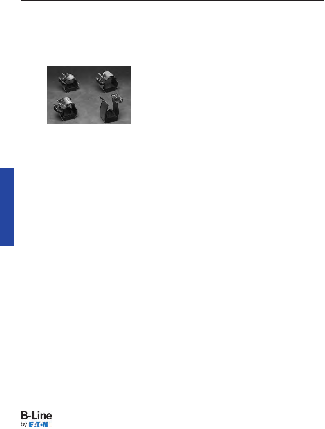
common single conductor application), these forces can
be calculated according to the formula:
Ft= (0.17 x ip2) / S.
Ft=Maximum Force on Conductor (Newtons/meter)
ip=Peak Short Circuit Current (kilo-Amperes)
S=Spacing between Conductors (meters) = Cable
Outside Diameter for Triplex (trefoil) Installations.
One technique to prevent excessive movement of
cables is to employ fault-rated cable cleats.
To maintain the minimum distance between conductors,
the single conductor cables should be securely bound in
circuit groups using fault rated cable cleats. If the cleat
spacing is properly chosen according to the available
fault-current, the resulting cable grouping will inherently
maintain a minimum distance between conductors. These
circuit groups provide the lowest possible circuit
reactance which is a factor in determining the current
balance amoung various circuit groups.
For installations that involve phase conductors of three
conductor or single conductor cables installed in parallel,
cable tray installations have conductor cost savings
advantages over conduit wiring systems. This is because
the conductors required for a cable tray wiring system are
often a smaller size than those required for a conduit
wiring system for the same circuit. No paralleled
conductor ampacity adjustment is required for single
conductor or three conductor cables in cable trays [See
NEC®Section 392.80(A)(1)].
There were changes in the 1993 NEC®and 1996 NEC®
for installations where an equipment grounding conductor
is included in a multiconductor cable: the equipment
grounding conductor must be fully rated per Section
250.122. If multiconductor cables with internal equipment
grounding conductors are paralleled, each multiconductor
cable must have a fully rated equipment grounding
conductor.
Section 250.122 now prohibits the use of standard three
conductor cables with standard size EGCs when they are
installed in parallel and the EGCs are paralleled. There
have been no safety or technical problems due to
operating standard three conductor cables with standard
sized EGCs in parallel. This has been a standard industrial
practice for over 40 years with large numbers of such
installations in service. This change was made without any
safety or technical facts to justify this change.
To comply with Section 250.122, Three options are
available: 1. Order special cables with increased sized
EGCs which increases the cost and the delivery time. 2.
Use three conductor cables without EGCs and install a
single conductor EGC in the cable tray or use the cable
tray as the EGC in qualifying installations. 3. Use standard
cables but don’t utilize their EGCs, use a single conductor
EGC or the cable tray as the EGC in qualifying installations.
Should industry be required to have special cables
fabricated for such installations when there have been
absolutely no safety problems for over 40 years? Each
designer and engineer must make his own decision on this
subject. If the installations are properly designed, quality
materials are used, and quality workmanship is obtained,
there is no safety reason for not following the past proven
practice of paralleling the EGCs of standard three
conductor cable.
392.20. Cable and Conductor Installation. (D)
Single Conductors.
This section states that single conductors in ladder or
ventilated trough cable tray that are Nos. 1/0 through 4/0,
must be installed in a single layer.
In addition to the fill information that is in Section
392.20(D), an exception was added which allows the
cables in a circuit group to be bound together rather than
have the cables installed in a flat layer. The installation
practice in the exception is desirable to help balance the
reactance’s in the circuit group. This reduces the
magnitudes of voltage unbalance in three phase circuits.
Where ladder or ventilated trough cable trays contain
multiconductor power or lighting cables, or any mixture of
multiconductor power, lighting, control, or signal cables,
the maximum number of cables that can be installed in a
cable tray are limited to the Table 392.22(A) allowable fill
areas. The cable tray fill areas are related to the cable
ampacities. Overfill of the cable tray with the conductors
operating at their maximum ampacities will result in cable
heat dissipation problems with the possibility of conductor
insulation and jacket damage.
Cable Tray Manual
MAN-22
Cable Tray Manual
Cable Tray Systems
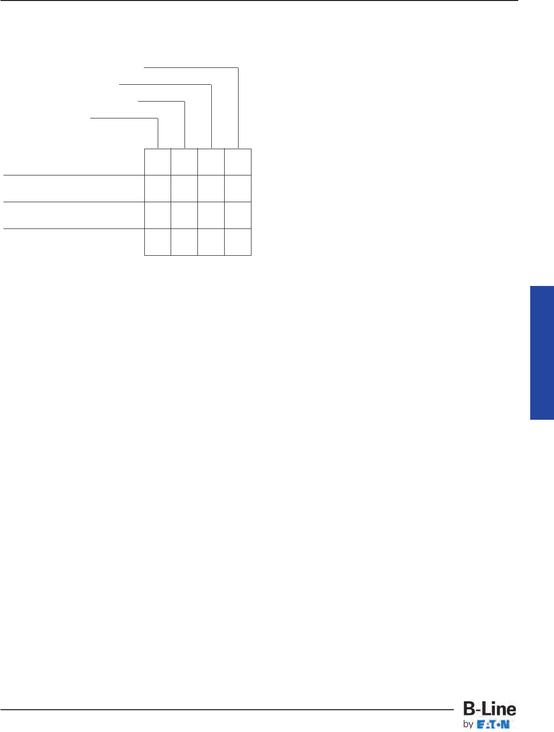
392.22. Number of Conductor of Cables.
(A) Number of Multiconductor Cables, Rated
2000 Volts or Less, in Cable Trays. (1) Ladder or
Ventilated Trough Cable Trays Containing Any
Mixture of Cables. (a) 4/0 or Larger Cables
The ladder or ventilated trough cable tray must have
an inside usable width equal to or greater than the sum
of the diameters (Sd) of the cables to be installed in it.
For an example of the procedure to use in selecting a
cable tray width for the type of cable covered in this
section see page MAN-43 (Appendix Sheet 3), [Example
392.22(A)(1)(a)].
Increasing the cable tray side rail depth increases the
strength of the cable tray but the greater side rail depth
does not permit an increase in cable fill area for power
or lighting cables or combinations of power, lighting,
control and signal cables. The maximum allowable fill
area for all cable tray with a 3 inch or greater loading
depth side rail is limited to the 38.9 percent fill area for a
3 inch loading depth side rail (Example: 3 inches x 6
inches inside cable tray width x 0.389 = 7.0 square inch
fill area. This is the first value in Column 1 of Table
392.22(A). All succeeding values for larger cable tray
widths are identically calculated).
392.22. Number of Conductor of Cables.
(A) Number of Multiconductor Cables, Rated
2000 Volts or Less, in Cable Trays. (1) Ladder or
Ventilated Trough Cable Trays Containing Any
Mixture of Cables. (b) Cables Smaller Than 4/0
The allowable fill areas for the different ladder or
ventilated trough cable tray widths are indicated in
square inches in Column 1 of Table 392.22(A). The total
sum of the cross-sectional areas of all the cables to be
installed in the cable tray must be equal to or less than
the cable tray allowable fill area. For an example of the
procedure to use in selecting a cable tray width for the
type of cable covered in this section see page MAN-44
(Appendix Sheet 4), [Example 392.22(A)(1)(b)].
392.22. Number of Conductor of Cables.
(A) Number of Multiconductor Cables, Rated
2000 Volts or Less, in Cable Trays. (1) Ladder or
Ventilated Trough Cable Trays Containing Any
Mixture of Cables. (c) 4/0 of Larger Cables
Installed With Cables Smaller Than 4/0
The ladder or ventilated trough cable tray needs to be
divided into two zones (a barrier or divider is not required
but one can be used if desired) so that the No. 4/0 and
larger cables have a dedicated zone as they are to be
placed in a single layer.
The formula for this type of installation is shown in
Column 2 of Table 392.22(A). This formula is a trial and
error method of selecting a cable tray of the proper
width. A direct method for determining the cable tray
width is available by figuring the cable tray widths that
are required for each of the cable combinations and then
adding these widths together to select the proper cable
tray width. [Sd (sum of the diameters of the No. 4/0 and
larger cables)] + [Sum of Total Cross Sectional Area of all
Cables No. 3/0 and Smaller) x (6 inches/7 square inches)]
= The Minimum Width of Cable Tray Required. For an
example of the procedure to use in selecting a cable tray
width for the type of cable covered in this section, see
page MAN-45, (Appendix Sheet 5), [EXAMPLE
392.22(A)(1)(c)].
392.22. Number of Conductor of Cables.
(A) Number of Multiconductor Cables, Rated
2000 Volts or Less, in Cable Trays. (2) Ladder or
Ventilated Trough Cable Trays Containing
Multiconductor or Control and/or Signal Cables
Only.
A ladder or ventilated trough cable tray, having a
loading depth of 6 inches or less containing only control
and/or signal cables, may have 50 percent of its
cross-sectional area filled with cable. If the cable tray has
a loading depth in excess of 6 inches, that figure cannot
be used in calculating the allowable fill area as a 6 inch
depth is the maximum value that can be used for the
cross-sectional area calculation. For an example of the
procedure to use in selecting a cable tray width for the
type of cable covered in this section, see page MAN-46
(Appendix Sheet 6),[Example 392.22(A)(2)].
Cable Tray Manual
Compatibility Of Cable Tray Types And
Cable Trays Based On The NEC®
3", 4", & 6" Wide Solid or Venti-
lated Channel Cable Tray
Solid Bottom Cable Tray
Ventilated Trough Cable Tray
Ladder Cable Tray
X - Indicates the Installations Allowed by Article 392
* - For cables rated up to 2000 volts.
** - For cables rated above 2000 volts.
*** - For 1/0 - 4/0 AWG single conductor cables
installed in ladder cable tray, maximum rung
spacing is 9 inches.
XXXX
* * *
XXXX
X X X
X X X
Multiconductor Cables
300 & 600 Volt *
Single Conductor
Cables - 600 Volt *
Type MV Multiconductor
Cables **
Type MV Single Conductor
Cables **
MAN-23
Cable Tray Manual
Cable Tray Systems
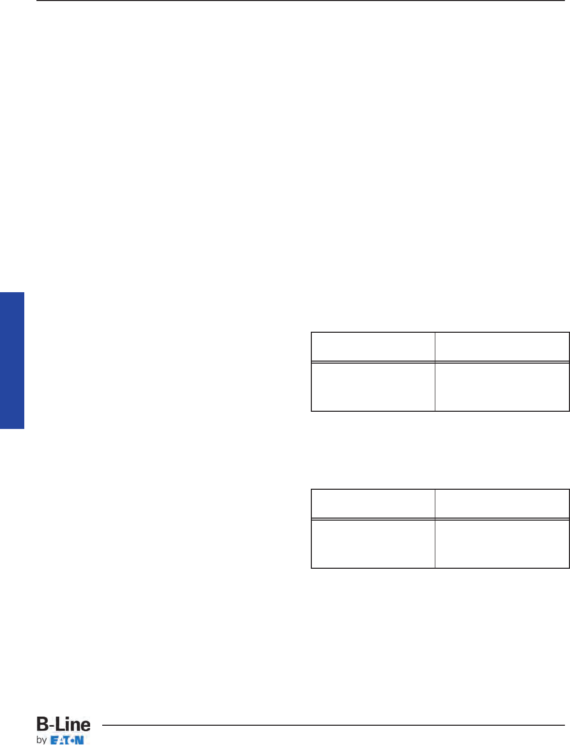
392.22. Number of Conductor of Cables.
(A) Number of Multiconductor Cables, Rated
2000 Volts or Less, in Cable Trays. (3) Solid
Bottom Cable Trays Containing Any Mixture of
Cables.
For solid bottom cable tray, the allowable cable fill area
is reduced to approximately 30 percent as indicated by
the values in Columns 3 and 4 of Table 392.22(A). The
first value in Column 3 was obtained as follows: 3 in.
loading depth x 6 in. inside width x 0.305 = 5.5 square
inches. The other values in Column 3 were obtained in a
like manner. The Sd term in Column 4 has a multiplier of
1 vs. the multiplier of 1.2 for Column 2.
392.22. Number of Conductor of Cables.
(A) Number of Multiconductor Cables, Rated
2000 Volts or Less, in Cable Trays. (3) Solid
Bottom Cable Trays Containing Any Mixture of
Cables. (a) 4/0 or Larger Cables.
The procedure used in selecting a cable tray width for
the type of cable covered in this section is similar to that
shown on Appendix Sheet 3 page MAN-43, but only 90
percent of the cable tray width can be used.
392.22. Number of Conductor of Cables.
(A) Number of Multiconductor Cables, Rated
2000 Volts or Less, in Cable Trays. (3) Solid
Bottom Cable Trays Containing Any Mixture of
Cables. (b) Cables Smaller Than 4/0.
The procedure used in selecting a cable tray width for
the type of cable covered in this section is similar to that
shown on Appendix Sheet 4 page MAN-44. The
maximum allowable cable fill area is in Column 3 of Table
392.22(A).
392.22. Number of Conductor of Cables.
(A) Number of Multiconductor Cables, Rated
2000 Volts or Less, in Cable Trays. (3) Solid
Bottom Cable Trays Containing Any Mixture of
Cables. (c) 4/0 or Larger Cables With Cables
Smaller Than 4/0.
No. 4/0 and larger cables must have a dedicated zone
in the tray in order to be installed in one layer. Therefore
the cable tray needs to be divided into two zones (a
barrier or divider is not required but one can be used if
desired).
The formula for this type of installation is shown in
Column 4 of Table 392.22(A). This formula is a trial and
error method of selecting a cable tray of the proper
width. A direct method for determining the cable tray
width is available by figuring the cable tray widths that
are required for each of the cable combinations and then
adding these widths together to select the proper cable
tray width. [Sd (sum of the diameters of the No. 4/0 and
larger cables) x (1.11)] + [(Sum of Total Cross-Sectional
Area of all Cables No. 3/0 and Smaller) x (6 inches/5.5
square inches) = The Minimum Width of Cable Tray
Required. The procedure used in selecting a cable tray
width for the type of cables covered in this section is
similar to that shown on Appendix Sheet 5 page
MAN-45.
392.22. Number of Conductor of Cables.
(A) Number of Multiconductor Cables, Rated
2000 Volts or Less, in Cable Trays. (4) Solid
Bottom Cable Trays Containing Multiconductor
Control and/or Signal Cables Only.
This is the same procedure as for ladder and ventilated
trough cable trays except that the allowable fill has been
reduced from 50 percent to 40 percent. The procedure
used in selecting a cable tray width for the type of cable
covered in this section is similar to that shown on
Appendix Sheet 6 page MAN-46. [Example 392.22(A)(2)]
392.22. Number of Conductor of Cables.
(A) Number of Multiconductor Cables, Rated
2000 Volts or Less, in Cable Trays. (5) Ventilated
Channel Cable Trays Containing Multiconductor
Cables of Any Type.
392.22(A)(5)(a)
Where only one multiconductor cable is installed in a
ventilated channel cable tray.
392.22(A)(5)(b)
The fill areas for combinations of multiconductor
cables of any type installed in ventilated channel cable
tray.
392.22. Number of Conductor of Cables.
(A) Number of Multiconductor Cables, Rated
2000 Volts or Less, in Cable Trays. (6) Solid
Channel Cable Trays Containing Multiconductor
Cables of Any Type.
Cable Tray Manual
Ventilated Channel Maximum Cross-Sectional
Cable Tray Size Area of the Cable
3 Inch Wide 2.3 Square Inches
4 Inch Wide 4.5 Square Inches
6 Inch Wide 7.0 Square Inches
Ventilated Channel Maximum Allowable
Cable Tray Size Fill Area
3 Inch Wide 1.3 Square Inches
4 Inch Wide 2.5 Square Inches
6 Inch Wide 3.8 Square Inches
MAN-24
Cable Tray Manual
Cable Tray Systems
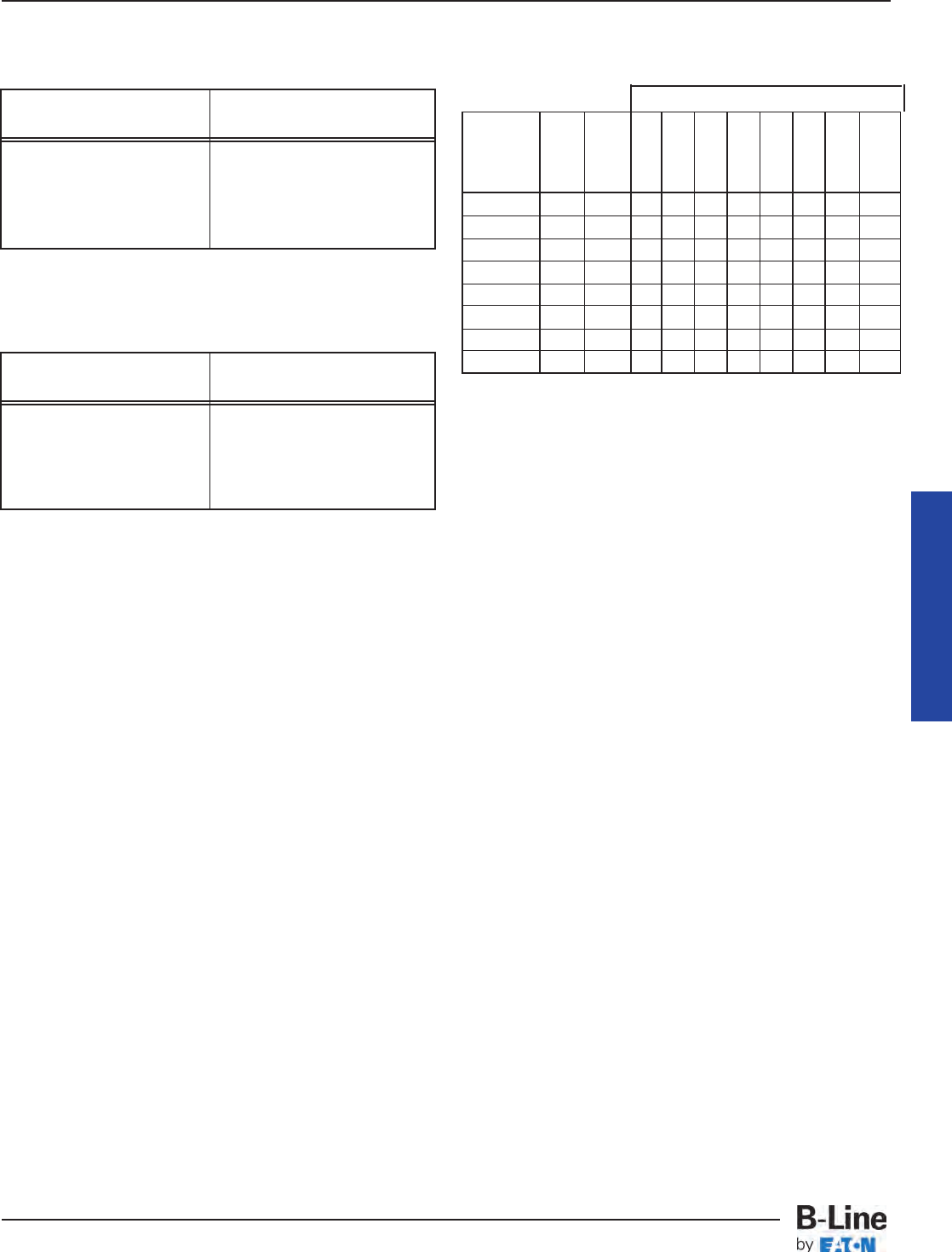
392.22(A)(6)(a)
Where only one multiconductor cable is installed in a
solid channel cable tray.
392.22(A)(6)(b)
The fill areas for combinations of multiconductor
cables of any type installed in solid channel cable tray.
392.22. Number of Conductor or Cables, (B)
Number of Single Conductor Cables, Rated 2000
Volts or Less, in Cable Trays.
Installation of single conductors in cable tray is
restricted to industrial establishments where conditions
of maintenance and supervision assure that only
qualified persons will service the installed cable tray
systems. Single conductor cables for these installations
must be 1/0 or larger, and they may not be installed in
solid bottom cable trays.
392.22. Number of Conductor of Cables.
(B) Number of Single Conductor Cables, Rated
2000 Volts or Less, in Cable Trays. (1) Ladder or
Ventilated Trough Cable Trays. (a) 1000 KCMIL
Through 900 KCMIL Cables.
The sum of the diameters (Sd) of all single conductor
cables shall not exceed the cable tray width, and the
cables shall be installed in a single layer.
392.22. Number of Conductor of Cables.
(B) Number of Single Conductor Cables, Rated
2000 Volts or Less, in Cable Trays. (1) Ladder or
Ventilated Trough Cable Trays. (b) 250 KCMIL
Through 900 KCMIL Cables.
Number Of 600 Volt Single Conductor Cables
That May Be Installed In Ladder Or Ventilated
Trough Cable Tray - Section 392.10(A) (2)
392.22. Number of Conductor of Cables.
(B) Number of Single Conductor Cables, Rated
2000 Volts or Less, in Cable Trays. (1) Ladder or
Ventilated Trough Cable Trays. (c) 1000 KCMIL or
Larger Cables Installed With Cables Smaller Than
1000 KCMIL.
Such installations are very rare.
392.22. Number of Conductor of Cables.
(B) Number of Single Conductor Cables, Rated
2000 Volts or Less, in Cable Trays. (1) Ladder or
Ventilated Trough Cable Trays. (d) Cables 1/0
Through 4/0.
The sum of the diameters (Sd) of all 1/0 through 4/0
cables shall not exceed the inside width of the cable tray.
Cable Tray Manual
Solid Channel Maximum Allowable
Cable Tray Size Fill Area
2 Inch Wide 0.8 Square Inches
3 Inch Wide 1.1 Square Inches
4 Inch Wide 2.1 Square Inches
6 Inch Wide 3.2 Square Inches
Solid Channel Maximum Cross-Sectional
Cable Tray Size Area of the Cable
2 Inch Wide 1.3 Square Inches
3 Inch Wide 2.0 Square Inches
4 Inch Wide 3.7 Square Inches
6 Inch Wide 5.5 Square Inches
Dia. (Note
Single In. Area #2)
Conductor (Note) Sq. 6 9 12 18 24 30 36 42
Size #1 In. In. In. In. In. In. In. In. In.
1/0 0.58 -- 10 15 20 31 41 51 62 72
2/0 0.62 -- 9 14 19 29 38 48 58 67
3/0 0.68 -- 8 13 17 26 35 44 52 61
4/0 0.73 -- 8 12 16 24 32 41 49 57
250 Kcmil 0.84 0.55 11 18 24 35 47 59 71 82
350 Kcmil 0.94 0.69 9 14 19 28 38 47 57 65
500 Kcmil 1.07 0.90 7 11 14 22 29 36 43 50
750 Kcmil 1.28 1.29 5 8 10 15 20 25 30 35
Cable Tray Width
Notes:
#1. Cable diameter's used are those for Okonite-
Okolon 600 volt single conductor power cables.
#2. 42 inch wide is ladder cable tray only.
#3. Such installations are to be made only in
qualifying industrial facilities as per Sections
392.10(B) & (B)(1).
#4. To avoid problems with unbalanced voltages, the
cables should be bundled with ties every three
feet or four feet. The bundle must contain the
circuit's three phase conductors plus the neutral
if one is used.
#5. The single conductor cables should be firmly tied
to the cable trays at six foot or less intervals.
MAN-25
Cable Tray Manual
Cable Tray Systems
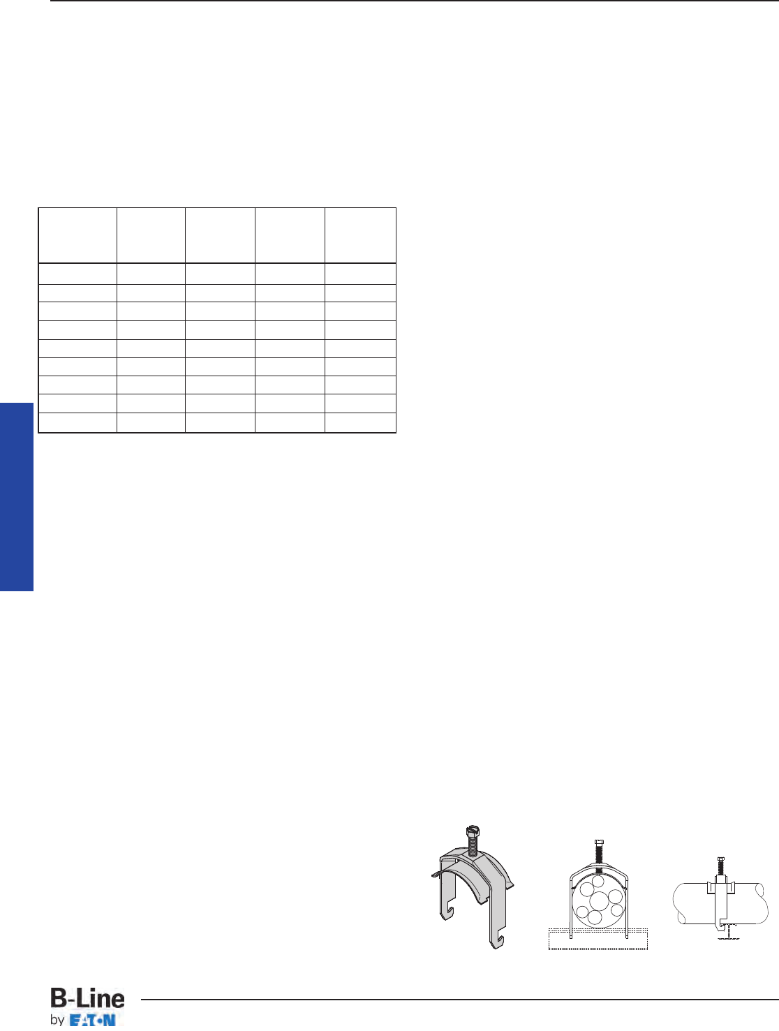
392.22. Number of Conductor of Cables.
(B) Number of Single Conductor Cables, Rated
2000 Volts or Less, in Cable Trays. (2) Ventilated
Channel Cable Trays.
The sum of the diameters (Sd) of all single conductors
shall not exceed the inside width of the ventilated cable
channel.
Number Of 600 Volt Single Conductor Cables
That May Be Installed In A Ventilated Channel
Cable Tray - Section 392.22(B)(2)
392.22. Number of Conductors of Cables. (C)
Number of Type MV and Type MC Cables (2001
Volts or Over) in Cable Trays.
Sum the diameters of all the cables (Sd) to determine
the minimum required cable tray width. Triplexing or
quadruplexing the cables does not change the required
cable tray width. Whether the cables are grouped or
ungrouped, all installations must be in a single layer.
392.30. Securing and Supporting. (B) Cables and
Conductors.
The intent of this section is to ensure that the
conductor insulation and cable jackets will not be
damaged due to stress caused by improper support.
Multiconductor 600 volt Type TC cables and 300 volt
Type PLTC cables exhibit a high degree of damage
resistance when exposed to mechanical abuse at normal
temperatures.
During an inspection of industrial installations by the
1973 NEC®Technical Subcommittee on Cable Tray, a
test setup was constructed of an 18 inch wide Class 20C
aluminum cable tray supported three feet above ground
level containing several sizes of multiconductor cables.
This installation was continuously struck in the same area
with eight pound sledge hammers until the cable tray
was severely distorted, the cables however, exhibited
only cosmetic damage. When these cables were tested
electrically, they checked out as new tray cable. Since
that time, significant improvements have been made in
cable jacket and conductor insulation materials so that
the cables available today are of better quality than the
1973 test cables. Although tray cables are capable of
taking a great deal of abuse without any problems, cable
tray installations must be designed by taking appropriate
measures to ensure that the tray cables will not be
subjected to mechanical damage.
392.30. Securing and Supporting. (B) Cables and
Conductors. (1) Other Than Horizontal Runs.
In seismic, high-shock and vibration prone areas, cables
(especially unarmored cables) should be secured to the
cable tray at 1 to 2 foot intervals to prevent the occurrence
of sheath chafing. Otherwise, there is no safety or technical
reason to tie down multiconductor cables in horizontal
cable tray runs unless the cable spacing needs to be
maintained or the cables need to be confined to a specific
location in the cable tray. In non-horizontal cable tray runs,
small multiconductor cables should be tied down at 3 or 4
foot intervals and larger (1 inch diameter and above) Type
MC and Type TC multiconductor cable should be tied
down at 6 foot intervals. If used outdoors, plastic ties
should be sunlight, ultraviolet (UV), resistant and be made
of a material that is compatible with the industrial
environment. Installed outdoors, white nylon plastic ties
without a UV resistant additive will last 8 to 14 months
before breaking. Also available for these applications are
cable cleats, stainless steel ties and P-clamps.
Cable Tray Manual
Notes:
#1. Cable diameter's used are those for Okonite-
Okolon 600 volt single conductor power cables.
#2. Such installations are to be made only in qualifying
industrial facilities as per Sections 392.10(B) &
(B)(1).
#3. The phase, neutral, and EGCs cables are all
counted in the allowable cable fill for the ventilated
channel cable tray.
#4. To avoid problems with unbalanced voltages, the
cables should be bundled with ties every three feet
or four feet. The bundle must contain the circuit's
three phase conductors plus the neutral if one is
used. If a cable is used as the EGC, it should also
be in the cable bundle. If the designer desires, the
ventilated channel cable tray may be used as the
EGC as per Table 392.60(A).
#5. The single conductor cables should be firmly tied
to the ventilated channel cable tray at six foot or
less intervals.
Single Diameter 3 Inch 4 Inch 6 Inch
Conductor Inches V. Channel V. Channel V. Channel
Size (Note #1) C.T. C.T. C.T.
1/0 AWG 0.58 5 6 10
2/0 AWG 0.62 4 6 9
3/0 AWG 0.68 4 5 8
4/0 AWG 0.73 4 5 8
250 Kcmil 0.84 3 4 7
350 Kcmil 0.94 3 4 6
500 Kcmil 1.07 2 3 5
750 Kcmil 1.28 2 3 4
1000 Kcmil 1.45 2 2 4
(P-Clamp shown installed on industrial aluminum rung)
MAN-26
Cable Tray Manual
Cable Tray Systems
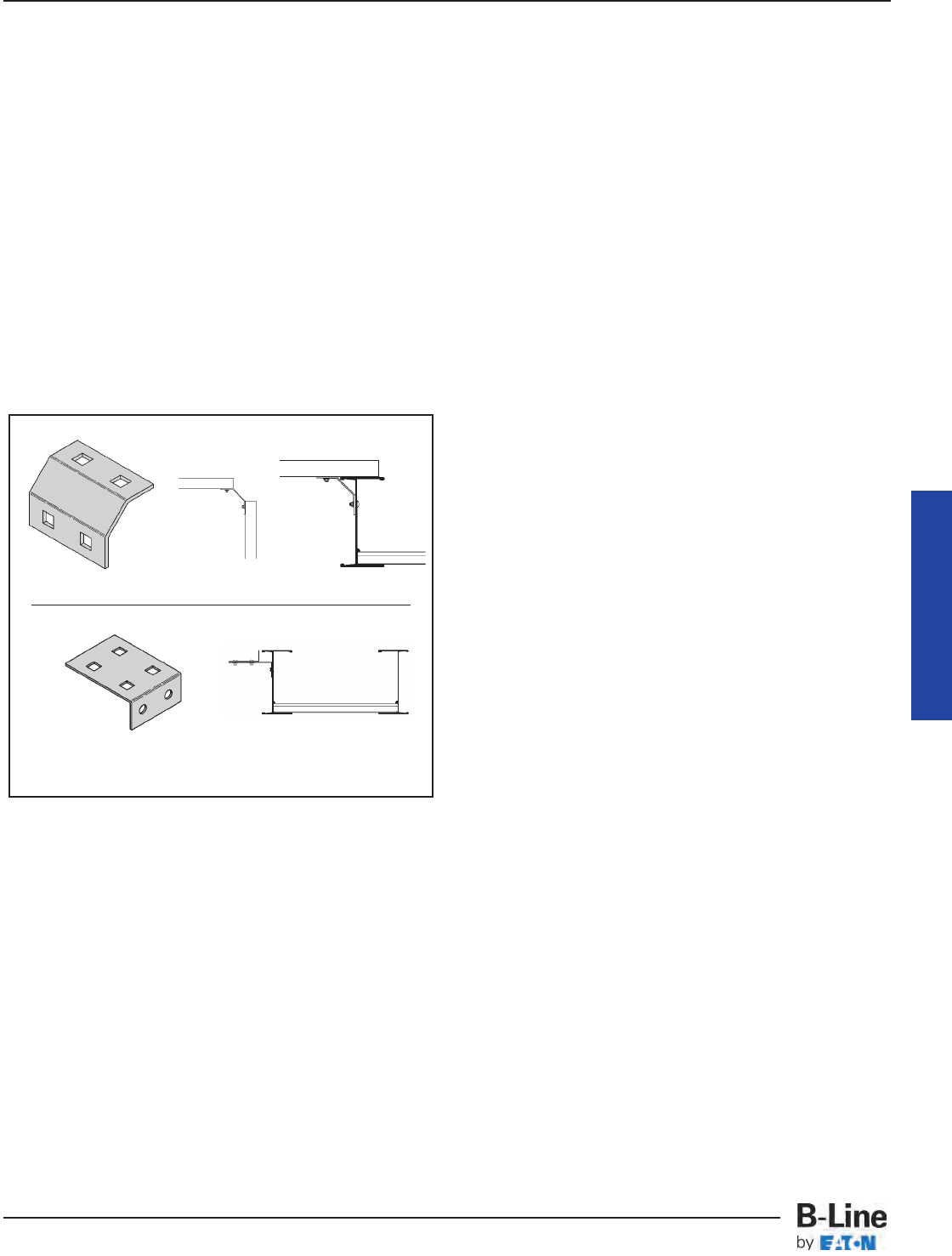
392.46. Bushed Conduit and Tubing.
For most installations, using a conduit to cable tray
clamp for terminating conduit on cable tray is the best
method. Where a cable enters a conduit from the cable
tray, the conduit must have a bushing to protect the cable
jacket from mechanical damage; a box is not required
[See Section 300.15(C). Boxes, Conduit Bodies, or
Fittings - Where Required. Where cables enter or exit
from conduit or tubing that is used to provide cable
support or protection against physical damage. A
fitting shall be provided on the end(s) of the conduit or
tubing to protect the wires or cables from abrasion.].
There are some special installations where the use of
conduit knockouts in the cable tray side rail for terminating
conduit is appropriate. This would not be a good standard
practice because it is costly and labor intensive, and if
randomly used may result in damaging and lowering the
strength of the cable tray.
392.56. Cable Splices.
There is no safety problem due to cable splices being
made in cable trays if quality splicing kits are used,
provided that the splice kits do not project above the
siderails and that they are accessible. A box or fitting is not
required for a cable splice in a cable tray.
Cable Channel Branch Circuit
Channel to Tray
Channel to
Channel
Cable Tray Manual
MAN-27
Cable Tray Manual
Cable Tray Systems
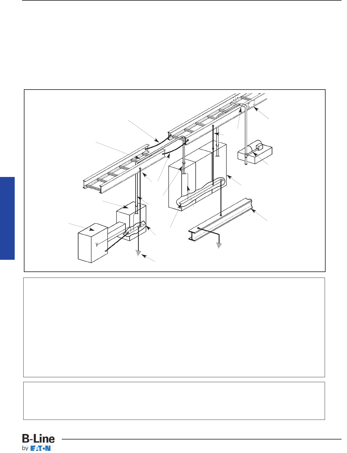
92.60. Grounding and Bonding, (A) Metallic Cable
Trays.
Cable tray may be used as the EGC in any installation
where qualified persons will service the installed cable
tray system. There is no restriction as to where the cable
tray system is installed. The metal in cable trays may be
used as the EGC as per the limitations of table 392.60(A).
All metallic cable trays shall be grounded as required
in Article 250.96 regardless of whether or not the cable
tray is being used as an equipment grounding conductor
(EGC).
The EGC is the most important conductor in an
electrical system as its function is electrical safety.
There are three wiring options for providing an EGC in
a cable tray wiring system: (1) An EGC conductor in or
on the cable tray. (2) Each multiconductor cable with its
individual EGC conductor. (3) The cable tray itself is used
as the EGC in qualifying facilities.
Cable Tray Manual
Ground Bus
Bonded To
Enclosure
EGC
EGC In
Cable
Discontinuous Joints
Require Bonding
For Qualifying Facilities
EGCs in the Cables or
EGC Cables Are Not Re-
quired If Rating Of The
Feeder Overcurrent Device
Permits Using The Tray
For the EGC
Bonding Jumper Not
Required For Rigidly
Bolted Joints
Conduit
Three Phase
Motor Installation
Building Steel
Lightning
Protection
Grounding
Bond
Switchgear
Bond
System Ground
Transformer
(Solidly
Grounded
Secondary)
Motor Control Center
Correct Bonding Practices To Assure That The
Cable Tray System Is Properly Grounded
If an EGC cable is installed in or on a cable tray, it should be bonded to each or alternate cable tray
sections via grounding clamps (this is not required by the NEC®but it is a desirable practice). In addition
to providing an electrical connection between the cable tray sections and the EGC, the grounding clamp
mechanically anchors the EGC to the cable tray so that under fault current conditions the magnetic forces
do not throw the EGC out of the cable tray.
A bare copper equipment grounding conductor should not be placed in an aluminum cable tray due to
the potential for electrolytic corrosion of the aluminum cable tray in a moist environment. For such
installations, it is best to use an insulated conductor and to remove the insulation where bonding
connections are made to the cable tray, raceways, equipment enclosures, etc. with tin or zinc plated
connectors.
See Table 250.122 on page MAN-47
for the minimum size EGC for
grounding raceway and equipment.
MAN-28
Cable Tray Manual
Cable Tray Systems

Aluminum Cable Tray Systems. (1) & (2)
Reproduced with permission from NFPA 70®-2011, National Electrical Code®,
Copyright ©2010, National Fire Protection Association, Quincy, MA. This
reprinted material is not the complete and official position of the NFPA on the
referenced subject, which is represented only by the standard in its entirety.
Table 392.60(A) "Metal Area Requirements for Cable
Trays used as Equipment Grounding Conductors" shows
the minimum cross-sectional area of cable tray side rails
(total of both side rails) required for the cable tray to be
used as the Equipment Grounding Conductor (EGC) for
a specific Fuse Rating, Circuit Breaker Ampere Trip
Rating or Circuit Breaker Ground Fault Protective Relay
Trip Setting. These are the actual trip settings for the
circuit breakers and not the maximum permissible trip
settings which in many cases are the same as the circuit
breaker frame size. If the maximum ampere rating of the
cable tray is not sufficient for the protective device to be
used, the cable tray cannot be used as the EGC and a
separate EGC must be included within each cable
assembly or a separate EGC has to be installed in or
attached to the cable tray. [See also Section 250-120 for
additional information]
The subject of using cable tray for equipment
grounding conductors was thoroughly investigated by
the 1973 NEC®Technical Subcommittee on Cable Tray.
Many calculations were made and a number of tests
were performed by Monsanto Company Engineers at the
Bussman High Current Laboratory. The test setup to
verify the capability of cable tray to be used as the EGC
is shown in Figure 1 on page MAN-30. The test amperes
available were forced through one cable tray side rail
which had three splice connections in series. No
conductive joint compound was used at the connections
and the bolts were wrench tight. Copper jumper cables
were used from the current source to the cable tray. The
cable tray was NEMA Class 12B. The test results are
shown on page MAN-41 (Appendix Sheet 1), Table I for
aluminum and Table II for steel cable tray.
One of the most interesting results of the tests was for
an aluminum cable tray with a corroded joint and only
two nylon bolts. 34,600 amperes for 14 cycles produced
only a 34° C temperature rise at the splice plate area. If
the protective devices work properly, the temperature
rises recorded at the cable tray splices during these tests
would not be sufficient to damage the cables in the cable
tray. Also note that in these tests only one side rail was
used, but in a regular installation, both side rails would
conduct fault current and the temperature rise at the
splice plate areas would be even lower.
When the cable tray is used as the EGC, consideration
has to be given to the conduit or ventilated channel cable
tray connections to the cable tray so that the electrical
grounding continuity is maintained from the cable tray
to the equipment utilizing the electricity. Conduit
connections to the cable tray were also tested. At that
time, no commercial fittings for connecting conduit to
cable tray were available, so right angle beam clamps
were used with very good results. There are now UL
Listed fittings for connecting and bonding conduit to
cable tray. This test setup and results are shown on page
MAN-42 (Appendix Sheet 2).
Cable Tray Manual
Table 392.60(A).
Metal Area Requirements for Cable Trays
Used as Equipment Grounding Conductors
Maximum Fuse Ampere Rating,
Circuit Breaker Ampere Trip Minimum Cross-Sectional Area
Setting, or Circuit Breaker of Metal* In Square Inches
Protective Relay Ampere Trip
Setting for Ground-Fault
Protection of Any Cable Circuit Steel Aluminum
In the Cable Tray System Cable Trays Cable Trays
60 0.20 0.20
100 0.40 0.20
200 0.70 0.20
400 1.00 0.40
600 1.50** 0.40
1000 --- 0.60
1200 --- 1.00
1600 --- 1.50
2000 --- 2.00**
For SI units: one square inch = 645 square millimeters.
*Total cross-sectional area of both side rails for ladder or trough
cable trays; or the minimum cross-sectional area of metal in channel
cable trays or cable trays of one-piece construction.
**Steel cable trays shall not be used as equipment grounding
conductors for circuits with ground-fault protection above 600
amperes. Aluminum cable trays shall not be used as equipment
grounding conductors for circuits with ground-fault protection
above 2000 amperes.
MAN-29
Cable Tray Manual
Cable Tray Systems
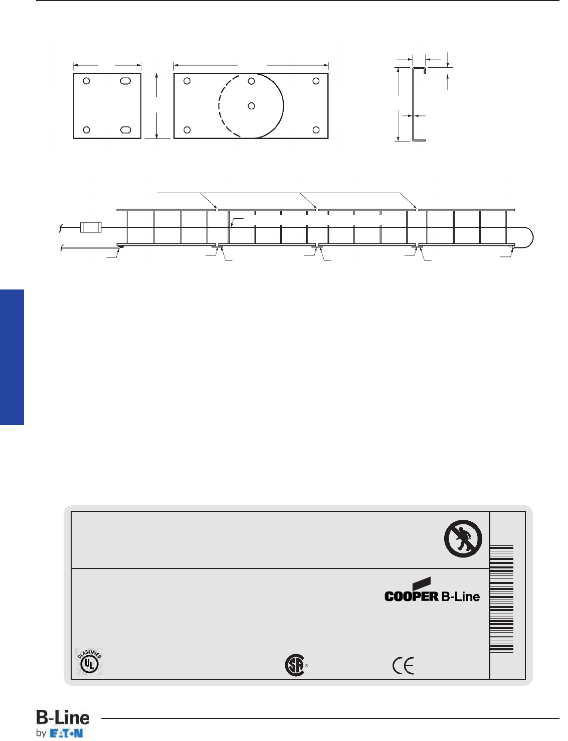
Cable Tray Manual
Material Thickness: 0.125" Aluminum or 14 Gauge Steel Cross Section Area,
2 Rails:
Aluminum - 1.00 sq. in.
Steel - 0.76 sq. in.
13/16"
3/8"
0.080" Aluminum or
14 Gauge Steel
3/8" Bolting Hardware
Cross Section Cable Tray Side Rail
Adjustable Vertical
Rigid
Cable Tray Connectors
41/2"
91/2"
4"
4"
Figure 1
(See Page MAN-41 Appendix Sheet 1)
Temperature Rise Test
C1
T T T
C2 C3
Current Source
500 kcmil copper, Type RH Insulation
Insulated Joints
Cable Lug
Fuse (if used)
Cable Lug
T - Temperature Measurement at each Tray Connection C1,
C2, & C3 - Cable Tray Connectors or Bonding Jumpers
Cable Tray Label
Use Only As A Mechanical Support For Cables, Tubing and Raceways.
Do Not Use As A Walkway, Ladder,
Or Support For Personnel.
www.cooperbline.com
(618) 654-2184
Catalog Number: 24A09-12-144 STR SECTION
Shipping Ticket: 260203 00 001
Mark Number: 78101115400
Purchase Order: D798981
Minimum Area: 1.000 SQ. IN.
Load Class: D1 179 KG/M 3 METER SPAN
30781011154005
1 of 1
09/15/2005
000291745
WARNING!
This product is classified by Underwriters Laboratories, Inc. as
to its suitability as an equipment grounding conductor only. 556E
NON-VENTILATED
Reference File #LR36026
MAN-30
Cable Tray Manual
Cable Tray Systems
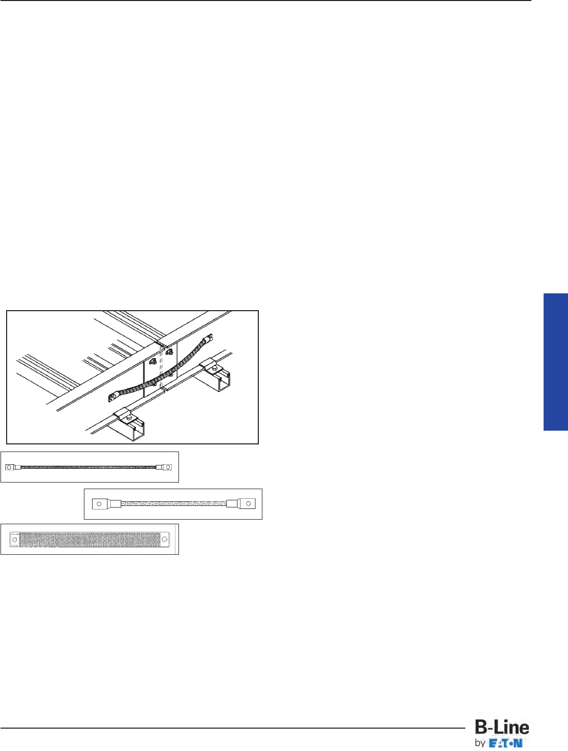
392.60. Grounding and Bonding. (B) Steel or
Aluminum Cable Tray Systems. (3) & (4)
For a cable tray to be used as an EGC the
manufacturer must provide a label showing the cross-
sectional area available. This also holds true for some
mechanically constructed cable tray systems such as
Redi-Rail®. Redi-Rail has been tested and UL Classified
as an EGC. B-Line label is shown at the bottom of page
MAN-30.
The cable tray system must be electrically continuous
whether or not it is going to serve as the EGC. At certain
locations (expansion joints, discontinuities, most
horizontal adjustable splice plates, etc.), bonding
jumpers will be required. Section 250.96. Bonding Other
Enclosures states that cable tray shall be effectively
bonded where necessary to assure electrical continuity
and to provide the capacity to conduct safely any fault
current likely to be imposed on them (also see Sections
250.92(A)(1) & 250.118(12)).
It is not necessary to install bonding jumpers at
standard splice plate connections. The splice connection
is UL classified as an EGC component of the cable tray
system.
NOTE: The NEC®only recognizes aluminum and steel
cable trays as EGC’s. As with all metallic cable trays,
stainless steel cable trays must be bonded according to
NEC®guidelines. Fiberglass cable trays do not require
bonding jumpers since fiberglass is non-conductive.
392.80. Ampacity of Conductors. (A) Ampacity of
Cables. Rated 2000 Volts or Less in Cable Trays.
Ampacity Tables 310.15(B)(16) and 310.15(B)(18) are to
be used for multiconductor cables which are installed in
cable tray using the allowable fill areas as per Section
392.22(A). The ampacities in Table 310.15(B)(16) are
based on an ambient temperature of 30˚ Celsius.
Conduit and cable tray wiring systems are often installed
in areas where they will be exposed to high ambient
temperatures. For such installations, some designers and
engineers neglect using the Ampacity Correction Factors
listed below the Wire Ampacity Tables which results in
the conductor insulation being operated in excess of its
maximum safe temperature. These correction factors
must be used to derate a cable for the maximum
temperature it will be subjected to anywhere along its
length.
392.80(A)(1)(a)
Section 310.15(B)(3)(a) refers to Section 392.80 which
states that the derating information of Table
310.15(B)(3)(a) applies to multiconductor cables with
more than three current carrying conductors but not to
the number of conductors in the cable tray.
392.80(A)(1)(b)
Where cable trays are continuously covered for more
than 6 feet (1.83m) with solid unventilated covers, not
over 95 percent of the allowable ampacities of Tables
310.15(B)(16) and 310.15(B)(18) shall be permitted for
multiconductor cables.
This is for multiconductor cables installed using Table
310.15(B)(16) or 310.15(B)(18). If these cables are
installed in cable trays with solid unventilated covers for
more than 6 feet the cables must be derated. Where
cable tray covers are to be used, it is best to use raised
or ventilated covers so that the cables can operate in a
lower ambient temperature.
392.80(A)(1)(c)
Where multiconductor cables are installed in a single
layer in uncovered trays, with a maintained spacing of
not less than one cable diameter between cables, the
ampacity shall not exceed the allowable ambient
temperature corrected ampacities of multiconductor
cables, with not more than three insulated conductors
rated 0-2000 volts in free air, in accordance with Section
310.15(C).
By spacing the cables one diameter apart, the engineer
may increase the allowable ampacities of the cables
to the free air rating as per Section 310.15(C) and
Table B-310.3 in Appendix B. Notice that the allowable
fill of the cable tray has been decreased in this design
due to the cable spacing.
Cable Tray Manual
99-N1
600 amps max.
99-40
1600 amps max.
99-1620
2000 amps max.
MAN-31
Cable Tray Manual
Cable Tray Systems
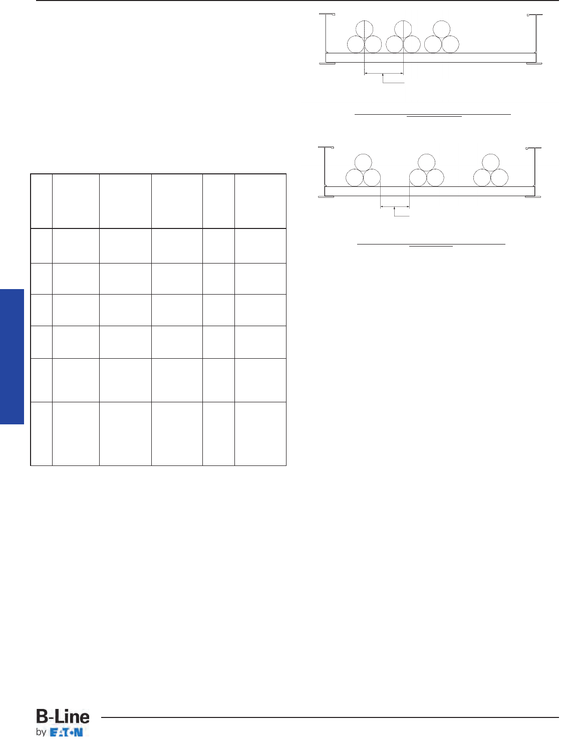
392.80. Ampacity of Conductors. (A) Ampacity of
Cables. Rated 2000 Volts or Less in Cable Trays.
(2) Single Conductor Cables.
Single conductor cables can be installed in a cable tray
cabled together (triplexed, quadruplexed, etc.) if desired.
Where the cables are installed according to the
requirements of Section 392.22(B), the ampacity
requirements are shown in the following chart as per
Section 392.80(A)(2), (a), (b), (c), and (d):
An exception is listed under 392.80(A)(2)(c). Stating that
the capacity for single conductor cables be placed in
solid bottom shall be determined by 310.15(C).
392.80. Ampacity of Conductors. (B) Ampacity of
Type MV and Type MC Cables (2001 Volts or Over)
in Cable Trays. (1) Multiconductor Cables (2001
Volts or Over)
Provision No. 1: Where cable trays are
continuously covered for more than six feet (1.83 m)
with solid unventilated covers, not more than 95% of
the allowable ampacities of Tables 310.60(C)(75) and
310.60(C)(76) shall be permitted for multiconductor
cables.
Cables installed in cable trays with solid unventilated
covers must be derated. Where cable tray covers are to
be used, it is best to use raised or ventilated covers
so that the cables can operate in a lower ambient
temperature.
Provision No. 2: Where multiconductor cables are
installed in a single layer in uncovered cable trays
with a maintained spacing of not less than one cable
diameter between cables, the ampacity shall not
exceed the allowable ampacities of Table
310.60(C)(71) and 310.60(C)(72).
If the cable tray does not have covers and the
conductors are installed in a single layer spaced not less
than one cable diameter apart, the cable conductor
ampacities can be 100 percent of the ambient
temperature corrected capacities in Tables 310.60(C)(71)
or 310.60(C)(72).
Cable Tray Manual
Spacing Between Conductors
(2.15 x O.D. of Conductor)
Spacing Between Conductors
(2.15 x O.D. of Conductor)
Technically Undesirable Installation
Interpretation #1
Technically Desirable Installation
Interpretation #2
Mult.
Solid Applicable Amp.
Sec. Cable Unventilated Ampacity Table Special
No. Sizes Cable Tray Tables Values Conditions
Cover (*) By
600 kcmil No Cover
310.15(B)(17)
(1) and Allowed and 0.75
Larger (**)
310.15(B)(19)
600 kcmil
310.15(B)(17)
(1) and Yes and 0.70
Larger
310.15(B)(19)
1/0 AWG No Cover
310.15(B)(17)
(2) through Allowed and 0.65
500 kcmil (**)
310.15(B)(19)
1/0 AWG
310.15(B)(17)
(2) through Yes and 0.60
500 kcmil
310.15(B)(19)
1/0 AWG Maintained
(3) & Larger No Cover
310.15(B)(17)
1.00 Spacing Of
In Single Allowed and One Cable
Layer (**)
310.15(B)(19)
Diameter
Single
Conductors
310.15(B)(20)
Spacing Of
(4) In Triangle No Cover [See NEC 2.15 x One
Config. Allowed Section 1.00 Conductor
1/0 AWG (**) 310.15(B)]
O.D. Between
and Larger Cables(***)
(*) The ambient ampacity correction factors must be used.
(**) At a specific position, where it is determined that the tray
cables require mechanical protection, a single cable tray cover
of six feet or less in length can be installed.
The wording of Section 392.80(A)(2)(d) states that a spacing of
2.15 times one conductor diameter is to be maintained between
circuits. Two interpretations of this statement are possible.
Interpretation #1. - The 2.15 times one conductor diameter is the
distance between the centerlines of the circuits (the center lines
of the conductor bundles). Interpretation #2. - The 2.15 times one
conductor diameter is the free air distance between the adjacent
cable bundles. The use of the word “circuit” is unfortunate as its
presence promotes Interpretation #1. An installation based on
Interpretation #1 is not desirable as a free air space equal to 2.15
times one conductor diameter between the cable bundles should
be maintained to promote cable heat dissipation.
MAN-32
Cable Tray Manual
Cable Tray Systems
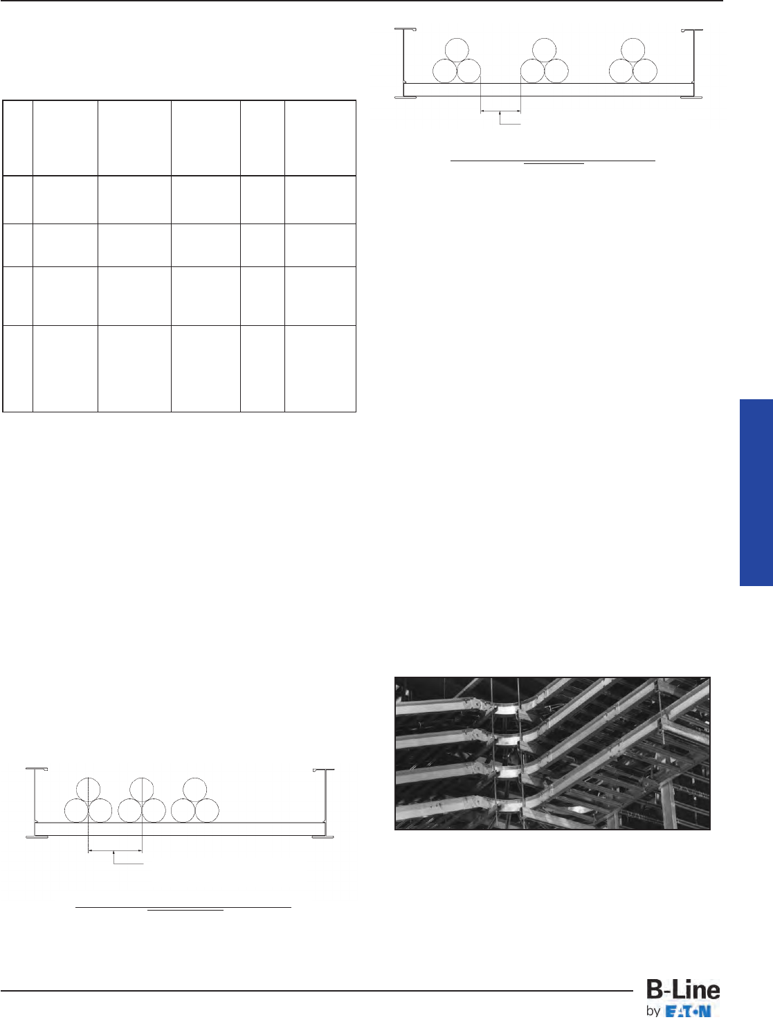
392.80. Ampacity of Conductors. (B) Ampacity of
Type MV and Type MC Cables (2001 Volts or Over)
in Cable Trays. (2) Single-Conductor Cables (2001
Volts or Over)
392.100. Construction Specifications. (A) Strength
and Rigidity.
The designer must properly select a structurally
satisfactory cable tray for their installation. This selection
is based on the cable tray's strength, the cable tray
loading and the spacing of the supports. The
ANSI/NEMA Metallic Cable Tray Systems Standard
Publication VE-1 contains the cable tray selection
information and it is duplicated in B-Line Cable Tray
Systems Catalog.
The NEMA Standard provides for a static load safety
factor of 1.5. A number (Span in Feet - the distance
between supports) and letter (Load in lbs/ft) designation
is used to properly identify the cable tray class on
drawings, in specifications, in quotation requisitions, and
in purchase requisitions to guarantee that the cable tray
with the proper characteristics will be received and
installed. The designer must specify the cable tray type,
the material of construction, section lengths, minimum
bend radius, width, rung spacing (for a ladder type cable
tray), and the total loading per foot for the cables on
a maximum support spacing (See pages MAN-50 &
MAN-51 for cable tray specifications checklist). For many
installations, the cable trays must be selected so that
they are capable of supporting specific concentrated
loads, the weight of any equipment or materials attached
to the cable tray, ice and snow loading, and for some
installations the impact of wind loading and/or
earthquakes must be considered.
Most cable trays are utilized as continuous beams with
distributed and concentrated loads. Cable trays can be
subjected to static loads like cable loads and dynamic
loads such as wind, snow, ice, and even earthquakes.
The total normal and abnormal loading for the cable tray
is determined by adding all the applicable component
Cable Tray Manual
(*) The ambient ampacity correction factors must be used.
(**) At a specific position, where it is determined that the tray
cables require mechanical protection, a single cable tray cover
of six feet or less in length can be installed.
The wording of Section 392.80(B)(2)(c) states that a spacing of
2.15 times one conductor diameter is to be maintained between
circuits. Two interpretations of this statement are possible.
Interpretation #1. - The 2.15 times one conductor diameter is the
distance between the centerlines of the circuits (the center lines
of the conductor bundles). Interpretation #2. - The 2.15 times one
conductor diameter is the free air distance between the adjacent
cable bundles. The use of the word “circuit” is unfortunate as its
presence promotes Interpretation #1. An installation based on
Interpretation #1 is not desirable as a free air space equal to 2.15
times one conductor diameter between the cable bundles should
be maintained to promote cable heat dissipation.
Mult.
Solid Applicable Amp.
Sec. Cable Unventilated Ampacity Table Special
No. Sizes Cable Tray Tables Values Conditions
Cover (*) By
1/0 AWG No Cover
310.60(C)(69)
(1) and Allowed and 0.75
Larger (**)
310.60(C)(70)
1/0 AWG
310.60(C)(69)
(1) and Yes and 0.70
Larger
310.60(C)(70)
1/0 AWG Maintained
(2) & Larger No Cover
310.60(C)(69)
1.00 Spacing Of
In Single Allowed and One Cable
Layer (**)
310.60(C)(70)
Diameter
Single
Conductors Spacing Of
(3) In Triangle No Cover
310.60(C)(67)
2.15 x One
Config. Allowed and 1.00 Conductor
1/0 AWG (**)
310.60(C)(68)
O.D. Between
and Larger Cables(***)
Spacing Between Conductors
(2.15 x O.D. of Conductor)
Technically Undesirable Installation
Interpretation #1
Spacing Between Conductors
(2.15 x O.D. of Conductor)
Technically Desirable Installation
Interpretation #2
MAN-33
Cable Tray Manual
Cable Tray Systems

loads. The cable load + the concentrated static loads +
ice load (if applicable) + snow load (if applicable) + wind
load (if applicable) + any other logical special condition
loads that might exist. This total load is used in the
selection of the cable tray.
The following is an explanation of the ‘historical’
NEMA cable tray load classifications found in
ANSI/NEMA VE-1.
There used to be four cable tray support span
categories, 8, 12, 16, and 20 feet, which are coupled with
one of three load designations, "A" for 50 lbs/ft, "B" for
75 lbs/ft, and "C" for 100 lbs/ft. For example, a NEMA
class designation of 20B identifies a cable tray that is to
be supported at a maximum of every 20 feet and can
support a static load of up to 75 lbs/linear foot.
The cable load per foot is easy to calculate using the
cable manufacturer's literature. If the cable tray has
space available for future cable additions, a cable tray
has to be specified that is capable of supporting the final
future load. Although these historical load designations
are still useful in narrowing down the choices of cable
trays, NEMA has recently changed the VE-1 document.
ANSI/NEMA VE-1 now requires the marking on the cable
trays to indicate the exact rated load on a particular
span. Trays are no longer limited to the four spans and
three loads listed above. Now, for example, a tray may
be rated for 150 lbs/ft on a 30 ft. span. It is
recommended when specifying cable tray, to specify the
required load, support span and straight section length
to best match the installation.
Example of Cable Loading per foot:
10 - 3/C No. 4/0 (2.62 lbs/ft)
Total = 26.20 lbs/ft
3 - 3/C No. 250 kcmil (3.18 lbs/ft)
Total = 9.54 lbs/ft
4 - 3/C No. 500 kcmil (5.87 lbs/ft)
Total = 23.48 lbs/ft
Total Weight of the Cables = 59.22 lbs/ft
These cables would fill a 30 inch wide cable tray and
if a 36 inch wide cable tray were used there would be
space available for future cables (See pages 443 thru 449
for information on calculating tray width.). To calculate
the proper cable tray design load for the 36" wide cable
tray multiply 59.22 lbs/ft x 36 inches/30 inches = 71.06
lbs/ft. If this cable tray is installed indoors, a load symbol
"B" cable tray would be adequate. If there were
additional loads on the cable tray or the cable tray were
installed outdoors, it would be necessary to calculate all
the additional potential loads. The potential load most
often ignored is installation loads. The stresses of pulling
large cables through cable trays can produce 3 times the
stress of the cables' static load. If the installation load is
not evaluated the cable tray may be damaged during
installation. A 16C or 20C NEMA Class should be
specified if large cables are to be pulled.
Even though walking on cable tray is not
recommended by cable tray manufacturers and OSHA
regulations, many designers will want to specify a cable
tray which can support a 200 lb. concentrated load "just
in case". A concentrated static load applied at the
midspan of a cable tray is one of the most stressful
conditions a cable tray will experience. To convert a
static concentrated load at midspan to an equivalent
distributed load take twice the concentrated load and
divide it by the support span [(2 x 200 lbs.)/Span].
The strength of the rung is also a very important
consideration when specifying a concentrated load. The
rung must be able to withstand the load for any
tray width, as well as additional stresses from cable
installation. Excessive rung deflection can weaken the
entire cable tray system. B-Line uses heavier rungs on
their wider industrial trays as a standard. Most cable tray
manufacturer's rungs are not heavy enough to withstand
concentrated loads at 36" tray widths.
For outdoor installations a cable tray might be subject
to ice, snow, and wind loading. Section 25 of the National
Electrical Safety Code (published by the Institute of
Electrical and Electronic Engineers) contains a weather
loading map of the United States to determine whether
the installation is in a light, medium, or heavy weather
load district. NESC Table 250-1 indicates potential ice
thicknesses in each loading district as follows: 0.50
inches for a heavy loading district, 0.25 inches for a
medium loading district, and no ice for a light loading
district. To calculate the ice load use 57 pounds per
cubic foot for the density of glaze ice. Since tray cables
are circular and the cable tray has an irregular surface
the resulting ice load on a cable tray can be 1.5 to 2.0
times greater than the glaze ice load on a flat surface.
Snow load is significant for a cable tray that is
completely full of cables or a cable tray that has covers.
The density of snow varies greatly due to its moisture
content, however the minimum density that should be
used for snow is 5 pounds per cubic foot. The engineer
will have to contact the weather service to determine the
potential snow falls for the installation area or consult the
local building code for a recommended design load.
Usually cable trays are installed within structures such
that the structure and equipment shelter the cable trays
from the direct impact of high winds. If wind loading is a
potential problem, a structural engineer and/or the
potential cable tray manufacturer should review the
installation for adequacy. To determine the wind speed
for proper design consult the Basic Wind Speed Map of
the United States in the NESC (Figure 250-2).
For those installations located in earthquake areas,
design engineers can obtain behavioral data for B-Line
cable trays under horizontal, vertical and longitudinal
loading conditions. Testing done for nuclear power plants
in the 1970's indicates that cable trays act like large
trusses when loaded laterally and are actually stronger
than when loaded vertically. Cable tray supports may still
Cable Tray Manual
MAN-34
Cable Tray Manual
Cable Tray Systems

need to be seismically braced and designers should
consult the B-Line Seismic Restraints Catalog for
detailed design information.
The midspan deflection multipliers for all B-Line cable
trays are listed in the Cable Tray Systems catalog. Simply
pick your support span and multiply your actual load
by the deflection multiplier shown for that span. The
calculated deflections are for simple beam installations
at your specified load capacity. If a deflection
requirement will be specified, extra care needs to be
taken to ensure that it does not conflict with the load
requirement and provides the aesthetics necessary.
Keep in mind that continuous beam applications are
more common and will decrease the deflection values
shown by up to 50%. Also, aluminum cable trays will
deflect 3 times more than steel cable trays of the same
NEMA class.
To complete the design, the standard straight section
length and minimum bend radius must be chosen. When
selecting the recommended length of straight sections,
be sure that the standard length is greater than or equal
to the maximum support span. Choose a fitting radius
which will not only meet or exceed the minimum bend
radius of the cables but will facilitate cable installation.
[See pages MAN-9 - MAN-11 for more information on
selecting the appropriate cable tray length]
392.100. Construction Specifications. (B) Smooth
Edges.
This is a quality statement for cable tray systems and
their construction. B-Line cable tray is designed and
manufactured to the highest standards to provide easy,
safe installation of both the cable tray and cables.
392.100. Construction Specifications. (C)
Corrosion Protection.
Cable tray shall be protected from corrosion per
Section 300.6, which lists some minimum criteria for
different corrosive environments. The B-Line Cable Tray
Catalog contains a corrosion chart for cable tray
materials. Cable trays may be obtained in a wide range
of materials including aluminum, pregalvanized steel, hot
dipped galvanized steel (after fabrication), Type 304 or
316 stainless steel, polyvinyl chloride (PVC) or epoxy
coated aluminum or steel and also nonmetallic (fiber
reinforced plastic). Check with a metallurgist to
determine which metals and coatings are compatible
with a particular corrosive environment. B-Line has
corrosion information available and may be able to
recommend a suitable material. Remember that no
material is totally impervious to corrosion. Stainless steel
can deteriorate when attacked by certain chemicals and
nonmetallic cable trays can deteriorate when attacked
by certain solvents.
392.100. Construction Specifications. (D)
Side Rails.
The technical information in Article 392 was originally
developed for cable trays with rigid side rails by the
1973 NEC®Technical Subcommittee on Cable Tray.
“Equivalent Structural Members” was added later to
incorporate new styles of cable tray such as center rail
type tray and ‘mesh’ or wire basket tray.
392.100. Construction Specifications. (E) Fittings.
This section has been misinterpreted to mean that
cable tray fittings must be used for all changes in
direction and elevation [See Section 392.18(A) Complete
system for further explanation). When two cable tray runs
cross at different elevations, lacing a cable between the
rungs of one tray and dropping into the other is a
common practice which changes the direction of the
cable while providing adequate cable support. Although
the use of cable tray fittings is not mandatory, it is often
desirable to use them when possible to improve the
appearance of the installation.
392.100. Construction Specifications. (F)
Nonmetallic Cable Tray.
This type of cable tray is usually made of Fiberglass
Reinforced Plastic (FRP). Applications for FRP cable tray
systems include some corrosive atmospheres and where
non-conductive material is required. B-Line fiberglass
cable tray systems are manufactured from glass fiber
reinforced plastic shapes that meet ASTM flammability
and self-extinguishing requirements. A surface veil is
applied during pultrusion to ensure a resin rich surface
and increase ultraviolet resistance, however, for
extended exposure to direct sunlight, additional
measures, such as painting the tray, are sometimes
employed to insure the longevity of the product. Ambient
temperature is also a design consideration when FRP
cable tray is used. An ambient temperature of 100°F will
decrease the loading capacity of polyester resin
fiberglass cable tray by 10%.
Cable Tray Manual
MAN-35
Cable Tray Manual
Cable Tray Systems

CABLE TRAY WIRING SYSTEM DESIGN AND IN-
STALLATION HINTS.
Cable tray wiring systems should have a standardized
cabling strategy. Standard cable types should be used
for each circuit type. Most of the following circuits should
be included; feeder circuits, branch circuits, control
circuits, instrumentation circuits, programmable logic
controller input and output (I/O) circuits, low level analog
or digital signals, communication circuits and alarm
circuits. Some cables may satisfy the requirements for
several circuit types. Minimizing the number of different
cables used on a project reduces installed costs. Some
companies have cable standards based on volume
usage to minimize the numbers of different cables used
on a project. For example: if a 6 conductor No. 14
control cable is needed but 7 conductor No. 14 control
cable is stocked, a 7 conductor control cable would be
specified and the extra conductor would not be used.
Following such a practice can reduce the number of
different cables handled on a large project without
increasing the cost since high volume cable purchases
result in cost savings. Orderly record keeping also helps
provide quality systems with lower installation costs. The
following items should be included in the project's cable
records:
• Cable Tray Tag Numbers - The tagging system
should be developed by the design personnel with
identification numbers assigned to cable tray runs on the
layout drawings. Cable tray tag numbers are used for
controlling the installation of the proper cable tray in the
correct location, routing cables through the tray system
and controlling the cable fill area requirements.
• Cable Schedules - A wire management system is
required for any size project. Cable schedules must be
developed to keep track of the cables. This is especially
true for projects involving more than just a few feeder
cables. A typical cable schedule would contain most or
all of the following:
• The Cable Number, the Cable Manufacturer &
Catalog Number, Number of conductors, the conductor
sizes, and the approximate cable length.
• Cable Origin Location - The origin equipment ID with
the compartment or circuit number and terminals on
which the cable conductors are to be terminated. It
should also include the origin equipment layout drawing
number, and the origin equipment connection diagram
number.
• Cable Routing - Identifies the cable tray sections or
runs that a cable will occupy. Cable tray ID tag numbers
are used to track the routing.
• Cable Termination Location - The device or terminal
equipment on which the cable conductors are to be
terminated. It should also include the termination
equipment layout drawing number, and the termination
equipment connection diagram number.
Some design consultants and corporate engineering
departments use spread sheets to monitor the cable tray
runs for cable fill. With such a program, the cable tray fill
area values for each cable tray run or section can be
continuously upgraded. If a specified cable tray run or
section becomes overfilled, it will be flagged for
corrective action by the designer.
• Cable Installation Provisions - The cable tray system
must be designed and installed, to allow access for cable
installation. For many installations, the cables may be
hand laid into the cable trays and no cable pulling
equipment is required. There are other installations where
sufficient room must be allotted for all the cable pulling
activities and equipment.
The cable manufacturers will provide installation
information for their cables such as maximum pulling
tension, allowable sidewall pressures, minimum bending
radii, maximum permissible pulling length etc..
Lubricants are not normally used on cables being
installed in cable trays.
The engineer and designers should discuss in detail
the installation of the cables with the appropriate
construction personnel. This will help to avoid installation
problems and additional installation costs. It is important
that the cable pull is in the direction that will result in the
lowest tension on the cables. Keep in mind there also
needs to be room at the ends of the pulls for the reel
setups and for the power pulling equipment. Cable
pulleys should be installed at each direction change.
Triple pulleys should be used for 90 degree horizontal
bends and all vertical bends. Single pulleys are adequate
for horizontal bends less than 90 degrees. Use rollers
in-between pulleys and every 10 to 20 feet depending on
the cable weight. Plastic jacketed cables are easier to
pull than are the metallic jacketed cables and there is less
chance of cable damage. The pulling eye should always
be attached to the conductor material to avoid tensioning
the insulation. For interlocked armor cables, the
conductors and the armor both have to be attached to
the pulling eye.
Normally, the cables installed in cable trays are
not subjected to the damage suffered by insulated
conductors pulled into conduit. Depending on the size
of the insulated conductors and the conduit, jamming
can take place which places destructive stresses on the
cable insulation. In the October, 1991 issue of EC&M
magazine, the article on cable pulling stated that 92
percent of the insulated conductors that fail do so
because they were damaged in installation.
Cable Tray Manual
MAN-36
Cable Tray Manual
Cable Tray Systems
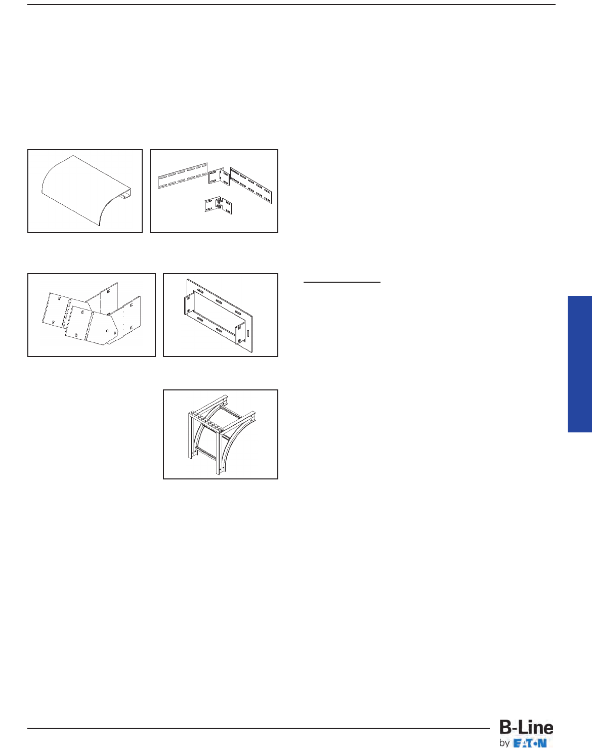
Cable Tray Manual
CABLE TRAY ACCESSORIES.
B-Line manufactures a full line of prefabricated
accessories for all types of B-Line cable trays. The use
of the appropriate accessories will provide installation
cost and time savings. In addition to providing desirable
electrical and mechanical features for the cable tray
system, the use of the appropriate accessories improves
the physical appearance of the cable tray system. Some
of the most common accessories are shown below and
on the following page.
FIREPROOFING CABLE TRAY
Cable trays should not be encapsulated for fire
protection purposes other than for the short lengths at
fire rated walls unless the cables are adequately derated.
Encapsulation to keep fire heat out will also keep
conductor heat in. If conductors cannot dissipate their
heat, their insulation systems will deteriorate. If the cable
tray will be encapsulated, the cable manufacturer should
be consulted for derating information.
CABLE TRAY MAINTENANCE AND REPAIR
If the cable tray finish and load capacity is properly
specified and the tray is properly installed, virtually no
maintenance is required.
Pre-Galvanized - This finish is for dry indoor
locations. No maintenance is required.
Hot Dip Galvanized - This finish is maintenance free
for many years in all but the most severe environments.
If components have been cut or drilled in the field, the
exposed steel area should be repaired with a cold
galvanizing compound. B-Line has a spray on zinc
coating available which meets the requirements of ASTM
A780, Repair of Hot Dip Finishes.
Aluminum - Our cable tray products are manufactured
from type 6063-T6 aluminum alloy with a natural finish.
The natural oxide finish is self healing and requires no
repair if it is field modified.
Non-metallic - Fabrication with fiberglass is relatively
easy and comparable to working with wood. Any surface
that has been drilled, cut, sanded, or otherwise broken,
must be sealed with a comparable resin. Polyester or
vinyl ester sealing kits are available.
Cable tray should be visually inspected each year for
structural damage i.e., broken welds, bent rungs or
severely deformed side rails. If damage is evident, from
abuse or installation, it is recommended that the
damaged section of cable tray be replaced rather than
repaired. It is much easier to drop a damaged section of
tray out from under the cables than it is to shield the
cables from weld spatter.
Frame Box Connector
Cable Support Fitting
Vertical Adjustable Splice
Requires supports within 24” on
both sides, per NEMA VE 2.
Ladder Dropout
Horizontal Adjustable Splice
Requires supports within 24” on
both sides, per NEMA VE 2.
MAN-37
Cable Tray Manual
Cable Tray Systems
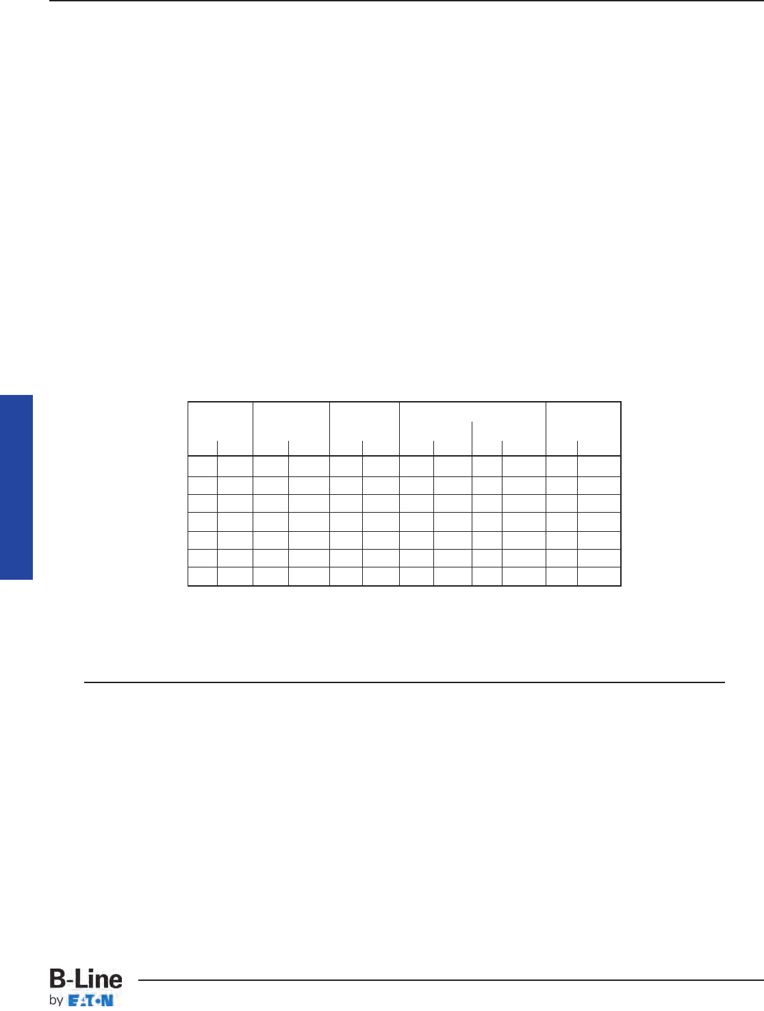
CABLE TRAY. THERMAL CONTRACTION AND
EXPANSION
All materials expand and contract due to temperature
changes. Cable tray installations should incorporate
features which provide adequate compensation for
thermal contraction and expansion. Installing expansion
joints in the cable tray runs only at the structure
expansion joints does not normally compensate
adequately for the cable tray's thermal contraction and
expansion. The supporting structure material and the
cable tray material will have different thermal expansion
values. They each require unique solutions to control
thermal expansion.
NEC®Section 300.7(B) states that 'Raceways shall
be provided with expansion joints where necessary
to compensate for thermal expansion or
contraction.' NEC®Section 392 does not address
thermal contraction and expansion of cable tray. One
document which addresses expansion is the NEMA
Standards Publication No. VE 2, Section 4.3.2. NEMA
VE-2 Table 4-2 shows the allowable lengths of steel and
aluminum cable tray between expansion joints for the
temperature differential values.
Reprinted with permission from NFPA 70-1999, the National
Electrical Code®, Copyright© 1998, National Fire Protection
Association, Quincy, MA 02269. This reprinted material is not the
complete and official position of the National Fire Protection
Association, on the referenced subject which is represented only by
the standard in its entirety.
Cable Tray Manual
Temp. Stainless Steel
Differential Steel Aluminum 304 316 FRP
°F (°C) Feet (m) Feet (m) Feet (m) Feet (m) Feet (m)
25 (13.9) 512 (156.0) 260 (79.2) 347 (105.7) 379 (115.5) 667 (203.3)
50 (27.8) 256 (78.0) 130 (39.6) 174 (53.0) 189 (57.6) 333 (101.5)
75 (41.7) 171 (52.1) 87 (26.5) 116 (35.4) 126 (38.4) 222 (67.6)
100 (55.6) 128 (39.0) 65 (19.8) 87 (26.5) 95 (29.0) 167 (50.9)
125 (69.4) 102 (31.1) 52 (15.8) 69 (21.0) 76 (23.2) 133 (40.5)
150 (83.3) 85 (25.9) 43 (13.1) 58 (17.7) 63 (19.2) 111 (33.8)
175 (97.2) 73 (22.2) 37 (11.3) 50 (15.2) 54 (16.4) 95 (28.9)
Table 4-2
Maximum Spacing Between Expansion Joints
That Provide For One Inch (25.4 mm) Movement
For a 100°F differential (winter to summer), a steel cable tray will require
an expansion joint every 128 feet and an aluminum cable tray every 65
feet. The temperature at the time of installation will dictate the gap
setting.
MAN-38
Cable Tray Manual
Cable Tray Systems
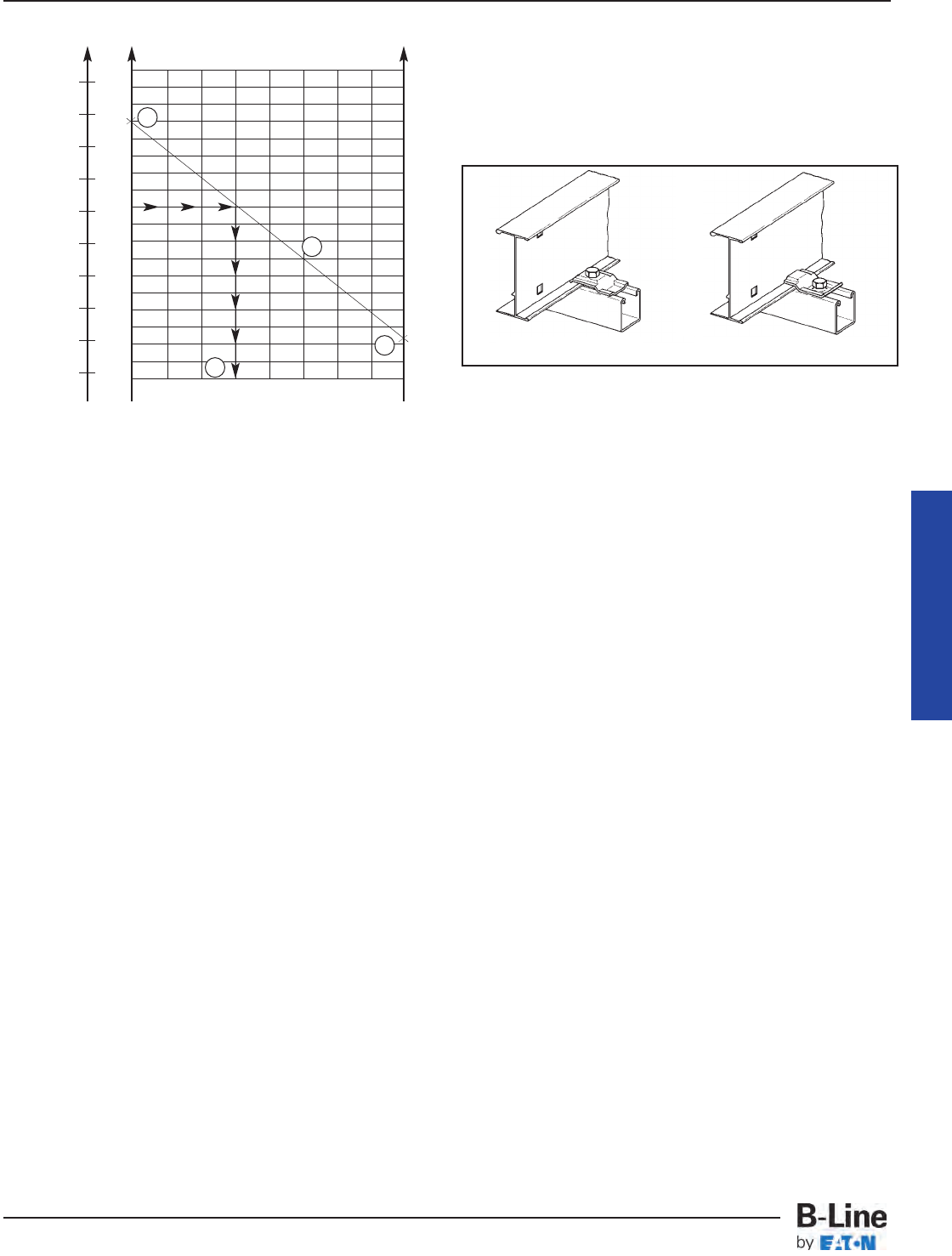
The Gap
Setting of the Expansion Joint Splice Plate is used as
follows per the example indicated in VE-2 Figure 4.13B.
Step 1. Plot the highest expected cable tray metal
temperature during the year on the maximum temperature
vertical axis. Example's Value: 100 Degrees F.
Step 2. Plot the lowest expected cable tray metal
temperature during the year on the minimum temperature
vertical axes. Example's Value: - 28 Degrees F.
Step 3. Draw a line between these maximum and
minimum temperature points on the two vertical axis.
Step 4. To determine the required expansion joint gap
setting at the time of the cable tray's installation: Plot the
cable tray metal temperature at the time of the cable tray
installation on the maximum temperature vertical axis
(Example's Value: 50 Degrees F). Project over from the 50
Degrees F point on the maximum temperature vertical
axis to an intersection with the line between the maximum
and minimum cable tray metal temperatures. From this
intersection point, project down to the gap setting
horizontal axis to find the correct gap setting value
(Example's Value: 3/8inch gap setting). This is the length
of the gap to be set between the cable tray sections at
the expansion joint.
The plotted High - Low Temperature Range in Figure
4-13B is 128° F. The 125° F line in Table 4-1 shows that
installations in these temperature ranges would require
3/8” expansion joints approximately every 102 feet for
Steel and every 52 feet for Aluminum cable tray.
Another item essential to the operation of the cable
tray expansion splices is the type of hold down clamps
used. The cable tray must not be clamped to each
support so firmly that the cable tray cannot contract and
expand without distortion. The cable tray needs to be
anchored at the support closest to the midpoint between
the expansion joints with hold down clamps and
secured by expansion guides at all other support
locations.The expansion guides allow the cable tray to
slide back and forth as it contracts and expands.
Supports must also be located on both sides of an
expansion splice. The supports should be located within
two feet of the expansion splice to ensure that the splice
will operate properly. If these guidelines for cable tray
thermal contraction and expansion are not followed,
there is the potential for the cable trays to tear loose from
their supports, and for the cable trays to bend and
collapse.
Max. Temp. Min. Temp.
Figure 4.13B
Gap Setting Of Expansion Splice Plate
1" (25.4 mm) Gap Maximum
130
110
90
70
50
30
10
-10
-30
50
C° F° F°
40
30
20
10
0
-10
-20
-30
-40
130
110
90
70
50
30
10
-10
-30
0
1/85/8
1/2
3/8
1/4
1
7/8
3/4
Gap Setting in Inches
Metal Temperature At Time
Of Installation (F° or C°)
As a clamp. As a guide.
1
2
3
4
Cable Tray Manual
MAN-39
Cable Tray Manual
Cable Tray Systems

Appendix Pages
Appendix Sheet 1 .......................................................................................................... MAN-41
Temperature Rise Tests, Cable Tray Connectors, Class II
Aluminum & Steel Ladder Tray
Appendix Sheet 2 .......................................................................................................... MAN-42
Temperature Rise Tests, Conduit Clamps For Bonding Rigid
Conduit To Cable Tray
Appendix Sheet 3 .......................................................................................................... MAN-43
Example - NEC®Section 392.22(A)(1)(a)
Appendix Sheet 4 .......................................................................................................... MAN-44
Example - NEC®Section 392.22(A)(1)(b)
Appendix Sheet 5 .......................................................................................................... MAN-45
Example - NEC®Section 392.22(A)(1)(c)
Appendix Sheet 6 .......................................................................................................... MAN-46
Example - NEC®Section 392.22(A)(2)
Appendix Sheet 7 .......................................................................................................... MAN-47
Table 250.122 Minimum Size EGC for Raceway and Equipment
Appendix Sheet 8 ........................................................................................ MAN-48 – MAN-49
Cable Tray Sizing Flowchart
Appendix Sheet 9 ........................................................................................ MAN-50 – MAN-51
Cable Tray Installation & Specification Checklist
Footnotes ...................................................................................................................... MAN-52
Additional Cable Tray Resources and Engineering Software
Cable Tray Manual
MAN-40
Cable Tray Manual
Cable Tray Systems
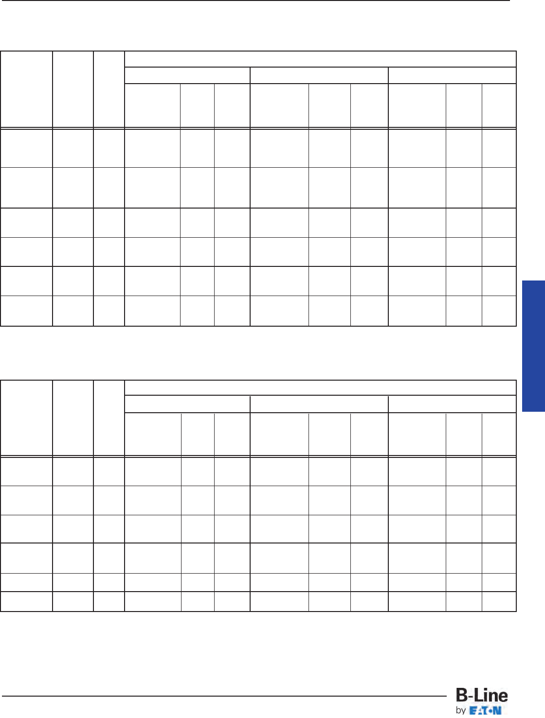
Appendix Sheet 1
TABLE I
TEMPERATURE RISE TESTS, CABLE TRAY CONNECTORS,
CLASS II ALUMINUM LADDER CABLE TRAY
TABLE II
TEMPERATURE RISE TESTS, CABLE TRAY CONNECTORS,
CLASS II STEEL LADDER CABLE TRAY
Test Connector Data
Current Test I2T C1 C2 C3
Amps Time
And Cycles mult. Type No. & Temp. Type No. & Temp. Type No. & Temp.
Fuse by Of Type Rise Of Type Rise Of Type Rise
Size* 106 Connector Bolts °C Connector Bolts °C Connector Bolts °C
1,980 52 3.4 Adj. Vert. 4 2 No. 6 CU AL-CU 10 Rigid 2 3
200A, FU 1 Bolt** Bond Lugs
1,970 394 25.5 Adj. Vert. 4 9 No. 6 CU AL-CU *** Rigid 2 15
400A, FU 1 Bolt** Bond Lugs
1,960 8100 51.8 Adj. Vert. 4 18 Rigid 4 23 Rigid 2 32
400A, FU 1 Bolt**
12,000 120 288 Adj. Vert. 4 94 Adj. Vert. 4 89 Rigid 4 81
2 Bolts** 2 Bolts**
12,000 123 295 Rigid 4 70 Rigid 4 87 Rigid 4 85
34,000 13 250 Rigid 4 71 Rigid 4 57 Rigid 4 69
Test Connector Data
Current Test I2T C1 C2 C3
Amps Time
And Cycles mult. Type No. & Temp. Type No. & Temp. Type No. & Temp.
Fuse by Of Type Rise Of Type Rise Of Type Rise
Size* 106 Connector Bolts °C Connector Bolts °C Connector Bolts °C
7,900 Adj. Vert. 3/0 CU AL-CU Rigid
1,200A 66 69 1 Bolt** 4 6 Bond Lugs 18 Clean 2 8
Fuse Steel Steel
7,900 Rigid 3/0 CU AL-CU Rigid
1,200A 82 85 Corroded 4 10 Bond Lugs 22 Clean 2 9
Fuse Steel Steel
12,000 120 288 Rigid 2 50 3/0 CU AL-CU 104 Rigid 2 32
Corroded Nylon Bond Lugs Clean Steel
12,000 124 297 Rigid 4 40 Rigid 4 46 Rigid 4 21
Corroded Steel Corroded Lugs Clean Steel
34,600 14 280 Rigid 2 34 3/0 CU AL-CU 75 Rigid 2 29
Corroded Nylon Bond Lugs Clean Steel
34,400 14 276 Rigid 4 28 Rigid 4 35 Rigid 4 20
Corroded Nylon Corroded Steel Clean Steel
* Test current was interrupted in a predetermined time when a fuse was not used.
** 1 or 2 Bolts - Number of bolts installed on the adjustable vertical connector hinge.
*** The No. 6 bonding jumper melted and opened the circuit when protected by 400A fuse.
(See Page MAN-30 - Figure 1 for Temperature Rise Test illustration)
Cable Tray Manual
MAN-41
Cable Tray Manual
Cable Tray Systems
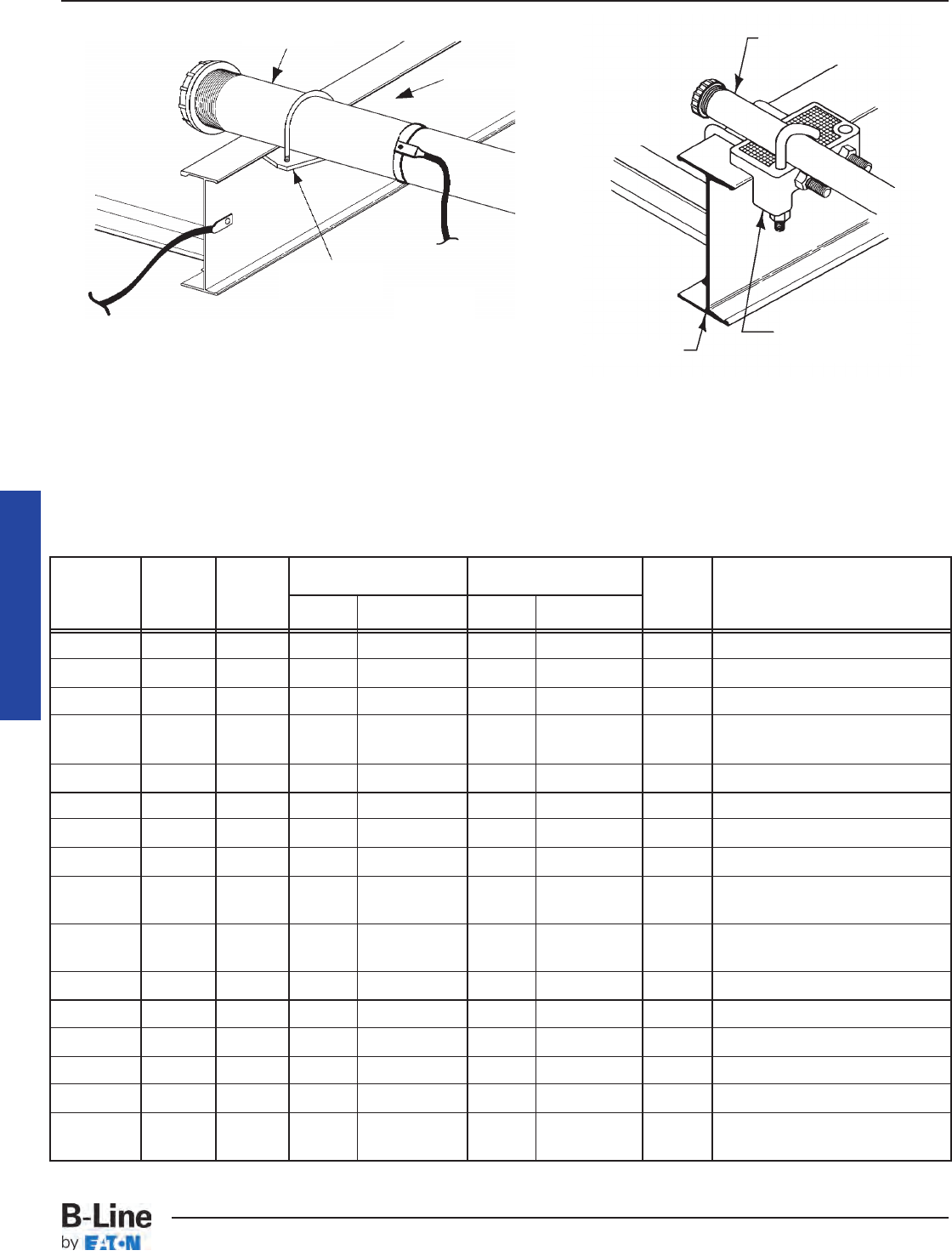
TABLE III
TEMPERATURE RISE TESTS, CONDUIT CLAMPS
FOR BONDING RIGID CONDUIT TO CABLE TRAY
Test Test I2T Rigid Conduit Cable Tray Temp.
Current Time mult. Rise Condition After Test
Amperes Cycles 106 Size Material Class Material °C
36,000 16 344.7 4" Aluminum II Aluminum 19 No arcing or damage
20,900 60.5 441.2 4" Aluminum II Aluminum 70 No arcing or damage
12,100 178 433.3 4" Aluminum II Aluminum 74 No arcing or damage
21,000 20 146.8 4" Steel II Steel (?) Zinc melted at point where
conduit contacted with tray
3,260 900 159.5 4" Steel II Steel 63 No arcing or damage
21,000 30 220 2" Aluminum II Aluminum 21 No arcing or damage
12,100 120.5 294.2 2" Aluminum II Aluminum 59 No arcing or damage
8,000 245 261.1 2" Aluminum II Aluminum 44 No arcing or damage
21,000 14 103.8 2" Steel II Steel 62 Zinc melted at point where
conduit contacted with tray
12,000 60.5 145.4 2" Steel II Steel 22 Slight arc between
clamp and tray
3,240 600 104.9 2" Steel II Steel 49 No arcing or damage
21,000 20 146.8 1" Aluminum II Aluminum 20 No arcing or damage
12,200 60.5 150.3 1" Aluminum II Aluminum 24 No arcing or damage
12,100 14.5 35.3 1" Steel II Steel 6 No arcing or damage
8,000 63.5 67.84 1" Steel II Steel 59 No arcing or damage
1,980 44.5 2.9 1" Steel II Steel 1 No arcing or damage
200A FU
Appendix Sheet 2
Conduit
UL Listed
Conduit Clamp
(9ZN-1158)
Cable Tray
Conduit
Cable Tray
Right Angle
Beam Clamp To Current
Source
To Current
Source
Conduit Clamp DetailTest Set-Up
CIRCUIT ARRANGEMENT FOR RIGID CONDUIT
TEMPERATURE RISE TESTS
Cable Tray Manual
MAN-42
Cable Tray Manual
Cable Tray Systems
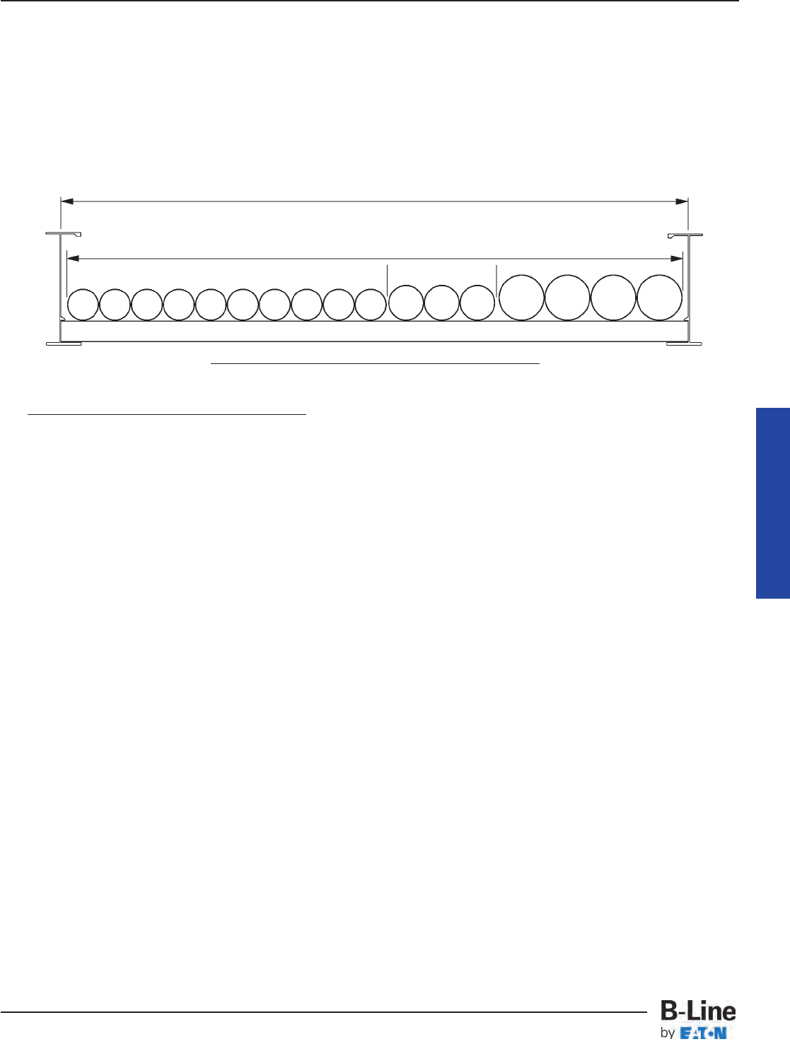
Appendix Sheet 3
Example - NEC®Section 392.22(A)(1)(a)
Width selection for cable tray containing 600 volt multiconductor cables, sizes #4/0 AWG and larger
only. Cable installation is limited to a single layer. The sum of the cable diameters (Sd) must be equal
to or less than the usable cable tray width.
Cable tray width is obtained as follows:
(D) (N) Multiply (D) x (N)
Item List List Cable List Number Subtotal of the
Number Cable Sizes Outside of Cables Sum of the Cables
Diameter Diameters (Sd)
1. 3/C - #500 kcmil 2.26 inches 4 9.04 inches
2. 3/C - #250 kcmil 1.76 inches 3 5.28 inches
3. 3/C - #4/0 AWG 1.55 inches 10 15.50 inches
The sum of the diameters (Sd) of all cables (Add Sds for items 1, 2, & 3.)
9.04 inches + 5.28 inches + 15.50 inches = 29.82 inches (Sd)
A cable tray with a usable width of 30 inches is required. For
a 10% increase in cost a 36 inch wide cable tray could be
purchased which would provide for some future cable additions.
Notes:
1. The cable sizes used in this example are a random selection.
2. Cables - copper conductors with cross linked polyethylene insulation and a PVC jacket.
(These cables could be ordered with or without an equipment grounding conductor.)
3. Total cable weight per foot for this installation.
61.4 lbs./ft. (without equipment grounding conductors)
69.9 lbs./ft. (with equipment grounding conductors)
This load can be supported by a load symbol "B" cable tray - 75 lbs./ft.
30" Usable Cable Tray Width
29.82" = Equals Cable Sd
Cross Section Of The Cables And The Cable Tray
33 33 3 3 33 33 222 1111
Cable Tray Manual
MAN-43
Cable Tray Manual
Cable Tray Systems
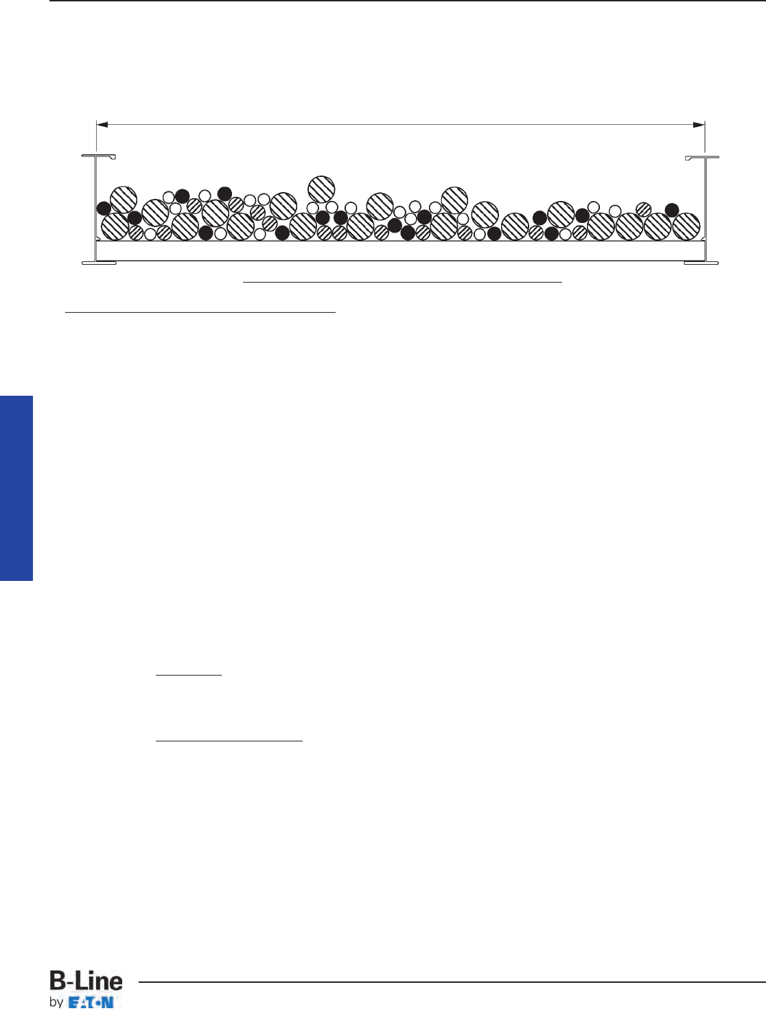
Example - NEC®Section 392.22(A)(1)(b)
Width selection for cable tray containing 600 volt multiconductor cables, sizes #3/0 AWG and
smaller. Cable tray allowable fill areas are listed in Column 1 of Table 392.22(A).
Cable tray width is obtained as follows:
(A) (N) Multiply (A) x (N)
Item List List Cable List Total of the
Number Cable Sizes Cross Sectional Number Cross Sectional
Areas of Cables Area for Each Item
1. 3/C #12 AWG 0.17 sq. in. 20 3.40 sq. in.
2. 4/C #12 AWG 0.19 sq. in. 16 3.04 sq. in.
3. 3/C #6 AWG 0.43 sq. in. 14 6.02 sq. in.
4. 3/C #2 AWG 0.80 sq. in. 20 16.00 sq. in.
Method 1.
The sum of the total areas for items 1, 2, 3, & 4:
3.40 sq. in. + 3.04 sq. in. + 6.02 sq. in. + 16.00 sq. in. = 28.46 sq. inches
From Table 392.9 Column 1 a 30 inch wide tray with an allowable fill area of 35 sq. in.
must be used. The 30 inch cable tray has the capacity for additional future cables (6.54
sq. in. additional allowable fill area can be used.)
Method 2.
The sum of the total areas for items 1, 2, 3, & 4 multiplied by
3.40 sq. in. + 3.04 sq. in. + 6.02 sq. in. + 16.00 sq. in. = 28 46 sq. in.
Use a 30 inch wide cable tray.
Notes:
1. The cable sizes used in this example are a random selection.
2. Cables - copper conductors with cross linked polyethylene insulation and a PVC jacket.
(These cables could be ordered with or without an equipment grounding conductor.)
3. Total cable weight per foot for this installation.
31.9 lbs./ft. (Cables in this example do not contain equipment grounding conductors.)
This load can be supported by a load symbol "A" cable tray - 50 lbs./ft.
30" Usable Cable Tray Width
Cross Section Of The Cables And The Cable Tray
( )
6 in.
7 sq. in. = cable tray width required
( )
28.46 sq. in. x 6 in.
7 sq. in. = 24.39 inch cable tray width required
Appendix Sheet 4
Cable Tray Manual
MAN-44
Cable Tray Manual
Cable Tray Systems
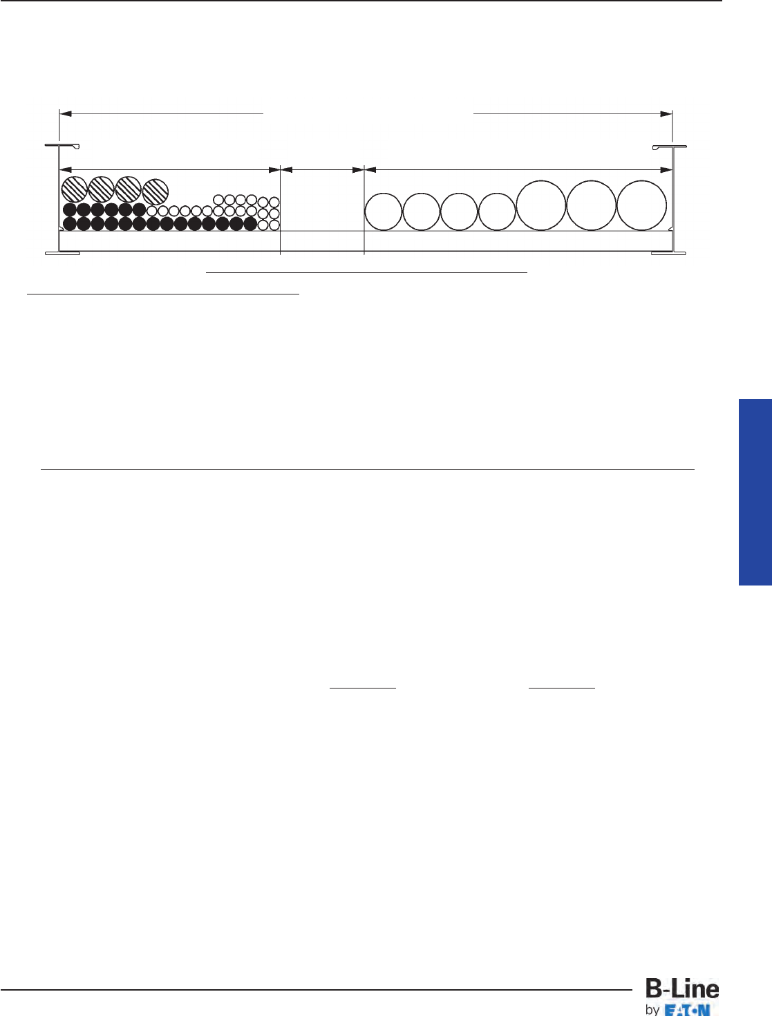
Example - NEC®Section 392.22(A)(1)(c)
Width selection for cable tray containing 600 volt multiconductor cables, sizes #4/0 AWG and larger
(single layer required) and #3/0 AWG and smaller. These two groups of cables must have dedicated
areas in the cable tray.
Cable tray width is obtained as follows:
A - Width required for #4/0 AWG and larger multiconductor cables -
(D) (N) Multiply (D) x (N)
Item List List Cable List Number Subtotal of the
Number Cable Sizes Outside of Cables Sum of the Cables
Diameter Diameters (Sd)
1. 3/C - #500 kcmil 2.26 inches 3 6.78 inches
2. 3/C - #4/0 AWG 1.55 inches 4 6.20 inches
Total cable tray width required for items 1 & 2 = 6.78 inches + 6.20 inches = 12.98 inches
B - Width required for #3/0 AWG and smaller multiconductor cables -
(A) (N) Multiply (A) x (N)
Item List List Cable List Number Total of the
Number Cable Sizes Cross Sectional of Cables Cross Sectional Area
Area For Each Item
3. 3/C #12 AWG 0.17 sq. in. 20 3.40 sq. in.
4. 3/C #10 AWG 0.20 sq. in. 20 4.00 sq. in.
5. 3/C #2 AWG 0.80 sq. in. 4 3.20 sq. in.
Total cable tray width required for items 3, 4, & 5
Actual cable tray width is A - Width (12.98 in.) + B - Width (9.09 in.) = 22.07 inches
A 24 inch wide cable tray is required. The 24 inch cable tray has the capacity for additional
future cables (1.93 inches or 2.25 sq. inches allowable fill can be used).
Notes:
1. This ratio is the inside width of the cable tray in inches divided by its maximum fill area in
sq. inches from Column 2 Table 392.22(A).
2. The cable sizes used in this example are a random selection.
3. Cables - copper conductors with cross linked polyethylene insulation and a PVC jacket.
4. Total cable weight per foot for this installation.
40.2 lbs./ft. (Cables in this example do not contain equipment grounding conductors.)
This load can be supported by a load symbol "A" cable tray - 50 lbs./ft.
24" Usable Cable Tray Width
9.09" 1.93" 12.98"
Cross Section Of The Cables And The Cable Tray
22 22 111
Appendix Sheet 5
(3.40 sq. in. + 4.00 sq. in. + 3.20 sq. in.) = (10.6 sq. in.) = 9.09 inches
( )
6 in.
7 sq. in. ( )
6 in.
7 sq. in.
1 1
Cable Tray Manual
MAN-45
Cable Tray Manual
Cable Tray Systems
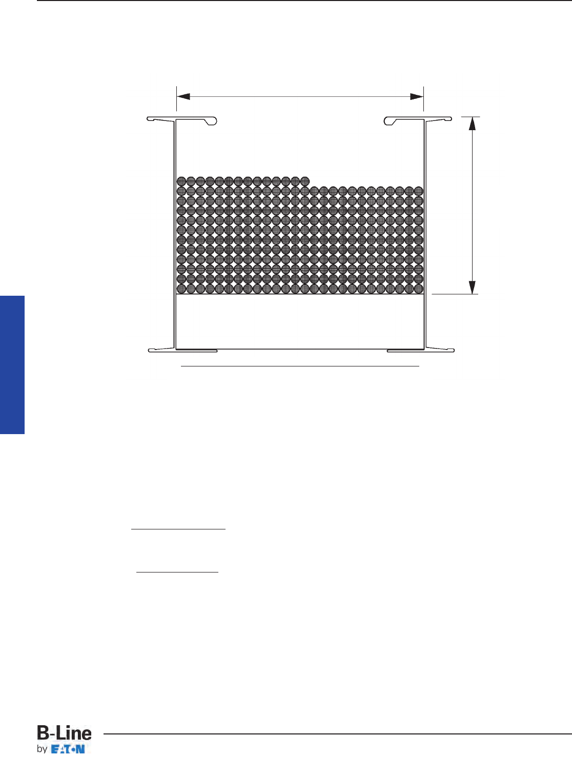
Appendix Sheet 6
Example - NEC®Section 392.22(A)(2)
Cable Tray containing Type ITC or Type PLTC Cables
50% of the cable tray useable cross sectional area can contain type PLTC cables
4 inches x 6 inches x .050 = 12 square inches allowable fill area.
2/C - #16 AWG 300 volt shielded instrumentation cable O.D. = 0.224 inches.
Cross Sectional Area = 0.04 square inches.
Notes:
1. The cable sizes used in this example are a random selection.
2. Cables - copper conductors with PVC insulation, aluminum/mylar shielding, and PVC jacket.
6" Usable Cable Tray Width
4" Usable
Cable Tray
Depth
Cross Section Of The Cables And The Cable Tray
= 300 cables can be installed in this cable tray.
12 sq. in.
0.04 sq. in./cable
= 11.54 rows can be installed in this cable tray.
300 cables
26 cables/rows
Cable Tray Manual
MAN-46
Cable Tray Manual
Cable Tray Systems

Appendix Sheet 7
Reproduced with permission from NFPA 70®-2011, National Electrical Code®, Copyright © 2010, National Fire Protection
Association, Quincy, MA. This reprinted material is not the complete and official position of the NFPA on the referenced
subject, which is represented only by the standard in its entirety.
Table 250.122. Minimum Size Equipment Grounding
Conductors for Grounding Raceways and Equipment
Rating or Setting of Size
Automatic Overcurrent (AWG or kcmil)
Device in Circuit Ahead
of Equipment, Conduit, Aluminum or
etc., Not Exceeding Copper-Clad
(Amperes) Copper Aluminum*
15 14 12
20 12 10
60 10 8
100 8 6
200 6 4
300 4 2
400 3 1
500 2 1/0
600 1 2/0
800 1/0 3/0
1000 2/0 4/0
1200 3/0 250
1600 4/0 350
2000 250 400
2500 350 600
3000 400 600
4000 500 750
5000 700 1200
6000 800 1200
Cable Tray Manual
MAN-47
Cable Tray Manual
Cable Tray Systems
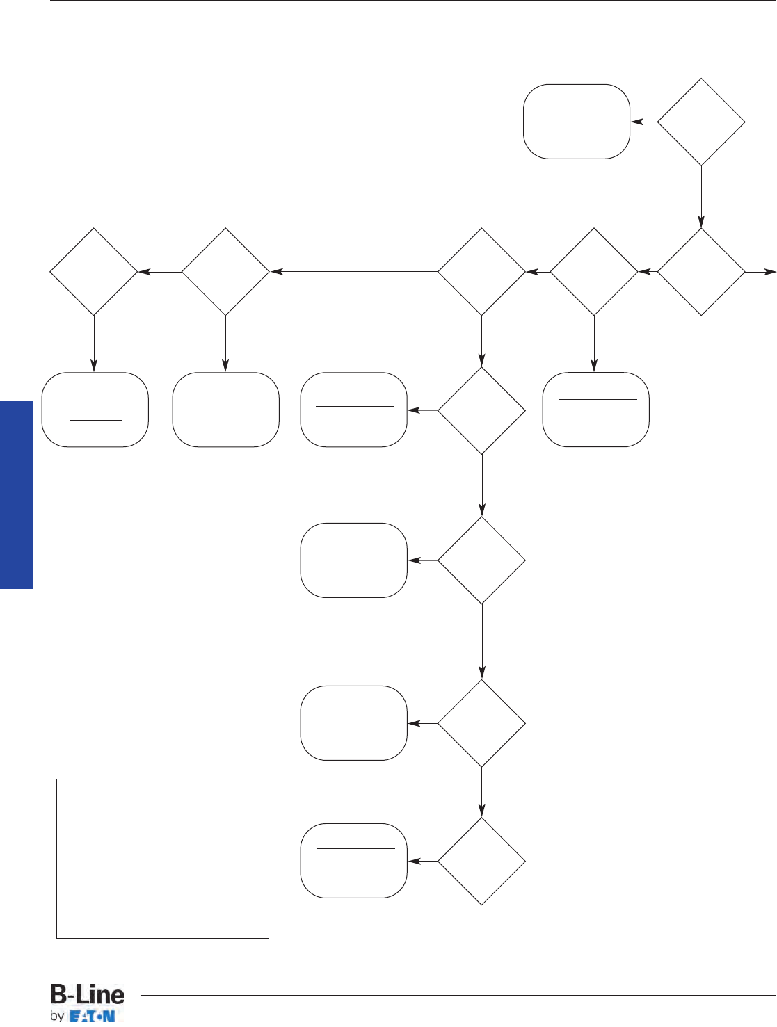
CABLE TRAY SIZING FLOWCHART
Appendix Sheet 8
392.22(C)
W ≥ Sd
(single layer)
392.10(B)(1)(a)
Not permitted
by the NEC®
See Exception
392.22(B)
392.22(B)(2)
W ≥ Sd
392.22(B)(1)(a)
W ≥ Sd
392.22(B)(1)(b)
W ≥ A/1.1
Note: The value “A”
only applies to cables
250 up to 1000kcmil.
The value “sd” only
applies to 1000 kcmil
and larger cables.
Note: Use when mixing
250 thru 1000 kcmil
cables with cables
larger than 1000 kcmil.
392.22(B)(1)(c)
392.22(B)(1)(d)
W ≥ Sd
(9” max. RS)
2000V
or less
cables
Multi-
conductor
cables
S/C 1/0
or larger
Ladder
or Vented
Trough
Tray
S/C
1000
kcmil or
larger
S/C
250
kcmil up
to 1000
kcmil
S/C
250 kcmil
and
larger
S/C 1/0
thru 4/0
Vented
Channel
Tray
Solid
Bottom
Tray
W ≥ A/1.1 +Sd
No
No
No
No
No No No
No
Yes
Yes
Yes
Yes
YesYes Yes
Yes
Yes
Continued
on next
page
Yes
Legend
W = Cable Tray Width
D = Cable Tray Load Depth
Sd = Sum of Cable Diameters
A = Sum of Cable Areas
S/C = Single Conductor
M/C = Multiconductor Cables
RS = Ladder Rung Spacing
Start
Here
Sizing Cable Tray Per NEC 392
Cable Tray Manual
MAN-48
Cable Tray Manual
Cable Tray Systems
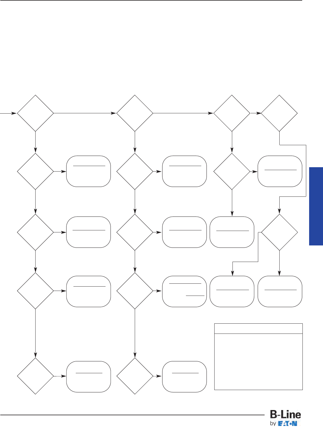
CABLE TRAY SIZING FLOWCHART
Appendix Sheet 8
392.22(A)(5)(a)
W x D ≥ 1.6A
392.22(A)(1)(a)
W ≥ Sd
(single layer)
392.22(A)(3)(a)
W ≥ Sd/0.9
(single layer)
Note: The value “A”
only applies to cables
smaller than 4/0.
The value “Sd” only
applies to 4/0 and
larger cables, which
must be single layer
Note: The value “A”
only applies to cables
smaller than 4/0.
The value “Sd” only
applies to 4/0 and
larger cables, which
must be single layer
392.22(A)(1)(c)
Vented
Channel
Tray
Solid
Channel
Tray
Solid
Bottom
Tray
Ladder
or Vented
Trough
Tray
One M/C
only
M/C 4/0
or larger
M/C 4/0
or larger
392.22(A)(5)(b)
W x D ≥ 2.9A
392.22(A)(6)(a)
W x D ≥ 1.9A
392.22(A)(6)(b)
W x D ≥ 3.2A
392.22(A)(1)(b)
W ≥ A/1.2
392.22(A)(3)(b)
W ≥ A/0.9
M/C
smaller
than 4/0
One
M/C
Only
M/C
smaller
than 4/0
M/C
smaller than
4/0, with
4/0 or
larger
M/C
control
and/or
signal
W ≥ A/1.2 + Sd
No NoNo
NoNo
NoNo
No No No
392.22(A)(2)
W x D ≥ 2A
392.22(A)(3)(c)
A + Sd
0.9
M/C
smaller than
4/0, with
4/0 or
larger
M/C
control
and/or
signal
W ≥
392.22(A)(4)
W x D ≥ 2.5A
YesYes
Yes NoYes
Yes
Yes
Yes
YesYes
Yes
Yes Yes Yes
Yes
Legend
W = Cable Tray Width
D = Cable Tray Load Depth
Sd = Sum of Cable Diameters
A = Sum of Cable Areas
S/C = Single Conductor
M/C = Multiconductor Cables
RS = Ladder Rung Spacing
Ampacity: See pages MAN-28 – MAN-30 for information on cable
ampacity that might affect the cable tray sizing flowchart.
See pages MAN-9 – MAN-12 for information on hazardous
(classified) areas that might affect the cable tray sizing
flowchart.
Cable Tray Manual
MAN-49
Cable Tray Manual
Cable Tray Systems

Material NEMA Load Depth*
Aluminum o 2” ** o
Pre-Galvanized Steel o 3” o
Hot-Dip Galvanized Steel o 4” o
304 Stainless Steel o 5” o
316 Stainless Steel o 6” o
Fiberglass-Polyester Resin o * Load depth is 1” less than siderail height.
Fiberglass-Vinyl Ester Resin o ** Fiberglass and wire mesh.
Fiberglass-Zero Halogen o
Fiberglass-Dis Stat o
Width Bottom Styles Length Fitting Radius
6” o 6” o Metallic 12” o
9” o 9” o 120” o 24” o
12” o 12” o 144” o 36” o
18” o 18” o 240” o 48” o
24” o Ventilated Trough o 288” o
30” o Non-Ventilated Trough o o
36” o Non-Ventilated Bottom o
Non-Metallic
42” o 120” o
240” o
Tray Series
System Loading
(50 lbs./ft.) o
(75 lbs./ft.) o
B-Line Series OR (100 lbs./ft.) o
o
Support Span ft.
Load Rating lbs./ft.
Safety Factor
CABLE TRAY INSTALLATION & SPECIFICATION CHECKLIST
Appendix Sheet 9
Project Information
Project Name: #
Location:
Contractor/Engineer:
Phone:
Project Information
Cable Tray
Distributor Name:
Location:
Contact:
Phone: Fax:
Cable Tray Manual
MAN-50
Cable Tray Manual
Cable Tray Systems
CABLE TRAY INSTALLATION & SPECIFICATION CHECKLIST
Material Width
Aluminum o 3” o
Pre-Galvanized Steel o 4” o
Hot-Dip Galvanized Steel o 6” o
304 Stainless Steel o 8” * o
316 Stainless Steel o * Fiberglass only.
Fiberglass-Polyester Resin o
Fiberglass-Vinyl Ester Resin o Fitting Radius
Fiberglass-Zero Halogen o 0” o
Fiberglass-Dis Stat o 6” o
Type 12” o
Ventilated o 24” o
Non-Ventilated o 36” o
Cable Channel
System Depth*
Data-Track o Straight Rung o
Verti-Rack o 2” o
Half-Rack o 3” o
Multi-Tier Half Rack o 4” o
6” o
Width* Rung Spacing* Tiers* Length
3” o 6” o 2 o 120” o
6” o 9” o 3 o 144” o
9” o 12” o 4 o
12” o 18” o 5 o
18” o 24” o 6 o
24” o
* Options shown are not available for all systems. Please check B-Line Cent-R-Rail Catalog for availability.
Cent-R-Rail
Width* Depth* Wire Mesh Size Length
2” o 1.5” o 2 x 4 118” (3 meters)
4” o 2” o
6” o 4” o
8” o 6” o
12” o * Widths shown are not available for all depths.
16” o
18” o
20” o
24” o
30” o
32” o
Flextray
Cable Tray Manual
Appendix Sheet 9
MAN-51
Cable Tray Manual
Cable Tray Systems

1 NEMA Standard VE-2, Section 4, Installation 4.3 Straight Section Installation - 4.3.1. Horizontal
Cable Tray Straight Sections states that straight section lengths should be equal to or greater than
the span length to ensure not more than one splice between supports.
Additional Cable Tray Resources
Cable Tray Institute National Electrical Manufacturers Association
1300 N. 17th Street 1300 N. 17th Street
Rosslyn, VA 22209 Rosslyn, VA 22209
www.cabletrays.com www.nema.org
B-Line Engineering Software
TrayCAD™
TrayCAD is a Cable Tray layout design program that works within the AutoCAD®
environment. TrayCAD is a windows based program and installs as an add-on to your
AutoCAD system. Use the TrayCAD toolbar to add cable tray to your existing plans by
drawing a single centerline representation of the tray run. Then, with the click of a button,
the program will build a full-scale 3-D wire-frame model of the cable tray and all the
appropriate fittings. The program also automatically creates a Bill of Material and contains a
library of modifiable details.
Runway Router™
Runway Router is a cable ladder runway (ladder rack) layout design program that works
within your AutoCAD environment. Use the commands from the Runway Router toolbar to
layout runway, relay racks and electronic cabinets. Add cable tray or CENT-R-RAIL™to your
existing plans by drawing a single centerline representation of the cable run. Then, with the
click of a button, the program will build a full-scale 3-D wire-frame model of the cable
runway and all the appropriate connectors and fittings. The program also automatically
creates a Bill of Material and contains a library of modifiable details.
Footnotes:
Cable Tray Manual
MAN-52
Cable Tray Manual
Cable Tray Systems
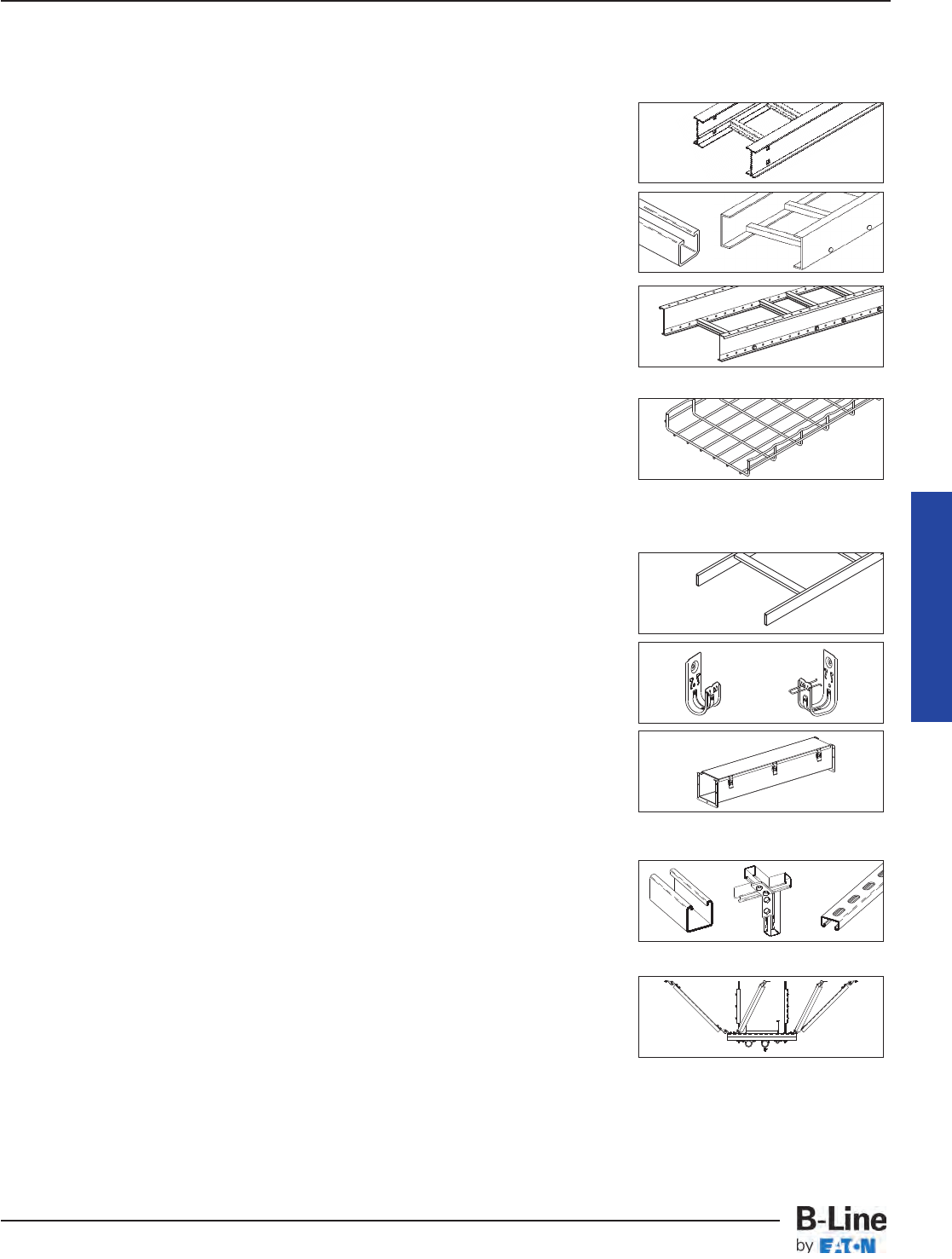
B-Line Wire Management Resources
B-Line Product Lines
• Cable Tray Systems . . . . . . . . . . . . . . . . . . . . . . . . . . . . . . . . . . . . . . . . . .
Metallic, Two Siderail System
Commercial and Industrial Applications
• Fiberglass Cable Tray . . . . . . . . . . . . . . . . . . . . . . . . . . . . . . . . . . . . . . . .
Non-Metallic, Two Siderail Trays
Non-Metallic Strut Systems
• REDI-RAIL™ . . . . . . . . . . . . . . . . . . . . . . . . . . . . . . . . . . . . . . . . . . . . . . . . . . .
Pre-Punched Aluminum Side Rail Design
Unmatched Job Site Adaptability for a Two
Side Rail System - Load Depths 2” to 6”
• FLEXTRAY™ . . . . . . . . . . . . . . . . . . . . . . . . . . . . . . . . . . . . . . . . . . . . . . . . . .
Unmatched Adaptability to Site Conditions
Pre-Packaged Installation Kits and Accessories
Fast - Adaptable - Economical
Other B-Line Wire Management Systems
• Telecom . . . . . . . . . . . . . . . . . . . . . . . . . . . . . . . . . . . . . . . . . . . . . . . . . . . . . . .
Cable Runway, Relay Racks, and
Unequal Flange Racks
• Cable Hooks . . . . . . . . . . . . . . . . . . . . . . . . . . . . . . . . . . . . . . . . . . . . . . . . .
Supports all Cat 5, Fiber Optic, Innerduct
and Low Voltage Cabling Requirements
• Wireway . . . . . . . . . . . . . . . . . . . . . . . . . . . . . . . . . . . . . . . . . . . . . . . . . . . . . .
Houses Runs of Control and Power Cable
Available in NEMA 12, Type 1 & Type 3R
B-Line Mechanical Support Systems
• Strut Systems . . . . . . . . . . . . . . . . . . . . . . . . . . . . . . . . . . . . . . . . . . . . . . . .
Metal Framing Support System. Fully Adjustable
and Reusable, with a Complete Line of Channel,
Fittings and Accessories for Multi-Purpose Applications
• Seismic Restraints . . . . . . . . . . . . . . . . . . . . . . . . . . . . . . . . . . . . . . . . . . .
Multi-Directional Bracing for Electrical Conduit,
Cable Tray and Mechanical Piping Systems.
OSHPD Pre-Approved Details
Cable Tray Manual
MAN-53
Cable Tray Manual
Cable Tray Systems
Prefix for REDI-RAIL™only
Example:
RSI 06A 09 SL - 12 - 120
Series Straight Ladder
Height/Material Width
Rung Spacing/Bottom Length
¨¬√ƒ≈
¨
¡
¬
√
ƒ
≈
¡
Prefix
Example: 148 * 12 - 24 - 144
Series Width
Material Length
Rung Spacing
¨¬√ ƒ
¨
¡
¬
√
ƒ
¡
Cable Tray Straight Sections
Index
Catalog No. Page
Catalog No. Page Catalog No. Page
Fiberglass Cable Tray
13F ¬-√-ƒ . . . . . . . . . . . . . .
FCT-21
13FA¬-√-ƒ . . . . . . . . . . . .
FCT-21
13FV¬-√-ƒ . . . . . . . . . . . . .
FCT-21
24F ¬-√-ƒ . . . . . . . . . . . . . .
FCT-22
24FA¬-√-ƒ . . . . . . . . . . . .
FCT-22
24FV¬-√-ƒ . . . . . . . . . . . . .
FCT-22
36F ¬-√-ƒ . . . . . . . . . . . . . .
FCT-23
36FA¬-√-ƒ . . . . . . . . . . . .
FCT-23
36FV¬-√-ƒ . . . . . . . . . . . . .
FCT-23
46F ¬-√-ƒ . . . . . . . . . . . . . .
FCT-24
46FA¬-√-ƒ . . . . . . . . . . . .
FCT-24
46FV¬-√-ƒ . . . . . . . . . . . . .
FCT-24
48F ¬-√-ƒ . . . . . . . . . . . . . .
FCT-26
48FA¬-√-ƒ . . . . . . . . . . . .
FCT-26
48FV¬-√-ƒ . . . . . . . . . . . . .
FCT-26
H46F ¬-√-ƒ . . . . . . . . . . . .
FCT-25
H46FA¬-√-ƒ . . . . . . . . . . .
FCT-25
H46FV¬-√-ƒ . . . . . . . . . . .
FCT-25
F = Polyester Resin
FA = Zero Halogen/Dis-Stat
FV = Vinyl Ester Resin
Series 2, 3, 4, & 5
Steel Cable Tray
248 G ¬-√-ƒ . . . .
HST-3 & HST-4
248 P ¬-√-ƒ . . . .
HST-3 & HST-4
258 G ¬-√-ƒ . . . .
HST-5 & HST-6
258 P ¬-√-ƒ . . . .
HST-5 & HST-6
268 G ¬-√-ƒ . . . .
HST-7 & HST-8
268 P ¬-√-ƒ . . . .
HST-7 & HST-8
346 G ¬-√-ƒ . . . .
HST-3 & HST-4
346 P ¬-√-ƒ . . . .
HST-3 & HST-4
356 G ¬-√-ƒ . . . .
HST-5 & HST-6
356 P ¬-√-ƒ . . . .
HST-5 & HST-6
366 G ¬-√-ƒ . . . .
HST-7 & HST-8
366 P ¬-√-ƒ . . . .
HST-7 & HST-8
378 G ¬-√-ƒ . . .
HST-9 & HST-10
378 P ¬-√-ƒ . . .
HST-9 & HST-10
444 G ¬-√-ƒ . . . .
HST-3 & HST-4
444 P ¬-√-ƒ . . . .
HST-3 & HST-4
454 G ¬-√-ƒ . . . .
HST-5 & HST-6
454 P ¬-√-ƒ . . . .
HST-5 & HST-6
464 G ¬-√-ƒ . . . .
HST-7 & HST-8
464 P ¬-√-ƒ . . . .
HST-7 & HST-8
476 G ¬-√-ƒ . . .
HST-9 & HST-10
476 P ¬-√-ƒ . . .
HST-9 & HST-10
574 G ¬-√-ƒ . . .
HST-9 & HST-10
574 P ¬-√-ƒ . . .
HST-9 & HST-10
G = Hot Dipped Galvanized Steel
P = Pre-Galvanized Steel
Series 2, 3, 4, & 5
Aluminum Cable Tray
24A ¬-√-ƒ . . . . . .
HAT-3 & HAT-4
25A ¬-√-ƒ . . . . . .
HAT-5 & HAT-6
26A ¬-√-ƒ . . . . . .
HAT-7 & HAT-8
34A ¬-√-ƒ . . . . . .
HAT-3 & HAT-4
35A ¬-√-ƒ . . . . . .
HAT-5 & HAT-6
36A ¬-√-ƒ . . . . . .
HAT-7 & HAT-8
37A ¬-√-ƒ . . . .
HAT-9 & HAT-10
46A ¬-√-ƒ . . . . . .
HAT-7 & HAT-8
47A ¬-√-ƒ . . . .
HAT-9 & HAT-10
57A ¬-√-ƒ . . . .
HAT-9 & HAT-10
H46A ¬-√-ƒ . . . .
HAT-7 & HAT-8
H47A ¬-√-ƒ . . .
HAT-9 & HAT-10
S8A ¬-√-ƒ . . . . . . . . . . . . .
HAT-11
A = Aluminum
REDI-RAIL™
Aluminum Cable Tray
RSI04A ¬SL -ƒ-≈ . . . . . . . .
RER-3
RSI05A ¬SL -ƒ-≈ . . . . . . . .
RER-3
RSI06A ¬SL -ƒ-≈ . . . . . . . .
RER-4
RSI07A ¬SL -ƒ-≈ . . . . . . . .
RER-4
A = Aluminum
Series 1
Steel Cable Tray
148 G ¬-√-ƒ . . . . . . . . . . . . .
LST-3
148 P ¬-√-ƒ . . . . . . . . . . . . .
LST-3
156 G ¬-√-ƒ . . . . . . . . . . . . .
LST-4
156 P ¬-√-ƒ . . . . . . . . . . . . .
LST-4
166 G ¬-√-ƒ . . . . . . . . . . . . .
LST-5
166 P ¬-√-ƒ . . . . . . . . . . . . .
LST-5
176 G ¬-√-ƒ . . . . . . . . . . . . .
LST-6
176 P ¬-√-ƒ . . . . . . . . . . . . .
LST-6
G = Hot Dipped Galvanized Steel
P = Pre-Galvanized Steel
Series 2, 3, 4, & 5
Stainless Steel Cable Tray
348SS4 ¬-√-ƒ . . . . . . . . . . .
SST-3
348SS6 ¬-√-ƒ . . . . . . . . . . .
SST-3
358SS4 ¬-√-ƒ . . . . . . . . . . .
SST-4
358SS6 ¬-√-ƒ . . . . . . . . . . .
SST-4
368SS4 ¬-√-ƒ . . . . . . . . . . .
SST-5
368SS6 ¬-√-ƒ . . . . . . . . . . .
SST-5
464SS4 ¬-√-ƒ . . . . . . . . . . .
SST-5
464SS6 ¬-√-ƒ . . . . . . . . . . .
SST-5
SS4 = Stainless Steel 304
SS6 = Stainless Steel 316
Catalog No. Page
IDX-1
Index - Straight Sections
Cable Tray Systems
Index
FLEXTRAY™
Catalog No. Page
Fiberglass Cable Channel
FCC-03 -ƒ . . . . . . . . . . . . . .
FCT-49
FCC-04 -ƒ . . . . . . . . . . . . . .
FCT-49
FCC-06 -ƒ . . . . . . . . . . . . . .
FCT-49
FCC-08 -ƒ . . . . . . . . . . . . . .
FCT-49
FCCA-03 -ƒ . . . . . . . . . . . . .
FCT-49
FCCA-04 -ƒ . . . . . . . . . . . . .
FCT-49
FCCA-06 -ƒ . . . . . . . . . . . . .
FCT-49
FCCA-08 -ƒ . . . . . . . . . . . . .
FCT-49
FCCAN-03 -ƒ . . . . . . . . . . .
FCT-49
FCCAN-04 -ƒ . . . . . . . . . . .
FCT-49
FCCAN-06 -ƒ . . . . . . . . . . .
FCT-49
FCCAN-08 -ƒ . . . . . . . . . . .
FCT-49
FCCN-03 -ƒ . . . . . . . . . . . . .
FCT-49
FCCN-04 -ƒ . . . . . . . . . . . . .
FCT-49
FCCN-06 -ƒ . . . . . . . . . . . . .
FCT-49
FCCN-08 -ƒ . . . . . . . . . . . . .
FCT-49
FCCV-03 -ƒ . . . . . . . . . . . . .
FCT-49
FCCV-04 -ƒ . . . . . . . . . . . . .
FCT-49
FCCV-06 -ƒ . . . . . . . . . . . . .
FCT-49
FCCV-08 -ƒ . . . . . . . . . . . . .
FCT-49
FCCVN-03 -ƒ . . . . . . . . . . .
FCT-49
FCCVN-04 -ƒ . . . . . . . . . . .
FCT-49
FCCVN-06 -ƒ . . . . . . . . . . .
FCT-49
FCCVN-08 -ƒ . . . . . . . . . . .
FCT-49
FCC = Polyester Resin
FCCA = Zero Halogen/Dis-Stat
FCCV = Vinyl Ester Resin
CC = Ventilated
CCN = Non-Ventilated
FLEXTRAY™Straight Sections
FT1.5X4X10 . . . . . . . . . . . . . . .
FLX-5
FT1.5X6X10 . . . . . . . . . . . . . . .
FLX-5
FT1.5X8X10 . . . . . . . . . . . . . . .
FLX-5
FT1.5X10X10 . . . . . . . . . . . . .
FLX-5
FT2X2X10 . . . . . . . . . . . . . . . .
FLX-5
FT2X4X10 . . . . . . . . . . . . . . . .
FLX-5
FT2X6X10 . . . . . . . . . . . . . . . .
FLX-5
FT2X8X10 . . . . . . . . . . . . . . . .
FLX-5
FT2X12X10 . . . . . . . . . . . . . . .
FLX-5
FT2X16X10 . . . . . . . . . . . . . . .
FLX-5
FT2X18X10 . . . . . . . . . . . . . . .
FLX-5
FT2X20X10 . . . . . . . . . . . . . . .
FLX-5
FT2X24X10 . . . . . . . . . . . . . . .
FLX-5
FT2X30X10 . . . . . . . . . . . . . . .
FLX-5
FT2X22X10 . . . . . . . . . . . . . . .
FLX-5
FT4X4X10 . . . . . . . . . . . . . . . .
FLX-6
FT4X6X10 . . . . . . . . . . . . . . . .
FLX-6
FT4X8X10 . . . . . . . . . . . . . . . .
FLX-6
FT4X12X10 . . . . . . . . . . . . . . .
FLX-6
FT4X16X10 . . . . . . . . . . . . . . .
FLX-6
FT4X18X10 . . . . . . . . . . . . . . .
FLX-6
FT4X20X10 . . . . . . . . . . . . . . .
FLX-6
FT4X24X10 . . . . . . . . . . . . . . .
FLX-6
FT4X30X10 . . . . . . . . . . . . . . .
FLX-6
FT6X8X10 . . . . . . . . . . . . . . . .
FLX-6
FT6X12X10 . . . . . . . . . . . . . . .
FLX-6
FT6X16X10 . . . . . . . . . . . . . . .
FLX-6
FT6X18X10 . . . . . . . . . . . . . . .
FLX-6
FT6X20X10 . . . . . . . . . . . . . . .
FLX-6
FT6X24X10 . . . . . . . . . . . . . . .
FLX-6
Catalog No. Page
Prefix
Example: A CC - 06 - 144
Material Width
Series Length
¨¬√
¨
¡
¬
√
Cable Channel Straight Sections
¡
Prefix
Example: FT 2X12 X 10
Flextray Width
loading Height Length 118”
¡¬√
¨
¡
¬
√
¨
Catalog No. Page
Aluminum Cable Channel
ACC -¬-√ . . . . . . . . . . . . . . .
CCT-3
ACCN -¬-√ . . . . . . . . . . . . . .
CCT-3
A = Aluminum
CC = Ventilated
CCN = Non-Ventilated
Steel Cable Channel
GCC -¬-√ . . . . . . . . . . . . . . .
CCT-3
GCCN -¬-√ . . . . . . . . . . . . . .
CCT-3
PCC -¬-√ . . . . . . . . . . . . . . .
CCT-3
PCCN -¬-√ . . . . . . . . . . . . . .
CCT-3
G = Hot Dipped Galvanized
P = Pre-Galvanized
CC = Ventilated
CCN = Non-Ventilated
Stainless Steel Cable Channel
SS4CC -¬-√ . . . . . . . . . . . . .
CCT-3
SS4CCN -¬-√ . . . . . . . . . . .
CCT-3
SS6CC -¬-√ . . . . . . . . . . . . .
CCT-3
SS6CCN -¬-√ . . . . . . . . . . .
CCT-3
SS4 = Stainless Steel 304
SS6 = Stainless Steel 316
CC = Ventilated
CCN = Non-Ventilated
IDX-2
Index - Straight Sections
Cable Tray Systems
Index
IDX-3
Index - Straight Sections
Cable Tray Systems
Catalog No. Page
Series 1
Steel Cable Tray Fittings
14G ¬-√VBS ∆ . . . . . . . . . .
LST-23
1(†)G ¬-√-ƒHB ∆ . . . . . . .
LST-16
1(†)G ¬-√HT ∆ . . . . . . . . . .
LST-17
1(†)G ¬-√HX ∆ . . . . . . . . . .
LST-17
1(†)G ¬-√LR ∆ . . . . . . . . . .
LST-18
1(†)G ¬-√RR ∆ . . . . . . . . . .
LST-18
1(†)G ¬-√SR ∆ . . . . . . . . . .
LST-18
1(†)G ¬-√-ƒVI ∆ . . .
LST-19
– 22
1(†)G ¬-√-ƒVO ∆ . .
LST-19
– 22
14P ¬-√VBS ∆ . . . . . . . . . .
LST-23
1(†)P ¬-√-ƒHB ∆ . . . . . . .
LST-16
1(†)P ¬-√HT ∆ . . . . . . . . . .
LST-17
1(†)P ¬-√HX ∆ . . . . . . . . . .
LST-17
1(†)P ¬-√LR ∆ . . . . . . . . . . .
LST-18
1(†)P ¬-√RR ∆ . . . . . . . . . .
LST-18
1(†)P ¬-√SR ∆ . . . . . . . . . .
LST-18
1(†)P ¬-√-ƒVI ∆ . . .
LST-19
– 22
1(†)P ¬-√-ƒVO ∆ . .
LST-19
– 22
G = Hot-Dipped Galvanized Steel
P = Pre-Galvanized Steel
(†) = Insert 4 for 4”, 5 for 5”, 6 for 6”
or 7 for 7” side rail heights
Series 2, 3, 4, & 5
Steel Cable Tray Fittings
(†)G ¬-√CFS ∆ . . . . . . . . . .
FTS-17
(†)G ¬-√-ƒHB ∆ . . . . .
FTS-4 & 5
(†)G ¬-√HT ∆ . . . . . .
FTS-6, 8 & 9
(†)G ¬-√HX ∆ . . . . . . .
FTS-6 & 10
(†)G ¬-√HYL . . . . . . . . . . . .
FTS-11
(†)G ¬-√HYR . . . . . . . . . . .
FTS-11
(†)G ¬-√LR ∆ . . . . . . . . . . . .
FTS-7
(†)G ¬-√RR ∆ . . . . . . . . . . . .
FTS-7
(†)G ¬-√SR ∆ . . . . . . . . . . . .
FTS-7
(†)G ¬-√-ƒVI ∆ . . . .
FTS-12 – 15
(†)G ¬-√-ƒVO ∆ . . .
FTS-12 – 15
(†)G ¬-√VT ∆ . . . . . . . . . . .
FTS-16
(†)G ¬-√VTU ∆ . . . . . . . . . .
FTS-16
(†)P ¬-√CFS ∆ . . . . . . . . . .
FTS-17
(†)P ¬-√-ƒHB ∆ . . . . . .
FTS-4 & 5
(†)P ¬-√HT ∆ . . . . . . .
FTS-6, 8 & 9
(†)P ¬-√HX ∆ . . . . . . . .
FTS-6 & 10
(†)P ¬-√HYL . . . . . . . . . . . .
FTS-11
(†)P ¬-√HYR . . . . . . . . . . . .
FTS-11
continued in next column
(†)P ¬-√LR ∆ . . . . . . . . . . . . .
FTS-7
(†)P ¬-√RR ∆ . . . . . . . . . . . .
FTS-7
(†)P ¬-√SR ∆ . . . . . . . . . . . .
FTS-7
(†)P ¬-√-ƒVI ∆ . . . . .
FTS-12 – 15
(†)P ¬-√-ƒVO ∆ . . . .
FTS-12 – 15
(†)P ¬-√VT ∆ . . . . . . . . . . . .
FTS-16
(†)P ¬-√VTU ∆ . . . . . . . . . .
FTS-16
G = Hot-Dipped Galvanized Steel
P = Pre-Galvanized Steel
(†) = Insert 4 for 4”, 5 for 5”, 6 for 6”
or 7 for 7” side rail heights
Series 2, 3, 4, & 5
Stainless Steel Cable Tray Fittings
(†)SS4 ¬-√CFS ∆ . . . . . . .
FTS-17
(†)SS4 ¬-√-ƒHB ∆ . . .
FTS-4 & 5
(†)SS4 ¬-√HT ∆ . . . .
FTS-6, 8 & 9
(†)SS4 ¬-√HX ∆ . . . . .
FTS-6 & 10
(†)SS4 ¬-√HYL . . . . . . . . .
FTS-11
(†)SS4 ¬-√HYR . . . . . . . . .
FTS-11
(†)SS4 ¬-√LR ∆ . . . . . . . . . .
FTS-7
(†)SS4 ¬-√RR ∆ . . . . . . . . . .
FTS-7
(†)SS4 ¬-√SR ∆ . . . . . . . . . .
FTS-7
(†)SS4 ¬-√-ƒVI ∆ . .
FTS-12 – 15
(†)SS4 ¬-√-ƒVO ∆ .
FTS-12 – 15
(†)SS4 ¬-√VT ∆ . . . . . . . . .
FTS-16
(†)SS4 ¬-√VTU ∆ . . . . . . .
FTS-16
(†)SS6 ¬-√CFS ∆ . . . . . . .
FTS-17
(†)SS6 ¬-√-ƒHB ∆ . . .
FTS-4 & 5
(†)SS6 ¬-√HT ∆ . . . .
FTS-6, 8 & 9
(†)SS6 ¬-√HX ∆ . . . . .
FTS-6 & 10
(†)SS6 ¬-√HYL . . . . . . . . .
FTS-11
(†)SS6 ¬-√HYR . . . . . . . . .
FTS-11
(†)SS6 ¬-√LR ∆ . . . . . . . . . .
FTS-7
(†)SS6 ¬-√RR ∆ . . . . . . . . . .
FTS-7
(†)SS6 ¬-√SR ∆ . . . . . . . . . .
FTS-7
(†)SS6 ¬-√-ƒVI ∆ . .
FTS-12 – 15
(†)SS6 ¬-√-ƒVO ∆ .
FTS-12 – 15
(†)SS6 ¬-√VT ∆ . . . . . . . . .
FTS-16
(†)SS6 ¬-√VTU ∆ . . . . . . .
FTS-16
SS4 = Stainless Steel 304
SS6 = Stainless Steel 316
(†) = Insert 4 for 4”, 5 for 5”, 6 for 6”
or 7 for 7” side rail heights
Catalog No. Page
Catalog No. Page
REDI-RAIL™
Aluminum Cable Tray Fittings
RSI(†)A09HB-ƒ-≈-∆ . . . . . . .
RER-20
RSI(†)A09HT-ƒ-∆ . . . . . .
RER-21 – 23
RSI(†)A09HX-ƒ-∆ . . . . .
RER-21 & 24
RSI(†)A09VI-ƒ-≈-∆ . . . . . .
RER-25 – 28
RSI(†)A09VO-ƒ-≈-∆ . . . . .
RER-25 – 28
RSI(†)A09VTD-ƒ-∆ . . . . . . . . . RER-29
RSI(†)A09VTU-ƒ-∆ . . . . . . . . . RER-29
(†) = Insert 04 for 4”, 05 for 5”, 06 for 6”
or 07 for 7” side rail heights
Series 2, 3, 4, & 5
Aluminum Cable Tray Fittings
(†)A ¬-√CFS ∆ . . . . . . . . . .
FTS-17
(†)A ¬-√-ƒHB ∆ . . . . . .
FTS-4 & 5
(†)A ¬-√HT ∆ . . . . . . .
FTS-6, 8 & 9
(†)A ¬-√HX ∆ . . . . . . . .
FTS-6 & 10
(†)A ¬-√HYL . . . . . . . . . . . .
FTS-11
(†)A ¬-√HYR . . . . . . . . . . . .
FTS-11
(†)A ¬-√LR ∆ . . . . . . . . . . . . .
FTS-7
(†)A ¬-√RR ∆ . . . . . . . . . . . .
FTS-7
(†)A ¬-√SR ∆ . . . . . . . . . . . .
FTS-7
(†)A ¬-√-ƒVI ∆ . . . . .
FTS-12 – 15
(†)A ¬-√-ƒVO ∆ . . . .
FTS-12 – 15
(†)A ¬-√VT ∆ . . . . . . . . . . . .
FTS-16
(†)A ¬-√VTU ∆ . . . . . . . . . .
FTS-16
A = Aluminum
(†) = Insert 4 for 4”, 5 for 5”, 6 for 6”
or 7 for 7” side rail heights
Cable Tray Fittings
Prefix for REDI-RAIL™only
Example:
RSI 04 A09 HB - 09 - 30 R12
Series Fitting Type
Height Width
Material/Rung Spacing Angle (HB, VI, VO)
¨¬√ ƒ
¨
¡
¬
√
ƒ
≈
¡≈
∆Radius
∆
Catalog No. Page
Prefix
Example: 4 * x - 24 - 90 HB 24
Series/Height Width
Material Angle (HB, VI, VO)
Bottom Type
¨¬√ ƒ
¨
¡
¬
√
ƒ
≈
¡≈
∆
∆
Index
IDX-4
Index - Fittings
Cable Tray Systems
Catalog No. Page
Steel Cable Channel Fittings
GCC -¬-√HB ≈ . . . . CCT-9 & 10
GCC -¬-√HC ≈ . . . . . . . . . CCT-7
GCC -¬HT ≈ . . . . . . . . . . . CCT-11
GCC -¬HTC ≈ . . . . . . . . . . . CCT-7
GCC -¬HX ≈ . . . . . . . . . . . CCT-11
GCC -¬HXC ≈ . . . . . . . . . . . CCT-7
GCC -¬PC ≈ . . . . . . . . . . . . CCT-7
GCC -¬-√VC ≈ . . . . . . . . . CCT-7
GCC -¬-√VI ≈ . . . . CCT-14 & 15
GCC -¬-√VO ≈ . . CCT-12 & 13
GCCN -¬-√HB ≈ . . CCT-9 & 10
GCCN -¬HT ≈ . . . . . . . . . CCT-11
GCCN -¬HX ≈ . . . . . . . . . CCT-11
GCCN -¬-√VI ≈ . . CCT-14 & 15
GCCN -¬-√VO ≈ . CCT-12 & 13
G = Hot-Dipped Galvanized Steel
Note: Not available in Pre-Galvanized
Catalog No. Page
Stainless Steel Cable Channel Fittings
SS4CC -¬-√HB ≈ . CCT-9 & 10
SS4CC -¬HT ≈ . . . . . . . . . CCT-11
SS4CC -¬HX ≈ . . . . . . . . CCT-11
SS4CC-¬-√VI≈ . . CCT-14 & 15
SS4CC-¬-√VO≈ . . CCT-12 & 13
SS4CCN -¬-√HB≈ . CCT-9 & 10
SS4CCN -¬HT ≈ . . . . . . . CCT-11
SS4CCN -¬HX ≈ . . . . . . . CCT-11
SS4CCN-¬-√VI≈
. . . CCT-14 & 15
SS4CCN-¬-√VO≈
. . CCT-12 & 13
SS6CC -¬-√HB ≈ . CCT-9 & 10
SS6CC -¬HT ≈ . . . . . . . . . CCT-11
SS6CC -¬HX ≈ . . . . . . . . CCT-11
SS6CC-¬-√VI≈ . . CCT-14 & 15
SS6CC-¬-√VO≈ . . CCT-12 & 13
SS6CCN -¬-√HB≈ . CCT-9 & 10
SS6CCN -¬HT ≈ . . . . . . . CCT-11
SS6CCN -¬HX ≈ . . . . . . . CCT-11
SS6CCN-¬-√VI≈
. . . CCT-14 & 15
SS6CCN-¬-√VO≈
. . CCT-12 & 13
SS4 = Stainless Steel 304
SS6 = Stainless Steel 316
Fiberglass Cable Channel Fittings
FCC(†)N-(xx)-45HB12 . . . FCT-49
FCC(†)N-(xx)-90HB12 . . . FCT-49
FCC(†)N-(xx)-HT12 . . . . . . FCT-50
FCC(†)N-(xx)-HX12 . . . . . . FCT-50
FCC(†)N-(xx)-45VI12 . . . . FCT-49
FCC(†)N-(xx)-45VO12 . . . FCT-49
FCC(†)N-(xx)-90VI12 . . . . FCT-49
FCC(†)N-(xx)-90VO12 . . . FCT-49
(†) For Polyester Resin leave blank
FA = Zero Halogen/Dis-Stat
For Vinyl Ester Resin insert V
(xx) = Insert 03 for 3”, 04 for 4”,
06 for 6” or 08 for 8” side rail heights
Catalog No. Page
Cable Tray Fittings Cable Channel Fittings
Prefix
Example: 4 * x - 24 - 90 HB 24
Series/Height Width
Material Angle (HB, VI, VO)
Bottom Type
¨¬√ ƒ
¨
¡
¬
√
ƒ
≈
¡≈
∆
∆
Prefix
Example: G CC - 04 - 45 VI 12
Material Angle
Series Type (HB, VI, VO)
Width Radius
¨¬√ƒ
¨
¡
¬
√
ƒ
≈
¡≈
Aluminum Cable Channel Fittings
ACC -¬-√HB ≈ . . . . CCT-9 & 10
ACC -¬-√HC ≈ . . . . . . . . . CCT-7
ACC -¬HT ≈ . . . . . . . . . . . CCT-11
ACC -¬HTC ≈ . . . . . . . . . . . CCT-7
ACC -¬HX ≈ . . . . . . . . . . . CCT-11
ACC -¬HXC ≈ . . . . . . . . . . . CCT-7
ACC -¬PC ≈ . . . . . . . . . . . . CCT-7
ACC -¬-√VC ≈ . . . . . . . . . CCT-7
ACC -¬-√VI ≈ . . . . CCT-14 & 15
ACC -¬-√VO ≈ . . . CCT-12 & 13
ACCN -¬-√HB ≈ . . CCT-9 & 10
ACCN -¬HT ≈ . . . . . . . . . . CCT-11
ACCN -¬HX ≈ . . . . . . . . . . CCT-11
ACCN -¬-√VI ≈ . . . CCT-14 & 15
ACCN -¬-√VO ≈ . CCT-12 & 13
A = Aluminum
Fiberglass Cable Tray Fittings
(†)F -√-ƒHB ∆ . . . . .
FCT-28 & 29
(†)F -√-HT ∆ . . . . .
FCT-30, 33 – 36
(†)F -√-HX ∆ . . . .
FCT-31, 37 & 38
(†)F -√-LR ∆ . . . . . . . . . . . . .
FCT-32
(†)F -√-RR ∆ . . . . . . . . . . . .
FCT-32
(†)F -√-SR ∆ . . . . . . . . . . . .
FCT-32
(†)F -√-ƒVI ∆ . . . . . . .
FCT-39 – 42
(†)F -√-ƒVO ∆ . . . . . .
FCT-39 – 42
(†)F -√-VT ∆ . . . . . . . .
FCT-43 & 44
(†)F -√-VTU ∆ . . . . . .
FCT-43 & 44
(†)FA -√-ƒHB ∆ . . . .
FCT-28 & 29
(†)FA -√-HT ∆ . . .
FCT-30, 33 – 36
(†)FA -√-HX ∆ . . .
FCT-31, 37 & 38
(†)FA -√-LR ∆ . . . . . . . . . . .
FCT-32
(†)FA -√-RR ∆ . . . . . . . . . . .
FCT-32
(†)FA -√-SR ∆ . . . . . . . . . . .
FCT-32
(†)FA -√-ƒVI ∆ . . . . .
FCT-39 – 42
(†)FA -√-ƒVO ∆ . . . .
FCT-39 – 42
(†)FA -√-VT ∆ . . . . . . .
FCT-43 & 44
(†)FA -√-VTU ∆ . . . . .
FCT-43 & 44
(†)FV -√-ƒHB ∆ . . . .
FCT-28 & 29
(†)FV -√-HT ∆ . . .
FCT-30, 33 – 36
(†)FV -√-HX ∆ . . .
FCT-31, 37 & 38
(†)FV -√-LR ∆ . . . . . . . . . . .
FCT-32
(†)FV -√-RR ∆ . . . . . . . . . . .
FCT-32
(†)FV -√-SR ∆ . . . . . . . . . . .
FCT-32
(†)FV -√-ƒVI ∆ . . . . .
FCT-39 – 42
(†)FV -√-ƒVO ∆ . . . .
FCT-39 – 42
(†)FV -√-VT ∆ . . . . . . .
FCT-43 & 44
(†)FV -√-VTU ∆ . . . . .
FCT-43 & 44
F = Polyester Resin,
FA = Zero Halogen/Dis-Stat
FV = Vinyl Ester Resin
(†) = Insert 3 for 3”, 4 for 4”, 6 for 6”
or 8 for 8” side rail heights
Index
IDX-5
Index - Covers
Cable Tray Systems
Cable Tray Covers
Catalog No. Page
Catalog No. Page Catalog No. Page
Prefix
Example: 867 A 40 SL - 12 - 72
Series Straight Ladder
Material Width
Thickness Length
¨¬√ ≈
ƒ
¨
¡
¬
√
ƒ
≈
¡
Catalog No. Page
Prefix
Example: 801 * 20 - 24 - 144
Series Width
Material Length or
Thickness Fitting Type
¨¬√ ƒ
¨
¡
¬
√
ƒ
¡
Series 2, 3, 4, & 5
Aluminum Cable Tray Covers
806 A 40 -√-ƒ . . . . . . . . . . HAT-22
807 A 40 -√-ƒ . . . . . . . . . . HAT-22
816 A 40 -√-ƒ . . . . . . . . . . HAT-22
817 A 40 -√-ƒ . . . . . . . . . . HAT-22
826 A 40 -√-ƒ . . . . . . . . . . HAT-22
827 A 40 -√-ƒ . . . . . . . . . . HAT-22
A = Aluminum
Contact B-Line Engineering
for fitting cover information.
See page HAT-22 for fitting cover examples.
REDI-RAIL™
Aluminum Cable Tray Covers
867A 40SL -ƒ-≈ . . . . . . . . RER-11
877A 40SL -ƒ-≈ . . . . . . . . RER-11
A = Aluminum
Contact B-Line Engineering
for fitting cover information.
See page RER-11 for fitting cover examples.
Series 1
Steel Cable Tray Covers
801 G 18 -√-ƒ . . . . . . . . . . LST-13
801 P 20 -√-ƒ . . . . . . . . . . . LST-13
809 G 18 -√-ƒ . . . . . . . . . . LST-13
809 P 20 -√-ƒ . . . . . . . . . . . LST-13
811 G 18 -√-ƒ . . . . . . . . . . LST-13
811 P 20 -√-ƒ . . . . . . . . . . . LST-13
819 G 18 -√-ƒ . . . . . . . . . . LST-13
819 P 20 -√-ƒ . . . . . . . . . . . LST-13
G = Hot Dipped Galvanized Steel
P = Pre-Galvanized Steel
Contact B-Line Engineering
for fitting cover information.
See page LST-13 for fitting cover examples.
Series 2, 3, 4, & 5
Steel Cable Tray Covers
802 G 18 -√-ƒ . . . . . . . . . . HST-20
802 P 20 -√-ƒ . . . . . . . . . . HST-20
803 G 18 -√-ƒ . . . . . . . . . . HST-20
803 P 20 -√-ƒ . . . . . . . . . . HST-20
804 G 18 -√-ƒ . . . . . . . . . . HST-20
804 P 20 -√-ƒ . . . . . . . . . . HST-20
812 G 18 -√-ƒ . . . . . . . . . . HST-20
812 P 20 -√-ƒ . . . . . . . . . . HST-20
813 G 18 -√-ƒ . . . . . . . . . . HST-20
813 P 20 -√-ƒ . . . . . . . . . . HST-20
814 G 18 -√-ƒ . . . . . . . . . . HST-20
814 P 20 -√-ƒ . . . . . . . . . . HST-20
822 G 18 -√-ƒ . . . . . . . . . . HST-20
822 P 20 -√-ƒ . . . . . . . . . . HST-20
823 G 18 -√-ƒ . . . . . . . . . . HST-20
823 P 20 -√-ƒ . . . . . . . . . . HST-20
824 G 18 -√-ƒ . . . . . . . . . . HST-20
824 P 20 -√-ƒ . . . . . . . . . . HST-20
G = Hot Dipped Galvanized Steel
P = Pre-Galvanized Steel
Contact B-Line Engineering
for fitting cover information.
See page HST-20 for fitting cover examples.
Series 2, 3, 4, & 5
Stainless Steel Cable Tray Covers
802 SS4 20 -√-ƒ . . . . . . . . SST-12
802 SS6 20 -√-ƒ . . . . . . . . SST-12
803 SS4 20 -√-ƒ . . . . . . . . SST-12
803 SS6 20 -√-ƒ . . . . . . . . SST-12
804 SS4 20 -√-ƒ . . . . . . . . SST-12
804 SS6 20 -√-ƒ . . . . . . . . SST-12
812 SS4 20 -√-ƒ . . . . . . . . SST-12
812 SS6 20 -√-ƒ . . . . . . . . SST-12
813 SS4 20 -√-ƒ . . . . . . . . SST-12
813 SS6 20 -√-ƒ . . . . . . . . SST-12
814 SS4 20 -√-ƒ . . . . . . . . SST-12
814 SS6 20 -√-ƒ . . . . . . . . SST-12
822 SS4 20 -√-ƒ . . . . . . . . SST-12
822 SS6 20 -√-ƒ . . . . . . . . SST-12
823 SS4 20 -√-ƒ . . . . . . . . SST-12
823 SS6 20 -√-ƒ . . . . . . . . SST-12
824 SS4 20 -√-ƒ . . . . . . . . SST-12
824 SS6 20 -√-ƒ . . . . . . . . SST-12
SS4 = Stainless Steel 304
SS6 = Stainless Steel 316
Contact B-Line Engineering
for fitting cover information.
See page SST-12 for fitting cover examples.
Fiberglass Cable Tray Covers
F-C -√-ƒ . . . . . . . . . . . . . . . FCT-45
FA-C -√-ƒ . . . . . . . . . . . . . . FCT-45
FAP-C -√-ƒ . . . . . . . . . . . . FCT-45
FP-C -√-ƒ . . . . . . . . . . . . . . FCT-45
FV-C -√-ƒ . . . . . . . . . . . . . . FCT-45
FVP-C -√-ƒ . . . . . . . . . . . . FCT-45
F = Polyester Resin
FA = Zero Halogen/Dis-Stat
FV = Vinyl Ester Resin
C = Cover
Covers are flat unless a P is added to
part number P = Peaked
Contact B-Line Engineering
for fitting cover information.
Index
IDX-6
Index - Covers
Cable Tray Systems
Catalog No. Page
Catalog No. Page
Prefix
Example: 808 * 20 - 04 - 120
Series Width
Material Length or
Thickness Fitting Type
¨¬√ ƒ
¨
¡
¬
√
ƒ
¡
Aluminum
Cable Channel Covers
808 A 40 -√-ƒ . . . . . . . . . . . CCT-6
A = Aluminum
Contact B-Line Engineering
for fitting cover information.
See page CCT-6 for fitting cover examples.
2 IN COVER . . . . . . . . . . . . . FLX-40
4 IN COVER . . . . . . . . . . . . . FLX-40
6 IN COVER . . . . . . . . . . . . . FLX-40
8 IN COVER . . . . . . . . . . . . . FLX-40
12 IN COVER . . . . . . . . . . . . FLX-40
16 IN COVER . . . . . . . . . . . . FLX-40
18 IN COVER . . . . . . . . . . . . FLX-40
20 IN COVER . . . . . . . . . . . . FLX-40
24 IN COVER . . . . . . . . . . . . FLX-40
Steel
Cable Channel Covers
808 G 18 -√-ƒ . . . . . . . . . . . CCT-6
808 P 20 -√-ƒ . . . . . . . . . . . CCT-6
G = Hot Dipped Galvanized Steel
P = Pre-Galvanized Steel
Contact B-Line Engineering
for fitting cover information.
See page CCT-6 for fitting cover examples.
Stainless Steel
Cable Channel Covers
808 SS4 20 -√-ƒ . . . . . . . . . CCT-6
808 SS6 20 -√-ƒ . . . . . . . . . CCT-6
SS4 = Stainless Steel 304
SS6 = Stainless Steel 316
Contact B-Line Engineering
for fitting cover information.
See page CCT-6 for fitting cover examples.
Cable Channel Covers
FLEXTRAY™Covers
Index
IDX-7
Index - Accessories
Cable Tray Systems
Aluminum REDI-RAIL™ Cable Tray Accessories
Not all accessories for Redi-Rail cable tray are aluminum only. Those finishes and part numbers will be listed in this section.
Catalog No. PageCatalog No. Page Catalog No. Page
REDI-RAIL™Tray Accessories
99-30 . . . . . . . . . . . . . . . . . . . . RER-6
9A-9012 . . . . . . . . . . . . . . . . RER-11
9A-R06RK . . . . . . . . . . . . . . RER-12
9A-R06SBERK . . . . . . . . . . RER-12
9A-R09RK . . . . . . . . . . . . . . RER-12
9A-R09SBERK . . . . . . . . . . RER-12
9A-R12RK . . . . . . . . . . . . . . RER-12
9A-R12SBERK . . . . . . . . . . RER-12
9A-R18RK . . . . . . . . . . . . . . RER-12
9A-R18SBERK . . . . . . . . . . RER-12
9A-R24RK . . . . . . . . . . . . . . RER-12
9A-R24SBERK . . . . . . . . . . RER-12
9A-R30RK . . . . . . . . . . . . . . RER-12
9A-R30SBERK . . . . . . . . . . RER-12
9A-R36RK . . . . . . . . . . . . . . RER-12
9A-R36SBERK . . . . . . . . . . RER-12
9A-RBC . . . . . . . . . . . . . . . . RER-12
9A-RFM-12RK . . . . . . . . . . RER-15
9A-RFM-24RK . . . . . . . . . . RER-15
9A-RFM-36RK . . . . . . . . . . RER-15
9A-SR0406 . . . . . . . . . . . . . RER-12
9A-SR0409 . . . . . . . . . . . . . RER-12
9A-SR0506 . . . . . . . . . . . . . RER-12
9A-SR0509 . . . . . . . . . . . . . RER-12
9G-1158 Series . . . . . . . . . . RER-6
9G-5500-1/2 . . . . . . . . . . . . . RER-7
9G-55XX-22SHA Series . . RER-7
9GRN-55XX-22SHA Series
RER-7
9P-55XX-22SH Series . . . . RER-7
9SS-R238 . . . . . . . . . . . . . . . . RER-6
9SS-R250 . . . . . . . . . . . . . . . . RER-6
9SS4-1241 . . . . . . . . . . . . . . . RER-9
9SS4-1242 . . . . . . . . . . . . . . . RER-9
9SS6-1241 . . . . . . . . . . . . . . . RER-9
9SS6-1242 . . . . . . . . . . . . . . . RER-9
9ZN-1204 . . . . . . . . . . . . . . . . RER-6
9ZN-1204NB . . . . . . . . . . . . . RER-6
9ZN-1241 . . . . . . . . . . . . . . . . RER-9
9ZN-1242 . . . . . . . . . . . . . . . . RER-9
9ZN-5212 . . . . . . . . . . . . . . . . RER-8
9ZN-5224 . . . . . . . . . . . . . . . . RER-8
9ZN-5500-1/2 . . . . . . . . . . . . RER-7
9ZN-9012 . . . . . . . . . . . . . . . RER-11
9ZN-LV1-1 . . . . . . . . . . . . . . RER-10
9ZN-LV1A-1 . . . . . . . . . . . . RER-10
9ZN-MB1-4 . . . . . . . . . . . . . RER-10
9ZN-MB1-5 . . . . . . . . . . . . . RER-10
9ZN-R238 . . . . . . . . . . . . . . . RER-6
9ZN-R250 . . . . . . . . . . . . . . . RER-6
B297 Series . . . . . . . . . . . . . . RER-9
R5A-VSP . . . . . . . . . . . . . . . . RER-5
R6A-ASP . . . . . . . . . . . . . . . . RER-5
R6A-CP . . . . . . . . . . . . . . . . RER-13
R6A-DHB-Length . . . . . . . RER-14
R6A-DSL-Length . . . . . . . RER-14
R6A-DVI-R (radius) . . . . . . RER-14
R6A-DVO-R (radius) . . . . RER-14
R6A-END Series . . . . . . . . . RER-6
R6A-ESP . . . . . . . . . . . . . . . . RER-5
R6A-FSP . . . . . . . . . . . . . . . . . RER-5
R6A-FTB Series . . . . . . . . . . RER-6
R6A-HDDC Series . . . . . . RER-11
R6A-RSP-CR . . . . . . . . . . . . RER-5
R6A-RSP-SR . . . . . . . . . . . . RER-5
R6A-SBUF . . . . . . . . . . . . . . RER-13
R6A-SSP . . . . . . . . . . . . . . . . RER-5
R6A-TTB . . . . . . . . . . . . . . . . . RER-6
R6A-UF . . . . . . . . . . . . . . . . . RER-13
R6A-VSP . . . . . . . . . . . . . . . . RER-5
R7A-ASP . . . . . . . . . . . . . . . . RER-5
R7A-CP . . . . . . . . . . . . . . . . RER-13
R7A-DHB-Length . . . . . . . RER-14
R7A-DSL-Length . . . . . . . RER-14
R7A-DVI-R (radius) . . . . . . RER-14
R7A-DVO-R (radius) . . . . RER-14
R7A-END Series . . . . . . . . . RER-6
R7A-ESP . . . . . . . . . . . . . . . . RER-5
R7A-FSP . . . . . . . . . . . . . . . . . RER-5
R7A-FTB Series . . . . . . . . . . RER-6
R7A-HDDC Series . . . . . . RER-11
R7A-RSP-CR . . . . . . . . . . . . RER-5
R7A-RSP-SR . . . . . . . . . . . . RER-5
R7A-SBUF . . . . . . . . . . . . . . RER-13
R7A-SSP . . . . . . . . . . . . . . . . RER-5
R7A-TTB . . . . . . . . . . . . . . . . . RER-5
R7A-UF . . . . . . . . . . . . . . . . . RER-13
R7A-VSP . . . . . . . . . . . . . . . . RER-5
RAA-OUT Series . . . . . . . . . RER-6
RRA-DSP-45 . . . . . . . . . . . . . RER-5
RRA-DSP-46 . . . . . . . . . . . . . RER-5
RRA-DSP-47 . . . . . . . . . . . . . RER-5
RRA-DSP-56 . . . . . . . . . . . . . RER-5
RRA-DSP-57 . . . . . . . . . . . . . RER-5
RRA-DSP-67 . . . . . . . . . . . . . RER-5
A = Aluminum
G = Hot-Dipped Galvanized
SS = Stainless Steel 304
ZN = Zinc Plated
B409 Series . . . . . . . . . . . . . . RER-9
B409UF-12 & 21 . . . . . . . . . RER-9
B494 Series . . . . . . . . . . . . . . RER-8
BAX-4-16 . . . . . . . . . . . . . . . RER-10
BAX-4-16-24 . . . . . . . . . . . RER-10
BAX-4-16-32 . . . . . . . . . . . RER-10
BAX-4-16-48 . . . . . . . . . . . RER-10
BL1400 . . . . . . . . . . . . . . . . . . RER-6
BL1410 . . . . . . . . . . . . . . . . . . RER-6
BL1420 . . . . . . . . . . . . . . . . . . RER-6
BL1430 . . . . . . . . . . . . . . . . . . RER-6
DB10-28 . . . . . . . . . . . . . . . . . RER-7
DB10-36 . . . . . . . . . . . . . . . . . RER-7
DB10-42 . . . . . . . . . . . . . . . . . RER-7
DB10-50 . . . . . . . . . . . . . . . . . RER-7
DB10-60 . . . . . . . . . . . . . . . . . RER-7
R4A-ASP . . . . . . . . . . . . . . . . RER-5
R4A-CP . . . . . . . . . . . . . . . . RER-13
R4A-DHB-Length . . . . . . . RER-14
R4A-DSL-Length . . . . . . . RER-14
R4A-DVI-R (radius) . . . . . . RER-14
R4A-DVO-R (radius) . . . . RER-14
R4A-END Series . . . . . . . . . RER-6
R4A-ESP . . . . . . . . . . . . . . . . RER-5
R4A-FSP . . . . . . . . . . . . . . . . . RER-5
R4A-FTB Series . . . . . . . . . . RER-6
R4A-HDDC Series . . . . . . RER-11
R4A-RSP-CR . . . . . . . . . . . . RER-5
R4A-RSP-SR . . . . . . . . . . . . RER-5
R4A-SBUF . . . . . . . . . . . . . . RER-13
R4A-SSP . . . . . . . . . . . . . . . . RER-5
R4A-TTB . . . . . . . . . . . . . . . . . RER-5
R4A-UF . . . . . . . . . . . . . . . . . RER-13
R4A-VSP . . . . . . . . . . . . . . . . RER-5
R5A-ASP . . . . . . . . . . . . . . . . RER-5
R5A-CP . . . . . . . . . . . . . . . . RER-13
R5A-DHB-Length . . . . . . . RER-14
R5A-DSL-Length . . . . . . . RER-14
R5A-DVI-R (radius) . . . . . . RER-14
R5A-DVO-R (radius) . . . . RER-14
R5A-END Series . . . . . . . . . RER-6
R5A-ESP . . . . . . . . . . . . . . . . RER-5
R5A-FSP . . . . . . . . . . . . . . . . . RER-5
R5A-FTB Series . . . . . . . . . . RER-6
R5A-HDDC Series . . . . . . RER-11
R5A-RSP-CR . . . . . . . . . . . . RER-5
R5A-RSP-SR . . . . . . . . . . . . RER-5
R5A-SBUF . . . . . . . . . . . . . . RER-13
R5A-SSP . . . . . . . . . . . . . . . . RER-5
R5A-TTB . . . . . . . . . . . . . . . . . RER-5
R5A-UF . . . . . . . . . . . . . . . . . RER-13
Index
IDX-8
Index - Accessories
Cable Tray Systems
Series 2, 3, 4, & 5 Aluminum Cable Tray Accessories
Not all accessories for aluminum cable tray are aluminum only. Those finishes and part numbers will be listed in this section.
Catalog No. PageCatalog No. Page Catalog No. Page
Aluminum Tray Accessories
73A-Length . . . . . . . . . . . . . HAT-15
73A-90HBFL . . . . . . . . . . . . HAT-15
73A-(angle)VI(radius) . . . . HAT-15
73A-(angle)VO(radius) . . . HAT-15
74A-Length . . . . . . . . . . . . . HAT-15
74A-90HBFL . . . . . . . . . . . . HAT-15
74A-(angle)VI(radius) . . . . HAT-15
74A-(angle)VO(radius) . . . HAT-15
75A-Length . . . . . . . . . . . . . HAT-15
75A-90HBFL . . . . . . . . . . . . HAT-15
75A-(angle)VI(radius) . . . . HAT-15
75A-(angle)VO(radius) . . . HAT-15
76A-Length . . . . . . . . . . . . . HAT-15
76A-90HBFL . . . . . . . . . . . . HAT-15
76A-(angle)VI(radius) . . . . HAT-15
76A-(angle)VO(radius) . . . HAT-15
99-40 . . . . . . . . . . . . . . . . . . . HAT-16
99-1124 . . . . . . . . . . . . . . . . HAT-15
99-1620 . . . . . . . . . . . . . . . . HAT-16
99-2125-15 . . . . . . . . . . . . . HAT-14
99-9980-tray width . . . . . . HAT-23
99-9982 . . . . . . . . . . . . . . . . HAT-16
99-N1 . . . . . . . . . . . . . . . . . . HAT-16
99-NP300 . . . . . . . . . . . . . . . HAT-17
99-PE34 . . . . . . . . . . . . . . . . HAT-17
99-PE36 . . . . . . . . . . . . . . . . HAT-17
9A-RBC . . . . . . . . . . . . . . . . HAT-15
9A-tray width-9P44 . . . . . . APP-4
9A-tray width-9P54 . . . . . . APP-4
9A-tray width-9P64 . . . . . . APP-4
9A-tray width-9P74 . . . . . . APP-4
9A-tray width-9044 . . . . . HAT-23
9A-tray width-9044P . . . . HAT-23
9A-tray width-9054 . . . . . HAT-23
9A-tray width-9054P . . . . HAT-23
9A-tray width-9064 . . . . . HAT-23
9A-tray width-9064P . . . . HAT-23
9A-tray width-9074 . . . . . HAT-23
9A-tray width-9074P . . . . HAT-23
9A-1004 . . . . . . . . . . . . . . . . HAT-13
9A-1004-1/2 . . . . . . . . . . . . . HAT-13
9A-1005 . . . . . . . . . . . . . . . . HAT-13
9A-1005-1/2 . . . . . . . . . . . . . HAT-13
9A-1006 . . . . . . . . . . . . . . . . HAT-13
9A-1006-1/2 . . . . . . . . . . . . . HAT-13
9A-1007 . . . . . . . . . . . . . . . . HAT-13
9A-1007-1/2 . . . . . . . . . . . . . HAT-13
9A-1014 . . . . . . . . . . . . . . . . HAT-13
9A-1015 . . . . . . . . . . . . . . . . HAT-13
9A-2046 . . . . . . . . . . . . . . . . HAT-13
9A-2047 . . . . . . . . . . . . . . . . HAT-13
9A-2130 . . . . . . . . . . . . . . . . HAT-16
9A-6006 . . . . . . . . . . . . . . . . HAT-13
9A-6007 . . . . . . . . . . . . . . . . HAT-13
9A-6016 . . . . . . . . . . . . . . . . . APP-3
9A-6017 . . . . . . . . . . . . . . . . . APP-3
9A-9012 . . . . . . . . . . . . . . . . HAT-23
9A-9043 . . . . . . . . . . . . . . . . HAT-23
9A-9053 . . . . . . . . . . . . . . . . HAT-23
9A-9063 . . . . . . . . . . . . . . . . HAT-23
9A-9073 . . . . . . . . . . . . . . . . HAT-23
9G-1158 Series . . . . . . . . . HAT-14
9G-1205 . . . . . . . . . . . . . . . . HAT-17
9G-1249 . . . . . . . . . . . . . . . . HAT-17
9G-1249HD . . . . . . . . . . . . . HAT-17
9G-5324 . . . . . . . . . . . . . . . . HAT-16
9G-5325 . . . . . . . . . . . . . . . . HAT-16
9G-5326 . . . . . . . . . . . . . . . . HAT-16
9G-5327 . . . . . . . . . . . . . . . . HAT-16
9G-5500-1/2 . . . . . . . . . . . . HAT-18
9G-55xx-22SHA Series . HAT-18
9GRN-55xx-22SHA Series
HAT-18
9P-55xx-22SH Series . . . HAT-18
9SS4-1241 . . . . . . . . . . . . . HAT-20
9SS4-1242 . . . . . . . . . . . . . HAT-20
9SS4-2351 . . . . . . . . . . . . . HAT-16
9SS4-2352 . . . . . . . . . . . . . HAT-16
9SS6-1205 . . . . . . . . . . . . . HAT-17
9SS6-1241 . . . . . . . . . . . . . HAT-20
9SS6-1242 . . . . . . . . . . . . . HAT-20
9ZN-1150 Series . . . . . . . . HAT-14
9ZN-1155 Series . . . . . . . . HAT-14
9ZN-1204 . . . . . . . . . . . . . . . HAT-17
9ZN-1204NB . . . . . . . . . . . HAT-17
9ZN-1205 . . . . . . . . . . . . . . . HAT-17
9ZN-1208 . . . . . . . . . . . . . . . HAT-17
9ZN-1208NB . . . . . . . . . . . HAT-17
9ZN-1241 . . . . . . . . . . . . . . . HAT-20
9ZN-1242 . . . . . . . . . . . . . . . HAT-20
9ZN-1249 . . . . . . . . . . . . . . . HAT-17
9ZN-1249HD . . . . . . . . . . . HAT-17
9ZN-2351 . . . . . . . . . . . . . . . HAT-16
9ZN-2352 . . . . . . . . . . . . . . . HAT-16
9ZN-5200 . . . . . . . . . . . . . . . HAT-19
9ZN-5212 . . . . . . . . . . . . . . . HAT-19
9ZN-5224 . . . . . . . . . . . . . . . HAT-19
9ZN-5324 . . . . . . . . . . . . . . . HAT-16
9ZN-5325 . . . . . . . . . . . . . . . HAT-16
continued on next page
9A-1016 . . . . . . . . . . . . . . . . HAT-13
9A-1017 . . . . . . . . . . . . . . . . HAT-13
9A-1024 . . . . . . . . . . . . . . . . HAT-13
9A-1025 . . . . . . . . . . . . . . . . HAT-13
9A-1026 . . . . . . . . . . . . . . . . HAT-13
9A-1027 . . . . . . . . . . . . . . . . HAT-13
9A-1034 . . . . . . . . . . . . . . . . HAT-13
9A-1034-12 . . . . . . . . . . . . . HAT-13
9A-1034-36 . . . . . . . . . . . . . HAT-13
9A-1035 . . . . . . . . . . . . . . . . HAT-13
9A-1035-12 . . . . . . . . . . . . . HAT-13
9A-1035-36 . . . . . . . . . . . . . HAT-13
9A-1036 . . . . . . . . . . . . . . . . HAT-13
9A-1036-12 . . . . . . . . . . . . . HAT-13
9A-1036-36 . . . . . . . . . . . . . HAT-13
9A-1037 . . . . . . . . . . . . . . . . HAT-13
9A-1037-12 . . . . . . . . . . . . . HAT-13
9A-1037-36 . . . . . . . . . . . . . HAT-13
9A-1045 . . . . . . . . . . . . . . . . HAT-13
9A-1046 . . . . . . . . . . . . . . . . HAT-13
9A-1047 . . . . . . . . . . . . . . . . HAT-13
9A-1054 . . . . . . . . . . . . . . . . HAT-14
9A-1055 . . . . . . . . . . . . . . . . HAT-14
9A-1056 . . . . . . . . . . . . . . . . HAT-14
9A-1057 . . . . . . . . . . . . . . . . HAT-14
9A-1060 . . . . . . . . . . . . . . . . HAT-13
9A-1061 . . . . . . . . . . . . . . . . HAT-13
9A-1062 . . . . . . . . . . . . . . . . HAT-13
9A-1064-reduction . . . . . . HAT-14
9A-1065-reduction . . . . . . HAT-14
9A-1066-reduction . . . . . . HAT-14
9A-1067-reduction . . . . . . HAT-14
9A-1074-tray width . . . . . HAT-14
9A-1075-tray width . . . . . HAT-14
9A-1076-tray width . . . . . HAT-14
9A-1077-tray width . . . . . HAT-14
9A-1084-tray width . . . . . HAT-14
9A-1085-tray width . . . . . HAT-14
9A-1086-tray width . . . . . HAT-14
9A-1087-tray width . . . . . HAT-14
9A-1104-tray width . . . . . HAT-15
9A-1104T-tray width . . . . HAT-15
9A-1205 . . . . . . . . . . . . . . . . HAT-17
9A-1224 . . . . . . . . . . . . . . . . HAT-20
9A-1225 . . . . . . . . . . . . . . . . HAT-20
9A-1226 . . . . . . . . . . . . . . . . HAT-20
9A-1227 . . . . . . . . . . . . . . . . HAT-20
9A-1240 . . . . . . . . . . . . . . . . HAT-14
9A-2044 . . . . . . . . . . . . . . . . HAT-13
9A-2045 . . . . . . . . . . . . . . . . HAT-13
Index
IDX-9
Index - Accessories
Cable Tray Systems
Aluminum Cable Tray Accessories
Series 1 Steel Cable Tray Accessories
Not all accessories for steel cable tray are steel only.
Those finishes and part numbers will be listed in this section.
Catalog No. Page
Catalog No. Page
Catalog No. Page
9ZN-5326 . . . . . . . . . . . . . . . HAT-16
9ZN-5327 . . . . . . . . . . . . . . . HAT-16
9ZN-5500-1/2 . . . . . . . . . . . HAT-18
9ZN-9012 . . . . . . . . . . . . . . . HAT-23
9ZN-9112 Series . . . . . . . . HAT-23
9ZN-9113 Series . . . . . . . . HAT-23
ATR Series . . . . . . . . . . . . . . HAT-16
B212-1/4or 3/8 . . . . . . . . . . HAT-21
B297 Series . . . . . . . . . . . . . HAT-20
B305-B308 . . . . . . . . . . . . . HAT-21
B312 Series . . . . . . . . . . . . . HAT-21
B321 Series . . . . . . . . . . . . . HAT-21
B355 . . . . . . . . . . . . . . . . . . . HAT-21
B409 Series . . . . . . . . . . . . . HAT-20
B409UF-12 or 21 . . . . . . . HAT-20
B441-22 . . . . . . . . . . . . . . . . HAT-21
B441-22A . . . . . . . . . . . . . . . HAT-21
B494 Series . . . . . . . . . . . . . HAT-19
B501 Series . . . . . . . . . . . . . HAT-20
B655-3/8 . . . . . . . . . . . . . . . . HAT-16
B655-1/2 . . . . . . . . . . . . . . . . HAT-16
B700-Jx Series . . . . . . . . . HAT-21
B750-Jx Series . . . . . . . . . HAT-21
BP081SS . . . . . . . . . . . . . . . HAT-16
BP110SS . . . . . . . . . . . . . . . HAT-16
BP135SS . . . . . . . . . . . . . . . HAT-16
BP175SS . . . . . . . . . . . . . . . HAT-16
BP205SS . . . . . . . . . . . . . . . HAT-16
BP250SS . . . . . . . . . . . . . . . HAT-16
BP300SS . . . . . . . . . . . . . . . HAT-16
BP325SS . . . . . . . . . . . . . . . HAT-16
BP375SS . . . . . . . . . . . . . . . HAT-16
BP425SS . . . . . . . . . . . . . . . HAT-16
BP475SS . . . . . . . . . . . . . . . HAT-16
DB10-28 . . . . . . . . . . . . . . . . HAT-18
DB10-36 . . . . . . . . . . . . . . . . HAT-18
DB10-42 . . . . . . . . . . . . . . . . HAT-18
DB10-50 . . . . . . . . . . . . . . . . HAT-18
DB10-60 . . . . . . . . . . . . . . . . HAT-18
SFHN 3/8”-16 . . . . . . . . . . . HAT-14
SNCB 3/8” x 3/4” . . . . . . . . HAT-14
A = Aluminum
G = Hot-Dipped Galvanized
GRN = Dura-Green Painted
P = Pre-Galvanized Steel
SS = Stainless Steel 304
SS4 = Stainless Steel 304
SS6 = Stainless Steel 316
ZN = Zinc Plated
9G-4006 . . . . . . . . . . . . . . . . . . LST-7
9G-4007 . . . . . . . . . . . . . . . . . . LST-7
9G-4014 . . . . . . . . . . . . . . . . . . LST-7
9G-4015 . . . . . . . . . . . . . . . . . . LST-7
9G-4016 . . . . . . . . . . . . . . . . . . LST-7
9G-4017 . . . . . . . . . . . . . . . . . . LST-7
9G-7024 . . . . . . . . . . . . . . . . . . LST-7
9G-8004 . . . . . . . . . . . . . . . . . . LST-7
9G-8024 . . . . . . . . . . . . . . . . . . LST-7
9G-8025 . . . . . . . . . . . . . . . . . . LST-7
9G-8026 . . . . . . . . . . . . . . . . . . LST-7
9G-8034 . . . . . . . . . . . . . . . . . . LST-7
9G-8034-12 . . . . . . . . . . . . . . LST-7
9G-8034-36 . . . . . . . . . . . . . . LST-7
9G-8035 . . . . . . . . . . . . . . . . . . LST-7
9G-8035-12 . . . . . . . . . . . . . . LST-7
9G-8035-36 . . . . . . . . . . . . . . LST-7
9G-8036 . . . . . . . . . . . . . . . . . . LST-7
9G-8036-12 . . . . . . . . . . . . . . LST-7
9G-8036-36 . . . . . . . . . . . . . . LST-7
9G-8045 . . . . . . . . . . . . . . . . . . LST-7
9G-8046 . . . . . . . . . . . . . . . . . . LST-7
9G-8054 . . . . . . . . . . . . . . . . . . LST-8
9G-8055 . . . . . . . . . . . . . . . . . . LST-8
9G-8056 . . . . . . . . . . . . . . . . . . LST-8
9G-8060 . . . . . . . . . . . . . . . . . . LST-7
9G-8064-reduction . . . . . . . LST-8
9G-8065-reduction . . . . . . . LST-8
9G-8066-reduction . . . . . . . LST-8
9G-8074-tray width . . . . . . . LST-8
9G-8075-tray width . . . . . . . LST-8
9G-8076-tray width . . . . . . . LST-8
9G-8084-tray width . . . . . . . LST-8
9G-8085-tray width . . . . . . . LST-8
9G-8086-tray width . . . . . . . LST-8
9G-8244 . . . . . . . . . . . . . . . . . . LST-7
9G-8245 . . . . . . . . . . . . . . . . . . LST-7
9G-8246 . . . . . . . . . . . . . . . . . . LST-7
9G-9014 . . . . . . . . . . . . . . . . LST-13
9G-9015 . . . . . . . . . . . . . . . . LST-13
9G-9016 . . . . . . . . . . . . . . . . LST-13
9G-9019 . . . . . . . . . . . . . . . . LST-13
9G-tray width-9040 . . . . . LST-13
9G-9043 . . . . . . . . . . . . . . . . LST-13
9G-tray width-9044 . . . . . LST-13
9G-9053 . . . . . . . . . . . . . . . . LST-13
continued on next page
Series 1 Steel
Cable Tray Accessories
72G-Length . . . . . . . . . . . . . LST-10
72G-90HBFL . . . . . . . . . . . . LST-10
72G-(angle)VI(radius) . . . . LST-10
72G-(angle)VO(radius) . . . LST-10
72P-Length . . . . . . . . . . . . . LST-10
72P-90HBFL . . . . . . . . . . . . LST-10
72P-(angle)VI(radius) . . . . LST-10
72P-(angle)VO(radius) . . . LST-10
737G-Length . . . . . . . . . . . . LST-10
737G-90HBFL . . . . . . . . . . . LST-10
737G-(angle)VI(radius) . . . LST-10
737G-(angle)VO(radius) . . LST-10
737P-Length . . . . . . . . . . . . LST-10
737P-90HBFL . . . . . . . . . . . LST-10
737P-(angle)VI(radius) . . . LST-10
737P-(angle)VO(radius) . . LST-10
747G-Length . . . . . . . . . . . . LST-10
747G-90HBFL . . . . . . . . . . . LST-10
747G-(angle)VI(radius) . . . LST-10
747G-(angle)VO(radius) . . LST-10
747P-Length . . . . . . . . . . . . LST-10
747P-90HBFL . . . . . . . . . . . LST-10
747P-(angle)VI(radius) . . . LST-10
747P-(angle)VO(radius) . . LST-10
757G-Length . . . . . . . . . . . . LST-10
757G-90HBFL . . . . . . . . . . . LST-10
757G-(angle)VI(radius) . . . LST-10
757G-(angle)VO(radius) . . LST-10
757P-Length . . . . . . . . . . . . LST-10
757P-90HBFL . . . . . . . . . . . LST-10
757P-(angle)VI(radius) . . . LST-10
757P-(angle)VO(radius) . . LST-10
99-2125-15 . . . . . . . . . . . . . . . LST-8
99-9980 . . . . . . . . . . . . . . . . . LST-13
99-9982 . . . . . . . . . . . . . . . . . LST-10
99-N1 . . . . . . . . . . . . . . . . . . . . LST-9
9A-2130 . . . . . . . . . . . . . . . . . . LST-9
9G-1104T-tray width . . . . LST-10
9G-1158 Series . . . . . . . . . . . LST-8
9G-2004-1/2 . . . . . . . . . . . . . . LST-7
9G-2005-1/2 . . . . . . . . . . . . . . LST-7
9G-2006-1/2 . . . . . . . . . . . . . . LST-7
9G-2007-1/2 . . . . . . . . . . . . . . LST-7
9G-4004 . . . . . . . . . . . . . . . . . . LST-7
9G-4005 . . . . . . . . . . . . . . . . . . LST-7
Index
IDX-10
Index - Accessories
Cable Tray Systems
Catalog No. PageCatalog No. Page Catalog No. Page
Series 1 Steel Cable Tray Accessories
Not all accessories for steel cable tray are steel only. Those finishes and part numbers will be listed in this section.
B305-B308 . . . . . . . . . . . . . . LST-12
B312 Series . . . . . . . . . . . . . LST-12
B321 Series . . . . . . . . . . . . . LST-12
B351L Series . . . . . . . . . . . . LST-12
B409 Series . . . . . . . . . . . . . LST-11
B409UF-Series . . . . . . . . . . LST-12
B441-22 Series . . . . . . . . . . LST-12
B441-22A Series . . . . . . . . LST-12
B494 Series . . . . . . . . . . . . . LST-12
B655 Series . . . . . . . . . . . . . . LST-9
B701-Jx Series . . . . . . . . . . LST-12
B751-Jx Series . . . . . . . . . . LST-12
B752 . . . . . . . . . . . . . . . . . . . . LST-12
B753 Series . . . . . . . . . . . . . LST-12
RNCB 3/8”-16 x 3/4” . . . . . . LST-8
SFHN 3/8”-16 . . . . . . . . . . . . . LST-8
A = Aluminum
G = Hot-Dipped Galvanized
P = Pre-Galvanized Steel
SS4 = Stainless Steel 304
ZN = Zinc Plated
9ZN-5109-WB . . . . . . . . . . . . LST-9
9ZN-5112 . . . . . . . . . . . . . . . . LST-9
9ZN-5112-WB . . . . . . . . . . . . LST-9
9ZN-5118 . . . . . . . . . . . . . . . . LST-9
9ZN-5118-WB . . . . . . . . . . . . LST-9
9ZN-5124 . . . . . . . . . . . . . . . . LST-9
9ZN-5124-WB . . . . . . . . . . . . LST-9
9ZN-5324 . . . . . . . . . . . . . . . . LST-9
9ZN-5325 . . . . . . . . . . . . . . . . LST-9
9ZN-5326 . . . . . . . . . . . . . . . . LST-9
9ZN-7024 . . . . . . . . . . . . . . . . LST-7
9ZN-8004 . . . . . . . . . . . . . . . . LST-7
9ZN-8024 . . . . . . . . . . . . . . . . LST-7
9ZN-8025 . . . . . . . . . . . . . . . . LST-7
9ZN-8026 . . . . . . . . . . . . . . . . LST-7
9ZN-8034 . . . . . . . . . . . . . . . . LST-7
9ZN-8034-12 . . . . . . . . . . . . . LST-7
9ZN-8034-36 . . . . . . . . . . . . . LST-7
9ZN-8035 . . . . . . . . . . . . . . . . LST-7
9ZN-8035-12 . . . . . . . . . . . . . LST-7
9ZN-8035-36 . . . . . . . . . . . . . LST-7
9ZN-8036 . . . . . . . . . . . . . . . . LST-7
9ZN-8036-12 . . . . . . . . . . . . . LST-7
9ZN-8036-36 . . . . . . . . . . . . . LST-7
9ZN-8045 . . . . . . . . . . . . . . . . LST-7
9ZN-8046 . . . . . . . . . . . . . . . . LST-7
9ZN-8060 . . . . . . . . . . . . . . . . LST-7
9ZN-8074-tray width . . . . . LST-8
9ZN-8075-tray width . . . . . LST-8
9ZN-8076-tray width . . . . . LST-8
9ZN-8244 . . . . . . . . . . . . . . . . LST-7
9ZN-8245 . . . . . . . . . . . . . . . . LST-7
9ZN-8246 . . . . . . . . . . . . . . . . LST-7
9ZN-9014 . . . . . . . . . . . . . . . LST-13
9ZN-9015 . . . . . . . . . . . . . . . LST-13
9ZN-9016 . . . . . . . . . . . . . . . LST-13
9ZN-9019 . . . . . . . . . . . . . . . LST-13
9ZN-9101 . . . . . . . . . . . . . . . LST-13
9ZN-9102 . . . . . . . . . . . . . . . LST-13
9ZN-9103 . . . . . . . . . . . . . . . LST-13
9ZN-9104 . . . . . . . . . . . . . . . LST-13
9ZN-9243 . . . . . . . . . . . . . . . LST-13
ATR Series . . . . . . . . . . . . . . . LST-9
B210 . . . . . . . . . . . . . . . . . . . . LST-12
B210A . . . . . . . . . . . . . . . . . . LST-12
B212 Series . . . . . . . . . . . . . LST-12
B297 Series . . . . . . . . . . . . . LST-11
9G-tray width-9054 . . . . . LST-13
9G-9063 . . . . . . . . . . . . . . . . LST-13
9G-tray width-9064 . . . . . LST-13
9G-9243 . . . . . . . . . . . . . . . . LST-13
9P-1104T-tray width . . . . LST-10
9P-2004-1/2 . . . . . . . . . . . . . . LST-7
9P-2005-1/2 . . . . . . . . . . . . . . LST-7
9P-2006-1/2 . . . . . . . . . . . . . . LST-7
9P-2007-1/2 . . . . . . . . . . . . . . LST-7
9P-7024 . . . . . . . . . . . . . . . . . . LST-7
9P-8054 . . . . . . . . . . . . . . . . . . LST-8
9P-8055 . . . . . . . . . . . . . . . . . . LST-8
9P-8056 . . . . . . . . . . . . . . . . . . LST-8
9P-8064-reduction . . . . . . . LST-8
9P-8065-reduction . . . . . . . LST-8
9P-8066-reduction . . . . . . . LST-8
9P-8084-tray width . . . . . . . LST-8
9P-8085-tray width . . . . . . . LST-8
9P-8086-tray width . . . . . . . LST-8
9P-tray width-9040 . . . . . . LST-13
9P-9043 . . . . . . . . . . . . . . . . . LST-13
9P-tray width-9044 . . . . . . LST-13
9P-9053 . . . . . . . . . . . . . . . . . LST-13
9P-tray width-9054 . . . . . . LST-13
9P-9063 . . . . . . . . . . . . . . . . . LST-13
9P-tray width-9064 . . . . . . LST-13
9SS4-2351 . . . . . . . . . . . . . . . LST-9
9SS4-2352 . . . . . . . . . . . . . . . LST-9
9ZN-1113 . . . . . . . . . . . . . . . . LST-9
9ZN-1150 Series . . . . . . . . . LST-8
9ZN-1204 . . . . . . . . . . . . . . . . LST-9
9ZN-1204NB . . . . . . . . . . . . . LST-9
9ZN-1208 . . . . . . . . . . . . . . . . LST-9
9ZN-1208NB . . . . . . . . . . . . . LST-9
9ZN-2351 . . . . . . . . . . . . . . . . LST-9
9ZN-2352 . . . . . . . . . . . . . . . . LST-9
9ZN-4004 . . . . . . . . . . . . . . . . LST-7
9ZN-4005 . . . . . . . . . . . . . . . . LST-7
9ZN-4006 . . . . . . . . . . . . . . . . LST-7
9ZN-4007 . . . . . . . . . . . . . . . . LST-7
9ZN-4014 . . . . . . . . . . . . . . . . LST-7
9ZN-4015 . . . . . . . . . . . . . . . . LST-7
9ZN-4016 . . . . . . . . . . . . . . . . LST-7
9ZN-4017 . . . . . . . . . . . . . . . . LST-7
9ZN-5106 . . . . . . . . . . . . . . . . LST-9
9ZN-5106-WB . . . . . . . . . . . . LST-9
9ZN-5109 . . . . . . . . . . . . . . . . LST-9
Index
IDX-11
Index - Acessories
Cable Tray Systems
Catalog No. PageCatalog No. Page Catalog No. Page
Series 2, 3, 4, & 5 Steel Cable Tray Accessories
Not all accessories for steel cable tray are steel only. Those finishes and part numbers will be listed in this section.
Series 2, 3, 4, & 5 Steel
Cable Tray Accessories
73G-Length . . . . . . . . . . . . . HST-13
73G-90HBFL . . . . . . . . . . . HST-13
73G-(angle)VI(radius) . . . . HST-13
73G-(angle)VO(radius) . . . HST-13
73P-Length . . . . . . . . . . . . . HST-13
73P-90HBFL . . . . . . . . . . . . HST-13
73P-(angle)VI(radius) . . . . HST-13
73P-(angle)VO(radius) . . . HST-13
74G-Length . . . . . . . . . . . . . HST-13
74G-90HBFL . . . . . . . . . . . HST-13
74G-(angle)VI(radius) . . . . HST-13
74G-(angle)VO(radius) . . . HST-13
74P-Length . . . . . . . . . . . . . HST-13
74P-90HBFL . . . . . . . . . . . . HST-13
74P-(angle)VI(radius) . . . . HST-13
74P-(angle)VO(radius) . . . HST-13
75G-Length . . . . . . . . . . . . . HST-13
75G-90HBFL . . . . . . . . . . . HST-13
75G-(angle)VI(radius) . . . . HST-13
75G-(angle)VO(radius) . . . HST-13
75P-Length . . . . . . . . . . . . . HST-13
75P-90HBFL . . . . . . . . . . . . HST-13
75P-(angle)VI(radius) . . . . HST-13
75P-(angle)VO(radius) . . . HST-13
76G-Length . . . . . . . . . . . . . HST-13
76G-90HBFL . . . . . . . . . . . HST-13
76G-(angle)VI(radius) . . . . HST-13
76G-(angle)VO(radius) . . . HST-13
76P-Length . . . . . . . . . . . . . HST-13
76P-90HBFL . . . . . . . . . . . . HST-13
76P-(angle)VI(radius) . . . . HST-13
76P-(angle)VO(radius) . . . HST-13
99-1124 . . . . . . . . . . . . . . . . HST-13
99-2125-15 . . . . . . . . . . . . . HST-12
99-9980-tray width . . . . . . HST-21
99-9982 . . . . . . . . . . . . . . . . HST-13
99-N1 . . . . . . . . . . . . . . . . . . HST-14
99-NP300 . . . . . . . . . . . . . . . HST-15
99-PE36 . . . . . . . . . . . . . . . . HST-15
9A-1205 . . . . . . . . . . . . . . . . HST-15
9A-2130 . . . . . . . . . . . . . . . . HST-14
9G-1104-tray width . . . . . HST-13
9G-1104T-tray width . . . . HST-13
9G-1158 Series . . . . . . . . . HST-12
9G-1205 . . . . . . . . . . . . . . . . HST-15
9G-1240 . . . . . . . . . . . . . . . . HST-12
9G-1241 . . . . . . . . . . . . . . . . HST-18
9G-1242 . . . . . . . . . . . . . . . . HST-18
9G-1249 . . . . . . . . . . . . . . . . HST-15
9G-5324 . . . . . . . . . . . . . . . . HST-14
9G-5325 . . . . . . . . . . . . . . . . HST-14
9G-5326 . . . . . . . . . . . . . . . . HST-14
9G-5327 . . . . . . . . . . . . . . . . HST-14
9G-5500-1/2 . . . . . . . . . . . . HST-16
9G-55xx-22SHA Series . HST-16
9G-6016 . . . . . . . . . . . . . . . . . APP-3
9G-6017 . . . . . . . . . . . . . . . . . APP-3
9G-8004 . . . . . . . . . . . . . . . . HST-11
9G-8004-1/2 . . . . . . . . . . . . HST-11
9G-8005 . . . . . . . . . . . . . . . . HST-11
9G-8005-1/2 . . . . . . . . . . . . HST-11
9G-8006 . . . . . . . . . . . . . . . . HST-11
9G-8006-1/2 . . . . . . . . . . . . HST-11
9G-8007 . . . . . . . . . . . . . . . . HST-11
9G-8007-1/2 . . . . . . . . . . . . HST-11
9G-8014 . . . . . . . . . . . . . . . . HST-11
9G-8015 . . . . . . . . . . . . . . . . HST-11
9G-8016 . . . . . . . . . . . . . . . . HST-11
9G-8017 . . . . . . . . . . . . . . . . HST-11
9G-8024 . . . . . . . . . . . . . . . . HST-11
9G-8025 . . . . . . . . . . . . . . . . HST-11
9G-8026 . . . . . . . . . . . . . . . . HST-11
9G-8027 . . . . . . . . . . . . . . . . HST-11
9G-8034 . . . . . . . . . . . . . . . . HST-11
9G-8034-12 . . . . . . . . . . . . . HST-11
9G-8034-36 . . . . . . . . . . . . . HST-11
9G-8035 . . . . . . . . . . . . . . . . HST-11
9G-8035-12 . . . . . . . . . . . . . HST-11
9G-8035-36 . . . . . . . . . . . . . HST-11
9G-8036 . . . . . . . . . . . . . . . . HST-11
9G-8036-12 . . . . . . . . . . . . . HST-11
9G-8036-36 . . . . . . . . . . . . . HST-11
9G-8037 . . . . . . . . . . . . . . . . HST-11
9G-8037-12 . . . . . . . . . . . . . HST-11
9G-8037-36 . . . . . . . . . . . . . HST-11
9G-8045 . . . . . . . . . . . . . . . . HST-11
9G-8046 . . . . . . . . . . . . . . . . HST-11
9G-8047 . . . . . . . . . . . . . . . . HST-11
9G-8054 . . . . . . . . . . . . . . . . HST-12
9G-8055 . . . . . . . . . . . . . . . . HST-12
9G-8056 . . . . . . . . . . . . . . . . HST-12
9G-8057 . . . . . . . . . . . . . . . . HST-12
9G-8060 . . . . . . . . . . . . . . . . HST-11
9G-8061 . . . . . . . . . . . . . . . . HST-11
9G-8062 . . . . . . . . . . . . . . . . HST-11
9G-8064-reduction . . . . . . HST-12
9G-8065-reduction . . . . . . HST-12
9G-8066-reduction . . . . . . HST-12
9G-8067-reduction . . . . . . HST-12
9G-8074-tray width . . . . . HST-12
9G-8075-tray width . . . . . HST-12
9G-8076-tray width . . . . . HST-12
9G-8077-tray width . . . . . HST-12
9G-8084-tray width . . . . . HST-12
9G-8085-tray width . . . . . HST-12
9G-8086-tray width . . . . . HST-12
9G-8087-tray width . . . . . HST-12
9G-8224 . . . . . . . . . . . . . . . . HST-18
9G-8225 . . . . . . . . . . . . . . . . HST-18
9G-8226 . . . . . . . . . . . . . . . . HST-18
9G-8227 . . . . . . . . . . . . . . . . HST-18
9G-8244 . . . . . . . . . . . . . . . . HST-11
9G-8245 . . . . . . . . . . . . . . . . HST-11
9G-8246 . . . . . . . . . . . . . . . . HST-11
9G-8247 . . . . . . . . . . . . . . . . HST-11
9G-9014 . . . . . . . . . . . . . . . . HST-21
9G-9015 . . . . . . . . . . . . . . . . HST-21
9G-9016 . . . . . . . . . . . . . . . . HST-21
9G-9017 . . . . . . . . . . . . . . . . HST-21
9G-9043 . . . . . . . . . . . . . . . . HST-21
9G-tray width-9P44 . . . . . . APP-4
9G-tray width-9P54 . . . . . . APP-4
9G-tray width-9P64 . . . . . . APP-4
9G-tray width-9P74 . . . . . . APP-4
9G-tray width-9044 . . . . . HST-21
9G-tray width-9044P . . . . HST-21
9G-9053 . . . . . . . . . . . . . . . . HST-21
9G-tray width-9054 . . . . . HST-21
9G-tray width-9054P . . . . HST-21
9G-9063 . . . . . . . . . . . . . . . . HST-21
9G-tray width-9064 . . . . . HST-21
9G-tray width-9064P . . . . HST-21
9G-9073 . . . . . . . . . . . . . . . . HST-21
9G-tray width-9074 . . . . . HST-21
9G-tray width-9074P . . . . HST-21
9GRN-55xx-22SHA Series
HST-16
9P-1104-tray width . . . . . HST-13
9P-1104T-tray width . . . . HST-13
9P-55xx-22SH Series . . . HST-16
9P-8024 . . . . . . . . . . . . . . . . HST-11
9P-8025 . . . . . . . . . . . . . . . . HST-11
9P-8026 . . . . . . . . . . . . . . . . HST-11
9P-8027 . . . . . . . . . . . . . . . . HST-11
9P-8054 . . . . . . . . . . . . . . . . HST-12
9P-8055 . . . . . . . . . . . . . . . . HST-12
continued on next page
Index
IDX-12
Index - Accessories
Cable Tray Systems
Catalog No. PageCatalog No. Page Catalog No. Page
Series 2, 3, 4, & 5 Steel Cable Tray Accessories
Not all accessories for steel cable tray are steel only. Those finishes and part numbers will be listed in this section.
9P-8056 . . . . . . . . . . . . . . . . HST-12
9P-8057 . . . . . . . . . . . . . . . . HST-12
9P-8064-reduction . . . . . . HST-12
9P-8065-reduction . . . . . . HST-12
9P-8066-reduction . . . . . . HST-12
9P-8067-reduction . . . . . . HST-12
9P-8084-tray width . . . . . HST-12
9P-8085-tray width . . . . . HST-12
9P-8086-tray width . . . . . HST-12
9P-8087-tray width . . . . . HST-12
9P-9043 . . . . . . . . . . . . . . . . HST-21
9P-tray width-9044 . . . . . HST-21
9P-tray width-9044P . . . . HST-21
9P-9053 . . . . . . . . . . . . . . . . HST-21
9P-tray width-9054 . . . . . HST-21
9P-tray width-9054P . . . . HST-21
9P-9063 . . . . . . . . . . . . . . . . HST-21
9P-tray width-9064 . . . . . HST-21
9P-tray width-9064P . . . . HST-21
9P-9073 . . . . . . . . . . . . . . . . HST-21
9P-tray width-9074 . . . . . HST-21
9P-tray width-9074P . . . . HST-21
9SS4-2351 . . . . . . . . . . . . . HST-14
9SS4-2352 . . . . . . . . . . . . . HST-14
9SS4-4050 . . . . . . . . . . . . . HST-14
9SS4-4075 . . . . . . . . . . . . . HST-14
9SS4-4100 . . . . . . . . . . . . . HST-14
9SS4-4125 . . . . . . . . . . . . . HST-14
9SS4-4150 . . . . . . . . . . . . . HST-14
9SS4-4175 . . . . . . . . . . . . . HST-14
9SS4-4200 . . . . . . . . . . . . . HST-14
9SS4-4225 . . . . . . . . . . . . . HST-14
9SS4-4250 . . . . . . . . . . . . . HST-14
9SS4-4275 . . . . . . . . . . . . . HST-14
9SS4-4300 . . . . . . . . . . . . . HST-14
9SS4-4325 . . . . . . . . . . . . . HST-14
9SS4-4350 . . . . . . . . . . . . . HST-14
9SS4-4375 . . . . . . . . . . . . . HST-14
9SS4-4400 . . . . . . . . . . . . . HST-14
9SS4-4425 . . . . . . . . . . . . . HST-14
9SS4-4450 . . . . . . . . . . . . . HST-14
9SS4-4475 . . . . . . . . . . . . . HST-14
9SS6-1205 . . . . . . . . . . . . . HST-15
9ZN-1150 Series . . . . . . . . HST-12
9ZN-1155 Series . . . . . . . . HST-12
9ZN-1204 . . . . . . . . . . . . . . . HST-15
9ZN-1204NB . . . . . . . . . . . HST-15
9ZN-1205 . . . . . . . . . . . . . . . HST-15
9ZN-1208 . . . . . . . . . . . . . . . HST-15
9ZN-1208NB . . . . . . . . . . . HST-15
9ZN-1240 . . . . . . . . . . . . . . . HST-12
9ZN-1241 . . . . . . . . . . . . . . . HST-18
9ZN-1242 . . . . . . . . . . . . . . . HST-18
9ZN-1249 . . . . . . . . . . . . . . . HST-15
9ZN-2351 . . . . . . . . . . . . . . . HST-14
9ZN-2352 . . . . . . . . . . . . . . . HST-14
9ZN-5200 . . . . . . . . . . . . . . . HST-17
9ZN-5212 . . . . . . . . . . . . . . . HST-17
9ZN-5224 . . . . . . . . . . . . . . . HST-17
9ZN-5324 . . . . . . . . . . . . . . . HST-14
9ZN-5325 . . . . . . . . . . . . . . . HST-14
9ZN-5326 . . . . . . . . . . . . . . . HST-14
9ZN-5327 . . . . . . . . . . . . . . . HST-14
9ZN-5500-1/2 . . . . . . . . . . . HST-16
9ZN-8004 . . . . . . . . . . . . . . . HST-11
9ZN-8004-1/2 . . . . . . . . . . . HST-11
9ZN-8005 . . . . . . . . . . . . . . . HST-11
9ZN-8005-1/2 . . . . . . . . . . . HST-11
9ZN-8006 . . . . . . . . . . . . . . . HST-11
9ZN-8006-1/2 . . . . . . . . . . . HST-11
9ZN-8007 . . . . . . . . . . . . . . . HST-11
9ZN-8007-1/2 . . . . . . . . . . . HST-11
9ZN-8014 . . . . . . . . . . . . . . . HST-11
9ZN-8015 . . . . . . . . . . . . . . . HST-11
9ZN-8016 . . . . . . . . . . . . . . . HST-11
9ZN-8017 . . . . . . . . . . . . . . . HST-11
9ZN-8034 . . . . . . . . . . . . . . . HST-11
9ZN-8034-12 . . . . . . . . . . . HST-11
9ZN-8034-36 . . . . . . . . . . . HST-11
9ZN-8035 . . . . . . . . . . . . . . . HST-11
9ZN-8035-12 . . . . . . . . . . . HST-11
9ZN-8035-36 . . . . . . . . . . . HST-11
9ZN-8036 . . . . . . . . . . . . . . . HST-11
9ZN-8036-12 . . . . . . . . . . . HST-11
9ZN-8036-36 . . . . . . . . . . . HST-11
9ZN-8037 . . . . . . . . . . . . . . . HST-11
9ZN-8037-12 . . . . . . . . . . . HST-11
9ZN-8037-36 . . . . . . . . . . . HST-11
9ZN-8045 . . . . . . . . . . . . . . . HST-11
9ZN-8046 . . . . . . . . . . . . . . . HST-11
9ZN-8047 . . . . . . . . . . . . . . . HST-11
9ZN-8060 . . . . . . . . . . . . . . . HST-11
9ZN-8061 . . . . . . . . . . . . . . . HST-11
9ZN-8062 . . . . . . . . . . . . . . . HST-11
9ZN-8074-tray width . . . . HST-12
9ZN-8075-tray width . . . . HST-12
9ZN-8076-tray width . . . . HST-12
9ZN-8077-tray width . . . . HST-12
9ZN-8224 . . . . . . . . . . . . . . . HST-18
9ZN-8225 . . . . . . . . . . . . . . . HST-18
9ZN-8226 . . . . . . . . . . . . . . . HST-18
9ZN-8227 . . . . . . . . . . . . . . . HST-18
9ZN-8244 . . . . . . . . . . . . . . . HST-11
9ZN-8245 . . . . . . . . . . . . . . . HST-11
9ZN-8246 . . . . . . . . . . . . . . . HST-11
9ZN-8247 . . . . . . . . . . . . . . . HST-11
9ZN-9002 . . . . . . . . . . . . . . . HST-13
9ZN-9014 . . . . . . . . . . . . . . . HST-21
9ZN-9015 . . . . . . . . . . . . . . . HST-21
9ZN-9016 . . . . . . . . . . . . . . . HST-21
9ZN-9017 . . . . . . . . . . . . . . . HST-21
9ZN-9101 . . . . . . . . . . . . . . . HST-21
9ZN-9102 . . . . . . . . . . . . . . . HST-21
9ZN-9103 . . . . . . . . . . . . . . . HST-21
9ZN-9104 . . . . . . . . . . . . . . . HST-21
9ZN-9114 Series . . . . . . . . HST-21
9ZN-9115 Series . . . . . . . . HST-21
ATR Series . . . . . . . . . . . . . . HST-14
B212 Series . . . . . . . . . . . . . HST-19
B297 Series . . . . . . . . . . . . . HST-18
B305-B308 . . . . . . . . . . . . . HST-19
B312 Series . . . . . . . . . . . . . HST-19
B321 Series . . . . . . . . . . . . . HST-19
B355 Series . . . . . . . . . . . . . HST-19
B409 Series . . . . . . . . . . . . . HST-18
B409UF-Series . . . . . . . . . HST-18
B441-22 Series . . . . . . . . . HST-19
B441-22A Series . . . . . . . . HST-19
B494 Series . . . . . . . . . . . . . HST-17
B501 Series . . . . . . . . . . . . . HST-18
B655 Series . . . . . . . . . . . . . HST-14
B700-Jx Series . . . . . . . . . HST-19
B750-Jx Series . . . . . . . . . HST-19
DB10-28 . . . . . . . . . . . . . . . . HST-16
DB10-36 . . . . . . . . . . . . . . . . HST-16
DB10-42 . . . . . . . . . . . . . . . . HST-16
DB10-50 . . . . . . . . . . . . . . . . HST-16
DB10-60 . . . . . . . . . . . . . . . . HST-16
RNCB 3/8”-16 x 3/4” . . . . . HST-12
SFHN 3/8”-16 . . . . . . . . . . . HST-12
A = Aluminum
G = Hot-Dipped Galvanized
GRN = Dura-Green Painted
P = Pre-Galvanized Steel
SS4 = Stainless Steel 304
SS6 = Stainless Steel 316
ZN = Zinc Plated

Index
IDX-13
Index - Accessories
Cable Tray Systems
Catalog No. PageCatalog No. Page Catalog No. Page
Series 2, 3, 4, & 5 Stainless Steel Cable Tray Accessories
Not all accessories for steel cable tray are steel only. Those finishes and part numbers will be listed in this section.
Series 2, 3, 4, & 5 Stainless Steel
Cable Tray Accessories
73SS4-Length . . . . . . . . . . . . SST-8
73SS4-90HBFL . . . . . . . . . . SST-8
73SS4-(angle)VI(radius) . . . SST-8
73SS4-(angle)VO(radius) . . SST-8
73SS6-Length . . . . . . . . . . . . SST-8
73SS6-90HBFL . . . . . . . . . . SST-8
73SS6-(angle)VI(radius) . . . SST-8
73SS6-(angle)VO(radius) . . SST-8
74SS4-Length . . . . . . . . . . . . SST-8
74SS4-90HBFL . . . . . . . . . . SST-8
74SS4-(angle)VI(radius) . . . SST-8
74SS4-(angle)VO(radius) . . SST-8
74SS6-Length . . . . . . . . . . . . SST-8
74SS6-90HBFL . . . . . . . . . . SST-8
74SS6-(angle)VI(radius) . . . SST-8
74SS6-(angle)VO(radius) . . SST-8
75SS4-Length . . . . . . . . . . . . SST-8
75SS4-90HBFL . . . . . . . . . . SST-8
75SS4-(angle)VI(radius) . . . SST-8
75SS4-(angle)VO(radius) . . SST-8
75SS6-Length . . . . . . . . . . . . SST-8
75SS6-90HBFL . . . . . . . . . . SST-8
75SS6-(angle)VI(radius) . . . SST-8
75SS6-(angle)VO(radius) . . SST-8
99-2125-15 . . . . . . . . . . . . . . SST-7
99-9980-tray width . . . . . . SST-13
99-9982 . . . . . . . . . . . . . . . . . . SST-8
99-NP300 . . . . . . . . . . . . . . . . SST-9
99-PE36 . . . . . . . . . . . . . . . . . SST-9
9G-1158 Series . . . . . . . . . . SST-7
9G-1249 . . . . . . . . . . . . . . . . . SST-9
9SS4-1104-tray width . . . . SST-8
9SS4-1150 Series . . . . . . . . SST-7
9SS4-1155 Series . . . . . . . . SST-7
9SS4-1240 . . . . . . . . . . . . . . . SST-7
9SS4-1241 . . . . . . . . . . . . . . SST-11
9SS4-1242 . . . . . . . . . . . . . . SST-11
9SS4-4050 . . . . . . . . . . . . . . . SST-9
9SS4-4075 . . . . . . . . . . . . . . . SST-9
9SS4-4100 . . . . . . . . . . . . . . . SST-9
9SS4-4125 . . . . . . . . . . . . . . . SST-9
9SS4-4150 . . . . . . . . . . . . . . . SST-9
9SS4-4175 . . . . . . . . . . . . . . . SST-9
9SS4-4200 . . . . . . . . . . . . . . . SST-9
9SS4-4225 . . . . . . . . . . . . . . . SST-9
9SS4-4250 . . . . . . . . . . . . . . . SST-9
9SS4-4275 . . . . . . . . . . . . . . . SST-9
9SS4-4300 . . . . . . . . . . . . . . . SST-9
9SS4-4325 . . . . . . . . . . . . . . . SST-9
9SS4-4350 . . . . . . . . . . . . . . . SST-9
9SS4-4375 . . . . . . . . . . . . . . . SST-9
9SS4-4400 . . . . . . . . . . . . . . . SST-9
9SS4-4425 . . . . . . . . . . . . . . . SST-9
9SS4-4450 . . . . . . . . . . . . . . . SST-9
9SS4-4475 . . . . . . . . . . . . . . . SST-9
9SS4-8004 . . . . . . . . . . . . . . . SST-6
9SS4-8004-1/2 . . . . . . . . . . . SST-6
9SS4-8005 . . . . . . . . . . . . . . . SST-6
9SS4-8005-1/2 . . . . . . . . . . . SST-6
9SS4-8006 . . . . . . . . . . . . . . . SST-6
9SS4-8006-1/2 . . . . . . . . . . . SST-6
9SS4-8014 . . . . . . . . . . . . . . . SST-6
9SS4-8015 . . . . . . . . . . . . . . . SST-6
9SS4-8016 . . . . . . . . . . . . . . . SST-6
9SS4-8024 . . . . . . . . . . . . . . . SST-6
9SS4-8025 . . . . . . . . . . . . . . . SST-6
9SS4-8026 . . . . . . . . . . . . . . . SST-6
9SS4-8034 . . . . . . . . . . . . . . . SST-6
9SS4-8034-12 . . . . . . . . . . . SST-6
9SS4-8034-36 . . . . . . . . . . . SST-6
9SS4-8035 . . . . . . . . . . . . . . . SST-6
9SS4-8035-12 . . . . . . . . . . . SST-6
9SS4-8035-36 . . . . . . . . . . . SST-6
9SS4-8036 . . . . . . . . . . . . . . . SST-6
9SS4-8036-12 . . . . . . . . . . . SST-6
9SS4-8036-36 . . . . . . . . . . . SST-6
9SS4-8045 . . . . . . . . . . . . . . . SST-6
9SS4-8046 . . . . . . . . . . . . . . . SST-6
9SS4-8054 . . . . . . . . . . . . . . . SST-7
9SS4-8055 . . . . . . . . . . . . . . . SST-7
9SS4-8056 . . . . . . . . . . . . . . . SST-7
9SS4-8060 . . . . . . . . . . . . . . . SST-6
9SS4-8064 . . . . . . . . . . . . . . . SST-7
9SS4-8065 . . . . . . . . . . . . . . . SST-7
9SS4-8066 . . . . . . . . . . . . . . . SST-7
9SS4-8074-tray width . . . . SST-7
9SS4-8075-tray width . . . . SST-7
9SS4-8076-tray width . . . . SST-7
9SS4-8084-tray width . . . . SST-7
9SS4-8085-tray width . . . . SST-7
9SS4-8086-tray width . . . . SST-7
9SS4-8224 . . . . . . . . . . . . . . . SST-9
9SS4-8225 . . . . . . . . . . . . . . . SST-9
9SS4-8226 . . . . . . . . . . . . . . . SST-9
9SS4-8227 . . . . . . . . . . . . . . . SST-9
9SS4-8244 . . . . . . . . . . . . . . . SST-6
9SS4-8245 . . . . . . . . . . . . . . . SST-6
9SS4-8246 . . . . . . . . . . . . . . . SST-6
9SS4-9002 . . . . . . . . . . . . . . . SST-8
9SS4-9043 . . . . . . . . . . . . . . SST-13
9SS4-tray width-9P44 . . . . APP-4
9SS4-tray width-9P54 . . . . APP-4
9SS4-tray width-9P64 . . . . APP-4
9SS4-tray width-9P74 . . . . APP-4
9SS4-tray width-9044 . . . SST-13
9SS4-tray width-9044P . SST-13
9SS4-9053 . . . . . . . . . . . . . . SST-13
9SS4-tray width-9054 . . . SST-13
9SS4-tray width-9054P . SST-13
9SS4-9063 . . . . . . . . . . . . . . SST-13
9SS4-tray width-9064 . . . SST-13
9SS4-tray width-9064P . SST-13
9SS4-9101 . . . . . . . . . . . . . . SST-13
9SS4-9102 . . . . . . . . . . . . . . SST-13
9SS4-9103 . . . . . . . . . . . . . . SST-13
9SS4-9104 . . . . . . . . . . . . . . SST-13
9SS4-9115 Series . . . . . . . SST-13
9SS6-1104-tray width . . . . SST-8
9SS6-1205 . . . . . . . . . . . . . . . SST-9
9SS6-1240 . . . . . . . . . . . . . . . SST-7
9SS6-1241 . . . . . . . . . . . . . . SST-11
9SS6-1242 . . . . . . . . . . . . . . SST-11
9SS6-6016 . . . . . . . . . . . . . . . APP-3
9SS6-8004 . . . . . . . . . . . . . . . SST-6
9SS6-8004-1/2 . . . . . . . . . . . SST-6
9SS6-8005 . . . . . . . . . . . . . . . SST-6
9SS6-8005-1/2 . . . . . . . . . . . SST-6
9SS6-8006 . . . . . . . . . . . . . . . SST-6
9SS6-8006-1/2 . . . . . . . . . . . SST-6
9SS6-8014 . . . . . . . . . . . . . . . SST-6
9SS6-8015 . . . . . . . . . . . . . . . SST-6
9SS6-8016 . . . . . . . . . . . . . . . SST-6
9SS6-8024 . . . . . . . . . . . . . . . SST-6
9SS6-8025 . . . . . . . . . . . . . . . SST-6
9SS6-8026 . . . . . . . . . . . . . . . SST-6
9SS6-8034 . . . . . . . . . . . . . . . SST-6
9SS6-8034-12 . . . . . . . . . . . SST-6
9SS6-8034-36 . . . . . . . . . . . SST-6
9SS6-8035 . . . . . . . . . . . . . . . SST-6
9SS6-8035-12 . . . . . . . . . . . SST-6
9SS6-8035-36 . . . . . . . . . . . SST-6
9SS6-8036 . . . . . . . . . . . . . . . SST-6
9SS6-8036-12 . . . . . . . . . . . SST-6
9SS6-8036-36 . . . . . . . . . . . SST-6
9SS6-8045 . . . . . . . . . . . . . . . SST-6
9SS6-8046 . . . . . . . . . . . . . . . SST-6
9SS6-8054 . . . . . . . . . . . . . . . SST-7
9SS6-8055 . . . . . . . . . . . . . . . SST-7
9SS6-8056 . . . . . . . . . . . . . . . SST-7
9SS6-8060 . . . . . . . . . . . . . . . SST-6
9SS6-8064 . . . . . . . . . . . . . . . SST-7
9SS6-8065 . . . . . . . . . . . . . . . SST-7
9SS6-8066 . . . . . . . . . . . . . . . SST-7
9SS6-8074-tray width . . . . SST-7
9SS6-8075-tray width . . . . SST-7
9SS6-8076-tray width . . . . SST-7
continued on next page
Index
IDX-14
Index - Accessories
Cable Tray Systems
Catalog No. PageCatalog No. Page Catalog No. Page
Stainless Steel
Cable Tray Accessories
9SS6-8084-tray width . . . . SST-7
9SS6-8085-tray width . . . . SST-7
9SS6-8086-tray width . . . . SST-7
9SS6-8224 . . . . . . . . . . . . . . . SST-9
9SS6-8225 . . . . . . . . . . . . . . . SST-9
9SS6-8226 . . . . . . . . . . . . . . . SST-9
9SS6-8227 . . . . . . . . . . . . . . . SST-9
9SS6-8244 . . . . . . . . . . . . . . . SST-6
9SS6-8245 . . . . . . . . . . . . . . . SST-6
9SS6-8246 . . . . . . . . . . . . . . . SST-6
9SS6-9002 . . . . . . . . . . . . . . . SST-8
9SS6-9014 . . . . . . . . . . . . . . SST-13
9SS6-9015 . . . . . . . . . . . . . . SST-13
9SS6-9016 . . . . . . . . . . . . . . SST-13
9SS6-9043 . . . . . . . . . . . . . . SST-13
9SS6-tray width-9P44 . . . . APP-4
9SS6-tray width-9P54 . . . . APP-4
9SS6-tray width-9P64 . . . . APP-4
9SS6-tray width-9P74 . . . . APP-4
9SS6-tray width-9044 . . . SST-13
9SS6-tray width-9044P . SST-13
9SS6-9053 . . . . . . . . . . . . . . SST-13
9SS6-tray width-9054 . . . SST-13
9SS6-tray width-9054P . SST-13
9SS6-9063 . . . . . . . . . . . . . . SST-13
9SS6-tray width-9064 . . . SST-13
9SS6-tray width-9064P . SST-13
9SS6-9101 . . . . . . . . . . . . . . SST-13
9SS6-9102 . . . . . . . . . . . . . . SST-13
9SS6-9103 . . . . . . . . . . . . . . SST-13
9SS6-9104 . . . . . . . . . . . . . . SST-13
9SS6-9115 Series . . . . . . . SST-13
ATR Series . . . . . . . . . . . . . . . SST-9
B212 Series . . . . . . . . . . . . . SST-11
B297 Series . . . . . . . . . . . . . SST-10
B355 Series . . . . . . . . . . . . . SST-11
B409 Series . . . . . . . . . . . . . SST-10
B441-22 Series . . . . . . . . . SST-11
B441-22A Series . . . . . . . . SST-11
B494 Series . . . . . . . . . . . . . SST-10
B655 Series . . . . . . . . . . . . . . SST-9
DB10-28 . . . . . . . . . . . . . . . . SST-10
DB10-36 . . . . . . . . . . . . . . . . SST-10
DB10-42 . . . . . . . . . . . . . . . . SST-10
DB10-50 . . . . . . . . . . . . . . . . SST-10
DB10-60 . . . . . . . . . . . . . . . . SST-10
RNCB 3/8”-16 x 3/4” . . . . . . SST-7
SFHN 3/8”-16 . . . . . . . . . . . . . SST-7
G = Hot-Dipped Galvanized
SS4 = Stainless Steel 304
SS6 = Stainless Steel 316
Fiberglass Cable Tray Accessories
Fiberglass
Cable Tray Accessories
9(x)-1083-W . . . . . . . . . . . . . FCT-46
9(x)-1084-W . . . . . . . . . . . . FCT-46
9(x)-1086-W . . . . . . . . . . . . FCT-46
9(x)-1088-W . . . . . . . . . . . . FCT-46
9(x)-1104-W . . . . . . . . . . . . FCT-48
9F-1208 . . . . . . . . . . . . . . . . FCT-48
9F-2008 . . . . . . . . . . . . . . . . FCT-48
9F-2009 . . . . . . . . . . . . . . . . FCT-48
9F-2010 . . . . . . . . . . . . . . . . FCT-48
9F-2011 . . . . . . . . . . . . . . . . FCT-48
9F-2012 . . . . . . . . . . . . . . . . FCT-48
9F-2013 . . . . . . . . . . . . . . . . FCT-48
9F-2014 . . . . . . . . . . . . . . . . FCT-48
9F-2015 . . . . . . . . . . . . . . . . FCT-48
9F-2016 . . . . . . . . . . . . . . . . FCT-48
9F-2017 . . . . . . . . . . . . . . . . FCT-48
9(x)-4003 . . . . . . . . . . . . . . . FCT-46
9(x)-4004 . . . . . . . . . . . . . . . FCT-46
9(x)-4013 . . . . . . . . . . . . . . . FCT-46
9(x)-4014 . . . . . . . . . . . . . . . FCT-46
9(x)-4023 . . . . . . . . . . . . . . . FCT-46
9(x)-4024 . . . . . . . . . . . . . . . FCT-46
9(x)-4033 . . . . . . . . . . . . . . . FCT-46
9(x)-4034 . . . . . . . . . . . . . . . FCT-46
9(x)-4043 . . . . . . . . . . . . . . . FCT-46
9(x)-4053 . . . . . . . . . . . . . . . FCT-46
9(x)-4054 . . . . . . . . . . . . . . . FCT-46
9(x)-4303H . . . . . . . . . . . . . . FCT-47
9(x)-4303V . . . . . . . . . . . . . . FCT-47
9(x)-4304H . . . . . . . . . . . . . . FCT-47
9(x)-4304V . . . . . . . . . . . . . . FCT-47
9(x)-4453H . . . . . . . . . . . . . . FCT-47
9(x)-4453V . . . . . . . . . . . . . . FCT-47
9(x)-4454H . . . . . . . . . . . . . . FCT-47
9(x)-4454V . . . . . . . . . . . . . . FCT-47
9(x)-4903H . . . . . . . . . . . . . . FCT-47
9(x)-4903V . . . . . . . . . . . . . . FCT-47
9(x)-4904H . . . . . . . . . . . . . . FCT-47
9(x)-4904V . . . . . . . . . . . . . . FCT-47
9(x)-8006 . . . . . . . . . . . . . . . FCT-46
9(x)-8008 . . . . . . . . . . . . . . . FCT-46
9(x)-8016 . . . . . . . . . . . . . . . FCT-46
9(x)-8018 . . . . . . . . . . . . . . . FCT-46
9(x)-8026 . . . . . . . . . . . . . . . FCT-46
9(x)-8028 . . . . . . . . . . . . . . . FCT-46
9(x)-8036 . . . . . . . . . . . . . . . FCT-46
9(x)-8038 . . . . . . . . . . . . . . . FCT-46
9(x)-8056 . . . . . . . . . . . . . . . FCT-46
9(x)-8058 . . . . . . . . . . . . . . . FCT-46
9(x)-8063 . . . . . . . . . . . . . . . FCT-46
9(x)-8064 . . . . . . . . . . . . . . . FCT-46
9(x)-8084 . . . . . . . . . . . . . . . FCT-46
9(x)-8086 . . . . . . . . . . . . . . . FCT-46
9(x)-8306H . . . . . . . . . . . . . . FCT-47
9(x)-8306V . . . . . . . . . . . . . . FCT-47
9(x)-8308H . . . . . . . . . . . . . . FCT-47
9(x)-8308V . . . . . . . . . . . . . . FCT-47
9(x)-8456H . . . . . . . . . . . . . . FCT-47
9(x)-8456V . . . . . . . . . . . . . . FCT-47
9(x)-8458H . . . . . . . . . . . . . . FCT-47
9(x)-8458V . . . . . . . . . . . . . . FCT-47
9(x)-8906H . . . . . . . . . . . . . . FCT-47
9(x)-8906V . . . . . . . . . . . . . . FCT-47
9(x)-8908H . . . . . . . . . . . . . . FCT-47
9(x)-8908V . . . . . . . . . . . . . . FCT-47
9(x)-9013 . . . . . . . . . . . . . . . FCT-45
9(x)-9014 . . . . . . . . . . . . . . . FCT-45
9(x)-9015 . . . . . . . . . . . . . . . FCT-45
9F-W-9034 . . . . . . . . . . . . . . FCT-45
9F-W-9034P . . . . . . . . . . . . FCT-45
9F-W-9044 . . . . . . . . . . . . . . FCT-45
9F-W-9044P . . . . . . . . . . . . FCT-45
9F-W-9064 . . . . . . . . . . . . . . FCT-45
9F-W-9064P . . . . . . . . . . . . FCT-45
9F-W-9084 . . . . . . . . . . . . . . FCT-45
9F-W-9084P . . . . . . . . . . . . FCT-45
72(x)-120 . . . . . . . . . . . . . . . FCT-48
72(x)-90HBLF . . . . . . . . . . . FCT-48
72(x)-90VI-24 . . . . . . . . . . . FCT-48
72(x)-90VO-24 . . . . . . . . . . FCT-48
73(x)-120 . . . . . . . . . . . . . . . FCT-48
73(x)-90HBLF . . . . . . . . . . . FCT-48
73(x)-90VI-24 . . . . . . . . . . . FCT-48
73(x)-90VO-24 . . . . . . . . . . FCT-48
75(x)-120 . . . . . . . . . . . . . . . FCT-48
75(x)-90HBLF . . . . . . . . . . . FCT-48
75(x)-90VI-24 . . . . . . . . . . . FCT-48
75(x)-90VO-24 . . . . . . . . . . FCT-48
77(x)-120 . . . . . . . . . . . . . . . FCT-48
77(x)-90HBLF . . . . . . . . . . . FCT-48
77(x)-90VI-24 . . . . . . . . . . . FCT-48
77(x)-90VO-24 . . . . . . . . . . FCT-48
RSK-010 . . . . . . . . . . . . . . . . FCT-48
TPDR . . . . . . . . . . . . . . . . . . . FCT-45
(x) = Insert F for Polyester Resin
Insert A for Zero Halogen/Dis-Stat
Insert V for Vinyl Ester Resin
Index
IDX-15
Index - Accessories
Cable Tray Systems
Catalog No. PageCatalog No. Page Catalog No. Page
Cable Channel Accessories
Aluminum Cable Channel
Accessories
99-1125 . . . . . . . . . . . . . . . . . . CCT-5
9A-1043 . . . . . . . . . . . . . . . . . CCT-4
9A-1044 . . . . . . . . . . . . . . . . . CCT-4
9A-1044-6 . . . . . . . . . . . . . . . CCT-4
9A-1237-3 . . . . . . . . . . . . . . . CCT-4
9A-1237-4 . . . . . . . . . . . . . . . CCT-4
9A-1237-6 . . . . . . . . . . . . . . . CCT-4
9A-1243 . . . . . . . . . . . . . . . . . CCT-5
9A-1244 . . . . . . . . . . . . . . . . . CCT-5
9A-1245 . . . . . . . . . . . . . . . . . CCT-5
9A-1246 . . . . . . . . . . . . . . . . . CCT-5
9A-1261-3 . . . . . . . . . . . . . . . CCT-4
9A-1261-4 . . . . . . . . . . . . . . . CCT-4
9A-1261-6 . . . . . . . . . . . . . . . CCT-4
9A-1543 . . . . . . . . . . . . . . . . . CCT-4
9A-1544 . . . . . . . . . . . . . . . . . CCT-4
9A-1546 . . . . . . . . . . . . . . . . . CCT-4
9A-1583 . . . . . . . . . . . . . . . . . CCT-4
9A-1584 . . . . . . . . . . . . . . . . . CCT-4
9A-1586 . . . . . . . . . . . . . . . . . CCT-4
9A-1643 . . . . . . . . . . . . . . . . . CCT-4
9A-1644 . . . . . . . . . . . . . . . . . CCT-4
9A-1646 . . . . . . . . . . . . . . . . . CCT-4
9A-1743 . . . . . . . . . . . . . . . . . CCT-4
9A-1744 . . . . . . . . . . . . . . . . . CCT-4
9A-1746 . . . . . . . . . . . . . . . . . CCT-4
9A-1843 . . . . . . . . . . . . . . . . . CCT-4
9A-1844 . . . . . . . . . . . . . . . . . CCT-4
9A-1846 . . . . . . . . . . . . . . . . . CCT-4
9A-3305-3 . . . . . . . . . . . . . . . CCT-5
9A-3305-4 . . . . . . . . . . . . . . . CCT-5
9A-3305-6 . . . . . . . . . . . . . . . CCT-5
9A-9023 . . . . . . . . . . . . . . . . . CCT-6
9A-9024 . . . . . . . . . . . . . . . . . CCT-6
9A-9033 . . . . . . . . . . . . . . . . . CCT-6
9A-9034 . . . . . . . . . . . . . . . . . CCT-6
9A-9036 . . . . . . . . . . . . . . . . . CCT-6
B185CCL . . . . . . . . . . . . . . . . CCT-5
A = Aluminum
G = Hot-Dipped Galvanized
ZN = Zinc Plated
Steel Cable Channel
Accessories
99-1125 . . . . . . . . . . . . . . . . . CCT-5
9G-1043 . . . . . . . . . . . . . . . . . CCT-4
9G-1044 . . . . . . . . . . . . . . . . . CCT-4
9G-1044-6 . . . . . . . . . . . . . . . CCT-4
9G-1231-3 & 4 . . . . . . . . . . . CCT-5
9G-1231-6 . . . . . . . . . . . . . . . CCT-5
9G-1232-3 . . . . . . . . . . . . . . . CCT-5
9G-1232-4 . . . . . . . . . . . . . . . CCT-5
9G-1232-6 . . . . . . . . . . . . . . . CCT-5
9G-1237-3 . . . . . . . . . . . . . . . CCT-4
9G-1237-4 . . . . . . . . . . . . . . . CCT-4
9G-1237-6 . . . . . . . . . . . . . . . CCT-4
9G-1243 . . . . . . . . . . . . . . . . . CCT-5
9G-1244 . . . . . . . . . . . . . . . . . CCT-5
9G-1245 . . . . . . . . . . . . . . . . . CCT-5
9G-1246 . . . . . . . . . . . . . . . . . CCT-5
9G-1261-3 . . . . . . . . . . . . . . . CCT-4
9G-1261-4 . . . . . . . . . . . . . . . CCT-4
9G-1261-6 . . . . . . . . . . . . . . . CCT-4
9G-1543 . . . . . . . . . . . . . . . . . CCT-4
9G-1544 . . . . . . . . . . . . . . . . . CCT-4
9G-1546 . . . . . . . . . . . . . . . . . CCT-4
9G-1583 . . . . . . . . . . . . . . . . . CCT-4
9G-1584 . . . . . . . . . . . . . . . . . CCT-4
9G-1586 . . . . . . . . . . . . . . . . . CCT-4
9G-1643 . . . . . . . . . . . . . . . . . CCT-4
9G-1644 . . . . . . . . . . . . . . . . . CCT-4
9G-1646 . . . . . . . . . . . . . . . . . CCT-4
9G-1743 . . . . . . . . . . . . . . . . . CCT-4
9G-1744 . . . . . . . . . . . . . . . . . CCT-4
9G-1746 . . . . . . . . . . . . . . . . . CCT-4
9G-1843 . . . . . . . . . . . . . . . . . CCT-4
9G-1844 . . . . . . . . . . . . . . . . . CCT-4
9G-1846 . . . . . . . . . . . . . . . . . CCT-4
9G-3305-3 . . . . . . . . . . . . . . . CCT-5
9G-3305-4 . . . . . . . . . . . . . . . CCT-5
9G-3305-6 . . . . . . . . . . . . . . . CCT-5
9G-9023 . . . . . . . . . . . . . . . . . CCT-6
9G-9024 . . . . . . . . . . . . . . . . . CCT-6
9G-9033 . . . . . . . . . . . . . . . . . CCT-6
9G-9034 . . . . . . . . . . . . . . . . . CCT-6
9G-9036 . . . . . . . . . . . . . . . . . CCT-6
9P-1043 . . . . . . . . . . . . . . . . . CCT-4
9P-1044 . . . . . . . . . . . . . . . . . CCT-4
9P-1044-6 . . . . . . . . . . . . . . . CCT-4
9P-1261-3 . . . . . . . . . . . . . . . CCT-4
9P-1261-4 . . . . . . . . . . . . . . . CCT-4
9P-1261-6 . . . . . . . . . . . . . . . CCT-4
9P-1543 . . . . . . . . . . . . . . . . . CCT-4
9P-1544 . . . . . . . . . . . . . . . . . CCT-4
9P-1546 . . . . . . . . . . . . . . . . . CCT-4
9P-1583 . . . . . . . . . . . . . . . . . CCT-4
9P-1584 . . . . . . . . . . . . . . . . . CCT-4
9P-1586 . . . . . . . . . . . . . . . . . CCT-4
9P-1643 . . . . . . . . . . . . . . . . . CCT-4
9P-1644 . . . . . . . . . . . . . . . . . CCT-4
9P-1646 . . . . . . . . . . . . . . . . . CCT-4
9P-1743 . . . . . . . . . . . . . . . . . CCT-4
9P-1744 . . . . . . . . . . . . . . . . . CCT-4
9P-1746 . . . . . . . . . . . . . . . . . CCT-4
9P-1843 . . . . . . . . . . . . . . . . . CCT-4
9P-1844 . . . . . . . . . . . . . . . . . CCT-4
9P-1846 . . . . . . . . . . . . . . . . . CCT-4
9P-9023 . . . . . . . . . . . . . . . . . CCT-6
9P-9024 . . . . . . . . . . . . . . . . . CCT-6
9P-9033 . . . . . . . . . . . . . . . . . CCT-6
9P-9034 . . . . . . . . . . . . . . . . . CCT-6
9P-9036 . . . . . . . . . . . . . . . . . CCT-6
9ZN-1231-3 & 4 . . . . . . . . . . CCT-5
9ZN-1231-6 . . . . . . . . . . . . . . CCT-5
9ZN-1232-3 . . . . . . . . . . . . . . CCT-5
9ZN-1232-4 . . . . . . . . . . . . . . CCT-5
9ZN-1232-6 . . . . . . . . . . . . . . CCT-5
9ZN-1237-3 . . . . . . . . . . . . . . CCT-4
9ZN-1237-4 . . . . . . . . . . . . . . CCT-4
9ZN-1237-6 . . . . . . . . . . . . . . CCT-4
9ZN-1243 . . . . . . . . . . . . . . . . CCT-5
9ZN-1244 . . . . . . . . . . . . . . . . CCT-5
9ZN-1245 . . . . . . . . . . . . . . . . CCT-5
9ZN-1246 . . . . . . . . . . . . . . . . CCT-5
9ZN-3305-3 . . . . . . . . . . . . . . CCT-5
9ZN-3305-4 . . . . . . . . . . . . . . CCT-5
9ZN-3305-6 . . . . . . . . . . . . . . CCT-5
B185CCL . . . . . . . . . . . . . . . . CCT-5
B409-6 . . . . . . . . . . . . . . . . . . CCT-5
B409-9 . . . . . . . . . . . . . . . . . . CCT-5
G = Hot-Dipped Galvanized
P = Pre-Galvanized Steel
ZN = Zinc Plated
Index
IDX-16
Index - Accessories
Cable Tray Systems
Catalog No. PageCatalog No. Page Catalog No. Page
Cable Channel Accessories
Stainless Steel Cable Channel
Accessories
99-1125 . . . . . . . . . . . . . . . . . CCT-5
9SS4-1043 . . . . . . . . . . . . . . . CCT-4
9SS4-1044 . . . . . . . . . . . . . . . CCT-4
9SS4-1044-6 . . . . . . . . . . . . CCT-4
9SS4-1237-3 . . . . . . . . . . . . CCT-4
9SS4-1237-4 . . . . . . . . . . . . CCT-4
9SS4-1237-6 . . . . . . . . . . . . CCT-4
9SS4-1243 . . . . . . . . . . . . . . . CCT-5
9SS4-1244 . . . . . . . . . . . . . . . CCT-5
9SS4-1245 . . . . . . . . . . . . . . . CCT-5
9SS4-1246 . . . . . . . . . . . . . . . CCT-5
9SS4-1261-3 . . . . . . . . . . . . CCT-4
9SS4-1261-4 . . . . . . . . . . . . CCT-4
9SS4-1261-6 . . . . . . . . . . . . CCT-4
9SS4-1543 . . . . . . . . . . . . . . . CCT-4
9SS4-1544 . . . . . . . . . . . . . . . CCT-4
9SS4-1546 . . . . . . . . . . . . . . . CCT-4
9SS4-1583 . . . . . . . . . . . . . . . CCT-4
9SS4-1584 . . . . . . . . . . . . . . . CCT-4
9SS4-1586 . . . . . . . . . . . . . . . CCT-4
9SS4-1643 . . . . . . . . . . . . . . . CCT-4
9SS4-1644 . . . . . . . . . . . . . . . CCT-4
9SS4-1646 . . . . . . . . . . . . . . . CCT-4
9SS4-1743 . . . . . . . . . . . . . . . CCT-4
9SS4-1744 . . . . . . . . . . . . . . . CCT-4
9SS4-1746 . . . . . . . . . . . . . . . CCT-4
9SS4-1843 . . . . . . . . . . . . . . . CCT-4
9SS4-1844 . . . . . . . . . . . . . . . CCT-4
9SS4-1846 . . . . . . . . . . . . . . . CCT-4
9SS4-3305-3 . . . . . . . . . . . . CCT-5
9SS4-3305-4 . . . . . . . . . . . . CCT-5
9SS4-3305-6 . . . . . . . . . . . . CCT-5
9SS4-9023 . . . . . . . . . . . . . . . CCT-6
9SS4-9024 . . . . . . . . . . . . . . . CCT-6
9SS4-9033 . . . . . . . . . . . . . . . CCT-6
9SS4-9034 . . . . . . . . . . . . . . . CCT-6
9SS4-9036 . . . . . . . . . . . . . . . CCT-6
9SS6-1043 . . . . . . . . . . . . . . . CCT-4
9SS6-1044 . . . . . . . . . . . . . . . CCT-4
9SS6-1044-6 . . . . . . . . . . . . CCT-4
9SS6-1237-3 . . . . . . . . . . . . CCT-4
9SS6-1237-4 . . . . . . . . . . . . CCT-4
9SS6-1237-6 . . . . . . . . . . . . CCT-4
9SS6-1243 . . . . . . . . . . . . . . . CCT-5
9SS6-1244 . . . . . . . . . . . . . . . CCT-5
Fiberglass Cable Channel
Accessories
9(x)-1001 . . . . . . . . . . . . . . . . FCT-50
9(x)-1013 . . . . . . . . . . . . . . . FCT-50
9(x)-1023 . . . . . . . . . . . . . . . . FCT-51
9(x)-1033 . . . . . . . . . . . . . . . FCT-51
9SS6-1247-3 . . . . . . . . . . . FCT-51
9SS6-1247-4 . . . . . . . . . . . FCT-51
9SS6-1247-6 . . . . . . . . . . . FCT-51
9SS6-1247-8 . . . . . . . . . . . FCT-51
9SS6-1248-3 . . . . . . . . . . . FCT-51
9SS6-1248-4 . . . . . . . . . . . FCT-51
9SS6-1248-6 . . . . . . . . . . . FCT-51
9SS6-1248-8 . . . . . . . . . . . FCT-51
9(x)-1301H . . . . . . . . . . . . . . FCT-50
9(x)-1301V . . . . . . . . . . . . . . FCT-51
9(x)-1451H . . . . . . . . . . . . . . FCT-50
9(x)-1451V . . . . . . . . . . . . . . FCT-51
9(x)-1901H . . . . . . . . . . . . . . FCT-50
9(x)-1901V . . . . . . . . . . . . . . FCT-50
SS6 = Stainless Steel 316
(x) = Insert F for Polyester Resin
Insert A for Zero Halogen/Dis-Stat
Insert V for Vinyl Ester Resin
9SS6-1245 . . . . . . . . . . . . . . . CCT-5
9SS6-1246 . . . . . . . . . . . . . . . CCT-5
9SS6-1261-3 . . . . . . . . . . . . CCT-4
9SS6-1261-4 . . . . . . . . . . . . CCT-4
9SS6-1261-6 . . . . . . . . . . . . CCT-4
9SS6-1543 . . . . . . . . . . . . . . . CCT-4
9SS6-1544 . . . . . . . . . . . . . . . CCT-4
9SS6-1546 . . . . . . . . . . . . . . . CCT-4
9SS6-1583 . . . . . . . . . . . . . . . CCT-4
9SS6-1584 . . . . . . . . . . . . . . . CCT-4
9SS6-1586 . . . . . . . . . . . . . . . CCT-4
9SS6-1643 . . . . . . . . . . . . . . . CCT-4
9SS6-1644 . . . . . . . . . . . . . . . CCT-4
9SS6-1646 . . . . . . . . . . . . . . . CCT-4
9SS6-1743 . . . . . . . . . . . . . . . CCT-4
9SS6-1744 . . . . . . . . . . . . . . . CCT-4
9SS6-1746 . . . . . . . . . . . . . . . CCT-4
9SS6-1843 . . . . . . . . . . . . . . . CCT-4
9SS6-1844 . . . . . . . . . . . . . . . CCT-4
9SS6-1846 . . . . . . . . . . . . . . . CCT-4
9SS6-3305-3 . . . . . . . . . . . . CCT-5
9SS6-3305-4 . . . . . . . . . . . . CCT-5
9SS6-3305-6 . . . . . . . . . . . . CCT-5
9SS6-9023 . . . . . . . . . . . . . . . CCT-6
9SS6-9024 . . . . . . . . . . . . . . . CCT-6
9SS6-9033 . . . . . . . . . . . . . . . CCT-6
9SS6-9034 . . . . . . . . . . . . . . . CCT-6
9SS6-9036 . . . . . . . . . . . . . . . CCT-6
G = Hot-Dipped Galvanized
SS4 = Stainless Steel 304
SS6 = Stainless Steel 316
ZN = Zinc Plated
Index
IDX-17
Index - Accessories
Cable Tray Systems
Catalog No. PageCatalog No. Page Catalog No. Page
FLEXTRAY™Accessories
Flextray™Accessories
1/4 FW . . . . . . . . . . . . . . . . . . . . . . . 88
1/4 HN . . . . . . . . . . . . . . . . . . . . . . . 88
1/4 LW . . . . . . . . . . . . . . . . . . . . . . . 88
3/8 FW . . . . . . . . . . . . . . . . . . . . . . . 88
3/8 HN . . . . . . . . . . . . . . . . . . . . . . . 88
3/8 LW . . . . . . . . . . . . . . . . . . . . . . . 88
1/2 FW . . . . . . . . . . . . . . . . . . . . . . . 88
1/2 HN . . . . . . . . . . . . . . . . . . . . . . . 88
1/2 LW . . . . . . . . . . . . . . . . . . . . . . . 88
2 IN DIVIDER . . . . . . . . . . . . . . . . 81
2 IN CTR SUPT . . . . . . . . . . . . . . 60
4 C BRKT . . . . . . . . . . . . . . . . . . . . 71
4 IN DIVIDER . . . . . . . . . . . . . . . . 81
4 L BRKT . . . . . . . . . . . . . . . . . . . . 67
6 IN DIVIDER . . . . . . . . . . . . . . . . 81
8 C BRKT . . . . . . . . . . . . . . . . . . . . 71
8 L BRKT . . . . . . . . . . . . . . . . 67, 77
12 C BRKT . . . . . . . . . . . . . . . . . . 71
12 L BRKT . . . . . . . . . . . . . . . 67, 77
16 L BRKT . . . . . . . . . . . . . . . . . . . 67
20 L BRKT . . . . . . . . . . . . . . . . . . . 67
24 L BRKT . . . . . . . . . . . . . . . . . . . 67
90 DEGREE KIT . . . . . . . . . . . . . . 55
7187 . . . . . . . . . . . . . . . . . . . . . . . . . 89
7197 . . . . . . . . . . . . . . . . . . . . . . . . . 89
AIRSHEAR . . . . . . . . . . . . . . . . . . . 91
ARC-37-150 . . . . . . . . . . . . . . . . . 89
ARS-37-150 . . . . . . . . . . . . . . . . . 89
ARS-37-150SW . . . . . . . . . . . . . . 89
ARW-37-200 . . . . . . . . . . . . . . . . . 89
ARW-37-200SW . . . . . . . . . . . . . 89
ATR1/4X72 . . . . . . . . . . . . . . . . . . 88
ATR1/4X120 . . . . . . . . . . . . . . . . . 88
ATR1/4X144 . . . . . . . . . . . . . . . . . 88
ATR3/8X72 . . . . . . . . . . . . . . . . . . 88
ATR3/8X120 . . . . . . . . . . . . . . . . . 88
ATR3/8X144 . . . . . . . . . . . . . . . . . 88
ATR1/2X72 . . . . . . . . . . . . . . . . . . 88
ATR1/2X120 . . . . . . . . . . . . . . . . . 88
ATR1/2X144 . . . . . . . . . . . . . . . . . 88
ATTACHMENT CLP . . . . . . . . . . 69
B22SGALV120 . . . . . . . . . . . . . . . 89
B22SHGALV120 . . . . . . . . . . . . . 89
B56SGALV120 . . . . . . . . . . . . . . . 89
B56SHGALV120 . . . . . . . . . . . . . 89
B201 . . . . . . . . . . . . . . . . . . . . . . . . . 88
B202 . . . . . . . . . . . . . . . . . . . . . . . . . 88
B409UF-12 . . . . . . . . . . . . . . . . . . 78
B409UF-18 . . . . . . . . . . . . . . . . . . 78
B409UF-21 . . . . . . . . . . . . . . . . . . 78
B441-22 . . . . . . . . . . . . . . . . . . . . . 89
B444-1/4 . . . . . . . . . . . . . . . . . . . . 89
B444-3/8 . . . . . . . . . . . . . . . . . . . . 89
B444-1/2 . . . . . . . . . . . . . . . . . . . . 89
B501-1 . . . . . . . . . . . . . . . . . . . . . . 78
B501-11/2 . . . . . . . . . . . . . . . . . . . 78
B501-2 . . . . . . . . . . . . . . . . . . . . . . 78
B501-21/2 . . . . . . . . . . . . . . . . . . . 78
B655-1/4 . . . . . . . . . . . . . . . . . . . . 88
B655-3/8 . . . . . . . . . . . . . . . . . . . . 88
B655-1/2 . . . . . . . . . . . . . . . . . . . . 88
B719EB . . . . . . . . . . . . . . . . . . . . . . 86
B999 . . . . . . . . . . . . . . . . . . . . . . . . . 86
B3036L-3/8 . . . . . . . . . . . . . . . . . . 88
B3036L-1/2 . . . . . . . . . . . . . . . . . . 88
BKC100 . . . . . . . . . . . . . . . . . . . . . 63
BKC200 . . . . . . . . . . . . . . . . . . . . . 63
BKCC . . . . . . . . . . . . . . . . . . . . . . . . 63
BKP10063 . . . . . . . . . . . . . . . . . . . 65
BKP10094 . . . . . . . . . . . . . . . . . . . 65
BKP15094 . . . . . . . . . . . . . . . . . . . 65
BKP15125 . . . . . . . . . . . . . . . . . . . 65
BKP20125 . . . . . . . . . . . . . . . . . . . 65
BKP20188 . . . . . . . . . . . . . . . . . . . 65
BKW063 . . . . . . . . . . . . . . . . . . . . . 63
BKW094 . . . . . . . . . . . . . . . . . . . . . 63
BKW125 . . . . . . . . . . . . . . . . . . . . . 63
BKW188 . . . . . . . . . . . . . . . . . . . . . 63
BKYC-094 . . . . . . . . . . . . . . . . . . . 64
BKYC-094-120K . . . . . . . . . . . . . 64
BTM WASHER . . . . . . . . . . . . . . . 49
BW4 . . . . . . . . . . . . . . . . . . . . . . . . . 83
CABLE ROLLER . . . . . . . . . . . . . 83
CLEANSHEAR . . . . . . . . . . . . . . . 91
CLEANSHEAR BEND . . . . . . . . 91
CTR HUNG CLP . . . . . . . . . . . . . 61
DROP OUT . . . . . . . . . . . . . . . . . . 84
FLEXMATE2 . . . . . . . . . . . . . . . . . 51
FLEXMATE TOOL . . . . . . . . . . . . 51
FTA2DO . . . . . . . . . . . . . . . . . . . . . 84
FTA2FS . . . . . . . . . . . . . . . . . . . . . . 79
FTA2RS . . . . . . . . . . . . . . . . . . . . . . 86
FTA4RS . . . . . . . . . . . . . . . . . . . . . . 86
FTA6HD . . . . . . . . . . . . . . 55, 60, 68
FTA6RS . . . . . . . . . . . . . . . . . . . . . . 86
FTA9WTK . . . . . . . . . . . . . . . . . . . . 70
FTA050CC . . . . . . . . . . . . . . . 69, 85
FTA075CC . . . . . . . . . . . . . . . . . . . 85
FTA100CC . . . . . . . . . . . . . . . . . . . 85
FTA125CC . . . . . . . . . . . . . . . . . . . 85
FTB2UB . . . . . . . . . . . . . . . . . 61, 69
FTB06CS . . . . . . . . . . . . . . . . . . . . 67
FTB06CT . . . . . . . . . . . . . . . . . . . . 62
FTB08CS . . . . . . . . . . . . . . . . . . . . 67
FTB08CT . . . . . . . . . . . . . . . . . . . . 62
FTB12CS . . . . . . . . . . . . . . . . . . . . 67
FTB12CT . . . . . . . . . . . . . . . . . . . . 62
FTB16CS . . . . . . . . . . . . . . . . . . . . 67
FTB16CT . . . . . . . . . . . . . . . . . . . . 62
FTB18CS . . . . . . . . . . . . . . . . . . . . 67
FTB18CT . . . . . . . . . . . . . . . . . . . . 62
FTB20CS . . . . . . . . . . . . . . . . . . . . 67
FTB20CT . . . . . . . . . . . . . . . . . . . . 62
FTB24CS . . . . . . . . . . . . . . . . . . . . 67
FTB24CT . . . . . . . . . . . . . . . . . . . . 62
FT BE 2X2 . . . . . . . . . . . . . . . . . . . 82
FT BE 2X4 . . . . . . . . . . . . . . . . . . . 82
FT BE 2X6 . . . . . . . . . . . . . . . . . . . 82
FT BE 2X8 . . . . . . . . . . . . . . . . . . . 82
FT BE 2X12 . . . . . . . . . . . . . . . . . . 82
FT BE 2X16 . . . . . . . . . . . . . . . . . . 82
FT BE 2X18 . . . . . . . . . . . . . . . . . . 82
FT BE 2X20 . . . . . . . . . . . . . . . . . . 82
FT BE 2X24 . . . . . . . . . . . . . . . . . . 82
FT BE 4X4 . . . . . . . . . . . . . . . . . . . 82
FT BE 4X6 . . . . . . . . . . . . . . . . . . . 82
FT BE 4X8 . . . . . . . . . . . . . . . . . . . 82
FT BE 4X12 . . . . . . . . . . . . . . . . . . 82
FT BE 4X16 . . . . . . . . . . . . . . . . . . 82
FT BE 4X18 . . . . . . . . . . . . . . . . . . 82
FT BE 4X20 . . . . . . . . . . . . . . . . . . 82
FT BE 4X24 . . . . . . . . . . . . . . . . . . 82
FT BE 6X8 . . . . . . . . . . . . . . . . . . . 82
FT BE 6X12 . . . . . . . . . . . . . . . . . . 82
FT BE 6X16 . . . . . . . . . . . . . . . . . . 82
FT BE 6X18 . . . . . . . . . . . . . . . . . . 82
FT BE 6X20 . . . . . . . . . . . . . . . . . . 82
FT BE 6X24 . . . . . . . . . . . . . . . . . . 82
FTHDWE 1/4 . . . . . . . . . . . . . . . . . 49
FTS3SP . . . . . . . . . . . . . . . . . . . . . . 51
FTS12ESK . . . . . . . . . . . . . . . . . . . 54
FTS12SB . . . . . . . . . . . . . . . . . . . . 54
FTS20SK . . . . . . . . . . . . . . . . . . . . 57
FTS21SK . . . . . . . . . . . . . . . . . . . . 57
FTS22SK . . . . . . . . . . . . . . . . . . . . 57
FTS23SK . . . . . . . . . . . . . . . . . . . . 57
FTS24SK . . . . . . . . . . . . . . . . . . . . 57
FTS36SB . . . . . . . . . . . . . . . . . . . . 54
FTSBK . . . . . . . . . . . . . . . . . . . . . . . 54
FTSCH . . . . . . . . . . . . . . . . . . . . . . . 50
FTSHAK . . . . . . . . . . . . . . . . . . . . . 55
FTSTLC . . . . . . . . . . . . . . . . . . . . . . 52
Index
IDX-18
Index - Accessories
Cable Tray Systems
Catalog No. PageCatalog No. Page Catalog No. Page
FLEXTRAY™Accessories
FTSWN . . . . . . . . . . . . . . . . . . . . . . 50
FTU2X6X2 . . . . . . . . . . . . . . . . . . . 73
FTU2X6X4 . . . . . . . . . . . . . . . . . . . .73
FTU2X6X10 . . . . . . . . . . . . . . . . . . 73
FTU2X12X2 . . . . . . . . . . . . . . . . . . 73
FTU2X12X4 . . . . . . . . . . . . . . . . . . 73
FTU2X12X10 . . . . . . . . . . . . . . . . . 73
FTU2X20X2 . . . . . . . . . . . . . . . . . . 73
FTU2X20X4 . . . . . . . . . . . . . . . . . . 73
FTU2X20X10 . . . . . . . . . . . . . . . . . 73
FTU4X6X2 . . . . . . . . . . . . . . . . . . . 73
FTU4X6X4 . . . . . . . . . . . . . . . . . . . 73
FTU4X6X10 . . . . . . . . . . . . . . . . . . 73
FTU4X12X2 . . . . . . . . . . . . . . . . . . 73
FTU4X12X4 . . . . . . . . . . . . . . . . . . 73
FTU4X12X10 . . . . . . . . . . . . . . . . . 73
FTU4X20X2 . . . . . . . . . . . . . . . . . . 73
FTU4X20X4 . . . . . . . . . . . . . . . . . . 73
FTU4X20X10 . . . . . . . . . . . . . . . . . 73
FTU6X6X2 . . . . . . . . . . . . . . . . . . . 73
FTU6X6X4 . . . . . . . . . . . . . . . . . . . 73
FTU6X6X10 . . . . . . . . . . . . . . . . . . 73
FTU6X12X2 . . . . . . . . . . . . . . . . . . 73
FTU6X12X4 . . . . . . . . . . . . . . . . . . 73
FTU6X12X10 . . . . . . . . . . . . . . . . . 73
FTU6X20X2 . . . . . . . . . . . . . . . . . . 73
FTU6X20X4 . . . . . . . . . . . . . . . . . . 73
FTU6X20X10 . . . . . . . . . . . . . . . . . 73
FTU120404 . . . . . . . . . . . . . . . . . . 74
FTU120608 . . . . . . . . . . . . . . . . . . 74
FTU200404 . . . . . . . . . . . . . . . . . . 74
FTU200608 . . . . . . . . . . . . . . . . . . 74
GROUND BOLT . . . . . . . . . . 79, 87
GROUND SUPT GL . . . . . . . . . . 87
LABEL CLIP . . . . . . . . . . . . . . . . . 87
N224 . . . . . . . . . . . . . . . . . . . . . . . . 89
N225 . . . . . . . . . . . . . . . . . . . . . . . . 89
N228 . . . . . . . . . . . . . . . . . . . . . . . . 89
PEDESTAL CLAMP . . . . . . . . . . 77
PEDESTAL KIT . . . . . . . . . . . . . . . 77
RACK CLAMP . . . . . . . . . . . . . . . 85
SB301-1/2X8 . . . . . . . . . . . . . . . . 61
SB420ACW . . . . . . . . . . . . . . . . . . 86
SB420AFB . . . . . . . . . . . . . . . . . . . 86
SB420ATG . . . . . . . . . . . . . . . . . . . 86
SB2204 . . . . . . . . . . . . . . . . . . . . . . 85
SPLICE BAR . . . . . . . . . . . . . . . . . 53
SUPT WASHER . . . . . . 55, 60, 68
TOOLLESS CLIP . . . . . . . . . 77, 83
TOP WASHER . . . . . . . . . . . . . . . 49
TRAPEZE SUPT2 . . . . . . . . . . . . 59
WASHER SPL KIT . . . . . . . . . . . 49
WB30BC . . . . . . . . . . . . . . . . . . . . . 92
WB30RB . . . . . . . . . . . . . . . . . . . . . 92
WB46H . . . . . . . . . . . . . . . . . . . . . . 59
WB48WMK . . . . . . . . . . . . . . . . . . 70
WB50BA . . . . . . . . . . . . . . . . . . . . . 92
WB50RB . . . . . . . . . . . . . . . . . . . . . 92
WB50WC . . . . . . . . . . . . . . . . . . . . 92
WB1224WMK . . . . . . . . . . . . . . . . 70
WBU1203 . . . . . . . . . . . . . . . . . . . . 76
WBU1204 . . . . . . . . . . . . . . . . . . . . 76
WBU1205 . . . . . . . . . . . . . . . . . . . . 76
WBU1206 . . . . . . . . . . . . . . . . . . . . 76
WBU1216 . . . . . . . . . . . . . . . . . . . . 74
WBU1224 . . . . . . . . . . . . . . . . . . . . 74
WBU1231 . . . . . . . . . . . . . . . . . . . . 74
WBU2016 . . . . . . . . . . . . . . . . . . . . 74
WBU2024 . . . . . . . . . . . . . . . . . . . . 74
WBU2031 . . . . . . . . . . . . . . . . . . . . 74
WBUCB8 . . . . . . . . . . . . . . . . . . . . 75
WBUCB12 . . . . . . . . . . . . . . . . . . . 75
WBUCF . . . . . . . . . . . . . . . . . . . . . . 76
WBUCK12 . . . . . . . . . . . . . . . . . . . 75
WBUCK812 . . . . . . . . . . . . . . . . . . 75
WBUF . . . . . . . . . . . . . . . . . . . . . . . 79
WBUFA . . . . . . . . . . . . . . . . . . . . . . 79
WBUFLT . . . . . . . . . . . . . . . . . . . . . 73
WBUFLT-06 . . . . . . . . . . . . . . . . . 73
WBUFLT-12 . . . . . . . . . . . . . . . . . 73
WBUHD . . . . . . . . . . . . . . . . . . . . . 76
WBUL16 . . . . . . . . . . . . . . . . . . . . . 75
WBUL24 . . . . . . . . . . . . . . . . . . . . . 75
WBUL31 . . . . . . . . . . . . . . . . . . . . . 75
WBUPC . . . . . . . . . . . . . . . . . . . . . 76
WBUTAPE . . . . . . . . . . . . . . . . . . . 79
Z BRKT . . . . . . . . . . . . . . . . . . . . . . 68
Index
IDX-19
Index - Accessories
Cable Tray Systems
Catalog No. PageCatalog No. Page Catalog No. Page
Barrier Bridge Hardware Kits
7SS-HK1 . . . . . . . . . . . . . . BBA-11
7SS-HK2 . . . . . . . . . . . . . . BBA-11
7SS-HK3 . . . . . . . . . . . . . . BBA-11
7SS-HK4 . . . . . . . . . . . . . . BBA-11
7SS-HK5 . . . . . . . . . . . . . . BBA-11
7ZN-HK1 . . . . . . . . . . . . . . BBA-11
7ZN-HK2 . . . . . . . . . . . . . . BBA-11
7ZN-HK3 . . . . . . . . . . . . . . BBA-11
7ZN-HK4 . . . . . . . . . . . . . . BBA-11
7ZN-HK5 . . . . . . . . . . . . . . BBA-11
Cable Fixing
9SS6-CCS Series . . . . . . . . CFX-3
9SS6-CCT Series . . . . . . . . CFX-2
9SS6-CCB-A . . . . . . . . . . . . CFX-4
9SS6-CCB-B . . . . . . . . . . . . CFX-4
9SS6-CCB-C . . . . . . . . . . . . CFX-4
9SS6-CCB-D . . . . . . . . . . . . CFX-4
Firestop
9P-FWS . . . . . . . . . . . . . . . . . . FSA-6
9P-WS . . . . . . . . . . . . . . . . . . . FSA-6
FSP-AT-4 . . . . . . . . . . . . . . . . FSA-5
FSP-BC-15 . . . . . . . . . . . . . . FSA-5
FSP-BC-25 . . . . . . . . . . . . . . FSA-5
FSP-CS-16x28 . . . . . . . . . . . FSA-3
FSP-CS-28x52 . . . . . . . . . . . FSA-3
FSP-CS-36x24 . . . . . . . . . . . FSA-3
FSP-CS-36x36 . . . . . . . . . . . FSA-3
FSP-CS-36x41 . . . . . . . . . . . FSA-3
FSP-EMAT . . . . . . . . . . . . . . . FSA-6
FSP-MPP-4x8 . . . . . . . . . . . FSA-3
FSP-MPP-7x7 . . . . . . . . . . . FSA-3
FSP-MPP-9x9 . . . . . . . . . . . FSA-3
FSP-MPS . . . . . . . . . . . . . . . . FSA-3
FSP-QPR-4 . . . . . . . . . . . . . . FSA-4
FSP-QPR-4BRK . . . . . . . . . FSA-4
FSP-QPS-2 . . . . . . . . . . . . . . FSA-4
FSP-QPS-2BRK . . . . . . . . . . FSA-4
FSP-QPS-4 . . . . . . . . . . . . . . FSA-4
FSP-QPS-4BRK . . . . . . . . . . FSA-4
FSP-SLP-L . . . . . . . . . . . . . . . FSA-2
FSP-SLP-M . . . . . . . . . . . . . . FSA-2
FSP-SLP-S . . . . . . . . . . . . . . FSA-2
Barrier Bridge Cable Fixings,
& Firestop
Elevation Brace
73A-EB √ . . . . . . . . . . BBA-3 – 10
73G-EB √ . . . . . . . . . . BBA-3 – 10
73P-EB √ . . . . . . . . . . BBA-3 – 10
73SS6-EB √ . . . . . . . BBA-3 – 10
74A-EB √ . . . . . . . . . . BBA-3 – 10
74G-EB √ . . . . . . . . . . BBA-3 – 10
74P-EB √ . . . . . . . . . . BBA-3 – 10
74SS6-EB √ . . . . . . . BBA-3 – 10
75A-EB √ . . . . . . . . . . BBA-3 – 10
75G-EB √ . . . . . . . . . . BBA-3 – 10
75P-EB √ . . . . . . . . . . BBA-3 – 10
75SS6-EB √ . . . . . . . BBA-3 – 10
76A-EB √ . . . . . . . . . . BBA-3 – 10
76G-EB √ . . . . . . . . . . BBA-3 – 10
76P-EB √ . . . . . . . . . . BBA-3 – 10
76SS6-EB √ . . . . . . . BBA-3 – 10
Prefix
Example: 73 * - EB 24
Series Elevation Brace
Material Length
¨¬√
¨
¡
¬
√
¡
Cable Bridge
73A-¬-CB ƒ . . . . . . . BBA-3 – 10
73G-¬-CB ƒ . . . . . . . BBA-3 – 10
73P-¬-CB ƒ . . . . . . . BBA-3 – 10
73SS6-¬-CB ƒ . . . . . BBA-3 – 10
74A-¬-CB ƒ . . . . . . . BBA-3 – 10
74G-¬-CB ƒ . . . . . . . BBA-3 – 10
74P-¬-CB ƒ . . . . . . . BBA-3 – 10
74SS6-¬-CB ƒ . . . . . BBA-3 – 10
75A-¬-CB ƒ . . . . . . . BBA-3 – 10
75G-¬-CB ƒ . . . . . . . BBA-3 – 10
75P-¬-CB ƒ . . . . . . . BBA-3 – 10
75SS6-¬-CB ƒ . . . . . BBA-3 – 10
76A-¬-CB ƒ . . . . . . . BBA-3 – 10
76G-¬-CB ƒ . . . . . . . BBA-3 – 10
76P-¬-CB ƒ . . . . . . . BBA-3 – 10
76SS6-¬-CB ƒ . . . . . BBA-3 – 10
Prefix
Example: 73 * - 12 - CB 20
Series Cable Bridge
Material Length
Bridge Width
¨¬√
¨
¡
¬
√
ƒ
¡

MIS-1
Notes
Cable Tray Systems

MIS-2
Notes
Cable Tray Systems

Cable Tray Systems

Eaton’s B-Line Business Eaton’s B-Line Business
509 West Monroe Street Walrow Industrial Estate
Highland, IL 62249 Somerset, TA9 4AQ
United States United Kingdom
Phone: (800) 851-7415 Phone: (44) 1278 772600
www.cooperbline.com/contactus www.cooperbline.com/contactuk
Eaton’s B-Line Business Eaton’s B-Line Business
5925 McLaughlin Road PO Box 70160 - Al Khobar - 31952
Mississauga, ON L5R 1B8 Kingdom of Saudi Arabia
Canada Phone: 00966 3 812 2236
Phone: (800) 569-3660 www.cooperbline.com/contactme
www.cooperbline.com/contactca
Eaton
1000 Eaton Boulevard
Cleveland, OH 44122
United States
Eaton.com
Eaton’s B-Line Business
509 West Monroe Street
Highland, IL 62249
Phone: 800-851-7415
Fax: 618-654-1917
www.bline.com
© 2013 Eaton
All Rights Reserved Eaton is a registered trademark
Printed in USA
Publication No. CT-13 All other trademarks are property
October 2013 30M of their respective owners.
U.S. Customer Service Center is staffed Monday through Friday
from 7 a.m. to 5:00 p.m. Central Standard Time.
For more information, visit www.bline.com.
