Product Detail Manual
2014-09-27
: Pdf 674191-Attachment 674191-Attachment 001227 Batch8 unilog
Open the PDF directly: View PDF ![]() .
.
Page Count: 111 [warning: Documents this large are best viewed by clicking the View PDF Link!]
- What’s New?
- CCW® Continuously Corrugated Welded Cable
- Table of Contents CCW® Continuously Corrugated Welding Cable for Hazardous Locations
- General Cable - One Company Connecting the World
- Spec 9025 - CCW® Armored Thermocouple, Single Pair, Overall Shield UL Type ITC-HL/PLTC, PVC, 105°C, Sunlight-Resistant, Direct Burial UL Marine Shipboard Cable, ABS CWCMC
- SPEC 9050 - CCW® Armored Thermocouple, Pairs, Overall Shield UL Type ITC-HL/PLTC, PVC, 105°C, Sunlight-Resistant, Direct Burial UL Marine Shipboard Cable, ABS CWCMC
- SPEC 9075 - CCW® Armored Thermocouple, Pairs, Individual and Overall Shield UL Type ITC-HL/PLTC, PVC, 105°C, Sunlight-Resistant, Direct Burial UL Marine Shipboard Cable, ABS CWCMC
- SPEC 9125 - CCW® Armored Instrumentation, Pairs/Triads, Overall Shield UL Type ITC-HL/PLTC, XLPE, 300 V, 90°C, Sunlight-Resistant, Direct Burial UL Marine Shipboard Cable, ABS CWCMC
- SPEC 9150 - CCW® Armored Instrumentation, Pairs/Triads, Individual and Overall Shield UL Type ITC-HL/PLTC, XLPE, 300 V, 90°C, Sunlight-Resistant, Direct Burial UL Marine Shipboard Cable, ABS CWCMC
- SPEC 9225 - CCW® Armored Instrumentation, Pairs/Triads, Overall Shield UL Type ITC-HL/PLTC, PVC, 300 V, 105°C, Sunlight-Resistant, Direct Burial UL Marine Shipboard Cable, ABS CWCMC
- SPEC 9250 - CCW® Armored Instrumentation, Pairs/Triads, Individual and Overall Shield UL Type ITC-HL/PLTC, PVC, 300 V, 105°C, Sunlight-Resistant, Direct Burial UL Marine Shipboard Cable, ABS CWCMC
- SPEC 9325 - CCW® Armored Instrumentation, Pairs/Triads, Overall Shield UL Type MC-HL, PVC/Nylon, 600 V, 90°C, Cable Tray Use, Sunlight-Resistant, Direct Burial UL Marine Shipboard Cable, ABS CWCMC
- SPEC 9350 - CCW® Armored Instrumentation, Pairs/Triads, Individual and Overall Shield UL Type MC-HL, PVC/Nylon, 600 V, 90°C, Cable Tray Use, Sunlight-Resistant, Direct Burial UL Marine Shipboard Cable, ABS CWCMC
- SPEC 9500 - CCW® Armored Control With Grounding Conductor UL Type MC-HL, XLPE, 600 V, 90°C, Cable Tray Use, Sunlight-Resistant, Direct Burial UL Marine Shipboard Cable, ABS CWCMC
- SPEC 9510 - CCW® Armored Control With Bare Grounding Conductor UL Type MC-HL, XLPE, 600 V, 90°C, Cable Tray Use, Sunlight-Resistant, Direct Burial UL Marine Shipboard Cable, ABS CWCMC
- SPEC 9525 - CCW® Armored Control Without Grounding Conductor UL Type MC, XLPE, 600 V, 90°C, Cable Tray Use, Sunlight-Resistant, Direct Burial UL Marine Shipboard Cable, ABS CWCMC
- SPEC 9600 - CCW® Armored Power, 3/C VFD and 4/C UL Type MC-HL, XLPE, 600 V, 90°C, Cable Tray Use, Sunlight-Resistant, Direct Burial UL Marine Shipboard Cable, ABS CWCMC
- SPEC 9615 - CCW® Armored Power, 3/C VFD UL Type MC-HL, XLPE, 2000 V, 90°C, Cable Tray Use, Sunlight-Resistant, Direct Burial UL Marine Shipboard Cable, ABS CWCMC
- SPEC 9625 - CCW® Armored Composite Power and Control UL Type MC-HL, XLPE, 600 V, 90°C, Cable Tray Use, Sunlight-Resistant, Direct Burial UL Marine Shipboard Cable, ABS CWCMC
- SPEC 9650 - CCW® Armored Composite Power and Control Without Ground UL Type MC, XLPE, 600 V, 90°C, Cable Tray Use, Sunlight-Resistant, Direct Burial UL Marine Shipboard Cable, ABS CWCMC
- SPEC 9675 - CCW® Armored Power, 1000 V, 3/C VFD CSA Type RA90, XLPE, 1000 V, 90°C, Cable Tray Use, Sunlight-Resistant Direct Burial, FT4, -40°C, AG14, HL
- SPEC 9700 - CCW® Armored Power, 2.4 kV, Nonshielded, 3/C VFD UL Type MC-HL or MV-90, EPR, 90°C, Cable Tray Use, Sunlight-Resistant Direct Burial, ABS CWCMC
- SPEC 9800 - CCW® Armored Power, 5 kV 133%/8 kV 100%, Shielded, 3/C VFD UL Type MC-HL or MV-105, EPR, 105°C, Cable Tray Use, Sunlight-Resistant Direct Burial, ABS CWCMC
- SPEC 9815 - CCW® Armored Power, 8 kV 133%, Shielded, 3/C VFD UL Type MC-HL or MV-105, EPR, 105°C, Cable Tray Use, Sunlight-Resistant Direct Burial, ABS CWCMC
- SPEC 9825 - CCW® Armored Power, 15 kV 100%, Shielded, 3/C UL Type MC-HL or MV-105, EPR, 105°C, Cable Tray Use, Sunlight-Resistant Direct Burial, ABS CWCMC
- SPEC 9835 - CCW® Armored Power, 15 kV 133%, Shielded, 3/C UL Type MC-HL or MV-105, EPR, 105°C, Cable Tray Use, Sunlight-Resistant Direct Burial, ABS CWCMC
- SPEC 9845 - CCW® Armored Power, 25 kV 100%, Shielded, 3/C UL Type MC-HL or MV-105, EPR, 105°C, Cable Tray Use, Sunlight-Resistant Direct Burial, ABS CWCMC
- SPEC 9855 - CCW® Armored Power, 25 kV 133%/35 kV 100%, Shielded, 3/C UL Type MC-HL or MV-105, EPR, 105°C, Cable Tray Use, Sunlight-Resistant Direct Burial, ABS CWCMC
- SPEC 9875 - CCW® Armored Power, 35 kV 133%, Shielded, 3/C UL Type MC-HL or MV-105, EPR, 105°C, Cable Tray Use, Sunlight-Resistant Direct Burial, ABS CWCMC
- SPEC 9900 - CCW® Armored Cable Tool Kit For Removal of CCW Armor Sheath Including Accessories
- Table of Contents Technical Information
- SPEC A001 - Metal-Clad CCW® Type MC-HL Wiring System
- SPEC A001 - CCW® Installation Manual
- CCW® Sheath Removal Instructions
- SPEC A010 - CCW® Explosion-Proof Gland Cross-Reference
- SPEC A015 - CCW® Part Number Cross- Reference –Okonite C-L-X® to General Cable CCW®
- SPEC A030 - Reference Standards
- SPEC A055 - Checklist for CCW® Specifications Guideline for Specifying MC-HL Constructions for Class I – Divisions 1, 2 for Zones 1, 2 Installations
- SPEC A100 - Common Color Sequence
- SPEC A150 - Metric Conversion Factors
- SPEC A185 - AWG (American Wire Gauge) to mm2 (Millimeters Squared) Conversion
- SPEC B025 - Class B Conductors for General Wiring
- SPEC D005 - Recommended Reel Handling Practices
- SPEC D025 - Recommended Cable Handling Practices
- SPEC D050 - Recommended Cable Storage Practices
- SPEC E005 - Pre-Installation Instructions
- SPEC E050 - Installation—Feed-In Setups
- SPEC E075 - Installation—Conductor Maximum Pulling Tensions Multiconductor Cables Having Equal-Sized Conductors; In Parallel or as Multiplexed Assemblies
- SPEC E100 - Installation—Training and Bending Limitations
- SPEC E125 - Installation—Maximum Sidewall Pressure
- SPEC F005 - DC “HI-POT” Pre-Test Guidelines for MV Cables
- SPEC F025 - DC “HI-POT” Testing Guidelines for MV Cables
- SPEC F075 - Field Electrical “HI-POT” Testing Guidelines
- SPEC F130 - CCW® Sheath as a Grounding Conductor
- Part Number Index
CCW®
Servicing Industrial and
Specialty Applications
This catalog contains in-depth
information on the most
comprehensive line of CCW®
instrumentation, power
and control Continuously
Corrugated Welded cable
available today. It features the
latest information on products,
along with detailed technical
and specification data in
indexed sections — with an
easy-to-use “spec-on-a-page”
format.
The “spec-on-a-page” format
was developed to meet your
needs. It features up-to-the-
minute product information,
from applications and
constructions to detailed
technical and specification data.
There’s also a comprehensive
technical section for additional
assistance.
And, of course, if you need
any further data, General
Cable’s Customer Service staff
provides the answers you need
quickly and efficiently.
All information in this catalog is presented solely
as a guide to product selection and is believed
to be reliable. All printing errors are subject to
correction in subsequent releases of this catalog.
Although General Cable has taken precautions to
ensure the accuracy of the product specifications
at the time of publication, the specifications of all
products contained herein are subject to change
without notice.
GENERAL CABLE and CCW are registered
trademarks of General Cable Technologies
Corporation.
C-L-X is a trademark of The Okonite Company.
© 2013. General Cable Technologies
Corporation.
Highland Heights, KY 41076
All rights reserved. Printed in USA.
What’s New?
GLOBAL OIL AND GAS SOLUTIONS
From exploration and extraction to production and processing
of natural resources, General Cable's products satisfy virtually
every cabling requirement around the globe.
WIRED FOR POWER GENERATION
Serving the Power Generation Market
General Cable is a multi-billion-dollar leader in energy and
industrial cables for power generation, transmission and
distribution worldwide and the largest energy product supplier
in North America.
FULL LINE CATALOG
Instrumentation, Power and Control Cables
This catalog contains in-depth information on the most
comprehensive line of instrumentation, power and control cable
available today. It features the latest information on products,
along with detailed technical and specification data in indexed
sections — with an easy-to-use “spec-on a page” format.

CCW
®
Continuously Corrugated Welded Cable
Participation in the global oil, gas and petrochemical (OGP) market
sector is an important part of General Cable’s long-term energy
strategy.
General Cable has positioned itself globally as an “energy company”
and is making major investments in wire and cable products for the
energy infrastructure markets. With oil and gas as a primary driver
of energy, General Cable has listened to customers and analyzed
its product offering based on market input. Consequently, it is
rounding out its portfolio of products on a global scale, adding CCW
(Continuously Corrugated Welded Cable), umbilical, and subsea cables
to a suite of products used by the oil, gas and petrochemical industries
for power, control, instrumentation, and communications.
The reintroduction of the CCW product line expands the current OGP
product offering, providing existing and new customers with a single
source for their wire and cable needs, while at the same time allowing
General Cable to participate more broadly in the downstream portion
of the OGP market, which includes refineries, petrochemical plants,
and LNG (liquid natural gas) facilities.
CCW products are used in hazardous locations (in accordance with
NEC® Articles 500-505) requiring cables that are impervious to gas,
liquids and vapors and terminated with explosion-proof glands to
electrical equipment. CCW is standardized by the refining industry as
the only acceptable product construction (reference API RF14F and
14FZ) and is a staple in offshore production platforms, refineries, LNG
facilities, and petrochemical processing mills. The CCW product line
is ideal for use in the world’s prominent “oil patches” in the U.S.A.,
Indonesia, Mexico, the Caribbean, South America, and the Middle East.
General Cable’s stocking profile includes a complete line of products
from 300 volt instrumentation through 35 kV power cable and will
provide a complete product offering to service the industrial and OGP
markets.

Phone: 888-593-3355
www.generalcable.com
Date of Issue 1/13
Section 1 Industrial Cables
Table of Contents
CCW
®
Continuously Corrugated Welding Cable for Hazardous Locations
SPECIFICATION NO. PRODUCT DESCRIPTION REVISION DATE
9025 CCW® Thermocouple Extension, Single Pair, Overall Shield (OS) Apr. 2011
Armor UL Type ITC-HL/PLTC, PVC, 105°C, ABS CWCMC
9050 CCW® Thermocouple Extension, Pairs, Overall Shield (OS) Apr. 2011
Armor UL Type ITC-HL/PLTC, PVC, 105°C, ABS CWCMC
9075 CCW® Thermocouple Extension, Pairs, Individual and Overall Shield (IS-OS) Apr. 2011
Armor UL Type ITC-HL/PLTC, PVC, 105°C, ABS CWCMC
9125 CCW® 300 V Instrumentation, Pairs/Triads, Overall Shield (OS) Apr. 2011
Armor UL Type ITC-HL/PLTC, XLPE, 90°C, ABS CWCMC
9150 CCW® 300 V Instrumentation, Pairs/Triads, Individual and Overall Shield (IS-OS) Apr. 2011
Armor UL Type ITC-HL/PLTC, XLPE, 90°C, ABS CWCMC
9225 CCW® 300 V Instrumentation, Pairs/Triads, Overall Shield (OS) Apr. 2011
Armor UL Type ITC-HL/PLTC, PVC, 105°C, ABS CWCMC
9250 CCW® 300 V Instrumentation, Pairs/Triads, Individual and Overall Shield (IS-OS) Apr. 2011
Armor UL Type ITC-HL/PLTC, PVC, 105°C, ABS CWCMC
9325 CCW® 600 V Instrumentation, Pairs/Triads, Overall Shield (OS) Feb. 2011
Armor UL Type MC-HL, PVC/Nylon, 90°C, ABS CWCMC
9350 CCW® 600 V Instrumentation, Pairs/Triads, Individual and Overall Shield (IS-OS) Feb. 2011
Armor UL Type MC-HL, PVC/Nylon, 90°C, ABS CWCMC
9500 CCW® 600 V Control With Grounding Conductor Feb. 2011
Armor UL Type MC-HL, XLPE, 90°C, ABS CWCMC
9510 CCW® 600 V Control With Bare Grounding Conductor Feb. 2011
Armor UL Type MC-HL, XLPE, 90°C, ABS CWCMC
9525 CCW® 600 V Control Without Grounding Conductor Feb. 2011
Armor UL Type MC, XLPE, 90°C, ABS CWCMC
9600 CCW® 600 V Power, 3/C VFD and 4/C Feb. 2011
Armor UL Type MC-HL, XLPE, 90°C, ABS CWCMC
9615 CCW® 2000 V Power, 3/C VFD Feb. 2011
Armor UL Type MC-HL, XLPE, 90°C, ABS CWCMC
9625 CCW® 600 V Composite Power and Control Jan. 2011
Armor UL Type MC-HL, XLPE, 90°C, ABS CWCMC
9650 CCW® 600 V Composite Power and Control Without Ground Feb. 2011
Armor UL Type MC, XLPE, 90°C, ABS CWCMC
9675 CCW® 1000 V Power, 3/C VFD Mar. 2012
Armor CSA Type RA90, HL, XLPE, 90°C
9700 CCW® 2.4 kV Power, Nonshielded, 3/C VFD Feb. 2011
Armor UL Type MC-HL or MV-90, EPR, 90°C, ABS CWCMC
9800 CCW® 5 kV 133%/8 kV 100% Power, Shielded, 3/C VFD May 2012
Armor UL Type MC-HL or MV-105, EPR, 105°C, ABS CWCMC
9815 CCW® 8 kV 133% Power, Shielded, 3/C VFD May 2012
Armor UL Type MC-HL or MV-105, EPR, 105°C, ABS CWCMC
9825 CCW® 15 kV 100% Power, Shielded, 3/C May 2012
Armor UL Type MC-HL or MV-105, EPR, 105°C, ABS CWCMC
9835 CCW® 15 kV 133% Power, Shielded, 3/C May 2012
Armor UL Type MC-HL or MV-105, EPR, 105°C, ABS CWCMC
9845 CCW® 25 kV 100% Power, Shielded, 3/C May 2012
Armor UL Type MC-HL or MV-105, EPR, 105°C, ABS CWCMC
9855 CCW® 25 kV 133%/35 kV 100% Power, Shielded, 3/C Feb. 2011
Armor UL Type MC-HL or MV-105, EPR, 105°C, ABS CWCMC
9875 CCW® 35 kV 133% Power, Shielded, 3/C Feb. 2011
Armor UL Type MC-HL or MV-105, EPR, 105°C, ABS CWCMC
9900 CCW® CCW® Armored Cable Tool Kit Jan. 2010
Armor

Phone: 888-593-3355
www.generalcable.com
Date of Issue 1/13
Industrial Cables Section 2
Table of Contents
Technical Information
SPECIFICATION NO. DESCRIPTION REVISION DATE
Technical Table of Contents Feb. 2011
A001 Metal-Clad CCW® Type MC-HL Wiring System Feb. 2011
A001 CCW® Installation Manual Jul. 2011
A001 CCW® Sheath Removal Instructions Feb. 2011
A010 CCW® Explosion-Proof Gland Cross-Reference Apr. 2010
A015 CCW® Part Number Cross-Reference — Jan. 2013
Okonite C-L-X® to General Cable CCW®
A030 Reference Standards Apr. 2010
A055 Checklist for CCW® Specifications Apr. 2010
A100 Common Color Sequence Apr. 2011
A150 Metric Conversion Factors Sept. 2010
A185 AWG (American Wire Gauge) to mm2 (Millimeters Squared) Conversion Sept. 2010
B025 Class B Conductors for General Wiring Mar. 2012
D005 Recommended Reel Handling Practices Mar. 2012
D025 Recommended Cable Handling Practices Oct. 2011
D050 Recommended Cable Storage Practices Nov. 2011
E005 Pre-Installation Instructions Apr. 2010
E050 Installation — Feed-In Setups Apr. 2010
E075 Installation — Conductor Maximum Pulling Tensions Mar. 2012
E100 Installation — Training and Bending Limitations Apr. 2010
E125 Installation — Maximum Sidewall Pressure Jan. 2011
F005 DC “HI-POT” Pre-Test Guidelines for MV Cables Apr. 2010
F025 DC “HI-POT” Testing Guidelines for MV Cables Apr. 2010
F075 Field Electrical “HI-POT” Testing Guidelines Apr. 2010
F130 CCW® Sheath as a Grounding Conductor Dec. 2010
Index Part Number Index Jan. 2013

Our Green Initiative symbol recognizes our role
and responsibility in promoting sustainability.
The symbol also reflects our commitment to achieving
industry-leading standards and responding
proactively to environmental global issues.
Visit www.generalcable.com
Select “COMPANY”, then select “Corporate Social Responsibility”

Building Bridges in the Sky
Making Contact with the World
Directing Traffic without Gridlock
General Cable is a leader in the
development, design, manufacture,
marketing and distribution of copper,
aluminum and fiber optic wire and cable
for the energy, industrial, specialty and
communications markets.
Our products inspire progress worldwide …
customers use our value-added products
to create global infrastructure that
improves the standard of living for
people everywhere.
Each day we’re building business
momentum — developing ideas into
innovative solutions and industry-leading
products, expanding geographic access and
furthering our investment in highly capable
associates, Lean Manufacturing, material
science and technology resources.
General Cable is influencing the world … with more than two-thirds
of our sales generated outside North America, 14,000 associates
worldwide and 57 manufacturing facilities throughout 26 countries.
As one of the largest wire and cable manufacturers, we are the
One Company Connecting the World.
Energy Cables
Our cables carry energy across the world — through the air,
underground and under the sea. Increasing demand for energy is
accelerating investment in exploration, extraction, power generation,
transmission and distribution — whether based on coal, natural gas,
oil, nuclear, wind, solar or water.
Industrial & Specialty Cables
Our cables channel the power and signals that make equipment hum
and engines run. From oil rigs and broadcast studios to cars and trains,
and in commercial buildings, public venues, factory floors and special
applications such as military, nuclear, marine and mining — we serve
an extensive range of markets.
Communications Cables
Our cables keep information flowing — facilitating a non-stop stream
of words and images around the world. We meet the high-speed
bandwidth needs of global communications networks, from fiber
optic submarine communications cables, copper and fiber aerial and
underground cables to copper and fiber optic enterprise cables and
system solutions.
World Headquarters
General Cable
4 Tesseneer Drive
Highland Heights, KY
41076-9753 U.S.A.
Phone: 888-593-3355
www.generalcable.com
SPEC 9025
April, 2011
Overall Jacket:
•Flame-retardant,moisture-and
sunlight-resistant Polyvinyl Chloride
(PVC) per UL Standards 13 and 2250
•ANSIcolor-coded
•Lowtemperatureperformancemeets
ASTM D746 brittleness temperature at
or below -40°C
Applications:
•CCWarmoredThermocouple
Extension cables provide superior
protection and reliability against
physical damage for use in
instrumentation and process control
applications requiring ITC-HL or PLTC
wiring methods
•ForuseasPowerLimitedTrayCable
on circuits rated 150 V or less and
5 amps or less in Class 2 or Class 3
circuits in accordance with NEC Article
725
•ForuseasInstrumentationTrayCable
on circuits rated 150 V or less and
5 amps or less in accordance with
NEC Article 727
•RecognizedforuseinClassI,II,and
III, Divisions 1 and 2; or Class I, Zones
1 and 2 hazardous locations per NEC
Articles 501, 502, 503, and 505
•Installedindoorsoroutdoors,inwetor
dry locations, in a raceway, as aerial
cable on a messenger, in cable trays,
or for direct burial
•Recognizedforuseonfixedor
floating offshore petroleum facilities
as recommended by the American
Petroleum Institute
Product Construction:
Conductor:
•16AWGsolidalloywireperANSI
MC 96.1
Insulation:
•Flame-retardantPolyvinylChloride
(PVC), rated 105°C per UL Standards
13 and 2250
•Color-codedperANSI
Pair Assembly:
•Insulatedconductorsarecabled
together with a left-hand lay
Overall Shield:
•Flexfoil
®
aluminum/polyester tape
shield providing 100% coverage
•Strandedtinnedcopperdrainwire,
same size as insulated conductors
Inner Jacket:
•Flame-retardantPolyvinylChloride
(PVC) per UL Standards 13 and 2250,
black
•Lowtemperatureperformancemeets
ASTM D746 brittleness temperature at
or below -40°C
•Nylonripcordtofacilitatejacket
removal
CCW Armor:
•Impervious,continuouslyweldedand
corrugated aluminum alloy sheath per
UL 1569
•CCWarmorconductivitymeetsthe
grounding requirements of NEC
Article 250
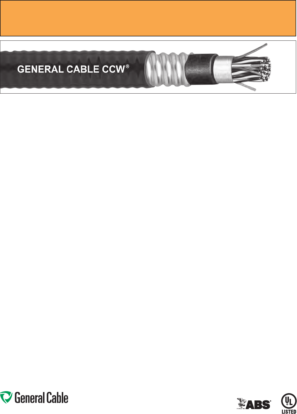
CCW
®
Armored Thermocouple, Single Pair, Overall Shield
UL Type ITC-HL/PLTC, PVC, 105°C, Sunlight-Resistant, Direct Burial
UL Marine Shipboard Cable, ABS CWCMC
Features:
•CCWarmorprovidessuperior
mechanical protection and an
impervious barrier to moisture, gas
and liquids
•CCWarmorprovidesEMIshielding
performance
•Meetscoldimpactat-40°C
Specifications:
Design Adherence:
•UL13Power-LimitedCircuitCables
•UL2250InstrumentationTrayCable
•UL1569MetalCladCables
•UL1309/CSAC22.2No.245Marine
Shipboard Cable
Flame Tests:
•ICEAT-29-520(210,000BTU/hr)
•IEEE383(70,000BTU/hr)
•CSAFT4
•IEEE1202(70,000BTU/hr)
•UL1581(70,000BTU/hr)
•IEC60332-3Cat.A
Compliances:
•ULTypePLTC,SUNRES,DIRBUR,
-40°C,ULFile#E36118
•ULTypeITC-HL,ULFile#E177408
•ULListedMarineShipboard,ULFile
#E85994
•AmericanBureauofShipping(ABS)
Listed for CWCMC
Phone: 888-593-3355
www.generalcable.com
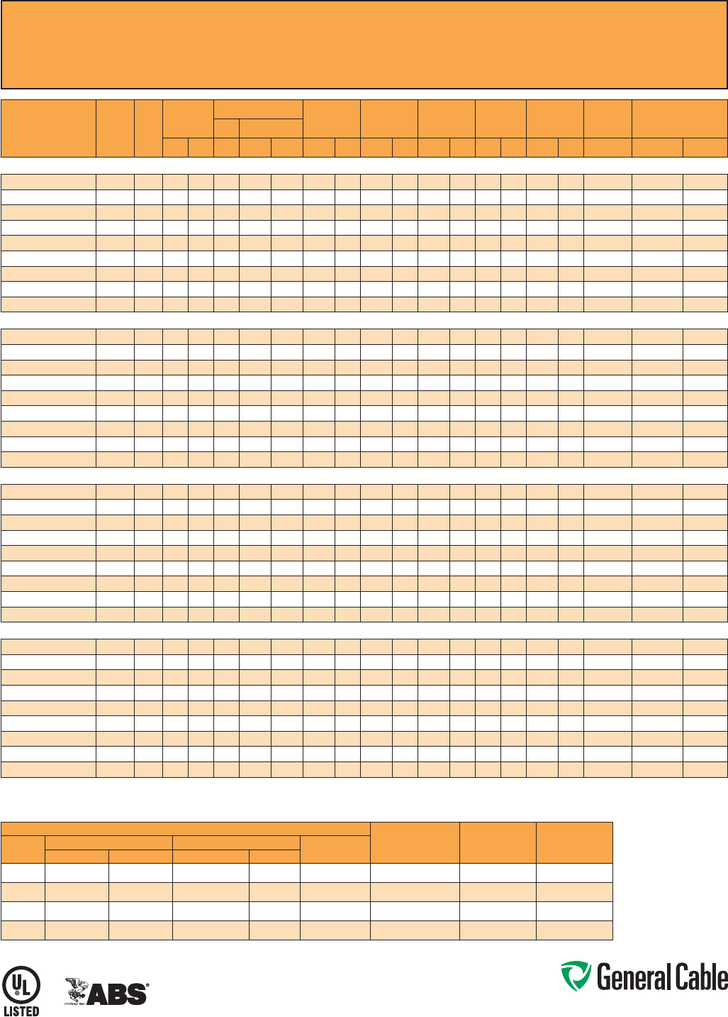
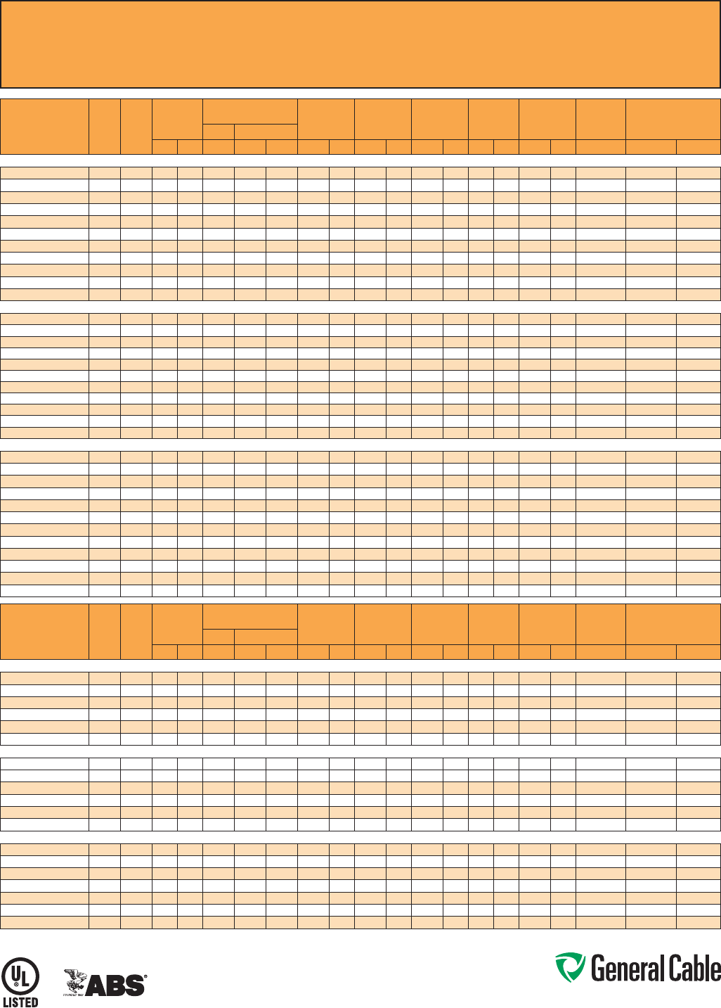
CCW
®
Armored Thermocouple, Single Pair, Overall Shield
UL Type ITC-HL/PLTC, PVC, 105°C, Sunlight-Resistant, Direct Burial
UL Marine Shipboard Cable, ABS CWCMC
SPEC 9025
April, 2011
PART
NUMBER
WIRE TYPE/
SIZE
(AWG)
NO. OF
PAIRS
INSULATION
THICKNESS
INNER JACKET
THICKNESS
NOMINAL
CORE O.D.
NOMINAL
ARMOR O.D.
JACKET
THICKNESS
NOMINAL
OVERALL O.D.
CROSS-
SECTIONAL
AREA¹
APPROXIMATE NET
WEIGHT
mils mm mils mm INCHES mm INCHES mm mils mm INCHES mm (SQ. IN.) LBS/1000 FT kg/1000 m
9025.16010001
EX / 16 115 0.38 35 0.89 0.25 6.4 0.45 11.4 50 1.27 0.56 14.2 0.25 132 196
9025.16010002
JX / 16 1 15 0.38 35 0.89 0.25 6.4 0.45 11.4 50 1.27 0.56 14.2 0.25 132 196
9025.16010003
KX / 16 1 15 0.38 35 0.89 0.25 6.4 0.45 11.4 50 1.27 0.56 14.2 0.25 132 196
9025.16010004
TX / 16 1 15 0.38 35 0.89 0.25 6.4 0.45 11.4 50 1.27 0.56 14.2 0.25 132 196
Dimensions and weights are nominal; subject to industry tolerances.
¹ Cross-sectional area for cable tray fill is in accordance with NEC® Section 392.22.
ANSI MC 96.1 CONDUCTOR ALLOY AND COLOR CODE
TEMP RANGE LIMITS OF ERROR
NOM. LOOP
RESISTANCE PER
100 FT @ 20°C
COND.
TYPE
POSITIVE WIRE NEGATIVE WIRE OUTER
JACKETALLOY COLOR ALLOY COLOR
EX
Chromel Purple Constantan Red Purple 0°C To +200°C +/- 1.7°C 27. 8 O hm s
JX
Iron White Constantan Red Black 0°C To +200°C +/- 2.2°C 13.9 Ohms
KX
Chromel Yellow Alumel Red Yellow 0°C To +200°C +/- 2.2°C 23.6 Ohms
TX
Copper Blue Constantan Red Blue -60°C To +100°C +/- 1.0°C 12.0 Ohms
Phone: 888-593-3355
www.generalcable.com
Overall Jacket:
•Flame-retardant,moisture-and
sunlight-resistant Polyvinyl Chloride
(PVC) per UL Standards 13 and 2250
•ANSIcolor-coded
•Lowtemperatureperformancemeets
ASTM D746 brittleness temperature at
or below -40°C
Applications:
•CCWarmoredThermocouple
Extension cables provide superior
protection and reliability against
physical damage for use in
instrumentation and process control
applications requiring ITC-HL or PLTC
wiring methods
•ForuseasPowerLimitedTrayCable
on circuits rated 150 V or less and
5 amps or less in Class 2 or Class 3
circuits in accordance with NEC
Article 725
•ForuseasInstrumentationTrayCable
on circuits rated 150 V or less and
5 amps or less in accordance with
NEC Article 727
•RecognizedforuseinClassI,II,and
III, Divisions 1 and 2; or Class I, Zones
1 and 2 hazardous locations per NEC
Articles 501, 502, 503, and 505
•Installedindoorsoroutdoors,inwetor
dry locations, in a raceway, as aerial
cable on a messenger, in cable trays,
or for direct burial
•Recognizedforuseonfixedor
floating offshore petroleum facilities
as recommended by the American
Petroleum Institute
Features:
•CCWarmorprovidessuperior
mechanical protection and an
impervious barrier to moisture, gas
and liquids
•CCWarmorprovidesEMIshielding
performance
•Meetscoldimpactat-40°C
Specifications:
Design Adherence:
•UL13Power-LimitedCircuitCables
•UL2250InstrumentationTrayCable
•UL1569MetalCladCables
•UL1309/CSAC22.2No.245Marine
Shipboard Cable
Flame Tests:
•ICEAT-29-520(210,000BTU/hr)
•IEEE383(70,000BTU/hr)
•CSAFT4
•IEEE1202(70,000BTU/hr)
•UL1581(70,000BTU/hr)
•IEC60332-3Cat.A
Compliances:
•ULTypePLTC,SUNRES,DIRBUR,
-40°C,ULFile#E36118
•ULTypeITC-HL,ULFile#E177408
•ULListedMarineShipboard,ULFile
#E85994
•AmericanBureauofShipping(ABS)
Listed for CWCMC
Product Construction:
Conductor:
•20AWGsolidalloywireperANSIMC
96.1
Insulation:
•Flame-retardantPolyvinylChloride
(PVC), rated 105°C per UL Standards
13 and 2250
•Color-codedperANSIwithone
conductor in each pair printed
alphanumerically for easy identification
Cable Assembly:
•Individualpairsandcommunication
wire are cabled together with a left-
hand lay
•Communicationwire:22AWGsolid
bare copper, flame-retardant Polyvinyl
Chloride (PVC), rated 105°C, orange
Overall Shield:
•Flexfoil
®
aluminum/polyester tape
shield providing 100% coverage
•Strandedtinnedcopperdrainwire,
same size as insulated conductors
Inner Jacket:
•Flame-retardantPolyvinylChloride
(PVC) per UL Standards 13 and 2250
•ANSIcolor-coded
•Lowtemperatureperformancemeets
ASTM D746 brittleness temperature at
or below -40°C
•Nylonripcordtofacilitatejacket
removal
CCW Armor:
•Impervious,continuouslyweldedand
corrugated aluminum alloy sheath per
UL 1569
•CCWarmorconductivitymeetsthe
grounding requierments of NEC
Article 250
CCW
®
Armored Thermocouple, Pairs, Overall Shield
UL Type ITC-HL/PLTC, PVC, 105°C, Sunlight-Resistant, Direct Burial
UL Marine Shipboard Cable, ABS CWCMC
SPEC 9050
April, 2011
Phone: 888-593-3355
www.generalcable.com
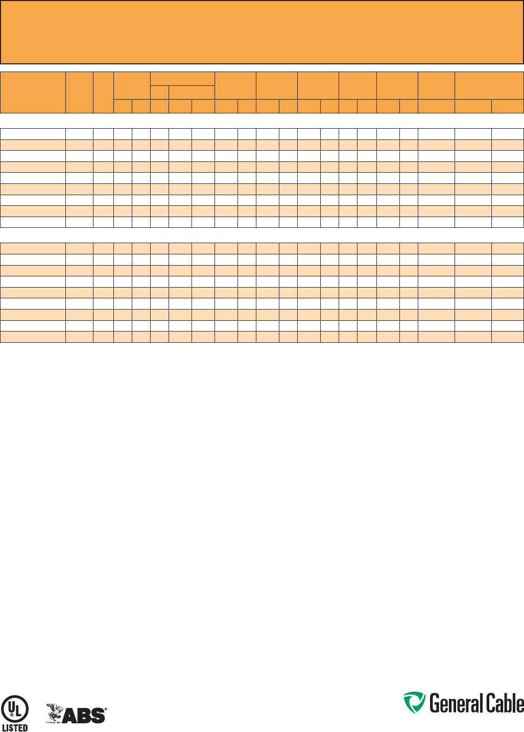
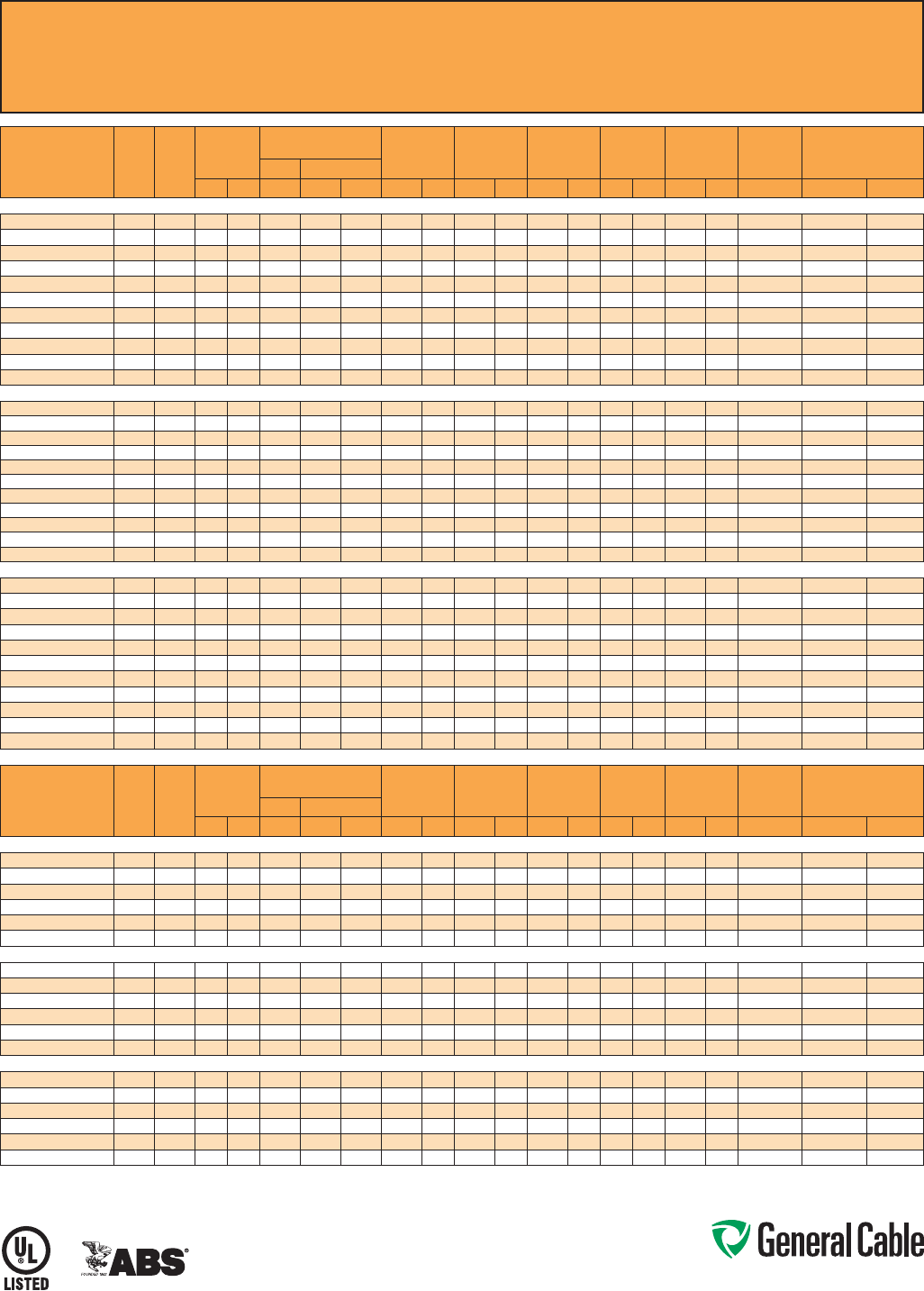
CCW
®
Armored Thermocouple, Pairs, Overall Shield
UL Type ITC-HL/PLTC, PVC, 105°C, Sunlight-Resistant, Direct Burial
UL Marine Shipboard Cable, ABS CWCMC
SPEC 9050
April, 2011
PART
NUMBER
WIRE
TYPE/
SIZE
(AWG)
NO.
OF
PAIRS
INSULATION
THICKNESS
COMMUNICATION WIRE INNER JACKET
THICKNESS
NOMINAL
CORE O.D.
NOMINAL
ARMOR O.D.
JACKET
THICKNESS
NOMINAL
OVERALL O.D.
CROSS-
SECTIONAL
AREA¹
APPROXIMATE
NET WEIGHTSIZE INS. THICKNESS
mils mm AWG mils mm mils mm INCHES mm INCHES mm mils mm INCHES mm (SQ. IN.) LBS/1000 FT kg/1000 m
20 AWG TYPE EX MULTIPLE PAIRS OVERALL SHIELDED THERMOCOUPLE EXTENSION CABLE
9050.20041221 EX / 20 4 15 0.38 22 12 0.30 40 1.02 0.36 9.1 0.58 14.7 50 1.27 0.69 17.5 0.38 195 290
9050.20081221 EX / 20 815 0.38 22 12 0.30 50 1.27 0.49 12.4 0.71 18.0 50 1.27 0.82 20.8 0.54 277 413
9050.20101221 EX / 20 10 15 0.38 22 12 0.30 50 1.27 0.53 13.5 0.75 19.1 50 1.27 0.86 21.8 0.59 337 501
9050.20121221 EX / 20 12 15 0.38 22 12 0.30 50 1.27 0.58 14.7 0.80 20.3 50 1.27 0.91 23.1 0.66 354 527
9050.20161221 EX / 20 16 15 0.38 22 12 0.30 50 1.27 0.62 15.7 0.84 21.3 50 1.27 0.95 24.1 0.72 422 628
9050.20201221 EX / 20 20 15 0.38 22 12 0.30 60 1.52 0.75 19.1 0.97 24.6 50 1.27 1.08 27.4 0.93 485 721
9050.20241221 EX / 20 24 15 0.38 22 12 0.30 60 1.52 0.77 19.6 1.02 25.9 50 1.27 1.13 28.7 1.02 552 821
9050.20361221 EX / 20 36 15 0.38 22 12 0.30 70 1.78 0.94 23.9 1.19 30.2 50 1.27 1.30 33.0 1.34 738 1,099
9050.20501221 EX / 20 50 15 0.38 22 12 0.30 70 1.78 1.09 27.7 1.34 34.0 50 1.27 1.45 36.8 1.67 925 1,377
20 AWG TYPE JX MULTIPLE PAIRS OVERALL SHIELDED THERMOCOUPLE EXTENSION CABLE
9050.20041222 JX / 20 4 15 0.38 22 12 0.30 40 1.02 0.36 9.1 0.58 14.7 50 1.27 0.69 17.5 0.38 194 288
9050.20081222 JX / 20 815 0.38 22 12 0.30 50 1.27 0.49 12.4 0.71 18.0 50 1.27 0.82 20.8 0.54 276 411
9050.20101222 JX / 20 10 15 0.38 22 12 0.30 50 1.27 0.53 13.5 0.75 19.1 50 1.27 0.86 21.8 0.59 335 498
9050.20121222 JX / 20 12 15 0.38 22 12 0.30 50 1.27 0.58 14.7 0.80 20.3 50 1.27 0.91 23.1 0.66 352 524
9050.20161222 JX / 20 16 15 0.38 22 12 0.30 50 1.27 0.62 15.7 0.84 21.3 50 1.27 0.95 24.1 0.72 419 624
9050.20201222 JX / 20 20 15 0.38 22 12 0.30 60 1.52 0.75 19.1 0.97 24.6 50 1.27 1.08 27.4 0.93 480 715
9050.20241222 JX / 20 24 15 0.38 22 12 0.30 60 1.52 0.77 19.6 1.02 25.9 50 1.27 1.13 28.7 1.02 547 814
9050.20361222 JX / 20 36 15 0.38 22 12 0.30 70 1.78 0.94 23.9 1.19 30.2 50 1.27 1.30 33.0 1.34 731 1,088
9050.20501222 JX / 20 50 15 0.38 22 12 0.30 70 1.78 1.09 27.7 1.34 34.0 50 1.27 1.45 36.8 1.67 914 1,360
20 AWG TYPE KX MULTIPLE PAIRS OVERALL SHIELDED THERMOCOUPLE EXTENSION CABLE
9050.20041223 KX / 20 4 15 0.38 22 12 0.30 40 1.02 0.36 9.1 0.58 14.7 50 1.27 0.69 17.5 0.38 195 290
9050.20081223 KX / 20 815 0.38 22 12 0.30 50 1.27 0.49 12.4 0.71 18.0 50 1.27 0.82 20.8 0.54 277 413
9050.20101223 KX / 20 10 15 0.38 22 12 0.30 50 1.27 0.53 13.5 0.75 19.1 50 1.27 0.86 21.8 0.59 337 501
9050.20121223 KX / 20 12 15 0.38 22 12 0.30 50 1.27 0.58 14.7 0.80 20.3 50 1.27 0.91 23.1 0.66 354 527
9050.20161223 KX / 20 16 15 0.38 22 12 0.30 50 1.27 0.62 15.7 0.84 21.3 50 1.27 0.95 24.1 0.72 422 628
9050.20201223 KX / 20 20 15 0.38 22 12 0.30 60 1.52 0.75 19.1 0.97 24.6 50 1.27 1.08 27.4 0.93 485 721
9050.20241223 KX / 20 24 15 0.38 22 12 0.30 60 1.52 0.77 19.6 1.02 25.9 50 1.27 1.13 28.7 1.02 552 821
9050.20361223 KX / 20 36 15 0.38 22 12 0.30 70 1.78 0.94 23.9 1.19 30.2 50 1.27 1.30 33.0 1.34 738 1,099
9050.20501223 KX / 20 50 15 0.38 22 12 0.30 70 1.78 1.09 27.7 1.34 34.0 50 1.27 1.45 36.8 1.67 925 1,377
20 AWG TYPE TX MULTIPLE PAIRS OVERALL SHIELDED THERMOCOUPLE EXTENSION CABLE
9050.20041224 TX / 20 4 15 0.38 22 12 0.30 40 1.02 0.36 9.1 0.58 14.7 50 1.27 0.69 17.5 0.38 196 291
9050.20081224 TX / 20 815 0.38 22 12 0.30 50 1.27 0.49 12.4 0.71 18.0 50 1.27 0.82 20.8 0.54 279 416
9050.20101224 TX / 20 10 15 0.38 22 12 0.30 50 1.27 0.53 13.5 0.75 19.1 50 1.27 0.86 21.8 0.59 339 504
9050.20121224 TX / 20 12 15 0.38 22 12 0.30 50 1.27 0.58 14.7 0.80 20.3 50 1.27 0.91 23.1 0.66 354 527
9050.20161224 TX / 20 16 15 0.38 22 12 0.30 50 1.27 0.62 15.7 0.84 21.3 50 1.27 0.95 24.1 0.72 426 634
9050.20201224 TX / 20 20 15 0.38 22 12 0.30 60 1.52 0.75 19.1 0.97 24.6 50 1.27 1.08 27.4 0.93 489 727
9050.20241224 TX / 20 24 15 0.38 22 12 0.30 60 1.52 0.77 19.6 1.02 25.9 50 1.27 1.13 28.7 1.02 557 829
9050.20361224 TX / 20 36 15 0.38 22 12 0.30 70 1.78 0.94 23.9 1.19 30.2 50 1.27 1.30 33.0 1.34 747 1,111
9050.20501224 TX / 20 50 15 0.38 22 12 0.30 70 1.78 1.09 27.7 1.34 34.0 50 1.27 1.45 36.8 1.67 935 1,392
Dimensions and weights are nominal; subject to industry tolerances.
¹ Cross-sectional area for cable tray fill is in accordance with NEC® Section 392.22.
ANSI MC 96.1 CONDUCTOR ALLOY AND COLOR CODE
TEMP RANGE
LIMITS OF
ERROR
NOM. LOOP
RESISTANCE PER
100 FT @ 20°C
COND.
TYPE
POSITIVE WIRE NEGATIVE WIRE OVERALL
JACKET COLORALLOY COLOR ALLOY COLOR
EX Chromel Purple Constantan Red Purple
0°C To +200°C +/- 1.7°C 70.7 Ohms
JX Iron White Constantan Red Black
0°C To +200°C +/- 2.2°C 35.7 Ohms
KX Chromel Yellow Alumel Red Yellow
0°C To +200°C +/- 2.2°C 59.0 Ohms
TX Copper Blue Constantan Red Blue
-60°C To +100°C +/- 1.0°C 29.8 Ohms

Phone: 888-593-3355
www.generalcable.com
CCW Armor:
•Impervious,continuouslyweldedand
corrugated aluminum alloy sheath per
UL 1569
•CCWarmorconductivitymeetsthe
grounding requirements of NEC
Article 250
Overall Jacket:
•Flame-retardant,moisture-and
sunlight-resistant Polyvinyl Chloride
(PVC) per UL Standards 13 and 2250
•ANSIcolor-codedoveralljacket
•Lowtemperatureperformancemeets
ASTM D746 brittleness temperature
at or below -40°C
Applications:
•CCWarmoredThermocouple
Extension cables with individually
shielded pairs and an overall shield
provide superior protection and
reliability against physical damage for
use in instrumentation and process
control applications requiring ITC-HL
or PLTC wiring methods where
shielding against both external EMI
and EMI between pairs is required
•ForuseasPowerLimitedTrayCable
on circuits rated 150 V or less and
5 amps or less in Class 2 or Class 3
circuits in accordance with NEC
Article 725
•ForuseasInstrumentationTrayCable
on circuits rated 150 V or less and 5
amps or less in accordance with NEC
Article 727
•RecognizedforuseinClassI,II,and
III, Divisions 1 and 2; or Class I, Zones
1 and 2 hazardous locations per NEC
Articles 501, 502, 503, and 505
Applications: (cont’d)
•Installedindoorsoroutdoors,inwet
or dry locations, in a raceway, as
aerial cable on a messenger, in cable
trays, or for direct burial
•Recognizedforuseonfixedor
floating offshore petroleum facilities
as recommended by the American
Petroleum Institute
Features:
•CCWarmorprovidessuperior
mechanical protection and an
impervious barrier to moisture, gas
and liquids
•CCWarmorprovidesEMIshielding
performance
•Meetscoldimpactat-40°C
Specifications:
Design Adherence:
•UL13Power-LimitedCircuitCables
•UL2250InstrumentationTrayCable
•UL1569MetalCladCables
•UL1309/CSAC22.2No.245Marine
Shipboard Cable
Flame Tests:
•ICEAT-29-520(210,000BTU/hr)
•IEEE383(70,000BTU/hr)
•CSAFT4
•IEEE1202(70,000BTU/hr)
•UL1581(70,000BTU/hr)
•IEC60332-3Cat.A
Compliances:
•ULTypePLTC,SUNRES,DIRBUR,
-40°C, UL File #
E36118
•ULTypeITC-HL,ULFile#E177408
•ULListedMarineShipboard,ULFile
#E85994
•AmericanBureauofShipping(ABS)
Listed for CWCMC
Product Construction:
Conductor:
•20AWGsolidalloywireperANSIMC
96.1
Insulation:
•Flame-retardantPolyvinylChloride
(PVC), rated 105°C per UL Standards
13 and 2250
•ANSIcolor-codedinsulation,withone
conductor in each pair printed alpha
numerically for easy identification
Shielded Pairs:
•Isolatedandindividuallytwistedpairs
with a Flexfoil
®
aluminum/polyester
tape shield providing 100% coverage
•Strandedtinnedcopperdrainwire,
two sizes smaller than insulated
conductors
Cable Assembly:
•Individuallyshieldedpairsand
communication wire are cabled
together with a left-hand lay
•Communicationwire:22AWG
solid bare copper, flame-retardant
Polyvinyl Chloride (PVC), rated 105°C,
orange
Overall Shield:
•Flexfoil
®
aluminum/polyester tape
shield providing 100% coverage
•Strandedtinnedcopperdrainwire,
same size as insulated conductors
Inner Jacket:
•Flame-retardantPolyvinylChloride
(PVC) per UL Standards 13 and 2250
•ANSIcolor-codedinnerjacket
•Lowtemperatureperformancemeets
ASTM D746 brittleness temperature
at or below -40°C
•Nylonripcordtofacilitatejacket
removal
CCW
®
Armored Thermocouple, Pairs, Individual and Overall Shield
UL Type ITC-HL/PLTC, PVC, 105°C, Sunlight-Resistant, Direct Burial
UL Marine Shipboard Cable, ABS CWCMC
SPEC 9075
April, 2011

Phone: 888-593-3355
www.generalcable.com
CCW
®
Armored Thermocouple, Pairs, Individual and Overall Shield
UL Type ITC-HL/PLTC, PVC, 105°C, Sunlight-Resistant, Direct Burial
UL Marine Shipboard Cable, ABS CWCMC
SPEC 9075
April, 2011
PART
NUMBER
WIRE
TYPE/
SIZE
(AWG)
NO.
OF
PAIRS
INSULATION
THICKNESS
COMMUNICATION WIRE INNER JACKET
THICKNESS
NOMINAL
CORE O.D.
NOMINAL
ARMOR O.D.
JACKET
THICKNESS
NOMINAL
OVERALL O.D.
CROSS-
SECTIONAL
AREA¹
APPROXIMATE
NET WEIGHTSIZE INS. THICKNESS
mils mm AWG mils mm mils mm INCHES mm INCHES mm mils mm INCHES mm (SQ. IN.) LBS/1000 FT kg/1000 m
20 AWG TYPE EX MULTIPLE PAIRS INDIVIDUAL AND OVERALL SHIELDED THERMOCOUPLE EXTENSION CABLE
9075.20041221 EX / 20 4 15 0.38 22 12 0.30 50 1.27 0.40 10.2 0.62 15.7 50 1.27 0.73 18.5 0.42 235 349
9075.20081221 EX / 20 815 0.38 22 12 0.30 50 1.27 0.53 13.5 0.75 19.1 50 1.27 0.86 21.8 0.59 313 466
9075.20101221 EX / 20 10 15 0.38 22 12 0.30 50 1.27 0.58 14.7 0.80 20.3 50 1.27 0.91 23.1 0.66 388 577
9075.20121221 EX / 20 12 15 0.38 22 12 0.30 50 1.27 0.62 15.7 0.84 21.3 50 1.27 0.95 24.1 0.72 417 621
9075.20161221 EX / 20 16 15 0.38 22 12 0.30 60 1.52 0.75 19.1 0.97 24.6 50 1.27 1.08 27.4 0.93 494 735
9075.20201221 EX / 20 20 15 0.38 22 12 0.30 60 1.52 0.81 20.6 1.06 26.9 50 1.27 1.17 29.7 1.09 571 850
9075.20241221 EX / 20 24 15 0.38 22 12 0.30 60 1.52 0.90 22.9 1.15 29.2 50 1.27 1.26 32.0 1.26 681 1,014
9075.20361221 EX / 20 36 15 0.38 22 12 0.30 70 1.78 1.09 27.7 1.34 34.0 50 1.27 1.45 36.8 1.67 877 1,305
9075.20501221 EX / 20 50 15 0.38 22 12 0.30 70 1.78 1.22 31.0 1.47 37.3 50 1.27 1.58 40.1 1.99 1,201 1,787
20 AWG TYPE JX MULTIPLE PAIRS INDIVIDUAL AND OVERALL SHIELDED THERMOCOUPLE EXTENSION CABLE
9075.20041222 JX / 20 4 15 0.38 22 12 0.30 50 1.27 0.40 10.2 0.62 15.7 50 1.27 0.73 18.5 0.42 234 348
9075.20081222 JX / 20 815 0.38 22 12 0.30 50 1.27 0.53 13.5 0.75 19.1 50 1.27 0.86 21.8 0.59 311 463
9075.20101222 JX / 20 10 15 0.38 22 12 0.30 50 1.27 0.58 14.7 0.80 20.3 50 1.27 0.91 23.1 0.66 386 574
9075.20121222 JX / 20 12 15 0.38 22 12 0.30 50 1.27 0.62 15.7 0.84 21.3 50 1.27 0.95 24.1 0.72 413 615
9075.20161222 JX / 20 16 15 0.38 22 12 0.30 60 1.52 0.75 19.1 0.97 24.6 50 1.27 1.08 27.4 0.93 491 730
9075.20201222 JX / 20 20 15 0.38 22 12 0.30 60 1.52 0.81 20.6 1.06 26.9 50 1.27 1.17 29.7 1.09 567 844
9075.20241222 JX / 20 24 15 0.38 22 12 0.30 60 1.52 0.90 22.9 1.15 29.2 50 1.27 1.26 32.0 1.26 676 1,006
9075.20361222 JX / 20 36 15 0.38 22 12 0.30 70 1.78 1.09 27.7 1.34 34.0 50 1.27 1.45 36.8 1.67 870 1,295
9075.20501222 JX / 20 50 15 0.38 22 12 0.30 70 1.78 1.22 31.0 1.47 37.3 50 1.27 1.58 40.1 1.99 1,190 1,771
20 AWG TYPE KX MULTIPLE PAIRS INDIVIDUAL AND OVERALL SHIELDED THERMOCOUPLE EXTENSION CABLE
9075.20041223 KX / 20 4 15 0.38 22 12 0.30 50 1.27 0.40 10.2 0.62 15.7 50 1.27 0.73 18.5 0.42 235 349
9075.20081223 KX / 20 815 0.38 22 12 0.30 50 1.27 0.53 13.5 0.75 19.1 50 1.27 0.86 21.8 0.59 313 466
9075.20101223 KX / 20 10 15 0.38 22 12 0.30 50 1.27 0.58 14.7 0.80 20.3 50 1.27 0.91 23.1 0.66 388 577
9075.20121223 KX / 20 12 15 0.38 22 12 0.30 50 1.27 0.62 15.7 0.84 21.3 50 1.27 0.95 24.1 0.72 417 621
9075.20161223 KX / 20 16 15 0.38 22 12 0.30 60 1.52 0.75 19.1 0.97 24.6 50 1.27 1.08 27.4 0.93 494 735
9075.20201223 KX / 20 20 15 0.38 22 12 0.30 60 1.52 0.81 20.6 1.06 26.9 50 1.27 1.17 29.7 1.09 571 850
9075.20241223 KX / 20 24 15 0.38 22 12 0.30 60 1.52 0.90 22.9 1.15 29.2 50 1.27 1.26 32.0 1.26 681 1,014
9075.20361223 KX / 20 36 15 0.38 22 12 0.30 70 1.78 1.09 27.7 1.34 34.0 50 1.27 1.45 36.8 1.67 877 1,305
9075.20501223 KX / 20 50 15 0.38 22 12 0.30 70 1.78 1.22 31.0 1.47 37.3 50 1.27 1.58 40.1 1.99 1,201 1,787
20 AWG TYPE TX MULTIPLE PAIRS INDIVIDUAL AND OVERALL SHIELDED THERMOCOUPLE EXTENSION CABLE
9075.20041224 TX / 20 4 15 0.38 22 12 0.30 50 1.27 0.40 10.2 0.62 15.7 50 1.27 0.73 18.5 0.42 236 351
9075.20081224 TX / 20 815 0.38 22 12 0.30 50 1.27 0.53 13.5 0.75 19.1 50 1.27 0.86 21.8 0.59 315 469
9075.20101224 TX / 20 10 15 0.38 22 12 0.30 50 1.27 0.58 14.7 0.80 20.3 50 1.27 0.91 23.1 0.66 391 581
9075.20121224 TX / 20 12 15 0.38 22 12 0.30 50 1.27 0.62 15.7 0.84 21.3 50 1.27 0.95 24.1 0.72 418 622
9075.20161224 TX / 20 16 15 0.38 22 12 0.30 60 1.52 0.75 19.1 0.97 24.6 50 1.27 1.08 27.4 0.93 497 739
9075.20201224 TX / 20 20 15 0.38 22 12 0.30 60 1.52 0.81 20.6 1.06 26.9 50 1.27 1.17 29.7 1.09 575 856
9075.20241224 TX / 20 24 15 0.38 22 12 0.30 60 1.52 0.90 22.9 1.15 29.2 50 1.27 1.26 32.0 1.26 686 1,022
9075.20361224 TX / 20 36 15 0.38 22 12 0.30 70 1.78 1.09 27.7 1.34 34.0 50 1.27 1.45 36.8 1.67 884 1,316
9075.20501224 TX / 20 50 15 0.38 22 12 0.30 70 1.78 1.22 31.0 1.47 37.3 50 1.27 1.58 40.1 1.99 1,211 1,802
Dimensions and weights are nominal; subject to industry tolerances.
¹ Cross-sectional area for cable tray fill is in accordance with NEC® Section 392.22.
ANSI MC 96.1 CONDUCTOR ALLOY AND COLOR CODE
TEMP. RANGE
LIMITS OF
ERROR
NOM. LOOP
RESISTANCE PER
100 FT @ 20°C
COND.
TYPE
POSITIVE WIRE NEGATIVE WIRE OVERALL
JACKET COLORALLOY COLOR ALLOY COLOR
EX Chromel Purple Constantan Red Purple
0°C To +200°C +/- 1.7°C 70.7 Ohms
JX Iron White Constantan Red Black
0°C To +200°C +/- 2.2°C 35.7 Ohms
KX Chromel Yellow Alumel Red Yellow
0°C To +200°C +/- 2.2°C 59.0 Ohms
TX Copper Blue Constantan Red Blue
-60°C To +100°C +/- 1.0°C 29.8 Ohms

Phone: 888-593-3355
www.generalcable.com
CCW Armor:
•Impervious,continuouslyweldedand
corrugated aluminum alloy sheath per
UL 1569
•CCWarmorconductivitymeetsthe
grounding requirements of NEC
Article 250
Overall Jacket:
•Flame-retardant,moisture-and
sunlight-resistant Polyvinyl Chloride
(PVC) per UL Standards 13 and 2250,
black
•Lowtemperatureperformancemeets
ASTM D746 brittleness temperature at
or below -40°C
Applications:
•CCWarmoredInstrumentation
cables with an overall shield provide
superior protection and reliability
against physical damage for use in
instrumentation and process control
applications requiring ITC-HL or
PLTC wiring methods where shielding
against external EMI is required
•ForuseasPowerLimitedTrayCable
on circuits rated 150 V or less and
5 amps or less in Class 2 or Class 3
circuits in accordance with NEC
Article 725
•ForuseasInstrumentationTrayCable
on circuits rated 150 V or less and
5 amps or less in accordance with
NEC Article 727
•RecognizedforuseinClassI,II,and
III, Divisions 1 and 2; or Class I, Zones
1 and 2 hazardous locations per NEC
Articles 501, 502, 503, and 505
•Installedindoorsoroutdoors,inwetor
dry locations, in a raceway, as aerial
cable on a messenger, in cable trays,
or for direct burial
Applications: (cont’d)
•Recognizedforuseonfixedor
floating offshore petroleum facilities
as recommended by the American
Petroleum Institute
Features:
•CCWarmorprovidessuperior
mechanical protection and an
impervious barrier to moisture, gas
and liquids
•CCWarmorprovidesEMIshielding
performance
•Meetscoldimpactat-40°C
Specifications:
Design Adherence:
•UL13Power-LimitedCircuitCables
•UL2250InstrumentationTrayCable
•UL1569MetalCladCables
•UL1309/CSAC22.2No.245Marine
Shipboard Cable
Flame Tests:
•ICEAT-29-520(210,000BTU/hr)
•IEEE383(70,000BTU/hr)
•CSAFT4
•IEEE1202(70,000BTU/hr)
•UL1581(70,000BTU/hr)
•IEC60332-3Cat.A
Compliances:
•ULTypePLTC,SUNRES,DIRBUR,
-40°C,ULFile#E36118
•ULTypeITC-HL,ULFile#E177408
•ULListedMarineShipboard,ULFile#
E85994
•AmericanBureauofShipping(ABS)
Listed for CWCMC
Product Construction:
Conductor:
•BareannealedcopperperASTMB3
•ClassBstrandingperASTMB8
Insulation:
•Cross-LinkedPolyethylene(XLPE),
rated 90°C per UL Standards 13 and
2250
•Color-codedperICEAMethod1:
pairs – black and white; triads – black,
white and red. Each conductor in each
pair or triad is printed alphanumerically
for easy identification
Cable Assembly:
•Individualpairsortriadsand
communication wire are cabled
together with a left hand lay
•Communicationwire:20AWG
solid bare copper, Cross-Linked
Polyethylene (XLPE), rated 90°C,
orange
•Communicationwireisnotincludedon
single pair or single triad cables
Overall Shield:
•Flexfoil
®
aluminum/polyester tape
shield providing 100% coverage
•Strandedtinnedcopperdrainwire,
same size as insulated conductors
Inner Jacket:
•Flame-retardantPolyvinylChloride
(PVC) per UL Standards 13 and 2250,
black
•Lowtemperatureperformancemeets
ASTM D746 brittleness temperature at
or below -40°C
•Nylonripcordtofacilitatejacket
removal
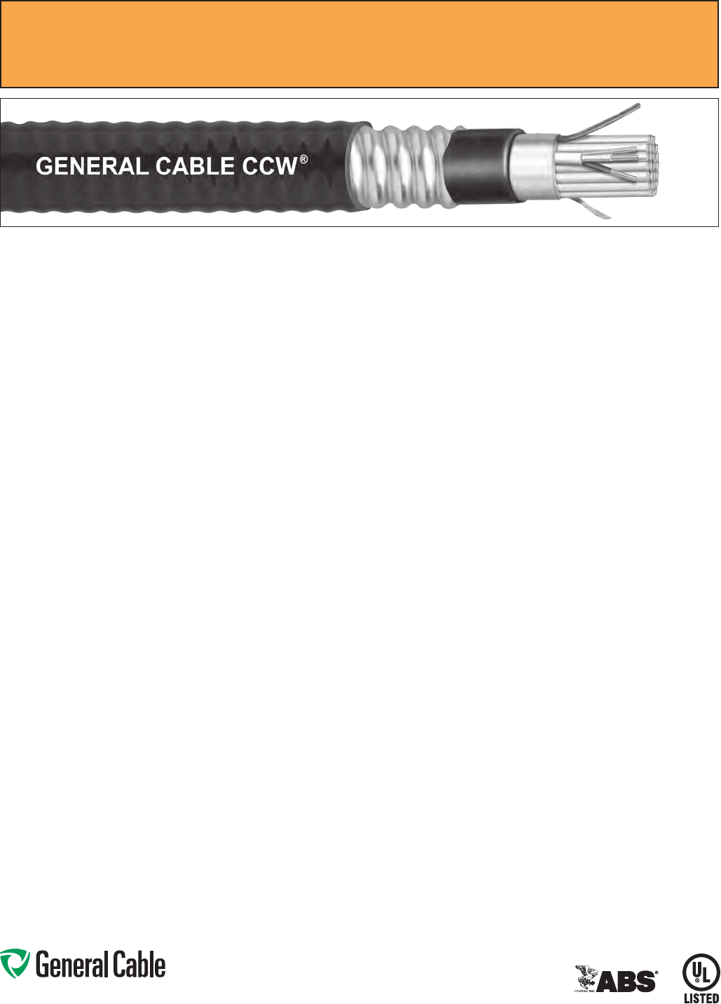
CCW
®
Armored Instrumentation, Pairs/Triads, Overall Shield
UL Type ITC-HL/PLTC, XLPE, 300 V, 90°C, Sunlight-Resistant, Direct Burial
UL Marine Shipboard Cable, ABS CWCMC
SPEC 9125
April, 2011
Phone: 888-593-3355
www.generalcable.com
CCW
®
Armored Instrumentation, Pairs/Triads, Overall Shield
UL Type ITC-HL/PLTC, XLPE, 300 V, 90°C, Sunlight-Resistant, Direct Burial
UL Marine Shipboard Cable, ABS CWCMC
SPEC 9125
April, 2011
PART
NUMBER
COND.
SIZE
(AWG)
NO.
OF
PAIRS
INSULATION
THICKNESS
COMMUNICATION WIRE INNER JACKET
THICKNESS
NOMINAL
CORE O.D.
NOMINAL
ARMOR O.D.
JACKET
THICKNESS
NOMINAL
OVERALL O.D.
CROSS-
SECTIONAL
AREA¹
APPROXIMATE
NET WEIGHTSIZE INS. THICKNESS
mils mm AWG mils mm mils mm INCHES mm INCHES mm mils mm INCHES mm (SQ. IN.) LBS/1000 FT kg/1000 m
16 AWG 7W (1.31 mm²) OVERALL SHIELDED PAIRS
9125.16010001
16 1 15 0.38 — — — 35 0.89 0.26 6.6 0.43 10.9 50 1.27 0.54 13.7 0.23 135 201
9125.16021201
16 2 15 0.38 20 15 0.38 40 1.02 0.37 9.4 0.58 14.7 50 1.27 0.69 17.5 0.38 235 350
9125.16041201
16 4 15 0.38 20 15 0.38 50 1.27 0.49 12.4 0.71 18.0 50 1.27 0.82 20.8 0.54 298 443
9125.16081201
16 815 0.38 20 15 0.38 60 1.52 0.65 16.5 0.89 22.6 50 1.27 1.00 25.4 0.80 412 613
9125.16121201
16 12 15 0.38 20 15 0.38 60 1.52 0.76 19.3 1.02 25.9 50 1.27 1.13 28.7 1.02 562 836
9125.16161201
16 16 15 0.38 20 15 0.38 60 1.52 0.87 22.1 1.11 28.2 50 1.27 1.22 31.0 1.18 665 990
9125.16241201
16 24 15 0.38 20 15 0.38 70 1.78 1.01 25.7 1.34 34.0 50 1.27 1.45 36.8 1.67 934 1,390
9125.16361201
16 36 15 0.38 20 15 0.38 70 1.78 1.24 31.5 1.56 39.6 60 1.52 1.69 42.9 2.27 1,236 1,840
9125.16501201
16 50 15 0.38 20 15 0.38 80 2.03 1.47 37.3 1.83 46.5 60 1.52 1.96 49.8 3.06 1,734 2,580
16 AWG 7W (1.31 mm²) OVERALL SHIELDED TRIADS
9125.16010002
16 1 15 0.38 — — — 35 0.89 0.27 6.9 0.49 12.4 50 1.27 0.60 15.2 0.29 158 235
9125.16021202
16 2 15 0.38 20 15 0.38 40 1.02 0.39 9.9 0.62 15.7 50 1.27 0.73 18.5 0.42 265 394
9125.16041202
16 4 15 0.38 20 15 0.38 50 1.27 0.52 13.2 0.75 19.1 50 1.27 0.86 21.8 0.59 358 533
9125.16081202
16 815 0.38 20 15 0.38 60 1.52 0.69 17.5 0.93 23.6 50 1.27 1.04 26.4 0.86 565 841
9125.16121202
16 12 15 0.38 20 15 0.38 60 1.52 0.81 20.6 1.06 26.9 50 1.27 1.17 29.7 1.09 793 1,179
9125.16161202
16 16 15 0.38 20 15 0.38 70 1.78 0.95 24.1 1.24 31.5 50 1.27 1.35 34.3 1.45 965 1,436
9125.16241202
16 24 15 0.38 20 15 0.38 70 1.78 1.14 29.0 1.42 36.1 50 1.27 1.53 38.9 1.86 1,446 2,152
9125.16361202
16 36 15 0.38 20 15 0.38 80 2.03 1.34 34.0 1.64 41.7 60 1.52 1.78 45.2 2.52 1,913 2,846
9125.16501202
16 50 15 0.38 20 15 0.38 80 2.03 1.57 39.9 1.92 48.8 60 1.52 2.05 52.1 3.34 2,585 3,846
Dimensions and weights are nominal; subject to industry tolerances.
¹ Cross-sectional area for cable tray fill is in accordance with NEC® Section 392.22.
Phone: 888-593-3355
www.generalcable.com
CCW Armor:
•Impervious,continuouslyweldedand
corrugated aluminum alloy sheath per
UL 1569
•CCWarmorconductivitymeetsthe
grounding requirements of NEC
Article 250
Overall Jacket:
•Flame-retardant,moisture-and
sunlight-resistant Polyvinyl Chloride
(PVC) per UL Standards 13 and 2250,
black
•Lowtemperatureperformancemeets
ASTM D746 brittleness temperature at
or below -40°C
Applications:
•CCWarmoredInstrumentationcables
with individually shielded pairs or
triads and an overall shield provide
superior protection and reliability
against physical damage for use in
instrumentation and process control
applications requiring ITC-HL or
PLTC wiring methods where shielding
against both external EMI and EMI
between groups is required
•ForuseasPowerLimitedTrayCable
on circuits rated 150 V or less and
5 amps or less in Class 2 or Class 3
circuits in accordance with NEC Article
725
•ForuseasInstrumentationTrayCable
on circuits rated 150 V or less and
5 amps or less in accordance with
NEC Article 727
•RecognizedforuseinClassI,II,and
III, Divisions 1 and 2; or Class I, Zones
1 and 2 hazardous locations per NEC
Articles 501, 502, 503, and 505
Applications: (cont’d)
•Installedindoorsoroutdoors,inwetor
dry locations, in a raceway, as aerial
cable on a messenger, in cable trays,
or for direct burial
•Recognizedforuseonfixedor
floating offshore petroleum facilities
as recommended by the American
Petroleum Institute
Features:
•CCWarmorprovidessuperior
mechanical protection and an
impervious barrier to moisture,
gas and liquids
•CCWarmorprovidesEMIshielding
performance
•Meetscoldimpactat-40°C
Specifications:
Design Adherence:
•UL13Power-LimitedCircuitCables
•UL2250InstrumentationTrayCable
•UL1569MetalCladCables
•UL1309/CSAC22.2No.245Marine
Shipboard Cable
Flame Tests:
•ICEAT-29-520(210,000BTU/hr)
•IEEE383(70,000BTU/hr)
•CSAFT4
•IEEE1202(70,000BTU/hr)
•UL1581(70,000BTU/hr)
•IEC60332-3Cat.A
Compliances:
•ULTypePLTC,SUNRES,DIRBUR,
-40°C,ULFile#E36118
•ULTypeITC-HL,ULFile#E177408
•ULListedMarineShipboard,ULFile#
E85994
•AmericanBureauofShipping(ABS)
Listed for CWCMC
Product Construction:
Conductor:
•BareannealedcopperperASTMB3
•ClassBstrandingperASTMB8
Insulation:
•
Cross-Linked Polyethylene
(XLPE),
rated 90°C per UL Standards 13 and
2250
•Color-codedperICEAMethod1:
pairs – black and white; triads – black,
white and red. Each conductor in each
pair or triad is printed alphanumerically
for easy identification
Shielded Pairs/Triads:
•Isolatedandindividuallytwistedpairs
or triads with a Flexfoil® aluminum/
polyester tape shield providing 100%
coverage
•Strandedtinnedcopperdrainwire,two
sizes smaller than insulated conductors
Cable Assembly:
•Individuallyshieldedpairsortriads
and communication wire are cabled
together with a left-hand lay
•Communicationwire:20AWGsolid
bare copper, Cross-Linked Polyethylene
(XLPE), rated 90°C, orange
Overall Shield:
•Flexfoil® aluminum/polyester tape shield
providing 100% coverage
•Strandedtinnedcopperdrainwire,
same size as insulated conductors
Inner Jacket:
•Flame-retardantPolyvinylChloride
(PVC) per UL Standards 13 and 2250,
black
•Lowtemperatureperformancemeets
ASTM D746 brittleness temperature at
or below -40°C
•Nylonripcordtofacilitatejacket
removal
CCW
®
Armored Instrumentation, Pairs/Triads, Individual and Overall Shield
UL Type ITC-HL/PLTC, XLPE, 300 V, 90°C, Sunlight-Resistant, Direct Burial
UL Marine Shipboard Cable, ABS CWCMC
SPEC 9150
April, 2011

Phone: 888-593-3355
www.generalcable.com
CCW
®
Armored Instrumentation, Pairs/Triads, Individual and Overall Shield
UL Type ITC-HL/PLTC, XLPE, 300 V, 90°C, Sunlight-Resistant, Direct Burial
UL Marine Shipboard Cable, ABS CWCMC
SPEC 9150
April, 2011
PART
NUMBER
COND.
SIZE
(AWG)
NO.
OF
PAIRS
INSULATION
THICKNESS
COMMUNICATION WIRE INNER JACKET
THICKNESS
NOMINAL
CORE O.D.
NOMINAL
ARMOR O.D.
JACKET
THICKNESS
NOMINAL
OVERALL O.D.
CROSS-
SECTIONAL
AREA¹
APPROXIMATE
NET WEIGHTSIZE INS. THICKNESS
mils mm AWG mils mm mils mm INCHES mm INCHES mm mils mm INCHES mm (SQ. IN.) LBS/1000 FT kg/1000 m
16 AWG 7W (1.31 mm²) OVERALL SHIELDED PAIRS
9150.16010001
16 1 15 0.38 — — — 35 0.89 0.26 6.6 0.43 10.9 50 1.27 0.54 13.7 0.23 135 201
9150.16021201
16 2 15 0.38 20 15 0.38 40 1.02 0.37 9.4 0.58 14.7 50 1.27 0.69 17.5 0.38 235 350
9150.16041201
16 4 15 0.38 20 15 0.38 50 1.27 0.49 12.4 0.71 18.0 50 1.27 0.82 20.8 0.54 298 443
9150.16081201
16 815 0.38 20 15 0.38 60 1.52 0.65 16.5 0.89 22.6 50 1.27 1.00 25.4 0.80 412 613
9150.16121201
16 12 15 0.38 20 15 0.38 60 1.52 0.76 19.3 1.02 25.9 50 1.27 1.13 28.7 1.02 562 836
9150.16161201
16 16 15 0.38 20 15 0.38 60 1.52 0.87 22.1 1.11 28.2 50 1.27 1.22 31.0 1.18 665 990
9150.16241201
16 24 15 0.38 20 15 0.38 70 1.78 1.01 25.7 1.34 34.0 50 1.27 1.45 36.8 1.67 934 1,390
9150.16361201
16 36 15 0.38 20 15 0.38 70 1.78 1.24 31.5 1.56 39.6 60 1.52 1.69 42.9 2.27 1,236 1,840
9150.16501201
16 50 15 0.38 20 15 0.38 80 2.03 1.47 37.3 1.83 46.5 60 1.52 1.96 49.8 3.06 1,734 2,580
16 AWG 7W (1.31 mm²) OVERALL SHIELDED TRIADS
9150.16010002
16 1 15 0.38 — — — 35 0.89 0.27 6.9 0.49 12.4 50 1.27 0.60 15.2 0.29 158 235
9150.16021202
16 2 15 0.38 20 15 0.38 40 1.02 0.39 9.9 0.62 15.7 50 1.27 0.73 18.5 0.42 265 394
9150.16041202
16 4 15 0.38 20 15 0.38 50 1.27 0.52 13.2 0.75 19.1 50 1.27 0.86 21.8 0.59 358 533
9150.16081202
16 815 0.38 20 15 0.38 60 1.52 0.69 17.5 0.93 23.6 50 1.27 1.04 26.4 0.86 565 841
9150.16121202
16 12 15 0.38 20 15 0.38 60 1.52 0.81 20.6 1.06 26.9 50 1.27 1.17 29.7 1.09 793 1,179
9150.16161202
16 16 15 0.38 20 15 0.38 70 1.78 0.95 24.1 1.24 31.5 50 1.27 1.35 34.3 1.45 965 1,436
9150.16241202
16 24 15 0.38 20 15 0.38 70 1.78 1.14 29.0 1.42 36.1 50 1.27 1.53 38.9 1.86 1,446 2,152
9150.16361202
16 36 15 0.38 20 15 0.38 80 2.03 1.34 34.0 1.64 41.7 60 1.52 1.78 45.2 2.52 1,913 2,846
9150.16501202
16 50 15 0.38 20 15 0.38 80 2.03 1.57 39.9 1.92 48.8 60 1.52 2.05 52.1 3.34 2,585 3,846
Dimensions and weights are nominal; subject to industry tolerances.
¹ Cross-sectional area for cable tray fill is in accordance with NEC® Section 392.22.

Phone: 888-593-3355
www.generalcable.com
Product Construction:
Conductor:
•BareannealedcopperperASTMB3
•ClassBstrandingperASTMB8
Insulation:
•Flame-retardantPolyvinylChloride
(PVC), rated 105°C per UL Standards
13 and 2250
•Color-codedperICEAMethod1:
pairs – black and white; triads – black,
white and red. Each conductor in each
pair or triad is printed alphanumerically
for easy identification
Cable Assembly:
•Individualpairsortriadsand
communication wire are cabled
together with a left-hand lay
•Communicationwire:22AWGsolid
bare copper, flame-retardant Polyvinyl
Chloride (PVC), rated 105°C, orange
•Communicationwireisnotincludedon
single pair or single triad cables
Overall Shield:
•Flexfoil
®
aluminum/polyester tape
shield providing 100% coverage
•Strandedtinnedcopperdrainwire,
same size as insulated conductors
Inner Jacket:
•Flame-retardantPolyvinylChloride
(PVC) per UL Standards 13 and 2250,
black
•Lowtemperatureperformancemeets
ASTM D746 brittleness temperature at
or below -40°C
•Nylonripcordtofacilitatejacket
removal
CCW Armor:
•Impervious,continuouslyweldedand
corrugated aluminum alloy sheath per
UL 1569
•CCWarmorconductivitymeetsthe
grounding requirements of NEC
Article 250
CCW
®
Armored Instrumentation, Pairs/Triads, Overall Shield
UL Type ITC-HL/PLTC, PVC, 300 V, 105°C, Sunlight-Resistant, Direct Burial
UL Marine Shipboard Cable, ABS CWCMC
SPEC 9225
April, 2011
Overall Jacket:
•Flame-retardant,moisture-and
sunlight-resistant Polyvinyl Chloride
(PVC) per UL Standards 13 and 2250,
black
•Lowtemperatureperformancemeets
ASTM D746 brittleness temperature at
or below -40°C
Applications:
•CCWarmoredInstrumentation
cables with an overall shield provide
superior protection and reliability
against physical damage for use in
instrumentation and process control
applications requiring ITC-HL or
PLTC wiring methods where shielding
against external EMI is required
•ForuseasPowerLimitedTrayCable
on circuits rated 150 V or less and
5 amps or less in Class 2 or Class 3
circuits in accordance with NEC Article
725
•ForuseasInstrumentationTrayCable
on circuits rated 150 V or less and
5 amps or less in accordance with
NEC Article 727
•RecognizedforuseinClassI,II,and
III, Divisions 1 and 2; or Class I, Zones
1 and 2 hazardous locations per NEC
Articles 501, 502, 503, and 505
•Installedindoorsoroutdoors,inwetor
dry locations, in a raceway, as aerial
cable on a messenger, in cable trays,
or for direct burial
•Recognizedforuseonfixedor
floating offshore petroleum facilities
as recommended by the American
Petroleum Institute
Features:
•CCWarmorprovidessuperior
mechanical protection and an
impervious barrier to moisture, gas
and liquids
•CCWarmorprovidesEMIshielding
performance
•Meetscoldimpactat-40°
Specifications:
Design Adherence:
•UL13Power-LimitedCircuitCables
•UL2250InstrumentationTrayCable
•UL1569MetalCladCables
•UL1309/CSAC22.2No.245Marine
Shipboard Cable
Flame Tests:
•ICEAT-29-520(210,000BTU/hr)
•IEEE383(70,000BTU/hr)
•CSAFT4
•IEEE1202(70,000BTU/hr)
•UL1581(70,000BTU/hr)
•IEC60332-3Cat.A
Compliances:
•ULTypePLTC,SUNRES,DIRBUR,
-40°C,ULFile#E36118
•ULTypeITC-HL,ULFile#E177408
•ULListedMarineShipboard,ULFile#
E85994
•AmericanBureauofShipping(ABS)
Listed for CWCMC
Phone: 888-593-3355
www.generalcable.com
CCW
®
Armored Instrumentation, Pairs/Triads, Overall Shield
UL Type ITC-HL/PLTC, PVC, 300 V, 105°C, Sunlight-Resistant, Direct Burial
UL Marine Shipboard Cable, ABS CWCMC
SPEC 9225
April, 2011
PART
NUMBER
COND.
SIZE
(AWG)
NO.
OF
PAIRS
INSULATION
THICKNESS
COMMUNICATION WIRE INNER JACKET
THICKNESS
NOMINAL
CORE O.D.
NOMINAL
ARMOR O.D.
JACKET
THICKNESS
NOMINAL
OVERALL O.D.
CROSS-
SECTIONAL
AREA¹
APPROXIMATE
NET WEIGHTSIZE INS. THICKNESS
mils mm AWG mils mm mils mm INCHES mm INCHES mm mils mm INCHES mm (SQ. IN.) LBS/1000 FT kg/1000 m
20 AWG 7W (0.52 mm²) OVERALL SHIELDED PAIRS
9225.20021221
20 2 15 0.38 22 12 0.30 40 1.02 0.35 8.9 0.58 14.7 50 1.27 0.69 17.5 0.38 174 260
9225.20041221
20 4 15 0.38 22 12 0.30 50 1.27 0.41 10.4 0.62 15.7 50 1.27 0.73 18.5 0.42 198 294
9225.20061221
20 6 15 0.38 22 12 0.30 50 1.27 0.45 11.4 0.67 17.0 50 1.27 0.78 19.8 0.48 250 372
9225.20081221
20 815 0.38 22 12 0.30 50 1.27 0.49 12.4 0.71 18.0 50 1.27 0.82 20.8 0.54 283 420
9225.20101221
20 10 15 0.38 22 12 0.30 50 1.27 0.53 13.5 0.75 19.1 50 1.27 0.86 21.8 0.59 330 492
9225.20121221
20 12 15 0.38 22 12 0.30 50 1.27 0.56 14.2 0.80 20.3 50 1.27 0.91 23.1 0.66 353 525
9225.20161221
20 16 15 0.38 22 12 0.30 60 1.52 0.66 16.8 0.89 22.6 50 1.27 1.00 25.4 0.80 432 644
9225.20201221
20 20 15 0.38 22 12 0.30 60 1.52 0.73 18.5 0.97 24.6 50 1.27 1.08 27.4 0.93 500 744
9225.20241221
20 24 15 0.38 22 12 0.30 60 1.52 0.79 20.1 1.06 26.9 50 1.27 1.17 29.7 1.09 556 827
9225.20361221
20 36 15 0.38 22 12 0.30 70 1.78 0.94 23.9 1.24 31.5 50 1.27 1.35 34.3 1.45 711 1,058
9225.20501221
20 50 15 0.38 22 12 0.30 70 1.78 1.06 26.9 1.34 34.0 50 1.27 1.45 36.8 1.67 949 1,412
18 AWG 7W (0.82 mm²) OVERALL SHIELDED PAIRS
9225.18021221
18 2 15 0.38 22 12 0.30 40 1.02 0.37 9.4 0.58 14.7 50 1.27 0.69 17.5 0.38 206 307
9225.18041221
18 4 15 0.38 22 12 0.30 50 1.27 0.44 11.2 0.67 17.0 50 1.27 0.78 19.8 0.48 249 370
9225.18061221
18 6 15 0.38 22 12 0.30 50 1.27 0.50 12.7 0.71 18.0 50 1.27 0.82 20.8 0.54 294 437
9225.18081221
18 8 15 0.38 22 12 0.30 50 1.27 0.55 14.0 0.80 20.3 50 1.27 0.91 23.1 0.66 337 501
9225.18101221
18 10 15 0.38 22 12 0.30 60 1.52 0.65 16.5 0.89 22.6 50 1.27 1.00 25.4 0.80 417 621
9225.18121221
18 12 15 0.38 22 12 0.30 60 1.52 0.68 17.3 0.93 23.6 50 1.27 1.04 26.4 0.86 449 668
9225.18161221
18 16 15 0.38 22 12 0.30 60 1.52 0.77 19.6 1.02 25.9 50 1.27 1.13 28.7 1.02 536 797
9225.18201221
18 20 15 0.38 22 12 0.30 60 1.52 0.83 21.1 1.06 26.9 50 1.27 1.17 29.7 1.09 623 927
9225.18241221
18 24 15 0.38 22 12 0.30 60 1.52 0.86 21.8 1.11 28.2 50 1.27 1.22 31.0 1.18 698 1,038
9225.18361221
18 36 15 0.38 22 12 0.30 70 1.78 0.99 25.1 1.29 32.8 50 1.27 1.40 35.6 1.56 965 1,436
9225.18501221
18 50 15 0.38 22 12 0.30 70 1.78 1.15 29.2 1.47 37.3 50 1.27 1.58 40.1 1.99 1,280 1,905
16 AWG 7W (1.31 mm²) OVERALL SHIELDED PAIRS
9225.16010001
16 1 15 0.38 – – – 35 0.89 0.26 6.6 0.43 10.9 50 1.27 0.54 13.7 0.23 135 201
9225.16021221
16 2 15 0.38 22 12 0.30 40 1.02 0.36 9.1 0.58 14.7 50 1.27 0.69 17.5 0.38 239 355
9225.16041221
16 4 15 0.38 22 12 0.30 50 1.27 0.48 12.2 0.71 18.0 50 1.27 0.82 20.8 0.54 296 440
9225.16061221
16 6 15 0.38 22 12 0.30 50 1.27 0.57 14.5 0.80 20.3 50 1.27 0.91 23.1 0.66 366 545
9225.16081221
16 815 0.38 22 12 0.30 60 1.52 0.63 16.0 0.84 21.3 50 1.27 0.95 24.1 0.72 424 631
9225.16101221
16 10 15 0.38 22 12 0.30 60 1.52 0.69 17.5 0.93 23.6 50 1.27 1.04 26.4 0.86 522 777
9225.16121221
16 12 15 0.38 22 12 0.30 60 1.52 0.74 18.8 0.97 24.6 50 1.27 1.08 27.4 0.93 570 849
9225.16161221
16 16 15 0.38 22 12 0.30 60 1.52 0.85 21.6 1.11 28.2 50 1.27 1.22 31.0 1.18 687 1,023
9225.16201221
16 20 15 0.38 22 12 0.30 70 1.78 0.96 24.4 1.24 31.5 50 1.27 1.35 34.3 1.45 849 1,263
9225.16241221
16 24 15 0.38 22 12 0.30 70 1.78 1.04 26.4 1.34 34.0 50 1.27 1.45 36.8 1.67 956 1,422
9225.16361221
16 36 15 0.38 22 12 0.30 70 1.78 1.20 30.5 1.51 38.4 60 1.52 1.65 41.9 2.17 1,283 1,910
9225.16501221
16 50 15 0.38 22 12 0.30 80 2.03 1.33 33.8 1.64 41.7 60 1.52 1.78 45.2 2.52 1,786 2,658
PART
NUMBER
COND.
SIZE
(AWG)
NO.
OF
TRIADS
INSULATION
THICKNESS
COMMUNICATION WIRE INNER JACKET
THICKNESS
NOMINAL
CORE O.D.
NOMINAL
ARMOR O.D.
JACKET
THICKNESS
NOMINAL
OVERALL O.D.
CROSS-
SECTIONAL
AREA¹
APPROXIMATE
NET WEIGHT
SIZE INS. THICKNESS
mils mm AWG mils mm mils mm INCHES mm INCHES mm mils mm INCHES mm (SQ. IN.) LBS/1000 FT kg/1000 m
20 AWG 7W (0.52 mm²) OVERALL SHIELDED TRIADS
9225.20041222
20 4 15 0.38 22 12 0.30 50 1.27 0.43 10.9 0.67 17.0 50 1.27 0.78 19.8 0.48 247 367
9225.20081222
20 815 0.38 22 12 0.30 50 1.27 0.52 13.2 0.75 19.1 50 1.27 0.86 21.8 0.59 336 499
9225.20121222
20 12 15 0.38 22 12 0.30 50 1.27 0.60 15.2 0.84 21.3 50 1.27 0.95 24.1 0.72 427 636
9225.20161222
20 16 15 0.38 22 12 0.30 60 1.52 0.70 17.8 0.93 23.6 50 1.27 1.04 26.4 0.86 528 786
9225.20241222
20 24 15 0.38 22 12 0.30 60 1.52 0.84 21.3 1.11 28.2 50 1.27 1.22 31.0 1.18 694 1,032
9225.20361222
20 36 15 0.38 22 12 0.30 70 1.78 1.00 25.4 1.29 32.8 50 1.27 1.40 35.6 1.56 955 1,421
18 AWG 7W (0.82 mm²) OVERALL SHIELDED TRIADS
9225.18041222
18 4 15 0.38 22 12 0.30 50 1.27 0.49 12.4 0.71 18.0 50 1.27 0.82 20.8 0.54 291 433
9225.18081222
18 8 15 0.38 22 12 0.30 50 1.27 0.59 15.0 0.80 20.3 50 1.27 0.91 23.1 0.66 409 609
9225.18121222
18 12 15 0.38 22 12 0.30 60 1.52 0.72 18.3 0.97 24.6 50 1.27 1.08 27.4 0.93 554 824
9225.18161222
18 16 15 0.38 22 12 0.30 60 1.52 0.82 20.8 1.06 26.9 50 1.27 1.17 29.7 1.09 671 999
9225.18241222
18 24 15 0.38 22 12 0.30 70 1.78 0.97 24.6 1.24 31.5 50 1.27 1.35 34.3 1.45 936 1,393
9225.18361222
18 36 15 0.38 22 12 0.30 70 1.78 1.06 26.9 1.34 34.0 50 1.27 1.45 36.8 1.67 1,256 1,869
16 AWG 7W (1.31 mm²) OVERALL SHIELDED TRIADS
9225.16010002
16 1 15 0.38 - - - 35 0.89 0.28 7.1 0.43 10.9 50 1.27 0.54 13.7 0.23 160 238
9225.16041222
16 4 15 0.38 22 12 0.30 50 1.27 0.51 13.0 0.75 19.1 50 1.27 0.86 21.8 0.58 353 525
9225.16081222
16 815 0.38 22 12 0.30 60 1.52 0.67 17.0 0.89 22.6 50 1.27 1.00 25.4 0.80 540 803
9225.16121222
16 12 15 0.38 22 12 0.30 60 1.52 0.79 20.1 1.06 26.9 50 1.27 1.17 29.7 1.09 727 1,082
9225.16161222
16 16 15 0.38 22 12 0.30 70 1.78 0.92 23.4 1.19 30.2 50 1.27 1.30 33.0 1.34 922 1,372
9225.16241222
16 24 15 0.38 22 12 0.30 70 1.78 1.11 28.2 1.42 36.1 50 1.27 1.53 38.9 1.86 1,254 1,866
9225.16361222
16 36 15 0.38 22 12 0.30 80 2.03 1.31 33.3 1.60 40.6 60 1.52 1.73 43.9 2.38 1,792 2,667
Dimensions and weights are nominal; subject to industry tolerances.
¹ Cross-sectional area for cable tray fill is in accordance with NEC® Section 392.22.

Phone: 888-593-3355
www.generalcable.com
CCW
®
Armored Instrumentation, Pairs/Triads, Individual and Overall Shield
UL Type ITC-HL/PLTC, PVC, 300 V, 105°C, Sunlight-Resistant, Direct Burial
UL Marine Shipboard Cable, ABS CWCMC
SPEC 9250
April, 2011
CCW Armor:
•Impervious,continuouslyweldedand
corrugated aluminum alloy sheath per
UL 1569
•CCWarmorconductivitymeetsthe
grounding requirements of NEC
Article 250
Overall Jacket:
•Flame-retardant,moisture-and
sunlight-resistant Polyvinyl Chloride
(PVC) per UL Standards 13 and 2250,
black
•Lowtemperatureperformancemeets
ASTM D746 brittleness temperature at
or below -40°C
Applications:
•CCWarmoredInstrumentationcables
with individually shielded pairs or
triads and an overall shield provide
superior protection and reliability
against physical damage for use in
instrumentation and process control
applications requiring ITC-HL or
PLTC wiring methods where shielding
against both external EMI and EMI
between groups is required
•ForuseasPowerLimitedTrayCable
on circuits rated 150 V or less and
5 amps or less in Class 2 or Class 3
circuits in accordance with NEC Article
725
•ForuseasInstrumentationTrayCable
on circuits rated 150 V or less and
5 amps or less in accordance with
NEC Article 727
•RecognizedforuseinClassI,II,and
III, Divisions 1 and 2; or Class I, Zones
1 and 2 hazardous locations per NEC
Articles 501, 502, 503, and 505
Applications: (cont’d)
•Installedindoorsoroutdoors,inwetor
dry locations, in a raceway, as aerial
cable on a messenger, in cable trays,
or for direct burial
•Recognizedforuseonfixedor
floating offshore petroleum facilities
as recommended by the American
Petroleum Institute
Features:
•CCWarmorprovidessuperior
mechanical protection and an
impervious barrier to moisture, gas
and liquids
•CCWarmorprovidesEMIshielding
performance
•Meetscoldimpactat-40°C
Specifications:
Design Adherence:
•UL13Power-LimitedCircuitCables
•UL2250InstrumentationTrayCable
•UL1569MetalCladCables
•UL1309/CSAC22.2No.245Marine
Shipboard Cable
Flame Tests:
•ICEAT-29-520(210,000BTU/hr)
•IEEE383(70,000BTU/hr)
•CSAFT4
•IEEE1202(70,000BTU/hr)
•UL1581(70,000BTU/hr)
•IEC60332-3Cat.A
Compliances:
•ULTypePLTC,SUNRES,DIRBUR,
-40°C,ULFile#E36118
•ULTypeITC-HL,ULFile#E177408
•ULListedMarineShipboard,ULFile
#E85994
•AmericanBureauofShipping(ABS)
Listed for CWCMC
Product Construction:
Conductor:
•BareannealedcopperperASTMB3
•ClassBstrandingperASTMB8
Insulation:
•Flame-retardantPolyvinylChloride
(PVC), rated 105°C per UL Standards
13 and 2250
•Color-codedperICEAMethod1:
pairs – black and white; triads – black,
white and red. Each conductor in each
pair or triad is printed alphanumerically
for easy identification
Shielded Pairs/Triads:
•Isolatedandindividuallytwistedpairs
or triads with a Flexfoil
®
aluminum/
polyester tape shield providing 100%
coverage
•Strandedtinnedcopperdrainwire,
two sizes smaller than insulated
conductors
Cable Assembly:
•Individuallyshieldedpairsortriads
and communication wire are cabled
together with a left hand lay
•Communicationwire:22AWGsolid
bare copper, flame-retardant Polyvinyl
Chloride (PVC), rated 105°C, orange
Overall Shield:
•Flexfoil
®
aluminum/polyester tape
shield providing 100% coverage
•Strandedtinnedcopperdrainwire,
same size as insulated conductors
Inner Jacket:
•Flame-retardantPolyvinylChloride
(PVC) per UL Standards 13 and 2250,
black
•Lowtemperatureperformancemeets
ASTM D746 brittleness temperature at
or below -40°C
•Nylonripcordtofacilitatejacket
removal
Phone: 888-593-3355
www.generalcable.com
CCW
®
Armored Instrumentation, Pairs/Triads, Individual and Overall Shield
UL Type ITC-HL/PLTC, PVC, 300 V, 105°C, Sunlight-Resistant, Direct Burial
UL Marine Shipboard Cable, ABS CWCMC
SPEC 9250
April, 2011
PART
NUMBER
COND.
SIZE
(AWG)
NO.
OF
PAIRS
INSULATION
THICKNESS
COMMUNICATION WIRE INNER JACKET
THICKNESS
NOMINAL
CORE O.D.
NOMINAL
ARMOR O.D.
JACKET
THICKNESS
NOMINAL
OVERALL O.D.
CROSS-
SECTIONAL
AREA¹
APPROXIMATE
NET WEIGHTSIZE INS. THICKNESS
mils mm AWG mils mm mils mm INCHES mm INCHES mm mils mm INCHES mm (SQ. IN.) LBS/1000 FT kg/1000 m
20 AWG 7W (0.52 mm²) INDIVIDUAL AND OVERALL SHIELDED PAIRS
9250.20021221
20 2 15 0.38 22 12 0.30 40 1.02 0.36 9.1 0.58 14.7 50 1.27 0.69 17.5 0.38 202 301
9250.20041221
20 4 15 0.38 22 12 0.30 50 1.27 0.43 10.9 0.62 15.7 50 1.27 0.73 18.5 0.42 239 355
9250.20061221
20 6 15 0.38 22 12 0.30 50 1.27 0.48 12.2 0.71 18.0 50 1.27 0.82 20.8 0.54 292 434
9250.20081221
20 815 0.38 22 12 0.30 50 1.27 0.53 13.5 0.75 19.1 50 1.27 0.86 21.8 0.59 323 481
9250.20101221
20 10 15 0.38 22 12 0.30 50 1.27 0.57 14.5 0.80 20.3 50 1.27 0.91 23.1 0.66 401 597
9250.20121221
20 12 15 0.38 22 12 0.30 60 1.52 0.63 16.0 0.84 21.3 50 1.27 0.95 24.1 0.72 439 653
9250.20161221
20 16 15 0.38 22 12 0.30 60 1.52 0.72 18.3 0.97 24.6 50 1.27 1.08 27.4 0.93 511 760
9250.20201221
20 20 15 0.38 22 12 0.30 60 1.52 0.81 20.6 1.06 26.9 50 1.27 1.17 29.7 1.09 593 882
9250.20241221
20 24 15 0.38 22 12 0.30 70 1.78 0.90 22.9 1.15 29.2 50 1.27 1.26 32.0 1.26 718 1,069
9250.20361221
20 36 15 0.38 22 12 0.30 70 1.78 1.04 26.4 1.34 34.0 50 1.27 1.45 36.8 1.67 925 1,377
9250.20501221
20 50 15 0.38 22 12 0.30 70 1.78 1.19 30.2 1.51 38.4 60 1.52 1.65 41.9 2.17 1,255 1,867
18 AWG 7W (0.82 mm²) INDIVIDUAL AND OVERALL SHIELDED PAIRS
9250.18021221
18 2 15 0.38 22 12 0.30 40 1.02 0.38 9.7 0.58 14.7 50 1.27 0.69 17.5 0.38 216 322
9250.18041221
18 4 15 0.38 22 12 0.30 50 1.27 0.49 12.4 0.71 18.0 50 1.27 0.82 20.8 0.54 278 414
9250.18061221
18 6 15 0.38 22 12 0.30 50 1.27 0.55 14.0 0.75 19.1 50 1.27 0.86 21.8 0.59 345 513
9250.18081221
18 8 15 0.38 22 12 0.30 50 1.27 0.60 15.2 0.80 20.3 50 1.27 0.92 23.4 0.67 397 590
9250.18101221
18 10 15 0.38 22 12 0.30 60 1.52 0.67 17.0 0.89 22.6 50 1.27 1.00 25.4 0.80 489 727
9250.18121221
18 12 15 0.38 22 12 0.30 60 1.52 0.71 18.0 0.93 23.6 50 1.27 1.04 26.4 0.86 540 803
9250.18161221
18 16 15 0.38 22 12 0.30 60 1.52 0.79 20.1 1.06 26.9 50 1.27 1.17 29.7 1.09 645 959
9250.18201221
18 20 15 0.38 22 12 0.30 60 1.52 0.88 22.4 1.15 29.2 50 1.27 1.26 32.0 1.26 794 1,181
9250.18241221
18 24 15 0.38 22 12 0.30 70 1.78 0.98 24.9 1.24 31.5 50 1.27 1.35 34.3 1.45 907 1,349
9250.18361221
18 36 15 0.38 22 12 0.30 70 1.78 1.15 29.2 1.47 37.3 50 1.27 1.58 40.1 1.99 1,227 1,826
9250.18501221
18 50 15 0.38 22 12 0.30 80 2.03 1.36 34.5 1.69 42.9 60 1.52 1.82 46.2 2.64 1,662 2,473
16 AWG 7W (1.31 mm²) INDIVIDUAL AND OVERALL SHIELDED PAIRS
9250.16021221
16 2 15 0.38 22 12 0.30 50 1.27 0.44 11.2 0.67 17.0 50 1.27 0.78 19.8 0.48 260 387
9250.16041221
16 4 15 0.38 22 12 0.30 50 1.27 0.52 13.2 0.71 18.0 50 1.27 0.82 20.8 0.54 334 496
9250.16061221
16 6 15 0.38 22 12 0.30 50 1.27 0.59 15.0 0.84 21.3 50 1.27 0.95 24.1 0.72 443 659
9250.16081221
16 815 0.38 22 12 0.30 60 1.52 0.69 17.5 0.93 23.6 50 1.27 1.04 26.4 0.86 515 767
9250.16101221
16 10 15 0.38 22 12 0.30 60 1.52 0.75 19.1 1.02 25.9 50 1.27 1.13 28.7 1.02 616 917
9250.16121221
16 12 15 0.38 22 12 0.30 60 1.52 0.81 20.6 1.06 26.9 50 1.27 1.17 29.7 1.09 684 1,019
9250.16161221
16 16 15 0.38 22 12 0.30 70 1.78 0.95 24.1 1.24 31.5 50 1.27 1.35 34.3 1.45 872 1,298
9250.16201221
16 20 15 0.38 22 12 0.30 70 1.78 1.03 26.2 1.34 34.0 50 1.27 1.45 36.8 1.67 1,024 1,524
9250.16241221
16 24 15 0.38 22 12 0.30 70 1.78 1.10 27.9 1.37 34.8 50 1.27 1.48 37.6 1.74 1,270 1,890
9250.16361221
16 36 15 0.38 22 12 0.30 80 2.03 1.29 32.8 1.60 40.6 60 1.52 1.73 43.9 2.38 1,712 2,547
9250.16501221
16 50 15 0.38 22 12 0.30 80 2.03 1.53 38.9 1.87 47.5 60 1.52 2.00 50.8 3.18 2,215 3,297
PART
NUMBER
COND.
SIZE
(AWG)
NO.
OF
TRIADS
INSULATION
THICKNESS
COMMUNICATION WIRE INNER JACKET
THICKNESS
NOMINAL
CORE O.D.
NOMINAL
ARMOR O.D.
JACKET
THICKNESS
NOMINAL
OVERALL O.D.
CROSS-
SECTIONAL
AREA¹
APPROXIMATE
NET WEIGHT
SIZE INS. THICKNESS
mils mm AWG mils mm mils mm INCHES mm INCHES mm mils mm INCHES mm (SQ. IN.) LBS/1000 FT kg/1000 m
20 AWG 7W (0.52 mm²) INDIVIDUAL AND OVERALL SHIELDED TRIADS
9250.20041222
20 4 15 0.38 22 12 0.30 50 1.27 0.45 11.4 0.67 17.0 50 1.27 0.78 19.8 0.48 263 392
9250.20081222
20 815 0.38 22 12 0.30 50 1.27 0.56 14.2 0.80 20.3 50 1.27 0.91 23.1 0.66 376 560
9250.20121222
20 12 15 0.38 22 12 0.30 60 1.52 0.67 17.0 0.89 22.6 50 1.27 1.00 25.4 0.80 514 765
9250.20161222
20 16 15 0.38 22 12 0.30 60 1.52 0.77 19.6 1.02 25.9 50 1.27 1.13 28.7 1.02 616 917
9250.20241222
20 24 15 0.38 22 12 0.30 70 1.78 0.96 24.4 1.24 31.5 50 1.27 1.35 34.3 1.45 869 1,293
9250.20361222
20 36 15 0.38 22 12 0.30 70 1.78 1.11 28.2 1.42 36.1 50 1.27 1.53 38.9 1.86 1,139 1,696
18 AWG 7W (0.82 mm²) INDIVIDUAL AND OVERALL SHIELDED TRIADS
9250.18041222
18 4 15 0.38 22 12 0.30 50 1.27 0.54 13.7 0.75 19.1 50 1.27 0.86 21.8 0.59 320 477
9250.18081222
18 8 15 0.38 22 12 0.30 60 1.52 0.69 17.5 0.93 23.6 50 1.27 1.04 26.4 0.86 485 721
9250.18121222
18 12 15 0.38 22 12 0.30 60 1.52 0.79 20.1 1.06 26.9 50 1.27 1.17 29.7 1.09 645 959
9250.18161222
18 16 15 0.38 22 12 0.30 70 1.78 0.90 22.9 1.15 29.2 50 1.27 1.26 32.0 1.26 797 1,185
9250.18241222
18 24 15 0.38 22 12 0.30 70 1.78 1.06 26.9 1.34 34.0 50 1.27 1.45 36.8 1.67 1,119 1,665
9250.18361222
18 36 15 0.38 22 12 0.30 80 2.03 1.29 32.8 1.60 40.6 60 1.52 1.73 43.9 2.38 1,570 2,336
16 AWG 7W (1.31 mm²) INDIVIDUAL AND OVERALL SHIELDED TRIADS
9250.16041222
16 4 15 0.38 22 12 0.30 50 1.27 0.58 14.7 0.80 20.3 50 1.27 0.91 23.1 0.58 392 583
9250.16081222
16 815 0.38 22 12 0.30 60 1.52 0.79 20.1 1.02 25.9 50 1.27 1.13 28.7 1.02 621 924
9250.16121222
16 12 15 0.38 22 12 0.30 70 1.78 0.95 24.1 1.19 30.2 50 1.27 1.30 33.0 1.34 879 1,308
9250.16161222
16 16 15 0.38 22 12 0.30 70 1.78 1.04 26.4 1.34 34.0 50 1.27 1.45 36.8 1.67 1,074 1,598
9250.16241222
16 24 15 0.38 22 12 0.30 80 2.03 1.27 32.3 1.60 40.6 60 1.52 1.73 43.9 2.38 1,605 2,389
9250.16361222
16 36 15 0.38 22 12 0.30 80 2.03 1.49 37.8 1.83 46.5 60 1.52 1.96 49.8 3.06 2,161 3,216
Dimensions and weights are nominal; subject to industry tolerances.
¹ Cross-sectional area for cable tray fill is in accordance with NEC® Section 392.22.
Phone: 888-593-3355
www.generalcable.com
Overall Jacket:
•Flame-retardant,moisture-and
sunlight-resistant Polyvinyl Chloride
(PVC) per UL Standard 1569, black
•Lowtemperatureperformancemeets
ASTM D746 brittleness temperature at
or below -40°C
Applications:
•CCWarmored600voltInstrumentation
cables with an overall shield provide
superior protection and reliability
against physical damage for use in
instrumentation and process control
applications where shielding against
external EMI is required
•ForuseinClass1remote-controland
signal circuits in accordance with NEC
Article 725
•RecognizedforuseinClassI,IIand
III, Divisions 1 and 2; or Class I, Zones
1 and 2 hazardous locations per NEC
Articles 501, 502, 503 and 505
•Installedindoorsoroutdoors,inwetor
dry locations, in a raceway, as aerial
cable on a messenger, in cable trays,
or for direct burial
•Recognizedforuseonfixedor
floating offshore petroleum facilities
as recommended by the American
Petroleum Institute
Features:
•CCWarmorprovidessuperior
mechanical protection and an
impervious barrier to moisture, gas
and liquids
•CCWarmorprovidesEMIshielding
performance
•Meetscoldimpactat-40°C
Specifications:
Design Adherence:
•UL83ThermoplasticInsulatedWire
and Cables
•UL1569MetalCladCables
•UL2225CablesandCableFittingsfor
Use in Hazardous Locations
•UL1309/CSAC22.2No.245Marine
Shipboard Cable
Flame Tests:
•ICEAT-29-520(210,000BTU/hr)
•IEEE383(70,000BTU/hr)
•CSAFT4
•IEEE1202(70,000BTU/hr)
•UL1581(70,000BTU/hr)
•IEC60332-3Cat.A
Compliances:
•ULTypeMC-HL,CTUSE,SUNRES,
DIR BUR, -40°C, UL File # E69797
•ULListedMarineShipboard,ULFile#
E85994
•AmericanBureauofShipping(ABS)
Listed for CWCMC
Product Construction:
Conductor:
•BareannealedcopperperASTMB3
•ClassBstrandingperASTMB8
Insulation:
•Flame-retardantPolyvinylChloride
(PVC) insulation and nylon covering,
rated90°CperULStandard83
•Color-codedperICEAMethod1:
pairs – black and white; triads – black,
white and red. Each conductor in each
pair or triad is printed alphanumerically
for easy identification
Cable Assembly:
•Individualpairsortriadsarecabled
together with a left-hand lay
Overall Shield:
•Flexfoil® aluminum/polyester tape shield
providing 100% coverage
•Strandedtinnedcopperdrainwire,
same size as insulated conductors
Inner Jacket:
•Flame-retardantPolyvinylChloride
(PVC) per UL Standard 1569, black
•Lowtemperatureperformancemeets
ASTM D746 brittleness temperature at
or below -40°C
•Nylonripcordtofacilitatejacket
removal
CCW Armor:
•Impervious,continuouslyweldedand
corrugated aluminum alloy sheath per
UL Standards 1569 and 2225
•CCWarmorconductivitymeetsthe
grounding requirements of NEC Article
250
CCW
®
Armored Instrumentation, Pairs/Triads, Overall Shield
UL Type MC-HL, PVC/Nylon, 600 V, 90°C, Cable Tray Use, Sunlight-Resistant, Direct Burial
UL Marine Shipboard Cable, ABS CWCMC
SPEC 9325
February, 2011
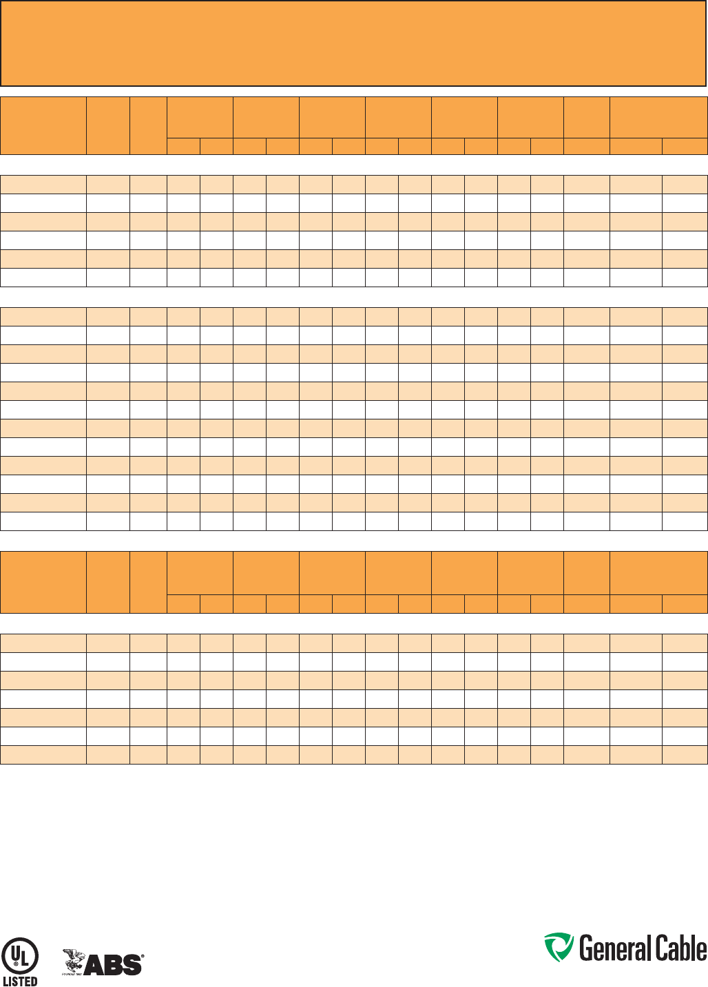
Phone: 888-593-3355
www.generalcable.com
CCW
®
Armored Instrumentation, Pairs/Triads, Overall Shield
UL Type MC-HL, PVC/Nylon, 600 V, 90°C, Cable Tray Use, Sunlight-Resistant, Direct Burial
UL Marine Shipboard Cable, ABS CWCMC
SPEC 9325
February, 2011
PART
NUMBER
COND.
SIZE
(AWG)
NO. OF
PAIRS
INSULATION
THICKNESS
INNER JACKET
THICKNESS
NOMINAL
CORE O.D.
NOMINAL
ARMOR O.D.
JACKET
THICKNESS
NOMINAL
OVERALL O.D.
CROSS-
SECTIONAL
AREA¹
APPROXIMATE NET
WEIGHT
mils mm mils mm INCHES mm INCHES mm mils mm INCHES mm (SQ. IN.) LBS/1000 FT kg/1000 m
18 AWG 7W (0.82 mm²) OVERALL SHIELDED PAIRS
9325.18020001
18 2 19 0.48 40 1.02 0.41 10.4 0.59 15.0 50 1.27 0.70 17.8 0.39 222 330
9325.18040001
18 4 19 0.48 40 1.02 0.48 12.2 0.65 16.5 50 1.27 0.75 19.1 0.45 268 399
9325.18080001
18 8 19 0.48 50 1.27 0.60 15.2 0.82 20.8 50 1.27 0.92 23.4 0.67 420 625
9325.18120001
18 12 19 0.48 50 1.27 0.78 19.8 1.00 25.4 50 1.27 1.10 27.9 0.96 560 833
9325.18160001
18 16 19 0.48 50 1.27 0.81 20.6 1.12 28.4 50 1.27 1.23 31.2 1.20 706 1,051
9325.18240001
18 24 19 0.48 50 1.27 1.08 27.4 1.39 35.3 50 1.27 1.49 37.8 1.77 969 1,442
16 AWG 7W (1.31 mm²) OVERALL SHIELDED PAIRS
9325.16010001
16 1 19 0.48 60 1.52 0.35 8.9 0.53 13.5 50 1.27 0.64 16.3 0.33 185 275
9325.16020001
16 2 19 0.48 40 1.02 0.38 9.7 0.58 14.7 50 1.27 0.69 17.5 0.38 246 366
9325.16040001
16 4 19 0.48 40 1.02 0.47 11.9 0.71 18.0 50 1.27 0.82 20.8 0.54 333 495
9325.16060001
16 6 19 0.48 50 1.27 0.58 14.7 0.80 20.3 50 1.27 0.91 23.1 0.66 405 603
9325.16080001
16 819 0.48 50 1.27 0.66 16.8 0.89 22.6 50 1.27 1.00 25.4 0.80 466 694
9325.16100001
16 10 19 0.48 50 1.27 0.76 19.3 1.02 25.9 50 1.27 1.13 28.7 1.02 556 827
9325.16120001
16 12 19 0.48 50 1.27 0.80 20.3 1.06 26.9 50 1.27 1.17 29.7 1.09 604 899
9325.16160001
16 16 19 0.48 50 1.27 0.87 22.1 1.15 29.2 50 1.27 1.26 32.0 1.26 799 1,189
9325.16200001
16 20 19 0.48 50 1.27 0.98 24.9 1.29 32.8 50 1.27 1.40 35.6 1.56 929 1,383
9325.16240001
16 24 19 0.48 50 1.27 1.08 27.4 1.37 34.8 50 1.27 1.48 37.6 1.74 1,040 1,548
9325.16360001
16 36 19 0.48 50 1.27 1.32 33.5 1.64 41.7 60 1.52 1.78 45.2 2.52 1,445 2,151
9325.16500001
16 50 19 0.48 50 1.27 1.48 37.6 1.83 46.5 60 1.52 1.96 49.8 3.06 1,897 2,823
PART
NUMBER
COND.
SIZE
(AWG)
NO. OF
TRIADS
INSULATION
THICKNESS
INNER JACKET
THICKNESS
NOMINAL
CORE O.D.
NOMINAL
ARMOR O.D.
OVERALL
JACKET
THICKNESS
NOMINAL
OVERALL O.D.
CROSS-
SECTIONAL
AREA¹
APPROXIMATE NET
WEIGHT
mils mm mils mm INCHES mm INCHES mm mils mm INCHES mm (SQ. IN.) LBS/1000 FT kg/1000 m
16 AWG 7W (1.31 mm²) OVERALL SHIELDED TRIADS
9325.16010002
16 1 19 0.48 50 1.27 0.35 8.9 0.53 13.5 50 1.27 0.64 16.3 0.33 195 290
9325.16040002
16 4 19 0.48 40 1.02 0.51 13.0 0.71 18.0 50 1.27 0.82 20.8 0.54 407 606
9325.16080002
16 819 0.48 50 1.27 0.71 18.0 0.93 23.6 50 1.27 1.04 26.4 0.86 617 918
9325.16120002
16 12 19 0.48 50 1.27 0.85 21.6 1.11 28.2 50 1.27 1.22 31.0 1.18 897 1,334
9325.16160002
16 16 19 0.48 50 1.27 0.93 23.6 1.19 30.2 50 1.27 1.30 33.0 1.34 1,161 1,727
9325.16240002
16 24 19 0.48 50 1.27 1.16 29.5 1.47 37.3 50 1.27 1.58 40.1 1.99 1,581 2,353
9325.16360002
16 36 19 0.48 50 1.27 1.42 36.1 1.74 44.2 60 1.52 1.87 47.5 2.78 2,142 3,188
Dimensions and weights are nominal; subject to industry tolerances.
¹ Cross-sectional area for cable tray fill is in accordance with NEC® Section 392.22.
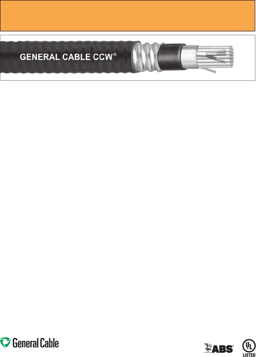
Phone: 888-593-3355
www.generalcable.com
CCW
®
Armored Instrumentation, Pairs/Triads, Individual and Overall Shield
UL Type MC-HL, PVC/Nylon, 600 V, 90°C, Cable Tray Use, Sunlight-Resistant, Direct Burial
UL Marine Shipboard Cable, ABS CWCMC
SPEC 9350
February, 2011
CCW Armor:
•Impervious,continuouslyweldedand
corrugated aluminum alloy sheath per
UL Standards 1569 and 2225
•CCWarmorconductivitymeetsthe
grounding requirements of NEC Article
250
Overall Jacket:
•Flame-retardant,moisture-and
sunlight-resistant Polyvinyl Chloride
(PVC) per UL Standard 1569, black
•Lowtemperatureperformancemeets
ASTM D746 brittleness temperature at
or below -40°C
Applications:
•CCWarmored600voltInstrumentation
cables with individually shielded pairs
or triads and an overall shield provide
superior protection and reliability
against physical damage for use in
instrumentation and process control
applications where shielding against
both external EMI and EMI between
groups is required
•ForuseinClass1remote-controland
signal circuits in accordance with NEC
Article 725
•RecognizedforuseinClassI,IIand
III, Divisions 1 and 2; or Class I, Zones
1 and 2 hazardous locations per NEC
Articles 501, 502, 503 and 505
•Installedindoorsoroutdoors,inwetor
dry locations, in a raceway, as aerial
cable on a messenger, in cable trays,
or for direct burial
•Recognizedforuseonfixedor
floating offshore petroleum facilities
as recommended by the American
Petroleum Institute
Features:
•CCWarmorprovidessuperior
mechanical protection and an
impervious barrier to moisture, gas
and liquids
•CCWarmorprovidesEMIshielding
performance
•Meetscoldimpactat-40°C
Specifications:
Design Adherence:
•UL83ThermoplasticInsulatedWire
and Cables
•UL1569MetalCladCables
•UL2225CablesandCableFittingsfor
Use in Hazardous Locations
•UL1309/CSAC22.2No.245Marine
Shipboard Cable
Flame Tests:
•ICEAT-29-520(210,000BTU/hr)
•IEEE383(70,000BTU/hr)
•CSAFT4
•IEEE1202(70,000BTU/hr)
•UL1581(70,000BTU/hr)
•IEC60332-3Cat.A
Compliances:
•ULTypeMC-HL,CTUSE,SUNRES,
DIR BUR, -40°C, UL File # E69797
•ULListedMarineShipboard,ULFile#
E85994
•AmericanBureauofShipping(ABS)
Listed for CWCMC
Product Construction:
Conductor:
•BareannealedcopperperASTMB3
•ClassBstrandingperASTMB8
Insulation:
•Flame-retardantPolyvinylChloride
(PVC) insulation and nylon covering,
rated90°CperULStandard83
•Color-codedperICEAMethod1:
pairs – black and white; triads – black,
white and red. Each conductor in each
pair or triad is printed alphanumerically
for easy identification
Shielded Pairs/Triads:
•Isolatedandindividuallytwistedpairs
or triads with a Flexfoil® aluminum/
polyester tape shield providing 100%
coverage
•Strandedtinnedcopperdrainwire,two
sizes smaller than insulated conductors
Cable Assembly:
•Individuallyshieldedpairsortriadsare
cabled together with a left-hand lay
Overall Shield:
•Flexfoil® aluminum/polyester tape shield
providing 100% coverage
•Strandedtinnedcopperdrainwire,
same size as insulated conductors
Inner Jacket:
•Flame-retardantPolyvinylChloride
(PVC) per UL Standard 1569, black
•Lowtemperatureperformancemeets
ASTM D746 brittleness temperature at
or below -40°C
•Nylonripcordtofacilitatejacket
removal
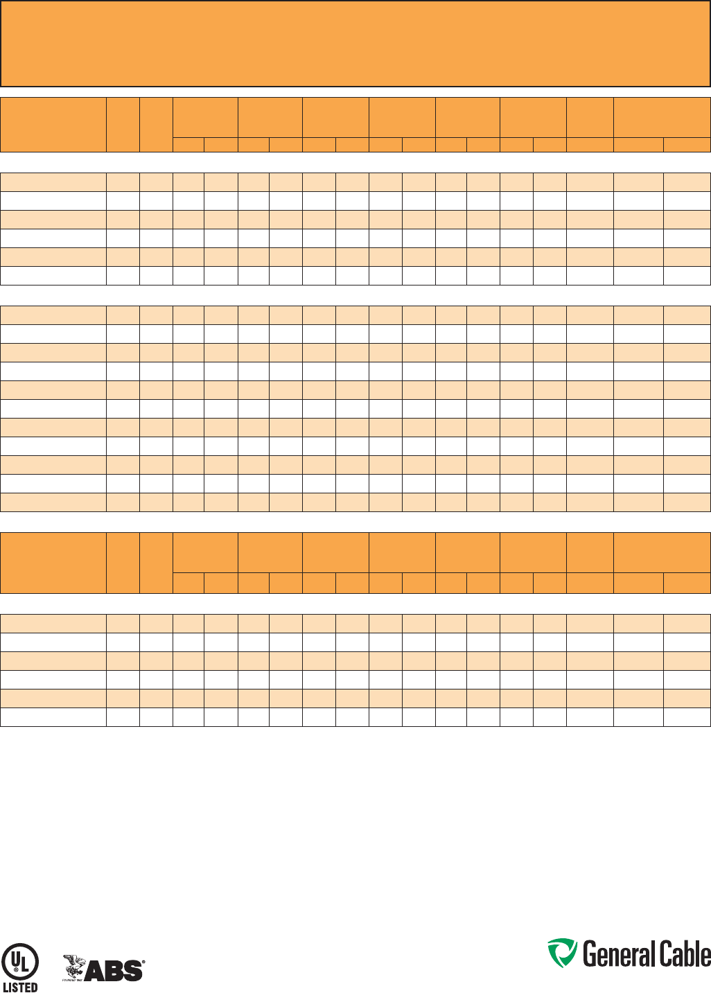
Phone: 888-593-3355
www.generalcable.com
CCW
®
Armored Instrumentation, Pairs/Triads, Individual and Overall Shield
UL Type MC-HL, PVC/Nylon, 600 V, 90°C, Cable Tray Use, Sunlight-Resistant, Direct Burial
UL Marine Shipboard Cable, ABS CWCMC
SPEC 9350
February, 2011
PART
NUMBER
COND.
SIZE
(AWG)
NO. OF
PAIRS
INSULATION
THICKNESS
INNER JACKET
THICKNESS
NOMINAL
CORE O.D.
NOMINAL
ARMOR O.D.
OVERALL
JACKET
THICKNESS
NOMINAL
OVERALL O.D.
CROSS-
SECTIONAL
AREA¹
APPROXIMATE
NET WEIGHT
mils mm mils mm INCHES mm INCHES mm mils mm INCHES mm (SQ. IN.) LBS/1000 FT kg/1000 m
18 AWG 7W (0.82 mm²) INDIVIDUAL AND OVERALL SHIELDED PAIRS
9350.18020001
18 2 19 0.48 40 1.02 0.41 10.4 0.59 15.0 50 1.27 0.70 17.8 0.39 225 335
9350.18040001
18 4 19 0.48 40 1.02 0.48 12.2 0.65 16.5 50 1.27 0.75 19.1 0.45 300 446
9350.18080001
18 8 19 0.48 50 1.27 0.60 15.2 0.82 20.8 50 1.27 0.92 23.4 0.67 450 670
9350.18120001
18 12 19 0.48 50 1.27 0.78 19.8 1.00 25.4 50 1.27 1.10 27.9 0.96 580 863
9350.18160001
18 16 19 0.48 50 1.27 0.81 20.6 1.12 28.4 50 1.27 1.23 31.2 1.20 760 1,131
9350.18240001
18 24 19 0.48 50 1.27 1.08 27.4 1.39 35.3 50 1.27 1.49 37.8 1.77 1,050 1,563
16 AWG 7W (1.31 mm²) INDIVIDUAL AND OVERALL SHIELDED PAIRS
9350.16020001
16 2 19 0.48 40 1.02 0.45 11.4 0.67 17.0 50 1.27 0.78 19.8 0.48 239 355
9350.16040001
16 4 19 0.48 50 1.27 0.56 14.2 0.80 20.3 50 1.27 0.91 23.1 0.66 342 509
9350.16060001
16 6 19 0.48 50 1.27 0.66 16.8 0.89 22.6 50 1.27 1.00 25.4 0.80 429 639
9350.16080001
16 819 0.48 50 1.27 0.70 17.8 0.93 23.6 50 1.27 1.04 26.4 0.86 502 747
9350.16100001
16 10 19 0.48 50 1.27 0.79 20.1 1.06 26.9 50 1.27 1.17 29.7 1.09 613 912
9350.16120001
16 12 19 0.48 50 1.27 0.85 21.6 1.11 28.2 50 1.27 1.22 31.0 1.18 687 1,023
9350.16160001
16 16 19 0.48 50 1.27 0.98 24.9 1.29 32.8 50 1.27 1.40 35.6 1.56 859 1,278
9350.16200001
16 20 19 0.48 50 1.27 1.06 26.9 1.34 34.0 50 1.27 1.45 36.8 1.67 997 1,483
9350.16240001
16 24 19 0.48 50 1.27 1.12 28.4 1.42 36.1 50 1.27 1.53 38.9 1.86 1,140 1,697
9350.16360001
16 36 19 0.48 50 1.27 1.37 34.8 1.69 42.9 60 1.52 1.82 46.2 2.64 1,618 2,407
9350.16500001
16 50 19 0.48 50 1.27 1.57 39.9 1.92 48.8 60 1.52 2.05 52.1 3.34 2,166 3,224
PART
NUMBER
COND.
SIZE
(AWG)
NO. OF
TRIADS
INSULATION
THICKNESS
INNER JACKET
THICKNESS
NOMINAL
CORE O.D.
NOMINAL
ARMOR O.D.
OVERALL
JACKET
THICKNESS
NOMINAL
OVERALL O.D.
CROSS-
SECTIONAL
AREA¹
APPROXIMATE
NET WEIGHT
mils mm mils mm INCHES mm INCHES mm mils mm INCHES mm (SQ. IN.) LBS/1000 FT kg/1000 m
16 AWG 7W (1.31 mm²) INDIVIDUAL AND OVERALL SHIELDED TRIADS
9350.16040002
16 4 19 0.48 50 1.27 0.61 15.5 0.84 21.3 50 1.27 0.95 24.1 0.72 403 600
9350.16080002
16 819 0.48 50 1.27 0.82 20.8 1.06 26.9 50 1.27 1.17 29.7 1.09 650 967
9350.16120002
16 12 19 0.48 50 1.27 0.98 24.9 1.24 31.5 50 1.27 1.35 34.3 1.45 853 1,269
9350.16160002
16 16 19 0.48 50 1.27 1.10 27.9 1.37 34.8 50 1.27 1.48 37.6 1.74 1,079 1,606
9350.16240002
16 24 19 0.48 50 1.27 1.33 33.8 1.64 41.7 60 1.52 1.78 45.2 2.52 1,515 2,254
9350.16360002
16 36 19 0.48 50 1.27 1.58 40.1 1.96 49.8 60 1.52 2.09 53.1 3.48 2,184 3,250
Dimensions and weights are nominal; subject to industry tolerances.
¹ Cross-sectional area for cable tray fill is in accordance with NEC® Section 392.22.
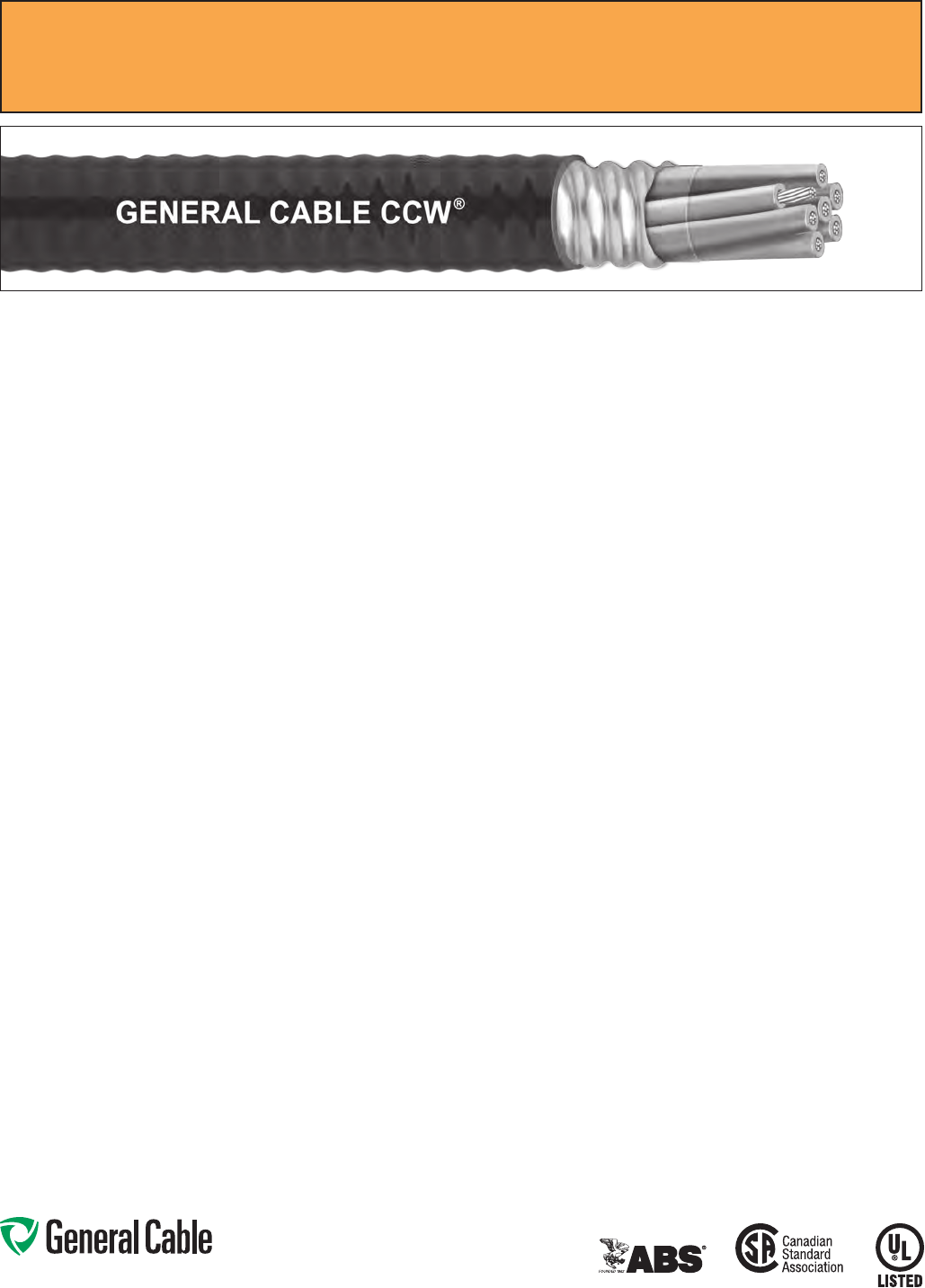
Phone: 888-593-3355
www.generalcable.com
SPEC 9500
February, 2011
Applications:
•CCWarmoredControlcablesoffer
an economical, rugged and reliable
alternative to labor-intensive cable in
conduit wiring methods
•ForuseinClassI,IIandIII,Divisions
1 and 2; and Class I, Zones 1 and 2
hazardous locations per NEC Articles
501, 502, 503 and 505
•Foruseasservices,feedersand
branch circuits for power, lighting,
control, and signal circuits in
accordance with NEC Articles 330
and 725
•Installedindoorsoroutdoors,wet
or dry locations, directly buried,
embedded in concrete, in a raceway,
as aerial cable on a messenger,
in cable trays, or as exposed runs
secured to supports in accordance
with NEC Article 330
•Recognizedforuseonfixedor
floating offshore petroleum facilities
as recommended by the American
Petroleum Institute
Features:
•CCWarmorprovidesanimpervious
barrier to moisture, gas and liquids
•CCWarmorprovidesEMIshielding
performance
•Factoryassembledandtestedcable
for use as an alternative to cable in
conduit wiring systems
•Meetscoldimpactat-40°C
•90˚Ccontinuousoperating
temperature, wet or dry
•130˚Cemergencyrating
•250˚Cshortcircuitrating
CCW
®
Armored Control With Grounding Conductor
UL Type MC-HL, XLPE, 600 V, 90°C, Cable Tray Use, Sunlight-Resistant, Direct Burial
UL Marine Shipboard Cable, ABS CWCMC
Product Construction:
Conductor:
•BareannealedcopperperASTMB3
•CompressedClassBstrandingper
ASTMB8
Insulation:
•Cross-LinkedPolyethylene(XLPE)
insulation per ICEA S-73-532 and UL
44, Listed XHHW-2
•Color-codedperICEAMethod1,Table
E2, full-colored insulation with stripes
•Color-codedperCSAC22.2No.123
where applicable
Grounding Conductor:
•ClassBstrandedbareannealed
copperperASTMB3andB8
•Cross-LinkedPolyethylene(XLPE)
insulation, green
•SizedinaccordancewithNECTable
25 0.122
Cable Assembly:
•Insulatedconductorsandgrounding
wire are cabled together with non-
hygroscopic fillers when required
•Abindertape,whenrequired,is
applied over the cabled core
CCW Armor:
•Impervious,continuouslyweldedand
corrugated aluminum alloy sheath per
UL 1569 and UL 2225
•CCWarmorconductivitymeetsthe
grounding requirements of NEC
Article 250
Jacket:
•Flame-retardant,moisture-and
sunlight-resistant Polyvinyl Chloride
(PVC), black
•Lowtemperatureperformancemeets
ASTM D746 brittleness temperature at
or below -40°C
•MeetsCSALowAcidGas
requirements
Specifications:
Design Adherence:
•ICEAS-73-532/WC-57Standardfor
Control, Thermocouple Extension and
Instrumentation Cables
•UL44RubberInsulatedWiresand
Cables
•UL1569MetalCladCables
•UL2225CablesandCableFittingsfor
Use in Hazardous Locations
•UL1309MarineShipboardCable
•CSAC22.2No.123MetalSheathed
Cables
•CSAC22.2No.174CablesandCable
Glands for Use in Hazardous Locations
Flame Tests:
•ICEAT-29-520(210,000BTU/hr)
•IEEE383(70,000BTU/hr)
•CSAFT4
•IEEE1202(70,000BTU/hr)
•UL1581(70,000BTU/hr)
•IEC60332-3Cat.A
Compliances:
•ULTypeMC-HL,XHHW-2,SUNRES,
CT USE, DIR BUR, -40°C, UL File
# E69797
•ULListedMarineShipboard,ULFile
#E85994
•AmericanBureauofShipping(ABS)
Listed for CWCMC
•CSAcertified
1
Type RA90, XLPE,
HL, SR, FT4, and -40°C, CSA File
# 7319
1
Standard cables are also marked CSA Type RA90,
except four (4) conductor cables which require a different
color code, which may be special-ordered.
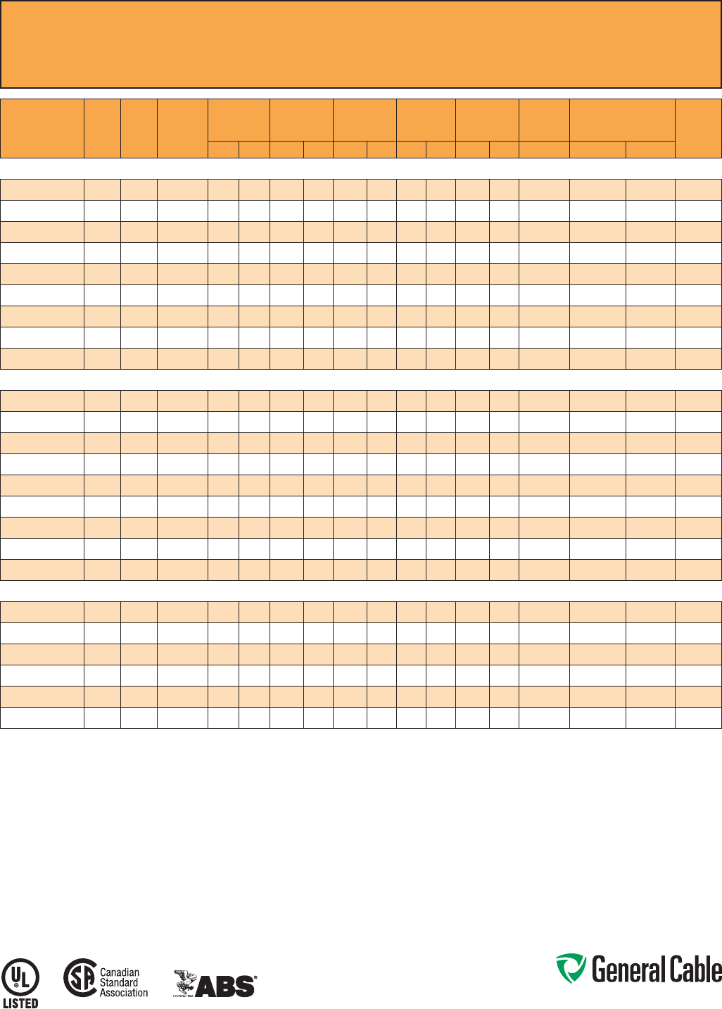
Phone: 888-593-3355
www.generalcable.com
SPEC 9500
February, 2011
CCW
®
Armored Control With Grounding Conductor
UL Type MC-HL, XLPE, 600 V, 90°C, Cable Tray Use, Sunlight-Resistant, Direct Burial
UL Marine Shipboard Cable, ABS CWCMC
PART
NUMBER
COND.
SIZE
(AWG)
NO. OF
COND.
GREEN
INSULATED
GROUND
(AWG)
INSULATION
THICKNESS
NOMINAL
CORE O.D.
NOMINAL
ARMOR O.D.
JACKET
THICKNESS
NOMINAL
OVERALL O.D.
CROSS-
SECTIONAL
AREA¹
APPROXIMATE NET
WEIGHT
90°C
AMPACITY
@ 30°C
AMBIENT²mils mm INCHES mm INCHES mm mils mm INCHES mm (SQ. IN.) LBS/1000 FT kg/1000 m
14 AWG 7W (2.08 mm²) MULTI-CONDUCTOR CONTROL CABLE WITH GREEN INSULATED GROUNDING CONDUCTOR
9500.01402114
14 2 14 30 0.76 0.30 7.6 0.49 12.4 50 1.27 0.60 15.2 0.29 163 243 15
9500.01403114
14 3 14 30 0.76 0.33 8.4 0.53 13.5 50 1.27 0.64 16.3 0.33 192 286 15
9500.01404114
14 4 14 30 0.76 0.37 9.4 0.58 14.7 50 1.27 0.69 17.5 0.38 222 330 15
9500.01405114
14 5 14 30 0.76 0.39 9.9 0.60 15.2 50 1.27 0.71 18.0 0.40 245 365 15
9500.01406114
14 6 14 30 0.76 0.41 10.4 0.62 15.7 50 1.27 0.73 18.5 0.42 267 397 15
9500.01408114
14 814 30 0.76 0.49 12.4 0.71 18.0 50 1.27 0.82 20.8 0.54 321 478 15
9500.01411114
14 11 14 30 0.76 0.57 14.5 0.80 20.3 50 1.27 0.91 23.1 0.66 395 588 12
9500.01418114
14 18 14 30 0.76 0.69 17.5 0.93 23.6 50 1.27 1.04 26.4 0.86 554 824 12
9500.01436114
14 36 14 30 0.76 0.97 24.6 1.24 31.5 50 1.27 1.35 34.3 1.45 948 1,411 10
12 AWG 7W (3.31 mm²) MULTI-CONDUCTOR CONTROL CABLE WITH GREEN INSULATED GROUNDING CONDUCTOR
9500.01202112
12 2 12 30 0.76 0.34 8.6 0.53 13.5 50 1.27 0.64 16.3 0.33 200 298 20
9500.01203112
12 3 12 30 0.76 0.37 9.4 0.58 14.7 50 1.27 0.69 17.5 0.38 239 356 20
9500.01204112
12 4 12 30 0.76 0.45 11.4 0.67 17.0 50 1.27 0.78 19.8 0.48 310 461 20
9500.01205112
12 5 12 30 0.76 0.46 11.7 0.67 17.0 50 1.27 0.78 19.8 0.48 324 482 20
9500.01206112
12 6 12 30 0.76 0.47 11.9 0.67 17.0 50 1.27 0.78 19.8 0.48 338 503 20
9500.01208112
12 812 30 0.76 0.56 14.2 0.80 20.3 50 1.27 0.91 23.1 0.66 426 634 20
9500.01211112
12 11 12 30 0.76 0.65 16.5 0.89 22.6 50 1.27 1.00 25.4 0.80 519 772 15
9500.01218112
12 18 12 30 0.76 0.78 19.8 1.02 25.9 50 1.27 1.13 28.7 1.02 739 1,100 15
9500.01236112
12 36 12 30 0.76 1.10 27.9 1.37 34.8 50 1.27 1.48 37.6 1.74 1,302 1,938 12
10 AWG 7W (5.26 mm²) MULTI-CONDUCTOR CONTROL CABLE WITH GREEN INSULATED GROUNDING CONDUCTOR
9500.01002110
10 2 10 30 0.76 0.39 9.9 0.58 14.7 50 1.27 0.69 17.5 0.38 253 377 30
9500.01003110
10 3 10 30 0.76 0.41 10.4 0.62 15.7 50 1.27 0.73 18.5 0.42 303 451 30
9500.01004110
10 4 10 30 0.76 0.45 11.4 0.67 17.0 50 1.27 0.78 19.8 0.48 348 518 30
9500.01006110
10 6 10 30 0.76 0.54 13.7 0.75 19.1 50 1.27 0.86 21.8 0.59 451 671 28
9500.01008110
10 810 30 0.76 0.65 16.5 0.89 22.6 50 1.27 1.00 25.4 0.80 568 845 28
9500.01011110
10 11 10 30 0.76 0.75 19.1 0.97 24.6 50 1.27 1.08 27.4 0.93 704 1,048 20
Dimensions and weights are nominal; subject to industry tolerances.
¹ Cross-sectional area for cable tray fill is in accordance with NEC Section 392.22.
² Ampacities in accordance with NEC Article 310 and Table 310.15(B)(16).
Note:Standardcableswithuptoandincludingsix(6)conductorsarealsomarkedCSATypeRA90.Allothersarespecialorder.
Phone: 888-593-3355
www.generalcable.com
SPEC 9510
February, 2011
Applications:
•CCWarmoredControlcablesoffer
an economical, rugged and reliable
alternative to labor-intensive cable in
conduit wiring methods
•ForuseinClassI,IIandIII,Divisions
1 and 2; and Class I, Zones 1 and 2
hazardous locations per NEC Articles
501, 502, 503 and 505
•Foruseasservices,feedersand
branch circuits for power, lighting,
control, and signal circuits in
accordance with NEC Articles 330
and 725
•Installedindoorsoroutdoors,wet
or dry locations, directly buried,
embedded in concrete, in a raceway,
as aerial cable on a messenger,
in cable trays, or as exposed runs
secured to supports in accordance
with NEC Article 330
•Recognizedforuseonfixedor
floating offshore petroleum facilities
as recommended by the American
Petroleum Institute
Features:
•CCWarmorprovidesanimpervious
barrier to moisture, gas and liquids
•CCWarmorprovidesEMIshielding
performance
•Factoryassembledandtestedcable
for use as an alternative to cable in
conduit wiring systems
•Meetscoldimpactat-40°C
•90˚Ccontinuousoperating
temperature, wet or dry
•130˚Cemergencyrating
•250˚Cshortcircuitrating
CCW
®
Armored Control With Bare Grounding Conductor
UL Type MC-HL, XLPE, 600 V, 90°C, Cable Tray Use, Sunlight-Resistant, Direct Burial
UL Marine Shipboard Cable, ABS CWCMC
Product Construction:
Conductor:
•BareannealedcopperperASTMB3
•CompressedClassBstrandingper
ASTMB8
Insulation:
•Cross-LinkedPolyethylene(XLPE)
insulation per ICEA S-73-532 and UL
44, Listed XHHW-2
•Color-codedperICEAMethod1,Table
E2, full-colored insulation with stripes
•Color-codedperCSAC22.2No.123
where applicable
Grounding Conductor:
•ClassBstrandedbareannealed
copperperASTMB3andB8
•SizedinaccordancewithNECTable
25 0.122
Cable Assembly:
•Insulatedconductorsandgrounding
wire are cabled together with non-
hygroscopic fillers when required
•Abindertape,whenrequired,is
applied over the cabled core
CCW Armor:
•Impervious,continuouslyweldedand
corrugated aluminum alloy sheath per
UL 1569 and UL 2225
•CCWarmorconductivitymeetsthe
grounding requirements of NEC
Article 250
Jacket:
•Flame-retardant,moisture-and
sunlight-resistant Polyvinyl Chloride
(PVC), black
•Lowtemperatureperformancemeets
ASTM D746 brittleness temperature at
or below -40°C
•MeetsCSALowAcidGas
requirements
Specifications:
Design Adherence:
•ICEAS-73-532/WC-57Standardfor
Control, Thermocouple Extension and
Instrumentation Cables
•UL44RubberInsulatedWiresand
Cables
•UL1569MetalCladCables
•UL2225CablesandCableFittingsfor
Use in Hazardous Locations
•UL1309MarineShipboardCable
•CSAC22.2No.123MetalSheathed
Cables
Flame Tests:
•ICEAT-29-520(210,000BTU/hr)
•IEEE383(70,000BTU/hr)
•CSAFT4
•IEEE1202(70,000BTU/hr)
•UL1581(70,000BTU/hr)
•IEC60332-3Cat.A
Compliances:
•ULTypeMC-HL,XHHW-2,SUNRES,
CT USE, DIR BUR, -40°C, UL File
# E69797
•ULListedMarineShipboard,ULFile
#E85994
•AmericanBureauofShipping(ABS)
Listed for CWCMC
•CSAcertified
1
Type RA90, XLPE, SR,
FT4, and -40°C, CSA File # 7319
1
Standard cables are also marked CSA Type RA90,
except four (4) conductor cables which require a different
color code, which may be special-ordered.
Phone: 888-593-3355
www.generalcable.com
SPEC 9510
February, 2011
PART
NUMBER
COND.
SIZE
(AWG)
NO. OF
COND.
BARE
INSULATED
GROUND
(AWG)
INSULATION
THICKNESS
NOMINAL
CORE O.D.
NOMINAL
ARMOR O.D.
JACKET
THICKNESS
NOMINAL
OVERALL O.D.
CROSS-
SECTIONAL
AREA¹
APPROXIMATE NET
WEIGHT
90°C
AMPACITY
@ 30°C
AMBIENT²mils mm INCHES mm INCHES mm mils mm INCHES mm SQ. IN. LBS/1000 FT kg/1000 m
14 AWG 7W (2.08 mm²) MULTI-CONDUCTOR CONTROL CABLE WITH BARE GROUNDING CONDUCTOR
9510.01404114
14 4 14 30 0.76 0.35 8.8 0.52 13.3 50 1.27 0.63 16.0 0.62 203 302 20
9510.01405114
14 5 14 30 0.76 0.38 9.7 0.53 13.5 50 1.27 0.63 16.0 0.62 224 333 20
9510.01407114
14 7 14 30 0.76 0.43 10.9 0.60 15.2 50 1.27 0.71 18.0 0.79 287 427 17.5
9510.01409114
14 9 14 30 0.76 0.51 13.0 0.75 19.1 50 1.27 0.86 21.8 1.16 368 548 17.5
9510.01412114
14 12 14 30 0.76 0.56 14.2 0.79 20.1 50 1.27 0.89 22.6 1.24 425 632 12.5
9510.01419114
14 19 14 30 0.76 0.67 17.0 0.92 23.4 50 1.27 1.02 25.9 1.63 594 884 12.5
9510.01437114
14 37 14 30 0.76 0.94 23.9 1.22 31.0 50 1.27 1.32 33.5 2.74 1030 1533 10
12 AWG 7W (3.31 mm²) MULTI-CONDUCTOR CONTROL CABLE WITH BARE GROUNDING CONDUCTOR
9510.01204112
12 4 12 30 0.76 0.38 9.7 0.55 14.0 50 1.27 0.65 16.5 0.66 246 366 24
9510.01205112
12 5 12 30 0.76 0.43 10.9 0.61 15.5 50 1.27 0.71 18.0 0.79 302 449 24
9510.01207112
12 7 12 30 0.76 0.49 12.4 0.64 16.3 50 1.27 0.74 18.8 0.86 362 539 21
9510.01209112
12 9 12 30 0.76 0.58 14.7 0.79 20.1 50 1.27 0.90 22.9 1.21 458 682 21
9510.012121112
12 12 12 30 0.76 0.64 16.3 0.83 21.1 50 1.27 0.94 23.9 1.39 545 811 15
10 AWG 7W (5.26 mm²) MULTI-CONDUCTOR CONTROL CABLE WITH BARE GROUNDING CONDUCTOR
9510.01004110
10 4 10 30 0.76 0.46 11.7 0.63 16.0 50 1.27 0.73 18.5 0.84 343 510 32
Dimensions and weights are nominal; subject to industry tolerances.
¹ Cross-sectional area for cable tray fill is in accordance with NEC Section 392.22.
² Ampacities in accordance with NEC Article 310 and Table 310.15(B)(16).
CCW
®
Armored Control With Bare Grounding Conductor
UL Type MC-HL, XLPE, 600 V, 90°C, Cable Tray Use, Sunlight-Resistant, Direct Burial
UL Marine Shipboard Cable, ABS CWCMC

Phone: 888-593-3355
www.generalcable.com
SPEC 9525
February, 2011
Applications:
•CCWarmoredControlcablesoffer
an economical, rugged and reliable
alternative to labor-intensive cable in
conduit wiring methods
•ForuseinClassIandII,Division2;
Class III, Divisions 1 and 2; and Class
I, Zone 2 hazardous locations per NEC
Articles 501, 502, 503 and 505
•Foruseasservices,feedersand
branch circuits for power, lighting,
control, and signal circuits in
accordance with NEC Articles 330
and 725
•Installedindoorsoroutdoors,wet
or dry locations, directly buried,
embedded in concrete, in a raceway,
as aerial cable on a messenger,
in cable trays, or as exposed runs
secured to supports in accordance
with NEC Article 330
•Recognizedforuseonfixedor
floating offshore petroleum facilities
as recommended by the American
Petroleum Institute
Features:
•CCWarmorprovidesanimpervious
barrier to moisture, gas and liquids
•CCWarmorprovidesEMIshielding
performance
•Factoryassembledandtestedcable
for use as an alternative to cable in
conduit wiring systems
•Meetscoldimpactat-40°C
Features: (cont’d)
•90˚Ccontinuousoperating
temperature, wet or dry
•130˚Cemergencyrating
•250˚Cshortcircuitrating
Specifications:
Design Adherence:
•ICEAS-73-532/WC-57Standardfor
Control, Thermocouple Extension and
Instrumentation Cables
•UL44RubberInsulatedWiresand
Cables
•UL1569MetalCladCables
•UL1309MarineShipboardCable
•CSAC22.2No.123MetalSheathed
Cables
Flame Tests:
•ICEAT-29-520(210,000BTU/hr)
•IEEE383(70,000BTU/hr)
•CSAFT4
•IEEE1202(70,000BTU/hr)
•UL1581(70,000BTU/hr)
•IEC60332-3Cat.A
Compliances:
•ULTypeMC,XHHW-2,SUNRES,
CT USE, DIR BUR, -40°C, UL File
# E69797
•ULListedMarineShipboard,ULFile
#E85994
•AmericanBureauofShipping(ABS)
Listed for CWCMC
•CSAcertified
1
Type RA90, XLPE, SR,
FT4, and -40°C, CSA File # 7319
1
Standard cables are also marked CSA Type RA90,
except four (4) conductor cables which require a different
color code, which may be special-ordered.
Product Construction:
Conductor:
•BareannealedcopperperASTMB3
•ClassBstrandingperASTMB8
Insulation:
•Cross-LinkedPolyethylene(XLPE)
insulation per ICEA S-73-532 and UL
44, Listed XHHW-2
•Color-codedperICEAMethod1,Table
E2, full-colored insulation with stripes
•Color-codedperCSAC22.2No.123
where applicable
Cable Assembly:
•Insulatedconductorsarecabled
together with non-hygroscopic fillers
when required
•Abindertape,whenrequired,is
applied over the cabled core
CCW Armor:
•Impervious,continuouslyweldedand
corrugated aluminum alloy sheath per
UL 1569
•CCWarmorconductivitymeetsthe
grounding requirements of NEC
Article 250
Jacket:
•Flame-retardant,moisture-and
sunlight-resistant Polyvinyl Chloride
(PVC), black
•Lowtemperatureperformancemeets
ASTM D746 brittleness temperature at
or below -40°C
•MeetsCSALowAcidGas
requirements
CCW
®
Armored Control Without Grounding Conductor
UL Type MC, XLPE, 600 V, 90°C, Cable Tray Use, Sunlight-Resistant, Direct Burial
UL Marine Shipboard Cable, ABS CWCMC
Phone: 888-593-3355
www.generalcable.com
CCW
®
Armored Control Without Grounding Conductor
UL Type MC, XLPE, 600 V, 90°C, Cable Tray Use, Sunlight-Resistant, Direct Burial
UL Marine Shipboard Cable, ABS CWCMC
SPEC 9525
February, 2011
PART
NUMBER
COND.
SIZE
(AWG)
NO.
OF
COND.
INSULATION
THICKNESS
NOMINAL
CORE O.D.
NOMINAL
ARMOR O.D.
JACKET
THICKNESS
NOMINAL
OVERALL O.D.
CROSS-
SECTIONAL
AREA¹
APPROXIMATE
NET WEIGHT 90˚C
AMPACITY @
30˚C AMBIENT²
mils mm INCHES mm INCHES mm mils mm INCHES mm (SQ. IN.) LBS/1000 FT kg/1000 m
14 AWG 7W (2.08 mm²) MULTI-CONDUCTOR CONTROL CABLE WITHOUT GROUNDING CONDUCTOR
9525.01402000
14 2 30 0.76 0.28 7.1 0.49 12.4 50 1.27 0.60 15.2 0.29 144 214 15
9525.01403000
14 3 30 0.76 0.30 7.6 0.49 12.4 50 1.27 0.60 15.2 0.29 155 231 15
9525.01404000
14 4 30 0.76 0.33 8.4 0.53 13.5 50 1.27 0.64 16.3 0.33 183 273 15
9525.01405000
14 5 30 0.76 0.37 9.4 0.58 14.7 50 1.27 0.69 17.5 0.38 213 317 15
9525.01407000
14 7 30 0.76 0.41 10.4 0.62 15.7 50 1.27 0.73 18.5 0.42 257 383 15
9525.01409000
14 9 30 0.76 0.50 12.7 0.71 18.0 50 1.27 0.82 20.8 0.54 312 465 15
9525.01412000
14 12 30 0.76 0.57 14.5 0.80 20.3 50 1.27 0.91 23.1 0.66 386 575 12
9525.01419000
14 19 30 0.76 0.69 17.5 0.93 23.6 50 1.27 1.04 26.4 0.86 544 810 12
9525.01437000
14 37 30 0.76 0.96 24.4 1.24 31.5 50 1.27 1.35 34.3 1.45 959 1,427 10
12 AWG 7W (3.31 mm²) MULTI-CONDUCTOR CONTROL CABLE WITHOUT GROUNDING CONDUCTOR
9525.01202000
12 2 30 0.76 0.31 7.9 0.53 13.5 50 1.27 0.64 16.3 0.33 166 247 20
9525.01203000
12 3 30 0.76 0.34 8.6 0.53 13.5 50 1.27 0.64 16.3 0.33 192 285 20
9525.01204000
12 4 30 0.76 0.38 9.7 0.58 14.7 50 1.27 0.69 17.5 0.38 229 341 20
9525.01205000
12 5 30 0.76 0.42 10.7 0.62 15.7 50 1.27 0.73 18.5 0.42 266 395 20
9525.01207000
12 7 30 0.76 0.47 11.9 0.67 17.0 50 1.27 0.78 19.8 0.48 328 489 20
9525.01209000
12 9 30 0.76 0.56 14.2 0.80 20.3 50 1.27 0.91 23.1 0.66 410 611 20
9525.01212000
12 12 30 0.76 0.65 16.5 0.89 22.6 50 1.27 0.99 25.1 0.78 510 759 15
9525.01219000
12 19 30 0.76 0.78 19.8 1.02 25.9 50 1.27 1.13 28.7 1.02 731 1,087 15
9525.01237000
12 37 30 0.76 1.08 27.4 1.37 34.8 50 1.27 1.48 37.6 1.74 1,318 1,962 12
10 AWG 7W (5.26 mm²) MULTI-CONDUCTOR CONTROL CABLE WITHOUT GROUNDING CONDUCTOR
9525.01002000
10 2 30 0.76 0.36 9.1 0.58 14.7 50 1.27 0.69 17.5 0.38 205 305 30
9525.01003000
10 3 30 0.76 0.39 9.9 0.58 14.7 50 1.27 0.69 17.5 0.38 241 359 30
9525.01004000
10 4 30 0.76 0.44 11.2 0.67 17.0 50 1.27 0.78 19.8 0.48 301 448 30
9525.01005000
10 5 30 0.76 0.48 12.2 0.71 18.0 50 1.27 0.82 20.8 0.54 353 525 30
9525.01007000
10 7 30 0.76 0.54 13.7 0.75 19.1 50 1.27 0.86 21.8 0.59 442 658 28
9525.01009000
10 9 30 0.76 0.65 16.5 0.89 22.6 50 1.27 1.00 25.4 0.80 551 820 28
9525.01012000
10 12 30 0.76 0.74 18.8 0.97 24.6 50 1.27 1.08 27.4 0.93 693 1,032 20
Dimensions and weights are nominal; subject to industry tolerances.
¹ Cross-sectional area for cable tray fill is in accordance with NEC® Section 392.22.
² Ampacities in accordance with NEC® Article 310 and Table 310.15(B)(16).
Note:Standardcableswithuptoandincludingsix(6)conductorsarealsomarkedCSATypeRA90.Allothersarespecialorder.
Phone: 888-593-3355
www.generalcable.com
SPEC 9600
February, 2011
Applications:
•VariableFrequencyDrives:
3-conductor CCW armored cables
with three (3) symmetrical grounding
wires are the preferred wiring method
for use with AC motors controlled by
pulse-width modulated inverters in
VFD applications
•CCWarmoredcablesofferan
economical, rugged and reliable
alternative to labor-intensive cable in
conduit wiring methods
•ForuseinClassI,IIandIII,Divisions
1 and 2; and Class I, Zones 1 and 2
hazardous locations per NEC Articles
501, 502, 503 and 505
•Foruseasservices,feedersand
branch circuits for power, lighting,
control, and signal circuits in
accordance with NEC Articles 330
and 725
•Installedindoorsoroutdoors,wet
or dry locations, directly buried,
embedded in concrete, in a raceway,
as aerial cable on a messenger,
in cable trays, or as exposed runs
secured to supports in accordance
with NEC Article 330
•Recognizedforuseonfixedor
floating offshore petroleum facilities
as recommended by the American
Petroleum Institute
Features:
•3-conductorCCWpowercables
with three grounding wires are
recommended for use with pulse-width
modulated AC drives
•CCWarmorprovidesanimpervious
barrier to moisture, gas and liquids
•CCWarmorprovidesEMIshielding
performance
•Factoryassembledandtestedcable
for use as an alternative to cable in
conduit wiring systems
Features: (cont’d)
•Meetscoldimpactat-40°C
•90˚Ccontinuousoperating
temperature, wet or dry
•130˚Cemergencyrating
•250˚Cshortcircuitrating
Specifications:
Design Adherence:
•ICEAS-95-658/WC-70Standardfor
Non-Shielded Power Cable, 2 kV
or Less
•UL44RubberInsulatedWires
and Cables
•UL1569MetalCladCables
•UL2225CablesandCableFittingsfor
Use in Hazardous Locations
•UL1309MarineShipboardCable
•CSAC22.2No.123MetalSheathed
Cables
•CSAC22.2No.174CablesandCable
Glands for Use in Hazardous Locations
Flame Tests:
•ICEAT-29-520(210,000BTU/hr)
•IEEE383(70,000BTU/hr)
•CSAFT4
•IEEE1202(70,000BTU/hr)
•UL1581(70,000BTU/hr)
•IEC60332-3Cat.A
Compliances:
•ULTypeMC-HL,XHHW-2,SUNRES,
CT USE, DIR BUR, -40°C, UL File
# E69797
•ULListedMarineShipboard,ULFile
#E85994
•AmericanBureauofShipping(ABS)
Listed for CWCMC
•CSAcertified
1
Type RA90, XLPE,
HL, SR, FT4, and -40°C, CSA File
# 7319
1
Standard cables are also marked CSA Type RA90,
except four (4) conductor cables which require a different
color code, which may be special-ordered.
Product Construction:
•BareannealedcopperperASTMB3
•10AWGandsmallerareClassB
compressedstrandingperASTMB8
•8AWGandlargerarecompact
stranding per ASTM B496
Insulation:
•Cross-LinkedPolyethylene(XLPE)
insulationperICEAS-95-658andUL
44, Listed XHHW-2
•6AWGandsmallerarecolor-coded
per ICEA Method 1, Table E2
•4AWGandlargerareblackwith
printed numbers per ICEA Method 4
•Color-codedperCSAC22.2No.123
where applicable
Grounding Conductor(s):
•ClassBstrandedbareannealed
copperperASTMB3andB8
•Wherespecified,singleorthree
split grounding wires are sized in
accordance with NEC Table 250.122
Cable Assembly:
•Insulatedconductorsandgrounding
wire(s) are cabled together with non-
hygroscopic fillers when required
•Abindertapeisappliedoverthe
cabled core
CCW Armor:
•Impervious,continuouslyweldedand
corrugated aluminum alloy sheath per
UL 1569 and UL 2225
•CCWarmorconductivitymeetsthe
grounding requirements of NEC
Article 250
Jacket:
•Flame-retardant,moisture-and
sunlight-resistant Polyvinyl Chloride
(PVC), black
•Lowtemperatureperformancemeets
ASTM D746 brittleness temperature at
or below -40°C
•MeetsCSALowAcidGas
requirements
CCW
®
Armored Power, 3/C VFD and 4/C
UL Type MC-HL, XLPE, 600 V, 90°C, Cable Tray Use, Sunlight-Resistant, Direct Burial
UL Marine Shipboard Cable, ABS CWCMC
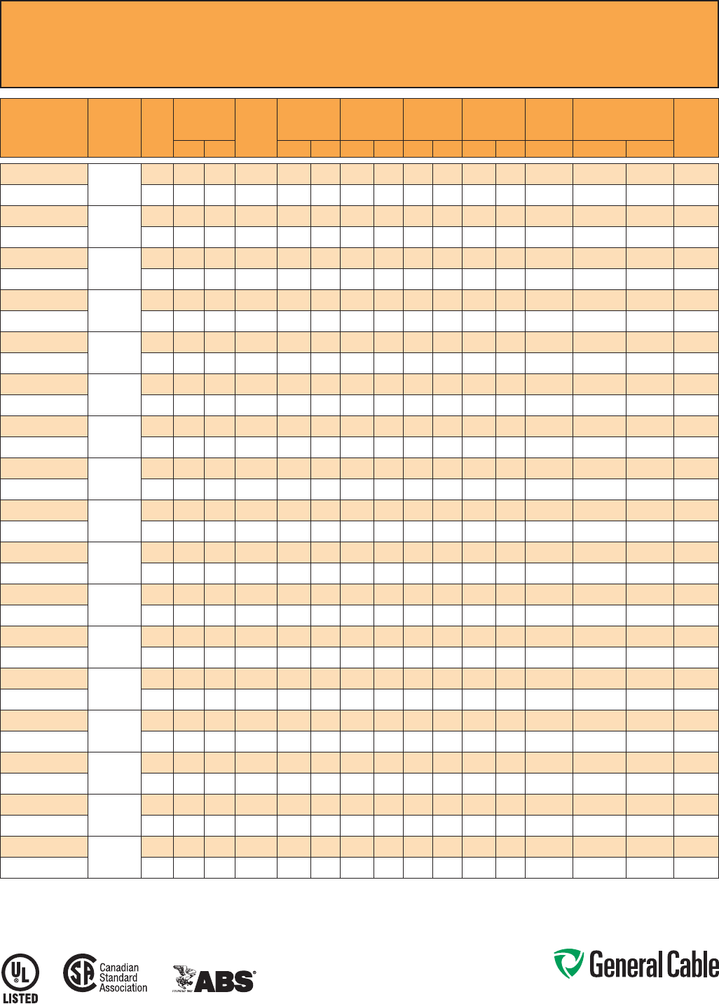
Phone: 888-593-3355
www.generalcable.com
CCW
®
Armored Power, 3/C VFD and 4/C
UL Type MC-HL, XLPE, 600 V, 90°C, Cable Tray Use, Sunlight-Resistant, Direct Burial
UL Marine Shipboard Cable, ABS CWCMC
SPEC 9600
February, 2011
PART
NUMBER
COND.
SIZE
(AWG/kcmil)
NO. OF
COND.
INSULATION
THICKNESS BARE
GROUND
(AWG)
NOMINAL
CORE O.D.
NOMINAL
ARMOR O.D.
JACKET
THICKNESS
NOMINAL
OVERALL O.D.
CROSS-
SECTIONAL
AREA¹
APPROXIMATE NET
WEIGHT
90°C
AMPACITY
@ 30°C
AMBIENT²mils mm INCHES mm INCHES mm mils mm INCHES mm (SQ. IN.) LBS/1000 FT kg/1000 m
9600.01403318
14 (7/W)
(2.08mm²)
3 30 0.76 3x#18 0.33 8.4 0.53 13.5 50 1.27 0.64 16.3 0.33 163 242 15
9600.01404318
4 30 0.76 3x#18 0.37 9.4 0.58 14.7 50 1.27 0.69 17.5 0.38 226 336 15
9600.01203316
12 (7/W)
(3.31 mm²)
3 30 0.76 3 x #16 0.37 9.4 0.58 14.7 50 1.27 0.69 17.5 0.38 243 362 20
9600.01204316
4 30 0.76 3 x #16 0.45 11.4 0.67 17.0 50 1.27 0.78 19.8 0.48 291 433 20
9600.01003314
10 (7/W)
(5.26 mm²)
3 30 0.76 3 x #14 0.41 10.4 0.62 15.7 50 1.27 0.73 18.5 0.42 305 454 30
9600.01004314
4 30 0.76 3 x #14 0.45 11.4 0.67 17.0 50 1.27 0.78 19.8 0.48 354 527 30
9600.00803314
8(7/W)
(8.36mm²)
3 45 1.14 3 x #14 0.50 12.7 0.71 18.0 50 1.27 0.81 20.6 0.52 392 583 55
9600.00804110
4 45 1.14 1 x #10 0.58 14.7 0.80 20.3 50 1.27 0.90 22.9 0.64 473 704 44
9600.00603312
6 (7/W)
(13.3 mm²)
3 45 1.14 3 x #12 0.58 14.7 0.80 20.3 50 1.27 0.90 22.9 0.64 534 795 75
9600.00604108
4 45 1.14 1x#8 0.66 16.8 0.89 22.6 50 1.27 0.99 25.1 0.78 641 954 60
9600.00403312
4 (7/W)
(21.2 mm²)
3 45 1.14 3 x #12 0.68 17.3 0.89 22.6 50 1.27 0.99 25.1 0.78 716 1,066 95
9600.00404108
4 45 1.14 1x#8 0.77 19.6 0.97 24.6 50 1.27 1.08 27.4 0.93 860 1,280 76
9600.00203310
2 (7/W)
(33.6 mm²)
3 45 1.14 3 x #10 0.80 20.3 1.02 25.9 50 1.27 1.13 28.7 1.02 1,013 1,507 130
9600.00204106
4 45 1.14 1 x #6 0.92 23.4 1.15 29.2 50 1.27 1.26 32.0 1.26 1,267 1,885 104
9600.00103310
1 (19/W)
(42.4 mm²)
3 55 1.40 3 x #10 0.92 23.4 1.15 29.2 50 1.27 1.26 32.0 1.26 1,119 1,666 150
9600.00104106
4 55 1.40 1 x #6 1.04 26.4 1.29 32.8 50 1.27 1.40 35.6 1.56 1,526 2,272 120
9600.11003310
1/0 (19/W)
(53.5 mm²)
3 55 1.40 3 x #10 1.00 25.4 1.24 31.5 50 1.27 1.34 34.0 1.43 1,496 2,226 170
9600.11004106
4 55 1.40 1 x #6 1.12 28.4 1.37 34.8 50 1.27 1.48 37.6 1.74 1,862 2,771 136
9600.21003310
2/0 (19/W)
(67.4 mm²)
3 55 1.40 3 x #10 1.09 27.7 1.34 34.0 50 1.27 1.44 36.6 1.65 1,801 2,681 195
9600.21004106
4 55 1.40 1 x #6 1.23 31.2 1.51 38.4 60 1.52 1.64 41.7 2.14 2,351 3,498 156
9600.31003308
3/0 (19/W)
(85.0mm²)
3 55 1.40 3x#8 1.21 30.7 1.47 37.3 60 1.52 1.58 40.1 1.99 2,262 3,367 225
9600.31004104
4 55 1.40 1 x #4 1.36 34.5 1.65 41.9 60 1.52 1.78 45.2 2.52 2,921 4,346 180
9600.41003308
4/0 (19/W)
(107 mm²)
3 55 1.40 3x#8 1.33 33.8 1.60 40.6 60 1.52 1.73 43.9 2.38 2,722 4,051 260
9600.41004104
4 55 1.40 1 x #4 1.49 37.8 1.78 45.2 60 1.52 1.91 48.5 2.90 3,491 5,194 208
9600.25003308
250 (37/W)
(127 mm²)
3 65 1.65 3x#8 1.48 37.6 1.74 44.2 60 1.52 1.87 47.5 — 3,195 4,755 290
9600.25004104
4 65 1.65 1 x #4 1.64 41.7 1.96 49.8 60 1.52 2.09 53.1 — 4,142 6,164 232
9600.35003307
350 (37/W)
(177 mm²)
3 65 1.65 3 x #7 1.66 42.2 1.96 49.8 60 1.52 2.09 53.1 — 4,284 6,376 350
9600.35004103
4 65 1.65 1 x #3 1.89 48.0 2.19 55.6 75 1.91 2.35 59.7 — 5,536 8,238 280
9600.50003306
500 (37/W)
(253 mm²)
3 65 1.65 3 x #6 1.94 49.3 2.28 57.9 75 1.91 2.44 62.0 — 6,035 8,981 430
9600.50004102
4 65 1.65 1 x #2 2.14 54.4 2.49 63.2 75 1.91 2.65 67.3 — 7,704 11,464 344
9600.75003305
750 (61/W)
(380mm²)
380 2.03 3 x #5 2.37 60.2 2.75 69.9 75 1.91 2.92 74.2 — 8,854 13,176 535
9600.75004101
480 2.03 1 x #1 2.61 66.3 3.03 77.0 85 2.16 3.21 81.5 — 11,449 17,037 428
9600.100031110
1000 (61/W)
(507 mm²)
380 2.03 1 x #1/0 2.67 67.8 3.11 79.0 85 2.16 3.30 83.8 — 11,611 17,280 615
9600.100041110
480 2.03 1 x #1/0 3.07 78.0 3.63 92.2 85 2.16 3.81 96.8 — 15,377 22,883 492
Dimensions and weights are nominal; subject to industry tolerances.
¹ Cross-sectional area for cable tray fill is in accordance with NEC Section 392.22.
² Ampacities in accordance with NEC Article 310 and Table 310.15(B)(16).
Note:Three(3)conductors,6AWGandsmallerarealsomarkedCSATypeRA90.One(1)AWGandlargerarealsomarkedCSATypeRA90.
Phone: 888-593-3355
www.generalcable.com
SPEC 9615
September, 2013
Applications:
•VariableFrequencyDrives:
3-conductorCCWarmoredcables
withthree(3)symmetricalgrounding
wiresisthepreferredwiringmethod
forusewithACmotorscontrolledby
pulse-widthmodulatedInvertersin
VFDapplications
•CCWarmoredcablesofferan
economical,ruggedandreliable
alternativetolabor-intensivecablein
conduitwiringmethods
•ForuseinClassI,IIandIII,Divisions
1and2;andClassI,Zones1and2
hazardouslocationsperNECArticles
501,502and503
•Foruseasservices,feedersand
branchcircuitsforpower,lighting,
control,andsignalcircuitsin
accordancewithNECArticles330
and725
•Installedindoorsoroutdoors,wet
ordrylocations,directlyburied,
embeddedinconcrete,inaraceway,
asaerialcableonamessenger,
incabletrays,orasexposedruns
securedtosupportsinaccordance
withNECArticle330
•Recognizedforuseonfixedor
floatingoffshorepetroleumfacilities
asrecommendedbytheAmerican
PetroleumInstitute
Features:
•90°C,2000VratedXLPEinsulation
withadielectricconstantlessthan3.0
towithstandmomentaryvoltagespikes
commonincertainVFDapplications
•Three(3)oversized,symmetrical
groundingwiresrecommendedforuse
withpulse-widthmodulatedACdrives
•CCWarmorprovidesanimpervious
barriertomoisture,gasandliquids
Features: (cont’d)
•CCWarmorprovidesEMIshielding
performance
•Factoryassembledandtestedcable
foruseasanalternativetocablein
conduitwiringsystems
•Meetscoldimpactat-40°C
•90˚Ccontinuousoperating
temperature,wetordry
•130˚Cemergencyrating
•250˚Cshortcircuitrating
Specifications:
Design Adherence:
•ICEAS-95-658/WC-70Standard
forNon-ShieldedPowerCable,2kV
orLess
•UL44RubberInsulatedWiresand
Cables
•UL1569MetalCladCables
•UL2225CablesandCableFittingsfor
UseinHazardousLocations
•UL1309MarineShipboardCable
Flame Tests:
•ICEAT-29-520(210,000BTU/hr)
•IEEE383(70,000BTU/hr)
•CSAFT4
•IEEE1202(70,000BTU/hr)
•UL1581(70,000BTU/hr)
•IEC332-3Cat.A
Compliances:
•ULTypeMC-HL,SUNRES,CTUSE,
DIRBUR,-40°C,ULFile#E69797
•ULListedMarineShipboard,ULFile
#E85994
•AmericanBureauofShipping(ABS)
ListedforCWCMC
Product Construction:
Conductor:
•BareannealedcopperperASTMB3
•10AWGandsmallerareClassB
compressedstrandingperASTMB8
•8AWGandlargerarecompact
standingperASTMB496
Insulation:
•Cross-LinkedPolyethylene(XLPE)
insulation,2000Vthicknessesper
ICEAS-95-658
•Color-codedblackwithprinted
numbersperICEAMethod4
Grounding Conductors:
•ClassBstrandedbareannealed
copperperASTMB3andB8
•Three(3)splitgroundingwires
perspecification9615exceedthe
minimumrequiredinNECTable
250.122
Cable Assembly:
•Insulatedconductorsandgrounding
wiresarecabledtogetherwithnon-
hygroscopicfillerswhenrequired
•Abindertapeisappliedoverthe
cabledcore
CCW Armor:
•Impervious,continuouslyweldedand
corrugatedaluminumalloysheathper
UL1569andUL2225
•CCWarmorconductivitymeetsthe
groundingrequirementsofNEC
Article250
Jacket:
•Flame-retardant,moisture-and
sunlight-resistantPolyvinylChloride
(PVC)—Black
•Lowtemperatureperformancemeets
ASTMD746brittlenesstemperatureat
orbelow-40°C
CCW
®
Armored Power, 3/C VFD
ULTypeMC-HL,XLPE,2000V,90°C,CableTrayUse,Sunlight-Resistant,DirectBurial
ULMarineShipboardCable,ABSCWCMC
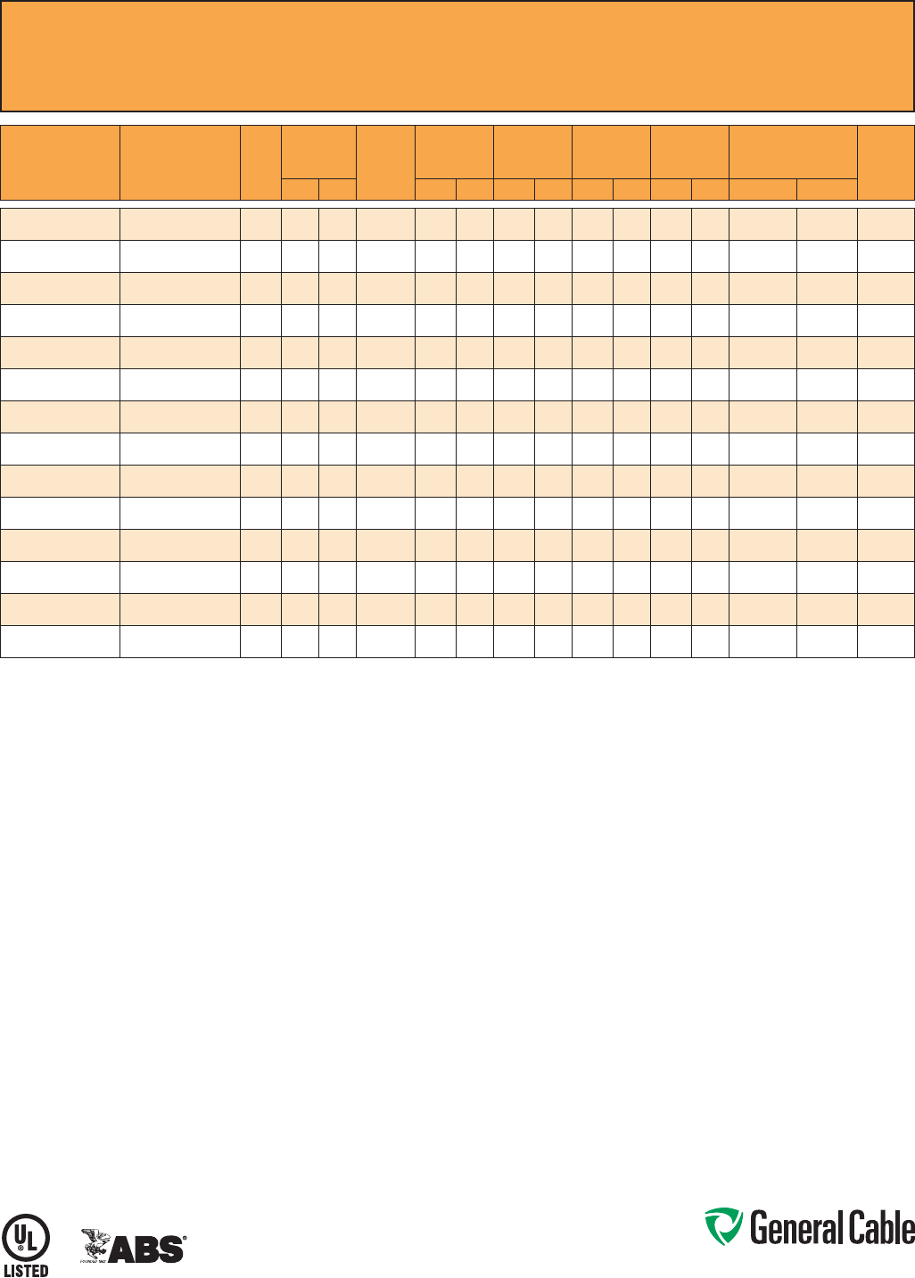
Phone: 888-593-3355
www.generalcable.com
CCW
®
Armored Power, 3/C VFD
ULTypeMC-HL,XLPE,2000V,90°C,CableTrayUse,Sunlight-Resistant,DirectBurial
ULMarineShipboardCable,ABSCWCMC
SPEC 9615
September, 2013
CATALOG
NUMBER
COND.
SIZE
(AWG/kcmil)
NO. OF
COND.
INSULATION
THICKNESS BARE
GROUND
(AWG)
NOMINAL
CORE O.D.
NOMINAL
ARMOR O.D.
JACKET
THICKNESS
NOMINAL
OVERALL O.D.
APPROXIMATE NET
WEIGHT
90°C
AMPACITY
@ 30°C
AMBIENT¹mils mm INCHES mm INCHES mm mils mm INCHES mm LBS/1000 FT kg/1000 m
9615.01403318
14(7/W)(2.08mm²)
360 1.52 3x#18 0.44 11.1 0.62 15.2 50 1.27 0.73 17. 9 267 397 15
9615.01203316
12(7/W)(3.31mm²)
360 1.52 3x#16 0.47 11.9 0.66 16.2 50 1.27 0.77 18.9 324 482 20
9615.01003314
10(7/W)(5.26mm²)
360 1.52 3x#14 0.53 13.3 0.73 17.8 50 1.27 0.84 20.5 400 595 30
9615.00803314
8(7/W)(8.36mm²)
370 1.78 3x#14 0.65 16.5 0.86 21.1 50 1.27 0.97 23.8 524 780 55
9615.00603312
6(7/W)(13.3mm²)
370 1.78 3x#12 0.71 18.0 0.96 23.4 50 1.27 1.07 26.1 697 1,037 75
9615.00403312
4(7/W)(21.2mm²)
370 1.78 3x#12 0.81 20.6 1.09 26.6 50 1.27 1.23 30.1 1,000 1,488 95
9615.00203310
2(7/W)(33.6mm²)
370 1.78 3x#10 0.94 23.9 1.25 30.6 50 1.27 1.36 33.3 1,285 1,912 130
9615.00103310
1(19/W)(42.4mm²)
390 2.29 3x#10 1.13 28.7 1.48 3 6.1 50 1.27 1.59 38.8 1,595 2,374 150
9615.11003310
1/0(19/W)(53.5mm²)
390 2.29 3x#10 1.21 30.6 1.55 38.0 60 1.52 1.68 41.2 1,930 2,872 170
9615.21003306
2/0(19/W)(67.4mm²)
390 2.29 3x#6 1.30 32.9 1.68 41.0 60 1.52 1.81 44.2 2,507 3,731 195
9615.41003304
4/0(19/W)(107mm²)
390 2.29 3x#4 1.53 38.7 1.91 46.7 60 1.52 2.04 49.9 3,590 5,342 260
9615.25003304
250(37/W)(127mm²)
3105 2.67 3x#4 1.71 43.4 2.12 51.8 60 1.52 2.25 55.1 4,150 6,176 290
9615.35003302
350(37/W)(177mm²)
3105 2.67 3x#2 1.93 48.9 2.41 58.9 75 1.91 2.57 62.8 5,214 7,759 350
9615.50003301
500(37/W)(253mm²)
3105 2.67 3x#1 2.20 55.8 2.68 65.5 75 1.91 2.84 69.5 6,977 10,382 430
Dimensionsandweightsarenominal;subjecttoindustrytolerances.
¹AmpacitiesinaccordancewithNECArticle310andTable310.15(B)(16).

Phone: 888-593-3355
www.generalcable.com
SPEC 9625
January, 2011
CCW
®
Armored Composite Power and Control
UL Type MC-HL, XLPE, 600 V, 90°C, Cable Tray Use, Sunlight-Resistant, Direct Burial
UL Marine Shipboard Cable, ABS CWCMC
Product Construction:
Conductor:
•BareannealedcopperperASTMB3
•10AWGandsmallerareClassB
compressedstrandingperASTMB8
•8AWGandlargerarecompact
stranding per ASTM B496
Insulation:
•Cross-LinkedPolyethylene(XLPE)
insulationperICEAS-95-658andUL
44, Listed XHHW-2
•Powerconductors6AWGandsmaller
are color-coded per ICEA Method 1,
Table E2
•Powerconductors4AWGandlarger
are black with printed numbers per
ICEA Method 4
•Controlconductorsarecolor-coded
black, red, blue and yellow
Grounding Conductor:
•ClassBstrandedbareannealed
copperperASTMB3andB8
•SizedinaccordancewithNECTable
25 0.122
Cable Assembly:
•Insulatedconductorsandgrounding
wire are cabled together with non-
hygroscopic fillers when required
•Abindertapeisappliedoverthe
cabled core
CCW Armor:
•Impervious,continuouslyweldedand
corrugated aluminum alloy sheath per
UL 1569 and UL 2225
•CCWarmorconductivitymeetsthe
grounding requirements of NEC
Article 250
Jacket:
•Flame-retardant,moisture-and
sunlight-resistant Polyvinyl Chloride
(PVC), black
•Lowtemperatureperformancemeets
ASTM D746 brittleness temperature at
or below -40°C
Applications:
•CCWarmoredCompositePowerand
Control cables offer an economical,
rugged and reliable alternative to
labor-intensive cable in conduit wiring
methods
•ForuseinClassI,IIandIII,Divisions
1 and 2; and Class I, Zones 1 and 2
hazardous locations per NEC Articles
501, 502, 503 and 505
•Foruseasservices,feedersand
branch circuits for power, lighting,
control, and signal circuits in
accordance with NEC Articles 330
and 725
•Installedindoorsoroutdoors,wet
or dry locations, directly buried,
embedded in concrete, in a raceway,
as aerial cable on a messenger,
in cable trays, or as exposed runs
secured to supports in accordance
with NEC Article 330
•Recognizedforuseonfixedor
floating offshore petroleum facilities
as recommended by the American
Petroleum Institute
Features:
•CCWarmorprovidesanimpervious
barrier to moisture, gas and liquids
•CCWarmorprovidesEMIshielding
performance
•Factoryassembledandtestedcable
for use as an alternative to cable in
conduit wiring systems
•Meetscoldimpactat-40°C
•90˚Ccontinuousoperating
temperature, wet or dry
•130˚Cemergencyrating
•250˚Cshortcircuitrating
Specifications:
Design Adherence:
•ICEAS-95-658/WC-70Standard
for Non-Shielded Power Cables,
2 kV or Less
•UL44RubberInsulatedWiresand
Cables
•UL1569MetalCladCables
•UL2225CablesandCableFittingsfor
Use in Hazardous Locations
•UL1309MarineShipboardCable
Flame Tests:
•ICEAT-29-520(210,000BTU/hr)
•IEEE383(70,000BTU/hr)
•CSAFT4
•IEEE1202(70,000BTU/hr)
•UL1581(70,000BTU/hr)
•IEC60332-3Cat.A
Compliances:
•ULTypeMC-HL,XHHW-2,SUNRES,
CT USE, DIR BUR, -40°C, UL File
# E69797
•ULListedMarineShipboard,ULFile
#E85994
•AmericanBureauofShipping(ABS)
Listed for CWCMC
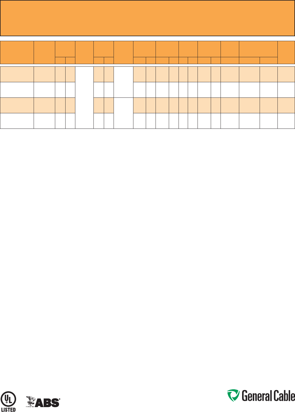
Phone: 888-593-3355
www.generalcable.com
SPEC 9625
January, 2011
CCW
®
Armored Composite Power and Control
UL Type MC-HL, XLPE, 600 V, 90°C, Cable Tray Use, Sunlight-Resistant, Direct Burial
UL Marine Shipboard Cable, ABS CWCMC
PART
NUMBER
POWER
COND. SIZE
(AWG)
POWER
INSULATION
THICKNESS
CONTROL
COND.
SIZE
(AWG)
CONTROL
INSULATION
THICKNESS BARE
GROUNDING
(AWG)
NOMINAL
CORE O.D.
NOMINAL
ARMOR O.D.
JACKET
THICKNESS
NOMINAL
OVERALL O.D.
CROSS-
SECTIONAL
AREA¹
APPROXIMATE NET
WEIGHT
90°C
AMPACITY
@ 30°C
AMBIENT²mils mm mils mm INCHES mm INCHES mm mils mm INCHES mm (SQ. IN.) LBS/1000 FT kg/1000 m
9625.103124110
3x#10 (7/W)
(5.26 mm²)
30 0.76
4 x #12
(7/W)
(3.31 mm²)
30 0.76
10 (7/W)
(5.2 mm²)
0.53 13.5 0.75 19.1 50 1.27 0.86 21.8 0.59 430 640 30
9625.083124110
3x#8(7/W)
(8.36 mm²)
45 1.14 30 0.76 0.65 16.5 0.89 22.6 50 1.27 0.99 25.1 0.78 535 796 55
9625.063124108
3x#6 (7/W)
(13.3 mm²)
45 1.14 30 0.76
8(7/W)
(8.36 mm²)
0.69 17.5 0.93 23.6 50 1.27 1.03 26.2 0.84 660 982 75
9625.043124108
3x#4 (7/W)
(21.2 mm²)
45 1.14 30 0.76 0.74 18.8 0.97 24.6 50 1.27 1.08 27.4 0.93 815 1,213 95
Dimensions and weights are nominal; subject to industry tolerances.
¹ Cross-sectional area for cable tray fill is in accordance with NEC Section 392.22.
² Ampacities in accordance with NEC Article 310 and Table 310.15(B)(16).
Phone: 888-593-3355
www.generalcable.com
SPEC 9650
February, 2011
CCW
®
Armored Composite Power and Control Without Ground
UL Type MC, XLPE, 600 V, 90°C, Cable Tray Use, Sunlight-Resistant, Direct Burial
UL Marine Shipboard Cable, ABS CWCMC
Product Construction:
Conductor:
•BareannealedcopperperASTMB3
•Sizes10AWGandsmallerareClassB
compressedstrandingperASTMB8
•Sizes8AWGandlargerarecompact
stranding per ASTM B496
Insulation:
•Cross-LinkedPolyethylene(XLPE)
insulationperICEAS-95-658andUL
44, Listed XHHW-2
•Powerconductorssizes6AWGand
smaller are color-coded per ICEA
Method 1, Table E2
•Powerconductorssizes4AWGand
larger are black with printed numbers
per ICEA Method 4
•Controlconductorsarecolor-coded
black, red, blue and yellow
Cable Assembly:
•Insulatedconductorsarecabled
together with non-hygroscopic fillers
when required
•Abindertape,whenrequired,is
applied over the cabled core
CCW Armor:
•Impervious,continuouslyweldedand
corrugated aluminum alloy sheath per
UL 1569
•CCWarmorconductivitymeetsthe
grounding requirements of NEC
Article 250
Jacket:
•Flame-retardant,moisture-and
sunlight-resistant Polyvinyl Chloride
(PVC), black
•Lowtemperatureperformancemeets
ASTM D746 brittleness temperature at
or below -40°C
Applications:
•CCWarmoredCompositePowerand
Control cables offer an economical,
rugged and reliable alternative to
labor-intensive cable in conduit wiring
methods
•ForuseinClassIandII,Division2;
Class III, Divisions 1 and 2; and Class
I, Zone 2 hazardous locations per NEC
Articles 501, 502, 503 and 505
•Foruseasservices,feedersand
branch circuits for power, lighting,
control, and signal circuits in
accordance with NEC Articles 330
and 725
•Installedindoorsoroutdoors,wet
or dry locations, directly buried,
embedded in concrete, in a raceway,
as aerial cable on a messenger,
in cable trays, or as exposed runs
secured to supports in accordance
with NEC Article 330
•Recognizedforuseonfixedor
floating offshore petroleum facilities
as recommended by the American
Petroleum Institute
Features:
•CCWarmorprovidesanimpervious
barrier to moisture, gas and liquids
•CCWarmorprovidesEMIshielding
performance
•Factoryassembledandtestedcable
for use as an alternative to cable in
conduit wiring systems
Features: (cont’d)
•Meetscoldimpactat-40°C
•90˚Ccontinuousoperating
temperature, wet or dry
•130˚Cemergencyrating
•250˚Cshortcircuitrating
Specifications:
Design Adherence:
•ICEAS-95-658/WC70Standard
for Non-Shielded Power Cable, 2 kV
or Less
•UL44RubberInsulatedWiresand
Cables
•UL1569MetalCladCables
•UL1309MarineShipboardCable
Flame Tests:
•ICEAT-29-520(210,000BTU/hr)
•IEEE383(70,000BTU/hr)
•CSAFT4
•IEEE1202(70,000BTU/hr)
•UL1581(70,000BTU/hr)
•IEC60332-3Cat.A
Compliances:
•ULTypeMC,XHHW-2,SUNRES,
CT USE, DIR BUR, -40°C, UL File #
E69797
•ULListedMarineShipboard,ULFile#
E85994
•AmericanBureauofShipping(ABS)
Listed for CWCMC
Phone: 888-593-3355
www.generalcable.com
SPEC 9650
February, 2011
CCW
®
Armored Composite Power and Control Without Ground
UL Type MC, XLPE, 600 V, 90°C, Cable Tray Use, Sunlight-Resistant, Direct Burial
UL Marine Shipboard Cable, ABS CWCMC
PART
NUMBER
POWER COND. SIZE
(AWG)
POWER
INSULATION
THICKNESS CONTROL COND.
SIZE
(AWG)
CONTROL
INSULATION
THICKNESS
NOMINAL
CORE O.D.
NOMINAL
ARMOR O.D.
JACKET
THICKNESS
NOMINAL
OVERALL O.D.
CROSS-
SECTIONAL
AREA¹
APPROXIMATE NET
WEIGHT
90°C
AMPACITY
@ 30°C
AMBIENT²mils mm mils mm INCHES mm INCHES mm mils mm INCHES mm (SQ. IN.) LBS/1000 FT kg/1000 m
9650.123143000
3x#12 (7/W) (3.31 mm²)
30 0.76
3x#14(7/W)(2.08mm²)
30 0.76 0.49 12.4 0.71 18.0 50 1.27 0.82 20.8 0.54 307 457 20
9650.123144000
3x#12 (7/W) (3.31 mm²)
30 0.76
4x#14(7/W)(2.08mm²)
30 0.76 0.49 12.4 0.71 18.0 50 1.27 0.82 20.8 0.54 323 481 20
9650.124143000
4x#12 (7/W) (3.31 mm²)
30 0.76
3x#14(7/W)(2.08mm²)
30 0.76 0.49 12.4 0.71 18.0 50 1.27 0.82 20.8 0.54 365 543 20
9650.124144000
4x#12 (7/W) (3.31 mm²)
30 0.76
4x#14(7/W)(2.08mm²)
30 0.76 0.53 13.5 0.75 19.1 50 1.27 0.86 21.8 0.59 388 577 20
9650.103143000
3x#10 (7/W) (5.26 mm²)
30 0.76
3x#14(7/W)(2.08mm²)
30 0.76 0.53 13.5 0.75 19.1 50 1.27 0.86 21.8 0.59 384 571 30
9650.103144000
3x#10 (7/W) (5.26 mm²)
30 0.76
4x#14(7/W)(2.08mm²)
30 0.76 0.58 14.7 0.80 20.3 50 1.27 0.91 23.1 0.66 392 583 30
9650.103123000
3x#10 (7/W) (5.26 mm²)
30 0.76
3x#12 (7/W) (3.31 mm²)
30 0.76 0.53 13.5 0.75 19.1 50 1.27 0.86 21.8 0.59 410 610 30
9650.104143000
4x#10 (7/W) (5.26 mm²)
30 0.76
3x#14(7/W)(2.08mm²)
30 0.76 0.58 14.7 0.80 20.3 50 1.27 0.91 23.1 0.66 412 613 30
9650.104144000
4x#10 (7/W) (5.26 mm²)
30 0.76
4x#14(7/W)(2.08mm²)
30 0.76 0.58 14.7 0.80 20.3 50 1.27 0.91 23.1 0.66 428 637 30
9650.104123000
4x#10 (7/W) (5.26 mm²)
30 0.76
3x#12 (7/W) (3.31 mm²)
30 0.76 0.58 14.7 0.80 20.3 50 1.27 0.91 23.1 0.66 436 649 30
9650.104124000
4x#10 (7/W) (5.26 mm²)
30 0.76
4x#12 (7/W) (3.31 mm²)
30 0.76 0.58 14.7 0.80 20.3 50 1.27 0.91 23.1 0.66 460 685 30
9650.083143000
3x#8(7/W)(8.36mm²)
45 1.14
3x#14(7/W)(2.08mm²)
30 0.76 0.58 14.7 0.80 20.3 50 1.27 0.91 23.1 0.66 424 631 55
9650.083144000
3x#8(7/W)(8.36mm²)
45 1.14
4x#14(7/W)(2.08mm²)
30 0.76 0.62 15.7 0.84 21.3 50 1.27 0.91 23.1 0.66 455 677 55
9650.083123000
3x#8(7/W)(8.36mm²)
45 1.14
3x#12 (7/W) (3.31 mm²)
30 0.76 0.58 14.7 0.80 20.3 50 1.27 0.95 24.1 0.72 455 677 55
9650.083124000
3x#8(7/W)(8.36mm²)
45 1.14
4x#12 (7/W) (3.31 mm²)
30 0.76 0.62 15.7 0.84 21.3 50 1.27 0.91 23.1 0.66 495 737 55
9650.084143000
4x#8(7/W)(8.36mm²)
45 1.14
3x#14(7/W)(2.08mm²)
30 0.76 0.62 15.7 0.84 21.3 50 1.27 0.95 24.1 0.72 505 752 44
9650.084144000
4x#8(7/W)(8.36mm²)
45 1.14
4x#14(7/W)(2.08mm²)
30 0.76 0.67 17.0 0.89 22.6 50 1.27 1.00 25.4 0.80 530 789 44
9650.084123000
4x#8(7/W)(8.36mm²)
45 1.14
3x#12 (7/W) (3.31 mm²)
30 0.76 0.67 17.0 0.89 22.6 50 1.27 1.00 25.4 0.80 535 796 44
9650.084124000
4x#8(7/W)(8.36mm²)
45 1.14
4x#12 (7/W) (3.31 mm²)
30 0.76 0.71 18.0 0.93 23.6 50 1.27 1.04 26.4 0.86 576 857 44
9650.063143000
3x#6 (7/W) (13.3 mm²)
45 1.14
3x#14(7/W)(2.08mm²)
30 0.76 0.62 15.7 0.84 21.3 50 1.27 0.95 24.1 0.72 525 781 75
9650.063144000
3x#6 (7/W) (13.3 mm²)
45 1.14
4x#14(7/W)(2.08mm²)
30 0.76 0.62 15.7 0.84 21.3 50 1.27 0.95 24.1 0.72 545 811 75
9650.063123000
3x#6 (7/W) (13.3 mm²)
45 1.14
3x#12 (7/W) (3.31 mm²)
30 0.76 0.62 15.7 0.84 21.3 50 1.27 0.95 24.1 0.72 556 827 75
9650.063124000
3x#6 (7/W) (13.3 mm²)
45 1.14
4x#12 (7/W) (3.31 mm²)
30 0.76 0.71 18.0 0.93 23.6 50 1.27 1.03 26.2 0.84 606 902 75
9650.064143000
4x#6 (7/W) (13.3 mm²)
45 1.14
3x#14(7/W)(2.08mm²)
30 0.76 0.71 18.0 0.93 23.6 50 1.27 1.04 26.4 0.86 657 978 60
9650.064144000
4x#6 (7/W) (13.3 mm²)
45 1.14
4x#14(7/W)(2.08mm²)
30 0.76 0.71 18.0 0.93 23.6 50 1.27 1.04 26.4 0.86 667 993 60
9650.064123000
4x#6 (7/W) (13.3 mm²)
45 1.14
3x#12 (7/W) (3.31 mm²)
30 0.76 0.75 19.1 0.97 24.6 50 1.27 1.08 27.4 0.93 687 1,022 60
9650.064124000
4x#6 (7/W) (13.3 mm²)
45 1.14
4x#12 (7/W) (3.31 mm²)
30 0.76 0.75 19.1 0.97 24.6 50 1.27 1.08 27.4 0.93 717 1,067 60
9650.043143000
3x#4 (7/W) (21.2 mm²)
45 1.14
3x#14(7/W)(2.08mm²)
30 0.76 0.71 18.0 0.93 23.6 50 1.27 1.04 26.4 0.86 707 1,052 95
9650.043144000
3x#4 (7/W) (21.2 mm²)
45 1.14
4x#14(7/W)(2.08mm²)
30 0.76 0.71 18.0 0.93 23.6 50 1.27 1.04 26.4 0.86 727 1,082 95
9650.043123000
3x#4 (7/W) (21.2 mm²)
45 1.14
3x#12 (7/W) (3.31 mm²)
30 0.76 0.71 18.0 0.93 23.6 50 1.27 1.04 26.4 0.86 727 1,082 95
9650.043124000
3x#4 (7/W) (21.2 mm²)
45 1.14
4x#12 (7/W) (3.31 mm²)
30 0.76 0.75 19.1 0.97 24.6 50 1.27 1.08 27.4 0.93 768 1,143 95
9650.044143000
4x#4 (7/W) (21.2 mm²)
45 1.14
3x#14(7/W)(2.08mm²)
30 0.76 0.81 20.6 1.06 26.9 50 1.27 1.17 29.7 1.09 899 1,338 76
9650.044144000
4x#4 (7/W) (21.2 mm²)
45 1.14
4x#14(7/W)(2.08mm²)
30 0.76 0.81 20.6 1.06 26.9 50 1.27 1.17 29.7 1.09 929 1,383 76
9650.044123000
4x#4 (7/W) (21.2 mm²)
45 1.14
3x#12 (7/W) (3.31 mm²)
30 0.76 0.81 20.6 1.06 26.9 50 1.27 1.17 29.7 1.09 929 1,383 76
9650.044124000
4x#4 (7/W) (21.2 mm²)
45 1.14
4x#12 (7/W) (3.31 mm²)
30 0.76 0.81 20.6 1.06 26.9 50 1.27 1.17 29.7 1.09 960 1,429 76
9650.023143000
3x#2 (7/W) (33.6 mm²)
45 1.14
3x#14(7/W)(2.08mm²)
30 0.76 0.81 20.6 1.06 26.9 50 1.27 1.17 29.7 1.09 995 1,481 130
9650.023144000
3x#2 (7/W) (33.6 mm²)
45 1.14
4x#14(7/W)(2.08mm²)
30 0.76 0.81 20.6 1.06 26.9 50 1.27 1.17 29.7 1.09 1,010 1,503 130
9650.023123000
3x#2 (7/W) (33.6 mm²)
45 1.14
3x#12 (7/W) (3.31 mm²)
30 0.76 0.81 20.6 1.06 26.9 50 1.27 1.17 29.7 1.09 1,020 1,518 130
9650.023124000
3x#2 (7/W) (33.6 mm²)
45 1.14
4x#12 (7/W) (3.31 mm²)
30 0.76 0.81 20.6 1.06 26.9 50 1.27 1.17 29.7 1.09 1,050 1,563 130
9650.024143000
4x#2 (7/W) (33.6 mm²)
45 1.14
3x#14(7/W)(2.08mm²)
30 0.76 0.90 22.9 1.15 29.2 50 1.27 1.26 32.0 1.26 1,242 1,848 104
9650.024144000
4x#2 (7/W) (33.6 mm²)
45 1.14
4x#14(7/W)(2.08mm²)
30 0.76 0.90 22.9 1.15 29.2 50 1.27 1.26 32.0 1.26 1,263 1,880 104
9650.024123000
4x#2 (7/W) (33.6 mm²)
45 1.14
3x#12 (7/W) (3.31 mm²)
30 0.76 0.90 22.9 1.15 29.2 50 1.27 1.26 32.0 1.26 1,273 1,894 104
9650.024124000
4x#2 (7/W) (33.6 mm²)
45 1.14
4x#12 (7/W) (3.31 mm²)
30 0.76 0.90 22.9 1.15 29.2 50 1.27 1.26 32.0 1.26 1,293 1,924 104
Dimensions and weights are nominal; subject to industry tolerances.
¹ Cross-sectional area for cable tray fill is in accordance with NEC Section 392.22.
² Ampacities in accordance with NEC Article 310 and Table 310.15(B)(16).
Phone: 888-593-3355
www.generalcable.com
SPEC 9675
March, 2012
CCW
®
Armored Power, 1000 V, 3/C VFD
CSA Type RA90, XLPE, 1000 V, 90°C, Cable Tray Use, Sunlight-Resistant
Direct Burial, FT4, -40°C, AG14, HL
Product Construction:
Conductor:
•BareannealedcopperperASTMB3
•Sizes10AWGandsmallerareClassB
compressedstrandingperASTMB8
•Sizes8AWGandlargerarecompact
stranding per ASTM B496
Insulation:
•Cross-linkedPolyethylene(XLPE)
insulation rated 1000 Volts, RW90 per
CSAC22.2No.38
•Sizes2AWGandsmallerutilizea
singlecolorinsulation:black,red
and blue
•Sizes1AWGandlargerutilizeblack
insulation with printed number/color,
1-black, 2-red, 3-blue
Bonding/Grounding Conductors:
•ClassBstrandedbareannealed
copperperASTMB3andB8
•Three(3)symmetricalgroundingwires
are sized in accordance with CEC
Table 16
Cable Assembly:
•Threesymmetricalgroundingwires
are cabled within the interstices of the
phase conductors
•Non-hygroscopicfillerswhenrequired
•Abindertapeisappliedoverthe
cabled core
CCW Armor:
•Impervious,continuouslyweldedand
corrugated aluminum alloy sheath per
C22.2 No. 123
Jacket:
•Flame-retardant,moisture-and
sunlight-resistant Polyvinyl Chloride
(PVC), black
•MeetsCSALowGasEmission
requirements, AG14
Applications:
•VariableFrequencyDrives:
3-conductor CCW armored cables
with three (3) symmetrical grounding
wires are the preferred wiring method
for use with AC motors controlled by
pulse-width modulated inverters in
VFD applications
•CCWarmoredcablesofferan
economical, rugged and reliable
alternative to labor-intensive cable in
conduit wiring methods
•Foruseinindustrialandcommercial
installations including hazardous
locations in accordance with the CEC
•Canbeinstalledinwetordry
locations, indoors or outdoors, in cable
trays, in a raceway, or direct buried in
accordance with the CEC
Features:
•90°C,1000VwetordryXLPE
insulation and three (3) symmetrical
grounding wires, recommended
for use with pulse-width modulated
AC drives
•XLPEinsulationhasadielectric
constant less than 3.0 to withstand
momentary voltage spikes common
with VFD applications
Features: (cont’d)
•CCWarmorprovidesanimpervious
barrier to moisture, gas and liquids
•CCWarmorprovidesEMIshielding
performance
•Factoryassembledandtestedcable
for use as an alternative to cable in
conduit wiring systems
•Meetscoldimpactat-40°C
•90˚Ccontinuousoperating
temperature, wet or dry
•130˚Cemergencyrating
•250˚Cshortcircuitrating
Specifications:
Design Adherence:
•CSAC22.2No.38Thermoset-
Insulated Wires and Cables
•CSAC22.2No.123MetalSheathed
Cables
•CSAC22.2No.174CablesandCable
Glands for Use in Hazardous Locations
Flame Tests:
•CSAFT4
•ICEAT-29-520(210,000BTU/hr)
•IEEE383(70,000BTU/hr)
•IEEE1202(70,000BTU/hr)
Compliances:
•CSACertifiedTypeRA90,XLPE,
HL, SR, FT4, AG14 and -40°C,
CSA File # 7319
Phone: 888-593-3355
www.generalcable.com
SPEC 9675
March, 2012
CCW
®
Armored Power, 1000 V, 3/C VFD
CSA Type RA90, XLPE, 1000 V, 90°C, Cable Tray Use, Sunlight-Resistant
Direct Burial, FT4, -40°C, AG14, HL
PART
NUMBER
COND.
SIZE
(AWG/kcmil)
NO. OF
COND.
INSULATION
THICKNESS
BARE
GROUND
COND.
(AWG)
NOMINAL
CORE O.D.
NOMINAL
ARMOR O.D.
JACKET
THICKNESS
NOMINAL
OVERALL O.D.
APPROXIMATE NET
WEIGHT MIN. BEND RADIUS ¹
90°C
AMPACITY
@ 30°C
AMBIENT²mils mm INCHES mm INCHES mm mils mm INCHES mm LBS/1000 FT kg/1000 m INCHES mm
9675.01203318 12 (7/W)
(3.31 mm²)
3 45 1.14 3x#18 0.40 10.2 0.60 15.3 50 1.27 0.70 17.8 249 370 7.0 178 30
9675.01003316 10 (7/W)
(5.26 mm²)
3 45 1.14 3 x #16 0.45 11.5 0.63 16.1 50 1.27 0.73 18.6 299 445 7.3 185 40
9675.00803314 8(7/W)
(8.36mm²)
3 45 1.14 3 x #14 0.50 12.7 0.76 19.2 50 1.27 0.86 21.9 417 620 8.6 218 55
9675.00603312 6 (7/W)
(13.3 mm²)
3 60 1.52 3 x #12 0.64 16.3 0.91 23.2 50 1.27 1.02 26.0 601 895 12.2 311 75
9675.00403312 4 (7/W)
(21.2 mm²)
3 60 1.52 3 x #12 0.74 18.7 0.98 24.8 50 1.27 1.08 27.4 763 1,135 12.9 329 95
9675.00203310 2 (7/W)
(33.6 mm²)
3 60 1.52 3 x #10 0.86 21.8 1.18 29.9 50 1.27 1.28 32.5 1,122 1,670 15.4 390 130
9675.00103310 1 (19/W)
(42.4 mm²)
380 2.03 3 x #10 1.01 25.7 1.36 34.6 50 1.27 1.46 37.1 1,404 2,090 17.5 445 145
9675.11003310 1/0 (19/W)
(53.5 mm²)
380 2.03 3 x #10 1.09 27.8 1.42 36.0 50 1.27 1.52 38.6 1,623 2,415 18.2 462 170
9675.21003310 2/0 (19/W)
(67.4 mm²)
380 2.03 3 x #10 1.18 30.0 1.56 39.6 50 1.27 1.66 42.2 2,043 3,040 20.0 506 195
9675.41003308 4/0 (19/W)
(107 mm²)
380 2.03 3x#8 1.40 35.5 1.75 44.4 50 1.27 1.85 47.0 2,950 4,390 22.2 564 260
9675.25003308 250 (37/W)
(127 mm²)
3 90 2.29 3 x #81.49 37.8 1.90 48.2 50 1.27 2.01 51.1 3,380 5,030 24.1 612 290
9675.35003308 350 (37/W)
(177 mm²)
3 90 2.29 3x#8 1.74 44.3 2.22 56.4 50 1.27 2.33 59.2 4,465 6,645 27.9 710 350
9675.50003306 500 (37/W)
(253 mm²)
3 90 2.29 3 x #6 2.00 50.9 2.48 63.0 50 1.27 2.59 65.8 6,152 9,155 31.0 789 430
Dimensions and weights are nominal; subject to industry tolerances.
¹ Minimum bend radius per Canadian Electrical Code, Part I, Section 12-712.
² Ampacity per Table #2, Canadian Electical Code.

Phone: 888-593-3355
www.generalcable.com
Applications:
•VariableFrequencyDrives:
3-conductor CCW armored cables
with three (3) symmetrical grounding
wires are the preferred wiring method
for use with AC motors controlled by
pulse-width modulated inverters in
VFD applications
•CCWarmoredMedium-Voltage
power cables offer an economical,
rugged and reliable alternative to
labor-intensive cable in conduit wiring
methods
•Foruseonfeedersandbranchcircuits
in industrial power distribution systems
perNECArticles328and330
•ForuseinClassI,IIandIII,Divisions
1 and 2; and Class I, Zones 1 and 2
hazardous locations per NEC Articles
501, 502, 503 and 505
•Installedonmetalracks,troughs,in
raceways, in cable trays or secured
to supports spaced not more than six
feet apart
•Installedinbothexposedand
concealed work, wet or dry locations,
directly buried or embedded in
concrete
•Recognizedforuseonfixedor
floating offshore petroleum facilities
as recommended by the American
Petroleum Institute
Features:
•CCWarmorprovidesanimpervious
barrier to moisture, gas and liquids
and meets the grounding requirements
of UL 1072 and the NEC
•Factoryassembledandtestedcable
for use as an alternative to cable in
conduit wiring systems
Features: (cont’d)
•GeneralCable’sEPRinsulationsystem
has outstanding corona resistance and
high dielectric strength, and it provides
electrical stability under stress
•Cablemeetscoldimpactat-40°C
•90˚Ccontinuousoperating
temperature, wet or dry
•140˚Cemergencyrating
•250˚Cshortcircuitrating
Specifications:
Design Adherence:
•ICEAS-96-659/WC71Standardfor
Nonshielded Cables Rated 2001 –
5000 Volts
•UL1072Medium-VoltagePower
Cables
•UL1569MetalCladCables
•UL2225CablesandCableFittingsfor
Use in Hazardous Locations
•UL1309MarineShipboardCable
Flame Tests:
•ICEAT-29-520(210,000BTU/hr)
•IEEE383(70,000BTU/hr)
•CSAFT4
•IEEE1202(70,000BTU/hr)
•UL1072
•IEC60332-3CategoryA
Compliances:
•ULTypeMV-90,ULFile#E90501
•ULTypeMC-HL,SUNRES,CT
USE, DIR BUR, -40°C, FT4, UL File #
E90496
•ULListedMarineShipboard,ULFile#
E85994
•AmericanBureauofShipping(ABS)
Listed for CWCMC
Product Construction:
Conductor:
•BareannealedcopperperASTMB3
•CompactstrandingperASTMB496
Extruded Strand Shield (ESS):
•Extrudedthermosetsemi-conductor
stress control layer over conductor per
ICEA S-96-659 and UL 1072
Insulation:
•90milsEthylenePropyleneRubber
(EPR) insulation per ICEA S-96-659
and UL 1072
•Insulationisprinted1-black,2-redand
3-blue for phase identification
Grounding Conductors:
•Three(3)splitClassBstranded
bare annealed copper grounding
conductors
•SizedinaccordancewithUL1072and
NEC Table 250.122
Cable Assembly:
•Insulatedandgroundingconductors
are cabled together with non-
hygroscopic fillers when required
•Bindertapeisappliedoverthecabled
core
CCW Armor:
•Impervious,continuouslyweldedand
corrugated aluminum alloy sheath per
UL 1072 and UL 1569
•CCWarmorconductivitymeets
the grounding requirements of NEC
Article 250
Jacket:
•Flame-retardant,moisture-and
sunlight-resistant Polyvinyl Chloride
(PVC), yellow
•Lowtemperatureperformancemeets
ASTM D746 brittleness temperature at
or below -40°C
CCW
®
Armored Power, 2.4 kV, Nonshielded, 3/C VFD
UL Type MC-HL or MV-90, EPR, 90°C, Cable Tray Use, Sunlight-Resistant
Direct Burial, ABS CWCMC
SPEC 9700
February, 2011
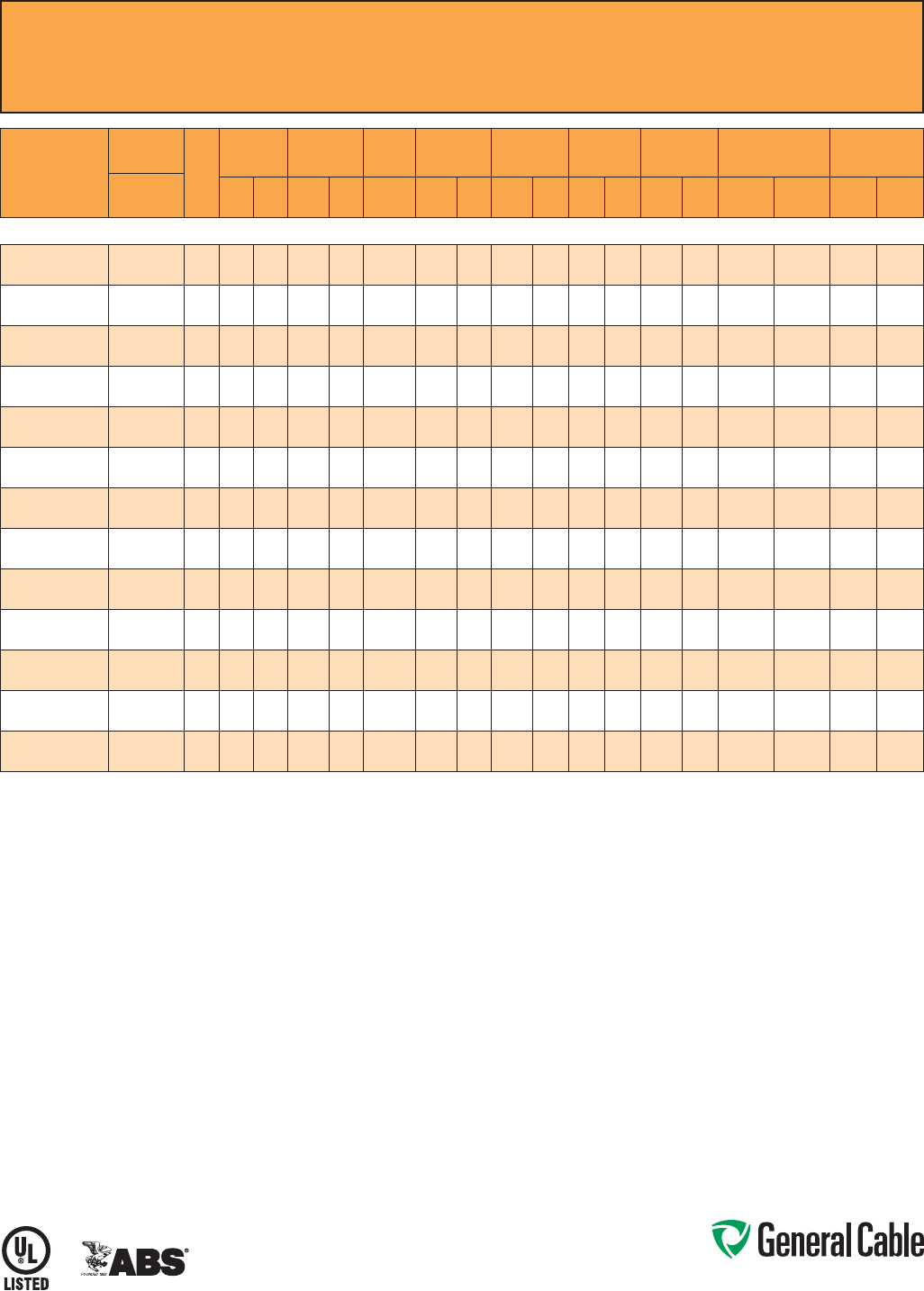
Phone: 888-593-3355
www.generalcable.com
CCW
®
Armored Power, 2.4 kV, Nonshielded, 3/C VFD
UL Type MC-HL or MV-90, EPR, 90°C, Cable Tray Use, Sunlight-Resistant
Direct Burial, ABS CWCMC
SPEC 9700
February, 2011
PART
NUMBER
COND.
SIZE
NO.
OF
COND.
INSULATION
THICKNESS
NOMINAL O.D.
OVER
INSULATION
BARE
GROUND
NOMINAL
CORE O.D.
NOMINAL
ARMOR O.D.
JACKET
THICKNESS
NOMINAL
OVERALL O.D.
APPROXIMATE NET
WEIGHT AMPACITY
AWG (kcmil) mils mm INCHES mm AWG INCHES mm INCHES mm mils mm INCHES mm
LBS/
1000 FT
kg/
1000 m IN AIR¹
DIRECT
BURIAL²
3/C WITH GROUND MC-HL OR MV-90, 90 MILS EPR, 2.4 kV, YELLOW JACKET
9700.00803312 8(7/W)
(8.36mm²)
3 90 2.3 0.36 9.1 3 x #12 0.77 19.6 0.97 24.6 50 1.27 1.08 27.4 570 848 59 85
9700.00603310 6 (7/W)
(13.3 mm²)
3 90 2.3 0.38 9.6 3 x #10 0.85 21.6 1.06 26.9 50 1.27 1.17 29.7 745 1,109 79 105
9700.00403310 4 (7/W)
(21.2 mm²)
3 90 2.3 0.43 10.8 3 x #10 0.97 24.6 1.19 30.2 50 1.27 1.30 33.0 965 1,436 105 135
9700.00203310 2 (7/W)
(33.6 mm²)
3 90 2.3 0.48 12.1 3 x #10 1.10 27.9 1.34 34.0 50 1.27 1.45 36.8 1,275 1,897 140 180
9700.00103308 1 (19/W)
(42.4 mm²)
3 90 2.3 0.52 13.1 3x#8 1.16 29.5 1.42 36.1 50 1.27 1.53 38.9 1,525 2,269 160 200
9700.11003308 1/0 (19/W)
(53.5 mm²)
3 90 2.3 0.55 13.9 3x#8 1.23 31.2 1.51 38.4 60 1.52 1.65 41.9 1,840 2,738 185 230
9700.21003308 2/0 (19/W)
(67.4 mm²)
3 90 2.3 0.59 14.9 3x#8 1.33 33.8 1.60 40.6 60 1.52 1.73 43.9 2,165 3,222 215 260
9700.41003307 4/0 (19/W)
(107 mm²)
3 90 2.3 0.69 17.4 3 x #7 1.53 38.9 1.83 46.5 60 1.52 1.96 49.8 3,080 4,584 285 335
9700.25003307 250 (37/W)
(127 mm²)
3 90 2.3 0.74 18.7 3 x #7 1.64 41.7 1.96 49.8 60 1.52 2.09 53.1 3,475 5,171 320 365
9700.35003306 350 (37/W)
(177 mm²)
3 90 2.3 0.83 21.0 3 x #6 1.86 47.2 2.19 55.6 60 1.52 2.32 58.9 4,710 7,009 395 440
9700.50003305 500 (37/W)
(253 mm²)
3 90 2.3 0.95 24.0 3 x #5 2.10 53.3 2.45 62.2 75 1.91 2.61 66.3 6,410 9,539 485 530
9700.75003304 750 (61/W)
(380mm²)
3 90 2.3 1.12 28.3 3 x #4 2.51 63.8 2.93 74.4 75 1.91 3.10 78.7 9,225 13,728 615 650
9700.10003304 1000 (61/W)
(507 mm²)
3 90 2.3 1.27 32.2 3 x #4 2.90 73.7 3.41 86.6 80 2.03 3.59 91.2 12,080 17,977 705 730
Dimensions and weights are nominal, subject to industry tolerances.
¹ In-air ampacities are per NEC Table 310.60(C)(71) for three insulated copper conductors rated 90°C, cabled with an overall covering and isolated in air at 40°C ambient temperature.
²DirectburialampacitiesareperNECTable310.60(C)(83)forthreeinsulatedcopperconductorsrated90°C,cabledwithinanoverallcoveringanddirectlyburiedinearthat20°C
ambient earth temperature.

Phone: 888-593-3355
www.generalcable.com
Jacket:
•Flame-retardant,moisture-and
sunlight-resistant Polyvinyl Chloride
(PVC), yellow
•Lowtemperatureperformancemeets
ASTM D746 brittleness temperature at
or below -40°C
Applications:
•VariableFrequencyDrives:
3-conductor CCW armored cables
with three (3) symmetrical grounding
wires are the preferred wiring method
for use with AC motors controlled by
pulse-width modulated inverters in
VFD applications
•CCWarmoredMedium-Voltage
power cables offer an economical,
rugged and reliable alternative to
labor-intensive cable in conduit wiring
methods
•Foruseonfeedersandbranchcircuits
in industrial power distribution systems
perNECArticles328and330
•ForuseinClassI,IIandIII,Divisions
1 and 2; and Class I, Zones 1 and 2
hazardous locations per NEC Articles
501, 502, 503 and 505
•Installedonmetalracks,troughs,in
raceways, in cable trays or secured
to supports spaced not more than six
feet apart
•Installedinbothexposedand
concealed work, wet or dry locations,
directly buried or embedded in
concrete
•Recognizedforuseonfixedor
floating offshore petroleum facilities
as recommended by the American
Petroleum Institute
Features:
•CCWarmorprovidesanimpervious
barrier to moisture, gas and liquids
and meets the grounding requirements
of UL 1072 and the NEC
Features: (cont’d)
•TripleExtrusion:Thestrandshield,
EPR insulation and insulation shield
are all extruded in one operation
•GeneralCable’sEPRinsulationsystem
has outstanding corona resistance and
high dielectric strength, and it provides
electrical stability under stress
•Cablemeetscoldimpactat-40°C
•105˚Ccontinuousoperating
temperature, wet or dry
•140˚Cemergencyrating
•250˚Cshortcircuitrating
Specifications:
Design Adherence:
•ICEAS-93-639/WC-74,5-46kV
Shielded Power Cable
•AEICCS8SpecificationforShielded
Power Cable, 5-46 kV
•UL1072Medium-VoltagePower
Cables
•UL1569MetalCladCables
•UL2225CablesandCableFittingsfor
Use in Hazardous Locations
•UL1309MarineShipboardCable
•CSAC68.3
Flame Tests:
•ICEAT-29-520(210,000BTU/hr)
•IEEE383(70,000BTU/hr)
•CSAFT4
•IEEE1202(70,000BTU/hr)
•UL1072
•IEC60332-3CategoryA
Compliances:
•ULTypeMV-105,ULFile#E90501
•ULTypeMC-HL,SUNRES,CT
USE, DIR BUR, -40°C, FT4, UL File #
E90496
•ULListedMarineShipboard,ULFile#
E85994
•AmericanBureauofShipping(ABS)
Listed for CWCMC
Product Construction:
Conductor:
•BareannealedcopperperASTMB3
•CompactstrandingperASTMB496
Extruded Strand Shield (ESS):
•Extrudedthermosetsemi-conductor
stress control layer over the conductor
per ICEA S-93-639 and UL 1072
Insulation:
•115milsEthylenePropyleneRubber
(EPR) insulation per ICEA S-93-639
and UL 1072
Extruded Insulation Shield (EIS):
•Thermosetsemi-conductingpolymeric
layer, free stripping from the insulation
per ICEA S-93-639 and UL 1072
Shield:
•5milannealedbarecoppertapewith
25% overlap
Phase Identification:
•Color-codedpolymericidentification
tape laid under the shield — black, red
and blue
Grounding Conductors:
•Three(3)splitClassBstranded
bare annealed copper grounding
conductors
•SizedinaccordancewithUL1072and
NEC Article 250
Cable Assembly:
•Insulatedandgroundingconductors
are cabled together with non-
hygroscopic fillers when required
•Bindertapeisappliedoverthecabled
core
CCW Armor:
•Impervious,continuouslyweldedand
corrugated aluminum alloy sheath per
UL 1072 and UL 1569
•CCWarmorconductivitymeets
the grounding requirements of NEC
Article 250
CCW
®
Armored Power, 5 kV 133%/8 kV 100%, Shielded, 3/C VFD
UL Type MC-HL or MV-105, EPR, 105°C, Cable Tray Use, Sunlight-Resistant
Direct Burial, ABS CWCMC
SPEC 9800
May, 2012

Phone: 888-593-3355
www.generalcable.com
CCW
®
Armored Power, 5 kV 133%/8 kV 100%, Shielded, 3/C VFD
UL Type MC-HL or MV-105, EPR, 105°C, Cable Tray Use, Sunlight-Resistant
Direct Burial, ABS CWCMC
SPEC 9800
May, 2012
PART
NUMBER
COND.
SIZE
NO. OF
COND.
INSULATION
THICKNESS
NOMINAL O.D.
OVER
INSULATION
BARE
GROUND
NOMINAL
CORE O.D.
NOMINAL
ARMOR O.D.
JACKET
THICKNESS
NOMINAL
OVERALL O.D.
APPROXIMATE NET
WEIGHT
5 kV³
AMPACITY
AWG (kcmil) mils mm INCHES mm AWG INCHES mm INCHES mm mils mm INCHES mm
LBS/
1000 FT
kg/
1000 m IN AIR¹
DIRECT
BURIAL²
3/C WITH GROUND MC-HL OR MV-105, 115 MILS EPR, 5 kV 133% AND 8 kV 100% INSULATION LEVEL
9800.00603310 6 (7/W)
(13.3 mm²) 3 115 2.9 0.43 10.9 3 x #10 1.15 29.2 1.37 34.8 50 1.27 1.48 37.6 1,121 1,668 88 115
9800.00403310 4 (7/W)
(21.2 mm²) 3 115 2.9 0.48 12.2 3 x #10 1.24 31.5 1.51 38.4 60 1.52 1.65 41.9 1,418 2,110 115 150
9800.00203310 2 (7/W)
(33.6 mm²) 3 115 2.9 0.53 13.5 3 x #10 1.37 34.8 1.64 41.7 60 1.52 1.78 45.2 1,731 2,576 154 190
9800.00103308 1 (19/W)
(42.4 mm²) 3 115 2.9 0.57 14.5 3x#8 1.47 37.3 1.69 42.9 60 1.52 1.82 46.2 1,978 2,944 180 215
9800.11003308 1/0 (19/W)
(53.5 mm²) 3 115 2.9 0.60 15.2 3x#8 1.56 39.6 1.78 45.2 60 1.52 1.91 48.5 2,259 3,362 205 245
9800.21003308 2/0 (19/W)
(67.4 mm²) 3 115 2.9 0.64 16.3 3x#8 1.61 40.9 1.92 48.8 60 1.52 2.05 52.1 2,626 3,908 240 280
9800.41003307 4/0 (19/W)
(107 mm²) 3 115 2.9 0.74 18.8 3 x #7 1.82 46.2 2.15 54.6 60 1.52 2.28 57.9 3,650 5,432 320 360
9800.25003306 250 (37/W)
(127 mm²) 3 115 2.9 0.80 20.3 3 x #6 2.01 51.1 2.23 56.6 60 1.52 2.36 59.9 4,060 6,042 355 395
9800.35003306 350 (37/W)
(177 mm²) 3 115 2.9 0.89 22.6 3 x #6 2.10 53.3 2.45 62.2 75 1.91 2.61 66.3 5,045 7,508 440 475
9800.50003305 500 (37/W)
(253 mm²) 3 115 2.9 1.01 25.7 3 x #5 2.39 60.7 2.75 69.9 75 1.91 2.92 74.2 7,137 10,621 545 570
9800.75003304 750 (61/W)
(380mm²) 3 115 2.9 1.19 30.2 3 x #4 3.07 78.0 3.32 84.3 85 2.16 3.50 88.9 10,268 15,280 685 700
9800.10003304 1000 (61/W)
(507 mm²) 3 115 2.9 1.34 34.0 3 x #4 3.43 87.1 3.76 95.5 85 2.16 3.94 100.1 13,051 19,422 790 785
Dimensions and weights are nominal; subject to industry tolerances.
¹ In-air ampacities are per NEC Table 310.60(C)(71) for three insulated copper conductors rated 105°C, cabled with an overall covering and isolated in air at 40°C ambient temperature.
²DirectburialampacitiesareperNECTable310.60(C)(83)forthreeinsulatedcopperconductorsrated105°C,cabledwithinanoverallcoveringanddirectlyburiedinearthat20°C
ambient earth temperature.
³For8kVampacities,refertoNECTables310.60(C)(71)and310.60(C)(83)forcableslisted5001-35,000volts.

Phone: 888-593-3355
www.generalcable.com
Jacket:
•Flame-retardant,moisture-and
sunlight-resistant Polyvinyl Chloride
(PVC), yellow
•Lowtemperatureperformancemeets
ASTM D746 brittleness temperature at
or below -40°C
Applications:
•VariableFrequencyDrives:
3-conductor CCW armored cables
with three (3) symmetrical grounding
wires are the preferred wiring method
for use with AC motors controlled by
pulse-width modulated inverters in
VFD applications
•CCWarmoredMedium-Voltage
power cables offer an economical,
rugged and reliable alternative to
labor-intensive cable in conduit wiring
methods
•Foruseonfeedersandbranchcircuits
in industrial power distribution systems
perNECArticles328and330
•ForuseinClassI,IIandIII,Divisions
1 and 2; and Class I, Zones 1 and 2
hazardous locations per NEC Articles
501, 502, 503 and 505
•Installedonmetalracks,troughs,in
raceways, in cable trays or secured
to supports spaced not more than six
feet apart
•Installedinbothexposedand
concealed work, wet or dry locations,
directly buried or embedded in
concrete
•Recognizedforuseonfixedor
floating offshore petroleum facilities
as recommended by the American
Petroleum Institute
Features:
•CCWarmorprovidesanimpervious
barrier to moisture, gas and liquids
and meets the grounding requirements
of UL 1072 and the NEC
Features: (cont’d)
•TripleExtrusion:Thestrandshield,
EPR insulation and insulation shield
are all extruded in one operation
•GeneralCable’sEPRinsulationsystem
has outstanding corona resistance and
high dielectric strength, and it provides
electrical stability under stress
•Cablemeetscoldimpactat-40°C
•105˚Ccontinuousoperating
temperature, wet or dry
•140˚Cemergencyrating
•250˚Cshortcircuitrating
Specifications:
Design Adherence:
•ICEAS-93-639/WC-74,5-46kV
Shielded Power Cable
•AEICCS8SpecificationforShielded
Power Cable, 5-46 kV
•UL1072Medium-VoltagePower
Cables
•UL1569MetalCladCables
•UL2225CablesandCableFittingsfor
Use in Hazardous Locations
•UL1309MarineShipboardCable
•CSAC68.3
Flame Tests:
•ICEAT-29-520(210,000BTU/hr)
•IEEE383(70,000BTU/hr)
•CSAFT4
•IEEE1202(70,000BTU/hr)
•UL1072
•IEC60332-3CategoryA
Compliances:
•ULTypeMV-105,ULFile#E90501
•ULTypeMC-HL,SUNRES,CT
USE, DIR BUR, -40°C, FT4, UL File #
E90496
•ULListedMarineShipboard,ULFile#
E85994
•AmericanBureauofShipping(ABS)
Listed for CWCMC
Product Construction:
Conductor:
•BareannealedcopperperASTMB3
•CompactstrandingperASTMB496
Extruded Strand Shield (ESS):
•Extrudedthermosetsemi-conductor
stress control layer over the conductor
per ICEA S-93-639 and UL 1072
Insulation:
•140milsEthylenePropyleneRubber
(EPR) insulation per ICEA S-93-639
and UL 1072
Extruded Insulation Shield (EIS):
•Thermosetsemi-conductingpolymeric
layer, free stripping from the insulation
per ICEA S-93-639 and UL 1072
Shield:
•5milannealedbarecoppertapewith
25% overlap
Phase Identification:
•Color-codedpolymericidentification
tape laid under the shield - black, red
and blue
Grounding Conductors:
•Three(3)splitClassBstranded
bare annealed copper grounding
conductors
•SizedinaccordancewithUL1072and
NEC Article 250
Cable Assembly:
•Insulatedandgroundingconductors
are cabled together with non-
hygroscopic fillers when required
•Bindertapeisappliedoverthecabled
core
CCW Armor:
•Impervious,continuouslyweldedand
corrugated aluminum alloy sheath per
UL 1072 and UL 1569
•CCWarmorconductivitymeetsthe
grounding requirements of the NEC
CCW
®
Armored Power, 8 kV 133%, Shielded, 3/C VFD
UL Type MC-HL or MV-105, EPR, 105°C, Cable Tray Use, Sunlight-Resistant
Direct Burial, ABS CWCMC
SPEC 9815
May, 2012
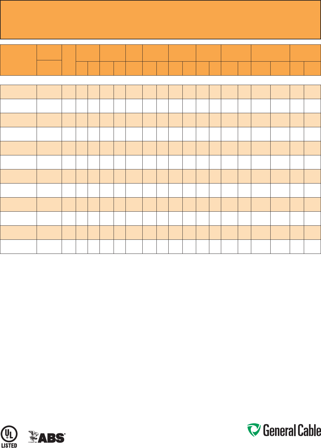
Phone: 888-593-3355
www.generalcable.com
CCW
®
Armored Power, 8 kV 133%, Shielded, 3/C VFD
UL Type MC-HL or MV-105, EPR, 105°C, Cable Tray Use, Sunlight-Resistant
Direct Burial, ABS CWCMC
SPEC 9815
May, 2012
PART
NUMBER
COND.
SIZE
NO. OF
COND.
INSULATION
THICKNESS
NOMINAL O.D.
OVER
INSULATION
BARE
GROUND
NOMINAL
CORE O.D.
NOMINAL
ARMOR O.D.
JACKET
THICKNESS
NOMINAL
OVERALL O.D.
APPROXIMATE NET
WEIGHT AMPACITY
AWG (kcmil) mils mm INCHES mm AWG INCHES mm INCHES mm mils mm INCHES mm
LBS/
1000 FT
kg/
1000 m IN AIR¹
DIRECT
BURIAL²
3/C WITH GROUND MC-HL OR MV-105, 140 MILS EPR, 8 kV 133% INSULATION LEVEL
9815.00603310 6 (7/W)
(13.3 mm²) 3 140 3.6 0.48 12.2 3 x #10 1.20 30.5 1.60 40.6 60 1.52 1.73 43.9 1,350 2,009 105 120
9815.00403310 4 (7/W)
(21.2 mm²) 3 140 3.6 0.53 13.5 3 x #10 1.29 32.8 1.70 43.2 60 1.52 1.83 46.5 1,600 2,381 135 155
9815.00203310 2 (7/W)
(33.6 mm²) 3 140 3.6 0.58 14.7 3 x #10 1.42 36.1 1.85 47.0 60 1.52 1.98 50.3 2,000 2,976 185 200
9815.00103308 1 (19/W)
(42.4 mm²) 3 140 3.6 0.62 15.7 3x#8 1.52 38.6 1.93 49.0 60 1.52 2.06 52.3 2,275 3,386 210 225
9815.11003308 1/0 (19/W)
(53.5 mm²) 3 140 3.6 0.65 16.5 3x#8 1.61 40.9 2.03 51.6 60 1.52 2.16 54.9 2,600 3,869 240 255
9815.21003308 2/0 (19/W)
(67.4 mm²) 3 140 3.6 0.69 17.5 3x#8 1.66 42.2 2.14 54.4 60 1.52 2.27 57.7 2,950 4,390 275 290
9815.41003307 4/0 (19/W)
(107 mm²) 3 140 3.6 0.79 20.1 3 x #7 1.87 47.5 2.40 61.0 75 1.91 2.56 65.0 4,025 5,990 360 375
9815.25003306 250 (37/W)
(127 mm²) 3 140 3.6 0.85 21.6 3 x #6 2.06 52.3 2.59 65.8 75 1.91 2.75 69.9 4,600 6,846 400 410
9815.35003306 350 (37/W)
(177 mm²) 3 140 3.6 0.94 23.9 3 x #6 2.15 54.6 2.85 72.4 75 1.91 3.01 76.5 5,800 8,631 490 495
9815.50003305 500 (37/W)
(253 mm²) 3 140 3.6 1.06 26.9 3 x #5 2.44 62.0 3.19 81.0 85 2.16 3.37 85.6 7,800 11,608 600 590
9815.75003304 750 (61/W)
(380mm²) 3 140 3.6 1.26 32.0 3 x #4 3.19 81.0 3.68 93.5 85 2.16 3.86 98.0 10,750 15,998 745 720
9815.10003304 1000 (61/W)
(507 mm²) 3 140 3.6 1.42 36.1 3 x #4 3.48 88.4 3.98 101.1 85 2.16 4.16 105.7 13,550 20,165 860 810
Dimensions and weights are nominal; subject to industry tolerances.
¹ In-air ampacities are per NEC Table 310.60(C)(71) for three insulated copper conductors rated 105°C, cabled with an overall covering and isolated in air at 40°C ambient temperature.
²DirectburialampacitiesareperNECTable310.60(C)(83)forthreeinsulatedcopperconductorsrated105°C,cabledwithinanoverallcoveringanddirectlyburiedinearthat20°C
ambient earth temperature.

Phone: 888-593-3355
www.generalcable.com
Jacket:
•Flame-retardant,moisture-and
sunlight-resistant Polyvinyl Chloride
(PVC), red
•Lowtemperatureperformancemeets
ASTM D746 brittleness temperature at
or below -40°C
Applications:
•CCWarmoredMedium-Voltage
power cables offer an economical,
rugged and reliable alternative to
labor-intensive cable in conduit wiring
methods
•Foruseonfeedersandbranchcircuits
in industrial power distribution systems
perNECArticles328and330
•ForuseinClassI,IIandIII,Divisions
1 and 2; and Class I, Zones 1 and 2
hazardous locations per NEC Articles
501, 502, 503 and 505
•Installedonmetalracks,troughs,in
raceways, in cable trays or secured
to supports spaced not more than six
feet apart
•Installedinbothexposedand
concealed work, wet or dry locations,
directly buried or embedded in
concrete
•Recognizedforuseonfixedor
floating offshore petroleum facilities
as recommended by the American
Petroleum Institute
Features:
•CCWarmorprovidesanimpervious
barrier to moisture, gas and liquids
and meets the grounding requirements
of UL 1072 and the NEC
•TripleExtrusion:Thestrandshield,
EPR insulation and insulation shield
are all extruded in one operation
Features: (cont’d)
•GeneralCable’sEPRinsulationsystem
has outstanding corona resistance and
high dielectric strength, and it provides
electrical stability under stress
•Cablemeetscoldimpactat-40°C
•105˚Ccontinuousoperating
temperature, wet or dry
•140˚Cemergencyrating
•250˚Cshortcircuitrating
Specifications:
Design Adherence:
•ICEAS-93-639/WC-74,5-46kV
Shielded Power Cable
•AEICCS8SpecificationforShielded
Power Cable, 5-46 kV
•UL1072Medium-VoltagePower
Cables
•UL1569MetalCladCables
•UL2225CablesandCableFittingsfor
Use in Hazardous Locations
•UL1309MarineShipboardCable
Flame Tests:
•ICEAT-29-520(210,000BTU/hr)
•IEEE383(70,000BTU/hr)
•CSAFT4
•IEEE1202(70,000BTU/hr)
•UL1072
•IEC60332-3CategoryA
Compliances:
•ULTypeMV-105,ULFile#E90501
•ULTypeMC-HL,SUNRES,CT
USE, DIR BUR, -40°C, FT4, UL File #
E90496
•ULListedMarineShipboard,ULFile#
E85994
•AmericanBureauofShipping(ABS)
Listed for CWCMC
Product Construction:
Conductor:
•BareannealedcopperperASTMB3
•CompactstrandingperASTMB496
Extruded Strand Shield (ESS):
•Extrudedthermosetsemi-conductor
stress control layer over the conductor
per ICEA S-93-639 and UL 1072
Insulation:
•175milsEthylenePropyleneRubber
(EPR) insulation per ICEA S-93-639
and UL 1072
Extruded Insulation Shield (EIS):
•Thermosetsemi-conductingpolymeric
layer, free stripping from the insulation
per ICEA S-93-639 and UL 1072
Shield:
•5milannealedbarecoppertapewith
25% overlap
Phase Identification:
•Color-codedpolymericidentification
tape laid under the shield - black, red
and blue
Grounding Conductor:
•ClassBstrandedbareannealed
copper grounding conductor
•SizedinaccordancewithUL1072and
NEC Article 250
Cable Assembly:
•Insulatedandgroundingconductors
are cabled together with non-
hygroscopic fillers when required
•Bindertapeisappliedoverthecabled
core
CCW Armor:
•Impervious,continuouslyweldedand
corrugated aluminum alloy sheath per
UL 1072 and UL 1569
•CCWarmorconductivitymeetsthe
grounding requirements of the NEC
CCW
®
Armored Power, 15 kV 100%, Shielded, 3/C
UL Type MC-HL or MV-105, EPR, 105°C, Cable Tray Use, Sunlight-Resistant
Direct Burial, ABS CWCMC
SPEC 9825
May, 2012
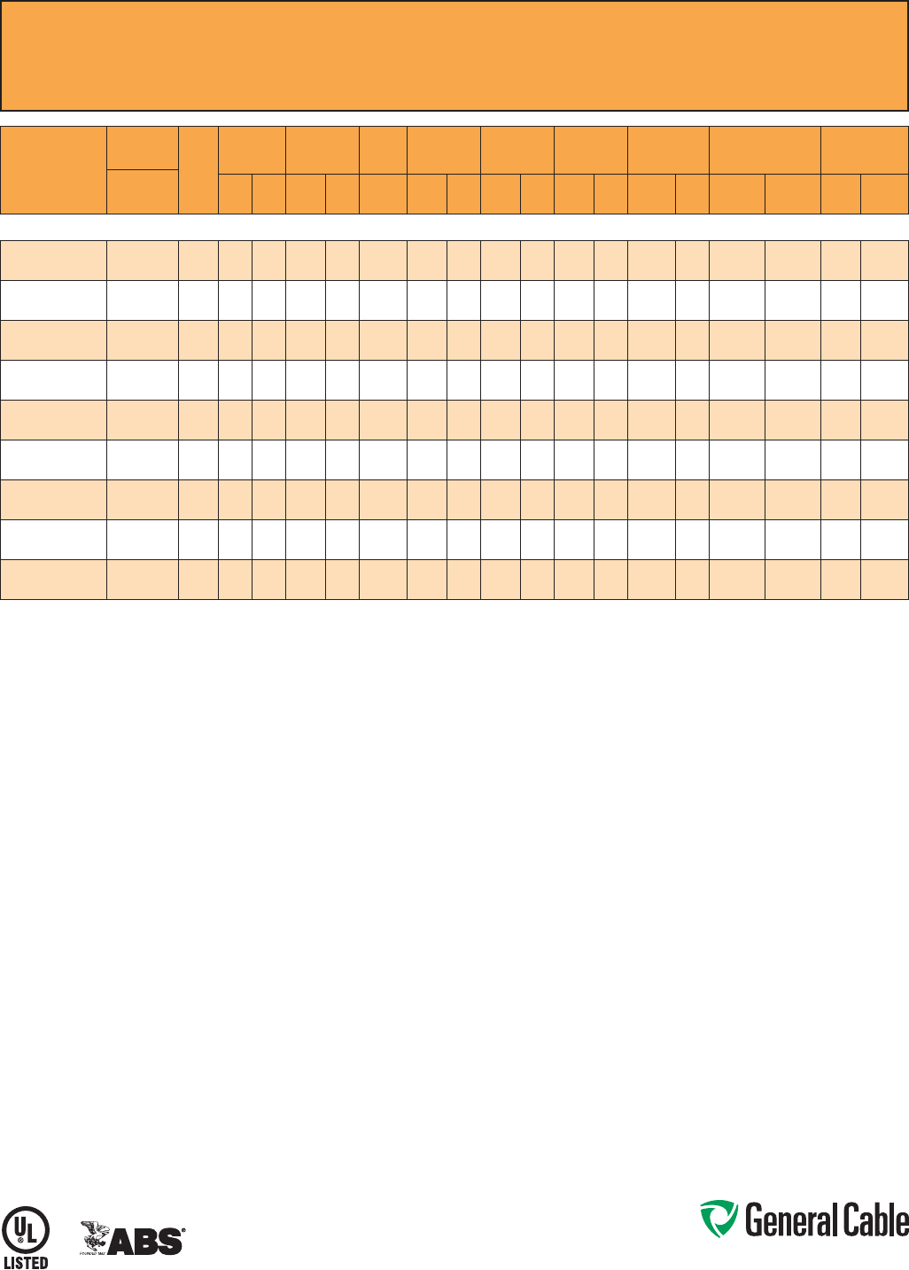
Phone: 888-593-3355
www.generalcable.com
SPEC 9825
May, 2012
CCW
®
Armored Power, 15 kV 100%, Shielded, 3/C
UL Type MC-HL or MV-105, EPR, 105°C, Cable Tray Use, Sunlight-Resistant
Direct Burial, ABS CWCMC
PART
NUMBER
COND.
SIZE
NO. OF
COND.
INSULATION
THICKNESS
NOMINAL O.D.
OVER
INSULATION
BARE
GROUND
NOMINAL
CORE O.D.
NOMINAL
ARMOR O.D.
JACKET
THICKNESS
NOMINAL
OVERALL O.D.
APPROXIMATE NET
WEIGHT AMPACITY
AWG (kcmil) mils mm INCHES mm AWG INCHES mm INCHES mm mils mm INCHES mm
LBS/
1000 FT
kg/
1000 m IN AIR¹
DIRECT
BURIAL²
3/C WITH GROUND MC-HL OR MV-105, 175 MILS EPR, 15 kV 100% INSULATION LEVEL
9825.00203106 2 (7/W)
(33.6 mm²)
3 175 4.4 0.65 16.5 6 1.61 40.9 1.96 49.8 60 1.52 2.05 52.1 2,077 3,091 185 200
9825.00103104 1 (19/W)
(42.4 mm²)
3 175 4.4 0.69 17.5 4 1.68 42.7 2.01 51.1 60 1.52 2.15 54.6 2,469 3,674 210 225
9825.11003104 1/0 (19/W)
(53.5 mm²)
3 175 4.4 0.72 18.3 41.78 45.2 2.10 53.3 60 1.52 2.24 56.9 2,760 4,107 240 255
9825.21003104 2/0 (19/W)
(67.4 mm²)
3 175 4.4 0.76 19.3 4 1.88 47.8 2.19 55.6 60 1.52 2.36 59.9 3,130 4,658 275 290
9825.41003103 4/0 (19/W)
(107 mm²)
3 175 4.4 0.86 21.8 3 2.09 53.1 2.45 62.2 75 1.91 2.61 66.3 4,290 6,384 360 375
9825.25003102 250 (37/W)
(127 mm²)
3 175 4.4 0.92 23.4 2 2.19 55.6 2.58 65.5 75 1.91 2.74 69.6 4,775 7,106 400 410
9825.35003102 350 (37/W)
(177 mm² )
3 175 4.4 1.01 25.7 2 2.45 62.2 2.85 72.4 75 1.91 3.01 76.5 6,132 9,125 490 495
9825.50003101 500 (37/W)
(253 mm²)
3 175 4.4 1.13 28.7 1 2.71 68.8 3.16 80.3 85 2.16 3.34 84.8 8,052 11,983 600 590
9825.750031110 750 (61/W)
(380mm²)
3 175 4.4 1.31 33.3 1/0 3.12 79.2 3.67 93.2 85 2.16 3.85 97.8 11,098 16,516 745 720
Dimensions and weights are nominal; subject to industry tolerances.
¹ Ampacities in air are per NEC Table 310.60(C)(71) for an insulated three-conductor copper cable isolated in air with 105°C rated conductors at a 40°C ambient temperature.
²DirectburialampacitiesareperNECTable310.60(C)(83)forthreeinsulatedcopperconductorscabledwithinanoverallcovering,directlyburiedinearthwith105°Cratedconductors
at 20°C ambient earth temperature.
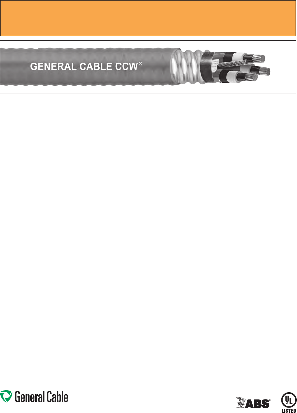
Phone: 888-593-3355
www.generalcable.com
Jacket:
•Flame-retardant,moisture-and
sunlight-resistant Polyvinyl Chloride
(PVC), red
•Lowtemperatureperformancemeets
ASTM D746 brittleness temperature at
or below -40°C
Applications:
•CCWarmoredMedium-Voltage
power cables offer an economical,
rugged and reliable alternative to
labor-intensive cable in conduit wiring
methods
•Foruseonfeedersandbranchcircuits
in industrial power distribution systems
perNECArticles328and330
•ForuseinClassI,IIandIII,Divisions
1 and 2; and Class I, Zones 1 and 2
hazardous locations per NEC Articles
501, 502, 503 and 505
•Installedonmetalracks,troughs,in
raceways, in cable trays or secured
to supports spaced not more than six
feet apart
•Installedinbothexposedand
concealed work, wet or dry locations,
directly buried or embedded in
concrete
•Recognizedforuseonfixedor
floating offshore petroleum facilities
as recommended by the American
Petroleum Institute
Features:
•CCWarmorprovidesanimpervious
barrier to moisture, gas and liquids
and meets the grounding requirements
of UL 1072 and the NEC
•TripleExtrusion:Thestrandshield,
EPR insulation and insulation shield
are all extruded in one operation
Features: (cont’d)
•GeneralCable’sEPRinsulationsystem
has outstanding corona resistance and
high dielectric strength, and it provides
electrical stability under stress
•Cablemeetscoldimpactat-40°C
•105˚Ccontinuousoperating
temperature, wet or dry
•140˚Cemergencyrating
•250˚Cshortcircuitrating
Specifications:
Design Adherence:
•ICEAS-93-639/WC-74,5-46kV
Shielded Power Cable
•AEICCS8SpecificationforShielded
Power Cable, 5-46 kV
•UL1072Medium-VoltagePower
Cables
•UL1569MetalCladCables
•UL2225CablesandCableFittingsfor
Use in Hazardous Locations
•UL1309MarineShipboardCable
Flame Tests:
•ICEAT-29-520(210,000BTU/hr)
•IEEE383(70,000BTU/hr)
•CSAFT4
•IEEE1202(70,000BTU/hr)
•UL1072
•IEC60332-3CategoryA
Compliances:
•ULTypeMV-105,ULFile#E90501
•ULTypeMC-HL,SUNRES,CT
USE, DIR BUR, -40°C, FT4, UL File #
E90496
•ULListedMarineShipboard,ULFile#
E85994
•AmericanBureauofShipping(ABS)
Listed for CWCMC
Product Construction:
Conductor:
•BareannealedcopperperASTMB3
•CompactstrandingperASTMB496
Extruded Strand Shield (ESS):
•Extrudedthermosetsemi-conductor
stress control layer over the conductor
per ICEA S-93-639 and UL 1072
Insulation:
•220milsEthylenePropyleneRubber
(EPR) insulation per ICEA S-93-639
and UL 1072
Extruded Insulation Shield (EIS):
•Thermosetsemi-conductingpolymeric
layer, free stripping from the insulation
per ICEA S-93-639 and UL 1072
Shield:
•5milannealedbarecoppertapewith
25% overlap
Phase Identification:
•Color-codedpolymericidentification
tape laid under the shield - black, red
and blue
Grounding Conductor:
•ClassBstrandedbareannealed
copper grounding conductor
•SizedinaccordancewithUL1072and
NEC Article 250
Cable Assembly:
•Insulatedandgroundingconductors
are cabled together with non-
hygroscopic fillers when required
•Bindertapeisappliedoverthecabled
core
CCW Armor:
•Impervious,continuouslyweldedand
corrugated aluminum alloy sheath per
UL 1072 and UL 1569
•CCWarmorconductivitymeetsthe
grounding requirements of the NEC
CCW
®
Armored Power, 15 kV 133%, Shielded, 3/C
UL Type MC-HL or MV-105, EPR, 105°C, Cable Tray Use, Sunlight-Resistant
Direct Burial, ABS CWCMC
SPEC 9835
May, 2012

Phone: 888-593-3355
www.generalcable.com
CCW
®
Armored Power, 15 kV 133%, Shielded, 3/C
UL Type MC-HL or MV-105, EPR, 105°C, Cable Tray Use, Sunlight-Resistant
Direct Burial, ABS CWCMC
SPEC 9835
May, 2012
PART
NUMBER
COND.
SIZE
NO. OF
COND.
INSULATION
THICKNESS
NOMINAL O.D.
OVER
INSULATION
BARE
GROUND
NOMINAL
CORE O.D.
NOMINAL
ARMOR O.D.
JACKET
THICKNESS
NOMINAL
OVERALL O.D.
APPROXIMATE NET
WEIGHT AMPACITY
AWG (kcmil) mils mm INCHES mm AWG INCHES mm INCHES mm mils mm INCHES mm
LBS/
1000 FT
kg/
1000 m IN AIR¹
DIRECT
BURIAL²
3/C WITH GROUND MC-HL OR MV-105, 220 MILS EPR, 15 kV 133% INSULATION LEVEL
9835.00203106 2 (7/W)
(33.6 mm²)
3 220 5.6 0.76 19.3 6 1.82 46.2 2.15 54.6 60 1.52 2.28 57.9 2,473 3,680 185 200
9835.00103104 1 (19/W)
(42.4 mm²)
3 220 5.6 0.79 20.1 4 1.88 47.8 2.23 56.6 60 1.52 2.36 59.9 2,811 4,183 210 225
9835.11003104 1/0 (19/W)
(53.5 mm²)
3 220 5.6 0.83 21.1 4 1.96 49.8 2.32 58.9 75 1.91 2.48 63.0 3,190 4,747 240 255
9835.21003104 2/0 (19/W)
(67.4 mm²)
3 220 5.6 0.87 22.1 4 2.06 52.3 2.40 61.0 75 1.91 2.56 65.0 3,630 5,402 275 290
9835.41003103 4/0 (19/W)
(107 mm²)
3 220 5.6 0.97 24.6 3 2.26 57.4 2.62 66.5 75 1.91 2.79 70.9 4,435 6,600 360 345
9835.25003102 250 (37/W)
(127 mm²)
3 220 5.6 1.03 26.2 2 2.36 59.9 2.75 69.9 75 1.91 2.92 74.2 5,086 7,569 400 410
9835.35003102 350 (37/W)
(177 mm²)
3 220 5.6 1.12 28.4 2 2.61 66.3 3.03 77.0 85 2.16 3.21 81.5 6,445 9,591 490 495
9835.50003101 500 (37/W)
(253 mm²)
3 220 5.6 1.24 31.5 1 2.86 72.6 3.32 84.3 85 2.16 3.50 88.9 8,376 12,465 600 590
9835.750031110 750 (61/W)
(380mm²)
3 220 5.6 1.41 35.8 1/0 3.25 82.6 3.80 96.5 85 2.16 3.98 101.1 11,431 17,011 745 720
Dimensions and weights are nominal; subject to industry tolerances.
¹ Ampacities in air are per NEC Table 310.60(C)(71) for an insulated three-conductor copper cable isolated in air with 105°C rated conductors at a 40°C ambient temperature.
²DirectburialampacitiesareperNECTable310.60(C)(83)forthreeinsulatedcopperconductorscabledwithinanoverallcovering,directlyburiedinearthwith105°Cratedconductors
at 20°C ambient earth temperature.

Phone: 888-593-3355
www.generalcable.com
Jacket:
•Flame-retardant,moisture-and
sunlight-resistant Polyvinyl Chloride
(PVC) per UL 1072, orange
•Lowtemperatureperformancemeets
ASTM D746 brittleness temperature at
or below -40°C
Applications:
•CCWarmoredMedium-Voltage
power cables offer an economical,
rugged and reliable alternative to
labor-intensive cable in conduit wiring
methods
•Foruseonfeedersandbranchcircuits
in industrial power distribution systems
perNECArticles328and330
•ForuseinClassI,IIandIII,Divisions
1 and 2; and Class I, Zones 1 and 2
hazardous locations per NEC Articles
501, 502, 503 and 505
•Installedonmetalracks,troughs,in
raceways, in cable trays or secured
to supports spaced not more than six
feet apart
•Installedinbothexposedand
concealed work, wet or dry locations,
directly buried or embedded in
concrete
•Recognizedforuseonfixedor
floating offshore petroleum facilities
as recommended by the American
Petroleum Institute
Features:
•CCWarmorprovidesanimpervious
barrier to moisture, gas and liquids
and meets the grounding requirements
of UL 1072 and the NEC
•TripleExtrusion:Thestrandshield,
EPR insulation and insulation shield
are all extruded in one operation
Features: (cont’d)
•GeneralCable’sEPRinsulationsystem
has outstanding corona resistance and
high dielectric strength, and it provides
electrical stability under stress
•Cablemeetscoldimpactat-40°C
•105˚Ccontinuousoperating
temperature, wet or dry
•140˚Cemergencyrating
•250˚Cshortcircuitrating
Specifications:
Design Adherence:
•ICEAS-93-639/WC-74,5-46kV
Shielded Power Cable
•AEICCS8SpecificationforShielded
Power Cable, 5-46 kV
•UL1072Medium-VoltagePower
Cables
•UL1569MetalCladCables
•UL2225CablesandCableFittingsfor
Use in Hazardous Locations
•UL1309MarineShipboardCable
Flame Tests:
•ICEAT-29-520(210,000BTU/hr)
•IEEE383(70,000BTU/hr)
•CSAFT4
•IEEE1202(70,000BTU/hr)
•UL1072
•IEC60332-3CategoryA
Compliances:
•ULTypeMV-105,ULFile#E90501
•ULTypeMC-HL,SUNRES,CT
USE, DIR BUR, -40°C, FT4, UL File #
E90496
•ULListedMarineShipboard,ULFile#
E85994
•AmericanBureauofShipping(ABS)
Listed for CWCMC
Product Construction:
Conductor:
•BareannealedcopperperASTMB3
•CompactstrandingperASTMB496
Extruded Strand Shield (ESS):
•Extrudedthermosetsemi-conductor
stress control layer over the conductor
per ICEA S-93-639 and UL 1072
Insulation:
•260milsEthylenePropyleneRubber
(EPR) insulation per ICEA S-93-639
and UL 1072
Extruded Insulation Shield (EIS):
•Thermosetsemi-conductingpolymeric
layer, free stripping from the insulation
per ICEA S-93-639 and UL 1072
Shield:
•5milannealedbarecoppertapewith
25% overlap
Phase Identification:
•Color-codedpolymericidentification
tape laid under the shield - black, red
and blue
Grounding Conductor:
•ClassBstrandedbareannealed
copper grounding conductor
•SizedinaccordancewithUL1072and
NEC Article 250
Cable Assembly:
•Insulatedandgroundingconductors
are cabled together with non-
hygroscopic fillers when required
•Bindertapeisappliedoverthecabled
core
CCW Armor:
•Impervious,continuouslyweldedand
corrugated aluminum alloy sheath per
UL 1072 and UL 1569
•CCWarmorconductivitymeetsthe
grounding requirements of the NEC
CCW
®
Armored Power, 25 kV 100%, Shielded, 3/C
UL Type MC-HL or MV-105, EPR, 105°C, Cable Tray Use, Sunlight-Resistant
Direct Burial, ABS CWCMC
SPEC 9845
May, 2012
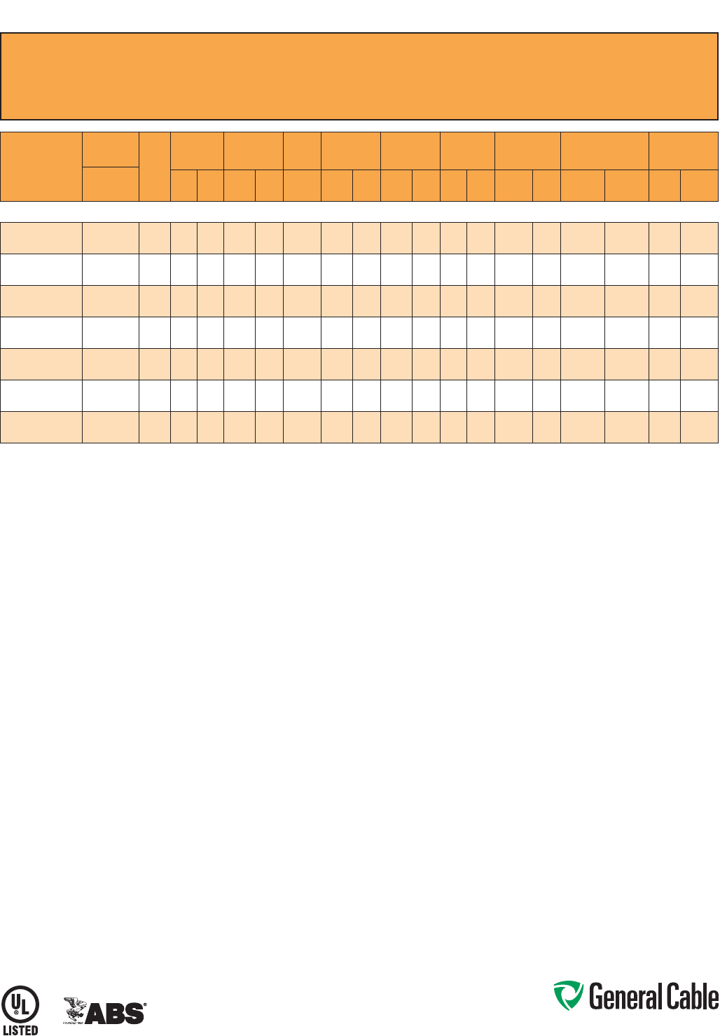
Phone: 888-593-3355
www.generalcable.com
CCW
®
Armored Power, 25 kV 100%, Shielded, 3/C
UL Type MC-HL or MV-105, EPR, 105°C, Cable Tray Use, Sunlight-Resistant
Direct Burial, ABS CWCMC
SPEC 9845
May, 2012
PART
NUMBER
COND.
SIZE
NO. OF
COND.
INSULATION
THICKNESS
NOMINAL O.D.
OVER
INSULATION
BARE
GROUND
NOMINAL
CORE O.D.
NOMINAL
ARMOR O.D.
JACKET
THICKNESS
NOMINAL
OVERALL O.D.
APPROXIMATE NET
WEIGHT AMPACITY
AWG (kcmil) mils mm INCHES mm AWG INCHES mm INCHES mm mils mm INCHES mm
LBS/
1000 FT
kg/
1000 m IN AIR¹
DIRECT
BURIAL²
3/C WITH GROUND MC-HL OR MV-105, 260 MILS EPR, 25 kV 100% INSULATION LEVEL
9845.00103104
1 (19/W)
(42.4 mm²)
3 260 6.6 0.87 22.1 4 2.07 52.6 2.45 62.2 75 1.91 2.61 66.3 3,189 4,746 210 225
9845.11003104
1/0 (19/W)
(53.5 mm²)
3 260 6.6 0.90 22.9 4 2.15 54.6 2.53 64.3 75 1.91 2.69 68.3 3,536 5,262 240 255
9845.21003104
2/0 (19/W)
(67.4 mm²)
3 260 6.6 0.94 23.9 4 2.24 56.9 2.62 66.5 75 1.91 2.79 70.9 3,939 5,862 275 290
9845.41003103
4/0 (19/W)
(107 mm²)
3 260 6.6 1.04 26.4 3 2.51 63.8 2.93 74.4 75 1.91 3.10 78.7 5,122 7,622 360 345
9845.25003102
250 (37/W)
(127 mm²)
3 260 6.6 1.10 27.9 2 2.61 66.3 3.07 78.0 85 2.16 3.25 82.6 5,819 8,660 400 410
9845.35003102
350 (37/W)
(177 mm²)
3 260 6.6 1.19 30.2 2 2.82 71.6 3.32 84.3 85 2.16 3.50 88.9 7,115 10,588 490 495
9845.50003101
500 (37/W)
(253 mm²)
3 260 6.6 1.31 33.3 1 3.08 78.2 3.62 91.9 85 2.16 3.81 96.8 9,125 13,579 600 590
Dimensions and weights are nominal; subject to industry tolerances.
¹ In-air ampacities are per NEC Table 310.60(C)(71) for three insulated copper conductors rated 105°C, cabled with an overall covering and isolated in air at 40°C ambient temperature.
²DirectburialampacitiesareperNECTable310.60(C)(83)forthreeinsulatedcopperconductorsrated105°C,cabledwithinanoverallcoveringanddirectlyburiedinearthat20°C
ambient earth temperature.

Phone: 888-593-3355
www.generalcable.com
Jacket:
•Flame-retardant,moisture-and
sunlight-resistant Polyvinyl Chloride
(PVC) per UL 1072, orange
•Lowtemperatureperformancemeets
ASTM D746 brittleness temperature at
or below -40°C
Applications:
•CCWarmoredMedium-Voltage
power cables offer an economical,
rugged and reliable alternative to
labor-intensive cable in conduit wiring
methods
•Foruseonfeedersandbranchcircuits
in industrial power distribution systems
perNECArticles328and330
•ForuseinClassI,IIandIII,Divisions
1 and 2; and Class I, Zones 1 and 2
hazardous locations per NEC Articles
501, 502, 503 and 505
•Installedonmetalracks,troughs,in
raceways, in cable trays or secured
to supports spaced not more than six
feet apart
•Installedinbothexposedand
concealed work, wet or dry locations,
directly buried or embedded in
concrete
•Recognizedforuseonfixedor
floating offshore petroleum facilities
as recommended by the American
Petroleum Institute
Features:
•CCWarmorprovidesanimpervious
barrier to moisture, gas and liquids
and meets the grounding requirements
of UL 1072 and the NEC
•TripleExtrusion:Thestrandshield,
EPR insulation and insulation shield
are all extruded in one operation
Features: (cont’d)
•GeneralCable’sEPRinsulationsystem
has outstanding corona resistance and
high dielectric strength, and it provides
electrical stability under stress
•Cablemeetscoldimpactat-40°C
•105˚Ccontinuousoperating
temperature, wet or dry
•140˚Cemergencyrating
•250˚Cshortcircuitrating
Specifications:
Design Adherence:
•ICEAS-93-639/WC-74,5-46kV
Shielded Power Cable
•AEICCS8SpecificationforShielded
Power Cable, 5-46 kV
•UL1072Medium-VoltagePower
Cables
•UL1569MetalCladCables
•UL2225CablesandCableFittingsfor
Use in Hazardous Locations
•UL1309MarineShipboardCable
Flame Tests:
•ICEAT-29-520(210,000BTU/hr)
•IEEE383(70,000BTU/hr)
•CSAFT4
•IEEE1202(70,000BTU/hr)
•UL1072
•IEC60332-3CategoryA
Compliances:
•ULTypeMV-105,ULFile#E90501
•ULTypeMC-HL,SUNRES,CT
USE, DIR BUR, -40°C, FT4, UL File #
E90496
•ULListedMarineShipboard,ULFile#
E85994
•AmericanBureauofShipping(ABS)
Listed for CWCMC
Product Construction:
Conductor:
•BareannealedcopperperASTMB3
•CompactstrandingperASTMB496
Extruded Strand Shield (ESS):
•Extrudedthermosetsemi-conductor
stress control layer over the conductor
per ICEA S-93-639 and UL 1072
Insulation:
•345milsEthylenePropyleneRubber
(EPR) insulation per ICEA S-93-639
and UL 1072
Extruded Insulation Shield (EIS):
•Thermosetsemi-conductingpolymeric
layer, free stripping from the insulation
per ICEA S-93-639 and UL 1072
Shield:
•5milannealedbarecoppertapewith
25% overlap
Phase Identification:
•Color-codedpolymericidentification
tape laid under the shield - black, red
and blue
Grounding Conductor:
•ClassBstrandedbareannealed
copper grounding conductor
•SizedinaccordancewithUL1072and
NEC Article 250
Cable Assembly:
•Insulatedandgroundingconductors
are cabled together with non-
hygroscopic fillers when required
•Bindertapeisappliedoverthecabled
core
CCW Armor:
•Impervious,continuouslyweldedand
corrugated aluminum alloy sheath per
UL 1072 and UL 1569
•CCWarmorconductivitymeetsthe
grounding requirements of the NEC
CCW
®
Armored Power, 25 kV 133%/35 kV 100%, Shielded, 3/C
UL Type MC-HL or MV-105, EPR, 105°C, Cable Tray Use, Sunlight-Resistant
Direct Burial, ABS CWCMC
SPEC 9855
February, 2011
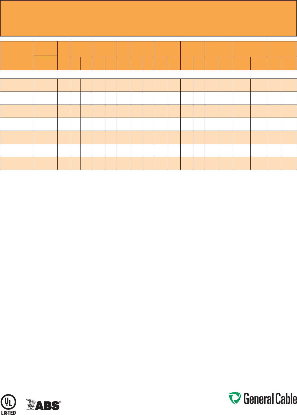
Phone: 888-593-3355
www.generalcable.com
CCW
®
Armored Power, 25 kV 133%/35 kV 100%, Shielded, 3/C
UL Type MC-HL or MV-105, EPR, 105°C, Cable Tray Use, Sunlight-Resistant
Direct Burial, ABS CWCMC
SPEC 9855
February, 2011
PART
NUMBER
COND.
SIZE
NO. OF
COND.
INSULATION
THICKNESS
NOMINAL O.D.
OVER
INSULATION
BARE
GROUND
NOMINAL
CORE O.D.
NOMINAL
ARMOR O.D.
JACKET
THICKNESS
NOMINAL
OVERALL O.D.
APPROXIMATE NET
WEIGHT AMPACITY
AWG (kcmil) mils mm INCHES mm AWG INCHES mm INCHES mm mils mm INCHES mm
LBS/
1000 FT
kg/
1000 m IN AIR¹
DIRECT
BURIAL²
3/C WITH GROUND MC-HL OR MV-105, 345 MILS EPR, 25 kV 133% AND 35 kV 100% INSULATION LEVEL³
9855.00103104
1 (19/W)
(42.4 mm²)
3 345 8.8 1.04 26.4 4 2.48 63.0 2.89 73.4 75 1.91 3.05 77.5 4,100 6,101 210 225
9855.11003104
1/0 (19/W)
(53.5 mm²)
3 345 8.8 1.07 27.2 4 2.56 65.0 2.98 75.7 75 1.91 3.14 79.8 4,500 6,697 240 255
9855.21003104
2/0 (19/W)
(67.4 mm²)
3 345 8.8 1.11 28.2 4 2.65 67.3 3.11 79.0 85 2.16 3.30 83.8 4,950 7,366 275 290
9855.41003103
4/0 (19/W)
(107 mm²)
3 345 8.8 1.22 31.0 3 2.88 73.2 3.41 86.6 85 2.16 3.60 91.4 6,200 9,227 360 345
9855.25003103
250 (37/W)
(127 mm²)
3 345 8.8 1.27 32.3 3 2.97 75.4 3.63 92.2 85 2.16 3.81 96.8 6,800 10,119 400 410
9855.35003102
350 (37/W)
(177 mm²)
3 345 8.8 1.36 34.5 2 3.20 81.3 3.76 95.5 85 2.16 3.94 100.1 8,000 11,905 490 495
9855.50003101
500 (37/W)
(253 mm²)
3 345 8.8 1.48 37.6 1 3.45 87.6 4.10 104.1 85 2.16 4.23 107.4 10,150 15,105 600 590
Dimensions and weights are nominal; subject to industry tolerances.
¹ In-air ampacities are per NEC Table 310.60(C)(71) for three insulated copper conductors rated 105°C, cabled with an overall covering and isolated in air at 40°C ambient temperature.
²DirectburialampacitiesareperNECTable310.60(C)(83)forthreeinsulatedcopperconductorsrated105°C,cabledwithinanoverallcoveringanddirectlyburiedinearthat20°C
ambient earth temperature.
³Partnumber9855.00103104,1AWG,3conductorisonlylisted25kV133%insulationlevelinaccordancewithUL1072.

Phone: 888-593-3355
www.generalcable.com
Jacket:
•Flame-retardant,moisture-and
sunlight-resistant Polyvinyl Chloride
(PVC) per UL 1072, orange
•Lowtemperatureperformancemeets
ASTM D746 brittleness temperature at
or below -40°C
Applications:
•CCWarmoredMedium-Voltage
power cables offer an economical,
rugged and reliable alternative to
labor-intensive cable in conduit wiring
methods
•Foruseonfeedersandbranchcircuits
in industrial power distribution systems
perNECArticles328and330
•ForuseinClassI,IIandIII,Divisions
1 and 2; and Class I, Zones 1 and 2
hazardous locations per NEC Articles
501, 502, 503 and 505
•Installedonmetalracks,troughs,in
raceways, in cable trays or secured
to supports spaced not more than six
feet apart
•Installedinbothexposedand
concealed work, wet or dry locations,
directly buried or embedded in
concrete
•Recognizedforuseonfixedor
floating offshore petroleum facilities
as recommended by the American
Petroleum Institute
Features:
•CCWarmorprovidesanimpervious
barrier to moisture, gas and liquids
and meets the grounding requirements
of UL 1072 and the NEC
•TripleExtrusion:Thestrandshield,
EPR insulation and insulation shield
are all extruded in one operation
Features: (cont’d)
•GeneralCable’sEPRinsulationsystem
has outstanding corona resistance and
high dielectric strength, and it provides
electrical stability under stress
•Cablemeetscoldimpactat-40°C
•105˚Ccontinuousoperating
temperature, wet or dry
•140˚Cemergencyrating
•250˚Cshortcircuitrating
Specifications:
Design Adherence:
•ICEAS-93-639/WC-74,5-46kV
Shielded Power Cable
•AEICCS8SpecificationforShielded
Power Cable, 5-46 kV
•UL1072Medium-VoltagePower
Cables
•UL1569MetalCladCables
•UL2225CablesandCableFittingsfor
Use in Hazardous Locations
•UL1309MarineShipboardCable
Flame Tests:
•ICEAT-29-520(210,000BTU/hr)
•IEEE383(70,000BTU/hr)
•CSAFT4
•IEEE1202(70,000BTU/hr)
•UL1072
•IEC60332-3CategoryA
Compliances:
•ULTypeMV-105,ULFile#E90501
•ULTypeMC-HL,SUNRES,CT
USE, DIR BUR, -40°C, FT4, UL File #
E90496
•ULListedMarineShipboard,ULFile#
E85994
•AmericanBureauofShipping(ABS)
Listed for CWCMC
Product Construction:
Conductor:
•BareannealedcopperperASTMB3
•CompactstrandingperASTMB496
Extruded Strand Shield (ESS):
•Extrudedthermosetsemi-conductor
stress control layer over the conductor
per ICEA S-93-639 and UL 1072
Insulation:
•420milsEthylenePropyleneRubber
(EPR) insulation per ICEA S-93-639
and UL 1072
Extruded Insulation Shield (EIS):
•Thermosetsemi-conductingpolymeric
layer, free stripping from the insulation
per ICEA S-93-639 and UL 1072
Shield:
•5milannealedbarecoppertapewith
25% overlap
Phase Identification:
•Color-codedpolymericidentification
tape laid under the shield - black, red
and blue
Grounding Conductor:
•ClassBstrandedbareannealed
copper grounding conductor
•SizedinaccordancewithUL1072and
NEC Article 250
Cable Assembly:
•Insulatedandgroundingconductors
are cabled together with non-
hygroscopic fillers when required
•Bindertapeisappliedoverthecabled
core
CCW Armor:
•Impervious,continuouslyweldedand
corrugated aluminum alloy sheath per
UL 1072 and UL 1569
•CCWarmorconductivitymeetsthe
grounding requirements of the NEC
CCW
®
Armored Power, 35 kV 133%, Shielded, 3/C
UL Type MC-HL or MV-105, EPR, 105°C, Cable Tray Use, Sunlight-Resistant
Direct Burial, ABS CWCMC
SPEC 9875
February, 2011
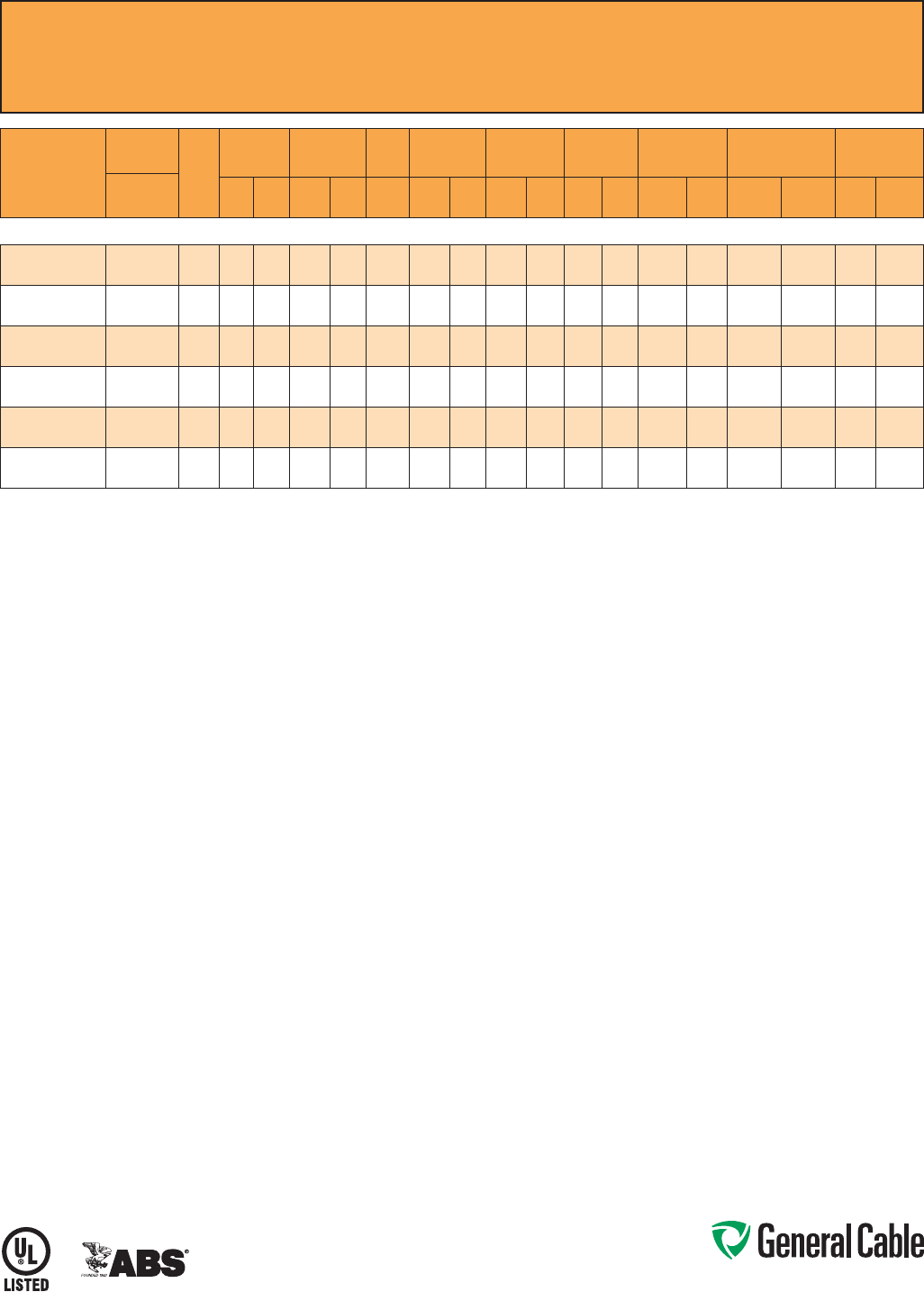
Phone: 888-593-3355
www.generalcable.com
CCW
®
Armored Power, 35 kV 133%, Shielded, 3/C
UL Type MC-HL or MV-105, EPR, 105°C, Cable Tray Use, Sunlight-Resistant
Direct Burial, ABS CWCMC
SPEC 9875
February, 2011
PART
NUMBER
COND.
SIZE
NO. OF
COND.
INSULATION
THICKNESS
NOMINAL O.D.
OVER
INSULATION
BARE
GROUND
NOMINAL
CORE O.D.
NOMINAL
ARMOR O.D.
JACKET
THICKNESS
NOMINAL
OVERALL O.D.
APPROXIMATE NET
WEIGHT AMPACITY
AWG (kcmil) mils mm INCHES mm AWG INCHES mm INCHES mm mils mm INCHES mm
LBS/
1000 FT
kg/
1000 m IN AIR¹
DIRECT
BURIAL²
3/C WITH GROUND MC-HL OR MV-105, 420 MILS EPR, 35 kV 133% INSULATION LEVEL
9875.11003104
1/0 (19/W)
(53.5 mm²)
3 420 10.7 1.24 31.5 4 2.91 73.9 3.41 86.6 85 2.16 3.59 91.2 5,300 7,887 240 255
9875.21003104
2/0 (19/W)
(67.4 mm²)
3 420 10.7 1.27 32.3 4 3.02 76.7 3.63 92.2 85 2.16 3.81 96.8 6,000 8,929 275 290
9875.41003103
4/0 (19/W)
(107 mm²)
3 420 10.7 1.38 35.1 3 3.23 82.0 3.80 96.5 85 2.16 3.98 101.1 7,100 10,566 360 345
9875.25003103
250 (37/W)
(127 mm²)
3 420 10.7 1.43 36.3 3 3.40 86.4 3.98 101.1 85 2.16 4.16 105.7 8,100 12,054 400 410
9875.35003102
350 (37/W)
(177 mm²)
3 420 10.7 1.52 38.6 2 3.51 89.2 4.10 104.1 85 2.16 4.29 109.0 9,000 13,393 490 495
9875.50003101
500 (37/W)
(253 mm²)
3 420 10.7 1.64 41.7 1 3.81 96.8 4.45 113.0 85 2.16 4.63 117.6 11,100 16,519 600 590
Dimensions and weights are nominal; subject to industry tolerances.
¹ In-air ampacities are per NEC Table 310.60(C)(71) for three insulated copper conductors rated 105°C, cabled with an overall covering and isolated in air at 40°C ambient temperature.
²DirectburialampacitiesareperNECTable310.60(C)(83)forthreeinsulatedcopperconductorsrated105°C,cabledwithinanoverallcoveringanddirectlyburiedinearthat20°C
ambient earth temperature.
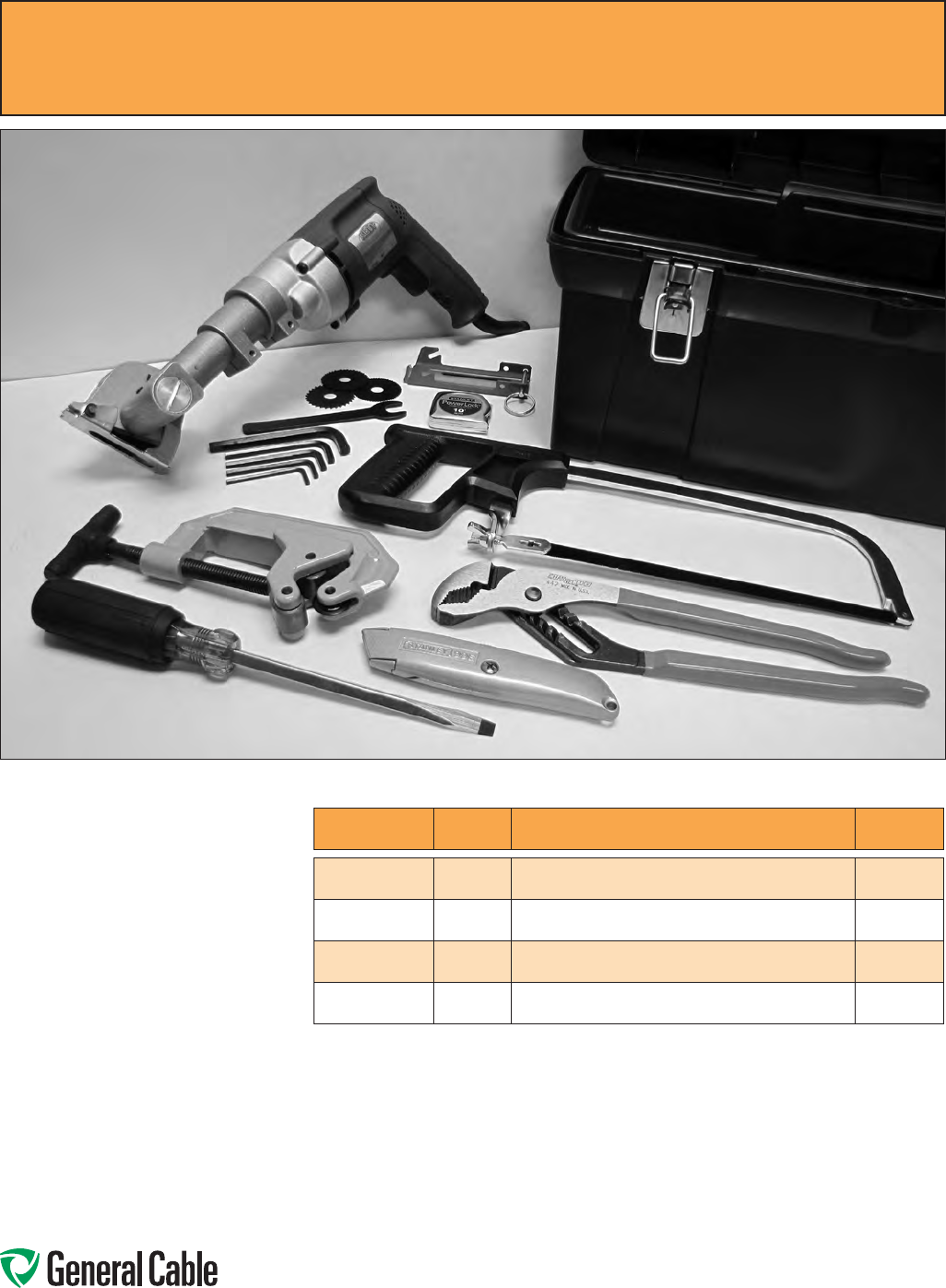
Phone: 888-593-3355
www.generalcable.com
CCW
®
Armored Cable Tool Kit
For Removal of CCW Armor Sheath
Including Accessories
SPEC 9900
January, 2010
Tool Kit Contents:
• 1ea.Kett-ToolMetalCladCableSaw
• 12pcs.2"/44teethCuttingBlades
• CableSawSpindleandAllenWrenches
• 1ea.MCCableGuide
• 1ea.TubingandPipeCutter
• 1ea.12"V-JawChannel-LockPliers
• 1ea.10"HacksawFrame
• 3ea.10"/24teeth/in.HacksawBlades
• 1ea.10ft.TapeMeasure
• 1ea.UtilityKnifewithBlades
• 1ea.5/16"Screwdriver
• 1ea.ToolBox
PART NUMBER QUANTITY DESCRIPTION
APPROXIMATE
WEIGHT
9900.KS226
1CCWTOOLKITWITH120VAC,
60HzELECTRICCUTTINGSAW 22.0LBS
9900.PS526
1CCWTOOLKITWITH90PSI
PNEUMATICCUTTINGSAW 20.0LBS
990 0.1574 4
12",44TREPLACEMENTCUTTINGBLADES
(12BLADESPERPACK) 1.0LBS
9900.27901
1MCCABLEGUIDE 0.5LBS

Phone: 888-593-3355
www.generalcable.com
SPECIFICATION NO. DESCRIPTION REVISION DATE
A001 Metal-Clad CCW® Type MC-HL Wiring System Feb. 2011
A001 CCW® Installation Manual Jul. 2011
A001 CCW® Sheath Removal Instructions Feb. 2011
A010 CCW® Explosion-Proof Gland Cross-Reference Apr. 2010
A015 CCW® Part Number Cross-Reference — Jan. 2013
Okonite C-L-X® to General Cable CCW®
A030 Reference Standards Apr. 2010
A055 Checklist for CCW® Specifications Apr. 2010
A100 Common Color Sequence Apr. 2011
A150 Metric Conversion Factors Sept. 2010
A185 AWG (American Wire Gauge) to mm2 (Millimeters Squared) Conversion Sept. 2010
B025 Class B Conductors for General Wiring Mar. 2012
D005 Recommended Reel Handling Practices Mar. 2012
D025 Recommended Cable Handling Practices Oct. 2011
D050 Recommended Cable Storage Practices Nov. 2011
E005 Pre-Installation Instructions Apr. 2010
E050 Installation — Feed-In Setups Apr. 2010
E075 Installation — Conductor Maximum Pulling Tensions Mar. 2012
E100 Installation — Training and Bending Limitations Apr. 2010
E125 Installation — Maximum Sidewall Pressure Jan. 2011
F005 DC “HI-POT” Pre-Test Guidelines for MV Cables Apr. 2010
F025 DC “HI-POT” Testing Guidelines for MV Cables Apr. 2010
F075 Field Electrical “HI-POT” Testing Guidelines Apr. 2010
F130 CCW® Sheath as a Grounding Conductor Dec. 2010
Index Part Number Index Jan. 2013
Table of Contents
TechnicalInformation
Technical
January, 2013
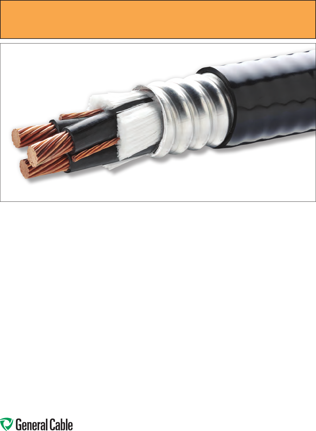
Phone: 888-593-3355
www.generalcable.com
CCW®isGeneralCable’stradenameforthecontinuouslycorrugated,
welded, aluminum-sheathed wiring system. CCW provides a unique
cable system within a sealed metallic sheath that provides complete
protection to the conductors from all external environments. CCW is
offeredinacompletelineofpower,control,signal,andinstrumentation
cables.
The Most Versatile Wiring Method Available
Ideal for Hazardous (Classified) Locations
Provides Best Performance for PWM Circuits
Metal-Clad CCW
®
Type MC-HL Wiring System
SPEC A001
February, 2011
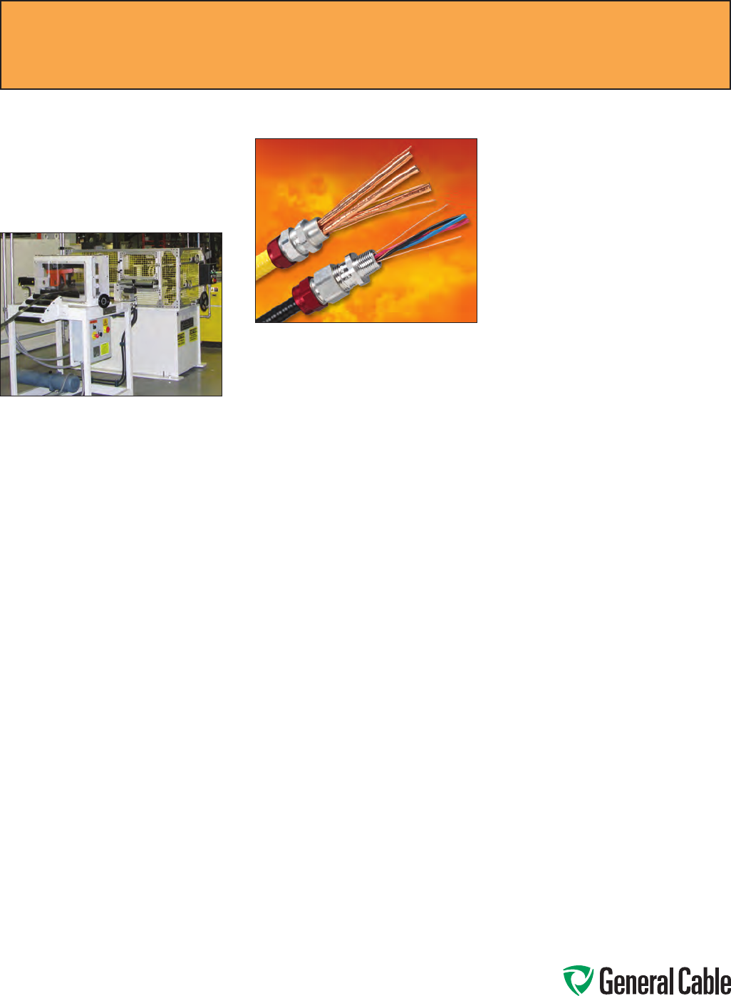
Phone: 888-593-3355
www.generalcable.com
Introduction
CCWprovidesauniquewiringsystem
thatisunparalleledinversatilityfor
practicallyeveryinstallationcondition
orrequirement.
CCW Is A Self-Contained Wiring
System
TheCCWwiringsystemconsists
ofconductorsoracableenclosed
inaracewayconsistingofastrong,
pliablealuminummetallicsheaththat
iscontinuouslyweldedtoprovide
acompletelyenclosedgas/vapor-
tight metallic sheath that is then
corrugated.Corrugatingthealuminum
sheathprovidesgreatercrushand
impactresistanceformechanical
protectionoftheconductorsand
increasesthepliabilityofthecable
duringinstallation.Thestandard
corrugated aluminum sheath used
onallCCWcablescomplieswith
themoreseverecrushandimpact
requirementsofUL2225forHL
cablespermittedinhazardous
locations.CCWTypeMCMetal-Clad
Cablehasbeeninstalledinsomeof
themostdemandingapplicationsfor
over40yearsandhasbecomean
industrystandardforindustrialand
commercialapplications.
CCW Has Almost-Universal
Applications
CCW Type MC
CCWisavailableinlow-andmedium-
voltagepower,control,signal,and
instrumentationcables.AsCCWis
ratedMC-HL,itcanbeusedinany
TypeMCapplication,asitcomplies
withUL1569,Metal-CladAluminum
Cable.
CCWhasbeenrecognizedbythe
NationalElectricalCode®(NEC®)for
morethan40years,andthepermitted
usesofCCWintheNEChavebeen
signicantlyexpandedovertheyears,
asusershaverecognizedtheunique
advantagesofthisfactory-assembled
wiringsystemandinspectorshave
observedandrecognizedthetrouble-
freeperformanceofCCWinallthe
usespermitted.
NECArticle330istheprimaryarticle
forCCWMetal-CladTypeMCCable.
InaccordancewiththisArticle,CCW
ratedfrom600Vto35kVispermitted
tobeusedintheapplicationsshown
below;theadditionalreferences
includedrefertothe2011NEC.
•Forservices,feeders,andbranch
circuits
•Forpower,lighting,control,and
signaling circuits
•Asexposedruns“ER”(formerly
openwiring)orconcealed
•Indoorsoroutdoors
•Incabletray,whereidentiedfor
suchuse–see392.10,392.20(A),
(B)and(C)
•AsaerialcableonMessenger-
SupportedWiringorinstalled
outsideofbuildingsorstructures–
see225.10,396.10,and396.12
•Inanyraceway
•Inhazardous(classied)locations
ClassI,Division1
[511.7,513.7,515.7,and516.7]
ClassI,Division2
[501.10(B)(1)and(5)]
ClassI,Zone2
[505.15(C)(1)(b)]
ClassII,Division2
[502.10(B)(3)and(6)]
ClassIII,Divisions1and2
[503.10(A)and(B)]
IntrinsicallySafeCircuits
[504.20]
Zone22
[506.15(C)(3)and(6)]
[NotincludedinUL2225]
•SpecialOccupancies–seeArticles
517through552
•AsService-EntranceCable–see
230.43
•Inwetanddrylocations–sincethe
metalliccoveringisimperviousto
moisture,theinsulatedconductors
under the metallic sheath are
listedforuseinwetlocations,and
acorrosion-resistantprotective
nonmetallicjacketisprovidedover
the metallic sheath
•Tobedirectburiedorencased
inconcrete,sinceCCWhasa
corrosion-resistantprotective
nonmetallicjacketoverthemetallic
sheath–see300.5or300.50,as
appropriate
•Assingle-conductorswhenallthe
phaseconductorsand,whereused,
theneutralconductoraregrouped
togethertominimizeinduced
voltageonthesheath–see300.20
Unlessotherwisestated,allreferencesrefertothe2011NEC
®
.
SPEC A001
July, 2011
CCW
®
Installation Manual

Phone: 888-593-3355
www.generalcable.com
CCW Type MC-HL
CCWTypeMC-HLcontainsseparate
equipmentgroundingconductor(s)
sizedinaccordancewith250.122in
allconstructions,inadditiontothe
standardgas/vapor-tightcontinuously
corrugated metallic sheath and overall
jacketofsuitablepolymericmaterials
andcomplieswithUL2225,Standard
forCablesandCableFittingsForUse
InHazardous(Classied)Locations.
UL2225alsoincludesadditional
requirementsthatthecablecomplywith
a-40°Clowtemperatureimpacttest,
moresevereroomtemperaturecrush
andimpacttests,andamoresevere
verticaltrayametest.
Wheninstalledwithtermination
ttingslistedfortheapplication,CCW
MC-HLmaybeusedinindustrial
establishmentswithrestrictedpublic
access,wheretheconditionsof
maintenanceandsupervisionensure
thatonlyqualiedpersonsservicethe
installation.Inadditiontoalltheuses
permittedforCCWTypeMC,CCWType
MC-HLisalsopermittedtobeinstalled
inthefollowinghazardous(classied)
locations:
ClassI,Division1
[501.10(A)(1)(c)]
ClassI,Zone1
[505.15(B)(1)(b)]
ClassII,Division1
[ 50 2.10 ( A ) (1)
and
(3)]
Zones20and21
[506.15(A)(3)and(B)(1)]
[NotincludedinUL2225]
CCW Type MV or MC
CCWTypeMVorMCcontains
conductorsrated105°Candisavailable
from2400Vto35kV.Thecable
complieswithbothUL1569,Metal-
CladAluminumCable,andUL1072,
Medium-VoltagePowerCables,andis
listedandmarkedasTypeMVorMC.
Thecableispermittedtobeusedin
accordancewith328.10and330.10and
installedinthesameapplicationsas
CCWTypeMC.
CCW Remote-Control, Signaling,
and Power-Limited Cables
CCWTypeMCandCCWTypeMC-
HLarepermittedtobeusedon600V
Class1power-limitedcircuits,Class1
remote-controlandsignalingcircuits,
andthesupplysideofClass2orClass
3powersourcesintheapplications
andlocationsshownaboveforthe
applicablecabletype,subjecttoany
limitationsspeciedinPartIIofArticle
725,alsosee725.127.
TypeMCcableispermittedtobe
installedincompliancewithPartsII
andIIIofArticle725and770.133as
applicableandinaccordancewith
330.10(B)(1)through(B)(4).
CCW Type ITC-HL
CCWInstrumentationTrayCableType
ITC-HLispermittedtobeinstalledin
accordancewithArticle501.10(A)(1)(d)
inClassl,Zone1orDivision1locations.
All constructions are manufactured
withthestandardgas/vaportight
continuouslycorrugatedmetallicsheath
andcoveredwithajacketofsuitable
polymericmaterial.CCWTypeITC-HL
cablecomplieswithUL2225,Standard
forCablesandCableFittingsForUse
InHazardous(Classied)Locations.
TheCCWsheathprovidesequipment
groundingthroughthesheath.UL2225
alsoincludesadditionalrequirements
thatthecablecomplywiththe-40°C
lowtemperatureimpacttest,more
severeroomtemperaturecrushand
impacttests,andamoreseverevertical
trayametest.
Inadditiontoalltheapplications
permittedforCCWTypeITC,CCWType
ITC-HLisalsopermittedinthefollowing
additionalhazardous(classied)
locations:
ClassI,Division1
[501.10(A)(1)(d)]
ClassI,Zone1
[505.15(B)(1)(c)]
CCW Type ITC-HL/PLTC
(Instrumentation Tray Cable/
Power-Limited Tray Cable)
CCWTypeITC-HL/PLTCispermitted
in727.4tobeusedasITCcableon
instrumentation and control circuits
operatingat150voltsorlessand
5amperesorlessinindustrial
establishmentswheretheconditionsof
maintenanceandsupervisionensure
thatonlyqualiedpersonsservicethe
installation:
• Incabletrays
• Inraceways
• Inthefollowinghazardous(classied)
locations:
ClassI,Division2
[501.10(B)(1),(3)and(4)]
ClassI,Zone2
[505.15(C)(1)(c)and(d)]
ClassII,Division2
[502.10(B)(1),(4)and(5)]
IntrinsicallySafeCircuits
[504.20]
Zone22
[506.15(C)(4)and(5)]
[NotincludedinUL2225]
Commercial garages
[ 511.7 ]
• Asaerialcableonamessenger
• Directburied
• Underraisedoorsinroomscontain-
ingindustrialprocesscontrolequip-
mentandrackrooms
• Underraisedoorsininformation
technologyequipmentrooms–see
Table645.5.
RefertoArticle727forcompletewiring
methods,installationrequirements,and
listingrequirementsforCCWTypeITC-
HLcables.
Unlessotherwisestated,allreferencesrefertothe2011NEC
®
.
SPEC A001
July, 2011
CCW
®
Installation Manual

Phone: 888-593-3355
www.generalcable.com
CCWTypeITC-HL/PLTCispermitted
in725.133tobeusedasPLTCcable
onClass2andClass3remote-control,
signaling,andpower-limitedcircuits:
• Asexposedruns“ER”
• Incabletrays
• Inraceways
• Inthefollowinghazardous(classied)
locations:
ClassI,Zone2
[505.15(C)(1)(d)]
ClassII,Division2
[ 50 2.10 ( B ) ( 1)
and
(4)]
IntrinsicallySafeCircuits
[504.20]
Zone22
[506.15(C)(4)]
[NotincludedinUL2225]
Commercial garages
[ 511.7 ]
• Asaerialcableonamessenger
• Directburied
• Underraisedoorsininformation
technologyequipmentrooms
–
see
Table645.5
RefertoPartsIIIandIVofNEC725for
completewiringmethods,installation
requirements,andlistingrequirements
forCCWTypePLTCcables.
CCW Is The Perfect Cable For
PWM Variable Frequency Drive
Cables
Asafunctionofitsconstruction,
CCWhasbeenrecognizedforits
abilitytoreducetheamountofstray
harmoniccurrentsgeneratedbyPulse
WidthModulated(PWM)variable
frequencydrives.Throughtheuseof
splitgroundcongurationsandthe
overallshieldwithCCW’scorrugated,
continuouslyweldedaluminum
sheath,thiscabledesignisoneof
thepreferredchoicesoftheworld’s
manufacturers of drives and motors
toreduceEMI,RFI,anddestructive
harmoniccurrents.CCWcablesprovide
highattenuationshieldingforcontrol,
signal,andinstrumentationcircuitsand
asymmetricallowimpedancepathto
ground.TheCCWsheatheffectively
reducescrosstalk,commonmode
currents,motorframevoltage,and
injectedgroundcurrents.Theseareall
importantconsiderationsforPWMac
driveapplications.
CCW Offshore And Shipboard
Cables Certified By ABS
CCWcablesarecertiedbythe
AmericanBureauofShipping(ABS)as
cableslistedasCWCMC.Thislisting
meansthatCCWcablesmaybeused
inMODUs(MobileOffshoreDrilling
Units),FixedProductionPlatforms,
FloatingProductionPlatforms,and
FPSOs(FloatingProduction,Storage
andOfoading)requiringMCorMC-
HL(HazardousLocations).These
cableconstructionsmeetUL1309,
StandardsForMarineShipboardCable
andUL2225,StandardForCablesand
CableFittingsForUseInHazardous
(Classied)Locations.
CCW Is An Economical Factory
Assembled Wiring System
CCWisafactory-assembledwiring
systemthateliminatesthecostof
installingracewaysandthepossibility
of damaging the insulated conductors
duringinstallationinracewaysorcable
trays.SinceCCWismanufacturedin
long,continuouslengthsandsupplied
onreels,scrapissignicantlyreduced.
SinceCCWTypeMCcablesare
approvedforexposedruns,theyoffera
veryeconomicalwiringsystem.Acable
trayorothersupportscanbeused
whentherearemultiplecablesinthe
samerun,andthenindividualcables
canbranchoffasexposedrunsfrom
thetrayorsupporttothetermination,as
required,withoutanychangeorsplices
inthecable.
CCW Is Easy To Install
CCWcanbeinstalledusingnormal
installationequipmentandestablished
installationtechniques.Itispliableand
canbeeasilyinstalledinlonglengths
incabletrays,onladdersorother
supports.Aswithanywiringmethod,
careshouldbetakennottoexceedthe
maximumpullingtension,minimum
bendingradius,ormaximumsidewall
pressure.Acompletecableinstallation
manualforallcablesandconductorsis
availablefromGeneralCable.
Theminimumbendingradiusfora
multiconductorcableisseventimes
(7x)theexternaldiameterofthemetallic
sheath.
CCWcableiseasilyterminated,
and sheath removal instructions are
includedinthiscatalog.Termination
kitsandsplicingkitsareavailablefrom
numerousmanufacturers.
CCW Provides Environmental
Protection
Theweldedandcorrugatedmetallic
sheathonCCWisimpervioustovapors,
gasesorliquidsandprovidesaclean,
dryenvironmentfortheconductors.
Thispermitstheconductorstobe
ratedat90°Cupto2400Vand105°C
formedium-voltagecablesinbothwet
anddryinstallations.Thestandard
jacketovertheCCWsheathislow-
temperature,sunlight-resistantPolyvinyl
Chloride(PVC).Otherjacketedor
unjacketedcablesareavailablefor
specicinstallationorenvironmental
conditions.ConsultyourGeneralCable
representativeforfurtherdetails.
Unlessotherwisestated,allreferencesrefertothe2011NEC
®
.
SPEC A001
July, 2011
CCW
®
Installation Manual

Phone: 888-593-3355
www.generalcable.com
CCW Cables Provide Excellent
Flame Resistance
CCWcables,withorwithoutaPVC
jacket,complywithallcurrentame
teststandards,includingUL1569,
IEEE1202,IEEE383,CSAFT4,ICEA
T-29-520(210,000BTU/hr)andIEC
60332.3CatA.
CCW Sheath Permitted As An
Equipment Grounding Conductor
ThesheathonCCWisactuallyahollow
aluminumtubethatprovidesacross-
sectionalareathatmeetsorexceeds
theequipmentgroundingconductor
requirementsspeciedin250.122inall
constructions.SpecF125providesthe
equivalentconductorsizeforeachCCW
aluminumsheathdiameter.
Eventhoughthemetallicsheath
providesanequipmentgrounding
conductorthatequalsorexceedsthe
NECrequirements,anadditionalcopper
equipmentgroundingconductoris
providedinallconstructionslistedMC-
HLtocomplywiththeuser’spreference
nottorelycompletelyonthemetallic
sheathforgroundingpowercables.
Theadditionalequipmentgrounding
conductorprovidesanaddedbenet
ofbeingabletoparalleltwostandard
powercablesandstillcomplywiththe
groundingrequirementsof250.122(F).
Inmanycases,threestandardpower
cablescanberuninparallel,butyou
shouldcheckwiththemanufacturerfor
thistypeofinstallation.
CCW Sheath Recognized As A
Voltage Separation Barrier
TheCCWaluminumsheathisrecognized
asasolidfixedbarrierwhenusedon
TypeMVorMCcablesinstalledincable
traywithcablesrated600voltsorlessin
accordancewith392.20(B).
Installation
Somespecicguidelinesforinstalling
CCWcablesarelistedbelow.
• WhenpullingCCWcablesinto
position,thepullingtensionmust
beontheconductorsratherthan
thealuminumsheath.Thepulling
eyes/boltsorbasketgripshould
beattachedtotheconductorsand
the metallic sheath fastened to the
insulatedconductorsorthepulling
ropetopreventmovementofthe
conductorswithintheCCWsheath.
Ifmovementoftheconductorswithin
the CCW sheath is noted at the start
ofapull,onemethodtostopthe
movement is to drive three or four
nailsabout2in.apartthroughthe
CCWsheathintoeachcopperpower
conductor.
• Theminimumbendingradiusofseven
times(7x)theexternaldiameterof
the metallic sheath for nonshielded
multiconductorcablesmustbe
maintainedduringpulling.Roller
assembliesmustprovideasmooth,
regularbendingradiusforthecable.
Usingsmallerrollerscandamagethe
aluminumsheathandthecable.
• Sidewallpressureshouldnotexceed
500lbs/ftofradiustoavoidattening
the CCW sheath or damaging the
conductors.
• Anti-shortbushingsarenotrequired
onCCWTypeMCcables.Thelisted
termination fittings are designed
such that the throat of the fitting is
constructedtopermittheconductors
topassthroughbutnotpermitthe
cut end of the sheath to contact the
insulatedconductors.
• Terminationkitsandsplicing
kitsareavailablefromnumerous
manufacturers.
RefertotheGeneralCableInstallation
ManualforPowerandControl
Cablesformoredetailedinstallation
instructions.Forspecialinstallations,
suchaslongverticalrisers,contact
GeneralCableforengineering
assistance.
CCW Installation Tips
Whileitisrarelydone,CCWcanbe
installedinaraceway.Oneapplication
iswhenarunofCCWTypeMCis
installedinanon-hazardousorClassI,
Division2hazardouslocationandone
endofthecableistobeterminatedina
ClassI,Division1hazardouslocation.
TheCCWcablemaybepulledintoa
racewayapprovedforuseinClassI,
Division1hazardouslocations,provided
thesealingrequirementsattheDivision
1and2boundariesaremet.This
providesalowercosttotalcablerun
andeliminatessplicingoftheCCWat
theDivisionboundary.Anotherinstance
wouldbetoinstalltheCCWinaraceway
toprovideadditionalmechanical
protectiontopreventphysicaldamageto
thecable.
Onverylongruns,thehigherampacity
permittedfor90°Cconductorsmaybe
utilizedfortheCCWcableand10-foot
lengths of a larger conductor that
complieswiththeampacitylimitations
requiredforthe60°Cor75°Ctermination
rating,tobesplicedontothecable
conductorsatthetermination.The10
feetofthelargerconductorwillactas
aheatsinkandensurethattherated
temperatureoftheterminationisnot
exceededwhilepermittingsmaller90°C
ratedconductorstobeusedforthe
majorityoftherun.Thesameinstallation
techniquecanalsobeusedfor105°C
conductorsinCCWTypeMVorMC
cable.
CCWcableterminateddirectlyon
busbarsispermittedtousethe90°Cor
105°Campacity,asapplicable.
Inlongverticalrunsasexposedrunor
incabletray,CCWcablescontaining
conductors4AWGandlargercan
complywithTable300.19(A)byhaving
horizontaloffsetsattherequired
distances.Forinstallationassistanceon
cablessmallerthan4AWGinstalledin
longverticalruns,contactGeneralCable
Engineering.
Unlessotherwisestated,allreferencesrefertothe2011NEC
®
.
CCW
®
Installation Manual
SPEC A001
July, 2011

Phone: 888-593-3355
www.generalcable.com
SPEC A001
February, 2011
Thefollowingproceduresprovide
asimple,safemeansofremoving
thenon-metallicjacketandthe
corrugated,continuouslywelded
(CCW)aluminumsheathfrom
TypeMCcableforterminating
orsplicingwithoutdamaging
theinsulatedconductors.These
proceduresarenotrecommended
foruseonTECK90,HVTECKor
interlockedarmorMC.
Tool Kit:
•Kett-ToolMetal-CladCableSaw
•2"/44teethCuttingBlades
•CableSawSpindleandAllen
Wrenches
•MCCableGuide
•TubingandPipeCutter
•12"V-JawChannel-LockPliers
•10"HacksawFrame
•10"/24teeth/in.HacksawBlades
•10ft.TapeMeasure
•UtilityKnifewithBlades
•5/16"Screwdriver
•ToolBox
Safe working practices should
be observed, including safety
glasses and adequate work
gloves. Cable installers should
be properly trained in cable
termination procedures.
Step 1:
Usingtheutilityknife,removethejackettoexposetherequiredlengthof
unarmoredcablewithintheenclosure.
Step 2:
Refer to the instructions of the gland manufacturer for the length of aluminum sheath
requiredtobeexposedbeyondthejacketforttingtheglandstothesheath.Mark
thesheathatthenearestcrown(highpoint).ThisistheCutting Point.
Installation Note 1:
Work Prior to Removing Sheath
Measuretwice,cutonce.Ensurethat
thepullofcable,inadditiontothe
terminationused,andtheamount
ofcablerequiredareadequatefor
theinstallation.Makesurethatyou
havethecorrectsizeandstyleglands
toproperlymarrythecabletothe
equipment.
CCW
®
Sheath Removal Instructions
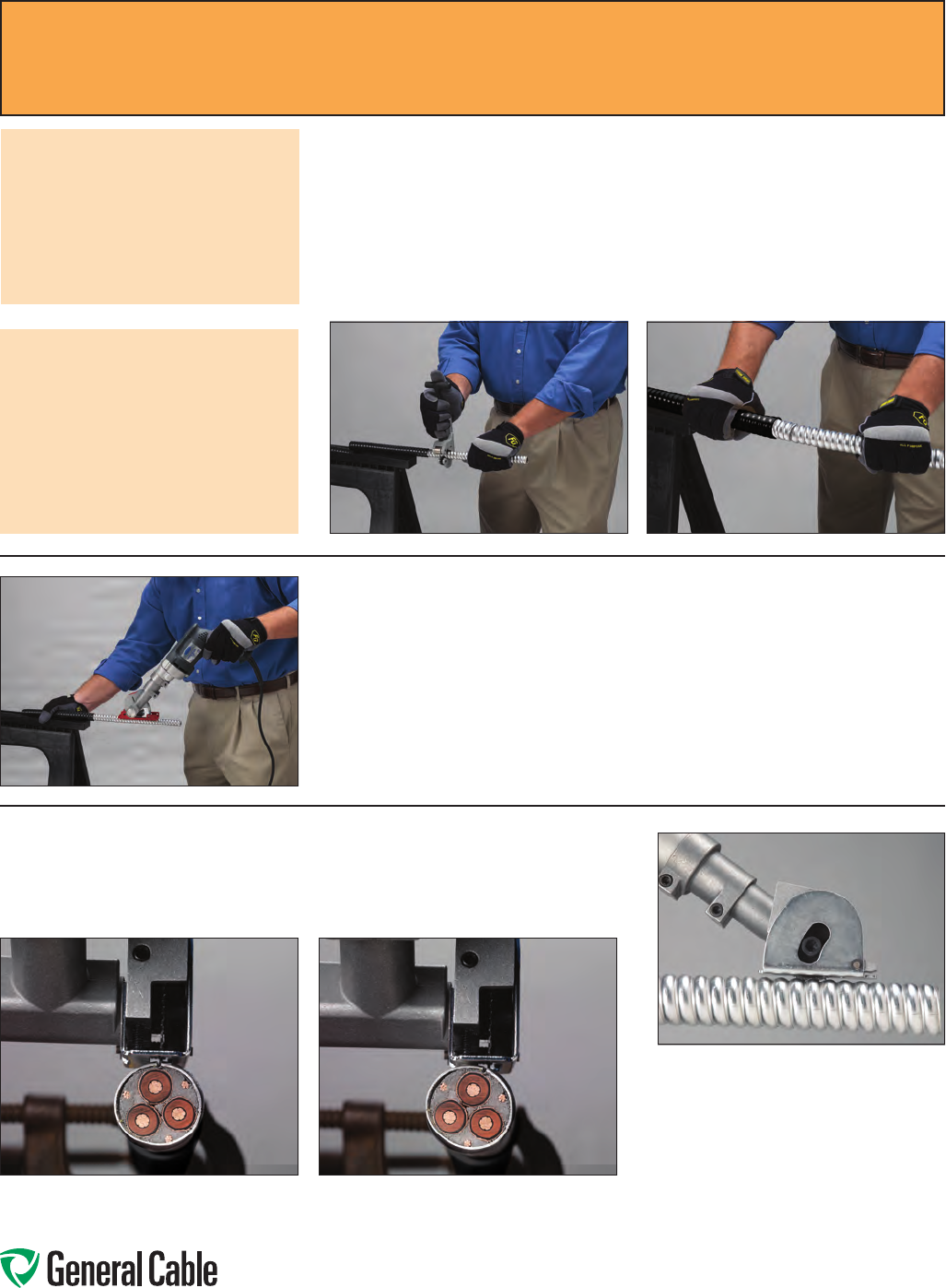
Phone: 888-593-3355
www.generalcable.com
For Small-Diameter CCW® Cable
(diameter of sheath less than or equal to 1.625")
Step 3:
Usingahacksawbladeortubingcutter,scoretheCCWaluminumsheatharound
the entire sheath at the Cutting Point.Grippingthecablewithahandoneither
side of the Cutting Point,flexthecableuntilthemetalopens.Carefullyremove
thefreedarmoredsheathfromtheendofthecable,beingcarefulnottoscoreor
damagethecabledcore.
Step 4:
ForCCWcableswithaninnerjacket
ortight-fittingsheath,itmaybe
necessarytousetheKett-ToolMetal-
CladCableSawwiththeoptionalred
cableguide.Attachthecableguide
totheKettCableSawandsecure
thecable.
Step 5:
Nowthatyourcross-cutiscomplete,
sheathremovalviatheKett-Tool
Metal-CladCableSawmustbedone
longitudinallydownthecablesheath.
Depthofthesawbladeanduseof
theguidesarecriticaltotheproper
cuttingoperation.Donotcutthrough
theentiresheath,asdamagetothe
coreislikely.Itissuggestedthatthe
sawdepthbeadjustedsothat80-
95%ofthemetalinthevalley(low
point)oftheCCW®sheathiscut.
Installation Note 2:
Review Sheath Outside
Diameters
Fordiameterslessthanorequalto
1.625",useSteps3-9.
Fordiametersgreaterthan1.625",
useSteps10-15.
Step 6:
WhensettinguptocutCCWcable,thecablesawblademustbeplacedtocut
perpendiculartothecablealongthecable.Seebelow:
CORRECT NOTCORRECT
Installation Note 3:
Using the Kett Model KS-226
Cable Saw
Whenusingthecablesaw,itis
importanttoreadandunderstand
themanufacturer’sinstructionsand
tobefamiliarwiththeKettCable
Sawcuttingequipmentpriorto
operating.
CCW
®
Sheath Removal Instructions
SPEC A001
February, 2011
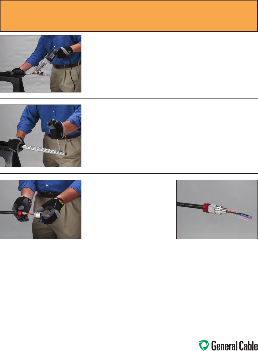
Phone: 888-593-3355
www.generalcable.com
CCW
®
Sheath Removal Instructions
SPEC A001
February, 2011
Step 7:
WithdownwardpressurebeingappliedtotheKettCableSaw,makealongitudinal
cutdownthelengthofthesheathtobestripped(fromthecutend)totheend
youhacksawedearlier.Donotattempttousethecablesawtoplungecut,asthis
couldresultininjury.
Step 8:
Insertthewideat-headscrewdriverintothecutatthefreeendandtwist.This
willcausetheremainingmetalinthevalleystobreak.Repeatuntilthesheath
completelyseparatesfromthecore.
Step 9:
Removethecablefillersandmarker
tapefromthecabledcore,separating
theconductorsandtheequipment
groundingconductor(s)foreasein
termination.Installtheappropriate
glandsuitedtotheapplicationperthe
manufacturer’sinstructions.Thecable
isnowreadytobeterminatedintothe
enclosure.
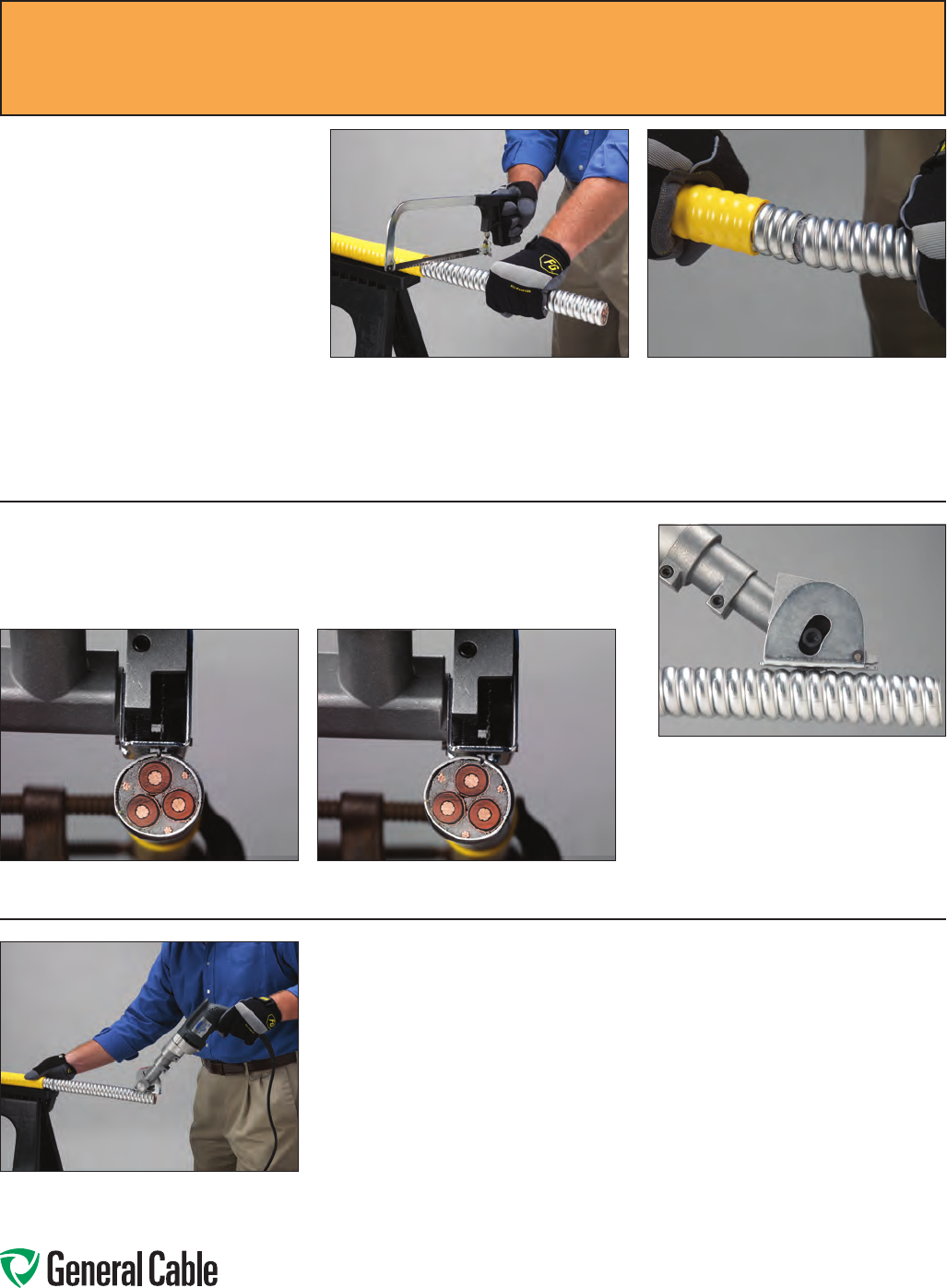
Phone: 888-593-3355
www.generalcable.com
Step 11:
Nowthatyourcross-cutiscomplete,sheathremovalviatheKett-ToolMetal-Clad
CableSawmustbedonelongitudinallydownthecablesheath.
For Large-Diameter CCW®
Cable (diameter of sheath
greater than 1.625")
Step 10:
Usingahacksawwiththeappropriate
bladeforcuttingmetal,cutthrough
thecrown(highpoint)oftheCCW
sheathatyourmarkedCutting Point
toconnectthevalley(lowpoint)ofthe
CCWsheath.
Oncethiscutismade,markthesheath
aroundthebalanceofthecable,
makingadditionalcutsforacompleted
circle.Ifyoucannotcompletethe
circleentirelythroughcutting,thenflex
thecableenduntilthemetalseparates
asshownatthefarright.
Depthofthesawbladeanduseof
theguidesarecriticaltotheproper
cuttingoperation.Donotcutthrough
theentiresheath,asdamagetothe
coreislikely.Itissuggestedthat
thesawdepthbeadjustedsothat
80-95%ofthemetalinthevalley(low
point)oftheCCW®sheathiscut.
Step 12:
WhensettinguptocutCCWcable,thecablesawblademustbeplacedtocut
perpendiculartothecablealongthecable.Seebelow:
CORRECT NOTCORRECT
CCW
®
Sheath Removal Instructions
SPEC A001
February, 2011
Step 13:
WithdownwardpressurebeingappliedtotheKettCableSaw,makealongitudinal
cutdownthelengthofthesheathtobestripped(fromthecutend)totheend
youhacksawedearlier.Donotattempttousethecablesawtoplungecut,asthis
couldresultininjury.
Atthispoint,youshouldhaveacompletedcutwithnoticeableconnectionsinthe
valleysofthesheath.
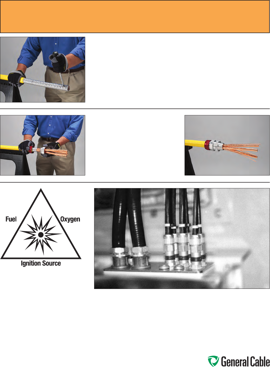
Phone: 888-593-3355
www.generalcable.com
CCW
®
Sheath Removal Instructions
SPEC A001
February, 2011
Step 14 :
Insertthewideat-headscrewdriverintothecutatthefreeendandtwist.This
willcausetheremainingmetalinthevalleystobreak.Repeatuntilthesheath
completelyseparatesfromthecore.
Step 15:
Removethecablefillersandmarker
tapefromthecabledcore,separating
theconductorsandgrounds/shields
foreaseintermination.Installthe
appropriatefitting/glandsuitedtothe
applicationperthemanufacturer’s
instructions.Thecableisnowready
tobeterminatedintotheenclosure.
Areaswithahighpropensityfor
ignitableenvironments,including
presenceofliquids,gasesordust.
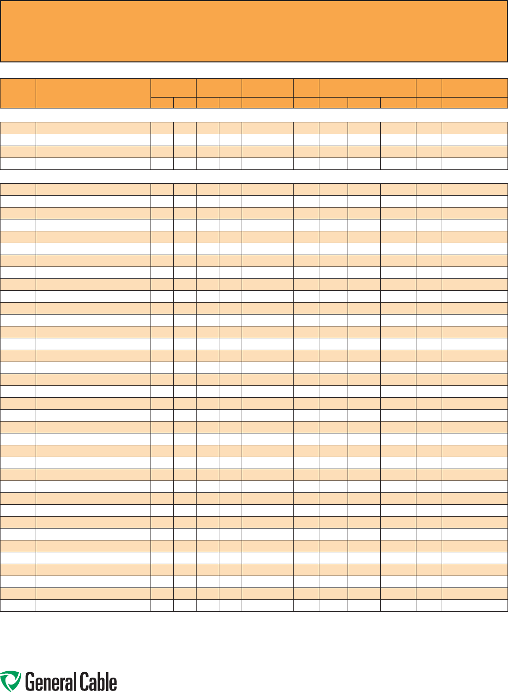
Phone: 888-593-3355
www.generalcable.com
CCW
®
Explosion-Proof Gland Cross-Reference
SPEC A010
April, 2010
Thermocouple Extension
CCW
PART
NUMBER PRODUCT DETAIL
NOMINAL ARMOR
O.D.
NOMINAL
OVERALL O.D. CROUSE-HINDS HAWKE
APPLETON (TMCX)
*end stop removed
Thomas &
Betts Hubbell/Killark
INCHES mm INCHES mm TMCX Series 711 Series Aluminum NP Brass Stainless Steel Spin-On X CMCXA
CCW® ARMORED THERMOCOUPLE EXTENSION, SINGLE PAIR, OVERALL SHIELD
9025.16010001 16 AWG TYPE EX 0.45 11.4 0.56 14.2 TMCX165 A TMCX050SA* TMCX050SNB* TMCX050SSS* 4-075-010 CMCXAA050
9025.16010002 16 AWG TYPE JX 0.45 11.4 0.56 14.2 TMCX165 A TMCX050SA* TMCX050SNB* TMCX050SSS* 4-075-010 CMCXAA050
9025.16010003 16 AWG TYPE KX 0.45 11.4 0.56 14.2 TMCX165 A TMCX050SA* TMCX050SNB* TMCX050SSS* 4-075-010 CMCXAA050
9025.16010004 16 AWG TYPE TX 0.45 11.4 0.56 14.2 TMCX165 A TMCX050SA* TMCX050SNB* TMCX050SSS* 4-075-010 CMCXAA050
CCW® ARMORED THERMOCOUPLE EXTENSION, PAIRS, OVERALL SHIELD
9050.20041221 20 AWG TYPE EX 4 PAIRS 0.58 14.7 0.69 17.5 TMCX165 A or B TMCX050A* TMCX050NB* TMCX050SS* 4-075-020 CMCXAA050 or CMCXAB075
9050.20041222 20 AWG TYPE JX 4 PAIRS 0.58 14.7 0.69 17.5 TMCX165 A or B TMCX050A* TMCX050NB* TMCX050SS* 4-075-020 CMCXAA050 or CMCXAB075
9050.20041223 20 AWG TYPE KX 4 PAIRS 0.58 14.7 0.69 17.5 TMCX165 A or B TMCX050A* TMCX050NB* TMCX050SS* 4-075-020 CMCXAA050 or CMCXAB075
9050.20041224 20 AWG TYPE TX 4 PAIRS 0.58 14.7 0.69 17.5 TMCX165 A or B TMCX050A* TMCX050NB* TMCX050SS* 4-075-020 CMCXAA050 or CMCXAB075
9050.20081221 20 AWG TYPE EX 8 PAIRS 0.71 18.0 0.82 20.8 TMCX285 B TMCX075A TMCX075NB TMCX075SS 4-075-040 CMCXAB075
9050.20081222 20 AWG TYPE JX 8 PAIRS 0.71 18.0 0.82 20.8 TMCX285 B TMCX075A TMCX075NB TMCX075SS 4-075-040 CMCXAB075
9050.20081223 20 AWG TYPE KX 8 PAIRS 0.71 18.0 0.82 20.8 TMCX285 B TMCX075A TMCX075NB TMCX075SS 4-075-040 CMCXAB075
9050.20081224 20 AWG TYPE TX 8 PAIRS 0.71 18.0 0.82 20.8 TMCX285 B TMCX075A TMCX075NB TMCX075SS 4-075-040 CMCXAB075
9050.20101221 20 AWG TYPE EX 10 PAIRS 0.75 19.1 0.86 21.8 TMCX285 B TMCX075A TMCX075NB TMCX075SS 4-100-050 CMCXAB075
9050.20101222 20 AWG TYPE JX 10 PAIRS 0.75 19.1 0.86 21.8 TMCX285 B TMCX075A TMCX075NB TMCX075SS 4-100-050 CMCXAB075
9050.20101223 20 AWG TYPE KX 10 PAIRS 0.75 19.1 0.86 21.8 TMCX285 B TMCX075A TMCX075NB TMCX075SS 4-100-050 CMCXAB075
9050.20101224 20 AWG TYPE TX 10 PAIRS 0.75 19.1 0.86 21.8 TMCX285 B TMCX075A TMCX075NB TMCX075SS 4-100-050 CMCXAB075
9050.20121221 20 AWG TYPE EX 12 PAIRS 0.80 20.3 0.91 23.1 TMCX285 or TMCX3112 B TMCX075A* TMCX075NB* TMCX075SS* 4-100-050 CMCXAB075
9050.20121222 20 AWG TYPE JX 12 PAIRS 0.80 20.3 0.91 23.1 TMCX285 or TMCX3112 B TMCX075A* TMCX075NB* TMCX075SS* 4-100-050 CMCXAB075
9050.20121223 20 AWG TYPE KX 12 PAIRS 0.80 20.3 0.91 23.1 TMCX285 or TMCX3112 B TMCX075A* TMCX075NB* TMCX075SS* 4-100-050 CMCXAB075
9050.20121224 20 AWG TYPE TX 12 PAIRS 0.80 20.3 0.91 23.1 TMCX285 or TMCX3112 B TMCX075A* TMCX075NB* TMCX075SS* 4-100-050 CMCXAB075
9050.20161221 20 AWG TYPE EX 16 PAIRS 0.84 21.3 0.95 24.1 TMCX285 or TMCX3112 B TMCX100A TMCX100NB TMCX100SS 4-100-070 CMCXAB075
9050.20161222 20 AWG TYPE JX 16 PAIRS 0.84 21.3 0.95 24.1 TMCX285 or TMCX3112 B TMCX100A TMCX100NB TMCX100SS 4-100-070 CMCXAB075
9050.20161223 20 AWG TYPE KX 16 PAIRS 0.84 21.3 0.95 24.1 TMCX285 or TMCX3112 B TMCX100A TMCX100NB TMCX100SS 4-100-070 CMCXAB075
9050.20161224 20 AWG TYPE TX 16 PAIRS 0.84 21.3 0.95 24.1 TMCX285 or TMCX3112 B TMCX100A TMCX100NB TMCX100SS 4-100-070 CMCXAB075
9050.20201221 20 AWG TYPE EX 20 PAIRS 0.97 24.6 1.08 27.4 TMCX3112 C TMCX100A TMCX100NB TMCX100SS 4-100-080 CMCXAB075 or CMCXAC100
9050.20201222 20 AWG TYPE JX 20 PAIRS 0.97 24.6 1.08 27.4 TMCX3112 C TMCX100A TMCX100NB TMCX100SS 4-100-080 CMCXAB075 or CMCXAC100
9050.20201223 20 AWG TYPE KX 20 PAIRS 0.97 24.6 1.08 27.4 TMCX3112 C TMCX100A TMCX100NB TMCX100SS 4-100-080 CMCXAB075 or CMCXAC100
9050.20201224 20 AWG TYPE TX 20 PAIRS 0.97 24.6 1.08 27.4 TMCX3112 C TMCX100A TMCX100NB TMCX100SS 4-100-080 CMCXAB075 or CMCXAC100
9050.20241221 20 AWG TYPE EX 24 PAIRS 1.02 25.9 1.13 28.7 TMCX3112 C TMCX100A* TMCX100NB* TMCX100SS* 4-100-080 CMCXAC100
9050.20241222 20 AWG TYPE JX 24 PAIRS 1.02 25.9 1.13 28.7 TMCX3112 C TMCX100A* TMCX100NB* TMCX100SS* 4-100-080 CMCXAC100
9050.20241223 20 AWG TYPE KX 24 PAIRS 1.02 25.9 1.13 28.7 TMCX3112 C TMCX100A* TMCX100NB* TMCX100SS* 4-100-080 CMCXAC100
9050.20241224 20 AWG TYPE TX 24 PAIRS 1.02 25.9 1.13 28.7 TMCX3112 C TMCX100A* TMCX100NB* TMCX100SS* 4-100-080 CMCXAC100
9050.20361221 20 AWG TYPE EX 36 PAIRS 1.19 30.2 1.30 33.0 TMCX4140 C or C2 TMCX125A TMCX125NB TMCX125SS 4-125-110 CMCXAC100 or CMCXAC2125
9050.20361222 20 AWG TYPE JX 36 PAIRS 1.19 30.2 1.30 33.0 TMCX4140 C or C2 TMCX125A TMCX125NB TMCX125SS 4-125-110 CMCXAC100 or CMCXAC2125
9050.20361223 20 AWG TYPE KX 36 PAIRS 1.19 30.2 1.30 33.0 TMCX4140 C or C2 TMCX125A TMCX125NB TMCX125SS 4-125-110 CMCXAC100 or CMCXAC2125
9050.20361224 20 AWG TYPE TX 36 PAIRS 1.19 30.2 1.30 33.0 TMCX4140 C or C2 TMCX125A TMCX125NB TMCX125SS 4-125-110 CMCXAC100 or CMCXAC2125
9050.20501221 20 AWG TYPE EX 50 PAIRS 1.34 34.0 1.45 36.8 TMCX4140 or TMCX5161 C2 TMCX150A TMCX150NB TMCX150SS 4-150-130 CMCXAC2125
9050.20501222 20 AWG TYPE JX 50 PAIRS 1.34 34.0 1.45 36.8 TMCX4140 or TMCX5161 C2 TMCX150A TMCX150NB TMCX150SS 4-150-130 CMCXAC2125
9050.20501223 20 AWG TYPE KX 50 PAIRS 1.34 34.0 1.45 36.8 TMCX4140 or TMCX5161 C2 TMCX150A TMCX150NB TMCX150SS 4-150-130 CMCXAC2125
9050.20501224 20 AWG TYPE TX 50 PAIRS 1.34 34.0 1.45 36.8 TMCX4140 or TMCX5161 C2 TMCX150A TMCX150NB TMCX150SS 4-150-130 CMCXAC2125
Allinformationinthiscross-referenceispresentedsolelyasaguidetoproductselectionandisbelievedtobereliable.Allprintingerrorsaresubjecttocorrectioninsubsequent
releasesofthiscatalog.AlthoughGeneralCablehastakenprecautionstoensuretheaccuracyoftheproductcross-referenceatthetimeofpublication,thespecificationsofall
productscontainedhereinaresubjecttochangebyglandmanufacturerswithoutnotice.
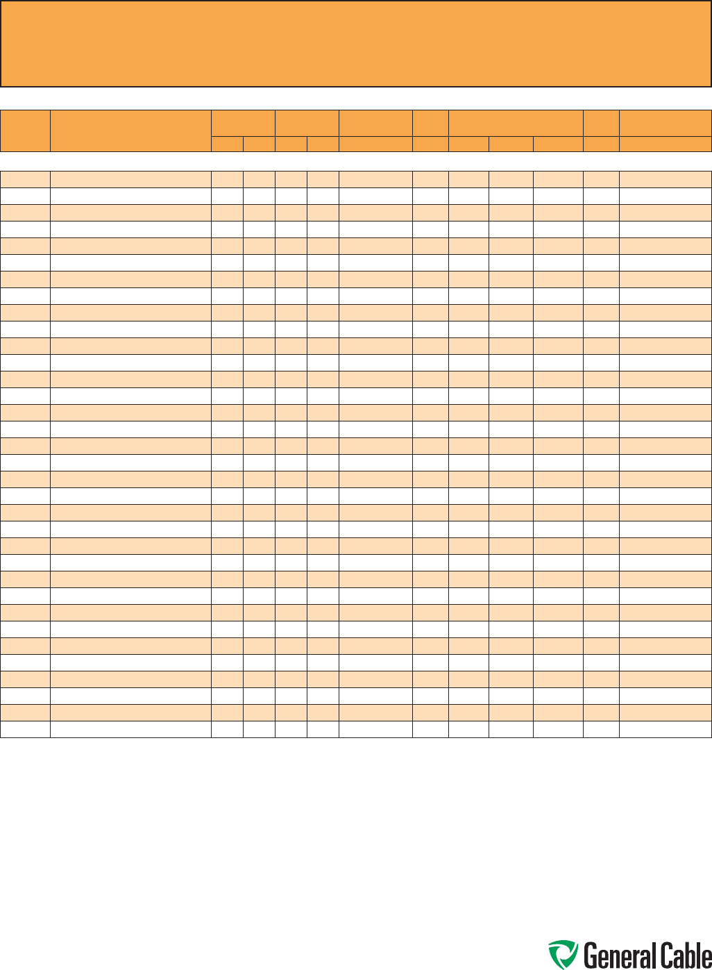
Phone: 888-593-3355
www.generalcable.com
CCW
®
Explosion-Proof Gland Cross-Reference
SPEC A010
April, 2010
Thermocouple Extension
CCW
PART
NUMBER PRODUCT DETAIL
NOMINAL ARMOR
O.D.
NOMINAL
OVERALL O.D. CROUSE-HINDS HAWKE
APPLETON (TMCX)
*end stop removed
Thomas &
Betts Hubbell/Killark
INCHES mm INCHES mm TMCX Series 711 Series Aluminum NP Brass Stainless Steel Spin-On X CMCXA
CCW® ARMORED THERMOCOUPLE EXTENSION, PAIRS, INDIVIDUAL AND OVERALL SHIELD
9075.20041221 20 AWG TYPE EX 4 PAIRS 0.62 15.7 0.73 18.5 TMCX165 or TMCX285 A or B TMCX075A TMCX075NB TMCX075SS 4-075-030 CMCXAA050 or CMCXAB075
9075.20041222 20 AWG TYPE JX 4 PAIRS 0.62 15.7 0.73 18.5 TMCX165 or TMCX285 A or B TMCX075A TMCX075NB TMCX075SS 4-075-030 CMCXAA050 or CMCXAB075
9075.20041223 20 AWG TYPE KX 4 PAIRS 0.62 15.7 0.73 18.5 TMCX165 or TMCX285 A or B TMCX075A TMCX075NB TMCX075SS 4-075-030 CMCXAA050 or CMCXAB075
9075.20041224 20 AWG TYPE TX 4 PAIRS 0.62 15.7 0.73 18.5 TMCX165 or TMCX285 A or B TMCX075A TMCX075NB TMCX075SS 4-075-030 CMCXAA050 or CMCXAB075
9075.20081221 20 AWG TYPE EX 8 PAIRS 0.75 19.1 0.86 21.8 TMCX285 B TMCX075A TMCX075NB TMCX075SS 4-100-050 CMCXAB075
9075.20081222 20 AWG TYPE JX 8 PAIRS 0.75 19.1 0.86 21.8 TMCX285 B TMCX075A TMCX075NB TMCX075SS 4-100-050 CMCXAB075
9075.20081223 20 AWG TYPE KX 8 PAIRS 0.75 19.1 0.86 21.8 TMCX285 B TMCX075A TMCX075NB TMCX075SS 4-100-050 CMCXAB075
9075.20081224 20 AWG TYPE TX 8 PAIRS 0.75 19.1 0.86 21.8 TMCX285 B TMCX075A TMCX075NB TMCX075SS 4-100-050 CMCXAB075
9075.20101221 20 AWG TYPE EX 10 PAIRS 0.80 20.3 0.91 23.1 TMCX285 or TMCX3112 B TMCX075A* TMCX075NB* TMCX075SS* 4-100-050 CMCXAB075
9075.20101222 20 AWG TYPE JX 10 PAIRS 0.80 20.3 0.91 23.1 TMCX285 or TMCX3112 B TMCX075A* TMCX075NB* TMCX075SS* 4-100-050 CMCXAB075
9075.20101223 20 AWG TYPE KX 10 PAIRS 0.80 20.3 0.91 23.1 TMCX285 or TMCX3112 B TMCX075A* TMCX075NB* TMCX075SS* 4-100-050 CMCXAB075
9075.20121222 20 AWG TYPE JX 12 PAIRS 0.84 21.3 0.95 24.1 TMCX285 or TMCX3112 B TMCX100A TMCX100NB TMCX100SS 4-100-070 CMCXAB075
9075.20121223 20 AWG TYPE KX 12 PAIRS 0.84 21.3 0.95 24.1 TMCX285 or TMCX3112 B TMCX100A TMCX100NB TMCX100SS 4-100-070 CMCXAB075
9075.20121224 20 AWG TYPE TX 12 PAIRS 0.84 21.3 0.95 24.1 TMCX285 or TMCX3112 B TMCX100A TMCX100NB TMCX100SS 4-100-070 CMCXAB075
9075.20161221 20 AWG TYPE EX 16 PAIRS 0.97 24.6 1.08 27.4 TMCX3112 C TMCX100A TMCX100NB TMCX100SS 4-100-080 CMCXAB075 or CMCXAC100
9075.20161222 20 AWG TYPE JX 16 PAIRS 0.97 24.6 1.08 27.4 TMCX3112 C TMCX100A TMCX100NB TMCX100SS 4-100-080 CMCXAB075 or CMCXAC100
9075.20161223 20 AWG TYPE KX 16 PAIRS 0.97 24.6 1.08 27.4 TMCX3112 C TMCX100A TMCX100NB TMCX100SS 4-100-080 CMCXAB075 or CMCXAC100
9075.20161224 20 AWG TYPE TX 16 PAIRS 0.97 24.6 1.08 27.4 TMCX3112 C TMCX100A TMCX100NB TMCX100SS 4-100-080 CMCXAB075 or CMCXAC100
9075.20201221 20 AWG TYPE EX 20 PAIRS 1.06 26.9 1.17 29.7 TMCX3112 C TMCX100A* TMCX100NB* TMCX100SS* 4-125-090 CMCXAC100
9075.20201222 20 AWG TYPE JX 20 PAIRS 1.06 26.9 1.17 29.7 TMCX3112 C TMCX100A* TMCX100NB* TMCX100SS* 4-125-090 CMCXAC100
9075.20201223 20 AWG TYPE KX 20 PAIRS 1.06 26.9 1.17 29.7 TMCX3112 C TMCX100A* TMCX100NB* TMCX100SS* 4-125-090 CMCXAC100
9075.20201224 20 AWG TYPE TX 20 PAIRS 1.06 26.9 1.17 29.7 TMCX3112 C TMCX100A* TMCX100NB* TMCX100SS* 4-125-090 CMCXAC100
9075.20241221 20 AWG TYPE EX 24 PAIRS 1.15 29.2 1.26 32.0 TMCX4140 C TMCX125A TMCX125NB TMCX125SS 4-125-100 CMCXAC100
9075.20241222 20 AWG TYPE JX 24 PAIRS 1.15 29.2 1.26 32.0 TMCX4140 C TMCX125A TMCX125NB TMCX125SS 4-125-100 CMCXAC100
9075.20241223 20 AWG TYPE KX 24 PAIRS 1.15 29.2 1.26 32.0 TMCX4140 C TMCX125A TMCX125NB TMCX125SS 4-125-100 CMCXAC100
9075.20241224 20 AWG TYPE TX 24 PAIRS 1.15 29.2 1.26 32.0 TMCX4140 C TMCX125A TMCX125NB TMCX125SS 4-125-100 CMCXAC100
9075.20361221 20 AWG TYPE EX 36 PAIRS 1.34 34.0 1.45 36.8 TMCX4140 or TMCX5161 C2 TMCX150A TMCX150NB TMCX150SS 4-150-130 CMCXAC2125
9075.20361222 20 AWG TYPE JX 36 PAIRS 1.34 34.0 1.45 36.8 TMCX4140 or TMCX5161 C2 TMCX150A TMCX150NB TMCX150SS 4-150-130 CMCXAC2125
9075.20361223 20 AWG TYPE KX 36 PAIRS 1.34 34.0 1.45 36.8 TMCX4140 or TMCX5161 C2 TMCX150A TMCX150NB TMCX150SS 4-150-130 CMCXAC2125
9075.20361224 20 AWG TYPE TX 36 PAIRS 1.34 34.0 1.45 36.8 TMCX4140 or TMCX5161 C2 TMCX150A TMCX150NB TMCX150SS 4-150-130 CMCXAC2125
9075.20501221 20 AWG TYPE EX 50 PAIRS 1.47 37.3 1.58 40.1 TMCX5161 C2 or D TMCX150A* TMCX150NB* TMCX150SS* 4-150-140 CMCXAC2125 or CMCXAD200
9075.20501222 20 AWG TYPE JX 50 PAIRS 1.47 37.3 1.58 40.1 TMCX5161 C2 or D TMCX150A* TMCX150NB* TMCX150SS* 4-150-140 CMCXAC2125 or CMCXAD200
9075.20501223 20 AWG TYPE KX 50 PAIRS 1.47 37.3 1.58 40.1 TMCX5161 C2 or D TMCX150A* TMCX150NB* TMCX150SS* 4-150-140 CMCXAC2125 or CMCXAD200
9075.20501224 20 AWG TYPE TX 50 PAIRS 1.47 37.3 1.58 40.1 TMCX5161 C2 or D TMCX150A* TMCX150NB* TMCX150SS* 4-150-140 CMCXAC2125 or CMCXAD200
Allinformationinthiscross-referenceispresentedsolelyasaguidetoproductselectionandisbelievedtobereliable.Allprintingerrorsaresubjecttocorrectioninsubsequent
releasesofthiscatalog.AlthoughGeneralCablehastakenprecautionstoensuretheaccuracyoftheproductcross-referenceatthetimeofpublication,thespecificationsofall
productscontainedhereinaresubjecttochangebyglandmanufacturerswithoutnotice.
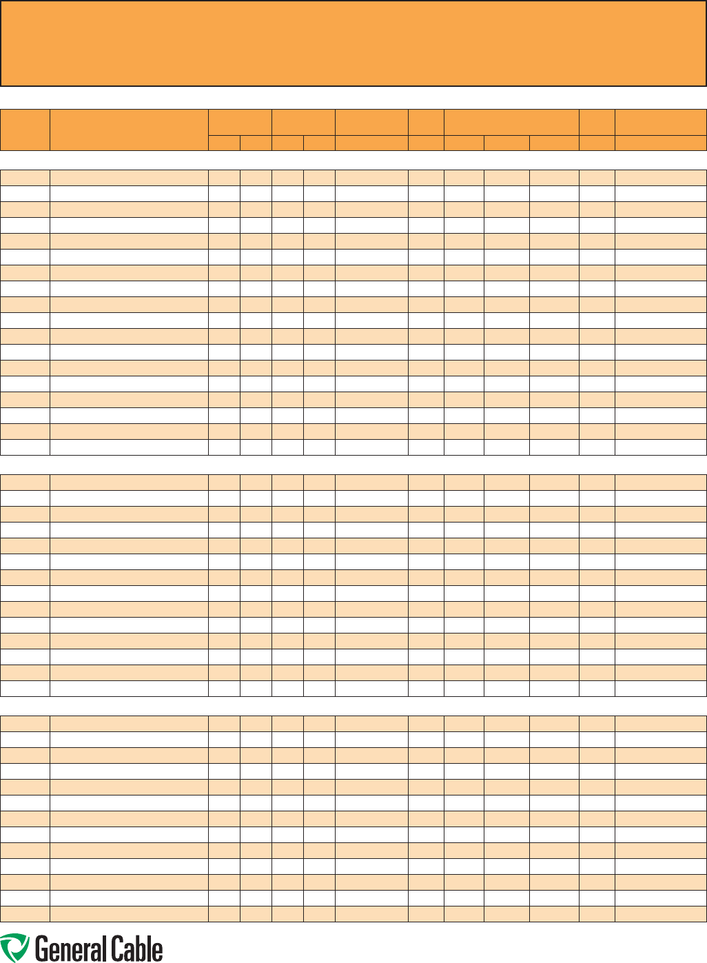
Phone: 888-593-3355
www.generalcable.com
CCW
®
Explosion-Proof Gland Cross-Reference
SPEC A010
April, 2010
Instrumentation - 300 V
CCW
PART
NUMBER PRODUCT DETAIL
NOMINAL ARMOR
O.D.
NOMINAL
OVERALL O.D. CROUSE-HINDS HAWKE
APPLETON (TMCX)
*end stop removed
Thomas &
Betts Hubbell/Killark
INCHES mm INCHES mm TMCX Series 711 Series Aluminum NP Brass Stainless Steel Spin-On X CMCXA
CCW® ARMORED INSTRUMENTATION, PAIRS/TRIADS, OVERALL SHIELD
9125.16010001 16 AWG 7W (1.31 mm²) 1 PAIR 0.43 10.9 0.54 13.7 - A TMCX050SA* TMCX050SNB* TMCX050SSS* 4-075-008 CMCXAA050
9125.16010002 16 AWG 7W (1.31 mm²) 1 TRIAD 0.49 12.4 0.60 15.2 TMCX165 A or B TMCX050SA* TMCX050SNB* TMCX050SSS* 4-075-010 CMCXAA050 or CMCXAB075
9125.16021201 16 AWG 7W (1.31 mm²) 2 PAIRS 0.58 14.7 0.69 17.5 TMCX165 A or B TMCX050A* TMCX050NB* TMCX050SS* 4-075-020 CMCXAA050 or CMCXAB075
9125.16021202 16 AWG 7W (1.31 mm²) 2 TRIADS 0.62 15.7 0.73 18.5 TMCX165 or TMCX285 A or B TMCX075A TMCX075NB TMCX075SS 4-075-030 CMCXAA050 or CMCXAB075
9125.16041201 16 AWG 7W (1.31 mm²) 4 PAIRS 0.71 18.0 0.82 20.8 TMCX285 B TMCX075A TMCX075NB TMCX075SS 4-075-040 CMCXAB075
9125.16041202 16 AWG 7W (1.31 mm²) 4 TRIADS 0.75 19.1 0.86 21.8 TMCX285 B TMCX075A TMCX075NB TMCX075SS 4-100-050 CMCXAB075
9125.16081201 16 AWG 7W (1.31 mm²) 8 PAIRS 0.89 22.6 1.00 25.4 TMCX3112 B or C TMCX100A TMCX100NB TMCX100SS 4-100-070 CMCXAB075 or CMCXAC100
9125.16081202 16 AWG 7W (1.31 mm²) 8 TRIADS 0.93 23.6 1.04 26.4 TMCX3112 B or C TMCX100A TMCX100NB TMCX100SS 4-100-070 CMCXAB075 or CMCXAC100
9125.16121201 16 AWG 7W (1.31 mm²) 12 PAIRS 1.02 25.9 1.13 28.7 TMCX3112 C TMCX100A* TMCX100NB* TMCX100SS* 4-100-080 CMCXAC100
9125.16121202 16 AWG 7W (1.31 mm²) 12 TRIADS 1.06 26.9 1.17 29.7 TMCX3112 C TMCX100A* TMCX100NB* TMCX100SS* 4-125-090 CMCXAC100
9125.16161201 16 AWG 7W (1.31 mm²) 16 PAIRS 1.11 28.2 1.22 31.0 TMCX3112 or TMCX4140 C TMCX125A TMCX125NB TMCX125SS 4-125-100 CMCXAC100
9125.16161202 16 AWG 7W (1.31 mm²) 16 TRIADS 1.24 31.5 1.35 34.3 TMCX4140 C2 TMCX125A* TMCX125NB* TMCX125SS* 4-125-110 CMCXAC2125
9125.16241201 16 AWG 7W (1.31 mm²) 24 PAIRS 1.34 34.0 1.45 36.8 TMCX4140 or TMCX5161 C2 TMCX150A TMCX150NB TMCX150SS 4-150-130 CMCXAC2125
9125.16241202 16 AWG 7W (1.31 mm²) 24 TRIADS 1.42 36.1 1.53 38.9 TMCX5161 C2 or D TMCX150A TMCX150NB TMCX150SS 4-150-140 CMCXAC2125 or CMCXAD200
9125.16361201 16 AWG 7W (1.31 mm²) 36 PAIRS 1.56 39.6 1.69 42.9 TMCX5161 C2 or D TMCX200SA TMCX200SNB TMCX200SSS 4-150-150 CMCXAC2125 or CMCXAD200
9125.16361202 16 AWG 7W (1.31 mm²) 36 TRIADS 1.64 41.7 1.78 45.2 TMCX6206 D TMCX200SA TMCX200SNB TMCX200SSS 4-200-160 CMCXAD200
9125.16501201 16 AWG 7W (1.31 mm²) 50 PAIRS 1.83 46.5 1.96 49.8 TMCX6206 D or E TMCX200A TMCX200NB TMCX200SS 4-200-180 CMCXAD200 or CMCXAE250
9125.16501202 16 AWG 7W (1.31 mm²) 50 TRIADS 1.92 48.8 2.05 52.1 TMCX6206 D or E TMCX200A TMCX200NB TMCX200SS 4-200-190 CMCXAD200 or CMCXAE250
CCW® ARMORED INSTRUMENTATION, PAIRS/TRIADS, INDIVIDUAL AND OVERALL SHIELD
9150.16021201 16 AWG 7W (1.31 mm²) 2 PAIRS 0.67 17.0 0.78 19.8 TMCX285 B TMCX075A TMCX075NB TMCX075SS 4-075-040 CMCXAB075
9150.16021202 16 AWG 7W (1.31 mm²) 2 TRIADS 0.71 18.0 0.82 20.8 TMCX285 B TMCX075A TMCX075NB TMCX075SS 4-075-040 CMCXAB075
9150.16041201 16 AWG 7W (1.31 mm²) 4 PAIRS 0.75 19.1 0.86 21.8 TMCX285 B TMCX075A TMCX075NB TMCX075SS 4-100-050 CMCXAB075
9150.16041202 16 AWG 7W (1.31 mm²) 4 TRIADS 0.84 21.3 0.95 24.1 TMCX285 or TMCX3112 B TMCX100A TMCX100NB TMCX100SS 4-100-070 CMCXAB075
9150.16081201 16 AWG 7W (1.31 mm²) 8 PAIRS 0.93 23.6 1.04 26.4 TMCX3112 B or C TMCX100A TMCX100NB TMCX100SS 4-100-070 CMCXAB075 or CMCXAC100
9150.16081202 16 AWG 7W (1.31 mm²) 8 TRIADS 1.06 26.9 1.17 29.7 TMCX3112 C TMCX100A* TMCX100NB* TMCX100SS* 4-125-090 CMCXAC100
9150.16121201 16 AWG 7W (1.31 mm²) 12 PAIRS 1.06 26.9 1.17 29.7 TMCX3112 C TMCX100A* TMCX100NB* TMCX100SS* 4-125-090 CMCXAC100
9150.16121202 16 AWG 7W (1.31 mm²) 12 TRIADS 1.24 31.5 1.35 34.3 TMCX4140 C2 TMCX125A* TMCX125NB* TMCX125SS* 4-125-110 CMCXAC2125
9150.16241201 16 AWG 7W (1.31 mm²) 24 PAIRS 1.42 36.1 1.53 38.9 TMCX5161 C2 or D TMCX150A TMCX150NB TMCX150SS 4-150-140 CMCXAC2125 or CMCXAD200
9150.16241202 16 AWG 7W (1.31 mm²) 24 TRIADS 1.60 40.6 1.73 43.9 TMCX5161 or TMCX6206 D TMCX200SA TMCX200SNB TMCX200SSS 4-200-160 CMCXAD200
9150.16361201 16 AWG 7W (1.31 mm²) 36 PAIRS 1.64 41.7 1.78 45.2 TMCX6206 D TMCX200SA TMCX200SNB TMCX200SSS 4-200-160 CMCXAD200
9150.16361202 16 AWG 7W (1.31 mm²) 36 TRIADS 1.87 47.5 2.00 50.8 TMCX6206 D or E TMCX200A TMCX200NB TMCX200SS 4-200-190 CMCXAD200 or CMCXAE250
9150.16501201 16 AWG 7W (1.31 mm²) 50 PAIRS 1.96 49.8 2.09 53.1 TMCX6206 or TMCX7247 D or E TMCX200A* TMCX200NB* TMCX200SS* 4-250-200 CMCXAD200 or CMCXAE250
9150.16501202 16 AWG 7W (1.31 mm²) 50 TRIADS 2.19 55.6 2.32 58.9 TMCX7247 E TMCX250SA* TMCX250SNB* TMCX250SSS* 4-250-220 CMCXAE250
CCW® ARMORED INSTRUMENTATION, PAIRS/TRIADS, OVERALL SHIELD
9225.16010001 16 AWG 7W (1.31 mm²) 1 PAIR 0.43 10.9 0.54 13.7 - A TMCX050SA* TMCX050SNB* TMCX050SSS* 4-075-008 CMCXAA050
9225.16010002 16 AWG 7W (1.31 mm²) 1 TRIAD 0.43 10.9 0.54 13.7 - A TMCX050SA* TMCX050SNB* TMCX050SSS* 4-075-008 CMCXAA050
9225.16021221 16 AWG 7W (1.31 mm²) 2 PAIRS 0.58 14.7 0.69 17.5 TMCX165 A or B TMCX050A* TMCX050NB* TMCX050SS* 4-075-020 CMCXAA050 or CMCXAB075
9225.16041221 16 AWG 7W (1.31 mm²) 4 PAIRS 0.71 18.0 0.82 20.8 TMCX285 B TMCX075A TMCX075NB TMCX075SS 4-075-040 CMCXAB075
9225.16041222 16 AWG 7W (1.31 mm²) 4 TRIADS 0.75 19.1 0.86 21.8 TMCX285 B TMCX075A TMCX075NB TMCX075SS 4-100-050 CMCXAB075
9225.16061221 16 AWG 7W (1.31 mm²) 6 PAIRS 0.80 20.3 0.91 23.1 TMCX285 or TMCX3112 B TMCX075A* TMCX075NB* TMCX075SS* 4-100-050 CMCXAB075
9225.16081221 16 AWG 7W (1.31 mm²) 8 PAIRS 0.84 21.3 0.95 24.1 TMCX285 or TMCX3112 B TMCX100A TMCX100NB TMCX100SS 4-100-070 CMCXAB075
9225.16081222 16 AWG 7W (1.31 mm²) 8 TRIADS 0.89 22.6 1.00 25.4 TMCX3112 B or C TMCX100A TMCX100NB TMCX100SS 4-100-070 CMCXAB075 or CMCXAC100
9225.16101221 16 AWG 7W (1.31 mm²) 10 PAIRS 0.93 23.6 1.04 26.4 TMCX3112 B or C TMCX100A TMCX100NB TMCX100SS 4-100-070 CMCXAB075 or CMCXAC100
9225.16121221 16 AWG 7W (1.31 mm²) 12 PAIRS 0.97 24.6 1.08 27.4 TMCX3112 C TMCX100A TMCX100NB TMCX100SS 4-100-080 CMCXAB075 or CMCXAC100
9225.16121222 16 AWG 7W (1.31 mm²) 12 TRIADS 1.06 26.9 1.17 29.7 TMCX3112 C TMCX100A* TMCX100NB* TMCX100SS* 4-125-090 CMCXAC100
9225.16161221 16 AWG 7W (1.31 mm²) 16 PAIRS 1.11 28.2 1.22 31.0 TMCX3112 or TMCX4140 C TMCX125A TMCX125NB TMCX125SS 4-125-100 CMCXAC100
9225.16161222 16 AWG 7W (1.31 mm²) 16 TRIADS 1.19 30.2 1.30 33.0 TMCX4140 C or C2 TMCX125A TMCX125NB TMCX125SS 4-125-110 CMCXAC100 or CMCXAC2125
Allinformationinthiscross-referenceispresentedsolelyasaguidetoproductselectionandisbelievedtobereliable.Allprinting
errorsaresubjecttocorrectioninsubsequentreleasesofthiscatalog.AlthoughGeneralCablehastakenprecautionstoensurethe
accuracyoftheproductcross-referenceatthetimeofpublication,thespecificationsofallproductscontainedhereinaresubjectto
changebyglandmanufacturerswithoutnotice.
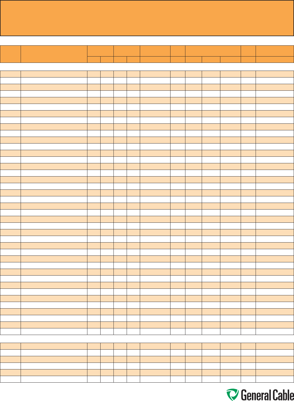
Phone: 888-593-3355
www.generalcable.com
CCW
®
Explosion-Proof Gland Cross-Reference
SPEC A010
April, 2010
Instrumentation - 300 V
CCW
PART
NUMBER PRODUCT DETAIL
NOMINAL ARMOR
O.D.
NOMINAL
OVERALL O.D. CROUSE-HINDS HAWKE
APPLETON (TMCX)
*end stop removed
Thomas &
Betts Hubbell/Killark
INCHES mm INCHES mm TMCX Series 711 Series Aluminum NP Brass Stainless Steel Spin-On X CMCXA
CCW® ARMORED INSTRUMENTATION, PAIRS/TRIADS, OVERALL SHIELD (cont’d)
9225.16201221 16 AWG 7W (1.31 mm²) 20 PAIRS 1.24 31.5 1.35 34.3 TMCX4140 C2 TMCX125A* TMCX125NB* TMCX125SS* 4-125-110 CMCXAC2125
9225.16241221 16 AWG 7W (1.31 mm²) 24 PAIRS 1.34 34.0 1.45 36.8 TMCX4140 or TMCX5161 C2 TMCX150A TMCX150NB TMCX150SS 4-150-130 CMCXAC2125
9225.16241222 16 AWG 7W (1.31 mm²) 24 TRIADS 1.42 36.1 1.53 38.9 TMCX5161 C2 or D TMCX150A TMCX150NB TMCX150SS 4-150-140 CMCXAC2125 or CMCXAD200
9225.16361221 16 AWG 7W (1.31 mm²) 36 PAIRS 1.51 38.4 1.65 41.9 TMCX5161 C2 or D TMCX200SA TMCX200SNB TMCX200SSS 4-150-150 CMCXAC2125 or CMCXAD200
9225.16361222 16 AWG 7W (1.31 mm²) 36 TRIADS 1.60 40.6 1.73 43.9 TMCX5161 or TMCX6206 D TMCX200SA TMCX200SNB TMCX200SSS 4-200-160 CMCXAD200
9225.16501221 16 AWG 7W (1.31 mm²) 50 PAIRS 1.64 41.7 1.78 45.2 TMCX6206 D TMCX200SA TMCX200SNB TMCX200SSS 4-200-160 CMCXAD200
9225.18021221 18 AWG 7W (0.82 mm²) 2 PAIRS 0.58 14.7 0.69 17.5 TMCX165 A or B TMCX050A* TMCX050NB* TMCX050SS* 4-075-020 CMCXAA050 or CMCXAB075
9225.18041221 18 AWG 7W (0.82 mm²) 2 PAIRS 0.67 17.0 0.78 19.8 TMCX285 B TMCX075A TMCX075NB TMCX075SS 4-075-040 CMCXAB075
9225.18041222 18 AWG 7W (0.82 mm²) 2 TRIADS 0.71 18.0 0.82 20.8 TMCX285 B TMCX075A TMCX075NB TMCX075SS 4-075-040 CMCXAB075
9225.18061221 18 AWG 7W (0.82 mm²) 6 PAIRS 0.71 18.0 0.82 20.8 TMCX285 B TMCX075A TMCX075NB TMCX075SS 4-075-040 CMCXAB075
9225.18081221 18 AWG 7W (0.82 mm²) 8 PAIRS 0.80 20.3 0.91 23.1 TMCX285 or TMCX3112 B TMCX075A* TMCX075NB* TMCX075SS* 4-100-050 CMCXAB075
9225.18081222 18 AWG 7W (0.82 mm²) 8 TRIADS 0.80 20.3 0.91 23.1 TMCX285 or TMCX3112 B TMCX075A* TMCX075NB* TMCX075SS* 4-100-050 CMCXAB075
9225.18101221 18 AWG 7W (0.82 mm²) 10 PAIRS 0.89 22.6 1.00 25.4 TMCX3112 B or C TMCX100A TMCX100NB TMCX100SS 4-100-070 CMCXAB075 or CMCXAC100
9225.18121221 18 AWG 7W (0.82 mm²) 12 PAIRS 0.93 23.6 1.04 26.4 TMCX3112 B or C TMCX100A TMCX100NB TMCX100SS 4-100-070 CMCXAB075 or CMCXAC100
9225.18121222 18 AWG 7W (0.82 mm²) 12 TRAIDS 0.97 24.6 1.08 27.4 TMCX3112 C TMCX100A TMCX100NB TMCX100SS 4-100-080 CMCXAB075 or CMCXAC100
9225.18161221 18 AWG 7W (0.82 mm²) 16 PAIRS 1.02 25.9 1.13 28.7 TMCX3112 C TMCX100A* TMCX100NB* TMCX100SS* 4-100-080 CMCXAC100
9225.18161222 18 AWG 7W (0.82 mm²) 16 TRIADS 1.06 26.9 1.17 29.7 TMCX3112 C TMCX100A* TMCX100NB* TMCX100SS* 4-125-090 CMCXAC100
9225.18201221 18 AWG 7W (0.82 mm²) 20 PAIRS 1.06 26.9 1.17 29.7 TMCX3112 C TMCX100A* TMCX100NB* TMCX100SS* 4-125-090 CMCXAC100
9225.18241221 18 AWG 7W (0.82 mm²) 24 PAIRS 1.11 28.2 1.22 31.0 TMCX3112 or TMCX4140 C TMCX125A TMCX125NB TMCX125SS 4-125-100 CMCXAC100
9225.18241222 18 AWG 7W (0.82 mm²) 24 TRIADS 1.24 31.5 1.35 34.3 TMCX4140 C2 TMCX125A* TMCX125NB* TMCX125SS* 4-125-110 CMCXAC2125
9225.18361221 18 AWG 7W (0.82 mm²) 36 PAIRS 1.29 32.8 1.40 35.6 TMCX4140 or TMCX5161 C2 TMCX125A* TMCX125NB* TMCX125SS* 4-125-120 CMCXAC2125
9225.18361222 18 AWG 7W (0.82 mm²) 36 TRIADS 1.34 34.0 1.45 36.8 TMCX4140 or TMCX5161 C2 TMCX150A TMCX150NB TMCX150SS 4-150-130 CMCXAC2125
9225.18501221 18 AWG 7W (0.82 mm²) 50 PAIRS 1.47 37.3 1.58 40.1 TMCX5161 C2 or D TMCX150A* TMCX150NB* TMCX150SS* 4-150-140 CMCXAC2125 or CMCXAD200
9225.20021221 20 AWG 7W (0.52 mm²) 2 PAIRS 0.58 14.7 0.69 17.5 TMCX165 A or B TMCX050A* TMCX050NB* TMCX050SS* 4-075-020 CMCXAA050 or CMCXAB075
9225.20041221 20 AWG 7W (0.52 mm²) 4 PAIRS 0.62 15.7 0.73 18.5 TMCX165 or TMCX285 A or B TMCX075A TMCX075NB TMCX075SS 4-075-030 CMCXAA050 or CMCXAB075
9225.20041222 20 AWG 7W (0.52 mm²) 4 TRIADS 0.67 17.0 0.78 19.8 TMCX285 B TMCX075A TMCX075NB TMCX075SS 4-075-040 CMCXAB075
9225.20061221 20 AWG 7W (0.52 mm²) 6 PAIRS 0.67 17.0 0.78 19.8 TMCX285 B TMCX075A TMCX075NB TMCX075SS 4-075-040 CMCXAB075
9225.20081221 20 AWG 7W (0.52 mm²) 8 PAIRS 0.71 18.0 0.82 20.8 TMCX285 B TMCX075A TMCX075NB TMCX075SS 4-075-040 CMCXAB075
9225.20081222 20 AWG 7W (0.52 mm²) 8 TRIADS 0.75 19.1 0.86 21.8 TMCX285 B TMCX075A TMCX075NB TMCX075SS 4-100-050 CMCXAB075
9225.20101221 20 AWG 7W (0.52 mm²) 10 PAIRS 0.75 19.1 0.86 21.8 TMCX285 B TMCX075A TMCX075NB TMCX075SS 4-100-050 CMCXAB075
9225.20121221 20 AWG 7W (0.52 mm²) 12 PAIRS 0.80 20.3 0.91 23.1 TMCX285 or TMCX3112 B TMCX075A* TMCX075NB* TMCX075SS* 4-100-050 CMCXAB075
9225.20121222 20 AWG 7W (0.52 mm²) 12 TRIADS 0.84 21.3 0.95 24.1 TMCX285 or TMCX3112 B TMCX100A TMCX100NB TMCX100SS 4-100-070 CMCXAB075
9225.20161221 20 AWG 7W (0.52 mm²) 16 PAIRS 0.89 22.6 1.00 25.4 TMCX3112 B or C TMCX100A TMCX100NB TMCX100SS 4-100-070 CMCXAB075 or CMCXAC100
9225.20161222 20 AWG 7W (0.52 mm²) 16 TRIADS 0.93 23.6 1.04 26.4 TMCX3112 B or C TMCX100A TMCX100NB TMCX100SS 4-100-070 CMCXAB075 or CMCXAC100
9225.20201221 20 AWG 7W (0.52 mm²) 20 PAIRS 0.97 24.6 1.08 27.4 TMCX3112 C TMCX100A TMCX100NB TMCX100SS 4-100-080 CMCXAB075 or CMCXAC100
9225.20241221 20 AWG 7W (0.52 mm²) 24 PAIRS 1.06 26.9 1.17 29.7 TMCX3112 C TMCX100A* TMCX100NB* TMCX100SS* 4-125-090 CMCXAC100
9225.20241222 20 AWG 7W (0.52 mm²) 24 TRIADS 1.11 28.2 1.22 31.0 TMCX3112 or TMCX4140 C TMCX125A TMCX125NB TMCX125SS 4-125-100 CMCXAC100
9225.20361221 20 AWG 7W (0.52 mm²) 36 PAIRS 1.24 31.5 1.35 34.3 TMCX4140 C2 TMCX125A* TMCX125NB* TMCX125SS* 4-125-110 CMCXAC2125
9225.20361222 20 AWG 7W (0.52 mm²) 36 TRIADS 1.29 32.8 1.40 35.6 TMCX4140 or TMCX5161 C2 TMCX125A* TMCX125NB* TMCX125SS* 4-125-120 CMCXAC2125
9225.20501221 20 AWG 7W (0.52 mm²) 50 PAIRS 1.34 34.0 1.45 36.8 TMCX4140 or TMCX5161 C2 TMCX150A TMCX150NB TMCX150SS 4-150-130 CMCXAC2125
CCW® ARMORED INSTRUMENTATION, PAIRS/TRIADS, INDIVIDUAL AND OVERALL SHIELD
9250.16021221 16 AWG 7W (1.31 mm²) 2 PAIRS 0.67 17.0 0.78 19.8 TMCX285 B TMCX075A TMCX075NB TMCX075SS 4-075-040 CMCXAB075
9250.16041221 16 AWG 7W (1.31 mm²) 4 PAIRS 0.71 18.0 0.82 20.8 TMCX285 B TMCX075A TMCX075NB TMCX075SS 4-075-040 CMCXAB075
9250.16041222 16 AWG 7W (1.31 mm²) 4 TRIADS 0.80 20.3 0.91 23.1 TMCX285 or TMCX3112 B TMCX075A* TMCX075NB* TMCX075SS* 4-100-050 CMCXAB075
9250.16061221 16 AWG 7W (1.31 mm²) 6 PAIRS 0.84 21.3 0.95 24.1 TMCX285 or TMCX3112 B TMCX100A TMCX100NB TMCX100SS 4-100-070 CMCXAB075
9250.16081221 16 AWG 7W (1.31 mm²) 8 PAIRS 0.93 23.6 1.04 26.4 TMCX3112 B or C TMCX100A TMCX100NB TMCX100SS 4-100-070 CMCXAB075 or CMCXAC100
9250.16081222 16 AWG 7W (1.31 mm²) 8 TRIADS 1.02 25.9 1.13 28.7 TMCX3112 C TMCX100A* TMCX100NB* TMCX100SS* 4-100-080 CMCXAC100
Allinformationinthiscross-referenceispresentedsolelyasaguidetoproductselectionandisbelievedtobereliable.Allprinting
errorsaresubjecttocorrectioninsubsequentreleasesofthiscatalog.AlthoughGeneralCablehastakenprecautionstoensurethe
accuracyoftheproductcross-referenceatthetimeofpublication,thespecificationsofallproductscontainedhereinaresubjectto
changebyglandmanufacturerswithoutnotice.
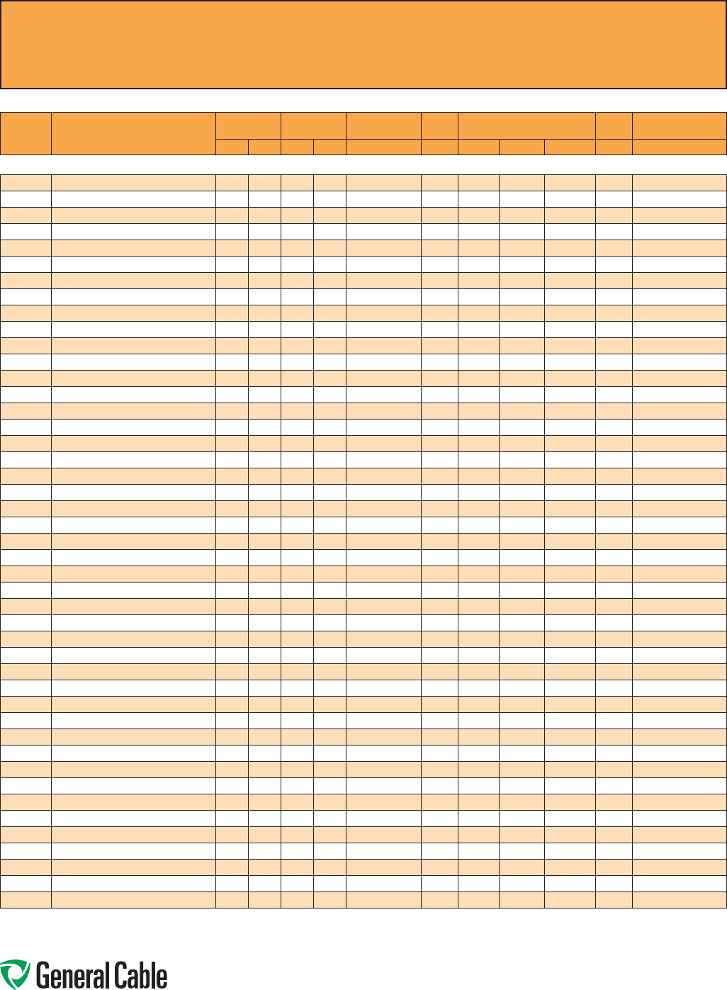
Phone: 888-593-3355
www.generalcable.com
CCW
®
Explosion-Proof Gland Cross-Reference
SPEC A010
April, 2010
Instrumentation - 300 V
CCW
PART
NUMBER PRODUCT DETAIL
NOMINAL ARMOR
O.D.
NOMINAL
OVERALL O.D. CROUSE-HINDS HAWKE
APPLETON (TMCX)
*end stop removed
Thomas &
Betts Hubbell/Killark
INCHES mm INCHES mm TMCX Series 711 Series Aluminum NP Brass Stainless Steel Spin-On X CMCXA
CCW® ARMORED INSTRUMENTATION, PAIRS/TRIADS, INDIVIDUAL AND OVERALL SHIELD (cont’d)
9250.16101221 16 AWG 7W (1.31 mm²) 10 PAIRS 1.02 25.9 1.13 28.7 TMCX3112 C TMCX100A* TMCX100NB* TMCX100SS* 4-100-080 CMCXAC100
9250.16121221 16 AWG 7W (1.31 mm²) 12 PAIRS 1.06 26.9 1.17 29.7 TMCX3112 C TMCX100A* TMCX100NB* TMCX100SS* 4-125-090 CMCXAC100
9250.16121222 16 AWG 7W (1.31 mm²) 12 TRIADS 1.19 30.2 1.30 33.0 TMCX4140 C or C2 TMCX125A TMCX125NB TMCX125SS 4-125-110 CMCXAC100 or CMCXAC2125
9250.16161221 16 AWG 7W (1.31 mm²) 16 PAIRS 1.24 31.5 1.35 34.3 TMCX4140 C2 TMCX125A* TMCX125NB* TMCX125SS* 4-125-110 CMCXAC2125
9250.16161222 16 AWG 7W (1.31 mm²) 16 TRIADS 1.34 34.0 1.45 36.8 TMCX4140 or TMCX5161 C2 TMCX150A TMCX150NB TMCX150SS 4-150-130 CMCXAC2125
9250.16201221 16 AWG 7W (1.31 mm²) 20 PAIRS 1.34 34.0 1.45 36.8 TMCX4140 or TMCX5161 C2 TMCX150A TMCX150NB TMCX150SS 4-150-130 CMCXAC2125
9250.16241221 16 AWG 7W (1.31 mm²) 24 PAIRS 1.37 34.8 1.48 37.6 TMCX4140 or TMCX5161 C2 or D TMCX150A TMCX150NB TMCX150SS 4-150-130 CMCXAC2125 or CMCXAD200
9250.16241222 16 AWG 7W (1.31 mm²) 24 TRIADS 1.60 40.6 1.73 43.9 TMCX5161 or TMCX6206 D TMCX200SA TMCX200SNB TMCX200SSS 4-200-160 CMCXAD200
9250.16361221 16 AWG 7W (1.31 mm²) 36 PAIRS 1.60 40.6 1.73 43.9 TMCX5161 or TMCX6206 D TMCX200SA TMCX200SNB TMCX200SSS 4-200-160 CMCXAD200
9250.16361222 16 AWG 7W (1.31 mm²) 36 TRIADS 1.83 46.5 1.96 49.8 TMCX6206 D or E TMCX200A TMCX200NB TMCX200SS 4-200-180 CMCXAD200 or CMCXAE250
9250.16501221 16 AWG 7W (1.31 mm²) 50 PAIRS 1.87 47.5 2.00 50.8 TMCX6206 D or E TMCX200A TMCX200NB TMCX200SS 4-200-190 CMCXAD200 or CMCXAE250
9250.18021221 18 AWG 7W (0.82 mm²) 2 PAIRS 0.58 14.7 0.69 17.5 TMCX165 A or B TMCX050A* TMCX050NB* TMCX050SS* 4-075-020 CMCXAA050 or CMCXAB075
9250.18041221 18 AWG 7W (0.82 mm²) 4 PAIRS 0.71 18.0 0.82 20.8 TMCX285 B TMCX075A TMCX075NB TMCX075SS 4-075-040 CMCXAB075
9250.18041222 18 AWG 7W (0.82 mm²) 4 TRIADS 0.75 19.1 0.86 21.8 TMCX285 B TMCX075A TMCX075NB TMCX075SS 4-100-050 CMCXAB075
9250.18061221 18 AWG 7W (0.82 mm²) 6 PAIRS 0.75 19.1 0.86 21.8 TMCX285 B TMCX075A TMCX075NB TMCX075SS 4-100-050 CMCXAB075
9250.18081221 18 AWG 7W (0.82 mm²) 8 PAIRS 0.80 20.3 0.92 23.4 TMCX285 or TMCX3112 B TMCX075A* TMCX075NB* TMCX075SS* 4-100-050 CMCXAB075
9250.18081222 18 AWG 7W (0.82 mm²) 8 TRIADS 0.93 23.6 1.04 26.4 TMCX3112 B or C TMCX100A TMCX100NB TMCX100SS 4-100-070 CMCXAB075 or CMCXAC100
9250.18101221 18 AWG 7W (0.82 mm²) 10 PAIRS 0.89 22.6 1.00 25.4 TMCX3112 B or C TMCX100A TMCX100NB TMCX100SS 4-100-070 CMCXAB075 or CMCXAC100
9250.18121221 18 AWG 7W (0.82 mm²) 12 PAIRS 0.93 23.6 1.04 26.4 TMCX3112 B or C TMCX100A TMCX100NB TMCX100SS 4-100-070 CMCXAB075 or CMCXAC100
9250.18121222 18 AWG 7W (0.82 mm²) 12 TRIADS 1.06 26.9 1.17 29.7 TMCX3112 C TMCX100A* TMCX100NB* TMCX100SS* 4-125-090 CMCXAC100
9250.18161221 18 AWG 7W (0.82 mm²) 16 PAIRS 1.06 26.9 1.17 29.7 TMCX3112 C TMCX100A* TMCX100NB* TMCX100SS* 4-125-090 CMCXAC100
9250.18161222 18 AWG 7W (0.82 mm²) 16 TRIADS 1.15 29.2 1.26 32.0 TMCX4140 C TMCX125A TMCX125NB TMCX125SS 4-125-100 CMCXAC100
9250.18201221 18 AWG 7W (0.82 mm²) 20 PAIRS 1.15 29.2 1.26 32.0 TMCX4140 C TMCX125A TMCX125NB TMCX125SS 4-125-100 CMCXAC100
9250.18241221 18 AWG 7W (0.82 mm²) 24 PAIRS 1.24 31.5 1.35 34.3 TMCX4140 C2 TMCX125A* TMCX125NB* TMCX125SS* 4-125-110 CMCXAC2125
9250.18241222 18 AWG 7W (0.82 mm²) 24 TRIADS 1.34 34.0 1.45 36.8 TMCX4140 or TMCX5161 C2 TMCX150A TMCX150NB TMCX150SS 4-150-130 CMCXAC2125
9250.18361221 18 AWG 7W (0.82 mm²) 36 PAIRS 1.47 37.3 1.58 40.1 TMCX5161 C2 or D TMCX150A* TMCX150NB* TMCX150SS* 4-150-140 CMCXAC2125 or CMCXAD200
9250.18361222 18 AWG 7W (0.82 mm²) 36 TRIADS 1.60 40.6 1.73 43.9 TMCX5161 or TMCX6206 D TMCX200SA TMCX200SNB TMCX200SSS 4-200-160 CMCXAD200
9250.18501221 18 AWG 7W (0.82 mm²) 50 PAIRS 1.69 42.9 1.82 46.2 TMCX6206 D TMCX200SA* TMCX200SNB* TMCX200SSS* 4-200-170 CMCXAD200
9250.20021221 20 AWG 7W (0.52 mm²) 2 PAIRS 0.58 14.7 0.69 17.5 TMCX165 A or B TMCX050A* TMCX050NB* TMCX050SS* 4-075-020 CMCXAA050 or CMCXAB075
9250.20041221 20 AWG 7W (0.52 mm²) 4 PAIRS 0.62 15.7 0.73 18.5 TMCX165 or TMCX285 A or B TMCX075A TMCX075NB TMCX075SS 4-075-030 CMCXAA050 or CMCXAB075
9250.20041222 20 AWG 7W (0.52 mm²) 4 TRIADS 0.67 17.0 0.78 19.8 TMCX285 B TMCX075A TMCX075NB TMCX075SS 4-075-040 CMCXAB075
9250.20061221 20 AWG 7W (0.52 mm²) 6 PAIRS 0.71 18.0 0.82 20.8 TMCX285 B TMCX075A TMCX075NB TMCX075SS 4-075-040 CMCXAB075
9250.20081221 20 AWG 7W (0.52 mm²) 8 PAIRS 0.75 19.1 0.86 21.8 TMCX285 B TMCX075A TMCX075NB TMCX075SS 4-100-050 CMCXAB075
9250.20081222 20 AWG 7W (0.52 mm²) 8 TRIADS 0.80 20.3 0.91 23.1 TMCX285 or TMCX3112 B TMCX075A* TMCX075NB* TMCX075SS* 4-100-050 CMCXAB075
9250.20101221 20 AWG 7W (0.52 mm²) 10 PAIRS 0.80 20.3 0.91 23.1 TMCX285 or TMCX3112 B TMCX075A* TMCX075NB* TMCX075SS* 4-100-050 CMCXAB075
9250.20121221 20 AWG 7W (0.52 mm²) 12 PAIRS 0.84 21.3 0.95 24.1 TMCX285 or TMCX3112 B TMCX100A TMCX100NB TMCX100SS 4-100-070 CMCXAB075
9250.20121222 20 AWG 7W (0.52 mm²) 12 TRIADS 0.89 22.6 1.00 25.4 TMCX3112 B or C TMCX100A TMCX100NB TMCX100SS 4-100-070 CMCXAB075 or CMCXAC100
9250.20161221 20 AWG 7W (0.52 mm²) 16 PAIRS 0.97 24.6 1.08 27.4 TMCX3112 C TMCX100A TMCX100NB TMCX100SS 4-100-080 CMCXAB075 or CMCXAC100
9250.20161222 20 AWG 7W (0.52 mm²) 16 TRIADS 1.02 25.9 1.13 28.7 TMCX3112 C TMCX100A* TMCX100NB* TMCX100SS* 4-100-080 CMCXAC100
9250.20201221 20 AWG 7W (0.52 mm²) 20 PAIRS 1.06 26.9 1.17 29.7 TMCX3112 C TMCX100A* TMCX100NB* TMCX100SS* 4-125-090 CMCXAC100
9250.20241221 20 AWG 7W (0.52 mm²) 24 PAIRS 1.15 29.2 1.26 32.0 TMCX4140 C TMCX125A TMCX125NB TMCX125SS 4-125-100 CMCXAC100
9250.20241222 20 AWG 7W (0.52 mm²) 24 TRIADS 1.24 31.5 1.35 34.3 TMCX4140 C2 TMCX125A* TMCX125NB* TMCX125SS* 4-125-110 CMCXAC2125
9250.20361221 20 AWG 7W (0.52 mm²) 36 PAIRS 1.34 34.0 1.45 36.8 TMCX4140 or TMCX5161 C2 TMCX150A TMCX150NB TMCX150SS 4-150-130 CMCXAC2125
9250.20361222 20 AWG 7W (0.52 mm²) 36 TRIADS 1.42 36.1 1.53 38.9 TMCX5161 C2 or D TMCX150A TMCX150NB TMCX150SS 4-150-140 CMCXAC2125 or CMCXAD200
9250.20501221 20 AWG 7W (0.52 mm²) 50 PAIRS 1.51 38.4 1.65 41.9 TMCX5161 C2 or D TMCX200SA TMCX200SNB TMCX200SSS 4-150-150 CMCXAC2125 or CMCXAD200
Allinformationinthiscross-referenceispresentedsolelyasaguidetoproductselectionandisbelievedtobereliable.Allprintingerrorsaresubjecttocorrectioninsubsequent
releasesofthiscatalog.AlthoughGeneralCablehastakenprecautionstoensuretheaccuracyoftheproductcross-referenceatthetimeofpublication,thespecificationsofall
productscontainedhereinaresubjecttochangebyglandmanufacturerswithoutnotice.
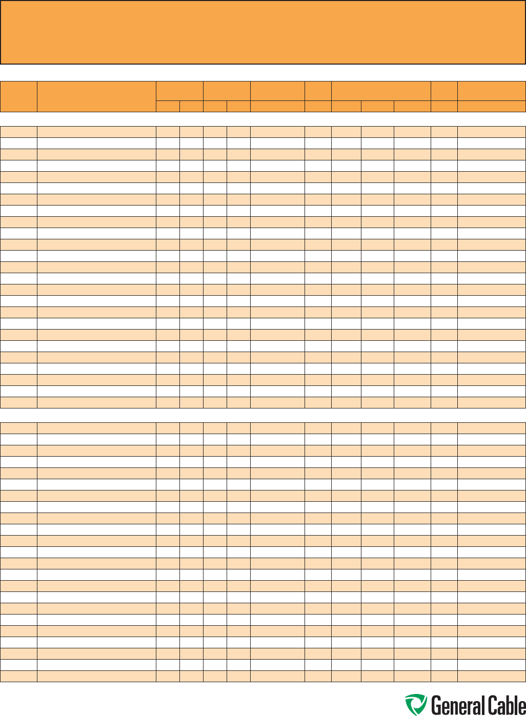
Phone: 888-593-3355
www.generalcable.com
CCW
®
Explosion-Proof Gland Cross-Reference
SPEC A010
April, 2010
Instrumentation - 600 V
CCW
PART
NUMBER PRODUCT DETAIL
NOMINAL ARMOR
O.D.
NOMINAL
OVERALL O.D. CROUSE-HINDS HAWKE
APPLETON (TMCX)
*end stop removed
Thomas &
Betts Hubbell/Killark
INCHES mm INCHES mm TMCX Series 711 Series Aluminum NP Brass Stainless Steel Spin-On X CMCXA
CCW® ARMORED INSTRUMENTATION, PAIRS/TRIADS, OVERALL SHIELD
9325.16010001 16 AWG 7W (1.31 mm²) 1 PAIR 0.53 13.5 0.64 16.3 TMCX165 A or B TMCX050A* TMCX050NB* TMCX050SS* 4-075-020 CMCXAA050 or CMCXAB075
9325.16010002 16 AWG 7W (1.31 mm²) 1 TRIAD 0.53 13.5 0.64 16.3 TMCX165 A or B TMCX050A* TMCX050NB* TMCX050SS* 4-075-020 CMCXAA050 or CMCXAB075
9325.16020001 16 AWG 7W (1.31 mm²) 2 PAIRS 0.58 14.7 0.69 17.5 TMCX165 A or B TMCX050A* TMCX050NB* TMCX050SS* 4-075-020 CMCXAA050 or CMCXAB075
9325.16040001 16 AWG 7W (1.31 mm²) 4 PAIRS 0.71 18.0 0.82 20.8 TMCX285 BTMCX075A TMCX075NB TMCX075SS 4-075-040 CMCXAB075
9325.16040002 16 AWG 7W (1.31 mm²) 4 TRIADS 0.71 18.0 0.82 20.8 TMCX285 BTMCX075A TMCX075NB TMCX075SS 4-075-040 CMCXAB075
9325.16060001 16 AWG 7W (1.31 mm²) 6 PAIRS 0.80 20.3 0.91 23.1 TMCX285 or TMCX3112 BTMCX075A* TMCX075NB* TMCX075SS* 4-100-050 CMCXAB075
9325.16080001 16 AWG 7W (1.31 mm²) 8 PAIRS 0.89 22.6 1.00 25.4 TMCX3112 B or C TMCX100A TMCX100NB TMCX100SS 4-100-070 CMCXAB075 or CMCXAC100
9325.16080002 16 AWG 7W (1.31 mm²) 8 TRIADS 0.93 23.6 1.04 26.4 TMCX3112 B or C TMCX100A TMCX100NB TMCX100SS 4-100-070 CMCXAB075 or CMCXAC100
9325.16100001 16 AWG 7W (1.31 mm²) 10 PAIRS 1.02 25.9 1.13 28.7 TMCX3112 CTMCX100A* TMCX100NB* TMCX100SS* 4-100-080 CMCXAC100
9325.16120001 16 AWG 7W (1.31 mm²) 12 PAIRS 1.06 26.9 1.17 29.7 TMCX3112 CTMCX100A* TMCX100NB* TMCX100SS* 4-125-090 CMCXAC100
9325.16120002 16 AWG 7W (1.31 mm²) 12 TRIADS 1.11 28.2 1.22 31.0 TMCX3112 or TMCX4140 CTMCX125A TMCX125NB TMCX125SS 4-125-100 CMCXAC100
9325.16160001 16 AWG 7W (1.31 mm²) 16 PAIRS 1.15 29.2 1.26 32.0 TMCX4140 CTMCX125A TMCX125NB TMCX125SS 4-125-100 CMCXAC100
9325.16160002 16 AWG 7W (1.31 mm²) 16 TRIADS 1.19 30.2 1.30 33.0 TMCX4140 C or C2 TMCX125A TMCX125NB TMCX125SS 4-125 -110 CMCXAC100 or CMCXAC2125
9325.16200001 16 AWG 7W (1.31 mm²) 20 PAIRS 1.29 32.8 1.40 35.6 TMCX4140 or TMCX5161 C2 TMCX125A* TMCX125NB* TMCX125SS* 4-125-120 CMCXAC2125
9325.16240001 16 AWG 7W (1.31 mm²) 24 PAIRS 1.37 34.8 1.48 3 7.6 TMCX4140 or TMCX5161 C2 or D TMCX150A TMCX150NB TMCX150SS 4-150-130 CMCXAC2125 or CMCXAD200
9325.16240002 16 AWG 7W (1.31 mm²) 24 TRIADS 1.47 37. 3 1.58 40.1 TMCX5161 C2 or D TMCX150A* TMCX150NB* TMCX150SS* 4-150-140 CMCXAC2125 or CMCXAD200
9325.16360001 16 AWG 7W (1.31 mm²) 36 PAIRS 1.64 41.7 1.78 45.2 TMCX6206 DTMCX200SA TMCX200SNB TMCX200SSS 4-200-16 0 CMCXAD200
9325.16360002 16 AWG 7W (1.31 mm²) 36 TRIADS 1.74 44.2 1.87 47.5 TMCX6206 DTMCX200SA* TMCX200SNB* TMCX200SSS* 4-200-170 CMCXAD200
9325.16500001 16 AWG 7W (1.31 mm²) 50 PAIRS 1.83 46.5 1.96 49.8 TMCX6206 D or E TMCX200A TMCX200NB TMCX200SS 4-200-180 CMCXAD200 or CMCXAE250
9325.18020001 18 AWG 7W (0.82 mm²) 2 PAIRS 0.59 15.0 0.70 17.8 TMCX165 A or B TMCX075A TMCX075NB TMCX075SS 4-075-030 CMCXAA050 or CMCXAB075
9325.18040001 18 AWG 7W (0.82 mm²) 4 PAIRS 0.65 16.5 0.75 19.1 TMCX165 or TMCX285 BTMCX075A TMCX075NB TMCX075SS 4-075-030 CMCXAB075
9325.18080001 18 AWG 7W (0.82 mm²) 8 PAIRS 0.82 20.8 0.92 23.4 TMCX285 or TMCX3112 BTMCX100A TMCX100NB TMCX100SS 4-100-070 CMCXAB075
9325.18120001 18 AWG 7W (0.82 mm²) 12 PAIRS 1.00 25.4 1.10 27.9 TMCX3112 CTMCX100A* TMCX100NB* TMCX100SS* 4-100-080 CMCXAC100
9325.18160001 18 AWG 7W (0.82 mm²) 16 PAIRS 1.12 28.4 1.23 31.2 TMCX3112 or TMCX4140 CTMCX125A TMCX125NB TMCX125SS 4-125-100 CMCXAC100
9325.18240001 18 AWG 7W (0.82 mm²) 24 PAIRS 1.39 35.3 1.49 37. 8 TMCX4140 or TMCX5161 C2 or D TMCX150A TMCX150NB TMCX150SS 4-150-130 CMCXAC2125 or CMCXAD200
CCW® ARMORED INSTRUMENTATION, PAIRS/TRIADS, INDIVIDUAL AND OVERALL SHIELD
9350.16020001 16 AWG 7W (1.31 mm²) 2 PAIRS 0.67 17. 0 0.78 19.8 TMCX285 BTMCX075A TMCX075NB TMCX075SS 4-075-040 CMCXAB075
9350.16040001 16 AWG 7W (1.31 mm²) 4 PAIRS 0.80 20.3 0.91 23.1 TMCX285 or TMCX3112 BTMCX075A* TMCX075NB* TMCX075SS* 4-100-050 CMCXAB075
9350.16040002 16 AWG 7W (1.31 mm²) 4 TRIADS 0.84 21.3 0.95 24.1 TMCX285 or TMCX3112 BTMCX100A TMCX100NB TMCX100SS 4-100-070 CMCXAB075
9350.16060001 16 AWG 7W (1.31 mm²) 6 PAIRS 0.89 22.6 1.00 25.4 TMCX3112 B or C TMCX100A TMCX100NB TMCX100SS 4-100-070 CMCXAB075 or CMCXAC100
9350.16080001 16 AWG 7W (1.31 mm²) 8 PAIRS 0.93 23.6 1.04 26.4 TMCX3112 B or C TMCX100A TMCX100NB TMCX100SS 4-100-070 CMCXAB075 or CMCXAC100
9350.16080002 16 AWG 7W (1.31 mm²) 8 TRIADS 1.06 26.9 1.17 29.7 TMCX3112 CTMCX100A* TMCX100NB* TMCX100SS* 4-125-0 90 CMCXAC100
9350.16100001 16 AWG 7W (1.31 mm²) 10 PAIRS 1.06 26.9 1.17 29.7 TMCX3112 CTMCX100A* TMCX100NB* TMCX100SS* 4-125-090 CMCXAC100
9350.16120001 16 AWG 7W (1.31 mm²) 12 PAIRS 1.11 28.2 1.22 31.0 TMCX3112 or TMCX4140 CTMCX125A TMCX125NB TMCX125SS 4-125-100 CMCXAC100
9350.16120002 16 AWG 7W (1.31 mm²) 12 TRIADS 1.24 31.5 1.35 34.3 TMCX4140 C2 TMCX125A* TMCX125NB* TMCX125SS* 4-125-110 CMCXAC2125
9350.16160001 16 AWG 7W (1.31 mm²) 16 PAIRS 1.29 32.8 1.40 35.6 TMCX4140 or TMCX5161 C2 TMCX125A* TMCX125NB* TMCX125SS* 4-125-120 CMCXAC2125
9350.16160002 16 AWG 7W (1.31 mm²) 16 TRIADS 1.37 34.8 1.48 37.6 TMCX4140 or TMCX5161 C2 or D TMCX150A TMCX150NB TMCX150SS 4 -150-130 CMCXAC2125 or CMCXAD200
9350.16200001 16 AWG 7W (1.31 mm²) 20 PAIRS 1.34 34.0 1.45 36.8 TMCX4140 or TMCX5161 C2 TMCX150A TMCX150NB TMCX150SS 4-150-130 CMCXAC2125
9350.16240001 16 AWG 7W (1.31 mm²) 24 PAIRS 1.42 36.1 1.53 38.9 TMCX5161 C2 or D TMCX150A TMCX150NB TMCX150SS 4-150 -140 CMCXAC2125 or CMCXAD200
9350.16240002 16 AWG 7W (1.31 mm²) 24 TRIADS 1.64 41.7 1.78 45.2 TMCX6206 DTMCX200SA TMCX200SNB TMCX200SSS 4-200-160 CMCXAD200
9350.16360001 16 AWG 7W (1.31 mm²) 36 PAIRS 1.69 42.9 1.82 46.2 TMCX6206 DTMCX200SA* TMCX200SNB* TMCX200SSS* 4-200-170 CMCXAD200
9350.16360002 16 AWG 7W (1.31 mm²) 36 TRIADS 1.96 49.8 2.09 53.1 TMCX6206 or TMCX7247 D or E TMCX200A* TMCX200NB* TMCX200SS* 4-250-200 CMCXAD200 or CMCXAE250
9350.16500001 16 AWG 7W (1.31 mm²) 50 PAIRS 1.92 48.8 2.05 52.1 TMCX6206 D or E TMCX200A TMCX200NB TMCX200SS 4-200-190 CMCXAD200 or CMCXAE250
9350.18020001 18 AWG 7W (0.82 mm²) 2 PAIRS 0.59 15.0 0.70 17. 8 TMCX165 A or B TMCX075A TMCX075NB TMCX075SS 4-075-030 CMCXAA050 or CMCXAB075
9350.18040001 18 AWG 7W (0.82 mm²) 4 PAIRS 0.65 16.5 0.75 19.1 TMCX165 or TMCX285 BTMCX075A TMCX075NB TMCX075SS 4-075-030 CMCXAB075
9350.18080001 18 AWG 7W (0.82 mm²) 8 PAIRS 0.82 20.8 0.92 23.4 TMCX285 or TMCX3112 BTMCX100A TMCX100NB TMCX100SS 4-100-070 CMCXAB075
9350.18120001 18 AWG 7W (0.82 mm²) 12 PAIRS 1.00 25.4 1.10 2 7.9 TMCX3112 CTMCX100A* TMCX100NB* TMCX100SS* 4-100-080 CMCXAC100
9350.18160001 18 AWG 7W (0.82 mm²) 16 PAIRS 1.12 28.4 1.23 31.2 TMCX3112 or TMCX4140 CTMCX125A TMCX125NB TMCX125SS 4-125-100 CMCXAC100
9350.18240001 18 AWG 7W (0.82 mm²) 24 PAIRS 1.39 35.3 1.49 37. 8 TMCX4140 or TMCX5161 C2 or D TMCX150A TMCX150NB TMCX150SS 4-150-130 CMCXAC2125 or CMCXAD200
Allinformationinthiscross-referenceispresentedsolelyasaguidetoproductselectionandisbelievedtobereliable.Allprinting
errorsaresubjecttocorrectioninsubsequentreleasesofthiscatalog.AlthoughGeneralCablehastakenprecautionstoensurethe
accuracyoftheproductcross-referenceatthetimeofpublication,thespecificationsofallproductscontainedhereinaresubjectto
changebyglandmanufacturerswithoutnotice.
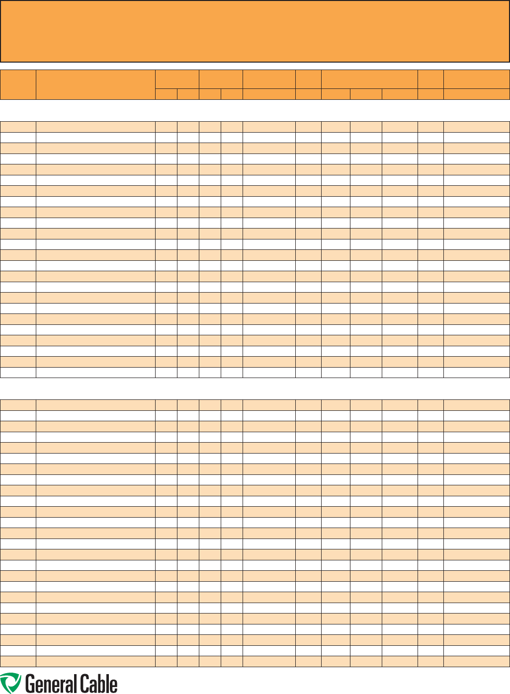
Phone: 888-593-3355
www.generalcable.com
CCW
®
Explosion-Proof Gland Cross-Reference
SPEC A010
April, 2010
CCW
PART
NUMBER PRODUCT DETAIL
NOMINAL ARMOR
O.D.
NOMINAL
OVERALL O.D. CROUSE-HINDS HAWKE
APPLETON (TMCX)
*end stop removed
Thomas &
Betts Hubbell/Killark
INCHES mm INCHES mm TMCX Series 711 Series Aluminum NP Brass Stainless Steel Spin-On X CMCXA
Control - 600 V
CCW® ARMORED CONTROL WITH GREEN INSULATED GROUNDING CONDUCTOR
9500.01002110 10 AWG 7W (5.26 mm²) 2/C W/10 AWG GROUND 0.58 14.7 0.69 17.5 TMCX165 A or B TMCX050A* TMCX050NB* TMCX050SS* 4-075-020 CMCXAA050 or CMCXAB075
9500.01003110 10 AWG 7W (5.26 mm²) 3/C W/10 AWG GROUND 0.62 15.7 0.73 18.5 TMCX165 or TMCX285 A or B TMCX075A TMCX075NB TMCX075SS 4-075-030 CMCXAA050 or CMCXAB075
9500.01004110 10 AWG 7W (5.26 mm²) 4/C W/10 AWG GROUND 0.67 17.0 0.78 19.8 TMCX285 B TMCX075A TMCX075NB TMCX075SS 4-075-040 CMCXAB075
9500.01006110 10 AWG 7W (5.26 mm²) 6/C W/10 AWG GROUND 0.75 19.1 0.86 21.8 TMCX285 B TMCX075A TMCX075NB TMCX075SS 4-100-050 CMCXAB075
9500.01008110 10 AWG 7W (5.26 mm²) 8/C W/10 AWG GROUND 0.89 22.6 1.00 25.4 TMCX3112 B or C TMCX100A TMCX100NB TMCX100SS 4-100-070 CMCXAB075 or CMCXAC100
9500.01011110 10 AWG 7W (5.26 mm²) 11/C W/10 AWG GROUND 0.97 24.6 1.08 27.4 TMCX3112 C TMCX100A TMCX100NB TMCX100SS 4-100-080 CMCXAB075 or CMCXAC100
9500.01202112 12 AWG 7W (3.31 mm²) 2/C W/12 AWG GROUND 0.53 13.5 0.64 16.3 TMCX165 A or B TMCX050A* TMCX050NB* TMCX050SS* 4-075-020 CMCXAA050 or CMCXAB075
9500.01203112 12 AWG 7W (3.31 mm²) 3/C W/12 AWG GROUND 0.58 14.7 0.69 17.5 TMCX165 A or B TMCX050A* TMCX050NB* TMCX050SS* 4-075-020 CMCXAA050 or CMCXAB075
9500.01204112 12 AWG 7W (3.31 mm²) 4/C W/12 AWG GROUND 0.67 17.0 0.78 19.8 TMCX285 B TMCX075A TMCX075NB TMCX075SS 4-075-040 CMCXAB075
9500.01205112 12 AWG 7W (3.31 mm²) 5/C W/12 AWG GROUND 0.67 17.0 0.78 19.8 TMCX285 B TMCX075A TMCX075NB TMCX075SS 4-075-040 CMCXAB075
9500.01206112 12 AWG 7W (3.31 mm²) 6/C W/12 AWG GROUND 0.67 17.0 0.78 19.8 TMCX285 B TMCX075A TMCX075NB TMCX075SS 4-075-040 CMCXAB075
9500.01208112 12 AWG 7W (3.31 mm²) 8/C W/12 AWG GROUND 0.80 20.3 0.91 23.1 TMCX285 or TMCX3112 B TMCX075A* TMCX075NB* TMCX075SS* 4-100-050 CMCXAB075
9500.01211112 12 AWG 7W (3.31 mm²) 11/C W/12 AWG GROUND 0.89 22.6 1.00 25.4 TMCX3112 B or C TMCX100A TMCX100NB TMCX100SS 4-100-070 CMCXAB075 or CMCXAC100
9500.01218112 12 AWG 7W (3.31 mm²) 18/C W/12 AWG GROUND 1.02 25.9 1.13 28.7 TMCX3112 C TMCX100A* TMCX100NB* TMCX100SS* 4-100-080 CMCXAC100
9500.01236112 12 AWG 7W (3.31 mm²) 36/C W/12 AWG GROUND 1.37 34.8 1.48 37.6 TMCX4140 or TMCX5161 C2 or D TMCX150A TMCX150NB TMCX150SS 4-150-130 CMCXAC2125 or CMCXAD200
9500.01402114 14 AWG 7W (2.08 mm²) 2/C W/14 AWG GROUND 0.49 12.4 0.60 15.2 TMCX165 A or B TMCX050SA* TMCX050SNB* TMCX050SSS* 4-075-010 CMCXAA050 or CMCXAB075
9500.01403114 14 AWG 7W (2.08 mm²) 3/C W/14 AWG GROUND 0.53 13.5 0.64 16.3 TMCX165 A or B TMCX050A* TMCX050NB* TMCX050SS* 4-075-020 CMCXAA050 or CMCXAB075
9500.01404114 14 AWG 7W (2.08 mm²) 4/C W/14 AWG GROUND 0.58 14.7 0.69 17.5 TMCX165 A or B TMCX050A* TMCX050NB* TMCX050SS* 4-075-020 CMCXAA050 or CMCXAB075
9500.01405114 14 AWG 7W (2.08 mm²) 5/C W/14 AWG GROUND 0.60 15.2 0.71 18.0 TMCX165 or TMCX285 A or B TMCX075A TMCX075NB TMCX075SS 4-075-030 CMCXAA050 or CMCXAB075
9500.01406114 14 AWG 7W (2.08 mm²) 6/C W/14 AWG GROUND 0.62 15.7 0.73 18.5 TMCX165 or TMCX285 A or B TMCX075A TMCX075NB TMCX075SS 4-075-030 CMCXAA050 or CMCXAB075
9500.01408114 14 AWG 7W (2.08 mm²) 8/C W/14 AWG GROUND 0.71 18.0 0.82 20.8 TMCX285 B TMCX075A TMCX075NB TMCX075SS 4-075-040 CMCXAB075
9500.01411114 14 AWG 7W (2.08 mm²) 11/C W/14 AWG GROUND 0.80 20.3 0.91 23.1 TMCX285 or TMCX3112 B TMCX075A* TMCX075NB* TMCX075SS* 4-100-050 CMCXAB075
9500.01418114 14 AWG 7W (2.08 mm²) 18/C W/14 AWG GROUND 0.93 23.6 1.04 26.4 TMCX3112 B or C TMCX100A TMCX100NB TMCX100SS 4-100-070 CMCXAB075 or CMCXAC100
9500.01436114 14 AWG 7W (2.08 mm²) 36/C W/14 AWG GROUND 1.24 31.5 1.35 34.3 TMCX4140 C2 TMCX125A* TMCX125NB* TMCX125SS* 4-125-110 CMCXAC2125
Control (Non-HL) - 600 V
CCW® ARMORED CONTROL WITHOUT GROUNDING CONDUCTOR
9525.01002000 10 AWG 7W (5.26 mm²) 2/C 0.58 14.7 0.69 17.5 TMCX165 A or B TMCX050A* TMCX050NB* TMCX050SS* 4-075-020 CMCXAA050 or CMCXAB075
9525.01003000 10 AWG 7W (5.26 mm²) 3/C 0.58 14.7 0.69 17.5 TMCX165 A or B TMCX050A* TMCX050NB* TMCX050SS* 4-075-020 CMCXAA050 or CMCXAB075
9525.01004000 10 AWG 7W (5.26 mm²) 4/C 0.67 17.0 0.78 19.8 TMCX285 B TMCX075A TMCX075NB TMCX075SS 4-075-040 CMCXAB075
9525.01005000 10 AWG 7W (5.26 mm²) 5/C 0.71 18.0 0.82 20.8 TMCX285 B TMCX075A TMCX075NB TMCX075SS 4-075-040 CMCXAB075
9525.01007000 10 AWG 7W (5.26 mm²) 7/C 0.75 19.1 0.86 21.8 TMCX285 B TMCX075A TMCX075NB TMCX075SS 4-100-050 CMCXAB075
9525.01009000 10 AWG 7W (5.26 mm²) 9/C 0.89 22.6 1.00 25.4 TMCX3112 B or C TMCX100A TMCX100NB TMCX100SS 4-100-070 CMCXAB075 or CMCXAC100
9525.01012000 10 AWG 7W (5.26 mm²) 12/C 0.97 24.6 1.08 27.4 TMCX3112 C TMCX100A TMCX100NB TMCX100SS 4-100-080 CMCXAB075 or CMCXAC100
9525.01202000 12 AWG 7W (3.31 mm²) 2/C 0.53 13.5 0.64 16.3 TMCX165 A or B TMCX050A* TMCX050NB* TMCX050SS* 4-075-020 CMCXAA050 or CMCXAB075
9525.01203000 12 AWG 7W (3.31 mm²) 3/C 0.53 13.5 0.64 16.3 TMCX165 A or B TMCX050A* TMCX050NB* TMCX050SS* 4-075-020 CMCXAA050 or CMCXAB075
9525.01204000 12 AWG 7W (3.31 mm²) 4/C 0.58 14.7 0.69 17.5 TMCX165 A or B TMCX050A* TMCX050NB* TMCX050SS* 4-075-020 CMCXAA050 or CMCXAB075
9525.01205000 12 AWG 7W (3.31 mm²) 5/C 0.62 15.7 0.73 18.5 TMCX165 or TMCX285 A or B TMCX075A TMCX075NB TMCX075SS 4-075-030 CMCXAA050 or CMCXAB075
9525.01207000 12 AWG 7W (3.31 mm²) 7/C 0.67 17.0 0.78 19.8 TMCX285 B TMCX075A TMCX075NB TMCX075SS 4-075-040 CMCXAB075
9525.01209000 12 AWG 7W (3.31 mm²) 9/C 0.80 20.3 0.91 23.1 TMCX285 or TMCX3112 B TMCX075A* TMCX075NB* TMCX075SS* 4-100-050 CMCXAB075
9525.01212000 12 AWG 7W (3.31 mm²) 12/C 0.89 22.6 0.99 25.1 TMCX3112 B or C TMCX100A TMCX100NB TMCX100SS 4-100-070 CMCXAB075 or CMCXAC100
9525.01219000 12 AWG 7W (3.31 mm²) 19/C 1.02 25.9 1.13 28.7 TMCX3112 C TMCX100A* TMCX100NB* TMCX100SS* 4-100-080 CMCXAC100
9525.01237000 12 AWG 7W (3.31 mm²) 37/C 1.37 34.8 1.48 37.6 TMCX4140 or TMCX5161 C2 or D TMCX150A TMCX150NB TMCX150SS 4-150-130 CMCXAC2125 or CMCXAD200
9525.01402000 14 AWG 7W (2.08 mm²) 2/C 0.49 12.4 0.60 15.2 TMCX165 A or B TMCX050SA* TMCX050SNB* TMCX050SSS* 4-075-010 CMCXAA050 or CMCXAB075
9525.01403000 14 AWG 7W (2.08 mm²) 3/C 0.49 12.4 0.60 15.2 TMCX165 A or B TMCX050SA* TMCX050SNB* TMCX050SSS* 4-075-010 CMCXAA050 or CMCXAB075
9525.01404000 14 AWG 7W (2.08 mm²) 4/C 0.53 13.5 0.64 16.3 TMCX165 A or B TMCX050A* TMCX050NB* TMCX050SS* 4-075-020 CMCXAA050 or CMCXAB075
9525.01405000 14 AWG 7W (2.08 mm²) 5/C 0.58 14.7 0.69 17.5 TMCX165 A or B TMCX050A* TMCX050NB* TMCX050SS* 4-075-020 CMCXAA050 or CMCXAB075
9525.01407000 14 AWG 7W (2.08 mm²) 7/C 0.62 15.7 0.73 18.5 TMCX165 or TMCX285 A or B TMCX075A TMCX075NB TMCX075SS 4-075-030 CMCXAA050 or CMCXAB075
9525.01409000 14 AWG 7W (2.08 mm²) 9/C 0.71 18.0 0.82 20.8 TMCX285 B TMCX075A TMCX075NB TMCX075SS 4-075-040 CMCXAB075
9525.01412000 14 AWG 7W (2.08 mm²) 12/C 0.80 20.3 0.91 23.1 TMCX285 or TMCX3112 B TMCX075A* TMCX075NB* TMCX075SS* 4-100-050 CMCXAB075
9525.01419000 14 AWG 7W (2.08 mm²) 19/C 0.93 23.6 1.04 26.4 TMCX3112 B or C TMCX100A TMCX100NB TMCX100SS 4-100-070 CMCXAB075 or CMCXAC100
9525.01437000 14 AWG 7W (2.08 mm²) 37/C 1.24 31.5 1.35 34.3 TMCX4140 C2 TMCX125A* TMCX125NB* TMCX125SS* 4-125-110 CMCXAC2125
Allinformationinthiscross-referenceispresentedsolelyasaguidetoproductselectionandisbelievedtobereliable.Allprinting
errorsaresubjecttocorrectioninsubsequentreleasesofthiscatalog.AlthoughGeneralCablehastakenprecautionstoensurethe
accuracyoftheproductcross-referenceatthetimeofpublication,thespecificationsofallproductscontainedhereinaresubjectto
changebyglandmanufacturerswithoutnotice.
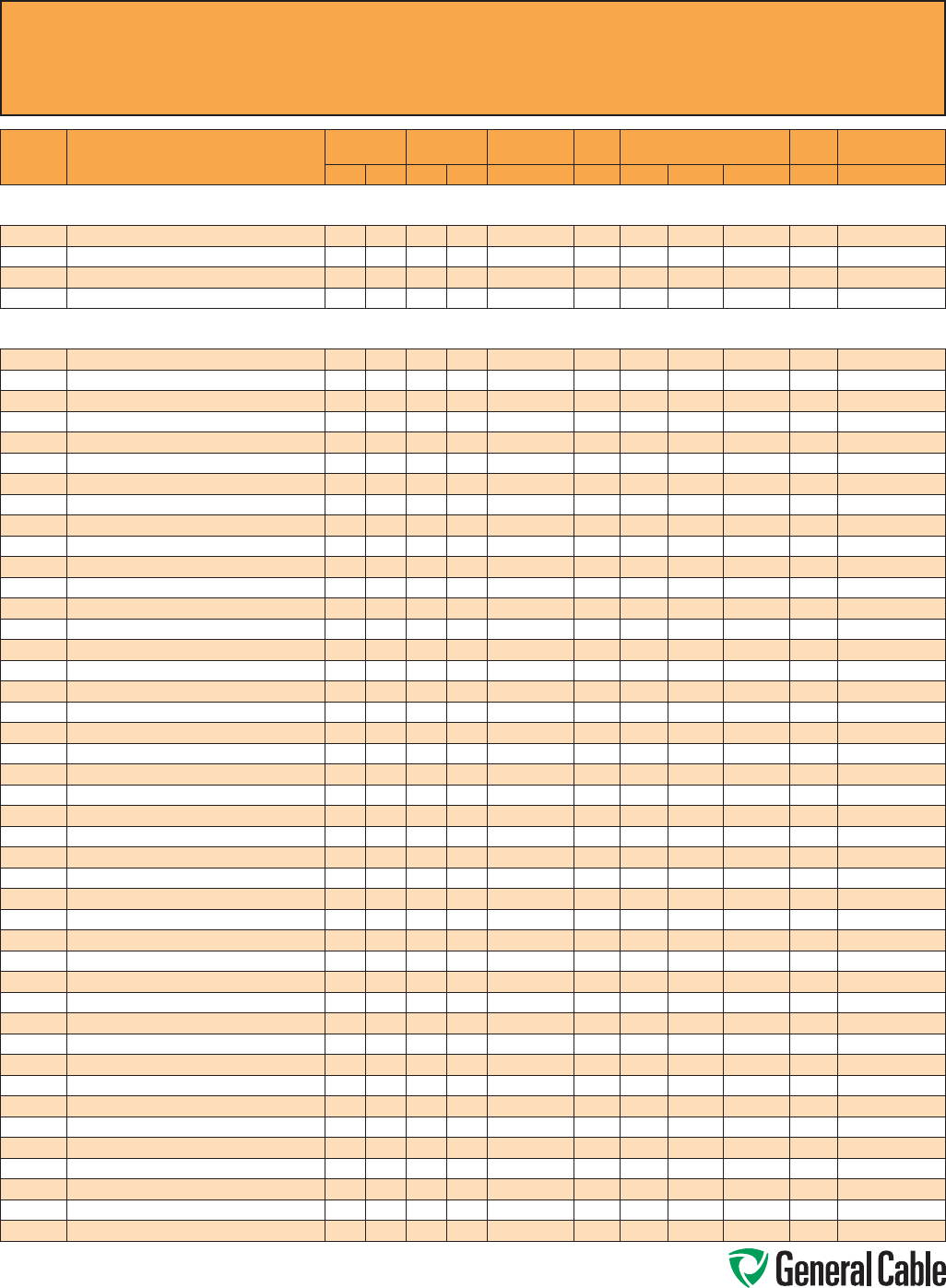
Phone: 888-593-3355
www.generalcable.com
CCW
®
Explosion-Proof Gland Cross-Reference
SPEC A010
April, 2010
CCW
PART
NUMBER PRODUCT DETAIL
NOMINAL ARMOR
O.D.
NOMINAL
OVERALL O.D. CROUSE-HINDS HAWKE
APPLETON (TMCX)
*end stop removed
Thomas &
Betts Hubbell/Killark
INCHES mm INCHES mm TMCX Series 711 Series Aluminum NP Brass Stainless Steel Spin-On X CMCXA
Composite Power & Control - 600 V
CCW® ARMORED COMPOSITE POWER AND CONTROL WITH BARE GROUND
9625.043124108 4 AWG 7W (21.2 mm²) 3/C W/12 AWG 4/C CONTROL & 8 AWG GROUND 0.97 24.6 1.08 27.4 TMCX3112 C TMCX100A TMCX100NB TMCX100SS 4-100-080 CMCXAB075 or CMCXAC100
9625.063124108 6 AWG 7W (13.3 mm²) 3/C W/12 AWG 4/C CONTROL & 8 AWG GROUND 0.93 23.6 1.03 26.2 TMCX3112 B or C TMCX100A TMCX100NB TMCX100SS 4-100-070 CMCXAB075 or CMCXAC100
9625.083124110 8 AWG 7W (8.36 mm²) 3/C W/12 AWG 4/C CONTROL & 10 AWG GROUND 0.89 22.6 0.99 25.1 TMCX3112 B or C TMCX100A TMCX100NB TMCX100SS 4-100-070 CMCXAB075 or CMCXAC100
9625.103124110
10 AWG 7W (5.26 mm²) 3/C W/12 AWG 4/C CONTROL & 10 AWG GROUND
0.75 19.1 0.86 21.8 TMCX285 B TMCX075A TMCX075NB TMCX075SS 4-100-050 CMCXAB075
Composite Power & Control (Non-HL) - 600 V
CCW® ARMORED COMPOSITE POWER AND CONTROL WITHOUT GROUND
9650.023123000 2 AWG 7W (33.6 mm²) 3/C W/12 AWG 3/C CONTROL 1.06 26.9 1.17 29.7 TMCX3112 C TMCX100A* TMCX100NB* TMCX100SS* 4-125-090 CMCXAC100
9650.023124000 2 AWG 7W (33.6 mm²) 3/C W/12 AWG 4/C CONTROL 1.06 26.9 1.17 29.7 TMCX3112 C TMCX100A* TMCX100NB* TMCX100SS* 4-125-090 CMCXAC100
9650.023143000 2 AWG 7W (33.6 mm²) 3/C W/14 AWG 3/C CONTROL 1.06 26.9 1.17 29.7 TMCX3112 C TMCX100A* TMCX100NB* TMCX100SS* 4-125-090 CMCXAC100
9650.023144000 2 AWG 7W (33.6 mm²) 3/C W/14 AWG 4/C CONTROL 1.06 26.9 1.17 29.7 TMCX3112 C TMCX100A* TMCX100NB* TMCX100SS* 4-125-090 CMCXAC100
9650.024123000 2 AWG 7W (33.6 mm²) 4/C W/12 AWG 3/C CONTROL 1.15 29.2 1.26 32.0 TMCX4140 C TMCX125A TMCX125NB TMCX125SS 4-125-100 CMCXAC100
9650.024124000 2 AWG 7W (33.6 mm²) 4/C W/12 AWG 4/C CONTROL 1.15 29.2 1.26 32.0 TMCX4140 C TMCX125A TMCX125NB TMCX125SS 4-125-100 CMCXAC100
9650.024143000 2 AWG 7W (33.6 mm²) 4/C W/14 AWG 3/C CONTROL 1.15 29.2 1.26 32.0 TMCX4140 C TMCX125A TMCX125NB TMCX125SS 4-125-100 CMCXAC100
9650.024144000 2 AWG 7W (33.6 mm²) 4/C W/14 AWG 4/C CONTROL 1.15 29.2 1.26 32.0 TMCX4140 C TMCX125A TMCX125NB TMCX125SS 4-125-100 CMCXAC100
9650.043123000 4 AWG 7W (21.2 mm²) 3/C W/12 AWG 3/C CONTROL 0.93 23.6 1.04 26.4 TMCX3112 B or C TMCX100A TMCX100NB TMCX100SS 4-100-070 CMCXAB075 or CMCXAC100
9650.043124000 4 AWG 7W (21.2 mm²) 3/C W/12 AWG 4/C CONTROL 0.97 24.6 1.08 27.4 TMCX3112 C TMCX100A TMCX100NB TMCX100SS 4-100-080 CMCXAB075 or CMCXAC100
9650.043143000 4 AWG 7W (21.2 mm²) 3/C W/14 AWG 3/C CONTROL 0.93 23.6 1.04 26.4 TMCX3112 B or C TMCX100A TMCX100NB TMCX100SS 4-100-070 CMCXAB075 or CMCXAC100
9650.043144000 4 AWG 7W (21.2 mm²) 3/C W/14 AWG 4/C CONTROL 0.93 23.6 1.04 26.4 TMCX3112 B or C TMCX100A TMCX100NB TMCX100SS 4-100-070 CMCXAB075 or CMCXAC100
9650.044123000 4 AWG 7W (21.2 mm²) 4/C W/12 AWG 3/C CONTROL 1.06 26.9 1.17 29.7 TMCX3112 C TMCX100A* TMCX100NB* TMCX100SS* 4-125-090 CMCXAC100
9650.044124000 4 AWG 7W (21.2 mm²) 4/C W/12 AWG 4/C CONTROL 1.06 26.9 1.17 29.7 TMCX3112 C TMCX100A* TMCX100NB* TMCX100SS* 4-125-090 CMCXAC100
9650.044143000 4 AWG 7W (21.2 mm²) 4/C W/14 AWG 3/C CONTROL 1.06 26.9 1.17 29.7 TMCX3112 C TMCX100A* TMCX100NB* TMCX100SS* 4-125-090 CMCXAC100
9650.044144000 4 AWG 7W (21.2 mm²) 4/C W/14 AWG 4/C CONTROL 1.06 26.9 1.17 29.7 TMCX3112 C TMCX100A* TMCX100NB* TMCX100SS* 4-125-090 CMCXAC100
9650.063123000 6 AWG 7W (13.3 mm²) 3/C W/12 AWG 3/C CONTROL 0.84 21.3 0.95 24.1 TMCX285 or TMCX3112 B TMCX100A TMCX100NB TMCX100SS 4-100-070 CMCXAB075
9650.063124000 6 AWG 7W (13.3 mm²) 3/C W/12 AWG 4/C CONTROL 0.93 23.6 1.03 26.2 TMCX3112 B or C TMCX100A TMCX100NB TMCX100SS 4-100-070 CMCXAB075 or CMCXAC100
9650.063143000 6 AWG 7W (13.3 mm²) 3/C W/14 AWG 3/C CONTROL 0.84 21.3 0.95 24.1 TMCX285 or TMCX3112 B TMCX100A TMCX100NB TMCX100SS 4-100-070 CMCXAB075
9650.063144000 6 AWG 7W (13.3 mm²) 3/C W/14 AWG 4/C CONTROL 0.84 21.3 0.95 24.1 TMCX285 or TMCX3112 B TMCX100A TMCX100NB TMCX100SS 4-100-070 CMCXAB075
9650.064123000 6 AWG 7W (13.3 mm²) 4/C W/12 AWG 3/C CONTROL 0.97 24.6 1.08 27.4 TMCX3112 C TMCX100A TMCX100NB TMCX100SS 4-100-080 CMCXAB075 or CMCXAC100
9650.064124000 6 AWG 7W (13.3 mm²) 4/C W/12 AWG 4/C CONTROL 0.97 24.6 1.08 27.4 TMCX3112 C TMCX100A TMCX100NB TMCX100SS 4-100-080 CMCXAB075 or CMCXAC100
9650.064143000 6 AWG 7W (13.3 mm²) 4/C W/14 AWG 3/C CONTROL 0.93 23.6 1.04 26.4 TMCX3112 B or C TMCX100A TMCX100NB TMCX100SS 4-100-070 CMCXAB075 or CMCXAC100
9650.064144000 6 AWG 7W (13.3 mm²) 4/C W/14 AWG 4/C CONTROL 0.93 23.6 1.04 26.4 TMCX3112 B or C TMCX100A TMCX100NB TMCX100SS 4-100-070 CMCXAB075 or CMCXAC100
9650.083123000 8 AWG 7W (8.36 mm²) 3/C W/12 AWG 3/C CONTROL 0.80 20.3 0.95 24.1 TMCX285 or TMCX3112 B TMCX075A* TMCX075NB* TMCX075SS* 4-100-050 CMCXAB075
9650.083124000 8 AWG 7W (8.36 mm²) 3/C W/12 AWG 4/C CONTROL 0.84 21.3 0.91 23.1 TMCX285 or TMCX3112 B TMCX100A TMCX100NB TMCX100SS 4-100-070 CMCXAB075
9650.083143000 8 AWG 7W (8.36 mm²) 3/C W/14 AWG 3/C CONTROL 0.80 20.3 0.91 23.1 TMCX285 or TMCX3112 B TMCX075A* TMCX075NB* TMCX075SS* 4-100-050 CMCXAB075
9650.083144000 8 AWG 7W (8.36 mm²) 3/C W/14 AWG 4/C CONTROL 0.84 21.3 0.91 23.1 TMCX285 or TMCX3112 B TMCX100A TMCX100NB TMCX100SS 4-100-070 CMCXAB075
9650.084123000 8 AWG 7W (8.36 mm²) 4/C W/12 AWG 3/C CONTROL 0.89 22.6 1.00 25.4 TMCX3112 B or C TMCX100A TMCX100NB TMCX100SS 4-100-070 CMCXAB075 or CMCXAC100
9650.084124000 8 AWG 7W (8.36 mm²) 4/C W/12 AWG 4/C CONTROL 0.93 23.6 1.04 26.4 TMCX3112 B or C TMCX100A TMCX100NB TMCX100SS 4-100-070 CMCXAB075 or CMCXAC100
9650.084143000 8 AWG 7W (8.36 mm²) 4/C W/14 AWG 3/C CONTROL 0.84 21.3 0.95 24.1 TMCX285 or TMCX3112 B TMCX100A TMCX100NB TMCX100SS 4-100-070 CMCXAB075
9650.084144000 8 AWG 7W (8.36 mm²) 4/C W/14 AWG 4/C CONTROL 0.89 22.6 1.00 25.4 TMCX3112 B or C TMCX100A TMCX100NB TMCX100SS 4-100-070 CMCXAB075 or CMCXAC100
9650.103123000 10 AWG 7W (5.26 mm²) 3/C W/12 AWG 3/C CONTROL 0.75 19.1 0.86 21.8 TMCX285 B TMCX075A TMCX075NB TMCX075SS 4-100-050 CMCXAB075
9650.103143000 10 AWG 7W (5.26 mm²) 3/C W/14 AWG 3/C CONTROL 0.75 19.1 0.86 21.8 TMCX285 B TMCX075A TMCX075NB TMCX075SS 4-100-050 CMCXAB075
9650.103144000 10 AWG 7W (5.26 mm²) 3/C W/14 AWG 4/C CONTROL 0.80 20.3 0.91 23.1 TMCX285 or TMCX3112 B TMCX075A* TMCX075NB* TMCX075SS* 4-100-050 CMCXAB075
9650.104123000 10 AWG 7W (5.26 mm²) 4/C W/12 AWG 3/C CONTROL 0.80 20.3 0.91 23.1 TMCX285 or TMCX3112 B TMCX075A* TMCX075NB* TMCX075SS* 4-100-050 CMCXAB075
9650.104124000 10 AWG 7W (5.26 mm²) 4/C W/12 AWG 4/C CONTROL 0.80 20.3 0.91 23.1 TMCX285 or TMCX3112 B TMCX075A* TMCX075NB* TMCX075SS* 4-100-050 CMCXAB075
9650.104143000 10 AWG 7W (5.26 mm²) 4/C W/14 AWG 3/C CONTROL 0.80 20.3 0.91 23.1 TMCX285 or TMCX3112 B TMCX075A* TMCX075NB* TMCX075SS* 4-100-050 CMCXAB075
9650.104144000 10 AWG 7W (5.26 mm²) 4/C W/14 AWG 4/C CONTROL 0.80 20.3 0.91 23.1 TMCX285 or TMCX3112 B TMCX075A* TMCX075NB* TMCX075SS* 4-100-050 CMCXAB075
9650.123143000 12 AWG 7W (3.31 mm²) 3/C W/14 AWG 3/C CONTROL 0.71 18.0 0.82 20.8 TMCX285 B TMCX075A TMCX075NB TMCX075SS 4-075-040 CMCXAB075
9650.123144000 12 AWG 7W (3.31 mm²) 3/C W/14 AWG 4/C CONTROL 0.71 18.0 0.82 20.8 TMCX285 B TMCX075A TMCX075NB TMCX075SS 4-075-040 CMCXAB075
9650.124143000 12 AWG 7W (3.31 mm²) 4/C W/14 AWG 3/C CONTROL 0.71 18.0 0.82 20.8 TMCX285 B TMCX075A TMCX075NB TMCX075SS 4-075-040 CMCXAB075
9650.124144000 12 AWG 7W (3.31 mm²) 4/C W/14 AWG 4/C CONTROL 0.75 19.1 0.86 21.8 TMCX285 B TMCX075A TMCX075NB TMCX075SS 4-100-050 CMCXAB075
Allinformationinthiscross-referenceispresentedsolelyasaguidetoproductselectionandisbelievedtobereliable.Allprinting
errorsaresubjecttocorrectioninsubsequentreleasesofthiscatalog.AlthoughGeneralCablehastakenprecautionstoensurethe
accuracyoftheproductcross-referenceatthetimeofpublication,thespecificationsofallproductscontainedhereinaresubjectto
changebyglandmanufacturerswithoutnotice.
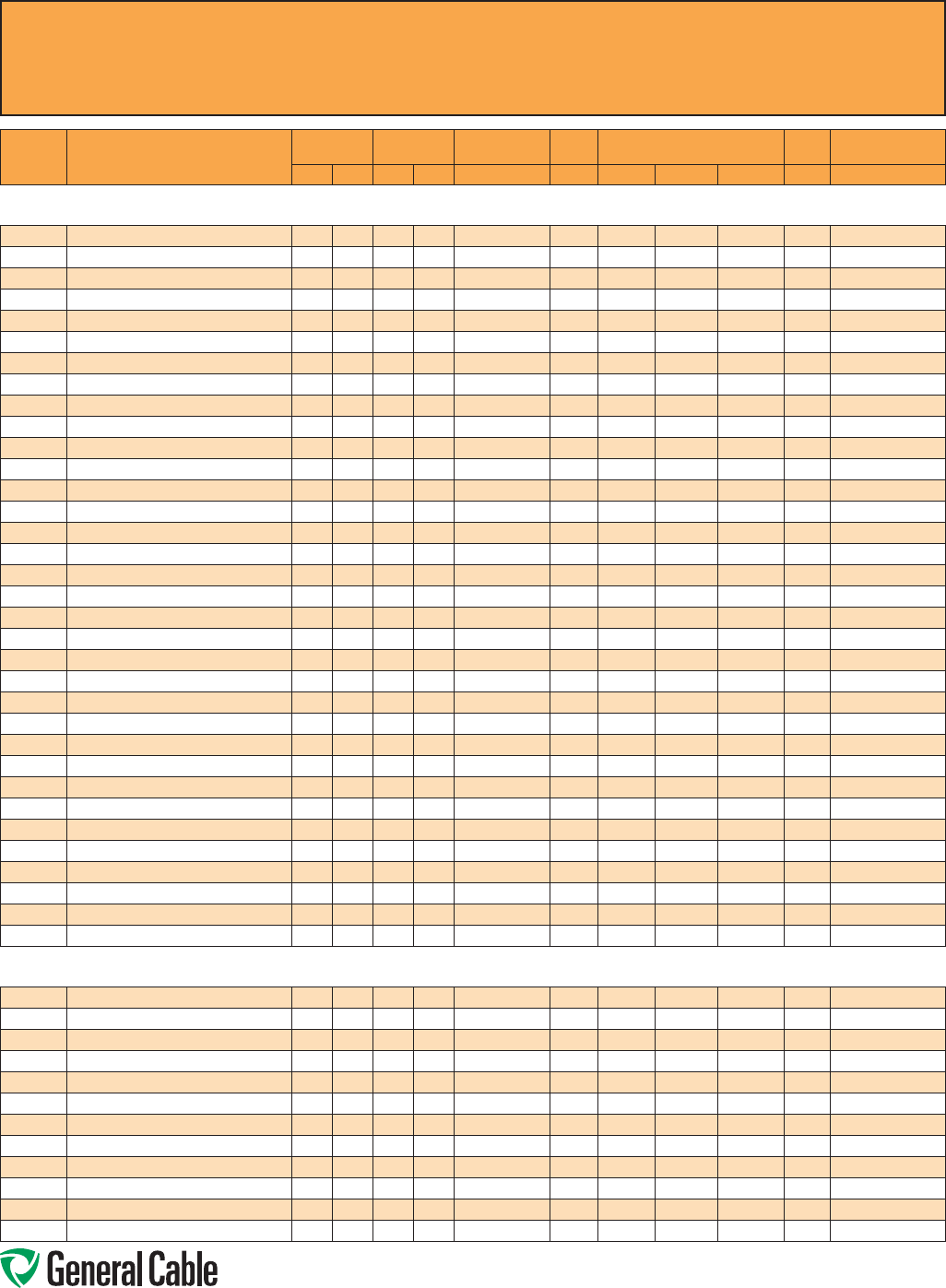
Phone: 888-593-3355
www.generalcable.com
CCW
®
Explosion-Proof Gland Cross-Reference
SPEC A010
April, 2010
CCW
PART
NUMBER PRODUCT DETAIL
NOMINAL ARMOR
O.D.
NOMINAL
OVERALL O.D. CROUSE-HINDS HAWKE
APPLETON (TMCX)
*end stop removed
Thomas &
Betts Hubbell/Killark
INCHES mm INCHES mm TMCX Series 711 Series Aluminum NP Brass Stainless Steel Spin-On X CMCXA
Power - 600 V
CCW® ARMORED POWER, 3/C VFD AND 4/C WITH BARE GROUND
9600.00103310 1 AWG 19W (42.4 mm²) 3/C VFD W/10 AWG 3/C GROUND 1.15 29.2 1.26 32.0 TMCX4140 C TMCX125A TMCX125NB TMCX125SS 4-125-100 CMCXAC100
9600.00104106 1 AWG 19W (42.4 mm²) 4/C W/6 AWG 1/C GROUND 1.29 32.8 1.40 35.6 TMCX4140 or TMCX5161 C2 TMCX125A* TMCX125NB* TMCX125SS* 4-125-120 CMCXAC2125
9600.00203310 2 AWG 7W (33.6 mm²) 3/C VFD W/10 AWG 3/C GROUND 1.02 25.9 1.13 28.7 TMCX3112 C TMCX100A* TMCX100NB* TMCX100SS* 4-100-080 CMCXAC100
9600.00204106 2 AWG 7W (33.6 mm²) 4/C W/6 AWG 1/C GROUND 1.15 29.2 1.26 32.0 TMCX4140 C TMCX125A TMCX125NB TMCX125SS 4-125-100 CMCXAC100
9600.00403312 4 AWG 7W (21.2 mm²) 3/C VFD W/12 AWG 3/C GROUND 0.89 22.6 0.99 25.1 TMCX3112 B or C TMCX100A TMCX100NB TMCX100SS 4-100-070 CMCXAB075 or CMCXAC100
9600.00404108 4 AWG 7W (21.2 mm²) 4/C W/8 AWG 1/C GROUND 0.97 24.6 1.08 27.4 TMCX3112 C TMCX100A TMCX100NB TMCX100SS 4-100-080 CMCXAB075 or CMCXAC100
9600.00603312 6 AWG 7W (13.3 mm²) 3/C VFD W/12 AWG 3/C GROUND 0.80 20.3 0.90 22.9 TMCX285 or TMCX3112 B TMCX075A* TMCX075NB* TMCX075SS* 4-100-050 CMCXAB075
9600.00604108 6 AWG 7W (13.3 mm²) 4/C W/8 AWG 1/C GROUND 0.89 22.6 0.99 25.1 TMCX3112 B or C TMCX100A TMCX100NB TMCX100SS 4-100-070 CMCXAB075 or CMCXAC100
9600.00803314 8 AWG 7W (8.36 mm²) 3/C VFD W/14 AWG 3/C GROUND 0.71 18.0 0.81 20.6 TMCX285 B TMCX075A TMCX075NB TMCX075SS 4-075-040 CMCXAB075
9600.00804110 8 AWG 7W (8.36 mm²) 4/C W/10 AWG 1/C GROUND 0.80 20.3 0.90 22.9 TMCX285 or TMCX3112 B TMCX075A* TMCX075NB* TMCX075SS* 4-100-050 CMCXAB075
9600.01003314 10 AWG 7W (5.26 mm²) 3/C VFD W/14 AWG 3/C GROUND 0.62 15.7 0.73 18.5 TMCX165 or TMCX285 A or B TMCX075A TMCX075NB TMCX075SS 4-075-030 CMCXAA050 or CMCXAB075
9600.01004314 10 AWG 7W (5.26 mm²) 4/C W/14 AWG 3/C GROUND 0.67 17.0 0.78 19.8 TMCX285 B TMCX075A TMCX075NB TMCX075SS 4-075-040 CMCXAB075
9600.01203316 12 AWG 7W (3.31 mm²) 3/C VFD W/16 AWG 3/C GROUND 0.58 14.7 0.69 17.5 TMCX165 A or B TMCX050A* TMCX050NB* TMCX050SS* 4-075-020 CMCXAA050 or CMCXAB075
9600.01204316 12 AWG 7W (3.31 mm²) 4/C W/16 AWG 3/C GROUND 0.67 17.0 0.78 19.8 TMCX285 B TMCX075A TMCX075NB TMCX075SS 4-075-040 CMCXAB075
9600.01403318 14 AWG 7W (2.08 mm²) 3/C VFD W/18 AWG 3/C GROUND 0.53 13.5 0.64 16.3 TMCX165 A or B TMCX050A* TMCX050NB* TMCX050SS* 4-075-020 CMCXAA050 or CMCXAB075
9600.01404318 14 AWG 7W (2.08 mm²) 4/C W/18 AWG 3/C GROUND 0.58 14.7 0.69 17.5 TMCX165 A or B TMCX050A* TMCX050NB* TMCX050SS* 4-075-020 CMCXAA050 or CMCXAB075
9600.100031110
1000 KCMIL 61W (507 mm²) 3/C VFD W/1/0 AWG 1/C GROUND
1.24 31.5 1.34 34.0 TMCX4140 C2 TMCX125A* TMCX125NB* TMCX125SS* 4-125-110 CMCXAC2125
9600.100041110 1000 KCMIL 61W (507 mm²) 4/C W/1/0 AWG 1/C GROUND 1.37 34.8 1.48 37.6 TMCX4140 or TMCX5161 C2 or D TMCX150A TMCX150NB TMCX150SS 4-150-130 CMCXAC2125 or CMCXAD200
9600.11003310 1/0 AWG 19W (53.5 mm²) 3/C VFD W/10 AWG 3/C GROUND 1.34 34.0 1.44 36.6 TMCX4140 or TMCX5161 C2 TMCX150A TMCX150NB TMCX150SS 4-150-130 CMCXAC2125
9600.11004106 1/0 AWG 19W (53.5 mm²) 4/C W/6 AWG 1/C GROUND 1.51 38.4 1.64 41.7 TMCX5161 C2 or D TMCX200SA TMCX200SNB TMCX200SSS 4-150-150 CMCXAC2125 or CMCXAD200
9600.21003310 2/0 AWG 19W (67.4 mm²) 3/C VFD W/10 AWG 3/C GROUND 1.74 44.2 1.87 47.5 TMCX6206 D TMCX200SA* TMCX200SNB* TMCX200SSS* 4-200-170 CMCXAD200
9600.21004106 2/0 AWG 19W (67.4 mm²) 4/C W/6 AWG 1/C GROUND 1.96 49.8 2.09 53.1 TMCX6206 or TMCX7247 D or E TMCX200A* TMCX200NB* TMCX200SS* 4-250-200 CMCXAD200 or CMCXAE250
9600.25003308 250 KCMIL 37W (127 mm²) 3/C VFD W/8 AWG 3/C GROUND 1.47 37.3 1.59 40.4 TMCX5161 C2 or D TMCX150A* TMCX150NB* TMCX150SS* 4-150-140 CMCXAC2125 or CMCXAD200
9600.25004104 250KCMIL 37W (127 mm²) 4/C W/4 AWG 1/C GROUND 1.65 41.9 1.78 45.2 TMCX6206 D TMCX200SA TMCX200SNB TMCX200SSS 4-200-160 CMCXAD200
9600.31003308 3/0 AWG 19W (85 mm²) 3/C VFD W/8 AWG 3/C GROUND 1.96 49.8 2.09 53.1 TMCX6206 or TMCX7247 D or E TMCX200A* TMCX200NB* TMCX200SS* 4-250-200 CMCXAD200 or CMCXAE250
9600.31004104 3/0 AWG 19W (85 mm²) 4/C W/4 AWG 1/C GROUND 2.19 55.6 2.35 59.7 TMCX7247 E TMCX250SA* TMCX250SNB* TMCX250SSS* 4-250-220 CMCXAE250
9600.35003307 350 KCMIL 37W (177 mm²) 3/C VFD W/7 AWG 3/C GROUND 1.60 40.6 1.73 43.9 TMCX5161 or TMCX6206 D TMCX200SA TMCX200SNB TMCX200SSS 4-200-160 CMCXAD200
9600.35004103 350 KCMIL 37W (177 mm²) 4/C W/3 AWG 1/C GROUND 1.78 45.2 1.91 48.5 TMCX6206 D or E TMCX200A TMCX200NB TMCX200SS 4-200-180 CMCXAD200 or CMCXAE250
9600.41003308 4/0 AWG 19W (107 mm²) 3/C VFD W/8 AWG 3/C GROUND 2.28 57.9 2.44 62.0 TMCX7247 E TMCX250A TMCX250NB TMCX250SS 4-250-230 CMCXAE250
9600.41004104 4/0 AWG 19W (107 mm²) 4/C W/4 AWG 1/C GROUND 2.49 63.2 2.65 67.3 TMCX8302 E or F TMCX250A* TMCX250NB* TMCX250SS* 4-300-240 CMCXAE250 or CMCXAF300
9600.50003306 500 KCMIL 37W (253 mm²) 3/C VFD W/6 AWG 3/C GROUND 2.75 69.9 2.92 74.2 TMCX8302 F TMCX300A TMCX300NB TMCX300SS 4-300-260 CMCXAF300
9600.50004102 500 KCMIL 37W (253 mm²) 4C W/2 AWG 1/C GROUND 3.03 77.0 3.21 81.5 TMCX9352 H TMCX350A TMCX350NB TMCX350SS — CMCXAH350
9600.75003305 750 KCMIL 61W (380 mm²) 3/C VFD W/5 AWG 3/C GROUND 3.11 79.0 3.30 83.8 TMCX9352 H TMCX350A TMCX350NB TMCX350SS 4-350-290 CMCXAH350
9600.75004101 750 KCMIL 61W (380 mm²) 4/C W/1 AWG 1/C GROUND 3.63 92.2 3.81 96.8 TMCX10402 — TMCX402400* — — 4-400-330 —
Power - 1000 V
CCW® ARMORED POWER, 1000 V, 3/C VFD WITH BARE GROUND
9675.00103310 1 AWG 19W (42.4 mm²) 3/C VFD W/10 AWG 3/C GROUND 1.36 34.6 1.46 37.1 TMCX4140 or TMCX5161 C2 TMCX150A TMCX150NB TMCX150SS 4-150-130 CMCXAC2125
9675.00203310 2 AWG 7W (33.6 mm²) 3/C VFD W/10 AWG 3/C GROUND 1.18 29.9 1.28 32.5 TMCX4140 C or C2 TMCX125A TMCX125NB TMCX125SS 4-125-100 CMCXAC100 or CMCXAC2125
9675.00403312 4 AWG 7W (21.2 mm²) 3/C VFD W/12 AWG 3/C GROUND 0.98 24.8 1.08 27.4 TMCX3112 CTMCX100A* TMCX100NB* TMCX100SS* 4-100-080 CMCXAC100
9675.00603312 6 AWG 7W (13.3 mm²) 3/C VFD W/12 AWG 3/C GROUND 0.91 23.2 1.02 26.0 TMCX3112 B or C TMCX100A TMCX100NB TMCX100SS 4-100-070 CMCXAB075 or CMCXAC100
9675.00803314 8 AWG 7W (8.36 mm²) 3/C VFD W/14 AWG 3/C GROUND 0.76 19.2 0.86 21.9 TMCX285 BTMCX075A* TMCX075NB* TMCX075SS* 4-100-050 CMCXAB075
9675.01003316 10 AWG 7W (5.26 mm²) 3/C VFD W/16 AWG 3/C GROUND 0.63 16.1 0.73 18.6 TMCX165 or TMCX285 A or B TMCX075A TMCX075NB TMCX075SS 4-075-030 CMCXAA050 or CMCXAB075
9675.01203318 12 AWG 7W (3.31 mm²) 3/C VFD W/18 AWG 3/C GROUND 0.60 15.3 0.70 17.8 TMCX165 or TMCX285 A or B TMCX075A TMCX075NB TMCX075SS 4-075-030 CMCXAA050 or CMCXAB075
9675.11003310 1/0 AWG 19W (53.5 mm²) 3/C VFD W/10 AWG 3/C GROUND 1.42 36.0 1.52 38.6 TMCX5161 C2 or D TMCX150A TMCX150NB TMCX150SS 4-15 0-140 CMCXAC2125 or CMCXAD200
9675.21003310 2/0 AWG 19W (67.4 mm²) 3/C VFD W/10 AWG 3/C GROUND 1.56 39.6 1.66 42.2 TMCX5161 C2 or D TMCX200SA TMCX200SNB TMCX200SSS 4-150-150 CMCXAC2125 or CMCXAD200
9675.25003308 250 KCMIL 37W (127 mm²) 3/C VFD W/8 AWG 3/C GROUND 1.90 48.2 2.01 51.1 TMCX6206 D or E TMCX200A TMCX200NB TMCX200SS 4-200-190 CMCXAD200 or CMCXAE250
9675.41003308 4/0 AWG 19W (107 mm²) 3/C VFD W/8 AWG 3/C GROUND 1.75 44.4 1.85 47.0 TMCX6206 DTMCX200SA* TMCX200SNB* TMCX200SSS* 4-200-170 CMCXAD200
9675.50003306 500 KCMIL 37W (253 mm²) 3/C VFD W/6 AWG 3/C GROUND 2.48 63.0 2.59 65.8 TMCX7247 or TMCX8302 E or F TMCX250A* TMCX250NB* TMCX250SS* 4-300-240 CMCXAE250 or CMCXAF300
Allinformationinthiscross-referenceispresentedsolelyasaguidetoproductselectionandisbelievedtobereliable.Allprinting
errorsaresubjecttocorrectioninsubsequentreleasesofthiscatalog.AlthoughGeneralCablehastakenprecautionstoensurethe
accuracyoftheproductcross-referenceatthetimeofpublication,thespecificationsofallproductscontainedhereinaresubjectto
changebyglandmanufacturerswithoutnotice.
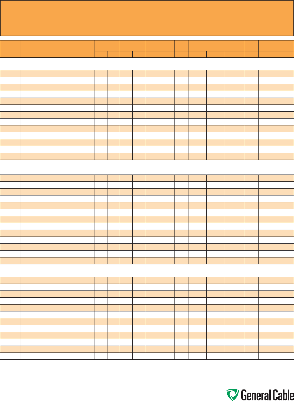
Phone: 888-593-3355
www.generalcable.com
CCW
®
Explosion-Proof Gland Cross-Reference
SPEC A010
April, 2010
CCW
PART
NUMBER PRODUCT DETAIL
NOMINAL ARMOR
O.D.
NOMINAL
OVERALL O.D. CROUSE-HINDS HAWKE
APPLETON (TMCX)
*end stop removed
Thomas &
Betts Hubbell/Killark
INCHES mm INCHES mm TMCX Series 711 Series Aluminum NP Brass Stainless Steel Spin-On X CMCXA
Power - 2.4 kV
CCW® ARMORED POWER, 2.4 kV, NONSHIELDED, 3/C VFD WITH BARE GROUND OR MV-90 W/90 MILS INSULATION
9700.00103308 1 AWG 19W (42.4 mm²) 3/C MC-HL W/8 AWG 3/C GROUND 1.42 36.1 1.53 38.9 TMCX5161 C2 or D TMCX150A TMCX150NB TMCX150SS 4-150-140 CMCXAC2125 or CMCXAD200
9700.00203310 2 AWG 7W (33.6 mm²) 3/C MC-HL W/10 AWG 3/C GROUND 1.34 34.0 1.45 36.8 TMCX4140 or TMCX5161 C2 TMCX150A TMCX150NB TMCX150SS 4-150-130 CMCXAC2125
9700.00403310 4 AWG 7W (21.2 mm²) 3/C MC-HL W/10 AWG 3/C GROUND 1.19 30.2 1.30 33.0 TMCX4140 C or C2 TMCX125A TMCX125NB TMCX125SS 4-125-110 CMCXAC100 or CMCXAC2125
9700.00603310 6 AWG 7W (13.3 mm²) 3/C MC-HL W/10 AWG 3/C GROUND 1.06 26.9 1.17 29.7 TMCX3112 C TMCX100A* TMCX100NB* TMCX100SS* 4-125-090 CMCXAC100
9700.00803312 8 AWG 7W (8.36 mm²) 3/C MC-HL W/12 AWG 3/C GROUND 0.97 24.6 1.08 27.4 TMCX3112 C TMCX100A TMCX100NB TMCX100SS 4-100-080 CMCXAB075 or CMCXAC100
9700.10003304 1000 KCMIL 61W (507 mm²) 3/C MC-HL W/4 AWG 3/C GROUND 3.41 86.6 3.59 91.2 TMCX9352 H TMCX350A* TMCX350NB* TMCX350SS* 4-350-310 CMCXAH350
9700.11003308 1/0 AWG 19W (53.5 mm²) 3/C MC-HL W/8 AWG 3/C GROUND 1.51 38.4 1.65 41.9 TMCX5161 C2 or D TMCX200SA TMCX200SNB TMCX200SSS 4-150-150 CMCXAC2125 or CMCXAD200
9700.21003308 2/0 AWG 19W (67.4 mm²) 3/C MC-HL W/8 AWG 3/C GROUND 1.60 40.6 1.73 43.9 TMCX5161 or TMCX6206 D TMCX200SA TMCX200SNB TMCX200SSS 4-200-160 CMCXAD200
9700.25003307 250 KCMIL 37W (127 mm²) 3/C MC-HL W/7 AWG 3/C GROUND 1.96 49.8 2.09 53.1 TMCX6206 or TMCX7247 D or E TMCX200A* TMCX200NB* TMCX200SS* 4-250-200 CMCXAD200 or CMCXAE250
9700.35003306 350 KCMIL 37W (177 mm²) 3/C MC-HL W/6 AWG 3/C GROUND 2.19 55.6 2.32 58.9 TMCX7247 E TMCX250SA* TMCX250SNB* TMCX250SSS* 4-250-220 CMCXAE250
9700.41003307 4/0 AWG 19W (107 mm²) 3/C MC-HL W/7 AWG 3/C GROUND 1.83 46.5 1.96 49.8 TMCX6206 D or E TMCX200A TMCX200NB TMCX200SS 4-200-180 CMCXAD200 or CMCXAE250
9700.50003305 500 KCMIL 37W (253 mm²) 3/C MC-HL W/5 AWG 3/C GROUND 2.45 62.2 2.61 66.3 TMCX7247 or TMCX8302 E or F TMCX250A* TMCX250NB* TMCX250SS* 4-300-240 CMCXAE250 or CMCXAF300
9700.75003304 750 KCMIL 37W (380 mm²) 3/C MC-HL W/4 AWG 3/C GROUND 2.93 74.4 3.10 78.7 TMCX8302 F or H TMCX350A TMCX350NB TMCX350SS — CMCXAF300 or CMCXAH350
Power 5 kV (133%) / 8 kV (100%)
CCW® ARMORED POWER, 5 kV 133%/8 kV 100%, SHIELDED, 3/C VFD WITH BARE GROUND OR MV-105 W/115 MILS INSULATION
9800.00103308 1 AWG 19W (42.4 mm²) 3/C MC-HL W/8 AWG 3/C GROUND 1.69 42.9 1.82 46.2 TMCX6206 D TMCX200SA* TMCX200SNB* TMCX200SSS* 4-200-170 CMCXAD200
9800.00203310 2 AWG 7W (33.6 mm²) 3/C MC-HL W/10 AWG 3/C GROUND 1.64 41.7 1.78 45.2 TMCX6206 D TMCX200SA TMCX200SNB TMCX200SSS 4-200-160 CMCXAD200
9800.00403310 4 AWG 7W (21.2 mm²) 3/C MC-HL W/10 AWG 3/C GROUND 1.51 38.4 1.65 41.9 TMCX5161 C2 or D TMCX200SA TMCX200SNB TMCX200SSS 4-150-150 CMCXAC2125 or CMCXAD200
9800.00603310 6 AWG 7W (13.3 mm²) 3/C MC-HL W/10 AWG 3/C GROUND 1.37 34.8 1.48 37.6 TMCX4140 or TMCX5161 C2 or D TMCX150A TMCX150NB TMCX150SS 4-150-130 CMCXAC2125 or CMCXAD200
9800.00803312 8 AWG 7W (8.36 mm²) 3/C MC-HL W/12 AWG 3/C GROUND 1.34 34.0 1.45 36.8 TMCX4140 or TMCX5161 C2 TMCX150A TMCX150NB TMCX150SS 4-150-130 CMCXAC2125
9800.10003304 1000 KCMIL 61W (507 mm²) 3/C MC-HL W/4 AWG 3/C GROUND 3.76 95.5 3.94 100.1 TMCX10402 — TMCX402400* — — 4-400-330 —
9800.11003308 1/0 AWG 19W (53.5 mm²) 3/C MC-HL W/8 AWG 3/C GROUND 1.78 45.2 1.91 48.5 TMCX6206 D or E TMCX200A TMCX200NB TMCX200SS 4-200-180 CMCXAD200 or CMCXAE250
9800.21003308 2/0 AWG 19W (67.4 mm²) 3/C MC-HL W/8 AWG 3/C GROUND 1.92 48.8 2.05 52.1 TMCX6206 D or E TMCX200A TMCX200NB TMCX200SS 4-200-190 CMCXAD200 or CMCXAE250
9800.25003307 250 KCMIL 37W (127 mm²) 3/C MC-HL W/7 AWG 3/C GROUND 2.23 56.6 2.36 59.9 TMCX7247 E TMCX250SA* TMCX250SNB* TMCX250SSS* 4-250-220 CMCXAE250
9800.35003306 350 KCMIL 37W (177 mm²) 3/C MC-HL W/6 AWG 3/C GROUND 2.45 62.2 2.61 66.3 TMCX7247 or TMCX8302 E or F TMCX250A* TMCX250NB* TMCX250SS* 4-300-240 CMCXAE250 or CMCXAF300
9800.41003307 4/0 AWG 19W (107 mm²) 3/C MC-HL W/7 AWG 3/C GROUND 2.15 54.6 2.28 57.9 TMCX7247 E TMCX250SA TMCX250SNB TMCX250SSS 4-250-210 CMCXAE250
9800.50003305 500 KCMIL 37W (253 mm²) 3/C MC-HL W/5 AWG 3/C GROUND 2.75 69.9 2.92 74.2 TMCX8302 F TMCX300A TMCX300NB TMCX300SS 4-300-260 CMCXAF300
9800.75003304 750 KCMIL 61W (380 mm²) 3/C MC-HL W/4 AWG 3/C GROUND 3.32 84.3 3.50 88.9 TMCX9352 H TMCX350A* TMCX350NB* TMCX350SS* — CMCXAH350
Power - 8 kV (133%)
CCW® ARMORED POWER, 8 kV 133%, SHIELDED, 3/C VFD WITH BARE GROUND OR MV-105 W/140 MILS INSULATION
9815.00103308 1 AWG 19W (42.4 mm²) 3/C MC-HL W/8 AWG 3/C GROUND 1.93 49.0 2.06 52.3 TMCX6206 or TMCX7247 D or E TMCX200A TMCX200NB TMCX200SS 4-200-190 CMCXAD200 or CMCXAE250
9815.00203310 2 AWG 7W (33.6 mm²) 3/C MC-HL W/10 AWG 3/C GROUND 1.85 47. 0 1.98 50.3 TMCX6206 D or E TMCX200A TMCX200NB TMCX200SS 4-200-190 CMCXAD200 or CMCXAE250
9815.00403310 4 AWG 7W (21.2 mm²) 3/C MC-HL W/10 AWG 3/C GROUND 1.70 43.2 1.83 46.5 TMCX6206 D TMCX200SA* TMCX200SNB* TMCX200SSS* 4-200 -170 CMCXAD200
9815.00603310 6 AWG 7W (13.3 mm²) 3/C MC-HL W/10 AWG 3/C GROUND 1.60 40.6 1.73 43.9 TMCX5161 or TMCX6206 D TMCX200SA TMCX200SNB TMCX200SSS 4-200-160 CMCXAD200
9815.10003304
1000 KCMIL 61W (507 mm²) 3/C MC-HL W/4 AWG 3/C GROUND
3.98 101.1 4.16 105.7 TMCX10402 — TMCX402400* — — 4-400-350 —
9815.11003308 1/0 AWG 19W (53.5 mm²) 3/C MC-HL W/8 AWG 3/C GROUND 2.03 51.6 2.16 54.9 TMCX6206 or TMCX7247 E TMCX200A* TMCX200NB* TMCX200SS* 4-250-200 CMCXAE250
9815.21003308 2/0 AWG 19W (67.4 mm²) 3/C MC-HL W/8 AWG 3/C GROUND 2.14 54.4 2.27 57.7 TMCX7247 E TMCX250SA TMCX250SNB TMCX250SSS 4-250-210 CMCXAE250
9815.25003307 250 KCMIL 37W (127 mm²) 3/C MC-HL W/7 AWG 3/C GROUND 2.59 65.8 2.75 69.9 TMCX8302 F TMCX300A TMCX300NB TMCX300SS 4-300-250 CMCXAF300
9815.35003306 350 KCMIL 37W (177 mm²) 3/C MC-HL W/6 AWG 3/C GROUND 2.85 72.4 3.01 76.5 TMCX8302 F TMCX300A* TMCX300NB* TMCX300SS* — CMCXAF300
9815.41003307 4/0 AWG 19W (107 mm²) 3/C MC-HL W/7 AWG 3/C GROUND 2.40 61.0 2.56 65.0 TMCX7247 E or F TMCX250A TMCX250NB TMCX250SS 4-300-240 CMCXAE250 or CMCXAF300
9815.50003305 500 KCMIL 37W (253 mm²) 3/C MC-HL W/5 AWG 3/C GROUND 3.19 81.0 3.37 85.6 TMCX9352 H TMCX350A TMCX350NB TMCX350SS 4-350-300 CMCXAH350
9815.75003304 750 KCMIL 61W (380 mm²) 3/C MC-HL W/4 AWG 3/C GROUND 3.68 93.5 3.86 98.0 TMCX10402 — TMCX402400* — — 4-400-330 —
Allinformationinthiscross-referenceispresentedsolelyasaguidetoproductselectionandisbelievedtobereliable.Allprintingerrorsaresubjecttocorrectioninsubsequent
releasesofthiscatalog.AlthoughGeneralCablehastakenprecautionstoensuretheaccuracyoftheproductcross-referenceatthetimeofpublication,thespecificationsofall
productscontainedhereinaresubjecttochangebyglandmanufacturerswithoutnotice.
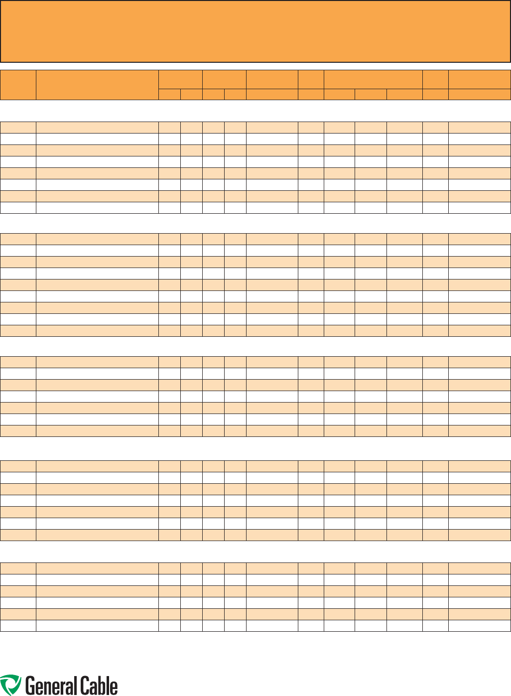
Phone: 888-593-3355
www.generalcable.com
CCW
®
Explosion-Proof Gland Cross-Reference
SPEC A010
April, 2010
CCW
PART
NUMBER PRODUCT DETAIL
NOMINAL ARMOR
O.D.
NOMINAL
OVERALL O.D. CROUSE-HINDS HAWKE
APPLETON (TMCX)
*end stop removed
Thomas &
Betts Hubbell/Killark
INCHES mm INCHES mm TMCX Series 711 Series Aluminum NP Brass Stainless Steel Spin-On X CMCXA
Power - 15 kV (100%)
CCW® ARMORED POWER, 15 kV 100%, SHIELDED, 3/C WITH BARE GROUND OR MV-105 175 MILS INSULATION
9825.00103104 1 AWG 19W (42.4 mm²) 3/C MC-HL W/4 AWG GROUND 2.01 51.1 2.15 54.6 TMCX6206 or TMCX7247 E TMCX200A* TMCX200NB* TMCX200SS* 4-250-200 CMCXAE250
9825.00203106 2 AWG 7W (33.6 mm²) 3/C MC-HL W/6 AWG GROUND 1.96 49.8 2.05 52.1 TMCX6206 or TMCX7247 D or E TMCX200A* TMCX200NB* TMCX200SS* 4-250-200 CMCXAD200 or CMCXAE250
9825.11003104 1/0 AWG 19W (53.5 mm²) 3/C MC-HL W/4 AWG GROUND 2.10 53.3 2.24 56.9 TMCX7247 E TMCX250SA TMCX250SNB TMCX250SSS 4-250-210 CMCXAE250
9825.21003104 2/0 AWG 19W (67.4 mm²) 3/C MC-HL W/4 AWG GROUND 2.19 55.6 2.36 59.9 TMCX7247 E TMCX250SA* TMCX250SNB* TMCX250SSS* 4-250-220 CMCXAE250
9825.25003103 250 KCMIL 37W (127 mm²) 3/C MC-HL W/3 AWG GROUND 2.58 65.5 2.74 69.6 TMCX8302 F TMCX300A TMCX300NB TMCX300SS 4-300-250 CMCXAF300
9825.35003102 350 KCMIL 37W (177 mm²) 3/C MC-HL W/2 AWG GROUND 2.85 72.4 3.01 76.5 TMCX8302 F TMCX300A* TMCX300NB* TMCX300SS* — CMCXAF300
9825.41003103 4/0 AWG 19W (107 mm²) 3/C MC-HL W/3 AWG GROUND 2.45 62.2 2.61 66.3 TMCX7247 or TMCX8302 E or F TMCX250A* TMCX250NB* TMCX250SS* 4-300-240 CMCXAE250 or CMCXAF300
9825.50003101 500 KCMIL 37W (253 mm²) 3/C MC-HL W/1 AWG GROUND 3.16 80.3 3.34 84.8 TMCX9352 H TMCX350A TMCX350NB TMCX350SS 4-350-290 CMCXAH350
Power - 15 kV (133%)
CCW® ARMORED POWER, 15 kV 133%, SHIELDED, 3/C WITH BARE GROUND OR MV-105 220 MILS INSULATION
9835.00103104 1 AWG 19W (42.4 mm²) 3/C MC-HL W/4 AWG GROUND 2.23 56.6 2.36 59.9 TMCX7247 E TMCX250SA* TMCX250SNB* TMCX250SSS* 4-250-220 CMCXAE250
9835.00203106 2 AWG 7W (33.6 mm²) 3/C MC-HL W/6 AWG GROUND 2.15 54.6 2.28 57.9 TMCX7247 E TMCX250SA TMCX250SNB TMCX250SSS 4-250-210 CMCXAE250
9835.11003104 1/0 AWG 19W (53.5 mm²) 3/C MC-HL W/4 AWG GROUND 2.32 58.9 2.48 63.0 TMCX7247 E or F TMCX250A TMCX250NB TMCX250SS 4-250-230 CMCXAE250 or CMCXAF300
9835.21003104 2/0 AWG 19W (67.4 mm²) 3/C MC-HL W/4 AWG GROUND 2.40 61.0 2.56 65.0 TMCX7247 E or F TMCX250A TMCX250NB TMCX250SS 4-300-240 CMCXAE250 or CMCXAF300
9835.25003103 250 KCMIL 37W (127 mm²) 3/C MC-HL W/3 AWG GROUND 2.75 69.9 2.92 74.2 TMCX8302 F TMCX300A TMCX300NB TMCX300SS 4-300-260 CMCXAF300
9835.35003102 350 KCMIL 37W (177 mm²) 3/C MC-HL W/2 AWG GROUND 3.03 77.0 3.21 81.5 TMCX9352 H TMCX350A TMCX350NB TMCX350SS — CMCXAH350
9835.41003103 4/0 AWG 19W (107 mm²) 3/C MC-HL W/3 AWG GROUND 2.62 66.5 2.79 70.9 TMCX8302 F TMCX300A TMCX300NB TMCX300SS 4-300-250 CMCXAF300
9835.50003101 500 KCMIL 37W (253 mm²) 3/C MC-HL W/1 AWG GROUND 3.32 84.3 3.50 88.9 TMCX9352 H TMCX350A* TMCX350NB* TMCX350SS* — CMCXAH350
9835.750031110 750 KCMIL 61W (380 mm²) 3/C MC-HL W/1/0 AWG GROUND 3.80 96.5 3.98 101.1 TMCX10402 — TMCX402400* — — — —
Power - 25 kV (100%)
CCW® ARMORED POWER, 25 kV 100%, SHIELDED, 3/C WITH BARE GROUND OR MV-105 260 MILS INSULATION
9845.00103104 1 AWG 19W (42.4 mm²) 3/C MC-HL W/4 AWG GROUND 2.45 62.2 2.61 66.3 TMCX7247 or TMCX8302 E or F TMCX250A* TMCX250NB* TMCX250SS* 4-300-240 CMCXAE250 or CMCXAF300
9845.11003104 1/0 AWG 19W (53.5 mm²) 3/C MC-HL W/4 AWG GROUND 2.53 64.3 2.69 68.3 TMCX8302 E or F TMCX250A* TMCX250NB* TMCX250SS* 4-300-250 CMCXAE250 or CMCXAF300
9845.21003104 2/0 AWG 19W (67.4 mm²) 3/C MC-HL W/4 AWG GROUND 2.62 66.5 2.79 70.9 TMCX8302 F TMCX300A TMCX300NB TMCX300SS 4-300-250 CMCXAF300
9845.25003103 250 KCMIL 37W (127 mm²) 3/C MC-HL W/3 AWG GROUND 3.07 78.0 3.25 82.6 TMCX9352 H TMCX350A TMCX350NB TMCX350SS 4-350-290 CMCXAH350
9845.35003102 350 KCMIL 37W (177 mm²) 3/C MC-HL W/2 AWG GROUND 3.32 84.3 3.50 88.9 TMCX9352 H TMCX350A* TMCX350NB* TMCX350SS* — CMCXAH350
9845.41003103 4/0 AWG 19W (107 mm²) 3/C MC-HL W/3 AWG GROUND 2.93 74.4 3.10 78.7 TMCX8302 F or H TMCX350A TMCX350NB TMCX350SS — CMCXAF300 or CMCXAH350
9845.50003101 500 KCMIL 37W (253 mm²) 3/C MC-HL W/1 AWG GROUND 3.62 91.9 3.81 96.8 TMCX10402 — TMCX402400* — — 4-400-330 —
Power 25 kV (133%)/35 kV (100%)
CCW® ARMORED POWER, 25 kV 133%/35 kV 100%, SHIELDED, 3/C WITH BARE GROUND OR MV-105 345 MILS INSULATION
9855.00103104 1 AWG 19W (42.4 mm²) 3/C MC-HL W/4 AWG GROUND 2.89 73.4 3.05 77.5 TMCX8302 F TMCX300A* TMCX300NB* TMCX300SS* — CMCXAF300
9855.11003104 1/0 AWG 19W (53.5 mm²) 3/C MC-HL W/4 AWG GROUND 2.98 75.7 3.14 79.8 TMCX8302 or TMCX9352 F or H TMCX350A TMCX350NB TMCX350SS — CMCXAF300 or CMCXAH350
9855.21003104 2/0 AWG 19W (67.4 mm²) 3/C MC-HL W/4 AWG GROUND 3.11 79.0 3.30 83.8 TMCX9352 H TMCX350A TMCX350NB TMCX350SS 4-350-290 CMCXAH350
9855.25003103 250 KCMIL 37W (127 mm²) 3/C MC-HL W/3 AWG GROUND 3.63 92.2 3.81 96.8 TMCX10402 — TMCX402400* — — 4-400-330 -—
9855.35003102 350 KCMIL 37W (177 mm²) 3/C MC-HL W/2 AWG GROUND 3.76 95.5 3.94 100.1 TMCX10402 — TMCX402400* — — 4-400-330 —
9855.41003103 4/0 AWG 19W (107 mm²) 3/C MC-HL W/3 AWG GROUND 3.41 86.6 3.60 91.4 TMCX9352 H TMCX350A* TMCX350NB* TMCX350SS* 4-350-310 CMCXAH350
9855.50003101 500 KCMIL 37W (253 mm²) 3/C MC-HL W/1 AWG GROUND 4.10 104.1 4.23 107.4 — — — — — — —
Power 35 kV (133%)
CCW® ARMORED POWER, 35 kV 133%, SHIELDED, 3/C WITH BARE GROUND OR MV-105 420 MILS INSULATION
9875.11003104 1/0 AWG 19W (53.5 mm²) 3/C MC-HL W/4 AWG GROUND 3.41 86.6 3.59 91.2 TMCX9352 H TMCX350A* TMCX350NB* TMCX350SS* 4-350-310 CMCXAH350
9875.21003104 2/0 AWG 19W (67.4 mm²) 3/C MC-HL W/4 AWG GROUND 3.63 92.2 3.81 96.8 TMCX10402 — TMCX402400* — — 4-400-330 —
9875.25003103 250 KCMIL 37W (127 mm²) 3/C MC-HL W/3 AWG GROUND 3.98 101.1 4.16 105.7 TMCX10402 — TMCX402400* — — 4-400-350 —
9875.35003102 350 KCMIL 37W (177 mm²) 3/C MC-HL W/2 AWG GROUND 4.10 104.1 4.29 109.0 — — — — — —- —
9875.41003103 4/0 AWG 19W (107 mm²) 3/C MC-HL W/3 AWG GROUND 3.80 96.5 3.98 101.1 TMCX10402 — TMCX402400* — — — —
9875.50003101 500 KCMIL 37W (253 mm²) 3/C MC-HL W/1 AWG GROUND 4.45 113.0 4.63 117.6 — — — — — — —
Allinformationinthiscross-referenceispresentedsolelyasaguidetoproductselectionandisbelievedtobereliable.Allprintingerrorsaresubjecttocorrectioninsubsequent
releasesofthiscatalog.AlthoughGeneralCablehastakenprecautionstoensuretheaccuracyoftheproductcross-referenceatthetimeofpublication,thespecificationsofall
productscontainedhereinaresubjecttochangebyglandmanufacturerswithoutnotice.

Phone: 888-593-3355
www.generalcable.com
CCW
®
Part Number Cross-Reference –
Okonite C-L-X
®
to General Cable CCW
®
SPEC A015
January, 2013
Okonite C-L-X®
Part Number
General Cable CCW®
Part Number
Okonite C-L-X®
Part Number
General Cable CCW®
Part Number
Okonite C-L-X®
Part Number
General Cable CCW®
Part Number
546-31-3002 9525.01402000 546-31-3927 9650.123144000 561-15-3304 9250.18041222
546-31-3003 9525.01403000 546-31-3950 9650.124143000 561-15-3308 9250.18081222
546-31-3004 9525.01404000 546-31-3956 9650.104143000 561-15-3312 9250.18121222
546-31-3005 9525.01405000 546-31-3958 9650.104124000 561-15-3316 9250.18161222
546-31-3007 9525.01407000 546-31-3983 9650.123143000 561-15-3324 9250.18241222
546-31-3009 9525.01409000 546-31-3984 9625.103124110 561-15-3336 9250.18361222
546-31-3012 9525.01412000 546-31-3987 9650.104144000 561-15-3404 9250.16041222
546-31-3019 9525.01419000 546-31-3988 9650.104123000 561-15-3408 9250.16081222
546-31-3037 9525.01437000 546-31-3990 9650.103123000 561-15-3412 9250.16121222
546-31-3082 9525.01202000 546-31-3992 9650.103144000 561-15-3416 9250.16161222
546-31-3083 9525.01203000 561-10-3202 9250.20021221 561-15-3424 9250.16241222
546-31-3084 9525.01204000 561-10-3204 9250.20041221 561-15-3436 9250.16361222
546-31-3085 9525.01205000 561-10-3206 9250.20061221 561-60-3402 9350.16020001
546-31-3087 9525.01207000 561-10-3208 9250.20081221 561-60-3404 9350.16040001
546-31-3089 9525.01209000 561-10-3210 9250.20101221 561-60-3406 9350.16060001
546-31-3092 9525.01212000 561-10-3212 9250.20121221 561-60-3408 9350.16080001
546-31-3099 9525.01219000 561-10-3216 9250.20161221 561-60-3410 9350.16100001
546-31-3117 9525.01237000 561-10-3220 9250.20201221 561-60-3412 9350.16120001
546-31-3162 9525.01002000 561-10-3224 9250.20241221 561-60-3416 9350.16160001
546-31-3163 9525.01003000 561-10-3236 9250.20361221 561-60-3420 9350.16200001
546-31-3164 9525.01004000 561-10-3250 9250.20501221 561-60-3424 9350.16240001
546-31-3165 9525.01005000 561-10-3302 9250.18021221 561-60-3436 9350.16360001
546-31-3167 9525.01007000 561-10-3304 9250.180 41221 561-60-3450 9350.16500001
546-31-3169 9525.01009000 561-10 -3306 925 0.180 61221 561-65-3404 9350.16040002
546-31-3172 9525.01012000 561-10-3308 9250.18081221 561-65-3408 9350.16080002
546-31-3402 9500.01402114 561-10-3310 9250.18101221 561-65-3412 9350.16120002
546-31-3403 9600.01403318 561-10-3312 9250.18121221 561-65-3416 9350.16160002
546-31-3404 9600.01404318 561-10-3316 9250.181612 21 561-65-3424 9350.16240002
546-31-3406 9500.01406114 561-10-3320 9250.18201221 561-65-3436 9350.16360002
546-31-3408 9500.01408114 561-10-3324 9250.18241221 564-10-3202 9225.20021221
546-31-3411 9500.01411114 561-10-3336 9250.18361221 564-10-3204 9225.20041221
546-31-3418 9500.01418114 561-10-3350 9250.18501221 564-10-3206 9225.20061221
546-31-3436 9500.01436114 561-10-3402 9250.16021221 564-10-3208 9225.20081221
546-31-3452 9500.01202112 561-10-3404 9250.16041221 564-10-3210 9225.20101221
546-31-3453 9600.01203316 561-10 -3406 925 0.160 61221 564-10-3212 9225.20121221
546-31-3454 9600.01204316 561-10-3408 9250.16081221 564-10-3216 9225.20161221
546-31-3456 9500.01206112 561-10-3410 9250.16101221 564-10-3220 9225.20201221
546-31-3458 9500.01208112 561-10-3412 9250.16121221 564-10-3224 9225.20241221
546-31-3461 9500.01211112 561-10-3416 9250.16161221 564-10-3236 9225.20361221
546-31-3468 9500.01218112 561-10-3420 9250.16201221 564-10-3250 9225.20501221
546-31-3486 9500.01236112 561-10-3424 9250.16241221 564-10-3302 9225.18021221
546-31-3502 9500.01002110 561-10-3436 9250.16361221 564-10-3304 9225.18041221
546-31-3503 9600.01003314 561-10-3450 9250.16501221 564-10-3306 9225.18061221
546-31-3504 9600.01004314 561-15-3204 9250.20041222 564-10-3308 9225.18081221
546-31-3506 9500.01006110 561-15-3208 9250.20081222 564-10-3310 9225.18101221
546-31-3508 9500.01008110 561-15-3212 9250.20121222 564-10-3312 9225.18121221
546-31-3511 9500.01011110 561-15-3216 9250.20161222 564-10-3316 9225.18161221
546-31-3758 9650.103143000 561-15-3224 9250.20241222 564-10-3320 9225.18201221
546-31-3925 9650.124144000 561-15-3236 9250.20361222 564-10-3324 9225.18241221
Allinformationinthiscross-referenceispresentedsolelyasaguidetoproductselectionandisbelievedtobereliable.Allprinting
errorsaresubjecttocorrectioninsubsequentreleasesofthiscatalog.AlthoughGeneralCablehastakenprecautionstoensurethe
accuracyoftheproductcross-referenceatthetimeofpublication,thespecificationsofallproductscontainedhereinaresubjectto
changebyglandmanufacturerswithoutnotice.
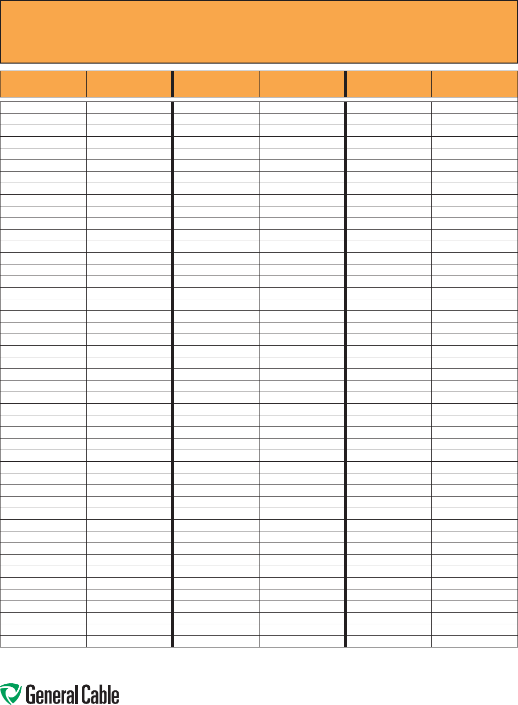
Phone: 888-593-3355
www.generalcable.com
CCW
®
Part Number Cross-Reference –
Okonite C-L-X
®
to General Cable CCW
®
SPEC A015
January, 2013
Okonite C-L-X®
Part Number
General Cable CCW®
Part Number
Okonite C-L-X®
Part Number
General Cable CCW®
Part Number
Okonite C-L-X®
Part Number
General Cable CCW®
Part Number
564-10-3336 9225.18361221 564-65-3408 9325.16080002 571-21-3244 9700.50003305
564-10-3350 9225.18501221 564-65-3412 9325.16120002 571-21-3248 9700.75003304
564-10-3401 9225.16010001 564-65-3416 9325.16160002 571-21-3252 9700.10003304
564-10-3402 9225.16021221 564-65-3424 9325.16240002 571-22-3696 9800.00603310
564-10-3404 9225.16041221 564-65-3436 9325.16360002 571-22-3698 9800.00403310
564-10-3406 9225.16061221 567-86-3402 9150.16021201 571-22-3706 9800.00203310
564-10-3408 9225.16081221 567-86-3404 9150.160 41201 571-22-3708 9800.00103308
564-10-3410 9225.16101221 567-86-3408 9150.16081201 571-22-3710 9800.11003308
564-10-3412 9225.16121221 567-86-3412 9150.16121201 571-22-3717 9800.21003308
564-10-3416 9225.16161221 567-86 -3424 9150.16241201 571-22-3725 9800.41003307
564-10-3420 9225.16201221 567-86-3436 9150.16361201 571-22-3727 9800.25003307
564-10-3424 9225.16241221 567-86-3450 9150.16501201 571-22-3748 9800.75003304
564-10-3436 9225.16361221 567-87-3402 9150.16021202 571-22-3751 9800.10003304
564-10-3450 9225.16501221 567-87-3404 9150.16041202 571-22-3838 9800.35003306
564-15-3204 9225.20041222 567-87-3408 9150.16081202 571-22-3846 9800.50003305
564-15-3208 9225.20081222 567-87-3412 9150.16121202 571-23-3204 9825.00203106
564-15-3212 9225.20121222 567-87-3424 915 0.16241202 571-23-3208 9825.00103104
564-15-3216 9225.20161222 567-87-3436 9150.16361202 571-23-3212 9825.11003104
564-15-3224 9225.20241222 567-87-3450 9150.16501202 571-23-3216 9825.21003104
564-15-3236 9225.20361222 567-93-3801 9125.16010001 571-23-3224 9825.41003103
564-15-3304 9225.18041222 567-93-3802 9125.16021201 571-23-3228 9825.25003103
564-15-3308 9225.18081222 567-93-3804 9125.16041201 571-23-3236 9825.35003102
564-15-3312 9225.18121222 567-93-3808 9125.16081201 571-23-3244 9825.50003101
564-15-3316 9225.18161222 567-93-3812 9125.16121201 571-23-3504 9835.00203106
564-15-3324 9225.18241222 567-93-3816 9125.16161201 571-23-3508 9835.00103104
564-15-3336 9225.18361222 567-93-3824 9125.16241201 571-23-3512 9835.11003104
564-15-3401 9225.16010002 567-93-3836 9125.16361201 571-23-3516 9835.21003104
564-15-3404 9225.16041222 567-93-3850 9125.16501201 571-23-3524 9835.41003103
564-15-3408 9225.16081222 567-94-3801 9125.16010002 571-23-3528 9835.25003103
564-15-3412 9225.16121222 567-94-3802 9125.16021202 571-23-3536 9835.35003102
564-15-3416 9225.16161222 567-94-3804 9125.16041202 571-23-3544 9835.50003101
564-15-3424 9225.16241222 567-94-3808 9125.16081202 571-23-3548 9835.750 0 31110
564-15-3436 9225.16361222 567-94-3812 9125.16121202 571-23-3758 9845.00103104
564-60-3401 9325.16010001 567-94-3816 9125.16161202 571-23-3762 9845.11003104
564-60-3402 9325.16020001 567-94-3824 9125.16241202 571-23-3766 9845.21003104
564-60-3404 9325.16040001 567-94-3836 9125.16361202 571-23-3774 9845.41003103
564-60-3406 9325.16060001 567-94-3850 9125.16501202 571-23-3778 9845.25003103
564-60-3408 9325.16080001 571-21-3193 9700.00803312 571-23-3786 9845.35003102
564-60-3410 9325.16100001 571-21-3196 9700.00603310 571-23-3794 9845.50003101
564-60-3412 9325.16120001 571-21-3200 9700.00403310 571-23-3808 9855.00103104
564-60-3416 9325.16160001 571-21-3204 9700.00203310 571-23-3812 9855.11003104
564-60-3420 9325.16200001 571-21-3208 9700.00103308 571-23-3816 9855.21003104
564-60-3424 9325.16240001 571-21-3212 9700.11003308 571-23-3824 9855.41003103
564-60-3436 9325.16360001 571-21-3217 9700.21003308 571-23-3826 9855.25003103
564-60-3450 9325.16500001 571-21-3224 9700.41003307 571-23-3836 9855.35003102
564-65-3401 9325.16010002 571-21-3228 9700.25003307 571-23-3844 9855.50003101
564-65-3404 9325.16040002 571-21-3236 9700.35003306 571-23-3852 9875.11003104
Allinformationinthiscross-referenceispresentedsolelyasaguidetoproductselectionandisbelievedtobereliable.Allprintingerrorsaresubjecttocorrectioninsubsequent
releasesofthiscatalog.AlthoughGeneralCablehastakenprecautionstoensuretheaccuracyoftheproductcross-referenceatthetimeofpublication,thespecificationsofall
productscontainedhereinaresubjecttochangebyglandmanufacturerswithoutnotice.

Phone: 888-593-3355
www.generalcable.com
CCW
®
Part Number Cross-Reference –
Okonite C-L-X
®
to General Cable CCW
®
SPEC A015
January, 2013
Okonite C-L-X®
Part Number
General Cable CCW®
Part Number
Okonite C-L-X®
Part Number
General Cable CCW®
Part Number
Okonite C-L-X®
Part Number
General Cable CCW®
Part Number
571-23-3856 9875.21003104 571-31-3670 9650.044123000 584-10-4216 9075.20161224
571-23-3864 9875.41003103 571-31-3671 9650.043123000 584-10-4220 9075.20201224
571-23-3876 9875.35003102 571-31-3672 9650.044124000 584-10 -4224 9075.20241224
571-23-3884 9875.50003101 571-31-3673 9650.063123000 584-10 -4236 9075.20361224
571-31-3190 9600.00803314 571-31-3674 9650.023144000 584-10-4250 9075.20501224
571-31-3191 9600.00603312 571-31-3675 9650.023123000 584-20-1204 9050.20041221
571-31-3192 9650.083143000 571-31-3677 9625.043124108 584-20-1208 9050.20081221
571-31-3195 9650.063143000 571-31-3680 9650.084124000 584-20-1210 9050.20101221
571-31-3200 9600.00403312 571-31-3682 9650.084143000 584-20-1212 9050.20121221
571-31-3203 9650.023143000 571-31-3683 9650.084123000 584-20-1216 9050.20161221
571-31-3204 9600.00203310 571-31-3684 9650.064144000 584-20-1220 9050.20201221
571-31-3208 9600.00103310 571-31-3685 9650.064123000 584-20-1224 9050.20241221
571-31-3213 9600.11003310 571-31-3688 9650.044143000 584-20-1236 9050.20361221
571-31-3216 9600.21003310 571-31-3960 9650.084144000 584-20-1250 9050.20501221
571-31-3224 9600.41003308 571-31-3965 9650.064124000 584-20-1401 9025.16010001
571-31-3228 9600.25003308 571-31-3968 9650.064143000 584-20-2204 9050.20041222
571-31-3236 9600.35003307 571-31-3970 9650.043144000 584-20-2208 9050.20081222
571-31-3244 9600.50003306 571-31-3974 9650.043124000 584-20-2210 9050.20101222
571-31-3248 9600.75003305 584-10 -1204 9075.20041221 584-20-2212 9050.20121222
571-31-3252 9600.100031110 584-10 -1208 9075.20081221 584-20-2216 9050.20161222
571-31-3263 9600.00804110 584-10-1210 9075.20101221 584-20-2220 9050.20201222
571-31-3270 9600.00604108 584-10-1216 9075.20161221 584-20-2224 9050.20241222
571-31-3272 9600.00404108 584-10-1220 9075.20201221 584-20-2236 9050.20361222
571-31-3276 9600.00204106 584-10-1224 9075.20241221 584-20-2250 9050.20501222
571-31-3280 9600.00104106 584-10-1236 9075.20361221 584-20-2401 9025.16010002
571-31-3285 9600.11004106 584-10-1250 9075.20501221 584-20-3204 9050.20041223
571-31-3289 9600.21004106 584-10-2204 9075.20041222 584-20-3208 9050.20081223
571-31-3296 9600.41004104 584-10-2208 9075.20081222 584-20-3210 9050.20101223
571-31-3300 9600.25004104 584-10-2210 9075.20101222 584-20-3212 9050.20121223
571-31-3308 9600.35004103 584-10-2212 9075.20121222 584-20-3216 9050.20161223
571-31-3316 9600.50004102 584-10 -2216 9075.20161222 584-20-3220 9050.20201223
571-31-3320 9600.75004101 584-10-2220 9075.20201222 584-20-3224 9050.20241223
571-31-3324 9600.100041110 584-10-2224 9075.20241222 584-20-3236 9050.20361223
571-31-3505 9650.023124000 584-10 -2236 9075.20361222 584-20-3250 9050.20501223
571-31-3506 9650.024143000 584-10-2250 9075.20501222 584-20-3401 9025.16010003
571-31-3507 9650.024144000 584-10-3204 9075.20041223 584-20-4204 9050.20041224
571-31-3508 9650.024123000 584-10-3208 9075.20081223 584-20-4208 9050.20081224
571-31-3509 9650.024124000 584-10-3210 9075.20101223 584-20-4210 9050.20101224
571-31-3655 9650.043143000 584-10-3212 9075.20121223 584-20-4212 9050.20121224
571-31-3657 9 625.083124110 584-10-3216 9075.20161223 584-20-4216 9050.20161224
571-31-3661 9650.083144000 584-10-3220 9075.20201223 584-20-4220 9050.20201224
571-31-3664 9650.083123000 584-10-3224 9075.20241223 584-20-4224 9050.20241224
571-31-3665 9650.083124000 584-10-3236 9075.20361223 584-20-4236 9050.20361224
571-31-3666 9650.063144000 584-10-3250 9075.20501223 584-20-4250 9050.20501224
571-31-3667 9625.063124108 584-10-4204 9075.20041224 584-20-4401 9025.16010004
571-31-3668 9650.063124000 584-10-4208 9075.20081224
571-31-3669 9650.044144000 584-10-4212 9075.20121224
Allinformationinthiscross-referenceispresentedsolelyasaguidetoproductselectionandisbelievedtobereliable.Allprintingerrorsaresubjecttocorrectioninsubsequent
releasesofthiscatalog.AlthoughGeneralCablehastakenprecautionstoensuretheaccuracyoftheproductcross-referenceatthetimeofpublication,thespecificationsofall
productscontainedhereinaresubjecttochangebyglandmanufacturerswithoutnotice.

Phone: 888-593-3355
www.generalcable.com
Reference Standards
SPEC A030
April, 2010
AEIC CS5: Specificationsfor
ThermoplasticandCrosslinked
PolyethyleneInsulatedShieldedPower
CablesRated5Through69kV
AEIC CS6: SpecificationsforEthylene
PropyleneRubberInsulatedShielded
PowerCablesRated5Through69kV
AEIC CS8: SpecificationforExtended
Dielectric,ShieldedPowerCablesRated5
through46kV
ANSI C2: NationalElectricalSafetyCode
ANSI MC96.1:ThermocoupleExtension
WireCalibration
ASTM B 3: StandardSpecificationforSoft
orAnnealedCopperWire
ASTM B 8: StandardSpecification
forConcentric-LayStrandedCopper
Conductors,Hard,Medium-HardorSoft
ASTM B 33: StandardSpecificationfor
TinnedSoftorAnnealedCopperWirefor
ElectricalPurposes
ASTM B 105: StandardSpecification
forHard-DrawnCopperAlloyWiresfor
ElectricalConductors
ASTM B 172: StandardSpecificationfor
Rope-Lay-StrandedCopperConductors
HavingBunch-StrandedMembers,for
ElectricalConductors
ASTM B 173: StandardSpecificationfor
Rope-Lay-StrandedCopperConductors
HavingConcentric-StrandedMembers,for
ElectricalConductors
ASTM B 174: StandardSpecificationfor
Bunch-StrandedCopperConductorsfor
ElectricalConductors
ASTM B 189: StandardSpecificationfor
Lead-CoatedandLead-Alloy-CoatedSoft
CopperWireforElectricalPurposes
ASTM B 193: StandardTestMethodfor
ResistivityofElectricalConductorMaterials
ASTM B 226: StandardSpecificationfor
Cored,Annular,Concentric-Lay-Stranded
CopperConductors
ASTM B 246:StandardSpecificationfor
TinnedHard-DrawnandMedium-Hard-
DrawnCopperWireforElectricalPurposes
ASTM B 258: StandardSpecification
forStandardNominalDiametersand
Cross-SectionalAreasofAWGSizesof
SolidRoundWiresUsedasElectrical
Conductors
ASTM B 263:StandardTestMethodfor
DeterminationofCross-SectionalAreaof
Stranded Conductors
ASTM B 298:StandardSpecificationfor
Silver-CoatedSoftorAnnealedCopper
Wire
ASTM B 324:StandardSpecificationfor
Nickel-CoatedSoftorAnnealedCopper
Wire
ASTM B 355:StandardSpecificationfor
Nickel-CoatedSoftorAnnealedCopper
Wire
ASTM B 496:StandardSpecificationfor
CompactRoundConcentric-Lay-Stranded
CopperConductors
ASTM B 738:StandardSpecificationfor
Fine-WireBunch-StrandedandRope-Lay
BunchStrandedCopperConductorsfor
UseasElectricalConductors
ASTM B 784:StandardSpecificationfor
ModifiedConcentric-Lay-StrandedCopper
ConductorsforUseinInsulatedElectrical
Cables
ASTM B 785:StandardSpecificationfor
CompactRoundModifiedConcentric-Lay-
StrandedCopperConductorsforUsein
InsulatedElectricalCables
ASTM D 149:StandardTestMethod
forDielectricBreakdownVoltageand
DielectricStrengthofSolidElectrical
InsulatingMaterialsatCommercialPower
Frequencies
ASTM D 470:MethodofTesting
CrosslinkedInsulationsandJacketsfor
WireandCable
ASTM D 866:SpecificationforStyrene-
Butadiene(SBR)SyntheticRubberJacket
forWireandCable
ASTM D 1047:SpecificationforPolyvinyl
Chloride(PVC)JacketforWireandCable
ASTM D 1351:Specificationfor
PolyethyleneInsulationforWireandCable
ASTM D 1352:SpecificationforOzone-
ResistingButylRubberInsulationforWire
andCable
ASTM D 1523: MethodforSynthetic
RubberInsulationforWireandCable,90°
Operation
ASTM D 1679:SpecificationforSynthetic
RubberHeatandMoisture-Resisting
InsulationforWireandCable,75°C
Operation
ASTM D 2219:SpecificationforPolyvinyl
Chloride(PVC)InsulationforWireand
Cable,60°Operation
ASTM D 2220:SpecificationforPolyvinyl
Chloride(PVC)InsulationforWireand
Cable,75°Operation
ASTM D 2308:Specificationfor
PolyethyleneJacketforElectricalInsulated
WireandCable
ASTM D 2526:SpecificationforOzone-
ResistingSiliconeRubberInsulationfor
WireandCable
ASTM D 2655:SpecificationforCrosslinked
PolyethyleneInsulationforWireandCable
Rated0to2000V
ASTM D 2656:SpecificationforCrosslinked
PolyethyleneInsulationforWireandCable
Rated2001to35000V
ASTM D 2768:SpecificationforGeneral-
PurposeEthylene-PropyleneRubberJacket
forWireandCable
ASTM D 2770: SpecificationforOzone-
ResistingEthylene-PropyleneRubber
IntegralInsulationandJacketforWireand
Cable
ASTM D 2802:SpecificationforOzone-
ResistantEthylene-PropyleneRubber
InsulationforWireandCable
ASTM D 3004:SpecificationforExtruded
ThermosettingandThermoplasticSemi-
Conduct ing Conductor and Insulation
Shields
ASTM D 3554:SpecificationforTrack-
ResistantBlackThermoplasticHighDensity
PolyethyleneInsulationforWireandCable
ASTM D 3555: SpecificationforTrack-
ResistantBlackCrosslinkedThermosetting
PolyethyleneInsulationforWireandCable
ASTM D 4244: SpecificationforGeneral-
Purpose,Heavy-DutyandExtra-Heavy
DutyAcrylonitrile-Butadiene/Polyvinyl
Chloride(NBR/PVC)JacketsforWireand
Cable

Phone: 888-593-3355
www.generalcable.com
Reference Standards
SPEC A030
April, 2010
ASTM D 4245:SpecificationforOzone-
ResistantThermoplasticElastomer
InsulationforWireandCable,90°CDry-
75°CWetOperation
ASTM D 4246:SpecificationforOzone-
ResistantThermoplasticElastomer
InsulationforWireandCable,90°C
Operation
ASTM D 4313: SpecificationforGeneral
PurposeHeavy-DutyandExtra-Heavy-
DutyCrosslinkedChlorinatedPolyethylene
JacketsforWireandCable
ASTM D 4363:Specificationfor
ThermoplasticChlorinatedPolyethylene
JacketforWireandCable
ASTM D 4496:TestMethodofDC
ResistanceorConductanceofModerately
ConductiveMaterials
CAN/CSA C22.2 No. 211: Standard for
CordSetsandPower-SupplyCords
CAN/CSA C22.2 No. 48: Standard for
NonmetallicSheathedCable
CAN/CSA C22.2 No. 49: Standard for
FlexibleCordsandCables
CAN/CSA C22.2 No. 51: Standard for
ArmoredCable
CAN/CSA C22.2 No. 96: Standard for
PortablePowerCables
CAN/CSA C22.2 No. 131: Standard for
TypeTECK90Cable
CAN/CSA C22.2 No. 239: Standard for
ControlandInstrumentationCables
CAN/CSA C22.2 No. 241:IEEEStandard
forCableJointsforUsewithExtruded
DielectricCableRated5,000VThrough
46,000V,andCableJointsforUsewith
LaminatedDielectricCableRated2,500V
Through500,000V(AdoptedIEEE404-
1986)
CAN/CSA C49.1: Standard for Round
Wire,ConcentricLay,OverheadElectrical
Conductors
CAN/CSA C68.3: Standard for Shielded
andConcentricNeutralPowerCables
Rated5-46kV
CSA C22.1: CanadianElectricalCode,
Part1,SafetyStandardforElectrical
Installations
CSA C22.2 No. 0.3:StandardforTest
MethodsforElectricalWiresandCables
CSA C22.2 No. 16: Standard for Insulated
ConductorsforPower-OperatedElectronic
Devices
CSA C22.2 No. 35: StandardforExtra-
Low-VoltageControlCircuitCables,Low-
EnergyControlCable,andExtra-Low-
VoltageControlCable
CSA C22.2 No. 38: Standard for
ThermosetInsulatedWiresandCables
CSA C22.2 No. 75: Standard for
Thermoplastic-InsulatedWiresandCables
CSA C22.2 No. 123: Standard for
AluminumSheathedCables
CSA C22.2 No. 127: Standard for
EquipmentWires
CSA C22.2 No. 138:StandardforHeat
TracingCableandCableSetsforUsein
HazardousLocations
CSA C22.2 No. 174:StandardforCables
andCableGlandsforUseinHazardous
Locations
CSA C22.2 No. 188:StandardforSplicing
WireandCableConnectors
CSA C22.2 No. 198.2: Standard for
UndergroundCableSplicingKits
CSA C22.2 No. 230:StandardforTray
Cable
CSA/CAN3 C22.3 No. 7: Standard for
UndergroundSystems
CSA M421: StandardforUseofElectricity
inMines
ICEA P-32-382: ICEAStandards
PublicationforShortCircuit
CharacteristicsofInsulatedCable
ICEA P-45-482:ICEAStandards
PublicationforShort-CircuitPerformance
ofMetallicShieldsandSheathsof
InsulatedCable
ICEA P-53-426:ICEA/NEMAStandards
PublicationforAmpacities,IncludingEffect
ofShieldLossesforSingle-Conductor
Solid-DielectricPowerCable15kV
through69kV(NEMAWC50)
ICEA P-54-440:ICEA/NEMAStandards
PublicationforAmpacitiesofCablesin
Open-TopCableTrays(NEMAWC51)
ANSI/ICEA S-70-547: ICEA/ANSI
StandardsPublicationforWeather-
ResistantPolyolefin-CoveredWire
andCable
ICEA S-73-532:ICEA/NEMA/ANSIStandards
PublicationforControlCables(NEMAWC57)
ICEA S-75-381:ICEA/NEMA/ANSI
StandardsPublicationforPortableand
PowerFeederCablesforUseinMinesand
SimilarApplications(NEMAWC58)
ICEA S-82-552:ICEA/NEMAStandards
PublicationforInstrumentationCablesand
ThermocoupleWire(NEMAWC55)
ICEA-S-93-639: ICEA/NEMAStandardfor
ShieldedPowerCablesRated5-46kVfor
theDistributionofElectricalEnergy(NEMA
WC74)
ICEA S-95-658: ICEA/NEMAStandard
forNon-shieldedPowerCablesRated
2000VoltsorLessfortheDistributionof
ElectricalEnergy(NEMAWC70)
ICEA S-96-659: ICEA/NEMAStandardfor
Non-shieldedCablesRated2001-5000
VoltsforuseintheDistributionofElectrical
Energy(NEMAWC71)
ICEA T-22-294: ICEAStandardTest
ProceduresforExtendedTime-Testingof
WireandCableInsulationsforServicein
WetLocations
ICEA T-25-425:ICEAGuidefor
EstablishingStabilityofVolumeResistivity
forConductingPolymericComponentsof
PowerCables
ICEA T-26-465:ICEA/NEMAGuidefor
FrequencyofSamplingExtrudedDielectric
Power,Control,InstrumentationandPort-
ableCablesforTest(NEMAWC54)
ICEA T-27-581: ICEA/NEMAStandardTest
MethodsforExtrudedDielectricPower,
Control,InstrumentationandPortable
Cables(NEMAWC53)
ANSI/ICEA T-28-562:ICEAStandardTest
MethodforMeasurementofHotCreepof
PolymericInsulations
ICEA T-29-520:ICEAStandardforVertical
TrayFlameTestsat210,000BTU
ICEA T-30-520:ICEAStandardforVertical
TrayFlameTestsat70,000BTU

Phone: 888-593-3355
www.generalcable.com
Reference Standards
SPEC A030
April, 2010
ICEA T-31-610:ICEAStandardforWater
PenetrationResistanceTest,Sealed
Conductor
IEC 92-3:InternationalElectrotechnical
CommissionElectricalInstallationin
Ships–Part3Cables(Constructions,
TestingandInstallations)
IEEE 45:IEEERecommendedPracticefor
ElectricInstallationsonShipboard
IEEE 48:IEEEStandardTestProcedures
andRequirementsforHigh-VoltageAlter-
natingCurrentCableTerminations
IEEE 100:IEEEStandardDictionaryof
ElectricalandElectronicsTerms
IEEE 141:IEEERecommendedPractice
forElectricPowerDistributionforIndustrial
Plants(“IEEERedBook”)
IEEE 142: IEEERecommended
PracticeforGroundingofIndustrialand
CommercialPowerSystems(“IEEE
GreenBook”)
IEEE 241: IEEERecommendedPractice
forElectricPowerSystemsinCommercial
Buildings(“IEEEGrayBook”)
IEEE 242:IEEERecommendedPractice
forProtectionandCoordinationof
IndustrialandCommercialPowerSystems
(“IEEEBuffBook”)
IEEE 323:IEEEStandardforQualifying
Class1EEquipmentforNuclearPower
GeneratingStations
IEEE 383: IEEEStandardforTypeTestof
Class1EElectricCables,FieldSplicesand
ConnectionsforNuclearPowerGenerating
Stations
IEEE 400:IEEEGuideforMakingHigh-
Direct-VoltageTestsonPowerCable
SystemsintheField
IEEE 404:IEEEStandardforCableJoints
forUsewithExtrudedDielectricCable
Rated5,000VThrough46,000V,andCable
JointsforUsewithLaminatedDielectric
CableRated2,500VThrough500,000V
(AdoptedasaNationalStandardof
Canada,CAN/CSA-C22.2No.241)
IEEE 446:IEEERecommendedPractice
forEmergencyandStandbyPower
SystemsforIndustrialandCommercial
Applications(“IEEEOrangeBook”)
IEEE 493:IEEERecommendedPractice
fortheDesignofReliableIndustrial
andCommercialPowerSystems
(“IEEEGoldBook”)
IEEE 525: IEEEGuidefortheDesign
andInstallationofCableSystemsin
Substations
IEEE 575:IEEEGuidefortheApplication
ofSheath-BondingMethodsforSingle-
ConductorCablesandtheCalculationof
InducedVoltagesandCurrentsinCable
Sheaths
IEEE 576: IEEERecommendedPractice
forInstallation,Termination,andTesting
ofInsulatedPowerCableasUsedinthe
PetroleumandChemicalIndustry
IEEE 602: IEEERecommendedPractice
forElectricSystemsinHealthCare
Facilities(“IEEEWhiteBook”)
IEEE 635:IEEEGuideforSelectionand
DesignofAluminumSheathsforPower
Cables
IEEE 789: IEEEStandardPerformance
RequirementsforCommunicationsand
ControlCablesforApplicationinHigh
VoltageEnvironments
IEEE 816: IEEEGuideforDeterminingthe
SmokeGenerationofSolidMaterialsUsed
forInsulationsandCoveringsofElectric
WireandCable
IEEE 1017:IEEERecommendedPractice
forFieldTestingElectricSubmersible
PumpCable
IEEE 1018:IEEERecommendedPractice
forSpecifyingElectricSubmersiblePump
Cable–Ethylene-PropyleneRubber
Insulation
IEEE 1019:IEEERecommendedPractice
forSpecifyingElectricSubmersiblePump
Cable–PolypropyleneInsulation
IEEE 1202:IEEEStandardforFlame
TestingofCablesforUseinCableTrayin
IndustrialandCommercialOccupancies
IEEE/ICEA S-135: PowerCable
Ampacities
NEMA WC 3: Rubber-InsulatedWire
andCablefortheTransmissionand
DistributionofElectricalEnergy(ICEA
S-19-81)
NEMA WC 5: Thermoplastic-Insulated
WireandCablefortheTransmissionand
DistributionofElectricalEnergy(ICEA
S-61-402)
NEMA WC 7:Cross-Linked-
Thermosetting-Polyethylene-Insulated
WireandCablefortheTransmissionand
DistributionofElectricalEnergy(ICEA
S-66-524)
NEMA WC 8:Ethylene-Propylene-
Rubber-InsulatedWireandCableforthe
TransmissionandDistributionofElectrical
Energy(ICEAS-68-516)
NEMA WC 26:WireandCablePackaging
NEMA WC 50: Ampacities,Including
EffectofShieldLossesforSingle-
ConductorSolidDielectricPowerCable
15kVthrough69kV(ICEAP-53-426)
NEMA WC 51:AmpacitiesofCablesin
Open-TopCableTrays(ICEAP-54-440)
NEMA WC 52:HighTemperatureand
ElectronicInsulatedWire-Impulse
DielectricTesting
NEMA WC 53:StandardTestMethodsfor
ExtrudedDielectricPower,Control,Instru-
mentation,andPortableCables(ICEA
T-27-581)
NEMA WC 54: GuideforFrequencyof
SamplingExtrudedDielectricPower,
Control,Instrumentation,andPortable
CablesforTest(ICEAT-26-465)
NEMA WC 55: InstrumentationCables
andThermocoupleWire(ICEAS-82-552)
NEMA WC 57: StandardforControlCables
(ICEAS-73-532)
NEMA WC 58:StandardforPortableand
PowerFeederCablesforUseinMinesand
SimilarApplications(ICEA-S-75-381)

Phone: 888-593-3355
www.generalcable.com
Reference Standards
SPEC A030
April, 2010
NEMA WC 61:TransferImpedanceTesting
NEMA WC 62:RepeatedSpark/Impulse
DielectricTesting
NEMA WC 70: StandardforNon-shielded
PowerCablesRated2000VoltsorLessfor
theDistributionofElectricalEnergy(ICEA
S-95-658)
NEMA WC 71: StandardforNon-shielded
CablesRated2001-5000VoltsforUsein
theDistributionofElectricalEnergy(ICEA
S-96-659)
NEMA WC 74: Standard for Shielded
PowerCablesRated5-46kVforthe
DistributionofElectricalEnergy(ICEA
S-93-639)
NFPA 70: NationalElectricalCode
NFPA 70HB: NationalElectricalCode
Handbook
NFPA 262: TestforFireandSmoke
CharacteristicsofWiresandCables
UL 4: StandardforArmoredCable
UL 13: StandardforPower-LimitedCircuit
Cables
UL 44: StandardforRubber-InsulatedWires
andCables
UL 62:StandardforFlexibleCordand
FixtureWire
UL 83:StandardforThermoplastic-
InsulatedWiresandCables
UL 486A: Standard for Wire Connectors
andSolderingLugsforUseWithCopper
Conductors
UL 486B: Standard for Wire Connectors
andSolderingLugsforUseWithAluminum
Conductors
UL 486C: StandardforSplicingWire
Connectors
UL 486D: Standard for Insulated Wire
ConnectorsforUseWithUnderground
Conductors
UL 486E: StandardforEquipmentWiring
TerminalsforUseWithAluminumand/or
CopperConductors
UL 493: StandardforThermoplastic-
InsulatedUndergroundFeederandBranch-
CircuitCables
UL 1072: StandardforMedium-Voltage
PowerCables
UL 1084: StandardforHoistwayCables
UL 1277: StandardforElectricalPower
andControlTrayCablesWithOptional
OpticalFiberMembers
UL 1309: StandardforMarineShipboard
Cable
UL 1424: StandardforCablesforPower-
LimitedFire-Protective-SignalingCircuits
UL 1569:StandardforMetal-CladCables
UL 1581: ReferenceStandardforElectrical
Wires,CablesandFlexibleCords
UL 1685: StandardforVertical-TrayFire-
PropagationandSmoke-ReleaseTestfor
ElectricalandOptical-FiberCables
UL 1807: Standard for Fire Resistant
CableCoatingMaterials
UL 2029: StandardforGas/Vapor-Blocked
CableClassifiedforUseinClass1
Hazardous(Classified)Locations
UL 2225: CableandCableFittingsforUse
inHazardousLocations
UL 2250: InstrumentationTrayCable
UL 2556: WireandCableTestMethods
UL Type ITC-HL: Listingfor
InstrumentationCableUsedinHazardous
Locations
UL Type PLTC: ListingforPower-Limited
TrayCables
WC: SeeNEMAlisting

Phone: 888-593-3355
www.generalcable.com
Instrumentation & Control Cable
Voltage Rating
___300V
___600V
___ Number of Conductor
Conductor Type-Copper
___AWG
___Bare
___Tinned
___Thermocouple
___EX
___JX
___KX
___TX
___ Solid
___ Stranded
___ClassB,concentric
___Flexible
Insulation
___PVC
___XLPE
Identification Method
___ Color code
___Numbering
Grounding Conductor
___Size
___Bare
___Tinned
___ Insulated
Aluminum Mylar Shields
___Individual(IS)
___Overall(OS)
___Individual/Overall(IOS)
CCW® Armor
___PLTC-HL
___ITC-HL
___MC
___MC-HL
Jacket
___PVC
___Other
Power Cable
Voltage rating
___600V
___2400V(2.4kV)
___5kV
___8kV
___15kV
___25kV
___35kV
Cable Assembly
___CabledVFD(splitgrounds)
___Multi-conductor(oneground)
___Other(special)
Conductor Size
___AWG
___kcmil
Conductor Type
___Copper
___Bare
___Tinned
___ Aluminum
Stranding
___ClassB,compact
___ClassB,concentric
___Other
Extruded Conductor Shielding
(MediumVoltageonly)
Insulation
___EPR
___XLPE
Insulation Level
(MediumVoltageonly)
___100%
___133%
Extruded Insulation Shielding
(MediumVoltageonly)
Metallic Shield
___Helicallyappliedcoppertape
___Other
Grounding Conductors
___Bare
___ Insulated
___ Quantity
___ Size
Sheath
___ContinuouslyCorrugatedWelded
armor(MC-HL)
___Interlockedarmor
___MC
___TECK
___Lead
___Non-metallic
___Other
Jacket
___CPE
___LSZH/XLPO
___PVC
___Other
Jacket Color
___Otherthanstandard
Temperature rating
___90°C
___105°C
General Checklist
Standards
___AEIC
___ABS
___ CSA
___ICEA
___IEEE
___UL
___Other
Testing Procedures
___AEIC
___ABS
___ CSA
___ICEA
___IEEE
___UL
___Other
Special Requirements
___Coldbend/Coldimpact
___Directburial
___Flame-retardant
___Oil-resistant
___Sunlight-resistant
___Other
Documentation
___CertificatesofCompliance(CofC)
___CertifiedTestReports(CTR)
___Drawings
___ Warranties
___Other
Shipping Details
___ Cut lengths
___Lagging
___Returnablereels
___Other
Identification Requirements
___Cable
___ Circuit
___ Reel
Note:Thischecklistmustbeaccompaniedbyexactsystemdetailsaboutthe
environmentandelectricalcharacteristics.
Checklist for CCW
®
Specifications
GuidelineforSpecifyingMC-HLConstructionsforClassI–
Divisions1,2forZones1,2Installations
SPEC A055
April, 2010
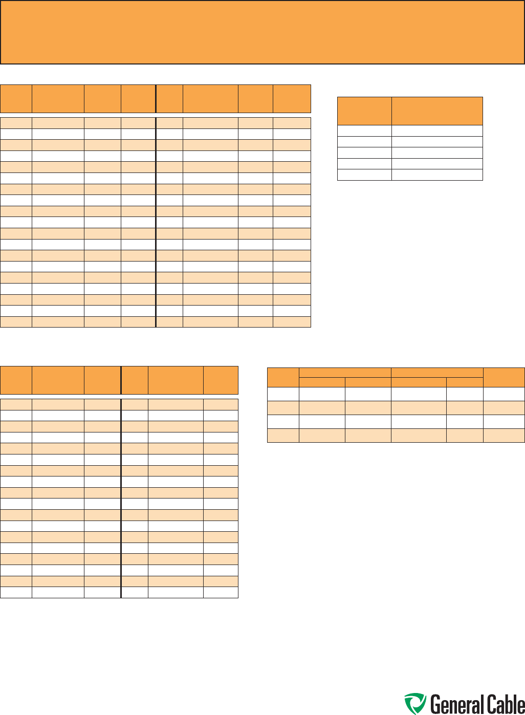
Phone: 888-593-3355
www.generalcable.com
Table E1 Color Sequence
COND.
NO.
BACKGROUND
OR BASE
COLOR
FIRST
TRACER
COLOR
SECOND
TRACER
COLOR
COND.
NO.
BACKGROUND
OR BASE
COLOR
FIRST
TRACER
COLOR
SECOND
TRACER
COLOR
1
Black - -
20
Red Green -
2
White - -
21
Orange Green -
3
Red - -
22
Black White Red
4
Green - -
23
White Black Red
5
Orange - -
24
Red Black White
6
Blue - -
25
Green Black White
7
White Black -
26
Orange Black White
8
Red Black -
27
Blue Black White
9
Green Black -
28
Black Red Green
10
Orange Black -
29
White Red Green
11
Blue Black -
30
Red Black Green
12
Black White -
31
Green Black Orange
13
Red White -
32
Orange Black Green
14
Green White -
33
Blue White Orange
15
Blue White -
34
Black White Orange
16
Black Red -
35
White Red Orange
17
White Red -
36
Orange White Blue
18
Orange Red -
37
White Red Blue
19
Blue Red -
PaircablesareBlack,Whiteandnumbered.TriadcablesareBlack,White,Redandnumbered.
Table E2 Color Sequence
COND.
NO.
BACKGROUND
OR BASE
COLOR
TRACER
COLOR
COND.
NO.
BACKGROUND
OR BASE
COLOR
TRACER
COLOR
1
Black -
19
Orange Blue
2
Red -
20
Yellow Blue
3
Blue -
21
Brown Blue
4
Orange -
22
Black Orange
5
Yellow -
23
Red Orange
6
Brown -
24
Blue Orange
7
Red Black
25
Yellow Orange
8
Blue Black
26
Brown Orange
9
Orange Black
27
Black Yellow
10
Yellow Black
28
Red Yellow
11
Brown Black
29
Blue Yellow
12
Black Red
30
Orange Yellow
13
Blue Red
31
Brown Yellow
14
Orange Red
32
Black Brown
15
Yellow Red
33
Red Brown
16
Brown Red
34
Blue Brown
17
Black Blue
35
Orange Brown
18
Red Blue
36
Yellow Brown
PaircablesareBlack,Redandnumbered.TriadcablesareBlack,Red,Blueandnumbered.
Colorsrepeatafter36conductors.TherearenoGreenorWhiteconductorsorstripes.
Method 4 -
All Conductors Black
COND. CONDUCTOR PRINTING
1st
“1-One”
2nd
“2-Two”
3rd
“3-Three”
4th
“4-Four”
5th
“5-Five”
Common Color Sequence
S PEC A100
April, 2011
ANSI MC 96.1 Conductor Alloy and Color Code
COND.
TYPE
POSITIVE WIRE NEGATIVE WIRE OUTER
JACKETALLOY COLOR ALLOY COLOR
EX
Chromel Purple Constantan Red Purple
JX
Iron White Constantan Red Black
KX
Chromel Yellow Alumel Red Yellow
TX
Copper Blue Constantan Red Blue

Phone: 888-593-3355
www.generalcable.com
To Convert From To Multiply By
Inches Millimeters 25.4
Millimeters Inches 0.03937
Inches Centimeters 2.54
Centimeters Inches 0.3937
Length
Feet Meters 0.3048
Meters Feet 3.2808
Kilofeet(1000feet) Kilometers 0.3048
Kilometers Kilofeet(1000feet) 3.2808
SquareInches SquareMillimeters 645.16
SquareMillimeters SquareInches 0.00155
SquareInches SquareCentimeters 6.4516
SquareCentimeters SquareInches 0.155
Area SquareInches CircularMils 1,273,240
CircularMils SquareInches 7.854x10⁻⁷
CircularMils SquareMillimeters 5.066x10⁴
SquareMillimeters CircularMils 1973.51
SquareFeet SquareMeters 0.0929
SquareMeters SquareFeet 10.764
Pounds Kilograms 0.4536
Kilograms Pounds 2.2046
Weight
Pound/Kilofeet Kilograms/Kilometer 1.4882
Kilograms/Kilometer Pounds/Kilofeet 0.6720
Ohms/Kilofeet Ohms/Kilometer 3.2808
Ohms/Kilometer Ohms/Kilofeet 0.3048
Microfarads/Kilofeet Microfarads/Kilometer 3.2808
Electrical Microfarads/Kilometer Microfarads/Kilofeet 0.3048
Insulation Resistance:
Megohms—Kilofeet Megohms—Kilometer 0.3048
Megohms—Kilometer Megohms—Kilofeet 3.2808
Pounds/SquareInch KiloPascal* 6.895
Mechanical KiloPascal* Pounds/SquareInch 0.1432
Pounds(force) Newtons 4.448
*1Pascal=1Newton/squaremeters
Metric Conversion Factors
S PEC A150
September, 2010
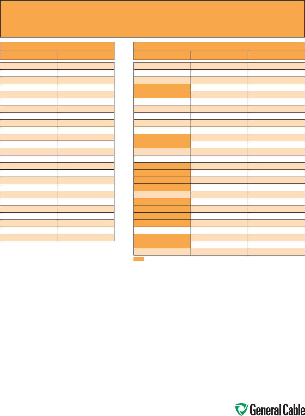
Phone: 888-593-3355
www.generalcable.com
AWG to mm² CONVERSION TABLE
AWG/kcmil [mm²]*
20 0.52
18 0.82
16 1.31
14 2.08
12 3.31
10 5.26
8 8.36
6 13.3
4 21.2
2 33.6
1 42.4
1/0 53.5
2/0 67.4
3/0 85.0
4/0 107
250 127
300 152
350 177
400 203
450 228
500 253
600 304
750 380
800 405
1000 507
*Equivalentmm2cross-sectionalarea
mm² to AWG CONVERSION TABLE
mm² [mm²] * AWG/kcmil
0.5 0.52 20
0.75 0.82 18
1.5 1.31 16
2.5 2.08 14
2.5 3.31 12
4 3.31 12
6 5.26 10
10 8.36 8
16 13.3 6
25 21.2 4
35 33.6 2
35 42.4 1
50 53.5 1/0
70 67.4 2/0
95 85.0 3/0
95 107 4/0
120 107 4/0
120 127 250
150 152 300
185 177 350
185 203 400
240 228 450
240 253 500
300 304 600
400 380 750
400 405 800
500 507 1000
MultipleAWGchoices—consultresponsibleengineerforrequiredampacity
AWG (American Wire Gauge) to mm2 (Millimeters Squared) Conversion
SPEC A185
September, 2010
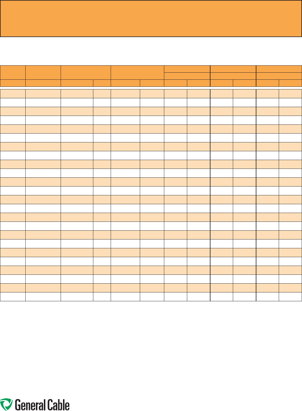
Phone: 888-593-3355
www.generalcable.com
Copper Conductor
ASTM CLASS B
COND. SIZE STRANDING NOMINAL AREA NOMINAL WEIGHT
CONCENTRIC COMPRESSED COMPACT
NOMINAL O.D. NOMINAL O.D. NOMINAL O.D.
AWG/kcmil INCHES CIRCULAR MILS mm² LBS/1000 FT¹ kg/km INCHES mm INCHES mm INCHES mm
22 7/.0096 640 0.32 1.99 2.96 0.029 0.74 — — — —
20 7/.0121 1,020 0.52 3.15 4.69 0.036 0.91 — — — —
18 7/.0152 1,620 0.82 5.10 7.59 0.046 1.17 — — — —
16 7/.0192 2,580 1.31 7.74 11.52 0.058 1.47 — — — —
14 7/.0242 4,110 2.08 12.70 18.90 0.073 1.84 0.071 1.80 — —
12 7/.0305 6,530 3.31 20.20 30.10 0.092 2.32 0.089 2.26 — —
10 7/.0385 10,380 5.26 32.10 47.80 0.116 2.95 0.113 2.87 — —
8 7/.0486 16,510 8.36 51 75.90 0.146 3.71 0.142 3.60 0.134 3.40
6 7/.0612 26,240 13.30 81.10 120.70 0.184 4.67 0.178 4.53 0.169 4.29
4 7/.0772 41,740 21.20 129 192 0.232 5.89 0.225 5.72 0.213 5.41
2 7/.0974 66,360 33.60 205 305.10 0.292 7.42 0.283 7.19 0.268 6.81
1 19/.0664 83,690 42.40 258 383.90 0.332 8.43 0.322 8.18 0.299 7.59
1/0 19/.0745 105,600 53.50 326 485.10 0.373 9.47 0.362 9.19 0.336 8.53
2/0 19/.0837 133,100 67.40 411 611.60 0.419 10.64 0.406 10.32 0.376 9.55
3/0 19/.0940 167,800 85 518 770.90 0.470 11.94 0.456 11.58 0.423 10.74
4/0 19/.1055 211,600 107 653 971.80 0.528 13.41 0.512 13.01 0.475 12.07
250 37/.0822 250,000 127 772 1148.90 0.575 14.61 0.558 14.17 0.520 13.21
300 37/.0900 300,000 152 926 1378 0.630 16.00 0.611 15.52 0.570 14.48
350 37/.0973 350,000 177 1,081 1609 0.681 17.30 0.661 16.78 0.616 15.65
400 37/.1040 400,000 203 1,235 1838 0.728 18.49 0.706 17.94 0.659 16.74
500 37/.1162 500,000 253 1,544 2298 0.813 20.65 0.789 20.03 0.736 18.69
600 61/.0992 600,000 304 1,883 2802 0.893 22.68 0.866 22.00 0.813 20.65
750 61/.1109 750,000 380 2,316 3447 0.998 25.35 0.968 24.59 0.908 23.06
1000 61/.1280 1,000,000 507 3,088 4595 1.152 29.26 1.117 28.38 1.060 26.92
Dimensionsandweightsarenominal;subjecttoindustrytolerances.
¹NominalconductorweightsareapplicableforConcentricClassBandCompressedStrandingperASTMB8.
Class B Conductors for General Wiring
SPEC B025
March, 2012
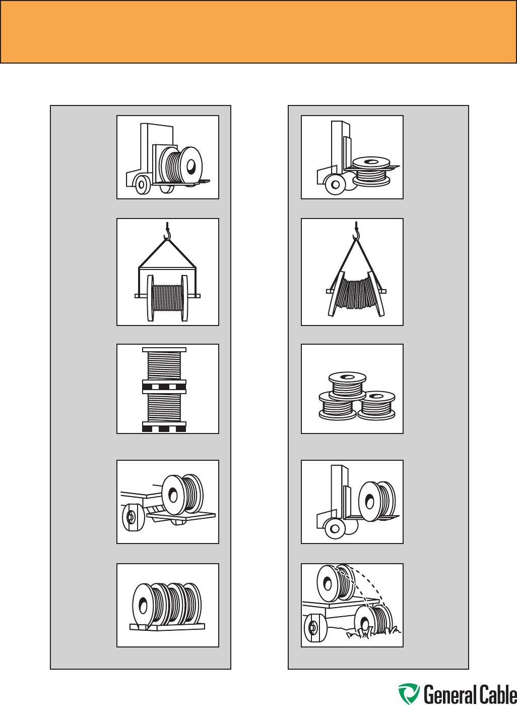
Phone: 888-593-3355
www.generalcable.com
How to Handle Cable Reels
.
Cradlebothreelflangesbetweenforks.
Reelscanbehoistedwithashaft
extendedthroughbothflanges.
Placespacersunderthebottomflange
andbetweenreelstocreateaspaceto
inserttheforks.(36"reelsmax.)
Lowerreelsfromtruckusinghydraulic
gate,hoistorforklift.LOWERCAREFULLY.
Alwaysloadwithflangesonedgeand
chockandblocksecurely.
Donotliftbytopflange.Cableorreel
willbedamaged
Useaspreaderbartopreventbending
thereelflangesandmashingthecable.
Upendedheavyreelswilloftenarrive
damaged.Refuseorreceivesubjectto
inspectionforhiddendamage.
Neverallowforkstotouchcablesurface
orreelwrap.
Neverdropreels.
YES NO
Recommended Reel Handling Practices
SPEC D005
March, 2012
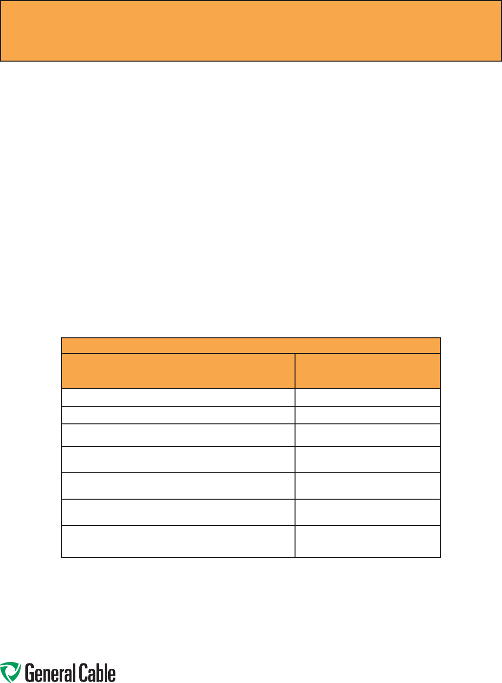
Phone: 888-593-3355
www.generalcable.com
Recommended Cable Handling Practices
SPEC D025
October, 2011
Unloading and Moving of Reels:
Cablereelsarenevershippedupended(flatsidedown).Cablereelsthatarriveinthismannershouldberejected
orreceivedonlyafterathoroughinspectionfordamage.
See“RecommendedReelHandlingPractices”page.
Uponreceipt,acable’sprotectivecoveringand/orlaggingshouldbeinspectedforevidenceofdamageduring
shipment.Ifevidenceofdamageisfound,areportshouldimmediatelybemadetothecarrier.
Undernocircumstancesshouldreelsbedroppedfromthedeliveringvehicletotheground.
Unloadingandreelhandlingshouldbeaccomplishedsothattheequipmentuseddoesnotcontactthecable
surface,andinthecaseofprotectivewrap,thattheequipmentdoesnotcontacttheprotectivewrap.
Ifunloadingandreelhandlingisaccomplishedbycrane,eitheracradlesupportingthereelflangesorashaft
throughthearborholeshouldbeused.Ifaforkliftisutilized,theforksmustliftthereelat90˚totheflanges
andtheforksmustbelongenoughtomakecompleteliftingcontactwithbothflanges.Undernocircumstances
shouldtheforkscomeintocontactwiththecablesurfaceortheprotectivewraps.
Whenareelofcableisrolledfromonepointtoanother,caremustbetakentoseethattherearenoobjectson
thesurfaceareawhichcouldcontactordamagethecablesurfaceorprotectivewrap.
Ifaninclinedrampisusedforunloading,therampmustbewideenoughtocontactbothflangescompletely.
Thestoppingofthereelsatthebottomshallbeaccomplishedbyusingthereelflangesandnotthesurfaceof
thecable.
Minimum Drum Diameters for Packaging Cables
Type of Cable Minimum Drum Diameter as a
Multiple of Outside
Diameter of Cable
1.Singleandmultipleconductorcable-unshielded0-2000V 10
2.Singleandmultipleconductorcable-unshielded2400V 12
3.Singleandmultipleconductorcable-wireshield(UniShield®)
5-35kV
12
4.Singleandmultipleconductorcable-helicallyappliedtapeshield
(Uniblend®)5-35kV
14
5.Singleandmultipleconductorcable-longitudinallyappliedflat
tapeshield(TypeTC)
20
6.
Singleandmultipleconductorcable-InterlockedArmor(Duralox®)
600V-35kV
14
7. Triplexedsingleconductorscabledtogether.Thecircumscribing
overalldiameter*shallbemultipliedbythefactorin1-6andthen
bythereductionfactor.
.75
*Singleconductortimes2.155times
NEMAWC26EEMAC201-2007BinationalWireandCablePackagingStandard

Phone: 888-593-3355
www.generalcable.com
Storage and Storage Maintenance:
Finishedcableshavenoestablishedshelf-life.Moistureandatmosphericconditionscancauseexposed
conductorstooxidizeanddiscolor.Uncovered/unshelteredcablewilldegradeduetoexposuretodirectsunlight
and/ortheelements.Ifthecablesareprotected,thereshouldbenodegradationoftheinsulation.
Ingeneral,anycableforuseindoorsshouldbestoredindoors.Anycablesuitableforinstallationoutdoorsis
suitableforstorageoutdoors.Cablesstoredoutdoorsshouldhavetheendssealedtopreventmoistureingress
intothecableandshouldbeusedwithintwoyearsorless.
Cablesshouldbestoredinashelteredarea.
Cableswithacoldtemperaturemarking,e.g.–10˚C,–25˚C,or–40˚C,maybestoredoutdoors.Cableswithouta
coldtemperaturemarkingmustbestoredindoors.
Cablereelsmustremainintheuprightposition.Cablereelsmustnotbestoredontheirsides.Reelsmustnotbe
stacked.
Cablereelsshouldbestoredwiththeprotectivecoveringorlagginginplace.Ifalengthofcablehasbeencut
fromthereel,thecableendshouldbeimmediatelyresealedtopreventtheentranceofmoisture.Ifapartlength
isreturnedtostorage,thereel’sprotectivecoveringshouldberestored.
Woodenreelsshouldbestoredoffthegroundtopreventrotting.Reelsshouldbestoredonaflat,hardsurface
sothatflangesdonotsinkintotheearth.Theweightofthereelandcablemustbecarriedatalltimesbythereel
flanges.
Cablereelsandlaggingmustnotbestoredforanextendedtimeperiodsittingindirectcontactwithwateror
dampness.Timbersormetalsupportsmustbeplacedunderthereelflangestoprovideelevatedstorageofthe
reelsawayfromthedirectcontactwithwaterordampsoil.
Reelsshouldbestoredinanareawhereconstructionequipment,fallingorflyingobjectsorothermaterialswill
notcontactthecable.
Cableshouldbestoredinanareawherechemicalsorpetroleumproductswillnotbespilledorsprayedonthe
cable.
Cableshouldbestoredinanareaawayfromopenfiresorsourcesofhighheat.
Ifthereelsarerelocated,theyshouldbehandledassuggestedinthe“RecommendedReelHandlingPractices”
section,andinspectionmadeoneachreelduringtherelocation.
Ifthecablesarestoredinasecureareaandnotexposedtotheeffectsoftheweather,anannualinspection
shouldbesatisfactory.
Wherethereelsareexposedtotheweather,abimonthlyinspectionshouldbeperformedtoobserveanysignof
deterioration.
Ifthereelsareexposedinanon-securearea,policingoftheareaatfrequentintervalsmayberequired
dependingoncircumstances.
Recordsofdeliverydate,manufacturer,installationdate,anyextenuatingcircumstances,alongwithalltest
reports,shouldbekeptonfile.
Recommended Cable Storage Practices
SPEC D050
November, 2011

Phone: 888-593-3355
www.generalcable.com
Overview
Toensuresafetyduringcableinstallation
andreliabilityoncethecableisinstalled,
youshouldconfirmthefollowingpriorto
installation:
• Thecableselectedisproperforyour
application
• Thecablehasnotbeendamagedin
transit or storage
Reviewallapplicablestateandnationalcodes
toverifythatthecablechosenisappropriate
forthejob.Also,consultyourlocalbuilding
authority.
Next,youmustidentifyanyexistingcable
damageandpreventanyfurtherdamage
fromoccurring.Thisisdonethroughproper
cableinspection,handlingandstorage.
CableInspection
Inspecteverycablereelfordamagebefore
acceptingtheshipment.Beparticularlyalert
forcabledamageif:
• Areelislayingflatonitsside
• Severalreelsarestacked
• Otherfreightisstackedonareel
• Nailshavebeendrivenintoreelflangesto
secureshippingblocks
• Areelflangeisdamaged
• Acablecoveringisremoved,stainedor
damaged
• Acableendsealisremovedor
damaged
• Areelhasbeendropped
(hiddendamagelikely)
CablingHandling
Removeallnailsandstaplesfromthereel
flangesbeforemovingareel,andavoidall
objectsthatcouldcrush,gougeorimpact
thecablewhenmoving.NEVERusethe
cableasameanstomoveareel.
Whenunreeling,observerecommended
bendingradii,useswivelstoprevent
twistingandavoidoverruns.
Pre-Installation
Pre-Installation Instructions
SPEC E005
April, 2010
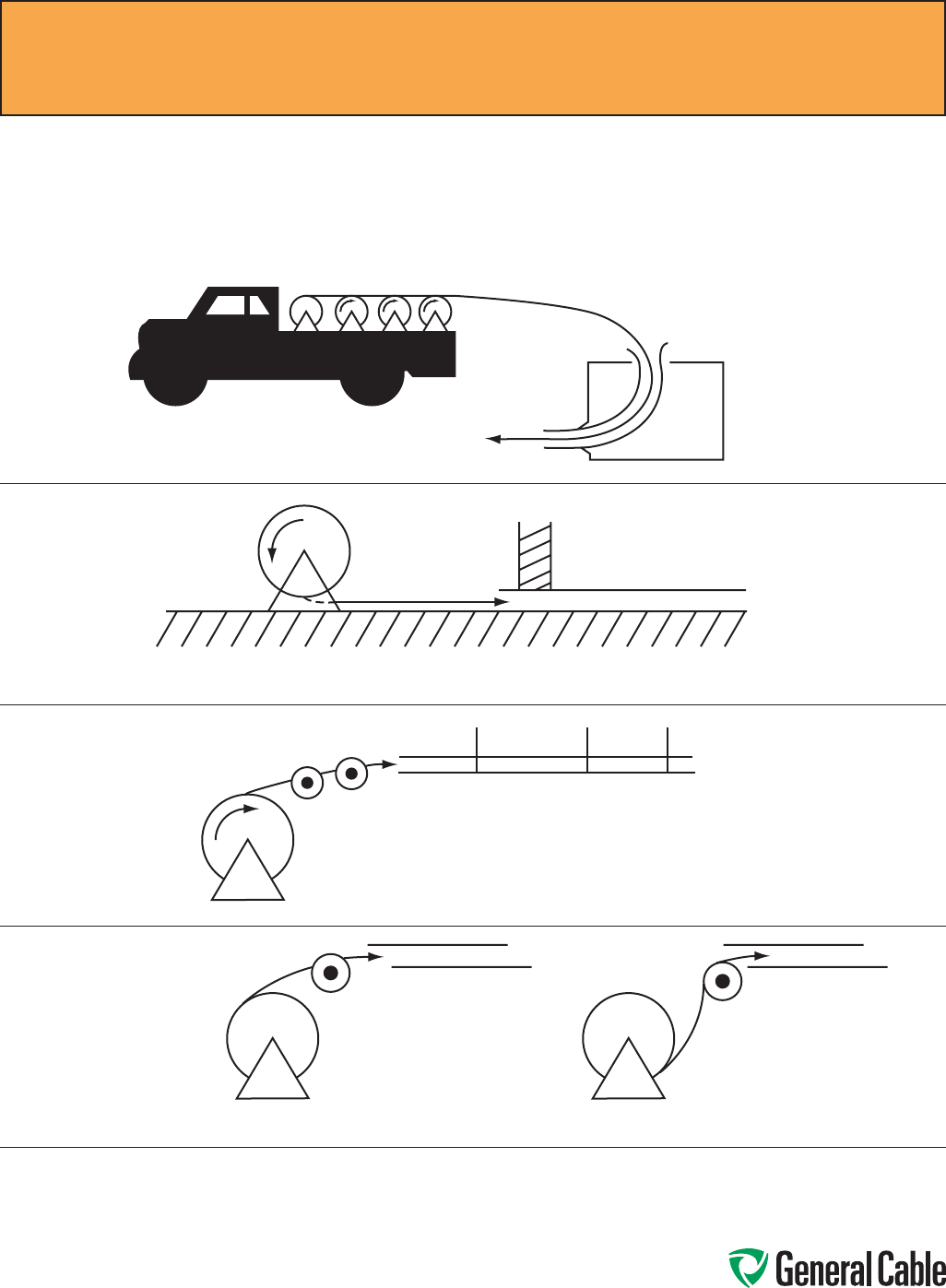
Phone: 888-593-3355
www.generalcable.com
Thefollowingdiagramsillustratevariouscablefeed-insetups:
CableFeed-InSetups
Thefeed-insetupshouldunreelthe
cablewithanaturalcurvature
(Figure1)asopposedtoareverse
“S”curvature(Figure2).
Reelsontruck
Applylubehere
Guide-intube
Setupforductclosetofloor
Setupforoverhead,intotray
IMPROPER
Figure2
PROPER
Figure1
Installation—Feed-In Setups
SPEC E050
April, 2010
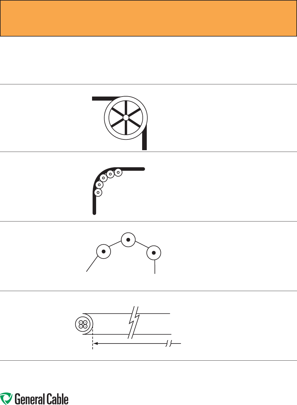
Phone: 888-593-3355
www.generalcable.com
Remembertousetheradiusofthe
surfaceoverwhichthecableisbent,
not the outside flange diameter of
thepulley.A“10inch”cablesheave
typicallyhasa10inchoutsideflange
diameterwitha6inchinsidediameter
thatprovidesaninside(bending)
radiusof3inches.
Singlesheavesshouldonlybe
usedforGUIDINGcables.Arrange
multipleblockstomaintainbending
radiiwhenevercablechanges
directionorelevation.
Forpullingaroundbends,
useconveyorsheave
assembliesofthe
appropriateradiusseries.
Thepulleysmustbepositionedtoensurethat
the effective curvature is smooth and changes
directionorelevationevenlyateachpulley.
Neverallowapolygoncurvaturetooccur
(Figure3).
Thefitofapulleyaroundthecableisalso
importantwhenpullingheavyweights
(i.e.pulleysatthetopofaverticaldrop).
CableFeed-InSetups(continued)
Single Sheave
SheaveAssembly
NEVERALLOW
Figure3
Radius
Installation—Feed-In Setups
SPEC E050
April, 2010
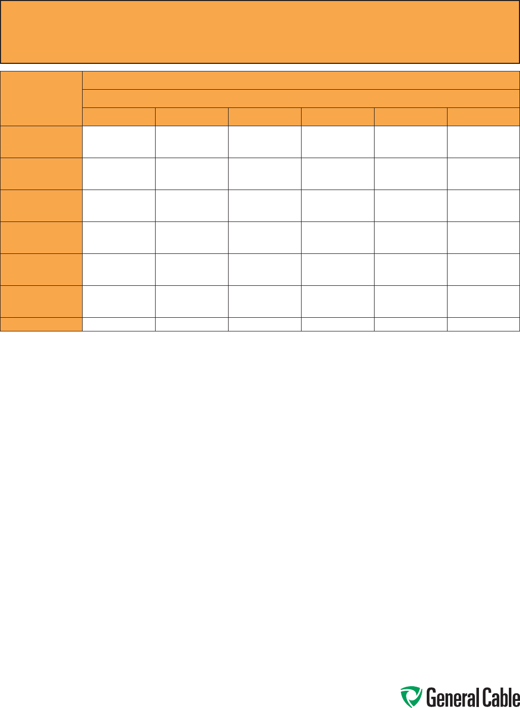
Phone: 888-593-3355
www.generalcable.com
Installation—Conductor Maximum Pulling Tensions
MulticonductorCablesHavingEqual-SizedConductors;
InParallelorasMultiplexedAssemblies
SPEC E075
March, 2012
AWG/kcmil
MAXIMUM ALLOWABLE PULLING TENSION (LBS)
NUMBER OF CONDUCTORS
123456
18
16
14
13
20
33
26
40
66
39
60
99
41
65
105
52
81
132
62
97
158
12
10
8
52
83
132
104
166
264
157
249
396
167
266
423
209
332
528
251
399
634
6
4
2
210
334
531
420
668
1062
630
1002
1593
672
1069
1699
840
1336
2124
1008
1603
2548
1
1/0
2/0
670
845
1065
1339
1690
2130
2009
2534
3194
2142
2703
3407
2678
3379
4259
3214
4055
5111
3/0
4/0
250
1342
1693
2000
2685
3386
4000
4027
5078
6000
4296
5417
6400
5370
6771
8000
6444
8125
9600
350
500
750
2800
4000
6000
5600
8000
10000
8400
10000
10000
8960
10000
10000
10000
10000
10000
10000
10000
10000
1000 8000 10000 10000 10000 10000 10000
Themaximumallowablepullingtensionsarefordirectattachmenttotheconductor.
T=0.008xcmilxn,ifn≤ 3
T=0.008xcmilxnx0.8,ifn>3
Whenmorethantwoconductorsarepulledinparallelinaninstallationcontainingbends,themaximunallowablepullingtensionislimited
tothetwoconductorcolumn,regardlessofthenumberofconductorsthatarebeingpulled.
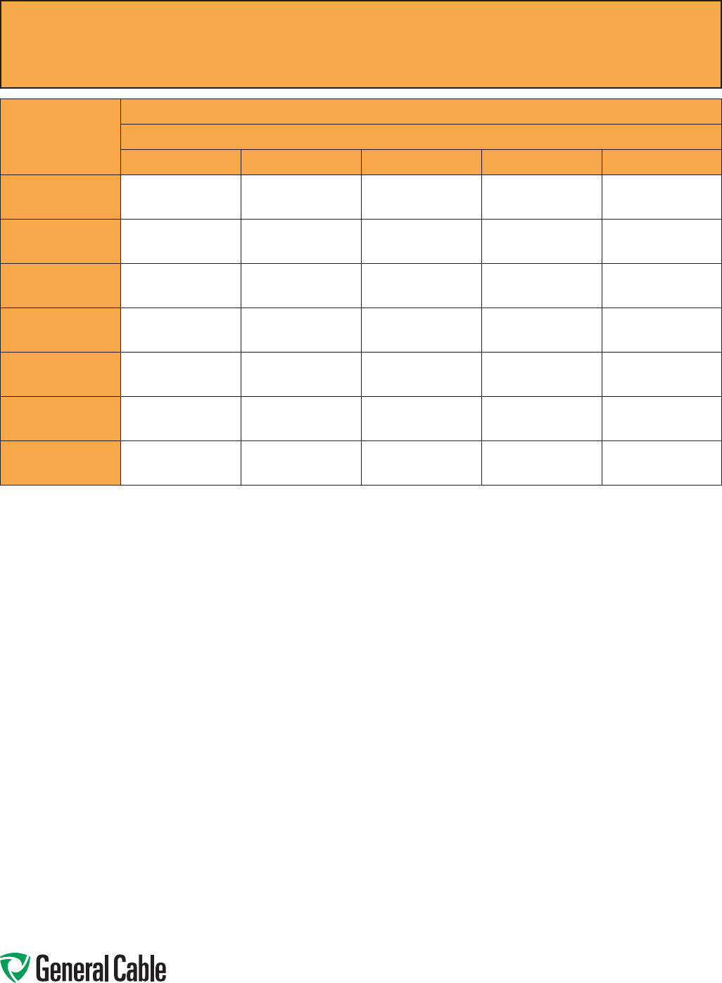
Phone: 888-593-3355
www.generalcable.com
Installation—Conductor Maximum Pulling Tensions
MulticonductorCablesHavingEqual-SizedConductors,WithoutSubassemblies
SPEC E075
March, 2012
NUMBER OF
CONDUCTORS
MAXIMUM ALLOWABLE PULLING TENSION (LBS)
CONDUCTOR SIZE (AWG/kcmil)
18 16 14 12 10
2
3
4
26
39
41
40
60
65
66
99
105
104
157
167
166
249
266
5
6
7
52
62
73
81
97
113
132
158
184
209
251
293
332
399
465
8
9
10
83
93
104
129
145
161
210
237
263
334
376
418
531
598
664
12
14
15
124
145
156
194
226
242
316
368
395
502
585
627
797
930
996
16
18
19
166
187
197
258
290
306
421
473
500
669
752
794
1000
1000
1000
20
22
24
207
228
249
323
355
387
526
549
631
836
919
1000
1000
1000
1000
25
30
37
259
311
383
403
484
596
658
789
974
1000
1000
1000
1000
1000
1000
Themaximumallowablepullingtensionsareformulti-conductorcablespulledintoaracewayorcabletrayusingabasketgriporsimilar
devicesecureddirectlytothecablejacket.Itisrecommendedthatacombinationofbasketgripsandpullingeyesbeusedwheneverpossible.
T=0.008xcmilxn,ifn≤ 3
T=0.008xcmilxnx0.8,ifn>3
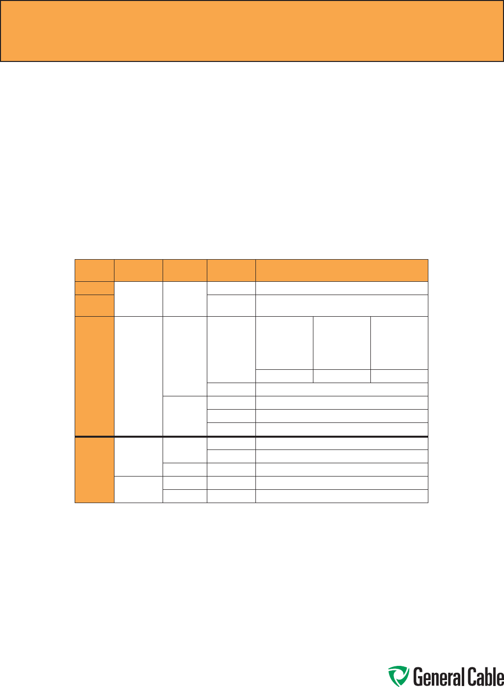
Phone: 888-593-3355
www.generalcable.com
Overview
Trainingisthepositioningofcablewhen
itisnotundertension.Bendingisthe
positioningofcablewhenitisunder
tension.Wheninstallingcable,theobject
is to limit the mechanical forces so that
thecable’sphysicalandelectrical
characteristics are maintained for the
expectedservicelife.Bendsinconductors,
multi-conductorcablesorassembliesof
conductorsshallbemadesothatthecable
willnotbedamaged.
Physical Limitations Training and Bending
Anonshieldedcablecantolerateasharper
bendthanashieldedcable.Thisis
especiallytrueforcableshavinghelically
appliedmetallicshieldingtapeswhich,
whenbenttoosharply,canseparateor
buckleandcutintotheinsulation.
Rememberthatoffsetsarebends.
Theproblemiscompoundedbythefact
thatmosttapesareunderjacketsthat
concealsuchdamage.Theextruded
polymersusedforinsulationshieldshave
sufcientconductivityandcoverage
initiallytopassacceptancetesting,then
failprematurelyduetocoronaatthe
shield/insulationinterface.
Minimum Bending Radius in Accordance with National Electric Code
Voltage Conductors Shielding Cable Types Minimum Bending Radius as a Multiple
of Conductor/Assembly Diameter
600 V Single Nonshielded All 5X
601-
2000 V All 8X
600 V
or
2000 V
Multi-
conductor
or
Multiplexed
Nonshielded TCorTC-ER
1in.(25mm)
or less
Over1in.to2in.
(>25mmto50
mm)
Over2in.
(>50mm)
4X 5X 6X
MC37X
Shielded
All 12X
TCorTC-ER 12X
MC 12X/7X1
Over
2000 V
Single Nonshielded MV 8X
MC37X
Shielded MCandMV 12X2
Multi-
conductor or
Multiplexed
Nonshielded MCandMV 8X
Shielded MCandMV 12X/7X1,2
1 12timesthediameterofanindividualshieldedconductoror7timestheoverallcablediameter,whicheverisgreater.
2 SinceUniShield®isauniqueconstruction,therearenoapplicablevaluesforthebendingradiusintheNEC.However,
GeneralCablerecommends8timesforsingleconductors,andformultiplexedormulti-conductorcables,itis8times
thediameteroftheindividualconductorsor5timestheoveralldiameter,whicheverisgreater,inaccordancewith
ANSI/ICEAS-93-6395-46kVShielded Power Cable for Use in the Transmission and Distribution of Electric Energy.
3 Per330.24BInterlocked-TypeArmororContinuouslyCorrugatedMetallicSheath.
Installation—Training and Bending Limitations
SPEC E100
April, 2010
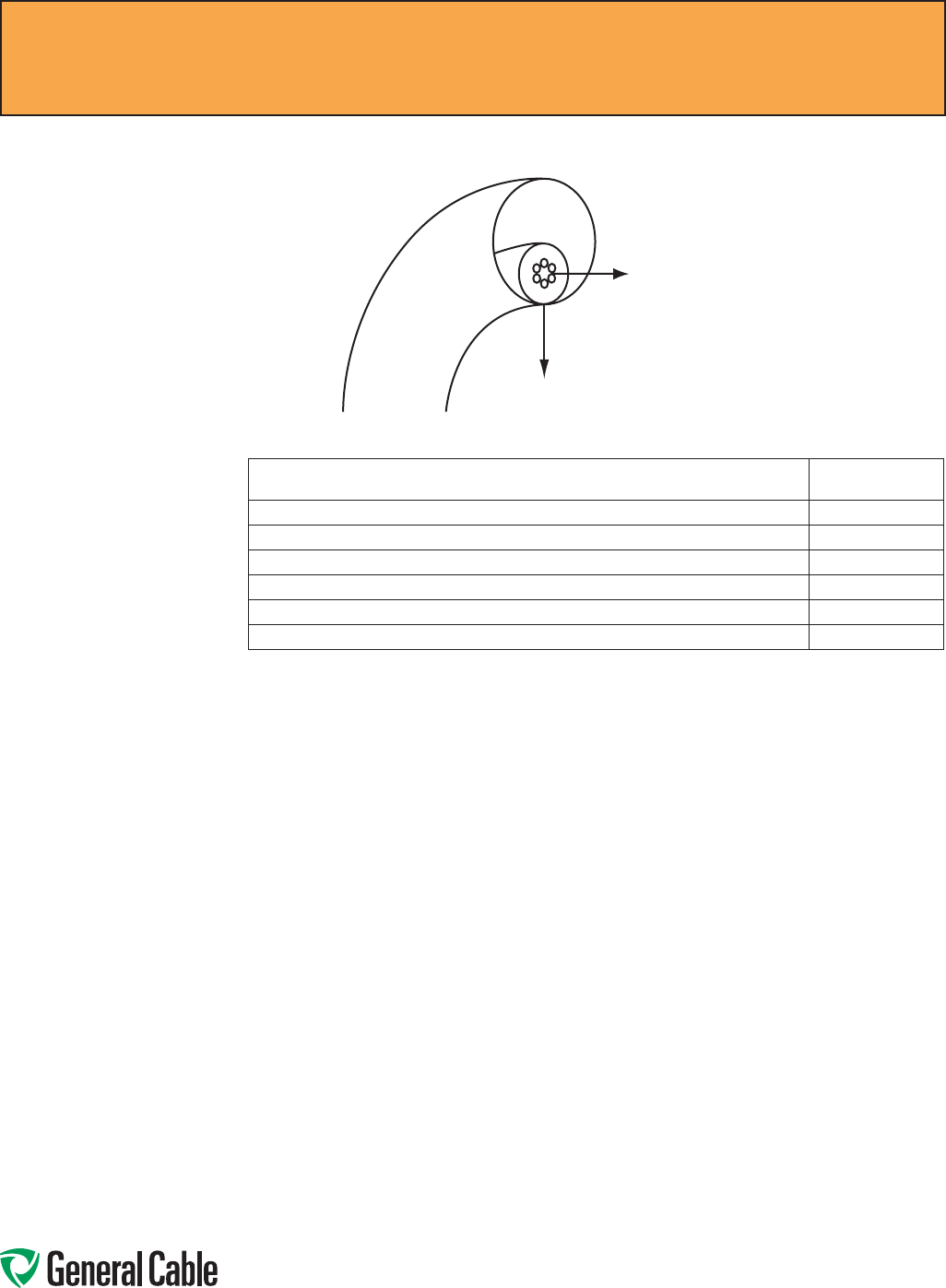
Phone: 888-593-3355
www.generalcable.com
Sidewall Load
Tension
Overview
Sidewallbearingpressure(SWBP),orsidewall
loading,istheradialforceexertedonacable
beingpulledaroundaconduitbendorsheave.
ExcessiveSWBPcancrushacableandis,
therefore,oneofthemostrestrictivefactorsin
installationshavingbendsandrequiringhigh
pullingtensions.SWBPisreducedbyincreasing
theradiusofbends.
Themaximumtensionthatcansafelybeapplied
tothecableduringinstallationcanbecalculated
usingthemaximumSWBPforthecableandthe
radiusofthebenditistraversing.
Forexample,acablehavingamaximumSWBP
of300lb/ftthatisbeingpulledaroundabend
havingaradiusof2feetshouldhavenomore
than300lbs/ftx2ftor600lbstensionapplied
toitasthecableexitsthebend.
*Yellow77notrecommendedforusewithUniShield®cables.
ForLSZHjacketedcable,consultwithpullingcompoundmanufacturers.
OtherwirepullingcompoundsmaybesuitableforusewithGeneralCableconstructions.Contactthewirepullingcompoundmanufacturerregardingthe
suitabilityoftheirproductswithspecicGeneralCableproducts.
General Cable’s Approval List of Cable Pulling Lubricants
Thefollowingmanufacturers,whoarelistedinthe2006ULElectricalConstructionEquipmentDirectory,providewirepullingcompoundsintendedfor
useaslubricantsininstallingelectricalconductorsinraceways.ThesemanufacturershavehadsomeoftheirproductsevaluatedbyUnderwriters
Laboratories(UL)todeterminetheircompatibilitywithconductorinsulationandcoverings.
Sinceitisnotfeasibletotesteverypossiblecombinationofcablematerialwitheverywirepullingcompound,theinstallershouldcheckwiththepulling
compoundmanufacturerorthecablemanufacturertodeterminecompatibilitybetweenspeciccablematerialsandthepullingcompound.
TheListingMarkfortheseproductsincludestheULsymbol,togetherwiththeword“LISTED,”acontrolnumberandtheproductname“WirePulling
Compound.”RefertothelatesteditionoftheULElectricalConstructionEquipmentDirectoryforthecurrentlistingofmanufacturersofwirepulling
compoundsandtheircontrolnumbers.
CABLE TYPE SWBP (LBS/FT)
300VNonshielded,300Vand600VShieldedControl&Instrumentation
500
600VNonshieldedControl&Instrumentation
500
600Vand2400VNonshieldedPower
1000
5kV-35kVShieldedPower
1000
InterlockedArmoredCable(allvoltage)
300
CCW®MC-HLArmoredCable
500
Installation—Maximum Sidewall Pressure
SPEC E125
October, 2012
J.C.WhitlamMfg.Co.
KleinToolsInc.
MadisonElectricProductsInc.
RainbowTechnologyCorp.
Rectorseal
Thomas&BettsCorp.
3MCompany
AmericanBentoniteInternationalInc.
AmericanPolywaterCorp.
ArncoCorp.
Dura-LineCorp.
GreenleeTextron
IdealIndustriesInc.*

Phone: 888-593-3355
www.generalcable.com
Thetestvoltageshouldbeincreasedinstepsof10kV,orminimumof5steps.Thedurationateachstepshould
belongenoughforthecurrenttoreachasteadyvalue(1minutesuggested).Thetestcurrentwillmomentarily
increaseforeachvoltageincrementduetochargingofthecapacitanceandthedielectricabsorptioncharacteris-
ticsoftheinsulation.Stabilizedcurrentshouldberecordedateachstep.
Themaximumtestvoltageshouldbemaintainedfor15minutes(newcable,shielded)/5minutes(non-shielded).
Leakagecurrentshouldberecordedeachminuteafterthemaximumtestvoltagehasbeenreached.
Increaseofleakagecurrentatanysteppointmaybeanindicationofacableinsulationproblem.Failureofthe
cableorcableaccessoriesmayresultunlessthevoltageisrapidlyreduced.
Otherwise,theleakagecurrentshouldstabilizeafterabout5minutes.Leakagecurrentisessentiallyafunctionof
theconstructionandlengthofcablebutitcanbeinfluencedbythetestconditions(windandhumidity)aswellas
thetestapparatus(leads).
Typicalleakagecurrentsintheorderof100–150microamperesorhigherarenotunusual.Adefectiveinstallation
isidentifiedbyincreasingleakagecurrentwithtime,atafixedDCvoltage.
Alltestingshouldbeperformedbyqualifiedpersonneltakingallappropriatesafetyprecautions.
DC “HI-POT” Pre-Test Guidelines for MV Cables
SPEC F005
April, 2010
Phone: 888-593-3355
www.generalcable.com
DC High Potential (HI-POT) Testing of Medium-Voltage Power Cable
Overview
Thisprocedureisintendedtoprovide
generalguidelinesforhighpotential
DCtestingofpowercables.
Alltestsmadeaftercableinstallation
andduringtheguaranteeperiod
shallbemadeinaccordancewith
applicablespecifications.
Allsafetyprecautionsmustbe
observedduringtestingat
highvoltage.
Readandunderstandandfollowthe
Operator’sManualfortheparticular
testsetbeingused!
Test Equipment
Directcurrenttestequipment
isavailablecommerciallywitha
widerangeofvoltages.Accessory
equipmentnecessarytosafely
conducthighvoltagetests—suchas
safetybarriers,rubberglovesand
nonconductinghardhats—mustbe
used;consultappropriate
safetyofficer.
Test Procedures
SeeIEEEStandard400Article5
DirectVoltageTesting.Acceptable
procedures,althoughvaryingslightly
intechnique,havemoreorlessbeen
standardizedaseithera“withstand
test”ora“time-leakingcurrenttest.”
Before performing any DC
over potential tests:
•Allequipmentmustbe
disconnectedfromthecable
circuit,i.e.,taps,motors,circuit
breakers,surgearrestors,etc.
Thiswillprecludedamagetosuch
equipmentandwillpreventtest
interruptionsduetoflashovers
and/ortrip-outsresultingfrom
excessive
leakagecurrent.
•Establishadequateclearance
betweenthecircuittestendsand
anygroundedobject,andtoother
equipmentnotundertest(about
2.5feet).
•Groundallcircuitconductorsnot
undertestwithallcableshields
includingnearbyequipment.
•Consultterminationmanufacturers
formaximumtestvoltage
recommendations and
timelimitations.
Thedirectcurrenttestvoltagemay
beappliedeithercontinuouslyorin
predeterminedstepstothemaximum
valueinaccordancewithapplicable
specifications.
•ContinuousMethod–Apply
testvoltageatanapproximate
riserateof1kVpersecondor
75%oftheratedcurrentoutput
oftheequipment,whicheveris
less.Someequipmentwilltake
longertoreachthemaximumtest
voltagebecauseoftheamountof
chargingcurrent.
•StepMethod–Applytestvoltage
slowlyin5to7incrementsof
equalvaluetothemaximum
specified.Allowsufficienttimeat
eachstopfortheleakagecurrent
tostabilize.
HI-POT TESTING PROCEDURES
Normallythisrequiresonlyafew
secondsunlesscablecircuitsofhigh
capacitanceareinvolved.
Recordleakagecurrentateachstep.
Maintainthetestvoltageat
theprescribedvalueforthe
timedesignatedinapplicable
specifications.Thefollowingtimes
areusuallyconsideredadequate:at
theendofthetestperiod,setthe
testsetvoltagecontroltozero,allow
the residual voltage on the circuit to
decay,thengroundtheconductorjust
tested.
CAUTION
ItshouldberecognizedthatDC
chargesoncablecanbuildupto
potentiallydangerouslevelsifgrounds
areremovedtooquickly.Maintain
solid grounds after the test on the
cableforatleast4timestheduration
of the test.Onexceptionallylong
cablelengths,itmaybenecessary
toincreasethegroundingtime.
It is advantageous to maintain
thesegroundslongerandwhile
reconnectingcircuitcomponents.
•AcceptanceTesting–After
installationandbeforethecable
isplacedinregularservice,the
specifiedtestvoltageshallbe
appliedfor15 consecutive
minutes.
•ProofTesting–Atanytimeduring
theperiodofguarantee,thecable
circuitmayberemovedfrom
service and tested at a reduced
voltage(normally65percentofthe
originalacceptancevalue)for5
consecutive minutes.
•Recordtheleakagecurrentatone
minute intervals for the duration of
thetesttimeinvolved.
DC “HI-POT” Testing Guidelines for MV Cables
SPEC F025
April, 2010

Phone: 888-593-3355
www.generalcable.com
DC High Potential (HI-POT) Testing of Medium-Voltage Power Cable
Comments
ThesignificanceofconductingDC
high-voltagetestsonnonshielded,
nonmetallic-sheathedcableis
dependentupontheenvironment
inwhichitisinstalledbecausethe
characteristics of the return circuits
areunknown.Theenvironmentmust
becarefullyconsideredortestresults
maynotbesignificant.Infact,these
tests can result in damage to the
cableinsulation.
Humidity,condensationandactual
precipitationonthesurfaceofa
cableterminationcanincreasethe
leakagecurrentbyseveralordersof
magnitude.Humidityalsoincreases
thecoronacurrent,whichindicationis
includedinthetotalleakagecurrent.
Windpreventstheaccumulationof
spacechargesatallbareenergized
terminals.
Thisresultsinanincreaseof
corona.Itismostdesirableto
reduce or eliminate corona current
atthebaremetalextremitiesof
cableorterminations.Thismaybe
accomplishedbycoveringtheseareas
withplasticenvelopes,plasticorglass
containers,plasticwraporsuitable
electricalputty.
RoutineperiodicDCmaintenance
testingofcablefortheevaluationof
the insulation strength is not a common
practice.Somepowercableusers
haveadoptedaprogramoftesting
circuitsduringplannedoutages,
preferringpossiblebreakdownsduring
testingratherthanexperiencinga
serviceoutage.Itisnearlyimpossible
to recommend test voltage values for
thosemaintenancetestswiththehistory
ofthecablecircuit.Anarbitrarytest
voltagelevelcouldbreakdownacable
circuitthatwouldotherwiserenderlong
trouble-freeserviceatnormaloperating
ACvoltage.
ThemainusefulnessofDChigh-voltage
testingistodetectconductingparticles
leftonthecreepagesurfaceduring
splicingortermination.
Testequipmentshouldbesupplied
fromastable,constantvoltage
source.Donotusethesamesource
thatissupplyingarcweldersor
otherequipmentcausinglinevoltage
fluctuations.Theoutputvoltageofthe
testsetmustbefilteredandregulated.
Considerusingaportable,motor-driven
alternatortoenergizethetestset.
Thegradualdecreaseornon-increaseof
leakagecurrentwithrespecttotimeat
maximumtestvoltageistheacceptance
criteriaforDCHI-POTtesting.
Testing Problems
Extra Leakage Current:
•Failuretoguardagainstcorona
•Failuretocleaninsulationsurface
•Failuretokeepcableendsdry
•Failuretoprovideadequate
clearance to ground
•Impropershieldtermination
Erratic Readings:
•Fluctuatingvoltagetotestset
•Impropertestleads
Environmental Influences:
•Highrelativehumidity
•Dampness,dew,fog
•Wind,snow
Results vs. Cable Life
Todatethereisnobasisfor
correlationbetweenDCtest
resultsandcablelifeexpectancy.
DC “HI-POT” Testing Guidelines for MV Cables
SPEC F025
April, 2010
Phone: 888-593-3355
www.generalcable.com
Acceptance Testing
Acceptancetestingisperformedtodetectanydefectsincableinsulationandterminationswhichmayhaveresultedfrompoor
workmanshipormechanicaldamage.Thisprooftestconfirmstheintegrityoftheinsulationandaccessoriesbeforethecableis
placedintoservice.
Afterinstallationandbeforethecableisplacedinregularservice,thetestvoltagesspecifiedintheICEAS-97-682Tableshould
beappliedfor15consecutiveminutes.Recordtheleakagecurrentatoneminuteintervalsforthedurationofthetest.
ICEA DC Field Test Voltages
ICEA S-97-682 Utility Shielded Power Cables Rated 5,000-46,000 Volts
Rated
Voltage Phase-
to-Phase (kV)
Conductor Size Nominal Insulation Thickness
(Insulation Level)
Maximum DC Field
Test Voltages (kV)
During or After
Installation First 5 Years
AWG/kcmil mm2
100% 133% 100% 133% 100% 133%
mils mm mils mm
58-1000 8.4-507 90 2.29 115 2.92 28 36 911
>1000 >507 140 3.56 140 3.56
86-1000 13.3-507 115 2.92 140 3.56 36 44 11 14
>1000 >507 175 4.45 175 4.45
15 2-1000 33.6-507 175 4.45 220 5.59 56 64 18 20
>1000 >507 220 5.59
25 1-2000 42.4-1013 260 6.60 320 8.13 80 96 25 30
28 1-2000 42.4-1013 280 7.11 345 8.76 84 100 26 31
35 1/0-2000 53.5-1013 345 8.76 420 10.7 100 124 31 39
46 4/0-2000 107.2-1013 445 11.3 580 14.7 132 172 41 54
DCtestvoltagesareappliedtodiscovergrossproblemssuchasimproperlyinstalledaccessoriesormechanicaldamage.DCtestingisnotexpectedtorevealdeteriorationdue
toaginginservice.ThereissomeevidencethatDCtestingofagedcross-linkedpolyethylenecablescanleadtoearlycablefailures.InformationonthissubjectisavailableinEPRI
projectreportTR-101245,“EffectofDCTestinginExtrudingCross-LinkedPolyethyleneInsulatedCables.
Dimensionsandweightsarenominal;subjecttoindustrytolerances.
Field Electrical “HI-POT” Testing Guidelines
SPEC F075
April, 2010

Phone: 888-593-3355
www.generalcable.com
CCW®
DIAMETER
INCHES
ALUMINUM
CROSS-
SECTIONAL
AREA kcmil
EQUIVALENT
ALUMINUM
CONDUCTOR
CCW® 10 CYCLE
FAULT
CAPABILITY*
(kA)
0.49 26.39 6 2.84
0.53 30.79 6 3.32
0.58 33.46 5 3.60
0.62 35.19 5 3.79
0.67 39.58 5 4.27
0.71 43.98 4 4.74
0.75 47.50 4 5.11
0.80 51.89 4 5.59
0.84 55.42 3 5.97
0.89 58.94 3 6.35
0.93 61.58 3 6.64
0.97 65.97 3 7.11
1.02 66.85 2 7.21
1.06 69.49 3 7.49
1.11 94.56 1 10.19
1.15 98.96 1 10.67
1.19 101.16 1 10.90
1.24 104.46 1 11.26
1.29 108.86 1/0 11.73
1.34 123.75 1/0 13.33
1.37 132.32 1/0 14.26
1.42 136.00 2/0 14.66
1.47 142.13 2/0 15.32
1.51 145.80 2/0 15.71
1.60 174.26 3/0 18.75
1.64 179.67 3/0 19.36
1.69 185.07 3/0 19.95
*ShortCircuitCapacitybasedonICEAP-45-482
CCW®
DIAMETER
INCHES
ALUMINUM
CROSS-
SECTIONAL
AREA kcmil
EQUIVALENT
ALUMINUM
CONDUCTOR
CCW® 10 CYCLE
FAULT
CAPABILITY*
(kA)
1.75 206.72 3/0 22.28
1.85 209.67 3/0 22.60
1.90 220.01 4/0 23.71
1.96 233.29 4/0 25.14
2.03 257.96 250 27.80
2.15 291.60 250 31.43
2.28 310.83 300 33.50
2.32 314.03 300 33.85
2.40 355.94 350 38.36
2.45 362.85 350 39.11
2.53 371.49 350 40.04
2.58 378.40 350 40.78
2.62 387.04 350 41.72
2.75 407.78 400 43.94
2.85 454.12 400 48.94
2.98 474.51 400 51.15
3.03 483.77 400 52.14
3.11 491.19 400 52.94
3.16 502.31 500 54.14
3.32 530.11 500 57.13
3.41 537.53 500 57.93
3.63 559.77 550 60.33
3.67 578.30 550 62.32
3.80 598.69 550 64.53
3.98 630.20 600 67.92
4.10 650.59 650 70.12
CCW
®
Sheath as a Grounding Conductor
SPEC F130
December, 2010

Phone: 888-593-3355
www.generalcable.com
PART SPEC
NUMBER NUMBER
PART SPEC
NUMBER NUMBER
PART SPEC
NUMBER NUMBER
PART SPEC
NUMBER NUMBER
Part Number Index
Index
January, 2013
9025.16010001..... SPEC 9025
9025.16010002..... SPEC 9025
9025.16010003..... SPEC 9025
9025.16010004..... SPEC 9025
9050.20041221..... SPEC 9050
9050.20041222..... SPEC 9050
9050.20041223..... SPEC 9050
9050.20041224..... SPEC 9050
9050.20081221..... SPEC 9050
9050.20081222..... SPEC 9050
9050.20081223..... SPEC 9050
9050.20081224..... SPEC 9050
9050.20101221..... SPEC 9050
9050.20101222..... SPEC 9050
9050.20101223..... SPEC 9050
9050.20101224..... SPEC 9050
9050.20121221..... SPEC 9050
9050.20121222..... SPEC 9050
9050.20121223..... SPEC 9050
9050.20121224..... SPEC 9050
9050.20161221..... SPEC 9050
9050.20161222..... SPEC 9050
9050.20161223..... SPEC 9050
9050.20161224..... SPEC 9050
9050.20201221..... SPEC 9050
9050.20201222..... SPEC 9050
9050.20201223..... SPEC 9050
9050.20201224..... SPEC 9050
9050.20241221..... SPEC 9050
9050.20241222..... SPEC 9050
9050.20241223..... SPEC 9050
9050.20241224..... SPEC 9050
9050.20361221..... SPEC 9050
9050.20361222..... SPEC 9050
9050.20361223..... SPEC 9050
9050.20361224..... SPEC 9050
9050.20501221..... SPEC 9050
9050.20501222..... SPEC 9050
9050.20501223..... SPEC 9050
9050.20501224..... SPEC 9050
9075.20041221..... SPEC 9075
9075.20041222..... SPEC 9075
9075.20041223..... SPEC 9075
9075.20041224..... SPEC 9075
9075.20081221..... SPEC 9075
9075.20081222..... SPEC 9075
9075.20081223..... SPEC 9075
9075.20081224..... SPEC 9075
9075.20101221..... SPEC 9075
9075.20101222..... SPEC 9075
9075.20101223..... SPEC 9075
9075.20101224..... SPEC 9075
9075.20121221..... SPEC 9075
9075.20121222..... SPEC 9075
9075.20121223..... SPEC 9075
9075.20121224..... SPEC 9075
9075.20161221..... SPEC 9075
9075.20161222..... SPEC 9075
9075.20161223..... SPEC 9075
9075.20161224..... SPEC 9075
9075.20201221..... SPEC 9075
9075.20201222..... SPEC 9075
9075.20201223..... SPEC 9075
9075.20201224..... SPEC 9075
9075.20241221..... SPEC 9075
9075.20241222..... SPEC 9075
9075.20241223..... SPEC 9075
9075.20241224..... SPEC 9075
9075.20361221..... SPEC 9075
9075.20361222..... SPEC 9075
9075.20361223..... SPEC 9075
9075.20361224..... SPEC 9075
9075.20501221..... SPEC 9075
9075.20501222..... SPEC 9075
9075.20501223..... SPEC 9075
9075.20501224..... SPEC 9075
9125.16010001..... SPEC 9125
9125.16010002..... SPEC 9125
9125.16021201..... SPEC 9125
9125.16021202..... SPEC 9125
9125.16041201..... SPEC 9125
9125.16041202..... SPEC 9125
9125.16081201..... SPEC 9125
9125.16081202..... SPEC 9125
9125.16121201..... SPEC 9125
9125.16121202..... SPEC 9125
9125.16161201..... SPEC 9125
9125.16161202..... SPEC 9125
9125.16241201..... SPEC 9125
9125.16241202..... SPEC 9125
9125.16361201..... SPEC 9125
9125.16361202..... SPEC 9125
9125.16501201..... SPEC 9125
9125.16501202..... SPEC 9125
9150.16010001..... SPEC 9150
9150.16010002..... SPEC 9150
9150.16021201..... SPEC 9150
9150.16021202..... SPEC 9150
9150.16041201..... SPEC 9150
9150.16041202..... SPEC 9150
9150.16081201..... SPEC 9150
9150.16081202..... SPEC 9150
9150.16121201..... SPEC 9150
9150.16121202..... SPEC 9150
9150.16161201..... SPEC 9150
9150.16161202..... SPEC 9150
9150.16241201..... SPEC 9150
9150.16241202..... SPEC 9150
9150.16361201..... SPEC 9150
9150.16361202..... SPEC 9150
9150.16501201..... SPEC 9150
9150.16501202..... SPEC 9150
9225.16010001..... SPEC 9225
9225.16010002..... SPEC 9225
9225.16021221..... SPEC 9225
9225.16041221..... SPEC 9225
9225.16041222..... SPEC 9225
9225.16061221..... SPEC 9225
9225.16081221..... SPEC 9225
9225.16081222..... SPEC 9225
9225.16101221..... SPEC 9225
9225.16121221..... SPEC 9225
9225.16121222..... SPEC 9225
9225.16161221..... SPEC 9225
9225.16161222..... SPEC 9225
9225.16201221..... SPEC 9225
9225.16241221..... SPEC 9225
9225.16241222..... SPEC 9225
9225.16361221..... SPEC 9225
9225.16361222..... SPEC 9225
9225.16501221..... SPEC 9225
9225.18021221..... SPEC 9225
9225.18041221..... SPEC 9225
9225.18041222..... SPEC 9225
9225.18061221..... SPEC 9225
9225.18081221..... SPEC 9225
9225.18081222..... SPEC 9225
9225.18101221..... SPEC 9225
9225.18121221..... SPEC 9225
9225.18121222..... SPEC 9225
9225.18161221..... SPEC 9225
9225.18161222..... SPEC 9225
9225.18201221..... SPEC 9225
9225.18241221..... SPEC 9225
9225.18241222..... SPEC 9225
9225.18361221..... SPEC 9225
9225.18361222..... SPEC 9225
9225.18501221..... SPEC 9225
9225.20021221..... SPEC 9225
9225.20041221..... SPEC 9225
9225.20041222..... SPEC 9225
9225.20061221..... SPEC 9225
9225.20081221..... SPEC 9225
9225.20081222..... SPEC 9225
9225.20101221..... SPEC 9225
9225.20121221..... SPEC 9225
9225.20121222..... SPEC 9225
9225.20161221..... SPEC 9225
9225.20161222..... SPEC 9225
9225.20201221..... SPEC 9225
9225.20241221..... SPEC 9225
9225.20241222..... SPEC 9225
9225.20361221..... SPEC 9225
9225.20361222..... SPEC 9225
9225.20501221..... SPEC 9225
9250.16021221..... SPEC 9250
9250.16041221..... SPEC 9250
9250.16041222..... SPEC 9250
9250.16061221..... SPEC 9250
9250.16081221..... SPEC 9250
9250.16081222..... SPEC 9250
9250.16101221..... SPEC 9250

Phone: 888-593-3355
www.generalcable.com
PART SPEC
NUMBER NUMBER
PART SPEC
NUMBER NUMBER
PART SPEC
NUMBER NUMBER
PART SPEC
NUMBER NUMBER
Part Number Index
Index
January, 2013
9250.16121221..... SPEC 9250
9250.16121222..... SPEC 9250
9250.16161221..... SPEC 9250
9250.16161222..... SPEC 9250
9250.16201221..... SPEC 9250
9250.16241221..... SPEC 9250
9250.16241222..... SPEC 9250
9250.16361221..... SPEC 9250
9250.16361222..... SPEC 9250
9250.16501221..... SPEC 9250
9250.18021221..... SPEC 9250
9250.18041221..... SPEC 9250
9250.18041222..... SPEC 9250
9250.18061221..... SPEC 9250
9250.18081221..... SPEC 9250
9250.18081222..... SPEC 9250
9250.18101221..... SPEC 9250
9250.18121221..... SPEC 9250
9250.18121222..... SPEC 9250
9250.18161221..... SPEC 9250
9250.18161222..... SPEC 9250
9250.18201221..... SPEC 9250
9250.18241221..... SPEC 9250
9250.18241222..... SPEC 9250
9250.18361221..... SPEC 9250
9250.18361222..... SPEC 9250
9250.18501221..... SPEC 9250
9250.20021221..... SPEC 9250
9250.20041221..... SPEC 9250
9250.20041222..... SPEC 9250
9250.20061221..... SPEC 9250
9250.20081221..... SPEC 9250
9250.20081222..... SPEC 9250
9250.20101221..... SPEC 9250
9250.20121221..... SPEC 9250
9250.20121222..... SPEC 9250
9250.20161221..... SPEC 9250
9250.20161222..... SPEC 9250
9250.20201221..... SPEC 9250
9250.20241221..... SPEC 9250
9250.20241222..... SPEC 9250
9250.20361221..... SPEC 9250
9250.20361222..... SPEC 9250
9250.20501221..... SPEC 9250
9325.16010001..... SPEC 9325
9325.16010002..... SPEC 9325
9325.16020001..... SPEC 9325
9325.16040001..... SPEC 9325
9325.16040002..... SPEC 9325
9325.16060001..... SPEC 9325
9325.16080001..... SPEC 9325
9325.16080002..... SPEC 9325
9325.16100001..... SPEC 9325
9325.16120001..... SPEC 9325
9325.16120002..... SPEC 9325
9325.16160001..... SPEC 9325
9325.16160002..... SPEC 9325
9325.16200001..... SPEC 9325
9325.16240001..... SPEC 9325
9325.16240002..... SPEC 9325
9325.16360001..... SPEC 9325
9325.16360002..... SPEC 9325
9325.16500001..... SPEC 9325
9325.18020001..... SPEC 9325
9325.18040001..... SPEC 9325
9325.18080001..... SPEC 9325
9325.18120001..... SPEC 9325
9325.18160001..... SPEC 9325
9325.18240001..... SPEC 9325
9350.16020001..... SPEC 9350
9350.16040001..... SPEC 9350
9350.16040002..... SPEC 9350
9350.16060001..... SPEC 9350
9350.16080001..... SPEC 9350
9350.16080002..... SPEC 9350
9350.16100001..... SPEC 9350
9350.16120001..... SPEC 9350
9350.16120002..... SPEC 9350
9350.16160001..... SPEC 9350
9350.16160002..... SPEC 9350
9350.16200001..... SPEC 9350
9350.16240001..... SPEC 9350
9350.16240002..... SPEC 9350
9350.16360001..... SPEC 9350
9350.16360002..... SPEC 9350
9350.16500001..... SPEC 9350
9350.18020001..... SPEC 9350
9350.18040001..... SPEC 9350
9350.18080001..... SPEC 9350
9350.18120001..... SPEC 9350
9350.18160001..... SPEC 9350
9350.18240001..... SPEC 9350
9500.01002110..... SPEC 9500
9500.01003110..... SPEC 9500
9500.01004110..... SPEC 9500
9500.01006110..... SPEC 9500
9500.01008110..... SPEC 9500
9500.01011110..... SPEC 9500
9500.01202112..... SPEC 9500
9500.01203112..... SPEC 9500
9500.01204112..... SPEC 9500
9500.01205112..... SPEC 9500
9500.01206112..... SPEC 9500
9500.01208112..... SPEC 9500
9500.01211112..... SPEC 9500
9500.01218112..... SPEC 9500
9500.01236112..... SPEC 9500
9500.01402114..... SPEC 9500
9500.01403114..... SPEC 9500
9500.01404114..... SPEC 9500
9500.01405114..... SPEC 9500
9500.01406114..... SPEC 9500
9500.01408114..... SPEC 9500
9500.01411114..... SPEC 9500
9500.01418114..... SPEC 9500
9500.01436114..... SPEC 9500
9510.01004110..... SPEC 9510
9510.01204112..... SPEC 9510
9510.01205112..... SPEC 9510
9510.01207112..... SPEC 9510
9510.01209112..... SPEC 9510
9510.01404114..... SPEC 9510
9510.01405114..... SPEC 9510
9510.01407114..... SPEC 9510
9510.01409114..... SPEC 9510
9510.01412114..... SPEC 9510
9510.01419114..... SPEC 9510
9510.01437114..... SPEC 9510
9510.012121112... SPEC 9510
9525.01002000..... SPEC 9525
9525.01003000..... SPEC 9525
9525.01004000..... SPEC 9525
9525.01005000..... SPEC 9525
9525.01007000..... SPEC 9525
9525.01009000..... SPEC 9525
9525.01012000..... SPEC 9525
9525.01202000..... SPEC 9525
9525.01203000..... SPEC 9525
9525.01204000..... SPEC 9525
9525.01205000..... SPEC 9525
9525.01207000..... SPEC 9525
9525.01209000..... SPEC 9525
9525.01212000..... SPEC 9525
9525.01219000..... SPEC 9525
9525.01237000..... SPEC 9525
9525.01402000..... SPEC 9525
9525.01403000..... SPEC 9525
9525.01404000..... SPEC 9525
9525.01405000..... SPEC 9525
9525.01407000..... SPEC 9525
9525.01409000..... SPEC 9525
9525.01412000..... SPEC 9525
9525.01419000..... SPEC 9525
9525.01437000..... SPEC 9525
9600.00103310..... SPEC 9600
9600.00104106..... SPEC 9600
9600.00203310..... SPEC 9600
9600.00204106..... SPEC 9600
9600.00403312..... SPEC 9600
9600.00404108..... SPEC 9600
9600.00603312..... SPEC 9600
9600.00604108..... SPEC 9600
9600.00803314..... SPEC 9600
9600.00804110..... SPEC 9600
9600.01003314..... SPEC 9600
9600.01004314..... SPEC 9600
9600.01203316..... SPEC 9600
9600.01204316..... SPEC 9600
9600.01403318..... SPEC 9600
9600.01404318..... SPEC 9600
9600.11003310..... SPEC 9600
9600.11004106..... SPEC 9600
Phone: 888-593-3355
www.generalcable.com
PART SPEC
NUMBER NUMBER
PART SPEC
NUMBER NUMBER
PART SPEC
NUMBER NUMBER
PART SPEC
NUMBER NUMBER
Part Number Index
Index
January, 2013
9600.21003310..... SPEC 9600
9600.21004106..... SPEC 9600
9600.25003308..... SPEC 9600
9600.25004104..... SPEC 9600
9600.31003308..... SPEC 9600
9600.31004104..... SPEC 9600
9600.35003307..... SPEC 9600
9600.35004103..... SPEC 9600
9600.41003308..... SPEC 9600
9600.41004104..... SPEC 9600
9600.50003306..... SPEC 9600
9600.50004102..... SPEC 9600
9600.75003305..... SPEC 9600
9600.75004101..... SPEC 9600
9600.100031110... SPEC 9600
9600.100041110... SPEC 9600
9615.00103310..... SPEC 9615
9615.00203310..... SPEC 9615
9615.00403312..... SPEC 9615
9615.00603312..... SPEC 9615
9615.00803314..... SPEC 9615
9615.01003314..... SPEC 9615
9615.01203316..... SPEC 9615
9615.01403318..... SPEC 9615
9615.11003310..... SPEC 9615
9615.21003306..... SPEC 9615
9615.25003304..... SPEC 9615
9615.35003302..... SPEC 9615
9615.41003304..... SPEC 9615
9615.50003301..... SPEC 9615
9625.043124108... SPEC 9625
9625.063124108... SPEC 9625
9625.083124110... SPEC 9625
9625.103124110... SPEC 9625
9650.023123000... SPEC 9650
9650.023124000... SPEC 9650
9650.023143000... SPEC 9650
9650.023144000... SPEC 9650
9650.024123000... SPEC 9650
9650.024124000... SPEC 9650
9650.024143000... SPEC 9650
9650.024144000... SPEC 9650
9650.043123000... SPEC 9650
9650.043124000... SPEC 9650
9650.043143000... SPEC 9650
9650.043144000... SPEC 9650
9650.044123000... SPEC 9650
9650.044124000... SPEC 9650
9650.044143000... SPEC 9650
9650.044144000... SPEC 9650
9650.063123000... SPEC 9650
9650.063124000... SPEC 9650
9650.063143000... SPEC 9650
9650.063144000... SPEC 9650
9650.064123000... SPEC 9650
9650.064124000... SPEC 9650
9650.064143000... SPEC 9650
9650.064144000... SPEC 9650
9650.083123000... SPEC 9650
9650.083124000... SPEC 9650
9650.083143000... SPEC 9650
9650.083144000... SPEC 9650
9650.084123000... SPEC 9650
9650.084124000... SPEC 9650
9650.084143000... SPEC 9650
9650.084144000... SPEC 9650
9650.103123000... SPEC 9650
9650.103143000... SPEC 9650
9650.103144000... SPEC 9650
9650.104123000... SPEC 9650
9650.104124000... SPEC 9650
9650.104143000... SPEC 9650
9650.104144000... SPEC 9650
9650.123143000... SPEC 9650
9650.123144000... SPEC 9650
9650.124143000... SPEC 9650
9650.124144000... SPEC 9650
9675.00103310..... SPEC 9675
9675.00203310..... SPEC 9675
9675.00403312..... SPEC 9675
9675.00603312..... SPEC 9675
9675.00803314..... SPEC 9675
9675.01003316..... SPEC 9675
9675.01203318..... SPEC 9675
9675.11003310..... SPEC 9675
9675.21003310..... SPEC 9675
9675.25003308..... SPEC 9675
9675.35001308..... SPEC 9675
9675.41003308..... SPEC 9675
9675.50003306..... SPEC 9675
9700.00103308..... SPEC 9700
9700.00203310..... SPEC 9700
9700.00403310..... SPEC 9700
9700.00603310..... SPEC 9700
9700.00803312..... SPEC 9700
9700.10003304..... SPEC 9700
9700.11003308..... SPEC 9700
9700.21003308..... SPEC 9700
9700.25003307..... SPEC 9700
9700.35003306..... SPEC 9700
9700.41003307..... SPEC 9700
9700.50003305..... SPEC 9700
9700.75003304..... SPEC 9700
9800.00103308..... SPEC 9800
9800.00203310..... SPEC 9800
9800.00403310..... SPEC 9800
9800.00603310..... SPEC 9800
9800.10003304..... SPEC 9800
9800.11003308..... SPEC 9800
9800.21003308..... SPEC 9800
9800.25003307..... SPEC 9800
9800.35003306..... SPEC 9800
9800.41003307..... SPEC 9800
9800.50003305..... SPEC 9800
9800.75003304..... SPEC 9800
9815.00103308..... SPEC 9815
9815.00203310..... SPEC 9815
9815.00403310..... SPEC 9815
9815.00603310..... SPEC 9815
9815.10003304..... SPEC 9815
9815.11003308..... SPEC 9815
9815.21003308..... SPEC 9815
9815.25003307..... SPEC 9815
9815.35003306..... SPEC 9815
9815.41003307..... SPEC 9815
9815.50003305..... SPEC 9815
9815.75003304..... SPEC 9815
9825.00103104..... SPEC 9825
9825.00203106..... SPEC 9825
9825.11003104..... SPEC 9825
9825.21003104..... SPEC 9825
9825.25003103..... SPEC 9825
9825.35003102..... SPEC 9825
9825.41003103..... SPEC 9825
9825.50003101..... SPEC 9825
9825.750031110... SPEC 9825
9835.00103104..... SPEC 9835
9835.00203106..... SPEC 9835
9835.11003104..... SPEC 9835
9835.21003104..... SPEC 9835
9835.25003103..... SPEC 9835
9835.35003102..... SPEC 9835
9835.41003103..... SPEC 9835
9835.50003101..... SPEC 9835
9835.750031110... SPEC 9835
9845.00103104..... SPEC 9845
9845.11003104..... SPEC 9845
9845.21003104..... SPEC 9845
9845.25003103..... SPEC 9845
9845.35003102..... SPEC 9845
9845.41003103..... SPEC 9845
9845.50003101..... SPEC 9845
9855.00103104..... SPEC 9855
9855.11003104..... SPEC 9855
9855.21003104..... SPEC 9855
9855.25003103..... SPEC 9855
9855.35003102..... SPEC 9855
9855.41003103..... SPEC 9855
9855.50003101..... SPEC 9855
9875.11003104..... SPEC 9875
9875.21003104..... SPEC 9875
9875.25003103..... SPEC 9875
9875.35003102..... SPEC 9875
9875.41003103..... SPEC 9875
9875.50003101..... SPEC 9875
9900.15744........... SPEC 9900
9900.27901........... SPEC 9900
9900.KS226 .......... SPEC 9900
9900.PS526 .......... SPEC 9900