Keyspan LIPA 8 09 685237 Catalog
648266-Catalog 648266-Catalog 648266-Catalog Batch9 unilog cesco-content
2014-09-05
: Pdf 685237-Catalog 685237-Catalog 784572 Batch7 unilog
Open the PDF directly: View PDF ![]() .
.
Page Count: 20
Meter Mounting Equipment
LIPA
National Grid

MILBANK OVERVIEW
2
2
Charles A. Milbank
1879-1966
Bill Martin
1916-1998
Robert F. Waldrop
1922-2002
Robert F. Waldrop, II
Chairman
Katrina Waldrop Henke
Vice Chairman
Milbank–Quality Metering Products for 80 Years
ilbank Manufacturing
Company was estab-
lished in 1927 by
Charles A. Milbank.
Originally, the company manu-
factured high voltage switches;
however, by 1941 Milbank devot-
ed itself primarily to the manufac-
ture of sheet metal enclosures
and related equipment for the
electrical generation and distribu-
tion industry. Today we are an
industry leader in the manufac-
ture of electrical meter sockets.
Through a national network of
manufacturer’s representatives we
provide wholesale electrical dis-
tributors with quality electrical
products for the utility, contractor,
industrial and OEM markets.
As the meter standards have
changed, Milbank has been suc-
cessful in adapting its product
line to these changes. Our full
scale engineering department
designs products to meet cus-
tomer specifications and satisfy
all utility requirements.
Milbank’s employee base of over
1,000 workers, along with our
five manufacturing facilities com-
prising almost 550,000 square
feet give us the flexibility to
schedule, produce, and ship
orders quickly. Currently,
Milbank manufactures over
10,000 different catalog items,
and this list continues to grow.
Our unique product offering
includes: Residential &
Commercial Meter Sockets;
Residential & Commercial Meter
Pedestals; RV/MH Power Outlets,
Service Pedestals, and
Transformers; Commercial &
Industrial Electrical Enclosures;
Circuit Breakers; Disconnects &
Safety Switches; Safety Sockets;
Utility & Residential Secondary
Pedestals; Hubs, and related
accessories. If you don’t find a
unit in this catalog to service your
needs, send us your specifications
and we will be happy to work
with you.
Our success has come from a
loyal customer base that can rely
on us to build quality products at
a fair price in a timely manner.
Our willingness and ability to
design and produce new products
to meet our customer demands is
an important factor to remain
competitive in today’s electrical
market.
Milbank has been serving the
electric utility & wholesale distri-
bution industries for 80 years
with innovative, quality engi-
neered products. So remember
us for all of your meter mounting
and related requirements, and
we will be happy to serve you as
we have in the past–with depend-
able service and quality products!
We take great pride in being
one of the few family-owned
businesses left in our industry.
We are a third generation run
business and truly believe that...
FAMILY MAKES A
DIFFERENCE!
M

3
3
TABLE OF CONTENTS
CAT.NO. PG
6003 . . . . . . . . . . . . . . . . . . . . . . . . . . . . . . . . . . . . .13
A7514 . . . . . . . . . . . . . . . . . . . . . . . . . . . . . . . . . . . .13
A7515 . . . . . . . . . . . . . . . . . . . . . . . . . . . . . . . . . . . .13
A7516 . . . . . . . . . . . . . . . . . . . . . . . . . . . . . . . . . . . .13
A7517 . . . . . . . . . . . . . . . . . . . . . . . . . . . . . . . . . . . .13
A7518 . . . . . . . . . . . . . . . . . . . . . . . . . . . . . . . . . . . .13
A7551 . . . . . . . . . . . . . . . . . . . . . . . . . . . . . . . . . . . .13
A8110 . . . . . . . . . . . . . . . . . . . . . . . . . . . . . . . . . . . .13
A8111 . . . . . . . . . . . . . . . . . . . . . . . . . . . . . . . . . . . .13
A8112 . . . . . . . . . . . . . . . . . . . . . . . . . . . . . . . . . . . .13
A9064 . . . . . . . . . . . . . . . . . . . . . . . . . . . . . . . . . . . .13
CP-21 . . . . . . . . . . . . . . . . . . . . . . . . . . . . . . . . . . . .13
K1190 . . . . . . . . . . . . . . . . . . . . . . . . . . . . . . . . . . . .13
K1350 . . . . . . . . . . . . . . . . . . . . . . . . . . . . . . . . . . . .13
K1539 . . . . . . . . . . . . . . . . . . . . . . . . . . . . . . . . . . . .13
K1540 . . . . . . . . . . . . . . . . . . . . . . . . . . . . . . . . . . . .13
K1541 . . . . . . . . . . . . . . . . . . . . . . . . . . . . . . . . . . . .13
K3082 . . . . . . . . . . . . . . . . . . . . . . . . . . . . . . . . . . . .13
K3083 . . . . . . . . . . . . . . . . . . . . . . . . . . . . . . . . . . . .13
K3441 . . . . . . . . . . . . . . . . . . . . . . . . . . . . . . . . . . . .13
K3442 . . . . . . . . . . . . . . . . . . . . . . . . . . . . . . . . . . . .13
K8180 . . . . . . . . . . . . . . . . . . . . . . . . . . . . . . . . . . . .13
M5-144 . . . . . . . . . . . . . . . . . . . . . . . . . . . . . . . . . . .13
S8324 . . . . . . . . . . . . . . . . . . . . . . . . . . . . . . . . . . . .13
U1854-XL-QG-BLG-LIS . . . . . . . . . . . . . . . . . . . . . . . .7
U3042-XL-QG-BLG-LIS . . . . . . . . . . . . . . . . . . . . . . . .7
U3800 . . . . . . . . . . . . . . . . . . . . . . . . . . . . . . . . . . . . .5
U3801 . . . . . . . . . . . . . . . . . . . . . . . . . . . . . . . . . . . . .5
CAT.NO. PG
U3830 . . . . . . . . . . . . . . . . . . . . . . . . . . . . . . . . . . . . .5
U3860 . . . . . . . . . . . . . . . . . . . . . . . . . . . . . . . . . . . . .5
U3822-20GR . . . . . . . . . . . . . . . . . . . . . . . . . . . . . . . .6
U3986-XL-100-LIS . . . . . . . . . . . . . . . . . . . . . . . . . . .11
U3986-XL-150-LIS . . . . . . . . . . . . . . . . . . . . . . . . . . .11
U3986-XL-200-LIS . . . . . . . . . . . . . . . . . . . . . . . . . . .11
U4142-XT-LIS . . . . . . . . . . . . . . . . . . . . . . . . . . . . . . .9
U4143-XT-LIS . . . . . . . . . . . . . . . . . . . . . . . . . . . . . . .9
U4144-XT-LIS . . . . . . . . . . . . . . . . . . . . . . . . . . . . . . .9
U4154-XT-LIS . . . . . . . . . . . . . . . . . . . . . . . . . . . . . .12
U4163-XT-11-LIS . . . . . . . . . . . . . . . . . . . . . . . . . . . .12
U4165-XT-LIS . . . . . . . . . . . . . . . . . . . . . . . . . . . . . .12
U4166-XT-Z21-LIS . . . . . . . . . . . . . . . . . . . . . . . . . . .12
U4302-X-LIS . . . . . . . . . . . . . . . . . . . . . . . . . . . . . . .10
U4303-X-LIS . . . . . . . . . . . . . . . . . . . . . . . . . . . . . . .10
U4304-X-LIS . . . . . . . . . . . . . . . . . . . . . . . . . . . . . . .10
U4305-X-LIS . . . . . . . . . . . . . . . . . . . . . . . . . . . . . . .10
U4306-X-LIS . . . . . . . . . . . . . . . . . . . . . . . . . . . . . . .10
U4523-X-Z11-LIS . . . . . . . . . . . . . . . . . . . . . . . . . . . .12
U4554-X-Z21-LIS . . . . . . . . . . . . . . . . . . . . . . . . . . . .12
U4881-O . . . . . . . . . . . . . . . . . . . . . . . . . . . . . . . . . . .6
U4881-O-50GB . . . . . . . . . . . . . . . . . . . . . . . . . . . . . .6
U4881-O-60GB . . . . . . . . . . . . . . . . . . . . . . . . . . . . . .6
U5059-X-2/150-K3L-LIS . . . . . . . . . . . . . . . . . . . . . . .11
U5080-RXL-200-LIS . . . . . . . . . . . . . . . . . . . . . . . . . .11
U5703-X-K3L-K2L-LIS . . . . . . . . . . . . . . . . . . . . . . . . .8
UC4278-XL-21-LIS . . . . . . . . . . . . . . . . . . . . . . . . . . .12
UC4279-XL-21-LIS . . . . . . . . . . . . . . . . . . . . . . . . . . .12
CATALOG NUMBER LOGIC . . . . . . . . . . . . . . . . . . . . . . . . . . . . . . . . . . . . . . . . . . . . . . . . . . . . . . . . . . . . . . . . . . . . . . . . . . . . .4
DISCONNECTS
30 & 60 amp – Fusible / Non-Fusible – Air Conditioner Disconnects . . . . . . . . . . . . . . . . . . . . . . . . . . . . . . . . . . . .5
AC Disconnect / Spa Box . . . . . . . . . . . . . . . . . . . . . . . . . . . . . . . . . . . . . . . . . . . . . . . . . . . . . . . . . . . . . . . . . .6
SINGLE POSITION
200 amp – Ringless – 5 & 7 Terminal – Lever Bypass . . . . . . . . . . . . . . . . . . . . . . . . . . . . . . . . . . . . . . . . . . . . . . . . . .7
320 amp Continuous – 400 amp Max – 5 Terminal – Jaw Clamping Lever – Ringless – 600 vac . . . . . . . . . . . . . .8
100-320 amp – 5 & 7 Terminal – Lever Bypass with Main Breaker . . . . . . . . . . . . . . . . . . . . . . . . . . . . . . . . . . . . .11
MULTIPLE POSITION
100 / 200 amp – 5 Terminal – Horizontal Gangs – Ringless–600 vac . . . . . . . . . . . . . . . . . . . . . . . . . . . . . . . . . . . .9
CONDOMINIUM METER MAIN
200 amp – 5 Terminal . . . . . . . . . . . . . . . . . . . . . . . . . . . . . . . . . . . . . . . . . . . . . . . . . . . . . . . . . . . . . . . . . . . . . . . . . . .10
TRANSFORMER RATED
400 / 800 amp – Trans-S Cabinets – Overhead / Underground . . . . . . . . . . . . . . . . . . . . . . . . . . . . . . . . . . . . . . . . .12
MISCELLANEOUS
Milbank Accessories . . . . . . . . . . . . . . . . . . . . . . . . . . . . . . . . . . . . . . . . . . . . . . . . . . . . . . . . . . . . . . . . . . . . . . . . . . . . . .13
Ampacity Information . . . . . . . . . . . . . . . . . . . . . . . . . . . . . . . . . . . . . . . . . . . . . . . . . . . . . . . . . . . . . . . . . . . . . . . . . . . . .14
Energization of Electrical Equipment . . . . . . . . . . . . . . . . . . . . . . . . . . . . . . . . . . . . . . . . . . . . . . . . . . . . . . . .15
Other Milbank Products . . . . . . . . . . . . . . . . . . . . . . . . . . . . . . . . . . . . . . . . . . . . . . . . . . . . . . . . . . . . . . . . . . . . . . . . .16-17
INDEX
CATALOG NUMBER LOGIC
4
4
5
5
DISCONNECTS
30 & 60 AMP–FUSIBLE / NON-FUSIBLE–AIR CONDITIONER DISCONNECTS
Utility requirements for this equipment may vary. Always consult the serving utility for their requirements before ordering or
installing equipment in this catalog.
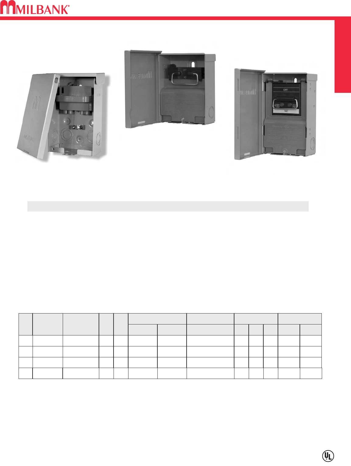
U3800
(No deadfront required)
Milbankʼs air conditioner disconnect has a removable hinged cover which makes wiring a breeze. Our
compact design meets all wire bending space requirements in the NEC and, also, complies with article
440-14 in the NEC. To insure the safest conditions, we designed our disconnect pullers to be remov-
able or they may be reinstalled in the off position. Another safety feature is the padlock provision on the
front cover. As with all Milbank products, our enclosure is constructed of G90U galvanized steel and
finished with an attractive, light gray, baked powder coating. Our state of the art finish combines epoxy
and polyester hybrid resins into a hybrid powder coating which is then electrostatically applied. This
offers a durable, nonfading finish.
TECHNICAL INFORMATION
AMP TYPE CATALOG
NUMBER
MAX
H.P.
WT.
@
#
30 FUSIBLE U3830 32.7
60 FUSIBLE U3860 10 3.3
60
NONFUSIBLE
U3800 10 3.25
LINE & LOAD
WIRE RANGE
GROUND
WIRE RANGE DIMENSIONS WIRE RATING
CU AL CU/AL
#14-#3
AWG #14-#3
AWG #14-3 AWG
#14-#3
AWG #14-#3
AWG #14-3 AWG
#14-#2
AWG #12-#2
AWG #14-3 AWG
D" W" H" CU °CAL °C
2-5/8 5760°/75°60°/75°
3 5 91
⁄
460°/75°60°/75°
35860°/75°60°/75°
PROFILE
U/L listed as Enclosed Pullout Switch
1∅, 240 VAC
Type 3R Rainproof
Six one-inch concentric knockouts
U3801
U3860
60
NONFUSIBLE
U3801 10 2.5 #14-#3
AWG #14-#3
AWG #14-3 AWG 2-3/8 56-3/4 60°/75°60°/75°
AC DISCONNECT / SPA BOX
6
DISCONNECTS
6
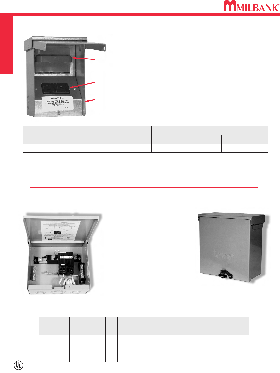
Utility requirements for this equip-
ment may vary. Always consult the
serving utility for their requirements
before ordering or installing equip-
ment in this catalog.
• Meets NEC # 210.63 Requirements *
• UL Listed as Power Outlet
• Type 3R Enclosure
• In-Use Cover**
• Duplex Ground Connector
• 1” Concentric Knockouts
AC DISCONNECT
•1
∅
, 240 Volt
• 60 amp, Non-Fused
GFCI RECEPTACLE
• 20 amp
• Reset/Test Button
• Padlock provision
Combination AC Disconnect / 20 Amp GFCI Receptacle–Together in 1 Box
To ensure the safest conditions, Milbank disconnect pullers are designed to be reversible so they may be reinstalled in the OFF position.
All units are designed with a padlock provision on the cover for security.
**Note: U3822-20GR cover rated as
IN-USE COVER
(Cover may be closed with cords plugged into receptacle).
*Reprinted with permission from NFPA 70-2002,
National Electrical Code
®, Copyright 2001, National Fire Protection Association, Quincy, MA 02269. This reprinted material is not the complete
and official position of the NFPA on the referenced subject, which is represented only by the standard in its entirety. National Electrical Code®and NEC®are registered trademarks of the
National Fire Protection Association, Quincy, MA.
* NEC®#210.63 Heating, Air-
Conditioning and Refrigeration
Equipment Outlet.
...The receptacle shall be locat-
ed on the same level and within
7.5 m (25 ft.) of the heating, air-
conditioning and refrigeration
equipment.
* NEC®#210.08 Ground-Fault
Circuit– Interruptor protection
for personnel.
U4881-O-50GB
AMP TYPE CATALOG
NUMBER
WT.
@
#
–
BREAKER
PROVISION
U4881-O 7
LINE & LOAD CONNECTOR
WIRE RANGE
GROUND CONNECTOR
WIRE RANGE DIMENSIONS
CU AL CU/AL
#14-1/0 #14-1/0 #14-1/0
D″
W″
H″
3 3
⁄
471
⁄
281
⁄
2
50
60
BREAKER
BREAKER
U4881-O-50GB
U4881-O-60GB
8
8
#14-1/0
#14-1/0
#14-1/0
#14-1/0
#14-1/0
#14-1/0
3 3
⁄
4
3 3
⁄
4
71
⁄
2
71
⁄
2
81
⁄
2
81
⁄
2
•
240 volt ground fault protection
•
UL listed, Type 3R rainproof
•
Milbank reliability
•
Easy installation
•
2 pole, 50 or 60 amp GFCI breaker protection
•
Compact size:
8-1/2” H x 7-1/2” W x 3-3/4” D
•
3 or 4 wire installation
•
1
∅
, 120 / 240 VAC
•
Standard package of 12
•
2 extra one-pole breaker spaces
•
100 amp overall rating
Sub Panel Breaker Enclosure
•
Use as a 100 amp, 4 circuit sub panel
enclosure
• U4881-O has provision for (2) 2-pole or
(4) 1-pole small frame breakers
Hot Tub Disconnect or Sub Panel Breaker Enclosure–Type 3R
Spa Box with GFCI Protection
U3822-20GR
60 amp,
Non-Fused
AC Disconnect
Duplex 20 amp
GFCI Receptacle
Type 3R
Enclosure with
In-Use Cover
AMP TYPE CATALOG
NUMBER
MAX
H.P.
WT.
@
#
60
NONFUSIBLE
U3822-20GR
10 6
LINE & LOAD CONNECTOR
WIRE RANGE
GROUND CONNECTOR
WIRE RANGE DIMENSIONS WIRE RATING
CU AL CU/AL
#14-#2
AWG #12-#2
AWG #14-4 AWG
D″W″H″CU °CAL °C
4.8 5.25 7.4 60°/75°60°/75°
7
7
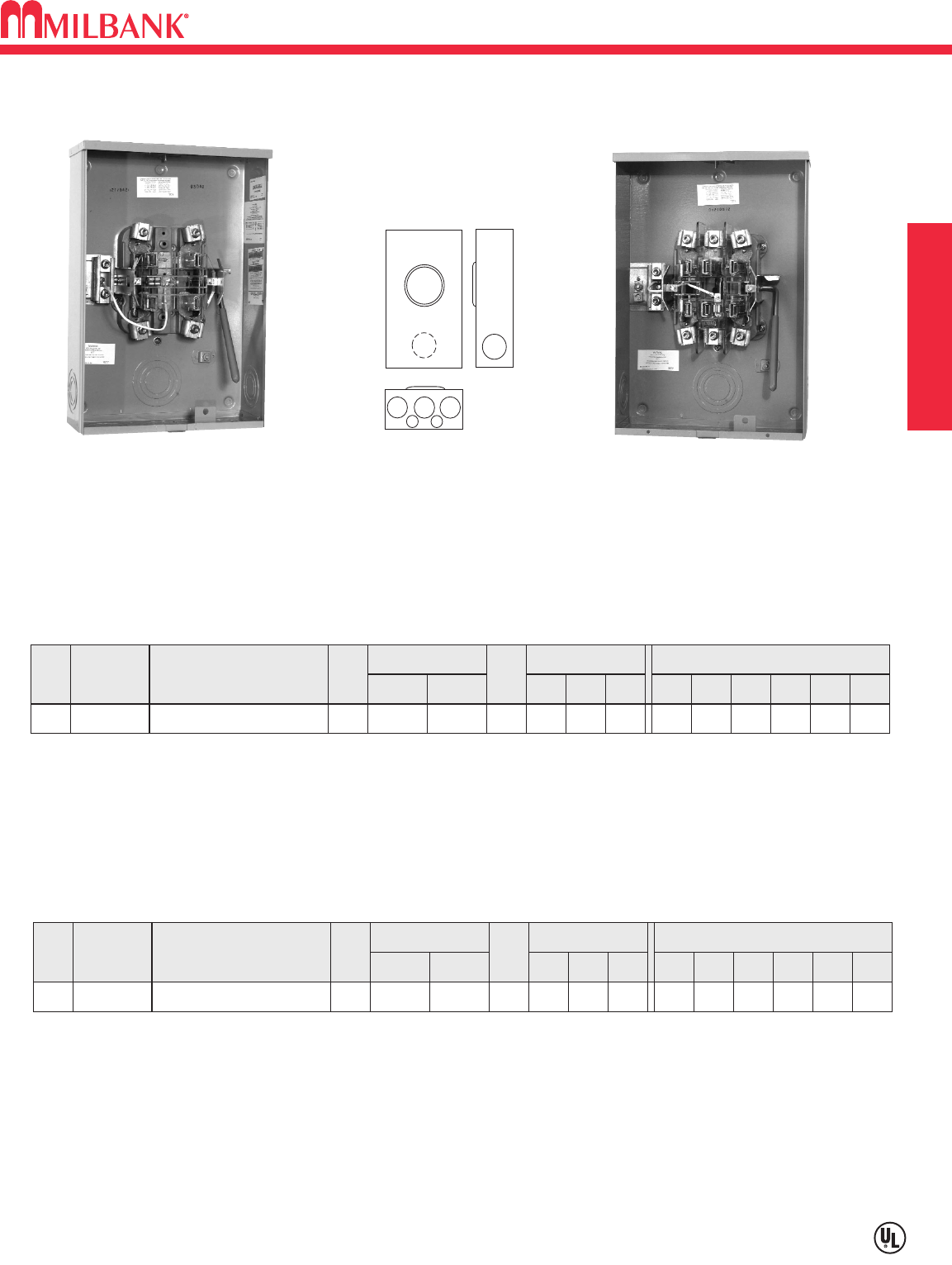
SINGLE POSITION
200 AMP – RINGLESS – 5 & 7 TERMINAL – LEVER BYPASS
U3042-XL-QG-BLG-LIS U1854-XL-QG-BLG-LIS
1
5
5
3 4
6
2
4
AMP SERVICE CATALOG
NUMBER HUB
CONNECTORS
CU/AL
LINE LOAD
BY-
PASS
DIMENSIONS CONCENTRIC K.O.ʼS
123456D″W″H″
200 OH/UG U1854-XL-QG-BLG-LIS C.P.
LEVER
321
⁄
23 3 1
⁄
41
⁄
4,1
⁄
247
⁄
813 19
#6-350
kcmil
#6-350
kcmil
200 AMP–7 TERMINAL–RINGLESS–3∅4W
HUBS: For proper hub selection see the hub suffix chart on the accessory page.
BYPASS: Lever supplies clamping action on meter spades and also operates bypass device.
INSULATED NEUTRAL: For field installed insulated neutral order as extra catalog number K1047.
BARREL LOCK (-BLG): Has provision for barrel lock with guard.
AMP SERVICE CATALOG
NUMBER HUB
CONNECTORS
CU/AL
LINE LOAD
BY-
PASS
DIMENSIONS CONCENTRIC K.O.ʼS
123456D″W″H″
200 OH/UG U3042-XL-QG-BLG-LIS C.P.
LEVER
321
⁄
23 3 1
⁄
41
⁄
4,1
⁄
247
⁄
813 19
#6-350
kcmil #6-350
kcmil
200 AMP–5 TERMINAL–RINGLESS–1∅3W
HUBS: For proper hub selection see the hub suffix chart on the accessory page.
BYPASS: Lever on the U3042 supplies clamping action on meter spades and also operates bypass device.
INSULATED NEUTRAL: For field installed insulated neutral order as extra catalog number K1047.
BARREL LOCK (-BLG): Has provision for barrel lock with guard.
Utility requirements for this equipment may vary. Always consult the serving utility for their requirements before ordering or
installing equipment in this catalog.

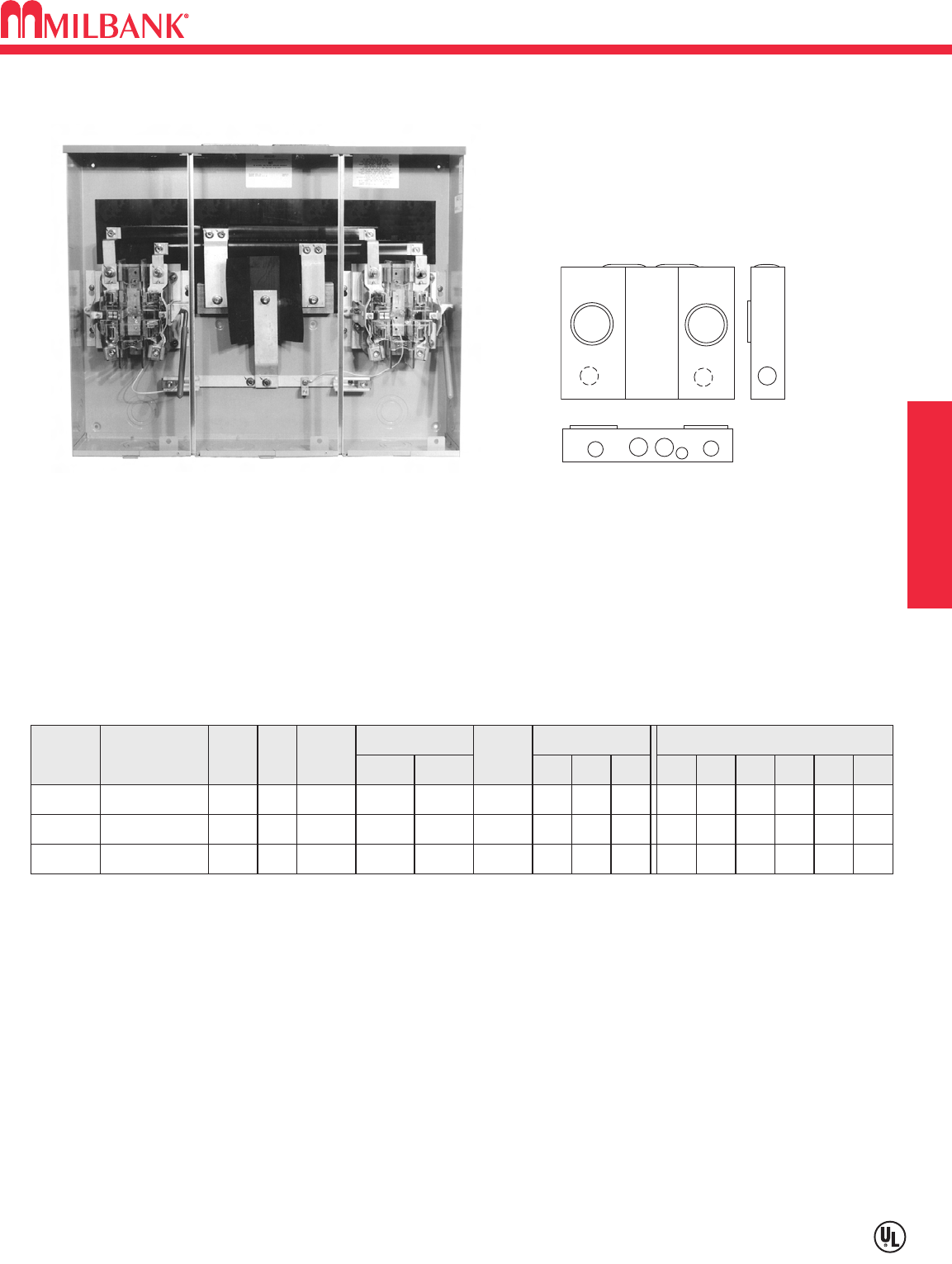
320 AMP CONTINUOUS–400 AMP MAX–5 TERMINAL
JAW CLAMPING LEVER–RINGLESS–600 VAC
8
SINGLE POSITION
8
BYPASS: The lever supplies the clamping action and also operates bypass device.
CONNECTORS: Factory installed connectors - line side - single conductor #4-600 kcmil or 2 conductors 1/0 - 250 kcmil -
load side - twin connectors #6-350 kcmil
* UL LISTED based on parallel 250 kcmil connectors maximum.
SERVICE CATALOG
NUMBER HUB
CONNECTORS
CU/AL
LINE LOAD
BY-
PASS
DIMENSIONS CONCENTRIC K.O.ʼS
123456D″W″H″
OH/UG U5073-X-K3L-K2L-LIS* C.P.
LEVER
33331
⁄
41
⁄
4,1
⁄
2
47
⁄
815 311
⁄
2
#4-600 or (2)
1/0 -250
(twin)
350
320 AMP–5 TERMINAL–RINGLESS–1∅3W–600 VAC
U5073-X-K3L-K2L-LIS
5073
Utility requirements for this equipment may vary. Always consult the serving utility for their requirements before ordering or
installing equipment in this catalog.
9
9
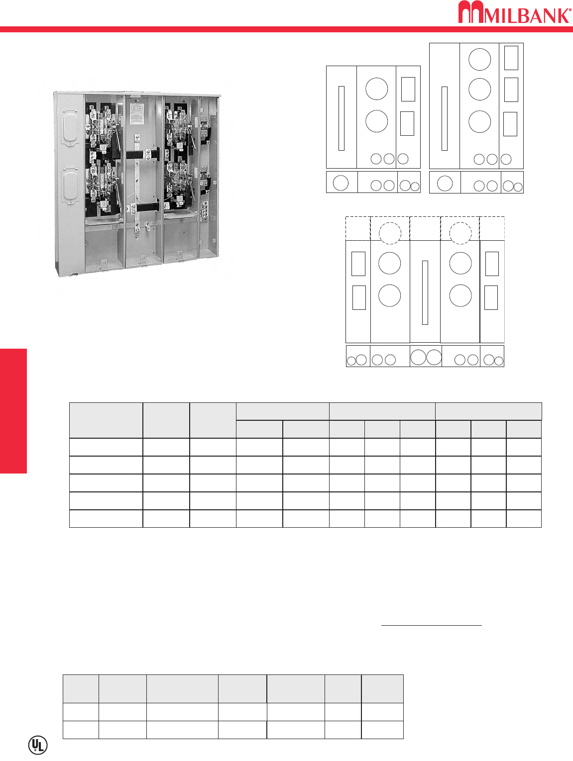
MULTIPLE POSITION
100/200 AMP–5 TERMINAL–HORIZONTAL GANGS–RINGLESS–600 VAC
CATALOG
NUMBER
NO.
OF
POS.
AMP
100/200
HUB
SERVICE
U4142-XT-LIS 2
3
4
C.P. OH/UG
CONNECTORS
CU/AL BY-
PASS
LEVER
DIMENSIONS CONCENTRIC K.O.ʼS
123456
21
⁄
221
⁄
2421
⁄
21
⁄
4,1
⁄
2–
D″W″H″
6321
⁄
8251
⁄
4
LINE LOAD
3/8 x 16″
STUDS
#6-350
kcmil
100/200 U4143-XT-LIS C.P. OH/UG LEVER 21
⁄
221
⁄
2421
⁄
21
⁄
4,1
⁄
2–6 423
⁄
16 251
⁄
4
3/8 x 16″
STUDS
#6-350
kcmil
100/200 U4144-XT-LIS C.P. OH/UG LEVER 21
⁄
221
⁄
2421
⁄
21
⁄
4,1
⁄
2–6 521
⁄
4251
⁄
4
3/8 x 16″
STUDS
#6-350
kcmil
100 / 200 AMP PER POSITION–5 TERMINAL–RESIDENTIAL / COMMERCIAL
U4142-XT-LIS
1
3 3
12
5
44
HUBS: Units are supplied with two closing plates as standard. To order hubs as extra refer to the hub chart on the accessory
page.
LEVER BYPASS: Lever supplies clamping action on meter spades and also operates bypass device.
CONNECTORS: Line wire sections are supplied with 3/8″– 16 hex head nuts with Belleville washers. For single lug connector
kits, order as extra: K1539 (350 kcmil) or K1540 (600 kcmil). For twin lug connectors: K1350 (350 kcmil) or K1541 (600 kcmil).
U4142
Utility requirements for this equipment may vary. Always consult the serving utility for their requirements before ordering or
installing equipment in this catalog.
200 AMP–5 TERMINAL–CONDOMINIUM METER MAIN
10
METER MAIN
10
U4304-X-LIS
CATALOG
NUMBER
BYPASS
CONNECTORS
DIMENSIONS
D” W” H” 1 2 3
LINE LOAD
U4302-X-LIS* LEVER
HUB
C.P. BREAKER 627 3⁄448 4 2 1⁄4,1⁄2
1⁄4,1⁄2
1⁄4,1⁄2
1⁄4,1⁄2
1⁄4,1⁄2
2
2
2
2
CONCENTRIC K.O.ʼS
U4303-X-LIS LEVER C.P. 3/8”-16 STUD BREAKER 627 3⁄460 4
U4304-X-LIS LEVER C.P. 3/8”-16 STUD BREAKER 645 48 4
U4305-X-LIS LEVER C.P. 3/8”-16 STUD BREAKER 645 60 4
U4306-X-LIS LEVER C.P. 3/8”-16 STUD BREAKER 645 60 4
200 AMP–5 TERMINAL–RINGLESS–LEVER BYPASS–CONDO METER MAIN–1Ø3W
HUBS: Units are supplied with 2 closing plates as standard. To order hubs as extra refer to the hub chart on the accessory
page.
CONNECTORS: Line wire sections are supplied with 3/8″- 16 hex head nuts with Belleville washers. For single lug connec-
tor kits, order as extra: K1539 (350 kcmil) or K1540 (600 kcmil). For twin lug connectors: K1350 (350 kcmil) or K1541 (600
kcmil.)
LEVER BYPASS: Lever supplies clamping action on meter spades and also operates bypass device.
REPLACEMENT LOCKING PIN: For replacement locking pin order part number Z816559-SC (1 pin).
BREAKERS: Units have provision for (1) double pole main per meter position.
Breakers NOT included
– order as extra.
See chart below.
* 2 Position Condominium meter main has additional 3” knockout (bottom left section).
22
2
22
2 3
1
3/8”-16 STUD
2 POSITION
22
2
22
2 3
1
3 POSITION
22 23
11
22
2
3
4-6 POSITION
PLUG-IN BREAKER COMPATIBILITY CHART
AMPS MILBANK
CUTLER-HAMMER
(WESTINGHOUSE
/ BRYANT)
SIEMENS
(ITE)
SIEMENS
MURRAY /
CROUSE-HINDS
G.E. SQ-D
125-200 QBR / BJ / HQP —MD Q LINE —
≤ 100 QQUICKLAG P /
BR / HQP QP MP Q LINE
HOMELINE
Utility requirements for this equip-
ment may vary. Always consult
the serving utility for their require-
ments before ordering or installing
equipment in this catalog.
11
11
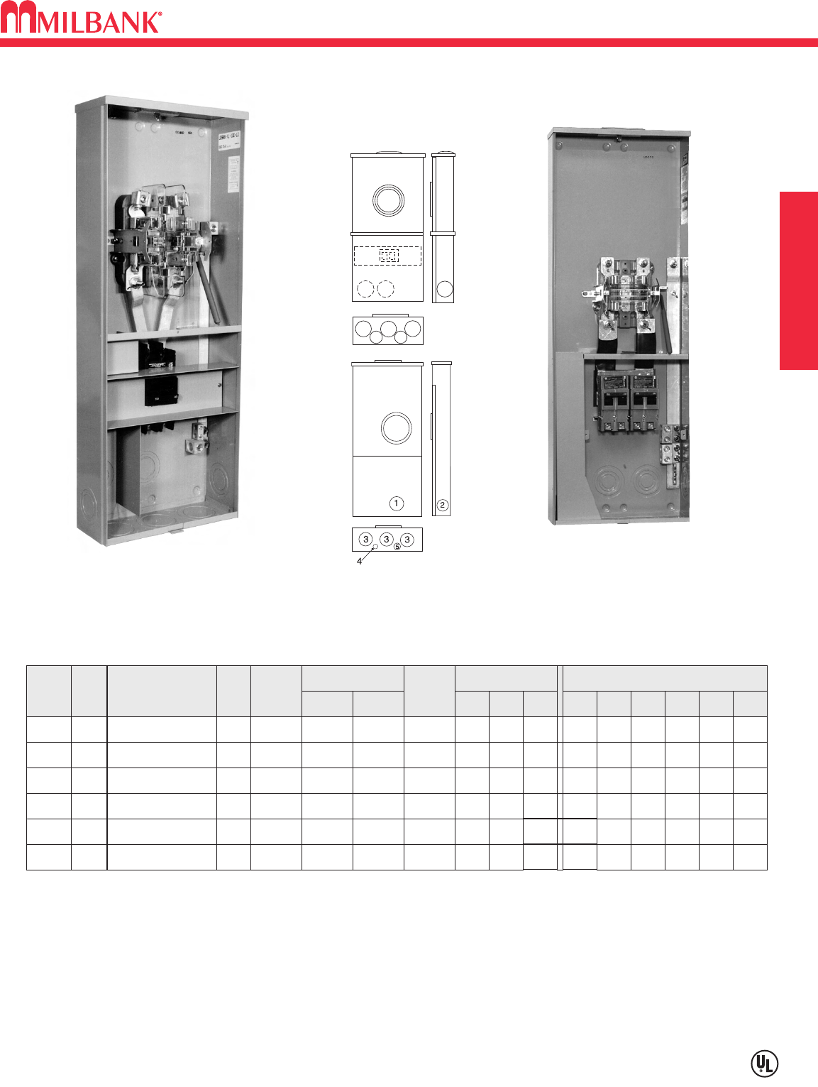
SINGLE POSITION
100-320 AMP—5 & 7 TERMINAL—LEVER BYPASS WITH MAIN BREAKER
U3986-XL-200-LIS
HUBS: Unit is supplied with closing plates as standard. To order hubs as extra, refer to the hub chart on the accessory page.
LEVER BYPASS: Lever supplies clamping action on meter spades and also operates bypass device.
CONNECTORS: Line wire sections are supplied with #6-350 kcmil lay-in connectors.
BREAKER: U3986 has factory installed double pole Milbank UQFB-100-X1, UQFB-150-X1 or UQFB-200-X1 main breaker.
U5080 has factory installed 3 pole Milbank UQFB-3200 main breaker.
* Side Wireway
1
3
12
44
65
CATALOG
NUMBER
AMP
NO.
OF
TERM.
1005
5
5
7
HUB
SERVICE
U3986-XL-100-LIS C.P. OH/UG
CONNECTORS
CU/AL BY-
PASS
LEVER
DIMENSIONS CONCENTRIC K.O.ʼS
123456
21
⁄
221
⁄
23 3 1
⁄
41
⁄
4,1
⁄
2
D″W″H″
47
⁄
813 34
LINE LOAD
#6-350
kcmil
#1-300
kcmil
150 U3986-XL-150-LIS C.P. OH/UG LEVER 21
⁄
221
⁄
23 3 1
⁄
41
⁄
4,1
⁄
2
47
⁄
813 34
#6-350
kcmil
#1-300
kcmil
200
200
U3986-XL-200-LIS
U5080-RXL-200-LIS
C.P.
C.P.
OH/UG
OH/UG
LEVER
LEVER
21
⁄
2
21
⁄
2
21
⁄
2
21
⁄
2
3
3
3
3
1
⁄
4
1
⁄
4
1
⁄
4,1
⁄
2
1
⁄
4,1
⁄
2
47
⁄
8
47
⁄
8
13
13
34
34
#6-350
kcmil
#6-350
kcmil
#1-300
kcmil
#1-300
kcmil
7150 U5080-RXL-150-LIS C.P. OH/UG LEVER 21
⁄
221
⁄
23 3 1
⁄
41
⁄
4,1
⁄
2
47
⁄
813 34
#6-350
kcmil
#1-300
kcmil
100 / 150 / 200 / 320 AMP—5 & 7 TERMINAL—WITH MAIN BREAKER—RINGLESS—LEVER BYPASS
Utility requirements for this equipment may vary. Always consult the serving utility for their requirements before ordering or
installing equipment in this catalog.
U5059-X-2/150-K3L-LIS
5320 U5059-X-2/150-K3L-LIS* C.P. UG LEVER 3331
⁄
41
⁄
4,1
⁄
2---
47
⁄
815 42
#4600
kcmil
#1/0-300
kcmil
3986
5080
5059
#4-600
kcmil
#4-600
kcmil
CATALOG
NUMBER
TERM
6
HUB
SERVICE
AMP
U4554-X-Z21-LIS C.P.
OH/UG
200/400
CONNECTORS
CU/AL
BY-
PASS
NONE
DIMENSIONS CONCENTRIC K.O.ʼS
12* 3 4 5 6
—
—
3
⁄
84 4 11
⁄
4—
D″W″H″
10 21 41
LINE LOAD
SEE
NOTE*
#4-600
kcmil
6
13
13
PHASE
1∅
1∅
3∅
3∅
U4166-XT-Z21-LIS
U4523-X-Z11-LIS
U4163-XT-11-LIS
C.P.
OH/UG
C.P.
OH/UG
C.P.
OH/UG
400/800
200/400
400/800
NONE
NONE
NONE
—
—
3
⁄
8
3
⁄
8
3
⁄
8
4
4
4
4
4
4
11
⁄
4
11
⁄
4
11
⁄
4
—
—
—
10
10
10
26
21
26
51
41
51
#4-600
kcmil
SEE
NOTE*
#4-600
kcmil
#4-600
kcmil
#4-600
kcmil
#4-600
kcmil
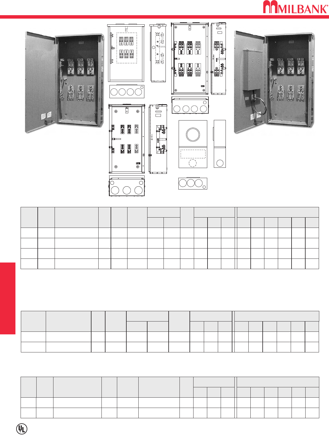
200 / 400 / 800 AMP—METERED—TRANS-S CABINET–1∅3W OR 3∅3W–600 VAC
* This is a 3/8” hole with plastic plug, not a concentric knock-out.
Lugs provided – rated up to single 600 kcmil - #4 awg.
Short circuit current withstand capability is 50K symmetrical amps.
Furnished with 1/2” - 13 studs, washers and hex nuts with conical sems for CT mounting.
*Only 200/400 amp units have elliptical lug - 1-#4-600 kcmil or up to 2-1/0-250 kcmil.
400 / 800 AMP–TRANS-S CABINETS–OVERHEAD / UNDERGROUND
12
TRANSFORMER RATED
12
CATALOG
NUMBER
TERM
PHASE
6
HUB
SERVICE
UC4278-XL-21-LIS BLANK UG
CONNECTORS
CU/AL
BY-
PASS
NONE
DIMENSIONS CONCENTRIC K.O.ʼS
123456
11
⁄
411
⁄
411
⁄
411
⁄
41
⁄
4,1
⁄
2—
D″W″H″
41
⁄
812 20#14-#2 MAX
13
1∅
3∅UC4279-XL-21-LIS BLANK UG NONE 11
⁄
411
⁄
411
⁄
411
⁄
41
⁄
4,1
⁄
2—
41
⁄
812 20#14-#2 MAX
20 AMP—1 PIECE COVER—REMOTE SOCKETS—RINGLESS—1∅—3∅ ∗
* This is a 3/8” hole with plastic plug, not a concentric knock-out.
Lugs provided – rated up to single 600 kcmil - #4 awg.
* These units are prewired per
LIPA
specifications.
U4154-XT-LIS
CATALOG
NUMBER
PHASE
1∅
HUB
SERVICE
U4165-XT-LIS C.P. OH/UG
CONNECTORS
CU/AL BY-
PASS
NONE
DIMENSIONS CONCENTRIC K.O.ʼS
12* 3 4 5 6
—3
⁄
84 4 11
⁄
4—
D″W″H″
10 26 51
LINE LOAD
#4-600
kcmil
3∅U4154-XT-LIS C.P. OH/UG NONE —3
⁄
84 4 11
⁄
4—10 26 51
#4-600
kcmil
400 / 800 AMP—UNMETERED ENCLOSURE
U4163-XT-11-LIS
4
5
4
33
2
1
434
5
2
4278
4279
4154
4165
3434
2
5
434
5
5
2
4163
4166
4554
4523
Utility requirements for this equip-
ment may vary. Always consult the
serving utility for their requirements
before ordering or installing equip-
ment in this catalog.
13
13
MISCELLANEOUS
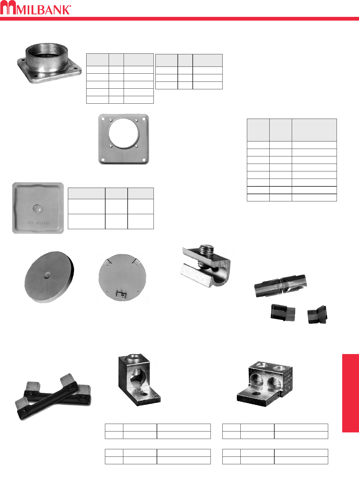
ACCESSORIES
INTERCHANGEABLE UNIT HUBS
HUB SUFFIX CHART
HUB ADAPTER PLATE
(Converts -R opening to -RL)
S8324
1″
-WL
SIZESUFFIX MILBANK
CAT. NO.
-YL
-ZL
-DL
-EL
A7514
11
⁄
4″A7515
11
⁄
2″A7516
2″A7517
21
⁄
2″A7518
3″
-F
SUFFIX SIZE MILBANK
CAT. NO.
-G
-H
A8110
31
⁄
2″A8111
4″A8112
SMALL “RL"
OPENING (STANDARD)
LARGE “R”
OPENING (HEAVY DUTY)
K1539K1 350 MCM (MAX)
K1540K3 600 MCM (MAX)
CATALOG #SUFFIX (3 per set) – 1 ∅
SINGLE TWIN
K3082K5 350 MCM (MAX)
K3441K7 600 MCM (MAX)
CATALOG #SUFFIX (4 per set) – 3 ∅
K1350K2 350 MCM (MAX)
K1541K4 600 MCM (MAX)
CATALOG #SUFFIX (3 per set) – 1 ∅
K3442K6 350 MCM (MAX)
K3083K8 600 MCM (MAX)
CATALOG #SUFFIX (4 per set) – 3 ∅
CONNECTOR KITS
For use with 3/8”-16 stud type
units only
METER CLOSING PLATE
(Gray Plastic)
6003
METAL CLOSING PLATE
(For ringless sockets)
CP-21
TRIPLEX GROUND
K1190
(For factory installed triplex
ground add suffix “TG” to
the catalog number.)
BYPASS LINK
CLOSING COVERS
DISCONNECT
SLEEVE
M5-144
K8180
(Bypass links are sold in pairs)
WL 1″For -RL Opening
SUF-
FIX
HUB
SIZE
APPLICATION
YL 11
⁄
4″For -RL Opening
ZL 11
⁄
2″For -RL Opening
DL 2″For -RL Opening
EL
F
G
H
21
⁄
2″
3″
31
⁄
2″
4″
For -RL Opening
For -R Opening
For -R Opening
For -R Opening
REMOVABLE HUB CLOSING PLATE
DESCRIPTION SUFFIX CAT. #
STANDARD
(for -RL opening)
-XL A7551
LARGE
(for -R opening) -X A9064
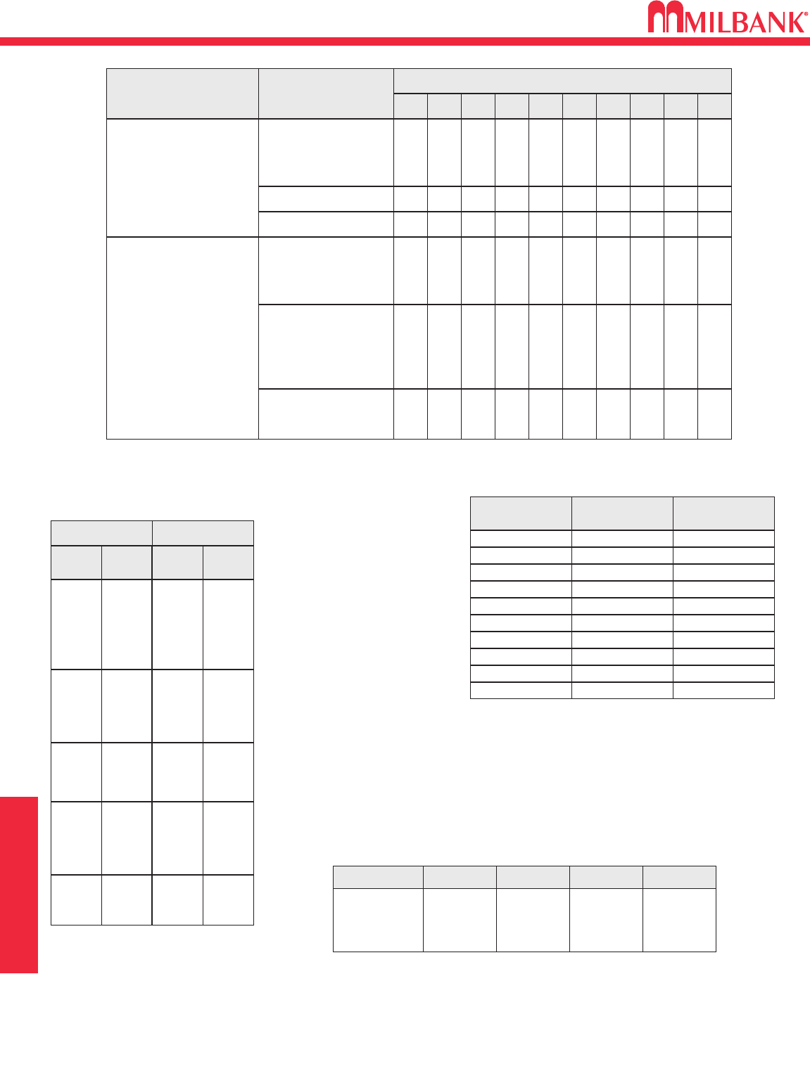
AMPACITY INFORMATION
14
MISCELLANEOUS
14
TYPE
RHW & RHH
(without outer covering)
THW
CONDUCTOR
SIZE
AWG,MCM
14
12
10
8
CONDUIT TRADE SIZES (INCHES)
1
⁄
23
⁄
4111
⁄
411
⁄
2221
⁄
2331
⁄
24
6
4
4
1
10
8
6
3
16
13
11
5
29
24
19
10
40
32
26
13
65
53
43
22
93
76
61
32
143
117
95
49
192
157
127
66
163
85
6 123710 16 23 36 48 62
3 1124610 15 23 31 40
1/0
2/0
3/0
4/0
250
300
350
400
500
600
700
750
1
1
1
1
1
1
1
2
1
1
1
3
3
2
1
5
5
4
3
8
7
6
5
12
10
9
7
16
14
12
10
21
18
15
13
1
1
1
1
1
1
1
1
1
1
1
1
2
2
1
1
1
4
3
3
2
1
6
5
4
4
3
8
7
6
5
4
10
9
8
7
6
1
1
1
1
1
1
1
1
1
3
2
2
4
3
3
5
4
4
TW
THW
FEPB (6 thru 2),
RHW and
RHH
(without outer covering)
RH, THHW
*This table is for concentric stranded conductors only. For cables with compact conductors refer to N.E.C.
*CU
A
18
16
14
12
10
8
6
4
3
2
1
1/0
2/0
3/0
4/0
250
300
350
400
500
600
700
750
255
285
310
335
380
420
460
475
—
—
20
25
35
50
65
85
100
115
130
150
175
200
230
B
250
300
350
400
500
600
700
750
—
—
—
12
10
8
6
4
3
2
1
1/0
2/0
3/0
4/0
A
AL or Cu-Clad AL
205
230
250
270
310
340
375
385
—
—
—
20
30
40
50
65
75
90
100
120
135
155
180
C
AMBIENT
TEMP.C°
CORRECTION
FACTOR
AMBIENT
TEMP.F°
21 - 25 1.05 70 - 77
26 - 30 1.00 79 - 86
31 - 35 .94 88 - 95
36 - 40 .88 97 - 104
41 - 45 .82 106 - 113
46 - 50 .75 115 - 122
51 - 55 .67 124 - 131
56 - 60 .58 133 - 140
61 - 65 .33 142 - 158
66 - 70 —160 - 176
*ALLOWABLE AMPACITIES OF INSULATED COPPER &
ALUMINUM CONDUCTORS (3W IN CONDUIT)75°C(167°F)
AMPACITY CORRECTION FACTORS
Overall ampere ratings of U/L listed Milbank multiple position meter sockets are based on
1993 N.E.C. Manual article 220-32 and ANSI / UL-414 (except where restricted by line con-
nector size.) These requirements provide for a diversity factor / demand factor being utilized
in determining the overall (main bus / lug) rating of a gang socket. All Milbank U/L listed
gang sockets meet or exceed these diversity factor/demand factor requirements. Standard
overall ampacity ratings for U/L listed and non U/L listed gang sockets are as shown in the
chart below. Ampere ratings of meter sockets are based on the meter socket being wired
with 75°C insulated wire conductor, sized in accordance with Table 310-16 of the National
Electric Code.
NO. OF METER
POSITIONS 100A / POS.
AMPACITY 125A / POS.
AMPACITY 150A / POS.
AMPACITY 200A / POS.
AMPACITY
2
3
4
5
6
200A
200A
200A
225A
270A
200A
225A
250A
285A
330A
200A
225A
270A
338A
396A
200A
270A
360A
450A
528A
A = Size: AWG/MCM
B = Ampere Rating for
Insulation Types:
FEPW, RH, RHW,
THW, THWN, XHHW,
USE, 2W.
C = Ampere Rating for
Insulation Types:
RH, RHW, THW,
THWN, XHHW, USE
(Per NEC table 310-16)
Unless otherwise permitted elsewhere in the Code, the overcurrent protection for conductor types marked with an obelisk ()
shall not exceed 15 amps for 14 AWG, 20 amps for 12 AWG, and 30 amps for 10 AWG copper: or 15 amps for 12 AWG and 25
amps for 10 AWG aluminum and copper-clad aluminum after any correction factors for ambient temperature and number of con-
ductors have been applied.
GANG SOCKET OVERALL AMPACITIES
15
15
MISCELLANEOUS
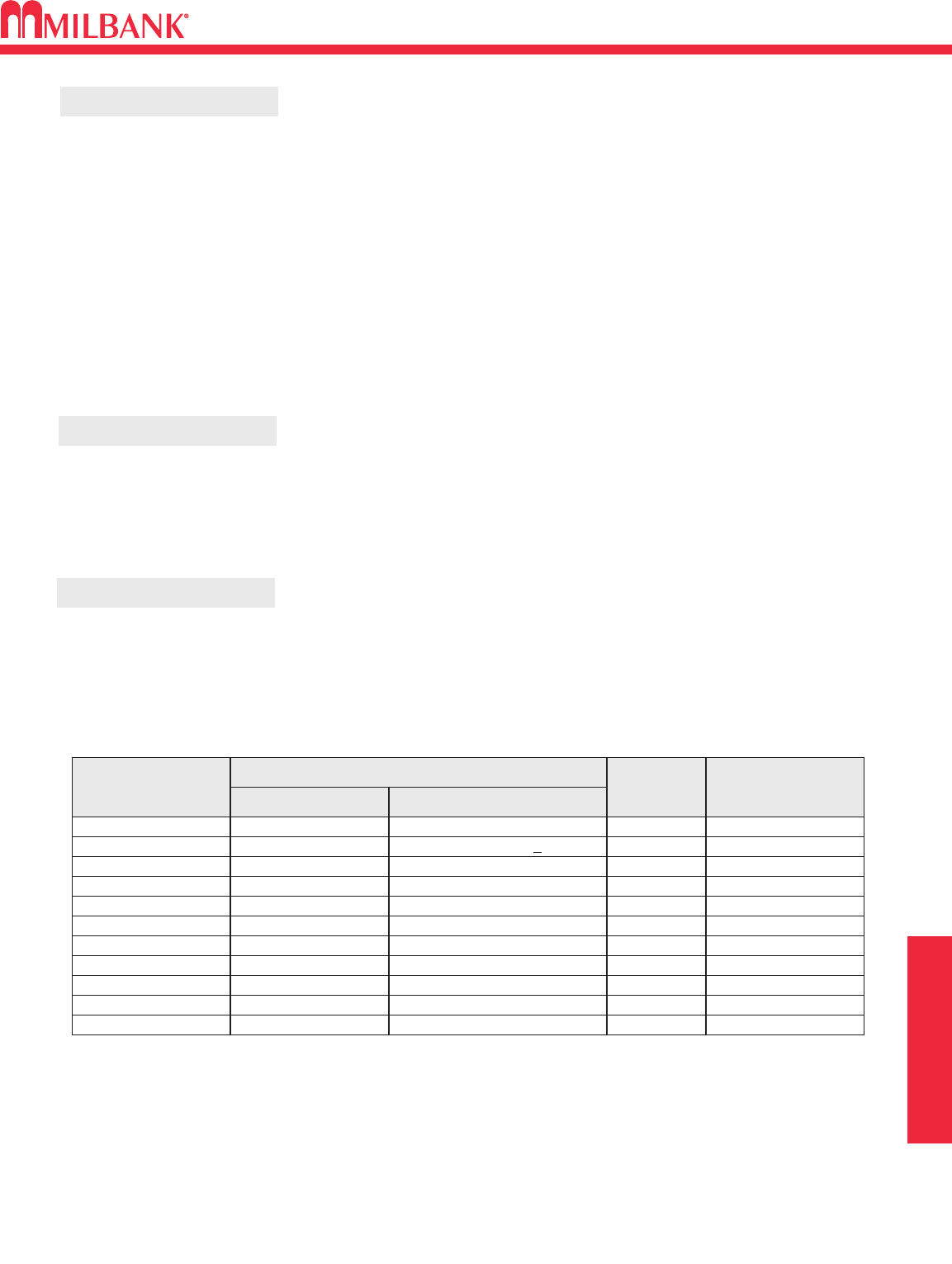
ENERGIZATION OF ELECTRICAL EQUIPMENT
BEFORE ENERGIZING
WHEN ENERGIZING
AFTER ENERGIZING
A. Give equipment a thorough visual examination to determine that:
1) No shipping or installation damage exists.
2) Proper clearances have been maintained.
3) All connections have been made.
4) Equipment is clean and dry.
B. Make a thorough examination to verify:
1) Tightness of all bolted connections ( see table below.)
2) Manually operate all circuit breakers, switches, relays, etc.
3) Check rigidity of all mountings, bus bars and components.
4) Use test equipment to check continuity of circuitry and integrity of insulation.
C. All switches and circuit breakers should be in the off position.
D. Verify that manual meter bypass (if applicable) is in non-bypass position.
E. Install cover and/or close doors.
F. If installation is not being energized at this time, follow “after-energizing” steps listed below. These
steps will secure the installation in case of accidental energization.
A. Use caution and follow established safety procedures:
1) Wear safety apparel.
2) Use safety equipment.
3) Take action to prevent injury to yourself and others in the event of failure of the installation.
4) Take action to prevent/decrease damage to property in the event of failure of the installation.
5) If you are unsure how to safely energize the installation, get someone who is knowledgeable to do it.
A. Secure the installation:
1) To prevent accidental contact with energized parts, cover all openings with approved filler devices.
2) To prevent unauthorized access, secure all covers and/or doors with approved security devices.
3) Attach/post information to advise others of potential hazards associated with the installation.
NOMINAL
SIZE
10
10
10
12
12
1/4
1/4
5/16
JOINT DESCRIPTION
SCREW NUT
BRASS
STEEL
STEEL
STEEL
STEEL
STEEL
STEEL
STEEL
Brass Nut or Extruded Hole
CU or AL Busbar <1/8″
Steel Nut or EH; CU or AL Busbar >1/8″
Aluminum Extruded Hole
Steel Nut or Extruded Hole
Aluminum Extruded Hole
Steel Nut or EH; CU or AL Busbar
Aluminum Extruded Hole
ALL
ALL
ALL
ALL
ALL
ALL
ALL
HEX
20-25 in. lbs.
25-30 in. lbs
30-35 in. lbs
30-35 in. lbs
40-50 in. lbs.
40-50 in. lbs.
50-60 in. lbs.
60-70 in. lbs.
5/16 STEEL Steel Nut or EH; CU or AL Busbar HEX 100-150 in. lbs.
3/8 STEEL Steel Nut HEX 150-200 in. lbs.
1/2 STEEL Steel Nut HEX 200-250 in. lbs.
HEAD TYPE TORQUE
( INCH LBS. )
*Interior labels typically indicate the required torque for wire connectors and studs, and should be referenced first.
EH: Extruded Hole
CU: Copper
AL: Aluminum
RECOMMENDED TORQUE FOR GENERAL APPLICATIONS*
16
MISCELLANEOUS
16
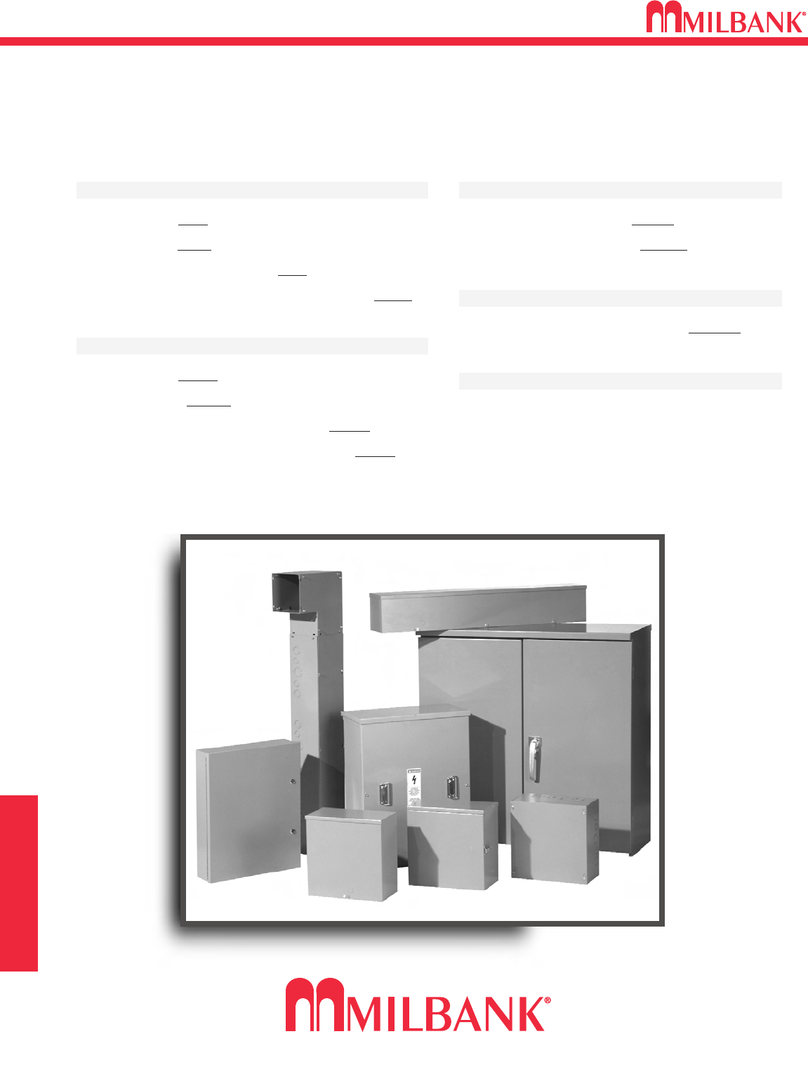
COMMERCIAL ENCLOSURES
Type 1 Enclosures
Screw Cover–SC1
Hinge Cover–HC1
Telephone Cabinet Covers–TSC
Telephone Cabinet Flush Mount Covers–TFLC
Type 3R Enclosures
Screw Cover–SC3R
Hinged Cover–HC3R
Telephone Cabinet Hinged Cover–TC3R
2 Door Current Transformer Cabinet–CT3R
Wireway–Type 1
Screw Cover Wireway–GSC1
Hinged Cover Wireway–GHC1
Wireway–Type 3R
Screw Cover Wireway Trough–GSC3R
Miscellaneous
Accessories
“Ask your local Milbank Enclosure Distributor
for the current Milbank Enclosure Catalog or
find it on-line at www.milbankmfg.com”
17
17
MISCELLANEOUS
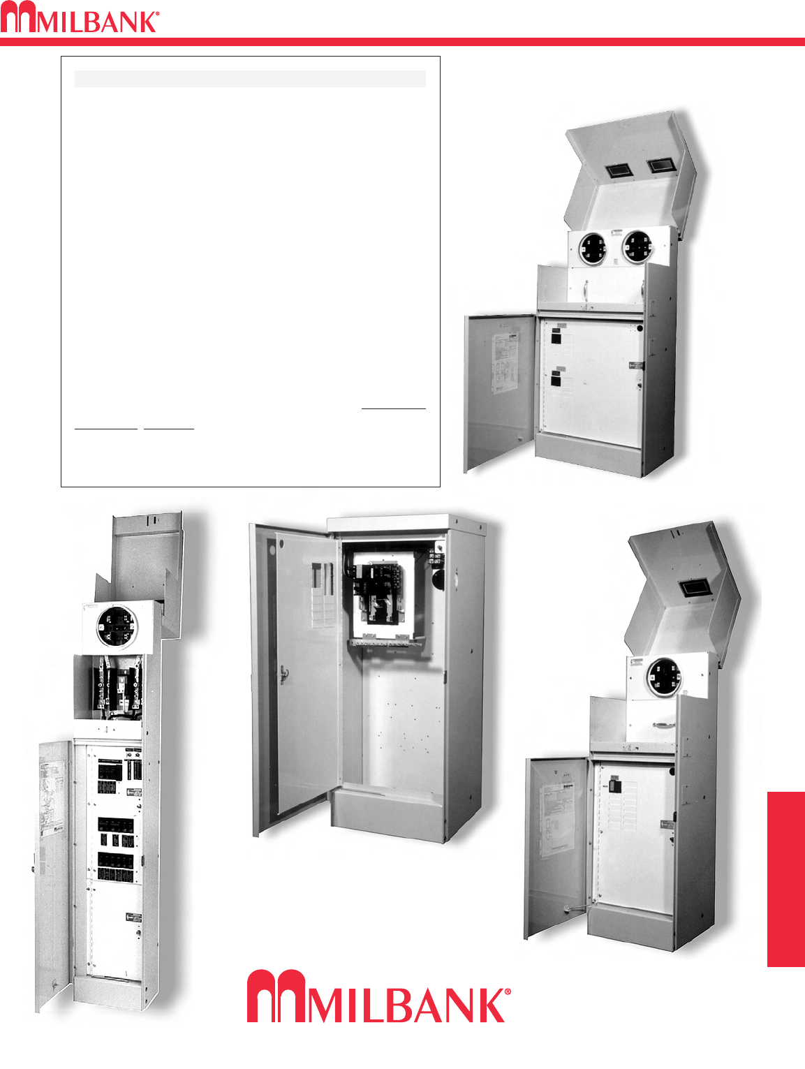
COMMERCIAL PEDESTALS
COMMERCIAL METER PEDESTAL
The commercial pedestal is a pad mounted,
weatherproof meter pedestal which contains an
underground utility pull section, a utility meter sec-
tion, and a customer compartment with pull section.
Typical uses are street and area lighting con-
trol, pump and irrigation control, remote power, and
temporary power needs.
It is designed to provide a vandal resistant
enclosed meter socket and a customer section in a
single enclosure. The three sections are isolated and
can be padlocked and sealed for security. The cus-
tomer section is designed to include distribution as
well as control components. A deadfront is used to
provide safety and protect interior parts.
The pedestal is UL listed as an Enclosed
Industrial Control, suitable only for use as service
equipment (File Number E113855.) Most units com-
ply with EUSERC drawing #308.

NOTES
18
18

19
19
NOTES
Meter Mounting Equipment & More!
Commercial Electrical Enclosures
Residential & Commercial Metering
Disconnect Devices
Current Transformer Enclosures
RV/MH Pedestals
Power Outlets
Circuit Breakers
Enclosed Circuit Breakers
Safety Switches
Test Switches
KELLY & NOVIELLO ASSOCIATES
65 Mahan Street
West Babylon, NY 11704
Tel: 631-643-1100
Fax: 631-643-1125
LIPA 08/09 (1500)
www.milbankmfg.com
MILBANK MFG. CO.
PO Box 419028
Kansas City, MO 64141-0028
Tel: 816.483.5314 Fax: 816.483.6357
www.milbankmfg.com
