Product Detail Manual
2014-06-03
: Pdf 690040-Attachment 690040-Attachment 047503 Batch4 unilog
Open the PDF directly: View PDF ![]() .
.
Page Count: 150 [warning: Documents this large are best viewed by clicking the View PDF Link!]
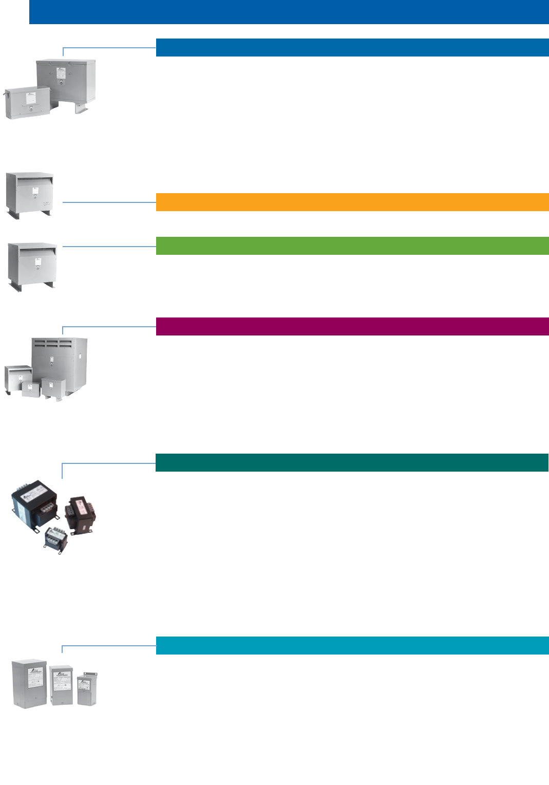
- Dry-Type Distribution Transformers
- Harmonic Mitigating Transformers
- Non-Linear Load® Transformers
- Drive Isolation Transformers & AC Line Reactors
- Industrial Control Transformers
- Selection Steps
- TA Series Open Core & Coil Construction Features
- TA Series Open Core & Coil Primary & Secondary Fuse Sizing Info
- TA Series Open Core & Coil Primary & Secondary Fuse Sizing Info Fuse Kits
- TA Series Open Core & Coil Jumper Link Connections
- TB Series Open Core & Coil General Description & Features
- TB Series Open Core & Coil Primary & Secondary Fuse Sizing Info
- TA & TB Series Open Core & Coil Transformers Selection Charts
- TA Series Open Core & Coil Wiring Diagrams & Dimensional Drawings
- TB Series Open Core & Coil Wiring Diagrams & Dimensional Drawings
- Harsh Environment Control Transformers
- AE/CE Series Encapsulated Transformers
- Finger/Guard® Industrial Control Transformers
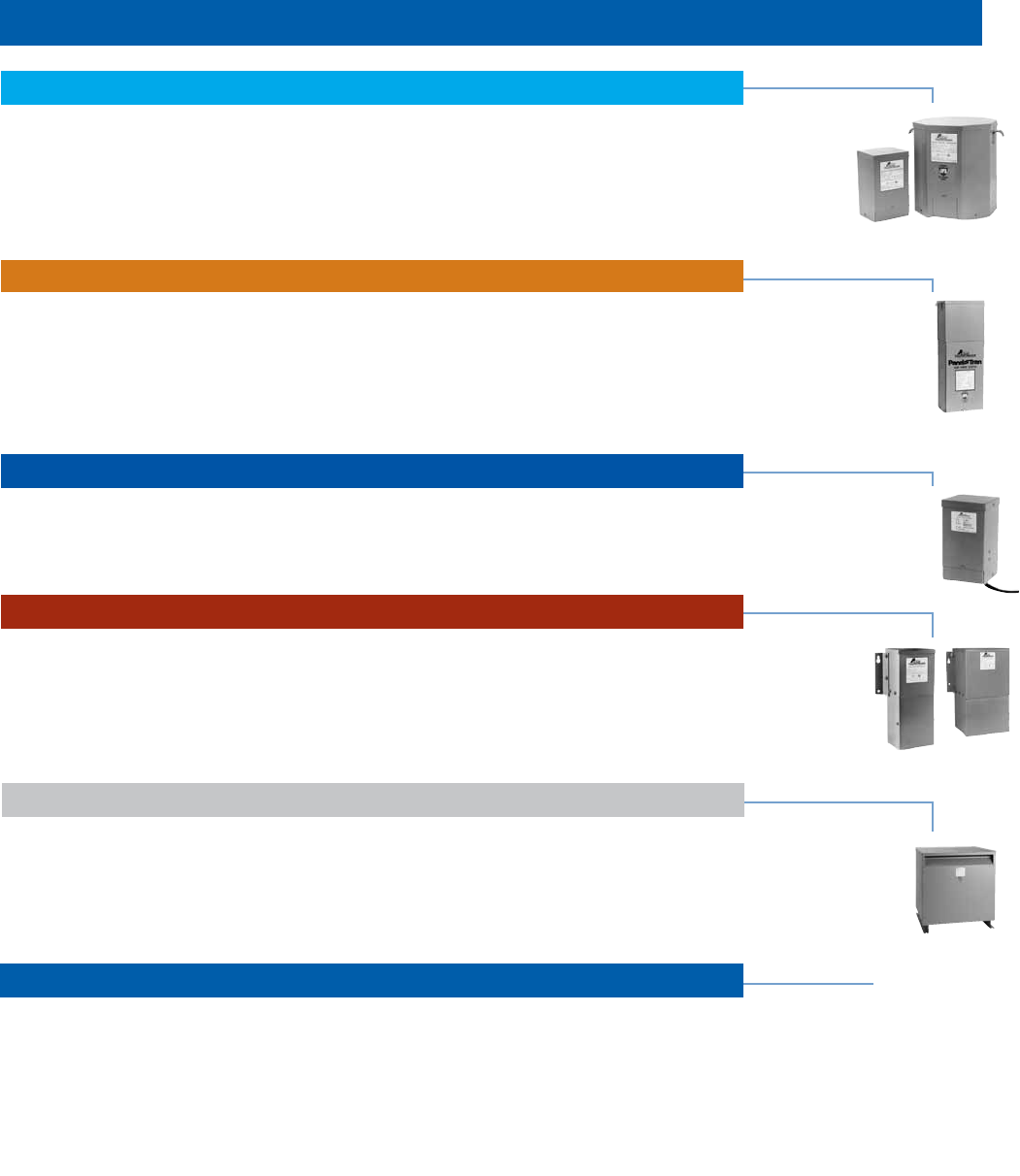
- Low Voltage Lighting Transformers & Power Supplies
- Buck-Boost Transformers
- Panel-Tran® Zone Power Centers
- Air Conditioning, Refrigeration & Appliance Transformers
- Power Conditioning Products
- Powerwise C3 Transformer
- General Information
FULL LINE PRODUCT CATALOG
CommerCial ConstruCtion • industrial automation
ACM_CAT_007_0913
Acme Electric
N85 W12545 Westbrook Crossing
Menomonee Falls, WI 53051
800.334.5214
acmetransformer.com
©2013 Electrical Holdings LLC. All rights reserved.
Acme Electric Full Line Product Catalog
For over eighty-eight years, Acme Electric has
been manufacturing power conversion and
power conditioning equipment for use in indus-
trial, commercial and OEM applica-
tions. Acme has built its reputation
as a true industry leader by provid-
ing superior service, quality and
technical expertise to the trans-
former market.
Acme Electric is a full line manufacturer of low
voltage (600V and below) dry type distribution
transformers, industrial control transformers and
power quality equipment. With roughly 1300 cat-
alog sku's, our products cover the full spectrum
of applications, from general purpose power dis-
tribution in commercial applications,
to ultra-efficient transformers used
in alternative energy, to transform-
ers that address harmful harmonic
conditions generated in today's
electrical loads. All of our products
are designed, manufactured and
verified to exceed the standards established by
UL, CSA, CE, NEMA, ANSI and IEEE.
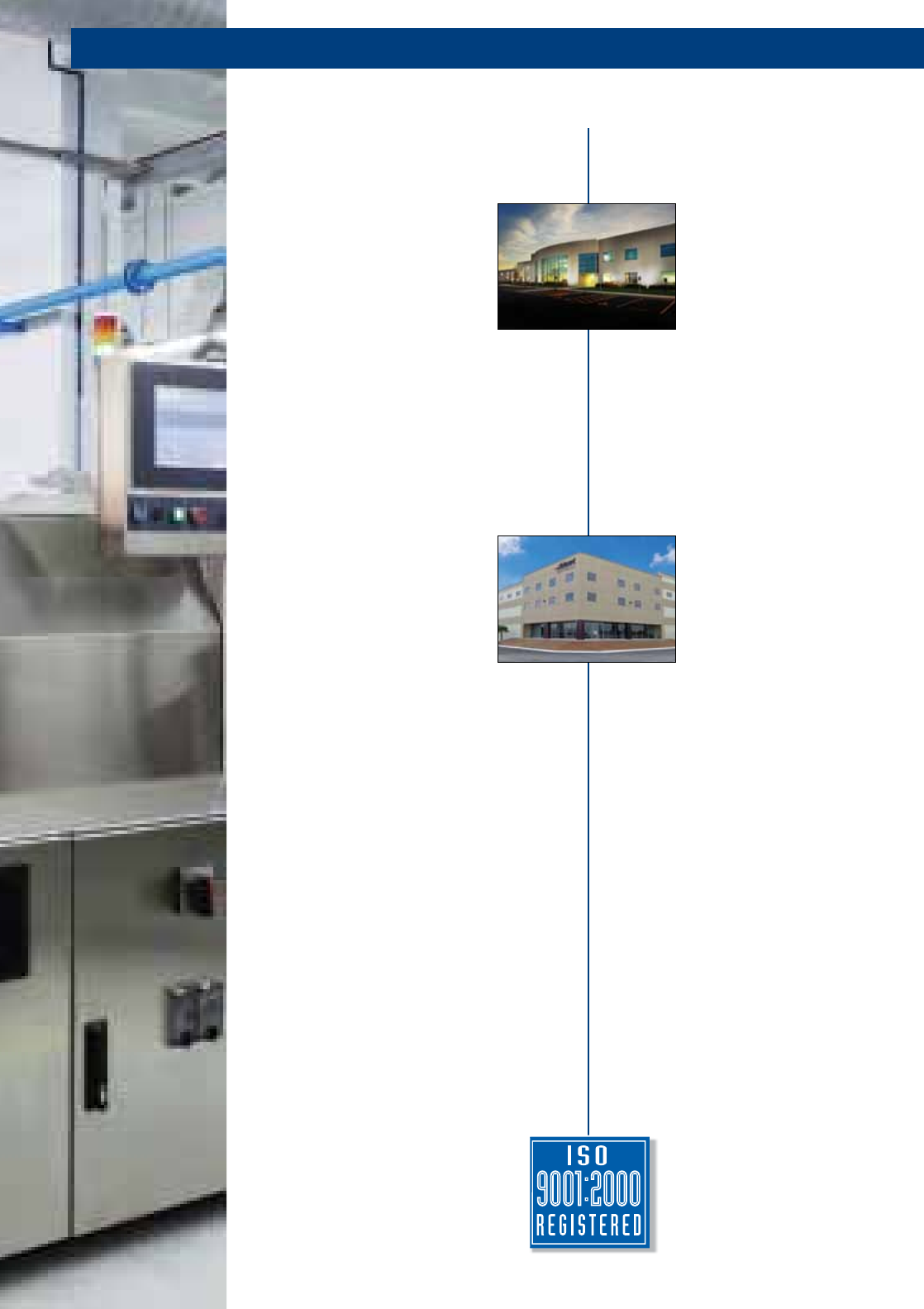
Acme operates out of two main facilities. Our
headquarters in Menomonee Falls is home to our
engineering and management staff. Our engi-
neers utilize modern computer aided design tools
and an in-house test lab to quickly, efficiently and
effectively turn around new product designs. The
Menomonee Falls facility also houses a power
laboratory which provides our engineering team
with the ability to test the performance of high
efficiency transformers and power quality equip-
ment under user-defined harmonic conditions.
This rather unique capability enables us to pro-
vide further assurance to our customers that our
products are fully qualified to meet the unique
challenges of their applications.
Manufacturing takes place in Acme's new
state-of-the-art, ISO 9001 production facility in
Monterrey, Mexico. With 133,000 square feet
of manufacturing space, it contains
the staffing, the equipment and the
processes indicative of world class,
flexible manufacturing operations.
The Monterrey facility also houses
an in house test lab with certifica-
tions from UL, CSA, ISO and TUV. Our manu-
facturing team is credited with defining and exe-
cuting the assembly methods and processes
that sustain Acme Electric's reputation as the
supplier of the highest quality transformers in
the industry. And, our on-site quality team takes
the lead in ensuring continuous improvement in
everything we do.
Once the manufacturing process
is complete, our products are
shipped to eight regional ware-
houses in the United States. The
location of each warehouse was
strategically determined to provide rapid deliv-
ery and short lead times to every corner of the
contiguous 48 states. And, with nearly 600
stocked part numbers, Acme has what you
need when you need it.
Acme's technical support team has over 100
years of combined experience in the electrical
industry. Only one phone call away, our techni-
cal support team is prepared and ready to help
you solve a broad range of challenges. From
finding the right solution for your application, to
helping you install your brand new transformer,
to helping you troubleshoot an electrical phe-
nomenon in your equipment or facility, our tech-
nical service team embodies our philosophy that
our commitment to the customer does not end
with the shipment of product.
Leadership in Quality Designed Products
And Quality Customer Satisfaction
ACME ELECTRIC
Selection Guide .................................................................................................................................83
General Purpose Low Voltage Transformers ...................................................................................84
Buck-Boost Lighting Transformers ...................................................................................................85
Wiring Diagrams ................................................................................................................................86
Low Voltage Lighting Transformers & Power Supplies
©2013 Electrical Holdings LLC. All rights reserved.
Information contained in this catalog is subject to change without notice and therefore cannot be guaranteed by Acme.
Harmonic Mitigating Transformers .............................................................................................. 34-35
SECTION 1
SECTION 2
SECTION 3
SECTION 4
SECTION 6
TABLE OF CONTENTS
Transformer Questions & Answers ................................................................................................ 6-10
Selection Steps ............................................................................................................................. 11-12
Construction Features .................................................................................................................. 13-15
316 Stainless Steel Transformers .............................................................................................17 & 25
Selection Charts, 1Ø and 3Ø ....................................................................................................... 17-29
Auto-Transformers .....................................................................................................................20 & 29
Auto Arrangements (Using 2 Single Phase) .................................................................................... 30
Auto Zig-Zag Transformers ............................................................................................................... 31
Non-Standard 3Ø Applications ......................................................................................................... 32
Design Figures, Wiring Diagrams & Accessories ...................................................................122-134
Dry-Type Distribution Transformers
Harmonic Mitigating Transformers
Non-Linear Description & Features ............................................................................................. 37-39
Non-Linear Selection Charts ........................................................................................................ 40-41
Non-Linear Definition of Terms ......................................................................................................... 42
Design Figures, Wiring Diagrams & Accessories ...................................................................122-134
Non-Linear Load® Transformers
General Description & Features .................................................................................................. 43-45
Selection Charts ........................................................................................................................... 46-47
Windings, Terminations & Construction ........................................................................................... 47
Thermal Switches .............................................................................................................................. 47
AC Line Reactors General Descriptions ..................................................................................... 48-49
AC Line Reactors Dimensional Drawings ........................................................................................ 48
AC Line Reactors Selection Charts .................................................................................................. 50
Drive Isolation Transformers & AC Line Reactors
SECTION 5
Selection Steps .................................................................................................................................. 52
TA Series Open Core & Coil Construction Features ........................................................................ 53
TA Series Open Core & Coil Primary & Secondary Fuse Sizing Info ......................................... 54-55
TA Series Open Core & Coil Primary & Secondary Fuse Sizing Info Fuse Kits ........................ 54-55
TA Series Open Core & Coil Jumper Link Connections .................................................................. 55
TB Series Open Core & Coil General Description & Features ....................................................... 56
TB Series Open Core & Coil Primary & Secondary Fuse Sizing Info ....................................... 57-58
TA & TB Series Open Core & Coil Transformers Selection Charts ............................................ 59-64
TA Series Open Core & Coil Wiring Diagrams & Dimensional Drawings ...................................... 65
TB Series Open Core & Coil Wiring Diagrams & Dimensional Drawings ...................................... 66
Harsh Environment Control Transformers ........................................................................................ 67
AE/CE Series Encapsulated Transformers .................................................................................. 68-75
Finger/Guard® Industrial Control Transformers. . . . . . . . . . . . ................................................... 76-79
Industrial Control Transformers
SECTION 8
TABLE OF CONTENTS
304 Stainless Steel Panel-Tran® ............................................................................................... 104-105
General Description & Construction ............................................................................................... 104
Features ........................................................................................................................................... 104
Selection Charts .......................................................................................................................106-107
Circuit Breaker Data ................................................................................................................. 106-107
Wiring Diagrams .............................................................................................................................. 108
Panel-Tran® Zone Power Centers
Construction Features ..............................................................................................................110-111
Selection Steps ................................................................................................................................ 111
Selection Charts .............................................................................................................................. 112
SECTION 9
Air Conditioning, Refrigeration & Appliance Transformers
True-Power® Constant Voltage Regulators
Introduction & Features .......................................................................................................114
Specifications ....................................................................................................................... 115
Selection Charts, Portable & Hardwired .............................................................................115
Dimensional Drawings ......................................................................................................... 116
SECTION 10
Power Conditioning Products
GENERAL
Design Figures ................................................................................................................................122
Wiring Diagrams .......................................................................................................................123-132
Transformer Accessories .........................................................................................................133-134
Acme Specifications Guide .....................................................................................................135-138
Industry Standards Data .................................................................................................................139
Alphanumerical Catalog Number Listing ................................................................................140-144
Product Warranty & Shielding Information .............................................................Inside Back Cover
General Information
Description & Applications ...........................................................................................................88-89
Questions & Answers ...................................................................................................................89-93
Selection Charts, Single Phase ....................................................................................................94-96
Selection Charts, Three Phase.....................................................................................................97-99
Specifications & Dimensions ..........................................................................................................100
Wiring Diagrams .......................................................................................................................101-102
SECTION 7
Buck-Boost Transformers
SECTION 11
CSL-3 Super Efficient Transformers ....................................................................................................... 117
General Description and Features ...................................................................................................118-119
Selection Charts ...................................................................................................................................... 120
Powerwise C3 Transformer

SECTION
600 Volt Class and Below
Single and Three Phase
Transformer Questions & Answers ........... 6-10
Enclosure Definitions ....................................10
Steps in Transformer Selection .............. 11-12
Construction Features ............................ 13-16
316 Stainless Steel Transformers ........ 17 & 25
Selection Charts 1Ø & 3Ø ...................... 17-29
Economical Auto Arrangements ..................30
Auto Zig-Zag Transformers ..........................31
Non-Standard Three Phase Applications ....32
DRY-TYPE
DISTRIBUTION
TRANSFORMERS
1

SECTION DRY-TYPE DISTRIBUTION TRANSFORMERS
ACME ELECTRIC • MILWAUKEE, WI • 800.334.5214 • acmetransformer.com
6
SECTION DRY-TYPE DISTRIBUTION TRANSFORMERS
1
6
1. What is a transformer and how does it work?
A transformer is an electrical apparatus designed to convert
alternating current from one voltage to another. It can be
designed to “step up” or “step down” voltages and works
on the magnetic induction principle. A transformer has no
moving parts and is a completely static solid state device,
which insures, under normal operating conditions, a long
and trouble-free life. It consists, in its simplest form, of
two or more coils of insulated wire wound on a laminated
steel core. When voltage is introduced to one coil, called
the primary, it magnetizes the iron core. A voltage is then
induced in the other coil, called the secondary or output coil.
The change of voltage (or voltage ratio) between the primary
and secondary depends on the turns ratio of the two coils.
2. What are taps and when are they used? Taps are
provided on some transformers on the high voltage winding
to correct for high or low voltage conditions, and still deliver
full rated output voltages at the secondary terminals.
Standard tap arrangements are at two-and-one-half and
five percent of the rated primary voltage for both high and
low voltage conditions. For example, if the transformer has
a 480 volt primary and the available line voltage is running
at 504 volts, the primary should be connected to the 5%
tap above normal in order that the secondary voltage be
maintained at the proper rating. The standard ASA and
NEMA designation for taps are “ANFC” (above normal full
capacity) and “BNFC” (below normal full capacity).
3. What is the difference between “Insulating,”
“Isolating,” and “Shielded Winding” transformers?
Insulating and isolating transformers are identical. These
terms are used to describe the isolation of the primary
and secondary windings, or insulation between the two.
A shielded transformer is designed with a metallic shield
between the primary and secondary windings to attenuate
transient noise. This is especially important in critical
applications such as computers, process controllers and
many other microprocessor controlled devices. All two,
three and four winding transformers are of the insulating or
isolating types. Only autotransformers, whose primary and
secondary are connected to each other electrically, are not
of the insulating or isolating variety.
4. Can transformers be operated at voltages other than
nameplate voltages? In some cases, transformers can be
operated at voltages below the nameplate rated voltage. In
NO case should a transformer be operated at a voltage in
excess of its nameplate rating, unless taps are provided for
this purpose. When operating below the rated voltage, the
kVA capacity is reduced correspondingly. For example, if
a 480 volt primary transformer with a 240 volt secondary is
operated at 240 volts, the secondary voltage is reduced to
120 volts. If the transformer was originally rated 10 kVA, the
reduced rating would be 5 kVA, or in direct proportion to the
applied voltage.
5. Can 60 Hz transformers be operated at 50 Hz?
ACME transformers rated below 1 kVA can be used on 50
Hz service. Transformers 1 kVA and larger, rated at 60 Hz,
should not be used on 50 Hz service, due to the higher
losses and resultant heat rise. Special designs are required
for this service. However, any 50 Hz transformer will operate
on a 60 Hz service.
Transformer Questions & Answers
6. Can transformers be used in parallel? Single phase
transformers can be used in parallel only when their
impedances and voltages are equal. If unequal voltages
are used, a circulating current exists in the closed network
between the two transformers, which will cause excess
heating and result in a shorter life of the transformer. In
addition, impedance values of each transformer must be
within 7.5% of each other. For example: Transformer A has
an impedance of 4%, transformer B which is to be parallel
to A must have an impedance between the limits of 3.7%
and 4.3%. When paralleling three phase transformers, the
same precautions must be observed as listed above, plus
the angular displacement and phasing between the two
transformers must be identical.
7. Can Acme Transformers be reverse connected?
ACME dry-type distribution transformers can be reverse
connected without a loss of kVA rating, but there are
certain limitations. Transformers rated 1 kVA and larger
single phase, 3 kVA and larger three phase can be reverse
connected without any adverse effects or loss in kVA
capacity. The reason for this limitation in kVA size is, the
turns ratio is the same as the voltage ratio. Example: A
transformer with a 480 volt input, 240 volt output— can
have the output connected to a 240 volt source and thereby
become the primary or input to the transformer, then the
original 480 volt primary winding will become the output
or 480 volt secondary. On transformers rated below 1 kVA
single phase, there is a turns ratio compensation on the
low voltage winding. This means the low voltage winding
has a greater voltage than the nameplate voltage indicates
at no load. For example, a small single phase transformer
having a nameplate voltage of 480 volts primary and 240
volts secondary, would actually have a no load voltage
of approximately 250 volts, and a full load voltage of 240
volts. If the 240 volt winding were connected to a 240 volt
source, then the output voltage would consequently be
approximately 460 volts at no load and approximately
442 volts at full load. As the kVA becomes smaller, the
compensation is greater— resulting in lower output voltages.
When one attempts to use these transformers in reverse, the
transformer will not be harmed; however, the output voltage
will be lower than is indicated by the nameplate.
8. Can a Single Phase Transformer be used on a
Three Phase source? Yes. Any single phase transformer
can be used on a three phase source by connecting the
primary leads to any two wires of a three phase system,
regardless of whether the source is three phase 3-wire or
three phase 4-wire. The transformer output will be single
phase.
9. Can Transformers develop Three Phase power
from a Single Phase source? No. Phase converters or
phase shifting devices such as reactors and capacitors are
required to convert single phase power to three phase.
10. How do you select transformers?
(1) Determine primary voltage and frequency.
(2) Determine secondary voltage required.
(3) Determine the capacity required in volt-amperes.
This is done by multiplying the load current (amperes) by
the load voltage (volts) for single phase. For example: if the

SECTION DRY-TYPE DISTRIBUTION TRANSFORMERS
ACME ELECTRIC • MILWAUKEE, WI • 800.334.5214 • acmetransformer.com
7
SECTION DRY-TYPE DISTRIBUTION TRANSFORMERS
1
7
insulation class 130°C. Compound filled transformers use
insulation class 180°C. Larger ventilated transformers are
designed to use 220°C insulation. All of these insulation
systems will normally have the same number of years
operating life. A well designed transformer, observing these
temperature limits, will have a life expectancy of 20-25
years.
17. Why should Dry-Type Transformers never be over-
loaded? Overloading of a transformer results in excessive
temperature. This excessive temperature causes
overheating which will result in rapid deterioration of the
insulation and cause complete failure of the transformer coils.
18. Are temperature rise and actual surface
temperature related? No. This can be compared with an
ordinary light bulb. The filament temperature of a light bulb
can exceed 2000 degrees, yet the surface temperature of
the bulb is low enough to permit touching with bare hands.
19. What is meant by “impedance” in transformers?
Impedance is the current limiting characteristic of a
transformer and is expressed in percentage.
20. Why is impedance important? It is used for determining
the interrupting capacity of a circuit breaker or fuse employed
to protect the primary of a transformer. Example: Determine
a minimum circuit breaker trip rating and interrupting capacity
for a 10 kVA single phase transformer with 4% impedance,
to be operated from a 480 volt 60 Hz source.
Calculate as follows:
Normal Full Load Current =
Nameplate Volt Amps = 10,000 VA =
Line Volts 480 V
20.8 Amperes
Maximum Short Circuit Amps =
Full Load Amps 20.8 Amps
4% = 4% =
520 Amps
The breaker or fuse would have a minimum interrupting rating
of 520 amps at 480 volts.
load is 40 amperes, such as a motor, and the secondary
voltage is 240 volts, then 240 x 40 equals 9600 VA. A 10
kVA (10,000volt-amperes) transformer is required. ALWAYS
SELECT THE TRANSFORMER LARGER THAN THE ACTUAL
LOAD. This is done for safety purposes and allows for
expansion, in case more load is added at a later date. For 3
phase kVA, multiply rated volts x load amps x 1.73 (square
root of 3) then divide by 1000.
(4) Determine whether taps are required. Taps are
usually specified on larger transformers.
(5) Use the selection charts in Section I.
11. What terminations are provided? Primary and
Secondary Terminations are provided on ACME Dry-Type
Transformers as follows:
No lugs— lead type connection on
0-25 kVA single phase
0-15 kVA three phase
Bus-bar terminations
(drilled to NEMA standards)
37.5 -250 kVA single phase
25-500 kVA three phase
12. Can 60 Hz transformers be used at higher frequencies?
ACME transformers can be used at frequencies above 60 Hz
up through 400 Hz with no limitations provided nameplate
voltages are not exceeded. However, 60 Hz transformers will
have less voltage regulation at 400 Hz than 60 Hz.
13. What is meant by regulation in a transformer?
Voltage regulation in transformers is the difference between
the no load voltage and the full load voltage. This is usually
expressed in terms of percentage. For example: A transformer
delivers 100 volts at no load and the voltage drops to 95
volts at full load, the regulation would be 5%. ACME dry-
type distribution transformers generally have regulation
from 2% to 4%, depending on the size and the application
for which they are used.
14. What is temperature rise in a transformer?
Temperature rise in a transformer is the temperature of
the windings and insulation above the existing ambient or
surrounding temperature.
15. What is “Class” in insulation? Insulation class
was the original method used to distinguish insulating
materials operating at different temperature levels. Letters
were used for different designations. Letter classifications
have been replaced by insulation system temperatures
in degrees Celsius. The system temperature is the
maximum temperature at the hottest spot in the winding
(coil). Graphical representations of six insulation systems
recognized by Underwriters’ Laboratories, Inc. are shown in
Figure A. These systems are used by Acme for a large part
of the product line.
16. Is one insulation system better than another?
Not necessarily. It depends on the application and the
cost benefit to be realized. Higher temperature class
insulation systems cost more and larger transformers are more
expensive to build. Therefore, the more expensive insulation
systems are more likely to be found in the larger kVA units.
Referring to Figure A, small fractional kVA transformers use
10
Total Winding Temperature °C
COIL HOT SPOT
DIFFERENTIAL
AV. WINDING
RISE
AMBIENT
105
130
180
220
30
25
10
55
80
115
150
AGENCY: UL/ANSI 1561 MARCH 1987
40 40 40 40
Figure A

SECTION DRY-TYPE DISTRIBUTION TRANSFORMERS
ACME ELECTRIC • MILWAUKEE, WI • 800.334.5214 • acmetransformer.com
8
SECTION DRY-TYPE DISTRIBUTION TRANSFORMERS
1
8
25. Can transformers listed in this catalog be reconnected
as autotransformers to increase their kVA rating? Several
standard single phase transformers listed in this catalog can
be connected as autotransformers. The kVA capacity will
be greatly increased when used as an autotransformer,
in comparison to the nameplate kVA as an insulating
transformer. Examples of autotransformer applications are
changing 600 volts to 480 volts in either single phase or three
phase; changing 480 volts to 240 volts single or three phase
or vice versa; or the developing of a fourth wire (neutral) from
a 480 volt three phase three wire system for obtaining 277
volts single phase. This voltage is normally used for operating
fluorescent lamps or similar devices requiring 277 volts. For
further details showing kVA and voltage combinations for
various autotransformer connections refer to Page 30 and 31
in this catalog.
26. Are ACME Transformers shown in this catalog U.L.
Listed? All of the transformers, with few exceptions, are
listed by Underwriters’ Laboratories and have met their
rigorous requirements. We are also prepared to have
transformers, which are not presently listed, submitted for
listing to Underwriters’ upon the customer’s request. Please
contact the factory for details.
27. Is CSA certification available for transformers shown in
this catalog? Most ACME transformers shown in this catalog
are certified by Canadian Standards Association. They have
been designed and tested in accordance with the latest
specifications. Please contact the factory if further details
are required.
28. What is BIL and how does it apply to transformers listed
in this catalog?
BIL is an abbreviation for Basic Impulse Level. Impulse tests
are dielectric tests that consist of the application of a high
frequency steep wave front voltage between windings, and
between windings and ground. The Basic Impulse Level of
a transformer is a method of expressing the voltage surge
(lightning, switching surges, etc.) that a transformer will
tolerate without breakdown. All transformers manufactured
in this catalog, 600 volts and below, will withstand the NEMA
standard BIL rating, which is 10 KV. This assures the user
that he will not experience breakdowns when his system is
properly protected with lightning arrestors or similar surge
protection devices.
29. What is polarity, when associated with a transformer?
Polarity is the instantaneous voltage obtained from the primary
winding in relation to the secondary winding. Transformers 600
volts and below are normally connected in additive polarity —
that is, when tested the terminals of the high voltage and low
voltage windings on the left hand side are connect ed together,
refer to diagram below. This leaves one high voltage and
Example: Determine the interrupting capacity, in amperes, of
a circuit breaker or fuse required for a 75 kVA, three phase
transformer, with a primary of 480 volts delta and secondary
of 208Y/120 volts. The transformer impedance (Z) = 5%. If the
secondary is short circuited (faulted), the following capacities
are required:
Normal Full Load Current =
Volt Amps 75,000 VA
√3 x Line Volts √3 x 480 V
90 Amps
Maximum Short Circuit Line Current =
Full Load Amps = 90 Amps
5% 5%
1,800 Amps
The breaker or fuse would have a minimum interrupting rating of
1,800 amps at 480 volts.
NOTE: The secondary voltage is not used in the calculation.
The reason is the primary circuit of the transformer is the only
winding being interrupted.
21. Can Single Phase Transformers be used for Three Phase
applications? Yes. Three phase transformers are sometimes
not readily available whereas single phase transformers can
generally be found in stock. Three single phase transformers can
be used in delta connected primary and wye or delta connected
secondary. They should never be connected wye primary to wye
secondary, since this will result in unstable secondary voltage.
The equivalent three phase capacity when properly connected
of three single phase transformers is three times the nameplate
rating of each single phase transformer. For example: Three
10 kVA single phase transformers will accommodate a 30 kVA
three phase load.
22. Does ACME provide “Zig-Zag” Grounding Transformers?
Yes. Please refer to Page 31 for a special diagram which
can be used to connect standard single phase off-the-shelf
transformers in a three phase zig-zag manner. This system can
be used for either grounding or developing a fourth wire from
a three phase neutral. An example would be to change a 480
V — three phase — three wire system to a 480Y/277 V — three
phase — four wire system.
23. What color are ACME Dry-Type Transformers?
ASA 61 (NEMA) light gray is used on all enclosed transformers
from .050 to 1000 kVA.
24. How do you select a transformer to operate in an ambient
higher than 40° centigrade?
When the ambient exceeds 40°C use the following chart for
de-rating standard transformers.
Instead of ordering custom built transformers to operate in
ambients higher than 40°C, it is more economical to use a
standard transformer of a larger kVA rating.
Maximum Ambient Maximum Percentage
Temperature of Loading
40°C (104°F) 100%
50°C (122°F) 92%
60°C (140°F) 84%
H1 H2
x2 x1
120 VOLT
OUTPUT
240 VOLT
INPUT
VOLT
METER
360
VOLT
READING
ADDITIVE
POLARITY
SECTION DRY-TYPE DISTRIBUTION TRANSFORMERS
ACME ELECTRIC • MILWAUKEE, WI • 800.334.5214 • acmetransformer.com
9
SECTION DRY-TYPE DISTRIBUTION TRANSFORMERS
1
9
one low voltage terminal unconnected. When the transformer
is excited, the resultant voltage appearing across a
voltmeter will be the sum of the high and low voltage
windings. This is useful when connecting single phase
transformers in parallel for three phase operations. Polarity is a
term used only with single phase transformers.
30. What is exciting current? Exciting current, when
used in connection with transformers, is the current or amperes
required for excitation. The exciting current on most lighting
and power transformers varies from approximately 10% on
small sizes of about 1 kVA and smaller to approximately .5%
to 4% on larger sizes of 750 kVA. The exciting current is made
up of two components, one of which is a real component and
is in the form of losses or referred to as no load watts; the other
is in the form of reactive power and is referred to as kVAR.
31. Will a transformer change Three Phase to single phase?
A transformer will not act as a phase changing device when
attempting to change three phase to single phase. There
is no way that a transformer will take three phase in and
deliver single phase out while at the same time presenting
a balanced load to the three phase supply system. There
are, however, circuits available to change three phase to two
phase or vice versa using standard dual wound transformers.
Please contact the factory for two phase applications.
32. Can air cooled transformers be applied to motor loads?
This is an excellent application for air cooled transformers.
Even though the inrush or starting current is five to seven
times normal running current, the resultant lower voltage
caused by this momentary overloading is actually beneficial
in that a cushioning effect on motor starting is the result. The
tables on Pages 11 and 12 illustrate some typical transformer
requirements for use with motor applications.
33. How is an Acme Drive Isolation Transformer (DIT)
different than a General Purpose Tranformer?
DITs, as the name implies, are designed to be used with
motor drives (AC and DC) and to provide isolation from the
service line. They are specifically designed to withstand the
“short circuit like” duty imposed by the firing of the thyristors.
Harmonics generated by drives create added loads on the
transformer. Therefore, it is important that a transformer
of equal or greater kVA to that recommended by the drive
manufacturer be installed for a particular motor application.
34. How are transformers sized to operate Three Phase
induction type squirrel cage motors? The minimum
transformer kVA rating required to operate a motor is
calculated as follows:
Minimum Transformer kVA =
Running Load Amperes x 1.73
x Motor Operating Voltage
1000
NOTE: If motor is to be started more than once per hour add
20% additional kVA.
Care should be exercised in sizing a transformer for an
induction type squirrel cage motor as when it is started,
the lock rotor amperage is approximately 5 to 7 times the
running load amperage. This severe starting overload will
result in a drop of the transformer output voltage. When the
voltage is low the torque and the horsepower of the motor
will drop proportionately to the square of the voltage. For
example: If the voltage were to drop to 70% of nominal, then
motor horsepower and torque would drop to 70 % squared
or 49% of the motor nameplate rating.
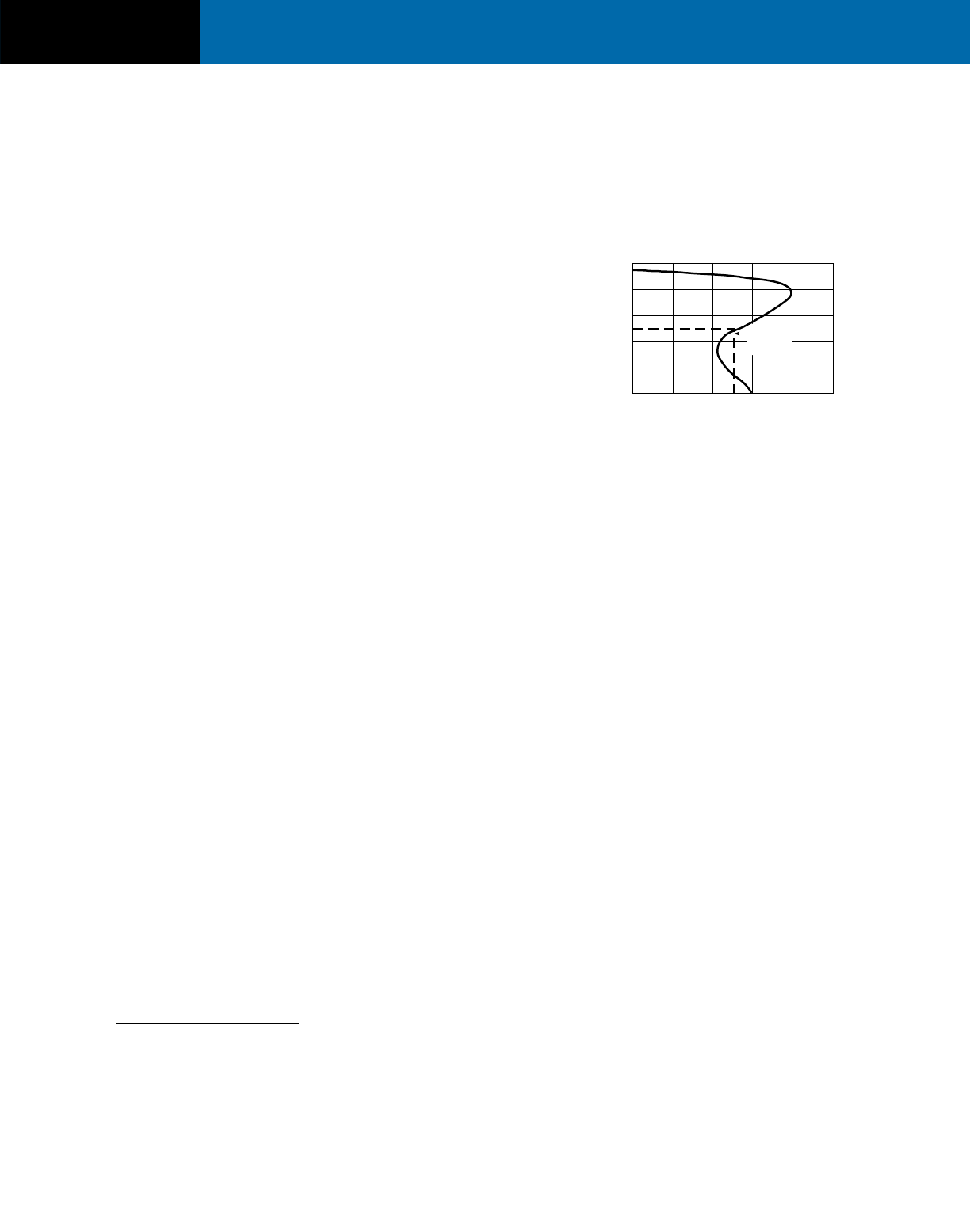
If the motor is used for starting a high torque load, the motor
may stay at approximately 50% of normal running speed as
illustrated by the graph below:
The underlying problem is low voltage at the motor terminals.
If the ampere rating of the motor and transformer overcurrent
device falls within the motor’s 50% RPM draw requirements,
a problem is likely to develop. The overcurrent device may not
open under intermediate motor ampere loading conditions.
Overheating of the motor and/or transformer would occur,
possibly causing failure of either component.
This condition is more pronounced when one transformer is
used to power one motor and the running amperes of the
motor is in the vicinity of the full load ampere rating of the
transformer. The following precautions should be followed:
(1) When one transformer is used to operate one motor, the
running amperes of the motor should not exceed 65% of
the transformer’s full load ampere rating.
(2) If several motors are being operated from one transformer,
avoid having all motors start at the same time. If this is
impractical, then size the transformer so that the total
running current does not exceed 65% of the transformer’s
full load ampere rating.
35. Why are Small Distribution Transformers not used for
Industrial Control Applications?
Industrial control equipment demands a momentary overload
capacity of three to eight times normal capacity. This is most
prevalent in solenoid or magnetic contactor applications where
inrush currents can be three to eight times as high as normal
sealed or holding currents but still maintain normal voltage at
this momentary overloaded condition. Distribution transformers
are designed for good regulation up to 100 percent loading,
but their output voltage will drop rapidly on momentary
overloads of this type making them unsuitable for high inrush
applications.
Industrial control transformers are designed especially
for maintaining a high degree of regulation even at eight
times normal load. This results in a larger and generally more
expensive transformer. For a complete listing of ACME
industrial control transformers, refer to Section V.
50 100 150 200 250
20
40
60
80
100
SPEED (PERCENT OF
SYNCHROUS SPEED)
TORQUE (PERCENT OF FULL LOAD TORQUE)
SPEED vs TORQUE FOR A TYPICAL THREE PHASE
INDUCTION TYPE SQUIRREL CAGE MOTOR
STALL
ZONE
SECTION DRY-TYPE DISTRIBUTION TRANSFORMERS
ACME ELECTRIC • MILWAUKEE, WI • 800.334.5214 • acmetransformer.com
10
SECTION DRY-TYPE DISTRIBUTION TRANSFORMERS
1
10
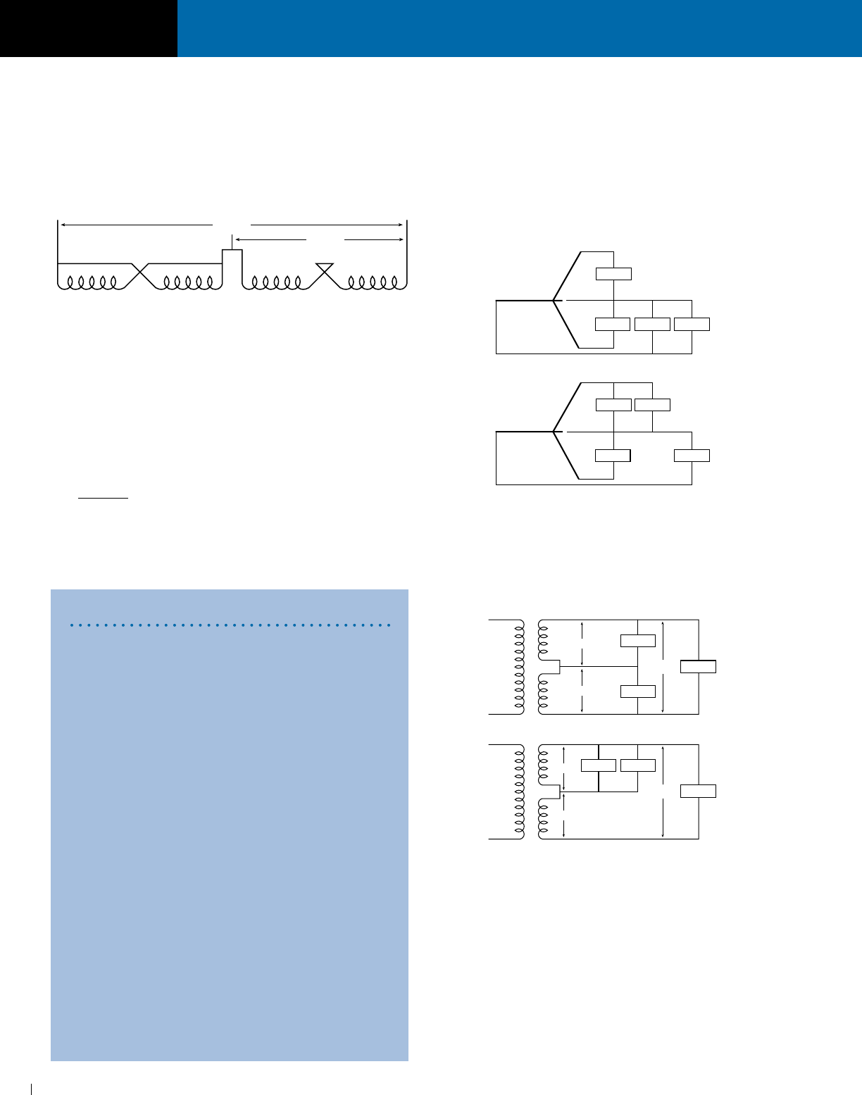
36. Can 4-Winding Single Phase Transformer be auto-
connected? Yes. There are occasions where 480 volts single
phase can be stepped down to 240 volts single phase by
autoconnecting a standard 4-winding isolating transformer
as shown in Figure 1. If connected in this manner, the
nameplate kVA is doubled. For example: A 10 kVA load can
be applied to a 5 kVA 4-winding transformer if connected per
Figure 1.
37. What about balanced loading on Three Phases?
Each phase of a three phase transformer must be considered
as a single phase transformer when determining loading. For
example: A 45 kVA three phase transformer with a 208Y/120
volt secondary is to service 4 loads at 120 volts single phase
each. These loads are 10 kVA, 5 kVA, 8 kVA,and 4 kVA.
NOTE: that maximum loading on any phase does not exceed
10 kVA. Each phase has a 15 kVA capacity.
45 kVA
3 phase = 15 kVA per phase
If incorrect method is used, phase B will have an 18 kVA
load which is 3 kVA above its normal capacity of 15 kVA and
failure will result even though we only have a total load of 27
kVA on a 45 kVA transformer.
38. What is meant by “Balanced Loading” on Single Phase
Transformer applications? Since most single phase
transformers have a secondary voltage of 120/240, they will
be operated as a three wire system. Care must be taken
in properly distributing the load as the transformer secondary
consists of 2 separate 120 volt windings. Each 120 volt
winding is rated at one-half the nameplate kVA rating. For
example: A 10 kVA transformer, 120/240 volt secondary is to
service an 8 kVA load at 240 volts and two 1 kVA loads at
120 volts each.
If the incorrect method is used, winding A will be loaded
at 6 kVA, and winding B will be loaded at 4 kVA. These
do total 10 kVA but, since each winding is only rated at
5 kVA (1/2 of nameplate rating), we have an overloaded
transformer and a certain failure.
39. What are typical applications for transfomers?
ACME transformers should be specified to:
(1) Distribute power at high voltage.
(2) Eliminate double wiring.
(3) Operate 120 volt equipment from power circuits.
(4) Insulate circuits/establish separately derived circuits.
(5) Provide 3- wire secondary circuits.
(6) Buck and Boost (See Section VII).
(7) Provide electrostatic shielding for transient noise protection.
Figure 1
H1
480V
H3 H2 H4 X1 X3 X2 X4
240V
Enclosure Definitions
Type 1 Enclosures — are intended for indoor use,
primarily to provide a degree of protection against
contact with the enclosed equipment.
Type 2 Enclosures — are intended for indoor use,
primarily to provide a degree of protection against
limited amounts of falling water and dirt.
Type 3R Enclosures — are intended for outdoor use,
primarily to provide a degree of protection against fall-
ing rain, sleet and external ice formation.
Definitions Pertaining to Enclosures
Ventilated — means constructed to provide for
circulation of external air through the enclosure to
remove excess heat, fumes or vapors.
Non-Ventilated — means constructed to provide no
intentional circulation of external air through the
enclosure.
Indoor Locations — are those areas protected from
exposure to the weather.
Outdoor Locations — are those areas exposed to
the weather.
Hazardous (Classified) Locations — are those
areas, which may contain hazardous (classified)
materials in sufficient quantity to create an explosion.
See Article 500 of The National Electrical Code.
(NEUTRAL)
10 KVA
8 KVA 4 KVA5 KVA
A
B
C
CORRECT WAY:
(NEUTRAL)
10 KVA
5 KVA 4 KVA
A
B
C
INCORRECT WAY:
8 KVA
CORRECT WAY:
1 KVA
120V
120V
240V 8 KVA
1 KVA
A
B
INCORRECT WAY:
1 KVA 1 KVA
120V
120V
240V 8 KVA

SECTION DRY-TYPE DISTRIBUTION TRANSFORMERS
ACME ELECTRIC • MILWAUKEE, WI • 800.334.5214 • acmetransformer.com
11
SECTION DRY-TYPE DISTRIBUTION TRANSFORMERS
1
11
①
When motor service factor is greater than 1,
increase full load amps proportionally.
Example: If service factor is 1.15, increase
above amp values by 15%.
1 Phase kVA = Volts x Amps
1000
NOTE: If motors are started more than once per
hour, increase minimum transformer kVA by 20%.
Steps for Selecting the Proper Transformer
SINGLE PHASE LOADS
1. Determine electrical load
A. Voltage required by load.
B. Amperes or kVA capacity required by load.
C. Frequency in Hz (cycles per second).
D. Verify load is designed to operate on a single phase supply.
All of the above information is standard data normally obtained from equipment
nameplates or instruction manuals.
2. Determine supply voltage
A. Voltage of supply (source).
B. Frequency in Hz (cycles per second).
The frequency of the line supply and electrical load must be the same. Select
single phase transformer designed to operate at this frequency, having a primary
(input) equal to the supply voltage and a secondary (output) equal to the volt-
age required by the load.
3. If the load nameplate expresses a rating in kVA, a transformer can be
directly selected from the charts. Choose from a group of transformers with
primary and secondary voltages matching those you have just determined.
A. Select a transformer with a standard kVA capacity equal to or greater than
that needed to operate the load.
B. Primary taps are available on most models to compensate for line voltage
variations. (Refer to question #2 in the Transformer Questions and Answers
Section on page 6.)
C. When load ratings are given only in amperes, tables 1 and 2 or the following
formulas may be used to determine proper kVA size for the required transformer.
(1) To determine kVA when volts and amperes are known:
kVA = Volts x Amps
1000
(2) To determine Amperes when kVA and volts are known:
Amps = kVA x 1000
Volts
Single Phase Example
Question: Select a transformer to meet the following conditions. Load is single
phase lighting using incandescent lamps. Each fixture requires 1.3 amps @ 120
volts, 1 phase, 60 Hz, power factor of unity. The installation requires 52-100 watt
fixtures. The desired circuit distributing power to the light fixtures is 120/240 volt,
three wire, single phase. The supply voltage is 460 volt, 3 phase.
Answer: Compute the kVA required.
1.3 amps x 120 volts = .156 kVA
1000
For each lighting fixture
Always use amps x volts to compute VA, never use lamp wattage. .156 kVA/
Fixture x 52 Fixture = 8.11 kVA. The two sizes (kVA) nearest 8.11 kVA are 7.5 kVA
and 10 kVA. Use the 10 kVA. This will not overload the transformer and allows some
capacity, 1.89 kVA, for future loads. Since the supply is 460 V (not 480 V) use
the 456 V tap. This will produce approximately 120 volts on output. If the tap is not
used, the output will be 115 V compared to the desired 120 V. Note the trans-
former selected is single phase but the supply is 480 V, 3 phase. Single phase is
obtained by using any 2 wires of the 3 phase supply.
TABLE 1
Full Load Current in Amperes–
Single Phase Circuits
MIN.
HORSE- 115 V 208 V 230 V TRANS-
POWER FORMER
KVA
1/6 4.4 2.4 2.2 .53
1/4 5.8 3.2 2.9 .70
1/3 7.2 4.0 3.6 .87
1/2 9.8 5.4 4.9 1.18
3/4 13.8 7.6 6.9 1.66
1 16 8.8 8 1.92
1.5 20 11.0 10 2.40
2 24 13.2 12 2.88
3 34 18.7 17 4.10
5 56 30.8 28 6.72
7.5 80 44 40 9.6
10 100 55 50 12.0
TABLE 2
Full Load Amperes
Single Phase A.C. Motors ①
kVA 120 V 208 V 240 V 277 V 380 V 440V 480 V 600 V
.050 0.4 0.2 0.2 0.2 0.1 0.1 0.1 0.1
.100 0.8 0.5 0.4 0.3 0.2 0.2 0.2 0.2
.150 1.2 0.7 0.6 0.5 0.4 0.3 0.3 0.3
.250 2.0 1.2 1.0 0.9 0.6 0.5 0.5 0.4
.500 4.2 2.4 2.1 1.8 1.3 1.1 1.0 0.8
.750 6.3 3.6 3.1 2.7 2.0 1.7 1.6 1.3
1 8.3 4.8 4.2 3.6 2.6 2.3 2.1 1.7
1.5 12.5 7.2 6.2 5.4 3.9 3.4 3.1 2.5
2 16.7 9.6 8.3 7.2 5.2 4.5 4.2 3.3
3 25 14.4 12.5 10.8 7.9 6.8 6.2 5.0
5 41 24.0 20.8 18.0 13.1 11.3 10.4 8.3
7.5 62 36 31 27 19.7 17 15.6 12.5
10 83 48 41 36 26 22.7 20.8 16.7
15 125 72 62 54 39 34 31 25
25 208 120 104 90 65 57 52 41
37.5 312 180 156 135 98 85 78 62
50 416 240 208 180 131 114 104 83
75 625 360 312 270 197 170 156 125
100 833 480 416 361 263 227 208 166
167 1391 802 695 602 439 379 347 278
250 2083 1201 1041 902 657 568 520 416

SECTION DRY-TYPE DISTRIBUTION TRANSFORMERS
ACME ELECTRIC • MILWAUKEE, WI • 800.334.5214 • acmetransformer.com
12
SECTION DRY-TYPE DISTRIBUTION TRANSFORMERS
1
12
THREE PHASE LOADS
1. Determine electrical load
A. Voltage required by load.
B. Amperes or kVA required by load.
C. Frequency in Hz (cycles per second).
D. Verify load is designed to operate on three phase.
All the above information is standard data normally obtained from equipment
nameplates or instruction manuals.
2. Determine supply voltage
A. Voltage of supply (source).
B. Frequency in Hz (cycles per second).
The frequency of the line supply and electrical load must be the same. A three
phase transformer is selected which is designed to operate at this frequency
having a primary (input) equal to the supply voltage and a secondary (output)
equal to the voltage required by the load.
3. If the load nameplate expresses a rating in kVA, a transformer can be
directly selected from the charts. Choose from the group of transformers
with primary and secondary voltages matching that which you have
just determined.
A. Select a transformer with a standard kVA capacity equal to or greater than
that needed to operate the load.
B. Primary taps are available on most models to compensate for line voltage
variations. (Refer to question #2 in the Transformer Questions and Answers
Section on page 6.)
C. When load ratings are given only in amperes, tables 3 and 4 or the following
formulas may be used to determine proper kVA size for the required transformer.
(1) To determine three phase kVA when volts and amperes are known:
Three Phase kVA =
Volts x Amps x 1.73
1000
(2) To determine Amperes when kVA and volts are known:
Amps = 3 Phase kVA x 1000
Volts x 1.73
Three Phase Example
Question: Select a transformer to fulfill the following conditions. Load is a three phase
induction motor, 25 horsepower @ 240 volts, 60 Hz and a heater load of 4 kilowatts @
240 volts single phase. The supply voltage is 480Y/277, three phase, 4 wire.
Answer: Compute the kVA required. Motor — From table 4 the current is 68 amps.
240 volts x 68 amps x 1.73 = 28.2 kVA
1000
(The kVA can also be obtained from table 4).
Heater — 4 kVA
A three phase transformer must be selected so that any one phase is not overloaded.
Each phase should have the additional 4 kVA rating required by the heater even though
the heater will operate on one phase only. So, the transformer should have a minimum
kVA rating of 28.2 + 4 + 4 + 4 or 40.2 kVA. Refer to the appropriate selection chart.
A 480 delta primary — 240 delta secondary transformer may be used on a 4 wire,
480Y/277 volt supply. The fourth wire (neutral) is not connected to the transformer. To
not overload the transformer, a 45 kVA transformer should be selected.
NOTE: Any two wires of the 240 volts, 3 phase developed by the secondary of the
transformer may be used to supply the heater. Any 2 wires of a 3 phase system is
single phase.
TABLE 3
Full Load Current in Amperes–
Three Phase Circuits
TABLE 4
Full Load Amperes
Three Phase A.C. Motors
①
①
When motor service factor is greater than 1,
increase full load amps proportionally.
Example: If service factor is 1.15, increase
above amp values by 15%.
3 Phase kVA =
Volts x Amps x 1.73
1000
NOTE: If motors are started more than once per
hour, increase minimum transformer kVA by 20%.
MIN.
HORSE- 208 V 230 V 460 V 575 V TRANS-
POWER FORMER
KVA
1/2 2.2 2.0 1.0 0.8 0.9
3/4 3.1 2.8 1.4 1.1 1.2
1 4.0 3.6 1.8 1.4 1.5
2 7.5 6.8 3.4 2.7 2.7
3 10.7 9.6 4.8 3.9 3.8
5 16.7 15.2 7.6 6.1 6.3
10 31 28 14 11 11.2
15 46 42 21 17 16.6
20 59 54 27 22 21.6
25 75 68 34 27 26.6
30 88 80 40 32 32.4
40 114 104 52 41 43.2
50 143 130 65 52 52
60 170 154 77 62 64
75 211 192 96 77 80
100 273 248 124 99 103
125 342 312 156 125 130
150 396 360 180 144 150
200 528 480 240 192 200
kVA 208 V 240 V 380 V 440 V 480 V 600 V
3 8.3 7.2 4.6 3.9 3.6 2.9
4.5 12.5 10.8 6.8 5.9 5.4 4.3
6 16.6 14.4 9.1 7.8 7.2 5.8
9 25 21.6 13.7 11.8 10.8 8.6
15 41 36 22.8 19.6 18.0 14.4
22.5 62 54 34.2 29 27 21.6
30 83 72 45.6 39 36 28
45 124 108 68.4 59 54 43
75 208 180 114 98 90 72
112.5 312 270 171 147 135 108
150 416 360 228 196 180 144
225 624 541 342 294 270 216
300 832 721 456 392 360 288
500 1387 1202 760 655 601 481
750 2081 1804 1139 984 902 721
1000 2775 2405 1519 1312 1202 962
SECTION DRY-TYPE DISTRIBUTION TRANSFORMERS
ACME ELECTRIC • MILWAUKEE, WI • 800.334.5214 • acmetransformer.com
13
SECTION DRY-TYPE DISTRIBUTION TRANSFORMERS
1
13
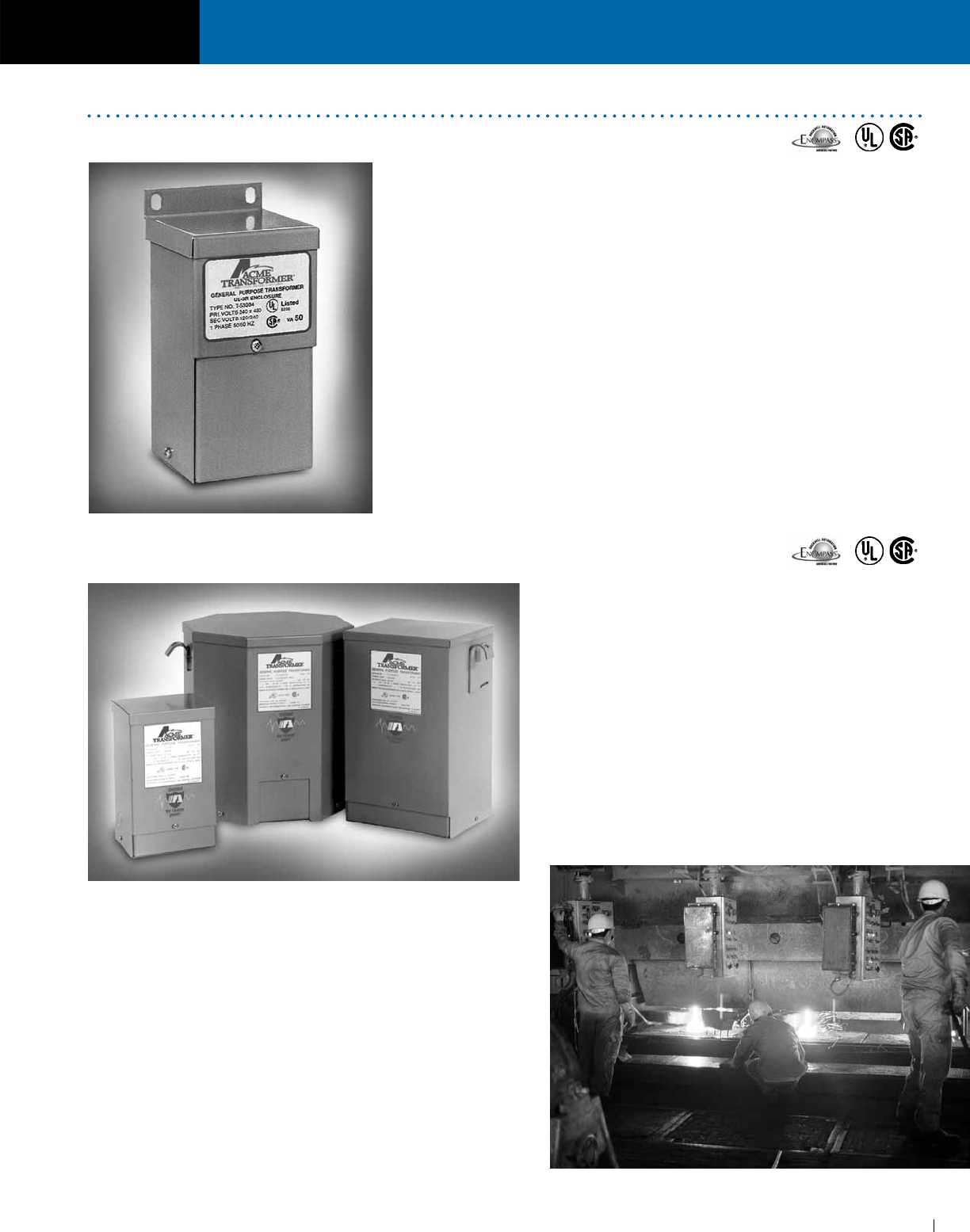
UL-3R Enclosures
ENCAPSULATED SINGLE PHASE, .05 to .150 kVA
n Installation keyhole mounting slots for mounting
bolts prior to installation. Mounting slots are
accessible from the front. Lifting ears are included
on 3 to 25 kVA units.
n Wiring flexible copper leadwire terminations for
easy connections outside the front access wiring
compartment. Dual size knockouts in both sides
and the bottom of the wiring compartment for
greater wiring convenience and flexibility.
FEATURES
n UL listed, CSA certified and UL-3R enclosure meets or exceeds all listing
criteria including NEMA, ANSI and OSHA standards.
n Easy and convenient installation to meet your re quirements, the transformer
can be mounted in any position.
n Long Life UL class 130°C insulation system. Transformers can be banked for
three phase service.
n Large wiring compartment, no conduit or pull boxes required. Front access
for wiring ease. Wiring compartment remains cool.
n Completely enclosed UL-3R enclosure for indoor/outdoor service. Rugged
non-ventilated construction.
n Plenty of knockouts for multi-directional entry.
n All copper lead wire terminations.
n Ground studs for use with non-metallic conduit.
FEATURES
n UL listed, CSA certified and UL-3R enclosures meets or
exceeds all listing criteria including NEMA, ANSI and OSHA
standards.
n Shielded for cleaner power.
n Encapsulated and completely enclosed design electrical
grade silica and resin compounds completely enclose the
core and coil to seal out all moisture and air. UL Type 3R
enclosure for indoor or outdoor service. Encapsulation eliminates
corrosion and insulation deterioration.
n Quiet operation with sound levels well below NEMA standards.
n Long life UL class 155°C insulation system. 115°C rise thru
.750 kVA; 180°C insulation system, 115°C rise, 1 kVA and above.
ENCAPSULATED SINGLE PHASE, .250 to 25 kVA
SECTION DRY-TYPE DISTRIBUTION TRANSFORMERS
ACME ELECTRIC • MILWAUKEE, WI • 800.334.5214 • acmetransformer.com
14
SECTION DRY-TYPE DISTRIBUTION TRANSFORMERS
1
14
316 STAINLESS STEEL
TRANSFORMERS
FEATURES
n 3R enclosure.
n Encapsulated construction.
n Single phase: 0.25 – 25 kVA.
Three phase: 3 – 7.5 kVA.
n Core and Coil assembly completely encapsulated in
polyester or epoxy seals out all moisture, eliminating
corrosion and deterioration of insulation.
n Electrostatic shielding.
APPLICATIONS
n Harsh industrial locations
n Corrosive chemical exposure
n Waste water treatment facilities
n Coastal or marine applications with high salt mist
n Any application where painted cold roll steel is not adequate
Shielded Power in Many Design Styles
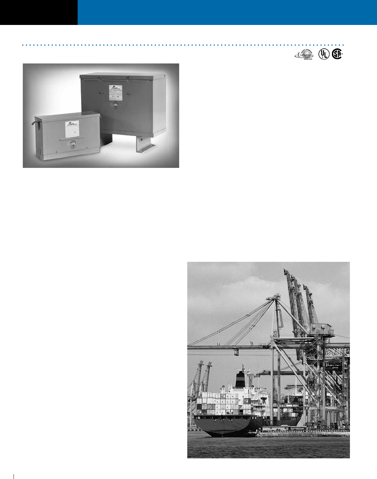
ENCAPSULATED THREE PHASE 3 to 75 kVA
FEATURES
n UL listed, CSA certified and UL-3R enclosure meets
or exceeds all listing criteria including NEMA, ANSI and
OSHA standards.
n UL Class 180°C insulation system. 115°C rise.
n Extra large front access wiring compartment through 9 kVA;
top access through 75 kVA for easier installation and cooler
case temperatures.
n Completely enclosed — suitable for indoor/outdoor
service. Consult selection charts for details. Excellent for
dust or lint laden atmosphere.
n Encapsulated — electrical grade silica and resin
compound completely encloses the core and coil.
Encapsulation seals out all moisture and air, eliminating
corrosion and insulation deterioration.
n High efficiency and excellent regulation.
n Sound levels below NEMA standards.
n Keyhole mounting slots permit installation of mounting
bolts prior to hanging transformer and are accessible from
the front. Lifting ears for easy installation.
n Wiring connections can be made outside of wiring
compartment due to the use of flexible leads.
n 3-9 kVA provided with dual size knockouts in sides and
bottom of wiring compartment.
n Termination — copper lead wire.
n Electrostatic shielding provided on all 60 Hz isolation
transformers.
NOTE:
Units above 15 kVA apply to Groups F and K.
SECTION DRY-TYPE DISTRIBUTION TRANSFORMERS
ACME ELECTRIC • MILWAUKEE, WI • 800.334.5214 • acmetransformer.com
15
SECTION DRY-TYPE DISTRIBUTION TRANSFORMERS
1
15
FEATURES
n With weather shield, UL Type 3R enclosure type 2 enclosure
without weather shield. UL listed and CSA certified.
n UL Class 220°C insulation system, 150°C rise.
n Extra large wiring compartment for easier installation and
cooler case temperatures.
n NEMA standard bus bar terminals, no special tools
needed to make clearly marked connections. Tap
changing easily accomplished with jumpers.
n Aluminum windings for increased insulation life, cooler
operation, lower losses.
n Noise and vibration isolating pads standard to assure
quiet operation.
n Large permanently legible nameplates on front.
n Single phase units can be banked for 3 phase service.
n All units have ground studs for use with non-metallic
conduit.
n Suitable for wall or “trapeze” mounting. Wall brackets are
available for units up to 50 kVA single and 75 kVA
three phase.
n Other models are available with class 220°C insulation
and either 115°C or 80°C rise operating temperature. Refer
to Opti-Miser® Section.
n Termination — single phase 37.5 to 100 kVA, copper bus;
167 to 250 kVA, aluminum bus. Three phase 27 to 225 kVA,
copper bus; Groups D, G & J 30 to 225 kVA and all 275 to
1000 kVA, aluminum bus.
n Electrostatic shielding provided on all 60 Hz
isolation transformers. Not available on
Groups D1 and G.
VENTILATED
SINGLE PHASE 37.5 to 250 kVA
THREE PHASE 25 to 1000 kVA

16
General Purpose Transformers • CSL-3/NEMA Premium Transformers • Harmonic Mitigating Transformers • Non-Linear Load Transformers
Drive Isolation Transformers • Line Reactors • Buck Boost Transformers • Constant Voltage Regulators…and more
TRANSFORMING THE WAY WE SERVE OUR CUSTOMERS
TRANSFORMING THE DEFINITION OF CUSTOMER SERVICE
8 Regional Distribution Centers
supporting multi-million dollar
inventory levels
Multiple World-class
manufacturing facilities
Industry leading Technical
Support Department and NEW
fully searchable online catalog
Follow us on
ACME ELECTRIC • MILWAUKEE, WI • 800.334.5214 • acmetransformer.com

SECTION DRY-TYPE DISTRIBUTION TRANSFORMERS
ACME ELECTRIC • MILWAUKEE, WI • 800.334.5214 • acmetransformer.com
17
SECTION DRY-TYPE DISTRIBUTION TRANSFORMERS
1
17
SELECTION CHARTS
SINGLE PHASE
①
Suitable for 50/60 Hz.
②
Wall mounting brackets are available for these sizes, refer to page 133.
240 X 480 PRIMARY VOLTS — 120/240 SECONDARY VOLTS — FOUR WINDINGS — 1Ø, 60 Hz
316 STAINLESS STEEL
240 X 480 PRIMARY VOLTS — 120/240 SECONDARY VOLTS — FOUR WINDINGS — 1Ø, 60 Hz
GROUP I–316SS
GROUP I
APPROX. DIMENSIONS APPROX. TYPE MTG. WEATHER Wiring Diagrams &
kVA CATALOG NO. Inches (cm.) SHIP WEIGHT W – Wall KNOCKOUTS SHIELD Design Figures
HEIGHT WIDTH DEPTH Lbs. (Kg.) F – Floor Inches (Cm.) P/N Begin on Page 122
① .05 T153004 6.41 (16.3) 3.14 (8.0) 3.05 (7.7) 4 (1.8) W 0.875 (2.2) NA 1–A
① .10 T153005 7.16 (18.2) 3.89 (9.9) 3.67 (9.3) 5 (2.3) W 0.875 (2.2) NA 1–A
① .15 T153006 7.16 (18.2) 3.89 (9.9) 3.67 (9.3) 7 (3.2) W 0.875 (2.2) NA 1–A
① .25 T253007S 8.68 (22.0) 4.08 (10.4) 3.88 (9.9) 10 (4.5) W 0.50-0.75 (1.3-1.9) NA 2–B
① .50 T253008S 9.06 (23.0) 4.37 (11.1) 4.20 (10.7) 15 (6.8) W 0.50-0.75 (1.3-1.9) NA 2–B
① .75 T253009S 9.68 (24.6) 4.75 (12.1) 4.50 (11.4) 19 (8.6) W 0.50-0.75 (1.3-1.9) NA 2–B
1.00 T253010S 10.50 (26.7) 5.50 (14.0) 5.13 (13.0) 24 (10.9) W 0.50-0.75 (1.3-1.9) NA 2–B
1.50 T253011S 11.62 (29.5) 5.50 (14.0) 5.13 (13.0) 30 (13.6) W 0.50-0.75 (1.3-1.9) NA 2–B
2.00 T253012S 13.00 (33.0) 5.50 (14.0) 5.13 (13.0) 38 (17.2) W 0.50-0.75 (1.3-1.9) NA 2–B
3.00 T253013S 11.50 (29.2) 10.31 (26.2) 7.13 (18.1) 55 (24.9) W 0.75-1.25 (1.9-3.2) NA 2–C
3.00 T2530134S 11.50 (29.2) 10.31 (26.2) 7.13 (18.1) 55 (24.9) W 0.75-1.25 (1.9-3.2) NA 3–C
5.00 T253014S 14.38 (36.5) 10.31 (26.2) 7.13 (18.1) 75 (34.0) W 0.75-1.25 (1.9-3.2) NA 2–C
5.00 T2530144S 14.38 (36.5) 10.31 (26.2) 7.13 (18.1) 75 (34.0) W 0.75-1.25 (1.9-3.2) NA 3–C
7.50 T2535153S 15.19 (38.6) 13.50 (34.3) 10.84 (27.5) 115 (52.2) W 0.75-1.25 (1.9-3.2) NA 4–D
10.00 T2535163S 15.19 (38.6) 13.50 (34.3) 10.84 (27.5) 125 (56.7) W 0.75-1.25 (1.9-3.2) NA 4–D
15.00 T2535173S 16.94 (43.0) 14.12 (35.9) 11.59 (29.4) 170 (77.1) W 1.00-1.50 (2.5-3.8) NA 4–D
25.00 T2535183S 18.44 (46.8) 16.13 (41.0) 13.34 (33.9) 250 (113.0) W 1.00-1.50 (2.5-3.8) NA 4–D
37.50 TP530193S 25.50 (64.8) 24.39 (61.9) 19.37 (49.2) 280 (127.0) F ② NA WSA1 5–E
50.00 TP530203S 25.50 (64.8) 24.39 (61.9) 19.37 (49.2) 350 (158.8) F ② NA WSA1 5–E
75.00 TP530213S 35.47 (90.1) 31.90 (81.0) 26.88 (68.3) 430 (195.0) F NA WSA3 5–E
100.00 TP530223S 41.52 (105.5) 32.90 (83.6) 29.87 (75.9) 525 (238.0) F NA WSA4 5–E
167.00 TP530233S 45.60 (115.8) 39.50 (100.3) 35.50 (90.2) 1050 (476.3) F NA WSA5 5–E
250.00 TP530243S 45.60 (115.8) 39.50 (100.3) 35.50 (90.2) 1440 (653.2) F NA WSA5 5–E
APPROX. DIMENSIONS APPROX. TYPE MTG. WEATHER Wiring Diagrams &
kVA CATALOG NO. Inches (Cm.) SHIP WEIGHT W – Wall KNOCKOUTS SHIELD Design Figures
HEIGHT WIDTH DEPTH Lbs. (Kg.) F – Floor Inches (Cm.) P/N Begin on Page 122
0.25 T253007SS 8.68 (22.0) 4.08 (10.4) 3.88 (9.9) 10 (4.5) W NA NA 2-B
0.50 T253008SS 9.06 (23.0) 4.37 (11.1) 4.20 (10.7) 15 (6.8) W NA NA 2-B
0.75 T253009SS 9.68 (24.6) 4.75 (12.1) 4.50 (11.4) 19 (8.6) W NA NA 2-B
1.00 T253010SS 10.50 (26.7) 5.50 (14.0) 5.13 (13.0) 24 (10.9) W NA NA 2-B
1.50 T253011SS 11.62 (29.5) 5.50 (14.0) 5.13 (13.0) 30 (13.6) W NA NA 2-B
2.00 T253012SS 13.00 (33.0) 5.50 (14.0) 5.13 (13.0) 38 (17.2) W NA NA 2-B
3.00 T253013SS 11.50 (29.2) 10.31 (26.2) 7.13 (18.1) 55 (24.9) W NA NA 3-C
5.00 T253014SS 14.38 (36.5) 10.31 (26.2) 7.13 (18.1) 75 (34.0) W NA NA 3-C
7.50 T253515SS 15.19 (38.6) 13.50 (34.3) 10.84 (27.5) 115 (52.2) W NA NA 4-D
10.00 T253516SS 15.19 (38.6) 13.50 (34.3) 10.84 (27.5) 125 (56.7) W NA NA 4-D
15.00 T253517SS 16.94 (43.0) 14.12 (35.9) 11.59 (29.4) 170 (77.1) W NA NA 4-D
25.00 T253518SS 18.44 (46.8) 16.13 (41.0) 13.34 (33.9) 250 (113.0) W NA NA 4-D
Notes: 0.05 through 25.0 kVA encapsulated (exempt from TP1), 37.5 through 250.0 kVA TP1 compliant
Notes: 0.25 through 25.0 kVA encapsulated (exempt from TP1)

SECTION DRY-TYPE DISTRIBUTION TRANSFORMERS
ACME ELECTRIC • MILWAUKEE, WI • 800.334.5214 • acmetransformer.com
18
SECTION DRY-TYPE DISTRIBUTION TRANSFORMERS
1
18
① Suitable for 50/60 Hz.
② Wall mounting brackets are available for these sizes, refer to page 133.
NON-VENTILATED TRANSFORMERS
—
240 X 480 PRIMARY VOLTS — 120/240 SECONDARY VOLTS — FOUR WINDINGS — 1Ø, 60 Hz
GROUP II
240 X 480 PRIMARY VOLTS — COPPER WINDINGS — 120/240 SECONDARY VOLTS — FOUR WINDINGS — 1Ø, 60 Hz
GROUP IA
APPROX. DIMENSIONS APPROX. TYPE MTG. WEATHER Wiring Diagrams &
kVA CATALOG NO. Inches (Cm.) SHIP WEIGHT W – Wall KNOCKOUTS SHIELD Design Figures
HEIGHT WIDTH DEPTH Lbs. (Kg.) F – Floor Inches (Cm.) P/N Begin on Page 122
7.50 TC535153S 15.19 (38.6) 13.50 (34.3) 10.84 (27.5) 100 (45.4) W 0.75-1.25 (1.9-3.2) NA 4–D
10.00 TC535163S 15.19 (38.6) 13.50 (34.3) 10.84 (27.5) 120 (54.4) W 0.75-1.25 (1.9-3.2) NA 4–D
15.00 TC535173S 16.94 (43.0) 14.12 (35.9) 11.59 (29.4) 160 (72.6) W 1.00-1.50 (2.5-3.8) NA 4–D
25.00 TC535183S 18.44 (46.8) 16.13 (41.0) 13.34 (33.9) 250 (113.0) W 1.00-1.50 (2.5-3.8) NA 4–D
37.50 TPC530193S 25.50 (64.8) 24.39 (61.9) 19.37 (49.2) 295 (133.8) F ② NA WSA1 5–E
50.00 TPC530203S 25.50 (64.8) 24.39 (61.9) 19.37 (49.2) 378 (172.0) F ② NA WSA1 5–E
APPROX. DIMENSIONS APPROX. TYPE MTG. WEATHER Wiring Diagrams &
kVA CATALOG NO. Inches (Cm.) SHIP WEIGHT W – Wall KNOCKOUTS SHIELD Design Figures
HEIGHT WIDTH DEPTH Lbs. (Kg.) F – Floor Inches (Cm.) P/N Begin on Page 122
37.50 TE2530193S 35.47 (90.1) 31.90 (81.0) 26.90 (68.3) 430 (195.0) F ② NA NA 5–H
50.00 TE2530203S 35.47 (90.1) 31.90 (81.0) 26.90 (68.3) 430 (195.0) F ② NA NA 5–H
75.00 TE2A530213S 35.47 (90.1) 31.90 (81.0) 26.90 (68.3) 525 (238.0) F NA NA 5–H
100.00 TE1530223S 42.00 (106.7) 40.00 (101.6) 30.00 (76.2) 775 (352.0) F NA NA 5–H
Notes: 7.5 through 25.0 kVA encapsulated (exempt from TP1), 37.5 through 50.0 kVA TP1 compliant
Notes: 37.5 through 100.0 kVA non-ventilated (exempt from TP1)

SECTION DRY-TYPE DISTRIBUTION TRANSFORMERS
ACME ELECTRIC • MILWAUKEE, WI • 800.334.5214 • acmetransformer.com
19
SECTION DRY-TYPE DISTRIBUTION TRANSFORMERS
1
19
208 PRIMARY VOLTS — 120/240 SECONDARY VOLTS — THREE WINDINGS — 1Ø, 60 Hz
600 PRIMARY VOLTS — 120/240 SECONDARY VOLTS — THREE WINDINGS — 1Ø, 60 Hz
GROUP IV
GROUP V
APPROX. DIMENSIONS APPROX. TYPE MTG. WEATHER Wiring Diagrams &
kVA CATALOG NO. Inches (Cm.) SHIP WEIGHT W – Wall KNOCKOUTS SHIELD Design Figures
HEIGHT WIDTH DEPTH Lbs. (Kg.) F – Floor Inches (Cm.) P/N Page 122
① .05 T153104 6.41 (16.3) 3.14 (8.0) 3.05 (7.7) 4 (1.8) W 0.875 (2.2) NA 8–A
① .10 T153105 7.16 (18.2) 3.89 (9.9) 3.67 (9.3) 5 (2.3) W 0.875 (2.2) NA 8–A
① .15 T153106 7.16 (18.2) 3.89 (9.9) 3.67 (9.3) 7 (3.2) W 0.875 (2.2) NA 8–A
① .25 T253107S 8.68 (22.0) 4.08 (10.4) 3.88 (9.9) 10 (4.5) W 0.50-0.75 (1.3-1.9) NA 9–B
① .50 T253108S 9.06 (23.0) 4.37 (11.1) 4.20 (10.7) 15 (6.8) W 0.50-0.75 (1.3-1.9) NA 9–B
① .75 T253109S 9.68 (24.6) 4.75 (12.1) 4.50 (11.4) 19 (8.6) W 0.50-0.75 (1.3-1.9) NA 9–B
1.00 T253110S 10.50 (26.7) 5.50 (14.0) 5.13 (13.0) 24 (10.9) W 0.50-0.75 (1.3-1.9) NA 9–B
1.50 T253111S 11.62 (29.5) 5.50 (14.0) 5.13 (13.0) 30 (13.6) W 0.50-0.75 (1.3-1.9) NA 9–B
2.00 T253112S 13.00 (33.0) 5.50 (14.0) 5.13 (13.0) 38 (17.2) W 0.50-0.75 (1.3-1.9) NA 9–B
3.00 T2531131S 11.50 (29.2) 10.31 (26.2) 7.13 (18.1) 55 (24.9) W 0.75-1.25 (1.9-3.2) NA 10–C
5.00 T2531141S 14.38 (36.5) 10.31 (26.2) 7.13 (18.1) 75 (34.0) W 0.75-1.25 (1.9-3.2) NA 10–C
7.50 T2536151S 15.19 (38.6) 13.50 (34.3) 10.84 (27.5) 115 (52.2) W 0.75-1.25 (1.9-3.2) NA 10–D
10.00 T2536161S 15.19 (38.6) 13.50 (34.3) 10.84 (27.5) 125 (56.7) W 0.75-1.25 (1.9-3.2) NA 10–D
15.00 T2536171S 16.94 (43.0) 14.12 (35.9) 11.59 (29.4) 170 (77.1) W 1.00-1.50 (2.5-3.8) NA 10–D
25.00 T2536181S 18.44 (46.8) 16.13 (41.0) 13.34 (33.9) 250 (113.0) W 1.00-1.50 (2.5-3.8) NA 10–D
37.50 TP531193S 25.50 (64.8) 24.40 (62.0) 19.40 (49.3) 275 (125.0) F ② NA WSA1 11-E
50.00 TP531203S 29.90 (76.0) 28.15 (71.5) 22.37 (56.8) 340 (154.0) F ② NA WSA2 11–E
75.00 TP531213S 35.47 (90.0) 31.90 (81.0) 26.88 (68.3) 430 (195.0) F NA WSA3 11-E
100.00 TP531223S 41.52 (105.5) 32.90 (83.6) 29.87 (75.9) 525 (238.0) F NA WSA4 11-E
167.00 TP531233S 45.60 (115.8) 39.5 (100.3) 35.5 (90.2) 1050 (476.3) F NA WSA5 11-E
①
Suitable for 50/60 Hz.
②
Wall mounting brackets are available for these sizes, refer to page 133.
APPROX. DIMENSIONS APPROX. TYPE MTG. WEATHER Wiring Diagrams &
kVA CATALOG NO. Inches (Cm.) SHIP WEIGHT W – Wall KNOCKOUTS SHIELD Design Figures
HEIGHT WIDTH DEPTH Lbs. (Kg.) F – Floor Inches (Cm.) P/N Begin on Page 122
37.5 TP536491S 25.48 (64.7) 24.39 (62.0) 19.37 (49.2) 257 (117.0) F ② N/A WSA1 58–E
50.0 TP536503S 25.48 (64.7) 24.39 (62.0) 19.37 (49.2) 340 (154.2) F ② N/A WSA1 17–E
75.0 TP536513S 35.40 (89.9) 31.90 (81.0) 26.88 (68.2) 420 (190.5) F ② N/A WSA3 17–E
Notes: 0.05 kVA through 25.0 kVA encapsulated (exempt from TP1), 37.5 through 167.0 kVA C802 compliant
Notes: 1.0 kVA through 25.0 kVA encapsulated (exempt from TP1), 37.5 through 75 kVA TP1 compliant

SECTION DRY-TYPE DISTRIBUTION TRANSFORMERS
ACME ELECTRIC • MILWAUKEE, WI • 800.334.5214 • acmetransformer.com
20
SECTION DRY-TYPE DISTRIBUTION TRANSFORMERS
1
20
AUTO-TRANSFORMERS
240 PRIMARY VOLTS — 120/240 SECONDARY VOLTS — 1Ø, 60 Hz
GROUP VIII
APPROX. DIMENSIONS APPROX. TYPE MTG. WEATHER Wiring Diagrams &
kVA CATALOG NO. Inches (Cm.) SHIP WEIGHT W – Wall KNOCKOUTS SHIELD Design Figures
HEIGHT WIDTH DEPTH Lbs. (Kg.) F – Floor Inches (Cm.) P/N Begin on Page 122
1.0 T253060 9.06 (23.0) 4.37 (11.1) 4.20 (10.7) 15 (6.8) W 0.50-0.75 (1.3-1.9) NA 12–B
1.5 T253061 9.68 (24.6) 4.50 (11.4) 4.51 (11.5) 19 (8.6) W 0.50-0.75 (1.3-1.9) NA 12–B
2.0 T253062 10.50 (26.7) 5.50 (14.0) 5.13 (13.0) 24 (10.9) W 0.50-0.75 (1.3-1.9) NA 12–B
3.0 T253063 11.62 (29.5) 5.50 (14.0) 5.13 (13.0) 30 (13.6) W 0.50-0.75 (1.3-1.9) NA 12–B
5.0 T253064 13.00 (33.0) 5.50 (14.0) 5.13 (13.0) 38 (17.2) W 0.50-0.75 (1.3-1.9) NA 12–B
7.5 T253065 11.50 (29.2) 10.31 (26.2) 7.13 (18.1) 55 (24.9) W 0.75-1.25 (1.9-3.2) NA 12–C
10.0 T253066 15.19 (38.6) 13.50 (34.3) 10.84 (27.5) 115 (52.2) W 0.75-1.25 (1.9-3.2) NA 12–D
15.0 T253067 15.19 (38.6) 13.50 (34.3) 10.84 (27.5) 115 (52.2) W 0.75-1.25 (1.9-3.2) NA 12–D
120/208/240/277 PRIMARY VOLTS –– 120/240 SECONDARY VOLTS –– 1Ø, 60 Hz
GROUP VII
APPROX. DIMENSIONS APPROX. TYPE MTG. WEATHER Wiring Diagrams &
kVA CATALOG NO. Inches (Cm.) SHIP WEIGHT W – Wall KNOCKOUTS SHIELD Design Figures
HEIGHT WIDTH DEPTH Lbs. (Kg.) F – Floor Inches (Cm.) P/N Begin on Page 122
1.0 T279740S 10.50 (26.7) 5.50 (14.0) 5.13 (13.0) 23 (10.4) W 0.50-0.75 (1.3-1.9) NA 23–B
1.5 T279741S 11.62 (29.5) 5.50 (14.0) 5.13 (13.0) 30 (13.6) W 0.50-0.75 (1.3-1.9) NA 23–B
2.0 T279742S 13.00 (33.0) 5.50 (14.0) 5.13 (13.0) 37 (16.8) W 0.50-0.75 (1.3-1.9) NA 23–B
3.0 T279743S 11.50 (29.2) 10.31 (26.2) 7.13 (18.1) 55 (24.9) W 0.75-1.25 (1.9-3.2) NA 23–C
5.0 T279744S 14.38 (36.5) 10.31 (26.2) 7.13 (18.1) 75 (34.0) W 0.75-1.25 (1.9-3.2) NA 23–C
7.5 T279745S 15.19 (38.6) 13.50 (34.3) 10.84 (27.5) 105 (47.6) W 0.75-1.25 (1.9-3.2) NA 63–D
10.0 T279746S 15.19 (38.6) 13.50 (34.3) 10.84 (27.5) 124 (56.2) W 0.75-1.25 (1.9-3.2) NA 63–D
15.0 T279747S 16.94 (43.0) 14.12 (35.9) 11.59 (29.4) 171 (77.6) W 1.00-1.50 (2.5-3.8) NA 63–D
25.0 T279748S 18.44 (46.8) 16.13 (41.0) 13.34 (33.9) 261 (118.4) W 1.00-1.50 (2.5-3.8) NA 63–D

SECTION DRY-TYPE DISTRIBUTION TRANSFORMERS
ACME ELECTRIC • MILWAUKEE, WI • 800.334.5214 • acmetransformer.com
21
SECTION DRY-TYPE DISTRIBUTION TRANSFORMERS
1
21
EXPORT MODEL
②
190/200/208/220 x 380/400/416/440 PRIMARY VOLTS –– 110/220 SECONDARY VOLTS –– 1Ø, 50/60 Hz
GROUP XI
* CE Marked
EXPORT MODEL
190/200/208/220 X 380/400/416/440 PRIMARY VOLTS
120/240 SECONDARY VOLTS — 1Ø, 50/60 Hz
GROUP IX
EXPORT MODEL
②
190/208/220/240 x 380/416/440/480 PRIMARY VOLTS –– 120/240 SECONDARY VOLTS –– 1Ø, 50/60 Hz
GROUP X
* CE Marked
* CE Marked
① Wall mounting brackets are available for these sizes, refer to page 133.
② Maximum exciting current 5% at 50 Hz.
APPROX. DIMENSIONS APPROX. TYPE MTG. WEATHER Wiring Diagrams &
kVA CATALOG NO. Inches (Cm.) SHIP WEIGHT W – Wall KNOCKOUTS SHIELD Design Figures
HEIGHT WIDTH DEPTH Lbs. (Kg.) F – Floor Inches (Cm.) P/N Begin on Page 122
* 1.0 TF217437S 10.50 (26.7) 5.50 (14.0) 5.13 (13.0) 24 (10.9) W 0.50-0.75 (1.3-1.9) NA 14–B
* 2.0 TF217439S 13.00 (33.0) 5.50 (14.0) 5.13 (13.0) 38 (17.2) W 0.50-0.75 (1.3-1.9) NA 14–B
* 3.0 TF249873S 11.50 (29.2) 10.31 (26.2) 7.13 (18.1) 55 (24.9) W 0.75-1.25 (1.9-3.2) NA 14–C
* 5.0 TF252520S 14.38 (36.5) 10.31 (26.2) 7.13 (18.1) 75 (34.0) W 0.75-1.25 (1.9-3.2) NA 14–C
* 7.5 TF252794S 15.19 (38.6) 13.50 (34.3) 10.84 (27.5) 115 (52.2) W 0.75-1.25 (1.9-3.2) NA 14–D
* 10.0 TF252795S 15.19 (38.6) 13.50 (34.3) 10.84 (27.5) 125 (56.7) W 0.75-1.25 (1.9-3.2) NA 14–D
* 15.0 TF252796S 16.94 (43.0) 14.12 (35.9) 11.59 (29.4) 170 (77.1) W 1.00-1.50 (2.5-3.8) NA 14–D
* 25.0 TF252797S 18.44 (46.8) 16.13 (41.0) 13.34 (33.9) 300 (136.0) W 1.00-1.50 (2.5-3.8) NA 14–D
APPROX. DIMENSIONS APPROX. TYPE MTG. WEATHER Wiring Diagrams &
kVA CATALOG NO. Inches (Cm.) SHIP WEIGHT W – Wall KNOCKOUTS SHIELD Design Figures
HEIGHT WIDTH DEPTH Lbs. (Kg.) F – Floor Inches (Cm.) P/N Begin on Page 122
*1.0 TF279260S 10.50 (26.7) 5.50 (14.0) 5.13 (13.0) 24 (10.9) W 0.50-0.75 (1.3-1.9) NA 64–B
*2.0 TF279261S 13.00 (33.0) 5.50 (14.0) 5.13 (13.0) 38 (17.2) W 0.50-0.75 (1.3-1.9) NA 64–B
*3.0 TF279262S 11.50 (29.2) 10.31 (26.2) 7.13 (18.1) 55 (24.9) W 0.75-1.25 (1.9-3.2) NA 64–C
*5.0 TF279263S 14.38 (36.5) 10.31 (26.2) 7.13 (18.1) 75 (34.0) W 0.75-1.25 (1.9-3.2) NA 64–C
*7.5 TF279264S 15.19 (38.6) 13.50 (34.3) 10.84 (27.5) 115 (52.2) W 0.75-1.25 (1.9-3.2) NA 64–D
*10.0 TF279265S 15.19 (38.6) 13.50 (34.3) 10.84 (27.5) 125 (56.7) W 0.75-1.25 (1.9-3.2) NA 64–D
*15.0 TF279266S 16.94 (43.0) 14.12 (35.9) 11.59 (29.4) 170 (77.1) W 1.00-1.50 (2.5-3.8) NA 64–D
*25.0 TF279267S 18.44 (46.8) 16.13 (41.0) 13.34 (33.9) 300 (136.1) W 1.00-1.50 (2.5-3.8) NA 64–D
APPROX. DIMENSIONS APPROX. TYPE MTG. WEATHER Wiring Diagrams &
kVA CATALOG NO. Inches (Cm.) SHIP WEIGHT W – Wall KNOCKOUTS SHIELD Design Figures
HEIGHT WIDTH DEPTH Lbs. (Kg.) F – Floor Inches (Cm.) P/N Begin on Page 122
*1.0 TF279300S 10.50 (26.7) 5.50 (14.0) 5.13 (13.0) 24 (10.9) W 0.50-0.75 (1.3-1.9) NA 65–B
*2.0 TF279301S 13.00 (33.0) 5.50 (14.0) 5.13 (13.0) 38 (17.2) W 0.50-0.75 (1.3-1.9) NA 65–B
*3.0 TF279302S 11.50 (29.2) 10.31 (26.2) 7.13 (18.1) 55 (24.9) W 0.75-1.25 (1.9-3.2) NA 65–C
*5.0 TF279303S 14.38 (36.5) 10.31 (26.2) 7.13 (18.1) 75 (34.0) W 0.75-1.25 (1.9-3.2) NA 65–C
*7.5 TF279304S 15.19 (38.6) 13.50 (34.3) 10.84 (27.5) 115 (52.2) W 0.75-1.25 (1.9-3.2) NA 65–D

SECTION DRY-TYPE DISTRIBUTION TRANSFORMERS
ACME ELECTRIC • MILWAUKEE, WI • 800.334.5214 • acmetransformer.com
22
SECTION DRY-TYPE DISTRIBUTION TRANSFORMERS
1
22
208 DELTA PRIMARY VOLTS –– 480Y/277 SECONDARY VOLTS –– 3Ø, 60 Hz
240 DELTA PRIMARY VOLTS –– 208Y/120 SECONDARY VOLTS –– 3Ø, 60 Hz
SELECTION CHARTS THREE PHASE
GROUP A
GROUP B
① Wall mounting brackets are available for these sizes, refer to page 133.
② Consult factory for wiring diagram.
277/480 PRIMARY VOLTS –– 208/277 SECONDARY VOLTS –– 1Ø, 60 Hz
GROUP XII
APPROX. DIMENSIONS APPROX. TYPE MTG. WEATHER Wiring Diagrams &
kVA CATALOG NO. Inches (Cm.) SHIP WEIGHT W – Wall KNOCKOUTS SHIELD Design Figures
HEIGHT WIDTH DEPTH Lbs. (Kg.) F – Floor Inches (Cm.) P/N Begin on Page 122
15.0 T3793671S 18.86 (48.0) 20.30 (51.6) 9.03 (22.9) 245 (111.0) F ① NA NA 48–I
30.0 TP793684S 25.50 (64.8) 24.40 (62.0) 19.40 (49.3) 330 (150.0) F ① NA WSA1 46–E
45.0 TP793694S 25.50 (64.8) 24.40 (62.0) 19.40 (49.3) 400 (181.0) F ① NA WSA1 46–E
75.0 TP793704S 29.41 (74.7) 28.15 (71.5) 22.37 (56.8) 530 (240.0) F ① NA WSA2 46–E
112.5 TP793714S 35.47 (90.1) 31.90 (81.0) 26.90 (68.3) 750 (340.0) F NA WSA3 46–E
150.0 TP793724S 41.52 (105.5) 32.90 (83.6) 29.87 (75.9) 950 (430.9) F NA WSA4 46–E
225.0 TP793734S 41.52 (105.5) 32.90 (83.6) 29.87 (75.9) 1200 (544.0) F NA WSA4 46–E
300.0 TP793744S 45.60 (115.8) 39.50 (100.3) 35.50 (90.2) 1550 (703.0) F NA WSA5 46–E
APPROX. DIMENSIONS APPROX. TYPE MTG. WEATHER Wiring Diagrams &
kVA CATALOG NO. Inches (Cm.) SHIP WEIGHT W – Wall KNOCKOUTS SHIELD Design Figures
HEIGHT WIDTH DEPTH Lbs. (Kg.) F – Floor Inches (Cm.) P/N Begin on Page 122
9.0 T2A533601S 14.03 (36.0) 17.77 (45.1) 11.52 (29.3) 180 (81.6) W 0.75-1.25 (1.9-3.2) NA 18–F
15.0 T3533611S 18.86 (48.0) 20.30 (51.6) 9.03 (23.0) 250 (113.0) F ① NA NA 18–I
30.0 TP533624S 25.50 (64.8) 24.39 (61.9) 19.37 (49.2) 325 (147.0) F ① NA WSA1 19–E
45.0 TP533634S 25.50 (64.8) 24.39 (61.9) 19.37 (49.2) 350 (158.8) F ① NA WSA1 19–E
75.0 TP533644S 29.41 (74.7) 28.15 (71.5) 22.37 (56.8) 450 (204.1) F ① NA WSA2 19–E
112.5 TP533654S 35.47 (90.1) 31.90 (81.0) 26.88 (68.3) 696 (294.8) F NA WSA3 19–E
150.0 TP533664S 41.52 (105.5) 32.90 (84.0) 29.87 (75.9) 978 (412.8) F NA WSA4 19–E
225.0 TP533674S 41.52 (105.5) 32.90 (84.0) 29.87 (75.9) 1200 (544.0) F NA WSA4 19–E
APPROX. DIMENSIONS APPROX. TYPE MTG. WEATHER Wiring Diagrams &
kVA CATALOG NO. Inches (Cm.) SHIP WEIGHT W – Wall KNOCKOUTS SHIELD Design Figures
HEIGHT WIDTH DEPTH Lbs. (Kg.) F – Floor Inches (Cm.) P/N Begin on Page 122
0.25 GP12250S 8.68 (22.0) 4.08 (10.4) 3.88 (9.9) 12 (5.4) W 0.50-0.75 (1.3-1.9) NA 78-B
0.50 GP12500S 9.06 (23.0) 4.37 (11.1) 4.20 (10.7) 19 (8.6) W 0.50-0.75 (1.3-1.9) NA 78-B
1.00 GP121000S 10.50 (26.7) 5.50 (14.0) 5.13 (13.0) 30 (13.6) W 0.50-0.75 (1.3-1.9) NA 78-B
3.00 GP123000S 11.50 (29.2) 10.31 (26.2) 7.13 (18.1) 58 (26.3) W 0.75-1.25 (1.9-3.2) NA 78-C
5.00 GP125000S 14.38 (36.5) 10.31 (26.2) 7.13 (18.1) 80 (36.3) W 0.75-1.25 (1.9-3.2) NA 78-C
10.00 GP1210000S 15.19 (38.6) 13.50 (34.3) 10.84 (27.5) 125 (56.7) W 0.75-1.25 (1.9-3.2) NA 78-D
15.00 GP1215000S 16.94 (43.0) 14.12 (35.9) 11.59 (29.4) 161 (70.0) W 1.00-1.50 (2.5-3.8) NA 79-D
Notes: 15 kVA unit encapsulated (exempt from TP1), 30 through 300 kVA TP1 compliant
Notes: 9.0 through 15.0 kVA units encapsulated (exempt from TP1), 30 kVA through 225 kVA TP1 compliant

SECTION DRY-TYPE DISTRIBUTION TRANSFORMERS
ACME ELECTRIC • MILWAUKEE, WI • 800.334.5214 • acmetransformer.com
23
SECTION DRY-TYPE DISTRIBUTION TRANSFORMERS
1
23
480 DELTA PRIMARY VOLTS –– 208Y/120 SECONDARY VOLTS –– MAY BE USED ON A 4 WIRE 480Y/277 VOLT SUPPLY –– 3Ø, 60 Hz
GROUP D
① Wall mounting brackets are available for these sizes, refer to page 133.
② Consult factory for wiring diagram.
480 DELTA PRIMARY VOLTS –– COPPER WINDINGS –– 208Y/120 SECONDARY VOLTS, 150°C RISE –– 3Ø, 60 Hz
GROUP D2
* NOTE: TC-53311-1S––Encapsulated, 115° C Rise, 180°C Insulation (TP1 exempt), 30.0 through 500 kVA TP1 compliant
APPROX. DIMENSIONS APPROX. TYPE MTG. WEATHER Wiring Diagrams &
kVA CATALOG NO. Inches (Cm.) SHIP WEIGHT W – Wall KNOCKOUTS SHIELD Design Figures
HEIGHT WIDTH DEPTH Lbs. (Kg.) F – Floor Inches (Cm.) P/N Begin on Page 122
15.0 TC533111S* 18.90 (48.0) 20.30 (51.6) 9.00 (22.9) 245 (111.1) F ① NA NA 21–I
30.0 TPC533123S 25.50 (64.8) 24.40 (62.0) 19.40 (49.3) 346 (157.0) F ① NA WSA1 22–E
45.0 TPC533133S 25.50 (64.8) 24.40 (62.0) 19.40 (49.3) 397 (180.1) F ① NA WSA1 22–E
75.0 TPC533143S 29.41 (74.7) 28.15 (71.5) 22.37 (56.8) 521 (236.3) F ① NA WSA2 22–E
112.5 TPC533153S 35.47 (90.1) 31.90 (81.0) 26.88 (68.3) 766 (347.5) F NA WSA3 22–E
150.0 TPC533163S 41.52 (105.5) 32.90 (83.6) 29.87 (75.9) 1026 (465.4) F NA WSA4 22–E
225.0 TPC533173S 41.52 (105.5) 32.90 (83.6) 29.87 (75.9) 1300 (589.7) F NA WSA4 22–E
300.0 TPC533183S 45.60 (115.8) 39.50 (100.3) 35.50 (90.2) 1551 (703.5) F NA WSA5 22–E
500.0 TPC533193S 57.80 (146.8) 45.00 (114.3) 41.50 (105.4) 2819 (1278.7) F NA WSA7 22–E
APPROX. DIMENSIONS APPROX. TYPE MTG. WEATHER Wiring Diagrams &
kVA CATALOG NO. Inches (Cm.) SHIP WEIGHT W – Wall KNOCKOUTS SHIELD Design Figures
HEIGHT WIDTH DEPTH Lbs. (Kg.) F – Floor Inches (Cm.) P/N Begin on Page 122
3.0 T2A 533081S 10.38 (26.4) 12.37 (31.4) 7.47 (19.0) 75 (34.0) W 0.75-1.25 (1.9-3.2) NA 21–F
6.0 T2A533091S 11.83 (30.0) 14.17 (36.0) 8.82 (22.4) 140 (63.5) W 0.75-1.25 (1.9-3.2) NA 21–F
9.0 T2A533101S 14.03 (36.0) 17.77 (45.1) 11.52 (29.3) 180 (81.6) W 0.75-1.25 (1.9-3.2) NA 21–F
15.0 T3533111S 18.86 (48.0) 20.30 (51.6) 9.03 (22.9) 250 (113.0) F ① NA NA 21–I
30.0 TP533123S 25.50 (64.8) 24.39 (61.9) 19.37 (49.2) 290 (132.0) F ① NA WSA1 22–E
45.0 TP533133S 25.50 (64.7) 24.39 (61.9) 19.37 (49.2) 400 (181.0) F ① NA WSA1 22–E
75.0 TP533143S 29.41 (74.7) 28.15 (71.5) 22.37 (56.8) 500 (226.8) F ① NA WSA2 22–E
112.5 TP533153S 35.47 (90.1) 31.90 (81.0) 26.88 (68.3) 750 (340.0) F NA WSA3 22–E
150.0 TP533163S 41.52 (105.5) 32.90 (83.6) 29.87 (75.9) 970 (440.0) F NA WSA4 22–E
225.0 TP1533173S 41.52 (105.5) 32.90 (83.6) 29.87 (75.9) 1200 (544.0) F NA WSA4 22–E
300.0 TP533183S 45.60 (115.8) 39.50 (100.3) 35.50 (90.2) 1550 (703.0) F NA WSA5 22–E
500.0 TP1533193S 57.80 (146.8) 45.60 (115.8) 41.50 (105.4) 2480 (1125.0) F NA WSA7 22–G
750.0 TP1533213S 62.80 (159.5) 54.00 (137.2) 41.50 (105.4) 3600 (1633.0) F NA WSA6 22–G
1000.0 TP1533222S 62.80 (159.5) 54.00 (137.2) 41.50 (105.4) 4300 (1950.0) F NA WSA6 80–G
Notes: 3.0 through 15.0 kVA units encapsulated (exempt from TP1), 30.0 through1000.0 kVA TP1 compliant

SECTION DRY-TYPE DISTRIBUTION TRANSFORMERS
ACME ELECTRIC • MILWAUKEE, WI • 800.334.5214 • acmetransformer.com
24
SECTION DRY-TYPE DISTRIBUTION TRANSFORMERS
1
24
For Additional Low Temperature Rise 115° and 80°C Units Consult Factory
115°C RISE
480 DELTA PRIMARY VOLTS — 208Y/120 SECONDARY VOLTS — MAY BE USED ON A 4 WIRE 480Y/277 VOLT SUPPLY — 3Ø, 60 Hz
GROUP D4
APPROX. DIMENSIONS APPROX. TYPE MTG. WEATHER Wiring Diagrams &
kVA CATALOG NO. Inches (Cm.) SHIP WEIGHT W – Wall KNOCKOUTS SHIELD Design Figures
HEIGHT WIDTH DEPTH Lbs. (Kg.) F – Floor Inches (Cm.) P/N Begin on Page 122
30.0 TP533121S 29.48 (74.9) 28.15 (71.5) 22.37 (56.8) 360 (163.3) F ① NA WSA2 22-E
45.0 TP533131S 29.48 (74.9) 28.15 (71.5) 22.37 (56.8) 417 (189.2) F ① NA WSA2 22-E
75.0 TP533141S 35.47 (90.1) 31.90 (81.0) 26.88 (68.3) 536 (243.1) F ① NA WSA3 22-E
112.5 TP533151S 41.50 (105.4) 32.90 (83.6) 29.90 (75.9) 760 (344.7) F NA WSA4 22-E
150.0 TP533161S 41.50 (105.4) 32.90 (83.6) 29.90 (75.9) 950 (430.9) F NA WSA4 22-E
225.0 TP533171S 45.59 (115.8) 39.50 (100.3) 35.50 (90.2) 1567 (712.3) F NA WSA5 22-E
300.0 TP533181S 45.59 (115.8) 39.50 (100.3) 35.50 (90.2) 1553 (705.9) F NA WSA5 22-E
500.0 TP533191S 57.84 (146.9) 45.50 (115.6) 41.50 (105.4) 2808 (1276.4) F NA WSA7 22-G
80°C RISE
480 DELTA PRIMARY VOLTS — 208Y/120 SECONDARY VOLTS — MAY BE USED ON A 4 WIRE 480Y/277 VOLT SUPPLY — 3Ø, 60 Hz
GROUP D5
For Copper Wound Transformers Consult Factory
APPROX. DIMENSIONS APPROX. TYPE MTG. WEATHER Wiring Diagrams &
kVA CATALOG NO. Inches (Cm.) SHIP WEIGHT W – Wall KNOCKOUTS SHIELD Design Figures
HEIGHT WIDTH DEPTH Lbs. (Kg.) F – Floor Inches (Cm.) P/N Begin on Page 122
30.0 TP533128S 25.49 (64.7) 24.39 (61.9) 19.37 (49.2) 364 (165.1) F ① NA WSA1 22–E
45.0 TP533138S 29.48 (74.9) 28.15 (71.5) 22.37 (56.8) 500 (226.8) F NA WSA2 22–E
75.0 TP533148S 35.90 (91.2) 31.90 (81.0) 26.88 (68.3) 698 (316.6) F NA WSA3 22–E
112.5 TP533158S 41.50 (105.4) 32.90 (83.6) 29.90 (75.9) 963 (437.7) F NA WSA4 22–E
150.0 TP533168S 41.50 (105.4) 32.90 (83.6) 29.90 (75.9) 1145 (520.4) F NA WSA4 22–E
① Wall mounting brackets are available for these sizes, refer to page 133.
ENCAPSULATED TRANSFORMERS, 115°C RISE
480 DELTA PRIMARY VOLTS — 208Y/120 SECONDARY VOLTS — 3Ø, 60 Hz
GROUP F
APPROX. DIMENSIONS APPROX. TYPE MTG. WEATHER Wiring Diagrams &
kVA CATALOG NO. Inches (Cm.) SHIP WEIGHT W – Wall KNOCKOUTS SHIELD Design Figures
HEIGHT WIDTH DEPTH Lbs. (Kg.) F – Floor Inches (Cm.) P/N Begin on Page 122
30.0 T3793123S 24.81 (63.0) 27.13 (68.9) 11.14 (28.3) 613 (278.1) F NA NA 22–I
45.0 T3793133S 25.31 (64.3) 30.18 (76.7) 12.76 (32.4) 780 (354.0) F NA NA 22–I
75.0 T3793143S 26.82 (68.1) 34.68 (88.1) 15.25 (38.7) 1126 (511.0) F NA NA 22–I
Notes: 30.0 through 75.0 kVA encapsulated (TP1 exempt)

SECTION DRY-TYPE DISTRIBUTION TRANSFORMERS
ACME ELECTRIC • MILWAUKEE, WI • 800.334.5214 • acmetransformer.com
25
SECTION DRY-TYPE DISTRIBUTION TRANSFORMERS
1
25
① Wall mounting brackets are available for these sizes, refer to page 133.
316 STAINLESS STEEL
ENCAPSULATED TRANSFORMERS, 115° C RISE
480 DELTA PRIMARY VOLTS — 208Y/120 SECONDARY VOLTS — 3Ø, 60 Hz
GROUP F – 316 SS
APPROX. DIMENSIONS APPROX. TYPE MTG. WEATHER Wiring Diagrams &
kVA CATALOG NO. Inches (Cm.) SHIP WEIGHT W – Wall KNOCKOUTS SHIELD Design Figures
HEIGHT WIDTH DEPTH Lbs. (Kg.) F – Floor Inches (Cm.) P/N Begin on Page 122
3.0 T2A53308SS 10.38 (26.4) 12.37 (31.4) 7.47 (19.0) 75 (34.0) W NA NA 21-F
6.0 T2A53309SS 11.83 (30.0) 14.17 (36.0) 8.82 (22.4) 140 (63.5) W NA NA 21-F
9.0 T2A53310SS 14.03 (35.6) 17.77 (45.1) 11.52 (29.3) 180 (81.6) W NA NA 21-F
15.0 T353311SS 18.86 (47.9) 20.30 (51.6) 9.03 (22.9) 250 (113.0) F NA NA 21-I
30.0 T379312SS 24.81 (63.0) 27.13 (68.9) 11.14 (28.3) 613 (278.1) F NA NA 22-I
45.0 T379313SS 25.31 (64.3) 30.18 (76.7) 12.76 (32.4) 780 (354.0) F NA NA 22-I
75.0 T379314SS 26.82 (68.1) 34.68 (88.1) 15.25 (38.7) 1126 (511.0) F NA NA 22-I
Notes: 3.0 through 75.0 kVA units encapsulated (TP1 exempt)
480 DELTA PRIMARY VOLTS –– 240 DELTA / 120 TAP SECONDARY VOLTS
MAY BE USED ON A 4 WIRE 480Y/277 VOLT SUPPLY –– 3Ø, 60 Hz
GROUP G
APPROX. DIMENSIONS APPROX. TYPE MTG. WEATHER Wiring Diagrams &
kVA② CATALOG NO. Inches (Cm.) SHIP WEIGHT W – Wall KNOCKOUTS SHIELD Design Figures
HEIGHT WIDTH DEPTH Lbs. (Kg.) F – Floor Inches (Cm.) P/N Begin on Page 122
3.0 T2A-533281S 10.38 (26.4) 12.37 (31.4) 7.47 (19.0) 75 (34.0) W 0.75-1.25 (1.9-3.2) NA 25–F
6.0 T2A-533291S 11.83 (30.0) 14.17 (36.0) 8.82 (22.4) 140 (63.5) W 0.75-1.25 (1.9-3.2) NA 25–F
9.0 T2A-533401S 14.03 (36.0) 17.77 (45.1) 11.52 (29.3) 180 (81.6) W 0.75-1.25 (1.9-3.2) NA 25–F
15.0 T3-533411S 18.86 (47.9) 20.30 (51.6) 9.03 (22.9) 250 (113.0) F ① NA NA 25–I
30.0 TP1533423S 25.50 (64.8) 24.39 (61.9) 19.37 (49.2) 325 (147.0) F ① NA WSA1 26–E
45.0 TP1533433S 25.50 (64.8) 24.39 (61.9) 19.37 (49.2) 400 (181.0) F ① NA WSA1 26–E
75.0 TP1533443S 29.41 (74.7) 28.15 (71.5) 22.37 (56.8) 500 (226.8) F ① NA WSA2 26–E
112.5 TP1533453S 35.47 (91.2) 31.90 (81.0) 26.88 (68.3) 750 (340.0) F NA WSA3 26–E
150.0 TP1533463S 41.52 (105.5) 32.90 (83.6) 29.87 (75.9) 1125 (510.0) F NA WSA4 26–E
225.0 TP1533473S 41.52 (105.5) 32.90 (83.6) 29.87 (75.9) 1200 (544.0) F NA WSA4 26–E
300.0 TP1533483S 45.60 (115.8) 39.50 (100.3) 35.50 (90.2) 1550 (703.0) F NA WSA5 26–G
500.0 TP1533493S 62.00 (157.5) 54.00 (137.2) 42.00 (106.7) 2675 (1213.0) F NA WSA7 26–G
750.0 TP1533503S 62.80 (159.5) 54.00 (137.2) 41.50 (105.4) 3408 (1545.8) F NA WSA6 26–G
Notes: 3.0 through 15.0 kVA units encapsulated (TP1 exempt), 30.0 through 750.0 kVA TP1 compliant. 3.0 kVA through 750.0 kVA provided with 120V lighting
tap limited to 5% of nameplate rating.

SECTION DRY-TYPE DISTRIBUTION TRANSFORMERS
ACME ELECTRIC • MILWAUKEE, WI • 800.334.5214 • acmetransformer.com
26
SECTION DRY-TYPE DISTRIBUTION TRANSFORMERS
1
26
① Wall mounting brackets are available for these sizes, refer to page 133.
480 DELTA PRIMARY VOLTS –– 480Y/277 SECONDARY VOLTS
MAY BE USED ON A 4 WIRE 480Y/277 VOLT SUPPLY –– 3Ø, 60 Hz
GROUP I
APPROX. DIMENSIONS APPROX. TYPE MTG. WEATHER Wiring Diagrams &
kVA CATALOG NO. Inches (Cm.) SHIP WEIGHT W – Wall KNOCKOUTS SHIELD Design Figures
HEIGHT WIDTH DEPTH Lbs. (Kg.) F – Floor Inches (Cm.) P/N Begin on Page 122
15.0 T335000153S 18.86 (48.0) 20.30 (51.6) 9.03 (22.9) 250 (113.0) F ① NA NA 31–I
30.0 TP35000303S 29.41 (74.7) 28.15 (71.5) 22.37 (56.8) 325 (147.0) F ① NA WSA2 31–E
45.0 TP135000453S 29.41 (74.7) 28.15 (71.5) 22.37 (56.8) 400 (181.0) F ① NA WSA2 31–E
75.0 TP35000753S 29.41 (74.7) 28.15 (71.5) 22.37 (56.8) 600 (272.0) F ① NA WSA2 31–E
112.5 TP35001123S 35.47 (90.1) 31.90 (81.0) 26.88 (68.3) 710 (322.0) F NA WSA3 31–E
150.0 TP35001503S 41.52 (105.5) 32.90 (83.6) 29.87 (75.9) 1155 (524.0) F NA WSA4 31–E
225.0 TP35002253S 41.52 (105.5) 32.90 (83.6) 29.87 (75.9) 1210 (548.8) F NA WSA4 31–E
300.0 TP35003003S 45.60 (115.8) 39.50 (100.3) 35.50 (90.2) 1600 (726.0) F NA WSA5 31–E
Notes: 15.0 kVA unit encapsulated (TP1 exempt), 30.0 through 300.0 kVA TP1 compliant
600 DELTA PRIMARY VOLTS –– 208Y/120 SECONDARY VOLTS –– 3Ø, 60 Hz
GROUP J
APPROX. DIMENSIONS APPROX. TYPE MTG. WEATHER Wiring Diagrams &
kVA CATALOG NO. Inches (Cm.) SHIP WEIGHT W – Wall KNOCKOUTS SHIELD Design Figures
HEIGHT WIDTH DEPTH Lbs. (Kg.) F – Floor Inches (Cm.) P/N Begin on Page 122
3.0 T2A-793301S 10.38 (26.4) 12.37 (31.4) 7.47 (19.0) 75 (34.0) W 0.75-1.25 (1.9-3.2) NA 28–F
6.0 T2A-793311S 11.83 (30.0) 14.17 (36.0) 8.82 (22.4) 140 (63.5) W 0.75-1.25 (1.9-3.2) NA 28–F
9.0 T2A-793321S 14.03 (36.0) 17.77 (45.1) 11.52 (29.3) 180 (81.6) W 0.75-1.25 (1.9-3.2) NA 28–F
15.0 T3-793331S 18.86 (47.9) 20.30 (51.6) 9.03 (22.9) 250 (113.0) F ① NA NA 28–I
30.0 TP131023S 25.50 (64.8) 24.39 (61.9) 19.37 (49.2) 325 (147.0) F ① NA WSA1 29–E
45.0 TP131033S 25.50 (64.8) 24.39 (61.9) 19.37 (49.2) 400 (181.0) F ① NA WSA1 29–E
75.0 TP131043S 29.41 (74.7) 28.15 (71.5) 22.37 (56.8) 600 (272.0) F ① NA WSA2 29–E
112.5 TP-131053S 35.47 (90.1) 31.90 (81.0) 26.88 (68.3) 750 (340.0) F NA WSA3 29-E
150.0 TP-131063S 41.52 (105.5 32.90 (83.6) 29.87 (75.9) 970 (440) F NA WSA4 29-E
225.0 TP-131073S 41.52 (105.5 32.90 (83.6) 29.87 (75.9) 1200 (544) F NA WSA4 29-E
300.0 TP-130993S 45.60 (115.8) 39.50 (100.3) 35.50 (90.2) 1550 (703.0) F NA WSA5 29-E
500.0 TP-131123S 57.84 (146.9) 45.00 (114.3) 41.50 (105.4) 2480 (1125.0) F NA WSA7 29-E
750.0 TP-131133S 62.84 (159.6) 54.00 (137.2) 41.50 (105.4) 3600 (1633.0) F NA WSA6 29-E
Notes: 3.0 through 15.0 kVA encapsulated (TP1 exempt), 30.0 through 75.0 kVA TP1 compliant

SECTION DRY-TYPE DISTRIBUTION TRANSFORMERS
ACME ELECTRIC • MILWAUKEE, WI • 800.334.5214 • acmetransformer.com
27
SECTION DRY-TYPE DISTRIBUTION TRANSFORMERS
1
27
600 DELTA PRIMARY VOLTS –– 480Y/277 SECONDARY VOLTS –– 3Ø, 60 Hz
GROUP M
APPROX. DIMENSIONS APPROX. TYPE MTG. WEATHER Wiring Diagrams &
kVA CATALOG NO. Inches (Cm.) SHIP WEIGHT W – Wall KNOCKOUTS SHIELD Design Figures
HEIGHT WIDTH DEPTH Lbs. (Kg.) F – Floor Inches (Cm.) P/N Begin on Page 122
3.0 T2A795161S 10.38 (26.4) 12.37 (31.4) 7.47 (19.0) 75 (34.0) W 0.75-1.25 (1.9-3.2) NA 55–F
6.0 T2A795171S 11.83 (30.0) 14.17 (36.0) 8.82 (22.4) 140 (63.5) W 0.75-1.25 (1.9-3.2) NA 55–F
9.0 T2A795181S 14.03 (38.8) 17.77 (45.1) 11.52 (29.3) 180 (81.6) W 0.75-1.25 (1.9-3.2) NA 55–F
15.0 T3795191S 18.86 (47.9) 20.30 (51.6) 9.03 (22.9) 250 (113.0) F ① NA NA 55–I
30.0 TP795203S 29.41 (74.7) 28.15 (71.5) 22.37 (56.8) 400 (181.0) F ① NA WSA2 51–E
45.0 TP795213S 29.41 (74.7) 28.15 (71.5) 22.37 (56.8) 425 (193.0) F ① NA WSA2 51–E
75.0 TP795223S 29.41 (74.7) 28.15 (71.5) 22.37 (56.8) 700 (318.0) F ① NA WSA2 51–E
112.5 TP795233S 35.47 (90.1) 31.90 (81.0) 26.88 (68.3) 750 (340.0) F NA WSA3 51–E
150.0 TP795243S 41.52 (105.5) 32.90 (83.6) 29.87 (75.9) 1125 (510.0) F NA WSA4 51–E
①Wall mounting brackets are available for these sizes, refer to page 133.
GROUP Q
240 DELTA PRIMARY VOLTS –– 480Y/277 SECONDARY VOLTS –– 3Ø, 60 Hz
APPROX. DIMENSIONS APPROX. TYPE MTG. WEATHER Wiring Diagrams &
kVA CATALOG NO. Inches (Cm.) SHIP WEIGHT W – Wall KNOCKOUTS SHIELD Design Figures
HEIGHT WIDTH DEPTH Lbs. (Kg.) F – Floor Inches (Cm.) P/N Begin on Page 122
15.0 T3-796931S 18.86 (48.0) 20.30 (51.6) 9.03 (22.9) 245 (111.1) F ① NA NA 70–I
30.0 TP796944S 25.50 (64.8) 24.39 (61.9) 19.37 (49.2) 330 (149.7) F ① NA WSA1 71–E
45.0 TP796954S 25.48 (64.7) 24.39 (61.9) 19.37 (49.2) 380 (172.4) F ① NA WSA1 71–E
75.0 TP796964S 29.41 (74.7) 28.15 (71.5) 22.37 (56.8) 455 (206.4) F ① NA WSA2 71–E
112.5 TP796974S 35.47 (90.1) 31.90 (81.0) 26.88 (68.3) 687 (311.6) F NA WSA3 71–E
150.0 TP796984S 41.52 (105.5) 32.90 (83.6) 29.87 (75.9) 973 (441.3) F NA WSA4 71–E
Notes: 3.0 through 15.0 kVA units are encapsulated (TP1 exempt), 30.0 through 150.0 kVA are TP1 compliant
208 DELTA PRIMARY VOLTS –– 208Y/120 SECONDARY VOLTS –– 3Ø, 60 Hz
GROUP 0
APPROX. DIMENSIONS APPROX. TYPE MTG. WEATHER Wiring Diagrams &
kVA CATALOG NO. Inches (Cm.) SHIP WEIGHT W – Wall KNOCKOUTS SHIELD Design Figures
HEIGHT WIDTH DEPTH Lbs. (Kg.) F – Floor Inches (Cm.) P/N Begin on Page 122
3.0 T2A792681S 10.38 (26.4) 12.37 (31.4) 7.47 (19.0) 75 (34.0) W 0.75-1.25 (1.9-3.2) NA 60–F
6.0 T2A792691S 11.83 (30.0) 14.17 (36.0) 8.82 (22.4) 140 (63.5) W 0.75-1.25 (1.9-3.2) NA 60–F
9.0 T2A792701S 14.03 (36.0) 17.77 (45.1) 11.52 (29.3) 180 (81.6) W 0.75-1.25 (1.9-3.2) NA 60–F
15.0 T3-792711S 18.86 (48.0) 20.30 (51.6) 9.03 (22.9) 245 (111.0) F ① NA NA 60–I
30.0 TP792724S 25.50 (64.8) 24.39 (61.9) 19.37 (49.2) 300 (136.0) F ① NA WSA1 61–E
45.0 TP792734S 25.48 (64.7) 24.39 (61.9) 19.37 (49.2) 365 (166.0) F ① NA WSA1 61–E
75.0 TP792744S 29.41 (74.7) 28.15 (71.5) 22.37 (56.8) 500 (227.0) F ① NA WSA2 61–E
Notes: 3.0 through 15.0 kVA units are encapsulated (TP1 exempt), 30.0 through 75.0 kVA units are TP1 compliant
600 DELTA PRIMARY VOLTS –– 240 DELTA/120 TAP SECONDARY VOLTS –– 3Ø, 60 Hz
GROUP P
APPROX. DIMENSIONS APPROX. TYPE MTG. WEATHER Wiring Diagrams &
kVA CATALOG NO. Inches (Cm.) SHIP WEIGHT W – Wall KNOCKOUTS SHIELD Design Figures
HEIGHT WIDTH DEPTH Lbs. (Kg.) F – Floor Inches (Cm.) P/N Begin on Page 122
30.0 TP131423S 25.50 (64.8) 24.39 (61.9) 19.37 (49.2) 299 (135.6) F ① NA WSA1 69–E
45.0 TP131433S 25.48 (64.7) 24.39 (61.9) 19.37 (49.2) 353 (160.1) F ① NA WSA1 69–E
75.0 TP131443S 29.41 (74.7) 28.15 (71.5) 22.37 (56.8) 463 (210.0) F ① NA WSA2 69–E
Notes: 30.0 through 75.0 kVA units TP1 compliant
Notes: 15 kVA unit encapsulated (TP1 exempt), 30.0 through 150.0 kVA TP1 compliant

SECTION DRY-TYPE DISTRIBUTION TRANSFORMERS
ACME ELECTRIC • MILWAUKEE, WI • 800.334.5214 • acmetransformer.com
28
SECTION DRY-TYPE DISTRIBUTION TRANSFORMERS
1
28
① Wall mounting brackets are available for these sizes, refer to page 133.
380 DELTA PRIMARY VOLTS –– 220Y/127 SECONDARY VOLTS –– 3Ø, 50 Hz
GROUP T
APPROX. DIMENSIONS APPROX. TYPE MTG. WEATHER Wiring Diagrams &
kVA CATALOG NO. Inches (Cm.) SHIP WEIGHT W – Wall KNOCKOUTS SHIELD Design Figures
HEIGHT WIDTH DEPTH Lbs. (Kg.) F – Floor Inches (Cm.) P/N Begin on Page 122
15.0 T3795511S 20.80 (52.8) 20.90 (53.1) 10.20 (25.9) 435 (197.3) F NA NA 24–I
30.0 T2A795523S 25.50 (64.8) 24.40 (62.0) 19.40 (49.3) 365 (165.6) F ① NA WSA1 20–E
45.0 T2A795533S 29.41 (74.7) 28.15 (71.5) 22.37 (56.8) 468 (212.3) F ① NA WSA2 20–E
75.0 T2A795543S 35.47 (90.1) 31.90 (80.0) 26.88 (68.3) 693 (314.3) F NA WSA3 20–E
112.5 T2A795553S 41.52 (105.5) 32.90 (83.6) 29.87 (75.9) 970 (440.0) F NA WSA4 20–E
Notes: 50 Hz units (TP1 exempt)
GROUP U
APPROX. DIMENSIONS APPROX. TYPE MTG. WEATHER Wiring Diagrams &
kVA CATALOG NO. Inches (Cm.) SHIP WEIGHT W – Wall KNOCKOUTS SHIELD Design Figures
HEIGHT WIDTH DEPTH Lbs. (Kg.) F – Floor Inches (Cm.) P/N Begin on Page 122
10.0 TF220105S 18.90 (48.0) 20.30 (51.6) 9.00 (22.9) 245 (111.1) F ① NA NA 73–I
15.0 TF220155S 25.50 (64.8) 24.40 (62.0) 19.40 (49.3) 291 (132.0) F ① NA WSA1 73–E
25.0 TF220255S 25.50 (64.8) 24.40 (62.0) 19.40 (49.3) 375 (170.1) F ① NA WSA1 73–E
50.0 TF220505S 29.41 (74.7) 28.15 (71.5) 22.37 (56.8) 437 (198.2) F ① NA WSA2 73–E
440 DELTA PRIMARY VOLTS –– 220Y/127 SECONDARY VOLTS –– 3Ø, 50 Hz
Notes: 50 Hz units (TP1 exempt)

SECTION DRY-TYPE DISTRIBUTION TRANSFORMERS
ACME ELECTRIC • MILWAUKEE, WI • 800.334.5214 • acmetransformer.com
29
SECTION DRY-TYPE DISTRIBUTION TRANSFORMERS
1
29
① Wall mounting brackets use PL-79911.
② If used on unbalanced loads, these units should only be used on a 4 wire
system with the supply neutral connected to the transformer. If used on
balanced loads, such as motor loads, then they may be used on a 3 wire
system without a neutral or 4th wire.
③ These units are encapsulated with a 115° C temperature rise.
④ These units are ventilated with 150° C temperature rise.
⑤ Wall mounting brackets use PL-79912.
190/200/208/220/240 DELTA PRIMARY VOLTS –– 400Y/231 SECONDARY VOLTS –– 3Ø, 60 Hz
GROUP V
APPROX. DIMENSIONS APPROX. TYPE MTG. WEATHER Wiring Diagrams &
kVA CATALOG NO. Inches (Cm.) SHIP WEIGHT W – Wall KNOCKOUTS SHIELD Design Figures
HEIGHT WIDTH DEPTH Lbs. (Kg.) F – Floor Inches (Cm.) P/N Begin on Page 122
15.0 T379083S 18.86 (47.9) 20.30 (51.6) 9.03 (22.9) 300 (136.1) F ① NA NA 75-I
30.0 TP79085S 29.90 (75.9) 28.15 (71.5) 22.37 (56.8) 511 (231.8) F ⑤ NA WSA2 74-E
45.0 TP79087S 25.50 (64.8) 24.39 (62.0) 19.37 (49.2) 540 (244.9) F ⑤ NA WSA1 74-E
75.0 TP79088S 35.90 (91.2) 31.90 (81.0) 26.88 (68.3) 703 (318.9) F NA WSA3 74-E
AUTO-TRANSFORMERS
600 PRIMARY VOLTS –– 480 SECONDARY VOLTS –– 3Ø, 60 Hz
480 PRIMARY VOLTS –– 380 SECONDARY VOLTS –– 3Ø, 50/60 Hz ALTERNATE RATING
kVA APPROX. DIMENSIONS APPROX. TYPE MTG. WEATHER Wiring Diagrams &
600 Pri. 480 Pri.
CATALOG NO. Inches (Cm.) SHIP WEIGHT W – Wall KNOCKOUTS SHIELD Design Figures
480V Sec.
380 Sec. HEIGHT WIDTH DEPTH Lbs. (Kg.) F – Floor Inches (Cm.) P/N Begin on Page 122
15.0 12.0 T2527031③ 15.21 (38.6) 19.25 (48.9) 7.37 (18.7) 104 (47.2) W NA NA 56–F
30.0 24.0 T2527051③ 15.21 (38.6) 19.25 (48.9) 7.37 (18.7) 152 (68.9) W NA NA 56–F
45.0 36.0 T2527071③ 15.21 (38.6) 19.25 (48.9) 7.37 (18.7) 156 (70.8) W NA NA 56–F
75.0 60.0 T3527101③ 18.86 (47.9) 20.30 (51.6) 9.03 (22.9) 300 (136.1) F ① NA NA 56–I
112.5 90.0 T2A527121④ 25.50 (64.8) 24.40 (62.0) 19.40 (49.3) 325 (147.0) F ⑤ NA WSA1 57–E
150.0 120.0 T2A527131④ 25.50 (64.8) 24.40 (62.0) 19.40 (49.3) 350 (158.8) F ⑤ NA WSA1 57–E
225.0 180.0 T2A527151④ 29.41 (74.7) 28.15 (71.5) 22.37 (56.8) 600 (272.0) F ⑤ NA WSA2 57–E
300.0 240.0 T2A527171④ 29.41 (74.7) 28.15 (71.5) 22.37 (56.8) 650 (294.8) F ⑤ NA WSA2 57–E
450.0 360.0 T2A527181④ 35.47 (90.1) 31.90 (81.0) 26.88 (68.3) 750 (340.0) F NA WSA3 57–E
500.0 400.0 T2A527191④ 35.47 (90.1) 31.90 (81.0) 26.88 (68.3) 790 (358.3) F NA WSA3 57–E
Notes: 15.0 kVA unit encapsulated (TP1 exempt), 30.0 through 75.0 kVA units TP1 compliant
Notes: Auto-Transformers TP1 exempt
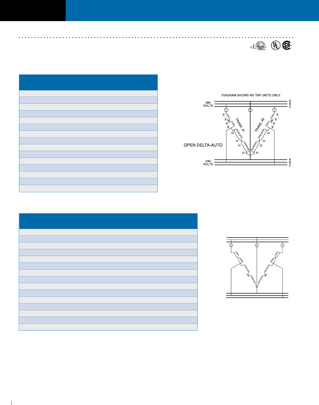
SECTION DRY-TYPE DISTRIBUTION TRANSFORMERS
ACME ELECTRIC • MILWAUKEE, WI • 800.334.5214 • acmetransformer.com
30
SECTION DRY-TYPE DISTRIBUTION TRANSFORMERS
1
30
600 PRIMARY VOLTS — 480 SECONDARY (open delta) VOLTS — 3Ø, 60 Hz
480 PRIMARY VOLTS — 380 SECONDARY (open delta) VOLTS — 3Ø, 50/60 Hz
① kVA capacity of three phase autotransformer bank, using two single phase, 60 Hz transformers
connected open delta.
② Catalog No. is for 1 transformer, 2 units are required.
③ Can be reverse connected with no change in kVA.
④For transformer dimensions, refer to appropriate table in section 1, page 17.
⑤For proper overcurrent protection, refer to Article 450-4 of N.E.C.
A
B
C
600
OR
480
VOLTS
480
OR
380
VOLTS
DIAGRAM SHOWS NO TAP UNITS ONLY
X
X
X
X
H
H
H
H
TRANS. #1
OPEN DELTA-
AUTO
X
X
X
X
H
H
H
H
TRANS. #2
A
B
C
THREE PHASE
480 PRIMARY (open delta) VOLTS ––
240 SECONDARY (open delta) VOLTS –– 3Ø, 60 Hz
⑤ O = Fuse Location NEC 450-4, 1990.
The diagrams above are for illustration purposes only. Please contact the factory for construction details.
Each Acme transformer is shipped with detailed wiring diagrams. Refer to nameplate located inside the front
cover for specific voltage tap combinations.
⑤ O = Fuse Location NEC 450-4, 1990.
Economical Auto Arrangements
Using two single phase transformers
Pri. 600V Pri. Sec. Pri. 480V Pri. Sec. Catalog ③ Max. Size
Sec. 480V Amps Amps Sec. 380V Amps Amps Qty ② No.④ Fuse or
kVA ① kVA ① Breaker
8.0 7.70 9.60 6.5 7.80 9.60 2 T253010S 15
12.0 11.55 14.40 9.5 11.55 14.40 2 T253011S 15
17.0 16.33 20.41 13.5 16.33 20.41 2 T253012S 25
25.0 24.06 30.01 20.0 24.06 30.01 2 T2530134S 30
43.0 41.38 51.70 34.0 41.38 51.70 2 T2530144S 60
64.0 61.59 77.00 51.0 61.59 77.00 2 T2535153S 80
86.0 82.76 103.44 68.0 82.76 103.44 2 T2535163S 110
129.0 124.13 155.20 103.0 124.13 155.20 2 T2535173S 175
216.0 207.85 259.80 172.0 207.85 259.80 2 T2535183S 300
324.0 311.78 389.70 259.0 311.78 389.70 2 TP530193S 400
433.0 416.67 520.83 346.0 416.67 520.83 2 TP530203S 600
650.0 625.00 781.00 519.0 625.00 781.00 2 TP530213S 800
865.0 833.00 1040.00 692.0 833.00 1051.00 2 TP530223S 1200
1445.0 1391.00 1738.00 1156.0 1391.00 1756.00 2 TP530233S 2000
2164.0 2083.00 2602.00 1731.0 2083.00 2629.00 2 TP530243S 3000
Primary Secondary Max. Size
kVA ① Qty. ② Catalog No. ③ Full Load Full Load Fuse or
Amps Amps Breaker
3.0 2 T253010S 3.60 7.20 10
5.0 2 T253011S 6.00 12.00 10
6.0 2 T253012S 7.20 14.40 15
10.0 2 T2530134S 12.00 24.00 15
17.0 2 T2530144S 20.50 40.80 30
26.0 2 T2535153S 31.50 63.00 40
34.0 2 T2535163S 41.00 81.60 60
52.0 2 T2535173S 63.00 125.00 80
86.0 2 T2535183S 104.00 206.30 150
130.5 2 TP530193S 157.00 314.00 200
173.0 2 TP530203S 209.00 418.00 300
259.0 2 TP530213S 312.00 623.00 400
346.0 2 TP530223S 417.00 834.00 600
578.0 2 TP530233S 696.00 1392.00 1000
865.0 2 TP530243S 1041.00 2082.00 1600
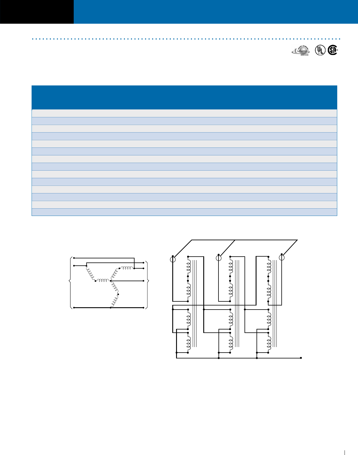
SECTION DRY-TYPE DISTRIBUTION TRANSFORMERS
ACME ELECTRIC • MILWAUKEE, WI • 800.334.5214 • acmetransformer.com
31
SECTION DRY-TYPE DISTRIBUTION TRANSFORMERS
1
31
PRIMARY (INPUT): 480 VOLTS SECONDARY (OUTPUT): 480Y/277 VOLTS
3Ø, 3 WIRE ①50/60 Hz 3Ø, 4 WIRE
① Applicable for the above connection only.
② Connection diagram (using 3 pieces of 1 phase, 60 hertz transformers connected zig-zag auto) for developing a neutral (4th wire) from a 3 phase,
3 wire supply.
③ For proper over-current protection, refer to the N.E.C. Article 450-5.
④ For transformer dimensions, refer to appropriate table in section 1, page 17.
Each Acme transformer is shipped with detailed wiring diagrams. Refer to nameplate located inside the front
cover for specific voltage tap combinations.
NEUTRAL
B
POINT
A,B OR C
TO
NEUTRAL
YIELDS
277 V
SINGLE
PHASE
4 WIRE
C
A
B
C
A
INPUT
480 V
3Ø
3 WIRE
BC
A
XX
X
X
X
H
H
H
H
X
X
X
X
H
H
H
H
X
X
X
H
H
H
H
COMMON TRIP DEVICE
NEUTRAL
TRANS. #3TRANS. #2TRANS. #1
See Footnote②
O = Fuse Location NEC 450-4, 1990.
③
Use 3 Pieces
Nameplate No. of Max. Continuous
of Available
kVA Tfmr. Three Phase Amp. Load Per
Type No.④ In
For Each Tfmr. Required kVA Phase
(277 Volts)
T253010S No Taps Only 1.0 3 10.80 12.50
T253011S No Taps Only 1.5 3 15.60 18.75
T253012S No Taps Only 2.0 3 20.70 25.00
T2530134S Taps & No Taps 3.0 3 31.20 37.50
T2530144S Taps & No Taps 5.0 3 51.90 62.50
T2535153S With Taps Only 7.5 3 78.00 93.50
T2535163S With Taps Only 10.0 3 103.80 125.00
T2535173S With Taps Only 15.0 3 156.00 187.50
T2535183S With Taps Only 25.0 3 259.50 312.00
TP530193S With Taps Only 37.5 3 390.00 468.00
TP530203S With Taps Only 50.0 3 519.00 625.00
TP530213S With Taps Only 75.0 3 780.00 935.00
TP530223S With Taps Only 100.0 3 1038.00 1250.00
TP530233S With Taps Only 167.0 3 1734.00 2085.00
Auto Zig-Zag Grounding Transformers
For developing a neutral from a three phase, 3-wire supply
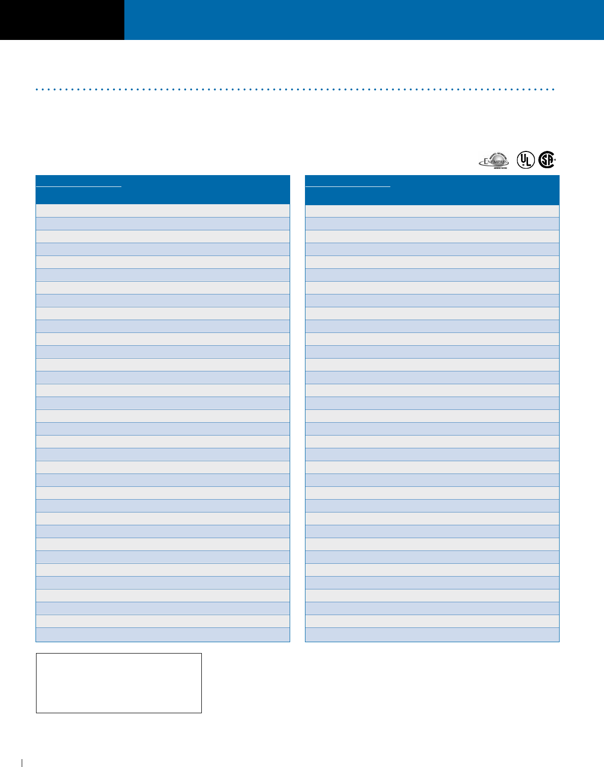
SECTION DRY-TYPE DISTRIBUTION TRANSFORMERS
ACME ELECTRIC • MILWAUKEE, WI • 800.334.5214 • acmetransformer.com
32
SECTION DRY-TYPE DISTRIBUTION TRANSFORMERS
1
32
KEY:
O.D. — Open Delta
ISO — Isolation
AUTO — Autotransformer
Do You Have a Non-Standard Three Phase
Voltage Application?
Many non-standard voltage correction problems can be solved
by using standard off-the-shelf single phase transformers.
The following is a list of such voltage combinations that can be
supplied by the Power Distribution Products Division. Drawings
for these products can be downloaded from our website at
www.acmepowerdist.com. If you don’t find the particular
combination you are looking for, contact our technical services
department for further assistance at 1-800- 334-5214.
THREE PHASE
① Cannot Be Reverse Connected.
VOLTAGES AVAILABLE ACME
KVA TYPE OF DRAWING
INPUT OUTPUT RANGE CIRCUIT NO.
208 Delta 208Y/120 3-75 Isolation A-125879
208 Delta 208Y/120 3-86 Auto Zig-Zag ① A-125895
208 Delta 240 Delta/120 1.68-25.2 O.D. ISO A-700314
208 Delta 240 Delta 3-75 Isolation A-125880
208 Delta 416Y/240 3-75 Isolation A-700598
208 Delta 416Y/240 112.5-300 Isolation A-700591
208Y/120 208Y/120 3-75 Isolation A-125857
208Y/120 374Y/216 22.5-75 Isolation A-125883
208Y/120 374Y/216 112.5-750 Isolation A-102730
208Y/120 480Y/277 3-75 Isolation B-39881 (pg 2)
240 Delta 208Y/120 3-15 Isolation A-125855
240 Delta 208Y/120 9-15 Isolation A-102723
240 Delta 208Y/120 22.5-75 Isolation A-102722-B
240 Delta 208Y/120 112.5-750 Isolation A-125856
240 Delta 208Y/120 3-75 Isolation A-125858
240 Delta 240 Delta 3-75 Isolation A-125859
240 Delta 240Y/138 10.3-258.75 Auto Zig-Zag ① A-125896
240 Delta 374Y/216 22.5-75 Isolation A-125881
240 Delta 374Y/216 112.5-750 Isolation A-125882
240 Delta 480Y/277 3-75 Isolation B-39881 (pg 1)
380 Delta 240 Delta 3-75 Isolation A-700592
380 Delta 240 Delta 112.5-300 Isolation A-700593
380 Delta 228 Delta 1.4-7.0 O.D. Auto A-35633
380 Delta 228 Delta 4.2-7.0 O.D. Auto A-125892
380 Delta 228 Delta 10.4-34.5 O.D. Auto A-125893
380 Delta 228 Delta 51-227 O.D. Auto A-125894
380 Delta 416Y/240 3-75 Isolation A-700599
380 Delta 416Y/240 112.5-300 Isolation A-700594
380Y/220 240 Delta 3-75 Isolation A-700600
380Y/220 240 Delta 112.5-300 Isolation A-700595
416Y/240 440 Delta 3-75 Isolation A-700602
416Y/240 440 Delta 112.5-300 Isolation A-700597
416 Delta 240 Delta 3-75 Isolation A-700601
416 Delta 240 Delta 112.5-300 Isolation A-700596
VOLTAGES AVAILABLE ACME
KVA TYPE OF DRAWING
INPUT OUTPUT RANGE CIRCUIT NO.
416Y/240 208Y/120 3-15 Isolation A-700319
416Y/240 208Y/120 22.5-75 Isolation A-700322
480 Delta 240 Delta/120 1.68-5.04 O.D. ISO Hi-Leg ① A-125849
480 Delta 240 Delta/120 3.36 O.D. ISO Hi-Leg ① A-125850
480 Delta 240 Delta/120 5.04 O.D. ISO Hi-Leg ① A-125851
480 Delta 240 Delta/120 8.4 O.D. ISO Hi-Leg ① A-125852
480 Delta 240 Delta/120 12.6-25.2 O.D. ISO Hi-Leg ① A-125853
480 Delta 240 Delta/120 42 O.D. ISO Hi-Leg ① A-125854
480 Delta 240 Delta/120 63-266 O.D. ISO Hi-Leg ① A-111702
480 Delta 240 Delta 1.68-8.4 O.D. ISO A-32817-B
480 Delta 240 Delta 5.04-8.4 O.D. ISO A-125872
480 Delta 240 Delta 12.6-42 O.D. ISO A-125873
480 Delta 240 Delta 63-420 O.D. ISO A-125874
480 Delta 416Y/240 3-15 Isolation A-125875
480 Delta 416Y/240 9-15 Isolation A-125876
480 Delta 416Y/240 22.5-75 Isolation A-125877
480 Delta 416Y/240 112.5-750 Isolation A-125878
480 Delta 394Y/228 9-15 Isolation A-125884
480 Delta 394Y/228 22.5-75 Isolation A-125885
480 Delta 394Y/228 112.5-750 Isolation A-125886
600 Delta 208Y/120 3-6 Isolation A-102758
600 Delta 208Y/120 9-75 Isolation A-125863
600 Delta 208Y/120 112.5-500 Isolation A-125864
600 Delta 240 Delta 3-6 Isolation A-125860
600 Delta 240 Delta 9-75 Isolation A-125861
600 Delta 240 Delta 112.5-500 Isolation A-125862
600 Delta 240 Delta/120 1.68-2.52 O.D. ISO Hi-Leg ① A-125865
600 Delta 240 Delta/120 3.36 O.D. ISO Hi-Leg ① A-125866
600 Delta 240 Delta/120 5.04-25.2 O.D. ISO Hi-Leg ① A-125867
600 Delta 240 Delta/120 42 O.D. ISO Hi-Leg ① A-125868
600 Delta 240 Delta/120 63-168 O.D. ISO Hi-Leg ① A-125869
600 Delta 240 Delta 1.68-3.36 O.D. ISO A-33227-A
600 Delta 240 Delta 5.04-42 O.D. ISO A-125870
600 Delta 240 Delta 63-280 O.D. ISO A-125871

SECTION 2
General Description & Features ....................... 34
Selection Charts ................................................ 35
HARMONIC
MITIGATING
TRANSFORMERS
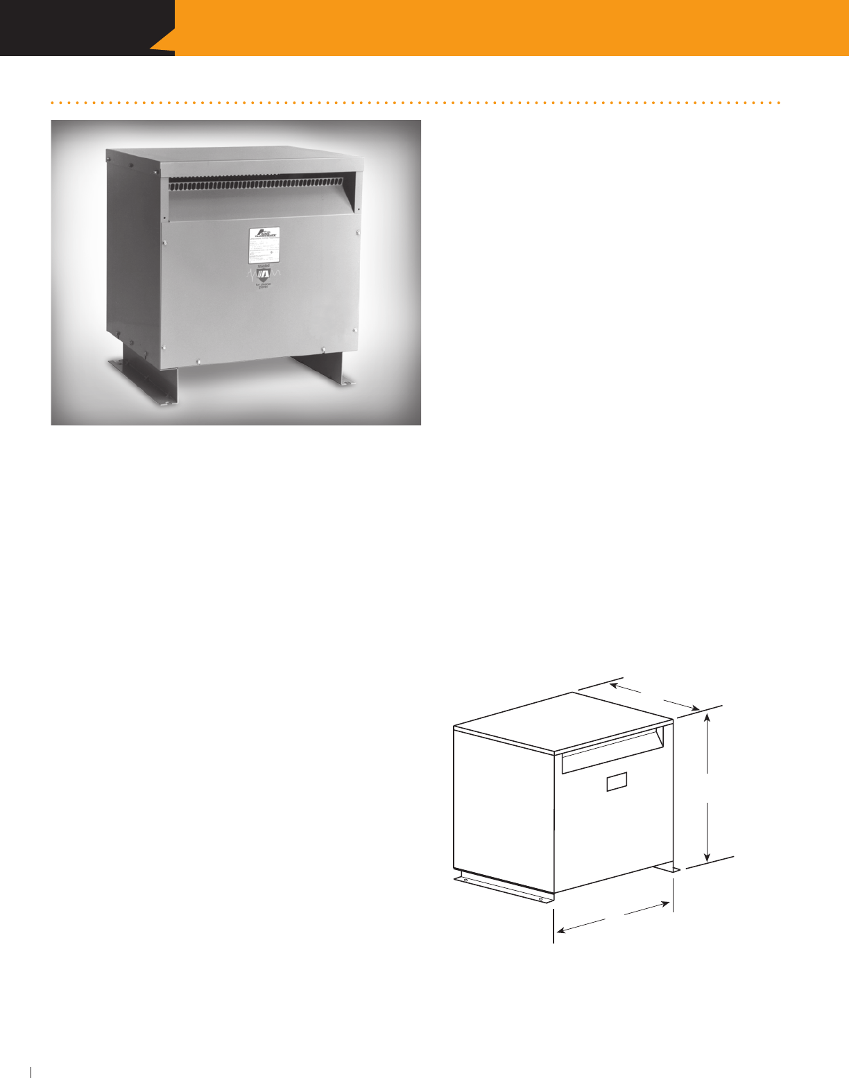
SECTION HARMONIC MITIGATING TRANSFORMERS
ACME ELECTRIC • MILWAUKEE, WI • 800.334.5214 • acmetransformer.com
34
2
SECTION HARMONIC MITIGATING TRANSFORMERS
34
Harmonic Mitigating Transformers
Many of today’s electronic devices are non-linear loads
generating high levels of harmonic currents that are then
fed back onto your distribution system. This waveform
distortion results in overheating of motors and transformers,
increased neutral currents and malfunction/damage to
other equipment on the line.
Acme Electric introduces a line of harmonic mitigating
transformers that combine the technologies shown in our
non-linear load (K-Factor) transformers. Where conventional
K-Factor transformers “deal” with harmonics, containing them
within the transformer and preventing them from going
further upstream; harmonic mitigating transformers eliminate
harmonics by pitting them against themselves. This technol-
ogy not only results in “cleaner power” but also provides the
most energy efficient means to deal with harmonic prob-
lems.
Available in sizes ranging from 30 thru 225 kVA, with copper
windings and a variety of other design options and acces-
sories, Acme harmonic mitigating transformers offer you
reduced transformer heat, reduced voltage distortion due to
3rd order harmonics, higher efficiency.
FEATURES
Unlike K-rated transformers, Harmonic Mitigating
transformers actually treat the triplen harmonics
in the secondary winding
Reduce supply voltage flat topping caused by
non-linear loads
Improve overall power factor of supply system
Suitable for K-Factor loads
Improved energy efficiency (Meet TP1 at K-1 load)
Copper conductor construction
APPLICATIONS
Financial facilities
Educational facilities
TV Broadcast facilities
Office buildings
Hospitals
Health care facilities
DIMENSIONAL DRAWING
D
H
W
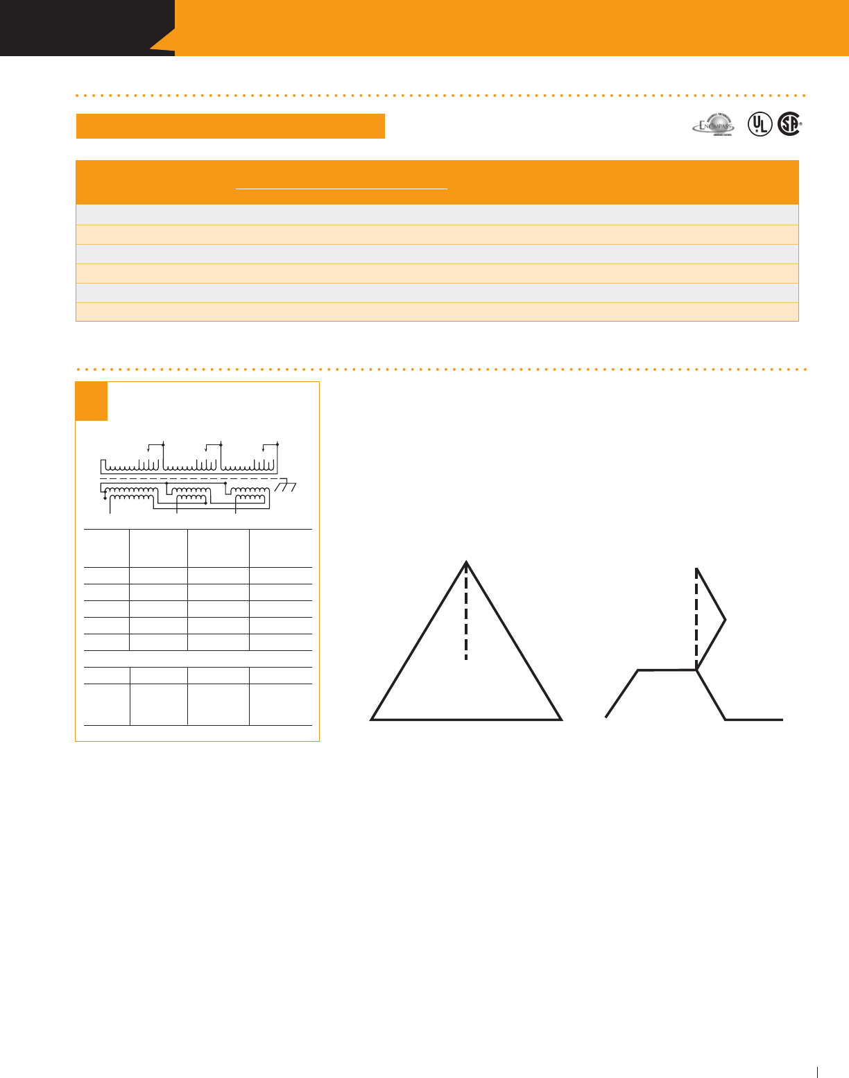
SECTION HARMONIC MITIGATING TRANSFORMERS
ACME ELECTRIC • MILWAUKEE, WI • 800.334.5214 • acmetransformer.com
35
2
SECTION HARMONIC MITIGATING TRANSFORMERS
35
480 DELTA PRIMARY VOLTS — 208Y/120 SECONDARY VOLTS
SELECTION CHARTS
HARMONIC MITIGATING TRANSFORMERS
APPROX. DIMENSIONS APPROX. TYPE MTG. WEATHER Wiring Diagrams &
kVA CATALOG NO. Inches (Cm.) SHIP WEIGHT W – Wall SHIELD Design Figures
HEIGHT WIDTH DEPTH Lbs. (Kg.) F – Floor P/N Begin on Page 122
30.0 CMT533124S 29.90 (75.9) 28.15 (71.5) 22.37 (56.8) 535 (242.7) F WSA2 81-E
45.0 CMT533134S 29.90 (75.9) 28.15 (71.5) 22.37 (56.8) 600 (272.2) F WSA2 81-E
75.0 CMT533144S 35.90 (91.2) 31.90 (81.0) 26.88 (68.3) 760 (344.7) F WSA3 81-E
112.5 CMT533154S 41.52 (105.5) 32.90 (83.6) 29.88 (75.9) 1180 (535.2) F WSA4 81-E
150.0 CMT533164S 41.52 (105.5) 32.90 (83.6) 29.88 (75.9) 1340 (607.8) F WSA4 81-E
225.0 CMT533174S 41.52 (105.5) 32.90 (83.6) 29.88 (75.9) 1970 (893.6) F WSA4 81-E
MITIGATING TRANSFORMER WIRING DIAGRAM
PRIMARY: 480 Volts Delta
SECONDARY: 208Y/120 Volts
TAPS: 2, 2 1
/2% ANFC, 2, 21
/2% BNFC
1
2
3
4
5
1
2
3
45
1
2
3
45
X3
X2
X1
H1 H2 H3
X0
81
Connect Connect
Primary Primary Inter- Secondary
Volts Lines To Connect Lines To
504 H1, H2, H3 1
492 H1, H2, H3 2
480 H1, H2, H3 3
468 H1, H2, H3 4
456 H1, H2, H3 5
Secondary Volts
208 X1, X2, X3
120 X1 to X0
1 phase X2 to X0
X3 to X0
Harmonic Mitigating Transformers – How do they work?
1. Acme utilizes special winding techniques and “foil”
conductors in both its K-Factor and Harmonic Mitigating
transformers to minimize the heating effects of harmonic
currents.
2. The use of foil conductor increases the dielectric strength
of the insulation because one layer is only one turn. Foil
also eliminates the effects of axial forces, which can result
in failure of wire wound transformers.
They consist of a Delta primary and a Zig-Zag secondary.
The Zig-Zag secondary causes a phase shift in the triplen
harmonics, which results in a canceling effect. This prevents
the triplen harmonic losses from being coupled back into
the primary and results in cooler operation and increased
energy efficiency.
The Acme Advantages
Diagram Showing Delta Primary &
Zig-Zag Secondary
(Zero degree angular displacement)
H2 X2
H1 H3 X1 X3
X0

SECTION HARMONIC MITIGATING TRANSFORMERS
ACME ELECTRIC • MILWAUKEE, WI • 800.334.5214 • acmetransformer.com
36
2
SECTION HARMONIC MITIGATING TRANSFORMERS
36
NOTES

SECTION 3
NON-LINEAR
LOAD ISOLATION®
TRANSFORMERS
Special winding techniques minimize
eddy current losses. A double sized
neutral handles excessive neutral
currents. UL Listed for “K” Factor
Loads 4, 13 & 20.
General Description & Features ..................38-39
Selection Charts ...........................................40-41
Definition of Terms ............................................ 42
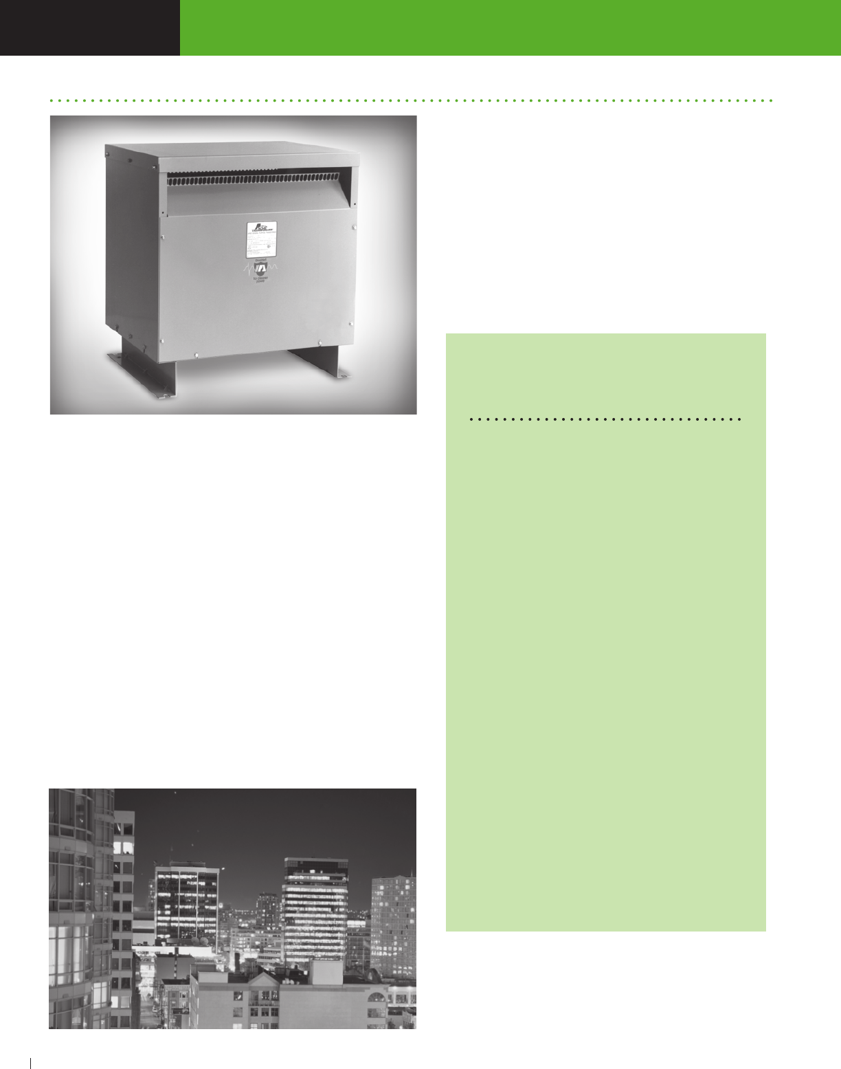
SECTION NON-LINEAR LOAD ISOLATION® TRANSFORMERS
ACME ELECTRIC • MILWAUKEE, WI • 800.334.5214 • acmetransformer.com
38
SECTION NON-LINEAR LOAD ISOLATION® TRANSFORMERS
3
38
Non-linear loads generate high levels of harmonic currents. When
supplying power to these loads, a special transformer design is
necessary.
Typical non-linear loads include desktop computers, AC variable
speed drives, HID lighting, electronic ballasts, inverters and welders.
Of these non-linear loads, the major source of harmonic currents is
the switch mode power supply found in desktop computers, data
processors and other office equipment.
Acme non-linear load isolation transformers use special winding
techniques to minimize eddy current losses generated by
harmonic currents. A double-sized neutral conductor handles the
excessive neutral current found in non-linear load applications.
The amount of harmonics produced by a given load is represented by
the term “K” factor. The larger the “K” factor, the more
harmonics are present. Linear loads have a “K” factor of 1; switch
mode power supplies typically have a “K” factor as high as 20.
Acme non-linear load isolation transformers are shielded for cleaner
power and carry the Acme exclusive 10-year limited warranty.
Non-Linear Load Isolation® Transformers
* These ratings are to be used as a guide
only. They may vary from one load equipment
manufacturer to another. A Spectrum Analysis is the
best source.
Note: Non-sinusoidal and non-linear are
synonymous terms relating to the same
transformer type.
K-Factor/Type of Load
K-1 Resistance heating
Incandescent lighting
Motors
Transformers, control/distribution
K-4 Welders
Induction heaters
HID lighting
Fluorescent lighting
Solid state controls
K-13 Telecommunications equipment
Branch Circuits in classrooms
and health care facilities
K-20 Main frame computers
Variable speed drives
Branch circuits with exclusive
loads of Data Processing
equipment
Desktop computers
The following guide will help you select the proper
transformer when the K-factor is unknown.*
FEATURES
Available in K-factors of 4, 13 and 20. Consult factory
for other K-factors.
150°C, 115°C and 80°C temperature rise units.
10-year limited warranty.
UL Listed and CSA Certified.
Available in 480V and 600V primary, 15 through 600 kVA.
Primary taps: (2) 21
/2% ANFC, (4) 21
/2% BNFC.
Aluminum windings
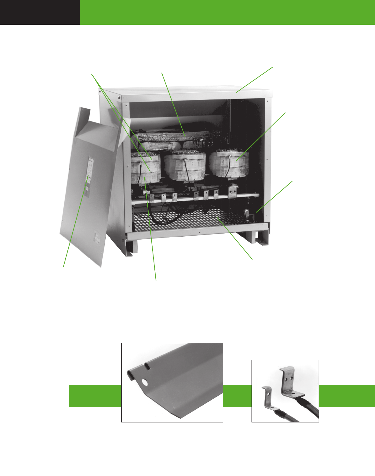
SECTION NON-LINEAR LOAD ISOLATION® TRANSFORMERS
ACME ELECTRIC • MILWAUKEE, WI • 800.334.5214 • acmetransformer.com
39
SECTION NON-LINEAR LOAD ISOLATION® TRANSFORMERS
3
39
Large legible
nameplates on
front cover Aluminum or copper
windings for increased life,
lower current losses
Industry standard full
capacity taps
Wound core construction for lower
losses and quiet operation
Heavy gauge steel UL Type 2
enclosures, UL-3R Listed with
weather shield accessory
Faraday shield eliminates
noise and voltage spikes
Rigid steel bottom is
punched for ventilation
Vibration isolation pads
reduce noise
Double-sized neutral
conductor handles exces-
sive neutral currents
Weather shields are available from stock
and are easily field-installed to make the
transformer weather resistant.

SECTION NON-LINEAR LOAD ISOLATION® TRANSFORMERS
ACME ELECTRIC • MILWAUKEE, WI • 800.334.5214 • acmetransformer.com
40
SECTION NON-LINEAR LOAD ISOLATION® TRANSFORMERS
3
40
480 DELTA PRIMARY VOLTS — 208Y/120 SECONDARY VOLTS — 3Ø, 60 Hz
SELECTION CHARTS THREE PHASE
Wall mounting brackets are available for these sizes, refer to page 133.
Dimensions in this section may change and are not to be used for detailed construction purposes. Please contact the factory for certified dimensional drawings.
480 DELTA PRIMARY VOLTS — 208Y/120 SECONDARY VOLTS — 3Ø, 60 Hz
GROUP A, K FACTOR 20, 150°C RISE
GROUP B,K FACTOR 13, 150°C RISE
GROUP C, K FACTOR 4, 150°C RISE
APPROX. DIMENSIONS APPROX. TYPE MTG. WEATHER Wiring Diagrams &
kVA CATALOG NO. Inches (Cm.) SHIP WEIGHT W – Wall SHIELD Design Figures
HEIGHT WIDTH DEPTH Lbs. (Kg.) F – Floor P/N Begin on Page 122
15.0 TPNS02533113S 25.50 (64.8) 24.40 (62.0) 19.40 (49.3) 325 (147.0) F WSA1 22–E
30.0 TPNS02533123S 25.50 (64.8) 24.40 (62.0) 19.40 (49.3) 420 (191.0) F WSA1 22–E
45.0 TPNS02533133S 35.90 (91.2) 31.90 (81.0) 26.88 (68.3) 575 (261.0) F WSA3 22–E
75.0 TPNS02533143S 35.90 (91.2) 31.90 (81.0) 26.88 (68.3) 620 (281.0) F WSA3 22–E
112.5 TPNS02533153S 41.52 (105.5) 32.90 (83.6) 29.88 (75.9) 1200 (544.0) F WSA4 22–E
150.0 TPNS02533163S 41.52 (105.5) 32.90 (83.6) 29.88 (75.9) 1700 (771.0) F WSA4 22–E
225.0 TPNS02533173S 45.60 (115.8) 39.50 (100.3) 35.50 (90.2) 2165 (982.0) F WSA5 22–G
480 DELTA PRIMARY VOLTS — 208Y/120 SECONDARY VOLTS — 3Ø, 60 Hz
APPROX. DIMENSIONS APPROX. TYPE MTG. WEATHER Wiring Diagrams &
kVA CATALOG NO. Inches (Cm.) SHIP WEIGHT W – Wall SHIELD Design Figures
HEIGHT WIDTH DEPTH Lbs. (Kg.) F – Floor P/N Begin on Page 122
15.0 TPNS01533113S 25.50 (64.8) 24.40 (62.0) 19.40 (49.3) 325 (147.0) F WSA1 22–E
30.0 TPNS01533123S 29.90 (75.9) 28.15 (71.5) 22.37 (56.8) 360 (163.0) F WSA2 22–E
45.0 TPNS01533133S 29.90 (75.9) 28.15 (71.5) 22.37 (56.8) 440 (200.0) F WSA2 22–E
75.0 TPNS01533143S 35.90 (91.2) 31.90 (81.0) 26.88 (68.3) 600 (272.0) F WSA3 22–E
112.5 TPNS01533153S 41.52 (105.5) 32.90 (83.6) 29.88 (75.9) 870 (395.0) F WSA4 22–E
150.0 TPNS01533163S 41.52 (105.5) 32.90 (83.6) 29.88 (75.9) 1500 (680.0) F WSA4 22–E
225.0 TPNS11533173S 45.60 (115.8) 39.50 (100.3) 35.50 (90.2) 1550 (703.0) F WSA5 22–E
APPROX. DIMENSIONS APPROX. TYPE MTG. WEATHER Wiring Diagrams
kVA CATALOG NO. Inches (Cm.) SHIP WEIGHT W – Wall SHIELD Design Figures
HEIGHT WIDTH DEPTH Lbs. (Kg.) F – Floor P/N Begin on Page 122
15.0 TPNS00533113S 25.50 (64.8) 24.40 (62.0) 19.40 (49.3) 325 (147.0) F WSA1 22–E
30.0 TPNS00533123S 29.90 (75.9) 28.15 (71.5) 22.37 (56.8) 345 (157.0) F WSA2 22–E
45.0 TPNS00533133S 29.90 (75.9) 28.15 (71.5) 22.37 (56.8) 430 (195.0) F WSA2 22–E
75.0 TPNS00533143S 35.90 (91.2) 31.90 (81.0) 26.88 (68.3) 560 (254.0) F WSA3 22–E
112.5 TPNS00533153S 41.52 (105.5) 32.90 (83.6) 29.88 (75.9) 875 (397.0) F WSA4 22–E
150.0 TPNS00533163S 41.52 (105.5) 32.90 (83.6) 29.88 (75.9) 1550 (703.0) F WSA4 22–E
225.0 TPNS10533173S 45.60 (115.8) 39.50 (100.3) 35.50 (90.2) 1600 (725.8) F WSA5 22–E
Notes: All TPNS models are TP1 compliant
Notes: All TPNS models are TP1 compliant
Notes: All TPNS models are TP1 compliant

SECTION NON-LINEAR LOAD ISOLATION® TRANSFORMERS
ACME ELECTRIC • MILWAUKEE, WI • 800.334.5214 • acmetransformer.com
41
SECTION NON-LINEAR LOAD ISOLATION® TRANSFORMERS
3
41
Wall mounting brackets are available for these sizes, refer to page 133.
Dimensions in this section may change and are not to be used for detailed construction purposes. Please contact the factory for certified dimensional drawings.
480 DELTA PRIMARY VOLTS — 208Y/120 SECONDARY VOLTS — 3Ø, 60 Hz
GROUP H, K FACTOR 13, 115°C RISE
APPROX. DIMENSIONS APPROX. TYPE MTG. WEATHER Wiring Diagrams &
kVA CATALOG NO. Inches (Cm.) SHIP WEIGHT W – Wall SHIELD Design Figures
HEIGHT WIDTH DEPTH Lbs. (Kg.) F – Floor P/N Begin on Page 122
30.0 TPNS01533121S 29.90 (75.9) 28.20 (71.6) 22.40 (56.9) 400 (181.0) F WSA2 22–E
45.0 TPNS01533131S 35.90 (91.2) 31.90 (81.0) 26.90 (68.3) 575 (261.0) F WSA3 22–E
75.0 TPNS01533141S 35.90 (91.2) 31.90 (81.0) 26.90 (68.3) 750 (340.0) F WSA3 22–E
112.5 TPNS01533151S 41.50 (105.4) 32.90 (83.6) 29.90 (75.9) 1120 (508.0) F WSA4 22–E
150.0 TPNS01533161S 41.50 (105.4) 32.90 (83.6) 29.90 (75.9) 1200 (544.0) F WSA4 22–E
Notes: All TPNS models are TP1 compliant
208 DELTA PRIMARY VOLTS — 208Y/120 SECONDARY VOLTS — 3Ø, 60 Hz
GROUP M, K FACTOR 13, 150°C RISE
APPROX. DIMENSIONS APPROX. TYPE MTG. WEATHER Wiring Diagrams &
kVA CATALOG NO. Inches (Cm.) SHIP WEIGHT W – Wall SHIELD Design Figures
HEIGHT WIDTH DEPTH Lbs. (Kg.) F – Floor P/N Begin on Page 122
15.0 TPNS01792714S 25.50 (64.8) 24.90 (62.0) 19.37 (49.2) 320 (145.1) F WSA1 61-E
30.0 TPNS01792724S 25.50 (64.8) 24.90 (62.0) 19.37 (49.2) 366 (166.0) F WSA1 61-E
45.0 TPNS01792734S 29.40 (74.7) 28.15 (71.5) 22.37 (56.8) 522 (236.8) F WSA2 61-E
75.0 TPNS01792744S 35.40 (89.9) 31.90 (81.0) 26.87 (68.2) 667 (302.6) F WSA3 61-E
NON-LINEAR LOAD ISOLATION® WIRING DIAGRAMS (Refer to pgs 122-124)
NON-LINEAR LOAD ISOLATION® DESIGN FIGURES (Refer to pg 122)
Notes: All TPNS models are TP1 compliant
Notes: All TPNS models are TP1 compliant
For Additional Low Temperature Rise 115° and 80° Degree Units and Copper Wound Units,
Consult Factory

SECTION NON-LINEAR LOAD ISOLATION® TRANSFORMERS
ACME ELECTRIC • MILWAUKEE, WI • 800.334.5214 • acmetransformer.com
42
SECTION
3
42
1. L i n e a r l o a d s
Loads where the current waveform conforms to the waveform
of the applied voltage. Or loads where a change in current
is directly proportional to a change in applied voltage. For
example:
• Resistance heating
• Incandescent lighting
• Water heater
2. Non-linear loads
Loads where the current waveform does not conform to the
waveform of the applied voltage. Or loads where a change in
current is not proportional to a change in applied voltage.
Examples are:
• Computer power supplies
• Motor drives
• Fluorescent lighting
Non-linear loads produce non-sinusoidal current or voltage
waveforms.
3. Sinusoidal current or voltage
This term refers to a periodic waveform that can be expressed
as the sine of a linear function of time.
4. Non-linear currents or voltages
A waveform of current or voltage which cannot be expressed
as the sine of a linear function of time. A non-linear load would
result in a non-sinusoidal current or voltage.
5. Harmonic
A sinusoidal waveform with a frequency that is an integral
multiple of the fundamental 60 Hz frequency.
60 Hz Fundamental
120 Hz 2nd Harmonic
180 Hz 3rd Harmonic
240 Hz 4th Harmonic
etc.
Current waveforms from non-linear loads appear distorted
because the non-linear waveform is the result of adding
harmonic components to the fundamental current.
6. Triplen harmonics
Odd multiples of the 3rd harmonic
(3rd, 9th, 15th, 21st, etc.).
7. H a r m o n i c d i s t o r t i o n
Non-linear distortion of a system
characterized by the appearance in the output of harmonic
currents (voltages) when the input is sinusoidal.
8. Voltage harmonic distortion (VHD)
Voltage harmonic distortion is distortion caused by harmonic
currents flowing through the system impedance. The utility
power system has relatively low system impedance, and the
VHD is very low. But, VHD on the distribution power system
can be significant due to its relatively high system impedance.
9. Total harmonic distortion (THD)
The square root of the sum of the squares of all harmonic
currents present in the load excluding the 60 Hz fundamental.
It is usually expressed as a percent of the fundamental.
10. Root mean squared current
(or voltage) RMS
1: The vector sum of the fundamental current and the total
harmonic distortion.
2: Square root of the sum of the squared value of the
fundamental current and the squared value of the total
harmonic distortion.
11. Edd y cu rrent s
Currents flowing in a conducting material in the presence of a
time varying magnetic field. These currents are in addition to
the current drawn by the load.
12. Eddy current losses
Power dissipated due to eddy currents. Includes eddy current
losses in the core, windings, case and associated hardware of
a transformer.
13. St ray losse s
A term used to express the difference
between the measured alternating current losses on a
transformer and the direct current (DC) losses (I2R). Stray
losses include eddy losses. Stray losses are usually
expressed as a percent of the direct current (DC) losses.
14. Per unit value
1: Percent value divided by 100.
2: The ratio of two components of a system.
15. Harmonic spectrum “K” factor
The sum of the product of each harmonic current squared
and that harmonic number squared for all harmonics from
the fundamental (60 Hz) to the highest harmonic of any
measurable consequence. When the “K” factor is multiplied
by the stray losses of the transformer, the answer represents
the losses in the transformer caused by harmonic currents.
When these losses are added to the I2R losses of the
transformer, the total load losses are known. The “K” factor for
a linear load without harmonics is one (1).

SECTION
DRIVE ISOLATION
TRANSFORMERS & AC LINE
REACTORS
4
Specifically designed to accommodate
the special voltage and kVA sizes
unique to AC and DC drive applications.
Shielded for extra protection from
supply line transients.
General Description & Features .....................44-45
Thermal Switches ................................................47
Selection Charts .............................................. 46-47
Windings, Terminations & Construction .............. 47
AC Line Reactors are designed to
protect DC motor drives, AC vaåriable
frequency drives and the motors
they power.
AC LINE REACTORS
General Description & Features ......................48-49
Selection Charts ...................................................50
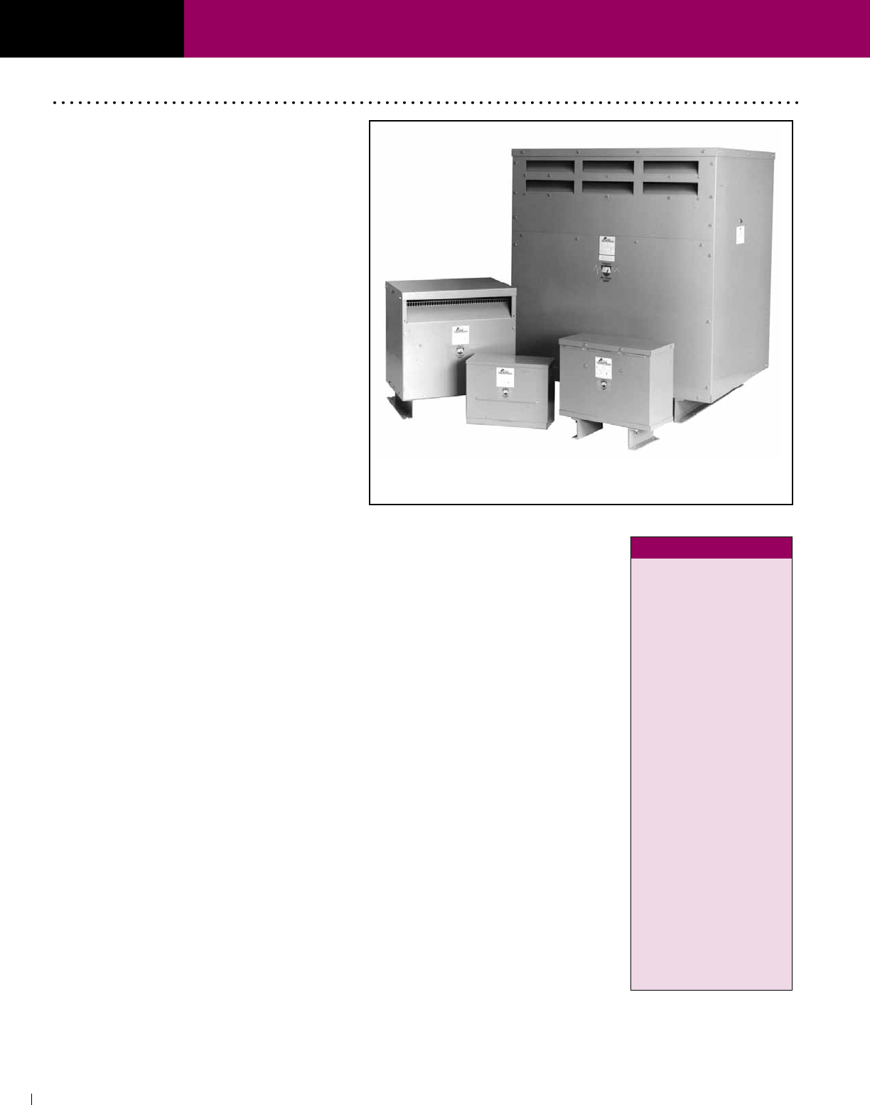
SECTION
ACME ELECTRIC • MILWAUKEE, WI • 800.334.5214 • acmetransformer.com
44
SECTION DRIVE ISOLATION TRANSFORMERS
4
44
Drive Isolation Transformers
Stress relief
Acme uses strip conductors (above 7.5 kVA)
instead of wire for a DIT series that easily
accommodates the severe electrical and
mechanical stresses found in today’s AC & DC
motor drives. The inherent excellent line isolation
of these transformers is further enhanced with
the extra protection of Acme’s Electrostatic
Shield — free in all DIT’s.
Lower losses
The harmonic currents generated by AC & DC
drives increase eddy current losses (heat) in
transformer windings. The thicker the winding
conductor, the greater the losses. Acme uses
one turn per layer of thin strip conductor which
provides lower eddy current losses than
comparable wire wound units. Lower losses =
cooler operation and longer transformer life.
DTGB0404S
DTGA72S
DTGA0142S
DTHA03304S
The Acme Drive Isolation Transformers are spe-
cifically designed to accommodate the
special voltages and kVA sizes unique to AC and
DC motor drive applications.
FEATURES
n UL Type 3R Enclosures with Weather Shield
on Ventilated Units (above 20 kVA). Type 2
Enclosure without weather shield. UL Listed and
CSA certified. 7.5–20.0 kVA are encapsulated,
UL 3R.
n 3-Phase 60 Hertz.
n 180°C and 220°C insulation systems.
n Encapsulated and ventilated designs. All
ventilated units, are of strip wound construction.
Acme’s reinforced core assemblies enhance
quiet operation.
n Nominally 6% impedance.
n Designed for use with AC, adjustable frequency
or DC drives.
n Full capacity taps are featured on all units. On
7.5 through 20 kVA units, taps are 1-5% ANFC
and 1-5% BNFC. On 27 through 660 kVA units,
taps are 2-21
/2% ANFC and 2-21
/2% BNFC.
n Full range of kVA ratings cover all standard
drive systems.
n Ample wiring compartment for easy cable entry.
n Optional wall mounting brackets for certain sizes.
Reduced short
circuit forces
Strip windings minimize axial
short circuit forces that can cause
mechanical displacement of the
windings under fault conditions.
For extra protection all designs 7.5
kVA and above use primary and
secondary coils of equal axial length.
This feature tends to negate axial
short circuit forces, further improving
transformer life expectancy.
Selection
instructions
If you know the motor horse-power,
simply follow the drive system
manufacturer's recommendation. Or,
select the corresponding kVA from
the chart at right.
For example, a 40 Hp motor requires a
51 kVA DIT.
H.P. kVA
5.0 7.5
7.5 11.0
10.0 14.0
15.0 20.0
20.0 27.0
25.0 34.0
30.0 40.0
40.0 51.0
50.0 63.0
60.0 75.0
75.0 93.0
100.0 118.0
125.0 145.0
150.0 175.0
200.0 220.0
250.0 275.0
300.0 330.0
400.0 440.0
500.0 550.0
600.0 660.0
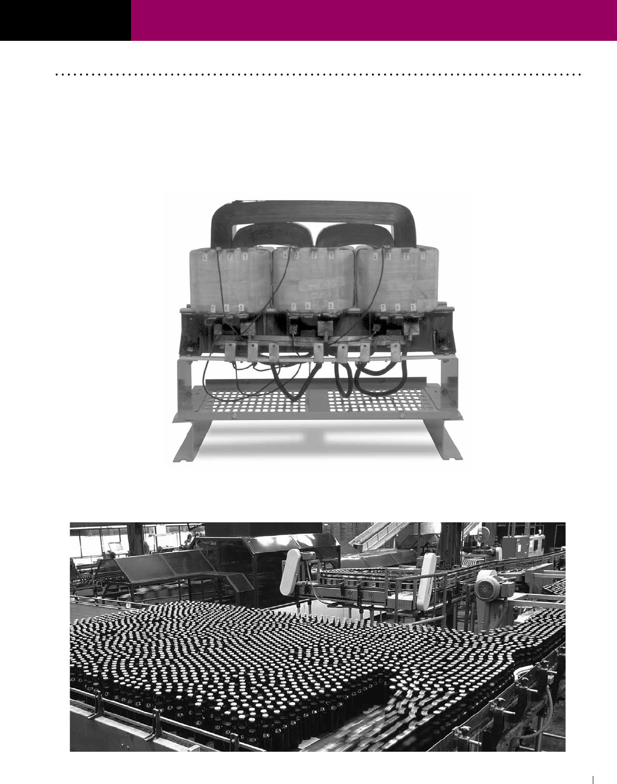
SECTION
ACME ELECTRIC • MILWAUKEE, WI • 800.334.5214 • acmetransformer.com
45
SECTION DRIVE ISOLATION TRANSFORMERS
4
45
Wound core construction showing all copper terminations
Acme Advantages
Wound Cores and Strip
Winding mean lower losses
All Acme DITs above 7.5 kVA are wound with strip windings
to ensure the lowest possible eddy current losses. All our
DITs use a three leg wound core. This superior design has
very low losses and quiet operation. Both of these features
combine to significantly reduce losses and operating costs
compared to other types of constructions.
Copper terminations provide trouble-
free operation
All Acme DITs up to and including 220 kVA have copper
terminations. The transition from aluminum strip coil
conductors to copper terminations is accomplished by a
bonding process known as “Koldwelding™”. This process
has been used by Acme for over 25 years to provide a
trouble-free, permanent bonding of the two metals.

SECTION
ACME ELECTRIC • MILWAUKEE, WI • 800.334.5214 • acmetransformer.com
46
SECTION DRIVE ISOLATION TRANSFORMERS
4
46
① Optional wall mounting kits – part # PL 79911 refer to Page 133.
② Optional wall mounting kits – part # PL 79912 refer to Page 133.
The number in ( )’s following the catalog number is the electrical wiring diagram number beginning on page 122.
SELECTION CHARTS
GROUP A GROUP B
GROUP C GROUP D
Primary 575V Delta Primary 575V Delta APPROX. DIMENSIONS ③ APPROX. TYPE MTG. WEATHER
kVA Secondary 230Y/133 Secondary 460Y/266 Inches (Cm.) SHIP WEIGHT W - Wall SHIELD DIM.
CATALOG NO. CATALOG NO. HEIGHT WIDTH DEPTH Lbs. (Kg.) F - Floor P/N
DRAWING
7.5 DTHA72S DTHB72S 15.21 (38.6) 19.25 (48.9) 7.37 (18.7) 180 (81.6) W NA F
11.0 DTHA0112S DTHB0112S 18.86 (47.9) 20.30 (51.6) 9.03 (22.9) 265 (120.0) F
①
NA I
14.0 DTHA0142S DTHB0142S 18.86 (47.9) 20.30 (51.6) 9.03 (22.9) 270 (123.0) F
①
NA I
20.0 DTHA0202S DTHB0202S 20.77 (52.8) 20.94 (53.2) 10.18 (25.9) 435 (197.0) F
①
NA I
27.0 DTHA0274S (41) DTHB0274S
(44) 25.50 (64.8) 24.39 (61.9) 19.37 (49.2) 320 (145.0) F
②
WSA1 E
34.0 DTHA0344S DTHB0344S 25.50 (64.8) 24.39 (61.9) 19.37 (49.2) 340 (154.0) F
②
WSA1 E
40.0 DTHA0404S DTHB0404S 25.50 (64.8) 24.39 (61.9) 19.37 (49.2) 395 (179.0) F
②
WSA1 E
51.0 DTHA0514S DTHB0514S 29.90 (75.9) 28.15 (71.5) 22.37 (56.8) 400 (181.0) F
②
WSA2 E
63.0 DTHA0634S DTHB0634S 29.90 (75.9) 28.15 (71.5) 22.37 (56.8) 550 (250.0) F
②
WSA2 E
75.0 DTHA0754S DTHB754S 29.90 (75.9) 28.15 (71.5) 22.37 (56.8) 570 (259.0) F
②
WSA2 E
93.0 DTHA0934S DTHB0934S 35.90 (91.2) 31.90 (81.0) 26.88 (68.3) 685 (311.0) F WSA3 E
118.0 DTHA01184S DTHB01184S 35.90 (91.2) 31.90 (81.0) 26.88 (68.3) 765 (347.0) F WSA3 E
145.0 DTHA01454S DTHB01454S 41.52 (105.5) 32.90 (83.6) 29.88 (75.9) 990 (449.0) F WSA4 E
175.0 DTHB01754S 41.52 (105.5) 32.90 (83.6) 29.88 (75.9) 1100 (499.0) F WSA4 E
220.0 DTHB02204S 41.52 (105.5) 32.90 (83.6) 29.88 (75.9) 1120 (508.0) F WSA4 E
275.0 DTHB002754S 45.60 (115.8) 39.50 (100.3) 35.50 (90.2) 2090 (948.0) F WSA5 E
330.0 DTHB03304S 45.60 (115.8) 39.50 (100.3) 35.50 (90.2) 2090 (948.0) F WSA5 G
440.0 DTHB04404S 57.84 (157.5) 45.50 (115.6) 41.49 (105.4) 2580 (1172.7) F WSA7 G
550.0 DTHB05504S 57.84 (157.5) 45.50 (115.6) 41.49 (105.4) 2640 (1200.0) F WSA7 G
660.0 DTHB006604S 62.84 (159.6) 54.00 (137.2) 41.49 (105.4) 3700 (1678.3) F WSA6 G
③ Dimensions may change and are not to be used for detailed construction purposes.
Please contact the factory for certified dimensional drawings.
Primary 460V Delta Primary 460V Delta APPROX. DIMENSIONS ③ APPROX. TYPE MTG. WEATHER
kVA Secondary 230Y/133 Secondary 460Y/266 Inches (Cm.) SHIP WEIGHT W - Wall SHIELD DIM.
CATALOG NO. CATALOG NO. HEIGHT WIDTH DEPTH Lbs. (Kg.) F - Floor P/N
DRAWING
7.5 DTGA72S DTGB72S 15.21 (38.6) 19.25 (48.9) 7.37 (18.7) 180 (81.6) W NA F
11.0 DTGA0112S DTGB0112S 18.86 (47.9) 20.30 (51.6) 9.03 (22.9) 265 (120.0) F
①
NA I
14.0 DTGA0142S DTGB0142S 18.86 (47.9) 20.30 (51.6) 9.03 (22.9) 270 (123.0) F
①
NA I
20.0 DTGA0202S DTGB0202S 20.77 (52.8) 20.94 (53.2) 10.18 (25.9) 435 (197.0) F
①
NA I
27.0 DTGA0274S (38) DTGB0274S (35) 25.50 (64.8) 24.39 (61.9) 19.37 (49.2) 320 (145.0) F
②
WSA1 E
34.0 DTGA0344S DTGB0344S 25.50 (64.8) 24.39 (61.9) 19.37 (49.2) 340 (154.0) F
②
WSA1 E
40.0 DTGA0404S DTGB0404S 25.50 (64.8) 24.39 (61.9) 19.37 (49.2) 395 (179.0) F
②
WSA1 E
51.0 DTGA0514S DTGB0514S 29.90 (75.9) 28.15 (71.5) 22.37 (56.8) 400 (181.0) F
②
WSA2 E
63.0 DTGA0634S DTGB0634S 29.90 (75.9) 28.15 (71.5) 22.37 (56.8) 550 (250.0) F
②
WSA2 E
75.0 DTGA0754S DTGB0754S 29.90 (75.9) 28.15 (71.5) 22.37 (56.8) 570 (259.0) F
②
WSA2 E
93.0 DTGA0934S DTGB0934S 35.90 (91.2) 31.90 (81.0) 26.88 (68.3) 685 (311.0) F WSA3 E
118.0 DTGA01184S DTGB01184S 35.90 (91.2) 31.90 (81.0) 26.88 (68.3) 765 (347.0) F WSA3 E
145.0 DTGA01454S DTGB01454S 41.52 (105.5) 32.90 (83.6) 29.88 (75.9) 990 (449.0) F WSA4 E
175.0 DTGA01754S DTGB01754S 41.52 (105.5) 32.90 (83.6) 29.88 (75.9) 1100 (499.0) F WSA4 E
220.0 DTGA02204S DTGB02204S 41.52 (105.5) 32.90 (83.6) 29.88 (75.9) 1120 (508.0) F WSA4 E
275.0 DTGA002754S DTGB002754S 45.60 (115.8) 39.50 (100.3) 35.50 (90.2) 2090 (948.0) F WSA5 E
330.0 DTGA03304S DTGB03304S 45.60 (115.8) 39.50 (100.3) 35.50 (90.2) 2090 (948.0) F WSA5 G
440.0 DTGB04404S 57.84 (146.9) 45.50 (115.6) 41.49 (105.4) 2295 (1043.2) F WSA7 G
550.0 DTGB05504S 57.84 (146.9) 45.50 (115.6) 41.49 (105.4) 2580 (1172.7) F WSA7 G
660.0 DTGB06604S 62.84 (159.6) 54.00 (137.2) 41.49 (105.4) 3700 (1678.3) F WSA6 G
770.0 DTGB07704S 62.84 (159.6) 54.00 (137.2) 41.49 (105.4) 4044 (1838.2) F WSA6 G
880.0 DTGB008804S 62.84 (159.6) 54.00 (137.2) 41.49 (105.4) 4230 (1922.7) F WSA6 G
990.0 DTGB9902S 62.84 (159.6) 54.00 (137.2) 41.49 (105.4) 4285 (1947.7) F WSA6 G
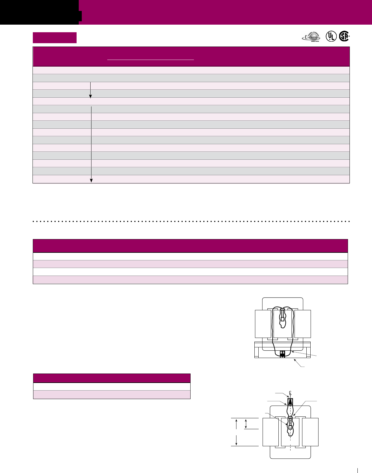
SECTION
ACME ELECTRIC • MILWAUKEE, WI • 800.334.5214 • acmetransformer.com
47
SECTION DRIVE ISOLATION TRANSFORMERS
4
For Information On The Following,
Please Contact The Factory
1. Transformers rated primary 230 volts delta, secondary 460Y/266 volts.
2. Low temperature rise units using class 220°C insulation with
either 115°C or 80°C rise operating temperature.
3. Totally enclosed non-ventilated units.
Windings, Terminations and Construction
①
Optional wall mounting kits – part # PL 79911 refer to Page 133.
②
Optional wall mounting kits – part # PL 79912 refer to Page 133.
The number in ( )’s following the catalog number is the electrical wiring diagram number beginning on page 155.
GROUP E
Figure 1
Figure 2
COIL 1 COIL 2COIL 3
CORE
BOTTOM OF CASE
COIL 1 COIL 3
THERMAL SWITCH
.625 (1.6 cm) H DIA.
EPOXY-RING
CORE
EPOXY LAYER
TERMINAL BLOCK
H
.5H
(1.3 cm)
COIL 2
Thermal Switch Kit - PL-79900
Acme Thermal Switch Kits are designed for use with single and three phase
drive isolation and distribution transformers. Thermal switch kits are available
for a one or three sensor system.
Thermal sensors can be field installed in the transformer winding ducts to detect
abnormal temperatures. The thermal sensors are a normally closed contact
that opens at 200°C ± 10°C and has a current capacity of 5 amps @ 120V or
2.5 amps @ 240V. This contact can activate any number of different types of
alarms or mechanisms that could warn of a potential failure.
KVA MOUNTING POSITION ILLUSTRATION
27.0-118.0 Bottom of the case Figure 1
145-750 Top flange of the core bracket Figure 2
PRIMARY SECONDARY INSULATION CONSTRUCTION
KVA WINDING WINDING SYSTEM TERMINATION ENCLOSURE CORE
7.5 CU wire CU wire 180°C CU wire Epoxy encapsulated Wound/distributed gap
11-20 AL foil AL foil 180°C CU wire Epoxy encapsulated Wound/distributed gap
27-220 AL foil AL foil 220°C CU bus Ventilated Wound/distributed gap
275-660 AL foil AL foil 220°C AL bus Ventilated Butt stacked/Step lap
PRIMARY 230 Delta APPROX. DIMENSIONS APPROX. TYPE MTG. WEATHER
kVA SECONDARY 230Y/133 Inches (Cm.) SHIP WEIGHT W – Wall Knockouts SHIELD DIM.
CATALOG NO. Height Width Depth Lbs. (Kg.) F – Floor Inches (Cm.) P/N
DRAWING
7.5 DTFA72S (62) 15.21 (38.6) 19.25 (48.9) 7.37 (18.7) 180 (81.6) W NA NA F
11.0 DTFA0112S (62) 18.86 (48.0) 20.30 (51.6) 9.03 (22.9) 265 (120.0) F ① NA NA I
14.0 DTFA0142S 18.86 (48.0) 20.30 (51.6) 9.03 (22.9) 265 (120.0) F ① NA NA I
20.0 DTFA0202S 20.77 (52.8) 20.94 (53.2) 10.18 (25.9) 435 (197.0) F ① NA NA I
27.0 DTFA0274S (59) 25.48 (64.8) 24.39 (62.0) 19.40 (49.3) 302 (137.0) F ② NA WSA1 E
34.0 DTFA0344S 25.48 (64.8) 24.39 (62.0) 19.40 (49.3) 330 (150.0) F ② NA WSA1 E
40.0 DTFA0404S 25.48 (64.8) 24.39 (62.0) 19.40 (49.3) 370 (168.0) F ② NA WSA1 E
51.0 DTFA0514S 29.40 (74.7) 28.15 (71.5) 22.40 (56.9) 375 (170.0) F ② NA WSA2 E
63.0 DTFA0634S 29.40 (74.7) 28.15 (71.5) 22.40 (56.9) 495 (225.0) F ② NA WSA2 E
75.0 DTFA0754S 29.40 (74.7) 28.15 (71.5) 22.40 (56.9) 525 (238.0) F ② NA WSA2 E
93.0 DTFA0934S 35.40 (89.9) 31.90 (81.0) 26.90 (68.3) 685 (311.0) F NA WSA3 E
118.0 DTFA01184S 35.40 (89.9) 31.90 (81.0) 26.90 (68.3) 710 (322.0) F NA WSA3 E
145.0 DTFA01454S 41.52 (105.5) 32.90 (83.6) 29.90 (75.9) 980 (445.0) F NA WSA4 E
175.0 DTFA01754S 41.52 (105.5) 32.90 (83.6) 29.90 (75.9) 1110 (504.0) F NA WSA4 E
220.0 DTFA02204S 41.52 (105.5) 32.90 (83.6) 29.90 (75.9) 1120 (508.0) F NA WSA4 E
DRIVE ISOLATION DESIGN FIGURES (Refer to pg 122)
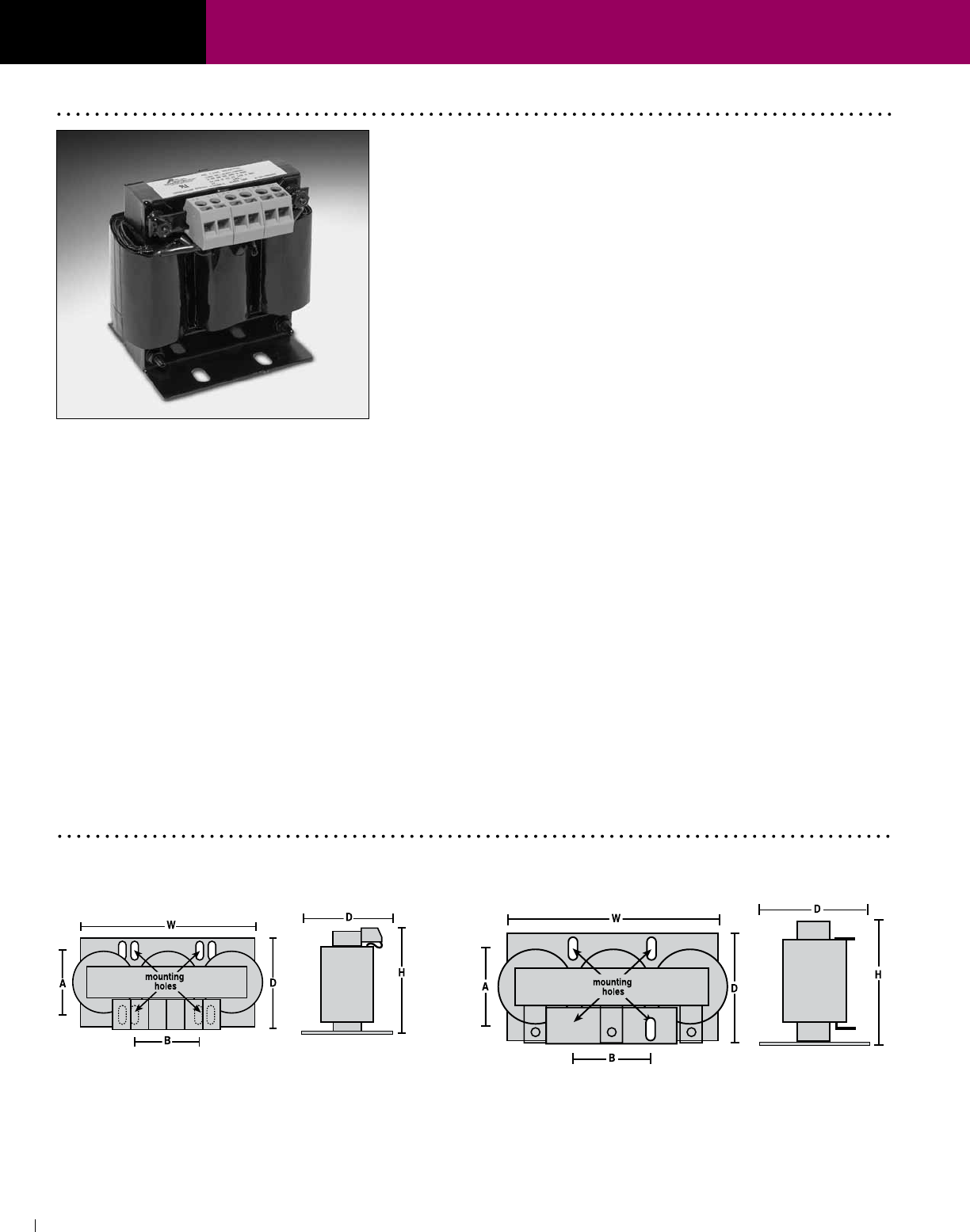
SECTION
ACME ELECTRIC • MILWAUKEE, WI • 800.334.5214 • acmetransformer.com
48
SECTION AC LINE REACTORS
4
AC Line Reactors
Protect your sensitive equipment from harmful line disturbances
with Acme AC Line Reactors. AC Line Reactors help
prevent equipment failure and downtime, and can add
years to the life of your equipment.
Designed to protect DC motor drives, AC variable frequency
drives and the motors they power. AC Line Reactors allow
Acme to augment the Drive Isolation Transformer package
to offer both line and load power quality protection for a
wide range of applications.
Our product line features flexible design and ease of
installation for use in a variety of applications such as paper
machines, process lines, press controls and drive systems,
along with tube mills and other sophisticated process
equipment. These applications are found in such industries as
food and beverage, paper, packaging systems and printing.
FEATURES
n Gapped iron core inductor–designed for optimum
performance while providing harmonics compensation.
n Precision wound copper coils–maximum protection from
short-circuiting.
n Finger-safe terminal blocks (up to 60 HP).
n Compact design–allows for more flexible installation.
n Amperage ratings of 2 to 600 amps
n Available in 3% and 5% impedance
n Can be used with 208, 240, 480 and 600 volts.
n Covered under Acme’s 10-year limited warranty.
n UR and cUR Recognized.
n CE Marked (up to 55 amps)
BENEFITS
Protect your motors and motor drives from a variety of power
conditioning problems while realizing the following benefits:
n Protection from damaging voltage drop.
n Elimination of nuisance tripping of drives or circuit
breakers.
n Reduction of motor current surges and power line spike
currents.
n Improvement in true power factor of capacitor input drives.
n Cooler, quieter operation.
n Reduction of harmonic distortion.
n Longer life for motors and solid state components.
AC LINE REACTORS DIMENSIONAL DRAWINGS
1-60 HP; 2-80 Amp 75-500 HP; 110-600 Amp
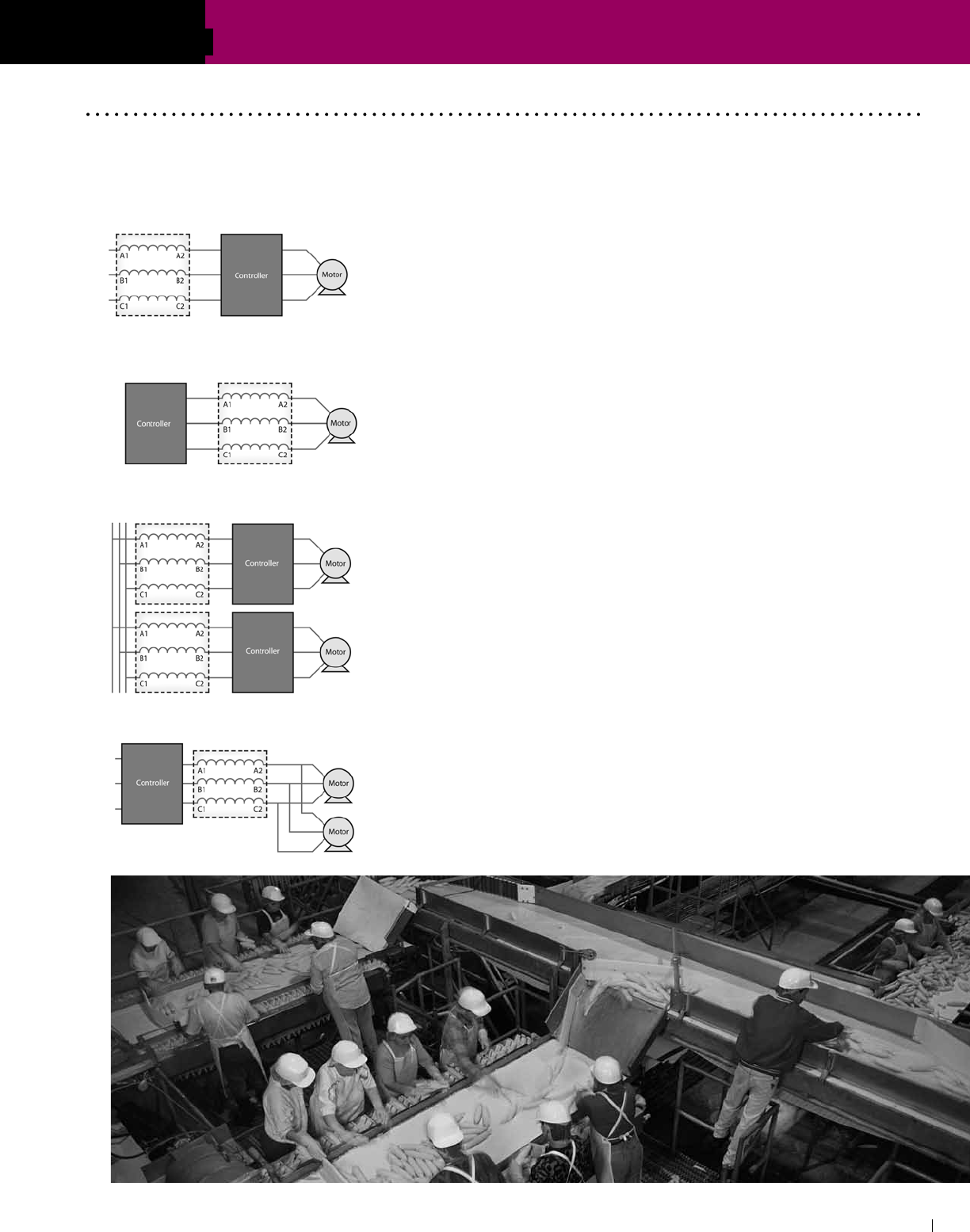
SECTION
ACME ELECTRIC • MILWAUKEE, WI • 800.334.5214 • acmetransformer.com
49
SECTION AC LINE REACTORS
4
Applying Acme AC Line Reactors
Input to Inverter/Drive
AC Line Reactors protect your sensitive equipment from noise
generated by the drive or inverter. They protect the controller from
power surges, spikes and harmonic distortion.
Output of Inverter/Drive
Motors run cooler and quieter with an AC Line Reactor placed
between the inverter and motor. This application also reduces
dv/dt and protects the controller from short circuits and surges.
Multiple Controllers on a Single Power Line
Each drive or inverter on a single power line requires its own AC
Line Reactor in order to provide adequate surge protection, prevent
crosstalk and reduce harmonic distortion.
Multiple Motors Controlled by a Single Drive
Multiple motors controlled by a single drive require only one AC Line
Reactor between the controller and motors.
Acme’s three-phase AC Line Reactors can be used as an input filter for adjustable speed DC drives and as input
or output filters for AC pulse width modulated variable frequency drives. They are bi-directional protective filtering
devices and can be applied in a variety of configurations.

SECTION
ACME ELECTRIC • MILWAUKEE, WI • 800.334.5214 • acmetransformer.com
50
SECTION AC LINE REACTORS
4
* Motor HP and Amp rated at 480 volts.
SELECTION CHARTS
GROUP B
480 VOLTS, 3% Z, 60 Hz (600 VOLTS, 2.4% Z; 240 VOLTS, 6% Z)
GROUP C
480 VOLTS, 5% Z, 60 Hz (600 VOLTS, 4% Z; 240 VOLTS, 10% Z )
MOTOR* REACTOR DIMENSIONS MOUNTING DIMENSIONS WEIGHT
CATALOG NO. HP AMP AMP uH H W D A (Depth) B (Width) (Lbs/Kg)
ALRB002TBC 1 2.1 2 11027 3.875 (9.8) 4.25 (10.8) 3.125 (7.90) 2.00 (5.1) 1.44 (3.7) 3 (1.4)
ALRB003TBC 1.5 3 3 7351 3.875 (9.8) 4.25 (10.8) 3.125 (7.90) 2.00 (5.1) 1.44 (3.7) 3 (1.4)
ALRB004TBC 2 3.4 4 5513 3.875 (9.8) 4.25 (10.8) 3.125 (7.90) 2.00 (5.1) 1.44 (3.7) 3 (1.4)
ALRB006TBC 3 4.8 6 3676 3.875 (9.8) 4.25 (10.8) 3.125 (7.90) 2.00 (5.1) 1.44 (3.7) 3 (1.4)
ALRB008TBC 5 7.6 8 2757 4.75 (12.1) 6.50 (16.5) 3.75 (9.50) 2.10 (5.3) 2.00 (5.1) 5 (2.3)
ALRB012TBC 7.5 11 12 1838 4.75 (12.1) 6.50 (16.5) 3.75 (9.50) 2.10 (5.3) 2.00 (5.1) 6 (2.7)
ALRB016TBC 10 14 16 1378 4.75 (12.1) 6.50 (16.5) 3.75 (9.50) 2.30 (5.8) 2.00 (5.1) 6 (2.7)
ALRB025TBC 15 21 25 882 4.75 (12.1) 6.50 (16.5) 4.00 (10.2) 2.60 (6.6) 2.50 (6.4) 9 (4.1)
ALRB027TBC 20 27 27 817 4.75 (12.1) 6.50 (16.5) 4.00 (10.2) 2.60 (6.6) 2.50 (6.4) 9 (4.1)
ALRB035TBC 25 34 35 630 4.75 (12.1) 6.50 (16.5) 4.50 (11.4) 3.20 (8.1) 2.50 (6.4) 13 (5.9)
ALRB045TBC 30 40 45 490 4.75 (12.1) 6.50 (16.5) 4.50 (11.4) 3.20 (8.1) 3.00 (7.6) 14 (6.4)
ALRB055TBC 40 52 55 401 7.00 (17.8) 9.00 (22.9) 4.50 (11.4) 3.50 (8.9) 3.60 (9.1) 22 (10.0)
ALRB080TBC 60 77 80 276 7.00 (17.8) 9.00 (22.9) 4.75 (12.1) 3.60 (9.1) 3.60 (9.1) 23 (10.4)
ALRB110CBC 75 96 110 200 7.00 (17.8) 9.00 (22.9) 5.50 (14.0) 3.60 (9.1) 3.60 (9.1) 27 (12.2)
ALRB130CBC 100 124 130 170 7.00 (17.8) 9.00 (22.9) 6.50 (16.5) 3.50 (8.9) 3.60 (9.1) 34 (15.4)
ALRB160CBC 125 156 160 138 7.00 (17.8) 9.00 (22.9) 6.50 (16.5) 4.20 (10.7) 3.60 (9.1) 36 (16.3)
ALRB200CBC 150 180 200 110 7.00 (17.8) 9.00 (22.9) 8.00 (20.3) 4.20 (10.7) 3.60 (9.1) 55 (24.9)
ALRB250CBC 200 240 250 88 8.50 (21.6) 10.80 (27.4) 8.00 (20.3) 5.70 (14.5) 4.60 (11.7) 74 (33.6)
ALRB300CBC 250 302 300 74 8.50 (21.6) 10.80 (27.4) 8.00 (20.3) 5.20 (13.2) 4.60 (11.7) 85 (38.6)
ALRB360CBC 300 361 360 61 8.50 (21.6) 10.80 (27.4) 8.00 (20.3) 6.20 (15.2) 4.60 (11.7) 105 (47.6)
ALRB420CBC 350 414 420 53 8.50 (21.6) 10.80 (27.4) 8.50 (21.6) 6.20 (15.2) 4.60 (11.7) 113 (51.3)
ALRB480CBC 400 477 480 46 8.50 (21.6) 10.80 (27.4) 8.50 (21.6) 6.70 (17.0) 4.60 (11.7) 119 (54.0)
MOTOR* REACTOR DIMENSIONS MOUNTING DIMENSIONS WEIGHT
CATALOG NO. HP AMP AMP uH H W D A (Depth) B (Width) (Lbs/Kg)
ALRC002TBC 1 2.1 2 18378 3.875 (9.8) 4.25 (10.8) 3.125 (7.9) 2.00 (5.1) 1.44 (3.7) 3 (1.4)
ALRC003TBC 1.5 3 3 12252 3.875 (9.8) 4.25 (10.8) 3.125 (7.9) 2.00 (5.1) 1.44 (3.7) 3 (1.4)
ALRC004TBC 2 3.4 4 9189 3.875 (9.8) 4.25 (10.8) 3.125 (7.9) 2.10 (5.3) 1.44 (3.7) 4 (1.8)
ALRC006TBC 3 4.8 6 6126 4.75 (12.1) 6.50 (16.5) 3.75 (9.5) 2.10 (5.3) 2.00 (5.1) 5 (2.3)
ALRC008TBC 5 7.6 8 4594 4.75 (12.1) 6.50 (16.5) 3.75 (9.5) 2.10 (5.3) 2.00 (5.1) 6 (2.7)
ALRC012TBC 7.5 11 12 3063 4.75 (12.1) 6.50 (16.5) 3.75 (9.5) 2.20 (5.6) 2.00 (5.1) 7 (3.2)
ALRC016TBC 10 14 16 2297 4.75 (12.1) 6.50 (16.5) 4.00 (10.2) 2.60 (6.6) 2.00 (5.1) 9 (4.1)
ALRC025TBC 15 21 25 1470 4.75 (12.1) 6.50 (16.5) 4.50 (11.4) 3.00 (7.6) 2.00 (5.1) 13 (5.9)
ALRC027TBC 20 27 27 1361 4.75 (12.1) 6.50 (16.5) 4.50 (11.4) 2.80 (7.1) 3.00 (7.6) 13 (5.9)
ALRC035TBC 25 34 35 1050 7.00 (17.8) 9.00 (22.9) 4.75 (12.1) 3.60 (9.1) 3.00 (7.6) 23 (10.4)
ALRC045TBC 30 40 45 817 7.00 (17.8) 9.00 (22.9) 4.75 (12.1) 3.60 (9.1) 3.00 (7.6) 23 (10.4)
ALRC055TBC 40 52 55 668 7.00 (17.8) 9.00 (22.9) 4.75 (12.1) 3.60 (9.1) 3.00 (7.6) 24 (10.9)
ALRC080TBC 60 77 80 459 7.00 (17.8) 9.00 (22.9) 5.75 (14.6) 4.60 (11.7) 3.60 (9.1) 34 (15.4)
ALRC110CBC 75 96 110 334 7.00 (17.8) 9.00 (22.9) 6.50 (16.5) 4.20 (10.7) 3.60 (9.1) 56 (25.4)
ALRC130CBC 100 124 130 283 7.00 (17.8) 9.00 (22.9) 6.50 (16.5) 4.20 (10.7) 3.60 (9.1) 56 (25.4)
ALRC160CBC 125 156 160 230 7.00 (17.8) 9.00 (22.9) 8.00 (20.3) 4.20 (10.7) 3.60 (9.1) 70 (31.8)
ALRC200CBC 150 180 200 184 8.50 (21.6) 10.80 (27.4) 8.25 (21.0) 5.90 (15.0) 3.60 (9.1) 76 (34.5)
ALRC250CBC 200 240 250 147 8.50 (21.6) 10.80 (27.4) 8.25 (21.0) 6.20 (15.7) 4.60 (11.7) 89 (40.4)
ALRC300CBC 250 302 300 123 10.93 (27.8) 16.50 (41.9) 8.13 (20.7) 6.20 (15.7) 4.60 (11.7) 106 (48.1)
ALRC360CBC 300 361 360 102 10.93 (27.8) 16.50 (41.9) 9.50 (24.1) 8.20 (20.8) 4.60 (11.7) 124 (56.2)
ALRC420CBC 350 414 420 88 10.93 (27.8) 16.50 (41.9) 9.50 (24.1) 8.20 (20.8) 4.60 (11.7) 124 (56.2)
ALRC480CBC 400 477 480 77 10.93 (27.8) 16.50 (41.9) 10.13 (25.7) 8.20 (20.8) 4.60 (11.7) 129 (58.5)
ALRC600CBC 500 590 600 61 10.93 (27.8) 16.50 (41.9) 10.13 (25.7) 8.20 (20.8) 7.20 (18.3) 190 (86.2)
®

SECTION
Industrial Control Transformers provide
a low and safe control voltage for the
operation of electromagnetic devices, such
as motor starters, contactors, solenoids
and timers ... or other loads requiring
above average voltage regulation when
actuated.
Selection Steps ......................................................52
TA Series Open Core & Coil . . . . . . . . . . . . . . . . . . . . . . . . . . . 5 3 - 5 5
Primary & Secondary Fuse Information .............54-55
Selection Charts ................................................59-64
Wiring Diagrams & Dimensions ..............................65
TB Series Open Core & Coil . . . . . . . . . . . . . . . . . . . . . . . . . . . 5 6 - 5 8
Primary & Secondary Fuse Information ..................57
Selection Charts ................................................59-64
Wiring Diagrams & Dimensions ..............................66
Harsh Environments Control Transformers .......67
AE/CE Series Encapsulated Transformers ..... 68-75
Selection Charts .................................................70-73
FINGER/GUARD®
Industrial Control Transformer ...........................76-79
Selection Charts ......................................................77
INDUSTRIAL
CONTROL
TRANSFORMERS
5

SECTION
ACME ELECTRIC • MILWAUKEE, WI • 800.334.5214 • acmetransformer.com
52
SECTION INDUSTRIAL CONTROL TRANSFORMERS
5
52
To make the proper transformer selection,
the load must be completely analyzed...
which involves every electrically energized
component in the control circuit.
All electromagnetic control devices have
two current requirements; the first to
energize the coil; the second to maintain
the contact for a definite period of time.
The initial energizing of the coil, which
takes 5 to 20 milliseconds, requires many
times more current than normal. This is
referred to as volt-ampere inrush... which
is immediately followed by the sealed volt-
amperes—the amount of current required
to hold the contact in the circuit.
Easy, five step selection
1. Determine the voltage and frequency
of supply circuit: Example: 460 Volts,
60 Hz.
2. Determine the total inrush VA of the
control circuits from the manufacturer’s
data or the contactor data table. Do not
neglect the current requirements of
indicating lights and timing devices
that do not have an inrush VA but are
energized at the same time as the
other components in the circuit. Their
total VA should be added to the total
inrush VA.
3. Refer to the regulation data chart.
If the supply circuit voltage (Step 1)
is reasonably stable and fluctuates
no more than ± 5%, refer to the
90% Secondary Voltage column. If
it fluctuates as much as ± 10%, refer to
the 95% Secondary Voltage column.
Go down the column you have selected
until you arrive at the inrush VA closest
to, but not less than, the inrush VA of
your control circuit.
4. R e a d t o t h e f a r l e f t s i d e o f t h e c h a r t
and you have selected the continuous
nominal VA rating of the transformer
needed. The secondary voltage that
will be delivered under inrush conditions
will be either 85%, 90%, or 95% of the
rated secondary voltage—depending
on the column selected from the
regulation data chart. The total sealed
VA of the control circuit must not exceed
the nominal VA rating of the transformer
selected from the manufacturer’s data
or the contactor’s data table.
5. Refer to the specification tables on the following pages to select a transformer
according to the required continuous nominal VA and primary/secondary voltages.
Data is most current at time of printing. Contact individual manufacturer for updates.
TABLE 2. Typical Magnetic Motor Starter & Contactor Data
60 Hz, 120 Volt, 3-Pole
Selecting Industrial Control Transformers
N.E.M.A. Size
Contactor 00 0 1 2 3 4 5
A L
500 Series — 192 192 240 660 1225 2040 1490 VA Inrush
Allen — 29 29 29 45 69 110 96 VA Sealed
Bradley 53 110 175 240 580 1000 1950 VA Inrush
K Series 15 20 22 31 43 65 98 VA Sealed
Heavy 85 85 100 150 490 900 1200 VA Inrush
ASEA Duty Series 9 9 11.5 15 35 55 65 VA Sealed
218 218 218 218 310 957 1518 VA Inrush
Furnas 25 25 25 25 26 75 116 VA Sealed
151 151 151 528 1152 1248 2580 VA Inrush
General Electric 24 24 24 60 83 86 191 VA Sealed
210 210 210 210 724 880 1790 VA Inrush
Joslyn Clark 18 18 18 18 30 39 295 VA Sealed
Siemens-Allis 76 76 76 194 365 530 1630 VA Inrush
(formerly ITE Gould) 12 12 12 21 35 40 110 VA Sealed
165 245 245 311 700 1185 2970 VA Inrush
Square D 33 27 27 37 46 85 212 VA Sealed
160 160 160 160 625 625 1700 VA Inrush
Westinghouse 25 25 25 25 50 50 180 VA Sealed
Cutler A1 Series 87 103 103 — — — 1158 VA Inrush
Hammer 15 20 20 — — — 100 VA Sealed
(Citation 102 103 103 140 390 1158 1158 VA Inrush
Line)
B1 Series 13 20 20 24 50 100 100 VA Sealed
Inrush VA @ 20% & 40% Power Factor
Nominal 85% Secondary Voltage 90% Secondary Voltage 95% Secondary Voltage
VA Rating
20% P.F. 40% P.F. 20% P.F. 40% P.F. 20% P.F. 40% P.F.
50 362 224 289 179 217 134
75 579 354 462 283 345 211
100 839 522 664 413 489 304
150 1326 842 1003 637 679 431
250 3447 2281 2462 1629 1477 977
300 3894 2618 2812 1890 1731 1163
350 5418 3689 3870 2635 2322 1581
500 6496 4575 4691 3304 2887 2033
750 8377 5811 5913 4102 3449 2393
1000 11329 9005 7789 6191 4248 3377
1500 25519 18803 18013 13273 10508 7742
2000 28178 21600 19372 14850 10566 8100
3000 34797 28391 24562 20041 14328 11690
5000 138500 84542 100000 61058 61550 37574
TABLE 1. Inrush VA
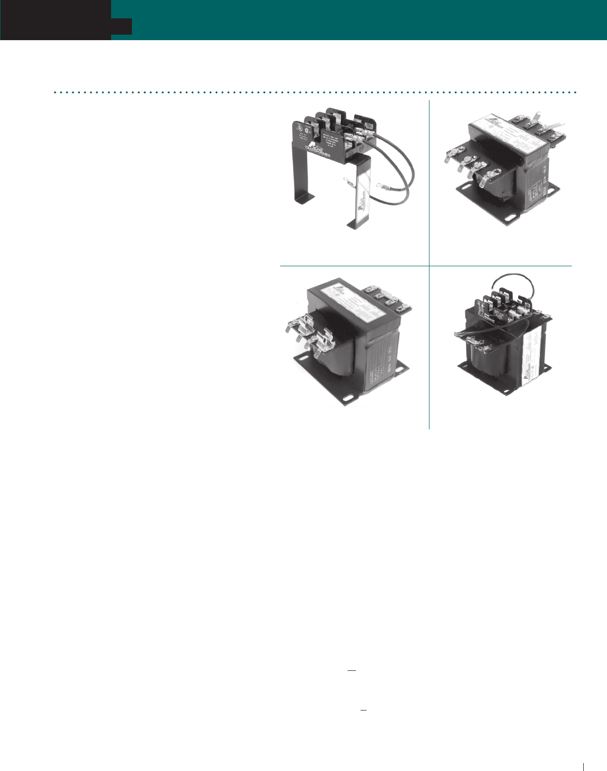
ACME ELECTRIC • MILWAUKEE, WI • 800.334.5214 • acmetransformer.com
53
SECTION
TA SERIES OPEN CORE & COIL INDUSTRIAL CONTROL TRANSFORMERS
53
SECTION
TA SERIES OPEN CORE & COIL INDUSTRIAL CONTROL TRANSFORMERS
5
TA Series Open Core & Coil
Industrial Control Transformers
Industrial control transformers are used to reduce
supply voltages to 230 V or lower for the operation
of electromagnetic devices such as contactors,
solenoids, relays, and timers. They are especially
designed to accommodate the momentary current
inrush caused when electromagnetic components
are energized... without sacrificing secondary
voltage stability beyond practical limits.
Acme Industrial Control Transformers are
dry-type, step-down transformers with the
secondary control circuit isolated from the primary
line circuit to assure maximum safety.
Voltage regulation of Acme Industrial Control
Transformers exceeds standards recommended
by the National Electrical Manufacturers
Association. Secondary circuit voltage drop
between no-load and momentary overload
remains exceptionally low. This excellent
secondary circuit voltage regulation assures
reliable operation of electromagnetic
components and may permit the use of a smaller
and less expensive industrial control transformer.
FEATURES
Constructed with high quality silicon steel
lamination to minimize core losses and
increase efficiency.
Designs incorporate precision wound coils for
improved regulation.
Primary fuse blocks and secondary fuse kits
available and easily adaptable.
Series-parallel connecting links save wiring and
labor costs.
Sturdy phenolic terminal panel protects the coil
from foreign objects and mechanical damage.
Copper windings on all groups.
130°C Insulation class. 80°C temperature rise.
Wire retention on both primary and secondary
terminals.
Mounting plate adapts to various mounting
dimensions.
Voltage regulation exceeds NEMA requirements.
UL Listed, CSA Certified.
Attractive finish, nameplate, and design features
enhance the end product.
Integrally Mounted Fuse Blocks
Primary Fuse Kit with Snap-on
Secondary Fuse Block
Jumper Link Connections
Secondary Fuse Clips
Acme Industrial Control Transformers Meet
or Exceed UL, CSA, NEMA & ANSI
Acme Industrial Control Transformers 50 through 5000 VA are UL
Listed, File E79947 and CSA certified, File 7357.
Laminations—High-permeability silicon steel continuously
annealed to minimize core losses.
Magnet Wire—Copper magnet wire is coated with high
temperature-resisting insulating film.
Coils—Precision wound by machine; total turns per coil
automatically counted.
Mounting—Heavy steel mounting plates add strength to core con-
struction and provide firm mounting, slotted to facilitate installation.
Terminal Boards—Sturdy phenolic terminal boards.
Sizing Primary Fuses:
Primary Amps < 2, fuse size is 300% of rated primary current.
Primary Amps 2< 9, fuse size is 167% of rated primary current.
Primary Amps > 9, fuse size is 125% of rated primary current.
Sizing Secondary Fuses:
Secondary Amps < 9, fuse size is 167% of rated secondary current.
Secondary Amps > 9, fuse size is 125% of rated secondary current.
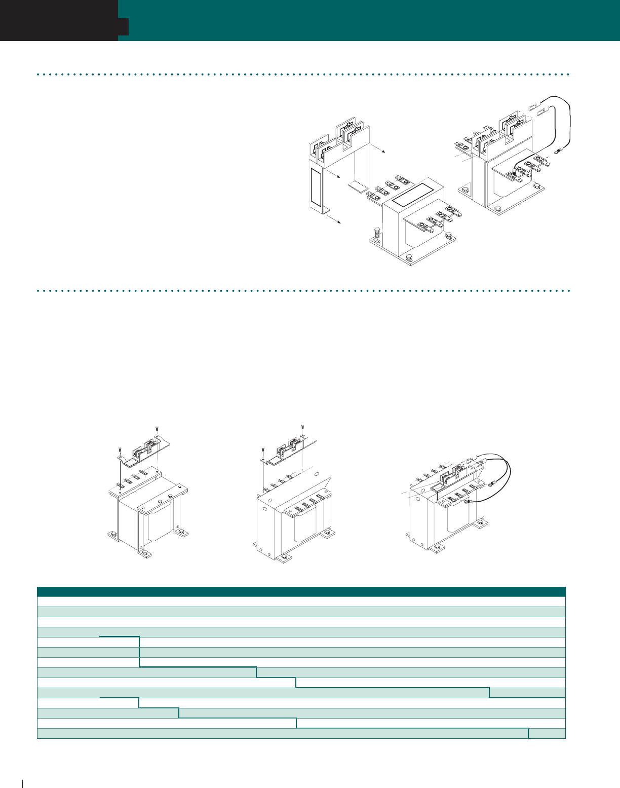
SECTION
ACME ELECTRIC • MILWAUKEE, WI • 800.334.5214 • acmetransformer.com
5454
SECTION
TA SERIES OPEN CORE & COIL INDUSTRIAL CONTROL TRANSFORMERS
5
Meets NEC Article 450 and UL-508 requirements.
For use with class “CC” fuses.
Eliminates remote mounting of primary overcurrent protection.
Covered by Acme Electric 10-year limited warranty.
Field installation is fast and easy. Simply loosen the mounting
hardware (Fig. 1), slide the bracket over the transformer and
re-tighten the mounting hardware. Make the proper connections
with the factory furnished jumpers (Fig. 2) and your unit is ready
for operation.
1. To mount the primary fuse kit bracket, remove the two 1/4"
(.64 cm) sheet metal screws on the terminal panel on the
primary (H side) of the transformer.
2. Place the slots in the fuse kit mounting bracket over the
holes in the terminal and mounting bracket. To secure the
fuse kit, reinsert the two 1/4" (.64 cm) sheet metal screws
and tighten securely.
3. Tighten all mounting screws securely–this will secure the
mounting bracket.
4. Attach the female quick connect of the jumpers supplied
with the fuse kit to male quick connects on the right side
of the fuse blocks—one jumper to each of the blocks.
5. Connect the ring terminal of the jumpers to the appropriate
screw terminals of the transformers primary (H side). Refer to
the transformer name plate for proper terminal connections.
6. Connect primary supply line leads to the screw terminals
on the left side of the block—one line lead to each of the
fuse blocks.
TA Series Primary Fuse Kits
Instructions for TA Series Primary Fuse Kit
Type PL112706 & PL112707: Using 2 Class CC Dual Element Fuses (3000-5000 VA)
Type PL112700 Through PL112705:
Using 2 Class CC Dual Element Fuses (not supplied)
PRIMARY (H SIDE)
SECONDARY (X SIDE)
PRIMARY (H SIDE)
INPUT
SUPPLY
LINE
PRIMARY (H SIDE)
SECONDARY (X SIDE)
PRIMARY (H SIDE)
SECONDARY (X SIDE)
INPUT
SUPPLY
LINE
Figure 1
Figure 2
Primary Fuse Sizing Chart
Fuse size based on time delay class CC fuses.
NOTE: Bold lines indicate changes in the percent of rated current used to calculate fuse sizes in accordance with article 450 of the NEC.
VA 120 V 208 V 230 V 240 V 277 V 380 V 416 V 440 V 460 V 480 V 550 V 600 V
50 1.2 0.6 0.6 0.6 0.6 0.3 0.3 0.3 0.3 0.3 0.3 0.3
75 1.9 1.0 1.0 1.0 0.8 0.6 0.6 0.6 0.5 0.5 0.4 0.4
100 2.5 1.5 1.3 1.3 1.0 0.8 0.8 0.6 0.6 0.6 0.6 0.5
150 3.8 2.0 2.0 1.9 1.5 1.2 1.2 1.0 1.0 1.0 0.8 0.8
250 3.5 3.5 3.5 3.0 3.0 2.0 1.8 1.8 1.5 1.5 1.4 1.2
300 4.0 4.0 4.0 3.5 3.0 2.5 2.5 2.0 2.0 1.9 1.5 1.5
350 5.0 5.0 4.5 4.0 4.0 2.5 2.5 2.5 2.0 2.0 1.9 1.8
500 7.0 4.0 3.5 3.5 5.5 4.0 3.5 3.5 3.5 3.0 3.0 2.5
750 10.0 6.0 5.5 5.0 4.5 6.0 5.5 5.0 5.0 5.0 4.0 4.0
1000 15.0 8.0 7.0 7.0 6.0 4.5 4.0 3.5 3.5 3.5 5.5 5.0
1500 20.0 12.0 12.0 12.0 10.0 7.0 6.0 6.0 5.5 5.5 5.0 4.5
2000 25.0 12.0 15.0 15.0 12.0 9.0 8.0 8.0 7.5 7.0 6.0 6.0
3000 30.0 20.0 20.0 20.0 15.0 15.0 12.0 12.0 12.0 12.0 10.0 9.0
5000 –– 30.0 30.0 30.0 25.0 20.0 15.0 15.0 15.0 15.0 12.0 15.0
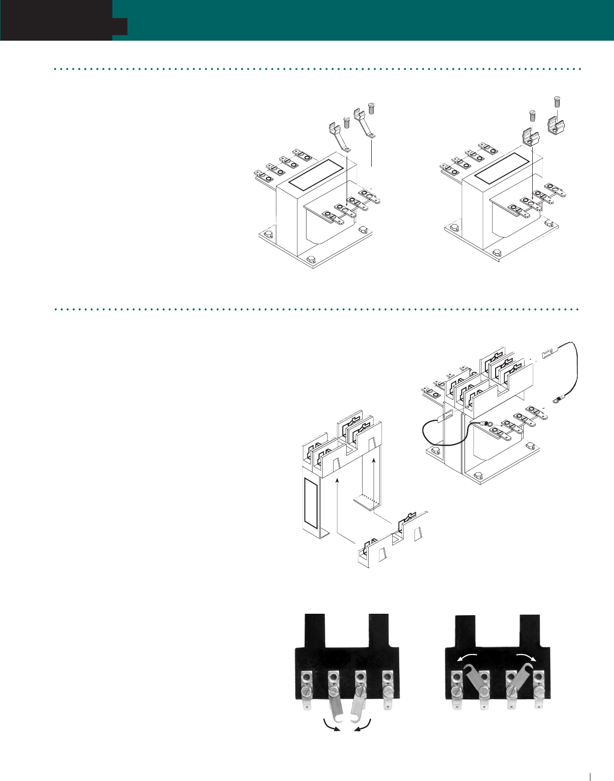
ACME ELECTRIC • MILWAUKEE, WI • 800.334.5214 • acmetransformer.com
55
SECTION
TA SERIES OPEN CORE & COIL INDUSTRIAL CONTROL TRANSFORMERS
55
SECTION
TA SERIES OPEN CORE & COIL INDUSTRIAL CONTROL TRANSFORMERS
5
Mount secondary fuse clips on terminals
X1 and F or F1 using the screws supplied
with the transformer.
Connect secondary load lines to terminals
X2 and F or F2.
Use dual-element slow-blowing fuses
such as Bussmann MFG., Fusetron Type
FNM, Littelfuse or Shawmut (not supplied
with fuse kits).
PL112600/601 Fuse Kit PL112602 Fuse Kit
1. To attach secondary fuse kit PL-112603 to primary fuse
kits PL112700 thru PL112707 snap the secondary single
pole fuse block onto the unlabeled side of the primary
double pole fuse block. (See Figure 1)
2. Install the fuse kits as instructed under the primary fuse kit
instructions on page 54.
3. Select the appropriate pair of jumpers for making the
connections between the secondary fuse block and the
secondary (X-side) of the transformer.
4. Connect the female quick-connect of the jumpers
supplied to one of the male quick-connects of the
secondary fuse block - one jumper to each end of
the fuse block. (See Figure 2)
5. Connect the ring terminal of the jumpers supplied
to screw terminals X1 and F or F1 on the secondary
(X-side) of the transformer.
6. Connect secondary load lines to terminals
X2 and F or F2.
SECONDARY (X SIDE)
Figure 1
Figure 2
Jumper Link Connections
Group A Series: 240 V parallel: 120 V
Group B Series: 480 V parallel: 240 V
Group F series: 230 V parallel: 115 V
Group I Series: 24 V parallel: 12 V
Group J Series: 480 V & 240 V: 240 V & 120 V
Group K Series: 240 V: 120 V
TA Series Instructions for Secondary Fuse Kit
Type PL112603: use dual element slow-blow fuse 13/32" x 1-1/2" (1.0 x 3.8 cm)
Series
Connection
Parallel
Connection
Exception: 150 VA transformer TA232404 does not have
quick connect terminals.
TA Series Secondary Fuse Kits
Type PL112600, 601, 602: Use Dual Element Slow-Blow Fuse
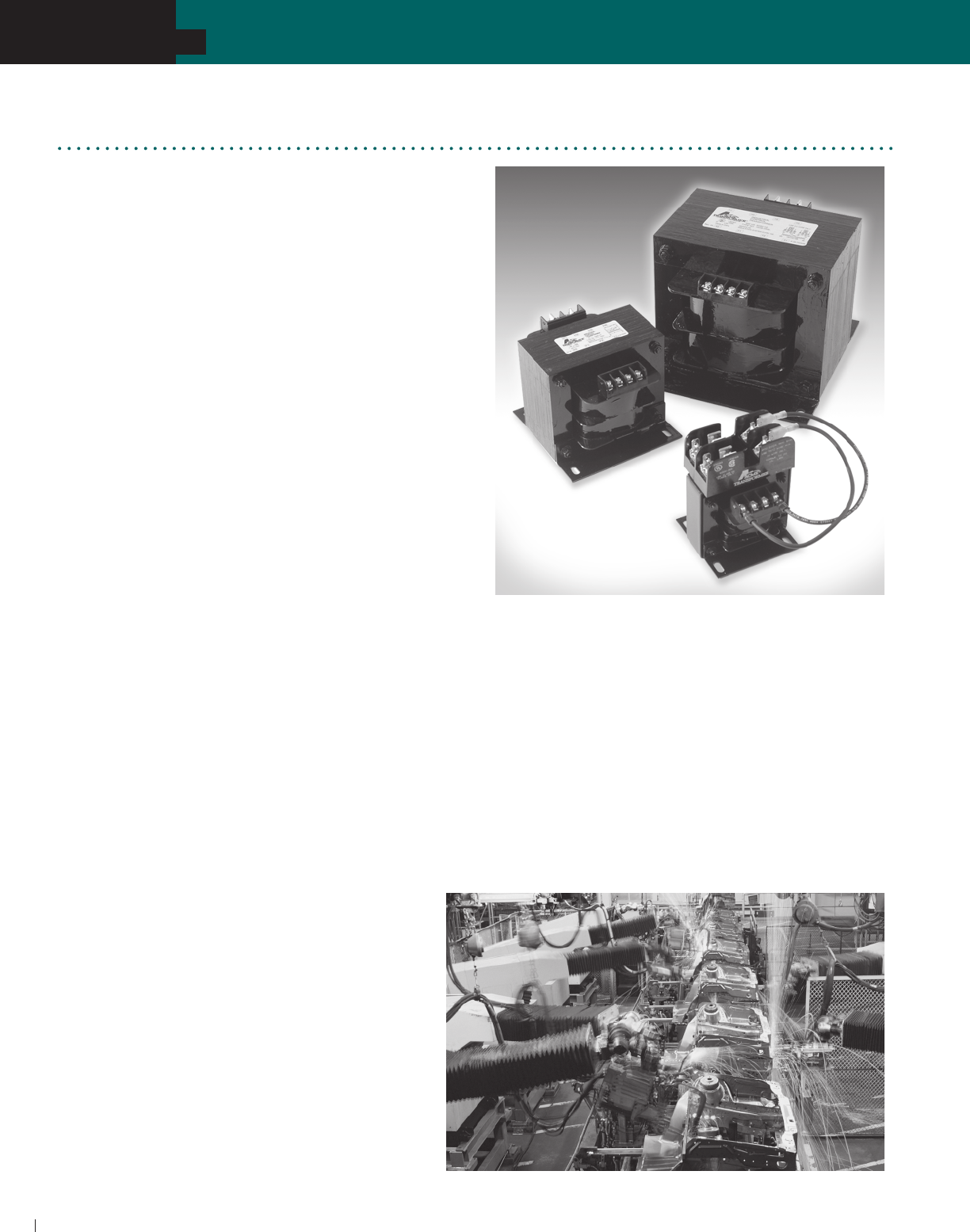
ACME ELECTRIC • MILWAUKEE, WI • 800.334.5214 • acmetransformer.com
56
SECTION
TA SERIES OPEN CORE & COIL INDUSTRIAL CONTROL TRANSFORMERS
56
SECTION
TB SERIES OPEN CORE & COIL INDUSTRIAL CONTROL TRANSFORMERS
5
Acme’s TB Series Industrial Control Transformers are especially
designed to accommodate the momentary current inrush
caused when electromagnetic components are energized...
without sacrificing secondary voltage stability beyond
practical limits.
Acme’s TB Series transformers are dry-type, step -down
transformers with the secondary control circuit isolated from
the primary line circuit to assure maximum safety.
Voltage regulation of Acme’s TB Series transformers
exceeds standards recommended by the National Electrical
Manufacturers Association. Secondary circuit voltage
drop between no-load and momentary overload remains
exceptionally low. This excellent secondary circuit voltage
regulation assures reliable operation of electromagnetic
components and may permit the use of a smaller and less
expensive industrial control transformer.
FEATURES & BENEFITS
600 volt class and below.
50–1000 VA, 50/60 Hz.
80°C temperature rise, 130°C insulation class.
Constructed with high quality silicon steel lamination to
minimize core losses and increase efficiency.
Designs incorporate precision split bobbin wound coils
for improved regulation.
Primary fuse blocks and secondary fuse kits available and
easily adaptable.
Series-parallel connecting links save wiring and labor costs.
Terminal blocks allow full access for ring terminals for easy
installation even with solid strand conductors.
Integrally molded terminal blocks with isolation barriers to
prevent arc over.
Footprint matches TA Series for easy interchangeability.
Copper windings on all groups.
Heavy gauge steel mounting plate adapts to various
mounting dimensions.
Voltage regulation exceeds NEMA requirements.
UL Listed and CSA Certified.
Meets or exceeds UL, CSA, NEMA, ANSI and
OSHA Standards.
Ten-year limited warranty.
APPLICATIONS
Motor Starters
Contactors
Solenoids
Timer Circuits
Relays
Control Panels
Robotics
TB Series Open Core & Coil
Industrial Control Transformers
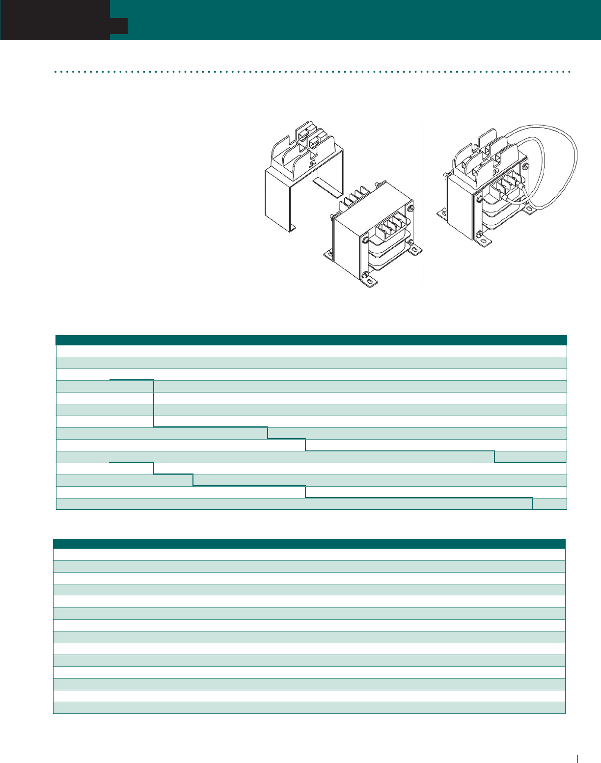
ACME ELECTRIC • MILWAUKEE, WI • 800.334.5214 • acmetransformer.com
57
SECTION
TA SERIES OPEN CORE & COIL INDUSTRIAL CONTROL TRANSFORMERS
57
SECTION
TB SERIES OPEN CORE & COIL INDUSTRIAL CONTROL TRANSFORMERS
5
TB Series Primary Fuse Kits
Type PL112700 Through PL112705:
Using 2 Class CC Dual Element Fuses (not supplied)
Primary Fuse Sizing Chart
VA 120 V 208 V 230 V 240 V 277 V 380 V 416 V 440 V 460 V 480 V 550 V 600 V
50 1.2 0.6 0.6 0.6 0.6 0.3 0.3 0.3 0.3 0.3 0.3 0.3
75 1.9 1.0 1.0 1.0 0.8 0.6 0.6 0.6 0.5 0.5 0.4 0.4
100 2.5 1.5 1.3 1.3 1.0 0.8 0.8 0.6 0.6 0.6 0.6 0.5
150 3.8 2.0 2.0 1.9 1.5 1.2 1.2 1.0 1.0 1.0 0.8 0.8
250 3.5 3.5 3.5 3.0 3.0 2.0 1.8 1.8 1.5 1.5 1.4 1.2
300 4.0 4.0 4.0 3.5 3.0 2.5 2.5 2.0 2.0 1.9 1.5 1.5
350 5.0 5.0 4.5 4.0 4.0 2.5 2.5 2.5 2.0 2.0 1.9 1.8
500 7.0 4.0 3.5 3.5 5.5 4.0 3.5 3.5 3.5 3.0 3.0 2.5
750 10.0 6.0 5.5 5.0 4.5 6.0 5.5 5.0 5.0 5.0 4.0 4.0
1000 15.0 8.0 7.0 7.0 6.0 4.5 4.0 3.5 3.5 3.5 5.5 5.0
1500 20.0 12.0 12.0 12.0 10.0 7.0 6.0 6.0 5.5 5.5 5.0 4.5
2000 25.0 12.0 15.0 15.0 12.0 9.0 8.0 8.0 7.5 7.0 6.0 6.0
3000 30.0 20.0 20.0 20.0 15.0 15.0 12.0 12.0 12.0 12.0 10.0 9.0
5000 –– 30.0 30.0 30.0 25.0 20.0 15.0 15.0 15.0 15.0 12.0 15.0
Figure 2
Meets NEC Article 450 and UL-508 requirements.
For use with class “CC” fuses.
Eliminates remote mounting of primary
overcurrent protection.
Covered by Acme Electric 10-year
limited warranty.
Field installation is fast and easy. Simply loosen
the mounting hardware (Fig. 1), slide the bracket
over the transformer and re-tighten the mounting
hardware. Make the proper connections with the
factory furnished jumpers (Fig. 2) and your unit is
ready for operation.
Figure 1
Secondary Fuse Sizing Chart
Fuse size based on time delay class CC fuses.
NOTE: Bold lines indicate changes in the percent of rated current used to calculate fuse sizes in accordance with article 450 of the NEC.
VA 24 V 85 V 91 V 99 V 100 V 110 V 115 V 120 V 125 V 130 V
50 VA 3.2 0.9 0.9 0.8 0.8 0.7 0.7 0.6 0.6 0.6
75 VA 5.0 1.4 1.2 1.2 1.2 1.0 1.0 1.0 1.0 0.8
100 VA 6.0 1.5 1.5 1.5 1.5 1.5 1.5 1.2 1.2 1.2
150 VA 10.0 2.5 2.5 2.5 2.5 2.0 2.0 2.0 2.0 1.5
250 VA 12.0 4.5 4.5 4.0 4.0 3.5 3.5 3.0 3.0 3.0
300 VA 15.0 5.5 5.5 5.0 5.0 4.5 4.5 4.0 4.0 3.5
350 VA 20.0 6.5 6.0 5.5 5.5 5.0 5.0 4.5 4.5 4.5
500 VA 25.0 9.0 9.0 8.0 8.0 7.0 7.0 6.0 6.0 6.0
750 VA 40.0 12.0 12.0 12.0 12.0 10.0 10.0 10.0 10.0 9.0
1000 VA 50.0 15.0 15.0 12.0 12.0 12.0 12.0 12.0 12.0 12.0
1500 VA — 25.0 20.0 20.0 20.0 20.0 20.0 15.0 15.0 15.0
2000 VA — 30.0 30.0 25.0 25.0 25.0 25.0 20.0 20.0 20.0
3000 VA — 40.0 40.0 40.0 40.0 35.0 35.0 30.0 30.0 30.0
5000 VA — 70.0 70.0 60.0 60.0 60.0 60.0 50.0 50.0 50.0
Fuse Kit adds approximately
1.75” to height of unit.
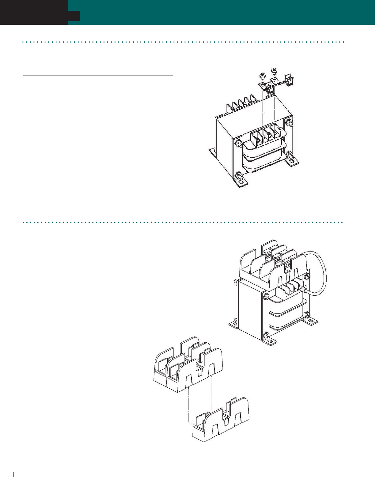
ACME ELECTRIC • MILWAUKEE, WI • 800.334.5214 • acmetransformer.com
58
SECTION
TA SERIES OPEN CORE & COIL INDUSTRIAL CONTROL TRANSFORMERS
58
SECTION
TB SERIES OPEN CORE & COIL INDUSTRIAL CONTROL TRANSFORMERS
5
Catalog Number VA Type
PL79924* 50-1000 1/4" x 1-1/4"
PL79930 50-350 13/32" x 1-1/2"
PL79931 500-1000 13/32" x 1-1/2"
Mount secondary fuse clips on terminals X1 and F or F1
using the screws supplied with the transformer.
Connect secondary load lines to terminals X2 and F or F2.
Use Jumper Link to connect F1 and F2.
Use dual-element slow-blowing fuses such as Bussmann
MFG., Fusetron Type FNM, Littelfuse or Ferraz Shawmut
(not supplied with fuse kits).
* PL79924: Use fuse kit on all transformers except 750 & 1000 VA
with 24 volt secondary.
Secondary
Fuse Kit
1. To attach secondary fuse kit PL 112603 to
p r i m a r y fuse kits PL112700 thru PL112705
snap the secondary single pole fuse block
o n t o t h e u n l a b e l e d s i d e o f t h e p r i m a r y d o u b l e
pole fuse block. (See Figure 1)
2. Install the fuse kits as instructed under the
p r i m a r y f u s e k i t i n s t r u c t i o n s o n p a g e 5 4 .
3. Select the appropriate pair of jumpers for
making the connections between the
secondary fuse block and the secondary
(X-side) of the transformer.
4. Connect the female quick-connect of the
j u m p e r s s u p p l i e d t o o n e o f t h e m a l e q u i c k -
c o n n e c t s o f t h e s e c o n d a r y f u s e b l o c k — o n e
j u m p e r t o e a c h e n d o f t h e f u s e b l o c k . ( S e e
F i g u r e 2 )
5. C o n n e c t t h e r i n g t e r m i n a l o f t h e j u m p e r s
supplied to screw terminals X1 and F or F1
o n t h e s e c o n d a r y ( X - s i d e ) o f t h e t r a n s f o r m e r .
6. Connect secondary load lines to terminals
X2 and F or F2.
Figure 1
Figure 2
Instructions for TB Series Secondary Fuse Kit
Type PL112603: use dual element slow-blow fuse 13/32" x 1-1/2" (1.0 x 3.8 cm)
TB Series Secondary Fuse Kits
Type PL79924, PL79930, & PL79931: Use Dual Element Slow-Blow Fuse

ACME ELECTRIC • MILWAUKEE, WI • 800.334.5214 • acmetransformer.com
59
SECTION
TA SERIES OPEN CORE & COIL INDUSTRIAL CONTROL TRANSFORMERS
59
SECTION
TA & TB SERIES OPEN CORE & COIL INDUSTRIAL CONTROL TRANSFORMERS
5
Secondary Fuse Kit PL112603 may be substituted for PL112600 thru PL112602 when Primary Fuse Kit is used. See page 58.
See chart for integrally mounted fuse block catalog number suffix.
120 X 240 PRIMARY VOLTS—12/24 SECONDARY VOLTS—1Ø, 50/60 Hz
GROUP A
SELECTION CHARTS
240 X 480, 230 X 460, 220 X 440 PRIMARY VOLTS—120/115/110 SECONDARY VOLTS—1Ø, 50/60 Hz
GROUP B
CATALOG VA OUTPUT APPROX. DIMENSIONS APPROX. PRIMARY SECONDARY SECONDARY
NO. RATING AMPS INCHES (CM.) SHIP WEIGHT FUSE BLOCK FUSE KIT FUSE SIZE
@ 120V A B C D E F LBS. (KG.) PART NO. PART NO. 120 VOLTS
TB81210 50 0.42 4.23 3.00 2.70 2.50 2.13 .22 x .50 4 PL112700 * 6/10 amp
(10.7) (7.6) (6.8) (6.4) (5.4) (0.6 x 1.3) (1.8)
TB81201 75 0.63 4.74 3.00 2.70 2.50 2.61 .22 x .50 4 PL112700 * 1 amp
(12.0) (7.6) (6.8) (6.4) (6.6) (0.6 x 1.3) (1.8)
TB81211 100 0.83 4.90 3.00 2.70 2.50 2.81 .22 x .50 4 PL112700 * 1
1/4 amps
(12.4) (7.6) (6.8) (6.4) (7.1) (0.6 x 1.3) (1.8)
TB81212 150 1.25 5.00 3.75 3.40 3.13 2.81 .22 x .50 6 PL112701 * 2 amps
(12.7) (9.5) (8.6) (8.0) (7.1) (0.6 x 1.3) (2.7)
TB81213 250 2.08 4.18 4.50 3.84 3.75 3.13 .22 x .50 9 PL112702 * 3
2/10 amps
(10.6) (11.4) (9.8) (9.5) (8.0) (0.6 x 1.3) (4.1)
TB81200 300 2.50 5.57 4.50 3.84 3.75 3.13 .22 x .50 10 PL112702 * 4 amps
(14.1) (11.4) (9.8) (9.5) (8.0) (0.6 x 1.3) (4.5)
TB81214 350 2.92 6.32 4.50 3.84 3.75 3.83 .22 x .50 12 PL112702 * 4
1/2 amps
(16.1) (11.4) (9.8) (9.5) (9.7) (0.6 x 1.3) (5.4)
TB81215 500 4.17 6.30 5.25 4.47 4.06 3.81 .22 x .50 15 PL112704 * 6
1/4 amps
(16.0) (13.3) (11.4) (10.3) (9.7) (0.6 x 1.3) (6.8)
TB81216 750 6.25 6.65 5.25 4.47 4.38 5.13 .31 x .50 23 PL112704 * 10 amps
(16.9) (13.3) (11.4) (11.1) (13.0) (0.8 x 1.3) (10.4)
TB81217 1000 8.33 7.58 6.75 5.78 5.75 3.69 .31 x .50 25 PL112705 * 12 amps
(19.3) (17.1) (14.7) (14.6) (9.4) (0.8 x 1.3) (11.3)
CATALOG VA OUTPUT APPROX. DIMENSIONS APPROX. PRIMARY SECONDARY
NO. RATING AMPS Inches (Cm.) SHIP WEIGHT FUSE BLOCK FUSE SIZE
A B C D E F Lbs. (Kg.) PART NO. 24 VOLTS
TB181141 50 2.08 4.23 3.00 2.70 2.50 2.13 .22 x .50 4 PL112700 3 2/10 amps
(10.7) (7.6) (6.8) (6.4) (5.4) (0.6 x 1.3) (1.8)
TB181142 75 3.13 4.74 3.00 2.70 2.50 2.61 .22 x .50 4 PL112700 5 amps
(12.0) (7.6) (6.8) (6.4) (6.6) (0.6 x 1.3) (1.8)
TB181143 100 4.17 4.90 3.00 2.70 2.50 2.81 .22 x .50 4 PL112700 61/4 amps
(12.4) (7.6) (6.8) (6.4) (7.1) (0.6 x 1.3) (1.8)
TB181144 150 6.25 4.78 3.75 3.40 3.13 2.63 .22 x .50 6 PL112701 10 amps
(12.1) (9.5) (8.6) (8.0) (6.7) (0.6 x 1.3) (2.7)
TB181146 250 10.42 5.08 4.50 3.84 3.75 3.05 .22 x .50 9 PL112702 15 amps
(12.9) (11.4) (9.8) (9.5) (7.7) (0.6 x 1.3) (4.1)
TB181148 350 14.58 6.12 4.50 3.84 3.75 4.06 .22 x .50 13 PL112702 20 amps
(15.5) (11.4) (9.8) (9.5) (10.3) (0.6 x 1.3) (5.9)
TB181149 500 20.83 5.90 5.25 4.47 4.38 4.19 .31 x .50 16 PL112704 30 amps
(15.0) (13.3) (11.4) (11.1) (10.6) (0.8 x 1.3) (7.3)
TB181150 750 31.25 7.53 5.25 4.47 4.38 5.25 .31 x .50 24 PL112704 —
(19.1) (13.3) (11.4) (11.1) (13.3) (0.8 x 1.3) (10.9)
TB181151 1000 41.67 7.43 6.75 5.72 5.75 3.81 .31 x .50 26 PL112705 —
(18.9) (17.1) (14.5) (14.6) (9.7) (0.8 x 1.3) (11.8)

ACME ELECTRIC • MILWAUKEE, WI • 800.334.5214 • acmetransformer.com
60
SECTION
TA SERIES OPEN CORE & COIL INDUSTRIAL CONTROL TRANSFORMERS
60
SECTION
TA & TB SERIES OPEN CORE & COIL INDUSTRIAL CONTROL TRANSFORMERS
5
ADD SUFFIX
TO CATALOG NO. CONFIGURATION
F2 Factory installed integrally mounted 2-pole primary block
F3 Factory installed integrally mounted 3-pole primary and
secondary block (100 VA & larger)
F4 Factory installed 2-pole primary block and secondary
fuse clips (50 & 75 VA)
* See fusing chart for secondary fuse kits.
Secondary Fuse Kit PL-112603 may be substituted for PL112600 thru PL112602 when Primary Fuse Kit is used. See page 58.
See chart for integrally mounted fuse block catalog number suffix.
240 X 480, 230 X 460, 220 X 440 PRIMARY VOLTS—120/115/110 SECONDARY VOLTS—1Ø, 50/60 Hz
GROUP B
Integrally Mounted Fuse Blocks Available:
(See Chart)
GROUP ‘A’ THROUGH 500 VA
GROUP ‘B’ THROUGH 2000 VA
Consult factory for other sizes available.
* See fusing chart for secondary fuse kits.
(CONTINUED)
240/480/600, 230/460/575, 220/440/550 PRIMARY VOLTS—120/100, 115/95, 110/90 SECONDARY VOLTS—
1Ø, 50/60 Hz
GROUP C
CATALOG VA OUTPUT APPROX. DIMENSIONS APPROX. PRIMARY SECONDARY SECONDARY
NO. RATING AMPS INCHES (CM.) SHIP WEIGHT FUSE BLOCK FUSE KIT FUSE SIZE
@ 120V A B C D E F LBS. (KG.) PART NO. PART NO. 120 VOLTS
TA2-81218 1500 12.50 8.80 6.75 5.72 5.75 5.75 .31 x .50 43 PL112705 PL112601 15 amps
(22.4) (17.1) (14.5) (14.6) (14.6) (0.8 x 1.3) (19.5)
TA2-81219 2000 16.67 9.25 6.75 5.72 5.75 6.38 .31 x .50 49 PL112705 PL112601 20 amps
(23.5) (17.1) (14.5) (14.6) (16.2) (0.8 x 1.3) (22.2)
TA2-81220 3000 25.00 8.81 7.50 8.34 6.50 7.52 .41 x .81 70 PL112706 — —
(22.4) (19.1) (21.2) (16.5) (19.1) (1.0 x 2.1) (31.8)
TA281221 5000 41.67 7.52 11.92 9.49 6.75 6.25 .41 x .81 125 PL112707 — —
(19.1) (30.3) (24.1) (17.1) (15.9) (1.0 x 2.1) (56.7)
CATALOG VA OUTPUT APPROX. DIMENSIONS APPROX. PRIMARY SECONDARY SECONDARY
NO. RATING AMPS INCHES (CM.) SHIP WEIGHT FUSE BLOCK FUSE KIT FUSE SIZE
@ 120V A B C D E F LBS. (KG.) PART NO. PART NO. 120 VOLTS
TB81000 50 0.42 4.56 3.00 2.70 2.50 2.61 .22 x .50 4 PL112700 * 6/10 amp
(11.6) (7.6) (6.8) (6.4) (6.6) (0.6 x 1.3) (1.8)
TB81009 75 0.63 4.90 3.00 2.70 2.50 2.81 .22 x .50 4 PL112700 * 1 amp
(12.4) (7.6) (6.8) (6.4) (7.1) (0.6 x 1.3) (1.8)
TB81001 100 0.83 5.36 3.00 2.70 2.50 3.26 .22 x .50 5 PL112700 * 1
1/4 amps
(13.6) (7.6) (6.8) (6.4) (8.3) (0.6 x 1.3) (2.3)
TB81002 150 1.25 5.00 3.75 3.40 3.13 3.06 .22 x .50 7 PL112701 * 2 amps
(12.7) (9.5) (8.6) (8.0) (7.8) (0.6 x 1.3) (3.2)
TB81003 250 2.08 5.57 4.50 3.84 3.75 3.50 .22 x .50 11 PL112702 * 3
2/10 amps
(14.1) (11.4) (9.8) (9.5) (8.9) (0.6 x 1.3) (5.0)
TB81020 300 2.50 6.48 4.65 4.15 4.06 4.06 .22 x .50 15 PL112702 * 4 amps
(16.5) (11.8) (10.5) (10.3) (10.3) (0.6 x 1.3) (6.8)
TB81004 350 2.92 6.48 4.65 4.15 4.06 4.06 .22 x .50 15 PL112702 * 4
1/2 amps
(16.5) (11.8) (10.5) (10.3) (10.3) (0.6 x 1.3) (6.8)
TB81005 500 4.17 6.43 5.25 4.47 4.38 4.56 .31 x .50 21 PL112704 * 6
1/4 amps
(16.3) (13.3) (11.4) (11.1) (11.6) (0.8 x 1.3) (9.5)
TB81006 750 6.25 7.19 6.75 5.78 5.75 3.81 .31 x .50 25 PL112705 * 10 amps
(18.3) (17.1) (14.7) (14.6) (9.7) (0.8 x 1.3) (11.3)
TB81007 1000 8.33 7.96 6.75 5.78 5.75 4.63 .31 x .50 32 PL112705 * 12 amps
(20.2) (17.1) (14.7) (14.6) (11.8) (0.8 x 1.3) (14.5)
TA281008 1500 12.50 9.46 6.75 5.72 5.75 6.38 .31 x .50 47 PL112705 PL112601 15 amps
(24.0) (17.1) (14.5) (14.6) (16.2) (0.8 x 1.3) (21.3)
TA253929 2000 16.67 7.90 7.50 7.66 6.50 6.57 .41 x .81 55 PL112706 PL112601 20 amps
(20.1) (19.1) (19.5) (16.5) (16.7) (1.0 x 2.1) (24.9)
TA253930 3000 25.00 7.02 11.92 8.83 6.75 5.75 .41 x .81 75 PL112707 — —
(17.8) (30.3) (22.4) (17.1) (14.6) (1.0 x 2.1) (34.0)
TA253931 5000 41.67 7.52 11.92 9.49 6.75 6.25 .41 x .81 110 PL112707 — —
(19.1) (30.3) (24.1) (17.1) (15.9) (1.0 x 2.1) (49.9)

ACME ELECTRIC • MILWAUKEE, WI • 800.334.5214 • acmetransformer.com
61
SECTION
TA SERIES OPEN CORE & COIL INDUSTRIAL CONTROL TRANSFORMERS
61
SECTION
TA & TB SERIES OPEN CORE & COIL INDUSTRIAL CONTROL TRANSFORMERS
5
208/277/380 PRIMARY VOLTS—115/95 SECONDARY VOLTS—1Ø, 50/60 Hz
GROUP E
* See fusing chart for secondary fuse kits.
Secondary Fuse Kit PL112603 may be substituted for PL112600 thru PL112602 when Primary Fuse Kit is used. See page 58.
See chart for integrally mounted fuse block catalog number suffix.
208/240/277/380/480 PRIMARY VOLTS—24 SECONDARY VOLTS—1Ø, 50/60 Hz
GROUP D
* See fusing chart for secondary fuse kits.
CATALOG VA OUTPUT APPROX. DIMENSIONS APPROX. PRIMARY SECONDARY SECONDARY
NO. RATING AMPS INCHES (CM.) SHIP WEIGHT FUSE BLOCK FUSE KIT FUSE SIZE
@ 115V A B C D E F LBS. (KG.) PART NO. PART NO. 115 VOLTS
TB81301 50 0.43 4.35 3.00 2.70 2.50 2.61 .22 x .50 4 PL112700 * 6/10 amp
(11.0) (7.6) (6.8) (6.4) (6.6) (0.6 x 1.3) (1.8)
TB81302 75 0.65 4.74 3.00 2.70 2.50 2.81 .22 x .50 4 PL112700 * 1 amp
(12.0) (7.6) (6.8) (6.4) (7.1) (0.6 x 1.3) (1.8)
TB81303 100 0.87 4.45 3.75 3.40 3.13 2.44 .22 x .50 5 PL112701 * 1
1/4 amps
(11.3) (9.5) (8.6) (8.0) (6.2) (0.6 x 1.3) (2.3)
TB81304 150 1.30 5.00 3.75 3.84 3.13 3.06 .22 x .50 5 PL112701 * 2 amps
(12.7) (9.5) (9.8) (8.0) (7.8) (0.6 x 1.3) (2.3)
TB81305 250 2.17 5.68 4.50 3.84 3.75 4.06 .22 x .50 13 PL112702 * 3
1/2 amps
(14.4) (11.4) (9.8) (9.5) (10.3) (0.6 x 1.3) (5.9)
TB81306 350 3.04 6.30 4.65 4.15 4.06 4.75 .22 x .50 18 PL112702 * 5 amps
(16.0) (11.8) (10.5) (10.3) (12.1) (0.6 x 1.3) (8.2)
TB81307 500 4.35 6.22 5.25 4.47 4.38 4.56 .22 x .50 20 PL112704 * 7 amps
(15.8) (13.3) (11.4) (11.1) (11.6) (0.6 x 1.3) (9.1)
TB81308 750 6.52 6.82 6.75 5.78 5.75 3.69 .31 x .50 24 PL112705 * 10 amps
(17.3) (17.1) (14.7) (14.6) (9.4) (0.8 x 1.3) (10.9)
TB81309 1000 8.70 7.96 6.75 5.72 5.75 4.44 .31 x .50 31 PL112705 * 12 amps
(20.2) (17.1) (14.5) (14.6) (11.3) (0.8 x 1.3) (14.1)
CATALOG VA OUTPUT APPROX. DIMENSIONS APPROX. PRIMARY SECONDARY SECONDARY
NO. RATING AMPS INCHES (CM.) SHIP WEIGHT FUSE BLOCK FUSE KIT FUSE SIZE
A B C D E F LBS. (KG.) PART NO. PART NO. 24 VOLTS
TB81321 50 2.08 4.08 3.75 3.40 3.13 2.19 .22 x .50 4 PL112701 * 3
2/10 amp
(10.4) (9.5) (8.6) (8.0) (5.6) (0.6 x 1.3) (1.8)
TB81322 75 3.13 4.31 3.75 3.40 3.13 2.31 .22 x .50 5 PL112701 * 5 amps
(10.9) (9.5) (8.6) (8.0) (5.9) (0.6 x 1.3) (2.3)
TB81323 100 4.17 4.52 3.75 3.40 3.13 2.63 .22 x .50 5 PL112701 * 6
1/4 amps
(11.5) (9.5) (8.6) (8.0) (6.7) (0.6 x 1.3) (2.3)
TB81324 150 6.25 4.75 4.50 3.84 3.75 3.05 .22 x .50 9 PL112702 * 10 amps
(12.1) (11.4) (9.8) (9.5) (7.7) (0.6 x 1.3) (4.1)
TB81325 250 10.42 5.24 4.65 4.15 4.06 3.25 .22 x .50 11 PL112702 * 15 amps
(13.3) (11.8) (10.5) (10.3) (8.3) (0.6 x 1.3) (5.0)
TB81326 350 14.58 6.02 5.25 4.47 4.38 4.00 .31 x .50 18 PL112704 * 20 amps
(15.3) (13.3) (11.4) (11.1) (10.2) (0.8 x 1.3) (8.2)
TB81327 500 20.83 6.51 5.25 4.47 4.38 4.19 .31 x .50 19 PL112704 * 30 amps
(16.5) (13.3) (11.4) (11.1) (10.6) (0.8 x 1.3) (8.6)
TB81328 750 31.25 7.08 6.75 5.78 5.75 3.81 .31 x .50 26 PL112705 * —
(18.0) (17.1) (14.7) (14.6) (9.7) (0.8 x 1.3) (11.8) 33 amps
TB81329 1000 41.67 8.10 6.75 5.72 5.75 4.63 .31 x .50 33 PL112705 * —
(20.6) (17.1) (14.5) (14.6) (11.8) (0.8 x 1.3) (15.0)

ACME ELECTRIC • MILWAUKEE, WI • 800.334.5214 • acmetransformer.com
62
SECTION
TA SERIES OPEN CORE & COIL INDUSTRIAL CONTROL TRANSFORMERS
62
SECTION
TA & TB SERIES OPEN CORE & COIL INDUSTRIAL CONTROL TRANSFORMERS
5
GROUP G
Secondary Fuse Kit PL112603 may be substituted for PL112600 thru PL112602 when Primary Fuse Kit is used. See page 58.
Secondary fuse kit application for 115V only.
240/416/480/600; 230/400/460/575; 220/380/440/550; 208/500 PRIMARY VOLTS
99/120/130; 95/115/125; 91/110/120; 85/100/110 SECONDARY VOLTS —1Ø, 50/60 Hz
380/440/550/600 PRIMARY VOLTS—115/230 SECONDARY VOLTS—1Ø, 50/60 Hz
GROUP F
CATALOG VA OUTPUT
APPROX. DIMENSIONS APPROX. PRIMARY SECONDARY
NO. RATING AMPS
INCHES (CM.) SHIP WEIGHT FUSE BLOCK FUSE SIZE
@ 115V A B C D E F LBS. (KG.) PART NO. 115 VOLTS
TA254535 50 0.43 4.12 3.75 3.21 3.13 2.19 .22 x .50 4 PL112701 6/10 amp
(10.5) (9.5) (8.2) (8.0) (5.6) (0.6 x 1.3) (1.8)
TA254536 100 0.87 4.56 3.75 3.21 3.13 2.31 .22 x .50 5 PL112701 11/4 amps
(11.6) (9.5) (8.2) (8.0) (5.9) (0.6 x 1.3) (2.3)
TA254537 150 1.30 5.00 3.75 3.21 3.13 3.06 .22 x .50 10 PL112701 2 amps
(12.7) (9.5) (8.2) (8.0) (7.8) (0.6 x 1.3) (4.5)
TA254538 250 2.17 5.49 4.50 3.84 3.75 3.50 .22 x .50 11 PL112702 31/2 amps
(13.9) (11.4) (9.8) (9.5) (8.9) (0.6 x 1.3) (5.0)
TA281197 350 3.04 6.03 4.88 4.15 4.06 4.38 .22 x .50 17 PL112703 5 amps
(15.3) (12.4) (10.5) (10.3) (11.1) (0.6 x 1.3) (7.7)
TA254539 500 4.35 6.76 4.88 4.15 4.06 5.75 .22 x .50 23 PL112703 7 amps
(17.1) (12.4) (10.5) (10.3) (14.6) (0.6 x 1.3) (10.4)
TA281240 750 6.52 7.19 6.75 5.72 5.75 3.69 .31 x .50 25 PL112705 10 amps
(18.3) (17.1) (14.5) (14.6) (9.4) (0.8 x 1.3) (11.3)
TA281241 1000 8.70 7.77 6.75 5.72 5.75 4.44 .31 x .50 30 PL112705 12 amps
(19.7) (17.1) (14.5) (14.6) (11.3) (0.8 x 1.3) (13.6)
CATALOG VA OUTPUT
APPROX. DIMENSIONS APPROX. PRIMARY SECONDARY SECONDARY
NO. RATING AMPS
INCHES (CM.) SHIP WEIGHT FUSE BLOCK FUSE KIT FUSE SIZE
@ 130V A B C D E F LBS. (KG.) PART NO. PART NO. 130 VOLTS
TB32403 50 0.38 4.08 3.75 3.40 3.13 2.31 .22 x .50 5 PL112701 NA 6/10 amp
(10.4) (9.5) (8.6) (8.0) (5.9) (0.6 x 1.3) (2.3)
TB32404 150 1.15 4.75 4.50 3.84 3.75 3.05 .22 x .50 10 PL112702 NA 16/10 amps
(12.1) (11.4) (9.8) (9.5) (7.7) (0.6 x 1.3) (4.5)
TB32405 250 1.92 5.58 4.65 4.15 4.06 4.06 .22 x .50 16 PL112702 NA 32/10 amps
(14.2) (11.8) (10.5) (10.3) (10.3) (0.6 x 1.3) (7.3)
TB32669 350 2.69 6.23 4.65 4.15 4.06 5.50 .22 x .50 22 PL112702 NA 4 amps
(15.8) (11.8) (10.5) (10.3) (14.0) (0.6 x 1.3) (10.0)
TB32406 500 3.85 6.40 6.75 5.78 5.75 3.69 .22 x .50 23 PL112705 NA 61/4 amps
(16.3) (17.1) (14.7) (14.6) (9.4) (0.6 x 1.3) (10.4)
TB54523 750 5.77 7.08 6.75 5.78 5.75 4.13 .31 x .50 29 PL112705 NA 9 amps
(18.0) (17.1) (14.7) (14.6) (10.5) (0.8 x 1.3) (13.2)
TB54524 1000 7.69 8.56 6.75 5.78 5.75 4.88 .31 x .50 35 PL112705 NA 12 amps
(21.7) (17.1) (14.7) (14.6) (12.4) (0.8 x 1.3) (15.9)
TA254525 1500 11.54 6.75 7.50 7.66 6.50 5.42 .41 x .81 55 PL112706 PL-112601 20 amps
(17.1) (19.1) (19.5) (16.5) (13.8) (1.0 x 2.1) (24.9)
TA281202 2000 15.39 7.45 7.50 7.66 6.50 6.12 .41 x .81 55 PL112706 PL-112601 25 amps
(18.9) (19.1) (19.5) (16.5) (15.5) (1.0 x 2.1) (24.9)
TA281203 3000 23.08 7.02 11.92 8.83 6.75 5.75 .41 x .81 70 PL112707 — —
(17.8) (30.3) (22.4) (17.1) (14.6) (1.0 x 2.1) (31.8)
TA281205 5000 38.46 7.52 11.92 9.49 6.75 6.25 .41 x .81 110 PL112707 — —
(19.1) (30.3) (24.1) (17.1) (15.9) (1.0 x 2.1) (49.9)

ACME ELECTRIC • MILWAUKEE, WI • 800.334.5214 • acmetransformer.com
63
SECTION
TA SERIES OPEN CORE & COIL INDUSTRIAL CONTROL TRANSFORMERS
63
SECTION
TA & TB SERIES OPEN CORE & COIL INDUSTRIAL CONTROL TRANSFORMERS
5
Secondary Fuse Kit PL112603 may be substituted for PL112600 thru PL112602 when Primary Fuse Kit is used. See page 58.
208/230/460 PRIMARY VOLTS—115 SECONDARY VOLTS—1Ø, 50/60 Hz
GROUP H
* See fusing chart for secondary fuse kits.
600 PRIMARY VOLTS—12/24 SECONDARY VOLTS—1Ø, 60 Hz
GROUP I
CATALOG VA OUTPUT
APPROX. DIMENSIONS APPROX. PRIMARY
NO. RATING AMPS INCHES (CM.) SHIP WEIGHT FUSE BLOCK
@ 12V A B C D E F LBS. (KG.) PART NO.
TA83300 50 4.17 4.13 3.00 2.59 2.50 2.30 .22 x .50 4 PL112700
(10.5) (7.6) (6.6) (6.4) (5.8) (0.6 x 1.3) (1.8)
TA83301 100 8.33 4.90 3.00 2.59 2.50 3.35 .22 x .50 4 PL112700
(12.4) (7.6) (6.6) (6.4) (8.5) (0.6 x 1.3) (1.8)
TA83302 150 12.50 4.92 3.75 3.21 3.13 2.81 .22 x .50 6 PL112701
(12.5) (9.5) (8.2) (8.0) (7.1) (0.6 x 1.3) (2.7)
TA83303 250 20.83 5.38 4.50 3.84 3.75 3.05 .22 x .50 9 PL112702
(13.7) (11.4) (9.8) (9.5) (7.7) (0.6 x 1.3) (4.1)
TA83304 500 41.67 6.06 4.88 4.15 4.06 4.06 .22 x .50 13 PL112703
(15.4) (12.4) (10.5) (10.3) (10.3) (0.6 x 1.3) (5.9)
TA83305 750 62.50 6.43 5.25 4.47 4.38 4.00 .31 x .50 21 PL112704
(16.3) (13.3) (11.4) (11.1) (10.2) (0.8 x 1.3) (9.5)
TA83306 1000 83.33 7.30 6.75 5.72 5.75 3.69 .31 x .50 24 PL112705
(18.5) (17.1) (14.5) (14.6) (9.4) (0.8 x 1.3) (10.9)
CONNECTION DETAILS FOR GROUP G
CONNECT TO LINE FOR RESPECTIVE VOLTAGE OUTPUT VOLTS
H1-H2 H1-H3 H1-H4 H1-H5 X1-X2 X1-X3 X1-X4
208 –– –– 500 85 100 110
220 380 440 550 91 110 120
230 400 460 575 95 115 125
240 416 480 600 99 120 130
CATALOG VA OUTPUT
APPROX. DIMENSIONS APPROX. PRIMARY SECONDARY SECONDARY
NO. RATING AMPS
INCHES (CM.)
SHIP WEIGHT FUSE BLOCK FUSE KIT FUSE SIZE
A B C D E F LBS. (KG.) PART NO. PART NO. 115 VOLTS
TB69300 50 0.43 4.44 3.00 2.70 2.50 2.61 .22 x .50 4 PL112700 * 6/10 amp
(11.3) (7.6) (6.8) (6.4) (6.6) (0.6 x 1.3) (1.8)
TB69301 100 0.87 5.21 3.00 2.70 2.50 3.26 .22 x .50 4 PL112700 * 1
4/10 amps
(13.2) (7.6) (6.8) (6.4) (8.3) (0.6 x 1.3) (1.8)
TB69302 150 1.30 5.10 3.75 3.40 3.13 3.06 .22 x .50 7 PL112701 * 2 amps
(13.0) (9.5) (8.6) (8.0) (7.8) (0.6 x 1.3) (3.2)
TB69303 250 2.17 5.38 4.50 3.84 3.75 3.50 .22 x .50 11 PL112702 * 3
1/2 amps
(13.7) (11.4) (9.8) (9.5) (8.9) (0.6 x 1.3) (5.0)
TB69304 350 3.04 5.90 4.65 4.15 4.06 3.81 .22 x .50 15 PL112702 * 5 amps
(15.0) (11.8) (10.5) (10.3) (9.7) (0.6 x 1.3) (6.8)
TB69305 500 4.35 6.22 5.25 4.47 4.38 4.56 .31 x .50 20 PL112704 * 7 amps
(15.8) (13.3) (11.4) (11.1) (11.6) (0.8 x 1.3) (9.1)
TB69306 750 6.52 6.82 6.75 5.78 5.75 3.81 .31 x .50 26 PL112705 * 10 amps
(17.3) (17.1) (14.7) (14.6) (9.7) (0.8 x 1.3) (11.8)
TB69307 1000 8.70 7.96 6.75 5.78 5.75 4.63 .31 x .50 33 PL112705 * 12 amps
(20.2) (17.1) (14.7) (14.6) (11.8) (0.8 x 1.3) (15.0)

ACME ELECTRIC • MILWAUKEE, WI • 800.334.5214 • acmetransformer.com
64
SECTION
TA SERIES OPEN CORE & COIL INDUSTRIAL CONTROL TRANSFORMERS
64
SECTION
TA & TB SERIES OPEN CORE & COIL INDUSTRIAL CONTROL TRANSFORMERS
5
600 PRIMARY VOLTS—120/240 SECONDARY VOLTS—1Ø, 60 Hz
GROUP K
240 X 480 PRIMARY VOLTS—120/240 SECONDARY VOLTS—1Ø, 60 Hz
GROUP J
* See fusing chart for secondary fuse kits.
TA SERIES PROTECTIVE DEVICES – Secondary Fuse Kits
FOR USE WITH INDUSTRIAL CONTROL TRANSFORMERS THROUGH 1500 VA.
CATALOG NO. APPROX. SHIP WEIGHT Lbs. (Kg.)
PL112700 1 (0.5)
PL112701 1 (0.5)
PL112702 1 (0.5)
PL112703 1 (0.5)
PL112704 1 (0.5)
PL112705 1 (0.5)
PL112706 1 (0.5)
PL112707 1 (0.5)
TB SERIES PROTECTIVE DEVICES
– Secondary Fuse Kits
APPROX. SHIPPING WT.
CATALOG NO. VA DESCRIPTION (LBS./ KG.)
PL79924 Fuse Kit: Secondary Fuse 1/4" x 1-1/4" w/ARM 1.0 (0.5)
PL79928 50 – 350 Link: Small Jumper Links (Qty. 2) 1.0 (0.5)
PL79929 500 & 750 Link: Large Jumper Links (Qty. 2) 1.0 (0.5)
PL79930 50 – 350 Fuse Kit: Secondary Fuse Midget w/ARM 1.0 (0.5)
PL79931 500 & 1000 Fuse Kit: Secondary Fuse Midget w/ARM 1.0 (0.5)
TA & TB SERIES PROTECTIVE DEVICES –
Primary Fuse Kits
FUSES ARE NOT INCLUDED. CONSULT CATALOG FOR
PROPER FUSE SELECTION. CATALOG NO. APPROX. SHIP WEIGHT Lbs. (Kg.)
PL112600 0.5 (0.2)
PL112601 0.5 (0.2)
PL112602 1 (0.5)
PL112603 1 (0.5)
CATALOG VA OUTPUT
APPROX. DIMENSIONS APPROX. PRIMARY
NO. RATING AMPS INCHES (CM.) SHIP WEIGHT FUSE BLOCK
@ 120V A B C D E F LBS. (KG.) PART NO.
TA83310 50 0.42 4.13 3.00 2.59 2.50 2.30 .22 x .50 4 PL112700
(10.5) (7.6) (6.6) (6.4) (5.8) (0.6 x 1.3) (1.8)
TA83311 100 0.83 4.90 3.00 2.59 2.50 3.35 .22 x .50 4 PL112700
(12.4) (7.6) (6.6) (6.4) (8.5) (0.6 x 1.3) (1.8)
TA83312 150 1.25 4.92 3.75 3.21 3.13 2.81 .22 x .50 6 PL112701
(12.5) (9.5) (8.2) (8.0) (7.1) (0.6 x 1.3) (2.7)
TA83313 250 2.08 5.38 4.50 3.84 3.75 3.05 .22 x .50 9 PL112702
(13.7) (11.4) (9.8) (9.5) (7.7) (0.6 x 1.3) (4.1)
TA83314 500 4.17 6.06 4.88 4.15 4.06 4.06 .22 x .50 13 PL112703
(15.4) (12.4) (10.5) (10.3) (10.3) (0.6 x 1.3) (5.9)
TA83315 750 6.25 6.43 5.25 4.47 4.38 4.00 .31 x .50 21 PL112704
(16.3) (13.3) (11.4) (11.1) (10.2) (0.8 x 1.3) (9.5)
TA83316 1000 8.33 7.34 6.75 5.72 5.75 3.69 .31 x .50 24 PL112705
(18.6) (17.1) (14.5) (14.6) (9.4) (0.8 x 1.3) (10.9)
CATALOG VA OUTPUT
APPROX. DIMENSIONS APPROX. PRIMARY
NO. RATING AMPS INCHES (CM.) SHIP WEIGHT FUSE BLOCK
@ 120V A B C D E F LBS. (KG.) PART NO.
TB83210 50 0.42 4.13 3.00 2.70 2.50 2.30 .22 x .50 4 PL112700
(10.5) (7.6) (6.8) (6.4) (5.8) (0.6 x 1.3) (1.8)
TB83212 100 0.83 4.90 3.00 2.70 2.50 3.35 .22 x .50 4 PL112700
(12.4) (7.6) (6.8) (6.4) (8.5) (0.6 x 1.3) (1.8)
TB83213 150 1.25 4.92 3.75 3.40 3.13 2.81 .22 x .50 6 PL112701
(12.5) (9.5) (8.6) (8.0) (7.1) (0.6 x 1.3) (2.7)
TB83215 250 2.08 5.38 4.50 3.84 3.75 3.05 .22 x .50 9 PL112702
(13.7) (11.4) (9.8) (9.5) (7.7) (0.6 x 1.3) (4.1)
TB83218 500 4.17 6.06 5.25 4.47 4.06 4.06 .22 x .50 13 PL112704
(15.4) (13.3) (11.4) (10.3) (10.3) (0.6 x 1.3) (5.9)
TB83219 750 6.25 6.43 5.25 4.47 4.38 5.30 .31 x .50 21 PL112704
(16.3) (13.3) (11.4) (11.1) (13.0) (0.8 x 1.3) (9.5)
TB83220 1000 8.33 7.34 6.75 5.78 5.75 3.69 .31 x .50 24 PL112705
(18.6) (17.1) (14.7) (14.6) (9.4) (0.8 x 1.3) (10.9)
TA83221 1500 12.50 8.80 6.75 5.72 5.75 5.02 .31 x .50 43 PL112705
(22.4) (17.1) (14.5) (14.6) (12.8) (0.8 x 1.3) (19.5)
TA83222 2000 16.67 9.15 6.75 5.72 5.75 5.42 .31 x .50 48 PL112705
(23.2) (17.1) (14.5) (14.6) (13.8) (0.8 x 1.3) (21.8)
TA83223 3000 25.00 7.00 7.50 7.66 6.50 5.55 .41 x .81 51 PL112706
(17.8) (19.1) (19.5) (16.5) (14.1) (1.0 x 2.1) (23.1)
TA83224 5000 41.67 7.06 11.92 8.75 6.75 5.75 .41 x .81 90 PL112707
(17.9) (30.3) (22.2) (17.1) (14.6) (1.0 x 2.1) (40.8)
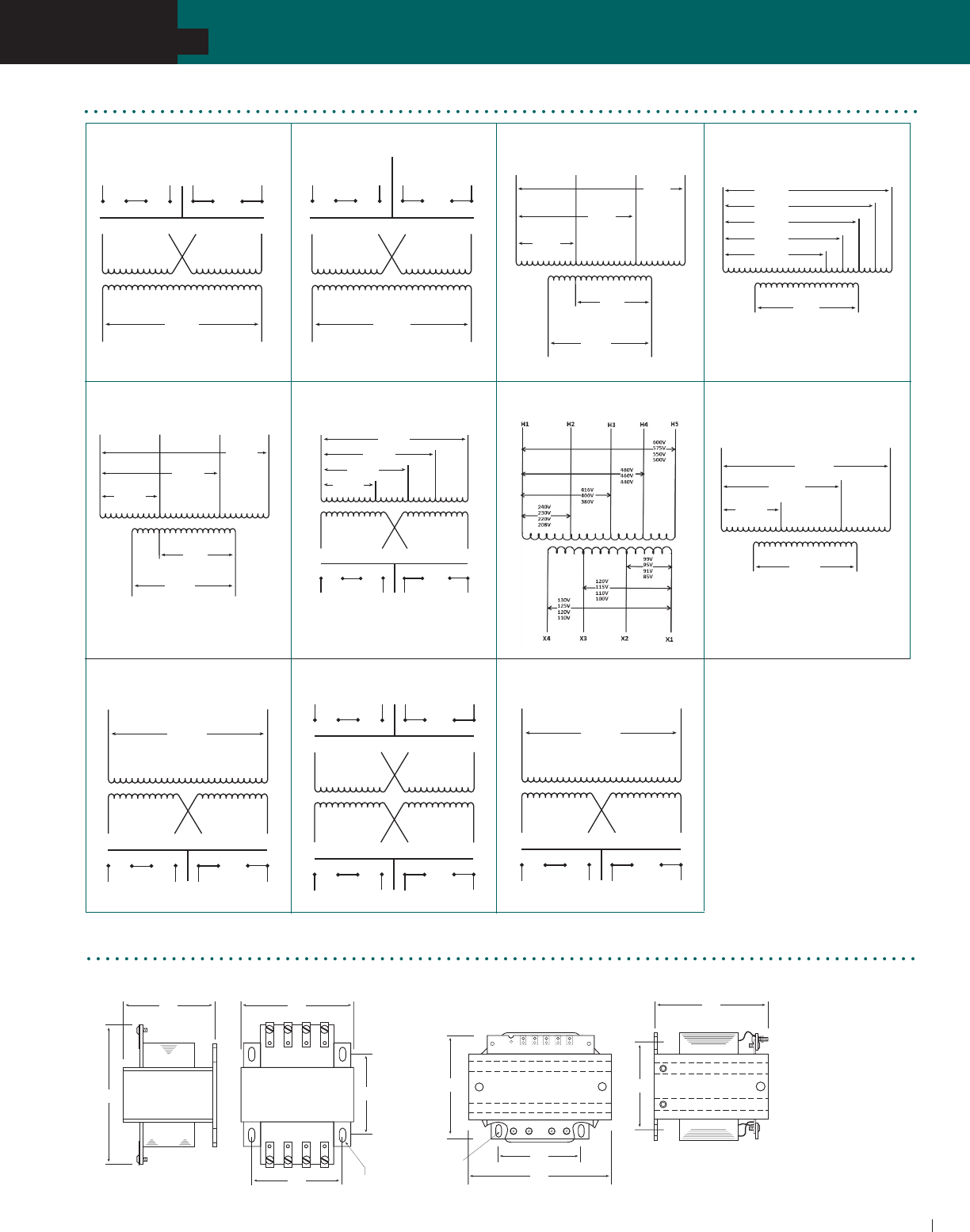
ACME ELECTRIC • MILWAUKEE, WI • 800.334.5214 • acmetransformer.com
65
SECTION
TA SERIES OPEN CORE & COIL INDUSTRIAL CONTROL TRANSFORMERS
65
SECTION
TA SERIES OPEN CORE & COIL INDUSTRIAL CONTROL TRANSFORMERS
5
TA Series Open Core & Coil Wiring Diagrams
Group A Group B Group C
X2 X1
H4
H2
H3
H1
24V
H1 H2
240V 120V
H3 H4 H1 H2
H3 H4
X2 X1
120V
115
110
H4
H2
H3
H1
H1 H2
480V
460
440
H3 H4 H1 H2
H3 H4
240V
230
220
X1
100V
95
90
240V
230
220
H2 H3
H1
600V
575
550
120V
115
110
X3
480V
460
440
H4
X2 X1
240V
208V
H6H1
24V
X2
H2
H3
H5
H4
277V
380V
480V
X2
X1
95V
277V
208V
H4H2 H3
H1
380V
115V
X3
X4 X2 X3 X1
X4 X2 X3 X1
X4 X2 X3 X1
H1
230V 115V
600V
H2
380V
440V H3
H4
H5
550V
X1
230V
208V
H4H1
460V
115V
X2
H2
H3
X4 X2 X3 X1
X4 X2 X3 X1
X4 X2 X3 X1
H1
24V 12V
600V
H2
Group D
Group E Group F Group G Group H
Group I Group J Group K
H1 H2
480V 240V
H3 H4
H1 H3 H2 H4
H1 H2
H3 H4
X4 X2 X3 X1
X4 X2 X3 X1
X4 X2 X3 X1
240V 120V
X4 X2 X3 X1
X4 X2 X3 X1
X4 X2 X3 X1
H1
240V 120V
600V
H2
50 VA Thru 2 kVA 3 & 5 kVA
B
D F
E
C
A
E
C
D
A
B
F
TA Series Open Core & Coil Dimensional Drawings
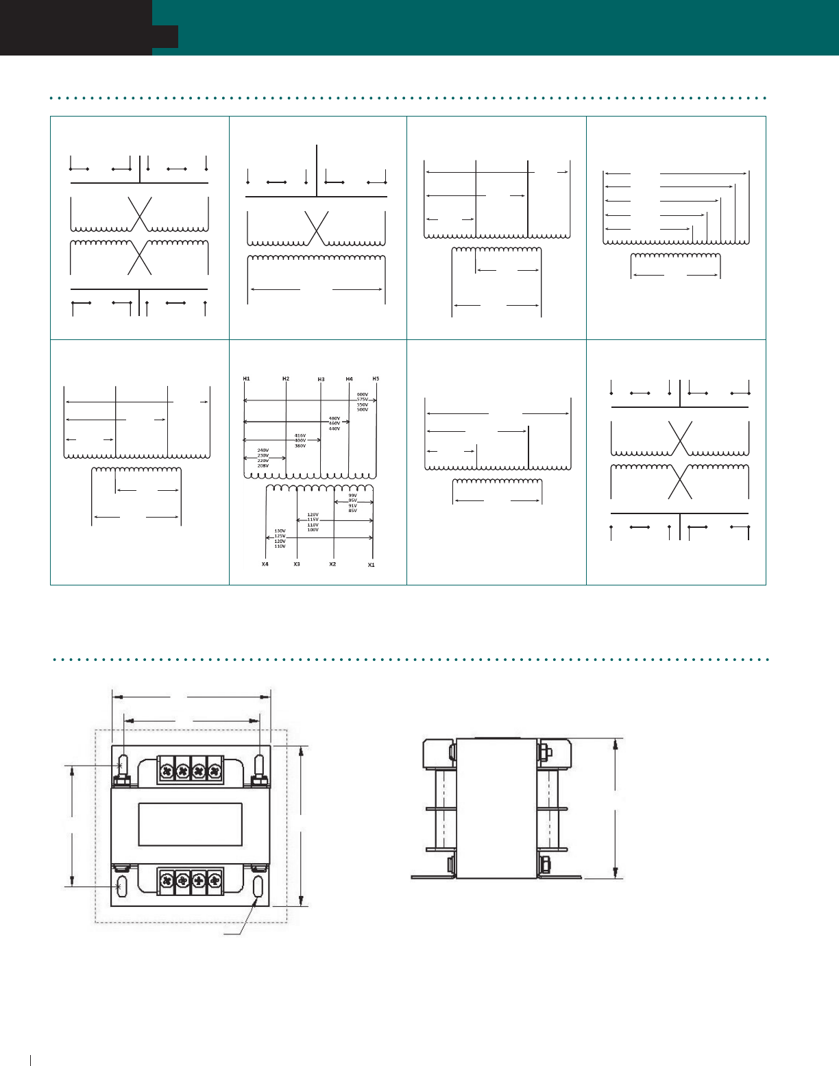
ACME ELECTRIC • MILWAUKEE, WI • 800.334.5214 • acmetransformer.com
66
SECTION
TA SERIES OPEN CORE & COIL INDUSTRIAL CONTROL TRANSFORMERS
66
SECTION
TB SERIES OPEN CORE & COIL INDUSTRIAL CONTROL TRANSFORMERS
5
TB Series Open Core & Coil Dimensional Drawings
C
B
E
D
A
F
TB Series Open Core & Coil Wiring Diagrams
Group A Group B Group C
120V
H1 H2
240V
H3 H4
H1 H3 H2 H4
H1 H2
H3 H4
X4 X2 X3 X1
X4 X2 X3 X1
X4 X2 X3 X1
12V 24V
X2 X1
120V
115
110
H4
H2
H3
H1
H1 H2
480V
460
440
H3 H4 H1 H2
H3 H4
240V
230
220
X1
100V
95
90
240V
230
220
H2 H3
H1
600V
575
550
120V
115
110
X3
480V
460
440
H4
X2 X1
240V
208V
H6H1
24V
X2
H2
H3
H5
H4
277V
380V
480V
X2
X1
95V
277V
208V
H4H2 H3
H1
380V
115V
X3
X1
230V
208V
H4H1
460V
115V
X2
H2
H3
Group D
Group E Group G Group H Group J
H1 H2
480V 240V
H3 H4
H1 H3 H2 H4
H1 H2
H3 H4
X4 X2 X3 X1
X4 X2 X3 X1
X4 X2 X3 X1
240V 120V
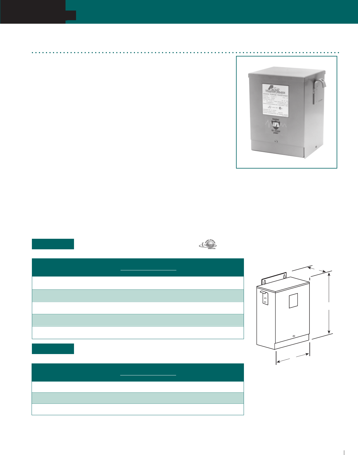
ACME ELECTRIC • MILWAUKEE, WI • 800.334.5214 • acmetransformer.com
67
SECTION
TA SERIES OPEN CORE & COIL INDUSTRIAL CONTROL TRANSFORMERS
SECTION INDUSTRIAL CONTROL TRANSFORMERS
5
67
See page 70 for electrical diagram.
See page 58 for fuse sizing information.
For secondary fuse size, multiply output amps x 1.25.
240/480/600 PRIMARY VOLTS
—120/100
Secondary Volts
—1Ø,
50/60 Hz
240 x 480 PRIMARY VOLTS
—
120 SECONDARY VOLTS
—1Ø,
50/60 Hz
Some specifications require installation of large control transformers, usually 1000 to
5000 VA outside the control cabinet. This means the transformer must be in a sheet
metal enclosure instead of the usual open core and coil construction method.
Acme meets this need by providing all of the power, protection, regulation and
performance of our standard industrial control transformers in one UL -3R enclosure.
These transformers are wound with copper magnet wire, deliver full nameplate
capacity, and provide the high regulation required in control applications.
Voltage combinations available are: 240 x 480V primary, 120V secondary and
240/480/600V primary, 120/100V secondary. Ratings available are 1000, 2000, 3000
and 5000 VA. All units are UL listed, CSA certified, and covered by Acme’s exclusive
10-year limited warranty.
FEATURES
Fully encapsulated and enclosed.
55°C temperature rise, 155°C insulation.
Copper windings.
1000, 2000, 3000, 5000 and 10000 VA sizes.
Voltage regulation exceeds NEMA requirements.
UL and UL-3R listed.
CSA certified.
10-year limited warranty.
Industrial Control Transformers for
Harsh Environments
Designed for Control Panels where Internal
Installation of Control Transformers is prohibited.
Encapsulated
1000 VA–10000 VA
D
H
W
GROUP L
GROUP M
APPROX. DIMENSIONS APPROX. SHIP
ELECTRICAL
CATALOG VA OUTPUT
INCHES (CM.) WEIGHT CONNECTION
NO. RATING AMPS H W D LBS. (KG.) DIAGRAM
T153929 2000 16.67 14.77 10.31 7.13 80 C
(37.5) (26.2) (18.1) (36.3)
T153930 3000 25.00 13.85 13.25 10.19 130 C
(35.2) (33.7) (25.9) (59.0)
T153931 5000 41.67 13.85 13.25 10.19 140 C
(35.2) (33.7) (25.9) (63.5)
APPROX. DIMENSIONS APPROX. SHIP
ELECTRICAL
CATALOG VA OUTPUT
INCHES (CM.) WEIGHT CONNECTION
NO. RATING AMPS H W D LBS. (KG.) DIAGRAM
T181217 1000 8.33 13.10 10.31 7.13 55 B
(33.3) (26.2) (18.1) (24.9)
T181219 2000 16.67 14.77 10.31 7.13 80 B
(37.5) (26.2) (18.1) (36.3)
T181220 3000 25.00 14.77 10.31 7.13 100 B
(37.5) (26.2) (18.1) (45.4)
T181221 5000 41.67 13.85 13.25 10.19 140 B
(35.2) (33.7) (25.9) (63.5)
T181223 10000 83.3 16.47 13.88 12.94 308 B
(41.8) (35.3) (32.9) (139.7)
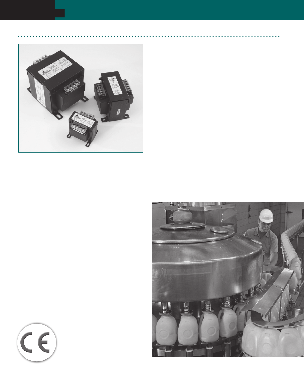
ACME ELECTRIC • MILWAUKEE, WI • 800.334.5214 • acmetransformer.com
68
SECTION
TA SERIES OPEN CORE & COIL INDUSTRIAL CONTROL TRANSFORMERS
68
SECTION AE/CE SERIES INDUSTRIAL CONTROL TRANSFORMERS
5
AE/CE Series Industrial Control Transformers
The Acme Electric AE and CE Series Industrial Control
Transformers are designed specifically for machine tool
control circuit applications. These transformers have
the ability to handle potentially damaging high in-rush
currents that occur when electromagnetic components are
energized, without sacrificing the required stable output
voltage. Designed to meet or exceed the demands of
international standards, combined with the full breadth
of product offering, the AE and CE Series Transformers
from Acme Electric are the ideal solution for your industrial
control applications.
Cooler. Cleaner. More Compact.
The AE and CE Series design improves the dissipation of
the heat away from the core and coil assembly providing
cooler operation. In addition, the AE and CE Series industrial
control transformers seal the transformer’s windings and
internal terminations within an epoxy encapsulant encased
in a durable thermoplastic end cap, protecting them from
potentially damaging moisture, dirt and other ambient
contaminants. Furthermore, Acme’s compact design helps
minimize the mounting footprint, providing more flexibility
in applications where space is at a premium.
FEATURES & BENEFITS
Epoxy encapsulated design protects core & coil assembly
from potentially damaging contaminants.
Integrally molded terminal blocks with isolation barriers to
prevent arc over, terminal blocks allow full access for ring
terminals for easy installation and solid termination.
Heavy gauge steel mounting feet.
Available factory or field installed fuse blocks provide
integral fusing on the primary or primary and secondary.
Dual labeling for easy product identification when
equipped with a fuse block.
50-750 VA, 50/60 Hz.
UL and cUL Listed, CE Marked (CE Series only).
Ten-year limited warranty.
55°C Temperature Rise.
105°C Insulation Class.
CE Series for Global Applications
Acme’s CE Series Encapsulated Industrial Control
Transformers carry the CE mark, indicating it complies with the
requirements established by the International Electrotechnical
Commission (IEC) for use of control
circuit transformers in the countries of
the European Union. Regulations that
apply to control transformers include
Low Voltage Directive 73/23/EEC and
Electromagnetic Compatibility (EMC)
Directive 89/336/EEC.
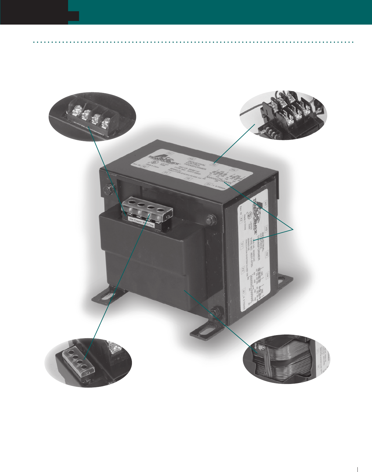
ACME ELECTRIC • MILWAUKEE, WI • 800.334.5214 • acmetransformer.com
69
SECTION
TA SERIES OPEN CORE & COIL INDUSTRIAL CONTROL TRANSFORMERS
69
SECTION AE/CE SERIES INDUSTRIAL CONTROL TRANSFORMERS
5
Integrally mounted fuse blocks
available in standard and touch-proof
(CE Series) style.
Dual labels for
identification
of fused modules
Integrally molded terminal blocks with
combination slotted/phillips screws. Isolation barriers
protect against arc over while able to accommodate
a full ring terminal.
CE Series offers touch-proof terminals,
isolating live contacts for
additional safety.
Epoxy encapsulated copper
windings and internal terminations,
providing isolation from external
contaminants and physical damage.
FEATURES

ACME ELECTRIC • MILWAUKEE, WI • 800.334.5214 • acmetransformer.com
70
SECTION
TA SERIES OPEN CORE & COIL INDUSTRIAL CONTROL TRANSFORMERS
70
SECTION AE/CE INDUSTRIAL CONTROL TRANSFORMERS
5
120 x 240 PRIMARY VOLTS—24 SECONDARY VOLTS –– 1Ø, 50/60 Hz
240 x 480 PRIMARY VOLTS—24 SECONDARY VOLTS –– 1Ø, 50/60 Hz
C
SELECTION CHARTS AE SERIES
200/220/440, 208/230/460, 240/480 PRIMARY VOLTS—23/110, 24/115, 25/120 SECONDARY VOLTS—1Ø, 50/60 Hz
VA APPROX. DIMENSIONS INCHES (CM.) MOUNTING SLOT APPROX.
RATING CATALOG NUMBER A B C D E F SHIPPING WT
50 AE020050 3.28 (8.3) 3.00 (7.6) 2.78 (7.0) 2.25 (5.7) 2.53 (6.4) .20 x .40 (0.5 x 1.0) 3.0 (1.4)
75 AE020075 3.28 (8.3) 3.00 (7.6) 3.09 (7.8) 2.53 (6.4) 2.81 (7.1) .20 x .40 (0.5 x 1.0) 4.0 (1.8)
100 AE020100 3.28 (8.3) 3.41 (8.6) 3.41 (8.6) 2.53 (6.4) 3.13 (7.9) .20 x .40 (0.5 x 1.0) 4.0 (1.8)
150 AE020150 4.03 (10.2) 3.75 (9.5) 3.41 (8.6) 3.28 (8.3) 3.13 (7.9) .20 x .40 (0.5 x 1.0) 7.0 (3.2)
250 AE020250 4.38 (11.1) 4.50 (11.4) 4.03 (10.2) 3.75 (9.5) 3.75 (9.5) .20 x .40 (0.5 x 1.0) 9.0 (4.1)
300 AE020300 5.13 (13.0) 4.50 (11.4) 4.97 (12.6) 3.88 (9.8) 4.38 (11.1) .31 x .69 (0.8 X 1.7) 11.0 (5.0)
350 AE020350 5.25 (13.3) 4.50 (11.4) 4.97 (12.6) 4.16 (10.5) 4.38 (11.1) .31 x .69 (0.8 X 1.7) 13.0 (5.9)
500 AE020500 6.31 (16.0) 5.25 (13.3) 4.97 (12.6) 5.25 (13.3) 4.38 (11.1) .31 x .69 (0.8 X 1.7) 19.0 (8.6)
750 AE020750 6.81 (17.3) 5.25 (13.3) 4.97 (12.6) 5.75 (14.6) 4.38 (11.1) .31 x .69 (0.8 X 1.7) 27.0 (12.2)
GROUP I
GROUP II
GROUP III
VA APPROX. DIMENSIONS INCHES (CM.) MOUNTING SLOT APPROX.
RATING CATALOG NUMBER A B C D E F SHIPPING WT
50 AE010050 2.69 (6.8) 3.00 (7.6) 2.81 (7.1) 2.03 (5.1) 2.53 (6.4) .20 x .40 (0.5 x 1.0) 2.50 (1.1)
75 AE010075 3.22 (8.1) 3.00 (7.6) 2.81 (7.1) 2.53 (6.4) 2.53 (6.4) .20 x .40 (0.5 x 1.0) 3.50 (1.6)
100 AE010100 3.28 (8.3) 3.41 (8.6) 3.09 (7.8) 2.41 (6.1) 2.81 (7.1) .20 x .40 (0.5 x 1.0) 4.05 (1.8)
150 AE010150 3.88 (9.8) 3.78 (9.6) 3.41 (8.6) 2.97 (7.5) 3.13 (7.9) .20 x .40 (0.5 x 1.0) 6.50 (2.9)
250 AE010250 4.13 (10.4) 4.50 (11.4) 3.84 (9.7) 2.94 (7.4) 3.75 (9.5) .20 x .40 (0.5 x 1.0) 9.25 (4.2)
350 AE010350 5.00 (12.7) 4.50 (11.4) 3.84 (9.7) 3.78 (9.6) 3.75 (9.5) .20 x .40 (0.5 x 1.0) 12.75 (5.8)
500 AE010500 5.53 (14.0) 5.25 (13.3) 4.66 (11.8) 4.16 (10.5) 4.38 (11.1) .31 x .69 (0.8 x 1.7) 19.00 (8.6)
750 AE010750 6.81 (17.3) 5.25 (13.3) 4.66 (11.8) 5.75 (14.6) 4.38 (11.1) .31 x .69 (0.8 x 1.7) 26.00 (11.8)
VA APPROX. DIMENSIONS INCHES (CM.) MOUNTING SLOT APPROX.
RATING CATALOG NUMBER A B C D E F SHIPPING WT
50 AE030050 2.69 (6.8) 3.00 (7.6) 2.81 (7.1) 2.03 (5.1) 2.53 (6.4) .20 x .40 (0.5 x 1.0) 2.5 (1.1)
75 AE030075 3.22 (8.1) 3.00 (7.6) 2.81 (7.1) 2.53 (6.4) 2.53 (6.4) .20 x .40 (0.5 x 1.0) 3.5 (1.6)
100 AE030100 3.28 (8.3) 3.41 (8.6) 3.09 (7.8) 2.41 (6.1) 2.81 (7.1) .20 x .40 (0.5 x 1.0) 4.0 (1.8)
150 AE030150 3.88 (9.8) 3.84 (9.7) 3.41 (8.6) 2.97 (7.5) 3.13 (7.9) .20 x .40 (0.5 x 1.0) 6.5 (2.9)
250 AE030250 4.13 (10.4) 4.50 (11.4) 3.84 (9.7) 2.94 (7.4) 3.75 (9.5) .20 x .40 (0.5 x 1.0) 9.2 (4.2)
350 AE030350 5.00 (12.7) 4.50 (11.4) 3.84 (9.7) 3.78 (9.6) 3.75 (9.5) .20 x .40 (0.5 x 1.0) 12.7 (5.8)
500 AE030500 5.53 (14.0) 5.25 (13.3) 4.66 (11.8) 4.16 (10.5) 4.34 (11.0) .31 x .69 (0.8 X 1.7) 19.0 (8.6)
750 AE030750 6.81 (17.3) 5.25 (13.3) 4.66 (11.8) 5.75 (14.6) 4.38 (11.1) .31 x .69 (0.8 X 1.7) 26.0 (11.8)

ACME ELECTRIC • MILWAUKEE, WI • 800.334.5214 • acmetransformer.com
71
SECTION
TA SERIES OPEN CORE & COIL INDUSTRIAL CONTROL TRANSFORMERS
71
SECTION AE/CE SERIES INDUSTRIAL CONTROL TRANSFORMERS
5
240 x 480, 230 x 460, 220 x 440 PRIMARY VOLTS —120/115/110 SECONDARY VOLTS –– 1Ø, 50/60 Hz
208/230/460 PRIMARY VOLTS –– 115 SECONDARY VOLTS –– 1Ø, 50/60 Hz
GROUP VI
GROUP VII
VA APPROX. DIMENSIONS INCHES (CM.) MOUNTING SLOT APPROX.
RATING CATALOG NUMBER A B C D E F SHIPPING WT
50 AE060050 2.69 (6.8) 3.00 (7.6) 2.81 (7.1) 2.03 (5.1) 2.53 (6.4) .20 x .40 (0.5 x 1.0) 2.5 (1.1)
75 AE060075 3.22 (8.1) 3.00 (7.6) 2.81 (7.1) 2.53 (6.4) 2.53 (6.4) .20 x .40 (0.5 x 1.0) 3.5 (1.6)
100 AE060100 3.28 (8.3) 3.41 (8.6) 3.09 (7.8) 2.41 (6.1) 2.81 (7.1) .20 x .40 (0.5 x 1.0) 4.0 (1.8)
150 AE060150 3.88 (9.8) 3.84 (9.7) 3.41 (8.6) 2.97 (7.5) 3.13 (7.5) .20 x .40 (0.5 x 1.0) 6.5 (2.9)
250 AE060250 4.13 (10.4) 4.50 (11.4) 3.84 (9.7) 2.94 (7.4) 3.75 (9.5) .20 x .40 (0.5 x 1.0) 9.2 (4.2)
350 AE060350 5.00 (12.7) 4.50 (11.4) 3.84 (9.7) 3.78 (9.6) 3.75 (9.5) .20 x .40 (0.5 x 1.0) 12.7 (5.8)
500 AE060500 5.53 (14.0) 5.25 (13.3) 4.66 (11.8) 4.16 (10.5) 4.34 (11.0) .31 x .69 (0.8 X 1.7) 19.0 (8.6)
750 AE060750 6.81 (17.3) 5.25 (13.3) 4.66 (11.8) 5.75 (14.6) 4.31 (10.9) .31 x .69 (0.8 X 1.7) 26.0 (11.8)
VA APPROX. DIMENSIONS INCHES (CM.) MOUNTING SLOT APPROX.
RATING CATALOG NUMBER A B C D E F SHIPPING WT
50 AE070050 2.84 (7.2) 3.00 (7.6) 2.81 (7.1) 2.16 (5.4) 2.53 (6.4) .20 x .40 (0.5 x 1.0) 2.6 (1.2)
100 AE070100 3.41 (6.6) 3.41 (8.6) 3.09 (7.8) 2.69 (6.8) 2.81 (7.1) .20 x .40 (0.5 x 1.0) 4.2 (1.9)
150 AE070150 3.88 (9.8) 3.75 (9.5) 3.41 (8.6) 3.09 (7.8) 3.09 (7.8) .20 x .40 (0.5 x 1.0) 6.7 (3.1)
250 AE070250 4.16 (10.5) 4.50 (11.4) 4.03 (10.2) 3.28 (8.3) 3.75 (9.5) .20 x .40 (0.5 x 1.0) 9.5 (4.3)
350 AE070350 5.19 (13.1) 4.50 (11.4) 4.03 (10.2) 4.38 (11.1) 3.75 (9.5) .20 x .40 (0.5 x 1.0) 13.4 (6.1)
500 AE070500 5.88 (14.9) 5.25 (13.3) 4.66 (11.8) 4.78 (12.1) 4.38 (11.1) .31 x .69 (0.8 X 1.7) 19.0 (8.6)
750 AE070750 6.81 (17.3) 5.25 (13.3) 4.66 (11.8) 5.75 (14.6) 4.38 (11.1) .31 x .69 (0.8 X 1.7) 27.0 (12.2)
230/460/575 PRIMARY VOLTS –– 95/115 SECONDARY VOLTS –– 1Ø, 50/60 Hz
GROUP XII
VA APPROX. DIMENSIONS INCHES (CM.) MOUNTING SLOT APPROX.
RATING CATALOG NUMBER A B C D E F SHIPPING WT
50 AE120050 2.88 (7.3) 3.00 (7.6) 2.81 (7.1) 2.19 (5.5) 2.53 (6.4) .20 x .40 (0.5 x 1.0) 2.6 (1.2)
100 AE120100 3.59 (9.1) 3.41 (8.6) 3.09 (7.8) 2.88 (7.3) 2.81 (7.1) .20 x .40 (0.5 x 1.0) 4.2 (1.9)
150 AE120150 3.94 (10.0) 3.78 (9.6) 3.41 (8.6) 3.28 (8.3) 3.09 (7.8) .20 x .40 (0.5 x 1.0) 6.8 (3.1)
250 AE120250 4.16 (10.5) 4.50 (11.4) 4.03 (10.2) 3.22 (8.1) 3.75 (9.5) .20 x .40 (0.5 x 1.0) 9.5 (4.3)
350 AE120350 5.00 (12.7) 4.50 (11.4) 4.03 (10.2) 3.69 (9.3) 4.31 (10.9) .20 x .40 (0.5 x 1.0) 13.2 (6.0)
500 AE120500 5.84 (14.8) 5.25 (13.3) 4.66 (11.8) 4.66 (11.8) 4.38 (11.1) .31 x .69 (0.8 X 1.7) 19.2 (8.7)
750 AE120750 6.81 (17.3) 5.25 (13.3) 4.66 (11.8) 5.81 (14.7) 4.38 (11.1) .31 x .69 (0.8 X 1.7) 27.0 (12.2)
C

ACME ELECTRIC • MILWAUKEE, WI • 800.334.5214 • acmetransformer.com
72
SECTION
TA SERIES OPEN CORE & COIL INDUSTRIAL CONTROL TRANSFORMERS
72
SECTION AE/CE SERIES INDUSTRIAL CONTROL TRANSFORMERS
5
240 x 480 PRIMARY VOLTS –– 24 SECONDARY VOLTS –– 1Ø, 50/60 Hz
GROUP IIIC
VA APPROX. DIMENSIONS INCHES (CM.) MOUNTING SLOT APPROX.
RATING CATALOG NUMBER A B C D E F SHIPPING WT
50 CE030050 3.00 (7.6) 3.00 (7.6) 2.81 (7.1) 2.25 (5.7) 2.53 (6.4) .20 x .40 (0.5 x 1.0) 2.5 (1.1)
75 CE030075 3.28 (8.3) 3.28 (8.3) 2.81 (7.1) 2.25 (5.7) 2.81 (7.1) .20 x .40 (0.5 x 1.0) 3.5 (1.6)
100 CE030100 3.28 (8.3) 3.75 (9.5) 3.09 (7.8) 2.53 (6.4) 3.13 (7.9) .20 x .40 (0.5 x 1.0) 4.0 (1.8)
150 CE030150 3.88 (9.8) 4.50 (11.4) 3.47 (8.8) 2.53 (6.4) 3.75 (9.5) .20 x .40 (0.5 x 1.0) 6.5 (2.9)
250 CE030250 4.13 (10.4) 4.50 (11.4) 4.03 (10.2) 3.22 (8.1) 3.75 (9.5) .20 x .40 (0.5 x 1.0) 9.2 (4.2)
350 CE030350 5.00 (12.7) 5.25 (13.3) 4.03 (10.2) 3.75 (9.5) 4.38 (11.1) .31 x .69 (0.8 X 1.7) 12.7 (5.8)
500 CE030500 5.53 (14.0) 5.25 (13.3) 4.66 (11.8) 4.28 (10.8) 4.38 (11.1) .31 x .69 (0.8 X 1.7) 19.0 (8.6)
750 CE030750 7.03 (17.8) 5.25 (13.3) 4.66 (11.8) 5.41 (13.7) 4.38 (11.1) .31 x .69 (0.8 X 1.7) 26.0 (11.8)
SELECTION CHARTS CE SERIES
120 x 240 PRIMARY VOLTS –– 24 SECONDARY VOLTS –– 1Ø, 50/60 Hz
200/220/440, 208/230/460, 240/480 PRIMARY VOLTS –– 23/110, 24/115, 25/120 SECONDARY VOLTS –– 1Ø, 50/60 Hz
GROUP IC
VA APPROX. DIMENSIONS INCHES (CM.) MOUNTING SLOT APPROX.
RATING CATALOG NUMBER A B C D E F SHIPPING WT
50 CE010050 2.69 (6.8) 3.00 (7.6) 2.81 (7.1) 2.25 (5.7) 2.56 (6.5) .20 x .40 (0.5 x 1.0) 2.5 (1.2)
75 CE010075 3.22 (8.1) 3.41 (8.6) 2.81 (7.1) 2.25 (5.7) 2.88 (7.3) .20 x .40 (0.5 x 1.0) 3.5 (1.6)
100 CE010100 3.28 (8.3) 3.75 (9.5) 3.09 (7.8) 2.53 (6.4) 3.13 (7.9) .20 x .40 (0.5 x 1.0) 4.2 (1.9)
150 CE010150 3.88 (9.8) 4.50 (11.4) 3.41 (8.6) 2.53 (6.4) 3.84 (9.7) .20 x .40 (0.5 x 1.0) 6.6 (3.0)
250 CE010250 4.13 (10.4) 4.50 (11.4) 4.03 (10.2) 3.22 (8.1) 3.84 (9.7) .20 x .40 (0.5 x 1.0) 9.4 (4.3)
350 CE010350 5.00 (12.7) 5.25 (13.3) 4.03 (10.2) 3.75 (9.5) 4.50 (11.4) .31 x .69 (0.8 X 1.7) 13.0 (5.9)
500 CE010500 5.50 (13.9) 5.25 (13.3) 4.66 (11.8) 4.28 (10.8) 4.50 (11.4) .31 x .69 (0.8 X 1.7) 19.1 (8.7)
750 CE010750 7.03 (17.8) 5.25 (13.3) 4.66 (11.8) 5.75 (14.6) 4.50 (11.4) .31 x .69 (0.8 X 1.7) 26.6 (12.1)
GROUP IIC
VA APPROX. DIMENSIONS INCHES (CM.) MOUNTING SLOT APPROX.
RATING CATALOG NUMBER A B C D E F SHIPPING WT
50 CE020050 3.28 (8.3) 3.28 (8.3) 2.81 (7.1) 2.25 (5.7) 2.81 (7.1) .20 x .40 (0.5 x 1.0) 2.7 (1.2)
100 CE020100 4.03 (10.2) 3.75 (9.5) 3.13 (7.9) 3.22 (8.1) 3.16 (8.0) .20 x .40 (0.5 x 1.0) 4.3 (1.9)
150 CE020150 4.03 (10.2) 4.50 (11.4) 3.41 (8.6) 2.81 (7.1) 3.75 (9.5) .20 x .40 (0.5 x 1.0) 6.8 (3.0)
250 CE020250 4.78 (12.1) 4.50 (11.4) 4.03 (10.2) 4.06 (10.3) 3.75 (9.5) .20 x .40 (0.5 x 1.0) 9.7 (4.4)
350 CE020350 5.53 (14.0) 5.25 (13.3) 4.03 (10.2) 4.28 (10.8) 4.38 (11.1) .31 x .69 (0.8 X 1.7) 13.5 (6.1)
500 CE020500 7.25 (18.4) 5.25 (13.3) 4.69 (11.9) 6.00 (15.2) 4.38 (11.1) .31 x .69 (0.8 X 1.7) 19.6 (8.9)
750 CE020750 6.81 (17.3) 5.28 (13.4) 4.69 (11.9) 5.75 (14.6) 4.44 (11.2) .31 x .69 (0.8 X 1.7) 27.0 (12.2)
C

ACME ELECTRIC • MILWAUKEE, WI • 800.334.5214 • acmetransformer.com
73
SECTION
TA SERIES OPEN CORE & COIL INDUSTRIAL CONTROL TRANSFORMERS
73
SECTION AE/CE SERIES INDUSTRIAL CONTROL TRANSFORMERS
5
380/400/415 PRIMARY VOLTS –– 110/220 SECONDARY VOLTS –– 1Ø, 50/60 Hz
208, 220/380/440, 230/400/460, 240/416/480 PRIMARY VOLTS ––
85/100/110, 91/110/120, 95/115/125, 99/120/130 SECONDARY VOLTS –– 1Ø, 50/60 Hz
GROUP IVC
VA APPROX. DIMENSIONS INCHES (CM.) MOUNTING SLOT APPROX.
RATING CATALOG NUMBER A B C D E F SHIPPING WT
50 CE040050 3.53 (8.9) 3.00 (7.6) 2.81 (7.1) 2.53 (6.4) 2.53 (6.4) .20 x .40 (0.5 x 1.0) 2.6 (1.2)
100 CE040100 3.53 (8.9) 3.75 (9.5) 3.22 (8.1) 2.53 (6.4) 3.13 (8.0) .20 x .40 (0.5 x 1.0) 4.3 (1.9)
150 CE040150 3.53 (8.9) 4.34 (11.0) 3.41 (8.6) 2.53 (6.4) 3.75 (9.5) .20 x .40 (0.5 x 1.0) 6.7 (3.0)
250 CE040250 4.03 (10.2) 4.50 (11.4) 4.22 (10.7) 3.22 (8.1) 3.75 (9.5) .20 x .40 (0.5 x 1.0) 9.4 (4.3)
350 CE040350 4.91 (12.4) 4.50 (11.4) 4.22 (10.7) 4.06 (10.3) 3.75 (9.5) .20 x .40 (0.5 x 1.0) 13.0 (5.9)
500 CE040500 6.00 (15.2) 5.25 (13.3) 4.69 (11.9) 4.78 (12.1) 4.38 (11.1) .31 x .69 (0.8 X 1.7) 18.8 (8.5)
750 CE040750 6.81 (17.3) 5.25 (13.3) 4.69 (11.9) 5.75 (14.6) 4.38 (11.1) .31 x .69 (0.8 X 1.7) 26.0 (11.8)
VA APPROX. DIMENSIONS INCHES (CM.) MOUNTING SLOT APPROX.
RATING CATALOG NUMBER A B C D E F SHIPPING WT
50 CE050050 4.03 (10.2) 3.41 (8.6) 3.09 (7.8) 2.47 (6.2) 2.81 (7.1) .20 x .40 (0.5 x 1.0) 2.7 (1.2)
150 CE050150 3.88 (9.8) 4.34 (11.0) 3.41 (8.6) 2.88 (7.3) 3.75 (9.5) .20 x .40 (0.5 x 1.0) 6.7 (3.0)
250 CE050250 5.13 (13.0) 4.50 (11.4) 4.03 (10.2) 4.38 (11.1) 3.75 (9.5) .20 x .40 (0.5 x 1.0) 9.5 (4.3)
350 CE050350 5.91 (15.0) 5.25 (13.3) 4.03 (10.2) 4.78 (12.1) 4.38 (11.1) .31 x .69 (0.8 X 1.7) 13.3 (6.0)
500 CE050500 5.91 (15.0) 5.25 (13.3) 4.66 (11.8) 4.63 (11.7) 4.38 (11.1) .31 x .69 (0.8 X 1.7) 19.0 (8.6)
750 CE050750 7.09 (18.0) 5.25 (13.3) 4.66 (11.1) 5.81 (14.7) 4.38 (11.1) .31 x .69 (0.8 X 1.7) 27.0 (12.2)
GROUP VC
240 x 480, 230 x 460, 220 x 440 PRIMARY VOLTS ––120/115/110 SECONDARY VOLTS –– 1Ø, 50/60 Hz
GROUP VIC
VA APPROX. DIMENSIONS INCHES (CM.) MOUNTING SLOT APPROX.
RATING CATALOG NUMBER A B C D E F SHIPPING WT
50 CE060050 3.41 (8.6) 3.00 (7.6) 2.81 (7.1) 2.53 (6.4) 2.53 (6.4) .20 x .40 (0.5 x 1.0) 2.6 (1.2)
75 CE060075 3.41 (8.6) 3.28 (8.3) 2.81 (7.1) 2.53 (6.4) 2.81 (7.1) .20 x .40 (0.5 x 1.0) 3.6 (1.6)
100 CE060100 3.41 (8.6) 3.75 (9.5) 3.09 (7.8) 2.53 (6.4) 3.13 (7.9) .20 x .40 (0.5 x 1.0) 4.3 (1.9)
150 CE060150 3.88 (9.8) 4.50 (11.4) 3.47 (8.8) 2.53 (6.4) 3.75 (9.5) .20 x .40 (0.5 x 1.0) 6.7 (3.0)
250 CE060250 4.13 (10.4) 4.50 (11.4) 4.03 (10.2) 3.22 (8.1) 3.75 (9.5) .20 x .40 (0.5 x 1.0) 9.4 (4.3)
300 CE060300 4.53 (11.5) 4.50 (11.4) 4.03 (10.2) 3.75 (9.5) 3.75 (9.5) .20 x .40 (0.5 x 1.0) 10.9 (4.9)
350 CE060350 5.00 (12.7) 5.25 (13.3) 4.03 (10.2) 3.75 (9.5) 4.38 (11.1) .31 x .69 (0.8 X 1.7) 13.0 (5.9)
500 CE060500 6.00 (15.2) 5.25 (13.3) 4.66 (11.8) 4.78 (12.1) 4.38 (11.1) .31 x .69 (0.8 X 1.7) 18.8 (8.5)
750 CE060750 6.81 (17.3) 5.25 (13.3) 4.66 (11.8) 5.75 (14.6) 4.38 (11.1) .31 x .69 (0.8 X 1.7) 26.0 (11.8)
C

ACME ELECTRIC • MILWAUKEE, WI • 800.334.5214 • acmetransformer.com
74
SECTION
TA SERIES OPEN CORE & COIL INDUSTRIAL CONTROL TRANSFORMERS
74
SECTION AE/CE INDUSTRIAL CONTROL TRANSFORMERS
5
RECOMMENDED RATING FOR CURRENT LIMITING MIDGET FUSES
NOTE: Bold lines indicate changes in the percent of rated current used to calculate fuse sizes in accordance with article 450 of the NEC.
RECOMMENDED RATING FOR CURRENT LIMITING CLASS CC FUSES
FUSE SIZING CHARTS
PRIMARY FUSE SIZING CHARTS
SECONDARY FUSE SIZING CHARTS
CONNECTION DETAILS FOR AE05 & CE05
VA 120 V 208 V 230 V 240 V 277 V 380 V 416 V 440 V 460 V 480 V 550 V 600 V
50 1.2 0.6 0.6 0.6 0.6 0.3 0.3 0.3 0.3 0.3 0.3 0.3
75 1.9 1.0 1.0 1.0 0.8 0.6 0.6 0.6 0.5 0.5 0.4 0.4
100 2.5 1.5 1.3 1.3 1.0 0.8 0.8 0.6 0.6 0.6 0.6 0.5
150 3.8 2.0 2.0 1.9 1.5 1.2 1.2 1.0 1.0 1.0 0.8 0.8
250 3.5 3.5 3.5 3.0 3.0 2.0 1.8 1.8 1.5 1.5 1.4 1.2
300 4.0 4.0 4.0 3.5 3.0 2.5 2.5 2.0 2.0 1.9 1.5 1.5
350 5.0 5.0 4.5 4.0 4.0 2.5 2.5 2.5 2.0 2.0 1.9 1.8
500 7.0 4.0 3.5 3.5 5.5 4.0 3.5 3.5 3.5 3.0 3.0 2.5
750 10.0 6.0 5.5 5.0 4.5 6.0 5.5 5.0 5.0 5.0 4.0 4.0
VA 24 V 85 V 91 V 99 V 100 V 110 V 115 V 120 V 125 V 130 V
50 VA 3.2 0.9 0.9 0.8 0.8 0.7 0.7 0.6 0.6 0.6
75 VA 5.0 1.4 1.2 1.2 1.2 1.0 1.0 1.0 1.0 0.8
100 VA 6.0 1.5 1.5 1.5 1.5 1.5 1.5 1.2 1.2 1.2
150 VA 10.0 2.5 2.5 2.5 2.5 2.0 2.0 2.0 2.0 1.5
250 VA 12.0 4.5 4.5 4.0 4.0 3.5 3.5 3.0 3.0 3.0
300 VA 15.0 5.5 5.5 5.0 5.0 4.5 4.5 4.0 4.0 3.5
350 VA 20.0 6.5 6.0 5.5 5.5 5.0 5.0 4.5 4.5 4.5
500 VA 25.0 9.0 9.0 8.0 8.0 7.0 7.0 6.0 6.0 6.0
750 VA 40.0 12.0 12.0 12.0 12.0 10.0 10.0 10.0 10.0 9.0
H1-H2 H1-H3 H1-H4 X1-X2 X1-X3 X1-X4
208 85 100 110
220 380 440 91 110 120
230 400 460 95 115 125
240 416 480 99 120 130
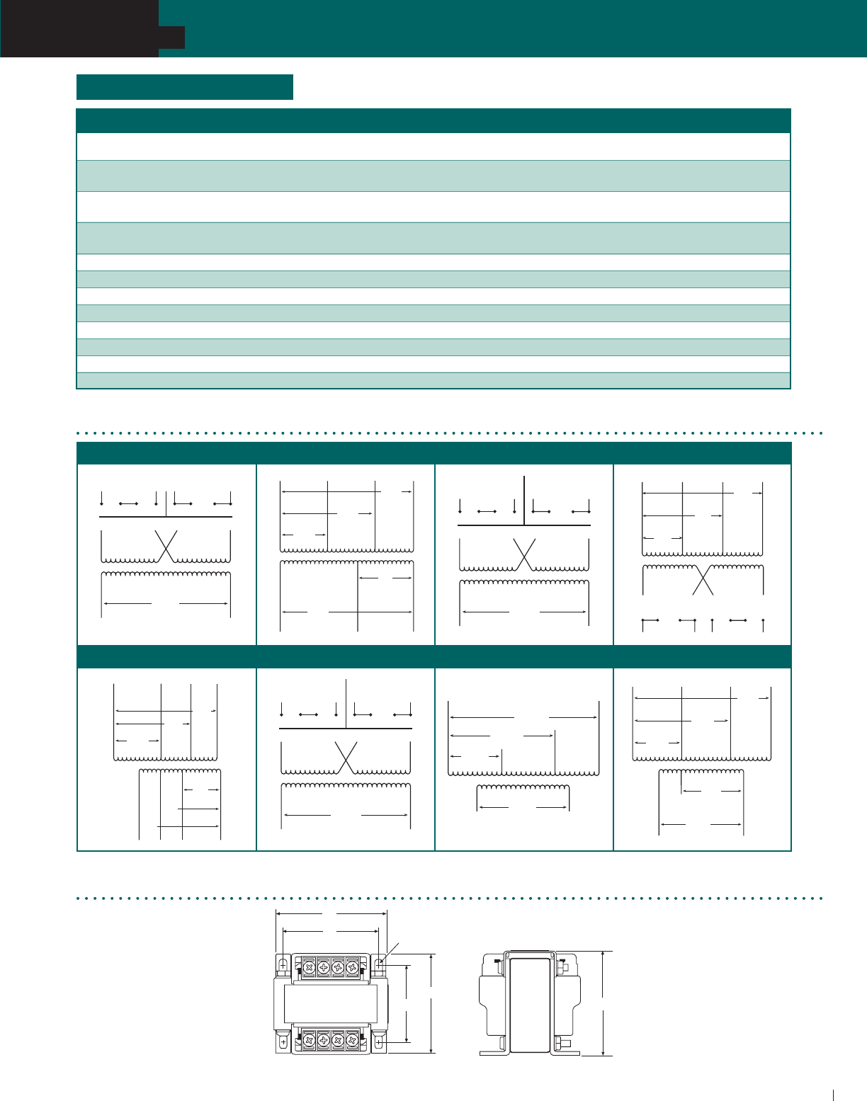
ACME ELECTRIC • MILWAUKEE, WI • 800.334.5214 • acmetransformer.com
75
SECTION
TA SERIES OPEN CORE & COIL INDUSTRIAL CONTROL TRANSFORMERS
75
SECTION AE/CE INDUSTRIAL CONTROL TRANSFORMERS
5
WIRING FOR AE01 & CE01 WIRING FOR AE02 & CE02 WIRING FOR AE03 & CE03 WIRING FOR CE04
WIRING FOR AE05 & CE05 WIRING FOR AE06 & CE06 WIRING FOR AE07 WIRING FOR AE12
X2 X1
H4
H2
H3
H1
24V
H1 H2
240V 120V
H3 H4 H1 H2
H3 H4
208
200
H2 H3
H1
480
460
440
240
230
220
H4
25
24
23
X2 X1
120
115
110
X3 X2 X1
24V
H4
H2
H3
H1
H1 H2
480V
460
440
H3 H4 H1 H2
H3 H4
240V
230
220
X1
X3
X2
X4
X4 X3
220V
X2 X1X4 X3
X2 X1
110V
380
H2 H3
H1
415
400
H4
X2 X1
99V
95
91
85
416V
400
380
240V
230
220
208
H2 H3H1
X4 X3
480V
460
440
H4
130V
125
120
110
120V
115
110
100
X2 X1
120V
115
110
H4
H2
H3
H1
H1 H2
480V
460
440
H3 H4 H1 H2
H3 H4
240V
230
220
X1
230V
208V
H4H1
460V
115V
X2
H2
H3
X1
100V
9 5
9 0
240V
230
220
H2 H3
H1
600V
575
550
120V
115
110
X3
480V
460
440
H4
X2
FUSE KITS & ACCESSORIES
AE & CE Series Wiring Diagrams
AE & CE Series Dimensional Drawings
B
E
D
A
C
F
CATALOG NUMBER VA DESCRIPTION APPROX. SHIPPING WT. (Lbs./ Kg.)
PL79920 50-750
Fuse Kit: Primary Fuse Block EIC Series
1.0 (0.5)
(2 Class CC Blocks)
PL79921 150-750
Fuse Kit: Primary & Secondary Fuse Block EIC Series
1.0 (0.5)
(2 Class CC and 1 Midget Blocks)
PL79922
50-750 Fuse Kit: Primary Fuse Block EIC Series
1.0 (0.5)
CE Listed w/ Covers (2 Class CC Blocks)
PL79923 Fuse Kit: Primary & Secondary Fuse Block EIC Series
1.0 (0.5)
150-750 CE Listed w/ Covers (2 Class CC and 1 Midget Blocks)
PL79924 Fuse Kit: Secondary Fuse 1/4” x 1-1/4” w/ARM 1.0 (0.5)
PL79925 50–350 Cover: Small Terminal Covers (Qty. 2) 1.0 (0.5)
PL79926 500 & 750 Cover: Large Terminal Covers (Qty. 2) 1.0 (0.5)
PL79927 Cover: Fuse Block Covers (Qty. 1) 1.0 (0.5)
PL79928 50–350 Link: Small Jumper Links (Qty. 2) 1.0 (0.5)
PL79929 500 & 750 Link: Large Jumper Links (Qty. 2) 1.0 (0.5)
PL79930 50–350 Fuse Kit: Secondary Fuse Midget w/ARM 1.0 (0.5)
PL79931 500 & 750 Fuse Kit: Secondary Fuse Midget w/ARM 1.0 (0.5)
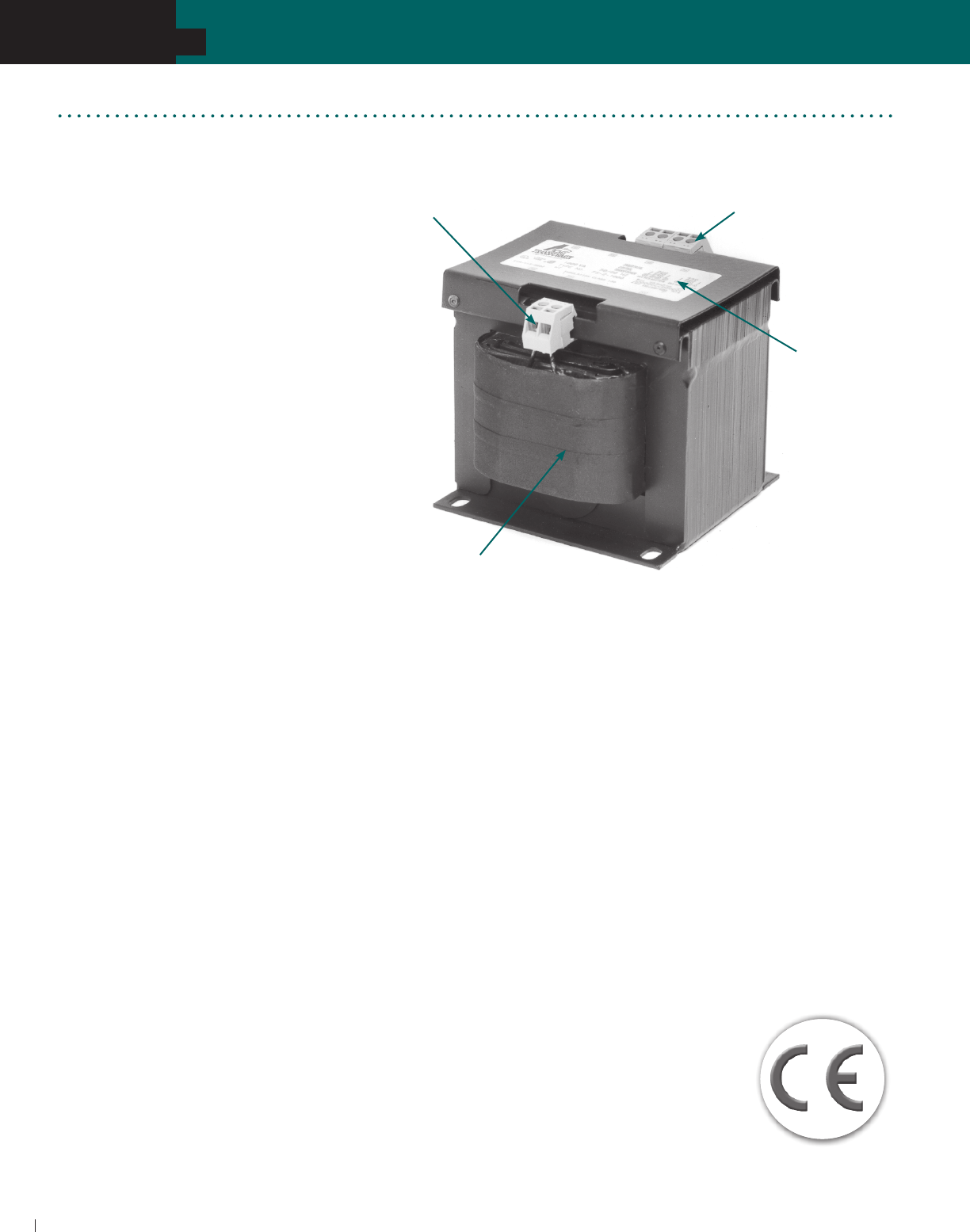
ACME ELECTRIC • MILWAUKEE, WI • 800.334.5214 • acmetransformer.com
76
SECTION
TA SERIES OPEN CORE & COIL INDUSTRIAL CONTROL TRANSFORMERS
76
SECTION FINGER/GUARD® INDUSTRIAL CONTROL TRANSFORMERS
5
The Acme FINGER/GUARD® line of
Touch-Protected Industrial Control
Transformers offers the most advanced
and versatile design concepts
available to the marketplace today.
They are designed to meet Acme’s rigid
standards for mechanical durability as
well as surpass Agency and Industry
electrical standards. The FINGER/
GUARD® line is designed for all control
applications and features integrally
installed, durable molded plastic
terminations designed to protect against
contact with live components. No slip -
on plastic covers to be broken, lost or
misplaced.
All FINGER/GUARD® products use
copper windings, high-permeability
silicon steel cores and 130 degree
C (Class B) insulation. All FINGER/
GUARD® products meet or exceed
ANSI, IEC and NEMA standards.
They are third party witness tested
and are UL Listed (File E79947), CSA
Certified (File 7357) and CE Marked
(to EN60742)...ON ALL SIZES. The
product is suitable for both 50 and 60
Hertz applications and is available in
sizes ranging from 50 VA to 3000 VA.
FEATURES
Constructed with high quality silicon
s t e e l l a m i n a t i o n t o m i n i m i z e c o r e
l o s s e s a n d i n c r e a s e e f f i c i e n c y .
Designs incorporate precision wound
coils for improved regulation.
Copper windings on all groups.
50 VA through 3000 VA sizes, 50/60 Hz.
130°C (Class B) Insulation 80°C
temperature rise.
Voltage regulation exceeds NEMA
requirements.
UL Listed, CSA Certified and
CE Marked.
Attractive finish, nameplate, and
design features enhance the end
product.
Ten-year limited warranty.
Smaller, lighter weight design.
FINGER/GUARD® Industrial Control Transformers
CE Marking
(Conformité Européene)
The CE Marking, standing for Conformité Européene, is a European Mark of
conformity indicating that a product or system to which it is applied, complies
with European law (Directives) regulating a necessary level of protection in
Europe with respect to safety, health, environmental and consumer protection;
however, it is not intended as a guarantee of quality for the consumer. The CE
Marking must be applied to products being placed on the European market.
The CE Marking does allow a product to be moved freely within the internal
market of the European Union.
The Directives that apply to Control or Power Distribution Transformers are:
• Low Voltage Directive, 73/23/EEC effective January 1, 1997
• Electromagnetic Compatibility (EMC) Directive, 89/336/EEC effective
• January 1, 1996
The stringent testing required to obtain a third party certification mark in many
cases is significantly more rigid than domestic requirements. This ensures that
not only the Acme FINGER/GUARD® product, but all of
our CE Marked products are designed to meet a higher
level of safety standards than non-CE Marked products.
All Acme transformers are manufactured in a facility
certified by Underwriters Laboratories to ISO-9001.
Durable molded plastic
terminal is designed for
protection against contact
with live components
Easy to read nameplate
clearly identifies
important data
Wide range of primary and
secondary voltages
Easy access front opening in
terminal makes for fast wire
connections with one screw

ACME ELECTRIC • MILWAUKEE, WI • 800.334.5214 • acmetransformer.com
77
SECTION
TA SERIES OPEN CORE & COIL INDUSTRIAL CONTROL TRANSFORMERS
CATALOG VA EUROPEAN* APPROX. DIMENSIONS INCHES (CM.) APPROX.
NO. RATING RATING A B C D E F SHIP WEIGHT LBS. (Kg.)
FS150
FS175
FS1100
FS1150
FS1250
FS1350
FS1500
FS1750
FS11000 1000 870 4.76 (12.1) 6.75 (17.1) 6.03 (15.3) 5.75 (14.6) 2.86 (7.3) .31 x .50 (0.8 x 1.3) 26 (11.8)
77
SECTION FINGER/GUARD® INDUSTRIAL CONTROL TRANSFORMERS
5
240/416/480/600; 230/400/460/575; 220/380/440/550; 208/500 PRIMARY VOLTS
99/120/130; 95/115/125; 91/110/120; 85/100/110 SECONDARY VOLTS—50/60 Hz
240 X 480, 230 X 460, 220 X 440 PRIMARY VOLTS—120/115/110 SECONDARY VOLTS—50/60 Hz
120 X 240 PRIMARY VOLTS—24 SECONDARY VOLTS—50/60 Hz
SELECTION CHARTS
GROUP A
GROUP B
GROUP C
CATALOG VA EUROPEAN* APPROX. DIMENSIONS INCHES (CM.) APPROX.
NO. RATING RATING A B C D E F SHIP WEIGHT LBS. (Kg.)
FS350 50 50 2.59 (6.6) 3.75 (9.5) 3.64 (9.2) 3.13 (8.0) 1.70 (4.3) .22 x .50 (0.6 x 1.3) 5 (2.3)
FS3150 150 150 3.31 (8.4) 4.50 (11.4) 4.15 (10.5) 3.75 (9.5) 2.18 (5.5) .22 x .50 (0.6 x 1.3) 8 (3.6)
FS3250 250 250 3.61 (9.2) 4.88 (12.4) 4.46 (11.3) 4.06 (10.3) 2.33 (5.9) .22 x .50 (0.6 x 1.3) 11 (5.0)
FS3350 350 345 4.69 (11.9) 4.88 (12.4) 4.46 (11.3) 4.06 (10.3) 3.48 (8.8) .22 x .50 (0.6 x 1.3) 17 (7.7)
FS3500 500 490 4.39 (11.2) 6.75 (17.1) 6.03 (15.3) 5.75 (14.6) 2.48 (6.3) .31 x .50 (0.8 x 1.3) 22 (10.0)
FS3750 750 720 5.18 (13.2) 6.75 (17.1) 6.03 (15.3) 5.75 (14.6) 3.31 (8.4) .31 x .50 (0.8 x 1.3) 30 (13.6)
FS31000 1000 870 6.18 (15.7) 6.75 (17.1) 6.03 (15.3) 5.75 (14.6) 4.30 (10.9) .31 x .50 (0.8 x 1.3) 39 (17.7)
FS31500 1500 1290 6.26 (15.9) 7.50 (19.1) 6.68 (17.0) 6.50 (16.5) 5.26 (13.4) .41 x .81 (1.0 x 2.1) 51 (23.1)
FS32000 2000 1680 7.76 (19.7) 7.50 (19.1) 7.70 (19.6) 6.50 (16.5) 6.75 (17.1) .41 x .81 (1.0 x 2.1) 66 (29.9)
FS33000 3000 2465 8.88 (22.6) 11.92 (30.3) 8.83 (22.4) 6.75 (17.1) 5.75 (14.6) .41 x .81 (1.0 x 2.1) 70 (31.8)
Reference Group IC (CE01):
CE Series Industrial Control Transformers
50-750 VA
See Pg 72
Reference Group VIC (CE06):
CE Series Industrial Control Transformers
50-750 VA
See Pg 73
CATALOG VA EUROPEAN* APPROX. DIMENSIONS INCHES (CM.) APPROX.
NO. RATING RATING A B C D E F SHIP WEIGHT LBS. (Kg.)
FS250
FS275
FS2100
FS2150
FS2250
FS2300
FS2350
FS2500
FS2750
FS21000 1000 870 4.76 (12.1) 6.75 (17.1) 6.03 (15.3) 5.75 (14.6) 2.86 (7.3) .31 x .50 (0.8 x 1.3) 26 (11.8)
FS21500 1500 1290 6.01 (15.3) 6.75 (17.1) 6.03 (15.3) 5.75 (14.6) 4.13 (10.5) .31 x .50 (0.8 x 1.3) 38 (17.2)
FS22000 2000 1680 6.51 (16.5) 6.75 (17.1) 6.03 (15.3) 5.75 (14.6) 4.63 (11.8) .31 x .50 (0.8 x 1.3) 44 (20.0)
FS23000 3000 2465 7.44 (18.9) 7.50 (19.1) 6.68 (17.0) 6.50 (16.5) 6.47 (16.4) .41 x .81 (1.0 x 2.1) 60 (27.2)

ACME ELECTRIC • MILWAUKEE, WI • 800.334.5214 • acmetransformer.com
78
SECTION
TA SERIES OPEN CORE & COIL INDUSTRIAL CONTROL TRANSFORMERS
78
SECTION FINGER/GUARD® INDUSTRIAL CONTROL TRANSFORMERS
5
PRIMARY FUSE SIZING CHARTS
RECOMMENDED RATING FOR CURRENT LIMITING CLASS CC FUSES
NOTE: Bold lines indicate changes in the percent of rated current used to calculate fuse sizes in accordance with article 450 of the NEC.
CONNECTION DETAILS FOR GROUP C
CONNECT TO LINE FOR RESPECTIVE VOLTAGE OUTPUT VOLTS
H1-H2 H1-H3 H1-H4 H1-H5 X1-X2 X1-X3 X1-X4
208 – – 500 85 100 110
220 380 440 550 91 110 120
230 400 460 575 95 115 125
240 416 480 600 99 120 130
FUSE KITS–FOR FINGER/GUARD® INDUSTRIAL CONTROL TRANSFORMERS
* EN60742 requires transformers to pass the temperature rise limits of a 130° C (Class B) insulation system at 6% above the rated supply voltage.
CATALOG NO. DESCRIPTION
PL79905 PRIMARY FUSE KIT FOR CLASS CC FUSES
PL79906 PRIMARY & SECONDARY FUSE KIT FOR CLASS CC PRIMARY FUSES & MIDGET SECONDARY FUSE
PL79907 PRIMARY FUSE KIT FOR MIDGET FUSES
PL79908 PRIMARY & SECONDARY FUSE KIT FOR MIDGET FUSES
VA 120 V 208 V 230 V 240 V 277 V 380 V 416 V 440 V 460 V 480 V 550 V 600 V
50 1.2 0.6 0.6 0.6 0.6 0.3 0.3 0.3 0.3 0.3 0.3 0.3
75 1.9 1.0 1.0 1.0 0.8 0.6 0.6 0.6 0.5 0.5 0.4 0.4
100 2.5 1.5 1.3 1.3 1.0 0.8 0.8 0.6 0.6 0.6 0.6 0.5
150 3.8 2.0 2.0 1.9 1.5 1.2 1.2 1.0 1.0 1.0 0.8 0.8
250 3.5 3.5 3.5 3.0 3.0 2.0 1.8 1.8 1.5 1.5 1.4 1.2
300 4.0 4.0 4.0 3.5 3.0 2.5 2.5 2.0 2.0 1.9 1.5 1.5
350 5.0 5.0 4.5 4.0 4.0 2.5 2.5 2.5 2.0 2.0 1.9 1.8
500 7.0 4.0 3.5 3.5 5.5 4.0 3.5 3.5 3.5 3.0 3.0 2.5
750 10.0 6.0 5.5 5.0 4.5 6.0 5.5 5.0 5.0 5.0 4.0 4.0
1000 15.0 8.0 7.0 7.0 6.0 4.5 4.0 3.5 3.5 3.5 5.5 5.0
1500 20.0 12.0 12.0 12.0 10.0 7.0 6.0 6.0 5.5 5.5 5.0 4.5
2000 25.0 12.0 15.0 15.0 12.0 9.0 8.0 8.0 7.5 7.0 6.0 6.0
3000 30.0 20.0 20.0 20.0 15.0 15.0 12.0 12.0 12.0 12.0 10.0 9.0
VA 24 V 85 V 91 V 99 V 100 V 110 V 115 V 120 V 125 V 130 V
50 VA 3.2 0.9 0.9 0.8 0.8 0.7 0.7 0.6 0.6 0.6
75 VA 5.0 1.4 1.2 1.2 1.2 1.0 1.0 1.0 1.0 0.8
100 VA 6.0 1.5 1.5 1.5 1.5 1.5 1.5 1.2 1.2 1.2
150 VA 10.0 2.5 2.5 2.5 2.5 2.0 2.0 2.0 2.0 1.5
250 VA 12.0 4.5 4.5 4.0 4.0 3.5 3.5 3.0 3.0 3.0
300 VA 15.0 5.5 5.5 5.0 5.0 4.5 4.5 4.0 4.0 3.5
350 VA 20.0 6.5 6.0 5.5 5.5 5.0 5.0 4.5 4.5 4.5
500 VA 25.0 9.0 9.0 8.0 8.0 7.0 7.0 6.0 6.0 6.0
750 VA 40.0 12.0 12.0 12.0 12.0 10.0 10.0 10.0 10.0 9.0
1000 VA 50.0 15.0 15.0 12.0 12.0 12.0 12.0 12.0 12.0 12.0
1500 VA — 25.0 20.0 20.0 20.0 20.0 20.0 15.0 15.0 15.0
2000 VA — 30.0 30.0 25.0 25.0 25.0 25.0 20.0 20.0 20.0
3000 VA — 40.0 40.0 40.0 40.0 35.0 35.0 30.0 30.0 30.0
SECONDARY FUSE SIZING CHARTS
RECOMMENDED RATING FOR CURRENT LIMITING MIDGET FUSES
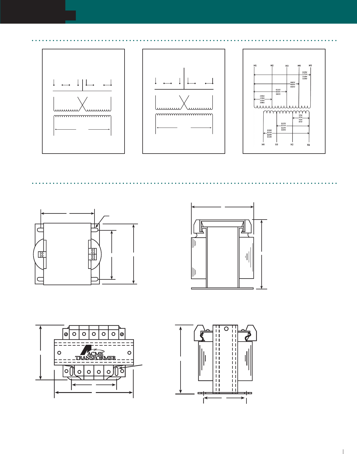
ACME ELECTRIC • MILWAUKEE, WI • 800.334.5214 • acmetransformer.com
79
SECTION
TA SERIES OPEN CORE & COIL INDUSTRIAL CONTROL TRANSFORMERS
79
SECTION FINGER/GUARD® INDUSTRIAL CONTROL TRANSFORMERS
5
X2 X1
H4
H2
H3
H1
24V
H1 H2
240V 120V
H3 H4 H1 H2
H3 H4
X2 X1
120V
115
110
H4
H2
H3
H1
H1 H2
480V
460
440
H3 H4 H1 H2
H3 H4
240V
230
220
GROUP A GROUP B GROUP C
FINGER/GUARD® Wiring Diagrams
A
B
D
F
C
E
3 kVA
50 VA Thru 2 kVA
B
D
F
E
A
C
FINGER/GUARD® Dimensional Drawings

ACME ELECTRIC • MILWAUKEE, WI • 800.334.5214 • acmetransformer.com
80
SECTION
TA SERIES OPEN CORE & COIL INDUSTRIAL CONTROL TRANSFORMERS
80
SECTION FINGER/GUARD® INDUSTRIAL CONTROL TRANSFORMERS
5
NOTES

General Purpose ................................................ 84
Buck - Boost ....................................................... 85
Wiring Diagrams ................................................ 86
LOW VOLTAGE/
LIGHTING
TRANSFORMERS
SECTION 6

SECTION
LOW VOLTAGE LIGHTING TRANSFORMERS & POWER SUPPLIES
ACME ELECTRIC • MILWAUKEE, WI • 800.334.5214 • acmetransformer.com
82
6
SECTION
LOW VOLTAGE LIGHTING TRANSFORMERS
82
Why Low Voltage?
Acme’s Low Voltage Lighting
products provide a safe, long last-
ing, highly reliable power source;
a perfect selection for landscape
applications as well as interior use.
Low voltage lighting is a creative
medium with unlimited application
possibilities. Low voltage lighting
benefits include:
Precision beam control
More light intensity per watt
Less radiated heat
Greater efficiency
Longer life
Safer to use
Easy installation
A high return on end-user
investment
Low Voltage Lighting
A greater selection for your indoor & outdoor low voltage lighting projects
More value
Acme low voltage transformers are available in a wide
range of options and models that are all UL listed for use
indoors or outdoors. See inside back cover for warranty
details.
More Power
Transformers in ratings of 100 through 1000 W; Group VI
Buck–Boost in .05 through 10 kVA.
More convenience
Groups IV, V and VI transformers have copper lead wires
for hardwiring. Circuit breakers for instant reset (except
pool and spa and Buck–Boost). No fumbling with fuses.
Generous wiring compartment, too!
Acme Advantages
More protection
A full fault current carrying Faraday Shield (except Buck–
Boost) prevents 120 volts from reaching the 12 volt side, as
required by UL-1571 and UL-1838.
Features & Options
The convenient “Selection Guide” on the facing page
provides you with the data you need to select the product
that best meets your requirement. Complete product
selection data, dimensions and wiring diagrams are
contained on the following pages. If you need help in
your selection, or if you have questions, just call technical
services at 1-800-334-5214.

SECTION
LOW VOLTAGE LIGHTING TRANSFORMERS & POWER SUPPLIES
ACME ELECTRIC • MILWAUKEE, WI • 800.334.5214 • acmetransformer.com
83
6
SECTION
LOW VOLTAGE LIGHTING TRANSFORMERS
83
11
10
8
9
6
7
3
4
5
2
1
TRANSFORMERS
GROUP V GROUP VI
Buck–Boost
Features/Options ‘T1’ ‘T1’ and ‘T2”
Catalog No. Catalog No.
100 .05
Ratings through through
(Watts, VA, kVA) 1000 VA 10 kVA
120 Volts or 120 x 240
Primary Input 240 Volts Volts
Secondary
Output 12V or 24V 12 x 24 V
Hardwired Primary Yes Yes
Auto Thermal Reset No
Overload Primary
Protection:
Secondary Circuit
Breakers No
Output Copper Copper
Wiring Lead Wires Lead Wires
UL Listed Yes Yes
CSA Certified Yes Yes
Faraday Yes No
Shield
Product
10 Years 10 Years
Warranty
UL-3R
Indoor/Outdoor No Yes
Enclosure
SELECTION GUIDE
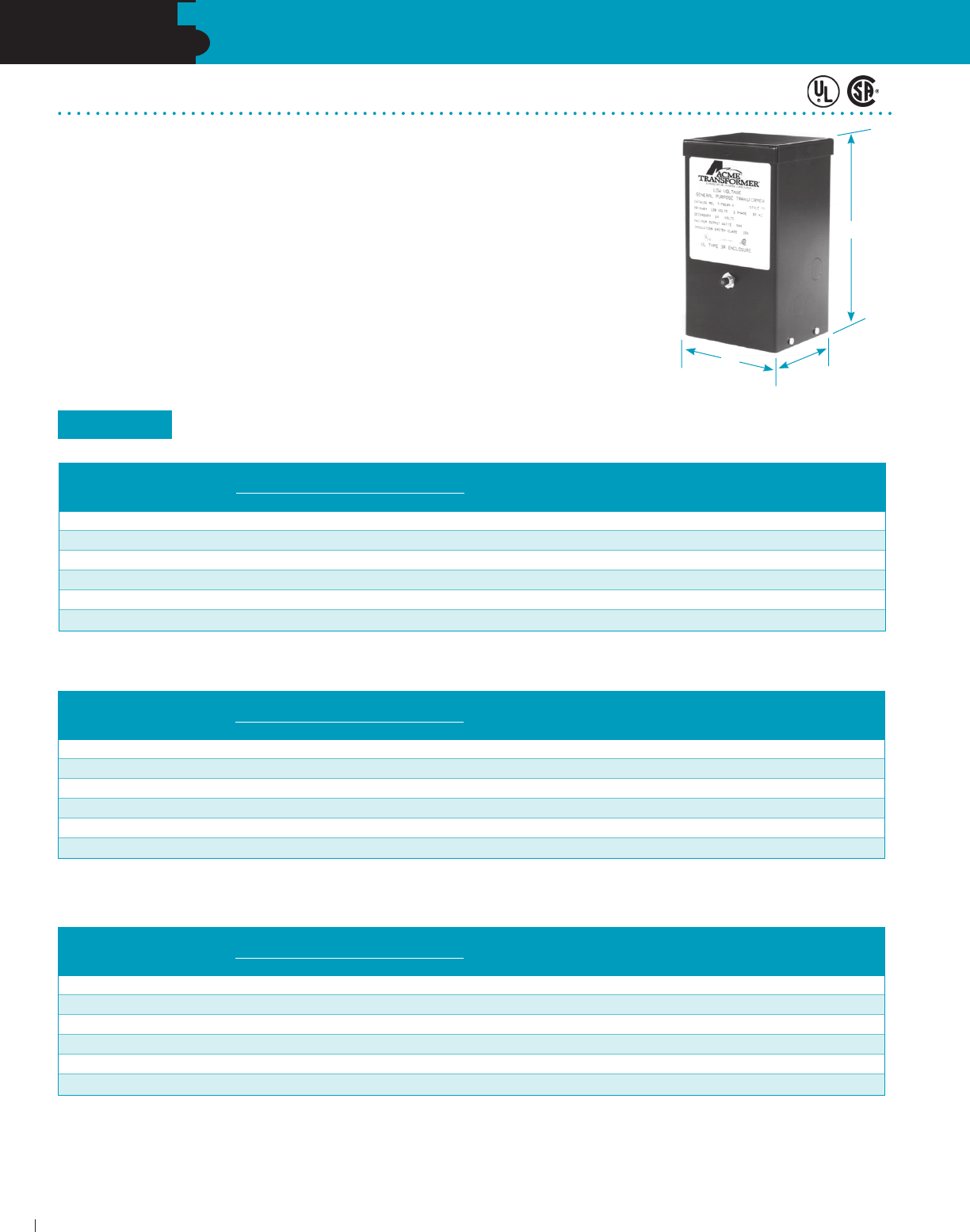
SECTION
LOW VOLTAGE LIGHTING TRANSFORMERS & POWER SUPPLIES
ACME ELECTRIC • MILWAUKEE, WI • 800.334.5214 • acmetransformer.com
84
6
SECTION
LOW VOLTAGE/ LIGHTING TRANSFORMERS
84
Low Voltage General Purpose Transformers
FEATURES
UL Listed , CSA Certified.
100, 150, 300, 600, 750, 1000 VA.
1 Phase, 60 Hz, 120 or 240 volt input.
12 or 24 volt output.
Input Auto-Thermal reset switch.
Output circuit breaker.
Fully encapsulated core and coil.
Full fault current carrying Faraday Shield.
Flexible copper leadwire terminations.
UL class 180°C insulation system 115°C rise.
UL Type 2 enclosure.
Keyhole slotted wall mounting brackets.
Black finish.
Bottom access.
Two 0.875 (2.2 cm) single knockouts
each side.
Two dual 0.875 (2.2 cm) and 1.125
(2.9 cm) knockouts on bottom cover.
120 PRIMARY VOLTS – 12 SECONDARY VOLTS, TWO WINDINGS, 1Ø, 60 Hz
120 PRIMARY VOLTS – 24 SECONDARY VOLTS, TWO WINDINGS, 1Ø, 60 Hz
240 PRIMARY VOLTS – 24 SECONDARY VOLTS, TWO WINDINGS, 1Ø, 60 Hz
H
WD
GROUP V
APPROX. DIMENSIONS APPROX.
VA CATALOG NO. INCHES (CM.) SHIP WEIGHT CB RATING CB STYLE
HEIGHT WIDTH DEPTH LBS. (KG.)
100 T179600S 9.01 (22.9) 4.08 (10.4) 3.88 (9.9) 7 (3.2) 15 AMP Push To Reset Thermal Breaker
150 T179620S 9.01 (22.9) 4.08 (10.4) 3.88 (9.9) 7 (3.2) 20 AMP Push To Reset Thermal Breaker
300 T179621S 11.68 (29.7) 4.66 (11.8) 4.57 (11.6) 11 (5.0) 40 AMP Push To Reset Thermal Breaker
600 T179622S 11.68 (29.7) 4.66 (11.8) 4.57 (11.6) 15 (6.8) 60 AMP Magnetic Toggle On/Off Breaker
750 T179603S 11.68 (29.7) 4.66 (11.8) 4.57 (11.6) 18 (8.2) 75 AMP Magnetic Toggle On/Off Breaker
1000 T179604S 11.93 (30.3) 5.41 (13.7) 5.20 (13.2) 26 (11.8) 100 AMP Magnetic Toggle On/Off Breaker
APPROX. DIMENSIONS APPROX.
VA CATALOG NO. INCHES (CM.) SHIP WEIGHT CB RATING CB STYLE
HEIGHT WIDTH DEPTH LBS. (KG.)
100 T179605S 9.01 (22.9) 4.08 (10.4) 3.88 (9.9) 7 (3.2) 7 AMP Push To Reset Thermal Breaker
150 T179623S 9.01 (22.9) 4.08 (10.4) 3.88 (9.9) 7 (3.2) 10 AMP Push To Reset Thermal Breaker
300 T179624S 11.68 (29.7) 4.66 (11.8) 4.57 (11.6) 11 (5.0) 20 AMP Push To Reset Thermal Breaker
600 T179625S 11.68 (29.7) 4.66 (11.8) 4.57 (11.6) 15 (6.8) 40 AMP Push To Reset Thermal Breaker
750 T179608S 11.68 (29.7) 4.66 (11.8) 4.57 (11.6) 18 (8.2) 50 AMP Push To Reset Thermal Breaker
1000 T179609S 11.93 (30.3) 5.41 (13.7) 5.20 (13.2) 26 (11.8) 50 AMP Magnetic Toggle On/Off Breaker
APPROX. DIMENSIONS APPROX.
VA CATALOG NO. INCHES (CM.) SHIP WEIGHT CB RATING CB STYLE
HEIGHT WIDTH DEPTH LBS. (KG.)
100 T179615S 9.01 (22.9) 4.08 (10.4) 3.88 (9.9) 7 (3.2) 7 AMP Push To Reset Thermal Breaker
150 T179629S 9.01 (22.9) 4.08 (10.4) 3.88 (9.9) 7 (3.2) 10 AMP Push To Reset Thermal Breaker
300 T179630S 11.68 (29.7) 4.66 (11.8) 4.57 (11.6) 11 (5.0) 20 AMP Push To Reset Thermal Breaker
600 T179631S 11.68 (29.7) 4.66 (11.8) 4.57 (11.6) 15 (6.8) 40 AMP Push To Reset Thermal Breaker
750 T179618S 11.68 (29.7) 4.66 (11.8) 4.57 (11.6) 18 (8.2) 50 AMP Push To Reset Thermal Breaker
1000 T179619S 11.93 (30.3) 5.41 (13.7) 5.20 (13.2) 26 (11.8) 50 AMP Magnetic Toggle On/Off Breaker
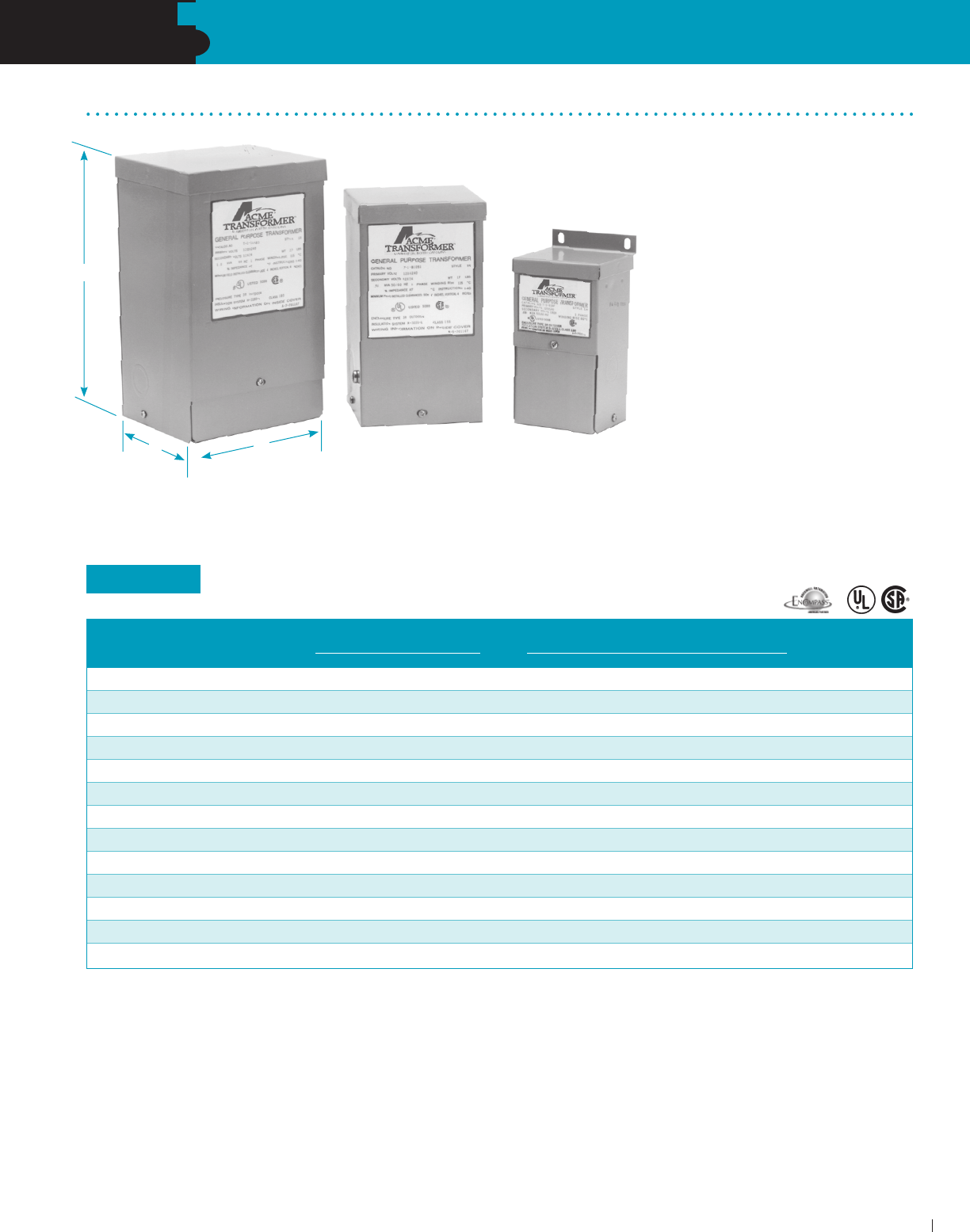
SECTION
LOW VOLTAGE LIGHTING TRANSFORMERS & POWER SUPPLIES
ACME ELECTRIC • MILWAUKEE, WI • 800.334.5214 • acmetransformer.com
85
6
SECTION
LOW VOLTAGE/ LIGHTING TRANSFORMERS
85
Buck-Boost Transformers
The No-Frills Low
Voltage Lighting
Buck-Boost Transformers offer a no-
frills approach to low voltage lighting.
(See Chart Below) A typical Buck-
Boost application is 120 volts in and
12 volts out for low voltage lighting or
control circuitry. In most applications,
this low voltage isolation transformer
is field connected as an autotrans-
former. For more information on Buck-
Boost Transformers, refer to the next
section in this catalog.
120 x 240 VOLT INPUT– 12/24 VOLT OUTPUT – 1Ø, 60 Hz
H
W
D
GROUP VI
INSULATING SECONDARY MAXIMUM
APPROX. DIMENSIONS APPROX.
CATALOG TRANSFORMER CURRENT OUTPUT INCHES (CM.) NET WEIGHT
NUMBER RATING 12V 24V HEIGHT WIDTH DEPTH LBS. (KG.)
T181047 0.05 kVA 4.16 2.08 6.38 (16.2) 3.19 (8.1) 3.00 (7.6) 4 (1.8)
T181048 0.10 kVA 8.32 4.16 6.62 (16.8) 3.75 (9.5) 3.62 (9.2) 5 (2.3)
T181049 0.15 kVA 12.52 6.25 7.12 (18.1) 3.75 (9.5) 3.62 (9.2) 7 (3.2)
T181050 0.25 kVA 20.80 10.40 8.68 (22.0) 4.08 (10.4) 3.88 (9.9) 10 (4.5)
T181051 0.50 kVA 41.60 20.80 9.06 (23.0) 4.37 (11.1) 4.20 (10.7) 15 (6.8)
T181052 0.75 kVA 62.50 31.25 9.68 (24.6) 4.75 (12.1) 4.51 (11.5) 19 (8.6)
T111683 1.00 kVA 83.20 41.60 10.50 (26.7) 5.50 (14.0) 5.13 (13.0) 24 (10.9)
T111684 1.50 kVA 125.00 62.50 11.62 (29.5) 5.50 (14.0) 5.13 (13.0) 30 (13.6)
T111685 2.00 kVA 166.00 83.20 13.00 (33.0) 5.50 (14.0) 5.13 (13.0) 38 (17.2)
T111686 3.00 kVA 250.00 125.00 11.50 (29.2) 10.31 (26.2) 7.13 (18.1) 55 (24.9)
T111687 5.00 kVA 416.00 208.00 14.38 (36.5) 10.31 (26.2) 7.13 (18.1) 75 (34.0)
T211688 7.50 kVA 625.00 312.50 21.19 (53.8) 13.50 (34.3) 10.84 (27.5) 125 (56.7)
T211689 10.00 kVA 833.00 416.60 21.19 (53.8) 13.50 (34.3) 10.84 (27.5) 160 (72.6)
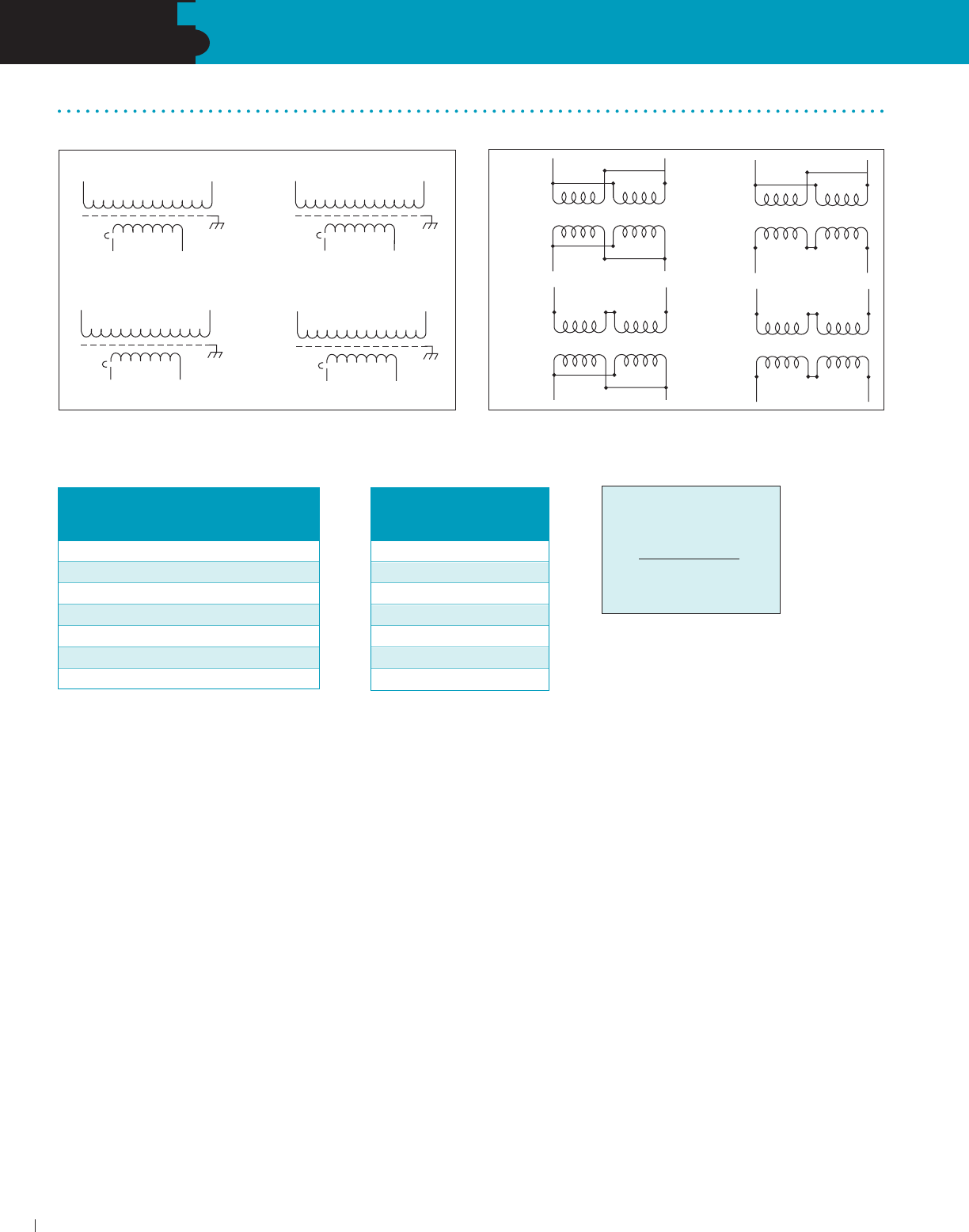
SECTION
LOW VOLTAGE LIGHTING TRANSFORMERS & POWER SUPPLIES
ACME ELECTRIC • MILWAUKEE, WI • 800.334.5214 • acmetransformer.com
86
6
SECTION
LOW VOLTAGE/ LIGHTING TRANSFORMERS
86
VOLTAGE DROP FORMULA
Total Watts on Cable
X Length of Run
Cable Size Constant
= Voltage Drop
GROUP VI
Low Voltage Lighting Wiring Diagrams
X1
H1
X2
120V
12V
H2
X1
H1
X2
120V
24V
H2
X1
H1
X2
240V
12V
H2
X1
H1
X2
240V
24V
H2
X1 X2 X3 X4
120V
INPUT
H4 H1
H3 H2
12V
OUTPUT
X1 X2 X3 X4
240V
INPUT
12V
OUTPUT
H1
H2H3H4
X1 X2 X3 X4
120V
INPUT
H4 H1
H3 H2
24V
OUTPUT
X1 X2 X3 X4
240V
INPUT
24V
OUTPUT
H1
H2H3H4
GROUP V
VOLTAGE DROP CHART
Voltage Life Expectancy % of Rated
at Lamp of Lamp Candlepower
13.2 2/3 Rated Life 350
12.6 3/4 Rated Life 180
12.0 As Rated 100
11.5 2X Rated Life 80
11.0 3X Rated Life 74
10.5 5X Rated Life 65
10.0 9X Rated Life 50
CABLE SIZE CONSTANT CHART
Cable Cable Size
Size Constant
#18 1380
#16 2200
#14 3500
#12 7500
#10 11,920
#8 18,960
#6 30,150

SECTION
A simple and economical way to
correct offstandard voltages...
from 95 to 500 volts; single and
three phase, in sizes up to 360 kVA.
Simplified buck-boost rating charts
make proper transformer selection
easy, accurate.
Description & Applications .................................88
Questions & Answers ................................... 89-93
Selection Charts – Single Phase .................. 94-96
Selection Charts – Three Phase ................... 97-99
Specifications .................................................. 100
Wiring Diagrams ....................................... 101-102
BUCK-BOOST
TRANSFORMERS
7
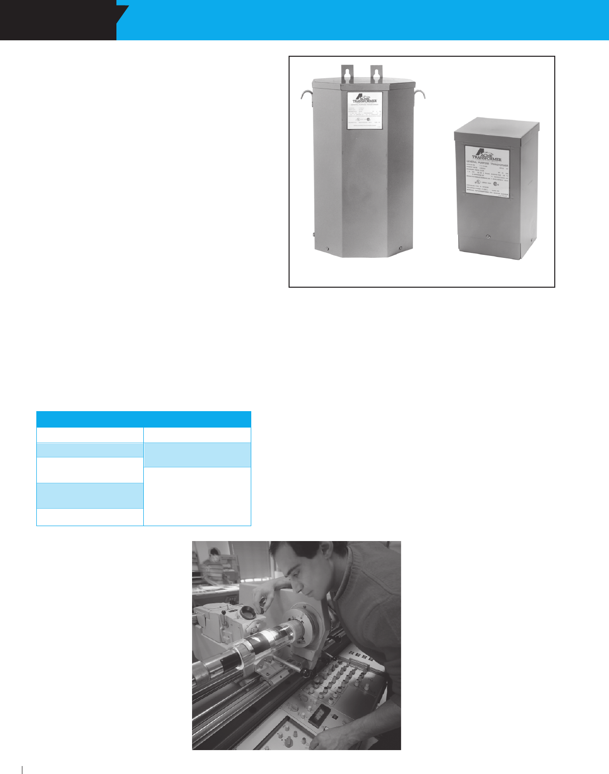
SECTION BUCK-BOOST TRANSFORMERS
ACME ELECTRIC • MILWAUKEE, WI • 800.334.5214 • acmetransformer.com
88
SECTION BUCK-BOOST TRANSFORMERS
7
88
Why Use Buck-Boost Instead of
Another Type Transformer ?
Take a look at the advantages and disadvantages of
using a buck-boost transformer (autotransformer)
compared to a standard isolation transformer of the
proper size and voltage combination.
As you can see, the advantages are many, the
economies great. Buck-boost transformers are
readily available from the stock of your nearest Power
Distribution Products Distributor.
A typical buck-boost application is 120 volts in, 12
volts out for low voltage lighting or control circuitry. In
most applications, this low voltage transformer is field
connected as an autotransformer. (See question 2 for the
definition of an autotransformer). Buck-boost transformers
provide tremendous capabilities and flexibility in kVA
sizes and input/output voltage combinations. Basically
you get 75 different transformers... all in one
convenient package.
Other buck-boost applications are, where (A) low supply
voltage exists because equipment is installed at the end
of a bus system; (B) the supply system is operating at or
over its design capacity; and (C) where overall consumer
demands may be so high the utility cuts back the supply
voltage to the consumer causing a “brownout.”
Where Are Buck-Boost
Transformers Used?
T211688 T111683
Proper Voltage Is Critical
With nearly two-thirds of all electrical loads being A.C. motor
loads, maintenance of the proper voltage to that motor is very
important. If the supply line voltage is not maintained, motor
winding current is increased causing reduced motor torque and
escalating motor temperature, all of which results in the rapid
loss of insulation life expectancy.
In addition to motor loads, the detrimental effects of low voltage
on both resistive heating loads and incandescent lighting
output is illustrated in the chart.
Anytime you have a lower than standard voltage, equipment
damage and failure can result.
Buck-boost transformers are an economical way to correct
this potentially very serious problem. Anytime a line voltage
change in the 5-20% range is required, a buck-boost
transformer should be considered as your first line of defense.
ADVANTAGES
More efficient
Smaller & lighter
5-10 times increase
in kVA
Versatile, many
applications
Lower cost
DISADVANTAGES
No circuit isolation
Cannot create a
neutral
Application voltages
and kVA don‘t match
the nameplate
voltages and kVA
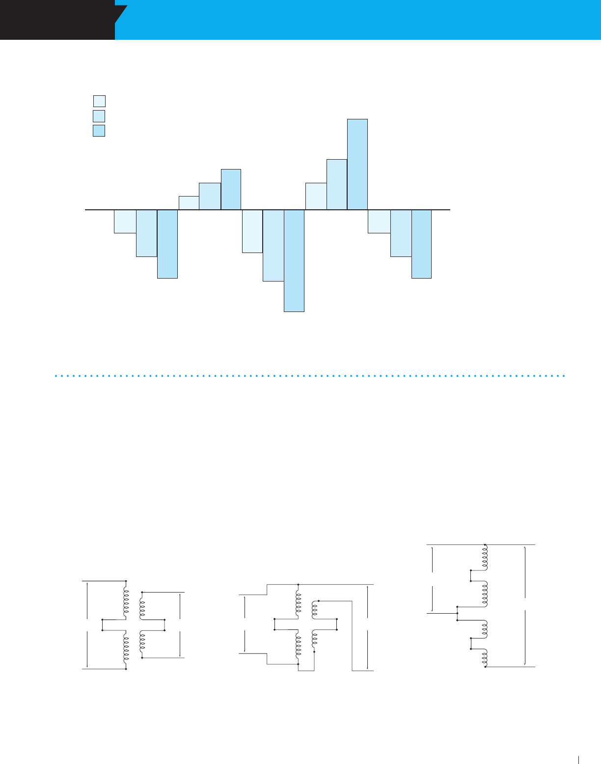
SECTION BUCK-BOOST TRANSFORMERS
ACME ELECTRIC • MILWAUKEE, WI • 800.334.5214 • acmetransformer.com
89
SECTION BUCK-BOOST TRANSFORMERS
7
89
1. What is a buck-boost transformer?
Buck-boost transformers are small single phase transformers
designed to reduce (buck) or raise (boost) line voltage from
5 -20%. The most common example is boosting 208 volts to
230 volts, usually to operate a 230 volt motor such as an air-
conditioner compressor, from a 208 volt supply line.
Buck-boosts are a standard type of single phase distribution
transformers, with primary voltages of 120, 240 or 480 volts
and secondaries typically of 12, 16, 24, 32 or 48 volts. They
are available in sizes ranging from 50 volt amperes to 10
kilo-volt amperes.
Buck-boost transformers are shipped ready to be connected
for a number of possible voltage combinations.
X1
X2
X3
X4
OUTPUT
H4
INPUT
H2
H3
H1
X1
X2
X3
X4
OUTPUT
H4
INPUT
H2
H3
H1 X1
X2
X3
X4
OUTPUT
H4
INPUT H2
H3
H1
Questions & Answers About Buck-Boost Transformers
How Low Voltage Affects Various
Equipment Operations and Functions
150%
140%
130%
120%
110%
100%
90%
80%
70%
60%
50%
901/2%
81%
72%
105%
111%
117%
84%
70%
57%
111%
123%
138%
901/2%
81%
72%
Increase of Motor
Temperature and
Corresponding Insulation Life
Expectancy Loss
Increase of Motor Winding
Current Requirements in
Induction Motor Loads
Decrease in Motor Torque
Output
Decrease of
Incandescent
Lighting Output
Decrease of Heat Output in
Resistive Heating Loads
= 5% Low Voltage
= 10% Low Voltage
= 15% Low Voltage
Figure 1. Buck-boost transformer connected as a
low voltage insulating transformer (primary and
secondary windings shown series connected).
Figure 2. Same buck-boost transformer connected
as a boosting autotransformer. The connection from
H1 to X4 “converted” the unit to an autotransformer.
Figure 3. Illustration No. 2 shown with the primary
and secondary windings “straightened”.
2. How does a buck-boost transformer differ from an
insulating transformer?
A buck-boost transformer IS an insulating type transformer
when it is shipped from the factory. When it is connected at
the job site, a lead wire on the primary is connected to a lead
wire on the secondary – thereby changing the transformer’s
electrical characteristics to those of an autotransformer. The
primary and secondary windings are no longer “insulated”
and secondary windings are no longer “insulated” and its kVA
capacity is greatly increased. Refer to figures 1, 2 and 3.
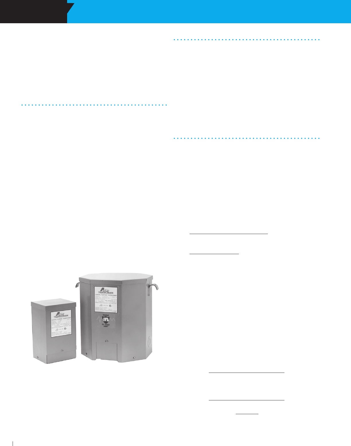
SECTION BUCK-BOOST TRANSFORMERS
ACME ELECTRIC • MILWAUKEE, WI • 800.334.5214 • acmetransformer.com
90
SECTION BUCK-BOOST TRANSFORMERS
7
90
Operation and Construction
7. Why do buck-boost transformers have 4
windings?
To make them versatile! A four winding buck-boost transformer
(2 primary and 2 secondary windings) can be connected
eight different ways to provide a multitude of voltage and kVA
outputs. A two winding (1 primary & 1 secondary) buck-boost
transformer can be connected only one way.
8. Will a buck-boost transformer
stabilize voltage?
No. The output voltage is a function of the input voltage. If the
input voltage varies, then the output voltage will also vary by
the same percentage.
Load Data
9. Are there any restrictions on the type
of load that can be operated from a
buck-boost transformer?
No, there are no restrictions.
10. Why can a buck-boost transformer
operate a kVA load many times larger than the
kVA rating on its nameplate?
Since the transformer has been auto-connected in such a
fashion that the 22V secondary voltage is added to the 208V
primary voltage, it produces 230V output.
The autotransformer kVA is calculated:
kVA = Output Volts x Secondary Amps
1000
kVA = 230 V x 41.67 Amps = 9.58 kVA
1000
3. What is the difference between a buck-
boost transformer and an autotransformer?
When a primary lead wire and secondary lead wire of a buck-
boost transformer are connected together electrically, in a
recommended voltage bucking or boosting connection, the
transformer is in all respects, an auto transformer. However,
if the inter connection between the primary and secondary
winding is not made, then the unit is an insulating type
transformer.
Applications
4. Why are they used?
Electrical and electronic equipment is designed to oper-
ate on standard supply voltage. When the supply voltage is
constantly too high or too low, (usually more than 55%), the
equipment fails to operate at maximum efficiency. A buck
and boost transformer is a simple and ECONOMICAL means
of correcting this off-standard voltage.
5. What are the most common applications
for buck-boost transformers?
Boosting 208V to 230V or 240V and vice versa for commer-
cial and industrial air conditioning systems; boosting 110V to
120V and 240V to 277V for lighting systems; voltage correc-
tion for heating systems and induction motors of all types.
Many applications exist where supply voltages are constantly
above or below normal.
6. Can buck-boost transformers be used to
power low voltage circuits?
Yes, low voltage control, lighting circuits, or other low voltage
applications requiring either 12V, 16V, 24V, 32V or 48V. The
unit is connected as an insulating transformer and the name-
plate kVA rating is the transformer’s capacity.
The picture to the left illustrates the difference in physical size between
the autotransformer of 1 kVA, capable of handling a 9.58 kVA load, and
an isolation transformer capable of handling a 7.5 kVA load.
To cite an example... a model T111683 buck-boost transformer has a
nameplate kVA rating of 1 kVA, but when it’s connected as an autotrans-
former boosting 208V to 230V, its kVA capacity increases to 9.58 kVA.
The key to understanding the operation of buck-boost transformers lies
in the fact that the secondary windings are the only parts of the trans-
former that do the work of transforming voltage and current. In the example
above, only 22 volts are being transformed (boosted) — i.e. 208V + 22V
= 230V. This 22V transformation is carried out by the secondary windings
which are designed to operate at a maximum current of 41.67 amps
(determined by wire size of windings).
Maximum Secondary Amps =
nameplate kVA x 1000
secondary volts
Maximum Secondary Amps =
1.0 kVA x 1000
24 V
1000 VA = 41.67 amps
24 V
(1 kVA) T111683 (7.5 kVA) T2535153S
=

SECTION BUCK-BOOST TRANSFORMERS
ACME ELECTRIC • MILWAUKEE, WI • 800.334.5214 • acmetransformer.com
91
SECTION BUCK-BOOST TRANSFORMERS
7
91
11. Can buck-boost transformers be used
on motor loads?
Yes, either single or three phase. Refer to the motor data
charts in Section I for determining kVA and Amps required by
NEMA standard motors.
12. How are single phase and three phase load
Amps and load kVA calculated?
Single phase Amps = kVA x 1000
Volts
Three phase Amps = kVA x 1000
Volts x 1.73
Single phase kVA = Volts x Amps
1000
Three phase kVA = Volts x Amps x 1.73
1000
Three-Phase
13. Can buck-boost transformers be used
on three-phase systems as well as single phase
systems?
Yes. A single unit is used to buck or boost single phase
voltage — two or three units are used to buck or boost three
phase voltage. The number of units to be used in a three -
phase installation depends on the number of wires in the
supply line. If the three-phase supply is 4 wire Y, use three
buck-boost transformers. If the 3-phase supply is 3 wire Y
(neutral not available), use two buck-boost transformers.
Refer to three-phase selection charts.
14. Should buck-boost transformers be used
to develop a three-phase 4 wire Y circuit from a
three-phase 3 wire delta circuit?
No. A three phase “wye” buck-boost transformer connection
should be used only on a 4 wire source of supply. A delta to
wye connection does not provide adequate current capacity to
accommodate unbalanced currents flowing in the neutral wire
of the 4 wire circuit.
15. Why isn’t a closed delta buck-boost
connection recommended?
A closed delta buck-boost auto transformer connection
requires more transformer kVA than a “wye” or open delta
connection and phase shifting occurs on the output.
Consequently the closed delta connection is more
expensive and electrically inferior to other three-phase
connections.
Connection and Frequency
16. How does the installer or user know how
to connect a buck-boost transformer?
The connection chart packed with each unit shows how to
make the appropriate connections. These same connection
charts are also shown in this section (page 118).
17. Can 60 Hertz buck-boost transformers
be used on a 50 Hertz service?
No. Acme buck-boost transformers should be operated only at
the frequencies recommended. However, units recommended
for 50 cycle operation are suitable for 60 cycle operation but
not vice versa.
Selection
18. How do you select a buck-boost
transformer?
Refer to the selection steps on page 101 for easy 4-step
selection, then go to the charts. Also, pages 12 and 13 are
helpful for determining buck-boost kVA when only the H.P.
rating of a motor is available.
Nameplate Data
19. Why are buck-boost transformers
shipped from the factory as insulating
transformers and not preconnected at the factory
as autotransformers?
A four winding buck-boost transformer can be auto connected
eight different ways to provide a multitude of voltage and
kVA output combinations. The proper transformer connection
depends on the user’s supply voltage, load voltage and load
kVA. Consequently, it is more feasible for the manufacturer to
ship the unit as an insulating transformer and allow the user
to connect it on the job site in accordance with the available
supply voltage and requirements of his load.
20. Why is the isolation transformer kVA
rating shown on the nameplate instead of the
autotransformer kVA rating?
The kVA rating of a buck-boost transformer when auto
connected depends on the amount of voltage buck or boost.
Since the amount of voltage buck or boost is different for
each connection, it is physically impossible to show all of the
various voltage combinations and attainable kVA ratings on the
nameplate. A connection chart showing the various attainable
single phase and three-phase connections is packed with
each unit.
Safety
21. Do buck-boost transformers present a safety
hazard usually associated with autotransformers?
No. Most autotransformers, if they are not of the buck-boost
variety, change voltage from one voltage class to another.
(Example 480V to 240V) In a system where one line is
grounded, the user thinks he has 240V; yet due to the primary
and secondary being tied together, it is possible to have 480V
to ground from the 240V output. A buck-boost transformer only
changes the voltage a small amount, such as 208V to 240V.
This small increase does not represent a safety hazard, as
compared to a buck of 480V to 240V. Refer to Figure on the
following page.
3 PHASE CONNECTIONS
INPUT
(SUPPLY SYSTEM)
DELTA
3 wire
OPEN DELTA
3 wire
WYE
3 or 4 wire
WYE
4 wire
WYE
3 or 4 wire
CLOSED DELTA
3 wire
DESIRED OUTPUT
CONNECTION
WYE
3 or 4 wire
WYE
3 or 4 wire
CLOSED DELTA
3 wire
WYE
3 or 4 wire
OPEN DELTA
3 wire
OPEN DELTA
3 wire
DO NOT USE
DO NOT USE
DO NOT USE
OK
OK
OK

SECTION BUCK-BOOST TRANSFORMERS
ACME ELECTRIC • MILWAUKEE, WI • 800.334.5214 • acmetransformer.com
92
SECTION BUCK-BOOST TRANSFORMERS
7
92
Sound Levels
22. Are buck-boost transformers as quiet as
standard isolation transformers?
Yes. However, an auto-connected buck-boost transformer will
be quieter than an isolation transformer capable of handling
the same load. The isolation transformer would have to be
physically larger than the buck-boost transformer, and small
transformers are quieter than larger ones. (Example) 1 kVA —
40 db; 75 kVA — 50 db. (db is a unit of sound measure).
Cost and Life Expectancy
23. How does the cost of a buck-boost
transformer compare to that of an insulating
transformer — both capable of handling the same
load?
For the most common buck-boost applications, the dollar
savings are generally greater than 75% compared to the use
of an insulating type distribution transformer for the same
application.
24. What is the life expectancy of a buck
boost transformer?
The life expectancy of a buck-boost transformer is the same
as the life expectancy of other dry type transformers.
National Electrical Code
25. Your catalog indicates that a buck-boost
transformer is suitable for connecting as an
AUTOTRANS-FORMER. What is the definition of
an autotransformer and how does it differ from an
isolation transformer?
An autotransformer is a transformer in which the primary
(input) and the secondary (output) are electrically connected
to each other. An isolation transformer, also known as an
insulating transformer, has complete electrical separation
between the primary (input) and the secondary (output). This
is illustrated in the drawing below.
An autotransformer changes or transforms only a portion of
the electrical energy it transmits. The rest of the electrical
energy flows directly through the electrical connections
between the primary and secondary. An isolation transformer
(insulating transformer) changes or transforms all of the
electrical energy it transmits.
Consequently, an autotransformer is smaller, lighter in weight,
and less costly than a comparable kVA size insulating
transformer.
Please refer to Question 27 for additional information on auto-
transformers.
Buck-boost transformers are frequently field-connected as
auto transformers.
26. Buck-boost transformers are almost
always installed as auto-transformers. Does the
N.E.C. (National Electrical Code) permit
the use of autotransformers?
Yes. Please refer to N.E.C. Article 450-4, “Autotransformers
600 Volts, Nominal, or Less.” Item (a) explains how to
overcurrent protect an autotransformer; item (b) explains that
an insulating transformer such as a buck-boost transformer
may be field connected as an autotransformer.
27. When a buck-boost transformer is
connected as an autotransformer such as
boosting 208V to 230V, the kVA is greatly
increased. What is the procedure for determining
the size (ampere rating) of the overcurrent
protective device such as a fuse or circuit
breaker?
The National Electrical Code Article 450-4 addresses
overcurrent protection of autotransformers. A copy is
reproduced below for easy reference.
450-4. Autotransformers 600 Volts, Nominal, or Less.
(a) Overcurrent Protection. Each autotransformer 600
volts, nominal, or less shall be protected by an individual
overcurrent device installed in series with each ungrounded
input conductor. Such overcurrent device shall be rated or
set at not more than 125 percent of the rated full-load input
current of the autotransformer. An overcurrent device shall
not be installed in series with the shunt winding (the winding
common to both the input and the output circuits) of the
autotransformer between Points A and B as shown in Diagram
450-4.
400 VOLTS
LINE TO GROUND
(POTENTIAL SAFETY
HAZARD)
480V
INPUT
240V OUTPUT
LINE TO LINE
PRIMARY
(INPUT)
PRIMARY
(INPUT)
SECONDARY
(OUTPUT)
SECONDARY
(OUTPUT)
AUTOTRANSFORMER
ISOLATION
TRANSFORMER
(ALSO CALLED
“INSULATING TRANSFORMER”)
SHUNT WINDING(S)
B
A
Diagram 450-4

SECTION BUCK-BOOST TRANSFORMERS
ACME ELECTRIC • MILWAUKEE, WI • 800.334.5214 • acmetransformer.com
93
SECTION BUCK-BOOST TRANSFORMERS
7
93
Exception: Where the rated input current of an
autotransformer is 9 am peres or more and 125 percent of this
current does not correspond to a standard rating of a fuse or
non-adjustable circuit breaker, the next higher standard
rating described in Section 240-6 shall be permitted. When
the rated input current is less than 9 amperes, an overcurrent
device rated or set at not more than 167 percent of the input
current shall be permitted.
(b) Transformer Field-Connected as an Autotransformer.
A transformer field-connected as an autotransformer shall
be identified for use at elevated voltage.
28. I have noted the reprint of the N.E.C.
(National Electrical Code), Article 450-4 shown in
the previous question covering autotransformer
overcurrent protection. Could you explain this
article in detail by citing an example?
An example of an everyday application is always a good
way to explain the intent of the “Code.” Example: A 1 kVA
transformer Catalog No. T111683 has a primary of 120 x
240V and a secondary of 12 x 24V. It is to be connected as an
autotransformer at the time of installation to raise 208V to
230V single phase.
When this 1 kVA unit is connected as an autotransformer for
this voltage combination, its kVA rating is increased to 9.58 kVA
(may also be expressed as 9,580 VA). This is the rating to
be used for determining the full load input amps and the
sizing of the overcurrent protect device (fuse or breaker) on
the input.
Full Load Input Amps =
9,580 Volt Amps = 46 Amps
208 Volts
When the full load current is greater than 9 amps, the
overcurrent protective device (usually a fuse or non-
adjustable breaker) amp rating can be up to 125 percent of
the full load rating of the autotransformer input amps.
Max. amp rating of the
overcurrent device
= 46 amps x 125% = 57.5 amps
The National Electrical Code, Article 450-4 (a) Exception,
permits the use of the next higher standard ampere rating of
the overcurrent device. This is shown in Article 240-6 of the
N.E.C.
Max. size of the fuse or circuit breaker
= 60 amps
You should have the following information before selecting
a buck-boost transformer.
Line Voltage — The voltage that you want to buck (decrease)
or boost (increase). This can be found by measuring the
supply line voltage with a voltmeter.
Load Voltage — The voltage at which your equipment is
designed to operate. This is listed on the nameplate of the
load equipment.
Load kVA or Load Amps — You do not need to know both
— one or the other is sufficient for selection purposes. This
information usually can be found on the nameplate of the
equipment that you want to operate.
Frequency — The supply line frequency must be the same as
the frequency of the equipment to be operated — either 50 or
60 cycles.
Phase — The supply line should be the same as the
equipment to be operated — either single or three phase.
Steps for Selecting the Proper Buck-Boost Transformer
Four Step Selection
1. A series of LINE VOLTAGE and LOAD
VOLTAGE combinations are listed across the top of
each selection chart. Select a LINE VOLTAGE and LOAD
VOLTAGE combination from ANY of the charts that comes
closest to matching the LINE VOLTAGE and LOAD
VOLTAGE of your application.
2. Read down the column you have selected until you reach
either the LOAD kVA or LOAD AMPS of the equipment you
want to operate. You probably will not find the exact value of
LOAD kVA or LOAD AMPS so go to the next higher rating.
3. From this point, read across the column to the far left-
hand side and you have found the catalog number of
the exact buck-boost transformer you need. Refer to the
catalog number listing on page 103 for dimensions.
4. CONNECT the transformer according to the connection
diagram specified at the bottom of the column where you
selected YOUR LINE VOLTAGE and LOAD VOLTAGE
combination. Connection diagrams are found at the end of
this section.
This same connection information is packed with each
buck-boost transformer.

SECTION BUCK-BOOST TRANSFORMERS
ACME ELECTRIC • MILWAUKEE, WI • 800.334.5214 • acmetransformer.com
94
SECTION BUCK-BOOST TRANSFORMERS
7
94
See chart on page 101, for number of leads per termination.
NOTE: Inputs and Outputs may be re versed; kVA capacity remains constant. All applications above bold face line are suitable for 50/60 Hz. All applications below bold
face line are suitable for 60 Hz only.
With larger kVA buck-boost units, it is necessary to utilize multiple conductors on the secondary (X) terminals as shown in the chart on page 101.
GROUP I
SELECTION CHARTS
SINGLE PHASE
SINGLE PHASE BOOSTING
Line Voltage 95 100 105 110 189 208 215 220
(Available)
Load Voltage 114 120 115 120 208 230 237 242
(Output)
CAT. NO.
Load kVA 0.24 0.25 0.48 0.50 0.43 0.48 0.49 0.50
T181047 Amps 2.08 2.08 4.17 4.17 2.08 2.08 2.08 2.08
Max. Size of 6 6 10 10 6 6 6 6
Fuse or Breaker
Load kVA 0.47 0.50 0.96 1.01 0.87 0.96 0.99 1.01
T181048 Amps 4.17 4.17 8.33 8.33 4.17 4.17 4.17 4.17
Max. Size of 10 10 15 15 10 10 10 10
Fuse or Breaker
Load kVA 0.71 0.75 1.43 1.51 1.30 1.43 1.48 1.51
T181049 Amps 6.25 6.25 12.50 12.50 6.25 6.25 6.25 6.25
Max. Size of 15 15 20 20 15 15 15 15
Fuse or Breaker
Load kVA 1.19 1.25 2.40 2.50 2.16 2.39 2.46 2.52
T181050 Amps 10.42 10.40 20.80 20.80 10.40 10.40 10.40 10.40
Max. Size of 25 25 40 30 15 15 15 15
Fuse or Breaker
Load kVA 2.37 2.50 4.80 5.00 4.33 4.79 4.93 5.04
T181051 Amps 20.83 20.83 41.67 41.67 20.83 20.83 20.83 20.83
Max. Size of 35 35 60 60 30 30 30 30
Fuse or Breaker
Load kVA 3.56 3.75 7.17 7.56 6.50 7.19 7.41 7.56
T181052 Amps 31.25 31.25 62.50 62.50 31.25 31.25 31.25 31.25
Max. Size of 50 50 90 90 45 45 45 45
Fuse or Breaker
Load kVA 4.75 5.00 9.58 10.00 8.66 9.58 9.87 10.00
T111683 Amps 41.67 41.67 83.31 83.31 41.67 41.67 41.67 41.67
Max. Size of 70 70 125 125 60 60 60 60
Fuse or Breaker
Load kVA 7.12 7.50 14.40 15.10 13.00 14.30 14.80 15.10
T111684 Amps 62.50 62.50 125.00 125.00 62.50 62.50 62.50 62.50
Max. Size of 100 100 175 175 90 90 90 90
Fuse or Breaker
Load kVA 9.50 10.00 19.20 20.20 17.30 19.16 19.70 20.10
T111685 Amps 83.30 83.30 166.60 166.60 83.30 83.30 83.30 83.30
Max. Size of 125 125 250 250 125 125 125 125
Fuse or Breaker
Load kVA 14.20 15.00 28.80 30.00 26.00 28.70 29.60 30.30
T111686 Amps 125.00 125.00 250.00 250.00 125.00 125.00 125.00 125.00
Max. Size of 200 200 350 350 175 175 175 175
Fuse or Breaker
Load kVA 23.70 25.00 47.90 50.00 43.30 47.80 49.30 50.30
T111687 Amps 208.00 208.00 416.60 416.60 208.00 208.00 208.00 208.00
Max. Size of 350 350 600 600 300 300 300 300
Fuse or Breaker
Load kVA 35.60 37.50 71.90 75.60 65.00 71.80 74.00 75.60
T211688 Amps 312.50 312.50 625.00 625.00 312.50 312.50 312.50 312.50
Max. Size of 500 500 1000 1000 450 450 450 450
Fuse or Breaker
Load kVA 47.50 50.00 95.80 100.00 86.60 95.80 98.70 101.00
T211689 Amps 416.60 416.60 833.30 833.30 416.60 416.60 416.60 416.60
Max. Size of 700 700 1200 1200 600 600 600 600
Fuse or Breaker
See Page 110 For Connection Diagrams D D C C H H H H
BUCKING
125 132 230 245 250 252
113 120 208 222 227 240
0.52 0.54 0.47 0.50 0.52 1.02
4.60 4.60 2.28 2.28 2.28 4.37
10 10 6 6 6 10
1.04 1.08 0.95 1.00 1.04 2.04
9.20 9.20 4.56 4.56 4.58 8.75
15 15 10 10 10 15
1.56 1.62 1.42 1.50 1.56 3.00
13.80 13.80 6.86 6.86 6.86 13.10
20 20 15 15 15 15
2.60 2.75 2.37 2.50 2.60 5.10
22.80 22.80 11.40 11.40 11.40 21.80
30 30 15 15 15 30
5.20 5.40 4.47 5.00 5.20 10.20
46.80 46.80 22.80 22.80 22.80 43.70
60 60 30 30 30 60
7.80 8.15 7.10 7.50 7.80 15.30
68.50 69.50 34.40 34.40 34.40 65.50
80 80 40 40 40 80
10.40 10.80 9.50 10.00 10.00 20.40
91.50 91.50 45.80 45.80 45.80 87.50
110 110 60 60 50 110
15.00 16.20 14.24 15.00 15.60 30.60
138.00 138.00 68.60 68.60 68.60 132.00
150 175 80 80 80 175
20.80 21.60 19.00 20.00 20.30 40.80
183.00 183.00 91.60 91.60 91.20 175.00
225 225 110 110 110 225
31.20 32.50 28.50 30.00 31.20 61.00
275.00 275.00 136.80 136.80 136.80 263.00
350 350 175 175 175 350
52.00 54.00 47.40 50.00 52.00 102.00
457.00 457.00 228.00 228.00 228.00 437.00
600 600 300 300 300 600
78.00 81.00 71.00 76.00 78.00 153.00
688.00 688.00 344.00 344.00 344.00 655.00
800 800 400 400 400 800
104.00 108.00 95.00 100.00 104.00 204.00
915.00 915.00 458.00 458.00 458.00 875.00
1200 1200 600 600 600 1200
F F I I I E

SECTION BUCK-BOOST TRANSFORMERS
ACME ELECTRIC • MILWAUKEE, WI • 800.334.5214 • acmetransformer.com
95
SECTION BUCK-BOOST TRANSFORMERS
7
95
See chart on page 101.
NOTE: Inputs and Outputs may be re versed; kVA capacity remains constant. All applications above bold face line are suitable for 50/60 Hz. All applications below
bold face line are suitable for 60 Hz only.
With larger kVA buck-boost units, it is necessary to utilize multiple conductors on the secondary (X) terminals as shown in the chart on page 101.
GROUP II
SINGLE PHASE BOOSTING
Line Voltage 95 100 105 208 215 215 220 225
(Available)
Load Voltage 120 114 119 240 244 230 235 240
(Output)
CAT. NO.
Load kVA 0.19 0.36 0.37 0.38 0.38 0.72 0.73 0.75
T181054 Amps 1.56 3.13 3.13 1.56 1.56 3.13 3.13 3.13
Max. Size of 6 6 6 6 6 6 6 6
Fuse or Breaker
Load kVA 0.38 0.71 0.74 0.75 0.76 1.44 1.47 1.50
T181055 Amps 3.13 6.25 6.25 3.13 3.13 6.25 6.25 6.25
Max. Size of 10 15 6 6 15 15 15 15
Fuse or Breaker
Load kVA 0.56 1.07 1.12 1.13 1.14 2.16 2.20 2.25
T181056 Amps 4.69 9.38 9.38 4.69 4.69 9.38 9.38 9.38
Max. Size of 10 15 15 10 10 15 15 15
Fuse or Breaker
Load kVA 0.94 1.78 1.86 1.88 1.91 3.59 3.67 3.75
T181057 Amps 7.81 15.63 15.63 7.81 7.81 15.63 15.63 15.63
Max. Size of 15 25 25 15 15 25 25 25
Fuse or Breaker
Load kVA 1.88 3.56 3.72 3.75 3.81 7.19 7.34 7.50
T181058 Amps 15.63 31.25 31.25 15.63 15.63 31.25 31.25 31.25
Max. Size of 25 45 45 25 25 45 45 45
Fuse or Breaker
Load kVA 2.81 5.34 5.58 5.63 5.72 10.78 11.02 11.25
T181059 Amps 23.44 46.88 46.88 23.44 23.44 46.88 46.88 46.88
Max. Size of 40 70 70 40 40 70 70 70
Fuse or Breaker
Load kVA 3.75 7.13 7.44 7.50 7.63 14.38 14.69 15.00
T113073 Amps 31.25 62.50 62.50 31.25 31.25 62.50 62.50 62.50
Max. Size of 50 90 90 50 50 90 90 90
Fuse or Breaker
Load kVA 5.63 10.69 11.16 11.25 11.44 21.56 22.03 22.50
T113074 Amps 46.90 93.80 93.80 46.90 46.90 93.80 93.80 93.80
Max. Size of 80 150 150 70 70 125 125 125
Fuse or Breaker
Load kVA 7.50 14.25 14.88 15.00 15.25 28.75 29.38 30.00
T113075 Amps 62.50 125.00 125.00 62.50 62.50 125.00 125.00 125.00
Max. Size of 100 200 200 90 90 175 175 175
Fuse or Breaker
Load kVA 11.25 21.38 22.31 22.50 22.88 43.13 44.06 45.00
T113076 Amps 93.80 187.50 187.50 93.80 93.80 187.50 187.50 187.50
Max. Size of 150 300 300 150 150 250 250 250
Fuse or Breaker
Load kVA 18.75 35.63 37.19 37.50 38.13 71.88 73.44 75.00
T113077 Amps 156.30 312.50 312.50 156.30 156.30 312.50 312.50 312.50
Max. Size of 250 450 450 225 225 450 450 450
Fuse or Breaker
Load kVA 28.10 53.40 55.80 56.30 57.20 107.80 110.20 112.50
T213078 Amps 234.40 468.80 468.80 234.40 234.40 468.80 468.80 468.80
Max. Size of 400 700 700 350 350 700 700 700
Fuse or Breaker
Load kVA 37.50 71.30 74.40 75.00 76.30 143.80 146.90 150.00
T213079 Amps 312.50 625.00 625.00 312.50 312.50 625.00 625.00 625.00
Max. Size of 500 1000 1000 450 450 1000 1000 1000
Fuse or Breaker
See Page 110 For D C C H H G G G
Connection Diagrams
BUCKING
135 240 240 245 250 255
119 208 225 230 234 239
0.42 0.37 0.75 0.77 0.78 0.80
3.54 1.77 3.33 3.33 3.33 3.33
6 3 6 6 6 6
0.84 0.74 1.50 1.53 1.56 1.59
7.08 3.54 6.67 6.67 6.67 6.67
15 6 15 15 15 15
1.26 1.11 2.25 2.30 2.34 2.39
10.63 5.31 10.00 10.00 10.00 10.00
15 6 15 15 15 15
2.11 1.84 3.75 3.83 3.90 3.98
17.71 8.85 16.67 16.67 16.67 16.67
20 15 20 20 20 20
4.21 3.68 7.50 7.67 7.80 7.97
35.42 17.71 33.33 33.33 33.33 33.33
40 20 40 40 40 40
6.32 5.53 11.25 11.50 11.70 11.95
53.13 26.56 50.00 50.00 50.00 50.00
60 30 60 60 60 60
8.43 7.37 15.00 15.33 15.60 15.93
70.83 35.42 66.67 66.67 66.67 66.67
80 40 80 80 80 80
12.64 11.05 22.50 23.00 23.40 23.90
106.30 53.10 100.00 100.00 100.00 100.00
125 60 125 125 125 125
16.86 14.73 30.00 30.67 31.20 31.87
141.70 70.80 133.30 133.30 133.30 133.30
175 80 175 175 175 175
25.29 22.10 45.00 46.00 46.80 47.80
212.50 106.30 200.00 200.00 200.00 200.00
250 125 250 250 250 250
42.15 36.83 75.00 76.67 78.00 79.67
354.20 177.10 333.30 333.30 333.30 333.30
400 200 400 400 400 400
63.20 55.30 112.50 115.00 117.00 119.50
531.30 265.60 500.00 500.00 500.00 500.00
600 300 600 600 600 600
84.30 73.70 150.00 153.30 156.00 159.30
708.30 354.20 666.70 666.70 666.70 666.70
800 400 800 800 800 800
F I E E E E

SECTION BUCK-BOOST TRANSFORMERS
ACME ELECTRIC • MILWAUKEE, WI • 800.334.5214 • acmetransformer.com
96
SECTION BUCK-BOOST TRANSFORMERS
7
96
See chart on page 101.
NOTE: Inputs and Outputs may be re versed; kVA capacity remains constant. All applications above bold face line are suitable for 50/60 Hz. All applications
below bold face line are suitable for 60 Hz only.
GROUP III
SINGLE PHASE BOOSTING
Line Voltage 230 380 416 425 430 435 440 440 450 460
(Available)
Load Voltage 277 420 457 467 473 457 462 484 472 483
(Output)
CAT. NO.
Load kVA 0.29 0.44 0.48 0.49 0.49 0.95 0.96 0.50 0.98 1.01
T181061 Amps 1.04 1.04 1.04 1.04 1.04 2.08 2.08 1.04 2.08 2.08
Max. Size of 3 3 3 3 3 6 6 3 6 6
Fuse or Breaker
Load kVA 0.58 0.87 0.95 0.97 0.99 1.90 1.93 1.01 1.97 2.01
T181062 Amps 2.08 2.08 2.08 2.08 2.08 4.17 4.17 2.08 4.17 4.17
Max. Size of 6 6 6 6 6 10 10 6 10 10
Fuse or Breaker
Load kVA 0.87 1.31 1.43 1.46 1.48 2.86 2.89 1.51 2.95 3.02
T181063 Amps 3.13 3.13 3.13 3.13 3.13 6.25 6.25 3.13 6.25 6.25
Max. Size of 10 6 6 6 6 15 15 6 15 15
Fuse or Breaker
Load kVA 1.44 2.19 2.38 2.43 2.46 4.76 4.81 2.52 4.92 5.03
T181064 Amps 5.21 5.21 5.21 5.21 5.21 5.21 10.42 5.21 10.42 10.42
Max. Size of 15 10 10 10 10 15 15 10 15 15
Fuse or Breaker
Load kVA 2.89 4.38 4.76 4.86 4.93 9.52 9.62 5.04 9.83 10.06
T181065 Amps 10.42 10.42 10.42 10.42 10.42 20.83 20.83 10.42 20.83 20.83
Max. Size of 20 15 15 15 15 30 30 15 30 30
Fuse or Breaker
Load kVA 4.33 6.56 7.14 7.30 7.39 14.28 14.44 7.56 14.75 15.09
T181066 Amps 15.63 15.63 15.63 15.63 15.63 31.25 31.25 15.63 31.25 31.25
Max. Size of 25 25 25 25 25 45 45 25 45 45
Fuse or Breaker
Load kVA 5.77 8.57 9.52 9.73 9.85 19.04 19.25 10.08 19.67 20.13
T137920 Amps 20.83 20.83 20.83 20.83 20.83 41.67 41.67 20.83 41.67 41.67
Max. Size of 35 30 30 30 30 60 60 30 60 60
Fuse or Breaker
Load kVA 8.66 13.13 14.28 14.59 14.78 28.56 28.88 15.13 29.50 30.19
T137921 Amps 31.25 31.25 31.25 31.25 31.25 62.50 62.50 31.25 62.50 62.50
Max. Size of 50 50 45 45 45 90 90 45 90 90
Fuse or Breaker
Load kVA 11.54 17.50 19.04 19.46 19.71 38.08 38.50 20.17 39.33 40.25
T137922 Amps 41.67 41.67 41.67 41.67 41.67 83.33 83.33 41.67 83.33 83.33
Max. Size of 70 60 60 60 60 110 110 60 110 110
Fuse or Breaker
Load kVA 17.31 26.25 28.56 29.19 29.56 57.13 57.75 30.25 59.00 60.38
T137923 Amps 62.50 62.50 62.50 62.50 62.50 125.00 125.00 62.50 125.00 125.00
Max. Size of 100 90 90 90 90 175 175 90 175 175
Fuse or Breaker
Load kVA 28.90 43.80 47.60 48.60 49.30 95.20 96.20 50.40 98.30 100.60
T137924 Amps 104.20 104.20 104.20 104.20 104.20 208.30 208.30 104.20 208.30 208.30
Max. Size of 175 150 150 150 150 300 300 150 300 300
Fuse or Breaker
Load kVA 43.30 65.60 71.40 73.00 73.90 142.80 144.40 75.60 147.50 150.90
T243570 Amps 156.30 156.30 156.30 156.30 156.30 312.50 312.50 156.30 312.50 312.50
Max. Size of 250 225 225 225 225 450 450 225 450 450
Fuse or Breaker
Load kVA 57.70 87.50 95.20 97.30 98.50 190.40 192.50 100.80 196.70 201.30
T243571 Amps 208.30 208.30 208.30 208.30 208.30 416.70 416.70 208.30 416.70 416.70
Max. Size of 350 300 300 300 300 600 600 300 600 600
Fuse or Breaker
See Page 110 For D H H H H G G H G G
Connection Diagrams
BUCKING
277 480 480 504
230 436 456 480
0.29 0.50 1.05 1.10
1.25 1.15 2.29 2.29
3 3 6 6
0.58 1.00 2.09 2.20
2.50 2.29 4.58 4.58
6 6 10 10
0.86 1.50 3.14 3.30
3.75 3.44 6.88 6.88
6 6 15 15
1.44 2.50 5.23 5.50
6.25 5.73 11.46 11.46
10 10 15 15
2.88 5.00 10.45 11.00
12.50 11.46 22.92 22.92
15 15 30 30
4.31 7.49 15.68 16.50
18.75 17.19 34.38 34.38
20 20 45 45
5.75 9.99 20.90 22.00
25.00 22.92 45.83 45.83
30 30 60 60
8.63 14.99 31.35 33.00
37.50 34.38 68.75 68.75
40 40 90 90
11.50 19.98 41.80 44.00
50.00 45.83 91.67 91.67
60 60 110 110
17.25 29.98 62.70 66.00
75.00 68.80 137.50 137.50
80 80 175 175
28.80 50.00 104.50 110.00
125.00 114.60 229.20 229.20
150 150 300 300
43.10 74.90 156.80 165.00
187.50 171.90 343.80 343.80
200 200 450 450
57.50 99.90 209.00 220.00
250.00 229.20 458.30 458.30
300 300 600 600
J I E E
SECTION BUCK-BOOST TRANSFORMERS
ACME ELECTRIC • MILWAUKEE, WI • 800.334.5214 • acmetransformer.com
97
SECTION BUCK-BOOST TRANSFORMERS
7
97
See chart on page 101.
GROUP I
SELECTION CHARTS
THREE PHASE
THREE PHASE BOOSTING
Line Voltage 189Y 196Y 201Y 208Y 189 208 220
(Available) 109Y 113Y 116Y 120Y
Load Voltage 208 234 240 230 208 230 242
(Output)
CAT. NO.
Load kVA 1.50 0.84 0.87 1.66 0.75 0.83 0.87
T181047 Amps 4.17 2.08 2.08 4.17 2.08 2.08 2.08
Max. Size of
10 6 6 10 6 6 6
Fuse or Breaker
Load kVA 3.00 1.69 1.73 3.32 1.50 1.66 1.75
T181048 Amps 8.33 4.17 4.17 8.33 4.17 4.17 4.17
Max. Size of
15 10 10 15 10 10 10
Fuse or Breaker
Load kVA 4.50 2.53 2.60 4.98 2.25 2.49 2.62
T181049 Amps 12.50 6.25 6.25 12.50 6.25 6.25 6.25
Max. Size of
20 15 15 20 15 15 15
Fuse or Breaker
Load kVA 7.51 4.22 4.33 8.30 3.75 4.15 4.37
T181050 Amps 20.83 10.42 10.42 20.83 10.42 10.42 10.42
Max. Size of
30 20 20 30 15 15 15
Fuse or Breaker
Load kVA 15.01 8.44 8.66 16.60 7.51 8.30 8.73
T181051 Amps 41.67 20.83 20.83 41.67 20.83 20.83 20.83
Max. Size of
60 35 35 60 30 30 30
Fuse or Breaker
Load kVA 22.52 12.67 12.99 24.90 11.26 12.45 13.10
T181052 Amps 62.50 31.25 31.25 62.50 31.25 31.25 31.25
Max. Size of
90 50 50 90 45 45 45
Fuse or Breaker
Load kVA 30.02 16.89 17.32 33.20 15.01 16.60 17.46
T111683 Amps 83.33 41.67 41.67 83.33 41.67 41.67 41.67
Max. Size of
125 70 70 125 60 60 60
Fuse or Breaker
Load kVA 45.03 25.33 25.98 49.80 22.52 24.90 26.20
T111684 Amps 125.00 62.50 62.50 125.00 62.50 62.50 62.50
Max. Size of
175 100 100 175 90 90 90
Fuse or Breaker
Load kVA 60.04 33.77 34.64 66.40 30.02 33.20 34.93
T111685 Amps 166.67 83.33 83.33 167.67 83.33 83.33 83.33
Max. Size of
250 125 125 250 125 125 125
Fuse or Breaker
Load kVA 90.07 50.66 51.96 99.59 45.03 49.80 52.39
T111686 Amps 250.00 125.00 125.00 250.00 125.00 125.00 125.00
Max. Size of
350 200 200 350 175 175 175
Fuse or Breaker
Load kVA 150.11 84.44 86.60 165.99 75.06 82.99 87.32
T111687 Amps 416.67 208.33 208.33 416.67 208.33 208.33 208.33
Max. Size of
600 350 350 600 300 300 300
Fuse or Breaker
Load kVA 225.17 126.66 129.90 248.98 112.58 124.49 130.99
T211688 Amps 625.00 312.50 312.50 625.00 312.50 312.50 312.50
Max. Size of
1000 500 500 1000 450 450 450
Fuse or Breaker
Load kVA 300.22 168.87 173.21 331.98 150.11 165.99 174.65
T211689 Amps 833.33 416.67 416.67 833.33 416.67 416.67 416.67
Max. Size of
1200 700 700 1200 600 600 600
Fuse or Breaker
Quantity Required 3 3 3 3 2 2 2
See Page 102 For A-A F-F F-F A-A B-B B-B B-B
Connection Diagrams
BUCKING
219 230 250 255 264
208 208 227 232 240
1.58 0.83 0.90 0.92 0.95
4.39 2.30 2.29 2.29 2.29
10 6 6 6 6
3.16 1.66 1.80 1.84 1.91
8.77 4.61 4.59 4.58 4.58
15 10 10 10 10
4.74 2.49 2.71 2.76 2.86
13.16 6.91 6.88 6.87 6.88
20 15 15 15 15
7.90 4.15 4.51 4.60 4.76
21.94 11.52 11.47 11.45 11.46
30 15 15 15 15
15.80 8.30 9.02 9.20 9.53
43.87 23.04 22.94 22.90 22.92
60 30 30 30 30
23.71 12.45 13.53 13.80 14.29
65.81 34.56 34.42 34.35 34.38
80 40 40 40 40
31.61 16.60 18.04 18.40 19.05
87.74 46.07 45.89 45.80 45.83
110 60 60 60 60
47.41 24.90 27.06 27.60 28.58
131.61 69.11 68.83 68.70 68.75
175 80 80 80 80
63.22 33.20 36.08 36.81 38.11
175.48 92.15 91.78 91.59 91.67
225 110 110 110 110
94.83 49.80 54.13 55.21 57.16
263.22 138.22 137.67 137.39 137.50
350 175 175 175 175
158.05 82.99 90.21 92.02 95.26
438.70 230.37 229.44 228.99 229.17
600 300 300 300 300
237.07 124.49 135.32 138.02 142.89
658.05 345.55 344.16 343.48 343.75
800 400 400 400 400
316.10 165.99 180.42 184.03 190.53
877.40 460.74 458.88 457.97 458.33
1200 600 600 600 600
2 2 2 2 2
C-C E-E E-E E-E E-E
SECTION BUCK-BOOST TRANSFORMERS
ACME ELECTRIC • MILWAUKEE, WI • 800.334.5214 • acmetransformer.com
98
SECTION BUCK-BOOST TRANSFORMERS
7
98
See chart on page 101.
NOTE: (1) Inputs and Outputs may be re versed; kVA capacity remains constant. All applications above bold face line are suitable for 50/60 Hz.
All applications below bold face line are suitable for 60 Hz only. (2) Connection Diagrams A-A and F-F cannot be reverse connected.
GROUP II
THREE PHASE BOOSTING
Line Voltage 183Y 208Y 195 208 225
(Available) 106Y 120Y
Load Voltage 208 236 208 240 240
(Output)
CAT. NO.
Load kVA 1.13 1.28 1.13 0.63 1.30
T181054 Amps 3.13 3.13 3.13 1.56 3.13
Max. Size of
6 6 6 3 6
Fuse or Breaker
Load kVA 2.25 2.55 2.25 1.27 2.60
T181055 Amps 6.25 6.25 6.25 3.13 6.25
Max. Size of
15 15 15 6 15
Fuse or Breaker
Load kVA 3.38 3.83 3.38 1.90 3.90
T181056 Amps 9.38 9.38 9.38 4.69 9.38
Max. Size of
15 15 15 10 15
Fuse or Breaker
Load kVA 5.63 6.39 5.63 3.17 6.50
T181057 Amps 15.63 15.63 15.63 7.81 15.63
Max. Size of
25 25 25 15 25
Fuse or Breaker
Load kVA 11.26 12.77 11.26 6.33 12.99
T181058 Amps 31.25 31.25 31.25 15.63 31.25
Max. Size of
45 45 45 25 45
Fuse or Breaker
Load kVA 16.89 19.16 16.89 9.50 19.49
T181059 Amps 46.88 46.88 46.88 23.44 46.88
Max. Size of
70 70 70 35 70
Fuse or Breaker
Load kVA 22.52 25.55 22.52 12.67 25.98
T113073 Amps 62.50 62.50 62.50 31.25 62.50
Max. Size of
90 90 90 45 90
Fuse or Breaker
Load kVA 33.77 38.32 33.77 19.00 38.97
T113074 Amps 93.75 93.75 93.75 46.88 93.75
Max. Size of
150 150 125 70 125
Fuse or Breaker
Load kVA 45.03 51.10 45.03 25.33 51.96
T113075 Amps 125.00 125.00 125.00 62.50 125.00
Max. Size of
200 200 175 90 175
Fuse or Breaker
Load kVA 67.55 76.64 67.55 38.00 77.94
T113076 Amps 187.50 187.50 187.50 93.75 187.50
Max. Size of
300 300 250 150 250
Fuse or Breaker
Load kVA 112.58 127.74 112.58 63.33 129.90
T113077 Amps 312.50 312.50 312.50 156.25 312.50
Max. Size of
450 450 450 225 450
Fuse or Breaker
Load kVA 166.87 191.61 168.87 94.99 194.86
T213078 Amps 468.75 468.75 468.75 234.38 468.75
Max. Size of
700 700 700 350 700
Fuse or Breaker
Load kVA 225.17 255.48 225.17 126.66 259.81
T213079 Amps 625.00 625.00 625.00 312.50 625.00
Max. Size of
1000 1000 1000 450 1000
Fuse or Breaker
Quantity Required 3 3 2 2 2
See Page 110 For A-A A-A G-G B-B G-G
Connection Diagrams
BUCKING
240 245 250 256 265 272
208 230 234 240 234 240
0.56 1.33 1.35 1.39 0.72 0.74
1.56 3.33 3.34 3.33 1.77 1.77
3 6 6 6 3 3
1.13 2.65 2.71 2.77 1.43 1.47
3.13 6.66 6.68 6.67 3.54 3.54
6 15 15 15 6 6
1.69 3.98 4.06 4.16 2.15 2.21
4.69 9.99 10.02 10.00 5.31 5.31
10 15 15 15 10 10
2.81 6.63 6.77 6.93 3.59 3.68
7.81 16.64 16.69 16.67 8.85 8.85
15 20 20 20 15 15
5.63 13.26 13.53 13.86 7.17 7.36
15.63 33.29 33.39 33.33 17.69 17.71
20 40 40 40 20 20
8.44 19.89 20.30 20.78 10.76 11.04
23.44 49.93 50.08 50.00 26.54 26.56
30 60 60 60 30 30
11.26 26.52 27.06 27.71 14.34 14.72
31.25 66.58 66.67 66.67 35.39 35.42
35 80 80 80 40 40
16.89 39.87 40.59 41.57 21.52 22.08
46.88 99.86 100.16 100.00 53.08 53.13
60 125 125 125 60 60
22.52 53.04 54.13 55.43 28.69 29.44
62.50 133.15 133.55 133.33 70.78 70.83
70 175 175 175 80 80
33.77 79.57 81.19 83.14 43.03 44.17
93.75 199.73 200.32 200.00 106.17 106.25
110 250 250 250 125 125
56.29 132.61 135.32 138.56 71.72 73.50
156.25 332.88 333.87 333.33 176.95 176.80
175 400 400 400 200 200
84.44 198.92 202.97 207.85 107.58 110.42
234.38 499.32 500.80 500.00 265.42 265.63
300 600 600 600 300 300
112.58 265.22 270.63 277.13 143.44 147.22
312.50 665.76 667.74 666.67 353.90 354.17
350 800 800 800 400 400
2 2 2 2 2 2
D-D C-C C-C C-C E-E E-E
SECTION BUCK-BOOST TRANSFORMERS
ACME ELECTRIC • MILWAUKEE, WI • 800.334.5214 • acmetransformer.com
99
SECTION BUCK-BOOST TRANSFORMERS
7
99
See chart on page 101.
NOTE: (1) Inputs and Outputs may be re versed; kVA capacity remains constant. All applications above bold face line are suitable for 50/60 Hz.
All applications below bold face line are suitable for 60 Hz only. (2) Connection Diagrams A-A and F-F cannot be reverse connected.
GROUP III
THREE PHASE BOOSTING
Line Voltage 399Y 380 430 440 460 460 480 480
(Available) 230Y
Load Voltage 480Y 420 473 462 506 483 528 504
(Output) 277Y
CAT. NO.
Load kVA 0.86 0.76 0.85 1.66 0.91 1.74 0.95 1.82
T181061 Amps 1.04 1.04 1.04 2.08 1.04 2.08 1.04 2.08
Max. Size of 3 3 3 6 3 6 3 6
Fuse or Breaker
Load kVA 1.73 1.51 1.70 3.33 1.82 3.48 1.90 3.63
T181062 Amps 2.08 2.08 2.08 4.16 2.08 4.16 2.08 4.16
Max. Size of 6 6 6 10 6 10 6 10
Fuse or Breaker
Load kVA 2.60 2.27 2.56 4.99 2.73 5.22 2.85 5.45
T181063 Amps 3.12 3.12 3.12 6.24 3.12 6.25 3.12 6.24
Max. Size of 10 6 6 15 6 15 6 15
Fuse or Breaker
Load kVA 4.33 3.78 4.26 8.32 4.56 8.70 4.76 9.08
T181064 Amps 5.20 5.20 5.20 10.40 5.20 10.40 5.20 10.40
Max. Size of 15 10 10 15 10 15 10 15
Fuse or Breaker
Load kVA 8.60 7.56 8.52 16.64 9.11 17.40 9.51 18.16
T181065 Amps 10.40 10.40 10.40 20.80 10.40 20.80 10.40 20.80
Max. Size of 20 15 15 30 15 30 15 30
Fuse or Breaker
Load kVA 12.90 11.34 12.77 24.97 13.67 26.10 14.27 27.24
T181066 Amps 15.60 15.60 15.60 31.20 15.60 31.20 15.60 31.20
Max. Size of 25 25 25 45 25 45 25 45
Fuse or Breaker
Load kVA 17.30 15.12 17.03 33.29 18.23 34.80 19.02 36.31
T137920 Amps 20.80 20.80 20.80 41.60 20.80 41.60 20.80 41.60
Max. Size of 35 30 30 60 30 60 30 60
Fuse or Breaker
Load kVA 25.90 22.69 25.55 49.93 27.34 52.20 28.53 54.47
T137921 Amps 31.20 31.20 31.20 62.40 31.20 62.40 31.20 62.40
Max. Size of 50 45 45 90 45 90 45 90
Fuse or Breaker
Load kVA 34.60 30.25 34.07 66.58 36.46 69.60 38.04 72.63
T137922 Amps 41.60 41.60 41.60 83.20 41.60 83.20 41.60 83.20
Max. Size of 70 60 60 110 60 110 60 110
Fuse or Breaker
Load kVA 52.00 45.45 51.18 100.03 54.69 104.57 57.07 109.12
T137923 Amps 62.50 62.50 62.50 125.00 62.50 125.00 62.50 125.00
Max. Size of 100 90 90 175 90 175 90 175
Fuse or Breaker
Load kVA 86.10 75.62 85.17 166.44 91.15 174.01 95.11 181.57
T137924 Amps 104.00 104.00 104.00 208.00 104.00 208.00 104.00 208.00
Max. Size of 175 150 150 300 150 300 150 300
Fuse or Breaker
Load kVA 129.30 113.43 127.75 249.66 136.72 261.01 142.67 272.36
T243570 Amps 156.00 156.00 156.00 312.00 156.00 312.00 156.00 312.00
Max. Size of 250 225 225 450 225 450 225 450
Fuse or Breaker
Load kVA 173.10 151.25 170.33 332.89 182.29 348.02 190.22 363.15
T243571 Amps 208.00 208.00 208.00 416.00 208.00 416.00 208.00 416.00
Max. Size of 350 300 300 600 300 600 300 600
Fuse or Breaker
Quantity Required 3 2 2 2 2 2 2 2
See Page 110 For F-F B-B B-B G-G B-B G-G B-B G-G
Connection Diagrams
BUCKING
440 440 460 460 480 480 500 500
400 419 438 418 457 436 455 477
0.79 1.58 1.66 0.83 1.73 0.86 0.90 1.80
1.14 2.18 2.18 1.14 2.18 1.14 1.14 2.18
3 6 6 3 6 3 3 6
1.59 3.17 3.31 1.66 3.46 1.73 1.80 3.61
2.29 4.37 4.37 2.29 4.37 2.29 2.29 4.37
6 10 10 6 10 6 6 10
2.38 4.75 4.97 2.48 5.19 2.59 2.70 5.41
3.43 6.55 6.55 3.43 6.55 3.43 3.43 6.55
6 15 15 6 15 6 6 15
3.96 7.92 8.28 4.14 8.64 4.32 4.51 9.02
5.72 10.92 10.92 5.72 10.92 5.72 5.72 10.92
10 15 15 10 15 10 10 15
7.93 15.85 16.57 8.28 17.29 8.64 9.02 18.04
11.44 21.84 21.84 11.44 21.84 11.44 11.44 21.84
15 30 30 15 30 15 15 30
11.89 23.77 24.85 12.42 25.93 12.96 13.52 27.07
17.16 32.76 32.76 17.16 32.76 17.16 17.16 32.76
20 40 40 20 40 20 20 40
15.85 31.70 33.14 16.57 34.57 17.28 18.03 36.09
22.88 43.68 43.68 22.88 43.68 22.88 22.88 43.68
30 60 60 30 60 30 30 60
23.78 47.55 49.71 24.85 51.86 25.92 27.05 54.13
34.32 65.52 65.52 34.32 65.52 34.32 34.32 65.52
40 80 80 40 80 40 40 80
31.70 63.40 66.27 33.13 69.15 34.56 36.06 72.18
45.76 87.36 87.36 45.76 87.36 45.76 45.76 87.36
60 110 110 60 110 60 60 110
47.63 95.25 99.57 49.77 103.89 51.92 54.18 108.44
68.75 131.25 131.25 68.75 131.25 68.75 68.75 131.25
80 175 175 80 175 80 80 175
79.26 158.50 165.69 82.83 172.87 86.39 90.16 180.44
114.40 218.40 218.40 114.40 218.40 114.40 114.40 218.40
150 300 300 150 300 150 150 300
118.89 237.75 248.53 124.24 259.31 129.59 135.23 270.66
171.60 327.60 327.60 171.60 327.60 171.60 171.60 327.60
200 400 400 200 400 200 200 400
158.52 317.00 331.37 165.65 345.75 172.78 180.31 360.88
228.80 436.80 436.80 228.80 436.80 228.80 228.80 436.80
300 600 600 300 600 300 300 600
2 2 2 2 2 2 2 2
E-E C-C C-C E-E C-C E-E E-E C-C

SECTION BUCK-BOOST TRANSFORMERS
ACME ELECTRIC • MILWAUKEE, WI • 800.334.5214 • acmetransformer.com
100
SECTION BUCK-BOOST TRANSFORMERS
7
100
240 X 480 PRIMARY VOLTS — 24/48 SECONDARY VOLTS — 60 Hz
GROUP III
SPECIFICATIONS
All units have ground studs for use with non-metallic conduit. All sizes of 0.75 kVA and less are suitable for 50/60 Hertz. Additional field wiring box may be required when using
units as autotransformers.
120 X 240 PRIMARY VOLTS — 12/24 SECONDARY VOLTS — 60 Hz
120 X 240 PRIMARY VOLTS — 16/32 SECONDARY VOLTS — 60 Hz
GROUP I
GROUP II
INSULATING SECONDARY MAXIMUM APPROX. DIMENSIONS APPROX.
CATALOG TRANSFORMER CURRENT OUTPUT INCHES (CM.) NET WEIGHT DIMENSIONAL
NUMBER RATING 24 V 48 V HEIGHT WIDTH DEPTH LBS. (KG.) DRAWINGS
T181061 0.05 kVA 2.08 1.04 6.41 (16.3) 3.14 (8.0) 3.05 (7.7) 4 (1.8) A
T181062 0.10 kVA 4.16 2.08 7.16 (18.2) 3.89 (9.9) 3.67 (9.3) 5 (2.3) A
T181063 0.15 kVA 6.24 3.12 7.16 (18.2) 3.89 (9.9) 3.67 (9.3) 7 (3.2) A
T181064 0.25 kVA 10.40 5.20 8.68 (22.0) 4.08 (10.4) 3.88 (9.9) 10 (4.5) B
T181065 0.50 kVA 20.80 10.40 9.06 (23.0) 4.37 (11.1) 4.20 (10.7) 15 (6.8) B
T181066 0.75 kVA 31.20 15.60 9.68 (24.6) 4.75 (12.1) 4.51 (11.5) 19 (8.6) B
T137920 1.00 kVA 41.60 20.80 10.50 (26.7) 5.50 (14.0) 5.13 (13.0) 24 (10.9) B
T137921 1.50 kVA 62.40 31.20 11.62 (29.5) 5.50 (14.0) 5.13 (13.0) 30 (13.6) B
T137922 2.00 kVA 83.20 41.60 13.00 (33.0) 5.50 (14.0) 5.13 (13.0) 38 (17.2) B
T137923 3.00 kVA 125.00 62.50 11.50 (29.2) 10.31 (26.2) 7.13 (18.1) 55 (24.9) C
T137924 5.00 kVA 208.00 104.00 14.38 (36.5) 10.31 (26.2) 7.13 (18.1) 75 (34.0) C
T243570 7.50 kVA 312.00 156.00 20.81 (52.9) 11.12 (28.2) 10.84 (27.5) 135 (61.2) D
T243571 10.00 kVA 416.00 208.00 20.81 (52.9) 11.75 (29.8) 11.59 (29.4) 160 (72.6) D
INSULATING SECONDARY MAXIMUM APPROX. DIMENSIONS APPROX.
CATALOG TRANSFORMER CURRENT OUTPUT INCHES (CM.) NET WEIGHT DIMENSIONAL
NUMBER RATING 16 V 32 V HEIGHT WIDTH DEPTH LBS. (KG.) DRAWINGS
T181054 0.05 kVA 3.12 1.56 6.41 (16.3) 3.14 (8.0) 3.05 (7.7) 4 (1.8) A
T181055 0.10 kVA 6.25 3.12 7.16 (18.2) 3.89 (9.9) 3.67 (9.3) 5 (2.3) A
T181056 0.15 kVA 9.38 4.69 7.16 (18.2) 3.89 (9.9) 3.67 (9.3) 7 (3.2) A
T181057 0.25 kVA 15.60 7.80 8.68 (22.0) 4.08 (10.4) 3.88 (9.9) 10 (4.5) B
T181058 0.50 kVA 31.20 15.60 9.06 (23.0) 4.37 (11.1) 4.20 (10.7) 15 (6.8) B
T181059 0.75 kVA 46.90 23.40 9.68 (24.6) 4.75 (12.1) 4.51 (11.5) 19 (8.6) B
T113073 1.00 kVA 62.50 31.20 10.50 (26.7) 5.50 (14.0) 5.13 (13.0) 24 (10.9) B
T113074 1.50 kVA 93.70 46.90 11.62 (29.5) 5.50 (14.0) 5.13 (13.0) 30 (13.6) B
T113075 2.00 kVA 125.00 62.50 13.00 (33.0) 5.50 (14.0) 5.13 (13.0) 38 (17.2) B
T113076 3.00 kVA 187.50 93.80 11.50 (29.2) 10.31 (26.2) 7.13 (18.1) 55 (24.9) C
T113077 5.00 kVA 312.00 156.00 14.38 (36.5) 10.31 (26.2) 7.13 (18.1) 75 (34.0) C
T213078 7.50 kVA 468.00 234.00 20.81 (52.9) 11.12 (28.2) 10.84 (27.5) 125 (56.7) D
T213079 10.00 kVA 625.00 312.00 20.81 (52.9) 11.75 (29.8) 10.84 (27.5) 160 (72.6) D
INSULATING SECONDARY MAXIMUM APPROX. DIMENSIONS APPROX.
CATALOG TRANSFORMER CURRENT OUTPUT INCHES (CM.) NET WEIGHT DIMENSIONAL
NUMBER RATING 12 V 24 V HEIGHT WIDTH DEPTH LBS. (KG.) DRAWINGS
T181047 0.05 kVA 4.16 2.08 6.41 (16.3) 3.14 (8.0) 3.05 (7.7) 4 (1.8) A
T181048 0.10 kVA 8.32 4.16 7.16 (18.2) 3.89 (9.9) 3.67 (9.3) 5 (2.3) A
T181049 0.15 kVA 12.52 6.25 7.16 (18.2) 3.89 (9.9) 3.67 (9.3) 7 (3.2) A
T181050 0.25 kVA 20.80 10.40 8.68 (22.0) 4.08 (10.4) 3.88 (9.9) 10 (4.5) B
T181051 0.50 kVA 41.60 20.80 9.06 (23.0) 4.37 (11.1) 4.20 (10.7) 15 (6.8) B
T181052 0.75 kVA 62.50 31.25 9.68 (24.6) 4.75 (12.1) 4.51 (11.5) 19 (8.6) B
T111683 1.00 kVA 83.20 41.60 10.50 (26.7) 5.50 (14.0) 5.13 (13.0) 24 (10.9) B
T111684 1.50 kVA 125.00 62.50 11.62 (29.5) 5.50 (14.0) 5.13 (13.0) 30 (13.6) B
T111685 2.00 kVA 166.00 83.20 13.00 (33.0) 5.50 (14.0) 5.13 (13.0) 38 (17.2) B
T111686 3.00 kVA 250.00 125.00 11.50 (29.2) 10.31 (26.2) 7.13 (18.1) 55 (24.9) C
T111687 5.00 kVA 416.60 208.00 14.38 (36.5) 10.31 (26.2) 7.13 (18.1) 75 (34.0) C
T211688 7.50 kVA 625.00 312.50 20.81 (52.9) 11.12 (28.2) 10.84 (27.5) 125 (56.7) D
T211689 10.00 kVA 833.00 416.60 20.81 (52.9) 11.75 (29.8) 11.59 (29.4) 160 (72.6) D
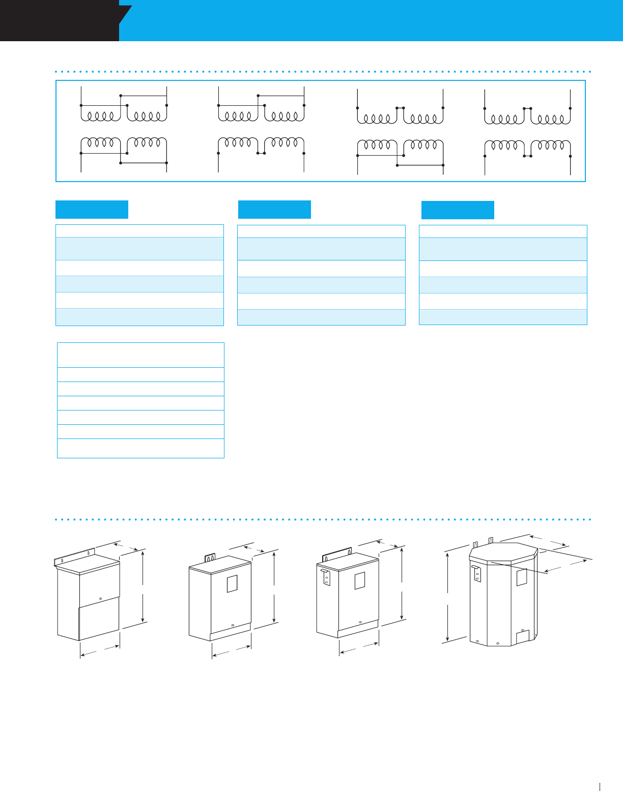
SECTION BUCK-BOOST TRANSFORMERS
ACME ELECTRIC • MILWAUKEE, WI • 800.334.5214 • acmetransformer.com
101
SECTION BUCK-BOOST TRANSFORMERS
7
101
DESIGN A DESIGN B DESIGN C DESIGN D
LOW VOLTAGE LIGHTING WIRING DIAGRAMS SINGLE PHASE
D
H
W
D
H
W
D
H
W
D
H
W
Number of Leads per Termination
H1 H2 H3 H4 X1 X2 X3 X4
T213078 1 1 1 1 2 2 2 2
T213079 1 1 1 1 2 2 2 2
T243571 1 1 1 1 2 2 2 2
T211688 1 1 1 1 2 2 2 2
T211689 1 1 1 1 2 2 2 2
All leads with same designation (ex. X1, X1)
MUST be joined together for proper operation.
GROUP I GROUP II GROUP III
KL MN
H4 H1
H3 H2
X1 X2 X3 X4 X1 X2 X3 X4
H4 H1
H3 H2
X1 X2 X3 X4
H4 H1H3 H2
X1 X2 X3 X4
H4 H1H3 H2
NOTE: All designs listed above are totally enclosed and suitable for UL 3R outdoor service.
BUCK-BOOST DIMENSIONAL DRAWINGS
Units Rated 120 x 240 V Input: 16/32 V Output
INPUT OUTPUT CONNECTION
DIAGRAM
120 16 K
120 32 L
240 16 M
240 32 N
Units Rated 120 x 240 V Input: 12/24 V Output
INPUT OUTPUT CONNECTION
DIAGRAM
120 12 K
120 24 L
240 12 M
240 24 N
Units Rated 240 x 480 V Input: 24/48 V Output
INPUT OUTPUT CONNECTION
DIAGRAM
240 24 K
240 48 L
480 24 M
480 48 N
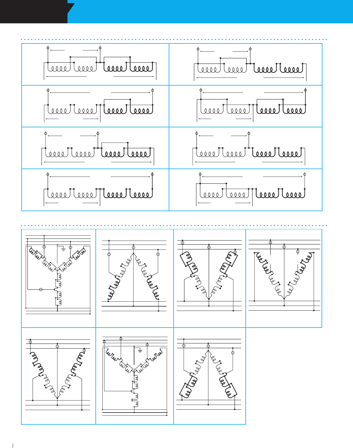
SECTION BUCK-BOOST TRANSFORMERS
7
102
INPUT ONLY
OUTPUT ONLY
1
2
3
1
2
3
H4
H3
H2
H1
X4
X3
X2
X1
H4
H3H2
H1
X4
X3
X2 X1
H4
H3
H2
H1
X4
X3
X2
X1
TRANS. #1
TRANS. #2
TRANS. #3
NEUTRAL
H4
H1
H3
H2
X4
X1
X3
X2
INPUT
OUTPUT
1
2
3
1
2
3
H4
H3
H2
H1
X4
X3
X2
X1
TRANS. #2
TRANS. #1
H4
H1
H3
H2
X4
X1
X3
X2
INPUT
OUTPUT
1
2
3
1
2
3
H4
H3
H2
H1
X4
X3
X2
X1
TRANS. #1
TRANS. #2
H4
H1
H3
H2
X4
X1
X3
X2
INPUT
OUTPUT
1
2
3
1
2
3
H4
H3
H2
H1
X4
X3
X2
X1
TRANS. #1
TRANS. #2
H4
H1
H3
H2
X4
X1
X3
X2
INPUT
OUTPUT
1
2
3
1
2
3
H4
H3
H2
H1
X4
X3
X2
X1
TRANS. #1
TRANS. #2
INPUT ONLY
OUTPUT ONLY
1
2
3
1
2
3
H4
H3
H2
H1
X4
X3
X2
X1
H3H2
H1
X4
X3
X2 X1
H4
H3
H2
H1
X4
X3
X2
X1
TRANS. #1
TRANS. #2
TRANS. #3
NEUTRAL
H4
H1
H3
H2
X4
X1
X3
X2
INPUT
OUTPUT
3
2
1
1
3
H4
H3
H2
H1
X4
X3
X2
X1
TRANS. #2
TRANS. #1
FIG. AA WYE FIG. BB OPEN DELTA FIG. CC OPEN DELTA FIG. DD OPEN DELTA
FIG. EE OPEN DELTA FIG. FF
WYE FIG. GG OPEN DELTA
The symbol O used in these
connection diagrams indicates
where to field install the over-
current protective device,
typically a fuse or circuit breaker.
Cannot be reverse connected.
IMPORTANT: Refer to the N.E.C.
(National Electrical Code) Article
450-4 for overcurrent protection
of an autotransformer. These
connection diagrams are packed
with each buck-boost transformer.
Do not use connections other
than those shown above.
BUCK-BOOST WIRING DIAGRAMS
SINGLE PHASE
H4 H1
H3 H2 X4 X1
X3 X2
INPUT
OUTPUT
H4 H1
H3 H2 X4 X1
X3 X2
INPUT
OUTPUT
H4 H1
H3 H2 X4 X1
X3 X2
INPUT
OUTPUT
H4 H1
H3 H2 X4 X1
X3 X2
INPUT
OUTPUT
H4 H1
H3 H2 X4 X1
X3 X2
INPUT
OUTPUT
H4 H1
H3 H2 X4 X1
X3 X2
INPUT
OUTPUT
H4 H1
H3 H2 X4 X1
X3 X2
INPUT
OUTPUT
H4 H1
H3 H2 X4 X1
X3 X2
INPUT
OUTPUT
FIG. D
FIG. F
FIG. C
FIG. E
FIG. G FIG. H
FIG. J
FIG. I
BUCK-BOOST WIRING DIAGRAMS
THREE PHASE

SECTION
Zone power centers combine an Acme
encapsulated distribution transformer
with a power panel assembly in one
convenient UL-3R enclosure, for
indoor/outdoor use and is suitable for
use as service entrance equipment.
304 Stainless Steel Panel Tran® . . . . . . . . . . . . . . . . . 1 0 4 - 1 0 5
Features ............................................................. 104
Selection Charts–Single Phase ........................ 106
Circuit Breaker Data–Single Phase .................. 106
Selection Charts–Three Phase ......................... 107
Circuit Breaker Data–Three Phase ................... 107
Wiring Diagrams ................................................ 108
8
PANEL-TRAN®
ZONE POWER
CENTERS

SECTION PANEL-TRAN® ZONE POWER CENTERS
ACME ELECTRIC • MILWAUKEE, WI • 800.334.5214 • acmetransformer.com
104
SECTION PANEL-TRAN® ZONE POWER CENTERS
8
104
Convenient Package Saves Costs and Space
ELECTRICAL CHARACTERISTICS
SINGLE PHASE
Primary Voltage:
480 Volts; 600 Volts Single Phase, 60 Hz
2 – 5% BNFC taps
Secondary Voltage:
240/120 Volts Single Phase, 60 Hz
Three wire system
kVA’s Available:
5, 7.5, 10, 15 and 25 kVA
THREE PHASE
Primary Voltage:
480 Volts Delta; 600 Volts Delta Three Phase, 60 Hz
With 2 – 5% BNFC taps
Secondary Voltage:
208Y/120 Volts Three Phase, 60 Hz
Four wire system
kVA’s Available:
9, 15, 22.5 and 30 kVA
Insulation Class:
180°C, UL recognized system, 115°C rise
Regulation:
2 – 3% at unity power factor
PT061150005LS PTBA3150015LS
Acme’s Panel-Tran® Power Center is a pre-wired combination
of a primary breaker disconnect, dry-type shielded
transformer, secondary breaker disconnect and a secondary
power panel all in one convenient package.
You save time, space and money by not having to individually
assemble, mount and wire these components. Simply add the
breakers of your choice and you’re ready to go.
FEATURES
600 volt class and below
Single and three phase, 480 and 600 volt primary, 60 Hz
Primary and secondary main circuit breakers provided
UL-3R enclosure
5 through 25 kVA single phase, 9 through 30 kVA
three phase
Meets or exceeds UL, CSA, NEMA, ANSI and
OSHA Standards
UL Listed and CSA Certified
Ten-year limited warranty
Shielded for cleaner power
Available in 304 stainless steel
304 STAINLESS STEEL
PANEL-TRAN®
FEATURES
3R Enclosure.
Abundant knockouts provided.
Encapsulated construction.
Single phase: 5 – 25 kVA.
Three phase: 9 – 30 kVA.
APPLICATIONS
Harsh industrial locations
Corrosive chemical exposure
Waste water treatment facilities
Coastal or marine applications with high salt spray level
Any application where painted cold roll steel is not
adequate
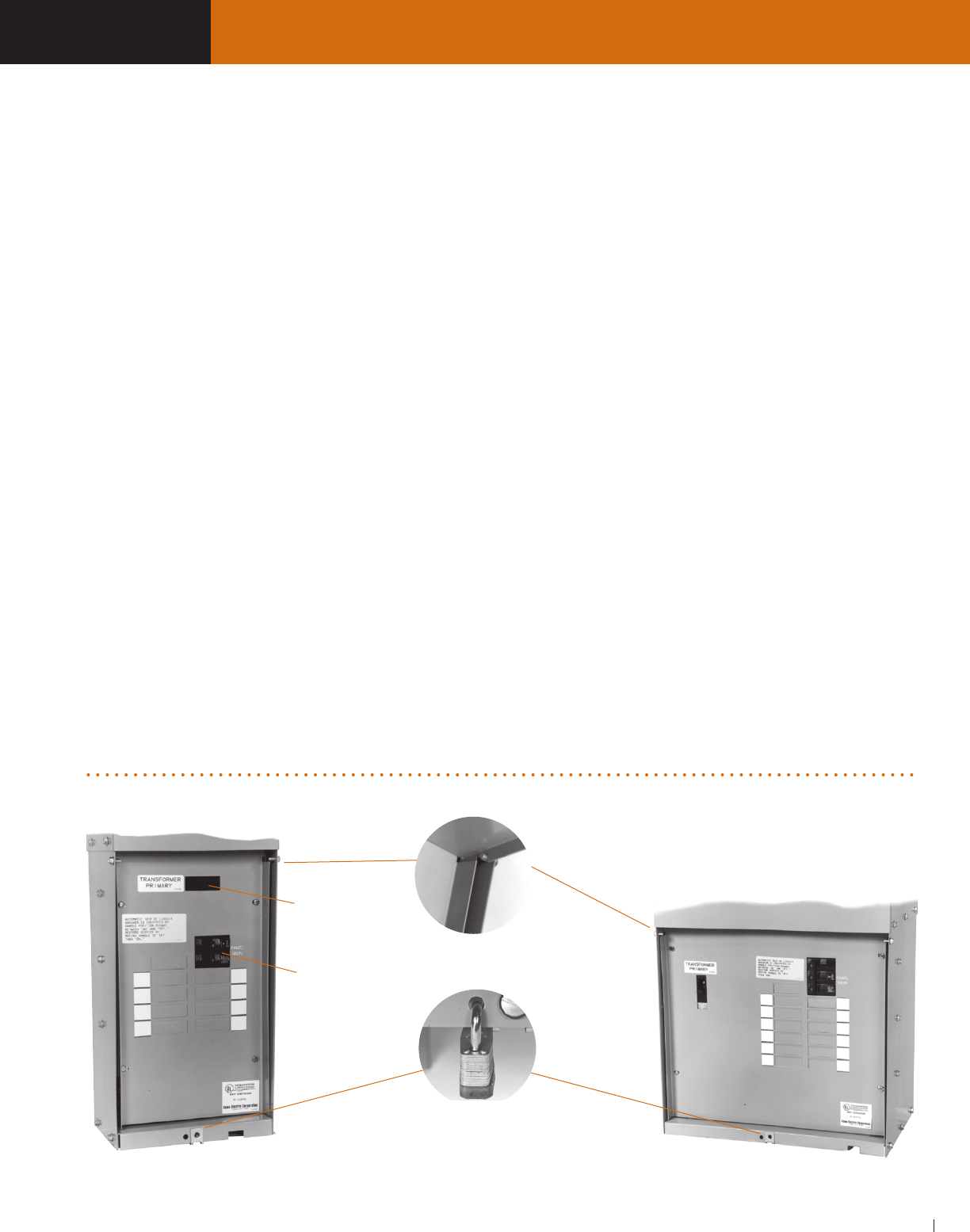
ACME ELECTRIC • MILWAUKEE, WI • 800.334.5214 • acmetransformer.com
105
SECTION PANEL-TRAN® ZONE POWER CENTERS
105
SECTION PANEL-TRAN® ZONE POWER CENTERS
8
UL-3R Enclosures All Panel -Tran® enclosures are UL-3R
listed for indoor and outdoor use.
Transformer Assembly Acme totally encapsulated
distribution transformers are designed for general purpose
indoor/outdoor operation. Panel-Tran® can be installed in a
wide variety of atmospheric and environmental conditions. A
180°C, UL recognized insulation system is used.
Panel-Tran® units are electrostatically shielded to provide
transient voltage protection at no extra cost.
Panel Assembly The power panel assembly will
accommodate one-inch, 1, 2 or 3-pole, common trip, duplex
secondary branch circuit breakers and ground fault circuit
breakers. Per UL and NEC requirements, the Panel-Tran®
assembly comes fully equipped with primary and secondary
main circuit breakers. Branch circuit breakers should be
obtained from our local distributor once you have established
your branch circuit requirements.
Panel-Tran® — W h y ? Panel-Tran® eliminates the normal
tangled masses of secondary circuit feeders and gives your
industrial/commercial distribution systems new flexibility. Use
your high voltage bus to full advantage by putting power where
the problem is. Reduce cost — save space — keep flexible.
Panel-Tran® — W h e r e ? Anywhere 120, 208 or 240 volt
branch circuits are required. Typically, Panel-Tran® is best
applied in situations similar to the following: Powering foreman
centers, vending machine areas, factory test set- ups, office
buildings, mining applications, assembly lines, portable or
temporary power sources, parking lots, small machine set-
ups, light industrial areas, warehouses, and numerous other
locations. Use where your branch circuits may require future
change or expansion.
UL Listed Panel-Tran® has been listed by Underwriters’
Laboratories for both indoor and outdoor operation under their
unit substation classification, file number E-56936. In addition,
Panel-Tran® is UL listed as suitable for use as Service Entrance
Equipment.
Meets The NEC Panel-Tran® fully complies with Article
450-3 of the latest edition of the NEC.
Protection A primary main breaker protects the transformer
and acts as a disconnect device. This primary main breaker
has a high interrupting capaci ty to handle fault conditions. A
secondary main breaker, between the transformer and the
panel, is required by the N.E.C.
Branch Circuits Typical 1" snap in circuit breakers, regular
or duplex, must be field installed. They are not provided with
the Panel-Tran® unit. A secondary ground is provided within
the wiring compartment for accepting your branch unit. All of
the breakers, including the primary main, secondary main,
and branch circuit breakers are located in the lower section of
the Panel-Tran®. This lower section is protected by a hinged,
removable front cover which can be padlocked for safety.
Recommended Branch Breakers We suggest using
branch breakers of the same manufacture as the panel in
Panel-Tran®. Please contact the factory for the proper branch
breaker recommendation.
Acme reserves the right to change breaker and panel
manufacturers without notification.
Connections All Panel-Tran® connections will accept
copper or aluminum conductor.
Primary
Main
Secondary
Main
Hinged Removable
Cover
Tamper-Proof
Pad-Lockable
Captive Hardware
Sturdy Unitized
Construction
FEATURES

SECTION PANEL-TRAN® ZONE POWER CENTERS
ACME ELECTRIC • MILWAUKEE, WI • 800.334.5214 • acmetransformer.com
106
SECTION PANEL-TRAN® ZONE POWER CENTERS
8
106
SELECTION CHARTS SINGLE PHASE
The number of secondary circuits shown is only a representation of circuits. Please contact the factory for exact number of secondary circuits available.
18,000 Amps RMS Symmetrical Interrupting Capacity.
Circuit Breaker Data
480 PRIMARY VOLTS –– 240/120 SECONDARY VOLTS –– 1Ø, 60 Hz
GROUP I
GROUP I – 304 SS
304 STAINLESS STEEL
480 PRIMARY VOLTS –– 240/120 SECONDARY VOLTS –– 1Ø, 60 Hz
480 VOLTS TO 240/120 VOLTS
MAXIMUM SECONDARY APPROX. DIMENSIONS APPROX.
CIRCUITS INCHES (CM.) NET WEIGHT
KVA CATALOG NO. 120 V 240 V HEIGHT WIDTH DEPTH LBS. (KG.)
5.0 PT061150005LS 8 4 32.13 (81.6) 13.25 (33.7) 7.63 (19.4) 120 (54.4)
7.5 PT061150007LS 8 4 32.13 (81.6) 15.88 (40.3) 11.00 (27.9) 160 (72.6)
10.0 PT061150010LS 8 4 34.38 (87.3) 15.88 (40.3) 11.00 (27.9) 185 (83.9)
15.0 PT061150015LS 12 6 34.38 (87.3) 17.13 (43.5) 12.38 (31.4) 240 (109.0)
25.0 PT061150025LS 20 10 41.88 (106.4) 17.88 (45.4) 13.50 (34.3) 330 (150.0)
MAXIMUM SECONDARY APPROX. DIMENSIONS APPROX.
CIRCUITS INCHES (CM.) NET WEIGHT
KVA CATALOG NO. 120 V 240 V HEIGHT WIDTH DEPTH LBS. (KG.)
(1-POLE) (2-POLE)
5.0 PT061150005SS 8 4 32.13 (81.6) 13.25 (33.7) 7.63 (19.4) 120 (54.4)
7.5 PT061150007SS 8 4 32.13 (81.6) 15.88 (40.3) 11.00 (27.9) 160 (72.6)
10.0 PT061150010SS 8 4 34.38 (87.3) 15.88 (40.3) 11.00 (27.9) 185 (83.9)
15.0 PT061150015SS 12 6 34.38 (87.3) 17.13 (43.5) 12.38 (31.4) 240 (109.0)
25.0 PT061150025SS 20 10 41.88 (106.4) 17.88 (45.4) 13.50 (34.3) 330 (150.0)
480 VOLTS 240/120 VOLTS MAXIMUM RATING
1Ø PRIMARY SECONDARY OF
KVA BREAKER MAIN SECONDARY BREAKERS
5.0 ED42B025L (25A) Q225 (25A) 20 amps
7.5 ED42B025L (25A) Q240 (40A) 30 amps
10.0 ED42B035L (35A) Q250 (50A) 40 amps
15.0 ED42B050L (50A) Q270 (70A) 60 amps
25.0 ED42B090L (90A) Q2125 (125A) 100 amps

ACME ELECTRIC • MILWAUKEE, WI • 800.334.5214 • acmetransformer.com
107
SECTION PANEL-TRAN® ZONE POWER CENTERS
107
SECTION PANEL-TRAN® ZONE POWER CENTERS
8
Circuit Breaker Data
480 VOLTS DELTA TO 208Y/120 VOLTS
SELECTION CHARTS THREE PHASE
GROUP A
The number of secondary circuits shown is only a representation of circuits. Please contact the factory for exact number of secondary circuits available.
10,000 Amps RMS Symmetrical Interrupting Capacity.
480 DELTA PRIMARY VOLTS –– 208Y/120 SECONDARY VOLTS –– 3Ø, 60 Hz
GROUP A – 304 SS
304 STAINLESS STEEL
480 DELTA PRIMARY VOLTS –– 208Y/120 SECONDARY VOLTS –– 3Ø, 60 Hz
MAX. SECONDARY CIRCUITS APPROX. DIMENSIONS APPROX.
1Ø 3Ø INCHES (CM.) NET WEIGHT
KVA CATALOG NO. 120 V 208 V HEIGHT WIDTH DEPTH LBS. (KG.)
(1-Pole) (3-Pole)
9.0 PTBA3150009LS 12 4 33.75 (85.7) 22.13 (56.2) 7.63 (19.4) 255 (116.0)
15.0 PTBA3150015LS 12 4 35.13 (89.2) 22.13 (56.2) 12.38 (31.4) 385 (175.0)
22.5 PTBA3150022LS 18 6 38.25 (97.2) 30.25 (76.8) 13.38 (34.0) 535 (243.0)
30.0 PTBA3150030LS 24 8 43.75 (111.1) 33.00 (83.8) 13.75 (34.9) 680 (308.0)
MAX. SECONDARY CIRCUITS APPROX. DIMENSIONS APPROX.
1Ø 3Ø INCHES (CM.) NET WEIGHT
KVA CATALOG NO. 120 V 208 V HEIGHT WIDTH DEPTH LBS. (KG.)
(1-Pole) (3-Pole)
9.0 PTBA3150009SS 12 4 33.75 (85.7) 22.13 (56.2) 7.63 (19.4) 255 (116.0)
15.0 PTBA3150015SS 12 4 35.13 (89.2) 22.13 (56.2) 12.38 (31.4) 385 (175.0)
22.5 PTBA3150022SS 18 6 38.25 (97.2) 30.25 (76.8) 13.38 (34.0) 535 (243.0)
30.0 PTBA3150030SS 24 8 43.75 (111.1) 33.00 (83.8) 13.75 (34.9) 680 (308.0)
3Ø 480 VOLTS 208Y/120 VOLTS MAXIMUM RATING
PRIMARY SECONDARY OF
KVA BREAKER MAIN SECONDARY BREAKERS
9.0 ED43B025L (25A) Q330 (30A) 25 amps
15.0 ED43B040L (40A) Q350 (50A) 40 amps
22.5 ED43B070L (70A) Q370 (70A) 60 amps
30.0 ED43B090L (90A) Q3100 (100A) 80 amps
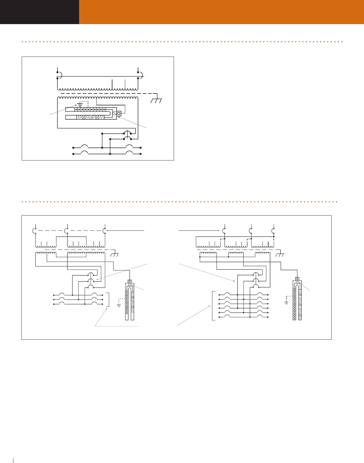
SECTION PANEL-TRAN® ZONE POWER CENTERS
ACME ELECTRIC • MILWAUKEE, WI • 800.334.5214 • acmetransformer.com
108
SECTION PANEL-TRAN® ZONE POWER CENTERS
8
108
Wiring Diagram 1Ø 5-25 kVA
X1
H1
X2X3
H3 H4H2
LINE 1 LINE 2
GROUND
WHEN
REQUIRED BOND
WHEN
REQUIRED
NEUTRAL
13
42
3Ø 9 kVA 3Ø 15-30 kVA
X3
GROUND
WHEN
REQUIRED
BOND
WHEN
REQUIRED
X1
H5
X2
H3H4 H7
LINE B LINE C
NEUTRAL
H1 H3H2
123123 1
2
3
X1 X2 X3
X0
H6
H9
H2 H1H8
LINE A LINE A LINE CLINE B
14
52
63
17
82
93
4 10
115
126
BOND
WHEN
REQUIRED
NEUTRAL
PRIMARY MAIN
FURNISHED
SECONDARY MAIN
FURNISHED
BRANCH CIRCUIT
BREAKERS ARE
ADDED BY INSTALLER
X0
GROUND
WHEN
REQUIRED
PANEL-TRAN® ZONE POWER CENTERS WIRING DIAGRAMS SINGLE PHASE
PANEL-TRAN® ZONE POWER CENTERS WIRING DIAGRAMS THREE PHASE
SECTION
An economical approach to changing
world voltages to 115V for operation
of air conditioners, refrigeration
equipment, appliances, business
machines, and related
equipment.
Construction Features ...............................110-111
Selection Instructions ....................................... 111
Selection Charts ................................................ 112
AIR CONDITIONING,
REFRIGERATION
& APPLIANCE
TRANSFORMERS
9
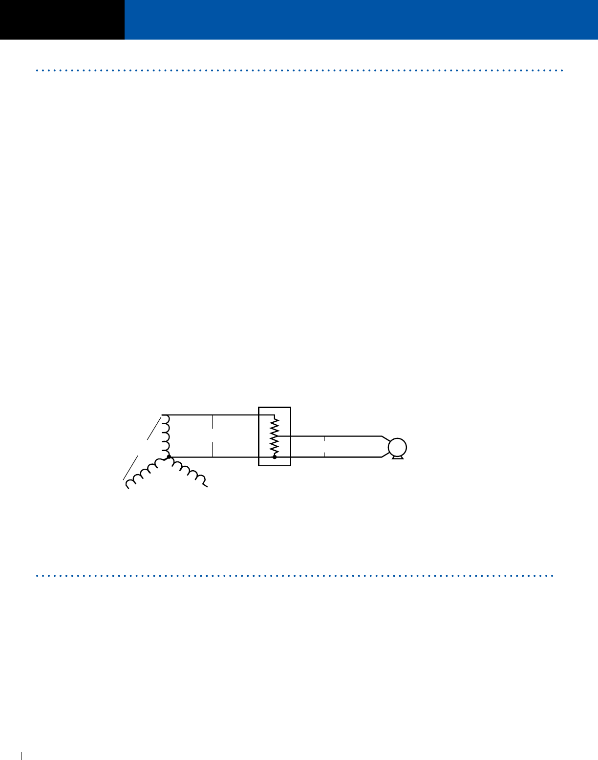
SECTION
AIR CONDITIONING, REFRIGERATION & APPLIANCE TRANSFORMERS
ACME ELECTRIC • MILWAUKEE, WI • 800.334.5214 • acmetransformer.com
110
SECTION
AIR CONDITIONING, REFRIGERATION & APPLIANCE TRANSFORMERS
9
110
The transformers in this section are autotransformers
designed to change a wide range of voltages to the standard
motor voltages for domestic appliances, air conditioners,
and related equipment.
Correcting high or low supply voltage conditions to match
the voltage requirements of appliances and equipment aids
in safe, efficient operation.
These Acme autotransformers change or correct off-
standard voltage that may be the result of:
1. Line supply voltage not matching the appliance motor
nameplate voltage, (e.g., supply voltage is 380Y/220V,
three phase, four wire. Appliance motor operates on 110 V,
single phase. See schematic).
2. Low voltage due to inadequate wiring capacity in the
electrical distribution system.
3. Low voltage caused by distribution of power over a
long distance.
4. High or low voltages supplied by the utility company.
Standard voltages and frequencies (Hz) vary throughout
many countries of the world. Since these autotransformers
are suitable for 50/60 Hz (cycle) service, they are
applicable in export trade where it is necessary to change
to a standard voltage for appliance operation.
These transformers are capable of adjusting voltage
only; they can’t change the frequency of a supply circuit.
However, in most instances, 60 Hz (cycle) equipment
can be operated from a 50 Hz supply if the voltage is
reduced approximately 8 -10%. For example, 115 V, 60 Hz
equipment can usually be operated on 50 Hz at 105 V.
Some common uses for Acme Air Conditioning, Refrigeration
and Appliance transformers include adjustment of off-
standard voltage to the nominal voltages required to
operate:
a) Air conditioners, television receivers, all home
appliances.
b) Hermetically sealed refrigeration motors.
c) Individual machine lighting, tool post grinders, fans,
convenience outlets for portable lights, power tools.
d) Magnetic contactors, relays, AC motors and similar
devices requiring large starting (inrush) currents.
Acme appliance transformers are autotransformers. The input
(primary) winding is in electrical series connection with the
output (secondary) winding; the input and output are not
electrically isolated.
The autotransformer principle is the most economical for
appliance applications, since only the difference between
input voltage and output voltage is transformed. This results
in smaller size, reduced weight and lower cost.
All units are constructed of core lamination processed
from annealed electrical grade silicon steel. This improves
transformer efficiency by keeping heat losses at a
minimum.
Coils are precision machine wound and hand finished.
The core and coil combination is impregnated with electrical
grade varnish, then heat cured. This provides cool
operation and protects the transformer from moisture and
contamination. The result is long transformer life.
Air Conditioning, Refrigeration & Appliance Transformers
380V
N
A
380Y/220V, 3Ø
4 WIRE SUPPLY
220V
110V
ACME
APPLIANCE
TRANSFORMER
LOAD
(MOTOR, APPLIANCE, ETC.)
Construction Features
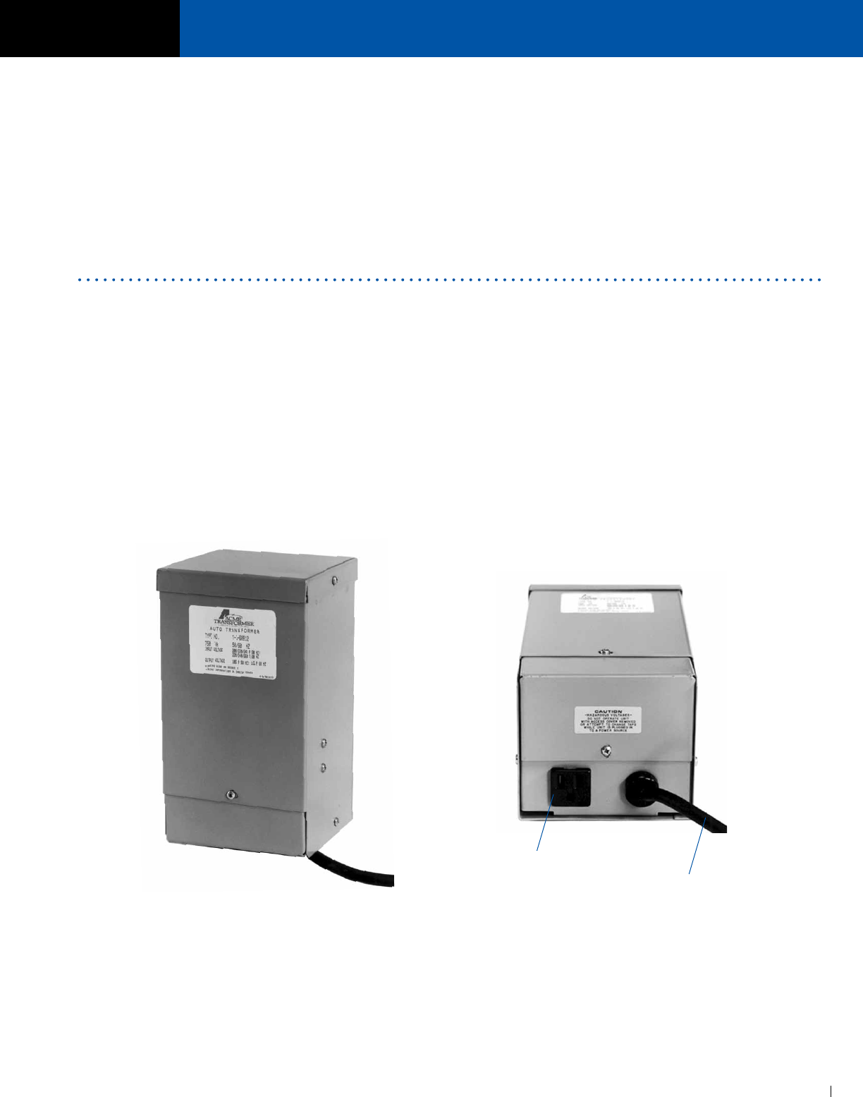
ACME ELECTRIC • MILWAUKEE, WI • 800.334.5214 • acmetransformer.com
111
SECTION
AIR CONDITIONING, REFRIGERATION & APPLIANCE TRANSFORMERS
111
SECTION
AIR CONDITIONING, REFRIGERATION & APPLIANCE TRANSFORMERS
9
1. Determine the value of incoming line supply voltage and
frequency (50 or 60 Hz).
2. Find the appliance or load equipment voltage rating and
amperes from the nameplate or instruction sheet. Multiply
the two to obtain VA requirement of the load. If the power
requirements are listed only in watts, consider this the
same as VA. (Exception: electric discharge lighting such
as mercury vapor, fluorescent, etc. should always be
sized by volts x amps (VA). If only wattage ratings are
known, double this requirement to obtain VA ratings of
transformers needed).
3. Add all VA requirements of equipment to obtain total
load. (All components must be of same voltage rating).
4. Add 10% for high starting current and overloading to
obtain VA size of transformers.
5. Select transformer from charts on following pages using
combination of supply voltage (primary), voltage rating of
equipment (secondary), load VA rating, and type of
connections desired.
Catalog # T160812
Selection Steps
Secondary Receptacle
6’ (1.8 M) Primary Cord
The transformers in this section will not cause harmonic
distortion to voltage or current wave shape.
All transformers in Group C are equipped with a SAFETY
grounding feature on both the input and output side.
Connection for ground may be made through lead wires or
through plug and receptacle combinations where installed.
All units are manufactured and tested in accordance with
National Electrical Manufacturers Association standards.
Some groups are equipped with primary voltage taps which
correct for voltage conditions constantly above or below the
nominal rating of the supply.

SECTION
AIR CONDITIONING, REFRIGERATION & APPLIANCE TRANSFORMERS
ACME ELECTRIC • MILWAUKEE, WI • 800.334.5214 • acmetransformer.com
112
SECTION
AIR CONDITIONING, REFRIGERATION & APPLIANCE TRANSFORMERS
9
112
GROUP C
PRIMARY VOLTS — 200/220/240 SECONDARY VOLTS — 115, 50/60 Hz
RECEPTACLE
CATALOG VA OUTPUT APPROX. DIMENSIONS APPROX.
NO. RATING AMPS INCHES (CM.) SHIP WEIGHT CONNECTIONS
HEIGHT WIDTH DEPTH LBS. (KG.) FEET (METERS)
T160830 ① 200 1.74 9.16 (23.3) 3.89 (9.9) 3.67 (9.3) 6 (2.7) 6 (1.8) primary cord and secondary receptacle
T160831 ① 300 2.61 9.16 (23.3) 3.89 (9.9) 3.67 (9.3) 6 (2.7) 6 (1.8) primary cord and secondary receptacle
T160832 ① 400 3.48 9.16 (23.3) 3.89 (9.9) 3.67 (9.3) 8 (3.6) 6 (1.8) primary cord and secondary receptacle
T160833 ① 500 4.35 9.68 (24.6) 4.75 (12.1) 4.51 (11.5) 10 (4.5) 6 (1.8) primary cord and secondary receptacle
T160834 ① 1000 8.70 9.68 (24.6) 4.75 (12.1) 4.51 (11.5) 14 (6.4) 6 (1.8) primary cord and secondary receptacle
T160835 ① 2000 17.40 11.50 (29.2) 7.81 (19.8) 7.13 (18.1) 27 (12.2) 6 (1.8) primary cord and secondary receptacle
① All models can be reverse connected with input voltage applied to secondary terminals and output voltage available at primary terminals.
Do not exceed rating voltages. Transformer VA capacity will remain the same.

SECTION
True-Power® Constant Voltage
Regulators .250–15.0 kVA
True-Power® Products .......................................114
Specifications ....................................................115
Selection Charts .................................................115
Dimensional Drawings .......................................116
POWER
CONDITIONING
PRODUCTS
10

ACME ELECTRIC • MILWAUKEE, WI • 800.334.5214 • acmetransformer.com
114
SECTION
CONSTANT VOLTAGE REGULATORS & POWER LINE CONDITIONERS
10
SECTION
CONSTANT VOLTAGE REGULATORS
FEATURES
n Reliable, regulated output voltage when input voltage varies,
even to brownout levels.
n Extended operation to 65% of nominal when operated at 60% of
full load.
n Noise rejection—effectively suppressing transient spikes and
surges—120 db common mode and 60 db transverse mode.
n Rapid response to line and load changes—5% variation in 8m
sec, 10% variation in 16m sec.
n Hold up time of 3m sec for complete loss of input power.
n Inherent overload and short circuit protection, without thermo
protectors, fuses or circuit breakers, for immediate recovery
when the overload is removed.
n Sinusoidal output features, less than 3% harmonic distortion,
improves input wave forms which have total harmonic distortions
of greater than 5%.
n Available in 250 through 15,000 VA in hardwired models.
n Handle multiple primary input voltages.
n Illuminated ON/OFF switch, multiple output receptacles and six
foot input power cord on portable units.
n UL Listed.
n CSA Certified
Acme True-Power® products consist of speciality designed
ferroresonant transformers. Although ferroresonant transformers
have been an economical solution to power problems for many
years, it took the skills of Acme’s highly regarded engineering
staff to refine it to meet today’s exacting requirements.
For example, typical ferroresonant transformers have an input
limited to 100-130 V. Acme’s True -Power® units have an input
range of +10/-20% around input voltage nominals of 120/208/240
and 480 volts. At 120 volt input, this relates to 95-130 volts.
The typical ferroresonant transformer has limited electrical noise
suppression capability. True-Power® power line conditioners
have the following noise attenuation capability:
Common Mode: 120 db
Transverse Mode: 60 db
The typical ferroresonant transformer has an audible hum that
can be objectionable in most offices. Acme’s True-Power® power
line conditioners are encapsulated in epoxy to lower sound levels
below ANSI standard C 89.2.
The typical ferroresonant transformer has on output regulation of
± 3% for input line changes only. Acme’s True-Power® power line
conditioners have an output regulation of ± 3% for input line and
load changes, making them suitable for operation at any load
condition.
APPLICATIONS
n
Industrial Automation and Control
Equipment
n
Electronic Test Equipment
n
Robotics
n
X-Ray Eauipment
n
Communications Equipment
Acme® True-Power® Constant Voltage Regulators
Product Selection Guide
Shielded
PROBLEM ENCOUNTERED Isolation True- SPS UPS
Transformer Power®
Power Failure — — X X
Widely Varying Source Voltage — X — X
Brown Outs — X X X
Switching Of Power Factor Correction Capacitors X X X X
Distorted Wave Shape Due To Harmonic Content — X — X
Common-Mode Transients X X — X
Transverse-Mode Transients — X X X
Voltage Spikes Due To Proximity Of
Welding Equipment Or Certain
Medical Diagnostic Equipment X X X X
Line Distortion Due To Noise Generated From
Occasional Lightning Strikes X X X X
Operation Of Computer Storage Devices Such
As Floppy Disks Or Winchester Drives
Generates Transients X X X X
10

ACME ELECTRIC • MILWAUKEE, WI • 800.334.5214 • acmetransformer.com
115
SECTION
CONSTANT VOLTAGE REGULATORS & POWER LINE CONDITIONERS
10
SECTION
10CONSTANT VOLTAGE REGULATORS
HARDWIRED MODELS — CONSTANT VOLTAGE REGULATORS
95-132 X 166-228 X 192-264 X 384-528 VOLT PRIMARY — 120/208/240 VOLT SECONDARY — 1Ø, 60 Hz
SPECIFICATIONS
F = Floor W = Wall
① Wall mounting brackets required for this size. Refer to Page 133.
② All hardwired models will accommodate these primary input voltages.
③ Dimensions not suitable for construction. Contact factory.
SELECTION CHARTS
GROUP II
Input (Primary) 95-132 VAC (Hardwired) ②
166-228 VAC
192-264 VAC
384-528 VAC
Phase: 1 Phase
Output (Secondary) 120/208/240 VAC (Hardwire)
Load Range 0-100%
Regulation ± 3% for line/load changes
Attenuation 120 db Common Mode Noise
60 db Transverse Mode Noise
Audible Noise Below ANSI std. C 89.2
APPROX. DIMENSIONS③
APPROX.
KVA CATALOG
INCHES (CM.) TYPE SHIP FIGURE WIRING
SIZE NUMBER A B C D E F G H J MTG. WEIGHT DIAGRAMS
HEIGHT WIDTH DEPTH LBS. (KG.) SEE PAGE 147
0.25 T169430 15.50 6.30 5.80 5.63 8.13 9.30 1.2 .41 x .81 5.00 F&W 37 II 16
(39.4) (16.0) (14.7) (14.3) (20.7) (23.6) (3.0) (1.0 x 2.1) (12.7) (16.8)
0.35 T169431 17.00 7.00 7.30 5.63 8.13 9.40 2.3 .41 x .81 6.50 F&W 51 II 16
(43.2) (17.8) (18.5) (14.3) (20.7) (23.9) (5.8) (1.0 x 2.1) (16.5) (23.1)
0.50 T169432 17.00 7.00 7.30 5.63 8.13 9.40 2.3 .41 x .81 6.50 F&W 53 II 16
(43.2) (17.8) (18.5) (14.3) (20.7) (23.9) (5.8) (1.0 x 2.1) (16.5) (24.0)
0.75 T169433 17.00 7.00 7.30 5.63 8.13 9.40 2.3 .41 x .81 6.50 F&W 65 II 16
(43.2) (17.8) (18.5) (14.3) (20.7) (23.9) (5.8) (1.0 x 2.1) (16.5) (29.5)
1.00 T169434 18.50 6.50 8.55 5.63 8.13 9.50 2.3 .41 x .81 7.75 F&W 82 II 16
(47.0) (16.5) (21.7) (14.3) (20.7) (24.1) (5.8) (1.0 x 2.1) (19.7) (37.2)
2.00 T169435 19.00 10.50 10.20 6.00 12.00 13.25 2.3 .44 x .63 9.40 F&W 142 III 16
(48.3) (26.7) (25.9) (15.2) (30.5) (33.7) (5.8) (1.1 x 1.6) (23.9) (64.4)
3.00 T169436 19.00 10.50 10.20 6.00 12.00 13.25 2.3 .44 x .63 9.40 F&W 176 III 16
(48.3) (26.7) (25.9) (15.2) (30.5) (33.7) (5.8) (1.1 x 1.6) (23.9) (79.8)
5.00 T169437 22.00 12.54 12.20 6.00 14.00 15.25 2.3 .44 x .63 11.40 F&W 295 III 16
(55.9) (31.9) (31.0) (15.2) (35.6) (38.7) (5.8) (1.1 x 1.6) (29.0) (134.0)
10.00 T169438 23.06 27.31 24.06 18.00 25.50 — — .56 — F&W ① 605 IV 16
(58.6) (69.4) (61.1) (45.7) (64.8) (1.4) (274.0)
15.00 T169439 23.06 40.13 24.06 18.00 38.31 — — .56 — F 880 IV 16
(58.6) (101.9) (61.1) (45.7) (97.3) (1.4) (399.0)
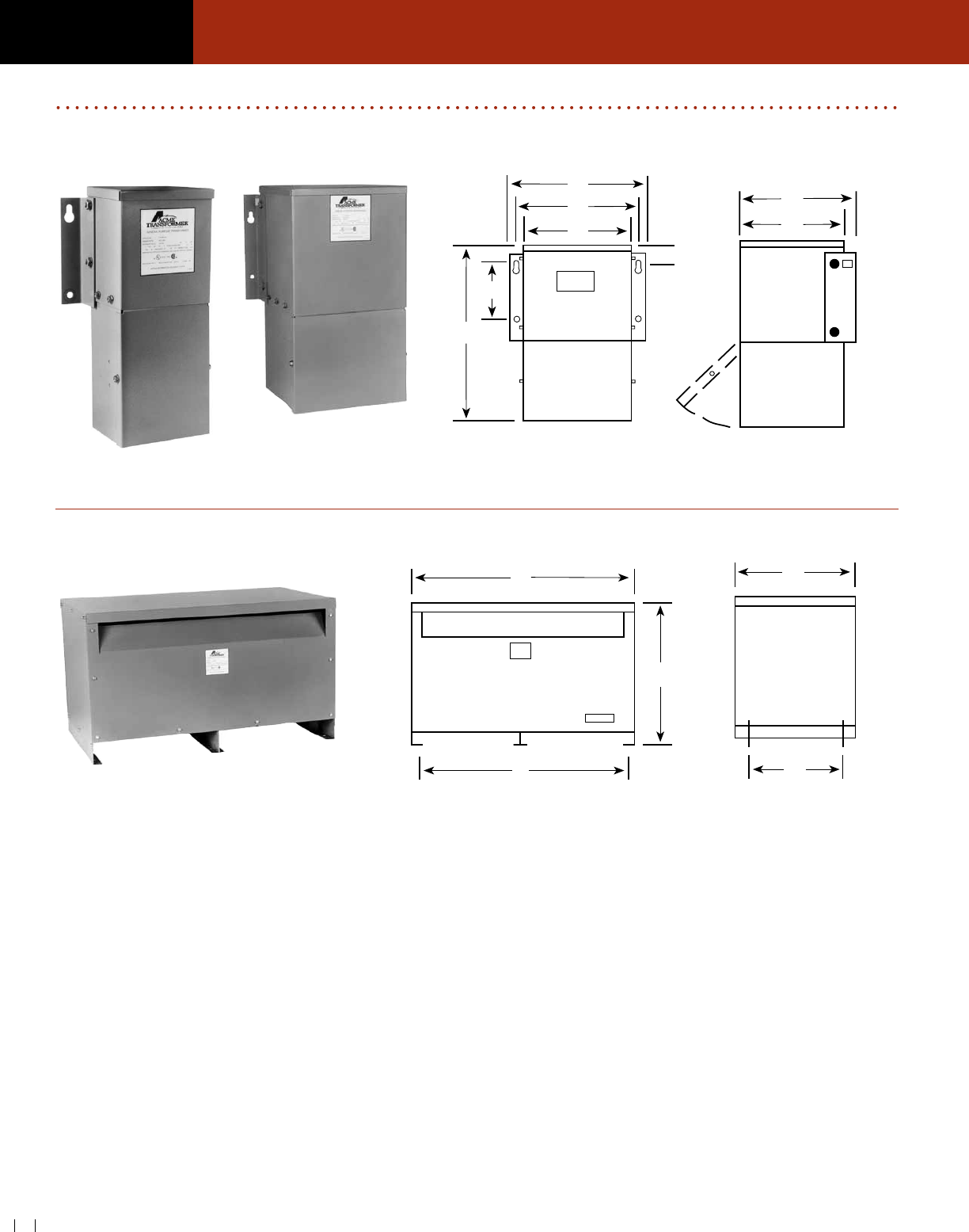
ACME ELECTRIC • MILWAUKEE, WI • 800.334.5214 • acmetransformer.com
116
SECTION
CONSTANT VOLTAGE REGULATORS & POWER LINE CONDITIONERS
10
116
SECTION
10CONSTANT VOLTAGE REGULATORS
FIGURE II & III
FIGURE IV
A
B
D
E
F
G
J
C
A
E
B
D
C
FRONT VIEW SIDE VIEW
FRONT VIEW SIDE VIEW
CONSTANT VOLTAGE REGULATORS DIMENSIONAL DRAWINGS

Acme High Efficiency Powerwise
C3 transformers provide the
perfect solution for LEED and green
facilities or end users looking for
the lowest total cost of ownership
in transformer design. See
acmepowerdist.com/c3 for energy
savings calculator.
CSL-3 Super Efficient Transformers ................. 118
General Description and Features ............118-119
Selection Charts ................................................ 120
POWERWISE C3
SECTION
11
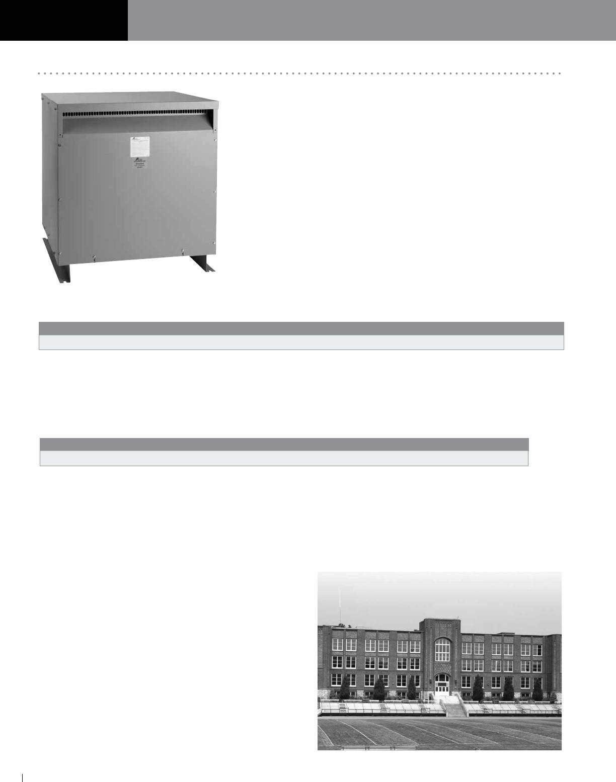
SECTION POWERWISE C3 TRANSFORMER
ACME ELECTRIC • MILWAUKEE, WI • 800.334.5214 • acmetransformer.com
118
SECTION POWERWISE C3 TRANSFORMER
118
11
In January 2007, the Energy Policy Act of 2005 (EPAct 2005) set the minimum
efficiency level (TP1) for transformers. While this standard sets a minimum
performance level, transformers rated at TP1 do not provide the greatest
efficiency or offer the lowest life cycle cost.
Acme POWERWISE C3 transformers are 30% better performing in efficiency
than standard TP1 transformers. Thanks to a more efficient core and higher-
grade electrical steel that minimizes losses, these energy-efficient units even
exceed the requirements of the US Department of Energy Candidate Standard
Level (CSL) 3 performance standard, commonly referred to as “C3.”
Depending on the kVA size, this increase in efficiency can save thousands of
dollars in energy costs per transformer. Whether you are looking to upgrade
your older pre-TP1 transformers or specify the highest-efficiency transformers
on your new project, Acme POWERWISE C3 transformers can deliver the
power and performance you need.
Within a typical facility, increasing the efficiency of your transformers can provide significant savings in a short period of time.
Payback usually occurs within 2.5 to 3.5 years, thanks in large part to our no-load losses. Because no-load losses are present
even when the transformers are lightly loaded, they are critical to overall efficiency — and POWERWISE losses are up to 40%
less than traditional TP1 designs.
EVALUATING TOTAL COST OF OWNERSHIP
Total Cost of Ownership = Initial Cost + Yearly Energy Cost
Cost over the life of the installation should be the most important factor when deciding which technology to use. Since the typical
transformer lasts 25 to 30 years, the total life cycle cost far outweighs the initial purchase price of the transformer. The electricity
wasted by low initial-cost transformers can amount to millions of wasted kilowatt hours over the operational life of the installation.
A New Standard in Transformer Efficiency
15 kVA 30 kVA 45 kVA 75 kVA 112.5 kVA 150 kVA 225 kVA 300 kVA 500 kVA
CSL-3 Efficiency 97.9% 98.3% 98.4% 98.6% 98.7% 98.8% 99.0% 99.0% 99.1%
15 kVA 30 kVA 45 kVA 75 kVA 112.5 kVA 150 kVA 225 kVA 300 kVA
No-Load Loss 70W 90W 130W 160W 240W 280W 370W 550W
TYPICAL APPLICATIONS INCLUDE:
n Educational Facilities (K–12/University)
n Government Buildings
n Manufacturing Facilities
n Office and Commercial Buildings
n Healthcare/Hospital/Medical Office Buildings
n Financial Institutions
n Data Processing Centers
n Wastewater and Sewage Treatment Facilities
n Correctional Facilities
n Industrial Facilities
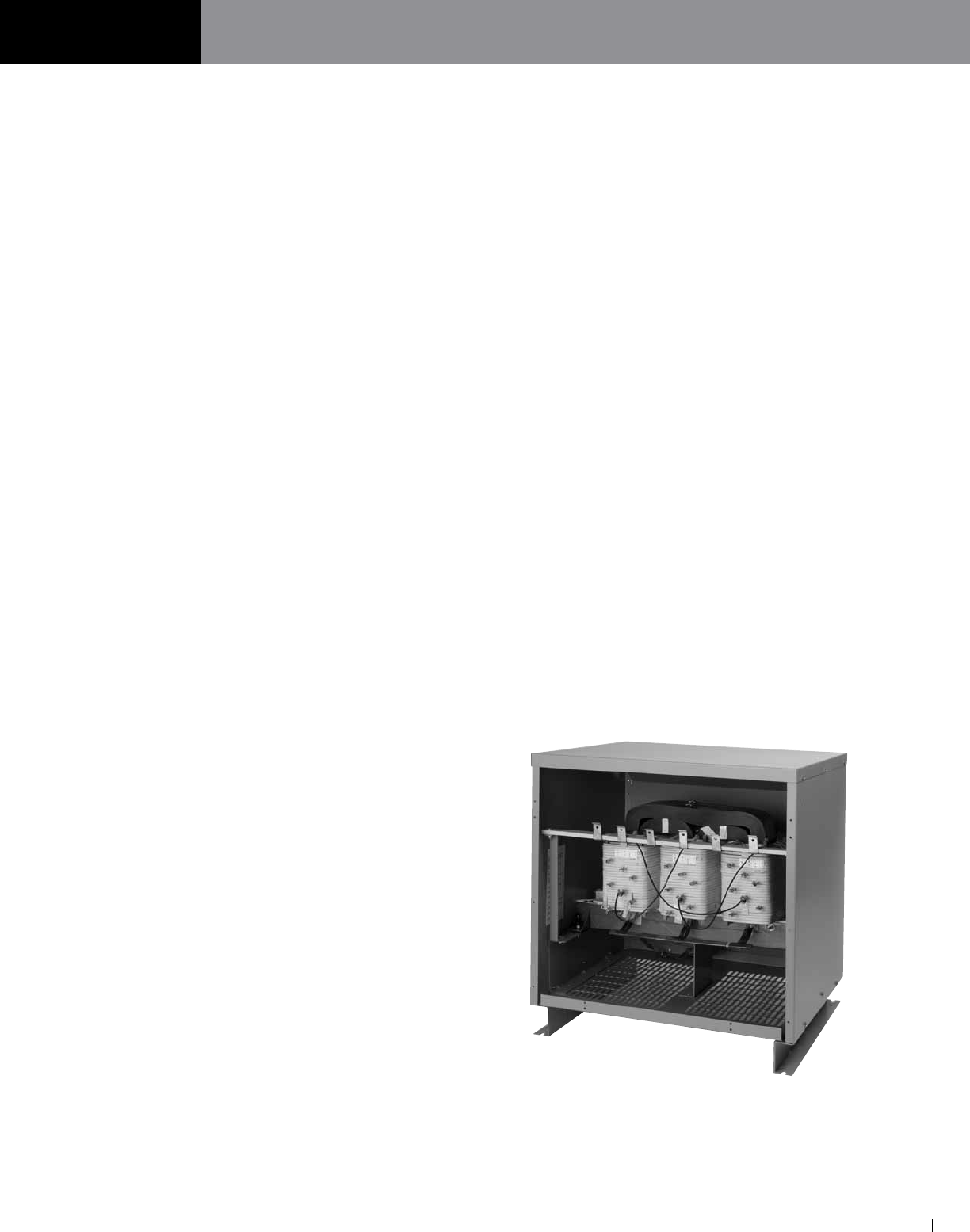
ACME ELECTRIC • MILWAUKEE, WI • 800.334.5214 • acmetransformer.com
119
SECTION POWERWISE C3 TRANSFORMER
119
SECTION POWERWISE C3 TRANSFORMER
11
APPLICATIONS
The Acme POWERWISE C3 transformer is the ideal
transformer for commercial environments where
energy efficiency is a primary concern. It is a perfect
choice for K through 12, college, university, healthcare,
governmental and commercial buildings where the
total life cycle cost of the facility and its electrical
system is a priority.
DESIGN
The Acme POWERWISE C3 sets new standards for
efficiency and reliability. Through more efficient core
material and higher-grade electrical steel, losses are
minimized and performance is maximized. Acme
POWERWISE C3 transformers are copper wound,
3-phase common-core, dry type ventilated isolation
transformers. Each transformer is meticulously
constructed to ANSI/IEEE Standards and is UL
and CSA listed.
ENVIRONMENTAL EFFICIENCY
Acme POWERWISE transformers are the most efficient
commercially available transformers. Because they
generate lower losses, they reduce power drawn from
generating stations, resulting in lower greenhouse gas
emissions and less smog. The result is a win for the
environment and a win in terms of lowest transformer
life cycle costs.
WARRANTY
Acme POWERWISE C3 transformers are subjected to
rigorous quality electrical and insulation tests in our
ISO 9001-certified facility, and they are backed by our
25-year pro-rated warranty.
SPECIFICATIONS
Windings ...........................Copper
Insulation Class ................. 220° C
Degree Rise ......................115° C or 130° C
Noise Levels......................Per NEMA ST-20 -5dB low noise
Rated for 60 Hertz ............
K Rating ............................K-13
Voltage Taps ..................... Voltage Taps: 15 through 500 kVA
(2)
2-1/2% ANFC, (4) 2-1/2% BNFC
Neutral Conductor ............200% Rated
Electrostatic Shield ...........Standard
Enclosure .......................... Ventilated NEMA 2 (NEMA 3R
available with drip shield)
ADDITIONAL FEATURES & BENEFITS
n
Exceeds US DOE CSL-3 efficiency to help you reduce
electrical waste and provide sustainability in your
electrical design
n
Significantly exceeds TP1 efficiency for low operating
cost over the life of the transformer
n
Optimized design provides maximum reliability and
proven performance
n
Produced in an ISO 9001 facility to ensure high quality
and rigorous testing standards

SECTION POWERWISE C3 TRANSFORMER
ACME ELECTRIC • MILWAUKEE, WI • 800.334.5214 • acmetransformer.com
120
SECTION POWERWISE C3 TRANSFORMER
120
11
SELECTION CHARTS
GROUP D6
POWERWISE C3 - 115 C RISE - COPPER WINDINGS
CSL 3 Efficiency (exceeds TP1)
480 DELTA PRIMARY VOLTS - 208Y120 SECONDARY VOLTS - MAY BE USED ON A 4 WIRE 480Y/277 VOLT SUPPLY - 3Ø, 60 Hz
APPROX. DIMENSIONS ② APPROX. TYPE MTG. WEATHER Wiring Diagrams &
kVA CATALOG NO. Inches (Cm.) SHIP WEIGHT W – Wall SHIELD Design Figures
HEIGHT WIDTH DEPTH Lbs. (Kg.) F – Floor P/N Begin on Page 154
15 TPC3533111S 29.41 (74.7) 28.15 (71.5) 22.37 (56.8) 350 (158.8) F WSA1 22-E
30 TPC3533121S 29.41 (74.7) 28.15 (71.5) 22.37 (56.8) 385 (174.6) F WSA2 22-E
45 TPC3533131S 29.41 (74.7) 28.15 (71.5) 22.37 (56.8) 455 (206.4) F WSA2 22-E
75 TPC3533141S 35.38 (89.9) 31.90 (81.0) 26.88 (68.3) 585 (265.4) F WSA3 22-E
112.5 TPC3533151S 41.52 (105.5) 33.06 (84.0) 29.87 (75.9) 1020 (462.7) F WSA4 22-E
150 TPC3533161S 41.52 (105.5) 33.06 (84.0) 29.87 (75.9) 1260 (571.5) F WSA4 22-E
225 TPC3533171S 41.52 (105.5) 33.06 (84.0) 29.87 (75.9) 1410 (639.6) F WSA4 22-E
300 TPC3533181S 45.70 (116.1) 39.50 (100.3) 35.50 (90.2) 1860 (843.7) F WSA5 22-E
500 TPC3533191S 62.95 (159.9) 54.00 (137.2) 41.88 (106.4) 3350 (1519.5) F WSA7 22-G
GROUP D7
POWERWISE C3 - 130 C RISE - COPPER WINDINGS
CSL 3 Efficiency (exceeds TP1)
480 DELTA PRIMARY VOLTS - 208Y120 SECONDARY VOLTS - MAY BE USED ON A 4 WIRE 480Y/277 VOLT SUPPLY - 3Ø, 60 Hz
APPROX. DIMENSIONS ② APPROX. TYPE MTG. WEATHER Wiring Diagrams &
kVA CATALOG NO. Inches (Cm.) SHIP WEIGHT W – Wall SHIELD Design Figures
HEIGHT WIDTH DEPTH Lbs. (Kg.) F – Floor P/N Begin on Page 154
15.0 TPC3533113S 29.41 (74.7) 28.15 (71.5) 22.37 (56.8) 350 (158.8) F WSA1 22-E
30.0 TPC3533123S 29.41 (74.7) 28.15 (71.5) 22.37 (56.8) 380 (172.4) F WSA2 22-E
45.0 TPC3533133S 29.41 (74.7) 28.15 (71.5) 22.37 (56.8) 440 (199.6) F WSA2 22-E
75.0 TPC3533143S 35.38 (89.9) 31.90 (81.0) 26.88 (68.3) 560 (254.0) F WSA3 22-E
112.5 TPC3533153S 41.52 (105.5) 33.06 (84.0) 29.87 (75.9) 1000 (453.6) F WSA4 22-E
150.0 TPC3533163S 41.52 (105.5) 33.06 (84.0) 29.87 (75.9) 1220 (553.4) F WSA4 22-E
225.0 TPC3533173S 41.52 (105.5) 33.06 (84.0) 29.87 (75.9) 1385 (628.2) F WSA4 22-E
300.0 TPC3533183S 45.70 (116.1) 39.50 (100.3) 35.50 (90.2) 1820 (825.5) F WSA5 22-E
500.0 TPC3533193S 62.95 (159.9) 54.00 (137.2) 41.88 (106.4) 3250 (1474.2) F WSA7 22-G

D
H
W
Design Figures, Wiring Diagrams,
Accessories, Specification
Guides, Industry Standards and
Alphanumerical Catalog
Number Index
Design Figures .........................................................122
Wiring Diagrams ..............................................123–132
Transformer Accessories ................................133–134
Specification Guides .......................................135–138
Industry Standards ..................................................139
Alphanumerical Catalog Number Index .........140–144
ACME®
TRANSFORMER™
GENERAL
INFORMATION
GENERAL
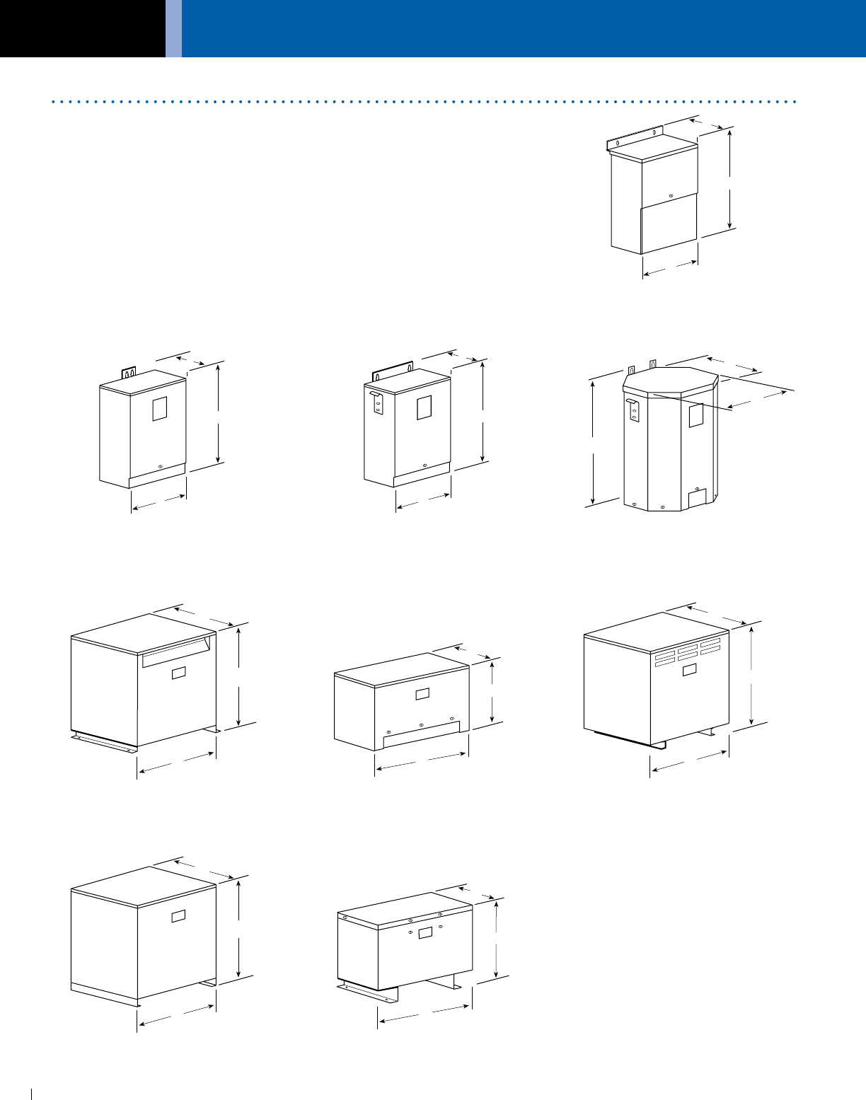
GENERAL ELECTRICAL CONNECTION DIAGRAMS
ACME ELECTRIC • MILWAUKEE, WI • 800.334.5214 • acmetransformer.com
122
GENERAL ACME® TRANSFORMER™ DESIGN FIGURES
122
Design Figures
Sections I, II, III & IV
Design A
Design B
Design E
Design H
Design C Design D
Design F Design G
Design I
These drawings are for reference only.
Contact factory for certified drawings.
D
H
W
D
H
W
D
H
W
D
H
W
D
H
W
D
H
W
D
H
W
D
H
W
D
H
W
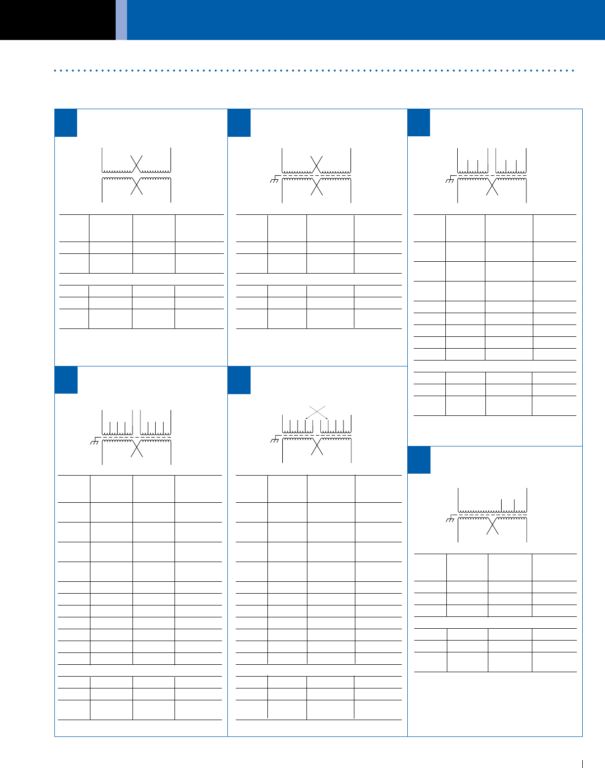
ACME ELECTRIC • MILWAUKEE, WI • 800.334.5214 • acmetransformer.com
123
GENERAL ELECTRICAL CONNECTION DIAGRAMS
123
GENERAL ACME® TRANSFORMER™ WIRING DIAGRAMS
PRIMARY: 240 X 480
SECONDARY: 120/240
TAPS: None
X4 X1
H4
H2
H3
H1
X2 X3
PRIMARY: 240 X 480
SECONDARY: 120/240
2, 21
/2% ANFC, 4, 21
/2% BNFC
X4 X1
H10
H2 H3
H1
X2 X3
H5 H6
H8H7
H4 H9
Connect Connect
Primary Primary Inter- Secondary
Volts Lines To Connect Lines To
216 H1-H10 H1 to H9
H10 to H2
228 H1-H10 H1 to H8
H10 to H3
240 H1-H10 H1 to H7
H10 to H4
252 H1-H10 H1 to H6
H10 to H5
432 H1-H10 H2 to H9
444 H1-H10 H3 to H9
456 H1-H10 H3 to H8
468 H1-H10 H4 to H8
480 H1-H10 H4 to H7
492 H1-H10 H5 to H7
504 H1-H10 H5 to H6
Secondary Volts
240 X2 to X3 X1-X4
120/240 X2 to X3 X1-X3-X4
120 X1 to X3 X1-X4
X2 to X4
PRIMARY: 240 X 480
SECONDARY: 120/240
TAPS:
2, 21
/2% ANFC, 2, 21
/2% BNFC
X4 X1
2
H1
X2 X3
H3
13
H4
45678
H2
Connect Connect
Primary Primary Inter- Secondary
Volts Lines To Connect Lines To
480 H1-H4 H2 to H3
240 H1-H3 &
H2-H4
Secondary Volts
240 X2 to X3 X1-X4
120/240 X2 to X3 X1-X2-X4
120 X1 to X3 X1-X4
X2 to X4
PRIMARY: 208
SECONDARY: 120/240
TAPS: 2, 5% BNFC
X4 X1
H1
X2 X3
H3
H4
H2
Connect Connect
Primary Primary Inter- Secondary
Volts Lines To Connect Lines To
208 H1 & H4
198 H1 & H3
187 H1 & H2
Secondary Volts
240 X2 to X3 X1-X4
120/240 X2 to X3 X1-X2-X4
120 X1 to X3 X1-X4
X2 to X4
Connect Connect
Primary Primary Inter- Secondary
Volts Lines To Connect Lines To
216 H1-H4 H1, H3, 8 &
H2, H4, 1
228 H1-H4 H1, H3, 7 &
H2, H4, 2
240 H1-H4 H1, H3, 6 &
H2, H4, 3
252 H1-H4 H1, H3, 5 &
H2, H4, 4
432 H1-H4 H2, 1 & H3, 8
444 H1-H4 H2, 2 & H3, 8
456 H1-H4 H2, 2 & H3, 7
468 H1-H4 H2, 3 & H3, 7
480 H1-H4 H2, 3 & H3, 6
492 H1-H4 H2, 4 & H3, 6
504 H1-H4 H2, 4 & H3, 5
Secondary Volts
240 X2 to X3 X1-X4
120/240 X2 to X3 X1-X2-X4
120 X1 to X3 X1-X4
X2 to X4
PRIMARY: 240 X 480
SECONDARY: 120/240
TAPS: 2, 21
/2% ANFC, 2, 21
/2% BNFC
X4 X1
H8
H2 H3
H1
X2 X3
H4 H5
H6 H7
Connect Connect
Primary Primary Inter- Secondary
Volts Lines To Connect Lines To
252 H1-H8 H1 to H5
H4 to H8
240 H1-H7 H1 to H5
H3 to H7
228 H1-H6 H1 to H5
H2 to H6
504 H1-H8 H4 to H5
492 H1-H8 H3 to H5
480 H1-H7 H3 to H5
468 H1-H7 H2 to H5
456 H1-H6 H2 to H5
Secondary Volts
240 X2 to X3 X1-X4
120/240 X2 to X3 X1-X2-X4
120 X1 to X3 X1-X4
X2 to X4
PRIMARY: 240 X 480
SECONDARY: 120/240
TAPS: None
X4 X1
H4
H2
H3
H1
X2 X3
Connect Connect
Primary Primary Inter- Secondary
Volts Lines To Connect Lines To
480 H1-H4 H2 to H3
240 H1-H3 &
H2-H4
Secondary Volts
240 X2 to X3 X1-X4
120/240 X2 to X3 X1-X2-X4
120 X1 to X3 X1-X4
X2 to X4
1 2 3
6
5
4
Wiring DiagramsSections I, II, III & IV
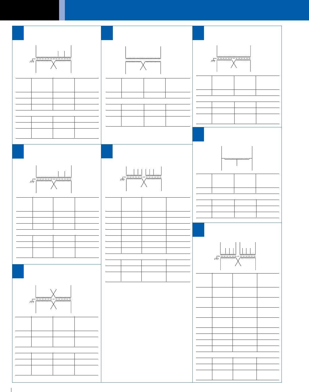
GENERAL ELECTRICAL CONNECTION DIAGRAMS
ACME ELECTRIC • MILWAUKEE, WI • 800.334.5214 • acmetransformer.com
124
GENERAL ACME® TRANSFORMER™ WIRING DIAGRAMS
124
PRIMARY: 120 x 240
SECONDARY: 120/240
TAPS: None
X4 X1
H4
H2
H3
H1
X2 X3
Connect Connect
Primary Primary Inter- Secondary
Volts Lines To Connect Lines To
240 H1-H4 H2 to H3
120 H1-H3 &
H2-H4
Secondary Volts
240 X2 to X3 X1-X4
120/240 X2 to X3 X1-X2-X4
120 X1 to X3 X1-X4
X2 to X4
PRIMARY: 600
SECONDARY: 120/240
TAPS: None
X4 X1
H1
X2 X3
H2
Connect Connect
Primary Primary Inter- Secondary
Volts Lines To Connect Lines To
600 H1-H2
Secondary Volts
240 X2 to X3 X1-X4
120/240 X2 to X3 X1-X2-X4
120 X1 to X3 X1-X4
X2 to X4
PRIMARY: 600
SECONDARY: 120/240
TAPS: None
X4 X1
H1
X2 X3
H2
Connect Connect
Primary Primary Inter- Secondary
Volts Lines To Connect Lines To
600 H1-H2
Secondary Volts
240 X2 to X3 X1-X4
120/240 X2 to X3 X1-X2-X4
120 X1 to X3 X1-X4
X2 to X4
PRIMARY: 277
SECONDARY: 120/240
TAPS: 2, 5% BNFC
X4 X1
H1
X2 X3
H3
H4
H2
Connect Connect
Primary Primary Inter- Secondary
Volts Lines To Connect Lines To
277 H1 & H4
263 H1 & H3
250 H1 & H2
Secondary Volts
240 X2 to X3 X1-X4
120/240 X2 to X3 X1-X2-X4
120 X1 to X3 X1-X4
X2 to X4
EXPORT MODEL
PRIMARY: 190-220 x 380-440
SECONDARY: 120/240
X4 X1
H5
H3
H1
X2 X3
H2 H4
H6
H7 H8 H9
H10
Connect Connect
Primary Primary Inter- Secondary
Volts Lines To Connect Lines To
190 H1 & H7 H1 to H6
H2 to H7
200 H1 & H8 H1 to H6
H3 to H8
208 H1 & H9 H1 to H6
H4 to H9
220 H1 & H10 H1 to H6
H5 to H10
380 H1 & H7 H2 & H6
400 H1 & H8 H3 & H6
416 H1 & H9 H4 & H6
440 H1 & H10 H5 & H6
Secondary Volts
240 X2 to X3 X1-X4
120/240 X2 to X3 X1-X2-X4
120 X1 to X3 X1-X4
X2 to X4
PRIMARY: 240
SECONDARY: 120/240
TAPS: None
1
1
2
3
3
Connect Connect
Primary Primary Inter- Secondary
Volts Lines To Connect Lines To
240 1-3
Secondary Volts
240 1-3
120 1-2 or 2-3
120/240 1-2-3
PRIMARY: 600
SECONDARY: 120/240
TAPS: 2, 21
/2% ANFC, 4, 21
/2% BNFC
X4 X1
1
H1
X2 X3
2
H2
3456
Connect Connect
Primary Primary Inter- Secondary
Volts Lines To Connect Lines To
540 H1-H2 1-6
555 H1-H2 1-5
570 H1-H2 2-6
585 H1-H2 2-5
600 H1-H2 3-5
615 H1-H2 2-4
635 H1-H2 3-4
Secondary Volts
240 X2 to X3 X1-X4
120/240 X2 to X3 X1-X2-X4
120 X1 to X3 X1-X4
X2 to X4
PRIMARY: 600
SECONDARY: 120/240
TAPS: 2, 5% BNFC
X4 X1
H1
X2 X3
H3
H4
H2
Connect Connect
Primary Primary Inter- Secondary
Volts Lines To Connect Lines To
600 H1-H4
570 H1-H3
540 H1-H2
Secondary Volts
240 X2 to X3 X1-X4
120/240 X2 to X3 X1-X2-X4
120 X1 to X3 X1-X4
X2 to X4
14
7 8 9
10 11
12
13
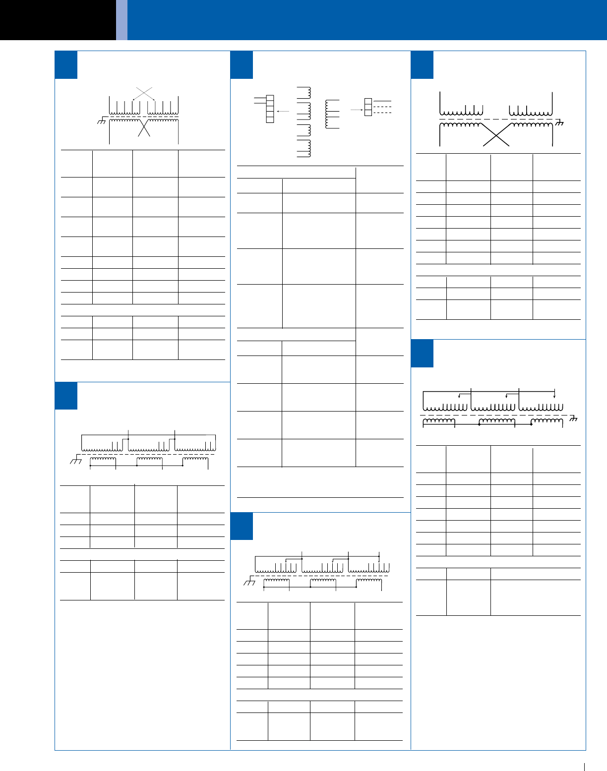
ACME ELECTRIC • MILWAUKEE, WI • 800.334.5214 • acmetransformer.com
125
GENERAL ELECTRICAL CONNECTION DIAGRAMS
125
GENERAL ACME® TRANSFORMER™ WIRING DIAGRAMS
PRIMARY: 240 Volts Delta
SECONDARY: 208Y/120 Volts
TAPS: 2, 5% BNFC
X1
H1
X2 X3
H3H2
X0
1
23
1
23
1
23
Connect Connect
Primary Primary Inter- Secondary
Volts Lines To Connect Lines To
240 H1, H2, H3 1
228 H1, H2, H3 2
216 H1, H2, H3 3
Secondary Volts
208 X1, X2, X3
120 X1 to X0
1 phase X2 to X0
X3 to X0
EXPORT MODEL
PRIMARY: 190-220 x 380-440
SECONDARY:120/240
X4 X1
2
H1
X2 X3
H3
13
H4
45678
H2
Connect Connect
Primary Primary Inter- Secondary
Volts Lines To Connect Lines To
190 H1 & H4 H1, H3, 8 &
H2, H4, 1
200 H1 & H4 H1, H3, 7 &
H2, H4, 2
208 H1 & H4 H1, H3, 6 &
H2, H4, 3
220 H1 & H4 H1, H3, 5 &
H2, H4, 4
380 H1 & H4 H2, H3, 1, 8
400 H1 & H4 H2, H3, 2, 7
416 H1 & H4 H2, H3, 3, 6
440 H1 & H4 H2, H3, 4, 5
Secondary Volts
240 X2 to X3 X1-X4
120/240 X2 to X3 X1-X2-X4
120 X1 to X3 X1-X4
X2 to X4
15
Input Connections Insulate
&
Volts Connect Isolate
120 1, 3, 6, 8 to A 4, 9
2, 5, 7, 10 to B
1, 6 to A
208 4, 9 to B 5, 10
2, 3 to C
7, 8 to D
1, 6 to A
240 5, 10 to B 4, 9
2, 3 to C
7, 8 to D
1 to A
10 to B
480 2, 3 to C 4, 9
5, 6 to D
7, 8 to E
Output Connections Output
Lines
Volts Connect To
11 to F
120 12 to G F, G
14 to H
11 to F
120/240 12 to G F, G, H
14 to H
11 to F
208 12 to G F, H
13 to H
11 to F
240 12 to G F, H
14 to H
NOTE: To prevent externally shorting, all leads marked
“INSULATE” must be individually capped with wire
nuts or equivalent. Insulate leads individually!
POWER LINE CONDITIONER
2F
1
3
H
4
5
6
7
8
G
9
10
11
12
13
14
B
C
D
E
A
INPUT LINE
16
18
PRIMARY: 208 Volts
SECONDARY: 120/240 Volts
TAPS:
17
PRIMARY: 240 Volts Delta
SECONDARY: 208Y/120 Volts
TAPS: 2, 21
/2% ANFC, 2, 21
/2% BNFC
X1
H1
X2 X3
H3H2
X0
1
23
1
23
1
23
4
54
54
5
Connect Connect
Primary Primary Inter- Secondary
Volts Lines To Connect Lines To
252 H1, H2, H3 1
246 H1, H2, H3 2
240 H1, H2, H3 3
234 H1, H2, H3 4
228 H1, H2, H3 5
Secondary Volts
208 X1, X2, X3
120 X1 to X0
1 phase X2 to X0
X3 to X0
19
PRIMARY: 380 Volts Delta
SECONDARY: 220Y/127 Volts
TAPS: 2, 21
/2% ANFC, 4, 21
/2% BNFC
20
H1
123
H2
456
X1X3X2X4
X3
H1
H3
123
H2 H3
X2X1
X0
4567 1234567 1234567
Connect Connect
Primary Primary Inter- Secondary
Volts Lines To Connect Lines To
218 H1 & H2 3 to 4
213 H1 & H2 2 to 4
208 H1 & H2 3 to 5
203 H1 & H2 2 to 5
198 H1 & H2 1 to 5
192 H1 & H2 2 to 6
187 H1 & H2 1 to 6
Secondary Volts
240 X2 to X3 X1-X4
120/240 X2 to X3 X1-X2-X4
120 X1 to X3 X1-X4
X2 to X4
Connect Connect
Primary Primary Inter- Secondary
Volts Lines To Connect Lines To
399 H1, H2, H3 1
390 H1, H2, H3 2
380 H1, H2, H3 3
371 H1, H2, H3 4
361 H1, H2, H3 5
352 H1, H2, H3 6
342 H1, H2, H3 7
Secondary Volts
220 X1, X2,X3
127 X1 to X0
1 phase X2 to X0
X3 to X0
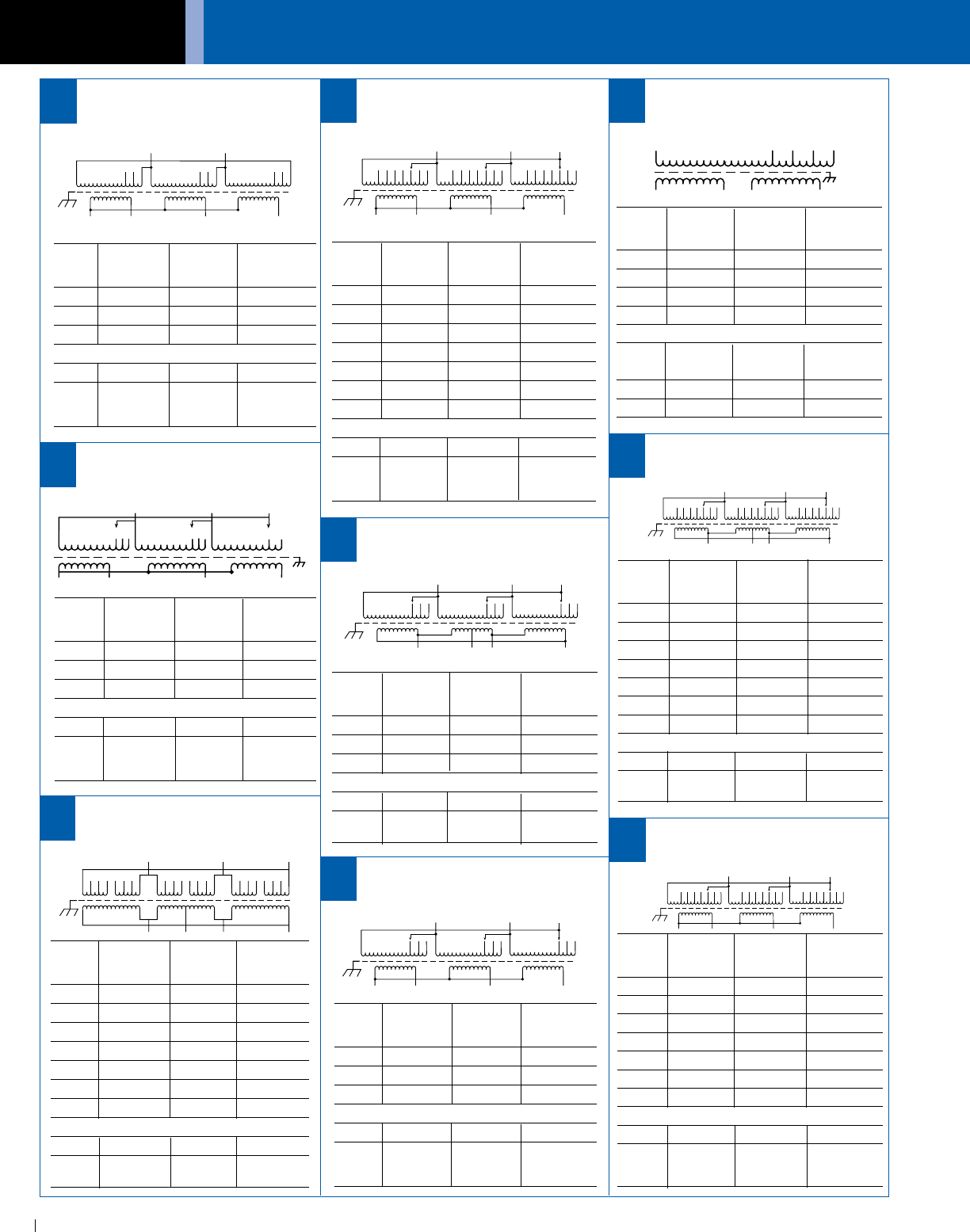
GENERAL ELECTRICAL CONNECTION DIAGRAMS
ACME ELECTRIC • MILWAUKEE, WI • 800.334.5214 • acmetransformer.com
126
GENERAL ACME® TRANSFORMER™ WIRING DIAGRAMS
126
PRIMARY: 480 Volts Delta
SECONDARY: 240 Volts Delta/120 Volts
TAPS: 2, 21
/2% ANFC, 4, 21
/2% BNFC
X1 X2 X3X4
H1 H3H2
1
35 246 2 46
1
35 2 46
1
35
Connect Connect
Primary Primary Inter- Secondary
Volts Lines To Connect Lines To
504 H1, H2, H3 1 to 2
492 H1, H2, H3 2 to 3
480 H1, H2, H3 1 to 4
468 H1, H2, H3 3 to 4
456 H1, H2, H3 1 to 6
444 H1, H2, H3 3 to 6
432 H1, H2, H3 5 to 6
Secondary Volts
240 X1, X2, X3
120 X1, X4 or
X2, X4
PRIMARY: 480 Volts Delta
SECONDARY: 240 Volts Delta/120 Volts
TAPS: 2, 21
/2% ANFC, 4, 21
/2% BNFC
Connect Connect
Primary Primary Inter- Secondary
Volts Lines To Connect Lines To
504 H1, H2, H3 1
492 H1, H2, H3 2
480 H1, H2, H3 3
468 H1, H2, H3 4
456 H1, H2, H3 5
444 H1, H2, H3 6
432 H1, H2, H3 7
Secondary Volts
240 X1, X2, X3
120 X1, X4 or
X2, X4
PRIMARY: 480 Volts Delta
SECONDARY: 240 Volts Delta/120 Volts
TAPS: 2, 5% BNFC
X1 X2 X3
X4
H1 H3H2
1
23
1
23
1
23
Connect Connect
Primary Primary Inter- Secondary
Volts Lines To Connect Lines To
480 H1, H2, H3 1
456 H1, H2, H3 2
432 H1, H2, H3 3
Secondary Volts
240 X1, X2, X3
120 X1, X4 or
X2, X4
PRIMARY: 600 Volts Delta
SECONDARY: 208Y/120 Volts
TAPS: 2, 5% BNFC
X1
H1
X2 X3
H3H2
X0
1
23
1
23
1
23
Connect Connect
Primary Primary Inter- Secondary
Volts Lines To Connect Lines To
600 H1, H2, H3 1
570 H1, H2, H3 2
540 H1, H2, H3 3
Secondary Volts
208 X1, X2, X3
120 X1 to X0
1 phase X2 to X0
X3 to X0
25
26
27
28
X1 X2 X3
X4
H1 H3H2
1
23
1
23
1
23
4
54
54
5
6
76
76
7
PRIMARY: 480 Volts Delta
SECONDARY: 208Y/120 Volts
TAPS: 2, 5% BNFC
X1
H1
X2 X3
H3H2
X0
1
23
1
23
1
23
Connect Connect
Primary Primary Inter- Secondary
Volts Lines To Connect Lines To
480 H1, H2, H3 1
456 H1, H2, H3 2
432 H1, H2, H3 3
Secondary Volts
208 X1, X2, X3
120 X1 to X0
1 phase X2 to X0
X3 to X0
21
PRIMARY: 480 Volts Delta
SECONDARY: 208Y/120 Volts
TAPS: 2, 21
/2% ANFC, 4, 21
/2% BNFC
X1
H1
X2 X3
H3H2
X0
1
23
1
23
1
23
4
54
54
5
6
76
76
7
Connect Connect
Primary Primary Inter- Secondary
Volts Lines To Connect Lines To
504 H1, H2, H3 1
492 H1, H2, H3 2
480 H1, H2, H3 3
468 H1, H2, H3 4
456 H1, H2, H3 5
444 H1, H2, H3 6
432 H1, H2, H3 7
Secondary Volts
208 X1, X2, X3
120 X1 to X0
1 phase X2 to X0
X3 to X0
PRIMARY: 120/208/240/277 Volts
SECONDARY: 120/240 Volts
H1 H5
X1
X2
X3
X4
H4H3
H2
22 23
PRIMARY: 380 Volts Delta
SECONDARY: 220Y/127 Volts
TAPS: 2, 5% BNFC
24
H3
X1
H3
123 123
X2
123
X3
H2
H1
X0
Connect Connect
Primary Primary Inter- Secondary
Volts Lines To Connect Lines To
277 H1, H5
240 H1, H4
208 H1, H3
120 H1, H2
Secondary Volts
120 X1 to X3 X1-X4
X2 to X4
120/240 X2 to X3 X1-X2-X4
240 X2 to X3 X1-X4
PRIMARY: 600 Volts Delta
SECONDARY: 208Y/120 Volts
TAPS: 2, 21
/2% ANFC, 4, 21
/2% BNFC
Connect Connect
Primary Primary Inter- Secondary
Volts Lines To Connect Lines To
630 H1, H2, H3 1
615 H1, H2, H3 2
600 H1, H2, H3 3
585 H1, H2, H3 4
570 H1, H2, H3 5
555 H1, H2, H3 6
540 H1, H2, H3 7
Secondary Volts
208 X1, X2, X3
120 X1 to X0
1 phase X2 to X0
X3 to X0
29
X1
H1
X2 X3
H3H2
X0
1
23
1
23
1
23
4
54
54
5
6
76
76
7
Connect Connect
Primary Primary Inter- Secondary
Volts Lines To Connect Lines To
380 H1, H2, H3 1
361 H1, H2, H3 2
342 H1, H2, H3 3
Secondary Volts
220 X1, X2, X3
127 X1 to X0
1 phase X2 to X0
X3 to X0
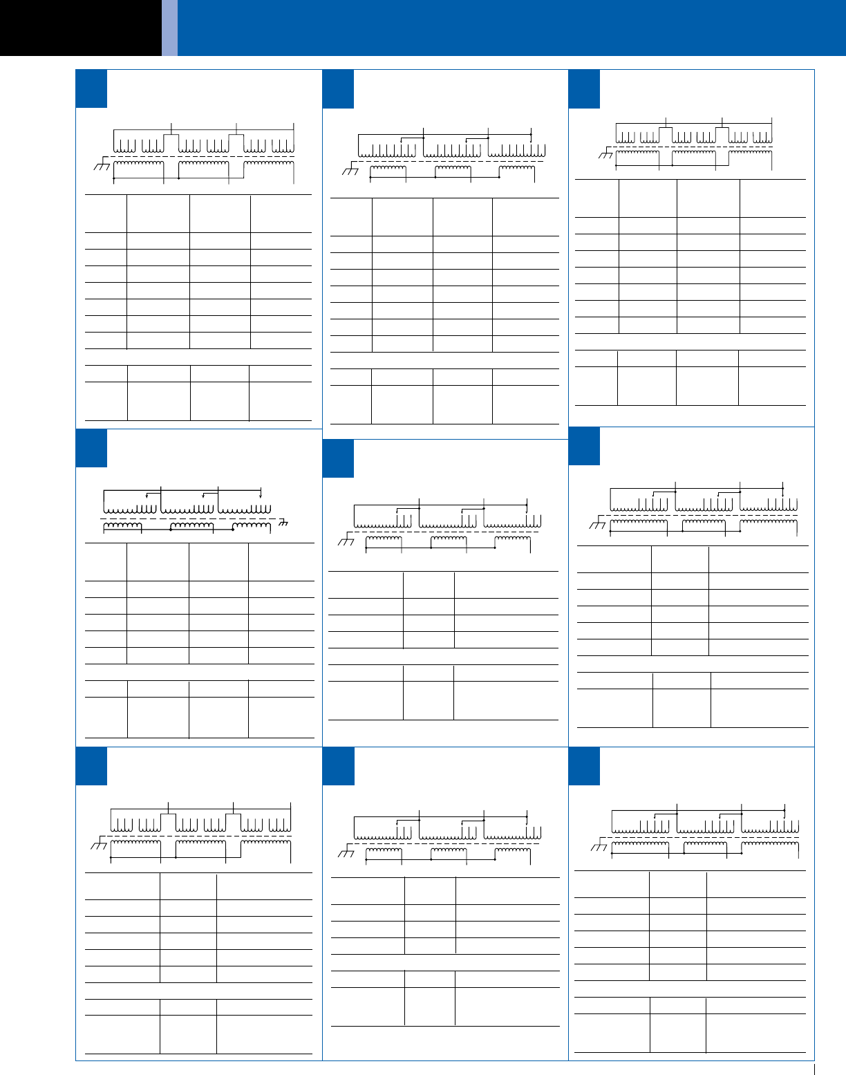
ACME ELECTRIC • MILWAUKEE, WI • 800.334.5214 • acmetransformer.com
127
GENERAL ELECTRICAL CONNECTION DIAGRAMS
127
GENERAL ACME® TRANSFORMER™ WIRING DIAGRAMS
PRIMARY: 600 Volts Delta
SECONDARY: 208Y/120 Volts
TAPS: 2, 21
/2% ANFC, 4, 21
/2% BNFC
X1 X2 X3X0
H1 H3H2
1
35 246 2 46
1
35 2 46
1
35
Connect Connect
Primary Primary Inter- Secondary
Volts Lines To Connect Lines To
630 H1, H2, H3 1 to 2
615 H1, H2, H3 2 to 3
600 H1, H2, H3 1 to 4
585 H1, H2, H3 3 to 4
570 H1, H2, H3 1 to 6
555 H1, H2, H3 3 to 6
540 H1, H2, H3 5 to 6
Secondary Volts
208 X1, X2, X3
120 X1 to X0
1 phase X2 to X0
X3 to X0
30
PRIMARY: 480 Volts Delta
SECONDARY: 480Y/277 Volts
TAPS: 2, 21
/2% ANFC, 4, 21
/2% BNFC
X1
H1
X2 X3
H3H2
X0
1
23
1
23
1
23
4
54
54
5
6
76
76
7
Connect Connect
Primary Primary Inter- Secondary
Volts Lines To Connect Lines To
504 H1, H2, H3 1
492 H1, H2, H3 2
480 H1, H2, H3 3
468 H1, H2, H3 4
456 H1, H2, H3 5
444 H1, H2, H3 6
432 H1, H2, H3 7
Secondary Volts
480 X1, X2, X3
277 X1 to X0
1 phase X2 to X0
X3 to X0
31
PRIMARY: 480 Volts Delta
SECONDARY: 480Y/277 Volts
TAPS: 2, 21
/2% ANFC, 4, 21
/2% BNFC
X1 X2 X3X0
H1 H3H2
1
35 246 2 46
1
35 2 46
1
35
Connect Connect
Primary Primary Inter- Secondary
Volts Lines To Connect Lines To
504 H1, H2, H3 1 to 2
492 H1, H2, H3 2 to 3
480 H1, H2, H3 1 to 4
468 H1, H2, H3 3 to 4
456 H1, H2, H3 1 to 6
444 H1, H2, H3 3 to 6
432 H1, H2, H3 5 to 6
Secondary Volts
480 X1, X2, X3
277 X1 to X0
1 phase X2 to X0
X3 to X0
32
PRIMARY: 380 Volts Delta
SECONDARY: 208/120 Volts
TAPS: 2-21
/2% ANFC and BNFC
33
X3
H1
H3
123
H2 H3
X2X1
X0
45 12345 12345
Connect Connect
Primary Primary Inter- Secondary
Volts Lines To Connect Lines To
399 H1, H2, H3 1
390 H1, H2, H3 2
380 H1, H2, H3 3
371 H1, H2, H3 4
361 H1, H2, H3 5
Secondary Volts
208 X1, X2, X3
120 X1 to X0
1 phase X2 to X0
X3 to X0
PRIMARY: 460 Volts Delta
SECONDARY: 460Y/266 Volts
TAPS: 1-5% ANFC and BNFC
X1
H1
X2 X3
H3H2
X0
1
23
1
23
1
23
Primary Connect Leads
Volts % to Tap No.
483 105 1
460 100 2
437 95 3
Secondary Volts
460 X1, X2, X3
266 X1 & X0
1 phase X2 & X0
X3 & X0
34
PRIMARY: 460 Volts Delta
SECONDARY: 460Y/266 Volts
TAPS: 2-21
/2% ANFC and BNFC
X1
H1
X2 X3
H3H2
X0
1
23
1
23
1
23
4
54
54
5
35
Primary Connect Leads
Volts % to Tap No.
483 105 1
472 102.5 2
460 100 3
449 97.5 4
437 95 5
Secondary Volts
460 X1, X2, X3
266 X1 & X0
1 phase X2 & X0
X3 & X0
PRIMARY: 460 Volts Delta
SECONDARY: 460Y/266 Volts
TAPS: 2-21
/2% ANFC and BNFC
X1 X2 X3X0
H1 H3H2
1
35 246 2 46
1
35 2 46
1
35
Primary Connect Leads
Volts % to Tap No.
483 105 1 to 2
472 102.5 2 to 3
460 100 1 to 4
449 97.5 3 to 4
437 95 4 to 5
Secondary Volts
460 X1, X2, X3
266 X1 & X0
1 phase X2 & X0
X3 & X0
36
PRIMARY: 460 Volts Delta
SECONDARY: 230Y/133 Volts
TAPS: 1-5% ANFC and BNFC
X1
H1
X2 X3
H3H2
X0
1
23
1
23
1
23
Primary Connect Leads
Volts % to Tap No.
483 105 1
460 100 2
437 95 3
Secondary Volts
230 X1, X2, X3
133 X1 & X0
1 phase X2 & X0
X3 & X0
37
PRIMARY: 460 Volts Delta
SECONDARY: 230Y/133 Volts
TAPS: 2-21
/2% ANFC and BNFC
X1
H1
X2 X3
H3H2
X0
1
23
1
23
1
23
4
54
54
5
Primary Connect Leads
Volts % to Tap No.
483 105 1
472 102.5 2
460 100 3
449 97.5 4
437 95 5
Secondary Volts
230 X1, X2, X3
133 X1 & X0
1 phase X2 & X0
X3 & X0
38
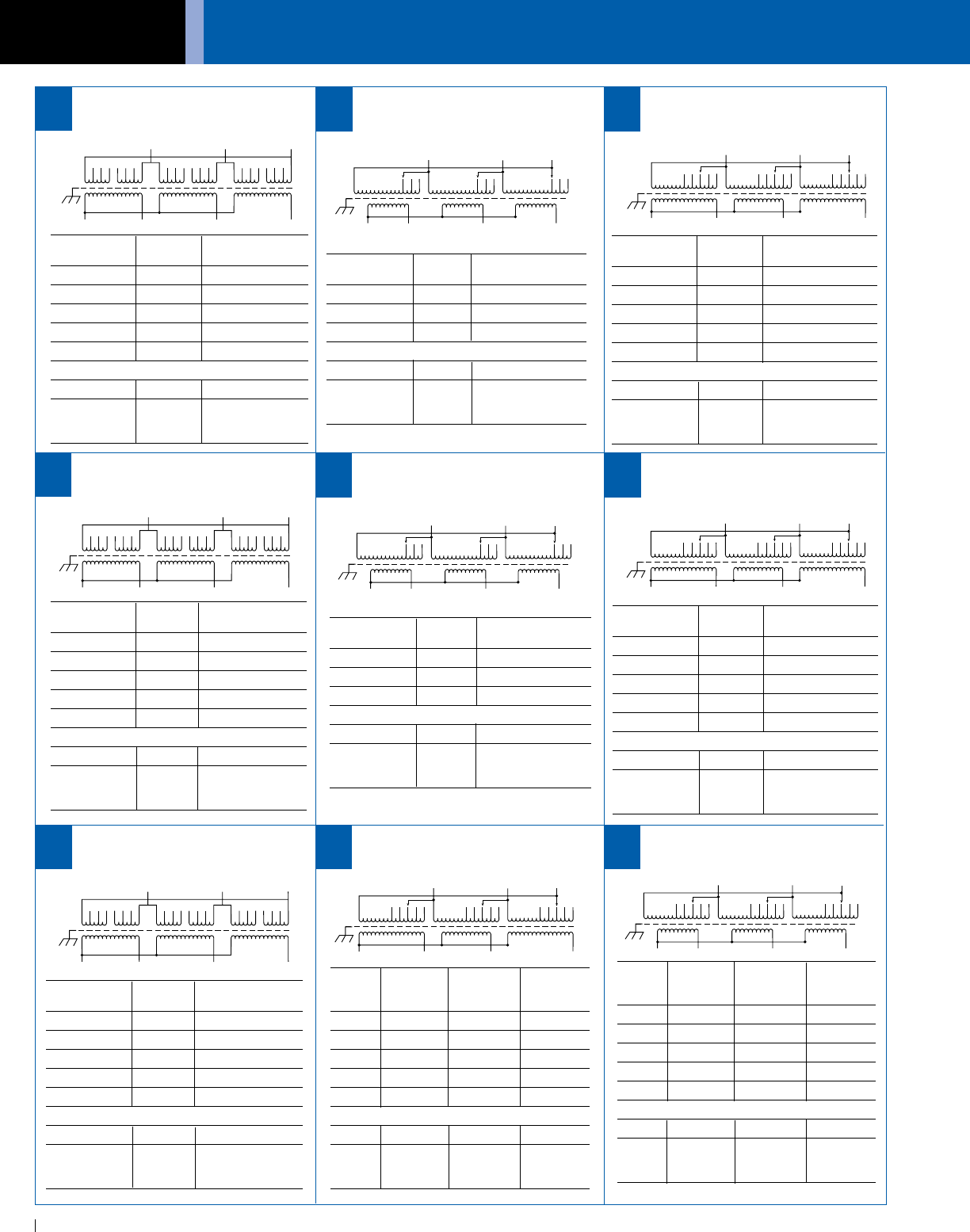
GENERAL ELECTRICAL CONNECTION DIAGRAMS
ACME ELECTRIC • MILWAUKEE, WI • 800.334.5214 • acmetransformer.com
128
GENERAL ACME® TRANSFORMER™ WIRING DIAGRAMS
128
PRIMARY: 575 Volts Delta
SECONDARY: 460Y/266 Volts
TAPS: 1-5% ANFC and BNFC
X1
H1
X2 X3
H3H2
X0
1
23
1
23
1
23
Primary Connect Leads
Volts % to Tap No.
604 105 1
575 100 2
546 95 3
Secondary Volts
460 X1, X2, X3
266 X1 & X0
1 phase X2 & X0
X3 & X0
PRIMARY: 575 Volts Delta
SECONDARY: 460Y/266 Volts
TAPS: 2-21
/2% ANFC and BNFC
X1 X2 X3X0
H1 H3H2
1
35 246 2 46
1
35 2 46
1
35
Primary Connect Leads
Volts % to Tap No.
604 105 1 to 2
589 102.5 2 to 3
575 100 1 to 4
561 97.5 3 to 4
546 95 4 to 5
Secondary Volts
460 X1, X2, X3
266 X1 & X0
1 phase X2 & X0
X3 & X0
PRIMARY: 575 Volts Delta
SECONDARY: 460Y/266 Volts
TAPS: 2-21
/2% ANFC and BNFC
X1
H1
X2 X3
H3H2
X0
1
23
1
23
1
23
4
54
54
5
Primary Connect Leads
Volts % to Tap No.
604 105 1
589 102.5 2
575 100 3
561 97.5 4
546 95 5
Secondary Volts
460 X1, X2, X3
266 X1 & X0
1 phase X2 & X0
X3 & X0
PRIMARY: 575 Volts Delta
SECONDARY: 230Y/133 Volts
TAPS: 1-5% ANFC and BNFC
X1
H1
X2 X3
H3H2
X0
1
23
1
23
1
23
Primary Connect Leads
Volts % to Tap No.
604 105 1
575 100 2
546 95 3
Secondary Volts
230 X1, X2, X3
133 X1 & X0
1 phase X2 & X0
X3 & X0
40
PRIMARY: 575 Volts Delta
SECONDARY: 230Y/133 Volts
TAPS: 2-21
/2% ANFC and BNFC
X1
H1
X2 X3
H3H2
X0
1
23
1
23
1
23
4
54
54
5
Primary Connect Leads
Volts % to Tap No.
604 105 1
589 102.5 2
575 100 3
561 97.5 4
546 95 5
Secondary Volts
230 X1, X2, X3
133 X1 & X0
1 phase X2 & X0
X3 & X0
41
PRIMARY: 575 Volts Delta
SECONDARY: 230Y/133 Volts
TAPS: 2-21
/2% ANFC and BNFC
X1 X2 X3X0
H1 H3H2
1
35 246 2 46
1
35 2 46
1
35
Primary Connect Leads
Volts % to Tap No.
604 105 1 to 2
589 102.5 2 to 3
575 100 1 to 4
561 97.5 3 to 4
546 95 4 to 5
Secondary Volts
230 X1, X2, X3
133 X1 & X0
1 phase X2 & X0
X3 & X0
42
45
44
43
Connect Connect
Primary Primary Inter- Secondary
Volts Lines To Connect Lines To
218 X1, X2, X3 1
213 X1, X2, X3 2
208 X1, X2, X3 3
203 X1, X2, X3 4
198 X1, X2, X3 5
Secondary Volts
480 H1, H2, H3
277 H1 to H0
1 phase H2 to H0
H3 to H0
PRIMARY: 208 Volts Delta
SECONDARY: 480Y/277 Volts
TAPS: 2, 21
/2% ANFC, 2, 21
/2% BNFC
46
H1
X1
H2 H3
X3X2
H0
1
23
1
23
1
23
4
54
54
5
PRIMARY: 460 Volts Delta
SECONDARY: 230Y/133 Volts
TAPS: 2-21
/2% ANFC and BNFC
X1 X2 X3X0
H1 H3H2
1
35 246 2 46
1
35 2 46
1
35
Primary Connect Leads
Volts % to Tap No.
483 105 1 to 2
472 102.5 2 to 3
460 100 1 to 4
449 97.5 3 to 4
437 95 4 to 5
Secondary Volts
230 X1, X2, X3
133 X1 & X0
1 phase X2 & X0
X3 & X0
39
Connect Connect
Primary Primary Inter- Secondary
Volts Lines To Connect Lines To
437 H1, H2, H3 1
426 H1, H2, H3 2
416 H1, H2, H3 3
406 H1, H2, H3 4
395 H1, H2, H3 5
Secondary Volts
208 X1, X2, X3
120 X1 to X0
1 phase X2 to X0
X3 to X0
PRIMARY: 416 Volts Delta
SECONDARY: 208Y/120 Volts
TAPS: 2, 21
/2% ANFC, 2, 21
/2% BNFC
47
X1
H1
X2 X3
H3H2
X0
1
23
1
23
1
23
4
54
54
5
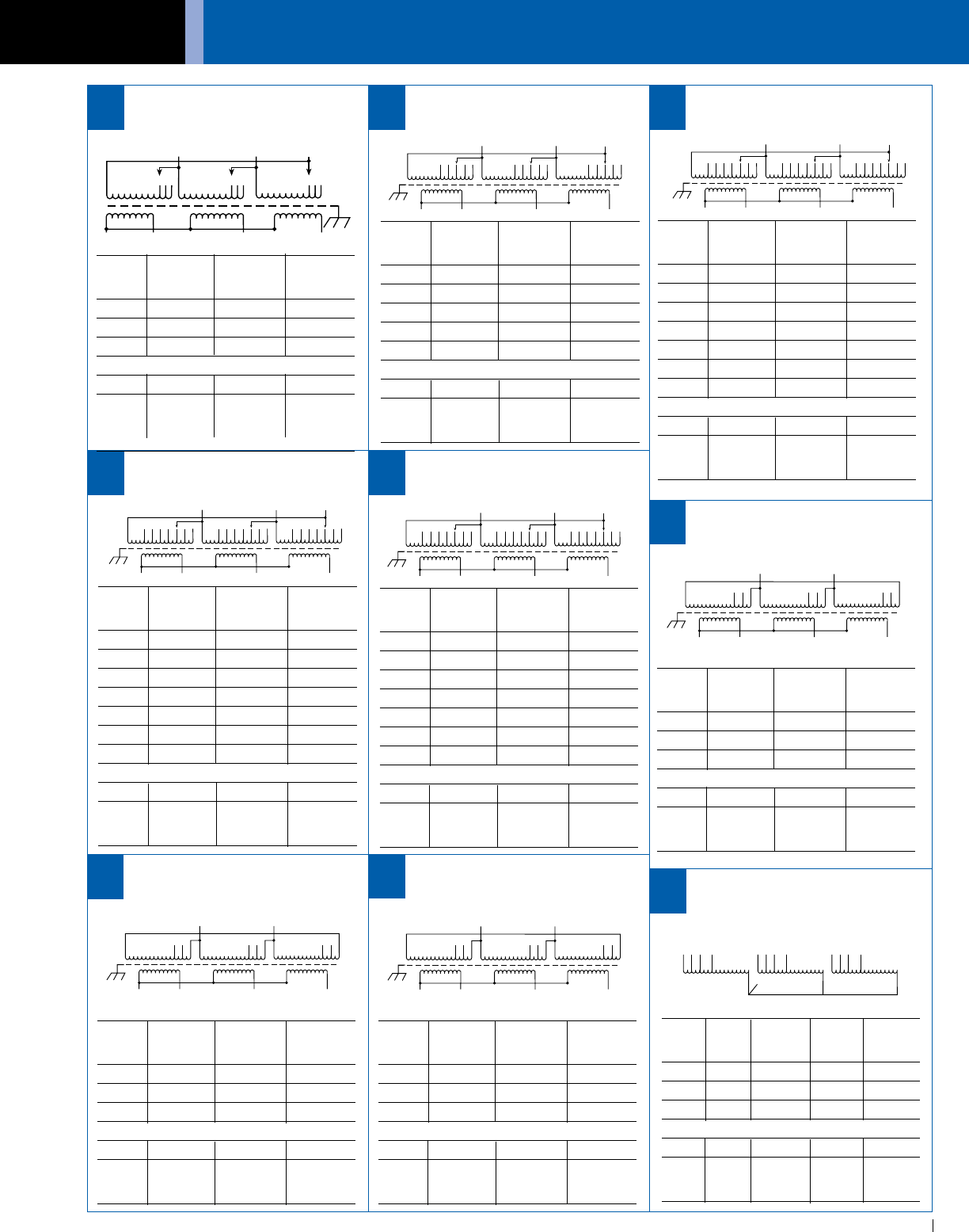
ACME ELECTRIC • MILWAUKEE, WI • 800.334.5214 • acmetransformer.com
129
GENERAL ELECTRICAL CONNECTION DIAGRAMS
129
GENERAL ACME® TRANSFORMER™ WIRING DIAGRAMS
PRIMARY: 600 Volts Delta
SECONDARY: 600Y/347 Volts
TAPS: 2, 21
/2% ANFC, 4, 21
/2% BNFC
X1
H1
X2 X3
H3H2
X0
1
23
1
23
1
23
4
54
54
5
6
76
76
7
PRIMARY: 208 Volts Delta
SECONDARY: 480Y/277 Volts
TAPS: 2, 5% BNFC
48
X1
H2 H3
X3
X2
12
3
123
123
H1H0 Connect Connect
Primary Primary Inter- Secondary
Volts Lines To Connect Lines To
630 H1, H2, H3 1
615 H1, H2, H3 2
600 H1, H2, H3 3
585 H1, H2, H3 4
570 H1, H2, H3 5
Secondary Volts
208 X1, X2, X3
120 X1 to X0
1 phase X2 to X0
X3 to X0
PRIMARY: 600 Volts Delta
SECONDARY: 208Y/120 Volts
TAPS: 2,
21
/2
% ANFC, 2,
21
/2
% BNFC
49
X1
H1
X2 X3
H3H2
X0
1
23
1
23
1
23
4
54
54
5
Connect Connect
Primary Primary Inter- Secondary
Volts Lines To Connect Lines To
630 H1, H2, H3 1
615 H1, H2, H3 2
600 H1, H2, H3 3
585 H1, H2, H3 4
570 H1, H2, H3 5
555 H1, H2, H3 6
540 H1, H2, H3 7
Secondary Volts
380 X1, X2, X3
220 X1 to X0
1 phase X2 to X0
X3 to X0
PRIMARY: 600 Volts Delta
SECONDARY: 380Y/220 Volts
TAPS: 2, 21
/2% ANFC, 4, 21
/2% BNFC
50
X1
H1
X2 X3
H3H2
X0
1
23
1
23
1
23
4
54
54
5
6
76
76
7
Connect Connect
Primary Primary Inter- Secondary
Volts Lines To Connect Lines To
630 H1, H2, H3 1
615 H1, H2, H3 2
600 H1, H2, H3 3
585 H1, H2, H3 4
570 H1, H2, H3 5
555 H1, H2, H3 6
540 H1, H2, H3 7
Secondary Volts
600 X1, X2, X3
347 X1 to X0
1 phase X2 to X0
X3 to X0
52
Connect Connect
Primary Primary Inter- Secondary
Volts Lines To Connect Lines To
630 H1, H2, H3 1
615 H1, H2, H3 2
600 H1, H2, H3 3
585 H1, H2, H3 4
570 H1, H2, H3 5
555 H1, H2, H3 6
540 H1, H2, H3 7
Secondary Volts
480 X1, X2, X3
277 X1 to X0
1 phase X2 to X0
X3 to X0
PRIMARY: 600 Volts Delta
SECONDARY: 480Y/277 Volts
TAPS: 2, 21
/2% ANFC, 4, 21
/2% BNFC
51
X1
H1
X2 X3
H3H2
X0
1
23
1
23
1
23
4
54
54
5
6
76
76
7
Connect Connect
Primary Primary Inter- Secondary
Volts Lines To Connect Lines To
600 H1, H2, H3 1
570 H1, H2, H3 2
540 H1, H2, H3 3
Secondary Volts
380 X1, X2, X3
220 X1 to X0
1 phase X2 to X0
X3 to X0
PRIMARY: 600 Volts Delta
SECONDARY: 380Y/220 Volts
TAPS: 2, 5% BNFC
53
X1
H1
X2 X3
H3H2
X0
1
23
1
23
1
23
Connect Connect
Primary Primary Inter- Secondary
Volts Lines To Connect Lines To
600 H1, H2, H3 1
570 H1, H2, H3 2
540 H1, H2, H3 3
Secondary Volts
600 X1, X2, X3
347 X1 to X0
1 phase X2 to X0
X3 to X0
PRIMARY: 600 Volts Delta
SECONDARY: 600Y/347 Volts
TAPS: 2, 5% BNFC
54
X1
H1
X2 X3
H3H2
X0
1
23
1
23
1
23
Connect Connect
Primary Primary Inter- Secondary
Volts Lines To Connect Lines To
600 H1, H2, H3 1
570 H1, H2, H3 2
540 H1, H2, H3 3
Secondary Volts
480 X1, X2, X3
277 X1 to X0
1 phase X2 to X0
X3 to X0
PRIMARY: 600 Volts Delta
SECONDARY: 480Y/277 Volts
TAPS: 2, 5% BNFC
55
X1
H1
X2 X3
H3H2
X0
1
23
1
23
1
23
Connect Connect
Primary Primary Inter- Secondary
Volts Lines To Connect Lines To
208 X1, X2, X3 1
198 X1, X2, X3 2
187 X1, X2, X3 3
Secondary Volts
480 H1, H2, H3
277 H1 to H0
1 phase H2 to H0
H3 to H0
X1
H1 X3
H3H2
X0
H4 H7
H0
X2
H5 H8 H6 H9
PRIMARY: 600 Volts
SECONDARY: 480 Volts
TAPS: 2, 5% BNFC
56
Connect Connect
Primary Alt Primary Inter- Secondary
Volts Rating Lines To Connect Lines To
600 480 H1, H2, H3
570 456 H4, H5, H6
540 432 H7, H8, H9
Secondary Volts
480 380 X1, X2, X3
277 220 X1 to X0
1 phase 1 phase X2 to X0
X3 to X0
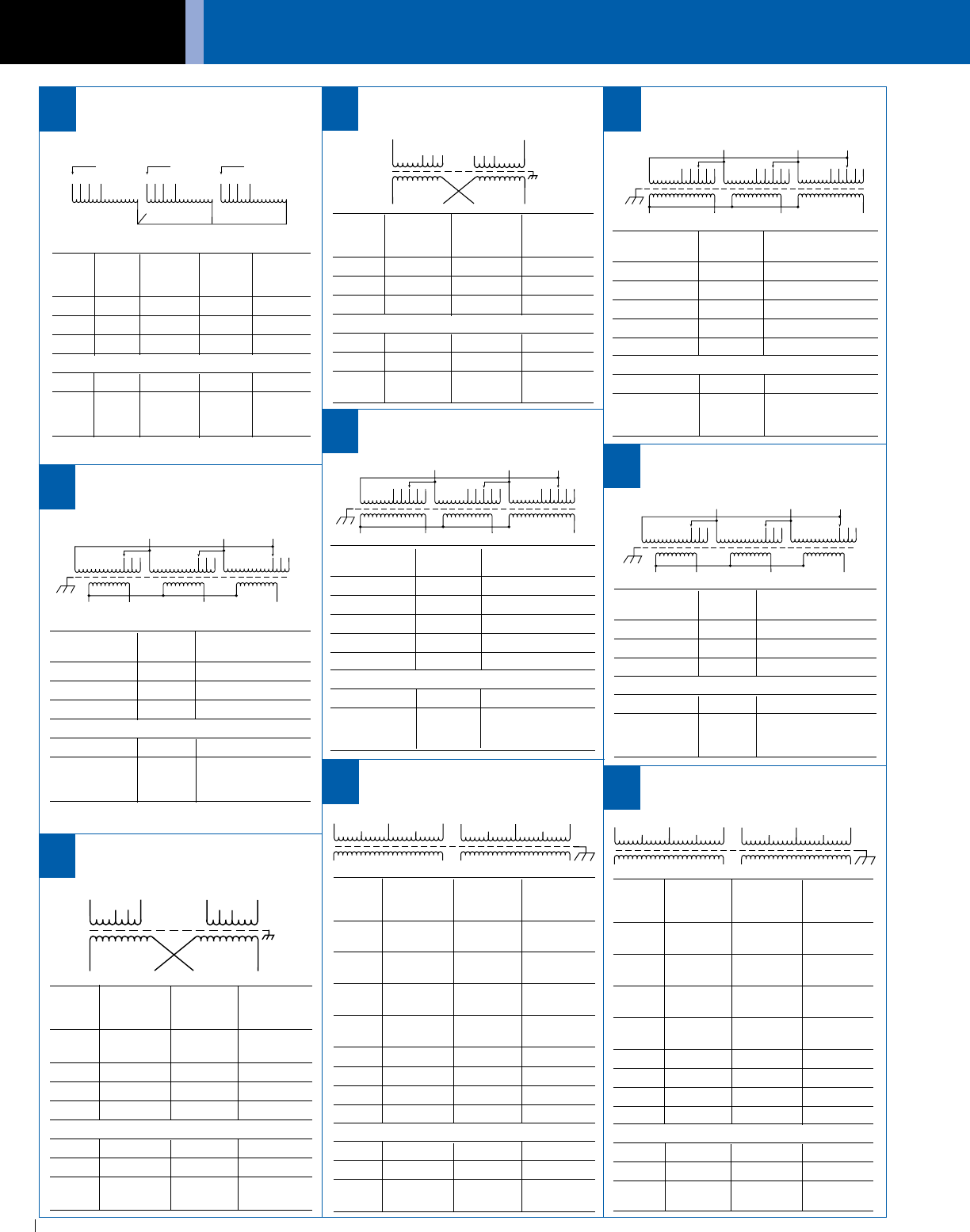
GENERAL ELECTRICAL CONNECTION DIAGRAMS
ACME ELECTRIC • MILWAUKEE, WI • 800.334.5214 • acmetransformer.com
130
GENERAL ACME® TRANSFORMER™ WIRING DIAGRAMS
130
Connect Connect
Primary Primary Inter- Secondary
Volts Lines To Connect Lines To
190 H1& H7 H1 to H6
H2 to H7
208 H1 & H8 H1 to H6
H3 to H8
220 H1 & H9 H1 to H6
H4 to H9
240 H1& H10 H1 to H6
H5 to H10
380 H1 & H7 H2 to H6
416 H1 & H8 H3 to H6
440 H1 & H9 H4 to H6
480 H1 & H10 H5 to H6
Secondary Volts
240 X2 to X3 X1 - X4
120/240 X2 to X3 X1- X2 - X4
120 X1 to X3 X1 - X4
X2 to X4
PRIMARY: 190/208/220/240 x
380/416/440/480 Volts
SECONDARY: 120/240 Volts
PRIMARY: 230 Volts Delta
SECONDARY: 230Y/133 Volts
TAPS: 2-21
/2% ANFC and 2-21
/2% BNFC
X1
H1
X2 X3
H3H2
X0
1
23
1
23
1
23
4
54
54
5
Primary Connect Leads
Volts % to Tap No.
242 105 1
236 102.5 2
230 100 3
224 97.5 4
219 95 5
Secondary Volts
230 X1, X2, X3
133 X1 & X0
1 phase X2 & X0
X3 & X0
PRIMARY: 208 Volts Delta
SECONDARY: 208Y/120 Volts
TAPS: 2-5% BNFC
X1
H1
X2 X3
H3H2
X0
1
23
1
23
1
23
Primary Connect Leads
Volts % to Tap No.
208 100 1
198 95 2
187 90 3
Secondary Volts
208 X1, X2, X3
120 X1 & X0
1 phase X2 & X0
X3 & X0
60
PRIMARY: 230 Volts Delta
SECONDARY: 230Y/133 Volts
TAPS: 1-5% ANFC and 1-5% BNFC
X1
H1
X2 X3
H3H2
X0
1
23
1
23
1
23
Primary Connect Leads
Volts % to Tap No.
241 105 1
230 100 2
218 95 3
Secondary Volts
230 X1, X2, X3
133 X1 & X0
1 phase X2 & X0
X3 & X0
62
PRIMARY: 208 Volts
SECONDARY: 120/240 Volts
TAPS: 2, 5% BNFC
H1
123
H2
456
X1X3X2X4
Connect Connect
Primary Primary Inter- Secondary
Volts Lines To Connect Lines To
208 H1 & H2 3 to 4
198 H1 & H2 2 to 5
187 H1 & H2 1 to 6
Secondary Volts
240 X2 to X3 X1-X4
120/240 X2 to X3 X1-X2-X4
120 X1 to X3 X1-X4
X2 to X4
58
PRIMARY: 600 Volts
SECONDARY: 480 Volts
TAPS: 2, 5% BNFC
57
X1
H1
X3
H3H2
X0
H0
X2
123123123
Connect Connect
Primary Alt Primary Inter- Secondary
Volts Rating Lines To Connect Lines To
600 480 H1, H2, H3 1
570 456 H1, H2, H3 2
540 432 H1, H2, H3 3
Secondary Volts
480 380 X1, X2, X3
277 220 X1 to X0
1 phase 1 phase X2 to X0
X3 to X0
PRIMARY: 120/208/240/277 Volts
SECONDARY: 120/240 Volts
H8
H6 H7
X1X3X2X4
H1
H2 H3
H4 H5
63
H1
H2
H3
H4
H5 H6
H7
H8
H9
H10
X4 X3 X2 X1
64
H1
H2
H3
H4
H5 H6
H7
H8
H9
H10
X4 X3 X2 X1
PRIMARY: 190/200/208/220 x
380/400/416/440 Volts
SECONDARY: 110/220 Volts
65
Connect Connect
Primary Primary Inter- Secondary
Volts Lines To Connect Lines To
120 H1 & H8 H1 to H6
H3 to H8
208 H1 & H8 H2 to H7
240 H1 & H8 H3 to H6
277 H1 & H8 H4 to H5
Secondary Volts
240 X2 to X3 X1 & X4
120/240 X2 to X3 X1, X3, X4
120 X1 to X3 X1 & X4
X2 to X4
PRIMARY: 208 Volts Delta
SECONDARY: 208Y/120 Volts
TAPS: 2-21
/2% ANFC and 2-21
/2% BNFC
X1
H1
X2 X3
H3H2
X0
1
23
1
23
1
23
4
54
54
5
Primary Connect Leads
Volts % to Tap No.
218 105 1
213 102.5 2
208 100 3
203 97.5 4
198 95 5
Secondary Volts
208 X1, X2, X3
120 X1 & X0
1 phase X2 & X0
X3 & X0
61
Connect Connect
Primary Primary Inter- Secondary
Volts Lines To Connect Lines To
190 H1 & H7 H1 to H6
H2 to H7
200 H1 & H8 H1 to H6
H3 to H8
208 H1 & H9 H1 to H6
H4 to H9
220 H1 & H10 H1 to H6
H5 to H10
380 H1 & H7 H2 to H6
400 H1 & H8 H3 to H6
415 H1 & H9 H4 to H6
440 H1 & H10 H5 to H6
Secondary Volts
220 X2 to X3 X1-X4
110/220 X2 to X3 X1-X2-X4
110 X1 to X3 X1-X4
X2 to X4
59
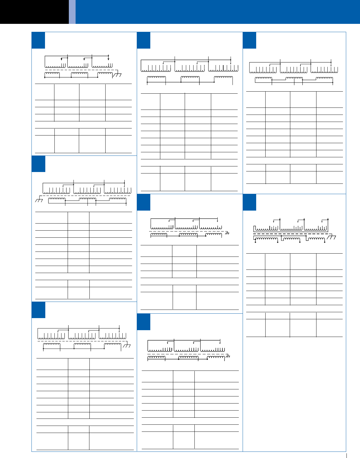
ACME ELECTRIC • MILWAUKEE, WI • 800.334.5214 • acmetransformer.com
131
GENERAL ELECTRICAL CONNECTION DIAGRAMS
131
GENERAL ACME® TRANSFORMER™ WIRING DIAGRAMS
PRIMARY: 480 Volts Delta
SECONDARY: 240 Volts Delta/120 Volts
TAPS: 2, 21
/2% ANFC, 4, 21
/2% BNFC
X1 X2 X3
X4
H1 H3H2
1
23
1
23
1
23
4
54
54
5
6
76
76
7
68
PRIMARY: 600 Volts Delta
SECONDARY: 240 Delta/120 Volts
TAPS: 2, 21
/2% ANFC, 4, 21
/2% BNFC
X1 X2 X3
X4
H1 H3H2
1
23
1
23
1
23
4
54
54
5
6
76
76
7
Primary Connect Leads
Volts % to Tap No.
630 105 1
615 102.5 2
600 100 3
585 97.5 4
570 95 5
555 92.5 6
540 90 7
Secondary Volts
240 X1, X2, X3
120 X1, X4, or
X2, X4
69
PRIMARY: 240 Volts Delta
SECONDARY: 480Y/277 Volts
TAPS: 2, 5% BNFC
H3
X1
H3
123 123
X2
123
X3
H2
H1
H0
70
PRIMARY: 240 Volts Delta
SECONDARY: 480Y/277 Volts
TAPS: 2, 21
/2% ANFC & BNFC
71
PRIMARY: 480 Volts Delta
SECONDARY: 208Y/120 Volts
TAPS: 2-21
/2% ANFC, 4, 21
/2% BNFC
X1
H1
X2 X3
H3H2
X0
1
23
1
23
1
23
4
54
54
5
6
76
76
7
Connect Connect
Primary Primary Inter- Secondary
Volts Lines To Connect Lines To
504 H1, H2, H3 1
492 H1, H2, H3 2
480 H1, H2, H3 3
468 H1, H2, H3 4
456 H1, H2, H3 5
444 H1, H2, H3 6
432 H1, H2, H3 7
Secondary Volts
208 X1, X2, X3
120 X1 to X0
1 phase X2 to X0
X3 to X0
67
PRIMARY: 416 Volts Delta
SECONDARY: 208Y/120 Volts
TAPS: 2, 5% BNFC
66
H1
X2 X3
H3
H2
12
3
123
123
X1X0
PRIMARY: 380 Volts Delta
SECONDARY: 208Y/120 Volts
TAPS: 2, 21
/2% ANFC, 4, 21
/2% BNFC
X1
H1
X2 X3
H3H2
X0
1
23
1
23
1
23
4
54
54
5
6
76
76
7
Primary Connect Leads
Volts % to Tap No.
399 105 1
390 102.5 2
380 100 3
371 97.5 4
361 95 5
352 92.5 6
342 90 7
Secondary Volts
208 X1, X2, X3
120 X1 to X0
1 phase X2 to X0
X3 to X0
72
PRIMARY: 440 Volts Delta
SECONDARY: 220Y/127 Volts
TAPS: 2, 5% ANFC & BNFC
X3
H1
H3
H2
12
3
H3
X2X1
X0
4
5
12
3
4
5
12
3
4
5
Primary Connect Leads
Volts % to Tap No.
484 110 1
462 105 2
440 100 3
418 95 4
396 90 5
Secondary Volts
220 X1, X2, X3
127 X1 to X0
1 phase X2 to X0
X3 to X0
73
Connect Connect
Primary Primary Inter- Secondary
Volts Lines To Connect Lines To
504 H1, H2, H3 1
492 H1, H2, H3 2
480 H1, H2, H3 3
468 H1, H2, H3 4
456 H1, H2, H3 5
444 H1, H2, H3 6
432 H1, H2, H3 7
Secondary Volts
240 X1, X2, X3
120 X1, X4, or
X2, X4
Primary Connect Leads
Volts % to Tap No.
240 100 1
228 95 2
216 90 3
Secondary Volts
480 H1, H2, H3
277 H1 to H0
1 phase H2 to H0
H3 to H0
Connect Connect
Primary Primary Inter- Secondary
Volts Lines To Connect Lines To
437 H1, H2, H3 1
416 H1, H2, H3 2
395 H1, H2, H3 3
Secondary Volts
208 X1, X2, X3
120 X1 to X0
1 phase X2 to X0
X3 to X0
Connect Connect
Primary Primary Inter- Secondary
Volts Lines To Connect Lines To
252 X1, X2, X3 1
246 X1, X2, X3 2
240 X1, X2, X3 3
234 X1, X2, X3 4
228 X1, X2, X3 5
Secondary Volts
480 H1, H2, H3
277 H1 to H0
1 phase H2 to H0
H3 to H0
H0
1
2
3
4
5
1
2
3
45
1
2
3
45
X3
X2
X1
H1 H2 H3
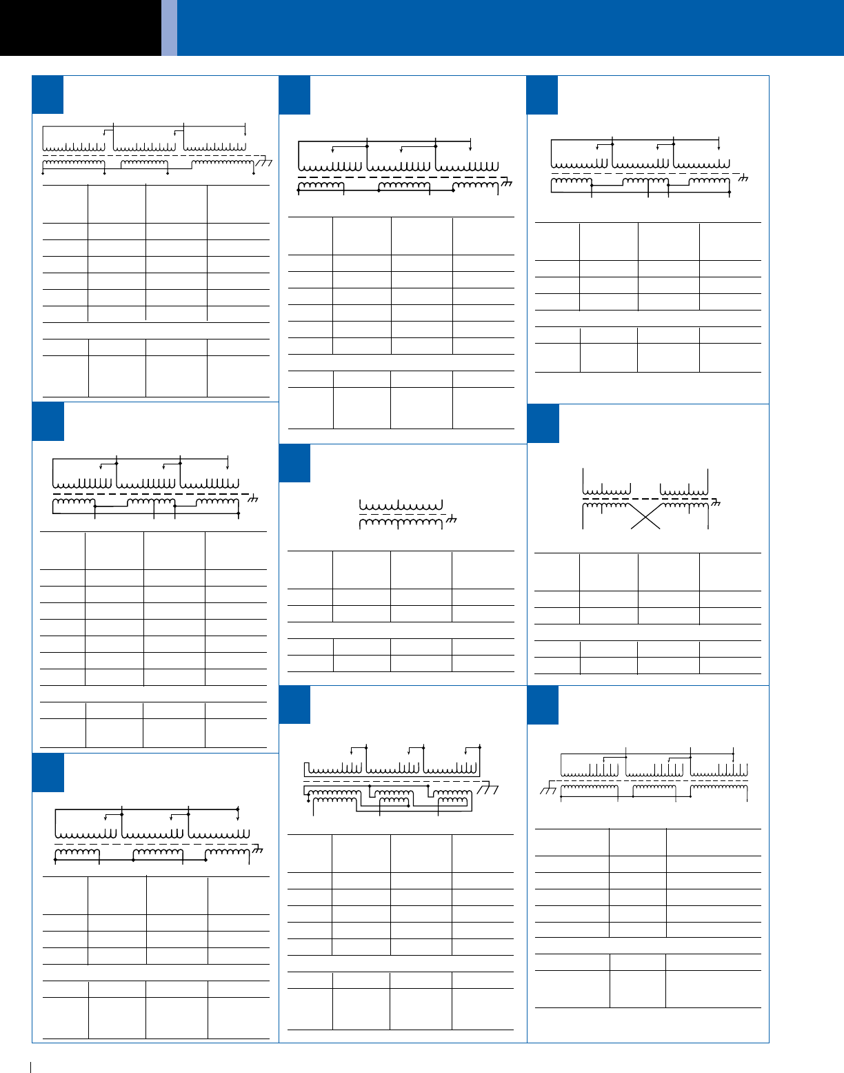
GENERAL ELECTRICAL CONNECTION DIAGRAMS
ACME ELECTRIC • MILWAUKEE, WI • 800.334.5214 • acmetransformer.com
132
GENERAL ACME® TRANSFORMER™ WIRING DIAGRAMS
132
PRIMARY: 190/200/210/220/
230/240 Volts Delta
SECONDARY: 400Y/231 Volts
PRIMARY: 400 Volts Delta
SECONDARY: 240 Volts Delta/120 Volts
TAPS: 2, 5% BNFC
X3
H1
123 123
H2
123
H3
X2
X1 X4
76
X1
H1 H2 H3
X2 X3
PRIMARY: 277/480 Volts
SECONDARY: 208/277 Volts
TAPS: NONE
H1 H6
X1
X4
X3
X6
H5
H4
H2 H3
X5 X2
79
X3
H1 H2
12
3
H3
X2X1
X0
4
5
12
3
4
5
12
3
4
5
666
Connect Connect
Primary Primary Inter- Secondary
Volts Lines To Connect Lines To
240 H1, H2, H3 1
230 H1, H2, H3 2
220 H1, H2, H3 3
210 H1, H2, H3 4
200 H1, H2, H3 5
190 H1, H2, H3 6
Secondary Volts
400 X1, X2, X3
231 X1 to X0
1 phase X2 to X0
X3 to X0
75
PRIMARY: 190/200/210/220/
230/240 Volts Delta
SECONDARY: 400Y/231 Volts
H1
X1
H2 H3
X3X2
H0
1
2
3
1
23
1
23
4
54
54
56 66
74
Connect Connect
Primary Primary Inter- Secondary
Volts Lines To Connect Lines To
400 H1, H2, H3 1
380 H1, H2, H3 2
360 H1, H2, H3 3
Secondary Volts
240 X1, X2, X3
120 X1 to X4 or
X2 to X4
Connect Connect
Primary Primary Inter- Secondary
Volts Lines To Connect Lines To
277 H1 - H5 H2 to H4
480 H1 - H6 H3 to H4
Secondary Volts
208 X2 to X4 X1 - X5
277 X3 to X4 X1 - X6
Connect Connect
Primary Primary Inter- Secondary
Volts Lines To Connect Lines To
240 X1, X2, X3 1
230 X1, X2, X3 2
220 X1, X2, X3 3
210 X1, X2, X3 4
200 X1, X2, X3 5
190 X1, X2, X3 6
Secondary Volts
400 H1, H2, H3
231 H1 to H0
1 phase H2 to H0
H3 to H0
Connect Connect
Primary Primary Inter- Secondary
Volts Lines To Connect Lines To
277 H1 & H2
480 H1 & H3
Secondary Volts
208 X1 to X2
277 X1 to X3
X3
H1 H2
12
3
H3
X2X1
X0
12
312
3
PRIMARY: 480 Volts Delta
SECONDARY: 208Y/120 Volts
TAPS: 1-5% ANFC & 1-5% BNFC
80
Connect Connect
Primary Primary Inter- Secondary
Volts Lines To Connect Lines To
504 H1, H2, H3 1
480 H1, H2, H3 2
456 H1, H2, H3 3
Secondary Volts
208 X1, X2, X3
120 X1 to X0
1 phase X2 to X0
X3 to X0
PRIMARY: 480 Volts Delta
SECONDARY: 208Y/120 Volts
TAPS: 2, 2 1
/2% ANFC, 2, 21
/2% BNFC
1
2
3
4
5
1
2
3
45
1
2
3
45
X3
X2
X1
H1 H2 H3
X0
81
Connect Connect
Primary Primary Inter- Secondary
Volts Lines To Connect Lines To
504 H1, H2, H3 1
492 H1, H2, H3 2
480 H1, H2, H3 3
468 H1, H2, H3 4
456 H1, H2, H3 5
Secondary Volts
208 X1, X2, X3
120 X1 to X0
1 phase X2 to X0
X3 to X0
X3
H1
123 123
H2
123
H3
X2
X1 X4
456
7456
7456
7
PRIMARY: 400 Volts Delta
SECONDARY: 240 Delta/120 Volts
TAPS: 2, 2 1
/2% ANFC, 4, 21
/2% BNFC
77
Connect Connect
Primary Primary Inter- Secondary
Volts Lines To Connect Lines To
420 H1, H2, H3 1
410 H1, H2, H3 2
400 H1, H2, H3 3
390 H1, H2, H3 4
380 H1, H2, H3 5
370 H1, H2, H3 6
360 H1, H2, H3 7
Secondary Volts
240 X1, X2, X3
120 X1 to X4 or
X2 to X4
PRIMARY: 277/480 Volts
SECONDARY: 208/277 Volts
TAPS: NONE
78
PRIMARY: 380 Volts Delta
SECONDARY: 208Y/120 Volts
TAPS: 2-21
/2% ANFC and 2-21
/2% BNFC
X1
H1
X2 X3
H3H2
X0
1
23
1
23
1
23
4
54
54
5
Primary Connect Leads
Volts % to Tap No.
399 105 1
390 102.5 2
380 100 3
371 97.5 4
361 95 5
Secondary Volts
208 X1, X2, X3
120 X1 to X0
1 phase X2 to X0
X3 to X0
82
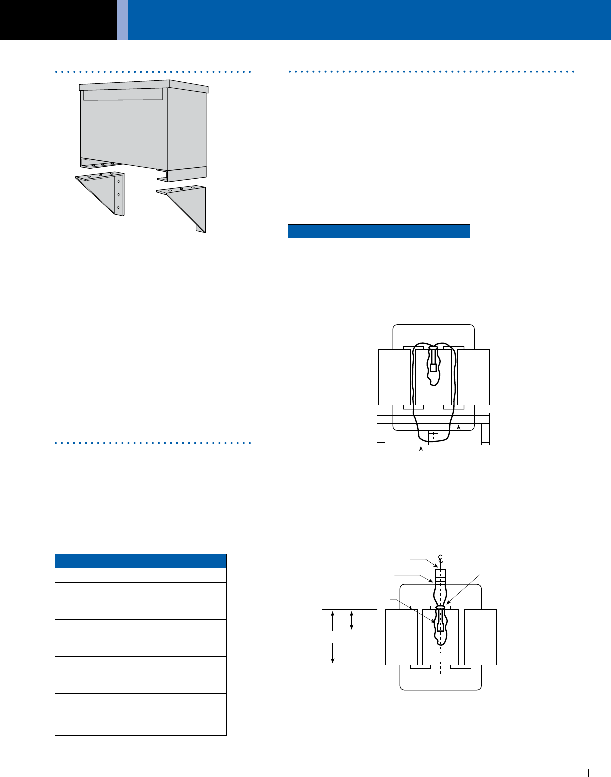
ACME ELECTRIC • MILWAUKEE, WI • 800.334.5214 • acmetransformer.com
133
GENERAL ELECTRICAL CONNECTION DIAGRAMS
133
GENERAL ACME® TRANSFORMER™ ACCESSORIES
Suffix Tap Arrangement
– 1S Two 5% (–) BNFC Taps
One 5% (+) ANFC Tap
– 2S and
One 5% (–) BNFC Tap
Two 2-1/2% (+) ANFC Taps
– 3S and
Four 2-1/2%(–) BNFC Taps
Two 2-1/2% (+) ANFC Taps
– 4S and
Two 2-1/2% (–) BNFC Taps
Two 5% (+) ANFC Taps
– 5S and
Two 5% (–) BNFC Taps
kVA Mounting Position Illustration
27.0 – Bottom of
220.0 the case Figure 1
275.0– Top Flange of the
750 Core Bracket Figure 2
COIL 1 COIL 3
THERMAL SWITCH
.625 (1.6 cm) H DIA.
EPOXY-RING
CORE
EPOXY LAYER
TERMINAL BLOCK
H
.5H
(1.3 cm)
COIL 2
Figure 2
COIL 1 COIL 2COIL 3
CORE
BOTTOM OF CASE
Required on:
Ventilated Units:
1Ø, 37.5 and 50 kVA
3Ø, 30, 45 and 75 kVA
Catalog Number: PL-79912
Encapsulated Units:
3Ø dit., 11 kVA — 20 kVA
3Ø std. distribution — 15 kVA
Catalog Number: PL-79911
Wall mounting brackets are not
required on:
1Ø units — 25 kVA and below
3Ø units — 9 kVA and below
The catalog number suffix provides tap
information as outlined in chart below:
If the catalog number has no suffix,
there are no taps available.
EXAMPLE: T-2-53019-3S
The suffix 3S indicates the unit has two 2.5%
(+) ANFC taps and four 2.5% (–) BNFC taps.
Acme Thermal Switch Kits are designed for use with single and three
phase drive isolation and distribution transformers. Thermal switch kits
are available for one or three sensor systems.
Thermal sensors can be field or factory installed in the transformer
winding ducts to detect abnormal temperatures. The thermal sensors
are a normally closed contact that opens at 200°C ± 10°C and has a
current capacity of 5 amps @ 120V or 2.5 amps @ 240V. This contact
can activate any number of different types of alarms or mechanisms
that could warn of a potential failure.
Figure 1
Thermal Switch Kits
Catalog Number: PL-79900
Wall Mounting Brackets
Standard Taps
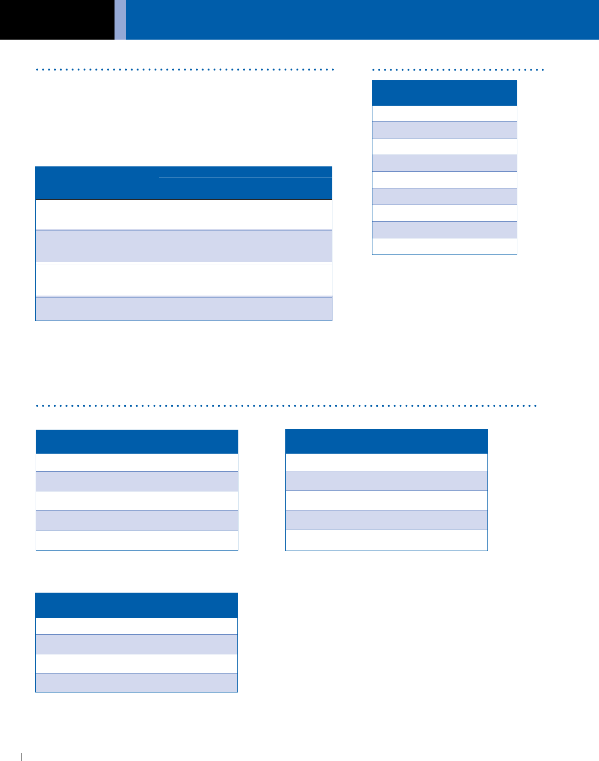
GENERAL ELECTRICAL CONNECTION DIAGRAMS
ACME ELECTRIC • MILWAUKEE, WI • 800.334.5214 • acmetransformer.com
134
GENERAL ACME® TRANSFORMER™ ACCESSORIES
134
Acme’s mechanical transformer lug kits contain all of the hardware
necessary to provide satisfactory transformer terminations. Lug kits are
available in sizes from 27 kVA to 660 kVA.
Acme lugs are of the dual rated single pole solderless type, made
from high strength aluminum alloy. To provide the best in low contact
resistance, all lugs in these kits are plated.
Lug Kits Weather Shields
Spare Parts
TOP COVER
SIDE PANEL
FRONT/REAR PANEL
Kit Contains
Transformer Wire Range
Catalog No. kVA Size Al or Cu Qty Nuts & Bolts Qty
Lug 1 371/2 1-phase 2 -14 8 1/4 - 20 X 3/4 8
27 - 45 3-phase 250 mcm - 6 4
Lug 2 50 - 75 1-phase 250 mcm - 6 12 1
/4 - 20 x 3/4 8
51 - 118 3-phase 1
/4 - 20 x 13/4 8
Lug 3 100 -167 1-phase 250 mcm - 6 3 1
/4 - 20 x 3/4 3
145 - 300 3-phase 600 mcm - 2 22 3/8 - 16 x 2 16
Lug 4 440 - 660 3-phase 600 mcm - 2 29 3/8 - 16 x 2 8
CATALOG NO. APPROX. SHIP WEIGHT
Lbs. (Kg.)
SA1701319 14 (6.4)
SA2701319 16 (7.3)
SA3701319 20 (9.1)
SA4701319 34 (15.4)
SA6701319 17 (7.7)
CATALOG NO. APPROX. SHIP WEIGHT
Lbs. (Kg.)
SA1701320 11 (5.0)
SA2701320 13 (5.9)
SA3701320 19 (8.6)
SA4701320 34 (15.4)
Catalog No. Approx. Ship Weight
Lbs. (Kg.)
WSA1 6 (2.7)
WSA2 7 (3.2)
WSA3 8 (3.6)
WSA4 8 (3.6)
WSA5 10 (4.5)
WSA6 10 (4.5)
WSA8 7 (3.2)
WSB3 30 (13.6)
WSB4 32 (14.5)
CATALOG NO. APPROX. SHIP WEIGHT
Lbs. (Kg.)
SA1701321 13 (5.9)
SA2701321 15 (6.8)
SA3701321 21 (9.5)
SA4701321 35 (15.9)
SA7701321 16 (7.3)

ACME ELECTRIC • MILWAUKEE, WI • 800.334.5214 • acmetransformer.com
135
GENERAL ELECTRICAL CONNECTION DIAGRAMS
135
GENERAL ACME® TRANSFORMER™ SPECIFICATIONS
1.0 Dry Type Transformers:
1.0.0 The following information should be utilized only by
trained technical personnel. If you need assistance,
please contact Acme’s Technical Services Department
at 800-334-5214.
1.0.1 Provide dry type, enclosed and ventilated transformers
as indicated herein. Transformers shall be Acme or
approved equal.
1.0.2 Transformers shall be designed, constructed and rated
in accordance with UL, CSA, NEMA, ANSI, IEEE, and
OSHA standards.
1.0.3 Transformers rated 27 kVA and larger, single and three
phase shall be the ventilated type, incorporating a 220
degree C insulation system and designed not to
exceed 150 degree C temperature rise above a 40
degree C ambient under full load conditions. Taps are
to be provided on the primary side of the transformer
as follows:
(a) 2 - 2.5% above normal full capacity.
4 - 2.5% below normal full capacity.
-or-
(b) 2 - 2.5% above normal full capacity.
2 - 2.5% below normal full capacity.
Alternate 1: 115 degree C rise transformers shall
incorporate a 220 degree C insulation system and
be designed not to exceed 115 degree C temperature
rise above a 40 degree C ambient under full load
conditions. In addition, the transformer shall have
the ability to carry a continuous 15% overload without
exceeding a 150 degree C rise above ambient.
Alternate 2: 80 degree C rise Transformers shall
incorporate a 220 degree C insulation system and
be designed not to exceed 80 degree C temperature
rise above a 40 degree C ambient under full load
conditions. In addition, the transformer shall have the
ability to carry a continuous 30% overload without
exceeding a 150 degree C rise above ambient.
1.0.4 Transformer enclosure finish must be ASA 61 gray
powder polyurethane paint. Transformer enclosure
temperature shall not exceed 50 degrees C plus
the ambient under any condition of loading at any
specified temperature rise at or below 150 degrees C.
1.0.5 Transformer enclosure shall be UL/NEMA Type 2 and
UL 3R Listed with the addition of a weather shield and
shall be so marked on the transformer.
1.0.6 Transformer shall incorporate an electrostatic shield
for the attenuation of voltage spikes, line noise, and
transients.
1.0.7 Single phase transformers and three phase
transformers terminate in copper or aluminum bus bar.
1.0.8 Transformer coils designed and manufactured for
increased insulation life, cooler operation, and lower
losses.
1.0.9 Transformers must operate at audible sound levels
below NEMA Standard ST-20. Sound levels will not
exceed the following:
30 - 50 kVA 45 db
51 - 150 kVA 50 db
151 - 300 kVA 55 db
301 - 500 kVA 60 db
501 - 750 kVA 65 db
Transformers must incorporate vibration isolation pads
in their construction located between the transformer
core and coil assembly and the transformer case.
External vibration isolation pads will not be used as
they tend to increase audible noise. Transformers shall
be floor mounted on a concrete pad. All connections
to the transformer will be made by means of flexible
metallic conduit.
1.0.10 Transformer enclosure shall be grounded per the
National Electric Code.
1.0.11 Transformers shall be dry-type 600 volt class, kVA
rating as indicated. Contractor to provide all necessary
lugs for all transformers.
1.0.12 Complete shop drawings must be submitted for
approval on all dry type transformers.
1.0.13 Typical performance data must be submitted for
approval on all transformers. Factory tests must be
made in accordance with the latest revisions of ANSI
Test Code C57.12.91 for Dry Type Transformers.
Performance data provided must contain but not be
limited to:
(a) No load losses.
(b) Full load losses.
(c) Polarity and phase rotation.
(d) Impedance at reference temperature.
(e) Efficiencies at 25, 50, 75, and 100% load.
(f) Regulation at 100% and 80% power factor.
(g) Audible sound level.
(h) Dimensions and weight.
(i) Applied potential test.
(j) Induced potential test.
(k) Excitation current.
(l) IR, IX, and IZ percentages.
(m) Reference and ambient temperature.
1.0.14 Warranty: Transformers must be warranted against
defects in materials, workmanship, and performance
for ten years from date of manufacture.
Specification Guide for
Dry Type Distribution Transformers

GENERAL ELECTRICAL CONNECTION DIAGRAMS
ACME ELECTRIC • MILWAUKEE, WI • 800.334.5214 • acmetransformer.com
136
GENERAL ACME® TRANSFORMER™ SPECIFICATIONS
136
1.0 Dry Type Transformers:
1.0.0 The following information should be utilized only by
trained technical personnel. If you need assistance,
please contact Acme’s Technical Services Department
at 800-334-5214.
1.0.1 Provide dry type, enclosed, epoxy encapsulated
transformers as indicated and specified herein.
Transformers must be Acme or approved equal.
1.0.2 Transformers must be designed, constructed and
rated in accordance with UL, CSA, NEMA, ANSI, IEEE,
and OSHA standards.
1.0.3 Transformers 3.0 - 75 kVA shall be compound filled,
incorporating a 180 degree C insulation system and
designed not to exceed a 115 degree C temperature
rise above a 40 degree C ambient under full load
conditions. Taps are to be provided on the primary
side of the transformer. The catalog number suffix will
provide the tap information outlined below:
SUFFIX TAP ARRANGEMENT
- 1S 2-5% BNFC
- 2S 1-5% ANFC & 1-5% BNFC
- 3S 2- 2.5% ANFC & 4-2.5% BNFC
- 4S 2- 2.5% ANFC & 2-2.5% BNFC
- 5S 2- 5% ANFC & 2-5% BNFC
1.0.4 Transformer enclosure finish must be ASA 61 gray
powder polyurethane paint.
1.0.5 Transformer enclosure temperature shall not exceed
65 degrees C plus the ambient.
1.0.6 Transformer enclosure shall be UL/NEMA Type 3R and
so marked on the transformer.
1.0.7 Transformer shall incorporate an electrostatic shield
for the attenuation of voltage spikes, line noise and
transients.
1.0.8 Transformer coils are typically wound with aluminum or
copper for increased insulation life, cooler operation
and lower losses.
1.0.9 All primary tap connections and both primary and
secondary phase conductors must be either copper
wire or copper bus bar.
1.0.10 Transformers must operate at audible sound levels
below ANSI/NEMA Standard ST-20. Sound levels will
not exceed the following:
Up to 9 kVA 40 db
10 - 50 kVA 45 db
51 - 150 kVA 50 db
1.0.11 Transformer enclosures shall be grounded per the
National Electric Code.
1.0.12 Complete shop drawings must be submitted for
approval on all Dry Type Transformers.
1.0.13 Typical performance data must be submitted for
approval on all transformers. Factory tests must be
made in accordance with the latest revisions of ANSI
Test Code C57.12.91 for Dry Type Transformers.
Performance data must contain but not be limited to:
(a) No load losses.
(b) Full load losses.
(c) Polarity and phase rotation.
(d) Impedance at reference temperature.
(e) Efficiencies at 25, 75, and 100% load.
(f) Regulation at 100% and 80% power factor.
(g) Audible sound level.
(h) Insulation class and rated temperature rise.
(i) Dimensions and weight.
(j) Applied potential test.
(k) Induced potential test.
(l) Excitation current.
(m) IR, IX, and IZ percentages.
(n) Reference and ambient temperature.
1.0.14 Warranty: Transformer must be warranted against
defects in materials, workmanship and performance
for ten years from date of manufacture.
Specification Guide for Single & Three Phase
Encapsulated Transformers

ACME ELECTRIC • MILWAUKEE, WI • 800.334.5214 • acmetransformer.com
137
GENERAL ELECTRICAL CONNECTION DIAGRAMS
137
GENERAL ACME® TRANSFORMER™ SPECIFICATIONS
1.0 Dry Type Transformers:
1.0.0 The following information should be utilized only by
trained technical personnel. If you need assistance,
please contact Acme’s Technical Services
Department at 800-334-5214.
1.0.1 Provide dry type, enclosed, and ventilated
transformers as indicated and specified herein.
Transformers must be Acme or approved equal.
Transformers must be UL listed for non-sinusoidal
current loads of a specified K Factor (UL Standard
1561), CSA certified and labeled as such.
1.0.2 For sizes 15 kVA and larger, low voltage dry
transformers will be ventilated type, incorporating a
220 degree C insulation system and designed not to
exceed 150 degree C temperature rise above a 40
degree C ambient under full load conditions. Taps will
be provided on the primary side of the transformer.
There will be 2, 2.5% taps above normal full capacity
and 4, 2.5% taps below normal full capacity.
Alternate 1: 115 degree C rise Transformers shall
incorporate a 220 degree C insulation system and
be designed not to exceed 80 degree C temperature
rise above a 40 degree C ambient under full load
conditions. In addition, the transformer shall have the
ability to carry a continuous 15% overload without
exceeding a 150 degree C rise above ambient.
Alternate 2: 80 degree C rise Transformers shall
incorporate a 220 degree C insulation system and
be designed not to exceed 80 degree C temperature
rise above a 40 degree C ambient under full load
conditions. In addition, the transformer shall have the
ability to carry a continuous 30% overload without
exceeding a 150 degree C rise above ambient.
1.0.3 Transformers shall incorporate an electrostatic shield
for the attenuation of voltage spikes, line noise, and
transients.
1.0.4 Transformers must be designed to handle non-
linear loads and the adverse effects of harmonics.
Transformer coils will be wound with foil to minimize
the heating effects caused by harmonic currents.
1.0.5 Transformers must be able to power non-linear loads
with a K-Factor as high as 20.
1.0.6 Transformers must operate at audible sound levels
below NEMA ST-20. Sound levels will not exceed the
following:
30 - 50 kVA 45 db*
51 - 150 kVA 50 db*
151 - 300 kVA 55 db*
301 - 500 kVA 60 db*
* Sound levels are based on transformers with a K-Factor of
4 and a temperature rise of 150 degrees centigrade.
Enclosed, ventilated transformers must incorporate
vibration dampening pads in their construction,
located between the transformer core and coil
assembly and the transformer case. External vibration
dampening pads will not be used on enclosed,
ventilated designs as they tend to increase audible
noise. Transformers 15 kVA and larger shall be floor
mounted on a concrete pad. All connections to the
transformer will be made by means of flexible metallic
conduit.
1.0.7 Transformers shall incorporate a neutral conductor
sized at 2 times rated phase current. Transformer
cases shall be grounded per the National Electric
Code.
1.0.8 Transformers shall be 60 Hz, 480 or 600 volts delta
primary, 208Y/120 volt secondary. kVA rating as
indicated. Contractor to provide all necessary lugs for
all transformers. Transformer enclosures shall be
Type 2 and UL-3R listed with the addition of a weather
shield.
1.0.9 Complete shop drawings must be submitted for
approval on all dry type transformers.
1.0.10 Typical performance data must be submitted for
approval on all transformers. Factory tests must be
made in accordance with the latest revisions of ANSI
Test Code C57.12.91 for Dry Type Transformers.
Performance data must contain but not be limited to:
(a) No load losses.
(b) Full load losses.
(c) Polarity and phase rotation.
(d) Impedance at reference temperature.
(e) Efficiencies at 25, 75, 50 and 100% load.
(f) Regulation at 100% and 80% power factor.
(g) Audible sound level.
(h) Insulation class and rated temperature rise.
(i) Dimensions and weight.
(j) Applied potential test.
(k) Induced potential test.
(l) Excitation current.
(m) IR, IX, and IZ percentages.
(n) Reference and ambient temperature.
1.0.11 Warranty: Transformers must be warranted against
defects in materials, workmanship and performance
for ten years from date of manufacture.
Specification Guide for Non-Linear Load
Isolation® Transformers

GENERAL ELECTRICAL CONNECTION DIAGRAMS
ACME ELECTRIC • MILWAUKEE, WI • 800.334.5214 • acmetransformer.com
138
GENERAL ACME® TRANSFORMER™ SPECIFICATIONS
138
1.0.9 Transformers must operate at audible sound levels
below NEMA standard ST-20. Sound levels will not
exceed the following:
up to 9kVA 40 db
10 - 50 kVA 45 db
51 - 150 kVA 50 db
151 - 300 kVA 55 db
301 - 500 kVA 60 db
501 - 750 kVA 65 db
Transformers must incorporate vibration isolation pads
in their construction located between the transformer
core and coil assembly and the transformer case, (27 -
750 kVA).
External vibration pads should not be used as they
tend to increase audible noise. Transformers shall be
floor mounted on a concrete pad. All connections to the
transformer will be made by means of flexible metallic
conduit.
1.0.10 Transformer enclosure shall be grounded per the
National Electrical Code.
1.0.11 Transformer voltages shall be as follows:
(a) 460 Delta - 460Y/266
(b) 460 Delta - 230Y/133
(c) 575 Delta - 230Y/133
(d) 575 Delta - 460Y/266
(e) 230 Delta-230Y/133
(f) Other
Transformer shall be 60 Hz. kVA rating as indicated.
Contractor to provide all necessary lugs for all transformers.
1.0.12 Complete shop drawings must be submitted for
approval on all dry type transformers.
1.0.13 Typical performance data must be submitted for
approval on all transformers. Factory tests must be
made in accordance with the latest revisions of ANSI
Test Code C57.12.91 for Dry Type Transformers.
Performance data provided must contain, but not be
limited to:
(a) No load losses.
(b) Full load losses.
(c) Polarity and phase rotation.
(d) Impedance at reference temperature.
(e) Efficiencies at 25, 75, 50 and 100% load.
(f) Regulation at 100% and 80% power factor.
(g) Audible sound level.
(h) Insulation class and rated temperature rise.
(i) Dimensions and weight.
(j) Applied potential test.
(k) Induced potential test.
(l) Excitation current.
(m) IR, IX, and IZ percentages.
(n) Reference and ambient temperature.
1.0.14 Warranty: Transformers must be warranted against
defects in materials, workmanship and performance for
ten years from date of manufacture.
1.0 Dry Type Transformers:
1.0.0 The following information should be utilized only by
trained technical personnel. If you need assistance,
please contact Acme’s Technical Services Department at
800-334-5214.
1.0.1 Provide dry type, enclosed, epoxy encapsulated
transformers as indicated and specified herein.
Transformers shall be designed for use with AC/DC
Drive applications and labeled as such.
1.0.2 Transformers shall be designed, constructed and rated
in accordance with UL, CSA, NEMA, ANSI, IEEE, and
OSHA standards.
1.0.3 Transformers 7.5 - 20 kVA shall be three phase,
compound filled, incorporating a 180 degree C insula-
tion system and designed not to exceed a 115 degree C
temperature rise above a 40 degree C ambient under full
load conditions. Taps are provided on the primary side of
the transformer as follows:
(a) 1-5% above normal full capacity.
(b) 1-5% below normal full capacity.
Transformers 27 - 750 kVA shall be the ventilated type,
incorporating a 220 degree C insulation system and
designed not to exceed a 150 degree C temperature rise
above a 40 degree C maximum ambient under full load
conditions. Taps are to be provided on the primary side
of the transformer as follows:
(a) 2 - 2.5% above normal full capacity.
(b) 2 - 2.5% below normal full capacity.
Alternate 1: 115 degree C rise transformers shall
incorporate a 220 degree C insulation system and be
designed not to exceed a 115 degree C temperature rise
above a 40 degree C maximum ambient under full load
conditions.
Alternate 2: 80 degree C rise transformers shall
incorporate a 220 degree C insulation system and be
designed not to exceed 80 degree C temperature rise
above a 40 degree C maximum ambient under full
load conditions.
1.0.4 Transformer enclosure finish must be ASA 61 gray
powder
polyurethane paint. Ventilated transformer enclosure
temperature shall not exceed 50 degrees C plus the ambient.
Compound filled transformer enclosure temperature shall not
exceed 65 degrees C, plus the ambient.
1.0.5 Compound filled transformer enclosure shall be UL/
NEMA Type 3R and so marked on the transformer
(7.5 - 20 kVA). No weather shield is required. Ventilated
transformer enclosure shall be UL/NEMA Type 2 and
UL-3R listed with the addition of a weather shield and
shall be so marked on the transformer (27 - 750 kVA).
1.0.6 Transformers shall incorporate an electrostatic shield for
the attenuation of voltage spikes, line noise, and tran-
sients.
1.0.7 Transformers up to 220 kVA shall terminate in copper bus
bar or copper wire.
1.0.8 Transformer coils must be wound with aluminum strip
conductors for increased insulation life, cooler operation
and lower losses.
Specification Guide for Drive Isolation Transformers
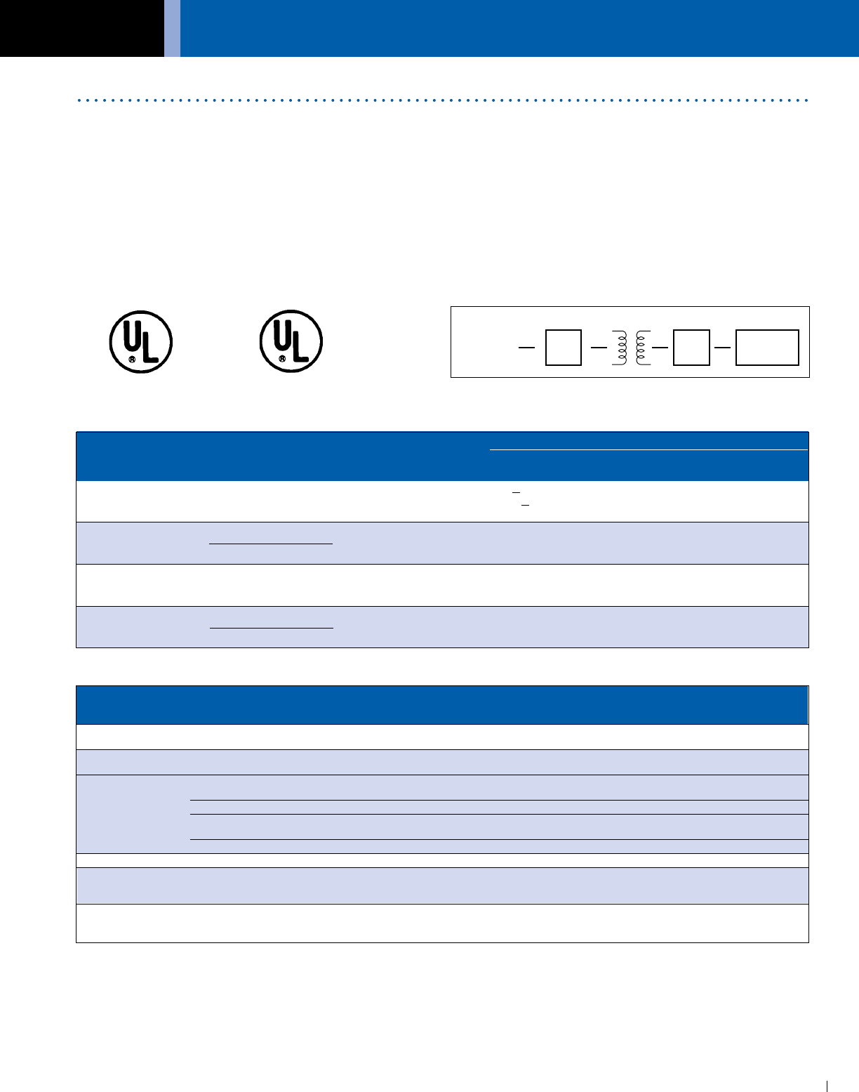
ACME ELECTRIC • MILWAUKEE, WI • 800.334.5214 • acmetransformer.com
139
GENERAL ELECTRICAL CONNECTION DIAGRAMS
139
GENERAL ACME® TRANSFORMER™ INDUSTRY STANDARDS
Primary Secondary
Type of Number of
Case Supply Phase Wires on Protection OCP Current OCP Current OCP
Voltage Secondary Required Location (AMPS) (% of rating) (AMPS) (% of rating)
>9 125 ①
1 Main 1Ø 2 Primary A < 9, > 2 167 max. Not Required
Only <2 300 max.
Primary ≥9 125 ①
2 Main 1Ø More than 2 & A & B < 9, ≥2 167 max. ≥9 125①
3Ø Not Applicable Secondary ② <2 300 max. <9 167 max.
Feeder None
3 Circuit 1Ø 2 on — Not Required Not Required
with OCP Either
Feeder
4 Circuit 1Ø More than 2 Secondary B Not Required 9 125 ①
with OCP 3Ø Not Applicable Only② <9 167 max.
Listed Certified
How to overcurrent protect (OCP) 600 volt class transformers and associated wiring
. . . in accordance with the ‘99 National Electric Code (Articles 450-3(b) and 240-3 (i))
BLOAD
A
SUPPLY
VOLTAGE
OCP LOCATION
① % of rated current (or next higher standard rating).
② In cases where the secondary is overcurrent protected, the primary overcurrent
protection rating can be no more than 250% (2.5 times) full load amps (shown on
above chart). For example, if a 10 kVA, single phase transformer has a 480V primary
and a 120/240 secondary, and the secondary is overcurrent protected, maximum
primary overcurrent protection rating is 20.8 amps (full load current) x 2.5 (250%) =
52. Therefore, use a standard 50 amp fuse or breaker selected from NEC Section
240-6 (below).
Acme® Transformer™ Products vs. U/L Insulation Systems & U/L Standards
Transformer Industry Standards
Underwriters’ Laboratories, Inc. is an independent not for profit
organization which tests products for safety.
Acme’s transformers are designed and manufactured to comply
with UL Standard 506, 1561, 1012, or 1062 and carry the
applicable UL Listing Label. Because of the continuous product
evolutions at Acme, it is best that you contact the factory for
the current file and guide numbers associated with the listings.
The Canadian Standards Association is the Canadian
counterpart to Underwriters’ Laboratories. Acme’s
transformers are also constructed and rated to comply with
CSA Standards C22.2-47 and C22.2-66 and carry the CSA
Certification Label.
All of Acme’s transformers are manufactured to meet National
Electrical Code requirements.
Other Agencies and Standards:
National Electrical Manufacturers Association (NEMA)
ST-20 1992 (R1978)
American National Standards Institute (ANSI)
OSHA
IEEE
Section 240-6 of the 1999 National Electrical Code. The standard ampere ratings
for fuses and inverse time circuit breakers shall be considered 15, 20, 25, 30, 35, 40,
45, 50, 60, 70, 80, 90, 100, 110, 125, 150, 175, 200, 225, 250, 300, 350, 400, 450, 500,
600, 700, 800, 1000, 1200, 1600, 2000, 2500, 3000, 4000, 5000 and 6000 amperes.
Exception: Additional standard ratings for fuses shall be considered 1, 3, 6, 10, and
601. “Extracted by permission from ANSI/NFPA 70-1999, National Electrical
Code®, Copyright©,1999, National Fire Protection Association, Boston, MA.”
Acme Electric–Power Distribution Products Division has never used
polychlorinated biphenyls (PCBs) in the manufacture of our quality products.
U/L U/L U/L U/L Insulation kVA kVA
Acme Construction Acme Catalog U/L Product File Listed Insulation System Single Three
Style Product Name Standard Category Number Control # Number Temp./C Phase Phase
Enclosed General Purpose 506 XPTQ E79947V1 50B8 B3223 130 .050-.150 N/A
and Buck-Boost
Compound Filled General Purpose 506 XPTQ E79947V1 50B8 X3221 155 .25-5.0 3.0-6.0
(Encapsulated) Buck-Boost & DIT H3221 180 7.5-25.0 7.5-75.0
Panel Tran® 1062 YEFR E56936V1 N/A H3180 180 5.0 N/A
H3221 180 7.5-25.0 9.0-30.0
Swim Pool & Spa 379 HDGV E111069V1 N/A H3180 180 0.10-.30 N/A
Hardwired CVR 1012 QQFU E86492V1 6B81 B3223 130 .25-3.0 N/A
X3221 155 5.0-15.0 N/A
Portable PLC 1012 QQFU E86492V1 60B1 B3223 130 .25-2.0 N/A
Open Core & Coil Industrial Control 506 XPTQ E79947V1 50B8 B3223 130 .050-5.0 N/A
Air Cooled General Purpose 1561 XQNX E12547V3 542B C3222 220 37.5-250.0 25-1000
Ventilated & Opti-Miser® & DIT
Non Ventilated
Air Conditioning NONE NONE NONE N/A NONE 130 .085-2.0 N/A
Enclosed and Refrigeration
Appliance

GENERAL ELECTRICAL CONNECTION DIAGRAMS
ACME ELECTRIC • MILWAUKEE, WI • 800.334.5214 • acmetransformer.com
140
GENERAL ALPHANUMERICAL CATALOG NUMBER INDEX
140
CATALOG NO. PAGE NO.
AE010050 ................................. 70
AE010075 ................................. 70
AE010100 ................................. 70
AE010150 ................................. 70
AE010250 ................................. 70
AE010350 ................................. 70
AE010500 ................................. 70
AE020050 ................................. 70
AE020075 ................................. 70
AE020100 ................................. 70
AE020150 ................................. 70
AE020250 ................................. 70
AE020300 ................................. 70
AE020350 ................................. 70
AE020500 ................................. 70
AE020750 ................................. 70
AE030050 ................................. 70
AE030075 ................................. 70
AE030100 ................................. 70
AE030150 ................................. 70
AE030250 ................................. 70
AE030350 ................................. 70
AE030500 ................................. 70
AE030750 ................................. 70
AE060050 ................................. 71
AE060075 ................................. 71
AE060100 ................................. 71
AE060150 ................................. 71
AE060250 ................................. 71
AE060350 ................................. 71
AE060500 ................................. 71
AE060750 ................................. 71
AE070050 ................................. 71
AE070100 ................................. 71
AE070150 ................................. 71
AE070250 ................................. 71
AE070350 ................................. 71
AE070500 ................................. 71
AE070750 ................................. 71
AE120050 ................................. 71
AE120100 ................................. 71
AE120150 ................................. 71
AE120250 ................................. 71
AE120350 ................................. 71
AE120500 ................................. 71
AE120750 ................................. 71
ALRB002TBC ........................... 50
ALRB003TBC ........................... 50
ALRB004TBC ........................... 50
ALRB006TBC ........................... 50
ALRB008TBC ........................... 50
ALRB012TBC ........................... 50
ALRB016TBC ........................... 50
ALRB025TBC ........................... 50
ALRB027TBC ........................... 50
ALRB035TBC ........................... 50
ALRB045TBC ........................... 50
ALRB055TBC ........................... 50
ALRB080TBC ........................... 50
ALRB110CBC .......................... 50
ALRB130CBC .......................... 50
ALRB160CBC .......................... 50
ALRB200CBC .......................... 50
ALRB250CBC .......................... 50
ALRB300CBC .......................... 50
ALRB360CBC .......................... 50
ALRB420CBC .......................... 50
ALRB480CBC .......................... 50
ALRC002TBC ........................... 50
ALRC003TBC ........................... 50
ALRC004TBC ........................... 50
ALRC006TBC ........................... 50
ALRC008TBC ........................... 50
ALRC012TBC ........................... 50
ALRC016TBC ........................... 50
ALRC025TBC ........................... 50
ALRC027TBC ........................... 50
ALRC035TBC ........................... 50
ALRC045TBC ........................... 50
ALRC055TBC ........................... 50
ALRC080TBC ........................... 50
ALRC110CBC .......................... 50
ALRC130CBC .......................... 50
ALRC160CBC .......................... 50
ALRC200CBC .......................... 50
ALRC250CBC .......................... 50
ALRC300CBC .......................... 50
ALRC360CBC .......................... 50
ALRC420CBC .......................... 50
ALRC480CBC .......................... 50
ALRC600CBC .......................... 50
CE010050 ................................ 72
CE010075 ................................ 72
CE010100 ................................ 72
CE010150 ................................ 72
CE010250 ................................ 72
CE010350 ................................ 72
CE010500 ................................ 72
CE020050 ................................ 72
CE020100 ................................ 72
CE020150 ................................ 72
CE020250 ................................ 72
CE020350 ................................ 72
CE020500 ................................ 72
CE020750 ................................ 72
CE030050 ................................ 72
CE030075 ................................ 72
CE030100 ................................ 72
CE030150 ................................ 72
CE030250 ................................ 72
CE030350 ................................ 72
CE030500 ................................ 72
CE030750 ................................ 72
CE040050 ................................ 73
CE040100 ................................ 73
CE040150 ................................ 73
CE040250 ................................ 73
CE040350 ................................ 73
CE040500 ................................ 73
CE040750 ................................ 73
CE050050 ................................ 73
CE050150 ................................ 73
CE050250 ................................ 73
CE050350 ................................ 73
CE050500 ................................ 73
CE050750 ................................ 73
CE060050 ................................ 73
CE060075 ................................ 73
CE060100 ................................ 73
CE060150 ................................ 73
CE060250 ................................ 73
CE060300 ................................ 73
CE060350 ................................ 73
CE060500 ................................ 73
CE060750 ................................ 73
CMT533124S ........................... 35
CMT533134S ........................... 35
CMT533144S ........................... 35
CMT533154S ........................... 35
CMT533164S ........................... 35
CMT533174S ........................... 35
DTFA0112S .............................. 47
DTFA01184S ............................ 47
DTFA0142S .............................. 47
DTFA01454S ............................ 47
DTFA01754S ............................ 47
DTFA0202S .............................. 47
DTFA02204S ............................ 47
DTFA0274S .............................. 47
DTFA0344S .............................. 47
DTFA0404S .............................. 47
DTFA0514S .............................. 47
DTFA0634S .............................. 47
DTFA0754S .............................. 47
DTFA0934S .............................. 47
DTFA72S .................................. 47
DTGA002754S ......................... 46
DTGA0112S ............................. 46
DTGA01184S ........................... 46
DTGA0142S ............................. 46
DTGA01454S ........................... 46
DTGA01754S ........................... 46
DTGA0202S ............................. 46
DTGA02204S ........................... 46
DTGA0274S ............................. 46
DTGA03304S ........................... 46
DTGA0344S ............................. 46
DTGA0404S ............................. 46
DTGA0514S ............................. 46
DTGA0634S ............................. 46
DTGA0754S ............................. 46
DTGA0934S ............................. 46
DTGA72S ................................. 46
DTGB002754S ......................... 46
DTGB008804S ......................... 46
DTGB0112S ............................. 46
DTGB01184S ........................... 46
DTGB0142S ............................. 46
DTGB01454S ........................... 46
DTGB01754S ........................... 46
DTGB0202S ............................. 46
DTGB02204S ........................... 46
DTGB0274S ............................. 46
DTGB03304S ........................... 46
DTGB0344S ............................. 46
DTGB0404S ............................. 46
DTGB04404S ........................... 46
DTGB0514S ............................. 46
DTGB05504S ........................... 46
DTGB0634S ............................. 46
DTGB06604S ........................... 46
DTGB0754S ............................. 46
DTGB07704S ........................... 46
DTGB0934S ............................. 46
DTGB72S ................................. 46
DTGB9902S ............................. 46
DTHA002754S ......................... 46
DTHA0112S ............................. 46
DTHA01184S ........................... 46
DTHA0142S ............................. 46
DTHA01454S ........................... 46
DTHA0202S ............................. 46
DTHA0274S ............................. 46
DTHA03304S ........................... 46
DTHA0344S ............................. 46
DTHA0404S ............................. 46
DTHA0514S ............................. 46
DTHA0634S ............................. 46
DTHA0754S ............................. 46
DTHA0934S ............................. 46
DTHA72S ................................. 46
DTHB002754S ......................... 46
Alphanumerical Catalog Number Index
This alphanumerical listing of catalog numbers has been
prepared to help you locate the appropriate page, when only
the catalog number is known. It is arranged in alphanumerical
order according to the first letter of the catalog number.
CATALOG NO. PAGE NO. CATALOG NO. PAGE NO. CATALOG NO. PAGE NO.

ACME ELECTRIC • MILWAUKEE, WI • 800.334.5214 • acmetransformer.com
141
GENERAL ELECTRICAL CONNECTION DIAGRAMS
141
GENERAL ALPHANUMERICAL CATALOG NUMBER INDEX
DTHB006604S ......................... 46
DTHB0112S ............................. 46
DTHB01184S ........................... 46
DTHB0142S ............................. 46
DTHB01454S ........................... 46
DTHB01754S ........................... 46
DTHB0202S ............................. 46
DTHB02204S ........................... 46
DTHB0274S ............................. 46
DTHB03304S ........................... 46
DTHB0344S ............................. 46
DTHB0404S ............................. 46
DTHB04404S ........................... 46
DTHB0514S ............................. 46
DTHB05504S ........................... 46
DTHB0634S ............................. 46
DTHB0754S ............................. 46
DTHB0934S ............................. 46
DTHB72S ................................. 46
FS1100 ..................................... 77
FS11000 ................................... 77
FS1150 ..................................... 77
FS1250 ..................................... 77
FS1350 ..................................... 77
FS150 ....................................... 77
FS1500 ..................................... 77
FS175 ....................................... 77
FS1750 ..................................... 77
FS2100 ..................................... 77
FS21000 ................................... 77
FS2150 ..................................... 77
FS21500 ................................... 77
FS22000 ................................... 77
FS2250 ..................................... 77
FS2300 ..................................... 77
FS23000 ................................... 77
FS2350 ..................................... 77
FS250 ....................................... 77
FS2500 ..................................... 77
FS275 ....................................... 77
FS2750 ..................................... 77
FS31000 ................................... 77
FS3150 ..................................... 77
FS31500 ................................... 77
FS32000 ................................... 77
FS3250 ..................................... 77
FS33000 ................................... 77
FS3350 ..................................... 77
FS350 ....................................... 77
FS3500 ..................................... 77
FS3750 ..................................... 77
GP1210000S ............................ 22
GP121000S .............................. 22
GP1215000S ............................ 22
GP12250S ................................ 22
GP123000S .............................. 22
GP125000S .............................. 22
GP12500S ................................ 22
LUG1 ...................................... 134
LUG2 ...................................... 134
LUG3 ...................................... 134
LUG4 ...................................... 134
PL112600 ................................. 64
PL112601 ................................. 64
PL112602 ................................. 64
PL112603 ................................. 64
PL112700 ................................. 64
PL112701 ................................. 64
PL112702 ................................. 64
PL112703 ................................. 64
PL112704 ................................. 64
PL112705 ................................. 64
PL112706 ................................. 64
PL112707 ................................. 64
PL79900 ................................. 133
PL79905 ................................... 78
PL79906 ................................... 78
PL79907 ................................... 78
PL79908 ................................... 78
PL79911 ................................. 133
PL79912 ................................. 133
PL79920 ................................... 75
PL79921 ................................... 75
PL79922 ................................... 75
PL79923 ................................... 75
PL79924 ................................... 75
PL79924 ............................. 64, 75
PL79925 ................................... 75
PL79926 ................................... 75
PL79927 ................................... 75
PL79928 ................................... 75
PL79928 ............................. 64, 75
PL79929 ................................... 75
PL79929 ............................. 64, 75
PL79930 ................................... 75
PL79930 ............................. 64, 75
PL79931 ................................... 75
PL79931 ............................. 64, 75
PLC85000 .............................. 115
PLC85001 .............................. 115
PLC85002 .............................. 115
PLC85003 .............................. 115
PLC85004 .............................. 115
PT061150005LS ..................... 106
PT061150005SS .................... 106
PT061150007LS ..................... 106
PT061150007SS .................... 106
PT061150010LS ..................... 106
PT061150010SS .................... 106
PT061150015LS ..................... 106
PT061150015SS .................... 106
PT061150025LS ..................... 106
PT061150025SS .................... 106
PTBA3150009LS ...................... 99
PTBA3150009SS ...................... 99
PTBA3150015LS ...................... 99
PTBA3150015SS ...................... 99
PTBA3150022LS ...................... 99
PTBA3150022SS ...................... 99
PTBA3150030LS ...................... 99
PTBA3150030SS ...................... 99
T111683 ..................... 94, 97, 100
T111684 ..................... 94, 97, 100
T111685 ..................... 94, 97, 100
T111686 ..................... 94, 97, 100
T111687 ..................... 94, 97, 100
T113073 ..................... 95, 98, 100
T113074 ..................... 95, 98, 100
T113075 ..................... 95, 98, 100
T113076 ..................... 95, 98, 100
T113077 ..................... 95, 98, 100
T137920 ..................... 96, 99, 100
T137921 ..................... 96, 99, 100
T137922 ..................... 96, 99, 100
T137923 ..................... 96, 99, 100
T137924 ..................... 96, 99, 100
T153004 ................................... 17
T153005 ................................... 17
T153006 ................................... 17
T153104 ................................... 19
T153105 ................................... 19
T153106 ................................... 19
T153929 ................................... 67
T153930 ................................... 67
T153931 ................................... 67
T160830 ................................. 112
T160831 ................................. 112
T160832 ................................. 112
T160833 ................................. 112
T160834 ................................. 112
T160835 ................................. 112
T169430 ................................. 115
T169431 ................................. 115
T169432 ................................. 115
T169433 ................................. 115
T169434 ................................. 115
T169435 ................................. 115
T169436 ................................. 115
T169437 ................................. 115
T169438 ................................. 115
T169439 ................................. 115
T179600S ................................. 84
T179603S ................................. 84
T179604S ................................. 84
T179605S ................................. 84
T179608S ................................. 84
T179609S ................................. 84
T179615S ................................. 84
T179618S ................................. 84
T179619S ................................. 84
T179620S ................................. 84
T179621S ................................. 84
T179622S ................................. 84
T179623S ................................. 84
T179624S ................................. 84
T179625S ................................. 84
T179629S ................................. 84
T179630S ................................. 84
T179631S ................................. 84
T181047 ............... 85, 94, 97, 100
T181048 ............... 85, 94, 97, 100
T181049 ............... 85, 94, 97, 100
T181050 ............... 85, 94, 97, 100
T181051 ............... 85, 94, 97, 100
T181052 ............... 85, 94, 97, 100
T181054 ..................... 95, 98, 100
T181055 ..................... 95, 98, 100
T181056 ..................... 95, 98, 100
T181057 ..................... 95, 98, 100
T181058 ..................... 95, 98, 100
T181059 ..................... 95, 98, 100
T181061 ..................... 96, 99, 100
T181062 ..................... 96, 99, 100
T181063 ..................... 96, 99, 100
T181064 ..................... 96, 99, 100
T181065 ..................... 96, 99, 100
T181066 ..................... 96, 99, 100
T181217 ................................... 67
T181219 ................................... 67
T181220 ................................... 67
T181221 ................................... 67
T181223 ................................... 67
T211688 ............... 85, 94, 97, 100
T211689 ............... 85, 94, 97, 100
T213078 ..................... 95, 98, 100
T213079 ..................... 95, 98, 100
T243570 ..................... 96, 99, 100
T243571 ..................... 96, 99, 100
T2527031 ................................. 29
T2527051 ................................. 29
T2527071 ................................. 29
T253007S ................................. 17
T253007SS ............................... 17
T253008S ................................. 17
T253008SS ............................... 17
T253009S ................................. 17
T253009SS ............................... 17
T253010S ................................. 17
T253010SS ............................... 17
T253011S ................................. 17
T253011SS ............................... 17
T253012S ................................. 17
T253012SS ............................... 17
T2530134S ............................... 17
T253013S ................................. 17
T253013SS ............................... 17
T2530144S ............................... 17
T253014S ................................. 17
T253014SS ............................... 17
T253060 ................................... 20
T253061 ................................... 20
T253062 ................................... 20
CATALOG NO. PAGE NO. CATALOG NO. PAGE NO. CATALOG NO. PAGE NO. CATALOG NO. PAGE NO.

GENERAL ELECTRICAL CONNECTION DIAGRAMS
ACME ELECTRIC • MILWAUKEE, WI • 800.334.5214 • acmetransformer.com
142
GENERAL ALPHANUMERICAL CATALOG NUMBER INDEX
142
T253063 ................................... 20
T253064 ................................... 20
T253065 ................................... 20
T253066 ................................... 20
T253067 ................................... 20
T253108S ................................. 19
T253109S ................................. 19
T253110S ................................. 19
T253111S ................................. 19
T253112S ................................. 19
T2531131S ............................... 19
T2531141S ............................... 19
T2535153S ............................... 17
T253515SS ............................... 17
T2535163S ............................... 17
T253516SS ............................... 17
T2535173S ............................... 17
T253517SS ............................... 17
T2535183S ............................... 17
T253518SS ............................... 17
T2536151S ............................... 19
T2536161S ............................... 19
T2536171S ............................... 19
T2536181S ............................... 19
T279740S ................................. 20
T279741S ................................. 20
T279742S ................................. 20
T279743S ................................. 20
T279744S ................................. 20
T279745S ................................. 20
T279746S ................................. 20
T279747S ................................. 20
T279748S ................................. 20
T2A527121 ............................... 29
T2A527131 ............................... 29
T2A527151 ............................... 29
T2A527171 ............................... 29
T2A527181 ............................... 29
T2A527191 ............................... 29
T2A533081S ............................. 23
T2A53308SS ............................ 25
T2A533091S ............................. 23
T2A53309SS ............................ 25
T2A533101S ............................. 23
T2A53310SS ............................ 25
T2A533281S ............................. 25
T2A533291S ............................. 25
T2A533401S ............................. 25
T2A533601S ............................. 22
T2A792681S ............................. 27
T2A792691S ............................. 27
T2A792701S ............................. 27
T2A793301S ............................. 26
T2A793311S ............................. 26
T2A793321S ............................. 26
T2A795161S ............................. 27
T2A795171S ............................. 27
T2A795181S ............................. 27
T2A795523S ............................. 28
T2A795533S ............................. 28
T2A795543S ............................. 28
T2A795553S ............................. 28
T335000153S ........................... 26
T3527101 ................................. 29
T3533111S ............................... 23
T353311SS ............................... 25
T3533411S ............................... 25
T3533611S ............................... 22
T379083S ................................. 29
T3792711S ............................... 27
T3793123S ............................... 24
T379312SS ............................... 25
T3793133S ............................... 24
T379313SS ............................... 25
T3793143S ............................... 24
T379314SS ............................... 25
T3793331S ............................... 26
T3793671S ............................... 22
T3795191S ............................... 27
T3795511S ............................... 28
T3796931S ............................... 27
TA253929 ................................. 60
TA253930 ................................. 60
TA253931 ................................. 60
TA254525 ................................. 62
TA254535 ................................. 62
TA254536 ................................. 62
TA254537 ................................. 62
TA254538 ................................. 62
TA254539 ................................. 62
TA281008 ................................. 60
TA281197 ................................. 62
TA281202 ................................. 62
TA281203 ................................. 62
TA281205 ................................. 62
TA281218 ................................. 60
TA281219 ................................. 60
TA281220 ................................. 60
TA281221 ................................. 60
TA281240 ................................. 62
TA281241 ................................. 62
TA83221 ................................... 64
TA83222 ................................... 64
TA83223 ................................... 64
TA83224 ................................... 64
TA83300 ................................... 63
TA83301 ................................... 63
TA83302 ................................... 63
TA83303 ................................... 63
TA83304 ................................... 63
TA83305 ................................... 63
TA83306 ................................... 63
TA83310 ................................... 64
TA83311 ................................... 64
TA83312 ................................... 64
TA83313 ................................... 64
TA83314 ................................... 64
TA83315 ................................... 64
TA83316 ................................... 64
TB181141 ................................. 59
TB181142 ................................. 59
TB181143 ................................. 59
TB181144 ................................. 59
TB181146 ................................. 59
TB181148 ................................. 59
TB181149 ................................. 59
TB181150 ................................. 59
TB181151 ................................. 59
TB32403 ................................... 62
TB32404 ................................... 62
TB32405 ................................... 62
TB32406 ................................... 62
TB32669 ................................... 62
TB54523 ................................... 62
TB54524 ................................... 62
TB81000 ................................... 60
TB81001 ................................... 60
TB81002 ................................... 60
TB81003 ................................... 60
TB81004 ................................... 60
TB81005 ................................... 60
TB81006 ................................... 60
TB81007 ................................... 60
TB81009 ................................... 60
TB81020 ................................... 60
TB81200 ................................... 59
TB81201 ................................... 59
TB81210 ................................... 59
TB81211 ................................... 59
TB81212 ................................... 59
TB81213 ................................... 59
TB81214 ................................... 59
TB81215 ................................... 59
TB81216 ................................... 59
TB81217 ................................... 59
TB81301 ................................... 61
TB81302 ................................... 61
TB81303 ................................... 61
TB81304 ................................... 61
TB81305 ................................... 61
TB81306 ................................... 61
TB81307 ................................... 61
TB81308 ................................... 61
TB81309 ................................... 61
TB81321 ................................... 61
TB81322 ................................... 61
TB81323 ................................... 61
TB81324 ................................... 61
TB81325 ................................... 61
TB81326 ................................... 61
TB81327 ................................... 61
TB81328 ................................... 61
TB81329 ................................... 61
TB83210 ................................... 64
TB83212 ................................... 64
TB83213 ................................... 64
TB83215 ................................... 64
TB83218 ................................... 64
TB83219 ................................... 64
TB83220 ................................... 64
TC533111S .............................. 23
TC535153S .............................. 18
TC535163S .............................. 18
TC535173S .............................. 18
TC535183S .............................. 18
TE1530223S ............................. 18
TE2530193S ............................. 18
TE2530203S ............................. 18
TE2A530213S .......................... 18
TF217437S ............................... 21
TF217439S ............................... 21
TF220105S ............................... 28
TF220155S ............................... 28
TF220255S ............................... 28
TF220505S ............................... 28
TF249873S ............................... 21
TF252520S ............................... 21
TF252794S ............................... 21
TF252795S ............................... 21
TF252796S ............................... 21
TF252797S ............................... 21
TF279260S ............................... 21
TF279261S ............................... 21
TF279262S ............................... 21
TF279263S ............................... 21
TF279264S ............................... 21
TF279265S ............................... 21
TF279266S ............................... 21
TF279267S ............................... 21
TF279300S ............................... 21
TF279301S ............................... 21
TF279302S ............................... 21
TF279303S ............................... 21
TF279304S ............................... 21
TP131023S ............................... 26
TP131033S ............................... 26
TP131043S ............................... 26
TP131423S ............................... 27
TP131433S ............................... 27
TP131443S ............................... 27
TP131053S ............................... 26
TP131063S ............................... 26
TP131073S ............................... 26
TP130993S ............................... 26
TP131123S ............................... 26
TP131133S ............................... 26
TP135000453S ......................... 26
TP1533173S ............................. 23
TP1533213S ............................. 23
TP1533222S ............................. 23
TP1533423S ............................. 25
TP1533433S ............................. 25
CATALOG NO. PAGE NO. CATALOG NO. PAGE NO. CATALOG NO. PAGE NO. CATALOG NO. PAGE NO.

ACME ELECTRIC • MILWAUKEE, WI • 800.334.5214 • acmetransformer.com
143
GENERAL ELECTRICAL CONNECTION DIAGRAMS
143
GENERAL ALPHANUMERICAL CATALOG NUMBER INDEX
TP1533443S ............................. 25
TP1533453S ............................. 25
TP1533463S ............................. 25
TP1533473S ............................. 25
TP1533483S ............................. 25
TP1533493S ............................. 25
TP1533503S ............................. 25
TP35000303S ........................... 26
TP35000753S ........................... 26
TP35001123S ........................... 26
TP35001503S ........................... 26
TP35002253S ........................... 26
TP35003003S ........................... 26
TP530193S ............................... 17
TP530203S ............................... 17
TP530213S ............................... 17
TP530223S ............................... 17
TP530233S ............................... 17
TP530243S ............................... 17
TP531193S ............................... 19
TP531203S ............................... 19
TP531213S ............................... 19
TP531223S ............................... 19
TP531233S ............................... 19
TP533121S ............................... 24
TP533123S ............................... 23
TP533128S ............................... 24
TP533131S ............................... 24
TP533133S ............................... 23
TP533138S ............................... 24
TP533141S ............................... 24
TP533143S ............................... 23
TP533148S ............................... 24
TP533151S ............................... 24
TP533153S ............................... 23
TP533158S ............................... 24
TP533161S ............................... 24
TP533163S ............................... 23
TP533168S ............................... 24
TP533171S ............................... 24
TP533181S ............................... 24
TP533183S ............................... 23
TP533191S ............................... 24
TP533624S ............................... 22
TP533634S ............................... 22
TP533644S ............................... 22
TP533654S ............................... 22
TP533664S ............................... 22
TP533674S ............................... 22
TP536491S ............................... 19
TP536503S ............................... 19
TP536513S ............................... 19
TP79085S ................................. 29
TP79087S ................................. 29
TP79088S ................................. 29
TP792724S ............................... 27
TP792734S ............................... 27
TP792744S ............................... 27
TP793684S ............................... 22
TP793694S ............................... 22
TP793704S ............................... 22
TP793714S ............................... 22
TP793724S ............................... 22
TP793734S ............................... 22
TP793744S ............................... 22
TP795203S ............................... 27
TP795213S ............................... 27
TP795223S ............................... 27
TP795233S ............................... 27
TP795243S ............................... 27
TP796944S ............................... 27
TP796954S ............................... 27
TP796964S ............................... 27
TP796974S ............................... 27
TP796984S ............................... 27
TPC530193S ............................ 18
TPC530203S ............................ 18
TPC533123S ............................ 23
TPC533133S ............................ 23
TPC533143S ............................ 23
TPC533153S ............................ 23
TPC533163S ............................ 23
TPC533173S ............................ 23
TPC533183S ............................ 23
TPC533193S ............................ 23
TPC3533111S ........................ 120
TPC3533113S ........................ 120
TPC3533121S ........................ 120
TPC3533123S ........................ 120
TPC3533131S ........................ 120
TPC3533133S ........................ 120
TPC3533141S ........................ 120
TPC3533143S ........................ 120
TPC3533151S ........................ 120
TPC3533153S ........................ 120
TPC3533161S ........................ 120
TPC3533163S ........................ 120
TPC3533171S ........................ 120
TPC3533173S ........................ 120
TPC3533181S ........................ 120
TPC3533183S ........................ 120
TPC3533191S ........................ 120
TPC3533193S ........................ 120
TPNS00533113S ...................... 40
TPNS00533123S ...................... 40
TPNS00533133S ...................... 40
TPNS00533143S ...................... 40
TPNS00533153S ...................... 40
TPNS00533163S ...................... 40
TPNS00533173S ...................... 40
TPNS01533113S ...................... 40
TPNS01533121S ...................... 41
TPNS01533123S ...................... 40
TPNS01533131S ...................... 41
TPNS01533133S ...................... 40
TPNS01533141S ...................... 41
TPNS01533143S ...................... 40
TPNS01533151S ...................... 41
TPNS01533153S ...................... 40
TPNS01533161S ...................... 41
TPNS01533163S ...................... 40
TPNS01533173S ...................... 40
TPNS01792714S ...................... 41
TPNS01792724S ...................... 41
TPNS01792734S ...................... 41
TPNS01792744S ...................... 41
TPNS02533113S ...................... 40
TPNS02533123S ...................... 40
TPNS02533133S ...................... 40
TPNS02533143S ...................... 40
TPNS02533153S ...................... 40
TPNS02533163S ...................... 40
TPNS02533173S ...................... 40
WSA1...................................... 134
WSA2...................................... 134
WSA3...................................... 134
WSA4...................................... 134
WSA5...................................... 134
WSA6...................................... 134
WSA8...................................... 134
WSB3...................................... 134
WSB4...................................... 134
CATALOG NO. PAGE NO. CATALOG NO. PAGE NO. CATALOG NO. PAGE NO. CATALOG NO. PAGE NO.
GENERAL ACME TRANSFORMER GENERAL INFORMATION
144
General Purpose Transformers
For over eighty-eight years, Acme Electric has been manufacturing Power Conditioning Equipment for use
in industrial, commercial and OEM applications. Built on a reputation for superior service, quality and
technical expertise in the transformer market, Acme is regarded as a true industry leader.
Dry Type General Purpose Transformers
Acme Electric is a full line manufacturer of low voltage (600V
and below) dry type distribution transformers using both copper
and aluminum conductor, offering an array of products between
0.05 -1000 KVA.
All Acme products are designed, constructed and rated to
meet or exceed the standards established by NEMA, ANSI and
IEEE. With few exceptions, all ACME transformers are
UL Listed.
K-Factor Transformers
Non-sinusoidal harmonic currents are created by much of
today’s electronic equipment. In fact, the switch mode power
supply found in desktop computers, data processors and other
office equipment is a major source of harmonic currents. Other
sources include electronic ballasts, variable frequency drives,
heating controls and rectifier circuits.
These non-linear loads can cause the transformer’s neutral
conductor to overheat, requiring special transformer design.
Acme’s non-linear load isolation transformers use special
winding techniques to minimize the eddy current losses
generated by harmonic currents. A double-sized neutral
conductor handles the excessive neutral current found in
non-linear load applications, preventing the transformer
from overheating.
Harmonic Mitigating Transformers
Harmonic currents can sometimes cause equipment to
malfunction, motors to burn out, circuit breakers to trip, and
fuses to blow. In such a case, there is an advantage to specifying
a transformer that treats the harmonic anomalies versus simply
tolerating them. Acme’s Harmonic Mitigating Transformers offer
the best solution for combating harmonics associated with non-
linear loads.
These foil wound transformers will, by nature, be smaller, more
efficient, and have lower eddy current losses than their wire
wound counterparts. Acme’s Harmonic Mitigating Transformers
utilize a time proven zig-zag connection in the secondary circuit
that results in a phase shift of the triplen harmonics and causes
them to cancel one another. This technology not only results in
cooler operation and “cleaner power”, but also provides a more
energy efficient means of dealing with harmonic problems.
CSL-3 / NEMA Premium Transformers
The Acme POWERWISE C3 sets a new standard for
efficiency and reliability. Due to the use of more efficient core
material and higher-grade electrical steel, POWERWISE C3
transformers are the most efficient commercially available
transformers. With a 30% increase in efficiency performance
over standard TP-1 transformers, these energy-efficient units
exceed the requirements of the US Department of Energy
Candidate Standard Level (CSL) 3 performance standard.
POWERWISE C3 transformers achieve the lowest life cycle
costs by reducing annual energy costs. Depending on the size
of the transformer, this can mean thousands of dollars saved
per transformer. And, because they generate lower losses, they
reduce power drawn from generating stations, resulting in lower
greenhouse gas emissions and less smog.
Acme POWERWISE C3 transformers are copper wound,
3-phase common-core, dry-type ventilated isolation
transformers. Each transformer is meticulously constructed
to ANSI/IEEE Standards and is UL and CSA listed. The
POWERWISE C3 transformer is a perfect choice for K
through 12, college, university, healthcare, governmental and
commercial buildings where the total life cycle cost of the
facility and its electrical system is a priority.

NOTES
GENERAL ACME® TRANSFORMER™ GENERAL INFORMATION
145

NOTES
GENERAL ACME® TRANSFORMER™ GENERAL INFORMATION
146

NOTES
GENERAL ACME® TRANSFORMER™ GENERAL INFORMATION
147
In today’s high-tech environments, it’s often the products you don’t see that are the most critical to your
success. That’s why leaders across a broad spectrum of industries look to Acme Electric for power
conversion and power conditioning equipment. While our products work quietly behind the scenes, our
engineers and researchers are out in front, discovering new ways to deliver power more efficiently in a
world ever aware of energy consumption and generation. Join customers around the globe who trust
Acme for reliable, efficient solutions in industrial, commercial, and OEM applications.
Peace of mind
Rock-solid power solutions
for over 80 years.
Acme Electric • N85 W12545 Westbrook Crossing • Menomonee Falls, WI 53051 • Phone: 262.293.1500 • acmetransformer.com
©2012 Acme Electric. All rights reserved.
ACME ELECTRIC 10-YEAR LIMITED* WARRANTY
Acme Electric (Acme) warrants to the original purchaser to correct by repair, replacement or refund of
original purchase price, at Acme’s option, products manufactured and sold by its Power Distribution Products
Division, that may fail in service within the applicable period as set forth below, from the date of manufacture
provided however, that conditions of operation have been normal at all times, and that the equipment has not
been subjected to abnormal stress from such causes as incorrect primary voltage or frequency, improper
ventilation or improper use. This warranty is made on the condition that prompt notice of defect is given to
Acme in writing within the warranty period, and that Acme’s inspection reveals to its satisfaction that the original
purchaser’s claim is valid under the terms of this warranty. Acme’s obligation under this warranty, which is
in lieu of all other warranties, express or implied, including the implied warranty of fitness for a particular purpose
and merchantability, is limited to replacing or repairing defective products or parts, free of charge, provided
they are returned to the factory, or refund of original purchase price, at Acme’s option. However, purchased
components (except for timers and photocells used in low voltage lighting power supplies) including but not
limited to capacitors, circuit breakers, terminal blocks, batteries, fuses and tubes shall not be covered under
this warranty. Repairs or replacement deliveries shall not interrupt or prolong the term of this warranty. Acme
will not be liable for any special, indirect, consequential or incidental damages, including, without limitation,
from loss of use, data, function or profits deriving out of or in connection with the use or performance of
the product and shall have no liability for payment of any other damages whether in an action of contract,
strict liability or tort. The remedy provided herein states Acme Electric’s entire liability and buyer’s sole and
exclusive remedy here under. Rights may vary in certain states.
*Warranty Period:
Standard Catalog Transformers — 10-year limited; Low Voltage Lighting Power Supplies, transformer —
10-year limited, True-Power® Power Line Conditioners, — 10-year limited; Custom products — 1 year.
Acme®
Transformers™ are Shielded for Cleaner Power – Free!
Shielding is a FREE standard
feature. Acme transformers have built-
in noise and surge protection provided
by internal electrostatic shielding. It’s
a standard feature on Acme general
purpose dry-type transformers.
Acme transformers provide clean
power. They provide noise and surge
protection for entire feeder and branch
circuits, plus every connected load.
And, they establish a separately derived
circuit and provide a solid single
point ground—all essential for cleaner
power. Install Acme transformers, and
take the most fundamental and cost
effective step toward cleaner power.
The more you use, the cleaner
your system. The Acme shield
constantly works to trap, knockdown
and shunt potentially damaging noise
and voltage spikes to ground at an
average reduction ratio of 100:1. The
more Acme shielded transformers you
use on the feeder and branch circuits,
the cleaner your system becomes.
Use two Acme transformers on the
same feeder and branch circuits, and
get 10,000:1 reduction.
With Acme you get all the extra benefits
of cleaner power, absolutely FREE!
Shielded
for cleaner
power™

FULL LINE PRODUCT CATALOG
CommerCial ConstruCtion • industrial automation
ACM_CAT_007_0913
Acme Electric
N85 W12545 Westbrook Crossing
Menomonee Falls, WI 53051
800.334.5214
acmetransformer.com
©2013 Electrical Holdings LLC. All rights reserved.
Acme Electric Full Line Product Catalog
