70509004 E EN 55022 And EN55024
2016-04-11
: Pdf 70509004-E En 55022 And En55024 70509004-E_EN_55022_and_EN55024 CertsReports 503983 ProductFiles
Open the PDF directly: View PDF ![]() .
.
Page Count: 52
Compliance Certification Services Inc.
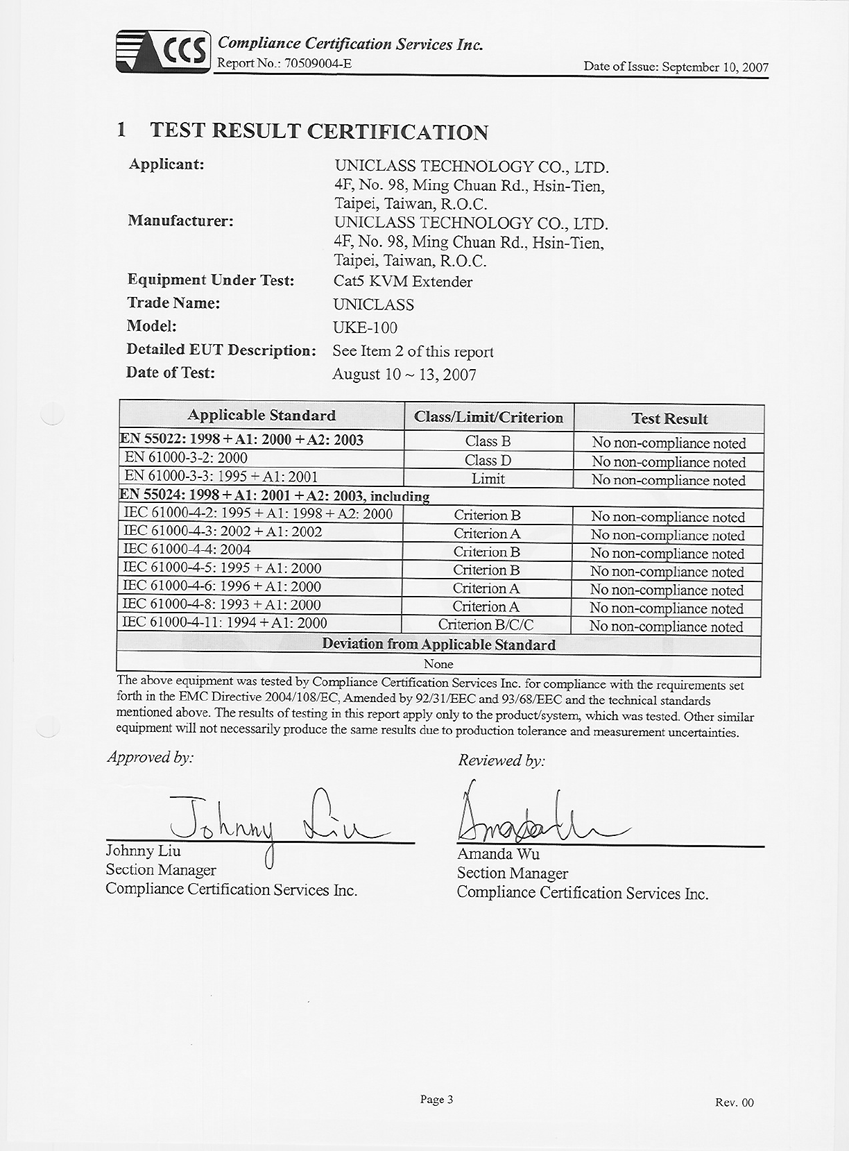
Report No.: 70509004-E Date of Issue: September 10, 2007
Note: This report shall not be reproduced except in full, without the written approval of Compliance
Certification Services Inc. This document may be altered or revised by Compliance Certification
Services Inc. personnel only, and shall be noted in the revision section of the document.
Page 1 Total Page:52
Rev. 00
CE EMC
TEST REPORT
For
Cat5 KVM Extender
Model: UKE-100
Trade Name: UNICLASS
Issued to
UNICLASS TECHNOLOGY CO., LTD.
4F, No. 98, Ming Chuan Rd., Hsin-Tien,
Taipei, Taiwan, R.O.C.
Issued by
Compliance Certification Services Inc.
No. 81-1, Lane 210, Bade Rd. 2, Luchu Hsiang,
Taoyuan Hsien, (338) Taiwan, R.O.C.
http://www.ccsemc.com.tw
service@tw.ccsemc.com

Compliance Certification Services Inc.
Report No.: 70509004-E Date of Issue: September 10, 2007
Page 2 Rev. 00
TABLE OF CONTENTS
1 TEST RESULT CERTIFICATION.........................................................................................................3
2 EUT DESCRIPTION...............................................................................................................................4
3 TEST METHODOLOGY........................................................................................................................5
3.1 EUT SYSTEM OPERATION ........................................................................................................5
3.2 DECISION OF FINAL TEST MODE ...........................................................................................5
4 INSTRUMENT AND CALIBRATION..................................................................................................6
4.1 MEASURING INSTRUMENT CALIBRATION..........................................................................6
4.2 TEST AND MEASUREMENT EQUIPMENT .............................................................................6
5 FACILITIES AND ACCREDITATIONS.............................................................................................10
5.1 FACILITIES.................................................................................................................................10
5.2 LABORATORY ACCREDITATIONS AND LISTINGS.............................................................11
6 SETUP OF EQUIPMENT UNDER TEST............................................................................................12
6.1 SETUP DIAGRAM......................................................................................................................12
6.2 SUPPORT EQUIPMENT ............................................................................................................12
7 POWERLINE CONDUCTED & RADIATED EMISSION TEST.......................................................13
7.1 LIMIT...........................................................................................................................................13
7.2 TEST PROCEDURE OF LINE CONDUCTED EMISSION......................................................14
7.3 TEST PROCEDURE OF COMMON MODE CONDUCTED EMISSION FOR
TELECOMMUNICATION PORT..............................................................................................15
7.4 TEST PROCEDURE OF RADIATED EMISSION.....................................................................16
7.5 TEST RESULTS ..........................................................................................................................17
8 POWER HARMONICS TEST..............................................................................................................20
9 POWER VOLTAGE FLUCTUATION / FLICKER TEST ..................................................................23
10 ELECTROSTATIC DISCHARGE (ESD) IMMUNITY TEST ............................................................26
11 RADIATED ELECTROMAGNETIC FIELD IMMUNITY TEST ......................................................32
12 FAST TRANSIENTS/BURST IMMUNITY TEST..............................................................................35
13 SURGE IMMUNITY TEST..................................................................................................................38
14 CONDUCTED DISTRBANCE/INDUCED RADIO-FREQUENCY FIELD IMMUNITY TEST ......40
15 POWER FREQUENCY MAGNETIC FIELD IMMUNITY TEST......................................................42
16 VOLTAGE DIPS / SHORT INTERRUPTIONS ..................................................................................44
APPENDIX I – PHOTOGRAPHS OF TEST SETUP................................................................................46
Compliance Certification Services Inc.
Report No.: 70509004-E Date of Issue: September 10, 2007
Page 4 Rev. 00
2 EUT DESCRIPTION
Product Cat5 KVM Extender
Trade Name UNICLASS
Model Number UKE-100
Model Discrepancy N/A
Housing Type Metal
EUT Power Rating
Power adapter 1:
Model: M7-10US08R-A
I/P: AC 100-240V, 50-60Hz, 0.5A
O/P: DC 9V, 1.11A
Power adapter 2:
Model: M7-10US08R-D
I/P: AC 100-240V, 50-60Hz, 0.5A
O/P: DC 9V, 1.11A
Compliance Certification Services Inc.
Report No.: 70509004-E Date of Issue: September 10, 2007
Page 5 Rev. 00
3 TEST METHODOLOGY
3.1 EUT SYSTEM OPERATION
Software Used During the Test
Operating System Windows XP
Program Sequence
1. EMI test program (file name: EMCTEST) was loaded and
executed in “Windows XP” mode.
2. The detect signal was sent to EUT.
3. Data was sent to the monitor, filling the screen with upper case
of “H” patterns.
4. Test program sequentially all related I/O’s of Host PC include
EUT and sent “H” patterns to all applicable output ports of
Host PC.
5. Repeat 2 to 4.
Remark: Test program is self-repeating throughout the test.
3.2 DECISION OF FINAL TEST MODE
The EUT (model: UKE-100) comes with two types of power adapters (M7-10US08R-A &
M7-10US08R-D) for sale. After the preliminary test, the power adapter with model
M7-10US08R-A was found to emit the worst emissions and therefore had been tested under
operating condition.
1. The following test mode was scanned during the preliminary test:
Mode 1
Operating
2. After the preliminary scan, the following test mode was found to produce the highest
emission level.
Mode 1
Then, the EUT configuration and cable configuration of the above highest emission mode
was chosen for all final test items.
Compliance Certification Services Inc.
Report No.: 70509004-E Date of Issue: September 10, 2007
Page 6 Rev. 00
4 INSTRUMENT AND CALIBRATION
4.1 MEASURING INSTRUMENT CALIBRATION
The measuring equipment utilized to perform the tests documented in this report has been
calibrated once a year or in accordance with the manufacturer's recommendations, and is
traceable to recognized national standards.
4.2 TEST AND MEASUREMENT EQUIPMENT
The following list contains measurement equipment used for testing. The equipment conforms to
the requirement of CISPR 16-1, ANSI C63.2 and other required standards.
Calibration of all test and measurement, including any accessories that may effect such
calibration, is checked frequently to ensure the accuracy. Adjustments are made and correction
factors are applied in accordance with the instructions contained in the respective manual.
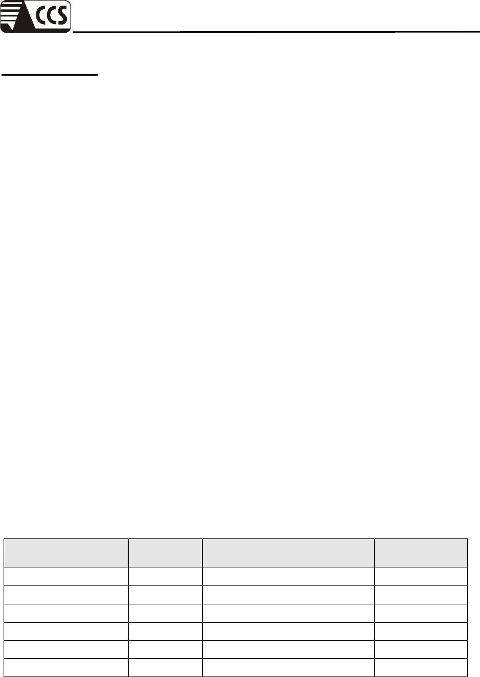
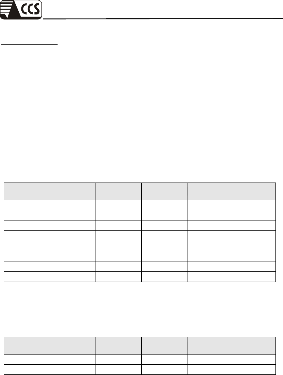
Equipment Used for Emission Measurement
Open Area Test Site # 3
Name of Equipment Manufacturer Model Serial Number Calibration Due
Spectrum Analyzer Agilnet E4411B MY41440314 N.C.R.
Spectrum Analyzer R&S FSP30 100112 10/10/2007
EMI Test Receiver R&S ESVS30 828488/004 03/12/2008
Pre-Amplifier Anritsu MH648A M18767 08/30/2008
Pre-Amplifier MITEQ
AFS42-00102650-42-10P-42 966468 04/26/2008
Bilog Antenna Schwazbeck VULB9163 144 03/30/2008
Horn Antenna EMCO 3115 00022250 04/15/2008
Loop Antenna EMCO 6502 2356 N.C.R.
Turn Table Chance Most CM-T003-1 T807-6 N.C.R.
Antenna Tower Chance Most CM-A003-1 A807-6 N.C.R.
Controller CCS CC-C-1F N/A N.C.R.
RF Switch Anritsu MP59B M53867 N.C.R.
Site NSA CCS N/A N/A 05/04/2008
Decoupling Network FCC F-201-DCN-5-6MM 34 06/04/2008
Test S/W LabVIEW 6.1 (CCS OATS EMI SW V2.6)
Remark: The measurement uncertainty is less than +/- 4.0235dB, which is evaluated as per the NAMAS NIS 81 and
CISPR/A/291/CDV.
Compliance Certification Services Inc.
Report No.: 70509004-E Date of Issue: September 10, 2007
Page 7 Rev. 00
Powerline Conducted Emissions Test Site
Name of Equipment Manufacturer Model Serial Number Calibration Due
EMI Test Receiver
9kHz-30MHz Rohde & Schwarz ESHS30 828144/003 10/31/2007
Two-Line V-Network
9kHz-30MHz Schaffner NNB41 03/10013 06/12/2008
LISN 10kHz-100MHz EMCO 3825/2 9106-1809 04/01/2008
ISN 9kHz-30MHz FCC FCC-TLISN-T4 20167 09/15/2007
Test S/W LABVIEW (V 6.1)
Remark: The measurement uncertainty is less than +/- 2.81dB, which is evaluated as per the NAMAS NIS 81 and
CISPR/A/291/CDV.
Power Harmonic & Voltage Fluctuation/Flicker Measurement (EN 61000-3-2&-3-3)
Name of Equipment Manufacturer Model Serial Number Calibration Due
Harmonic & Flicker Tester EMC-Partner HAR1000-1P 107 05/21/2008
Test S/W HARCS (Ver. 4.0)
Equipment Used for Immunity Measurement
ESD Test Site (IEC 61000-4-2)
Name of Equipment Manufacturer Model Serial Number Calibration Due
ESD Simulator NoiseKen ESS-2001 ESS0210582 11/15/2007
Radiated Electromagnetic Field Immunity Test Site (IEC 61000-4-3)
Name of Equipment Manufacturer Model Serial Number Calibration Due
Signal Generator Agilent 8648C 4108A05772 10/23/2007
150 Watts 80-1000MHz
Amplifier Amplifier Research 150W1000M3 306730 N.C.R.
30 Watts 0.8-3.0GHz
Amplifier Amplifier Research 30S1G3M1 306722 N.C.R.
Power Meter Boonton 4232A-01-02 98601 10/25/2007
Power Sensor Boonton 51011-EMC 32920 10/25/2007
Power Sensor Boonton 51011-EMC 32863 10/25/2007
Log-Periodic Antenna Amplifier Research AT1080 306709 N.C.R.
Microwave Horn Antenna Amplifier Research AT4002A 306750 N.C.R.
RF Test System Controller Amplifier Research SC1000M3 306666 N.C.R.
Field Probe Amplifier Research FP6001 305657 04/17/2008
0.8-4.2GHz Amplifier Research DC7144A N/A N.C.R.
80-1000MHz Amplifier Research DC6180A N/A N.C.R.
Antenna Tower Amplifier Research TP2000 N/A N.C.R.
Probe Stand Amplifier Research PS2000 N/A N.C.R.
Test S/W SW1005 (Release 1.4)
Compliance Certification Services Inc.
Report No.: 70509004-E Date of Issue: September 10, 2007
Page 8 Rev. 00
Fast Transients/Burst Test Site (IEC 61000-4-4)
Name of Equipment Manufacturer Model Serial Number Calibration Due
ECAT Control Center KeyTek E-Class Series 100 9502325 03/08/2008
Capacitor Clamp KeyTek CCL-4 9503290 N.C.R.
Test S/W E400 Burstware (V4.19 (c))
Surge Immunity Test Site (IEC 61000-4-5)
Name of Equipment Manufacturer Model Serial Number Calibration Due
ECAT Control Center KeyTek E-Class Series 100 9502325 03/08/2008
External Coupler / Decoupler For
Telecom Lines KeyTek CM-TELCD 0104399 N.C.R.
I/O Signal Line Coupler /
Decoupler KeyTek CM-I / OCD 0103234 N.C.R.
Test S/W E500 Surgeware (V4.19cc)
CS Test Site (IEC 61000-4-6)
Name of Equipment Manufacturer Model Serial Number Calibration Due
Signal Generator Agilent 8648C 4108A05773 09/19/2007
75 Watts 10kHz-250MHz
Amplifier Amplifier Research 75A250AM1 306334 N.C.R.
Power Meter Boonton 4232A-01-02 98501 09/15/2007
Power Sensor Boonton 51011-EMC 32862 09/15/2007
Power Sensor Boonton 51011-EMC 32864 09/15/2007
Power Line Coupling
Decoupling Network
Fischer Custom
Communications, Inc. FCC-801-M2-16A 03026 09/15/2007
Power Line Coupling
Decoupling Network
Fischer Custom
Communications, Inc. FCC-801-M3-16A 03027 09/15/2007
Signal Line Coupling
Decoupling Network
Fischer Custom
Communications, Inc. FCC-801-T2 03016 09/15/2007
Signal Line Coupling
Decoupling Network
Fischer Custom
Communications, Inc. FCC-801-T4 03017 09/15/2007
EM Injection Clamp Fischer Custom
Communications, Inc. F-203I-23mm 421 09/15/2007
Passive Impedance Adapters Fischer Custom
Communications, Inc. FCC-801-150-50-CDN 03053&03054 09/15/2007
Calibration Fixture Fischer Custom
Communications, Inc. F-203I-CF-23mm 408 09/15/2007
Signal Line Coupling
Decoupling Network
Fischer Custom
Communications, Inc. FCC-801-T8-RJ45 04024 09/15/2007
Attenuator Amplifier Research HFP-575-3/6-NM NF201875106 N.C.R.
Coupler Amplifier Research DC2600A 306621 N.C.R.
Test S/W SW1005 (Release 1.4)
Compliance Certification Services Inc.
Report No.: 70509004-E Date of Issue: September 10, 2007
Page 9 Rev. 00
Power Frequency Magnetic Field Immunity Test Site (IEC 61000-4-8)
Name of Equipment Manufacturer Model Serial Number Calibration Due
Magnetic Field Tester Haefely Trench MAG100.1 081436-02 N.C.R.
Frequency Converter Extech Electronics CFC-105 810390 N.C.R.
Digital Multimeter DHA CM-312A ET93C-06-208-01 05/31/2008
EMF Tester
Electromagnetic Field TES 1390 020401598 05/17/2008
Voltage Dips/Short Interruption and Voltage Variation Immunity Test Site (IEC 61000-4-11)
Name of Equipment Manufacturer Model Serial Number Calibration Due
Dips/Interruption and
Variations Simulator Haefely Trench PLINE 1610 081568-06 08/06/2008
Test S/W WinPATS (V. 3.26)
Compliance Certification Services Inc.
Report No.: 70509004-E Date of Issue: September 10, 2007
Page 10 Rev. 00
5 FACILITIES AND ACCREDITATIONS
5.1 FACILITIES
All measurement facilities used to collect the measurement data are located at
No.199, Chunghsen Road, Hsintien City, Taipei Hsien, Taiwan, R.O.C.
Tel: 886-2-2217-0894 / Fax: 886-2-2217-1029
No.11, Wugong 6th Rd., Wugu Industrial Park, Taipei Hsien 248, Taiwan
Tel: 886-2-2299-9720 / Fax: 886-2-2298-4045
No.81-1, Lane 210, Bade 2nd Rd., Luchu Hsiang, Taoyuan Hsien 338, Taiwan
Tel: 886-3-324-0332 / Fax: 886-3-324-5235
The sites are constructed in conformance with the requirements of ANSI C63.7, ANSI C63.4 and
CISPR Publication 22.
Compliance Certification Services Inc.
Report No.: 70509004-E Date of Issue: September 10, 2007
Page 11 Rev. 00
5.2 LABORATORY ACCREDITATIONS AND LISTINGS
The test facilities used to perform Electromagnetic compatibility tests are registered or
accredited by the organizations listed in the following table which includes the recognized scope
specifically.
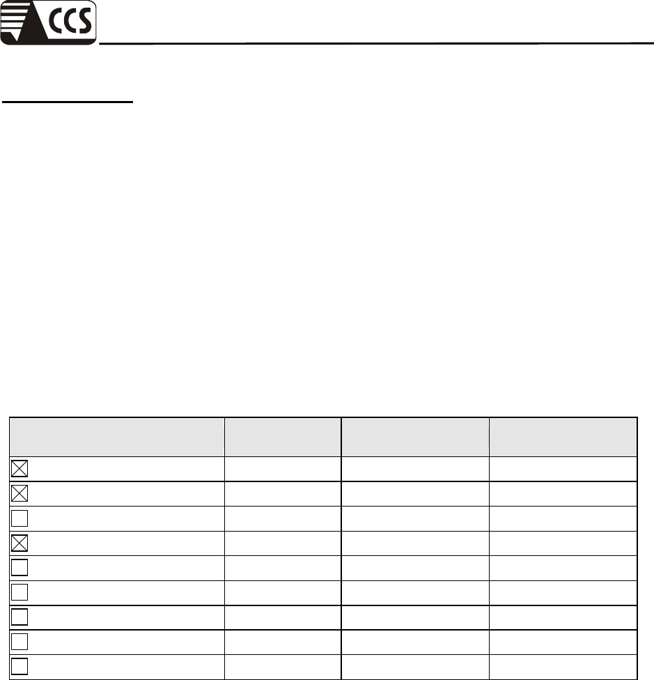
Country Agency Scope of Accreditation Logo
USA A2LA
EN 55011, EN 55014-1/2, CISPR 11, CISPR 14-1/2,
EN 55022, EN 55015, CISPR 22, CISPR 15,
AS/NZS 3548, VCCI V3 (2001), CFR 47, FCC Part 15/18,
CNS 13783-1, CNS 13439, CNS 13438, CNS 13803,
CNS 14115, EN 55024, IEC 801-2, IEC 801-3, IEC 801-4,
IEC/EN 61000-3-2, IEC/EN 61000-3-3,
IEC/EN 61000-4-2/3/4/5/6/8/11, EN 50081-1/
EN 61000-6-3, EN 50081-2/EN 61000-6-4,
EN 50081-2/EN 61000-6-1: 2001
USA FCC
3/10 meter Open Area Test Sites (93105, 90471) /
3M Semi Anechoic Chamber (965860) to perform
FCC Part 15/18 measurements
93105, 90471
965860
Japan VCCI
3/10 meter Open Area Test Sites to perform conducted/radiated
measurements
R-393/1066/725/879
C-402/747/912
N
orwa
y
N
EMKO
EN 50081-1/2, EN 50082-1/2, IEC 61000-6-1/2, EN 50091-2,
EN 50130-4, EN 55011, EN 55013, EN 55014-1/2,
EN 55015, EN 55022, EN 55024, EN 61000-3-2/3,
EN 61326-1, IEC 61000-4-2/3/4/5/6/8/11, EN 60601-1-2,
EN 300 328, EN 300 422-2, EN 301 419-1,
EN 301 489-01/03/07/08/09/17, EN 301 419-2/3,
EN 300 454-2, EN 301 357-2
ELA 124a
ELA 124b
ELA 124c
Taiwan TAF
EN 300 328, EN 300 220-1, EN 300 220-2, EN 300 220-3,
47 CFR FCC Part 15 Subpart C,
EN 61000-3-2, EN 61000-3-3, CNS 13439, CNS 13783-1,
CNS 14115, CNS 13438, AS/NZS CISPR 22, CNS 13022-1,
IEC 61000-4-2/3/4/5/6/8/11, CNS 13022-2/3
Taiwan BSMI
CNS 13438, CNS 13783-1,
CNS 13439, CNS 14115
SL2-IS-E-0014
SL2-IN-E-0014
SL2-A1-E-0014
SL2-R1-E-0014
SL2-R2-E-0014
SL2-L1-E-0014
Canada Industry
Canada
3/10 meter Open Area Test Sites (IC 2324C-3, IC 2324C-5) /
3M Semi Anechoic Chamber (IC 6106)
IC 2324C-3
IC 2324C-5
IC 6106
* No part of this report may be used to claim or imply product endorsement by A2LA or any agency of the US
Government.
Compliance Certification Services Inc.
Report No.: 70509004-E Date of Issue: September 10, 2007
Page 12 Rev. 00
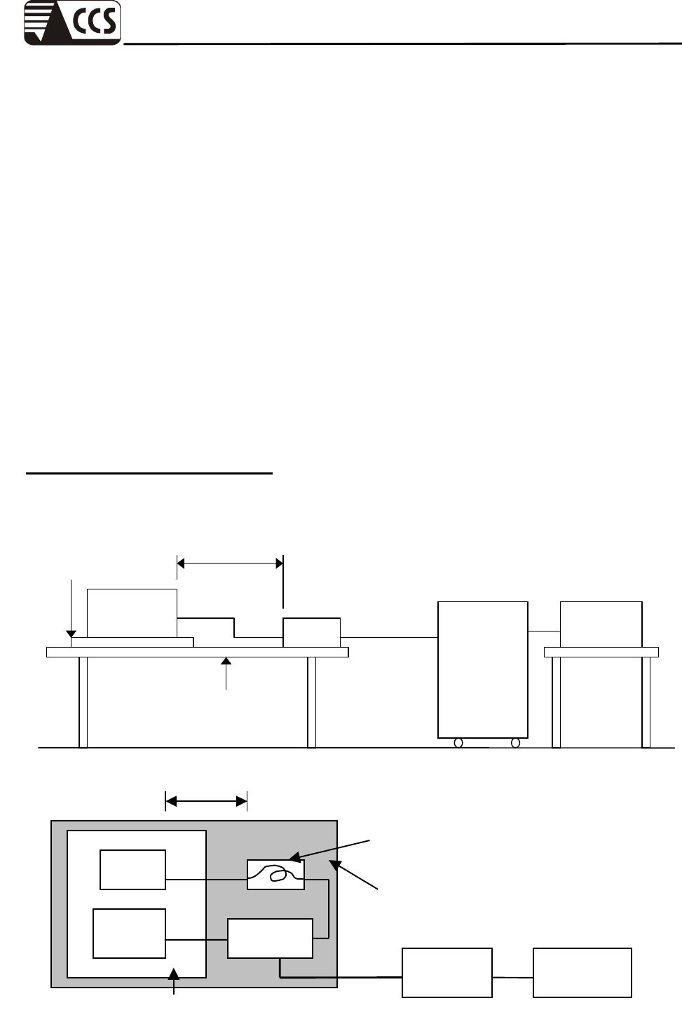
6 SETUP OF EQUIPMENT UNDER TEST
6.1 SETUP DIAGRAM
See test photographs attached in Appendix I for the actual connections between EUT and support
equipment.
6.2 SUPPORT EQUIPMENT
No Equipment Trade
Name Model Serial No. FCC ID Data Cable Power Cord
1. PC HP DX-6120 SGH5330GK7 FCC
DoC N/A Unshielded, 1.8m
2. PC HP PL926AV SGH528048P FCC
DoC N/A Unshielded, 1.8m
3. CRT Monitor Samsung 959NF AQ19H2RT706139P FCC
DoC
Shielded, 1.8m
with 2 cores Unshielded, 1.8m
4. LCD Monitor Samsung 173P DI17H4JXB04968Y FCC
DoC
Shielded, 1.8m
with 2 cores
AC I/P:
Unshielded, 1.8m
DC O/P:
Unshielded, 1.8m
with a core
5. LCD Monitor SAMSUNG 959NF AQ19H2RT706121B FCC DoC
Shielded, 1.8m
with 2 cores
AC I/P:
Unshielded, 1.8m
DC O/P:
Unshielded, 1.8m
with a core
6. LCD Monitor LG L1740PQ 503KGXA2K858 BEJL17NU Shielded, 1.8m
with 2 cores
AC I/P:
Unshielded, 1.8m
DC O/P:
Unshielded, 1.8m
with a core
7. PS/2 Keyboard Logitech Y-SJ17 SY528UK FCC
DoC Shielded, 1.8m N/A
8. PS/2 Keyboard Logitech Y-SJ17 SY528UK FCC
DoC Shielded, 1.8m N/A
9. PS/2 Keyboard hp KB-0316 355630-AB1 FCC DoC Shielded, 1.8m N/A
10. PS/2 Keyboard COMPAQ KB-0133 N/A FCC DoC Shielded, 1.8m N/A
11. PS/2 Mouse Logitech M-S34 HCA25200400 DZL211029 Shielded, 1.8m N/A
12. PS/2 Mouse Logitech M-S34 HCA25200475 DZL211029 Shielded, 1.8m N/A
13. PS/2 Mouse Logitech M-S34 LZC85106992 FCC
DoC Shielded, 1.8m N/A
14. PS/2 Mouse Logitech M-S34 HCA25200251 DZL211029 Shielded, 1.8m N/A
15. Printer EPSON STYLUS C60 DR3K039633 FCC
DoC Shielded, 1.8m Unshielded, 1.8m
16. Printer EPSON STYLUS C60 DR3K041995 FCC
DoC Shielded, 1.8m Unshielded, 1.8m
17. Multimedia
Earphone Labtec Axis-301 N/A FCC
DoC Unshielded, 1.8m N/A
18. Multimedia
Earphone Ergotech ET-E220 N/A FCC
DoC Unshielded, 1.8m N/A
19. Modem ACEEX DM-1414 304012269 IFAXDM1414 Shielded, 1.8m Unshielded, 1.8m
Remark: All the above equipment/cables were placed in worse case positions to maximize emission signals during
emission test.
Grounding: Grounding was in accordance with the manufacturer’s requirements and conditions for the intended use.
Compliance Certification Services Inc.
Report No.: 70509004-E Date of Issue: September 10, 2007
Page 13 Rev. 00
7 POWERLINE CONDUCTED & RADIATED EMISSION TEST
7.1 LIMIT
Maximum permissible level of Line Conducted Emission
Class A
(dBuV/m)
Class B
(dBuV/m)
Frequency
(MHZ) Quasi-peak Average Quasi-peak Average
0.15 - 0.5 79 66 66 - 56 56 - 46
0.50 - 5.0 73 60 56 46
5.0 - 30.0 73 60 60 50
Remark: The lower limit shall apply at the transition frequency.
Maximum permissible level of Common Mode Conducted Emission
(Telecommunication Ports)
CLASS A
Voltage Limit
(dBuV)
Current Limit
(dBuA)
Frequency
(MHz) Quasi-peak Average Quasi-peak Average
0.15 - 0.5 97 – 87 84 - 74 53 – 43 40 – 30
0.5 - 30.0 87 74 43 30
Remark: The lower limit shall apply at the transition frequency.
CLASS B
Voltage Limit
(dBuV)
Current Limit
(dBuA)
Frequency
(MHz) Quasi-peak Average Quasi-peak Average
0.15 - 0.5 84 - 74 74 - 64 40 – 30 30 – 20
0.5 - 30.0 74 64 30 20
Remark: 1. The lower limit shall apply at the transition frequency.
2. According to Note 3 on table 4 of EN 55022: 1998 standard, a relaxation of 10 dB over the frequency
range of 6 MHz to 30 MHz is allowed for high-speed services having significant spectral density in this
band. However, this relaxation is restricted to the common mode disturbance converted by the cable from
the wanted signal.
Maximum permissible level of Radiated Emission measured at 10 meter
Class A
(dBuV/m)
Class B
(dBuV/m)
Frequency
(MHz) Quasi-peak Quasi-peak
30 – 230 40 30
230 - 1000 47 37
Remark: The lower limit shall apply at the transition frequency.
Compliance Certification Services Inc.
Report No.: 70509004-E Date of Issue: September 10, 2007
Page 14 Rev. 00
7.2 TEST PROCEDURE OF LINE CONDUCTED EMISSION
Procedure of Preliminary Test
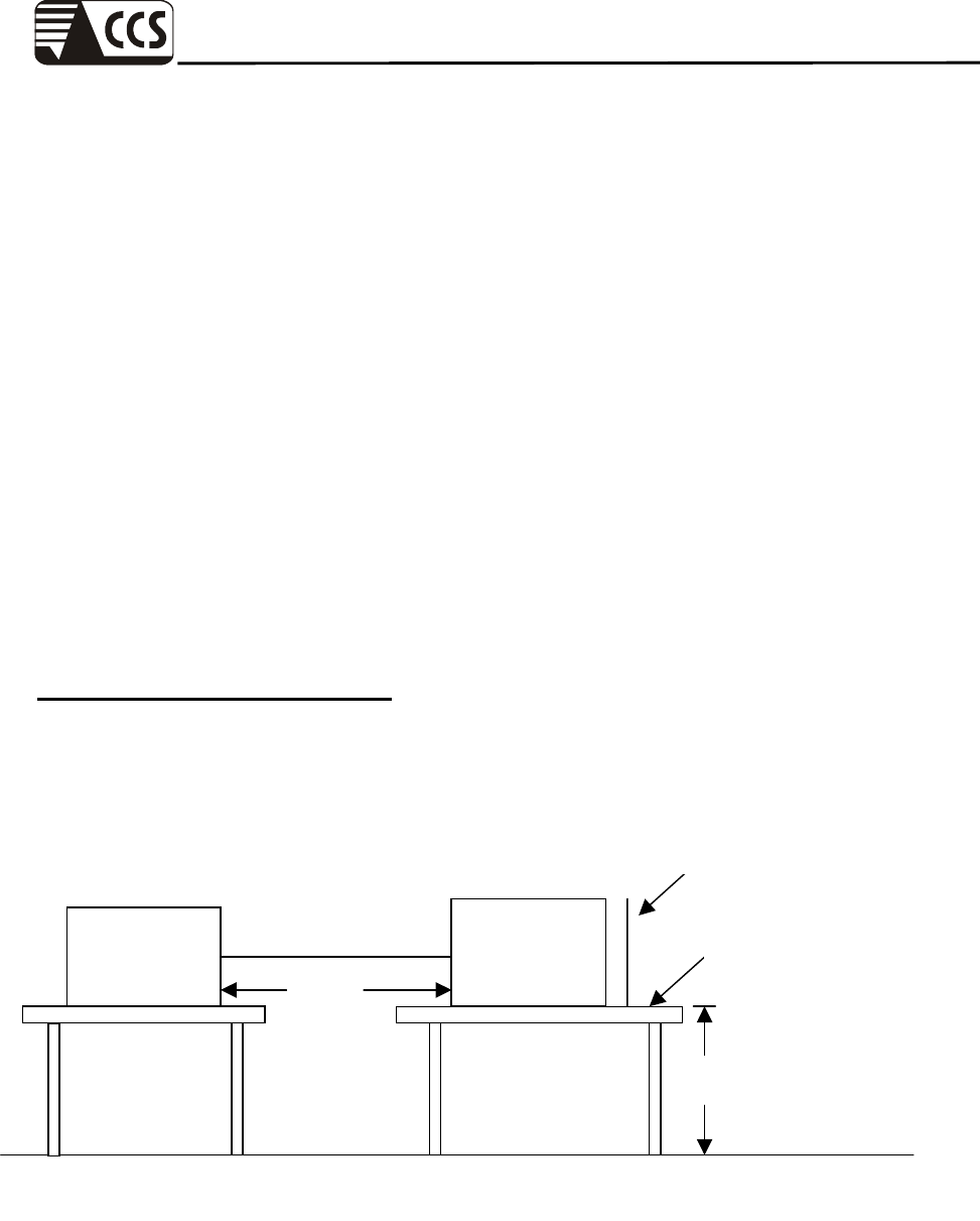
The EUT was set up as per the test configuration to simulate typical usage per the user’s manual.
When the EUT is a tabletop system, a wooden table with a height of 0.8 meters is used and is
placed on the ground plane as per EN 55022 (see Test Facility for the dimensions of the ground
plane used). When the EUT is a floor-standing equipment, it is placed on the ground plane which
has a 3-12 mm non-conductive covering to insulate the EUT from the ground plane.
Support equipment, if needed, was placed as per EN 55022.
All I/O cables were positioned to simulate typical actual usage as per EN 55022.
The test equipment EUT installed received AC power, 230VAC/50Hz, through a Line Impedance
Stabilization Network (LISN), which supplied power source and was grounded to the ground
plane.
All support equipments received power from a second LISN.
The EUT test program was started. Emissions were measured on each current carrying line of
the EUT using an EMI Test Receiver connected to the LISN powering the EUT.
The Receiver scanned from 150kHz to 30MHz for emissions in each of the test modes.
During the above scans, the emissions were maximized by cable manipulation.
The test mode(s) described in Item 3.2 were scanned during the preliminary test.
After the preliminary scan, we found the test mode described in Item 3.2 producing the highest
emission level.
The EUT configuration and cable configuration of the above highest emission level were
recorded for reference of the final test.
Procedure of Final Test
EUT and support equipment were set up on the test bench as per the configuration with highest
emission level in the preliminary test.
A scan was taken on both power lines, Line 1 and Line 2, recording at least the six highest
emissions. Emission frequency and amplitude were recorded into a computer in which
correction factors were used to calculate the emission level and compare reading to the
applicable limit.
The test data of the worst-case condition(s) was recorded.

Compliance Certification Services Inc.
Report No.: 70509004-E Date of Issue: September 10, 2007
Page 15 Rev. 00
7.3 TEST PROCEDURE OF COMMON MODE CONDUCTED
EMISSION FOR TELECOMMUNICATION PORT
Selecting ISN for unscreened cable or a current probe for screened cable to take measurement.
The port of the EUT was connected to the remote side support equipment through the
ISN/Current Probe and communication in normal condition.
Making a overall range scan by using the test receiver controlled by controller and record at least
six highest emissions for showing in the test report.
Emission frequency and amplitude were recorded into a computer in which correction factors
were used to calculate the emission level and compare reading to the applicable limit.
In case of measuring on the screened cable, the current limit shall be applied, otherwise the
voltage limit should be applied.
The following test mode was scanned during the preliminary test:
Not applicable, because EUT has no LAN port or modem port.

Compliance Certification Services Inc.
Report No.: 70509004-E Date of Issue: September 10, 2007
Page 16 Rev. 00
7.4 TEST PROCEDURE OF RADIATED EMISSION
Procedure of Preliminary Test
The equipment was set up as per the test configuration to simulate typical usage per the user’s
manual. When the EUT is a tabletop system, a wooden turntable with a height of 0.8 meters is
used which is placed on the ground plane. When the EUT is a floor-standing equipment, it is
placed on the ground plane which has a 3-12 mm non-conductive covering to insulate the EUT
from the ground plane.
Support equipment, if needed, was placed as per EN 55022.
All I/O cables were positioned to simulate typical usage as per EN 55022.
The EUT received AC power source, 230VAC/50Hz, from the outlet socket under the turntable.
All support equipments received power from another socket under the turntable.
The antenna was placed at 10 meter away from the EUT as stated in EN 55022. The antenna
connected to the Spectrum Analyzer via a cable and at times a pre-amplifier would be used.
The Analyzer / Receiver quickly scanned from 30MHz to 1000MHz. The EUT test program was
started. Emissions were scanned and measured rotating the EUT to 360 degrees and positioning
the antenna 1 to 4 meters above the ground plane, in both the vertical and the horizontal
polarization, to maximize the emission reading level.
The test mode(s) described in Item 3.2 were scanned during the preliminary test:
After the preliminary scan, we found the test mode described in Item 3.2 producing the highest
emission level.
The EUT and cable configuration, antenna position, polarization and turntable position of the
above highest emission level were recorded for the final test.
Procedure of Final Test
EUT and support equipment were set up on the turntable as per the configuration with highest
emission level in the preliminary test.
The Analyzer / Receiver scanned from 30MHz to 1000MHz. Emissions were scanned and
measured rotating the EUT to 360 degrees, varying cable placement and positioning the antenna
1 to 4 meters above the ground plane, in both the vertical and the horizontal polarization, to
maximize the emission reading level.
Recorded at least the six highest emissions. Emission frequency, amplitude, antenna position,
polarization and turntable position were recorded into a computer in which correction factors
were used to calculate the emission level and compare reading to the applicable limit and only
Q.P. reading is presented.
The test data of the worst-case condition(s) was recorded.
Compliance Certification Services Inc.
Report No.: 70509004-E Date of Issue: September 10, 2007
Page 17 Rev. 00
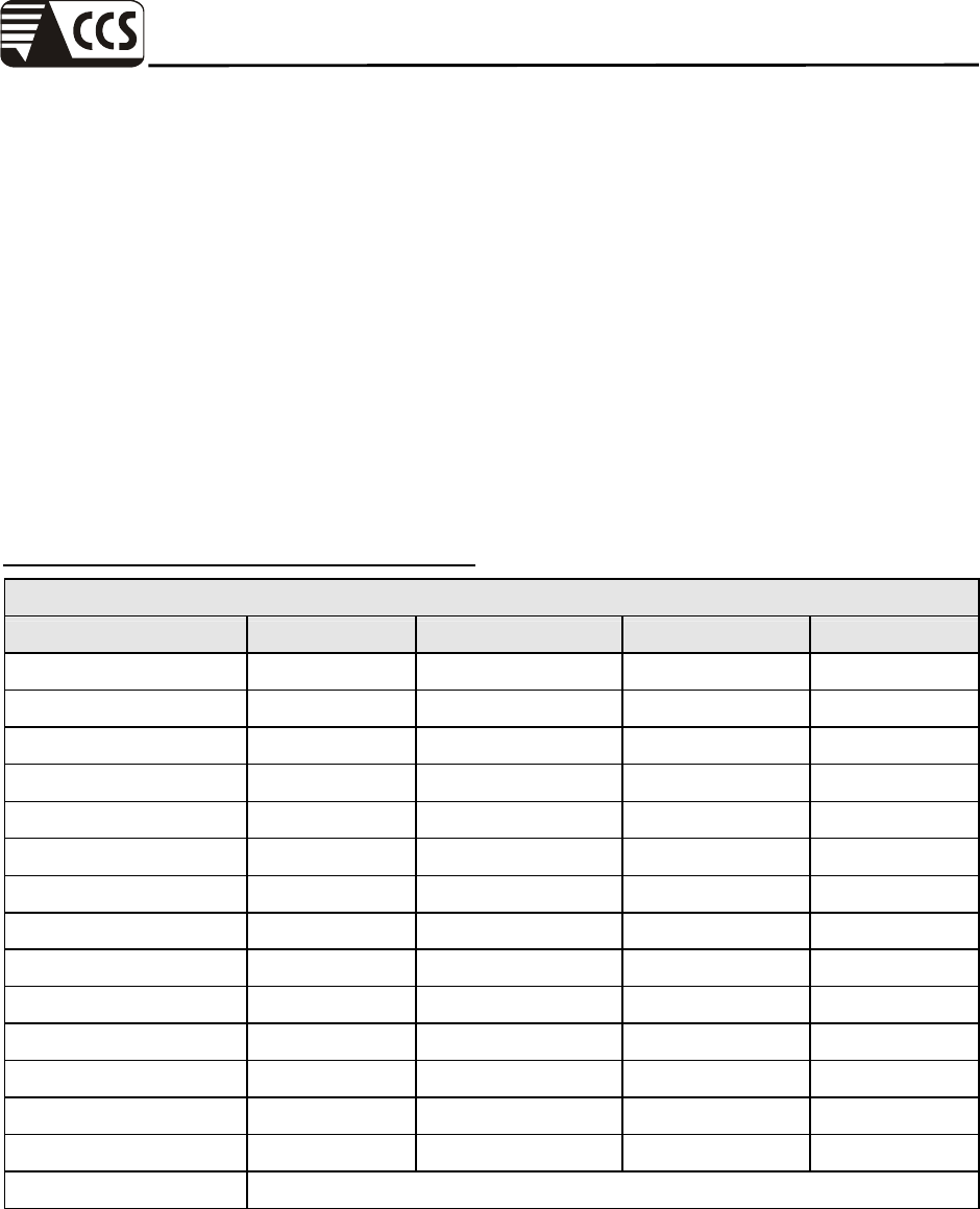
7.5 TEST RESULTS
Powerline Conducted Emission
Operation Mode: Mode 1 Test Date: August 10, 2007
Temperature: 25oC Humidity: 55% RH
Tested by: Eric Cheng
Freq.
(MHz)
QP
Reading
(dBuV)
AV
Reading
(dBuV)
Corr.
factor
(dB)
QP
Result
(dBuV)
AV
Result
(dBuV)
QP
Limit
(dBuV)
AV
Limit
(dBuV)
QP
Margin
(dB)
AV
Margin
(dB)
Note
0.160 51.270 48.700 0.180 51.450 48.880 65.464 55.464 -14.014 -6.584 L1
0.213 48.090 45.700 0.100 48.190 45.800 63.088 53.088 -14.898 -7.288 L1
0.372 44.960 41.710 0.100 45.060 41.810 58.456 48.456 -13.396 -6.646 L1
0.532 46.610 43.640 0.100 46.710 43.740 56.000 46.000 -9.290 -2.260 L1
9.453 43.860 39.010 0.645 44.505 39.655 60.000 50.000 -15.495 -10.345 L1
11.175 38.100 34.560 0.724 38.824 35.284 60.000 50.000 -21.176 -14.716 L1
0.156 46.640 42.520 0.188 46.828 42.708 65.674 55.674 -18.846 -12.966 L2
0.213 45.410 42.520 0.100 45.510 42.620 63.088 53.088 -17.578 -10.468 L2
0.266 40.950 38.560 0.100 41.050 38.660 61.242 51.242 -20.192 -12.582 L2
0.532 44.590 43.700 0.100 44.690 43.800 56.000 46.000 -11.310 -2.200 L2
9.230 34.440 29.670 0.623 35.063 30.293 60.000 50.000 -24.937 -19.707 L2
11.086 31.470 26.960 0.722 32.192 27.682 60.000 50.000 -27.808 -22.318 L2
Remark:
1. Measuring frequencies from 0.15 MHz to 30MHz.
2. The emissions measured in frequency range from 0.15 MHz to 30MHz were made with
an instrument using Quasi-peak detector and average detector.
3. The IF bandwidth of SPA between 0.15MHz and 30MHz was 10kHz; the IF bandwidth
of Test Receiver between 0.15MHz and 30MHz was 9kHz;
4. L1 = Line One (Live Line) / L2 = Line Two (Neutral Line)
Compliance Certification Services Inc.
Report No.: 70509004-E Date of Issue: September 10, 2007
Page 18 Rev. 00
Test Plots
Conducted emissions (Line 1)
Conducted emissions (Line 2)
Compliance Certification Services Inc.
Report No.: 70509004-E Date of Issue: September 10, 2007
Page 19 Rev. 00
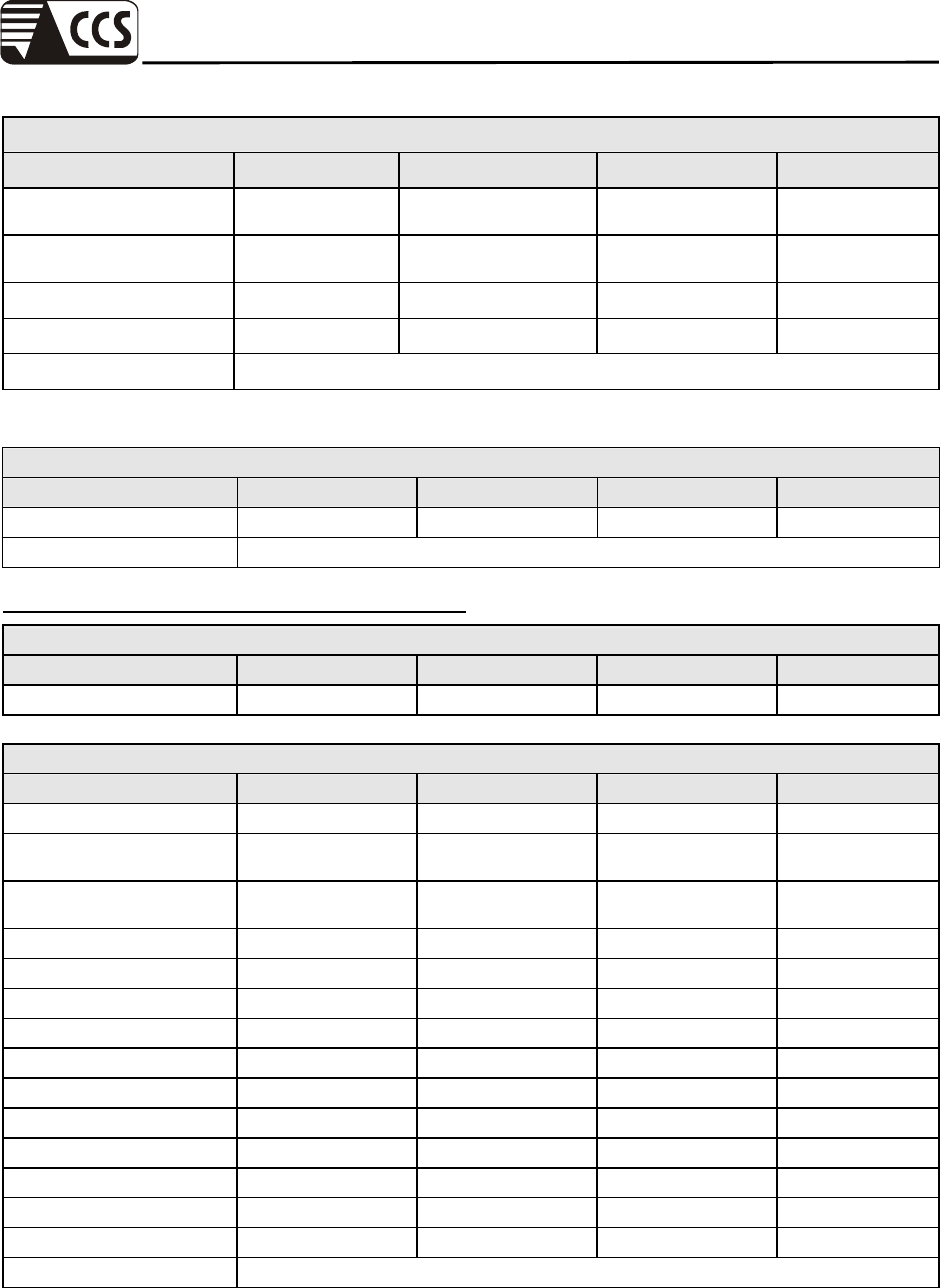
Radiated Emission
Operation Mode: Mode 1 Test Date: August 13, 2007
Temperature: 26oC Tested by: Eric Cheng
Humidity: 55% RH Polarity: Ver. / Hor.
Frequency
(MHz)
Ant. Pol.
(H/V)
Detector
Mode
(PK/QP)
Reading
(dBuV)
Correction Factor
(dB/m)
Result
(dBuV/m)
Limit 10m
(dBuV/m)
Margin
(dB)
59.10 V QP 9.50 12.99 22.49 30.00 -7.51
141.55 V QP 10.50 9.32 19.82 30.00 -10.18
163.38 V QP 8.80 10.22 19.02 30.00 -10.98
253.10 V QP 6.40 14.38 20.78 37.00 -16.22
536.83 V QP 6.20 20.90 27.10 37.00 -9.90
648.37 V QP 5.80 22.74 28.54 37.00 -8.46
55.27 H QP 10.10 13.20 23.30 30.00 -6.70
134.27 H QP 15.50 9.79 25.29 30.00 -4.71
182.78 H QP 8.10 11.33 19.43 30.00 -10.57
253.10 H QP 12.00 14.38 26.38 37.00 -10.62
612.00 H QP 6.40 22.38 28.78 37.00 -8.22
752.65 H QP 4.90 23.59 28.49 37.00 -8.51
Remark:
1. Measuring frequencies from 30MHz to 1GHz.
2. Radiated emissions measured in frequency range from 30MHz to 1000MHz were made
with an instrument using Peak /Quasi-peak detector mode.
3. Measurements above show only up to 6 maximum emissions noted, or would be lesser,
with “ N/A ” remark, if no specific emissions from the EUT are recorded (ie:
margin>20dB from the applicable limit) and considered that's already beyond the
background noise floor.
4. The IF bandwidth of SPA between 30MHz and 1GHz was 100 kHz.
Compliance Certification Services Inc.
Report No.: 70509004-E Date of Issue: September 10, 2007
Page 20 Rev. 00
8 POWER HARMONICS TEST
Port : AC mains
Basic Standard : EN 61000-3-2
Limits : CLASS A; CLASS B; CLASS C; CLASS D
Tested by : Eric Cheng
Temperature : 25oC
Humidity : 55% RH
Limit:
Limits for Class A equipment Limits for Class D equipment
Harmonics
Order
n
Max. permissible
harmonics current
A
Harmonics
Order
n
Max. permissible harmonics
current per watt mA/W
Max. permissible
harmonics current
A
Odd harmonics Odd harmonics only
3 2.30 3 3.4 2.30
5 1.14 5 1.9 1.14
7 0.77 7 1.0 0.77
9 0.40 9 0.5 0.40
11 0.33 11 0.35 0.33
13 0.21 13 0.30 0.21
15<=n<=39 0.15x15/n 15<=n<=39 3.85/n 0.15x15/n
Even harmonics
2 1.08
4 0.43
6 0.30
8<=n<=40 0.23x8/n
Compliance Certification Services Inc.
Report No.: 70509004-E Date of Issue: September 10, 2007
Page 21 Rev. 00
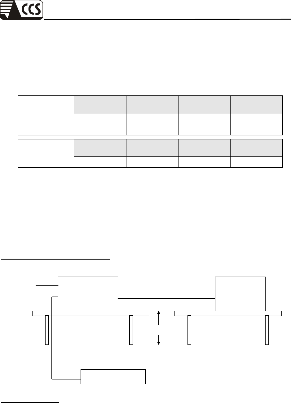
Block Diagram of Test Setup:
Test Procedure:
a. The EUT was placed on the top of a wooden table 0.8 meters above the ground and
operated to produce the maximum harmonic components under normal operating conditions
for each successive harmonic component in turn.
b. The correspondent test program of test instrument to measure the current harmonics
emanated from EUT is chosen. The measure time shall be not less than the time necessary
for the EUT to be exercised.
Test Result:
No non-compliance noted.
Harmonics & Flicker
Analyzer
+
Power Source
EUT Support Units
Power Cord
0.8m
Compliance Certification Services Inc.
Report No.: 70509004-E Date of Issue: September 10, 2007
Page 22 Rev. 00
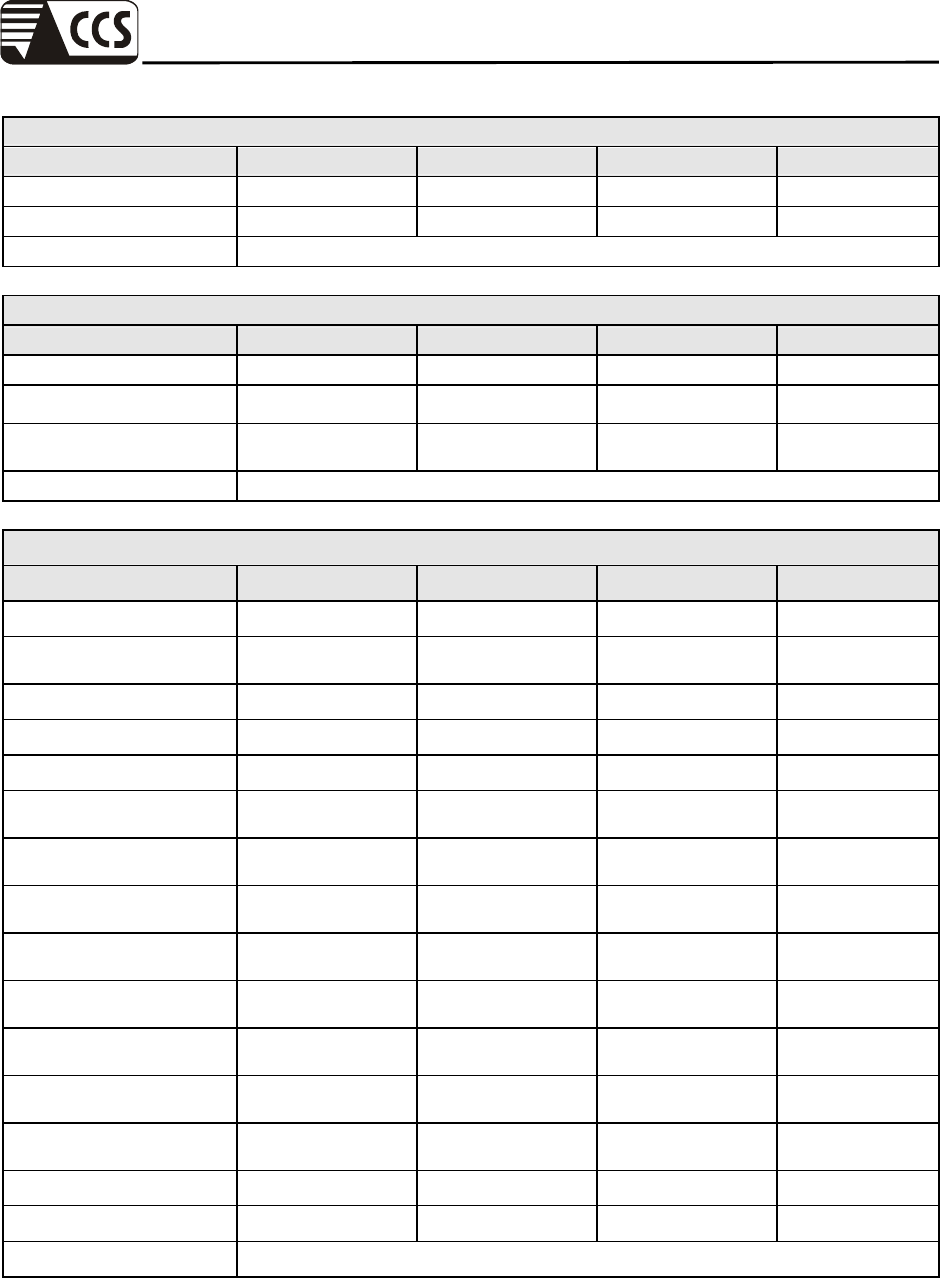
Harmonic Emission - IEC 61000-3-2 , EN 61000-3-2 , (EN60555-2)
Cat5 KVM Extender
UKE-100
Eric Cheng
Remarks Temp : 25'C Humidity : 55% RH
Full Bar : Actual Values
Empty Bar : Maximum Values
Blue : Current , Green : Voltage , Red : Failed
According to EN 61000-3-2, for the following categories of equipment, limits are not specified
in this standard:
Remark:
1. Limits may be defined in a future amendment or revision of the standard. Equipment with a
rated power of 75W or less, other than lighting equipment.
2. This value may be reduced from 75W to 50W in the future, subject to approval by National
Committees at that time.
Compliance Certification Services Inc.
Report No.: 70509004-E Date of Issue: September 10, 2007
Page 23 Rev. 00
9 POWER VOLTAGE FLUCTUATION / FLICKER TEST
Port : AC mains
Basic Standard : EN 61000-3-3
Limits : §5 of EN 61000-3-3
Tested by : Eric Cheng
Temperature : 25oC
Humidity : 55% RH
Limit:
TEST ITEM LIMIT REMARK
Pst 1.0 Pst means short-term flicker indicator.
Plt 0.65 Plt means long-term flicker indicator.
Tdt (ms) 500 Tdt means maximum time that dt exceeds 3 %.
dmax (%) 4% dmax means maximum relative voltage change.
dc (%) 3.3% dc means relative steady-state voltage change
Block Diagram of Test Setup:
Harmonics & Flicker
Analyzer
+
Power Source
EUT Support Units
Power
Cord
0.8m
Compliance Certification Services Inc.
Report No.: 70509004-E Date of Issue: September 10, 2007
Page 24 Rev. 00
Test Procedure:
a. The EUT was placed on the top of a wooden table 0.8 meters above the ground and
operated to produce the most unfavorable sequence of voltage changes under normal
operating conditions.
b. During the flick measurement, the measure time shall include that part of whole operation
cycle in which the EUT produce the most unfavorable sequence of voltage changes. The
observation period for short-term flicker indicator is 10 minutes and the observation period
for long-term flicker indicator is 2 hours.
Test Result:
No non-compliance noted.

Compliance Certification Services Inc.
Report No.: 70509004-E Date of Issue: September 10, 2007
Page 25 Rev. 00
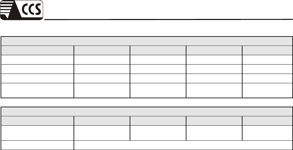
Measurement
Date : 2007/8/10 PM 09:22:1 V4.15
File :
Cat5 KVM Extender
UKE-100
Eric Cheng
Remarks Temp : 25'C Humidity : 55% RH
Urms = 229.9V Freq = 49.948 Range: 0.5 A
Irms = 0.043A Ipk = 0.240A cf = 5.528
P = 3.939W S = 9.991VA pf = 0.394
Test - Time : 1 x 10min = 10min ( 100 %)
LIN (Line Impedance Network) : L: 0.24ohm +j0.15ohm N: 0.16ohm +j0.10ohm
Limits : Plt : 0.65 Pst : 1.00
dmax : 4.00 % dc : 3.30 %
dtLim: 3.30 % dt>Lim: 500ms
Test completed, Result: PASSED
Plt = 0.076
Pst P50s P10s P3s P1s P0.1s Fli dmax dc
dt>Lim
[%] [%]
[ms]
1 0.076 0.010 0.010 0.011 0.015 0.021 0.002 0.000 0.000
0.000
Compliance Certification Services Inc.
Report No.: 70509004-E Date of Issue: September 10, 2007
Page 26 Rev. 00
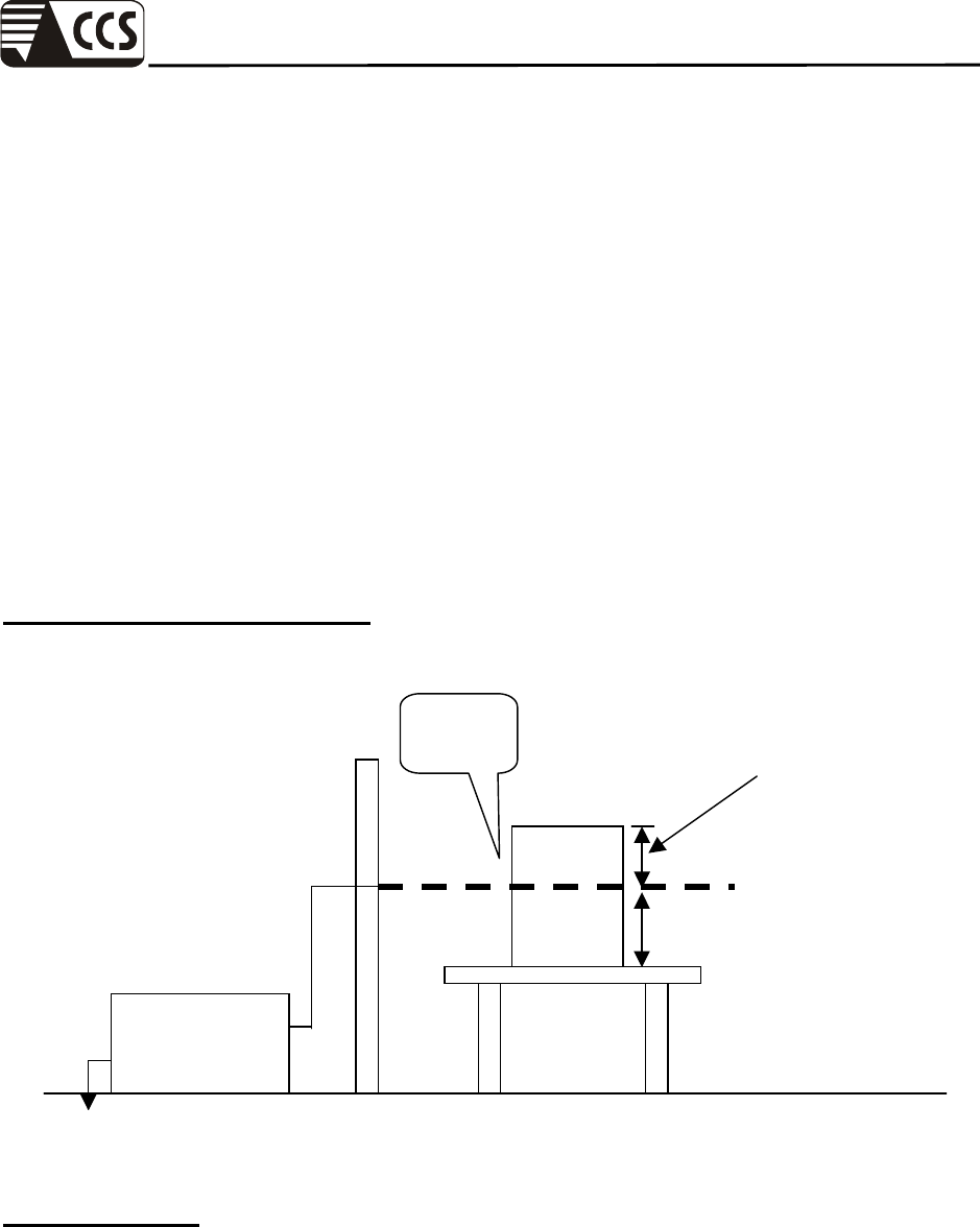
10 ELECTROSTATIC DISCHARGE (ESD) IMMUNITY TEST
Port : Enclosure
Basic Standard : IEC 61000-4-2
Test Level : ± 8 kV (Air Discharge)
± 4 kV (Contact Discharge)
± 4 kV (Indirect Discharge)
Performance Criterion : B (Standard Required)
Tested by : Eric Cheng
Temperature : 25oC
Humidity : 55% RH
Pressure : 1005mbar
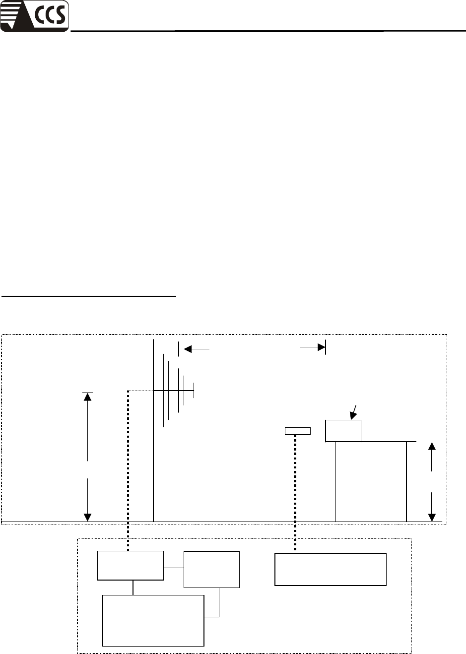
Block Diagram of Test Setup:
(The 470 k ohm resistors are installed per standard requirement.)
Ground Reference Plane
Wooden Table
Indirect
Support units
EUT & its
direct
Support Units
VCP
HCP
>1m
0.8m
Compliance Certification Services Inc.
Report No.: 70509004-E Date of Issue: September 10, 2007
Page 27 Rev. 00
Test Procedure:
1. The EUT was located 0.1 m minimum from all side of the HCP.
2. The indirect support units were located 1 m minimum away from the EUT, but direct support
unit was/were located at same location as EUT on the HCP and keep at a distance of 10 cm
with EUT.
3. A scroll ‘H’ test program was loaded and executed in Windows XP mode.
4. The EUT sent above message to LCD monitor and related peripherals through the test.
5. Active the communication function if the EUT with such port(s).
6. As per the requirement of EN 55024; applying direct contact discharge at the sides other than
front of EUT at minimum 50 discharges (25 positive and 25 negative) if applicable, can’t be
applied direct contact discharge side of EUT then the indirect discharge shall be applied. One of
the test points shall be subjected to at least 50 indirect discharge (contact) to the front edge of
horizontal coupling plane.
7. Other parts of EUT where it is not possible to perform contact discharge then selecting
appropriate points of EUT for air discharge, a minimum of 10 single air discharges shall be
applied.
8. The application of ESD to the contact of open connectors is not required.
9. The EUT direct connection units also need to be applied ESD at the port of EUT cable
connected.
10. To simulate a single ESD event (either by air or by contact discharge), the charge on the EUT
shall be removed prior to each applied ESD pulse. The charge on the metallic point or part to
which the ESD pulse is to be applied, for example, connector shells, battery charge pins,
metallic antennae, shall be removed prior to each applied ESD test pulse. When one or several
metallic accessible parts are subject to the ESD test, the charge shall be removed from the point
where the ESD pulse is to be applied, as no guarantee can be given about the resistance
between this and other accessible points on the product.
11. Putting a mark on EUT to show tested points. The following test condition was followed during
the tests.
Remark: As per IEC 61000-4-2, two 470k bleed resistors cable is connected between the EUT and HCP during the
test applicable for power ungrounded or battery operating unit only.
The electrostatic discharges were applied as follows:
Amount of discharge Voltage Coupling Test Result
(Criterion)
Min. 20 / Point ± 8 kV Air Discharge A
Min. 50 / Point ± 4 kV Contact Discharge A
Min. 50 / Point ± 4 kV Indirect Discharge HCP (Front) A
Min. 50 / Point ± 4 kV Indirect Discharge VCP (Right) A
Min. 50 / Point ± 4 kV Indirect Discharge VCP (Left) A
Min. 50 / Point ± 4 kV Indirect Discharge VCP (Back) A
Remark: For tested points to EUT, refer to the enclosed pages. Be aware that the Blue mark is for contact
discharge, and the red mark is for air discharge.
Compliance Certification Services Inc.
Report No.: 70509004-E Date of Issue: September 10, 2007
Page 28 Rev. 00
Performance & Result:
Criteria A: The apparatus continues to operate as intended. No degradation of
performance or loss of function is allowed below a performance level
specified by the manufacturer, when the apparatus is used as intended.
In some cases the performance level may be replaced by a permissible
loss of performance.
Criteria B: The apparatus continues to operate as intended after the test. No
degradation of performance or loss of function is allowed below a
performance level specified by the manufacturer, when the apparatus is
used as intended. In some cases the performance level may be replaced
by a permissible loss of performance. During the test, degradation of
performance is however allowed.
Criteria C: Temporary loss of function is allowed, provided the functions self
recoverable or can be restored by the operation of controls.
PASS FAIL
Observation: No function degraded during the tests.
Compliance Certification Services Inc.
Report No.: 70509004-E Date of Issue: September 10, 2007
Page 29 Rev. 00
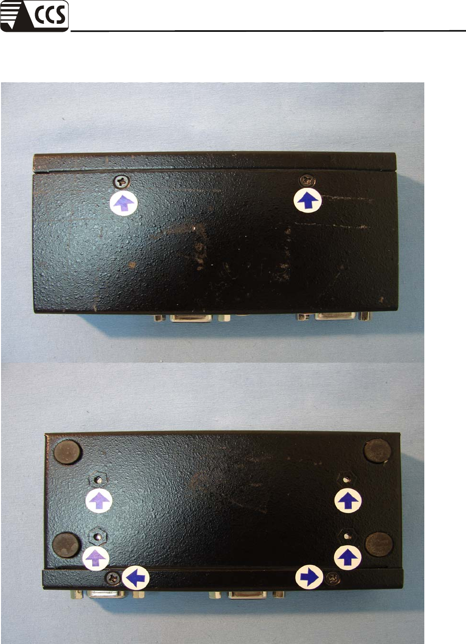
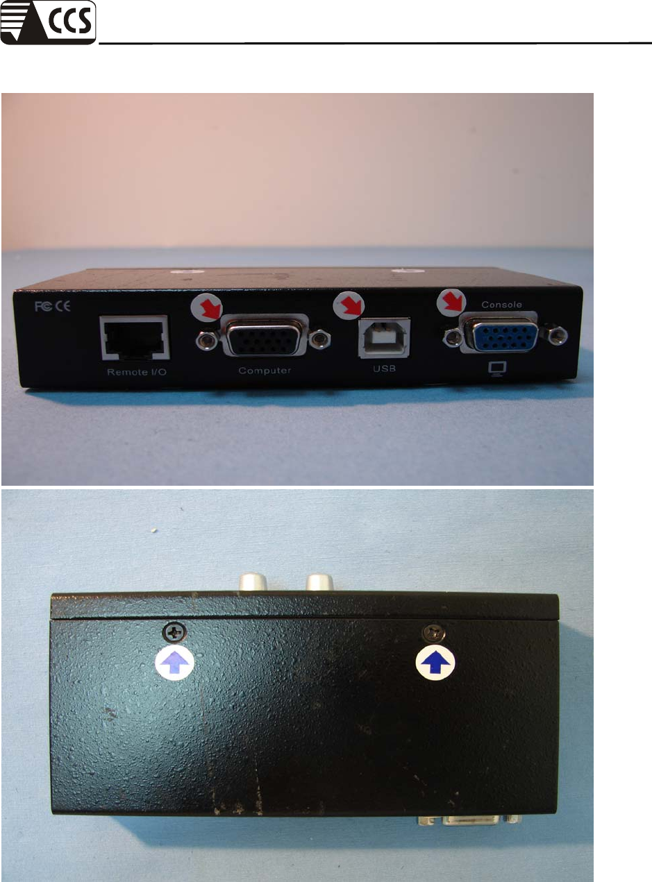
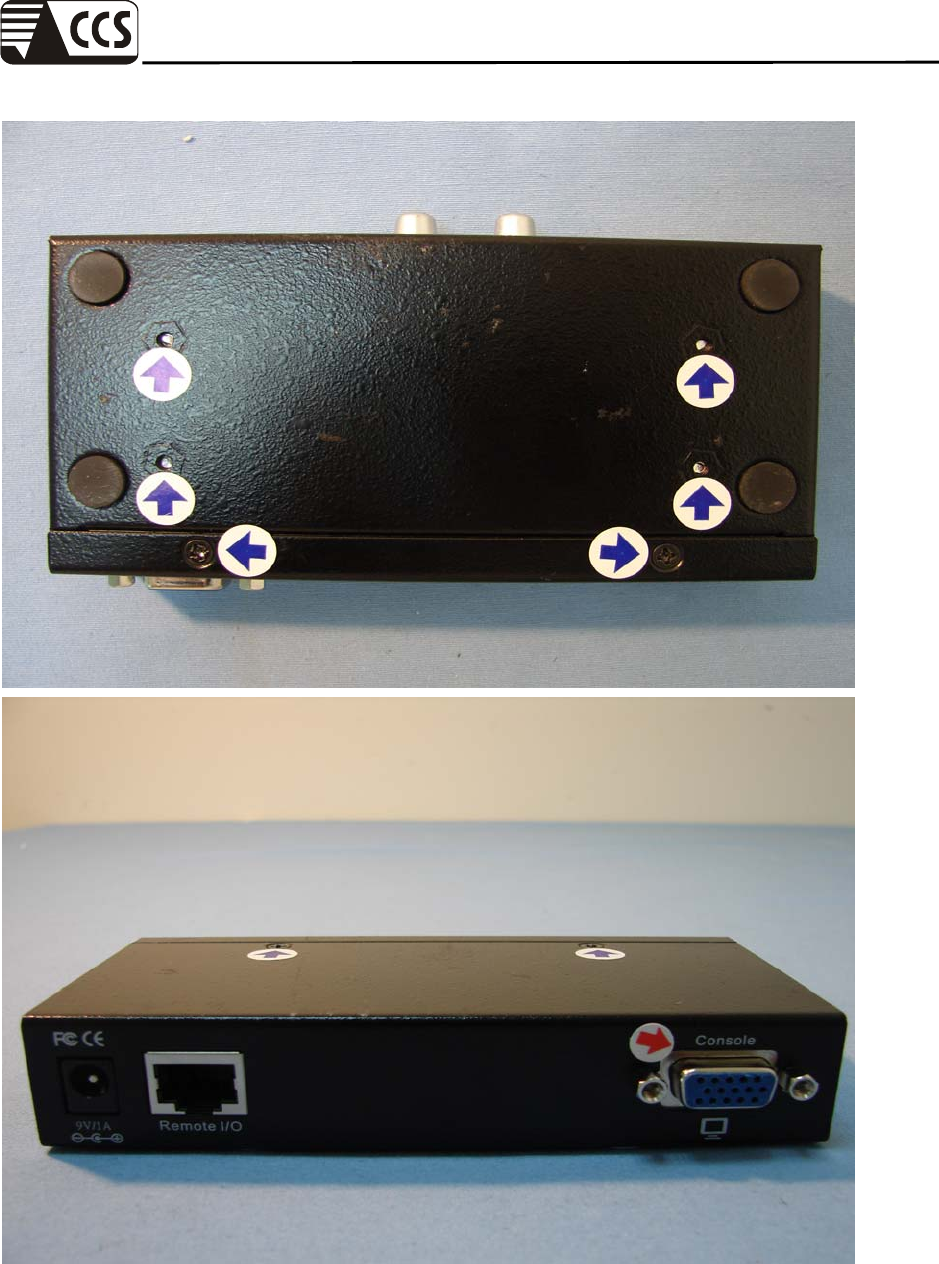
The Tested Points of EUT
Compliance Certification Services Inc.
Report No.: 70509004-E Date of Issue: September 10, 2007
Page 30 Rev. 00
Compliance Certification Services Inc.
Report No.: 70509004-E Date of Issue: September 10, 2007
Page 31 Rev. 00
Compliance Certification Services Inc.
Report No.: 70509004-E Date of Issue: September 10, 2007
Page 32 Rev. 00
11 RADIATED ELECTROMAGNETIC FIELD IMMUNITY TEST
Port : Enclosure
Basic Standard : IEC 61000-4-3
Requirements : 3 V/m / with 80% AM. 1 kHz Modulation.
Performance Criterion : A (Standard Required)
Tested by : Eric Cheng
Temperature : 25oC
Humidity : 55% RH
Pressure : 1005mbar
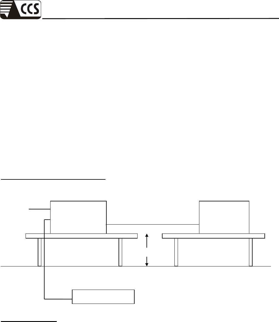
Block Diagram of Test Setup:
0.8m
Power Amp Signal
Generator
EUT Monitoring by using
a camera
Control Room
7x3x3
EUT & Support
Units
PC Controller to
control S.G. & PA as
well as forward power
3 meter
1.5 meter
Compliance Certification Services Inc.
Report No.: 70509004-E Date of Issue: September 10, 2007
Page 33 Rev. 00
Test Procedure:
1. The EUT was located at the edge of supporting table keep 3 meter away from transmitting
antenna, it just the calibrated square area of field uniformity. The support units were located
outside of the uniformity area, but the cable(s) connected with EUT were exposed to the
calibrated field as per IEC 61000-4-3.
2. Setting the testing parameters of RS test software per IEC 61000-4-3.
3. Performing the pre-test at each side of with double specified level (6V/m) at 4% steps.
4. From the result of pre-test in step 5, choice the worst side of EUT for final test from 80 MHz
to 1000 MHz at 1% steps.
5. Recording the test result in following table.
Preliminary test conditions:
Test level : 6V/m
Steps : 4 % of fundamental
Dwell Time : 3 sec
Freq. Range
(MHz) Field Modulation Polarity Position Test Result
(Criterion)
80-1000 6V/m Yes H Front A
80-1000 6V/m Yes V Front A
80-1000 6V/m Yes H Right A
80-1000 6V/m Yes V Right A
80-1000 6V/m Yes H Back A
80-1000 6V/m Yes V Back A
80-1000 6V/m Yes H Left A
80-1000 6V/m Yes V Left A
Final test conditions:
Test level : 3V/m
Steps : 1 % of fundamental
Dwell Time : 3 sec
Freq. Range
(MHz) Field Modulation Polarity Position Test Result
(Criterion)
80-1000 3V/m Yes H Front A
80-1000 3V/m Yes V Front A

Compliance Certification Services Inc.
Report No.: 70509004-E Date of Issue: September 10, 2007
Page 34 Rev. 00
Performance & Result:
Criteria A: The apparatus continues to operate as intended. No degradation of
performance or loss of function is allowed below a performance level
specified by the manufacturer, when the apparatus is used as intended.
In some cases the performance level may be replaced by a permissible
loss of performance.
Criteria B: The apparatus continues to operate as intended after the test. No
degradation of performance or loss of function is allowed below a
performance level specified by the manufacturer, when the apparatus is
used as intended. In some cases the performance level may be replaced
by a permissible loss of performance. During the test, degradation of
performance is however allowed.
Criteria C: Temporary loss of function is allowed, provided the functions self
recoverable or can be restored by the operation of controls.
PASS FAIL
Observation: No function degraded during the tests.

Compliance Certification Services Inc.
Report No.: 70509004-E Date of Issue: September 10, 2007
Page 35 Rev. 00
12 FAST TRANSIENTS/BURST IMMUNITY TEST
Port : On Power Supply Lines and Data Line
Basic Standard : IEC 61000-4-4
Requirements : ± 1 kV for Power Supply Line
Performance Criterion : B (Standard Required)
Tested by : Eric Cheng
Temperature : 25oC
Humidity : 55% RH
Pressure : 1005mbar
Block Diagram of Test Setup:
Injection Clamp
Burst Generator
To Load
AC Line
Comm. Line ≧ 3 m
EUT
Non-Conductive Table
10cm
Controller Computer
EFT/Burst/
Surge Generator
EUT Support Units
Non-Conductive Table
AC Line
Ground Reference Plane
Ground Reference Plane
10cm
10cm
Compliance Certification Services Inc.
Report No.: 70509004-E Date of Issue: September 10, 2007
Page 36 Rev. 00
Test Procedure:
1. The EUT and support units were located on a wooden table 0.1 m away from ground
reference plane.
2. A 0.5m long power cord was attached to EUT during the test.
3. The length of communication cable between communication port and clamp was keeping
within 0.5m.
4. Injected test voltage to the EUT ports from minimum to standard request or client request.
5. Recording the test result as shown in following table.
Test conditions:
Impulse Frequency : 5kHz
Tr/Th : 5/50ns
Burst Duration : 15ms
Burst Period : 3Hz
Inject Line Voltage kV Inject Method Test Result
(Criterion)
Line ±1 Direct A
Neutral ±1 Direct A
PE ±1 Direct N/A
Line + Neutral ±1 Direct A
L + PE ±1 Direct N/A
N + PE ±1 Direct N/A
L + N + PE ±1 Direct N/A
RJ45 port (LAN cable) ±0.5 Clamp N/A
RJ11 port (Line cable) ±0.5 Clamp N/A
Compliance Certification Services Inc.
Report No.: 70509004-E Date of Issue: September 10, 2007
Page 37 Rev. 00
Performance & Result:
Criteria A: The apparatus continues to operate as intended. No degradation of
performance or loss of function is allowed below a performance level
specified by the manufacturer, when the apparatus is used as intended.
In some cases the performance level may be replaced by a permissible
loss of performance.
Criteria B: The apparatus continues to operate as intended after the test. No
degradation of performance or loss of function is allowed below a
performance level specified by the manufacturer, when the apparatus is
used as intended. In some cases the performance level may be replaced
by a permissible loss of performance. During the test, degradation of
performance is however allowed.
Criteria C: Temporary loss of function is allowed, provided the functions self
recoverable or can be restored by the operation of controls.
PASS FAIL
Observation: No function degraded during the tests.
Compliance Certification Services Inc.
Report No.: 70509004-E Date of Issue: September 10, 2007
Page 38 Rev. 00
13 SURGE IMMUNITY TEST
Port : Power Cord
Basic Standard : IEC 61000-4-5
Requirements : ± 1 kV (Line to Line)
Performance Criterion : B (Standard Required)
Tested by : Eric Cheng
Temperature : 25oC
Humidity : 55% RH
Pressure : 1005mbar
Block Diagram of Test Setup:
Test Procedure:
1. The EUT and support units were located on a wooden table 0.8 m away from ground floor.
2. Injected test voltage to the EUT ports from minimum to standard request or client request.
3. Recording the test result as shown in following table.
Surge Immunity
Test
Controller Computer
EUT
&
Support Units
0.8m
To AC
Source
Compliance Certification Services Inc.
Report No.: 70509004-E Date of Issue: September 10, 2007
Page 39 Rev. 00
Test conditions:
Voltage Waveform : 1.2/50 us
Current Waveform : 8/20 us
Polarity : Positive/Negative
Phase angle : 0o, 90o, 270o
Number of Test : 5
Coupling Line Voltage
(kV) Polarity Coupling
Method
Test Result
(Criterion)
Line + Neutral 1 Pos./ Neg. Capacitive A
L + PE 2 Pos./ Neg. Capacitive N/A
N + PE 2 Pos./ Neg. Capacitive N/A
T, R-Ground 1 Pos./ Neg. Capacitive N/A
L1, 2, 3, 4-G 1 Pos./ Neg. Capacitive N/A
Performance & Result:
Criteria A: The apparatus continues to operate as intended. No degradation of
performance or loss of function is allowed below a performance level
specified by the manufacturer, when the apparatus is used as intended.
In some cases the performance level may be replaced by a permissible
loss of performance.
Criteria B: The apparatus continues to operate as intended after the test. No
degradation of performance or loss of function is allowed below a
performance level specified by the manufacturer, when the apparatus is
used as intended. In some cases the performance level may be replaced
by a permissible loss of performance. During the test, degradation of
performance is however allowed.
Criteria C: Temporary loss of function is allowed, provided the functions self
recoverable or can be restored by the operation of controls.
PASS FAIL
Observation: No function degraded during the tests.
Compliance Certification Services Inc.
Report No.: 70509004-E Date of Issue: September 10, 2007
Page 40 Rev. 00
14 CONDUCTED DISTRBANCE/INDUCED RADIO-FREQUENCY
FIELD IMMUNITY TEST
Port : AC Port and Data Line
Basic Standard : IEC 61000-4-6
Requirements : 3 V with 80% AM. 1 kHz Modulation.
Injection Method : CDN-M2 for Power Cord
Performance Criterion : A (Standard Required)
Tested by : Eric Cheng
Temperature : 25oC
Humidity : 55% RH
Pressure : 1005mbar
Block Diagram of Test Setup:
Side View:
CDN
EUT and
Support units Power
Amplifier
PC
Controller
Ground Reference Plane
10 cm isolation
su
pp
orte
r
0.1m< L <0.3m
0.1m<L<0.3
m
Power
Amplifier
PC
Controller
EM-Clamp/
CDN
EUT &
Support
Units
Support
Units
Ground Reference Plane
3 - 5 cm isolation su
pp
orte
r
10 cm isolation su
pp
orte
r
Top Vi e w :
Compliance Certification Services Inc.
Report No.: 70509004-E Date of Issue: September 10, 2007
Page 41 Rev. 00
Test Procedure:
1. The EUT and support units were located at a ground reference plane with the interposition of
a 0.1 m thickness insulating support and the CDN was located on GRP directly.
2. Setting the testing parameters of CS test software as per IEC 61000-4-6.
3. Recording the test result in following table.
Test conditions:
Frequency Range : 0.15MHz-80MHz
Frequency Step : 1% of fundamental
Dwell Time : 3 sec
CDN: FCC-801-M2-16A / FCC-801-M3-16A
FCC-801-T4 / FCC-801-T2
Range (MHz) Field Modulation Test Result
(Criterion)
0.15-80 3V Yes A
Performance & Result:
Criteria A: The apparatus continues to operate as intended. No degradation of
performance or loss of function is allowed below a performance level
specified by the manufacturer, when the apparatus is used as intended.
In some cases the performance level may be replaced by a permissible
loss of performance.
Criteria B: The apparatus continues to operate as intended after the test. No
degradation of performance or loss of function is allowed below a
performance level specified by the manufacturer, when the apparatus is
used as intended. In some cases the performance level may be replaced
by a permissible loss of performance. During the test, degradation of
performance is however allowed.
Criteria C: Temporary loss of function is allowed, provided the functions self
recoverable or can be restored by the operation of controls.
PASS FAIL
Observation: No function degraded during the tests.
Compliance Certification Services Inc.
Report No.: 70509004-E Date of Issue: September 10, 2007
Page 42 Rev. 00
15 POWER FREQUENCY MAGNETIC FIELD IMMUNITY TEST
Port : Enclosure
Basic Standard : IEC 61000-4-8
Requirements : 1 A/m
Performance Criterion : A (Standard Required)
Tested by : Eric Cheng
Temperature : 25oC
Humidity : 55% RH
Pressure : 1005mbar
Block Diagram of Test Setup:
Test Procedure:
1. The EUT and support units were located on Ground Reference Plane with the interposition
of a 0.1 m thickness insulation support.
2. Putting the induction coil on horizontal direction. ( X direction )
3. Rotating the induction coil by 90o ( Y direction )
4. Rotating the induction coil by 90o again ( Z direction )
5. Recording the test result as shown in following table.
EUT
Signal
Generator
To
Earth Ground
Induction
Coil
1/2 Dimension
of EUT
Compliance Certification Services Inc.
Report No.: 70509004-E Date of Issue: September 10, 2007
Page 43 Rev. 00
Test conditions:
Field Strength: 1A/m
Power Freq.: 50Hz
Orientation: X, Y, Z
Orientation Field Test Result
(Criterion)
X 1A/m A
Y 1A/m A
Z 1A/m A
Performance & Result:
Criteria A: The apparatus continues to operate as intended. No degradation of
performance or loss of function is allowed below a performance level
specified by the manufacturer, when the apparatus is used as intended.
In some cases the performance level may be replaced by a permissible
loss of performance.
Criteria B: The apparatus continues to operate as intended after the test. No
degradation of performance or loss of function is allowed below a
performance level specified by the manufacturer, when the apparatus is
used as intended. In some cases the performance level may be replaced
by a permissible loss of performance. During the test, degradation of
performance is however allowed.
Criteria C: Temporary loss of function is allowed, provided the functions self
recoverable or can be restored by the operation of controls.
PASS FAIL
Observation: No function degraded during the tests.
Compliance Certification Services Inc.
Report No.: 70509004-E Date of Issue: September 10, 2007
Page 44 Rev. 00
16 VOLTAGE DIPS / SHORT INTERRUPTIONS
Port : AC mains
Basic Standard : IEC 61000-4-11
Requirement : PHASE ANGLE 0, 45, 90, 135, 180, 225, 270, 315 degrees
Test Level
% UT
Reduction
(%)
Duration
( periods )
Performance
Criteria
<5 >95 0.5 B
Voltage
Dips
70 30 25 C
Test Level
% UT
Reduction
(%)
Duration
( periods )
Performance
Criteria
Voltage
Interruptions <5 >95 250 C
Test Interval : Min. 10 sec.
Tested by : Eric Cheng
Temperature : 25oC
Humidity : 55% RH
Pressure : 1005mbar
Block Diagram of Test Setup:
Test Procedure:
1. The EUT and support units were located on a wooden table, 0.8 m away from ground floor.
2. Setting the parameter of tests and then Perform the test software of test simulator.
3. Conditions changes to occur at 0 degree crossover point of the voltage waveform.
4. Recording the test result in test record form.
Dips/Interruption
and Variations
Simulator
Controller Computer
EUT
&
Support Units
0.8
m
To AC
Source
Compliance Certification Services Inc.
Report No.: 70509004-E Date of Issue: September 10, 2007
Page 45 Rev. 00
Test conditions
The duration with a sequence of three dips/interruptions with interval of 10 s minimum (Between
each test event )
Voltage Dips:
Test Level
% UT
Reduction
(%)
Duration
(periods) Observation
Meet
Performance
Criteria
0 100 0.5 Normal A
70 30 25 Normal A
Voltage Interruptions:
Test Level
% UT
Reduction
(%)
Duration
(periods) Observation
Meet
Performance
Criteria
0 100 250
EUT shut down, but can
be recovered manually as
the events disappeared.
C
Performance & Result:
Criteria A: The apparatus continues to operate as intended. No degradation of
performance or loss of function is allowed below a performance level
specified by the manufacturer, when the apparatus is used as intended.
In some cases the performance level may be replaced by a permissible
loss of performance.
Criteria B: The apparatus continues to operate as intended after the test. No
degradation of performance or loss of function is allowed below a
performance level specified by the manufacturer, when the apparatus is
used as intended. In some cases the performance level may be replaced
by a permissible loss of performance. During the test, degradation of
performance is however allowed.
Criteria C: Temporary loss of function is allowed, provided the functions self
recoverable or can be restored by the operation of controls.
PASS FAIL
Compliance Certification Services Inc.
Report No.: 70509004-E Date of Issue: September 10, 2007
Page 46 Rev. 00
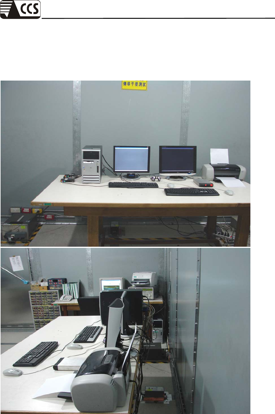
APPENDIX I –
PHOTOGRAPHS OF TEST SETUP
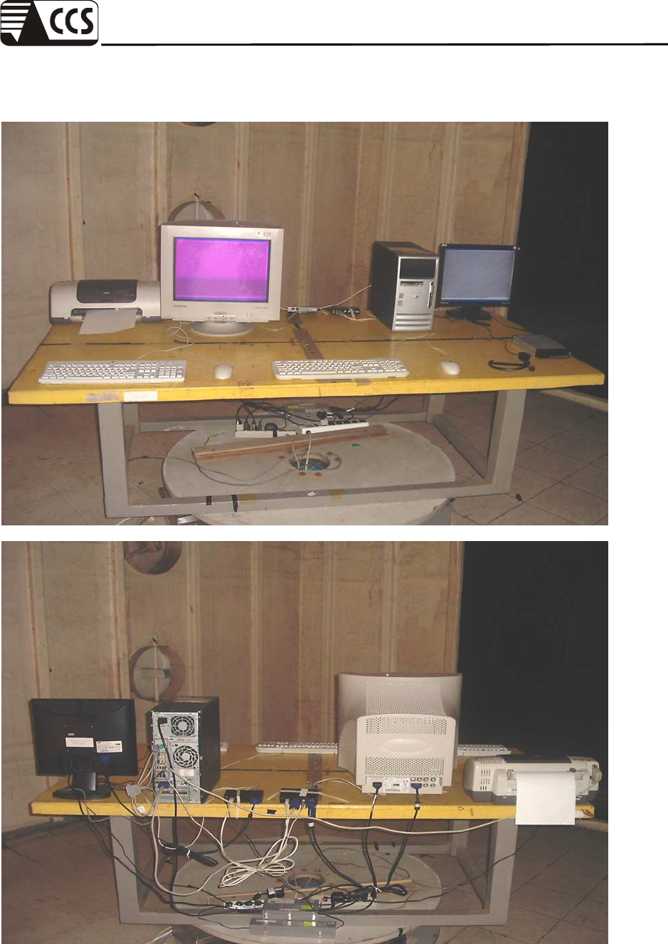
POWERLINE CONDUCTED EMISSION TEST (EN 55022)
Compliance Certification Services Inc.
Report No.: 70509004-E Date of Issue: September 10, 2007
Page 47 Rev. 00
RADIATED EMISSION TEST (EN 55022)
Compliance Certification Services Inc.
Report No.: 70509004-E Date of Issue: September 10, 2007
Page 48 Rev. 00
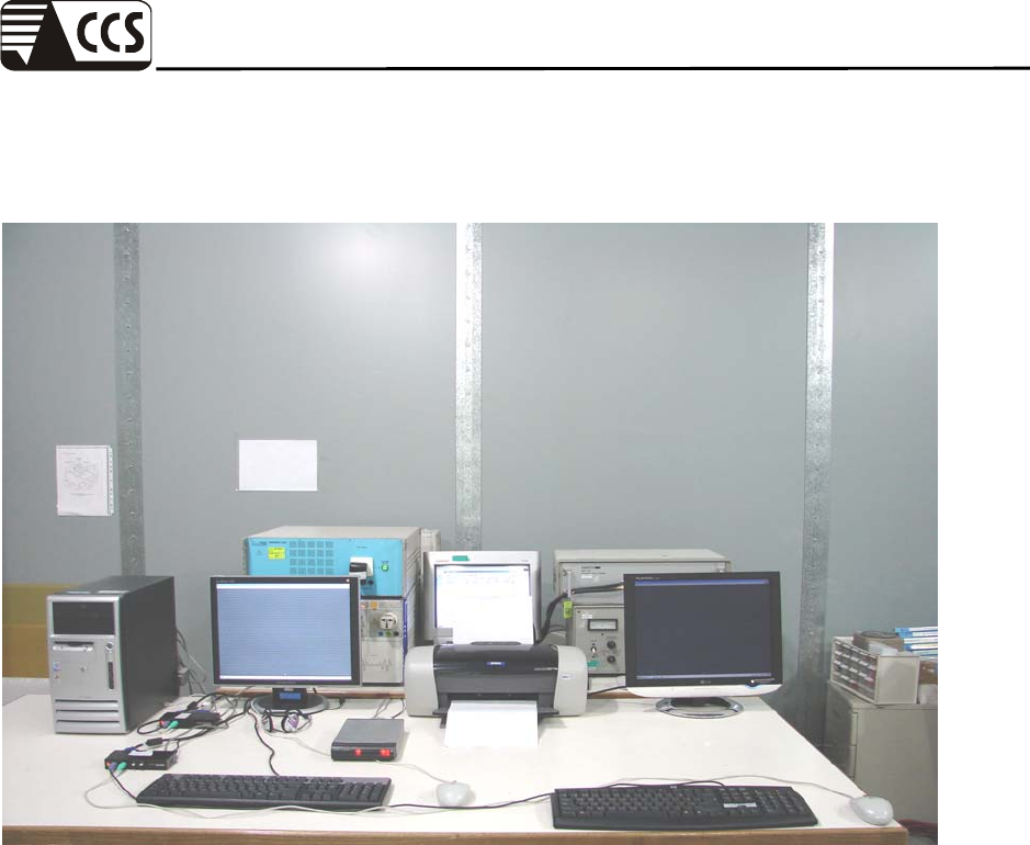
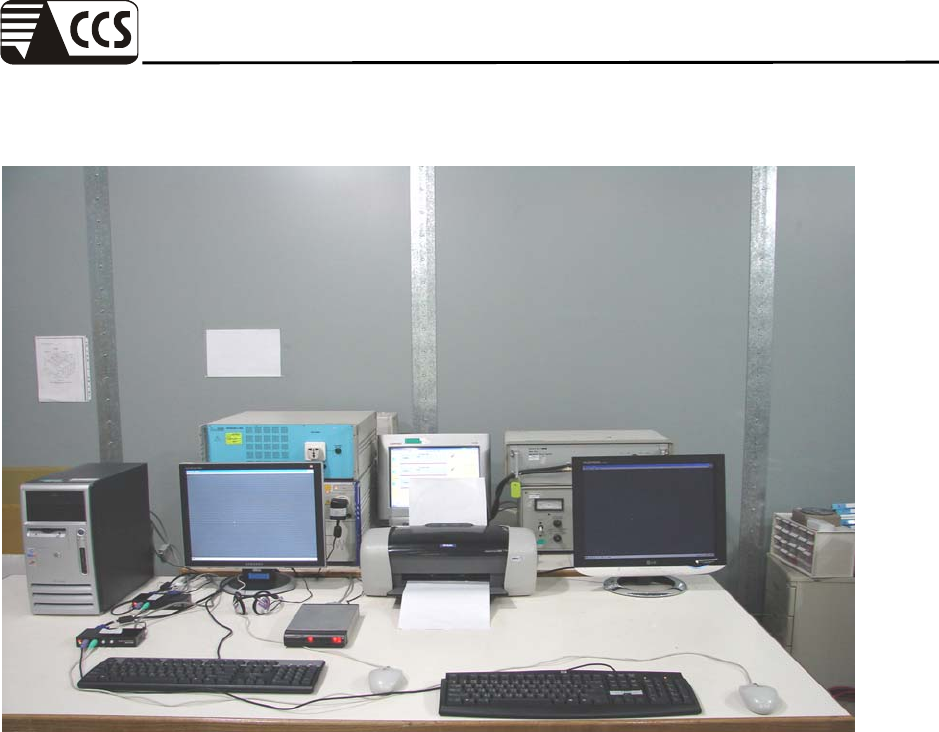
POWER HARMONIC & VOLTAGE FLUCTUATION / FLICKER TEST
(EN 61000-3-2/EN 61000-3-3)
Compliance Certification Services Inc.
Report No.: 70509004-E Date of Issue: September 10, 2007
Page 49 Rev. 00
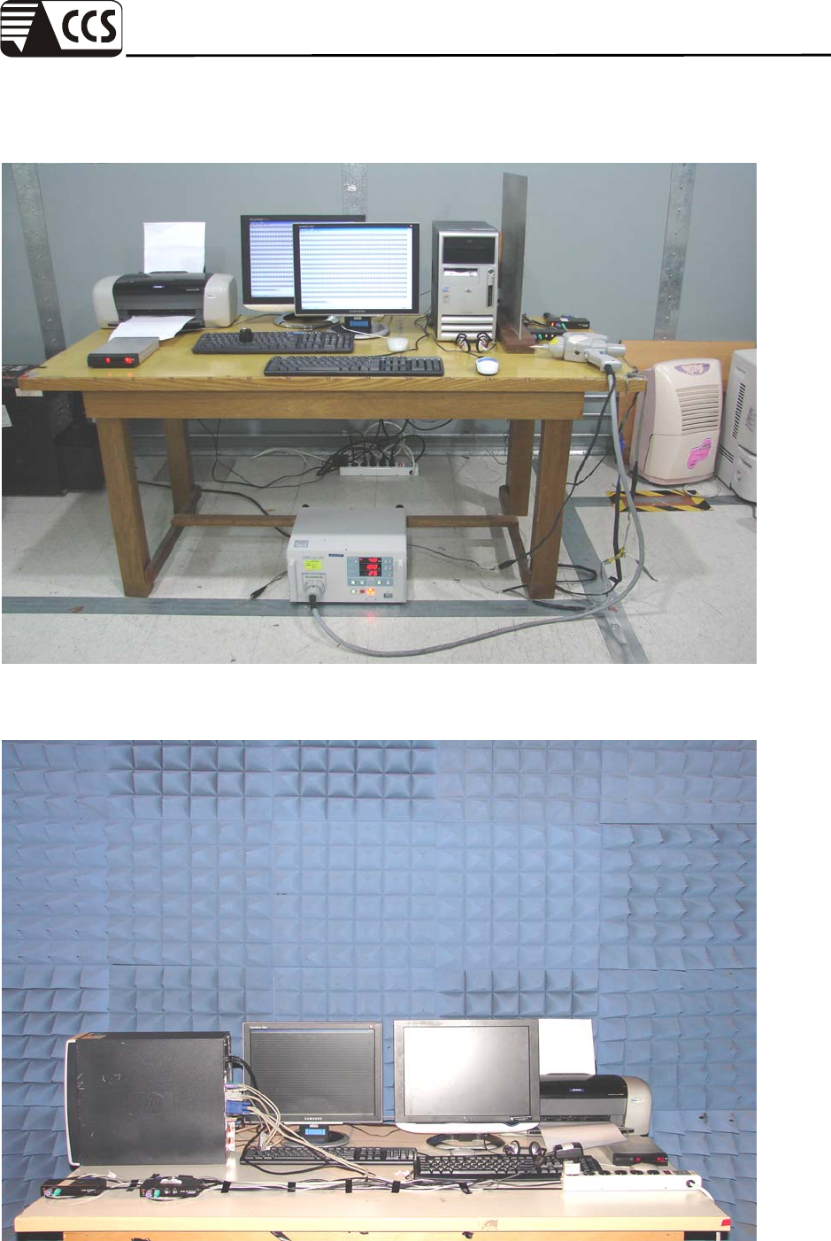
ELECTROSTATIC DISCHARGE TEST (IEC 61000-4-2)
RADIATED ELECTROMAGNETIC FIELD TEST (IEC 61000-4-3)
Compliance Certification Services Inc.
Report No.: 70509004-E Date of Issue: September 10, 2007
Page 50 Rev. 00
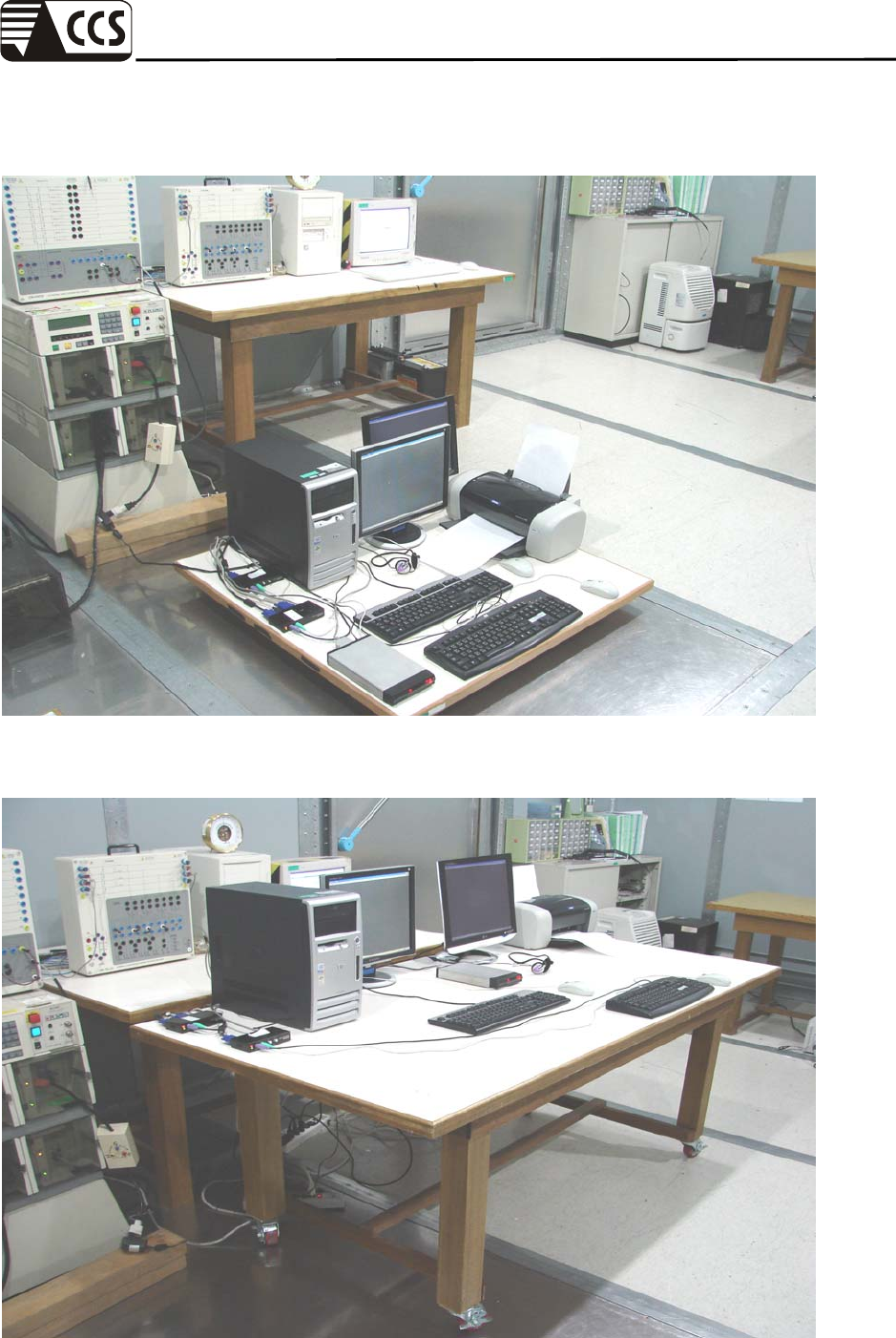
FAST TRANSIENTS/BURST TEST (IEC 61000-4-4)
SURGE IMMUNITY TEST (IEC 61000-4-5)
Compliance Certification Services Inc.
Report No.: 70509004-E Date of Issue: September 10, 2007
Page 51 Rev. 00
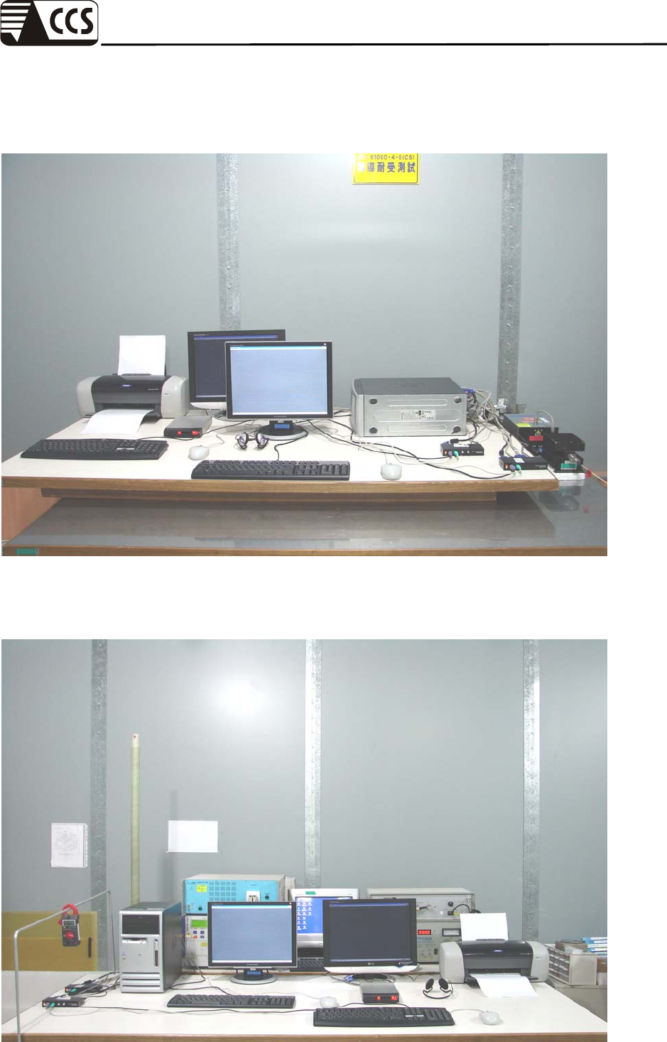
CONDUCTED DISTURBANCE, INDUCED BY RADIO-FREQUENCY
FIELDS TEST (IEC 61000-4-6)
POWER FREQUENCY MAGNETIC FIELD IMMUNITY TEST (IEC
61000-4-8)
Compliance Certification Services Inc.
Report No.: 70509004-E Date of Issue: September 10, 2007
Page 52 Rev. 00
VOLTAGE DIPS / INTERRUPTION TEST (IEC 61000-4-11)
