80 Y0306 1 WIRELESS CONNECTIVITY S USER GUIDE
User Manual: Pdf
Open the PDF directly: View PDF ![]() .
.
Page Count: 152 [warning: Documents this large are best viewed by clicking the View PDF Link!]
- 1 Introduction
- 2 Hardware Setup and Requirements
- 3 Software Installation
- 3.1 SW requirements
- 3.2 QDART for non-FFA setup
- 3.3 NI GPIB setup
- 3.4 Android debug bridge installation
- 3.5 LitePoint software for running
- 3.6 Agilent N4010A software installation
- 3.7 LitePoint IQxel wave files installation
- 3.8 NI PXI5644R software installation
- 3.9 Agilent N5182A software and waveform files installation (ANT only)
- 3.10 LitePoint IQNFC Software
- 4 Station Calibration
- 5 Test Matrix
- 5.1 Bluetooth non-signaling production test matrix
- 5.2 WLAN production SISO test matrix
- 5.3 WLAN production MIMO test matrix
- 5.4 FM production test matrix
- 5.5 ANT production test matrix
- 5.6 WLAN WCN36x0 CLPC calibration
- 5.7 Bluetooth signaling production test matrix
- 5.8 NFC production functional test matrix
- 5.9 NFC reference test matrix
- 6 Chipsets Supported
- 7 Setup Configuration
- 8 QSPR Test Trees
- 9 Test Setup Details
- 9.1 Bluetooth initialization and de-initialization tests
- 9.1.1 Bluetooth initialization
- 9.1.2 Bluetooth configuration file details
- 9.1.3 Bluetooth de-initialization
- 9.1.4 Bluetooth UART/USB test setup using BT DIAG BRIDGE
- 9.1.5 Bluetooth User Defined Transport (UDT) test setup using BT DIAG BRIDGE
- 9.1.6 Additional configuration for remote DUT using User Defined Transport and BT DIAG BRIDGE on remote PC.
- 9.2 WLAN setup and initialization tests
- 9.3 FM setup and initialization tests
- 9.4 ANT setup and initialization tests
- 9.5 NFC initialization and deinitialization
- 9.1 Bluetooth initialization and de-initialization tests
- 10 Wireless Connectivity Test Description
- 10.1 Bluetooth non-signaling production test description
- 10.1.1 Set Bluetooth ChipID
- 10.1.2 BTDUT_FFA_DisableLegacyLogMode
- 10.1.3 Setup DUT for GFSK and EDR transmit tests
- 10.1.4 Setup DUT for LE transmit tests
- 10.1.5 Measure Tx output power and initial carrier frequency tolerance
- 10.1.6 Measure GFSK modulation DeltaF2 and CarrierDrift
- 10.1.7 Measure GFSK modulation DeltaF1
- 10.1.8 Measure EDR modulation
- 10.1.9 Measure LE Tx output power
- 10.1.10 Measure LE modulation DeltaF1
- 10.1.11 Measure LE modulation DeltaF2, FreqOffset, FreqDrift and MaxDriftRate
- 10.1.12 Measure Rx sensitivity/max input
- 10.1.13 Measure LE Rx sensitivity/max input
- 10.1.14 Set BTDUT_PROD_TEST_SUBCOMMAND_TEST_RX_BURST
- 10.1.15 BTDUT_PROD_TEST_HCI_GET_PER_AR3002
- 10.2 WLAN production test description (SISO Only)
- 10.3 WLAN production test description (MIMO or SISO)
- 10.4 FM production test description
- 10.5 ANT production test description
- 10.6 Bluetooth signaling production test description
- 10.6.1 BTDUT_FFA_DisableLegacyLogMode
- 10.6.2 BTDUT_EnableBT_DUTMode
- 10.6.3 Measure Tx GFSK power
- 10.6.4 Measure Tx modulation characteristics
- 10.6.5 Measure GFSK initial carrier frequency tolerance
- 10.6.6 Measure GFSK carrier frequency drift
- 10.6.7 Measure EDR relative transmit power
- 10.6.8 Measure EDR modulation accuracy
- 10.6.9 Measure Rx sensitivity single slot packets
- 10.6.10 Measure Rx sensitivity multiple slot packets
- 10.6.11 Measure EDR Rx sensitivity
- 10.7 NFC production functional test description
- 10.8 NFC reference parametric test description
- 10.8.1 SetInstrumentConfigFile
- 10.8.2 NFCDUT_SetConfigFile
- 10.8.3 NFCDUT_Instantiate
- 10.8.4 DUT_InitFramework
- 10.8.5 EnableDUTPower
- 10.8.6 WaitForPortToExist
- 10.8.7 NFCDUT_RunTopLevelScript
- 10.8.8 NFCDUT_Connect
- 10.8.9 NFCDUT_PatchFirmwareUsingPatchFile
- 10.8.10 InitializeNFCTester
- 10.8.11 NFCTesterCalibrate
- 10.8.12 NFCTesterLoadCalibration
- 10.8.13 NFCDUT_CoreResetAndInit
- 10.8.14 NFCDUT_ConfigureDUT
- 10.8.15 ConfigureNFCTester
- 10.8.16 NFCDUT_FindResonance
- 10.8.17 NFCDUT_TuneCapNVM
- 10.8.18 InitiatorTest
- 10.8.19 InitiatorRxTest
- 10.8.20 TargetTest
- 10.8.21 ResonanceTest
- 10.8.22 Disconnect
- 10.8.23 Shutdown
- 10.1 Bluetooth non-signaling production test description

NOTICE REGARDING QUALCOMM ATHEROS, INC.
Effective June 2016, Qualcomm Atheros, Inc. (QCA) transferred certain of its assets, including
substantially all of its products and services, to its parent corporation, Qualcomm Technologies, Inc.
Qualcomm Technologies, Inc. is a wholly-owned subsidiary of Qualcomm Incorporated. Accordingly,
references in this document to Qualcomm Atheros, Inc., Qualcomm Atheros, Atheros, QCA or similar
references, should properly reference, and shall be read to reference, Qualcomm Technologies, Inc.

Confidential and Proprietary – Qualcomm Atheros, Inc.
NO PUBLIC DISCLOSURE PERMITTED: Please report postings of this document on public servers or websites to:
DocCtrlAgent@qualcomm.com.
Restricted Distribution: Not to be distributed to anyone who is not an employee of either Qualcomm or its subsidiaries without
the express approval of Qualcomm’s Configuration Management.
Not to be used, copied, reproduced, or modified in whole or in part, nor its contents revealed in any manner to others without the
express written permission of Qualcomm Atheros, Inc.
Qualcomm is a registered trademark of QUALCOMM Incorporated. Atheros is a registered trademark of Qualcomm Atheros,
Inc. MSM is a trademark of QUALCOMM Incorporated, registered in the United States and other countries. Android is a
trademark of Google Inc. Bluetooth word mark and logos are registered trademarks owned by Bluetooth SIG, Inc. All other
registered and unregistered trademarks are the property of QUALCOMM Incorporated, Qualcomm Atheros, Inc., or their
respective owners and used with permission. Registered marks owned by QUALCOMM Incorporated and Qualcomm Atheros,
Inc. are registered in the United States and may be registered in other countries.
This technical data may be subject to U.S. and international export, re-export, or transfer (“export”) laws. Diversion contrary to
U.S. and international law is strictly prohibited.
Qualcomm Atheros, Inc.
1700 Technology Drive
San Jose, CA 95110
U.S.A.
© 2012-2014 Qualcomm Atheros, Inc.
Wireless Connectivity Tests
User Guide
80-Y0306-1 Rev. L
October 1, 2014
Submit technical questions at:
https://support.cdmatech.com

80-Y0306-1 Rev. L MAY CONTAIN U.S. AND INTERNATIONAL EXPORT CONTROLLED INFORMATION 2
Confidential and Proprietary – Qualcomm Atheros, Inc.
Revision history
Revision
Date
Description
A
April 2012
Initial Release
B
June 2012
Added BT Low Energy, WLAN AR6003, Agilent N4010 WLAN
support.
C
October 2012
WLAN802.11ac support with IQxel and NI PXI5644R, Agilent
N4010A BT support, Station calibration support with
connectivity test box, default WCNTesterConfig.xml for each
test equipment.
D
January 2013
FM digital audio support, BT IQxel support, Test equipment
options updated.
E
March 2013
BT LE IQxel support, BT LE CMW support, Test equipment
options updated
F
July 2013
Added BT and WLAN AnritsuMT8870A support
QSPR Bluetooth tests moved to BTTestSuite.
Added BT AR3002 QSPR tests
G
October 2013
Added QCA6174 test support
Added WLAN MIMO test description
Added ANT test description
Added BT standalone support
H
November 2013
Added section 2.1.3 for WLAN MIMO test setup.
Updated section 9.1.4 for BT standalone configuration.
J
March 2014
Added BT signaling test support
K
July 2014
Added NFC functional test support for SoC and FFA targets
L
September 2014
Added description for NFC tests utilizing IQNFC
Added UDT support for BT DUT

80-Y0306-1 Rev. L MAY CONTAIN U.S. AND INTERNATIONAL EXPORT CONTROLLED INFORMATION 3
Confidential and Proprietary – Qualcomm Atheros, Inc.
Contents
1 Introduction .................................................................................................... 15
1.1 Purpose........................................................................................................................ 15
1.2 Scope ........................................................................................................................... 15
1.3 Conventions ................................................................................................................ 15
1.4 Related documentation................................................................................................ 16
1.4.1 Qualcomm documents ..................................................................................... 16
1.5 Technical assistance .................................................................................................... 16
1.6 Acronyms .................................................................................................................... 17
2 Hardware Setup and Requirements ............................................................. 18
2.1 RF test setup ................................................................................................................ 18
2.1.1 BT/WLAN/FM RF test setup .......................................................................... 18
2.1.2 ANT RF test setup ........................................................................................... 19
2.1.3 WLAN MIMO test setup ................................................................................. 20
2.1.4 NFC parametric test setup ............................................................................... 21
2.2 Station calibration ....................................................................................................... 21
2.2.1 BT/WLAN/FM station calibration setup ......................................................... 21
2.3 Test equipment ............................................................................................................ 22
2.3.1 Supported BT, WLAN, NFC and FM test box ................................................ 23
2.3.2 Supported power supply .................................................................................. 23
2.3.3 Supported signal generator for ANT ............................................................... 24
2.3.4 Supported spectrum analyzer for ANT ............................................................ 24
2.4 Station calibration test equipment ............................................................................... 25
2.4.1 Supported power meter for station calibration ................................................ 25
2.4.2 Supported signal generator for station calibration ........................................... 25
3 Software Installation ..................................................................................... 27
3.1 SW requirements ......................................................................................................... 27
3.2 QDART for non-FFA setup ........................................................................................ 27
3.3 NI GPIB setup ............................................................................................................. 28
3.3.1 NI GPIB software setup ................................................................................... 28
3.3.2 NI GPIB driver setup ....................................................................................... 29
3.4 Android debug bridge installation .............................................................................. 30
3.5 LitePoint software for running .................................................................................... 31
3.6 Agilent N4010A software installation ........................................................................ 32
3.7 LitePoint IQxel wave files installation ....................................................................... 32
3.8 NI PXI5644R software installation ............................................................................. 33
3.9 Agilent N5182A software and waveform files installation (ANT
only) ........................................................................................................................... 34

Wireless Connectivity Tests User Guide Contents
80-Y0306-1 Rev. L MAY CONTAIN U.S. AND INTERNATIONAL EXPORT CONTROLLED INFORMATION 4
Confidential and Proprietary – Qualcomm Atheros, Inc.
3.10 LitePoint IQNFC Software ....................................................................................... 34
4 Station Calibration ......................................................................................... 35
4.1 Station calibration data file ......................................................................................... 35
4.1.1 BT/WLAN/FM RF test station calibration data file ........................................ 35
4.2 Station calibration instrument config file.................................................................... 35
4.3 Station calibration procedure ...................................................................................... 42
4.3.1 BT/WLAN/FM RF test station calibration procedure ..................................... 42
4.3.2 NFC RF test station calibration procedure ...................................................... 43
5 Test Matrix ...................................................................................................... 45
5.1 Bluetooth non-signaling production test matrix .......................................................... 45
5.2 WLAN production SISO test matrix ........................................................................... 46
5.3 WLAN production MIMO test matrix ........................................................................ 46
5.4 FM production test matrix .......................................................................................... 46
5.5 ANT production test matrix ........................................................................................ 47
5.6 WLAN WCN36x0 CLPC calibration ......................................................................... 47
5.7 Bluetooth signaling production test matrix ................................................................. 47
5.8 NFC production functional test matrix ....................................................................... 48
5.9 NFC reference test matrix ........................................................................................... 49
6 Chipsets Supported ...................................................................................... 51
7 Setup Configuration ...................................................................................... 52
7.1 Power supply configuration ........................................................................................ 52
7.2 Bluetooth non-signaling tester configuration .............................................................. 53
7.3 WLAN tester configuration (SISO only) .................................................................... 58
7.4 WLAN Tester Configuration (MIMO only) ............................................................... 61
7.5 FM tester configuration............................................................................................... 62
7.6 Bluetooth signaling tester configuration ..................................................................... 63
7.7 NFC tester configuration............................................................................................. 65
8 QSPR Test Trees ........................................................................................... 66
8.1 Bluetooth non-signaling + Bluetooth LE production test tree .................................... 66
8.2 WLAN production test trees ....................................................................................... 67
8.3 FM production test trees ............................................................................................. 69
8.4 ANT production test tree ............................................................................................ 70
8.5 Bluetooth signaling + Bluetooth LE production test tree ........................................... 70
8.6 NFC production functional test tree ............................................................................ 72
8.7 NFC production reference test tree ............................................................................. 73
9 Test Setup Details ......................................................................................... 75
9.1 Bluetooth initialization and de-initialization tests ...................................................... 75
9.1.1 Bluetooth initialization .................................................................................... 75
9.1.2 Bluetooth configuration file details ................................................................. 76
9.1.3 Bluetooth de-initialization ............................................................................... 79
9.1.4 Bluetooth UART/USB test setup using BT DIAG BRIDGE .......................... 79

Wireless Connectivity Tests User Guide Contents
80-Y0306-1 Rev. L MAY CONTAIN U.S. AND INTERNATIONAL EXPORT CONTROLLED INFORMATION 5
Confidential and Proprietary – Qualcomm Atheros, Inc.
9.1.5 Bluetooth User Defined Transport (UDT) test setup using BT DIAG BRIDGE
.................................................................................................................................. 82
9.1.6 Additional configuration for remote DUT using User Defined Transport and
BT DIAG BRIDGE on remote PC. .......................................................................... 84
9.2 WLAN setup and initialization tests ........................................................................... 84
9.2.1 WLAN initialization ........................................................................................ 84
9.2.2 WLAN de-initialization ................................................................................... 86
9.3 FM setup and initialization tests ................................................................................. 87
9.3.1 FM initialization .............................................................................................. 87
9.3.2 FM RX initialization ........................................................................................ 88
9.3.3 FM TX initialization ........................................................................................ 89
9.3.4 FM de-initialization ......................................................................................... 89
9.4 ANT setup and initialization tests ............................................................................... 90
9.4.1 ANT initialization ............................................................................................ 90
9.4.2 ANT De-initialization ...................................................................................... 90
9.5 NFC initialization and deinitialization ........................................................................ 91
9.5.1 NFC setup config ............................................................................................. 91
9.5.2 NFC DUT configuration file details ................................................................ 91
9.5.3 NFC DUT Initialization ................................................................................... 93
9.5.4 NFC de-initialization ....................................................................................... 94
10 Wireless Connectivity Test Description .................................................... 95
10.1 Bluetooth non-signaling production test description ................................................ 95
10.1.1 Set Bluetooth ChipID .................................................................................... 95
10.1.2 BTDUT_FFA_DisableLegacyLogMode ....................................................... 95
10.1.3 Setup DUT for GFSK and EDR transmit tests .............................................. 96
10.1.4 Setup DUT for LE transmit tests ................................................................... 96
10.1.5 Measure Tx output power and initial carrier frequency tolerance ................. 97
10.1.6 Measure GFSK modulation DeltaF2 and CarrierDrift................................... 97
10.1.7 Measure GFSK modulation DeltaF1 ............................................................. 98
10.1.8 Measure EDR modulation ............................................................................. 98
10.1.9 Measure LE Tx output power ........................................................................ 99
10.1.10 Measure LE modulation DeltaF1 ................................................................. 99
10.1.11 Measure LE modulation DeltaF2, FreqOffset, FreqDrift and MaxDriftRate
................................................................................................................................ 100
10.1.12 Measure Rx sensitivity/max input ............................................................. 100
10.1.13 Measure LE Rx sensitivity/max input ....................................................... 101
10.1.14 Set BTDUT_PROD_TEST_SUBCOMMAND_TEST_RX_BURST ....... 102
10.1.15 BTDUT_PROD_TEST_HCI_GET_PER_AR3002 .................................. 102
10.2 WLAN production test description (SISO Only) .................................................... 103
10.2.1 SetUpDutTx ................................................................................................. 103
10.2.2 WlanTxEvmTest .......................................................................................... 103
10.2.3 WlanTxVerifySpectrumTest ........................................................................ 104
10.2.4 WlanTxVerifyPowerTest ............................................................................. 105
10.2.5 WlanTxVerifyMaskTest .............................................................................. 106
10.2.6 WlanPerTest ................................................................................................ 106
10.2.7 WlanPerSweepTest ...................................................................................... 107
10.2.8 WlanSendRxPacketsTest ............................................................................. 108
10.3 WLAN production test description (MIMO or SISO) ............................................ 109

Wireless Connectivity Tests User Guide Contents
80-Y0306-1 Rev. L MAY CONTAIN U.S. AND INTERNATIONAL EXPORT CONTROLLED INFORMATION 6
Confidential and Proprietary – Qualcomm Atheros, Inc.
10.3.1 SetUpDutTxDetails ...................................................................................... 109
10.3.2 WlanTxEvmTest_NxN ................................................................................ 110
10.3.3 WlanTxVerifyPowerTest_NxN ................................................................... 111
10.3.4 MeasureMask_NxN ..................................................................................... 112
10.3.5 MeasureSpectrum_NxN .............................................................................. 113
10.3.6 WlanPerTest_NxN ....................................................................................... 114
10.3.7 WlanPerSweepTest_NxN ............................................................................ 115
10.3.8 WlanSendRxPacketsTest_NxN ................................................................... 116
10.4 FM production test description ............................................................................... 116
10.4.1 FM RX tests ................................................................................................. 116
10.4.2 FM TX tests ................................................................................................. 122
10.5 ANT production test description ............................................................................. 123
10.5.1 Transmit channel power .............................................................................. 123
10.5.2 Receive sensitivity ....................................................................................... 125
10.6 Bluetooth signaling production test description ...................................................... 126
10.6.1 BTDUT_FFA_DisableLegacyLogMode ..................................................... 126
10.6.2 BTDUT_EnableBT_DUTMode .................................................................. 126
10.6.3 Measure Tx GFSK power ............................................................................ 126
10.6.4 Measure Tx modulation characteristics ....................................................... 127
10.6.5 Measure GFSK initial carrier frequency tolerance ...................................... 128
10.6.6 Measure GFSK carrier frequency drift ........................................................ 128
10.6.7 Measure EDR relative transmit power ......................................................... 129
10.6.8 Measure EDR modulation accuracy ............................................................ 129
10.6.9 Measure Rx sensitivity single slot packets .................................................. 130
10.6.10 Measure Rx sensitivity multiple slot packets ............................................ 131
10.6.11 Measure EDR Rx sensitivity...................................................................... 132
10.7 NFC production functional test description ............................................................ 134
10.7.1 NFCDUT_DetectTag ................................................................................... 134
10.7.2 NFCDUT_DetectField ................................................................................. 134
10.7.3 NFCDUT_SelfTest ...................................................................................... 135
10.8 NFC reference parametric test description.............................................................. 135
10.8.1 SetInstrumentConfigFile .............................................................................. 135
10.8.2 NFCDUT_SetConfigFile ............................................................................. 136
10.8.3 NFCDUT_Instantiate ................................................................................... 136
10.8.4 DUT_InitFramework ................................................................................... 136
10.8.5 EnableDUTPower ........................................................................................ 137
10.8.6 WaitForPortToExist ..................................................................................... 137
10.8.7 NFCDUT_RunTopLevelScript .................................................................... 137
10.8.8 NFCDUT_Connect ...................................................................................... 138
10.8.9 NFCDUT_PatchFirmwareUsingPatchFile .................................................. 138
10.8.10 InitializeNFCTester ................................................................................... 138
10.8.11 NFCTesterCalibrate ................................................................................... 139
10.8.12 NFCTesterLoadCalibration ....................................................................... 140
10.8.13 NFCDUT_CoreResetAndInit .................................................................... 140
10.8.14 NFCDUT_ConfigureDUT ......................................................................... 140
10.8.15 ConfigureNFCTester ................................................................................. 141
10.8.16 NFCDUT_FindResonance ......................................................................... 144
10.8.17 NFCDUT_TuneCapNVM ......................................................................... 146
10.8.18 InitiatorTest................................................................................................ 146
10.8.19 InitiatorRxTest ........................................................................................... 147

Wireless Connectivity Tests User Guide Contents
80-Y0306-1 Rev. L MAY CONTAIN U.S. AND INTERNATIONAL EXPORT CONTROLLED INFORMATION 7
Confidential and Proprietary – Qualcomm Atheros, Inc.
10.8.20 TargetTest .................................................................................................. 149
10.8.21 ResonanceTest ........................................................................................... 150
10.8.22 Disconnect ................................................................................................. 151
10.8.23 Shutdown ................................................................................................... 151

Wireless Connectivity Tests User Guide Contents
80-Y0306-1 Rev. L MAY CONTAIN U.S. AND INTERNATIONAL EXPORT CONTROLLED INFORMATION 8
Confidential and Proprietary – Qualcomm Atheros, Inc.
Figures
Figure 2-1 BT/WLAN/FM RF test setup ................................................................................................... 18
Figure 2-2 ANT test setup .......................................................................................................................... 19
Figure 2-3 WLAN MIMO test setup.......................................................................................................... 20
Figure 2-4 NFC parametric test setup ......................................................................................................... 21
Figure 2-5 Station calibration setup ........................................................................................................... 22
Figure 3-1 Enable .NET Framework 4.0 Support on NI 488.2 for Windows Install ................................. 28
Figure 3-2 Signal generator supported by test solution ............................................................................. 29
Figure 3-3 NI GPIB hardware setup – step 2 ............................................................................................. 29
Figure 3-4 NI GPIB hardware setup – step 3 ............................................................................................. 30
Figure 3-5 Path system variable on environment variables ....................................................................... 30
Figure 3-6 Add ADB as part of the system path ........................................................................................ 31
Figure 3-7 Path system variable on environment variables ....................................................................... 32
Figure 3-8 LitePoint IQxel waveform location .......................................................................................... 33
Figure 3-9 Loading waveform files on Agilent N5182A ........................................................................... 34
Figure 4-1 Station calibration GPIB power meter configuration ............................................................... 36
Figure 4-2 Station calibration VISA power meter configuration ............................................................... 37
Figure 4-3 Station calibration SG resource ID ........................................................................................... 37
Figure 4-4 Station calibration LP IQ2010 as signal generator ................................................................... 38
Figure 4-5 Station calibration R&S CMW500 as signal generator ............................................................ 39
Figure 4-6 Station calibration Agilent N4010A as signal generator .......................................................... 40
Figure 4-7 Station calibration LP IQxel as signal generator ...................................................................... 40
Figure 4-8 Station calibration NI PXI5644R as signal generator .............................................................. 41
Figure 4-9 Station calibration LP IQxel as signal generator ...................................................................... 42
Figure 4-10 Station calibration test tree ..................................................................................................... 43
Figure 4-11 NFC tester calibration test ....................................................................................................... 44
Figure 7-1 Power supply section on WCNTesterConfig.xml .................................................................... 53
Figure 7-2 Bluetooth LitePoint config section in WCNTesterConfig.xml ................................................ 54
Figure 7-3 BT R&S CMW500 GPIB settings in WCNTesterConfig.xml ................................................. 54
Figure 7-4 Bluetooth waveform address section in WCNTesterConfig.xml ............................................. 55
Figure 7-5 BT AgilentN4010A VISA settings in WCNTesterConfig.xml ................................................ 55
Figure 7-6 BT LitePoint IQxel settings in WCNTesterConfig.xml ........................................................... 56
Figure 7-7 BT Anritsu MT8870A settings in WCNTesterConfig.xml ...................................................... 57
Figure 7-8 WLAN LitePoint test box section on WCNTesterConfig.xml ................................................. 59
Figure 7-9 R&S CMW WLAN section on WCNTesterConfig.xml .......................................................... 59
Figure 7-10 Agilent N4010A WLAN section on WCNTesterConfig.xml ................................................ 59
Figure 7-11 NI PXI5644R WLAN section on WCNTesterConfig.xml ..................................................... 60
Figure 7-12 OptionalConfigInfoList section for Anritsu MT8870A on WCNTesterConfig.xml .............. 60
Figure 7-13 ITcpClient section for Anritsu MT8870A on WCNTesterConfig.xml .................................. 60
Figure 7-14 WLAN LitePoint Test Box section (MIMO only) on WCNTesterConfig.xml ...................... 61
Figure 7-15 NI PXI5644R WLAN Section (MIMO only) on WCNTesterConfig.xml ............................. 62
Figure 7-16 FM test box section on WCNTesterConfig.xml .................................................................... 63
Figure 7-17 Sample R&S CBT config section in WCNTesterConfig.xml ................................................. 64

Wireless Connectivity Tests User Guide Contents
80-Y0306-1 Rev. L MAY CONTAIN U.S. AND INTERNATIONAL EXPORT CONTROLLED INFORMATION 9
Confidential and Proprietary – Qualcomm Atheros, Inc.
Figure 7-18 AnritsuMT8852B config section in WCNTesterConfig.xml .................................................. 64
Figure 7-19 LitePoint IQNFC config section in NFCTesterConfig.xml .................................................... 65
Figure 8-1 Sample Bluetooth production test tree ..................................................................................... 66
Figure 8-2 Sample WLAN production test tree part I................................................................................ 67
Figure 8-3 Sample WLAN production test tree part II .............................................................................. 68
Figure 8-4 Sample FM production test tree ............................................................................................... 69
Figure 8-5 Sample ANT production test tree ............................................................................................. 70
Figure 8-6 Sample Bluetooth signaling test tree ......................................................................................... 71
Figure 8-7 NFC Functional test tree ........................................................................................................... 72
Figure 8-8 Sample NFC Reference Tree ..................................................................................................... 74
Figure 9-1 Sample Bluetooth test initialization ......................................................................................... 75
Figure 9-2 Bluetooth DUT configuration file ............................................................................................ 77
Figure 9-3 Sample Bluetooth de-initialization ........................................................................................... 79
Figure 9-4 BT Diag Bridge - opening QPST ............................................................................................. 79
Figure 9-5 BT Diag Bridge - setup QPST IP address and port number ..................................................... 80
Figure 9-6 Running BT DIAG BRIDGE ................................................................................................... 81
Figure 9-7 BT Diag Bridge - QPST comport listing .................................................................................. 82
Figure 9-8 Connect DUT using DUT type and connection options ............................................................ 83
Figure 9-9 Input parameters of ConnectDutUsingDutType ........................................................................ 83
Figure 9-10 Remote PC connects to DUT using UDT ............................................................................... 84
Figure 9-11 Sample WLAN test initialization ........................................................................................... 85
Figure 9-12 Sample WLAN test initialization with user Transport DLL .................................................. 85
Figure 9-13 Sample WLAN test de-initialization ...................................................................................... 86
Figure 9-14 Sample FM tester initialization .............................................................................................. 87
Figure 9-15 Sample FM RX initialization ................................................................................................. 88
Figure 9-16 Sample FM TX initialization .................................................................................................. 89
Figure 9-17 Sample FM de-initialization ................................................................................................... 89
Figure 9-18 Sample ANT test initialization ............................................................................................... 90
Figure 9-19 Sample ANT test de-initialization .......................................................................................... 90
Figure 9-20 NFC DUT Configuration file .................................................................................................. 92

Wireless Connectivity Tests User Guide Contents
80-Y0306-1 Rev. L MAY CONTAIN U.S. AND INTERNATIONAL EXPORT CONTROLLED INFORMATION 10
Confidential and Proprietary – Qualcomm Atheros, Inc.
Tables
Table 1-1 References ................................................................................................................................. 16
Table 1-2 Acronyms .................................................................................................................................. 17
Table 2-1 Test equipment needed for BT, WLAN and FM tests ............................................................... 22
Table 2-2 Test box supported by test solution ........................................................................................... 23
Table 2-3 Power supply supported by test solution ................................................................................... 24
Table 2-4 Signal generator supported by ANT solutions........................................................................... 24
Table 2-5 Spectrum analyzer supported by ANT solutions ....................................................................... 24
Table 2-6 Test equipment needed for station calibration ........................................................................... 25
Table 2-7 Power meter supported by test solution ..................................................................................... 25
Table 2-8 Signal generator supported by test solution ............................................................................... 25
Table 5-1 Bluetooth non-signaling production test matrix ........................................................................ 45
Table 5-2 WLAN production test matrix ................................................................................................... 46
Table 5-3 WLAN production test matrix ................................................................................................... 46
Table 5-4 FM production test matrix ......................................................................................................... 46
Table 5-5 ANT production test matrix ....................................................................................................... 47
Table 5-6 Bluetooth signaling production test matrix................................................................................. 47
Table 5-7 NFC production functional tests ................................................................................................. 48
Table 5-8 NFC functional test tree nodes ................................................................................................... 48
Table 5-9 NFC reference tests .................................................................................................................... 49
Table 5-10 NFC reference test tree nodes ................................................................................................... 49
Table 6-1 Supported chipsets ..................................................................................................................... 51
Table 9-1 Initialize Wlan tester parameters ............................................................................................... 85
Table 9-2 Connect DUT parameters .......................................................................................................... 86
Table 9-3 Connect DUT with user transport DLL parameters .................................................................. 86
Table 9-4 WLAN DUT load ...................................................................................................................... 86
Table 10-1 Set Bluetooth ChipID input parameters ................................................................................... 95
Table 10-2 Set Bluetooth ChipID output parameters ................................................................................. 95
Table 10-3 BTDUT_FFA_DisableLegacyLogMode input parameters ...................................................... 95
Table 10-4 BTDUT_FFA_DisableLegacyLogMode output parameters ................................................... 96
Table 10-5 BTDUT_PROD_TEST_SUBCOMMAND_TEST_TX_BURST input parameters ............... 96
Table 10-6 BTDUT_PROD_TEST_SUBCOMMAND_TEST_TX_BURST output parameters ............. 96
Table 10-7 BTDUT_LE_TX_Command input parameters ....................................................................... 96
Table 10-8 BTDUT_LE_TX_Command output parameters ..................................................................... 97
Table 10-9 Measure Tx output power and initial carrier frequency tolerance input parameters ............... 97
Table 10-10 Measure output power and initial carrier frequency tolerance output parameters ................. 97
Table 10-11 Measure GFSK modulation DeltaF2 and CarrierDrift input parameters ............................... 97
Table 10-12 Measure GFSK modulation DeltaF2 and CarrierDrift output parameters ............................. 98
Table 10-13 Measure GFSK modulation DeltaF1 input parameters.......................................................... 98
Table 10-14 Measure GFSK modulation DeltaF1 output parameters........................................................ 98
Table 10-15 Measure EDR modulation input parameters .......................................................................... 98
Table 10-16 Measure EDR modulation output parameters ........................................................................ 98
Table 10-17 Measure LE Tx output power input parameters .................................................................... 99

Wireless Connectivity Tests User Guide Contents
80-Y0306-1 Rev. L MAY CONTAIN U.S. AND INTERNATIONAL EXPORT CONTROLLED INFORMATION 11
Confidential and Proprietary – Qualcomm Atheros, Inc.
Table 10-18 Measure LE Tx output power output parameters .................................................................. 99
Table 10-19 Measure LE modulation DeltaF1 input parameters ............................................................... 99
Table 10-20 Measure LE modulation DeltaF1 output parameters ............................................................. 99
Table 10-21 Measure LE modulation DeltaF2, FreqOffset, FreqDrift and MaxDriftRate input parameters
.................................................................................................................................................................. 100
Table 10-22 Measure LE modulation DeltaF2, FreqOffset, FreqDrift and MaxDriftRate output
parameters ................................................................................................................................................. 100
Table 10-23 Measure Rx sensitivity input parameters ............................................................................. 100
Table 10-24 Measure RxSensitivity output parameters ........................................................................... 101
Table 10-25 Measure LE Rx sensitivity input parameters ....................................................................... 101
Table 10-26 Measure LE Rx sensitivity output parameters ..................................................................... 102
Table 10-27 BTDUT_PROD_TEST_SUBCOMMAND_TEST_RX_BURST input parameters ........... 102
Table 10-28 BTDUT_PROD_TEST_SUBCOMMAND_TEST_RX_BURST output parameters ......... 102
Table10-29 BTDUT_PROD_TEST_HCI_GET_PER_AR3002 input parameters .................................. 103
Table 10-30 BTDUT_PROD_TEST_HCI_GET_PER_AR3002 output parameters ............................... 103
Table 10-31 SetUpDutTx parameters ...................................................................................................... 103
Table 10-32 TX EVM test input parameters ............................................................................................ 104
Table 10-33 TX EVM test output parameters .......................................................................................... 104
Table 10-34 TxVerifySpectrum test input parameters ............................................................................. 104
Table 10-35 TxVerifySpectrum test output parameters ........................................................................... 105
Table 10-36 Tx verify power test input parameters ................................................................................. 105
Table 10-37 TX verify power test output parameters .............................................................................. 105
Table 10-38 TxVerifyMask test input parameters ................................................................................... 106
Table 10-39 TxVerifyMask output parameters ........................................................................................ 106
Table 10-40 WLAN Per test input parameters ......................................................................................... 107
Table 10-41 WLAN Per test output parameters ....................................................................................... 107
Table 10-42 WLAN PerSweepTest input parameters .............................................................................. 107
Table 10-43 WLAN PerSweepTest output parameters ............................................................................ 108
Table 10-44 WLAN PerSweepTest input parameters .............................................................................. 108
Table 10-45 SetUpDutTxDetails parameters ........................................................................................... 109
Table 10-46 TX EVM Test NxN input parameters .................................................................................. 110
Table 10-47 TX EVM Test NxN output parameters ................................................................................ 111
Table 10-48 Tx verify power test NxN input parameters ........................................................................ 111
Table 10-49 TX verify power Test NxN output parameters .................................................................... 111
Table 10-50 MeasureMask_NxN test input parameters........................................................................... 112
Table 10-51 MeasureMask_NxN test output parameters......................................................................... 112
Table 10-52 MeasureSpectrum_NxN test input parameters .................................................................... 113
Table 10-53 MeasureSpectrum_NxN test output parameters .................................................................. 113
Table 10-54 WLAN Per NxN test input parameters ................................................................................ 114
Table 10-55 WLAN Per NxN test output parameters .............................................................................. 114
Table 10-56 WLAN PerSweepTest_NxN input parameters .................................................................... 115
Table 10-57 WLAN PerSweepTest_NxN output parameters .................................................................. 115
Table 10-58 WLAN PerSweepTest input parameters .............................................................................. 116
Table 10-59 Sensitivity GONOGO input parameters .............................................................................. 116

Wireless Connectivity Tests User Guide Contents
80-Y0306-1 Rev. L MAY CONTAIN U.S. AND INTERNATIONAL EXPORT CONTROLLED INFORMATION 12
Confidential and Proprietary – Qualcomm Atheros, Inc.
Table 10-60 Sensitivity GONOGO output parameters ............................................................................ 117
Table 10-61 Sensitivity characterization input parameters ...................................................................... 117
Table 10-62 Sensitivity characterization output parameters .................................................................... 117
Table 10-63 Max SNR input parameters ................................................................................................. 118
Table 10-64 Max SNR output parameters ............................................................................................... 118
Table 10-65 Intermediate SNR input parameters..................................................................................... 119
Table 10-66 Intermediate SNR output parameters................................................................................... 119
Table 10-67 THD input parameters ......................................................................................................... 120
Table 10-68 THD output parameters ....................................................................................................... 120
Table 10-69 RDS BLER input parameters .............................................................................................. 121
Table 10-70 RDS BLER output parameters ............................................................................................ 121
Table 10-71 TX output power input parameters ...................................................................................... 122
Table 10-72 TX output power output parameters .................................................................................... 122
Table 10-73 FM deviation input parameters ............................................................................................ 122
Table 10-74 FM deviation output parameters .......................................................................................... 122
Table 10-75 TX stereo audio SNR input parameters ............................................................................... 123
Table 10-76 TX stereo audio SNR output parameters ............................................................................. 123
Table 10-77 TX channel power input parameters .................................................................................... 123
Table 10-78 TX channel power output parameters .................................................................................. 124
Table 10-79 Receive sensitivity input parameters ................................................................................... 125
Table 10-80 Receive sensitivity output parameters ................................................................................. 125
Table 10-81 BTDUT_FFA_DisableLegacyLogMode input parameters .................................................. 126
Table 10-82 BTDUT_FFA_DisableLegacyLogMode output parameters ............................................... 126
Table 10-83 TRM/CA/01 TX Power GFSK input parameters ................................................................. 127
Table 10-84 TRM/CA/01 TX Power GFSK output parameters ............................................................... 127
Table 10-85 TRM/CA/07 modulation characteristics input parameters .................................................. 127
Table 10-86 TRM/CA/07 modulation characteristics output parameters ................................................ 127
Table 10-87 TRM/CA/08 initial carrier frequency tolerance input parameters ....................................... 128
Table 10-88 TRM/CA/08 initial carrier frequency tolerance output parameters ..................................... 128
Table 10-89 TRM/CA/09 carrier frequency drift input parameters ......................................................... 128
Table 10-90 TRM/CA/09 Carrier Frequency Drift output parameters .................................................... 129
Table 10-91 TRM/CA/10/C EDRRelativeTransmitPower input parameters .......................................... 129
Table 10-92 TRM/CA/10/C EDRRelativeTransmitPower output parameters ........................................ 129
Table 10-93 TRM/CA/11 EDR modulation accuracy input parameters .................................................. 130
Table 10-94 TRM/CA/11 EDR modulation accuracy output parameters ................................................ 130
Table 10-95 RCV/CA/01 sensitivity – single slot packets input parameters ........................................... 130
Table 10-96 RCV/CA/01 sensitivity – single slot packets output parameters ......................................... 131
Table 10-97 RCV/CA/02 sensitivity – multiple slot packets input parameters ....................................... 131
Table 10-98 RCV/CA/02 Sensitivity – multiple slot packets output parameters ..................................... 132
Table 10-99 RCV/CA/07 EDR sensitivity input parameters ................................................................... 132
Table 10-100 RCV/CA/07 EDR sensitivity output parameters ............................................................... 133
Table 10-101 NFCDUT_DetectTag input parameters .............................................................................. 134
Table 10-102 NFCDUT_DetectTag output parameters ............................................................................ 134
Table 10-103 NFCDUT_DetectField input parameters ............................................................................ 134

Wireless Connectivity Tests User Guide Contents
80-Y0306-1 Rev. L MAY CONTAIN U.S. AND INTERNATIONAL EXPORT CONTROLLED INFORMATION 13
Confidential and Proprietary – Qualcomm Atheros, Inc.
Table 10-104 NFCDUT_DetectField output parameters .......................................................................... 134
Table 10-105 NFCDUT_SelfTest input parameters ................................................................................. 135
Table 10-106 NFCDUT_SelfTest output parameters ............................................................................... 135
Table 10-107 SetInstrumentConfigFile input parameters ......................................................................... 135
Table 10-108 SetInstrumentConfigFile output parameters ....................................................................... 135
Table 10-109 NFCDUT_SetConfigFile input parameters ........................................................................ 136
Table 10-110 NFCDUT_SetCOnfigFile output parameters ..................................................................... 136
Table 10-111 NFCDUT_Instantiate output parameters ............................................................................ 136
Table 10-112 DUT_InitFramework input parameters .............................................................................. 136
Table 10-113 InitFramework output parameters....................................................................................... 136
Table 10-114 EnableDUTPower input parameters ................................................................................... 137
Table 10-115 EnableDUTPower output parameters ................................................................................. 137
Table 10-116 WaitForPortToExist input parameters ................................................................................ 137
Table 10-117 WaitForPortToExist output parameters .............................................................................. 137
Table 10-118 NFCDUT_RunTopLevelScript input parameters ............................................................... 137
Table 10-119 NFCDUT_RunTopLevelScript output parameters ............................................................. 138
Table 10-120 NFCDUT_Connect output parameters ............................................................................... 138
Table 10-121 NFCDUT_PatchFirmwareUsingPatchFile input parameters .............................................. 138
Table 10-122 NFCDUT_PatchFirmwareUsingPatchFile output parameters ............................................ 138
Table 10-123 InitializeNFCTester input parameters ................................................................................. 139
Table 10-124 NFCDUT_DetectTag output parameters ............................................................................ 139
Table 10-125 NFCTesterCalibrate input parameters ................................................................................ 139
Table 10-126 NFCTesterCalibrate output parameters .............................................................................. 140
Table 10-127 NFCTesterLoadCalibration input parameters ..................................................................... 140
Table 10-128 NFCTesterLoadCalibration output parameters ................................................................... 140
Table 10-129 NFCDUT_CoreResetAndInit output parameters ............................................................... 140
Table 10-130 NFCDUT_ConfigureDUT input parameters ...................................................................... 140
Table 10-131 NFCDUT_ConfigureDUT output parameters .................................................................... 141
Table 10-132 ConfigureNFCTester input parameters............................................................................... 141
Table 10-133 ConfigureNFCTester .......................................................................................................... 142
Table 10-134 Type A initiator test default tester configuration ................................................................ 142
Table 10-135 Type B initiator test default tester configuration ................................................................ 142
Table 10-136 Type F initiator test default tester configuration ................................................................ 142
Table 10-137 Type A target test default tester configuration ................................................................... 143
Table 10-138 Type B target test default tester configuration ................................................................... 143
Table 10-139 Type F target test default tester configuration .................................................................... 143
Table 10-140 Resonance test default tester configuration ........................................................................ 144
Table 10-141 NFCDUT_FindResonance input parameters ...................................................................... 145
Table 10-142 NFCDUT_FindResonance output parameters .................................................................... 145
Table 10-143 NFCDUT_TuneCapNVM input parameters ....................................................................... 146
Table 10-144 NFCDUT_TuneCapNVM output parameters ..................................................................... 146
Table 10-145 InitiatorTest input parameters ............................................................................................. 146
Table 10-146 InitiatorTest output parameters ........................................................................................... 147
Table 10-147 Initiator Rx test input parameters ....................................................................................... 148

Wireless Connectivity Tests User Guide Contents
80-Y0306-1 Rev. L MAY CONTAIN U.S. AND INTERNATIONAL EXPORT CONTROLLED INFORMATION 14
Confidential and Proprietary – Qualcomm Atheros, Inc.
Table 10-148 Initiator Rx test output parameters ..................................................................................... 149
Table 10-149 TargetTest input parameters ............................................................................................... 149
Table 10-150 TargetTest output parameters ............................................................................................. 149
Table 10-151 ResonanceTest output parameters ...................................................................................... 150
Table 10-152 Disconnect output parameters............................................................................................. 151
Table 10-153 Shutdown output parameters .............................................................................................. 151

80-Y0306-1 Rev. L MAY CONTAIN U.S. AND INTERNATIONAL EXPORT CONTROLLED INFORMATION 15
Confidential and Proprietary – Qualcomm Atheros, Inc.
1 Introduction
1.1 Purpose
This document provides the procedures to perform wireless connectivity non-signaling RF tests
and BT signaling tests using the Qualcomm® Sequence Profiling Resource (QSPR) and factory
test mode (FTM) commands.
1.2 Scope
This document is intended for use by test engineers and test equipment companies that need to
control Qualcomm connectivity chipsets that are mated with Qualcomm processors (MSM™ or
MDM or APQ) and standalone SoC based targets. This document contains non signaling tests for
WCN2243, WCN36x0, AR3002, AR6003, AR6005 and QCA6174 Qualcomm devices.
1.3 Conventions
Function declarations, function names, type declarations, and code samples appear in a different
font, e.g., #include.
Button and key names appear in bold font, e.g., click Save or press Enter.

Wireless Connectivity Tests User Guide Introduction
80-Y0306-1 Rev. L MAY CONTAIN U.S. AND INTERNATIONAL EXPORT CONTROLLED INFORMATION 16
Confidential and Proprietary – Qualcomm Atheros, Inc.
1.4 Related documentation
Reference documents, which may include Qualcomm, standards, and resource documents, are
listed in section 1.4.1.
1.4.1 Qualcomm documents
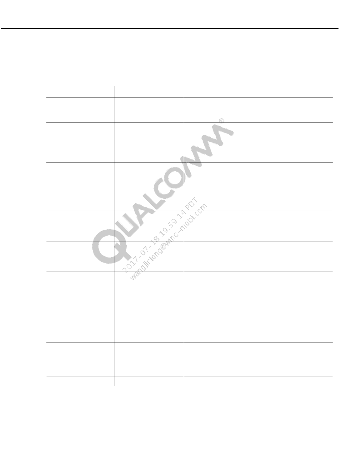
Table 1-1 References
Reference
Document
DCN
Qualcomm
Q1
Factory Test Mode Procedure for WLAN
RF Test (WCN131X/WCN3660/WCN3680)
80-WL300-18
Q2
Factory Test Mode Procedure for FM RF
Test
80-WL300-17
Q3
Factory Test Mode Procedure for Bluetooth
RF Test
80-WL024-12
Q4
Qualcomm Sequence Profiling Resource
QSPR User guide
80-VB987-1
Q5
Qualcomm Sequence Profiling Resource
(QSPR) Tester Configuration User Guide
80-VB987-3
Q6
Qualcomm Product Support Tool (QPST)
2.7 User Guide
80-V1400-3
Q7
How to Install Qualcomm 64-Bit Windows 7
USB Host Driver User Guide
80-N2328-2
Q8
Application Note: Software Glossary for
Customers
CL93-V3077-1
Q9
WCN36x0 Training WLAN Tx CLPC
Characterization Using QSPR Tools
80-WL300-25
Q10
QCA61X4, QCA937X, QCA65X4 QDART
USER GUIDE
80-WL400-24
References
R1
IEEE
IEEE Std 802.11-2007
R2
IEEE
IEEE Std_80211N_2009
R3
Bluetooth SIG
RF-PHY.TS/4.0.1
R4
Bluetooth SIG
BLUETOOTH SPECIFICATION
Version 4.0
1.5 Technical assistance
For assistance or clarification on information in this guide, submit a case to Qualcomm CDMA
Technologies at https://support.cdmatech.com/.
If you do not have access to the CDMATech Support Service website, register for access or send
email to support.cdmatech@qualcomm.com.

Wireless Connectivity Tests User Guide Introduction
80-Y0306-1 Rev. L MAY CONTAIN U.S. AND INTERNATIONAL EXPORT CONTROLLED INFORMATION 17
Confidential and Proprietary – Qualcomm Atheros, Inc.
1.6 Acronyms
The following terms are used in this document. Some elements are identified by more than one
term.
Table 1-2 Acronyms
Term
Definition
APQ
Applications-Only Processor QUALCOMM
ARB
Arbitrary
BER
Bit Error Rate
BR
Basic Rate
BT
Bluetooth
CW
Continuous Wave
DPSK
Differential Phase Shift Keying
DQPSK
Differential Quaternary Phase Shift Keying
DUT
Device Under Test
EDR
Enhanced Data Rate
EUT
Equipment Under Test
EVM
Error Vector Magnitude
FFA
Form Factor Accurate
FTM
Field Test Mode
GFSK
Gaussian Frequency Shift Keying
GPIB
General Purpose Interface Bus
LE
Low Energy
MDM
Mobile Data Modem
MIMO
Multiple-Input and Multiple Output
MSM
Mobile Station Modem
NFC
Near Field Communication
PER
Packet Error Rate
QSPR
Qualcomm Sequence Profiling Resource
RF
Radio Frequency
R&S
Rohde & Schwarz
SG
Signal Generator
SoC
System on a Chipset
SRS
System Requirement Specification
SW
Software
UART
Universal Asynchronous Receiver-Transmitter
UDT
User Defined Transport
USB
Universal Serial Bus
80-Y0306-1 Rev. L MAY CONTAIN U.S. AND INTERNATIONAL EXPORT CONTROLLED INFORMATION 18
Confidential and Proprietary – Qualcomm Atheros, Inc.
2 Hardware Setup and Requirements
This section covers the hardware installation pieces required for BT, WLAN and FM production
tests for connectivity chipsets that are mated with Qualcomm processors (MSM or MDM or
APQ) or standalone SoC connectivity chipsets. The test solutions utilize FTM features integrated
on Qualcomm processors to communicate with connectivity chipsets for testing.
2.1 RF test setup
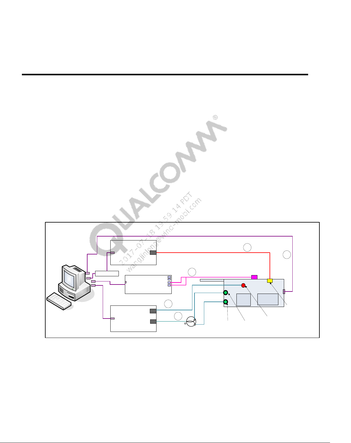
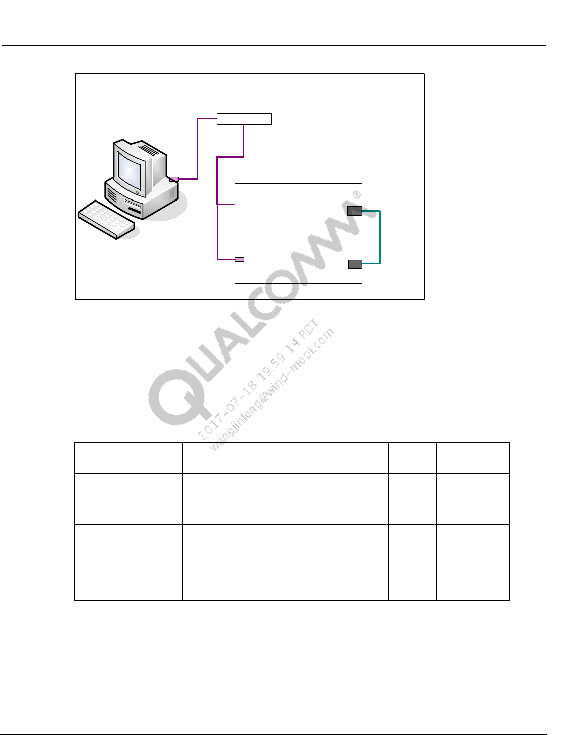
2.1.1 BT/WLAN/FM RF test setup
Figure 2-1 shows the test setup needed for performing BT, WLAN and FM RF functional tests.
DUT in Figure 2-1 refers to an FFA device that contains Qualcomm processors (MSM or MDM
or APQ) mated with supported connectivity chipset.
Figure 2-1 BT/WLAN/FM RF test setup
The following cables are required in the test setup:
1. A Power supply or battery emulator cable (cable#1)
2. An USB cable (cable #2)
3. A RF cable for FM headset and PWB paths using RF combiner from DUT to test box (cable
#3)
4. A RF cable for BT and WLAN path from DUT to test box (cable #4)
`
USB/
GPIB
BT/WLAN/FM Test setup
USB - GPIB
Recommended
path loss 3dB to
7dB(max)
BT/WLAN/FM
Tester
FM port
DUT
1
2
USB
Power supply
Default GPIB Addr:5
BT/WLAN RF port
Battery connector
Default: Litepoint IQ2010
WLAN/BT
RF Port
FM Headset
Antenna port
FM PWB
Antenna
port
RF Combiner
FM Audio
Digitizer RIGHT IN
LEFT IN
MSM or
MDM or
APQ
Connectivity
Chipset
3
4
5
USB
Default: Litepoint
AIM Module
Wireless Connectivity Tests User Guide Hardware Setup and Requirements
80-Y0306-1 Rev. L MAY CONTAIN U.S. AND INTERNATIONAL EXPORT CONTROLLED INFORMATION 19
Confidential and Proprietary – Qualcomm Atheros, Inc.
5. A Stereo to L-R/RCA audio cable from DUT stereo audio jack to FM audio interface module
(cable #5). Note: the FM Audio Digitizer and its related audio and USB cabling is not
required when FM audio is digitally captured directly from the DUT.
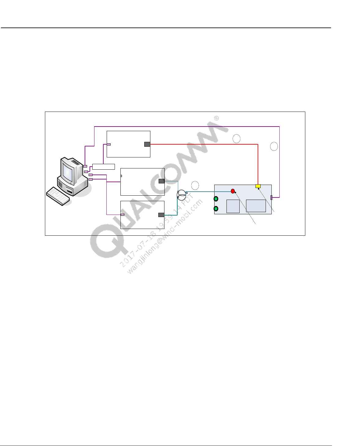
2.1.2 ANT RF test setup
ANT RF functional tests are performed using the test setup shown below.
`
USB/
GPIB
ANT Test setup
USB - GPIB
Signal
Generator
RF Output
DUT
1
2
USB
Power supply
Default GPIB Addr:5
ANT/BT/WLAN RF
port
Battery connector
Default: Agilent E4443A
RF Combiner
Spectrum
analyzer
RF Input
MSM or
MDM or
APQ
Connectivity
Chipset
3
USB – GPIB
Default: Agilent E4402B
Figure 2-2 ANT test setup
The following cables are required in the test setup:
6. A Power supply or battery emulator cable
7. An USB cable
8. A RF cable for ANT path using RF directional coupler from DUT to ARB signal generator
and spectrum analyzer
Wireless Connectivity Tests User Guide Hardware Setup and Requirements
80-Y0306-1 Rev. L MAY CONTAIN U.S. AND INTERNATIONAL EXPORT CONTROLLED INFORMATION 20
Confidential and Proprietary – Qualcomm Atheros, Inc.
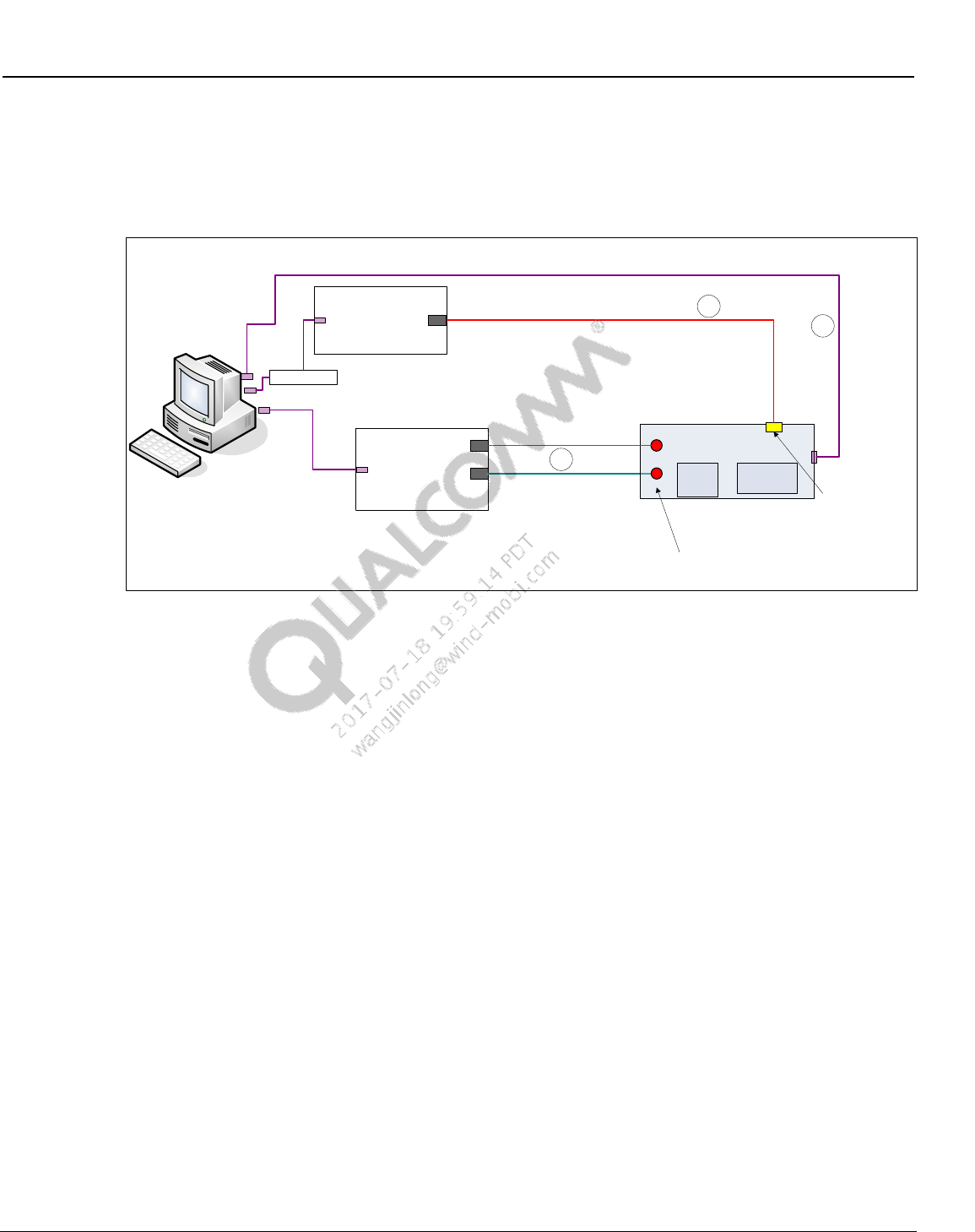
2.1.3 WLAN MIMO test setup
While not recommended for production, full WLAN MIMO characterization can be done with
multi-chain setup show below.
Figure 2-3 WLAN MIMO test setup
The following cables are required in the test setup:
9. A Power supply or battery emulator cable
10. An USB cable (for standalone PCIe DUT, the DUT would be directly connected to the PC via
a PCIe extender connection)
11. Two RF cables for both chains of the WLAN path from DUT to test box (cables #3)
`
USB/
GPIB
WLAN MIMO Test setup
USB - GPIB
WLAN 2 chain
MIMO Tester WLAN RF
Ports
DUT
1
2
USB
Power supply
Default GPIB Addr:5
WLAN MIMO chain
connections
Battery connector
Default: Litepoint IQXel 2x2
MSM or
MDM or
APQ
Connectivity
Chipset
3
USB – GPIB
Wireless Connectivity Tests User Guide Hardware Setup and Requirements
80-Y0306-1 Rev. L MAY CONTAIN U.S. AND INTERNATIONAL EXPORT CONTROLLED INFORMATION 21
Confidential and Proprietary – Qualcomm Atheros, Inc.
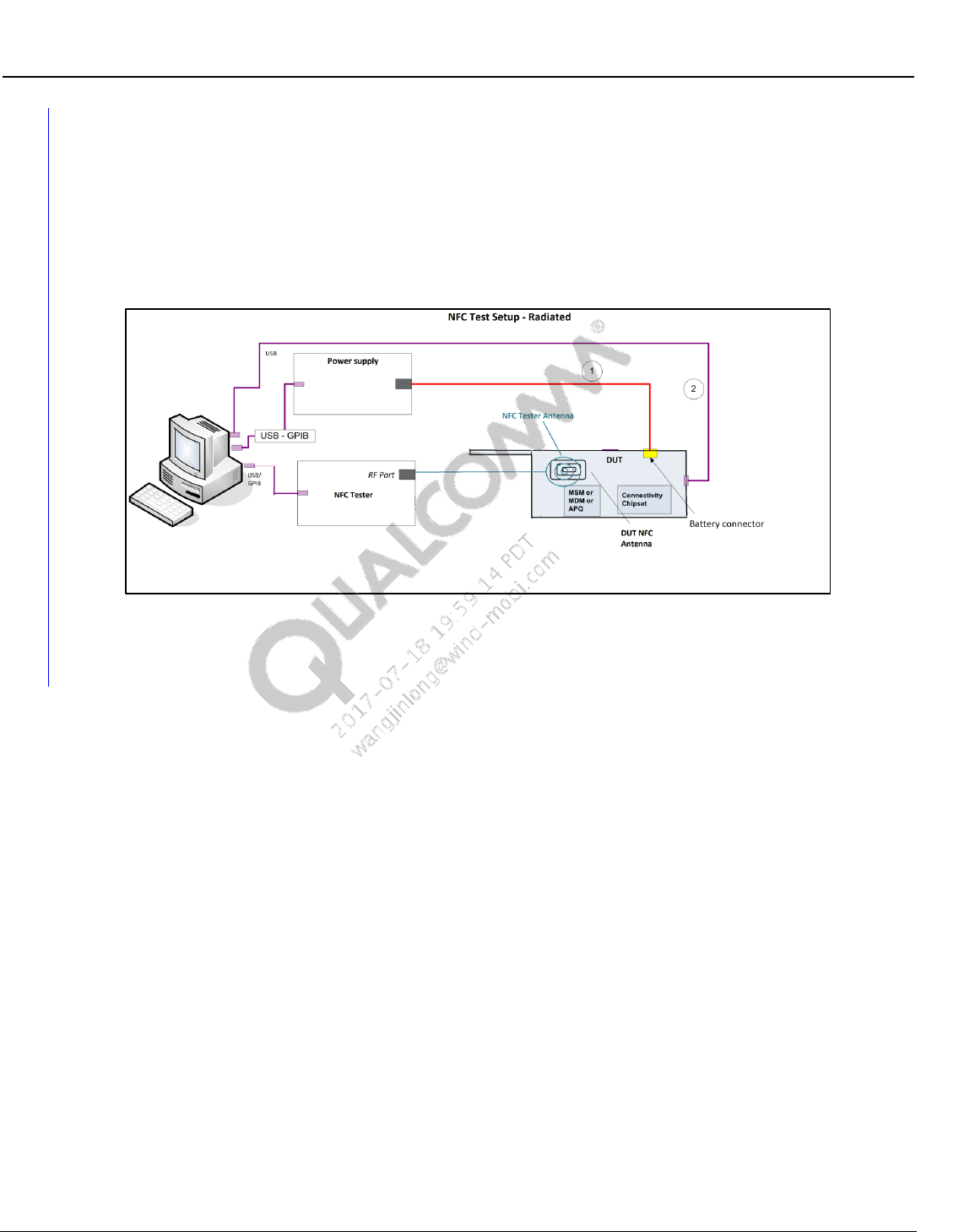
2.1.4 NFC parametric test setup
Figure 2-4 shows the test setup needed for performing NFC parametric tests. DUT in Figure 2-4
refers to an FFA device that contains Qualcomm processors (MSM or MDM or APQ) mated with
supported NFC connectivity chipset. NFC Testing is performed in a radiated fashion. The NFC
DUT antenna and the NFC Tester antenna should be placed in close proximity, similar to a NFC
tag.
Figure 2-4 NFC parametric test setup
2.2 Station calibration
2.2.1 BT/WLAN/FM station calibration setup
Setup in Figure 2-5 is utilized to perform station calibration on various RF paths.
The following paths are required to be calibrated for performing BT, WLAN, FM and ANT tests:
A Bluetooth path (default path name = BTPath)
A WLAN path (default path name = WCD)
A FM headset path (default path name = FM_HS_RX)
A FM pwb path (default path name = FM_PWB_RXTX)
An ANT Transmit path (transmit path name = SAPath)
An ANT Receive path (default path name = ARBPath)
A signal generator is connected on the DUT end in order to calibrate the path losses on the above
listed RF paths from DUT to power meter.
Wireless Connectivity Tests User Guide Hardware Setup and Requirements
80-Y0306-1 Rev. L MAY CONTAIN U.S. AND INTERNATIONAL EXPORT CONTROLLED INFORMATION 22
Confidential and Proprietary – Qualcomm Atheros, Inc.
Figure 2-5 Station calibration setup
2.3 Test equipment
The list of test equipment needed to perform BT, WLAN and FM tests are mentioned in
Table 2-1. If test equipment is GPIB controlled, GPIB address is configurable based on an
external configuration file. Please follow the instructions in Chapter 7 to update the GPIB address
for respective test equipment.
Table 2-1 Test equipment needed for BT, WLAN and FM tests
Manufacturer / Model
Description
Quantity
Default GPIB
Address
Supported test box
Refer to 2.3.1 for supported connectivity test
box
1
20 (if GPIB
based)
Supported power
supply
Refer to section 2.3.2for supported power
supply
1
5
Supported signal
generator for ANT
Refer to 2.3.3 for supported signal generator for
ANT
1
19
Supported spectrum
analyzer for ANT
Refer to 2.3.4 for supported spectrum analyzer
for ANT
1
18
Supported BT signaling
test box
Refer to 2.3.1 for supported BT signaling test
box
1
27
`
USB
BT/WLAN/FM Station Calibration setup
USB - GPIB
Power meter
RF in
Signal generator
RF out
Default GPIB Addr: 9
Default GPIB Addr: 19
Wireless Connectivity Tests User Guide Hardware Setup and Requirements
80-Y0306-1 Rev. L MAY CONTAIN U.S. AND INTERNATIONAL EXPORT CONTROLLED INFORMATION 23
Confidential and Proprietary – Qualcomm Atheros, Inc.
2.3.1 Supported BT, WLAN, NFC and FM test box
To perform connectivity tests one of supported test boxes on Table 2-2 should be used.
Table 2-2 Test box supported by test solution
Manufacturer / Model
Description
Required Options
LitePoint IQ2010
Non-signaling
connectivity test box
(WLAN(SISO)/BT/FM)
FM Software License: 0300-20XX-002
FM AUDIO Analysis Option: 0300-20XX-003
Refer to section 3.3 for SW details
R&S CMW500
Non-signaling
connectivity test box
(WLAN(SISO)/BT no
FM)
BT/WLAN RF generator (prerequisite: CMW-B110A)
BT Measurements (CMW-KM610)
BT Low Energy (CMW-KM611)
WLAN ABG RF analyzer (CMW-KM650)
WLAN N RF analyzer (CMW-KM651)
Agilent N4010A
Non-signaling
connectivity test box
(WLAN(SISO)/BT no
FM)
2.4 GHz and 5 GHz WLAN Tx/Rx analysis: N4010A-103
802.11n MIMO modulation analysis: N4010A-108
Bluetooth: N4010A-101
Bluetooth EDR – transmit and receive:N4010A-105
Bluetooth LE Tx/Rx: N4010A-109
Refer to Section 3.5 for SW details
LitePoint IQxel
Non-signaling
connectivity test box
(WLAN(SISO+MIMO)/BT
no FM)
Bluetooth 1,2,3,4(LE) SW License : 0300-IXEL-001
Iqxel80 Test System,802.11a,b,g,n,ac(80MHz) : 0100-
IXEL-002
Refer to section 3.6 for SW details
NI PXI5644R
Non-signaling
connectivity test box
(WLAN(SISO+MIMO)
only)
Refer to section 3.7 for SW details
Anritsu 8870A
Non-signaling
connectivity test box
(WLAN(SISO) + BT +
FM)
MU887000A
MU887000A-001
MV887030A
MV887031A
MX887030A
MX887031A
MV887040A
MX887040A
MX887050A
R&S CBT
BT Signaling test box
(Bluetooth only)
CBT-K55 “Enhanced Data Rate”
CBT-K57 “Low Energy”
Anritsu MT8852B
BT Signaling test box
(Bluetooth only)
Option 27 “Low Energy”
LitePoint IQNFC
NFC test box
Advanced Software License
2.3.2 Supported power supply
In order to perform RF tests one of the power supplies mentioned in Table 2-3 should be used.
The model string on the config file column refers to the model number information that can be
specified on the configuration file to switch to other equipment than default.
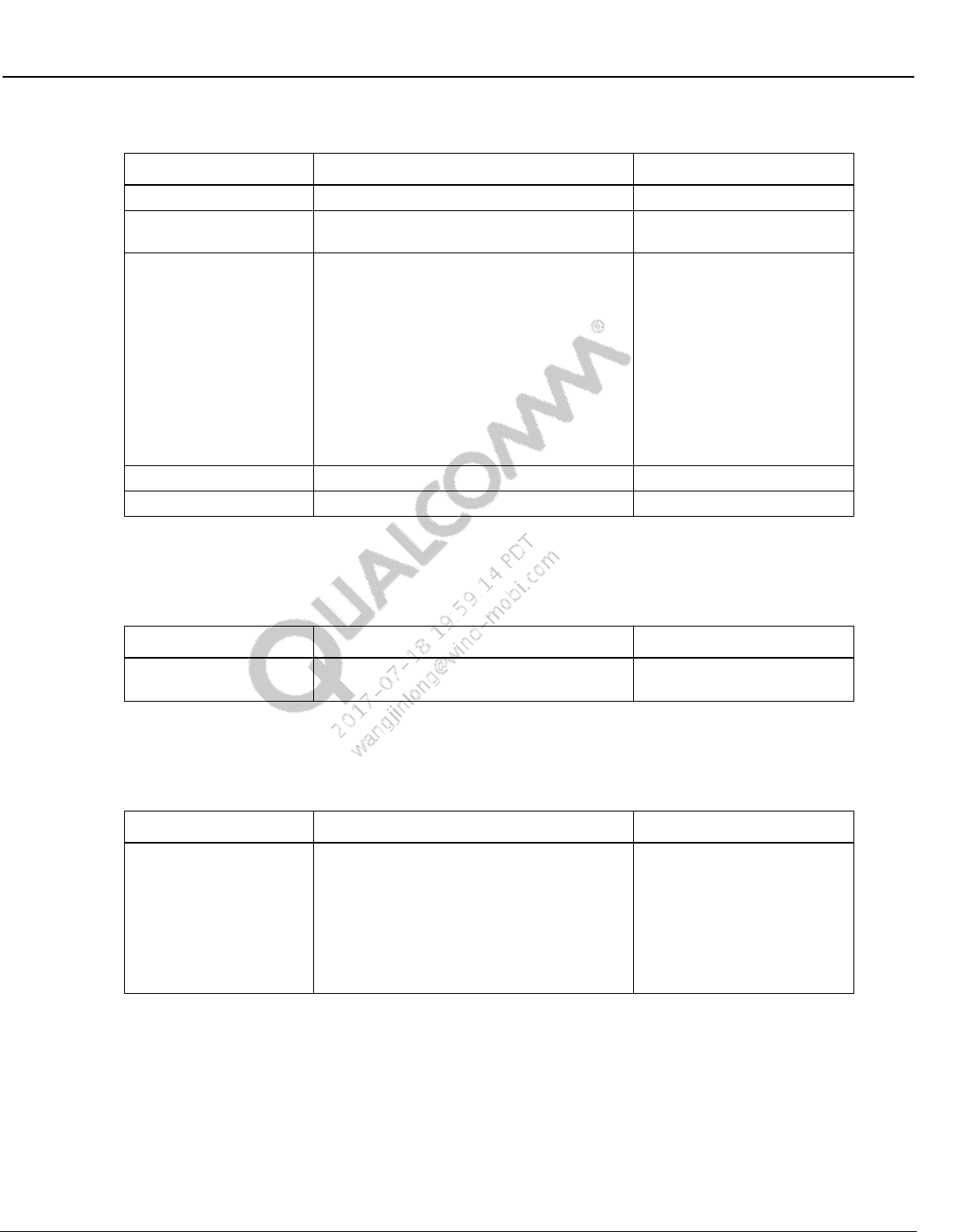
Wireless Connectivity Tests User Guide Hardware Setup and Requirements
80-Y0306-1 Rev. L MAY CONTAIN U.S. AND INTERNATIONAL EXPORT CONTROLLED INFORMATION 24
Confidential and Proprietary – Qualcomm Atheros, Inc.
Table 2-3 Power supply supported by test solution
Manufacturer / Model
Description
Model String on Config File
Keithley2303 (Default)
Keithley 2303 power supply
PS_KEITHLEY2303
Fluke 2812 /2813
Fluke 2812/2813 power supply
PS_FlukePM2812/
PS_FlukePM2813
Agilent E3640A/
Agilent E3641A/
Agilent E3642A/
Agilent E3643A/
Agilent E3644A/
Agilent E3645A/
Agilent E3646A/
Agilent E3647A/
Agilent E3648A/
Agilent E3649A
Agilent E364xA power supply
PS_AgilentE3640A/
PS_AgilentE3641A/
PS_AgilentE3642A/
PS_AgilentE3643A/
PS_AgilentE3644A/
PS_AgilentE3645A/
PS_AgilentE3646A/
PS_AgilentE3647A/
PS_AgilentE3648A/
PS_AgilentE3649A/
INSTEK 3202
Instek 3202 power supply
PS_PST3202
XantrexXDL355T
Xantrek XDL 355T power supply
PS_XDL355T
2.3.3 Supported signal generator for ANT
Table 2-4 Signal generator supported by ANT solutions
Manufacturer / Model
Description
Model String on Config File
AgilentN5182A
Agilent N5182A RF Vector Signal Generator
with option 506 for 6GHz
SG_AgilentN5182A
2.3.4 Supported spectrum analyzer for ANT
Table 2-5 Spectrum analyzer supported by ANT solutions
Manufacturer / Model
Description
Model String on Config File
AgilentE4443A
AgilentE4402B
AgilentE4403B
AgilentE4404B
AgilentE4405B
AgilentE4407B
AgilentE4408B
Agilent E4443A PSA Spectrum Analyzer
Agilent E440xB ESA Spectrum Analyzer
SA_ AgilentE4443A
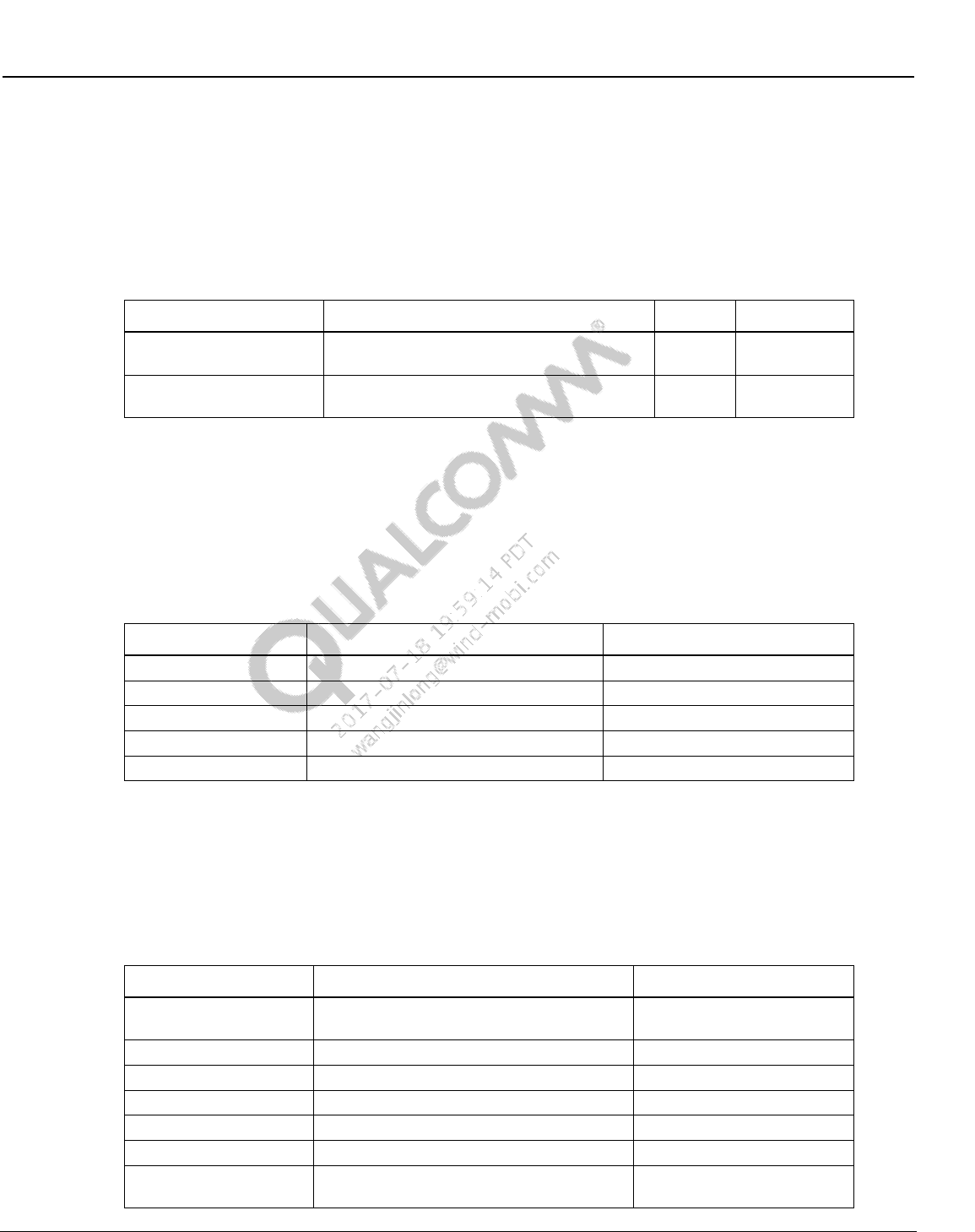
Wireless Connectivity Tests User Guide Hardware Setup and Requirements
80-Y0306-1 Rev. L MAY CONTAIN U.S. AND INTERNATIONAL EXPORT CONTROLLED INFORMATION 25
Confidential and Proprietary – Qualcomm Atheros, Inc.
2.4 Station calibration test equipment
This section lists the test equipment required for station calibration. Station calibration is meant to
update the RF path losses on various RF paths on a station calibration data file in the local PC. It
is recommended to run an automated station calibration, but this file could be updated manually
as well.
Table 2-6 Test equipment needed for station calibration
Manufacturer / Model
Description
Quantity
Default
Supported signal
generator
Refer to Section 2.4.2 for supported signal
generators
1
LitePoint
IQ2010
Supported power meter
Refer to Section 2.4.1 for supported power
meters
1
Giga-tronics
8541C
2.4.1 Supported power meter for station calibration
To perform station calibration one of supported power meters in Table 2-7 should be used.
Additional power meters from the same vendors may work if the GPIB command set is the same.
The model string on the config file column refers to the model number information that can be
specified on the configuration file to switch to other equipment rather than the default.
Table 2-7 Power meter supported by test solution
Manufacturer / Model
Description
Model String on Config File
Agilent 4418B (Default)
Agilent 4418B
PM_HPE4418B
Giga-tronics 8651A
Giga-tronics 8651A
PM_GIG8651A
Giga-tronics 8541C
Giga-tronics 8541C
PM_GIG8541C
Agilent 437B
Agilent 437B
PM_HP437B
Rhode & Schwartz
NRP-Z11
PM_RSNRPZ11
2.4.2 Supported signal generator for station calibration
To perform station calibration one of supported signal generator mentioned in Table 2-8 should
be used. Please note that the signal generators listed on Table 2-8 are the supported signal
generators that go at least to 6GHz or more.
Table 2-8 Signal generator supported by test solution
Manufacturer / Model
Description
Model String on Config File
LitePoint IQ2010
(Default)
LitePoint IQ2010 with IQMeasure SW
SG_LitepointIQ2010
Agilent N4010A
Agilent N4010A - Test Suite version 6.53.0
SG_AgilentN4010A
R&S CMW500
Rohde and Schwarz CMW500
SG_CMW500
LitePoint IQxel
LitePoint IQxel
SG_LitePointIQxel
NI PXI5644R
National Instrument PXI5644R
SG_NITrident
Anritsu MT8870A
Anritsu MT8870A
SG_AnritsuMT8870A
Agilent 83712B
Agilent 83712B Synthesized CW Generator,
10 MHz to 20 GHz
SG_Agilent83712B
Wireless Connectivity Tests User Guide Hardware Setup and Requirements
80-Y0306-1 Rev. L MAY CONTAIN U.S. AND INTERNATIONAL EXPORT CONTROLLED INFORMATION 26
Confidential and Proprietary – Qualcomm Atheros, Inc.
Manufacturer / Model
Description
Model String on Config File
Agilent 8665B
Agilent 8665B High-Performance Signal
Generator, 6GHz
SG_Agilent8665B
AgilentE8257D
Agilent E8257D PSD Signal Generator
SG_AgilentE8257D
AgilentN5182A
Agilent N5182A RF Vector Signal Generator
with option 506 for 6GHz
SG_AgilentN5182A
Keithley2920
Keithley 2920 RF Vector Signal Generator
SG_Keithley2920
Anritsu MT8870A
Anritsu MT8870A
SG_AnritsuMT8870A

80-Y0306-1 Rev. L MAY CONTAIN U.S. AND INTERNATIONAL EXPORT CONTROLLED INFORMATION 27
Confidential and Proprietary – Qualcomm Atheros, Inc.
3 Software Installation
3.1 SW requirements
The following are software requirements for a PC that would run Wireless Connectivity test
solutions on a Qualcomm based target. Appropriate version numbers are included against
software packages where a specific version is required:
Windows XP with Service Pack 3 or Windows 7
Qualcomm SW tools
QDART installation with Manufacturing tool kit for QSPR option checked
– QDART 4.8.05 or above
QPST installer – Refer to [Q6] in Qualcomm documents of section 1.4.1
Qualcomm Windows XP/7 USB composite drivers – [Q7]
3rd Party tools
NI 488.2 GPIB 2.73 version or later (See Section 3.3 for details)
LitePoint IQ2010 software (See Section 3.5 for details)
Agilent N4010A software (See Section 3.6 for details)
LitePoint IQxel wave files (See Section 3.7 for details)
National Instrument NI PXI5644R (See Section 3.8 for details)
LitePoint IQNFC software(See Section 3.10 for details)
Android debug bridge (adb) installed / available on system path (See Section 3.4 for
details)
– Included as part of Android SDK from Google
Adb.exe (Android debug bridge executable)
Adbwinapi.dll (ADB Windows API DLL)
Android Windows XP/7 USB drivers
– Obtain drivers from SW team usually drivers are included with the Android build
– Install the USB drivers on boot up of the DUT
3.2 QDART for non-FFA setup
Please see [Q10], QDART Users Guide for more information.
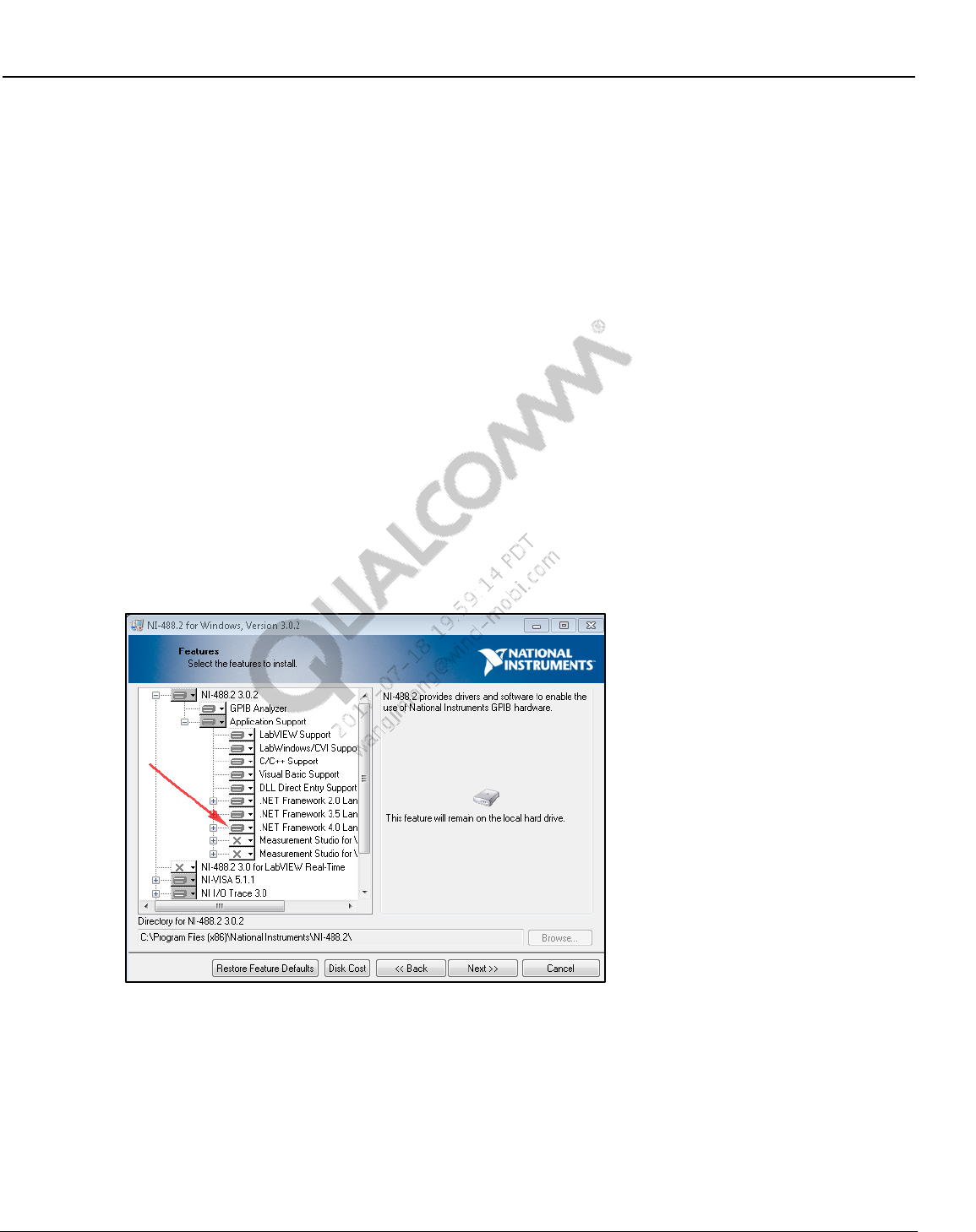
Wireless Connectivity Tests User Guide Software Installation
80-Y0306-1 Rev. L MAY CONTAIN U.S. AND INTERNATIONAL EXPORT CONTROLLED INFORMATION 28
Confidential and Proprietary – Qualcomm Atheros, Inc.
3.3 NI GPIB setup
National Instruments’ GPIB software and drivers are used to control the power supply, power
meter, signal generator and GPIB controlled connectivity test box connected to the PC to perform
the automated testing.
3.3.1 NI GPIB software setup
The NI 488.2 software can be downloaded from the NI website at http://www.ni.com.
NOTE: NI 488.2 3.02 version or later is required to be compatible with test software. Also, “.NET
framework 4.0 Languages support” must be selected as part of installation as listed below:
To setup NI GPIB software:
1. Navigate to the latest NI GPIB software and run the setup.exe
2. Follow the on-screen prompts to install the NI 488.2 drivers and software
3. Please select Custom on the select installation option window
4. On the features to install window, please ensure that “.NET Framework 4.0 Languages
support” is selected to install this feature
Figure 3-1 Enable .NET Framework 4.0 Support on NI 488.2 for Windows Install
5. The installer installs several parts of the package and then prompts for the addition of GPIB
hardware. The wizard may be cancelled as the addition can be done when the hardware is
plugged in.
6. Complete the installation by rebooting the computer.
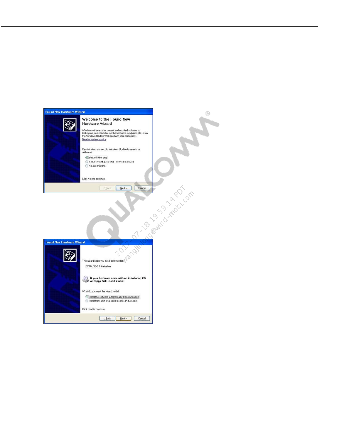
Wireless Connectivity Tests User Guide Software Installation
80-Y0306-1 Rev. L MAY CONTAIN U.S. AND INTERNATIONAL EXPORT CONTROLLED INFORMATION 29
Confidential and Proprietary – Qualcomm Atheros, Inc.
3.3.2 NI GPIB driver setup
When the USB to GPIB controller is connected to the USB port on the PC, Windows starts to
install the hardware driver for GPIB-USB controller. The following steps need to be followed for
installing the driver properly:
1. Windows will prompt the “Found New Hardware Wizard.” Make sure that “Yes, this time
only” is selected for windows update to search for drivers.
Figure 3-2 Signal generator supported by test solution
2. Windows prompts for automatic or manual installation of the driver. Make sure that the
automatic installation is selected.
Figure 3-3 NI GPIB hardware setup – step 2
3. Windows will install the driver for the USB to GPIB controller and completes the hardware
driver installation procedure.
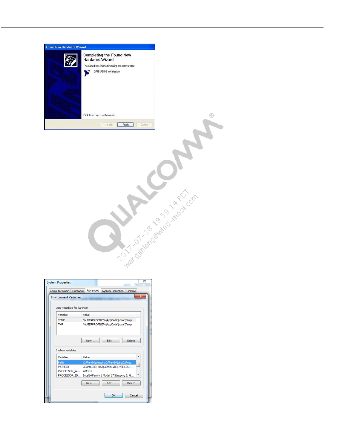
Wireless Connectivity Tests User Guide Software Installation
80-Y0306-1 Rev. L MAY CONTAIN U.S. AND INTERNATIONAL EXPORT CONTROLLED INFORMATION 30
Confidential and Proprietary – Qualcomm Atheros, Inc.
Figure 3-4 NI GPIB hardware setup – step 3
3.4 Android debug bridge installation
NOTE: These steps are specific based on HLOS on the embedded side. Skip them for non-Android
HLOS.
The following steps will install adb and will add it to the system path:
1. Install the Android SDK from Google or obtain the SDK files from the software team.
2. Copy the following two Android SDK files into a local directory such as C:\Android_tools.
Android debug bridge executable (Adb.exe)
Adb Windows API dll (Adbwinapi.dll)
3. Navigate to system properties on the computer. On Advanced tab, click on “Environment
Variables…” and scroll to the Path variable on System variables section.
Figure 3-5 Path system variable on environment variables
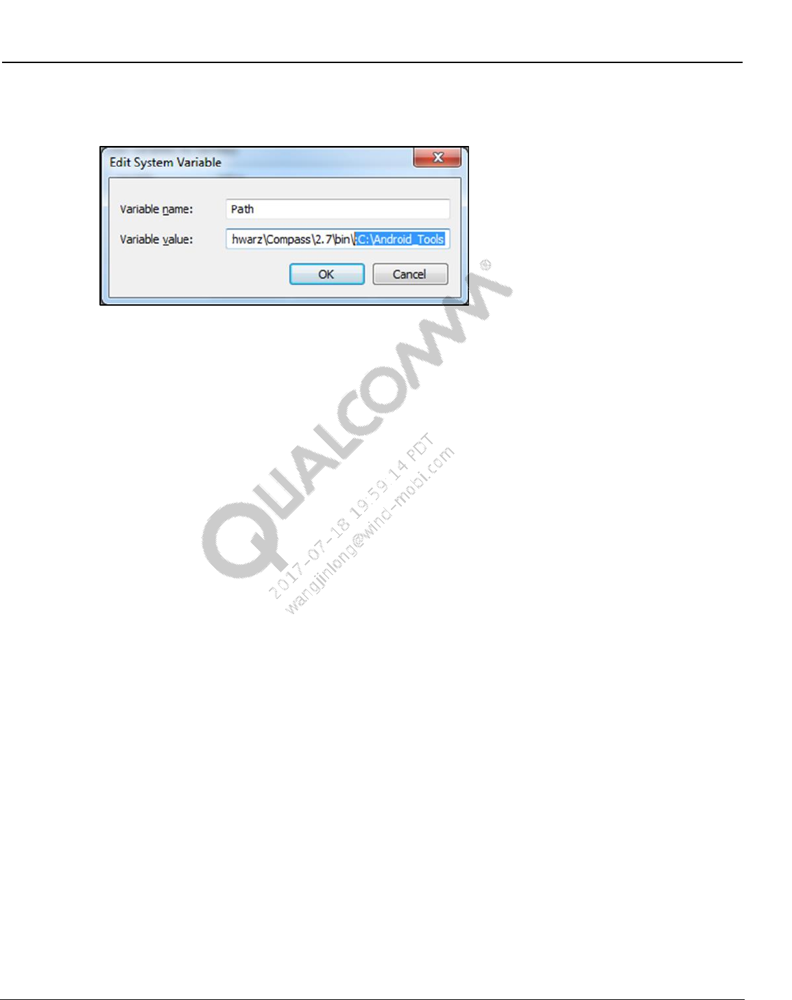
Wireless Connectivity Tests User Guide Software Installation
80-Y0306-1 Rev. L MAY CONTAIN U.S. AND INTERNATIONAL EXPORT CONTROLLED INFORMATION 31
Confidential and Proprietary – Qualcomm Atheros, Inc.
4. Click on “Edit…” and add C:\Android_tools or the local directory where the files are as
shown in Figure 3-6.
Figure 3-6 Add ADB as part of the system path
3.5 LitePoint software for running
NOTE: These steps are specific to LitePoint IQ2010 software installation.
The following software programs are needed for LitePoint IQ2010. Please contact LitePoint to
obtain this software.
Drivers for IQ2010 installed on the PC (only required for LitePoint IQ2010)
Should be available as part of the disk that came with LitePoint
IQmeasure package 3.0.8.3 or above – Available from LitePoint
NOTE: Test solutions are validated with IQMeasure package 3.0.8.3
Bin folder of IQMeasure is required to be added to Windows system “Path”
– Navigate to system properties on the computer. On Advanced tab, click on
“Environment Variables…” and scroll to the Path variable on System variables
section.
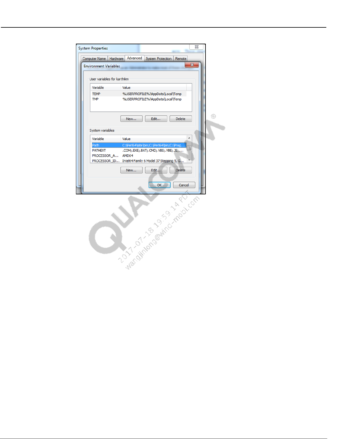
Wireless Connectivity Tests User Guide Software Installation
80-Y0306-1 Rev. L MAY CONTAIN U.S. AND INTERNATIONAL EXPORT CONTROLLED INFORMATION 32
Confidential and Proprietary – Qualcomm Atheros, Inc.
Figure 3-7 Path system variable on environment variables
– Click on Edit... and add “C:\LitePoint\IQmeasure\IQmeasure_3.0.8.3”
3.6 Agilent N4010A software installation
An Agilent IO library 14.2 is required to be installed for Agilent N4010A testing.
Agilent WLAN test software suite version A.06.53.00 and Agilent drivers are required to be
installed before running the test.
For downloading WLAN and custom Bluetooth waveforms, please contact Agilent
Technologies N4010A Technical Support Team to get a website link and password: JIANN-
DER SHAW jiann-der_shaw@agilent.com, LEI YANG lei_yang@agilent.com, GRACE HU
grace_hu@agilent.com
3.7 LitePoint IQxel wave files installation
Obtain wave files with iqvsg extensions from LitePoint and copy to tester PC.
Add the path location of the wave files to the config file WCNTesterConfig.xml under the
IQxel WLAN and BT section in info item name “WaveFilePath”.
If the wave file names differ from the default file names in WCNTesterConfig.xml under the
IQxel WLAN and BT section, enter the correct wave file names to be associated with each
rate.
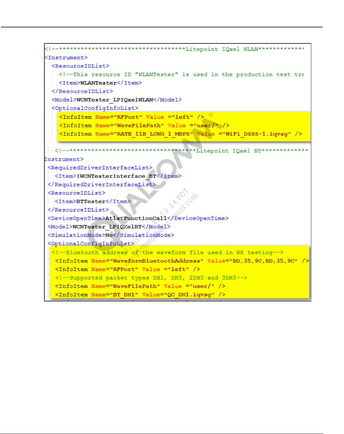
Wireless Connectivity Tests User Guide Software Installation
80-Y0306-1 Rev. L MAY CONTAIN U.S. AND INTERNATIONAL EXPORT CONTROLLED INFORMATION 33
Confidential and Proprietary – Qualcomm Atheros, Inc.
Figure 3-8 LitePoint IQxel waveform location
3.8 NI PXI5644R software installation
The following software programs are needed for NI PXI5644R. Please contact National
Instruments to obtain this software.
Drivers for NI WLAN, NI Spectral Measurement Tool, NI-VST and NI-RIO installed on
the PC. This is available as part of the disk that comes with National Instruments
NIDotNetWrappersClassLibrary.dll and QDART NI client server modules are required. –
Available from NI. Please note that the remote servers from NI needs to be running while
QSPR is communicating with the NI PXI 5644R
Generally, when the software is installed, it will reside in C:/Program Files/National
Instruments and the DLLs for toolkits and drivers will reside in C:/Program Files/IVI
Foundation
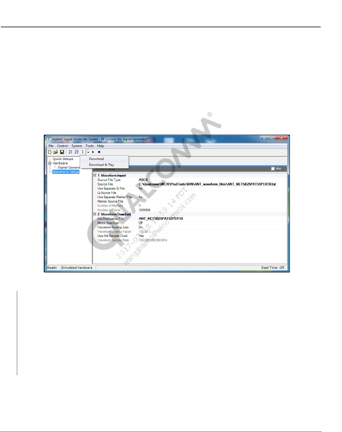
Wireless Connectivity Tests User Guide Software Installation
80-Y0306-1 Rev. L MAY CONTAIN U.S. AND INTERNATIONAL EXPORT CONTROLLED INFORMATION 34
Confidential and Proprietary – Qualcomm Atheros, Inc.
To obtain further information on the system requirements and setup please contact
qct_FTTL@ni.com, reference part number 862003-01.
3.9 Agilent N5182A software and waveform files installation
(ANT only)
Agilent N7622B Signal Studio for Toolkit is required to copy ANT waveform files to Agilent
N5182A (or equivalent Agilent) ARB signal generator. This software is available for download
from Agilent technologies website for free. After installation, use the settings shown below to
download the waveform files.
Figure 3-9 Loading waveform files on Agilent N5182A
3.10 LitePoint IQNFC Software
NOTE: These steps are specific to LitePoint IQNFC software installation. Skip this section if LitePoint
IQNFC is not used at test box.
The following software programs are needed for LitePoint IQNFC. Please contact LitePoint to
obtain this software.
Drivers + Software for IQNFC installed on the PC
Should be available as part of the disk that came with LitePoint

80-Y0306-1 Rev. L MAY CONTAIN U.S. AND INTERNATIONAL EXPORT CONTROLLED INFORMATION 35
Confidential and Proprietary – Qualcomm Atheros, Inc.
4 Station Calibration
This section describes the station calibration test tree procedure. This test tree provides a way to
perform station calibration and update the files using an automation environment.
4.1 Station calibration data file
4.1.1 BT/WLAN/FM RF test station calibration data file
Path loss on the RF path between the antenna test ports on DUT to the power meter is stored in
the station calibration data file. Station calibration data file is present in:
C:\QUALCOMM\WCN\ProdTests\StationCal\QTA_CalDataFile.xml.
The following paths are required to be calibrated for performing BT, WLAN, FM and ANT tests:
Bluetooth path (default path name = BTPath)
WLAN path (default path name = WCD)
FM
FM headset path (default path name = FM_HS_RX)
FM pwb path (default path name = FM_PWB_RXTX)
ANT
ANT transmit path (default path name = SAPath)
ANT receive path (default path name = ARBPath)
The data list main tag contains various data elements that contain the frequency at which loss
(value) was measured. Delta indicates the difference between the current measurement to the
previous measurement.
<Data>
<Frequency>2400</Frequency>
<Value>11.35</Value>
<Delta>0</Delta>
</Data>
4.2 Station calibration instrument config file
Signal generator and power meter equipment to be utilized to perform station calibration is
indicated by the instrument config file for station calibration.
StationCalInstrumentConfigFile.xml present in C:\QUALCOMM\WCN\ProdTests\ConfigFiles
controls this configuration. The following XML tag can be changed by the user for power meter
and signal generator:
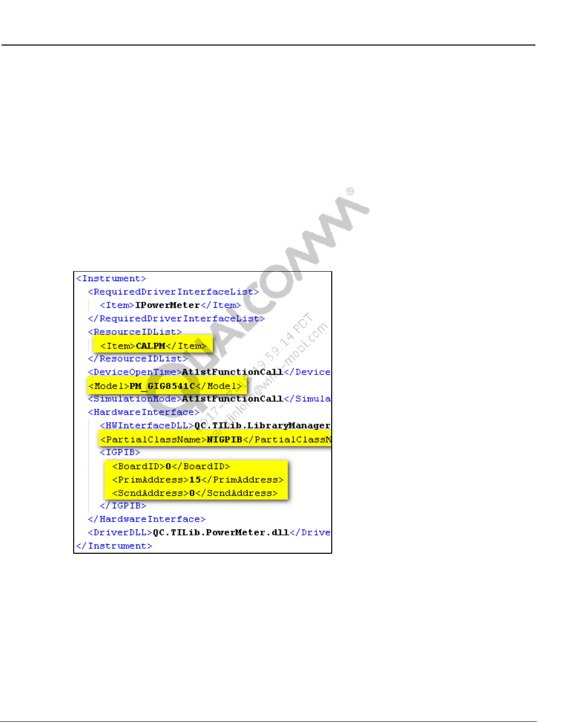
Wireless Connectivity Tests User Guide Station Calibration
80-Y0306-1 Rev. L MAY CONTAIN U.S. AND INTERNATIONAL EXPORT CONTROLLED INFORMATION 36
Confidential and Proprietary – Qualcomm Atheros, Inc.
Model tag needs to reflect the model number of power meter and signal generator on their
respective sections. Please use the model string config information specified in section 2.4.1
and 2.4.2 for changing the test equipment model if they are different from defaults. GPIB
primary address for both types of equipment is specified in <PrimAddress> tag.
<Model>SG_Agilent83712B</Model>
<Model>PM_GIG8541C</Model>
Power meter configuration
Make sure <ResourceIDList> tag contains “CALPM” <Item> tag.
GPIB based power meter configuration.
– Use <PartialClassName> tag as “NIGPIB”.
– Configure <IGPIB> tag with BoardID , PrimAddress and ScndAddress
Figure 4-1 Station calibration GPIB power meter configuration
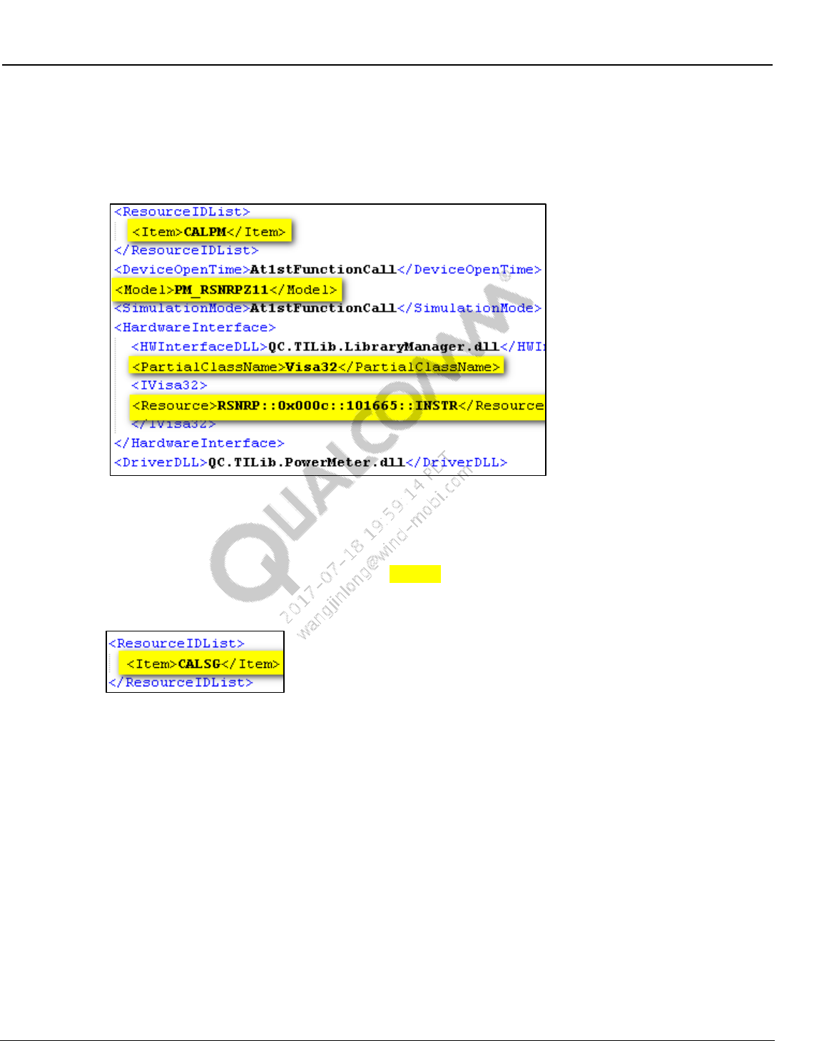
Wireless Connectivity Tests User Guide Station Calibration
80-Y0306-1 Rev. L MAY CONTAIN U.S. AND INTERNATIONAL EXPORT CONTROLLED INFORMATION 37
Confidential and Proprietary – Qualcomm Atheros, Inc.
VISA based power meter configuration (R&S NRPZ11 only)
– Use <PartialClassName> tag as “Visa32”.
– Configure <Resource> tag with VISA instrument string or VISA instrument alias.
Figure 4-2 Station calibration VISA power meter configuration
Signal generator configuration:
In order to use the certain test equipment for station calibration, find the section of the test
equipment, set <ResourceIDList><Item>CALSG</Item></ResourceIDList> tag to
“CALSG”, and change other equipment tag to something else.
Figure 4-3 Station calibration SG resource ID
LitePoint IQ2010 as signal generator
– Under <ResourceIDList> tag configure <Item> tag as “CALSG”
– Model – SG_LitepointIQ2010
– Under OptionalConfigInfoList, check the ServerExeFullLocation path to ensure that
the StartLitepointConnectivityServer.exe is available. Set IPAddress, set RFPort to
“LEFT” to use left RF port, “RIGHT” to use right RF port or “FM” to use FM port.
Check the installation required for LitePoint software in section 3.3.
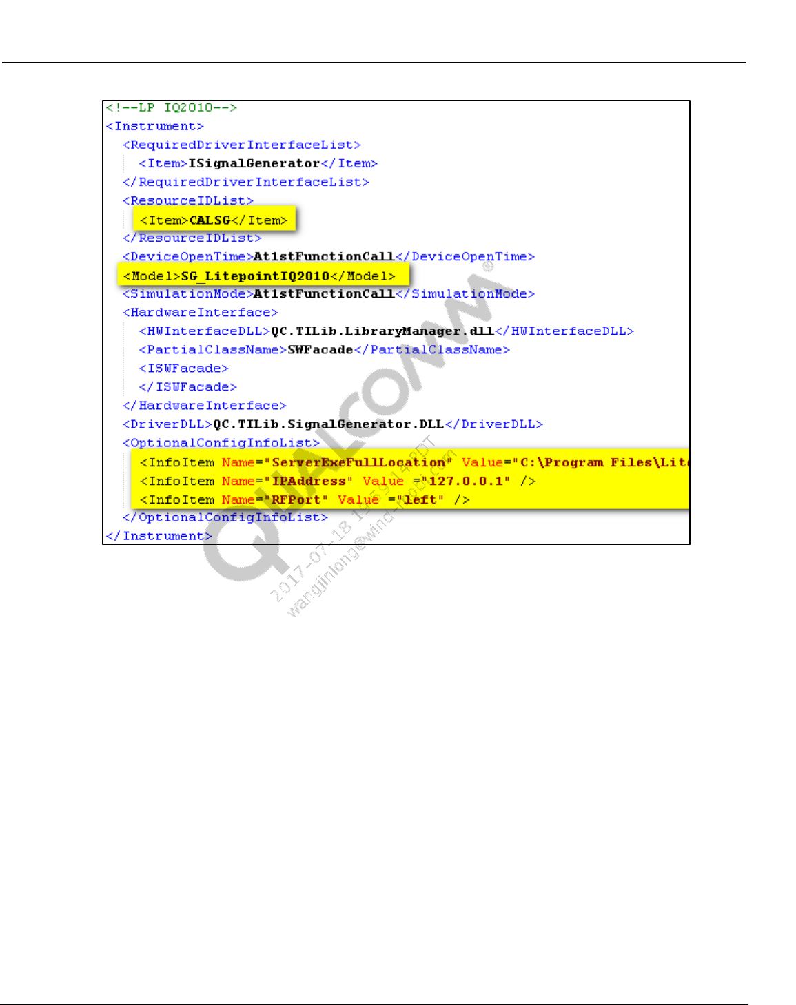
Wireless Connectivity Tests User Guide Station Calibration
80-Y0306-1 Rev. L MAY CONTAIN U.S. AND INTERNATIONAL EXPORT CONTROLLED INFORMATION 38
Confidential and Proprietary – Qualcomm Atheros, Inc.
Figure 4-4 Station calibration LP IQ2010 as signal generator
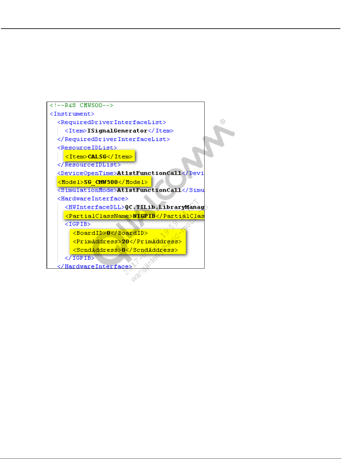
Wireless Connectivity Tests User Guide Station Calibration
80-Y0306-1 Rev. L MAY CONTAIN U.S. AND INTERNATIONAL EXPORT CONTROLLED INFORMATION 39
Confidential and Proprietary – Qualcomm Atheros, Inc.
R&S CMW500 as signal generator
– Under <ResourceIDList> tag configure <Item> tag as “CALSG”
– Model – SG_CMW500
– Specify GPIB primary address specified in <PrimAddress>
Figure 4-5 Station calibration R&S CMW500 as signal generator
Agilent N4010A as signal generator
– Under <ResourceIDList> tag configure <Item> tag as “CALSG”
– Model – SG_AgilentN4010A
– Set Partial Class Name to Visa32
– Specify Visa instrument string or Visa instrument alias for <Resource> tag
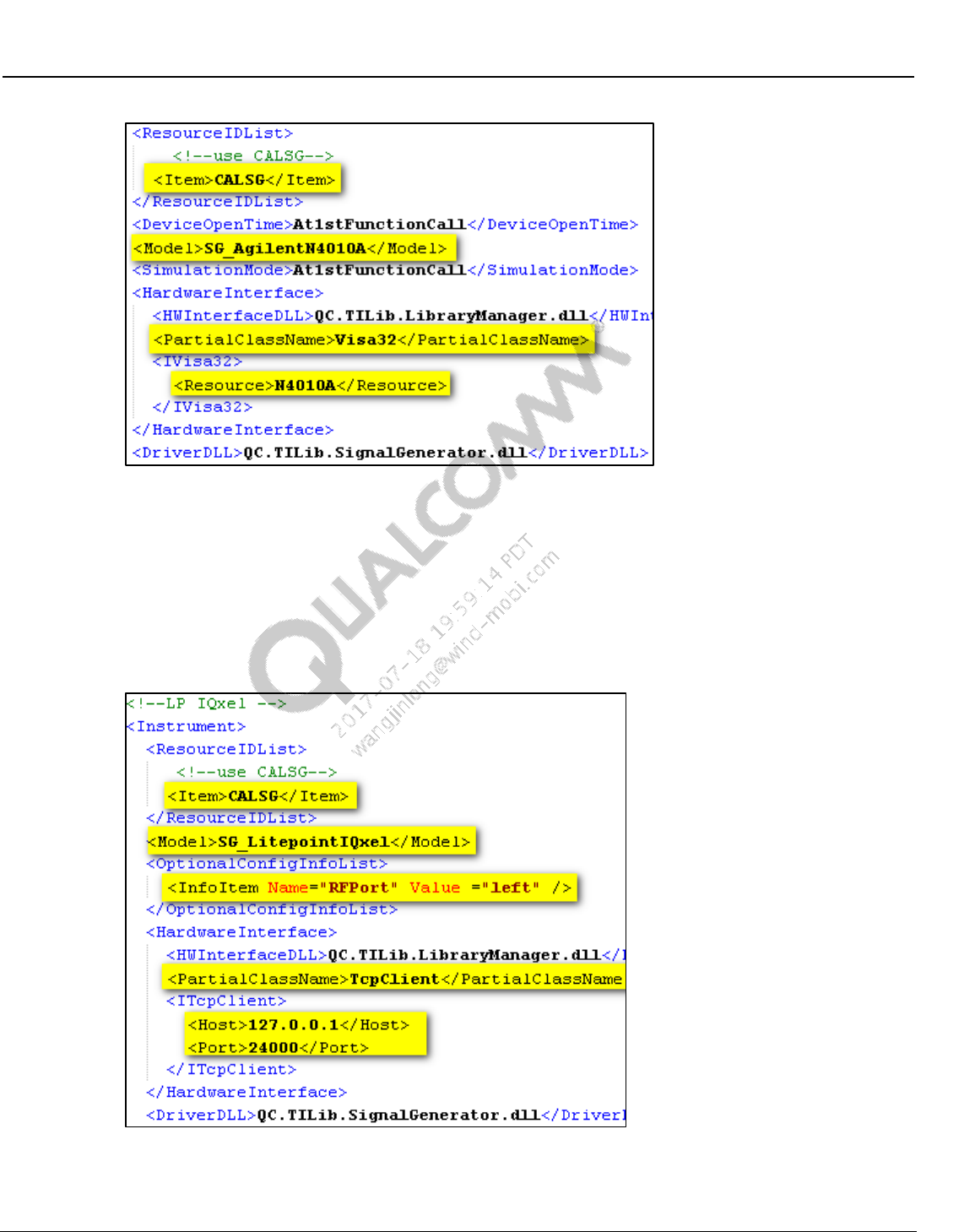
Wireless Connectivity Tests User Guide Station Calibration
80-Y0306-1 Rev. L MAY CONTAIN U.S. AND INTERNATIONAL EXPORT CONTROLLED INFORMATION 40
Confidential and Proprietary – Qualcomm Atheros, Inc.
Figure 4-6 Station calibration Agilent N4010A as signal generator
LitePoint IQxel as signal generator
– Under <ResourceIDList> tag configure <Item> tag as “CALSG”
– Model – SG_LitePointIQxel
– Under OptionalConfigInfoList. Set RFPort to “LEFT” to use left RF port or “RIGHT”
to use right RF port, set host IP address and port number.
Figure 4-7 Station calibration LP IQxel as signal generator
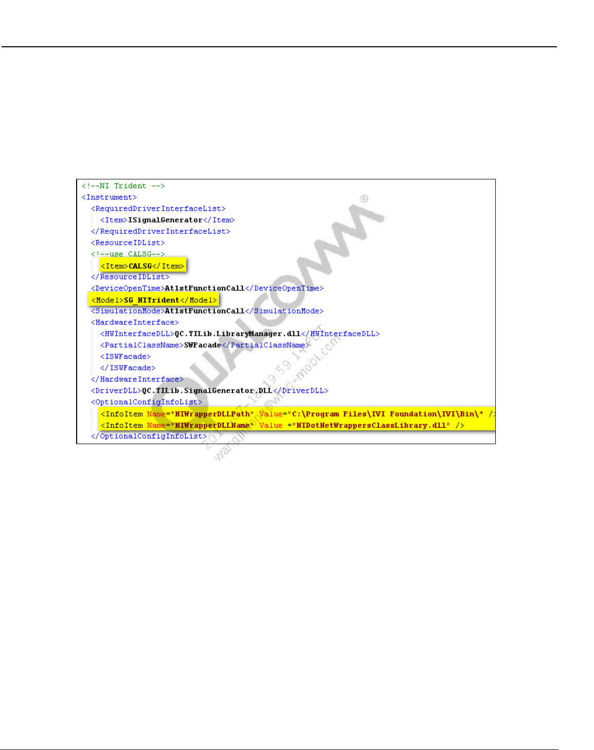
Wireless Connectivity Tests User Guide Station Calibration
80-Y0306-1 Rev. L MAY CONTAIN U.S. AND INTERNATIONAL EXPORT CONTROLLED INFORMATION 41
Confidential and Proprietary – Qualcomm Atheros, Inc.
NI PXI5644R as signal generator
– Under <ResourceIDList> tag configure <Item> tag as “CALSG”
– Model – SG_NITrident
– Under OptionalConfigInfoList. Check the NIWrapperDLLPath and
NIWrapperDLLName.
Figure 4-8 Station calibration NI PXI5644R as signal generator
Anritsu MT8870A as signal generator
– Under <ResourceIDList> tag configure <Item> tag as “CALSG”
– Model – SG_AnritsuMT8870A
– Under OptionalConfigInfoList. Set RFPort to “1” to use left RF port or “2” to use
right RF port, set host IP address and port number.
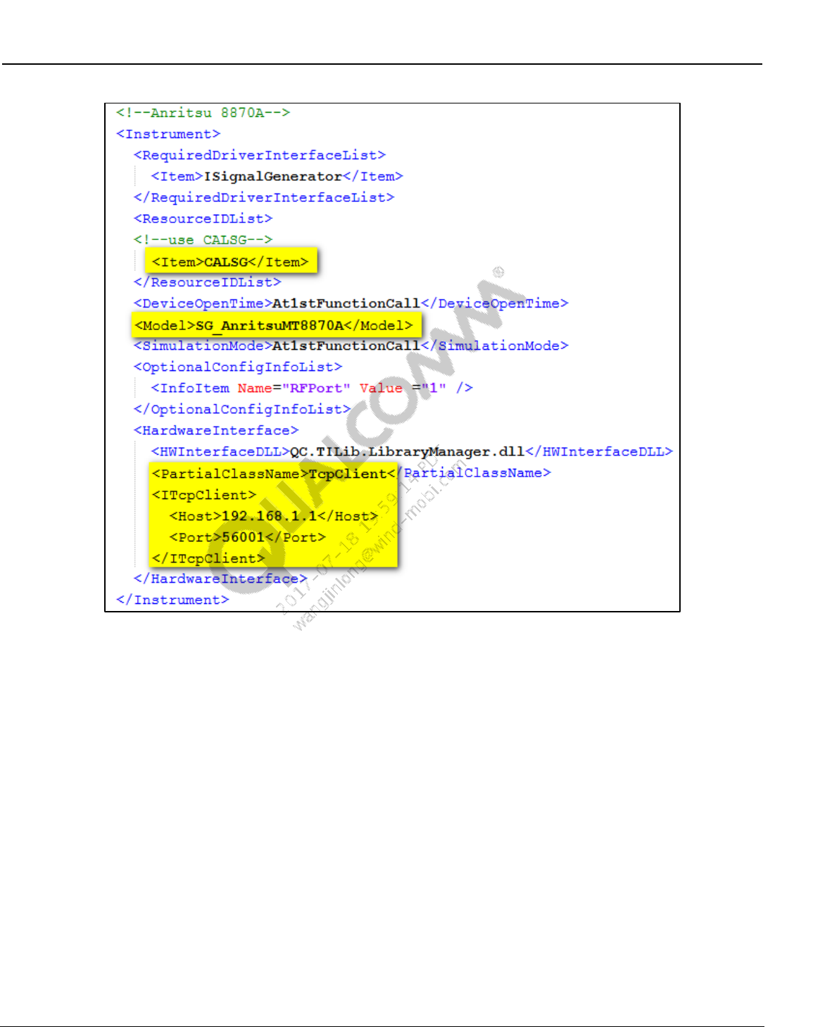
Wireless Connectivity Tests User Guide Station Calibration
80-Y0306-1 Rev. L MAY CONTAIN U.S. AND INTERNATIONAL EXPORT CONTROLLED INFORMATION 42
Confidential and Proprietary – Qualcomm Atheros, Inc.
Figure 4-9 Station calibration LP IQxel as signal generator
4.3 Station calibration procedure
4.3.1 BT/WLAN/FM RF test station calibration procedure
1. From the Windows Start menu, select Start All Programs QDART QSPR
2. From QSPR, open the Test Tree by selecting File Open
C:\QUALCOMM\WCN\ProdTests\TestTrees\StationalCalibration.xtt
3. Click the Go/No-Go button on the QSPR menu (the right arrow represented as a green-circle
on Figure 4-10).
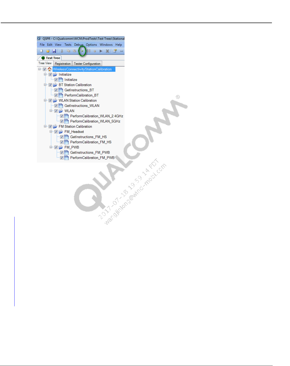
Wireless Connectivity Tests User Guide Station Calibration
80-Y0306-1 Rev. L MAY CONTAIN U.S. AND INTERNATIONAL EXPORT CONTROLLED INFORMATION 43
Confidential and Proprietary – Qualcomm Atheros, Inc.
Figure 4-10 Station calibration test tree
4. Ignore the warning messages as the test tree is meant for updating the local files
5. While performing the station calibration if messages pop up to merge the paths for WLAN
path, select “Yes” to merge path for WLAN 2.4 GHz and 5 GHz path
6. At the end of successful test tree execution, the data file in this location:
C:\QUALCOMM\WCN\ProdTests\StationCal will be updated
4.3.2 NFC RF test station calibration procedure
NFC Tester Calibration is required if using LitePoint IQNFC tester. The calibration data is used
by the tester while performing frequency sweep tests (NFCResonanceTest and
NFCDUT_FindResonance tests). Please run the ‘NFCTesterCalibrate’ test once manually with
the complete fixture but with no DUT on the NFCTester Antenna. This test will save the
calibration file to local disk which can be used every time the tree is run on that particular station.
The calibration file is unique to the Field Strength Level, Start Freq, Step Frequency and Stop
Frequency which was used to run the calibrate function. ConfigureNFCTester test used to
configure for Frequency Sweep and FindResonance tests should use the same parameters as the
Calibration Test.
This test is part of NFC_Test_Reference.xtt
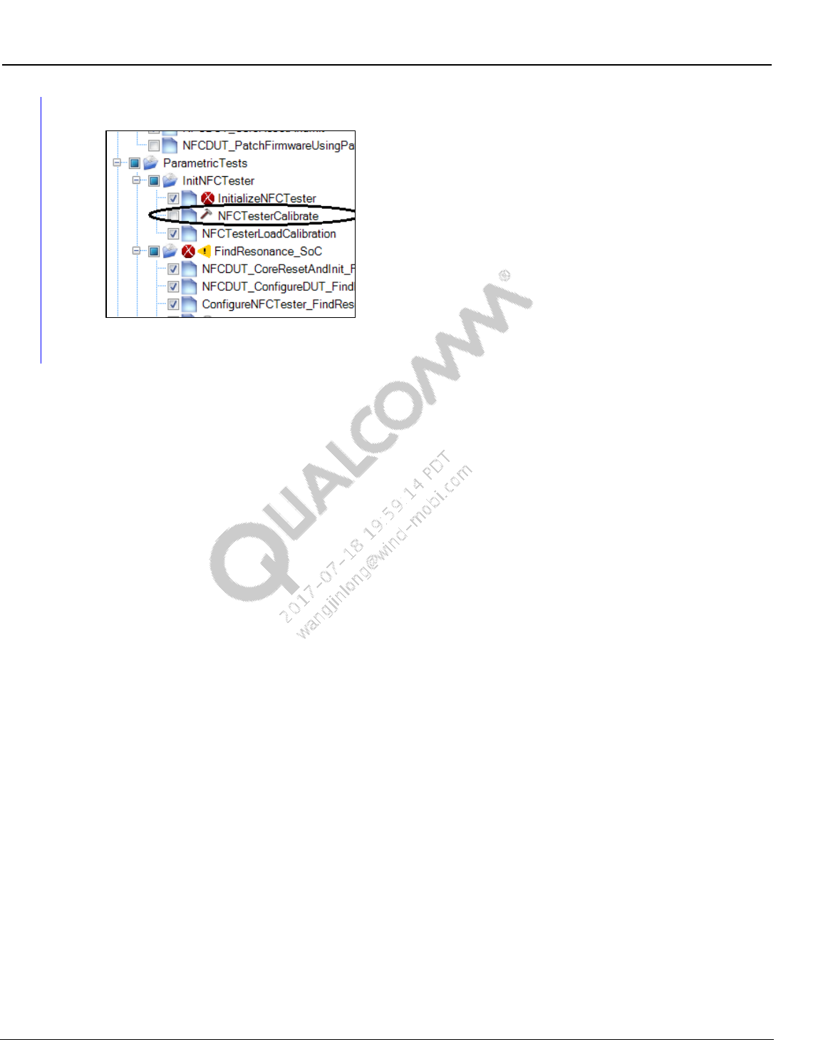
Wireless Connectivity Tests User Guide Station Calibration
80-Y0306-1 Rev. L MAY CONTAIN U.S. AND INTERNATIONAL EXPORT CONTROLLED INFORMATION 44
Confidential and Proprietary – Qualcomm Atheros, Inc.
Figure 4-11 NFC tester calibration test

80-Y0306-1 Rev. L MAY CONTAIN U.S. AND INTERNATIONAL EXPORT CONTROLLED INFORMATION 45
Confidential and Proprietary – Qualcomm Atheros, Inc.
5 Test Matrix
The following matrices present the type of tests and brief description of various tests that are
performed in production environments. Detailed explanation and test settings are covered in later
sections.
5.1 Bluetooth non-signaling production test matrix
Table 5-1 lists the tests that are covered under this document for testing Bluetooth devices in
production environment.
Table 5-1 Bluetooth non-signaling production test matrix
Rate
Test Name
Description
BR
Measure_OutputPower_InitialCarrierFr
equencyTolerance
This test measures average transmitter
output power and transmitter initial carrier
frequency tolerance.
BR
Measure_GFSK_Modulation_DeltaF2_
CarrierDrift
This test measures Delta F2 and carrier
frequency drift of the BT transmitter
BR
Measure_GFSK_Modulation_DeltaF1
This test measures Delta F1 of the BT
transmitter
BR
GFSK RX Sensitivity
This test verifies minimum sensitivity at a
given power and measures BER %.
BR
GFSK Max Input Power
This test verifies maximum input power at a
given power and measures BER %.
EDR
Measure_EDRModulation
This test verifies the transmitter carrier
frequency stability and modulation accuracy
EDR
EDR Sensitivity
This test verifies sensitivity at a given power
and measures BER %.
EDR
EDR Max Input Power
This test measure maximum input power for
given maximum BER %.
BLE
Measure_LE_TxOutputPower
This test measures average transmitter
output power
BLE
Measure_LE_Modulation_DeltaF1
This test measure modulation parameters
like DeltaF1
BLE
Measure_LE_Modulation_DeltaF2_Fre
qOffset_FreqDrift_MaxDriftRate
This test measures delta F2, frequency
offset, carrier drift and max drift rate of LE
transmitter
BLE
LE RX Sensitivity
This test measure LE receiver sensitivity
BLE
LE Max Input Power
This test measure max input power for given
maximum PER%
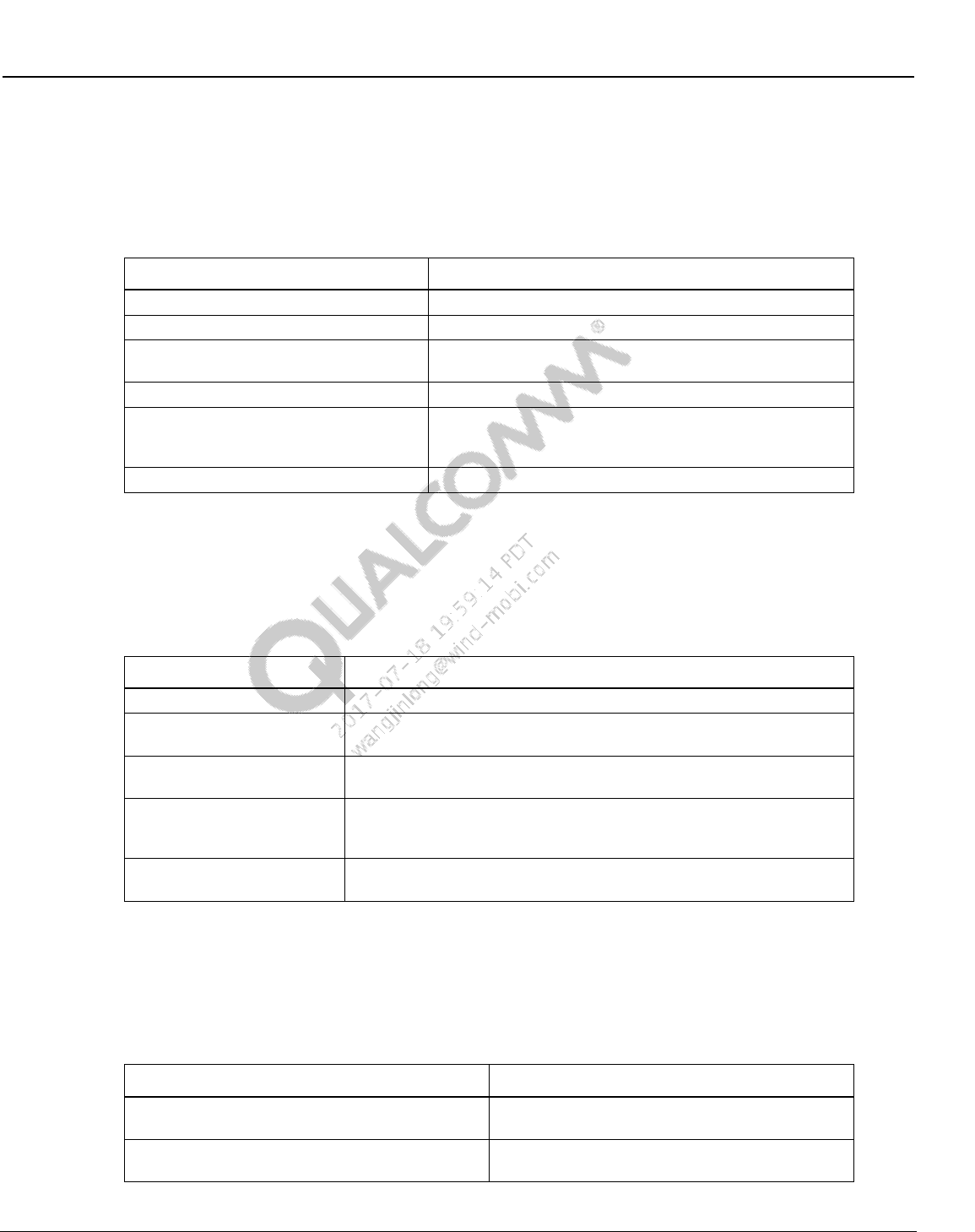
Wireless Connectivity Tests User Guide Test Matrix
80-Y0306-1 Rev. L MAY CONTAIN U.S. AND INTERNATIONAL EXPORT CONTROLLED INFORMATION 46
Confidential and Proprietary – Qualcomm Atheros, Inc.
5.2 WLAN production SISO test matrix
Table 5-2 lists the tests that are covered under this document for testing WLAN devices in
production environment.
Table 5-2 WLAN production test matrix
Test Name
Description
SetUpDutTx
Sets up the DUT for TX testing
WlanTxEVMTest
Transmit Modulation Accuracy Test; Measures EVM
WlanTxVerifySpectrumTest
Transmit Spectrum Verification Test; Measures center
frequency leakage and spectral flatness
WlanTxVerifyMaskTest
Transmit Spectrum Mask Verification Test
WlanTxVerifyPowerTest
Transmit Power Verification Test; Measures maximum,
minimum average TX power and maximum, minimum,
average Peak TX Power
WlanPerTest
Receiver Minimum Input Sensitivity Test; Measures PER
5.3 WLAN production MIMO test matrix
Table 5-3 lists the tests that are covered under this document for testing MIMO and SISO WLAN
devices in production environment.
Table 5-3 WLAN production test matrix
Test Name
Description
SetUpDutTxDetails
Sets up the DUT for TX testing (QCA6174)
WlanTxEvmTest_NxN
Transmit Modulation Accuracy Test for MIMO/SISO modulation rate;
Measures EVM, Power Freq_err etc.
MeasureSpectrum_NxN
Transmit Spectrum Verification Test for MIMO/SISO modulation rate;
Measures center frequency leakage and spectral flatness
WlanTxVerifyPowerTest_NxN
Transmit Power Verification Test for MIMO/SISO modulation rate;
Measures maximum, minimum average TX power and maximum,
minimum, average Peak TX Power
WlanPerTest_NxN
Receiver Minimum Input Sensitivity Test for MIMO/SISO modulation
rate; Measures PER
5.4 FM production test matrix
Table 5-4 lists the tests that are covered under this document for testing FM devices in production
environment.
Table 5-4 FM production test matrix
Test Name
Description
RX Sensitivity GONOGO
This test verifies sensitivity at a given power and
measures SNR
RX Sensitivity Characterization
This test finds the minimum sensitivity level with an
iterative search
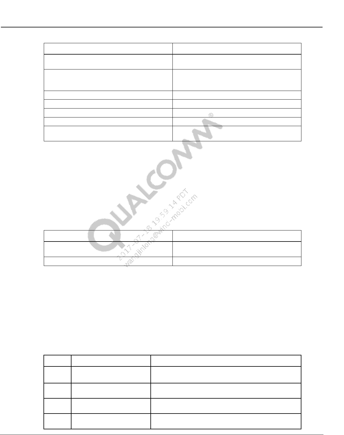
Wireless Connectivity Tests User Guide Test Matrix
80-Y0306-1 Rev. L MAY CONTAIN U.S. AND INTERNATIONAL EXPORT CONTROLLED INFORMATION 47
Confidential and Proprietary – Qualcomm Atheros, Inc.
Test Name
Description
RX Max SNR
This test measures SNR at a strong input signal
level
RX Intermediate SNR
This test measures SNR at an intermediate input
signal level with AM distortion added to the FM
signal
RX THD
This test measures Total Harmonic Distortion
RX RDS Block Error Rate
This test measures RDS Block Error Rate (BLER)
TX Output Power
This test measures TX output power
TX FM Deviation
This test measures FM deviation on the TX signal
TX Stereo Audio SNR
This test measures audio SNR for Left & Right
channels on the TX signal
NOTE: All FM tests are not supported with WCN2243. Tests listed in bold in Table 5-4 are not
supported for WCN2243. Tests that are supported by WCN2243 are only supported for default
headset path.
5.5 ANT production test matrix
Table 5-5 lists the tests that are covered under this document for testing ANT devices in
production environment.
Table 5-5 ANT production test matrix
Test Name
Description
RX Sensitivity
This test finds the minimum sensitivity level with an
iterative search
TX Channel Power
This test measures TX channel output power
5.6 WLAN WCN36x0 CLPC calibration
Refer to [Q9] for WLAN closed loop power control calibration for WCN36x0.
5.7 Bluetooth signaling production test matrix
Table 5-6 lists the tests that are covered under this document for testing Bluetooth devices in
signaling environment.
Table 5-6 Bluetooth signaling production test matrix
Rate
Test Name
Description
BR
TRM/CA/01
TX Output Power
Verification of the maximum peak and average RF-output
power.
BR
TRM/CA/07 Modulation
Characteristics
Verification of the modulation index.
BR
TRM/CA/08 Initial Carrier
Frequency Tolerance
Verification of the transmitter carrier frequency accuracy
BR
TRM/CA/09 Carrier
Frequency Drift
Verification of the transmitter center frequency drift within a
packet.

Wireless Connectivity Tests User Guide Test Matrix
80-Y0306-1 Rev. L MAY CONTAIN U.S. AND INTERNATIONAL EXPORT CONTROLLED INFORMATION 48
Confidential and Proprietary – Qualcomm Atheros, Inc.
Rate
Test Name
Description
EDR
TRM/CA/10 EDR Relative
Transmit Power
This test ensures the difference in average transmit power
during frequency modulated [GFSK] and phase modulated
[DPSK] portions of a packet is within an acceptable range.
EDR
TRM/CA/11
EDR Carrier Frequency
Stability and Modulation
Accuracy
This test verifies the transmitter carrier frequency stability
and modulation accuracy.
BR
RCV/CA/01 Sensitivity –
single slot packets
The sensitivity is tested using a non-ideal transmitter (one-
slot packet).
BR
RCV/CA/02 Sensitivity –
multiple slot packets
Multi-slot packets are sent to the EUT at the sensitivity level.
EDR
RCV/CA/07
EDR Sensitivity
Verification of the receiver sensitivity for the 10-4 bit error
rate using a non-ideal transmitter.
BLE
TRM-LE/CA/01/02 LE TX
Output Power
This test verifies the maximum peak and average power
emitted from the EUT.
BLE
TRM-LE/CA/05
LE Modulation DeltaF1
This test verifies that the modulation characteristics (delta
F1) of the transmitted signal are correct.
BLE
TRM-LE/CA/05/06/07 LE
Modulation Delta F2 and
Frequency Offset and Drift
This test verifies that the modulation characteristics (delta
F2) of the transmitted signal are correct. This test verifies
that the carrier frequency offset and carrier drift of the
transmitted signal is within specified limits.
BLE
RCV-LE/CA/01/02 LE
Receiver Sensitivity
This test verifies that the receiver sensitivity is within limits
for non-ideal signals.
5.8 NFC production functional test matrix
Table 5-7 lists the tests that are covered under this document for testing NFC device functionality.
Table 5-7 NFC production functional tests
Test
Description
Detect Tag
This test verifies the DUT is able to detect a NFC
tag.
Detect Field
This test verifies the DUT is able to detect an
externally generated NFC field.
NFCDUT_SelfTest
This test is based on the NFC chip’s built in Self
Test Function
Table 5-8 NFC functional test tree nodes
Test
Applicable to Phone
Applicable to SoC
SetInstrumentConfigFile
Yes
Yes
NFCDUT_SetConfigFile
Yes
Yes
NFCDUT_Instantiate
Yes
Yes
DUT_InitFramework
Yes
Yes
NFCDUT_RunTopLevelScript
No
Yes
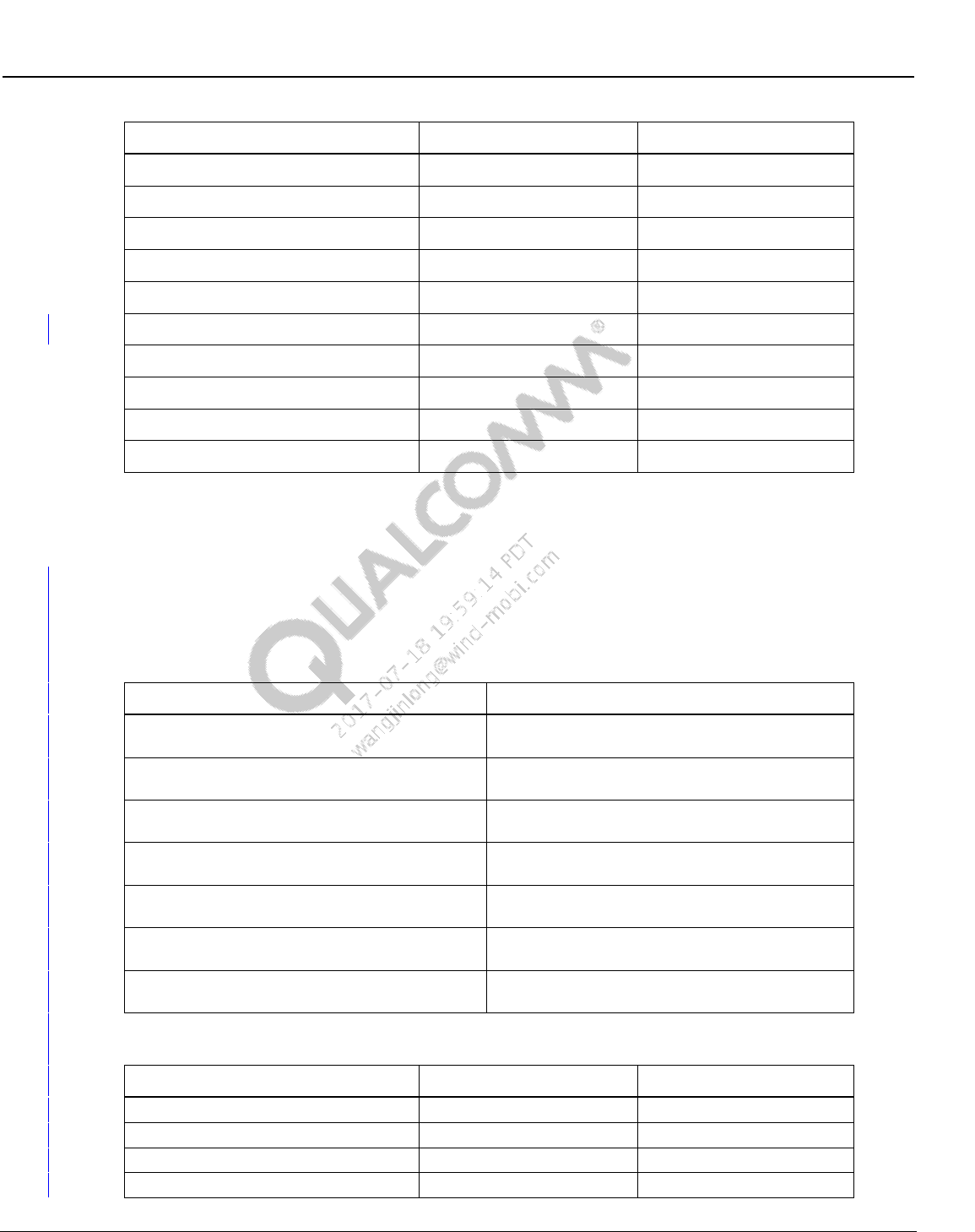
Wireless Connectivity Tests User Guide Test Matrix
80-Y0306-1 Rev. L MAY CONTAIN U.S. AND INTERNATIONAL EXPORT CONTROLLED INFORMATION 49
Confidential and Proprietary – Qualcomm Atheros, Inc.
Test
Applicable to Phone
Applicable to SoC
NFCDUT_Connect
Yes
Yes
NFCDUT_CoreResetAndInit
Yes
Yes
NFCDUT_PatchFirmwareUsingPatchFile
No
Yes
DialogBox_DetectTAG
Yes
Yes
NFCDUT_DetectTAG
Yes
Yes
NFCDUT_SelfTest
Yes
No
DialogBox_EnableField
Yes
Yes
NFCDUT_DetectField
Yes
Yes
NFCDUT_Disconnect
Yes
Yes
NFCDUT_Shutdown
Yes
Yes
NOTE: NFC Test nodes that are not applicable for a particular DUT type will be ignored and just exit
true.
5.9 NFC reference test matrix
Table 5-9 lists the tests that are covered under this document for testing NFC device functionality.
Table 5-9 NFC reference tests
Test
Description
Initiator Test
This test measures the different RF characteristics
of the DUT Initiator Tx waveform
InitiatorRx Test
This test verifies the functionality of the DUT
Initiator Rx block.
Target Test
This test measures the different RF characteristics
of the DUT Target Tx waveform
NFC Resonance Test
This test measures the resonance frequency which
the DUT is tuned to.
Detect Tag
This test verifies the DUT is able to detect a NFC
tag.
Detect Field
This test verifies the DUT is able to detect an
externally generated NFC field.
NFCDUT_SelfTest
This test is based on the NFC chip’s built in Self
Test Function
Table 5-10 NFC reference test tree nodes
Test
Applicable to Phone
Applicable to SoC
SetInstrumentConfigFile
Yes
Yes
NFCDUT_SetConfigFile
Yes
Yes
NFCDUT_Instantiate
Yes
Yes
DUT_InitFramework
Yes
Yes

Wireless Connectivity Tests User Guide Test Matrix
80-Y0306-1 Rev. L MAY CONTAIN U.S. AND INTERNATIONAL EXPORT CONTROLLED INFORMATION 50
Confidential and Proprietary – Qualcomm Atheros, Inc.
Test
Applicable to Phone
Applicable to SoC
NFCDUT_RunTopLevelScript
No
Yes
NFCDUT_Connect
Yes
Yes
NFCDUT_CoreResetAndInit
Yes
Yes
NFCDUT_PatchFirmwareUsingPatchFile
No
Yes
NFCDUT_FindResonance
No
Yes
NFCDUT_TuneCapNVM
No
Yes
InitiatorTest
Yes
Yes
InitiatorRxTest
Yes
Yes
TargetTest
Yes
Yes
ResonanceTest
Yes
Yes
DialogBox_DetectTAG
Yes
Yes
NFCDUT_DetectTAG
Yes
Yes
DialogBox_EnableField
Yes
Yes
NFCDUT_DetectField
Yes
Yes
NFCDUT_SelfTest
Yes
No
NFCDUT_Disconnect
Yes
Yes
NFCDUT_Shutdown
Yes
Yes
NOTE: NFC Test nodes that are not applicable for a particular DUT type will be ignored and just exit
true.

80-Y0306-1 Rev. L MAY CONTAIN U.S. AND INTERNATIONAL EXPORT CONTROLLED INFORMATION 51
Confidential and Proprietary – Qualcomm Atheros, Inc.
6 Chipsets Supported
Table 6-1 lists supported Wireless Connectivity chipsets. These chipsets are supported as long as
they are mated to Qualcomm applications processor targets with appropriate FTM test support.
Table 6-1 Supported chipsets
Chipset
Bluetooth
WLAN
FM
ANT
NFC
WCN2243
Yes
No
Yes
No
No
WCN36x0
Yes
Yes
Yes
Yes
No
AR6003
No
Yes
No
No
No
AR6004
No
Yes
No
No
No
AR6005
No
Yes
No
No
No
AR3002
Yes
No
No
No
No
QCA6174*
Yes
Yes
No
Yes
No
QCA1990
No
No
No
No
Yes
NOTE: QCA6174 and QCA1990 can also run in standalone mode connected directly to PC.

80-Y0306-1 Rev. L MAY CONTAIN U.S. AND INTERNATIONAL EXPORT CONTROLLED INFORMATION 52
Confidential and Proprietary – Qualcomm Atheros, Inc.
7 Setup Configuration
Navigate to C:\Qualcomm\ WCN\ProdTests \ConfigFiles\Sample. Based on the type of test box
used, copy and rename the appropriate xxx--WCNTesterConfig.xml to WCNTesterConfig.xml
under C:\Qualcomm\ WCN\ProdTests \ConfigFiles. Open WCNTesterConfig.xml. Verify the test
equipment model types, settings and GPIB addresses match the setup on the test station. Make
changes and save as required.
7.1 Power supply configuration
1. Instrument configuration file: Test instrument to be utilized to perform power supply tests is
indicated by the instrument config file. WCNTesterConfig.xml present in
C:\QUALCOMM\WCN\ProdTests\ConfigFiles controls this configuration.
a. To select a GPIB based power supply specified in section 2.3.2, check the following
XML tags:
i ResourceID should be selected as “PowerSupply” on the Item
<ResourceIDList>
<Item>PowerSupply</Item>
</ResourceIDList>
ii Ensure that the GPIB address mentioned on the config file has the right information.
This is specified on <PrimAddress> tag
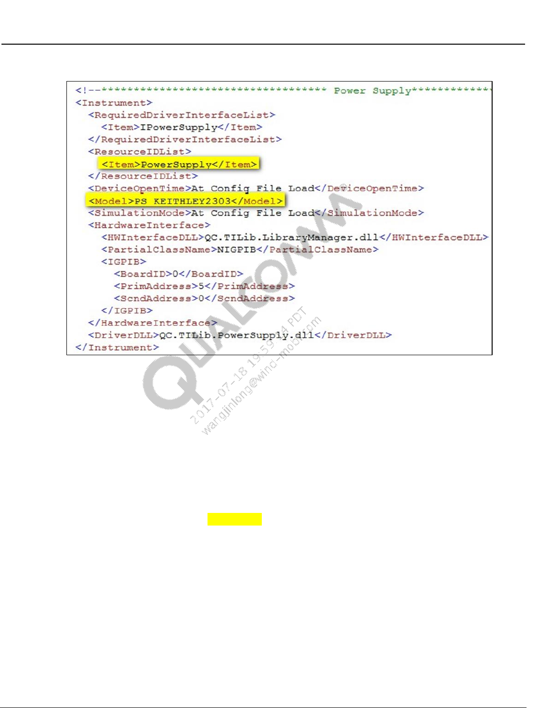
Wireless Connectivity Tests User Guide Setup Configuration
80-Y0306-1 Rev. L MAY CONTAIN U.S. AND INTERNATIONAL EXPORT CONTROLLED INFORMATION 53
Confidential and Proprietary – Qualcomm Atheros, Inc.
Figure 7-1 Power supply section on WCNTesterConfig.xml
7.2 Bluetooth non-signaling tester configuration
1. Test instrument to be utilized to perform BT tests is indicated by the instrument config file.
WCNTesterConfig.xml present in C:\QUALCOMM\WCN\ProdTests\ConfigFiles controls
this configuration
a. For BTTestBoxes specified in Table 2-2 check the following XML tags
i ResourceID should be selected as “BTTesterNS” on the Item
<ResourceIDList>
<Item>BTTesterNS</Item>
</ResourceIDList>
ii LitePoint IQ2010 only: Under OptionalConfigInfoList, check the
ServerExeFullLocation Path to ensure that the StartLitepointConnectivityServer.exe
is available. Check the installation required for LitePoint in section 3.3.
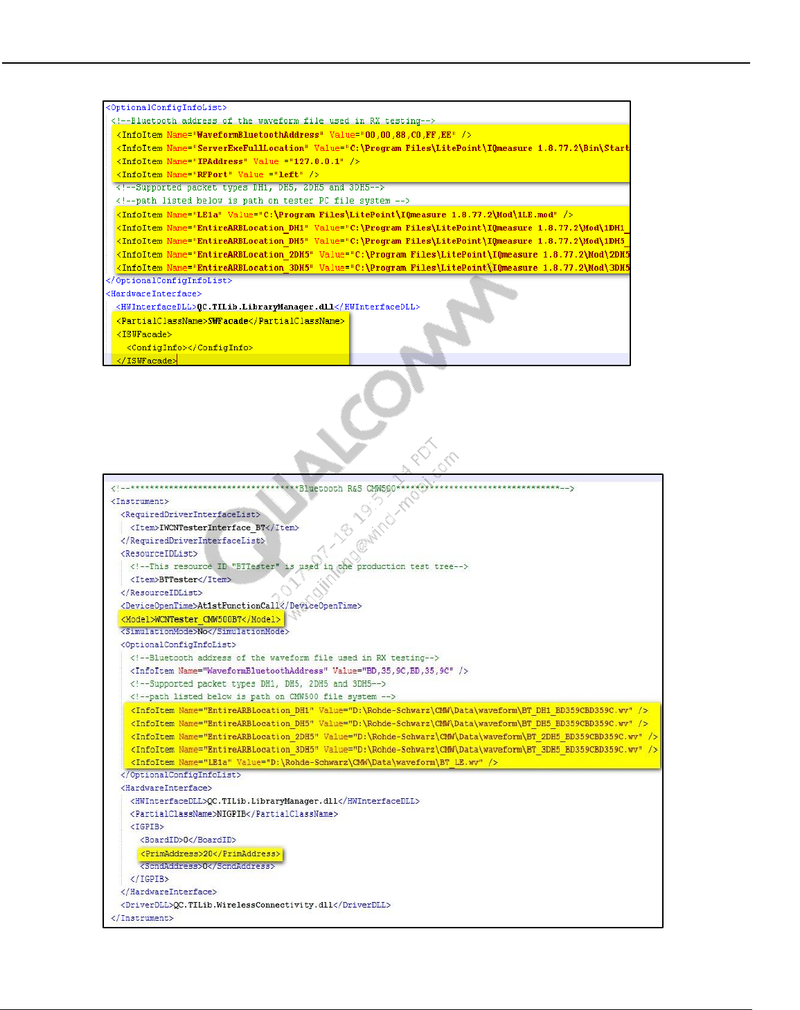
Wireless Connectivity Tests User Guide Setup Configuration
80-Y0306-1 Rev. L MAY CONTAIN U.S. AND INTERNATIONAL EXPORT CONTROLLED INFORMATION 54
Confidential and Proprietary – Qualcomm Atheros, Inc.
Figure 7-2 Bluetooth LitePoint config section in WCNTesterConfig.xml
iii R&S CMW500 only: Ensure that the GPIB address mentioned in the config file has
the right information. This is specified on <PrimAddress> tag.
Figure 7-3 BT R&S CMW500 GPIB settings in WCNTesterConfig.xml
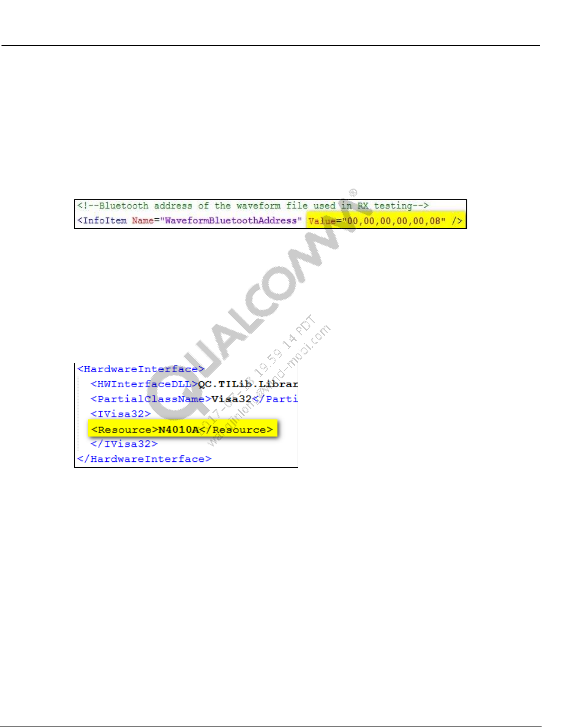
Wireless Connectivity Tests User Guide Setup Configuration
80-Y0306-1 Rev. L MAY CONTAIN U.S. AND INTERNATIONAL EXPORT CONTROLLED INFORMATION 55
Confidential and Proprietary – Qualcomm Atheros, Inc.
iv Under OptionalConfigInfoList, check the EntireARBLocation_xDHx to ensure the
location of ARB waveforms. For LitePoint and AgilentN4010A
EntireARBLocation_xDHx is the location on local PC and for CMW it is the location
on the test box hard drive.
v Under OptionalConfigInfoList, check the “WaveformBluetoothAddress” provided by
test equipment vendors. Bluetooth address listed in the config file should match the
Bluetooth address used for creating the ARB waveform files. This is a requirement
for BT Rx testing.
Figure 7-4 Bluetooth waveform address section in WCNTesterConfig.xml
vi For BT Low Energy receiver test waveform name and location needs to be listed in
OptionalConfigInfoList. Make sure the “InfoItem Name=” matches the one used in
QSPR test tree parameter “WaveformKey” for LE Rx Sensitivity. “Value=” is the
entire location and filename of the waveform file.
vii For AgilentN4010A only: Please verify the VISA instrument string or VISA
instrument alias in the test PC. Default VISA alias set in config file is “N4010A”.
Figure 7-5 BT AgilentN4010A VISA settings in WCNTesterConfig.xml
viii For LitePoint IQxel only: Please verify the RF port, host IP address and port number
in the config file.
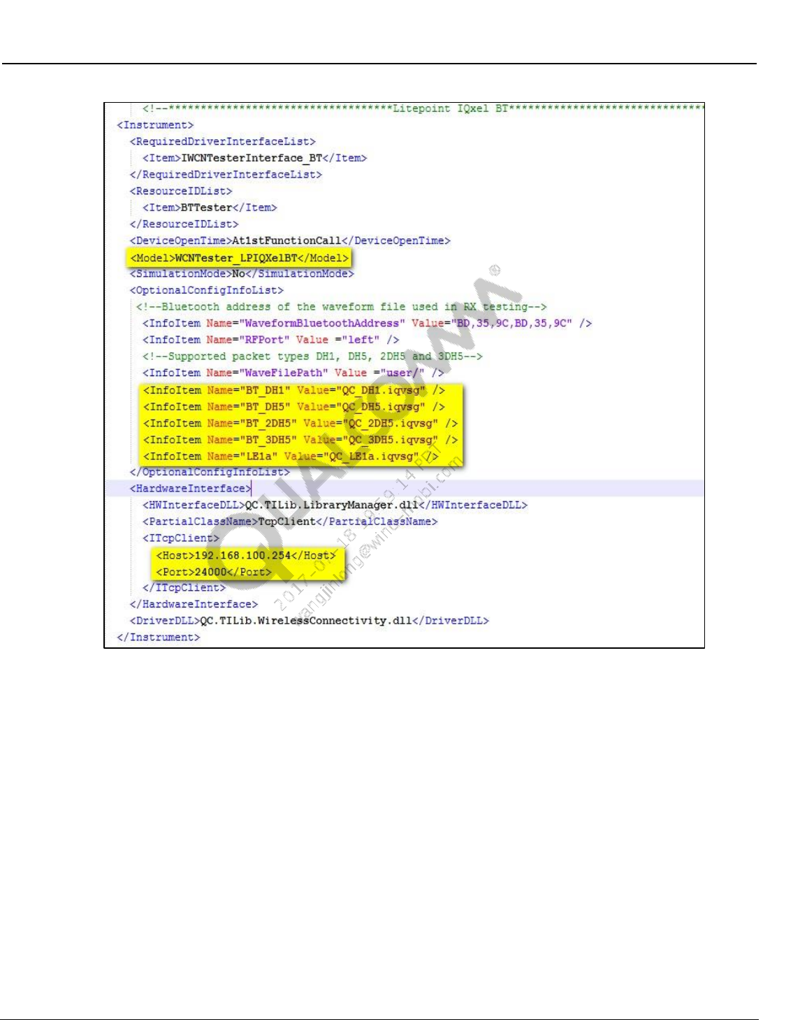
Wireless Connectivity Tests User Guide Setup Configuration
80-Y0306-1 Rev. L MAY CONTAIN U.S. AND INTERNATIONAL EXPORT CONTROLLED INFORMATION 56
Confidential and Proprietary – Qualcomm Atheros, Inc.
Figure 7-6 BT LitePoint IQxel settings in WCNTesterConfig.xml
ix For Anritsu MT8870A only: Please verify the RF port, host IP address and port
number in the config file.
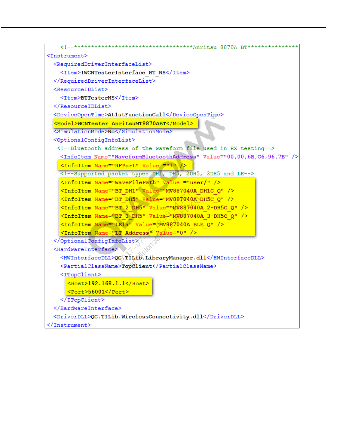
Wireless Connectivity Tests User Guide Setup Configuration
80-Y0306-1 Rev. L MAY CONTAIN U.S. AND INTERNATIONAL EXPORT CONTROLLED INFORMATION 57
Confidential and Proprietary – Qualcomm Atheros, Inc.
Figure 7-7 BT Anritsu MT8870A settings in WCNTesterConfig.xml
Wireless Connectivity Tests User Guide Setup Configuration
80-Y0306-1 Rev. L MAY CONTAIN U.S. AND INTERNATIONAL EXPORT CONTROLLED INFORMATION 58
Confidential and Proprietary – Qualcomm Atheros, Inc.
7.3 WLAN tester configuration (SISO only)
1. Instrument configuration file: Test instrument to be utilized to perform WLAN tests is
indicated by the instrument config file. WCNTesterConfig.xml present in
C:\QUALCOMM\WCN\ProdTests\ConfigFiles controls this configuration
a. For WLANTestBoxes specified on Table 2-2 check the following XML tags.
i ResourceID should be selected as “WLANTester” on the Item
<ResourceIDList>
<Item>WLANTester</Item>
</ResourceIDList>
ii LitePoint IQ2010 only: Under LitePoint IQ2010 on OptionalConfigInfoList, check
the ServerExeFullLocation Path to ensure that the
StartLitepointConnectivityServer.exe is available. Check the installation required for
LitePoint on 3.3.
iii GPIB based testers only, ensure that the GPIB address mentioned on the config file
has the right information. This is specified on <PrimAddress> tag.
iv For LitePoint and CMW500 on OptionalConfigInfoList, check the WaveFilePath to
ensure the location of ARB waveforms. For LitePoint WaveformFilePath is the
location on local PC and for CMW500 it is the location on the test box hard driver.
v NI PXI5644R only: On OptionalConfigInfoList, check the NIWrapperDLLPath has
the correct path information and also ensures that the dll is available at that path. On
OptionalConfigInfoList NIWrapperDLLName is the name of the dll provided by NI
that is mostly NIDotNetWrappersClassLibrary.dll.
vi Agilent N4010 for WLAN only: Under Agilent N4010A (See Figure 7-10).
(a) "InstrumentVisaString": This string value must be set to identify the Instrument’s
Visa String. The string could identify a USB, GPIB, or WLAN connection to the
N4010A. It is recommended to use a USB connection to the N4010A with the
rsrcName value in specified in the “InstrumentVisaString” value field. Default
value used in config file is “N4010A”.
(b) "UseAutoRange": This item tells the instrument whether or not to use the
AutoRange function. The value should be set to either 0 or 1. AutoRange will set
the instrument PowerRange, TriggerLevel, MaxPacketLength, and
MaxSymbolsUsed parameters which are used on TX measurements. Default
value is 0
(c) "UseIncreasedDynamicRangeFor11bSpectralMask": This item tells the
instrument whether or not to use an increased dynamic range for 802.11b spectral
mask measurements. The value should be set to either 0 or 1. Default value is 0.
(d) "WaveformSampleRate_11N_HT20": This specifies the sample rate of 20 MHz
802.11n waveforms. The default value is 40000000. The units are Hz. If 20 MHz
802.11n waveforms are created with another sample rate, then specify that rate
here.
(e) "WaveformSampleRate_11N_HT40": This specifies the sample rate of 40 MHz
802.11n waveforms. The default value is 80000000. The units are Hz. If 40 MHz
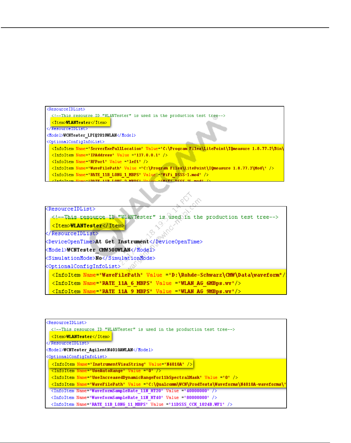
Wireless Connectivity Tests User Guide Setup Configuration
80-Y0306-1 Rev. L MAY CONTAIN U.S. AND INTERNATIONAL EXPORT CONTROLLED INFORMATION 59
Confidential and Proprietary – Qualcomm Atheros, Inc.
802.11n waveforms are created with another sample rate, then specify that rate
here.
vii For Anritsu 8870A on OptionalConfigInfoList, check the WaveFilePath to ensure the
location of ARB waveforms. The WaveFilePath is the location on the test box for
Anritsu 8870A. Also make sure that the IP address and port number for tester is
properly set in ITcpClient as shown in Figure 7-12.
Figure 7-8 WLAN LitePoint test box section on WCNTesterConfig.xml
Figure 7-9 R&S CMW WLAN section on WCNTesterConfig.xml
Figure 7-10 Agilent N4010A WLAN section on WCNTesterConfig.xml
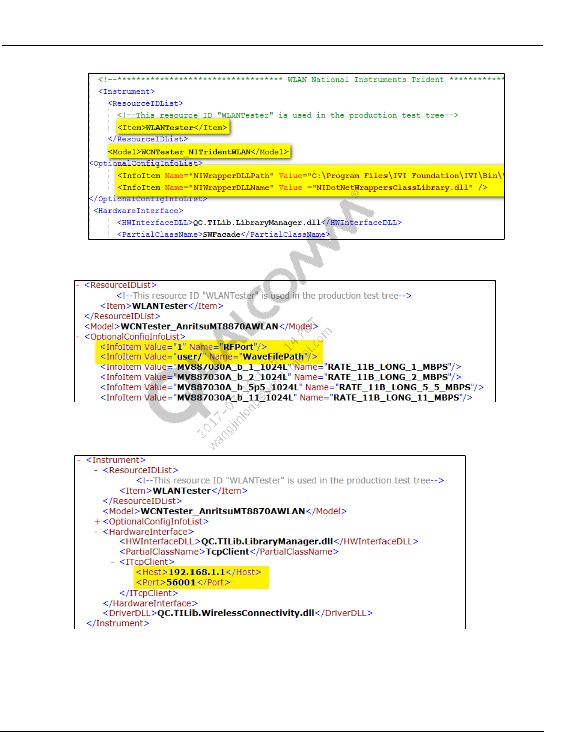
Wireless Connectivity Tests User Guide Setup Configuration
80-Y0306-1 Rev. L MAY CONTAIN U.S. AND INTERNATIONAL EXPORT CONTROLLED INFORMATION 60
Confidential and Proprietary – Qualcomm Atheros, Inc.
Figure 7-11 NI PXI5644R WLAN section on WCNTesterConfig.xml
Figure 7-12 OptionalConfigInfoList section for Anritsu MT8870A on
WCNTesterConfig.xml
Figure 7-13 ITcpClient section for Anritsu MT8870A on WCNTesterConfig.xml
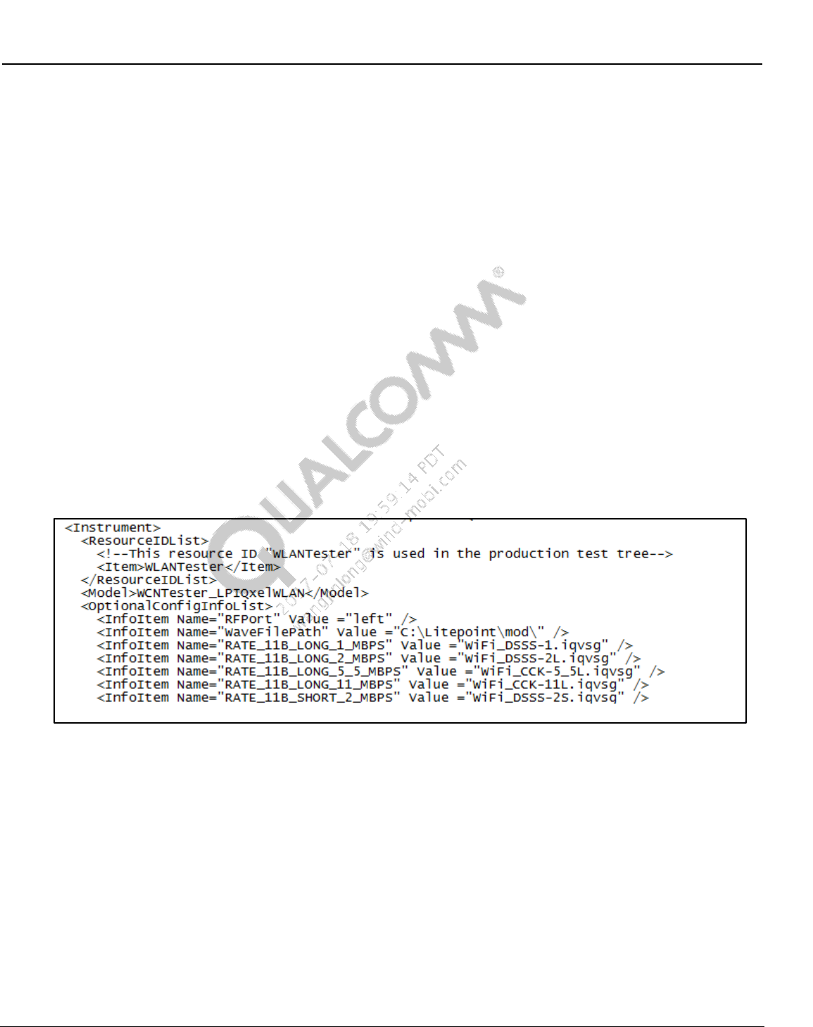
Wireless Connectivity Tests User Guide Setup Configuration
80-Y0306-1 Rev. L MAY CONTAIN U.S. AND INTERNATIONAL EXPORT CONTROLLED INFORMATION 61
Confidential and Proprietary – Qualcomm Atheros, Inc.
7.4 WLAN Tester Configuration (MIMO only)
1. Instrument configuration file: Test instrument to be utilized to perform WLAN tests is
indicated by the instrument config file. WCNTesterConfig.xml present in
C:\QUALCOMM\WCN\ProdTests\ConfigFiles controls this configuration
a. For WLANTestBoxes specified on Table 2-2 check the following XML tags
i ResourceID should be selected as “WLANTester” on the Item
<ResourceIDList>
<Item>WLANTester</Item>
</ResourceIDList>
ii LitePoint IQxel, make sure IQmeasure_3.0.6\Bin is in your system path
For this release it release IQmeasure_3.0.6 up.
iii For LitePoint on OptionalConfigInfoList, check the WaveFilePath to ensure the
location of ARB waveforms. For LitePoint WaveformFilePath is the location on local
PC.
iv NI PXI5644R only: On OptionalConfigInfoList, check the NIWrapperDLLPath has
the correct path information and also ensures that the dll is available at that path. On
OptionalConfigInfoList NIWrapperDLLName is the name of the dll provided by NI
that is mostly NIDotNetWrappersClassLibrary.dll
Figure 7-14 WLAN LitePoint Test Box section (MIMO only) on
WCNTesterConfig.xml
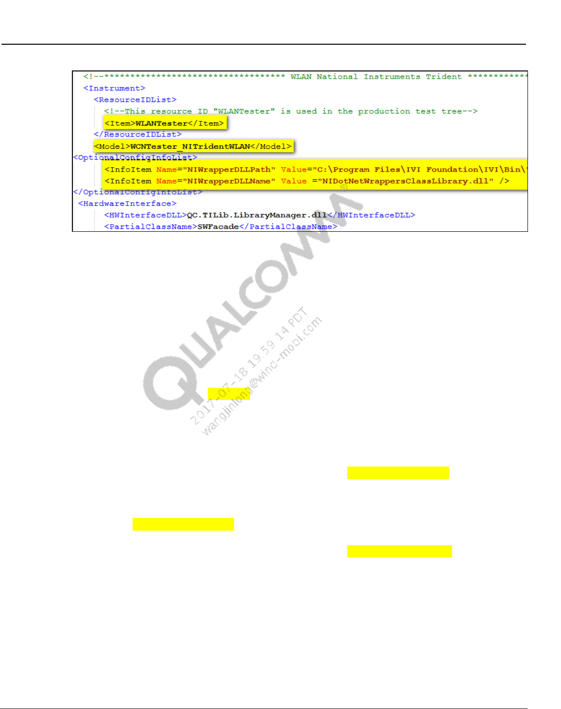
Wireless Connectivity Tests User Guide Setup Configuration
80-Y0306-1 Rev. L MAY CONTAIN U.S. AND INTERNATIONAL EXPORT CONTROLLED INFORMATION 62
Confidential and Proprietary – Qualcomm Atheros, Inc.
Figure 7-15 NI PXI5644R WLAN Section (MIMO only) on WCNTesterConfig.xml
7.5 FM tester configuration
1. Instrument configuration file: Test instrument to be utilized to perform FM tests is indicated
by the instrument config file. WCNTesterConfig.xml present in
C:\QUALCOMM\WCN\ProdTests\ConfigFiles controls this configuration.
a. For FMTestBoxes specified in Table 2-2 check the following XML tags:
i ResourceID should be selected as “FMTester” on the Item
<ResourceIDList>
<Item>FMTester</Item>
</ResourceIDList>
ii For LitePoint on OptionalConfigInfoList, check the ServerExeFullLocation path to
ensure that the StartLitepointConnectivityServer.exe is available. Check the
installation required for LitePoint on 3.3.
iii For LitePoint on OptionalConfigInfoList, check the FmAudioWaveFilePath path to
ensure where the .wav audio files (audio from DUT captured with LitePoint AIM
module) are to be written. These files are used for FM RX audio measurements.
NOTE: Please ensure FmAudioWaveFilePath path is physically available on the local PC.
iv For LitePoint on OptionalConfigInfoList, check the FmAudioCaptureSource value. A
value of 0 specifies to digitize analog audio with the LitePoint AIM. A value of 1
specifies to capture digital FM audio directly from the DUT. Currently this is only
supported on WCN3660. If this tag is omitted, then a default value of 0 is used.
v For LitePoint on OptionalConfigInfoList, check the FmAudioCaptureSampleRate
value in Hz specifies the sample rate of the LitePoint AIM module. (default =
48000).
vi For LitePoint on OptionalConfigInfoList, check the FmExpectedMaxTxPower value
to Zero. This affects the gain in the FM VSA. Set this to a value that is guaranteed
not to be exceeded at the FM VSA input. Allow some safety margin so that the signal
to the ADC in the VSA is never over range. Excessive margin however, may degrade
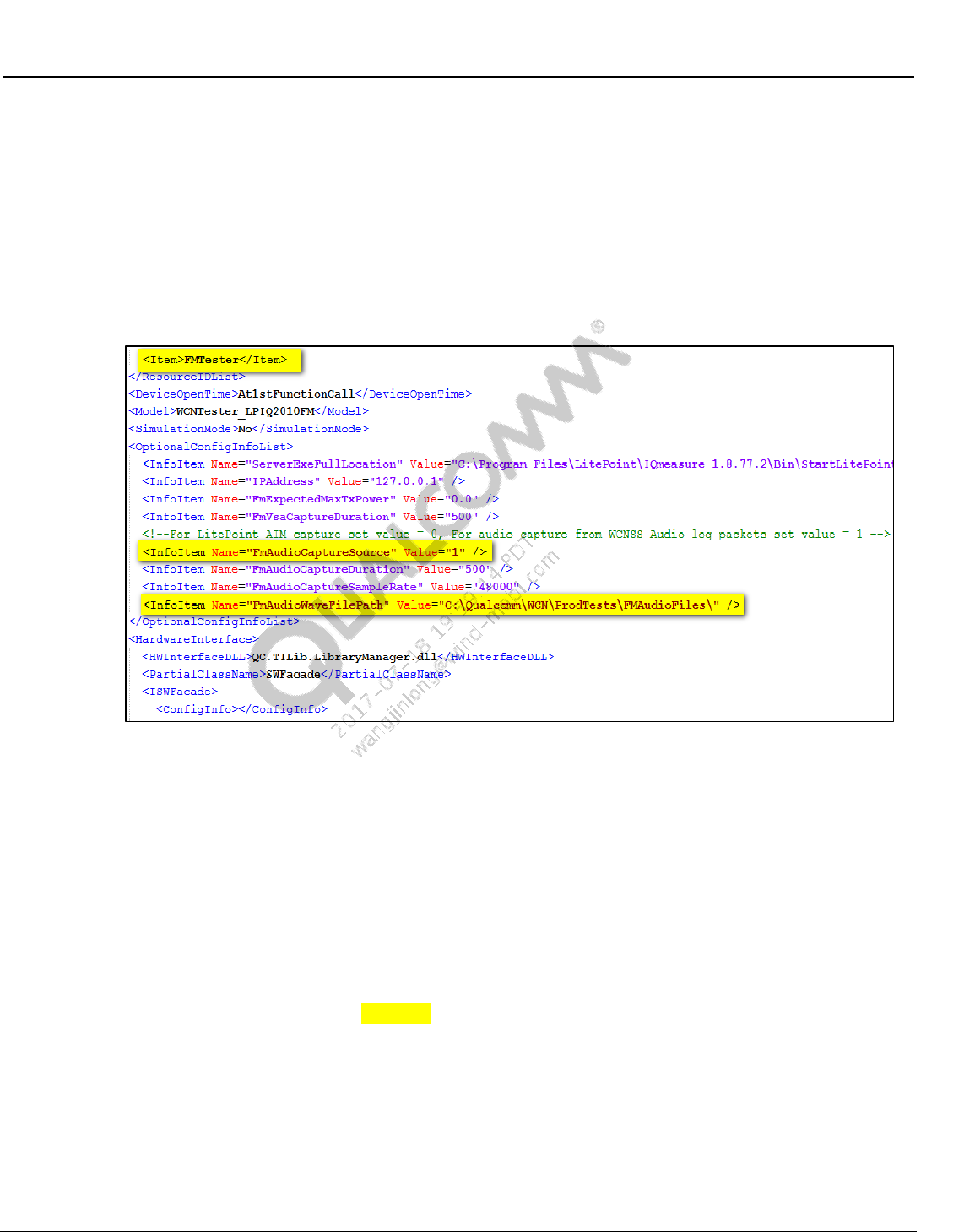
Wireless Connectivity Tests User Guide Setup Configuration
80-Y0306-1 Rev. L MAY CONTAIN U.S. AND INTERNATIONAL EXPORT CONTROLLED INFORMATION 63
Confidential and Proprietary – Qualcomm Atheros, Inc.
the TX Audio SNR measurements. The range of valid values is -40 dBm to +10
dBm. (default = 0.0).
vii For LitePoint on OptionalConfigInfoList, check the FmVsaCaptureDuration. This
value in milliseconds sets the capture duration for the FM VSA. This VSA capture is
used for all TX RF, TX Demod, and TX Audio measurements. (default = 500).
viii For LitePoint on OptionalConfigInfoList, check the FmAudioCaptureDuration. This
value in milliseconds sets the capture duration for FM RX audio from the DUT.
Audio capture is performed with the LitePoint AIM module. (default = 500).
Figure 7-16 FM test box section on WCNTesterConfig.xml
7.6 Bluetooth signaling tester configuration
1. Test instrument to be utilized to perform BT tests is indicated by the instrument config file.
WCNTesterConfig.xml present in C:\QUALCOMM\WCN\ProdTests\ConfigFiles controls
this configuration
a. For BTTestBoxes specified on 2.3.1 check the following XML tags
i ResourceID should be selected as “BTTester” on the Item
<ResourceIDList>
<Item>BTTester</Item>
</ResourceIDList>
ii Sample R&S CBT:
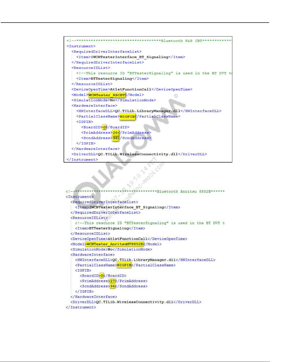
Wireless Connectivity Tests User Guide Setup Configuration
80-Y0306-1 Rev. L MAY CONTAIN U.S. AND INTERNATIONAL EXPORT CONTROLLED INFORMATION 64
Confidential and Proprietary – Qualcomm Atheros, Inc.
Figure 7-17 Sample R&S CBT config section in WCNTesterConfig.xml
iii Sample AnritsuMT8852B:
Figure 7-18 AnritsuMT8852B config section in WCNTesterConfig.xml
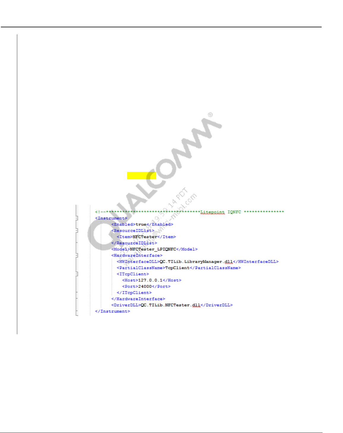
Wireless Connectivity Tests User Guide Setup Configuration
80-Y0306-1 Rev. L MAY CONTAIN U.S. AND INTERNATIONAL EXPORT CONTROLLED INFORMATION 65
Confidential and Proprietary – Qualcomm Atheros, Inc.
7.7 NFC tester configuration
Sample NFC Tester file is present in C:\Qualcomm\WCN\ProdTests\ConfigFiles\Sample\ LP-
IQNFC--NFCTesterConfig.xml.
NOTE: Please copy and rename the appropriate NFC Tester sample (e.g. LP-IQNFC--
NFCTesterConfig.xml) to C:\Qualcomm\WCN\ProdTests\ConfigFiles\ NFCTesterConfig.xml
before running QSPR NFC reference tree tests.
2. Test instrument to be utilized to perform NFC tests is indicated by the instrument config file.
NFCTesterConfig.xml present in C:\QUALCOMM\WCN\ProdTests\ConfigFiles controls
this configuration.
a. For NFC TestBoxes specified on 2.3.1 check the following XML tags
i ResourceID should be selected as “NFCTester” on the Item
<ResourceIDList>
<Item>NFCTester</Item>
</ResourceIDList>
ii Sample LitePoint IQNFC config item entry:
Figure 7-19 LitePoint IQNFC config section in NFCTesterConfig.xml
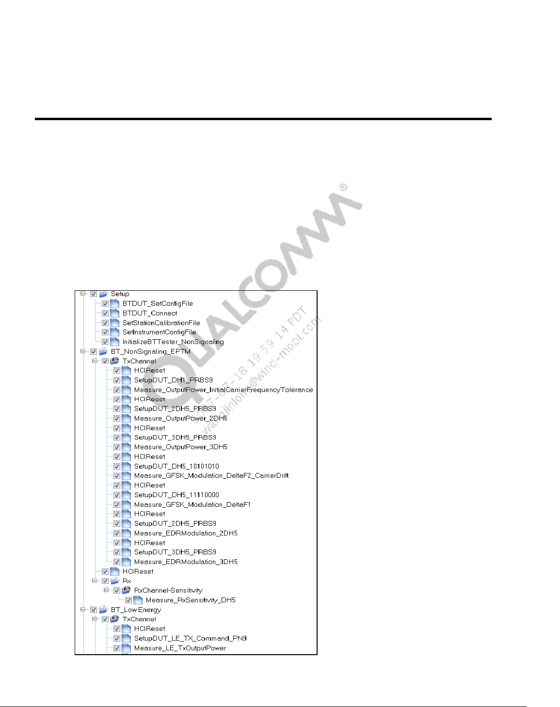
80-Y0306-1 Rev. L MAY CONTAIN U.S. AND INTERNATIONAL EXPORT CONTROLLED INFORMATION 66
Confidential and Proprietary – Qualcomm Atheros, Inc.
8 QSPR Test Trees
The following section contains sample wireless connectivity production test trees.
8.1 Bluetooth non-signaling + Bluetooth LE production test
tree
Figure 8-1 shows Bluetooth test tree. BT_xx(TYPE))_xx(TestMode)_Reference.xtt test tree is
located on the local PC at C:\QUALCOMM\WCN\ProdTests\TestTrees\BT
Figure 8-1 Sample Bluetooth production test tree
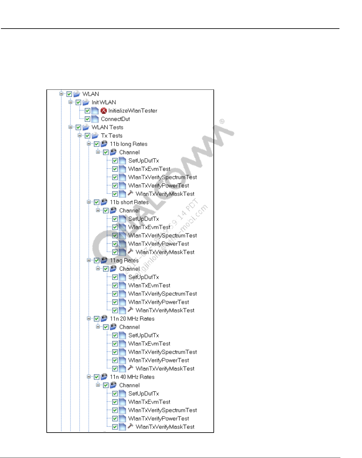
Wireless Connectivity Tests User Guide QSPR Test Trees
80-Y0306-1 Rev. L MAY CONTAIN U.S. AND INTERNATIONAL EXPORT CONTROLLED INFORMATION 67
Confidential and Proprietary – Qualcomm Atheros, Inc.
8.2 WLAN production test trees
Figure 8-2 and Figure 8-3show a WLAN test tree. The WLAN_xx(chipset)_Production.xtt test
tree is located on the local PC at C:\QUALCOMM\WCN\ProdTests\TestTrees\WLAN
Figure 8-2 Sample WLAN production test tree part I
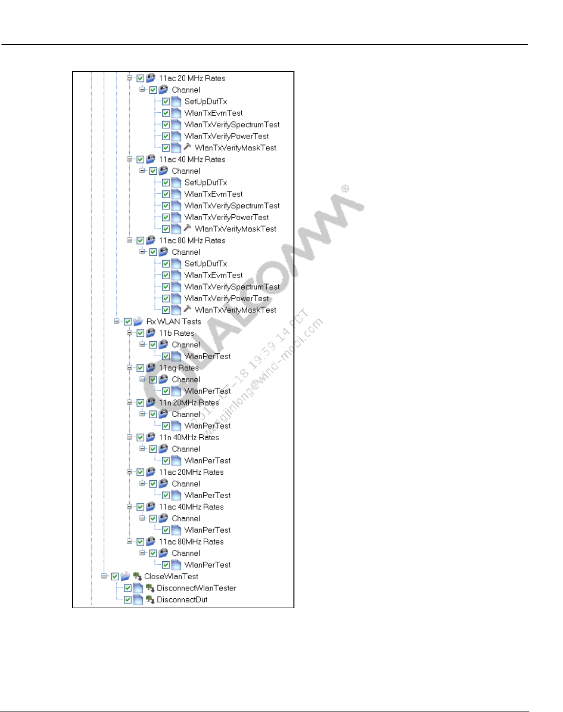
Wireless Connectivity Tests User Guide QSPR Test Trees
80-Y0306-1 Rev. L MAY CONTAIN U.S. AND INTERNATIONAL EXPORT CONTROLLED INFORMATION 68
Confidential and Proprietary – Qualcomm Atheros, Inc.
Figure 8-3 Sample WLAN production test tree part II
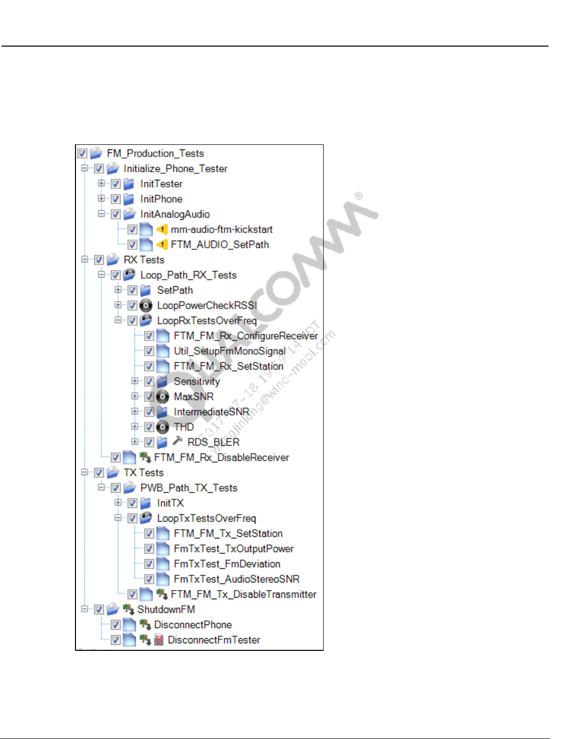
Wireless Connectivity Tests User Guide QSPR Test Trees
80-Y0306-1 Rev. L MAY CONTAIN U.S. AND INTERNATIONAL EXPORT CONTROLLED INFORMATION 69
Confidential and Proprietary – Qualcomm Atheros, Inc.
8.3 FM production test trees
Figure 8-4 shows a WLAN test tree. FM_xx(chipset)_Production.xtt test tree is located on the local PC at
C:\QUALCOMM\WCN\ProdTests\TestTrees\FM
Figure 8-4 Sample FM production test tree
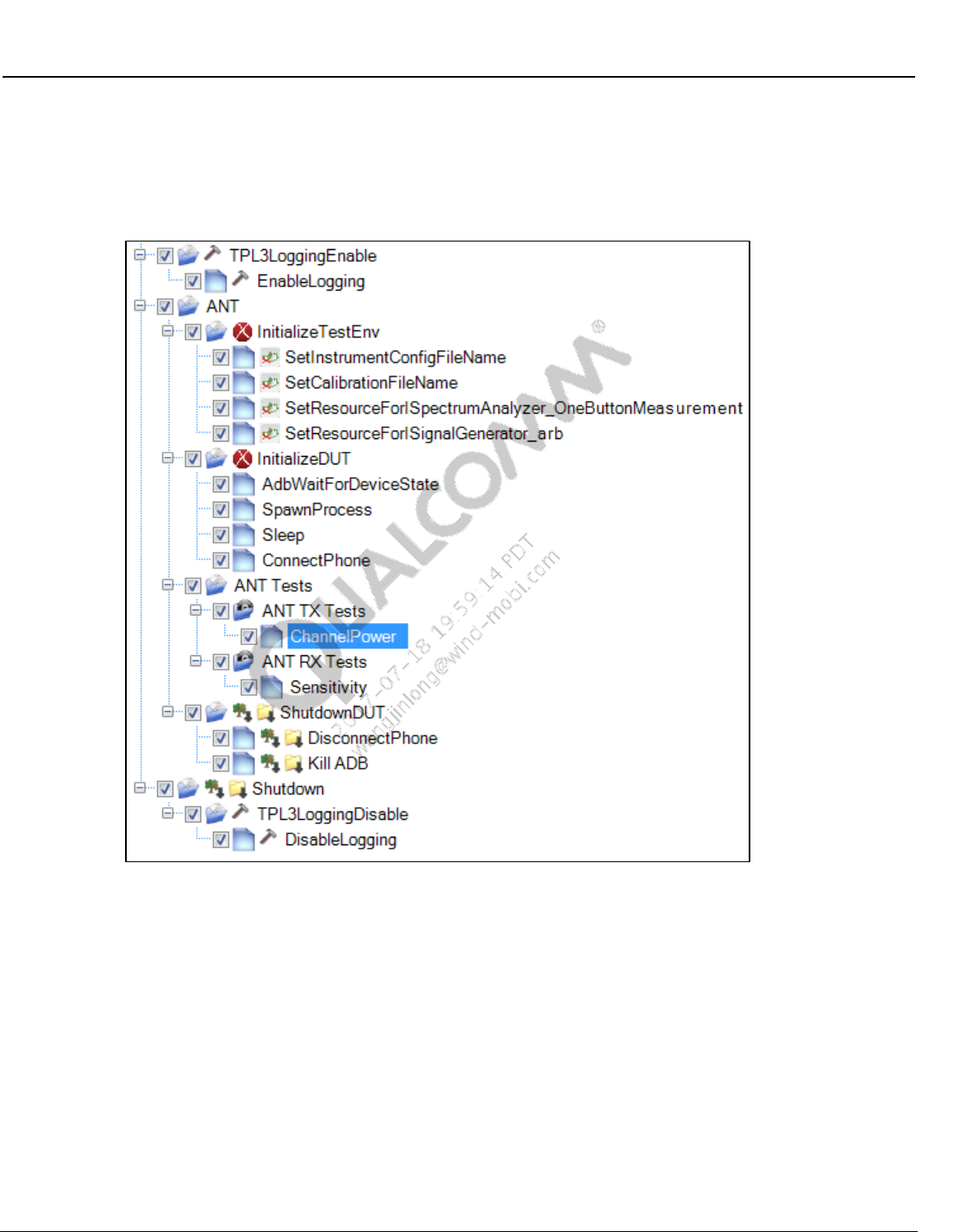
Wireless Connectivity Tests User Guide QSPR Test Trees
80-Y0306-1 Rev. L MAY CONTAIN U.S. AND INTERNATIONAL EXPORT CONTROLLED INFORMATION 70
Confidential and Proprietary – Qualcomm Atheros, Inc.
8.4 ANT production test tree
Figure 8-5 shows an ANT test tree. ANT_xx(chipset)_Production.xtt test tree is located on the
local PC at C:\QUALCOMM\WCN\ProdTests\TestTrees\ANT
Figure 8-5 Sample ANT production test tree
8.5 Bluetooth signaling + Bluetooth LE production test tree
Figure 8-6 shows Bluetooth test tree. BT_xx(TYPE))_xx(TestMode)_Reference.xtt test tree is
located on the local PC at C:\QUALCOMM\WCN\ProdTests\TestTrees\BT
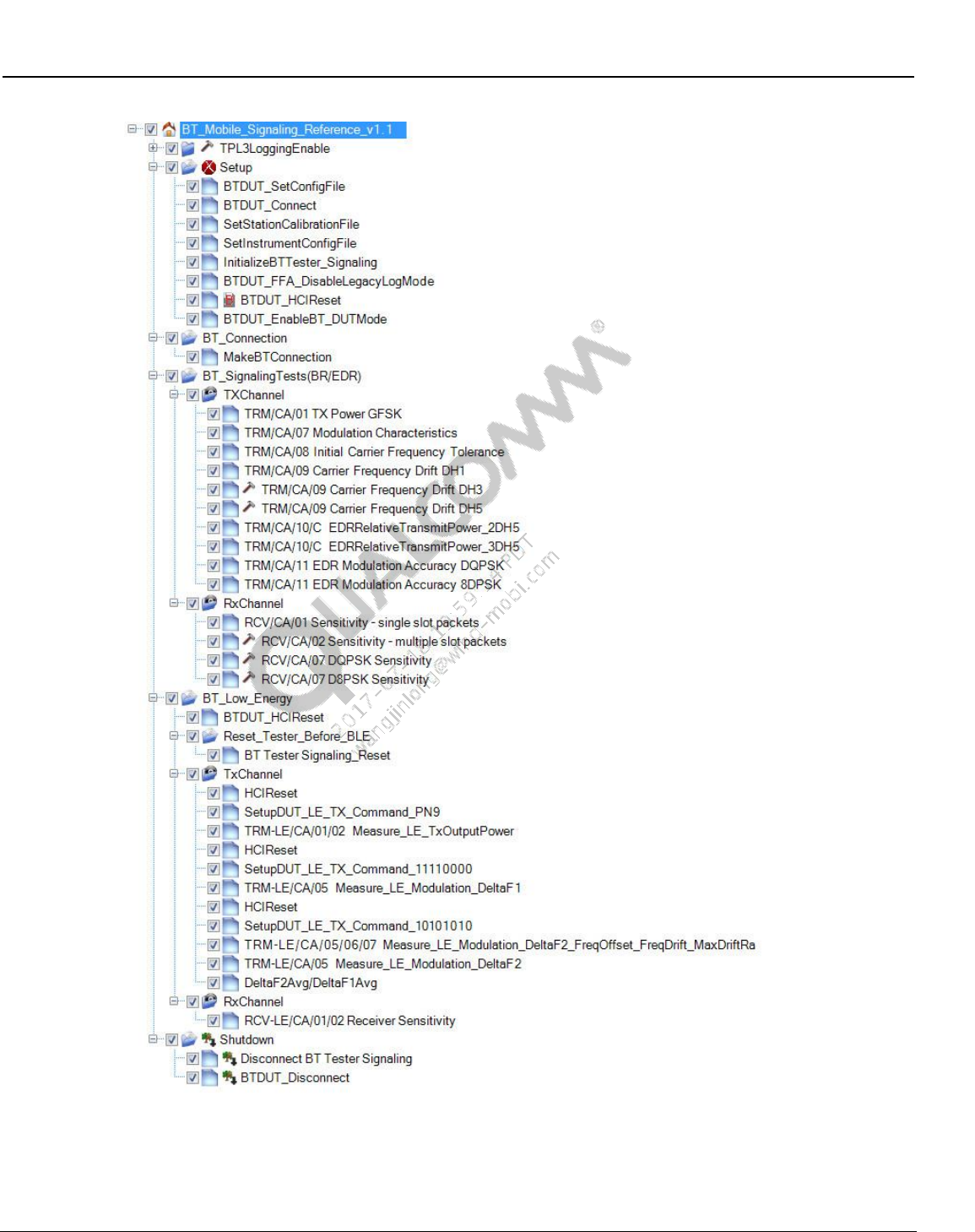
Wireless Connectivity Tests User Guide QSPR Test Trees
80-Y0306-1 Rev. L MAY CONTAIN U.S. AND INTERNATIONAL EXPORT CONTROLLED INFORMATION 71
Confidential and Proprietary – Qualcomm Atheros, Inc.
Figure 8-6 Sample Bluetooth signaling test tree
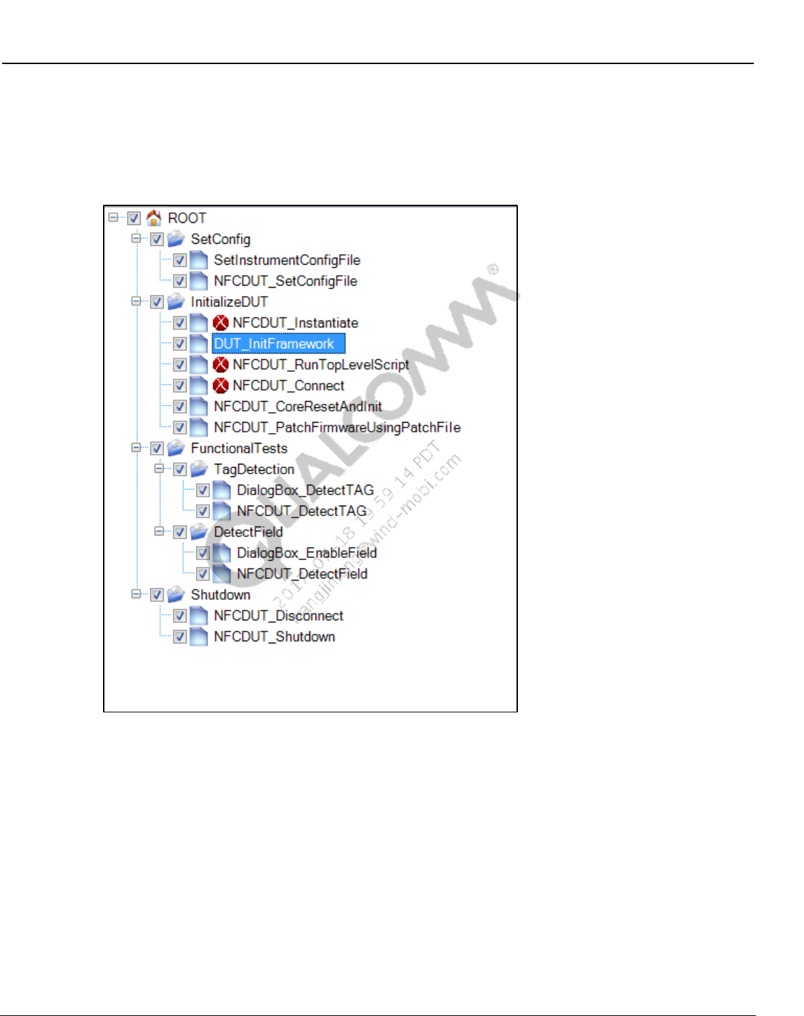
Wireless Connectivity Tests User Guide QSPR Test Trees
80-Y0306-1 Rev. L MAY CONTAIN U.S. AND INTERNATIONAL EXPORT CONTROLLED INFORMATION 72
Confidential and Proprietary – Qualcomm Atheros, Inc.
8.6 NFC production functional test tree
Figure 8-7 shows the NFC Functional test tree. NFC_Functional.xtt test tree is located on the
local PC at C:\QUALCOMM\WCN\ProdTests\Test Trees\NFC
Figure 8-7 NFC Functional test tree
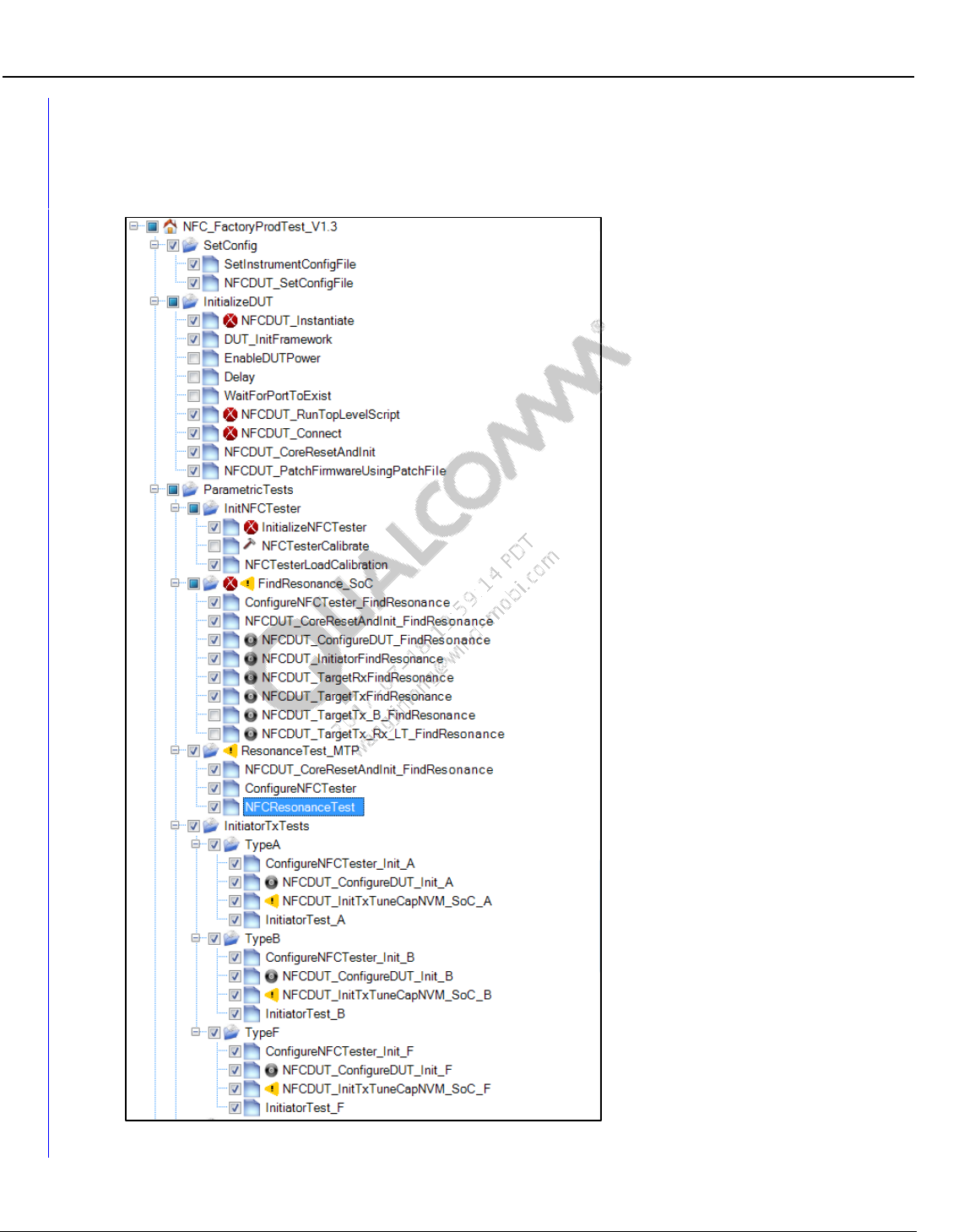
Wireless Connectivity Tests User Guide QSPR Test Trees
80-Y0306-1 Rev. L MAY CONTAIN U.S. AND INTERNATIONAL EXPORT CONTROLLED INFORMATION 73
Confidential and Proprietary – Qualcomm Atheros, Inc.
8.7 NFC production reference test tree
Figure 8-8 shows the NFC reference test tree. NFC_Test_Reference.xtt test tree is located on the
local PC at C:\QUALCOMM\WCN\ProdTests\Test Trees\NFC
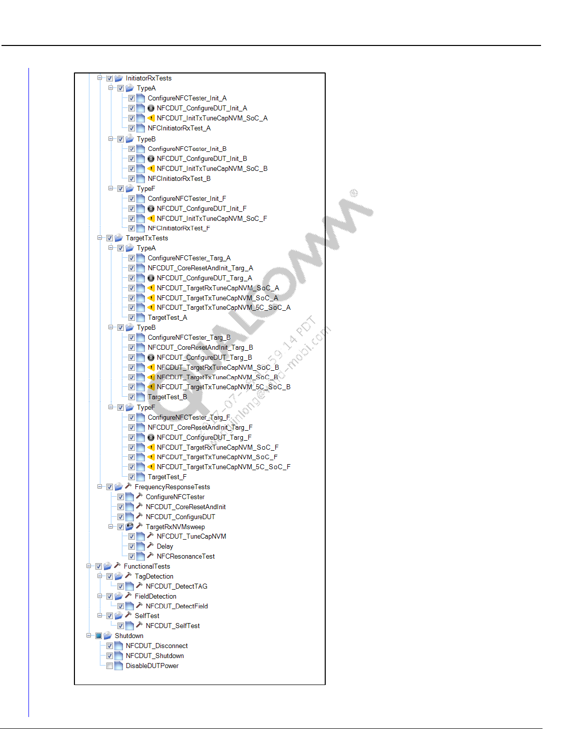
Wireless Connectivity Tests User Guide QSPR Test Trees
80-Y0306-1 Rev. L MAY CONTAIN U.S. AND INTERNATIONAL EXPORT CONTROLLED INFORMATION 74
Confidential and Proprietary – Qualcomm Atheros, Inc.
Figure 8-8 Sample NFC Reference Tree
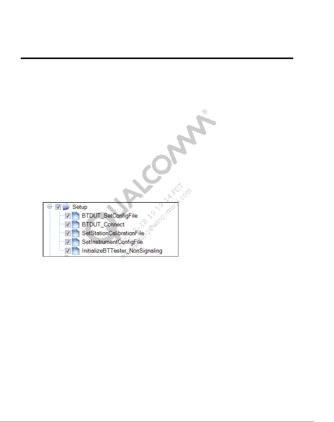
80-Y0306-1 Rev. L MAY CONTAIN U.S. AND INTERNATIONAL EXPORT CONTROLLED INFORMATION 75
Confidential and Proprietary – Qualcomm Atheros, Inc.
9 Test Setup Details
This section lists the initialization tests required for wireless connectivity tests. These tests are
“setup tests” that are performed to setup the device under test and test equipment before actual
functional tests are performed.
9.1 Bluetooth initialization and de-initialization tests
This section applies to Bluetooth and Bluetooth Low energy setup tests that are done before
performing core non-signaling functional tests as described in section 10.1.
Sample section of Bluetooth DUT and tester initialization test tree looks like as shown in
Figure 9-1. A sample section of Bluetooth shutdown test tree is shown in Figure 9-2.
9.1.1 Bluetooth initialization
Figure 9-1 Sample Bluetooth test initialization
BTDUT_SetBTConfigFile
This test sets the path of Bluetooth configuration file. Refer to section 9.1.2 for details.
BTDUT_Connect
This test connect to the device under test. HCI reset after successfully connection is optional
(This test requires Bluetooth FTM running).
BTDUT_LoadNVMFile (only applicable to standalone device, if required by chipset)
This test sets NVM file location and downloads NVM to the device under test.
BTDUT_PatchFirmware (only applicable to standalone device, if required by chipset)
This test sets firmware patch file location and downloads firmware patch to the device under
test.
BTDUT_ FFA_DisableLegacyLogMode(only applicable to FFA/MTP based device)
This test sets disables legacy DIAG log for Bluetooth
SetStationCalibrationFile
This test sets the location of station calibration file used for testing

Wireless Connectivity Tests User Guide Test Setup Details
80-Y0306-1 Rev. L MAY CONTAIN U.S. AND INTERNATIONAL EXPORT CONTROLLED INFORMATION 76
Confidential and Proprietary – Qualcomm Atheros, Inc.
SetInstrumentConfigFile
This test sets the tester configuration file path
InitializeBTTester_NonSignaling
This test initializes Bluetooth non-signaling test box based on the ResourceID listed in
instrument configuration file.
InitializeBTTester_Signaling
This test initializes Bluetooth signaling test box based on the ResourceID listed in instrument
configuration file.
9.1.2 Bluetooth configuration file details
Bluetooth configuration section is listed in
C:\Qualcomm\WCN\ProdTests\ConfigFiles\Sample\BluetoothDUTConfig_Sample.xml.
NOTE: Please copy and rename BluetoothDUTConfig_Sample.xml to
C:\Qualcomm\WCN\ProdTests\ConfigFiles\BluetoothDUTConfig.xml before running QSPR
Bluetooth tests.
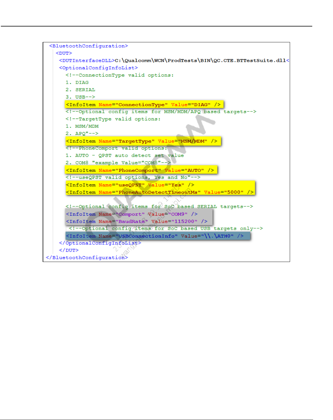
Wireless Connectivity Tests User Guide Test Setup Details
80-Y0306-1 Rev. L MAY CONTAIN U.S. AND INTERNATIONAL EXPORT CONTROLLED INFORMATION 77
Confidential and Proprietary – Qualcomm Atheros, Inc.
Figure 9-2 Bluetooth DUT configuration file
ConnectionType
This field configures the transport/protocol type for device under test. Valid options:
DIAG – MSM/MDM or APQ based targets
SERIAL – UART based devices
USB – USB based devices
TargetType
This option is only valid when ConnectionType is DIAG. Valid options:
MSM/MDM – when target type is MSM or MDM
APQ – when target type is APQ

Wireless Connectivity Tests User Guide Test Setup Details
80-Y0306-1 Rev. L MAY CONTAIN U.S. AND INTERNATIONAL EXPORT CONTROLLED INFORMATION 78
Confidential and Proprietary – Qualcomm Atheros, Inc.
PhoneComport
This option is only valid when ConnectionType is DIAG. Valid options:
AUTO – auto detects the first available connected device
COMx – (example: COM23)
useQPST
This option is only valid when ConnectionType is DIAG. Valid options:
Yes
No
PhoneAutoDetectTimeoutMs
This option is only valid when ConnectionType is DIAG. This timeout is used for auto
detecting the COM port.
Comport
This option is only valid when ConnectionType is SERIAL.
COMx (example: COM9)
BaudRate
This option is only valid when ConnectionType is SERIAL.
Device and PC support baud rate. Example : 115200
USBConnectionInfo
This option is only valid when ConnectionType is USB.
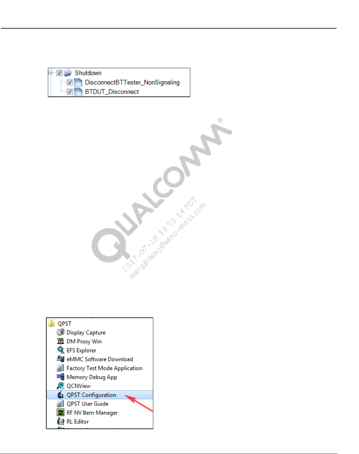
Wireless Connectivity Tests User Guide Test Setup Details
80-Y0306-1 Rev. L MAY CONTAIN U.S. AND INTERNATIONAL EXPORT CONTROLLED INFORMATION 79
Confidential and Proprietary – Qualcomm Atheros, Inc.
9.1.3 Bluetooth de-initialization
Figure 9-3 Sample Bluetooth de-initialization
DisconnectBTester_NonSignaling
This test disconnects to the non-signaling tester and releases any resources used by the tester
DisconnectBTester_Signaling
This test disconnects to the signaling tester and releases any resources used by the tester
BTDUT_Disconnect
This test disconnects to the Bluetooth DUT
9.1.4 Bluetooth UART/USB test setup using BT DIAG BRIDGE
NOTE: This mode requires QPST running
This section summarizes setup details for running QSPR/QRCT tests in UART/ USB mode for
standalone devices.
QC.BT.DIAG.BRIDGE.exe application gets installed on PC at C:\Program Files
(x86)\Qualcomm\QDART\bin
To set up BT DIAG BRIDGE, use the following sequence.
QPST configuration
1. Open QPST configuration
Figure 9-4 BT Diag Bridge - opening QPST
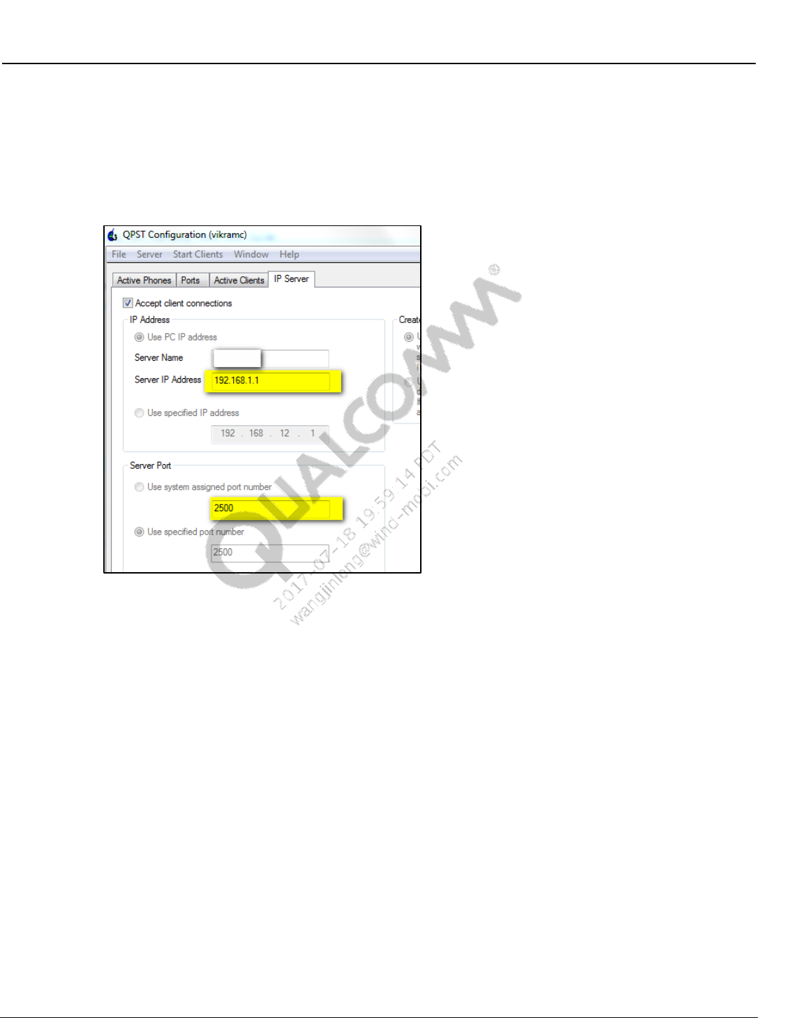
Wireless Connectivity Tests User Guide Test Setup Details
80-Y0306-1 Rev. L MAY CONTAIN U.S. AND INTERNATIONAL EXPORT CONTROLLED INFORMATION 80
Confidential and Proprietary – Qualcomm Atheros, Inc.
2. Navigate to “IP Server” tab
3. Under “IP Address” select “Use PC IP Address” to connect to local machine
4. Under Server Port select “Use specified port number”, example 2500
5. Check “Accept Client connections”
Figure 9-5 BT Diag Bridge - setup QPST IP address and port number
6. Open a command line
7. Navigate to C:\Program Files (x.86)\Qualcomm\QDART\bin.
8. Run QC.BT.DIAG.BRIDGE.exe with various command line arguments.
Note: No spaces are allowed in between ‘=’. Command line arguments are not case sensitive.
Refer to the following example, arguments in bold are mandatory.
QC.BT.DIAG.BRIDGE.exe IPAddress=192.168.1.1 Port=2500 IOType=SERIAL
ConnectionDetails=COM13 Handshake=none Baudrate=115200 Patch=C:\xxx.img
NVM=c:\xxx.nvm
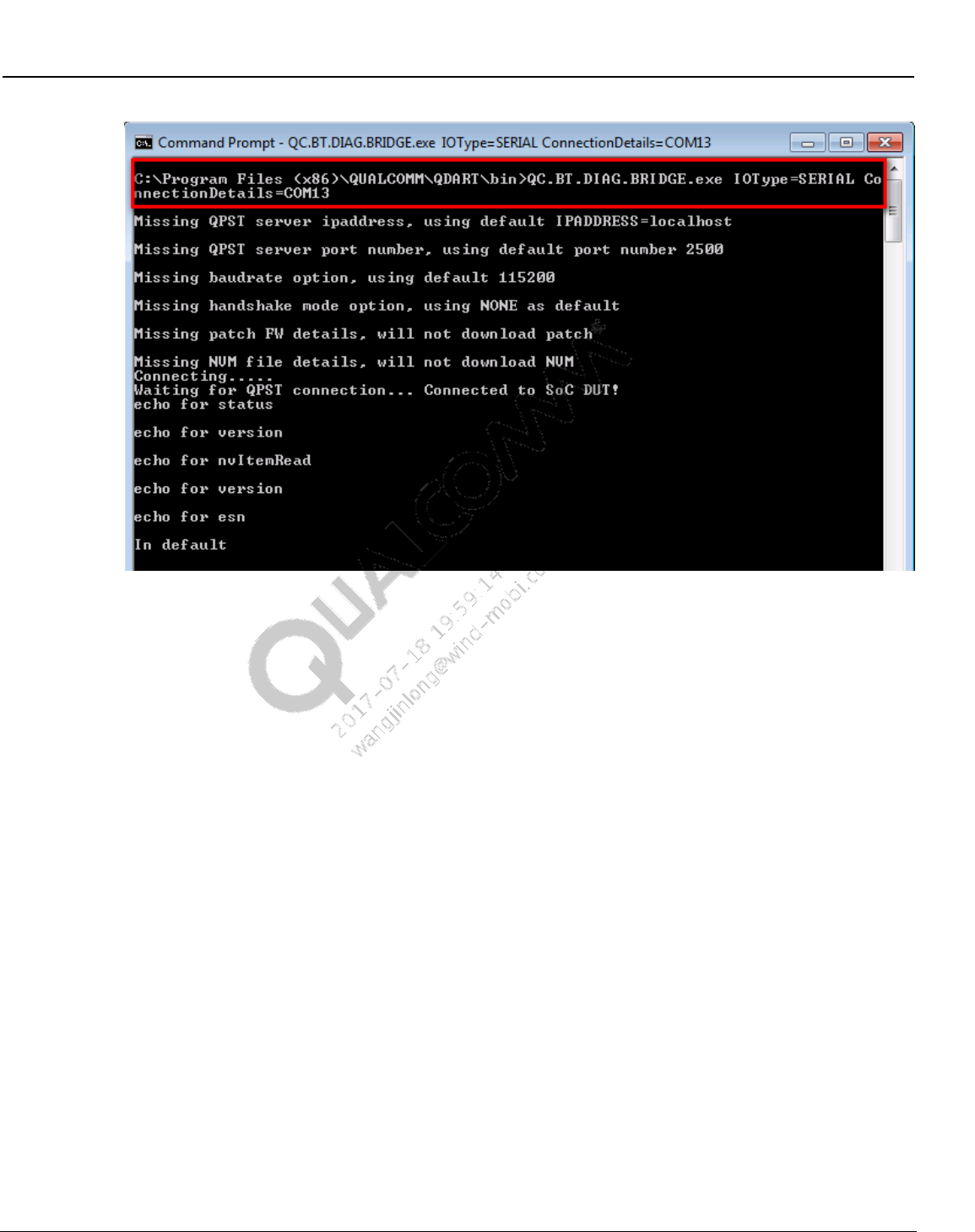
Wireless Connectivity Tests User Guide Test Setup Details
80-Y0306-1 Rev. L MAY CONTAIN U.S. AND INTERNATIONAL EXPORT CONTROLLED INFORMATION 81
Confidential and Proprietary – Qualcomm Atheros, Inc.
Figure 9-6 Running BT DIAG BRIDGE
Command line arguments
IPAddress (optional, default = localhost)
Use same ipaddress listed in QPST as shown in Figure 9-5, QPST is running on the same
machine one can use “localhost” too.
Port (optional, default = 2500)
Use the same port number listed in QPST as shown in Figure 9-5.
IOType
– SERIAL (for UART based devices)
– USB (for USB based devices)
ConnectionDetails
– COMxx (applicable in UART/SERIAL connection type, example COM96)
– \\.\ATH0 (applicable for USB connection type only)
Baudrate (optional, only applicable in SERIAL mode)
– 115200 (default)
Handshaking (optional, only applicable in SERIAL mode)
– NONE (default)
– XONXOFF
– RequestToSend
– RequestToSendXONXOFF
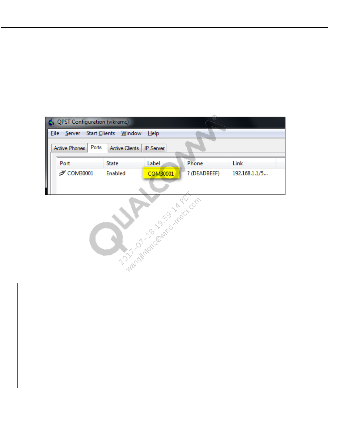
Wireless Connectivity Tests User Guide Test Setup Details
80-Y0306-1 Rev. L MAY CONTAIN U.S. AND INTERNATIONAL EXPORT CONTROLLED INFORMATION 82
Confidential and Proprietary – Qualcomm Atheros, Inc.
Patch (optional, only applicable in SERIAL mode)
– Location for patch file on PC
NVM (optional, only applicable in SERIAL mode)
– Location of NVM file on PC
9. After QC.BT.DIAG.BRIDGE.exe is successfully started, QSPT will list a COM3000x
comport as shown in Figure 9-7.
Figure 9-7 BT Diag Bridge - QPST comport listing
10. The comport listed in Figure 9-7 can be used to configure QSPR Bluetooth test or
QRCT/QMSL DUT connection.
Configuring QSPR tests in this mode.
– Update BluetoothDUTConfig.xml as shown in section 9.1.2.
– Confirm “ConnectionType” in config file is “DIAG.”
– Confirm “PhoneComport” lists the same comport as shown in Figure 9-7, e.g.,
“COM30001.”
9.1.5 Bluetooth User Defined Transport (UDT) test setup using BT
DIAG BRIDGE
This section summarizes setup details for running QSPR tests in UDT mode for standalone
devices.
QMSL_BT_Transport.dll gets installed on C:\Program Files (x86)\Qualcomm\QDART\BIN
QC.BT.DIAG.BRIDGE.exe application gets installed on C:\Program Files
(x86)\Qualcomm\QDART\bin
NOTE: For testing DUT connected to remote PC, the two files are in the same location in remote PC.
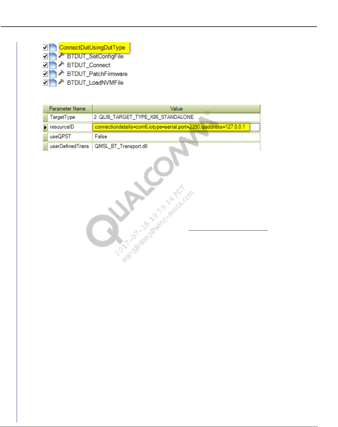
Wireless Connectivity Tests User Guide Test Setup Details
80-Y0306-1 Rev. L MAY CONTAIN U.S. AND INTERNATIONAL EXPORT CONTROLLED INFORMATION 83
Confidential and Proprietary – Qualcomm Atheros, Inc.
Figure 9-8 Connect DUT using DUT type and connection options
Figure 9-9 Input parameters of ConnectDutUsingDutType
Input parameters to use for UDT mode:
TargetType
This field configures the target type for device under test. Valid options:
0 QLIB_TARGET_TYPE_MSM_MDM– MSM/MDM based targets
1 QLIB_TARGET_TYPE_APQ– APQ based devices
2 QLIB_TARGET_TYPE_X86_STANDALONE – Standalone/SoC based devices
resourceID
This field configures the unique target resource ID for different DUTs.
For MSM/MDM and APQ based devices, it can be AUTO or exact comport of the device.
AUTO mode will pick up first device in QPST list
For Standalone devices, its resourceID is formed by several parameters. As an example:
iotype=serial,connectiondetails=com8,port=2390,ipaddress=127.0.0.1
iotype:
serial – UART based devices
usb – USB based devices
connectiondetails:
comx – This option is the physical comport that DUT connects to the PC, it is only valid
when iotype is SERIAL
\\.\ATHx – This option is the physical usb port that DUT connects to the PC, it is only
valid when iotype is USB
port:
TCP IP port of the PC or remote PC (if applicable).
ipaddress:
TCP IP address of the local PC, ipaddress. If DUT is connected to the same PC one can
either ignore this or set it 127.0.0.1.
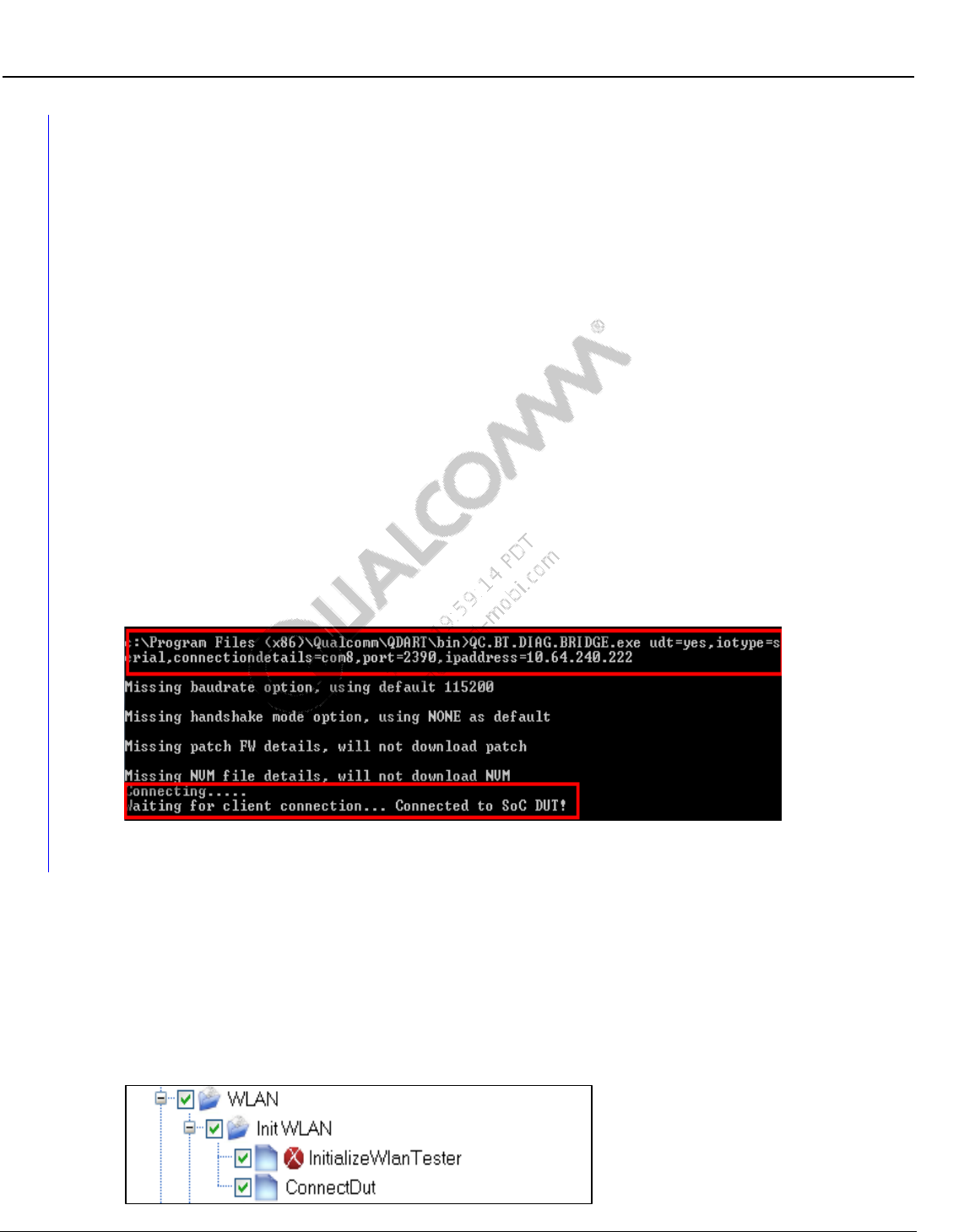
Wireless Connectivity Tests User Guide Test Setup Details
80-Y0306-1 Rev. L MAY CONTAIN U.S. AND INTERNATIONAL EXPORT CONTROLLED INFORMATION 84
Confidential and Proprietary – Qualcomm Atheros, Inc.
For running in remote PC, TCP IP address cannot be omitted and is required to provide
IP address of the remote PC.
NOTE: No spaces are allowed in the resourceID. Command line arguments are not case sensitive. Refer
example, arguments in bold are mandatory and each argument is separated by coma.
UseQPST
True means DUT connection uses QPST, QPST installer – Refer to [Q6] in Qualcomm
documents of section 1.4.1
False means DUT connection uses UDT as the dll is defined below.
userDefinedTransport
User Defined transport dll name; used only on Standalone configuration.
9.1.6 Additional configuration for remote DUT using User Defined
Transport and BT DIAG BRIDGE on remote PC.
BT DIAG BRIDGE must be executed in remote PC before running QSPR on local machine.
Command line for BT DIAG BRIDGE must add one additional parameter “udt=yes,
iotype=serial,connectiondetails=com8,port=2390,ipaddress=127.0.0.1” before other
command line arguments. As shown in Figure 9-10.
Figure 9-10 Remote PC connects to DUT using UDT
9.2 WLAN setup and initialization tests
There are three initialization tests that need to be executed before running WLAN Production
Tests described in section 10.1.12.
These three tests are grouped under the folder “Init WLAN” as shown in Figure 9-11 and de-
initialization is shown in Figure 9-12.
9.2.1 WLAN initialization
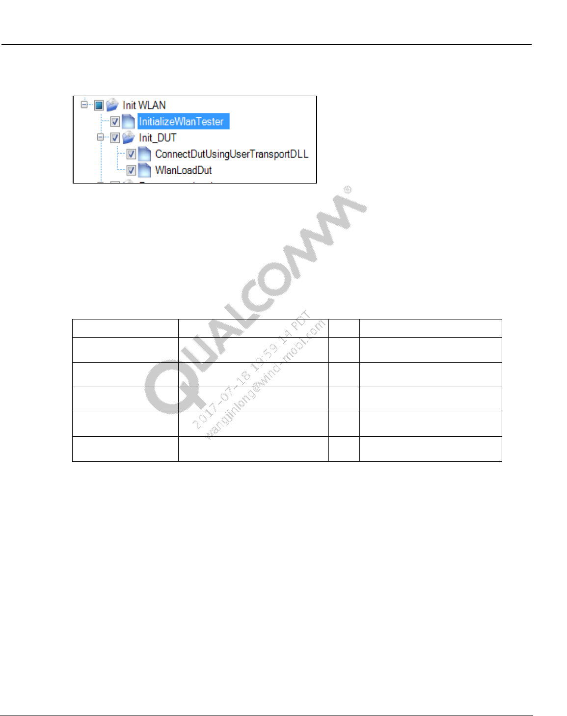
Wireless Connectivity Tests User Guide Test Setup Details
80-Y0306-1 Rev. L MAY CONTAIN U.S. AND INTERNATIONAL EXPORT CONTROLLED INFORMATION 85
Confidential and Proprietary – Qualcomm Atheros, Inc.
Figure 9-11 Sample WLAN test initialization
Figure 9-12 Sample WLAN test initialization with user Transport DLL
InitializeWlanTester
This test makes the connection with the Wlan Tester and initializes the Wlan Tester
specified by “WlanTesterResourceID”
WlanTesterResourceID must match the item value described in Section 7.3.
<Item>WLANTester</Item>
Table 9-1 Initialize Wlan tester parameters
Parameter Name
Value
Unit
Description
testerConfigFileName
C:\Qualcomm\WCN\ProdTests\
ConfigFiles\WCNTesterConfig.xml
Full path name of configuration
file
stationCalFileName
C:\Qualcomm\WCN\ProdTests\
StationCal\ QTA_CalDataFile.xml
Full path name of station
calibration file
WlanTesterResoureID
WLANTester
WLAN Tester resource name as
it appears in config file
TxStationCalPathName
WCD
Tx Station cal path name as it
appears in station cal file
RxStationCalPathName
WCD
Rx Station cal path name as it
appears in station cal file
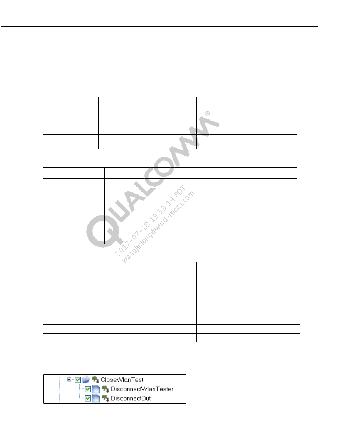
Wireless Connectivity Tests User Guide Test Setup Details
80-Y0306-1 Rev. L MAY CONTAIN U.S. AND INTERNATIONAL EXPORT CONTROLLED INFORMATION 86
Confidential and Proprietary – Qualcomm Atheros, Inc.
ConnectDut
This test makes the connection to the DUT specified by “wlanId” through COM port via
QPST.
DUT must be set up for WLAN FTM communication before this test can run
Table 9-2 Connect DUT parameters
Parameter Name
Value
Unit
Description
Type
0 QLIB_TARGET_TYPE_MSM_MDM
Select target type MSM or APQ
wlanId
3680
WLAN ID.
comPort
AUTO
Com port number or “AUTO”
useQPST
True
True: Use QPST, False: talk
directly to com port
Table 9-3 Connect DUT with user transport DLL parameters
Parameter Name
Value
Unit
Description
Type
1 QLIB_TARGET_TYPE_APQ
Select target type MSM or APQ
wlanId
6174
WLAN ID.
comPort
127.0.0.1
IP or 127.0.0.1 for user
TransportDLL
userTransPortDll
QMSL_WLAN_Transport.dll
User Defined Transport DLL
name with folder path, or dll
name only with default path at
where QMSL_MSVC DLL is
located.
Table 9-4 WLAN DUT load
Parameter
Name
Value
Unit
Description
DevDLLName
QC6174
Device dll name (less than 30
characters)
refDesign
QC6174
refDesign
eepFName
C:\QUALCOMM\WCN\ProdTests\
refDesigns\BoardData\
fakeBoardData_AR6320.bin
eep file name with path (less
than 250 characters)
iNVMemOption
3 DataOtp
NV memory Option
ssid
0x3e
Device ID
9.2.2 WLAN de-initialization
Figure 9-13 Sample WLAN test de-initialization
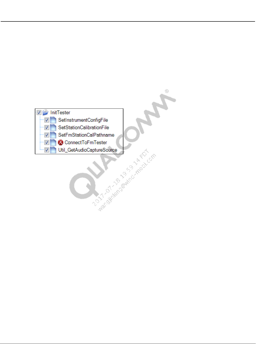
Wireless Connectivity Tests User Guide Test Setup Details
80-Y0306-1 Rev. L MAY CONTAIN U.S. AND INTERNATIONAL EXPORT CONTROLLED INFORMATION 87
Confidential and Proprietary – Qualcomm Atheros, Inc.
DisconnectWlanTester
This test disconnects to the tester and releases any resources used by the tester.
DisconnectPhone
This test disconnects to the DUT and closes QPST server.
9.3 FM setup and initialization tests
9.3.1 FM initialization
Figure 9-14 Sample FM tester initialization
SetInstrumentConfigFile
This test sets the FM tester configuration file path.
SetStationCalibrationFile
This test sets the location of station calibration file used for FM testing.
SetFmStationCalPathname
This sets the default name of station calibration path name specified in station calibration
path loss file to be used for FM tests. This may be reset later on in the test tree.
ConnectToFmTester
This test makes the connection with the FMTester and initialize the FM tester specified by the
“FMResourceID”. The FMTesterResourceID must match the <Item> value specified by
<ResourceIDList> described in section 7.4.
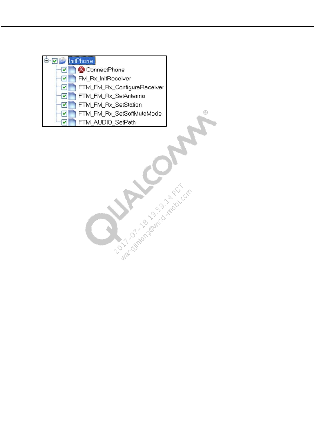
Wireless Connectivity Tests User Guide Test Setup Details
80-Y0306-1 Rev. L MAY CONTAIN U.S. AND INTERNATIONAL EXPORT CONTROLLED INFORMATION 88
Confidential and Proprietary – Qualcomm Atheros, Inc.
9.3.2 FM RX initialization
Figure 9-15 Sample FM RX initialization
ConnectPhone
This test connects to the phone DIAG port. The COM port can be specified or auto
detection can be used.
FM_Rx_InitReceiver
This test disables FM TX, if it was enabled. It then calls FTM command
FTM_FM_RX_ENABLE_RECEIVER with input parameters RadioBand, Emphasis,
ChSpacing, RdsStd, UserDefinedBandFreqMin, and UserDefinedBandFreqMax. If this
command completes successfully, it then waits some delay (see parameter
DelayAfterEnable) and then exits.
If the Enable command returns an error status, the test then tries FTM command
FTM_FM_RX_CONFIGURE_RECEIVER with the same 6 parameters. This is done
because on WCN2243 platforms, the Enable command can only be done once.
Subsequent calls of the Enable command do no harm, but they return a bad status. So in
order to determine if the FM receiver is ready for test, the Configure command is called
after bad status is returned by the Enable command.
FTM_FM_Rx_ConfigureReceiver
This calls FTM command FTM_FM_RX_CONFIGURE_RECEIVER.
FTM_FM_Rx_SetAntenna
This calls FTM command FTM_FM_RX_SET_ANTENNA to select either the headset
FM antenna or the PWB FM antenna.
FTM_FM_Rx_SetStation
This calls FTM command FTM_FM_RX_SET_STATION to set an initial frequency.
FTM_FM_Rx_SetSoftMuteMode
This calls FTM command FTM_FM_RX_SET_SOFTMUTE to disable soft muting. Soft
mute is disabled because it makes it more difficult to perform accurate audio
measurements at low RF signal levels.
FTM_FM_AUDIO_SetPath
This calls FTM command FTM_AUDIO_SET_PATH with a path value that directs FM
RX audio to the headset port.
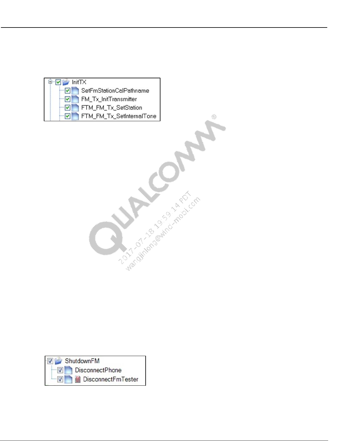
Wireless Connectivity Tests User Guide Test Setup Details
80-Y0306-1 Rev. L MAY CONTAIN U.S. AND INTERNATIONAL EXPORT CONTROLLED INFORMATION 89
Confidential and Proprietary – Qualcomm Atheros, Inc.
9.3.3 FM TX initialization
This folder contains items to configure the DUT and tester for testing FM TX on the PWB
antenna port.
Figure 9-16 Sample FM TX initialization
SetFmStationCalPathname
This test sets the name of station calibration path name specified in station calibration
path loss file to be used for FM TX tests
FM_Tx_InitTransmitter
This test disables FM RX, if it was enabled. It then calls FTM command
FTM_FM_TX_ENABLE_TRANSMITTER with input parameters RadioBand,
Emphasis, ChSpacing, RdsStd, UserDefinedBandFreqMin, and
UserDefinedBandFreqMax. If this command completes successfully it waits some delay
(see parameter DelayAfterEnable) and exits
If the Enable command returns an error status, the test then tries FTM command
FTM_FM_TX_CONFIGURE_TRANSMITTER with the same 6 parameters. This is
done because on WCN2243 platforms the Enable command can only be done once.
Subsequent calls of the Enable command do no harm but they return a bad status. In
order to determine if the FM transmitter is ready for test, the Configure command is
called after bad status is returned by the Enable command
FTM_FM_Tx_SetStation
This calls FTM command FTM_FM_TX_SET_STATION to set an initial frequency
FTM_FM_Tx_SetInternalTone
This calls FTM command FTM_FM_TX_SET_INTERNAL_TONE to select an audio
tone for modulating TX. The tone used is 1 kHz at full scale (0 dBFS) with Left=Right
9.3.4 FM de-initialization
Figure 9-17 Sample FM de-initialization
DisconnectPhone
This test disconnects to the Bluetooth DUT and closes QPST server
DisconnectFmTester
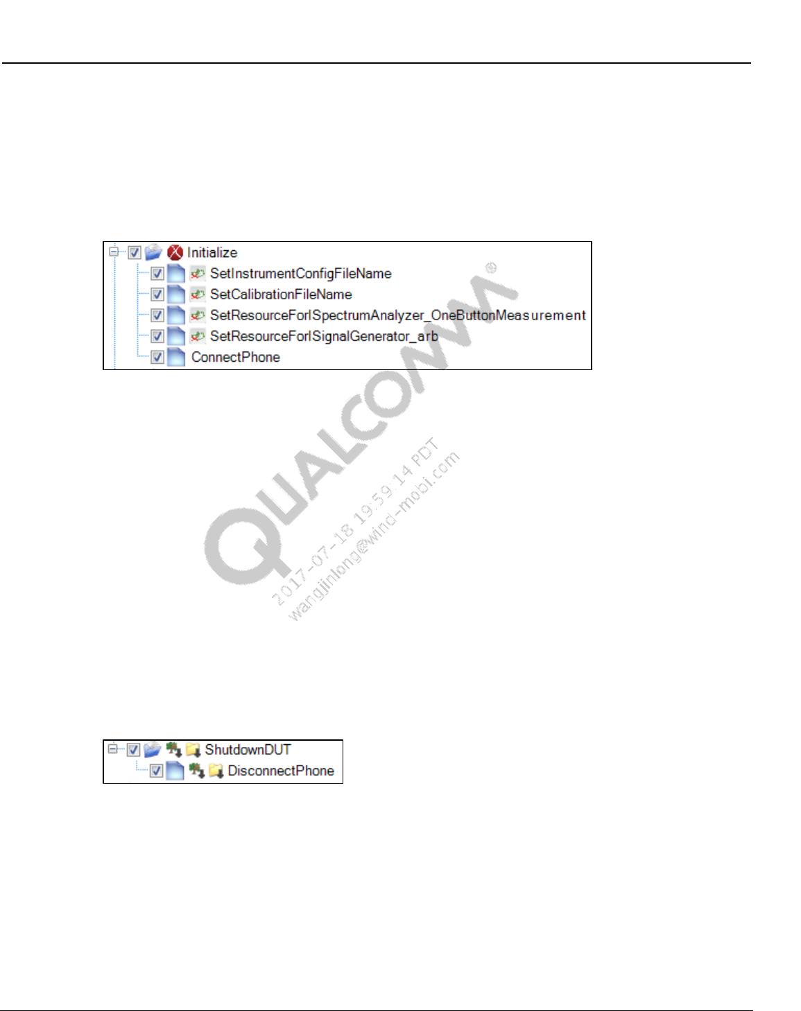
Wireless Connectivity Tests User Guide Test Setup Details
80-Y0306-1 Rev. L MAY CONTAIN U.S. AND INTERNATIONAL EXPORT CONTROLLED INFORMATION 90
Confidential and Proprietary – Qualcomm Atheros, Inc.
This test disconnects to the tester and releases any resources used by the tester
9.4 ANT setup and initialization tests
9.4.1 ANT initialization
Figure 9-18 Sample ANT test initialization
SetInstrumentConfigFileName
This test sets the ANT tester configuration file path
SetCalibrationFileName
This test sets the location of station calibration file used for ANT testing
SetResourceForISpectrumAnalyzer_OneButtonMeasurement
This test initializes the spectrum analyzer specified by the parameter “ResourceID”.
SetResourceForISignalGenerator_arb
This test initializes the signal generator specified by the parameter “ResourceID”.
ConnectPhone
This test connects to the device under test.
9.4.2 ANT De-initialization
Figure 9-19 Sample ANT test de-initialization
DisconnectPhone
This test disconnects from the DUT and closes QPST server
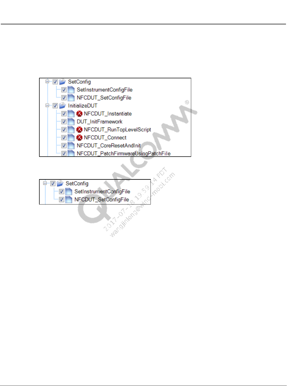
Wireless Connectivity Tests User Guide Test Setup Details
80-Y0306-1 Rev. L MAY CONTAIN U.S. AND INTERNATIONAL EXPORT CONTROLLED INFORMATION 91
Confidential and Proprietary – Qualcomm Atheros, Inc.
9.5 NFC initialization and deinitialization
This section describes the setup and initialization tests that need to be run before running any
functional tests.
This is a screen shot of the initialization section of the tree.
9.5.1 NFC setup config
SetInstrumentConfigFile
This test sets the path for the NFC tester/equipment config file and loads it. NFC testers (if
applicable) and power supply (if applicable)will be set by this config file.
NFCDUT_SetConfigFile
This test sets the path for the DUT configuration file and loads it. Config items related to the
DUT type (SoC/phone) and connection related parameters
9.5.2 NFC DUT configuration file details
NFC configuration file is installed at the following location
C:\Qualcomm\WCN\ProdTests\ConfigFiles\Sample\NFCDUTConfig.xml.
Copy NFCDUTConfig.xml to C:\Qualcomm\WCN\ProdTests\ConfigFiles\NFCDUTConfig.xml
before running QSPR NFC tests.
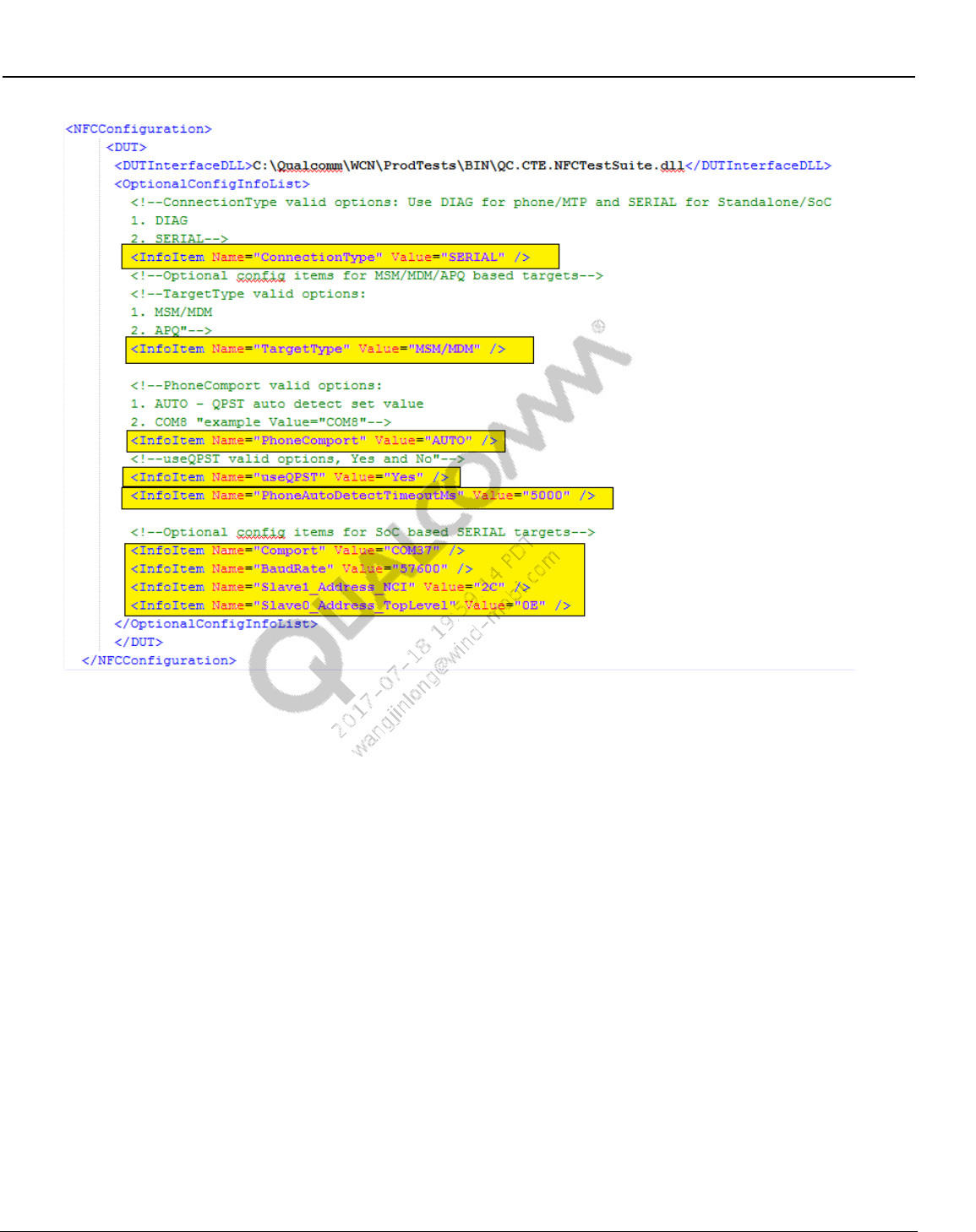
Wireless Connectivity Tests User Guide Test Setup Details
80-Y0306-1 Rev. L MAY CONTAIN U.S. AND INTERNATIONAL EXPORT CONTROLLED INFORMATION 92
Confidential and Proprietary – Qualcomm Atheros, Inc.
Figure 9-20 NFC DUT Configuration file
ConnectionType
This field configures the transport/protocol type for device under test. Valid options:
DIAG – MSM/MDM or APQ based targets
SERIAL – UART based devices (standalone EVK/EVB etc)
TargetType (Phone type DUT)
This option is only valid when ConnectionType is DIAG. Valid options:
MSM/MDM – when target type is MSM or MDM
APQ – when target type is APQ
PhoneComport (Phone type DUT)
This option is only valid when ConnectionType is DIAG. Valid options:
AUTO – auto detects the first available connected device
COMx – (example: COM23)
useQPST
This option is only valid when ConnectionType is DIAG. Valid options:
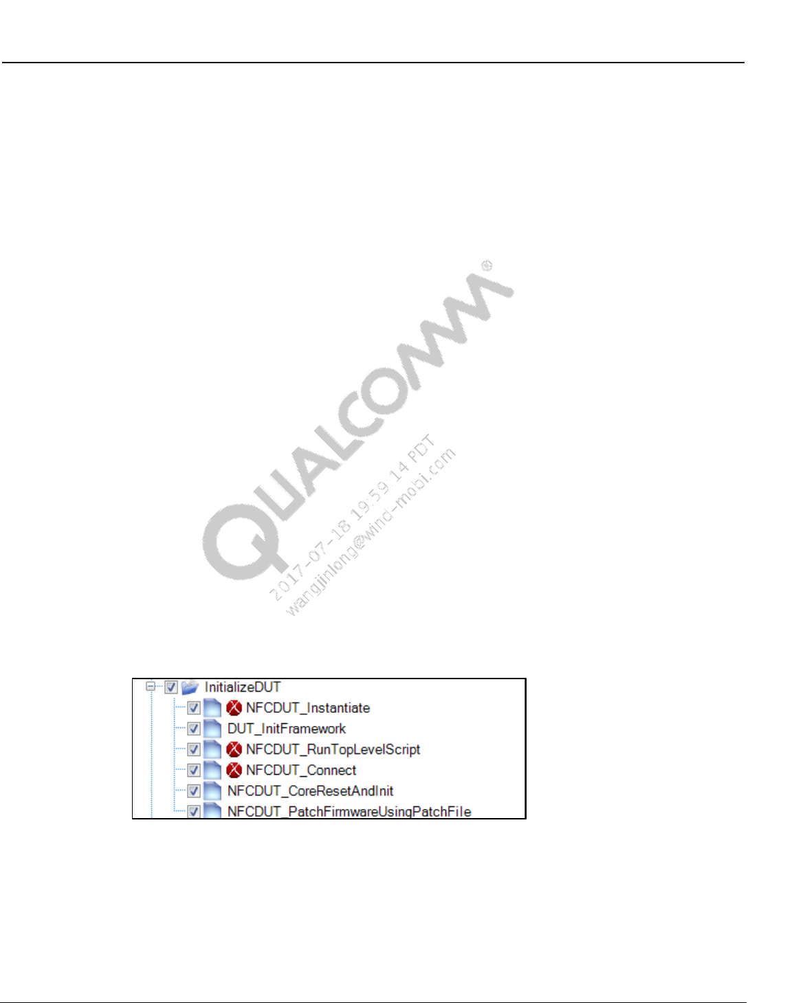
Wireless Connectivity Tests User Guide Test Setup Details
80-Y0306-1 Rev. L MAY CONTAIN U.S. AND INTERNATIONAL EXPORT CONTROLLED INFORMATION 93
Confidential and Proprietary – Qualcomm Atheros, Inc.
Yes
No
PhoneAutoDetectTimeoutMs
This option is only valid when ConnectionType is DIAG. This timeout is used for auto
detecting the COM port.
Comport (SoC only)
This option is only valid when ConnectionType is SERIAL. This port will be used to open
the NFC port on the device.
COMx (example: COM9)
BaudRate
This option is only valid when ConnectionType is SERIAL.
Device and PC support baud rate. Example : 57600
Slave1_Address_NCI
This option is only valid when ConnectionType is SERIAL. This is the I2C slave address (in
hex) used to send the NCI commands.
Device and PC support baud rate. Example : 2C
Slave0_Address_TopLevel
This option is only valid when ConnectionType is SERIAL. This is the I2C slave address in
hex used for I2C writes and for bring up script.
Device and PC support baud rate. Example : 0E
9.5.3 NFC DUT Initialization
NFCDUT_Instantiate
This test instantiates the DUT type as set in the config file.
DUT_InitFramework
This test starts up the test framework. This test also sets the path for the folder that contains
installed TCL files/binaries.
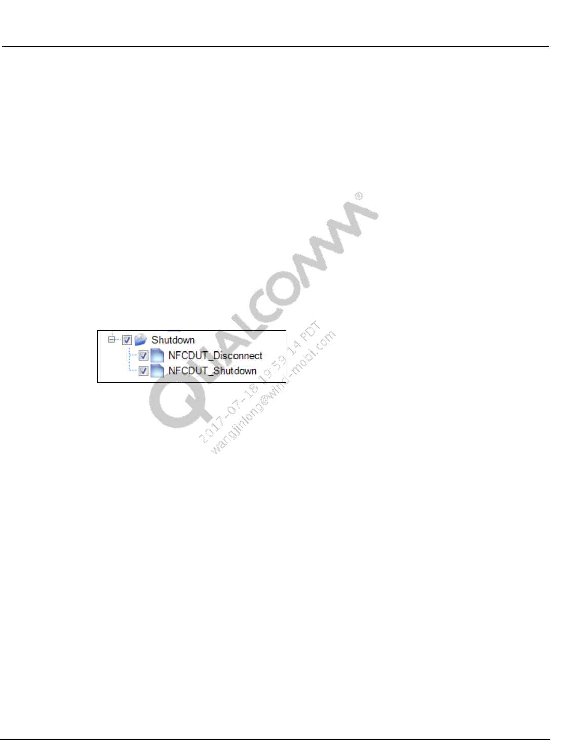
Wireless Connectivity Tests User Guide Test Setup Details
80-Y0306-1 Rev. L MAY CONTAIN U.S. AND INTERNATIONAL EXPORT CONTROLLED INFORMATION 94
Confidential and Proprietary – Qualcomm Atheros, Inc.
NFCDUT_RunTopLevelScript (only applicable to standalone device, if required by chipset)
This test runs the initialization TCL script to start up the development board.
NFCDUT_Connect
This test connect to the device under test using the connection details specified in the NFC
DUT config file.
NFCDUT_CoreResetAndInit
This test sends a NFC core reset command followed by a core init command. For phone type
DUT, NFC FTM daemon needs to be running for this test.
NFCDUT_PatchFirmwareUsingPatchFile (only applicable to standalone device, if required
by chipset)
This test sets firmware patch file location and downloads firmware patch to the device under
test.
9.5.4 NFC de-initialization
NFCDUT_Disconnect
This test disconnects the DUT and releases all the COM ports used by the test.
NFCDUT_Shutdown
This test releases all the resources used by the test suite framework.
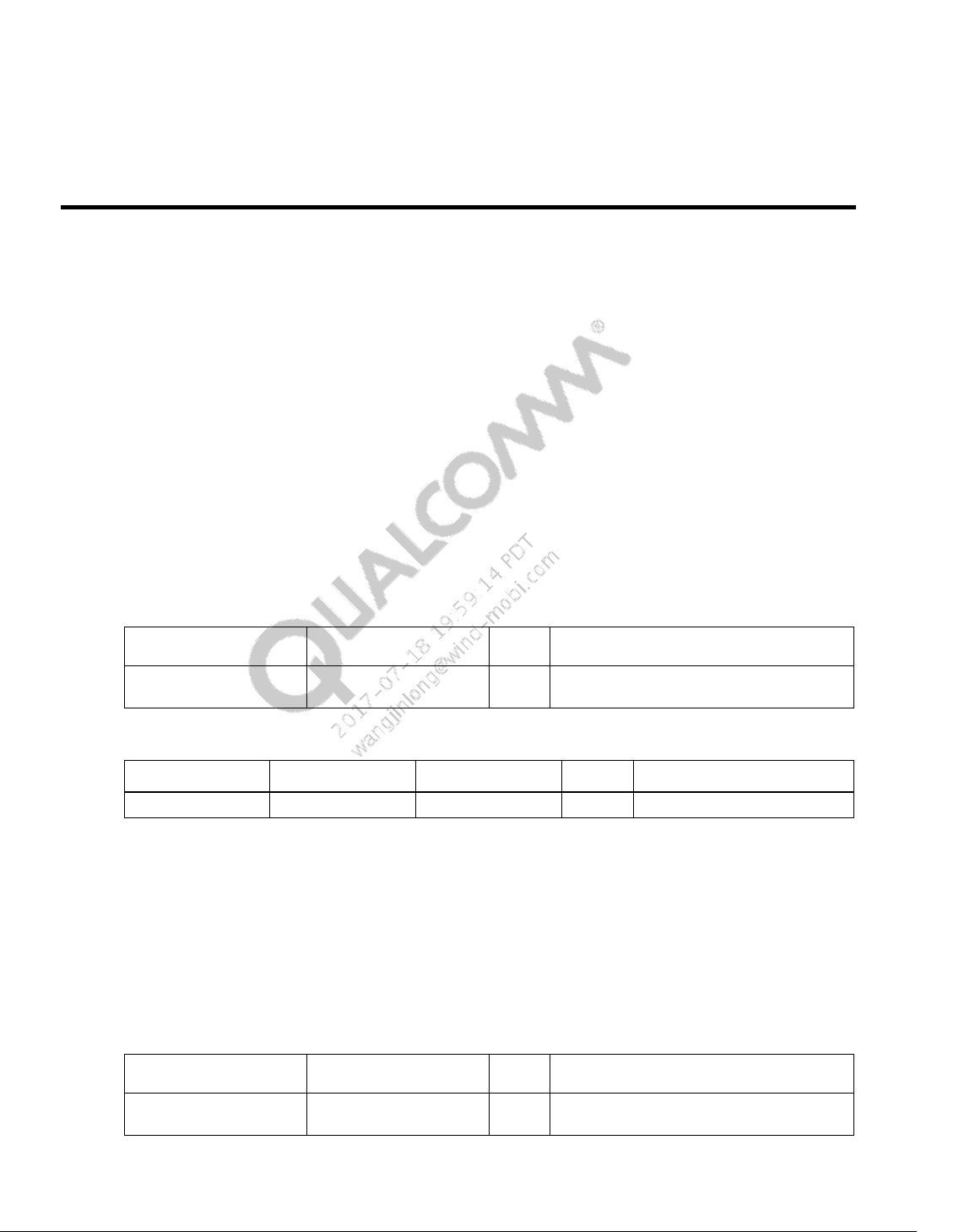
80-Y0306-1 Rev. L MAY CONTAIN U.S. AND INTERNATIONAL EXPORT CONTROLLED INFORMATION 95
Confidential and Proprietary – Qualcomm Atheros, Inc.
10 Wireless Connectivity Test Description
10.1 Bluetooth non-signaling production test description
This section summarizes limits and parameters captured for Bluetooth RF functional tests in
operations. All the productions Bluetooth tests are performed at three channels 0, 39, 78.
10.1.1 Set Bluetooth ChipID
This test is performed for configuring BT chip ID.
Table 10-1 and Table 10-2 list the input and output parameters for this test.
Test Name: BTDUT_SetBluetoothChipID
Test Condition: None
Table 10-1 Set Bluetooth ChipID input parameters
Parameter Name
Value
Unit
Description
BluetoothChipID
0
Bluetooth Chip ID = 0, for WCN2243 and
WCN36xx , = 3002, for AR3002 chipset
Table 10-2 Set Bluetooth ChipID output parameters
Parameter Name
Lower Limit
Upper Limit
Unit
Description
errorMessage
NA
error messages
10.1.2 BTDUT_FFA_DisableLegacyLogMode
This test is performed for supporting Bluetooth legacy log.
Table 10-3 and Table 10-4 list the input and output parameters for this test.
Test Name: BTDUT_FFA_DisableLegacyLogMode
Test Condition: None
Table 10-3 BTDUT_FFA_DisableLegacyLogMode input parameters
Parameter Name
Value
Unit
Description
disableLegacyLogMode
True
Disable legacy log mode = true, Enable
legacy log mode = false
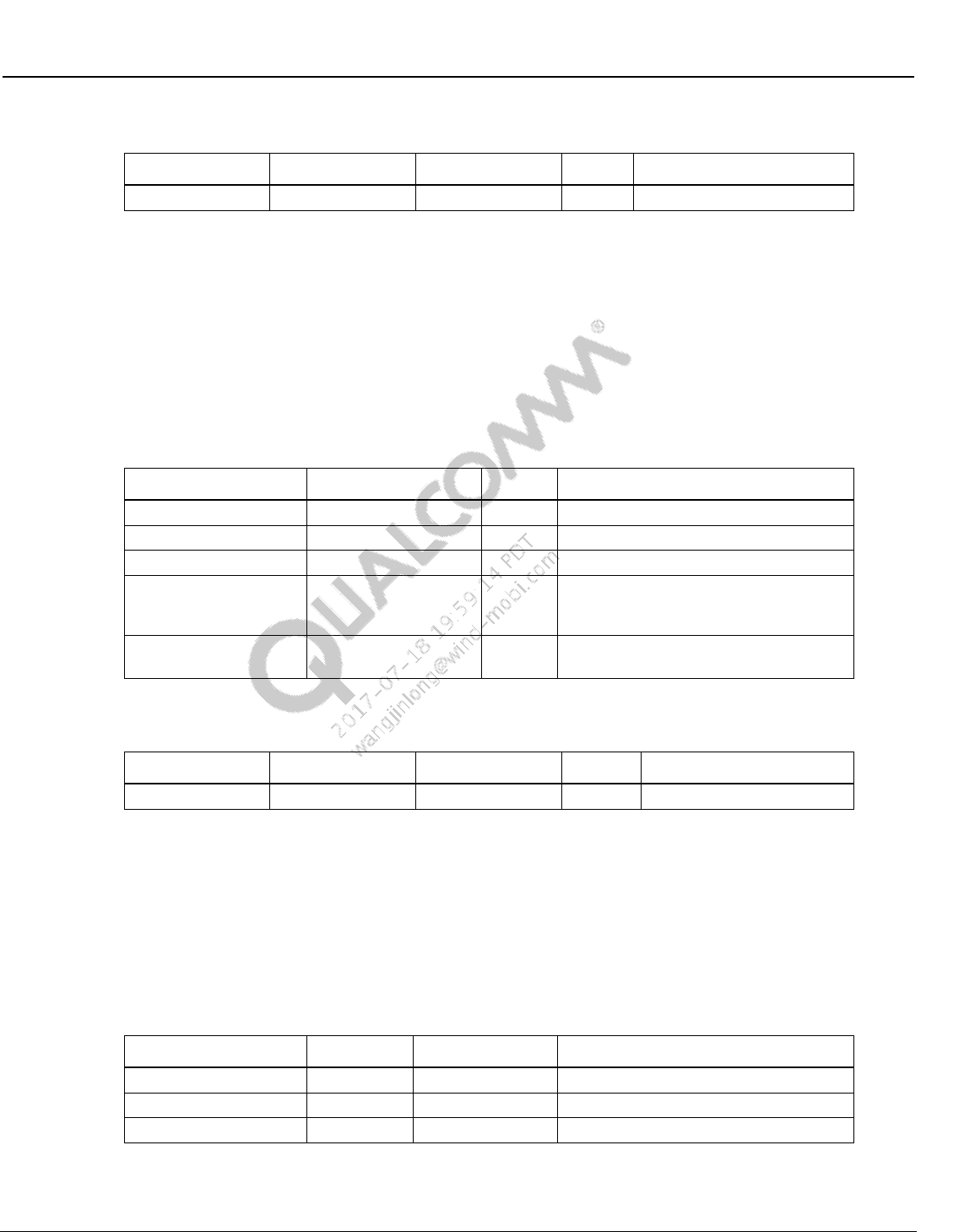
Wireless Connectivity Tests User Guide Wireless Connectivity Test Description
80-Y0306-1 Rev. L MAY CONTAIN U.S. AND INTERNATIONAL EXPORT CONTROLLED INFORMATION 96
Confidential and Proprietary – Qualcomm Atheros, Inc.
Table 10-4 BTDUT_FFA_DisableLegacyLogMode output parameters
Parameter Name
Lower Limit
Upper Limit
Unit
Description
errorMessage
NA
error messages
10.1.3 Setup DUT for GFSK and EDR transmit tests
This test is performed for configuring device under test for GFSK and EDR transmit tests.
Table 10-5 and Table 10-6 list the input and output parameters for this test.
Test Name: BTDUT_PROD_TEST_SUBCOMMAND_TEST_TX_BURST
Test Condition: Normal
Table 10-5 BTDUT_PROD_TEST_SUBCOMMAND_TEST_TX_BURST input
parameters
Parameter Name
Value
Unit
Description
TxChannel
0
NA
Channel range (0-78)
PacketType
BT_DH1
NA
Bluetooth packet type
TransmitPattern
PSEUDO_RANDOM
NA
Bluetooth transmit pattern
PowerLevel
9
NA
Bluetooth Power Level
(WCN36x0/WCN2243 = 0-9, AR3002 =
0-7
BluetoothAddress
BD,35,9C,BD,35,9C
NA
Bluetooth Address, comma separated,
example = BD,35,9C,BD,35,9C
Table 10-6 BTDUT_PROD_TEST_SUBCOMMAND_TEST_TX_BURST output
parameters
Parameter Name
Lower Limit
Upper Limit
Unit
Description
errorMessage
NA
error messages
10.1.4 Setup DUT for LE transmit tests
This test is performed for configuring device under test for LE transmit tests. Table 10-7 and
Table 10-8 list the input and output parameters for this test.
Test Name: BTDUT_LE_TX_Command
Test Condition: Normal
Table 10-7 BTDUT_LE_TX_Command input parameters
Parameter Name
Value
Unit
Description
TxChannel
0
NA
Tx Channel (Range - 0-78, even only)
PayloadLength
37
Byte(s)
Payload length
TransmitPattern
PN_9
NA
TransmitPattern
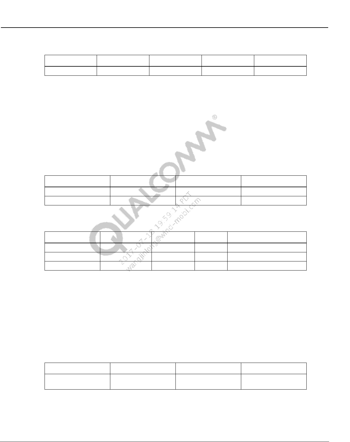
Wireless Connectivity Tests User Guide Wireless Connectivity Test Description
80-Y0306-1 Rev. L MAY CONTAIN U.S. AND INTERNATIONAL EXPORT CONTROLLED INFORMATION 97
Confidential and Proprietary – Qualcomm Atheros, Inc.
Table 10-8 BTDUT_LE_TX_Command output parameters
Parameter Name
Lower Limit
Upper Limit
Unit
Description
errorMessage
Error message
10.1.5 Measure Tx output power and initial carrier frequency tolerance
This test verifies and measures transmitter power and carrier frequency tolerance. Table 10-9 and
Table 10-10 list the input and output parameters for this test.
Test Name: Measure_OutputPower_InitialCarrierFrequencyTolerance
Test Condition: Normal
Loop Condition: Tx Channel
Table 10-9 Measure Tx output power and initial carrier frequency tolerance input
parameters
Parameter name
Value
Unit
Description
TxChannel
78
NA
TX channel (0-78)
PacketType
BT_DH1
NA
Bluetooth Packet Type
Table 10-10 Measure output power and initial carrier frequency tolerance output
parameters
Parameter Name
Lower Limit
Upper Limit
Unit
Description
errorMessage
error message from test
Power
-4
13
dBm
Transmit power in dBm
FrequencyDeviation
-75
75
KHz
Frequency deviation KHz
10.1.6 Measure GFSK modulation DeltaF2 and CarrierDrift
This test verifies and measures transmitter delta F2 and carrier frequency drift. Table 10-11 and
Table 10-12 list the input and output parameters for this test.
Test Name: Measure_GFSK_Modulation_DeltaF2_CarrierDrift
Test Condition: Normal
Loop Condition: Tx Channel
Table 10-11 Measure GFSK modulation DeltaF2 and CarrierDrift input parameters
Parameter Name
Value
Unit
Description
TxChannel
78
NA
Bluetooth Tx Channel
(0-78)
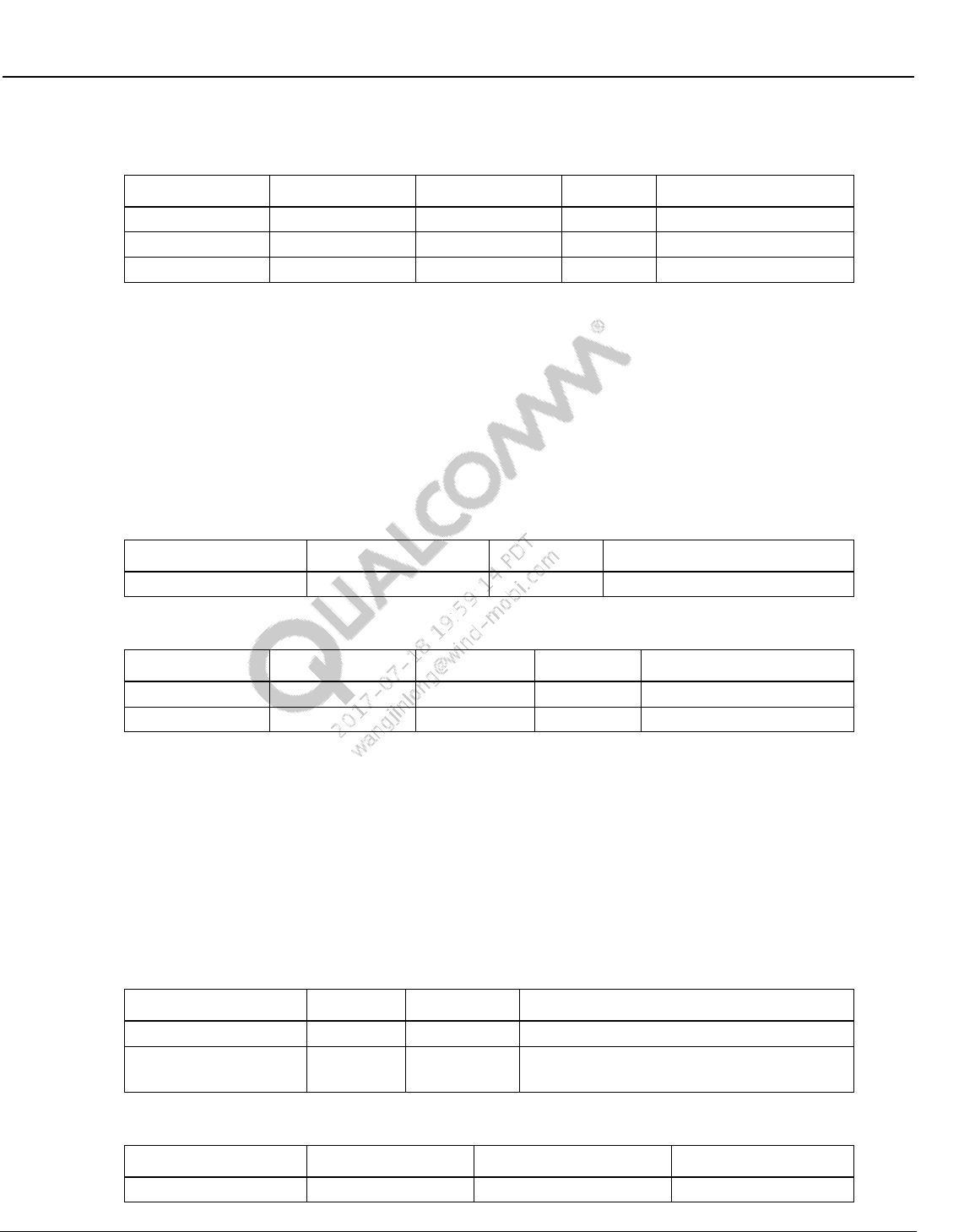
Wireless Connectivity Tests User Guide Wireless Connectivity Test Description
80-Y0306-1 Rev. L MAY CONTAIN U.S. AND INTERNATIONAL EXPORT CONTROLLED INFORMATION 98
Confidential and Proprietary – Qualcomm Atheros, Inc.
Table 10-12 Measure GFSK modulation DeltaF2 and CarrierDrift output
parameters
Parameter Name
Lower Limit
Upper Limit
Unit
Description
errorMessage
error message from test
DeltaF2Max
115
300
KHz
Delta F2 Max in KHz
FrequencyDrift
-40
45
KHz
Frequency drift in KHz
10.1.7 Measure GFSK modulation DeltaF1
This test verifies and measures transmitter delta F1. Table 10-13 and Table 10-14 list the input
and output parameters for this test.
Test Name: Measure_GFSK_Modulation_DeltaF1
Test Condition: Normal
Loop Condition: Tx Channel
Table 10-13 Measure GFSK modulation DeltaF1 input parameters
Parameter Name
Value
Unit
Description
TxChannel
78
NA
Bluetooth Tx Channel (0-78)
Table 10-14 Measure GFSK modulation DeltaF1 output parameters
Parameter Name
Lower Limit
Upper Limit
Unit
Description
errorMessage
error message from test
DeltaF1Average
140
175
KHz
Delta F1 in KHz
10.1.8 Measure EDR modulation
This test verifies and measures transmitter average and peak DEVM. Table 10-15 and Table 10-
16 list the input and output parameters for this test.
Test Name: Measure_EDRModulation
Test Condition: Normal
Loop Condition: Tx Channel
Table 10-15 Measure EDR modulation input parameters
Parameter Name
Value
Unit
Description
TxChannel
0
NA
Bluetooth Tx Channel (0-78)
PacketType
BT_2_DH5
NA
Bluetooth Packet Type
This test is only valid for EDR packet types.
Table 10-16 Measure EDR modulation output parameters
Parameter Name
Lower Limit
Upper Limit
Unit
errorMessage
Wireless Connectivity Tests User Guide Wireless Connectivity Test Description
80-Y0306-1 Rev. L MAY CONTAIN U.S. AND INTERNATIONAL EXPORT CONTROLLED INFORMATION 99
Confidential and Proprietary – Qualcomm Atheros, Inc.
Parameter Name
Lower Limit
Upper Limit
Unit
EDRAverageDEVM
0
0.2
EDRPeakDEVM
0
0.35
10.1.9 Measure LE Tx output power
This test verifies and measures LE transmitter power. Table 10-17 and Table 10-18 list the input
and output parameters for this test.
Test Name: Measure_LE_TxOutputPower
Test Condition: Normal
Loop Condition: Tx Channel
Table 10-17 Measure LE Tx output power input parameters
Parameter Name
Value
Unit
Description
TxChannel
0
NA
TX Channel, only even channel in BLE
Table 10-18 Measure LE Tx output power output parameters
Parameter Name
Lower Limit
Upper Limit
Unit
Description
errorMessage
error message from test
AvgPower
-4
15
dBm
Average LE Power in dBm
10.1.10 Measure LE modulation DeltaF1
This test verifies and measures LE transmitter delta F1. Table 10-19 and Table 10-20 list the
input and output parameters for this test.
Test Name: Measure_LE_Modulation_DeltaF1
Test Condition: Normal
Loop Condition: Tx Channel
Table 10-19 Measure LE modulation DeltaF1 input parameters
Parameter Name
Value
Unit
Description
TxChannel
0
NA
TX Channel, only even channel in BLE
Table 10-20 Measure LE modulation DeltaF1 output parameters
Parameter Name
Lower Limit
Upper Limit
Unit
Description
errorMessage
error message from test
DeltaF1Average
225
275
KHz
Delta F1 average in KHz
Wireless Connectivity Tests User Guide Wireless Connectivity Test Description
80-Y0306-1 Rev. L MAY CONTAIN U.S. AND INTERNATIONAL EXPORT CONTROLLED INFORMATION 100
Confidential and Proprietary – Qualcomm Atheros, Inc.
10.1.11 Measure LE modulation DeltaF2, FreqOffset, FreqDrift and
MaxDriftRate
This test verifies and measures LE transmitter delta F2, frequency offset, frequency drift and max
drift rate. Table 10-21 and Table 10-22 list the input and output parameters for this test.
Test Name: Measure_LE_Modulation_DeltaF2_FreqOffset_FreqDrift_MaxDriftRate
Test Condition: Normal
Loop Condition: Tx Channel
Table 10-21 Measure LE modulation DeltaF2, FreqOffset, FreqDrift and
MaxDriftRate input parameters
Parameter Name
Value
Unit
Description
TxChannel
0
NA
TX Channel, only even channel in BLE
Table 10-22 Measure LE modulation DeltaF2, FreqOffset, FreqDrift and
MaxDriftRate output parameters
Parameter Name
Lower Limit
Upper Limit
Unit
Description
errorMessage
error message from test
DeltaF2
185
500
kHz
Delta F2 in kHz
FrequencyOffset
-150
150
kHz
FrequencyOffset
FrequencyDrift
-50
50
kHz
Frequency drift
MaxDriftRate
0
20
kHz/μs
Max drift rate
10.1.12 Measure Rx sensitivity/max input
This test verifies sensitivity/Max Input at a given power and measures BER %. Table 10-23 and
Table 10-24 list the input and output parameters for this test.
Test Name: Measure_RxSensitivity
Test Condition: Normal
Loop Condition: Rx Channel
Table 10-23 Measure Rx sensitivity input parameters
Parameter Name
Value
Unit
Description
RxChannel
0
RX channel (0-78)
StartPowerdBm
-70
dBm
Start Test RX power from VSG,
if Start and Stop are same it acts
like GoNoGo
StopPowerdBm
-70
dBm
Stop Test RX power from VSG, if
Start and Stop are same it acts
like GoNoGo
PacketType
BT_DH5
NA
Bluetooth Packet Type
MinimumCoarseNumberOfPackets
100
NA
Minimum coarse number of
packets required for test
Wireless Connectivity Tests User Guide Wireless Connectivity Test Description
80-Y0306-1 Rev. L MAY CONTAIN U.S. AND INTERNATIONAL EXPORT CONTROLLED INFORMATION 101
Confidential and Proprietary – Qualcomm Atheros, Inc.
Parameter Name
Value
Unit
Description
MinimumFineNumberOfPackets
1000
NA
Minimum fine number of packets
required for test
fineStepSize
0.5
dB
step size for BER fine search
loop
coarseStepSize
1
dB
step size for BER coarse search
loop
ReceiverTestType
Sensitivity
NA
RX Test Type:
Sensitivity
MaxInput
Table 10-24 Measure RxSensitivity output parameters
Parameter Name
Lower Limit
Upper Limit
Unit
Description
errorMessage
Error message
BER
0
0.1
%
BER in percent
RxSensitivityPowerdBm
-70
-70
dBm
Sensitivity level
10.1.13 Measure LE Rx sensitivity/max input
This test verifies sensitivity/Max input at a given power and measures PER %. Table 10-25 and
Table 10-26 list the input and output parameters for this test.
Test Name: Measure_LE_RxSensitivity
Test Condition: Normal
Loop Condition: Rx Channel
Table 10-25 Measure LE Rx sensitivity input parameters
Parameter Name
Value
Unit
Description
RxChannel
0
RX channel (0-78),only even
channels in BLE
StartPowerdBm
-70
dBm
Start Test RX power from VSG,
if Start and Stop are same it acts
like GoNoGo
StopPowerdBm
-70
dBm
Stop Test RX power from VSG, if
Start and Stop are same it acts
like GoNoGo
CoarseNumberOfPackets
500
Minimum coarse number of
packets required for test
FineNumberOfPackets
2000
Minimum fine number of packets
required for test
fineStepSize
0.5
dB
step size for PER fine search
loop
coarseStepSize
2.0
dB
step size for PER coarse search
loop
WaveformKey
LE1a
NA
Waveform key in the tester
config XML file
Wireless Connectivity Tests User Guide Wireless Connectivity Test Description
80-Y0306-1 Rev. L MAY CONTAIN U.S. AND INTERNATIONAL EXPORT CONTROLLED INFORMATION 102
Confidential and Proprietary – Qualcomm Atheros, Inc.
Parameter Name
Value
Unit
Description
PacketIntegrity
False
LE packet integrity is on or off,
not valid if using waveforms
ReceiverTestType
Sensitivity
RX Test Type: :
Sensitivity
MaxInput
Dirty
0
Dirty mode, not valid if using
waveforms
Table 10-26 Measure LE Rx sensitivity output parameters
Parameter Name
Lower Limit
Upper Limit
Unit
Description
errorMessage
Error message
BER
0
0.1
%
BER in percent
RxSensitivityPower
-70
-70
dBm
Rx Sensitivity in dBm
10.1.14 Set BTDUT_PROD_TEST_SUBCOMMAND_TEST_RX_BURST
This test configures the device under tests in receive mode for performing non-signaling Rx tests.
Table 10-27 and Table 10-28 list the input and output parameters for this test., if tests can be used
to configure AR3002 receiver.
Test Name: BTDUT_PROD_TEST_SUBCOMMAND_TEST_RX_BURST
Test Condition: Normal
Table 10-27 BTDUT_PROD_TEST_SUBCOMMAND_TEST_RX_BURST input
parameters
Parameter Name
Value
Unit
Description
RxChannel
0
NA
Channel range (0-78))
BluetoothAddress
BD,35,9C,BD,35,
9C
NA
Bluetooth Address, comma
separated, example =
BD,35,9C,BD,35,9C
PacketType
15
NA
Bluetooth packet type
LTAddress
0
NA
Bluetooth LT/AM Address
Table 10-28 BTDUT_PROD_TEST_SUBCOMMAND_TEST_RX_BURST output
parameters
Parameter Name
Lower Limit
Upper Limit
Unit
Description
errorMessage
Error message
10.1.15 BTDUT_PROD_TEST_HCI_GET_PER_AR3002
NOTE: This test is only valid when ChipID = 3002
This test verifies gets receiver statistics from device under tests. Table10-29 and Table 10-30 list
the input and output parameters for this test.
Wireless Connectivity Tests User Guide Wireless Connectivity Test Description
80-Y0306-1 Rev. L MAY CONTAIN U.S. AND INTERNATIONAL EXPORT CONTROLLED INFORMATION 103
Confidential and Proprietary – Qualcomm Atheros, Inc.
Test Name: BTDUT_PROD_TEST_HCI_GET_PER_AR3002
Test Condition: Normal
Table10-29 BTDUT_PROD_TEST_HCI_GET_PER_AR3002 input parameters
Parameter Name
Value
Unit
Description
PacketType
BT_DH5
Bluetooth packet type
Table 10-30 BTDUT_PROD_TEST_HCI_GET_PER_AR3002 output parameters
Parameter Name
Lower Limit
Upper Limit
Unit
Description
errorMessage
error message
from test
PacketsReceived
NA
Total packets
received
PacketsWithCRCErrors
NA
Total CRC
packets received
10.2 WLAN production test description (SISO Only)
10.2.1 SetUpDutTx
Table 10-31 SetUpDutTx parameters
Parameter Name
Value
Unit
Description
channel
1
WLAN Channel
cbState
0 none
Channel Bonding State 0:HT20, 1-3:HT40, 4-
10:VHT80
Rate
3
RATE_11MBs
TX Data Rate
Short11b_nGuard
False
boolean
True: 11b short or 11n/11ac short guard
pwrMode
2 SCPC
TX Power Control Mode
powerLevel
10.0
dBm
TX Power Level
gain
2
unitless
RF Gain (open loop power control mode only)
digitalGain
0
unitless
Digital Gain (open loop power control mode
only)
dpdMode
False
boolean
True: Enable DPD (WCN36x0 targets only)
payloadSize
500
bytes
Payload size in bytes
txChain
1
TX Chain to transmit on
10.2.2 WlanTxEvmTest
This test measures transmit modulation accuracy. Table 10-32 and Table 10-33 list the input and
output parameters for this test.
Test Name: WlanTxEvmTest
Test Condition: Normal
Wireless Connectivity Tests User Guide Wireless Connectivity Test Description
80-Y0306-1 Rev. L MAY CONTAIN U.S. AND INTERNATIONAL EXPORT CONTROLLED INFORMATION 104
Confidential and Proprietary – Qualcomm Atheros, Inc.
Loop Condition: Channel, Rate
Test Equipment: “LitePoint IQ2010, “LitePoint IQxel”, Rohde & Schwarz CMW500”, “NI
PXI5644R”, Agilent 4010A”
Table 10-32 TX EVM test input parameters
Parameter Name
Value
Unit
Description
channel
1
WLAN Channel
powerLevel
10.0
dBm
TX Power Level
wlanRate
16
WLAN_RATE
WLAN Rate Enums
chEstimationMethod
preambleOnly
ChannelEstimationOption Enums
numOfMIMOStream
1
unitless
Number of MIMO steams
numAverages
3
number of averages
vsaTriggerLevel
-20
dB
VSA trigger Level
Table 10-33 TX EVM test output parameters
Parameter Name
Lower Limit
Upper Limit
Unit
Description
evm
-100
-25
dBm
TX EVM
amplErr
dB
TX Amplitude Error
dataRateMB
1
135
Mbs
TX Data Rate
symbolClockError
PPM
TX Symbol Clock Error
freqErr
-20
20
PPM
TX Frequency Error
phaseErr
PPM
TX Phase Error
avgTxPower
7
13
dBm
Average TX Power
avgTxPowerDelta
-2
2
dB
TX Power Accuracy
loLeakage
-120
-15
dB
LO Leakage
10.2.3 WlanTxVerifySpectrumTest
This test measures transmit spectrum in terms of carrier center frequency leakage and spectral
flatness. Table 10-34 and Table 10-35 list the input and output parameters for this test.
Test Name: WlanTxVerifySpectrumTest
Test Condition: Normal
Loop Condition: Channel, Rate
Test Equipment: “LitePoint IQ2010, “LitePoint IQxel”, Rohde & Schwarz CMW500”, “NI
PXI5644R”, Agilent 4010A”
Table 10-34 TxVerifySpectrum test input parameters
Parameter Name
Value
Unit
Description
channel
1
WLAN Channel
powerLevel
10.0
dBm
TX Power Level
wlanRate
16
WLAN_RATE
WLAN Rate Enums
chEstimationMethod
preambleOnly
ChannelEstimationOption Enums
Wireless Connectivity Tests User Guide Wireless Connectivity Test Description
80-Y0306-1 Rev. L MAY CONTAIN U.S. AND INTERNATIONAL EXPORT CONTROLLED INFORMATION 105
Confidential and Proprietary – Qualcomm Atheros, Inc.
Parameter Name
Value
Unit
Description
numOfMIMOStream
1
Number of MIMO steams
vsaTriggerLevel
-20
dB
VSA trigger Level
Table 10-35 TxVerifySpectrum test output parameters
Parameter Name
Lower Limit
Upper Limit
Unit
Description
carrierNumber
-52
52
Number of Carriers
flatnessMargin
-4
2
dB
Average Power Flatness over
spectrum
loLeakage
-120
-15
dBm
LO Leakage
avgTxPower
7
13
dBm
Average TX Power
10.2.4 WlanTxVerifyPowerTest
This test measures transmit power levels. It measures the maximum, minimum and average TX
power and maximum, minimum and average peak Tx power. Table 10-36 and Table 10-37 list
the input and output parameters for this test.
Test Name: WlanTxVerifyPowerTest
Test Condition: Normal
Loop Condition: Channel, Rate
Test Equipment: “LitePoint IQ2010, “LitePoint IQxel”, Rohde & Schwarz CMW500”, “NI
PXI5644R”, Agilent 4010A”
Table 10-36 Tx verify power test input parameters
Parameter Name
Value
Unit
Description
channel
1
WLAN Channel
powerLevel
10.0
dBm
TX Power Level
wlanRate
16
WLAN_RATE
WLAN Rate Enums
numOfMIMOStream
1
unitless
Number of MIMO steams
vsaTriggerLevel
-20
dB
VSA trigger Level
Table 10-37 TX verify power test output parameters
Parameter Name
Lower Limit
Upper Limit
Unit
Description
txPowerAvg
dBm
Average TX Power
txPowerAvgDelta
-2
2
dB
TX Power Accuracy
txPowerMax
dBm
Maximum TX Power
txPowerMin
dBm
Minimum TX Power
txPowerPeak
dBm
Average Peak TX Power
txPowerPeakMax
dBm
Maximum Peak TX Power
txPowerPeakMin
dBm
Minimum Peak TX Power
cableLoss
dBm
Path loss (from cable)
Wireless Connectivity Tests User Guide Wireless Connectivity Test Description
80-Y0306-1 Rev. L MAY CONTAIN U.S. AND INTERNATIONAL EXPORT CONTROLLED INFORMATION 106
Confidential and Proprietary – Qualcomm Atheros, Inc.
10.2.5 WlanTxVerifyMaskTest
This test measures transmit spectrum mask; it reports whether the WLAN transmit spectrum
complies or fails with the standard WLAN mask. It will also output the worst failure margins and
their associated frequencies. Table 10-38 and Table 10-39 list the input and output parameters for
this test. Note: This test generates a lot of data. “Out of Memory” errors can occur in QSPR if this
test is executed excessively in a loop.
Test Name: WlanTxVerifySpectrumTest
Test Condition: None
Loop condition: Channel, Rate
Test Equipment: “LitePoint IQ2010, “LitePoint IQxel”, Rohde & Schwarz CMW500”, “NI
PXI5644R”, Agilent 4010A”
Table 10-38 TxVerifyMask test input parameters
Parameter Name
Value
Unit
Description
channel
1
WLAN Channel
powerLevel
10.0
dBm
TX Power Level
wlanRate
16
WLAN_RATE
WLAN Rate Enums
numOfMIMOStream
1
unitless
Number of MIMO steams
vsaTriggerLevel
-25
dB
VSA trigger Level
Table 10-39 TxVerifyMask output parameters
Parameter Name
Lower Limit
Upper Limit
Unit
Description
maskPass
Pass/Fail WLAN Mask
violationPct
Percentage of the mask that
fails
avgTxPower
7
13
dBm
Average TX Power
spectrum
Spectrum Magnitude Array
spectrumFreqs
Spectrum Frequency Array
Mask
Mask Magnitude Array
MaskFreqs
Mask Frequency Array
10.2.6 WlanPerTest
This test measures receiver minimum input sensitivity. It measures the PER of the receiver at the
minimum input sensitivity level: -69 dBm for 2.4GHz; -65 dBm for 5GHz. Table 10-40 and
Table 10-41 list the input and output parameters for this test.
Test Name: WlanPerTest
Test Condition: None
Loop Condition: Channel
Test Equipment: “LitePoint IQ2010, “LitePoint IQxel”, Rohde & Schwarz CMW500”, “NI
PXI5644R”, Agilent 4010A”
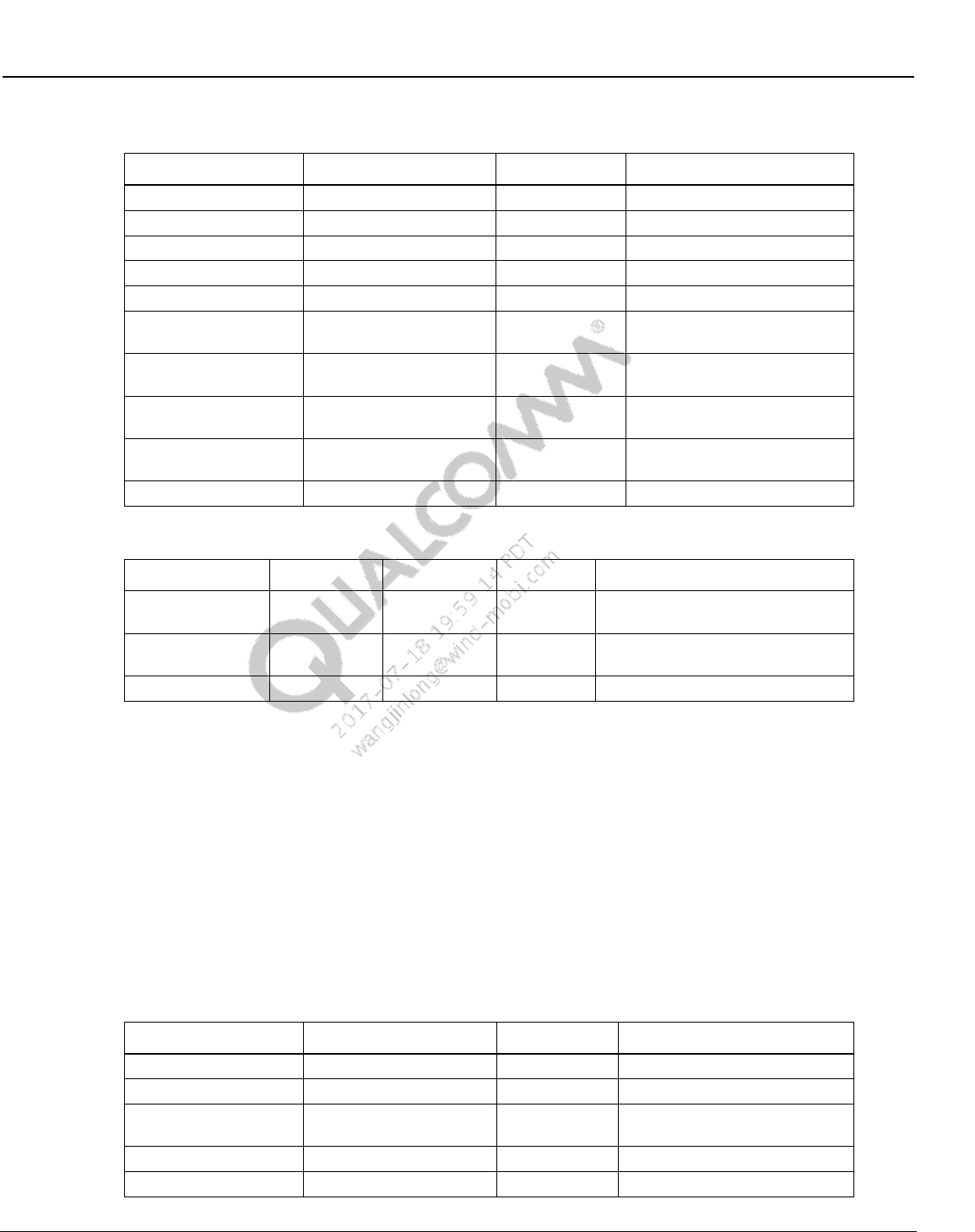
Wireless Connectivity Tests User Guide Wireless Connectivity Test Description
80-Y0306-1 Rev. L MAY CONTAIN U.S. AND INTERNATIONAL EXPORT CONTROLLED INFORMATION 107
Confidential and Proprietary – Qualcomm Atheros, Inc.
Table 10-40 WLAN Per test input parameters
Parameter Name
Value
Unit
Description
startPower
-69
dBm
PER Search Start Power
stopPower
-69
dBm
PER Search Stop Power
channel
7
WLAN Channel
rate
RATE_11N_HT20_MCS7
WLAN_RATE
WLAN Rate Enums
wlanMode
2
WLAN_MODE
WLAN Mode Enums
coursePktCount
2000
number of packets for PER
coarse search loop
finePktCount
10000
number of packets for PER
fine search loop
coarseStepSize
2.0
dB
step size for PER coarse
search loop
fineStepSize
0.5
dB
step size for PER fine search
loop
rxChain
1
Rx Chain to test
Table 10-41 WLAN Per test output parameters
Parameter Name
Lower Limit
Upper Limit
Unit
Description
PER
0
10
%
PER at Per Power; must define
Upper Limit
PerPower
-100
0
dBm
Power at which reported PER is
measured
Rssi
-100
0
dBm
Received Signal Strength Indicator
10.2.7 WlanPerSweepTest
This test sweeps receiver’s power with a specified step, measures receiver PER at each input
power steps.
Table 10-42 and Table 10-43 list the input and output parameters for this test.
Test Name: WlanPerSweepTest
Test Condition: None
Loop Condition: Channel
Test Equipment: LitePoint IQ2010 “,“LitePoint IQxel”, “NI PXI5644R”
Table 10-42 WLAN PerSweepTest input parameters
Parameter Name
Value
Unit
Description
startPower
-50
dBm
PER Search Start Power
stopPower
-90
dBm
PER Search Stop Power
channel
7
WLAN Channel number or
FreqMHz
rate
RATE_11N_HT20_MCS7
WLAN_RATE
WLAN Rate Enums
channelBonding
2
WLAN_MODE
WLAN Mode Enums
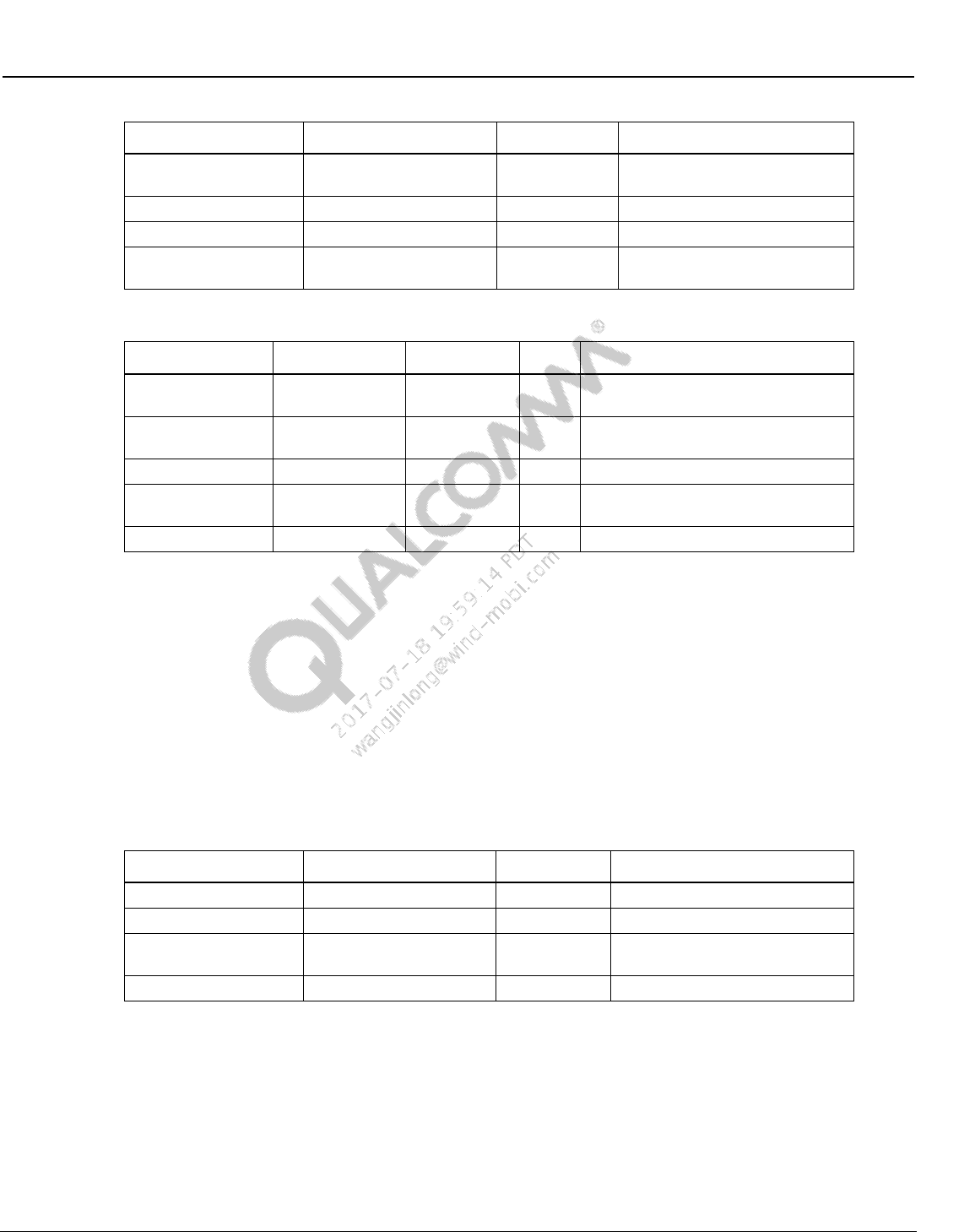
Wireless Connectivity Tests User Guide Wireless Connectivity Test Description
80-Y0306-1 Rev. L MAY CONTAIN U.S. AND INTERNATIONAL EXPORT CONTROLLED INFORMATION 108
Confidential and Proprietary – Qualcomm Atheros, Inc.
Parameter Name
Value
Unit
Description
pktCount
200
number of packets for PER
sweep
stepSize
-2.0
dB
step size for PER sweep
rxChain
1
Rx ChainMask to test
perLimit
10
PER limit to compute min and
max passed power
Table 10-43 WLAN PerSweepTest output parameters
Parameter Name
Lower Limit
Upper Limit
Unit
Description
allMeasuredPERs
0
10
%
PER at Per Power; must define
Upper Limit
allPerPowers
-110
0
dBm
Power at which reported PER is
measured
allMeasuredRssis
-100
0
dBm
Received Signal Strength Indicator
minPassPerPower
-100 (rate
dependent)
0
dBm
Min power for PER within upperLimit
maxPassPerPower
-100
0
dBm
Max power for PER within upperLimit
10.2.8 WlanSendRxPacketsTest
This test set VSG to Tx number of packets (numPackets) at specified power level
Table 10-44 list the input parameters for this test.
Test Name: WlanSendRxPacketsTest
Test Condition: None
Loop Condition: Channel
Test Equipment: LitePoint IQ2010 “,“LitePoint IQxel”, “NI PXI5644R”
Table 10-44 WLAN PerSweepTest input parameters
Parameter Name
Value
Unit
Description
Power
-60
dBm
VSG Tx Power level
numPackets
1000
Number of packets to send
channel
5210
WLAN Channel number or
FreqMHz
rate
RATE_11N_HT20_MCS7
WLAN_RATE
WLAN Rate Enums
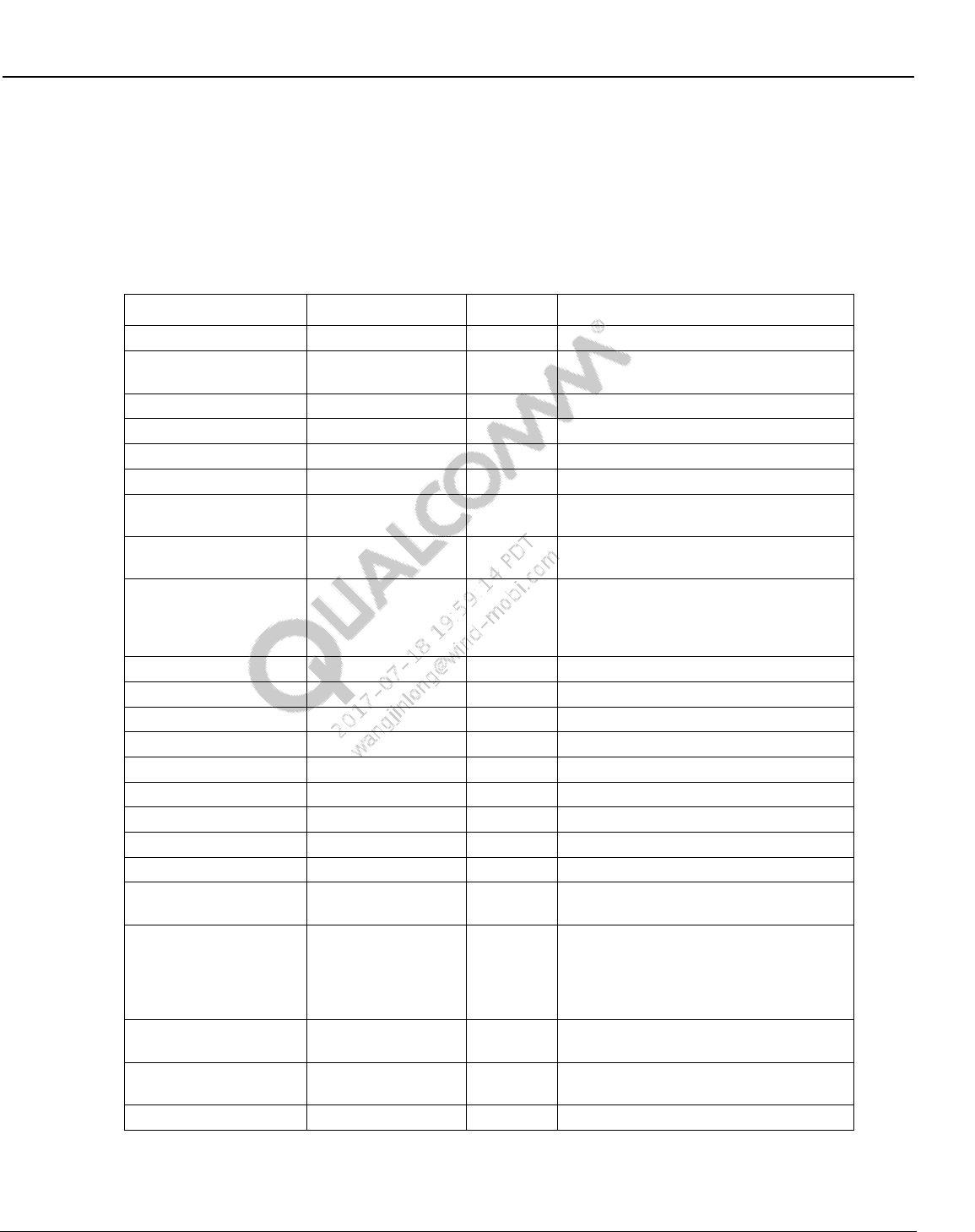
Wireless Connectivity Tests User Guide Wireless Connectivity Test Description
80-Y0306-1 Rev. L MAY CONTAIN U.S. AND INTERNATIONAL EXPORT CONTROLLED INFORMATION 109
Confidential and Proprietary – Qualcomm Atheros, Inc.
10.3 WLAN production test description (MIMO or SISO)
10.3.1 SetUpDutTxDetails
Only applicable to QC98xx, QCA6174
Table 10-45 SetUpDutTxDetails parameters
Parameter Name
Value
Unit
Description
channel
1
WLAN Channel
cbState
0 none
Channel Bonding State 0:HT20, 1-
3:HT40, 4-10:VHT80
Rate
3 RATE_11MBs
TX Data Rate
pwrMode
2 SCPC
TX Power Control Mode
txMode
3 ContTx99
Tx Mode
txChainMask
3 WLAN_CHAIN_12
Tx ChainMask to turn on
powerLevel
10.0
dBm
TX Power Level dBm, only for pwrMode
set as one of TxPowerForce
gain
2
unitless
gain index only for pwrMode set as
ForcedGain or ForcedDesiredGain
digitalGain
0
unitless
Digital Gain (open loop power control
mode only) dacGain only for pwrMode
set as ForcedGain or
ForcedDesiredGain
PAcfg
0
PA configuration only for QCA6174
payloadSize
1500
bytes
Payload size in bytes
Short11b_nGuard
False
boolean
True: 11b short or 11n/11ac short guard
ldpcRate
False
boolean
True if this is an 11n or 11ac LDPC rate
stbcMode
False
boolean
True if this is an 11n or 11ac stbc mode
aggregation
1
1 to 31
aggregation
dpdMode
Disable
boolean
Enable/Disable PA predistortion
Ifs
1
byte
Interframe space
dutyCycle
10
byte
dutyCycle percentage (not programmed
in this release)
nPattern
4
byte
data frame data pattern enum. If >=6,
data frame will be user defined in pattern
with length of nPattern
(nPattern>=6 not programmed in this
release)
Pattern
1
byte
Used when nPattern >=6, user defined
data pattern with length of nPattern
nPacket
0
byte
0 for continuous Tx
>0 for number of packets Tx send
broadcastMode
True
boolean
True: BroadCastMode
pwrMode
ForcedGain 0 TPC_FORCED_GAINIDX = 4
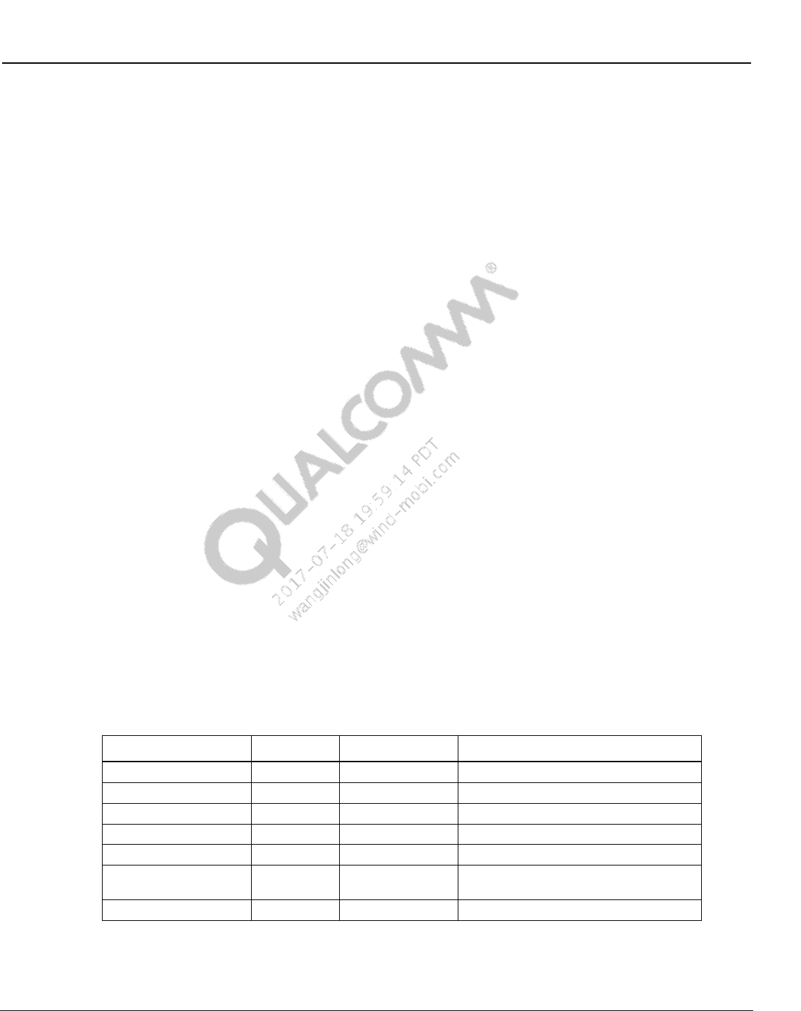
Wireless Connectivity Tests User Guide Wireless Connectivity Test Description
80-Y0306-1 Rev. L MAY CONTAIN U.S. AND INTERNATIONAL EXPORT CONTROLLED INFORMATION 110
Confidential and Proprietary – Qualcomm Atheros, Inc.
OpenLoopSearch 1 not used
TxPowerAuto 2 TPC_TGT_PWR = 1
TxPowerForce_CLPC 3 TPC_TX_PWR = 0
TxPowerForce_SCPC 4 TPC_TX_PWR = 0
TxPowerForce_OLPC 5 TPC_TX_PWR = 0
ForcedDesiredGain 6 TPC_FORCED_GAINIDX = 4
txMode
DisablingContinuousMode = 0,
EnablingContinuousUnmodulatedTX = 1,
EnablingContinuousModulatedTX = 2,
ContTx99 = 3,
ContTx100 = 4,
txChainMask
WLAN_CHAIN_1 = 1,
WLAN_CHAIN_2 = 2,
WLAN_CHAIN_12 = 3,
WLAN_CHAIN_3 = 4,
WLAN_CHAIN_13 = 5,
WLAN_CHAIN_123 = 7,
10.3.2 WlanTxEvmTest_NxN
This test measures transmit modulation accuracy. Table 10-46 and Table 10-47 list the input and
output parameters for this test.
Test Name: WlanTxEvmTest_NxN
Test Condition: Normal
Loop Condition: Channel, Rate
Test Equipment: “LitePoint IQxel”, “NI PXI5644R”
Table 10-46 TX EVM Test NxN input parameters
Parameter Name
Value
Unit
Description
rate
WLAN_RATE
WLAN_DataRate Enums
channel
Center Frequency of Tx Signal
powerLevel
dBm
TX Power Level
vsaTriggerLevel
dBm
VSA trigger Level
chEstimationMethod
ChannelEstimationOption Enums
chainStreamSelection
Chain or stream EVM Selection ( 0 for
chain; 1 for stream )
numAverages
number of samples for averaging
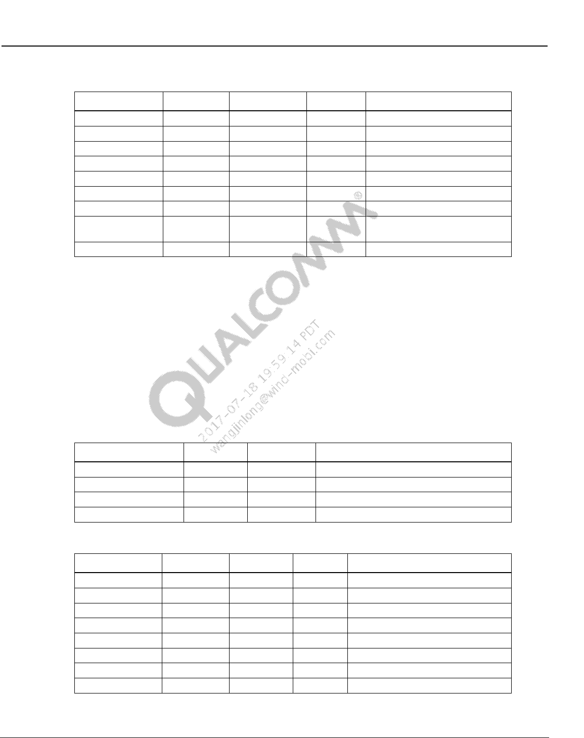
Wireless Connectivity Tests User Guide Wireless Connectivity Test Description
80-Y0306-1 Rev. L MAY CONTAIN U.S. AND INTERNATIONAL EXPORT CONTROLLED INFORMATION 111
Confidential and Proprietary – Qualcomm Atheros, Inc.
Table 10-47 TX EVM Test NxN output parameters
Parameter Name
Lower Limit
Upper Limit
Unit
Description
evm[]
-100
-25
dB
TX EVM
evmDataMb
-999
999
Mbs
TX Data Rate
amplErr[]
dB
TX Amplitude Error
symbolClockError[]
m
PPM
TX Symbol Clock Error
freqErr[]
-20
20
PPM
TX Frequency Error
phaseErr[]
PPM
TX Phase Error
avgTxPower[]
7
13
dBm
Average TX Power
avgTxPowerDelta
-2
2
dB
Delta Between Requested And
Measured Tx Power
loLeakage[]
-120
-15
dB
LO Leakage
10.3.3 WlanTxVerifyPowerTest_NxN
This test measures transmit power levels. It measures the maximum, minimum and average TX
power and maximum, minimum and average peak Tx power. Table 10-48 and Table 10-49 list
the input and output parameters for this test.
Test Name: WlanTxVerifyPowerTest_NxN
Test Condition: Normal
Loop Condition: Channel, Rate
Test Equipment: “LitePoint IQxel”, “NI PXI5644R”
Table 10-48 Tx verify power test NxN input parameters
Parameter Name
Value
Unit
Description
rate
Wi-Fi Rate of Tx Signal
channel
MHz
Center Frequency of Tx Signal
powerLevel
dBm
TX Power Level
vsaTriggerLevel
dB
VSA trigger Level
Table 10-49 TX verify power Test NxN output parameters
Parameter Name
Lower Limit
Upper Limit
Unit
Description
txPowerAvg[]
dBm
Average TX Power
txPowerAvgDelta[]
-2
2
dB
TX Power Accuracy
txPowerMax[]
dBm
Maximum TX Power
txPowerMin[]
dBm
Minimum TX Power
txPowerPeak[]
dBm
Average Peak TX Power
txPowerPeakMax[]
dBm
Maximum Peak TX Power
txPowerPeakMin[]
dBm
Minimum Peak TX Power
cableLoss[]
dBm
Path loss (from cable)
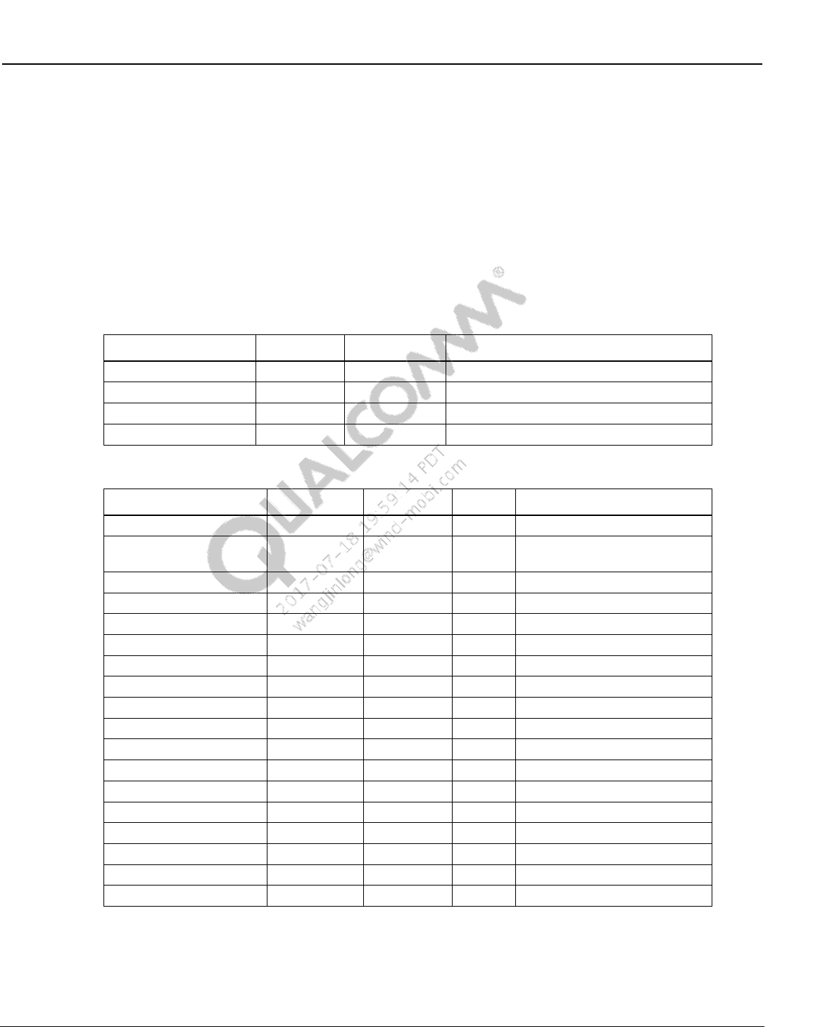
Wireless Connectivity Tests User Guide Wireless Connectivity Test Description
80-Y0306-1 Rev. L MAY CONTAIN U.S. AND INTERNATIONAL EXPORT CONTROLLED INFORMATION 112
Confidential and Proprietary – Qualcomm Atheros, Inc.
10.3.4 MeasureMask_NxN
This test measures transmit spectral mask; it reports whether the WLAN transmit spectrum
complies or fails with the standard WLAN mask. Table 10-50 and Table 10-51 list the input and
output parameters for this test.
Test Name: MeasureMask_NxN
Test Condition: Normal
Loop Condition: Channel, Rate
Test Equipment: “LitePoint IQxel”, “NI PXI5644R”
Table 10-50 MeasureMask_NxN test input parameters
Parameter Name
Value
Unit
Description
rate
WLAN Rate Enums
channel
MHz
Center Frequency of Tx Singal
powerLevel
dBm
TX Power Level
vsaTriggerLevel[]
dBm
VSA trigger Level
Table 10-51 MeasureMask_NxN test output parameters
Parameter Name
Lower Limit
Upper Limit
Unit
Description
maskPass[]
dBm
Pass/Fail WLAN Mask
violationPct[]
-2
2
dB
Percentage of the mask that
fails
freq_at_margin_positive[]
Hz
Frequency At Margin Positive
freq_at_margin_negative[]
Hz
Frequency At Margin Negative
margin_db_positive[]
dB
Margin at Positive
margin_db_negative[]
dB
Margin at Negative
spectrumTrace_1
dB
Spectral Trace Chain 1
spectrumMaskTrace_1
dB
Spectral Mask Trace Chain 1
frequencyList_1
Hz
Frequency List Chain 1
spectrumTrace_2
dB
Spectral Trace Chain 2
spectrumMaskTrace_2
dB
Spectral Mask Trace Chain 2
frequencyList_2
Hz
Frequency List Chain 2
spectrumTrace_3
dB
Spectral Trace Chain 3
spectrumMaskTrace_3
dB
Spectral Mask Trace Chain 3
frequencyList_3
Hz
Frequency List Chain 3
spectrumTrace_4
dB
Spectral Trace Chain 4
spectrumMaskTrace_4
dB
Spectral Mask Trace Chain 4
frequencyList_4
Hz
Frequency List Chain 4
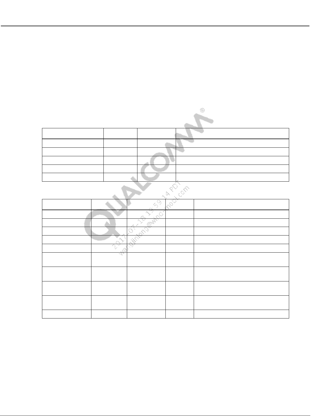
Wireless Connectivity Tests User Guide Wireless Connectivity Test Description
80-Y0306-1 Rev. L MAY CONTAIN U.S. AND INTERNATIONAL EXPORT CONTROLLED INFORMATION 113
Confidential and Proprietary – Qualcomm Atheros, Inc.
10.3.5 MeasureSpectrum_NxN
This test measures transmit spectrum in terms of carrier center frequency leakage and spectral
flatness. Table 10-52 and Table 10-53 list the input and output parameters for this test.
Test Name: MeasureSpectrum_NxN
Test Condition: Normal
Loop Condition: Channel, Rate
Test Equipment: “LitePoint IQxel”, “NI PXI5644R”
Table 10-52 MeasureSpectrum_NxN test input parameters
Parameter Name
Value
Unit
Description
rate
WLAN Rate Enums
channel
1
MHz
Center Frequency of Tx Singal
powerLevel
10.0
dBm
TX Power Level
vsaTriggerLevel[]
-25
dBm
VSA trigger Level
chEstimationMethod
ChannelEstimationOption Enums
Table 10-53 MeasureSpectrum_NxN test output parameters
Parameter Name
Lower Limit
Upper Limit
Unit
Description
spectrumPower[]
dBm
Spectrum Power
carrierNumber_1[]
Carrier Number for Chain 1
carrierNumber_2[]
Carrier Number for Chain 2
carrierNumber_3[]
Carrier Number for Chain 3
carrierNumber_4[]
Carrier Number for Chain 4
flatnessMargin_1[]
dB
Average Power Flatness over
spectrum for chain 1
flatnessMargin_2[]
dB
Average Power Flatness over
spectrum for chain 2
flatnessMargin_3[]
dB
Average Power Flatness over
spectrum for chain 3
flatnessMargin_4[]
dB
Average Power Flatness over
spectrum for chain 4
loLeakage[]
dBm
LO Leakage
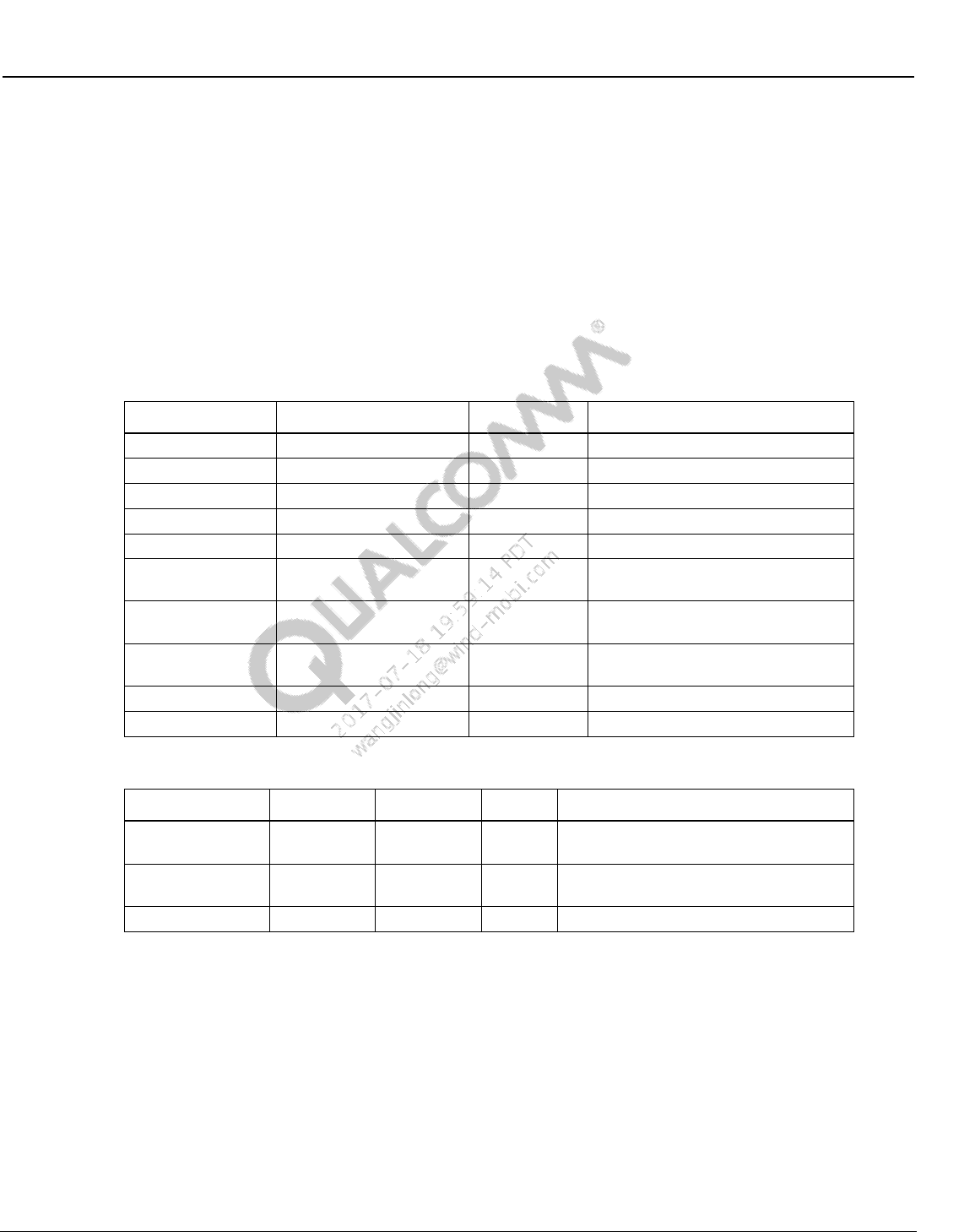
Wireless Connectivity Tests User Guide Wireless Connectivity Test Description
80-Y0306-1 Rev. L MAY CONTAIN U.S. AND INTERNATIONAL EXPORT CONTROLLED INFORMATION 114
Confidential and Proprietary – Qualcomm Atheros, Inc.
10.3.6 WlanPerTest_NxN
This test measures receiver minimum input sensitivity. It measures the PER of the receiver at the
minimum input sensitivity level: -69 dBm for 2.4GHz; -65 dBm for 5GHz. Table 10-54 and
Table 10-55 list the input and output parameters for this test.
Test Name: WlanPerTest_NxN
Test Condition: None
Loop Condition: Channel
Test Equipment: “LitePoint IQxel”, “NI PXI5644R”
Table 10-54 WLAN Per NxN test input parameters
Parameter Name
Value
Unit
Description
startPower
-69
dBm
PER Search Start Power
stopPower
-69
dBm
PER Search Stop Power
channel
5180
WLAN Channel number or FreqMHz
rate
RATE_11N_HT20_MCS7
WLAN_RATE
WLAN 11n/11ac Rate Enums
channelBonding
2
WLAN_MODE
WLAN Mode Enums
coursePktCount
2000
number of packets for PER coarse
search loop
finePktCount
10000
number of packets for PER fine
search loop
coarseStepSize
2.0
dB
step size for PER coarse search
loop
fineStepSize
0.5
dB
step size for PER fine search loop
rxChain
1
Rx ChainMask
Table 10-55 WLAN Per NxN test output parameters
Parameter Name
Lower Limit
Upper Limit
Unit
Description
PER
0
10
%
PER at Per Power; must define Upper
Limit
PerPower
-100
0
dBm
Power at which reported PER is
measured
Rssi
-100
0
dBm
Received Signal Strength Indicator
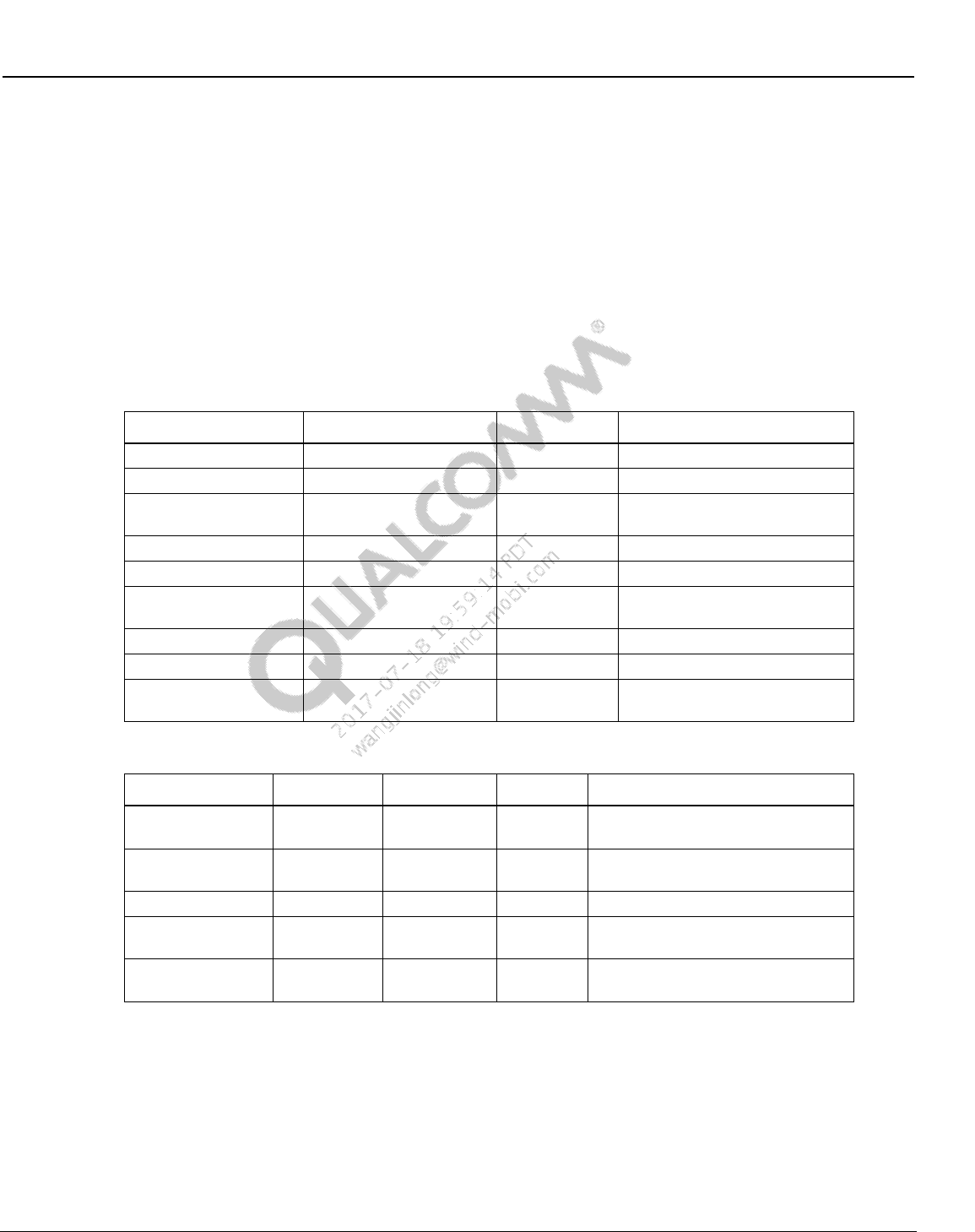
Wireless Connectivity Tests User Guide Wireless Connectivity Test Description
80-Y0306-1 Rev. L MAY CONTAIN U.S. AND INTERNATIONAL EXPORT CONTROLLED INFORMATION 115
Confidential and Proprietary – Qualcomm Atheros, Inc.
10.3.7 WlanPerSweepTest_NxN
This test sweeps receiver’s power with a specified step, measures receiver PER at each input
power steps.
Table 10-56 and Table 10-57 list the input and output parameters for this test.
Test Name: WlanPerSweepTest_NxN
Test Condition: None
Loop Condition: Channel
Test Equipment: “LitePoint IQxel”, “NI PXI5644R”
Table 10-56 WLAN PerSweepTest_NxN input parameters
Parameter Name
Value
Unit
Description
startPower
-50
dBm
PER Search Start Power
stopPower
-90
dBm
PER Search Stop Power
channel
7
WLAN Channel number or
FreqMHz
rate
RATE_11N_HT20_MCS7
WLAN_RATE
WLAN 11n/11ac Rate Enums
channelBonding
2
WLAN_MODE
WLAN Mode Enums
pktCount
200
number of packets for PER
sweep
stepSize
-2.0
dB
step size for PER sweep
rxChain
3
Rx ChainMask to test
perLimit
10
PER limit to compute min and
max passed power
Table 10-57 WLAN PerSweepTest_NxN output parameters
Parameter Name
Lower Limit
Upper Limit
Unit
Description
allMeasuredPERs
0
10
%
PER at Per Power; must define
Upper Limit
allPerPowers
-110
0
dBm
Power at which reported PER is
measured
allMeasuredRssis
-100
0
dBm
Received Signal Strength Indicator
minPassPerPower
-100 (rate
dependent)
0
dBm
Min power for PER within upperLimit
maxPassPerPower
-100
0
dBm
Max power for PER within
upperLimit
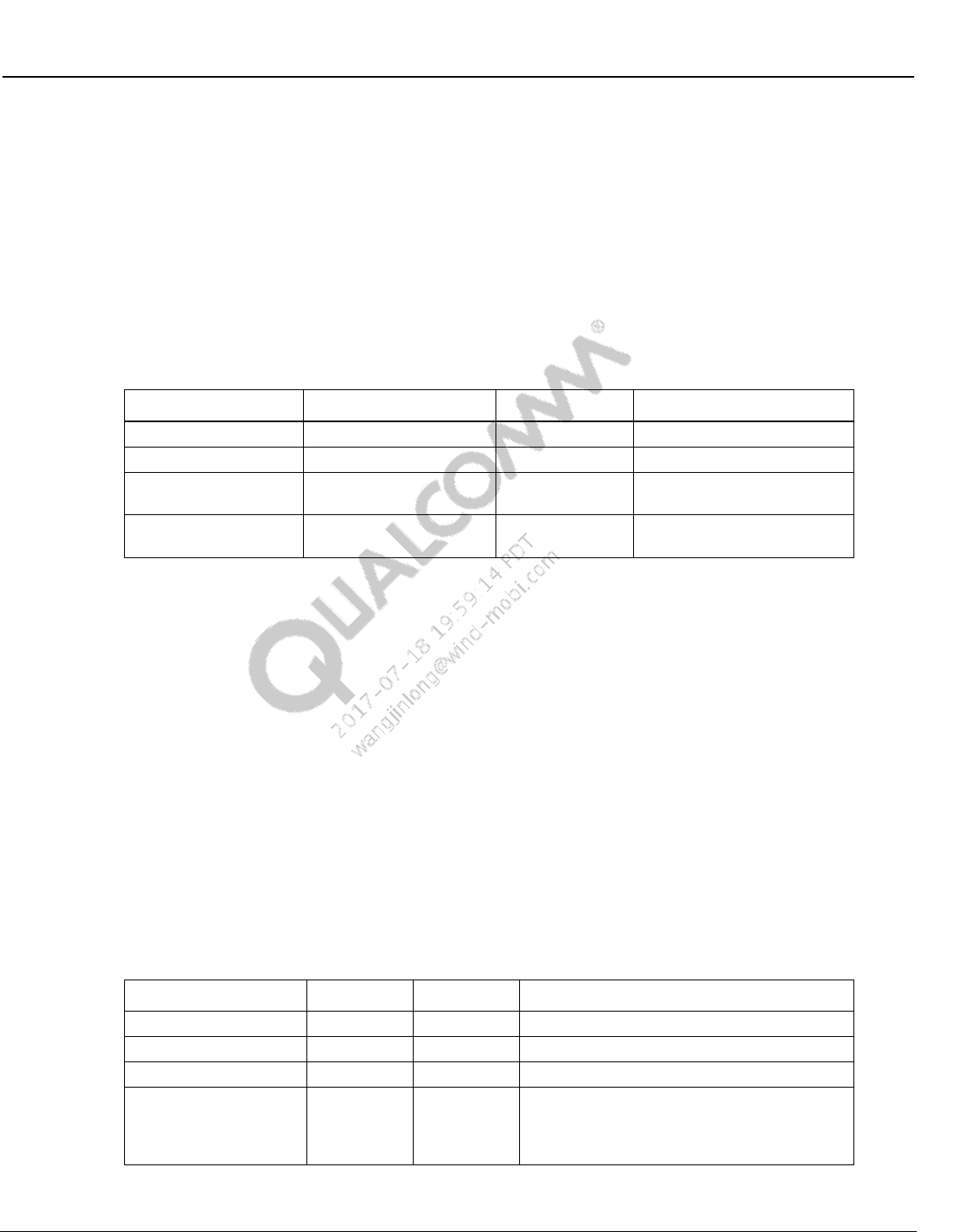
Wireless Connectivity Tests User Guide Wireless Connectivity Test Description
80-Y0306-1 Rev. L MAY CONTAIN U.S. AND INTERNATIONAL EXPORT CONTROLLED INFORMATION 116
Confidential and Proprietary – Qualcomm Atheros, Inc.
10.3.8 WlanSendRxPacketsTest_NxN
This test set VSG to Tx number of packets (numPackets) at specified power level
Table 10-58 list the input parameters for this test.
Test Name: WlanSendRxPacketsTest_NxN
Test Condition: None
Loop Condition: Channel
Test Equipment: “LitePoint IQxel”, “NI PXI5644R”
Table 10-58 WLAN PerSweepTest input parameters
Parameter Name
Value
Unit
Description
Power
-60
dBm
VSG Tx Power level
numPackets
1000
Number of packets to send
channel
5210
WLAN Channel number or
FreqMHz
rate
RATE_11N_HT20_MCS7
WLAN_RATE
WLAN 11n/11AC Rate
Enums
10.4 FM production test description
10.4.1 FM RX tests
10.4.1.1 Sensitivity GONOGO
This test verifies that the minimum sensitivity is met. But it does NOT find the sensitivity level,
defined as the input power level where SNR=26 dB. Table 10-59 and Table 10-60 list the input
and output parameters for this test.
Test Name: FmRxTest_Sensitivity_GONOGO
Test Condition: Normal
Loop Condition: FM Frequency
Test Equipment: “LitePoint IQ2010”
Table 10-59 Sensitivity GONOGO input parameters
Parameter Name
Value
Unit
Description
carrierPowerdBm
-102.0
dBm
Input Power Level at DUT
carrierFreqKHz
Set by loop
kHz
RF Frequency
audioToneFreqHz
1000
Hz
Audio Frequency
MaxRetries
3
Max # of measurement retry attempts. Retries
happen if SNR < lower limit, or L&R
measurements are unbalanced by more than
1 dB
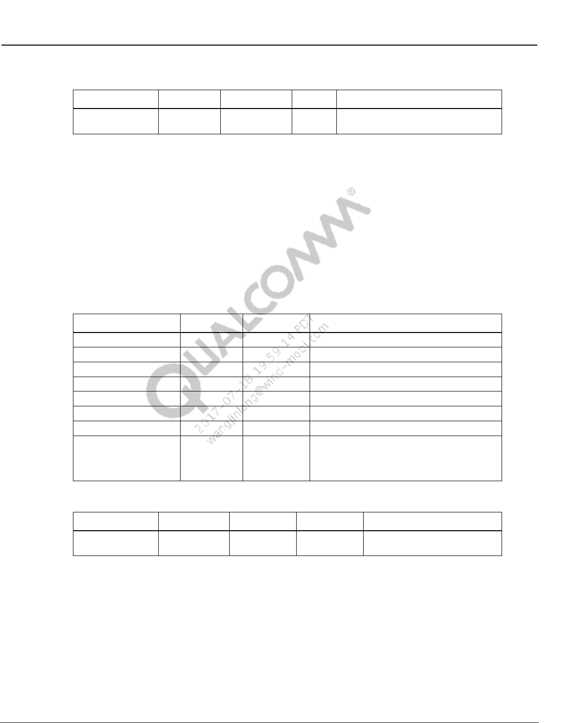
Wireless Connectivity Tests User Guide Wireless Connectivity Test Description
80-Y0306-1 Rev. L MAY CONTAIN U.S. AND INTERNATIONAL EXPORT CONTROLLED INFORMATION 117
Confidential and Proprietary – Qualcomm Atheros, Inc.
Table 10-60 Sensitivity GONOGO output parameters
Parameter Name
Lower Limit
Upper Limit
Unit
Description
SNR
26
99
dB
Audio SNR; lower limit must be
specified in test tree
10.4.1.2 Sensitivity characterization
This test finds the minimum FM sensitivity level with an iterative search. FM Sensitivity is
defined as the input power level where SNR=26 dB. Table 10-61 and Table 10-62 list the input
and output parameters for this test.
Test Name: FmRxTest_Sensitivity_Characterization
Test Condition: Normal
Loop Condition: FM Frequency
Test Equipment: “LitePoint IQ2010”
Table 10-61 Sensitivity characterization input parameters
Parameter Name
Value
Unit
Description
PowerStart
-108.0
dBm
Start power for iterative search
PowerStep
1.0
dB
Step size for iterative search
PowerMax
-90.0
dBm
Max power for iterative search
PowerMin
-114.0
dBm
Min power for iterative search
SNRTarget
26.0
dB
SNR target for iterative search
carrierFreqKHz
Set by loop
kHz
RF Frequency
audioToneFreqHz
1000
Hz
Audio Frequency
MaxRetries
3
Max # of measurement retry attempts.
Retries happen if SNR < 10 dB, or L&R
measurements are unbalanced by more than
1 dB
Table 10-62 Sensitivity characterization output parameters
Parameter Name
Lower Limit
Upper Limit
Unit
Description
FmSens
-115
-102
dBm
FM Sensitivity; RF input level
where audio SNR = 26 dB

Wireless Connectivity Tests User Guide Wireless Connectivity Test Description
80-Y0306-1 Rev. L MAY CONTAIN U.S. AND INTERNATIONAL EXPORT CONTROLLED INFORMATION 118
Confidential and Proprietary – Qualcomm Atheros, Inc.
10.4.1.3 Max SNR
This test finds the maximum SNR. Table 10-63 and Table 10-64 list the input and output
parameters for this test.
Test Name: FmRxTest_MaxSNR
Test Condition: Normal
Loop Condition: FM Frequency
Test Equipment: “LitePoint IQ2010”
Table 10-63 Max SNR input parameters
Parameter Name
Value
Unit
Description
carrierPowerdBm
-47.0
dBm
Input Power Level at DUT
carrierFreqKHz
Set by loop
kHz
RF Frequency
stereo
True or False
Boolean
Flag to Enable Stereo Pilot &
Modulation
pilotDeviationHz
6750
Hz
Pilot Deviation; Only relevant if
stereo=True
totalFmDeviationHz
22500 (if mono)
75000 (if stereo)
Hz
Total FM Deviation
audioToneFreqHz
1000
Hz
Audio Frequency
MaxRetries
3
3
Max # of measurement retry attempts.
Retries happen if SNR < lower limit, or
L&R measurements are unbalanced by
more than 1 dB
Table 10-64 Max SNR output parameters
Parameter Name
Lower Limit
Upper Limit
Unit
Description
SNR
57 (if mono)
53 (if stereo)
99
dB
Audio SNR;
lower limit must be
specified in test tree
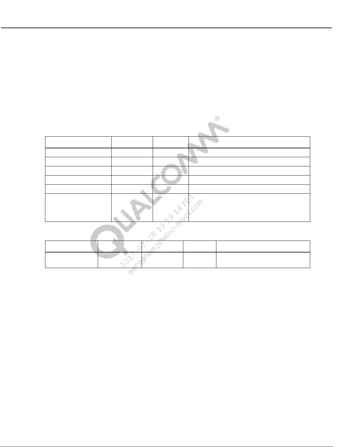
Wireless Connectivity Tests User Guide Wireless Connectivity Test Description
80-Y0306-1 Rev. L MAY CONTAIN U.S. AND INTERNATIONAL EXPORT CONTROLLED INFORMATION 119
Confidential and Proprietary – Qualcomm Atheros, Inc.
10.4.1.4 Intermediate SNR
This test finds the SNR at an intermediate power level with AM distortion added to the FM
signal. Table 10-65 and Table 10-66 list the input and output parameters for this test.
Test Name: FmRxTest_ IntermediateSNR
Test Condition: Normal
Loop Condition: FM Frequency
Test Equipment: “LitePoint IQ2010”
Table 10-65 Intermediate SNR input parameters
Parameter Name
Value
Unit
Description
carrierPowerdBm
-90.0
dBm
Input Power Level at DUT
carrierFreqKHz
Set by loop
kHz
RF Frequency
audioToneFreqHz
1000
Hz
Audio FM Frequency
amFreqHz
400
Hz
AM Frequency
amDepthPercent
30
%
AM Depth
MaxRetries
3
Max # of measurement retry attempts. Retries
happen if SNR < lower limit, or L&R
measurements are unbalanced by more than
1 dB
Table 10-66 Intermediate SNR output parameters
Parameter Name
Lower Limit
Upper Limit
Unit
Description
SNR
45
99
dB
Audio SNR; lower limit must be
specified in test tree
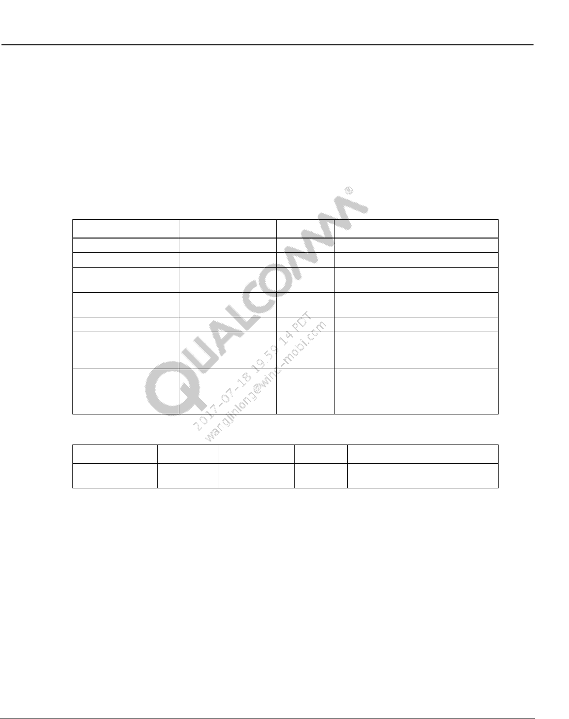
Wireless Connectivity Tests User Guide Wireless Connectivity Test Description
80-Y0306-1 Rev. L MAY CONTAIN U.S. AND INTERNATIONAL EXPORT CONTROLLED INFORMATION 120
Confidential and Proprietary – Qualcomm Atheros, Inc.
10.4.1.5 THD
This test finds the Total Harmonic Distortion (THD). Table 10-67 and Table 10-68 list the input
and output parameters for this test.
Test Name: FmRxTest_THD
Test Condition: Normal
Loop Condition: FM Frequency, Audio Frequency, and mono|stereo state
Test Equipment: “LitePoint IQ2010”
Table 10-67 THD input parameters
Parameter Name
Value
Unit
Description
carrierPowerdBm
-47.0
dBm
Input Power Level at DUT
carrierFreqKHz
Set by loop
kHz
RF Frequency
stereo
True or False
Boolean
Flag to Enable Stereo Pilot &
Modulation
pilotDeviationHz
6750
Hz
Pilot Deviation; Only relevant if
stereo=True
totalFmDeviationHz
75000
Hz
audioToneFreqHz
mono: 400, 1000, &
3000
stereo: 3000
Hz
Audio Frequency
MaxRetries
3
Max # of measurement retry attempts.
Retries happen if THD > upper limit, or
L&R measurements are unbalanced
by more than 1 dB
Table 10-68 THD output parameters
Parameter Name
Lower Limit
Upper Limit
Unit
Description
THD
0
0.8 (if mono)
1.5 (if stereo)
%
Audio THD; upper limit must be
specified in test tree
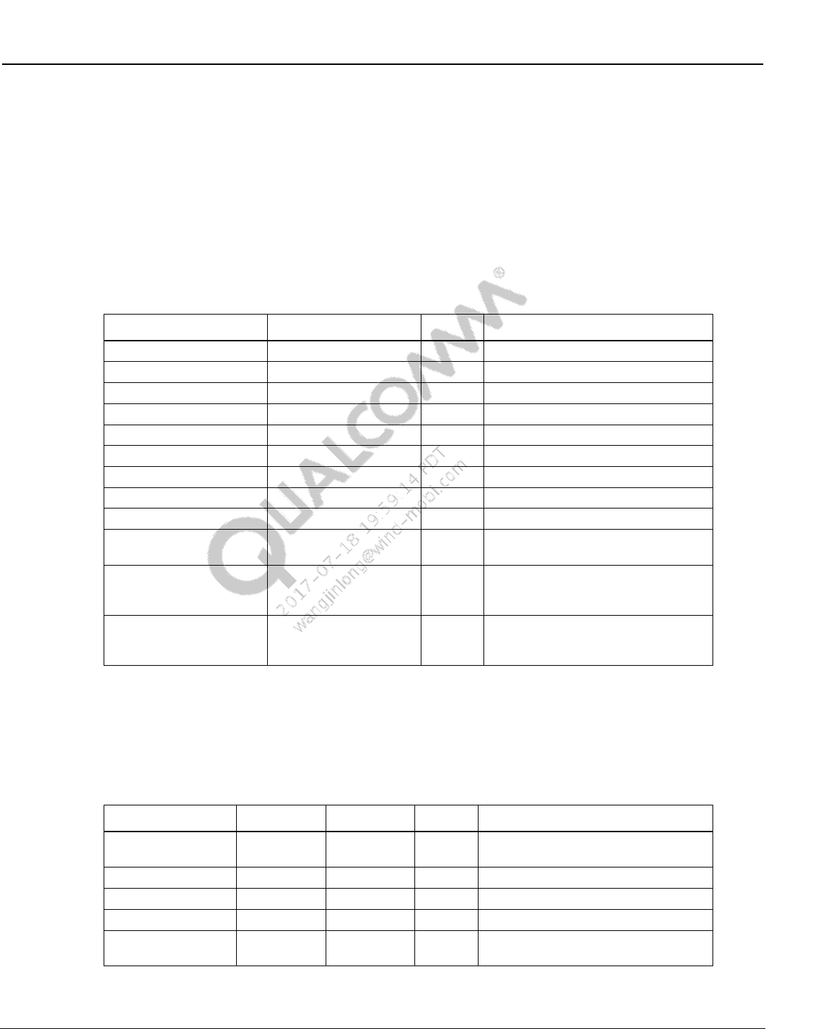
Wireless Connectivity Tests User Guide Wireless Connectivity Test Description
80-Y0306-1 Rev. L MAY CONTAIN U.S. AND INTERNATIONAL EXPORT CONTROLLED INFORMATION 121
Confidential and Proprietary – Qualcomm Atheros, Inc.
10.4.1.6 RDS block error rate
This test finds the RDS Block Error Rate (BLER). Table 10-69 and Table 10-70 list the input and
output parameters for this test.
Test Name: FmRxTest_RDS_BLER
Test Condition: Normal
Loop Condition: FM Frequency
Test Equipment: “LitePoint IQ2010”
Table 10-69 RDS BLER input parameters
Parameter Name
Value
Unit
Description
carrierPowerdBm
-86.0*
dBm
Input Power Level at DUT
carrierFreqKHz
Set by loop
kHz
RF Frequency
pilotDeviationHz
6750
Hz
Pilot Deviation
rdsDeviationHz
2000
Hz
RDS Deviation
totalFmDeviationHz
75000
Hz
Total FM Deviation
preEmphasis
PRE_EMPHASIS_75US
enum
Time Constant of Pre-emphasis filter
rdsTransmitString
QCOM-RDS
RDS Transmit String
audioToneFreqHz
1000
Hz
Audio Frequency
MinNumBlocks
5000*
Sec
Min # of Blocks for BLER calculation
DelayBeforeMeasurement
1
Sec
Delay between enabling RDS signal
and measuring BLER
TimeOutPercent
110.0
%
Percentage of expected time to wait
for MinNumBlocks before aborting
the test
ExitEarlyIfFailing
True
Boolean
Flag to exit test early if
TotalRdsBlockErrors guarantees the
test is going to fail
NOTE: The value for carrierPowerdBm is not fixed by chip specifications. Choose an appropriate value.
The value for MinNumBlocks is a tradeoff of test time vs. statistical confidence. Choose an
appropriate value.
Table 10-70 RDS BLER output parameters
Parameter Name
Lower Limit
Upper Limit
Unit
Description
BLER_percent
0.0
5.0
%
Block Error Rate; upper limit must be
specified in test tree
TotalRdsBlockErrors
# of RDS Block Errors
TotalRdsBlocks
# of RDS Blocks
TotalRdsGroups
# of RDS Groups
ElapsedTime
seconds
time duration of the BLER
measurement
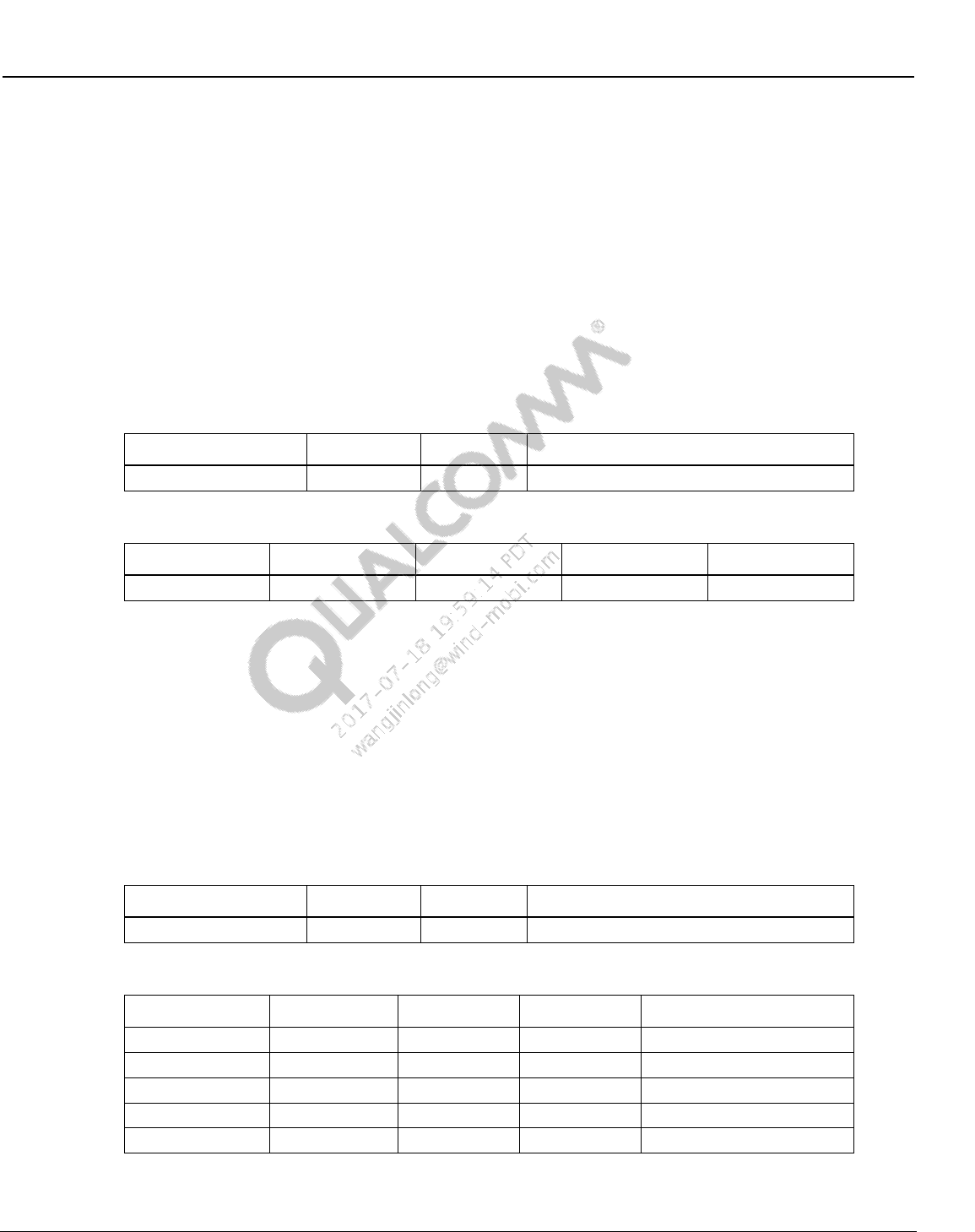
Wireless Connectivity Tests User Guide Wireless Connectivity Test Description
80-Y0306-1 Rev. L MAY CONTAIN U.S. AND INTERNATIONAL EXPORT CONTROLLED INFORMATION 122
Confidential and Proprietary – Qualcomm Atheros, Inc.
10.4.2 FM TX tests
10.4.2.1 TX output power
This test measures the TX output power. Table 10-71 and Table 10-72 list the input and output
parameters for this test.
Test Name: FmTxTest_TxOutputPower
Test Condition: Normal
Loop Condition: FM Frequency
Test Equipment: “LitePoint IQ2010”
Table 10-71 TX output power input parameters
Parameter Name
Value
Unit
Description
carrierFreqKHz
Set by loop
kHz
RF Frequency
Table 10-72 TX output power output parameters
Parameter Name
Lower Limit
Upper Limit
Unit
Description
TxOutputPower
dBm
Tx Output Power
10.4.2.2 FM deviation
This test measures FM Deviation. Table 10-73 and Table 10-74 list the input and output
parameters for this test.
Test Name: FmTxTest_TxOutputPower
Test Condition: Normal
Loop Condition: FM Frequency
Test Equipment: “LitePoint IQ2010”
Table 10-73 FM deviation input parameters
Parameter Name
Value
Unit
Description
carrierFreqKHz
Set by loop
kHz
RF Frequency
Table 10-74 FM deviation output parameters
Parameter Name
Lower Limit
Upper Limit
Unit
Description
PlusPeakDev
Hz
Positive Peak Dev
MinusPeakDev
Hz
Negative Peak Dev
AvgPeakDev
70000
80000
Hz
Average Peak Dev
RmsPeakDev
Hz
RMS Peak Dev
Cfo
Hz
Center Frequency Offset
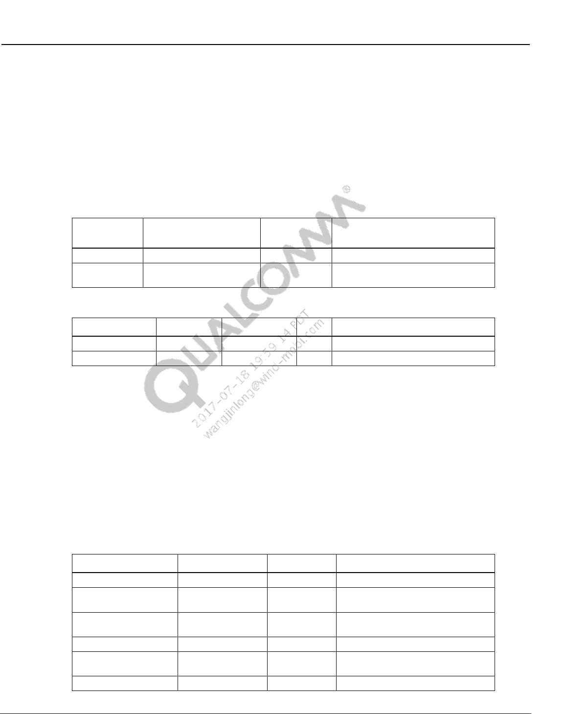
Wireless Connectivity Tests User Guide Wireless Connectivity Test Description
80-Y0306-1 Rev. L MAY CONTAIN U.S. AND INTERNATIONAL EXPORT CONTROLLED INFORMATION 123
Confidential and Proprietary – Qualcomm Atheros, Inc.
10.4.2.3 TX stereo audio SNR
This test measures TX stereo audio SNR. Table 10-75 and Table 10-76 list the input and output
parameters for this test.
Test Name: FmTxTest_TxOutputPower
Test Condition: Normal
Loop Condition: FM Frequency
Test Equipment: “LitePoint IQ2010”
Table 10-75 TX stereo audio SNR input parameters
Parameter
Name
Value
Unit
Description
carrierFreqKHz
Set by loop
kHz
RF Frequency
deEmphasis
DE_EMPHASIS_75US
Enum
analysis de-emphasis setting; set this
to match DUT pre-emphasis setting
Table 10-76 TX stereo audio SNR output parameters
Parameter name
Lower limit
Upper limit
Unit
Description
TxLeftSNR
60
99
dB
Left Channel SNR
TxRightSNR
60
99
dB
Right Channel SNR
10.5 ANT production test description
10.5.1 Transmit channel power
This test measures the TX output power over the channel bandwidth.
Test Name: ChannelPower
Test Condition: Normal
Loop Condition: ANT Frequency
Test Equipment: “Agilent E4443A/E440xB”
Table 10-77 TX channel power input parameters
Parameter Name
Value
Unit
Description
Bandwidth
1
MHz
Channel bandwidth
FrequencyOffset
Set by loop
MHz
Transmit frequency offset from 2400
MHz
Packets
0
Total number of packets for Tx/Rx. 0
indicates continuous test
PacketRate
100
Hz
Packet rate per second
DeviceNumber
55
Device number field of device
address
DeviceType
11
Device type field of device address
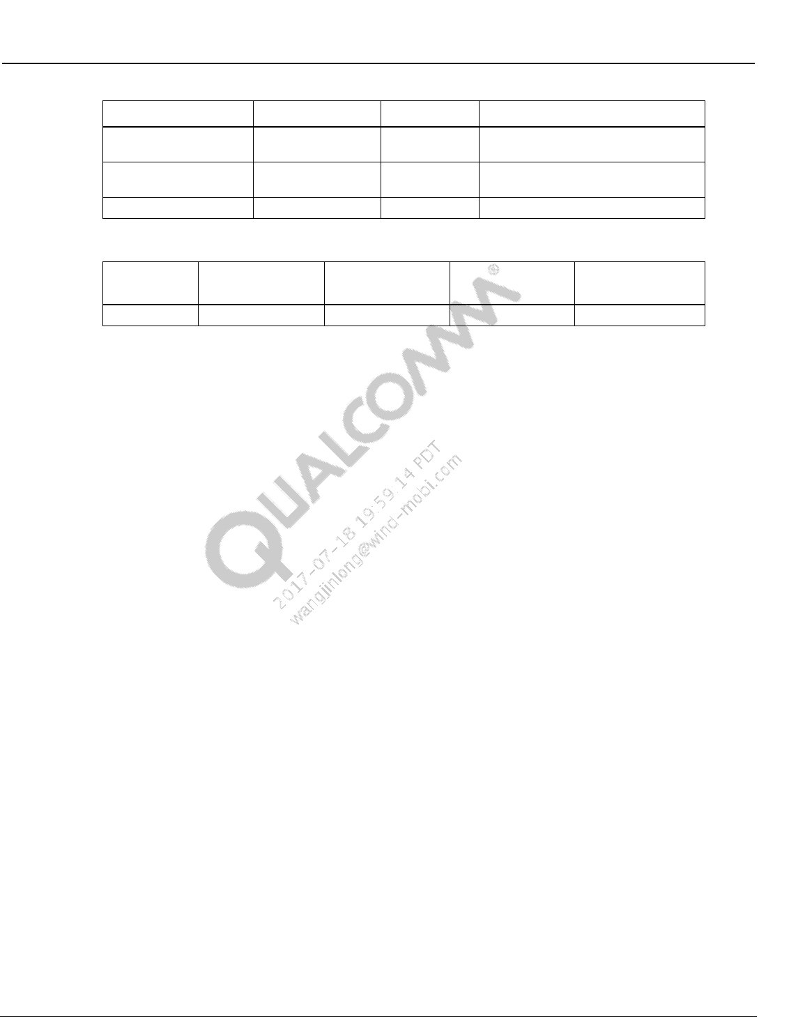
Wireless Connectivity Tests User Guide Wireless Connectivity Test Description
80-Y0306-1 Rev. L MAY CONTAIN U.S. AND INTERNATIONAL EXPORT CONTROLLED INFORMATION 124
Confidential and Proprietary – Qualcomm Atheros, Inc.
Parameter Name
Value
Unit
Description
TransmissionType
208
Transmission type field of device
address
DataPayload
5555555555555555
Data payload in the expected packet
in hex format
TxPathName
SAPath
Transmit path name
Table 10-78 TX channel power output parameters
Parameter
Name
Lower Limit
Upper Limit
Unit
Description
channelPower
-2
2
dBm
Channel power
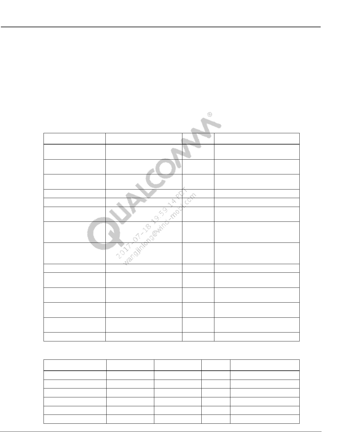
Wireless Connectivity Tests User Guide Wireless Connectivity Test Description
80-Y0306-1 Rev. L MAY CONTAIN U.S. AND INTERNATIONAL EXPORT CONTROLLED INFORMATION 125
Confidential and Proprietary – Qualcomm Atheros, Inc.
10.5.2 Receive sensitivity
This test measures the RX sensitivity defined as minimum power level at which BER is less than
1%.
Test Name: Sensitivity
Test Condition: Normal
Loop Condition: ANT Frequency
Test Equipment: “Agilent N5182A”
Table 10-79 Receive sensitivity input parameters
Parameter Name
Value
Unit
Description
ArbFileName
ANT_NET5B25PAT55PER10
ARB file name on signal
generator
StartPower
-85
dBm
Power value at which search
starts
StopPower
-100
dBm
Power value at which search
stops
CoarsePowerStep
1
dBm
Initial power step
FinePowerStep
0.1
dBm
Final power step
FrequencyOffset
Set by loop
MHz
Transmit frequency offset from
2400 MHz
CoarsePackets
1000
Total number of packets for
Tx/Rx for initial search with
coarse step size
Packets
10000
Total number of packets for
Tx/Rx. 0 indicates continuous
test
PacketRate
100
Hz
Packet rate per second
DeviceNumber
55
Device number field of device
address
DeviceType
11
Device type field of device
address
TransmissionType
208
Transmission type field of device
address
DataPayload
5555555555555555
Data payload in the expected
packet in hex format
RxPathName
ARBPath
Receive path name
Table 10-80 Receive sensitivity output parameters
Parameter Name
Lower Limit
Upper Limit
Unit
Description
sensitivity
-98
-85
dBm
Sensitivity
lostPacketRate
0
50
LPR
crcErrorRate
0
50
CRC Error rate
packetErrorRate
0
50
PER
bitErrorRate
0
0.1
BER
packetsReceived
0
10000
No. of packets received
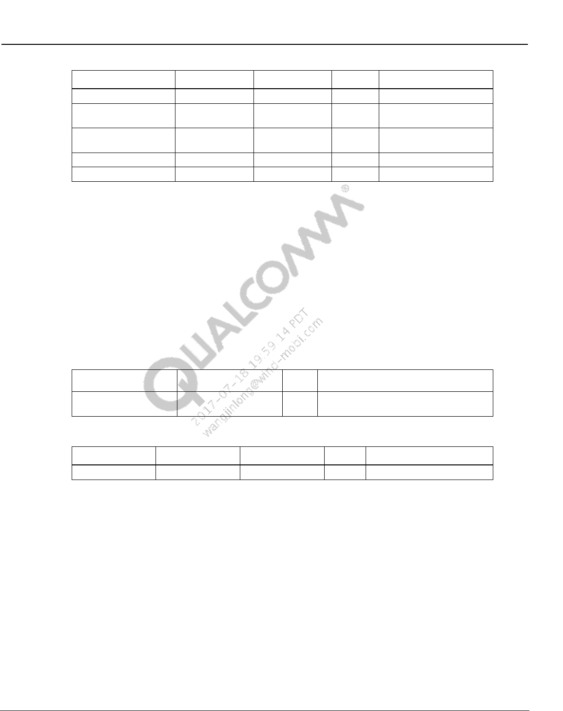
Wireless Connectivity Tests User Guide Wireless Connectivity Test Description
80-Y0306-1 Rev. L MAY CONTAIN U.S. AND INTERNATIONAL EXPORT CONTROLLED INFORMATION 126
Confidential and Proprietary – Qualcomm Atheros, Inc.
Parameter Name
Lower Limit
Upper Limit
Unit
Description
packetsLost
0
5000
No. of packets lost
packetsWithBadHeader
0
5000
No. of packets with bad
header
packetsWithBadCRC
0
5000
No. of packets with bad
CRC
totalBitErrors
0
12000
Total bit errors
syncLosses
No. of sync losses
10.6 Bluetooth signaling production test description
LE production tests are covered in Section 10.1.
10.6.1 BTDUT_FFA_DisableLegacyLogMode
This test is performed for supporting Bluetooth legacy log.
Table 10-81 and Table 10-82 list the input and output parameters for this test.
Test Name: BTDUT_FFA_DisableLegacyLogMode
Test Condition: None
Table 10-81 BTDUT_FFA_DisableLegacyLogMode input parameters
Parameter Name
Value
Unit
Description
disableLegacyLogMode
True
Disable legacy log mode = true, Enable
legacy log mode = false
Table 10-82 BTDUT_FFA_DisableLegacyLogMode output parameters
Parameter Name
Lower Limit
Upper Limit
Unit
Description
errorMessage
NA
error messages
10.6.2 BTDUT_EnableBT_DUTMode
This test is performed to enable BT DUT mode.
Test Name: BTDUT_EnableBT_DUTMode
Test Condition: None
10.6.3 Measure Tx GFSK power
This test is performed for configuring device under test for GFSK transmit tests.
Table 10-83 and Table 10-84 list the input and output parameters for this test.
Test Name: TRM/CA/01 TX Power GFSK
Test Condition: Normal
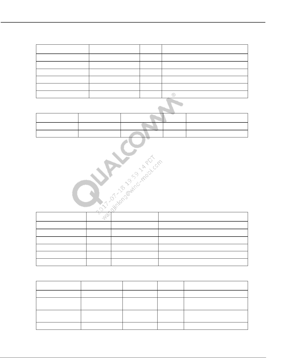
Wireless Connectivity Tests User Guide Wireless Connectivity Test Description
80-Y0306-1 Rev. L MAY CONTAIN U.S. AND INTERNATIONAL EXPORT CONTROLLED INFORMATION 127
Confidential and Proprietary – Qualcomm Atheros, Inc.
Table 10-83 TRM/CA/01 TX Power GFSK input parameters
Parameter Name
Value
Unit
Description
TxChannel
0
NA
TX Channel (0-78)
RxChannel
78
NA
RX Channel (0-78)
PacketType
BT_DH1
NA
Bluetooth packet type
Hopping
No
NA
Channel Hopping mode
DefaultTxPower
-40
dBm
Default TX Power Level
NumOfPackets
1
NA
Number of packets (0-10000)
Table 10-84 TRM/CA/01 TX Power GFSK output parameters
Parameter Name
Lower Limit
Upper Limit
Unit
Description
errorMessage
NA
error messages
AvgPowerdBm
2
16
dBm
Average Bluetooth power
10.6.4 Measure Tx modulation characteristics
This test verifies and measures modulation characteristics. Table 10-85 and Table 10-86 list the
input and output parameters for this test.
Test Name: TRM/CA/07 Modulation Characteristics
Test Condition: Normal
Loop Condition: Tx Channel
Table 10-85 TRM/CA/07 modulation characteristics input parameters
Parameter name
Value
Unit
Description
TxChannel
78
NA
TX channel (0-78)
RxChannel
0
NA
RX channel (0-78)
PacketType
BT_DH5
NA
Bluetooth Packet Type
TestType
Loopback
NA
Test Type
DefaultTxPower
-40
dBm
Default TX Power Level
NumOfPackets
1
NA
Number of packets (0-10000)
Table 10-86 TRM/CA/07 modulation characteristics output parameters
Parameter Name
Lower Limit
Upper Limit
Unit
Description
errorMessage
error message from test
DeltaF1Avg
140
175
KHz
Delta F1 average deviation
KHz
DeltaF2Max
115
250
KHz
Delta F2 maximum deviation
KHz
DeltaF2byF1
0.8
2
NA
Delta F2 by F1
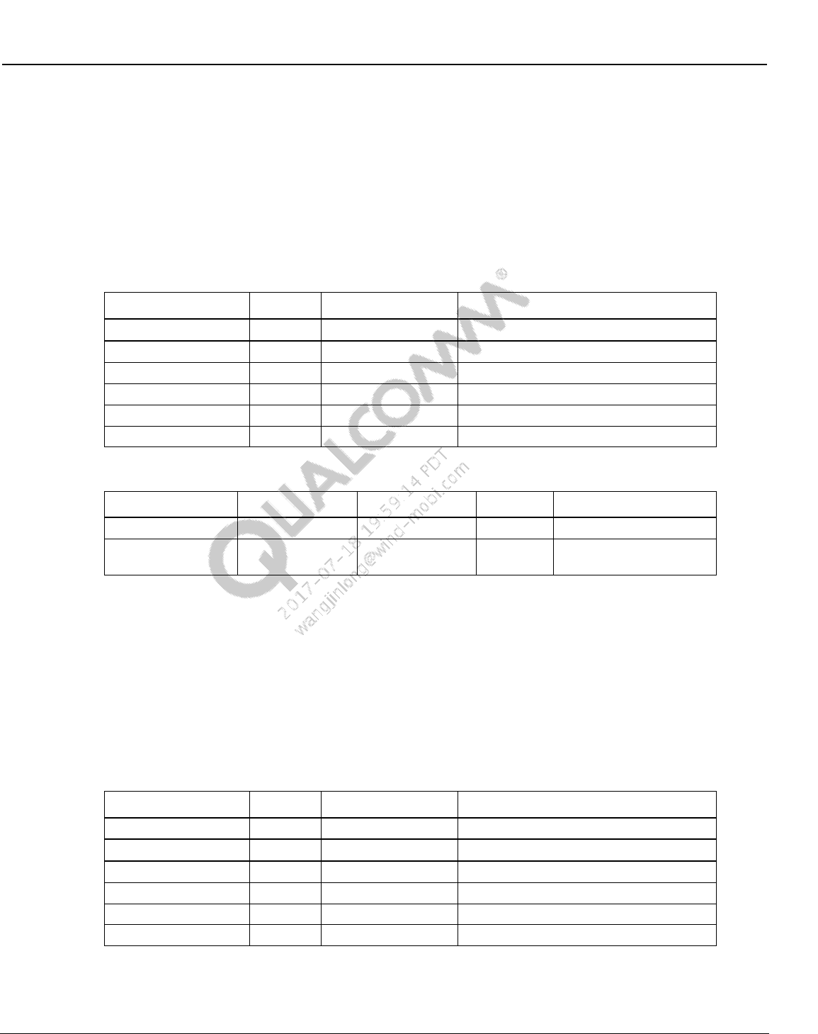
Wireless Connectivity Tests User Guide Wireless Connectivity Test Description
80-Y0306-1 Rev. L MAY CONTAIN U.S. AND INTERNATIONAL EXPORT CONTROLLED INFORMATION 128
Confidential and Proprietary – Qualcomm Atheros, Inc.
10.6.5 Measure GFSK initial carrier frequency tolerance
This test verifies and measures initial carrier frequency tolerance. Table 10-87 and Table 10-88
list the input and output parameters for this test.
Test Name: TRM/CA/08 Initial Carrier Frequency Tolerance
Test Condition: Normal
Loop Condition: Tx Channel
Table 10-87 TRM/CA/08 initial carrier frequency tolerance input parameters
Parameter name
Value
Unit
Description
TxChannel
78
NA
TX channel (0-78)
RxChannel
0
NA
RX channel (0-78)
PacketType
BT_DH1
NA
Bluetooth Packet Type
TestType
Loopback
NA
Test Type
DefaultTxPower
-40
dBm
Default TX Power Level
NumOfPackets
1
NA
Number of packets (0-10000)
Table 10-88 TRM/CA/08 initial carrier frequency tolerance output parameters
Parameter Name
Lower Limit
Upper Limit
Unit
Description
errorMessage
error message from test
FrequencyTolerance
-75
75
KHz
Frequency Tolerance in
KHz
10.6.6 Measure GFSK carrier frequency drift
This test verifies and measures carrier frequency drift and frequency drift rate. Table 10-89 and
Table 10-90 list the input and output parameters for this test.
Test Name: TRM/CA/09 Carrier Frequency Drift
Test Condition: Normal
Loop Condition: Tx Channel
Table 10-89 TRM/CA/09 carrier frequency drift input parameters
Parameter name
Value
Unit
Description
TxChannel
78
NA
TX channel (0-78)
RxChannel
0
NA
RX channel (0-78)
PacketType
BT_DH1
NA
Bluetooth Packet Type
TestType
Loopback
NA
Test Type
DefaultTxPower
-40
dBm
Default TX Power Level
NumOfPackets
1
NA
Number of packets (0-10000)
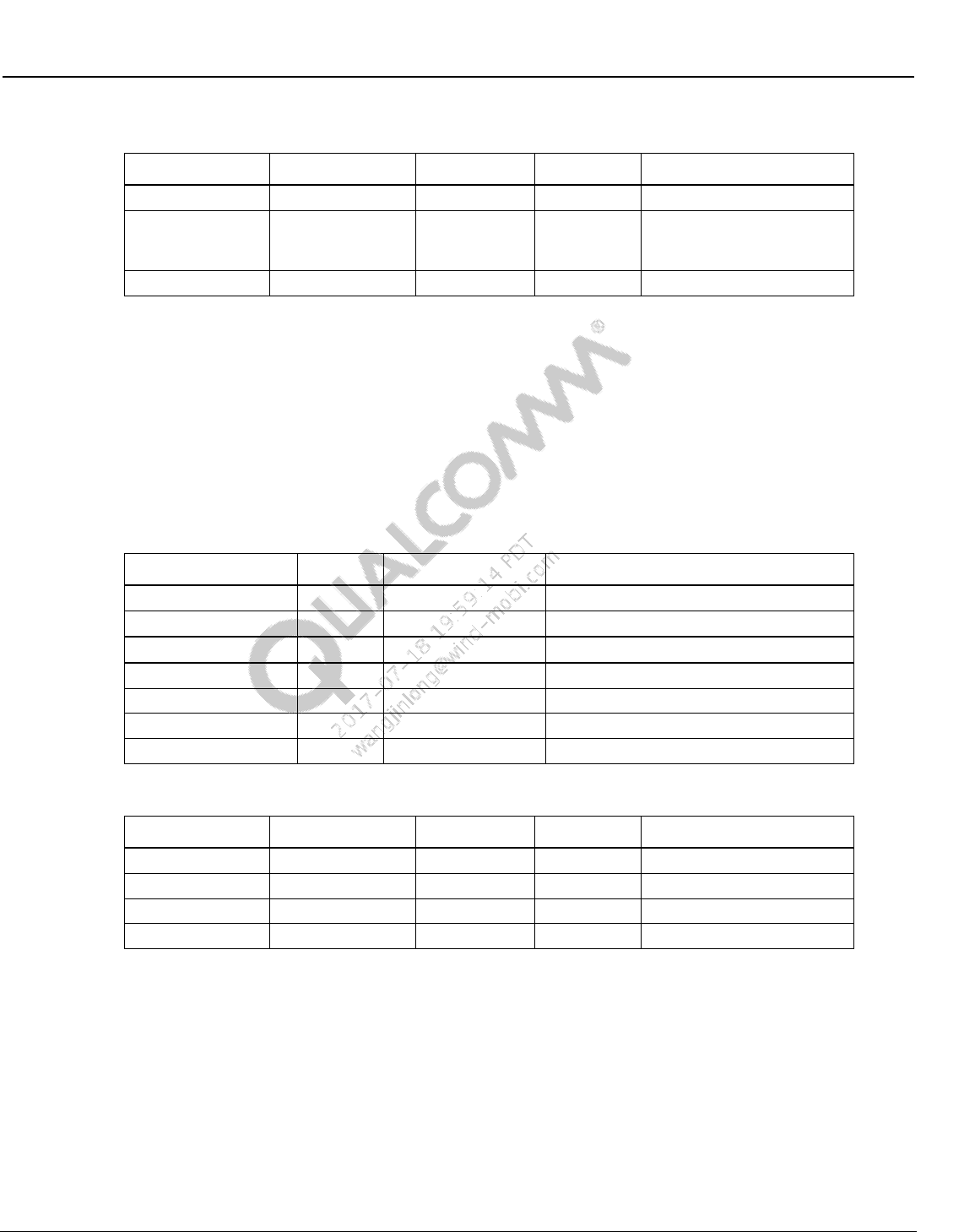
Wireless Connectivity Tests User Guide Wireless Connectivity Test Description
80-Y0306-1 Rev. L MAY CONTAIN U.S. AND INTERNATIONAL EXPORT CONTROLLED INFORMATION 129
Confidential and Proprietary – Qualcomm Atheros, Inc.
Table 10-90 TRM/CA/09 Carrier Frequency Drift output parameters
Parameter Name
Lower Limit
Upper Limit
Unit
Description
errorMessage
error message from test
MaxDrift
-25
25
KHz
Max drift in kHz, limit for
DH1= +- 25, for DH3 and
DH5 limit = +-40
MaxDriftRate
-20
20
KHz/50us
Max drift rate
10.6.7 Measure EDR relative transmit power
This test verifies and measures EDR relative transmit power. Table 10-91 and Table 10-92 list the
input and output parameters for this test.
Test Name: TRM/CA/10/C EDRRelativeTransmitPower
Test Condition: Normal
Loop Condition: Tx Channel
Table 10-91 TRM/CA/10/C EDRRelativeTransmitPower input parameters
Parameter name
Value
Unit
Description
TxChannel
78
NA
TX channel (0-78)
RxChannel
0
NA
RX channel (0-78)
PacketType
BT_2DH5
NA
Bluetooth Packet Type
Hopping
No
NA
Channel Hopping mode
TestType
Loopback
NA
Test Type
DefaultTxPower
-40
dBm
Default TX Power Level
NumOfPackets
1
NA
Number of packets (0-10000)
Table 10-92 TRM/CA/10/C EDRRelativeTransmitPower output parameters
Parameter Name
Lower Limit
Upper Limit
Unit
Description
errorMessage
error message from test
GFSKPower
3
12
dBm
GFSK absolute power
DPSKPower
3
12
dBm
DPSK absolute power
RelativePower
-4
1
dB
Relative power
10.6.8 Measure EDR modulation accuracy
This test verifies and measures EDR modulation accuracy. Table 10-93 and Table 10-94 list the
input and output parameters for this test.
Test Name: TRM/CA/11 EDR Modulation Accuracy
Test Condition: Normal
Loop Condition: Tx Channel
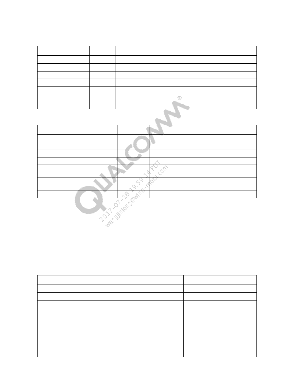
Wireless Connectivity Tests User Guide Wireless Connectivity Test Description
80-Y0306-1 Rev. L MAY CONTAIN U.S. AND INTERNATIONAL EXPORT CONTROLLED INFORMATION 130
Confidential and Proprietary – Qualcomm Atheros, Inc.
Table 10-93 TRM/CA/11 EDR modulation accuracy input parameters
Parameter name
Value
Unit
Description
TxChannel
78
NA
TX channel (0-78)
RxChannel
0
NA
RX channel (0-78)
PacketType
BT_2DH5
NA
Bluetooth Packet Type
Hopping
No
NA
Channel Hopping mode
TestType
Loopback
NA
Test Type
DefaultTxPower
-40
dBm
Default TX Power Level
NumOfPackets
1
NA
Number of packets (0-10000)
Table 10-94 TRM/CA/11 EDR modulation accuracy output parameters
Parameter Name
Lower Limit
Upper Limit
Unit
Description
errorMessage
error message from test
InitialFreqError
-75
75
KHz
Initial Frequency Error
FreqError
-10
10
KHz
Frequency Error
BlockFreqError
-75
75
KHz
Block Freuqency Error
DEVMRMS
0
0.2
NA
DEVMRMS Limit for 2DHx limit =
0.20 and for 3DHx limit = 0.13
DEVMPeak
0
0.35
NA
DEVMPeak Limit for 2DHx limit =
0.35 and for 3DHx limit = 0.25
DEVM99Percent
99
100
%
DEVM 99%
10.6.9 Measure Rx sensitivity single slot packets
This test verifies sensitivity at a given power and measures BER %. Table 10-95 and Table 10-96
list the input and output parameters for this test.
Test Name: RCV/CA/01 Sensitivity – single slot packets
Test Condition: Normal
Loop Condition: Rx Channel
Table 10-95 RCV/CA/01 sensitivity – single slot packets input parameters
Parameter Name
Value
Unit
Description
RxChannel
0
RX channel (0-78)
TxChannel
78
TX channel (0-78)
Dirty
Yes
Dirty mode
StartPowerdBm
-70
dBm
Start Test RX power from VSG,
if Start and Stop are same it acts
like GoNoGo
StopPowerdBm
-70
dBm
Stop Test RX power from VSG, if
Start and Stop are same it acts
like GoNoGo
fineStepSize
0.5
dB
step size for BER fine search
loop
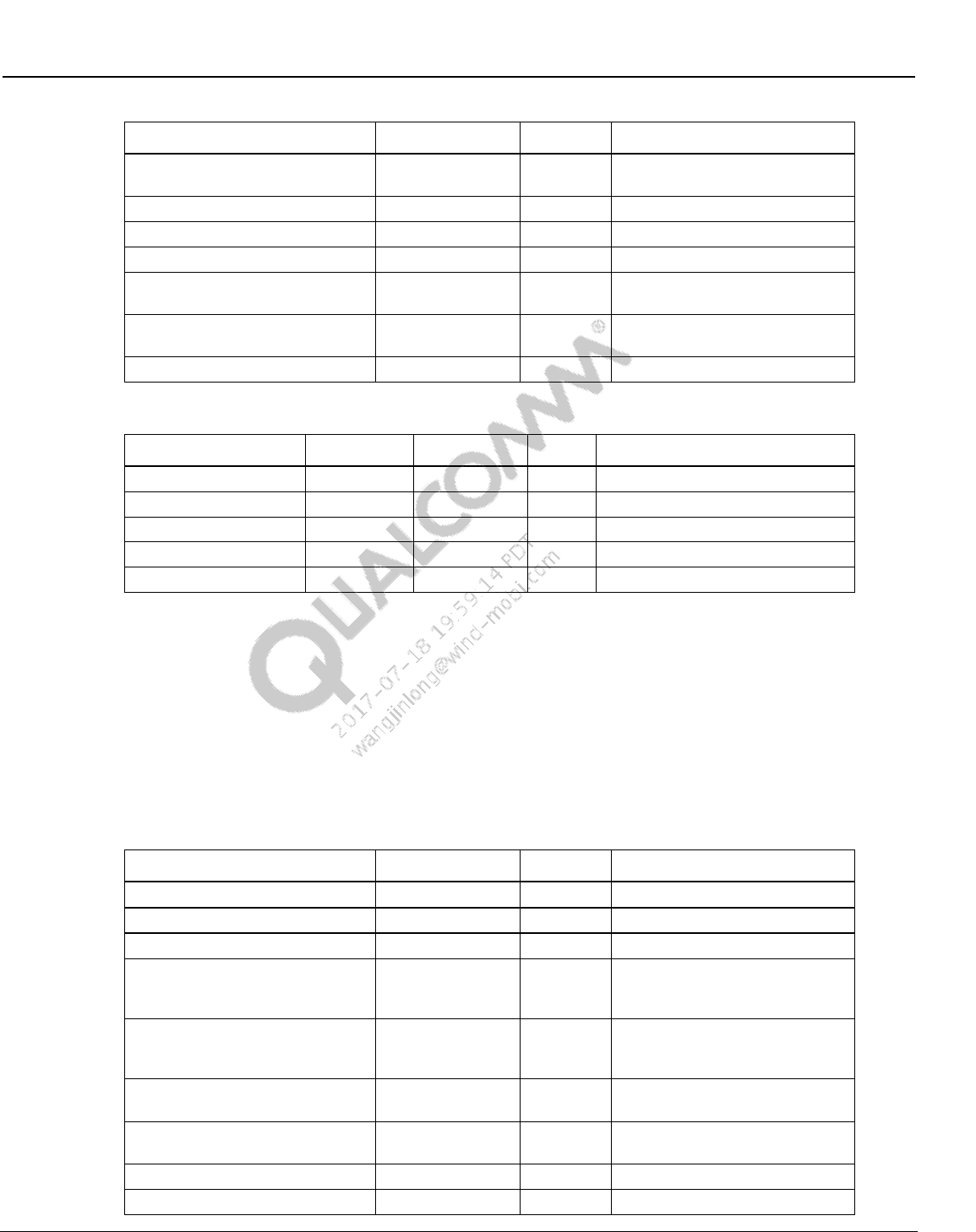
Wireless Connectivity Tests User Guide Wireless Connectivity Test Description
80-Y0306-1 Rev. L MAY CONTAIN U.S. AND INTERNATIONAL EXPORT CONTROLLED INFORMATION 131
Confidential and Proprietary – Qualcomm Atheros, Inc.
Parameter Name
Value
Unit
Description
coarseStepSize
1
dB
step size for BER coarse search
loop
PacketType
BT_DH1
NA
Bluetooth Packet Type
Hopping
No
NA
Channel Hopping mode
DefaultTxPower
-40
NA
Default Tx Power for test
CoarseNumberOfPackets
100
NA
Minimum coarse number of
packets required for test
FineNumberOfPackets
5000
NA
Minimum fine number of packets
required for test
ReceiverTestType
Sensitivity
NA
RX Test type
Table 10-96 RCV/CA/01 sensitivity – single slot packets output parameters
Parameter Name
Lower Limit
Upper Limit
Unit
Description
errorMessage
Error message
BERPercent
0
0.1
%
BER in percent
FERPercent
0
50
%
FER in percent
RxSensitivityPowerdBm
-70
-70
dBm
Sensitivity level
LPR
0
50
%
LPR in percent
10.6.10 Measure Rx sensitivity multiple slot packets
This test verifies sensitivity at a given power and measures BER %. Table 10-97 and Table 10-98
list the input and output parameters for this test.
Test Name: RCV/CA/02 Sensitivity – multiple slot packets
Test Condition: Normal
Loop Condition: Rx Channel
Table 10-97 RCV/CA/02 sensitivity – multiple slot packets input parameters
Parameter Name
Value
Unit
Description
RxChannel
0
RX channel (0-78)
TxChannel
78
TX channel (0-78)
Dirty
Yes
Dirty mode
StartPowerdBm
-70
dBm
Start Test RX power from VSG,
if Start and Stop are same it acts
like GoNoGo
StopPowerdBm
-70
dBm
Stop Test RX power from VSG, if
Start and Stop are same it acts
like GoNoGo
fineStepSize
0.5
dB
step size for BER fine search
loop
coarseStepSize
1
dB
step size for BER coarse search
loop
PacketType
BT_DH5
NA
Bluetooth Packet Type
Hopping
No
NA
Channel Hopping mode
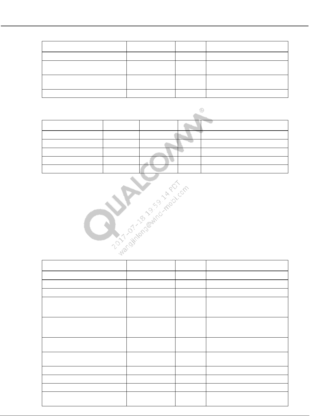
Wireless Connectivity Tests User Guide Wireless Connectivity Test Description
80-Y0306-1 Rev. L MAY CONTAIN U.S. AND INTERNATIONAL EXPORT CONTROLLED INFORMATION 132
Confidential and Proprietary – Qualcomm Atheros, Inc.
Parameter Name
Value
Unit
Description
DefaultTxPower
-40
NA
Default Tx Power for test
CoarseNumberOfPackets
100
NA
Minimum coarse number of
packets required for test
FineNumberOfPackets
589
NA
Minimum fine number of packets
required for test
ReceiverTestType
Sensitivity
NA
RX Test type
Table 10-98 RCV/CA/02 Sensitivity – multiple slot packets output parameters
Parameter Name
Lower Limit
Upper Limit
Unit
Description
errorMessage
Error message
BERPercent
0
0.1
%
BER in percent
FERPercent
0
50
%
FER in percent
RxSensitivityPowerdBm
-70
-70
dBm
Sensitivity level
LPR
0
50
%
LPR in percent
10.6.11 Measure EDR Rx sensitivity
This test verifies sensitivity at a given power and measures BER %. Table 10-99 and Table 10-
100 list the input and output parameters for this test.
Test Name: RCV/CA/07 EDR Sensitivity
Test Condition: Normal
Loop Condition: Rx Channel
Table 10-99 RCV/CA/07 EDR sensitivity input parameters
Parameter Name
Value
Unit
Description
RxChannel
0
RX channel (0-78)
TxChannel
78
TX channel (0-78)
Dirty
Yes
Dirty mode
StartPowerdBm
-70
dBm
Start Test RX power from VSG,
if Start and Stop are same it acts
like GoNoGo
StopPowerdBm
-70
dBm
Stop Test RX power from VSG, if
Start and Stop are same it acts
like GoNoGo
fineStepSize
0.5
dB
step size for BER fine search
loop
coarseStepSize
1
dB
step size for BER coarse search
loop
PacketType
BT_2DH5
NA
Bluetooth Packet Type
Hopping
No
NA
Channel Hopping mode
DefaultTxPower
-40
NA
Default Tx Power for test
CoarseNumberOfPackets
100
NA
Minimum coarse number of
packets required for test
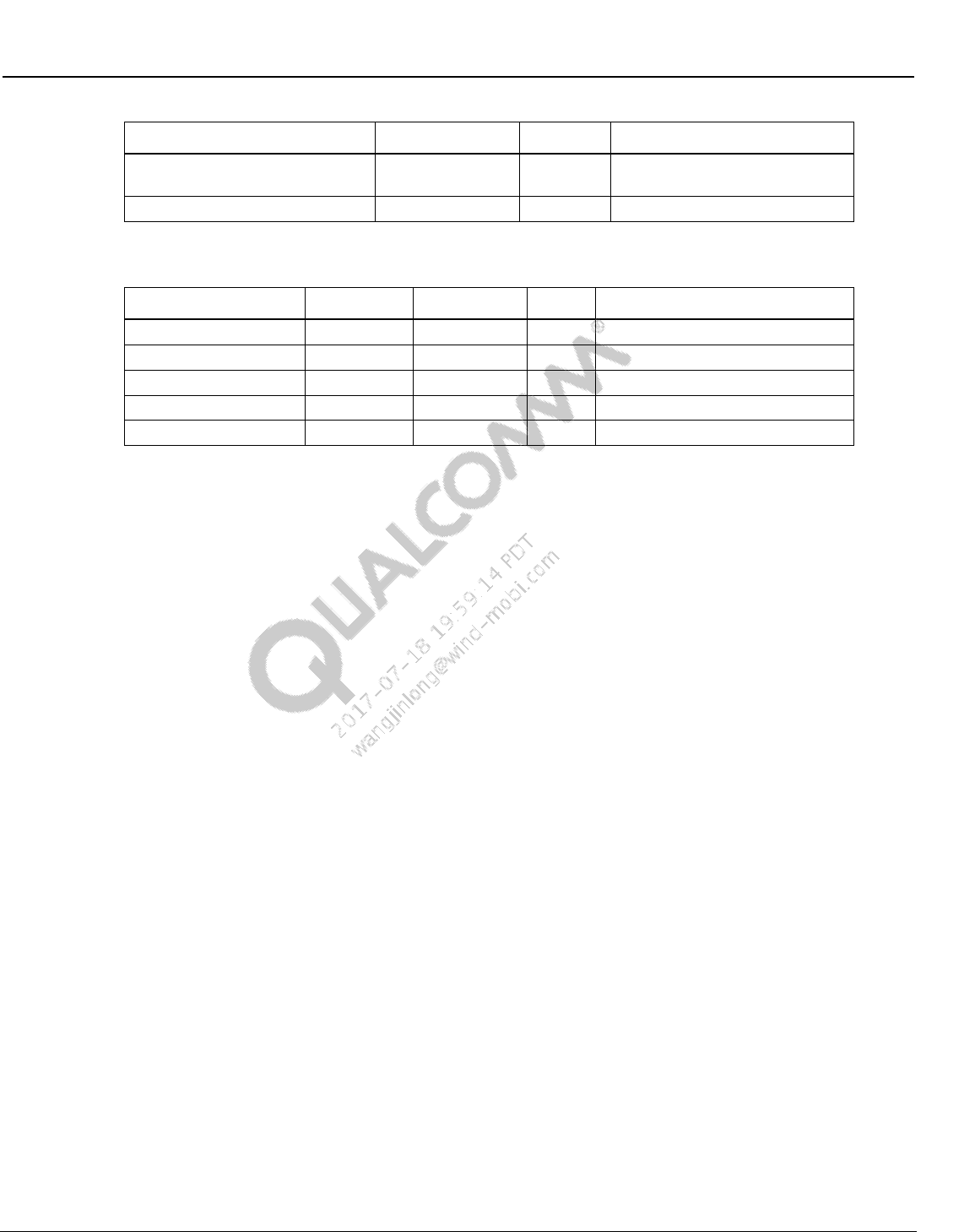
Wireless Connectivity Tests User Guide Wireless Connectivity Test Description
80-Y0306-1 Rev. L MAY CONTAIN U.S. AND INTERNATIONAL EXPORT CONTROLLED INFORMATION 133
Confidential and Proprietary – Qualcomm Atheros, Inc.
Parameter Name
Value
Unit
Description
FineNumberOfPackets
294
NA
Minimum fine number of packets
required for test
ReceiverTestType
Sensitivity
NA
RX Test type
Table 10-100 RCV/CA/07 EDR sensitivity output parameters
Parameter Name
Lower Limit
Upper Limit
Unit
Description
errorMessage
Error message
BERPercent
0
0.1
%
BER in percent
PERPercent
0
50
%
PER in percent
RxSensitivityPowerdBm
-70
-70
dBm
Sensitivity level
LPR
0
50
%
LPR in percent
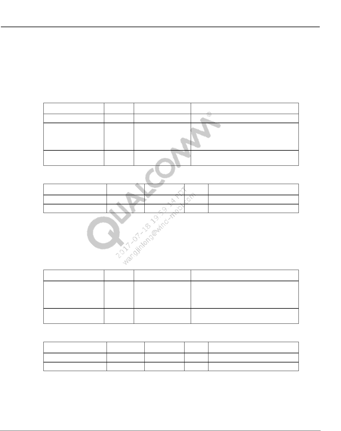
Wireless Connectivity Tests User Guide Wireless Connectivity Test Description
80-Y0306-1 Rev. L MAY CONTAIN U.S. AND INTERNATIONAL EXPORT CONTROLLED INFORMATION 134
Confidential and Proprietary – Qualcomm Atheros, Inc.
10.7 NFC production functional test description
10.7.1 NFCDUT_DetectTag
This test verifies that the DUT is able to detect a NFC tag.
Table 10-101 NFCDUT_DetectTag input parameters
Parameter name
Value
Unit
Description
SelectNFCTech
3 ALL
NA
Select the NFC Polling Protocol.
timeoutMs
5000
ms
Specify the time the test waits for the RF
Interface activated notification from the
DUT to arrive. This parameter only applies
for standalone DUT.
RetryCount
3
Number of times to rerun the test in case
the test fails.
Table 10-102 NFCDUT_DetectTag output parameters
Parameter Name
Lower Limit
Upper Limit
Unit
Description
errorMessage
Error message
ErrorCode
Value is 0 if no error, 1 is any error
10.7.2 NFCDUT_DetectField
This test verifies the DUT is able to detect an externally generated NFC field. The DUT is setup
to listen for all the three protocols – POLLA, POLLB and POLLF
Table 10-103 NFCDUT_DetectField input parameters
Parameter name
Value
Unit
Description
timeoutMs
5000
ms
Specify the time the tests waits for the RF
Field info notification to arrive from the
DUT. This parameter only applies for
standalone DUT.
RetryCount
3
Number of times to rerun the test in case
the test fails.
Table 10-104 NFCDUT_DetectField output parameters
Parameter Name
Lower Limit
Upper Limit
Unit
Description
errorMessage
Error message
ErrorCode
Value is 0 if no error, 1 is any error
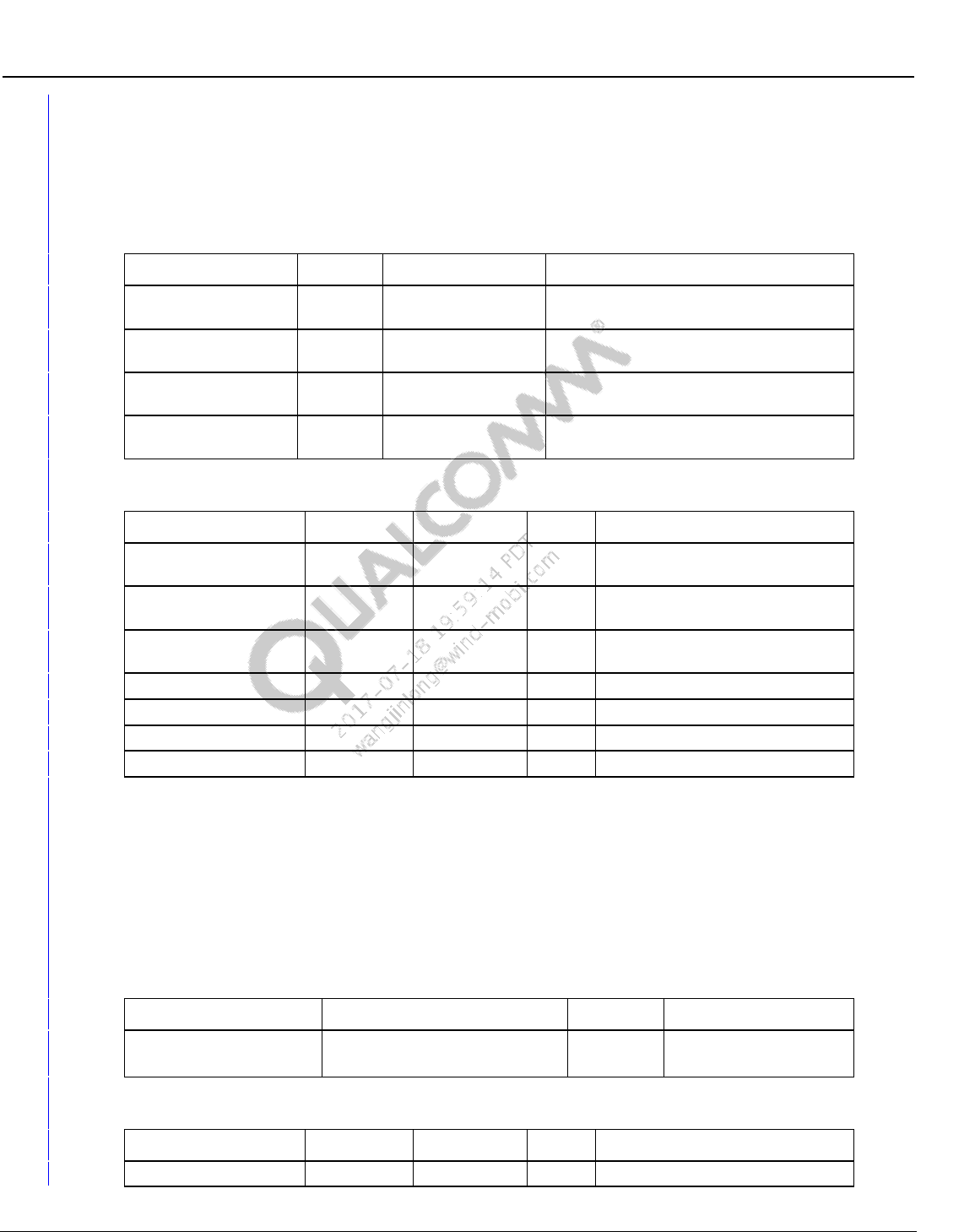
Wireless Connectivity Tests User Guide Wireless Connectivity Test Description
80-Y0306-1 Rev. L MAY CONTAIN U.S. AND INTERNATIONAL EXPORT CONTROLLED INFORMATION 135
Confidential and Proprietary – Qualcomm Atheros, Inc.
10.7.3 NFCDUT_SelfTest
This test verifies executes the firmware based SelfTest function and reports the results. The
firmware test limits for RFOsc count can be set using input parameters.
Table 10-105 NFCDUT_SelfTest input parameters
Parameter name
Value
Unit
Description
CheckSWP1
1
N.A
Enter 1 to enable SWP1 check, 0 to
disable
CheckSWP2
1
N.A
Enter 1 to enable SWP2 check, 0 to
disable
iRfOscLL
109936
N.A
Enter the lower limit RF Oscillator count
value to check for pass/fail
iRfOscUL
132800
N.A
Enter the upper limit RF Oscillator count
value to check for pass/fail
Table 10-106 NFCDUT_SelfTest output parameters
Parameter Name
Lower Limit
Upper Limit
Unit
Description
ErrorCodeNFCEE
N.A
0= PASS, 1 = FAIL, 2= TIMEOUT,
3 = ERROR
ErrorCodeRfOsc
N.A
0= PASS, 1 = FAIL, 2= TIMEOUT,
3 = ERROR
ErrorCodeCarrierDet
N.A
0= PASS, 1 = FAIL, 2= TIMEOUT,
3 = ERROR
NFCEE
N.A
Read NFCEE value
RfOsc
N.A
RfOsc Count value
CarrierDet
N.A
Carrier Detect value
errorMessage
N.A
Error message
10.8 NFC reference parametric test description
10.8.1 SetInstrumentConfigFile
This test sets the instrument config xml file for the test suite. The instrument config file contains
details about the NFC Tester to be used and the power supply being used.
Table 10-107 SetInstrumentConfigFile input parameters
Parameter name
Value
Unit
Description
InstrumentConfigFilename
C:\Qualcomm\WCN\ProdTests\
ConfigFiles\NFCTesterConfig.xml
N.A
Full path and name for
the instrument config file.
Table 10-108 SetInstrumentConfigFile output parameters
Parameter Name
Lower Limit
Upper Limit
Unit
Description
ErrorMessage
N.A
Error message
Wireless Connectivity Tests User Guide Wireless Connectivity Test Description
80-Y0306-1 Rev. L MAY CONTAIN U.S. AND INTERNATIONAL EXPORT CONTROLLED INFORMATION 136
Confidential and Proprietary – Qualcomm Atheros, Inc.
10.8.2 NFCDUT_SetConfigFile
This test sets the DUT config xml file for the test suite. The instrument config file contains details
about the DUT Type and the connection details for the DUT.
Table 10-109 NFCDUT_SetConfigFile input parameters
Parameter name
Value
Unit
Description
NFCDUTConfigFilename
C:\Qualcomm\WCN\ProdTests\
ConfigFiles\NFCDUTConfig.xml
N.A
Full path and name for
the DUT config file.
Table 10-110 NFCDUT_SetCOnfigFile output parameters
Parameter Name
Lower Limit
Upper Limit
Unit
Description
ErrorMessage
N.A
Error message
10.8.3 NFCDUT_Instantiate
This test reads the loaded DUTconfig file and sets the DUT type for the Test Suite – Serial/SoC
or MTP/Phone. The two possible DUT interface strings are
QC.CTE.NFCTestSuite.NFCDUT_SoC and QC.CTE.NFCTestSuite.NFCDUT_MTP.
Table 10-111 NFCDUT_Instantiate output parameters
Parameter Name
Lower Limit
Upper Limit
Unit
Description
DUTInterface
N.A
This parameter displays the DUT
interface type set in the config file.
ErrorMessage
N.A
Error message
10.8.4 DUT_InitFramework
This test starts up the test framework. This test also sets the path for the folder that contains
installed TCL files/binaries.
Table 10-112 DUT_InitFramework input parameters
Parameter name
Value
Unit
Description
tclInstallPath
C:\Qualcomm\WCN\ProdTests\bin\TCL\
N.A
Provide the directory path
for the tcl installation
folder
Table 10-113 InitFramework output parameters
Parameter Name
Lower Limit
Upper Limit
Unit
Description
ErrorMessage
N.A
Error message
Wireless Connectivity Tests User Guide Wireless Connectivity Test Description
80-Y0306-1 Rev. L MAY CONTAIN U.S. AND INTERNATIONAL EXPORT CONTROLLED INFORMATION 137
Confidential and Proprietary – Qualcomm Atheros, Inc.
10.8.5 EnableDUTPower
This test turns ON the power supply specified in the instrument config file.
Table 10-114 EnableDUTPower input parameters
Parameter name
Value
Unit
Description
voltage
Volts
The voltage for the power
supply
Table 10-115 EnableDUTPower output parameters
Parameter Name
Lower Limit
Upper Limit
Unit
Description
ErrorMessage
N.A
Error message
10.8.6 WaitForPortToExist
This test waits for the port to be available until the specified timeout.
Table 10-116 WaitForPortToExist input parameters
Parameter name
Value
Unit
Description
portName
COM37
N.A
Specify the port name to
be checked for availability
timeoutMs
millisec
Time in milliseconds to
wait before failing the
test.
Table 10-117 WaitForPortToExist output parameters
Parameter Name
Lower Limit
Upper Limit
Unit
Description
ErrorMessage
N.A
Error message
10.8.7 NFCDUT_RunTopLevelScript
This test only applies to standalone/SoC type DUT.
Qualcomm NFC EVK/EVB boards need to be initialized by a tcl script to initialize all the clocks
and voltages on the board. This test runs the specified top level script.
Table 10-118 NFCDUT_RunTopLevelScript input parameters
Parameter name
Value
Unit
Description
filename
N.A
Specify the path to the
top level tcl script
workingDirectory
N.A
The directory path of the
tcl file
Wireless Connectivity Tests User Guide Wireless Connectivity Test Description
80-Y0306-1 Rev. L MAY CONTAIN U.S. AND INTERNATIONAL EXPORT CONTROLLED INFORMATION 138
Confidential and Proprietary – Qualcomm Atheros, Inc.
Parameter name
Value
Unit
Description
TopLevelI2C_API
None_ScriptOpensPort,
TopLevelI2C_API_FM,
TopLevelI2C_API_NFC
Dropdown
Selection
Select which type of port
access API’s the script
uses – NFC API’s, FM
API’s or None(Script will
open and close the
correct ports)
Table 10-119 NFCDUT_RunTopLevelScript output parameters
Parameter Name
Lower Limit
Upper Limit
Unit
Description
ErrorMessage
N.A
Error message
10.8.8 NFCDUT_Connect
This test will try to open the port and connect to the DUT.
Table 10-120 NFCDUT_Connect output parameters
Parameter Name
Lower Limit
Upper Limit
Unit
Description
ErrorMessage
N.A
Error message
10.8.9 NFCDUT_PatchFirmwareUsingPatchFile
This test only applies to Standalone/SoC type DUT. This test will download the tcl based patch to
the DUT.
Table 10-121 NFCDUT_PatchFirmwareUsingPatchFile input parameters
Parameter name
Value
Unit
Description
FileName
NA
Specify the file path to the patch
file (signedtclpatch.out file)
Table 10-122 NFCDUT_PatchFirmwareUsingPatchFile output parameters
Parameter Name
Lower Limit
Upper Limit
Unit
Description
ErrorMessage
N.A
Error message
10.8.10 InitializeNFCTester
This test initializes the NFC Tester. This test has to be run before any other NFC Tester based
tests. If using LitePoint IQNFC, please start the LitePoint SCPI server before running this test.
Refer to Section 3.10 for LitePoint software installation.
Supported Test Box: LitePoint IQNFC
Wireless Connectivity Tests User Guide Wireless Connectivity Test Description
80-Y0306-1 Rev. L MAY CONTAIN U.S. AND INTERNATIONAL EXPORT CONTROLLED INFORMATION 139
Confidential and Proprietary – Qualcomm Atheros, Inc.
Table 10-123 InitializeNFCTester input parameters
Parameter name
Value
Unit
Description
testerConfigFileName
C:\Qualcomm\WCN\
ProdTests\ConfigFiles\
NFCTesterConfig.xml
NA
Provide the path to the tester
config xml file for NFC
NFCTesterResourceID
NFCTester
NA
Specify the Equipment resource
ID
Table 10-124 NFCDUT_DetectTag output parameters
Parameter Name
Lower Limit
Upper Limit
Unit
Description
ErrorMessage
N.A
Error message
10.8.11 NFCTesterCalibrate
NOTE: Calibration is required to capture the baseline (no DUT) return loss values for the NFC Tester.
NFCTesterCalibrate should be run in the actual test setup/fixture but without the DUT. Since the
procedure is sensitive to external electromagnetic interference and proximity to metal, it is
recommended that the test be performed without any NFC coils, electronic equipment, metal
object etc. in the close vicinity of the NFC Tester antenna. One feet or more of clearance is
recommended.
NOTE: Please run this test once manually without the DUT to set up the calibration.
This test is disabled by default so it won’t run automatically every time the tree is run. The
calibration file will be saved on the local machine with the name provided in the input
parameters. The file path is always fixed and does not need to be specified. This same file name
then needs to be loaded in the subsequent test ‘NFCTesterLoadCalibration’ which is run every
time the tree is run.
This test only needs to be rerun if the configuration of the test fixture changes.
Supported Test Box: LitePoint IQNFC
Pre-requisite Test: InitializeNFCTester has to be run before this test.
Table 10-125 NFCTesterCalibrate input parameters
Parameter name
Value
Unit
Description
FileName
NFCTesterCalibration1
NA
FS
0
dBvpeak
Field Strength to use for
calibration
FreqStart
12
MHz
Start frequency for calibration
FreqStep
0.005
MHz
Frequency step/resolution for
calibration
FreqStop
16
MHz
End frequency for calibration

Wireless Connectivity Tests User Guide Wireless Connectivity Test Description
80-Y0306-1 Rev. L MAY CONTAIN U.S. AND INTERNATIONAL EXPORT CONTROLLED INFORMATION 140
Confidential and Proprietary – Qualcomm Atheros, Inc.
Table 10-126 NFCTesterCalibrate output parameters
Parameter Name
Lower Limit
Upper Limit
Unit
Description
ErrorMessage
N.A
Error message
10.8.12 NFCTesterLoadCalibration
This test loads the previously saved calibration file. This test needs to be run before any
resonance sweep or Resonance Find tests are run.
Supported Test Box: LitePoint IQNFC
Table 10-127 NFCTesterLoadCalibration input parameters
Parameter name
Value
Unit
Description
FileName
NFCTesterCalibration1
NA
Specify the file name for the
previously saved calibration file.
Table 10-128 NFCTesterLoadCalibration output parameters
Parameter Name
Lower Limit
Upper Limit
Unit
Description
ErrorMessage
N.A
Error message
10.8.13 NFCDUT_CoreResetAndInit
This test sends a core reset followed by a core init command to the chip. This applies to both SoC
and phone type DUT.
Table 10-129 NFCDUT_CoreResetAndInit output parameters
Parameter Name
Lower Limit
Upper Limit
Unit
Description
ErrorMessage
N.A
Error message
10.8.14 NFCDUT_ConfigureDUT
This test sets up the DUT for a specific test. The test type and the NFC protocol type needs to be
selected.
Table 10-130 NFCDUT_ConfigureDUT input parameters
Parameter name
Value
Unit
Description
SelectTestType
Frequency Sweep Test,
Initiator test,
Target test or
P2P tests
Dropdown
selection
Select one of the test type to set
up the DUT for. P2P test is not
supported currently.
SelectNFCTech
A,
B,
F,
All
Dropdown
selection
Selects the NFC technology type

Wireless Connectivity Tests User Guide Wireless Connectivity Test Description
80-Y0306-1 Rev. L MAY CONTAIN U.S. AND INTERNATIONAL EXPORT CONTROLLED INFORMATION 141
Confidential and Proprietary – Qualcomm Atheros, Inc.
Table 10-131 NFCDUT_ConfigureDUT output parameters
Parameter Name
Lower Limit
Upper Limit
Unit
Description
ErrorMessage
N.A
Error message
10.8.15 ConfigureNFCTester
This test sets up and configures the NFC tester. The NFC tester needs to be configured prior to
the test being performed. The three types of tests supported are Frequency Sweep Test, Initiator
Tests and Target Tests. P2P tests are not currently supported.
Supported Test Box: LitePoint IQNFC
Table 10-132 ConfigureNFCTester input parameters
Parameter name
Value
Unit
Description
SelectTestType
Frequency Sweep Test,
Initiator test,
Target test or
P2P tests
Dropdown
selection
Select one of the test type to set
up the NFC Tester for. P2P test is
not supported currently.
SelectNFCTech
A,
B,
F,
All
Dropdown
selection
Selects the NFC technology type
ResonatorType
OFF,
RES_13_56MHZ,
RES_15MHZ,
RES_16_1MHZ
Dropdown
selection
Selector the coupling resonance
for the NFC Tester
CaptureLength
s
Specify the capture length for the
NFC captures in seconds
DataRate
RATE_R106,
RATE_R212,
RATE_R424
Dropdown
selection
Select the data rate for the NFC
tester transceiver
ModDepth
Dropdown
selection
Select the modulation depth for
the NFC Tester Initiator mode
FieldStrength
Allowed range -30 to 24
dBVp
Specifies the field strength for
initiator mode in dBv peak. This
field Strength will be used for
Initiator mode tests and
Resonance Sweep tests.
FreqStart
12
MHz
Starting frequency for Resonance
Sweep tests
FreqStop
16
MHz
End Frequency for Resonance
Sweep Tests
FreqStep
0.005
MHz
Frequency step/resolution for
Resonance Tests
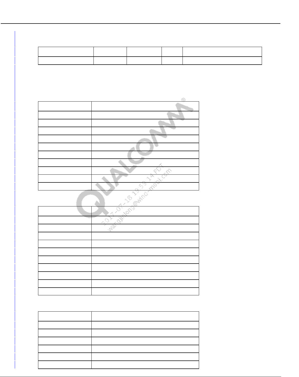
Wireless Connectivity Tests User Guide Wireless Connectivity Test Description
80-Y0306-1 Rev. L MAY CONTAIN U.S. AND INTERNATIONAL EXPORT CONTROLLED INFORMATION 142
Confidential and Proprietary – Qualcomm Atheros, Inc.
Table 10-133 ConfigureNFCTester
Parameter Name
Lower Limit
Upper Limit
Unit
Description
ErrorMessage
N.A
Error message
10.8.15.1 Default Settings for Configure NFC Tester
Table 10-134 Type A initiator test default tester configuration
Parameter name
Value
SelectTestType
INITIATOR TEST
SelectNFCTech
A
ResonatorType
RES_13_56MHZ,
CaptureLength
0.1
DataRate
RATE_R106
ModDepth
M100
FieldStrength
6
FreqStart
12 (not applicable for this test mode)
FreqStop
16 (not applicable for this test mode)
FreqStep
0.005 (not applicable for this test mode)
Table 10-135 Type B initiator test default tester configuration
Parameter name
Value
SelectTestType
INITIATOR TEST
SelectNFCTech
B
ResonatorType
RES_13_56MHZ,
CaptureLength
0.1
DataRate
RATE_R106
ModDepth
M10
FieldStrength
6
FreqStart
12 (not applicable for this test mode)
FreqStop
16 (not applicable for this test mode)
FreqStep
0.005 (not applicable for this test mode)
Table 10-136 Type F initiator test default tester configuration
Parameter name
Value
SelectTestType
INITIATOR TEST
SelectNFCTech
F
ResonatorType
RES_13_56MHZ,
CaptureLength
0.1
DataRate
RATE_R212
ModDepth
M100

Wireless Connectivity Tests User Guide Wireless Connectivity Test Description
80-Y0306-1 Rev. L MAY CONTAIN U.S. AND INTERNATIONAL EXPORT CONTROLLED INFORMATION 143
Confidential and Proprietary – Qualcomm Atheros, Inc.
Parameter name
Value
FieldStrength
6
FreqStart
12 (not applicable for this test mode)
FreqStop
16 (not applicable for this test mode)
FreqStep
0.005 (not applicable for this test mode)
Table 10-137 Type A target test default tester configuration
Parameter name
Value
SelectTestType
TARGET_TEST
SelectNFCTech
A
ResonatorType
RES_13_56MHZ,
CaptureLength
0.1
DataRate
RATE_R106
ModDepth
M100
FieldStrength
6
FreqStart
12 (not applicable for this test mode)
FreqStop
16 (not applicable for this test mode)
FreqStep
0.005 (not applicable for this test mode)
Table 10-138 Type B target test default tester configuration
Parameter name
Value
SelectTestType
TARGET_TEST
SelectNFCTech
B
ResonatorType
RES_13_56MHZ,
CaptureLength
0.1
DataRate
RATE_R106
ModDepth
M10
FieldStrength
6
FreqStart
12 (not applicable for this test mode)
FreqStop
16 (not applicable for this test mode)
FreqStep
0.005 (not applicable for this test mode)
Table 10-139 Type F target test default tester configuration
Parameter name
Value
SelectTestType
TARGET_TEST
SelectNFCTech
F
ResonatorType
RES_13_56MHZ,
CaptureLength
0.1
DataRate
RATE_R212
ModDepth
M100
FieldStrength
6
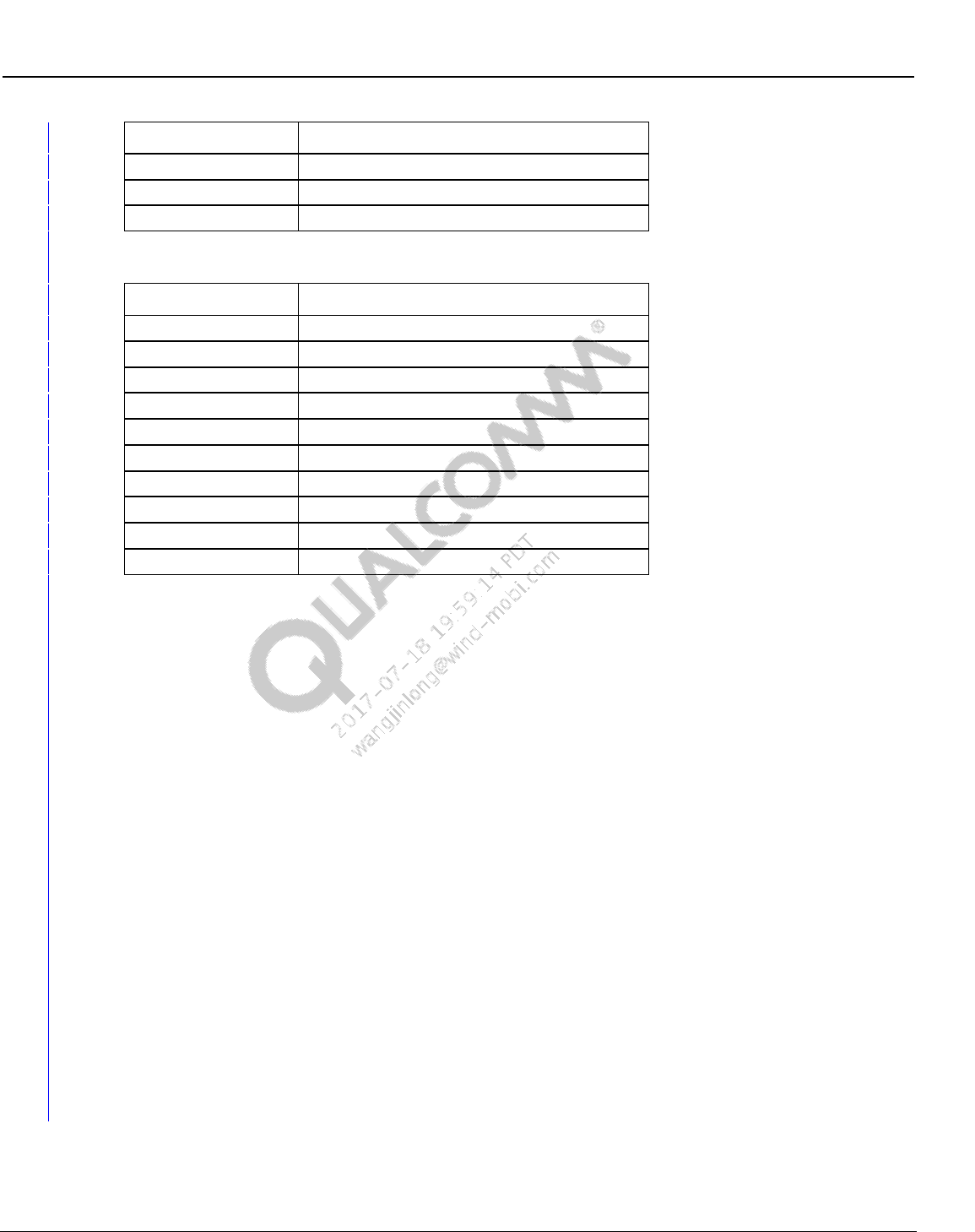
Wireless Connectivity Tests User Guide Wireless Connectivity Test Description
80-Y0306-1 Rev. L MAY CONTAIN U.S. AND INTERNATIONAL EXPORT CONTROLLED INFORMATION 144
Confidential and Proprietary – Qualcomm Atheros, Inc.
Parameter name
Value
FreqStart
12 (not applicable for this test mode)
FreqStop
16 (not applicable for this test mode)
FreqStep
0.005 (not applicable for this test mode)
Table 10-140 Resonance test default tester configuration
Parameter name
Value
SelectTestType
FREQ_SWEEP_TEST
SelectNFCTech
A (not applicable for this test mode)
ResonatorType
OFF
CaptureLength
0.1 (not applicable for this test mode)
DataRate
RATE_R212 (not applicable for this test mode)
ModDepth
M100 (not applicable for this test mode)
FieldStrength
0
FreqStart
12
FreqStop
16
FreqStep
0.005
10.8.16 NFCDUT_FindResonance
This test is applicable to SoC/Standalone type DUT. The main purpose of this test is to find the
cap code to calibrate the DUT matching for fixture specific impedance variations.
This test finds the cap code corresponding to the required resonance frequency using the NFC
Tester. Cap codes are written to specific NVM registers specified by the Payload Format
parameter to tune the resonance frequency. Maximum and minimum possible Cap Codes are
taken as input parameters. These values set the boundaries for the test to sweep the Cap Code.
The test uses an iterative algorithm to find the cap code corresponding to the target resonance
frequency within the specified tolerance. Initial estimation for the cap code is calculated by
interpolating from the measured maximum and minimum possible resonance frequency.
The algorithm halts and exits if any of the following situations are encountered:
1. Resonance frequency within the specified tolerance has been attained.
2. Maximum or Minimum Cap Code reached. The target frequency is probably out of range.
3. Minimum Cap Code resolution reached. Finer tuning using Cap Code is not possible.
It is recommended that QSPR output parameter limits should be set on ‘FreqError’ parameter to
enable a pass/fail condition for this test. The final achieved Cap Code will be copied to a QSPR
global variable which will be used in the tests that follow.
Supported Test Box: LitePoint IQNFC
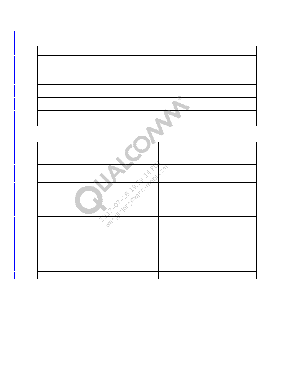
Wireless Connectivity Tests User Guide Wireless Connectivity Test Description
80-Y0306-1 Rev. L MAY CONTAIN U.S. AND INTERNATIONAL EXPORT CONTROLLED INFORMATION 145
Confidential and Proprietary – Qualcomm Atheros, Inc.
Table 10-141 NFCDUT_FindResonance input parameters
Parameter name
Value
Unit
Description
PayloadFormat
00 00 00 02 00 82 02 00
N.A
This is the format for the NCI
command to be used for setting
the NVM. It contains the public
register address for the Target Rx
Cap NVM
TargetTuneFreq
MHz
The required Resonance
frequency
Tolerance
0.02
MHz
Target tolerance for the achieved
frequency.
MinCapCode
00
N.A
Minimum valid Cap Code
MaxCapCode
1F
N.A
Maximum valid Cap Code
Table 10-142 NFCDUT_FindResonance output parameters
Parameter Name
Lower Limit
Upper Limit
Unit
Description
CapCode
N.A
Final achieved Cap Code by the
test
AchievedFreq
MHz
Final Achieved frequency
corresponding to the achieved Cap
Code
FreqError
MHz
Frequency difference between
Target and actual achieved
frequency. It is recommended that
the FreqError test limits be set
higher than the input parameter
‘Tolerance’.
ErrorCode
N.A
Status code explaining the
algorithm status:
0 = no error,
1 = generic error,
2 = max/min cap code reached,
3 = max iteration count of 8 reache
d
4 = accuracy limited by cap code
tuning resolution.
ErrorMessage
N.A
Error message
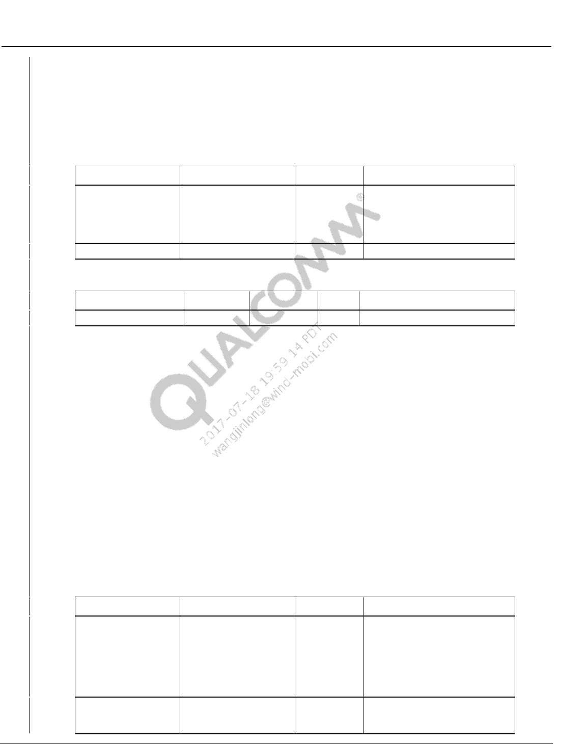
Wireless Connectivity Tests User Guide Wireless Connectivity Test Description
80-Y0306-1 Rev. L MAY CONTAIN U.S. AND INTERNATIONAL EXPORT CONTROLLED INFORMATION 146
Confidential and Proprietary – Qualcomm Atheros, Inc.
10.8.17 NFCDUT_TuneCapNVM
This test updates the NVM with the provided CapCode and the payload format. It uses the
provided payload format to generate the NCI command string. The payload format also contains
the public address for the NVM register.
Table 10-143 NFCDUT_TuneCapNVM input parameters
Parameter name
Value
Unit
Description
PayloadFormat
00 00 00 02 00 82 02 00
N.A
This is the format for the NCI
command to be used for setting
the NVM. It contains the public
register address for the Target Rx
Cap NVM
CapCode
N.A
The CapCode to be written.
Table 10-144 NFCDUT_TuneCapNVM output parameters
Parameter Name
Lower Limit
Upper Limit
Unit
Description
ErrorMessage
N.A
Error message
10.8.18 InitiatorTest
This test measures RF parametric of the DUT Initiator Tx signal. This test will capture and report
details of the first poll signal within the capture length specified in the ConfigureNFCTester test.
The ConfigureNFCTester and ConfigureDUT should be run every time before this test so that
the DUT and the NFC tester have been configured to the correct NFC protocols, test type
(initiator test) and other setup details.
Supported Test Box: LitePoint IQNFC
Pre-requisite setup tests:
NFCDUT_ConfigureDUT (please select Initiator test for test type and the required NFC
protocol type)
ConfigureNFCTester (please select Initiator test for test type and the required NFC protocol
type and other details to match the protocol type. Refer to section 10.8.15.1 for more details
regarding default for each protocol)
Test Scenario: The NFC Tester is configured to be a target and the DUT as an initiator.
Table 10-145 InitiatorTest input parameters
Parameter name
Value
Unit
Description
NfcType
NFCA,
NFCB,
NFCF,
NFCP2P
Dropdown
selection
Select the NFC protocol type.
Only the selected NFC initiator
signal parametric data will be
reported. Other NFC types if
present will be ignored.
NFCP2P is currently not
supported.
RetryCount
3
N.A
This is the number of times the
test will retry, if it fails to find the
Polling signal.
Wireless Connectivity Tests User Guide Wireless Connectivity Test Description
80-Y0306-1 Rev. L MAY CONTAIN U.S. AND INTERNATIONAL EXPORT CONTROLLED INFORMATION 147
Confidential and Proprietary – Qualcomm Atheros, Inc.
Table 10-146 InitiatorTest output parameters
Parameter Name
Lower Limit
Upper Limit
Unit
Description
Meas_FS
mA/m
This is the measured Field
Strength in mA/m for the DUT
Initiator field
Meas_DataRate
Kbps
Measured data rate for the initiator
signal
Mod_Index
%
Modulation index. Applicable for
NFC B and F
Mod_Depth
%
Modulation depth. Applicable for
NFC A
Carrier_Freq_Offset
Hz
Measured Carrier frequency offset
in Hz
Rise_Time
μs
Applicable to NFC B and F
Fall_Time
μs
Applicable to NFC B and F
Rise_Overshoot
%
Applicable to NFC B and F
Rise_Undershoot
%
Applicable to NFC B and F
Fall_Overshoot
%
Applicable to NFC B and F
Fall_Undershoot
%
Applicable to NFC B and F
Bits
Comma separated string of
decoded bits
CRC
bool
CRC check result
t1
μs
Applicable to NFC A
t2
μs
Applicable to NFC A
t3
μs
Applicable to NFC A
t4
μs
Applicable to NFC A
t5
μs
Applicable to NFC A
ErrorMessage
Error message
10.8.19 InitiatorRxTest
This test checks the functionality of the Initiator Rx block. The test methodology is shown in the
figure. The NFC tester responds to the polling from the DUT with SENS_RES. The DUT upon
successfully receiving SENS_RES, will send the next Poll in accordance with the NFC protocol.
This test checks for this second poll to verify that the DUT Initiator Rx is functional.
The ConfigureNFCTester and ConfigureDUT should be run every time before this test so that the
DUT and the NFC tester have been configured to the correct NFC protocols, test type (initiator
test) and other setup details.
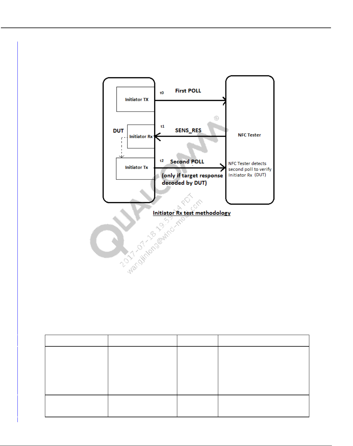
Wireless Connectivity Tests User Guide Wireless Connectivity Test Description
80-Y0306-1 Rev. L MAY CONTAIN U.S. AND INTERNATIONAL EXPORT CONTROLLED INFORMATION 148
Confidential and Proprietary – Qualcomm Atheros, Inc.
Supported Test Box: LitePoint IQNFC
Pre-requisite setup tests:
NFCDUT_ConfigureDUT (select Initiator test for test type and the required NFC protocol
type)
ConfigureNFCTester (select Initiator test for test type and the required NFC protocol type
and other details to match the protocol type. Refer to section 10.8.15.1 for more details
regarding default for each protocol)
Test Scenario: The NFC Tester is configured to be a target and the DUT as an initiator.
Table 10-147 Initiator Rx test input parameters
Parameter name
Value
Unit
Description
NfcType
NFCA,
NFCB,
NFCF,
NFCP2P
Dropdown
selection
Select the NFC protocol type.
Only the selected NFC initiator
signal parametric data will be
reported. Other NFC types if
present will be ignored.
NFCP2P is currently not
supported.
RetryCount
3
N.A
This is the number of times the
test will retry, if it fails to find the
Polling signal.
Wireless Connectivity Tests User Guide Wireless Connectivity Test Description
80-Y0306-1 Rev. L MAY CONTAIN U.S. AND INTERNATIONAL EXPORT CONTROLLED INFORMATION 149
Confidential and Proprietary – Qualcomm Atheros, Inc.
Table 10-148 Initiator Rx test output parameters
Parameter Name
Lower Limit
Upper Limit
Unit
Description
Poll1Bits
Comma separated string of
decoded bits for 1st POLL
Poll2Bits
Comma separated string of
decoded bits for 2nd POLL
ErrorCode
0
0
0 if no error(Test passed) and 1 if
any error(Test Failed)
ErrorMessage
Error message
10.8.20 TargetTest
This test measures RF parametric of the DUT target Tx signal. This test will capture and report
details of the first target response signal within the capture length specified in the
ConfigureNFCTester test. The ConfigureNFCTester and ConfigureDUT should be run every time
before this test so that the DUT and the NFC tester have been configured to the correct NFC
protocols, test type (set as target test) and other setup details.
Supported Test Box: LitePoint IQNFC
Pre-requisite setup tests:
NFCDUT_ConfigureDUT (please select target test for test type and the required NFC
protocol type),
ConfigureNFCTester (please select target test for test type and the required NFC protocol
type and other details to match the protocol type. Refer to section 10.8.15.1 for more details
regarding default for each protocol)
Test Scenario: The NFC Tester is configured to be an initiator and the DUT as a target.
Table 10-149 TargetTest input parameters
Parameter name
Value
Unit
Description
NfcType
NFCA,
NFCB,
NFCF,
NFCP2P
Dropdown
selection
Select the NFC protocol type.
Only the selected NFC initiator
signal parametric data will be
reported. Other NFC types if
present will be ignored.
NFCP2P is currently not
supported.
RetryCount
3
N.A
This is the number of times the
test will retry, if it fails to find the
Polling signal.
Table 10-150 TargetTest output parameters
Parameter Name
Lower Limit
Upper Limit
Unit
Description
Meas_DataRate
Kbps
Measured data rate for the target
response
Frame_Delay_Time
μs
Frame delay time in sec
Load_Modulation
mA/m
measured load modulation in volts
Wireless Connectivity Tests User Guide Wireless Connectivity Test Description
80-Y0306-1 Rev. L MAY CONTAIN U.S. AND INTERNATIONAL EXPORT CONTROLLED INFORMATION 150
Confidential and Proprietary – Qualcomm Atheros, Inc.
Parameter Name
Lower Limit
Upper Limit
Unit
Description
Mod_Index
%
Not used
Mod_Depth
%
Not used
Volt_Peak_to_Peak
mA/m
Peak to peak measurement for the
RF envelop
SubCarrierFrequency
kHz
Measured sub carrier frequency for
load modulation
Bits
Comma separated string of
decoded data bits in the target
response
CRC
bool
CRC check
ErrorMessage
Error message
10.8.21 ResonanceTest
This test measures resonance of the DUT NFC antenna system. This test will capture and report
the Measured resonance frequency, the associated Q and the Bandwidth of the resonance
network. The ConfigureNFCTester and ConfigureDUT should be run every time before this test
so that the DUT and the NFC tester have been configured to the correct mode and test type
(Frequency Sweep test).
Supported Test Box: LitePoint IQNFC
Pre-requisite setup tests:
NFCDUT_ConfigureDUT (please select target test for test type. This will put the DUT in listen
mode. Other modes like CoreResetAndInit can be selected depending on the user requirement)
ConfigureNFCTester (please select FREQ_SWEEP_TEST for test type other details to match the
protocol type. Refer to section 10.8.15.1 for more details regarding default for each protocol)
The Frequency Start, Stop, and the FS Level set during the creation of the Calibration file should
match the settings in ConfigureTester test. Loading the matching calibration file is required for
this test.
Test Scenario: The NFC Tester is configured for Resonance sweep and the DUT can be
configured in a mode deemed appropriate by the user.
Table 10-151 ResonanceTest output parameters
Parameter Name
Lower Limit
Upper Limit
Unit
Description
Freq
MHz
Measured resonance frequency in
MHz. Calculated using geometric
mean of the 3dB points
Q
N.A
Q of the resonance network
BW_3dB
kHz
3dB Bandwidth
ErrorMessage
N.A
Error message
Wireless Connectivity Tests User Guide Wireless Connectivity Test Description
80-Y0306-1 Rev. L MAY CONTAIN U.S. AND INTERNATIONAL EXPORT CONTROLLED INFORMATION 151
Confidential and Proprietary – Qualcomm Atheros, Inc.
10.8.22 Disconnect
This test disconnects all the open ports.
Table 10-152 Disconnect output parameters
Parameter Name
Lower Limit
Upper Limit
Unit
Description
ErrorMessage
N.A
Error message
10.8.23 Shutdown
This test shuts down the test suite framework and releases all the resources.
Table 10-153 Shutdown output parameters
Parameter Name
Lower Limit
Upper Limit
Unit
Description
ErrorMessage
N.A
Error message
