FRONTD 8178071 Duet Dryer
2013-05-09
: Pdf 8178071 Duet Dryer 8178071 Duet dryer dryer may8
Open the PDF directly: View PDF ![]() .
.
Page Count: 68
CONSUMER SERVICES TECHNICAL
EDUCATION GROUP PRESENTS
L-69
JOB AID
Part No. 8178071
GAS AND ELECTRIC
DRYERS
Model Numbers:
GGW9200L & GEW9200L
™

- ii -
WHIRLPOOL CORPORATION assumes no responsibility for any repairs made
on our products by anyone other than Authorized Service Technicians.
FORWARD
This Whirlpool Job Aid, “Duet™ Gas and Electric Dryers,” (Part No. 8178071), provides the
technician with information on the operation and service of the Gas and Electric Dryers. It is to be
used as a training Job Aid and Service Manual. For specific information on the model being
serviced, refer to the “Use and Care Guide,” or “Tech Sheet” provided with the dryer.
The Wiring Diagrams used in this Job Aid are typical and should be used for training purposes only.
Always use the Wiring Diagram supplied with the product when servicing the unit.
GOALS AND OBJECTIVES
The goal of this Job Aid is to provide detailed information that will enable the service technician to
properly diagnose malfunctions and repair the Whirlpool Gas and Electric Dryers.
The objectives of this Job Aid are to:
• Understand and follow proper safety precautions.
• Successfully troubleshoot and diagnose malfunctions.
• Successfully perform necessary repairs.
• Successfully return the Gas or Electric Dryer to its proper operational status.
Copyright © 2001, Whirlpool Corporation, Benton Harbor, MI 49022
- iii -
TABLE OF CONTENTS
GENERAL............................................................................................................................................. 1-1
Important Safety Information........................................................................................................... 1-1
Model & Serial Number Designations ............................................................................................. 1-2
Model & Serial Number Label And Tech Sheet Locations ............................................................. 1-3
Specifications .................................................................................................................................. 1-4
Warranty .......................................................................................................................................... 1-5
INSTALLATION INFORMATION ......................................................................................................... 2-1
Electrical Requirements For Electric Dryers ................................................................................... 2-1
Electrical Connections For Electric Dryers ..................................................................................... 2-3
Electrical Requirements For Gas Dryers ........................................................................................ 2-8
Gas Supply Requirements .............................................................................................................. 2-9
Optional Exhaust Information........................................................................................................ 2-10
Leveling The Dryer ........................................................................................................................ 2-10
Reversing The Door Swing ........................................................................................................... 2-11
Installing The Optional Pedestal ................................................................................................... 2-14
Optional Stack Kit (#8519492) ...................................................................................................... 2-16
PRODUCT OPERATION ...................................................................................................................... 3-1
COMPONENT ACCESS ....................................................................................................................... 4-1
Component Locations ..................................................................................................................... 4-1
Removing The Machine Control Electronics Board ........................................................................ 4-2
Removing The Console & The Touchpad Subassembly ................................................................ 4-4
Removing The Door Switch ............................................................................................................ 4-6
Removing The Thermal Fuse, Thermistor, Drive Motor, & Belt Switch .......................................... 4-7
Removing The Heater, The High-Limit Thermostat, & Thermal Cutoff......................................... 4-10
Removing The Belt, Drum, & Rollers ............................................................................................ 4-11
Removing The Drum Light Socket ................................................................................................ 4-14
Removing The Moisture Sensor ................................................................................................... 4-15
COMPONENT TESTING ...................................................................................................................... 5-1
Making Electrical Tests ................................................................................................................... 5-1
Drive Motor...................................................................................................................................... 5-2
Heater ............................................................................................................................................. 5-3
Thermal Fuse .................................................................................................................................. 5-4
Thermistor ....................................................................................................................................... 5-5
Thermal Cutoff (Electric Dryers Only) ............................................................................................. 5-6
Gas Valve (Gas Dryers Only) ......................................................................................................... 5-7
Moisture Sensor .............................................................................................................................. 5-8
Console Pushbuttons & LEDs......................................................................................................... 5-8
Door Switch ................................................................................................................................... 5-10
DIAGNOSIS AND TROUBLESHOOTING ........................................................................................... 6-1
Diagnosis ........................................................................................................................................ 6-1
Display Fault/Error Codes ......................................................................................................... 6-1
Diagnostic Tests ........................................................................................................................ 6-1
Keypad Test .............................................................................................................................. 6-2
Additional Tests ......................................................................................................................... 6-2
Troubleshooting Guide .................................................................................................................... 6-3
WIRING DIAGRAMS ............................................................................................................................ 7-1
Page
- iv -
— NOTES —
1-1
ELECTRICAL SHOCK HAZARD
Disconnect power before servicing.
Replace all panels before operating.
Failure to do so could result in death or
electrical shock.
Important safety messages have been pro-
vided in this Job Aid. Always read and obey all
safety messages.
IMPORTANT SAFETY INFORMATION
Your safety and the safety of others is very important.
This is the safety alert symbol.
This symbol alerts you to haz-
ards that can kill or hurt you
and others.
All safety messages will be preceded by the
safety alert symbol and the word “WARNING.”
All safety messages will identify the hazard, tell
you how to reduce the chance of injury, and tell
you what can happen if the instructions are not
followed.
WARNING
ELECTROSTATIC DISCHARGE
(ESD) SENSITIVE ELECTRONICS
ESD problems are present everywhere. ESD
may damage or weaken the electronic control
assembly. The new control assembly may ap-
pear to work well after repair is finished, but
failure may occur at a later date due to ESD
stress.
• Use an antistatic wrist strap. Connect the
wrist strap to a green ground connection
point or unpainted metal in the appliance;
or touch your finger repeatedly to a green
ground connection point or unpainted metal
in the appliance.
• Before removing the part from its pack-
age, touch the antistatic bag to a green
ground connection point or unpainted metal
in the appliance.
• Avoid touching electronic parts or terminal
contacts. Handle the electronic control
assembly by the edges only.
• When repackaging the failed electronic
control assembly in an antistatic bag, ob-
serve the above instructions.
GENERAL
FIRE HAZARD
Disconnect gas supply before servicing.
Replace all panels before operating.
Failure to do so could result in death or
electrical shock.
WARNING

1-2
MODEL & SERIAL NUMBER DESIGNATIONS
MODEL NUMBER (DRYER)
MODEL NUMBER (PEDESTAL)
SERIAL NUMBER (DRYER) SERIAL NUMBER (PEDESTAL)
MODEL NUMBER G E W 9200 L W 0
PRODUCT GROUP
G = Domestic Laundry Gold
PRODUCT IDENTIFICATION
E = Electric Dryer
G = Gas Dryer
FEATURE CODE
W = High Efficiency
FEATURE LEVEL
YEAR OF INTRODUCTION
L = 2002
COLOR CODE
W = White / Grey
Q = White / Blue
ENGINEERING CHANGE
0 = Basic, 1 = 1st Revision, 2 = 2nd Revision
MODEL NUMBER L A B 2 7 0 0 L Q 0
PRODUCT GROUP
L = Domestic Laundry
PRODUCT IDENTIFICATION
A = Laundry Accessory
FEATURE CODE
B = Pedestal Base
PRODUCT WIDTH
FILLER
FILLER
YEAR OF INTRODUCTION
COLOR CODE
K = Graphite (Laundry)
Q = White On White
T = Biscuit On Biscuit
ENGINEERING CHANGE
SERIAL NUMBER
M L 16 00036
MANUFACTURING SITE
MARION, OH
YEAR OF PRODUCTION
L = 2001
WEEK OF PRODUCTION
PRODUCT SEQUENCE NUMBER
SERIAL NUMBER C T L 01 10001
MANUFACTURING SITE
TAYLOR IND., MANSFIELD, OH
YEAR OF PRODUCTION
L = 2001
WEEK OF PRODUCTION
PRODUCT SEQUENCE NUMBER
1-3
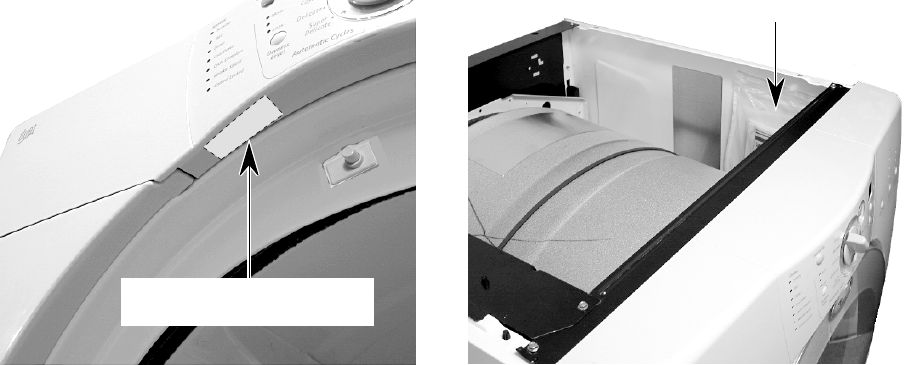
MODEL & SERIAL NUMBER LABEL
AND TECH SHEET LOCATIONS
The Model/Serial Number label and Tech Sheet locations are shown below.
Tech Sheet Location
(Located Under Top Cover)
Model & Serial
Number Label Location

1-4
SPECIFICATIONS
BRAND Whirlpool Whirlpool Whirlpool Whirlpool
MODEL NUMBER GEW9200LW GEW9200LQ GGW9200LW GGW9200LQ
FUEL Electric Electric Gas Gas
CABINET COLOR White/Grey White/Blue White/Grey White/Blue
INSTALLATION OPTIONS
FREESTANDING
XXXX
PEDESTAL
XXXX
STACKABLE
XXXX
CAPACITY (cu ft)
7.0 7.0 7.0 7.0
CAPACITY NOMENCLATURE
SUPER CAPACITY SUPER CAPACITY SUPER CAPACITY SUPER CAPACITY
AUTO CYCLE TERMINATION
ENHANCED EH (Fuzzy Logic)
XXXX
SENSION CONTROL
XXXX
LINT HANDLING
FRONT SCREEN
XXXX
CONTROLS
Electronic Electronic Electronic Electronic
CONTROL LOCK OUT
XXXX
CONTROL TYPE PRIMARY
Rotary Rotary Rotary Rotary
CONTROL TYPE SECONDARY
Tap Touch Tap Touch Tap Touch Tap Touch
NON-HEATED DRY RACK
XXXX
MULTI-VENT OPTION
4 WAY 4 WAY 4 WAY 4 WAY
UTILITIES
FREQUENCY
60HZ 60HZ 60HZ 60HZ
MOTOR RATING
1/3 HP 1/3 HP 1/3 HP 1/3 HP
HEATER ELEMENT
5400W 5400W
GAS BTU
22,000 22,000
RATED AMPERAGE (ELECTRIC)
28 28
DIMENSIONS (UNCRATED)
HEIGHT OF TOP*
37 2/5 37 2/5 37 2/5 37 2/5
TOTAL HEIGHT*
37 2/5 37 2/5 37 2/5 37 2/5
WIDTH
27 27 27 27
DEPTH
ELECTRIC
30 3/4 30 3/4 30 3/4 30 3/4
GAS + 1 INCH
31 3/4 31 3/4 31 3/4 31 3/4
DEPTH DOOR OPEN
51 51 51 51
PRODUCT WEIGHT
143 143 143 143
WARRANTY
LABOR
1 Yr 1 Yr 1 Yr 1 Yr
PARTS
1 Yr 1 Yr 1 Yr 1 Yr
PORCELAIN TOP
5 Yr 5 Yr 5 Yr 5 Yr
MOTOR/ELEMENT/BURNER
1 Yr 1 Yr 1 Yr 1 Yr
CONTROLS
2 Yr 2 Yr 2 Yr 2 Yr
1-5
FULL ONE YEAR WARRANTY ON MECHANICAL
AND ELECTRICAL PARTS
For one year from the date of purchase, Whirlpool will pay for replacement
parts and repair labor for mechanical or electrical parts to correct defects
in materials or workmanship. Whirlpool will perform necessary adjust-
ments. Service must be provided by a Whirlpool Service Department in
Canada or an authorized agent.
NOTE: Exhausting this dryer with a plastic vent can void this warranty. See
the “Installation Instructions” for the exhaust requirements for this dryer.
LIMITED TWO YEAR WARRANTY ON SENSOR SMART™
ELECTRONIC CONTROL BOARD
For two years from the date of purchase, Whirlpool will replace the
electronic control board if defective in materials or workmanship. You will
be charged for labor after the first year.
LIMITED FIVE YEAR WARRANTY ON PORCELAIN TOP
For five years from the date of purchase, Whirlpool will replace parts for the
po top should it be perforated by rust or chippage.
PEDESTAL OPTION WARRANTY
WARRANTY
FULL ONE YEAR WARRANTY ON MECHANICAL PARTS
For one year from the date of purchase, when Pedestal is installed with this
dryer and operated according to the instructions provided in the Owner’s
Manual, supplier will repair or replace any mechanical parts if defective in
material or workmanship.
1-6
— NOTES —
2-1
ELECTRICAL REQUIREMENTS FOR ELECTRIC DRYERS
ELECTRICAL SHOCK HAZARD
Check with a qualified electrician if you
are in doubt as to whether the appliance
is properly grounded. Do not modify the
power supply cord plug. If it will not fit the
outlet, have a proper outlet installed by a
qualified electrician.
Improper connection of the equipment
grounding conductor can result in a risk
of electrical shock.
WARNING
It is your responsibility:
• To contact a qualified electrical installer.
• To be sure that the electrical connections are
adequate and in conformance with the Na-
tional Electrical Code, ANSI/NFPA 70-latest
edition and all local codes and ordinances.
A copy of the above code standards can be
obtained from: National Fire Protection As-
sociation, Batterymarch Park, Quincy, MA
02269.
• To supply the required 3 or 4 wire, single
phase, 120/240-volt, 60 Hz, AC-only electri-
cal supply (or 3 or 4 wire, 120/208-volt elec-
trical supply, if specified on the serial/rating
plate) on a separate 30-ampere circuit, fused
on both sides of the line. A time-delay fuse or
circuit breaker is recommended. Connect
the wiring to an individual branch circuit.
• Do not use an extension cord.
• If codes permit and a separate ground wire
is used, it is recommended that a qualified
electrician determine that the ground path is
adequate.
INSTALLATION INFORMATION
For a grounded, cord-connected dryer:
This dryer must be grounded. In the event of
malfunction or breakdown, grounding will re-
duce the risk of electric shock by providing a
path of least resistance for electric current.
This dryer uses a cord having an equipment-
grounding conductor and a grounding plug.
The plug must be plugged into an appropriate
outlet that is properly installed and ground-
ed in accordance with all local codes and or-
dinances.
For a permanently connected dryer:
This dryer must be connected to a grounded
metal, permanent wiring system, or an equip-
ment-grounding conductor must be run with
the circuit conductors and connected to the
equipment-grounding terminal or lead on the
dryer.
GROUNDING INSTRUCTIONS
2-2
Choose a 4-wire power supply cord with ring,
or spade terminals, and a UL-approved strain
relief. The 4-wire power supply cord must have
4, 10 gauge solid copper wires, and match a 4-
wire receptacle, NEMA type 14-30R. The fourth
wire (ground conductor) must be identified with
a green cover, and the neutral conductor by a
white cover.
ELECTRICAL CONNECTION
If using a power supply cord, the cord must
be:
• U.L.-listed or CSA certified
• 120/240 volt minimum
• 30 amp
• Type SRD or SRDT
• At least 4 ft (122 cm) long
The wires that connect to the dryer must end in
ring terminals, or spade terminals with up-
turned ends.
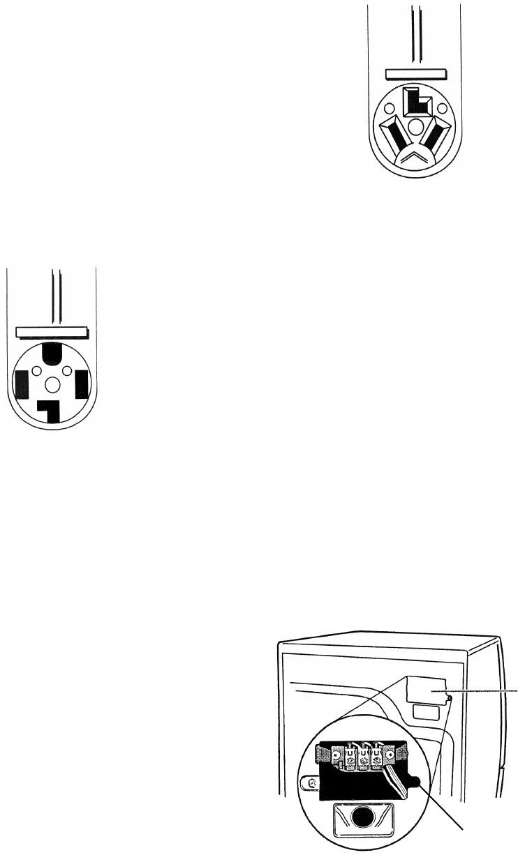
If the outlet looks like this:
4-Wire Receptacle (14-30R)
Choose a 3-wire power supply cord with ring,
or spade terminals, and a UL-approved strain
relief. The 3-wire power supply cord, must
have three #10 copper wires, and match a 3-
wire receptacle, NEMA type 10-30R.
If connecting by direct wire:
The power supply cable must match power
supply (4-wire or 3-wire) and be:
• Flexible armored or nonmetallic sheathed
copper cable (with ground wire). All current-
carrying wires must be insulated.
• 10 gauge solid copper wire (do not use
aluminum).
• At least 4 ft (122 cm) long.
If the outlet looks like this:
3-Wire Receptacle (10-30R)
Terminal
Block
Cover
Terminal
Block
All wire connections are be made to the termi-
nal block, located on the rear of the appliance.
The terminal block and its cover location is
shown below.
2-3
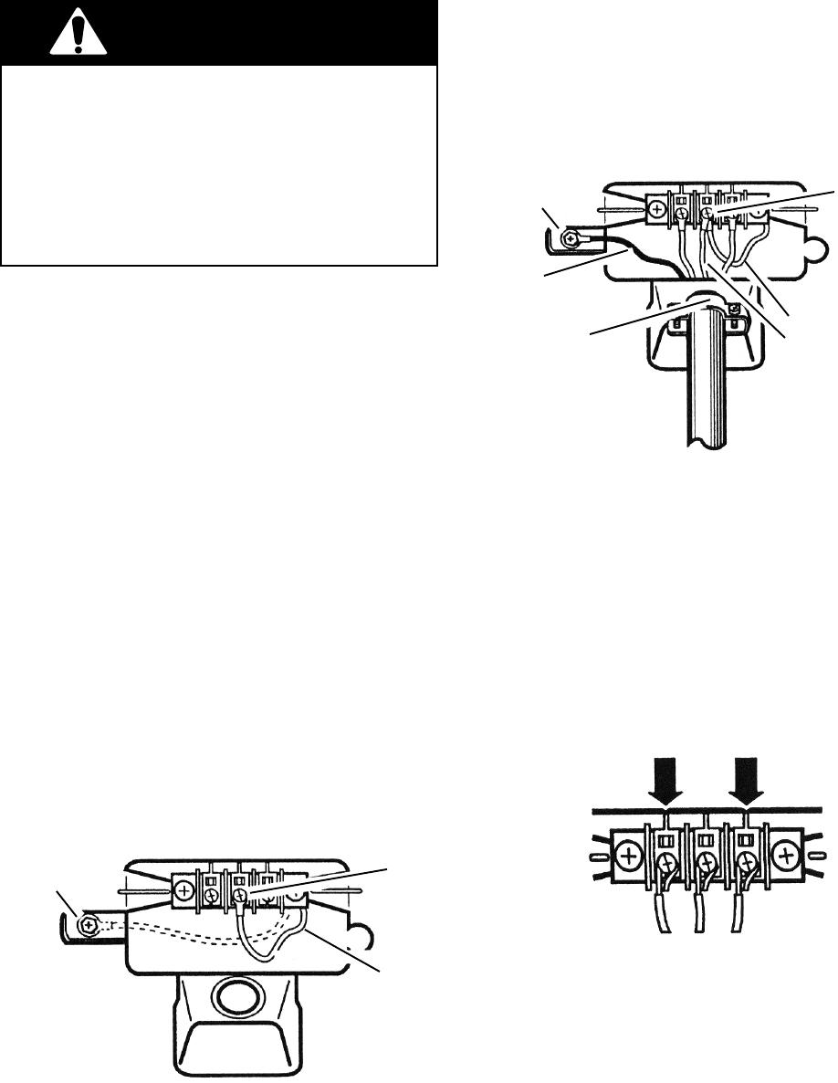
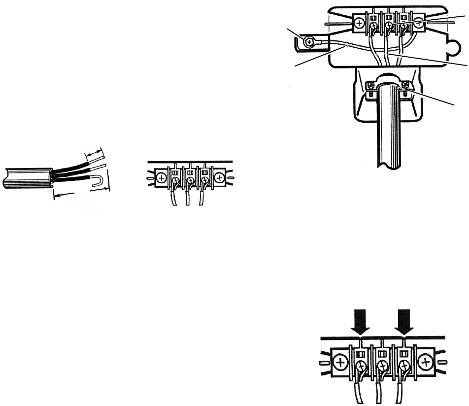
ELECTRICAL CONNECTIONS FOR ELECTRIC DRYERS
A. External ground connector (dotted lines show
position of neutral ground wire before being
moved)
B. Center, silver terminal block screw
C. Neutral grounding wire (green/yellow) in har-
ness
NOTE: This section shows the installation for:
• 4-wire power supply cord connection
• 4-wire direct connection
• 3-wire power supply cord connection
• 3-wire direct connection
• Optional 3-wire connection
4-WIRE POWER SUPPLY
CORD CONNECTION
IMPORTANT: A 4-wire connection is re-
quired for use in mobile homes, and where
local codes do not permit the use of 3-wire
connections.
1. Remove the terminal block cover hold-
down screw and open the cover at the
back of the dryer.
2. Remove the center terminal block screw.
3. Remove the appliance ground wire (green
with a yellow tracer) from the external
ground connector screw, and reconnect it
to the center, silver terminal block screw.
4. Connect the ground wire (green or bare) of
the power supply cord to the external
ground conductor screw.
5. Connect the neutral wire (white or center
wire) of the power supply cord to the
center screw of the terminal block.
B
C
A
AD
E
F
B
C
A. External ground connector
B. Green or bare copper wire of power supply
cord
C. 3/4″ (1.9 cm) UL-listed strain relief
D. Center, silver terminal block screw
E. Neutral grounding wire (green/yellow)
F. Neutral wire (white)
6. Connect the ends of the remaining power
supply wires to the left and right terminal
block screws.
7. Check the wire connections and make
sure that they are all tight.
8. Tighten the strain relief clamp screws.
9. Insert the tab of the terminal block cover
into the slot of the dryer rear panel and
secure the cover with its mounting screw.
LR
ELECTRICAL SHOCK HAZARD
Disconnect power before making electrical
connections.
Securely tighten all electrical connections.
Failure to do so can result in death or
electrical shock.
WARNING
2-4
4-WIRE DIRECT CONNECTION
1. Strip 5″ (12.7cm) of outer covering from
the end of the cable.
2. Cut 1-1/2″ (3.8 cm) from the 3 insulated
wires. Do not cut the bare ground wire.
3. Strip 1″ (2.5 cm) of insulation from the
ends of the three wires.
4. Twist the loose wire strands together on
each wire and form a hook in the bare wire
ends.
1″
(2.5 cm)
5″
(12.7 cm)
D
E
F
C
A
B
A. External ground connector
B. Green or bare copper wire of power supply
cord
C. 3/4″ (1.9 cm) UL-listed strain relief
D. Center, silver terminal block screw
E. Neutral grounding wire (green/yellow)
F. Neutral wire (white)
9. Connect the end of the neutral (white) wire
of the power supply cable to the center
screw of the terminal block.
10. Connect the ends of the remaining power
supply wires to the left and right terminal
block screws.
LR
11. Check the wire connections and make
sure that they are all tight.
12. Tighten the strain relief clamp screws.
13. Insert the tab of the terminal block cover
into the slot of the dryer rear panel and
secure the cover with its mounting screw.
8. Connect the ground wire (green or bare) of
the power supply cable to the external
ground conductor screw.
5. Remove the terminal block cover hold-
down screw and open the cover at the
back of the dryer.
6. Remove the center terminal block screw.
7. Remove the appliance ground wire (green
with a yellow tracer) from the external
ground connector screw, and reconnect it
to the center, silver terminal block screw.
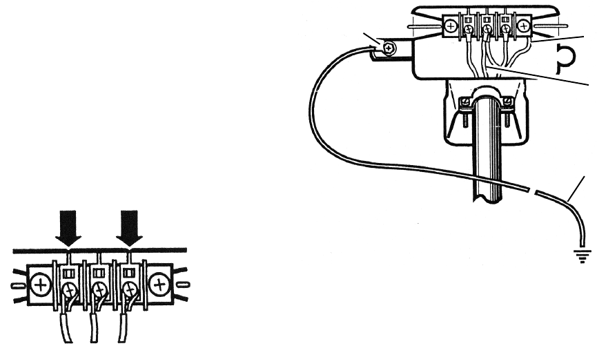
2-5
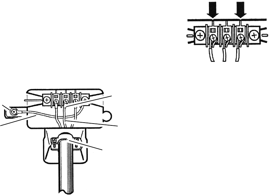
3-WIRE POWER SUPPLY
CORD CONNECTION
IMPORTANT: Use this procedure only where
local codes permit connecting a cabinet-ground
conductor to the neutral wire.
1. Remove the terminal block cover hold-
down screw and open the cover at the
back of the dryer.
2. Remove the center terminal block screw.
3. Connect the neutral wire (white or center
wire) of the power supply cord to the
center, silver terminal block screw.
A. External ground connector
B. Neutral grounding wire (green/yellow)
C. Center, silver terminal block screw
D. Neutral wire (white or center wire)
E. 3/4″ (1.9 cm) UL-listed strain relief
A
B
C
D
E
4. Connect the ends of the remaining power
supply wires to the left and right terminal
block screws.
LR
5. Check the wire connections and make
sure that they are all tight.
6. Tighten the strain relief clamp screws.
7. Insert the tab of the terminal block cover
into the slot of the dryer rear panel and
secure the cover with its mounting screw.
2-6
3-WIRE DIRECT CONNECTION
IMPORTANT: Use this procedure only where
local codes permit connecting a cabinet-ground
conductor to the neutral wire.
1. Strip 3-1/2″ (8.9 cm) of outer covering
from the end of the cable.
2. Strip 1″ (2.5 cm) of insulation from the
ends of the wires. NOTE: If you are using
a 3-wire cable with a ground wire, cut the
bare wire even with the outer insulation.
3. Form a hook in the bare wire ends.
1″
(2.5 cm)
3-1/2″
(8.9 cm)
4. Remove the terminal block cover hold-
down screw and open the cover at the
back of the dryer.
5. Loosen or remove the center terminal
block screw.
D
E
C
A
B
7. Connect the ends of the remaining power
supply wires to the left and right terminal
block screws.
LR
8. Check the wire connections and make
sure that they are all tight.
9. Tighten the strain relief clamp screws.
10. Insert the tab of the terminal block cover
into the slot of the dryer rear panel and
secure the cover with its mounting screw.
6. Connect the neutral wire (white or center
wire) of the power supply cable, to the
center terminal block screw.
A. External ground connector
B. Neutral grounding wire (green/yellow)
C. Center, silver terminal block screw
D. Neutral wire (white or center wire)
E. 3/4″ (1.9 cm) UL-listed strain relief
2-7
OPTIONAL 3-WIRE CONNECTION
IMPORTANT: Use this procedure for connect-
ing a direct wire or power supply cord (where
local codes permit) to a cabinet-ground con-
ductor to the neutral wire.
1. Remove the terminal block cover hold-
down screw and open the cover at the
back of the dryer.
2. Remove the center terminal block screw.
3. Remove the appliance ground wire (green
with a yellow tracer) from the external
ground connector screw. Reconnect the
ground wire, and the neutral wire (white or
center wire) of the power supply cord/
cable, to the center (silver) terminal block
screw.
4. Connect the ends of the remaining power
supply wires to the left and right terminal
block screws.
LR
5. Check the wire connections and make
sure that they are all tight.
6. Tighten the strain relief clamp screws.
7. Insert the tab of the terminal block cover
into the slot of the dryer rear panel and
secure the cover with its mounting screw.
8. Connect a separate copper ground wire
from the external ground connector screw
to an adequate ground (determined by a
qualified electrician).
A
D
B
C
A. External ground connector
B. Neutral grounding wire (green/yellow)
C. Neutral wire (white or center wire)
D. Grounding path (determined by a qualified
electrician)
2-8
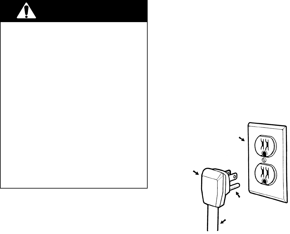
ELECTRICAL SHOCK HAZARD
Check with a qualified electrician if you
are in doubt as to whether the appliance
is properly grounded. Do not modify the
power supply cord plug. If it will not fit the
outlet, have a proper outlet installed by a
qualified electrician.
Improper connection of the equipment
grounding conductor can result in a risk
of electrical shock.
Plug into a grounded 3 prong outlet.
Do not remove the ground prong.
Do not use an adapter.
Do not use an extension cord.
Failure to follow these instructions can
result in death, fire, or electrical shock.
WARNING
A 120 volt, 60 Hz, AC only, 15 or 20 ampere
fused electrical supply is required. A time-
delay fuse or circuit breaker is recommended.
It is also recommended that a separate circuit
serving only this appliance be provided.
GROUNDING INSTRUCTIONS
For A Grounded Power Cord
Connected Dryer
This dryer must be grounded. In the event of
malfunction or breakdown, grounding will re-
duce the risk of electric shock by providing a
path of least resistance for electric current. This
dryer uses a cord having an equipment ground-
ing conductor and a grounding plug. The plug
must be plugged into an appropriate outlet that
is properly installed and grounded in accor-
dance with all local codes and ordinances.
3-Prong
Grounding
Plug
3-Prong
Grounding-
Type Wall
Receptacle
Grounding
Prong
Power Supply
Cord
ELECTRICAL REQUIREMENTS FOR GAS DRYERS

2-9
EXPLOSION HAZARD
Use a new AGA or CSA approved gas
supply line.
Install a shutoff valve.
Securely tighten all gas connections.
If connected to L.P. gas, have a qualified
person make sure gas pressure does not
exceed 13″″
″″
″ (33 cm) water column.
Examples of a qualified person include:
Licensed heating personnel.
Authorized gas company personnel, and
authorized service personnel.
Failure to do so can result in death, explo-
sion, or fire.
WARNING
GAS SUPPLY REQUIREMENTS
GAS TYPE
Natural Gas:
This dryer is equipped for use with NATURAL
GAS. It is design-certified by CSA International
for L.P. (propane or butane) gases with appro-
priate conversion.
• Your dryer must have the correct burner for
the type of gas in your home. Burner infor-
mation is located on the rating plate in the
door well of your dryer. If this information
does not agree with the type of gas available,
contact your local Whirlpool Service Center.
L.P. Gas Conversion:
Conversion must be made by a qualified
technician.
No attempt shall be made to convert the appli-
ance from the gas specified on the model/serial
rating plate for use with a different gas without
consulting the serving gas supplier.
2-10
The dryer can be converted to exhaust out the
right or left sides, or through the bottom.
ELECTRICAL SHOCK HAZARD
Cover unused exhaust holes with the
following kit:
279818 (white)
Contact your local dealer.
Failure to follow these instructions can
result in death, fire, electrical shock, or
serious injury.
WARNING
OPTIONAL EXHAUST INFORMATION
LEVELING THE DRYER
Make sure that the floor is level with a maxi-
mum slope of 1″ (2.5 cm) under the entire
dryer. If the slope is greater than that stated,
install the “Extended Dryer Feet Kit,” #279810.
If the dryer is not level, the clothes may not
tumble properly, and the automatic cycles may
not operate properly.
NOTE: Do not use the leveling legs if the dryer
will be installed on a pedestal.
4 Leveling Legs (supplied in parts package)
Number Of Type Of Box Or Angled
90°°
°° Turns Vent Louvered Hoods
Or Elbows Hoods
Rigid metal 64 ft (20 m) 58 ft (17.7 m)
Flexible metal 36 ft (11 m) 28 ft (8.5 m)
Rigid metal 54 ft (16.5 m) 48 ft (14.6 m)
Flexible metal 31 ft (9.4 m) 23 ft (7.0 m)
Rigid metal 44 ft (13.4 m) 38 ft (11.6 m)
Flexible metal 27 ft (8.2 m) 19 ft (5.8 m)
Rigid metal 35 ft (10.7 m) 29 ft (8.8 m)
Flexible metal 25 ft (7.6 m) 17 ft (5.2 m)
Rigid metal 27 ft (8.2 m) 21 ft (6.4 m)
Flexible metal 23 ft (7.0 m) 15 ft (4.6 m)
4
0
1
2
3
2-11
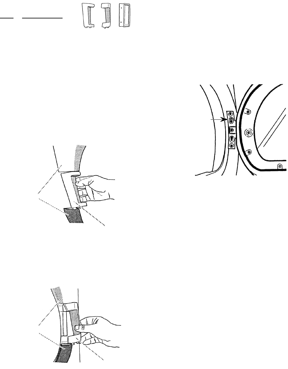
REVERSING THE DOOR SWING
Door Reversal Kit:
Key Description
1 Handle Filler
2 Hinge Cover
3 Door Handle
LOOSEN THE DOOR TRIM
1. Place a towel or a soft cloth on top of the
dryer or work space to protect the door
surface.
2. Loosen the plastic trim (1) above and
below the handle filler (2).
3. Carefully pull out on the trim until it un-
snaps and remove the handle filler and set
it aside.
1
2
4. Loosen the plastic trim (1) above and
below the hinge cover (3).
5. Carefully pull out on the trim until it un-
snaps, remove the hinge cover, and set it
aside.
3
NOTE: Keep the original handle filler and hinge
cover in case you decide to return the door to
its original position. A new handle filler and
hinge cover are provided in the door reversing
kit that will be installed in a later step.
REMOVE THE DOOR
1. Open the dryer door.
2. Loosen the top keyhole screw, then re-
move the other four hinge screws.
3. Lift the door from the top keyhole slot
screw and place it on a padded surface
with the inside door assembly facing up.
4. Remove the top keyhole slot screw and
place it with the others.
Loosen This
Hinge Screw
Continued on the next page.
123
1
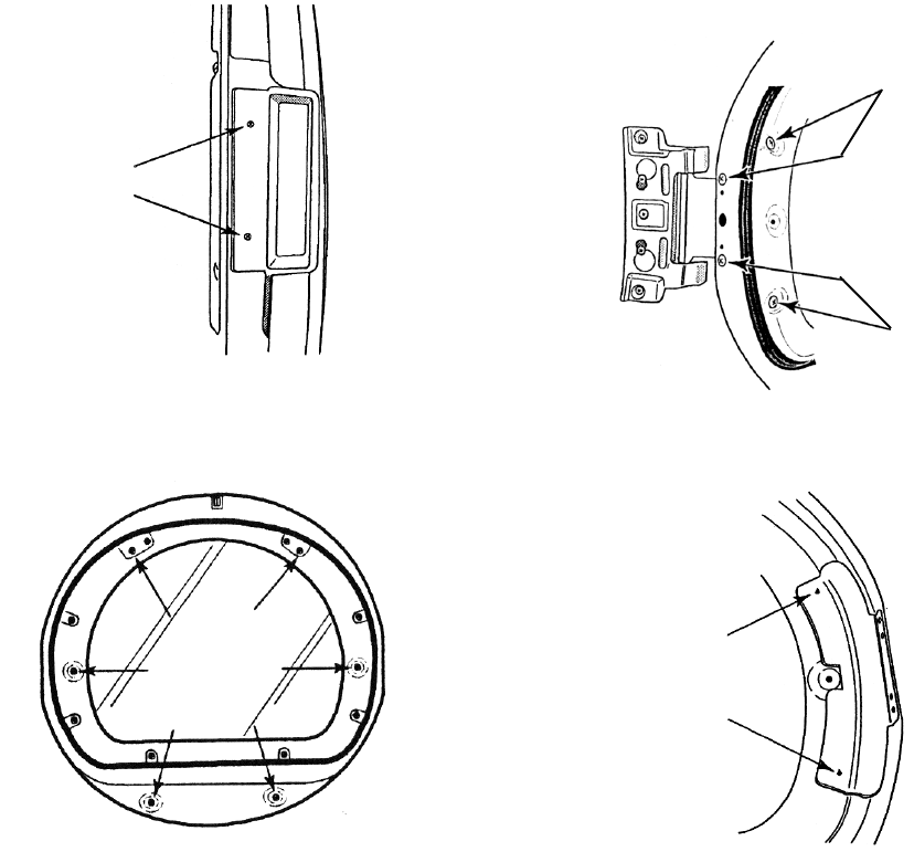
2-12
6. Remove the six screws that are indicated
by the arrows, shown in the illustration. Do
not remove any of the other screws.
Remove
These 6
Screws
7. Lift the inner door assembly off of the outer
door assembly and set the outer door
assembly aside.
2 Hinge
Screws
3. Remove the two screws from the handle
bracket and remove the bracket.
4. Mount the hinge to the other side of the
door with the four screws you removed in
step 2.
5. Mount the handle bracket to the other side
of the door with the two screws you re-
moved in step 3.
6. Set the inner door assembly aside.
5. Remove the two screws from the door
handle and remove the handle by pulling
straight out on it. Set the handle aside and
keep it in case you ever want to restore the
door swing to its original position.
2 Door
Handle
Screws
REVERSE THE HINGE
& HINGE BRACKET
1. Place the inner door, screw head side
facing up, on the padded work surface.
2. Remove the four door hinge screws.
2 Handle
Bracket
Screws
2 Hinge
Screws
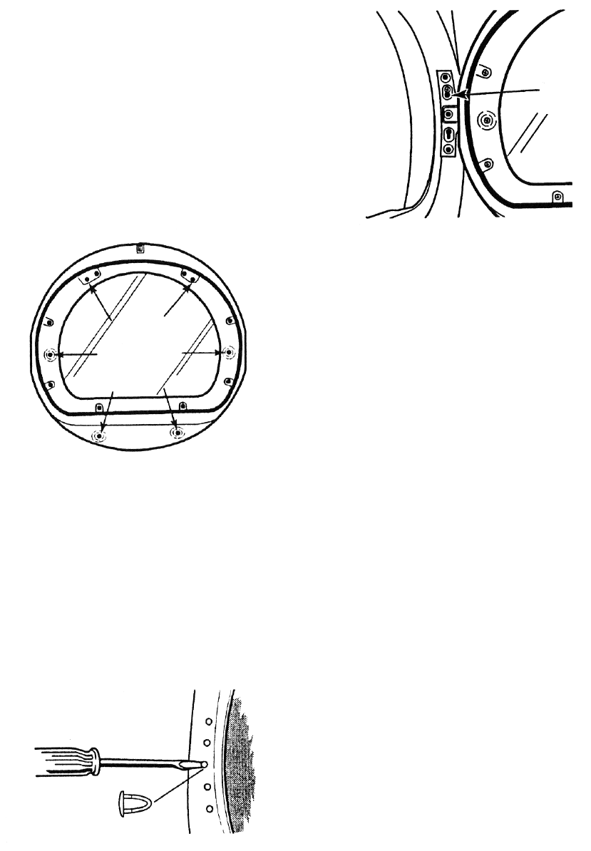
2-13
Install
These 6
Screws
Hole Plug
6. Install a screw halfway into the second
hole from the top.
7. Hang the door hinge on the screw you just
installed, then install the remaining four
screws in their holes, and tighten the loose
screw securely. Make sure that all five
hinge screws are secure.
INSTALL THE NEW HANDLE
FILLER AND HINGE COVER
1. Using the new handle filler that was pro-
vided with the reversing kit, hook the top of
the handle filler onto the loosened upper
door trim, and snap the joined pieces into
place.
2. Hook the bottom of the handle filler onto
the lower door trim and snap it into place.
3. Repeat steps 1 and 2 to install the hinge
cover on the opposite side of the door.
4. Close the door and make sure that it
latches securely.
Partially Install A
Screw In This Hole
4. Insert the new handle into the side open-
ing of the door. Make sure that the handle
seats all the way in the opening, and that
the holes are all aligned properly, then
mount the handle with two screws.
5. Using a small screwdriver, remove the
hole plugs in the door opening of the dryer,
and install them in the former screw holes
in the other side of the dryer. Be careful not
to damage the finish.
REINSTALL THE DOOR
1. If necessary, clean both sides of the door
glass before reassembling it.
2. Place the inner door assembly into the
outer door assembly and align the hinge in
the opening on the side. Fit the inside door
assembly edge completely inside the outer
door assembly.
3. Loosely install the six screws in the door.
Once all of the screws are loosely in-
stalled, and the edges of the door are
properly aligned, tighten the screws se-
curely.
2-14
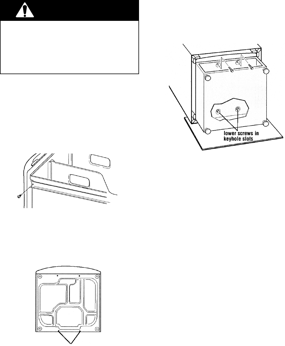
EXCESSIVE WEIGHT HAZARD
Use two or more people to move and
install pedestal.
Failure to do so can result in back or other
injury.
WARNING
1 Open the pedestal drawer and remove the
envelope taped inside. This envelope con-
tains four #12 x 5/8″ (1.6 cm) hex-head
sheet metal screws that will be used in the
assembly.
2. Remove the phillips screw from each
drawer slide and remove the drawer. Set
the drawer and two screws aside.
INSTALLING THE OPTIONAL PEDESTAL
Dryer Bottom
3. Push the slides back into the pedestal.
4. If installed, remove the feet from the dryer.
Do not install the feet that came with a new
dryer.
5. Partially install the two lower #12 x 5/8″
(1.6 cm) hex-head sheet metal screws,
leaving a space of about 3/8″ (1 cm) be-
tween the screw head and the bottom of
the dryer.
6. Move the pedestal against the dryer bot-
tom. Slide the pedestal’s keyhole slots
over the two lower partially installed screws.
7. Lift the pedestal toward the front of the
dryer and partially install the two remain-
ing hex-head sheet metal screws.
8. Align the sides of the pedestal so that
they are even with the sides of the dryer.
Reach inside the pedestal drawer opening
and securely tighten all four pedestal
screws.
9. Tip the dryer and pedestal assembly back
to the upright position and remove the
protective cardboard.
10. Position the dryer close to its final location.
11. If the dryer is still in its packaging, follow
the instructions on the packaging and re-
move it.
12. Follow the Installation Instructions that
were supplied with the dryer, and finish
installing or reinstalling it.
Install Screws
2-15
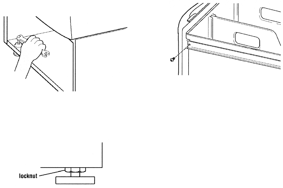
13. Place a spirit level on the top of the pedes-
tal. Use a 1/4″ (6.4 mm) hex-head ratchet
or open-end wrench, and adjust the four
feet, to level the dryer from side-to-side
and front-to-back.
15. Pull both drawer slides out and reassemble
the drawer to the drawer slides with the
two phillips screws.
14. When the dryer is level, use a 9/16″ (14.3
mm) open-end wrench to securely tighten
all four feet locknuts against the pedestal.
The locknuts must be tightened.
16. Install the dividers and close the drawer.
2-16
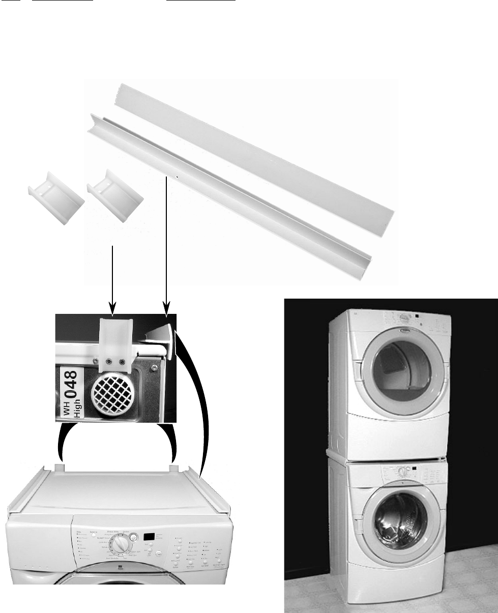
OPTIONAL STACK KIT (#8519492)
An optional stack kit will be made available to
mount the dryer on top of the matching Duet
washer. The Kit contains the following:
Qty Description Part Number
2 Spacer Pad #8519491
2 Mounting Bracket #8529746
4 Hex-Head Screw #3400804
1 Installation Instructions #8519474
(2) Brackets - #8529746
(2) Spacer Pads - #8519491
The kit parts will be attached to the washer so
that the dryer can be mounted on top. Use the
instructions that are provided with the kit to
install the parts.
3-1
FIRE HAZARD
No washer can completely remove oil.
Do not dry anything that has ever had any
type of oil on it (including cooking oils).
Items containing foam, rubber, or plastic
must be dried on a clothesline or by using
an Air Cycle.
Failure to follow these instructions can
result in death or fire.
PRODUCT OPERATION
Status
Dryness
Level
Automatic Cycles Manual Cycles
Control On
Heavy Duty
Casual
Delicate
Quick Dry
Touch Up
Timed Dry
Wrinkle Shield
Temperature
(Manual Cycles only)
End Of Cycle Signal
Hold for 3 Seconds To
More
Time
Estimated
Time
Remaining
Less
Time
Super
Delicate
Normal
Sensing
Wet
More
Less
Damp
Cool Down
Cycle Complete
Wrinkle Shield
Control Locked
Pause
Cancel
On
High
Medium
Low
Extra Low
Air Only
Louder
Softer
Off
Hold To
Start
88:88
Lock / Unlock Control
WARNING
EXPLOSION HAZARD
Keep flammable materials and vapors,
such as gasoline, away from dryer.
Do not dry anything that has ever had
anything flammable on it (even after wash-
ing).
Failure to follow these instructions can
result in death, explosion, or fire.
STARTING THE DRYER
The following is a guide to starting the dryer.
Please refer to specific sections of the Owner’s
Manual for more detailed information.
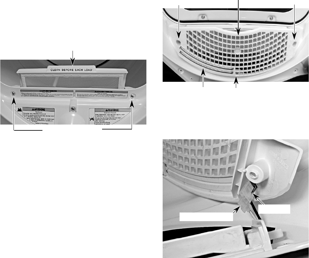
1. Clean the lint screen before or after each
cycle.
2. Place the laundry into the dryer and close
the door.
3. Rotate the dial to select either an Auto-
matic or Manual Cycle, then press the
Control On button. The preset settings
and drying time for the cycle chosen will be
displayed.
To use an Automatic Cycle:
• Point the dial to an Automatic Cycle.
• Select the Dryness Level to adjust how dry
you want the clothes. The time displayed is
an estimated length of the cycle based on
the dryness level selected. As the cycle runs,
the control senses the dryness of the load
and adjusts the time automatically for the
selected dryness level.
Dryness
Level
More
Less
NOTE: Time is not adjustable for Automatic
Cycles. Pressing the More Time or Less Time
buttons will cause a triple beep, indicating that
the time cannot be changed.

3-2
• Press the Temperature button until the de-
sired temperature is indicated.
NOTE: Pressing the Dryness Level button will
cause the triple beep, indicating that this option
is not selectable. Also, a dryness level is not
indicated.
The initial time displayed is the actual drying
time. As the cycle runs, the control senses the
dryness of the load, and adjusts the time auto-
matically for the selected dryness level.
• Press and release the Wrinkle Shield button
if this option is desired.
• Press the End Of Cycle Signal button to set
the volume to the desired level.
• Press and hold the Hold To Start button until
the dryer starts (about 1 second).
To use a Manual Cycle:
• Rotate the dial to select a Manual Cycle.
• Press More Time or Less Time until the
desired drying time is displayed. Tap More
Time or Less Time and the time will change
by 1 minute intervals. Press and hold More
Time or Less Time and the time will change
by 5 minute intervals.
NOTE: The More Time or Less Time feature
can only be used with Manual Cycles.
More
Time
Less
Time
• Press the Wrinkle Shield feature button, if
this option is desired.
• Press the End Of Cycle Signal button to set
the signal volume to the desired level.
• Press and hold the Hold To Start button until
the dryer starts (about 1 second).
Once an Automatic Cycle has started, the
Wrinkle Shield feature, and the End Of Cycle
Signal level can be adjusted. Press the Pause/
Cancel button twice to stop the dryer and clear
the settings, allowing you to select another
cycle and dryness level.
During a Manual Cycle, you can change the
settings for Time, Temperature, the Wrinkle
Shield feature, and the End of Cycle Signal
functions. Press the Pause/Cancel button twice
to stop the dryer and clear the settings, allow-
ing you to select another cycle.
STOPPING THE DRYER
To stop the dryer at any time:
• Press the Pause/Cancel button twice.
PAUSING OR RESTARTING
To pause the dryer at anytime:
• Open the door or press the Pause/Cancel
button once.
To restart the dryer:
• Close the door and press and hold the Hold
To Start button until the dryer starts.
NOTE: Drying will continue from where the
cycle was interrupted if you close the door and
press Start within 5 minutes. If the cycle is
interrupted for more than 5 minutes, the dryer
will shut off. Select the new cycle settings
before restarting the dryer.
CONTROL LOCKED
This feature allows you to lock your settings to
prevent unintended use of the dryer. You can
also use this feature to prevent unintended
cycle changes during dryer operation.
To enable the Control Locked feature:
Press and hold the End Of Cycle Signal button
for 3 seconds. The control is locked when a
single beep is heard and the Control Locked
status light is on.
• When the dryer is off, it is not necessary to
press the Control On button before activat-
ing the Control Locked feature.
To unlock the Control Locked feature:
Press and hold the End Of Cycle Signal button
for 3 seconds to turn this feature off.
NOTE: When the dryer is running and Control
Locked is on, the dryer can be stopped by
pressing the Pause/Cancel button, but cannot
be restarted until the control is unlocked.

3-3
STATUS LIGHTS
The Status indicator lights show the progress
of the dryer. Each of the lights indicate as
follows:
Status
Sensing
Wet
Damp
Cool Down
Cycle Complete
Wrinkle Shield
Control Locked
Sensing
When the dryer is first turned on, the Sensing
light glows until a wet item is detected.
•In an Automatic Cycle, if a wet item has not
been detected within 10 minutes, the Sens-
ing light will turn off, and the dryer will shut
down.
• In a Manual Cycle, if a wet item is not
detected after 10 minutes, the Wet light
turns on, and the selected cycle continues.
Wet
The Wet light will turn on when a wet item has
been detected in the dryer. The Wet light will
remain on until:
• The damp dry point is reached in an Auto-
matic Cycle.
• The dryer enters the cool down period in a
Manual Cycle.
Damp
The Damp light indicates that the load has
reached a damp dry level.
NOTE: The Damp light is not used with Manual
Cycles.
Cool Down
The Cool Down light glows during the cool
down part of the cycle. Laundry is cooling down
for ease in handling.
Cycle Complete
This light glows when a drying cycle is finished.
If the Wrinkle Shield feature has been selected,
the Wrinkle Shield feature indicator light will
also be on.
The Cycle Complete light turns off 1 hour after
the end of a drying cycle (including the Wrinkle
Shield cycle of 2 hours), when Pause/Cancel i s
pressed, or when the door is opened.
Wrinkle Shield Feature
The Wrinkle Shield feature light glows when
this option is selected. This indicator stays on
with the Cycle Complete light.
Control Locked
The Control Locked light glows when this op-
tion is enabled.
Indicator Lights
Other indicator lights on the control panel,
show Cycle, Temperature, and End Of Cycle
Signal settings that are selected.
The time display will indicate the estimated or
actual time remaining in a cycle.

3-4
Manual Cycles
The Manual Cycles allow the user to select a
specific amount of drying time and a drying
temperature. When a Manual Cycle is se-
lected, the Estimated Time Remaining display
shows the actual time remaining in the cycle.
The actual time in the cycle can be changed by
pressing More Time or Less Time.
Timed Dry
Use this cycle to extend drying time when items
are still damp after an Automatic Cycle.
Touch Up
Use this cycle to remove wrinkles from items,
such as clothes packed in a suitcase, or items
wrinkled from being left in the dryer too long.
Quick Dry
Use this cycle for drying small loads or loads
that need a short drying time.
ADDITIONAL FEATURES
Wrinkle Shield Feature
Wrinkle Shield
On
Prevents wrinkles that form when the dryer is
not unloaded immediately at the end of a cycle.
• Press the Wrinkle Shield feature to get up to
2 hours of heat-free, periodic tumbling at the
end of a cycle.
• Stop at any time by pressing the Wrinkle
Shield feature button, or by opening the
dryer door.
Automatic Cycles Manual Cycles
Heavy Duty
Casual
Delicate
Quick Dry
Touch Up
Timed Dr
y
Super
Delicate
Normal
Hold To
Start
CYCLE DESCRIPTIONS
Automatic Cycles
The Automatic Cycles allow the user to match
a cycle to the type of load to be dried. A sensor
detects the moisture in the clothes, and auto-
matically adjusts the drying time for optimal
drying.
Heavy Duty
Uses high heat for heavy fabrics, such as
cotton towels or bedspreads.
Normal
Uses medium heat for drying sturdy fabrics,
such as work clothes.
Casual
Uses medium heat for no-iron fabrics, such as
sport shirts, casual business clothes, and per-
manent press.
Delicate
Uses low heat for drying synthetic fabrics,
washable knit fabrics, and no-iron finishes.
Super Delicate
Uses extra-low heat for drying items such as
lingerie, exercise wear, or sheer curtains.
Automatic Cycles Manual Cycles
Heavy Duty
Casual
Delicate
Quick Dry
Touch Up
Timed Dr
y
Super
Delicate
Normal
Hold To
Start

3-5
Temperature
(Manual Cycles only)
High
Medium
Low
Extra Low
Air Only
Air Only
Use for items that require drying without heat,
such as rubber, plastic and heat-sensitive fab-
rics. NOTE: The Air Only feature will not oper-
ate with Automatic Cycles.
• For the Casual Cycle, the Wrinkle Shield
feature is preset to On. The other Automatic
Cycles will retain the Wrinkle Shield feature
setting.
NOTE: If you do not select the Wrinkle Shield
feature, the dryer stops after cool down.
Temperature
Use the Temperature settings to select tem-
peratures for the Manual Cycles. Press the
Temperature button until the desired tempera-
ture setting is indicated on the display. Tem-
perature settings cannot be used with the Au-
tomatic Cycles.
Press the End of Cycle Signal to adjust the
sound level or turn off the signal.
NOTE: When Wrinkle Shield feature is se-
lected and the End of Cycle Signal is on, an
audible sound will be heard every 5 minutes
until the clothes are removed, or until the
Wrinkle Shield feature is finished.
End of Cycle Signal
The End of Cycle Signal produces an audible
sound when the drying cycle is finished.
Promptly removing clothes at the end of the
cycle reduces wrinkling.
End Of Cycle Signal
Hold for 3 Seconds To
Louder
Softer
Off
Lock / Unlock Control
3-6
— NOTES —
4-1
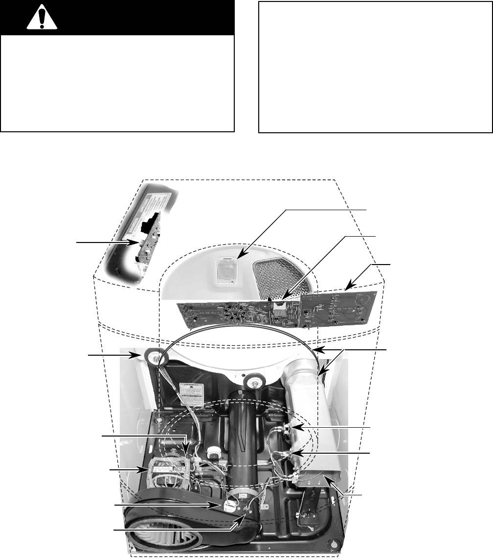
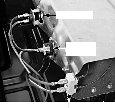
COMPONENT LOCATIONS
This section instructs you on how to service each component inside the Gas and Electric Dryers.
The components and their locations are shown below.
COMPONENT ACCESS
ELECTRICAL SHOCK HAZARD
Disconnect power before servicing.
Replace all panels before operating.
Failure to do so can result in death or
electrical shock.
WARNING
FIRE HAZARD
Shut off gas supply line valve before
servicing.
Check all gas line connections and re-
place all panels before operating.
Failure to do so could result in explosion,
fire, or other injury.
Machine Control
Electronics
Board
Drum Light
Console
Electronics Board
Drum Roller
(1 of 4)
Drive Motor
Thermal Fuse
Thermistor
Belt & Drum
Thermal Cutoff
(Electric Only)
High-Limit Thermostat
NOT SHOWN:
Door Switch &
Moisture Sensor
Console
Electronics Board
Belt Switch (Mounted
On Drive Motor Bracket)
Heater (Or Gas Burner)
4-2
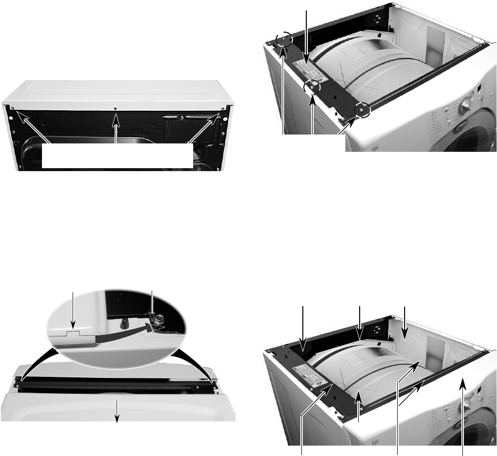
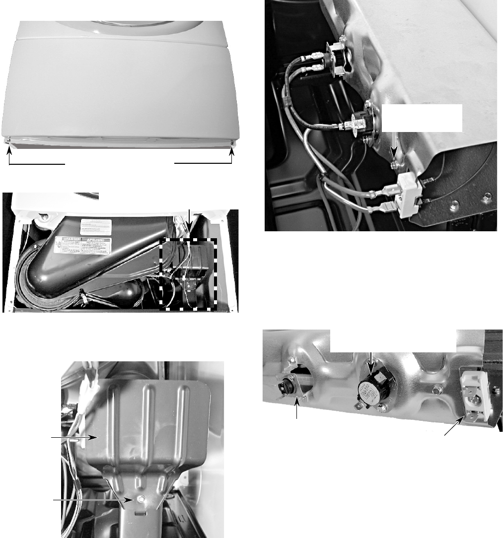
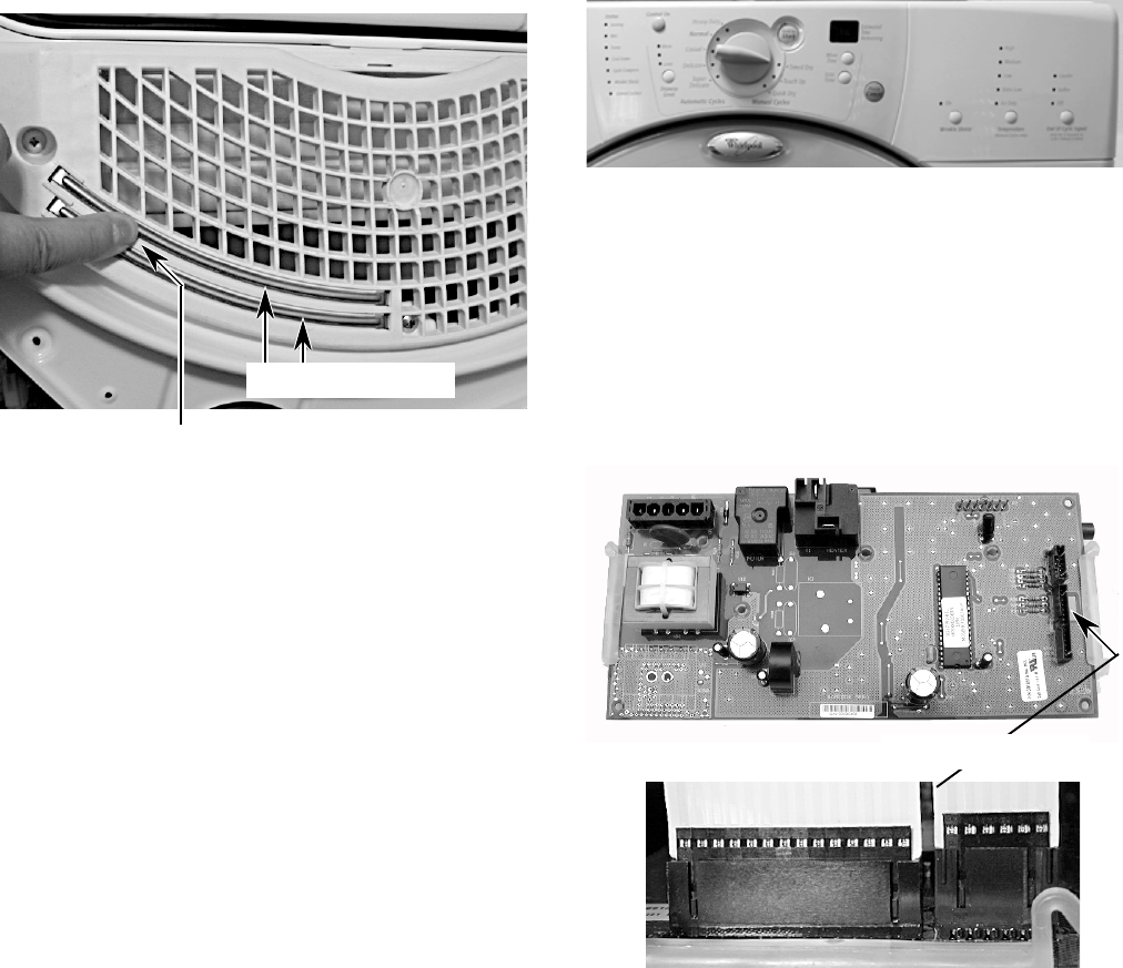
REMOVING THE MACHINE CONTROL
ELECTRONICS BOARD
NOTE: Sharp edges may be present.
6. Disconnect the 3-wire connector from the
main harness.
7. Remove the following connectors and
wires from the board:
5-wire connector at P1.
Red and black wires at relay K1.
7-wire connector at P2.
Ribbon cables at P3 and P4.
1. Turn off the gas to the dryer and discon-
nect the electrical power.
2. Pull the dryer away from the wall far
enough to access the back.
3. Remove the three hex-head screws from
the rear flange of the dryer’s top cover.
NOTE: The top cover screws have nylon
flat washers on them. Be sure to use these
screws when you reinstall the top cover.
5. Remove the three screws from the ma-
chine control electronics board bracket
and pull the bracket away from the side of
the dryer so you can access the connec-
tors.
Electronics Board
Bracket
3 Screws
P1 Relay K1 P2
1/4″ Screw Ribbon Cables 3-Wire
P3 & P4 Connector
Electronics
Board
Top Cover Rear Flange Screws
W/Nylon Flat Washers
4. Lift the rear of the top cover and slide it
back so the tabs clear the catches on the
bracket, and remove the cover from the
unit. NOTE: Make sure that the tabs slide
under the bracket catches when you rein-
stall the top cover.
Slide Top Cover Back
Cover Flange Tab Under Bracket Catch
8. Remove the 1/4″ hex-head screw from the
electronics board.
4-3
9. Squeeze the two board supports and re-
move the electronics board from the
bracket.
Squeeze Ends Of Supports To Remove Board
4-4
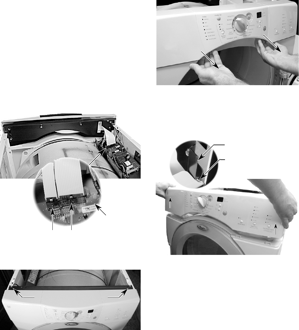
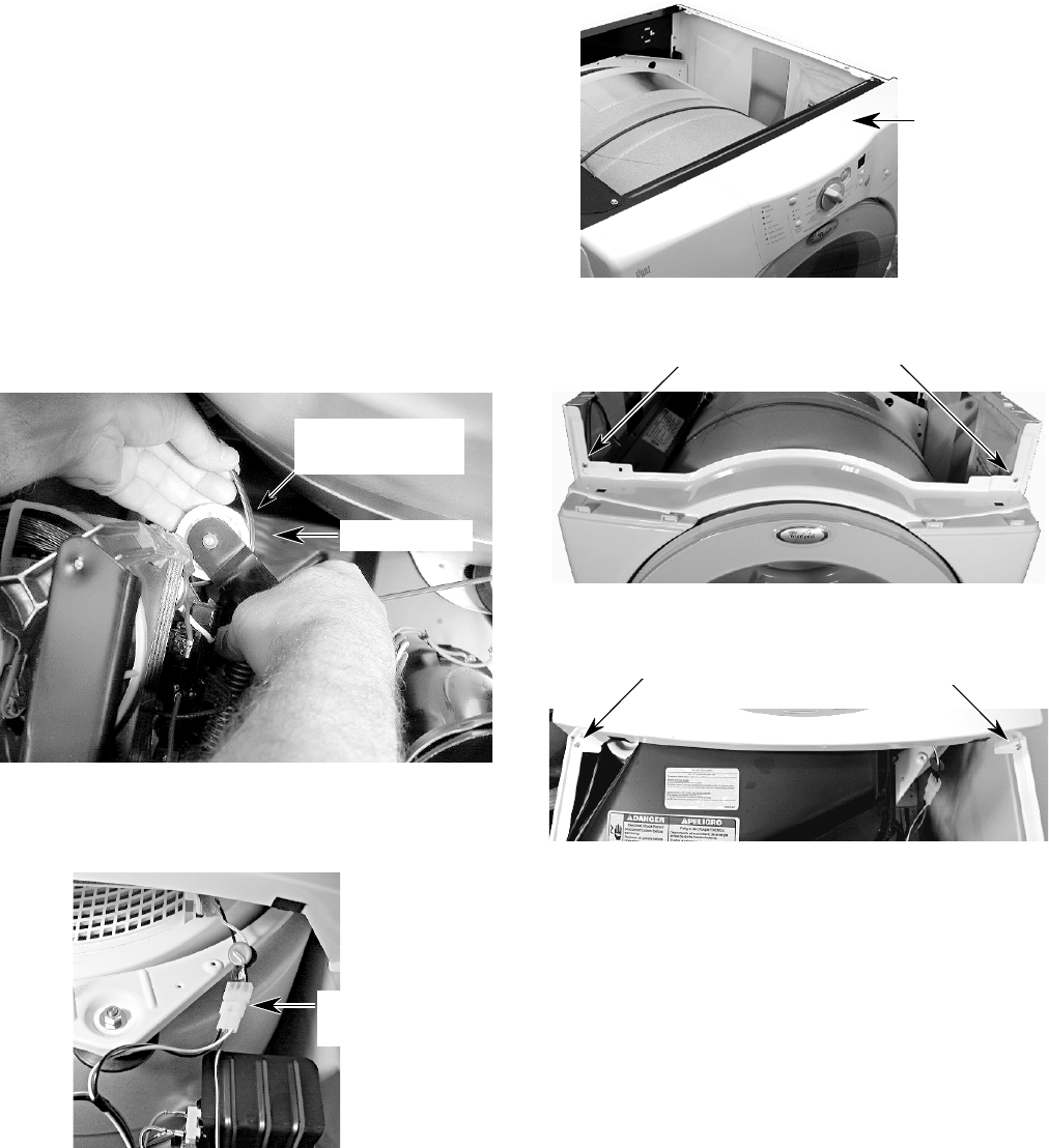
REMOVING THE CONSOLE & THE
TOUCHPAD SUBASSEMBLY
NOTE: Sharp edges may be present.
1. Turn off the gas to the dryer and discon-
nect the electrical power.
2. Pull the dryer away from the wall and
remove the top cover (see steps 3 and 4
on page 4-2 for the procedure).
3. Remove the three screws from the ma-
chine control electronics board bracket,
and tip the bracket assembly inside the
dryer (see step 5 on page 4-2 for the
procedure).
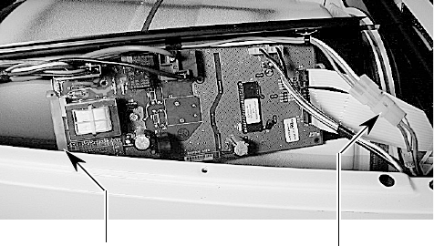
4. Disconnect the ends of the two ribbon
cables from the machine control electron-
ics board connectors P3 and P4.
5. Remove the two screws from the console
bracket.
P3
P4
Press In On Clips To
Release Cables
Machine
Control
Electronics
Board
Lift Console Bracket From
Flange On Both Sides
7. Lift the console straight up until the brack-
ets are free of the left and right side panel
flanges and remove the console.
Viewed From Back Of Console
Side Panel Flange
8. Place the console assembly on a padded
work surface with the bracket side facing
up, as shown in step 9.
Console Bracket Screws
6. Open the door and pull out on the bottom
of the console to release the locking tabs
from the door panel.
4-5
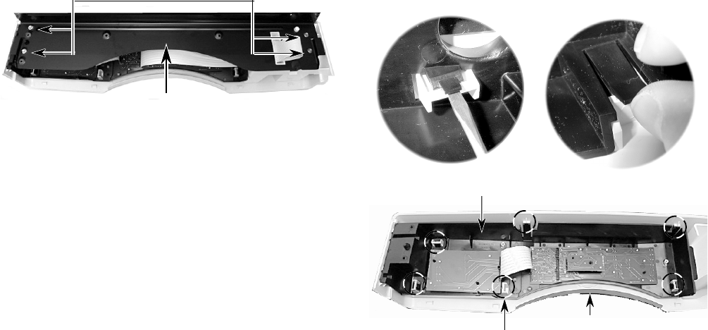
10. Remove the selector knob.
11. Remove the touchpad subassembly from
the console by unsnapping the six catches.
Use your thumb or a screwdriver.
Console
Subpanel Catch
(1 of 6)
Console Bracket Screws
Console Bracket
9. Remove the four hex-head screws from
the console bracket and remove the
bracket.
Touchpad Subassembly
4-6
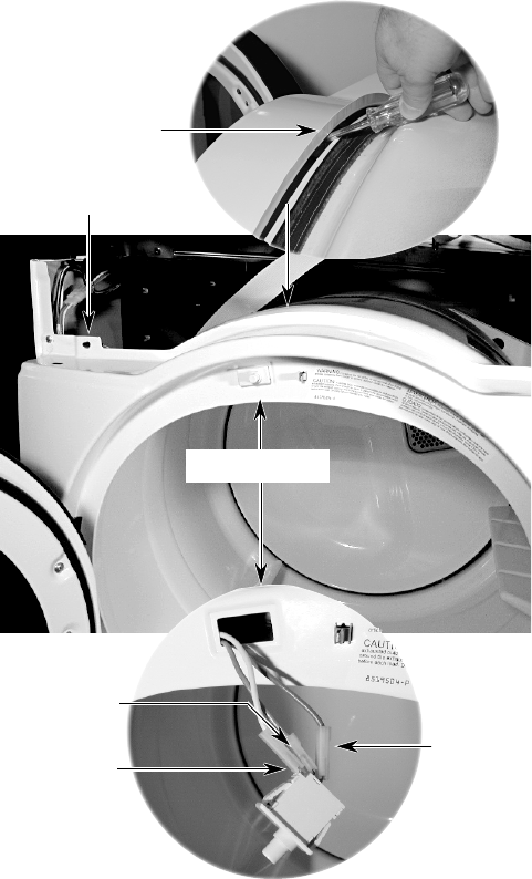
REMOVING THE DOOR SWITCH
NOTE: Sharp edges may be present.
1. Turn off the gas to the dryer and discon-
nect the electrical power.
2. Pull the dryer away from the wall and
remove the top cover (see steps 3 and 4
on page 4-2 for the procedure).
3. Remove the console (see page 4-4 for the
procedure). Tip the console back and lay
it on a padded surface.
4. Push the wire holder out of the chassis
hole.
5. Pry the door switch out of the cutout. If
necessary, press a screwdriver blade
against the locking arms on each side of
the door switch, (from behind the cutout),
and push the switch out.
6. Disconnect the wires from the door switch
terminals.
Wire Holder
Door Switch
Screwdriver
Removal
Brown Wire
(N.C.)
White Wire
(COM)
Blue Wire
(N.O.)
4-7
Thermal Fuse
(2 Screws)
Thermistor
(2 Screws)
2 Cover Screws
REMOVING THE THERMAL FUSE, THERMISTOR,
DRIVE MOTOR, & BELT SWITCH
NOTE: Sharp edges may be present.
1. Turn off the gas to the dryer and discon-
nect the electrical power.
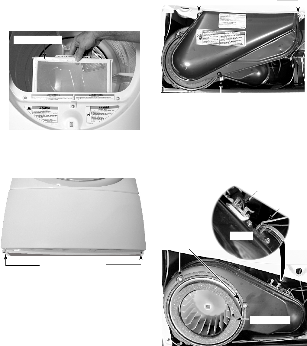
2. Open the dryer door and remove the lint
filter screen, then close the door.
4. Remove the hex-head screw from the lint
duct bracket and remove the bracket.
3. Remove the two hex-head screws from
the bottom flange of the toe panel. Pull the
panel out at the bottom, pull down, and
remove the panel.
Lint Filter Screen
Toe Panel Screws
Toe Panel
5. Remove the two hex-head screws from
the lint duct and remove the duct.
6. To remove the thermal fuse or ther-
mistor:
a) Remove the two wires from the termi-
nals.
b) Remove the two hex-head screws.
Lint Duct Bracket & Screw
Screws
Continued on the next page.
Lint Duct Screws
Blower Cover
4-8
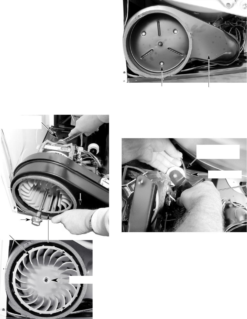
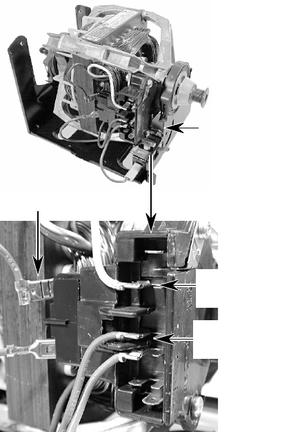
7. To remove the drive motor:
a) Remove the wires from the thermal
fuse and thermistor terminals (see the
photo at the bottom of the previous
page).
b) Remove the two hex-head screws from
the blower cover (see the previous page)
and remove the cover.
c) Reach around to the back of the drive
motor and attach a 7/8″ open-end
wrench over the hex-end of the motor
shaft, and a ratchet with a 1/2″ drive on
the blower wheel hub.
d) Turn the blower wheel clockwise (shown
by the “REMOVE” arrow that is em-
bossed on the front of the wheel ) and
remove the wheel from the motor shaft.
e) Remove the three hex-head screws
from the blower housing and remove it.
Housing Screw
(1 of 3) Blower Housing
f) Reach around behind the drive motor
and push the idler wheel arm to the left,
then remove the tension, and remove
the belt from the idler pulley.
Push To Left
Remove Belt
From Idler Pulley
REMOVE
TIGHTEN
7/8″ Open-End
Wrench
Ratchet w/ 1/2″
Drive
Blower Wheel
1/2″ Drive
4-9
Motor Harness Plug
c) Remove the two screws from the belt
switch and remove it from the motor.
Belt Switch Screws
g) Lift the top locking tab of the motor
harness plug and pull the top pins away
from the motor connector, then release
the bottom tab, and remove the plug.
8. To remove the belt switch:
a) If not already done, remove the drive
motor (see step 7 on page 4-8).
b) Remove the 3/8″ hex shoulder-washer
screw from the idler pulley assembly
and remove the assembly.
h) Remove the two hex washer-head
mounting screws from the drive motor,
then lift the right side of the motor
slightly, pull the two tabs on the left side
out of the chassis slots, and remove the
drive motor.
Top Locking Tab
Idler Pulley Assembly
3/8″ hex shoulder-
washer screw
Belt Switch
d)Disconnect the blue wires from the belt
switch terminals.
Blue Wire Blue Wire
Hex Washer-Head Screws
4-10
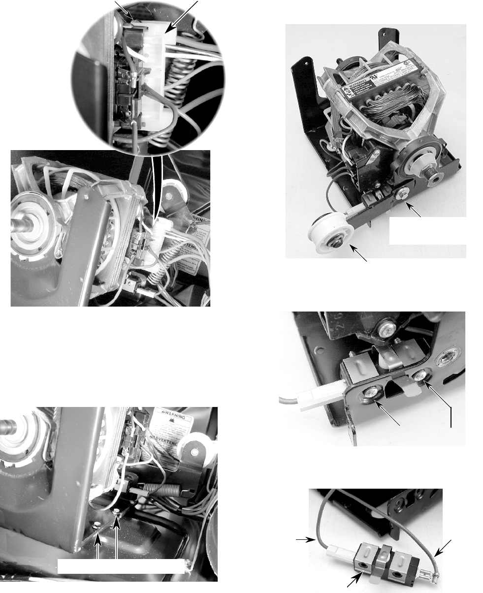
REMOVING THE HEATER, THE HIGH-LIMIT
THERMOSTAT, & THERMAL CUTOFF
NOTE: Sharp edges may be present.
1. Turn off the gas to the dryer and discon-
nect the electrical power.
2. Remove the two hex-head screws from
the bottom flange of the toe panel. Pull the
panel out at the bottom, pull down, and
remove the panel.
4. To remove the heater:
a) Remove the two wires from the termi-
nal block (see bottom photo).
b) Remove the hex-head screw from the
heater housing, and slide the heater
out of the duct.
High-Limit Thermostat,
Thermal Cutoff, & Heater Area
3. Remove the hex-head screw from the
heater shield and remove the shield.
Heater
Shield
Screw
5. To remove the high-limit thermostat or
the thermal cutoff:
a) Disconnect the wires from the high-
limit thermostat or the thermal cutoff.
b) Remove the two hex-head screws.
High-Limit Thermostat
(Red-White & Black Wires)
Heater Terminal Block
(Red & Red-White Wires)
Thermal Cutoff
(Red & Black Wires)
Toe Panel Screws
Toe Panel
Heater Housing
Screw
4-11
REMOVING THE BELT, DRUM, & ROLLERS
NOTE: Sharp edges may be present.
8. Loosen the two top front panel screws.
1. Turn off the gas to the dryer and discon-
nect the electrical power.
2. Pull the dryer away from the wall and
remove the top cover (see steps 3 and 4
on page 4-2 for the procedure).
3. Remove the console (see page 4-4 for the
procedure).
4. Remove the lint duct (see steps 2 through
5 on page 4-7 for the procedure).
5. Reach around behind the drive motor and
push the idler wheel arm to the left, then
remove the tension, and remove the belt
from the idler pulley.
9. Remove the two bottom front panel screws.
Push To Left
Remove Belt
From Idler Pulley
6. Disconnect the 3-wire moisture sensor
connector from the main harness connec-
tor.
Top Front Panel Screws
Bottom Front Panel Screws
7. Disconnect the 3-wire door switch con-
nector from the machine control electron-
ics board connector.
Moisture Sensor
Connector
3-Wire
Door Switch
Connector
Continued on the next page.
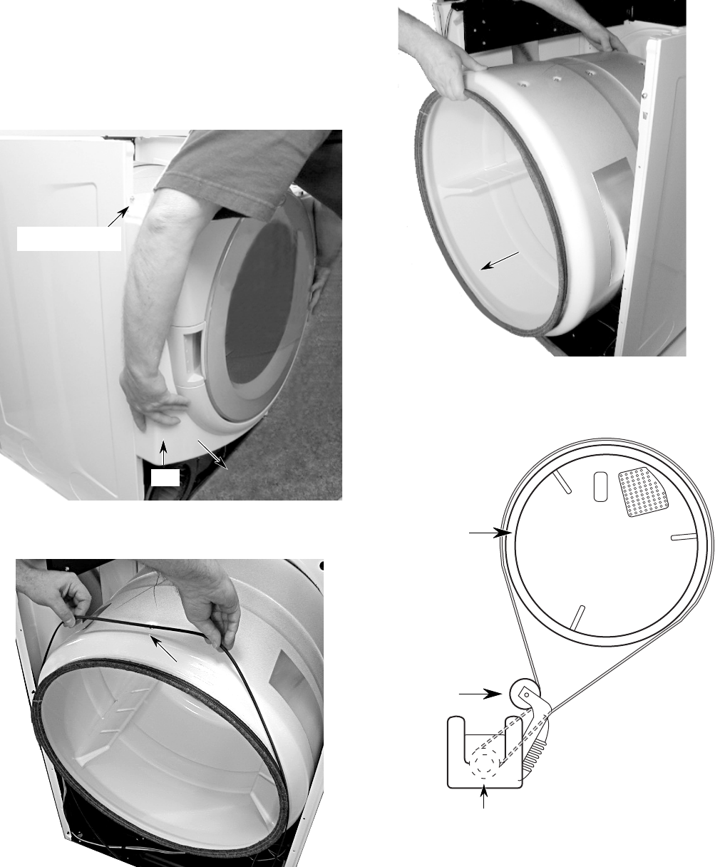
4-12
10. To remove the belt and drum:
a) Grasp the sides, lift, and pull the front
panel forward so that the top screws
are free of the keyhole slots. Lower the
panel so that the drum sits on the com-
ponents inside the cabinet, and slide
the front panel and rollers away from
the drum.
c) Lift the drum and remove it from the
unit.
b) Slide the belt off the drum.
Belt
REASSEMBLY NOTE: Use the following illus-
tration as a guide when installing a new belt.
Idler Pulley
Drum
Drive Motor Pulley
Keyhole Slot
Lift
4-13
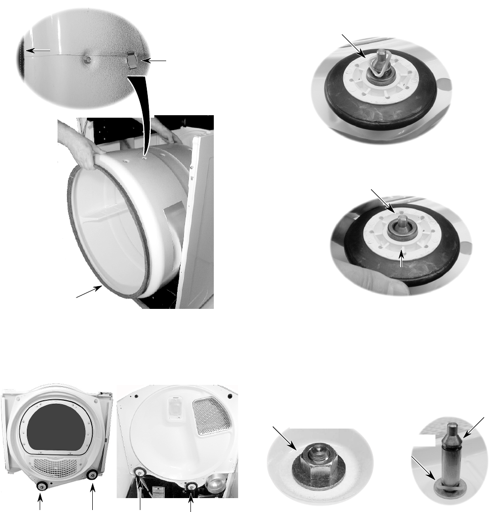
11. To remove a roller:
a) Pry the sides of the triangular ring out
of the groove in the roller support with
a small screwdriver.
c) Use a 9/16″ socket or open-end
wrench, and remove the hex nut and
flat washer from the roller support, and
remove the support. NOTE: If you are
replacing the roller support, remove the
other triangular ring from the support.
9/16″ Nut & Flat Washer
Triangular
Ring
Roller Support
Roller Support
Triangular Ring
b) Slide the roller off the roller support.
NOTE: There are two rollers on the front panel
and two on the rear panel, as shown below.
Front Rollers Rear Rollers
Rear Panel (inside)
Front Panel (inside)
DRUM INSTALLATION NOTE: Be sure to po-
sition the drum with the clip toward the front
when you reinstall it.
Front
Install Drum
Position Clip
Towards Front
4-14
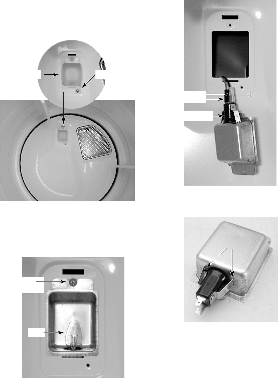
REMOVING THE DRUM LIGHT SOCKET
NOTE: Sharp edges may be present.
1. Turn off the gas to the dryer and discon-
nect the electrical power.
2. Open the dryer door.
3. Remove the screw from the drum light
lens and remove the lens.
4. Remove the bulb from the drum light
socket.
5. Remove the screw from the drum light
holder and pull it forward so you can
access the wires.
6. Disconnect the wire connectors from the
light socket terminals.
Lens Screw
Drum Light Lens
Drum Light
Holder Screw
Bulb
Wire Connectors
Light Socket
Squeeze
Arms
7. Squeeze the locking arms and remove the
socket from the drum light holder.
4-15
REMOVING THE MOISTURE SENSOR
NOTE: Sharp edges may be present.
1. Turn off the gas to the dryer and discon-
nect the electrical power.
2. Open the dryer door and remove the lint
filter screen.
3. Remove the two front screws from the
outlet grille.
4. Remove the three inside screws from the
outlet grille.
Outlet Grille Screws
Lint Filter
Screw
Screw
Screw
Outlet Grille
5. Pull the moisture sensor away from the
dryer and disconnect the black and yel-
low-red wires from the moisture sensor
strips.
Yellow-Red Wire
Black Wire
Moisture Sensor
4-16
— NOTES —
5-1
ELECTRICAL SHOCK HAZARD
Disconnect power before servicing.
Replace all panels before operating.
Failure to do so could result in death or
electrical shock.
COMPONENT TESTING
WARNING
Before servicing, check the following:
• Make sure that the power cord is firmly
plugged into a live circuit with the proper
voltage.
• Check for a blown household fuse or circuit
breaker that has tripped.
• Make sure that the dryer vent is properly in-
stalled and clear of lint or obstructions.
• Check the connections before replacing a
component. Look for broken or loose wires,
failed terminals, or wires that are not pressed
into their connectors far enough.
• Check for wire connectors that are not
pressed tightly onto their terminals.
• Voltage tests must be made with all connec-
tors attached.
• Resistance tests must be made with the
power cord unplugged from the outlet, and
with the wiring disconnected.
• All tests should be made with a VOM (volt-
ohmmeter) or DVM (digital voltmeter) hav-
ing a sensitivity of 20,000 ohms-per-volt DC
or greater.
MAKING ELECTRICAL TESTS
For any additional test beyond what is covered
in this Component Testing section, refer to the
Tech Sheet that is supplied with the product.
5-2
DRIVE MOTOR
Refer to page 4-7 for the procedure for servic-
ing the drive motor.
1. Disconnect the electrical power to the
dryer.
2. Set the ohmmeter to the R X 1 scale.
3. Disconnect the plug from the motor con-
nector.
4. Touch one ohmmeter test lead to the blue
motor wire connector, and the other test
lead to connector pin 5 (white-orange wire).
The ohmmeter should indicate between
2.4 and 3.6 Ω (main winding).
5. Touch one ohmmeter test lead to the blue
motor wire connector, and the other test
lead to connector pin 3 (violet wire). The
ohmmeter should indicate between 2.4 and
3.8 Ω (start winding).
6. If either resistance is much larger than
4 ohms, replace the motor.
If the resistances at the motor are correct,
check for a failed belt switch.
If the belt switch is okay, check for an open
circuit between the motor and the machine
control electronics board.
Pin 3
(violet)
Motor
Connector
Pin 5
(white-orange)
Blue Motor Wire
5-3
HEATER
Refer to page 4-10 for the procedure for ser-
vicing the heater.
1. Disconnect the electrical power to the
dryer.
2. Set the ohmmeter to the R X 1 scale.
3. Disconnect one of the wire connectors from
the heater terminal block.
4. Touch the ohmmeter test leads to the ter-
minals on the heater terminal block. The
ohmmeter should indicate between 7 and
12 ohms.
Heater Terminal Block
5-4
THERMAL FUSE
Refer to page 4-7 for the procedure for servic-
ing the thermal fuse.
Electric Dryers: The thermal fuse is wired in
series with the drive motor. If the thermal fuse
opens, 91°C (196°F), power to the motor is
turned off. A centrifugal switch on the motor
also opens the heater circuit.
Gas Dryers: The thermal fuse is wired in
series with the gas valve. If the thermal fuse
opens, 91°C (196°F), power to the valve is
turned off. A centrifugal switch on the motor
also opens the heater circuit.
Once the thermal fuse has opened, it will not
reset, and must be replaced. Check for a failed
thermistor, or a shorted heater element (elec-
tric dryers only).
Blower
Housing
Thermal Fuse
91°C (196°F)
1. Disconnect the electrical power to the
dryer.
2. Set the ohmmeter to the R X 1 scale.
3. Disconnect the wires from the thermal fuse.
4. Touch the ohmmeter test leads to the ther-
mal fuse terminals. The ohmmeter should
indicate continuity (0 Ω). If the meter indi-
cates an open circuit (infinite), replace the
thermal fuse.
5-5
THERMISTOR
Refer to page 4-7 for the procedure for servic-
ing the thermistor.
The thermistor monitors the exhaust temper-
ature and cycles the high-limit thermostat on
and off to maintain the desired temperature.
1. Turn the dryer off but keep the electrical
supply connected.
2. Make sure that the dryer is empty and that
the lint screen is clean.
3. Close the dryer door.
4. Select Heavy Duty, Timed Dry, More Time
or Less Time, End of Cycle Signal (Louder)
and Start.
5. If error codes E1 or E2 flash on the dis-
play after 1 minute and the dryer turns off,
the thermistor, or the wire harness, is ei-
ther shorted or open. Check the wire con-
nections at the thermistor or the machine
control electronics board. If wiring checks
okay, replace the thermistor.
6. If the dryer seems to operate normally, re-
move the exhaust vent and start the dryer.
7. Select the desired temperature cycle to be
tested, and select 20 minutes of Timed Dry
heat using the More Time or Less Time
pushbuttons.
8. Hold a glass bulb thermometer capable of
reading from 32°C to 82°C (90° to 180°F)
in the center of the exhaust outlet. Mea-
sure the exhaust temperatures with the
heater on and off. The correct exhaust tem-
peratures for the various settings are
shown in the following chart.
9. If the exhaust temperature is not within the
specified limits, check the resistance of the
thermistor, as shown in the following chart.
If the resistance is okay, replace the ma-
chine control electronics board.
TEMP RESISTANCE TEMP RESISTANCE
°C (°F) (K Ω ) °C (°F) (K Ω )
10° (50°)19.9 43° (110°)4.7
16° (60°)15.3 49° (120°)3.7
21° (70°)11.9 54° (130°)3.1
27° (80°)9.2 60° (140°)2.5
32° (90°)7.4 66° (150°)2.1
38° (100°)5.7 71° (160°)1.7
THERMISTOR RESISTANCE
TEMPERATURE HEAT TURNS HEAT TURNS
SETTING OFF ON
68° C ±6°
(155° F ±10°)
MEDIUM
66° C ±6°6 - 8° C
HIGH
(150° F ±10°) (10 - 15° F)
60° C ±6°below the heat
(140° F ±10°)turn off
52° C ±6°temperature
(125° F ±10°)
EXTRA
41° C ±3°
LOW
(105° F ±5°)
HIGH
MEDIUM
LOW
5-6
THERMAL CUTOFF
(ELECTRIC DRYERS ONLY)
Refer to page 4-10 for the procedure for ser-
vicing the thermal cutoff.
The thermal cutoff is a non-resettable device.
The cutoff temperature is 178°C (352°F).
If the dryer does not heat and there is 240 VAC
to the dryer, perform the following test.
1. Disconnect the electrical power to the
dryer.
2. Set the ohmmeter to the R X 1 scale.
3. Disconnect the wires from the thermal cut-
off.
4. Touch the ohmmeter test leads to the ther-
mal cutoff terminals. The ohmmeter should
indicate continuity (0 Ω). If the meter indi-
cates an open circuit (infinite), replace both
the thermal cutoff and the high-limit ther-
mostat. In addition, check for a failed
heater element, or a blocked, or improper
exhaust system.
Thermal Cutoff
High-Limit
Thermostat
Heater Terminals
5-7
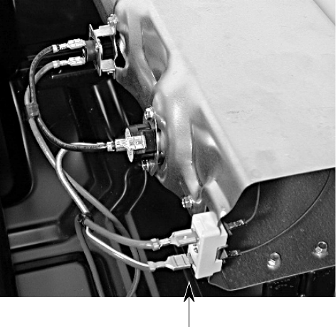
GAS VALVE (GAS DRYERS ONLY)
1. Disconnect the electrical power to the
dryer.
2. Set the ohmmeter to the R X 1 scale.
3. Disconnect the wires from the gas valve
terminals.
4. Touch the ohmmeter test leads to the ter-
minal numbers shown in the chart. If the
resistance readings are not within the lim-
its specified in the chart, replace the gas
valve.
IMPORTANT: Make sure to loop the wire har-
ness back through the strain relief after test-
ing.
1
24
5
3
TERMINALS RESISTANCE
1 to 2 1365Ω ± 25
1 to 3 560Ω ± 25
4 to 5 1220Ω ± 50
5-8
CONSOLE PUSHBUTTONS & LEDS
Refer to page 4-4 for the procedure for servic-
ing the console.
Refer to the Diagnostic Tests on page 6-1, and
activate the “Diagnostic Test Mode.” Check for
the following situations:
• None of the LEDs light.
• A particular group of LEDs does not light.
• One LED does not light.
• No beep sounds.
• No dryer function is activated when a
particular pushbutton is pressed.
• An “E3” error code is displayed.
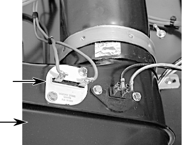
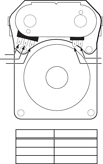
MOISTURE SENSOR
Refer to page 4-15 for the procedure for ser-
vicing the moisture sensor.
Perform this test if the dryer shuts off too soon
when set to an automatic cycle.
1. Set the dryer to the “Diagnostic Test Mode”
(refer to the procedure on page 6-1).
2. Open the dryer door.
3. Place a finger across the two metal sen-
sor strips on the lint screen housing. If a
beep tone sounds and “03” is displayed
in the console window, the sensor is work-
ing normally.
4. If the moisture sensor fails the diagnostic
test, check the moisture sensor wiring. Dis-
connect the power to the dryer, use an
ohmmeter, and check the yellow-red and
black wires for shorts (continuity to
ground), first with no load (wire connector
disconnected), and then with a load (con-
nected).
5. If the diagnostic test passes, perform the
thermistor test (refer to page 5-5).
6. If the problem still exists after replacing the
thermistor, check the ribbon connections
from the control panel to the machine con-
trol electronics board.
7. If all of the above are satisfactory, replace
the machine control electronics board.
Metal Sensor Strips
Bridge Strips
With Finger
P4
P3
Refer to the following test that corresponds to
your problem.
NONE OF THE LEDS LIGHT
1. Check to make sure that ribbon connec-
tors P3 and P4 are inserted all the way
into the machine control electronics board.
Viewed From This Side
Console Pushbuttons & LEDs
Machine Control Electronics Board
5-9
A PARTICULAR GROUP OF LEDS
DOES NOT LIGHT
A group or combination of LEDs share a com-
mon electronic connection. If this connection
is open, all of the LEDs in the group will be
disabled. If this occurs, replace the entire con-
sole electronics and housing.
ONE LED DOES NOT LIGHT
Press the button associated with the LED
several times. If the LED does not light, the
LED has failed. Replace the entire console
electronics and housing.
NO BEEP SOUNDS
If the associated LEDs do light up, the beeper
circuit may have failed on the machine control
electronics board.
NO DRYER FUNCTION IS ACTIVATED
WHEN A PARTICULAR PUSHBUTTON
IS PRESSED
If the associated LEDs do light up, the machine
control electronics board may have failed.
AN E3 ERROR CODE IS DISPLAYED
An E3 error code means that there is a user
interface or a software mismatch. It can also
mean that a component on the console elec-
tronics, or the machine control electronics
board has failed.
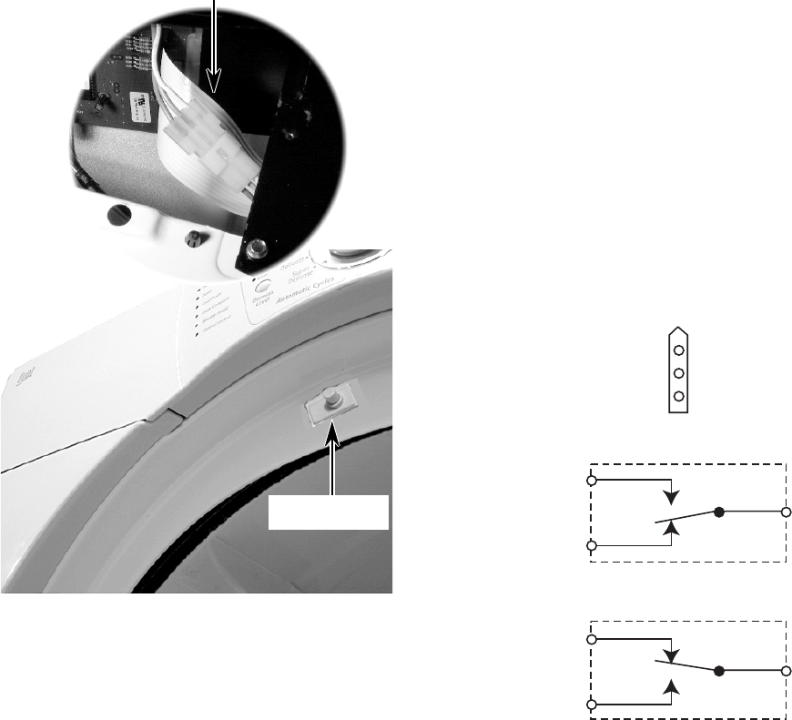
5-10
DOOR SWITCH
Refer to page 4-6 for the procedure for servic-
ing the door switch.
1. Set the dryer to the “Diagnostic Test Mode”
(refer to the procedure on page 6-1).
2. Open and close the dryer door. You should
hear a “beep” each time the door is closed
and opened, and “OE” should be displayed
in the console window whenever the door
is opened.
If a beep does not sound, or if “OE” is dis-
played with the door closed, check the wir-
ing between the door switch and the ma-
chine control electronics board for positive
connections or short circuits (see the
photo).
If the wiring is okay, perform the resistance
tests.
RESISTANCE TESTS
1. Disconnect the electrical power to the
dryer.
2. Close the dryer door.
3. Disconnect the 3-wire connector from the
door switch to the machine control elec-
tronics board.
4. Set the ohmmeter to the R X 1 scale.
Refer to the illustration below for the following
tests.
5. Touch the black ohmmeter test lead to the
white wire pin in the connector and leave
it there for the remaining tests.
6. Touch the red ohmmeter test lead to the
brown wire pin in the connector. The meter
should indicate an open circuit (infinite).
7. Touch the red ohmmeter test lead to the
blue wire pin in the connector. The meter
should indicate a closed circuit (0 ohms).
8. Open the dryer door.
9. Touch the red ohmmeter test lead to the
blue wire pin in the connector. The meter
should indicate an open circuit (infinite).
10. Touch the red ohmmeter test lead to the
brown wire pin in the connector. The meter
should indicate a closed circuit (0 ohms).
11. If the resistance test is incorrect, replace
the wire and door switch assembly, (see
page 4-6 for the procedure), and retest.
Door Switch Connector
Brown
Brown (N.C.)
White
White (COM)
Blue
Blue (N.O.)
N.O.
N.C.
COM
DOOR OPEN
Brown
White
Blue N.O.
N.C.
COM
DOOR CLOSED
CONNECTOR
Door Switch

6-1
DIAGNOSIS
DIAGNOSIS AND TROUBLESHOOTING
DIAGNOSTIC TESTS
The Diagnostic Tests will test and verify all of
the inputs to the machine control electronics
board. These tests are an overall check of the
dryer electronics and the related components.
The tests should be run prior to making any of
the troubleshooting tests.
ACTIVATING THE DIAGNOSTIC
TEST MODE
1. Make sure that the dryer is in the “Standby”
mode (plugged in and all of the indicators
are off).
2. Press the following control panel keypad
sequence all within 5 seconds:
More Time—Less Time—More Time—
Less Time.
3. All indicators on the console should now
be illuminated with “88” showing in
the “Estimated Time Remaining” display,
if this test mode has been entered suc-
cessfully.
NOTE: If the “Diagnostic Test Mode” entry was
unsuccessful, perform the following actions for
specific indications.
Indication #1
Problem: None of the indicators or dis-
play digits light.
DISPLAY FAULT/ERROR CODES
Corrective Action: Press one of the
Manual Cycles pushbuttons. If the indica-
tors light, change the dryer time by press-
ing the More Time and Less Time push-
buttons.
If either pushbutton fails to change the
time, the pushbutton is defective, and it is
not possible to enter the diagnostic mode.
Remove the console electronics and hous-
ing (see page 4-4).
Indication #2
Problem: E1 or E2 flashes on the display.
Corrective Action: Refer to “Thermistor
Test” on page 5-5.
Indication #3
Problem: E3 flashes on the display.
Corrective Action: Check that the cor-
rect console electronics and housing, and
the machine control electronics board are
installed. To do this, remove these com-
ponents (see pages 4-2 through 4-5 for
the procedures). Check the part numbers
and compare them to the part numbers
shown in the Tech Sheet that is supplied
with the dryer. Replace the components, if
necessary.
EXPLANATION & RECOMMENDED
PROCEDURE
“PF” Flashes to indicate that a power failure
occurred while the dryer was running.
Press START to continue the cycle, or press
STOP/CANCEL to clear the display.
“E1” flashes if the thermistor is open.
See “Thermistor Test” on page 5-5.
“E2” flashes if the thermistor has shorted.
See “Thermistor Test” on page 5-5.
DISPLAY DESCRIPTION
Power FailurePF
E1
E2
Thermistor Open
Thermistor Shorted
6-2
KEYPAD TEST
1. Press the Dryness Level keypad.
The three Dryness Level LEDs should
turn off and the dryer should beep.
2. Press the Control On keypad.
The Control Locked LED should turn off.
3. Turn the cycle selector knob one complete
rotation.
When the knob points to a cycle, the
corresponding LED should go out, and the
dryer should beep. When the knob is point-
ing in the large spaces between the Manual
and Automatic cycle groups, only a beep
should be heard.
4. Touch the More Time keypad.
The most significant “8” should turn off and
the dryer should beep.
5. Touch the Less Time keypad.
The least significant “8” should turn off and
the dryer should beep.
6. Touch the Wrinkle Shield keypad.
The corresponding LED should turn off
and the dryer should beep.
7. Touch the Temperature keypad.
The five Temperature Level LEDs should
turn off and the dryer should beep.
8. Touch the End Of Cycle Signal keypad.
The three End Of Cycle level LEDs should
turn off and the dryer should beep.
ADDITIONAL TESTS
1. Open the dryer door.
The dryer should beep and the display will
show a number, followed by a capital “E”
for electric models, or a lower case “g” for
gas models. The first number will be a 3
(Whirlpool access).
2. Touch the Sensing keypad.
The dryer should beep while touching the
keypad and the display will show a 2-digit
software revision code.
3. Close the dryer door.
The display should turn blank.
4. Touch the Start keypad.
The Status LEDs should turn off, the heater
and motor should turn on, and the display
should read a 2-digit project ID code.

6-3
TROUBLESHOOTING GUIDE
PROBLEM
Unit will not power up.
Unit will not cycle when Start
pushbutton is pressed.
Unit will not turn off.
The control panel will not accept com-
mands.
The unit will not heat.
The unit heats during the “air” cycle.
The unit turns off before the clothes
are dry.
1. Check the 120 VAC electrical supply.
2. Check the wiring harness connections.
3. Check the control electronics.
1. Be sure to hold the Start pushbutton down for
3 seconds.
2. Check the wiring harness connections.
3. If the displayed number flashes, make sure the
door is completely closed. Press and hold the
Start pushbutton down for 3 seconds.
1. Test the Pause/Cancel pushbutton.
2. Check the control electronics and housing.
3. Check the moisture sensor.
1. Check the heater voltage.
2. Check the wire connections to the heater.
1. Check the thermistor.
1. Check the moisture sensor.
POSSIBLE CAUSE/TEST
1. Check the control electronics and housing.
6-4
— NOTES —
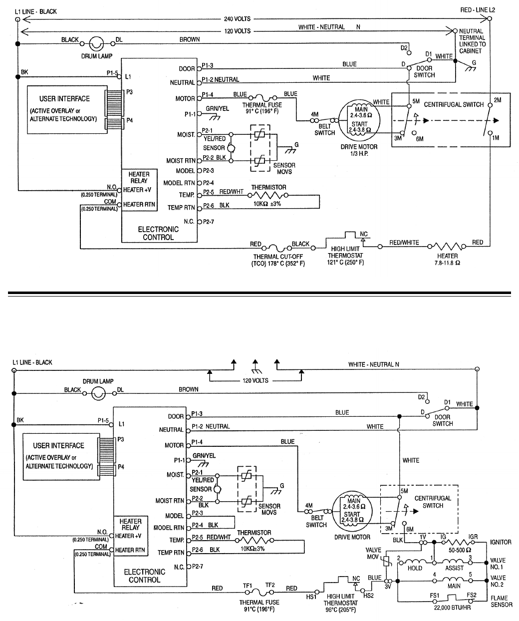
7-1
WIRING DIAGRAMS
ELECTRIC DRYER
GAS DRYER
7-2
— NOTES —
7-3
— NOTES —
7-4
— NOTES —

PRODUCT SPECIFICATIONS
AND
WARRANTY INFORMATION SOURCES
IN THE UNITED STATES:
FOR PRODUCT SPECIFICATIONS AND WARRANTY INFORMATION CALL:
FOR TECHNICAL ASSISTANCE WHILE AT THE CUSTOMER’S HOME CALL:
THE TECHNICAL ASSISTANCE LINE: 1-800-253-2870
HAVE YOUR STORE NUMBER READY TO IDENTIFY YOU AS AN
AUTHORIZED SERVICER
FOR LITERATURE ORDERS:
PHONE: 1-800-851-4605
IN CANADA:
FOR PRODUCT SPECIFICATIONS AND WARRANTY INFORMATION CALL:
1-800-461-5681
FOR TECHNICAL ASSISTANCE WHILE AT THE CUSTOMER’S HOME CALL:
THE TECHNICAL ASSISTANCE LINE: 1-800-488-4791
HAVE YOUR STORE NUMBER READY TO IDENTIFY YOU AS AN
AUTHORIZED SERVICER
FOR WHIRLPOOL PRODUCTS: 1-800-253-1301
FOR KITCHENAID PRODUCTS: 1-800-422-1230
FOR ROPER PRODUCTS: 1-800-447-6737

CO
RP
O
R
A
T
ION
