FRNTPGSP 8178455 Whrlpl P GAS RANGE KR 35
2013-05-09
: Pdf 8178455 - Whrlpl - P Gas Range - Kr-35 8178455 - Whrlpl - P GAS RANGE - KR-35 gasrange may8
Open the PDF directly: View PDF ![]() .
.
Page Count: 68
CONSUMER SERVICES TECHNICAL
EDUCATION GROUP PRESENTS
KR-35
JOB AID
Part No. 8178455
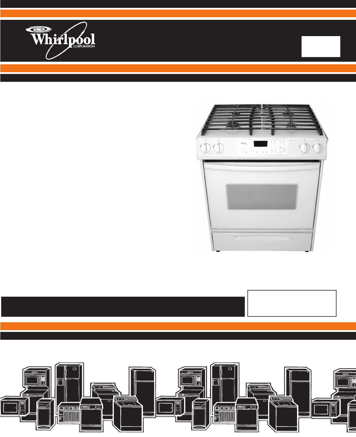
SELF-CLEANING
SLIDE-IN GAS
RANGE
Model: GW395LEP

- ii -
WHIRLPOOL CORPORATION assumes no responsibility for any repairs made
on our products by anyone other than Authorized Service Technicians.
FORWARD
This Whirlpool Job Aid, “Self-Cleaning Slide-In Gas Range,” (Part #8178455), provides the
technician with information on the installation, operation, and service of the Self-Cleaning Slide-
In Gas Range. It is to be used as a training Job Aid and Service Manual. For specific information
on the model being serviced, refer to the “Use and Care Guide,” or “Wiring Diagram” provided with
the gas range.
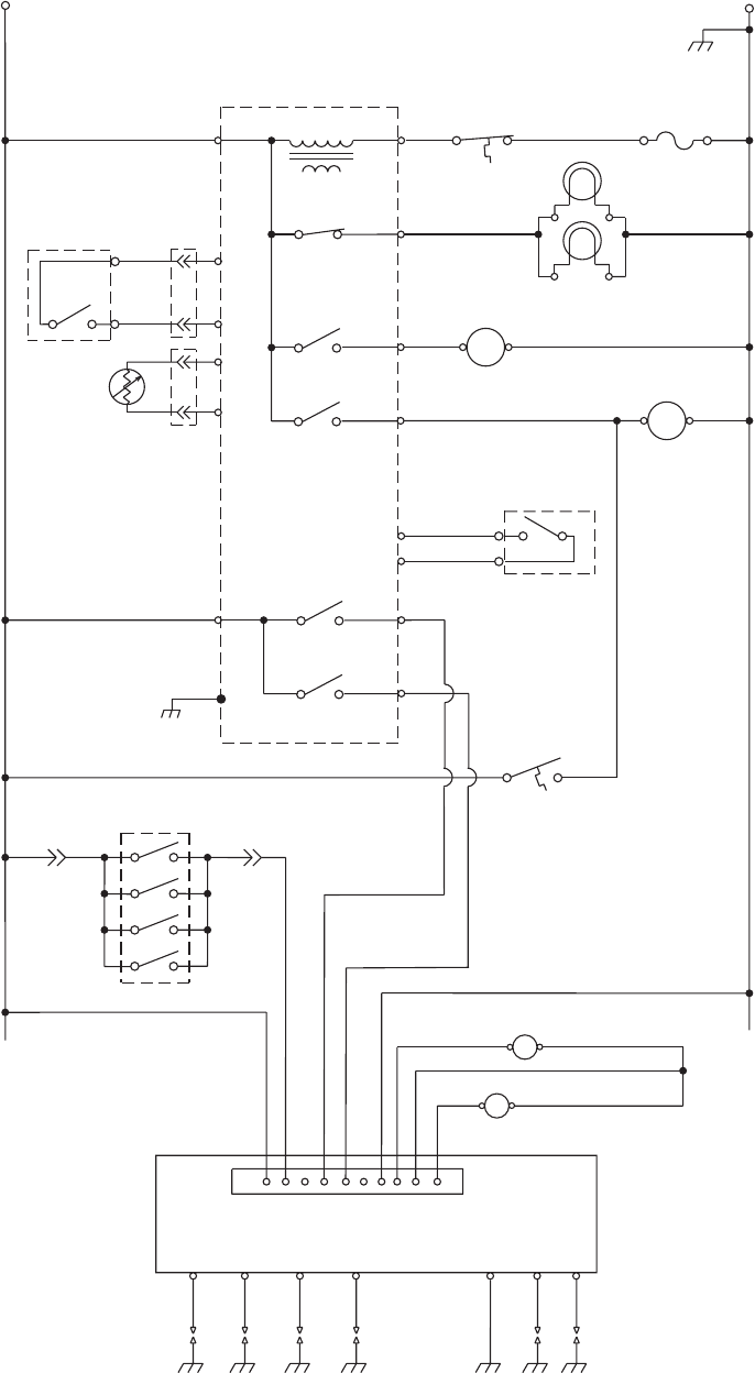
The Wiring Diagram and Strip Circuits used in this Job Aid are typical and should be used for
training purposes only. Always use the Wiring Diagram supplied with the product when servicing
the unit.
GOALS AND OBJECTIVES
The goal of this Job Aid is to provide detailed information that will enable the service technician to
properly diagnose malfunctions and repair the Whirlpool Self-Cleaning Slide-In Gas Range.
The objectives of this Job Aid are to:
• Understand and follow proper safety precautions.
• Successfully troubleshoot and diagnose malfunctions.
• Successfully perform necessary repairs.
• Successfully return the range to its proper operational status.
Copyright © 2004, Whirlpool Corporation, Benton Harbor, MI 49022
- iii -
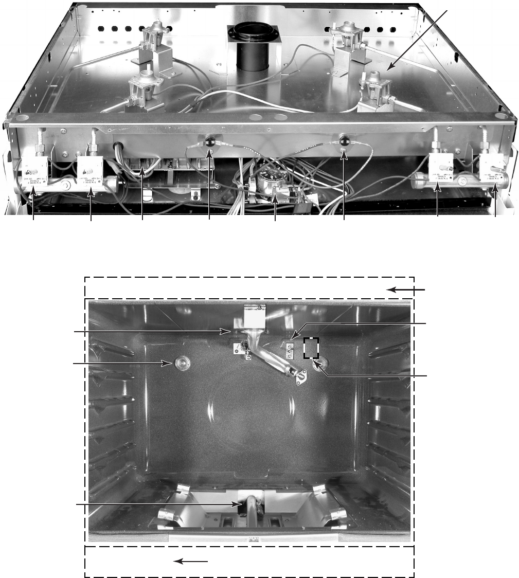
TABLE OF CONTENTS Page
GENERAL............................................................................................................................... 1-1
Safety First......................................................................................................................... 1-1
Model & Serial Number Designations ................................................................................ 1-2
Model & Serial Number Label & Wiring Diagram Locations .............................................. 1-3
Specifications..................................................................................................................... 1-4
Whirlpool Gas Range Warranty ......................................................................................... 1-6
INSTALLATION INFORMATION ........................................................................................... 2-1
Gas Supply Requirements ................................................................................................. 2-1
Electrical Requirements ..................................................................................................... 2-3
L.P. Gas Conversion.......................................................................................................... 2-4
Adjusting For The Proper Flame........................................................................................ 2-8
Installing The Anti-Tip Bracket ........................................................................................... 2-9
THEORY OF OPERATION ..................................................................................................... 3-1
Electronic Oven Control System Functions ....................................................................... 3-1
COMPONENT ACCESS ......................................................................................................... 4-1
Component Locations ........................................................................................................ 4-1
Removing The Control Panel And The Electronic Oven Control Board &
User Interface ................................................................................................................. 4-2
Removing The Ignition Switches, A Gas Valve,
And The Control And Cooling Fan TODs ....................................................................... 4-4
Removing The Door Latch Assembly And The Spark Module (DSI) ................................. 4-6
Removing The Cooktop, And A Surface Burner & Ignitor.................................................. 4-8
Removing The Rear Panel .............................................................................................. 4-10
Removing An Oven Light Socket Assembly .................................................................... 4-11
Removing The Broil Burner And Ignitor ........................................................................... 4-12
Removing The Bake Burner And Ignitor .......................................................................... 4-14
Removing The Oven Temperature Sensor ...................................................................... 4-16
Removing The Cooling Fan ............................................................................................. 4-17
Removing The Oven TOD ............................................................................................... 4-18
Removing The Gas Distribution Valve ............................................................................. 4-19
Removing The Power Supply Cord ................................................................................. 4-20
Removing A Side Panel ................................................................................................... 4-21
Removing & Reinstalling The Oven Door ........................................................................ 4-22
Removing The Oven Door Gasket................................................................................... 4-23
Removing The Decorative Glass And Oven Door Handle,
The Hinges, And The Oven Door Glass ...................................................................... 4-24
- iv -
Page
COMPONENT TESTING ........................................................................................................ 5-1
Control & Cooling Fan TODs ............................................................................................. 5-1
Ignition Switches ................................................................................................................ 5-2
Door Latch Assembly......................................................................................................... 5-3
Oven Temperature Sensor ................................................................................................ 5-3
Cooling Fan Motor ............................................................................................................. 5-4
Oven TOD.......................................................................................................................... 5-4
Gas Distribution Valve ....................................................................................................... 5-5
Gas Valve .......................................................................................................................... 5-5
Clock .................................................................................................................................. 5-6
Keypad Layout ................................................................................................................... 5-6
Display Board & Connector Pinouts .................................................................................. 5-7
DIAGNOSTICS & TROUBLESHOOTING .............................................................................. 6-1
Diagnostics ........................................................................................................................ 6-1
Failure/Error Display Codes........................................................................................... 6-1
Hidden EOC Functions ................................................................................................. 6-2
Temperature Adjustment ............................................................................................... 6-2
EZ354 ............................................................................................................................ 6-3
Troubleshooting Chart ....................................................................................................... 6-4
WIRING DIAGRAM & STRIP CIRCUITS ............................................................................... 7-1
Wiring Diagram .................................................................................................................. 7-1
Strip Circuits ...................................................................................................................... 7-2
1-1
GENERAL
SAFETY FIRST
Your safety and the safety of others is very important.
We have provided many important safety messages in this Job Aid and on the appliance. Always
read and obey all safety messages.
This is the safety alert symbol.
This symbol alerts you to hazards that can kill or hurt you and others.
All safety messages will follow the safety alert symbol and either the word
“DANGER” or “WARNING.” These words mean:
DANGER
WARNING
All safety messages will tell you what the potential hazard is, tell you how to reduce the chance
of injury, and tell you what can happen if the instructions are not followed.
You can be killed or seriously injured if you don’t
immediately follow instructions.
You can be killed or seriously injured if you don’t
follow instructions.

1-2
MODEL & SERIAL NUMBER DESIGNATIONS
MODEL NUMBER
SERIAL NUMBER
MODEL NUMBER GW3 9 5 LEP Q
PRODUCT GROUP
R = ELECTRIC RANGES
S = GAS RANGES
G = WHIRLPOOL GOLD RANGE
PRODUCT IDENTIFICATION
A = ACCESSORY K = KITS
B = BUILT-IN M = MV COMBO
C = COOKTOP S = SET-IN
E = EYE-LEVEL W = SLIDE-IN GAS
F = FREESTANDING Y = SLIDE-IN ELECTRIC
H = HOODS
MODEL SIZE
3 = 30" SLIDE-IN
4 = 40" SLIDE-IN
5 = 36" SLIDE-IN
6 = 30" SET-IN RANGES
OVEN TYPE
0 THRU 3 = STANDARD PORCELAIN
4 THRU 9 = PYROLYTIC SELF-CLEAN
FEATURE / VARIATIONS
ELECTRIC
0, 1, 2, 5, 7 = COIL ELEMENTS
4 = STANDARD PATTERN CERAMIC
6, 8, 9 = DELUXE PATTERN CERAMIC
GAS
0, 1, 2, 3, 4, 6 = OPEN BURNER
5 & 7 = SEALED BURNER
DOOR TYPE
B = SOLID BLACK GLASS
L = LARGE WINDOW
O = METAL OVEN DOOR
P = STANDARD WINDOW GLASS
FEATURE CODE
E = ELECTRONIC IGNITION (GAS ONLY)
S = STANDING IGNITION (GAS ONLY)
C = COLOR COORDINATED GLASS (BEFORE 1998)
X = NOT DEFINED
YEAR OF INTRODUCTION
P = 2004
COLOR CODE
B = BLACK
Q = WHITE ON WHITE
S = STAINLESS STEEL
T = BISCUIT
SERIAL NUMBER X R 07 1 2 3 4 5
MANUFACTURING SITE
X = OXFORD, MS
YEAR OF PRODUCTION
R = 2004
WEEK OF PRODUCTION
(7th WEEK)
PRODUCT SEQUENCE NUMBER
1-3
MODEL & SERIAL NUMBER LABEL
& WIRING DIAGRAM LOCATIONS
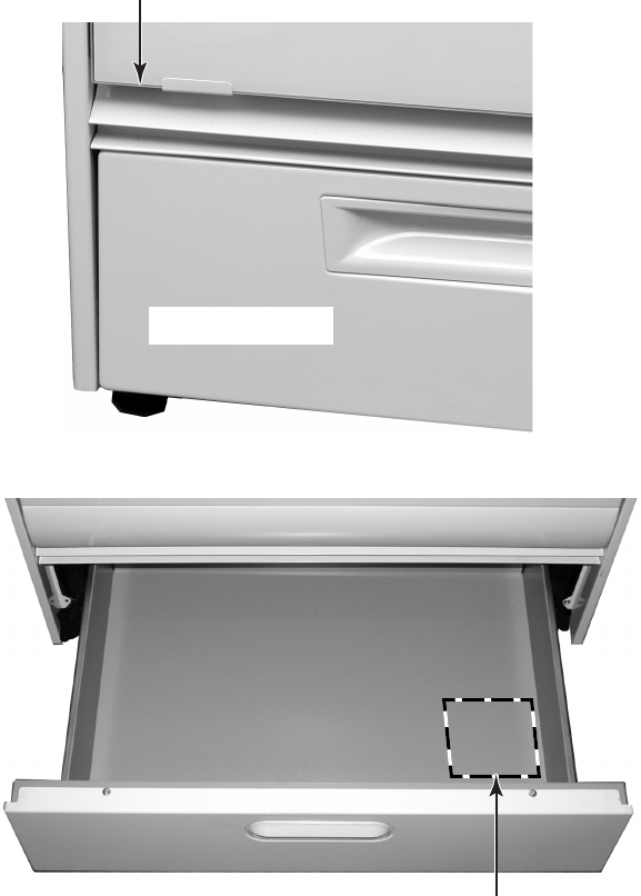
Storage Drawer
The Model/Serial Number label and Wiring Diagram locations are shown below.
Wiring Diagram Location
(On Underside Of Drawer)
Model/Serial Number Location
(Above Storage Drawer)

1-4
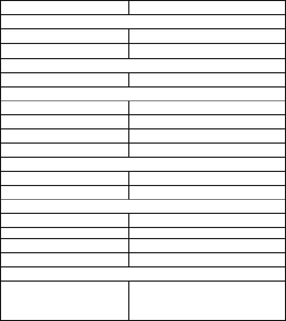
SPECIFICATIONS
Model # GW395LEP Q/B/T/S
Model Description Gas Self-Clean
Oven Control Type EZ354
OVEN CONTROL FUNCTIONS
Convect bake No
Bake Yes
Temperature range 170 to 500°F
Custom broil Yes
Temperature range 300 to 500°F
Temperature control Temperature up/down buttons
(5 degree increments)
Self-clean Yes, variable time
Time set range 2:30 to 4:30 (15 min. increments)
Delay bake Yes (Cook time, Stop time buttons)
Timer Yes (up to 12hrs, 59 min. max.)
Oven light (manual) Yes
Control lockout Yes
Pre-heat countdown timer Yes
Control overlay color Q=White/Nestle, B=Black/blk Divide,
T=Biscuit/dk biscuit, S=Black/blk Divide
Oven Heating Indicator Light In display
Hidden functions
Select F/C temperature, temperature
calibration offset, disable/enable timer
reminder signals, disable/enable cycle end
audible signals
CONSOLE FEATURES
Location Front
Burner "ON" Indicator Light No
Burner Controls Push to turn, infinite
Valve degrees of rotation 210 degrees
COOKTOP FEATURES
Burner Type Sealed
Ignition Electronic
Burner Configuration
Right Front Burner 6,000 btu
Left Front Burner 14,000 btu
Right Rear Burner 12,000 btu
Left Rear Burner 6,000 btu
Lift Top No
OVEN FEATURES
Oven cleaning type Self-clean
Accubake system Yes
Number of temperature sensors 1
Oven Capacity 4.3 Cu. Ft.
Broil Burner 10,000 btu
Door Position in Broil Closed
Bake Burner 15,500 btu
Oven Light Yes
1-5
Model # GW395LEP Q/B/T/S
OVEN DOOR FEATURES
Door Latch Yes-Motorized
Removable Door Yes
STORAGE/WARMING DRAWER
Storage Drawer Yes
LITERATURE
Use & Care Guide Yes (English + French)
Tech Sheets/Wiring Diagrams 9757668
Installation Instructions Yes (English + French)
Service Manual/Job Aid 8178455
DIMENSIONS
Height-Overall 35.9"
Width 29.875"
OTHER SPECIFICATIONS
LP Convertible Yes, conversion orifices included
Agency Approval CSA
Power cord Included
Anti-Tip Device w/ Unit Floor Bracket
ACCESSORIES
Trim Kit
Included, matches body color, to close gap
from rear of unit to wall (previous
freestanding installation)

1-6
WHIRLPOOL GAS RANGE WARRANTY
ONE-YEAR FULL
WARRANTY
FROM DATE OF
PURCHASE.
LENGTH OF
WARRANTY:
WHIRLPOOL
WILL PAY FOR:
FSP® replacement
parts and repair
labor costs to
correct defects in
materials or work-
manship. Service
must be provided
by an authorized
Whirlpool service
company.
WHIRLPOOL
WILL NOT PAY FOR:
A. Service calls to:
1. Correct the installation of the range.
2. Instruct you how to use the range.
3. Replace house fuses or correct house wiring.
4. Replace owner-accessible light bulbs.
5. Correct house plumbing.
B. Repairs when the range is used in other than
normal, single-family household use.
C. Pickup and delivery. The range is designed to
be repaired in the home.
D. Damage to the range caused by accident, alter-
ation, misuse, abuse, fire, flood, acts of God, or
use of products not approved by Whirlpool.
E. Repairs to parts or systems resulting from unau-
thorized modifications made to the appliance.
F. In Canada, travel or transportation expenses for
customers who reside in remote areas.
G. Replacement parts or repair labor costs for units
operated outside the United States and Canada.
WHIRLPOOL CORPORATION AND WHIRLPOOL CANADA INC.
SHALL NOT BE LIABLE FOR INCIDENTAL OR CONSEQUENTIAL DAMAGES.
Some states and provinces do not allow the exclusion or limitation of incidental or consequential damages
so this exclusion or limitation may not apply to you. This warranty gives you specific legal rights and you
may also have other rights which vary from state to state or province to province.
Outside the 50 United States and Canada, this warranty does not apply. Contact your authorized
Whirlpool dealer to determine if another warranty applies.
If you need service first see “Troubleshooting” in the “Use & Care Guide.” Additional help can be found by
checking “Assistance or Service” or call our Customer Interaction Center at 1-800-253-1301 from
anywhere in the U.S.A., or write: Whirlpool Brand Home Appliances, Customer Interaction Center, 553
Benson Road, Benton Harbor, MI 49022-2692. In Canada, call Whirlpool Canada Inc. at 1-800-807-6777.
2-1
INSTALLATION INFORMATION
GAS SUPPLY REQUIREMENTS
Explosion Hazard
Use a new AGA or CSA approved gas
supply line.
Install a shutoff valve.
Securely tighten all gas connections.
If connected to L.P. gas, have a qualified
person make sure gas pressure does
not exceed 14″ water column.
Examples of a qualified person include
licensed heating personnel, authorized
gas company personnel, and
authorized service personnel.
Failure to do so can result in death,
explosion, or fire.
Flexible Gas Supply Line
1. This installation must conform with local
codes and ordinances. In the absence of
local codes, installations must conform
with American National Standard, National
Fuel Gas Code ANSI Z223.1—latest edi-
tion* or CANI-B149—latest edition** in-
stallation codes.
Copies of the standards listed may be obtained
from:
* American Gas Association
1515 Wilson Boulevard
Arlington, Virginia 22209
** CSA International
8501 East Pleasant Valley Road
Cleveland, Ohio 44131-5575
2. Input ratings shown on the model/serial
rating plate are for elevations up to 2,000
feet (609.6 m). For elevations above 2,000
feet (609.6 m), ratings are reduced at a
rate of 4% for each 1,000 feet (304.8 m)
above sea level. (Not applicable for
Canada.)
3. This range is equipped for use with Natu-
ral gas. It is design-certified by AGA/CSA
for Natural and L.P. gas with appropriate
conversion. Conversion to L.P. gas can be
made using the kit included in the litera-
ture package. The model/serial rating plate
has information on the type of gas that can
be used. If this information does not agree
with the type of gas available, check with
your Whirlpool dealer.
4. Provide a gas supply line of 3/4″ (1.9 cm)
rigid pipe to the range location. A smaller
size pipe on long runs may result in insuf-
ficient gas supply. Pipe-joint compounds
appropriate for use with L.P. gas must be
used. With L.P. gas, piping or tubing size
can be 1/2″ (1.3 cm) minimum. L.P. gas
suppliers usually determine the size and
materials used on the system.
5. If local codes permit, a new AGA/CSA
design-certified, 4-5 foot (122 -152.4 cm)
long, 1/2″ (1.3 cm) or 3/4″ (1.9 cm) I.D.,
flexible metal appliance connector is rec-
ommended for connecting this range to
the gas supply line. Do Not kink or damage
the flexible tubing when moving the range.
A 1/2″ (1.3 cm) male pipe thread is needed
for connection to pressure regulator fe-
male pipe threads.
WARNING
Observe all governing codes and ordi-
nances.
IMPORTANT: Range must be connected to
a regulated gas supply.
Continued on the next page.

2-2
Rigid Pipe
6. The supply line shall be equipped with an
approved shutoff valve. This valve should
be located in the same room, but external
to the range, and should be in a location
that allows ease of opening and closing.
Do Not block access to shutoff valve.
7. If rigid pipe is used as a gas supply line, a
combination of pipe fittings must be used
to obtain an in-line connection to the range.
All strains must be removed from the sup-
ply and fuel lines so the range will be level
and in line.
8. The regulator setting must be checked at
a minimum of 1 inch water column above
the manifold pressure. The inlet pressure
to the regulator should be as follows for
operation:
Natural gas:
Manifold pressure—5 inches
Maximum pressure—14 inches
L.P. gas:
Manifold pressure—10 inches
Maximum pressure—14 inches
9. Line pressure testing:
Testing above 1/2 psi (gauge)
The range and its individual shutoff valve
must be disconnected from the gas supply
piping system during any pressure testing
of that system at test pressures greater
than 1/2 psig (3.5 kPa).
Testing at 1/2 psi (gauge) or lower
The range must be isolated from the gas
supply piping system by closing its indi-
vidual manual shutoff valve during any pres-
sure testing of the gas supply piping sys-
tem at test pressures equal to or less than
1/2 psig (3.5 kPa).
Manual Shutoff Valve
OPEN Position
To Range
Gas Supply Line
2-3
Electrical Shock Hazard
Plug into a grounded 3 prong outlet.
Do not remove ground prong.
Do not use an adapter.
Do not use an extension cord.
Failure to follow these instructions can
result in death, fire, or electrical shock.
ELECTRICAL REQUIREMENTS
If codes permit and a separate ground wire
is used, it is recommended that a qualified
electrician determine that the ground path
is adequate.
Do Not ground to a gas pipe.
Check with a qualified electrician if you are
not sure range is grounded.
Do Not have a fuse in the neutral or ground
circuit.
A 120-volt, 60-Hz, AC-only, 15-ampere, fused
electrical circuit is required. A time-delay fuse
or circuit breaker is recommended. It is recom-
mended that a separate circuit serving only this
range be provided.
Electronic ignition systems operate within wide
voltage limits, but proper grounding and polar-
ity are necessary. In addition to checking that
the outlet provides 120-volt power and is cor-
rectly grounded, the outlet must be checked by
a qualified electrician to see if it is wired with
correct polarity.
Copies of the standards listed may be obtained
from:
* National Fire Protection Association
Batterymarch Park
Quincy, Massachusetts, 02269
** CSA International
8501 East Pleasant Valley Road
Cleveland, Ohio 44131-5575
NOTE: The metal chassis of the range MUST
be grounded in order for the control panel to
work. If the metal chassis of the range is not
grounded, NO keypads will operate. Check
with a qualified electrician if you are in doubt as
to whether the metal chassis of the range is
grounded.
Recommended ground method
For personal safety, this range is equipped with
a power supply cord having a 3-prong ground
plug. To minimize possible shock hazard, the
cord must be plugged into a mating 3-prong,
ground-type outlet, grounded in accordance
with the National Electrical Code, ANSI/NFPA
70—latest edition* or CSA Standard C22.1,
Canadian Electrical Code, Part 1,—latest edi-
tion** and all local codes and ordinances. If a
mating outlet is not available, it is the personal
responsibility and obligation of the customer to
have a properly grounded, 3-prong outlet in-
stalled by a qualified electrician.
WARNING

2-4
1. Check to make sure that the main gas
supply line to the range has been shut off,
and that the power supply cord is discon-
nected from the AC outlet.
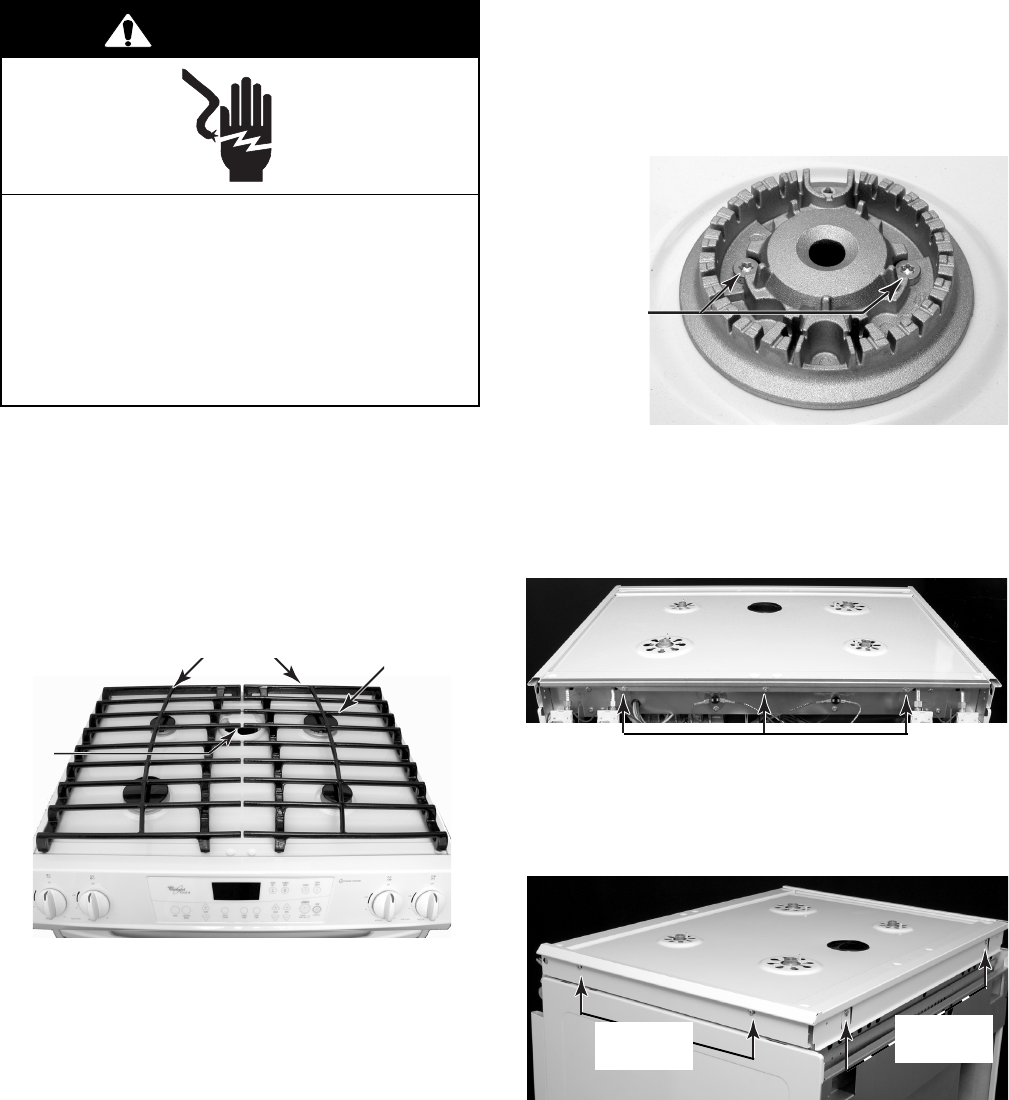
2. To convert the surface burners for use
with L.P. gas:
a)Remove the grates and burner caps
from the cooktop.
b)Remove the two screws from each of
the burner heads and lift the heads off
the cooktop.
Burner Head
Gas Valve Handle
To “Shutoff” Position
L.P. GAS CONVERSION
NOTE: Gas conversion from Natural to L.P.
gas must be done by a qualified installer.
Examples of a qualified installer include
licensed heating personnel, authorized gas
company personnel, and authorized ser-
vice personnel.
L.P. gas must not be used unless the L.P.
conversion has been made using the kit that is
included with this range. See the “Gas Supply
Requirements” starting on page 2-1.
Electrical Shock Hazard
Disconnect power before servicing.
Replace all parts and panels before
operating.
Failure to do so can result in death or
electrical shock.
WARNING
Fire Hazard
Shut off gas supply line valve.
Make all conversions before turning
gas supply valve back on.
Failure to follow these instructions
could result in explosion, fire, or other
injury.
WARNING
2-5
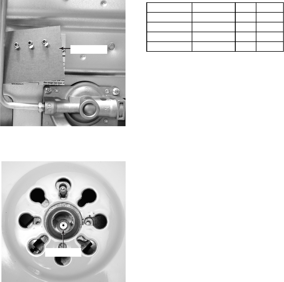
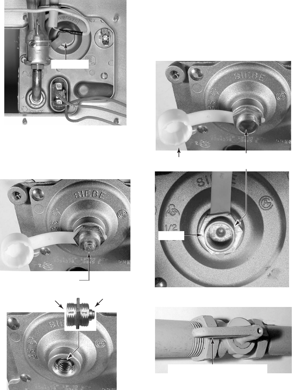
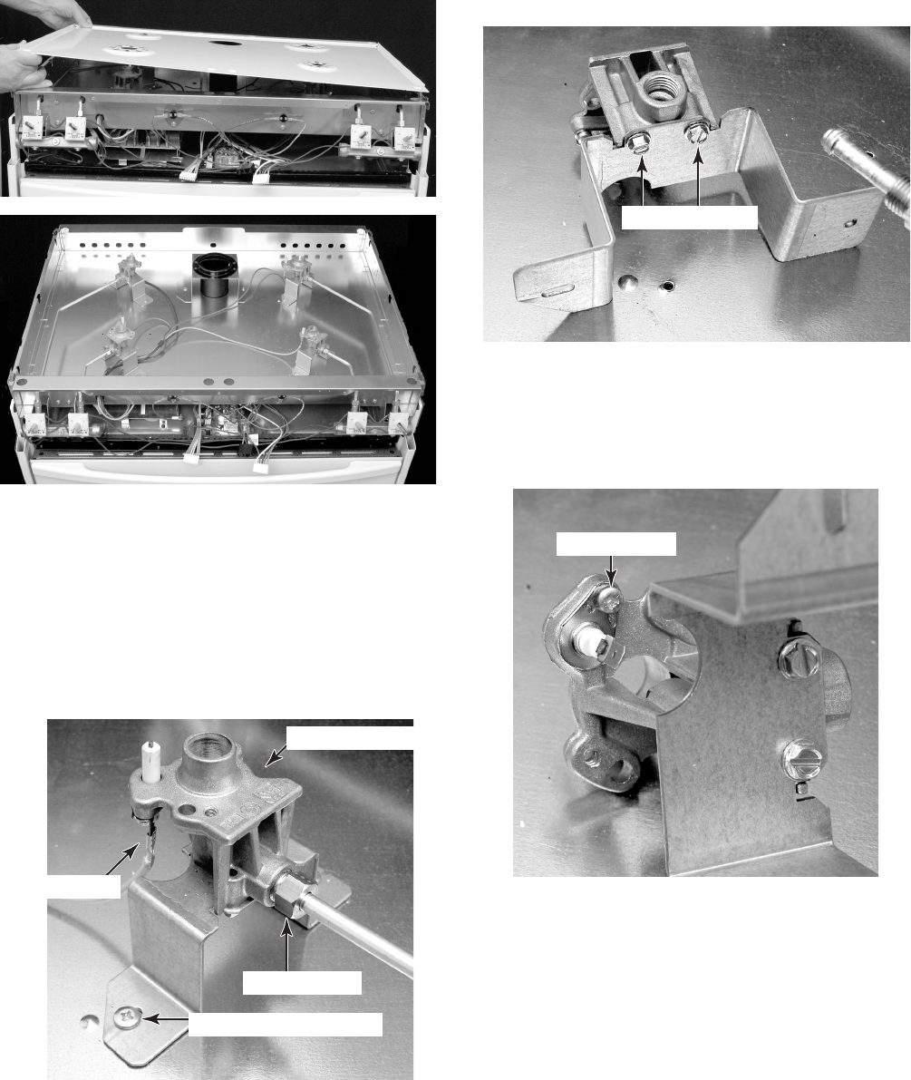
c) Use an 8 mm socket and carefully re-
move the orifice spud from each of the
four burners.
d)Install the four L.P. gas orifices in the
burners, as shown in the following chart
(do not overtighten them):
NOTE: The L.P. orifices are fastened to the
back of the range near the bottom on a card-
board form.
e)Place the natural gas orifices in the ori-
fice card holes.
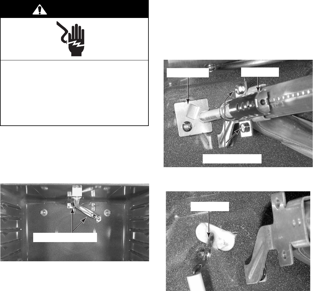
3. To convert the broil burner for use with
L.P. gas:
a)Open the oven door and remove the
oven racks.
b)Use a 1/2″ open-end wrench and turn
the orifice hood down snug onto the pin
(approximately 2-1/2 turns). DO NOT
OVERTIGHTEN THE ORIFICE. The
burner flame cannot be properly ad-
justed if this conversion is not made.
c) Reinstall the oven racks and close the
oven door.
Orifice Card
Orifice Spud
Continued on the next page.
Burner Location Burner Rating Color Size
Right Front 5,000 BTU Red 0.70 mm
Left Front 13,000 BTU Green 1.10 mm
Right Rear 10,000 BTU Blue 0.95 mm
Left Rear 5,000 BTU Red 0.70 mm
2-6
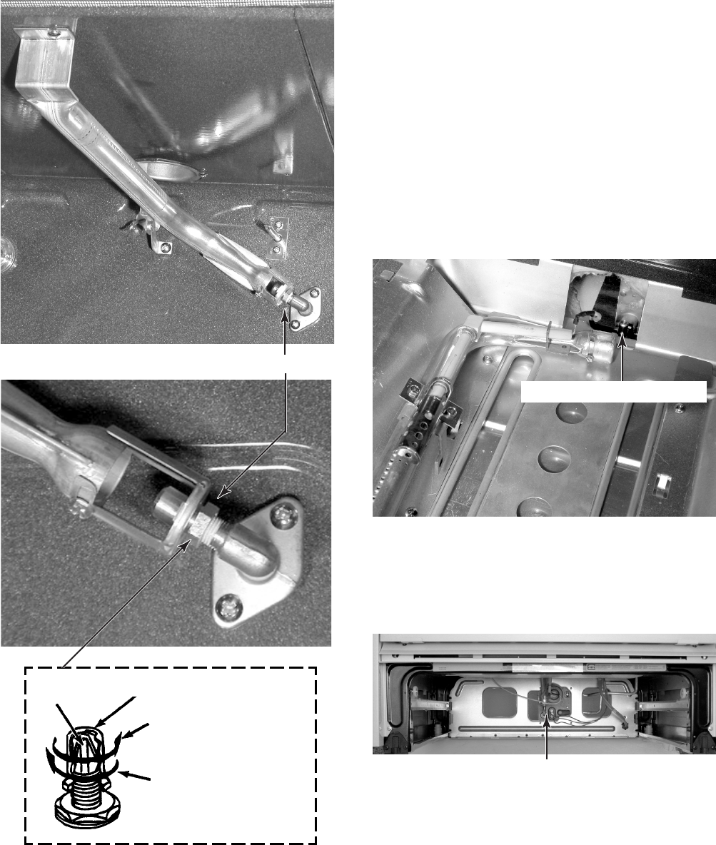
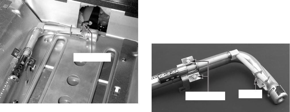
4. To convert the bake burner for use with
L.P. gas:
a)Remove the bake burner from the gas
distribution valve orifice (see page 4-14
for the procedure).
b)Use a 1/2″ open-end wrench and turn
the bake burner orifice hood down snug
onto the pin (approximately 2-1/2 turns).
DO NOT OVERTIGHTEN THE ORI-
FICE. The burner flame cannot be prop-
erly adjusted if this conversion is not
made.
Broil Burner Orifice
Pin
Orifice
Hood
Natural Gas:
Increases Flame Size
In This Direction
L.P. Gas:
Increases Flame Size
In This Direction
Bake Burner Orifice Hood
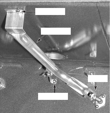
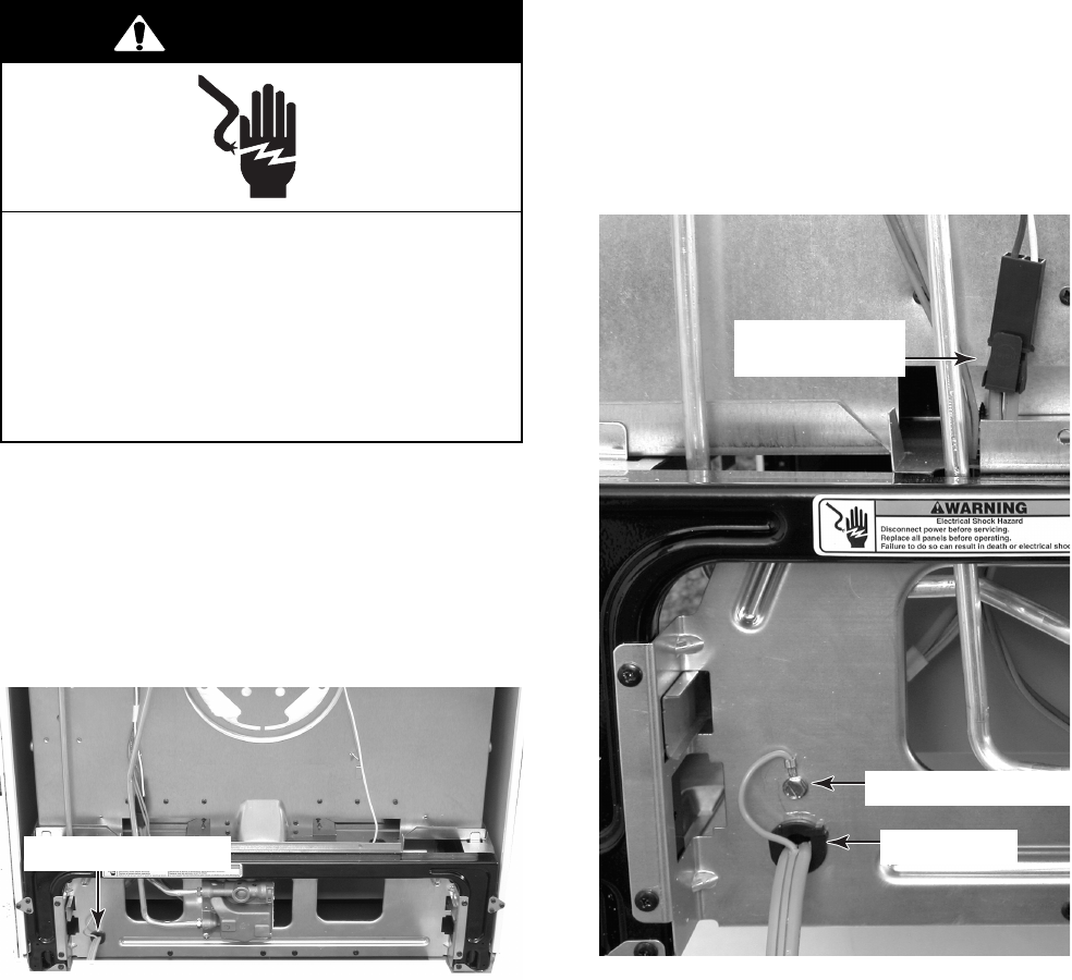
5. To convert the gas distribution valve
for use with L.P. gas:
a)Remove the storage drawer from the
range.
Gas Distribution Valve
2-7
c) Unscrew the conversion cap from the
gas distribution valve and remove it and
the plastic cap. Note the difference be-
tween the L.P. and Natural gas ends of
the cap.
d)Install the loop on the plastic cap over
the natural gas side of the conversion
cap.
e)Install the plastic cap and the conver-
sion cap on the gas distribution valve
with the L.P. side facing up (you will see
“LP” stamped inside the cap, as shown
below).
f) Reinstall the storage drawer.
6. Turn the gas supply valve handle on.
Conversion Cap Set
For Use With L.P. Gas
Plastic Cap
Conversion Cap Set For
Use With (N) Natural Gas
L.P. Gas
b)Pull the plastic cap off the gas distribu-
tion valve conversion cap.
Plastic Cap
L.P. Gas
Gas Valve Handle To “On” Position
Natural Gas
2-8
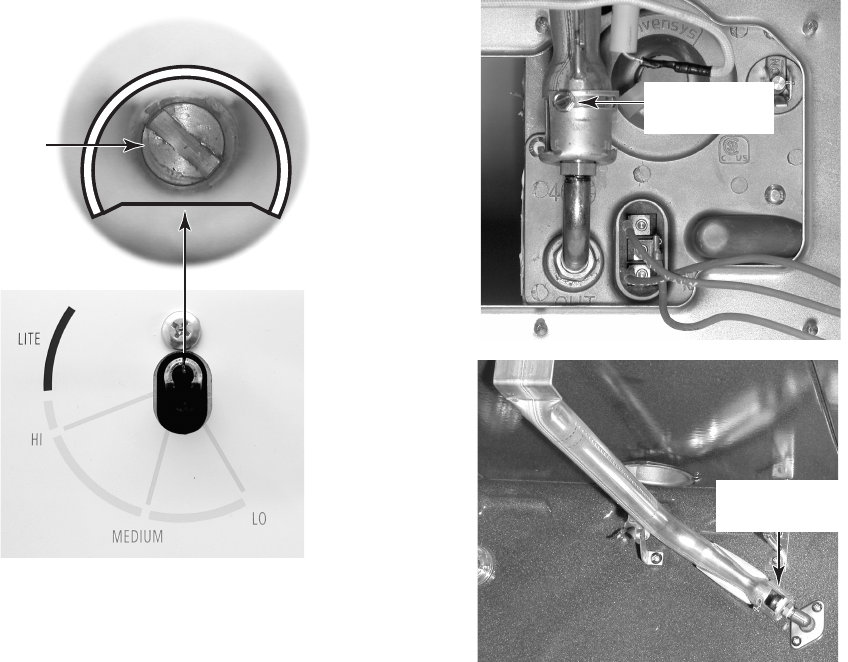
SURFACE BURNERS
1. Turn on one of the surface burners and set
the flame to its lowest (LO) setting. The
flame should be steady and the inner cone
should be dark blue in color. The size
should be approximately 1/4″ (0.64 cm)
high.
2. If the low flame needs to be adjusted:
a)Remove the control knob.
b) Look inside the gas valve stem and note
the small screw. Insert a small screw-
driver into the gas valve stem and fit it
in the screw slot.
ADJUSTING FOR THE PROPER FLAME
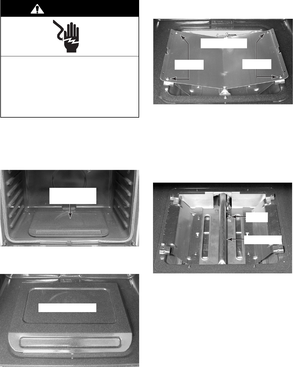
BAKE & BROIL BURNERS
1. Remove the oven racks and oven bottom.
2. Light the bake and broil burners, then
check their flames. They should be ap-
proximately 1/2″ (1.3 cm) high.
3. If the bake or broil burner flame needs to
be adjusted:
a)Loosen the locking screw on the burner
air shutter. NOTE: For the bake burner,
you will have to remove the unit from
its mounting location to access the air
shutter.
c) Hold the gas valve stem with a pair of
pliers, and turn the screw in either di-
rection until the flame size is approxi-
mately 1/4″ high.
d)Replace the control knob.
e)Turn the control knob from HI to LO and
check to make sure that it remains ad-
justed properly.
f) Check the other three burners, and ad-
just them, if necessary.
Flame
Adjustment
Screw
b)Adjust the air shutter until the flame is
the proper height. The inner cone
should be bluish-green, and the outer
mantle should be dark blue. There
should be no blowing or lifting of the
flame away from the burner ports.
NOTE: Natural gas flame does not have
a yellow tip.
c) Retighten the air shutter screw.
Bake Burner
Air Shutter
Broil Burner
Air Shutter
2-9
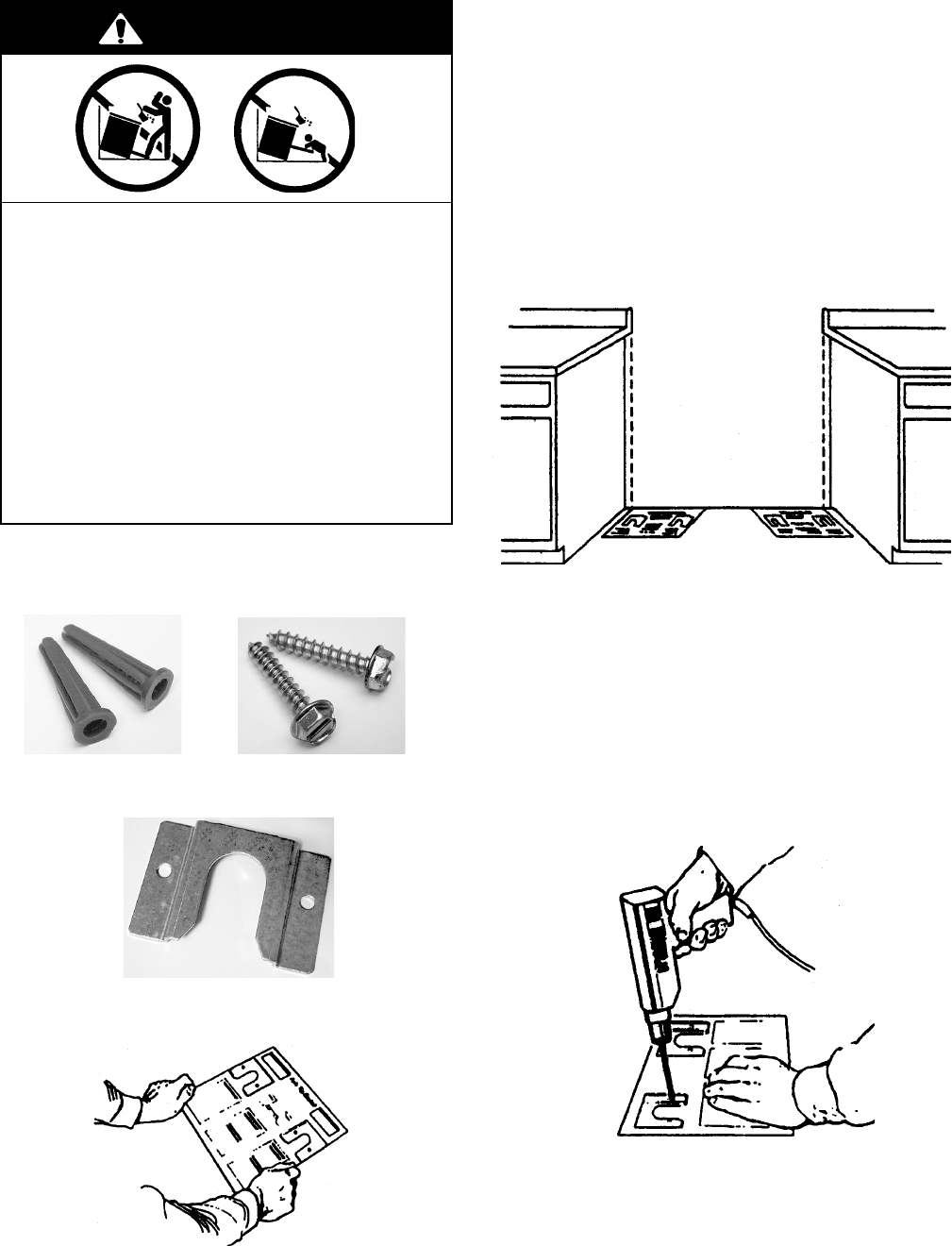
INSTALLING THE ANTI-TIP BRACKET
PARTS SUPPLIED
(2) Plastic Anchors (2) Screws
(1) Anti-Tip Bracket
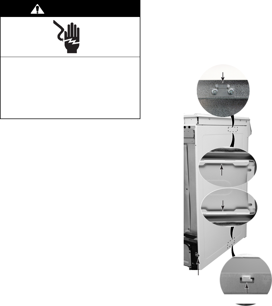
NOTE: The anti-tip bracket can be installed to
hold either the right or left rear leg of the range.
1. Determine which leg you wish to anchor to
the floor.
2. Place the template on the floor in the
range opening so that the top edge is
against the wall, molding, or cabinet, and
the template is in the location where the
anti-tip bracket will be installed.
3. Tape the template to the floor.
Template
NOTE: For mounting to a wood floor, proceed
with step 4. For concrete or ceramic floors,
proceed to step 5.
4. To mount the anti-tip bracket to a wood
floor:
a)Use the template to mark the hole loca-
tions to be drilled.
b) Use a 1/8″ drill bit and drill the two holes.
Continued on the next page.
Tip-Over Hazard
A child or adult can tip the range and
be killed.
Connect anti-tip bracket to rear range
foot.
Reconnect the anti-tip bracket, if the
range is moved.
Failure to follow these instructions can
result in death or serious burns to
children and adults.
WARNING
2-10
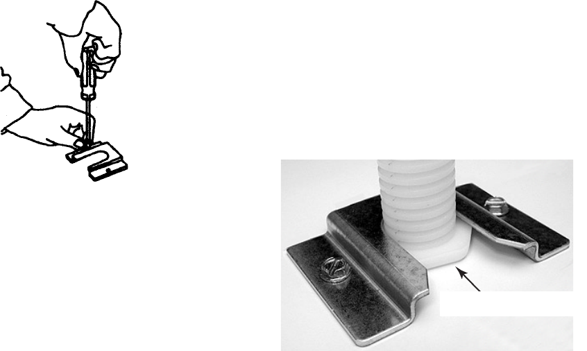
c) Remove the template from the floor.
d)Line up the two mounting holes in the
anti-tip bracket with the two holes you
just drilled in the floor.
e)Use the two screws that were supplied
and fasten the anti-tip bracket to the
floor.
c) Remove the template from the floor.
d)Tap the two plastic anchors into the
mounting holes with a hammer.
e)Line up the two mounting holes in the
anti-tip bracket with the two holes you
just drilled in the floor.
f) Use the two screws that were supplied
and fasten the anti-tip bracket to the
floor.
6. Move the range close to the cabinet open-
ing and plug the power supply cord into a
grounded outlet.
7. Move the range into position and make
sure that the rear leveling leg slides into
the anti-tip bracket, as shown.
Slide Leg Into Bracket
5. To mount the anti-tip bracket to a con-
crete or ceramic floor:
a)Use the template to mark the hole loca-
tions to be drilled.
b)Use a 3/16″ drill bit and drill the two
holes.
3-1
THEORY OF OPERATION
ELECTRONIC OVEN CONTROL SYSTEM FUNCTIONS
BAKE PREHEAT
When the user presses the BAKE key, the con-
trol displays Pre in 3-digit display area during
preheat countdown. The BAKE and ON LEDs
are also lit.
If the user queries the set temperature, the
control displays the set temperature, a flash-
ing degree symbol, and a solidly lit tempera-
ture scale.
If the user changes the set temperature dur-
ing the preheat cycle, the countdown contin-
ues uninterrupted.
When the preheat countdown expires:
1. The control sounds the preheat end au-
dible signal.
2. The control shows the set temperature in
the 3-digit display area, along with a sol-
idly lit degree symbol.
3. The BAKE and ON LEDs remain lit. The
displayed temperature does not change
unless the user changes the set tempera-
ture.
Open Door Preheat
If the door is opened during the preheat cycle:
1. An open door display is shown (door LED).
2. Electric Models: Both bake and broil ele-
ments will turn off at the end of cycle.
3. Gas Models: The broil burner will turn off
as soon as the user opens the door, and
the bake burner will turn off after a 15-
second delay.
4. The preheat countdown continues in back-
ground.
BAKE
If the control receives the door-locked signal
during an active bake function, the control
should perform the following procedure:
1. Moves the door latch to the unlocked
position.
2. Waits for the door-unlocked signal from
the door switch.
3. If the door-unlocked signal is not received,
it terminates the bake function, and sounds
the audible failure signal.
4. If the door-locked signal is discontinued,
the control continues the Bake function.

3-2
Open Door Bake
If the door is opened during a bake cycle:
1. An open door display is shown (door LED).
2. Electric Models: Both bake and broil ele-
ments will turn off at the end of cycle.
3. Gas Models: The broil burner will turn off
as soon as the user opens the door, and
the bake burner will turn off after a 15-
second delay.
4. Both bake and broil burners will turn off
until the user closes the door, or presses
the OFF/CANCEL key.
BROIL
Electric ranges offer open-door broiling, and
gas ranges offer closed-door broiling.
If the control receives the door-locked signal
during an active broil function, the control
should perform the following procedure:
1. Moves the door latch to the unlocked
position.
2. Waits for the door-unlocked signal from
the door switch.
POWER FAILURE DURING CLEAN
The control will write the state of the clean cycle
to the EEPROM so that when powerup occurs,
the control can follow the cool-down sequence.
The door latch will stay latched.
COOLING FAN
The cooling fan will be on during all cook or
clean functions. In addition, the fan should
remain on after all cook or clean functions until
oven cavity temperature reaches 270°F
(132°F).
CONVECTION BROIL
The convection broil default temperatures are:
• Electric 500°F (260°C)
• Gas HI (525°F) (292°C)
RECALL LAST FAILURE CODE
The oven control will provide visual identifica-
tion of the last electronic control failure. The
user can recall the last failure code by pressing
and holding the OFF/CANCEL key for 5 sec-
onds. The failure code display is terminated by
pressing the OFF/CANCEL key, unless it is the
OFF/CANCEL key itself that has failed.
KEYBOARD LOCKOUT
Disabling All Cook And Clean Functions
The user disables/enables all oven functions
(Bake, Broil, Clean) by pressing and holding
the START key for 5 seconds. When the user
disables/enables the keyboard lockout, the
control sounds the Enable/Disable audible sig-
nal.
Clock and timer functions are still available
during keyboard lockout. The control illumi-
nates the “lock” icon ( ) and the Loc LED
whenever the user has disabled the keyboard.
When the keyboard has been disabled, the
control prompts the user to press and hold the
Oven START key for 5 seconds by illuminat-
ing the START? LED whenever the user
presses an oven function key, a timed oven
function key, a temperature, or a time slew.
When the range has powered down, the con-
trol stores the status (enabled or disabled) of
the keyboard lockout function in the EEPROM.
Upon power up, the control recalls the key-
board lockout status from the EEPROM.
This feature can only be activated from the
“idle” mode.
3-3
POWER UP
When the control is powered up, it checks the
oven temperature, the keytail connector and
keypad, illuminates the display, and allows one
minute for a complete oven test.
Power Up Membrane
Switch Connection Test
The keytail connector is checked on power up.
An “Invalid Entry Signal” sounds if the mem-
brane switch tail is not connected.
Illumination At Power Up
The electronic display powers up with the en-
tire vacuum display area illuminated for three
seconds.
The three second time period can be overrid-
den by pressing any key.
Tulsa/Oxford Manufacturing
Test Sequence
This test is available for only the first minute
after power up.
The test is accessed by pressing the CANCEL,
CANCEL, and START keys. The routine will
present a blank display, then any system or
control failures will be detected in two seconds.
Exit the test sequence by pressing the OFF/
CANCEL key.
HIDDEN FUNCTION SUMMARY
The user activates all of the hidden functions
by pressing and holding the appropriate key
for 5 seconds. The following shows a list of all
the hidden features or functions.
* Recall last failure code function or failure mode.
KEY HIDDEN FUNCTION
BAKE Temperature Calibration Offset
BROIL Temperature Scale Selection (°F / °C)
OFF/CANCEL Recall Last Failure Code
START/ENTER* Software Revision Number
TIMER SET Disable / Enable Timer Reminder
Signals
COOK TIME Disable / Enable Cycle End Audible
Signals
STOP TIME Disable / Enable Valid Data Entry
Signals
TBD Audible Signal Pitch Control
3-4
— NOTES —
4-1
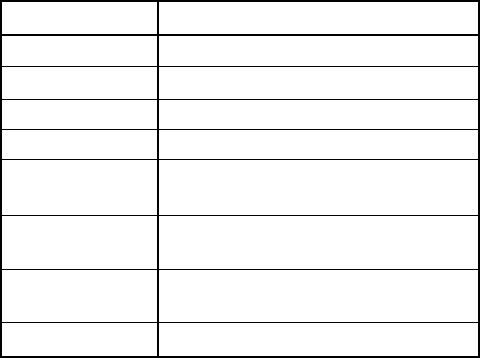
COMPONENT LOCATIONS
Cooktop Components
This section instructs you on how to service each component inside the Self-Cleaning Slide-In Gas
Range. The components and their locations are shown below.
COMPONENT ACCESS
Not Shown: Electronic Oven Control Surface Burner
& Ignitor (4 ea)
Door Latch
Assembly
Oven
Temperature
Sensor
Gas Valves /
Ignition Switches
Spark Module
(DSI)
Cooling Fan
TOD
Bake Burner
& Ignitor
Control
TOD
Gas Valves /
Ignition Switches
Gas Distribution Valve
(Rear Of Unit)
Cooling Fan
(Rear Of Unit)
Oven & Rear Components
Broil Burner
& Ignitor
Oven Light Oven TOD
(Rear Of Unit)
4-2
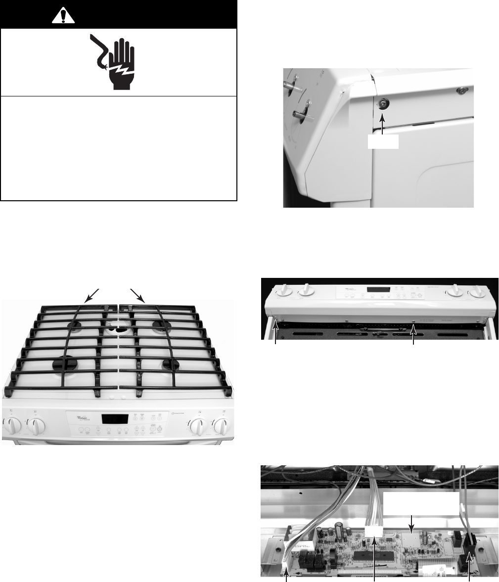
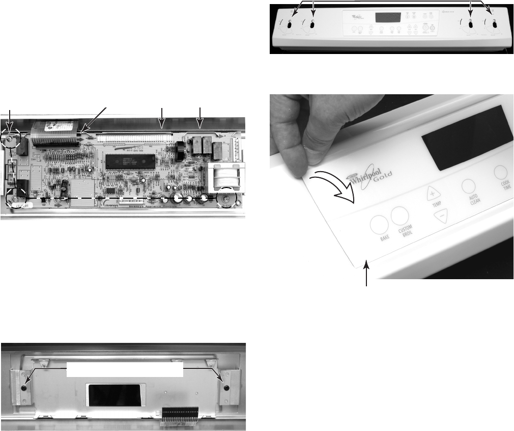
REMOVING THE CONTROL PANEL AND THE ELECTRONIC
OVEN CONTROL BOARD & USER INTERFACE
4. To remove the control panel:
a) Pull the knobs off the gas valves.
b) Remove the two screws from the sides
of the end caps.
d) Close the oven door.
e) Pull the control panel forward and re-
move the two end caps.
f) Disconnect the wire connectors from
the electronic oven control board at P2,
P3, and P4.
c) Open the oven door and remove the six
screws from the bottom of the control
panel (two end cap screws and four
control panel screws).
1. Unplug range or disconnect power.
2. Turn off gas supply to range.
3. Remove the two grates from the top of the
range.
Electrical Shock Hazard
Disconnect power before servicing.
Replace all parts and panels before
operating.
Failure to do so can result in death or
electrical shock.
WARNING
Screw
Right
End Cap
Grates
End Cap Screw (2) Control Panel Screw (4)
P4 P3 P2
Electronic Oven
Control Board
4-3
5. To remove the electronic oven control
board:
a) Remove the control panel (see step 4).
b) Disconnect the ribbon cable from con-
nector P1.
c) Remove the three screws from the elec-
tronic oven control board. Lift the bot-
tom of the board slightly, slide the top
edge out from under the holders, and
remove the board.
6. To remove the user interface:
a) Remove the control panel (see step 4).
b) Remove the electronic oven control
board (see step 5).
c) Remove the two screws from the elec-
tronic oven control board bracket and
remove the bracket.
Ribbon Cable P1
3 Screws Holders
d) Remove the four screws from the con-
trol panel bracket and remove the
bracket.
Board Bracket Screws
e) Lift one of the corners, and peel the
user interface off the control panel.
Control Panel Bracket Screws
Peel Off
User Interface
4-4
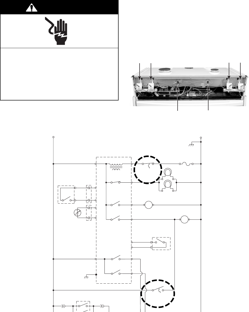
REMOVING THE IGNITION SWITCHES, A GAS VALVE,
AND THE CONTROL AND COOLING FAN TODS
1. Unplug range or disconnect power.
2. Turn off gas supply to range.
3. Remove the two grates from the top of the
range.
4. Remove the control panel (see step 4 on
page 4-2 for the procedure).
Electrical Shock Hazard
Disconnect power before servicing.
Replace all parts and panels before
operating.
Failure to do so can result in death or
electrical shock.
WARNING
Control TOD (N.C.)
Opens @ 96°C (205°F)
Resets @ 74°C (165°F)
Cooling Fan TOD (N.O.)
Resets @ 70°C (158°F)
Closes @ 60°C (140°F)
Right Gas Valves &
Ignition Switches
Left Gas Valves &
Ignition Switches
L1
BK
P4-4 BK/W
P4-5
P3-1
P3-2
P2-1
P2-4
P4-1
BR
BU
BU
BU
N.O.
COM
DOOR LATCH
SWITCH
LATCH DRIVE
W
P3-3
P3-4
P3-6
P3-7
P2-2
P4-3
OVEN
TEMP
SENSOR
V
V
N
W
SURFACE BURNER
IGNITION SWITCHES
M
K-4
K-3
K-2
K-1
t
°
LATCH RELAY
OVEN LIGHT RELAY
BAKE RELAY
BROIL RELAY
W
Y
Y
P4-7 GY
COOLING
FAN MOTOR
W
M
K-8
COOLING
FAN RELAY
R
BK BK
GY
BK
BK
BK
W
OVEN LIGHT 1
OVEN LIGHT 2
CONTROL TOD
96.1
°±
3
°
C
(205
°±
6
°
F)
BK
OVEN CONTROL
TRANSFORMER
DOOR
SWITCH
Y
Y
N.O.
COM
V
V
BK
G
GND
COOLING FAN TOD
70
°±
3
°
C
(158
°±
6
°
F)
GND
OVEN TOD
()
120
°
+10
°
-0
°
C
248
°
+18
°
-0
°
F
WW

4-5
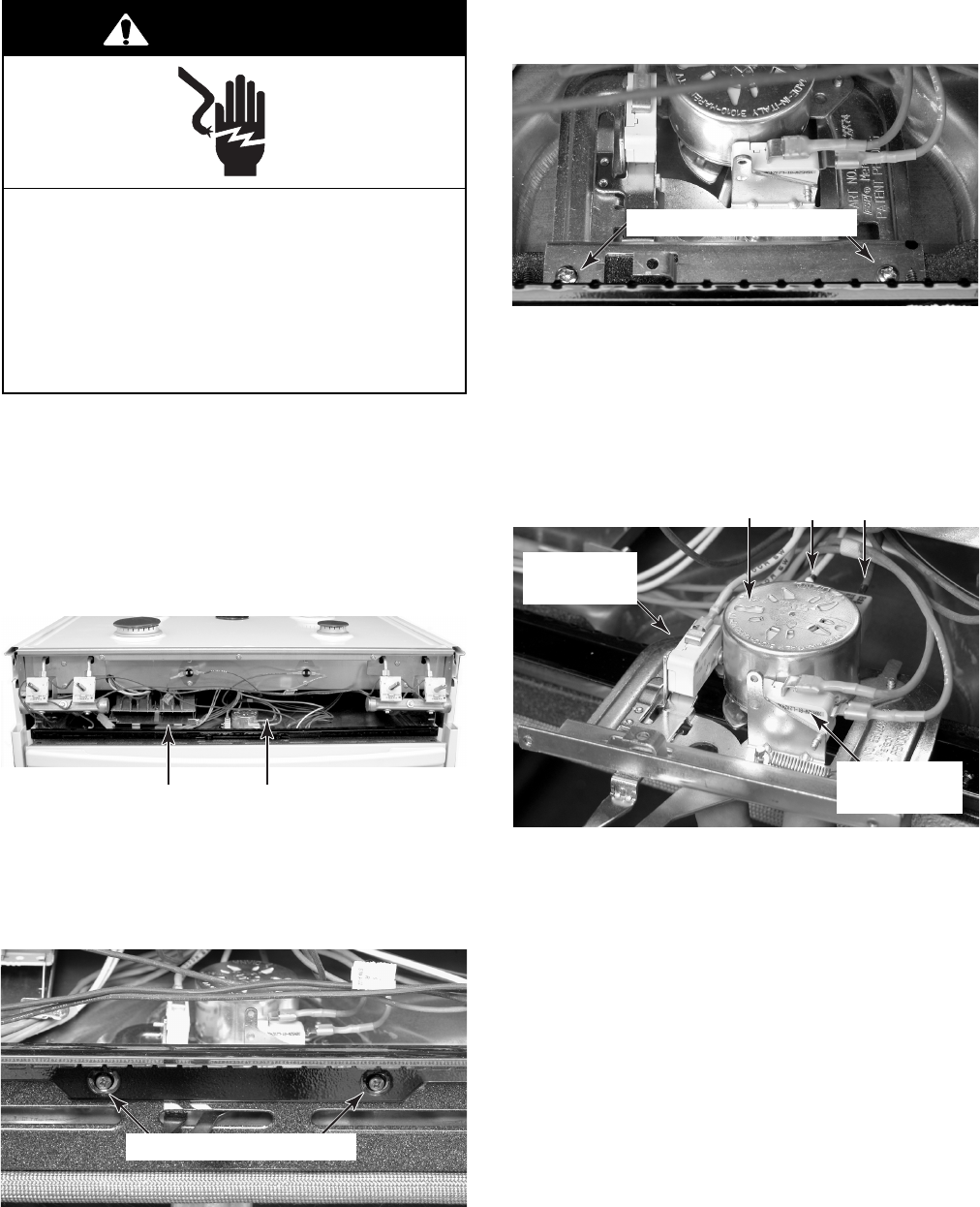
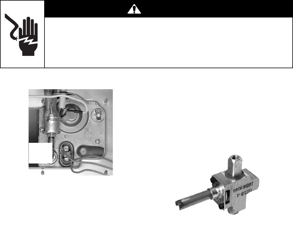
5. To remove the ignition switches:
NOTE: The ignition switches must be replaced
as an assembly. They cannot be replaced indi-
vidually.
a) Pull the ignition switches and unsnap
them from the gas valves, then remove
them from the valve stems.
b) Disconnect the ignition switch wire con-
nector from the main harness and re-
move the switches.
6. To remove a gas valve:
a) Remove the ignition switch from the gas
valve you are servicing (see step 5).
b) Remove the 1/2″ gas line connector
from the gas valve.
c) Remove the 1/4″ hex-head gas valve
mounting screw and its rubber seal
from the front of the gas manifold.
Ignition Switches
Ignition Switch
Connector
1/2″ Gas Line
Connector
Gas Valve Screw
Gas Valve
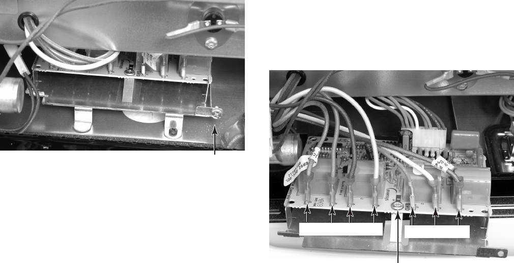
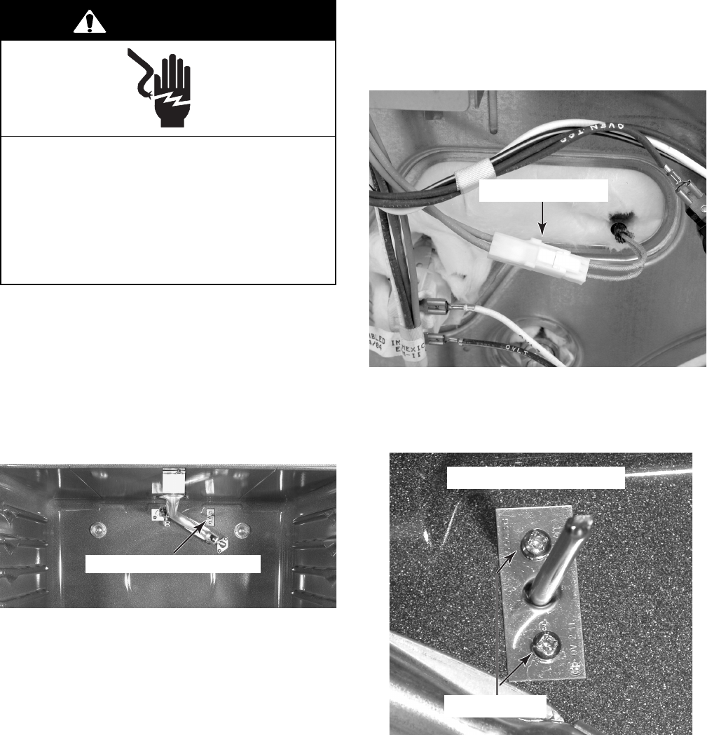
7. To remove a control or cooling fan
TOD:
a) Remove the wires from the terminals.
b) Remove the mounting screw.
Control Or Cooling Fan TOD
REASSEMBLY NOTES:
• Before reinstalling the gas valve, make sure
that the rubber seals on the mounting screw,
and on the valve, are not cracked or dam-
aged. If they are, replace them.
• Perform a leak check on the gas valve after
reinstalling it. Use a soap bubble method to
perform the check.
Seals
4-6
REMOVING THE DOOR LATCH ASSEMBLY
AND THE SPARK MODULE (DSI)
1. Unplug range or disconnect power.
2. Turn off gas supply to range.
3. Remove the two grates from the top of the
range.
4. Remove the control panel (see step 4 on
page 4-2 for the procedure).
Electrical Shock Hazard
Disconnect power before servicing.
Replace all parts and panels before
operating.
Failure to do so can result in death or
electrical shock.
WARNING
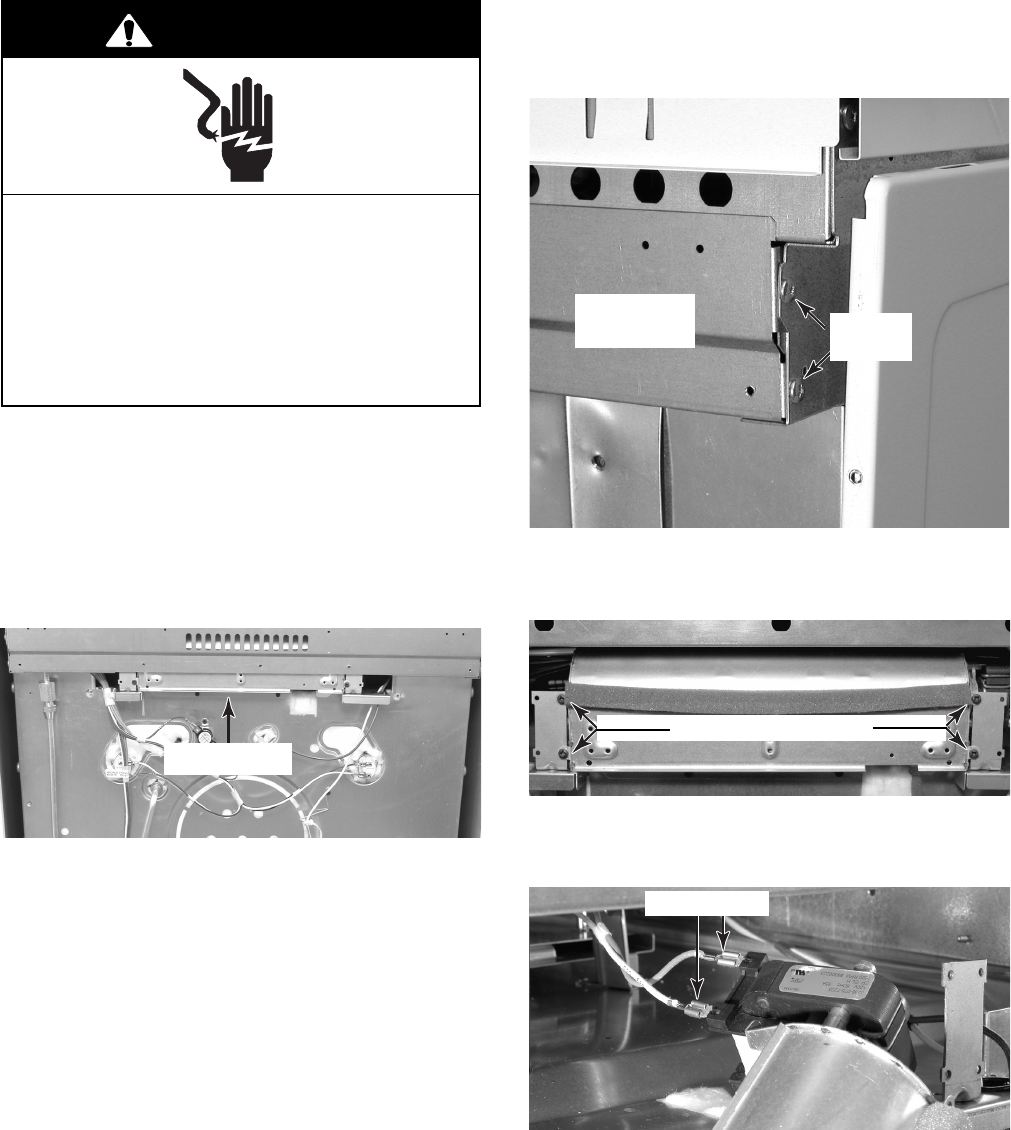
5. To remove the door latch assembly:
a) Open the oven door and remove the
two front mounting screws from the air
vent.
Spark Module Door Latch Assembly
Front Door Latch Screws
b) Remove the two top screws from the
door latch assembly bracket.
c) Pull the door latch assembly forward as
far as it will go, and disconnect the
wires from the terminals of the two
switches and the motor.
d) Remove the door latch assembly from
the unit.
Top Door Latch Screws
Door Switch
(2 Yellow)
Latch Switch
(2 Blue)
Motor White Brown
4-7
6. To remove the spark module (DSI):
a) Remove the bracket mounting screw.
b) Pull the spark module forward as far as
it will go and disconnect the wires from
the terminals, then remove the spark
module from the unit.
c) Remove the spark module mounting
screw from the bracket and remove the
module from the bracket.
Spark Module Screw
J1
BU OR RD YL GN WH BN
Module Screw
4-8
REMOVING THE COOKTOP, AND A
SURFACE BURNER & IGNITOR
Burner Head
W/2 Screws
1. Unplug range or disconnect power.
2. Turn off gas supply to range.
3. Pull the range out of its mounting location
so that you can access the rear of the unit.
4. Remove the grates, the vent cover, and
the burner caps from the top of the range.
Electrical Shock Hazard
Disconnect power before servicing.
Replace all parts and panels before
operating.
Failure to do so can result in death or
electrical shock.
WARNING
5. Remove the control panel (see step 4 on
page 4-2 for the procedure).
6. Remove the two screws from each of the
burner heads and lift the heads off the
cooktop.
Grates
Vent
Cover
Burner Cap (4)
7. To remove the cooktop:
a) Remove the three screws from the front
cooktop bracket and remove the
bracket.
b) Remove the screws from the left, right,
and rear trim pieces and remove the
trim from around the cooktop.
3 Cooktop Bracket Screws
Side Trim
Screws
Rear Trim
Screws
4-9
9. To remove an ignitor:
a) Remove the surface burner from the
burner box (see step 8).
b) Remove the screw from the ignitor.
8. To remove a surface burner:
a) Remove the cooktop (see step 7).
b) Remove the gas line.
c) Disconnect the ignitor wire from the
terminal.
d) Remove the two bracket screws from
the burner box.
e) Remove the two hex-head bracket
screws and remove the burner from the
bracket.
c) Lift the cooktop off the top of the unit
and set it aside.
Gas Line Nut
Ignitor Wire
Bracket Screw (1 of 2)
Surface Burner
Bracket Screws
Ignitor Screw
4-10
REMOVING THE REAR PANEL
1. Unplug range or disconnect power.
2. Turn off gas supply to range.
3. Pull the range out of its mounting location
so that you can access the rear of the unit.
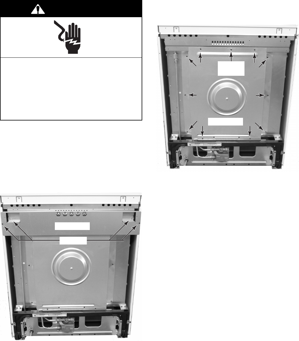
4. From the rear of the unit, remove the four
screws from the top bracket and remove
the bracket.
Electrical Shock Hazard
Disconnect power before servicing.
Replace all parts and panels before
operating.
Failure to do so can result in death or
electrical shock.
WARNING
5. Remove the eleven screws from the rear
panel and remove the panel.
4 Screws
Top Bracket
Rear Panel
Screw
(1 of 11)
4-11
REMOVING AN OVEN LIGHT SOCKET ASSEMBLY
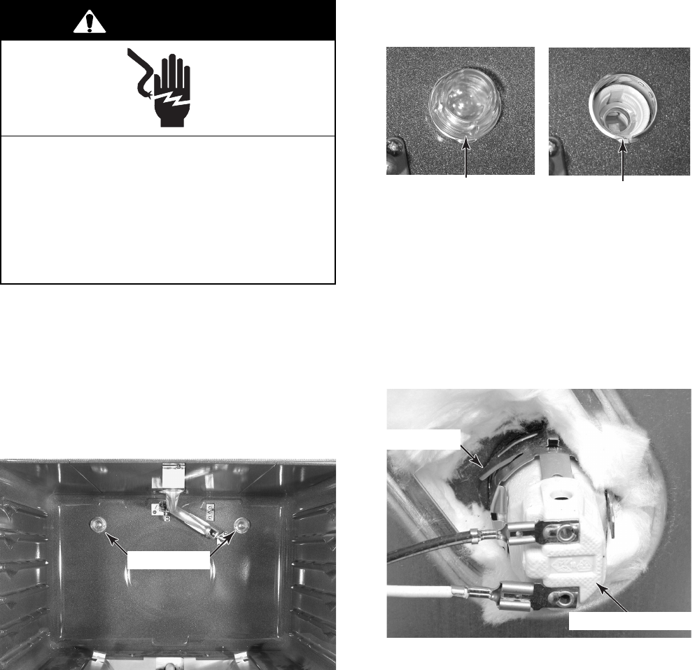
5. Unscrew the lens and bulb from the oven
light socket assembly and remove them.
1. Unplug range or disconnect power.
2. Turn off gas supply to range.
3. Open the oven door, remove the racks
from inside the oven, then close the oven
door.
4. Pull the range out of its mounting location
so that you can access the rear of the unit.
Electrical Shock Hazard
Disconnect power before servicing.
Replace all parts and panels before
operating.
Failure to do so can result in death or
electrical shock.
WARNING
6. Remove the rear panel from the unit (see
page 4-10 for the procedure).
7. Disconnect the two wire connectors from
the oven light socket terminals.
8. Move the insulation out of the way, and
press in on the two locking tabs of the oven
light socket, then push the socket out of
the liner opening.
Oven Lights
Oven Lens & Bulb Oven Light Socket
Oven Light Socket
Socket Tab
4-12
REMOVING THE BROIL BURNER AND IGNITOR
4. To remove the ignitor from the broil
burner:
a) Remove the ignitor cover screw and
remove the cover from the liner.
b) Remove the two 5/16″ hex-head
screws from the ignitor bracket.
1. Unplug range or disconnect power.
2. Turn off gas supply to range.
3. Open the oven door, remove the racks
from inside the oven, then close the oven
door.
Electrical Shock Hazard
Disconnect power before servicing.
Replace all parts and panels before
operating.
Failure to do so can result in death or
electrical shock.
WARNING
c) Pull the ignitor into the oven and dis-
connect the wire from the terminal.
Broil Burner & Ignitor
Broil Ignitor Screws
Ignitor Cover Broil Ignitor
Ignitor Wire
4-13
5. To remove the broil burner:
a) Remove the ignitor from the broil burner
(see step 4).
b) Remove the rear screw from the broil
burner.
c) Loosen the front broil burner screw,
slide the burner off the orifice, and
remove the burner.
Rear Screw
Front Screw
Orifice
Broil Burner
4-14
REMOVING THE BAKE BURNER AND IGNITOR
4. Lift the bake burner cover off the flame
spreader.
5. Remove the four screws from the flame
spreader and remove the spreader.
6. To remove the bake burner:
a) Remove the screw from the bake burner
bracket.
b) Lift the bake burner off the gas orifice
and slide it back to remove the front
from the chassis slot. Position the burner
and ignitor so you can lift it out of the
lower section of the oven.
Flame Spreader
1. Unplug range or disconnect power.
2. Turn off gas supply to range.
3. Open the oven door, remove the racks
from inside the oven, then close the oven
door.
Electrical Shock Hazard
Disconnect power before servicing.
Replace all parts and panels before
operating.
Failure to do so can result in death or
electrical shock.
WARNING
Bake Burner &
Ignitor Location
Bake Burner Cover
2 Screws
2 Screws
Screw
Bake Burner
4-15
c) Disconnect the wire from the ignitor
terminal.
7. To remove the ignitor from the bake
burner:
a) Remove the bake burner from the unit
(see step 6).
b) Remove the two 5/16″ hex-head screws
from the ignitor bracket, and slide the
end of the ignitor out of the support.
Ignitor Wire
Ignitor Screws Support
4-16
REMOVING THE OVEN TEMPERATURE SENSOR
1. Unplug range or disconnect power.
2. Turn off gas supply to range.
3. Open the oven door, remove the racks
from inside the oven, then close the oven
door.
4. Pull the range out of its mounting location
so that you can access the rear of the unit.
Electrical Shock Hazard
Disconnect power before servicing.
Replace all parts and panels before
operating.
Failure to do so can result in death or
electrical shock.
WARNING
Oven Temperature Sensor
7. From inside the oven, remove the screws
from the temperature sensor and remove
the sensor.
Oven Temperature Sensor
5. Remove the rear panel (see page 4-10 for
the procedure).
6. Disconnect the oven temperature sensor
connector from the wiring harness.
Sensor Connector
Sensor Screws
4-17
REMOVING THE COOLING FAN
1. Unplug range or disconnect power.
2. Turn off gas supply to range.
3. Pull the range out of its mounting location
so that you can access the rear of the unit.
4. Remove the rear panel (see page 4-10 for
the procedure).
Electrical Shock Hazard
Disconnect power before servicing.
Replace all parts and panels before
operating.
Failure to do so can result in death or
electrical shock.
WARNING
Cooling Fan
6. Remove the four screws from the cooling
fan and remove the fan from the bracket.
5. Use a 90° screwdriver, and remove the
two screws from each end of the cooling
fan cover, then remove the cover.
7. Disconnect the two cooling fan wires from
the motor terminals.
Cooling Fan
Cover Screws
(2 of 4)
Cooling Fan Screws
Motor Wires
4-18
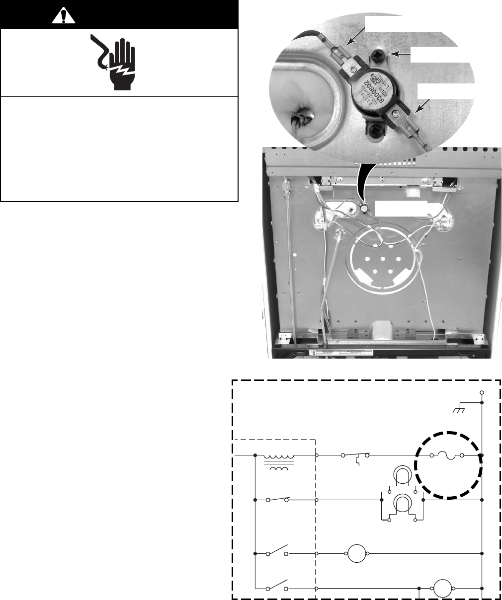
REMOVING THE OVEN TOD
1. Unplug range or disconnect power.
2. Turn off gas supply to range.
3. Pull the range out of its mounting location
so that you can access the rear of the unit.
4. Remove the rear panel (see page 4-10 for
the procedure).
5. Remove the two wire connectors from the
oven TOD terminals.
6. Remove the two screws from the oven
TOD and remove it.
Electrical Shock Hazard
Disconnect power before servicing.
Replace all parts and panels before
operating.
Failure to do so can result in death or
electrical shock.
WARNING
Screw (1 of 2)
Wire Connector
Wire Connector
Oven TOD
P4-4 BK/W
P4-5
P4-1
BR
LATCH DRIVE
W
P
3-3
P
3-4
P
3-6
P
3-7
P
4-3
N
W
M
K-4
K-3
LATCH RELAY
OVEN LIGHT RELAY
W
P4-7 GY
COOLING
FAN MOTOR
W
M
K-8
COOLING
FAN RELAY
W
OVEN LIGHT 1
OVEN LIGHT 2
CONTROL TOD
96.1
°±
3
°
C
(205
°±
6
°
F)
OVEN CONTROL
TRANSFORMER
GND
OVEN TOD
()
120
°
+10
°
-0
°
C
248
°
+18
°
-0
°
F
WW
4-19
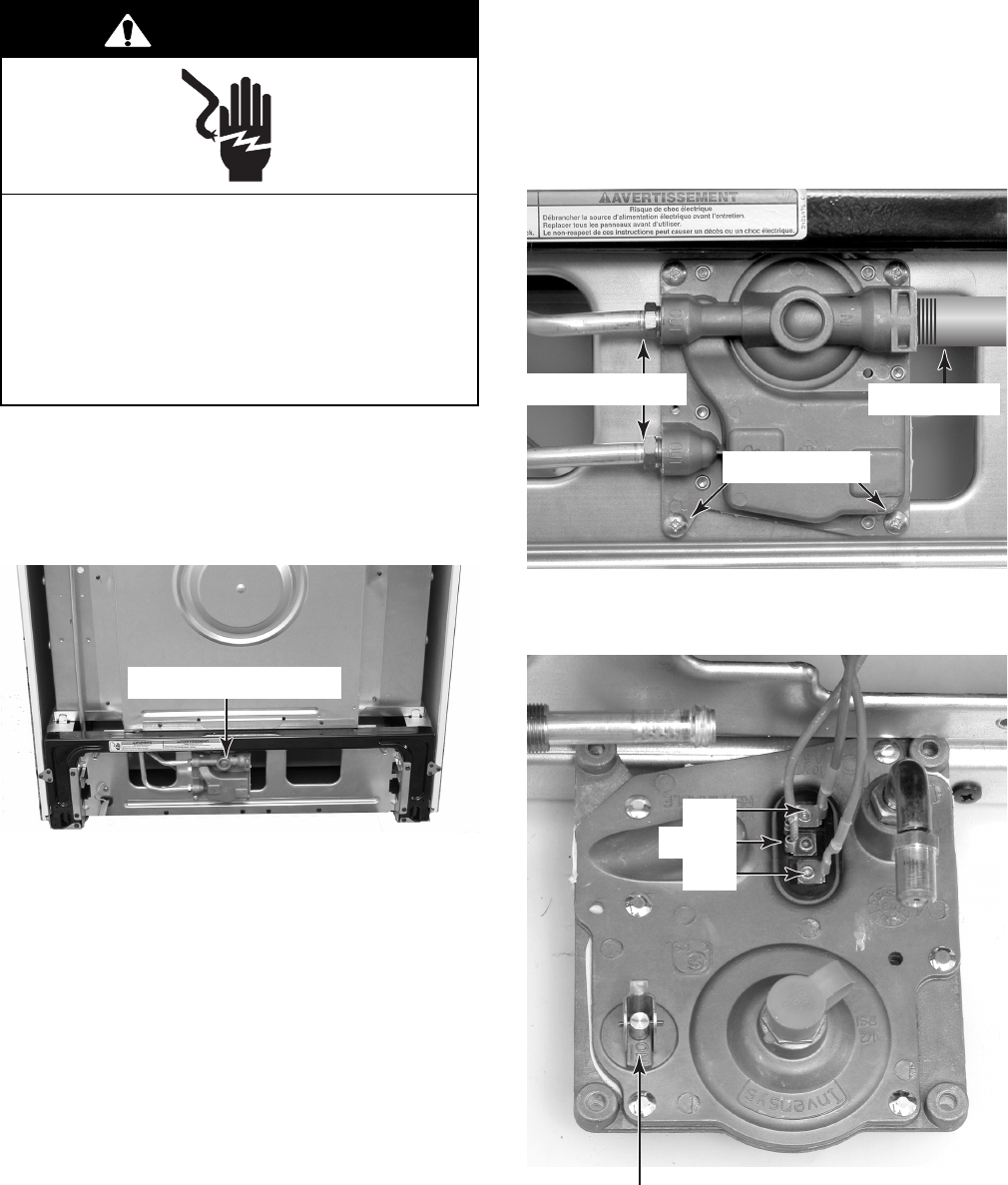
REMOVING THE GAS DISTRIBUTION VALVE
4. Disconnect the gas lines from the gas
distribution valve.
5. Remove the four screws from the gas
distribution valve, pull it down to remove
the orifice from the bake burner, and lay it
down so you can access the wires.
1. Unplug range or disconnect power.
2. Turn off gas supply to range.
3. Pull the range out of its mounting location
so that you can access the rear of the unit.
Electrical Shock Hazard
Disconnect power before servicing.
Replace all parts and panels before
operating.
Failure to do so can result in death or
electrical shock.
WARNING
Gas Distribution Valve
6. Disconnect the three wires from the gas
distribution valve terminals.
Gas Outlet Lines
Screws (2 of 4)
Gas Inlet Line
Red
Orange
Blue
Oven Shutoff Valve
NOTE: For servicing the Gas Distribution Sys-
tem, refer to Job Aid KR-28, Part Number
8177893.
4-20
REMOVING THE POWER SUPPLY CORD
1. Unplug range or disconnect power.
2. Turn off gas supply to range.
3. Pull the range out of its mounting location
so that you can access the rear of the unit.
4. Remove the rear panel (see page 4-10 for
the procedure).
Electrical Shock Hazard
Disconnect power before servicing.
Replace all parts and panels before
operating.
Failure to do so can result in death or
electrical shock.
WARNING
Power Supply Cord
5. Disconnect the power supply cord con-
nector from the main harness connector.
6. Remove the green ground wire screw
from the power supply cord.
7. Release the strain relief from the power
cord and remove the cord from the unit.
Power Supply
Cord Connector
Green Ground Wire
Strain Relief
4-21
REMOVING A SIDE PANEL
1. Unplug range or disconnect power.
2. Turn off gas supply to range.
3. Pull the range out of its mounting location
so that you can access the rear of the unit.
4. Remove the top bracket (see page 4-10
for the procedure).
Electrical Shock Hazard
Disconnect power before servicing.
Replace all parts and panels before
operating.
Failure to do so can result in death or
electrical shock.
WARNING
5. Remove the bottom rear screw for the side
panel you are removing.
6. Pull the back of the side panel out so it
clears the mounting bracket, then slide the
panel back until the top and bottom brack-
ets are in the panel cutouts, then remove
the panel.
Top Bracket
Bottom Bracket
Left Side
Panel Screw
Top Cutout
Bottom Cutout
4-22
REMOVING & REINSTALLING THE OVEN DOOR
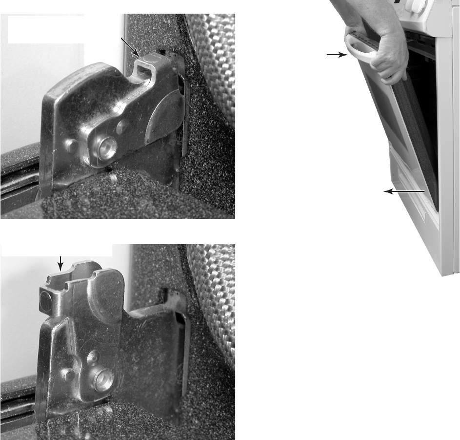
To reinstall the oven door:
1. While tilting the door back slightly from a
vertical position, insert the hinge hangers
into the chassis slots as far as they will go.
Continue to push in on the bottom, and
fully open the door.
2. Rotate the locking arm on the hinge hang-
ers to the locked, or fully “down” position.
3. Open and close the oven door to make
sure that it operates and seals properly.
To remove the oven door:
1. Fully open the door.
2. Rotate the locking arm on the door hinge
from the locked “down” position, to the
unlocked “up” position.
3. Close the door to within six to eight inches,
then pull out on the bottom of the door
while slowly closing the door, and remove
the hinge hangers from the slots in the
chassis.
Locking Arm In The
Locked “Down” Position
Locking Arm In The
Unlocked “Up” Position
Pull Out
Close
To Remove Door

4-23
REMOVING THE OVEN DOOR GASKET
REASSEMBLY NOTE: After the door gasket
is installed, make sure that it is even along the
surface of the door when the door is closed.
1. Fully open the oven door.
2. Remove the screw from the door gasket
cover and remove the cover.
3. Starting at one end of the door gasket, pull
the clips out of the liner holes, and remove
the gasket.
Gasket Cover
Pull Gasket Clips
Out Of Liner Holes
4-24
4. To remove a hinge:
a) Remove the decorative glass and
handle from the door liner (see step 3).
b) Position the oven door liner with the
inner glass facing up.
c) Remove the two screws from the hinge
you are servicing.
d) Lift the door liner and remove the hinge.
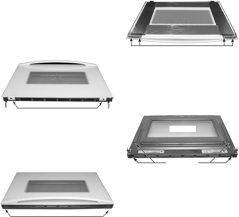
REMOVING THE DECORATIVE GLASS AND OVEN DOOR
HANDLE, THE HINGES, AND THE OVEN DOOR GLASS
1. Remove the oven door from the range
(see page 4-22 for the procedure).
2. Place the oven door on a padded work
surface with the decorative glass and
handle facing up and the bottom edge
facing the front.
3. To remove the decorative glass and
handle:
a) Remove the screw from each of the two
decorative glass retainers, and remove
the retainers.
b) Turn the door 180° so the handle faces
the front.
c) Remove the two door handle bracket
screws.
d) Lift the bottom of the decorative glass
and slide it down so the top clears the
lip of the liner, then lift the glass and
handle off the door liner assembly.
Decorative Glass Retainers
Door Handle Bracket Screws
e) Remove the two door handle screws
from each of the brackets and remove
the handle from the decorative glass.
Door Handle Bracket Screws
Inner Glass
5. To remove the two pieces of outer oven
door glass:
a) Remove the decorative glass and
handle from the door liner (see step 3).
Hinge Screws
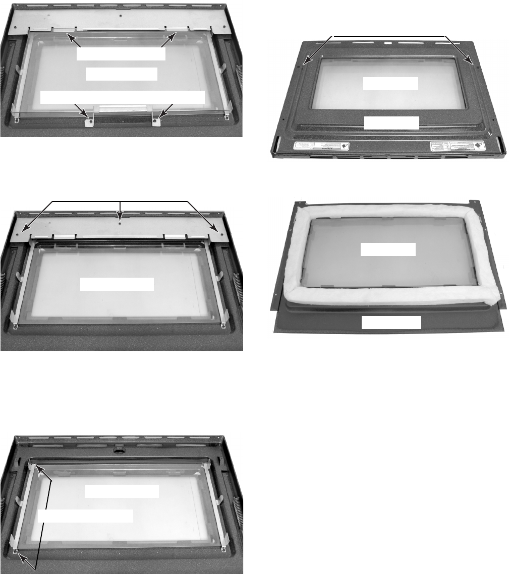
4-25
e) Remove the three screws from the top
retainer and remove the retainer from
the liner.
6. To remove the inner oven door glass:
a) Remove the decorative glass and
handle from the door liner (see step 3).
b) Remove the two hinges (see step 4).
c) Remove the first piece of outer door
glass (perform steps 5b through 5d).
d) Remove the two inner door liner screws
and lift the inner liner off the outer liner.
Lower Outer Glass Bracket Screws
Outer Glass #1
f) For the second piece of outer oven
glass, remove the two screws from the
left bracket, then remove the bracket
and second piece of glass from the
door liner.
Top Retainer Screws
e) Lift the inner oven door glass off the
outer liner.
Outer Glass #2
Outer Glass #2
Left Bracket Screws
b) Position the door liner with the outer
oven glass facing up, as shown.
c) Remove the two screws from the lower
bracket for the outer oven glass.
d) Slide the lower bracket off the first piece
of outer oven glass, then slide the glass
out of the top retainer tabs.
Inner Glass
Inner Liner
Inner Liner Screws
Inner Glass
Outer Liner
Top Retainer Tabs
4-26
— NOTES —
5-1
COMPONENT TESTING
Before testing any of the components, perform
the following checks:
• The most common cause for control failure is
corrosion on connectors. Therefore, discon-
necting and reconnecting wires will be nec-
essary throughout test procedures.
• All tests/checks should be made with a VOM
or DVM having a sensitivity of 20,000 ohms-
per-volt DC, or greater.
• Check all connections before replacing com-
ponents, looking for broken or loose wires,
failed terminals, or wires not pressed into
connectors far enough.
• Resistance checks must be made with power
cord unplugged from outlet, and with wiring
harness or connectors disconnected.
WARNING
Electrical Shock Hazard
Disconnect power before servicing.
Replace all parts and panels before operating.
Failure to do so can result in death or electrical shock.
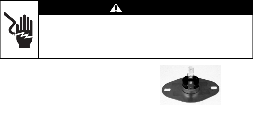
Refer to page 4-4 for the procedure for servic-
ing the control and cooling fan TODs.
1. Unplug range or disconnect power.
2. Turn off gas supply to range.
3. Disconnect one of the wires from the TOD
under test.
4. Set the ohmmeter to the R x 1 scale.
5. For the control TOD (N.C.), touch the
ohmmeter test leads to the terminals. The
meter should indicate continuity (0 Ω).
6. For the cooling fan TOD (N.O.), touch
the ohmmeter test leads to the terminals.
The meter should indicate an open circuit
(infinite).
CONTROL & COOLING FAN TODs
Control TOD (N.C.)
Opens @ 96°C (205°F)
Resets @ 74°C (165°F)
Cooling Fan TOD (N.O.)
Resets @ 70°C (158°F)
Closes @ 60°C (140°F)
5-2
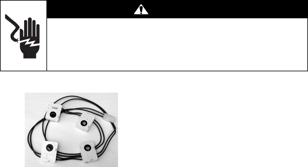
IGNITION SWITCHES
WARNING
Electrical Shock Hazard
Disconnect power before servicing.
Replace all parts and panels before operating.
Failure to do so can result in death or electrical shock.
Refer to page 4-4 for the procedure for servic-
ing the ignition switches.
NOTE: The ignition switches are connected to
each other in a parallel circuit so that if one
switch fails, the others will still operate. To
check each of the ignition switches for proper
operation, perform the following steps.
1. Unplug range or disconnect power.
2. Turn off gas supply to range.
3. Remove the control panel and access the
ignition switch connector (see page 4-2 for
the procedure).
4. Reinstall the knobs on the valve stems.
5. Disconnect the ignition switch connector
from the wire harness.
6. Set the ohmmeter to the R x 1 scale.
7. Connect the ohmmeter test leads to the
pins of the spark module connector.
8. Press and turn one of the gas valve knobs
to the LITE position. At that point, the
switch should close, and the meter should
indicate continuity.
9. Continue to turn the knob away from the
LITE position. The switch should open,
and the meter should indicate an open
(infinite ∞) circuit.
10. Repeat steps 8 and 9 for the other ignition
switches. If the readings are not as stated,
replace the entire ignition switch assem-
bly. They are supplied as an assembly and
cannot be changed individually.
5-3
WARNING
Electrical Shock Hazard
Disconnect power before servicing.
Replace all parts and panels before operating.
Failure to do so can result in death or electrical shock.
Refer to page 4-6 for the procedure for servic-
ing the door latch assembly.
1. Unplug range or disconnect power.
2. Turn off gas supply to range.
3. Disconnect one of the wires from the door
latch assembly component under test.
4. Set the ohmmeter to the R x 1 scale.
5. To test the motor, touch the ohmmeter
test leads to the terminals. The meter
should indicate between 2.6K and 3K Ω.
6. To test the door switch & latch switch:
a) Touch the ohmmeter test leads to the
COM and N.O. terminals. The meter
should indicate an open circuit (infinite).
b) With the ohmmeter leads connected as
stated in the previous step, press the
switch actuator. The meter should in-
dicate continuity (0 Ω).
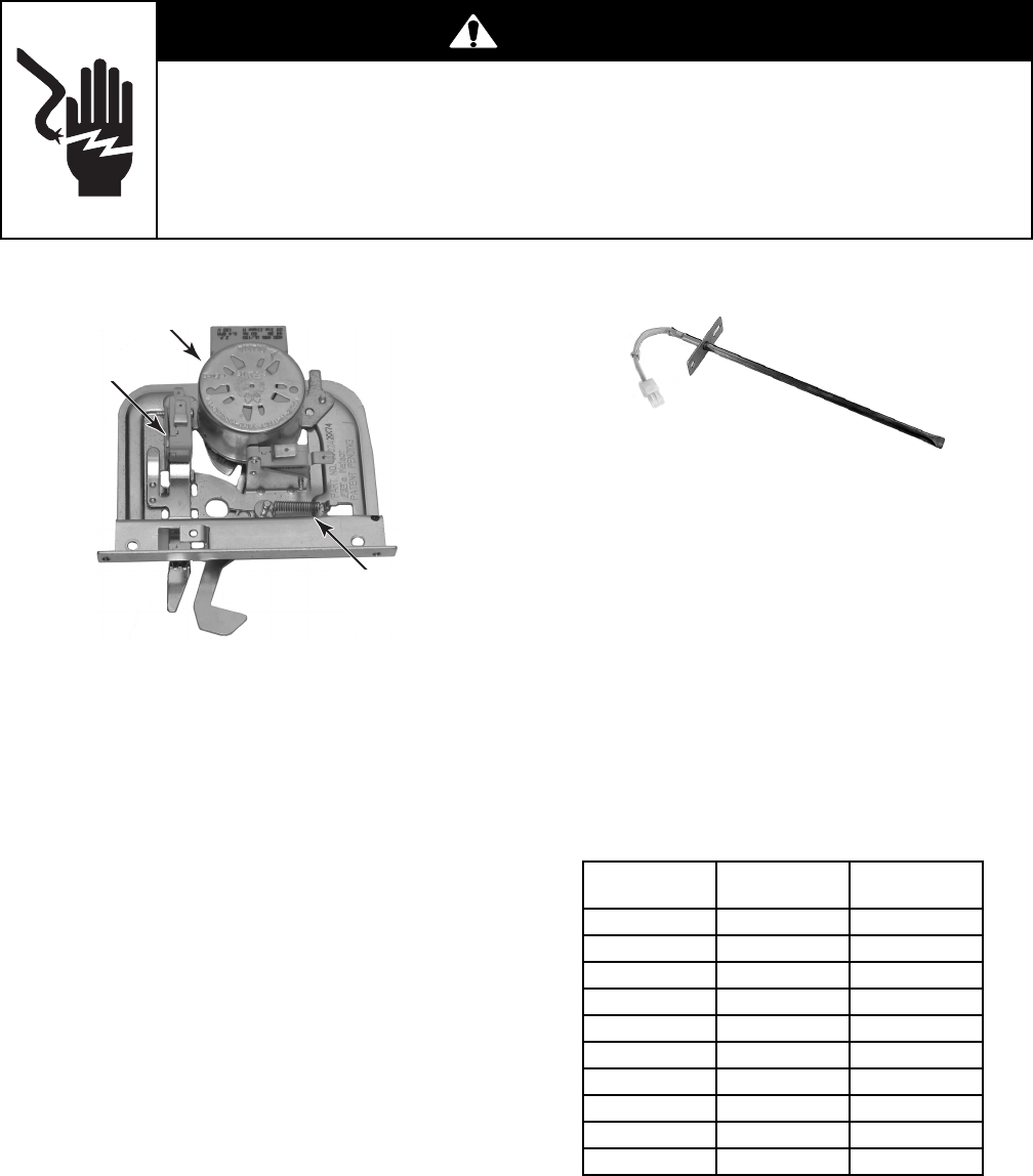
DOOR LATCH ASSEMBLY OVEN TEMPERATURE SENSOR
Refer to page 4-16 for the procedure for ser-
vicing the oven temperature sensor.
1. Unplug range or disconnect power.
2. Turn off gas supply to range.
3. Disconnect the oven temperature sensor
connector.
4. Set the ohmmeter to the R x 1K scale.
5. Touch the ohmmeter test leads to the
oven temperature sensor connector pins.
The meter should indicate as shown in the
chart below.
Door Switch
Latch Switch
Motor
Temperatures
(
°F
)
Temperatures
(
°C
)
Resistance
(
Ω
)
32 0 1000
7 5 2 5 1100
200 9 5 1350
250 120 1450
350 175 1650
4 5 0 230 1850
550 290 2050
650 350 2240
865 465 2630
900 480 2700

5-4
COOLING FAN MOTOR
Refer to page 4-17 for the procedure for servic-
ing the cooling fan motor.
1. Unplug range or disconnect power.
2. Turn off gas supply to range.
3. Disconnect one of the wires from the cool-
ing fan motor.
4. Set the ohmmeter to the R x 1 scale.
5. Touch the ohmmeter test leads to the
cooling fan motor terminals. The meter
should indicate between 3 and 6 Ω.
WARNING
Electrical Shock Hazard
Disconnect power before servicing.
Replace all parts and panels before operating.
Failure to do so can result in death or electrical shock.
OVEN TOD
Refer to page 4-18 for the procedure for ser-
vicing the oven TOD.
1. Unplug range or disconnect power.
2. Turn off gas supply to range.
3. Disconnect the wires to the oven TOD
terminals.
4. Set the ohmmeter to the R x 1 scale.
5. Touch the ohmmeter test leads to the
oven TOD terminals. The meter should
indicate a closed circuit (0 Ω).
5-5
WARNING
Electrical Shock Hazard
Disconnect power before servicing.
Replace all parts and panels before operating.
Failure to do so can result in death or electrical shock.
GAS DISTRIBUTION VALVE
Refer to page 4-4 for the procedure for servic-
ing the gas valves.
To test a gas valve, use a low-pressure ma-
nometer, and measure the inlet and outlet pres-
sure across the valve. There should be no pres-
sure drop. If there is a pressure drop, the valve
should be replaced.
GAS VALVE
Refer to page 4-19 for the procedure for ser-
vicing the gas distribution valve.
1. Unplug range or disconnect power.
2. Turn off gas supply to range.
3. Remove the storage drawer. NOTE: You
can access the gas distribution valve from
inside the drawer area.
4. Disconnect the wires from the gas distri-
bution valve terminals.
5. Set the ohmmeter to the R x 1 scale.
6. Touch the ohmmeter test leads to the
indicated gas distribution valve terminals.
The meter should read as follows:
Terminal 1 (red) to terminal 2 (orange)
= 216 Ω ±30.
Terminal 2 (orange) to terminal 3 (blue)
= 216 Ω ±30.
Orange
Blue
Red
5-6
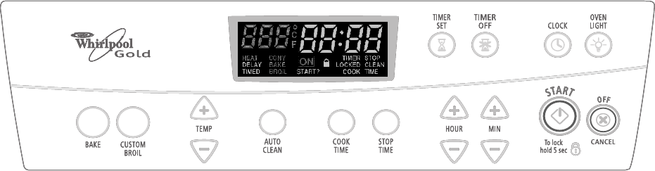
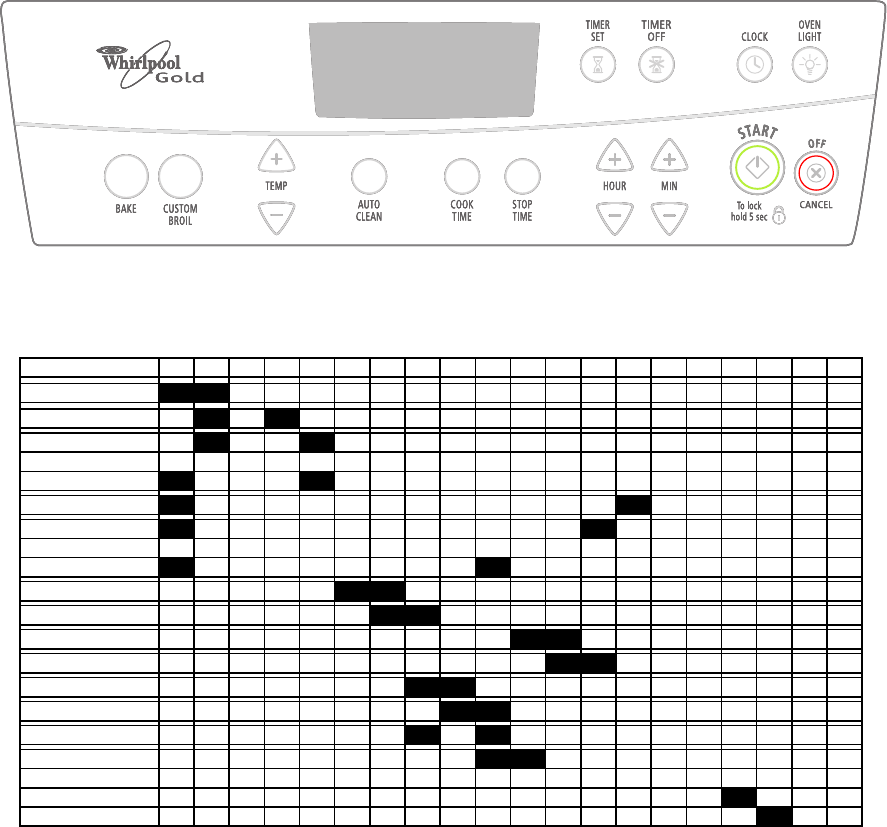
CLOCK
KEYPAD LAYOUT
1234567891011121314151617181920
BAKE
BROIL
CLEAN
TEMP UP
TEMP DOWN
COOK TIME
STOP TIME
TIMER SET
TIMER OFF
CLOCK
OVEN LIGHT
HOUR UP
MINUTE UP
HOUR DOWN
MINUTE DOWN
START
OFF/CANCEL
5-7
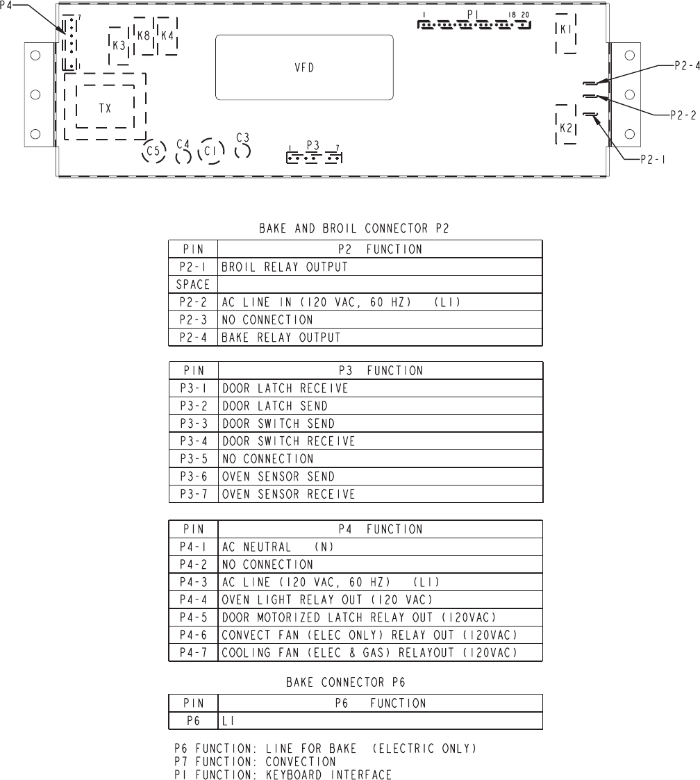
DISPLAY BOARD & CONNECTOR PINOUTS
5-8
— NOTES —
6-1
DIAGNOSTICS & TROUBLESHOOTING
DIAGNOSTICS
• All units that have failed during the first few
days of use should be checked for loose
connections, or miswiring.
• All checks should be made with a meter
having a sensitivity of 20,000 ohms-per-volt,
or greater.
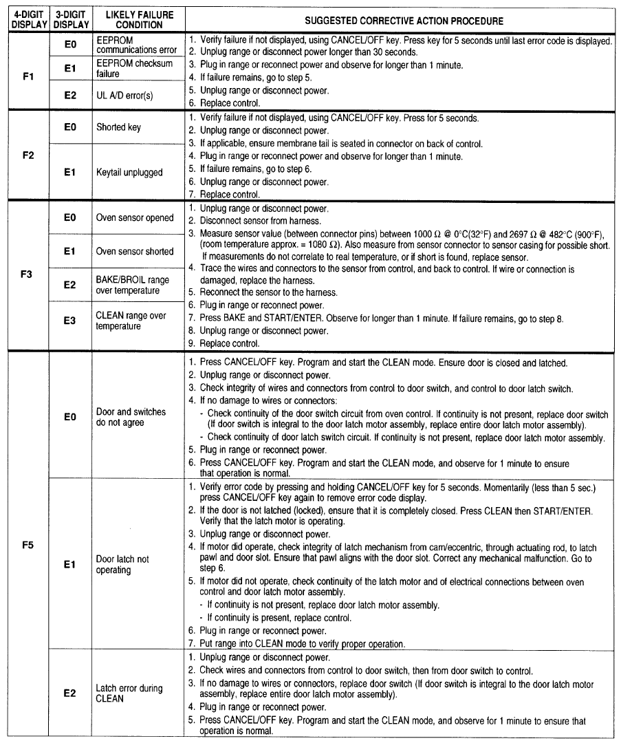
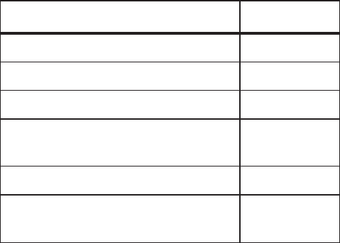
FAILURE/ERROR DISPLAY CODES
• All diagnoses of this range must begin with a
normal check of the line voltage, blown fuses,
and failed components.
6-2
HIDDEN EOC FUNCTIONS
The user activates all hidden EOC functions by
pressing and holding the appropriate key for 5
seconds. The chart shows the hidden func-
tions or features.
HIDDEN FUNCTIONS KEY
Temperature calibration offset Bake
°Fto°C Broil
Recall last failure code Off/Cancel
Disable/enable cycle end audible
signal Cook Time
Disable/enable reminder signal Timer Set
Disable/enable valid data entry
signals Stop Time
1. Press and hold the BAKE keypad for five (5)
seconds. The current offset, if any, will be
shown in the 3-digit display. CAL is shown
in the 4-digit display (3 digits on right).
2. Pressing the TEMP keypad “up” arrow (s)
adjusts the temperature in 5.6°C (10°F)
increments in the following sequence: Cel-
sius: 0°, 5.6°, 11.1°, 16.7°,–16.7° –11.1°,
–5.6°, 0°, (Fahrenheit: 0°, 10°, 20°, 30°,
–30°, –20°, –10°, 0°), and so on.
3. Press the START/ENTER keypad to acti-
vate the desired temperature adjustment. If
the START/ENTER keypad is not pressed
within 5 minutes, the adjustment is ignored.
4. BAKE temperature adjustment cannot re-
sult in operating temperatures higher than
274°C (525°F), or lower than 77°C, (1 70°F),
as measured at oven cavity center.
5. Once the BAKE temperature has been ad-
justed, BROIL temperatures are automati-
cally offset to the same degree.
6. The CLEAN temperature is also offset au-
tomatically when the BAKE temperature is
adjusted. If the BAKE temperature has been
raised, the CLEAN temperature is offset
+3°C (+5°F). If the BAKE temperature has
been lowered, the CLEAN temperature is
offset –3°C (–5°F).
TEMPERATURE ADJUSTMENT
6-3
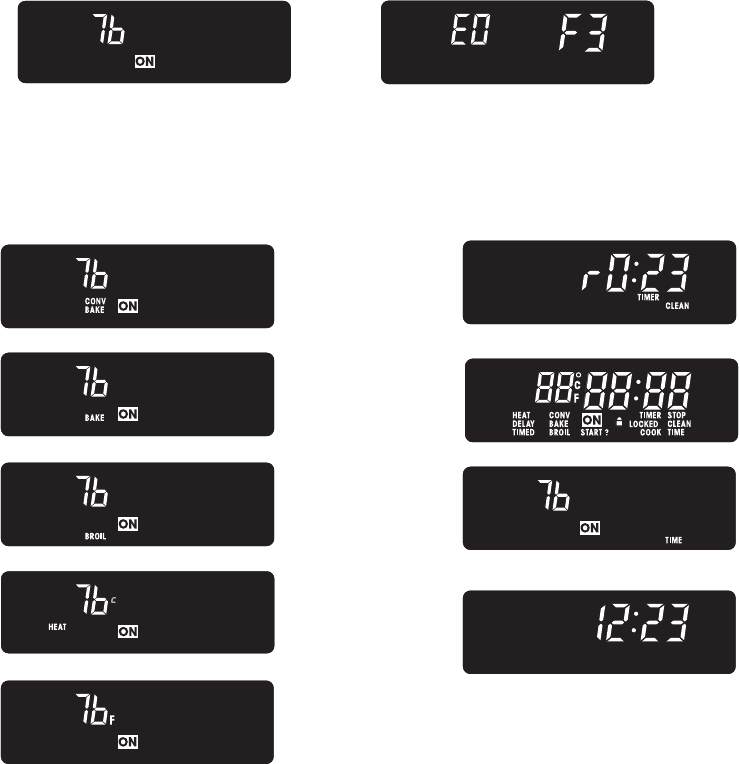
EZ354
Test Mode: Available for the first 60 seconds after power up.
Enter the Test Mode by pressing:
CANCEL
CANCEL
START
Any system or control failures will be displayed within 2 seconds.
NORMAL DISPLAY ERROR DISPLAY
Exit the Test Mode by pressing the OFF/CANCEL key.
To recall the last error code, press the OFF/CANCEL key for 5 seconds.
Pressing the indicated keys will show the following displays:
Convection
Bake
Bake
Custom
Broil
Temp +
Temp –
WILL CYCLE LATCH MOTOR
EXIT TEST MODE
WILL CHECK BUZZER
Auto Clean
Min +
Clock
OFF/CANCEL
Hidden Functions
Holding the appropriate key for 5 seconds will activate the hidden function:
BAKE Temperature Calibration Offset
BROIL Temperature Scale Selection (°F / °C)
OFF/CANCEL Recalls The Last Failure Code
START/ENTER Software Revision Number
TIMER SET Disables/Enables Timer Reminder Signals
COOK TIME Disables/Enables Cycle End Signals
STOP TIME Disables/Enables Valid Date Entry Signals

6-4
TROUBLESHOOTING CHART
PROBLEM SOLUTION
Oven will not operate. Electronic oven control is not set prop-
erly.
A delay start has been programmed.
Reset the oven control (see the Use &
Care Guide for instructions describ-
ing the function you are operating).
Range is not plugged in.
A household fuse or circuit breaker
has opened.
Burner ports are clogged.
Burner fails to light.
Burner flames are uneven. Burner ports are clogged. Clean burner ports with straight pin.
POSSIBLE CAUSE
Wait for the start time to be reached.
Plug power cord into a live AC outlet.
Replace fuse or reset the breaker.
Clean burner ports with straight pin.
Burner flames lift off ports, are yel-
low, or are noisy when turned off.
Adjust air shutters for bake or broil
burners.
Top burner ports are clogged. Clean
or replace burner.
The air-to-gas mixture is incorrect.
Burner is wet.Burner makes “popping” noise when
on.
It is normal for all four burners to
spark briefly when:
• A draft is blowing on the burners.
• A very large pot on burner causes
flame to be unstable.
• The burner is turned on but has not
ignited.
Continuous sparking may be caused
when:
• A switch contact is wet.
• There is a faulty spark module.
• The wall outlet wiring is not
correct.
Burners spark.
Allow burner to dry.
Allow switch to dry.
Replace the spark module.
Rewire wall outlet.
Control knob will not turn. Press in on the knob before turning. If knob is still hard to turn, replace the
gas valve.
The self-clean cycle will not oper-
ate.
A delay start time has been pro-
grammed.
The cooling fan is not running.
Wait for the start time to be reached.
Check the cooling fan wiring.
Test the control panel shutdown switch.
Replace the motor.
“PF” shows on the display. There has been a power failure. Reset the clock.
A failure code (E3, F1, etc.) is show-
ing on the display.
Press the CANCEL/OFF keypad. If the code does not disappear, refer
to page 6-1, and identify the cause of
the error message to help you correct
the problem.
The keypads do not operate. The Control Lock has been set. Press and hold the Control Lock key-
pad for 5-seconds to unlock the key-
pads.
The range is not properly grounded.
7-1
WIRING DIAGRAM & STRIP CIRCUITS
WIRING DIAGRAM
L1
BK
P4-4 BK/W
P4-5
P3-1
P3-2
P2-1
P2-4
P4-1
BR
BU
BU
BU
N.O.
COM
DOOR LATCH
SWITCH
LATCH DRIVE
W
P3-3
P3-4
P3-6
P3-7
P2-2
P4-3
OVEN
TEMP
SENSOR
V
V
N
W
SURFACE BURNER
IGNITION SWITCHES
M
K-4
K-3
K-2
K-1
t
°
LATCH RELAY
OVEN LIGHT RELAY
BAKE RELAY
BROIL RELAY
W
Y
Y
P4-7 GY
COOLING
FAN MOTOR
W
M
K-8
COOLING
FAN RELAY
R
DSI
BK
10 9 2 14365
87
SURFACE IGNITORS GND
BK
J1
W
BAKE BROIL
GY
BK
BK
BK
BK
W
OVEN LIGHT 1
OVEN LIGHT 2
CONTROL TOD
96.1
°±
3
°
C
(205
°±
6
°
F)
BK
OVEN CONTROL
TRANSFORMER
DOOR
SWITCH
Y
Y
N.O.
COM
V
V
BK
G
GND
COOLING FAN TOD
70
°±
3
°
C
(158
°±
6
°
F)
BU
OR
RBAKE SOLENOID
S
BROIL SOLENOID
SOR
OR
GND
OVEN TOD
()
120
°
+10
°
-0
°
C
248
°
+18
°
-0
°
F
WW
Tech Sheet #9757668
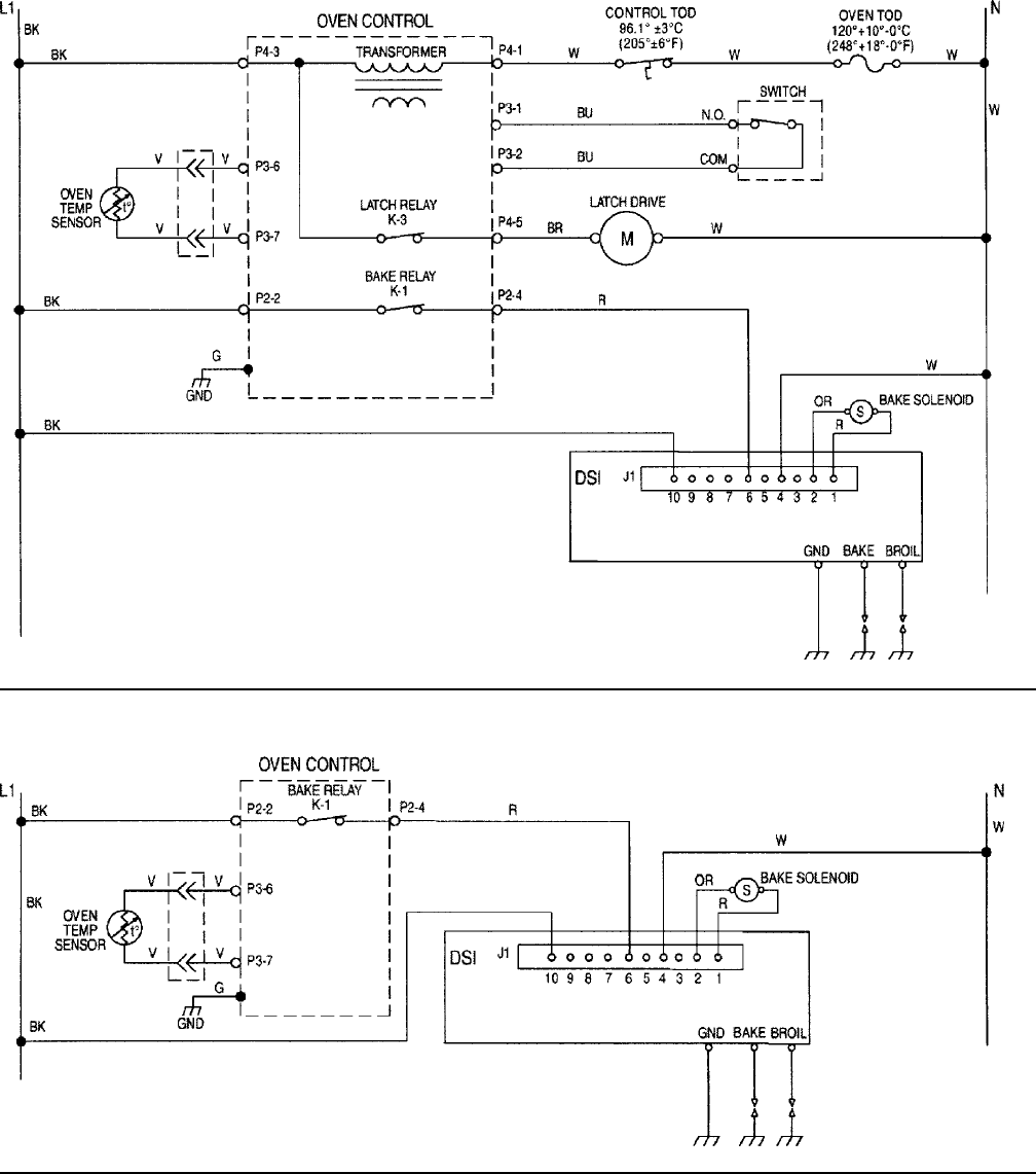
7-2
STRIP CIRCUITS
CLEAN
BAKE
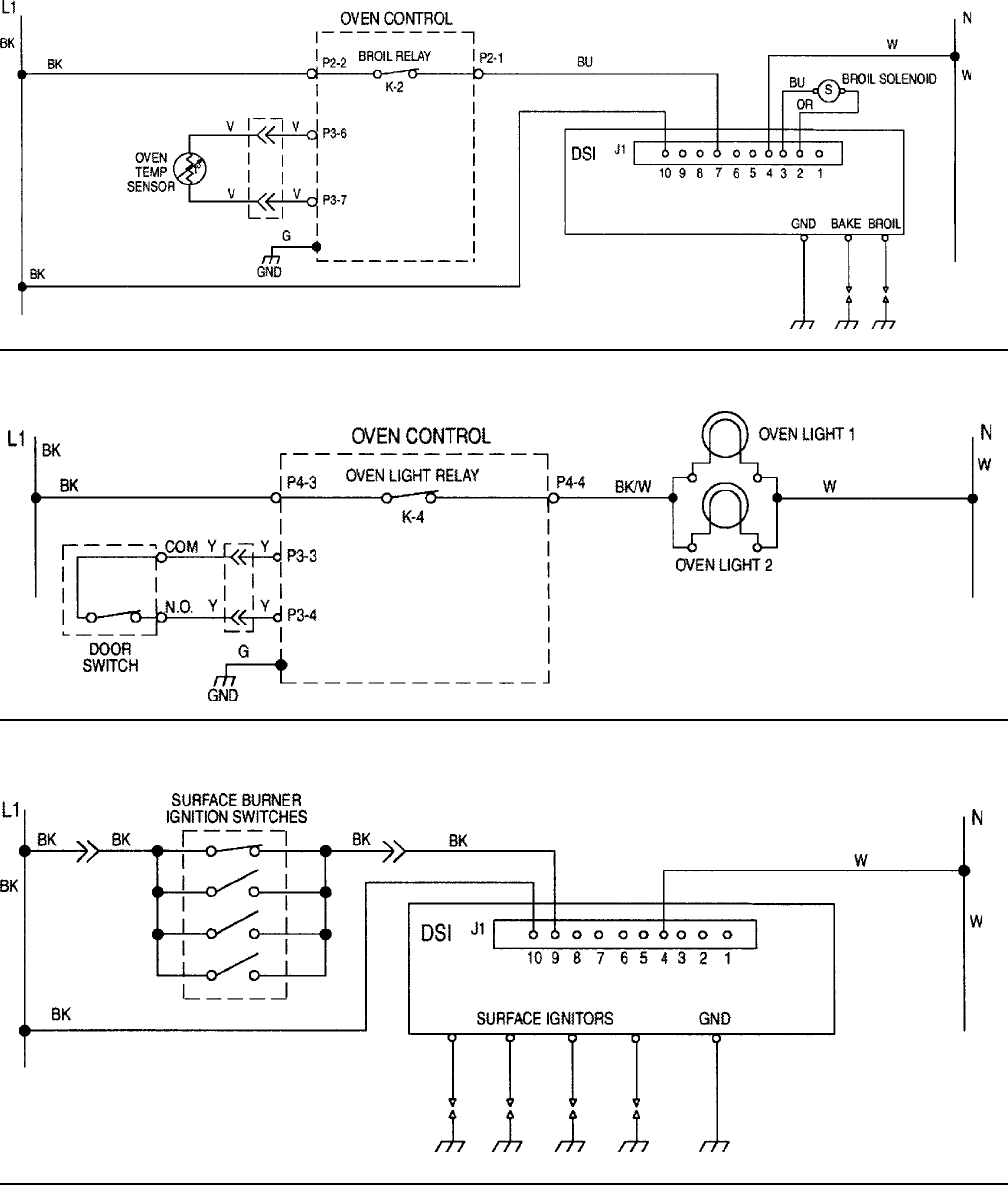
7-3
BROIL
SURFACE BURNER
OVEN LIGHT
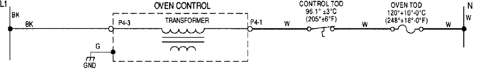
7-4
CONTROL POWER

PRODUCT SPECIFICATIONS
AND
WARRANTY INFORMATION SOURCES
IN THE UNITED STATES:
FOR PRODUCT SPECIFICATIONS AND WARRANTY INFORMATION CALL:
FOR TECHNICAL ASSISTANCE WHILE AT THE CUSTOMER’S HOME CALL:
THE TECHNICAL ASSISTANCE LINE: 1-800-253-2870
HAVE YOUR STORE NUMBER READY TO IDENTIFY YOU AS AN
AUTHORIZED SERVICER
FOR LITERATURE ORDERS:
PHONE: 1-800-851-4605
FOR TECHNICAL INFORMATION AND SERVICE POINTERS:
www.servicematters.com
IN CANADA:
FOR PRODUCT SPECIFICATIONS AND WARRANTY INFORMATION CALL:
1-800-461-5681
FOR TECHNICAL ASSISTANCE WHILE AT THE CUSTOMER’S HOME CALL:
THE TECHNICAL ASSISTANCE LINE: 1-800-488-4791
HAVE YOUR STORE NUMBER READY TO IDENTIFY YOU AS AN
AUTHORIZED SERVICER
FOR WHIRLPOOL PRODUCTS: 1-800-253-1301
FOR KITCHENAID PRODUCTS: 1-800-422-1230
FOR ROPER PRODUCTS: 1-800-447-6737

CO
RP
O
R
A
T
ION
