82122900_3290 D_Display_Equipment_Oct68 82122900 3290 D Display Equipment Oct68
User Manual: Pdf 82122900_3290-D_Display_Equipment_Oct68
Open the PDF directly: View PDF ![]() .
.
Page Count: 77
- 0001
- 0002
- 0003
- 0004
- 001
- 002
- 003
- 004
- 005
- 1-00
- 1-01
- 1-02
- 1-03
- 1-04
- 1-05
- 1-06
- 1-07
- 1-08
- 1-09
- 2-01
- 2-02
- 2-03
- 2-04
- 2-05
- 2-06
- 2-07
- 2-08
- 2-09
- 2-10
- 2-11
- 3-01
- 3-02
- 3-03
- 3-04
- 3-05
- 3-06
- 3-07
- 3-08
- 3-09
- 3-10
- 3-11
- 3-12
- 3-13
- 3-14
- 3-15
- 3-16
- 3-17
- 3-18
- 3-19
- 3-20
- 3-21
- 3-22
- 3-23
- 3-24
- 3-25
- 3-26
- 3-27
- 3-28
- 3-29
- 3-30
- 3-31
- 3-32
- 3-33
- 3-34
- 3-35
- 3-36
- 3-37
- A-01
- A-02
- A-03
- A-04
- A-05
- A-06
- A-07
- A-08
- Index-01
- Index-02
CONTROL
DATA
CONTROL
DATA®
MODEL
3290·0
DISPLAY
EQUIPMENT
•
General
Description
•
Operation
• Programm i ng
HARDWARE
REFERENCE
MANUAL
MODEL
3290-D
DISPLAY EQUIPMENT
HARDWARE
REFERENCE
MANUAL
SECTIONS
IN
THIS
MANUAL:
Section
I
Section
II
Section
III
General
Description
Operation
Programming
Any comments
concerning
this
publication
should
be
addressed
to:
Control
Data
Corporation
Technical
Publ
ication
Department
2401
North
Fairview
Avenue
St.
Paul,
Minnesota
55113
Publication
No.
82122900
April 1968
C>
Copyright
1968
Control
Data
Corporation
PRINTED
I N
USA
Changed
October
1968
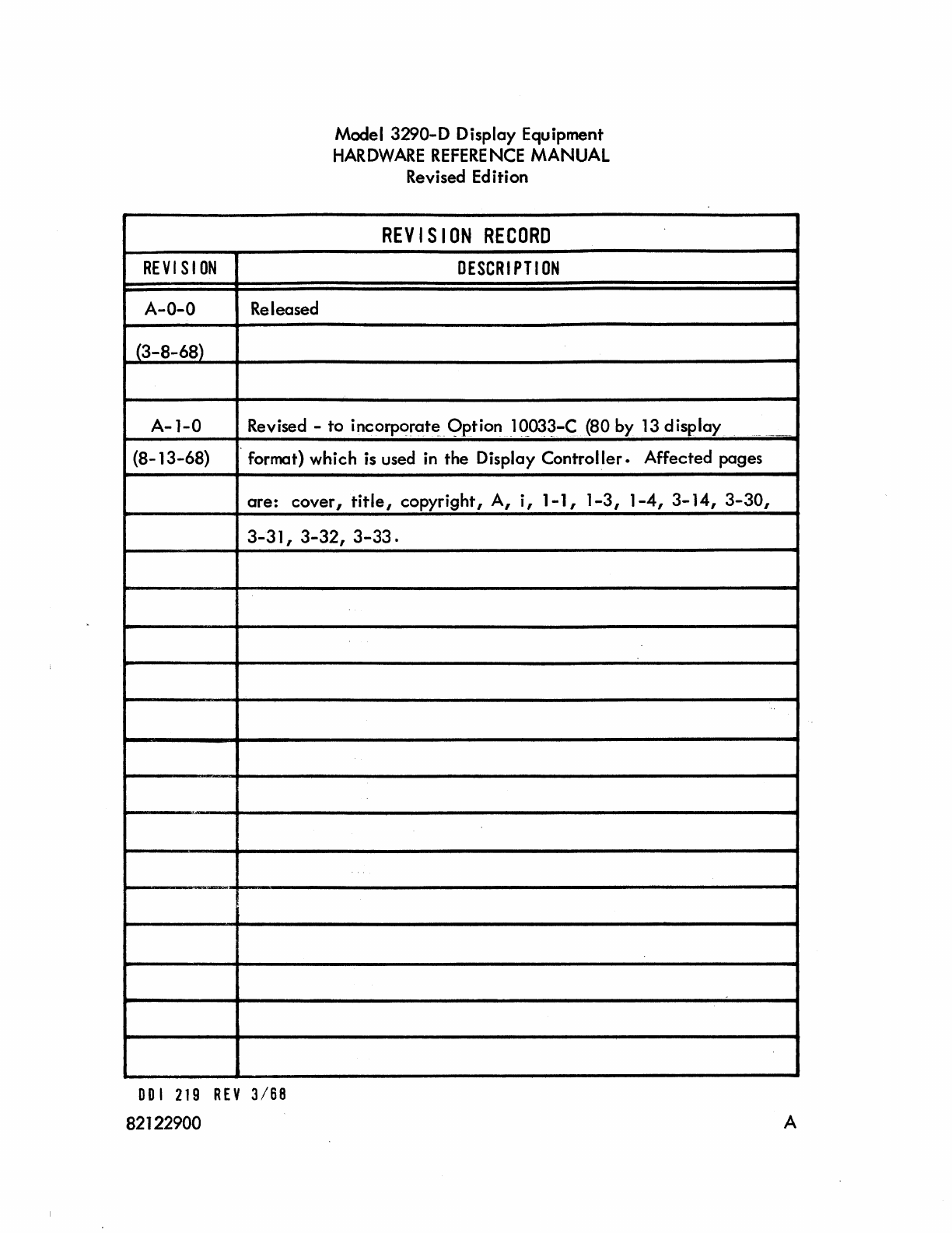
REVI
S
ION
A-O-O
(3-8-68)
A-I-0
(8-13-68)
--
Released
Model
3290-0
Display Equipment
HARDWARE
REFERENCE
MANUAL
Revised Edition
REVISION
RECORD
DESCRIPTION
Revised -
to
incorporat~~9ption
lC>..03~-C
(80
by
13
display
format)
which
is used in
the
Display
Controller.
Affected
pages
are:
cover,
title,
copyright,
A,
i,
1-1,
1-3,
1-4,
3-14,
3-30,
3-31,
3-32,
3-33.
DOl
219
REV
3/68
82122900 A

3290
FOREWORD
This manual contains infonnation
to
guide
personnel in operating
the
CON-
TROL
DATA
Model 3290-D Display Equipment.
This
manual explains
the
operation
of
the
display equipment
from
a user's point
of
view and bridges
the
gap
between
the
more
detai
led customer eng i neering publications for
each
device.
Discussion in th
is
manual
is
arranged in three basic
sections.
A
brief
outl ine
of
each
section follows:
Section I, General Description contains functional, operotional, physical
descriptions, and
electrical
data.
Section II,
Operation
-lists controls and
their
functions and explains operating
procedures through use
of
the
controls.
Section III, Programming -gives programm ing aspects
of
the
display equipment.
Information
is
provided on function codes, status codes,
interface
signals, word
formats,
etc.
For
a more
detailed
description
of
the equipment described
herein,
reference
the
Model
211-G,
H,
J,
K,
l,
P Display Station Reference/Customer Engineering
Manual (publication number 82117800), Model 218-F, G Printer Station
Reference/
Customer Engineering Manual (publ ication number 82132900), and Model
3290-0
(with
215-8
Poller and including Option
l0033-C)
Customer Engineering tv\anual,
Books
1 through 4 (publication numbers 82123000, 82123100, 82135600, 82123200,
and 82123300, respectively).
82122900
Changed
10/68
3290
TABLE
OF
CONTENTS
Section
Page
I GENERAL DESCRIPTION
Operational
Description 1-1
Functional Description
1-2
Environmental Conditions
1-4
Physical
Data
1-4
Display Controller Electrical Data
1-6
Display Station Electrical
Data
1-7
Printer Station Electrical
Data
1-7
Conven
ience
Outlets
1-9
II
OPERATION
Controls 2-1
Display
Controller
2-1
Display Station
2-5
Printer Station
2-8
Operating
Procedures
2-9
Turn
On/Turn
Off
2-10
Typical
Operation
Sequence
2-10
III PROGRAMMING
Interface Signal
lines
3-1
Data
lines
(12) 3-1
Parity
line
3-1
Connect
line
3-1
Function
line
3-3
Read
line
3-3
Write Line
3-4
Data Signal
line
3-4
Master C
lear
line
3-4
Channel
Busy
line
3-4
Negate
BCD
Conversion Line
3-4
ii
82122900
Section
III
3290
TABLE
OF
CONTENTS
(CONT)
Reply
line
Reiect
line
Suppress Assembly/Disassembly
line
End
of
Record
line
Parity Error
line
Status
lines
(12)
Interrupt
lines
(8)
Interface Control Codes
Connect
Code
Function Codes
Status Codes
Interrupts
Symbol
Data
Word Formats
Read;Write
Operations
Read
Operation
Initiated
by a Requesting
Station
Read
Operation
Initiated
by the Computer
Write
Operation
to a
local
Display Station
Write
Operation
to Poller
Programming Aids
Programm ing Restri ctions
Poller Translation
InterfaceS
ignals
Poller Control Codes
Symbol Subset
Message Format
Error Processing
Poller Symbol Repertoire
APPENDIX 1 - CONVERSION
TABLES
AlPAHBETICAl INDEX
82122900
3-4
3-5
3-5
3-6
3-6
3-6
3-6
3-6
3-7
3-7
3-7
3-11
3-12
3-14
3-19
3-20
3-21
3-21
3-21
3-22
3-22
3-23
3-23
3-26
3-28
3-30
3-35
3-36
1A-1
iii
3290
LIST
OF
ILLUSTRATIONS
Section
Figure
Page
I GENERAL DESCRIPTION
1-1
Typical
Set
of
Display
Equipment
1-0
1-2
Display
Station
Functional
Diagram
1-3
1-3
Display
Equipment
Block
Diagram
1-6
1-4
Display
Controller
Physical
Data
1-7
1-5
Display
Station
Physical
Data
1-8
1-6
Printer
Station
Physical
Data
1-8
II
OPERATION
2-1
Display
Controller
Maintenance
Panel
2-1
2-2
Auxiliary
Maintenance
Panel
2-3
2-3
A-C
Control
Panel
2-3
2-4
Display
Controller
Interface
Panel
2-4
2-5
Data
Set
Interface
Pane
I 2-4
2-6
Display
Station
2-5
2-7
Display
Station
Keyboard
2-6
2-8
Printer
Station
Typewriter
Controls
2-9
2-9
Typical
Operation
Sequence
Flow
Diagram
2-11
III
PROGRAMMING
3-1
Computer/Display
Controller
Interface
Lines 3-2
3-2
Connect
Code
3-7
3-3 Symbol
Code
Quick
Reference
Chart
3-14
3-4
Connect
Sequence
3-17
3-5
Function
Sequence
3-18
3-6
Simplified
Read Timing 3-20
3-7
Simplified
Write
Timing
3-21
3-8
Poller
Interface
Signals
3-24
3-9
Genera
I
Message
Format 3-30
3-10 Symbol
and
Function
Codes,
Binary
Translation
3-37
iv
82122900
3290
LIST
OF
TABLES
Section
Table Page
I GENERAL DESCRIPTION
1-1
Display
Controller
Environmental
Conditions
1-5
1-2 Display
Station
Environmental Conditions
1-5
1-3
Printer
Station
Environmental
Conditions
1-5
II
OPERATION
2-1
Maintenance
Panel
Controls
and Indicators 2-2
2-2 Turn
On/Turn
Off
Procedures 2-10
III PROGRAMMING
3-1
Display
Controller
Function Codes 3-8
3-2 Display
Controller
Starus Conditions 3-10
3-3 Display
Controller
Interrupts 3-12
3-4 Symbol Repertoire 3-13
3-5 Word Formats 3-15
3-6
Control
Codes
3-26
3-7 Symbol Subset Conversion to Computer 3-29
3-8 Symbol Subset Conversion from Computer 3-29
3-9 Messages
Sent
by
the
Poller
3-31
3-10 Messages Received by the Poller 3-33
82122900
v
I
o
Figure
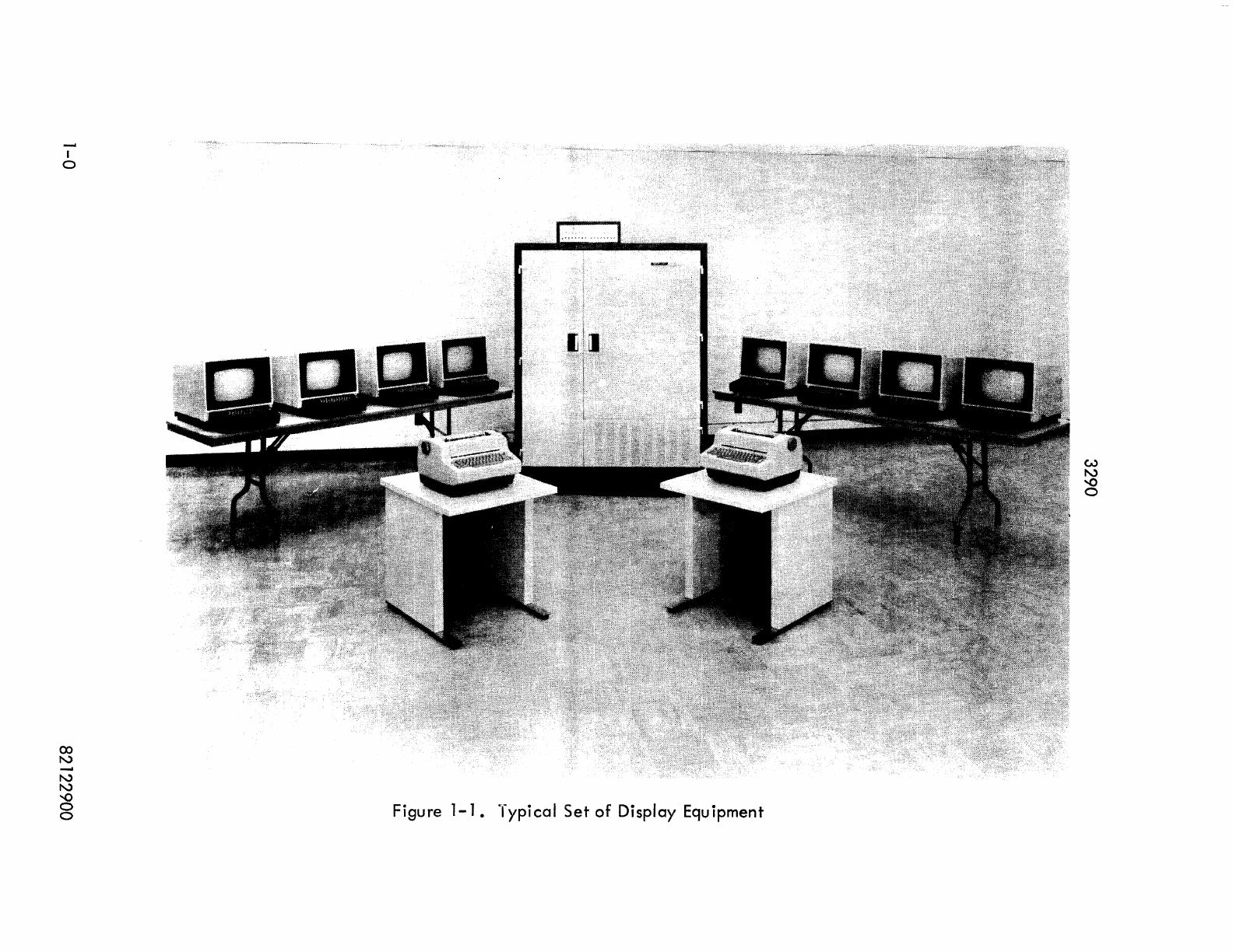
1-1.
Typical
Set
of
Display
Equipment
3290
SECTION I
GENERAL
DESCRIPTION
The display
equipnent,
designed for use with a CONTROL
DATA
3000
Series computer, consists
of
a Display Controller and a combination (not to
exceed
12)
of
Display Stations,
Pri
nter
Stations, and po
II
ers •
A typical
set
of
display equipment
is
shown
in
figure
1-1.
The display
equip-
ment provides access to
data
storage and computational
capabil
ities
of
a
central
com-
puter complex
by
means
of
inquiry and retrieval Display
Stations.
To
obtain
hardcopy
records
of
displayed messages, transfer
data
to
an
associated
off-line
Printer
Station.
The poller allows communications between
the
computer and remote
sites.
The Display Stations
and/or
Printer Stations may
be
located as far as 1000
feet
from
the
Dispray
Controller.
A Display Station and its associated logic circu itry
must be employed for
every
Printer Station used; however,
one
Printer Station may
serve more than
one
Display
Station.
The
poller
assembly controls communications
between
the
3000 Series computer
and
a remote terminal Display
Controller.
Com-
munications between
the
poller
assembly and
the
remote Display Controller
take
place
over
conventional phone lines
utilizing
a DATA-PHONE * Data
Set
201A
or
2018.
OPERATIONAL DESCRIPTION.
Data
is
entered
on>the Display Station 14-inch (diagonal measurement)
cathode
ray tube (crt) screen
from
the
computer
at
an approximate rate
of
50,000
symbols per second and
from
the
Display Station keyboard
at
operator typing
speeds.
Standard display format
is
20
lines
of
50
symbols per line within a nominal
8-inch-
wide by
6-inch-high
raster
area.
An optional display format
is
available
with
13
lines of 80 symbols per
line.
Symbol intensity
is
adiustable and the
P4
phosphor-coated
crt
makes displays
clearly
legible in normal
office
lighting. Data presented on
the
display screen
is
refreshed
at
a
flicker-free
rate
of
50
cycles
per
second.
Symbol dimensions
are
nominally
1/8-inch
wide
by
1/4-inch
high.
* Trademark
of
AT&T
82122900
Changed
10/68
1-1
General
Description 3290
Section
I
An
entry
marker, displayed as an
underline,
conveniently
indicates
to
the
operator
where
the
next
symbol will
appear.
The
entry
marker
can
be
positioned
anywhere with in
the
8
by
6 inch viewing
area
and
moves
automatically
across
the
page
as
each
symbol is
typed,
or inserted by
the
computer.
At
the
end
of
a
line,
the entry marker
automatically
moves to the first symbol position in
the
next
line
down.
When
it
reaches
the
end
of
the
last I ine on
the
page,
it
automatically
moves
to
the
first symbol position in the
upper
left
corner
of
the
screen.
Positioning the
entry
marker
at
the
end
of
the
print
message and depressing
the keyboard PRINT key transmits displayed messages to an associated Printer
Station.
Data
from
the
top
of
the screen to
the
entry
marker position
is
transmitted to the
Printer Station and typed
out
at
the
rate
of
15.5 symbols per second on continuous
strip
paper
9-7/8
inches wide and perforated for folding and
tearing
at
ll-inch
intervals.
FU
NCTIONAL DESCRIPTION.
The remainder
of
Section
I describes in more
detail
primary Display
Control-
ler,
Display
Station,
and
Printer Station
functions.
The Display
Controller
consists
of
an
interface,
central
control
and
symbol
generator
assembly, station
driver
assemblies,
printer
driver assembl
ies,
and may
contain
up to two
poller
assemblies.
On
diagrams and some figures
the
central
control
and
symbol
generator
assembly is referred to as CBU, station drivers as SDU's and
printer
drivers as PCU·s.
The
interface
enables
Display
Controller
communications with a 3000
Series
computer.
Two
cables
(up to 200
feet
long),
identified
as "All and "BII, provide the
data
link
between
the computer and Display
Controller.
Twisted-pair
signal
lines,
contained
in
cables
A
and
B,
are
described
under
interface
signals in
Section
III.
Symbol
generation,
timing, and
data
flow
gating
logic
are
contained
in
the
central
control and symbol
generator
assembly.
Video
pulse
trains,
representing
symbols,
are
developed
in
the
symbol
generator.
These pulse trains
are
made
availa-
ble
to
each
station
driver.
The station
driver
selects
the
proper pulse train and
transmits
it
to the
crt
where
it
is displayed by unblanking the beam in a 5 by 7
dot
matrix.
Symbol dimensions
are,
nominally,
1/8-inch
wide by
1/4-inch
high.
Each
station
driver
contains
logic
circuitry
controlling the
operation
of
a Display
Station.
It
receives
data
from
the
Display Station keyboard and the
central
control symbol
generator
assembly. All
data
sent
to
the
station
driver
is
stored
in
an assoc iated
1-2
82122900
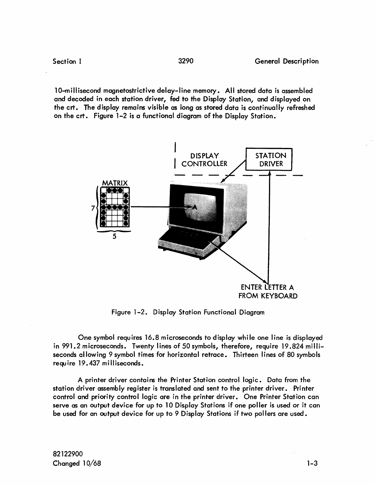
Section I 3290 General Description
10-millisecond magnetostrictive
delay-line
memory. All stored
data
is
assembled
and decoded in
each
station driver, fed
to
the
Display Station, and displayed on
the
crt.
The display remains visible as long as stored
data
is
continually
refreshed
on
the
crt.
Figure
1-2
is
a functional diagram
of
the
Display
Station.
7
MATRIX
5
DISPLAY
CONTROLLER
ENTER
L
TTER
A
FROM
KEYBOARD
Figure
1-2.
Display Station Functional Diagram
One
symbol requires
16.8
microseconds
to
display while one line
is
displayed
in
991.2
microseconds. Twenty lines
of
50 symbols,
therefore,
require
19.824
milli-
seconds allowing 9 symbol times for horizontal
retrace.
Thirteen lines
of
80 symbols
require
19.437
milliseconds.
A printer driver contains
the
Printer Station control
logic.
Data
from
the
station driver assembly register
is
translated and sent
to
the
printer
driver.
Printer
control and priority control logic
are
in
the
printer
driver.
One
Printer Station
can
serve as an output
device
for up
to
10 Display Stations if one
poller
is
used
or
it
can
be
used for an output
device
for up
to
9 Display Stations if two pollers
are
used.
82122900
Changed
10/68
1-3
General
Description 3290
Section
I
Each Printer
Station
contains
a
Selectric
* typewriter; depressing
the
PRINT
key
at
a Display
Station
activates
the
typewriter.
If
the
PRINT
keys
at
several Display
Stations associated with a Printer
Station
are
depressed
while
the
Printer
Station
is
busy
printing,
the
requests
are
processed in
order
of
lowest Display
Station
number.
Type
set
is
designated
IIData
No.
111
** and
type
spacing
is
10 symbols
per
inch
in
a line with 6 lines
per
inch.
The
printer
uses a
black
fabric ribbon to
type
symbols
on
a
9-7/8-inch-wide
continuous strip
paper.
The paper
is
perforated for folding
and
tearing
at
ll-inch
intervals.
Feed holes
are
9-3/8
inches
apart
and
spaced
1/2
inch in
the
longitudinal
direction.
Printout
is
accomplished
at
the
following speeds: print
one
symbol,
64.5
milliseconds;
carriage
return,
129.0
milliseconds;
shift,
64.5
milliseconds; and
space,
64.5
milliseconds.
The Display
Controller
may
contain
a maximum
of
two
pollers.
Data
is
sent
to
or
from
the
remote stations
via
the
poller
in
8-bit
serial
codes.
The Data
Set
synchronizes
all
received
or
transmitted
data.
A
poller
controls
the
remote site1s
requests to transfer
data
by
periodically
polling (scanning) them
in
sequential
order.
ENVIRONMENTAL
CONDITIONS.
The Display
Controller
operates
at
normal room
temperature
but has a blower
assembly housing
located
beneath
the
logic chassis assemblies for
specific
cooling
of
the
logic chassis. The Display Stations and Printer Stations also
operate
at
normal
room temperature but
are
cooled
by
radiation
and
convection.
Tables 1-1 through
1-3
list
specific
environmental limitations for
all
three
units.
PHYSICAL DATA.
The
display
equ ipment
configuration
may consist
of
no more
than
12
Display
Stations,
Printer Stations, and
pollers.
No
more than two pollers may
be
employed,
so
the
maximum display equipment configuration
that
would
be
possible
locally
would
be
a combination
of
ten
Display Stations
and/or
Printer Stations with two
pollers.
The pollers are
capable
of communicating with up
to
16 remote Display
Controllers.
Refer
to
figure
1-3.
*
IBM
Trademark.
**
IBM
Classification.
1-4 82122900
Changed 1
0/68
Section I 3290 General Description
TABLE
1-1.
DISPLAY
CONTROLLER
ENVIRONMENTAL CONDITIONS
CONDITION
OPERATIONAL
NONOPERATIONAL
Normal/Standby
Stor~ge/Tran_s~t
(Note
1)
Temperature
+65
F to +85 F -30 F to + 150 F
Relative Humidity
10
to
900k
a to
1000k
(Note 2)
Altitude -1000 to + 10,000 feet -1000 to + 15, 000 feet
Note 1 -packed for shipment.
Note 2 -includes condensation in the
form
of
mo
i
stu
re or frost.
TABLE
1-2.
DISPLAY
STATION
ENVIRONMENTAL
CONDITIONS
CONDITION
OPERATIONAL
NONOPERATIONAL
Normal/Standby Storage/Transit (Note
1)
Temperature
+65
F to + 100 F -65 F to + 160 F
Relative Humidity 40 to
600k
10
to
900k
(Note
2)
Altitude
8,
000 feet 12, 000 feet
Note 1 -packed for
sh
ipment.
Note 2 -includes condensation
in
the
form
of moisture
or frost.
TABLE
1-3.
PRINTER
STATION
ENVIRONMENTAL
CONDITIONS
CONDITION
OPERATIONAL
NONOPERATIONAL
Norma I/S tandby Storage/Transit (Note
1)
Temperature + 60 F
to
+ 100 F -30 F to + 150 F
Relative Humidity
10
to
900k
5 to
1000/0
(Note
2)
Altitude -1000 to +
10
, 000 feet -1000 to +
15,000
feet
Note 1 -packed for shipment.
Note 2 -includes condensation in the
form
of
moisture or frost.
82122900 1-5
General
Description
UPTO
8
REMOTE
SITES
.-
DATA
SET
POLLER
/
PRINTER
-
STATION -
3290
CONTROL
DATA
DATA
3000
SERIES
--.
COMPUTER
SET
DISPLAY
CONTROLLER
-
INTERFACE
-
POLLER
CENTRAL
CONTROL
AND
SYMBOL
GENERATOR
I I
PRINTER
STATION
DRIVER DRIVER
/ "'-
~.
----
TOTAL
COMBINATION:
..
DISPLAY
UP
TO
11
WITH
T
POLLER
STATION
UP
TO
10
WITH
2 POllERS
Figure
1-3.
Display Equipment Block Diagram
Section
I
UP
TO
8
REMOTE
SITES
Physical
construction
of
the
display
equipment
incorporates
latest
recognized
factors in
engineering,
convenience,
and
safety
to
operating
personnel 0 Figures
1-4
through
1-6
show the dimensions and
approximate
weight
of
the
Display
Controller,
Display
Station,
and Printer
Station
respectively.
DISPLAY CONTROLLER
ELECTRICAL
DATA.
The Display
Controller
requires 57
to
63
Hz,
187 to 216
volts,
3-phase
alternating
current
of
8
amperes.
Each
station
driver
or
printer
driver
requires
0.4
ampere
in
addition
to
that
required
for the Display
Controller.
1-6
82122900
Section
I 3290
General
Description
NOTE:
Only
on
units
with
pollers.
---..
Figure
1-4.
Display
Controller
Physical
Data
DISPLAY STATION
ELECTRICAL
DATA.
The Display Station requires
115/23Q-volt,
50/60-Hz,
3-wire,
single-phase
power.
Power
expended
is
130
watts
with
heat
dissipation
of
465
Btu
per
hour.
Voltage
potentials
in
the
Display
Station
range
from
-
16
volts
dc
to
10
kilovolts.
PRINTER
STATION
ELECTRICAL
DATA.
The Printer
Station
requires
120-volt,
single-phase,
60-Hz
power.
It has a
maxi
mum
current
rating
of
1
.0
ampere,
dissipates 400
Btu
per hour, and
is
cooled
by rad iation and
convection.
82122900
1-7
General
Description
3290
Section
I
.
1-17-3/4"-j
I
16-5/8
11
-!
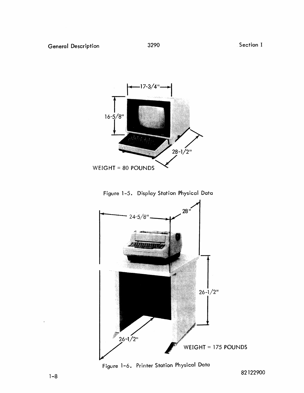
Figure 1-5. Display
Station
Physical
Data
28"
24-5/8"
----~
WEIGHT = 175 POUNDS
Figure
1-6.
Printer
Station
Physical
Data
1-8
82122900
Section I 3290
General
Description
CONVENIENCE OUTLETS.
To
facilitate
the
use
of
test equipment during periods
of
maintenance,
Con-
trol Data requires
that
a convenience
outlet
be
available
within
15
feet
of
each
system component
cabinet.
The
outlets
may
be located
in
the walls or raised floor
panels and
must
not
be obstructed by storage racks or
other
furniture. The
recepta-
cles
shall be
of
the
single-phase grounded
type,
installed according to local
electri-
cal
codes.
For
60-hertz
installations, the nominal
voltage
shall be 120
volts.
For
50-hertz
installations,
the
nominal
voltage
shall be 220, 230, or 240 volts, as
dictated
by the single-phase power
available
at
the
site.
82122900
1-9
3290
SECTION
II
OPERATION
Th
is
section contains a I ist
of
control s for operation and maintenance
of
the
display equipment and also contains information on
data
inquiry, and turn
on/turn
off
procedures.
CONTROLS.
Display Equipment controls
are
divided into three groups: Display
Controller,
Display
Station,
and Printer
Station.
Following paragraphs
explain
control usage
within
each
group.
The Display
Controller
maintenance panel controls apply power and
enable
checking
the display equipment operational
sequence.
Display Station controls
apply
power and adiust
crt
intensity.
The Display Station keyboard enters
data
into
the
.
display equipment and controls its
destination.
Printer Station controls
apply
power
to
the hardcopy
printer.
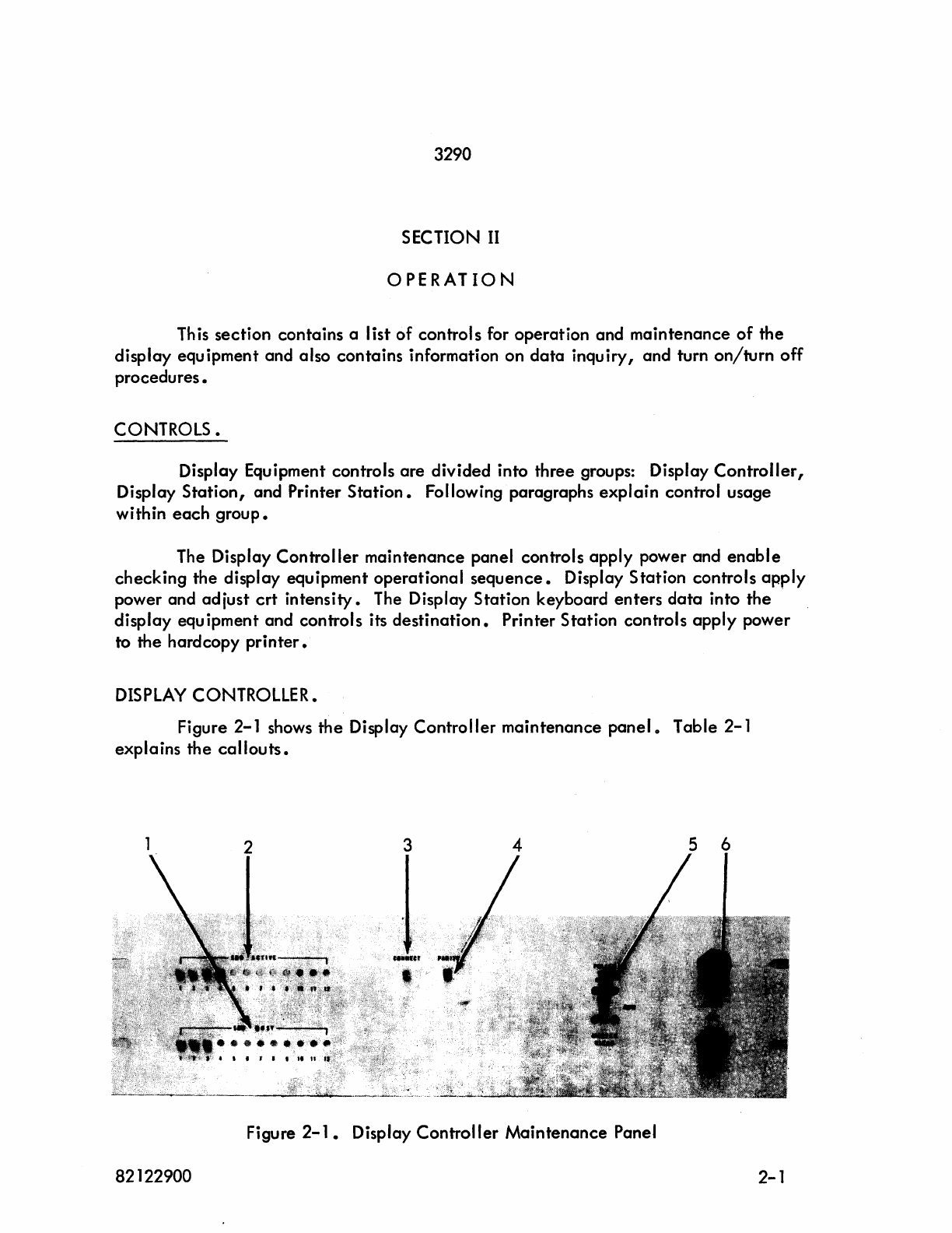
DISPLAY
CONTROLLER.
Figure 2-1 shows
the
Display
Controller
maintenance panel 0 Table 2-1
explains the
ca
II
outs •
3 4 5 6
Figure
2-1.
Display
Controller
Maintenance
Panel
82122900 2-1
Operation
3290
Section
III
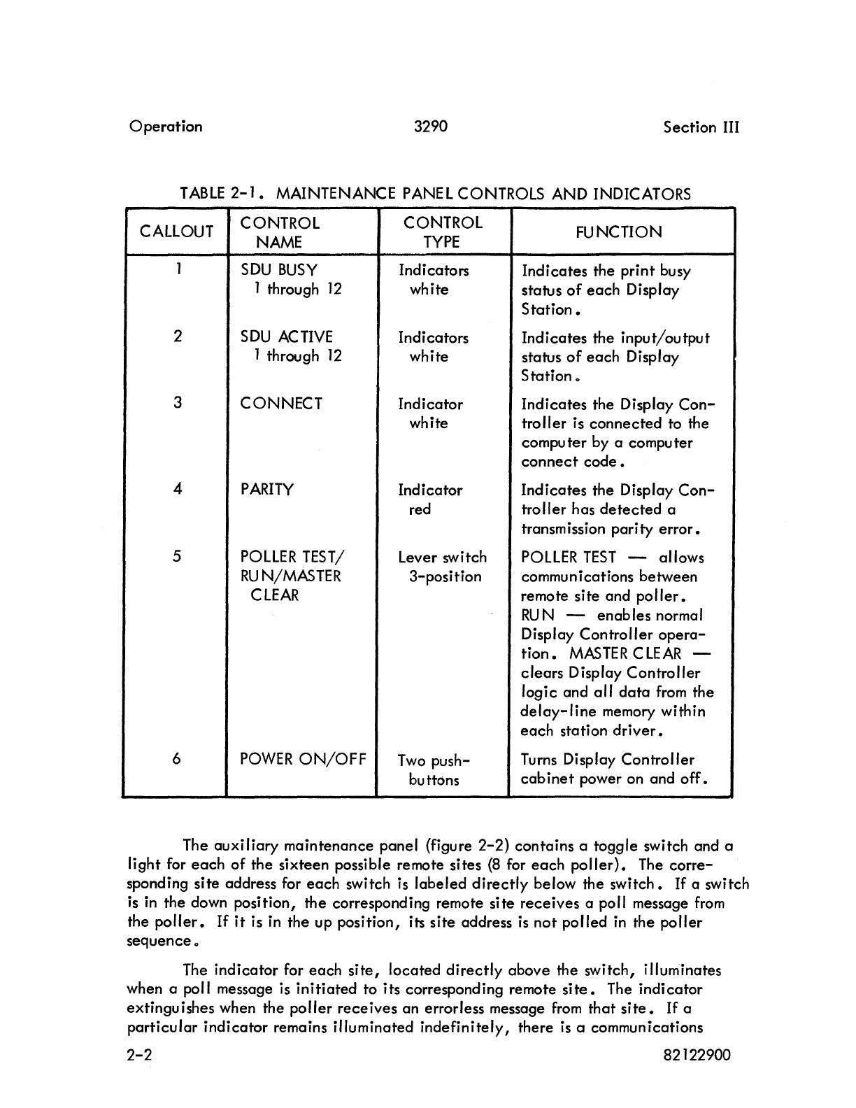
TABLE
2-1.
MAINTENANCE PANE L CONTROLS AND INDICATORS
CALLOUT
CONTROL
CONTROL
FUNCTION
NAME
TYPE
1
SDU
BUSY
Indicators
Indicates
the
print
busy
1 through
12
white
status
of
each
Display
Station.
2
SDU
ACTIVE
Indicators
Indicates
the
input/output
1 through
12
white
status
of
each
Display
Station
..
3
CONNECT
Indicator
Indicates
the
Display
Con-
white
troller
is
connected
to the
compu
ter
by a compu
ter
connect
code.
4
PARITY
Indicator
Indicates
the
Display
Con-
red
troller
has
detected
a
transmission
parity
error.
5
POllER
TEST/
lever
switch POLlER
TEST
-allows
RUN/MASTER
3-position
communications
between
CLEAR
remote
site
and
poller.
RUN
-
enables
normal
Display
Controller
opera-
tion.
MASTER
CLEAR
-
clears
Display
Controller
logic
and
all
data
from
the
delay-line
memory within
each
station
driver.
6
POWER
ON/OFF
Two
push- Turns Display
Controller
butt()ns
cabinet
power on and
off.
The
auxiliary
maintenance
panel
(figure
2-2)
contains
a
toggle
switch and a
light
for
each
of
the
sixteen
possible remote sites
(8
for
each
poller).
The
corre-
sponding
site
address for
each
switch is
labeled
directly
below the
switch.
If
a switch
is in the down
position,
the
corresponding remote
site
receives
a poll message
from
the
poller.
If
it
is in
the
up
position,
its
site
address
is
not
polled
in
the
poller
sequence
..
The
indicator
for
each
site,
located
directly
above
the
switch,
illuminates
when a poll message is
initiated
to
its
corresponding remote
site.
The
indicator
extinguishes
when the
poller
receives
an errorless message from
that
site.
If
a
particular
indicator
remains
illuminated
indefinitely
I there is a communications
2-2
82122900
Section II 3290
Operation
problem between
that
site and the
poller.
The switch corresponding to th is indicator
should then be
placed
in
the up position 0 This will extinguish the light and remove
the site
from
the system 0
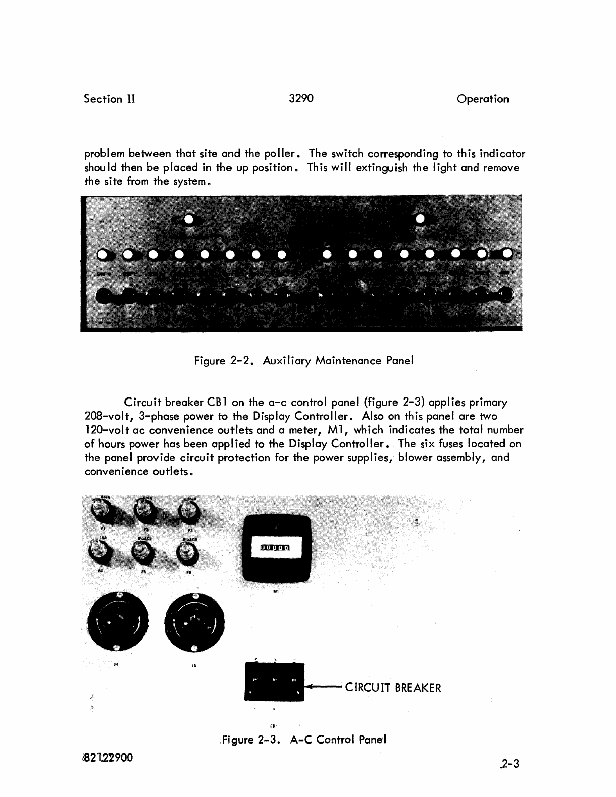
Figure
2-2.
Auxiliary Maintenance Panel
Circuit
breaker
CB
1 on the
a-c
control panel (figure
2-3)
applies primary
20B-volt, 3-phase power to the Display
Controller.
Also on this panel
are
two
120-volt
ac
convenience
outlets
and a meter,
Ml,
which indicates the total number
of
hours power has been appl ied to the Display
Controller.
The six fuses located on
the panel provide
circuit
protection for the power supplies, blower assembly, and
convenience outletso
V!
1$
....--
CIRCUIT
BREAKER
,Figure
2-3.
A-C
Control Panel
{8.212'2900
.2-3
Operation
3290 Section
II
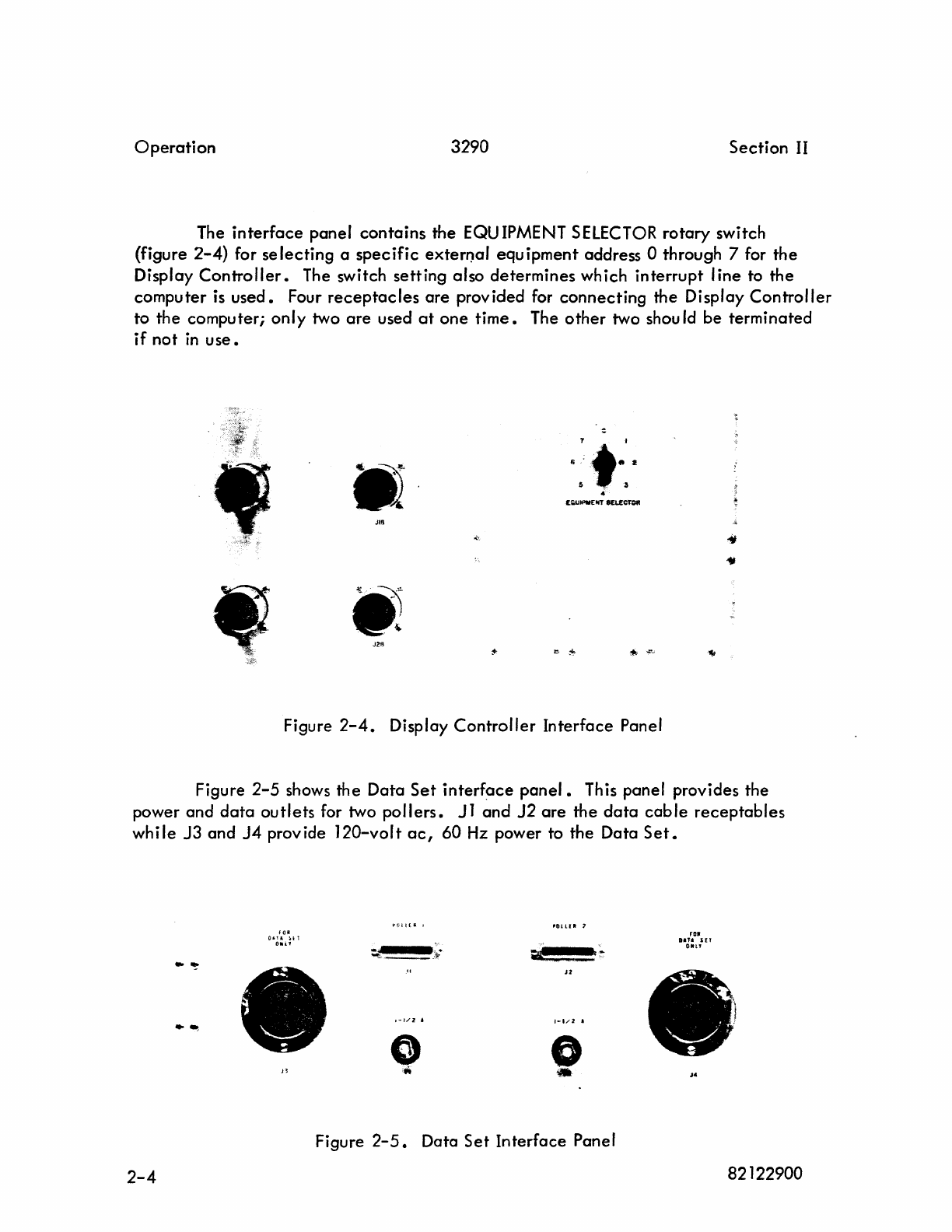
The
interface
panel
contains
the
EQU
IPMENT
SELECTOR
rotary
switch
(figure
2-4)
for
selecting
a
specific
exterr)al equipment address 0 through 7 for the
Display
Controller.
The switch setting also determines which interrupt line to the
computer is
used.
Four
receptacles
are
provided for
connecting
the Display
Controller
to the computer;
only
two
are
used
at
one
time.
The
other
two shou
Id
be terminated
if
not
in
use.
•
Jill
J21l
:
....
6 " I
"
1;U_IIT
$EI.£~
Figure
2-4.
Display
Controller
Interface Panel
Figure
2-5
shows the Data
Set
interf~ce
panel.
This panel provides the
power and
data
outlets
for two
pollers.
Jl
and
J2
are
the
data
cable
receptables
whi Ie
J3
and
J4
provide
120-volt
ac
,
60
Hz
power to the Data
Set.
'OlU_
t
I~.
ro.
O'!A
H1
DIU
HT
01li1'
Oat'
..
,.
-
't
~.
__
}F-
..
~
Jl
,-J/Z
j
/·1/2
.
..
~
0 0
n
..
•
J.
Figure
2-5.
Data
Set
Interface Panel
2-4
82122900
Section II
3290
Operation
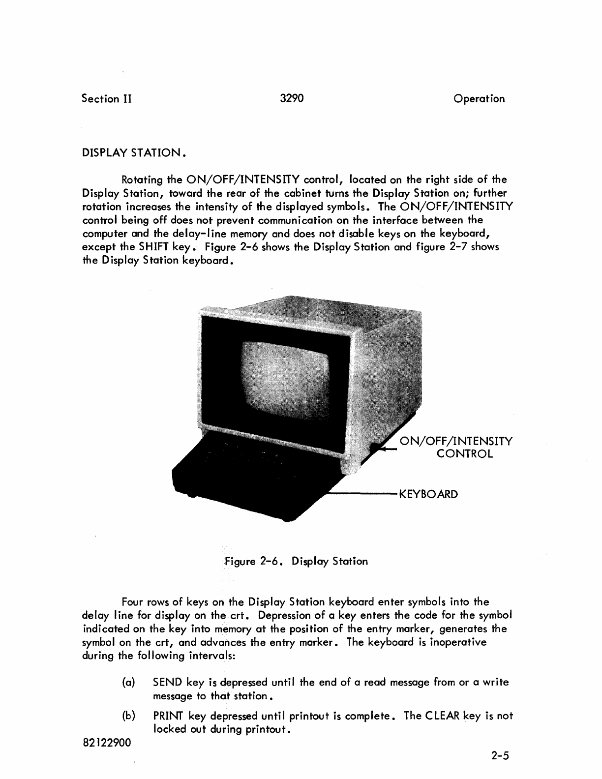
DISPLAY
STATION.
Rotating the
ON/OFF/INTENSITY
control, located on the right side
of
the
Display
Station,
toward the rear
of
the
cabinet
turns
the
Display Station on; further
rotation increases
the
intensity
of
the
displayed symbols. The
ON/OFF/INTENSITY
control being off does not prevent communication on the
interface
between the
computer and the
delay-line
memory and does
not
disable keys on the keyboard,
except
the
SHIFT
key.
Figure
2-6
shows the Display Station and figure
2-7
shows
the Display Station
keyboard.
ON/OFF/INTENSITY
CONTROL
----KEyBOARD
Figure
2-6.
Display Station
Four rows of keys on the Display Station keyboard
enter
symbols into
the
delay
I ine for display on the
crt.
Depression
of
a key enters
the
code for the symbol
indicated on
the
key into memory
at
the position
of
the entry marker, generates the
symbol on the
crt,
and advances the entry marker. The keyboard
is
inoperative
during the following intervals:
(a) SEND key is depressed until the end
of
a read message
from
or a
write
message to
that
. station •
(b)
PRINT
key depressed unti I printout
is
complete.
The C
LEAR
key is not
locked out during
printout.
82122900 2-5
Operation
3290
Section
II
Clear.
Figure
2-7.
Display
Station
Keyboard
(c) The
station
is
connected
and
the
Channel
Busy
signal is a
logical
1.
(d) Reset function
or
reset
clear
function
is
being
performed by
the
Display
Station.
The following list
explains
the
operation
of
the
control
keys.
Depress
the
C
LEAR
key
to
clear
all
data
from
the
delay
I ine
and
from
the
crt.
The
entry
marker moves to
the
upper
left
corner
of
the
screen.
Th
is
operation
pre-
vents
sending
or
rece
iv
ing
data
from
the
time the key is depressed until
16.8
micro-
seconds to 20 mill i seconds
after
the
key is re
leased.
(The time
variation
is
due
to
latency
characteristics
of
the
de
lay
line).
2-6
82122900
Section
II
3290
Operation
Reset.
Depress the
RES
ET
key to move the
entry
marker to the upper
left
corner
without
affecting
data.
This operation prevents sending or receiving
data
from
the
time the
key
is depressed until
16.8
microseconds to 20 milliseconds
after
the
key
is re
leased.
Sh
ift.
Continued depression
of
either
SHIFT
key enables entry
of
the upper symbol
on the two-symbol
keys.
Operation
of
the single-symbol keys is
not
affected
by
the
SHIFT
keys;
all
alphabetic
symbols
are
displayed in uppercase form. The SHIFT
keys are non locking •
Space.
Operating
the
SPACE
key stores a space code in the
delay
line
at
the position
of
the entry marker and advances the
entry
marker. Data
is
not
affected.
Skip.
Depress
the
S
KIP
key to move
the
entry
marker one space forward. Data
is
unchanged.
Repeat.
Operating
the
REPT
key in coniunction with
another
key
enables
a
repeated
action
of
that
key's
character/function.
CLEAR, PRINT,
RESET,
SEND, and SHIFT
keys
are
not
affected
by the
REPT
key.
Backspace.
The
BKSP
key moves the entry marker
one
space back without changing
data.
Backspace is accomplished in 10 milliseconds minimum to 90 milliseconds maximum,
during which time no
data
can
be transferred on the
data
channel.
82122900 2-7
Operation
3290
Section
II
Line
Skip.
Depress
the
LINE SKIP
key
to
advance
the
entry
marker to
the
beginning
of
the
next
line.
Line skip is
accomplished
in
151.2
microseconds minimum
to
1
milli-
second
maximum, during which time no
data
is
transferred
between
a
connected
Display
Station
and
the
computer.
Return.
Operation
of
the
RETU
RN
key
inserts a
carriage
return
code
at
the
entry
marker position
and
moves
the
entry
marker
to
the
first symbol position on
the
next
line.
The
carriage
return
is
displayed
as a
superscript
dash
().
The return
takes
from
151.2
microseconds
(if
the
entry
marker
is
at
the
end
of
a
line)
to 1 millisecond
(if
the
entry
marker is
at
the
beginning
of
a
line),
during which time no
data
can
be
transferred
between
the
Display
Station
and
the
computer.
Send.
~
The SEND key stores
an
end
of
message symbol
(elevated
)
at
the
entry
marker posi tion
and
moves
the
entry
marker
to
the
upper
left
corner.
Data
transfer
is
prevented
during
the
time
(16.8
microseconds minimum
to
20
milliseconds
maximum)
the
entry
marker
is
moving.
Print.
Operation
of
the
PRINT
key
stores an
end
of
print
code
(')
at
the
entry
marker
position,
moves
the
entry
marker
to
the
upper
left
corner,
and
initiates
printout
of
data
from
the
upper
left
corner
to
the
end
of
print
code
on
an
associated
Printer
Station.
The
keyboard,
except
for
the
C
LEAR
key,
is
disabled
during
printout.
During
printout,
the
Display
Station
is
not
ready
to the
computer.
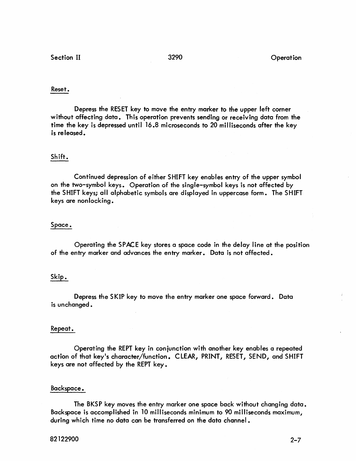
PRINTER
STATION.
Figure
2-8
shows
the
Printer
Station
typewriter
controls
0
Note
the
location
of
the
ON/OFF
switch to
the
right
of
the
keyboard.
A
multipaper
adjustment
(top left) provides
even
printing
for carbon
copies.
Remaining
controls
are
common
2-8
82122900
Section
II 3290 Operation
to an
electric
typewriter and include the following: platen knobs for manually
advancing the
paper,
a line space lever for single or double
spacing,
a paper
release lever, left and right visible margin stops, an impression
selector
lever which
adjusts
the
striking force of the typing
element,
a tab
set
and
clear
control,
tab
key,
index key, shift keys, margin
release,
space bar,
etc.
Refer to the
IBM
Selectric
Manual supplied with the equipment for more
detailed
information about the typewriter.
LEFT-RIGHT
MARGIN
PLATEN
KNOB
MULTICOPY
CONTROL
LINE
SPACE
PAPER
--
RELEASE
IMPRESSION
SELECTOR
Figure
2-8.
Printer Station Typewriter Controls
OPERATING
PROCEDURES.
The remainder of
th
is
section describes normal operating procedures for the
display equipment. Included are turn
on/turn
off procedures followed by a typical
operation
sequence.
82122900
2-9
Operation
3290
Section
II
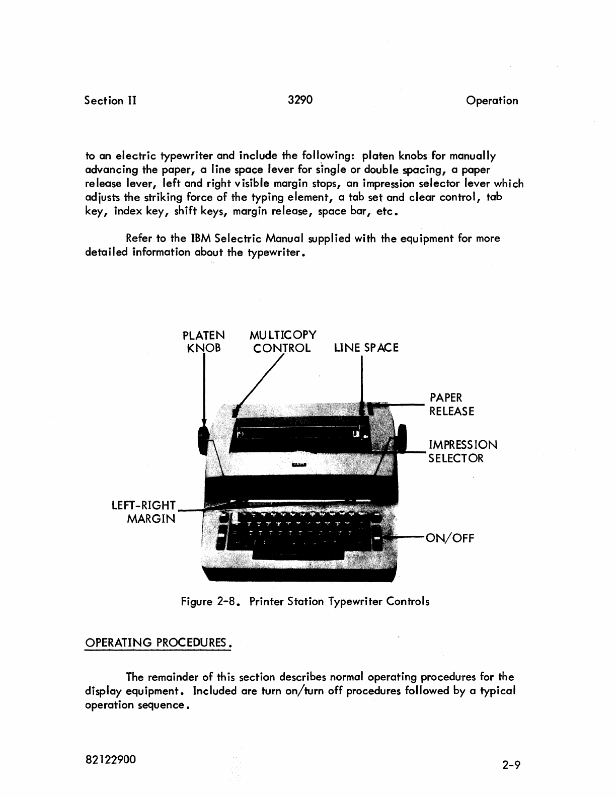
TURN
ON/TURN
OFF.
Turn
on/turn
off
procedures
are
listed
in
table
2-2.
For
precautionary
measures,
it
is recommended
the
steps be followed in the
order
listed.
TABLE
2-2.
TURN
ON/TURN
OFF
PROCEDURES
STEP
LOCATION
I I
1 Display
Controller
2 Display Stations
3
Printer
Stations
Printer
Stations
2 Display Stations
3 Display
Controller
OPERATION
TURN
ON
Place
the
POWER
ON/OFF
switch in
the
ON
position.
Move
RU
N/MASTER C
LEAR
switch
to
MASTER
C
LEAR
position,
then to
RU
N
position.
Rotate
the
ON/OFF/INTENSITY
control to
the
ON
position.
Depress the
CLEAR
key.
After
a
30-second
warmup
period,
rotate
ON/OFF/
INTENS
ITY
control
until
the
entry
marker
is
visible.
Depress
the
ON/OFF
rocker switch to
the
ON
position.
TURN
OFF
Depress
the
ON/OFF
rocker
s~itch
to
the
OFF
position.
Rotate
the
ON/OFF/INTENSITY
control to
the
OFF
position.
Place
the
POWER
ON/OFF
switch in the OFF
position 0
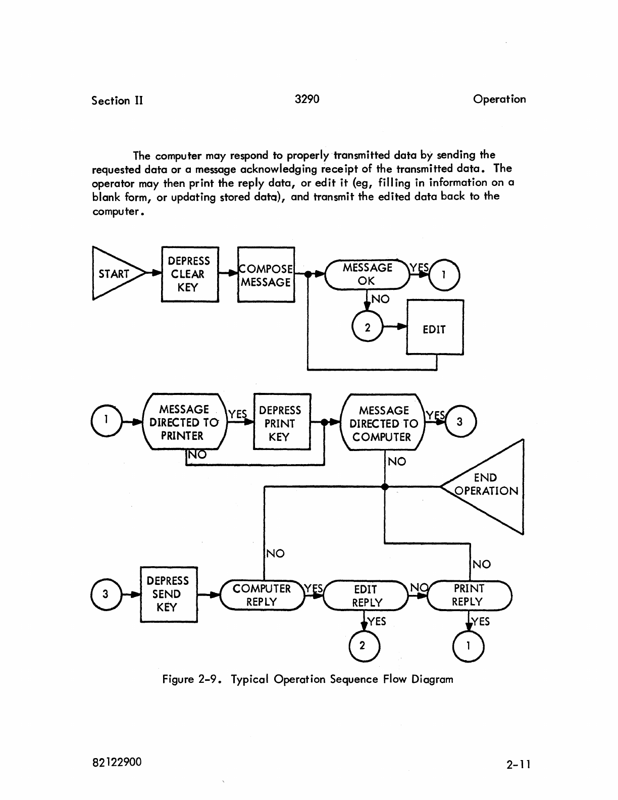
TYPICAL OPERATION SEQUENCE.
F'igure
2-9
is a flow diagram
depicting
a
typical
operation
sequence.
Depress
the
CLEAR
key
on the Display
Station
keyboard to
clear
the
display
screen.
The
operator
then
enters
data
via
data
entry
keys.
When
data
is
properly
composed,
it
may be
sent
to
the
computer by
actuation
of
the
SEND
key,
or
to a Printer
Station,
which shares memory with the Display
Station,
by depressing
the
PRINT
key.
2-10
82122900
Section
II
3290
Operation
The
computer may respond to properly transmitted
data
by sending the
requested
data
or a message acknowledging
receipt
of the transmitted
data.
The
operator may then print the reply
data,
or
edit
it
(eg, fill ing in information on a
blank form, or updating stored
data),
and transmit the edited
data
back to the
computer.
82122900
DEPRESS
CLEAR
KEY
MESSAGE
DIRECTED
TO
PRINTER
DEPRESS
SEND
KEY
OMPOSE
..............
MESSAGE
DEPRESS
PRINT
KEY
NO
COMPUTER
REPLY
NO
Figure
2-9.
Typical Operation Sequence
Flow
Diagram
NO
2-11
3290
SECTION III
PROGRAMMING
This section describes programming aspects
of
the
display
equipment.
It
provides a complete description
of
signals, function and status codes, interrupts,
symbol
data,
word formats, various
read/write
operations, and programming aids
for both
interface
and poller assemblies.
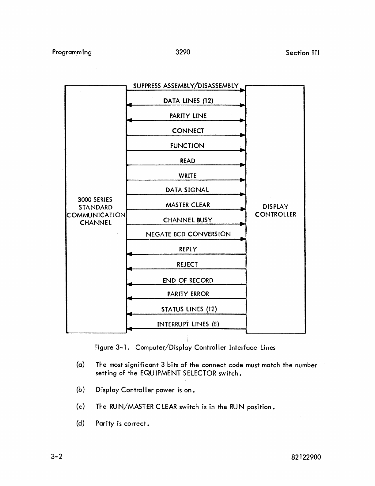
INTERFACE
SIGNAL LINES.
The
Display Controller operates
from
the standard (12 bit) 3000 Series standard
communications
channels.
Figure 3-1 shows
the
interconnecting
data
and control
lines between the computer communications channel and the Display
Controller.
Following
is
a description
of
each
line
or
group
of
lines.
DATA
LINES
(12).
There are
12
bidirectional
data
lines.
During a read operation (input to the
computer), these
data
lines carry
data,
12
bits
at
a time,
from
the Display Controller
to the computer. During a
writ~
operation (output
fro~
the computer),· the
data
lines carry
data
from
the computer to the Display
Controller.
The
data
lines also
are
used to transmit the
12-bit
connect
and function codes associated with
Connect
and Function signals,
respectively.
PARITY
LINE.
A
parity
bit
accompanies
each
12 bits
of
data,
connect
code,
and function
code transmitted between the computer and the Display
Controller.
Odd
parity
is
used,
ie,
the total number
of
lis
transmitted
is
always an odd number.
CONNECT
LINE.
A
Connect
signal is
sent
to the Display Controller when a
12-bit
connect
code is
available
on the dato
lines.
The
li>isplay
Controller connects only
if
the
following conditions are met:
82122900 3-1
Programm ing
3290
Section
III
SUPPRESS
ASSEMBLY
ISA
SEMBLY
_
!Os
..
.-
DATA
LINES
(12)
-
-
..
-
PARITY
LINE
-
....
-..
CONNECT -
·
FUNCTION'
,;..
READ
-
·
WRITE
-
..
DATA
SIGNAL -
..
3000
SERIES
MASTER
CLEAR
STANDARD
-
DISPLAY
..
COMMUNICATION
CONTROLLER
CHANNEL CHANNEL
BUSY
-
-.,.
NEGATE
BCD
CONVERSION -
·
REPLY
...
-
...
REJECT
-
-
END
OF
RECORD
....
.-
PARITY
ERROR
-
-
STATUS
LINES
(12)
....
-
INTERRUPT
LINES
(8)
--
Figure
3-1.
Computer/Display
Controller
Interface
Li
nes
(a) The most
significant
3
bits
of
the
connect
code
must match
the
number
setting
of
the
EQUIPMENT SELECTOR
switch.
(b)
Display
Controller
power
is
on.
(c)
The
RU
N/MASTER C
LEAR
switch
is in
the
RU
N
position.
(d)
Parity
is
correct.
3-2
82122900
Section
III 3290 Programming
No
response is returned when a parity error exists on the
connect
code;
however, the red
PARITY
error
indicator
on the Display
Controller
maintenance panel
(figure
2-1)
lights on
all
Display Controllers and
external
equipment controllers
associated with
that
communications
channel.
After a
delay
of
100 microseconds,
the communications channel
generates
its own internal Reiect
signal.
Once
a Display Controller
is
connected
to the computer,
it
remains
connected
until the communications channel
initiates
a
disconnect.
To
perform a
disconnect,
send any
connect
code with
the
upper 3 bits
not
matching the Display
Controller
EQUIPMENT
SELECTOR
switch
setting,
a Master
Clear
signal,
or a release function
code.
FU
NCTION LINE.
A Function signal is
sent
to the Display Controller when a
12-bit
function
code is
available
on the
data
I ines (function codes are listed under interface control
codes).
If
the Display
Controller
is
connected to the computer and is
capable
of
executing
the specified function
at
the time
it
receives
the
Function
signal,
it
initiates
the function and returns a Reply
signal.
If the Display
Controller
cannot
perform the function,
it
returns a Reiect
signal.
The Function signal and
12-bit
function code drop when a Reply or Reiect signal is
returned.
If
a Reply or Reiect
signal
is
not
returned within 100 microseconds, the computer
generates
its own
internal
reiect.
The specified function
is
not performed if a parity error exists on the function
code;
however, a Parity Error signal
is
returned by the Display
Controller
and the red
PARITY
error
indicator
on the Display
Controller
maintenance panel (figure
2-1)
lights.
Once
a function code is
accepted
by the Display
Controller,
all
other
function
codes
are
locked
out
until the first
one
is
acted
upon.
The Display Controller does
not
hold
or
stack up the function codes; a Reply or Reiect signal is returned within 5
microseconds. If a second function code is
received
which specifies the same function
as
the
previous function
code,
the second function code is
reiected
unless the function
can
be
performed immediately a second
time.
READ
LINE.
A Read signal transmitted to the Display Controller
directs
the
Display
Con-
troller
to begin reading
data
from
a specified Display Station memory.
82122900
3-3
Programming
3290
Section
III
WRITE
LINE.
A
Write
signal transmitted to
the
Display
Controller
directs
the
Display
Con-
troller
to
begin
writing
data
into a
specified
Display
Station
memory.
DATA
SIGNAL
LINE.
A
Data
signal is
sent
from
the
computer
to
the
Display
Controller
for
each
12-bit
data
word du.ring
read
and
write
operations.
The
Data
signal drops when a
Reply (or
End
of
Record) signal is transmitted by
the
Display
Controller.
During a
read
operation,
the
Data
signal
indicates
that
the
computer
is
ready
to
accept
a
12-bit
data
word from
the
Display
Controller.
During a
write
operation,
the
Data
signal
indicates
that
the
computer
placed
a
12-bit
data
word on
the
data
lines.
MASTER
CLEAR LINE.
A
Master
Clear
signal
sent
from
the
computer returns
the
Display
Controller
to its
initial
clear
condition
and
starts
the
polling
operation.
CHANNEL
BUSY
LINE.
A
Channel
Busy
signal
is
sent
to
the
Display
Controller
when the computer
communications
channel
is
active
during a
read
or
write
operation.
NEGATE
BCD
CONVERSION
LINE.
When
the
Negate
BCD
Conversion signal is a
logical
1
,external
BCD
codes
are
used; when
the
N,egate
BCD
Conversion signal is a
logical
0,
internal
BCD
codes
are
used.
' Refer to Symbol
Data
in th
is
section.
REPLY
LINE.
The Display
Controller
transmits a Reply signal in response to
the
following:
3-4 82122900
Section III
3290
Programm i ng
(a) A
connect
code having no parity error and containing a matching
Display
Controller
EQUIPMENT S
ELECTOR
switch equ ipment se
lect
code and proper
select
code.
(b) A function
code
received
with no parity error
if
the Display Controller
is
capable
of
executing the specified function
at
the time
it
receives
the Function
signal.
(c) During a write operation
after
the Display Controller has read a
data
word.
(d) During a read operation when the Display Controller has a word on the
data
lines (see
End
of
Record signal for
exception).
The Reply signal drops when the
Connect,
Function,
or
Oata signal drops.
REJECT
LI
NE
•
The Display Controller transmits a Reiect signal in response to the following:
(a) A
connect
code
(with no
parity
error) specifying a nonexistent
or
busy
station.
(b) A function
code
(with no parity error) specifying an illegal
function.
(c) A function code (with no parity error) which
cannot
be performed
within 5 microseconds
after
receipt
of
the
Function signal (refer to
programming aids for such conditions).
(d)
An
alert
function to a
poller
that
had its
alert
request status
cleared,
or an
alert
function to any station
other
than a poller 0
SUPPRESS
ASSEMBLY/DISASSEMBLY
LINE.
During a read
operation,
the Suppress Assembly/Disassembly signal forces the
Display Controller to assemble logical
O·s
in
bits 6 through
11
of
each
12-bit
data
byte.
In
a write
operation,
bits 6 through
11
are
not used when the Suppress
Assembly/Disassembly line is
enabled.
The signal has no
effect
on the address word
during a read operation
initiated
by
an
interrupt.
82122900 3-5
Programming
3290
Section
III
END
OF
RECORD LINE.
The Display
Controller
transmits an
End
of
Record
signal
(instead
of
a Reply
signal)
in response to
the
next
Data
signal following transmission
of
EOM
signal.
The
End
of
Record signal drops when
the
Data
signal
drops.
If
the
Read signal drops
before
the
read
operation
completes,
the
End
of
Record signal is
not
transmitted
because
the
remaining
data
is
not
transmitted.
PARITY
ERROR
LINE.
The Display
Controller
transmits a
Parity
Error signal when a
parity
error
occurs
on a
function
code
or
write
operation.
No
Parity Error signal
is
generated
for a
parity
error
occurring
on a
connect
code
or
read
operation.
During a
write
operation,
a
parity
error
on
one
word
of
a
12-bit
byte
results in
displ~y
of
both words
as
parity
error
symbols when the Suppress signal
equals
-0.
STATUS
LINES
(12).
The Display
Controller
places
information
on
the 12
available
status
lines
following a
connect
operation
to
indicate
its
operating
conditions
to the
computer.
Display
equipment
status remains
enabled
to
the
computer
until
a
disconnect
is
sent
from
the
computer.
The computer may sample the status
lines
at
any
time.
Status
bits
are
listed
under
interface
control
codes.
INTERRUPT
LINES
(8).
Each Display
Controller
and
external
equipment
controller
attached
to a
given
computer communications
channel
is assigned to
one
of
eight
separate
interrupt
lines
selected
by
the
EQUIPMENT SELECTOR
switch.
The
interrupt
line
indicates
to the computer
that
a
predetermined
condition
has
been
reached.
The
interrupting
condition
can
be
determined
by program sampling
the
status lines following
trans-
mission
of
an
Interrupt
signal
if
connected.
INTERFACE
CONTROL
CODES.
Interface
control
codes
include
connect,
function,
and status
codes.
The
connect
code
is used in addressing
the
display
equipment.
Function
codes,
with
3-6
82122900
Section III 3290 Programm i ng
the exception
of
reset,
alert,
and
release,
set
up and remove interrupt conditions in
the Display
Controller.
Status codes
indicate
what
conditions exi st
at
the Display
Controller.
Following is a description
of
the
connect
code,
display equipment
func-
tion codes, and status line assignments.
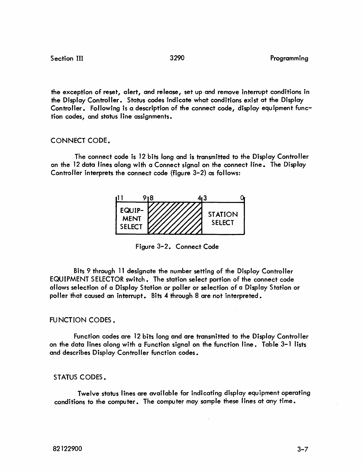
CONNECT
CODE.
The
connect
code
is
12
bits long and is transmitted to the Display Controller
on the
12
data
I ines along with a
Connect
signal on the
connect
line.
The Display
Controller interprets the
connect
code (figure
3-2)
as follows:
11
9 8
EQUIP-
MENT
SELECT
STATION
SELECT
Figure
3-2.
Connect
Code
Bits 9 through
11
designate the number setting
of
the Display Controller
EQUIPMENT
SELECTOR
switch.
The station
select
portion
of
the
connect
code
allows selection
of
a Display Station or
poller
or selection
of
a Display Station or
poller
that
caused an
interrupt.
Bits
4 through 8
are
not
interpreted.
FUNCTION CODES.
Function codes
are
12
bits long and
are
transmitted to the Display Controller
on the
data
lines along with a Function signal on the function
line.
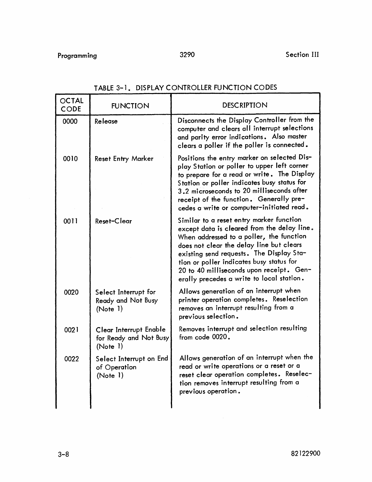
Table 3-1 lists
and describes Display Controller function
codes.
STATUS
CODES.
Twelve status lines
are
available
for indicating display equipment operating
conditions to the computer. The computer may sample these lines
at
any
time.
82122900 3-7
Programm ing 3290
Section
III
TABLE
3-1.
DISPLAY CONTROLLER FUNCTION CODES
OCTAL
CODE
0000
0010
0011
0020
0021
0022
3-8
FUNCTION
Release
Reset Entry Marker
Reset-Clear
Select
Interrupt for
Ready and
Not
Bu
sy
(Note
1)
Clear
Interrupt Enable
for Ready and
Not
Busy
(Note
1)
Select
Interrupt on
End
of
Operation
(Note
1)
DESCRIPTION
Disconnects
the
Display
Controller
from
the
computer and
clears
all
interrupt
selections
and
parity
error
indications.
Also master
clears
a
poller
if
the
poller
is
connected.
Positions the
entry
marker on
selected
Dis-
play
Station
or
poller
to upper
left
corner
to
prepare
for a
read
or
write.
The Display
Station
or
poller
indicates
busy status for
3.2
microseconds to
20
milliseconds
after
receipt
of
the
function.
Generally
pre-
cedes
a write
or
computer-initiated
read 0
Simi lar to a
reset
entry
marker function
except
data
is
cleared
from
the
delay
line 0
When addressed to a
poller,
the function
does
not
clear
the
delay
line
but
clears
existing send
requests.
The Display
Sta-
tion or
poller
indicates
busy status for
20
to
40
milliseconds upon
receipt.
Gen-
erally
precedes
a
write
to local
station.
Allows
generation
of
an
interrupt when
printer
operation
completes.
Rese
lection
removes an
interrupt
resu Iting
from
a
previous
selection.
Removes
interrupt
and
selection
resulting
from
code
0020.
Allows
generation
of
an interrupt when the
read or wri te operations or a
reset
or a
reset
clear
operation
completes.
Reselec-
tion removes
interrupt
resulting
from
a
previous
operation.
82122900
Section III 3290 Programming
TABLE
3-1.
DISPLAY
CONTROLLER FUNCTION CODES (CONT)
OCTAL
CODE
0023
0024
0025
0026
0027
(Note
2)
FUNCTION
Clear
Interrupt on
End
of
Operation
(Note
1)
Select
Alert
Interrupt
Clear
Alert
Interrupt
Select
Station Interrupt
(Note
1)
Clear
Station Interrupt
(Note
1)
Alert Poller
DESCRIPTION
Removes interrupt and selection result-
ing
from
code
0022.
Allows generation
of
an interrupt upon
completion
of
an
alert
message by a
poller.
Reselection removes an
inter-
rupt resulting
from
a previous
operation.
Clears interrupt and se lection due to
code 0024.
Allows generation
of
an interrupt if a
SEND key on a Display Station
is
depressed,
if
a poller receives a read
message
in
response to a poll message
or
if
an error
is
indicated.
Reselection
removes an interrupt resu Iting
from
a
previous selection
if
a read or write
operation
is
performed on the interrupt-
ing station prior to
reselection.
Stack-
ing
of
station interrupts
is
possible
and,
if
more than one stQtion has had its
SEND key depressed, another interrupt
occurs immediately
after
reselection.
Removes interrupt and selection result-
i
ng
from
code 0026.
Instructs connected poller to send an
alert
message
to
the addressed remote
site and
station.
Alert occurs
in
the
polling
sequence.
If the
alert
is sent
to a local station,
it
is
reiected.
Note 1 -
affect
all stations simultaneously.
Note 2 -
1XXXXXXX0011
binary.
82122900
3-9
Programm i ng
3290
Section
III
Table
3-2
identifies
status
conditions,
lines,
and
octal
codes
characteristic
of
the
Display
Controller.
The computer may sample
any
single
status line
or
group
of
lines.
All conditions listed in
table
3-2
except
send request
and
print
request,
are
general
status conditions;
ie,
the computer
connects
only
to
the
Display
Controller
and
any
existing
station
before
sampling
status.
Lines
0,
2,
3,
4,
5,
and
10
are
on
a
per
station
basis,
ie,
a
specific
station
must
be
referred to
before
sampling
status.
Lines
not
listed in
table
3-2
are
not
used.
TABLE
3-2.
DISPLAY
CONTROLLER
STAmS
CONDITIONS
LINE OCTAL
CONDITION
DESCRIPTION
CODE
0
XXX1
Ready The Display
Controller
is
ready
when
power is on
and
the
RU
N/MASTER
C
LEAR
switch is in
the
RU
N position 0
A
particular
station
may become
not
ready
if
an
operator
depresses the
PRINT key and
the
printer
begins
printout.
1 XXX2
Busy
The Display
Controller
is
busy when
the
Channel
Busy
and the Read signal
or
Write
signal is
active,
or when
the
reset
or
reset-clear
function
is
executed.
The Display
Station
keys
are
inoperative
during a read
or
write
operation.
2 XXX4 Send Request Indicates on a
per
station
basis
that
an
operator
depressed the SEND
key
or
that
a
connected
poller
has a
read
message
or
a message in
error.
3 XX1X Print Request
Indicates
on a per
station
basis
that
a
print
operation
is
requested by
the
station
or
it
is
performing a
print
operation.
4 XX2X Poll Message Error Indicates
that
the
connected
poller
was
unable
to
receive
an
expected
response to a poll message
in
three
attempts 0
3-10
82122900
Section III 3290 Programm ing
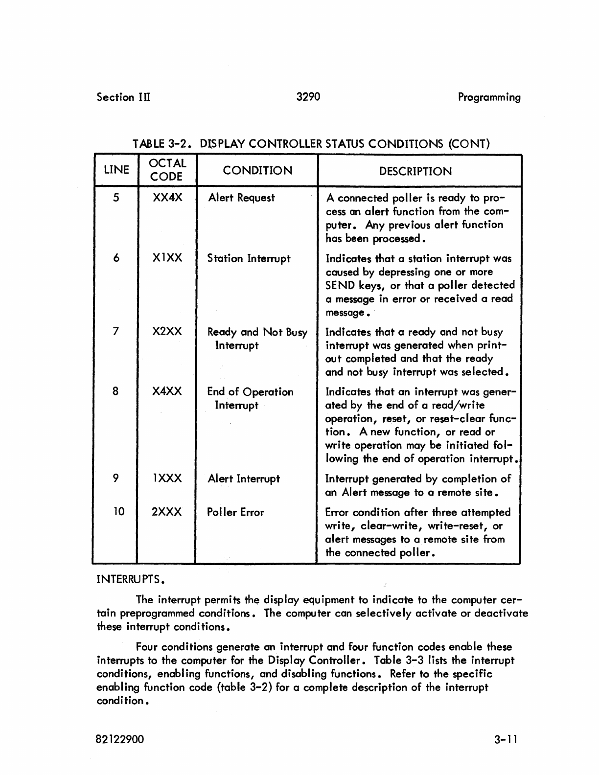
TABLE
3-2.
DISPLAY
CONTROLLER
STATUS
CONDITIONS (CONT)
LINE
OCTAL CONDITION DESCRIPTION
CODE
5
XX4X
AI
ert
Request A connected poller is ready to pro-
cess an
alert
function
from
the com-
puter.
Any previous
alert
function
has been processed.
6
X1XX
Station Interrupt Indicates
that
a station interrupt was
caused by depressing one or
more
SEND keys, or
that
a poller
detected
a message
in
error or received a read
message.
7
X2XX
Ready and
Not
Busy
Indicates
that
a ready and not busy
Interrupt interrupt was generated when
print-
ou
t completed and
that
the ready
and not busy interrupt was
selected.
8
X4XX
End
of
Operation Indicates
that
an interrupt was
gener-
Interrupt
ated
by the end
of
a read/wri te
operation,
reset,
or
reset-clear
func-
tion.
A new function, or read or
write operation
may
be initiated
fol-
lowing the end
of
operation interrupt.
9 1
XXX
AI
ert
In
terrupt Interrupt generated by completion
of
an Alert message to a remote
site.
10
2XXX
Poller Error Error condi tion
after
three attempted
write,
clear-write,
write-reset,
or
alert
messages to a remote site
from
the connected
poller.
I
NTERRU
PTS
•
The
interrupt permits
th~
display equipment to indicate to the computer
cer-
tain preprogrammed conditions. The computer can
selectively
activate
or
deactivate
these interrupt condi tions.
Four conditions generate an interrupt and four function codes
enable
these
interrupts to the computer for the Display Controller. Table
3-3
lists the interrupt
cQnditions, enabling functions, and disabling functions. Refer to the specific
enabling function code (table
3-2)
for a complete description
of
the interrupt
condition.
82122900
3-11
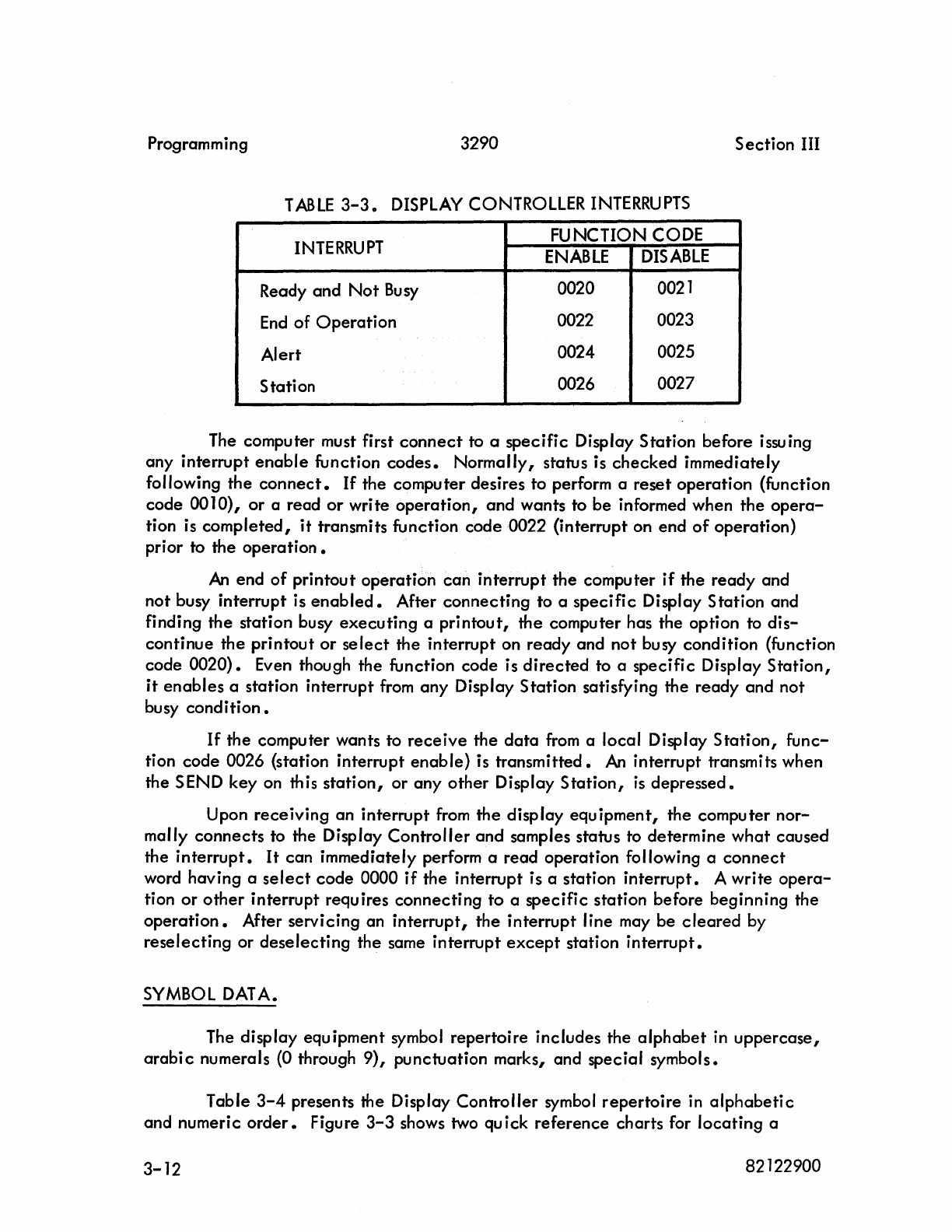
Programming 3290
Section
III
TABLE
3-3.
DISPLAY CONTROLLER
INTERRUPTS
INTERRUPT
FUNCTION CODE
ENABLE
DISABLE
Ready
and
Not
Busy
0020 0021
End
of
Operation
0022 0023
Alert 0024 0025
Station 0026 0027
The computer must first
connect
to a
specific
Display Station before issuing
any interrupt
enable
function
codes.
Normally, status is
checked
immediately
following the
connect.
If
the computer desires to perform a
reset
operation
(function
code
0010),
or
a read
or
write
operation,
and wants to
be
informed when the
opera-
tion is
completed,
it
transmits function code 0022 (interrupt on end
of
operation)
prior to the
operation.
An
end
of
printout operation
can
interrupt the computer
if
the ready and
not busy interrupt is
enabled.
After
connecting
to a
specific
Display Station and
finding the station busy
executing
a
printout,
the computer has the option to
dis-
continue
the
printout
or
select
the interrupt on
ready
and not busy condition (function
code
0020).
Even though the function code is
directed
to a specific Display
Station,
it
enables
a station interrupt
from
any
Display
Station
satisfying the ready and not
busy
condition.
If
the computer wants to
receive
the
data
from
a local Display
Station,
func-
tion
code
0026 {station interrupt enable} is
transmitted.
An
interrupt transmits when
the SEND key on this
station,
or
any
other
Display
Station,
is
depressed.
Upon
receiving
an interrupt
from
the display
equipment,
the computer
nor-
mally
connects
to the Display
Controller
and
samples status to determine
what
caused
the
interrupt.
It
can immediately perform a read operation following a
connect
word having a
select
code
0000
if
the interrupt is a station
interrupt.
A write
opera-
tion
or
other
interrupt requires
connecting
to
a
specific
station before beginning the
operation.
After servicing an
interrupt,
the
interrupt
line may
be
cleared
by
reselecting
or
deselecting
the same interrupt
except
station
interrupt.
SYMBOL DATA.
The display equipment symbol repertoire includes the
alphabet
in
uppercase,
arabic
numerals (0 through 9), punctuation marks, and special symbols.
Table
3-4
presents the Display
Controller
symbol
repertoire
in
alphabetic
and numeric
order.
Figure
3-3
shows two quick
reference
charts for
locating
a
3-12
82122900
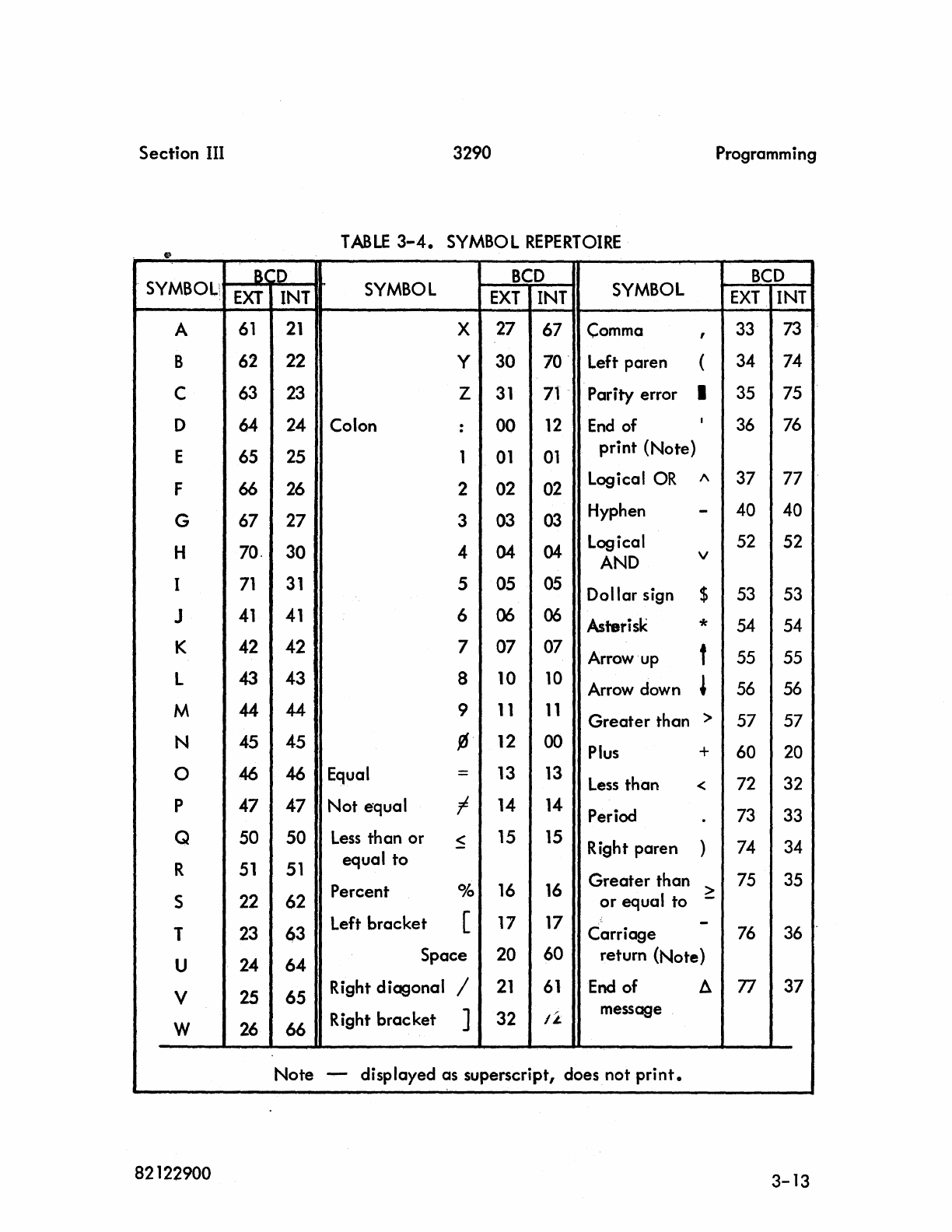
Section III
3290
Programming
TABLE
3-4.
SYMBOL
REPERTOIRE
.
SYMBOL:
BCD
SYMBOL
BCD
SYMBOL
BCD
EXT
INT
EXT
INT
EXT
INT
A
61
21
X
27
67
Comma
,
33
73
B
62
22
Y
30
70· Left paren (
34
74
C
63
23
Z
31
71
Parity error I
35
75
D
64
24
Colon
00
12
End
of I
36
76
:
E
65
25
1
01
01
print (Note)
F 66
26
2
02
02
Logical
OR
1\
37
77
G
67
27
3
03
03
Hyphen -
40 40
H
70.
30
4
04
04-
Logical
52
52
AND
v
I
71
31
5
05
05
Dollar sign $
53
53
J
41
41
6 06
06
Asterisk *
54 54
K
42
42
7
07
07
Arrow
up
f
55
55
L
43
43
8
10
10
Arrow
down
~
56 56
M 44 44 9
11
11
Greater than >
57
57
N
45
45
{6
12
00
Plus
+
60
20
0 46
46
Equal
=
13
13
Less
than <
72
32
P
47
47
Not equal I
14
14
Period
73
33
.
Q
50
50
Less
than or
~
15
15
Right paren )
74
34
R
51 51
equal to
Percent
Ok
16
16
Greater than >
75
35
S
22
62
or
equal to -
Left bracket [ 17
17
-
T
23
63
Carriage
76
36
U
24
64 Space
20
60
return (Note)
V
2S
65
Right diagonal /
21
61
End
of
fl.
77
37
Right brac ket ]
32
I~
message
W
26
66
Note -displayed as superscript, does not
print.
82122900
3-13
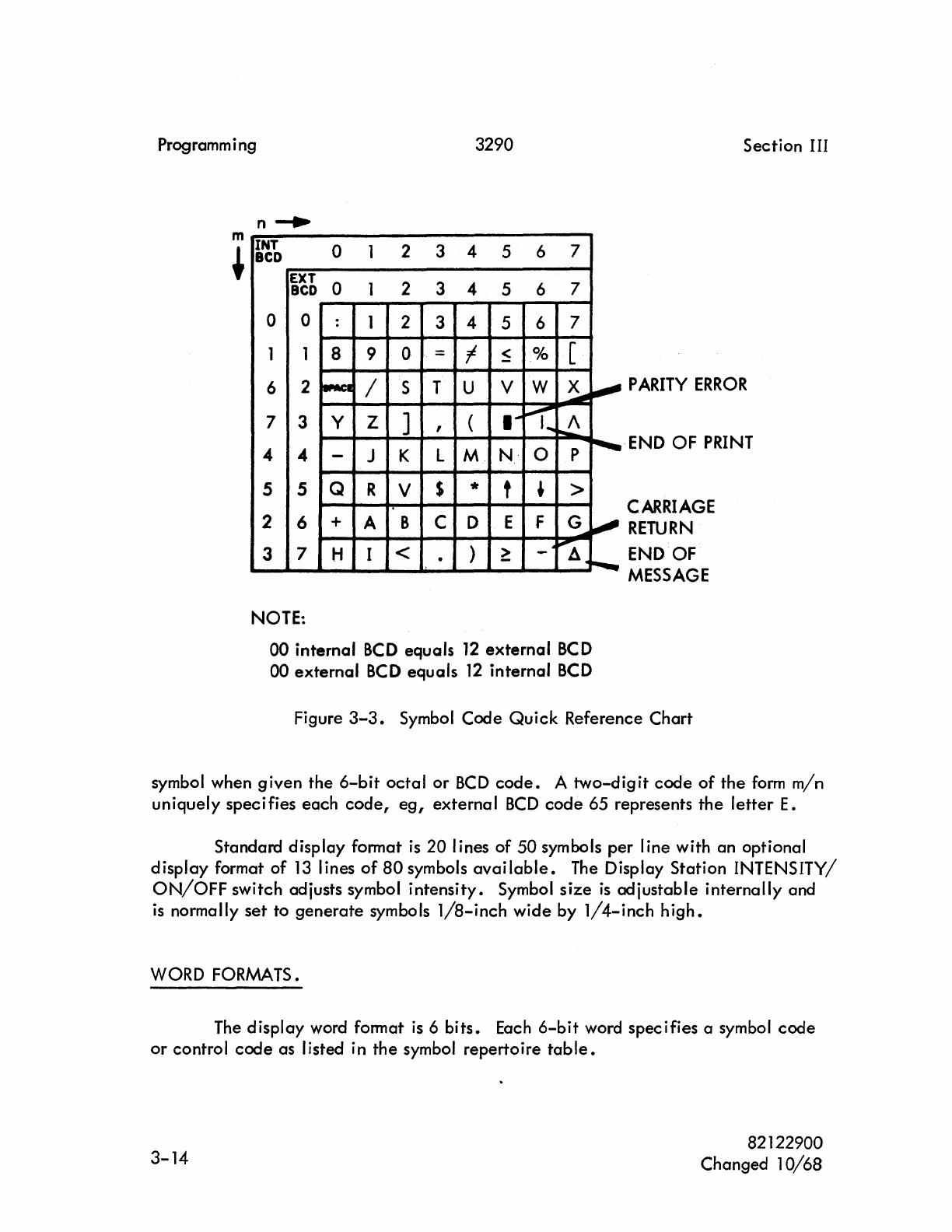
Programm i ng 3290
m
~
n-.
INT
0 1 2 3 4 5 6 7
BCD
EXT
0 1 2 3 4 5 6 7
BCD
0 0 : 1 2 3 4 5 6 7
1 1 8 9 0 = t
~
% [
6 2
~
/ S T U V W
~
~
7 3 Y Z ] , (
....
~
....
~
4 4 -J K L M
N-
O P
r--
5 5 Q R V $ * t , >
2 6 + A B C 0 E F G
~
......
3 7 H I < )
~
~
. - A ......
NOTE:
00
internal
BCD
equals
12
external
BCD
00
external
BCD
equals
12
internal
BCD
Section
III
PARITY
ERROR
-END
OF
PRINT
CARRIAGE
RETURN
END
OF
MESSAGE
Figure
3-3.
Symbol
Code
Quick
Reference
Chart
symbol when
given
the
6-bit
octal
or
BCD
code.
A
two-digit
code
of
the
form
min
uniquely
specifies
each
code,
eg,
external
BCD
code
65 represents
the
letter
E.
Standard
display
format
is
20
lines
of
50
symbols
per
line with an optional
display
format
of
13
lines
of
80
symbols
available.
The Display Station INTENSITY/
ON/OFF
switch adjusts symbol
intensity.
Symbol
size
is
adjustable
internally
and
is
normally
set
to
generate
symbols
1/8-inch
wide
by
1/4-inch
high.
WORD FORMATS.
The
display
word format
is
6
bits.
Each
6-bit
word
specifies
a symbol
code
or
control
code
as listed in
the
symbol
repertoire
table.
3-14
82122900
Changed
10/68
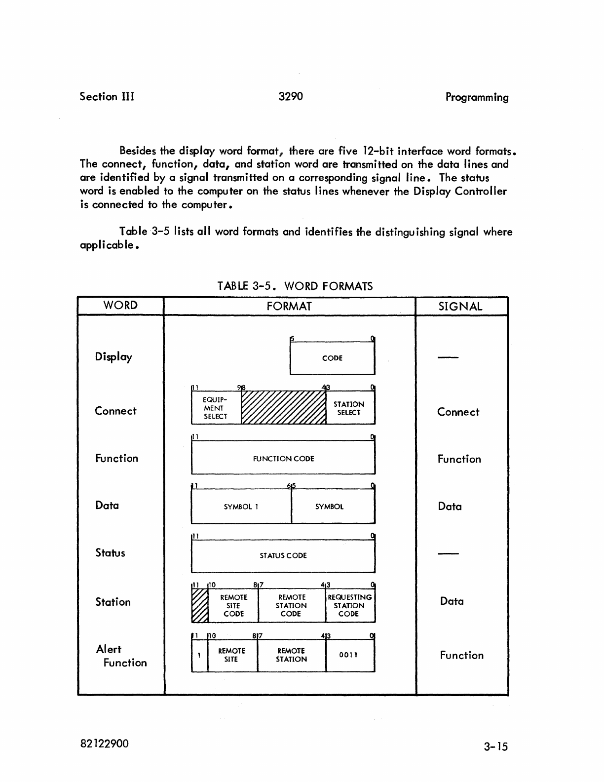
Section III 3290 Programming
Besides the display word format, there are five 12-bit interface word formats.
The
connect,
function,
data,
and station word
are
transmitted on the
data
lines and
are
identified by a signal transmitted on a corresponding signal
line.
The status
word is enabled to the computer on the status lines whenever the Display Controller
is connected to the computer.
Table 3-5 lists all word formats and identifies the distinguishing signal where
applicable.
WORD
Display
Connect
Function
Data
Status
Station
Alert
Function
82122900
1
10
1
REMOTE
SITE
SIGNAL
Connect
Function
Data
Data
87
43
J:l
Function
REMOTE
0011
STATION
3-15
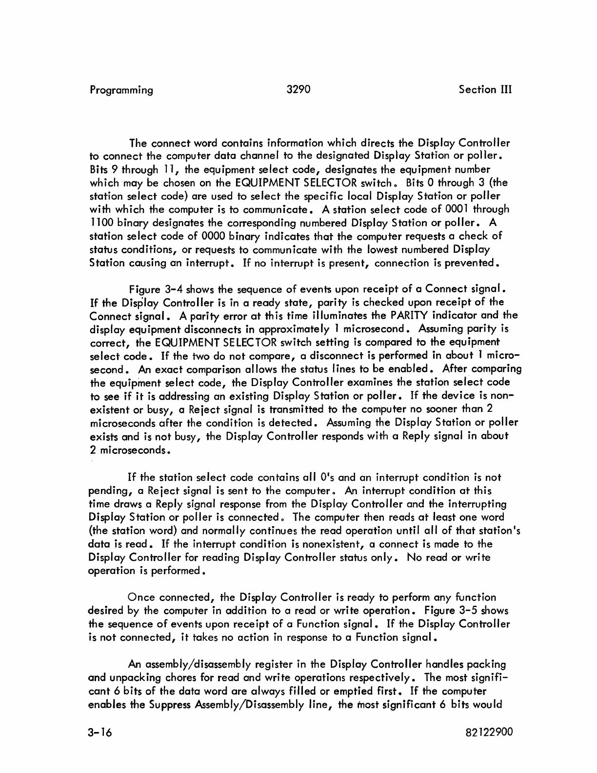
Programming 3290 Section
III
The
connect
word contains information which directs the Display
Controller
to
connect
the computer
data
channer to the designated Display Station or
poller.
Bits 9 through 11, the equipment
select
code,
designates the equipment number
which may be chosen on the EQUIPMENT
SELECTOR
switch
C)
Bits a through 3 (the
station
select
code) are used to
select
the specific local Display Station
or
poller
with which the computer is to
communicate.
A station
select
code
of
0001 through
1100 binary designates the corresponding numbered Display Station or
poller.
A
station
select
code
of
0000 binary
indicates
that
the computer requests a
check
of
status conditions, or requests to commun
icate
with the lowest numbered Display
Station causing an
interrupt.
If
no interrupt is
present,
connection
is
prevented
C)
Figure
3-4
shows the sequence
of
event5 upon
receipt
of
a
Connect
signal.
If
the Display Controller is
in
a ready
state,
parity
is
checked
upon
receipt
of
the
Connect
signal.
A parity error
at
th is time illuminates the
PARITY
indicator
and the
display equipment disconnects in approximately 1 microsecond. Assuming
parity
is
correct,
the EQUIPMENT
SELECTOR
switch setting
is
compared
to
the equipment
select
code.
If the two do
not
compare,
a disconnect is performed in
about
1 micro-
second.
An
exact
comparison allows the status lines to be
enabled.
After comparing
the equipment
select
code,
the Display
Controller
examines the station
select
code
to see
if
it
is addressing an existing Display Station or
poller.
If
the
device
is
non-
existent
or
busy, a Reiect signal is transmitted to the computer no sooner than 2
microseconds
after
the condition
is
detected.
Assuming the Display Station or
poller
exists and is
not
busy, the Display
Controller
responds with a Reply signal in
about
2 microseconds.
If
the station
select
code contains all
O·s
and an interrupt condition
is
not
pending,
a Reiect signal is
sent
to the computer 0
An
interrupt condition
at
this
time draws a Reply signal response
from
the Display Controller and the interrupting
Display
Station
or poller
is
connected
C)
The computer then reads
at
least one word
(the station word) and normally continues the read operation unti
I
all
of
that
station·s
data
is
read.
If
the interrupt condition is nonexistent, a
connect
is made to the
Display
Controller
for reading Display
Controller
status
only.
No read or write
operation is performed.
Once
connected,
the Display Controller is ready to perform any function
desired by the computer in addition to a read or write
operation.
Figure
3-5
shows
the sequence
of
events upon
rece
ipt
of
a Function
signal.
If
the Display
Controller
is
not
connected,
it
takes no
action
in
response to a Function
signal.
An
assembly/disassembly register in the Display Controller handles packing
and
unpacking chores for read and write operations
respectively.
The most signifi-
cant
6 bits
of
the
data
word
are
always filled or emptied
first.
If
the computer
enables
the Suppress Assembly/Disassembly
line,
the most
significant
6 bits would
3-16
82122900
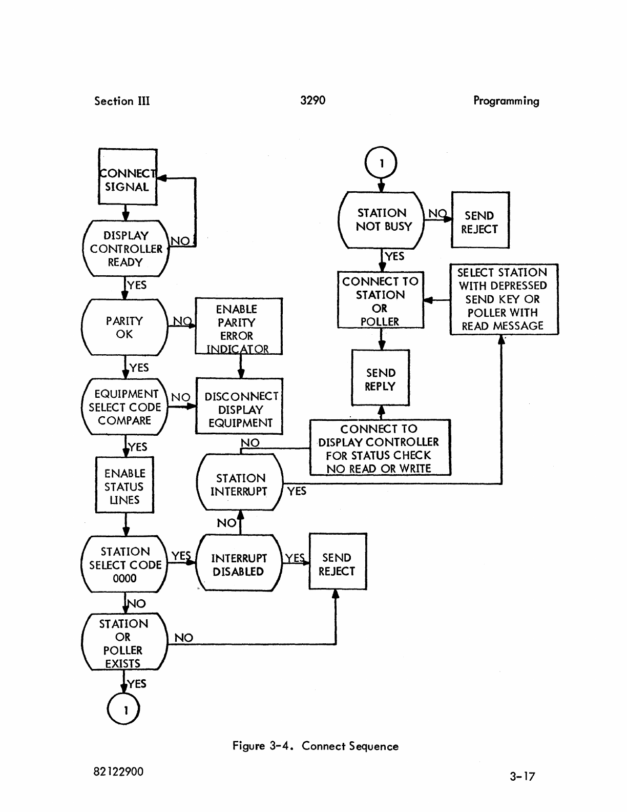
Section III
ONNEC.~
__
SIGNAL
ENABLE
PARITY
ERROR
DISCONNECT
3290
CONNECT
TO
STATION
OR
POllER
SEND
REPLY
~..
DISPLAY
82122900
EQUIPMENT
CONNECT
TO
NO
·DISPLAY
CONTROLLER
~:""-----t
FOR
STATUS
CHECK
INTERRUPT
DISABLED
NO
READ
OR
WRITE
SEND
REJECT
Figure
3-4.
Connect Sequence
Programm i
ng
SEND
REJECT
SELECT
STATION
WITH
DEPRESSED
SEND
KEY
OR
POLlER
WITH
READ
MESSAGE
3-17
Programming
FUNCTION
SIGNAL
RESET
OR
RE
5
ET
-C
LEAR
PERFORM
FUNCTION
SEND
REPLY
SIGNAL
BUSY
3290
PARITY
ERROR
INDICATOR
UGHTS
YES
SEND
PARITY
ERROR
SIGNAL
;YES
SEND
REJECT
SIGNAL
Figure
3-5.
Function
Sequence
3-18
Section
III
82122900
Section
III
3290
Programming
neither be filled or emptied for the duration
of
the
signal.
The least significant
6 bits are unaffected; therefore,
data
transmission takes
place
in the
form
of
one
6-bit
word
at
a
time.
READ;WRITE
OPERATIONS.
Read
or write operations to or
from
a local Display Station may
be
performed
any time
at
the discretion
of
the computer, after checking
status.
The computer-
initiated
action takes priority over the
operator.
If
a read or write operation is
initiated
during a period when an operator is composing a message
from
the keyboard,
the operator1s keyboard is locked
out
and computer operation takes
over.
A read or
write operation to a Display Station performing a printout results in termination of
the printout and the read or write operation is performed
at
the specified Display
Station.
The Display Controller allows the computer to
enable
an interrupt on an end
of
printout
condition.
Following connection to a specific Display Station and
sampling status, print request status (line 3) is enabled
if
the Display Station requests
a print operation or
if
it
is presently performing a
printout.
Not
ready status
indi-
cates
the Display Station is
actually
performing a
printout.
Using function code
0020
octal,
the computer
may
enable
the
select
interrupt on ready and
not
busy
condition.
Upon completing printout, an interrupt is sent to the computer and status line 7
(ready and not busy interrupt) is made
active.
The
0020
function code enables an
interrupt to
generate
when any Display Station completes printout 0
Computer read and write operations do not take priority
in
the
poller.
The
poller scans the remote stations to determine
if
a SEND key
is
depressed.
If
this
condition exists, the selected station transmits a read message to the
poller.
After
storing the message
in
memory, the poller generates a send request and the computer
responds with a read
operation.
In response to the read message, the computer must
send a write message to the selected
poller.
The poller then relays this message to
the remote
station.
The
alert
function turns on the
ALERT
light and audible alarm
at
the remote
station; the SEND key must be depressed to tum them
off.
The subsequent read
message
enables
the computer to perform a write
operation.
Read
operations
may
be
initiated
from
the local or remote Display Stations
by an operator depressing the SEND key or
from
the computer by programmed
instructions (local Display Station
only).
A write operation is
initiated
only
from
the computer. Following is a description
of
read and write operationso
82122900
3-19
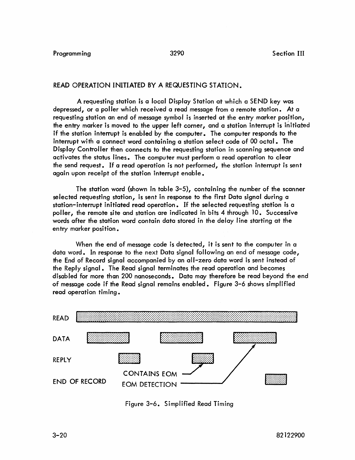
Programm ing
3290
Section
III
READ
OPERATION INITIATED
BY
A REQUESTING STATION.
A requesting station is a local Display Station
at
which a SEND key was
depressed, or a
poller
which
received
a read message
from
a remote
station.
At a
requesting station an end
of
message symbol is inserted
at
the entry marker
position,
I
the
entry
marker is moved to
the
upper
left
corner,
and a station interrupt is in
itiared
if
the
station interrupt is
enabled
by the
computer.
The computer responds
to
the
interrupt with a
connect
word
containing
a station
select
code
of
00
octal.
The
Display
Controller
then
connects
to the requesting station in scanning sequence and
activates
the status
lines.
The computer must perform a read operation to
clear
the send
request.
If
a read
operation
is not performed, the station interrupt is
sent
again
upon
receipt
of
the station interrupt
enable.
The station word (shown in
table
3-5),
containing
the number
of
the
scanner
selected
requesting
station,
is
sent
in response to
the
first Data signal during a
station-interrupt
initiated
read
operation.
If
the
selected
requesting station
is
a
poller,
the remote site and station
are
indicated
in bits 4 through
10.
Successive
words
after
the
station word
contain
data
stored in
the
delay
line starting
at
the
entry
marker
position.
When the end
of
message code is
detected,
it
is
sent
to the computer in a
data
word.
In
response to the
next
Data signal following an end
of
message
code,
the
End
of
Record signal
accompanied
by an
all-zero
data
word is
sent
instead
of
the Reply
signal.
The Read signal terminates the read operation and becomes
disabled for more than
200
nanoseconds. Data may therefore be read beyond the
end
of
message code
if
the Read signal remains
enabled.
Figure
3-6
shows simplified
read
operation
timing.
READ
Itt~~tttttt~~lItt~ttt/rIt{ttIttrIftttrfrrtrmtI~~tIttttItJfItl
DATA
Mttt~~tt~~tttl
ttr~~~~~~~~r~fft~tJ
r{ft~~~~))))~~~~~J
REPLY
[E[J
END OF
RECORD
CONTAINS
EOM
EOM DETECTION
Figure
3-6.
Simplified Read Timing
3-20 82122900
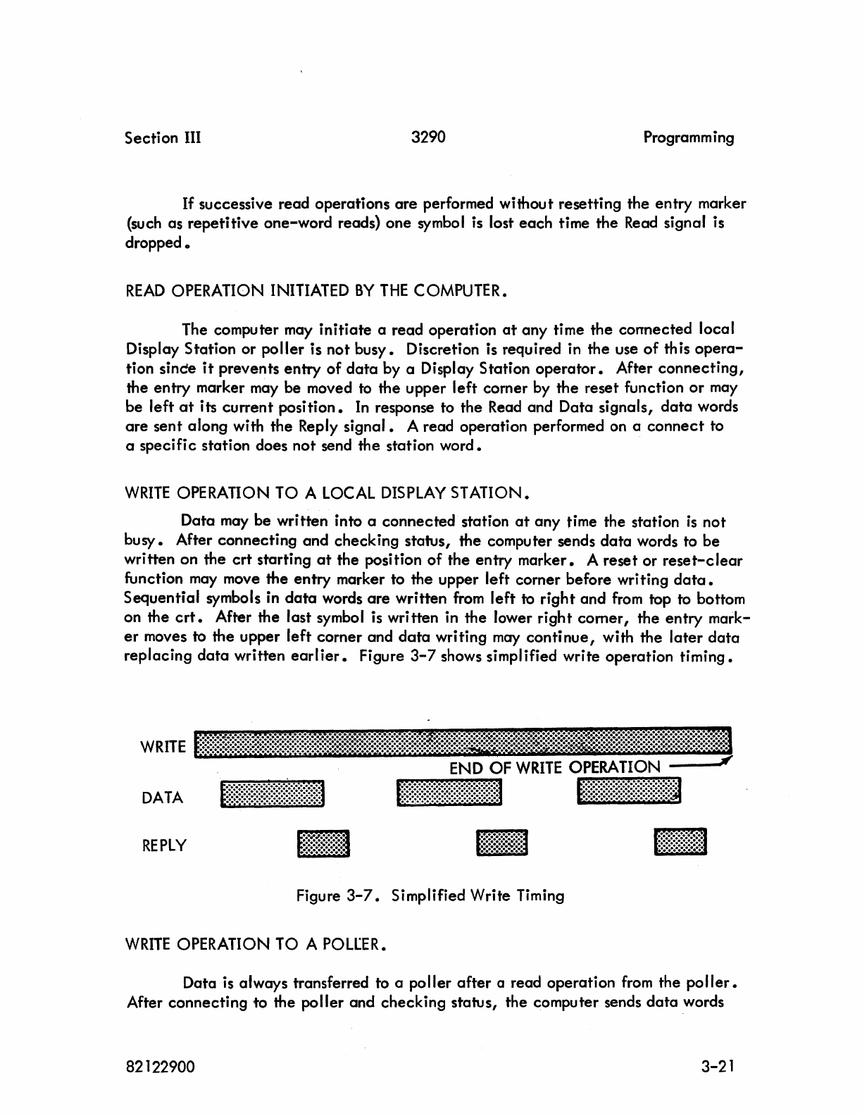
Section III
3290
Programming
If
successive read operations
are
performed without resetting the entry marker
(such as
repetitive
one-word reads) one symbol is lost
each
time the Read signal is
dropped.
READ
OPERATION INITIATED
BY
THE
COMPUTER.
The computer may
initiate
a read operation
at
any time the
connected
local
Display Station or poller is not busy. Discretion is required in the use
of
th
is
opera-
tion since
it
prevents
entry
of
data
by a Display Station
operator.
After
connecting,
the entry marker may be moved to the upper left corner by
the
reset function
or
may
be left
at
its current
position.
In
response to the Read and Data signals,
data
words
are
sent along with
the
Reply
signal.
A read operation performed on a
connect
to
a specific station does
not
send the station word.
WRITE
OPERATION TO A
LOCAL
DISPLAY
STATION.
Data may be written into a connected station
at
any
time the station
is
not
busy. After connecting and checking status, the computer sends
data
words to be
written on the
crt
starting
at
the position
of
the entry marker. A reset or
reset-clear
function
may
move the entry marker to the upper left corner before writing
data.
Sequential symbols in
data
words
are
written
from
left
to
right
and
from
top to bottom
on the
crt.
After the last symbol is wri tten in the lower right
comer,
the
entry
mark-
er
moves to the upper
left
corner and
data
writing
may
continue,
with the
later
data
replacing
data
written
earlier.
Figure
3-7
shows simplified write operation
timing.
DATA
REPLY
l~m~;~~~~~;~;~~;~~;~~;t~~~~~~~~;~~l
1~~~~~~~~~~~~~1
Figure
3-7.
Simplified Write Timing
WRITE
OPERATION TO A
POLL:ER.
Data
is
always transferred to a poller
after
a read operation
from
the
potier.
After connecting
to
the poller and checking status, the computer sends
data
words
82122900
3-21
Programm ing 3290 Section III
to be written into the
poller
memory starting
at
the position
of
the entry marker
..
The
entry
marker
is
always
at
start-of-memory
after
any computer read
operation.
A reset function immediately preceding a write to the
poller
results in a
write-reset
message
from
the
poller
to the remote station; a
reset-clear
function
results in a
clear-write
message.
No
function results
in
write message. Sequential
symbols in
dpta
words
are
written into the
poller
memory. The poller is informed
that
it
is to send the message when the Write signal drops. The
write,
write-reset,
or
clear-write
message is sent to the remote station
wh
ich had iust previously sent
a read message.
PROGRAMMING AIDS.
Following are several points concerning display equipment timing:
(a) The Display
Controller
is busy for 33 microseconds
after
the last Reply
signal is sent
at
the end
of
a write
operation.
(b)
The Display
Controller
is busy from
3.2
microseconds to
20
mi
lIiseconds
after
rece
ipt
of
a reset
function.
(c) If a read or write operation follows a reset function which transmits
an interrupt upon completion, 20-millisecond
delay
(after the end
of
operation interrupt
is
sent) occurs before the first
data
word
is
stored
or read
from
memory.
(d)
One
symbol time
is
16.8
microseconds. Each
data
word contains two
symbols and requires
33.6
microseconds. The
delay-line
memory
cycle
time
is
20 millisecondso During a read or write
operation,
successive
data
words must follow within 33 06 microseconds (time required to read
or write two symbols)
or
a 20-millisecond
delay
occurs between bytes
due to
delay
line
latency
characteristics.
PROGRAMMING RESTRICTIONS.
(a)
It
is necessary to read
at
least two
12-bit
words to
clear
the send ff
when a
connect
is issued
after
an
interrupt.
(b)
There should not be any unsolicited read or write operations (poller
only) •
(c) Sending an end
of
print message to a Display Station
initiates
operation
of
its associated Printer Station{s}.
3-22
82122900
Section
III
3290
Programm ing
POlLER TRANSLATION.
The
poller
converts
all
codes
and
signals to a format which is
compatible
with
Data
Set
operation.
Signals
transmitted
between
the
poller
and
the
Data
Set
meet
or
exceed
the
minimum
of
EIA Standard RS-232. A
negative
voltage
of
greater
than
-6
volts
represents a logical 1; a positive
voltage
greater
than
+6
volts
repre-
sents a logical
O.
Half duplex"
2-
or
4-wire
operati_on, DATA-PHONE
Data
Set
201 A
or
201 B
service
is
required.
Private communications
lines
are
necessary
and no provision is made for
automatic
ringing
or
answering.
A
single-phase,
12o-volt,
60-Hz,
three-wire
outlet
from
the
Display
Con-
troller
is supplied for the
Data
Set,
so
the
same ground bus is used for
both.
This
measure is necessary
to
prevent
impulse noise
potentials
which might otherwise
develop
and
cause
data
errors.
The
poller
sends
and
receives
data
in
an
8-bit
code
which is transmitted
serially
over
Send
Data
and
Receive
Data
lines.
These bits
are
synchronized with
the
Serial
Clock
Receive
and
Serial
Clock
Transmit
signals.
Data
Set
201 A
oper-
ates
at
2000
baud,
Data
Set
201B
at
2400
baud.
INTERFACE
SIGNALS 0
Figure
3-8
shows
interface
signals
between
the
Data
Set
and
the
poller.
The
arrows
indicate
signal
origin.
Following paragraphs provide
an
elaboration
on
the
signals shown in figure
3-8.
Send
Data.
The Send
Data
signal
originates
in
the
poller
and
contains serial
dato.
Posi-
tive
polarity
represents a
logical
0 and
negative
polarity
represents a
logical
1.
Data
bits
are
provided to the
Data
Set
at
the
time
of
positive transition
of
the
Serial
C lock Transmit
signal.
Request to
Send.
The
poller
makes
the
Request to Send signal positive when a transmit
operation
is
desired.
Placing
a
negative
potential
on
the
line returns
the
Data
Set
to a
receive
condition.
82122900
3-23
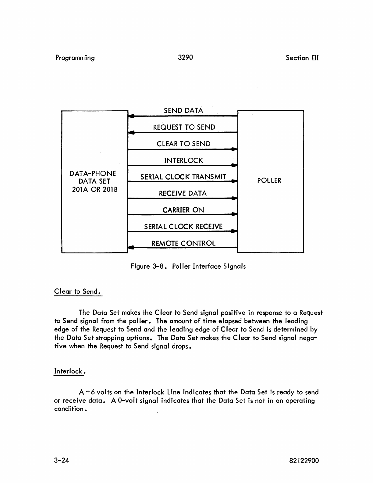
Programming 3290 Section III
SEND
DATA
-
-
REQUEST
TO
SEND
-
-
CLEAR
TO
SEND
-
-
INTERLOCK
--
-
DATA-PHONE
SERIAL
CLOCK
TRANSMIT
_
DATA
SET
-POllER
201A
OR
201
B
RECEIVE
DATA
--
-
CARRIER
ON -
-
SERIAL
CLOCK
RECEIVE
--
-
-
REMOTE
CONTROL
-
Figure
3-8.
Poller Interface Signals
Clear
to
Send.
The Data Set makes the
Clear
to Send signal positive
in
response to a Request
to Send signal
from
the
poller.
The amount
of
time elapsed between the leading
edge
of
the Request to Send and the leading
edge
of
C
lear
to Send is determined
by
the Data
Set
strapping
options.
The Data
Set
makes the C
lear
to Send signal
nega-
tive when the Request to Send signal drops 0
Interlock 0
A + 6 volts on the Interlock Line indicates
that
the Data
Set
is
ready to send
or
receive
datao A O-volt signal indicates
that
the Data
Set
is not
in
an operating
condition 0
3-24
82122900
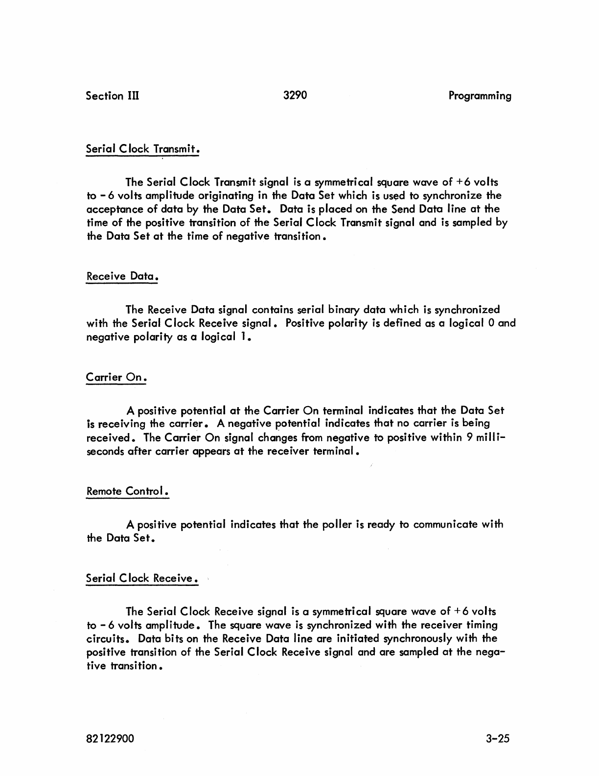
Section III
3290
Programm i
ng
Serial Clock Transmit.
The Serial Clock Transmit signal
is
a symmetrical square wave
of
+6
volts
to - 6 volts amplitude originating in the Data
Set
which is
us~d
to synchronize the
acceptance
of
data
by the Data
Set.
Data is placed on the Send Data line
at
the
time
of
the positive transition
of
the Serial Clock Transmit signal and is sampled by
the Data
Set
at
the time
of
negative transition.
Rece i ve
Data.
The Receive Data signal contains serial binary
data
which is synchronized
with the Serial C lock Receive signal 0 Positive polarity
is
defined as a logical 0 and
negative polarity as a logical
1.
Carrier
On.
A positive potential
at
the Carrier
On
terminal indicates
that
the Data
Set
is receiving the
carrier.
A negative potential indicates
that
no carrier is being
received.
The
Carrie"r
On
signal
cha~ges
from
negative to positive within 9 milli-
seconds
after
carrier appears
at
the
receiver
terminal.
Remote
Control.
A positive potential indicates
that
the poller is ready to communicate with
the Data
Set.
Serial C lock Receive.
The Serial C lock Receive signal is a symmetri cal square wave
of
+ 6 volts
to - 6 volts amplitude. The square wave
is
synchronized with the receiver timing
circuits.
Data bits on the Receive Data line are initiated synchronously with the
positive transition of the Serial Clock Receive signal and are sampled
at
the
nega-
tive transition.
82122900
3-25
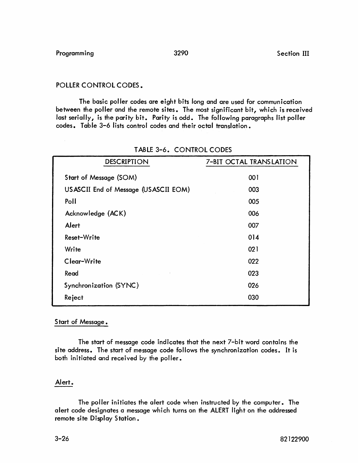
Programming
3290
Section
III
pallER
CONTROL
CODES.
The basic
poller
codes
are
eight
bits long and
are
used for commun
ication
between the
poller
and the remote
sites.
The most
significant
bit,
which is
received
last
serially,
is the
parity
bit.
Parity is
odd.
The following paragraphs list
poller
codes.
Table
3-6
lists control codes and
their
octal
translation.
TABLE
3-6.
CONTROL CODES
DESCRIPTION
Start
of
Message
(SaM)
USASCII
End
of
Message (USASCII EOM)
Poll
Acknowledge
(AC
K)
Alert
Reset-Write
Write
Clear-Write
Read
Synchron
ization
(SYNC)
Reiect
S
tart
of
Message.
7-81T OCTAL
TRANS
lATION
001
003
005
006
007
014
021
022
023
026
030
The
start
of
message
code
indicates
that
the
next
7-bit
word contains the
site
address.
The
start
of
message
code
follows the synchronization
codes.
It
is
both
initiated
and
received
by the
poller.
Alert.
The
poller
initiates
the
alert
code when instructed by the
computer.
The
alert
code
designates a message which turns on the
ALERT
light on the addressed
remote site Display Station 0
3-26 82122900
Section III 3290 Programming
USASCII
End
of
Message.
The USASCII end
of
message
code
indicates
that
the previous word was the
last word
of
data.
The word following the USASCII end
of
message code
is
the
message parity
word.
This code is both
initiated
and
received
by the
poller.
Message
Parity.
Message parity is
applicable
from
the
start
of
message through the USASCII
end
of
message
code,
and excludes all sync
codes.
The message parity code is oddo
The parity
bit
is
excluded.
Poll.
The
poller
initiates
the poll code which designates the poll message. The
poll message instructs the remote site to respond with a read message if a SEND key
has been depressed or a read request
active
is
set
or a
reiect
message
if
the above
two conditions do not
exist.
Acknowledge.
The acknowledge code
originates
at
a remote site and designates a message
which acknowledges
receipt
of'a
write,
reset-write,
clear-write,
or
alert
message
wi
th
no
errors.
Reset-Write.
The
poller
transmits the
reset-write
code when instructed by the computer 0
The code designates a message which instructs the addressed display equipment to
write
data
starting
at
the upper
left
corner.
The
reset-write
code
is
followed by
12
sync codes to allow time for the
entry
marker to
reset.
Write 0
The
poller
initiates
the write code when instructed
by
a computer message.
The message contains
data
to be written on the remote
crt
starting
at
the
current
entry marker
position.
82122900
3-27
Programming 3290 Section III
Clear-Write.
The poller in
itiates
the
clear-write
code when instructed by the compu
ter.
This
code
designates a message which instructs the addressed Display Station to
clear
data
from
the
crt
and write the contained
data
starting
at
the upper
left
corner.
The
poller
transmits
12
sync codes following the
clear-write
code
to
allow
time for
the entry marker to
reset.
Read.
The read code originates
at
a remote site and designates a message containing
data
on the Display Station
crt
wh
ich
is
to be sent to the compu
ter
It
Synchronization.
The
poller
receives
and transmits the sync
code.
Four sync codes are trans-
mitted
at
the beginning
of
each
message to assure
receiver
synchronization.
These
codes
are
not
considered for purposes
of
message parity 0
Sync codes also
act
as synchronization idles when
contained
with
in
the mes-
sage structure {reset-write and
clear-write}
0
Reject.
The
reject
code originates
at
a remote
site.
This code designates a message
which informs the poller
that
a SEND key was not depressed, a read request
active
was
not
set
before
receipt
of
the poll message,
or
because
of
a busy
condition,
a
write,
reset-write
or
clear-write
was
rejected.
SYMBOL
SUBSET.
The symbol subset codes (codes with
bit
5 or 6 a logical 1, but
not
both) are
stored
in
the
delay-line
memory and specify
data
presented or
are
displayed on the
crt
of
a Display Station
at
a remote
site.
These codes are the
data
sent in
read,
write,
reset-write,
and
clear-write
messageso
3-28
82122900
Section
III 3290 Programm ing
An
escape
code (76) followed by
any
code
other
than
carriage
return,
E 1,
E2, or
E3
codes will be
converted
to a
space
code (20
external
BCD
or
60
internal
BCD). Refer to
tables
3-7
and
3-8.
TABLE
3-7.
SYMBOL
SUBSET
CONVERSION
TO
COMPUTER
INTERNAL
EXTERNAL
ESCAPE
CODE
RECEIVED
CODE CODE
36 76 76
01
(CR)
37
77 76
02 (E1)
76 36 76 40 (E2)
75 35 76
41
(E3)
TABLE
3-8.
SYMBOL
SUBSET
CONVERSION FROM COMPUTER
INTERNAL
EXTERNAL
ESCAPE
CODE SENT
BCD BCD
36
76
76
01
(CR)
37
77 76
02 (E1)
76 36 76 40 (E2)
75 35
76
41
(E3)
Station
Address.
The station address code designates
the
remote site Display
Station
to which
a
poller
is communicating 0 The station address in a read message is
retained
by the
poller
and
sent
to the
computer.
The
next
write,
reset-write,
or
clear-write
mes-
sage
from
the computer to
the
poller
is
automatically
sent to the Display Station
from
which the read message was
received.
Site
Address.
The
site
address
code
designates the remote site to which a message
is
addressed or
from
which a message
is
received.
The remote sites polled
are
desig-
nated
by site address switches on the Display
Controller
auxiliary
maintenance
panels.
Polling takes
place
in numerical order 0
82122900
3-29
Programming 3290
Section
III
MESSAGE FORMAT.
Messages received and
sent
by the
poller
consist
of
several
codes.
The
general
message format
is
shown in figure
3-9.
All messag'es transmitted
are
pre-
ceded
by four sync codes to assure synchronization recovery on the receiving
end.
The start
of
message
code
designates
that
the next
code
is
the
first word
of
the
mes-
sage.
The
site
address and
station
address follow in
that
order.
The control
code
defines the command or
data
which follows. Data
to
or
from
a remote Display
Sta-
tion may consist
of
1 to 1040 words. The USASCII end
of
message
code
designates
that
the
previous word was
the
last word
of
the
message. The message parity
code
follows
the
end
of
message
code.
Message
parity
is
applicable
from
the
start
of
message through
the
end
of
message
code
inclusive and excludes
all
sync
codes.
Specific
messages sent and
received
are
listed in tables
3-9
and
3-10.
IGNORE
FOR
PURPOSES
OF
MESSAGE
PARllY
T
<tC
..
>
SYNC
SYNC
SYNC
SYNC
SQ\A
SITE
ADDRESS
STATI~
ADDRESS
CONTROL
CODE
} DATA
(NOTE)
,l
USACII
END
a=
IVESSAGE
caE
-
V<
YtORD
PARITY
MESSAGE
~RITY
.CODE
Synchronization.
NOTE:
1-1000
WORDS
(50X
20)
DISPLAY FORMAT).
1-1040
WORDS
(SOX
13)
DISPLAY FORMAT).
Figure
3-9.
General
Message Format
After
the
Data Set turns on
the
Carrier
On
signal,
data
input
from
the
Data
Set
is
fed into a buffer
register.
After
each
data
bit
is
received,
the
contents
of
the
buffer register
is
examined to determine if
the
code
is
a sync
code.
When two
3-30
82122900
Changed
10/68
Section
III
3290
TABLE
3-9.
MESSAGES
SENT
BY
THE
PO
LLER
MESSAGE
Alert
Poll
Write
CODE
SYNC
I 4 Total
SYNC
START
OF
MESSAGE
SITE
ADDRESS
STATION
ADDRESS
ALERT
USASCII
END
OF
MESSAGE
MESSAGE
PARITY
SYNC
t 4 Total
SYNC
START
OF
MESSAGE
SITE
ADD
RESS
STATION
ADDRESS
POLL
USASCII
END
OF
MESSAGE
MESSAGE
PARITY
SYNC
t 4 Total
SYNC
START
OF
MESSAGE
SITE
ADDRESS
STATION
ADDRESS
WRITE
Programmi
ng
l 1 to 1 000 *
words
of
data
Clear-Write
USASCII
END
OF
MESSAGE
MESSAGE
PARITY
SYNC
t 4 Total
SYNC
START
OF
MESSAGE
SITE
ADDRESS
STATION
ADDRESS
*
1040
words
if 80
by
13
display format
82122900
Changed 10/68 3-31
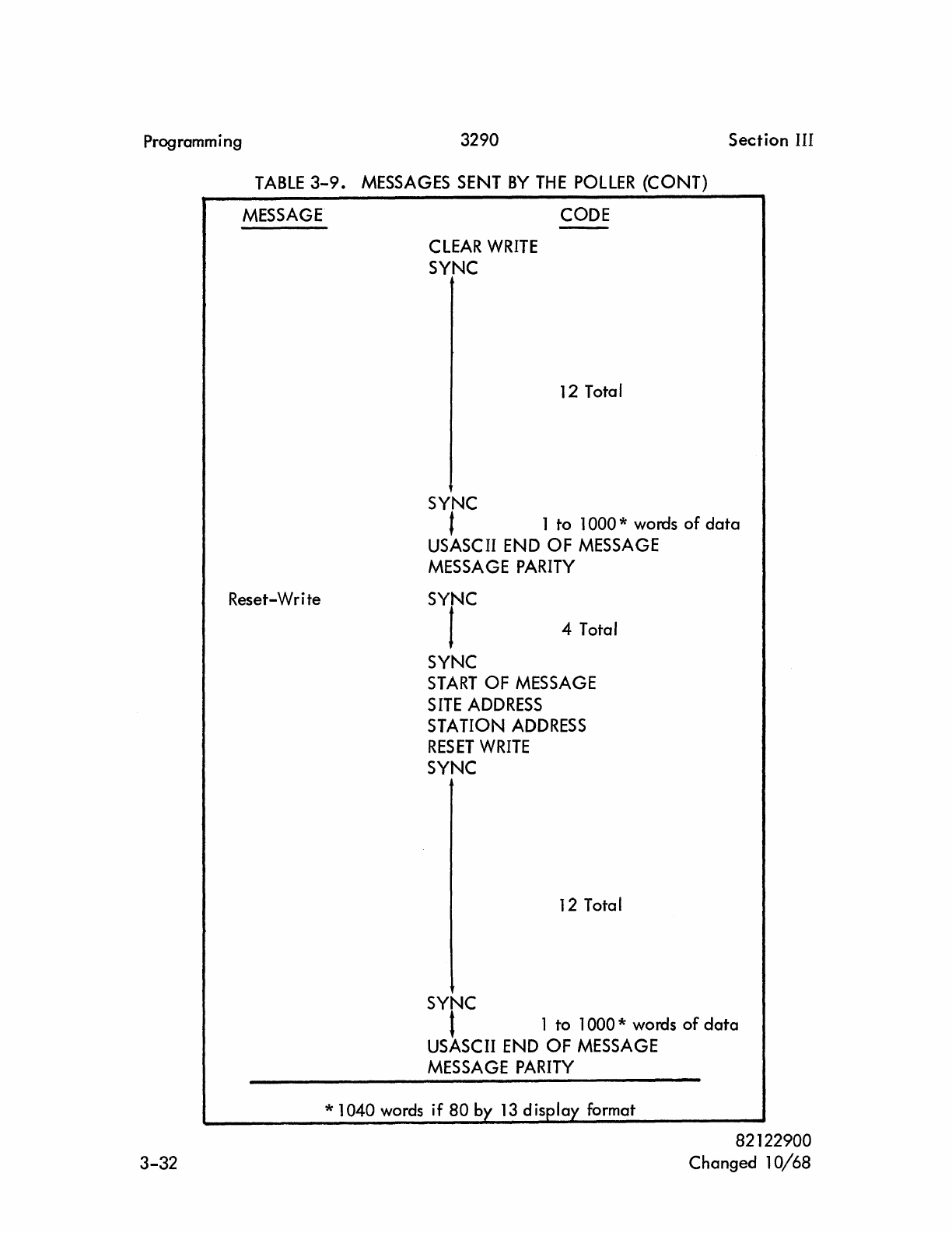
Programming 3290
Section
III
TABLE
3-9.
MESSAGES
SENT
BY
THE
POllER (CONT)
MESSAGE
Reset-Write
3-32
CLEAR
WRITE
SYNC
SYNC
CODE
12 Total
t 1 to 1 000 * words
of
data
USASCII
END
OF
MESSAGE
MESSAGE
PARITY
SYNC
1 4 Total
SYNC
START
OF
MESSAGE
SITE
ADDRESS
STATION
ADDRESS
RESET
WRITE
SYNC
12 Total
SYNC
t 1 to 1000 * words
of
data
USASCII
END
OF
MESSAGE
MESSAGE
PARITY
82122900
Changed
10/68
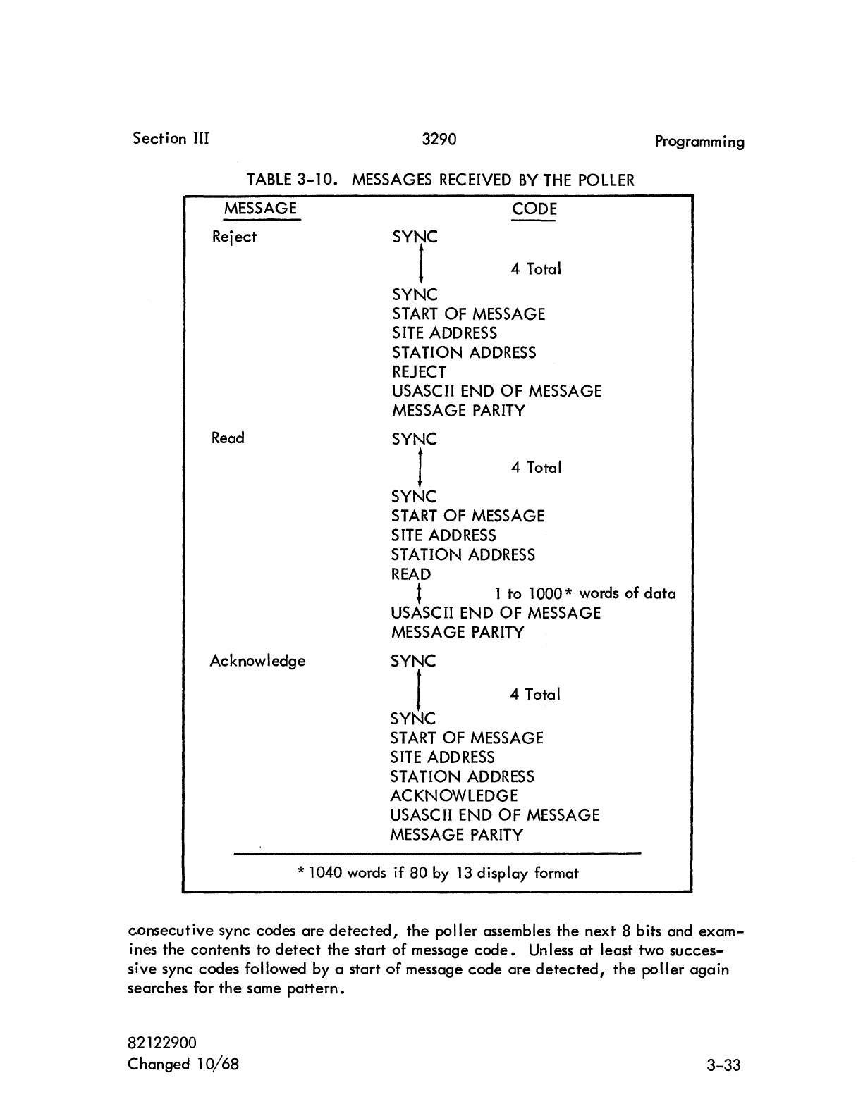
Section III 3290
TABLE
3-10.
MESSAGES
REC
EIVED
BY
THE
POLLER
MESSAGE
CODE
Reject
Read
SYNC
t 4 Total
SYNC
START
OF
MESSAGE
SITE
ADDRESS
STATION
ADDRESS
REJECT
USASCII
END
OF
MESSAGE
MESSAGE
PARITY
SYNC
I 4 Total
SYNC
START
OF
MESSAGE
SITE
ADDRESS
STATION
ADDRESS
READ
Programming
t 1
to
1 000 * words
of
data
Acknowledge
USASCII
END
OF
MESSAGE
MESSAGE
PARITY
SYNC
1 4 Total
SYNC
START
OF
MESSAGE
SITE
ADDRESS
STATION
ADDRESS
ACKNOWLEDGE
USASCII
END
OF
MESSAGE
MESSAGE
PARITY
* 1040 words if
80
by
13
display format
consecutive
sync codes
are
detected,
the
poller assembles the
next
8 bits and
exam-
ines the contents to
detect
the
start of message
code.
Unless
at
least two
succes-
sive
sync codes followed by a start
of
message
code
are
detected,
the
poller
again
searches for
the
same
pattern.
82122900
Changed 1
0/68
3-33
Programm i ng
3290
Section
III
AI
ert
Message.
The computer
cannot
directly
send a
write,
reset-write,
or
clear-write
mes-
sage to be written on a remote Display
Station.
It
can
indicate
to a remote display
equipment
that
the
computer has a message to be written by
initiating
an
alert
mes-
sage 0 The
alert
message is
initiated
by the computer as
an
alert
function to the
poller.
At the time the
poller
would normally poll a
site,
it
determines if an
alert
function was
rece
ived for
that
site.
The
poller
then sends an
alert
message instead
of
a pol'! message. The remote Display
Station,
upon
receipt
of
an
alert
message,
lights the
ALERT
indicator
and responds with an acknowledge message.
Operator
action
(depress
SE
NO key)
is
necessary before a wri te message can be sent 0
Polling 0
The following description
of
the
poller
operation assumes
that
no error occurred
while being transmitted
over
the
DATA-PHONE and
that
the remote site is operating
properly.
The
poller
is normally in a poll status during
wh
ich time
it
sends periodic and
sequential poll messages to the
sites.
If
a SEND key is depressed
at
a
site,
the
remote display equipment responds with a
read
message.
If
a SEND key
is
not
depressed, the remote display
equipment
responds with a
reject
message.
If
a read
message is
received,
it
is transferred to the computer as a message
from
a local
station would be
transferred.
The
poller
responds with a
reset-write,
write,
or
clear-write
message addressed to the Display Station
at
which the SEND key was
depressed.
The
poller
sends the message to
the
remote Display
Station.
The remote
display equipment responds to the
reset-write,
write,
or
clear-write
message with an
acknowledge
message which completes the communication 0
Reject
Message.
The
reject
message is a reply
from
a remote site to a poll message indicating
that
a SEND key was not
depressed.
The
reiect
message also
is
used to inform the
poller
that
the previous
write,
clear-write,
reset-write
or
alert
function was
not
performed. The
poller
interprets this as an
error.
3-34
82122900
Section
III
3290
Programm i ng
Read
Message.
The read message is a reply
from
a remote site to a poll message
indicating
a SEND key was
depressed.
The
data,
read from the
crt,
begins
at
the
upper
left
corner and terminates with
the
data
subset
end
of
message
code
0 The read message
enables
send request status
and
the station
interrupt.
The computer then reads
the
site
address and station address in the station
word.
After
reading
the station word,
the computer may
continue
to read the rest
of
the
data
in
the
message
or
may send
a
write
message
immediately.
The computer reading a
data
word
clears
the send
request.
Write
Message.
The write message contains
data
from
the
computer to be written on the
crt
of
a remote Display
Station,
starting
at
the present
or
reset
entry
marker
position.
A
write,
reset-write,
or
clear-write
message is always
sent
in reply to a read message
(with
correct
parity)
from
a remote
site.
After
receiving
a write message with
correct
channel
parity
from
the computer, the
poller
switches to transmit
and
trans-
fers the
data
to a remote
si
te
•
Acknowledge
Message.
If
the message is an
acknowledge
in response to an
alert
message,
alert
request and poll interrupt status
are
set.
The computer, upon reading status, is
informed
that
the
alert
message was
received
by the remote Display
Station.
An
acknowledge response to a
write,
reset-write,
or
clear-write
message turns the
site
indicator
off
and the poll ing resumes 0
ERROR
PROCESSING.
Errors may arise between the sending
of
a message to a remote site and
receiv-
ing a message
from
a remote site 0 The
poller
recognizes these errors:
(a)
lack
of
response before time
out
0
(b) Parity error in a
received
message 0
(c)
An
unexpected
response such as a read message in response to a write
message.
82122900
3-35
Programming 3290 Section III
Anyone
of
the error conditions causes the message to be retransmitted. The
message is transmitted up to three times
in
attempting to
get
an
error-free
response 0
If,
after
three transmissions, an
error-free
response
cannot
be
obtained,
the
poller
ceases trying to communicate with
that
remote
site.
If
three attempts to successfully communicate an
alert
message to a remote
display equipment
fail,
the Interrupt signal
is
enabled
and the
poller
resumes
poll
ing.
When the computer se lects the
poller,
poll interrupt,
poller
error,
and
alert
request status are
indicated.
Three unsuccessful attempts to communicate a
write,
write-reset,
or
clear-
write message to a remote site results in an Interrupt
signal.
Selection
of
the
poller
indicates
poller
error, station interrupt, and send request
status.
The computer must
then read the station
word.
The computer may reread the station word,
if
it
con-
tained a parity
error,
by reconnecting to station
o.
In
order to
clear
the status bits
and resume
polling,
it
is necessary
that
the computer send a release function 0
If
a poll message
cannot
be successfully communicated in three attempts,
the Interrupt signal is,
again,
enabled.
When the
poller
is
connected,
it
indicates
send request, poll
failure,
and station interrupt
status.
The computer then reads
the station
word.
POllER
SYMBOL
REPERTOIRE.
The
poller
communicates with a
7-bit
code plus
parity.
The
least
significant
bit
(bit 0)
is
received first, and
bit
7
is
parity 0
Codes
with bit 6 or
bit
5 (but
not
both) a logical 1 are stored in the
delay-
line memory associated with the
connected
poller
0 These codes
are
the
data
sent
in
read,
write,
reset-write,
and
clear-write
communications with the remote sites 0
Remain ing codes specify various functions, site address, and station address. Fig-
ure
3-10
lists symbol and function codes according to their binary
translation.
3-36 82122900
Section
III 3290
NOTE
1
DATA
SUBSET
--------
---------------
--
.""
b6 0 0 0 0 1 1
f'....
'"
~
bS 0 0 1 1 0 0
........
b3 b2 b1
~
0 1 0 1 0 1
0 0 0 0 -MINUS
r---
+ :
BLANK
(El)
COLON
J I
0 0 0 1
Sa.!
WRITE
-A
r---
I
(E3)
(CRI
CLEAR- 2
0 0 1 0
WRITE
K a
r---
S
(EI)
U5
0 0 1 1 ASCII
REAO
L C 3 T
ECN
0 1 0 0 M D " U
0 1 0 1 POLL N E 5 V
0 1 1 0
ACK
SYNC
0 F 6 W
0 1 1 1
ALERT
P G 7 X
1 0 0 0 REJECT Q H 8 y
1 0 0 1 R I 9 Z
1 0 J 0 V <
~
]
1 0 1 1 S = ,
PERIOD
COM'I.IA
1 1 0 0 * ) f {
1 1 0 1 t
~
~
1 1 1 0 ,
ESCAPE
%
1 1 1 1 > [ "
NOTES:
1.
Set aside for
USASCII
control codes.
2.
The
lower portion
of
the four two-symbol
data
subset blocks
are
the
interpretation
of
the codes when they immediately follow on
escape
code.
Programm ing
1 1
1 1
0 1
STATICIoI
ADDRESS
0
ON
POLL
.
1 1
:--
.
2 2
I--
VI
3 3
VI
w
~
1--
0
0
4:
4 " w
I:::;
1---1.1'1
5 5
VI
6
VI
6
w
0<:
0
r--
0
4:
7 Z 7
0
Ir
i=
4:
I-
8
VI
9
10
11
12
•
Figure
3-10.
Symbol and Function
Codes,
Binary Translation
82122900
3-37
3290
TABLE
lA-l.
POWERS.
OF
2
2n n 2-n
1 0 1.0
2 1 0.5
4 2 0.25
8 3 0.125
16 4 0.062 5
32 5 0.031 25
64
6 0.015 625
128 7 0.007
812
5
256
8 0.003
906
25
512 9 0.001 953 125
1
024
10 0.000
976
562 5
2
048
11
0.000
488
281 25
4 096 12 0.000
244
140 625
8 192 13 0.000 122
070
312 5
16
384
14 0.000 061
035
156 25
32 768 15 0.000
030
517 578 125
65 536 16 0.000
015
258
789
062
5
131
072 17 0.000 007 629
394
531
25
262 144 18 0.000
003
814
697
265
625
524 288 19 0.000 001 907
348
632 812 5
1 048 576
20
0.000
000
953
674
316
406
25
2 097 152
21
0.000
000
476
837 158 203 125
4 194
304
22 0.000
000
238
418
579
101
562 5
8 388 608 23 0.000
000
119 209 289 550 781 25
16 777 216
24
0.000
000
059 604
644
775
390
625
33 554 432 25 0.000
000
029 802 322 387 695
312
5
67 108
864
26 0.000
000
014
901
161
193 847 656 25
134
217 728 27 0.000
000
007
450
580
596 923
828
125
268
435 456
28
0.000
000
003
725
290
298 461
914
062
5
536
870
912 29 0.000
000
001 862 645 149
230
957 031 25
1
073
741
824
30
0.000
000 000
931
322
574 615
478
515 625
2 147 483 648
31
0.000
000
000
465
661 287 307 739 257 812 5
4
294
967 296 32 0.000
000
000
232
830
643 653 869 628 906 25
8 589
934
592 33 0.000
000
000
116
415
321
826
934
814
453 125
17
179 869 184
34
0.000
000
000
058 207
e60
913 467 407 226 562 5
34
359
738 368 35 0.000
000
000
029 103
830
456 733 703 613 281 25
68 719
476
736
36
0.000
000
000 014
551
915 228
366
861 808
840
625
137
438
963 472 37 0.000
000
000
007
275
957
614
183
425
903
320
312
6
274
877 906
944
38 0.000
000
000
003 637 978 807 091 712 961
860
166
25
649 756 813
888
39 0.000
000
000
001
818
989
403
546
856
475
830
078
125
82122900
lA-l
3290
TABLE
lA-2.
OCTAL-DECIMAL CONVERSION
TABLE
(SHEET
1 OF 4)
0 1 2 3 4 5 6 7 0 1 2 3 4 5 6 7
0000 0000
0001
0002
0003
0004
0005
0006
0007
0400 0256
0257
0258
0259
0260
0261
0262
0263
0000 0000
0010
0008
0009
0010
0011
0012 0013
0014
0015 0410
0264
0265
0266
0267
0266
0269
0270
0271
to to
0020
0016 0017
0018
0019
0020
0021
0022 0023
0030
0024 0025
0026 0027
0028 0029 0030
0031
0040
0032
0033
0034
0035 0036
0037
0038
0039
0420 0272
0273
0274
0275 0276
0277
0278
0279
0430 0280
0281
0282 0283
0284
0285 0286
0287
0440
0288
0289
0290
0291
0292 0293
0294 0295
0777
0511
(Octal)
(Decimal)
0050 0040
0041
0042
0043
0044
0045
0046
0047
0450 0296
0297
0298 0299 0300
0301
0302 0303
0060
0048
0049
0050
0051
0052 0053
0054
0055 0460
0304
0305
0306
0307
0308 0309
0310
0311
0070
0056
0057 0058
0059 0060
0061
0062 0063
0470
0312
0313
0314
0315 0316 0317
0318
0319
Octal
Decimal
10000·
4096
0100 0064
0065
0066
0067
0068 0069 0070
0071
0500
0320
0321
0322
0323
0324 0325
0326
0327
20000
-
8192
0110
0072
0073
0074
0075
0076 0077
0078
0079
0120 0080
0081
0082
0083
0084
0085 0086
0087
0130
00118
0089
0090
0091
0092 0093
0094
0095
0140
0096
0097
0098
0099
0100
0101
0102 0103
0150 0104
0105
0106
0107
0108
0109
0110
0111
0510 0328
0329
0330
0331
0332 0333
0334
0335
0520
0336
0337
0338
0339
0340
0341
0342
0343
0530
0344
0345
0346
0347
0346
0349 0350
0351
0540
0352
0353
0354
0355
0356
0357
0358
0359
0550 0360
0361
0362
0363 0364
0365
0366
0367
30000
.
12288
40000
.
16364
50000
.
20460
60000
.
24576
0160
0112
0113
0114
0115
Dl18
D117
0118
0119 0580
0368
0369
0370
0371
0372 0373
0374 0375
70000
.
28672
0170
0120
0121
0122
0123 0124
0125
0126
0127
0570
0378
0377
0378 0379 0380
0381
0382
0383
0200
0128
0129
0130
0131
0132 0133
0134
0135
0600
0364
0385
0386
0387
0388
0389 0390
0391
0210 0136 0137
0138
0139
0140
0141
0142
0143
0610
0392
0393
0394
0395 0396
0397
0398
0399
0220
0144
0145
0146 0147
0148 0149
0150
0151
0820
0400
0401
0402
0403
0404
0405
0406
0407
0230
0152
0153
0154 0155
0156
0157
0158 0159 0630
0408
0409
0410
0411
0412
0413
0414
0415
0240 0160
0181
0162
0163
0164
0165 0168
0167 0840 0416
0417
0418 0419 0420
0421
0422
0423
0250 0168
0189
0170
0171
0172
0173
0174
0175 0850 0424
0425
0426
0427 0428 0429
0430
0431
0260 0176
0177
0178 0179 0180
0181
0182 0183 0880
0432 0433
0434
0435
0438
0437
0438 0439
0270
0184 0185
0186 0187 0188
0189
0190
0191
0670
0440
0441
0442 0443 0444
0445
0446
0447
0300 0192
0193 0194
0195
0196
0197
0198 0199 0700 0446 0449 0450
0451
0452
0453
0454
0455
0310
0200
0201
0202
0203 0204 0205 0206
0207
0710
0456
0457
0458 0459
0460
0481
0462
0463
0320
0208
0209
0210
0211
0212
0213
0214
0215
0720
0484
0485
0466
0467
0468 0469 0470
0471
0330
0218
0217
0218
0219
0220
0221
0222 0223 0730
0472
0473
0474
0475
0476
0477
0478
0479
0340 0224
0225
0228 0227 0228
0229 0230
0231
0740 0480
0461
0462
0463 0484 0485
0486
0487
0350 0232
0233
0234 0235 0236
0237
0238 0239 0750 0488 0489
0490
0491
0492
0493
0494 0495
0380 0240
0241
0242 0243 0244
0245
0246
0247
0760
0496
0497
0498
0499
0500
0501
0502
0503
0370
0248
0249
0250
0251
0252 0253
0254
0255
0770
0504
0505
0506
0507 0508
0509 0510
0511
,.-.
r---------
0 1 2 3 4 6 8 7 0 1 2 3 4 6 6 7
1000
0512
0513
0514 0515 0518
0517
0518
0519
1400
0768
0769
0770
0771
0772 0773
0774
0775
1000
0612
1010
0520
0521
0522 0523
0524
0626 0526 0527
1410
0176
0777
0778
0779
0180
0781
0782
0783
10 10
1020
0628
0529
0530
0531
0532 0633
0534
0635
1030
0638
0537 0538
0539 0540
0541
0542
0543
1040
0544
0546
0548
0547
0548 0549 0550
0551
1420
0784
0785
0788
0787
0788
0789 0790
0791
1430
0792
0793
0794
0796
0796
0797 0798
0799
1440
0800
0801
0802 0803
0804
0805 0806
0807
1717
lD23
(OcIII)
(Olelmll)
1060
0662 0553
0564 0566 0558
0667
0558
0559
1450
0808
0809
0810
0811
0812 0813
0814
0816
1080
0680
0681 0582
0583 0584 0686 0586
0587
1480
0818
0817
0818 0819
0820
0821
0822
0823
1070
0!l88
0589
0570
0571
0572 0573
0574
0575
147D
0824
0825
0826
0827
0828 0829
0830
0831
1100
0678
0517
0578
0579
0580
0581
0582 0583
1500
0832
0833
0834
0835
0838
0837
0838
0839
1110
0584
0685
0688
0581
0588 0689
0590
0591
1510
0840
D841
0842
0843
0844
0846
0848
0847
1120
0692
0593 0594 0595
0598
0697
0598 0599
1620
0848 0849
0850
0851
0862 0853
0864
0866
1130
0800
0801 0802 0803
0804
0806
0808
0801
1140
0808
0809
01110
0811
0812
0813
01114
0815
1630
0868
0857
0868
0869 0880
0881
0882
0883
1540
0884
0885
0888
0887
0888
088~
087D
0871
1150
0818
0817
01118
0819 0820
0821
0822 0823
1550
0872
0873
0874
0875 0878
0877
0878
0879
1180
0824
0825
0828
0821 0828
0829
0830
0831
1580
0880
D881
D882
0883 0884 0886
0888
0887
1170
0832
0833 0834 0836 0838
0837
0838
0839
1570
0888
D889
0890
0891
0892 0893
0894
0896
1200
0840
0841
0842
0843
0844
0846 0848
0841
1800
0898
D897
0898 0899
0900
0901
0902
0903
1210
0848 0849
0850
0861
0862
0853
01154
0856
1810
0904
0906
0908
0907 0908
0909
0910
0911
1220
0858
0857
01158
0859
08eD
0881
0882
0883
1820
0912
0913
0914
0916 0918
0917
0918 0919
1230
0884
0885
0888
0887
01188
0189
0870
0871
1830
0920
0921
0922 0923 0924 0926
09211
0927
1240
0872
01173
01174
01175 01178
01177
01178
01179
1840
0928
D929
0930
0931
0932
0933
0934 0935
1260
01180
0881
0882
0883
0884
DII86
011811
01187
1660
0938
0937
0938
0939
0940
0941
0942 0943
1280
0888
DII89
D89D
0891
0892
D893
DII94
0896
1880
0944
0946
09411
0947
0948 0949
0960
0961
1270
08911
0897
DII98
DII99
070D
0701
0702
0703
1870
0962 0963
0954
0966
0958
0967
0968
0969
13DO
0704
D706
07D8
07D7
07D8
D709
0710
0711
1700
0980
0981
0982 0983 0984 0986
0988
0987
1310
0712
0713 0714
D716
0718
D717
0718
0719
1710
0988
D989
0970
0971
0972
0973
0974 0976
1320
0720
0721
0722
0723 0724
0726
0728
0727
1720
0978
0977
0978 0979 0980
0981
0982
0983
1330
072B
0729
0730
0731
0732
0733 0734
om
1730
0984
0986
0988
0987
0888
0989
0990
0991
1340
0738
0737 0738
0739
0740
0741
0742
0743
1740
0992 0993
0994
0995
0998
0997
0998
0999
1350
0744
0745
0748
0747
0748
0749
0750
0761
1760
1000
1001
lD02
1003
lD04 lD06
1008
1007
13110
0752
0753
0754
D758
om
07&7
0768
om
1780
1008
1008 1010
1011
lD12
1013
1014
lD16
1370
07110
0781
D782
D783
0784
0785
0788
0787
1770
10111
1017
1018 1019
lD2D
1021
1022
1023
lA-2
82122900
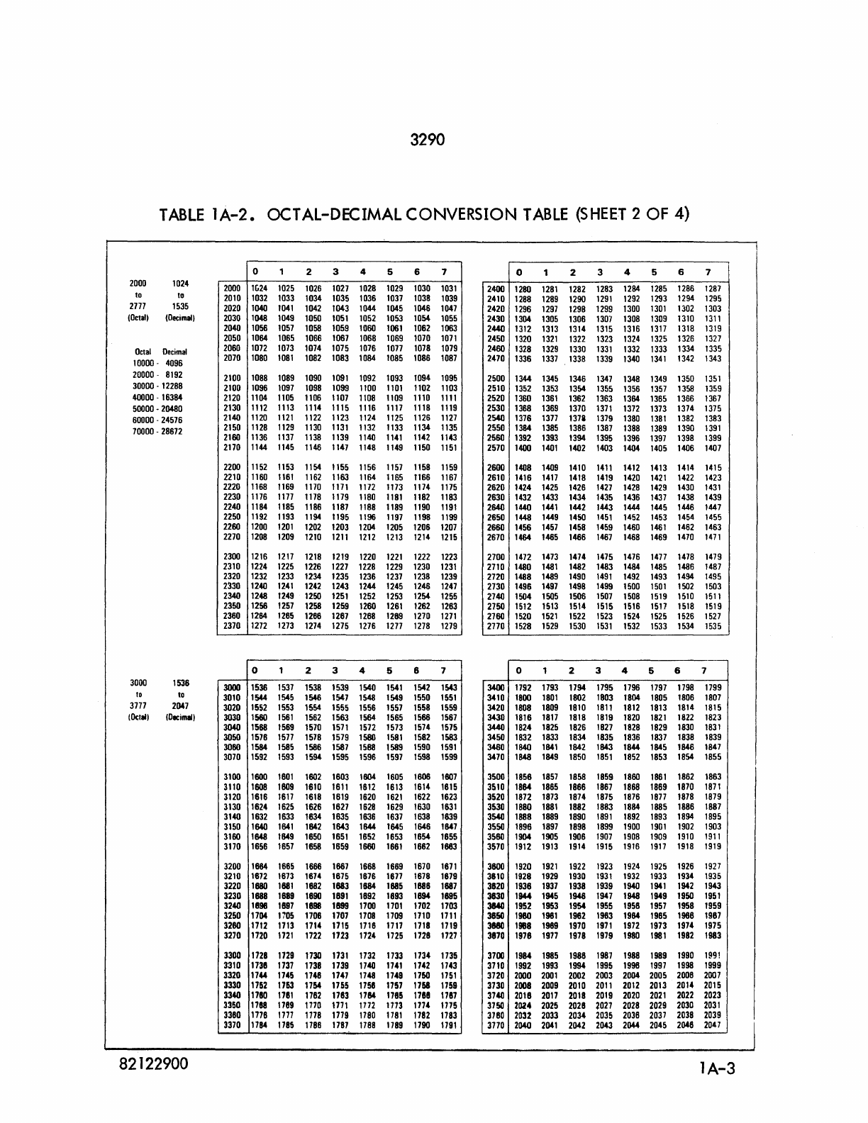
3290
TABLE
lA-2.
OCTAL-DECIMAL CONVERSION
TABLE
(SHEET
2 OF 4)
2000
1024
to to
2777
1535
(DetaIl
(Decima!l
Octal
Decimal
10000
-
4096
20000
-
8192
30000
-
12288
40000
-
16384
50000
-
20480
60000
-
24576
70000
-
28672
3000
1536
to
to
3777
2047
(~,.U
(Decima/I
82122900
2000
2010
2020
2030
2040
2050
2060
2070
2100
2100
2120
2130
2140
2150
2160
2170
2200
2210
2220
2230
2240
2250
2260
2270
2300
2310
2320
2330
2340
2350
2360
2370
3000
3010
3020
3030
3040
3050
3080
3070
3100
3110
3120
3130
3140
3150
3160
3170
3200
3210
3220
3230
3240
3250
3280
3270
3300
3310
3320
3330
3340
3350
3360
3370
0 1
1£;24
1025
1032 1033
1040
1041
1048
1049
1056
1057
1064
1065
1072
1073
1080
1081
1088
1089
1096
1097
1104
1105
1112
1113
1120
1121
1128 1129
1136
1137
1144 1145
1152
1153
1160
1161
1168
1169
1176
1177
1184 1185
1192
1193
1200
1201
1208
1209
1216 1217
1224
1225
1232
1233
1240
1241
1248 1249
1256
1257
1264
1265
1272 1273
0 1
1536
1537
1544
1545
1552 1553
1560
1561
1568
1569
1576
1577
1584
1585
1592 1593
1600
1601
1608 1809
1616
1617
1624
1625
1632 1633
1640
1641
1648
1649
1656
1657
1664
1665
1672
1673
1680
1881
1688 1889
1898
1897
1704
1705
1712
1713
1720
1721
1728
1729
1738
1737
1744
1745
1762
1763
1780
1781
1788
1789
1776
1777
1794
1785
2 3 4 5 6
1026 1027
1028 1029 1030
1034
1035
1036
1037
1038
1042
1043
1044
1045
1046
1050
1051
1052
1053
1054
1058
1059
1060
1061
1062
1066 1067 1068
1069 1070
1074
1075
1076
1077
1078
1082
1083
1084 1085 1086
1090
1091
1092
1093
1094
1098
1099
1100
1101
1102
1106 1107
1108
1109 1110
1114
1115
1116
1117
1118
1122
1123
1124 1125
1126
1130
1131
1132 1133
1134
1138
1139
1140
1141
1142
1146 1147 1148
1149
1150
1154
1155
1156
1157
1158
1162
1163 1164
1165
fl66
1170 1171
1172 1173
1174
1178
1179
1180
1181
1182
1186 1187
1188
1189 1190
1194
1195
1196
1197
1198
1202
1203
1204
1205
1206
1210
1211
1212
1213
1214
1218
1219
1220
1221
1222
1226
1227
1228
1229 1230
1234
1235
1236
1237 1238
1242
1243 1244
1245 1246
1250
1251
1252
1253
1254
1258
1259
1260
1261
1262
1266
1267
1268
1289
1270
1274 1275
1276
1277 1278
2 3 4 5 6
1538
1539
1540
1541
1542
1546 1547 1548 1549 1550
1554
1555
1556
1557
1558
1562
1563
1564
1565 1566
1570
1571
1572
1573
1574
1578
1579 1580
1581
1582
1586
1587
1588
1589 1590
1594 1595
1596
1597 1598
1602
1603
1604
1605
1608
1610
1611
1612
1613 1614
1618
1619
1620
1621
1622
1626
1627
1628
1629
1630
1634
1635
1636 1637 1638
1642
1643
1644
1645 1646
1650
1651
1652 1653 1654
1658
1659
1660
1661
1662
1666
1667 1668
1669
1670
1674
1675
1676
1677
1678
1682
1883
1664
1685
1886
1690
1891
1692 1693
1694
1698
1899
1700
1701
1702
1706
1707 1708
1709 1710
1714 1715
1718
1717
1718
1722
1723
1724
1725
1726
1730
1731
1732 1733
1734
1738
1739
1740
1741
1742
1746
1747
1748
1749 1750
1764 1755
1758 1757
1768
1782
1783
\164
1786 1788
1770
1771
1772
1773
1774
1778
1779
1780
1781
1782
1788
1787
1788
1789 1790
7 0 1 2 3 4 5 6
1031
2400
1280
1281
1282 1283
1284
1285
1286
1039
2410
1288
1289
1290
1291
1292
1293
1294
1047
2420
1296
1297
1298 1299 1300
1301
1302
1055
2430
1304
1305 1306
1307
1308
1309
1310
1063
2440
1312
1313
1314
1315
1316
1317
1318
1071
2450
1320
1321
1322
1323 1324
1325
1326
1079
2460
1328
1329
1330
1331
1332
1333
1334
1087
2470
1336
1337
1338
1339 1340
1341
1342
1095
2500
1344
1345 1346
1347
1348
1349
1350
1103
2510
1352
1353
1354
1355
1356
1357
1358
1111
2520
1360
1361
1362
1363 1364 1365
1366
1119
2530
1368
1369
1370
1371
1372
1373
1374
1127
2540
1376
1377
1378
1379 1380
1381
1382
1135
2550
1384
1385
1386
1387
1388
1389
1390
1143
2560
1392
1393
1394
1395 1396
1397
1398
1151
2570
1400
1401
1402 1403
1404
1405
1406
1159
2600
1408 1409
1410
1411
1412 1413
1414
1167
2610
1416
1417
1418
1419
1420
1421
1422
1175
2620
1424
1425 1426
1427
1428 1429
1430
1183
2630
1432 1433
1434
1435 1436
1437
1438
1191
2640
1440
1441
1442 1443
1444
1445
1446
1199
2650
1448 1449 1450
1451
1452
1453
1454
1207
2660
1456
1457
1458
1459
1460
1461
1462
1215
2670
1464
1465
1466
1467
1468 1469
1470
1223
2700
1472 1473
1474
1475
1476
1477
1478
1231
2710
1480
1481
1482 1483
1484
1485 1486
1239
2720
1488
1489 1490
1491
1492
1493
1494
1247
2730
1496
1497
1498 1499 1500
1501
1502
1255
2740
1504
1505
1506
1507
1508 1519
1510
1263
2750
1512
1513
1514
1515
1516
1517 1518
1271
2760
1520
1521
1522
1523
1524
1525
1526
1279
2770
1528 1529 1530
1531
1532 1533
1534
7 0 1 2 3 4 5 6
1543
3400
1792 1793
1794
1795
1796 1797
1798
1551
3410
1800
1801
1802 1803
1804
1805 1806
1559
3420
1808 1809
1810
1811
1812
1813 1814
1567
3430
1816
1817
1818 1819 1820
1821
1822
1575
3440
1824
1825 1826
1827
1828 1829
1830
1583
3450
1832 1833
1834
1835 1836
1837
1838
1591
3460
1840
1841
1842 1643
1844
1845
1646
1599
3470
1848 1849 1850
1851
1852
1853 1854
1807
3500
1858
1857
1858 1859
1860
1861
1862
1615
3510
1864
1865
1866
1867 1868
1869
1870
1623
3520
1872 1873
1874
1875 1876
1877
1878
1631
3530
1880
1881
1882
1883
1884
1685
1886
1639
3540
1888
1889
1890
1891
1892
1893
1894
1647
3550
1896
1897
1898
1899
1900
1901
1902
1655
3560
1904 1905 1906
1907
1908
1909
1910
1683
3570
1912
1913
1914
1915 1916
1917
1918
1671
3800
1920
1921
1922
1923
1924 1925
1926
1679
3610
1928 1929 1930
1931
1932
1933
1934
1887
3820
1938
1937
1938 1939
1940
1941
1942
1695
3830
1944
1945 1946
1947
1948 1949 1950
1703
3840
1952 1953
1954
1955
1958
1957
1958
1711
3850
1980
1981
1962 1983
1964 1965
1988
1719
3880
1988 1989 1970
1971
1972
1973
1974
1727
3870
1978
1977
1978
1979
1980
1981
1982
1735
3700
1984
1985
1988
1987
1988
1989
1990
1743
3710
1992
1993
1994
1995 1998
1997
1998
1751
3720
2000
2001
2002
2003
2004 2005
2008
1759
3730
2008 2009 2010
2011
2012
2013
2014
1787
3740
2018
2017
2018 2019 2020
2021
2022
1775
3750
2024
2025
2028
~027
2028
2029 2030
1783
3780
2032 2033
2034
2035 2038 2037 2038
1791
3770
2040
2041
2042
2043
2044 2045 2048
7
1287
1295
1303
1311
1319
1327
1335
1343
1351
1359
1367
1375
1383
1391
1399
1407
1415
1423
1431
1439
1447
1455
1463
1471
1479
1487
1495
1503
1511
1519
1527
1535
7
1799
1807
1815
1823
1831
1839
1847
1855
1863
1871
1879
1887
1895
1903
1911
1919
1927
1935
1943
1951
1959
1967
1975
1983
1991
1999
2007
2015
2023
2031
2039
2047
lA-3
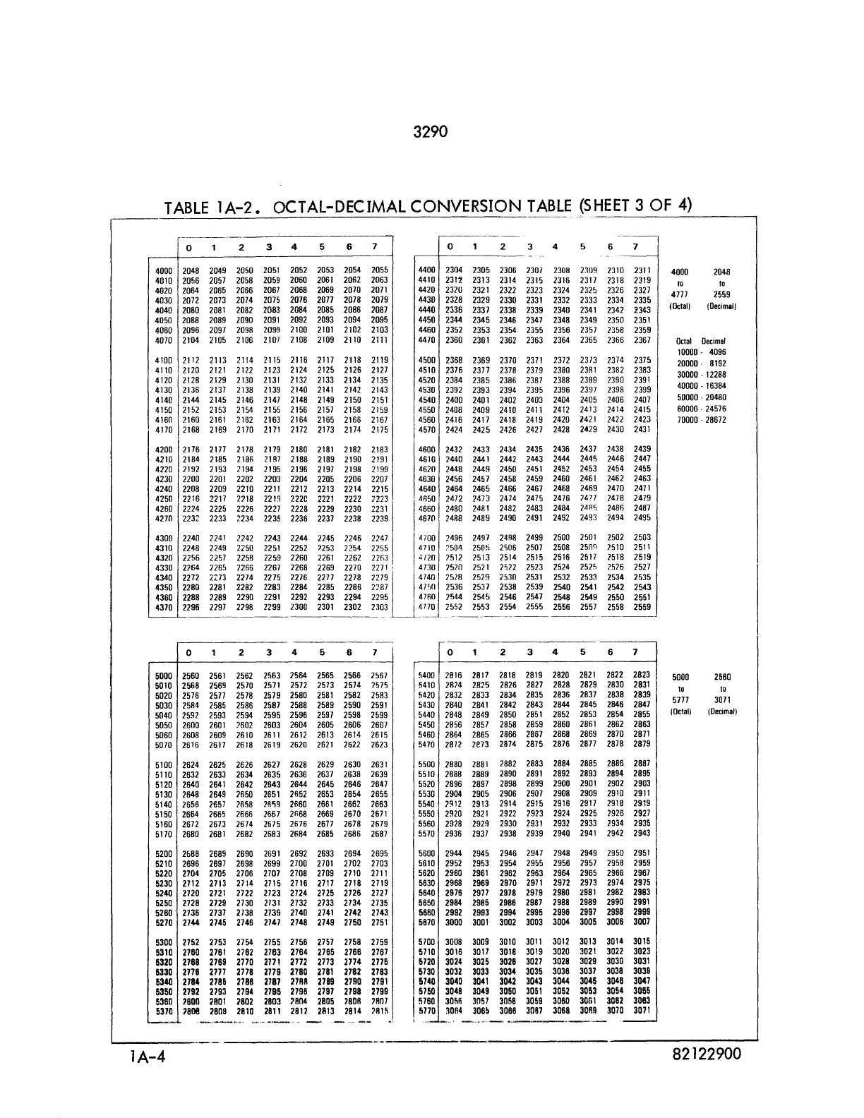
3290
TABLE
lA-2.
OCTAL-DECIMAL CONVERSION
TABLE
(SHEET
3 OF
4)
o 2 3 4 5 6 7
4000 2048 2049 2050
2051
2052 2053 2054 2055
4010 2056 2057 2058 2059 2060
2061
2062 2063
4020 2064 2065 2066 2067 2068 2069 2070
2071
4030 2072 2073 2074 2075 2076 2077 2078 2079
4040 2080
2081
2082 2083 2084 2085 2086 2087
4050 2088 2089
1090
2091
2092 2093 2094 2095
4060 2096 2097 2098 2099 2100
2101
2102 2103
4070 2104 2105 2106
2107
2108 2109 2110
2111
4100 2112 2113 2114 2115 2116 2117 2118 2119
4110 2120
2121
2122 2123 2124 2125 2126 2127
4120 2128 2129 2130
2131
2132 2133 2134 2135
4130 2136 2137 2138
2139
2140
2141
2142 2143
4140 2144 2145 2146
2147
2148 2149 2150
2151
4150 2152 2153 2154 2155 2156 2157 2158 2159
416021602161216221632164216521662167
4170 2168 2169 2170
2171
2172 2173 2174 2175
4200 2176 2177 2178 2179 2180
2181
2182 2183
4210 2184 2185 2186
21R7
2188 2189 2190
2191
4220 2192 2193 2194 2195 2196
2197
2198 2199
4230 2200
2201
2202 2203 2204 2205 2206 2207
4240 2208 2209 2210
2211
2212 2213 2214 2215
4250 2216 2217
21'18
221n
22211
2221
2222
7223
4260 2224 2225 2226
2227
2228 2229 2230
2231
4270 223:: 2233 2234 2235 2236 2237 2238 2239
o 2 3 4 5 6 7
4400 2304 2305 2306 2307 2308 2:l0S 2310
2311
4410
231~
2313 2314 2315 2316 2317 2318 2319
4420 2320 2321 2322 2323 2324
232!J
2326 2321
4430 2328 2329 2330
2331
2332 2333 2334 2335
4440 2336 2337 2338 2339 2340
2341
2342 2343
4450 2344 2345 2346 2347 2348 2349 2350
2351
4460 2352 2353 2354 2355 2356 2357 2358 2359
4410 2360 2361 2362 2363 2364 2365 2366 2367
4500 2368 2369 2370
2371
2372 2373 2374 2375
4510 2376 2377 2378 2379 2380
2381
2382 2383
4520 2384 2385 2386 2387 2388 2389 2390
2391
4530 2392 2393 2394 2395 2396 2397 2398 2399
4540 2400 2401 2402 2403 2404 2405 2406 2407
4550 2408 2409 2410
2411
2412 2413 2414 2415
I 4560 2416 2417 2418 2419 2420
2421
2422 2423
4570 2424 2425 2426 2421 2428 2429 2430
2431
4600 2432 2433 2434 2435 2436 2437 2438 2439
4610 1440 2441 2442 2443 2444 2445 2446 2447
4620 2448 2449 2450
2451
2452 2453 2454 2455
4630 2456 2457 2458 2459 2460
2461
2462 2463
4640 2464 2465 2466 2467 2468 2469 2470
2471
4650 2472 1473 2474 2475 2476 2477 2478 2479
4660 2480 2481 2482 2483 2484
2.1R'i
2486 2487
4670 2488 2489 2490
2491
2492 2493 2494 2495
4300 2240
2241
2242 2243 2244 2245 2246 2247 4700 2496 2497 2498 2499 2500
2501
2502
7510
2518
2526
2534
2542
2550
2558
2503
2511
2519
2527
2535
2543
2551
2559
4310 2248 2249 2250
2251
2252
:1253
2254 2255 4710 7504 2505
2'-'06
2507 2508
250'1
4320 2256 2257 2258 2259 2260
2261
2262 22fl3,
4/20
7512 2513 2514 2515 2516 2517
4330 2764 2265
nB6
2267
2268 2269 2270
2271:
4730 7520
2521
7522 2523 2524 2525
4340 2272 2::73 2274 2275 2276 2277 2278
22791[4740
I 7528 2529 2530
2531
2532 2533
4350 2280
2281
2282 2283 2284 2285 2286 2287 47'i0 2536 2537 2538 2539 2540
2541
4360 2288 2289 2290
2291
2292 2293 2294 2295 4760 2544 2545 2546 2547 2548 2549
4370 2296 2297 2798 2299 2300
2301
2302 2303 4770 2552 2553 2554 2555 2556
2557
L...-L....____________________ _
___
1
__
-
___________
_
o 2 3 4 5 6 7
5000 2560
2561
2562 2563 2564 2565 2566 2567
5010 2568 2569 2570
2571
2572 2573 2574 7575
5020 2576 2577 2578 2579 2580
2581
2582 2583
5030 2584 2585 2586 2587 2588 2589 2590
2591
5040 2592 2593 2594 2595 2596 2597 2598 2599
5050 2600
2601
:602
2603 2604 2605 2606 2607
5060 2608 2609 2610
2611
2612 2613 2614 2615
5070 2616 2617 2618 2619 2620
2621
2622 2623
5100 2624 2625 2626 2627 2628 2629 2630
2631
5110 2632 2633 2634 2635 2636 2637 2638 2639
5120 2640
2641
2642 2643 2644 2645 2646 2647
5130 2648 2649 2650
2651
2652 2653 2654 2655
5140 2656 2657 7658 26'i9 2660
2661
2662 2663
5150 2664 2665 2666 2667 2r,68 2669 2670
2671
5160 2672 2673 2674 2675 2676 2677 2678 2679
5170 2680
2681
2682 2683 2684 2685 2686 2687
5200
26B8
26B9
2690
2691
2692 2693 2694 2695
5210 2696 2697 2698 2699 2700
2701
2702 2703
5220 2704 2705 2706 2707 2708 2709 2710
2711
5230 2712 2713 2114 2115 2116 2717 2718 2719
5240 2720
2721
2722 2723 2724 2125 2726 2127
5250 2728 2729 2730
2731
2732
2733
2734 2735
5260 2736 2737 2738 2739 2740
2741
2742 2743
5270 2144 2745 2746 2147 2748 2749 2750
2751
5300 2752 2753 2754 2755 2756 2757 2758 2759
5310 2760
2761
2162 2763 2764 2765 2766 2767
5320 2768 2769 2770
2771
2772 2773 2774 2775
5330 2778 2777 2778 2779 2780
2781
2782 2783
5340 2784 2785 2788 2787 :nRB 2789
27!10
2191
5350 2792 2193 2794 2195 2798 2197 2198 2199
5380
'800
2801
2802 2803 2804
2B05
'BOA
'AOl
5370
'808
2809 2810
2811
2812 2813 2814
'Rl~
lA-4
o 2 3 4 5 6 7
5400 2816 2817 2818 2819 2820
2821
2822 2823
5410 2874 2825 2826 2827 2828 2829 2830
2831
5420 2832 2833 2834 2835 2836 2837 2838 2839
5430 2840
2841
2842 2843 2844 2845 2846 2847
5440 2848 2849 2850
2851
2852 2853 2854 2855
5450 2856 2857 2858 2859 2860
2861
2862 2863
5460 2864 2865 2866 2867 2868 2869 2870
2871
5470 2872 2873 2874 2875 2876 2877 2878 2879
5500 2880
2881
2882 2883 2884 2885 2886 2887
5510 2888 2889 2890
2891
2892 2893 2894 2895
5520 2896 2897 2898 2899 2900
2901
2902 2903
5530 2904 2905 2906 2907 2908 2909 2910
2911
5540
]912
2913 2914 2915 2916 2917 2918 2919
5550 2920
2921
2922 2923 2924 2925 2926 2927
5560 2928 2929 2930
2931
2932 2933 2934 2935
5570 2936
2937
2938 2939 2940
2941
2942 2943
5600 2944 2945 2946 2947 2948 2949 2950
2951
5610 2952 2953 2954 2955 2956 2957 2958 2959
5620 2960
2961
2962 2963 2964 2965 2966 2967
5630 2968 2969 2970
2971
2972 2973 2974 2975
5640 2976 2971 2978 2979 2980
2981
2982 2983
5650 2984 2985 2986 2987 2988 2989 2990
2991
5660 2992 2993 2994 2995 2996 2997 2998 2999
5870 3000
3001
3002 3003 3004 3005 3006 3007
5100 3008 3009 3010
3011
3012 3013 3014 3015
5710 3016 3017 3018 3019 3020
3021
3022 3023
5720 3024 3025 3028
3027
3028 3029 3030 3031
5730 3032 3033 3034 3035 3036 3037 3038 3039
5140 3040
3041
3042 3043 3044 3045 3048 3047
5750 3048 3049 3050
3051
3052 3053 3054 3055
5760
30M
3051 3058 3059 3060 30Gl 3082 3083
5770
:10114
306!!
3088
30B7
3068 3089 3070 3071
-..•...
--.----
4000 2048
to to
4777
2559
(Octal)
(Decimal)
Octal
Decimal
10000 -4096
20000· 8192
30000 -12288
40000 -16384
50000 . 20480
60000 . 24576
70000 . 28672
5000 2560
to
to
5777
3071
(Octal)
(Oecimal)
82122900
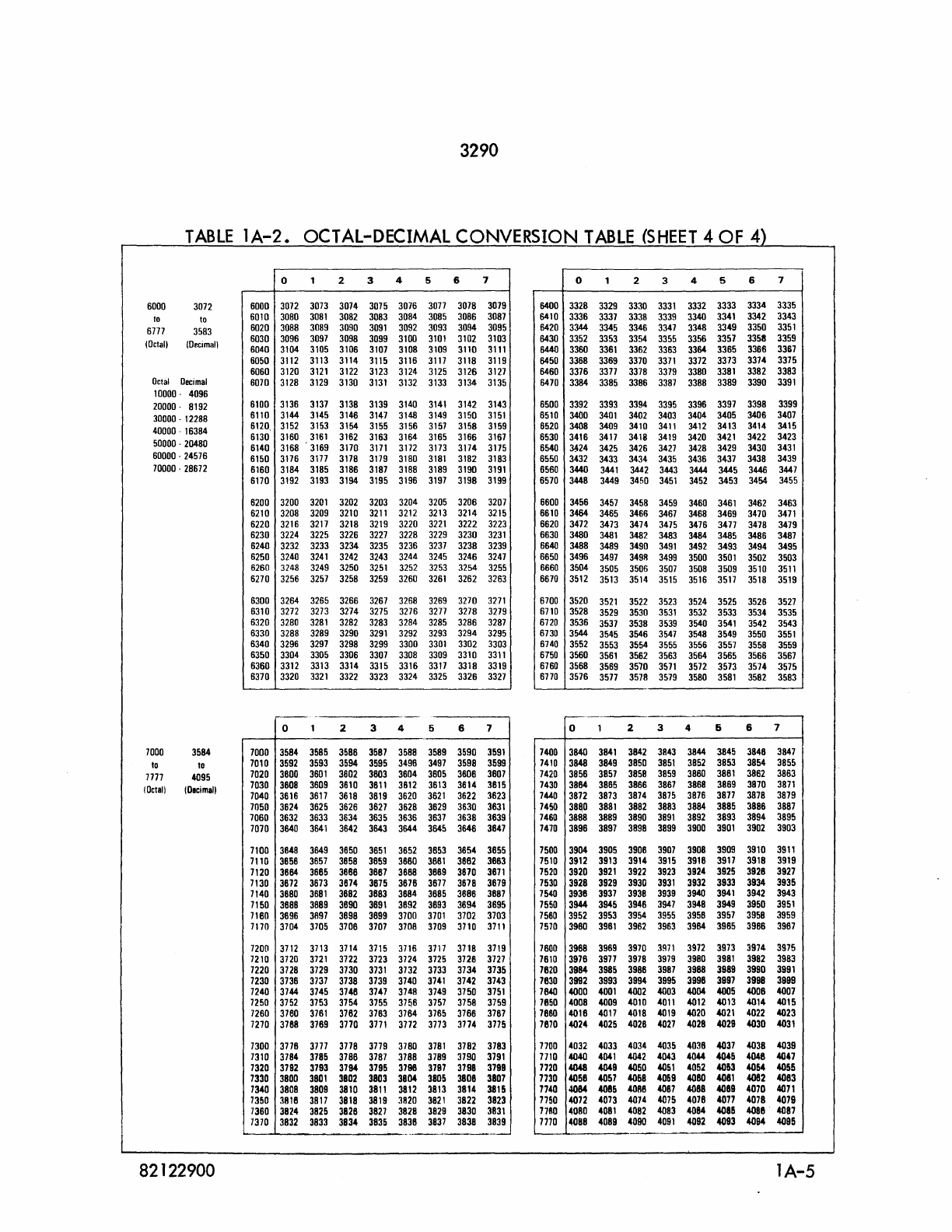
3290
TABLE
1A-2.
OCTAL-DECIMAL CONVERSION
TABLE
(SHEET
4 OF 4)
6000
3072
to
to
6717
3583
(Octal}
(Decimal}
Octal
Decimal
10000
-4096
20000
-
8192
30000
-
12288
40000
-
16384
50000
-
20480
60000
-
24576
70000
-
28672
7000
3584
to
to
7777
4095
(Octal}
(olcimal}
82122900
6000
6010
6020
6030
6040
6050
6060
6010
6100
6110
6120,
6130
6140
6150
6160
6170
6200
6210
6220
6230
6240
6250
6260
6270
6300
6310
6320
6330
6340
6350
6360
6370
7000
7010
7020
7030
7040
7050
7060
7070
7100
7110
7120
7130
7140
7150
7180
7170
7200
7210
7220
7230
7240
7250
7260
7270
7300
7310
7320
7330
7340
7350
7360
1370
0 1 2
3072 3073
3074
3080
3081
3082
3088
3089 3090
3096
3097
3098
3104
3105
3106
3112
3113
3114
3120
3121
3122
3128
3129
3130
3136 3137
3138
3144 3145
3146
3152
3153
3154
3160
3161
3162
3168 3169
3170
3176
3177
3178
3184 3185
3186
3192
3193
3194
3200
3201
3202
3208 3209
3210
3216 3217
3218
3224 3225 3226
3232
3233
3234
3240
3241
3242
3248
3249
3250
3256
3257
3258
3264 3265 3266
3272
3273
3274
3280
3281
3282
3288 3289
3290
3296
3297
3298
3304 3305 3306
3312 3313
3314
3320
3321
3322
--
0 1 2
3584 3585
3588
3592
3593
3594
3800
3601
3602
3608
3609 3610
3616
3617
3618
3624
3625
3626
3632
3633 3634
3840
3641
3642
3848 3649 3650
3858
3657
3658
3864 3885
3888
3872
3673
3874
3880
3681
3882
3888 3889 3890
3896
3897
3898
3704
3705
3708
3712 3113 3714
3120
3121
3722
3728
3129 3730
3738
3737
3738
3744 3745 3748
3752 3753
3754
3780
3761
3762
3788
3769
3770
3718
3777
3778
3784
3785
3788
3792
3793
3794
3800
3801
3802
3808
3809
3810
3818
3817
3818
3824
3825
3828
3832
3833
3834
3 4 5 6 7
3075 3076
3077
3078 3079
3083
3084
3085
3086 3087
3091
3092
3093
3094
3095
3099
3100
3101
3102 3103
3107
3108
3109 3110
3111
3115 3116
3117
3118
3119
3123
3124
3125
3126
3127
3131
3132
3133
3134
3135
3139 3140
3141
3142 3143
3147
3148
3149
3150
3151
3155 3156
3157
3158
3159
3163
3164
3165
3166
3167
3171
3172
3173
3174
3175
3179
3180
3181
3182
3183
3187 3188 3189
3190
3191
3195 3196
3197
3198
3199
3203
3204
3205
3206
3207
3211
3212 3213
3214
3215
3219
3220
3221
3222
3223
3227
3228 3229
3230
3231
3235
3236
3237
3238
3239
3243
3244
3245
3246
3247
3251
3252
3253
3254
3255
3259
3260
3261
3262
3263
3267
3268 3269
3270
3271
3275
3276
3277
3278
3279
3283
3284
3285
3286
3287
3291
3292
3293
3294
3295
3299 3300
3301
3302
3303
3307
3308 3309
3310
3311
3315
3316
3317
3318 3319
3323 3324
3325
3326
3327
--
3 4 5 6 7
3587 3588 3589
3590
3591
3595
3498
3497
3598
3599
3803
3604
3805
3808
3807
3811
3612
3613
3814
3815
3819
3620
3621
3622 3823
3627
3628
3629
3630
3631
3635
3636
3637
3638
3639
3643
3844
3645
3846
3647
3651
3652
3853
3854
3855
3859
3880
3661
3882 3863
3887
3888
3889
3870
3671
3875
3678
3871
3678
3879
3883
3884
3885
3686
3887
3891
3892
3893
3894
3695
3899
3700
3701
3702
3703
3707
3708
3709
3710
3711
3715
3716
3717
3718
3719
3723
3724
3725
3728
3127
3731
3732
3733
3734 3735
3739
3740
3741
3742 3743
3747
3748
3749
3750
3751
3755
37~6
3757
3758 3759
3763
3764
3765
3766
3767
3771
3772 3713
3174
3775
3779
3780
3781
3782 3783
3787
3788
3789
3790
3791
3796
3798
3797
3798
3799
3803
3804
3805
3808 3807
3811
3812
3813 3814
3815
3819
3820
3821
3822 3823
3827
3828 3829 3830
3831
3835
3838
3837
3838
3839
...
_--------
0 1 2 3 4 5 6
6400
3328 3329
3330
3331
3332
3333 3334
6410
3336
3337 3338 3339
3340
3341 3342
6420
3344
3345
3346
3347
3348
3349
3350
6430
3352
3353
3354 3355
3356 3357
3358
6440
3360
3361
3362
3363
3364
3365
3366
6450
3368 3369
3370
3371
3372
3373 3374
6460
3376
3317 3378
3379 3380
3381
3382
6470
3384 3385
3386
3387
3388
3389
3390
6500
3392 3393
3394
3395 3396
3397
3398
6510
3400
3401
3402
3403
3404
3405
3406
6520
3408
3409
3410
3411
3412
3413
3414
6530
3416
3417
3418
3419 3420 3421
3422
6540
~24
3425
3426
3427
3428
3429
3430
6550
3432
3433
3434
3435
3436
3437
3438
6560
3440
3441
3442 3443 3444
3445
3446
6570
3448
3449 3450
3451
3452
3453 3454
6600
3456
3457
3458
3459
3460 3461
3462
6610
3484 3465 3466
3467
3468
3469
3470
6620
3472
3473
3474
3475
3476
3417
3478
6630
3480
3481
3482 3483
3484
3485
3486
6640
3488
3489 3490
3491
3492
3493
3494
6650
3496
3497
3498
3499
3500
3501
3502
6660
3504
3505
3506
3507
3508
3509
3510
6670
3512 3513 3514
3515
3516
3517
3518
6700
3520
3521
3522 3523
3524
3525
3526
6710
3528
3529
3530
3531
3532
3533
3534
6720
3536
3537
3538
3539 3540
3541
3542
6730
3544
3545
3546
3547
3548
3549
3550
6740
3552
3553
3554
3555
3556 3557 3558
6750
3560
3561
3562
3563
3564
3565
3566
6760
3568
3569
35'70
3571
3572
3573 3574
6770
3576
3577
3578
3579
3580
3581
3582
,..--.
0 1 2 3 4 6 6
740D
3840
3841
3842
3843
3844
3845
3846
7410
3848
3849
3850
3851
3852
3853 3854
7420
3856
3857 3858
3859 3880 3861
3862
7430
3884
3865 3866
3867
3888
3869 3870
7440
3872
3873
3874 3875 3876 3877 3878
7450
3880
3881
3882
3883
3884
3885
3886
7460
3888 3889 3890
3891
3892
3893
3894
747D
3896
3897
3898
3899
3900
3901
3902
7500
3904
3905 3906
3907
3908
3909 3910
7510
3912
3913 3914
3915
3916
3917 3918
7520
3920
3921
3922
3923
3924 3925 3928
7530
3928 3929 3930
3931
3932
3933 3934
7540
3936
3937
3938
3939
3940
3941
3942
7550
3944
3945
3946
3947
3948
3949 3950
7560
3952
3953 3954
3955
3956 3957
3958
7510
3980
3981
3962 3963
3964 3965
3966
7600
3988
3969 3970
3!l71
3972
3973
3974
7610
3978
3977
3978
3979
3980
3981
3982
7620
3984
3985
3986
3987
3988 3989
3990
7630
3992 3993
3994
3995
3996
3997
3998
7840
4000
4001
4002
4003
4004
4D05
4006
7650
4008 4009
4010
4011
4012
4013
4014
7660
4016
4017
4018
4019
4020
4021
4022
7670
4024
4025 4026
4027
4028 4029
4030
7700
4032 4033 4034
4035
4038
4D37
4038
7710
4040
4041
4042
4043
4044
4045
4046
7720
4048
4049
4050
4051
4052
4063
4054
7730
4056
4057 4068
4059
4080
4081
4082
7740
4084
4086
4086
4087
4088
4089 4070
7750
4072 4073 4074
4075
4018
4077
4078
77RO
4080
4081
4082
4083
4084
4086
4D88
7770
4088 4089 4090
4091
4092
4093 4094
7
3335
3343
3351
3359
3367
3375
3383
3391
3399
3407
3415
3423
3431
3439
3447
3455
3463
3471
3479
3487
3495
3503
3511
3519
3527
3535
3543
3551
3559
3567
3575
3583
7
3847
3855
3863
3871
3879
3887
3895
3903
3911
3919
3927
3935
3943
3951
3959
3967
3975
3983
3991
3999
4007
4015
4023
4D31
4039
4047
4055
4083
4071
4079
4087
4095
lA-5
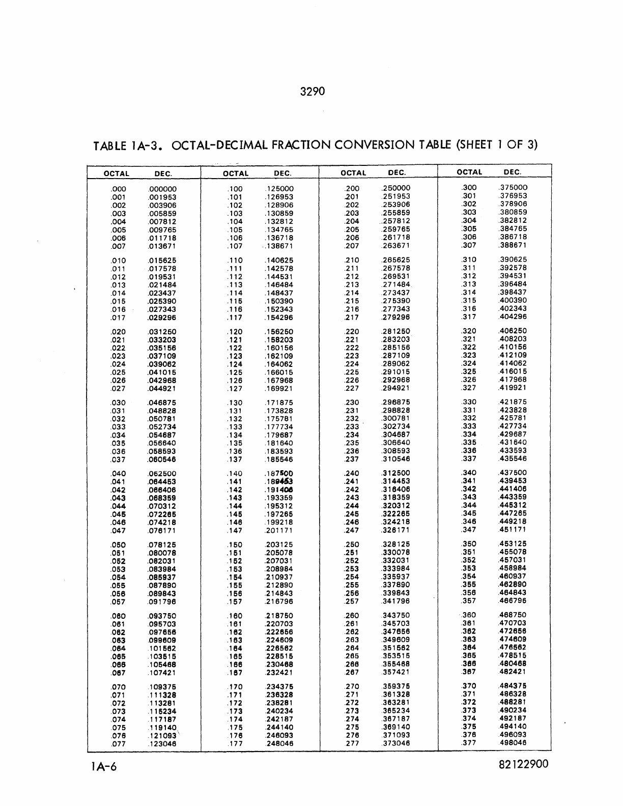
3290
TABLE
lA-3.
OCTAL-DECIMAL
FRACTION
CONVERSION
TABLE
(SHEET
1
OF
3)
.. ' -
OCTAL DEC. OCTAL DEC. OCTAL DEC. OCTAL DEC.
.000
.000000
.100
.125000
.200
.250000
.300
.375000
.001
.001953
.101
.126953
.201
.251953
.301
.376953
.002
.003906
.102
.128906
.202
.253906
.302
.378906
.003
.005859
.103
.130859
.203
.255859
.303
.380859
.004
.007812
.104
.132812
.204
..
257812
.304
.382812
.005
.009765
.105
.134765
.205
.259765
:305
.384765
.006
.011718
.106
.136718
.206
.261718
.306
.386718
.007 .013671
.107
.138671 .207 .263671
.307
.388671
.010
.015625
.110
.140625
.210
.265625
.310
.390625
.011
.017578
.111
.142578
.211
.267578
.311
.392578
.012 .019531
.112
.144531 .212 .269531 .312 .394531
.013
.021484
.113
.146484
.213
.271484
.313
.396484
.014
.023437
.114
.148437
.214
.273437
.314
.398437
.015
.025390
.115
.150390
.215
.275390
.315
.400390
.016
.027343
.116
.152343
.216
.277343
.316
.402343
.017
.029296
.117
.154296
.217
.279296
.317
.404296
.020
.031250
.120
.156250
.220
.281250
.320
.406250
.021
.033203
.121
.158203
.221
.283203
.321
.408203
.022
.035156
.122
.160156
.222
.285156
.322
.410156
.023
.037109
.123
.162109
.223
.287109
.323
.412109
.024
.039062
.124
.164062
.224
.289062
.324
.414062
.025
.041015
.125
.166015
.225
.291015
.325
.416015
.026
.042968
.126
.167968
.226
.292968
.326
.417968
.027 .044921
.127
.169921 .227 .294921 .327 .419921
.030
.046875
.130
.171875
.230
.296875
330
.421875
.031
.048828
.131
.173828
.231
.298828
331
.423828
.032 .050781
.132
.175781 .232 .300781 .332 .425781
.033
,052734
.133
.177734
.233
.302734
.333
.427734
.034
.054687
.134
.179687
.234
.304687
.334
.429687
,035
.056640
.135
.181640
.235
.306640
,335
.431640
,036
.058593
.136
.183593
.236
.308593
,336
.433593
.037
.060546
.137
,185546
.237
,310546
,337
.435546
.040
.062500
.140
.187500
.240
.312500
.340
.437600
.041
.064463
.141
.189453
.241
,314463
,341
,439453
.042
,066406
,142
.191406
.242
,318406
,342
,441408
.043
,068359
,143
,193359
.243
,318369
.343
,443359
,044
.070312
.144
.195312
.244
.320312
.344
,446312
.046
,072265
,146
,197265
.245
,322265
,345
,447265
.046
,074218
,146
.199218
,246
.324218
,346
,449218
.047
.076171
.147
.201171 .247 .326171 .347 .451171
,060
.078125
.150
.203125
.250
.328125
.350
.453125
.051
.080078
.161
.205078
.251
.330078
.351
.455078
.052
.082031 .162 .207031 .252 .332031 .352 .457031
.053
.083984
.163
.208984
.253
.333984
.353
.458984
.054
.085937
,164
.210937
.254
.335937
,354
,460937
.055
.087890
,155
,212890
.255
.337890
.355
.462890
.056
.089843
.166
.214843
.256
,339843
.356
.464843
.057
,091796
.167
,216796
.257
.341796
.357
.466796
.060
.093750
.160
.218750
.260
343750
',360
.468750
.061
.095703
.161
.220703
,261
.345703
361
.470703
.062
097658
,182
.222856
262
,347658
,362
,472656
083
.099809
,163
224609
263
.349609
.383
474609
,064
101562
.184
,226562
264
.351562
384
.478582
,066
.103515
165
228515
266
353515
.365
.478515
,068
.105468
,186
230488
28e
.365488
36e
.480468
.067 .107421 .187 232421
267
.357421 .367 482421
.070
109375
.170
.234375
270
359375
.370
.484375
,071
.111328
,171
.236328
.271
.361328
.371
486328
.072 113281
,172
.238281 .272 .363281 .372 .488281
.073
.115234
.173
.240234
,273
.365234
,373
,490234
,074
.117187
,174
,242187
,274
,367187
374
492187
.075 ,119140, ,175
.244140
275
.369140
,375
.494140
,076
.121093'
176
,246093
276
371093
.376
.496093
.077
,123046
,177
,248046
277
,373046
.377
498046
lA-6
82122900
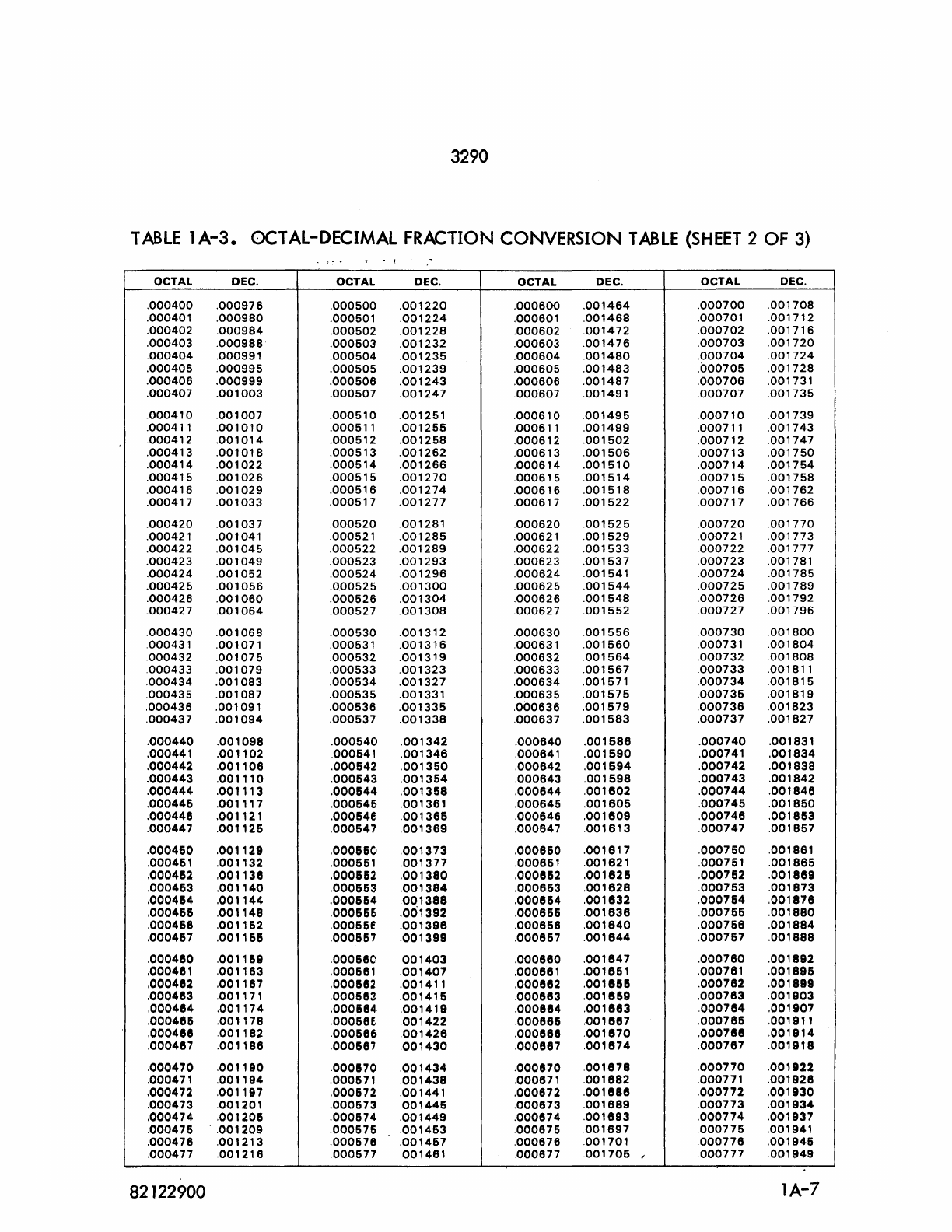
3290
TABLE
lA-3.
OCTAL-DECIMAL
FRACTION
CONVERSION
TABLE
(SHEET
2
OF
3)
.
-,
OCTAL
DEC.
OCTAL
DEC.
OCTAL
DEC.
OCTAL
DEC.
.000400
.000976
.000500
.001220
.000600
.001464
.000700
.001708
.000401
.000980
.000501
.001224
.000601
.001468
.000701
.001712
.000402
.000984
.000502
.001228
.000602
.001472
.000702
.001716
.000403
.000988
.000503
.001232
.000603
.001476
.000703
.001720
.000404
.000991
.000504
.001235
.000604
.001480
.000704
.001724
.000405
.000995 .000505
.001239
.000605
.001483
.000705
.001728
.000406
.000999 .000506
.001243
.000606
.001487
.000706
.001731
.000407
.001003
.000507
.001247
.000607
.001491
.000707 .001735
.000410 .001007
.000510
.001251
.000610
.001495 .000710
.001739
.000411
.001010
.000511
.001255
.000611
.001499
.000711
.001743
.000412
.001014
.000512
.001258
.000612
.001502
.000712
.001747
.000413
.001018
.000513
.001262
.000613
.001506
.000713
.001750
.000414 .001022
.000514
.001266
.000614
.001510
.000714
.001754
.000415
.001026 .000515
.001270
.000615
.001514
.000715
.001758
.000416
.001029
.000516
.001274
.000616
.001518 .000716
.001762
.000417
.001033
.000517
.001277
.000617
.001522
.000717
.001766
.000420 .001037
.000520
.001281
.000620
.001525
.000720
.001770
.000421
.001041
.000521
.001285
.000621
.001529
.000721
.001773
.000422
.001045
.000522
.001289
.000622
.001533 .000722
.001777
.000423
.001049
.000523
.001293
.000623
.001537 .000723
.001781
.000424 .001052
.000524
.001296
.000624
.001541
.000724
.001785
.000425
.001056
.000525
.001300
.000625
.001544
.000725
.001789
.000426
.001060 .000526
.001304
.000626
.001548 .000726
.001792
.000427
.001064
.000527
.001308
.000627
.001552
.000727
.001796
.000430
.001069
.000530
.001312
.000630
.001556 .000730
.001800
.000431
.001071
.000531
.001316
.000631
.001560
.000731
.001804
.000432
.001075
.000532
.001319
.000632
.001564
.000732
.001808
.000433
.001079
.000533
.001323
.000633
.001567
.000733
.001811
.000434
.001083
.000534 .001327
.000634
.001571
.000734
.001815
.000435
.001087
.000535
.001331
.000635
.001575 .000735
.001819
.000436
.001091
.000536
.001335
.000636
.001579
.000736
.001823
.000437
.001094
.000537
.001338
.000637
.001583 .000737
.001827
.000440 .001098
.000540
.001342
.000640
.001688 .000740
.001831
.000441
.001102
.000641
.001348
.000841
.001690
.000741
.001834
.000442
.001108
.000642
.001350
.000642
.001694
.000742
.001838
.000443
.001110
.000643
.001354
.000643
.001598 .000743
.001842
.000444 .001113
.000644
.001358
.000844
.001802
.000744
.001846
.000446
.001117
.000646
.001381
.000645
.001805 .000745
.001850
.000446
.001121
.00064f
.001365
.000646
.001609
.000748
.001853
.000447
.001125
.000547
.001369
.000647
.001613 .000747
.001857
.000460 .001129
.000660
.001373
.000850
.001617
.000750
.001861
,000461
,001132
.000661
.001377
,000851
.001821 .000751
.001885
.000462
,001138
.000662
.001380
.000862
.001825
.000762
.001889
.000463
.001140
.000663
.001384
.000853
.001828 .000763
.001873
.000464
.001144
.000664 .001388
.000864 .001832
.000764
.001878
,000466
.001148
.000666
.001392
.000666
.001638 .000766
.001880
,000468
.001162
.00066f
.001398
.000868
.001840
,000768
.001884
.000467
.001166
.000667
.001399
.000667
.001844
.000767
.001888
.000460 .001169
.00058C
.001403
.000880
.001847
.000760
.001892
.000481
,001163
.0001581
.001407
.000881
.001861
,000781
.0018915
,000482
.001187
.0001582
.001411
.000882
.001856
.000782
.001899
.000483
.001171
.0001583
.001415
.000883
.001859
,000783
.001903
,000484
.001174
.0001584
.001419
.000884
.001883 .000784
,001907
.000486 .001178
.000S8f.
.001422
.000886
.
.001887
.0007815
.001911
.0004e8
.001182
.0001586
.001428
.0008e8
.001870
.000788
.001914
,000487
.001188
.0001587
.001430
.000887
.001874
.000787
.001918
.000470
.001190
.0001570
.001434
.000870
.00187S
.000770
.001922
.000471
.001194
.0001571
.001438
.000871
.001882
.000771
.001928
.000472
.001197
.0001572
.001441
.000672
.0018S8
.000772
.001930
.000473
.001201
.000573
.001445
.000873
.001889
.000773
.001934
.000474 .001206
.000574
.001449
.000874 .001893
.000774
.001937
.000475
..
001209
.000575 .001453
.000675
.001897
.000775
.001941
.000476
.001213 .000576 .001457
.000678
.001701
.000776
.001945
.000477
.001218
.000577
.001481
.000677
.001705
,
.000777
.001949
82122900
lA-7
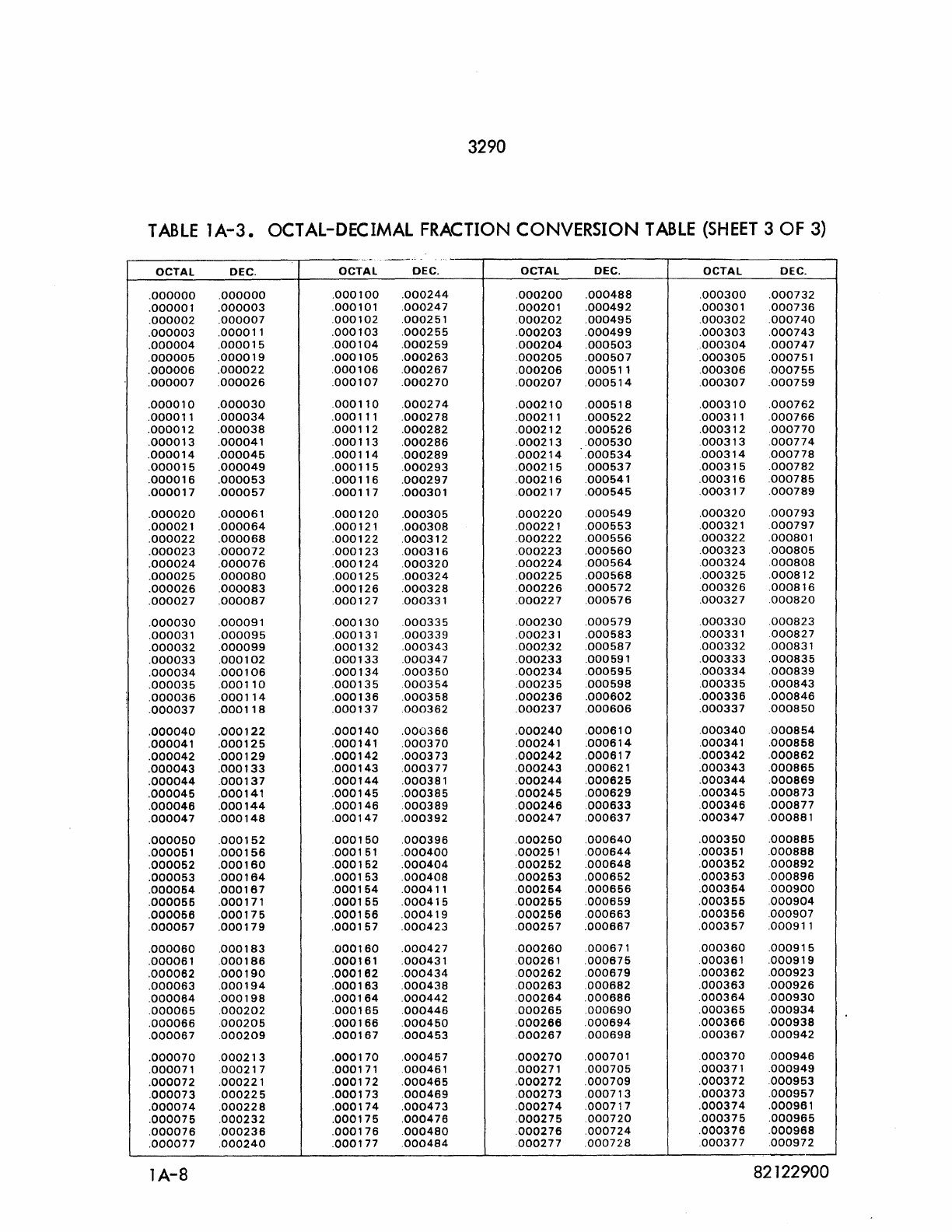
3290
TABLE
lA-3.
OCTAL-DECIMAL FRACTION
CONVERSION
TABLE
(SHEET
3 OF 3)
~
..
-
..
--
..
-
OCTAL
DEC.
OCTAL
DEC.
OCTAL
DEC.
OCTAL
DEC
.
.000000
.000000
.
000100
.000244
.000200
.000488
.000300
.000732
.000001
.000003
.000101
.000247
.000201
.000492
.000301
.000736
.000002
.000007
.000102
.000251
.000202
.000495
.000302
.000740
.000003
.000011
.000103
.000255
.000203
.000499
.000303 .000743
.000004 .000015 .000104 .000259 .000204
.000503 .000304
.000747
.000005
.000019
.000105
.000263
.000205 .000507
.000305
.000751
.000006 .000022
.000106
.000267 .000206
.000511
.000306
.000755
.000007
.000026
.000107
.000270
.000207
.000514
.000307
.000759
.000010
.000030
.000110
.000274
.000210
.000518 .000310
.000762
.000011
.000034
.000111
.000278
.000211
.000522
.000311
.000766
.000012
.000038
.000112
.000282
.000212
.000526
.000312 .000770
.000013
.000041
.000113
.000286
.000213
.000530
.000313
.000774
.000014
.000045
.000114 .000289 .000214
.000534
.000314
.000778
.000015
.000049
.000115 .000293
.000215 .000537 .000315
.000782
.000016 .000053
.000116 .000297
.000216
.000541
.000316
.000785
.000017
.000057
.000117
.000301
.000217
.000545
.000317
.000789
.000020
.000061
.000120
.000305
.000220
.000549
.000320
.000793
.000021
.000064
.000121
.000308
.000221
.000553
.000321
.000797
.000022
.000068
.000122
.000312
.000222
.000556
.000322
.000801
.000023
.000072
.000123
.000316
.000223
.000560
.000323
.000805
.000024
.000076
.000124 .000320 .000224
.000564
.000324
.000808
.000025
.000080
.000125
.000324
.000225
.000568
.000325
.000812
.000026
.000083
.000126
.000328 .000226
.000572 .000326 .000816
.000027
.000087
.000127
.000331
.000227
.000576
.000327
.000820
.000030
.000091
.000130
.000335
.000230
.000579
.000330
.000823
.000031
.000095
.000131
.000339
.000231
.000583
.000331
000827
.000032
.000099
.000132
.000343
.0002.32
.000587
.000332
.000831
.000033
.000102
.000133
.000347
.000233
.000591
.000333
.000835
.000034 .000106
.000134 .000350
.000234
.000595
.000334
.000839
.000035
.000110
.000135 .000354
.000235
.000598 .000335
.000843
I
.000036
.000114
.000136
.000358
.000236 .000602 .000336
.000846
.000037
.000118
.000137
.000362
.000237
.000606
.000337
.000850
.000040
.000122 .000140
.000366
.000240
.000610
.000340 .000854
.000041
.000125
.000141
.000370
.000241
.000614
.000341
.000858
.000042
.000129
.000142
.000373
.000242
.000617 .000342
.000862
.000043
.000133
.000143
.000377 .000243
.000621
.000343
.000865
.000044
.000137
.000144
.000381
.000244
.000625
.000344
.000869
.000045
.000141
.000145 .000385 .000245
.000629
.000345
.000873
.000046
.000144
.000146
.000389
.000246
.000633
.000346
.000877
.000047
.000148
.000147
.000392
.000247
.000637
.000347
.000881
.000050
.000152
.000150
.000396
.000250
.000640
.000350
.000885
.000051
.000156
.000151
.000400
.000251
.000644
.000351
.000888
.000062
.000160
.000152
.000404
.000262
.000648
.000352
.000892
.000053
.000164
.000153
.000408
.000253
.000652 .000353 .000896
.000064
.000167 .000154
.000411
.000264
.000656
.000364
.000900
.000065
.000171
.000155 .000415
.000265
.000659
.000355
.000904
.000066
.000175
.000156 .000419 .000256
.000663
.000356
.000907
.000057
.000179
.000167
.000423
.000257
.000667
.000357
.000911
.000060 .000183
.000160
.000427
.000260
.000671
.000360
.000915
.000061
.000186
.000161
.000431
.000261
.000675
.000361
.000919
.000062 .000190 .000162 .000434
.000262
.000679
.000362
.000923
.000063
.000194
.000163
.000438
.000263
.000682 .000363
.000926
.000064 .000198
.000164
.000442
.000264
.000686
.000364
.000930
.000065
.000202
.000165 .000446
.000265 .000690 .000365 .000934
.000066 .000205 .000166
.000450
.000266 .000694
.000366 .000938
.000067
.000209
.000167
.000453
.000267 .000698
.000367
.000942
.000070 .000213
.000170
.000457
.000270
.000701
.000370
.000946
.000071
.000217
.000171
.000461
.000271
.000705
.000371
.000949
.000072
.000221
.000172
.000465
.000272
.000709
.000372
.000953
.000073 .000225 .000173
.000469
.000273
.000713 .000373
.000957
.000074
.000228
.000174
.000473
.000274
.000717
.000374
.000961
.000075
.000232
.000176 .000476 .000275 .000720 .000375
.000965
.000076 .000236
.000176 .000480
.000276
.000724
.000376
.000968
.000077
.000240
.000177
.000484
000277
.000728
.000377
.000972
lA-8
82122900
3290
ALPHABETICAL
INDEX
Subject Page
C Channel
Busy
line
3-4
Connect Code
3-7
Connect
Line
3-1
Controls 2-1
0 Data Lines (12) 3-1
Data Signal
line
3-4
Display Controller 2-1
Display Station
2-5
E
End
of
Record
li
ne
3-6
Error
Processing
3-35
F
Fu
nction Codes
3-7
Function
line
3-3
Functional Description 1-2
I Interface Control Codes
3-6
Interface Signal
lines
3-1
Interrupt
lines
(8)
3-6
Interrupts 3-11
M Master C lear
line
3-4
Message Format
3-30
N Negate
BCD
Conversion
line
3-4
0 Operating Procedures
2-9
Operational Description 1-1
P Parity
Error
Line
3-6
Parity
line
3-1
Poller Symbol Repertoire
3-36
Poller Translation
3-23
Poller Interface Signals
3-23
82122900
3290
ALPHABETICAL
INDEX
(CONT)
Subject
Page
P Poller Control Codes
3-26
Programming Aids
3-22
Programming Restrictions
3-22
R Read Line
3-3
Read
Operation
Initiated
by a Requesting Station
3-20
Read
Operation
Initiated
by the Computer
3-21
Read;Write
Operations
3-19
Reiect Line
3-5
Reply Line
3-4
S Status Codes
3-7
Status
lines
(12)
3-6
Suppress Assembly/Disassembly Line
3-5
Symbol
Data
3-12
T Typical
Operation
Sequence
2-10
W Word Formats
3-14
Write Line
3-4
Write
Operation
to a Local Display Station 3-21
Write
Operation
to a Poller
3-21
2 82122900
