54 24 0478d1 5334 86900 Catalog
2014-10-23
: Pdf 86900-Catalog 86900-Catalog Batch9 unilog
Open the PDF directly: View PDF ![]() .
.
Page Count: 4
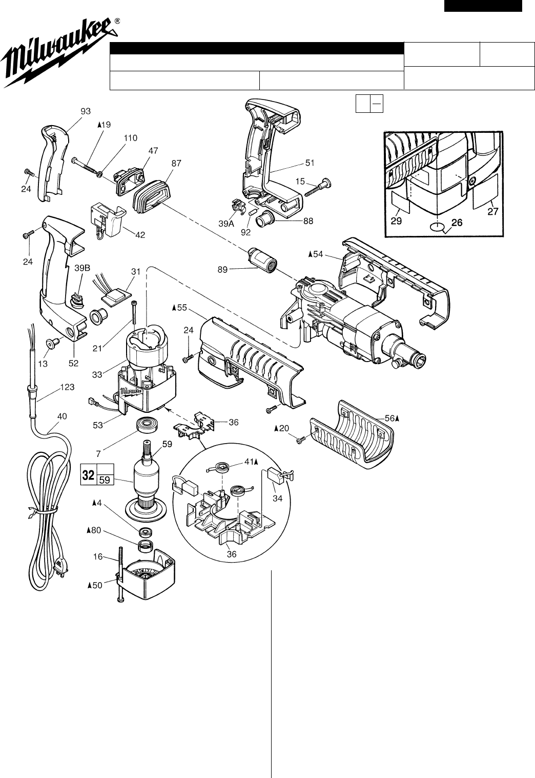
LIGHT CHIPPER HAMMER May '99
54-24-0477
5334 58-01-1555
54-24-0478
881D
FIG. PART NO. DESCRIPTION OF PART NO. REQ.
4 02-04-0847 Ball Bearing (1)
7 02-04-1525 Ball Bearing (1)
13 05-59-0100 Pivot Nut (1)
15 05-77-0100 Pivot Bolt (1)
16 05-81-0920 M6 x 1.0 x 120 Pan Hd. Slt. Tapt. T-27 (4)
19 06-81-1805 Special Screw (2)
20 06-82-7252 8-32 x 3/8" Pan Hd. Slt. Tapt. T-20 (4)
21 06-82-7425 8-16 x 2" Pan Hd. Slt. Plast. T-20 (2)
24 06-95-6290 M5 x 2.24 x 18 Pan Hd. Slt. PT T-20 (7)
26 10-75-2760 Milwaukee Label (1)
27 10-98-5316 Product Label (1)
29 12-20-3305 Service Nameplate Kit (1)
31 14-20-0726 Remote Trigger Speed Control (1)
32 16-50-1261 120 Volt Armature (1)
33 18-50-0260 120 Volt Field (1)
34 22-18-0870 120 V Carbon Brush (2) Kit (1)
36 22-22-1480 Brush Carrier Assembly (1)
39A 31-17-0260 Lower Cord Clamp (1)
39B 31-17-0265 Upper Cord Clamp (1)
PAGE 1 OF 2
FIG. PART NO. DESCRIPTION OF PART NO. REQ.
40 22-64-0785 Cord (1)
41 23-52-1550 Brush Spring (2)
42 23-66-2160 Speed Control Switch (1)
47 28-90-0280 Upper Handle Mount (1)
50 31-15-0430 Motor Cover (1)
51 31-44-1955 Left Handle Half (1)
52 31-44-1960 Right Handle Half (1)
53 31-50-0530 Motor Housing (1)
54 31-55-0240 Left Shroud (1)
55 31-55-0250 Right Shroud (1)
56 31-55-0225 Belly Shroud (1)
59 34-60-3620 Retaining Ring (1)
80 42-96-0130 Bearing Cup (1)
87 43-87-0030 Isolation Bellows (1)
88 43-87-0040 Pivot Isolator (2)
89 43-87-0060 Isolation Module Assembly (1)
92 14-46-1001 Foam Slug Kit (Bag of 10) (1)
93 44-52-0580 Handle Cushion (1)
110 45-88-8555 Rubber Washer (2)
123 44-76-0210 Cord Protector (1)
%SEE BACK PAGE OF THIS BULLETIN
FOR ADDITIONAL LUBRICATION
AND SERVICE NOTES
«
«
«
REVISED BULLETIN DATE
SERVICE PARTS LIST
SPECIFY CATALOG NO. AND SERIAL NO. WHEN ORDERING PARTS
STARTING
SERIAL NO.
CATALOG NO. WIRING INSTRUCTION
EXAMPLE:
Component Parts (Small #) Are Included
When Ordering The Assembly (Large #).
0
00
BULLETIN NO.
MILWAUKEE ELECTRIC TOOL CORPORATION
13135 W. LISBON RD., BROOKFIELD, WI 53005
Drwg. 1
l
«
_______________________________________________________________
______________________________________________________________
________________________________________________________________
_______________________________________________________________
______________________________________________________________
______________________________________________________________
________________________________________________________________
________________________________________
___________________________________________
________________________________________
___________________________________________
FASTENER TORQUE SPECIFICATIONS (IN./LBS.)
SEATING TORQUE
FIG. NO. MINIMUM MAXIMUM
14 120 140
15 20 25
16 30 35
19 30 35
20 25 30
21 20 25
22 25 30
30 35
25 30
20 25
10 15
25 35 45
22-18-0870 CARBON BRUSH SERVICE KIT
THIS KIT CONTAINS:
2 --------------- Carbon Brush
Assemble Thrust Washers
#107 and Belleville Spring
Washers #78 into Intermediate
Housing #46 as illustrated.
NOTE: USE OIL
ON ALL AREAS
TO BE PRESS FIT
BARREL
%SEE BACK PAGE
OF THIS BULLETIN
FOR ADDITIONAL
LUBRICATION
AND SERVICE NOTES
23 CRANKCASE COVER
HANDLE HALVES
AND SHROUDS
CUSHION GRIP
24
● ●
● ●
● 14-46-9070 1-1/2" HAMMER SERVICE KIT
THIS KIT CONTAINS:
1 31-12-0270 Cap-Cover
1 34-40-4310 Rubber Damping Washer
1 34-40-4320 Seal-Cover
1 34-40-4330 O-Ring
3 34-40-4350 O-Ring
1 42-96-0130 Bearing Cup
1 43-44-0970 Gasket
1 45-06-0540 Dust Seal-Hex
1 49-08-5250 6 Oz. Tube "S" Grease
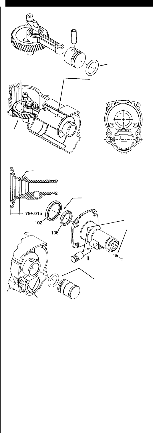
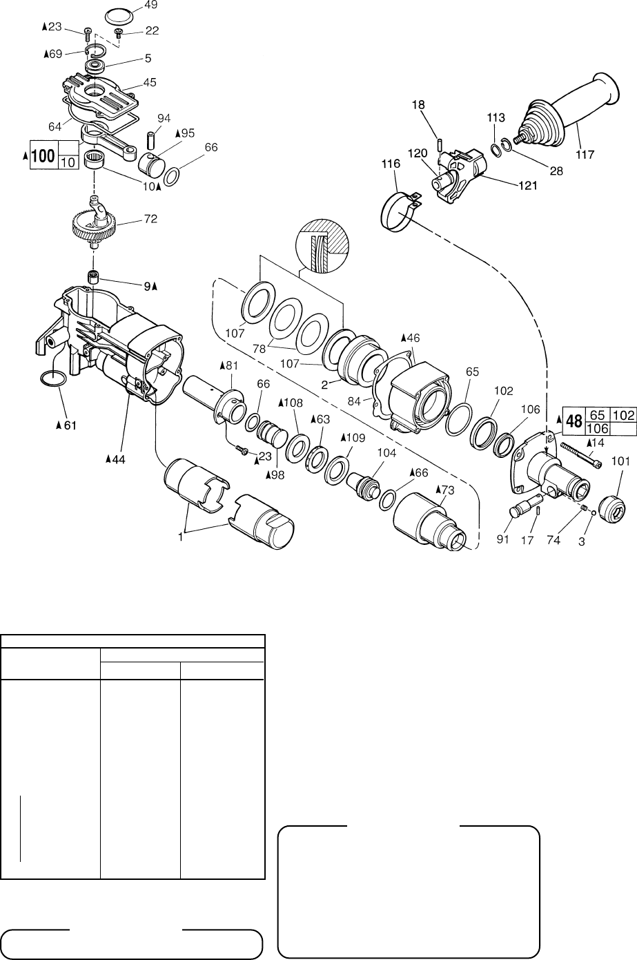
FIG. PART NO. DESCRIPTION OF PART NO. REQ.
1 31-01-0030 Grease Displacer (2)
2 45-60-0615 Spindle Support (1)
3 02-02-0250 1/4" Steel Ball (1)
5 02-04-0911 Ball Bearing (1)
9 02-50-2470 Needle Bearing (1)
10 02-50-4020 Needle Bearing (1)
14 05-74-0670 M6 x 1.0 x 70 Skt. Hd. Cap Screw T-27 (4)
17 06-65-0828 Groove Pin (1)
18 06-65-1660 Dowel Pin (1)
22 06-82-8842 8-32 x 3/8" Pan Hd. Slt. Taptite T-20 (1)
23 06-95-6280 M4 x 0.7 x 14 Pan Hd. Slt. Taptite T-20 (6)
28 34-60-2580 External Retaining Ring (1)
44 28-14-2285 Crankcase (1)
45 28-20-1325 Crankcase Cover (1)
46 28-50-6445 Intermediate Housing (1)
48 14-52-0020 Nose Assembly (1)
49 31-12-0270 Cap-Cover (1)
61 34-40-1375 O-Ring (1)
63 34-40-4310 Rubber Damping Washer (1)
64 34-40-4320 Seal-Cover (1)
65 34-40-4330 O-Ring (1)
66 34-40-4350 O-Ring (3)
69 34-80-5090 Retaining Ring-Beveled (1)
72 14-09-0150 Crankshaft Assembly (1)
73 38-50-6060 Spindle (1)
74 40-50-8420 Bit Lock Spring (1)
78 40-50-8590 Belleville Spring (2)
81 42-98-0240 Barrel (1)
84 43-44-0970 Gasket (1)
91 44-20-0222 Bit Lock (1)
94 44-60-1400 Wrist Pin (1)
95 44-62-0210 Piston (1)
98 44-82-0170 Ram (1)
100 44-94-0395 Connecting Rod Assembly (1)
101 49-62-0095 Dust Seal-Hex (5/pkg.) (1)
102 45-06-0560 Oil Seal (1)
104 45-56-2610 Striker (1)
106 45-88-5176 Felt Seal (1)
107 45-88-8520 Thrust Washer (2)
108 45-88-8530 Barrel Thrust Washer (1)
109 45-88-8535 Striker Cushion Washer (1)
113 45-88-8730 Wave Washer (1)
115 06-14-0040 Hex Head Bolt-Special (1)
116 42-16-0150 Side Handle Band (1)
117 14-34-0516 Side Handle Assembly (1)
120 44-86-0620 Band Retainer (1)
121 31-44-2020 Side Handle Housing (1)
61-10-0670 Nose Service Tool
%SEE BACK PAGE OF THIS BULLETIN
FOR ADDITIONAL LUBRICATION
AND SERVICE NOTES
BULLETIN No. 54-24-0478 May '99 PAGE 2 OF 2
●
●
●
●
●
●
●
«
LUBRICATION NOTES: (TYPE "S" GREASE, NO. 49-08-5250)
Fill Piston #95 with grease and
assemble to Connecting Rod #100
with Wrist Pin #94. Front surface
of Piston to be free of grease.
Lubricate O-Ring #66
with grease.
Place 2.0 oz. grease here.
FRONT OF CRANKCASE
Place
1.5 oz.
grease in bottom
of crankcase prior to
installing crankshaft
assembly.
Place a total of 1.5 oz. grease
in the crankcase #44 above the barrel.
Place .5 oz. in left corner in barrel
and 1.0 oz. in the right.
Lightly grease
Spring #74 and
bit lock #92.
Lubricate O-Ring #66 with grease.
Install O-Ring onto Ram #98.
Assemble Ram into Barrel #81,
O-Ring end first. Set end Of Ram
flush with end of Barrel. Do not
Push Ram deep into Barrel.
Place 1.0 oz. grease in
lower clutch pinion cavity.
Seal to be installed with
garter spring to left as shown.
Dip Felt Washer #106 into light oil.
Press Oil Seal #102 and Felt Washer
into Nose #48 to dimension shown
using Nose Service Tool
61-10-0670.
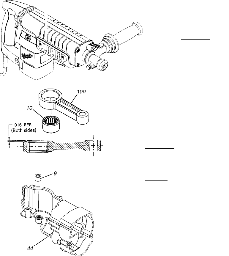
FIG. %NOTES
54, 55, 56 TO REMOVE BELLY SHROUD #56 FROM TOOL, INSERT SMALL
SCREW DRIVER INTO GROOVE BETWEEN BELLY AND SIDE
SHROUDS #54 AND #55, ABOUT 1/3 OF THE WAY FROM THE
MOTOR END, AS SHOWN. PRY OUT AND DOWN ON BOTH
SIDES OF THE TOOL.
54, 55 TO INSTALL THE SIDE SHROUDS #54 AND #55, THE TOP HINGE
OF THE SHROUDS MUST BE COMPLETELY INTERLOCKED,
THEN THE BACK SIDE ROTATED CLOSED AROUND THE TOOL.
73 LUBRICATE ALL BORES IN SPINDLE #73 WITH A MEDIUM
COATING OF GREASE.
63, 108, 109 LUBRICATE RUBBER DAMPING WASHER #63, BARREL
THRUST WASHER #108 AND STRIKER CUSHION WASHER
#109 WITH A MEDIUM COATING OF GREASE BEFORE
ASSEMBLY.
10, 100 PRESS NEEDLE BEARING #10 IN ROD #100 SO THAT THE
SAME AMOUNT STICKS OUT ON BOTH SIDES OF THE ROD,
AS SHOWN.
9, 44 PRESS NEEDLE BEARING #9 INTO CRANKCASE #44, FLUSH
WITH TOP OF BORE, AS SHOWN.
81 LIGHTLY GREASE INSIDE OF BARREL #81 BEFORE ASSEMBLY.
48, 73 SMALL OUTSIDE DIAMETER OF SPINDLE #73 IS TO BE
LUBRICATED WITH A LIGHT COAT OF GREASE BEFORE
ASSEMBLING THE NOSE ASSEMBLY #48 TO THE TOOL.
48, 73, 102 NOSE ASSEMBLY #48 MUST BE PLACED SQUARELY OVER
SPINDLE #73, WHEN ASSEMBLING, TO PREVENT DAMAGE TO
OIL SEAL #102.
14, 19, 20, 23 FASTENERS #14, #19, #20 AND #23 ARE TO BE RE-ASSEMBLED
USING BLUE LOCTITE.
48, 102 LUBRICATE BORE IN NOSE ASSEMBLY #48 BEFORE
PRESSING OIL SEAL #102 INTO PLACE.
61, 66 LUBRICATE O-RINGS #61 AND #66 WITH GREASE.
69 INSTALL BEVEL SNAP RING #69 WITH BEVEL SIDE UP.
4, 50, 80 PLACE BEARING CUP #80 ON SMALL ARMATURE BEARING
#4 BEFORE INSTALLING MOTOR COVER #50.
41 BRUSH SPRINGS #41 ARE TO BE WOUND 1/2 TURN TO
ENGAGE BRUSHES.
4 RUBBER SEAL SIDE OF BALL BEARING #4 TO FACE FAN.
95, 98 FACES OF PISTON #95 AND RAM #98 ARE TO BE FREE OF
GREASE.
INSERT SMALL
SCREW DRIVER
HERE
