A 1 40 Updated 88327 Catalog
73505-Catalog 73505-Catalog 73505-Catalog Batch10 unilog cesco-content
134433-Catalog 134433-Catalog 134433-Catalog Batch9 unilog cesco-content
98416-Catalog 98416-Catalog 98416-Catalog 781381 Batch10 unilog cesco-content
52905-Catalog 52905-Catalog 52905-Catalog 781381 Batch10 unilog cesco-content
80995-Catalog 80995-Catalog 80995-Catalog 781381 Batch10 unilog cesco-content
2014-10-17
: Pdf 88327-Catalog 88327-Catalog 781381 Batch10 unilog
Open the PDF directly: View PDF ![]() .
.
Page Count: 41
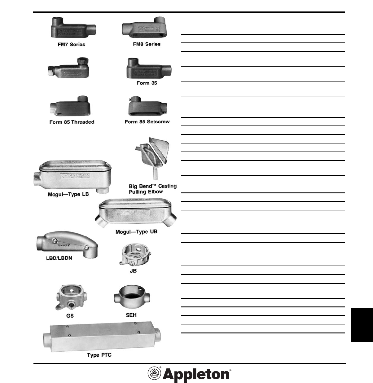
- Unilet® Conduit Bodies and Boxes
- Form 35®
- Form 85™
- FM7™
- FM8®
- FM9™
- Mogul Unilet® Conduit Outlet Bodies: NEC 6x8x Series (C, LB and UB) and Types LL, LR and T
- LBD and LBDN Pulling Fittings
- JB Conduit Outlet Boxes, Covers, and Hangers
- SEH Conduit Outlet Boxes and Covers
- Pull Boxes with Threaded Hubs and Covers
- Big-Bend™ Cast Pulling Elbow
Effective September, 2005
Copyright 2005
800-621-1506
www.appletonelec.com
PAGE 1
A-1
A
Unilet® Conduit Bodies and Boxes
Page Description
2-16 Form 35® Malleable Iron, and Form 85™ Aluminum,
FM7™, FM8® and FM9™ Grayloy™, FM7™ Aluminum
Conduit Outlet Bodies
2-6 Form 35 Bodies Covers/Gaskets and Dimensions
7-11 Form 85 Bodies Covers/Gaskets and Dimensions
12-16 FM7 Series Bodies/Covers/Gaskets and
Dimensions
17-20 FM8 Series Bodies/Covers/Gaskets and
Dimensions
21-24 FM9 Series Bodies/Covers/Gaskets and
Dimensions
25-32 Mogul Malleable Iron and Aluminum
Conduit Outlet Bodies– NEC 6x8x
Series and LL, LR and T
25 Features
26 Bodies and Covers
27 Bending Radii and Bending Space
28-31 NEC 6x8x Pull Charts and Dimensions
32 Wiring Capacity Tables
33 LBD and LBDN Malleable Iron and
Aluminum Pulling Unilets
33 Features; Bodies, Covers and Dimensions;
Wiring Capacity Tables
34-35 JB Conduit Outlet Boxes
34 Features
34-35 JBX, JBDX, JBLX Boxes, Covers, Fixture
Hangers, and Accessories
35 Dimensions and Wiring Capacity Tables
36-37 GS Conduit Outlet Boxes
36 Features
36-37 GS Boxes, Covers, Fixture Hangers,
Gaskets, and Accessories
37 Dimensions and Wiring Capacity Tables
38 SEH Conduit Outlet Boxes
38 Features; SEH Boxes, Covers and Dimensions;
Wiring Capacity Tables
39
Pull Boxes with Threaded Hubs & Covers
40-41 Big Bend™ Cast Pulling Elbow
40 Features
41 Bending Radii and Dimensions
Form 35 Compression
Effective September, 2005
Copyright 2005
PAGE 2
800-621-1506
www.appletonelec.com
A-2
A
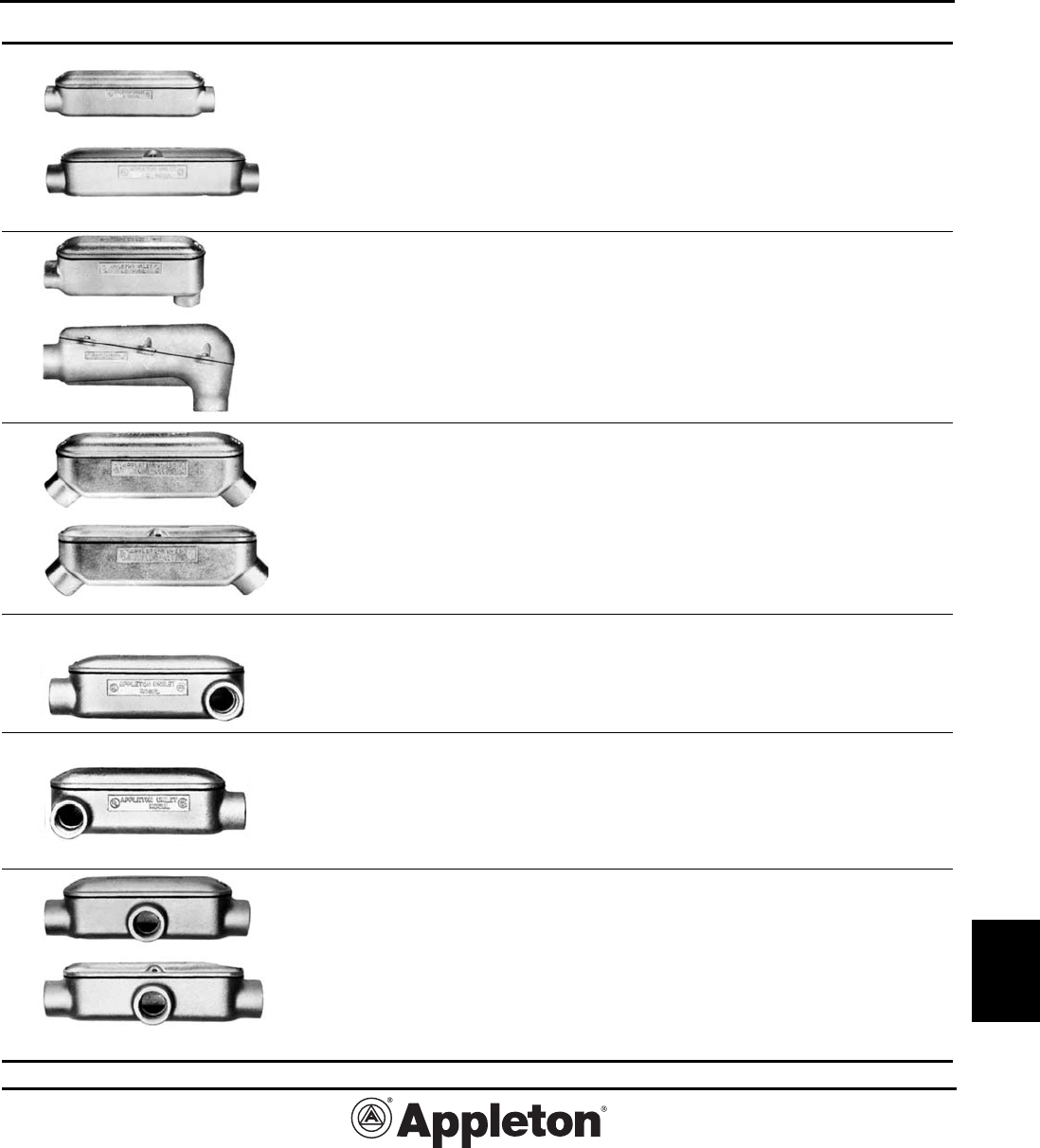
Form 35® Unilet® Conduit Outlet Bodies
For use with Rigid Steel, Rigid Aluminum, IMC, and EMT Conduit.
Applications
• Serve as pulling fittings.
• Make bends in conduit system.
• Provide openings for splicing.
• Connect and change direction of
conduit runs.
• Allow connections for branch runs.
• Permit access to conductors for
maintenance.
Features: Unilet® conduit
outlet bodies
• Roomy interiors: more wiring space.
• Smooth, rounded integral bushings in
hubs protect conductor insulation.
• Accurately tapped, tapered threads for
tight, rigid joints and excellent ground
continuity.
Features: Form 35®
❹ Form 35 malleable iron Unilets: high
tensile strength and ductility. High cor-
rosion-resistance, high impact and
shock resistance.
• Exclusive built-in easy-pulling roll-
ers in type C (1-1/4” thru 4”) and type
LB (1-1/4” thru 4”)– eliminate damage
when cable is pulled through hubs.
• Sizes with flat-back design ideal
where fitting is mounted flat against
surface.
• Complete line of conduit bodies, cov-
ers and receptacles.
• Blank covers domed for extra wiring
space.
Standard Materials
• Form 35 Unilet conduit outlet bodies:
malleable iron.
• Covers: blank– malleable iron, steel
and aluminum. Duplex grounding re-
ceptacle– phenolic. Lamp receptacle–
porcelain. Wiring device and switch
covers– aluminum. Cover screws: stain-
less steel.
• Gaskets: neoprene or composition
fiber.
Standard Finishes
• Malleable iron bodies: triple-coat– (1)
zinc electroplate, (2) dichromate, and
(3) epoxy powder coat.
• Covers: steel: zinc electroplate. Mal-
leable iron: triple-coat– (1) zinc elec-
troplate, (2) dichromate, and (3) epoxy
powder coat.
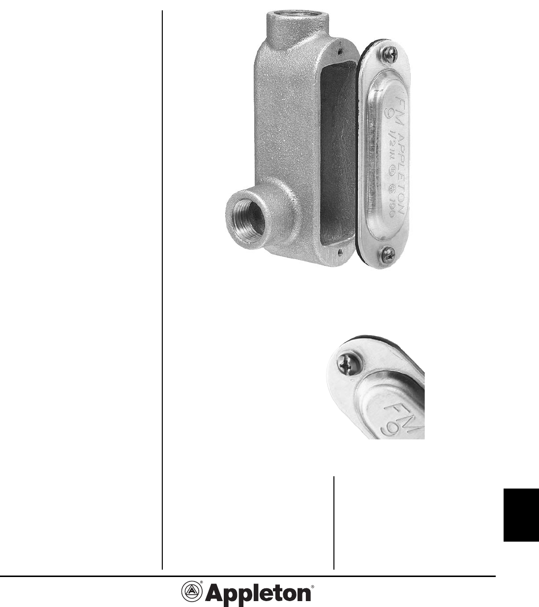
❹ Form 35 Malleable.
2” Type LB with rollers shown.
Compliances
• UL Standard 514A.
• Federal Spec. W-C-586B.
• Suitable for classified location use in
Class I, Division 2 areas, if installed in
compliance with NEC 501-4(b).
• Appleton malleable iron products con-
form to ASTM A47-77, Grade 32510,
which has the following properties: ten-
sile strength, 50,000 psi; yield, 32,000
psi; and elongation, 10%.
• Appleton aluminum products are pro-
duced from a high strength copper-free
(4/10 of 1% max.) alloy.
• Appleton Grayloy-iron products are a
gray iron alloy with tensile strength sim-
ilar to ASTM-A48 Class 30A (30,000
psi tensile), and with a Brinell hardness
of approximately 180BH.
Product Cross Reference
• For explosionproof conduit outlet
bodies and boxes, see Cat. Section J.
• For Mogul Unilets®, see pages A-17
through A-24.
Form 35
Form 35
Effective September, 2005
Copyright 2005
800-621-1506
www.appletonelec.com
PAGE 3
A-3
A
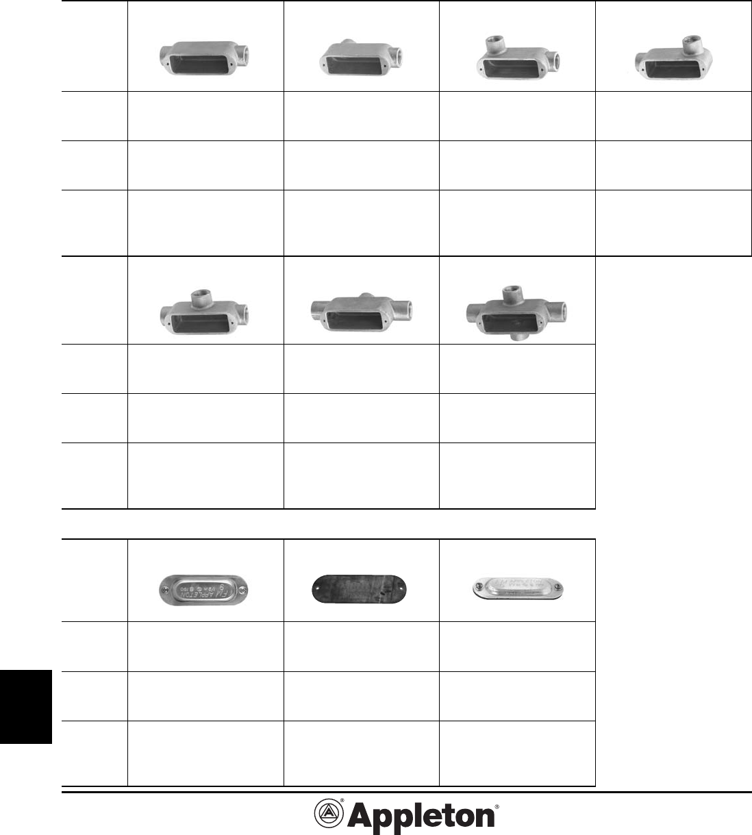
Appleton Form 35® Threaded Type Conduit Bodies NOTE: Refer to page A-16 for Wiring Capacity Tables
C E LB LL LR
Hub
Size (in.)
1/2 C50-M E50-M LB50-M LL50-M LR50-M
3/4 C75-M E75-M LB75-M LL75-M LR75-M
1 C100-M E100-M LB100-M LL100-M LR100-M
1-1/4 C125-M
◊
E125-M LB125-M
◊
LL125-M LR125-M
1-1/2 C150-M
◊
E150-M LB150-M
◊
LL150-M LR150-M
2 C200-M
◊
— LB200-M
◊
LL200-M LR200-M
2-1/2 C250-M
◊
— LB250-M
◊
LL250-M LR250-M
3 C300-M
◊
— LB300-M
◊
LL300-M LR300-M
3-1/2 C350-M
◊
— LB350-M
◊
LL350-M LR350-M
4 C400-M
◊
— LB400-M
◊
LL400-M LR400-M
5 — — LB500-M — —
6 — — LB600-M — —
LRL* T TA TB X
Hub
Size (in.)
1/2 LRL50-M T50-M TA50-M TB50-M X50-M
3/4 LRL75-M T75-M TA75-M TB75-M X75-M
1 LRL100-M T100-M TA100-M TB100-M X100-M
1-1/4 LRL125-M T125-M — TB125-M X125-M
1-1/2 LRL150-M T150-M — TB150-M X150-M
2 LRL200-M T200-M — TB200-M X200-M
2-1/2 — T250-M — — —
3 — T300-M — — —
3-1/2 — T350-M — — —
4 — T400-M — — —
Form 35® Malleable Iron
Unilet® Conduit Outlet Bodies
Threaded Type for use with Rigid Metal Conduit and IMC;
Compression Type for use with Threadless Rigid Metal Conduit.
Back Style for Form 35 Unilet conduit body
sizes (inches)
Unilet Body Flat Back Round Back
C, LB 1/2 - 2 2-1/2 and up
E 1/2 - 1-1/2 1-1/4 and up
LL, LR, T 1/2 - 2 2-1/2 and up
TB 1-1/4, 1-1/2 1/2, 3/4, 1, 2
X 1/2 - 1 1-1/4 and up
All TA Unilets are round back design.
All Compression Type are flatback design.
*LRL Unilets have double opening and are furnished with one steel cover, assembled.
◊
Catalog numbers having patented roller feature, all others do not.
Compression Type—For use with Threadless Rigid Metal Conduit
LB LRL* T
Hub
Size (in.)
1/2 LB50N-M LRL50N-M T50N-M
3/4 LB75N-M LRL75N-M T75N-M
1 LB100N-M LRL100N-M T100N-M
Effective September, 2005
Copyright 2005
PAGE 4
800-621-1506
www.appletonelec.com
A-4
A
Covers and Gaskets for Form 35®
Unilet® Conduit Outlet Bodies
Covers Furnished with Stainless Steel Fastening Screws.
Appleton Form 35® Covers and Gaskets NOTE: Refer to page A-16 for Wiring Capacity Tables.
Size Blank Stamped Steel Blank Cast Malleable Neoprene Composition Fiber
Domed: 1/2” - 3” Flat: 1/2” - 2” Tear out
inner perforated
Form 35 section to convert to
Body “open type” gasket.
Size (in.)
Flat: 3-1/2” - 6” Domed: 2-1/2” - 4”
1/2 K50 K50-CM GK50-N GK50-V
3/4 K75 K75-CM GK75-N GK75-V
1 K100 K100-CM GK100-N GK100-V
1-1/4 K125 & 150 K125 & 150-CM GK125-150-N GK125-150-V
1-1/2 K125 & 150 K125 & 150-CM GK125-150-N GK125-150-V
2 K200 K200-CM GK200-N GK200-V
2-1/2 K250 & 300 K250 & 300-CM GK250-300-N GK-250-300-V
3 K250 & 300 K250 & 300-CM GK250-300-N GK-250-300-V
3-1/2 K350 & 400 K350 & 400-CM GK350-400-N GK-350-400-V
4 K350 & 400 K350 & 400-CM GK350-400-N GK-350-400-V
5 K500 — GK500-SN†
6 K600 — GK600-SN†
† Not perforated
Wiring Device Covers
Lamp Receptacle with Device Cover for Interchangeable Switch Cover for Interchangeable
1-1/2” Shade Holder Groove. (Despard) Wiring Devices, (Despard) Devices, Cast Aluminum
Porcelain, 600 Watt, 600 Volt Rating Cast Aluminum with Mounting Strap with Gasket and Steel Mounting Strap
Form 35 Form 35 Form 35
Body Size (in.) Cat. No. Body Size (in.) Cat. No. Body Size (in.) Cat. No.
1/2 KLR50 1/2 KWD50-A 3/4 KVS75-A
3/4 KLR75
Effective September, 2005
Copyright 2005
800-621-1506
www.appletonelec.com
PAGE 5
A-5
A
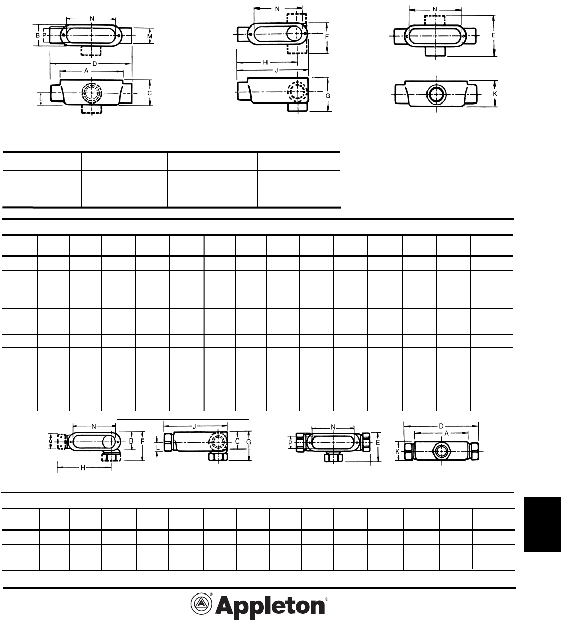
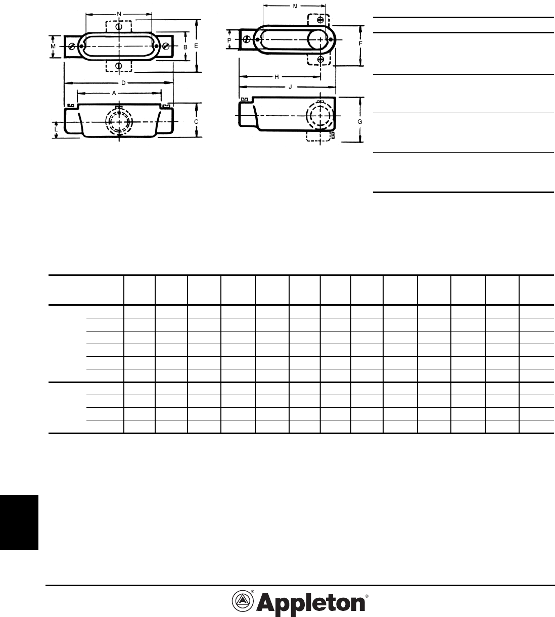
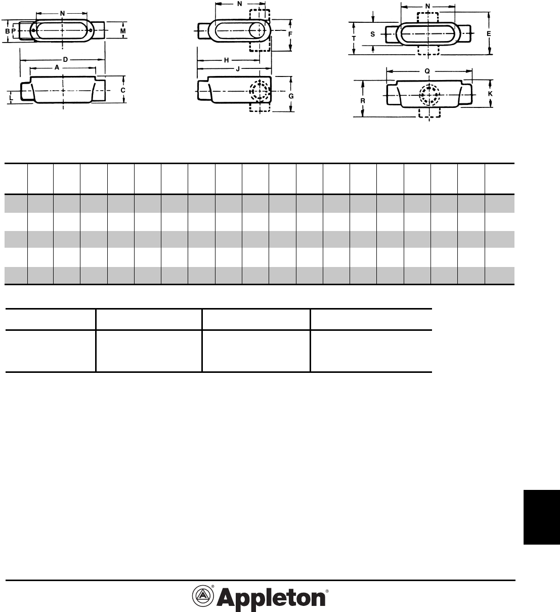
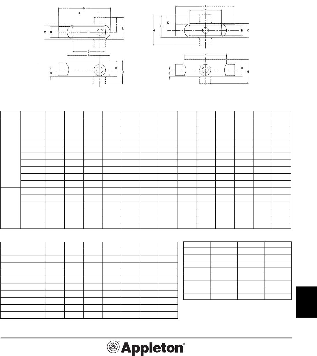
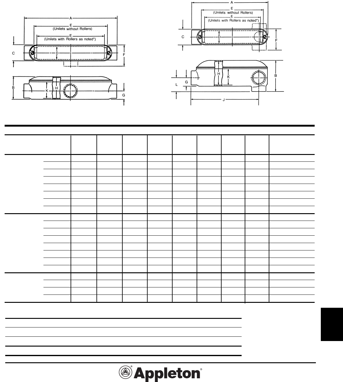
Dimensions:
Form 35® Malleable Iron Unilet®
Conduit Outlet Bodies
Threaded Type for use with Rigid Metal Conduit and IMC;
Compression Type for use with Threadless Rigid Metal Conduit.
Compression Type Dimensions in Inches
Hub Size A B C D E F G H J K L M N P
1/2 3.94 1.31 1.44 6.06 2.38 2.38 2.50 4.31 5.00 1.75 .63 1.31 3.16 1.00
3/4 4.63 1.56 1.69 6.81 2.69 2.69 2.81 4.81 5.75 2.00 .75 1.63 3.78 1.22
1 5.38 1.81 1.94 7.63 2.94 2.94 3.06 5.38 6.50 2.25 .94 1.88 4.53 1.47
Fraction/Decimal Equivalents (Inches)
Fraction Decimal Fraction Decimal Fraction Decimal Fraction Decimal
1/16 0.06 5/16 0.31 9/16 0.56 13/16 0.81
1/8 0.13 3/8 0.38 5/8 0.63 7/8 0.88
3/16 0.19 7/16 0.44 11/16 0.69 15/16 0.94
1/4 0.25 1/2 0.50 3/4 0.75 1 1.00
Threaded Type Dimensions in Inches
Hub Size A B C D E F G H J K L M N P
1/2 3.94 1.31 1.44 5.38 2.69 2.00 2.13 3.94 4.63 1.75 .63 1.19 3.16 1.00
3/4 4.63 1.56 1.69 6.06 2.88 2.19 2.31 4.44 5.38 2.00 .75 1.38 3.78 1.22
1 5.38 1.81 1.94 7.13 3.38 2.56 2.69 5.13 6.25 2.25 .94 1.69 4.53 1.47
1-1/4 7.19 2.50 2.56 9.19 4.50 3.50 3.56 7.06 8.19 2.56 1.19 2.00 6.00 2.00
1-1/2 7.19 2.50 2.75 9.19 4.50 3.50 3.75 6.81 8.19 2.75 1.38 2.38 6.00 2.00
2 9.50 3.13 3.38 11.63 5.25 4.19 4.63 8.94 10.56 3.38 1.63 2.94 8.06 2.56
2-1/2 12.25 4.31 3.88 15.13 7.19 5.75 5.25 11.88 13.69 3.88 1.81 3.38 10.63 3.69
3 12.25 4.31 4.63 15.13 7.19 5.75 6.00 11.56 13.69 4.63 2.19 4.13 10.63 3.69
3-1/2 14.88 5.50 5.19 18.13 8.75 7.13 6.81 14.00 16.50 5.19 2.50 4.75 13.13 4.88
4 14.88 5.50 5.56 18.13 8.75 7.13 7.19 13.75 16.50 5.56 2.75 5.13 13.13 4.88
5 18.25 7.25 7.00 9.00 16.88 20.25 3.38 6.50 16.25 6.50
6 23.00 8.63 8.69 10.69 21.06 25.00 3.94 7.56 21.00 7.81
Types A, C, TA, TB Types A, C, TA, TBTypes E, LB, LL, LR, LRL Types T, X
Types LB, LRL Type T

Effective September, 2005
Copyright 2005
PAGE 6
800-621-1506
www.appletonelec.com
A-6
A
Wiring Capacity:
Form 35® Conduit Bodies and Covers
Combine Body and Cover Capacities for Total usable Capacity
per NEC 370-6(a)(1)
Form 35® Malleable Iron Bodies and Covers: Threaded and Compression
Capacity in Cubic Inches
Hub LL Stamped Cast
Size (In.) C E LB LR LRL T TA TB X Cover Cover
1/2 4.5 4.5 4.5 4.5 5.0 6.0 4.3 4.3 6.0 0.5 0
3/4 7.5 7.5 7.5 7.5 8.8 9.5 7.0 7.0 9.5 0.8 0.3
1 12.5 12.5 12.5 12.5 14.3 15.0 15.0 13.0 15.0 1.0 0.5
1-1/4 35.0 29.3 32.3 32.0 34.8 33.0 — 35.0 31.5 2.5 0.8
1-1/2 35.3 32.5 35.3 35.3 40.0 36.0 — 35.3 40.0 2.5 0.8
2 75.0 — 73.0 73.0 85.0 71.0 — 71.0 71.0 6.5 1.5
2-1/2 143.0 — 139.0 140.5 — 146.0 — — — 18.0 30.0
3 180.0 — 177.0 175.0 — 185.0 — — — 18.0 30.0
3-1/2 303.0 — 300.0 300.0 — 314.0 — — — — 50.0
4 340.0 — 330.0 330.0 — 345.0 — — — — 50.0
5 — — 756.0 — — — — — — — —
6 — — 1328.0 — — — — — — — —
Effective September, 2005
Copyright 2005
800-621-1506
www.appletonelec.com
PAGE 7
A-7
A
Form 85™ Unilet® Conduit Outlet Bodies
For use with Rigid Steel, Rigid Aluminum, IMC, and EMT Conduit.
Applications
• Serve as pulling fittings.
• Make bends in conduit system.
• Provide openings for splicing.
• Connect and change direction of
conduit runs.
• Allow connections for branch runs.
• Permit access to conductors for
maintenance.
Features: Unilet® conduit
outlet bodies
• Roomy interiors: more wiring space.
• Smooth, rounded integral bushings in
hubs protect conductor insulation.
• Accurately tapped, tapered threads for
tight, rigid joints and excellent ground
continuity.
Features: Form 85™
❺ Form 85 aluminum Unilets: copper-
free aluminum (max. 4/10 of 1% copper
content). Lightweight, high corrosion re-
sistance. Self-oxidizing, self-renewing.
• Lightweight aluminum facilitates ship-
ping, handling and installing.
•
Sizes with flat-back design ideal where
fitting is mounted flat against surface.
• Complete line of conduit bodies, cov-
ers and receptacles.
• Blank covers domed for extra wiring
space.
Standard Materials
• Unilet conduit outlet bodies: alumi-
num– copper-free (max. 4/10 of 1%).
1/2” thru 2”– pressure cast. 2-1/2” thru
4”– sand cast.
• Covers: blank– malleable iron, steel
and aluminum. Duplex grounding re-
ceptacle– phenolic. Lamp receptacle–
porcelain. Wiring device and switch
covers– aluminum. Cover screws: stain-
less steel.
• Gaskets: neoprene or composition
fiber.
Standard Finishes
• Aluminum bodies: epoxy powder coat.
• Stamped aluminum covers: natural
finish.
• Cast aluminum covers: epoxy powder
coat.
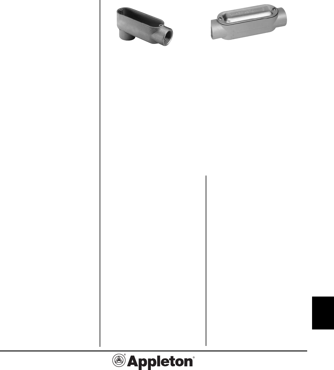
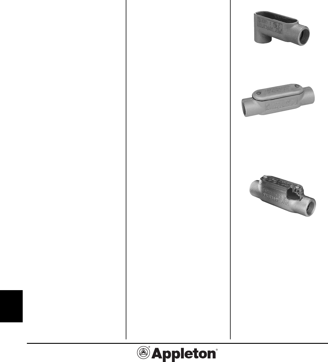
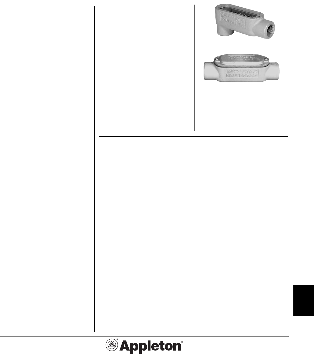
❺ Form 85 Aluminum Conduit
Body with Stamped Aluminum
Cover. 2” Type C shown.
Form 85
Compliances
• UL Standard 514A.
• Federal Spec. W-C-586B.
• Suitable for classified location use in
Class I, Division 2 areas, if installed in
compliance with NEC 501-4(b).
• Appleton malleable iron products
conform to ASTM A47-77, Grade
32510, which has the following proper-
ties: tensile strength, 50,000 psi; yield,
32,000 psi; and elongation, 10%.
• Appleton aluminum products are pro-
duced from a high strength copper-free
(4/10 of 1% max.) alloy.
• Appleton Grayloy-iron products are a
gray iron alloy with tensile strength sim-
ilar to ASTM-A48 Class 30A (30,000
psi tensile), and with a Brinell hardness
of approximately 180BH.
Product Cross Reference
• For explosionproof conduit outlet
bodies and boxes, see Cat. Section J.
• For Mogul Unilets®, see pages A-17
through A-24.
Effective September, 2005
Copyright 2005
PAGE 8
800-621-1506
www.appletonelec.com
A-8
A
Form 85™ Aluminum Unilet®
Conduit Outlet Bodies
Threaded Type for use with Rigid Metal Conduit and IMC.
Setscrew Type for use with Electrical Metal Tubing (EMT).
Appleton Form 85™ Conduit Bodies: Threaded/SetScrew Type NOTE: Refer to page A-16 for Wiring Capacity Tables
C E LB LL LR
Hub Threaded Setscrew Threaded Setscrew Threaded Setscrew Threaded Setscrew Threaded Setscrew
Size (in.) Type Type Type Type Type Type Type Type Type Type
1/2 C50-A C50T-A E50-A E50T-A LB50-A LB50T-A LL50-A LL50T-A LR50-A LR50T-A
3/4 C75-A C75T-A E75-A — LB75-A LB75T-A LL75-A LL75T-A LR75-A LR75T-A
1 C100-A C100T-A E100-A — LB100-A LB100T-A LL100-A LL100T-A LR100-A LR100T-A
1-1/4 C125-A C125T-A — — LB125-A LB125T-A LL125-A LL125T-A LR125-A LR125T-A
1-1/2 C150-A C150T-A — — LB150-A LB150T-A LL150-A LL150T-A LR150-A LR150T-A
2 C200-A — — — LB200-A LB200T-A LL200-A LL200T-A LR200-A LR200T-A
2-1/2 C250-A — — — LB250-A — LL250-A — LR250-A —
3 C300-A — — — LB300-A — LL300-A — LR300-A —
3-1/2 C350-A — — — LB350-A — LL350-A — LR350-A —
4 C400-A — — — LB400-A — LL400-A — LR400-A —
Back Style for Form 85®
Unilet Body Flat Back Round Back
C, LB, LL, LR, T 1/2” – 2” 2-1/2” – 4”
TB 1-1/4”, 1-1/2” 1/2”, 3/4”, 1”, 2”
E, X 1/2” – 1”
All setscrew types are flatback design.
Typical Form 85 Conduit
Bodies with Setscrews.
For use with Electrical
Metal Tubing (EMT).
T TB X
Hub Threaded Setscrew Threaded Setscrew Threaded Setscrew
Size (in.) Type Type Type Type Type Type
1/2 T50-A T50T-A TB50-A — X50-A —
3/4 T75-A T75T-A TB75-A — X75-A —
1 T100-A T100T-A TB100-A — X100-A —
1-1/4 T125-A — TB125-A — — —
1-1/2 T150-A — TB150-A — — —
2 T200-A — TB200-A — — —
2-1/2 T250-A — — — — —
3 T300-A — — — — —
3-1/2 T350-A — — — — —
4 T400-A — — — — —
Effective September, 2005
Copyright 2005
800-621-1506
www.appletonelec.com
PAGE 9
A-9
A
Covers and Gaskets for Form 85™
Unilet® Conduit Outlet Bodies
Covers Furnished with Stainless Steel Fastening Screws.
Appleton Form 85™ Covers and Gaskets NOTE: Refer to page A-16 for Wiring Capacity Tables.
Size Blank Stamped Aluminum Blank Cast Aluminum Neoprene Composition Fiber
Domed: 1/2” - 3” Flat: 1/2” - 2” Tear out
inner perforated
section to convert to
Form 85 “open type” gasket.
Body
Size (in.)
Flat: 3-1/2” - 4” Domed: 2-1/2” - 4”
1/2 K50-A K50-CA GK50-N GK50-V
3/4 K75-A K75-CA GK75-N GK75-V
1 K100-A K100-CA GK100-N GK100-V
1-1/4 K125 & 150-A K125 & 150-CA GK125-150-N GK125-150-V
1-1/2 K125 & 150-A K125 & 150-CA GK125-150-N GK125-150-V
2 K200-A K200-CA GK200-N GK200-V
2-1/2 K250 & 300-A K250 & 300-CA GK250-300-N GK-250-300-V
3 K250 & 300-A K250 & 300-CA GK250-300-N GK-250-300-V
3-1/2 K350 & 400-A K350 & 400-CA GK350-400-N GK-350-400-V
4 K350 & 400-A K350 & 400-CA GK350-400-N GK-350-400-V
Wiring Device Covers
Lamp Receptacle with Device Cover for Interchangeable Switch Cover for Interchangeable
1-1/2” Shade Holder Groove. (Despard) Wiring Devices, (Despard) Devices, Cast Aluminum
Porcelain, 600 Watt, 600 Volt Rating Cast Aluminum with Mounting Strap with Gasket and Steel Mounting Strap
Form 85 Form 85 Form 85
Body Size (in.) Cat. No. Body Size (in.) Cat. No. Body Size (in.) Cat. No.
1/2 KLR50 1/2 KWD50-A 3/4 KVS75-A
3/4 KLR75
Effective September, 2005
Copyright 2005
PAGE 10
800-621-1506
www.appletonelec.com
A-10
A
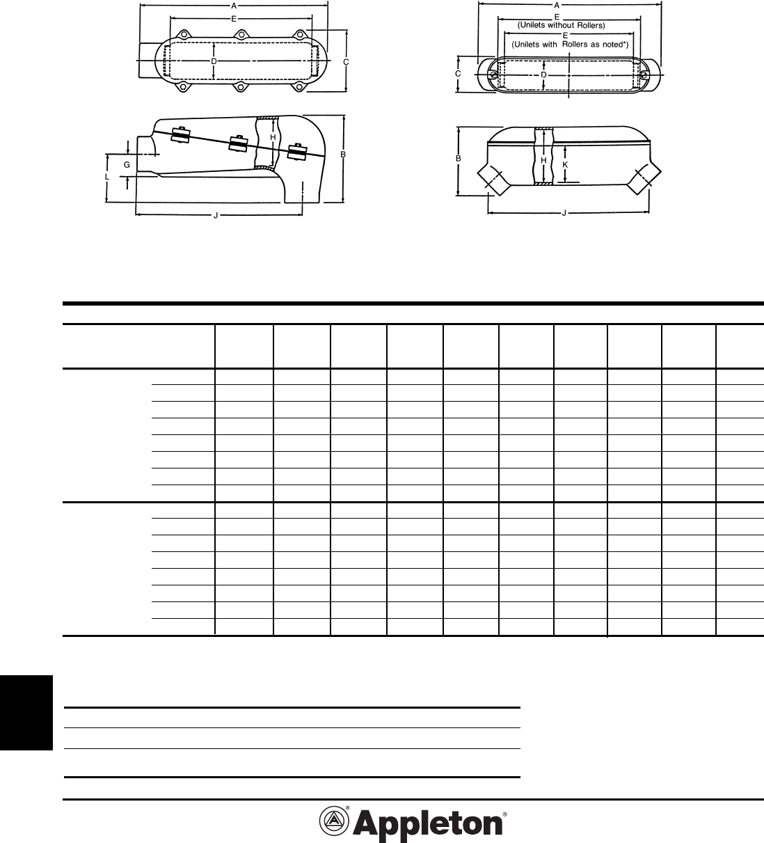
Dimensions In Inches
Hub
Trade A B C D E F G H J L M N P
Size (In.)
1/2 3.94 1.31 1.38 4.75 2.56 2.00 2.06 3.50 4.31 .63 1.13 3.14 1.05
3/4 4.63 1.56 1.63 5.63 3.00 2.25 2.44 4.13 5.13 .75 1.38 3.78 1.27
1 5.38 1.81 1.88 6.69 3.50 2.63 2.81 4.88 6.00 .94 1.69 4.50 1.52
1-1/4 7.19 2.50 2.75 8.56 3.50 3.88 6.56 7.88 1.06 2.13 6.00 2.25
1-1/2 7.19 2.50 2.75 8.56 3.50 3.81 6.44 7.88 1.19 2.38 6.00 2.25
2 9.50 3.13 3.44 10.81 4.19 4.56 8.31 10.19 1.50 2.94 8.06 2.75
2-1/2 12.25 4.31 3.88 15.13 7.19 5.75 5.25 11.88 13.69 1.81 3.38 10.63 3.69
3 12.25 4.31 4.63 15.13 7.19 5.75 6.00 11.56 13.69 2.19 4.13 10.63 3.69
3-1/2 14.88 5.50 5.19 18.13 8.75 7.13 6.81 14.00 16.50 2.50 4.75 13.13 4.88
4 14.88 5.50 5.56 18.13 8.75 7.13 7.19 13.75 16.50 2.75 5.13 13.13 4.88
Dimensions:
Form 85™ Threaded and Setscrew, Unilet®
Conduit Outlet Bodies, Aluminum
Types C, T, X Types E, LB, LL, LR
Fraction/Decimal
Equivalents (Inches)
Fraction Decimal
1/16 0.06
1/8 0.13
3/16 0.19
1/4 0.25
5/16 0.31
3/8 0.38
7/16 0.44
1/2 0.50
9/16 0.56
5/8 0.63
11/16 0.69
3/4 0.75
13/16 0.81
7/8 0.88
15/16 0.94
1 1.00
Sand
Cast
Pressure
Cast

Effective September, 2005
Copyright 2005
800-621-1506
www.appletonelec.com
PAGE 11
A-11
A
Wiring Capacity:
Form 85™ Conduit Bodies and Covers
Combine Body and Cover Capacities for Total usable Capacity
per NEC 370-6(a)(1)
Form 85™ Aluminum Bodies and Covers: Threaded and Setscrew
Capacity in Cubic Inches
Hub LL Stamped Cast
Size (In.) C E LB LR LRL T TA TB X Cover Cover
1/2 4.0 4.0 4.0 4.0 — 4.0 — 6.0 4.0 0.5 0
3/4 7.0 7.0 7.0 7.0 — 7.0 — 7.0 7.0 0.8 0.3
1 11.8 11.8 11.8 11.8 — 11.8 — 13.0 11.8 1.0 0.5
1-1/4 34.8 — 34.8 34.0 — 34.0 — 35.0 — 2.5 0.8
1-1/2 35.0 — 35.0 35.0 — 35.0 — 34.5 — 2.5 0.8
2 70.0 — 70.0 70.0 — 70.0 — 71.0 — 6.5 1.5
2-1/2 143.0 — 139.0 140.5 — 146.0 — — — 18.0 30.0
3 180.0 — 177.0 175.0 — 185.0 — — — 18.0 30.0
3-1/2 303.0 — 300.0 300.0 — 314.0 — — — — 50.0
4 340.0 — 330.0 330.0 — 345.0 — — — — 50.0
Effective June, 2006
Copyright 2006
PAGE 12
800-621-1506
www.appletonelec.com
A-12
A
FM7™ Unilet® Conduit Outlet Bodies
For use with Rigid Steel, Rigid Aluminum, IMC, and EMT Conduit.
Applications
• Serve as pulling fittings.
• Make bends in conduit system.
• Provide openings for splicing.
• Connect and change direction of
conduit runs.
• Allow connections for branch runs.
• Permit access to conductors for
maintenance.
Features: Unilet® conduit
outlet bodies
• Roomy interiors: more wiring space.
• Smooth, rounded integral bushings in
hubs protect conductor insulation.
• Accurately tapped, tapered threads for
tight, rigid joints and excellent ground
continuity.
Features: FM7™ Series
❶ FM7 Grayloy™-Iron Unilets: most eco-
nomical conduit bodies for use where
the special advantages of malleable
iron or aluminum are not required.
❷ FM7 Aluminum Unilets: same
dimensions and design features as
FM7 Grayloy™-lron, plus light weight,
high corrosion resistance.
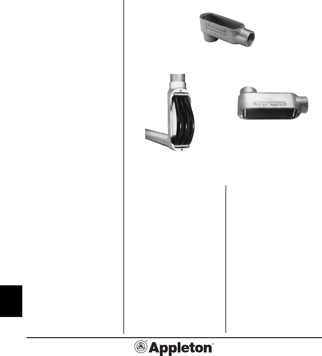
• FM7 Wedge-Lok™ Formtite™ covers
with integral gasket are approved for
use in wet locations.
• Unique Wedge-Lok™ clip covers allow
easy removal. No retapping of corrod-
ed body screw holes is necessary to
replace cover.
• Completely interchangeable with
Crouse-Hinds Form 7™ bodies, gaskets
and covers. Equivalent FM7 and Form
7™ units have identical applications and
installation dimensions.
• Flat back design provides greater
cubic content for easier wire pulling
and more room for splicing.
• Smooth hub bushings and cover
openings protect conductor insulation.
Smooth hub openings allow easy con-
duit joining.
• Pan-head cover screws secure cover
clips and provide superior screwdriver
seating and torque. Cover screws and
clips are captive to prevent loss.
• Hub size, body style, and compli-
ance data molded into body in large,
easy-to-read form. Also maximum wire
number/size and cubic capacity.
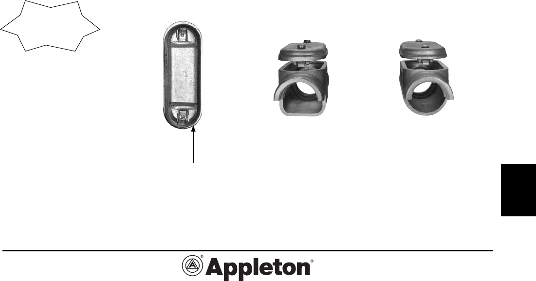
❶ FM7 Grayloy™-iron, 1” Type C
shown with cut-away body and
cover to illustrate Wedge-Lok™
Clip Cover detail.
Standard Materials
• Grayloyiron or copper-free alumi-
num.
• Stamped steel, stamped aluminum,
cast Grayloy-iron, and cast aluminum;
cover screws: stainless steel.
Standard Finishes
• Grayloy-iron bodies: triplecoat– (1)
zinc electroplate, (2) dichromate, and
(3) epoxy powder coat.
• Aluminum bodies: epoxy powder
coat.
• Steel covers: zinc electroplate.
• Stamped aluminum covers: natural
finish.
• Grayloy-iron covers: triplecoat– (1)
zinc electroplate, (2) dichromate, and
(3) epoxy powder coat.
• Cast aluminum covers: epoxy powder
coat.
Compliances
• UL Standard 514A.
• Federal Spec. W-C-586B.
• Suitable for classified location use in
Class I, Division 2 areas, if installed in
compliance with NEC 501-4(b).
• Appleton malleable iron products con-
form to ASTM A47-77, Grade 32510,
which has the following properties: ten-
sile strength, 50,000 psi; yield, 32,000
psi; and elongation, 10%.
• Appleton aluminum products are pro-
duced from a high strength copper-free
(4/10 of 1% max.) alloy.
• Appleton Grayloy-iron products are a
gray iron alloy with tensile strength sim-
ilar to ASTM-A48 Class 30A (30,000
psi tensile), and with a Brinell hardness
of approximately 180BH.
Product Cross Reference
• For explosionproof conduit outlet
bodies and boxes, see Cat. Section J.
FM7
*Form 7 is a product of Crouse-Hinds, a member
company of Cooper Industries.
❷ FM7 Aluminum
Conduit Body with
Cast Aluminum
Cover. 1” Type C
shown.
Effective June, 2006
Copyright 2006
800-621-1506
www.appletonelec.com
PAGE 13
A-13
A
FM7™ Grayloy™-Iron and Aluminum Unilet®
Conduit Bodies: Wedge-Lok™ Clip Covers
For use with Rigid Steel, Rigid Aluminum and IMC Conduit.
Interchangeable. Appleton FM7 bodies, covers and
gaskets are completely interchangeable with equivalent
Crouse-Hinds Form 7* bodies and covers.
Applications and installation dimensions are also inter-
changeable.
No wire damage. Appleton FM7 bodies have a smooth,
rounded, internal bushing in each hub and smooth cover
openings to protect conductor insulation.
Easy cover removal. Unique FM7 Wedge-Lok Clip-Cover
design allows easy removal at any later time, without dam-
aging the conduit body. Because the cover is secured with
clips– not screws – no retapping of corroded body screw
holes is necessary to replace cover.
Positive-seating cover screws. Pan-head stainless steel
cover screws, which hold the clips, provide superior screw-
driver seating and torque for easier cover installation or
removal. Each cover screw and its attached locking clip
are held captive in the cover to prevent loss.
Full-line choice. Appleton FM7 bodies are offered in a
complete range of hub configurations and sizes. FM7
covers are available in blank stamped steel or stamped
aluminum, and also in cast Grayloy-iron or cast alumi-
num. Covers can be used without gaskets, or with a solid
neoprene gasket. All Appleton FM7 bodies, covers and
gaskets are interchangeable with Crouse-Hinds Form 7*
bodies, covers and gaskets.
Approved for wet locations.
FM7 Grayloy-iron bodies with cast covers and gasket are
approved for use in wet locations. (NEMA 3R)
Maximum corrosion protection. Appleton FM7 Grayloy-
iron conduit bodies and cast covers have a triple-coat fin-
ish– (1) zinc electroplate, (2) dichromate, and (3) epoxy
powder coating. FM7 aluminum bodies and cast covers are
coated with epoxy powder coating. FM7 blank steel covers
have a zinc electroplate finish. Superior FM7 finish gives
greater corrosion protection in wet or harsh environments,
assuring long, trouble-free service.
Grayloy-iron properties. Grayloy™ is an Appleton pro-
prietary cast graphite flake gray iron alloy with superior
physical and mechanical properties offering strength, hard-
ness, fracture toughness, high vibration absorption and
dimensional stability. Tensile strength is similar to ASTM-
A48 Class 30A (30,000 tensile), with Brinell hardness of
approximately 180BH.
Aluminum properties. Aluminum products are produced
from a high strength copper-free (4/10 of 1% max.) alloy.
More wiring space. Appleton’s FM7 flat-back design
provides greater cubic content for easier wire pulling, and
more room for splicing. FM7 flat back fits flush and snug
against flat surfaces for more stable installation.
*Form 7 ia a product of Crouse-Hinds, a member company of Cooper Industries.
Appleton FM7:
• Maximum wire number/size and cubic capacity molded into body.
• Large size, style and compliance data molded into body.
Illustrated views are cut away to demonstrate back configurations.
Appleton
FM7™
Crouse-Hinds
Form 7
Appleton FM7 (C57, 1-1/2”)
28 Cubic Inches Capacity
Flat-Back Design
Crouse-Hinds Form 7 (C57, 1-1/2”)
26 Cubic Inches Capacity
Formtite™ 7 Features
• One-piece cover and gasket
assembly
• Neoprene gasket is bonded to
Iron, Steel or Aluminum cover
• Ease of installation
• Productivity gain
• Eliminates “stock outs” of one item
or the other
• No need to order, store, handle, or
install separate covers and gaskets
because there are fewer SKU’s to
order and inventory
Neoprene Integral
Gasket pre-assembled
to Conduit Body Cover
NEW
Formtite™ 7
Covers with
Integral Gaskets
Effective June, 2006
Copyright 2006
PAGE 14
800-621-1506
www.appletonelec.com
A-14
A
FM7™ Grayloy™-Iron and Aluminum Unilet®
Conduit Bodies with Wedge-Lok™ Clip Covers
and Gaskets
For use with Rigid Steel, Rigid Aluminum and IMC Conduit.
These Appleton FM7 conduit bodies, covers and gaskets have the same applications and installation dimensions as Crouse-Hinds Form 7
conduit bodies. Equivalent FM7 and Form 7 items are completely interchangeable.
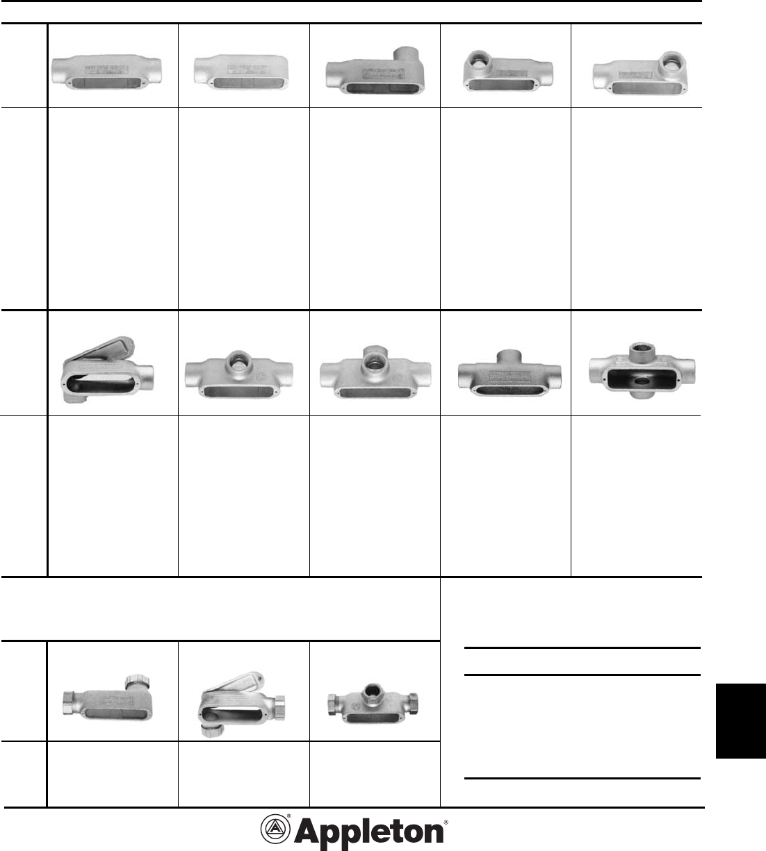
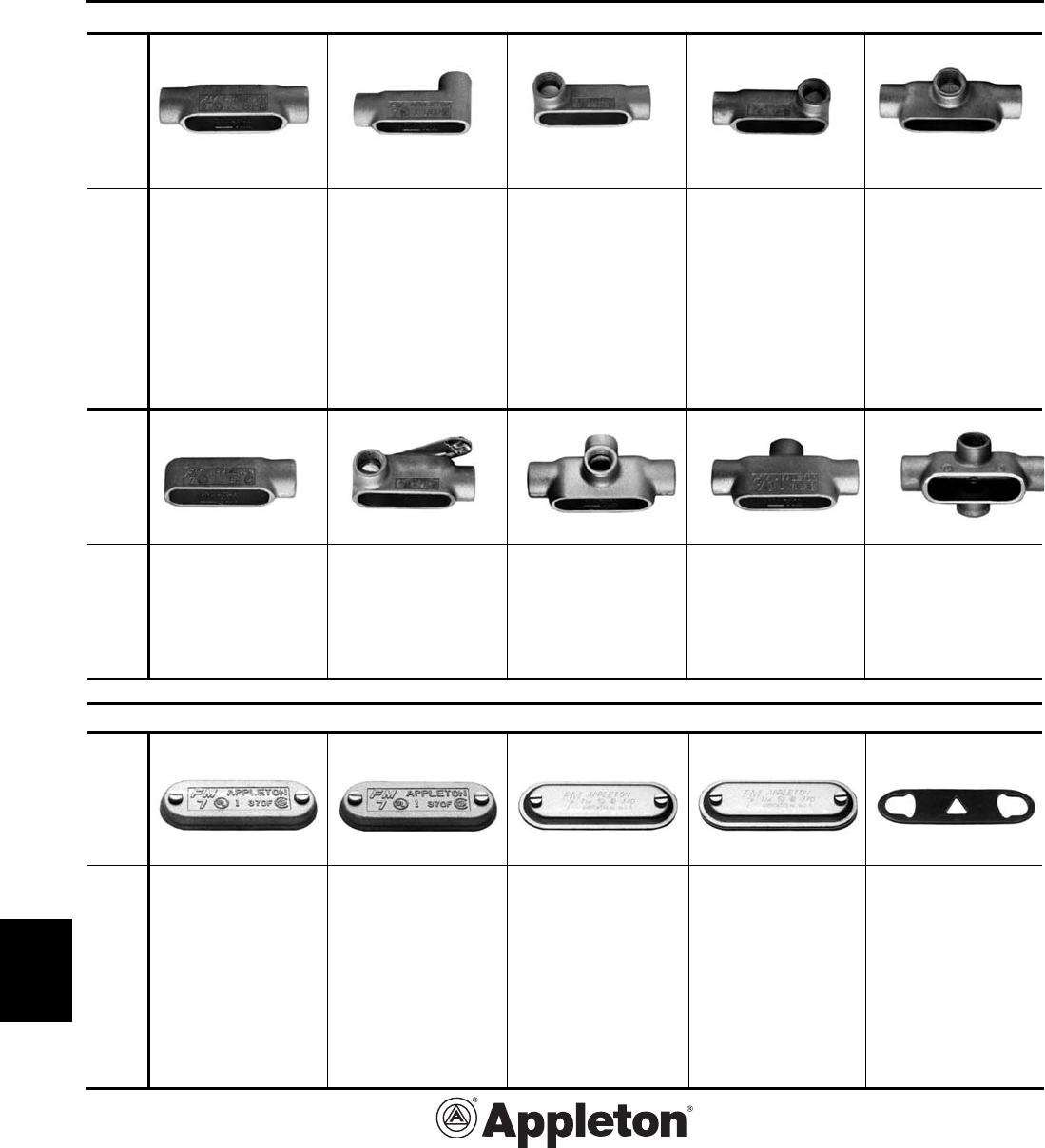
Appleton FM7 Conduit Bodies NOTE: Refer to page A-15 for Wiring Capacity Tables
C LB LL LR T
Hub
Size (in.) Grayloy-Iron Aluminum Grayloy-Iron Aluminum Grayloy-Iron Aluminum Grayloy-Iron Aluminum Grayloy-Iron Aluminum
1/2 C17 C17-SA LB17 LB17-SA LL17 LL17-SA LR17 LR17-SA T17 T17-SA
3/4 C27 C27-SA LB27 LB27-SA LL27 LL27-SA LR27 LR27-SA T27 T27-SA
1 C37 C37-SA LB37 LB37-SA LL37 LL37-SA LR37 LR37-SA T37 T37-SA
1-1/4 C47 C47-SA LB47 LB47-SA LL47 LL47-SA LR47 LR47-SA T47 T47-SA
1-1/2 C57 C57-SA LB57 LB57-SA LL57 LL57-SA LR57 LR57-SA T57 T57-SA
2 C67 C67-SA LB67 LB67-SA LL67 LL67SA LR67 LR67-SA T67 T67-SA
2-1/2 C77 C77-SA LB77 LB77-SA LL77 LL77-SA LR77 LR77-SA T77 T77-SA
3 C87 C87-SA LB87 LB87-SA LL87 LL87-SA LR87 LR87-SA T87 T87-SA
3-1/2 — — LB97 LB97-SA LL97 LL97-SA LR97 LR97-SA T97 T97-SA
4 — — LB107 LB107-SA LL107 LL107-SA LR107 LR107-SA T107 T107-SA
E L* TA TB X
Hub
Size (in.) Grayloy-Iron Aluminum Grayloy-Iron Aluminum Grayloy-Iron Aluminum Grayloy-Iron Aluminum Grayloy-Iron Aluminum
1/2 E17 E17-SA L17 — TA17 — TB17 TB17-SA X17 X17-SA
3/4 E27 E27-SA L27 — TA27 — TB27 TB27-SA X27 X27-SA
1 E37 E37-SA L37 — TA37 — TB37 TB37-SA X37 X37-SA
1-1/4 — — L47 — TA47 — TB47 TB47-SA X47 X47-SA
1-1/2 — — L57 — TA57 — TB57 TB57-SA X57 X57-SA
2 — — L67 — TA67 — TB67 TB67-SA X67 X67-SA
* L Unilets have double opening and are furnished with one steel cover, assembled.
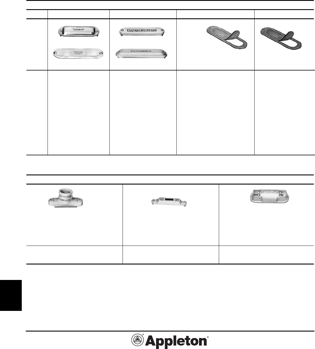
Appleton FM7 Blank Covers and Gaskets (Covers furnished with Stainless Steel Screws)
Wedge-Lok Formtite Cast Cover Wedge-Lok Formtite Stamped Cover Solid
Cast Cover with Integral Gasket Stamped Cover with Integral Gasket Neoprene Gasket
FM7
Body
Size (in.) Grayloy-Iron Aluminum Grayloy-Iron Aluminum Steel Aluminum Steel Aluminum
1/2 170F 170F-SA 170FG 170FG-SA 170 170-SA 170G 170G-SA GASK571
3/4 270F 270F-SA 270FG 270FG-SA 270 270-SA 270G 270G-SA GASK572
1 370F 370F-SA 370FG 370FG-SA 370 370-SA 370G 370G-SA GASK573
1-1/4 470F 470F-SA 470FG 470FG-SA 470 470-SA 470G 470G-SA GASK574
1-1/2 570F 570F-SA 570FG 570FG-SA 570 570-SA 570G 570G-SA GASK575
2 670F 670F-SA 670FG 670FG-SA 670 670-SA 670G 670G-SA GASK576
2-1/2 870F 870F-SA 870FG 870FG-SA 870 870-SA 870G 870G-SA GASK578
3 870F 870F-SA 870FG 870FG-SA 870 870-SA 870G 870G-SA GASK578
3-1/2 970F 970F-SA 970FG 970FG-SA 970 970-SA 970G 970G-SA GASK579
4 970F 970F-SA 970FG 970FG-SA 970 970-SA 970G 970G-SA GASK579
Effective June, 2006
Copyright 2006
800-621-1506
www.appletonelec.com
PAGE 15
A-15
A
FM7™ Conduit Body Dimensions
Type C Types E, L, LB, LL, LR Types T, TA, TB, X
Dimensions in Inches
Hub
Size A B C D E F G H J K L M N P Q R S T
1/2 3.63 1.38 1.38 5.38 3.31 2.25 2.25 3.94 4.56 1.75 0.63 1.25 3.19 0.94 5.63 2.63 1.56 2.44
3/4 4.25 1.56 1.63 6.00 3.50 2.44 2.50 4.44 5.19 2.00 0.75 1.50 3.81 1.13 6.25 2.88 1.88 2.63
1 5.00 1.75 1.88 7.00 3.88 2.75 2.88 5.19 6.00 2.25 0.88 1.75 4.50 1.38 7.25 3.25 2.00 3.00
1-1/4 5.50 2.19 2.31 7.44 4.13 3.19 3.31 5.44 6.50 2.31 1.13 2.19 5.00 1.75 7.44 3.31 2.19 3.19
1-1/2 6.00 2.44 2.56 8.19 4.63 3.50 3.69 5.94 7.13 2.56 1.25 2.44 5.44 1.94 8.19 3.63 2.44 3.56
2 7.00 3.00 3.13 9.19 5.19 4.06 4.25 6.63 8.13 3.13 1.50 3.00 6.38 2.44 9.19 4.19 3.00 4.13
2-1/2 9.00 4.25 3.63 12.00 — 5.75 5.13 8.75 10.50 3.63 1.75 3.50 8.38 3.56 12.00 — 4.25 5.75
3 9.00 4.25 4.38 12.00 — 5.75 5.88 8.38 10.50 4.38 2.13 4.25 8.38 3.56 12.06 — 4.25 5.75
3-1/2 11.00 5.25 4.88 — — 6.94 6.56 10.25 12.69 4.88 2.38 4.75 10.25 4.50 14.31 — 5.25 6.94
4 11.00 5.25 5.38 — — 6.94 7.06 10.00 12.69 5.38 2.63 5.25 10.25 4.50 14.31 — 5.25 6.94
Fraction/Decimal Equivalents (Inches)
Fraction Decimal Fraction Decimal Fraction Decimal Fraction Decimal
1/16 0.06 5/16 0.31 9/16 0.56 13/16 0.81
1/8 0.13 3/8 0.38 5/8 0.63 7/8 0.88
3/16 0.19 7/16 0.44 11/16 0.69 15/16 0.94
1/4 0.25 1/2 0.50 3/4 0.75 1 1.00

Effective June, 2006
Copyright 2006
PAGE 16
800-621-1506
www.appletonelec.com
A-16
A
Wiring Capacity:
FM7™ Conduit Bodies and Covers
Combine Body and Cover Capacities for Total usable Capacity
per NEC 370-6(a)(1)
FM7™ Grayloy™-Iron Bodies and Covers: Threaded
Capacity in Cubic Inches
Hub LL Stamped Cast
Size (In.) C E LB LR L T TA TB X Cover Cover
1/2 4.0 4.0 4.0 4.0 5.0 6.0 6.0 6.0 6.0 0.3 0.4
3/4 7.0 7.0 7.0 7.0 9.0 10.0 10.0 10.0 10.0 0.5 0.8
1 11.0 11.0 11.0 11.0 13.5 15.5 15.5 15.5 15.5 1.3 1.3
1-1/4 20.0 — 20.0 20.0 22.5 20.0 20.0 20.0 20.0 1.8 2.0
1-1/2 28.0 — 28.0 28.0 31.0 28.0 28.0 28.0 28.0 2.3 3.0
2 50.0 — 50.0 50.0 55.0 50.0 50.0 50.0 50.0 2.8 4.8
2-1/2 102.0 — 102.0 102.0 — 102.0 — — — 9.8 9.7
3 133.0 — 133.0 133.0 — 133.0 — — — 9.8 9.7
3-1/2 — — 218.0 218.0 — 218.0 — — — 16.5 16.0
4 — — 244.0 244.0 — 244.0 — — — 16.5 16.0
FM7™ Aluminum Bodies and Covers: Threaded
Capacity in Cubic Inches
Hub LL Stamped Cast
Size (In.) C E LB LR L T TA TB X Cover Cover
1/2 4.0 4.0 4.0 4.0 — 6.0 — 6.0 6.0 0.3 0.4
3/4 7.0 7.0 7.0 7.0 — 10.0 — 10.0 10.0 0.5 0.8
1 11.0 11.0 11.0 11.0 — 15.5 — 15.5 15.5 1.3 1.3
1-1/4 20.0 — 20.0 20.0 — 20.0 — 20.0 20.0 1.8 2.0
1-1/2 28.0 — 28.0 28.0 — 28.0 — 28.0 28.0 2.3 3.0
2 50.0 — 50.0 50.0 — 50.0 — 50.0 50.0 2.8 4.8
2-1/2 102.0 — 102.0 102.0 — 102.0 — — — 9.8 9.7
3 133.0 — 133.0 133.0 — 133.0 — — — 9.8 9.7
3-1/2 — — 218.0 218.0 — 218.0 — — — 16.5 16.0
4 — — 244.0 244.0 — 244.0 — — — 16.5 16.0
Effective September, 2005
Copyright 2005
800-621-1506
www.appletonelec.com
PAGE 17
A-17
A
FM8® Unilet® Conduit Outlet Bodies
For use with Rigid Steel, Rigid Aluminum, IMC, and EMT Conduit.
Applications
• Serve as pulling fittings.
• Make bends in conduit system.
• Provide openings for splicing.
• Connect and change direction of
conduit runs.
• Allow connections for branch runs.
• Permit access to conductors for
maintenance.
Features: Unilet® conduit
outlet bodies
• Roomy interiors: more wiring space.
• Smooth, rounded integral bushings in
hubs protect conductor insulation.
• Accurately tapped, tapered threads for
tight, rigid joints and excellent ground
continuity.
Features: FM8® Series
❸ Completely interchangeable with
Crouse-Hinds Form 8™ bodies, gaskets
and covers. Equivalent FM8 and Form
8* units have identical applications and
installation dimensions.
• Flat back design provides greater
cubic content for easier wire pulling
and more room for splicing.
• FM8 Grayloy™-iron with “FG” Series
cast covers and gaskets are approved
for use in wet locations.
• Stainless steel screws on stamped
and cast covers.
• Smooth hub bushings and cover
openings protect conductor insulation.
Smooth hub openings allow easy con-
duit joining.
Standard Materials
• Unilet conduit bodies: Grayloyiron.
• Covers: cast Grayloy-iron, stamped
steel; cover screws: stainless steel.
•
Gaskets: neoprene.
Standard Finishes
• Grayloy-iron bodies: triplecoat– (1)
zinc electroplate, (2) dichromate, and
(3) epoxy powder coat.
• FM8 steel covers: zinc electroplate.
• FM8 Grayloy-iron covers: triplecoat–
(1) zinc electroplate, (2) dichromate,
and (3) epoxy powder coat.
Compliances
• UL Standard 514A.
• Federal Spec. W-C-586B.
❸ FM8 Grayloy™-iron Conduit Body
with cast cover. 1” Type C shown.
• Suitable for classified location use in
Class I, Division 2 areas, if installed in
compliance with NEC 501-4(b).
• Appleton malleable iron products con-
form to ASTM A47-77, Grade 32510,
which has the following properties: ten-
sile strength, 50,000 psi; yield, 32,000
psi; and elongation, 10%.
• Appleton aluminum products are pro-
duced from a high strength copper-free
(4/10 of 1% max.) alloy.
• Appleton Grayloy-iron products are a
gray iron alloy with tensile strength sim-
ilar to ASTM-A48 Class 30A (30,000
psi tensile), and with a Brinell hardness
of approximately 180BH.
Product Cross Reference
• For explosionproof conduit outlet
bodies and boxes, see Cat. Section J.
• For Mogul Unilets®, see pages A-17
through A-24.
FM8
*Form 8 ia a product of Crouse-Hinds, a member
company of Cooper Industries.
Freedom of Choice. With new FM8 series
added to Appleton’s full-line family of con-
duit bodies, you have a single source for
the right choice needed for every job– FM8
Grayloy-iron bodies and covers, FM7 Gray-
loy-iron or aluminum threaded bodies and
covers... malleable iron Form 35... aluminum
Form 85... and malleable iron or aluminum
NEC Mogul 6x8x.
Interchangeable. Appleton FM8 bod-
ies, covers and gaskets are completely
interchangeable with equivalent Crouse-
Hinds Form 8* bodies and covers.
Applications and installation dimensions are
also interchangeable.
No wire damage. Appleton FM8 bodies
have a smooth, rounded, internal bushing
in each hub and smooth cover openings to
protect conductor insulation.
Full-line choice. Appleton FM8 bodies are
offered in a complete range of hub configu-
rations and sizes. FM8 covers are available
in Grayloy-iron. Covers can be used without
gaskets, or with a solid neoprene gasket.
All Appleton FM8 bodies, covers and gas-
kets are interchangeable with Crouse-Hinds
Form 8* bodies, covers and gaskets.
Approved for wet locations. FM8
Grayloy-iron bodies with cast covers
and gasket are approved for use in wet
locations. (NEMA 3R)
Maximum corrosion protection. Appleton
FM8 Grayloy-iron conduit bodies and cast
covers have a triple-coat finish– (1) zinc
electroplate, (2) dichromate, and (3) epoxy
powder coating. FM8 blank steel covers have
a zinc electroplate finish. Superior FM8 finish
gives greater corrosion protection in wet or
harsh environments, assuring long, trouble-
free service.
Grayloy-iron properties. Grayloy™ is an
Appleton proprietary cast graphite flake
gray iron alloy with superior physical and
mechanical properties offering strength,
hardness, fracture toughness, high vibration
absorption and dimensional stability. Tensile
strength is similar to ASTM-A48 Class 30A
(30,000 tensile), with Brinell hardness of ap-
proximately 180BH.
Aluminum properties. Aluminum products
are produced from a high strength copper-
free (4/10 of 1% max.) alloy.
More wiring space. Appleton’s FM8 flat-
back design provides greater cubic con-
tent for easier wire pulling, and more room
for splicing. FM8 flat back fits flush and
snug against flat surfaces for more stable
installation.
Effective September, 2005
Copyright 2005
PAGE 18
800-621-1506
www.appletonelec.com
A-18
A
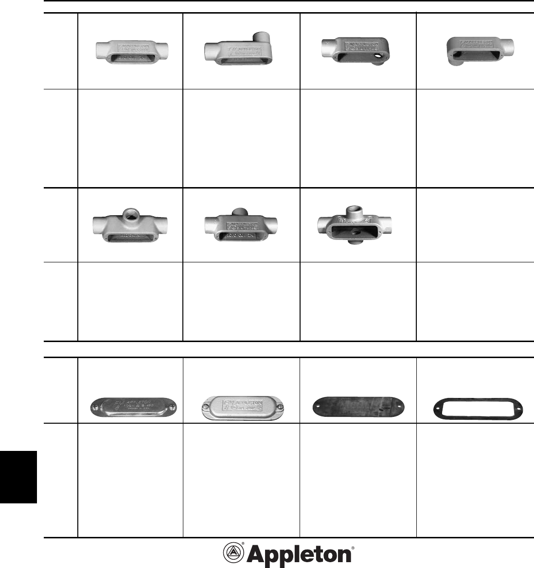
Appleton FM8® Blank Covers and Gaskets (Covers furnished with stainless steel screws, 1-1/2” – 4” covers provided with 4 screws)
Stamped Cover Cast Cover Solid Gasket Open Gasket
Steel Grayloy-Iron Neoprene Neoprene
FM8
Body
Size (in.)
1/2 180 180F GASK851N —
3/4 280 280F GASK852N —
1 380 380F GASK853N —
1-1/4 480 480F GASK854N —
1-1/2 580 580F — GASK805N
2 680 680F — GASK806N
2-1/2 880 880F — GASK808N
3 880 880F — GASK808N
3-1/2 980 980F — GASK809N
4 980 980F — GASK809N
FM8® Grayloy™-Iron Unilet® Conduit Bodies
with Covers and Gaskets
For use with Rigid Steel and IMC Conduit.
These Appleton FM8 conduit bodies, covers and gaskets have the same applications and installation dimensions as Crouse-Hinds Form 8
conduit bodies. Equivalent FM8 and Form 8 items are interchangeable.
Appleton FM8® Conduit Bodies NOTE: Refer to page A-15 for Wiring Capacity Table
C LB LL LR
Hub
Size (in.) Grayloy-Iron Grayloy-Iron Grayloy-Iron Grayloy-Iron
1/2 C18 LB18 LL18 LR18
3/4 C28 LB28 LL28 LR28
1 C38 LB38 LL38 LR38
1-1/4 C448 LB448 LL448 LR448
1-1/2 C58 LB58 LL58 LR58
2 C68 LB68 LL68 LR68
2-1/2 C78 LB78 LL78 LR78
3 C88 LB888 LL888 LR888
3-1/2 — LB98 — —
4 — LB108 — —
T TB X
Hub
Size (in.) Grayloy-Iron Grayloy-Iron Grayloy-Iron
1/2 T18 TB18 X18
3/4 T28 TB28 X28
1 T38 TB38 X38
1-1/4 T448 TB448 X448
1-1/2 T58 TB58 X58
2 T68 TB68 X68
2-1/2 T78 — —
3 T88 — —
Effective September, 2005
Copyright 2005
800-621-1506
www.appletonelec.com
PAGE 19
A-19
A
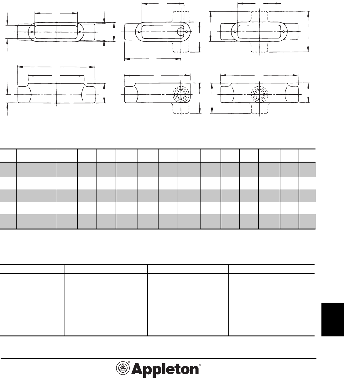
FM8® Conduit Body Dimensions
Fraction/Decimal Equivalents (Inches)
Fraction Decimal Fraction Decimal Fraction Decimal Fraction Decimal
1/32 0.03 9/32 0.28 17/32 0.53 25/32 0.78
1/16 0.06 5/16 0.31 9/16 0.56 13/16 0.81
3/32 0.09 11/32 0.34 19/32 0.59 27/32 0.84
1/8 0.13 3/8 0.38 5/8 0.63 7/8 0.88
5/32 0.16 13/32 0.41 21/32 0.66 29/32 0.91
3/16 0.31 7/16 0.44 11/16 0.69 15/16 0.94
7/32 0.22 15/32 0.47 23/32 0.72 31/32 0.97
1/4 0.25 1/2 0.50 3/4 0.75 1 1.00
TYPE C TYPES E, LB, LL, LR TYPES T, TB, X
Dimensions In Inches
Hub A B C D E F G H J K L M N P R
Size
1/2 4.22 1.47 1.47 5.94 3.13 2.31 2.28 4.38 5.09 1.78 0.63 1.25 3.28 1.00 2.59
3/4 4.81 1.66 1.69 6.56 3.31 2.50 2.50 4.91 5.75 2.00 0.75 1.50 3.94 1.19 2.81
1 5.59 1.84 1.97 7.56 3.72 2.78 2.91 5.72 6.63 2.28 0.88 1.75 4.53 1.38 3.22
1-1/4 6.56 2.19 2.38 8.44 4.06 3.13 3.31 6.41 7.50 2.63 1.09 2.19 5.31 1.75 3.56
1-1/2 7.88 2.78 2.78 10.38 5.28 4.03 4.03 7.75 9.13 2.78 1.38 2.44 6.50 2.09 4.03
2 9.75 3.88 3.56 12.38 6.38 5.13 4.81 9.19 11.13 3.56 1.88 3.00 8.63 3.00 4.81
2-1/2 12.25 5.00 4.44 15.63 — 6.69 6.13 11.44 13.94 4.44 2.50 3.50 10.88 4.25 —
3 12.25 5.00 4.81 15.63 — 6.69 6.50 11.44 13.94 4.81 2.50 4.25 10.88 4.25 —
3-1/2 15.00 6.25 5.69 — — — 7.56 13.75 16.88 — 3.13 4.75 13.44 5.44 —
4 15.00 6.25 5.94 — — — 7.81 13.75 16.88 — 3.13 5.25 13.44 5.44 —
N
PM
C
D
A
L
B
F
N
H
J
GR
D
K
E
N
F
N
N
B
M
P
H
F
F
N
E
D
A
L
CK
D
R
G
J

Effective September, 2005
Copyright 2005
PAGE 20
800-621-1506
www.appletonelec.com
A-20
A
Wiring Capacity:
FM8® Conduit Bodies and Covers
Combine Body and Cover Capacities for Total usable Capacity
per NEC 370-6(a)(1)
FM8® Grayloy™-Iron Bodies and Covers: Threaded
Capacity in Cubic Inches
Hub LL Stamped Cast
Size (In.) C E LB LR L T TA TB X Cover Cover
1/2 5.0 — 5.0 5.0 — 6.0 — 6.0 6.0 0.5 0.3
3/4 8.0 — 8.0 8.0 — 10.0 — 10.0 10.0 0.8 0.8
1 13.0 — 13.0 13.0 — 15.0 — 15.0 15.0 1.0 1.0
1-1/4 24.0 — 24.0 24.0 — 25.0 — 25.0 25.0 1.5 1.5
1-1/2 42.5 — 42.5 42.5 — 44.0 — 44.0 44.0 1.8 7.5
2 105.0 — 105.0 105.0 — 105.0 — 105.0 105.0 4.5 12.5
2-1/2 200.0 — 200.0 200.0 — 200.0 — — — 12.3 34.5
3 217.0 — 217.0 217.0 — 217.0 — — — 12.3 34.5
3-1/2 — — 380.0 — — — — — — 24.0 65.3
4 — — 400.0 — — — — — — 24.0 65.3
Effective June, 2006
Copyright 2006
800-621-1506
www.appletonelec.com
PAGE 21
A-21
A
FM9™ Aluminum Unilet® Conduit Outlet Bodies,
Covers and Gaskets
For use with Rigid Steel, Rigid Aluminum and IMC.
Applications
• Serve as pulling fittings.
• Make bends in conduit system.
• Provide openings for splicing.
• Connect and change direction of
conduit runs.
• Allow connections for branch runs.
• Permit access to conductors for
maintenance.
Features: FM9 Unilet® conduit outlet
bodies
• Roomy interiors: deep body cavity
provides increased volume allowing
higher wiring capacity.
• Smooth, rounded integral bushings in
hubs protect conductor insulation.
• Accurately tapped, tapered threads
for tight, rigid joints and excellent
ground continuity.
• Completely interchangeable with
Crouse-Hinds Mark9™ bodies, gaskets
and covers. Equivalent FM9 and Mark
9™ units have identical applications and
installation dimensions.
• Seven body styles available in 1/2”
to 4” sizes, TB’s in 1/2” to 2” ans X’s in
1/2” to1”.
Features:
• Aluminum Unilets: produced from a
high-strength copper-free (4/10 of 1%
max.) alloy, for light weight and high
corrosion resistance.
• FM9™ Formtite™ 9 covers with inte-
gral gasket are approved for use in wet
locations.
• Covers are domed for extra wiring
space.
• Smooth hub bushings and cover
openings protect conductor insulation.
Smooth hub openings allow easy con-
duit joining.
• Stainless steel pan-head cover
screws secure cover to body and pro-
vide superior screwdriver seating and
torque. Cover screws are captive to
prevent loss in sizes 1/2” to 2”.
• Hub size, body style, and compli-
ance data molded into body in large,
easy-to-read form. Also maximum wire
number/size and cubic capacity.
Standard Materials
• Conduit bodies: copper-free alumi-
num.
• Covers: stamped copper-free alumi-
num
• Cover screws: stainless steel.
• Gaskets: Neoprene
LL Body with
Formtite™ 9 Integral Gasket Cover
Captive Stainless Steel
Pan-Head Cover Screws
Standard Finishes
• Conduit bodies, covers and screws:
natural
Compliances
• UL Standard 514A.
Effective June, 2006
Copyright 2006
PAGE 22
800-621-1506
www.appletonelec.com
A-22
A
FM9™ Aluminum Unilet® Conduit Bodies, Covers
and Gaskets
For use with Rigid Steel, Rigid Aluminum and IMC Conduit.
Appleton FM9 Conduit Bodies NOTE: Refer to page A-23 for Wiring Capacity Tables
CLBLLLR
Hub Size
(in.)
1/2 C19 LB19 LL19 LR19
3/4 C29 LB29 LL29 LR29
1C39 LB39 LL39 LR39
1-1/4 C49 LB49 LL49 LR49
1-1/2 C59 LB59 LL59 LR59
2C69 LB69 LL69 LR69
2-1/2 C789 LB789 LL789 LR789
3C889 LB889 LL889 LR889
3-1/2 C989 LB989 LL989 LR989
4C1089 LB1089 LL1089 LR1089
TTBX
Hub Size
(in.)
1/2 T19 TB19 X19
3/4 T29 TB29 X29
1T39 TB39 X39
1-1/4 T49 TB49 –
1-1/2 T59 TB59 –
2T69 TB69 –
2-1/2 T789 ––
3T889 ––
3-1/2 T989 ––
4T1089 ––
Appleton FM9 Blank Covers and Gaskets and Formtite™ 9 Stamped Aluminum Cover with Integral Gasket
(Covers furnished with Stainless Steel Screws)
Stamped Aluminum Cover Solid Gasket Neoprene Formtite™ 9
FM9 Body
Size (in.)
1/2 190 GASK1941 190G
3/4 290 GASK1942 290G
1390 GASK1943 390G
1-1/4 490 GASK1944 490G
1-1/2 590 GASK1945 590G
2690 GASK1946 690G
2-1/2 889 GASK808N 889G
3889 GASK808N 889G
3-1/2 989 GASK809N 989G
4989 GASK809N 989G
Effective June, 2006
Copyright 2006
800-621-1506
www.appletonelec.com
PAGE 23
A-23
A
FM9™ Conduit Body Dimensions
Type C, T, TB & X
Type LB, LL & LR
Dimensions in Inches
Hub Size A B C D E F G H J K L M N
C, LB,
T, LL,
& LR
1/2 4.97 1.56 1.38 1.06 3.28 4.22 0.63 2.31 3.59 1.44 2.13 –4.59
3/4 5.69 1.81 1.56 1.22 3.94 4.81 0.75 2.59 4.09 1.59 2.38 –2.52
1 6.59 2.06 1.75 1.41 4.56 5.59 0.88 3.03 4.84 1.84 2.72 –6.09
1-1/4 7.63 2.69 2.19 1.88 5.25 6.56 1.09 3.75 5.38 2.16 3.25 –7.09
1-1/2 8.25 3.03 2.53 2.19 5.94 7.25 1.25 4.03 6.00 2.25 3.53 –7.81
2 10.69 3.75 3.19 2.81 8.06 9.56 1.50 4.88 7.88 2.66 4.25 –10.13
2-1/2 15.63 4.94 5.00 4.25 10.88 12.25 2.50 6.63 11.44 4.19 6.69 –13.94
3 15.63 5.31 5.00 4.25 10.88 12.25 2.50 7.00 11.44 4.19 6.69 –13.94
3-1/2 18.75 6.19 6.25 5.44 13.44 15.00 3.13 8.06 13.75 5.00 8.13 –16.88
4 18.75 6.44 6.25 5.44 13.44 15.00 3.13 8.31 13.75 5.00 8.13 –16.88
TB
& X
1/2 5.94 1.94 1.38 1.03 3.28 4.22 0.63 2.75 –1.56 2.25 3.13 5.06
3/4 6.56 2.22 1.56 1.22 3.94 4.81 0.75 3.03 –1.66 2.44 3.31 5.69
1 7.50 2.44 1.75 1.38 4.56 5.59 0.88 3.38 –1.84 2.72 3.69 6.53
1-1/4 8.50 2.69 2.19 1.75 5.25 6.56 1.09 3.75 ––––7.53
1-1/2 8.25 3.03 2.53 2.19 5.94 7.25 1.25 4.03 ––––7.81
2 10.69 3.75 3.19 2.75 8.06 9.56 1.50 4.88 ––––10.13
Wiring Capacity in Cubic Inches
Hub Size C LB LL / LR T TB X Cover
1/2 4.8 5.0 5.3 5.0 6.8 7.3 0.5
3/4 7.8 8.3 8.5 8.3 11.0 11.3 0.8
112.3 12.8 13.3 12.5 16.5 17.0 1.0
1-1/4 25.3 26.5 27.3 26.3 25.8 1.5
1-1/2 37.5 39.0 39.8 38.5 36.5 2.5
277.5 81.3 82.8 79.5 77.0 6.5
2-1/2 230.0 230.0 230.0 230.0 12.3
3250.0 250.0 250.0 250.0 12.3
3-1/2 450.0 450.0 450.0 450.0 24.0
4470.0 470.0 470.0 470.0 24.0
Fraction/Decimal Equivalents (Inches)
Fraction Decimal Fraction Decimal
1/16 0.06 9/16 0.56
1/8 0.13 5/8 0.63
3/16 0.19 11/16 0.69
1/4 0.25 3/4 0.75
5/16 0.31 13/16 0.81
3/8 0.38 7/8 0.88
7/16 0.44 15/16 0.94
1/2 0.50 1 1.00
Effective September, 2005
Copyright 2005
PAGE 24
800-621-1506
www.appletonelec.com
A-24
A
Mogul Unilet® Conduit Outlet Bodies:
NEC 6x8x Series (C, LB and UB)
and Types LL, LR and T
For use with Threaded Rigid Metal Conduit and IMC.
Complete with Assembled Cover and Neoprene Gasket.
Applications
• Larger body size facilitates pulling of
large and heavy conductors. Specially
designed raised cast covers provide
additional wiring area.
• Mogul Unilets® for pulling straight,
45° or 90° angle turns and/or making
taps and splices.
Features
• LB and UB Moguls
Length Requirement: distance between
centerline of each hub bushing (con-
duit stop) exceeds six times the trade
diameter of the conduit per NEC 314-
28(a)(2).
Bending Space Requirement: these
moguls also meet the NEC 314-28(a)(2)
Exception requirement spelled out in
NEC 312-6(a) Table.
• C Moguls
Length Requirement: distance between
centerline of each hub bushing (conduit
stop) exceeds eight times the trade
diameter of the conduit per NEC 314-
28(a)(1).
Bending Space Requirement: not ap-
plicable.
•
LL and LR Moguls: Like LB moguls,
these moguls have an end hub. However,
the second hub is in the side (LL left
and LR right) instead of the back.*
• T Moguls: These are like “C” moguls
(1” thru 4”), except with an additional
middle side hub. Distance between the
centerline of each “C” hub conduit stop
exceeds eight times the trade diameter
of the conduit per NEC 314-28(a)(1).*
• Exclusive built-in rollers facilitate
cable pulling. Available on NEC 6x8x
Series Moguls (C, LB and UB) in sizes
1-1/4” and up.
•
Smooth, rounded integral bushing in
each hub protects conductor insulation.
• Accurately tapped, tapered threads for
tight, rigid joints and ground continuity.
• Covers have captive stainless steel
screws to speed installation, prevent
“freezing” of screws.
*If less than maximum conductors permit-
ted by NEC are used, smaller wires may be
used additionally through “LL”, “LR” or “T”
hubs. If large conductors are required to be
bent in “LL”, “LR” or “T” direction, order junc-
tion boxes instead from Cat. Sec. C.
Standard Materials
• Malleable iron or aluminum.
• Gaskets: Neoprene.
Standard Finishes
•
Malleable iron bodies and covers:
triple-coat — (1) zinc electroplate, (2)
dichromate and (3) epoxy powder coat.
• Aluminum bodies and covers: epoxy
powder coat.
Compliances
• UL Standard 514A.
• NEC 6x8x Series moguls comply with
NEC 314-28(a)-1-2.
• Federal Spec. W-C-586B.
• Suitable for classified location use
in Class I, Div. 2 areas, if installed in
compliance with NEC 501-4(b).
• Appleton malleable iron products
conform to ASTM A47-77, Grade
32510, which has the following proper-
ties: tensile strength, 50,000 psi; yield,
32,000 psi; and elongation, 10%.
• Appleton aluminum products are pro-
duced from a high strength copper-free
(4/10 of 1% max.) alloy.
Patented rollers make cable-pulling easier,
eliminate insulation damage.
NEC 6x8x SERIES MOGULS
LL, LR AND T MOGULS
C Type NEC 8x LB Type 1” - 2” NEC 6x
LB Type 2-1/2” - 4” NEC 6x UB Type NEC 6x
LR Type NEC 6x LL Type NEC 6x
T Type NEC 8x
Effective September, 2005
Copyright 2005
800-621-1506
www.appletonelec.com
PAGE 25
A-25
A
NEC 6x8x Series (C, LB and UB)
and Types LL, LR and T Mogul Unilet®
Malleable Iron or Aluminum
For use with Threaded Rigid Metal Conduit and IMC.
Furnished with Assembled Cast Cover and Neoprene Gasket.
NOTE: Refer to page A-24 for Wiring Capacity Tables.
Hub Body, Cover & Gasket Gasket Cover & Gasket
Type Size (In.) Malleable Iron Aluminum Only Malleable Iron Aluminum
C
◊
Patented Roller Feature
NEC 8X 1 BC100-M BC100-A BG100 BKG100-M BKG100-A
1-1/4 BC125-M
◊
BC125-A
◊
BGC125 BKGC125-M BKGC125-A
1” - 2” 1-1/2 BC150-M
◊
BC150-A
◊
BG150 BKG150-M BKG150-A
2 BC200-M
◊
BC200-A
◊
BGC200 BKGC200-M BKGC200-A
2-1/2 BC250-M
◊
BC250-A
◊
BGC250 BKGC250-M BKGC250-A
3 BC300-M
◊
BC300-A
◊
BGC300 BKGC300-M BKGC300-A
3-1/2 BC350-M
◊
BC350-A
◊
BGC350 BKGC350-M BKGC350-A
2-1/2” - 4” 4 BC400-M
◊
BC400-A
◊
BGC400 BKGC400-M BKGC400-A
LB
◊
Patented Roller Feature
NEC 6X 1 BLB100-M BLB100-A BG100 BKG100-M BKG100-A
1-1/4 BLB125-M
◊
BLB125-A
◊
BGL125 BKGL125-M BKGL125-A
1” - 2” 1-1/2 BLB150-M
◊
BLB150-A
◊
BG150 BKG150-M BKG150-A
2 BLB200-M
◊
BLB200-A
◊
BGL200 BKGL200-M BKGL200-A
2-1/2 BLB250-M
◊
BLB250-A
◊
BGL250 BKGL250-M BKGL250-A
3 BLB300-M
◊
BLB300-A
◊
BGL300 BKGL300-M BKGL300-A
3-1/2 BLB350-M
◊
BLB350-A
◊
BGL350 BKGL350-M BKGL350-A
2-1/2” - 4” 4 BLB400-M
◊
BLB400-A
◊
BGL400 BKGL400-M BKGL400-A
UB
◊
Patented Roller Feature
NEC 6X 1 BUB100-M BUB100-A BG100 BKG100-M BKG100-A
1-1/4 BUB125-M
◊
BUB125-A
◊
BGL125 BKGL125-M BKGL125-A
1” - 2” 1-1/2 BUB150-M
◊
BUB150-A
◊
BG150 BKG150-M BKG150-A
2 BUB200-M
◊
BUB200-A
◊
BGL200 BKGL200-M BKGL200-A
2-1/2 BUB250-M
◊
BUB250-A
◊
BGL250 BKGC250-M BKGC250-A
3 BUB300-M
◊
BUB300-A
◊
BGL300 BKGU300-M BKGU300-A
3-1/2 BUB350-M
◊
BUB350-A
◊
BGL350 BKGC350-M BKGC350-A
2-1/2” - 4” 4 BUB400-M
◊
BUB400-A
◊
BGL400 BKGU400-M BKGU400-A
LL
NEC 6X 1 BLL100-M BLL100-A BG100 BKG100-M BKG100-A
1-1/4 BLL125-M BLL125-A BGL125 BKGL125-M BKGL125-A
1-1/2 BLL150-M BLL150-A BG150 BKG150-M BKG150-A
1” - 2” 2 BLL200-M BLL200-A BGL200 BKGL200-M BKGL200-A
LR
NEC 6X 1 BLR100-M BLR100-A BG100 BKG100-M BKG100-A
1-1/4 BLR125-M BLR125-A BGL125 BKGL125-M BKGL125-A
1-1/2 BLR150-M BLR150-A BG150 BKG150-M BKG150-A
1” - 2”
2 BLR200-M BLR200-A BGL200 BKGL200-M BKGL200-A
T
NEC 8X 1 BT100-M BT100-A BG100 BKG100-M BKG100-A
1-1/4 BT125-M BT125-A BGC125 BKGC125-M BKGC125-A
1” - 2” 1-1/2 BT150-M BT150-A BG150 BKG150-M BKG150-A
2 BT200-M BT200-A BGC200 BKGC200-M BKGC200-A
2-1/2 BT250-M BT250-A BGC250 BKGC250-M BKGC250-A
3 BT300-M BT300-A BGC300 BKGC300-M BKGC300-A
3-1/2 BT350-M BT350-A BGC350 BKGC350-M BKGC350-A
2-1/2” - 4” 4 BT400-M BT400-A BGC400 BKGC400-M BKGC400-A
For Dimensions, See Pages A-22 and A-23.
Effective September, 2005
Copyright 2005
PAGE 26
800-621-1506
www.appletonelec.com
A-26
A
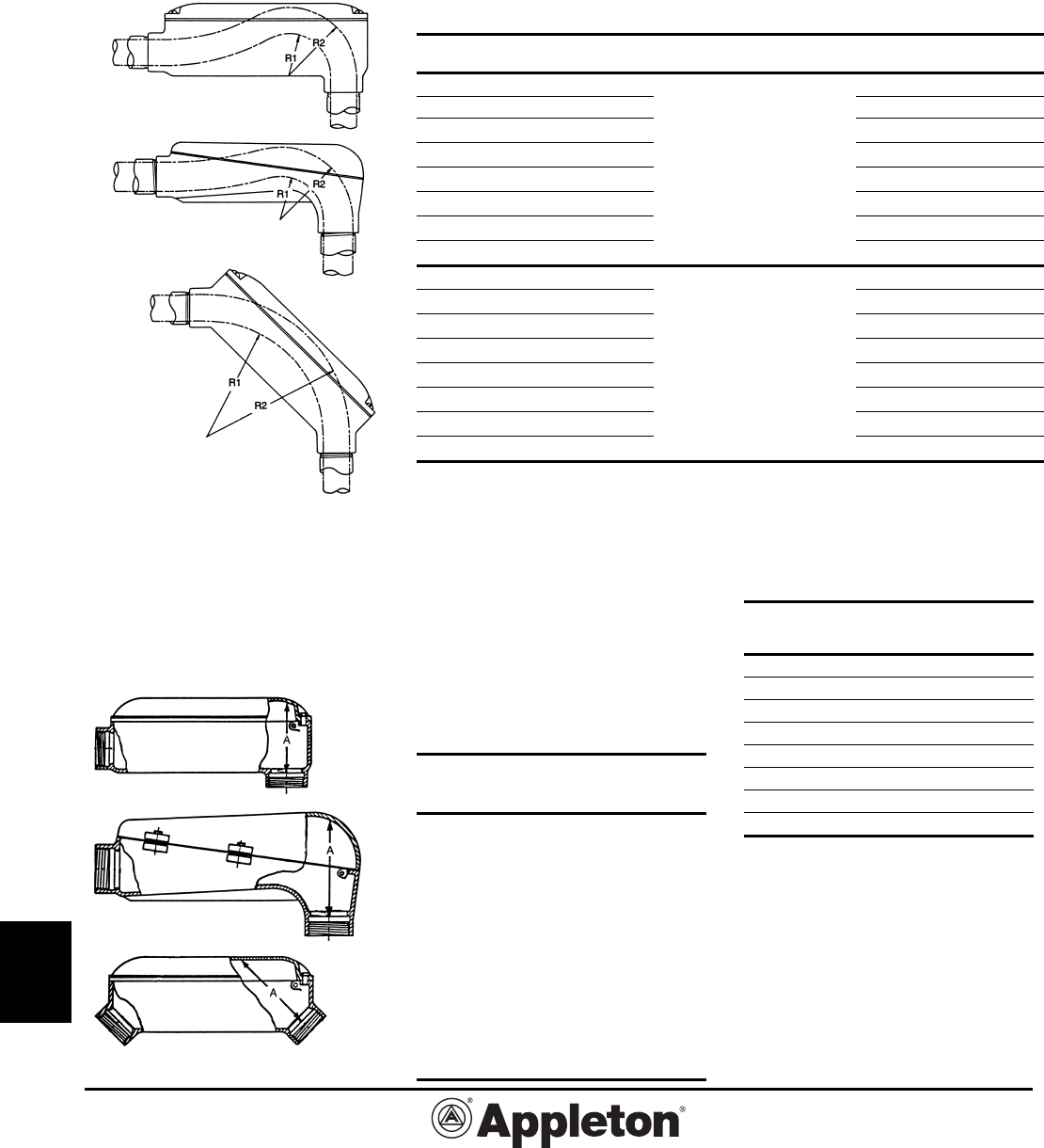
Bending RADII and Bending Space of
Appleton LB and UB Moguls
BENDING SPACE DEFINED:
NEC 370-28(a)(2) Exception.
This article applies to LB and UB Moguls,
defines bending space and refers to NEC
373-6(a) Table as guideline for determin-
ing minimum bending space distance.
Bending space is illustrated as Dimension
“A” below:
MINIMUM WIRE BENDING SPACE:
NEC 373-6(a) Table
The applicable portion of this table is
shown below. Only the “1 Wire Per Termi-
nal” column is retained, because the oth-
ers are not applicable. Example for using
table below and table at right:
EXAMPLE:
350MCM wire size requires 5” bending
space. A 2” LB or UB Appleton Mogul is
suitable.
AWG or
Circular-Mill. 1 Wire per Terminal
Size of Wire Min.Bending Space
14-10 Not Specified
8-6 1-1/2”
4-3 2”
2 2-1/2”
1 3”
0-00 3-1/2”
000-0000 4”
250 MCM 4-1/2”
300-350 MCM 5”
400-500 MCM 6”
600-700 MCM 8”
750-900 MCM 8”
1,000-1,250 MCM 10”
1,500-2,000 MCM 12”
BENDING SPACE OF APPLETON
MOGULS (Dim. “A” in sketches at left)
Mogul
Size Type Distance
1 LB,UB 2-1/2”
1-1/4 LB,UB 3-1/2”
1-1/2 LB, UB 4”
2 LB, UB 5”
2-1/2 LB, UB 6”
3 LB, UB 8”
3-1/2 LB, UB 8”
4 LB, UB 10”
NOTE ON RADII TABLE: Secure cable or
wire bending radius from manufacturer.
Then select a mogul having this radius
or more. If radius is 6-1/4”, an LB 2-1/2”
mogul or BUB 1-1/2” mogul is suitable.
NOTE ON NEC 373-6(a) TABLE: Because
cable sizes vary, table is limited to single
wire sizes. Use as guideline only for cable
sizes.
Appleton Compliances with NEC Bending Space Requirements
UB Mogul
LB Mogul 2-1/2”—4”
LB Mogul 1”—2”
Bending RADII of Appleton Moguls
Catalog Number Hub Size Type R1 R2
(Inches) (Inches) (Inches)
BLB100-A,M 1
1.625 2.625
BLB125-A,M 1-1/4 2.250 3.625
BLB150-A,M 1-1/2 2.625 4.125
BLB200-A,M 2 3.000 5.000
BLB250-A,M 2-1/2 3.875 6.250
BLB300-A,M 3 5.000 8.000
BLB350-A,M 3-1/2 5.000 8.375
BLB400-A,M 4 6.250 10.250
BUB100-A,M 1 4.500 5.500
BUB125-A,M 1-1/4 4.625 6.000
BUB150-A,M 1-1/2 7.000 8.500
BUB200-A,M 2 7.500 9.500
BUB250-A,M 2-1/2 13.125 15.500
BUB300-A,M 3 13.875 16.875
BUB350-A,M 3-1/2 19.750 23.250
BUB400-A,M 4 20.750 24.750
UB Mogul
LB Mogul
2-1/2”—4”
LB Mogul
1”—2”
LB
UB
Effective September, 2005
Copyright 2005
800-621-1506
www.appletonelec.com
PAGE 27
A-27
A
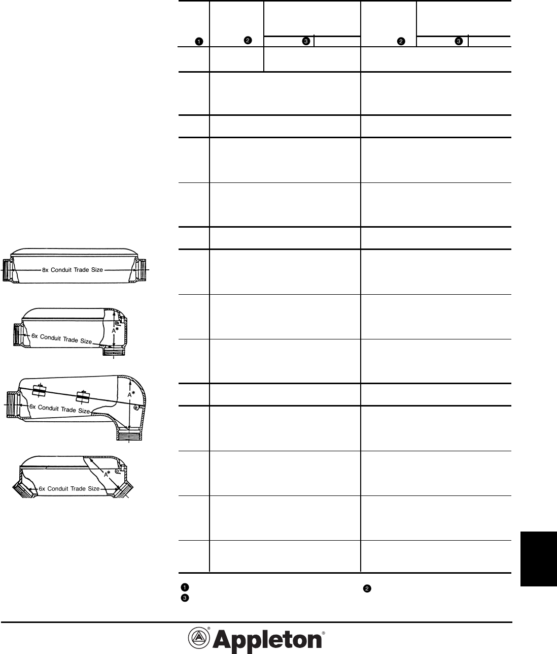
Applicable NEC References for
C, LB and UB Moguls
•Straight Pull Length Requirements:
NEC 314.28(A)(2)— C Moguls
“... shall not be less than eight times the
trade diameter of the largest raceway.”
(See table at right.)
•Angle or U Pull Length Requirements:
NEC 314.28(A)(2)— LB, UB Moguls
“The distance between each raceway entry
inside the box and the opposite wall of the
box shall not be less than six times the
tradediameter of the largest raceway.”
(See next page.)
•Bending-Space Requirements: NEC
314.28(A)(2). Exception 312.6(A) Table—
LB, UB Moguls
“Where a conduit or cable entry is in the
wall of a box or conduit body opposite to a
removable cover.” (See dim. “A” below, table
on next page and page 11G.)
•Length and Bending Space
Requirements:
*Dimension “A” is bending space.
BENDING SPACE EXAMPLE: LB with 3”
hubs (Cat. No. BLB300-M) using 500MCM
wire with four conductors.
Table on next page shows that, in this ex-
ample, NEC requires a bending space of 6”
and that the Appleton 3” LB provides a bend-
ing space of 8”.
**For table on angle or U pulls,
see next page.
NEC 6x8x Series Moguls (C, LB and UB)
Comply with NEC Large-Wire Requirements
C Mogul— 1” thru 4”
LB Mogul— 2-1/2” thru 4”
LB Mogul— 1” thru 2”
UB Mogul— 1” thru 4”
NEC 370-28(a). Limited to minimum #4 wire. NEC Chapter 9, Table 3B.
NEC 370-28(a)(1). This is 8 times conduit trade size
C Moguls— Straight Pulls:
Maximum No. Conductors, Minimum Lengths**
WIRE
SIZE PER NEC APPLETON PER NEC APPLETON
BC100-M and 1-1/4” BC125-M and
1” HUBS BC100-A HUBS BC125-A
4 4 8” 8” 7 10” 10”
3 3 8” 8” 6 10” 10”
2 3 8” 8” 5 10” 10”
1 - - - 3 10” 10”
0 - - - 3 10” 10”
1-1/2” BC150-M and BC200-M and
HUBS BC150-A 2” HUBS BC200-A
4 9 12” 12” 16 16” 16”
3 8 12” 12” 13 16” 16”
2 7 12” 12” 11 16” 16”
1 5 12” 12” 8 16” 16”
0 4 12” 12” 7 16” 16”
00 3 12” 12” 6 16” 16”
000 3 12” 12” 5 16” 16”
0000 - - - 4 16” 16”
250 - - - 3 16” 16”
300 - - - 3 16” 16”
2-1/2” BC250-M and BC300-M and
HUBS BC250-A 3” HUBS BC300-A
4 22 20” 20” 35 24” 24”
3 19 20” 20” 29 24” 24”
2 16 20” 20” 25 24” 24”
1 12 20” 20” 18 24” 24”
0 10 20” 20” 15 14” 24”
00 8 20” 20” 13 24” 24”
000 7 20” 20” 11 24” 24”
0000 6 20” 20” 9 24” 24”
250 4 20” 20” 7 24” 24”
300 4 20” 20” 6 24” 24”
350 3 15” 20” 5 24” 24”
400 3 15” 20” 5 24” 24”
500 - - - 4 24” 24”
600 - - - 3 24” 24”
700 - - - 3 24” 24”
3-1/2” BC350-M and BC400-M and
HUBS BC350-A 4” HUBS BC400-A
4 47 28” 28” 60 32” 32”
3 39 28” 28” 51 32” 32”
2 33 28” 28” 43 32” 32”
1 25 28” 28” 32 32” 32”
0 21 28” 28” 27 32” 32”
00 17 28” 28” 32 32” 32”
000 14 28” 28” 18 32” 32”
0000 12 28” 28” 15 32” 32”
250 10 28” 28” 12 32” 32”
300 8 28” 28” 11 32” 32”
350 7 28” 28” 9 32” 32”
400 6 28” 28” 8 32” 32”
500 5 28” 28” 7 32” 32”
600 4 28” 28” 5 32” 32”
700 4 28” 28” 5 32” 32”
750 3 28” 28” 4 32” 32”
800 3 28” 28” 4 32” 32”
900 3 28” 28” 4 32” 32”
1000 - - - 3 32” 32”
LENGTH
REQUIREMENTS
(Conduit Stop to
Conduit Stop)
MAX. NO.
CONDUCTORS
PER NEC
MAX. NO.
CONDUCTORS
PER NEC
LENGTH
REQUIREMENTS
(Conduit Stop to
Conduit Stop)
Effective September, 2005
Copyright 2005
PAGE 28
800-621-1506
www.appletonelec.com
A-28
A
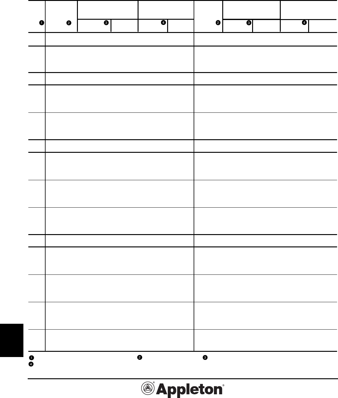
NEC 6x8x Series Moguls
(C, LB and UB) Comply with NEC
Large-Wire Requirements
LB and UB Moguls- Angle or U Pulls: Max. No. Conductors, Min. Lengths, Min. Bending Spaces
SIZE PER NEC APPLETON PER NEC APPLETON PER NEC APPLETON PER NEC APPLETON
BLB100-M, BLB100-A BLB125-M, BLB125-A
1” HUBS
BUB100-M and BUB100-A 1-1/4” HUBS BUB125-M and BUB200-A
4 4 6” 6” 2” 2-1/2” 7 7-1/2” 7-1/2” 2” 3-1/2”
3 3 6” 6” 2” 2-1/2” 6 7-1/2” 7-1/2” 2” 3-1/2”
2 3 6” 6” 2-1/2” 2-1/2” 5 7-1/2” 7-1/2” 2-1/2” 3-1/2”
1 - - - - - 3 7-1/2” 7-1/2” 3” 3-1/2”
0 - - - - - 3 7-1/2” 7-1/2” 3-1/2” 3-1/2”
BLB150-M, BLB150-A BLB200-M, BLB200-A
1-1/2” HUBS BUB150-M and BUB150-A 2” HUBS BUB200-M and BUB200-A
4 9 9” 9” 2” 4” 16 12” 12” 2” 5”
3 8 9” 9” 2” 4” 13 12” 12” 2” 5”
2 7 9” 9” 2-1/2” 4” 11 12” 12” 2-1/2” 5”
1 5 9” 9” 3” 4” 8 12” 12” 3” 5”
0 4 9” 9” 3-1/2” 4” 7 12” 12” 3-1/2” 5”
00 3 9” 9” 3-1/2” 4” 6 12” 12” 3-1/2” 5”
000 3 9” 9” 4” 4” 5 12” 12” 4” 5”
0000 - - - - - 4 12” 12” 4” 5”
250 - - - - - 3 12” 12” 4-1/2” 5”
300 - - - - - 3 12” 12” 5” 5”
BLB250-M, BLB250-A BLB300-M, BLB300-A
2-1/2” HUBS BUB250-M and BUB250-A 3” HUBS BUB300-M and BUB300-A
4 22 15” 15” 2” 6” 35 18” 18” 2” 8”
3 19 15” 15” 2” 6” 29 18” 18” 2” 8”
2 16 15” 15” 2-1/2” 6” 25 18” 18” 2-1/2” 8”
1 12 15” 15” 3” 6” 18 18” 18” 3” 8”
0 10 15” 15” 3-1/2” 6” 15 18” 18” 3-1/2” 8
00 8 15” 15” 3-1/2” 6” 13 18” 18” 3-1/2” 8”
000 7 15” 15” 4” 6” 11 18” 18” 4” 8”
0000 6 15” 15” 4” 6” 9 18” 18” 4” 8”
250 4 15” 15” 4-1/2” 6” 7 18” 18” 4-1/2” 8”
300 4 15” 15” 5 6” 6 18” 18” 5” 8”
350 3 15” 15” 5” 6” 5 18” 18” 5” 8”
400 3 15” 15” 6” 6” 5 18” 18” 6” 8”
500 - - - - - 4 18” 18” 6” 8”
600 - - - - - 3 18” 18” 8” 8”
700 - - - - - 3 18” 18” 8” 8”
BLB350-M, BLB350-A BLB400-M, BLB400-A
3-1/2” HUBS BUB350-M and BUB350-A 4” HUBS BUB400-M and BUB400-A
4 47 21” 21” 2” 8” 60 24” 24” 2” 10”
3 39 21” 21” 2” 8” 51 24” 24” 2” 10”
2 33 21” 21” 2-1/2” 8” 43 24” 24” 2-1/2” 10”
1 25 21” 21” 3” 8” 32 24” 24” 3” 10”
0 21 21” 21” 3-1/2” 8” 27 24” 24” 3-1/2” 10”
00 17 21” 21” 3-1/2” 8” 22 24” 24” 3-1/2” 10”
000 14 21” 21” 4” 8” 18 24” 24” 4” 10”
0000 12 21” 21” 4” 8” 15 24” 24” 4” 10”
250 10 21” 21” 4-1/2” 8” 12 24” 24” 4-1/2” 10”
300 8 21” 21” 5” 8” 11 24” 24” 5” 10”
350 7 21” 21” 5” 8” 9 24” 24” 5” 10”
400 6 21” 21” 6” 8” 8 24” 24” 6” 10”
500 5 21” 21” 6” 8” 7 24” 24” 6” 10”
600 4 21” 21” 8” 8” 5 24” 24” 8” 10”
700 4 21” 21” 8” 8” 5 24” 24” 8” 10”
750 3 21” 21” 8” 8” 4 24” 24” 8” 10”
800 3 21” 21” 8” 8” 4 24” 24” 8” 10”
900 3 21” 21” 8” 8” 4 24” 24” 8” 10”
1000 - - - - - 3 24” 24” 10” 10”
LENGTH
REQUIREMENTS
(Conduit Stop to
Conduit Stop)
MAX. NO.
CONDUC-
TORS
PER NEC
MAX. NO.
CONDUCTORS
PER NEC
WIRE
“A”
BENDING SPACE
REQUIREMENTS
“A”
BENDING SPACE
REQUIREMENTS
NEC 370-28(a). Limited to minimum #4 wire. NEC Chapter 9, Table 3B. NEC 370-28(a)(2) This is 6 times conduit trade size.
NEC 370-28(a)(2) Exception (373-6(a) Table). This is distance “A” bending space illustrated on preceding page.
LENGTH
REQUIREMENTS
(Conduit Stop to
Conduit Stop)
Effective September, 2005
Copyright 2005
800-621-1506
www.appletonelec.com
PAGE 29
A-29
A
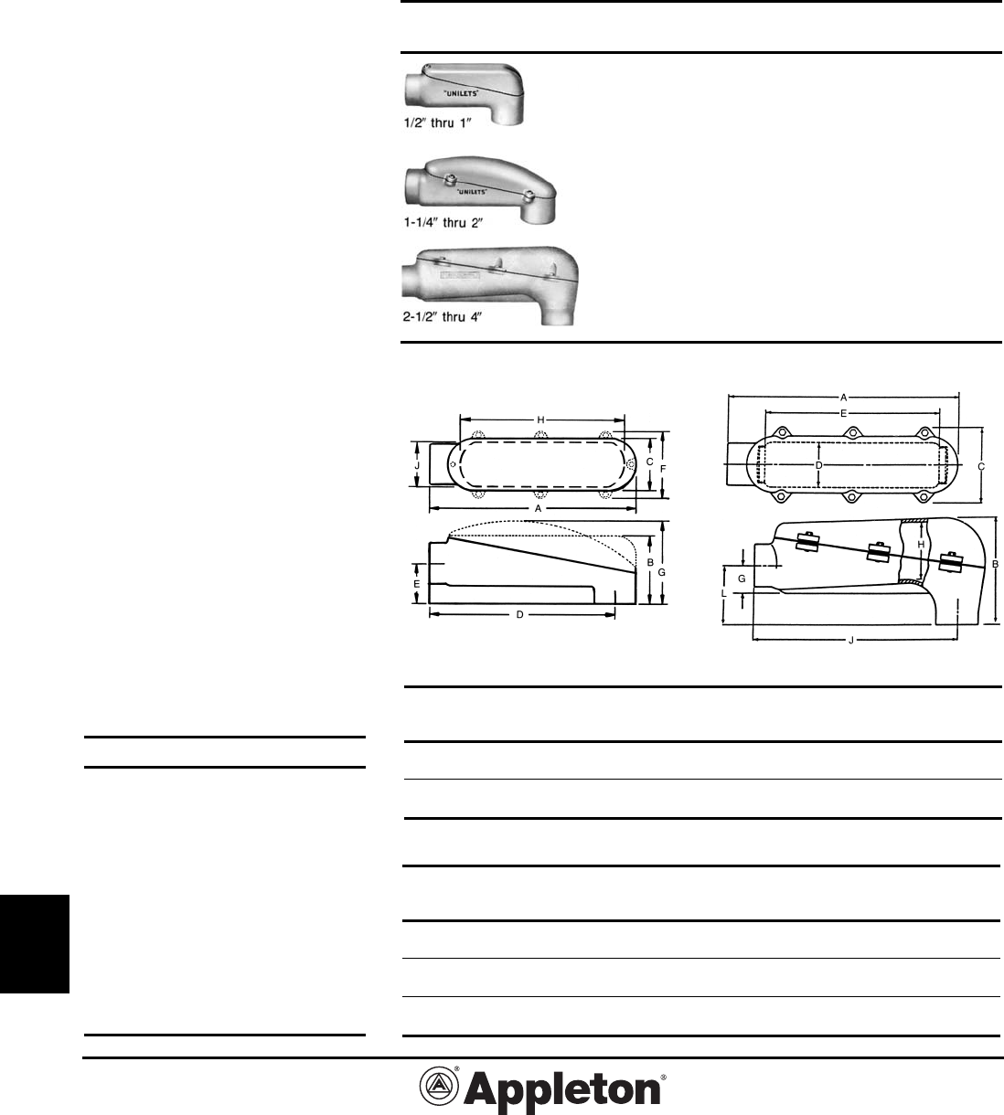
Dimensions:
Mogul Types C, T, LL and LR
* Furnished with patented rollers for easier cable pulling.
Type Mogul Number of Cover Holes
All LB, LL and LR plus C, T and UB 1” thru 2” sizes Two
C, T and UB 2-1/2” thru 4” sizes Four
All LB 2-1/2” thru 4” sizes Six
† See page A-23 for dimension table on LB Mogul type.
Types C & T Types LB,† LL & LR
Dimensions in Inches
Hub
Type Trade A B C D E F G H J K
Mogul Size (In.)
1 9.81 2.75 2.38 1.88 6.63 .94 2.44 1.88
1-1/4* 12.00 3.31 2.38 1.88 7.69 1.16 3.00 2.19
1-1/2* 13.94 3.75 3.13 2.50 9.31 1.38 3.38 2.56
2* 17.94 4.44 3.13 2.50 13.00 1.63 4.00 3.18
2-1/2* 23.25 5.13 4.63 3.75 17.50 1.81 4.63 3.63
3* 26.88 5.94 4.63 3.63 21.00 2.16 5.44 4.38
3-1/2* 31.38 7.19 5.63 4.50 24.94 2.50 6.69 4.88
4* 35.38 7.56 5.63 4.50 28.94 2.75 7.06 5.25
1 9.81 2.75 2.38 1.88 6.63 3.25 .94 2.44 1.88
1-1/4 12.00 3.31 2.38 1.88 8.56 3.38 1.16 3.00 2.19
1-1/2 13.94 3.75 3.13 2.50 10.38 4.13 1.38 3.38 2.56
2 17.94 4.44 3.13 2.50 14.13 4.13 1.63 4.00 3.18
2-1/2 23.25 5.13 4.63 3.75 18.69 6.00 1.81 4.63 3.63
3 26.88 5.94 4.63 3.63 22.19 6.00 2.16 5.44 4.38
3-1/2 31.38 7.19 5.63 4.50 26.19 7.25 2.50 6.69 4.88
4 35.38 7.56 5.63 4.50 30.19 7.25 2.75 7.06 5.25
1 8.94 2.75 2.38 1.88 6.63 3.25 .94 2.44 7.88 1.88
1-1/4 9.69 3.31 2.38 1.88 7.25 3.38 1.16 3.00 8.50 2.19
1-1/2 13.00 3.75 3.13 2.50 10.38 4.13 1.38 3.38 11.63 2.56
2 14.63 5.00 3.13 2.50 11.81 4.13 1.63 4.56 12.94 3.44
LL,LR
T
C
Effective September, 2005
Copyright 2005
PAGE 30
800-621-1506
www.appletonelec.com
A-30
A
Dimensions:
Mogul Types LB and UB
* Furnished with patented rollers for easier cable pulling.
† See page A-22 for illustration of LB in sizes 1” thru 2”.
Type Mogul Number of Cover Holes
All LB, LL and LR plus C, T and UB 1” thru 2” sizes Two
C, T and UB 2-1/2” thru 4” sizes Four
All LB 2-1/2” thru 4” sizes Six
Type LB (2-1/2” thru 4”)† Type UB
Dimensions In Inches
Hub
Type Trade A B C D E G H J K L
Mogul Size (In.)
1 8.94 3.63 2.38 1.88 6.63 .94 2.44 7.88 1.88 1.88
1-1/4* 9.69 4.75 2.38 1.88 6.31 1.16 3.44 8.50 2.63 2.16
1-1/2* 13.00 5.25 3.13 2.50 9.31 1.38 3.94 11.63 3.06 2.38
2* 14.63 6.31 3.13 2.50 10.75 1.63 4.88 12.94 3.44 2.69
2-1/2* 17.88 8.00 5.88 3.50 13.75 2.13 4.13 15.81 4.56
3* 21.06 10.00 5.88 3.50 17.00 2.50 5.13 18.50 5.38
3-1/2* 24.31 10.25 7.00 4.63 19.88 3.00 4.75 21.38 6.63
4* 27.50 12.50 7.00 4.63 23.00 3.25 6.38 24.38 7.00
1 9.63 3.50 2.38 1.88 6.63 2.44 8.44 1.88
1-1/4* 10.25 4.13 2.38 1.88 6.31 3.00 8.94 2.19
1-1/2* 13.69 4.63 3.13 2.50 9.31 3.38 12.19 2.56
2* 15.25 5.00 3.13 2.50 10.75 4.56 13.38 3.18
2-1/2* 22.88 7.06 4.63 3.75 17.50 5.44 20.13 4.38
3* 22.88 7.31 4.63 3.75 17.50 6.81 20.13 4.38
3-1/2* 30.88 8.94 5.63 4.50 24.88 7.06 27.50 5.25
4* 30.88 10.31 5.63 4.50 24.88 8.44 27.50 5.25
LB
UB
Effective September, 2005
Copyright 2005
800-621-1506
www.appletonelec.com
PAGE 31
A-31
A
Wiring Capacity:
Mogul Bodies with Cover
Body and Cover Capacities Combined for Total Usable Capacity
per NEC 370-6(a)(1).
Mogul Bodies with Covers:
Malleable Iron and Aluminum
CAPACITY IN CUBIC INCHES
Hub Size, Inches Type Mogul Capacity, Cu. In.
1 C, LB, LL 31
LR, T, UB
1-1/4 C, T 50
LB 48
LL, LR 42
UB 40
1-1/2 C, LL, LR, T 93
LB 107
UB 91
2 C, T 143
LB 145
LL, LR, UB 134
2-1/2 C, T 335
LB 210
UB 375
3 C, T 475
LB 345
UB 445
3-1/2 C, T 830
LB 500
UB 840
4 C, T 1010
LB 740
UB 960
Effective September, 2005
Copyright 2005
PAGE 32
800-621-1506
www.appletonelec.com
A-32
A
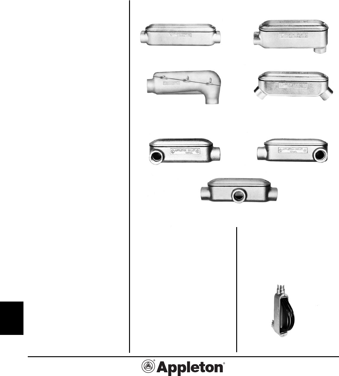
LBD and LBDN Pulling Fittings:
Malleable Iron, Aluminum
UNILET® for use with Threaded Rigid Metal Conduit and IMC.
Furnished with Cover and Gasket.
Catalog Number
Hub Malleable
Type Size (in) Iron Aluminum
LBD 1/2 LBD50-M —
3/4 LBD75-M —
1 LBD100-M —
LBD 1-1/4 LBD125-M LBD125-A
1-1/2 LBD150-M LBD150-A
2 LBD200-M LBD200-A
LBDN 2-1/2 LBDN250-M LBDN250-A
3 LBDN300-M LBDN300-A
3-1/2 LBDN350-M LBDN350-A
4 LBDN400-M LBDN400-A
LBD Series Dimensions, Inches
Hub
Trade A B C D E F G H J
Size (In.)
1/2 5.00 2.19 1.31 4.38 1.25 - - 3.56 .94
3/4 6.19 2.50 1.50 5.50 1.44 - - 4.75 1.13
1 6.38 2.69 1.75 5.50 1.69 - - 4.94 1.38
1-1/4 8.50 - 2.63 7.50 2.13 3.38 4.75 7.19 2.00
1-1/2 12.25 - 3.13 10.94 2.31 4.13 4.88 10.63 2.56
2 12.44 - 3.13 10.94 2.75 4.13 5.25 10.63 2.56
LBDN Series Dimensions, Inches
Hub
Trade A B C D E G H J L
Size (In.)
2-1/2 17.88 8.00 5.88 3.50 13.75 2.13 4.13 15.81 4.56
3 21.06 10.00 5.88 3.50 17.00 2.50 5.13 18.50 5.38
3-1/2 24.31 10.25 7.00 4.63 19.88 3.00 4.75 21.38 6.63
4 27.50 12.50 7.00 4.63 23.00 3.25 6.38 24.38 7.00
Features
• Serve as pulling fittings—ideal for
heavy, difficult-to-bend conductors.
• Make 90° bends in conduit—straight
pull through hubs in either direction.
• Use as service entrance fitting.
• Complete with gasketed covers.
Standard Materials
• Unilets and covers: malleable iron
(some in aluminum).
• Gaskets: Neoprene or composition
fiber.
Standard Finishes
• Malleable iron bodies and covers:
triple-coat — (1) zinc electroplate,
(2) dichromate and (3) epoxy powder
coat.
• Aluminum bodies and covers: epoxy
powder coat.
Compliances
• UL Standard 514A.
• Federal Spec. W-C-586B.
• LBDN complies with NEC 370-
28(a)(2).
• Suitable for classified location use in
Class I, Division 2 areas, if installed in
compliance with NEC 501-4(b).
• Appleton malleable iron conforms to
ASTM A47-77, Grade 32510.
• Appleton aluminum products are pro-
duced from a high strength copper-free
(4/10 of 1% max.) alloy.
LBD Dimensions LBDN Dimensions
LBD/LBDN Bodies and Covers:
Malleable Iron and Aluminum
Hub Size (Inches) Capacity, Cu. In.
1/2 4.0
3/4 8.0
1 12.0
1-1/4 37.0
1-1/2 66.0
2 81.0
2-1/2 (LBDN) 210.0
3 (LBDN) 345.0
3-1/2 (LBDN) 500.0
4 (LBDN) 740.0
Effective September, 2005
Copyright 2005
800-621-1506
www.appletonelec.com
PAGE 33
A-33
A
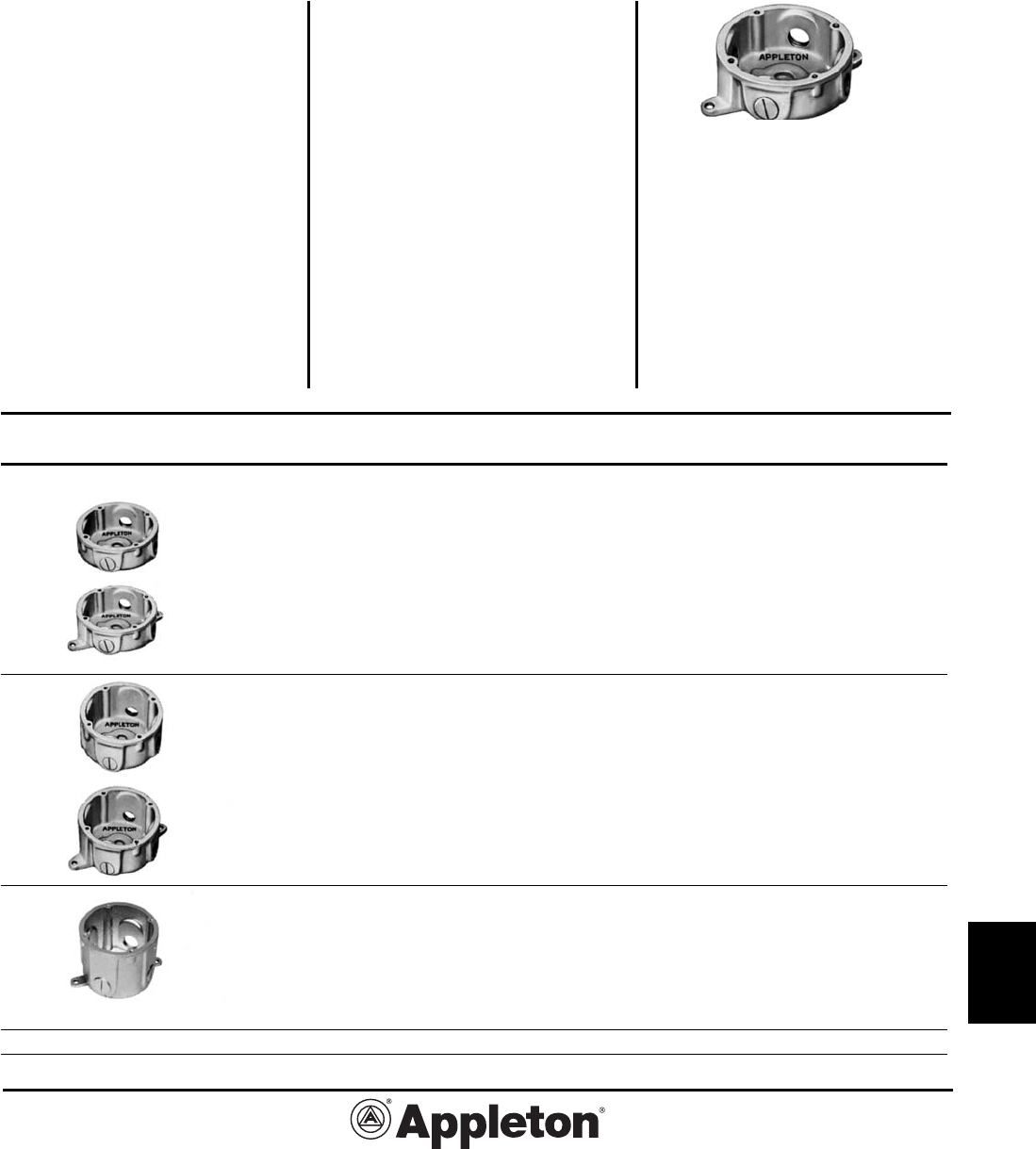
JB Conduit Outlet Boxes, Covers, and Hangers:
Malleable Iron, Aluminum
UNILET® for use with Threaded Rigid Metal Conduit and IMC.
NOTE: Refer to page A-31 for Wiring Capacity Tables.
Hub Size Length Catalog Number
Description (Inches) (A) Malleable Iron Aluminum
JBX — 1-5/16” inside depth
Furnished with four tapped
openings and two close-up plugs.
Less mounting lugs
1/2 — JBX-50 —
3/4 — JBX-75 —
1 — JBX-100 —
With mounting lugs 1/2 — JBX-50L JBX50L-A
3/4 — JBX-75L JBX75L-A
1 — JBX-100L —
JBDX — 2-1/16” inside depth
Furnished with four tapped
openings and two close-up plugs.
Less mounting lugs
1/2 — JBDX-50 —
3/4 — JBDX-75 —
1 — JBDX-100 —
With mounting lugs 1/2 — JBDX-50L —
3/4 — JBDX-75L —
1 — JBDX-100L —
JBLX — 3-1/8” inside depth
Furnished with four tapped
openings and two close-up plugs.
With removable mounting lugs
1/2 — JBLX-50L JBLX-50L-A
3/4 — JBLX-75L JBLX-75L-A
1 — JBLX-100L JBLX-100L-A
Features
• Raintight when enclosed and gas-
keted with hub or blank covers.
• For exposed or concealed use.
• Blind cover screw holes prevent
conductor damage during installation,
provide water-tightness.
• Available in three inside depths—
1-5/16”, 2-1/16”, and 3-1/8”.
•
Order with or without mounting lugs.
• Furnished with four tapped holes and
two close-up plugs.
• Malleable iron or aluminum.
• Cushion fixture hangers enclosed
and gasketed (vaportight).
Standard Materials
• JB conduit outlet boxes and cov-
ers plus JB fixture hangers: malleable
iron.
• JB-A boxes and covers: copper-free
aluminum.
• Gaskets: Neoprene or composition
fiber.
Standard Finishes
• Malleable iron conduit outlet boxes,
and hub covers: triple-coat — (1) zinc
electroplate, (2) dichromate and (3)
epoxy powder coat.
• Fixture hangers, JB 1/2” hub and
blank covers: (1) zinc electroplate,
(2) dichromate and (3) epoxy powder
coat.
• Aluminum JB conduit outlet boxes:
epoxy powder coat.
Compliances
• UL Standard 514A.
JB conduit outlet box. Choice of three
depths. JBX shown.
• Federal Spec. W-C-586B.
• Suitable for classified location use in
Class I, Division 2 areas, if installed in
compliance with NEC 501-4(b).
• Appleton malleable iron conforms to
ASTM A47-77, Grade 32510.
• Appleton aluminum products are pro-
duced from a high strength copper-free
(4/10 of 1% max.) alloy.
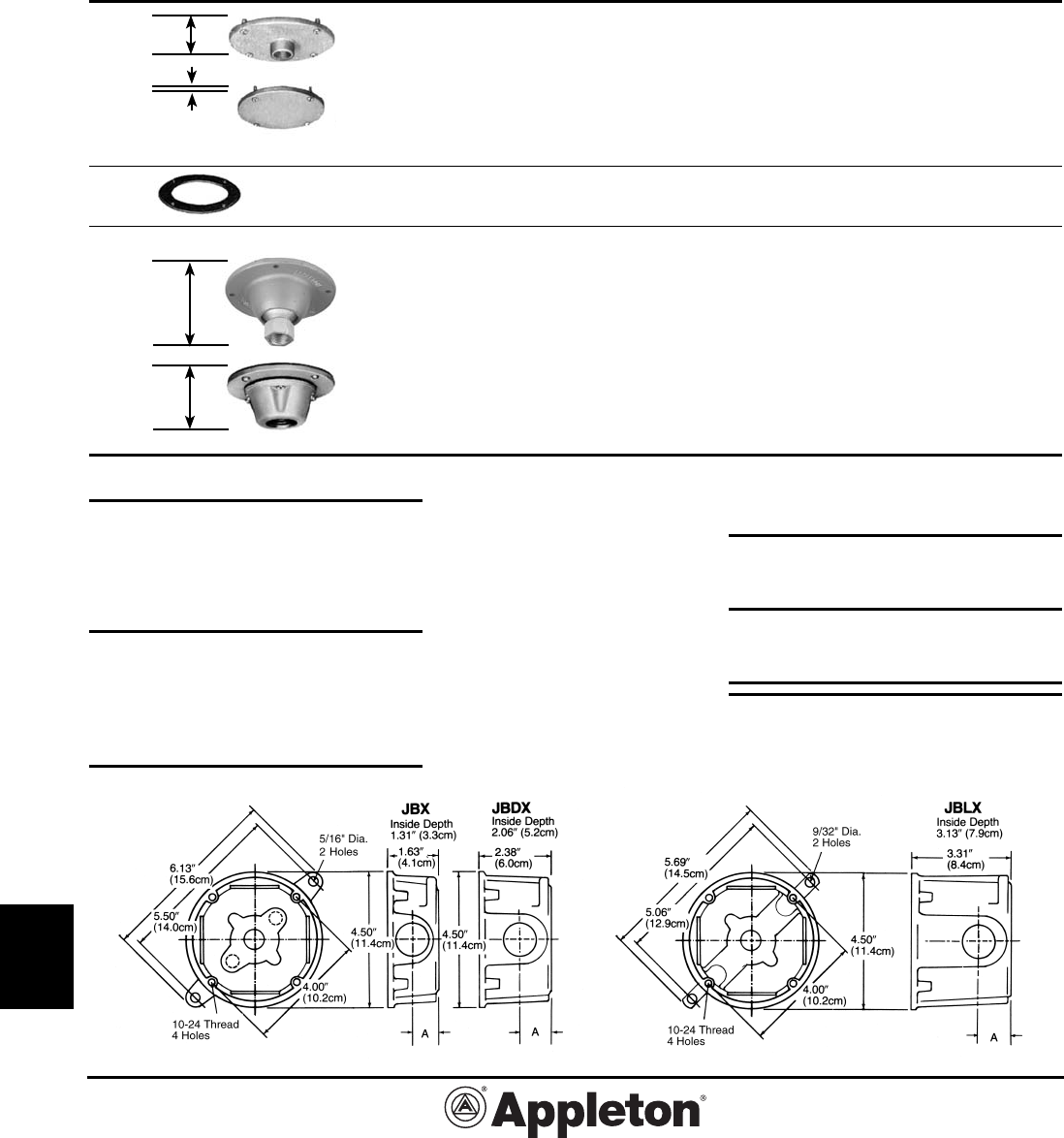
Effective September, 2005
Copyright 2005
PAGE 34
800-621-1506
www.appletonelec.com
A-34
A
Cushion
A
A
A
Ball
A
Hub Size Length Catalog Number
Description (Inches) (A) Malleable Iron Aluminum
JBX, JBDX, JBLX — Cast Covers
Furnished with screws.
When used with gasket provides
raintight fit, supports 250 lbs.
Hub Covers
1/2 .75” (1.9cm) JBK-50 JBK-50-A
3/4 .94” (2.3cm) JBK-75 JBK-75-A
Cover Blank .19” (0.4cm) JBK-B JBK-1B-CA
JBX, JBDX, JBLX —
Gasket, Neoprene — — JB-GK-N JB-GK-N
JBX, JBDX, JBLX —
Flexible Fixture Hangers
Furnished with gasket and screws.
Ball Type — 15° swing in all
directions, support 250 lbs. 1/2 2.56” (6.5cm) JBK-50-BS —
3/4 2.56” (6.5cm) JBK-75-BS —
Cushion type, enclosed and
gasketed — 8° swing in all
directions. Cushions 40 lbs., 1/2 1.63 (4.1cm) JBK-50-CS —
supports 250 lbs. 3/4 1.63 (4.1cm) JBK-75-CS —
JB Conduit Outlet Boxes, Covers, and Hangers:
Malleable Iron, Aluminum
UNILET® for use with Threaded Rigid Metal Conduit and IMC.
NOTE: Refer to page A-31 for Wiring Capacity Tables.
JBX and JBDX
Dimensions
Hub size Dimension “A” (Inches)
(Inches) JBX JBDX JBLX
1/2 .75 .75 .75
3/4 .88 .88 .88
1 .81 1.06 1.06
Hub size Dimension “A”(Centimeters)
(Inches) JBX JBDX JBLX
1/2 1.9 1.9 1.9
3/4 2.2 2.2 2.2
1 2.1 2.7 2.7
JBLX
JB Malleable Iron and Aluminum Boxes.
CAPACITY IN CUBIC INCHES*
Hub
Size (In.) JBX JBDX JBLX
1/2 15.5 23.0 33.0
3/4 15.5 23.0 33.0
1 15.5 23.0 33.0
*JB covers add no additional cubic inch capacity.
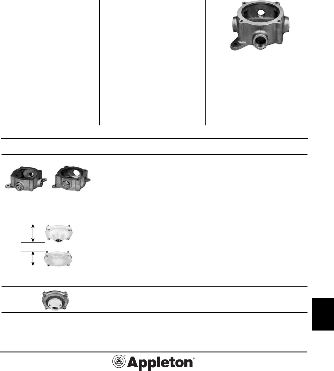
Effective September, 2005
Copyright 2005
800-621-1506
www.appletonelec.com
PAGE 35
A-35
A
GS Conduit Outlet Boxes, Covers, and Hangers:
Malleable Iron
UNILET® for use with Threaded Rigid Metal Conduit and IMC.
Features
• Raintight when enclosed and gas-
keted with hub or blank covers.
• Extra wide mating surfaces of GS
box and cover provide greater gasket
contact for more positive seal.
• For exposed or concealed use.
• GSU-20 will take connection block.
•
Universal design—furnished with 4
threaded universal 3/4” hubs, four 3/4” to
1/2” reducers, and 3 close-up plugs.
• Furnished with mounting lugs.
• Cushion fixture hangers enclosed
and gasketed (vaportight).
Standard Materials
• Conduit outlet boxes, covers and
fixture hangers: malleable iron.
• Gaskets: Neoprene or composition
fiber.
Standard Finishes
• Malleable iron conduit outlet boxes,
fixture hangers hub covers: triple-coat
— (1) zinc electroplate, (2) dichromate
and (3) epoxy powder coat.
• 1/2” hub and blank covers: (1) zinc
electroplate, (2) dichromate and (3)
epoxy powder coat.
Compliances
• UL Standard 514A.
• Federal Spec. W-C-586B.
• Suitable for classified location use in
Class I, Division 2 areas, if installed in
compliance with NEC 501-4(b).
• Appleton malleable iron conforms to
ASTM A47-77, Grade 32510.
• Appleton aluminum products are pro-
duced from a high strength copper-free
(4/10 of 1% max.) alloy.
GS conduit outlet box. Four tapped
conduit entrances.
Hub Size Length
Description (Inches) (A) Catalog Number
GS — 1-3/4” inside depth,
with mounting lugs (Form 20)
Four threaded universal 3/4” hubs,
four 3/4” to 1/2” reducers, and
three 1/2” close-up plugs. 1/2 or 3/4 — GSU-20
Four 1” threaded openings and
three 1” close-up plugs. 1 — GSU-100
GS — Cast Covers
Furnished with gasket and screws.
Enclosed and gasketed for raintight fit,
supports 250 lbs.
Hub Cover 1/2 1.75” (4.4cm) GSK-50-20
3/4 1.75” (4.4cm) GSK-75-20
Blank Cover Blank 1.06” (2.6cm) GSK-BC-20
GS — Cover, Lamp Receptacle
Furnished with gasket and screws. — 1.63” (4.1cm) GSK-LR20
GSU-20 GSU-100
A
A
Hub Cover
Blank Cover
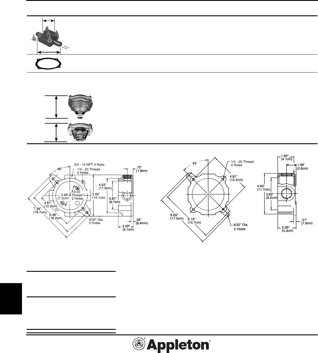
Effective September, 2005
Copyright 2005
PAGE 36
800-621-1506
www.appletonelec.com
A-36
A
Ball
Cushion
A
A
1.312” / 3.33 cm
2.875” / 7.06 cm 0.219” / 0.56 cm
i
i
GS Conduit Outlet Boxes, Covers, and Hangers:
Malleable Iron
UNILET® for use with Threaded Rigid Metal Conduit and IMC.
Hub Size Length
Description (Inches) (A) Catalog Number
GS-20 — Connection Block
Furnished with mounting screws.
5-Wire, 20-Amp, 300 Volt — — CB205
GS — Gasket, Neoprene — — GS-GK20-R
GS — Flexible Fixture
Hangers — Form 20
Furnished with gasket and screws.
Ball Type — 15° swing in all — 3.00” (7.6cm) GSK-50-20B
directions, support 250 lbs. — 3.25” (8.2cm) GSK-75-20B
Cushion Type, enclosed and
gasketed — 8° swing in all
directions. Cushions 40 lbs., — 2.00” (5.0cm) GSK-50-20C
supports 250 lbs. — 2.00” (5.0cm) GSK-75-20C
GSU-20
Inside Depth
1.75” (4.5cm)
GSU-100
Inside Depth
1.75” (4.5cm)
Dimensions
GS Malleable Iron Boxes*
CAPACITY IN CUBIC INCHES
Hub GSK Covers
Size (In.) GS Hub Blank
1/2 24.0 8.5 8.5
3/4 24.0 8.5 8.5
1 24.0 8.5 8.5
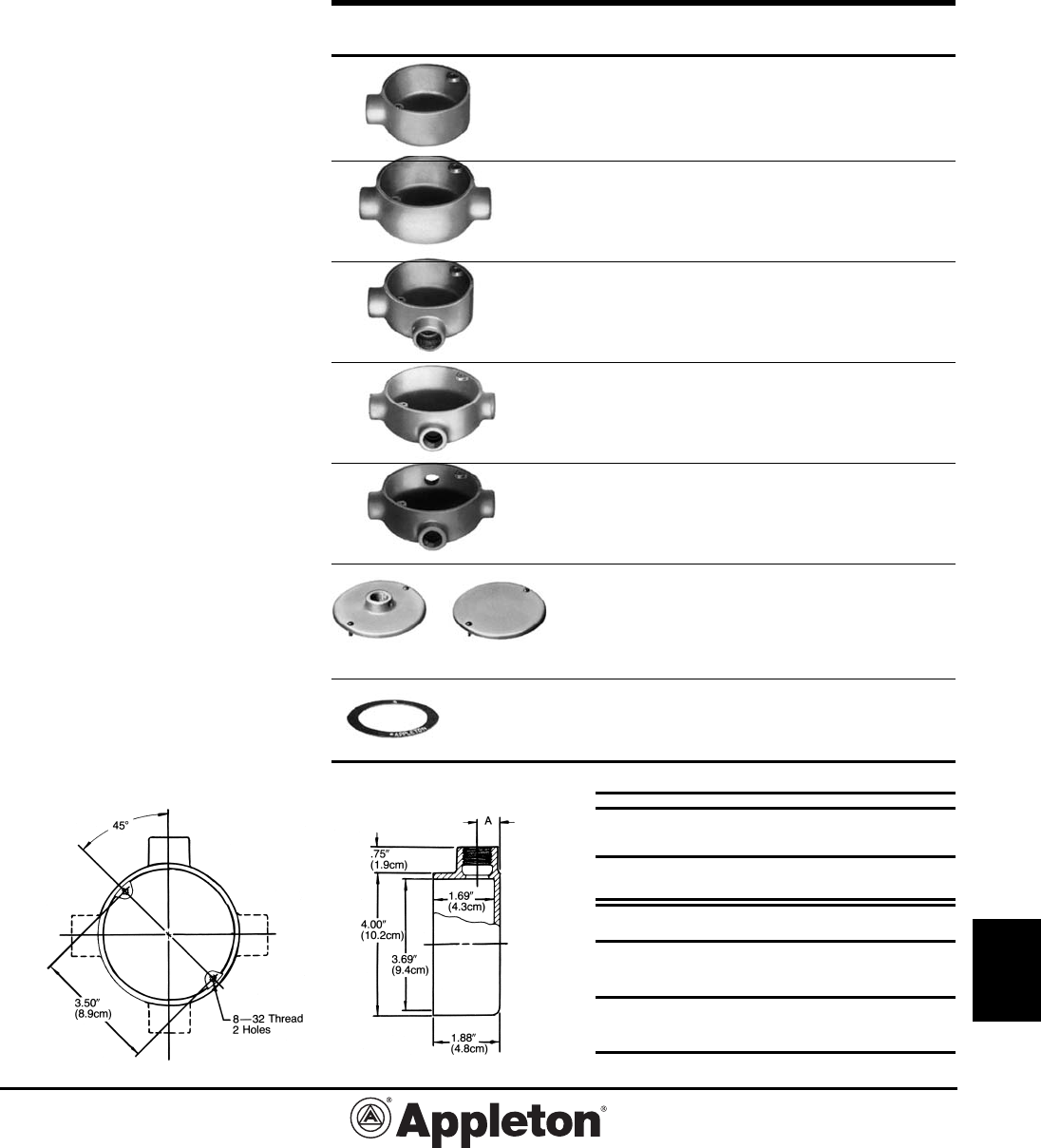
Effective September, 2005
Copyright 2005
800-621-1506
www.appletonelec.com
PAGE 37
A-37
A
SEH Conduit Outlet Boxes and Covers:
Malleable Iron
UNILETS® for use with Threaded Rigid Metal Conduit and IMC.
SEH Boxes Take Wiring Devices Designed
for 4” Octagonal Outlet Boxes.
NOTE: Refer to page A-31 for Wiring Capacity Tables.
Hub Size
(Inches) A (Inches) A(Centimeters)
1/2 .63 1.6
3/4 .75 1.9
CAPACITY IN CUBIC INCHES
Hub
Size (In.) SEH
1/2 18.0
3/4 18.0
*SEH covers add no additional cubic inch capacity.
Features
• Economy cast conduit outlet box.
• Take wiring devices designed for 4”
octagonal outlet boxes.
• Two 8-32 screw holes tapped on
3-1/2” centers.
Standard Materials
• Conduit outlet boxes and covers:
malleable iron.
• Gaskets: Neoprene or composition
fiber.
Standard Finishes
• Malleable iron conduit outlet boxes,
and hub covers: triple-coat — (1) zinc
electroplate, (2) dichromate and (3)
epoxy powder coat.
• Blank cast cover: (1) zinc electro-
plate, (2) dichromate and (3) epoxy
powder coat.
• Blank steel cover: zinc electroplate.
Compliances
• UL Standard 514A.
• Federal Spec. W-C-586B.
• Suitable for classified location use in
Class I, Division 2 areas, if installed in
compliance with NEC 501-4(b).
• Appleton malleable iron conforms to
ASTM A47-77, Grade 32510.
• Appleton aluminum products are pro-
duced from a high strength copper-free
(4/10 of 1% max.) alloy.
Dimensions
Hub Size Catalog
Description (Inches) Number
SEH 1/2 SEH-50
3/4 SEH-75
SEHC 1/2 SEHC-50
3/4 SEHC-75
SEHL 1/2 SEHL-50
3/4 SEHL-75
SEHT 1/2 SEHT-50
3/4 SEHT-75
SEHX 1/2 SEHX-50
3/4 SEHX-75
SEH—Covers Furnished with screws.
Hub Cover, cast malleable 1/2 SEHK-50
Cover, steel Blank SEHK-B
Cover, cast malleable Blank SEHK-BC
SEH—Gasket SEH-GK
Fiber Composition
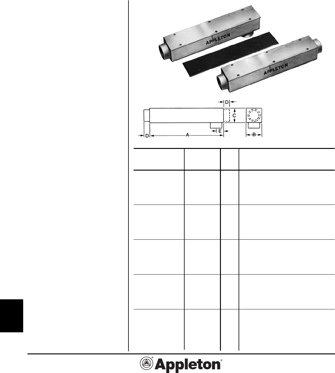
Effective September, 2005
Copyright 2005
PAGE 38
800-621-1506
www.appletonelec.com
A-38
A
Pull Boxes with Threaded Hubs and Covers
For use with Threaded Rigid Metal Conduit and IMC.
Applications
• Serve as pulling fittings.
• Provide openings for splicing.
• Make straight connections and 90°
bends in conduit runs.
• Permit access to conductors for
maintenance.
Features
• Roomy interiors, more wiring space.
• Accurately tapped, tapered threads
(NPT) for tight, rigid joints and ground
continuity.
Standard Materials
• Bodies and covers– steel.
• Hubs– malleable iron or steel.
• Cover bolts– stainless steel.
Standard Finish
• Zinc electroplate, dichromate and
epoxy powder coat.
Size Range
• Straight Type PTC– 1” thru 6” (hub)
sizes, 12” thru 48” lengths.
Options
• Custom lengths up to 72” available,
consult factory.
Compliances
• UL Standard 514A.
Catalog Numbers Hub
Straight 90° Gaskets for Size Pull Box Dimensions (Inches)
PTC Box PTB Box PTC & PTB (In.) A B C D E
12-inch
1200 1250 GK-12-100 1 12 2-3/16 2-1/8 27/32 15/16
1201 1251 GK-12-150 1-1/4 12 2-1/2 2-7/16 1-1/16 1-5/32
1202 1252 GK-12-150 1-1/2 12 2-1/2 2-7/16 1-1/16 1-3/8
1203 1253 GK-12-200 2 12 3-11/32 3-5/16 1-5/16 1-11/16
18-inch
1211 — GK-18-150 1-1/4 18 2-1/2 2-7/16 1-1/16 1-5/32
1212 — GK-18-150 1-1/2 18 2-1/2 2-7/16 1-1/16 1-3/8
1213 — GK-18-200 2 18 3-11/32 3-5/16 1-5/16 1-11/16
1214 — GK-18-250 2-1/2 18 4-13/16 4-3/4 1-19/32 1-13/16
24-inch
1222 1272 GK-24-150 1-1/2 24 2-1/2 2-7/16 1-1/16 1-3/8
1223 1273 GK-24-200 2 24 3-11/32 3-5/16 1-5/16 1-11/16
1224 1274 GK-24-300 2-1/2 24 4-13/16 4-3/4 1-19/32 1-13/16
1225 1275 GK-24-300 3 24 4-13/16 4-3/4 1-21/32 2-1/16
36-inch
1244 1294 GK-36-300 2-1/2 36 4-13/16 4-3/4 1-19/32 1-13/16
1245 1295 GK-36-300 3 36 4-13/16 4-3/4 1-21/32 2-1/16
1246 1296 GK-36-400 3-1/2 36 6-5/16 6-3/16 1-29/32 2-3/8
1247 1297 GK-36-400 4 36 6-5/16 6-3/16 1-29/32 2-21/32
48-inch
1812 — GK-48-300 3 48 4-13-16 4-3/4 1-21/32 2-1/16
1813 — GK-48-400 3-1/2 48 6-5/16 6-3/16 1-29/32 2-3/8
1814 — GK-48-400 4 48 6-5/16 6-3/16 1-29/32 2-21/32
1815 — GK-48-500 5 48 7-5/16 7-3/16 1-27/32 3-1/4
1816 — GK-48-600 6 48 8-5/16 8-3/16 2-1/32 4-1/32
TYPE “PTB”
TYPE “PTC”
PTB/PTC gasket
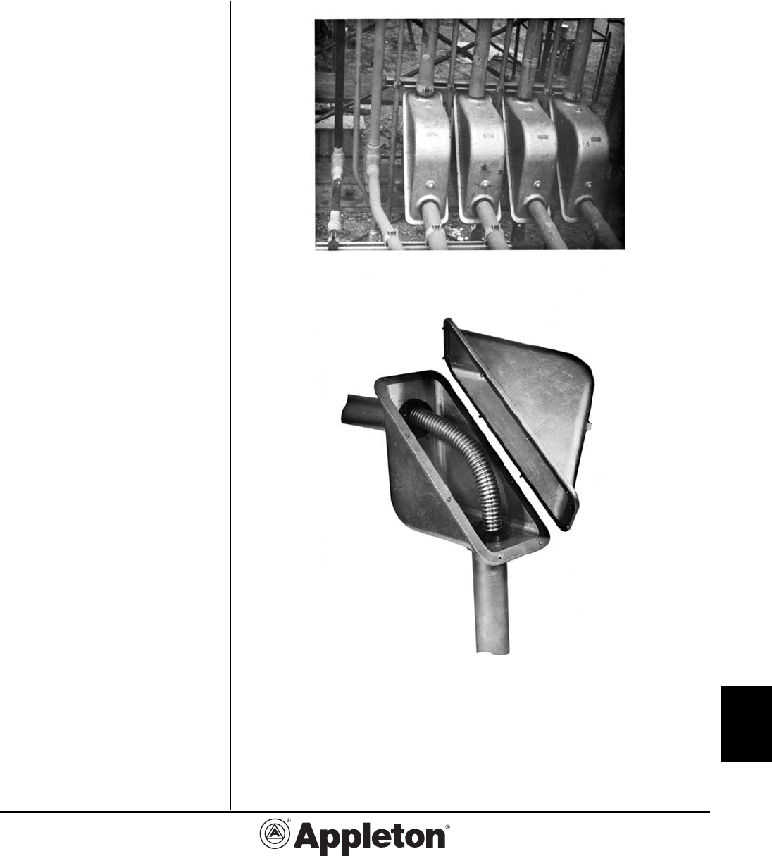
Effective September, 2005
Copyright 2005
800-621-1506
www.appletonelec.com
PAGE 39
A-39
A
Big-Bend™ Cast Pulling Elbow
For use with Threaded Rigid Metal Conduit and IMC.
Application
• Big-Bend™ Pulling Elbow is installed
in conduit systems to provide 90°
bends in conduit runs, pull outlets for
conductors, access to conductors for
maintenance and openings for making
splices.
Features
• Cast from copper-free aluminum.
• Composition gasket in cover.
• Stainless steel cover bolts.
• Plugged 1/2” outlets top and bottom
for breather and drain.
• Available in cast iron.
• Allows bending radius of 8 to 12 times
outside diameter of conductor.
• Conductors can be pulled straight
through.
• Cover easily installed.
Standard Materials
• Bodies and covers: copper-free
aluminum.
• Gaskets: composition.
• Cover bolts: stainless steel.
Standard Finishes
• Acrylic paint.
Compliances
• Certification Standard C22.2 No.
18-M1987 NEMA 4.
• UL Standard 514A.
Conduit Systems Installations
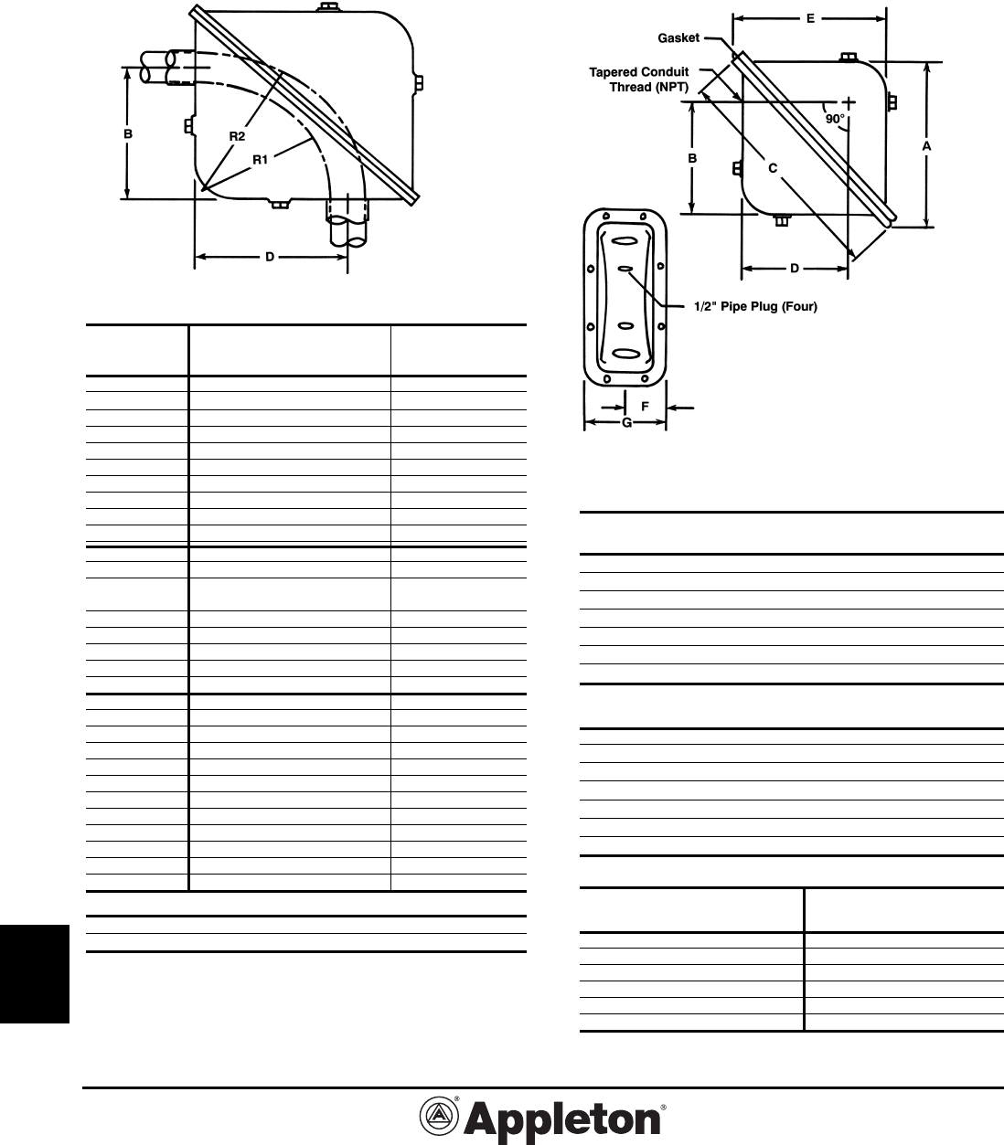
Effective September, 2005
Copyright 2005
PAGE 40
800-621-1506
www.appletonelec.com
A-40
A
Big-Bend™ Cast Pulling Elbow
Conduit Systems Installations
BENDING RADII OF BIG-BEND PULLING ELBOW
Catalog Conduit R1 R2 R1 R2
Number Size (In.) (In.) (In.) (Cm) (Cm)
BB1-050 1/2 8.187 8.812 20.79 22.38
BB1-075 3/4 8.062 8.875 20.48 22.54
BB1-100 1 7.875 8.937 20.00 22.70
BB1-125 1-1/4 7.812 9.250 19.84 23.50
BB1-150 1-1/2 7.687 9.312 19.52 23.65
BB1-200 2 7.437 9.500 18.89 24.13
BB1-250 2-1/2 7.250 9.687 18.42 34.60
BB1-300 3 6.875 9.937 17.46 25.24
BB1-350 3-1/2 6.687 10.250 16.98 26.04
BB1-400 4 6.437 10.500 16.35 26.67
BB2-075 3/4 12.937 13.750 32.86 34.93
BB2-100 1 12.750 13.812 32.39 35.08
BB2-125 1-1/4 12.687 14.125 32.22 35.88
BB2-150 1-1/2 12.562 14.187 31.91 36.03
BB2-200 2 12.312 14.375 31.27 36.51
BB2-250 2-1/2 12.125 14.562 30.80 36.99
BB2-300 3 11.750 14.812 29.85 37.62
BB2-350 3-1/2 11.562 15.125 29.37 38.42
BB2-400 4 11.312 15.375 28.73 29.05
BB3-050 1/2 13.062 13.687 33.18 34.76
BB3-075 3/4 12.937 13.750 32.86 34.93
BB3-100 1 12.750 13.812 32.39 35.08
BB3-125 1-1/4 12.687 14.125 32.22 35.88
BB3-150 1-1/2 12.562 14.187 31.91 36.03
BB3-200 2 12.312 14.375 31.27 36.51
BB3-250 2-1/2 12.125 14.562 30.80 36.99
BB3-300 3 11.750 14.812 29.85 37.62
BB3-350 3-1/2 11.562 15.125 29.37 38.42
BB3-400 4 11.312 15.375 28.73 39.05
BB3-500 5 10.812 15.812 27.46 40.16
BB3-600 6 10.312 16.375 26.19 41.59
Size BB1 BB2 BB3
Inside Dimensions 12x12x6 18x18x6 18x18x8
Approx. Shp. Wt/Unit 18lbs. 32 lbs. 48 lbs.
Dimensions In Inches
BB1 BB2 BB3
A 12-3/4 19-7/8 19-7/8
B 9 14 14
C 18-3/4 27-1/4 27-1/2
D 9 14 14
E 12-3/4 19-7/8 19-7/8
F 3-7/8 3-7/8 5
G 7-3/4 7-3/4 10
Dimensions In Centimeters
BB1 BB2 BB3
A 32.39 50.48 50.48
B 24.48 38.10 35.56
C 47.63 69.22 69.85
D 24.48 38.10 35.56
E 34.93 50.48 50.48
F 9.84 9.84 12.70
G 19.69 19.69 25.40
Conduit Conduit
Size (In.) Code Size (In.) Code
1/2 050 2-1/2 250
3/4 075 3 300
1 100 3-1/2 350
1-1/4 125 4 400
1-1/2 150 *5 500
2 200 *6 600
* Available in Big-Bend™ Size 3 only
Effective September, 2005
Copyright 2005
800-621-1506
www.appletonelec.com
PAGE 41
A-41
A
®
