06200335_011
2014-11-11
: Pdf 88470-Attachment 88470-Attachment 011011 Batch12 unilog
Open the PDF directly: View PDF ![]() .
.
Page Count: 2
2598 8/16-Point
AC Discrete Output Module
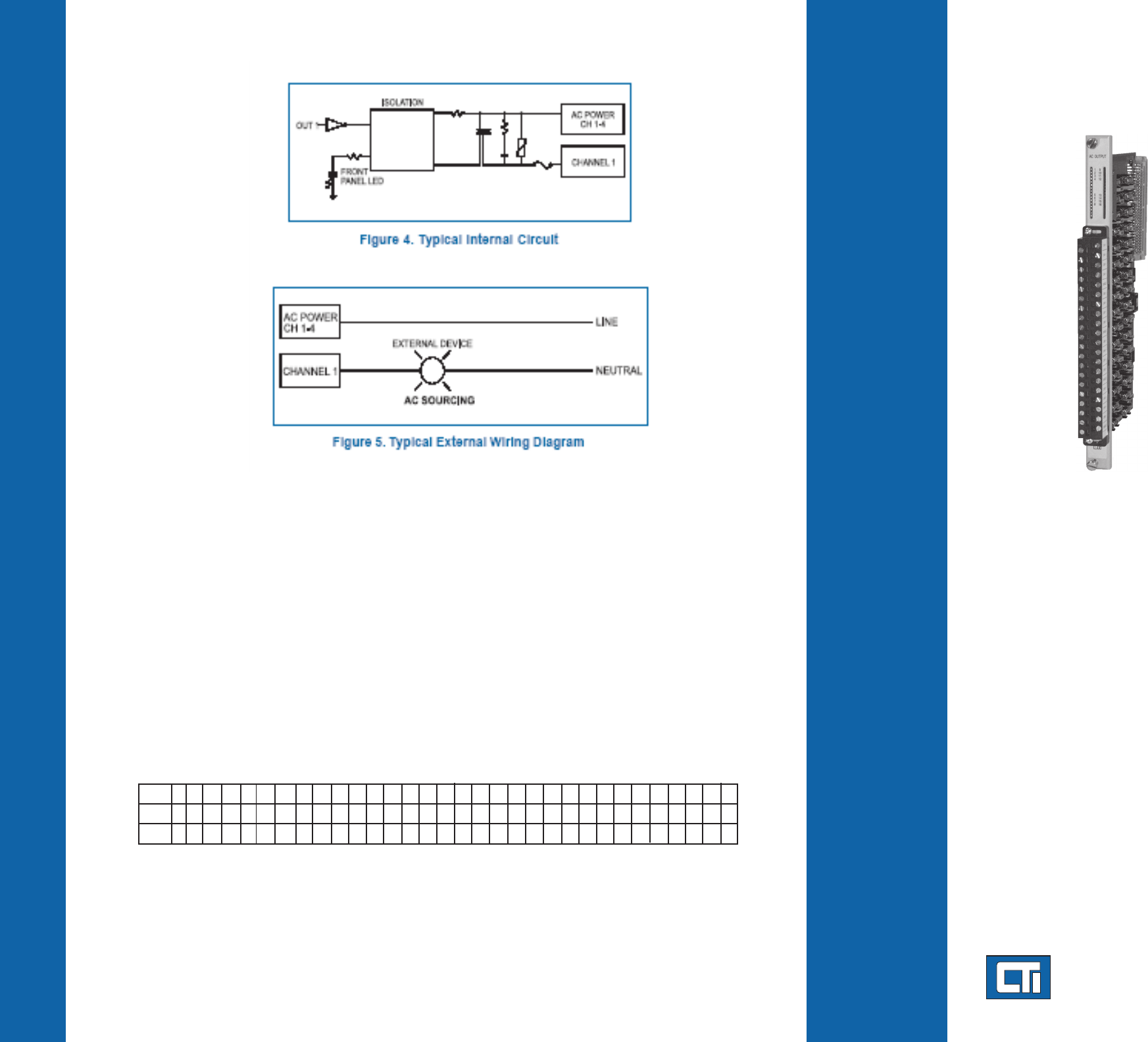
Description
The 2598 8/16-Point AC Discrete Output
Module provides eight or sixteen outputs from
CTI 2500 Series or Simatic® 505 I/O bases.
The module utilizes solid-state output circuits to
switch on or off external devices such as pilot
lamps, motor starters, or solenoids. The 2598 is
designed to switch externally supplied 11 to 240
VAC. The internal logic signals are isolated from
the external outputs to 2100 VDC.
Features
8 or 16 AC output points
Replaces Siemens® 505-4608, -4616,
-4808, -4816
3000 VDC group-to-group isolation
2100 VDC channel-to-backplane isolation
Isolation in groups of four (16pt. login) or in
groups of two (8pt. login)
Wide 11-240 VAC output range
2.0 Amps per output
Individually fused outputs
Sourcing outputs
Single-wide module
Specifications
Outputs per Module: 8 or 16
Isolation: 2100 VAC channel-to-backplane
3000 VAC group-to-group
Output Voltage: 11 VAC to 240 VAC
Maximum Output Current:
2A per point
8A per group
32A per module (16pt login)
for Class 1 Div 2 locations:
2A per point @ 50C
1.5A per point @ 60C
Maximum Surge Current: 3 Amps for 15 Sec
“ON” State Voltage Drop: 1.0 V @ 1.0 Amp
“OFF” State Leakage Current: 1 mA @ 120 VAC
Turn On Time: 1 AC cycle
Turn Off Time: 1 AC cycle
Fuses: 16, 2.5 amp, 250V,
Type Littlefuse #21602.5,
Bussman GDA-2.5, (Field replaceable)
Connector: Removable
Wire Gauge: 14 - 22 AWG
Backplane Power: 1.25 Watts max.
Module Size: Single-wide
Operating Temperature: 0o to 60oC
(32o to 140oF)
Storage Temperature: -40o to 85oC
(-40o to 185oF)
Relative Humidity: 5% to 95%
(non-condensing)
Agency Approvals:
UL, UL-Canada, Class 1, Div 2, CE
Shipping Weight: 1.5 lb. (0.68 Kg)
Note: For CTI Limited Product Warranty and RMA procedures please go to www.controltechnology.com/support.htm.
8/16 Point Configuration Explanation
The 2598 was designed to be primarily a 16pt module. However, in order to provide maximum flexibility for the user,
it may also be configured as an 8 point module. Some details are listed below to help the user better understand
the jumper settings and PCB labeling discrepancies for the 8 point setting.
8 Point Mode: Move jumper in “Login” box to location JP3 to choose 8pt mode. Ensure the Isolation jumpers
J2,4,5, & 6 are in ‘8 Common’ positions to correspond to the Siemens® counterpart 8 point modules (2 inputs/
common). Also, note that many of the printed channels (CH 1-CH 32) on the PC board are no longer valid, nor
are the front panel connector labels. (You may find it helpful to utilize the appropriate 8 pt. connector labels
shipped with the product.) If 8 Point is enabled, the following table’s 8pt. row is the new correlation of PC board
printing and front panel label’s LED area printing. For example, in 8 Point Login Configuration, the board marking
for channel 10 (CH 10) would be the input channel 6. Likewise, the PC board marking for CH 13 would correlate
to input channel 7.
8 pt: 1 2 - - - - - - 3 4 - - - - - - 5 6 - - - - - - 7 8 - - - - - -
32 pt: 1 2 3 4 5 6 7 8 9 10 11 12 13 14 15 16 17 18 19 20 21 22 23 24 25 26 27 28 29 30 31 32
16 pt: 1 2 3 4 - - - - 5 6 7 8 - - - - 9101112 - - - -13141516 - - - -
Channel/Fuse Labeling
Login
Mode
2500 Series PLC System
Product Bulletin
Control Technology Inc.
5734 Middlebrook Pike, Knoxville, TN 37921-5962
Phone: 865/584-0440 Fax: 865/584-5720 www.controltechnology.com
Copyright© 2006 Control Technology Inc. All Rights Reserved
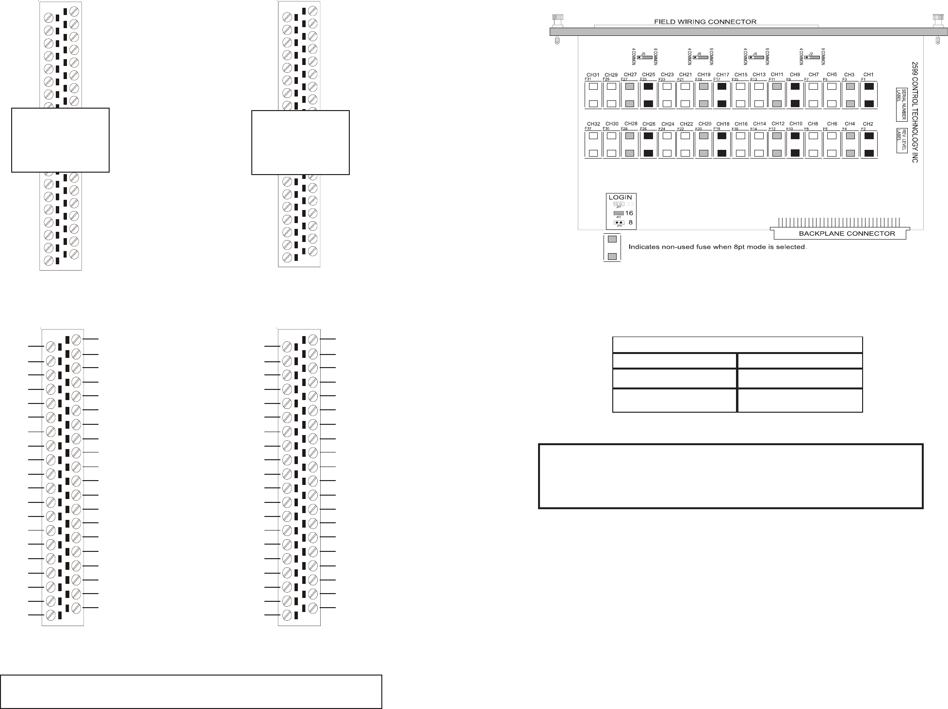
Standard Shipping Configuration
Grouping Configuration
The 2598 is shipped to allow four channels to be grouped and share a common field user power, thereby
allowing a different user power supply voltage to be used by each grouping. Jumpers J2, J4, J5, and J6
come
set in the “8 Common” selection from the factory and should not be altered for proper module operaton.
This setting allows for 4 points per common operation.
For example, Channels 1-4 will share a common user power and Channels 5-8 will share another com-
mon user power. In this example each group of four channels is isolated from the other group of four
channels. Because each group of four is isolated, the user may also change the supply voltage for each
group. So, in this example, Channels 1-4 could be 240VAC outputs and Channels 5-8 could be 120VAC
outputs.
Figure 3. Jumper and Fuse Configuration
Table 1. Jumper Configuration Table
8 Pt Login
Selection Jumper in
8 Common Position
8 Pt Login
Selection Jumper in
4 Common Position
16 Pt Login
Selection Jumper in
4 Common Position
16 Pt Login
Selection Jumper in
8 Common Position*
A
R
A
1
A
C
A
5
A
6
A
7
A
8
BC
B5
B6
B7
B8
CC
C5
C6
C7
C8
DC
D5
D6
D7
D8
A
2
A
3
A
4
BR
B1
B2
B3
B4
CR
C1
C2
C3
C4
DR
D1
D2
D3
D4
Not Applicable:
See explanation
in section on
back page
A
R
A
1
A
C
A
5
A
6
A
7
A
8
BC
B5
B6
B7
B8
CC
C5
C6
C7
C8
DC
D5
D6
D7
D8
A
2
A
3
A
4
BR
B1
B2
B3
B4
CR
C1
C2
C3
C4
DR
D1
D2
D3
D4
Not Applicable:
See explanation
in section on
back page
Not Used
Not Used
Not Used
Not Used
Not Used
Not Used
Not Used
Not Used
Not Used
Not Used
Not Used
Not Used
Not Used
Not Used
Not Used
Not Used
A
R
A
1
A
C
A
5
A
6
A
7
A
8
BC
B5
B6
B7
B8
CC
C5
C6
C7
C8
DC
D5
D6
D7
D8
A
2
A
3
A
4
BR
B1
B2
B3
B4
CR
C1
C2
C3
C4
DR
D1
D2
D3
D4
Channel 1
Channel 2
Channel 3
Channel 4
Channel 5
Channel 6
Channel 7
Channel 8
Channel 9
Channel 10
Channel 11
Channel 12
Channel 13
Channel 14
Channel 15
Channel 16
User Pwr AC (+)
Channels 1-4
User Pwr AC (+)
Channels 5-8
Not Used
User Pwr AC (+)
Channels 9-12
User Pwr AC (+)
Channels 13-16
Not Used
Not Used
Not Used
A
R
A
1
A
C
A
5
A
6
A
7
A
8
BC
B5
B6
B7
B8
CC
C5
C6
C7
C8
DC
D5
D6
D7
D8
A
2
A
3
A
4
BR
B1
B2
B3
B4
CR
C1
C2
C3
C4
DR
D1
D2
D3
D4
Channel 1
Channel 2
Not Used
Not Used
Channel 3
Channel 4
Not Used
Not Used
Channel 5
Channel 6
Not Used
Not Used
Channel 7
User Pwr AC(+)
Channels 1-2
User Pwr AC(+)
Channels 3-4
Not Used
User Pwr AC(+)
Channels 5-6
User Pwr AC(+)
Channels 7-8
Not Used
Not Used
Not Used
Channel 8
Not Used
Not Used
Not Used
Not Used
Not Used
Not Used
Not Used
Not Used
Not Used
Not Used
Not Used
Not Used
Not
Not Used
Not Used
Not Used
Not Used
Not Used
*Note: Due to a new rev ‘C’ 2598/99 PCB, the 16pt login above differs from the former ‘B’ rev
PCB. The one above is 100% Siemens® compatible
WARNING:
Do not alter ‘8 COMMON’ jumper J2, 4, 5, and 6 settings. The module is configured
as needed for proper wiring compatibility with its Siemens® counterpart. Remove
the module from the 505 base before changing LOGIN jumper JP2 and 3 settings.
Jumper Configuration
Jumper Selection
J2, J4, J5, J6 8 Common
JP 2, 3 JP2 - 16 pt. Login
(see chart on back for actual channel correlations)
