CA08100014E
155736-Catalog 155736-Catalog 155736-Catalog B5 unilog cesco-content
2016-10-06
: Pdf 90288-Attachment 90288-Attachment B5 unilog
Open the PDF directly: View PDF ![]() .
.
Page Count: 621 [warning: Documents this large are best viewed by clicking the View PDF Link!]

Electrical Sector Solutions
Volume 12: Aftermarket, Renewal Parts and Life Extension Solutions
Eaton is a registered trademark.
All other trademarks are property
of their respective owners.
Eaton
1000 Eaton Boulevard
Cleveland, OH 44122
United States
Eaton.com
© 2013 Eaton
All Rights Reserved
Printed in USA
Publication No. CA08100014E / Z14331
October 2013

18741833 1886 1911 19141893 198319621961 1989198419771908190618991897 1963 19671934
The power of fusion.
There’s a certain energy at Eaton. It’s the power of uniting some of the
world’s most respected names to build a brand you can trust to meet
your every power management need.
Eaton is dedicated to ensuring that reliable, effi cient and safe power
is available when it’s needed most. Building on over 100 years of
experience in electrical power management, the experts at Eaton
deliver customized, integrated solutions to solve your most critical
challenges. To learn more, visit Eaton.com/Electrical
All of the above are trademarks of Eaton or its afliates. Eaton has a license to use the Westinghouse
brand name in Asia Pacic. ©2013 Eaton.
Volume 12—Aftermarket, Renewal Parts and Life Extension Solutions CA08100014E—November 2013 www.eaton.com
1
2
3
4
5
6
7
8
9
10
11
12
13
14
15
16
17
18
19
20
21
22
23
24
Contents
Molded Case Circuit Breakers
Motor Control
Switchgear
Introduction . . . . . . . . . . . . . . . . . . . . . . . . . . . . . . . . . . . . . . . . . . . . . . . . . . . . . . .
Distribution System . . . . . . . . . . . . . . . . . . . . . . . . . . . . . . . . . . . . . . . . . . . . . . . . .
Molded-Case Circuit Breakers . . . . . . . . . . . . . . . . . . . . . . . . . . . . . . . . . . . . . . . . .
Panelboards . . . . . . . . . . . . . . . . . . . . . . . . . . . . . . . . . . . . . . . . . . . . . . . . . . . . . . .
Loadcenters . . . . . . . . . . . . . . . . . . . . . . . . . . . . . . . . . . . . . . . . . . . . . . . . . . . . . . . .
Meter Centers . . . . . . . . . . . . . . . . . . . . . . . . . . . . . . . . . . . . . . . . . . . . . . . . . . . . . .
Safety Switches . . . . . . . . . . . . . . . . . . . . . . . . . . . . . . . . . . . . . . . . . . . . . . . . . . . .
Dry-Type Distribution Transformers . . . . . . . . . . . . . . . . . . . . . . . . . . . . . . . . . . . .
Busway (Low Voltage) . . . . . . . . . . . . . . . . . . . . . . . . . . . . . . . . . . . . . . . . . . . . . . .
IQ Products . . . . . . . . . . . . . . . . . . . . . . . . . . . . . . . . . . . . . . . . . . . . . . . . . . . . . . . .
Communication Systems . . . . . . . . . . . . . . . . . . . . . . . . . . . . . . . . . . . . . . . . . . . .
Programmable Logic Controllers . . . . . . . . . . . . . . . . . . . . . . . . . . . . . . . . . . . . . .
Motor Control . . . . . . . . . . . . . . . . . . . . . . . . . . . . . . . . . . . . . . . . . . . . . . . . . . . . . .
Motor Control Centers . . . . . . . . . . . . . . . . . . . . . . . . . . . . . . . . . . . . . . . . . . . . . . .
Distribution Switchboards (Low Voltage) . . . . . . . . . . . . . . . . . . . . . . . . . . . . . . .
High Resistance Grounding System . . . . . . . . . . . . . . . . . . . . . . . . . . . . . . . . . . . .
Switchgear . . . . . . . . . . . . . . . . . . . . . . . . . . . . . . . . . . . . . . . . . . . . . . . . . . . . . . . .
Medium Voltage Fuses . . . . . . . . . . . . . . . . . . . . . . . . . . . . . . . . . . . . . . . . . . . . . . .
Network Protectors . . . . . . . . . . . . . . . . . . . . . . . . . . . . . . . . . . . . . . . . . . . . . . . . .
Automatic Transfer Switches . . . . . . . . . . . . . . . . . . . . . . . . . . . . . . . . . . . . . . . . . .
Power Factor Correction Capacitors . . . . . . . . . . . . . . . . . . . . . . . . . . . . . . . . . . . .
Eaton’s Electrical Services & Systems . . . . . . . . . . . . . . . . . . . . . . . . . . . . . . . . . .
Pushbuttons and Indicating Lights . . . . . . . . . . . . . . . . . . . . . . . . . . . . . . . . . . . . .
Sales & Service Locations . . . . . . . . . . . . . . . . . . . . . . . . . . . . . . . . . . . . . . . . . . . .
Appendix 1—Eaton Terms & Conditions
Appendix 2—Alphabetical Product Index

Volume 12—Aftermarket, Renewal Parts and Life Extension Solutions CA08100014E—November 2013 www.eaton.com
1
2
3
4
5
6
7
8
9
10
11
12
13
14
15
16
17
18
19
20
21
22
23
24
25
Copyright
Dimensions, Weights and Ratings
Dimensions, weights and ratings given in this catalog are approximate and should not be used
for construction purposes. Drawings containing exact dimensions are available upon request.
All listed product specifications and ratings are subject to change without notice. Photographs
are representative of production units.
Terms and Conditions
All prices and discounts are subject to change without notice. When price changes occur,
they are published in Eaton’s Price and Availability Digest (PAD). All orders accepted by
Eaton’s Electrical Sector are subject to the general terms and conditions as set forth in
Appendix 1—Eaton Terms & Conditions.
Technical and Descriptive Publications
This catalog contains brief technical data for proper selection of products. Further information
is available in the form of technical information publications and in illustrated brochures.
If additional product information is required, contact your local Eaton Products Distributor,
call 1-800-525-2000 or visit our website at www.eaton.com.
Compliance with Nuclear Regulation 10 CFR 21
Eaton products are sold as commercial grade products not intended for application in facilities
or activities licensed by the United States Nuclear Regulatory Commission for atomic purposes,
under 10 CFR 21. Further certification will be required for use of these products in a safety-related
application in any nuclear facility licensed by the United States Nuclear Regulatory Commission.
WARNING
The installation and use of Eaton products should be in accordance with the provisions of the
U.S. National Electrical Code® and/or other local codes or industry standards that are pertinent
to the particular end use. Installation or use not in accordance with these codes and standards
could be hazardous to personnel and/or equipment.
Copyright ©2013, Eaton, All Rights Reserved.
These catalog pages do not purport to cover all details or variations in equipment, nor to provide for
every possible contingency to be met in connection with installation, operation or maintenance.
Should further information be desired or should particular problems arise that are not covered
sufficiently for the purchaser’s purposes, the matter should be referred to the local Eaton Products
Distributor or Sales Office. The contents of this catalog shall not become part of or modify any prior
or existing agreement, commitment or relationship. The sales contract contains the entire
obligation of Eaton’s Electrical Sector. The warranty contained in the contract between the parties
is the sole warranty of Eaton. Any statements contained herein do not create new warranties or
modify the existing warranty.

Volume 12—Aftermarket, Renewal Parts and Life Extension Solutions CA08100014E—November 2013 www.eaton.com i
Introduction
Eaton is a global leader in power distribution, power quality,
control and automation, and monitoring products.
At Eaton, we believe a reliable, efficient and safe power system is the foundation of every
successful enterprise. Through innovative technologies, cutting-edge products and our highly
skilled services team, we empower businesses around the world to achieve a powerful advantage.
In addition, Eaton is committed to creating and maintaining powerful customer relationships built
on a foundation of excellence. From the products we manufacture to our dedicated customer
service and support, we know what’s important to you.
Solutions
Eaton takes the complexity out of power systems management with a holistic and strategic
approach, leveraging our industry-leading technology, solutions and services. We focus on
the following three areas in all we do:
●Reliability—maintain the
appropriate level of power
continuity without
disruption or unexpected
downtime
●Efficiency—minimize
energy usage, operating
costs, equipment footprint
and environmental impact
●Safety—identify and
mitigate electrical hazards
to protect what you value
most
Using the Eaton Catalog Library
As we grow, it becomes increasingly difficult to include all products in one or two comprehensive
catalogs. Knowing that each user has their specific needs, we have created a library of catalogs for our
products that when complete, will contain 15 volumes. Since the volumes will continuously be a work
in progress and updated, each volume will stand alone. Refer to our volume directory, MZ08100001E,
for a quick glance of where to look for the products you need. The 15 volumes include:
●Volume 1—Residential
and Light Commercial
(CA08100002E)
●Volume 2—Commercial
Distribution (CA08100003E)
●Volume 3—Power
Distribution and Control
Assemblies (CA08100004E)
●Volume 4—Circuit
Protection (CA08100005E)
●Volume 5—Motor Control
and Protection
(CA08100006E)
●Volume 6—Solid-State
Motor Control
(CA08100007E)
●Volume 7—Logic Control,
Operator Interface and
Connectivity Solutions
(CA08100008E)
●Volume 8—Sensing
Solutions (CA08100010E)
●Volume 9—Original
Equipment Manufacturer
(CA08100011E)
●Volume 10—Enclosed
Control (CA08100012E)
●Volume 11—Vehicle and
Commercial Controls
(CA08100013E)
●Volume 12—Aftermarket,
Renewal Parts and Life
Extension Solutions
(CA08105001E)
●Volume 13—Counters,
Timers and Tachometers
(CA08100015E)—Available
in electronic format only
●Volume 14—Fuses
(CA08100016E)—Available
in electronic format only
●Volume 15—Solar Inverters
and Electrical Balance of
System (CA08100018E)
These volumes are not all-inclusive of every product, but they are meant to be an overview
of our product lines. For our full range of product solutions and additional product information,
consult Eaton.com/electrical and other catalogs and product guides in our literature library.
These references include:
●The Consulting Application
Guide (CA08104001E)
●The Eaton Power Quality
Product Guide (COR01FYA)
If you don’t have the volume that contains the product or information that you are looking for,
not to worry. You can access every volume of the catalog library at Eaton.com/electrical in the
Literature Library.
By installing our Automatic Tab Updater (ATU), you can be sure you always have the most recent
version of each volume and tab.

ii Volume 12—Aftermarket, Renewal Parts and Life Extension Solutions CA08100014E—November 2013 www.eaton.com
Introduction
Icons
Green Leaf
Eaton Green Solutions are products, systems or solutions that represent Eaton
benchmarks for environmental performance. The green leaf symbol is our
promise that the solution has been reviewed and documented as offering
exceptional, industry-leading environmental benefits to customers, consumers
and our communities. Though all of Eaton’s products and solutions are
designed to meet or exceed applicable government standards related to
protecting the environment, our products with the Green Leaf designation
further provide “exceptional environmental benefit.”
Learn Online
When you see the Learn Online icon, go to Eaton.com/electrical and search for
the product or training page. There you will find 100-level training courses,
podcasts, webcasts or games and puzzles to learn more.
Drawings Online
When you see the Drawings Online icon, go to Eaton.com/electrical and find the
products page. There you will find a tab that includes helpful product drawings
and illustrations.
Contact Us
If you need additional help, you can find contact information
under the Customer Care heading of Eaton.com/electrical.

Volume 12—Aftermarket, Renewal Parts and Life Extension Solutions CA08100014E—November 2013 www.eaton.com V12-T1-1
1
2
3
4
5
6
7
8
9
10
11
12
13
14
15
16
17
18
19
20
21
22
23
24
25
Introduction
Continuous Support for the
Installed Base
1 Introduction
Welcome . . . . . . . . . . . . . . . . . . . . . . . . . . . . . . . . . . . . . . . . . . . . . . V12-T1-2
Logo History . . . . . . . . . . . . . . . . . . . . . . . . . . . . . . . . . . . . . . . . . . . . V12-T1-2
Eaton . . . . . . . . . . . . . . . . . . . . . . . . . . . . . . . . . . . . . . . . . . . . . . . . . . V12-T1-2
The Installed Base . . . . . . . . . . . . . . . . . . . . . . . . . . . . . . . . . . . . . . . . V12-T1-3
One Source for All Your Aftermarket Needs . . . . . . . . . . . . . . . . . . . . V12-T1-3
What’s New? . . . . . . . . . . . . . . . . . . . . . . . . . . . . . . . . . . . . . . . . . . . . V12-T1-3
Using the Catalog . . . . . . . . . . . . . . . . . . . . . . . . . . . . . . . . . . . . . . . . V12-T1-3
Catalog Format . . . . . . . . . . . . . . . . . . . . . . . . . . . . . . . . . . . . . . . . . . V12-T1-3
What Does the Shaded Area Mean?. . . . . . . . . . . . . . . . . . . . . . . . . . V12-T1-3
Eaton’s Electrical Business on the World Wide Web . . . . . . . . . . . . . V12-T1-3
Eaton . . . . . . . . . . . . . . . . . . . . . . . . . . . . . . . . . . . . . . . . . . . . . . . . . . V12-T1-3
V12-T1-2 Volume 12—Aftermarket, Renewal Parts and Life Extension Solutions CA08100014E—November 2013 www.eaton.com
1
2
3
4
5
6
7
8
9
10
11
12
13
14
15
16
17
18
19
20
21
22
23
24
25
1
Introduction
Welcome
Welcome to the latest edition of Eaton’s Aftermarket, Renewal
Parts and Life Extension Solutions catalog (formerly YES catalog).
In this fifth expanded edition, you will find increased solutions to
extend the life, modernize and upgrade your installed base of
electrical distribution and industrial control equipment.
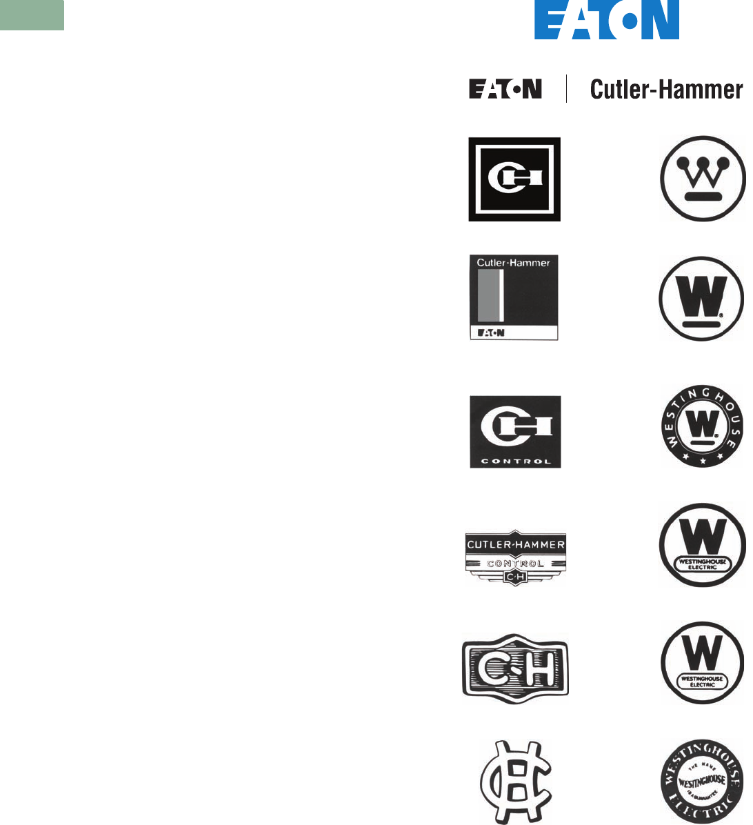
Logo History
The installed base of Westinghouse and Cutler-Hammer®
distribution and control equipment can be found everywhere.
Whether in an industrial facility such as paper, chemical,
pharmaceutical, auto and steel, or commercial installations
including universities, hospitals, airports and just about any
type of government building; you will find equipment that was
manufactured by Eaton or one of its acquired companies.
In some situations due to the age of the equipment, the original
nameplate information may be difficult to obtain. This is why the
logo history is provided. If all else fails, the logo on the front of
the equipment will help you identify when it was manufactured.
Knowing this, and the type of product, you can refer to the
applicable section of the catalog to find the solutions available
to support it.
Eaton
Eaton is backed by more than 100 years of history and experience.
This experience has resulted in many innovations in distribution
and industrial control products each incorporating leading-edge
technology to provide the highest value to our customers.
This same technology and engineering expertise is applied
to solutions to upgrade existing installed older equipment.
Our engineers and scientists are recognized throughout the
industry and around the world as experts in a wide range of
disciplines including: photoelectric optical technology, arc
interruption, vacuum technology, digital and analog electronics,
and communications technology.
2009–Present
2000–2009
1994–2000 1960–1994
1980–1994 1953–1960
1960–1980 1940–1953
1933–1960 1922–1940
1914–1933 1910–1922
1900–1914 1900–1910

Volume 12—Aftermarket, Renewal Parts and Life Extension Solutions CA08100014E—November 2013 www.eaton.com V12-T1-3
1
2
3
4
5
6
7
8
9
10
11
12
13
14
15
16
17
18
19
20
21
22
23
24
25
1
Introduction
The Installed Base
The installed base of electrical distribution and control
equipment is a product of the economic changes that have
occurred over the last 15 or 20 years.
They could:
●Be operating beyond capacity
●Have higher fault currents because of additions
●Pose major safety issues
●Cause increased unscheduled outages having a direct
impact on productivity
It has also been a witness to:
●Reductions in budgets and people resources
●Increases in maintenance intervals
●Decreases in support from the original manufacturer
Where do you go for help?
One Source for All Your Aftermarket Needs
The Aftermarket, Renewal Parts and Life Extension Solutions
catalog is a reference tool to help you identify existing electrical
distribution and control equipment and then provide a wide range
of solutions available from Eaton to support it. Regardless of the
vintage or the original manufacturer, we can provide solutions
that will extend the useful life of your existing equipment.
What’s New?
Our catalog has a new name to reflect our membership in the
family of electrical solutions catalogs—the Aftermarket, Renewal
Parts and Life Extension Solutions catalog replaces the former
YES (Your Electrical Solutions) catalog. It continues to offer
cutting-edge engineered life extension solutions—it just has
a new look and a new name.
Additionally, as the number of available solutions has grown, so
has the catalog. Incorporated in this latest edition are increased
capabilities that have been introduced since the last printing in
2003. For example, in order to address ongoing safety concerns,
Eaton has engineered the Arcflash Reduction Maintenance
System™ and the universal remote power racking system. Also,
there are new product offerings in the area of trip unit retrofit
kits, low voltage power breakers and medium voltage vacuum
replacement breakers, just to name a few. With changes to the
molded-case circuit breaker product line, this catalog is simpler
to use with an updated replacement breaker cross-reference
section. Additionally, automatic transfer switches and power
factor correction capacitors are included in brand-new tabs in
this edition.
Using the Catalog
You can find information in several ways. The Table of
Contents in the front and the detailed Alphabetical Product
Index in the back will refer you to the correct section. The
capabilities overview in Tab 2 highlights various capabilities,
and provides the tab number where that capability is listed.
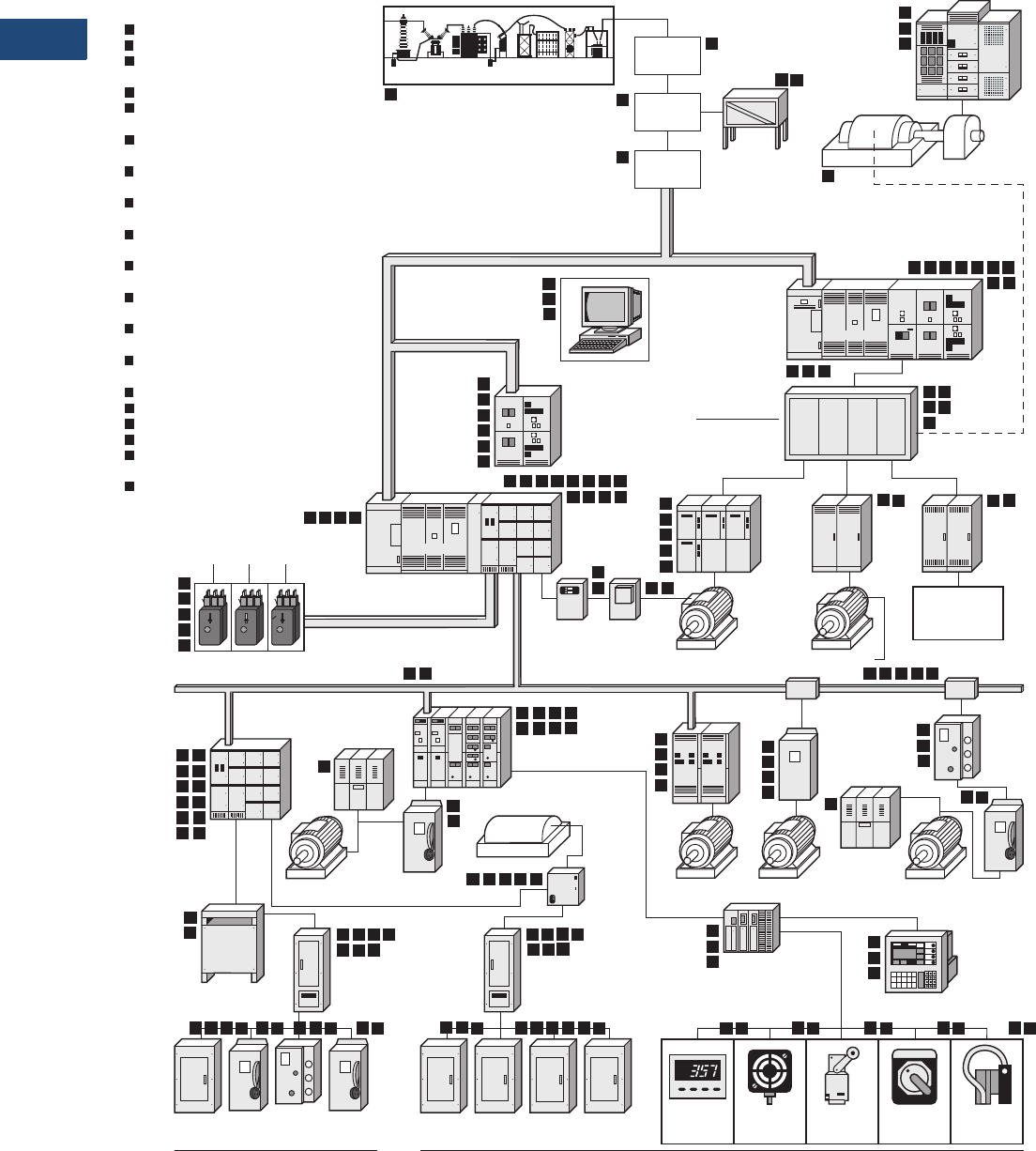
Also included in this tab is a pictorial representation of a typical
distribution system illustrating the various products and where
they can be found.
Catalog Format
Each section of the catalog includes the following elements:
●Product Description
●Product History
●Product History Time Line
●Replacement Capabilities
●Technology Upgrades (where applicable)
●Further Information
●Pricing Information
Where relevant, Additional Information, Customer Required
Information, General Information and Support Services
are included.
What Does the Shaded Area Mean?
In some sections of the catalog, you will again see tables and
text that have been shaded. The shaded areas indicate obsolete
or discontinued product, and although the product is no longer
manufactured, it is still shown for historical reference. In the
molded-case circuit breaker section (Ta b 3 ), many of the tables
have shaded areas. Although the product is no longer manufactured,
cross-reference tables have been developed to provide alternative
solutions using current
manufactured molded-case circuit breakers.
The cross-reference
tables begin on Page V12-T3-115 and are in
alphanumeric order, based on style or catalog number of the
obsolete or discontinued product.
Eaton’s Electrical Business on the World Wide Web
Our Aftermarket, Renewal Parts and Life Extension Solutions
catalog is designed to be your everyday, at-your-fingertips, at-a-
glance reference for our wide range of products and services
that support your installed base. But it’s just the paper “tip” of
the electronic “iceberg” of continuously updated information that
you can access, online, anytime.
http://www.eaton.com
Eaton
Eaton’s electrical business is a global leader with expertise
in power distribution and circuit protection; backup power
protection; control and automation; lighting and security;
structural solutions and wiring devices; solutions for harsh and
hazardous environments; and engineering services. Eaton is
positioned through its global solutions to answer today’s
most critical electrical power management challenges.
Eaton is a power management company providing energy-
efficient solutions that help our customers effectively manage
electrical, hydraulic and mechanical power. A global technology
leader, Eaton acquired Cooper Industries plc in November 2012.
The 2012 revenue of the combined companies was $21.8 billion
on a pro forma basis. Eaton has approximately 102,000
employees and sells products to customers in more than
175 countries. For more information, visit www.eaton.com.

Volume 12—Aftermarket, Renewal Parts and Life Extension Solutions CA08100014E—November 2013 www.eaton.com V12-T2-1
1
2
3
4
5
6
7
8
9
10
11
12
13
14
15
16
17
18
19
20
21
22
23
24
25
Distribution System
Technology Upgrades
for the Installed Base
2 Distribution System
A Commitment to the Installed Base . . . . . . . . . . . . . . . . . . . . . . . . . V12-T2-2
Replacement Components and Renewal Parts . . . . . . . . . . . . . . . . . . V12-T2-2
Equipment Modernization and Upgrades . . . . . . . . . . . . . . . . . . . . . . V12-T2-2
Products and Services Overview . . . . . . . . . . . . . . . . . . . . . . . . . . . . V12-T2-4
V12-T2-2 Volume 12—Aftermarket, Renewal Parts and Life Extension Solutions CA08100014E—November 2013 www.eaton.com
1
2
3
4
5
6
7
8
9
10
11
12
13
14
15
16
17
18
19
20
21
22
23
24
25
2
Distribution System
Capabilities Overview
Distribution System
A Commitment to the
Installed Base
Our employees are
committed to supporting
all Cutler-Hammer® and
Westinghouse
®
Distribution
and Control
equipment, no
matter when it was
manufactured by Eaton’s
electrical business, or how
long it has been in service.
Our dedicated Aftermarket
Organization provides
products, services and
expertise through a focused
management team, sales
engineers and technicians
that work to keep customers’
equipment operating.
Eaton also offers multiple
solutions to extend the life
of other manufacturers’
equipment, including
modernization, technology
upgrades, reconditioning
and repair. Support for
other manufactures’
equipment include:
●General Electric®
●Square D®
●Federal Pacific®
●ITE®
●Siemens®
●Siemens-Allis™
●Allen-Bradley®
●Allis-Chalmers
Eaton’s innovative engineering
provides
the highest level of
life extension to support the
industry’s installed base,
regardless of the original
manufacturer.
Replacement Components
and Renewal Parts
A full line of replacement
components and renewal
parts is available for the
existing installed base
of Cutler-Hammer
and
Westinghouse equipment.
These replacement
components and renewal
parts are new, not used or
surplus material. The use
of original production tooling,
assembly fixtures, and
original specifications
and drawings guarantees
compatibility with existing
equipment.
Equipment Modernization
and Upgrades
Cutler-Hammer equipment
modernization and upgrades
can extend the life of your
existing equipment. They can
economically upgrade Cutler-
Hammer and Westing
house
products, as well as those of
other
manufacturers. These
state-of-the-art upgrades are
engineered to provide:
●Solutions for obsolete
electrical equipment
●New technology for
aging equipment
●Retrofit, repair and
remanufacturing processes
●Monitoring, protection
and control capabilities
to your system
●Genuine new replacement
components and renewal
parts
Breaker Reconditioning and Trip
System Upgrades with Arcflash
Reduction Maintenance System™
Digitrip™ RMS trip unit
retrofit kits are available for
Eaton, Westinghouse and
other manufacturers of low
voltage power breakers.
These retrofits will improve
circuit protection while
increasing breaker and
electrical system reliability.
See Ta b 17 .
Motor Control Center Bucket Retrofits
Freedom™ 2100, Advantage™
and IT. replacement starter
units can be used to increase
the capacity of a motor control
center without investing in a
completely new assembly.
Competitive retrofits and
new buckets are also available
for other manufacturers’
units, using current Eaton
technology. See Ta b 1 4 .
Power Breaker Replacement
New DB, DS, DSII,
Magnum™ DS and SPB
power breakers are available
for replacement, to fill existing
cells, or in a cell retrofit
package for upgrading existing
older low voltage switchgear.
These breakers are electrically
and mechanically identical to
the original vintages of DB,
DS, DSII, Magnum DS and
SPB breakers. See Ta b 17 .
Switchgear Fluidized Epoxy Bus
Existing switchgear bus can be
replaced or returned to our
factory, regardless of the
original manufacturer for
reinsulation, using the custom
fluidized epoxy
bed process. It
is available from 600V
to 15 kV
for switchgear, bus runs and
other equipment. See Tab 1 7 .
Medium Voltage Starter Upgrades
Vacuum contactors can be
retrofitted or retrofilled into
existing medium voltage air
magnetic starters, achieving
the benefits of vacuum
technology without the
expense of a completely
new assembly. See Ta b 1 3 .
Replacement Vacuum Breakers
MVVR (Medium Voltage
Vacuum Replacement)
breakers provide a means to
cost-effectively
modernize
existing
air magnetic medium
voltage switchgear while
further increasing its effective
life. See Ta b 17 .
Volume 12—Aftermarket, Renewal Parts and Life Extension Solutions CA08100014E—November 2013 www.eaton.com V12-T2-3
1
2
3
4
5
6
7
8
9
10
11
12
13
14
15
16
17
18
19
20
21
22
23
24
25
2
Distribution System
Capabilities Overview
PowerNet
Eaton’s Cutler-Hammer
PowerNet™ system is
designed to manage the
power distribution system.
This integrated power
management system is the
ideal tool to help manage
energy costs, to troubleshoot
power quality problems,
and to ensure the reliability
and integrity of the
electrical
distribution system. See
Ta b 11
.
Submetering Retrofits
Eaton’s Cutler-Hammer IQ
Energy Sentinel submetering
device can be easily
retrofitted on Series C®
breakers, or those of other
manufacturers, in existing
equipment. When combined
with the PowerNet system,
the IQ Energy Sentinel can
now provide submetering
at numerous levels of
monitoring and energy
management. See Ta b s 4
and 10.
Power Management Products
Eaton’s Cutler-Hammer
IQ Metering and Protective
Relaying products are
multifunctional communicating
products based on micro-
processor technology. They
are designed to replace
existing electromechanical
devices and can be applied
at low, medium and high
voltage points in the electrical
distribution system. These
devices offer communications
capabilities to link electrical
distribution equipment
to PowerNet Power
Management Software.
See Ta b 10 .
Replacement Molded-Case
Breakers and Accessories
Circuit breaker replacements
and upgrades are designed
for use in panelboards,
switchboards, motor control
centers, control panels,
combination starters,
individual enclosures,
and bus duct plug-in units.
See Ta b s 3 , 4, 9 and 14.
SPD System Retrofits
Protect solid-state devices
from the damaging effects
of transient overvoltages.
The Eaton SPD products can
be installed in low voltage
distribution gear or retrofitted
into existing switchboards,
panelboards and motor
control centers to eliminate
the effects of surges before it
reaches sensitive equipment.
See Ta b s 4 and 17.
Low Voltage High Resistance
Grounding Systems
Type C-HRG provides service
continuity by providing a
ground path for ground
current via resistance that
limits current magnitude and
includes a means to trace the
fault source. See Tab 1 6 .
Installation and Startup Services
Installation and startup
services can be provided for
Eaton equipment, as well as
equipment manufactured
by other organizations.
See Ta b 2 3 .
Genuine LV Control Renewal Parts
Genuine factory-warranted
low voltage control renewal
parts are available to support
the complete line of Cutler-
Hammer and Westinghouse
design starters and
contactors. Renewal parts
include contact kits, coils,
overload relays and heaters,
to name a few. See Ta b 1 3 .
V12-T2-4 Volume 12—Aftermarket, Renewal Parts and Life Extension Solutions CA08100014E—November 2013 www.eaton.com
1
2
3
4
5
6
7
8
9
10
11
12
13
14
15
16
17
18
19
20
21
22
23
24
25
2
Distribution System
Typical Distribution System
Product and Services for Life Extension and Equipment Upgrades Overview
Tab
Digitrip RMS Trip Unit Retrofit Kits . . . . . . . . . 17
Motor Control Center Bucket Retrofits . . . . . . 2
DHP-VR Vacuum
Replacement Breaker . . . . . . . . . . . . . . . . . . . 17
Switchgear Fluidized Epoxy Bus . . . . . . . . . . . 17
Retrofit/Replace with
Vacuum Contactors . . . . . . . . . . . . . . . . . . . . . 17
Cell Retrofit with DSII/SPB
Circuit Breakers . . . . . . . . . . . . . . . . . . . . . . . . 17
Low Voltage High Resistance
Grounding Systems . . . . . . . . . . . . . . . . . . . . . 16
PowerNet Communication
System . . . . . . . . . . . . . . . . . . . . . . . . . . . . . . . . 11
Retrofit Front Panel
with IQ Devices . . . . . . . . . . . . . . . . . . . . . . . . 10
Retrofit with IQ Energy
Sentinel for Submetering . . . . . . . . . . . . . . . . 10
Retrofit with Surge Protective
Devices (SPD) . . . . . . . . . . . . . . . . 4, 9, 14, 15
Replacement Molded-Case
Breakers and Parts . . . . . . . . . . . . . . . . . . . . . . 3
Rebuilding/
Remanufacturing Service . . . . . . . . . . . 3, 13, 15
Renewal/Replacement Parts . . . . . . . . . . . . . ALL
Service Capability . . . . . . . . . . . . . . . . . . . . . . ALL
Power Factor Correction Capacitors . . . . . . . 21
Automatic Transfer Switches . . . . . . . . . . . . . 20
Arcflash Reduction
Maintenance System. . . . . . . . . . . . . . . . . . . . 17
Remote Power Racking . . . . . . . . . . . . . . . . . . . 17
12
11
10
9
8
14
SECONDARY SPOT NETWORK
WITH NETWORK PROTECTORS
8
12
11
10
9
8
15
14
12
11
8
7
6
1
14
14
13
12
8
914
8
913 14
5 84
15
14
13
4
14
9
8
ADJUSTABLE
FREQUENCY CONTROL
ENCLOSED
CONTROL
REDUCED
VOLTAGE
STARTER
TRANSFORMER
TRANSFORMER
MEDIUM VOLTAGE
SWITCHGEAR
LOW VOLTAGE
SECONDARY UNIT
SUBSTATION
LOAD
INTERRUPTER
SWITCHGEAR
PROGRAMMABLE
LOGIC
CONTROLLER
MOTOR
CONTROL
CENTER
LOW VOLTAGE
SWITCHBOARD
INDIVIDUAL/
GROUP MOUNTED
POWER FACTOR
CORRECTION
CAPACITORS
UP TO 1500 HP
ARC RESISTANT
SWITCHGEAR
UTILITY SYSTEM
EXCITATION
CONTROL
ON-SITE
GENERATION
GROUNDING
RESISTOR
HIGH CURRENT
LOW VOLTAGE
PROCESS
START STOP
COUNT
CONTROL
PROXIMITY
SENSOR
LIMIT
SWITCH
SELECTOR
SWITCH
PHOTOELECTRIC
SENSOR
SAFETY
SWITCH
LIGHTING
CONTROL
PANELBOARD
OFFICE BUILDING
LIGHTING
PANELBOARD
LIGHTING
PANELBOARD
LIGHTING
PANELBOARD
LIGHTING
CONTROL
PANELBOARD
PROCESS
RECTIFIER
SYSTEM
DC
DRIVE
SAFETY
SWITCH
MEDIUM
VOLTAGE
STARTER
MEDIUM VOLTAGE
NON-SEGREGATED BUS
LOW VOLTAGE BUS
BUS PLUG
UP TO 700 HP
DRY-TYPE
DISTRIBUTION
TRANSFORMER
LOW VOLTAGE
DISTRIBUTION
PANELBOARD
LOW VOLTAGE
DISTRIBUTION
PANELBOARD
ELECTRICAL
OPERATOR
INTERFACE
BUS PLUG
MAGNETIC SHOEBREAK
MEDIUM VOLTAGE
TRANSFER EQUIPMENT
VACUUM BREAKERS
OR LOAD BREAK
FUSED SWITCHES
34.5 kV
SWITCHGEAR
POWER
TRANSFORMER
15 kV
SWITCHGEAR
RECTIFIER
AND
EXCITER
SYNCHRONOUS
MOTOR FIELD
APPLICATION
PANEL
GENERATOR
LOW
VOLTAGE
TRANSFER
SWITCH
ADDITIONAL
UTILITY
SOURCES
SAFETY
SWITCH
MANUFACTURING FACILITY
SAFETY
SWITCH
SYNCHRONOUS
MOTOR
LOAD
INTERRUPTER
SWITCHGEAR
ENCLOSED
CONTROL
POWERNET
INTEGRATED
MONITORING
PROTECTION
AND CONTROL
COMMUNICATION
SYSTEM
14
14
9
8
14
14
14
14
14
9
14
5
13
8
14
6 7
14
4 5 8 91
15
810 12 14
8
14
9
10
12
8
14
9
11
2
14
14
14
8
11
14
8
11
14
12 148
14
8
14
8
14
14141414
14
12 1410 118
14
8
141414
914 88
1
2
3
4
5
6
7
8
9
10
11
12
13
14
15
15
15
18
15
15
15
15
15
15
151515151515
15
15 15
15
15 15 15
15
15
15
15
15
15
18
15
15 15
15
15 15
15
15
19
15
15
15
15
15
15
15
15
16
16
POWER FACTOR
CORRECTION
CAPACITORS
16
UP TO 300 HP UP TO 300 HP
17
17
18
19
10 19
13
19
19
19
3

Volume 12—Aftermarket, Renewal Parts and Life Extension Solutions CA08100014E—July 2016 www.eaton.com V12-T3-1
1
2
3
4
5
6
7
8
9
10
11
12
13
14
15
16
17
18
19
20
21
22
23
24
25
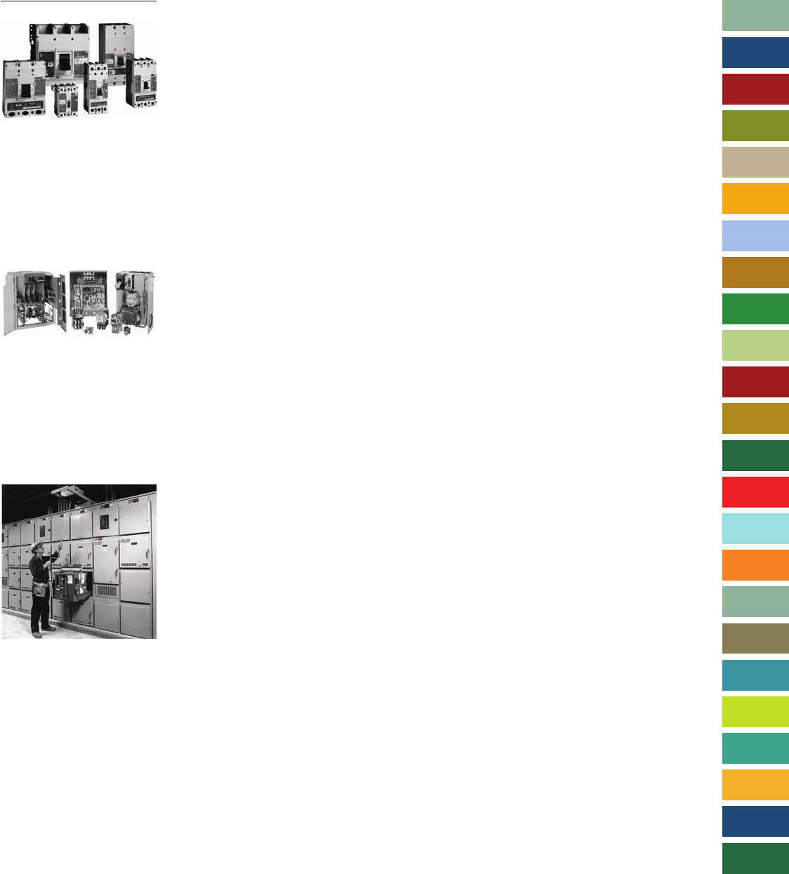
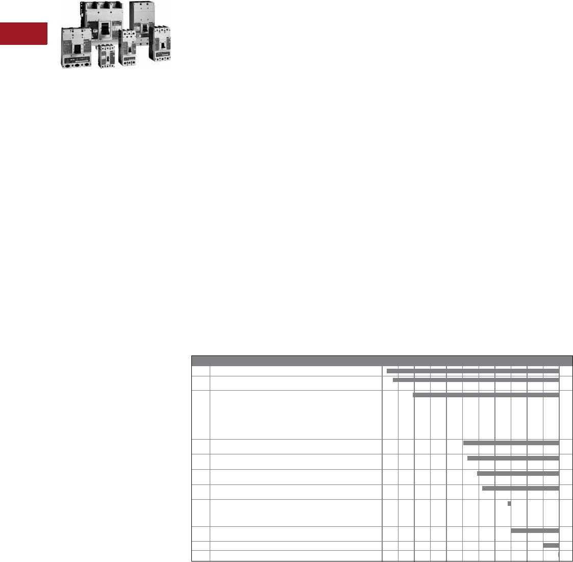
Molded-Case Circuit Breakers
Molded-Case Circuit Breakers Family
3 Molded-Case Circuit Breakers
Product Description, History, Major Product Introduction . . . . . . . . . . . . V12-T3-2
General Information. . . . . . . . . . . . . . . . . . . . . . . . . . . . . . . . . . . . . . . V12-T3-3
Nameplate Data . . . . . . . . . . . . . . . . . . . . . . . . . . . . . . . . . . . . . . . V12-T3-3
Identifying Factory Original Circuit Breakers . . . . . . . . . . . . . . . . . V12-T3-4
Replacement and Upgrade Options . . . . . . . . . . . . . . . . . . . . . . . . V12-T3-5
Replacement Guides
Miniature Circuit Breakers . . . . . . . . . . . . . . . . . . . . . . . . . . . . . . . V12-T3-6
Molded-Case Circuit Breakers . . . . . . . . . . . . . . . . . . . . . . . . . . . . V12-T3-10
Replacement Devices
Circuit Breakers . . . . . . . . . . . . . . . . . . . . . . . . . . . . . . . . . . . . . . . V12-T3-15
Molded-Case Switches . . . . . . . . . . . . . . . . . . . . . . . . . . . . . . . . . . V12-T3-61
Motor Circuit Protectors . . . . . . . . . . . . . . . . . . . . . . . . . . . . . . . . . V12-T3-63
Accessories . . . . . . . . . . . . . . . . . . . . . . . . . . . . . . . . . . . . . . . . . . V12-T3-63
Panelboard Replacement Breakers. . . . . . . . . . . . . . . . . . . . . . . . . V12-T3-80
Replacement Guide . . . . . . . . . . . . . . . . . . . . . . . . . . . . . . . . . . . . V12-T3-81
Motor Control Center Replacement Breakers . . . . . . . . . . . . . . . . V12-T3-88
Technology Upgrades for Circuit Breakers. . . . . . . . . . . . . . . . . . . . . . V12-T3-91
Handle Mechanisms . . . . . . . . . . . . . . . . . . . . . . . . . . . . . . . . . . . . . . V12-T3-95
Replacement and Service Capabilities . . . . . . . . . . . . . . . . . . . . . . . . V12-T3-112
Cross-Reference
Westinghouse, Challenger and Bryant Replacements . . . . . . . . . . V12-T3-113
Breaker Replacements . . . . . . . . . . . . . . . . . . . . . . . . . . . . . . . . . . V12-T3-115
Mining Breaker Replacements . . . . . . . . . . . . . . . . . . . . . . . . . . . . V12-T3-162
Pricing Information . . . . . . . . . . . . . . . . . . . . . . . . . . . . . . . . . . . . . . . V12-T3-168
V12-T3-2 Volume 12—Aftermarket, Renewal Parts and Life Extension Solutions CA08100014E—July 2016 www.eaton.com
1
2
3
4
5
6
7
8
9
10
11
12
13
14
15
16
17
18
19
20
21
22
23
24
25
3
Molded-Case Circuit Breakers
Molded-Case
Circuit Breakers
Molded-Case Circuit Breaker Family
Product Description
Eaton’s molded-case circuit
breakers are designed to
provide circuit protection
for low voltage distribution
systems. They are described
by NEMA® as “...a device
for closing and interrupting
a circuit between separable
contacts under both normal
and abnormal conditions,”
and furthermore as “...a
breaker assembled as an
integral unit in supporting
an enclosed housing of
insulating material.” The
NEC® describes them as
“. . . a device designed to
open and close a circuit by
non-automatic means, and to
open the circuit automatically
on a predetermined overload
of current, without injury to
itself when properly applied
within its rating.”
Circuit breakers protect
against overloads in
conductors and protects
against short circuits in
connected apparatus such as
motors and motor starters.
Circuit breakers are designed
for use in panelboards,
switchboards, motor control
centers, control panels,
combination starters,
individual enclosures and
bus duct plug-in units.
Product History
Originally a
Westinghouse Product
The need for molded-case
circuit breakers came about
in 1918 when numerous
applications for electrical
motors resulted in a demand
for a device that would
ensure safe operation and,
at the same time, protect
electrical circuits.
During this period, individual
motors were used for the
first time in industrial plants
to operate machine tools and
in private homes to operate
appliances. Plant electricians
were constantly changing
fuses blown during motor
startups because of the lack
of properly designed fuses for
motor circuit protection.
Homes experienced similar
problems when electrical
circuits were overloaded.
Inspectors were concerned
about fire hazards because of
plug fuses being bridged with
pennies and the installation
of fuses with too high an
ampere rating.
Inspection authorities
became involved and
attempted to find a solution
to the problem. Meetings
with switch manufacturers
were initiated in an effort
to find a solution. Switch
manufacturers were asked to
develop a switching device
that would interrupt a circuit
under prolonged overload
conditions. The device would
have to be safe, reliable and
tamperproof. It should also
be resettable so as to be
reusable after an interruption
without replacing any parts.
This search for better circuit
protection resulted in many
different but unacceptable
approaches to the problem.
These early meetings and
subsequent efforts prepared
the groundwork for the
eventual development of the
molded-case circuit breaker.
After intensive research and
development,
Westinghouse
produced the DE-ION® arc
extinguisher for use in large
oil circuit breakers. Although
too large in its initial form to
be practical for small circuit
breakers, the arc extinguisher
was eventually modified
into a usable size. The first
compact, workable circuit
breaker was developed in
1923 when the modified arc
extinguisher was coupled
with a thermal tripping
mechanism. It was not until
four years later, however,
that Westinghouse research
engineers found the ideal
combination of materials and
design that permitted circuit
breakers to interrupt fault
currents of 5000A at 120 Vac
or Vdc. One year later,
Westinghouse placed the
first circuit breaker on the
market. Its acceptance
was instantaneous.
Since that initial introduction
in 1927, Westinghouse
continued to be at the forefront
of circuit breaker technology
with an unprecedented series
of circuit protective
enhancements and
introductions as chronicled
below. In 1994, Eaton, another
world-class technology leader,
acquired the Westinghouse
Distribution and Control
Business Unit (DCBU)
and integrated it with their
Cutler-Hammer business
unit forming a powerful, new
combination, poised to meet
the challenges of the next
100 years.
Time Line—Major Product Introductions
1923 First compact, workable circuit breaker developed by Westinghouse
1927 Westinghouse introduced the first complete circuit breaker line,
rated 10– 600A, 600V
1939 Along with ordering information and style numbers, the various
maximum current ratings came to be known by frame designations:
50A E-Frame
100A F-Frame (non-interchangeable trip)
100A G-Frame
225A K-Frame
600A L-Frame
1970 Motor Circuit Protector (MCP) introduced—first sensitive, low
level protection designed specifically for motor circuits
1973 SELTRONIC™ introduced—first molded-case circuit breaker
with an electronic trip unit
1979 Current Limit-R circuit breaker introduced— first true current
limiting trip unit
1982 Series C® Family introduced—new world-class standard, meeting
increasing interrupting requirements without sacrificing compact size
1994 Westinghouse Distribution and Control Business Unit (DCBU)
acquired by Eaton, integrated with Cutler-Hammer
(the Cutler-Hammer line of molded case circuit breakers was
sold when merged with Westinghouse)
1995 OPTIM™ Family introduced—first truly programmable
molded-case circuit breaker
2002 Next Generation E125, J250
2004 Series G® First Global Breaker Line
Year Product 1920 1930 1940 1950 1960 1970 1980 1990 1995
2000 2002 Present
Volume 12—Aftermarket, Renewal Parts and Life Extension Solutions CA08100014E—July 2016 www.eaton.com V12-T3-3
1
2
3
4
5
6
7
8
9
10
11
12
13
14
15
16
17
18
19
20
21
22
23
24
25
3
Molded-Case Circuit Breakers
Breaker Identification
Nameplate Data
A circuit breaker is identified by
data found on the nameplate.
This includes:
●Catalog number
●Shop order number
●Style number
●Amperage
●Number of poles
●Voltage class
●Temperature rating
In most instances, the
catalog number, style number
or shop order number will
supply enough information
to identify the circuit breaker.
However, it is always
advisable to obtain all
data from the nameplate
to facilitate identification.
A Catalog Number begins
with a series of letters
followed by numbers
that identify:
●Circuit breaker type
●Number of poles
●Maximum amperage
●Example: Catalog number
F3020 indicates a Type F
circuit breaker, three poles,
20A
A Shop Order Number
begins with one or two
numbers followed by a
single letter and four
additional numbers.
A shop order number is
listed in place of a catalog
number and indicates that the
circuit breaker was modified
at the factory, i.e., addition
of a shunt trip, special
calibration, etc. Every shop
order number must be
researched with the
factory to properly identify
modifications. Call your
Cutler-Hammer Field Sales
office for this information.
●Example: 70E2121
Note: Eaton does not
recommend replacing a circuit
breaker identified by a Shop
Order Number with a standard
“off-the-shelf” circuit breaker
without first identifying the
modifications. They may
be critical to safe and
reliable operation.
Accessories
Most circuit breaker
accessories are mounted
internally and are not visible
with a quick inspection.
However, because many
accessories rely on or supply
an external signal, there may
be electrical leads exiting the
circuit breaker case. Inspect
for these leads when
obtaining full descriptive
information for circuit breaker
replacement. Examples of
common accessories:
Shunt Trip
Used to remotely trip the
circuit breaker using an
electrical signal. Typically
two wires extend through
the case.
Undervoltage Release (UVR)
Trips the circuit breaker
when voltage drops below
a specified percentage of
coil voltage (typically 70%).
Typically two wires extend
through the case.
Auxiliary Switch
Provides remote indication
of the circuit breaker status
(open/closed). Typically
three wires extend through
the case in a single-pole
1A/1B application.
Alarm Lockout Switch
For remote indication of
an automatic trip operation.
Typically two or three wires
extend through the case.
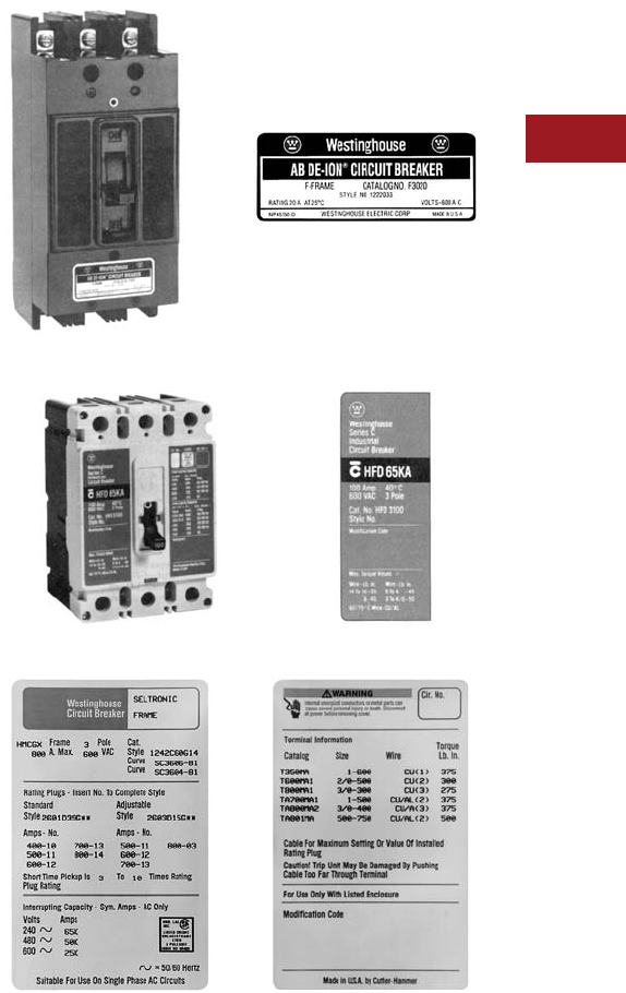
Pre-Series C Breaker with Original Label (Labels updated in 1997)
Series C Breaker with Original Label (Labels updated in 1997)
Vintage Label for Typical SELTRONIC Molded-Case Circuit Breaker
V12-T3-4 Volume 12—Aftermarket, Renewal Parts and Life Extension Solutions CA08100014E—July 2016 www.eaton.com
1
2
3
4
5
6
7
8
9
10
11
12
13
14
15
16
17
18
19
20
21
22
23
24
25
3
Molded-Case Circuit Breakers
Factory Original
Circuit Breakers
Why Insist on Only Genuine,
New MCCBs Purchased Through
Authorized Distributors?
Eaton defines “New” product
as that which has not yet been
installed in an electrical circuit,
purchased through authorized
channels in factory original
condition and packaged in
unopened Eaton cartons.
●The only way to ensure
safe and reliable operation
of your system is to use
genuine, new, Eaton’s
Cutler-Hammer products
exclusively. Eaton does not
resell the component parts
for molded-case circuit
breakers, the only way
for third-party breaker
refurbishers to get parts
for the breakers that
they are rebuilding is
to cannibalize other
used breakers or to use
counterfeit components.
Neither is a very good
option for the end user
●In some cases,
unauthorized resellers
of molded-case circuit
breakers have been found
to misrepresent used,
rebuilt or surplus products.
Only products purchased as
“new” through authorized
channels are covered under
the Eaton warranty policy
●There have been
instances where third-party
refurbishers have rebuilt
breakers using the wrong
parts, with parts missing
or the factory lubrication
removed in the cleaning
process—any of which may
result in devices that may
not be depended upon to
function properly to protect
equipment and personnel
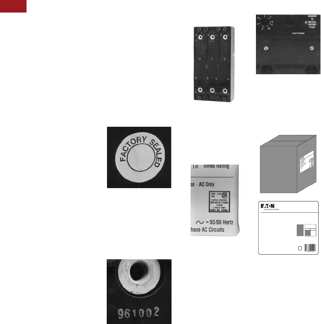
Identifying Genuine, Factory
Original Westinghouse Circuit
Breakers Manufactured by Eaton
The features on a molded-case
circuit breaker that identify it
as genuine or counterfeit
may or may not be readily
apparent. In fact, there may be
differences not detectable by
an external investigation.
A genuine Eaton brand
molded-case circuit breaker
manufactured by Eaton will
have a serialized bar code
unique to the breaker as well
as an unbroken seal where
the case comes together.
This barcode and seal were
placed at the factory and
ensures the internal integrity
of the breaker. If, for any
reason the barcode is
missing or the seal is
broken, do not accept the
breaker. (Seal does not
appear on interchangeable
trip breakers.)
Unbroken Seal
There is a manufacturing date
code on the back of genuine
molded-case circuit breakers
stamped in silver and white. If
this coding is missing, it may
mean the breaker has been
subjected to tampering.
Frequently, this date code is
wiped off in an attempt to
represent the breaker as new.
Manufacturing Date Code
Another way to tell if a
breaker has been tampered
with is to examine the sealant
used to cover the screws on
the top rear of the breaker. If
the sealant appears sloppy or
is missing, it indicates that the
unit may have been subjected
to tampering.
Sealant Used to Cover Screws
A UL® label on a genuine
Westinghouse breaker is
either exactly as shown in
the photo or is stamped in
white ink onto the frame in
older pre-Series C breakers.
Anything other than this may
indicate fraud.
UL Label
If front cover screw shows
marks from use, someone
has attempted to open the
breaker. The front covers
are either black or gray on
genuine Westinghouse
molded-case circuit breakers.
Front Cover Screws
Westinghouse molded-
case circuit breakers
manufactured by Eaton
are packed individually and
shipped in Eaton labeled
cartons. Anything other than
this is not to be considered
new and should be suspect.
Eaton Labeled Cartons
www.eaton.com xxxxxxxxx
A
Lorem Ipsum: dolor sit
amet, consectetuer adi
piscing elit, sed diam
nonummy nibh euismod
DOLOR SIT AMET
CONSECT ETUER ADI
Adpiscing
elit sed
diamnon
euismod
Dolor Sit Amet Elit
XX-XXX-XXXX
Product Name
Product Series
Made in U.S.A.
Lorem ipsum: dolor sit amet,
consectetuter adipleiscing,
sed diam nonummy, nibheuis
mod tincidunt.

Volume 12—Aftermarket, Renewal Parts and Life Extension Solutions CA08100014E—July 2016 www.eaton.com V12-T3-5
1
2
3
4
5
6
7
8
9
10
11
12
13
14
15
16
17
18
19
20
21
22
23
24
25
3
Molded-Case Circuit Breakers
Replacement Capabilities
Series C and Series G Molded-
Case Circuit Breakers
When and Where to Use
●Generally a first choice
wherever physically and
electrically practical
●Where communications,
arc flash protection,
energy and power quality
monitoring are desired
●As a direct replacement
or add-on to already
installed Series C or
Series G product, including
Westinghouse breakers
(see Page V12-T3-114)
●For special applications
such as DC engine
generator
Advantages
●The most current
molded-case circuit
breaker technology
●Higher interrupting
capacities in each
frame size
●Smaller and lighter for
a given frame size than
other options
●Generally less expensive
than other replacement
breaker options
●Readily available
throughout range, high
levels of stock
●Available from stock
●One-year warranty
Current Production Replacement
Circuit Breakers
When and Where to Use
●As a direct, one-for-one
replacement of current
production pre-Series C
product
●Where you know the
catalog/style number
but not the physical or
electrical specifics about
the application
Advantages
●Ease of selection and
certainty of replacement
●Guaranteed to be both a
physical and electrical
duplicate of original
●Still in production
●Newly manufactured
●UL listed
●Available from stock
●One-year warranty
Replacement of Current
Panelboard Molded-Case
Circuit Breakers
When and Where to Use
●When replacing Series C
circuit breakers in a current
design panelboard
Advantages
●Newly manufactured
and tested to the latest
technology
●UL Listed
●Available from stock in
most frame sizes
●One-year warranty. Refer
to Page V12-T3-91 for
Series C connector kits
Replacement of Out-of-
Production Panelboard
Molded-Case Circuit Breakers
(Including Westinghouse)
When and Where to Use
●When replacing out-of-
production circuit breakers
in an existing panelboard
●When replacing
Westinghouse breakers.
Refer to Pages V12-T3-81–
V12-T3-90 and
Page V12-T3-114
Advantages
●Newly manufactured
and tested to the latest
applicable standards
●Both physically and
electrically interchangeable
with the circuit breakers
that they are designed
to replace
●UL Listed
●Available from stock in
most frame sizes
●One-year warranty
Replacement of Out-of-
Production Motor Control Center
Molded-Case Circuit Breakers
and Upgrades
When and Where to Use
●When replacing out-of-
production circuit breakers
in an existing motor control
center: 5 Star, Type W and
F10 designs
●When upgrading
Westinghouse breakers
with a Series C technology
upgrade breaker
Advantages
●Newly manufactured
and tested to the latest
technology
●Series C retrofit kits are
physically and electrically
interchangeable with the
circuit breakers that they
are designed to replace
●UL Listed
●Available from stock in
most frame sizes
●One-year warranty.
Refer to Page V12-T3-91
Contact: 1-800-OLD-UNIT.
Service for Molded-Case
Circuit Breakers
When and Where to Use
●Where circuit breaker has
sustained minor physical
damage to a handle, lug,
etc., that otherwise would
be fully functional
●Large frame circuit breaker
(600A and above) that has
experienced some normal
wear, but is in generally
good condition, as an
economically driven
alternative to new
●When replacing
Westinghouse breakers.
Refer to Page V12-T3-114
Advantages
●Prevents loss of circuit
breakers due to minor
damage
●Reduces overall
breaker costs
●Prevents use of potentially
unreliable third-party
refurbishers
●Includes full one-year
Eaton Electrical Inc.
warranty
●Ensures reliability through
dealing with the original
manufacturer with a long
and well-recognized
tradition of product safety,
integrity and quality
●Provides a simple and
convenient solution
Contact Eaton’s
Breaker Service Center:
1-877-BRK-SRVC.
V12-T3-6 Volume 12—Aftermarket, Renewal Parts and Life Extension Solutions CA08100014E—July 2016 www.eaton.com
1
2
3
4
5
6
7
8
9
10
11
12
13
14
15
16
17
18
19
20
21
22
23
24
25
3
Molded-Case Circuit Breakers
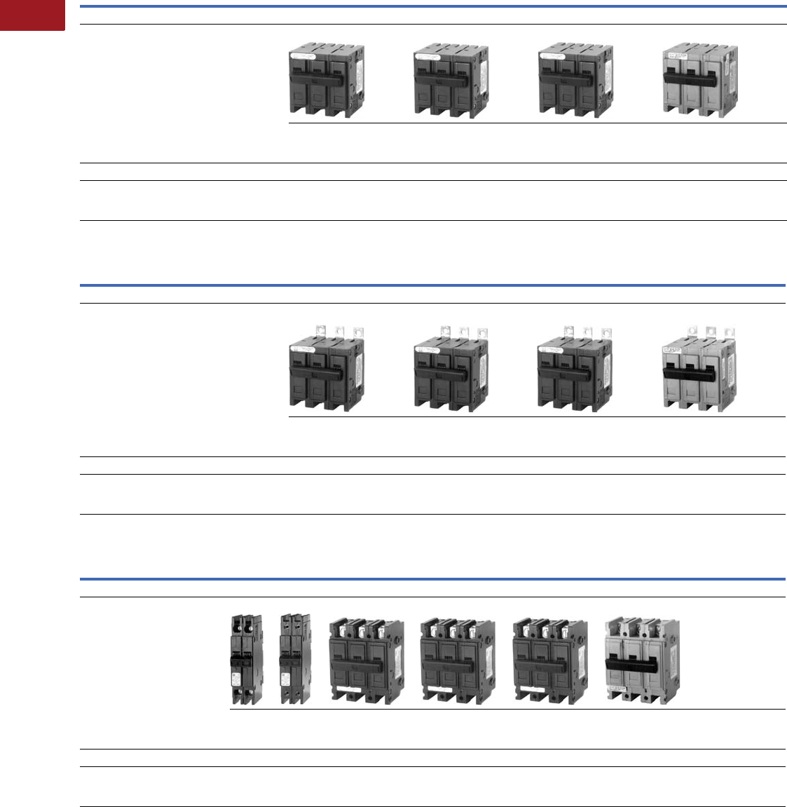
QUICKLAG and Eaton Miniature Circuit Breaker Replacement Guide
QUICKLAG and Eaton Plug-In Industrial Circuit Breakers—Dimensions in Inches
QUICKLAG Bolt-On Industrial Circuit Breakers—Dimensions in Inches
QUICKLAG and Eaton Cable-In/Cable-Out Industrial Circuit Breakers—Dimensions in Inches
Note: For supplementary protectors, the Eaton WMZS and FAZ Series replace the WMS supplementary protectors that are no longer manufactured.
Description
Maximum Amperes
150A 125A 100A 30A
Current Design
These circuit breakers replace the out-of-production
circuit breakers listed below.
HQP QPHW QHPX QHPW
Width: 1.00
Height: 2.94
Depth: 2.38
Width: 1.00
Height: 2.94
Depth: 2.38
Width: 1.00
Height: 2.94
Depth: 2.38
Width: 1.00
Height: 2.94
Depth: 2.38
Out-of-Production Westinghouse Circuit Breakers
These circuit breakers are no longer
manufactured. Recommended QUICKLAG circuit
breakers listed above.
HQNPL, HQNPAL, HQNP,
HQNPA, QP, QPA, QPAH, QNPL,
QNPA L , QNP, Type P, P L
QPH No previous circuit
breaker existed
QHPL
QHP
Description
Maximum Amperes
150A 125A 100A 30A
Current Design
These circuit breakers replace the out-of-production
circuit breakers listed below.
BAB QBHW HBAX HBAW
Width: 1.00
Height: 2.94
Depth: 2.38
Width: 1.00
Height: 2.94
Depth: 2.38
Width: 1.00
Height: 2.94
Depth: 2.38
Width: 1.00
Height: 2.94
Depth: 2.38
Out-of-Production Westinghouse Circuit Breakers
These circuit breakers are no longer
manufactured. Recommended QUICKLAG circuit
breakers listed above.
HQNB, HQNBA, QB, BA,
QNBL, QNBAL
QBH No previous circuit
breaker existed
HBA
Description
Maximum Amperes
60A 100A 100A 100A 30A 40A
Current Design
These circuit breakers replace the
out-of-production circuit breakers
listed below.
QCR QCF QC QCHW QHCX QHCW WMZ/FAZ
Width: 0.50
Height: 3.94
Depth: 2.44
Width: 1.00
Height: 3.75
Depth: 2.44
Width: 1.00
Height: 3.75
Depth: 2.44
Width: 1.00
Height: 3.75
Depth: 2.44
Width: 1.00
Height: 3.75
Depth: 2.44
Width: 0.70
Height: 4.10
Depth: 2.60
Out-of-Production Westinghouse Circuit Breakers
These circuit breakers are no
longer manufactured. Recommended
QUICKLAG circuit breakers listed above.
No previous circuit
breaker existed
HQCL, HQCAL, HQC,
HQCA, QCA
QCH No previous circuit
breaker existed
QHCL, QHC WMT

Volume 12—Aftermarket, Renewal Parts and Life Extension Solutions CA08100014E—July 2016 www.eaton.com V12-T3-7
1
2
3
4
5
6
7
8
9
10
11
12
13
14
15
16
17
18
19
20
21
22
23
24
25
3
Molded-Case Circuit Breakers
QUICKLAG Miniature
Circuit Breakers
QUICKLAG is the largest and
most complete family of
industrial thermal-magnetic
miniature circuit breakers.
They provide the exclusive
features of steel frame
calibration and arc chutes
in every pole.
QUICKLAG circuit breakers
are provided in ranges from
5 to 125A continuous in
single-, two- and three-pole
configurations with
interrupting capacities
from
10,000 AIC to 65,000 AIC.
QUICKLAG
circuit breakers
have been series rated up to
200,000 AIC in conjunction
with larger Westinghouse/
Cutler-Hammer current
limiting circuit breakers.
Each QUICKLAG rating is
available for plug-in (Type P),
bolt-on (Type B) and cable-to-
cable connections (Type C)
for line/load feed applications.
They are also available with
one of the industry’s widest
selection of accessories,
including shunt trip, and
can be custom modified
to meet special application
requirements.
Circuit Breaker Selection Guide
Notes
1 Two-pole DC interrupting rating based on two poles connected in series.
Circuit breaker type codes: P Plug-in; B Bolt-on; C Cable-in/Cable-out; GF Ground Fault, 5 mA; GFEP Ground Fault, 30 mA.
Circuit
Breaker
Type
Circuit
Breaker
Type Code
Continuous
Ampere
Rating at 40°C
No.
of
Poles
Volts Federal
Spec.
W-C-375b
UL Listed Interrupting Ratings rms Symmetrical Amperes
AC Ratings Volts DC 1
AC DC 120 120/240 240 24 48 80
HQP P 5–70 1 120/240 24, 48, 80 10a, 11a, 12a — 10,000 — 5000 5000 2000
HQP P 10–125 2 120/240 24, 48, 80 10a, 12a — 10,000 — 5000 5000 5000
HQP P 10–100 2, 3 240 — 10b, 11b, 12b — — 10,000 — — —
QPHW P 15–70 1 120/240 24, 48, 80 14a — 22,000 — 5000 5000 2000
QPHW P 15–125 2 120/240 24, 48, 80 14a — 22,000 — 5000 5000 5000
QPHW P 15–100 2, 3 240 — 14b — — 22,000 — — —
QHPX P 15–70 1 120/240 24, 48, 80 — — 42,000 — 5000 5000 2000
QHPX P 15–100 2 120/240 24, 48, 80 — — 42,000 — 5000 5000 5000
QHPX P 15–100 3 240 — — — — 42,000 — — —
QHPW P 15–30 1 120/240 24, 48, 80 15a — 65,000 — 5000 5000 2000
QHPW P 15–30 2 120/240 24, 48, 80 15a — 65,000 — 5000 5000 5000
QHPW P 15–30 3 240 — 15b — — 65,000 — — —
QPGF P, GF 15–30 1 120 — 10a, 11a, 12a 10,000 — — — — —
QPGF P, GF 15–50 2 120/240 — 10a, 11a, 12a — 10,000 — — — —
QPHGF P, GF 15–30 1 120 — 10a, 11a, 12a 22,000 — — — — —
QPHGF P, GF 15–50 2 120/240 — 10a, 11a, 12a — 22,000 — — — —
QPGFEP P, GFEP 15–30 1 120 — — 10,000 — — — — —
QPGFEP P, GFEP 15–50 2 120/240 — — — 10,000 — — — —
QPHGFEP P, GFEP 15–30 1 120 — — 22,000 — — — — —
QPHGFEP P, GFEP 15–30 2 120/240 — — 22,000 — — — — —
BAB B 5–70 1 120/240 24, 48, 80 10a, 11a, 12a — 10,000 — 5000 5000 2000
BAB B 10–125 2 120/240 24, 48, 80 10a, 12a — 10,000 — 5000 5000 5000
BAB B 10–100 2, 3 240 — 10b, 11b, 12b — — 10,000 — — —
QBHW B 15–70 1 120/240 24, 48, 80 14a — 22,000 — 5000 5000 2000
QBHW B 15–125 2 120/240 24, 48, 80 14a — 22,000 — 5000 5000 5000
QBHW B 15–100 2, 3 240 — 14b — — 22,000 — — —
HBAX B 15–70 1 120/240 24, 48, 80 — — 42,000 — 5000 5000 2000
HBAX B 15–100 2 120/240 24, 48, 80 — — 42,000 — 5000 5000 5000
HBAX B 15–100 3 240 — — — — 42,000 — — —
HBAW B 15–30 1 120/240 24, 48, 80 15a — 65,000 — 5000 5000 2000
HBAW B 15–30 2 120/240 24, 48, 80 15a — 65,000 — 5000 5000 5000
HBAW B 15–30 3 240 — 15b — — 65,000 — — —
QBGF B, GF 15–30 1 120 — 10a, 11a, 12a 10,000 — — — — —
QBGF B, GF 15–50 2 120/240 — 10a, 11a, 12a — 10,000 — — — —

V12-T3-8 Volume 12—Aftermarket, Renewal Parts and Life Extension Solutions CA08100014E—July 2016 www.eaton.com
1
2
3
4
5
6
7
8
9
10
11
12
13
14
15
16
17
18
19
20
21
22
23
24
25
3
Molded-Case Circuit Breakers
Circuit Breaker Selection Guide, continued
Notes
1 Two-pole DC interrupting rating based on two poles connected in series.
Circuit breaker type codes: P Plug-in; B Bolt-on; C Cable-in/Cable-out; GF Ground Fault, 5 mA; GFEP Ground Fault, 30 mA.
Circuit
Breaker
Type
Circuit
Breaker
Type Code
Continuous
Ampere
Rating at 40°C
No.
of
Poles
Volts Federal
Spec.
W-C-375b
UL Listed Interrupting Ratings rms Symmetrical Amperes
AC Ratings Volts DC 1
AC DC 120 120/240 240 24 48 80
QBHGF B, GF 15–30 1 120 — 10a, 11a, 12a 22,000 — — — — —
QBHGF B, GF 15–30 2 120/240 — 10a, 11a, 12a — 22,000 — — — —
QBGFEP B, GFEP 15–30 1 120 — — 10,000 — — — — —
QBGFEP B, GFEP 15–50 2 120/240 — — — 10,000 — — — —
QBHGFEP B, GFEP 15–30 1 120 — — 22,000 — — — — —
QBHGFEP B, GFEP 15–30 2 120/240 — — 22,000 — — — — —
QC C 5–70 1 120/240 24, 48, 80 10a, 11a, 12a — 10,000 — 5000 5000 2000
QC C 10–100 2 120/240 24, 48, 80 10a, 12a — 10,000 — 5000 5000 5000
QC C 10–100 2, 3 240 — 10b, 11b, 12b — — 10,000 — — —
QC C 15–100 4 240 — 10b, 11b, 12b — — 10,000 — — —
QCF C 10–60 1, 2 120/240 — — 10,000 10,000 — — — —
QCR C 10–60 1, 2 120/240 — — 10,000 10,000 — — — —
QCHW C 15–70 1 120/240 24, 48, 80 14a — 22,000 — 5000 5000 2000
QCHW C 15–100 2 120/240 24, 48, 80 14a — 22,000 — 5000 5000 5000
QCHW C 15–100 2, 3 240 — 14b — — 22,000 — — —
QHCX C 15–70 1 120/240 24, 48, 80 — — 42,000 — 5000 5000 2000
QHCX C 15–100 2 120/240 24, 48, 80 — — 42,000 — 5000 5000 5000
QHCX C 15–100 3 240 — — — — 42,000 — — —
QHCW C 15–30 1 120/240 24, 48, 80 15a — 65,000 — 5000 5000 2000
QHCW C 15–30 2 120/240 24, 48, 80 15a — 65,000 — 5000 5000 5000
QHCW C 15–30 3 240 — 15b — — 65,000 — — —
QCGF C, GF 15–30 1 120 — — 10,000 — — — — —
QCGF C, GF 15–50 2 120/240 — — 10,000 10,000 — — — —
QCHGF C, GF 15–30 1 120 — — 22,000 — — — — —
QCHGF C, GF 15–30 2 120/240 — — 22,000 22,000 — — — —
QCGFEP C, GFEP 15–30 1 120 — — 10,000 — — — — —
QCGFEP C, GFEP 15–30 2 120/240 — — 10,000 10,000 — — — —
QCHGFEP C, GFEP 15–30 1 120 — — 22,000 — — — — —
QCHGFEP C, GFEP 15–30 2 120/240 — — 22,000 22,000 — — — —
Volume 12—Aftermarket, Renewal Parts and Life Extension Solutions CA08100014E—July 2016 www.eaton.com V12-T3-9
1
2
3
4
5
6
7
8
9
10
11
12
13
14
15
16
17
18
19
20
21
22
23
24
25
3
Molded-Case Circuit Breakers
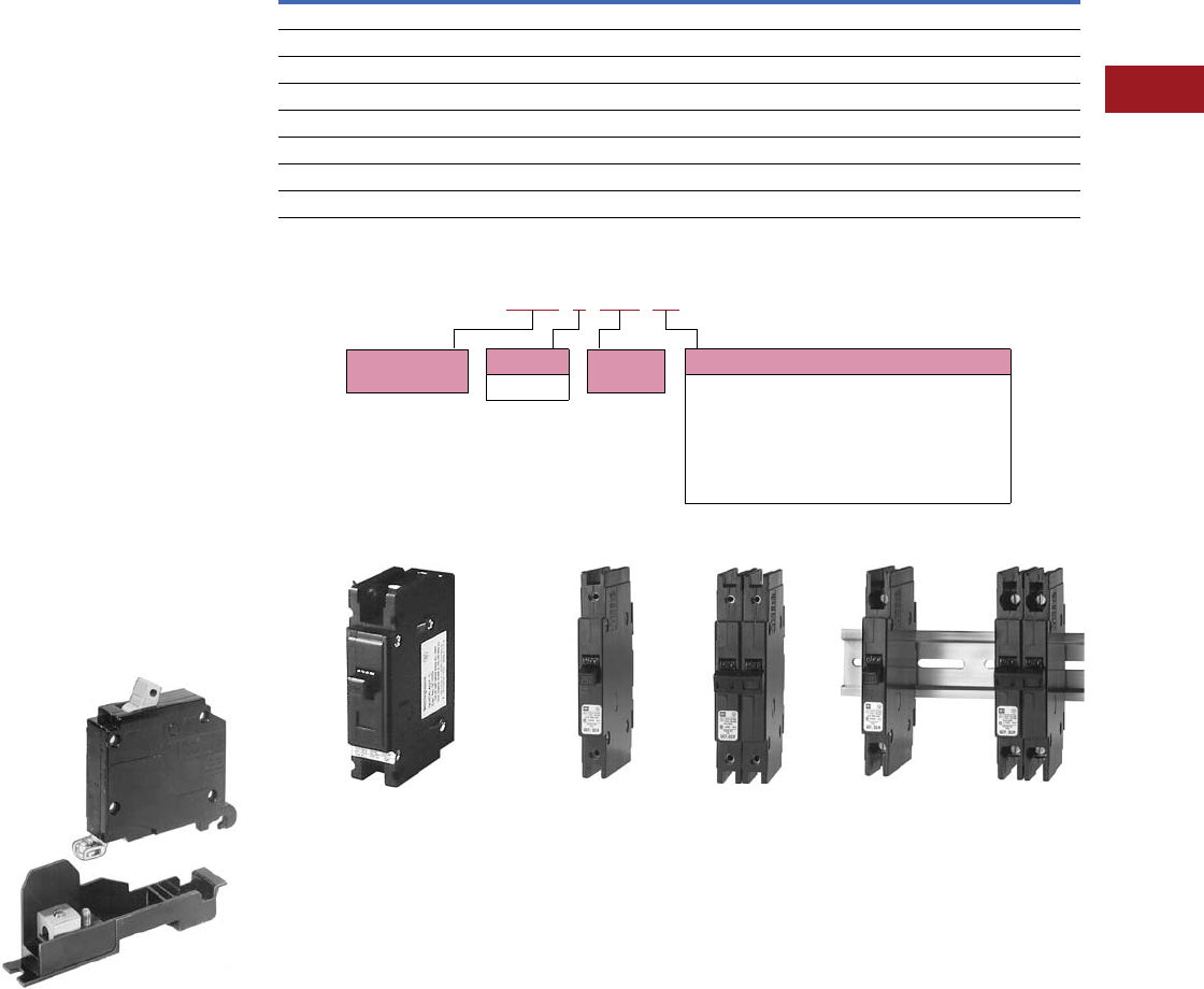
CHB Circuit Breaker
Originally a
Cutler-Hammer Product
The CHB breaker continues
to be available as a
replacement breaker for
use in Cutler-Hammer
Type PB panelboards.
When combined with the
mounting base, CHB
breakers were also used for
surface and DIN rail mount
cable-in/
cable-out applications.
(See photo below.)
For “new” cable-in/
cable-out applications,
Eaton recommends the
use of our most current
product offering:
●QUICKLAG Type QC
breakers (1.00-inch
per pole)
●QCR breakers—rear
mount (0.50-inch per pole)
●QCF breakers—front
mount (0.50-inch per pole)
QCR and QCF breakers
provide a 50% space savings
over 1.00-inch per pole
designs of the same rating.
CHB Breaker Mounting Base
CHB Mounting Bases
CHB Circuit Breaker Catalog Numbering System
Replacement Capabilities
Single-Pole
QUICKLAG Type QC Cable-In/
Cable-out Breaker—1.00 Inch per Pole
Single-Pole Two-Pole
Type QCF Cable-In/Cable-Out Breaker
—0.50 Inch per Pole (Front-Connected)
Single-Pole Two-Pole
Type QCR Cable-In/Cable-Out Breaker
—0.50 Inch per Pole (Rear-Connected)
Description Catalog Number
Low Ampere
15–50A Single-pole CHB9L1
15–50A Two-pole CHB9L250
15–50A Three-pole CHB9L350
High Ampere
25–50A Single-pole CHB9H1
25–125A Two-pole CHB9H2125
25–100A Three-pole CHB9H3100
CHB 3 100
Accessories
ST = Shunt-trip (requires extra pole space)
SW = Switched neutral application
HID = High intensity discharge lighting applications
HM = High magnetic trip
GF = Ground fault personnel protection
EPD = Ground fault equipment protection
H2 = 22,000 AIC (40, 50, 60A obsolete)
Poles
1-, 2- or 3-
Ampere
Rating
Bolt-on
Circuit Breaker
V12-T3-10 Volume 12—Aftermarket, Renewal Parts and Life Extension Solutions CA08100014E—July 2016 www.eaton.com
1
2
3
4
5
6
7
8
9
10
11
12
13
14
15
16
17
18
19
20
21
22
23
24
25
3
Molded-Case Circuit Breakers
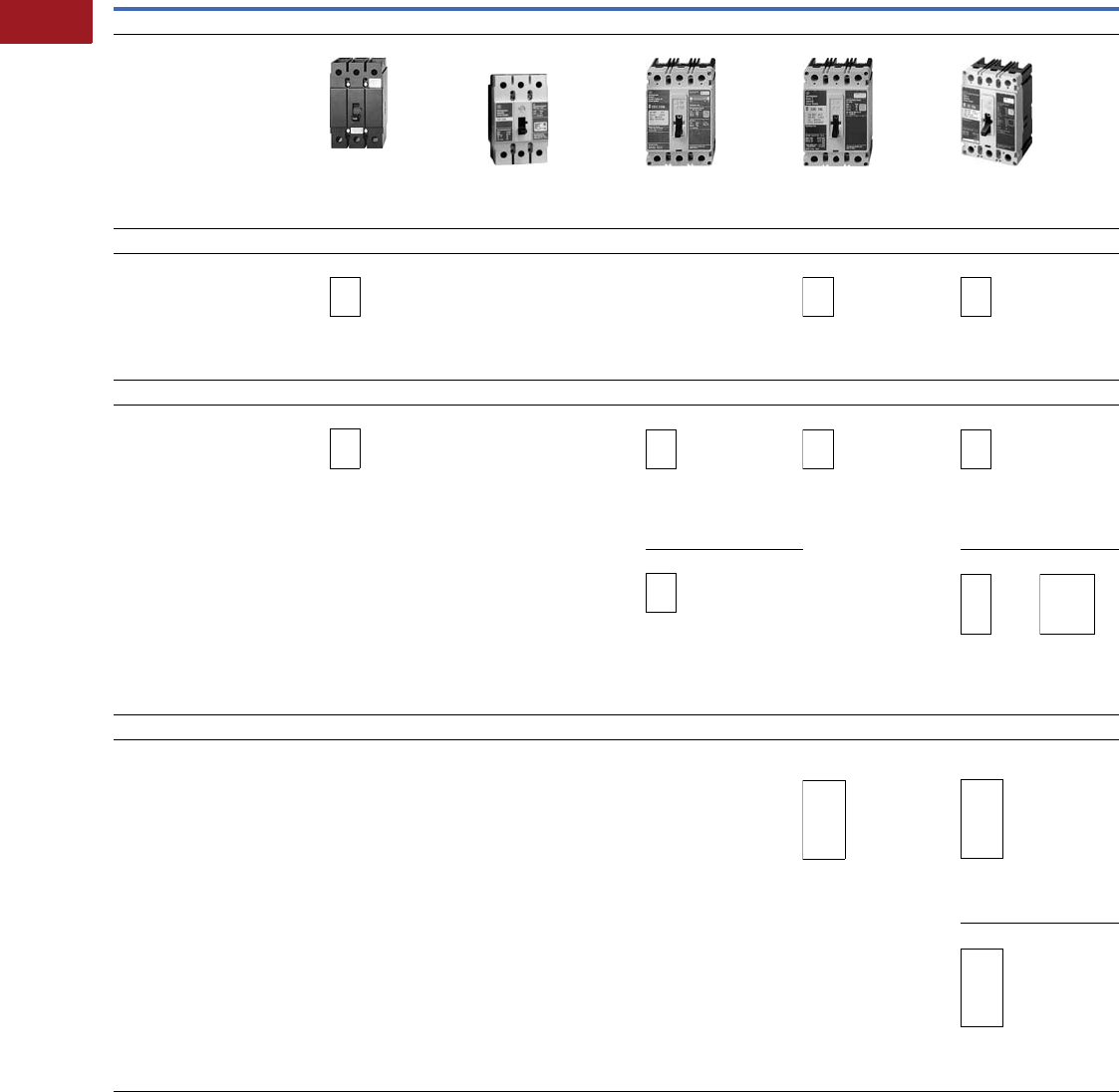
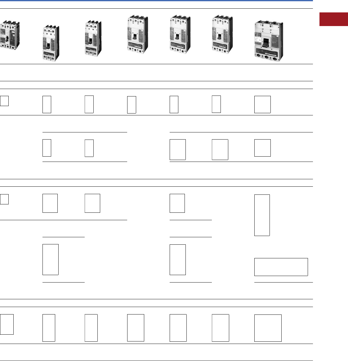
Series C Molded-Case Circuit Breaker Replacement Guide
Series C Industrial Circuit Breakers—Dimensions in Inches (Per Three-Pole Breaker)
Note
1 These frames are obsolete. For replacement solutions see the cross-reference on Pages V12-T3-114–V12-T3-167.
Description
Maximum Amperes
100A 100A/125A 225A 100A 100A
Current Design
Series C circuit breakers are the current
offering and, as such, are a logical first
choice when upgrading or retrofitting
equipment. All circuit breakers listed
in a column are ELECTRICALLY
INTERCHANGEABLE.
GHC EG
GD
ED, EDH, EDC EHD FDB, FD, HFD, FDC
Width: 3.00
Height: 4.88
Depth: 2.94
Width: 3.00
Height: 4.88
Depth: 2.81
Width: 4.13
Height: 6.00
Depth: 3.38
Width: 4.13
Height: 6.00
Depth: 3.38
Width: 4.13
Height: 6.00
Depth: 3.38
Replacement Circuit Breakers
These new UL labeled circuit breakers
continue to be manufactured and are
primarily applied to achieve exact
physical and electrical replacement of
previously installed Cutler-Hammer/
Westinghouse circuit breakers of the
same style number and rating.
EB 1No previous circuit
breaker existed
EHB 1FB 1, HFB
Width: 4.13
Height: 6.00
Depth: 3.38
Width: 4.13
Height: 6.00
Depth: 3.38
Width: 4.13
Height: 6.00
Depth: 3.38
Out-of-Production Westinghouse Circuit Breakers
These circuit breakers are no
longer manufactured. *Indicates the
last date of manufacture. As an option,
any of these circuit breakers can be
reconditioned at the original factory.
For details, see Page V12-T3-5, or
contact your local Eaton Field
Sales office.
E, EA
*1974
QCC
* 1968
EH
* 1974
FA, HFA
* 1974
Width: 4.13
Height: 6.00
Depth: 3.38
Width: 4.50
Height: 7.00
Depth: 3.38
Width: 4.13
Height: 6.50
Depth: 3.38
Width: 4.13
Height: 6.50
Depth: 3.38
CA, CAH, HCA 1F, H F
1974
G
1965
Width: 4.13
Height: 6.50
Depth: 2.69
Width: 4.13
Height: 9.38
Depth: 4.06
Width: 8.25
Height: 9.38
Depth: 4.06
Out-of-Production Cutler-Hammer Circuit Breakers Last Manufactured by Eaton in 1994
FS
EC, EHC
FS, FH,
FC, HFC
Width: 4.13
Height: 6.13
Depth: 3.38
Width: 4.13
Height: 6.13
Depth: 3.19
FL
Width: 4.13
Height: 9.31
Depth: 3.19
Volume 12—Aftermarket, Renewal Parts and Life Extension Solutions CA08100014E—July 2016 www.eaton.com V12-T3-11
1
2
3
4
5
6
7
8
9
10
11
12
13
14
15
16
17
18
19
20
21
22
23
24
25
3
Molded-Case Circuit Breakers
Series C Industrial Circuit Breakers—Dimensions in Inches (Per Three-Pole Breaker), Continued
Notes
1When upgrading a HLB, LBB to a Series C K-Frame in a panelboard application, also order
TAD3 spacer kit.
2These frames are obsolete. For replacement solutions see the cross-reference on
Pages V12-T3-114–V12-T3-167.
Maximum Amperes
150A 225A, 250A 400A 600A
Current Design
FDB, FD, HFD, FDC JG
JD, HJD, JDC
250A
JDB
250A
DK 1KD, HKD, KDC 1KDB LG
LD, HLD, LDB
Width: 4.13
Height: 6.00
Depth: 3.38
Width: 4.13
Height: 10.00
Depth: 4.06
Width: 4.13
Height: 10.00
Depth: 4.06
Width: 5.50
Height: 10.13
Depth: 4.06
Width: 5.50
Height: 10.13
Depth: 4.06
Width: 5.50
Height: 10.13
Depth: 4.06
Width: 8.25
Height: 10.75
Depth: 4.06
Replacement Circuit Breakers
FB 2, HFB KB 2, HKB 2JB 2DA 2LB 2, HLB 1LBB 2LC 2, HLC
Width: 4.13
Height: 6.00
Depth: 3.38
Width: 4.13
Height: 10.00
Depth: 4.06
Width: 4.13
Height: 10.00
Depth: 4.06
Width: 5.50
Height: 10.13
Depth: 4.06
Width: 5.50
Height: 10.13
Depth: 4.06
Width: 5.50
Height: 10.13
Depth: 4.06
Width: 8.25
Height: 10.75
Depth: 4.06
KA 2, HKA 2JA 2LA 2, HLA LAB 2LA 2, HLA
Width: 5.50
Height: 10.13
Depth: 4.06
Width: 5.50
Height: 10.13
Depth: 4.06
Width: 8.25
Height: 10.75
Depth: 4.06
Width: 8.25
Height: 10.75
Depth: 4.06
Width: 8.25
Height: 10.75
Depth: 4.06
Out-of-Production Westinghouse Circuit Breakers
FA, HFA
*1974
JK
*1967
J
*1967
JKL
*1967
L, LM, HLM
*1967
Width: 8.25
Height: 22.00
Depth: 5.50
Width: 4.13
Height: 6.50
Depth: 3.38
*Indicates the last
date of manufacture.
Width: 8.25
Height: 10.75
Depth: 4.06
Width: 8.25
Height: 10.13
Depth: 4.06
Width: 8.25
Height: 10.75
Depth: 4.06
K, HK
*1967
KL, HKL
*1967
Width: 8.25
Height: 15.50
Depth: 4.06
Width: 8.25
Height: 5.75
Depth: 4.06
Width: 8.25
Height: 10.75
Depth: 4.06
Out-of-Production Cutler-Hammer Circuit Breakers Last Manufactured by Eaton in 1994
FS, FH, FC, HFC JS, JH, JL JS KS-D, KS KS-D, KH-D, KS, KH KS-D, KH-D, KS, KH LS(E), LH(E), LS(A), LH(A)
Width: 4.25
Height: 6.13
Depth: 3.19
Width: 4.25
Height: 12.00
Depth: 3.81
Width: 4.25
Height: 12.00
Depth: 3.81
Width: 5.50
Height: 10.13
Depth: 3.81
Width: 5.50
Height: 10.13
Depth: 3.81
Width: 5.50
Height: 10.13
Depth: 3.81
Width: 8.25
Height: 10.75
Depth: 3.81
250A
250A
225A
225A
225A
225A
SPCB 600A,
SCB 600A
*1986 (Consult Eaton)
225A
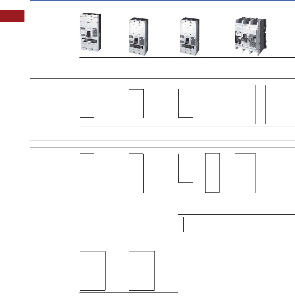
V12-T3-12 Volume 12—Aftermarket, Renewal Parts and Life Extension Solutions CA08100014E—July 2016 www.eaton.com
1
2
3
4
5
6
7
8
9
10
11
12
13
14
15
16
17
18
19
20
21
22
23
24
25
3
Molded-Case Circuit Breakers
Series C Industrial Circuit Breakers—Dimensions in Inches (Per Three-Pole Breaker), Continued
Notes
1RD breaker replaces PC, PCC and PB breakers for 2000 and 2500A only. 2These frames are obsolete. For replacement solutions, see the cross-reference on
Pages V12-T3-114–V12-T3-167.
Description
Maximum Amperes
800A 1200A 1600A/2000A/2500A 1
Current Design
Series C circuit breakers are the
current offering and, as such,
are a logical first choice when
upgrading or retrofitting equipment.
All circuit breakers listed in
a column are ELECTRICALLY
INTERCHANGEABLE.
MDL, HMDL NG
ND, HND, NDC
NG
ND, HND, NDC
RG
RD
Width: 8.25
Height: 16.00
Depth: 4.06
Width: 8.25
Height: 16.00
Depth: 5.50
Width: 8.25
Height: 16.00
Depth: 5.50
Width: 15.50
Height: 16.00
Depth: 9.75
Replacement Circuit Breakers
These new UL labeled circuit
breakers continue to be
manufactured and are primarily
applied to achieve exact physical
and electrical replacement of
previously installed Cutler-Hammer/
Westinghouse circuit breakers of
the same style number and rating.
PB/PC breakers are not UL Listed.
MA 2, HMA, MD 2, MDS 2
and MC 2
MA 2, HMA and MC 2, MCC 2
SELTRONIC™ 2
NC 2, HNC and NB 2, HNB PC, PCC PB
Width: 8.25
Height: 16.00
Depth: 4.06
Width: 8.25
Height: 16.00
Depth: 4.06
Width: 8.25
Height: 16.00
Depth: 5.50
Width: 12.06
Height: 22.06
Depth: 9.06
Width: 12.06
Height: 22.06
Depth: 9.06
Out-of-Production Westinghouse Circuit Breakers
These circuit breakers are
no longer manufactured.
*Indicates the last date of
manufacture. As an option, any
of these circuit breakers can be
reconditioned at the original factory.
For details, see Page V12-T3-5,
or contact your local Eaton Field
Sales office.
LM, HLM and M
*1967
LM, HLM and M
*1967
MA, HMA
*1968
MA, HLM
*1967
PA
*1974
Width: 8.25
Height: 22.00
Depth: 5.50
Width: 8.25
Height: 22.00
Depth: 5.50
Width: 8.25
Height: 16.00
Depth: 5.50
Width: 8.25
Height: 22.00
Depth: 5.50
Width: 12.00
Height: 22.00
Depth: 9.06
Width: 8.25 Height: 16.00 Depth: 5.50 Width: 12.06 Height: 22.06 Depth: 9.06
Out-of-Production Cutler-Hammer Circuit Breakers Last Manufactured by Eaton in 1994
MS, MH NS, NH No equivalent Cutler-Hammer brand
frame size existed
No equivalent Cutler-Hammer brand frame
size existed
Width: 8.25
Height: 16.00
Depth: 4.06
Width: 8.25
Height: 16.00
Depth: 5.50
1200A
SPCB 1200A,
SCB 1200A
*1986 (Consult Eaton)
SPCB 2000–3000A,
SCB 2000–3000A
*1986 (Consult Eaton)
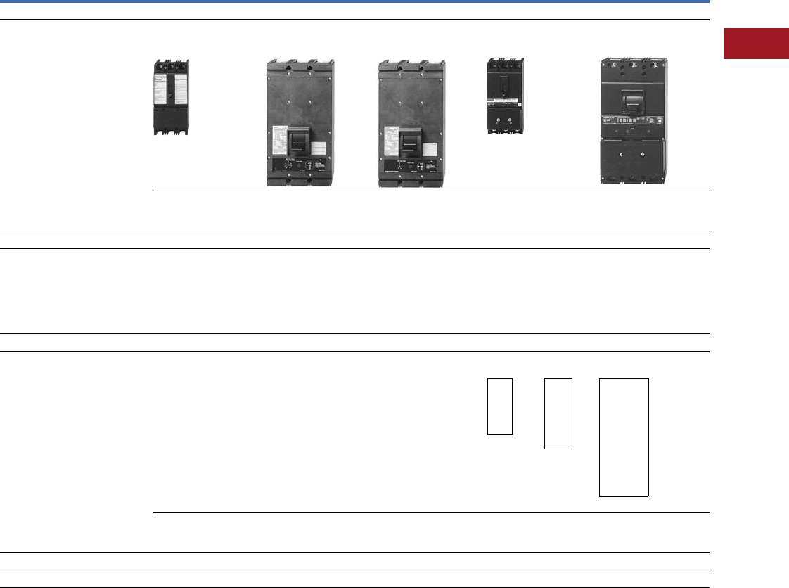
Volume 12—Aftermarket, Renewal Parts and Life Extension Solutions CA08100014E—July 2016 www.eaton.com V12-T3-13
1
2
3
4
5
6
7
8
9
10
11
12
13
14
15
16
17
18
19
20
21
22
23
24
25
3
Molded-Case Circuit Breakers
Current Limiting Circuit Breakers—Dimensions in Inches (Per Three-Pole Breaker)
Description
Maximum Amperes
100A 250A 400A 100A 225A
Current Design
All circuit breakers listed in a
column are ELECTRICALLY
INTERCHANGEABLE.
FCL
Current Limit-R
(non-fused)
LCL
Current Limit-R
(non-fused)
LCL
Current Limit-R
(non-fused)
FB
TRI-PAC®
(fused)
LA
TRI-PAC
(fused)
Width: 4.13
Height: 8.75
Depth: 3.38
Width: 8.25
Height: 16.00
Depth: 4.06
Width: 8.25
Height: 16.00
Depth: 4.06
Width: 4.13
Height: 8.75
Depth: 3.50
Width: 8.25
Height: 16.00
Depth: 4.75
Replacement Circuit Breakers
These new UL labeled circuit breakers
continue to be manufactured and are
primarily applied to achieve exact
physical and electrical replacement of
previously installed Cutler-Hammer/
Westinghouse circuit breakers of the
same style number and rating.
Out-of-Production Westinghouse Circuit Breakers
These circuit breakers are no
longer manufactured.
*Indicates the last date of manufacture.
As an option, any of these circuit breakers
can be reconditioned at the original
factory. For details, see Page V12-T3-5,
or contact your local Eaton Field
Sales office.
FA
TRI-PAC
*1968
F
TRI-PAC
*1968
K
TRI-PAC
*1968
Width: 4.13
Height: 9.38
Depth: 3.19
Width: 4.63
Height: 11.81
Depth: 3.81
Width: 8.25
Height: 19.63
Depth: 4.06
Out-of-Production Cutler-Hammer Circuit Breakers Last Manufactured by Eaton in 1994
No Equivalent Cutler-Hammer Brand Frame Sizes Existed
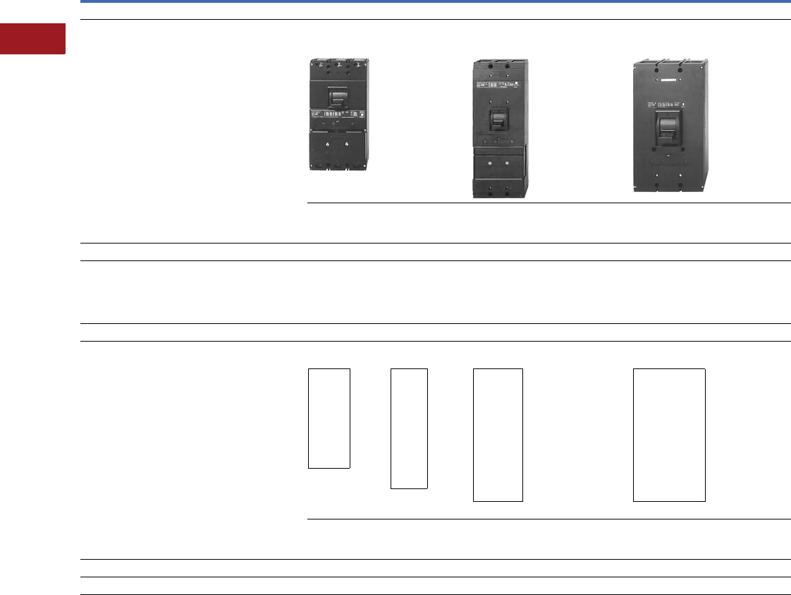
V12-T3-14 Volume 12—Aftermarket, Renewal Parts and Life Extension Solutions CA08100014E—July 2016 www.eaton.com
1
2
3
4
5
6
7
8
9
10
11
12
13
14
15
16
17
18
19
20
21
22
23
24
25
3
Molded-Case Circuit Breakers
Current Limiting Circuit Breakers—Dimensions in Inches (Per Three-Pole Breaker)
Description
Maximum Amperes
400A 800A 1600A
Current Design
All circuit breakers listed in a column are
ELECTRICALLY INTERCHANGEABLE.
LA
TRI-PAC®
(Fused)
NB
TRI-PAC
(Fused)
PB
TRI-PAC
(Fused)
Width: 8.25
Height: 16.00
Depth: 4.75
Width: 8.25
Height: 22.00
Depth: 5.50
Width: 12.06
Height: 22.13
Depth: 9.06
Replacement Circuit Breakers
These new UL labeled circuit breakers continue to be
manufactured and are primarily applied to achieve exact
physical and electrical replacement of previously installed
Cutler-Hammer/Westinghouse circuit breakers of the same
style number and rating.
Out-of-Production Westinghouse Circuit Breakers
These circuit breakers are no longer manufactured.
*Indicates the last date of manufacture. As an option, any
of these circuit breakers can be reconditioned at the original
factory. For details, see Page V12-T3-5, or contact your local
Eaton Field Sales office.
KL
TRI-PAC
*1968
L
TRI-PAC
*1968
MA
TRI-PAC
*1968
PA
TRI-PAC
*1968
Width: 8.25
Height: 19.63
Depth: 4.06
Width: 8.25
Height: 26.91
Depth: 5.50
Width: 8.25
Height: 22.00
Depth: 5.50
Width: 12.00
Height: 22.00
Depth: 9.06
Out-of-Production Cutler-Hammer Circuit Breakers Last Manufactured by Eaton in 1994
No equivalent Cutler-Hammer brand frame sizes existed
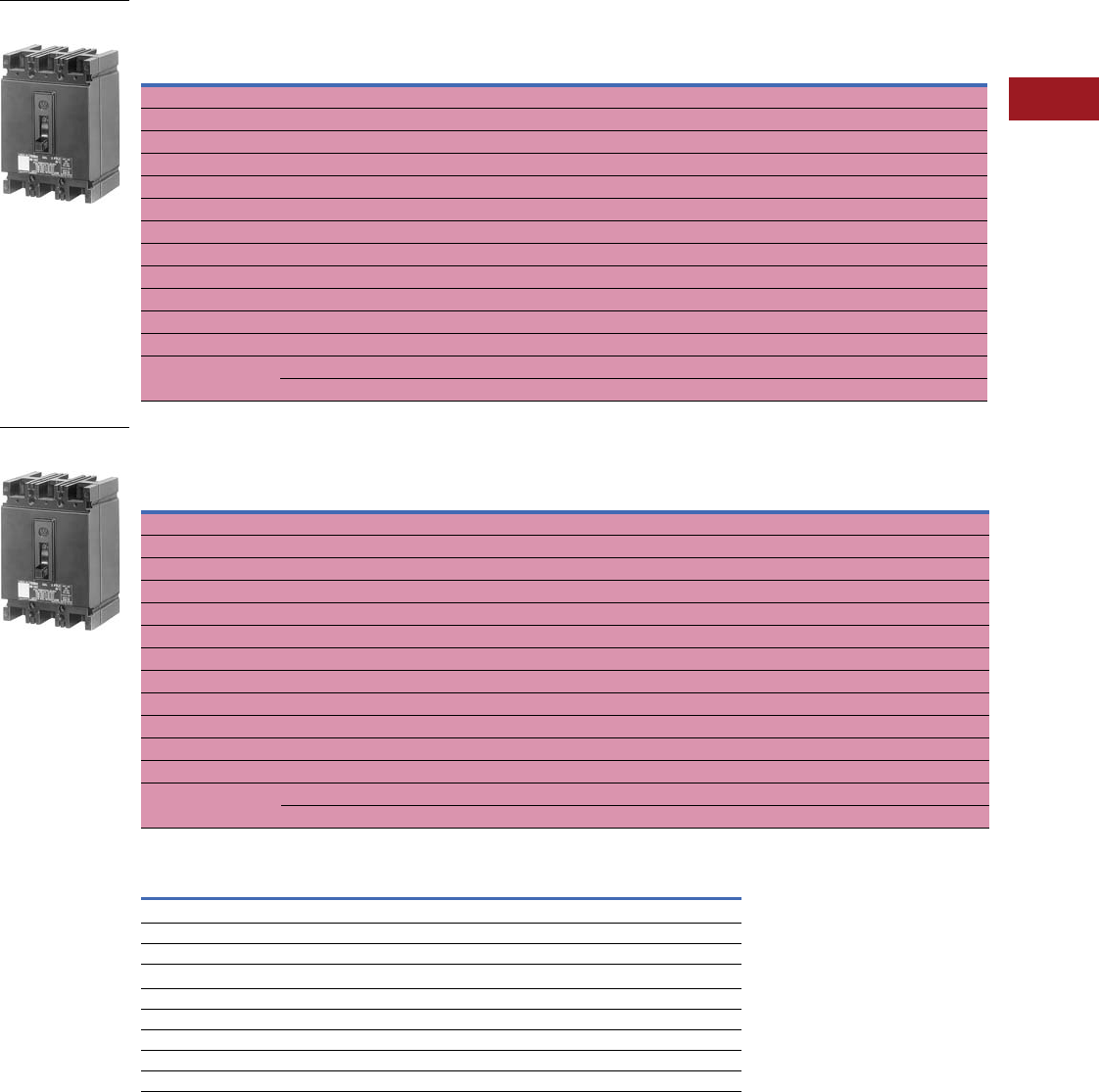
Volume 12—Aftermarket, Renewal Parts and Life Extension Solutions CA08100014E—July 2016 www.eaton.com V12-T3-15
1
2
3
4
5
6
7
8
9
10
11
12
13
14
15
16
17
18
19
20
21
22
23
24
25
3
Molded-Case Circuit Breakers
Replacement Capabilities
■
Shaded area denotes obsolete or discontinued products and services. 1
Type EB Single-, Two-, Three-Pole; 240 Vac Maximum; Thermal-Magnetic and Saf-T-Vue®
2
Type EHB Single-, Two-, Three-Pole; 480 Vac Maximum; Thermal-Magnetic and Saf-T-Vue 2
UL Listed Interrupting Ratings 7
Notes
1 These frames are obsolete. For replacement solutions, see the cross-reference on Pages V12-T3-114–V12-T3-167.
2 Includes load terminals only.
3 DC ratings apply to substantially non-inductive circuits.
4 Not UL Listed.
5 Switching duty rated for 120 Vac fluorescent light applications only.
6 Switching duty rated for 277 Vac fluorescent light applications only.
7 Interrupting capacities shown do not apply to molded-case switches.
Continuous Ampere
Rating at 40°C
Single-Pole, 120 Vac, 125 Vdc 3Two-Pole, 240 Vac, 125/250 Vdc 3Three-Pole, 240 Vac, 125/250 Vdc 3
Standard Standard Standard Saf-T-Vue 4
Catalog Number Catalog Number Catalog Number Catalog Number
15 EB1015 5EB2015 EB3015 EB3015S
20 EB1020 5EB2020 EB3020 EB3020S
25 EB1025 EB2025 EB3025 EB3025S
30 EB1030 EB2030 EB3030 EB3030S
35 EB1035 EB2035 EB3035 EB3035S
40 EB1040 EB2040 EB3040 EB3040S
45 EB1045 EB2045 EB3045 EB3045S
50 EB1050 EB2050 EB3050 EB3050S
60 EB1060 EB2060 EB3060 EB3060S
70 EB1070 EB2070 EB3070 EB3070S
80 EB1080 EB2080 EB3080 EB3080S
90 EB1090 EB2090 EB3090 EB3090S
100 EB1100 EB2100 EB3100 EB3100S
Approximate shipping weight is 2 lbs Approximate shipping weight is 3 lbs Approximate shipping weight is 4.5 lbs
Continuous Ampere
Rating at 40°C
Single-Pole, 277 Vac, 125 Vdc 3Two-Pole, 480 Vac, 250 Vdc 3Three-Pole, 480 Vac
Standard Standard Standard Saf-T-Vue 4
Catalog Number Catalog Number Catalog Number Catalog Number
15 EHB1015 6EHB2015 EHB3015 EHB3015S
20 EHB1020 6EHB2020 EHB3020 EHB3020S
25 EHB1025 EHB2025 EHB3025 EHB3025S
30 EHB1030 EHB2030 EHB3030 EHB3030S
35 EHB1035 EHB2035 EHB3035 EHB3035S
40 EHB1040 EHB2040 EHB3040 EHB3040S
45 EHB1045 EHB2045 EHB3045 EHB3045S
50 EHB1050 EHB2050 EHB3050 EHB3050S
60 EHB1060 EHB2060 EHB3060 EHB3060S
70 EHB1070 EHB2070 EHB3070 EHB3070S
80 EHB1080 EHB2080 EHB3080 EHB3080S
90 EHB1090 EHB2090 EHB3090 EHB3090S
100 EHB1100 EHB2100 EHB3100 EHB3100S
Approximate shipping weight is 2 lbs Approximate shipping weight is 3 lbs Approximate shipping weight is 4.5 lbs
Maximum Volts Amperes
EB Breakers
120 and 240 AC 10,000 asymmetrical, symmetrical
125/250 DC 5000 3
EHB, FB Breakers
240 AC 20,000 asymmetrical, 18,000 symmetrical
277 AC (EHB) 15,000 asymmetrical, 14,000 symmetrical
480 AC 15,000 asymmetrical, 14,000 symmetrical
600 AC (FB) 15,000 asymmetrical, 14,000 symmetrical
250 DC 10,000 3
EB: 120, 240 Vac;
125/250 Vdc
EHB: 277, 480 Vac;
250 Vdc
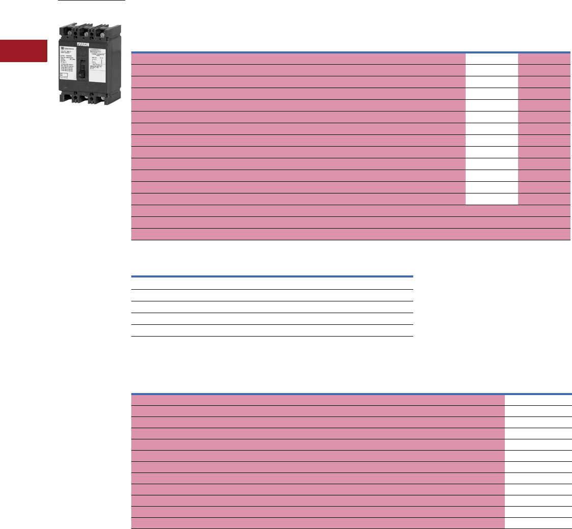
V12-T3-16 Volume 12—Aftermarket, Renewal Parts and Life Extension Solutions CA08100014E—July 2016 www.eaton.com
1
2
3
4
5
6
7
8
9
10
11
12
13
14
15
16
17
18
19
20
21
22
23
24
25
3
Molded-Case Circuit Breakers
Replacement Capabilities
■
Shaded area denotes obsolete or discontinued products and services. 1
Type FB, HFB Single-, Two-, Three-, Four-Pole; 480V Max.; Thermal-Magnetic MARK 75® Saf-T-Vue
UL Listed Interrupting Ratings 9
Special Breakers Type FB, Magnetic Only, Front Adjustable
Notes
1 These frames are obsolete. For replacement solutions, see the cross-reference on Pages V12-T3-114–V12-T3-167.
2 DC ratings apply to substantially non-inductive circuits.
3 Not UL Listed.
4 All four poles have thermal-magnetic trip elements. Can be supplied with three protected poles and one unprotected, non-automatic pole if required.
Order by description with no price or dimensional differences.
5 15–30A rated 75,000 AIC. 40–100A rated 30,000A asymmetrical, 25,000A symmetrical.
6 Two-pole breakers are supplied in three-pole frames with current carrying parts omitted from center pole.
7 Includes line and load terminals. MARK 75 frame color changed from gray to black in mid-2002.
8 Switching duty rated for 277 Vac fluorescent light applications only.
9 Interrupting capacities shown do not apply to molded-case switches.
jRatings above 10,000A not UL Listed.
Continuous
Ampere
Rating
at 40°C
Single-Pole
277 Vac; 125 Vdc 2
Two-Pole
600 Vac; 250 Vdc 2
Three-Pole
600 Vac
Four-Pole 34
600 Vac
MARK 75 5Standard MARK 75 6Standard Saf-T-Vue 6
MARK 75
7Standard
Catalog Number Catalog Number Catalog Number Catalog Number Catalog Number Catalog Number Catalog Number
15 HFB1015 8FB2015 HFB2015 FB3015 FB3015S HFB3015L FB4015
20 HFB1020 8FB2020 HFB2020 FB3020 FB3020S HFB3020L FB4020
25 HFB1025 FB2025 HFB2025 FB3025 FB3025S HFB3025L FB4025
30 HFB1030 FB2030 HFB2030 FB3030 FB3030S HFB3030L FB4030
35 HFB1035 FB2035 HFB2035 FB3035 FB3035S HFB3035L FB4035
40 HFB1040 FB2040 HFB2040 FB3040 FB3040S HFB3040L FB4040
45 HFB1045 FB2045 HFB2045 FB3045 FB3045S HFB3045L FB4045
50 HFB1050 FB2050 HFB2050 FB3050 FB3050S HFB3050L FB4050
60 HFB1060 FB2060 HFB2060 FB3060 FB3060S HFB3060L FB4060
70 HFB1070 FB2070 HFB2070 FB3070 FB3070S HFB3070L FB4070
80 HFB1080 FB2080 HFB2080 FB3080 FB3080S HFB3080L FB4080
90 HFB1090 FB2090 HFB2090 FB3090 FB3090S HFB3090L FB4090
100 HFB1100 FB2100 HFB2100 FB3100 FB3100S HFB3100L FB4100
110 — — — FB3110 FB3110S HFB3110 —
125 — — — FB3125 FB3125S HFB3125 —
150 — — — FB3150 FB3150S HFB3150 —
Maximum Volts Amperes
MARK 75 Type HFB
240 AC 75,000 asymmetrical, 65,000 symmetrical
277 AC 675,000 asymmetrical, 65,000 symmetrical
480 AC 30,000 asymmetrical, 25,000 symmetrical
250 DC (two-pole) 20,000 2j
Continuous
Ampere
Rating
Magnetic
Trip Range
Amperes
Two-Pole, 600 Vac Three-Pole, 600 Vac
Standard MARK 75 Standard Saf-T-Vue MARK 75 7
Catalog/Style Number Catalog/Style Number Catalog/Style Number Catalog/Style Number Catalog/Style Number
37–22 FB2022MRL HFB2022ML FB3022MRL FB3022SMRL HFB3022ML
515–45 FB2045MRL HFB2045ML FB3045MRL FB3045SMRL HFB3045ML
10 35–110 FB2110MRL HFB2110ML FB3110MRL FB3110SMRL HFB3110ML
25 32–80 2610D53G12 4994D96G12 2610D53G30 4998D89G30 2610D57G30
25 66–190 FB2190MRL HFB2190ML FB3190MRL FB3190SMRL HFB3190ML
30 50–150 1268C14G05 —1268C14G06 ——
30 90–270 FB2270MRL HFB2270ML FB3270MRL FB3270SMRL HFB3270ML
50 66–190 1268C14G01 —1268C14G02 ——
50 160–480 FB2480MRL HFB2480ML FB3480MRL FB3480SMRL HFB3480ML
70 100–270 2610D53G13 4994D96G13 2610D53G31 2610D58G31 4994D96G31
100 150–480 1268C14G03 —1268C14G04 81E4647 65E4667
100 450–1550 FB21550MRL HFB21550ML FB31550MRL FB31550SMRL HFB31550ML
FB, HFB: 600 Vac;
250 Vdc
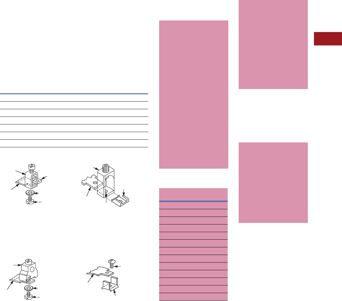
Volume 12—Aftermarket, Renewal Parts and Life Extension Solutions CA08100014E—July 2016 www.eaton.com V12-T3-17
1
2
3
4
5
6
7
8
9
10
11
12
13
14
15
16
17
18
19
20
21
22
23
24
25
3
Molded-Case Circuit Breakers
Replacement Capabilities
Accessories and Modifications
Terminals
Breakers include load
terminals only. Terminals are
UL Listed as suitable for wire
type and size. When used with
aluminum conductors, use
joint compound. When line
terminals are required, order
by style number from the table
at no charge with the breaker.
Note: Magnetic only breakers
include both line and
load terminals.
Note: Suffix “L” on catalog number
indicates line and load terminals
included. If factory installation is
required, specify on order.
Terminals
Terminal Style 624B100G02
Insert collar enclosing
conductor as shown. Locate
nut on top of conductor and
tighten securely with screw
and washer. Caution: Collar
must surround conductor.
Terminal Style 624B100G10
Assemble collar on top
of conductor as shown.
Tighten securely with
screw and washer.
Terminal Style 624B100G17
Insert collar enclosing
conductor and center on
extrusion on collar. Install clip
with legs on top of conductor
and snap end around bottom
of collar.
Terminal Style 624B100G14
Assemble wire clamp
to bottom of conductor
as shown.
Maximum
Amperes
Wire
Type
Wire
Range
Package of Three Line Terminals 1
Style Number
Standard Pressure Type Terminals
20 (EB, EHB) Al/Cu #14–#10 624B100G14
100 Al/Cu #14–1/0 624B100G02
150 Al/Cu # 4–4/0 624B100G17
Optional Al/Cu Pressure Terminals
50 Al/Cu #14–#4 624B100G10
100 Al/Cu # 4–4/0 624B100G17
Conductor
Collar
Screw
Washer
Nut
Conductor
Collar
Screw
Washer
Clip
Extrusion
Conductor
Collar
Screw
Wire Clamp
Conductor
■
Shaded area denotes
obsolete or discontinued
products and services.
LFB Current Limiter
Attachment 2
Notes
1Style listed is for package of
three terminals.
2These frames are obsolete. For
replacement solutions, see the cross-
reference on Pages V12-T3-114–
V12-T3-167.
3Ratings through 70A can be supplied
with terminals for Cu cable only
(#14–#2). Order by description.
4Superseded by LFD3070R.
5Superseded by LFD3150R.
6Replace with Series C HMCP and ELC
current limiters or replace with MCP
and EL current limiters
50°C Calibration
Add suffix “V” to catalog
number for complete breaker,
listed above, when ordering
breakers to be used in 50°C
ambients.
Note: Not UL Listed.
Federal Specification
Classifications
EB, EHB, FB and HFB
breakers meet requirements
of Federal Specification
W-C-375b as follows:
●EB: single-pole, Class 11a;
two-, three-pole, Classes
10b, 11b, 12b
●EHB: single-pole,
Class 13a; two-,
three-pole, Class 13b
●FB: two-, three-pole,
Class 18a
●HFB: single-pole,
Class 13a; two-, three-pole,
Class 22a
For all three-phase
delta, grounded B phase
applications, contact
Avery Creek, NC,
Technical Resource Center
at 1-800-356-1243.
LFB Current Limiter Attachment
The LFB current limiter is
an attachment that bolts to
the load end of a standard
FB thermal-magnetic or
magnetic only breaker,
providing 200,000A
interrupting capacity (AIC) at
up to 600 Vac. Limiters for
thermal-magnetic breakers
are UL Listed. Current
limiters must be applied
as indicated in the table
on Page V12-T3-16.
Standard LFB terminals
are suitable for Cu/AI cable.
Ratings through 70A accept
(1) #14–#2, and 100 and
150A accept (1) #1–4/0.
Note: Cannot be used with
plug-in adapters. Ratings
through 70A can be supplied
with terminals for Cu cable only
(#14–#2). Order by description.
Breaker Rating,
Amperes
Limiter
Catalog Number
For Thermal-Magnetic Breakers 3
15–70 LFB3070R 4
80–150 LFB3150R 5
For Magnetic Only Breakers 36
3LFB3003MR
5LFB3005MR
10 LFB3010MR
25 LFB3025MR
30 LFB3030MR
50 LFB3050MR
70 LFB3070MR
100 LFB3100MR
150 LFB3150MR
Special Calibrations
Special calibration price
additions apply to ampere
ratings not listed as
standard or for ambients
other than 40°C or 50°C.
For frequencies other than
0–60 Hz AC, refer to Eaton.
See Application Data 29-160
for information regarding
special conditions.
Maximum calibration for
400 Hz is 135A.
Note: Not UL Listed.
Ambient Compensating
Breakers
To order, add suffix letter
“A” to standard thermal-
magnetic breaker
catalog number.
Available in all standard
ratings of EB, EHB, FB
and HFB breakers up to
ratings of 100A. Factory
adder 20%.
Note: Not UL Listed.
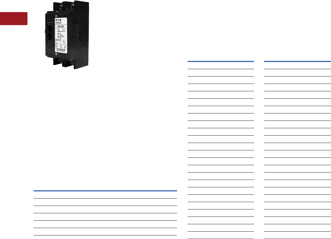
V12-T3-18 Volume 12—Aftermarket, Renewal Parts and Life Extension Solutions CA08100014E—July 2016 www.eaton.com
1
2
3
4
5
6
7
8
9
10
11
12
13
14
15
16
17
18
19
20
21
22
23
24
25
3
Molded-Case Circuit Breakers
Replacement Capabilities
Type CCV 120/240V Tenant Main Circuit Breaker
10,000A and 25,000A Interrupting Capacity, 100–225A
Type CCV Two-Pole
120/240V Tenant
Main Circuit Breaker
Product Description
Ratings
●120/240 Vac, two-pole,
through 225 continuous
amperes, calibrated
at 40ºC
Tripping Characteristics
●Thermal-magnetic trip,
calibrated and sealed
after assembly. Indirectly
heated thermal tripping
bimetal elements
Interrupting Capacity
at 120/240 Vac
●Type CCV—10,000A rms
symmetrical
●Type CCVH—25,000A rms
symmetrical
Handles
●Trip-free with “ON-
TRIPPED-OFF” positions.
Reset past “OFF” is
required to latch breaker
contacts after tripping
Terminals
●Standard lugs (wire
connectors) suitable for
either CU or AL wire
Standards
●Complies with UL Standard
489, breakers are listed
under UL File #E781
Backward Compatibility
●CCV and CCVH retains
same profile and footprint
of the CC and CCH breaker
allowing use in the
same applications
Product Selection
Ampere
Rating
Two-Pole Breaker
Wire Size Range, Al/Cu 10,000 AIC 25,000 AIC
100 #2/0–300 kcmil CCV2100 CCVH2100
125 #2/0–300 kcmil CCV2125 CCVH2125
150 #2/0–300 kcmil CCV2150 CCVH2150
175 #2/0–300 kcmil CCV2175 CCVH2175
200 #2/0–300 kcmil CCV2200 CCVH2200
225 #2/0–300 kcmil CCV2225 CCVH2225
Terminal Options
Terminal configurations available by adding the following
designator on the suffix:
W = No terminals
X = Load side terminals only
Y = Line side terminals only
CCV as tenant main breaker with CC as aftermarket option.
Cross-Reference
CCV Catalog
Number
CC Catalog
Number
CCV Catalog
Number
CC Catalog
Number
CCV2100 CC2100 CCVH2100 CCH2100
CCV2100W CC2100W CCVH2100W CCH2100W
CCV2100X CC2100X CCVH2100X CCH2100X
CCV2100Y CC2100Y CCVH2100Y CCH2100Y
CCV2125 CC2125 CCVH2125 CCH2125
CCV2125W CC2125W CCVH2125W CCH2125W
CCV2125X CC2125X CCVH2125X CCH2125X
CCV2125Y CC2125Y CCVH2125Y CCH2125Y
CCV2150 CC2150 CCVH2150 CCH2150
CCV2150W CC2150W CCVH2150W CCH2150W
CCV2150X CC2150X CCVH2150X CCH2150X
CCV2150Y CC2150Y CCVH2150Y CCH2150Y
CCV2175 CC2175 CCVH2175 CCH2175
CCV2175W CC2175W CCVH2175W CCH2175W
CCV2175X CC2175X CCVH2175X CCH2175X
CCV2175Y CC2175Y CCVH2175Y CCH2175Y
CCV2200 CC2200 CCVH2200 CCH2200
CCV2200W CC2200W CCVH2200W CCH2200W
CCV2200X CC2200X CCVH2200X CCH2200X
CCV2200Y CC2200Y CCVH2200Y CCH2200Y
CCV2225 CC2225 CCVH2225 CCH2225
CCV2225W CC2225W CCVH2225W CCH2225W
CCV2225X CC2225X CCVH2225X CCH2225X
CCV2225Y CC2225Y CCVH2225Y CCH2225Y
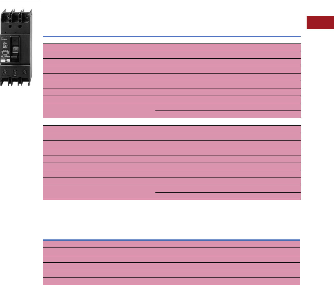
Volume 12—Aftermarket, Renewal Parts and Life Extension Solutions CA08100014E—July 2016 www.eaton.com V12-T3-19
1
2
3
4
5
6
7
8
9
10
11
12
13
14
15
16
17
18
19
20
21
22
23
24
25
3
Molded-Case Circuit Breakers
Replacement Capabilities
Type JB
■
Shaded area denotes obsolete or discontinued products and services. 1
Type JB 90–250A, 600 Vac, 250 Vdc, Two- and Three-Pole, Fixed Trip, Thermal-Magnetic, Saf-T-Vue
(Suitable for Reverse-Feed)
Magnetic Only Breakers, Front Adjustable 3
Notes
1 These frames are obsolete. For replacement solutions, see the cross-reference on Pages V12-T3-114–V12-T3-167.
2 Terminals are shipped separately from breaker frame.
3 Not UL Listed.
4 Two-pole breakers are supplied in three-pole frames with current carrying parts omitted from center pole.
5 Select desired terminal from table and order as separate item.
Continuous Ampere
Rating at 40°C
Magnetic Trip Setting,
Amperes (Set on High Side,
Adjustable to Lower Limits)
Complete Breaker Includes
Pressure Type Aluminum Terminals 2Breaker Without Terminals
Standard Saf-T-Vue 3Standard Saf-T-Vue 3
Low High Catalog Number Catalog Number Catalog Number Catalog Number
Two-Pole, 600 Vac, 250 Vdc 4
70 350 700 JB2070 JB2070S JB2070W JB2070SW
90 450 900 JB2090 JB2090S JB2090W JB2090SW
100 500 1000 JB2100 JB2100S JB2100W JB2100SW
125 625 1250 JB2125 JB2125S JB2125W JB2125SW
150 750 1500 JB2150 JB2150S JB2150W JB2150SW
175 875 1750 JB2175 JB2175S JB2175W JB2175SW
200 1000 2000 JB2200 JB2200S JB2200W JB2200SW
225 1125 2250 JB2225 JB2225S JB2225W JB2225SW
250 1250 2500 JB2250 JB2250S JB2250W JB2250SW
Approx. shipping weight. 12 lbs Approx. shipping weight 12 lbs
Three-Pole, 600 Vac Only
70 350 700 JB3070 JB3070S JB3070W JB3070SW
90 450 900 JB3090 JB3090S JB3090W JB3090SW
100 500 1000 JB3100 JB3100S JB3100W JB3100SW
125 625 1250 JB3125 JB3125S JB3125W JB3125SW
150 750 1500 JB3150 JB3150S JB3150W JB3150SW
175 875 1750 JB3175 JB3175S JB3175W JB3175SW
200 1000 2000 JB3200 JB3200S JB3200W JB3200SW
225 1125 2250 JB3225 JB3225S JB3225W JB3225SW
250 1250 2500 JB3250 JB3250S JB3250W JB3250SW
Approx. shipping weight 14 lbs Approx. shipping weight 12 lbs
Continuous
Ampere Rating
at 40°C
Magnetic Trip Setting,
Amperes (Set on High Side,
Adjustable to Lower Limits)
Breaker Only, No Terminals 5
Two-Pole 4Three-Pole
Standard Saf-T-Vue Standard Saf-T-Vue
Low High Catalog Number Catalog Number Catalog Number Catalog Number
250 350 700 JB2700MW JB2700SMW JB3700MW JB3700SMW
250 625 1250 JB21250MW JB21250SMW JB31250MW JB31250SMW
250 750 1500 JB21500MW JB21500SMW JB31500MW JB31500SMW
250 875 1750 JB21750MW JB21750SMW JB31750MW JB31750SMW
250 1125 2250 JB22250MW JB22250SMW JB32250MW JB32250SMW
250 1250 2500 JB22500MW JB22500SMW JB32500MW JB32500SMW
JB: 600 Vac; 250 Vdc

V12-T3-20 Volume 12—Aftermarket, Renewal Parts and Life Extension Solutions CA08100014E—July 2016 www.eaton.com
1
2
3
4
5
6
7
8
9
10
11
12
13
14
15
16
17
18
19
20
21
22
23
24
25
3
Molded-Case Circuit Breakers
Replacement Capabilities
UL Listed Interrupting Ratings 1
Te rm i n a l s
Note
1Ratings above 10,000A not UL Listed.
Maximum Volts Amperes
240 AC 30,000 asymmetrical, 25,000 symmetrical
480 AC 25,000 asymmetrical, 22,000 symmetrical
600 AC 15,000 asymmetrical, 14,000 symmetrical
250 DC 10,000
Maximum
Amperes
Number of Cables,
Wire Range, Type
Catalog
Number
Standard Al/Cu Pressure Terminals
250 (1) #4–350 kcmil Al/Cu TA250KB
Optional Pressure Terminals
250 (1) #4–350 kcmil Cu T250KB
Accessories and Modifications
■
Shaded area denotes
obsolete or discontinued
products and services.
Type JB breakers meet
requirements of Class 19a
circuit breakers as defined
by Federal Specification
W-C-375b.
Note: Not UL Listed.
UL Listed Interrupting
Rating (see table)
For all three-phase
delta, grounded B phase
applications, contact
Avery Creek, NC, Technical
Resource Center at
1-800-356-1243.
Terminals (see table)
Two terminals are required
per pole.
Terminals are UL Listed for
wire type and range listed left.
When used with aluminum
conductors, use joint
compound. To order optional
copper only terminals, add
suffix “C” to complete
breaker catalog number.
Note: Terminals are shipped
separately from breaker frame.
Magnetic Only Breakers
For description, refer to
Application Data 29-160.
Additional Accessories
and Modifications
Refer to Pages V12-T3-65–
V12-T3-79.
Special Calibrations
Special calibration price
additions apply to ampere
ratings not listed as
standard or for ambients
other than 40°C or 50°C.
For frequencies other than
0–60 Hz AC, refer to Eaton.
Note: Not UL Listed.
50°C Calibration
Add suffix “V” to catalog
number for complete
breaker when ordering
breakers to be used in 50°C
ambients. Same price as
standard 40°C breakers.
For CSA®, see
Page V12-T3-48.
Volume 12—Aftermarket, Renewal Parts and Life Extension Solutions CA08100014E—July 2016 www.eaton.com V12-T3-21
1
2
3
4
5
6
7
8
9
10
11
12
13
14
15
16
17
18
19
20
21
22
23
24
25
3
Molded-Case Circuit Breakers
Replacement Capabilities
Types KB and HKB
■
Shaded area denotes obsolete or discontinued products and services. 1
Type KB and MARK 75 Type HKB 90–250A, 600 Vac, 250 Vdc, Two- and Three-Pole, Interchangeable Trip
Thermal-Magnetic, Saf-T-Vue
Magnetic Only, Front Adjustable Breakers 4
Notes
1 These frames are obsolete. For replacement solutions, see the cross-reference on Pages V12-T3-114–V12-T3-167.
2 Terminals shipped separately from breaker frame.
3 Not UL Listed.
4 Two-pole breakers are supplied in three-pole frames with current carrying parts omitted from center pole.
5 Set on high side, adjustable to lower limit.
Continuous
Ampere
Rating at 40°C
Magnetic Trip
Setting Amperes 3Complete Breaker Includes
Pressure Type Aluminum Terminals 3
Shipped as Frame, Trip Unit and Terminals 2
Frame Only Trip Unit Only
Standard
Catalog
Number
Saf-T-Vue 3
Catalog
Number
MARK 75
Catalog
Number
Standard
Catalog
Number
Saf-T-Vue 4
Catalog
Number
MARK 75
Catalog
Number
Standard
Saf-T-Vue
MARK 75
Catalog
NumberLow High
Two-Pole, 600 Vac, 250 Vdc 3
70 350 700 KB2070 KB2070S HKB2070 KB2250F KB2250FS HKB2250F HKB2070T
90 450 900 KB2090 KB2090S HKB2090 KB2250F KB2250FS HKB2250F HKB2090T
100 500 1000 KB2100 KB2100S HKB2100 KB2250F KB2250FS HKB2250F HKB2100T
125 625 1250 KB2125 KB2125S HKB2125 KB2250F KB2250FS HKB2250F HKB2125T
150 750 1500 KB2150 KB2150S HKB2150 KB2250F KB2250FS HKB2250F HKB2150T
175 875 1750 KB2175 KB2175S HKB2175 KB2250F KB2250FS HKB2250F HKB2175T
200 1000 2000 KB2200 KB2200S HKB2200 KB2250F KB2250FS HKB2250F HKB2200T
225 1125 2250 KB2225 KB2225S HKB2225 KB2250F KB2250FS HKB2250 HKB2225T
250 1250 2500 KB2250 KB2250S HKB2250 KB2250F KB2250FS HKB2250F HKB2250T
Approx. shipping weight 12 lbs Approx. shipping weight 9 lbs Approx. shipping
weight 2 lbs
Three-Pole, 600 Vac Only
70 350 700 KB3070 KB3070S HKB3070 KB3250F KB3250FS HKB3250F HKB3070T
90 450 900 KB3090 KB3090S HKB3090 KB3250F KB3250FS HKB3250F HKB3090T
100 500 1000 KB3100 KB3100S HKB3100 KB3250F KB3250FS HKB3250F HKB3100T
125 625 1250 KB3125 KB3125S HKB3125 KB3250F KB3250FS HKB3250F HKB3125T
150 750 1500 KB3150 KB3150S HKB3150 KB3250F KB3250FS HKB3250F HKB3150T
175 875 1750 KB3175 KB3175S HKB3175 KB3250F KB3250FS HKB3250F HKB3175T
200 1000 2000 KB3200 KB3200S HKB3200 KB3250F KB3250FS HKB3250F HKB3200T
225 1125 2250 KB3225 KB3225S HKB3225 KB3250F KB3250FS HKB3250F HKB3225T
250 1250 2500 KB3250 KB3250S HKB3250 KB3250F KB3250FS HKB3250F HKB3250T
Approx. shipping weight 14 lbs Approx. shipping weight 11 lbs Approx. shipping
weight 2 lbs
Continuous
Ampere Rating
Magnetic Trip Setting Amperes 5
Trip Units Only
Two-Pole 4Three-Pole
Low High Catalog Number Catalog Number
250 350 700 HKB2700TM HKB3700TM
250 500 1000 HKB21000TM HKB31000TM
250 625 1250 HKB21250TM HKB31250TM
250 750 1500 HKB21500TM HKB31500TM
250 875 1750 HKB21750TM HKB31750TM
250 1125 2250 HKB22250TM HKB32250TM
250 1250 2500 HKB22500TM HKB32500TM
KB/MARK 75/HKB:
600 Vac; 250 Vdc

V12-T3-22 Volume 12—Aftermarket, Renewal Parts and Life Extension Solutions CA08100014E—July 2016 www.eaton.com
1
2
3
4
5
6
7
8
9
10
11
12
13
14
15
16
17
18
19
20
21
22
23
24
25
3
Molded-Case Circuit Breakers
Replacement Capabilities
UL Listed Interrupting Ratings
Te r m i n a l s 2
Notes
1Ratings above 10,000A not UL Listed.
2Terminals shipped separately from breaker frame.
Maximum Volts Amperes
Standard Breakers
240 AC 30,000 asymmetrical, 25,000 symmetrical
480 AC 25,000 asymmetrical, 22,000 symmetrical
600 AC 15,000 asymmetrical, 14,000 symmetrical
250 DC 10,000
MARK 75 Breakers
240 AC 75,000 asymmetrical., 65,000 symmetrical.
480 AC 30,000 asymmetrical, 25,000 symmetrical
600 AC 20,000 asymmetrical, 18,000 symmetrical
250 DC 20,000 1
Maximum
Amperes
Number of Cables,
Wire Range, Type
Catalog
Number
Standard Al/Cu Pressure Terminals
250 (1) #4–350 kcmil Al/Cu TA250KB
Optional Pressure Terminals
250 (1) #4–350 kcmil Cu T250KB
Accessories and Modifications
■
Shaded area denotes
obsolete or discontinued
products and services.
Magnetic Only, Front Adjustable
Breakers (see table on
Page V12-T3-21)
Type KB breakers meet
requirements for Class 19a,
as defined by Federal
Specification W-C-375b.
Type HKB breakers not
defined in W-C-375b.
UL Listed Interrupting Ratings
(see table)
For all three-phase
delta, grounded B phase
applications, contact
Avery Creek, NC, Technical
Resource Center at
1-800-356-1243.
Terminals (see table)
Two terminals are required
per pole.
Terminals are UL Listed for
wire type and range listed
below. When used with
aluminum conductors, use
joint compound. To order
optional copper only terminals,
add suffix “C” to complete
breaker catalog number.
Magnetic Only Breakers
For description, refer to
Application Data 29-160. To
order these breakers, select
frame, trip unit and terminals.
Additional Accessories
and Modifications
Refer to Pages V12-T3-65–
V12-T3-79.
Special Calibrations
Special calibration price
additions apply
to ampere
ratings not listed as standard
or for ambients other than
40°C or 50°C. For frequencies
other than 0–60 Hz AC, refer
to Eaton.
Note: Two-pole breakers are
supplied in three-pole frames
with current carrying parts
omitted from center pole.
50°C Calibration
Add suffix “V” to catalog
number for complete
breaker, listed on
Page V12-T3-21, when
ordering breakers to be
used in 50°C ambients.
For CSA, see
Page V12-T3-48.
Note: Two-pole breakers are
supplied in three-pole frames
with current carrying parts
omitted from center pole.
Volume 12—Aftermarket, Renewal Parts and Life Extension Solutions CA08100014E—July 2016 www.eaton.com V12-T3-23
1
2
3
4
5
6
7
8
9
10
11
12
13
14
15
16
17
18
19
20
21
22
23
24
25
3
Molded-Case Circuit Breakers
Replacement Capabilities
Type JA
■
Shaded area denotes obsolete or discontinued products and services. 1
Type JA 70–225A, 600 Vac, 250 Vdc, Two- and Three-Pole, Fixed Trip, Thermal-Magnetic, Saf-T-Vue
(Suitable for Reverse-Feed)
Special Breakers 4
Notes
1 These frames are obsolete. For replacement solutions, see the cross-reference on Pages V12-T3-114–V12-T3-167.
2 Terminals are shipped separately from breaker frame.
3 Not UL Listed.
4 Two-pole breakers are supplied in three-pole frames with current carrying parts omitted from center pole.
5 Select desired terminal from table and order as separate item.
Continuous
Ampere Rating
at 40°C
Magnetic Trip Setting,
Amperes (Set on High Side,
Adjustable to Lower Limits)
Complete Breaker Includes
Pressure Type Aluminum Terminals 2Breaker Without Terminals
Standard Saf-T-Vue Standard Saf-T-Vue
Low High Catalog Number Catalog Number Catalog Number Catalog Number
Two-Pole, 600 Vac, 250 Vdc 3
70 350 700 JA2070 JA2070S JA2070W JA2070SW
90 450 900 JA2090 JA2090S JA2090W JA2090SW
100 500 1000 JA2100 JA2100S JA2100W JA2100SW
125 625 1250 JA2125 JA2125S JA2125W JA2125SW
150 750 1500 JA2150 JA2150S JA2150W JA2150SW
175 875 1750 JA2175 JA2175S JA2175W JA2175SW
200 1000 2000 JA2200 JA2200S JA2200W JA2200SW
225 1125 2250 JA2225 JA2225S JA2225W JA2225SW
Approx. shipping weight 12 lbs Approx. shipping weight 12 lbs
Three-Pole, 600 Vac Only
70 350 700 JA3070 JA3070S JA3070W JA3070SW
90 450 900 JA3090 JA3090S JA3090W JA3090SW
100 500 1000 JA3100 JA3100S JA3100W JA3100SW
125 625 1250 JA3125 JA3125S JA3125W JA3125SW
150 750 1500 JA3150 JA3150S JA3150W JA3150SW
175 875 1750 JA3175 JA3175S JA3175W JA3175SW
200 1000 2000 JA3200 JA3200S JA3200W JA3200SW
225 1125 2250 JA3225 JA3225S JA3225W JA3225SW
Approx. shipping weight 14 lbs Approx. shipping weight 12 lbs
Continuous
Ampere Rating
at 40°C
Magnetic Trip Setting, Amperes (Set on
High Side, Adjustable to Lower Limits)
Two-Pole 4Three-Pole
Standard Saf-T-Vue Standard Saf-T-Vue
Low High Catalog Number Catalog Number Catalog Number Catalog Number
Magnetic Only Breakers, Front Adjustable—Without Terminals 5
225 350 700 JA2700MW JA2700SMW JA3700MW JA3700SMW
225 625 1250 JA21250MW JA21250SMW JA31250MW JA31250SMW
225 750 1500 JA21500MW JA21500SMW JA31500MW JA31500SMW
225 875 1750 JA21750MW JA21750SMW JA31750MW JA31750SMW
225 1125 2250 JA22250MW JA22250SMW JA32250MW JA32250SMW
Ambient Compensating Breakers
70 350 700 JA2070A —JA3070A —
100 500 1000 JA2100A —JA3100A —
125 625 1250 JA2125A —JA3125A —
150 750 1500 JA2150A —JA3150A —
175 875 1750 JA2175A —JA3175A —
200 1000 2000 JA2200A —JA3200A —
225 1125 2250 JA2225A —JA3225A —
JA: 600 Vac; 250 Vdc

V12-T3-24 Volume 12—Aftermarket, Renewal Parts and Life Extension Solutions CA08100014E—July 2016 www.eaton.com
1
2
3
4
5
6
7
8
9
10
11
12
13
14
15
16
17
18
19
20
21
22
23
24
25
3
Molded-Case Circuit Breakers
Replacement Capabilities
UL Listed Interrupting Ratings
Te rm i n a l s
Note
1Optional terminal.
Maximum Volts Amperes
240 AC 30,000 asymmetrical, 25,000 symmetrical
480 AC 25,000 asymmetrical, 22,000 symmetrical
600 AC 25,000 asymmetrical, 22,000 symmetrical
250 DC 10,000
Maximum
Amperes
Number of Cables,
Wire Range, Type
Catalog
Number
Standard Al/Cu Pressure Terminals
70–225 (1) #6–350 kcmil Cu, or (1) #4–350 kcmil Al TA225LA1
Optional Copper Pressure Terminals
70–225 (1) #6–350 kcmil Cu T225LA
70–225 1(1) #6–250 kcmil Cu T225LBF
Accessories and Modifications
■
Shaded area denotes
obsolete or discontinued
products and services.
For CSA, see
Page V12-T3-48.
Type JA breakers meet
requirements of Class 19a
and 20a circuit breakers
as defined by Federal
Specification W-C-375b.
For all three-phase
delta, grounded B phase
applications, contact Avery
Creek, NC, Technical
Resource Center at
1-800-356-1243.
Terminals (see table)
Two terminals are required
per pole.
Terminals are UL Listed for
wire type and range listed left.
When used with aluminum
conductors, use joint
compound. To order optional
copper only terminals, add
suffix “C” to complete
breaker catalog number.
Note: Terminals are shipped
separately from breaker frame.
Note: If upgrading a JA breaker
to a Series C K-Frame in a
panelboard application, order
TAD3 spacer kit.
UL Listed Interrupting Ratings
(see table)
Special Calibrations (see table
on Page V12-T3-23)
Special calibration price
additions apply to ampere
ratings not listed as
standard or for ambients
other than 40°C or 50°C.
For frequencies other than
0–60 Hz AC, refer to Eaton.
See Application Data 29-160
for information regarding
special conditions.
Note: Not UL Listed.
50°C Calibration
Add suffix “V” to catalog
number for complete
breaker when ordering
breakers to be used in
50°C ambients. Magnetic Only and Ambient
Compensating Breakers
For description, refer to
Application Data 29-160.
To order, select catalog
number from table on
Page V12-T3-23.
Volume 12—Aftermarket, Renewal Parts and Life Extension Solutions CA08100014E—July 2016 www.eaton.com V12-T3-25
1
2
3
4
5
6
7
8
9
10
11
12
13
14
15
16
17
18
19
20
21
22
23
24
25
3
Molded-Case Circuit Breakers
Replacement Capabilities
Types KA and HKA
■
Shaded area denotes obsolete or discontinued products and services. 1
Type KA 70–225A, 600 Vac, 250 Vdc, Two- and Three-Pole, Interchangeable Trip, Thermal-Magnetic,
Saf-T-Vue and MARK 75 Type HKA
Trip Units Only for Magnetic Only and Ambient Compensating Breakers 5
Notes
1 These frames are obsolete. For replacement solutions, see the cross-reference on Pages V12-T3-114–V12-T3-167.
2 Set on high side, adjustable to lower limit.
3 Terminals are shipped separately from breaker frame.
4 Two-pole breakers are supplied in three-pole frames with current carrying parts omitted from center pole.
5 Not UL Listed.
Continuous
Ampere
Rating
at 40°C
Magnetic
Trip Setting
Amperes 2
Complete Breaker Shipped as Frame, Trip Unit and Terminals
Includes Pressure Type Aluminum Terminals 3Frame Only Trip Unit Only
Standard
Catalog
Number
Saf-T-Vue
Catalog
Number
MARK 75
Catalog
Number
Standard
Catalog
Number
Saf-T-Vue
Catalog
Number
MARK 75
Catalog
Number
Standard MARK 75
or Saf-T-Vue
Catalog
NumberLow High
Two-Pole, 600 Vac, 250 Vdc 4
70 350 700 KA2070 KA2070S HKA2070 KA2225F KA2225FS HKA2225F HKA2070T
90 450 900 KA2090 KA2090S HKA2090 KA2225F KA2225FS HKA2225F HKA2090T
100 500 1000 KA2100 KA2100S HKA2100 KA2225F KA2225FS HKA2225F HKA2100T
125 625 1250 KA2125 KA2125S HKA2125 KA2225F KA2225FS HKA2225F HKA2125T
150 750 1500 KA2150 KA2150S HKA2150 KA2225F KA2225FS HKA2225F HKA2150T
175 875 1750 KA2175 KA2175S HKA2175 KA2225F KA2225FS HKA2225F HKA2175T
200 1000 2000 KA2200 KA2200S HKA2200 KA2225F KA2225FS HKA2225F HKA2200T
225 1125 2250 KA2225 KA2225S HKA2225 KA2225F KA2225FS HKA2225F HKA2225T
Approx. shipping weight 12 lbs Approx. shipping weight 9.5 lbs Approx. shipping weight 2 lbs
Three-Pole, 600 Vac Only
70 350 700 KA3070 KA3070S HKA3070 KA3225F KA3225FS HKA3225F HKA3070T
90 450 900 KA3090 KA3090S HKA3090 KA3225F KA3225FS HKA3225F HKA3090T
100 500 1000 KA3100 KA3100S HKA3100 KA3225F KA3225FS HKA3225F HKA3100T
125 625 1250 KA3125 KA3125S HKA3125 KA3225F KA3225FS HKA3225F HKA3125T
150 750 1500 KA3150 KA3150S HKA3150 KA3225F KA3225FS HKA3225F HKA3150T
175 875 1750 KA3175 KA3175S HKA3175 KA3225F KA3225FS HKA3225F HKA3175T
200 1000 2000 KA3200 KA3200S HKA3200 KA3225F KA3225FS HKA3225F HKA3200T
225 1125 2250 KA3225 KA3225S HKA3225 KA3225F KA3225FS HKA3225F HKA3225T
Approx. shipping weight 14 lbs Approx. shipping weight 11 lbs Approx. shipping weight 2.5 lb.
Continuous
Ampere Rating
Magnetic Trip Setting, Amperes 2Two-Pole 4Three-Pole
Low High Catalog Number Catalog Number
Magnetic Only, Front Adjustable Breakers
225 350 700 HKA2700TM HKA3700TM
225 625 1250 HKA21250TM HKA31250TM
225 750 1500 HKA21500TM HKA31500TM
225 875 1750 HKA21750TM HKA31750TM
225 1125 2250 HKA22250TM HKA32250TM
Ambient Compensating Breakers
70 350 700 HKA2070TA HKA3070TA
100 500 1000 HKA2100TA HKA3100TA
125 625 1250 HKA2125TA HKA3125TA
150 750 1500 HKA2150TA HKA3150TA
175 875 1750 HKA2175TA HKA3175TA
200 1000 2000 HKA2200TA HKA3200TA
225 1125 2250 HKA2225TA HKA3225TA
KA: 600 Vac; 250 Vdc

V12-T3-26 Volume 12—Aftermarket, Renewal Parts and Life Extension Solutions CA08100014E—July 2016 www.eaton.com
1
2
3
4
5
6
7
8
9
10
11
12
13
14
15
16
17
18
19
20
21
22
23
24
25
3
Molded-Case Circuit Breakers
Replacement Capabilities
UL Listed Interrupting Ratings
Te rm i n a l s
Notes
1Ratings above 10,000A not UL Listed.
2Optional terminal.
Maximum Volts Amperes
Standard Breakers
240 AC 30,000 asymmetrical, 25,000 symmetrical
480 AC 25,000 asymmetrical, 22,000 symmetrical
600 AC 25,000 asymmetrical, 22,000 symmetrical
250 DC 10,000
MARK 75 Breakers
240 AC 75,000 asymmetrical, 65,000 symmetrical
480 AC 40,000 asymmetrical, 35,000 symmetrical
600 AC 30,000 asymmetrical, 25,000 symmetrical
250 DC 20,000 1
Maximum
Amperes
Number of Cables,
Wire Range, Type
Catalog
Numbers
Standard Al/Cu Pressure Terminals
225 (1) #6–350 kcmil Cu, or
(1) #4–350 kcmil Al
TA225LA1
Optional Copper Pressure Terminals
225 (1) #6–350 kcmil Cu T225LA
225 2(1) #6–250 kcmil Cu T225LBF
Accessories and Modifications
■
Shaded area denotes
obsolete or discontinued
products and services.
50°C Calibration
Add suffix “V” to catalog
number for complete breaker
when ordering breakers to be
used in 50°C ambients.
Note: Not UL Listed.
Terminals (see table)
Two terminals are required
per pole.
Terminals are UL Listed for
wire type and range listed
below. When used with
aluminum conductors, use
joint compound. To order
optional copper only terminals,
add suffix “C” to complete
breaker catalog number.
Type KA breakers meet
requirements for Class 19a
and 20a circuit breakers, and
Type HKA meet requirements
for Class 23a as defined
by Federal Specification
W-C-375b.
For all three-phase
delta, grounded B phase
applications, contact Avery
Creek, NC, Technical
Resource Center at
1-800-356-1243.
Note: Terminals are shipped
separately from breaker frame.
Note: If upgrading a KA, HKA
breaker to a Series C K-Frame in a
panelboard application, also order
TAD3 spacer kit.
UL Listed Interrupting Ratings
(see table)
Magnetic Only Breakers
For description, refer to
Application Data 29-160. To
order these breakers, select
frame, trip unit and terminals.
Special Calibrations
Special calibration price
additions apply to ampere
ratings not listed as
standard or for ambients
other than 40°C or 50°C.
For frequencies other than
0–60 Hz AC, refer to Eaton.
See Application Data 29-160
for information regarding
special conditions.
Note: Not UL Listed.
Volume 12—Aftermarket, Renewal Parts and Life Extension Solutions CA08100014E—July 2016 www.eaton.com V12-T3-27
1
2
3
4
5
6
7
8
9
10
11
12
13
14
15
16
17
18
19
20
21
22
23
24
25
3
Molded-Case Circuit Breakers
Replacement Capabilities
Type LBB
■
Shaded area denotes obsolete or discontinued products and services. 1
Type LBB 125–400A, 600 Vac, 250 Vdc, Two- and Three-Pole, Fixed Trip, Thermal-Magnetic, Saf-T-Vue
(Suitable for Reverse-Feed)
Notes
1 These frames are obsolete. For replacement solutions, see the cross-reference on Pages V12-T3-114–V12-T3-167.
2 Set on high side, adjustable to lower limits.
3 Terminals are shipped separately from breaker.
4 Two-pole breakers or trips are supplied in three-pole frames with current carrying parts omitted from center pole.
Continuous
Ampere Rating
at 40°C
Magnetic Trip Setting,
Amperes 2
Complete Breaker Includes Pressure Type
Aluminum Terminals 3Breaker Without Terminals
Standard Saf-T-Vue Standard Saf-T-Vue
Low High Catalog Number Catalog Number Catalog Number Catalog Number
Two-Pole, 600 Vdc, 250 Vdc 4
125 625 1250 LBB2125 LBB2125S LBB2125W LBB2125SW
150 750 1500 LBB2150 LBB2150S LBB2150W LBB2150SW
175 875 1750 LBB2175 LBB2175S LBB2175W LBB2175SW
200 1000 2000 LBB2200 LBB2200S LBB2200W LBB2200SW
225 1125 2250 LBB2225 LBB2225S LBB2225W LBB2225SW
250 1250 2500 LBB2250 LBB2250S LBB2250W LBB2250SW
300 1500 3000 LBB2300 LBB2300S LBB2300W LBB2300SW
350 1750 3500 LBB2350 LBB2350S LBB2350W LBB2350SW
400 2000 4000 LBB2400 LBB2400S LBB2400W LBB2400SW
Approx. shipping weight 13 lbs Approx. shipping weight 13 lbs
Three-Pole, 600 Vac Only
125 625 1250 LBB3125 LBB3125S LBB3125W LBB3125SW
150 750 1500 LBB3150 LBB3150S LBB3150W LBB3150SW
175 875 1750 LBB3175 LBB3175S LBB3175W LBB3175SW
200 1000 2000 LBB3200 LBB3200S LBB3200W LBB3200SW
225 1125 2250 LBB3225 LBB3225S LBB3225W LBB3225SW
250 1250 2500 LBB3250 LBB3250S LBB3250W LBB3250SW
300 1500 3000 LBB3300 LBB3300S LBB3300W LBB3300SW
350 1750 3500 LBB3350 LBB3350S LBB3350W LBB3350SW
400 2000 4000 LBB3400 LBB3400S LBB3400W LBB3400SW
Approx. shipping weight 15 lbs Approx. shipping weight 15 lbs
LBB: 600 Vac; 250 Vdc

V12-T3-28 Volume 12—Aftermarket, Renewal Parts and Life Extension Solutions CA08100014E—July 2016 www.eaton.com
1
2
3
4
5
6
7
8
9
10
11
12
13
14
15
16
17
18
19
20
21
22
23
24
25
3
Molded-Case Circuit Breakers
Replacement Capabilities
■
Shaded area denotes obsolete or discontinued products and services. 1
Magnetic Only, Ambient Compensating Breakers 2
UL Listed
Interrupting Ratings
Accessories and
Modifications
■
Shaded area denotes
obsolete or discontinued
products and services.
Terminals
Two terminals required
per pole.
Select from Page V12-T3-35.
Note: Terminals are shipped
separately from breaker.
Note: If upgrading an LBB
breaker to a Series C K-Frame in a
panelboard application, also order
TAD3 spacer kit.
For CSA, see
Page V12-T3-48.
Type LBB breakers meet
requirements for Class 21a
circuit breakers, as defined
by Federal Specification
W-C-375b.
UL Listed Interrupting Ratings
(see table)
For all three-phase
delta, grounded B phase
applications, contact Avery
Creek, NC, Technical
Resource Center at
1-800-356-1243.
Notes
1These frames are obsolete. For
replacement solutions, see the cross-
reference on Pages V12-T3-114–
V12-T3-167.
2Not UL Listed.
3Set on high side, adjustable to
lower limits.
4Two-pole breakers or trips are supplied
in three-pole frames with current
carrying parts omitted from center pole.
5Select desired terminals from
V12-T3-30, and order as separate item.
6Ratings above 10,000A not UL Listed.
Continuous
Ampere Rating
Magnetic Trip Setting, Amperes 3
Two-Pole Breakers 4Three-Pole Breakers
Standard Saf-T-Vue Standard Saf-T-Vue
Low High Catalog Number Catalog Number Catalog Number Catalog Number
Magnetic Only Breakers, Front Adjustable—Without Terminals 5
400 350 700 LBB2700MW LBB2700SMW LBB3700MW LBB3700SMW
400 625 1250 LBB21250MW LBB21250SMW LBB31250MW LBB31250SMW
400 750 1500 LBB21500MW LBB21500SMW LBB31500MW LBB31500SMW
400 875 1750 LBB21750MW LBB21750SMW LBB31750MW LBB31750SMW
400 1125 2250 LBB22250MW LBB22250SMW LBB32250MW LBB32250SMW
400 1500 3000 LBB23000MW LBB23000SMW LBB33000MW LBB33000SMW
400 2000 4000 LBB24000MW LBB24000SMW LBB34000MW LBB34000SMW
Ambient Compensating Breakers—Includes Terminals
125 625 1250 LBB2125A LBB2125SA LBB3125A LBB3125SA
150 750 1500 LBB2150A LBB2150SA LBB3150A LBB3150SA
175 875 1750 LBB2175A LBB2175SA LBB3175A LBB3175SA
200 1000 2000 LBB2200A LBB2200SA LBB3200A LBB3200SA
225 1125 2250 LBB2225A LBB2225SA LBB3225A LBB3225SA
250 1250 2500 LBB2250A LBB2250SA LBB3250A LBB3250SA
300 1500 3000 LBB2300A LBB2300SA LBB3300A LBB3300SA
350 1750 3500 LBB2350A LBB2350SA LBB3350A LBB3350SA
400 2000 4000 LBB2400A LBB2400SA LBB3400A LBB3400SA
Maximum
Volts Amperes
240 AC 50,000 asymmetrical,
42,000 symmetrical
480 AC 35,000 asymmetrical,
30,000 symmetrical
600 AC 25,000 asymmetrical,
22,000 symmetrical
250 DC 20,000 6
Special Calibrations
Special calibration price
additions apply to ampere
ratings not listed as
standard or for ambients
other than 40°C or 50°C.
For frequencies other than
0–60 Hz AC, refer to Eaton.
See Application Data 29-160
for information regarding
special conditions.
Maximum calibration for
400 Hz is 300A.
Note: Not UL Listed.
50°C Calibration
Add suffix “V” to catalog
number for complete
breaker when ordering
breakers to be used in
50°C ambients.
Note: Not UL Listed.
Magnetic Only Breakers
For description, refer to
Application Data 29-160.
To order, select catalog
number from table above.
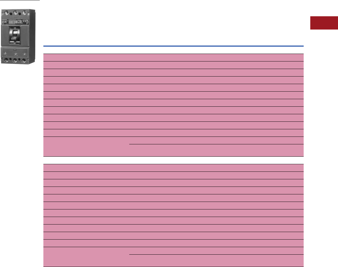
Volume 12—Aftermarket, Renewal Parts and Life Extension Solutions CA08100014E—July 2016 www.eaton.com V12-T3-29
1
2
3
4
5
6
7
8
9
10
11
12
13
14
15
16
17
18
19
20
21
22
23
24
25
3
Molded-Case Circuit Breakers
Replacement Capabilities
Types LB and HLB
■
Shaded area denotes obsolete or discontinued products and services. 1
Type LB and MARK 75 Type HLB 70–400A, 600 Vac, 250 Vdc, Two- and Three-Pole, Interchangeable Trip,
Thermal-Magnetic, Saf-T-Vue and MARK 75
Notes
1 These frames are obsolete. For replacement solutions, see the cross-reference on Pages V12-T3-126–V12-T3-167.
2 Set on high side, adjustable to lower limits.
3 Terminals are shipped separately from breaker.
4 Two-pole breakers or trips are supplied in three-pole frames with current carrying parts omitted from center pole.
Continuous
Ampere
Rating
at 40°C
Magnetic Trip Setting
Amperes 2
Complete Breaker Shipped as Frame, Trip Unit and Terminals 3
Includes Pressure Type
Aluminum Terminals 3Frame Only Trip Unit Only
Standard
Catalog
Number
Saf-T-Vue
Catalog
Number
MARK 75
Catalog
Number
Standard
Catalog
Number
Saf-T-Vue
Catalog
Number
MARK 75
Catalog
Number
Standard Saf-T-Vue,
MARK 75
Catalog NumberLow High
Two-Pole, 600 Vac, 250 Vdc 4
70 350 700 LB2070 LB2070S —LB2400F LB2400FS HLB2400F HLB2070T
90 450 900 LB2090 LB2090S —LB2400F LB2400FS HLB2400F HLB2090T
100 500 1000 LB2100 LB2100S —LB2400F LB2400FS HLB2400F HLB2100T
125 625 1250 LB2125 LB2125S HLB2125 LB2400F LB2400FS HLB2400F HLB2125T
150 750 1500 LB2150 LB2150S HLB2150 LB2400F LB2400FS HLB2400F HLB2150T
175 875 1750 LB2175 LB2175S HLB2175 LB2400F LB2400FS HLB2400F HLB2175T
200 1000 2000 LB2200 LB2200S HLB2200 LB2400F LB2400FS HLB2400F HLB2200T
225 1125 2250 LB2225 LB2225S HLB2225 LB2400F LB2400FS HLB2400F HLB2225T
250 1250 2500 LB2250 LB2250S HLB2250 LB2400F LB2400FS HLB2400F HLB2250T
300 1500 3000 LB2300 LB2300S HLB2300 LB2400F LB2400FS HLB2400F HLB2300T
350 1750 3500 LB2350 LB2350S HLB2350 LB2400F LB2400FS HLB2400F HLB2350T
400 2000 4000 LB2400 LB2400S HLB2400 LB2400F LB2400FS HLB2400F HLB2400T
Approx. shipping weight 13 lbs Approx. shipping weight 10 lbs Approx. shipping
weight 2 lbs
Three-Pole, 600 Vac Only
70 350 700 LB3070 LB3070S —LB3400F LB3400FS HLB3400F HLB3070T
90 450 900 LB3090 LB3090S —LB3400F LB3400FS HLB3400F HLB3090T
100 500 1000 LB3100 LB3100S —LB3400F LB3400FS HLB3400F HLB3100T
125 625 1250 LB3125 LB3125S HLB3125 LB3400F LB3400FS HLB3400F HLB3125T
150 750 1500 LB3150 LB3150S HLB3150 LB3400F LB3400FS HLB3400F HLB3150T
175 875 1750 LB3175 LB3175S HLB3175 LB3400F LB3400FS HLB3400F HLB3175T
200 1000 2000 LB3200 LB3200S HLB3200 LB3400F LB3400FS HLB3400F HLB3200T
225 1125 2250 LB3225 LB3225S HLB3225 LB3400F LB3400FS HLB3400F HLB3225T
250 1250 2500 LB3250 LB3250S HLB3250 LB3400F LB3400FS HLB3400F HLB3250T
300 1500 3000 LB3300 LB3300S HLB3300 LB3400F LB3400FS HLB3400F HLB3300T
350 1750 3500 LB3350 LB3350S HLB3350 LB3400F LB3400FS HLB3400F HLB3350T
400 2000 4000 LB3400 LB3400S HLB3400 LB3400F LB3400FS HLB3400F HLB3400T
Approx. shipping weight 15 lbs Approx. shipping weight 12 lbs Approx. shipping
weight 2.5 lbs
LB: 600 Vac; 250 Vdc

V12-T3-30 Volume 12—Aftermarket, Renewal Parts and Life Extension Solutions CA08100014E—July 2016 www.eaton.com
1
2
3
4
5
6
7
8
9
10
11
12
13
14
15
16
17
18
19
20
21
22
23
24
25
3
Molded-Case Circuit Breakers
Replacement Capabilities
■
Shaded area denotes obsolete or discontinued products
and services. 1
Special Breakers—Trip Units Only 2
Accessories and
Modifications
■
Shaded area denotes
obsolete or discontinued
products and services.
50°C Calibration
Add suffix “V” to catalog
number for complete breaker
or trip unit only, when
ordering breakers to be
used in 50°C ambients.
Note: Not UL Listed.
Magnetic Only Breakers
For description, refer to
Application Data 29-160.
To order, select trip unit
from table above, frame
and terminals.
Note: Not UL Listed.
For CSA, see
Page V12-T3-48.
Type LB breakers meet
requirements for Class 21a
circuit breakers, and Type HLB
meet requirements for Class
23a, as defined by Federal
Specification W-C-375b.
Continuous
Ampere
Rating
Magnetic Trip Setting,
Amperes 3
Trip Unit Only
Two-Pole 4Three-Pole
Low High Catalog Number Catalog Number
Magnetic Only Breakers, Front Adjustable
400 350 700 HLB2700TM HLB3700TM
400 625 1250 HLB21250TM HLB31250TM
400 750 1500 HLB21500TM HLB31500TM
400 875 1750 HLB21750TM HLB31750TM
400 1125 2250 HLB22250TM HLB32250TM
400 1125 2250 HLB22250TM HLB32250TM
400 1500 3000 HLB23000TM HLB33000TM
400 2000 4000 HLB24000TM HLB34000TM
Ambient Compensating Breakers
70 350 700 HLB2070TA HLB3070TA
90 450 900 HLB2090TA HLB3090TA
100 500 1000 HLB2100TA HLB3100TA
125 625 1250 HLB2125TA HLB3125TA
150 750 1500 HLB2150TA HLB3150TA
175 875 1750 HLB2175TA HLB3175TA
200 1000 2000 HLB2200TA HLB3200TA
225 1125 2250 HLB2225TA HLB3225TA
250 1250 2500 HLB2250TA HLB3250TA
300 1500 3000 HLB2300TA HLB3300TA
350 1750 3500 HLB2350TA HLB3350TA
400 2000 4000 HLB2400TA HLB3400TA
Special Calibrations
Special calibration price
additions apply to ampere
ratings not listed as standard
or for ambients other
than 40°C or 50°C. For
frequencies other than
0–60 Hz AC circuits, refer
to Eaton. See Application
Data 29-160 for information
regarding special conditions.
Maximum calibration for
400 Hz is 300A.
Note: Not UL Listed.
UL Listed
Interrupting Ratings
For all three-phase
delta, grounded B phase
applications, contact Avery
Creek, NC, Technical
Resource Center at
1-800-356-1243.
Terminals
Two terminals are required
per pole.
Terminals are UL Listed for
wire type and range listed
below. When used with
aluminum cable, use joint
compound. To order optional
copper only terminals, add
suffix “C” to complete
breaker catalog number.
Note: Terminals are shipped
separately from breaker. If
upgrading an LB, HLB breaker
to a Series C K-Frame in a
panelboard application, also
order TAD3 spacer kit.
Terminals
Notes
1These frames are obsolete. For replacement solutions, see the cross-reference on
Pages V12-T3-126–V12-T3-167.
2Not UL Listed.
3Set on high side, adjustable to lower limits.
4Two-pole breakers or trips are supplied in three-pole frames with current carrying parts
omitted from center pole.
5Ratings above 10,000A not UL Listed.
6Optional terminal.
Maximum
Volts Amperes
Standard Breakers
240 AC 50,000 asymmetrical,
42,000 symmetrical
480 AC 35,000 asymmetrical,
30,000 symmetrical
600 AC 25,000 asymmetrical,
22,000 symmetrical
250 DC 20,000 5
MARK 75 Breakers
240 AC 75,000 asymmetrical,
65,000 symmetrical
480 AC 40,000 asymmetrical,
35,000 symmetrical
600 AC 30,000 asymmetrical,
25,000 symmetrical
250 DC 20,000 5
Maximum
Amperes
Number of Cables,
Wire Range, Type
Catalog
Number
Standard Pressure Terminals
225 (1) #6–350 kcmil Cu, or (1) #4–350 kcmil Al TA225LA1
350 (1) 250–500 kcmil Al/Cu TA350DA
400 (2) 3/0–250 kcmil Cu only T400DA2
Optional Copper Pressure Terminals
225 (1) #6–350 kcmil Cu T225LA
225 6(1) #6–250 kcmil Cu T225LBF
350 (1) 250–500 kcmil Cu T350DA
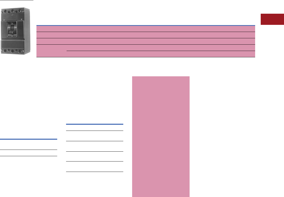
Volume 12—Aftermarket, Renewal Parts and Life Extension Solutions CA08100014E—July 2016 www.eaton.com V12-T3-31
1
2
3
4
5
6
7
8
9
10
11
12
13
14
15
16
17
18
19
20
21
22
23
24
25
3
Molded-Case Circuit Breakers
Replacement Capabilities
Type DA
■
Shaded area denotes obsolete or discontinued products and services. 1
Type DA Breakers 250–400A, 240 Vac, 250 Vdc, Two- and Three-Pole, Fixed Trip, Thermal-Magnetic
(Suitable for Reverse-Feed)
Accessories and
Modifications
■
Shaded area denotes
obsolete or discontinued
products and services
Type DA breakers meet
requirements of Federal
Specification W-C-375b.,
Class 14b.
UL Listed
Interrupting Ratings
For all three-phase
delta, grounded B phase
applications, contact
Avery Creek, NC, Technical
Resource Center at
1-800-356-1243.
Terminals
Terminals are UL Listed for
the wire type and size listed
below. When used with
aluminum conductors,
use joint compound.
Te r m i n a l s
Note: If upgrading a DA breaker
to a Series C K-Frame in a
panelboard application, also
order TAD3 spacer kit.
For CSA, see
Page V12-T3-48.
Notes
1These frames are obsolete. For
replacement solutions, see the cross-
reference on Pages V12-T3-114–
V12-T3-167.
2Two-pole breakers are supplied in
three-pole frames.
Continuous
Ampere Rating
at 40°C
Breakers With Line Terminals Only Breakers With Line and Load Terminals
Two-Pole 2
Catalog Number
Three-Pole
Catalog Number
Two-Pole 2
Catalog Number
Three-Pole
Catalog Number
250 DA2250Y DA3250Y DA2250 DA3250
300 DA2300Y DA3300Y DA2300 DA3300
350 DA2350Y DA3350Y DA2350 DA3350
400 DA2400Y DA3400Y DA2400 DA3400
Approx. shipping weight 13 lbs Approx. shipping weight 15 lbs Approx. shipping weight 13 lbs Approx. shipping weight 13 lbs
DA: 240 Vac; 250 Vdc
Maximum
Volts Amperes
240 AC 25,000 asymmetrical, 22,000
symmetrical
250 DC 10,000
Maximum
Amperes
Number
of Cables,
Wire Range,
Type
Catalog
Number
Standard Pressure Terminals
350 (1) 250–500 kcmil
Al/Cu
TA350DA
400 (2) 3/0–250 kcmil
Cu only
T400DA2
Optional Terminals
(for Copper Cable)
350 (1) 250–500 kcmil
Cu
T350DA
Special Calibrations
Special calibration price
additions apply to ampere
ratings not listed as standard
or for ambients other
than 40°C or 50°C. For
frequencies other than
0–60 Hz AC circuits, refer
to Eaton. See Application
Data 29-160 for information
regarding special conditions.
Maximum 400 Hz
calibrations: Type DA, 300A.
Note: Not UL Listed.
50°C Calibration
Add suffix “V” to catalog
number for complete
breaker when ordering
breakers to be used in 50°C
ambients. Same price as
standard 40°C breakers.
Note: Not UL Listed.
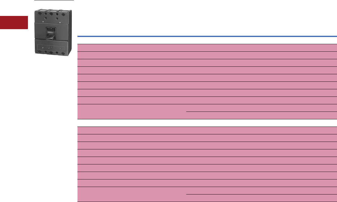
V12-T3-32 Volume 12—Aftermarket, Renewal Parts and Life Extension Solutions CA08100014E—July 2016 www.eaton.com
1
2
3
4
5
6
7
8
9
10
11
12
13
14
15
16
17
18
19
20
21
22
23
24
25
3
Molded-Case Circuit Breakers
Replacement Capabilities
Type LAB
■
Shaded area denotes obsolete or discontinued products and services. 1
Type LAB 125–400A, 600 Vac, 250 Vdc, Two- and Three-Pole, Fixed Trip, Thermal-Magnetic, Saf-T-Vue
(Suitable for Reverse-Feed)
Notes
1 These frames are obsolete. For replacement solutions, see the cross-reference on Pages V12-T3-114–V12-T3-167.
2 Set on high side, adjustable to lower limits.
3 Terminals shipped separately from breaker.
4 Two-pole breakers or trips are supplied in three-pole frames with current carrying parts omitted from center pole.
Continuous
Ampere Rating
at 40°C
Magnetic Trip Setting, Amperes 2
Complete Breaker Includes Pressure Type
Aluminum Terminals 3Breaker Without Terminals
Standard Saf-T-Vue Standard Saf-T-Vue
Low High Catalog Number Catalog Number Catalog Number Catalog Number
Two-Pole, 600 Vac, 250 Vdc 4
125 625 1250 LAB2125 LAB2125S LAB2125W LAB2125SW
150 750 1500 LAB2150 LAB2150S LAB2150W LAB2150SW
175 875 1750 LAB2175 LAB2175S LAB2175W LAB2175SW
200 1000 2000 LAB2200 LAB2200S LAB2200W LAB2200SW
225 1125 2250 LAB2225 LAB2225S LAB2225W LAB2225SW
250 1250 2500 LAB2250 LAB2250S LAB2250W LAB2250SW
300 1500 3000 LAB2300 LAB2300S LAB2300W LAB2300SW
350 1750 3500 LAB2350 LAB2350S LAB2350W LAB2350SW
400 2000 4000 LAB2400 LAB2400S LAB2400W LAB2400SW
Approx. shipping weight 22 lbs Approx. shipping weight 22 lbs
Three-Pole, 600 Vac Only
125 625 1250 LAB3125 LAB3125S LAB3125W LAB3125SW
150 750 1500 LAB3150 LAB3150S LAB3150W LAB3150SW
175 875 1750 LAB3175 LAB3175S LAB3175W LAB3175SW
200 1000 2000 LAB3200 LAB3200S LAB3200W LAB3200SW
225 1125 2250 LAB3225 LAB3225S LAB3225W LAB3225SW
250 1250 2500 LAB3250 LAB3250S LAB3250W LAB3250SW
300 1500 3000 LAB3300 LAB3300S LAB3300W LAB3300SW
350 1750 3500 LAB3350 LAB3350S LAB3350W LAB3350SW
400 2000 4000 LAB3400 LAB3400S LAB3400W LAB3400SW
Approx. shipping weight 24.5 lbs Approx. shipping weight 24.5 lbs
LAB: 600 Vac; 250 Vdc

Volume 12—Aftermarket, Renewal Parts and Life Extension Solutions CA08100014E—July 2016 www.eaton.com V12-T3-33
1
2
3
4
5
6
7
8
9
10
11
12
13
14
15
16
17
18
19
20
21
22
23
24
25
3
Molded-Case Circuit Breakers
Replacement Capabilities
■
Shaded area denotes obsolete or discontinued products and services. 1
Special Breakers 2
Accessories and
Modifications
■
Shaded area denotes
obsolete or discontinued
products and services.
Type LAB breakers meet
requirements for Class 21a
circuit breakers, as defined
by Federal Specification
W-C-375b.
UL Listed
Interrupting Ratings 6
For all three-phase
delta, grounded B phase
applications, contact
Avery Creek, NC, Technical
Resource Center at
1-800-356-1243.
Terminals
Two terminals required
per pole.
Select from the table on
Page V12-T3-36.
Note: Terminals shipped
separately from breaker.
Magnetic Only and Ambient
Compensating Breakers
To order, select catalog
number from “Special
Breakers” table above.
Additional Accessories and
Modifications
Refer to Pages V12-T3-65–
V12-T3-79.
Notes
1These frames are obsolete. For
replacement solutions, see the cross-
reference on Pages V12-T3-114–
V12-T3-167.
2Not UL Listed.
3Set on high side, adjustable to
lower limits.
4Two-pole breakers or trips are supplied in
three-pole frames with current carrying
parts omitted from center pole.
5Select desired terminals from
Page V12-T3-39 and order as
separate item.
6Interrupting capacities shown do not
apply to molded-case switches.
7Ratings above 10,000A not UL Listed.
Continuous
Ampere Rating
Magnetic Trip Setting, Amperes 3
Breaker Catalog Number
Two-Pole 4Three-Pole
Standard Saf-T-Vue Standard Saf-T-Vue
Low High Catalog Number Catalog Number Catalog Number Catalog Number
Magnetic Only Breakers, Front Adjustable—Without Terminals 5
400 350 700 LAB2700MW LAB2700SMW LAB3700MW LAB3700SMW
400 625 1250 LAB21250MW LAB21250SMW LAB31250MW LAB31250SMW
400 750 1500 LAB21500MW LAB21500SMW LAB31500MW LAB31500SMW
400 875 1750 LAB21750MW LAB21750SMW LAB31750MW LAB31750SMW
400 1125 2250 LAB22250MW LAB22250SMW LAB32250MW LAB32250SMW
400 1500 3000 LAB23000MW LAB23000SMW LAB33000MW LAB33000SMW
400 2000 4000 LAB24000MW LAB24000SMW LAB34000MW LAB34000SMW
Ambient Compensating Breakers—Includes Terminals
125 625 1250 LAB2125A —LAB3125A —
150 750 1500 LAB2150A —LAB3150A —
175 875 1750 LAB2175A —LAB3175A —
200 1000 2000 LAB2200A —LAB3200A —
225 1125 2250 LAB2225A —LAB3225A —
250 1250 2500 LAB2250A —LAB3250A —
300 1500 3000 LAB2300A —LAB3300A —
350 1750 3500 LAB2350A —LAB3350A —
400 2000 4000 LAB2400A —LAB3400A —
Special Calibrations
Special calibration price
additions apply to ampere
ratings not listed as
standard or for ambients
other than 40°C or 50°C.
For frequencies other than
0–60 Hz AC circuits, refer
to Eaton. See Application
Data 29-160 for information
regarding special conditions.
Maximum
calibration for
400 Hz is 300A.
Note: Not UL Listed.
50°C Calibration
Add suffix “V” to catalog
number for complete
breaker when ordering
breakers to be used in 50°C
ambients. For CSA, see
Page V12-T3-48.
Note: Not UL Listed.
Maximum
Volts Amperes
240 AC 50,000 asymmetrical,
42,000 symmetrical
480 AC 35,000 asymmetrical,
30,000 symmetrical
600 AC 25,000 asymmetrical,
22,000 symmetrical
250 DC 20,000 7
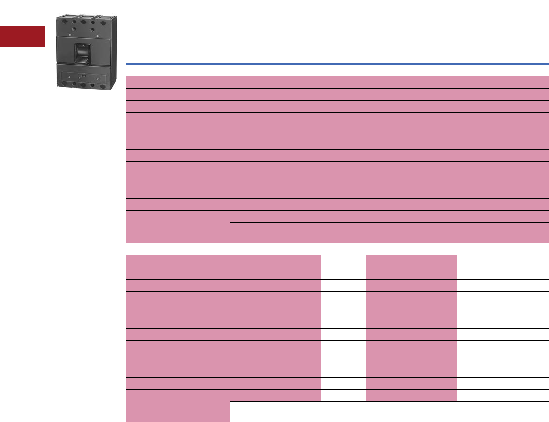
V12-T3-34 Volume 12—Aftermarket, Renewal Parts and Life Extension Solutions CA08100014E—July 2016 www.eaton.com
1
2
3
4
5
6
7
8
9
10
11
12
13
14
15
16
17
18
19
20
21
22
23
24
25
3
Molded-Case Circuit Breakers
Replacement Capabilities
Types LA and HLA
■
Shaded area denotes obsolete or discontinued products and services. 1
Type LA and MARK 75 Type HLA 70–400A, 600 Vac, 250 Vdc, Two- and Three-Pole, Interchangeable Trip
Notes
1 These frames are obsolete. For replacement solutions, see the cross-reference on Pages V12-T3-114–V12-T3-167.
2 Set on high side, adjustable to lower limits.
3 Terminals shipped separately from breaker.
4 Terminals, trip units and accessories are not interchangeable between 400 and 600A frames.
5 Two-pole breakers or trips are supplied in three-pole frames with current carrying parts omitted from center pole.
6 These ratings have interrupting capacities reduced to 25,000A symmetrical at 240V, 20,000A symmetrical at 480V, and 15,000A symmetrical at 600V.
Continuous
Ampere
Rating
at 40°C
Magnetic
Trip Setting
Amperes 2
Complete Breaker Shipped as Frame, Trip Unit and Terminals
Includes Pressure Type Aluminum Terminals 3Frame Only Trip Unit Only
Standard,
MARK 75,
Saf-T-Vue
Catalog Number
Standard
Catalog
Number
Saf-T-Vue
Catalog
Number
MARK 75
Catalog
Number
Standard
Catalog
Number
Saf-T-Vue
Catalog
Number
MARK 75
Catalog
NumberLow High
400A Frame Breakers 4—Two-Pole, 600 Vac, 250 Vdc 5
70 6350 700 LA2070 LA2070S HLA2070 LA2400F LA2400FS HLA2400F HLA2070T
90 6450 900 LA2090 LA2090S HLA2090 LA2400F LA2400FS HLA2400F HLA2090T
100 6500 1000 LA2100 LA2100S HLA2100 LA2400F LA2400FS HLA2400F HLA2100T
125 625 1250 LA2125 LA2125S HLA2125 LA2400F LA2400FS HLA2400F HLA2125T
150 750 1500 LA2150 LA2150S HLA2150 LA2400F LA2400FS HLA2400F HLA2150T
175 875 1750 LA2175 LA2175S HLA2175 LA2400F LA2400FS HLA2400F HLA2175T
200 1000 2000 LA2200 LA2200S HLA2200 LA2400F LA2400FS HLA2400F HLA2200T
225 1125 2250 LA2225 LA2225S HLA2225 LA2400F LA2400FS HLA2400F HLA2225T
250 1250 2500 LA2250 LA2250S HLA2250 LA2400F LA2400FS HLA2400F HLA2250T
300 1500 3000 LA2300 LA2300S HLA2300 LA2400F LA2400FS HLA2400F HLA2300T
350 1750 3500 LA2350 LA2350S HLA2350 LA2400F LA2400FS HLA2400F HLA2350T
400 2000 4000 LA2400 LA2400S HLA2400 LA2400F LA2400FS HLA2400F HLA2400T
Approx. shipping weight 21.75 lbs Approx. shipping weight 17.5 lbs Approx.shipping
weight 2.25 lbs
Three-Pole, 600 Vac Only
70 6350 700 LA3070 LA3070S HLA3070 LA3400F LA3400FS HLA3400F HLA3070T
90 6450 900 LA3090 LA3090S HLA3090 LA3400F LA3400FS HLA3400F HLA3090T
100 6500 1000 LA3100 LA3100S HLA3100 LA3400F LA3400FS HLA3400F HLA3100T
125 625 1250 LA3125 LA3125S HLA3125 LA3400F LA3400FS HLA3400F HLA3125T
150 750 1500 LA3150 LA3150S HLA3150 LA3400F LA3400FS HLA3400F HLA3150T
175 875 1750 LA3175 LA3175S HLA3175 LA3400F LA3400FS HLA3400F HLA3175T
200 1000 2000 LA3200 LA3200S HLA3200 LA3400F LA3400FS HLA3400F HLA3200T
225 1125 2250 LA3225 LA3225S HLA3225 LA3400F LA3400FS HLA3400F HLA3225T
250 1250 2500 LA3250 LA3250S HLA3250 LA3400F LA3400FS HLA3400F HLA3250T
300 1500 3000 LA3300 LA3300S HLA3300 LA3400F LA3400FS HLA3400F HLA3300T
350 1750 3500 LA3350 LA3350S HLA3350 LA3400F LA3400FS HLA3400F HLA3350T
400 2000 4000 LA3400 LA3400S HLA3400 LA3400F LA3400FS HLA3400F HLA3400T
Approx. shipping weight 24.5 lbs Approx. shipping weight 19 lbs Approx. shipping
weight 3 lbs
LA: 600 Vac; 250 Vdc

Volume 12—Aftermarket, Renewal Parts and Life Extension Solutions CA08100014E—July 2016 www.eaton.com V12-T3-35
1
2
3
4
5
6
7
8
9
10
11
12
13
14
15
16
17
18
19
20
21
22
23
24
25
3
Molded-Case Circuit Breakers
Replacement Capabilities
■
Shaded area denotes obsolete or discontinued products and services. 1
Special Breakers 2—Trip Units Only
Notes
1These frames are obsolete. For replacement solutions, see the cross-reference on Pages V12-T3-114–V12-T3-167.
2Not UL Listed.
3Set on high side, adjustable to lower limits.
4Two-pole breakers or trips are supplied in three-pole frames with current carrying parts omitted from center pole.
5Terminals, trip units and accessories are not interchangeable between 400 and 600A frames.
6These ratings have interrupting capacities reduced to 25,000A symmetrical at 240V, 20,000A symmetrical at 480V, and 15,000A symmetrical at 600V.
Continuous
Ampere Rating
Magnetic Trip Setting, Amperes 3Two-Pole 4Three-Pole
Low High Catalog Number Catalog Number
Magnetic Only Breakers, Front Adjustable—400A Frame Breakers 5
400 350 700 HLA2700TM HLA3700TM
400 625 1250 HLA21250TM HLA31250TM
400 750 1500 HLA21500TM HLA31500TM
400 875 1750 HLA21750TM HLA31750TM
400 1125 2250 HLA22250TM HLA32250TM
400 1500 3000 HLA23000TM HLA33000TM
400 2000 4000 HLA24000TM HLA34000TM
Ambient Compensating Breakers—400A Frame Breakers Only 5
70 6350 700 HLA2070TA HLA3070TA
90 6450 900 HLA2090TA HLA3090TA
100 6500 1000 HLA2100TA HLA3100TA
125 625 1250 HLA2125TA HLA3125TA
150 750 1500 HLA2150TA HLA3150TA
175 875 1750 HLA2175TA HLA3175TA
200 1000 2000 HLA2200TA HLA3200TA
225 1125 2250 HLA2225TA HLA3225TA
250 1250 2500 HLA2250TA HLA3250TA
300 1500 3000 HLA2300TA HLA3300TA
350 1750 3500 HLA2350TA HLA3350TA
400 2000 4000 HLA2400TA HLA3400TA

V12-T3-36 Volume 12—Aftermarket, Renewal Parts and Life Extension Solutions CA08100014E—July 2016 www.eaton.com
1
2
3
4
5
6
7
8
9
10
11
12
13
14
15
16
17
18
19
20
21
22
23
24
25
3
Molded-Case Circuit Breakers
Replacement Capabilities
Accessories and
Modifications
■
Shaded area denotes
obsolete or discontinued
products and services.
50°C Calibration
Add suffix “V” to catalog
number for complete breaker
or trip unit only, when
ordering breakers to be
used in 50°C ambients.
Note: Not UL Listed.
Terminals
Two terminals required
per pole.
Select from table at right.
Note: Terminals shipped
separately from breaker.
Magnetic Only Breakers
To order, select trip unit from
the table on Page V12-T3-35,
frame and terminals from
table at right.
Note: Not UL Listed. MARK 75
frame color changed from gray
to black in mid-2002.
UL Listed Except as Noted
Type LA breakers meet
requirements for Class 21a
circuit breakers, and Type
HLA meet requirements
for Class 23a as defined
by Federal Specification
W-C-375b.
UL Listed
Interrupting Ratings 1
For all three-phase
delta, grounded B phase
applications, contact
Avery Creek, NC, Technical
Resource Center at
1-800-356-1243.
Special Calibrations
Special calibration price
additions apply to ampere
ratings not listed as standard
or for ambients other
than 40°C or 50°C. For
frequencies other than
0–60 Hz AC, refer to Eaton.
See Application Data 29-160
for information regarding
special conditions. Maximum
400 Hz calibration: 400A
frame, 300A.
Note: Not UL Listed.
Maximum
Volts Amperes
Standard Breakers
240 AC 50,000 asymmetrical,
42,000 symmetrical
480 AC 35,000 asymmetrical,
30,000 symmetrical
600 AC 25,000 asymmetrical,
22,000 symmetrical
250 DC 20,000 2
MARK 75 Breakers
240 AC 75,000 asymmetrical,
65,000 symmetrical
480 AC 40,000 asymmetrical,
35,000 symmetrical
600 AC 30,000 asymmetrical,
25,000 symmetrical
250 DC 20,000 2
Terminals
Two terminals are required
per pole.
Terminals are UL Listed for
wire type and range listed
below. When used with
aluminum cable, use joint
compound. To order optional
copper only terminals, add
suffix “C” to complete
breaker catalog number.
Note: Terminals shipped
separately from breaker.
Terminals, trip units and
accessories are not
interchangeable between
400 and 600A frames.
Terminals
Notes
1Interrupting capacities do not apply to molded-case switches.
2Ratings above 10,000A not UL Listed.
3400A frame only.
4Optional terminal.
Maximum
Amperes
Number of Cables,
Wire Range, Type
Catalog
Number
Standard Al/Cu Pressure Terminals
225 3(1) #6–350 kcmil Cu, or (1) #4–350 kcmil Al TA225LA1
400 3(1) #4–250 kcmil Al/Cu, plus (1) 3/0–600 kcmil Al/Cu TA400LA1
Optional Copper Pressure Terminals
225 3(1) #6–350 kcmil Cu T225LA
225 34 (1) #6–250 kcmil Cu T225LBF
400 3(1) #4–250 kcmil Cu, plus (1) 3/0–600 kcmil Cu T401LA
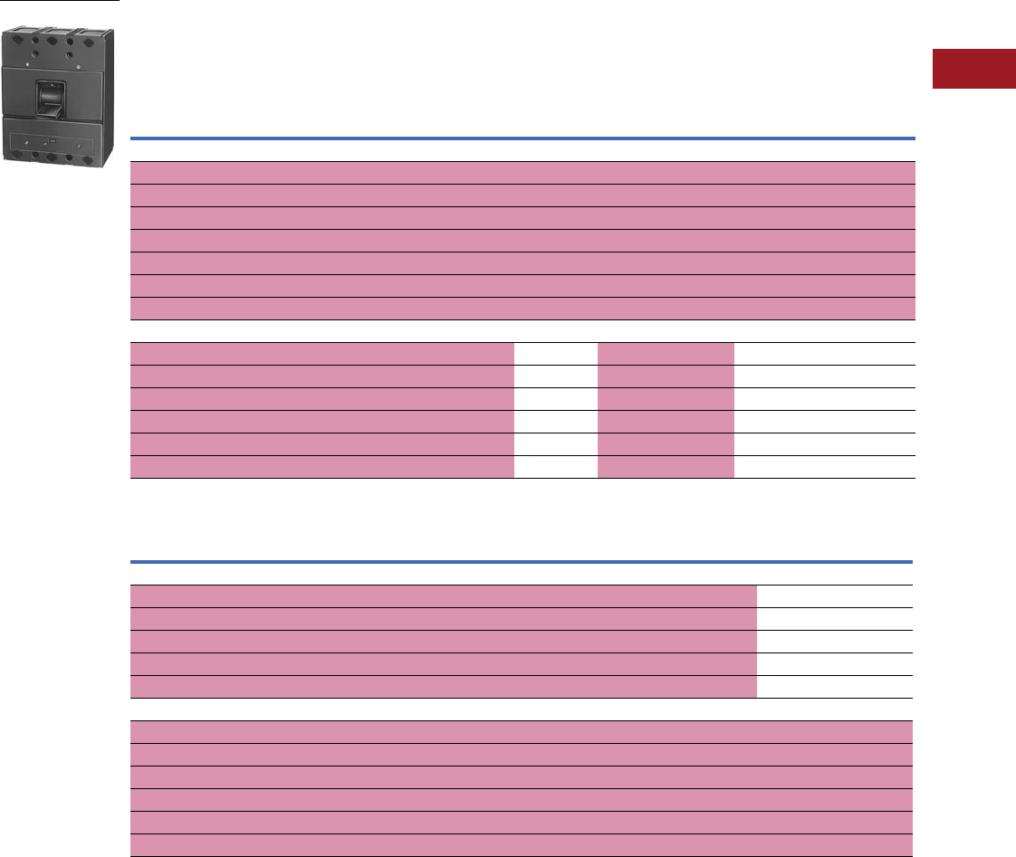
Volume 12—Aftermarket, Renewal Parts and Life Extension Solutions CA08100014E—July 2016 www.eaton.com V12-T3-37
1
2
3
4
5
6
7
8
9
10
11
12
13
14
15
16
17
18
19
20
21
22
23
24
25
3
Molded-Case Circuit Breakers
Replacement Capabilities
Types LA and HLA
■
Shaded area denotes obsolete or discontinued products and services. 1
Type LA and MARK 75 Type HLA 250–600A, 600 Vac, 250 Vdc, Two-, Three-Pole, Interchangeable Trip
Thermal-Magnetic, Saf-T-Vue and MARK 75 Breakers
Type Special Breakers 6—Trip Units Only
Notes
1 These frames are obsolete. For replacement solutions, see the cross-reference on Pages V12-T3-114–V12-T3-167.
2 Set on high side, adjustable to lower limits.
3 Terminals shipped separately from breakers.
4 Terminals, trip units and accessories are not interchangeable between 400 and 600A frames.
5 Two-pole breakers or trips are supplied in three-pole frames with current carrying parts omitted from center pole.
6 Not UL Listed.
Continuous
Ampere
Rating
at 40°C
Magnetic Trip
Setting, Amperes 2
Complete Breaker Shipped as Frame, Trip Unit and Terminals 3
Includes Pressure Type Aluminum Terminals 3Frame Only Trip Unit Only
Standard
Catalog
Number
Saf-T-Vue
Catalog
Number
MARK 75
Catalog
Number
Standard
Catalog
Number
Saf-T-Vue
Catalog
Number
MARK 75
Catalog
Number
Standard Saf-T-Vue,
MARK 75
Catalog
NumberLow High
600A Frame Breakers 4—Two-Pole, 600 Vac, 250 Vdc 5
250 1250 2500 2603D50G01 2603D50G13 1256C10G02 LA2600F LA2600FS HLA2600F 2603D46G07
300 1500 3000 2603D50G02 2603D50G14 1256C10G03 LA2600F LA2600FS HLA2600F 2603D46G08
350 1750 3500 2603D50G03 2603D50G15 1256C10G04 LA2600F LA2600FS HLA2600F 2603D46G09
350 1750 3500 2603D50G03 2603D50G15 1256C10G04 LA2600F LA2600FS HLA2600F 2603D46G09
400 2000 4000 2603D50G04 2603D50G16 1256C10G05 LA2600F LA2600FS HLA2600F 2603D46G10
500 2500 5000 LA2500 LA2500S HLA2500 LA2600F LA2600FS HLA2600F HLA2500T
600 3000 6000 LA2600 LA2600S HLA2600 LA2600F LA2600FS HLA2600F HLA2600T
Three-Pole, 600 Vac Only
250 1250 2500 2603D50G07 2603D50G019 1256C10G12 LA3600F LA3600FS HLA3600F 2603D46G26
300 1500 3000 2603D50G08 2603D50G020 1256C10G13 LA3600F LA3600FS HLA3600F 2603D46G27
350 1750 3500 2603D50G09 2603D50G021 1256C10G14 LA3600F LA3600FS HLA3600F 2603D46G28
400 2000 4000 2603D50G10 2603D50G022 1256C10G15 LA3600F LA3600FS HLA3600F 2603D46G29
500 2500 5000 LA3500 LA3500S HLA500 LA3600F LA3600FS HLA3600F HLA3500T
600 3000 6000 LA3600 LA3600S HLA3600 LA3600F LA3600FS HLA3600F HLA3600T
Continuous
Ampere Rating
Magnetic Trip Setting, Amperes Two-Pole 5
Catalog Number
Three-Pole
Catalog NumberLow High
600A Frame Breakers 4—Magnetic Only Breakers, Front Adjustable
600 1125 2250 2603D47G07 2603D47G26
600 1500 3000 2603D47G08 2603D47G27
600 2000 4000 2603D47G10 2603D47G29
600 2500 5000 HLA25000TM HLA35000TM
600 3000 6000 HLA26000TM HLA36000TM
600A Frame Breakers—Ambient Compensating Breakers
250 1250 2500 5683D88G07 5683D88G26
300 1500 3000 5683D88G08 5683D88G27
350 1750 3500 5683D88G09 5683D88G28
400 2000 4000 5683D88G10 5683D88G29
500 2500 5000 HLA2500TA HLA3500TA
600 3000 6000 HLA2600TA HLA3600TA
LA: 600 Vac; 250 Vdc

V12-T3-38 Volume 12—Aftermarket, Renewal Parts and Life Extension Solutions CA08100014E—July 2016 www.eaton.com
1
2
3
4
5
6
7
8
9
10
11
12
13
14
15
16
17
18
19
20
21
22
23
24
25
3
Molded-Case Circuit Breakers
Replacement Capabilities
Accessories and
Modifications
■
Shaded area denotes
obsolete or discontinued
products and services.
50°C Calibration
Add suffix “V” to catalog
number for complete breaker
or trip unit only, when
ordering breakers to be used
in 50°C ambients. Same price
as standard 40°C breakers.
For CSA, see
Page V12-T3-48.
Type LA breakers meet
requirements for Class 21a
circuit breakers, and type
HLA meet requirements
for Class 23a as defined
by Federal Specification
W-C-375b.
Note: Not UL Listed. MARK 75
frame color changed from gray
to black in mid-2002.
UL Listed Interrupting
Ratings 1
For all three-phase
delta, grounded B phase
applications, contact
Avery Creek, NC, Technical
Resource Center at
1-800-356-1243.
Special Calibrations
Special calibration price
additions apply to ampere
ratings not listed as standard
or for ambients other
than 40°C or 50°C. For
frequencies other than
0–60 Hz AC, refer to Eaton.
See Application Data 29-160
for information regarding
special conditions.
Maximum 400 Hz calibration:
600A frame, 450A.
Note: Not UL Listed.
Maximum
Volts Amperes
Standard Breakers
240 AC 50,000 asymmetrical,
42,000 symmetrical
480 AC 35,000 asymmetrical,
30,000 symmetrical
600 AC 25,000 asymmetrical,
22,000 symmetrical
250 DC 20,000 2
MARK 75 Breakers
240 AC 75,000 asymmetrical,
65,000 symmetrical
480 AC 40,000 asymmetrical,
35,000 symmetrical
600 AC 30,000 asymmetrical,
25,000 symmetrical
250 DC 20,000 2
Terminals
Two terminals are required
per pole. Terminals are UL
Listed for wire type and range
listed below. When used with
aluminum cable, use joint
compound. To order optional
copper only terminals, add
suffix “C” to complete
breaker catalog number.
Note: Terminals shipped
separately from breakers.
Terminals, trip units and
accessories are not
interchangeable between
400 and 600A frames.
Magnetic Only Breakers
To order, select frame, trip
unit and terminals from tables
on this page.
Accessories and
Modifications
Refer to Pages V12-T3-65–
V12-T3-79.
Terminals
Notes
1Interrupting capacities shown do not apply to molded case switches.
2Ratings above 10,000A not UL Listed.
3For 600A frame breakers only.
Maximum
Amperes
Number of Cables,
Wire Range, Type
Catalog
Number
Standard Al/Cu Pressure Terminals
600 3(2) 250–500 kcmil Al/Cu TA600LA
Optional Copper Pressure Terminals
600 3(2) 250–500 kcmil Cu T600LA
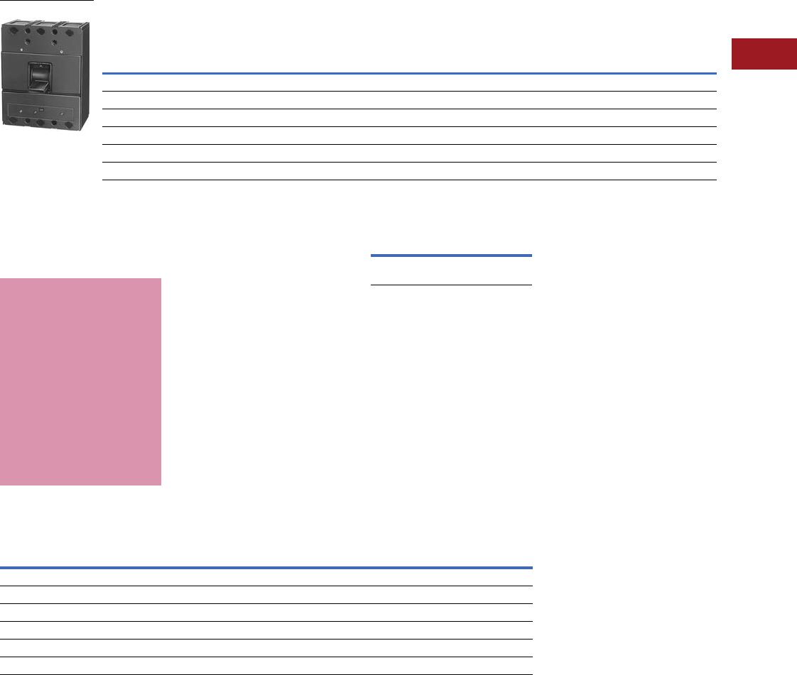
Volume 12—Aftermarket, Renewal Parts and Life Extension Solutions CA08100014E—July 2016 www.eaton.com V12-T3-39
1
2
3
4
5
6
7
8
9
10
11
12
13
14
15
16
17
18
19
20
21
22
23
24
25
3
Molded-Case Circuit Breakers
Replacement Capabilities
Type LAY
■
Shaded area denotes obsolete or discontinued products and services. 1
Type LAY 250–600A, 240 Vac, Three-Pole, Interchangeable Trip Thermal-Magnetic, 600A Frame 2
Accessories and
Modifications
■
Shaded area denotes
obsolete or discontinued
products and services.
50°C Calibration
Add suffix “V” to catalog
number for complete breaker
or trip unit only, when
ordering breakers to be used
in 50°C ambients. Same price
as standard 40°C breakers.
For CSA, see
Page V12-T3-48.
Type LAY breakers are
not defined by Federal
Specification W-C-375b.
Note: Not UL Listed.
For all three-phase
delta, grounded B phase
applications, contact
Avery Creek, NC, Technical
Resource Center at
1-800-356-1243.
UL Listed
Interrupting Ratings
Terminals
Two terminals are required
per pole.
Terminals are UL Listed for
wire type and range listed
below. When used with
aluminum cable, use joint
compound.
Note: Terminals shipped
separately from breaker.
Additional Accessories
and Modifications
Refer to Pages V12-T3-65–
V12-T3-79.
Terminals
Notes
1These frames are obsolete. For replacement solutions, see the cross-reference on Pages V12-T3-114–V12-T3-167.
2Optional terminal.
3Set on high side, adjustable to lower limits.
4Terminals shipped separately from breaker.
5For 600A frame breakers only.
6Not UL Listed.
Continuous
Ampere Rating
at 40°C
Magnetic Trip Setting Amperes 3
Complete Breaker Shipped as Frame, Trip Unit and Terminals 5
Includes Pressure Type
Aluminum Terminals 4Frame Only Trip Unit Only
Low High Catalog Number Catalog Number Catalog Number
250 1250 2500 LAY3250 LAY3600F 2603D46G26
300 1500 3000 LAY3300 LAY3600F 2603D46G27
350 1750 3500 LAY3350 LAY3600F 2603D46G28
400 2000 4000 LAY3400 LAY3600F 2603D46G29
500 2500 5000 LAY3500 LAY3600F HLA3500T
600 3000 6000 LAY3600 LAY3600F HLA3600T
LAY: 240 Vac
Special Calibrations
Special calibration price
additions apply to ampere
ratings not listed as standard
or for ambients other
than 40°C or 50°C. For
frequencies other than
0–60 Hz AC, refer to
Eaton. See Application
Data 29-160 for information
regarding special conditions.
Maximum 400 Hz calibration:
600A frame, 450A.
Note: Not UL Listed.
Maximum
Volts Amperes
240 AC 115,000 asymmetrical,
100,000 symmetrical
Maximum Amperes Number of Cables, Wire Range, Type Catalog Number
Standard Al/Cu Pressure Terminals
500 5(2) 3/0–250 kcmil Al/Cu TA602LD
600 5(2) 400–500 kcmil Al/Cu TA603LA
600 5(2) 250–500 kcmil Al/Cu TA600LA
Optional Copper Pressure Terminals
600 6(2) 250–500 kcmil Cu T600LA
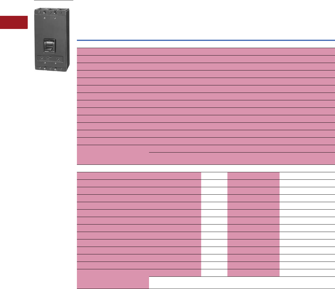
V12-T3-40 Volume 12—Aftermarket, Renewal Parts and Life Extension Solutions CA08100014E—July 2016 www.eaton.com
1
2
3
4
5
6
7
8
9
10
11
12
13
14
15
16
17
18
19
20
21
22
23
24
25
3
Molded-Case Circuit Breakers
Replacement Capabilities
Types MA and HMA
■
Shaded area denotes obsolete or discontinued products and services. 1
Type MA 125–800A, 600 Vac, 250 Vdc 2, Two- and Three-Pole, Interchangeable Trip
Notes
1 These frames are obsolete. For replacement solutions, see the cross-reference on Pages V12-T3-114–V12-T3-167.
2 Above 600A, DC rating applies to magnetic only breakers.
3 Set on high side, adjustable to lower limits.
4 Terminals are shipped separately from breaker.
5 Two-pole breakers are supplied in three-pole frames with current carrying parts omitted from center pole.
6 60 Hz AC only.
7 Interrupting capacities shown do not apply to high magnetic molded-case switches.
MARK 75 frame color changed from gray to black in mid-2002. Also magnetic only trip units available: HMA8000TM 4000–8000A.
Continuous
Ampere
Rating
at 40°C
Magnetic Trip
Setting Amperes 3
Complete Breaker Shipped as Frame, Trip Unit and Terminals 4
Includes Pressure Type Copper Terminals 4Frame Only Trip Unit Only
Standard
Catalog
Number
Saf-T-Vue
Catalog
Number
MARK 75
Catalog
Number
Standard
Catalog
Number
Saf-T-Vue
Catalog
Number
MARK 75
Catalog
Number
Standard
Saf-T-Vue,
MARK 75
Catalog NumberLow High
Two-Pole, 600 Vac, 250 Vdc 25
125 625 1250 MA2125 MA2125S HMA2125 MA2800F MA2800FS HMA2800F HMA2125T
150 750 1500 MA2150 MA2150S HMA2150 MA2800F MA2800FS HMA2800F HMA2150T
175 875 1750 MA2175 MA2175S HMA2175 MA2800F MA2800FS HMA2800F HMA2175T
200 1000 2000 MA2200 MA2200S HMA2200 MA2800F MA2800FS HMA2800F HMA2200T
225 1125 2250 MA2225 MA2225S HMA2225 MA2800F MA2800FS HMA2800F HMA2225T
250 1250 2500 MA2250 MA2250S HMA2250 MA2800F MA2800FS HMA2800F HMA2250T
300 1500 3000 MA2300 MA2300S HMA2300 MA2800F MA2800FS HMA2800F HMA2300T
350 1750 3500 MA2350 MA2350S HMA2350 MA2800F MA2800FS HMA2800F HMA2350T
400 2000 4000 MA2400 MA2400S HMA2400 MA2800F MA2800FS HMA2800F HMA2400T
500 2500 5000 MA2500 MA2500S HMA2500 MA2800F MA2800FS HMA2800F HMA2500T
600 3000 6000 MA2600 MA2600S HMA2600 MA2800F MA2800FS HMA2800F HMA2600T
700 3000 6000 MA2700 6MA2700S HMA2700 MA2800F MA2800FS HMA2800F HMA2700T 6
800 3000 6000 MA2800 6MA2800S HMA2800 MA2800F MA2800FS HMA2800F HMA2800T 6
800 MCS 7—MA2800WK MA2800WSK — — — — Incl. in Frame
Approx. shipping weight 37 lbs Approx. shipping weight 24 lbs Approx. shipping
weight 3.5 lbs
Three-Pole, 600 Vac Only
125 625 1250 MA3125 MA3125S HMA3125 MA3800F MA3800FS HMA3800F HMA3125T
150 750 1500 MA3150 MA3150S HMA3150 MA3800F MA3800FS HMA3800F HMA3150T
175 875 1750 MA3175 MA3175S HMA3175 MA3800F MA3800FS HMA3800F HMA3175T
200 1000 2000 MA3200 MA3200S HMA3200 MA3800F MA3800FS HMA3800F HMA3200T
225 1125 72250 MA3225 MA3225S HMA3225 MA3800F MA3800FS HMA3800F HMA3225T
250 1250 2500 MA3250 MA3250S HMA3250 MA3800F MA3800FS HMA3800F HMA3250T
300 1500 3000 MA3300 MA3300S HMA3300 MA3800F MA3800FS HMA3800F HMA3300T
350 1750 3500 MA3350 MA3350S HMA3350 MA3800F MA3800FS HMA3800F HMA3350T
400 2000 4000 MA3400 MA3400S HMA3400 MA3800F MA3800FS HMA3800F HMA3400T
500 2500 5000 MA3500 MA3500S HMA3500 MA3800F MA3800FS HMA3800F HMA3500T
600 3000 6000 MA3600 MA3600S HMA3600 MA3800F MA3800FS HMA3800F HMA3600T
700 3000 6000 MA3700 6MA3700S HMA3700 MA3800F MA3800FS HMA3800F HMA3700T 6
800 3000 6000 MA3800 6MA3800S HMA3800 MA3800F MA3800FS HMA3800F HMA3800T 6
800 MCS 7—MA3800WK MA3800WSK — —— — Incl. in Frame
Approx. shipping weight 44 lbs Approx. shipping weight 28 lbs Approx. shipping
weight 4 lbs
MA: 600 Vac; 250 Vdc

Volume 12—Aftermarket, Renewal Parts and Life Extension Solutions CA08100014E—July 2016 www.eaton.com V12-T3-41
1
2
3
4
5
6
7
8
9
10
11
12
13
14
15
16
17
18
19
20
21
22
23
24
25
3
Molded-Case Circuit Breakers
Replacement Capabilities
■
Shaded area denotes obsolete or discontinued products
and services. 1
Magnetic Only Breakers, Front Adjustable 2
Ambient Compensating Breakers 2
Continuous
Ampere
Rating
Magnetic
Trip Range 4
Trip Unit Only
Two-Pole 4Three-Pole
Low High Catalog Number Catalog Number
800 625 1250 HMA21250TM HMA31250TM
800 1000 2000 HMA22000TM HMA32000TM
800 1500 3000 HMA23000TM HMA33000TM
800 2000 4000 HMA24000TM HMA34000TM
800 3000 6000 HMA26000TM HMA36000TM
800 4000 8000 HMA28000TM HMA38000TM
Continuous
Ampere
Rating
Magnetic
Trip Range 3
Trip Unit Only
Two-Pole Three-Pole
Low High Catalog Number Catalog Number
125 625 1250 HMA2125TA HMA3125TA
150 750 1500 HMA2150TA HMA3150TA
175 875 1750 HMA2175TA HMA3175TA
200 1000 2000 HMA2200TA HMA3200TA
220 1125 2250 HMA2225TA HMA3225TA
250 1250 2500 HMA2250TA HMA3250TA
300 1500 3000 HMA2300TA HMA3300TA
350 1750 3500 HMA2350TA HMA3350TA
400 2000 4000 HMA2400TA HMA3400TA
500 2500 5000 HMA2500TA HMA3500TA
600 3000 6000 HMA2600TA HMA3600TA
700 3000 6000 HMA2700TA HMA3700TA
800 3000 6000 HMA2800TA HMA3800TA
Type MA Accessories
and Modifications
50°C Calibration
Add suffix “V” to catalog
number for complete
breaker or trip unit only,
when ordering breakers to
be used in 50°C ambients.
Note: Not UL Listed.
For CSA, see
Page V12-T3-48.
Type MA breakers meet
requirements for Class 21a
circuit breakers, and Type
HMA meet requirements
for Class 23a, as defined
by Federal Specification
W-C-375b.
For all three-phase
delta, grounded B phase
applications, contact
Avery Creek, NC, Technical
Resource Center at
1-800-356-1243.
Type MA UL Listed Interrupting Ratings 5
Notes
1These frames are obsolete. For replacement solutions, see the cross-reference on
Pages V12-T3-114–V12-T3-167.
2Not UL Listed.
3Set on high side, adjustable to lower limits.
4Two-pole breakers are supplied in three-pole frames with current carrying parts omitted from
center pole.
5Interrupting capacities shown do not apply to high magnetic molded-case switches.
6Above 600A, DC rating applies to magnetic only breakers.
7Ratings above 10,000A not UL Listed.
Special Calibrations
Special calibration price
additions apply to ampere
ratings not listed as standard
or for ambients other
than 40°C or 50°C. For
frequencies other than
0–60 Hz AC (50 Hz AC
minimum, 60 Hz AC
maximum, refer to Eaton.
See Application Data 29-160
for additional information
regarding special conditions.
Note: Not UL Listed.
Maximum
Volts Amperes
Standard Breakers
240 AC 50,000 asymmetrical, 42,000 symmetrical
480 AC 35,000 asymmetrical, 30,000 symmetrical
600 AC 25,000 asymmetrical, 22,000 symmetrical
250 DC 620,000 7
MARK 75 Breakers
240 AC 75,000 asymmetrical, 65,000 symmetrical
480 AC 40,000 asymmetrical, 35,000 symmetrical
600 AC 30,000 asymmetrical, 25,000 symmetrical
250 DC 620,000 7

V12-T3-42 Volume 12—Aftermarket, Renewal Parts and Life Extension Solutions CA08100014E—July 2016 www.eaton.com
1
2
3
4
5
6
7
8
9
10
11
12
13
14
15
16
17
18
19
20
21
22
23
24
25
3
Molded-Case Circuit Breakers
Replacement Capabilities
■
Shaded area denotes obsolete or discontinued products
and services.
Terminals
Two terminals are required
per pole.
Terminals are UL Listed for
wire type and range listed
below. When used with
aluminum conductors, use
joint compound.
Note: Terminals are shipped
separately from breaker.
Magnetic Only and Ambient
Compensating Breakers
To order a complete breaker,
select trip unit plus frame
and terminals.
Te r m i n a l s 1
Maximum
Amperes
Number of Cables,
Wire Range, Type
Catalog
Number
Standard Al/Cu Pressure Terminals
600 (2) #1–500 kcmil Al/Cu TA700MA1
800 (Std.) (3) 3/0–400 kcmil Al/Cu TA800MA2
800 2(2) 500–750 kcmil Al/Cu TA801MA
Optional Copper Pressure Terminals
350 (1) #1–600 kcmil Cu T350MA
600 (2) 2/0–500 kcmil Cu T600MA1
800 (3) 3/0–300 kcmil Cu T800MA1
Type MAY Accessories and Modifications
Type MAY 600–800A, 240 Vac, Three-Pole,
Interchangeable Trip 1
Type MAY breakers are
not defined by Federal
Specification W-C-375b.
Note: Not UL listed.
Type MAY UL Listed
Interrupting Ratings
For all three-phase
delta, grounded B phase
applications, contact
Avery Creek, NC, Technical
Resource Center at
1-800-356-1243.
Additional Accessories
and Modifications
Refer to Pages V12-T3-65–
V12-T3-79.
Notes
1These frames are obsolete. For
replacement solutions, see the cross-
reference on Pages V12-T3-114–
V12-T3-167.
2Not UL Listed.
3Set on high side, adjustable to
lower limits.
4Terminals are shipped separately
from breaker.
e60 Hz AC only.
Continuous
Ampere
Rating
at 40°C
Magnetic Trip
Setting, Amperes 3
Complete
Breaker
Shipped as Frame,
Trip Unit and Terminals 4
Includes Pressure
Type Aluminum
Terminals 4
Catalog Number
Frame
Only
Catalog
Number
Trip Unit
Only
Catalog
NumberLow High
Three-Pole, 240 Vac Only
600 3000 6000 MAY3600 MAY3800F HMA3600T
700 e3000 6000 MAY3700 MAY3800F HMA3700T
800 e3000 6000 MAY3800 MAY3800F HMA3800T
Maximum
Volts Amperes
240 Vac 115,000 asymmetrical,
100,000 symmetrical
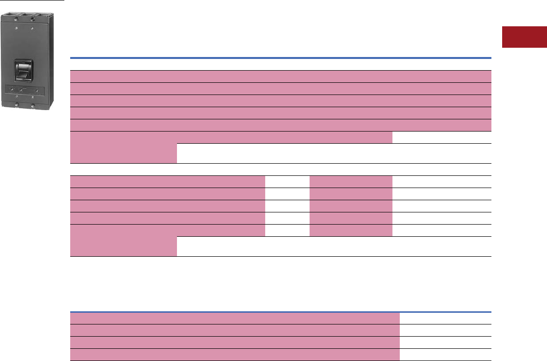
Volume 12—Aftermarket, Renewal Parts and Life Extension Solutions CA08100014E—July 2016 www.eaton.com V12-T3-43
1
2
3
4
5
6
7
8
9
10
11
12
13
14
15
16
17
18
19
20
21
22
23
24
25
3
Molded-Case Circuit Breakers
Replacement Capabilities
Types NB and NHB
■
Shaded area denotes obsolete or discontinued products and services. 1
Type NB 700–1200A, 600V, 60 Hz AC 2, 250 Vdc 3, Two- and Three-Pole Interchangeable Trip
Magnetic Only Breakers, Front Adjustable 78
Notes
1 These frames are obsolete. For replacement solutions, see the cross-reference on Pages V12-T3-114–V12-T3-167.
2 Higher frequency calibration not available. Minimum of 50 Hz calibration available on special order.
3 250 Vdc rating applied only to magnetic only type breakers.
4 Set on high side, adjustable to lower limits.
5 Terminals shipped separately from breaker.
6 Two-pole breakers supplied in three-pole frames with current carrying parts omitted from center pole.
7 Frames, terminals, studs, mounting hardware, dimensions and shipping weights are same as standard thermal-magnetic breakers.
8 Not UL Listed.
Continuous
Ampere
Rating
at 40°C
Magnetic Trip
Setting, Amperes 4
Complete Breaker Shipped as Frame, Trip Unit and Terminals 5
Includes Pressure Type Copper Terminals 5Frame Only Trip Unit Only
Standard
Catalog
Number
Saf-T-Vue
Catalog
Number
MARK 75
Catalog
Number
Standard
Catalog
Number
Saf-T-Vue
Catalog
Number
MARK 75
Catalog
Number
Standard Saf-T-Vue,
MARK 75
Catalog NumberLow High
Two-Pole, 600 Vac, 250V DC 36
700 3000 6000 NB2700 NB2700S HNB2700 NB21200F NB21200FS HNB21200F HNB2700T
800 3000 6000 NB2800 NB2800S HNB2800 NB21200F NB21200FS HNB21200F HNB2800T
900 4000 8000 NB2900 NB2900S HNB2900 NB21200F NB21200FS HNB21200F HNB2900T
1000 4000 8000 NB21000 NB21000S HNB21000 NB21200F NB21200FS HNB21200F HNB21000T
1200 4000 8000 NB21200 NB21200S HNB21200 NB21200F NB21200FS HNB21200F HNB21200T
600 3000 6000 —————HNB31200F HNB3600T
Approx. shipping weight 43 lbs Approx. shipping weight 29 lbs Approx. shipping
weight 3.5 lbs
Three-Pole, 600 Vac Only
700 3000 6000 NB3700 NB3700S HNB3700 NB31200F NB31200FS HNB31200F HNB3700T
800 3000 6000 NB3800 NB3800S HNB3800 NB31200F NB31200FS HNB31200F HNB3800T
900 4000 8000 NB3900 NB3900S HNB3900 NB31200F NB31200FS HNB31200F HNB3900T
1000 4000 8000 NB31000 NB31000S HNB31000 NB31200F NB31200FS HNB31200F HNB31000T
1200 4000 8000 NB31200 NB31200S HNB31200 NB31200F NB31200FS HNB31200F HNB31200T
Approx. shipping weight 51 lbs Approx. shipping weight 32 lbs Approx. shipping
weight 4 lbs
Continuous
Ampere Rating
Magnetic Trip Range 4
Trip Unit Only
Two-Pole 6Three-Pole
Low High Catalog Number Catalog Number
1200 3000 6000 HNB26000TM HNB36000TM
1200 4000 8000 HNB28000TM HNB38000TM
1200 5000 10000 HNB210000TM HNB310000TM
1200 6000 12000 HNB212000TM HNB312000TM
NB: 600 Vac; 250 Vdc

V12-T3-44 Volume 12—Aftermarket, Renewal Parts and Life Extension Solutions CA08100014E—July 2016 www.eaton.com
1
2
3
4
5
6
7
8
9
10
11
12
13
14
15
16
17
18
19
20
21
22
23
24
25
3
Molded-Case Circuit Breakers
Replacement Capabilities
UL Listed Interrupting Ratings
Terminals 4
Maximum Volts Amperes
Standard Breakers
240 AC 50,000 asymmetrical, 42,000 symmetrical
480 AC 35,000 asymmetrical, 30,000 symmetrical
600 AC 25,000 asymmetrical, 22,000 symmetrical
250 DC 12 20,000 3
MARK 75 Breakers
240 AC 75,000 asymmetrical, 65,000 symmetrical
480 AC 40,000 asymmetrical, 35,000 symmetrical
600 AC 30,000 asymmetrical, 25,000 symmetrical
250 DC 12 20,000 3
Maximum
Amperes
Number of Cables,
Wire Range, Type,
Catalog
Number
Standard Al/Cu Pressure Terminals
1000 (3) 3/0–400 kcmil Al/Cu TA1000NB1
1200 (4) 4/0–500 kcmil Al/Cu TA1200NB1
Optional Copper or Al/Cu Pressure Terminals
1000 (3) 3/0–500 kcmil Cu T1000NB1
1200 (4) 3/0–400 kcmil Cu T1200NB1
1200 (3) 500–750 kcmil Al/Cu TA1201NB1
Accessories and
Modifications
■
Shaded area denotes
obsolete or discontinued
products and services.
50°C Calibration
Add suffix “V” to catalog
number for complete breaker
or trip unit only, when
ordering breakers to be used
in 50°C ambients. For CSA,
see Page V12-T3-48.
Note: Not UL Listed.
Type NB breakers meet
requirements for Class 21a
circuit breakers, and Type
HNB meet requirements
for Class 23a, as defined
by Federal Specification
W-C-375b.
For all three-phase
delta, grounded B phase
applications, contact
Avery Creek, NC, Technical
Resource Center at
1-800-356-1243.
Terminals
Two terminals are required
per pole.
Terminals are UL Listed for
wire type and range listed
below. When used with
aluminum conductors, use
joint compound. To order
optional copper terminals,
add suffix “C” to complete
breaker catalog number.
Note: Frames, terminals, studs,
mounting hardware, dimensions
and shipping weights are same
as standard thermal magnetic
breakers.
Magnetic Only Breakers
To order a complete breaker,
select trip unit, plus frame
and terminals.
Note: Not UL Listed.
Additional Accessories
and Modifications
Refer to Pages V12-T3-65–
V12-T3-79.
Notes
1250 Vdc rating applied only to magnetic
only type breakers.
2Terminals shipped separately from
breaker.
3Ratings above 10,000A not UL Listed.
4MARK 75 frame color changed from gray
to black in mid-2002.
Special Calibrations
Special calibration price
additions apply
to ampere
ratings not listed as standard
or for ambients other
than 40°C or 50°C.
For
frequencies other than
0–60 Hz AC (50 Hz AC
minimum, 60 Hz AC
maximum for ratings of
700A and above), refer
to Eaton. See Application
Data 29-160 for additional
information regarding
special conditions.
Maximum 400 Hz
calibration for type MA
is 475A.
Note: Not UL Listed.
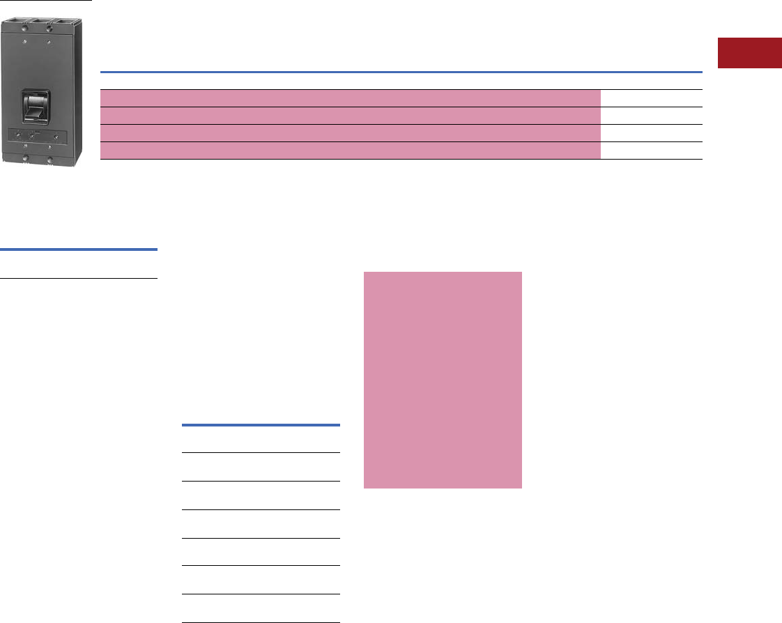
Volume 12—Aftermarket, Renewal Parts and Life Extension Solutions CA08100014E—July 2016 www.eaton.com V12-T3-45
1
2
3
4
5
6
7
8
9
10
11
12
13
14
15
16
17
18
19
20
21
22
23
24
25
3
Molded-Case Circuit Breakers
Replacement Capabilities
Type NBY
■
Shaded area denotes obsolete or discontinued products and services. 1
Type NBY 700–1200A, 240V, 60 Hz AC 2, Three-Pole, Interchangeable Trip
UL Listed
Interrupting Ratings
For all three-phase
delta, grounded B phase
applications, contact
Avery Creek, NC, Technical
Resource Center at
1-800-356-1243.
Terminals
Two terminals are required
per pole.
Terminals are UL Listed for
wire type and range listed
below. When used with
aluminum conductors, use
joint compound.
Note: Terminals shipped
separately from breaker.
Te r m i n a l s
Accessories
and Modifications
■
Shaded area denotes
obsolete or discontinued
products and services.
50°C Calibration
Add suffix “V” to catalog
number for complete breaker
or trip unit only, when
ordering for breakers to be
used in 50°C ambients.
Note: Not UL Listed.
For CSA, see
Page V12-T3-48.
Type NBY breakers are
not defined by Federal
Specification W-C-375b.
Additional Accessories
and Modifications
Refer to Pages V12-T3-65–
V12-T3-79.
Notes
1These frames are obsolete. For
replacement solutions, see the cross-
reference on Pages V12-T3-114–
V12-T3-167.
2Higher frequency calibration not
available. Minimum of 50 Hz calibration
available on special order.
3Set on high side, adjustable to
lower limits.
4Terminals shipped separately
from breaker.
Continuous
Ampere Rating
at 40°C
Magnetic Trip Setting
Amperes 3
Complete Breaker Shipped as Frame, Trip Unit and Terminals 4
Includes Pressure Type
Aluminum Terminals 4Frame Only Trip Unit Only
Low High Catalog Number Catalog Number Catalog Number
Three-Pole, 600 Vac Only
700 3000 6000 NBY3700 NBY31200F HNB3700T
800 3000 6000 NBY3800 NBY31200F HNB3800T
900 4000 8000 NBY3900 NBY31200F HNB3900T
1200 4000 8000 NBY31200 NBY31200F HNB31200T
NBY: 240 Vac
Maximum
Volts Amperes
240 AC 115,000 asymmetrical,
100,000 symmetrical
Max.
Amperes
Number
of Cables,
Wire Range,
Type,
Catalog
Number
Standard Al/Cu
Pressure Terminals
1000 (3) 3/0–400 kcmil
Al/Cu
TA1000NB1
1200 (4) 4/0–500 kcmil
Al/Cu
TA1200NB1
1200 (3) 500–750 kcmil
Al/Cu
TA1201NB1
Alternate Copper
Pressure Terminals
1000 (3) 3/0–500 kcmil
Cu
T1000NB1
1200 (4) 3/0–400 kcmil
Cu
T1200NB1
Special Calibrations
Special calibration price
additions apply
to ampere
ratings not listed as
standard or for ambients
other than 40°C or 50°C.
For frequencies other than
0–60 Hz AC (50 Hz AC
minimum, 60 Hz AC
maximum), refer to Eaton.
See Application Data 29-160
for additional information
regarding special
conditions.
Note: Not UL Listed.
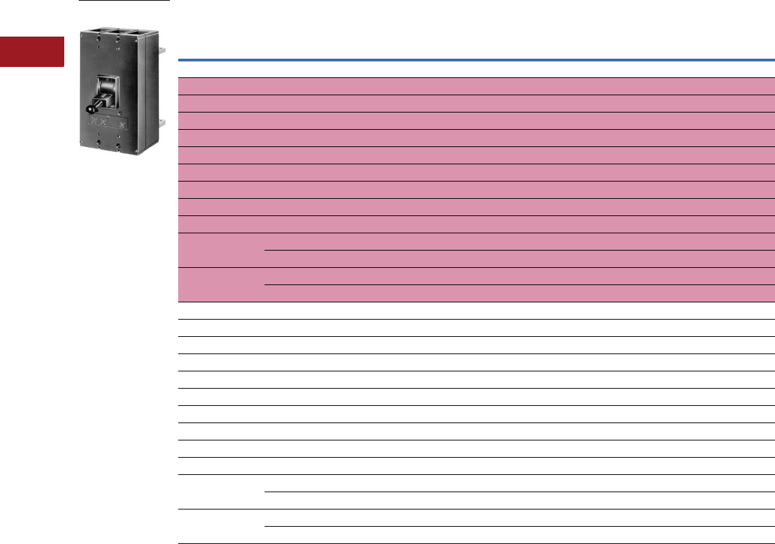
V12-T3-46 Volume 12—Aftermarket, Renewal Parts and Life Extension Solutions CA08100014E—July 2016 www.eaton.com
1
2
3
4
5
6
7
8
9
10
11
12
13
14
15
16
17
18
19
20
21
22
23
24
25
3
Molded-Case Circuit Breakers
Replacement Capabilities
Type PB
■
Shaded area denotes obsolete or discontinued products and services. 1
Type PB 600–25s00A, 600V, 60 Cycle AC 2, 250 Vdc 3, Two- and Three-Pole, Interchangeable Trip
Notes
1 These frames are obsolete. For replacement solutions, see the cross-reference on Pages V12-T3-114–V12-T3-167.
2 Higher frequency calibration not available. Minimum of 50 Hz calibration available on special order.
3 Available only on magnetic only breakers.
4 Higher magnetic trip settings are available as special calibration. Refer to magnetic only breakers for specific trip ranges.
5 Set on high side, adjustable to lower limits.
6 Shipped separately from breaker.
7 Two-pole breakers are supplied in three-pole frames with current carrying parts omitted from center pole.
Continuous
Ampere Rating
at 40°C
Magnetic Trip Setting,
Amperes 45
Complete Breaker Shipped as Frame, Trip Unit and Rear Connectors
Includes Busbar Connectors 6Frame Only Trip Unit Only
Low High Catalog Number Catalog Number Catalog Number
Two-Pole, 600 Vac Only 7
600 1500 5000 PB2600 PB22500F PB2600T
700 1500 5000 PB2700 PB22500F PB2700T
800 1500 5000 PB2800 PB22500F PB2800T
900 1500 5000 PB2900 PB22500F PB2900T
1000 1500 5000 PB21000 PB22500F PB21000T
1200 2000 6000 PB21200 PB22500F PB21200T
1400 2500 7000 PB21400 PB22500F PB21400T
1600 3000 8000 PB21600 PB22500F PB21600T
1800 3000 8000 PB21800 PB22500F PB21800T
2000 3000 8000 PB22000 PB22500F PB22000T
Approx. shipping weight 132 lbs 98 lbs 18 lbs
2500 3000 8000 PB22500 PB22500F PB22500T
Approx. shipping weight 144 lbs 98 lbs 18 lbs
Three-Pole, 600 Vac Only—Not UL Listed
600 1500 5000 PB3600 PB32500F PB3600T
700 1500 5000 PB3700 PB32500F PB3700T
800 1500 5000 PB3800 PB32500F PB3800T
900 1500 5000 PB3900 PB32500F PB3900T
1000 1500 5000 PB31000 PB32500F PB31000T
1200 2000 6000 PB31200 PB32500F PB31200T
1400 2500 7000 PB31400 PB32500F PB31400T
1600 3000 8000 PB31600 PB32500F PB31600T
1800 3000 8000 PB31800 PB32500F PB31800T
2000 3000 8000 PB32000 PB32500F PB32000T
Approx. shipping weight 155 lbs 108 lbs 23 lbs
2500 3000 8000 PB32500 PB32500F PB32500T
Approx. shipping weight 173 lbs 108 lbs 23 lbs
Rear Connected PB
Breaker: 600 Vac
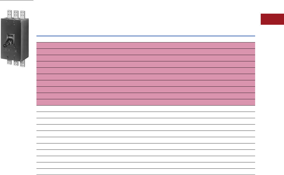
Volume 12—Aftermarket, Renewal Parts and Life Extension Solutions CA08100014E—July 2016 www.eaton.com V12-T3-47
1
2
3
4
5
6
7
8
9
10
11
12
13
14
15
16
17
18
19
20
21
22
23
24
25
3
Molded-Case Circuit Breakers
Replacement Capabilities
Type PBF
■
Shaded area denotes obsolete or discontinued products and services. 1
Type PBF Front-Connected 600–2000A, 600V, 60 Cycle AC 2, 250 Vdc 3, Two- and Three-Pole,
Interchangeable Trip
Notes
1 These frames are obsolete. For replacement solutions, see the cross-reference on Pages V12-T3-114–V12-T3-167.
2 Higher frequency calibration not available. Minimum of 50 Hz calibration available on special order.
3 Available only on magnetic only breakers.
4 Included with frame.
5 Two-pole breakers are supplied in three-pole frames with current carrying parts omitted from center pole.
Continuous
Ampere
Rating
at 40°C
Magnetic Trip Setting, Amperes
(Set on High Side, Adjustable
to Lower Limits)
Complete Breaker Shipped As:
Includes Busbar
Connectors 4
Frame Only Includes
Busbar Connectors 4
Trip Unit
Only
Low High Catalog Number Catalog Number Catalog Number
Two-Pole, 600 Vac 5
600 1500 5000 PBF2600 PBF22000F PBF2600T
700 1500 5000 PBF2700 PBF22000F PBF2700T
800 1500 5000 PBF2800 PBF22000F PBF2800T
900 1500 5000 PBF2900 PBF22000F PBF2900T
1000 1500 5000 PBF21000 PBF22000F PBF21000T
1200 2000 6000 PBF21200 PBF22000F PBF21200T
1400 2500 7000 PBF21400 PBF22000F PBF21400T
1600 3000 8000 PBF21600 PBF22000F PBF21600T
1800 3000 8000 PBF21800 PBF22000F PBF21800T
2000 3000 8000 PBF22000 PBF22000F PBF22000T
Three-Pole, 600 Vac—Not UL Listed
600 1500 5000 PBF3600 PBF32000F PBF3600T
700 1500 5000 PBF3700 PBF32000F PBF3700T
800 1500 5000 PBF3800 PBF32000F PBF3800T
900 1500 5000 PBF3900 PBF32000F PBF3900T
1000 1500 5000 PBF31000 PBF32000F PBF31000T
1200 2000 6000 PBF31200 PBF32000F PBF31200T
1400 2500 7000 PBF31400 PBF32000F PBF31400T
1600 3000 8000 PBF31600 PBF32000F PBF31600T
1800 3000 8000 PBF31800 PBF32000F PBF31800T
2000 3000 8000 PBF32000 PBF32000F PBF32000T
PBF Front Connected:
600 Vac
V12-T3-48 Volume 12—Aftermarket, Renewal Parts and Life Extension Solutions CA08100014E—July 2016 www.eaton.com
1
2
3
4
5
6
7
8
9
10
11
12
13
14
15
16
17
18
19
20
21
22
23
24
25
3
Molded-Case Circuit Breakers
Replacement Capabilities
Types PB and PBF Accessories and Modifications
■
Shaded area denotes obsolete or discontinued products
and services. 1
PB breakers are not UL Listed.
Special Breakers 2 Magnetic Only, Front Adjustable 3
Trip Unit Only
Accessories
and Modifications
■
Shaded area denotes
obsolete or discontinued
products and services.
50°C Calibration
Add suffix “V” to catalog
number for complete
breaker or trip unit only,
when ordering breakers to
be used in 50°C ambients.
Type PB breakers meet the
requirements for Class 25a
circuit breakers as defined
by Federal Specification
W-C-375b.
Continuous
Ampere
Rating
Magnetic Trip Range,
Amperes 4Two-Pole 5Three-Pole
Low High Catalog Number Catalog Number
For Rear-Connected Type PB Breakers
2000 1500 5000 PB25000TM PB35000TM
2000 2000 6000 PB26000TM PB36000TM
2000 2500 7000 PB27000TM PB37000TM
2000 3000 8000 PB28000TM PB38000TM
2000 3500 10,000 PB210000TM PB310000TM
2000 4000 12,000 PB212000TM PB312000TM
2500 4000 12,000 373D488G08 373D488G09
For Front-Connected Type PBF Breakers
2000 1500 5000 PBF25000TM PBF35000TM
2000 2000 6000 PBF26000TM PBF36000TM
2000 2500 7000 PBF27000TM PBF37000TM
2000 3000 8000 PBF28000TM PBF38000TM
2000 3500 10,000 PBF210000TM PBF310000TM
2000 4000 12,000 PBF212000TM PBF312000TM
Special Calibrations
Special calibration price
additions apply to ampere
ratings not listed as
standard, or for ambients
other than 40°C or 50°C.
For frequencies other than
0–60 Hz AC, refer to Eaton.
See Application Data 29-160
for information regarding
special conditions.
Note: Not UL Listed.
Interrupting Ratings
For all three-phase delta, grounded B phase applications, contact
Avery Creek, NC, Technical Resource Center at 1-800-356-1243.
Magnetic Only Breakers
To order a complete breaker, select trip unit, plus frame
and connectors.
Note: Not UL Listed.
Busbar Connections
Busbar Connections—“T” Connector
(For Cu/AI Bus)
Two required per pole. For rear bus connection of breakers
through 2000A. Accepts up to four bus bolts. May be rotated 90°.
Note: Shipped separately from breaker.
“C” Connector (For Cu/AI Bus)
Two required per pole. For rear bus connection of
2500A breakers.
Cable Connector
Fits “T” Connector and 2000A front-connected breakers.
Accepts four 400–600 kcmil copper cables.
Notes
1These frames are obsolete. For replacement solutions, see the cross-reference
on Pages V12-T3-114–V12-T3-167.
2Not UL Listed.
3Frames, connectors, dimensions and shipping weights are same as thermal-magnetic
breakers.
4Set on high side, adjustable to lower limits.
5Two-pole breakers are supplied in three-pole frames with current carrying parts omitted
from center pole.
6Based on NEMA test procedure.
Maximum Volts Amperes
240 AC 2150,000 asymmetrical, 125,000 symmetrical
480 AC 2115,000 asymmetrical, 100,000 symmetrical
600 AC 2115,000 asymmetrical, 100,000 symmetrical
250 DC 275,000A 6
Catalog Number
BA2000PB
Breaker Amperes Catalog Number
2500 BA2500PB
Catalog Number
505C706G04
“T” Connector
“C” Connector
Cable Connector
Volume 12—Aftermarket, Renewal Parts and Life Extension Solutions CA08100014E—July 2016 www.eaton.com V12-T3-49
1
2
3
4
5
6
7
8
9
10
11
12
13
14
15
16
17
18
19
20
21
22
23
24
25
3
Molded-Case Circuit Breakers
Replacement Capabilities
Types LC, LCC, LCA, LCCA, MARK 75 Types HLC, HLCC, HLCA, HLCCA SELTRONIC with Solid-State Trip Units 600 Vac, 50/60 Hz
Complete breaker requires frame and rating plug. See the table and terminals on Page V12-T3-60. Extra current transformer included
for neutral. See accessories on Page V12-T3-65 for remote ground fault trip indicator.
■
Shaded area denotes obsolete or discontinued products and services. 1
Breakers for Standard Applications—Frame Only
Breakers for Applications at 100% Rating—Frame Only
Notes
1 These frames are obsolete. For replacement solutions, see the cross-reference on Pages V12-T3-114–V12-T3-167.
2 Two-pole breakers are supplied in three-pole frames with current carrying parts omitted from center pole.
3 UL Recognized component.
MARK 75 frame color changed from gray to black in mid-2002.
Number
of Poles 2
Standard
(Long Delay and Short Time) Short Time Only 3
Long Delay, Short Time and Adjustable
Short Delay Time (0.06–0.22 sec.)
Catalog Number Catalog Number Catalog Number
Types LC 150 and LCA 150 (75–150A)
2LC2150F LC2150FM LCA2150F
3LC3150F LC3150FM LCA3150F
MARK 75 Types HLC 150 and HLCA 150 (75–150A)
2HLC2150F HLC2150FM HLCA2150F
3HLC3150F HLC3150FM HLCA3150F
Types LC 300 and LCA 300 (150–300A)
2LC2300F LC2300FM LCA2300F
3LC3300F LC3300FM LCA3300F
MARK 75 Types HLC 300 and HLCA 300 (150–300A)
2HLC2300F HLC2300FM HLCA2300F
3HLC3300F HLC3300FM HLCA3300F
Types LC 400 and LCA 400 (200–400A)
2LC2400F LC2400FM LCA2400F
3LC3400F LC3400FM LCA3400F
MARK 75 Types HLC 400 and HLCA 400 (200–400A)
2HLC2400F HLC2400FM HLCA2400F
3HLC3400F HLC3400FM HLCA3400F
Types LC 600 and LCA 600 (300–600A)
2LC2600F LC2600FM LCA2600F
3LC3600F LC3600FM LCA3600F
MARK 75 Types HLC 600 and HLCA 600 (300–600A)
2HLC2600F HLC2600FM HLCA2600F
3HLC3600F HLC3600FM HLCA3600F
Number of
Poles 2
Standard
(Long Delay and Short Time) Short Time Only 3
Long Delay, Short Time and Adjustable
Short Delay Time (0.06–0.22 sec.)
Catalog Number Catalog Number Catalog Number
Types LCC 600 and LCCA 600 (300–600A)
3LCC3600F —LCCA3600F
MARK 75 Types HLCC 600 and HLCCA 600 (300–600A)
3HLCC3600F — HLCCA3600F
LCA: 600 Vac

V12-T3-50 Volume 12—Aftermarket, Renewal Parts and Life Extension Solutions CA08100014E—July 2016 www.eaton.com
1
2
3
4
5
6
7
8
9
10
11
12
13
14
15
16
17
18
19
20
21
22
23
24
25
3
Molded-Case Circuit Breakers
Replacement Capabilities
Types LCG, LCCG, LCGA,
LCCGA, MARK 75 HLCG,
HLCCG, HLCGA, HLCCGA
SELTRONIC with Built-In
Ground Fault Protection
Complete breaker requires
frame and rating plug. See
the table and terminals on
Page V12-T3-60
. Extra current
transformer
included for
neutral. See accessories on
Page V12-T3-65 for remote
ground fault trip indicator.
■
Shaded area denotes
obsolete or discontinued
products and services.
Note: These breakers use
LC terminals. The fourth
CT uses MC breaker terminals,
Page V12-T3-53.
Note: Available without extra
CT for neutral. Order by
description as similar to above
except without neutral CT or
external CT terminal
connections at same price.
Note the standard ground fault
unit can also be used without
the neutral CT.
■
Shaded area denotes obsolete or discontinued products and services. 1
Breakers for Standard Application—Frame Only
Breakers for Application at 100% Rating—Frame Only
Notes
1These frames are obsolete. For replacement solutions, see the cross-reference on Pages V12-T3-114–V12-T3-167.
2Two-pole breakers supplied in three-pole frames with current carrying parts omitted from center pole.
3For applications other than standard residual scheme, see Application Data 29-160.
MARK 75 frame color changed from gray to black in mid-2002.
Number
of Poles 2
Standard (Long Delay,
Short Time) and Ground Fault Trip
Long Delay, Short Time, Adjustable
Short Delay Time and Ground Fault Trip
Ground Fault Characteristics
Pickup Setting
Amperes
Time
SettingCatalog Number
Types LCG 150 and LCGA 150 (75–150A) 3
3LCG3150F LCGA3150F 50–150 3.5–30 Cy
MARK 75 Types HLCG 150 and HLCGA 150 (75–150A) 3
3HLCG3150F HLCGA3150F 50–150 3.5–30 Cy
Types LCG 300 and LCGA 300 (150–300A) 3
3LCG3300F LCGA3300F 60–300 3.5–30 Cy
MARK 75 Types HLCG 300 and HLCGA 300 (150–300A) 3
3HLCG3300F HLCGA3300F 60–300 3.5–30 Cy
Types LCG 400 and LCGA 400 (200–400A) 3
3LCG3400F LCGA3400F 0–400 3.5–30 Cy
MARK 75 Types HLCG 400 and HLCGA 400 (200–400A) 3
3HLCG3400F HLCGA3400F 80–400 3.5–30 Cy
Types LCG 600 and LCGA 600 (300–600 Amperes) 3
3LCG3600F LCGA3600F 120–600 3.5–30 Cy
MARK 75 Types HLCG 600 and HLCGA 600 (300–600A) 3
3HLCG3600F HLCGA3600F 120–600 3.5–30 Cy
Number
of Poles 2
Standard (Long Delay,
Short Time) and Ground Fault Trip
Long Delay, Short Time, Adjustable
Short Delay Time and Ground Fault Trip
Ground Fault Characteristics
Pickup Setting
Amperes
Time
SettingCatalog Number
Types LCCG 600 and LCCGA 600 (300–600A) 3
3LCCG3600F LCCGA3600F 120–600 3.5–30 Cy
MARK 75 Types HLCCG 600 and HLCCGA 600 (300–600A) 3
3HLCCG3600F HLCCGA3600F 120–600 3.5–30 Cy

Volume 12—Aftermarket, Renewal Parts and Life Extension Solutions CA08100014E—July 2016 www.eaton.com V12-T3-51
1
2
3
4
5
6
7
8
9
10
11
12
13
14
15
16
17
18
19
20
21
22
23
24
25
3
Molded-Case Circuit Breakers
Replacement Capabilities
Types LCG, LCCG, LCGA, LCCGA, MARK 75 HLCG, HLCCG, HLCGA,
HLCCGA SELTRONIC with Built-In Ground Fault Protection
Accessories and Modifications
Field-Mountable Attachments 12345
For CSA, see Page V12-T3-48.
Type LC breakers meet requirements for Class 21a circuit
breakers, and Type HLC meet requirements for Class 23a as
defined by Federal Specification W-C-375b.
UL Listed Interrupting Ratings 8
For all three-phase delta, grounded B phase applications, contact
Avery Creek, NC, Technical Resource Center at 1-800-356-1243.
Additional Accessories and Modifications
Refer to Pages V12-T3-65–V12-T3-79.
Terminals
Note: Order separately.
Two terminals are required per pole.
Terminals are UL Listed for wire type and range listed below.
When used with aluminum cable, use joint compound.
150, 300 and 400A Frames Only
600A Frame Only
Notes
1Only one attachment may be mounted per breaker.
2Contact Avery Creek, NC, Technical Resource Center for other combinations.
3Molded-case switches do not use standard SELTRONIC attachments, and should be ordered
by description for factory mounting.
4Does not void listing of UL Listed breakers.
5Left pole mounting.
6Rated 48 volts minimum for ground fault applications requiring tripping at 55% of voltage.
7Not for use on ground fault applications.
8Interrupting capacities shown do not apply to molded-case switches.
MARK 75 frame color changed from gray to black in mid-2002.
Description Style Number
Provision to trip flux transfer shunt trip from external source
32 to 120 Vdc to 60 Hz 6
1371D11G22
240 to 600 Vac, 50/60 Hz 71371D11G32
Provision to trip flux transfer shunt trip from external source,
plus a 1A-1B auxiliary switch
32 to 120 Vdc to 60 Hz 6
1371D11G15
240 to 600 Vac, 50/60 Hz 71371D11G25
Provision to trip flux transfer shunt trip from 24 Vdc source 1371D93G01
1A-1B auxiliary switch 1371D11G03
24 Vdc shunt trip and 1A-1B auxiliary switch 1371D94G08
Maximum Volts Amperes
Standard Breakers
240 AC 50,000 Asymmetrical, 42,000 Symmetrical
480 AC 35,000 Asymmetrical, 30,000 Symmetrical
600 AC 25,000 Asymmetrical, 22,000 Symmetrical
MARK 75 Breakers
240 AC 75,000 Asymmetrical, 65,000 Symmetrical
480 AC 40,000 Asymmetrical, 35,000 Symmetrical
600 AC 30,000 Asymmetrical, 25,000 Symmetrical
Maximum
Amperes Number of Cables, Wire Range, Type
Catalog
Number
Al/Cu Pressure Terminals
225 (1) #6–350 kcmil Cu, or (1) #4–350 kcmil Al TA225LA1
400 (1)
#4
–
250 kcmil Al/Cu, plus
(1) 3/0–600 kcmil Al/Cu TA400LA1
Optional Copper Pressure Terminals
225 (1) #6–350 kcmil Cu T225LA
225 (1) #6–250 kcmil Cu T225LBF
400 (1) #4–250 kcmil Cu, plus (1) 3/0–600 kcmil Cu T401LA
Maximum
Amperes Number of Cables, Wire Range, Type
Catalog
Number
Al/Cu Pressure Terminals
500 (2) 250–350 kcmil Al/Cu TA602LD
600 (2) 400–500 kcmil Al/Cu TA603LA
600
(std.)
(2) 250–500 kcmil Al/Cu TA600LA
Optional Copper Pressure Terminals
600 (2) 250–500 kcmil Cu T600LA
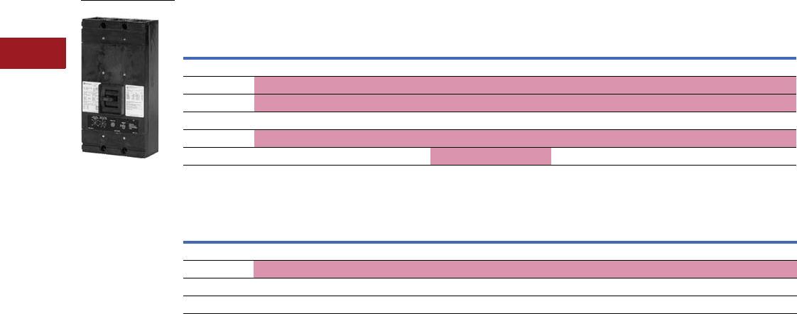
V12-T3-52 Volume 12—Aftermarket, Renewal Parts and Life Extension Solutions CA08100014E—July 2016 www.eaton.com
1
2
3
4
5
6
7
8
9
10
11
12
13
14
15
16
17
18
19
20
21
22
23
24
25
3
Molded-Case Circuit Breakers
Replacement Capabilities
Types MC, MCC, MCA, MCCA, MARK 75 Types HMC, HMCC, HMCA, HMCCA SELTRONIC with Solid-State Trip Units 600 Vac, 50/60 Hz
■
Shaded area denotes obsolete or discontinued products and services. 1
Breakers for Standard Applications—Frame Only
Breakers for Application at 100% Rating—Frame Only 1
Notes
1 These frames are obsolete. Effective 2/1/02, only the MARK 75 version is available. For replacement solutions, see the cross-reference on
Pages V12-T3-114–V12-T3-167.
2 Two-pole breakers are supplied in three-pole frames with current-carrying parts omitted from center pole.
3 UL Recognized component.
Type MC800 molded-case switch; refer to Page V12-T3-62. MARK 75 frame color changed from gray to black in mid-2002.
Number
of Poles 2
Standard
(Long Delay and Short Time) Short Time Only 3
Long Delay, Short Time and Adjustable
Short Delay Time (0.08 –0.30 seconds)
Catalog Number Catalog Number Catalog Number
Types MC and MCA (400–800A)
2MC2800F MC2800FM MCA2800F
3MC3800F MC3800FM MCA3800F
MARK 75 Types HMC and HMCA (400–800A)
2HMC2800F HMC2800FM HMCA2800F
3HMC3800F HMC3800FM HMCA3800F
Number
of Poles 2
Standard
(Long Delay and Short Time) Short Time Only 3
Long Delay, Short Time and Adjustable
Short Delay Time (0.08 –0.30 seconds)
Catalog Number Catalog Number Catalog Number
Types MCC and MCCA (400–800A)
3MCC3800F —MCCA3800F
MARK 75 Types HMCC and HMCCA (400–800A)
3HMCC3800F — HMCCA3800F
MCA: 600 Vac

Volume 12—Aftermarket, Renewal Parts and Life Extension Solutions CA08100014E—July 2016 www.eaton.com V12-T3-53
1
2
3
4
5
6
7
8
9
10
11
12
13
14
15
16
17
18
19
20
21
22
23
24
25
3
Molded-Case Circuit Breakers
Replacement Capabilities
Types MCG, MCCG, MCGA, MCCGA and MARK 75 Types HMCG,
HMCCG, HMCGA, HMCCGA SELTRONIC with Built-In Ground
Fault Protection
Complete breaker requires frame and rating plug. See the table
and terminals on Page V12-T3-60. Extra current transformer
included for neutral. See accessories on Page V12-T3-65 for
remote ground fault trip indicator.
■
Shaded area denotes obsolete or discontinued products
and services. 1
Note: Order two of the desired terminals for each pole of the breaker and
two for the neutral CT. The standard ground fault unit can also be used
without the neutral CT. MARK 75 frame color changed from gray to black
in mid-2002.
Breakers for Standard Applications—Frame Only
Breakers for Application at 100% Rating—Frame Only
Accessories and Modifications
Field-Mountable Attachments 3456
Additional Accessories and Modifications
Refer to Pages V12-T3-65–V12-T3-79.
Rating Plugs
Select from the table on Page V12-T3-60.
For CSA, see Page V12-T3-48.
Type MC SELTRONIC breakers meet requirements for Class 21a,
and MARK 75. Type HMC meet Class 23a as defined by
Federal Spec. W-C-375b.
UL Listed Interrupting Capacity, rms Symmetrical Amperes 9
Terminals
Terminals—Two Terminals Required Per Pole
Notes
1These frames are obsolete. Effective 2/1/02, only the MARK 75 version is available. For
replacement solutions, see the cross-reference on Pages V12-T3-114–V12-T3-167.
2For applications other than standard residual scheme, see Application Data 29-160.
3Does not void listing of UL Listed breakers.
4Only one of the attachments may be mounted per breaker.
5For other possible combinations, refer to factory.
6Molded-case switches do not use standard SELTRONIC attachments and should be ordered
by description.
7Rated 48V minimum for ground fault applications requiring tripping at 55% of voltage.
8Not for ground fault applications.
9Interrupting capacities shown do not apply to molded-case switches.
jType Al/Cu pressure terminal.
Also used on breakers with ground fault and on separately mounted neutral current
transformers. MARK 75 frame color changed from gray to black in mid-2002.
Note: Available without extra CT for neutral. Order by description as
similar to above except without neutral CT or external CT terminal
connections at same price.
Number
of Poles
Standard
(Long Delay,
Short Time and
Ground Fault Trip)
Long Delay,
Short Time, Adjustable
Short Delay Time and
Ground Fault Trip
Ground Fault
Characteristics
Pickup
Setting
Amperes
Time
SettingCatalog Number
Types MCG and MCGA (400–800A) 2
3MCG3800F MCGA3800F 80–800 3.5–30 Cy
MARK 75 Types HMCG and HMCGA (400–800A) 2
3HMCG3800F HMCGA3800F 80–800 3.5-30 Cy
Number
of Poles
Standard
(Long Delay,
Short Time and
Ground Fault Trip)
Long Delay,
Short Time, Adjustable
Short Delay Time and
Ground Fault Trip
Ground Fault
Characteristics
Pickup
Setting
Amperes
Time
SettingCatalog Number Catalog Number
Types MCCG and MCCGA (400–800A) 2
3MCCG3800F MCCGA3800F 80–800 3.5–30 Cy
MARK 75 Types HMCCG and HMCCGA (400–800A) 2
3HMCCG3800F HMCCGA3800F 80–800 3.5–30 Cy
Description Style Number
Provision to trip flux transfer shunt trip from external source
32 to 120 Vdc to 60 Hz 7
1371D72G22
240 to 600 Vac, 50/60 Hz 81371D72G32
Provision to trip flux transfer shunt trip from external source,
plus 1a-1b auxiliary switch
32 to 120 Vdc to 60 Hz 7
1371D72G15
240 to 600 Vac, 50/60 Hz 81371D72G25
Provision to trip flux transfer shunt trip from external 24 Vdc source 1370D85G01
1A-1B auxiliary switch 1371D72G03
Breaker
AC Volts
240 480 600
MC, MCG 42,000 30,000 22,000
HMC, HMCG 65,000 50,000 25,000
Maximum Amperes Number of Cables, Wire Range, Type Catalog Number
Al/Cu Pressure Terminals
600 (2) #1–500 kcmil TA700MA1 j
800 (std.) (3) 3/0–400 kcmil TA800MA2 j
800 (2) 500–750 kcmil TA801MA j
Optional Copper Pressure Terminals
600 (2) 2/0–500 kcmil T600MA1
800 (3) 3/0–300 kcmil T800MA1
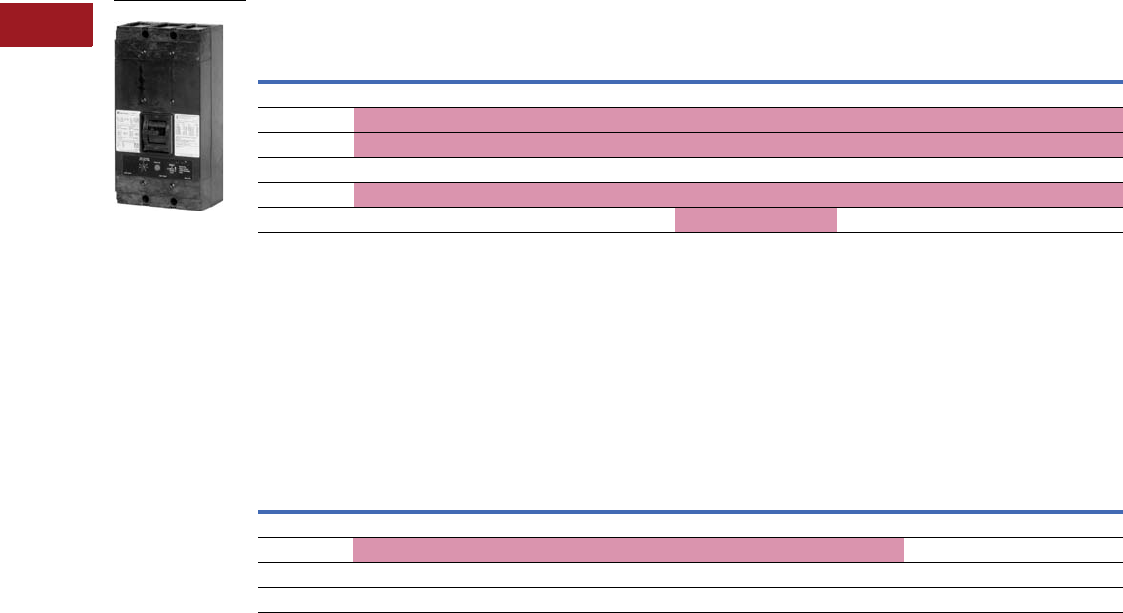
V12-T3-54 Volume 12—Aftermarket, Renewal Parts and Life Extension Solutions CA08100014E—July 2016 www.eaton.com
1
2
3
4
5
6
7
8
9
10
11
12
13
14
15
16
17
18
19
20
21
22
23
24
25
3
Molded-Case Circuit Breakers
Replacement Capabilities
Types NC, NCA, NCG, NCGA, MARK 75 Type HNC, HNCA, HNCG, HNCGA SELTRONIC with Solid-State Trip Units, 600 Vac
Complete breaker requires frame and rating plug. See the table and terminals on Page V12-T3-60. Extra current transformer included
for neutral. See accessories on Page V12-T3-65 for remote ground fault trip indicator.
■
Shaded area denotes obsolete or discontinued products and services. 1
Type NC, NCA, MARK 75 Type HNC, HNCA SELTRONIC with Solid-State Trip Units, 600 Vac—Frame Only 2
Types NCG, NCGA, and MARK 75 Types HNCG, HNCGA SELTRONIC with Built-In Ground Fault Protection
Complete breaker requires frame and rating plug. See the table and terminals on Page V12-T3-60. Extra current transformer included
for neutral. See accessories on Page V12-T3-65 for remote ground fault trip indicator.
Note: The standard ground fault unit above can also be used without the neutral CT. Order two of the desired terminals for each pole of the breaker and
two for the neutral CT.
Types NCG, NCGA and MARK 75 Type HNCG, HNCGA SELTRONIC with Built-In Ground Fault Protection—
Frame Only
Notes
1 These frames are obsolete. Effective 2/1/02, only the MARK 75 version is available. For replacement solutions, see the cross-reference on
Pages V12-T3-114–V12-T3-167.
2 Complete breaker requires frame and rating plug. See the table on Page V12-T3-60. For terminals, see the table on Page V12-T3-55.
3 Two-pole breakers are supplied in three-pole frames with current-carrying parts omitted from center pole.
4 UL Recognized component.
5 For applications other than standard residual scheme, see Application Data 29-160.
Type NC 1200A molded-case switch; refer to Page V12-T3-62. MARK 75 frame color changed from gray to black in mid-2002.
Number
of Poles 3
Standard (Long Delay and Short Time) Short Time Only 4
Long Delay, Short Time and Adjustable
Short Delay Time (0.08 –0.30 Seconds)
Catalog Number Catalog Number Catalog Number
Types NC and NCA (800–1200A)
2NC21200F NC21200FM NCA21200F
3NC31200F NC31200FM NCA31200F
Mark 75 Types HNC and HNCA (800–1200A)
2HNC21200F HNC21200FM HNCA21200F
3HNC31200F HNC31200FM HNCA31200F
Number
of Poles
Standard (Long Delay, Short Time
and Ground Fault Trip)
Long Delay, Short Time, Adjustable
Short Delay Time, and Ground Fault Trip
Ground Fault Characteristics
Pickup Setting
Amperes Time SettingCatalog Number Catalog Number
Types NCG and NCGA (800–1200A) 5
3NCG31200F NCGA31200F 120–1200 3.5–30 Cy
MARK 75 Types HNCG and HNCGA (800–1200A) 5
3HNCG31200F HNCGA31200F 120–1200 3.5–30 Cy
NC: 600 Vac

Volume 12—Aftermarket, Renewal Parts and Life Extension Solutions CA08100014E—July 2016 www.eaton.com V12-T3-55
1
2
3
4
5
6
7
8
9
10
11
12
13
14
15
16
17
18
19
20
21
22
23
24
25
3
Molded-Case Circuit Breakers
Replacement Capabilities
Types NC, NCA, NCG, NCGA, MARK 75 Type HNC, HNCA, HNCG,
HNCGA SELTRONIC with Solid-State Trip Units, 600 Vac
Accessories and Modifications
Field-Mountable Attachments—Left Handed 12345
For CSA, see Page V12-T3-48.
Type NC SELTRONIC breakers meet requirements for Class 21a,
and MARK 75. Type HNC meet Class 23a as defined by Federal
Spec. W-C-375b.
UL Listed Interrupting Capacity, rms Symmetrical Amperes 8
Rating Plugs
Select from the table on Page V12-T3-60.
Terminals
Note: Two terminals required per pole.
Terminals 9
Additional Accessories and Modifications
Refer to Pages V12-T3-65–V12-T3-79.
Note: MARK 75 frame color changed from gray to black in mid-2002.
Notes
1For other possible combinations, refer to factory.
2Molded-case switches do not use standard SELTRONIC attachments and should be ordered
by description.
3Does not void listing of UL Listed breakers.
4Only one of the attachments may be mounted per breaker.
5Left pole mounting.
6Rated 48V minimum for ground fault applications requiring tripping at 55% of voltage.
7Not for ground fault applications.
8Interrupting capacities shown do not apply to molded-case switches.
9Also used on breakers with ground fault and on separately mounted neutral
current transformers.
jType Al/Cu pressure terminal.
Description Style Number
Provision to trip flux transfer shunt trip from external source
32 to 120 Vdc to 60 Hz 61372D39G13
240 to 600 Vac, 50/60 Hz 71372D39G23
Provision to trip flux transfer shunt trip from external source,
plus a 1A-1B auxiliary switch
32 to 120 Vdc to 60 Hz 61372D39G16
240 to 600 Vac, 50/60 Hz 71372D39G26
Provision to trip flux transfer shunt trip from external 24 Vdc source 1371D94G05
1A-1B auxiliary switch 1371D39G03
24 Vdc shunt trip and 1A-1B auxiliary switch 1371D94G08
Breaker
AC Volts
240 480 600
NC, NCG 42,000 30,000 22,000
HNC, HNCG 65,000 50,000 25,000
Maximum
Amperes
Number of Cables,
Wire Range, Type
Catalog
Number
Al/Cu Pressure Terminals
1000 (3) 3/0–400 kcmil TA1000NB1 j
1200 (std.) (4) 4/0–500 kcmil TA1200NB1 j
1200 (3) 500–750 kcmil TA1201NB1 j
Optional Copper Pressure Terminals
1000 (3) 3/0–500 kcmil T1000NB1
1200 (4) 3/0–400 kcmil T1200NB1
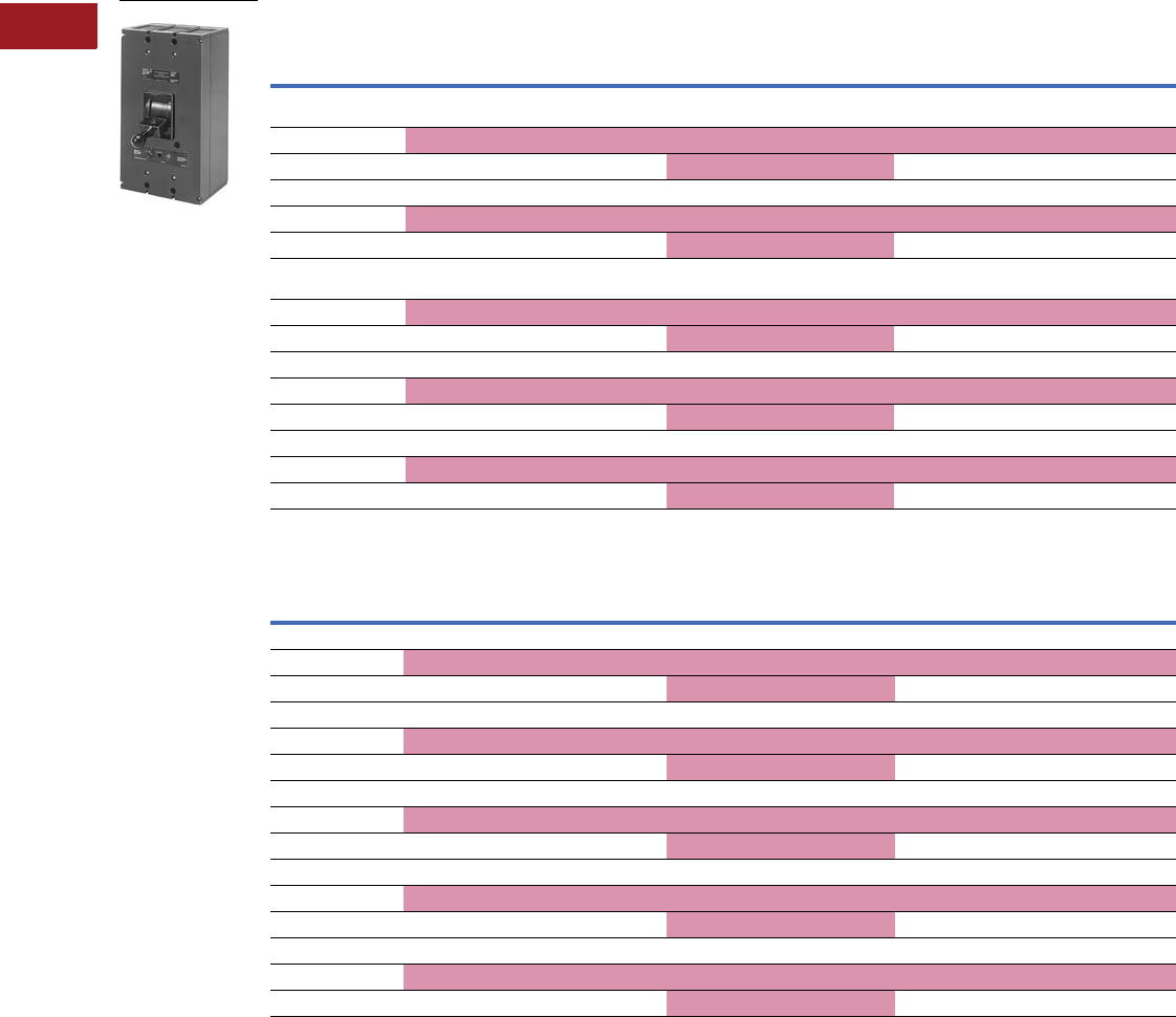
V12-T3-56 Volume 12—Aftermarket, Renewal Parts and Life Extension Solutions CA08100014E—July 2016 www.eaton.com
1
2
3
4
5
6
7
8
9
10
11
12
13
14
15
16
17
18
19
20
21
22
23
24
25
3
Molded-Case Circuit Breakers
Replacement Capabilities
Types PC, PCA, PCC, PCCA 2000, 2500 and 3000A SELTRONIC with Solid-State Trip Units, 600 Vac, 50/60 Hz
Complete breaker requires frame and rating plug. See the table on Page V12-T3-60 and rear connectors (connectors are included in
3000A and all front-connected frames.) Suitable for reverse-feed applications.
■
Shaded area denotes obsolete or discontinued products and services. 1
Breakers for Standard Applications—Frame Only
Breakers for Standard Application at 100% Rating—Frame Only
Notes
1 These frames are obsolete. For replacement solutions, see the cross-reference on Pages V12-T3-114–V12-T3-167.
2 Two-pole breakers are supplied in three-pole frames with current carrying parts omitted from center pole.
3 UL Recognized component.
4 UL Listed for standard applications.
5 These breakers are UL Listed for application at 100% of rating per NEC exceptions when used in a properly ventilated and listed enclosure.
Number
of Poles 2
Standard (Long Delay and Short Time) Short Time Only 3
Long Delay, Short Time Trip, and Adjustable
Short Delay Time (0.08 –0.30 seconds)
Catalog Number Catalog Number Catalog Number
Type PC 2000, 1000 to 2000A 4
Rear-Connected Breakers
Type PCA 2000 4
Rear-Connected Breakers
2PC22000F PC22000FM PCA22000F
3PC32000F PC32000FM PCA32000F
Front-Connected Breakers Front-Connected Breakers
2PCF22000F PCF22000FM PCFA22000F
3PCF32000F PCF32000FM PCFA32000F
Type PC 2500, 1400 to 2500A 4
Rear-Connected Breakers
Type PCA 2500 4
Rear-Connected Breakers
2PC22500F PC22500FM PCA22500F
3PC32500F PC32500FM PCA32500F
Front-Connected Breakers Front-Connected Breakers
2PCF22500F PCF22500FM PCFA22500F
3PCF32500F PCF32500FM PCFA32500F
Type PC 3000, 1600 to 3000A 4Type PCA 3000 4
2PC23000F PC23000FM PCA23000F
3PC33000F PC33000FM PCA33000F
Number
of Poles 2
Standard (Long Delay and Short Time) Short Time Only 3
Long Delay, Short Time Trip, and Adjustable
Short Delay Time (0.08 –0.30 seconds)
Catalog Number Catalog Number Catalog Number
Type PCC 2000, 1000 to 2000A 5—Rear-Connected Breakers
2PCC22000F PCC22000FM PCCA22000F
3PCC32000F PCC32000FM PCCA32000F
Front Connected Breakers
2PCCF22000F PCCF22000FM PCCFA22000F
3PCCF32000F PCCF32000FM PCCFA32000F
Type PCC 2500, 1400 to 2500A 5—Rear-Connected Breakers
2PCC22500F PCC22500FM PCCA22500F
3PCC32500F PCC32500FM PCCA32500F
Front-Connected Breakers
2PCCF22500F PCCF22500FM PCCFA22500F
3PCCF32500F PCCF32500FM PCCFA32500F
Type PC 3000, 1600 to 3000A 5
2PCC23000F PCC23000FM PCCA23000F
3PCC33000F PCC33000FM PCCA33000F
PC: 600 Vac

Volume 12—Aftermarket, Renewal Parts and Life Extension Solutions CA08100014E—July 2016 www.eaton.com V12-T3-57
1
2
3
4
5
6
7
8
9
10
11
12
13
14
15
16
17
18
19
20
21
22
23
24
25
3
Molded-Case Circuit Breakers
Replacement Capabilities
Accessories and
Modifications
Drawout Mounting Breakers,
Three-Pole Only
Breaker frame and complete
drawout frame with safety
tripping interlock.
Order by description.
Secondary contacts supplied
as required at no extra
charge. Order required rating
plug separately. Refer to
Page V12-T3-79.
Note: Includes breakers without
adjustable short delay time.
Rating Plugs
Select from the table on
Page V12-T3-60.
Stationary portion of drawout
frame only for future breaker
installations, three-pole only.
Refer to Page V12-T3-79.
Special Type PCC Breakers for
SCR Power Supplies
These drawout mounting
breakers are designed with
a 2 to 4 times magnetic trip
adjustment and special time
delay trip characteristics to
provide maximum protection
and coordination with SCR
power supplies on offshore
drilling rigs. Suitable for
application at 100% of rating.
Order by description.
Secondary contacts supplied
as required. Order standard
rating plugs separately.
Availability: PCC2000,
PCC2500 drawout-mounting
breakers.
Type PC and PCC meet
requirements of Class 25a
as defined in Federal Spec.
W-C-375b.
For CSA, see
Page V12-T3-48.
UL Listed Interrupting Capacity rms Symmetrical Amperes
(Standard and Ground Fault Breakers) 1
Note
1Interrupting capacities shown do not apply to molded-case switches.
Additional Accessories
and Modifications
Refer to Pages V12-T3-65–
V12-T3-79.
Breaker
AC Volts
240 480 600
PC, PCC 125,000 100,000 100,000

V12-T3-58 Volume 12—Aftermarket, Renewal Parts and Life Extension Solutions CA08100014E—July 2016 www.eaton.com
1
2
3
4
5
6
7
8
9
10
11
12
13
14
15
16
17
18
19
20
21
22
23
24
25
3
Molded-Case Circuit Breakers
Replacement Capabilities
Types PCG, PCGA, PCCG,
PCCGA SELTRONIC with
Built-In Ground Fault
Protection Includes Extra
Current Transformer for
Neutral (Optional Remote
Ground Fault Trip Indicator
Kit, Page V12-T3-65)
Complete breaker requires
frame and rating plug. See the
table on Page V12-T3-60 and
rear connectors (except front-
connected frames and 3000A
frames include connectors).
■
Shaded area denotes
obsolete or discontinued
products and services.
Note: The standard ground fault
unit listed can also be used
without the neutral CT.
Note: Available without
extra CT for neutral. Order
by description as similar to
above except without neutral
CT or external CT terminal
connections at same price.
Older catalog numbers:
PCFGX—”X” means without
fourth CT.
Breakers for Standard Application—Frame Only
Breakers for Application at 100% Rating—Frame Only
Notes
1UL Listed for standard applications.
2For application other than standard residual schemes, refer to Application Data 29-160.
3These breakers are UL Listed for application at 100% of rating per NEC exceptions when used in a properly ventilated and listed enclosure.
Number
of Poles
Standard (Long Delay,
Short Time and Ground Fault Trip)
Long Delay, Short Time, Ground Fault
Trip, and Adjustable Short Delay Time
(0.08 –0.30 Seconds)
Ground Fault Characteristics
Pickup
Setting
Time
SettingCatalog Number Catalog Number
Type PCG 2000 12—Rear-Connected Breakers Type PCGA 2000 12 1000 to 2000A 2—Rear-Connected Breakers
3PCG32000F PCGA32000F 200–1200 3.5–30 cycles
Front-Connected Breakers
3PCFG32000F PCFGA32000F 200–1200 3.5–30 cycles
Ty p e P C G 2 5 0 0 12—Rear-Connected Breakers Type PCGA 2500 12 1400 to 2500A 2—Rear-Connected Breakers
3PCG32500F PCGA32500F 240–1200 3.5–30 cycles
Front-Connected Breakers
3PCFG32500F PCFGA32500F 240–1200 3.5–30 cycles
Type PCG 3000 12 Type PCGA 3000 12 1600 to 3000A 2
3PCG33000F PCGA33000F 300–1200 3.5–30 cycles
Number
of Poles
Standard (Long Delay,
Short Time and Ground Fault Trip)
Long Delay, Short Time, Ground Fault
Trip, and Adjustable Short Delay Time
(0.08 –0.30 Seconds)
Ground Fault
Characteristics
Pickup
Setting
Time
SettingCatalog Number Catalog Number
Type PCCG 2000 3—Rear-Connected Breakers Type PCCGA 2000 3 1000 to 2000A 2—Rear-Connected Breakers
3PCCG32000F PCCGA32000F 200–1200 3.5–30 cycles
Front-Connected Breakers
3PCCFG32000F PCCFGA32000F 200–1200 3.5–30 cycles
Type PCCG 2500 3—Rear-Connected Breakers Type PCCGA 2500 3 1400 to 2500A 2—Rear-Connected Breakers
3PCCG32500F PCCGA32500F 240–1200 3.5–30 cycles
Front-Connected Breakers
3PCCFG32500F PCCFGA32500F 240–1200 3.5–30 cycles
Type PCCG 3000 3Type PCCGA 3000 3 1600 to 3000A 2
3PCCG33000F PCCGA33000F 300–1200 3.5–30 cycles
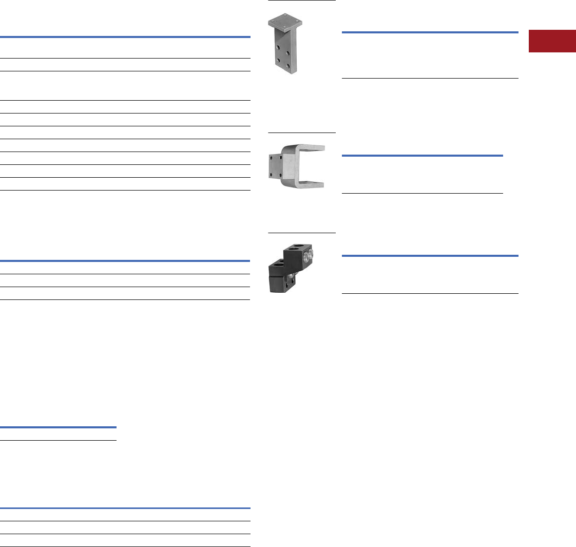
Volume 12—Aftermarket, Renewal Parts and Life Extension Solutions CA08100014E—July 2016 www.eaton.com V12-T3-59
1
2
3
4
5
6
7
8
9
10
11
12
13
14
15
16
17
18
19
20
21
22
23
24
25
3
Molded-Case Circuit Breakers
Replacement Capabilities
Types PCG, PCGA, PCCG, PCCGA SELTRONIC with Built-In
Ground Fault Protection Accessories and Modifications
PC breakers are not UL Listed.
Field-Mountable Attachments 123
Rear Bus Connectors
Two required per pole. Fixed mounting breakers.
Rear Bus Connectors
Racking Crank for
Drawout Frames
To engage or withdraw
the moving portion of
the drawout. A standard
0.50-inch hex socket with
extension can be used for
this purpose.
Racking Crank
Cell Switches Mounted on
Drawout Frames, All Ratings
A maximum of four switches
can be provided. Order by
description. Each switch
provides a NO and NC
contact that transfers before
reaching the test position
when being withdrawn, and
after the test position when
being racked in.
Approximate Shipping Weights, PC and PCC Breakers
(Three-Pole)
Description Style Number
Provision to trip flux transfer shunt trip from external source
32 to 120 Vdc to 60 Hz 4
1372D35G22
240 to 600 Vac, 50/60 Hz 51372D35G32
Provision to trip flux transfer shunt trip from external source
plus 1A-1B auxiliary switch
32 to 120 Vdc to 60 Hz 4
1372D35G15
240 to 600 Vac, 50/60 Hz 51372D35G25
2A-2B auxiliary switch 1372D35G18
Provision to trip flux transfer shunt trip from external 24 Vdc source 1371D95G01
1A-1B auxiliary switch 1372D35G03
1A-1B auxiliary switch and 24 Vdc shunt trip 1371D95G04
2A-2B auxiliary switch and 24 Vdc shunt trip 1371D95G07
3A-3B auxiliary switch and 24 Vdc shunt trip 1371D95G10
Breaker Frame 6Connector Style/Catalog Number
PC2000 7, PCC2000 7BA2000PB
PC2500 7, PCC2500 7BA2500PB
PC3000, PCC3000 Included in frame
Style Number
765A767G01
Rating
Breaker
PC, PCC PCF, PCCF PCG, PCCG PCFG, PCCFG
2000 136 lbs 163 lbs 160 lbs 185 lbs
2500 145 lbs 175 lbs 170 lbs 200 lbs
3000 220 lbs — 245 lbs —
Busbar Connections
Busbar Connections—“T” Connector
(For Cu/AI Bus)
Two required per pole. For rear bus connection of breakers
through 2000A. Accepts up to four bus bolts. May be rotated 90°.
Note: Shipped separately from breaker.
“C” Connector (For Cu/AI Bus)
Two required per pole. For rear bus connection of
2500A breakers.
Cable Connector
Fits “T” Connector and 2000A front-connected breakers.
Accepts four 400–600 kcmil copper cables.
Notes
1For other possible combinations, contact your local Eaton Field Sales office.
2Only one of these attachments may be mounted per breaker.
3Left pole mounting.
4Rated 48V minimum for ground fault applications.
5Not for ground fault applications.
6Also apply to equivalent ratings of PCG and PCCG ground fault breakers.
7Not required for front-connected frames.
Catalog Number
BA2000PB
Breaker Amperes Catalog Number
2500 BA2500PB
Catalog Number
505C706G04
“T” Connector
“C” Connector
Cable Connector

V12-T3-60 Volume 12—Aftermarket, Renewal Parts and Life Extension Solutions CA08100014E—July 2016 www.eaton.com
1
2
3
4
5
6
7
8
9
10
11
12
13
14
15
16
17
18
19
20
21
22
23
24
25
3
Molded-Case Circuit Breakers
Replacement Capabilities
SELTRONIC Rating Plug Selection Data
Rating plugs listed below are for both standard breakers and breakers with built-in ground fault protection.
Rating Plug Selection Data
Notes
1Ampere rating when used in short time only frames:
LC-150: 150A MC-800: 800A PC-3000: 3000A
LC-300: 300A NC-1200: 1200A LCL-250: 250A
LC-400: 400A PC-2000: 2000A LCL-400: 400A
LC-600: 600A PC-2500: 2500A
2Magnetic trip range of adjustable rating plugs:
LC, HLC, MC, HMC: 3 to 10 times ampere setting
NC, HNC, PC, PCC, LCL-400: 2 to 8 times ampere setting
LCL-250: 3 to 9 times ampere setting
3Adjustable 70 to 100% except as noted.
4Adjustable 75 to 100%.
5Adjustable 50 to 100%.
6Adjustable 80 to 100%.
Contact Avery Creek, NC, Technical Resource Center for old style (three prong) ground fault
rating plugs.
Rating Plugs Only (For Two- or Three-Pole Frames)
Continuous
Ampere
Rating 1
Magnetic Trip
Setting, Amperes
Fixed
Rating Plugs
Adjustable
Rating Plugs 23
Low High Catalog Number Catalog Number
For 150A Frames: LC, LCA, LCG, LCGA, HLC, HLCA, HLCG, HLCGA
75 225 750 1LC75 —
90 270 900 1LC90 —
100 300 1000 1LC100 A1LC100 4
125 375 1250 1LC125 A1LC125
150 450 1500 1LC150 A1LC150 5
For 300A Frames: LC, LCA, LCG, LCGA, HLC, HLCA, HLCA, HLCG, HLCGA
150 450 1500 3LC150 —
175 525 1750 3LC175 —
200 600 2000 3LC200 —
225 675 2250 3LC225 A3LC225
250 750 2500 3LC250 A3LC250
275 825 2750 3LC275 A3LC275
300 900 3000 3LC300 A3LC300 5
For 400A Frames: LC, LCA, LCG, LCGA, HLC, HLCA, HLCG, HLCGA
200 600 2000 4LC200 —
225 675 2250 4LC225 —
250 750 2500 4LC250 —
300 900 3000 4LC300 A4LC300
350 1050 3500 4LC350 A4LC350
400 1200 4000 4LC400 A4LC400 5
For 600A Frames: LC, LCA, LCG, LCGA, HLC, HLCA, HLCG, HLCGA, LCC,
LCCA, HLCC, HLCCA, LCCG, LCCGA, HLCCG, HLCCGA
300 900 3000 6LC300 —
350 1050 3500 6LC350 —
400 1200 4000 6LC400 A6LC400 4
450 1350 4500 6LC450 A6LC450
500 1500 5000 6LC500 A6LC500
600 1800 6000 6LC600 A6LC600 5
For 800A Frames: MC, MCA, MCG, MCGA, HMC, HMCA, HMCG, HMCGA,
MCC, MCCA, HMCC, HMCCA, MCCG, MCCGA, HMCCG, HMCCGA, MDS
400 1200 4000 8MC400 —
500 1500 5000 8MC500 A8MC500 6
600 1800 6000 8MC600 A8MC600
700 2100 7000 8MC700 A8MC700
800 2400 8000 8MC800 A8MC800 5
Rating Plugs Only (For Two- or Three-Pole Frames)
Continuous
Ampere
Rating 1
Magnetic Trip
Setting, Amperes
Fixed
Rating Plugs
Adjustable
Rating Plugs 23
Low High Catalog Number Catalog Number
For 1200A Frames: NC, NCA, NCG, NCGA, HNC, HNCA, HNCG, HNCGA
800 1600 6400 12NC800 A12NC800 4
900 1800 7200 12NC900 A12NC900
1000 2000 8000 12NC1000 A12NC1000
1200 2400 9600 12NC1200 A12NC1200 5
For 2000A Frames: PC, PCA, PCC, PCCA, PCG, PCGA, PCCG, PCCGA
1000 2000 8000 20PC1000 —
1200 2400 9600 20PC1200 —
1400 2800 11,200 20PC1400 —
1600 3200 12,800 20PC1600 A20PC1600
1800 3600 14,400 20PC1800 A20PC1800
2000 4000 16,000 20PC2000 A20PC2000 5
For 2500A Frames: PC, PCA, PCC, PCCA, PCG, PCGA, PCCG, PCCGA
1400 2800 11,200 25PC1400 —
1600 3200 12,800 25PC1600 —
1800 3600 14,400 25PC1800 A25PC1800
2000 4000 16,000 25PC2000 A25PC2000
2500 5000 20,000 25PC2500 A25PC2500 5
For 3000A Frames: PC, PCA, PCC, PCCA, PCG, PCGA, PCCG, PCCGA
1600 3200 12,800 30PC1600 —
1800 3600 14,400 30PC1800 —
2000 4000 16,000 30PC2000 —
2500 5000 20,000 30PC2500 A30PC2500
3000 6000 24,000 30PC3000 A30PC3000 5

Volume 12—Aftermarket, Renewal Parts and Life Extension Solutions CA08100014E—July 2016 www.eaton.com V12-T3-61
1
2
3
4
5
6
7
8
9
10
11
12
13
14
15
16
17
18
19
20
21
22
23
24
25
3
Molded-Case Circuit Breakers
Replacement Capabilities
Molded-Case Switches
Molded-case switches are UL Listed devices and are available
only as high magnetic trip type with fixed trip setting.
■
Shaded area denotes obsolete or discontinued
products and services. 1
Molded-Case Switches with High Magnetic Trip
(Fixed Trip Setting)
Molded-Case Switch Terminal Data
Molded-Case Switches with High Magnetic Trip—
Trip Setting and Tolerance
Notes
1These frames are obsolete. For replacement solutions, see the cross-reference
on Pages V12-T3-114–V12-T3-167.
2Catalog number suffix identification:
K = Molded-case switch with high magnetic trip (fixed trip setting)
S = Saf-T-Vue cover
L = With line and load terminals
W = No terminals
3Molded-case switch dimensions are the same as the equivalent thermal-magnetic breaker.
Refer to Dimension Sheet 29-171.
Number
of Poles
Maximum
Volts
Maximum
Amperes
Switch
Catalog Number 23
2240 400 DA2400WK
3240 400 DA3400WK
1120 100 EB1100LK
2240 100 EB2100LK
3240 100 EB3100LK
3240 100 EB3100SLK
1277 100 EHB1100LK
2480 100 EHB2100LK
3480 100 EHB3100LK
3480 100 EHB3100SLK
2600 100 FB2100LK
2600 150 FB2150LK
3600 100 FB3100LK
3600 150 FB3150LK
3600 150 FB3150SLK
4277/480 100 FB4100LK
4277/480 150 FB4150LK
2600 225 JA2225WK
2600 225 JA2225WSK
3600 225 JA3225WK
3600 225 JA3225WSK
2600 250 JB2250WK
2600 250 JB2250WSK
3600 250 JB3250WK
3600 250 JB3250WSK
2600 225 KA2225WK
2600 225 KA2225WSK
3600 225 KA3225WK
3600 225 KA3225WSK
2600 250 KB2250WK
2600 250 KB2250WSK
3600 250 KB3250WK
3600 250 KB3250WSK
2600 400 LB2400WK
2600 400 LB2400WSK
3600 400 LB3400WK
3600 400 LB3400WSK
2600 400 LBB2400WK
2600 400 LBB2400WSK
3600 400 LBB3400WK
3600 400 LBB3400WSK
MCS
Type
Maximum
Switch
Amperes
Wire
Type
Number
of Wires
Wire
Range
Terminal Type
or Catalog
Number
Standard Terminals
DA, LB, LBB 400 Cu only 2 3/0–250 kcmil T400DA2
EB, EHB, FB 100 Cu 1 #14–1/0 Pressure
FB 150 Cu/Al 1 #4–4/0 Pressure
JA, KA 225 Cu/Al 1 #4–350 kcmil TA225LA1
JB, KB
250
Cu/Al 1 #4–350 kcmil TA250KB
Optional Terminals
DA, LB, LBB 400 — — — —
EB, EHB, FB 100 Cu/Al 1 #4–4/0 Pressure
FB 150 — — — —
JA, KA 225 Cu 1 #6–350 kcmil T225LA
JB, KB 250 Cu 1 #4–350 kcmil T250KB
Frame Rating
Trip Setting
(Amperes)
Tolerance
(%)
EB 100 1000 ±20
EHB/FB 100 1200 ±20
FB 150 1500 ±20
DA/LB/LBB 400 4000 +10
– 0
JA/KA 225 2250 +10
– 0
JB/KB 250 2500 +10
– 0

V12-T3-62 Volume 12—Aftermarket, Renewal Parts and Life Extension Solutions CA08100014E—July 2016 www.eaton.com
1
2
3
4
5
6
7
8
9
10
11
12
13
14
15
16
17
18
19
20
21
22
23
24
25
3
Molded-Case Circuit Breakers
Replacement Capabilities
■
Shaded area denotes obsolete or discontinued products and services. 1
Molded-Case Switches with High Magnetic Trip
(Fixed Trip Setting)
Molded-Case Switch Terminal Data
Molded-Case Switches With High Magnetic Trip—
Trip Setting and Tolerance
Notes
1These frames are obsolete. For replacement solutions, see the cross-reference
on Pages V12-T3-114–V12-T3-167.
2Catalog number suffix identification:
K = Molded-case switch with high magnetic trip (fixed trip setting)
S = Saf-T-Vue cover
W = No terminals
3Molded-case switch dimensions are the same as the equivalent thermal-magnetic breaker.
Refer to Dimension Sheet 29-171.
4For molded-case switch types LC, LCC—use LA attachments;
MC and MCC—use MA attachments; NC—use NB attachments.
5For molded-case switch types PC, PCC and PCF, rating plug is included and use SELTRONIC
PC attachments.
Number
of Poles
Maximum
Volts
Maximum
Amperes
Switch
Catalog Number 23
2240225CA2225KW
3240225CA3225KW
2600 400 LA2400WK
2600 400 LA2400WSK
2600 600 LA2600WK
2600 600 LA2600WSK
3600 400 LA3400WK
3600 400 LA3400WSK
3600 400 LA3600WK
3600 400 LA3600WSK
2600 400 LAB2400WK
2600 400 LAB2400WSK
3600 400 LAB3400WK
3600 400 LAB3400WSK
2600 600 LC2600WK 4
3600 600 LC3600WK 4
2600 600 LCC2600WK 4
3600 600 LCC3600WK 4
2600 800 MA2800WK
2600 800 MA2800WSK
3600 800 MA3800WK
3600 800 MA3800WSK
2600 800 MC2800WK 4
3600 800 MC3800WK 4
2600 800 MCC2800WK 4
3600 800 MCC3800WK 4
2600 1200 NB21200WK
2600 1200 NB21200WSK
3600 1200 NB31200WK
3600 1200 NB31200WSK
2600 1200 NC21200WK 4
3600 1200 NC31200WK 4
2600 2000 PB22000WK
2600 2500 PB22500WK
3 600 2000 PB32000WK
3 600 2500 PB32500WK
2600 2000 PBF22000K
3 600 2000 PBF32000WK
2 5600 2000 PC22000WK
2 5600 2500 PC22500WK
2 5600 3000 PC23000K
3 5600 2000 PC32000WK
3 5600 2500 PC32500WK
3 5600 3000 PC33000K
2 5600 2000 PCC22000WK
2 5600 2500 PCC22500WK
2 5600 3000 PCC23000K
3 5600 2000 PCC32000WK
3 5600 2500 PCC32500WK
3 5600 3000 PCC33000K
2 5600 2000 PCF22000K
3 5600 2000 PCF32000K
MCS
Type
Maximum
Switch
Amperes
Wire
Range
Wire
Type
Number
of Wires
Terminal
Type or
Catalog
Number
Standard Terminals (Aluminum Body)
CA 225 #1–300 kcmil Cu/Al 1 TA225CA2
LA400, LAB 400 #4–250 kcmil,
plus 3/0–600 kcmil
Cu/Al 1 TA400LA1
LA600, LC600 600 250/500 kcmil Cu/Al 2 TA600LA
MC, MA 800 3/0–400 kcmil Cu/Al 3 TA800MA2
NC, NB 1200 4/0–500 kcmil Cu/Al 4 TA1200NB1
NC, NB 1200 — — — —
PC2000, PCC2000 2000 BA2000PB rear bus connector
PC2500, PCC2500 2500 BA2500PB rear bus connector
PC3000, PCC3000 3000 Rear bus connector included in frame
Optional Terminals
CA 225 — — — —
LA400, LAB 400 #4–250 kcmil,
plus 3/0–600 kcmil
Cu 1 T401LA
LA600, LC600 600 250/500 kcmil Cu 2 T600LA
MC, MA 800 3/0–300 kcmil Cu 3 T800MA1
NC, NB 1200 3/0–400 kcmil Cu 4 T1200NB1
NC, NB 1200 500–750 kcmil Cu/Al 3 TA1201NB1
PC2000, PCC2000 2000 BA2000PB rear bus connector
PC2500, PCC2500 2500 BA2500PB rear bus connector
PC3000, PCC3000 3000 Rear bus connector included in frame
Frame Rating
Trip Setting
(Amperes)
Tolerance
(%)
CA 225 2250 +20
–10
LA (400) 400 4000 +10
– 0
LA/LC 600 6000 +10
– 0
MA/MC 800 8000 +10
– 0
NB/NC 1200 12,000 +10
– 0
PB/PC 2000–3000 12,000 +10
– 0
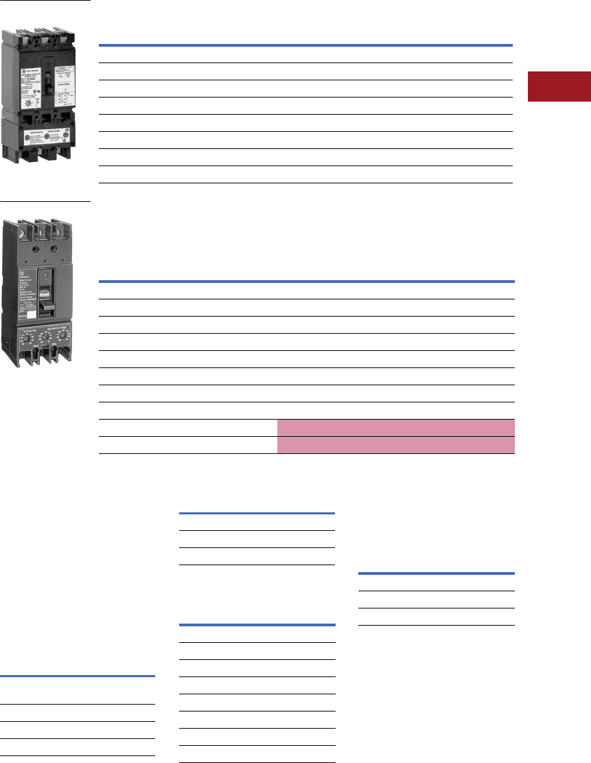
Volume 12—Aftermarket, Renewal Parts and Life Extension Solutions CA08100014E—July 2016 www.eaton.com V12-T3-63
1
2
3
4
5
6
7
8
9
10
11
12
13
14
15
16
17
18
19
20
21
22
23
24
25
3
Molded-Case Circuit Breakers
Replacement Capabilities
Type MCP Motor
Circuit Protector
The motor circuit protector
(MCP) is designed specifically
for the protection of motor
circuits. It operates on the
magnetic principle with a
current sensing coil in each of
the three poles, with the
trip-
point adjustable from the front.
MCPs
are the fastest devices
available for clearing low level
faults and offer circuit breaker
features and convenience
—
reset
table, quick-make
quick-break, deadfront
and protection against
single phasing.
MCPs are rated to correspond
to NEMA starter size.
Current Limiter Attachment
The EL current limiter is an
attachment that bolts to
the load end of the MCP to
provide increased interrupting
capacity. The combination is
UL Listed as a recognized
component for application at
up to 200,000A symmetrical
at 600 Vac. It is coordinated
with the MCP so that normal
short circuits will be cleared
automatically by the MCP,
opening all three poles, and
only the rare high fault will
cause the limiter to function.
Current limiters must be
applied as shown in the
terminal table above.
Note: Sizes 0–4 only.
Terminals
Terminals are included
with both the MCP and the
current limiter. Standard
terminals are aluminum alloy,
with non-aluminum terminals
optional for use with only
the MCP. Both standard
and optional terminals will
accommodate aluminum
or copper conductors.
Note: Except 400A Size 5.
Non-aluminum terminal suitable
for copper only.
When using aluminum
conductors, use of joint
compound is recommended.
Wire ranges are listed in the
terminal table above.
Te r m i n a l s
Motor Circuit Protectors
■
Shaded area denotes obsolete or discontinued products
and services. 1
UL Listed
The MCP is UL Listed
as a
recognized component
and
requires additional listing by
the control manufacturer in
combination with a contactor
and overload relay.
Modifications for MCP
These modifications must be
factory installed. Consult
factory for pricing.
Modifications for MCP 3
Accessories for MCP
For handle mechanisms
refer to Pages V12-T3-95–
V12-T3-112.
Note: On 400A Size 5, an external
resistor is supplied for voltages,
above 240 Vac and 24 Vdc.
Accessories for MCP
Current Limiters
Interrupting Ratings
Maximum application current
shall be determined by testing
the MCP in combination with
a contactor and overload relay.
Additional capacity can be
obtained by using the current
limiter attachment.
Base Mounting Hardware
No charge when ordered
with MCP. Order separately
when required.
Base Mounting Hardware
Notes
1These frames are obsolete. For
replacement solutions, see the cross-
reference on Pages V12-T3-114–
V12-T3-167.
2Catalog numbers ending in CR were
previously listed ending in RC. This
is a catalog number change only, not
a material change.
3Not UL Listed.
4Mounts only in right pole; only one
Modification marked can be used in
MCP (Sizes 0–4).
5On 400A Size 5, an external resistor is
supplied for voltages above 240 Vac
and 24 Vdc.
6On Sizes 0–4 and 250A Size 5, an
external resistor is supplied for customer
mounting, except for 120 Vac, 12, 24,
125 Vdc.
7Also applicable to MCPs with
optional terminals.
MCP or Limiter
(Amperes)
Terminals
Standard Aluminum Optional Non-Aluminum
Size 0, 1, 2 #14–#4 #14–1/0
Size 3 #6–3/0 #14–1/0
Size 4 #4–4/0 #4–4/0
Size 5 (250) #4–350 kcmil #4–350 kcmil
Size 5 (400) — (2) 3/0–250 kcmil
Limiters to 50 #14–#2 —
Limiters to 100 #1–4/0 —
Limiters to 150 #1–4/0 —
Starter
Size
Tri p
Range,
Amperes
Continuous
Ampere
Rating
With Standard Aluminum
Alloy Terminals
Catalog Number
With Optional
Non-Aluminum Terminals 2
Catalog Number
07–22 3 MCP0322R MCP0322CR
0 18–58 7 MCP0358R MCP0358CR
0 50–150 15 MCP03150R MCP03150CR
1 100–300 30 MCP13300R MCP13300CR
2 160–480 50 MCP23480R MCP23480CR
3 275–1000 100 MCP331000R MCP331000CR
4 450–1550 150 MCP431550R MCP431550CR
4 575–1800 150 MCP431800R MCP431800CR
5 1250–2500 250 MCP532500 MCP532500C
5 2000–4000 400 —MCP534000C
Sizes 0–4 MCP with
Current Limiter
Size 5 MCP 532500
Description
Auxiliary switches 4—1A and 1B,
2As and 2Bs
Shunt trip 4
Undervoltage release 456
Moisture-fungus treatment
For
MCP Size
Use
Accessories For
Sizes 0–4 FB
5 (250A) KB
5 (400A) LB
Limiter Catalog
Numbers
For MCP Catalog
Numbers 7
EL3003R MCP0322R
EL3007R MCP0358R
EL3015R MCP03150R
EL3030R MCP13300R
EL3050R MCP23480R
EL3100R MCP331000R
EL3150R MCP431550R
EL3150R MCP431800R
Description Style Number
Sizes 0–4 21C6782G18
Size 5 (250A) 673B125G12
Size 5 (400A) 21C6782G22

V12-T3-64 Volume 12—Aftermarket, Renewal Parts and Life Extension Solutions CA08100014E—July 2016 www.eaton.com
1
2
3
4
5
6
7
8
9
10
11
12
13
14
15
16
17
18
19
20
21
22
23
24
25
3
Molded-Case Circuit Breakers
Replacement Capabilities
Series C 30 mA Ground Fault
(Earth Leakage)
The Series C units (prefix only
listed below) that included a
breaker and integral Earth
Leakage module have been
replaced by the Series G
solution that has the flexibility
to add the Earth Leakage
module in the field. The
Series G solution has an
extended range of 15–630A.
Series C 30 mA Ground
Fault (Earth Leakage)
Note: Please contact Eaton
customer service for assistance
with crossing from the obsolete
product to the new Series G.
Ampere Range—15–400A
Catalog Prefix
Three-Pole Four-Pole
ELFD EL4FD
ELFW EL4FW
ELHMCP EL4HFD
ELHFD EL4HFW
ELHFW EL4HJW
ELHJD EL4HKW
ELHJW EL4JW
ELHKD EL4KW
ELHKW —
ELJD —
ELJW —
ELKD —
ELKW —
Earth Leakage
Ampere
Rating
Series C
Four-Pole
Series G
MCCB
Series G
MCCB
Alt
Series G Earth
Leakage Module
15 EL4FD3015L EGS4015FFG EGC4015FFG ELEBN4125G
20 EL4FD3020L EGS4020FFG EGC4020FFG ELEBN4125G
25 EL4FD3025L EGS4025FFG EGC4025FFG ELEBN4125G
30 EL4FD3030L EGS4030FFG EGC4030FFG ELEBN4125G
35 EL4FD3035L EGS4035FFG EGC4035FFG ELEBN4125G
40 EL4FD3040L EGS4040FFG EGC4040FFG ELEBN4125G
45 EL4FD3045L EGS4045FFG EGC4045FFG ELEBN4125G
50 EL4FD3050L EGS4050FFG EGC4050FFG ELEBN4125G
60 EL4FD3060L EGS4060FFG EGC4060FFG ELEBN4125G
70 EL4FD3070L EGS4070FFG EGC4070FFG ELEBN4125G
80 EL4FD3080L EGS4080FFG EGC4080FFG ELEBN4125G
90 EL4FD3090L EGS4090FFG EGC4090FFG ELEBN4125G
100 EL4FD3100L EGS4100FFG EGC4100FFG ELEBN4125G
110 EL4FD3110L EGS4110FFG EGC4110FFG ELEBN4125G
125 EL4FD3125L EGS4125FFG EGC4125FFG ELEBN4125G
150 EL4FD3150L JGE4150FAG JGC4150FAG ELJBN4150W
50 EL4FW3050JL GES4050AFM — ELEBE4125G
50 EL4FWC3050JL GEC4050AFM — ELEBE4125G
15 EL4HFD3015L EGH4015FFG —ELEBN4125G
20 EL4HFD3020L EGH4020FFG —ELEBN4125G
25 EL4HFD3025L EGH4025FFG —ELEBN4125G
30 EL4HFD3030L EGH4030FFG —ELEBN4125G
35 EL4HFD3035L EGH4035FFG —ELEBN4125G
40 EL4HFD3040L EGH4040FFG —ELEBN4125G
45 EL4HFD3045L EGH4045FFG —ELEBN4125G
50 EL4HFD3050L EGH4050FFG —ELEBN4125G
60 EL4HFD3060L EGH4060FFG —ELEBN4125G
70 EL4HFD3070L EGH4070FFG —ELEBN4125G
80 EL4HFD3080L EGH4080FFG —ELEBN4125G
90 EL4HFD3090L EGH4090FFG —ELEBN4125G
100 EL4HFD3100L EGH4100FFG —ELEBN4125G
110 EL4HFD3110L EGH4110FFG —ELEBN4125G
125 EL4HFD3125L EGH4125FFG —ELEBN4125G
150 EL4HFD3150L JGH3150FAG —ELJBN4150W
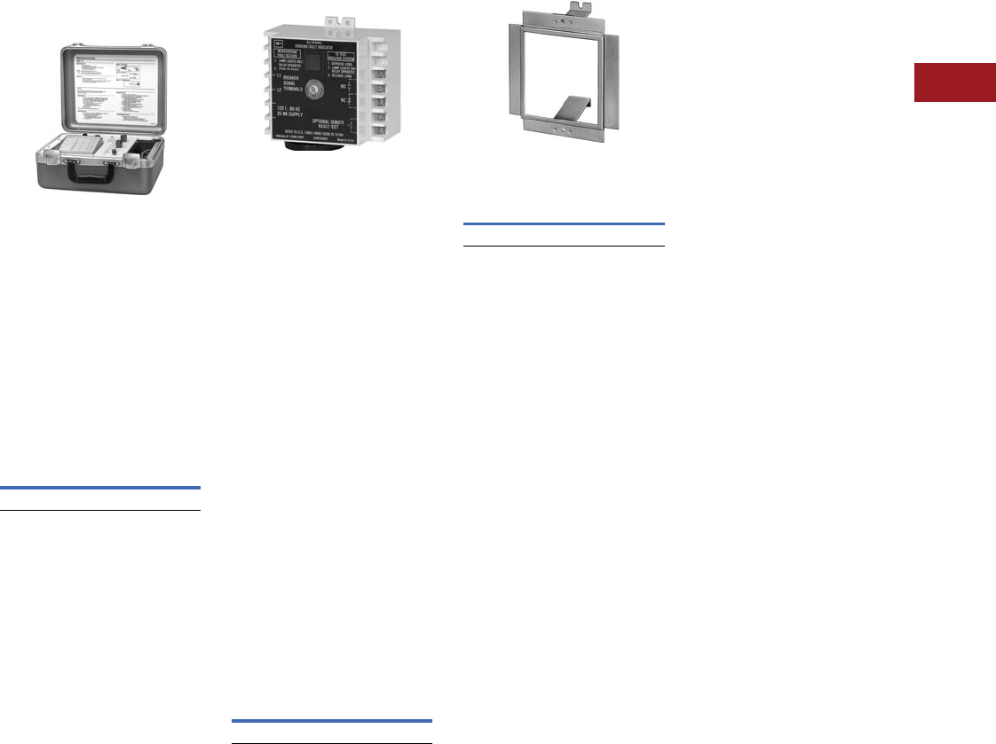
Volume 12—Aftermarket, Renewal Parts and Life Extension Solutions CA08100014E—July 2016 www.eaton.com V12-T3-65
1
2
3
4
5
6
7
8
9
10
11
12
13
14
15
16
17
18
19
20
21
22
23
24
25
3
Molded-Case Circuit Breakers
Replacement Capabilities
Portable Test Kit and Remote
Ground Fault Trip Indicator
Portable Test Kit
Provides verification of
performance of all frame
sizes of SELTRONIC breakers
while devices are still in
service under varying load
and/or phase unbalance.
The tester operates on
120V, 50/60 Hz, and includes
complete instructions and
test times for testing the long
time, instantaneous operation
and optional ground fault
operation of the breaker.
Portable Test Kit
Remote Ground Fault
Trip Indicator
For use only with SELTRONIC
circuit breakers (LCG, HLCG,
MCG, HMCG, NCG, HNCG,
PCG and PCCG) with built-in
ground fault protection.
Note: UL Listed as a recognized
component.
The SELTRONIC ground fault
indicator is a remotely
mounted device with a
combination indicating light/
reset/test button that will
light when the breaker trips
on a ground fault. Tripping
from overloads or short
circuits will not activate the
device. A separate 120V,
50/60 Hz power source is
required to power the light
and internal relay, which
has 1NO/1NC contacts
for customer connected
alarm, etc. Designed for
panel mounting, it can be
face-mounted by ordering
the optional mounting
bracket below.
Remote Ground
Fault Indicator
Face Mounting Bracket
Face Mounting Bracket for
Ground Fault Indicator
Style Number
STK2
Style Number Catalog Number
1259C14G01 GFAU
Style Number
1264C67G01
V12-T3-66 Volume 12—Aftermarket, Renewal Parts and Life Extension Solutions CA08100014E—July 2016 www.eaton.com
1
2
3
4
5
6
7
8
9
10
11
12
13
14
15
16
17
18
19
20
21
22
23
24
25
3
Molded-Case Circuit Breakers
Replacement Capabilities
Accessories
Rear-Connected Studs
For complete stud assembly,
order a stud and an
appropriate tube based on
thickness of customer’s
mounting panel. A short stud
must be assembled adjacent
to a long stud to maintain
clearances required by
Underwriters Laboratories.
400A LA studs of the
same length have sufficient
clearance; however, customer
connections may make it
necessary to use a short stud
adjacent to a long stud. Two
studs are required per pole.
Refer to DS29171 Dimension
Sheets for stud sizes and
extensions behind breaker.
For DA, EB, EHB, FB, JA, KA, JB, KB, LB, LBB, HFB, HKA, HKB and HLB Breakers 1
Notes
1 For insulated panels only; two required per pole.
2 Not UL Listed.
3 Included at no charge when ordered with stud.
Mounting Panel
Thickness, Inches
Stud 2Tube 3
Length Style Number Length Style Number
DA, LB, LBB and HLB Breakers
3/4–1 Short 656D565G03 27/32 313C909H17
3/4–1 Long 656D565G04 3-25/32 313C909H20
1/2–3/4 Short 656D565G03 1-3/32 313C909H18
1/2–3/4 Long 656D565G04 4-1/32 313C909H21
1/4–1/2 Short 656D565G03 1-11/32 313C909H19
1/4–1/2 Long 656D565G04 4-9/32 313C909H22
EB, EHB, FB and HFB (100A Maximum)
1 Short 451D874G01 1-1/16 32B9446H20
1 Long 451D874G02 3-7/16 32B9446H24
1-1/16–15/16 Short 451D874G01 1-3/8 32B9446H21
1-1/16–15/16 Long 451D874G02 3-3/4 32B9446H25
3/8–5/8 Short 451D874G01 1-11/16 32B9446H22
3/8–5/8 Long 451D874G02 4-1/16 32B9446H26
1/4–5/16 Short 451D874G01 232B9446H23
1/4–5/16 Long 451D874G02 4-3/8 32B9446H27
FB, HFB 150 Ampere Breakers
1 Short 374D883G01 1-1/16 374D883H06
1 Long 374D883G02 4-5/16 374D883H10
11/16–15/16 Short 374D883G01 1-3/8 374D883H07
11/16–15/16 Long 374D883G02 4-5/8 374D883H11
3/8–5/8 Short 374D883G01 1-11/16 374D883H08
3/8–5/8 Long 374D883G02 4-15/16 374D883H12
1/4–5/16 Short 374D883G01 2374D883H09
1/4–5/16 Long 374D883G02 5-1/4 374D883H13
JA, KA and HKA Breakers
3/4–1 Short 656D565G01 27/32 456D983H05
3/4–1 Long 656D565G02 3-25/32 456D983H08
1/2–3/4 Short 656D565G01 1-3/32 456D983H06
1/2–3/4 Long 656D565G02 4-1/32 456D983H09
1/4 –1/2 Short 656D565G01 1-11/32 456D983H07
1/4 –1/2 Long 656D565G02 4-9/32 456D983H10
JB, KB and HKB Breakers
3/4–1 Short 5010D23G01 27/32 456D983H05
3/4–1 Long 5010D23G02 3-7/8 5010D23H05
1/2–3/4 Short 5010D23G01 1-3/32 456D983H06
1/2–3/4 Long 5010D23G02 4-1/8 5010D23H06
1/4 –1/2 Short 5010D23G01 1-11/32 456D983H07
1/4 –1/2 Long 5010D23G02 4-3/8 5010D23H07
Rear Connected Stud

Volume 12—Aftermarket, Renewal Parts and Life Extension Solutions CA08100014E—July 2016 www.eaton.com V12-T3-67
1
2
3
4
5
6
7
8
9
10
11
12
13
14
15
16
17
18
19
20
21
22
23
24
25
3
Molded-Case Circuit Breakers
Replacement Capabilities
For LAB, LA, MA, HLA, HMA and HNB Breakers 1
Notes
1For insulated panels only; two required per pole.
2150, 250, 300 and 400A frames only.
3This is a special stud that includes six contact nuts for use where bus contact nuts
must be used.
4600A frames only.
Stud Ampere
Rating
Diameter, Inches
and Thread
Extension Back
of Breaker, Inches
Stud
Style Number
LAB, LA, HLA, LC and HLC Breakers
225 21/2–13 3-7/32 1241 345
225 21/2–13 6-9/32 1241 346
225 23 1/2–13 4-31/32 1241 392
400 23/4–16 5-15/32 5B7383G15
400 23/4–16 7-31/32 5B7383G16
400 23/4–16 10-15/32 5B7383G17
600 41–12 5-29/32 314C960G07
600 41–12 5-13/32 314C960G08
600 41–12 5-29/32 314C960G09
MA, HMA, MC, HMC, MD and MDS Breakers
225 1/2–13 3-21/32 314C960G01
400 3/4–16 5-29/32 314C960G04
400 3/4–16 8-13/32 314C960G05
400 3/4–16 10-29/32 314C960G06
600 1–12 5-29/32 314C960G07
600 1–12 8-13/32 314C960G08
600 1–12 10-29/32 314C960G09
800 1-1/8–12 5-29/32 314C960G10
800 1-1/8–12 8-13/32 314C960G11
800 1-1/8–12 10-29/32 314C960G12
NB, HNB, NC and HNC Breakers
800 1-1/8–12 5-1/2 623B222G01
800 1-1/8–12 8 623B222G02
800 1-1/8–12 10-1/2 623B222G03
1200 1-1/4–12 5-1/2 373B375G04
1200 1-1/4–12 10-1/2 373B375G03

V12-T3-68 Volume 12—Aftermarket, Renewal Parts and Life Extension Solutions CA08100014E—July 2016 www.eaton.com
1
2
3
4
5
6
7
8
9
10
11
12
13
14
15
16
17
18
19
20
21
22
23
24
25
3
Molded-Case Circuit Breakers
Replacement Capabilities
Panelboard Connecting Straps
For connecting line end of breakers to panelboard bus.
For DA, EB, EHB, FB, JA, KA, JB, KB, LB,
LBB, HFB, HKB and HLB Breakers
For CA, LAB, LA, MA, HLA, HMA and HNB Breakers
Notes
1Not UL Listed.
2Bus spacing 2.75 inches in box 5.75 inches deep (600V maximum).
3Bus spacing 3.50 inches.
Ampere Rating Connector Type 1Style Number
EB, EHB, FB and HFB Breakers
Narrow Distribution Panelboards 2
50 Center 673B142G02
50 Outside 673B142G09
100 Center 673B142G02
100 Outside 673B142G10
150 Center 673B142G04
150 Outside 673B142G03
Power Panelboards (Convertible) 3
50 Center 1253C72G01
50 Outside 1253C72G03
100 Center 1253C73G03
100 Outside 1253C73G06
150 Center 1253C73G01
150 Outside 1253C73G05
Three-pole mounting bracket 624B600H01
Two-pole mounting bracket 624B600H02
DA, LB, LBB and HLB Breakers 3
400 Center 314C940G04
400 Outside 505C680G01
Mounting bracket (one required) 208B264H01
JA, KA and HKA Breakers 3
225 Center 314C940G03
225 Outside 180C074G01
Mounting bracket (one required) 208B264H01
JB, KB and HKB Breakers 3
250 Center 2600D26G01
250 Outside 2600D26G02
Mounting bracket (one required) 1576707
Panelboard
Connecting Strap
Ampere Rating Connector Type 1Style Number
CA Breaker Power Panelboards (Convertible) 3
225 Center 1253C74G01
225 Outside 1253C74G02
Three-pole mounting bracket 624B624H01
Two-pole mounting bracket 624B624H02
LAB, LA, HLA, LC, HLC 150, 300 and 400A Frames 3
400 Center 32B4570G02
400 Outside 314C541G01
Mounting bracket (two required) 208B297H01
LA, HLA, LC and HLC 600A Frames 3
600 Center 624B609G01
600 Outside 506C052G01
Mounting bracket (two required) 208B297H01
MA, HMA, MC, HMC, MD and MDS Breakers 3
800 Short 314C996G01
800 Medium 314C996G02
800 Long 314C996G03
Mounting bracket (four required) 315C270H01
NB, HNB, NC and HNC Breakers 3
1200 Short 505C606G04
1200 Medium 505C606G05
1200 Long 505C606G06
Mounting bracket (four required) 315C270H01
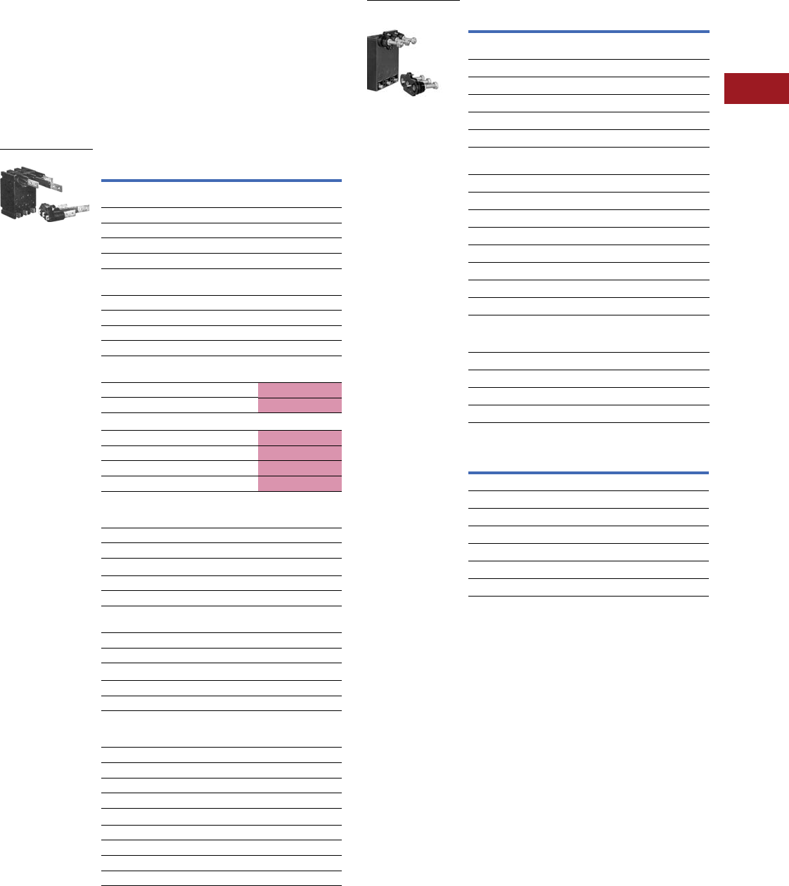
Volume 12—Aftermarket, Renewal Parts and Life Extension Solutions CA08100014E—July 2016 www.eaton.com V12-T3-69
1
2
3
4
5
6
7
8
9
10
11
12
13
14
15
16
17
18
19
20
21
22
23
24
25
3
Molded-Case Circuit Breakers
Replacement Capabilities
Plug-In Adapter Kits
For rear-connected applications such as switchboards.
Facilitates ease of installation and front removal of breaker.
Includes conductor for mounting on breaker, plug-in mounting
blocks with matching conductor, rear studs and mounting
hardware. Order two mounting blocks style number when line
and load are required; order one mounting block style number
when either line or load is required.
■
Shaded area denotes obsolete or discontinued products
and services. 1
Flat Bus Type
Threaded Studs Type
Mounting Plates
Notes
1 These accessories are no longer available.
2 These plug-in adapter kits are UL Listed as recognized
components.
3 700–1200A adapter kit is front removable, bolt-on design—
not plug-in type.
4 Not UL Listed.
Description Style Number
EB, EHB, FB Thermal-Magnetic Breakers 2
Flat Bus Type—One Mounting Block, Line or Load
Two-pole, 100A 1480D13G05
Two-pole, 150A 1480D13G05
Three-pole, 100A 1480D13G06
Three-pole, 150A 1480D13G06
FB and HFB Magnetic Only, HFB Thermal-Magnetic 2
Flat Bus Type—One Mounting Block, Line or Load
Two-pole, 100A 1480D13G05
Two-pole, 150A 1480D13G05
Three-pole, 100A 1480D13G06
Three-pole, 150A 1480D13G06
JB, KB, HKB Breakers 1 Flat Bus Type—
Two Mounting Blocks, Line and Load
Two-pole 506C144G17
Three-pole 506C144G18
One Mounting Block, Line Only
Two-pole 1260C86G01
Three-pole 1260C86G02
Two-pole 1260C86G03
Three-pole 1260C86G04
LAB, LA, HLA, LC and HLC (150, 250, 300 and
400A Frame) (Threaded Studs Type)—
Two Mounting Blocks, Line and Load
Two-pole 313C644G25
Three-pole 313C644G26
One Mounting Block, Line or Load
Two-pole 450D010G15
Three-pole 450D010G16
DA, LB, LBB, HLB Breakers 2 Flat Bus Type—
Two Mounting Blocks, Line and Load
Two-pole 313C644G45
Three-pole 313C644G46
One Mounting Block, Line or Load
Two-pole 314C932G03
Three-pole 314C932G04
MA, HMA, MC, HMC, MD and MDS Breakers 3
Threaded Studs—Two Mounting Blocks,
Line and Load
Two-pole, 125–600A 313C644G27
Two-pole, 700–800A 176C544G01 3
Three-pole, 125–600A 313C644G28
Three-pole, 700–800A 176C544G02 3
One Mounting Block, Line or Load
Two-pole, 125–600A 313C370G03
Two-pole, 700–800A 507C049G01 3
Three-pole, 125–600A 313C370G04
Three-pole, 700–800A 507C049G02 3
Flat Bus Type
Description Style Number
JA, KA and HKA Breakers 4 (Threaded Studs
Type)—Two Mounting Blocks, Line and Load
Two-pole 313C644G29
Three-pole 313C644G30
One Mounting Block, Line or Load
Two-pole 314C932G01
Three-pole 314C932G02
LA, HLA, LC and HLC (600A Frames) 2 (Threaded
Studs)—Two Mounting Blocks, Line and Load
Two-pole 313C644G50
Three-pole 313C644G51
One Mounting Block, Line or Load
Two-pole 506C059G03
Three-pole 506C059G04
One Mounting Block, Line or Load Flat Bus Type
Two-pole 1288C19G01
Three-pole 1288C19G02
MA, HMA, MC, HMC, MD, MDS, NB, HNB, NC, HNC
and NB TRI-PAC Breakers 4 (Flat Bus Type)—
One Mounting Block, Line or Load
MA, HMA, MC, HMC, MD, MDS two-pole 2614D53G05
MA, HMA, MC, HMC, MD, MDS three-pole 2614D53G06
NB, HNB, NC, HNC, NB TRI-PAC two-pole 2614D53G03
NB, HNB, NC, HNC, NB TRI-PAC three-pole 2614D53G04
Description Style Number
Predrilled panels for:
EB, EHB, FB, HFB 507C047H01
JB, KB 179C207H01
JA, KA 504C823H01
DA, LB, LBB, ALB 178C781H01
LA, LAB, HLA, LC, HLC 504C824H01
MA, HMA, MC, MMC, NB, HNB, NC, HNC 1290C73H01
Threaded Stud Type
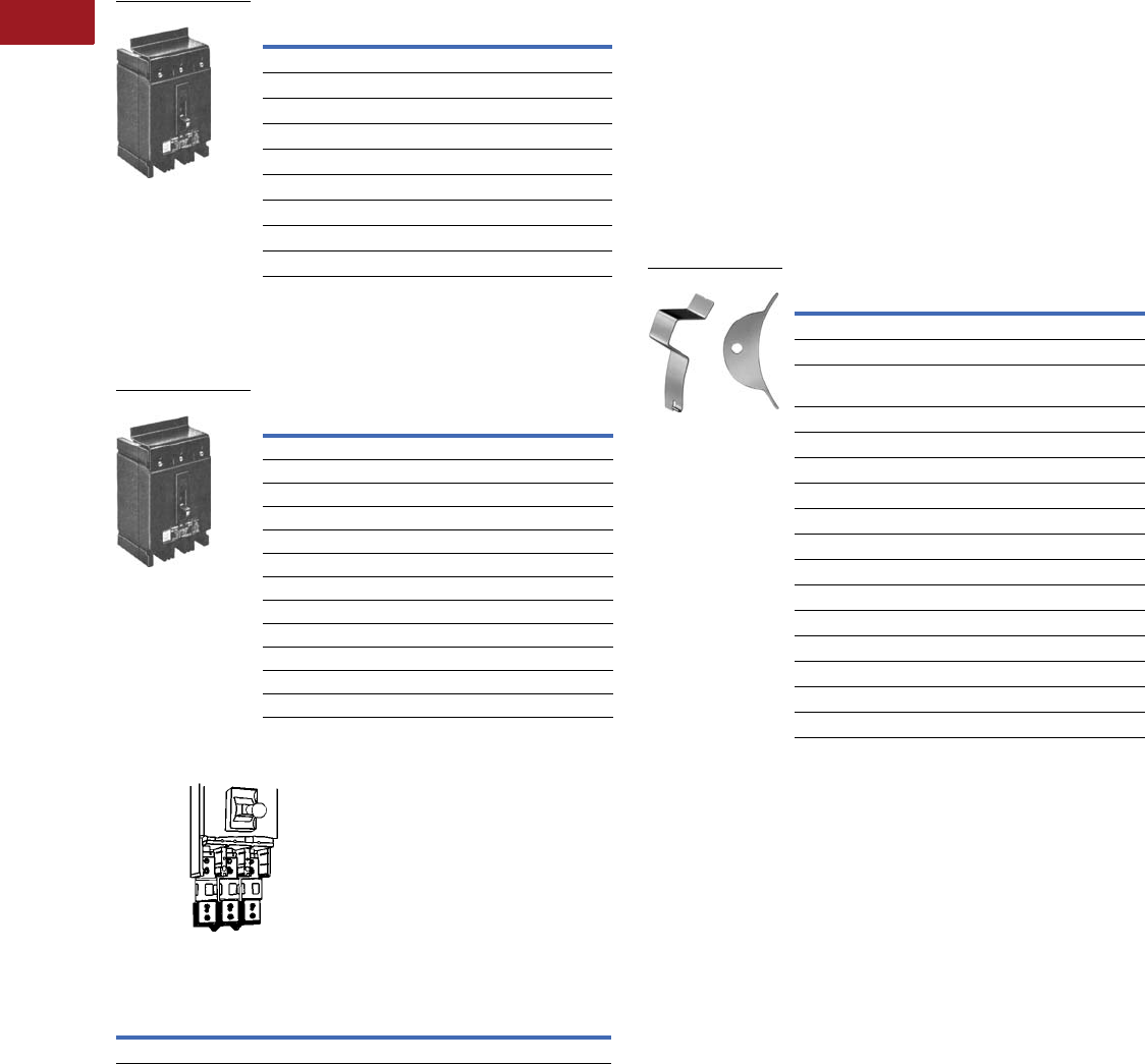
V12-T3-70 Volume 12—Aftermarket, Renewal Parts and Life Extension Solutions CA08100014E—July 2016 www.eaton.com
1
2
3
4
5
6
7
8
9
10
11
12
13
14
15
16
17
18
19
20
21
22
23
24
25
3
Molded-Case Circuit Breakers
Replacement Capabilities
Extended Line Terminal Shields
For shielding line side terminal connections. One shield required
per breaker. Order separately when needed. Sold only in lots of
10, including hardware.
Extended Line Terminal Shields 1
Base Mounting Hardware
No charge when ordered with breaker. Order separately
when needed.
Base Mounting Hardware
Fuse Mounting Base for PB Breakers
For 2000A non-automatic breakers only.
Fuse Mounting Base for PB Breakers
For use with non-automatic, three-pole circuit breaker. Includes
fuse mounting base and hardware to mount standard Class L
current limiting fuses, 801–2000A (fuses not included).
Note: Interrupters used with fuse mounting base will accept all standard
PB accessories. See Dimension Sheet 29-171 for mounting details.
Breaker Frame Style Number
JB, KB, HKB 1266C07G01
MA, HMA, MC, HMC 208B966G01
NB, HNB, NC, HNC 208B966G02
LAB, LA, (Saf-T-Vue) 314C420G02
JA, KA, LB, LBB (Saf-T-Vue) 314C420G04
LAB, LA, HLA, LC, HLC 314C420G05
DA 314C420G06
JA, KA, HKA, LB, LBB, HLB (standard breaker) 314C420G06
EB, EHB, FB, HFB 625B229G08 2
Description Style Number
Single-Pole Breakers
EB, EHB, HFB 3624B375G01
EB, EHB, HFB 4624B375G02
Two- and Three-Pole Breakers
LAB, LA, HLA, LC, HLC, MA, NB, HMA, HNB, MC 21C6782G05
HMC, NC, HNC 1091716
PB, PC, PCC 624B375G22
DA, JA, KA, HKA, LB, LBB, HLB 21C6782G22
EB, EHB, FB, HFB, MCP 21C6782G18
JB, KB, HKB 673B125G12
CA two-pole 21C6782G28
CA three-pole 21C6782G29
Style Number
6635C78G02 1
Line Terminal Shield
Line Terminal Shield
For complete installation, order:
1. Front-connected, non-automatic PB breaker.
(Order similar to standard front connected, except
omit load conductor extensions.)
2. Fuse mounting base.
3. Fuses (from distributor).
Handle Locks
Non-Padlockable
For prevention of unintentional operation of breaker. Fits over
breaker handle and may be removed.
Padlockable
For prevention of unauthorized operation of breaker. Is non-
removable once installed on breaker. Meets Underwriters
Laboratories and California Code requirements.
Handle Locks 15
Notes
1 Not UL Listed.
2 One of style 625B229G08 is one package of 10.
3 Individually mounted.
4 Group mounted.
5 All breakers are trip free and will trip with handle locks attached.
Cannot be used when handle extension is used.
Breaker Frame Style Number
Non-Padlockable
FA, EA, CA, EB, EHB, FB, HFB 29B2721H01
LAB, LA, LC, HLC, MA, NB, HLA, HMA, HNB,
MC, HMC, NC, HNC
28B4596G01
GB, GC, GHB, GHC 1294C01H01
DA, JA, KA, HKA, LB, LBB, HLB 29B2721H04
Padlockable
CA 506C438G01
FA, EA, EB, EHB, FB, HFB, MCP150 765A754G01
DA, JA, KA, LB, LBB, HKA, HLB, MCP400 673B796G02
JB, KB, HKB, MCP250 673B796G01
LAB, LA, HLA, LC, HLC 373B591G02
MA, HMA, MC, HMC, MD, MDS 6591C30G02–OFF
MA, HMA, MC, HMC, MD, MDS 6591C30G05–ON/OFF
NB, HNB, NC, HNC 6591C30G01–OFF
NB, HNB, NC, HNC 6591C30G04–ON/OFF
PA, SPCB, PB, Tri-Pac PB, PC 6591C30G03–OFF
Handle Locks

Volume 12—Aftermarket, Renewal Parts and Life Extension Solutions CA08100014E—July 2016 www.eaton.com V12-T3-71
1
2
3
4
5
6
7
8
9
10
11
12
13
14
15
16
17
18
19
20
21
22
23
24
25
3
Molded-Case Circuit Breakers
Replacement Capabilities
Cable Connectors
The fuse mounting base will accept the following terminals
for front cable connection (omit “T” connectors from rear
connected breakers).
Cable Connectors
Molded Type Handle Extension
For LAB, LA and HLA Breakers 1
For MA, HMA, MC, HMC,
NB, HNB, NC and HNC
Breakers
1
For PB, PC, PCC and PA/RD Breakers 1
Wire Range, Type Number of Cables Style Number
(3) 3/0–400 kcmil Cu 672B655G01
(4) 400–500 kcmil Cu 180C046G03
Style Number
372B399G01
Style Number
1251C65G01 2
Style Number
6635C78G02 2
Modifications
Only two internally mounted
modifications—shunt trip,
undervoltage release,
auxiliary switch, alarm
switch—may be mounted
in EB through PB. Only one
of these modifications may
be mounted in FB, HFB
magnetic only, two-pole EB,
EHB, FB and SELTRONIC
breakers. None are available
in single-pole breakers except
alarm switch in EB, EHB and
HFB. Contact Avery Creek,
NC, Technical Resource
Center for possible special
combinations of the following
modifications not in
tabulations. Contact factory
for pricing if accessories
are factory installed.
Shunt Trip
For tripping breaker from
a remote point. A solenoid
device mounts within breaker
case. Breaker trips when
coil is energized.
Shunt trips should not be
used as circuit interlocks
using maintained contact
pilot devices.
A cutoff switch breaks the
circuit to the momentary rated
coil when the breaker opens.
Available for control voltages
up to 250 Vdc or 600 Vac.
Voltage and frequency must
be specified. Standard leads
extend 18.00 inches outside
the breaker. Longer leads may
be specified.
Factory-Mounted Shunt Trips
Factory-mounted shunt trips
only can be supplied for the
following breakers: CA, HCA,
CAH, HFB magnetic only
and
PB/PBF non-automatic
breakers (molded-
case
switches). They are 120 Vac
rated, suitable for 55% pickup
for ground fault application.
Right hand mounting is
standard and they are not
UL Listed.
Notes
1Not UL listed.
2Included with frame at no charge.
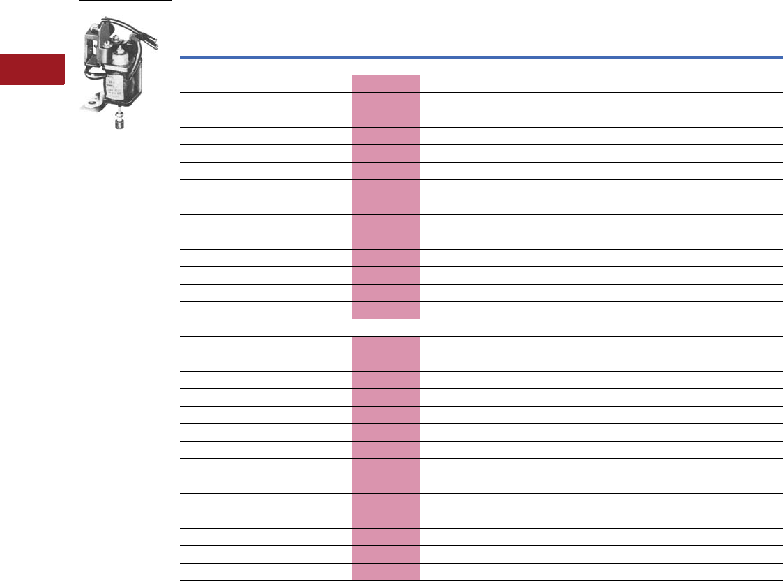
V12-T3-72 Volume 12—Aftermarket, Renewal Parts and Life Extension Solutions CA08100014E—July 2016 www.eaton.com
1
2
3
4
5
6
7
8
9
10
11
12
13
14
15
16
17
18
19
20
21
22
23
24
25
3
Molded-Case Circuit Breakers
Replacement Capabilities
■
Shaded area denotes obsolete or discontinued products and services. 4
Shunt Trip for Field Mounting 123
Notes
1 120 Vac ratings suitable for 55% pickup for ground fault applications.
2 Not field mountable on non-automatic breakers (molded-case switches).
3 Field mounting voids breakers’ UL listing except on LA, HLA, MA, HMA, NB, HNB, PB, KB, HKB, KA, HKA, LB, HLB and SELTRONIC breakers.
4 These frames are obsolete. For replacement solutions, see the cross-reference on Pages V12-T3-114–V12-T3-168.
5 Available similar to this except “Leads out the load end—(not UL Listed).” Order by description.
Voltage/Hz
Breaker Type Catalog Number
EB, EHB, FB, HFB 5
(Thermal-Magnetic Only) JB, KB, HKB
JA, KA, HKA, DA,
LB, LBB, HLB LA, LAB, HLA MA, HMA NB, HNB
PB TRI-PAC
and PA
Right-Hand Mounting
600/50–60 Hz 2609D39G15 2609D42G15 2605D15G15 2606D56G15 2606D57G15 2606D58G15 2606D59G15
480/50–60 Hz 2609D39G16 2609D42G16 2605D15G16 2606D56G16 2606D57G16 2606D58G16 2606D59G16
240/50–60 Hz 2609D39G17 2609D42G17 2605D15G17 2606D56G17 2606D57G17 2606D58G17 2606D59G17
208/50–60 Hz 2609D39G18 2609D42G18 2605D15G18 2606D56G18 2606D57G18 2606D58G18 2606D59G18
120/50–60 Hz 2609D39G19 2609D42G19 2605D15G19 2606D56G19 2606D57G19 2606D58G19 2606D59G19
60/50–60 Hz 2609D39G20 2609D42G20 2605D15G20 2606D56G20 2606D57G20 2606D58G20 2606D59G20
48/50–60 Hz 2609D39G21 2609D42G21 2605D15G21 2606D56G21 2606D57G21 2606D58G21 2606D59G21
24/50–60 Hz 2609D39G22 2609D42G22 2605D15G22 2606D56G22 2606D57G22 2606D58G22 2606D59G22
250 DC 2609D39G23 2609D42G23 2605D15G23 2606D56G23 2606D57G23 2606D58G23 2606D59G23
125 DC 2609D39G24 2609D42G24 2605D15G24 2606D56G24 2606D57G24 2606D58G24 2606D59G24
60 DC 2609D39G25 2609D42G25 2605D15G25 2606D56G25 2606D57G25 2606D58G25 2606D59G25
48 DC 2609D39G26 2609D42G26 2605D15G26 2606D56G26 2606D57G26 2606D58G26 2606D59G26
24 DC 2609D39G27 2609D42G27 2605D15G27 2606D56G27 2606D57G27 2606D58G27 2606D59G27
12 DC 2609D39G28 2609D42G28 2605D15G28 2606D56G28 2606D57G28 2606D58G28 2606D59G28
Left-Hand Mounting
600/50–60 Hz 2609D39G01 2609D42G01 2605D15G01 2606D56G01 2606D57G01 2606D58G01 2606D59G01
480/50–60 Hz 2609D39G02 2609D42G02 2605D15G02 2606D56G02 2606D57G02 2606D58G02 2606D59G02
240/50–60 Hz 2609D39G03 2609D42G03 2605D15G03 2606D56G03 2606D57G03 2606D58G03 2606D59G03
208/50–60 Hz 2609D39G04 2609D42G04 2605D15G04 2606D56G04 2606D57G04 2606D58G04 2606D59G04
120/50–60 Hz 2609D39G05 2609D42G05 2605D15G05 2606D56G05 2606D57G05 2606D58G05 2606D59G05
60/50–60 Hz 2609D39G06 2609D42G06 2605D15G06 2606D56G06 2606D57G06 2606D58G06 2606D59G06
48/50–60 Hz 2609D39G07 2609D42G07 2605D15G07 2606D56G07 2606D57G07 2606D58G07 2606D59G07
24/50–60 Hz 2609D39G08 2609D42G08 2605D15G08 2606D56G08 2606D57G08 2606D58G08 2606D59G08
250 DC 2609D39G09 2609D42G09 2605D15G09 2606D56G09 2606D57G09 2606D58G09 2606D59G09
125 DC 2609D39G10 2609D42G10 2605D15G10 2606D56G10 2606D57G10 2606D58G10 2606D59G10
60 DC 2609D39G11 2609D42G11 2605D15G11 2606D56G11 2606D57G11 2606D58G11 2606D59G11
48 DC 2609D39G12 2609D42G12 2605D15G12 2606D56G12 2606D57G12 2606D58G12 2606D59G12
24 DC 2609D39G13 2609D42G13 2605D15G13 2606D56G13 2606D57G13 2606D58G13 2606D59G13
12 DC 2609D39G14 2609D42G14 2605D15G14 2606D56G14 2606D57G14 2606D58G14 2606D59G14
Shunt Trip

Volume 12—Aftermarket, Renewal Parts and Life Extension Solutions CA08100014E—July 2016 www.eaton.com V12-T3-73
1
2
3
4
5
6
7
8
9
10
11
12
13
14
15
16
17
18
19
20
21
22
23
24
25
3
Molded-Case Circuit Breakers
Replacement Capabilities
Left-Hand Mounting Kits for SELTRONIC Breakers
Left-Hand Mounting Kits for SELTRONIC Breakers
Shunt Trip Coil Data
Notes
1Rated 48V minimum for ground fault applications.
2Also available for 24 Vdc. Order by description.
3Not for ground fault.
Description
Breaker
Type
Style
Number
Provision to trip flux transfer shunt trip from
external 32 to 120 Vdc and Vac to 60 Hz source 12
MC, HMC 1371D72G22
NC, HNC 1372D39G13
PC, PCC 1372D35G22
LC, HLC 1371D11G22
Provision to trip flux transfer shunt trip from
external 240 to 600 Vac, 50/60 Hz source 23
MC, HMC 1371D72G32
NC, HNC 1372D39G23
PC, PCC 1372D35G32
LC, HLC 1371D11G32
Shunt Trip
Voltage
Rating
For All Breakers Listed in Previous
Table and on Previous Page
Except CA and SELTRONIC SELTRONIC
Coil Inrush Coil Inrush
Amperes Volt-Amperes Amperes Volt-Amperes
600 AC 0.105 63.0 — —
480 AC 0.085 40.8 — —
240 AC 1.7 408.0 — —
208 AC 1.4 291.2 — —
120 AC 0.88 105.6 15 18
60 AC 9.10 546.0 — —
48 AC 7.50 360.0 — —
24 AC 3.95 94.8 — —
250 DC 2.5 625.0 — —
125 DC 0.975 121.9 — —
60 DC 0.525 31.5 — —
48 DC 1.3 62.4 — —
24 DC (FB) 6 144.0 — —
24 DC (KB) 3.8 91.2 — —
24 DC (others) 8 192 — —
12 DC 6 72 — —
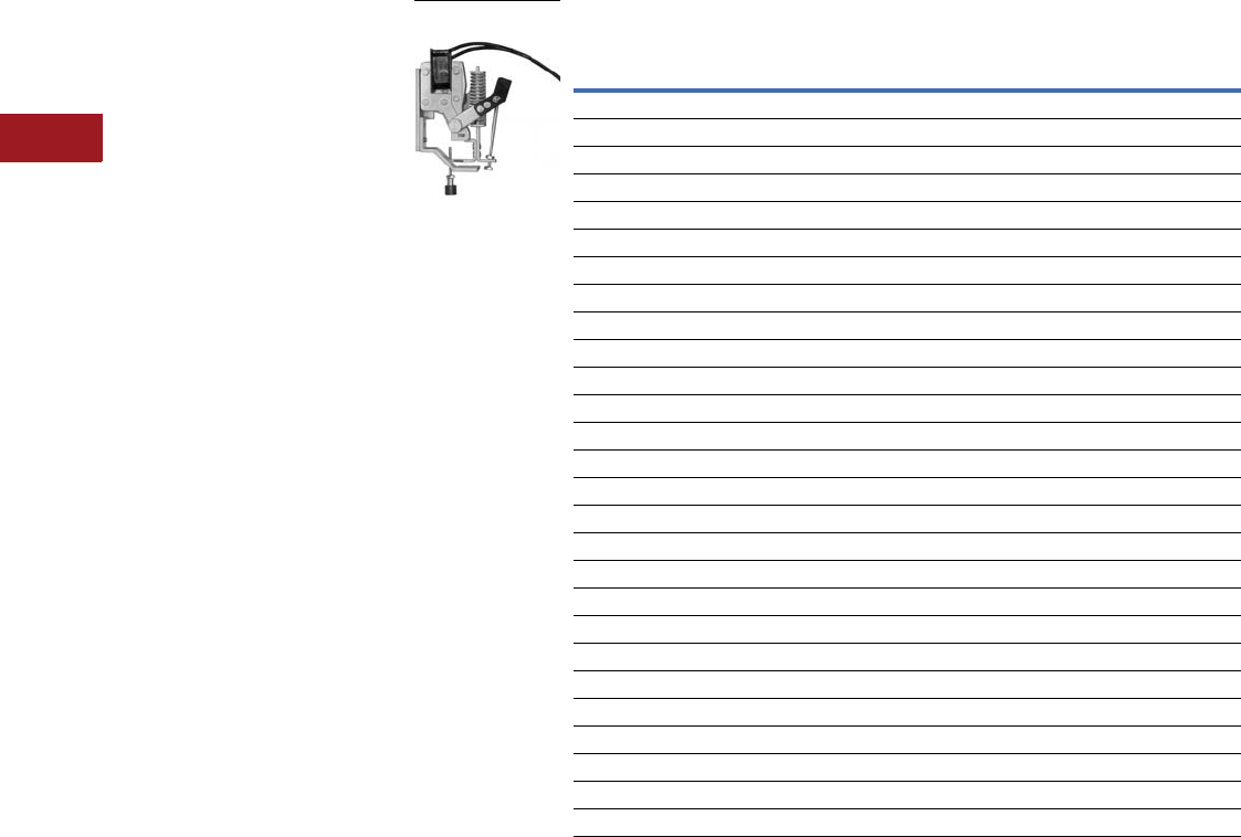
V12-T3-74 Volume 12—Aftermarket, Renewal Parts and Life Extension Solutions CA08100014E—July 2016 www.eaton.com
1
2
3
4
5
6
7
8
9
10
11
12
13
14
15
16
17
18
19
20
21
22
23
24
25
3
Molded-Case Circuit Breakers
Replacement Capabilities
Standard Undervoltage Release
For undervoltage protection.
A solenoid device mounts
within a breaker case. Coil
must be energized before
closing breaker.
Trips breaker
when voltage drops below 35
to 70% of coil rating. Picks
up and seals in at 85% of coil
rating. For line voltages
up to 250 Vdc or 600 Vac.
Externally mounted resistors
are supplied for certain
ratings. Standard leads
extend 18.00 inches outside
of breaker. Longer leads may
be specified.
Note: Undervoltage release
attachments are not designed
for, and should not be used as,
circuit interlocks. For further
information, Contact Avery
Creek, NC, Technical Resource
Center at 1-800-356-1243.
Factory-Mounted
Undervoltage Releases
All of the above undervoltage
releases can be specified for
factory mounting. Contact
factory for pricing. These
attachments have the leads
out the side and are UL
Listed when factory mounted
unless other non-UL Listed
modifications are used.
Note: Right-hand mounting
is considered standard unless
specified otherwise except JA,
KA, DA, HKA, LB, LBB, HLB
and SELTRONIC available
for left-hand only. JB, KB, HKB
are obsolete.
Factory-mounted
undervoltage releases
only can be supplied for
the following breakers:
●SELTRONIC breakers
(120 Vac, 60 Hz only
standard), MC, HMC, NC,
HNC, PC, PCC, LC, HLC
●SELTRONIC breakers with
remote trip provisions,
MC, HMC 2, NC, HNC 2,
PC, PCC 2, LC, HLC 2
●EB 3, EHB 3, FB 3, HFB 3,
FB 45 and HFB magnetic
only 45
●No UVR available for CA,
CAH and HCA
Undervoltage Release Attachment Kits for Field Mounting 67
Notes
1 Cannot be used with other attachments except a small 1A-1B auxiliary switch rated 250V can be supplied in
right-hand pole.
2 Provided with two leads (total of four) for use with a remote normally open contact (pushbutton, etc.) to trip the
breaker. No external power required.
3 Not available on ambient compensating breakers.
4 Not UL Listed.
5 Right-hand mounting only.
6 Not field mountable on non-automatic breakers (molded-case switches).
7 Field mounting voids UL listing of breaker except on LA, HLA, MA, HMA, NB, HNB, PB, KA, HKA, LB and HLB.
Attachment
Voltage, Hz
Breaker Type
JA, KA, DA, HKA,
LB, LBB, HLB LA, LAB, HLA MA, HMA NB, HNB PB, PA 4
For Right-Hand Mounting
24, 60 — 60A9355G17 — — —
48, 60 — 60A9355G08 — — 5674D29G16
120, 60 — 60A9355G01 457D727G01 373D632G01 5674D29G09
208, 60 — 60A9355G02 457D727G19 373D632G19 5674D29G10
240, 60 — 60A9355G03 457D727G02 373D632G02 5674D29G11
480, 60 — 60A9355G05 457D727G03 373D632G03 5674D29G13
600, 60 — 60A9355G06 457D727G04 373D632G04 5674D29G14
12 DC — 458D020G01 457D727G09 372D032G01 4976D85G01
24 DC — 458D020G02 457D727G10 372D032G02 4976D85G02
48 DC — 458D020G03 457D727G11 372D032G03 4976D85G03
60 DC — 458D020G04 457D727G21 — 4976D85G04
125 DC — 458D020G07 457D727G12 372D032G04 4976D85G07
250 DC — 458D020G08 457D727G13 372D032G05 4976D85G08
For Left-Hand Mounting
48, 60 — 60A9355G16 — — 5674D29G08
120, 60 458D070G01 60A9355G09 457D727G05 373D632G05 5674D29G01
208, 60 458D070G05 60A9355G10 457D727G20 373D632G20 5674D29G02
240, 60 458D070G02 60A9355G11 457D727G06 373D632G06 5674D29G03
480, 60 458D070G03 60A9355G13 457D727G07 373D632G07 5674D29G05
600, 60 458D070G04 60A9355G14 457D727G08 373D632G08 5674D29G06
12 DC 458D070G09 458D020G11 457D727G14 372D032G06 4976D85G11
24 DC 458D070G10 458D020G12 457D727G15 372D032G07 4976D85G12
48 DC 458D070G11 458D020G13 457D727G16 372D032G08 4976D85G13
60 DC — 458D020G14 457D727G22 — 4976D85G14
125 DC 458D070G12 458D020G17 457D727G17 372D032G09 4976D85G17
250 DC 458D070G13 458D020G18 457D727G18 372D032G10 4976D85G18
Standard Undervoltage
Release

Volume 12—Aftermarket, Renewal Parts and Life Extension Solutions CA08100014E—July 2016 www.eaton.com V12-T3-75
1
2
3
4
5
6
7
8
9
10
11
12
13
14
15
16
17
18
19
20
21
22
23
24
25
3
Molded-Case Circuit Breakers
Replacement Capabilities
Undervoltage Release Coil Data
Voltage
Rating Hz
Breaker Type
EB, EHB, FB, HFB, JB, KB and HKB JA, KA, HKA, DA, LB, LBB and HLB LA, LAB, HLA and PB
Coil
Amperes
External Series
Resistance (Ohms)
Total
VA
Coil
Amperes
External Series
Resistance (Ohms)
Total
VA
Coil
Amperes
External Series
Resistance (Ohms)
Total
VA
600 AC 0.020 25,000 12.0 0.012 50,000 7.2 0.029 20,000 17.4
480 AC 0.016 20,000 7.7 0.013 30,000 6.3 0.014 — 6.8
240 AC 0.021 6000 5.1 0.013 — 3.2 0.036 — 8.7
208 AC 0.019 6000 4.0 0.018 — 3.8 0.036 — 7.5
120 AC 0.023 — 2.8 0.023 — 2.8 0.073 — 8.8
60 AC 0.203 250 12.2 — — — — — —
48 AC 0.245 150 11.8 — — — 0.152 — 7.3
24 AC 0.250 50 6.0 — — — — — —
250 DC 0.026 5000 6.5 0.013 16,500 3.3 0.035 5000 8.8
125 DC 0.026 — 3.3 0.013 6500 1.7 0.039 1500 4.9
60 DC 0.248 200 14.9 0.013 1500 0.8 0.034 — 2.1
48 DC 0.260 150 12.5 0.012 600 0.6 0.040 — 2.0
24 DC 0.141 — 3.4 0.023 — 0.6 0.069 — 1.7
12 DC 0.286 — 3.5 0.048 — 0.6 0.136 — 1.7
MA and HMA NB and HNB MC, HMC, NC, HNC, PC, PCC, LC and HLC
Coil
Amperes
External Series
Resistance (Ohms)
Total
VA
Coil
Amperes
External Series
Resistance (Ohms)
Total
VA
Coil
Amperes
External Series
Resistance (Ohms)
Total
VA
600 AC 0.012 50,000 7.2 0.016 35,000 9.6 — — —
480 AC 0.013 30,000 6.3 0.013 30,000 6.3 — — —
240 AC 0.013 — 3.2 0.013 — 3.2 — — —
208 AC 0.018 — 3.8 0.018 — 3.8 — — —
120 AC 0.023 — 2.8 0.023 — 2.8 0.5 — 6
60 AC — — — — — — — — —
48 AC — — — — — — — — —
24 AC — — — — — — — — —
250 DC 0.013 16,500 3.3 0.013 16,500 3.3 — — —
125 DC 0.013 6500 1.7 0.013 6500 1.7 — — —
60 DC 0.013 1500 0.8 — — — — — —
48 DC 0.012 600 0.6 0.012 600 0.6 — — —
24 DC 0.02 — 0.6 0.023 — 0.6 — — —
12 DC 0.048 — 0.6 0.048 — 0.6 — — —
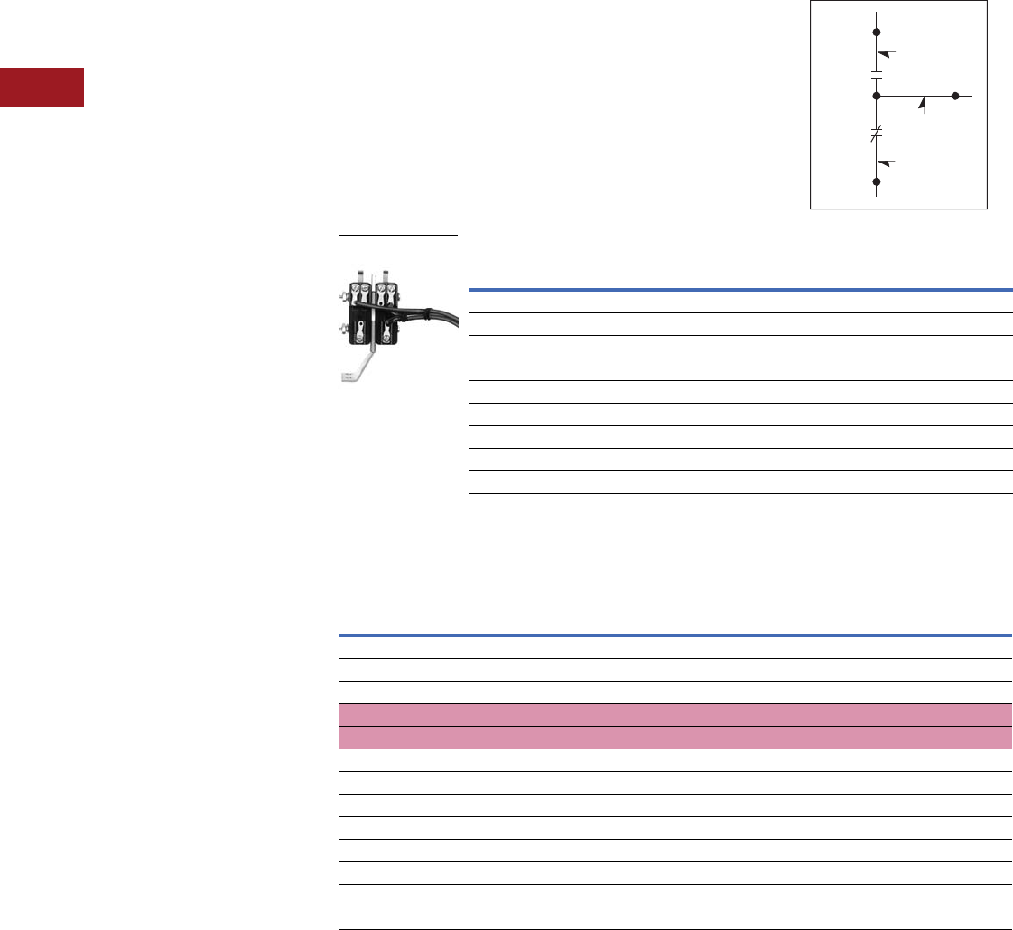
V12-T3-76 Volume 12—Aftermarket, Renewal Parts and Life Extension Solutions CA08100014E—July 2016 www.eaton.com
1
2
3
4
5
6
7
8
9
10
11
12
13
14
15
16
17
18
19
20
21
22
23
24
25
3
Molded-Case Circuit Breakers
Replacement Capabilities
Alarm Switch
Availability: EB through PC.
For light or alarm indication
when breaker trips. Does
not function with manual
operation. Automatically
resets when breaker is
relatched. Standard leads
extend 18.00 inches outside
of breaker. Longer leads
may be specified. Not
field mountable.
Alarm Switch Contact
Rating (Non-Inductive)
●MC, HMC, LA, LAB, HLA,
LC, HLC: 10A, 120 Vac;
5A, 240 Vac
●EB, EHB, FB, HFB:
5A, 120 Vac
●All other breakers:
10A, 120–240 Vac
Auxiliary Switch
For auxiliary control circuits.
Miniature switches mount
within breaker. Commonly
used for remote indication
of open or closed breaker
and electrically interlocking
component control circuits.
“A” contacts are closed
when breaker is closed.
“B” contacts are open when
breaker is closed. Standard
leads extend 18.00 inches
outside of breaker. Longer
leads may be specified.
Note: Right-hand mounting
standard for EB, EHB, FB, HFB,
JB, KB and HKB. All others are
left-hand mounting as standard
unless otherwise specified.
Factory-Mounted
Auxiliary Switches
All of the above auxiliary
switches can be specified
for factory mounting at the
same price as listed for the
kit. These attachments have
the leads out the side of the
breaker and are UL Listed
when factory mounted
unless other non-UL Listed
modifications are used
(except as noted).
Note: Right-hand mounting
standard for EB, EHB, FB, HFB,
JB, KB and HKB. All others are
left-hand mounting as standard
unless otherwise specified.
Factory-mounted switches
only can be supplied for the
following breaker:
●JB, LBB, LAB, JA, DA, FB l
magnetic only 2m and HFB
magnetic only 2m
Switch Schematic
Alarm Switch
■
Shaded area denotes obsolete or discontinued products and services. 9
Auxiliary Switch Attachment Kits for Field Mounting 678
Notes
1Alarm switches are no longer available
for these frames.
2Not UL Listed.
3Not available for magnetic only,
ambient compensating, or breakers
with undervoltage release.
4When alarm switch is used in
conjunction with auxiliary switch,
the auxiliary switch is rated 250 Vac,
5A maximum.
5Except when other attachments are
used, must be mounted in right pole.
6Not for use on molded-case switches.
7All switches are multiples of 1A-1B with
a common electrical connection (see
diagram above right).
8Field mounting voids UL listing of breaker
except on LA, HLA, MA, HMA, NB,
HNB, KB, HKB, KA, HKA, LB, HLB and
SELTRONIC breakers.
9These accessories are no
longer available.
jFor DC applications, refer to factory.
kThermal-magnetic only.
lAuxiliary switches are no longer
available for these frames.
mRight-hand mounting only.
Black Lead
Blue Lead
Red Lead
Breaker
Frame
Normal
Pole Mounting
Contact Operation
(Specify Type Desired)
DA 1Left Make or break
EB 1, EHB 1, FB 1, HFB 23 Mechanism Make or break
JA 1, KA 1, LB 1, LBB 1, HKA, HLB Left Make or break
JB 1, KB 1, HKB 1Left Make or break
LAB 1, LA 1, MA 1, NB 1, HLA, HMA, HNB Left Make or break
LC 1, HLC Left 4Make or break
MC 1, HMC Left only 4Make or break
NC 1, HNC Left only 4Make or break
PB Left Make or break
PC, PCC Left 45 Make or break
Breaker
Type
Maximum For Left-Hand Mounting For Right-Hand Mounting
AC Voltage
Rating j
Non-inductive
Amperes 1A-1B 2A-2B 1A-1B 2A-2B
EB, EHB, FB, HFB k240 5 4979D06G03 4979D06G09 4979D06G03 4979D06G08
JA, KA, DA, HKA, LB 480 10 458D067G03 — 458D067G08 —
LBB, HLB 240 5 — 656D527G01 2— 656D527G09 2
JB, KB, HKB 480 10 2600D97G03 —2600D97G08 —
JB, KB, HKB 240 5—2609D45G03 9—2609D45G08 9
LA, LAB, HLA 480 10 655D555G12 655D555G13 655D555G05 655D555G06
MA, HMA 480 10 458D013G12 458D013G13 458D013G05 458D013G06
NB, HNB 480 10 4980D16G12 4980D16G13 4980D16G05 4980D16G06
PB, PA 480 10 2602D32G11 2602D32G12 2602D32G14 2602D32G15
MC, HMC, MCG, HMCG 480 6 (10 at 24) 1371D72G03 1371D72G06 — —
NC, HNC, NCG, HNCG 480 6 (10 at 24) 1372D39G03 1372D39G06 — —
PC, PCC, PCG, PCCG 480 6 (10 at 24) 1372D35G03 1372D35G06 — —
LC, HLC, LCG, HLCG 480 6 (10 at 24) 1371D11G03 1371D11G06 — —
Switch with 2A-2B
Contacts
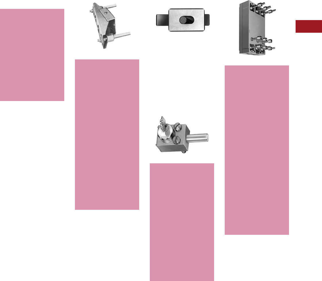
Volume 12—Aftermarket, Renewal Parts and Life Extension Solutions CA08100014E—July 2016 www.eaton.com V12-T3-77
1
2
3
4
5
6
7
8
9
10
11
12
13
14
15
16
17
18
19
20
21
22
23
24
25
3
Molded-Case Circuit Breakers
Replacement Capabilities
■
Shaded area denotes
obsolete or discontinued
products and services.
Mechanical Interlocks (A-C)
For mechanically interlocking
a pair of breakers so that only
one may be closed at one
time, but both may be open
simultaneously.
Note: Not UL Listed.
Moisture-Fungus-Corrosion
Treatment
Availability: EB through PC.
Treatment can be provided
to meet customer’s
specific atmospheric
conditions. Moisture-
fungus treating material
used meets JAN-T-152;
treatment meets
MIL-V-173a. Requests
and orders should specify
government specifications
or conditions to be met.
Note: Not UL Listed.
A. Walking Beam Type
Walking Beam
B. Sliding Bar Type
(Field Mountable)
Sliding Bar Type
Availability: HFB through PC.
Mounts on panel (not included)
fitting over front of breakers.
Standard breaker spacing:
HLC, HLA, HMA, HMC, HNB
and HNC 8.50-inch center
to center; HKA and HLB
5.75-inch center to center;
HFB 4.1875-inch center
to center.
C. Kirk Key Interlock
Kirk Key Interlock
Center Studs
Center Studs
Availability: EB through PC.
Mounts on panel (not
included) at rear of breaker.
Standard breaker spacing:
center to center; LAB, LA,
LC, HLC, MA, MC, NB, NC,
HLA, HMA, HMC, HNB and
HNC 8.50-inch center to
center; PB, PC and PCC
12.25-inch center to center;
DA, JA, KA, HKA, LB, LBB
and HLB 5.75 inch center
to center; EB, EHB, FB,
JB, KB, HFB and HKB
4.375 inch center to center.
Order as a set of two
special factory drilled
breakers and one walking
beam interlock. Specify
breaker type, panel
thickness and center
to center dimension
of breakers.
Note: Not UL Listed. 2000A
maximum for PB breaker. Not
available on drawout breakers.
Availability: EB through PC.
Permits interlocking of two
breakers or one breaker
with other devices. Before
breaker can be closed,
key must be inserted and
turned in breaker interlock.
Breaker must be opened
before key can be
removed. It can then be
inserted in interlock or
other devices to permit
their closure. Requests and
orders should completely
outline interlocking
scheme, ultimate user
and address.
Note: Not available on motor
operated breakers. (No CA,
LCL, FCL breakers.)
Availability: 600A frames
(LA) through (NB) 1200A
frames except SELTRONIC
and current limiting
breakers.
Provides connections for
dual voltage generators, so
that same trip unit can be
used for protection at both
voltages. At higher voltage,
the trip unit carries full load
current. At lower voltage,
half the current bypasses
the trip unit through the
center studs. Trip rating
cannot exceed 50% of
frame rating.
Field Discharge Switch
Availability: 400, 600A
frame (LA).
Breaker is used exclusively
to discharge the field of
a DC motor or generator,
usually through a resistor.
When the two outer
poles open, the center
pole closes.
Note: Not UL Listed.
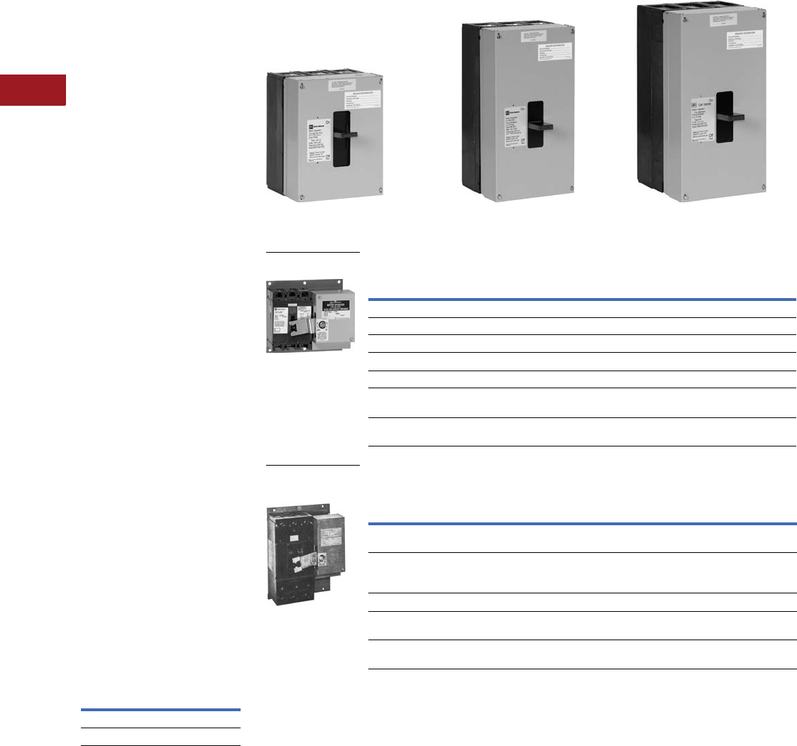
V12-T3-78 Volume 12—Aftermarket, Renewal Parts and Life Extension Solutions CA08100014E—July 2016 www.eaton.com
1
2
3
4
5
6
7
8
9
10
11
12
13
14
15
16
17
18
19
20
21
22
23
24
25
3
Molded-Case Circuit Breakers
Replacement Capabilities
Motor Operators
Motor operators provide
complete remote control by
means of a pushbutton or a
similar pilot device.
Note: The pilot device must be
maintained contact type for EB,
EHB, FB, HFB, DA, JA, KA, JB,
KB, HKB and LB mechanisms,
momentary contact type for
all others.
Positive switching action is
accomplished by use of an
operating arm engaging the
breaker handle. The unit is
energized momentarily to
actuate the lever arm moving
it to either the ON or OFF
position. The control is broken
by an internal cutoff switch.
Means for emergency manual
operations is provided.
Motor operations are
available with motors
rated 120 Vac, 208 Vac
and 240 Vac.
Note: LA and larger available for
125 Vdc.
The 480V operators use a
120 Vac motor in conjunction
with a 480/240V to 120V
dual voltage transformer.
(On LA and larger operators,
the transformer is supplied
for separate mounting by
the customer.)
Note: The motor operator is
intended only for infrequent
operation in line with Underwriters
Laboratories endurance standards
for molded-case breakers.
Minimum 1 kVA transformer
is required for use with all
motor operations.
Back Mounting Plates
Breaker
Type
120, 208, 240,
480 Vac
Style Number
EB, EHB, FB, HFB 503C707G01
DA, JA, KA, LB, HLB 503C981G01
Motor Operator Selection 12
Motor Data
Notes
1 AC voltage rated operators are UL Listed as recognized components.
2 See Dimension Sheet 29-170.
Breaker
Type
Style Number—AC Voltage Style Number—DC Voltage
120 208 240 480 125 24
EB, EHB, FB, HFB 656D148G11 656D148G04 656D148G02 656D148G13 — —
DA, JA, KA, HKA 657D819G23 657D819G10 657D819G08 657D819G24 — —
LB, LBB, HLB 657D819G25 657D819G16 657D819G14 657D819G26 — —
LAB, LA, HLA, LC, HLC 2607D97G37 2607D97G40 2607D97G38 2607D97G39 2607D97G51 2607D97G42
MA, HMA, MC, HMC 5664D54G75 5664D54G78 5664D54G76 5664D54G77 5664D54G96 5664D54G81
NB, HNB, NC, HNC.
SPCB1200
1494D60G31 1494D60G32 1494D60G33 1494D60G34 1494D60G35 1494D60G36
PB, PC, PCC, PA,
SPCB2000
5661D52G01 5661D52G04 5661D52G02 5661D52G03 5661D52G17 —
Breaker
Type
Motor
Inrush Current,
Ampere (Peak)
Continuous
Current (rms) Operating
Time, Open
or CloseType Hp 120V 208V 240V 120V 208V 240V
EB, EHB,
FB, HFB
Split-phase 1/75 10 4 5 2.3 1.17 1.65 1.5 seconds
DA, JA, KA,
JB, KB, LB, LBB,
HKB, HLB
Split-phase 1/50 14 6 7 3.5 1.6 1.75 1.5 seconds
LAB, LA, HLA Reversing — 8 5 4 — — — 12 cycles
MA, HMA, NB,
HNB, SPCB1200
Reversing — 11 7 6 — — — 12 cycles
PB, PA,
SPCB2000
Reversing — 20 12 11 — — — 10 cycles
For LAB, LA, HLA Breakers For MA, HMA, NB, HNB Breakers For PB Breakers
For EB, EHB, FB
and HFB
For DA, JA, KA, JB,
LB, LBB, HKA, HKB
and HLB Breakers
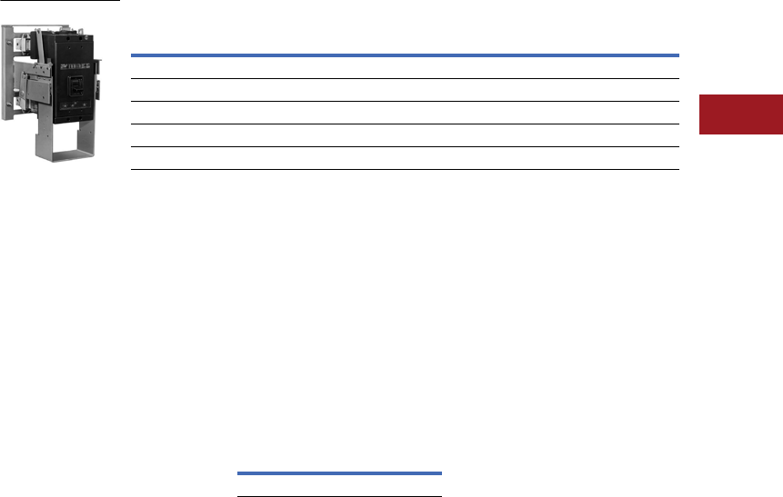
Volume 12—Aftermarket, Renewal Parts and Life Extension Solutions CA08100014E—July 2016 www.eaton.com V12-T3-79
1
2
3
4
5
6
7
8
9
10
11
12
13
14
15
16
17
18
19
20
21
22
23
24
25
3
Molded-Case Circuit Breakers
Replacement Capabilities
Drawout Frame
These drawout frames are
for use with standard three-
pole Cutler-Hammer molded-
case circuit breakers. They
consist of two separate
parts: stationary mounting
frame and movable carrier
frame. Slide rails are
drawer-type, and a screw
mechanism is used to
engage or withdraw the
movable carrier frame.
The drawout frames have three
positions:
connected, test and
disconnected. The frames do
not include a safety tripping
interlock or secondary
contacts. These are optional
items and may be ordered at
additional cost.
Breakers mounted in the
drawout frames can be
equipped with standard
breaker accessories including
shunt trip, undervoltage
release, auxiliary switch,
alarm switch and motor
operator.
Optional Features
Safety Interlock
This feature trips the breaker
as the movable carrier frame
is withdrawn, and must be
factory installed. Order
as follows.
Note: Safety interlock not
available on MC, NC, HMC,
HNC, LC and HLC.
For LA, MA and
NB Breakers
Order standard stationary
mounting frame. Order
breaker and movable carrier
frame assembled with
safety interlock.
Secondary Contacts
These are used to disconnect
auxiliary circuits when
attachments such as shunt
trip or motor operator are
used. Available in multiples
of four contacts with a
maximum of 24 contacts for
the LA 600 or 32 contacts for
the MA and NB. They must
be factory mounted. Order
by description as similar to
stationary or moving frame
and specify number of
contacts required.
Selection Data 12
Ordering Information
Note: SELTRONIC circuit
breakers with built-in ground fault
require a special breaker frame
with leads out the side in place of
standard terminal block. Order by
description the breaker frame and
carrier as one assembly.
Standard Installation
Order one stationary
mounting frame and one
movable carrier frame.
Order breakers without
terminals or rear connectors.
Order any attachments
desired (shunt trip,
undervoltage release, etc.)
Order secondary contacts
as required:
●A shunt trip, an under-
voltage release or an
alarm switch requires
two contacts
●A 1A-1B auxiliary switch
requires three contacts
●A motor operator requires
a maximum of four
contacts
●Others as required
With Safety Interlock
Order stationary mounting
frame and movable carrier
frame as directed under
optional features.
Racking Crank
A special crank to engage or
withdraw the moving portion
of the drawout. A standard
0.50-inch hex socket with
extension can be used for
this purpose.
Racking Crank
Cell Switches Mounted
on Drawout Frames,
All Ratings
Up to four switches can be
provided. Order by description.
Each switch provides
NO and NC contact that
transfers before reaching
the test position when being
withdrawn, and after the test
position when being racked
in. Contact factory for pricing.
Notes
1Safety interlock not available on MC, NC,
HMC, HNC, LC and HLC.
2SELTRONIC circuit breakers with built-in
ground fault require a special breaker
frame with leads out the side in place
of standard terminal block. Order by
description the breaker frame and carrier
as one assembly.
3These units are UL Listed.
4Not UL Listed.
5Factory installed only.
Breaker
Type
Stationary Mounting Frame
Style Number
Movable Carrier Frame
Style Number
HLA600, HLC600, LA600, LD, HLD 32603D84G01 2608D35G06
HMA, HMC, MDL, HMDL 32603D85G01 2608D34G10
HNB, HNC, ND, HND 32603D85G01 2608D34G08
PB, PC, PCC 2000A 42601D18G04 Order by description 5
PB 2500A, PC, PCC 2500A and 3000A 42601D18G05 Order by description 5
Drawout Frame
Style Number
765A767G01

V12-T3-80 Volume 12—Aftermarket, Renewal Parts and Life Extension Solutions CA08100014E—July 2016 www.eaton.com
1
2
3
4
5
6
7
8
9
10
11
12
13
14
15
16
17
18
19
20
21
22
23
24
25
3
Molded-Case Circuit Breakers
Replacement Capabilities
Panelboard “Only”
Replacement Breaker
Selection Guide
Panelboard “Only”
replacement breakers
are generally for use as
replacement for out-of-
production panelboard
branch circuit breakers
where both physical and
electrical interchangeability
is required. Where possible,
consideration should be
given to application of either
current Series C or Series G
circuit breakers.
For additional information,
consult the charts on
Pages V12-T3-84 and
V12-T3-85 or contact your
local Eaton Field Sales
office or the Breaker
Service Centers.
Replacement Chart 1
Current
Panelboard
Circuit
Breaker
Type
Out-of-
Production
Circuit
Breaker
Type
Vac
(50/60 Hz)
240 480 600
REA 1EA 1■
RE E 1■
REH EH 1■
RFA 1FA 1■
RHFA HFA 1■
RF 1F 1■
RHF HF 1■
RJ J 2■
RK 1K 2■
RHK HK 2■
RKL 1KL 2■
RHKL HKL 2■
RLM 1LM 2■
RHLM HLM 2■
HLA JK 2■
HLA 1JKL 2■
■
Shaded area denotes obsolete or discontinued products and services. 3
Panelboard “Only” Replacement Breaker Selection Guide
Replacement of all out-of-
production panelboard circuit
breakers are designated by
the easily identifiable addition
of an ”R“ prefix to the
out-of-production circuit
breaker catalog number
that they replace.
An Example:
RHF3100 is a newly
manufactured, three-pole,
100A trip panelboard
replacement breaker for an
out-of-production HF3100.
RDesignates new
panelboard “only”
replacement breaker.
HF Identifies the out-of-
production circuit
breaker frame.
3Number of poles.
100 Trip ampere rating.
Notes:
1. Panelboard “only”
replacement circuit
breakers have non-
interchangeable trip
units and the same
interrupting capacity
as the out-of-production
circuit breakers that
they replace.
2. The RE breaker has
off-center terminals
just like the E breaker
it is replacing.
3. For out-of-production
breakers, the “B” suffix
denotes 277 Vac rating
for the panelboard
replacement breaker.
(Example: RE3020B)
4. Some panelboard “only”
replacement breakers do
not have the same
physical dimensions or
mounting holes as the
breakers that they
replace. For example, the
types REH and RHFA are
6.00 inches in length
and the breakers that
they
replace, EH and HFA,
are 6.50 inches
in length.
Mounting hardware
is provided with each
breaker to resolve these
differences, and must be
installed to ensure a
proper fit.
5. Panelboard “only”
replacement breakers
can be installed in the
following styles of out-of-
production
Westinghouse
panelboards:
6. ABH NEB
A2B NHDP
NHEB NH1B
NA1B NLAB-AB
NA1B-LX NLAB-ABH
NDP
Notes
1Last manufacture date—1974.
2Last manufacture date—1967.
3These frames are obsolete. For
replacement solutions, see the cross-
reference on Pages V12-T3-114–
V12-T3-167 or call 803-481-6843 for
other panelboard solutions.
Breaker
Type Amperes
Panelboard Replacement Breaker Interrupting Ampere Rating
120 Vac 240 Vac 277 (Single-Pole) 480 Vac 600 Vac 125
(Single-Pole) 250 VdcSym. Asym. Sym. Asym. Sym. Asym. Sym. Asym. Sym. Asym.
RE 15–20 — — — — 10,000 10,000 — — — — — —
RE 15–100 7500 7500 7500 7500 — — — — — — 5000 5000
REA 15–20 — — — — 10,000 10,000 — — — — — —
REA 15–100 7500 7500 7500 7500 — — — — — — 5000 5000
REH 15–100 — — 18,000 20,000 10,000 10,000 14,000 15,000 ——— 10,000
RF 15–100 — — 18,000 20,000 ——14,000 15,000 14,000 15,000 —10,000
RFA 15–150 — — 18,000 20,000 ——14,000 15,000 14,000 15,000 —10,000
RHF 15–100 — — 65,000 75,000 ——25,000 30,000 18,000 20,000 —20,000
RHFA 15–100 — — 65,000 75,000 ——25,000 30,000 18,000 20,000 —20,000
RJ 70–225 — — 22,000 25,000 ——18,000 20,000 14,000 15,000 —10,000
HLA 70–225 — — 42,000 50,000 ——30,000 35,000 22,000 25,000 —20,000
HLA 125–400 — — 42,000 50,000 ——30,000 35,000 22,000 25,000 —20,000
RK 70–225 — — 42,000 50,000 ——22,000 25,000 22,000 25,000 —10,000
RKL 125–400 — — 42,000 50,000 ——30,000 35,000 22,000 25,000 —20,000
RLM 125–800 — — 42,000 50,000 ——30,000 35,000 22,000 25,000 —20,000
RHK 70–225 — — 65,000 75,000 ——35,000 40,000 25,000 30,000 —20,000
RHKL 125–400 — — 65,000 75,000 ——35,000 40,000 25,000 30,000 —20,000
RHLM 125–800 — — 65,000 75,000 ——35,000 40,000 25,000 30,000 —20,000
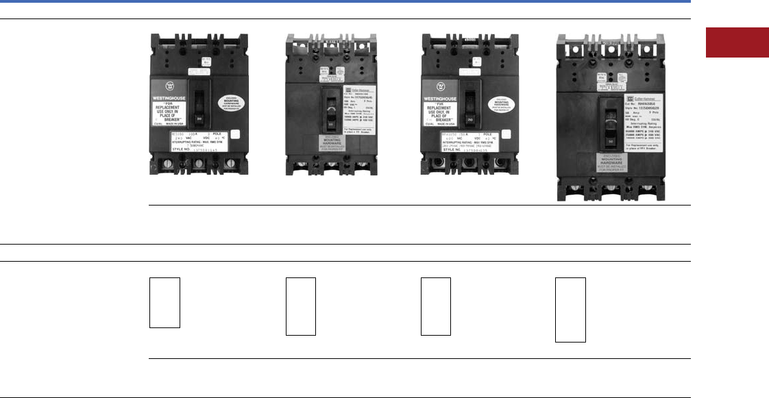
Volume 12—Aftermarket, Renewal Parts and Life Extension Solutions CA08100014E—July 2016 www.eaton.com V12-T3-81
1
2
3
4
5
6
7
8
9
10
11
12
13
14
15
16
17
18
19
20
21
22
23
24
25
3
Molded-Case Circuit Breakers
Replacement Capabilities
Panelboard “Only” Replacement Circuit Breaker Guide—Dimensions in Inches (Per Three-Pole Breaker)
Notes
1Obsolete—no replacement.
2Obsolete—use REH (available in three-pole only).
3Obsolete—use RHFA (available in three-pole only).
4Obsolete—use RHF (available in three-pole only).
Description
Maximum Amperes
100A 225A
Current Design
Panelboard ”only“
replacement circuit breakers
These circuit breakers, when used in a
panelboard, are direct replacements for
the circuit breakers listed below both
electrically and physically.
RE 1, REA 2REH RFA 3, RHFA RF 4, RHF
Width: 4.13
Height: 6.00
Depth: 3.38
Width: 4.13
Height: 6.00
Depth: 3.38
Width: 4.13
Height: 6.00
Depth: 3.38
Width: 4.13
Height: 9.38
Depth: 3.81
Out-of-Production Westinghouse Circuit Breakers
These circuit breakers
are no longer manufactured
These circuit breakers, when used
in a panelboard, are directly replaced
by the circuit breakers listed above.
*Indicates last date of manufacture.
E, EA
*1974
EH
*1974
FA, HFA
*1974
F, HF
*1974
Width: 4.13
Height: 6.00
Depth: 3.38
Width: 4.13
Height: 6.50
Depth: 3.38
Width: 4.13
Height: 6.50
Depth: 3.38
Width: 4.13
Height: 9.38
Depth: 3.81
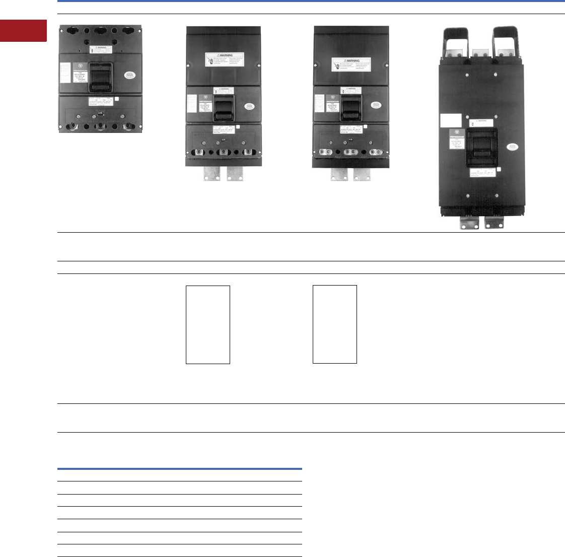
V12-T3-82 Volume 12—Aftermarket, Renewal Parts and Life Extension Solutions CA08100014E—July 2016 www.eaton.com
1
2
3
4
5
6
7
8
9
10
11
12
13
14
15
16
17
18
19
20
21
22
23
24
25
3
Molded-Case Circuit Breakers
Replacement Capabilities
Panelboard “Only” Replacement Circuit Breaker Guide—Dimensions in Inches (Per Three-Pole Breaker), continued
Further Information
Notes
1Obsolete—use RHK (available in three-pole only).
2Obsolete—use RHKL (available in three-pole only).
3Obsolete—use RHLM (available in three-pole only).
Maximum Amperes
225A 400A 400A 800A
Current Design
RJ RK 1, RHK RKL 2, RHKL RLM 3, RHLM
Width: 8.25
Height: 10.13
Depth: 4.06
Width: 8.25
Height: 15.50
Depth: 4.06
Width: 8.25
Height: 16.00
Depth: 4.06
Width: 8.25
Height: 22.00
Depth: 5.50
Out-of-Production Westinghouse Circuit Breakers
J
*1967
K, HK
*1967
KL, HKL
*1967
LM, HLM
*1967
Width: 8.25
Height: 10.13
Depth: 4.06
Width: 8.25
Height: 15.50
Depth: 4.06
Width: 8.25
Height: 16.00
Depth: 4.06
Width: 8.25
Height: 22.00
Depth: 5.50
Publication Number Description
IL 15558 Mounting information for the RE, REA breakers
IL 15559 Mounting information for the RF, RHF breakers
IL 15562 Mounting information for the REH, RFA, RHFA breakers
IL 15563 Mounting information for the RJ breaker
IL 15564 Mounting information for the RK, RHK breakers
IL 15565 Mounting information for the RKL, RHKL breakers
IL 15566 Mounting information for the RLM, RHLM breakers
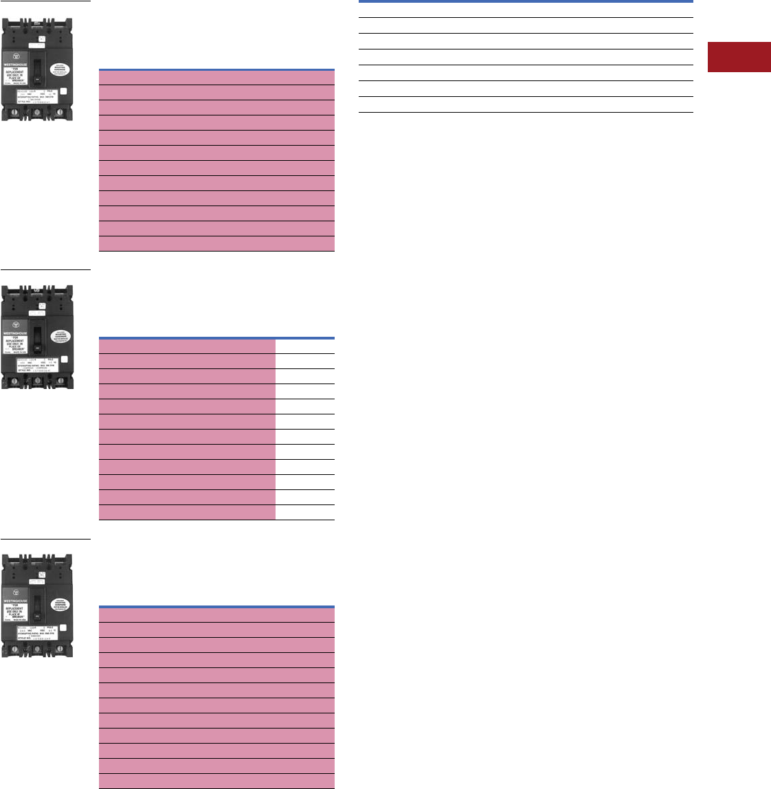
Volume 12—Aftermarket, Renewal Parts and Life Extension Solutions CA08100014E—July 2016 www.eaton.com V12-T3-83
1
2
3
4
5
6
7
8
9
10
11
12
13
14
15
16
17
18
19
20
21
22
23
24
25
3
Molded-Case Circuit Breakers
Replacement Capabilities
■
Shaded area denotes obsolete or discontinued products
and services. 1
Type REA, Single-, Two- and Three-Pole,
240 Vac Maximum, Thermal-Magnetic
Type REH, Single-, Two- and Three-Pole,
480 Vac Maximum, Thermal-Magnetic
Type RE, Single-, Two- and Three-Pole,
240 Vac Maximum, Thermal-Magnetic
Terminals
Accessories and Modifications
All accessories and modifications available for Replacement
Breakers Types EB, EHB and FB are also available for
Panelboard Replacement Breakers Types RE, REH, RFA,
RF, RHF, REA and RHFA.
For accessories and modifications, refer to Pages V12-T3-65–
V12-T3-79.
Terminals
See table on Page V12-T3-83.
50°C Calibration
Add suffix “V” to catalog number for breakers to be used in
50°C ambients. Same price as standard 40°C breakers.
Note: Not UL Listed.
Notes
1These frames are obsolete. For replacement solutions, see the cross-reference on
Pages V12-T3-114–V12-T3-167 or call 803-481-6843 for other panelboard solutions.
2Package of three.
Continuous
Ampere
Rating at 40°C
Catalog Number
Single-Pole,
120 Vac
Two-Pole,
240 Vac
Three-Pole,
240 Vac
10 REA1010 — —
15 REA1015 REA2015 REA3015
20 REA1020 REA2020 REA3020
25 REA1025 REA2025 REA3025
30 REA1030 REA2030 REA3030
40 REA1040 REA2040 REA3040
50 REA1050 REA2050 REA3050
60 REA1060 REA2060 REA3060
70 REA1070 REA2070 REA3070
80 REA1080 REA2080 REA3080
90 REA1090 REA2090 REA3090
100 REA1100 REA2100 REA3100
Continuous
Ampere
Rating at 40°C
Catalog Number
Single-Pole,
277 Vac
Two-Pole,
480 Vac
Three-Pole,
480 Vac
10 REH1010 ——
5REH1015 REH2015 REH3015
20 REH1020 REH2020 REH3020
25 REH1025 REH2025 REH3025
30 REH1030 REH2030 REH3030
40 REH1040 REH2040 REH3040
50 REH1050 REH2050 REH3050
60 REH1060 REH2060 REH3060
70 REH1070 REH2070 REH3070
80 REH1080 REH2080 REH3080
90 REH1090 REH2090 REH3090
100 REH1100 REH2100 REH3100
Continuous
Ampere
Rating at 40°C
Catalog Number
Single-Pole,
120 Vac
Two-Pole,
240 Vac
Three-Pole,
240 Vac
10 RE1010 — —
15 RE1015 RE2015 RE3015
20 RE1020 RE2020 RE3020
25 RE1025 RE2025 RE3025
30 RE1030 RE2030 RE3030
40 RE1040 RE2040 RE3040
50 RE1050 RE2050 RE3050
60 RE1060 RE2060 RE3060
70 RE1070 RE2070 RE3070
80 RE1080 RE2080 RE3080
90 RE1090 RE2090 RE3090
100 RE1100 RE2100 RE3100
Type REA
Type REH
Type RE
Maximum Amperes Wire Type Wire Range Style Number 2
Standard Pressure Type Terminals
20 (EB, EHB) Al/Cu #14–#10 624B100G14
100 Al/Cu #14–1/0 624B100G02
150 Al/Cu #4–4/0 624B100G17
Optional Al/Cu Pressure Terminals
50 Al/Cu #14–#4 624B100G10
100 Al/Cu #4–4/0 624B100G17
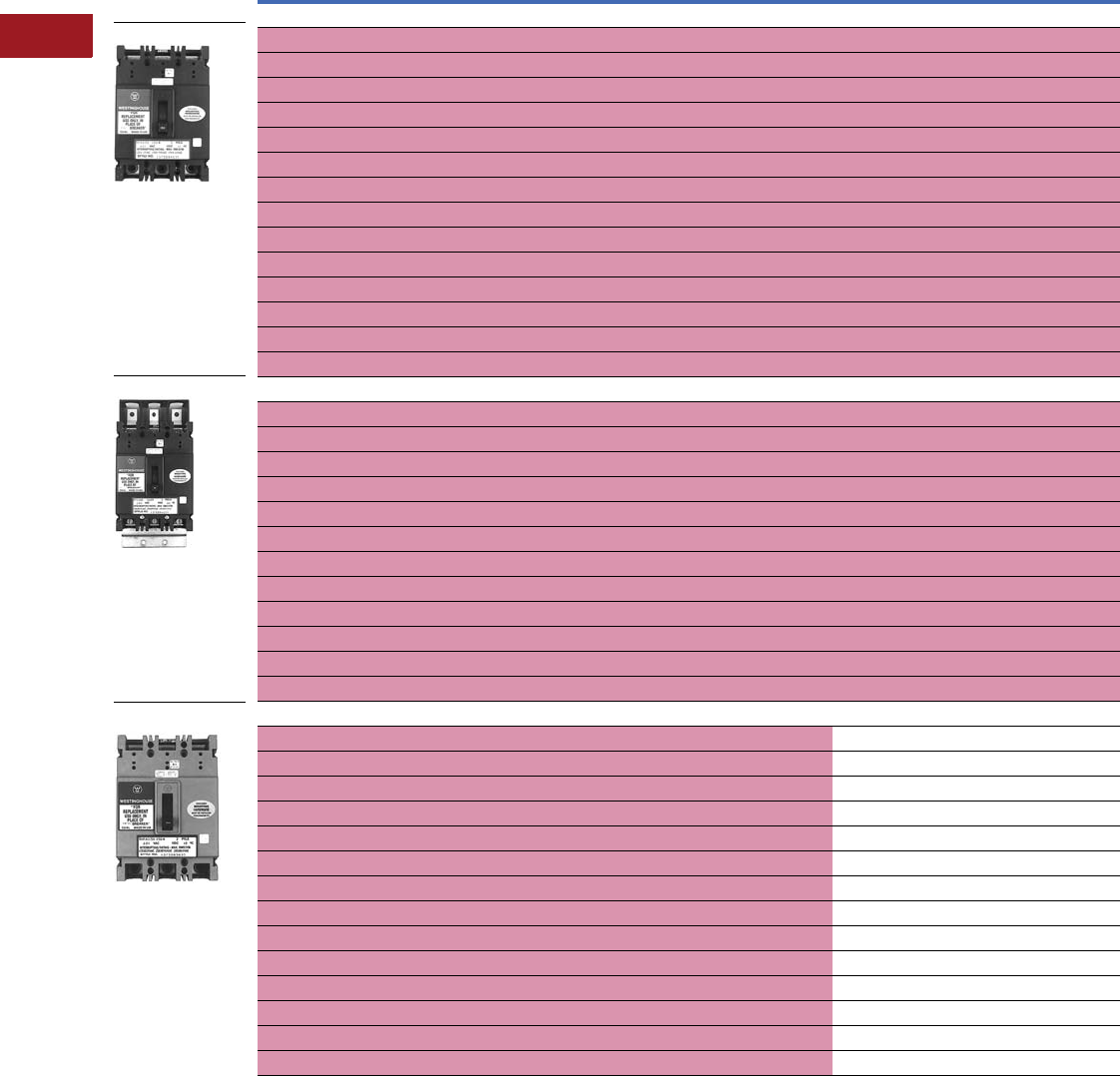
V12-T3-84 Volume 12—Aftermarket, Renewal Parts and Life Extension Solutions CA08100014E—July 2016 www.eaton.com
1
2
3
4
5
6
7
8
9
10
11
12
13
14
15
16
17
18
19
20
21
22
23
24
25
3
Molded-Case Circuit Breakers
Replacement Capabilities
■
Shaded area denotes obsolete or discontinued products and services. 1
Panelboard Replacement Circuit Breakers (Includes Terminals on Load Side Only)
Note
1 These frames are obsolete. For replacement solutions, see the cross-reference on Pages V12-T3-114–V12-T3-167 or call 803-481-6843 for other panelboard solutions.
Continuous Ampere
Rating at 40°C
Catalog Number
Two-Pole, 600 Vac Three-Pole, 600 Vac
Type RFA Two-, Three-Pole, 600 Vac Maximum, Thermal-Magnetic
15 RFA2015 RFA3015
20 RFA2020 RFA3020
25 RFA2025 RFA3025
30 RFA2030 RFA3030
35 RFA2035 RFA3035
40 RFA2040 RFA3040
50 RFA2050 RFA3050
60 RFA2060 RFA3060
70 RFA2070 RFA3070
80 RFA2080 RFA3080
90 RFA2090 RFA3090
100 RFA2100 RFA3100
125 RFA2125 RFA3125
150 RFA2150 RFA3150
Type RF Two-, Three-Pole, 600 Vac Maximum, Thermal-Magnetic
15 RF2015 RF3015
20 RF2020 RF3020
25 RF2025 RF3025
30 RF2030 RF3030
35 RF2035 RF3035
40 RF2040 RF3040
50 RF2050 RF3050
60 RF2060 RF3060
70 RF2070 RF3070
80 RF2080 RF3080
90 RF2090 RF3090
100 RF2100 RF3100
Type RHFA Two-, Three-Pole, 600 Vac Maximum, Thermal-Magnetic
15 RHFA2015 RHFA3015
20 RHFA2020 RHFA3020
25 RHFA2025 RHFA3025
30 RHFA2030 RHFA3030
35 RHFA2035 RHFA3035
40 RHFA2040 RHFA3040
50 RHFA2050 RHFA3050
60 RHFA2060 RHFA3060
70 RHFA2070 RHFA3070
80 RHFA2080 RHFA3080
90 RHFA2090 RHFA3090
100 RHFA2100 RHFA3100
125 RHFA2125 RHFA3125
150 RHFA2150 RHFA3150
Type RFA
Type RF
Type RHFA
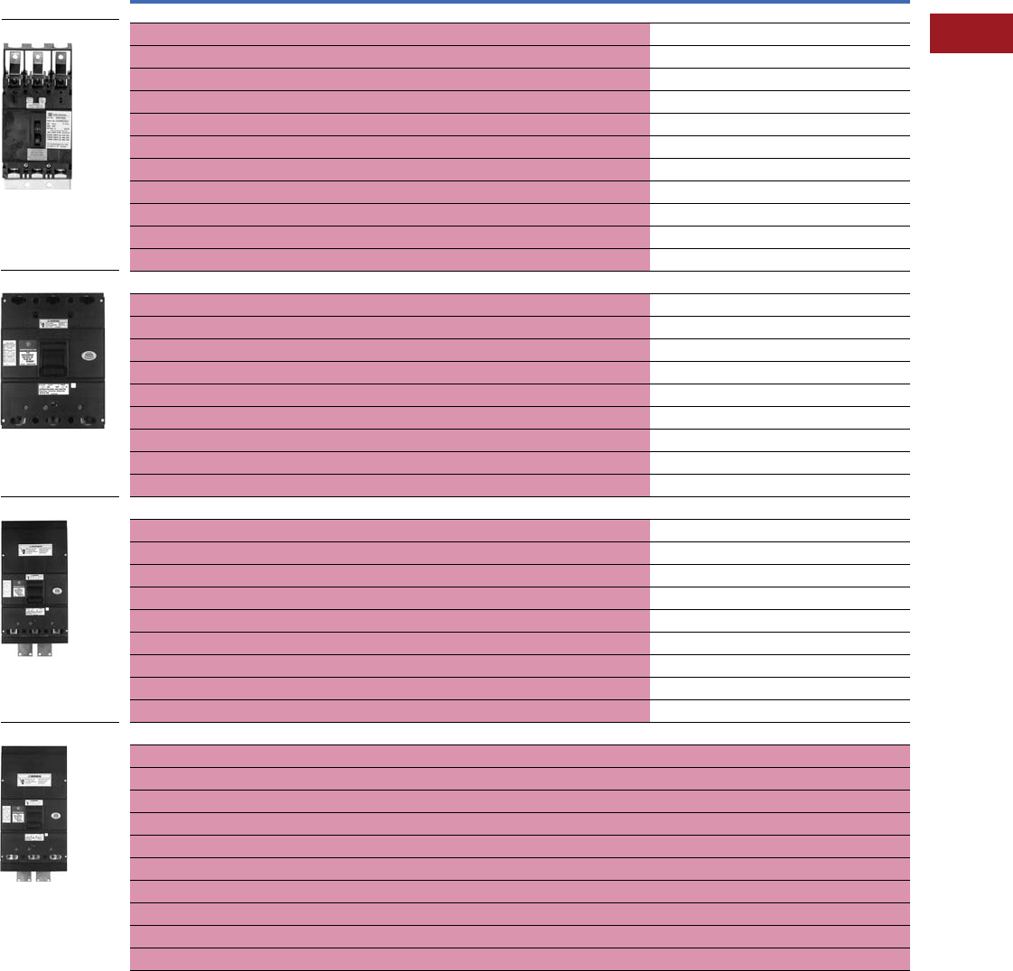
Volume 12—Aftermarket, Renewal Parts and Life Extension Solutions CA08100014E—July 2016 www.eaton.com V12-T3-85
1
2
3
4
5
6
7
8
9
10
11
12
13
14
15
16
17
18
19
20
21
22
23
24
25
3
Molded-Case Circuit Breakers
Replacement Capabilities
■
Shaded area denotes obsolete or discontinued products and services. 1
Panelboard Replacement Circuit Breakers (Includes Terminals on Load Side Only)
Note
1 These frames are obsolete. For replacement solutions, see the cross-reference on Pages V12-T3-114–V12-T3-167 or call 803-481-6843 for other panelboard solutions.
Continuous Ampere
Rating at 40°C
Catalog Number
Two-Pole, 600 Vac Three-Pole, 600 Vac
Type RHF Two-, Three-Pole, 600 Vac Maximum, Thermal-Magnetic
15 RHF2015 RHF3015
20 RHF2020 RHF3020
25 RHF2025 RHF3025
30 RHF2030 RHF3030
40 RHF2040 RHF3040
50 RHF2050 RHF3050
60 RHF2060 RHF3060
70 RHF2070 RHF3070
80 RHF2080 RHF3080
90 RHF2090 RHF3090
100 RHF2100 RHF3100
Type RJ Two-, Three-Pole, 600 Vac Maximum, Thermal-Magnetic
70 RJ2070 RJ3070
90 RJ2090 RJ3090
100 RJ2100 RJ3100
125 RJ2125 RJ3125
150 RJ2150 RJ3150
175 RJ2175 RJ3175
200 RJ2200 RJ3200
225 RJ2225 RJ3225
225 MCS RJ2225K RJ3225K
Type RK Two-, Three-Pole, 600 Vac Maximum, Thermal-Magnetic
70 RK2070 RK3070
90 RK2090 RK3090
100 RK2100 RK3100
125 RK2125 RK3125
150 RK2150 RK3150
175 RK2175 RK3175
200 RK2200 RK3200
225 RK2225 RK3225
225 MCS RK2225K RK3225K
Type RKL Two-, Three-Pole, 600 Vac Maximum, Thermal-Magnetic
125 RKL2125 RKL3125
150 RKL2150 RKL3150
175 RKL2175 RKL3175
200 RKL2200 RKL3200
225 RKL2225 RKL3225
250 RKL2250 RKL3250
300 RKL2300 RKL3300
350 RKL2350 RKL3350
400 RKL2400 RKL3400
400 MCS RKL2400K RKL3400K
Type RHF
Type RJ
Type RK
Type RKL
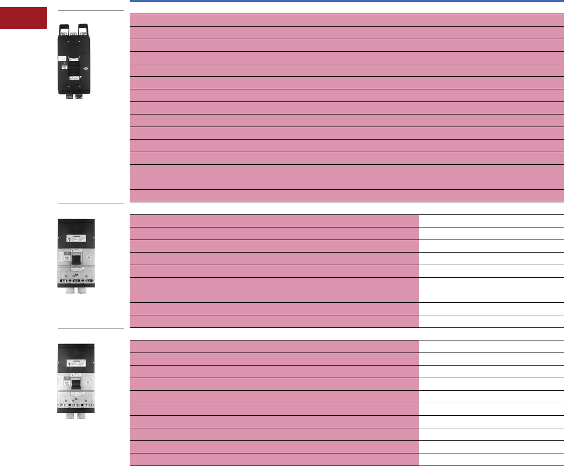
V12-T3-86 Volume 12—Aftermarket, Renewal Parts and Life Extension Solutions CA08100014E—July 2016 www.eaton.com
1
2
3
4
5
6
7
8
9
10
11
12
13
14
15
16
17
18
19
20
21
22
23
24
25
3
Molded-Case Circuit Breakers
Replacement Capabilities
■
Shaded area denotes obsolete or discontinued products and services. 1
Panelboard Replacement Circuit Breakers (Includes Terminals on Load Side Only)
Note
1 These frames are obsolete. For replacement solutions, see the cross-reference on Pages V12-T3-114–V12-T3-167 or call 803-481-6843 for other panelboard solutions.
Continuous Ampere
Rating at 40°C
Catalog Number
Two-Pole, 600 Vac Three-Pole, 600 Vac
Type RLM Two-, Three-Pole, 600 Vac Maximum, Thermal-Magnetic
125 RLM2125 RLM3125
150 RLM2150 RLM3150
175 RLM2175 RLM3175
200 RLM2200 RLM3200
225 RLM2225 RLM3225
250 RLM2250 RLM3250
275 RLM2275 RLM3275
300 RLM2300 RLM3300
350 RLM2350 RLM3350
400 RLM2400 RLM3400
500 RLM2500 RLM3500
600 RLM2600 RLM3600
600 MCS RLM2600K RLM3600K
700 RLM2700 RLM3700
800 RLM2800 RLM3800
Type RHK Two-, Three-Pole, 600 Vac Maximum, Thermal-Magnetic
70 RHK2070 RHK3070
90 RHK2090 RHK3090
100 RHK2100 RHK3100
125 RHK2125 RHK3125
150 RHK2150 RHK3150
175 RHK2175 RHK3175
200 RHK2200 RHK3200
225 RHK2225 RHK3225
225 MCS RHK2225K RHK3225K
Type RHKL Two-, Three-Pole, 600 Vac Maximum, Thermal-Magnetic
125 RHKL2125 RHKL3125
150 RHKL2150 RHKL3150
175 RHKL2175 RHKL3175
200 RHKL2200 RHKL3200
225 RHKL2225 RHKL3225
250 RHKL2250 RHKL3250
300 RHKL2300 RHKL3300
350 RHKL2350 RHKL3350
400 RHKL2400 RHKL3400
400 MCS RHKL2400K RHKL3400K
Type RLM
Type RHK
Type RHKL
Volume 12—Aftermarket, Renewal Parts and Life Extension Solutions CA08100014E—July 2016 www.eaton.com V12-T3-87
1
2
3
4
5
6
7
8
9
10
11
12
13
14
15
16
17
18
19
20
21
22
23
24
25
3
Molded-Case Circuit Breakers
Replacement Capabilities
■
Shaded area denotes obsolete or discontinued products and services. 1
Panelboard Replacement Circuit Breakers (Includes Terminals on Load Side Only)
Accessories and
Modifications
All accessories and
modifications available for
replacement breakers types
KA, LA and MA are also
available for panelboard
replacement breakers types
RJ, RK, RKL, RLM, RHK,
RHKL and RHLM.
For additional accessories
and modifications, refer to
Pages V12-T3-65–
V12-T3-79.
Terminals
50°C Calibration
Add suffix “V” to catalog
number for breakers to be
used in 50°C ambients.
Same price as standard
40°C breakers.
Note: Not UL Listed.
Panelboard and Switchboard
Replacement Breaker
Ordering Instructions
1. Choose the breaker
frame and amperage.
2. Select the proper
connector kit (if needed).
3. Call your local distributor
with catalog numbers
and request Eaton’s Free
Express Service.
Compatible with Panelboards
and Switchboards from:
Westinghouse Distribution
and Control Business Unit
1987–1998
1991–1998
1994–2000
2000–2009
2009–Present
Connector Kits for Pow-R-
Line 4 Panelboards and
Pow-R-Line C Switchboards
For further information,
reference Page V12-T3-168
in this catalog.
Notes
1These frames are obsolete. For
replacement solutions, see the cross-
reference on Pages V12-T3-114–
V12-T3-167 or call 803-481-6843 for
other panelboard solutions.
2Packaged individually.
Continuous Ampere
Rating at 40°C
Catalog Number
Two-Pole, 600 Vac Three-Pole, 600 Vac
Type RHLM Two-, Three-Pole, 600 Vac Maximum, Thermal-Magnetic
125 RHLM2125 RHLM3125
150 RHLM2150 RHLM3150
175 RHLM2175 RHLM3175
200 RHLM2200 RHLM3200
225 RHLM2225 RHLM3225
250 RHLM2250 RHLM3250
275 RHLM2275 RHLM3275
300 RHLM2300 RHLM3300
325 RHLM2325 RHLM3325
350 RHLM2350 RHLM3350
400 RHLM2400 RHLM3400
450 RHLM2450 RHLM3450
500 RHLM2500 RHLM3500
550 RHLM2550 RHLM3550
600 RHLM2600 RHLM3600
600 MCS RHLM2600K RHLM3600K
700 RHLM2700 RHLM3700
800 RHLM2800 RHLM3800
Type RHLM
Panelboard
Circuit
Breakers Terminals 2
RJ TA225LA1
RK TA225LA1
RHK TA225LA1
RKL TA400LA1
RHKL TA400LA1
RLM TA700MA1 (for <600A)
RHLM TA800MA1 (for 700–800A)
Special Breakers
Magnetic only (includes
load terminals). Available
for all ampere ratings for
two- and three-pole RJ,
RK, RKL, RLM, RHK, RHKL
and RHLM.
High magnetic molded-
case switches (K suffix) are
available to replace out-of-
production non-automatic
breakers (N suffix).
Note: Not UL Listed.
Breaker
Type
Catalog Number
Single Twin
F-Frame — KPRL4FD
J-Frame KPRL4JDS KPRL4JDT
K-Frame KPRL4KDS KPRL4KDT
L-Frame KPRL4LD —
M-Frame KPRL4MC —
N-Frame KPRL4ND —
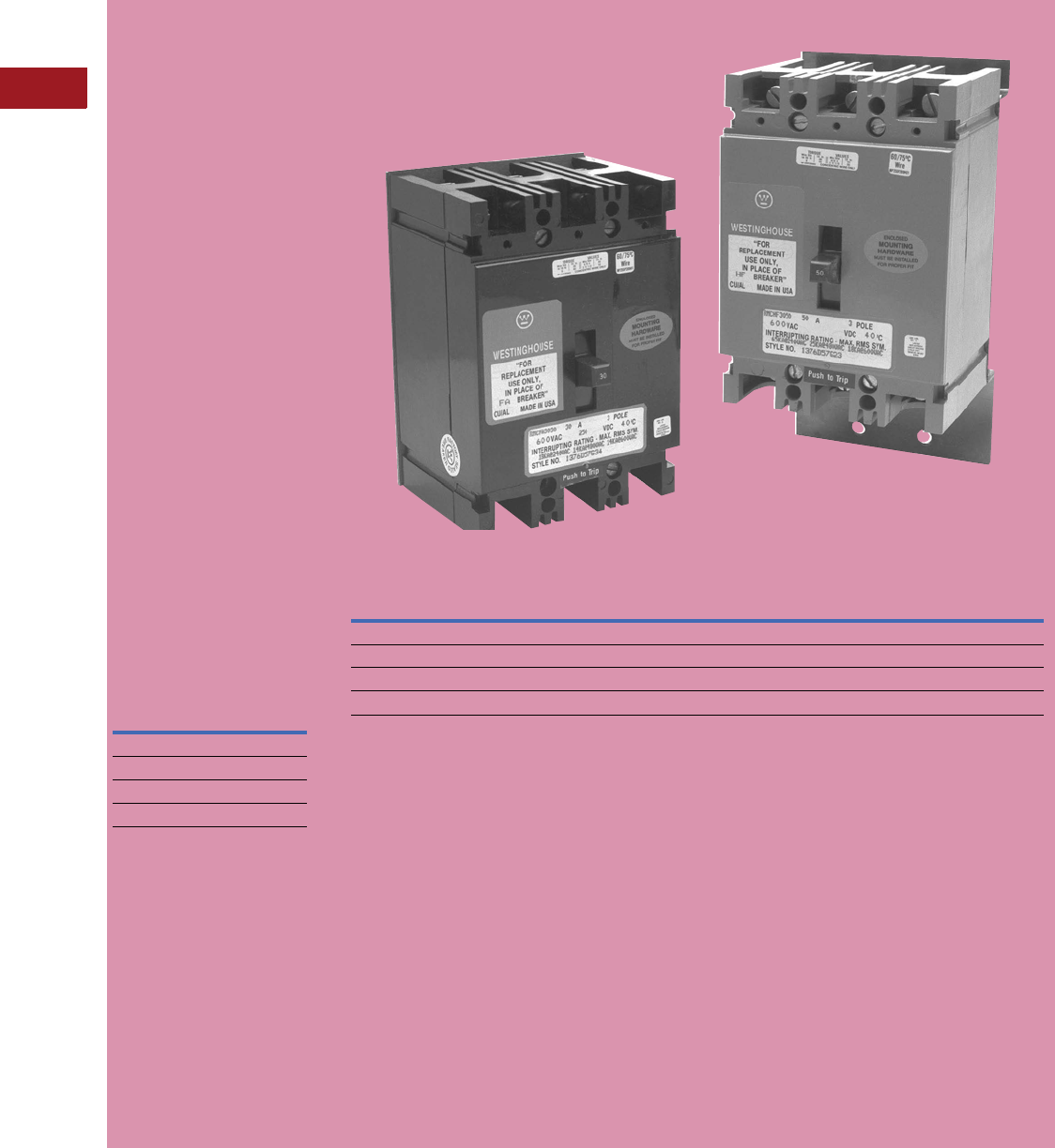
V12-T3-88 Volume 12—Aftermarket, Renewal Parts and Life Extension Solutions CA08100014E—July 2016 www.eaton.com
1
2
3
4
5
6
7
8
9
10
11
12
13
14
15
16
17
18
19
20
21
22
23
24
25
3
Molded-Case Circuit Breakers
Replacement Capabilities
■
Shaded area denotes obsolete or discontinued products and services.
Replacement Capabilities
Cutler-Hammer motor
control center replacement
circuit breakers are newly
manufactured and tested
to the latest applicable
standards at the Eaton
molded-case circuit breaker
plant in Beaver, PA. This
plant has a long and well-
recognized tradition of
product safety, integrity
and quality.
The motor control center
replacement circuit breaker
solution eliminates the
need to consider alternative
approaches. Eaton
customers are ensured
that the high standards
of product quality and
reliability do not have to be
sacrificed when replacing
Westinghouse out-of-
production circuit breakers.
All motor control center
replacement circuit breakers
are easily identified by the
prefix “RMC” added to the
out-of-production type
circuit breaker catalog
number they replace.
Replacement Chart
Current
MCC
Circuit
Breaker
Type
Out-of-
Production
Circuit
Breaker
Type 1
Volts AC
(50/60 Hz)
600
RMCFA FA ■
RMCHFA HFA ■
RMCF F ■
RMCHF HF ■
Replacement Motor Control Center Breakers
Motor Control Center Replacement Breaker Interrupting Ampere Ratings
Breaker Type Amperes 240 Vac 480 Vac 600 Vac 250 Vac
RMCF 23 15–100 18,000 14,000 14,000 10,000
RMCFA 234 15–150 18,000 14,000 14,000 10,000
RMCHF 23 15–100 65,000 25,000 18,000 20,000
RMCHFA 234 15–150 65,000 25,000 18,000 20,000
Example:
An RMCF3100 is a newly
manufactured, three-pole,
100A trip panelboard
replacement circuit breaker.
It replaces an out-of-
production F circuit breaker.
Example:
RMC Designates new
motor control
center replacement
circuit breaker.
FIdentifies the out-of-
production circuit
breaker frame.
3Number of poles.
100 Trip unit
ampere rating.
Contact 1-800-OLD-UNIT
for replacement or
Page V12-T3-91 for
Series C retrofit kits.
Notes
1Last manufacture date—1974.
2Motor control center replacement
breakers do not have the same
physical dimensions or mounting holes
as the breakers they replace. Types
RMCFA and RMCHFA are 6.00
inches long and the breakers they
replace, FA and HFA, are 6.50 inches
long. Types RMCF and RMCHF
are 6.00 inches long and the breakers
they replace, F and HF, are 9.375
inches long. A mounting plate is
provided with each breaker to resolve
these differences, and must be
installed to ensure a proper fit.
3Motor control center replacement
circuit breakers have non-
interchangeable trip units and the
same interrupting capacity as the
out-of-production circuit breakers
they replace.
4RMCFA and RMCHFA two-pole
breakers are supplied in a three-pole
frame with current carrying parts
omitted from the center pole.
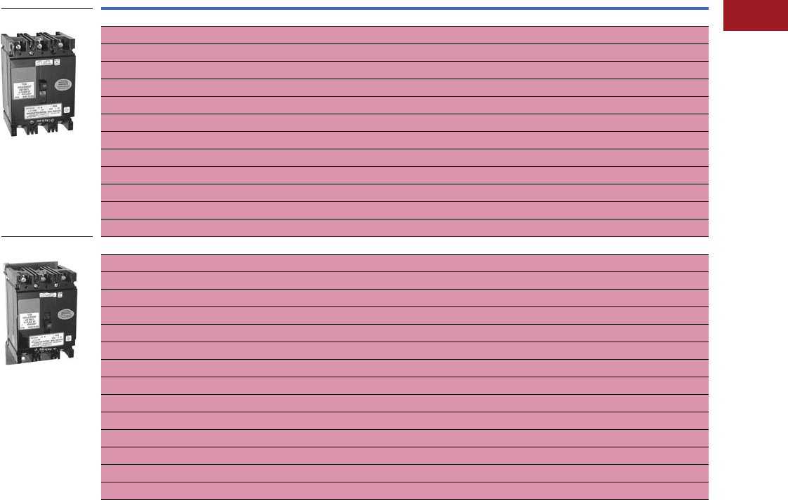
Volume 12—Aftermarket, Renewal Parts and Life Extension Solutions CA08100014E—July 2016 www.eaton.com V12-T3-89
1
2
3
4
5
6
7
8
9
10
11
12
13
14
15
16
17
18
19
20
21
22
23
24
25
3
Molded-Case Circuit Breakers
Replacement Capabilities
Types RMCFA, RMCF, RMCHFA and RMCHF—Motor Control Center Replacement
■
Shaded area denotes obsolete or discontinued products and services. 1
Motor Control Center Replacement Circuit Breakers
Notes
1 These frames are obsolete. For more information, call 1-800-OLD-UNIT for Cutler-Hammer motor control solutions.
See Page V12-T3-91 for Series C retrofit kits.
Continuous Ampere
Rating at 40°C
Catalog Number
Single-Pole Two-Pole Three-Pole
Type RMCFA—15–100A Two-, Three-Pole, 600 Vac Maximum, Thermal-Magnetic
15 —RMCFA2015 RMCFA3015
20 —RMCFA2020 RMCFA3020
25 —RMCFA2025 RMCFA3025
30 —RMCFA2030 RMCFA3030
35 —RMCFA2035 RMCFA3035
40 —RMCFA2040 RMCFA3040
50 —RMCFA2050 RMCFA3050
60 —RMCFA2060 RMCFA3060
70 —RMCFA2070 RMCFA3070
80 —RMCFA2080 RMCFA3080
90 —RMCFA2090 RMCFA3090
100 —RMCFA2100 RMCFA3100
Type RMCF—15–150A Two-, Three-Pole, 600 Vac Maximum, Thermal-Magnetic
15 —RMCHF2015 RMCHF3015
20 —RMCHF2020 RMCHF3020
25 —RMCHF2025 RMCHF3025
30 —RMCHF2030 RMCHF3030
35 —RMCHF2035 RMCHF3035
40 —RMCHF2040 RMCHF3040
50 —RMCHF2050 RMCHF3050
60 —RMCHF2060 RMCHF3060
70 —RMCHF2070 RMCHF3070
80 —RMCHF2080 RMCHF3080
90 —RMCHF2090 RMCHF3090
100 —RMCHF2100 RMCHF3100
125 —RMCHF2125 RMCHF3125
150 —RMCHF2150 RMCHF3150
Type RMCFA
Type RMCF
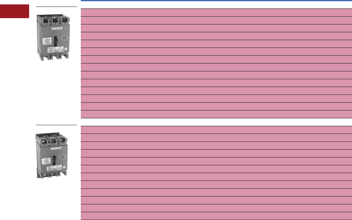
V12-T3-90 Volume 12—Aftermarket, Renewal Parts and Life Extension Solutions CA08100014E—July 2016 www.eaton.com
1
2
3
4
5
6
7
8
9
10
11
12
13
14
15
16
17
18
19
20
21
22
23
24
25
3
Molded-Case Circuit Breakers
Replacement Capabilities
■
Shaded area denotes obsolete or discontinued products and services. 1
Motor Control Center Replacement Circuit Breakers
Notes
1 These frames are obsolete. For more information, call 1-800-OLD-UNIT for Cutler-Hammer motor control solutions.
See Page V12-T3-91 for Series C retrofit kits.
Continuous Ampere
Rating at 40°C
Catalog Number
Single-Pole Two-Pole Three-Pole
Type RMCHFA—15–100A Two-, Three-Pole, 600 Vac Maximum, Thermal-Magnetic
15 —RMCHFA2015 RMCHFA3015
20 —RMCHFA2020 RMCHFA3020
25 —RMCHFA2025 RMCHFA3025
30 —RMCHFA2030 RMCHFA3030
35 —RMCHFA2035 RMCHFA3035
40 —RMCHFA2040 RMCHFA3040
50 —RMCHFA2050 RMCHFA3050
60 —RMCHFA2060 RMCHFA3060
70 —RMCHFA2070 RMCHFA3070
80 —RMCHFA2080 RMCHFA3080
90 —RMCHFA2090 RMCHFA3090
100 —RMCHFA2100 RMCHFA3100
125 —RMCHFA2125 RMCHFA3125
150 —RMCHFA2150 RMCHFA3150
Type RMCHF—15–100A Two-, Three-Pole, 600 Vac Maximum, Thermal-Magnetic
15 —RMCHF2015 RMCHF3015
20 —RMCHF2020 RMCHF3020
25 —RMCHF2025 RMCHF3025
30 —RMCHF2030 RMCHF3030
35 —RMCHF2035 RMCHF3035
40 —RMCHF2040 RMCHF3040
50 —RMCHF2050 RMCHF3050
60 —RMCHF2060 RMCHF3060
70 —RMCHF2070 RMCHF3070
80 —RMCHF2080 RMCHF3080
90 —RMCHF2090 RMCHF3090
100 —RMCHF2100 RMCHF3100
Type RMCHF
Type RMCHFA
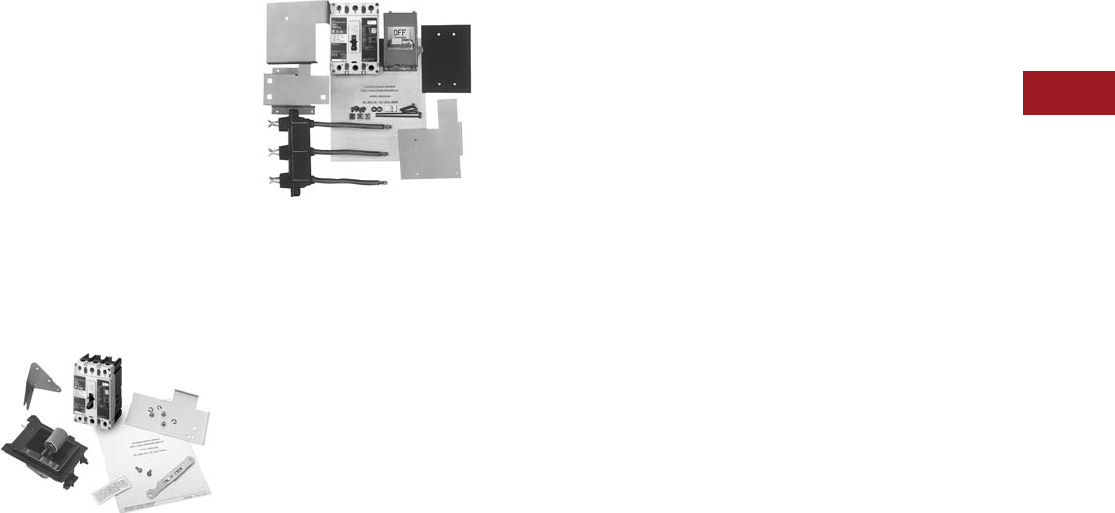
Volume 12—Aftermarket, Renewal Parts and Life Extension Solutions CA08100014E—July 2016 www.eaton.com V12-T3-91
1
2
3
4
5
6
7
8
9
10
11
12
13
14
15
16
17
18
19
20
21
22
23
24
25
3
Molded-Case Circuit Breakers
Replacement Capabilities
Technology Upgrades
Series C Retrofit Kits
Series C Retrofit Kits are to
be used to upgrade existing
Type W and 5 Star motor
control center units by
changing out the old breakers
with new Series C models.
These kits can be applied to
both starter and feeder units.
Some of the breakers that
these kits will upgrade
include:
●MCP, F, FA, FB, HFB, K, KA,
KB, HKB, L, LA, LB and
HLB breakers
5 Star Series C Retrofit Kit
5 Star Series C Retrofit Kit
The 5 Star Series C retrofit kit
includes:
●Series C device, 65 kA
(either HMCP or thermal-
magnetic breaker)
●Operating handle, including
tripped indication and
push-to-trip mechanism
●Label stating that the MCC
unit has been retrofitted
with Series C device
suitable for 65 kA (similar
to UL quality label)
●Templates for desired
frame size
●Assembly instructions
Customer benefits:
●Ease of ordering—one
catalog number for all
required parts
●Series C technology—
higher AIC rating
●All new components
associated with the
breaker, including new
stab assembly, operating
mechanism and door,
if required
Type W Series C Retrofit Kit
Type W Series C Retrofit Kit
The Type W Series C retrofit
kit includes:
●Series C device, 65 kA
(either HMCP or thermal-
magnetic breaker)
●Operating handle, including
tripped indication and
push-to-trip mechanism
●Label stating that the MCC
unit has been retrofitted
with Series C device
suitable for 65 kA (similar
to UL quality label)
●Templates for proper hole
placement for desired
frame size
●Series C breaker mounting
hardware
●New door and hardware
●New stab assembly
●Assembly instructions
310+ Electronic Trip Unit
The 310+ electronic trip unit
has advantages and upgraded
features over the Series C
310 electronic trip unit
as follows:
●Adjustable Ir continuous
current setting eliminates
the need for rating plugs
●Cause of trip information
can be extracted from
the breaker
●Zone selective interlocking
option for breaker
coordination
●Ground fault alarm only
option to keep critical
equipment on-line when
a ground fault is present
●Arcflash Reduction
Maintenance System™ to
improve worker safety
Note: Available only for the LG,
NG, RG/RD 310+ models.
The 310+ electronic trip unit
is available for the following
MCCB breakers:
●Series C FDE
●Series G JG
●Series G LG
●Series G NG
●Series G RG
●Series C RD (available
as a field retrofit kit)
Series C to Series G
Upgrades
The Series C 250A JD and
600A LD breakers are being
replaced by Series G 250A
JG and 600A LG breakers
respectively. There are
several advantages in
moving from these Series C
to Series G breakers.
Series G 250A JG Molded-Case
Circuit Breaker
●Smaller breaker footprint
than Series C JD
●Breaker is duel rated,
UL and IEC
●Interruption ratings up to
200 kAIC at 480 Vac
●Accessories are field
installable thru-cover
●Now available with an
electronic, 310+ trip unit
●Can accommodate the
ANSI C12.1 Power
Monitoring/Metering
Module (PM3)
Series G 600A LG Molded-Case
Circuit Breaker:
●Smaller breaker footprint
Series C LD
●Breaker is duel rated,
UL and IEC
●Interruption ratings up
to 200 kAIC at 480 Vac
●Accessories are field
installable thru-cover
●Upgraded from 310
electronic trip unit to a
310+ electronic trip unit
●Can accommodate the
ANSI C12.1 Power
Monitoring Metering
Module (PM3)
Advantages of 310+ Electronic
Trip Unit Technology Versus
the 310 Electronic Trip Unit:
●Adjustable Ir continuous
current setting eliminates
the need for rating plugs
●Cause of trip information
can be extracted from
the breaker
●Zone selective interlocking
option for breaker
coordination
●Ground fault alarm only
option to keep critical
equipment on-line when
a ground fault is present
●Arcflash Reduction
Maintenance System to
improve worker safety
(not available in the JG
310+ electronic trip unit)
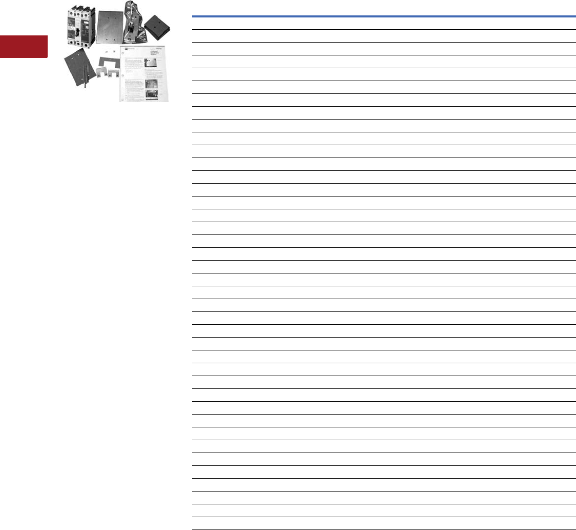
V12-T3-92 Volume 12—Aftermarket, Renewal Parts and Life Extension Solutions CA08100014E—July 2016 www.eaton.com
1
2
3
4
5
6
7
8
9
10
11
12
13
14
15
16
17
18
19
20
21
22
23
24
25
3
Molded-Case Circuit Breakers
Replacement Capabilities
F10 Series C Retrofit Kit
F10 Series C Retrofit Kit
The F10 Series C retrofit
kit includes:
●Series C device, 65 kA
(either HMCP or thermal-
magnetic breaker)
●Operating handle
mechanism, including
tripped indication
push-to-trip
●Label stating that the MCC
unit has been retrofitted
with Series C device
suitable for 65 kA (similar
to UL quality label)
●Templates for desired
frame size
●Assembly instructions
Series C Molded-Case Circuit Breakers
Frame
Type
Interrupting Rating (kAIC) Trip Rating
Amperes
Catalog
Number240V 480V 600V
HFD 100 65 25 15 HFD3015
HFD 100 65 25 20 HFD3020
HFD 100 65 25 25 HFD3025
HFD 100 65 25 30 HFD3030
HFD 100 65 25 40 HFD3040
HFD 100 65 25 50 HFD3050
HFD 100 65 25 60 HFD3060
HFD 100 65 25 70 HFD3070
HFD 100 65 25 80 HFD3080
HFD 100 65 25 90 HFD3090
HFD 100 65 25 100 HFD3100
HFD 100 65 25 125 HFD3125
HFD 100 65 25 150 HFD3150
FDC 200 100 35 15 FDC3015
FDC 200 100 35 20 FDC3020
FDC 200 100 35 25 FDC3025
FDC 200 100 35 30 FDC3030
FDC 200 100 35 40 FDC3040
FDC 200 100 35 50 FDC3050
FDC 200 100 35 60 FDC3060
FDC 200 100 35 70 FDC3070
FDC 200 100 35 80 FDC3080
FDC 200 100 35 90 FDC3090
FDC 200 100 35 100 FDC3100
FDC 200 100 35 125 FDC3125
FDC 200 100 35 150 FDC3150
HJD 100 65 25 175 HJD3175
HJD 100 65 25 200 HJD3200
HJD 100 65 25 225 HJD3225
HJD 100 65 25 250 HJD3250
JDC 200 100 35 175 JDC3175
JDC 200 100 35 200 JDC3200
JDC 200 100 35 225 JDC3225
JDC 200 100 35 250 JDC3250
HKD 100 65 35 300 HKD3300
HKD 100 65 35 350 HKD3350
HKD 100 65 35 400 HKD3400
KDC 200 100 50 300 KDC3300
KDC 200 100 50 350 KDC3350
KDC 200 100 50 400 KDC3400
Volume 12—Aftermarket, Renewal Parts and Life Extension Solutions CA08100014E—July 2016 www.eaton.com V12-T3-93
1
2
3
4
5
6
7
8
9
10
11
12
13
14
15
16
17
18
19
20
21
22
23
24
25
3
Molded-Case Circuit Breakers
Replacement Capabilities
Series C Motor Circuit Protectors Series C Retrofit Kit Catalog Numbering System
How to Order
Step 1: Select the correct Series C molded-case circuit breaker
from the table on Page V12-T3-92 or the Series C motor circuit
protector from the table on this page.
Step 2: Create a catalog number based on the MCC type,
device selected, modifications, door size and device panel.
Step 3: Select price from PL04304002E.
Starter
Size
Magnetic Trip
Range Amperes
Continuous
Rating Amperes
Catalog
Number
09–303HMCP003A0
0 21–70 7 HMCP007C0
0 45–150 15 HMCP015E0
0 40–60 25 HMCP025D0
1 90–300 30 HMCP030H1
2 80–120 50 HMCP050G2
2 150–500 50 HMCP050K2
2 115–170 70 HMCP070J2
2 210–700 70 HMCP070M2
3 160–240 100 HMCP100L3
3 300–1000 100 HMCP100R3
4 450–1500 150 HMCP150T4
4 750–2500 150 HMCP150U4
4, 5 350–700 250 HMCP250A5
5 450–900 250 HMCP250C5
5 500–1000 250 HMCP250D5
5 625–1250 250 HMCP250F5
5 750–1500 250 HMCP250G5
5 875–1750 250 HMCP250J5
5 1000–2000 250 HMCP250K5
5 1125–2250 250 HMCP250L5
5 1250–2500 250 HMCP250W5
5 500–1000 400 HMCP400D5
5 625–1250 400 HMCP400F5
5 750–1500 400 HMCP400G5
5 875–1750 400 HMCP400J5
5 1000–2000 400 HMCP400K5
5 1125–2250 400 HMCP400L5
5 1250–2500 400 HMCP400M5
5 1500–3000 400 HMCP400N5
5 1750–3500 400 HMCP400R5
5, 6 2000–4000 400 HMCP400X5
Device Panel
D= With device
panel
N= No device panel
FT HMCP030H1 C 12 N
MCC Type
FT = Type W
FS = 5 Star
FR = F10
Device Catalog
Number
Use tables.
Modifications
C= Copper lugs
for HMCP
L= Lugs for molded-
case breaker Door Size
Height of door in inches,
6.00-inch increments
V12-T3-94 Volume 12—Aftermarket, Renewal Parts and Life Extension Solutions CA08100014E—July 2016 www.eaton.com
1
2
3
4
5
6
7
8
9
10
11
12
13
14
15
16
17
18
19
20
21
22
23
24
25
3
Molded-Case Circuit Breakers
Replacement Capabilities
OPTIM 550 Trip Units for Upgrading Thermal/Magnetic Trips
Digitrip OPTIM 550
Replacement of the
OPTIM 550 trip units and
the associated accessories
allows a customer to easily
upgrade an existing Series C,
K- or L-Frame molded-case
circuit breaker equipped
with a standard thermal-
magnetic trip unit, without
the need to purchase a new
circuit breaker.
Key features and benefits
of the OPTIM 550 trip
unit include:
●10 set points providing for
premium protection and
coordination
●Cause-of-Trip indication
(LEDs and digital memory)
●Load monitoring to provide
information for energy
management
●Diagnostics to assist in
system troubleshooting
●Communications and zone
interlocking options—field
or factory installed
OPTIM 550 Trip Units for Upgrading Thermal/Magnetic Trips
Maximum
Ampere Rating
(Sensor)
Catalog Number
Type of OPTIM 550 Trip Unit
LSI LSIA LSIG
KD, HKD, KDC, CKD and CHKD Breaker Frames
125 KEP3125T52 KEP3125T57 KEP3125T56
250 KEP3250T52 KEP3250T57 KEP3250T56
400 KEP3400T52 KEP3400T57 KEP3400T56
LD, HLD, LDC, CLD, CHLD and CLDC Breaker Frames
125 LEP3125T52 LEP3125T57 LEP3125T56
250 LEP3250T52 LEP3250T57 LEP3250T56
400 LEP3400T52 LEP3400T57 LEP3400T56
600 LEP3600T52 LEP3600T57 LEP3600T56
Cutler-Hammer PowerNet™ and Zone Interlock Kits (OPTIM 550 Only)
K-, L- and N-Frames
PowerNet
Communication Kit
The Cutler-Hammer
PowerNet communications
kit can be ordered to add
PowerNet communications
to an existing OPTIM 550
breaker in the field. An
18.00-inch wiring pigtail is
routed to the rear of the
breaker: two wires for
PowerNet and two wires
for 24 Vdc (45 mA load).
It is recommended that the
power supply be an “isolated
high quality” unit.
PowerNet and Zone Interlock Kits
Notes
1Includes a ground fault alarm signal that can drive the ground fault alarm unit
(catalog number GFAU).
Instruction leaflet numbers (K) 29C506, (L) 29C897, (N) 29C898.
Circuit
Breaker
PowerNet
Zone Interlocking/
Ground 1
PowerNet and Zone
Interlocking/Ground 1
Factory
Install
Suffix
Catalog
Number
Factory
Install
Suffix
Catalog
Number
Factory
Install
Suffix
Catalog
Number
K-Frame PN ICK550K ZG ZGK550K ZGP ZGPK550K
L-Frame PN ICK550L ZG ZGK550L ZGP ZGPK550L
N-Frame PN ICK550N ZG ZGK550N ZGP ZGPK550N
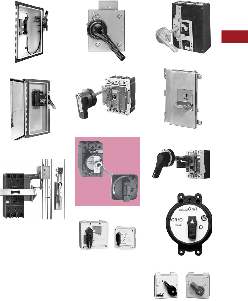
Volume 12—Aftermarket, Renewal Parts and Life Extension Solutions CA08100014E—July 2016 www.eaton.com V12-T3-95
1
2
3
4
5
6
7
8
9
10
11
12
13
14
15
16
17
18
19
20
21
22
23
24
25
3
Molded-Case Circuit Breakers
Replacement Capabilities
Handle Mechanisms
■
Shaded area denotes
obsolete or discontinued
products and services.
MCCB Handle Mechanism
Introduction
Eaton offers a broad range
of handle mechanisms for
molded-case circuit breakers.
Each of these has been
designed specifically for
safe, dependable operation
and ease of installation.
Handle mechanisms are
used in a wide variety of
applications including
enclosed molded-case circuit
breakers,
control panels and
motor control centers.
Whether replacing a damaged
handle mechanism with a like
unit, switching from fuses
to circuit breakers in order to
limit downtime, or upgrading
to take advantage of the
many benefits associated
with applying communicating,
programmable molded-case
circuit breaker technology,
Eaton has the handle
mechanism solution
that is right for you.
Flex-Shaft Type—Page V12-T3-107
Type SM Safety Handle—
Page V12-T3-101
Type AMT Vari-Depth—
Page V12-T3-104
Slide Plate Type—Page V12-T3-99
Universal Rotary Type—
Page V12-T3-110
G-Frame Vari-Depth
Universal Direct—Page V12-T3-111
Vari-Depth Type—Page V12-T3-105
Type MC Motor Control—
Page V12-T3-103
Series C Rotary Type— Page V12-T3-109
G Direct—Page V12-T3-111
Euro IEC Direct—Page V12-T3-111

V12-T3-96 Volume 12—Aftermarket, Renewal Parts and Life Extension Solutions CA08100014E—July 2016 www.eaton.com
1
2
3
4
5
6
7
8
9
10
11
12
13
14
15
16
17
18
19
20
21
22
23
24
25
3
Molded-Case Circuit Breakers
Replacement Capabilities
Handle Mechanism Selection and Availability Guide
Notes
1For application only with Series C molded-case circuit breakers and HMCPs.
2Series C F-Frame includes EHD, ED, FDB, FD, HFD and FDC designations.
Circuit Breaker and
Switch Type
Door Mounted Flange Mounted
Vari-
Depth
Series C 1
Rotary
Slide
Plate MC
Series C 1
Flex Shaft SM
AMT
Fixed Width
AMT
Vari-Depth
Series C Breakers
F-Frame/F HMCP 2■■■■■■■■
J-Frame/J HMCP ■■■■■■■■
K-Frame/K HMCP ■■■■■■■■
L-Frame/L HMCP ■■■■■■■■
M-Frame ■■■■■■ ■
N-Frame ■■
R-Frame ■■
Other Industrial Breakers
GB/GHB/GC/GHC/GD/GMCP ■
LA/LAB/HLA ■■■■■■
LC/HLC/LCG ■■■■■■
MA/HMA ■■■■■
MC/HMC ■■■■■
NB/HNB ■■■■■
NC/HNC ■■■■■
PB ■
PC/PCC ■
FB TRI-PAC ■■■■■
LA TRI-PAC ■■ ■■
NB TRI-PAC ■■ ■■
PB TRI-PAC ■
FCL ■■■
LCL ■ ■■■
EB/EHB/FB/HFB ■■■■■■
JA/KA/HKA/DA/LB/LBB/HLB ■■■■■■
Disconnect Switches
DE-ION® 30, 60, 100 ■■
DS 30, 60, 100, 200 ■■■■■■
DS 400, 600 ■
Visi-Flex Model “T” 30, 60, 100 ■
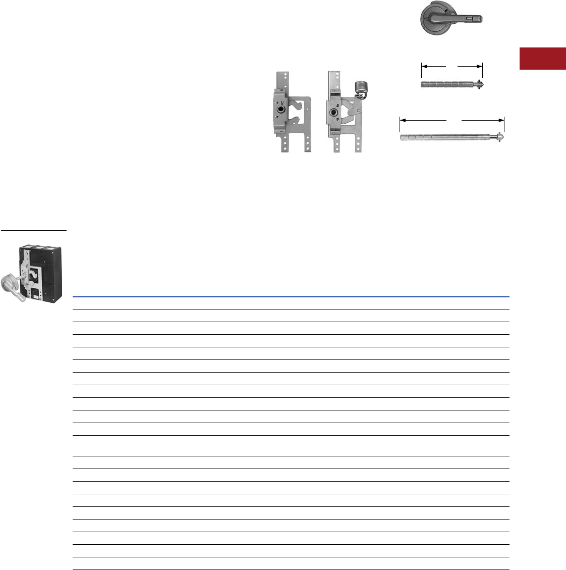
Volume 12—Aftermarket, Renewal Parts and Life Extension Solutions CA08100014E—July 2016 www.eaton.com V12-T3-97
1
2
3
4
5
6
7
8
9
10
11
12
13
14
15
16
17
18
19
20
21
22
23
24
25
3
Molded-Case Circuit Breakers
Replacement Capabilities
Vari-Depth Type
General purpose vari-depth
handle mechanisms are
suitable for use with Type 1
fabricated enclosures. They
are designed for use with
breakers or disconnect
switches when used in deep
enclosures.
Required for a standard
application are a padlockable
operating handle, a shaft and
a mechanism. Two variable
depth shafts are offered
to better cover the wide
range of depths of various
enclosures...these are
referred to in the table as the
standard and the long shaft.
The dimensions for panel
depth given in the following
table are from the mounting
surface of the breaker or the
disconnect to the inside of
the enclosure cover.
Standard mechanisms do
not include an internal lockoff
device. Mechanisms with this
feature are, however, offered
as an optional item. The
internal lockoff provides a
means of padlocking the
breaker or the switch in
the OFF position while the
enclosure door is open.
These mechanisms may
also be used in conjunction
with Type 4, 7 and 9 cast
enclosures. When used
with these enclosures, the
special handle kits shown
as accessory items must be
ordered in place of the
standard handle.
The adapter bushing, a
component of the special
handle kit, may be ordered
separately.
Mechanism
Handle
Standard Shaft
Long Shaft
Vari-Depth Type Catalog Numbers
Notes
1 Includes hardware.
2 When used with plug-in adapter kits or rear-connected studs, special mounting hardware is required. Refer to Eaton.
3 UL File No. E56845 Vol. 1 Section 4.
4 Extra long shaft includes support bracket for Series C F-Frame with no internal lockoff. Order 373D958G24, which includes the mechanism, shaft and bracket. Order
handle separately. Panel depth 16-3/8–24-1/4.
5 Mechanism style includes a handle and a standard shaft. A long shaft may be ordered separately if required.
6.5
10.0
For Complete Applications,
Order Mechanism,
Handle and Shaft
Mechanism 12 Handle 3Shaft
Standard–
(No Internal
Lockoff)
Style
Number
Special–
(With Internal
Lockoff)
Style
Number
Type 1, 3R, 12
(With
Hardware)
Style
Number
Standard
Panel
Depth
Standard
Style
Number
Long
Panel
Depth
Long
Style
Number
Circuit Breakers
Series C F-Frame and HMCP F 4373D958G22 373D958G23 504C323G07 5–10-1/4 47A4446G36 10-1/2–14 47A4446G37
EB, EHB, FB, HFB, MCP 373D958G05 373D958G06 504C323G07 5–10-1/4 47A4446G36 10-1/2–14 47A4446G37
CA 458D493G20 458D493G21 504C323G07 4-3/4–9-3/4 47A4446G36 9-3/4–13-1/2 47A4446G37
Series C J-Frame and HMCP J 5092A62G03 5092A62G04 504C323G07 5-7/8–11-1/8 47A4446G36 11-1/8–14-7/8 47A4446G37
Series C K-Frame and HMCP K 5092A62G01 5092A62G02 504C323G07 5-7/8–11-1/8 47A4446G36 11-1/8–14-7/8 47A4446G37
Series C L-Frame and HMCP L 5092A62G05 5092A62G06 504C323G07 6-1/8–11-1/4 47A4446G36 11-1/4–15 47A4446G37
JA, KA, HKA, DA, LB, LBB, HLB 458D493G03 458D493G11 504C323G07 5-7/8–11-1/8 47A4446G36 11-1/8–14-7/8 47A4446G37
LA, HLA, LC, HLC 458D493G04 458D493G12 504C323G07 6-1/8–11-1/4 47A4446G36 11-1/4–15 47A4446G37
TRI-PAC FB 373D958G10 373D958G11 504C323G07 5–10-1/4 47A4446G36 10-1/4–14 47A4446G37
FCL 373D958G16 373D958G17 504C323G07 5–10-1/4 47A4446G36 10-1/4–14 47A4446G37
MA, HMA, MC, HMC, Series C
MD, MDS Frame (not MDL)
458D493G05 458D493G13 504C323G07 6-11/16–11-13/16 47A4446G36 11-13/16–15-9/16 47A4446G37
NB, HNB, NC, HNC 373D958G07 373D958G08 504C323G07 7-15/16–13-1/4 47A4446G36 12-15/16–16-15/16 47A4446G37
TRI-PAC LA 374D075G02 374D075G01 504C323G07 6-1/8–11-1/4 47A4446G36 11-1/4–15 47A4446G37
TRI-PAC NB 373D958G12 373D958G13 504C323G07 7-15/16–13-1/4 47A4446G36 12-15/16–16-15/16 47A4446G37
LCL 458D493G22 458D493G23 504C323G07 6-11/16–11-13/16 47A4446G36 11-13/16–15-9/16 47A4446G37
Circuit Breakers
30, 60, 100A DE-ION 547A4446G34 — 55-3/4–11 511–14-3/4 47A4446G37
Type DS 30, 60, 100A 4987D14G02 — 504C323G07 5-3/8–10-5/8 47A4446G36 10-3⁄/8–14-5/16 47A4446G37
Type DS 200A 4987D14G01 — 504C323G07 6-11/16–11-3/16 47A4446G36 10-7/8–14-7/8 47A4446G37
200A DE-ION 458D493G04 458D493G12 504C323G07 6-1/8–11-1/4 47A4446G36 11-1/4–15 47A4446G37
Vari-Depth Type
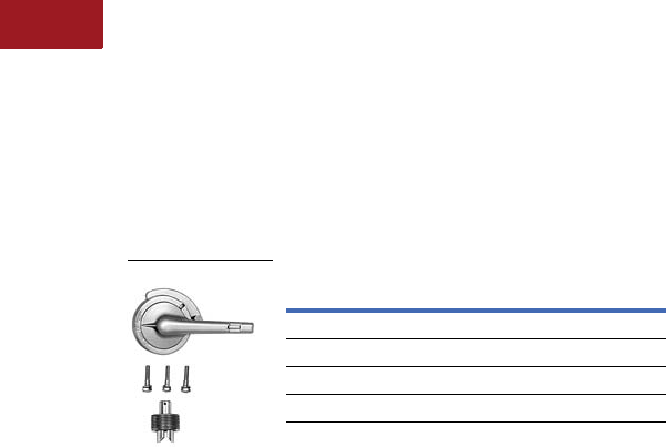
V12-T3-98 Volume 12—Aftermarket, Renewal Parts and Life Extension Solutions CA08100014E—July 2016 www.eaton.com
1
2
3
4
5
6
7
8
9
10
11
12
13
14
15
16
17
18
19
20
21
22
23
24
25
3
Molded-Case Circuit Breakers
Replacement Capabilities
Vari-Depth Type
Special Handles
Meet Type 4 sheet steel
requirements. These handles
are similar to standard
handles, except they include
an internal neoprene gasket.
Due to gasketing effect
between handle and housing,
handle will not indicate a
tripped position when used
with circuit breakers.
UL File No. E56845 Vol. 1
Section 4.
Handle Kits
These kits are for use
with Type 4, 7 and 9 cast
enclosures. They include
a special operating handle,
mounting bolts and an adapter
bushing (bushing may be
purchased separately). Kits
may be used with standard
mechanisms and shafts.
Instruction drawing 314C809
applies for assembly.
Handle Kits
Description Style Number
Standard finish 504C323G08
For Type 4, 9 enclosure 314C794G10
For Type 7 enclosure 314C794G09
Adapter bushing only 314C794G04
Handle Kits
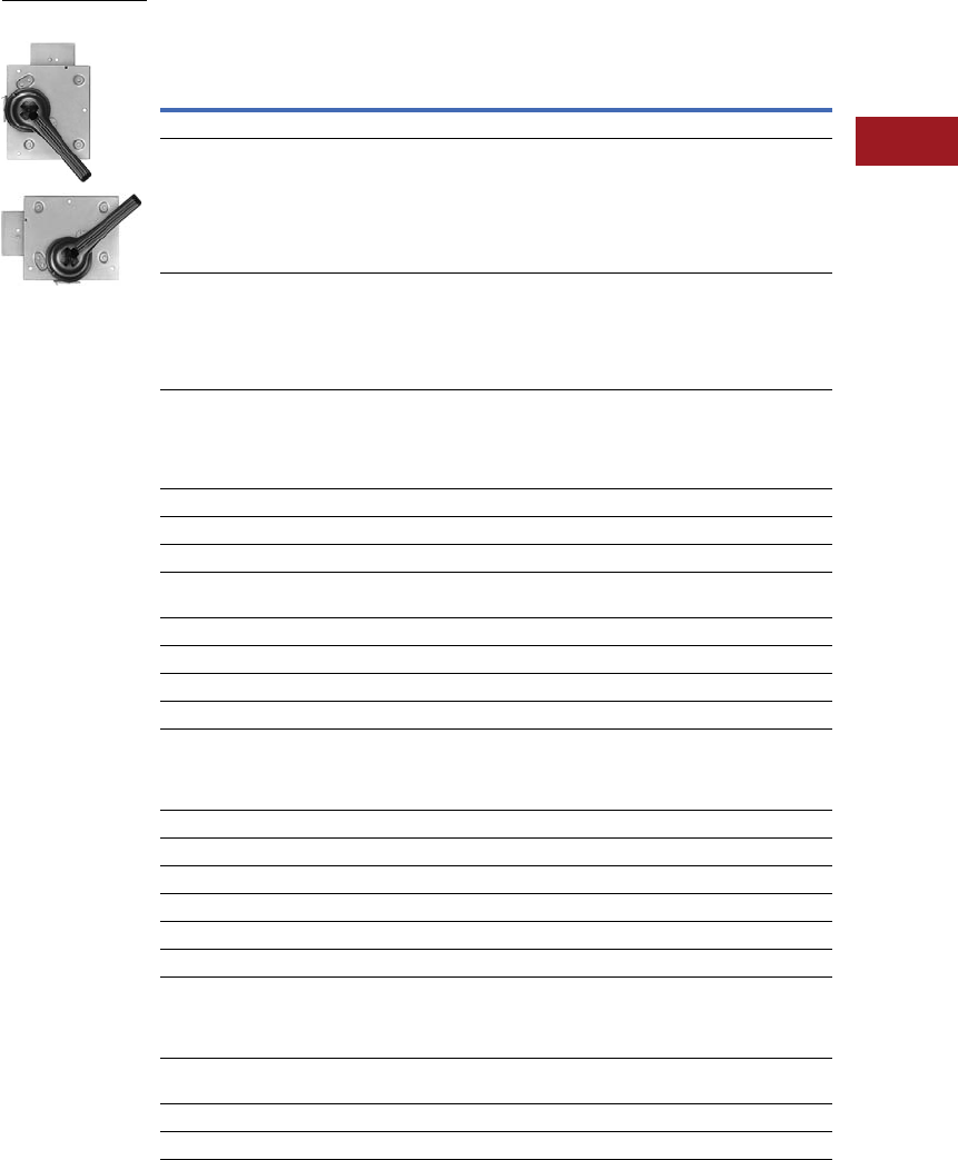
Volume 12—Aftermarket, Renewal Parts and Life Extension Solutions CA08100014E—July 2016 www.eaton.com V12-T3-99
1
2
3
4
5
6
7
8
9
10
11
12
13
14
15
16
17
18
19
20
21
22
23
24
25
3
Molded-Case Circuit Breakers
Replacement Capabilities
Slide Plate Type
These compact slide plate
handle mechanisms are
especially designed for use
with AB DE-ION circuit
breakers and disconnect
switches when they are
mounted in a shallow
enclosure. They are
suitable for use on
Type 1 applications.
Because of the mechanisms’
simplified installation—
three mounting holes—and
preassembled construction,
these units are commonly
used where high volume,
standardized enclosures are
being fabricated.
The mechanism styles listed
on this page are for use on
enclosures that have covers
hinged on the right side. If
these mechanisms are used
on enclosures that have
covers hinged on the left
side, the door interlock will
not function.
Standard Slide Plate Mechanism Catalog Numbers
Notes
1
Does not padlock in OFF position. Type 3R version available as special. Contact Avery Creek, NC, Technical Resource Center.
2 Handle mechanisms cannot be used on Visi-Flex switches with 200A fuse kits.
Enclosure Cover
Hinged on Right
Vertical Mounting Horizontal Mounting
Padlocks in
OFF Position
Style Number
Padlocks in
ON or OFF Position
Style Number
Padlocks in
OFF Position
Style Number
Circuit Breakers
KL and HKL frame
MA, HMA, MC and HMC breaker
LA, HLA, LC and HLC breaker
JA, KA, HKA, DA, LB, LBB and HLB breaker
NB, HNB, NC and HNC breaker
JB, KB and HKB breaker
LCL breaker
314C386G01 314C386G08 314C386G04
EH breaker 2P with long handle
EH breaker 3P with long handle
F-Frame 2P
F- and HF-Frame 3P
Type AQB and NQB 100A frames and
Type PF 15–100A frame
314C386G02 314C386G09 314C386G05
EH standard 2P
EH standard 3P and FA magnetic only 2 and 3P
FA 2 and 3P thermal-magnetic
EB, EHB, FB, HFB 3P MCP, HMCP (0-4) 2P
FCL breaker
314C386G03 314C386G10 314C386G06
PB, TRI-PAC PB, PC, PCC, PCF 505C294G03 — —
Series C Circuit Breakers
F-Frame Series C + HMCP-F 314C386G03 314C386G10 314C386G06
J-Frame Series C + HMCP-J
K-Frame Series C + HMCP-K
314C386G02 314C386G09 314C386G05
L-Frame Series C + HMCP-L, MDL 314C386G18 314C386G08 314C386G04
M-Frame Series C 314C386G01 314C386G08 314C386G04
R-Frame 1505C294G03 — —
TRI-PAC switches
225A TRI-PAC Type K
400A TRI-PAC Type KL
LA TRI-PAC
NB TRI-PAC
314C386G01 314C386G08 314C386G04
100A TRI-PAC 314C386G02 314C386G09 314C386G05
FB TRI-PAC 314C386G03 314C386G10 314C386G06
Visi-Flex Switches (Model T) 2
60–100A Visi-Flex 314C386G01 314C386G08 314C386G04
30A and Special 60A Visi-Flex 314C386G02 314C386G09 314C386G05
DE-ION Switches and Disconnect Switches
30–60A (long handle) DE-ION
100A (long handle) DE-ION
200A disconnect switch
200 DS switch
314C386G01 314C386G08 314C386G04
30–60A disconnect switch
100A disconnect switch
314C386G02 314C386G09 314C386G05
30, 60, 100A DS switch 314C386G03 314C386G10 314C386G06
400 and 60A DS switch 314C386G15 — —
Vertical and
Horizontal Mounting

V12-T3-100 Volume 12—Aftermarket, Renewal Parts and Life Extension Solutions CA08100014E—July 2016 www.eaton.com
1
2
3
4
5
6
7
8
9
10
11
12
13
14
15
16
17
18
19
20
21
22
23
24
25
3
Molded-Case Circuit Breakers
Replacement Capabilities
Outdoor or Hazardous Type
This handle mechanism is
designed for use with
fabricated or cast, Type 3, 4
or 5 enclosures. A butterfly
cam type mechanism may
be used on enclosures with
either right- or left-hand
hinged covers or on
enclosures with bolted
covers. The mechanism
has a provision for padlocking.
Will accept up to three locks.
Assembly of this mechanism
is accomplished by welding
it to the enclosure door or
the cover. Refer to IL29C287
for drilling plan. For PB,
PC and RD, refer to
drawing 372D690.
Mechanisms for Outdoor or Hazardous Locations
Accessories
Door Interlock Kits
Note: For use with slide plate mechanisms used in larger panels where regular interlock is not adequate.
Description
Drilling Plan
Reference
Complete Handle Mechanisms Type 3, 4, 5
Padlocks in
OFF Position
Style Number
Padlocks in ON or
OFF Position
Style Number
Circuit Breakers
Series C F-Frame EB, EHB, FB, HFB 48A3656 48A3656G03 48A3656G04
JA, KA, LA, MA, HKA, HLA, HMA, LB, HLB 452D028 452D028G01 —
DE-ION Switches
30, 60, 100A 48A3656 48A3656G03 48A3656G04
Description
Drilling Plan
Reference
Style
Number
3 point—for mechanisms, style numbers: 314C386G01, 02, 03, 04, 05, 06, 08, 09, 10 208B624 28A2656G08
2 point—for PB mechanism, style number 505C294G03 372D690 1532990
Outdoor or Hazardous
Location Type
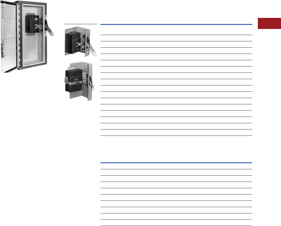
Volume 12—Aftermarket, Renewal Parts and Life Extension Solutions CA08100014E—July 2016 www.eaton.com V12-T3-101
1
2
3
4
5
6
7
8
9
10
11
12
13
14
15
16
17
18
19
20
21
22
23
24
25
3
Molded-Case Circuit Breakers
Replacement Capabilities
Type SM Safety Handle
Enclosed Breaker with SM Handle
Type SM safety handle
mechanism is designed
to prevent tampering by
unauthorized individuals
and provides the optimum
in personnel safety. When
properly applied, these
mechanisms conform
to Type 12 and J.I.C.
requirements, and are
well-suited for use by the
automotive and machine
tool industries.
Completely preassembled
in a rugged cast housing,
the Type SM safety handle
mechanism includes a
predrilled mounting plate
for simplified customer
installation. Standard handles
are 5.125 inches long and
can be padlocked in the OFF
position with as many as
three padlocks. A shorter
handle 3.875 inches long
can be supplied on SM100,
SM101 or SM150
mechanisms when specified.
All Type SM safety handle
mechanisms
can be used on
any size enclosure. Order
handle mechanism from the
table at right, plus desired
door hardware for complete
application. Dress nameplate
required to meet automotive
specifications is available
from accessories section.
Type SM Safety Handle Mechanism Catalog Numbers
Further Information
Notes
1 Must be ordered with door hardware; if not, door-operated defeater kit is required.
Mechanisms for Type 4 Applications—Mechanisms with stainless steel parts and special gasketing can
be supplied. Order by description. 30% adder.
Handle Mechanism for Use With:
Catalog Number 1
Right-Hand
Mounting
Enclosure
Cover Hinged
On Left
Left-Hand
Mounting
Enclosure
Cover Hinged
On Right
Series C—F-Frame, MCP, HMCP F, EB, EHB, FB, HFB breakers,
and Type DS 30, 60, 100A non-fusible switches
SM150R SM150L
Type DS 30, 60, 100A fusible switches SM100SFR SM100SFL
FB TRI-PAC, FB breaker with current limiter, or Type FCL SM101PR SM101PL
30, 60, 100A DE-ION switches SM100R SM100L
DA, JA, KA, HKA, LB, LBB, HLB breakers SM225R SM225L
Series C—J-Frame, HMCP J SM250JR SM250JL
Series C—K-Frame, HMCP K SM400KR SM400KL
LAB, LA, HLA, LC, HLC breakers (400 and 600A) SM400R SM400L
Series C—L-Frame, HMCP L, MDL SM600R SM600L
Series C—M-Frame, MD, MDS SM800R SM800L
MA, HMA, MC, HMC breakers SM800R SM800L
TRI-PAC LA breaker SM400PR SM400PL
TRI-PAC NB SM800PR SM800PL
NB, HNB, NC, HNC breakers SM1200R SM1200L
Type DS 200A non-fusible switch SM200SR SM200SL
Type DS 200A fusible switch SM200SFR SM200SFL
Type LCL SM400LCLR SM400LCLL
Publication
Number Description
IL 14439 F-Frame, EB, EHB, FB, FCL, HFB, MCP, FB-P, 30–100A DS switch
IL 29C274 J- and K-Frame
IL 29C284 L-Frame
IL 13282 JA, KA, JB, KB, LAB, LA, MA, NB, HLA, NB-P, 200A DS switch
IL 13327 DH1L door hardware
IL 13326 DH1R door hardware
IL 13325 DH2R door hardware
IL 13324 DH3L door hardware
IL 13322 DH3R door hardware
IL 13287 Electrical interlock
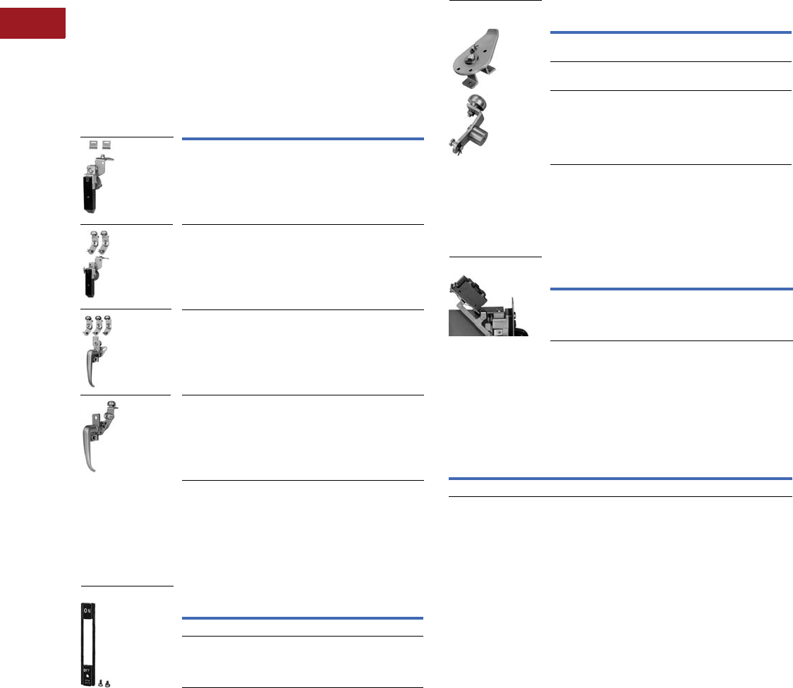
V12-T3-102 Volume 12—Aftermarket, Renewal Parts and Life Extension Solutions CA08100014E—July 2016 www.eaton.com
1
2
3
4
5
6
7
8
9
10
11
12
13
14
15
16
17
18
19
20
21
22
23
24
25
3
Molded-Case Circuit Breakers
Replacement Capabilities
Type SM Safety Handle
Door Hardware
Three choices of door hardware and an auxiliary handle are
offered to provide the best latching scheme for individual needs.
The door hardware is designed with a provision for padlocking,
and a coin-proof slot that requires the use of a tool to open the
door, for maximum security.
Select desired hardware from the table below. Additional latches
can be ordered from accessories section if desired. Type 1, 12 only.
Door Hardware
Dress Nameplates
Required to meet automotive specifications. Mounts from inside
enclosure and covers operating mechanism mounting bolts,
making mechanism non-removable when enclosure door is closed.
Dress Nameplate
Description
Catalog Number
Right Hand Left Hand
With sliding latches for smaller
panels up to approximately
30.00 inches high
DH1R 1DH1L 2
With 2-roller latches for
intermediate panels up to
approximately 40.00 inches high
DH2R 1DH2L 2
With 3-roller latches for larger
panels, approximately
40.00 inches and higher
DH3R 1DH3L 2
Auxiliary handle for
larger panels
DH4R 1DH4L 2
Description Style Number
For SM100, SM150 mechanisms 373D260G05
For SM200, and larger mechanisms 373D260G05
Dress Nameplate
Auxiliary Latch Kits
Provide an additional latch for use with applications where
2-point latching may not be adequate.
Auxiliary Latch Kits
Electrical Interlock Kit
Provides 1NC and 1NO contacts (SPDT switch) for use with
auxiliary circuits. Mounts to end of mechanism housing as shown.
Electrical Interlock Kit
Door Operated Interlock Defeater Kit
Required when door hardware is not used; operates as door
closes. Additional method of securing door such as screw latch,
also required (to be supplied by box manufacturer).
Door Operated Interlock Defeater Kit
Notes
1Enclosure cover hinged on left.
2Enclosure cover hinged on right.
Description Style Number
Door hardware using sliding latches,
right- or left-hand mounting
656D669G01
Door hardware using roller latches,
right-hand mounting
370D801G04
Left-hand mounting 370D802G04
Style Number
622B747G01
Style Number
623B214G02
Slide and
Roller Latches
Electrical Interlock Kit
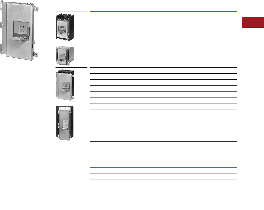
Volume 12—Aftermarket, Renewal Parts and Life Extension Solutions CA08100014E—July 2016 www.eaton.com V12-T3-103
1
2
3
4
5
6
7
8
9
10
11
12
13
14
15
16
17
18
19
20
21
22
23
24
25
3
Molded-Case Circuit Breakers
Replacement Capabilities
Type MC Motor Control
225A Mechanism
Type MC handle mechanisms
are linear drive, fixed depth
mechanisms designed for
through-door mounting in
standardized or shallow depth
enclosures such as motor
control centers or enclosed
circuit breakers.
Mounting directly to the
front of the disconnect,
these mechanisms provide
positive operation and handle
indication. Both disconnect
and mechanism mount
simultaneously with
mounting hardware supplied
with the mechanism.
For security, the handle can
be padlocked in the OFF
position with up to three
0.375-inch hasp padlocks.
Also, the mechanism is
interlocked with the enclosure
door so that the disconnect
must be OFF before the
door can be opened. A
defeater is provided to
bypass this interlock.
Catalog numbers listed
include the mechanism,
mounting hardware and
door interlock clip.
Type MC Motor Control Catalog Numbers
Further Information
Notes
1 Mechanisms are shown mounted on breaker for illustration purposes only. Breakers are not included.
2 These mechanisms are recognized under the component program of Underwriters Laboratories.
3 Selection data for handle mechanism only; circuit breaker not included.
Handle Mechanism 1
For Use With
Catalog Number 23
Type 1
Enclosure
Type 12
Enclosure
Series C F-Frame HMCP F SMCU150FD CMCU150FD
EB, EHB, FB, HFB breakers and MCP (Size 0–4) SMCU150FD CMCU150FD
FB TRI-PAC SMCU100FBP CMCU100FBP
FCL breakers SMCU100FCL CMCU100FCL
30, 60,100A DS switch fusible, non-fusible SMCU100DS CMCU100DS
200A DS switch fusible, non-fusible SMCU200DS CMCU200DS
Series C J-Frame HMCP J SMCU250JD CMCU250JD
Series C K-Frame HMCP K, DA, JA, KA, HKA, LB, LBB, HLB SMCU400KD CMCU400KD
Breakers, Size 5 MCP (400A) SMCU225KA CMCU225KA
Series C L-Frame HMCP L, MDL SMCU600LD CMCU600LD
Series C M-Frame not MDL SMCU800MA CMCU800MA
LAB, LA, HLA, LC, HLC breakers (400 and 600A frame) SMCU400LA SMCU400LA
LA TRI-PAC SMCU400LAP SMCU400LAP
MA, HMA, MC, HMC Breakers (800A frame) SMCU800MA SMCU800MA
NB, HNB, NC, HNC Breakers (1200A frame) SMCU1200NB SMCU1200NB
LCL225 and 400 SMCU400LCL SMCU400LCL
Series C L-Frame HMCP L SMCU600LD SMCU600LD
Publication
Number Description
IL 14572 F-Frame, EB, EHB, FB, MCP, HFB
IL 29C273 J- and K-Frame
IL 29C283 L-Frame
IL 14571 FB-P
IL 14938 JB, KB
IL 14573 30, 60, 100A DS switch
IL 14574 200A DS switch
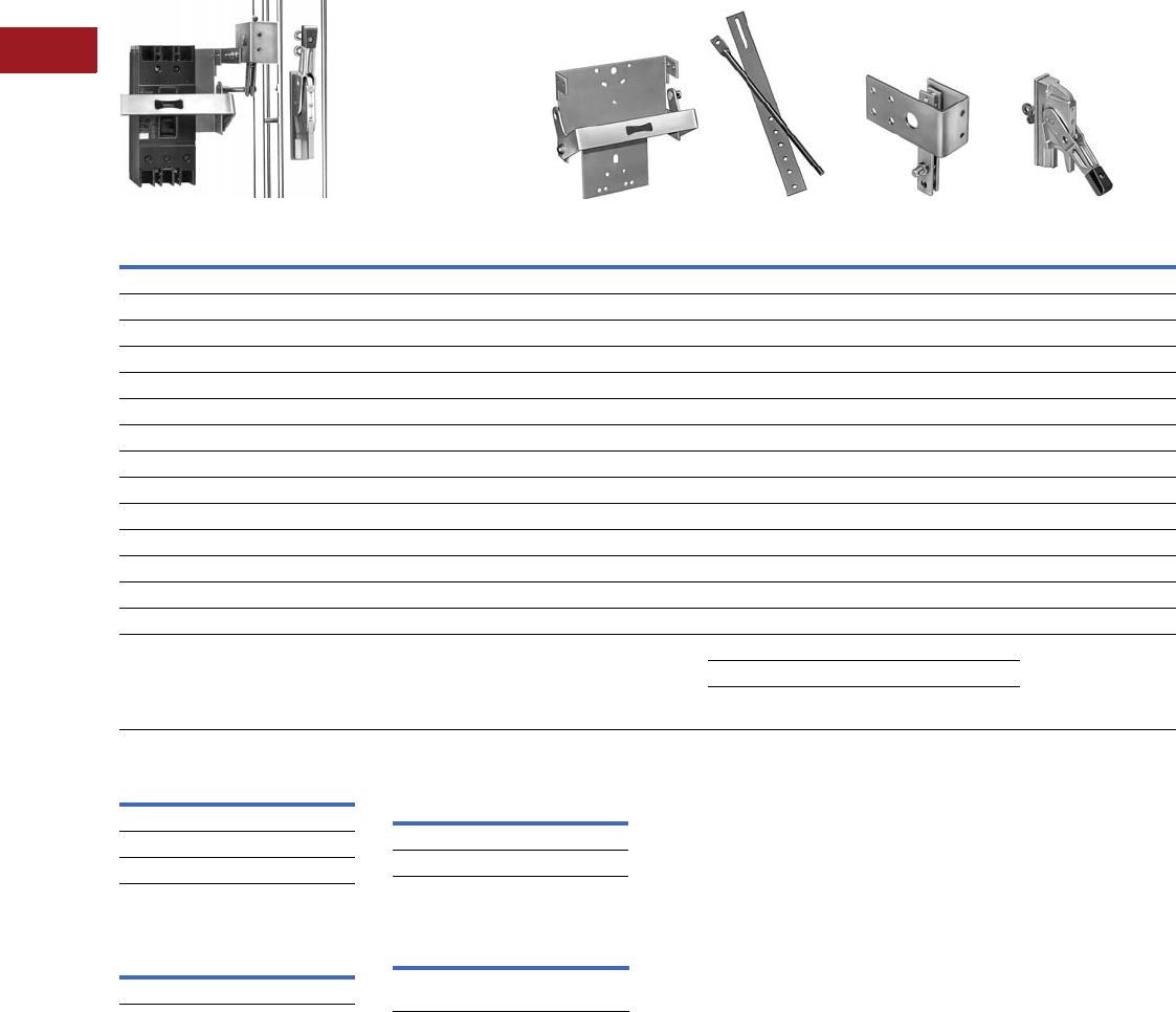
V12-T3-104 Volume 12—Aftermarket, Renewal Parts and Life Extension Solutions CA08100014E—July 2016 www.eaton.com
1
2
3
4
5
6
7
8
9
10
11
12
13
14
15
16
17
18
19
20
21
22
23
24
25
3
Molded-Case Circuit Breakers
Replacement Capabilities
AMT Vari-Depth
Fixed Width Type—Type AMT for Below Handle Mounting
Standard Door Hardware 78
Door Hardware
Adapter Kit 9
Door Hardware Kit for
Hoffman A-25 Enclosure jk
Further Information
Notes
1AMTR is rod only; AMTRI is rod and
brace assembly.
2Complete assembly not available,
order components parts listed above.
3Also for use with equivalent
HMCP Frame.
4For switches using 30, 60, 100A, 600V
NEC Class H, R or J fuses.
5For switches using 30, 60, 100A, 250V
NEC Class H or R fuses.
6AMTR and AMTRB1 for use with
enclosure depth of 6.50–14.25 inches.
For 12.25–18.25 inch depth, use optional
AMTRB2. For 18.00–24.00 inch depth,
use optional AMTRB3.
7Requires adapter kit shown in Door
Hardware Adapter Kit table.
8For standard door hardware description,
see Page V12-T3-102.
9Required on standard door hardware
only when used with any AMT handle
mechanisms.
jKit consists of special door hardware and
door interlock pin. Available for right-
hand flange mounting only.
kFor use with AMT fixed width
mechanisms only.
l2-point latch for use with panels up to
approximately 40.00 inches high.
m3-point latch for use with panels
approximately 40.00 inches and higher.
Breaker or
Switch Type
Complete
Assembly 12
Catalog Number
Backplate and
Yoke Assembly
Catalog Number
Rod and Brace
Assembly
Catalog Number
Pivot Mechanism
Assembly
Catalog Number
Operating Handle
Assembly
Catalog Number
Below the Handle—Fixed Width—with Short Brace and/or Rod as Listed (For all enclosures including Hoffman A-25 Enclosures)
Series C F-Frame HMCP F 3AMTFDBSFH AMTFD-B AMTR AMTPM-FH AMTOP
Series C J-Frame HMCP J 3AMTJDBSFH AMTKB-B AMTRB1 AMTPM-FSH AMTOP
Series C K-Frame HMCP K 3AMTKDBSFH AMTLB-B AMTRB1 AMTPM-FSH AMTOP
Series C L-Frame HMCP L 3AMTLDBSFH AMTLD-B AMTRB1 AMTPM-FS AMTOP
DS-30, 60, 100 unfused AMTDSBSFH AMTDS100-B AMTR AMTPM-FH AMTOP
DS-30, 60, 100 fused 4AMTDSFBSFH AMTDS100F-B AMTR AMTPM-FH AMTOP
DS-30, 60, 100 fused 5AMTDSF1BSFH AMTDS100F1-B AMTR AMTPM-FH AMTOP
DS-200 unfused AMTDS2BSFH AMTDS200-B AMTRB1 AMTPM-FSH AMTOP
DS-200 fused AMTDS2FBSFH AMTDS200F-B AMTRB1 AMTPM-FSH AMTOP
Below the Handle—Fixed Width—with Short Brace and/or Rod as Listed (Not for use with Hoffman A-25 Enclosures)
EB, EHB, FB, HFB, MCP (0-4) AMTFBBSF AMTFD-B AMTR AMTPM-F AMTOP
JB, KB, MCP (250A) AMTKBBSF AMTKB-B AMTRB1 AMTPM-FS AMTOP
JA, KA, HKA, LB, LBB, HLB, DA MCP (400A) AMTLBBSF AMTLB-B AMTRB1 AMTPM-FS AMTOP
FB TRI-PAC, FCL AMTFBPBSF AMTFBP-B AMTR AMTPM-F AMTOP
Optional rod and brace 6
AMTRB2 long rod and brace
AMTRB3 extended rod and brace
Catalog Number
DH1R
DH2R
DH3R
Catalog Number
AMTDHA
Catalog Number
HDH-2R l
HDH-3R m
Publication
Number Description
IL 29C277 AMT Vari-Depth
Handle Mechanism

Volume 12—Aftermarket, Renewal Parts and Life Extension Solutions CA08100014E—July 2016 www.eaton.com V12-T3-105
1
2
3
4
5
6
7
8
9
10
11
12
13
14
15
16
17
18
19
20
21
22
23
24
25
3
Molded-Case Circuit Breakers
Replacement Capabilities
AMT Vari-Depth
Vari- Width Typ e—
Type AMT for Above
Handle Mounting
The Type AMT is an
extra heavy-duty handle
mechanism designed for
mounting in flange-type
enclosures, and has
provisions for mounting in
various depth
enclosures
and for varying the width
relationship between the
disconnect device and the
external handle.
A door interlock is provided
to prevent opening the
enclosure door with the
disconnect in the ON position
or to close the disconnect
with the enclosure door
open. The external handle
can be locked in the OFF
position with up to three
padlocks. The AMT
mechanism is supplied
for mounting in right-hand
flange enclosures but can
be easily converted for
left-hand mounting.
AMT mechanisms are
available for above the
handle mounting or below
the handle mounting.
Mechanisms for below the
handle mounting are also
available as fixed width
units. When door hardware
is used with an AMT handle
mechanism, a door hardware
adapter kit is required.
Accessories
Spacer kit to Vari-Width
(not for use
with fixed
mechanisms) catalog
number
AMTSK1 for up
to 1.00-inch variation.
Note: This spacer kit is for up to
1.00-inch variation and consists of
multiples of thin spacers to be
used as required. A maximum of
two kits per installation may be
used. Due to the possible variation
in dimensions, hardware is
not supplied. Use standard
1/4–20 bolts.
Further Information
Pub. Number Description
IL 14946 AMT Vari-Depth handle
mechanism
MD, MSMVari-Width Type—Type AMT for Above Handle Mounting
Notes
1Assembled Type AMT for above handle
mounting (breaker not included).
2Complete assembly not available, order
components parts listed above.
3Width spacer kit not included.
4This spacer kit is for up to 1.00-inch
variation and consists of multiples of
thin spacers to be used as required. A
maximum of two kits per installation may
be used. Due to the possible variation in
dimensions, hardware is not supplied.
Use standard 1/4–20 bolts.
5Also for use with equivalent
HMCP frame.
6For switches using 30, 60, 100A, 600V
NEC Class H, R or J fuses.
7For switches using 30, 60, 100A, 600V
NEC Class H or R fuses.
Breaker or
Switch Type
Complete
Assembly 12
Catalog Number
Backplate
and Yoke
Assembly
Catalog
Number
Operating
Rod and
Brace
Assembly
Catalog
Number
Flange
Mounted
Pivot
Mechanism
Assembly 34
Catalog Number
External
Operating
Handle
Catalog Number
Above the Handle Mounting with Short Rod and Brace
Series C F-Frame 5 EB, EHB, FB, HFB, MCP (0–4) AMTFDASV AMTFB AMTRB1 AMTPM AMTOP
Series C J-Frame 5AMTJDASV AMTJD AMTRB1 AMTPM AMTOP
Series C K-Frame 5AMTKDASV AMTKD AMTRB1 AMTPM AMTOP
Series C L-Frame, MDL 5AMTLDASV AMTLD AMTRB1 AMTPM AMTOP
JA, KA, HKA, LB, LBB, HLB, DA, MCP (400A) AMTLBASV AMTLB AMTRB1 AMTPM AMTOP
LA, HLA, LC, HLC AMTLAASV AMTLA AMTRB1 AMTPM AMTOP
MD, MDS, MA, HMA, MC, HMC, Series C
M-Frame, LCL
AMTMAASV AMTMA AMTRB1 AMTPM AMTOP
NB, HNB, NC, HNC AMTNBASV AMTNB AMTRB1 AMTPMNB AMTOP
FB TRI-PAC, FCL AMTFBASV AMTFB AMTRB1 AMTPM AMTOP
LA TRI-PAC AMTLAPASV AMTLAP AMTRB1 AMTPM AMTOP
NB TRI-PAC AMTNBPASV AMTNBP AMTRB1 AMTPMNB AMTOP
DS-30, 60, 100 unfused AMTDSASV AMTDS100 AMTRB1 AMTPM AMTOP
DS-30, 60, 100 fused 6AMTDSFASV AMTDS100F AMTRB1 AMTPM AMTOP
DS-30, 60, 100 fused 7AMTDSF1ASV AMTDS100F1 AMTRB1 AMTPM AMTOP
DS-200 unfused AMTDS2ASV AMTDS200 AMTRB1 AMTPM AMTOP
DS-200 fused AMTDS2FASV AMTDS200F AMTRB1 AMTPM AMTOP
Above the Handle Mounting with Long Rod and Brace
Series C F-Frame 5 EB, EHB, FB, HFB, MCP (0–4) AMTFDALV AMTFB AMTRB2 AMTPM AMTOP
Series C J-Frame 5AMTJDALV AMTJD AMTRB2 AMTPM AMTOP
Series C K-Frame 5AMTKDALV AMTKD AMTRB2 AMTPM AMTOP
Series C L-Frame, MDL 5AMTLDALV AMTLD AMTRB2 AMTPM AMTOP
JA, KA, HKA, LB, LBB, HLB, DA, MCP (400A) AMTLBALV AMTLB AMTRB2 AMTPM AMTOP
LA, HLA, LC, HLC AMTLAALV AMTLA AMTRB2 AMTPM AMTOP
MD, MDS, MA, HMA, MC, HMC, Series C
M-Frame, LCL
AMTMAALV AMTMA AMTRB2 AMTPM AMTOP
NB, HNB, NC, HNC AMTNBALV AMTNB AMTRB2 AMTPMNB AMTOP
FB TRI-PAC, FCL AMTFBALV AMTFB AMTRB2 AMTPM AMTOP
LA TRI-PAC AMTLAPALV AMTLAP AMTRB2 AMTPM AMTOP
NB TRI-PAC AMTNBPALV AMTNBP AMTRB2 AMTPMNB AMTOP
DS-30, 60, 100 unfused AMTDSALV AMTDS100 AMTRB2 AMTPM AMTOP
DS-30, 60, 100 fused 6AMTDSFALV AMTDS100F AMTRB2 AMTPM AMTOP
DS-30, 60, 100 fused 7AMTDSF1ALV AMTDS100F1 AMTRB2 AMTPM AMTOP
DS-200 unfused AMTDS2ALV AMTDS200 AMTRB2 AMTPM AMTOP
DS-200 fused AMTDS2FALV AMTDS200F AMTRB2 AMTPM AMTOP
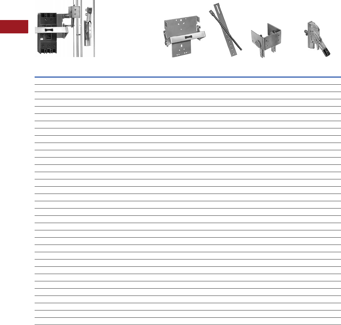
V12-T3-106 Volume 12—Aftermarket, Renewal Parts and Life Extension Solutions CA08100014E—July 2016 www.eaton.com
1
2
3
4
5
6
7
8
9
10
11
12
13
14
15
16
17
18
19
20
21
22
23
24
25
3
Molded-Case Circuit Breakers
Replacement Capabilities
Vari-Width Type—Type AMT for Below Handle Mounting
Notes
1 AMTR is rod only; AMTRI is rod and brace assembly.
2 Complete assembly not available, order components parts listed above.
3 Width spacer kit not included.
4 This spacer kit is for up to 1-inch variation and consists of multiples of thin spacers to be used as required. A maximum of two kits per installation may be used.
Due to the possible variation in dimensions, hardware is not supplied. Use standard 1/4–20 bolts.
5 Also for use with equivalent HMCP Frame.
6 For switches using 30, 60, 100A, 600V NEC Class H, R or J fuses.
7 For switches using 30, 60, 100A, 600V NEC Class H or R fuses.
Breaker or
Switch Type
Complete
Assembly 12
Catalog Number
Backplate and
Yoke Assembly
Catalog Number
Rod and Brace
Assembly
Catalog Number
Flange Mounted Pivot
Mechanism Assembly 34
Catalog Number
External Operating
Handle Assembly
Catalog Number
Below the Handle Mounting with Short Rod and Brace
Series C F-Frame 5 EB, EHB, FB, HFB, MCP (0–4) AMTFDBSV AMTFD-B AMTRB1 AMTPM-B AMTOP
Series C J-Frame 5AMTJDBSV AMTJD-B AMTRB1 AMTPM-B AMTOP
Series C K-Frame 5AMTKDBSV AMTKD-B AMTRB1 AMTPM-B AMTOP
Series C L-Frame MDL 5AMTLDBSV AMTLD-B AMTRB1 AMTPM-B AMTOP
JA, KA, HKA, LB, LBB, HLB, DA, MCP (400A) AMTLBBSV AMTLB-B AMTRB1 AMTPM-B AMTOP
LA, HLA, LC, HLC AMTLABSV AMTLA-B AMTRB1 AMTPM-B AMTOP
MD, MDS, MA, HMA, MC, HMC, Series C M-Frame, LCL AMTMABSV AMTMA-B AMTRB1 AMTPM-B AMTOP
NB, HNB, NC, HNC AMTNBBSV AMTNB-B AMTRB1 AMTPM-B AMTOP
FB TRI-PAC, FCL AMTFBPBSV AMTFBP-B AMTRB1 AMTPM-B AMTOP
LA TRI-PAC AMTLAPBSV AMTLAP-B AMTRB1 AMTPM-B AMTOP
NB TRI-PAC AMTNBPBSV AMTNBP-B AMTRB1 AMTPM-B AMTOP
DS-30, 60, 100 unfused AMTDSBSV AMTDS100-B AMTRB1 AMTPM-B AMTOP
DS-30, 60, 100 fused 6AMTDSFBSV AMTDS100F-B AMTRB1 AMTPM-B AMTOP
DS-30, 60, 100 fused 7AMTDSF1BSV AMTDS100F1-B AMTRB1 AMTPM-B AMTOP
DS-200 unfused AMTDS2BSV AMTDS200-B AMTRB1 AMTPM-B AMTOP
DS-200 fused AMTDS2FBSV AMTDS200F-B AMTRB1 AMTPM-B AMTOP
Below the Handle Mounting with Long Rod and Brace
Series C F-Frame 5 EB, EHB, FB, HFB, MCP (0–4) AMTFDBLV AMTFD-B AMTRB2 AMTPM-B AMTOP
Series C J-Frame 5AMTJDBLV AMTJD-B AMTRB2 AMTPM-B AMTOP
Series C K-Frame 5AMTKDBLV AMTKD-B AMTRB2 AMTPM-B AMTOP
Series C L-Frame MDL 5AMTLDBLV AMTLD-B AMTRB2 AMTPM-B AMTOP
JA, KA, HKA, LB, LBB, HLB, DA, MCP (400A) AMTLBBLV AMTLB-B AMTRB2 AMTPM-B AMTOP
LA, HLA, LC, HLC AMTLABLV AMTLA-B AMTRB2 AMTPM-B AMTOP
MD, MDS, MA, HMA, MC, HMC, Series C M-Frame, LCL AMTMABLV AMTMA-B AMTRB2 AMTPM-B AMTOP
NB, HNB, NC, HNC AMTNBBLV AMTNB-B AMTRB2 AMTPM-B AMTOP
FB TRI-PAC, FCL AMTFBPBLV AMTFBP-B AMTRB2 AMTPM-B AMTOP
LA TRI-PAC AMTLAPBLV AMTLAP-B AMTRB2 AMTPM-B AMTOP
NB TRI-PAC AMTNBPBLV AMTNBP-B AMTRB2 AMTPM-B AMTOP
DS-30, 60, 100 unfused AMTDSBLV AMTDS100-B AMTRB2 AMTPM-B AMTOP
DS-30, 60, 100 fused 6AMTDSFBLV AMTDS100F-B AMTRB2 AMTPM-B AMTOP
DS-30, 60, 100 fused 7AMTDSF1BLV AMTDS100F1-B AMTRB2 AMTPM-B AMTOP
DS-200 unfused AMTDS2BLV AMTDS200-B AMTRB2 AMTPM-B AMTOP
DS-200 fused AMTDS2FBLV AMTDS200F-B AMTRB2 AMTPM-B AMTOP
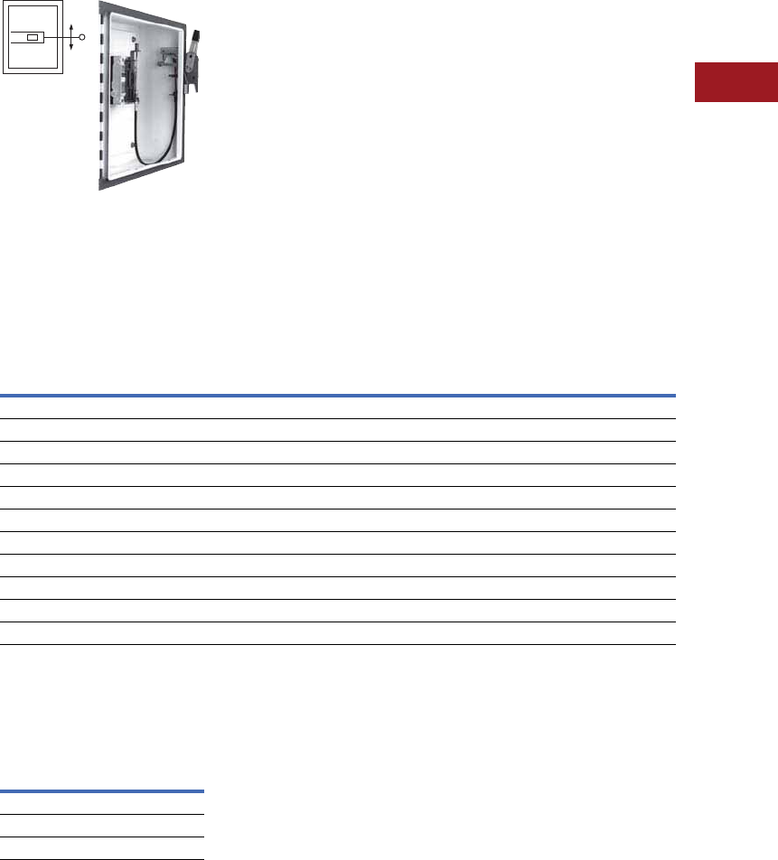
Volume 12—Aftermarket, Renewal Parts and Life Extension Solutions CA08100014E—July 2016 www.eaton.com V12-T3-107
1
2
3
4
5
6
7
8
9
10
11
12
13
14
15
16
17
18
19
20
21
22
23
24
25
3
Molded-Case Circuit Breakers
Replacement Capabilities
Accessories
Spacer kit to Vari-Width
(not for use with fixed
mechanisms) catalog
number AMTSK1 for up
to 1.00-inch variation.
Note: This spacer kit is for up to
1.00-inch variation and consists of
multiples of thin spacers to be
used as required. A maximum
of two kits per installation may
be used. Due to the possible
variation in dimensions, hardware
is not supplied. Use standard
1/4–20 bolts.
Ordering Information
●Complete assembly
not available, order
components parts as listed
on Pages V12-T3-104,
V12-T3-105 and
V12-T3-106
●Order spacer kits or
door hardware adapter
as required
●Individual component
parts may be ordered by
catalog number
Flex Shaft
Flex Shaft
The Flex Shaft is an extra
heavy-duty mechanism that
includes a flexible shaft in
various lengths, 3 feet (0.9m)
through 10 feet (3m) for use
with various size enclosures.
The Flex Shaft handle will
accept up to three padlock
shackles, each with a
maximum diameter of
0.375-inch (9.5 mm). Can be
used with Type 1, 3R and 12
fabricated enclosures. An
optional handle is available
for Flex Shaft that is suitable
for use with Type 4 and 4X
environments. Flex Shaft
comes preset from the
factory, requiring only
minor field adjustments
on installation, which
takes about 10 minutes—
a significant time savings
compared to installation of
other types of flange handle
mechanisms. The Flex Shaft
mechanism also takes up less
interior enclosure space than
competitive designs and the
handle fits standard flange
cutouts. Flex Shaft handle
can be remotely mounted
from breaker, where an
operator can use it by
“funneling” the cable
through conduit.
Flex Shaft is UL Listed under
File E64983 and meets
CSA requirements.
Flex Shaft Ordering Information (Three-Pole Only) 123
Flex Shaft Accessories
(F- through R-Frame)
NEMA 12 Safety Door
Hardware for Flex Shaft 4
Notes
1Type 4/4X handle mechanisms are
available. Add Suffix X to complete
catalog number. Add Suffix I to complete
catalog number for IEC handle. Add
Suffix L (Standard on F, J, K and L) to
complete catalog number for 6.00-inch
(152.4 mm) handle. Original narrow
handle design (no C suffix) is available.
Remove C from catalog number.
2When selecting the length of shaft,
ensure minimum bending radius of
4.00 inches (101.6 mm) is maintained to
operate properly. The standard method
of shipment includes the mechanism
preset at the factory; however, minor
field adjustments may be required.
3Dual breakers operator available
on F-Frame only.
4Customer: Consult with box
manufacturer for correct door hardware
and any adapters required for assembly.
5The 0.25 inch x 0.50 inch (6.35 x 12.7 mm)
standard mill rectangular locking bar is
not supplied with these kits.
6Third roller latch for use with 4.00- or
6.00-inch (101.6 or 152.4 mm) handle
when 3-point latching is required.
Refer to handle mechanisms in the molded-
case circuit breaker section of Volume 4—
Circuit Protection Catalog, CA08100005E,
Tab 2.
Breaker
Frame
Flexible Shaft Length in Feet (m)
3.00 (0.9) 4.00 (1.2) 5.00 (1.5) 6.00 (1.8) 7.00 (2.1) 8.00 (2.4) 9.00 (2.7) 10.00 (3.0)
Catalog Number
E125 EHMFS03 EHMFS04 EHMFS05 EHMFS06 — — — —
J250 JHMFS03 JHMFS04 JHMFS05 JHMFS06 JHMFS07 JHMFS08 JHMFS09 JHMFS10
GF0S03C F0S04C F0S05C F0S06C — — — —
FF1S03C F1S04C F1S05C F1S06C F1S07C F1S08C F1S09C F1S10C
F (Dual) F1S03CD F1S04CD F1S05CD F1S06CD F1S07CD F1S08CD F1S09CD F1S10CD
JF2S03C F2S04C F2S05C F2S06C F2S07C F2S08C F2S09C F2S10C
KF3S03C F3S04C F3S05C F3S06C F3S07C F3S08C F3S09C F3S10C
L and MDL — F4S04C F4S05C F4S06C — — — F4S10C
N— F5S04C F5S05C F5S06C — — — F5S10C
R— F6S04 F6S05 F6S06 — — — —
MD — F7S04C F7S05C F7S06C — — — F7S10C
Handle Length
in Inches (mm)
Catalog
Number 5
4.00 (101.6) C361KJ4
6.00 (152.4) C361KJ6
Roller latch 6C361KR

V12-T3-108 Volume 12—Aftermarket, Renewal Parts and Life Extension Solutions CA08100014E—July 2016 www.eaton.com
1
2
3
4
5
6
7
8
9
10
11
12
13
14
15
16
17
18
19
20
21
22
23
24
25
3
Molded-Case Circuit Breakers
Replacement Capabilities
The Type C371 circuit breaker
operating mechanisms are
designed for installation in
control enclosures where
main or branch circuit
protective devices are
required. All circuit breaker
mechanisms are suitable for
right-hand mounting.
Auxiliary contacts are not
available for mounting on
operating mechanisms.
Where required, have them
installed in circuit breaker.
Type C371 is UL Listed under
File E62635.
Type C371 Ordering Information—Dimensions in Inches (mm)
Handle Only—Dimensions in Inches (mm)
Channel Support Kit
(Rod Not Supplied) 4
Connecting Rods 5
Flange-Mounted
Instruction Leaflets
Notes
1For increased maximum allowable depth,
see connecting rods table to the left.
2Dimensions shown are from panel
flange surface.
3Does not include handle.
4For use to prevent bending of the
operating handle mounting surface. This
is especially useful when the operating
handle is mounted on a channel in a
multi-door enclosure. Included in
600–1200A.
5Increase maximum allowable depth
by 5.00 inches (127.0 mm).
Refer to handle mechanisms in the molded-
case circuit breaker section of Volume 4—
Circuit Protection Catalog, CA08100005E,
Tab 2.
Circuit Breaker
or Motor Circuit
Protector
Frame
Size
Variable Depth
Mounting Range
Min./Max. 12
Operating
Mechanism Only 3
Catalog Number
Operating Mechanism With 4.00-Inch Handle
For Type 1–12
Enclosure
Catalog Number
For Type 4
Enclosure
Catalog Number
HMCP and Series C
EHD, FDB, FD, FDC, HFD, ED
150 6.50–160 (165.1–406.4) C371E C371E1 C371E2
HMCP and Series C
HJD, JD, JDB, JDC
250 6.50–16.63 (165.1–422.4) C371F C371F5 C371F6
HMCP and Series C
DK, HKD, KD, KDB
400 6.50–16.63 (165.1–422.4) C371F C371F5 C371F6
Series C
HLD, LD, LDC
600 8.50–22.00 (215.9–558.8) C371G C371G5 C371G6
Series C
MD, MDS
800 8.75–22.00 (222.3–558.8) C371K C371K5 C371K6
Series C
HND, ND, NDC
1200 9.75–22.00 (247.7–558.8) C371K C371K5 C371K6
Circuit Breaker Frame Size
(Amperes)
NEMA
Enclosure Type
Operating
Handle Length
Catalog
Number
150 1, 3R, 3, 12 4.00 (101.6) C371H1
4/4X 4.00 (101.6) C371H2
1, 3R, 3, 12 4.00 (101.6) C371H3
4/4X 4.00 (101.6) C371H4
250–1200 1, 3R, 3, 12 4.00 (101.6) C371H5
4/4X 4.00 (101.6) C371H6
1, 3R, 3, 12 4.00 (101.6) C371H7
4/4X 4.00 (101.6) C371H8
Catalog Number
C371CS6
Application
Catalog
Number
Disconnect switches
(30, 60, 100, 200A sizes)
C371CS1
Circuit breakers
(150, 250, 400A sizes)
C371CS1
Circuit breakers
(600, 800, 1200A sizes)
C371CS2
Breaker
Frame
Instruction
Leaflet Number
Flex Shaft
E125 IL0510TE0002
J250 IL0510TE0005
GTBD
F15609
J15605
K15604
L and M 15606
N15606
R15606

Volume 12—Aftermarket, Renewal Parts and Life Extension Solutions CA08100014E—July 2016 www.eaton.com V12-T3-109
1
2
3
4
5
6
7
8
9
10
11
12
13
14
15
16
17
18
19
20
21
22
23
24
25
3
Molded-Case Circuit Breakers
Replacement Capabilities
Series C Rotary and
Universal Rotary
Series C Rotary
Series C rotary and universal
rotary handle mechanisms
are for use with molded-case
circuit breakers (G, F, J, K, L,
MDL), molded-case switches
and motor circuit protectors.
Series C rotary is suitable
for use with Type 1, 3R, 12
and 4/4X enclosure types.
Type 4/4X application
requires special handle,
see “Ordering Information.”
The universal rotary is suitable
for use with Type 1 and 12
enclosure types. All rotary
handle mechanisms include a
handle “Lock Off,” to prevent
turning the breaker ON while
in the OFF position. All rotary
handles indicate ON/OFF/
Tripped/Reset positions;
however, Universal Rotary
has the added feature of
international markings for
ON (I) and OFF (O). Series C
rotary handle is metal.
Universal rotary is made of
molded material. Series C
rotary handle is black and
universal rotary is available
in black or yellow/red.
Series C rotary handle was
ergonomically designed with
extra clearance for a “gloved
hand” to operate. Handle
has a 45º rotation. Universal
Rotary has a 90º rotation
(“pipe valve” operation)
where ON is vertical and
OFF is horizontal. Shafts
include a support brace to
ensure proper alignment.
In addition, the 16.00-inch
(406.4 mm) and 24.00-inch
(609.6 mm) extra long
shafts include an adjustable
support bracket.
Series C rotary and universal
rotary, are UL Listed and
meet CSA requirements.
Universal rotary also meets
IEC947-1/2 for international
compliance. Rotary UL File
Number is E64983.
Series C Rotary Ordering Information
Notes
1
Complete catalog number includes the standard handle, mechanism, shaft and support brace/bracket.
2Handle is designed suitable for Types 1, 3R and 12 enclosures. Use style number 6648C22G03 for Type 4/4X handle or add X Suffix to
complete catalog number.
3Breaker mechanism includes a shaft support bracket and its parts.
4Longer shafts,16.00-inch (406.4 mm) and 24.00-inch (609.6 mm), include an adjustable support extension.
5IEC handle mechanism supplied with metric thread mounting hardware.
6Complete catalog number includes a handle, mechanism and shaft.
Refer to handle mechanisms in the molded-case circuit breaker section of Volume 4—Circuit Protection Catalog, CA08100005E, Tab 2.
Shaft Length
Inches (mm)
Complete
Catalog
Number 1
Separate Catalog Number Catalog Number
Standard
Handle 2
Breaker
Mechanism 3Shaft 4IEC IP65 56 IEC IP66 56
F-Frame
6.00 (152.4) HM1R06 6648C22G01 6648C23G11 4217B37G04 WHM1R06 WHM1R06X
12.00 (304.8) HM1R12 6648C22G01 6648C23G11 4217B37G01 WHM1R12 WHM1R12X
16.00 (406.4) HM1R16 6648C22G01 6648C23G11 4217B37G02 WHM1R16 WHM1R16X
24.00 (609.6) HM1R24 6648C22G01 6648C23G11 4217B37G03 WHM1R24 WHM1R24X
J-Frame
6.00 (152.4) HM2R06 6648C22G01 6648C23G21 4217B37G04 WHM2R06 WHM2R06X
12.00 (304.8) HM2R12 6648C22G01 6648C23G21 4217B37G01 WHM2R12 WHM2R12X
16.00 (406.4) HM2R16 6648C22G01 6648C23G21 4217B37G02 WHM2R16 WHM2R16X
24.00 (609.6) HM2R24 6648C22G01 6648C23G21 4217B37G03 WHM2R24 WHM2R24X
K-Frame
6.00 (152.4) HM3R06 6648C22G01 6648C23G25 4217B37G04 WHM3R06 WHM3R06X
12.00 (304.8) HM3R12 6648C22G01 6648C23G25 4217B37G01 WHM3R12 WHM3R12X
16.00 (406.4) HM3R16 6648C22G01 6648C23G25 4217B37G02 WHM3R16 WHM3R16X
24.00 (609.6) HM3R24 6648C22G01 6648C23G25 4217B37G03 WHM3R24 WHM3R24X
L- and MDL-Frame
6.00 (152.4) HM4R06 6648C22G11 6648C23G19 4217B37G04 WHM4R06 WHM4R06X
12.00 (304.8) HM4R12 6648C22G11 6648C23G19 4217B37G01 WHM4R12 WHM4R12X
16.00 (406.4) HM4R16 6648C22G11 6648C23G19 4217B37G02 WHM4R16 WHM4R16X
24.00 (609.6) HM4R24 6648C22G11 6648C23G19 4217B37G03 WHM4R24 WHM4R24X
MD/MDS
6.00 (152.4) HM7R06 6648C22G21 6648C23G17 4217B37G04 — —
12.00 (304.8) HM7R12 6648C22G21 6648C23G17 4217B37G01 — —
16.00 (406.4) HM7R16 6648C22G21 6648C23G17 4217B37G02 — —
24.00 (609.6) HM7R24 6648C22G21 6648C23G17 4217B37G03 — —
N-Frame
6.00 (152.4) HM5R06 6648C22G21 6648C23G08 4217B37G04 WHM5R06 WHM5R06X
12.00 (304.8) HM5R12 6648C22G21 6648C23G08 4217B37G01 WHM5R12 WHM5R12X
16.00 (406.4) HM5R16 6648C22G21 6648C23G08 4217B37G02 WHM5R16 WHM5R16X
24.00 (609.6) HM5R24 6648C22G21 6648C23G08 4217B37G03 WHM5R24 WHM5R24X
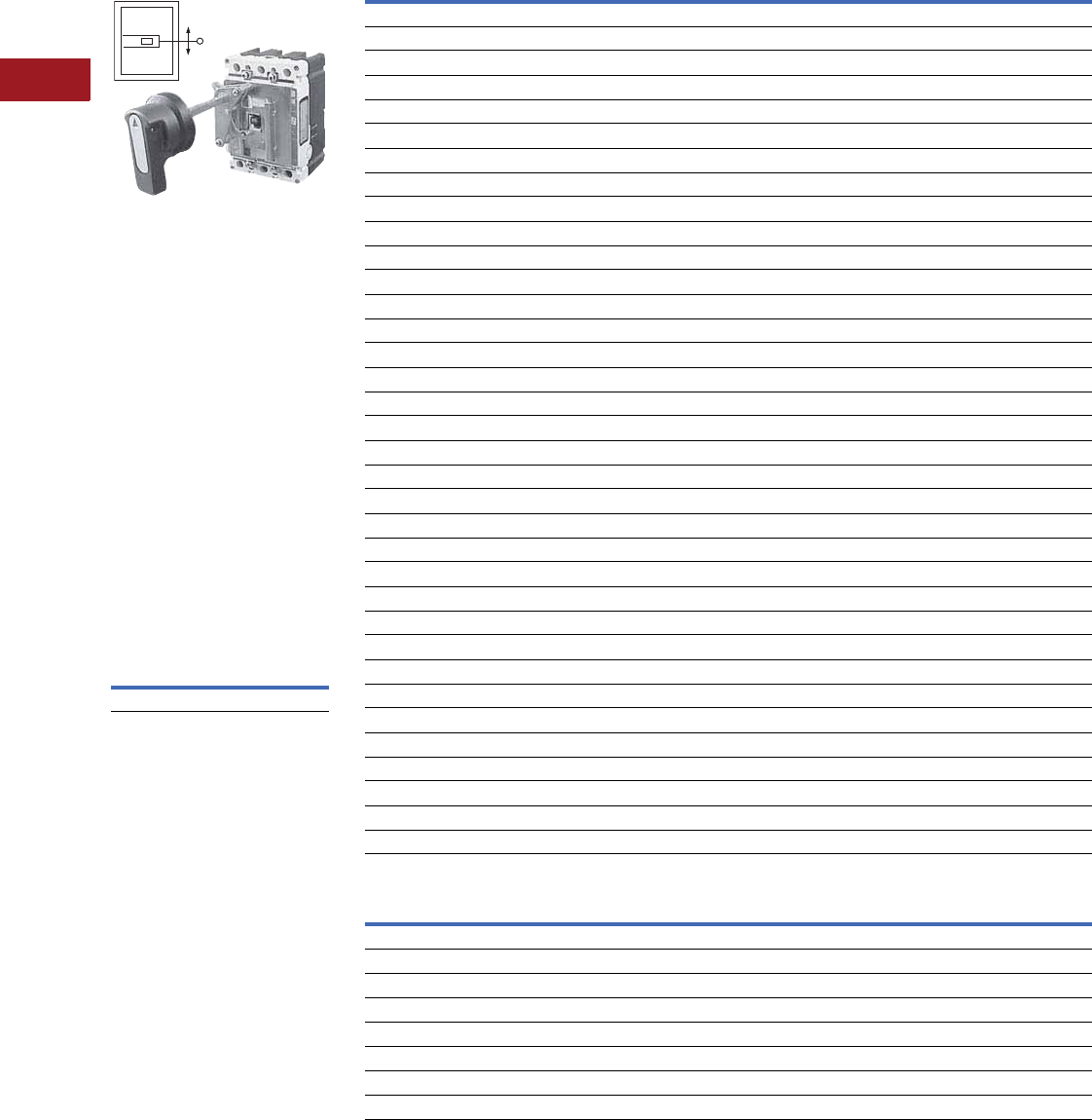
V12-T3-110 Volume 12—Aftermarket, Renewal Parts and Life Extension Solutions CA08100014E—July 2016 www.eaton.com
1
2
3
4
5
6
7
8
9
10
11
12
13
14
15
16
17
18
19
20
21
22
23
24
25
3
Molded-Case Circuit Breakers
Replacement Capabilities
Universal Rotary
Universal Rotary
Type 4/4X handles are similar
to standard handles except
that they include an internal
neoprene gasket. Type 4/4X
handle style number is
6648C22G03. Due to
gasketing effect between
the handle and the housing,
the handle may not indicate
a tripped position.
Series C Rotary Accessories
As an option, an auxiliary
switch is offered so that the
control panel builder may
electrically indicate the
status of the breaker. This
accessory would be mounted
on the mechanism and
comes with 24.00-inch
(609.6 mm) pigtail leads.
Series C Auxiliary Switch
Catalog Number
5108A61G01
Universal Rotary Ordering Information
Through-the-Door Instruction Leaflets Number
Note: Refer to handle mechanisms in the molded-case circuit breaker section of Volume 4—Circuit Protection Catalog, CA08100005E, Tab 2.
Shaft Length in Inches (mm) Handle Color Complete Catalog Number
E125 Frame
6.00 (152.4) Black EHMVD06B
12.00 (304.8) Black EHMVD12B
6.00 (152.4) Red EHMVD06R
12.00 (304.8) Red EHMVD12R
J250 Frame
6.00 (152.4) Black FJHMVD06B
12.00 (304.8) Black FJHMVD12B
6.00 (152.4) Red FJHMVD06R
12.00 (304.8) Red FJHMVD12R
G-Frame
6.00 (152.4) Black GHMVD06B
12.00 (304.8) Black GHMVD12B
6.00 (152.4) Red GHMVD06R
12.00 (304.8) Red GHMVD12R
F-Frame
6.00 (152.4) Black FHMVD06B
12.00 (304.8) Black FHMVD12B
6.00 (152.4) Red FHMVD06R
12.00 (304.8) Red FHMVD12R
J-Frame
6.00 (152.4) Black JHMVD06B
12.00 (304.8) Black JHMVD12B
6.00 (152.4) Red JHMVD06R
12.00 (304.8) Red JHMVD12R
K-Frame
6.00 (152.4) Black KHMVD06B
12.00 (304.8) Black KHMVD12B
6.00 (152.4) Red KHMVD06R
12.00 (304.8) Red KHMVD12R
L- and MDL-Frames
6.00 (152.4) Black LHMVD06B
12.00 (304.8) Black LHMVD12B
6.00 (152.4) Red LHMVD06R
12.00 (304.8) Red LHMVD12R
Breaker Frame Series C Rotary Universal Rotary
E125 — IL0510TE0001
J250 — IL0510TE0001
G — 29C250
F 15594 29C250
J 15599 29C250
K 15600 29C250
L and MDL 15601 29C250
N 15602 —
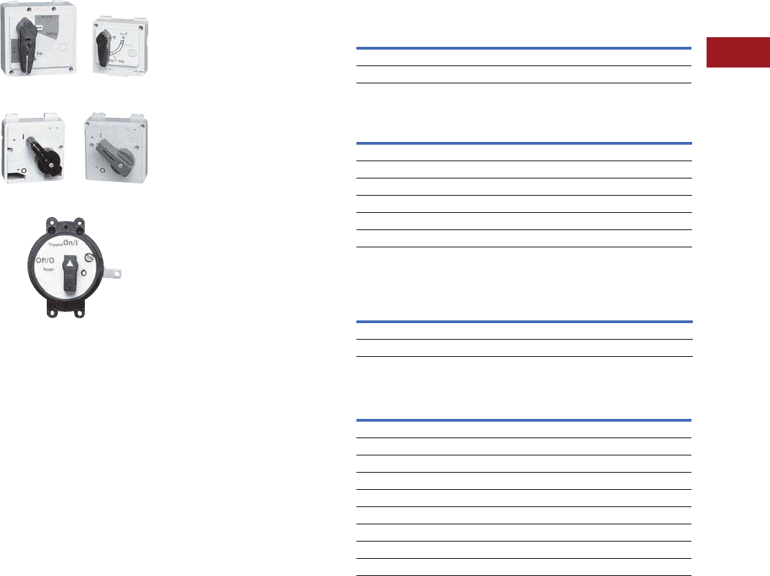
Volume 12—Aftermarket, Renewal Parts and Life Extension Solutions CA08100014E—July 2016 www.eaton.com V12-T3-111
1
2
3
4
5
6
7
8
9
10
11
12
13
14
15
16
17
18
19
20
21
22
23
24
25
3
Molded-Case Circuit Breakers
Replacement Capabilities
Direct (Close-Coupled)
Handle Mechanisms
Universal Direct
Euro IEC Direct
G Direct
Direct (close-coupled) handle
mechanisms mount directly
to the circuit breaker.
They are used in shallow
enclosures where the
standard variable depth
through-the-door type
mechanism is not practical
or cannot be used. They
are typically for applications
where high volume,
standardized enclosures
are being fabricated.
The Universal Direct handle
mechanism is designed
exclusively for the new
Cutler-Hammer E125 and
J250 circuit breakers. It is
available as standard with
a door interlock to prevent
opening the enclosure
while the circuit breaker
is in the ON position. It
is also available without
a door interlock.
The Euro IEC Direct handle
mechanism can be used on
F- through R-Frames.
The G Direct is available with
a black or a yellow handle,
and with or without a shroud.
It is suitable for use with Type
1 enclosures. It is for use only
with the G-Frame (GD, GC,
GHC, GMCP).
An escutcheon ring and an
interlock clip are provided as
standard. The standard design
includes a lock-off feature.
The Universal Direct handle
mechanism is UL 489 Listed,
IEC947-1/2 and meets CSA
requirements. The Euro IEC
Direct handle mechanism
is IEC-240-1. G Direct is
UL Listed and meets
CSA requirements.
Universal Direct Ordering Information
Euro IEC Direct Ordering Information
G Direct Ordering Information 1
Direct (Close-Coupled) Instruction Leaflets
Notes
1Suitable for use on two- or three-pole G-Frame.
Refer to handle mechanisms in the molded-case circuit breaker section of Volume 4—
Circuit Protection Catalog, CA08100005E, Tab 2.
Frame
Universal Direct
Domestic International
With Interlock
(White)
Catalog Number
Without Interlock
(White)
Catalog Number
Without Interlock
(Charcoal With Global Label)
Catalog Number
E125 EHMCCBI EHMCCB EHMCCR
J250 JHMCCBI JHMCCB JHMCCR
Frame
Black Handle
Catalog Number
Red Handle
Catalog Number
FHMCC1B HMCC1R
JHMCC2B HMCC2R
KHMCC3B HMCC3R
L and M HMCC4B HMCC4R
NHMCC5B HMCC5R
RHMCC6B HMCC6R
Frame
Black Handle Yellow Handle
With Shroud
Catalog Number
Without Shroud
Catalog Number
With Shroud
Catalog Number
Without Shroud
Catalog Number
GD/GHC HRGCC1S HRGCC10 HRGCC3S HRGCC30
GMCP HRGMC1S HRGMC10 HRGMC3S HRGMC30
Frame
Instruction Leaflet Number
Universal Direct Euro IEC Direct G Direct
E125 29C255 — —
J250 29C256 — —
G — — 15567
F — 29C288A —
J — 29C288A —
K — 29C288A —
L and MDL — 29C289 —
N — 29C290 —
R — 29C291 —
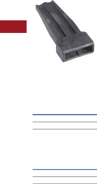
V12-T3-112 Volume 12—Aftermarket, Renewal Parts and Life Extension Solutions CA08100014E—July 2016 www.eaton.com
1
2
3
4
5
6
7
8
9
10
11
12
13
14
15
16
17
18
19
20
21
22
23
24
25
3
Molded-Case Circuit Breakers
Replacement Capabilities
Handle Extensions
Handle Extension
Handle extension is not
included with J-, K-, L- and
M-Frame breakers. It must
be purchased separately.
Handle Extension
Handle extension is included
with breaker with N- and
R-Frame breakers.
Handle Extension
Note: Refer to handle
mechanisms in the molded-
case circuit breaker section of
Volume 4—Circuit Protection
Catalog, CA08100005E, Tab 2.
Replacement and
Service Capabilities
Breaker Service Center
Factory Service for Mining
and Industrial Molded-Case
Circuit Breakers
Eaton owns and operates
two fully authorized Breaker
Service Centers (BSC)
in Skelton, WV, and
Evansville, IN. They are
available to support all non-
warranty service needs for
Cutler-Hammer industrial
molded-case breakers 600A
and above and all frames of
mining duty breakers.
The Breaker Service
Centers, as extensions of
our manufacturing plants,
are the only facilities
authorized to provide breaker
service solutions for Eaton,
Cutler-Hammer and historic
Westinghouse molded-case
circuit breakers. Staff are
dedicated to providing genuine
factory-supported solutions to
our customers.
This is just another example
of how Eaton supports
a complete offering of
solutions for circuit breakers.
See the following for the
benefits of choosing the BSC
and our service offerings.
Offerings
Basic Tune-Up
Clean, test and re-certify.
Basic Modification
Replace accessories and
attachments including
terminals, trip units,
UVRs, shunt trips and
auxiliary switches.
Basic Service
Replace components
including covers, handles
and stationary contacts.
Frame Style Number
J, K HEX3
L, M HEX4
Frame Style Number
NHEX5
RHEX6
Custom Service
Replace frame or trip unit,
with or without accessories.
Full Service
Replace both frame and
trip unit, with or without
accessories.
Factory Modifications
For new or existing
operational breakers
●Trip unit upgrades
●Addition of accessories
and attachments
●UL modifications to
factory-sealed breakers
Facilities
●Dedicated sites supported
by engineering and
manufacturing
●Staffed by factory trained
technicians with experience
servicing molded-case
circuit breakers
●State-of-the-art cleaning
and testing equipment
The Breaker Service Centers
are open to help you. Give us
a call at 1-877-BRK-SRVC or
contact your local Eaton
authorized distributor or sales
office for more information.
Know What You’re Getting—
Here’s the Reality of
Third-Party Repair
●Breakers are serviced
using least worn,
counterfeit or reverse
engineered components
●You get no technical
support from the original
manufacturer
●There is no option for an
upgrade to new technology
●You could end up with a
breaker that doesn’t
perform as expected
Reasons to Use Eaton’s Breaker
Service Centers
●Eaton is a world leader in
circuit breaker technology
and manufacturing
●The Breaker Service
Centers are staffed by
factory trained technicians
●One year warranty.
●Eaton uses only genuine
replacement parts and
components
●Full engineering
support—original
product specifications
and manufacturing data
●State-of-the-art cleaning
equipment—uses a
non-destructive cleaning
process while maintaining
integrity of the breaker
●Modern test equipment—
the breaker service center
uses the same hi-tech
test equipment used by
engineering, development
and manufacturing
facilities. This allows the
breaker service center
to match original test
conditions at the factory
●Exchange option—
we can upgrade to the
newest technology
●Competitive price—all the
benefits of third-party prices
For more information on
Eaton
products and services,
call 1-877-386-2273. Select
option 1 for technical
support and select option
6 for Eaton’s Electrical
Services & Systems,
or visit our website at
www.eaton.com/electrical.

Volume 12—Aftermarket, Renewal Parts and Life Extension Solutions CA08100014E—July 2016 www.eaton.com V12-T3-113
1
2
3
4
5
6
7
8
9
10
11
12
13
14
15
16
17
18
19
20
21
22
23
24
25
3
Molded-Case Circuit Breakers
Replacement Capabilities
Cross-Reference
Westinghouse and Challenger
Cross-Reference for Cutler-Hammer Industrial MCB/MCCBs
Circuit Breaker Brand and Type Circuit Breaker Brand and Type
Westinghouse Challenger Cutler-Hammer Westinghouse Challenger Cutler-Hammer
BAB CBB BAB HMC CSHM HMC
BAB-H CBB-H BAB-H HMCC CSHMC HMCC
CA CD CA HNB — HNB
CAH CDH CAH HNC CSHN HNC
CHKD CKHC CHKD HND CNH HND
CHLD CLHC CHLD JB, KB — JB, KB
CHND CNHC CHND JD CJ JD
CKD CKC CKD JDB CJS JDB
CKDC CKVC CKDC JDC CJV JDC
CLD CLC CLD KD CK KD
CLDC CLVC CLDC KDB CKS KDB
CND CNC CND KDC CKV KDC
CNDC CNVC CNDC LA — LA
CRD CRC CRD LA-P CTL LA-P
CRDC CRVC CRDC LC CSL LC
DK CDK DK LCC CSLC LCC
EB — EB LCL CXL LCL
ED CED ED LCY CSLY LCY
EDC CEV EDC LD CL LD
EDH CEH EDH LDB CK LDB
EHB — EHB LDC CLV LDC
EHD CE EHD MA — MA
FB — FB MC CSM MC
FB-P CTB FB-P MCC CSMC MCC
FCL CXF FCL MCY CSMY MCY
FD CF FD MDS CSMDMDS
FDB CFS FDB MDSC CSMDC MDSC
FDC CFV FDC MDSY CSMDY MDSY
GB CG GB NB — NB
GC CGL GC NB-P CTN NB-P
GDB CGDB GDB NC CSN NC
GHB CH GHB NCY CSNY NCY
GHBS CSCB GHBS ND CN ND
GHC CHL GHC NDC CNV NDC
HCA CDT HCA PB-P CTP PB-P
HFB — HFB PC CSP PC
HFD CFH HFD PCC CSPC PCC
HJD CJH HJD QBGF CBBGF QBGF
HKB — HKB QBGFEP CBBGFEP QBGFEP
HKD CKH HKD QBHGF CBBHGF QBHGF
HLA — HLA QBHGFEP CBBHGFEP QBHGFEP
HLC CSHL HLC QBHW CBBH QBHW
HLCC CSHLC HLCC QBHW-H CBBH-H QBHW-H
HLD CLH HLD RD CR RD
HMA — HMA RDC CRV RDC

V12-T3-114 Volume 12—Aftermarket, Renewal Parts and Life Extension Solutions CA08100014E—July 2016 www.eaton.com
1
2
3
4
5
6
7
8
9
10
11
12
13
14
15
16
17
18
19
20
21
22
23
24
25
3
Molded-Case Circuit Breakers
Replacement Capabilities
Westinghouse, Challenger and Bryant
Cross-Reference for Cutler-Hammer Residential MCBs
Circuit Breaker Brand and Type
Westinghouse Challenger Bryant Cutler-Hammer
BR C BR BR
BRD A BRD BRD
BRH HC BRH BRH
BRHH VC BRHH BRHH
— XC — BRX
BRO C BRO BRO
GFCB HAGF GFCB GFCB
GFCBH HAGFH GFCBH GFCBH
GFEP HAGFEP GFEP GFEP
GFEPH HAGFHEP GFEPH GFEPH
—CM —BW
—CMH—BWH
—CMV—BWHH
—CB—CC
WFL QFL — QFL
WFP QFP — QFP
Notes for Replacement Breaker and Mining Breaker
Replacement Tables (Pages V12-T3-113–V12-T3-167)
1. Many of the suggested
Series C replacements
are electrical
replacements only,
and may have different
dimensions, mountings,
handle forces and throw
(which would require
a handle mechanism
change). The MARK 75
replacement would have
the same dimensions,
mountings, handle forces
and throw. Only three-
pole MARK 75 available.
2. Replacement breaker
frames, trips,
plugs and
some of the terminals and
attachments are not
interchangeable with
the Series C. Obsoleted
frames and trips, etc.,
may require a complete
breaker change.
3.
Replacing with a Higher
IC MARK 75
or Series C
breaker does not increase
the IC rating of the
assembly (panelboard,
switchboard, etc.).
4. Saf-T-Vue is no
longer available on the
replacement breaker line.
Eaton Canada does
make the Series C with
Saf-T-Vue and may be
sourced through our
Canadian Distribution
Center at 905-631-4318.
5. Suggested replacements
also apply to breakers
that had suffixes such
as “L,” line and load
terminals, “V” 50C
calibration and “W”
without terminals.
6. The HFB two-pole
breaker is on a three-pole
frame. The Series C
replacement is a true
two-pole.
7. Continuous amperes
and/or trip range may be
a little different on the
replacement Series C.
8. Replacement breaker
MARK 75 breakers with
interchangeable trip units
are to be supplied as
frame, trip, terminals and
attachment as separate
items (except when
accessories must be
factory installed). No
single-phase, ambient
compensated, Saf-T-Vue,
reverse-feed, or
SELTRONIC magnetic
only are available on
replacement breakers.
9. JA, DA, KA, HKA, LB,
LBB and HLB breakers
when replaced with a
Series C breaker “K”
frame, when bussed on
the line side such as a
panelboard, requires a
TAD3 spacer kit.
10. Contact the local Eaton
Satellite for complete
panelboard replacement
or new interior
replacement. Use
Panelboard Replacement
Breakers where possible.
MARK 75 and three-pole
only replacements are
available. Contact the
Breaker Service Center
at 1-877-275-7782 for
reconditioned breaker
solutions.
Note: If accessories are to be
factory installed, contact the
factory for pricing.

Volume 12—Aftermarket, Renewal Parts and Life Extension Solutions CA08100014E—July 2016 www.eaton.com V12-T3-115
1
2
3
4
5
6
7
8
9
10
11
12
13
14
15
16
17
18
19
20
21
22
23
24
25
3
Molded-Case Circuit Breakers
Replacement Capabilities
Cross-Reference
Replacement Breaker Cross-Reference
Note
1O = Obsolete, A = Available.
Replacement Breaker
Status 1
Replacements Notes
(See Page V12-T3-114)Catalog Number Style Number MARK 75 Catalog Number MARK 75 Style Number Series C Catalog Number
1256C10G03 1256C10G03 O — — LD2300 1–3, 5, 8
1256C10G04 1256C10G04 O — — LD2350 1–3, 5, 8
1256C10G05 1256C10G05 O — — LD2400 1–3, 5, 8
1256C10G12 1256C10G12 A — — KD3250 1–3, 5, 8
1256C10G13 1256C10G13 A — — LD3300 1–3, 5, 8
1256C10G14 1256C10G14 A — — LD3350 1–3, 5, 8
1256C10G15 1256C10G15 A — — LD3400 1–3, 5, 8
1268C14G01 1268C14G01 O — — HMCP050G2C 1–3, 7
1268C14G02 1268C14G02 O — — HMCP050G2C 1–3, 7
1268C14G03 1268C14G03 O 65E4667 65E466 HMCP100L3C 1–3, 7
1268C14G04 1268C14G04 O 65E4667 65E4667 HMCP100L3C 1–3, 7
1268C14G05 1268C14G05 O — — HMCP050G2C 1–3, 7
1268C14G06 1268C14G06 O — — HMCP050G2C 1–3, 7
2603D46G07 2603D46G07 O — — KT2250T 2, 8
2603D46G08 2603D46G08 O — — LT2300T 2, 8
2603D46G09 2603D46G09 O — — LT2350T 2, 8
2603D46G10 2603D46G10 O — — LT2400T 2, 8
2603D46G26 2603D46G26 A — — KT3250T 2, 8
2603D46G27 2603D46G27 A — — LT3300T 2, 8
2603D46G28 2603D46G28 A — — LT3350T 2, 8
2603D46G29 2603D46G29 A — — LT3400T 2, 8
2603D47G07 2603D47G07 O — — — 2, 8
2603D47G08 2603D47G08 O — — — 2, 8
2603D47G10 2603D47G10 O — — — 2, 8
2603D47G26 2603D47G26 A — — — 2, 8
2603D47G27 2603D47G27 A — — — 2, 8
2603D47G29 2603D47G29 A — — — 2, 8
2603D50G01 2603D50G01 O — — KD2250 1–3, 5, 8
2603D50G02 2603D50G02 O — — LD2300 1–3, 5, 8
2603D50G03 2603D50G03 O — — LD2350 1–3, 5, 8
2603D50G04 2603D50G04 O — — LD2400 1–3, 5, 8
2603D50G07 2603D50G07 O — — KD3250 1–3, 5, 8
2603D50G08 2603D50G08 O 1256C10G13 1256C10G13 LD3300 1–3, 5, 8
2603D50G09 2603D50G09 O 1256C10G14 1256C10G14 LD3350 1–3, 5, 8
2603D50G10 2603D50G10 O 1256C10G15 1256C10G15 LD3400 1–3, 5, 8
2603D50G13 2603D50G13 O — — KD2250 1–5, 8
2603D50G14 2603D50G14 O — — LD2300 1–5, 8
2603D50G15 2603D50G15 O — — LD2350 1–5, 8
2603D50G16 2603D50G16 O — — LD2400 1–5, 8
2603D50G19 2603D50G19 O 1256C10G12 1256C10G12 KD3250 1–5, 8
2603D50G20 2603D50G20 O 1256C10G13 1256C10G13 LD3300 1–5, 8
2603D50G21 2603D50G21 O 1256C10G14 1256C10G14 LD3350 1–5, 8
2603D50G22 2603D50G22 O 1256C10G15 1256C10G15 LD3400 1–5, 8
2610D53G12 2610D53G12 O 4994D96G30 4994D96G30 HMCP025D0C 1–3, 7
2610D53G13 2610D53G13 O 4994D96G31 4994D96G31 HMCP070J2C 1–3, 7

V12-T3-116 Volume 12—Aftermarket, Renewal Parts and Life Extension Solutions CA08100014E—July 2016 www.eaton.com
1
2
3
4
5
6
7
8
9
10
11
12
13
14
15
16
17
18
19
20
21
22
23
24
25
3
Molded-Case Circuit Breakers
Replacement Capabilities
Replacement Breaker Cross-Reference
Note
1O = Obsolete, A = Available.
Replacement Breaker
Status 1
Replacements Notes
(See Page V12-T3-114)Catalog Number Style Number MARK 75 Catalog Number MARK 75 Style Number Series C Catalog Number
2610D53G30 2610D53G30 O 4994D96G30 4994D96G30 HMCP025D0C 1–3, 7
2610D53G31 2610D53G31 O 4994D96G31 4994D96G31 HMCP070J2C 1–3, 7
2610D58G31 2610D58G31 O — — — 1–4, 7
373D488G08 373D488G08 O 373D488G09 373D488G09 — 2, 8
4994D96G12 4994D96G12 O 4994D96G30 4994D96G30 HMCP025D0C 1–3, 7
4994D96G13 4994D96G13 O 4994D96G31 4994D96G31 HMCP070J2C 1–3, 7
4994D96G30 4994D96G30 A — — HMCP025D0C 1–3, 7
4994D96G31 4994D96G31 A — — HMCP070J2C 1–3, 7
4998D89G30 4998D89G30 O — — — 1–4, 7
5683D88G07 5683D88G07 O — — KT2250T 2, 8
5683D88G08 5683D88G08 O — — LT2300T 2, 8
5683D88G09 5683D88G09 O — — LT2350T 2, 8
5683D88G10 5683D88G10 O — — LT2400T 2, 8
5683D88G26 5683D88G26 O 2603D46G26 2603D46G26 KT3250T 2, 8
5683D88G27 5683D88G27 O 2603D46G27 2603D46G27 LT3300T 2, 8
5683D88G28 5683D88G28 O 2603D46G28 2603D46G28 LT3350T 2, 8
5683D88G29 5683D88G29 O 2603D46G29 2603D46G29 LT3400T 2, 8
65E4667 65E4667 A — — HMCP100L3C 1–3, 7
81E4647 81E4647 O — — — 1–4, 7
DA2250 375D152G11 O — — DK2250 1–3, 5, 8, 9
DA2250Y 376D872G11 O — — DK2250Y 1–3, 5, 8, 9
DA2300 375D152G12 O — — DK2300 1–3, 5, 8, 9
DA2300Y 376D872G12 O — — DK2300Y 1–3, 5, 8, 9
DA2350 375D152G13 O — — DK2350 1–3, 5, 8, 9
DA2350Y 376D872G13 O — — DK2350Y 1–3, 5, 8, 9
DA2400 375D152G14 O — — DK2400 1–3, 5, 8, 9
DA2400WK 752B050G01 O — — DK2400KW 1–3, 5, 8
DA2400Y 376D872G14 O — — DK2400Y 1–3, 5, 8, 9
DA3250 375D152G26 O — — DK3250 1–3, 5, 8, 9
DA3250Y 376D872G26 O — — DK3250Y 1–3, 5, 8, 9
DA3300 375D152G27 O — — DK3300 1–3, 5, 8, 9
DA3300Y 376D872G27 O — — DK3300Y 1–3, 5, 8, 9
DA3350 375D152G28 O — — DK3350 1–3, 5, 8, 9
DA3350Y 376D872G28 O — — DK3350Y 1–3, 5, 8, 9
DA3400 375D152G29 O — — DK3400 1–3, 5, 8, 9
DA3400WK 752B050G06 O — — DK3400KW 1–3, 5, 8
DA3400Y 376D872G29 O — — DK3400Y 1–3, 5, 8, 9
EB1015 4990D03G02 O — — EHD1015 1–3, 5
EB1020 4990D03G03 O — — EHD1020 1–3, 5
EB1025 4990D03G04 O — — EHD1025 1–3, 5
EB1030 4990D03G05 O — — EHD1030 1–3, 5
EB1035 4990D03G06 O — — EHD1035 1–3, 5
EB1040 4990D03G07 O — — EHD1040 1–3, 5
EB1045 4990D03G14 O — — EHD1045 1–3, 5
EB1050 4990D03G08 O — — EHD1050 1–3, 5
EB1060 4990D03G09 O — — EHD1060 1–3, 5
EB1070 4990D03G10 O — — EHD1070 1–3, 5

Volume 12—Aftermarket, Renewal Parts and Life Extension Solutions CA08100014E—July 2016 www.eaton.com V12-T3-117
1
2
3
4
5
6
7
8
9
10
11
12
13
14
15
16
17
18
19
20
21
22
23
24
25
3
Molded-Case Circuit Breakers
Replacement Capabilities
Replacement Breaker Cross-Reference
Note
1O = Obsolete, A = Available.
Replacement Breaker
Status 1
Replacements Notes
(See Page V12-T3-114)Catalog Number Style Number MARK 75 Catalog Number MARK 75 Style Number Series C Catalog Number
EB1080 4990D03G65 O — — EHD1080 1–3, 5
EB1090 4990D03G11 O — — EHD1090 1–3, 5
EB1100 4990D03G12 O — — EHD1100 1–3, 5
EB1100LK 1226C25G01 O — — — 1–3, 5, 8
EB2015 4990D03G18 O — — EHD2015 1–3, 5
EB2020 4990D03G19 O — — EHD2020 1–3, 5
EB2025 4990D03G20 O — — EHD2025 1–3, 5
EB2030 4990D03G21 O — — EHD2030 1–3, 5
EB2035 4990D03G22 O — — EHD2035 1–3, 5
EB2040 4990D03G23 O — — EHD2040 1–3, 5
EB2050 4990D03G24 O — — EHD2050 1–3, 5
EB2060 4990D03G25 O — — EHD2060 1–3, 5
EB2070 4990D03G26 O — — EHD2070 1–3, 5
EB2080 4990D03G32 O — — EHD2080 1–3, 5
EB2090 4990D03G27 O — — EHD2090 1–3, 5
EB2100 4990D03G28 O — — EHD2100 1–3, 5
EB2100LK 1226C25G02 O — — EHD2100KL 1–3, 5, 8
EB3015 4990D03G34 O HFB3015L 4997D19G34 EHD3015 1–3, 5
EB3015S 4991D35G02 O HFB3015L 4997D19G34 EHD3015 1–5
EB3020 4990D03G35 O HFB3020L 4997D19G35 EHD3020 1–3, 5
EB3020S 4991D35G03 O HFB3020L 4997D19G35 EHD3020 1–5
EB3025 4990D03G36 O HFB3025L 4997D19G36 EHD3025 1–3, 5
EB3025S 4991D35G04 O HFB3025L 4997D19G36 EHD3025 1–5
EB3030 4990D03G37 O HFB3030L 4997D19G37 EHD3030 1–3, 5
EB3030S 4991D35G05 O HFB3030L 4997D19G37 EHD3030 1–5
EB3035 4990D03G38 O HFB3035L 4997D19G38 EHD3035 1–3, 5
EB3035S 4991D35G06 O HFB3035L 4997D19G38 EHD3035 1–5
EB3040 4990D03G39 O HFB3040L 4997D19G39 EHD3040 1–3, 5
EB3040S 4991D35G07 O HFB3040L 4997D19G39 EHD3040 1–5
EB3045 4990D03G46 O HFB3045L 4997D19G54 EHD3045 1–3, 5
EB3045S 4990D03G40 O HFB3045L 4997D19G54 EHD3045 1–5
EB3050 4991D35G08 O HFB3050L 4997D19G40 EHD3050 1–3, 5
EB3050S 4990D03G41 O HFB3050L 4997D19G40 EHD3050 1–5
EB3060 4991D35G09 O HFB3060L 4997D19G41 EHD3060 1–3, 5
EB3060S 4990D03G42 O HFB3060L 4997D19G41 EHD3060 1–5
EB3070 4991D35G10 O HFB3070L 4997D19G42 EHD3070 1–3, 5
EB3070S 4990D03G48 O HFB3070L 4997D19G42 EHD3070 1–5
EB3080 4990D03G43 O HFB3080L 4997D19G55 EHD3080 1–3, 5
EB3080S 4991D35G11 O HFB3080L 4997D19G55 EHD3080 1–5
EB3090 4990D03G43 O HFB3090L 4997D19G43 EHD3090 1–3, 5
EB3090S 4991D35G11 O HFB3090L 4997D19G43 EHD3090 1–5
EB3100 4990D03G44 O HFB3100L 4997D19G44 EHD3100 1–3, 5
EB3100LK 1226C25G03 O — — EHD3100KL 1–3, 5, 8
EB3100S 4991D35G12 O HFB3100L 4997D19G44 EHD3100 1–5
EB3100SLK 1226C25G04 O — — EHD3100KL 1–3, 5, 8
EHB1015 4989D52G02 O — — EHD1015 1–3, 5
EHB1020 4989D52G03 O — — EHD1020 1–3, 5

V12-T3-118 Volume 12—Aftermarket, Renewal Parts and Life Extension Solutions CA08100014E—July 2016 www.eaton.com
1
2
3
4
5
6
7
8
9
10
11
12
13
14
15
16
17
18
19
20
21
22
23
24
25
3
Molded-Case Circuit Breakers
Replacement Capabilities
Replacement Breaker Cross-Reference
Note
1O = Obsolete, A = Available.
Replacement Breaker
Status 1
Replacements Notes
(See Page V12-T3-114)Catalog Number Style Number MARK 75 Catalog Number MARK 75 Style Number Series C Catalog Number
EHB1025 4989D52G04 O — — EHD1025 1–3, 5
EHB1030 4989D52G05 O — — EHD1030 1–3, 5
EHB1035 4989D52G06 O — — EHD1035 1–3, 5
EHB1040 4989D52G07 O — — EHD1040 1–3, 5
EHB1050 4989D52G08 O — — EHD1050 1–3, 5
EHB1060 4989D52G09 O — — EHD1060 1–3, 5
EHB1070 4989D52G10 O — — EHD1070 1–3, 5
EHB1080 4989D52G14 O — — EHD1080 1–3, 5
EHB1090 4989D52G11 O — — EHD1090 1–3, 5
EHB1100 4989D52G12 O — — EHD1100 1–3, 5
EHB1100LK 1226C25G11 O — — — 1–3, 5, 8
EHB2015 4989D52G18 O — — EHD2015 1–3, 5
EHB2020 4989D52G19 O — — EHD2020 1–3, 5
EHB2025 4989D52G20 O — — EHD2025 1–3, 5
EHB2030 4989D52G21 O — — EHD2030 1–3, 5
EHB2035 4989D52G22 O — — EHD2035 1–3, 5
EHB2040 4989D52G23 O — — EHD2040 1–3, 5
EHB2045 4989D52G29 O — — EHD2045 1–3, 5
EHB2050 4989D52G24 O — — EHD2050 1–3, 5
EHB2060 4989D52G25 O — — EHD2060 1–3, 5
EHB2070 4989D52G26 O — — EHD2070 1–3, 5
EHB2090 4989D52G27 O — — EHD2090 1–3, 5
EHB2100 4989D52G28 O — — EHD2100 1–3, 5
EHB2100LK 1226C25G12 O — — EHD2100KL 1–3, 5, 8
EHB3015 4989D52G34 O HFB3015L 4997D19G34 EHD3015 1–3, 5
EHB3015S 4991D35G18 O HFB3015L 4997D19G34 EHD3015 1–5
EHB3020 4989D52G35 O HFB3020L 4997D19G35 EHD3020 1–3, 5
EHB3020S 4991D35G19 O HFB3020L 4997D19G35 EHD3020 1–5
EHB3025 4989D52G36 O HFB3025L 4997D19G36 EHD3025 1–3, 5
EHB3025S 4991D35G20 O HFB3025L 4997D19G36 EHD3025 1–5
EHB3030 4989D52G37 O HFB3030L 4997D19G37 EHD3030 1–3, 5
EHB3030S 4991D35G21 O HFB3030L 4997D19G37 EHD3030 1–5
EHB3035 4989D52G38 O HFB3035L 4997D19G38 EHD3035 1–3, 5
EHB3035S 4991D35G22 O HFB3035L 4997D19G38 EHD3035 1–5
EHB3040 4989D52G39 O HFB3040L 4997D19G39 EHD3040 1–3, 5
EHB3040S 4991D35G23 O HFB3040L 4997D19G39 EHD3040 1–5
EHB3045 4989D52G45 O HFB3045L 4997D19G54 EHD3045 1–3, 5
EHB3045S NO STYLE O HFB3045L 4997D19G54 EHD3045 1–5
EHB3050 4993D67G40 O HFB3050L 4997D19G40 EHD3050 1–3, 5
EHB3050S 4991D35G24 O HFB3050L 4997D19G40 EHD3050 1–5
EHB3060 4993D67G41 O HFB3060L 4997D19G41 EHD3060 1–3, 5
EHB3060S 4991D35G25 O HFB3060L 4997D19G41 EHD3060 1–5
EHB3070 4993D67G42 O HFB3070L 4997D19G42 EHD3070 1–3, 5
EHB3070S 4991D35G26 O HFB3070L 4997D19G42 EHD3070 1–5
EHB3080 4993D67G46 O HFB3080L 4997D19G55 EHD3080 1–3, 5
EHB3080S NO STYLE O HFB3080L 4997D19G55 EHD3080 1–5
EHB3090 4993D67G43 O HFB3090L 4997D19G43 EHD3090 1–3, 5

Volume 12—Aftermarket, Renewal Parts and Life Extension Solutions CA08100014E—July 2016 www.eaton.com V12-T3-119
1
2
3
4
5
6
7
8
9
10
11
12
13
14
15
16
17
18
19
20
21
22
23
24
25
3
Molded-Case Circuit Breakers
Replacement Capabilities
Replacement Breaker Cross-Reference
Note
1O = Obsolete, A = Available.
Replacement Breaker
Status 1
Replacements Notes
(See Page V12-T3-114)Catalog Number Style Number MARK 75 Catalog Number MARK 75 Style Number Series C Catalog Number
EHB3090S 4991D35G27 O HFB3090L 4997D19G43 EHD3090 1–5
EHB3100 4993D67G44 O HFB3100L 4997D19G44 EHD3100 1–3, 5
EHB3100LK 1226C25G13 O — — EHD3100KL 1–3, 5, 8
EHB3100S 4991D35G28 O — — EHD3100 1–5
EHB3100SLK 1226C25G14 O — — EHD3100KL 1–3, 5, 8
FB2015 4975D71G18 O — — FD2015 1–3, 5
FB2020 4975D71G19 O — — FD2020 1–3, 5
FB2022MRL 2610D53G03 O — — HMCP003A0C 1–3, 7
FB2025 4975D71G20 O — — FD2025 1–3, 5
FB2030 4975D71G21 O — — FD2030 1–3, 5
FB2035 4975D71G22 O — — FD2035 1–3, 5
FB2040 4975D71G23 O — — FD2040 1–3, 5
FB2045MRL 2610D53G04 O — — HMCP007C0C 1–3, 7
FB2050 4975D71G24 O — — FD2050 1–3, 5
FB2060 4975D71G25 O — — FD2060 1–3, 5
FB2070 4975D71G26 O — — FD2070 1–3, 5
FB2080 4975D71G02 O — — FD2080 1–3, 5
FB2090 4975D71G27 O — — FD2090 1–3, 5
FB2100 4975D71G28 O — — FD2100 1–3, 5
FB2100LK 1226C25G21 O — — FD2100KL 1–3, 5, 8
FB2110MRL 2610D53G05 O — — HMCP015E0C 1–3, 7
FB2150LK 1226C25G22 O — — FD2150KL 1–3, 5, 8
FB21550MRL 2610D53G08 O — — HMCP150T4C 1–3, 7
FB21800MRL 2610D53G11 O — — HMCP150U4C 1–3, 7
FB2190MRL 2610D53G06 O — — HMCP030H1C 1–3, 7
FB2270MRL 2610D53G10 O — — HMCP030H1C 1–3, 7
FB2480MRL 2610D53G07 O — — HMCP050K2C 1–3, 7
FB3015 4975D71G34 O HFB3015L 4997D19G34 FD3015 1–3, 5
FB3015S 4991D35G34 O HFB3015L 4997D19G34 FD3015 1–5
FB3020 4975D71G35 O HFB3020L 4997D19G35 FD3020 1–3, 5
FB3020S 4991D35G35 O HFB3020L 4997D19G35 FD3020 1–5
FB3022MRL 2606D95G21 O HFB3022ML 4994D96G21 HMCP003A0C 1–3, 7
FB3022SMRL 2610D58G21 O HFB3022ML 4994D96G21 HMCP003A0C 1–4, 7
FB3025 4975D71G36 O HFB3025L 4997D19G36 FD3025 1–3, 5
FB3025S 4991D35G36 O HFB3025L 4997D19G36 FD3025 1–5
FB3030 4975D71G37 O HFB3030L 4997D19G37 FD3030 1–3, 5
FB3030S 4991D35G37 O HFB3030L 4997D19G37 FD3030 1–5
FB3035 4975D71G38 O HFB3035L 4997D19G38 FD3035 1–3, 5
FB3040 4975D71G39 O HFB3040L 4997D19G39 FD3040 1–3, 5
FB3040S 4991D35G39 O HFB3040L 4997D19G39 FD3040 1–5
FB3045L 4975D71G05 O HFB3045L 4997D19G54 FD3045 1–3, 5
FB3045MRL 2610D53G22 O HFB3045ML 4994D96G22 HMCP007C0C 1–3, 7
FB3045S NO STYLE O HFB3045L 4997D19G54 FD3045 1–5
FB3045SMRL 2610D58G22 O HFB3045ML 4994D96G22 HMCP007C0C 1–4, 7
FB3050 4975D71G40 O HFB3050L 4997D19G40 FD3050 1–3, 5
FB3050S 4991D35G40 O HFB3050L 4997D19G40 FD3050 1–5
FB3060 4975D71G41 O HFB3060L 4997D19G41 FD3060 1–3, 5

V12-T3-120 Volume 12—Aftermarket, Renewal Parts and Life Extension Solutions CA08100014E—July 2016 www.eaton.com
1
2
3
4
5
6
7
8
9
10
11
12
13
14
15
16
17
18
19
20
21
22
23
24
25
3
Molded-Case Circuit Breakers
Replacement Capabilities
Replacement Breaker Cross-Reference
Note
1O = Obsolete, A = Available.
Replacement Breaker
Status 1
Replacements Notes
(See Page V12-T3-114)Catalog Number Style Number MARK 75 Catalog Number MARK 75 Style Number Series C Catalog Number
FB3060S 4991D35G41 O HFB3060L 4997D19G41 FD3060 1–5
FB3070 4975D71G42 O HFB3070L 4997D19G42 FD3070 1–3, 5
FB3070S 4991D35G42 O HFB3070L 4997D19G42 FD3070 1–5
FB3080 4975D71G06 O HFB3080L 4997D19G55 FD3080 1–3, 5
FB3080S NO STYLE O HFB3080L 4997D19G55 FD3080 1–5
FB3090 4975D71G43 O HFB3090L 4997D19G43 FD3090 1–3, 5
FB3090S 4991D35G43 O HFB3090L 4997D19G43 FD3090 1–5
FB3100 4975D71G44 O HFB3100L 4997D19G44 FD3100 1–3, 5
FB3100LK 1226C25G23 O — — FD3100KL 1–3, 5, 8
FB3100S 4991D35G44 O HFB3100L 4997D19G44 FD3100 1–5
FB3110 4975D71G07 O — — FD3110 1–3, 5
FB3110MRL 2610D53G23 O HFB3110ML 4994D96G23 HMCP015E0C 1–3, 7
FB3110S NO STYLE O — — FD3110 1–5
FB3110SMRL 2610D58G23 O — — HMCP015E0C 1–4, 7
FB3125 4975D71G45 O — — FD3125 1–3, 5
FB3125S 4991D35G45 O — — FD3125 1–4, 5
FB3150 4975D71G46 O — — FD3150 1–3, 5
FB3150LK 1226C25G24 O — — FD3150KL 1–3, 5, 8
FB3150S 4991D35G46 O — — FD3150 1–5
FB3150SLK 1226C25G25 O — — FD3150KL 1–3, 5, 8
FB31550MRL 2610D53G26 O HFB31550ML 4994D96G26 HMCP150T4C 1–3, 7
FB31550SMRL 2610D58G26 O HFB31550ML 4994D96G26 HMCP150T4C 1–4, 7
FB31800MRL 2610D53G29 O — — HMCP150U4C 1–3, 7
FB31800SMRL 2610D58G29 O — — HMCP150U4C 1–4, 7
FB3190MRL 2610D53G24 O HFB3190ML 4994D96G24 HMCP030H1C 1–3, 7
FB3190SMRL 2610D58G24 O HFB3190ML 4994D96G24 HMCP030H1C 1–4, 7
FB3270MRL 2610D53G28 O HFB3270ML 4994D96G28 HMCP030H1C 1–3, 7
FB3270SMRL 2610D58G28 O HFB3270ML 4994D96G28 HMCP030H1C 1–4, 7
FB3480MRL 2610D53G25 O HFB3480ML 4994D96G25 HMCP050K2C 1–3, 7
FB3480SMRL 2610D58G25 O HFB3480ML 4994D96G25 HMCP050K2C 1–4, 7
FB4015 4975D71G50 O — — FD4015 1–3, 5
FB4020 4975D71G51 O — — FD4020 1–3, 5
FB4025 4975D71G52 O — — FD4025 1–3, 5
FB4030 4975D71G53 O — — FD4030 1–3, 5
FB4035 4975D71G54 O — — FD4035 1–3, 5
FB4040 4975D71G55 O — — FD4040 1–3, 5
FB4045 NO STYLE O — — FD4045 1–3, 5
FB4050 4975D71G56 O — — FD4050 1–3, 5
FB4060 4975D71G57 O — — FD4060 1–3, 5
FB4070 4975D71G58 O — — FD4070 1–3, 5
FB4080 NO STYLE O — — FD4080 1–3, 5
FB4090 4975D71G59 O — — FD4090 1–3, 5
FB4100 4975D71G60 O — — FD4100 1–3, 5
FB4100LK 1226C25G26 O — — FD4100KL 1–3, 5, 8
FB4150LK 1226C25G27 O — — FD4150KL 1–3, 5, 8
HFB1015 4976D04G02 O — — HFD1015 1–3, 5
HFB1020 4976D04G03 O — — HFD1020 1–3, 5

Volume 12—Aftermarket, Renewal Parts and Life Extension Solutions CA08100014E—July 2016 www.eaton.com V12-T3-121
1
2
3
4
5
6
7
8
9
10
11
12
13
14
15
16
17
18
19
20
21
22
23
24
25
3
Molded-Case Circuit Breakers
Replacement Capabilities
Replacement Breaker Cross-Reference
Note
1O = Obsolete, A = Available.
Replacement Breaker
Status 1
Replacements Notes
(See Page V12-T3-114)Catalog Number Style Number MARK 75 Catalog Number MARK 75 Style Number Series C Catalog Number
HFB1025 4976D04G04 O — — HFD1025 1–3, 5
HFB1030 4976D04G05 O — — HFD1030 1–3, 5
HFB1035 4976D04G06 O — — HFD1035 1–3, 5
HFB1040 4976D04G07 O — — HFD1040 1–3, 5
HFB1045 4976D04G49 O — — HFD1045 1–3, 5
HFB1050 4976D04G08 O — — HFD1050 1–3, 5
HFB1060 4976D04G09 O — — HFD1060 1–3, 5
HFB1070 4976D04G10 O — — HFD1070 1–3, 5
HFB1080 4976D04G50 O — — HFD1080 1–3, 5
HFB1090 4976D04G11 O — — HFD1090 1–3, 5
HFB1100 4976D04G12 O — — HFD1100 1–3, 5
HFB2015 4976D04G18 O — — FD3015 1–3, 5, 6
HFB2020 4976D04G19 O — — FD3020 1–3, 5, 6
HFB2022ML 2610D57G03 O — — HMCP003A0C 1, 2, 3, 7
HFB2025 4976D04G20 O — — FD3025 1, 2, 3, 5, 6
HFB2030 4976D04G21 O — — FD3030 1, 2, 3, 5, 6
HFB2035 4976D04G22 O — — FD3035 1, 2, 3, 5, 6
HFB2040 4976D04G23 O — — FD3040 1, 2, 3, 5, 6
HFB2045 4976D04G51 O — — FD3045 1, 2, 3, 5, 6
HFB2045ML 2610D57G04 O — — HMCP007COC 1, 2, 3, 7
HFB2050 4976D04G24 O — — FD3050 1, 2, 3, 5, 6
HFB2060 4976D04G25 O — — FD3060 1, 2, 3, 5, 6
HFB2070 4976D04G26 O — — FD3070 1, 2, 3, 5, 6
HFB2080 4976D04G52 O — — FD3080 1, 2, 3, 5, 6
HFB2090 4976D04G27 O — — FD3090 1, 2, 3, 5, 6
HFB2100 4976D04G28 O — — FD3100 1, 2, 3, 5, 6
HFB2125 4976D04G29 O — — FD3125 1, 2, 3, 5, 6
HFB2150 4976D04G30 O — — FD3150 1, 2, 3, 5, 6
HFB2110ML 2610D57G05 O — — HMCP015E0C 1, 2, 3, 7
HFB21550ML 2610D57G08 O — — HMCP150T4C 1, 2, 3, 7
HFB21800ML 2610D57G11 O — — HMCP150U4C 1, 2, 3, 7
HFB2190ML 2610D57G06 O — — HMCP030H1C 1, 2, 3, 7
HFB2270ML 2610D57G10 O — — HMCP030H1C 1, 2, 3, 7
HFB2480ML 2610D57G07 O — — HMCP050K2C 1, 2, 3, 7
HFB3015 4976D04G34 O HFB3015L 4997D19G34 FD3015 1, 2, 3, 5
HFB3020 4976D04G35 O HFB3020L 4997D19G35 FD3020 1, 2, 3, 5
HFB3022ML 2610D57G21 A — — HMCP003A0C 1, 2, 3, 7
HFB3025 4976D04G36 O HFB3025L 4997D19G36 FD3025 1, 2, 3, 5
HFB3030 4976D04G37 O HFB3030L 4997D19G37 FD3030 1, 2, 3, 5
HFB3035 4976D04G38 O HFB3035L 4997D19G38 FD3035 1, 2, 3, 5
HFB3040 4976D04G39 O HFB3040L 4997D19G39 FD3040 1–3, 5
HFB3045 4976D04G54 O HFB3045L 4997D19G54 FD3045 1–3, 5
HFB3045ML 2610D57G22 A — — HMCP007C0C 1–3, 7
HFB3050 4976D04G40 O HFB3050L 4997D19G40 FD3050 1–3, 5
HFB3060 4976D04G41 O HFB3060L 4997D19G41 FD3060 1–3, 5
HFB3070 4976D04G42 O HFB3070L 4997D19G42 FD3070 1–3, 5
HFB3080 4976D04G55 O HFB3080L 4997D19G55 FD3080 1–3, 5

V12-T3-122 Volume 12—Aftermarket, Renewal Parts and Life Extension Solutions CA08100014E—July 2016 www.eaton.com
1
2
3
4
5
6
7
8
9
10
11
12
13
14
15
16
17
18
19
20
21
22
23
24
25
3
Molded-Case Circuit Breakers
Replacement Capabilities
Replacement Breaker Cross-Reference
Note
1O = Obsolete, A = Available.
Replacement Breaker
Status 1
Replacements Notes
(See Page V12-T3-114)Catalog Number Style Number MARK 75 Catalog Number MARK 75 Style Number Series C Catalog Number
HFB3090 4976D04G43 O HFB3090L 4997D19G43 FD3090 1–3, 5
HFB3100 4976D04G44 O HFB3100L 4997D19G44 FD3100 1–3, 5
HFB3110 4976D04G56 O — — FD3110 1–3, 5
HFB3110ML 2610D57G23 A — — HMCP015E0C 1–3, 7
HFB3125 4976D04G45 O — — FD3125 1–3, 5
HFB3150 4976D04G46 O — — FD3150 1–3, 5
HFB31550ML 2610D57G26 O — — HMCP150T4C 1–3, 7
HFB31800ML 2610D57G29 O — — HMCP150U4C 1–3, 7
HFB3190ML 2610D57G24 A — — HMCP030H1C 1–3, 7
HFB3270ML 2610D57G28 A — — HMCP030H1C 1–3, 7
HFB3480ML 2610D57G25 A — — HMCP050K2C 1–3, 7
HKA2070 1255C59G02 O — — JD2070 1–3, 5, 8, 9
HKA2070T 2602D83G02 O — — — 2, 8
HKA2070TA 459D987G02 O — — JT2070T 2, 8
HKA2090 1255C59G03 O — — JD2090 1–3, 5, 8, 9
HKA2090T 657D789G03 O — — — 2, 8
HKA2090TA 459D987G03 O — — — 2, 8
HKA2100 1255C59G04 O — — KD2100 1–3, 5, 8, 9
HKA2100T 2602D83G04 O — — — 2, 8
HKA2100TA 459D987G04 O — — — 2, 8
HKA2125 1255C59G05 O — — KD2125 1–3, 5, 8, 9
HKA21250TM 2602D84G05 O — — — 2, 8
HKA2125T 2602D83G05 O — — — 2, 8
HKA2125TA 459D987G05 O — — — 2, 8
HKA2150 1255C59G06 O — — KD2150 1–3, 5, 8, 9
HKA21500TM 2602D84G06 O — — — 2, 8
HKA2150T 2602D83G06 O — — — 2, 8
HKA2150TA 459D987G06 O — — — 2, 8
HKA2175 1255C59G07 O — — KD2175 1–3, 5, 8, 9
HKA21750TM 2602D84G07 O — — — 2, 8
HKA2175T 2602D83G07 O — — — 2, 8
HKA2175TA 459D987G07 O — — — 2, 8
HKA2200 1255C59G08 O — — KD2200 1–3, 5, 8, 9
HKA2200T 2602D83G08 O — — — 2, 8
HKA2200TA 459D987G08 O — — — 2, 8
HKA2225 1255C59G09 O — — KD2225 1–3, 5, 8, 9
HKA22250TM 2602D84G09 O — — — 2, 8
HKA2225F 2602D86G05 O — — KD2400F 2, 8
HKA2225T 2602D83G09 O — — KT2225T 2, 8
HKA2225TA 459D987G09 O — — KT2225T 2, 8
HKA2700TM 2602D84G02 O — — — 2, 8
HKA3070 1255C59G17 O — — JD3070 1–3, 5, 8, 9
HKA3070T 657D788G17 A — — — 2, 5
HKA3070TA 459D987G17 O HKA3070T 657D789G17 — 2, 8
HKA3090 1255C59G18 O — — JD3090 1–3, 5, 8, 9
HKA3090T 2602D83G18 A — — — 2, 5
HKA3090TA 459D987G18 O HKA3090T 657D789G18 — 2, 8

Volume 12—Aftermarket, Renewal Parts and Life Extension Solutions CA08100014E—July 2016 www.eaton.com V12-T3-123
1
2
3
4
5
6
7
8
9
10
11
12
13
14
15
16
17
18
19
20
21
22
23
24
25
3
Molded-Case Circuit Breakers
Replacement Capabilities
Replacement Breaker Cross-Reference
Note
1O = Obsolete, A = Available.
Replacement Breaker
Status 1
Replacements Notes
(See Page V12-T3-114)Catalog Number Style Number MARK 75 Catalog Number MARK 75 Style Number Series C Catalog Number
HKA3100 1255C59G19 O — — KD3100 1–3, 5, 8, 9
HKA3100T 2602D83G19 A — — — 2, 5
HKA3100TA 459D987G19 O HKA3100T 657D789G19 — 2, 8
HKA3125 1255C59G20 O — — KD3125 1–3, 5, 8, 9
HKA3125T 2602D83G20 A — — — 2, 5
HKA3125TA 459D987G20 O HKA3125T 657D789G20 — 2, 8
HKA3150 1255C59G21 O — — KD3150 1–3, 5, 8, 9
HKA3150T 2602D83G21 A — — — 2, 5
HKA3150TA 459D987G21 O HKA3150T 657D789G21 — 2, 8
HKA3175 1255C59G22 O — — KD3175 1–3, 5, 8, 9
HKA3175T 2602D83G22 A — — — 2, 5
HKA3175TA 459D987G22 O HKA3175T 657D789G22 — 2, 8
HKA3200 1255C59G23 O — — KD3200 1–3, 5, 8, 9
HKA3200T 2602D83G23 A — — — 2, 5
HKA3200TA 459D987G23 O HKA3200T 657D789G23 — 2, 8
HKA3225 1255C59G24 O — — KD3225 1–3, 5, 8, 9
HKA3225F 2602D86G06 O — — KD3400F 2, 8
HKA3225T 2602D83G24 A — — — 2, 5
HKA3225TA 459D987G24 O HKA3225T 657D789G24 — 2, 8
HKB2070 1291C44G01 O — — JD2070 1–3, 5
HKB2070T 1293C31G01 O — — — 2, 5
HKB2090 1291C44G02 O — — JD2090 1–3, 5
HKB2090T 1293C31G02 O — — — —
HKB2100 1291C44G03 O — — JD2100 1–3, 5
HKB21000TM 1293C35G03 O — — — —
HKB2100T 1293C31G03 O — — — —
HKB2125 1291C44G04 O — — JD2125 1–3, 5
HKB21250TM 1293C35G04 O — — — —
HKB2125T 1293C31G04 O — — — —
HKB2150 1291C44G05 O — — JD2150 1–3, 5
HKB21500TM 1293C35G05 O — — — —
HKB2150T 1293C31G05 O — — — —
HKB2175 1291C44G06 O — — JD2175 1–3, 5
HKB21750TM 1293C35G06 O — — — —
HKB2175T 1293C31G06 O — — — —
HKB2200 1291C44G07 O — — JD2200 1–3, 5
HKB2200T 1293C31G07 O — — — —
HKB2225 1291C44G08 O — — JD2225 1–3, 5
HKB22250TM 1293C35G07 O — — — —
HKB2225T 1293C31G08 O — — — —
HKB2250 1291C44G09 O — — JD2250 1–3, 5
HKB22500TM 1293C35G09 O — — — —
HKB2250F 2601D44G15 O — — JD2250F —
HKB2250T 4974D52G12 O — — — —
HKB2700TM 1293C35G01 O — — — —
HKB3070 1291C44G16 O — — JD3070 1–3, 5
HKB3070T 1293C32G01 O — — — —

V12-T3-124 Volume 12—Aftermarket, Renewal Parts and Life Extension Solutions CA08100014E—July 2016 www.eaton.com
1
2
3
4
5
6
7
8
9
10
11
12
13
14
15
16
17
18
19
20
21
22
23
24
25
3
Molded-Case Circuit Breakers
Replacement Capabilities
Replacement Breaker Cross-Reference
Note
1O = Obsolete, A = Available.
Replacement Breaker
Status 1
Replacements Notes
(See Page V12-T3-114)Catalog Number Style Number MARK 75 Catalog Number MARK 75 Style Number Series C Catalog Number
HKB3090 1291C44G17 O — — JD3090 1–3, 5
HKB3090T 1293C32G02 O — — — —
HKB3100 1291C44G18 O — — JD3100 1–3, 5
HKB31000TM 1293C36G03 O — — — —
HKB3100T 1293C32G03 O — — — —
HKB3125 1291C44G19 O — — JD3125 1–3, 5
HKB31250TM 1293C36G04 O — — — —
HKB3125T 1293C32G04 O — — — —
HKB3150 1291C44G20 O — — JD3150 1–3, 5
HKB31500TM 1293C36G05 O — — — —
HKB3150T 1293C32G05 O — — — —
HKB3175 1291C44G21 O — — JD3175 1–3, 5
HKB31750TM 1293C36G06 O — — — —
HKB3175T 1293C32G06 O — — — —
HKB3200 1291C44G22 O — — JD3200 1–3, 5
HKB3200T 1293C32G06 O — — — —
HKB3225 1291C44G23 O — — JD3225 1–3, 5
HKB32250TM 1293C36G08 O — — — —
HKB3225T 1293C32G07 O — — — —
HKB3250 1291C44G24 O — — JD3250 1–3, 5
HKB32500TM 1293C36G09 O — — — 2, 5
HKB3250F 2601D44G16 O — — JD3250F —
HKB3250FS NO STYLE O — — JD3250F —
HKB3250T 1293C32G08 O — — — —
HKB3700TM 1293C36G01 O — — — —
HLA2070T 2602D98G02 O — — — 2, 8
HLA2070TA 457D581G02 O — — — 2, 8
HLA2090T 2602D98G03 O — — — 2, 8
HLA2090TA 457D581G03 O — — — 2, 8
HLA2100T 2602D98G04 O — — — 2, 8
HLA2100TA 457D581G04 O — — — 2, 8
HLA2125 1255C74G05 O — — KD2125 1–3, 5, 8
HLA21250TM 2602D97G03 O — — — 2, 8
HLA2125T 2602D98G05 O — — — 2, 8
HLA2125TA 457D581G05 O — — — 2, 8
HLA2150 1255C74G06 O — — KD2150 1–3, 5, 8
HLA21500TM 2602D97G04 O — — — 2, 8
HLA2150T 2602D98G06 O — — — 2, 8
HLA2150TA 457D581G06 O — — — 2, 8
HLA2175 1255C74G07 O — — KD2175 1–3, 5, 8
HLA21750TM 2602D97G05 O — — — 2, 8
HLA2175T 2602D98G07 O — — — 2, 8
HLA2175TA 457D581G07 O — — — 2, 8
HLA2200 1255C74G08 O — — KD2200 1–3, 5, 8
HLA2200T 2602D98G08 O — — — 2, 8
HLA2200TA 457D581G08 O — — — 2, 8
HLA2225 1255C74G09 O — — KD2225 1–3, 5, 8

Volume 12—Aftermarket, Renewal Parts and Life Extension Solutions CA08100014E—July 2016 www.eaton.com V12-T3-125
1
2
3
4
5
6
7
8
9
10
11
12
13
14
15
16
17
18
19
20
21
22
23
24
25
3
Molded-Case Circuit Breakers
Replacement Capabilities
Replacement Breaker Cross-Reference
Note
1O = Obsolete, A = Available.
Replacement Breaker
Status 1
Replacements Notes
(See Page V12-T3-114)Catalog Number Style Number MARK 75 Catalog Number MARK 75 Style Number Series C Catalog Number
HLA22250TM 2602D97G06 O — — — 2, 8
HLA2225T 2602D98G09 O — — — 2, 8
HLA2225TA 457D581G09 O — — — 2, 8
HLA2250 1255C74G10 O — — KD2250 1–3, 5, 8
HLA2250T 2602D98G10 O — — — 2, 8
HLA2250TA 457D581G10 O — — — 2, 8
HLA2300 1255C74G11 O — — KD2300 1–3, 5, 8
HLA23000TM 2602D97G07 O — — — 2, 8
HLA2300T 2602D98G11 O — — — 2, 8
HLA2300TA 457D581G11 O — — — 2, 8
HLA2350 1255C74G12 O — — KD2350 1–3, 5, 8
HLA2350T 2602D98G12 O — — — 2, 8
HLA2350TA 457D781G12 O — — — 2, 8
HLA2400 1255C74G13 O — — KD2400 1–3, 5, 8
HLA24000TM 2602D97G08 O — — — 2, 8
HLA2400F 673B352G01 O — — KD2400F 1–3, 5, 8
HLA2400T 2602D98G13 O — — — 2, 8
HLA2400TA 457D581G13 O — — — 2, 8
HLA2500 1256C10G10 O — — LD2500 1–3, 5, 8
HLA25000TM 2603D47G12 O — — — 2, 8
HLA2500T 2603D46G12 O — — — 2, 8
HLA2500TA 5683D88G12 O — — — 2, 8
HLA2600 1256C10G07 O — — LD2600 1–3, 5, 8
HLA26000TM 2603D47G13 O — — — 2, 8
HLA2600F 375D400G09 O — — LD2600F 1–3, 5, 8
HLA2600T 2603D46G13 O — — — 2, 8
HLA2600TA 5683D88G13 O — — — 2, 8
HLA2700TM 2602D97G02 O — — — 2, 8
HLA3070T 2602D98G21 A — — — 2, 8
HLA3070TA 457D581G21 O HLA3070T 370D749G21 — 2, 8
HLA3090T 2602D98G22 A — — — 2, 8
HLA3090TA 457D581G22 O HLA3090T 370D749G22 — 2, 8
HLA3100T 2602D98G23 A — — — 2, 8
HLA3100TA 457D581G23 O HLA3100T 370D749G23 — 2, 8
HLA3125 504C740G20 A — — KD3125 1–3, 5, 8
HLA31250TM 2602D97G25 A — — — 2, 8
HLA3125T 2602D98G24 A — — — 2, 8
HLA3125TA 457D581G24 O HLA3125T 370D749G24 — 2, 8
HLA3150 504C740G21 A — — KD3150 1–3, 5, 8
HLA31500TM 2602D97G26 A — — — 2, 8
HLA3150T 2602D98G25 A — — — 2, 8
HLA3150TA 457D581G25 O HLA3150T 370D749G25 — 2, 8
HLA3175 504C740G22 A — — KD3175 1–3, 5, 8
HLA31750TM 2602D97G27 A — — — 2, 8
HLA3175T 2602D98G26 A — — — 2, 8
HLA3175TA 457D581G26 O HLA3175T 370D749G26 — 2, 8
HLA3200 504C740G23 A — — KD3200 1–3, 5, 8

V12-T3-126 Volume 12—Aftermarket, Renewal Parts and Life Extension Solutions CA08100014E—July 2016 www.eaton.com
1
2
3
4
5
6
7
8
9
10
11
12
13
14
15
16
17
18
19
20
21
22
23
24
25
3
Molded-Case Circuit Breakers
Replacement Capabilities
Replacement Breaker Cross-Reference
Note
1O = Obsolete, A = Available.
Replacement Breaker
Status 1
Replacements Notes
(See Page V12-T3-114)Catalog Number Style Number MARK 75 Catalog Number MARK 75 Style Number Series C Catalog Number
HLA3200T 2602D98G27 A — — — 2, 8
HLA3200TA 457D581G27 O HLA3200T 370D749G27 — 2, 8
HLA3225 504C740G24 A — — KD3225 1–3, 5, 8
HLA32250TM 2602D97G28 A — — — 2, 8
HLA3225T 2602D98G28 A — — — 2, 8
HLA3225TA 457D581G28 O HLA3225T 370D749G28 — 2, 8
HLA3250 504C740G25 A — — KD3250 1–3, 5, 8
HLA3250T 2602D98G29 A — — — 2, 8
HLA3250TA 457D581G29 O HLA3250T 370D749G29 — 2, 8
HLA3300 504C740G26 A — — KD3300 1–3, 5, 8
HLA33000TM 2602D97G29 A — — — 2, 8
HLA3300T 2602D98G30 A — — — 2, 8
HLA3300TA 457D581G30 O HLA3300T 370D749G30 — 2, 8
HLA3350T 2602D98G31 A — — — 2, 8
HLA3350TA 457D581G31 O HLA3350T 370D749G31 — 2, 8
HLA3400 504C740G28 A — — KD3400 1–3, 5, 8
HLA34000TM 2602D97G30 A — — — 2, 8
HLA3400F 673B352G02 A — — KD3400F 1–3, 5, 8
HLA3400T 2602D98G32 A — — — 2, 8
HLA3400TA 457D581G32 O HLA3400T 370D749G32 — 2, 8
HLA3500 177C429G16 A — — LD3500 1–3, 5, 8
HLA35000TM 2603D47G31 A — — — 2, 8
HLA3500T 2603D46G31 A — — — 2, 8
HLA3500TA 5683D88G31 O HLA3500T 375D259G31 — 2, 8
HLA3600 177C429G17 A — — LD3600 1–3, 5, 8
HLA36000TM 2603D47G32 A — — — 2, 8
HLA3600F 2603D48G06 A — — LD3600F 1–3, 5, 8
HLA3600T 2603D46G32 A — — — 2, 8
HLA3600TA 5683D88G32 O HLA3600T 375D259G32 — 2, 8
HLA3700TM 455D565G24 A — — — 2, 8
HLB2070T 5680D04G07 O — — — 2, 8
HLB2070TA 5680D04G31 O — — — 2, 8
HLB2090T 5680D04G08 O — — — 2, 8
HLB2090TA 5680D04G32 O — — — 2, 8
HLB2100T 5680D04G09 O — — — 2, 8
HLB2100TA 5680D04G33 O — — — 2, 8
HLB2125 179C848G04 O — — KD2125 1–3, 5, 8, 9
HLB21250TM 5680D04G56 O — — — 2, 8
HLB2125T 5680D04G10 O — — — 2, 8
HLB2125TA 5680D04G34 O — — — 2, 8
HLB2150 179C848G05 O — — KD2150 1–3, 5, 8, 9
HLB21500TM 5680D04G57 O — — — 2, 8
HLB2150T 5680D04G11 O — — — 2, 8
HLB2150TA 5680D04G35 O — — — 2, 8
HLB2175 179C848G06 O — — KD2175 1–3, 5, 8, 9
HLB21750TM 5680D04G58 O — — — 2, 8
HLB2175T 5680D04G12 O — — — 2, 8

Volume 12—Aftermarket, Renewal Parts and Life Extension Solutions CA08100014E—July 2016 www.eaton.com V12-T3-127
1
2
3
4
5
6
7
8
9
10
11
12
13
14
15
16
17
18
19
20
21
22
23
24
25
3
Molded-Case Circuit Breakers
Replacement Capabilities
Replacement Breaker Cross-Reference
Note
1O = Obsolete, A = Available.
Replacement Breaker
Status 1
Replacements Notes
(See Page V12-T3-114)Catalog Number Style Number MARK 75 Catalog Number MARK 75 Style Number Series C Catalog Number
HLB2175TA 5680D04G36 O — — — 2, 8
HLB2200 179C848G07 O — — KD2200 1–3, 5, 8, 9
HLB2200T 5680D04G13 O — — — 2, 8
HLB2200TA 5680D04G37 O — — — 2, 8
HLB2225 179C848G08 O — — KD2225 1–3, 5, 8, 9
HLB22250TM 5680D04G59 O — — — 2, 8
HLB2225T 5680D04G14 O — — — 2, 8
HLB2225TA 5680D04G38 O — — — 2, 8
HLB2250 179C848G09 O — — KD2250 1–3, 5, 8, 9
HLB2250T 5680D04G15 O — — — 2, 8
HLB2250TA 5680D04G39 O — — — 2, 8
HLB2300 179C848G10 O — — KD2300 1–3, 5, 8, 9
HLB23000TM 5680D04G60 O — — — 2, 8
HLB2300T 5680D04G16 O — — — 2, 8
HLB2300TA 5680D04G40 O — — — 2, 8
HLB2350 179C848G11 O — — KD2350 1–3, 5, 8, 9
HLB2350TA 5680D04G41 O — — — 2, 8
HLB2400 179C848G12 O — — KD2400 1–3, 5, 8, 9
HLB24000TM 5680D04G61 O — — — 2, 8
HLB2400F 5680D03G09 O — — KD2400F 1–3, 5, 8, 9
HLB2400T 5680D04G18 O — — — 2, 8
HLB2400TA 5680D04G42 O — — — 2, 8
HLB2700TM 5680D04G55 O — — — 2, 8
HLB3070T 5680D04G19 O — — — 2, 8
HLB3070TA 5680D04G43 O — — — 2, 8
HLB3090T 5680D04G20 O — — — 2, 8
HLB3090TA 5680D04G44 O — — — 2, 8
HLB3100T 5680D04G21 O — — — 2, 8
HLB3100TA 5680D04G45 O — — — 2, 8
HLB3125 179C848G19 O — — KD3125 1–3, 5, 8, 9
HLB31250TM 5680D04G63 O — — — 2, 8
HLB3125T 5680D04G22 O — — — 2, 8
HLB3125TA 5680D04G46 O — — — 2, 8
HLB3150 179C848G20 O — — KD3150 1–3, 5, 8, 9
HLB31500TM 5680D04G64 O — — — 2, 8
HLB3150T 5680D04G23 O — — — 2, 8
HLB3150TA 5680D04G47 O — — — 2, 8
HLB3175 179C848G21 O — — KD3175 1–3, 5, 8, 9
HLB31750TM 5680D04G65 O — — — 2, 8
HLB3175T 5680D04G24 O — — — 2, 8
HLB3175TA 5680D04G48 O — — — 2, 8
HLB3200 179C848G22 O — — KD3200 1–3, 5, 8, 9
HLB3200T 5680D04G25 O — — — 2, 8
HLB3200TA 5680D04G49 O — — — 2, 8
HLB3225 179C848G23 O — — KD3225 1–3, 5, 8, 9
HLB32250TM 5680D04G66 O — — — 2, 8
HLB3225T 5680D04G26 O — — — 2, 8

V12-T3-128 Volume 12—Aftermarket, Renewal Parts and Life Extension Solutions CA08100014E—July 2016 www.eaton.com
1
2
3
4
5
6
7
8
9
10
11
12
13
14
15
16
17
18
19
20
21
22
23
24
25
3
Molded-Case Circuit Breakers
Replacement Capabilities
Replacement Breaker Cross-Reference
Note
1O = Obsolete, A = Available.
Replacement Breaker
Status 1
Replacements Notes
(See Page V12-T3-114)Catalog Number Style Number MARK 75 Catalog Number MARK 75 Style Number Series C Catalog Number
HLB3225TA 5680D04G50 O — — — 2, 8
HLB3250 179C848G24 O — — KD3250 1–3, 5, 8, 9
HLB3250T 5680D04G27 O — — — 2, 8
HLB3250TA 5680D04G51 O — — — 2, 8
HLB3300 179C848G25 O — — KD3300 1–3, 5, 8, 9
HLB33000TM 5680D04G67 O — — — 2, 8
HLB3300T 5680D04G28 O — — — 2, 8
HLB3300TA 5680D04G52 O — — — 2, 8
HLB3350TA 5680D04G53 O — — — 2, 8
HLB3400 179C848G27 O — — KD3400 1–3, 5, 8, 9
HLB34000TM 5680D04G68 O — — — 2, 8
HLB3400F 5680D03G10 O — — KD3400F 1–3, 5, 8, 9
HLB3400T 5680D04G30 O — — — 2, 8
HLB3400TA 5680D04G54 O — — — 2, 8
HLB3700TM 5680D04G62 O — — — 2, 8
HLC2150F 1242C92G01 O — — KD3400F/KES3150LS 1–3, 5, 8
HLC2150FM 1242C92G03 O — — KD3400F/KES3150LS 1–3, 5, 8
HLC2300F 1242C92G05 O — — KD3400F/KES3400LS 1–3, 5, 8
HLC2300FM 1242C92G07 O — — KD3400F/KES3400LS 1–3, 5, 8
HLC2400F 1242C92G09 O — — KD3400F/KES3400LS 1–3, 5, 8
HLC2400FM 1242C92G11 O — — KD3400F/KES3400LS 1–3, 5, 8
HLC2600F 1242C92G13 O — — LD3600F/LES3600LS 1–3, 5, 8
HLC2600FM 1242C92G15 O — — LD3600F/LES3600LS 1–3, 5, 8
HLC3150F 1242C92G02 A — — KD3400F/KES3150LS 1–3, 5, 8
HLC3150FM 1242C92G04 O HLC3150F 1284C66G02 KD3400F/KES3150LS 1–3, 5, 8
HLC3300F 1242C92G06 A — — KD3400F/KES3400LS 1–3, 5, 8
HLC3300FM 1242C92G08 O HLC3300F 2612D41G46 KD3400F/KES3400LS 1–3, 5, 8
HLC3400F 1242C92G10 A — — KD3400F/KES3400LS 1–3, 5, 8
HLC3400FM 1242C92G12 O HLC3400F 2613D44G08 KD3400F/KES3400LS 1–3, 5, 8
HLC3600F 1242C92G14 A — — LD3600F/LES3600LS 1–3, 5, 8
HLC3600FM 1242C92G16 O HLC3600F 2612D41G48 LD3600F/LES3600LS 1–3, 5, 8
HLCA2150F 1242C92G23 O — — KD3400F/KES3150LSI 1–3, 5, 8
HLCA2300F 1242C92G27 O — — KD3400F/KES3400LSI 1–3, 5, 8
HLCA2400F 1242C92G31 O — — KD3400F/KES3400LSI 1–3, 5, 8
HLCA2600F 1242C92G35 O — — LD3600F/LES3600LSI 1–3, 5, 8
HLCA3150F 1242C92G24 A — — KD3400F/KES3150LSI 1–3, 5, 8
HLCA3300F 1242C92G28 A — — KD3400F/KES3400LSI 1–3, 5, 8
HLCA3400F 1242C92G32 A — — KD3400F/KES3400LSI 1–3, 5, 8
HLCA3600F 1284C66G36 A — — LD3600F/LES3600LSI 1–3, 5, 8
HLCC3600F 6590C11G14 A — — CLD3600F/LES3600LS 1–3, 5, 8
HLCCA3600F 6590C11G36 A — — CLD3600F/LES3600LSI 1–3, 5, 8
HLCCG3600F 1242C94G04 A — — CLD3600F/LES3600LSG 1–3, 5, 8
HLCCGA3600F 1242C94G12 A — — CLD3600F/LES3600LSIG 1–3, 5, 8
HLCG3150F 1242C89G01 A — — KD3400F/KES3150LSG 1–3, 5, 8
HLCG3300F 1242C89G02 A — — KD3400F/KES3400LSG 1–3, 5, 8
HLCG3400F 1242C89G03 A — — KD3400F/KES3400LSG 1–3, 5, 8
HLCG3600F 1371D17G40 A — — LD3600F/LES3600LS 1–3, 5, 8

Volume 12—Aftermarket, Renewal Parts and Life Extension Solutions CA08100014E—July 2016 www.eaton.com V12-T3-129
1
2
3
4
5
6
7
8
9
10
11
12
13
14
15
16
17
18
19
20
21
22
23
24
25
3
Molded-Case Circuit Breakers
Replacement Capabilities
Replacement Breaker Cross-Reference
Note
1O = Obsolete, A = Available.
Replacement Breaker
Status 1
Replacements Notes
(See Page V12-T3-114)Catalog Number Style Number MARK 75 Catalog Number MARK 75 Style Number Series C Catalog Number
HLCGA3150F 1242C89G09 A — — KD3400F/KES3150LSIG 1–3, 5, 8
HLCGA3300F 1242C89G10 A — — KD3400F/KES3400LSIG 1–3, 5, 8
HLCGA3400F 1242C89G11 A — — KD3400F/KES3400LSIG 1–3, 5, 8
HLCGA3600F 1270C61G12 A — — LD3600F/LES3600LSIG 1–3, 5, 8
HMA2125 1252C22G01 O — — KD2125 1–3, 5, 8
HMA21250TM 457D455G07 O — — — 2, 8
HMA2125T 371D371G05 O — — — 2, 8
HMA2125TA 457D458G05 O — — — 2, 8
HMA2150 1252C22G02 O — — KD2150 1–3, 5, 8
HMA2150T 371D371G06 O — — — 2, 8
HMA2150TA 457D458G06 O — — — 2, 8
HMA2175 1252C22G03 O — — KD2175 1–3, 5, 8
HMA2175T 371D371G07 O — — — 2, 8
HMA2175TA 457D458G07 O — — — 2, 8
HMA2200 1252C22G04 O — — KD2200 1–3, 5, 8
HMA22000TM 457D455G08 O — — — 2, 8
HMA2200T 371D371G08 O — — — 2, 8
HMA2200TA 457D458G08 O — — — 2, 8
HMA2225 1252C22G05 O — — KD2225 1–3, 5, 8
HMA2225T 371D371G09 O — — — 2, 8
HMA2225TA 457D458G09 O — — — 2, 8
HMA2250 1252C22G06 O — — KD2250 1, 2, 3, 5, 8
HMA2250T 371D371G10 O — — — 2, 8
HMA2250TA 457D458G10 O — — — 2, 8
HMA2300 1252C22G07 O — — MDL2300 1–3, 5, 8
HMA23000TM 457D455G09 O — — — 2, 8
HMA2300T 371D371G11 O — — — 2, 8
HMA2300TA 457D458G11 O — — — 2, 8
HMA2350 1252C22G08 O — — MDL2350 1–3, 5, 8
HMA2350T 371D371G12 O — — — 2, 8
HMA2350TA 457D458G12 O — — — 2, 8
HMA2400 1252C22G09 O — — MDL2400 1–3, 5, 8
HMA24000TM 457D455G10 O — — — 2, 8
HMA2400T 371D371G13 O — — — 2, 8
HMA2400TA 457D458G13 O — — — 2, 8
HMA2500 1252C22G10 O — — MDL2500 1–3, 5, 8
HMA2500T 371D372G06 O — — — 2, 8
HMA2500TA 457D459G06 O — — — 2, 8
HMA2600 1252C22G11 O — — MDL2600 1–3, 5, 8
HMA2600T 371D372G08 O — — — 2, 8
HMA2600TA 457D459G08 O — — — 2, 8
HMA2700 1252C22G12 O — — MDL2700 1, 2, 3, 5, 8
HMA2700T 371D373G10 O — — — 2, 8
HMA2700TA 457D460G10 O — — — 2, 8
HMA2800 1252C22G13 O — — MDL2800 1, 2, 3, 5, 8
HMA28000TM 457D455G12 O — — — 2, 8
HMA2800F 373B237G03 O — — MDL2800F —

V12-T3-130 Volume 12—Aftermarket, Renewal Parts and Life Extension Solutions CA08100014E—July 2016 www.eaton.com
1
2
3
4
5
6
7
8
9
10
11
12
13
14
15
16
17
18
19
20
21
22
23
24
25
3
Molded-Case Circuit Breakers
Replacement Capabilities
Replacement Breaker Cross-Reference
Note
1O = Obsolete, A = Available.
Replacement Breaker
Status 1
Replacements Notes
(See Page V12-T3-114)Catalog Number Style Number MARK 75 Catalog Number MARK 75 Style Number Series C Catalog Number
HMA2800T 371D373G12 O — — — 2, 8
HMA2800TA 457D460G12 O — — — 2, 8
HMA3125 1252C22G16 A — — KD3125 1, 2, 3, 5, 8
HMA31250TM 457D455G23 A — — — 2, 8
HMA3125T 371D371G21 A — — — 2, 8
HMA3125TA 457D458G21 O HMA3125T 371D371G21 — 2, 8
HMA3150 1252C22G17 A — — KD3150 1, 2, 3, 5, 8
HMA3150T 371D371G22 A — — — 2, 8
HMA3150TA 457D458G22 O HMA3150T 371D371G22 — 2, 8
HMA3175 1252C22G18 A — — KD3175 1, 2, 3, 5, 8
HMA3175T 371D371G23 A — — — 2, 8
HMA3175TA 457D458G23 O HMA3175T 371D371G23 — 2, 8
HMA3200 1252C22G19 A — — KD3200 1, 2, 3, 5, 8
HMA32000TM 457D455G24 A — — — 2, 8
HMA3200T 371D371G24 A — — — 2, 8
HMA3200TA 457D458G24 O HMA3200T 371D371G24 — 2, 8
HMA3225 1252C22G20 A — — KD3225 1, 2, 3, 5, 8
HMA3225T 371D371G25 A — — — 2, 8
HMA3225TA 457D458G25 O HMA3225T 371D371G25 — 2, 8
HMA3250 1252C22G21 A — — KD3250 1, 2, 3, 5, 8
HMA3250T 371D371G26 A — — — 2, 8
HMA3250TA 457D458G26 O HMA3250T 371D371G26 — 2, 8
HMA3300 1252C22G22 A — — MDL3300 1, 2, 3, 5, 8
HMA33000TM 457D455G25 A — — — 2, 8
HMA3300T 371D371G27 A — — — 2, 8
HMA3300TA 457D458G27 O HMA3300T 371D371G27 — 2, 8
HMA3350 1252C22G23 A — — MDL3350 1, 2, 3, 5, 8
HMA3350T 371D371G28 A — — — 2, 8
HMA3350TA 457D458G28 O HMA3350T 371D371G28 — 2, 8
HMA3400 1252C22G24 A — — MDL3400 1, 2, 3, 5, 8
HMA34000TM 457D455G26 A — — — 2, 8
HMA3400T 371D371G29 A — — — 2, 8
HMA3400TA 457D458G29 O HMA3400T 371D371G29 — 2, 8
HMA3500 1252C22G25 A — — MDL3500 1, 2, 3, 5, 8
HMA3500T 371D372G22 A — — — 2, 8
HMA3500TA 457D459G22 O HMA3500T 371D372G22 — 2, 8
HMA3600 1252C22G26 A — — MDL3600 1, 2, 3, 5, 8
HMA36000TM 457D455G27 A — — — 2, 8
HMA3600T 371D372G24 A — — — 2, 8
HMA3600TA 457D459G24 O HMA3600T 371D372G24 — 2, 8
HMA3700 1252C22G27 A — — MDL3700 1, 2, 3, 5, 8
HMA3700T 371D373G26 A — — — 2, 8
HMA3700TA 457D460G26 O HMA3700T 371D373G26 — 2, 8
HMA3800 1252C22G28 A — — MDL3800 1, 2, 3, 5, 8
HMA38000TM 457D455G28 A — — — 2, 8
HMA3800F 2600D43G10 A — — MDL3800F 2, 8
HMA3800T 371D373G28 A — — — 2, 8

Volume 12—Aftermarket, Renewal Parts and Life Extension Solutions CA08100014E—July 2016 www.eaton.com V12-T3-131
1
2
3
4
5
6
7
8
9
10
11
12
13
14
15
16
17
18
19
20
21
22
23
24
25
3
Molded-Case Circuit Breakers
Replacement Capabilities
Replacement Breaker Cross-Reference
Note
1O = Obsolete, A = Available.
Replacement Breaker
Status 1
Replacements Notes
(See Page V12-T3-114)Catalog Number Style Number MARK 75 Catalog Number MARK 75 Style Number Series C Catalog Number
HMA3800TA 457D460G28 O HMA3800T 371D373G28 — 2, 8
HMC2800F 6590C16G05 O — — MDL3800F/MES3800LS 1, 2, 3, 5, 8
HMC2800FM 6590C16G07 O — — MDL3800F/MES3800LS 1, 2, 3, 5, 8
HMC3800F 6590C16G06 A — — MDL3800F/MES3800LS 1, 2, 3, 5, 8
HMC3800FM 6590C16G08 O HMC3800F 6590C16G06 MDL3800F/MES3800LS 1, 2, 3, 5, 8
HMCA2800F 6590C16G17 A — — MDL3800F/MES3800LSI 1, 2, 3, 5, 8
HMCA3800F 6590C16G18 A — — MDL3800F/MES3800LSI 1–3, 5, 8
HMCC3800F 6590C14G06 A — — CMDL3800F/MES3800LS 1–3, 5, 8
HMCCA3800F 6590C14G18 A — — CMDL3800F/MES3800LSI 1–3, 5, 8
HMCCG3800F 1242C62G09 A — — CMDL3800F/MES3800LSG 1–3, 5, 8
HMCCGA3800F 1242C62G11 A — — CMDL3800F/MES3800LSIG 1–3, 5, 8
HMCG3800F 1242C60G09 A — — MDL3800F/MES3800LSG 1–3, 5, 8
HMCGA3800F 1242C60G11 A — — MDL3800F/MES3800LSIG 1–3, 5, 8
HNB21000 1234C26G15 O — — ND212T33W/12NES1000T+ 1–3, 5, 8
HNB210000TM 371D590G13 O — — — 2, 8
HNB21000T 371D589G13 O — — — 2, 8
HNB21200 1234C26G17 O — — ND212T33W/12NES1200T+ 1–3, 5, 8
HNB212000TM 371D590G14 O — — — 2, 8
HNB21200F 2610D64G19 O — — ND212T33W 1–3, 5, 8
HNB21200T 371D589G15 O — — — 2, 8
HNB26000TM 371D590G11 O — — — 2, 8
HNB2700 1234C26G12 O — — ND2800T33W/8NES700T+ 1–3, 5, 8
HNB2700T 371D589G10 O — — — 2, 8
HNB2800 1234C26G13 O — — ND2800T33W/8NES800T+ 1–3, 5, 8
HNB28000TM 371D590G12 O — — — 2, 8
HNB2800T 371D589G11 O — — — 2, 8
HNB2900 1234C26G14 O — — ND212T33W/12NES900T+ 1–3, 5, 8
HNB2900T 371D589G12 O — — — 2, 8
HNB31000 1234C26G33 A — — ND312T33W/12NES1000T+ 1–3, 5, 8
HNB310000TM 371D590G29 A — — — 2, 8
HNB31000T 371D589G29 A — — — 2, 8
HNB31200 1234C26G35 A — — ND312T33W/12NES1200T+ 1–3, 5, 8
HNB312000TM 371D590G30 A — — — 2, 8
HNB31200F 625B494G08 A — — ND312T33W 1–3, 5, 8
HNB31200T 371D589G31 A — — — 2, 8
HNB36000TM 371D590G27 A — — — 2, 8
HNB3700 1234C26G30 A — — ND3800T33W/8NES700T+ 1–3, 5, 8
HNB3700T 371D589G26 A — — — 2, 8
HNB3800 1234C26G31 A — — ND3800T33W/8NES800T+ 1–3, 5, 8
HNB38000TM 371D590G28 A — — — 2, 8
HNB3800T 371D589G27 A — — — 2, 8
HNB3900 1234C26G32 A — — ND312T33W/12NES900T+ 1–3, 5, 8
HNB3900T 371D589G28 A — — — 2, 8
HNC21200F 2613D29G06 O — — ND212T33W 1–3, 5, 8
HNC21200FM 2613D29G08 O — — — 1–3, 5, 8
HNC31200F 2613D29G05 A — — ND312T33W 1–3, 5, 8
HNC31200FM 2613D29G07 O HNC31200F 2613D29G05 — 1–3, 5, 8

V12-T3-132 Volume 12—Aftermarket, Renewal Parts and Life Extension Solutions CA08100014E—July 2016 www.eaton.com
1
2
3
4
5
6
7
8
9
10
11
12
13
14
15
16
17
18
19
20
21
22
23
24
25
3
Molded-Case Circuit Breakers
Replacement Capabilities
Replacement Breaker Cross-Reference
Note
1O = Obsolete, A = Available.
Replacement Breaker
Status 1
Replacements Notes
(See Page V12-T3-114)Catalog Number Style Number MARK 75 Catalog Number MARK 75 Style Number Series C Catalog Number
HNCA21200F 2613D29G18 O HNCA31200F 2613D29G17 ND212T32W 1–3, 5, 8
HNCA31200F 2613D29G17 A — — ND312T32W 1–3, 5, 8
HNCG31200F 1242C72G04 A — — ND312T35W 1–3, 5, 8
HNCGA31200F 1242C72G12 A — — ND312T36W 1–3, 5, 8
JA2070 371D957G02 O — — JDB2070 1–3, 5, 8, 9
JA2070A 456D988G80 O — — JDB2070 1–3, 8, 9
JA2070S 657D791G46 O — — JDB2070 1–5, 8, 9
JA2070SW 657D791G26 O — — JDB2070W 1–5, 8, 9
JA2070W 657D791G02 O — — JDB2070W 1–3, 5, 8, 9
JA2090 371D957G03 O — — JDB2090 1–3, 5, 8, 9
JA2090A 456D988G81 O — — JDB2090 1–3, 8, 9
JA2090S 657D791G47 O — — JDB2090 1–5, 8, 9
JA2090SW 657D791G27 O — — JDB2090W 1–5, 8, 9
JA2090W 657D791G03 O — — JDB2090W 1–3, 5, 8, 9
JA2100 371D957G04 O — — KDB2100 1–3, 5, 8, 9
JA2100A 456D988G82 O — — KDB2100 1–3, 8, 9
JA2100S 657D791G48 O — — KDB2100 1–5, 8, 9
JA2100SW 657D791G28 O — — KDB2100W 1–5, 8, 9
JA2100W 657D791G04 O — — KDB2100W 1–3, 5, 8, 9
JA2125 371D957G05 O — — KDB2125 1–3, 5, 8, 9
JA21250MW 371D957G67 O — — HM2P400F5W 1–3, 8, 9
JA21250SMW NO STYLE O — — HM2P400F5W 1–4, 8, 9
JA2125A 456D988G83 O — — KDB2125 1–3, 8, 9
JA2125S 657D791G49 O — — KDB2125 1–5, 8, 9
JA2125SW 657D791G29 O — — KDB2125W 1–5, 8, 9
JA2125W 657D791G05 O — — KDB2125W 1–3, 5, 8, 9
JA2150 371D957G06 O — — KDB2150 1–3, 5, 8, 9
JA21500MW 371D957G68 O — — HM2P400G5W 1–3, 8, 9
JA21500SMW NO STYLE O — — HM2P400G5W 1–4, 8, 9
JA2150A 456D988G84 O — — KDB2150 1–3, 8, 9
JA2150S 657D791G50 O — — KDB2150 1–5, 8, 9
JA2150SW 657D791G30 O — — KDB2150W 1–5, 8, 9
JA2150W 657D791G06 O — — KDB2150W 1–3, 5, 8, 9
JA2175 371D957G07 O — — KDB2175 1–3, 5, 8, 9
JA21750MW 371D957G69 O — — HM2P400J5W 1–3, 8, 9
JA21750SMW NO STYLE O — — HM2P400J5W 1–4, 8, 9
JA2175A 456D988G85 O — — KDB2175 1–3, 8, 9
JA2175S 657D791G51 O — — KDB2175 1–5, 8, 9
JA2175SW 657D791G31 O — — KDB2175W 1–5, 8, 9
JA2175W 657D791G07 O — — KDB2175W 1–3, 5, 8, 9
JA2200 371D957G08 O — — KDB2200 1–3, 5, 8, 9
JA2200A 456D988G86 O — — KDB2200 1–3, 8, 9
JA2200S 657D791G52 O — — KDB2200 1–5, 8, 9
JA2200SW 657D791G32 O — — KDB2200W 1–5, 8, 9
JA2200W 657D791G08 O — — KDB2200W 1–3, 5, 8, 9
JA2225 371D957G09 O — — KDB2225 1–3, 5, 8, 9
JA22250MW 371D957G70 O — — HM2P400L5W 1–3, 8, 9

Volume 12—Aftermarket, Renewal Parts and Life Extension Solutions CA08100014E—July 2016 www.eaton.com V12-T3-133
1
2
3
4
5
6
7
8
9
10
11
12
13
14
15
16
17
18
19
20
21
22
23
24
25
3
Molded-Case Circuit Breakers
Replacement Capabilities
Replacement Breaker Cross-Reference
Note
1O = Obsolete, A = Available.
Replacement Breaker
Status 1
Replacements Notes
(See Page V12-T3-114)Catalog Number Style Number MARK 75 Catalog Number MARK 75 Style Number Series C Catalog Number
JA22250SMW NO STYLE O — — HM2P400L5W 1–4, 8, 9
JA2225A 456D988G87 O — — KDB2225 1–3, 8, 9
JA2225S 657D791G53 O — — KDB2225 1–5, 8, 9
JA2225SW 657D791G33 O — — KDB2225W 1–5, 8, 9
JA2225W 657D791G09 O — — KDB2225W 1–3, 5, 8, 9
JA2225WK 752B047G01 O — — KDB2400KW 1–3, 5, 8, 9
JA2225WSK 752B047G02 O — — KDB2400KW 1–3, 5, 8, 9
JA2250W NO STYLE O — — KDB2250W 1–3, 5, 8, 9
JA2700MW 371D957G66 O — — HM2P400D5W 1–3, 5, 7, 8, 9
JA2700SMW NO STYLE O — — HM2P400D5W 1–5, 7–9
JA3070 371D957G12 O — — JDB3070 1–3, 8, 9
JA3070A 456D988G90 O — — JDB3070 1–3, 8, 9
JA3070S 657D791G56 O — — JDB3070 1–5, 8, 9
JA3070SW 657D791G36 O — — JDB3070W 1–5, 8, 9
JA3070W 657D791G12 O — — JDB3070W 1–3, 5, 8, 9
JA3090 371D957G13 O — — JDB3090 1–3, 8, 9
JA3090A 456D988G91 O — — JDB3090 1–3, 8, 9
JA3090S 657D791G57 O — — JDB3090 1–5, 8, 9
JA3090SW 657D791G37 O — — JDB3090W 1–5, 8, 9
JA3090W 657D791G13 O — — JDB3090W 1–3, 5, 8, 9
JA3100 371D957G14 O — — KDB3100 1–3, 8, 9
JA3100A 456D988G92 O — — KDB3100 1–3, 8, 9
JA3100S 657D791G58 O — — KDB3100 1–5, 8, 9
JA3100SW 657D791G38 O — — KDB3100W 1–5, 8, 9
JA3100W 657D791G14 O — — KDB3100W 1–3, 5, 8, 9
JA3125 371D957G15 O — — KDB3125 1–3, 8, 9
JA31250MW 371D957G74 O — — HMCP400F5W 1–3, 8, 9
JA31250SMW NO STYLE O — — HMCP400F5W 1–4, 8, 9
JA3125A 456D988G93 O — — KDB3125 1–3, 8, 9
JA3125S 657D791G59 O — — KDB3125 1–5, 8, 9
JA3125SW 657D791G39 O — — KDB3125W 1–5, 8, 9
JA3125W 657D791G15 O — — KDB3125W 1–3, 5, 8, 9
JA3150 371D957G16 O — — KDB3150 1–3, 8, 9
JA31500MW 371D957G75 O — — HMCP400G5W 1–3, 8, 9
JA31500SMW 82E2537 O — — HMCP400G5W 1–4, 8, 9
JA3150A 456D988G94 O — — KDB3150 1–3, 8, 9
JA3150S 657D791G60 O — — KDB3150 1–5, 8, 9
JA3150SW 657D791G40 O — — KDB3150W 1–5, 8, 9
JA3150W 657D791G16 O — — KDB3150W 1–3, 5, 8, 9
JA3175 371D957G17 O — — KDB3175 1–3, 8, 9
JA31750MW 371D957G76 O — — HMCP400J5W 1–3, 8, 9
JA31750SMW 82E0668 O — — HMCP400J5W 1–4, 8, 9
JA3175A 456D988G95 O — — KDB3175 1–3, 8, 9
JA3175S 657D791G61 O — — KDB3175 1–5, 8, 9
JA3175SW 657D791G41 O — — KDB3175W 1–5, 8, 9
JA3175W 657D791G17 O — — KDB3175W 1–3, 5, 8, 9
JA3200 371D957G18 O — — KDB3200 1–3, 8, 9

V12-T3-134 Volume 12—Aftermarket, Renewal Parts and Life Extension Solutions CA08100014E—July 2016 www.eaton.com
1
2
3
4
5
6
7
8
9
10
11
12
13
14
15
16
17
18
19
20
21
22
23
24
25
3
Molded-Case Circuit Breakers
Replacement Capabilities
Replacement Breaker Cross-Reference
Note
1O = Obsolete, A = Available.
Replacement Breaker
Status 1
Replacements Notes
(See Page V12-T3-114)Catalog Number Style Number MARK 75 Catalog Number MARK 75 Style Number Series C Catalog Number
JA3200A 456D988G96 O — — KDB3200 1–3, 8, 9
JA3200S 657D791G62 O — — KDB3200 1–5, 8, 9
JA3200SW 657D791G42 O — — KDB3200W 1–5, 8, 9
JA3200W 657D791G18 O — — KDB3200W 1–3, 5, 8, 9
JA3225 371D957G19 O — — KDB3225 1–3, 8, 9
JA32250MW 371D957G77 O — — HMCP400L5W 1–3, 8, 9
JA32250SMW 82E8642 O — — HMCP400L5W 1–4, 8, 9
JA3225A 456D988G97 O — — KDB3225 1–3, 8, 9
JA3225S 657D791G63 O — — KDB3225 1–5, 8, 9
JA3225SW 657D791G43 O — — KDB3225W 1–5, 8, 9
JA3225W 657D791G19 O — — KDB3225W 1–3, 5, 8, 9
JA3225WK 752B047G06 O — — KDB3400KW 1–3, 5, 8, 9
JA3225WSK 752B047G07 O — — KDB3400KW 1–3, 5, 8, 9
JA3250W NO STYLE O — — KDB3250W 1–3, 5, 8, 9
JA3700MW NO STYLE O — — HMCP400D5W 1–3, 5, 7–9
JA3700SMW NO STYLE O — — HMCP400D5W 1–5, 7–9
JB2070 NO STYLE O — — JDB2070 1–3, 5
JB2070S NO STYLE O — — JDB2070 1–5
JB2070SW NO STYLE O — — JDB2070W 1–5
JB2070W 752B417G34 O — — JDB2070W 1–3, 5
JB2090 NO STYLE O — — JDB2090 1–3, 5
JB2090S NO STYLE O — — JDB2090 1–5
JB2090SW NO STYLE O — — JDB2090W 1–5
JB2090W 752B417G35 O — — JDB2090W 1–3, 5
JB2100 NO STYLE O — — JDB2100 1–3, 5
JB2100S NO STYLE O — — JDB2100 1–5
JB2100SW NO STYLE O — — JDB2100W 1–5
JB2100W 752B417G01 O — — JDB2100W 1–3, 5
JB2125 NO STYLE O — — JDB2125 1–3, 5
JB21250MW 752B416G02 O — — HM2P250F5W 1–3
JB21250SMW 752B416G14 O — — HM2P250F5W 1–4
JB2125S NO STYLE O — — JDB2125 1–5
JB2125SW NO STYLE O — — JDB2125W 1–5
JB2125W 752B417G02 O — — JDB2125W 1–3, 5
JB2150 NO STYLE O — — JDB2150 1–3, 5
JB21500MW 752B416G03 O — — HM2P250G5W 1–3
JB21500SMW 752B416G15 O — — HM2P250G5W 1–4
JB2150S NO STYLE O — — JDB2150 1–5
JB2150SW NO STYLE O — — JDB2150W 1–5
JB2150W 752B417G03 O — — JDB2150W 1–3, 5
JB2175 NO STYLE O — — JDB2175 1–3, 5
JB21750MW 752B416G04 O — — HM2P250J5W 1–3
JB21750SMW 752B416G16 O — — HM2P250J5W 1–4
JB2175S NO STYLE O — — JDB2175 1–5
JB2175SW NO STYLE O — — JDB2175W 1–5
JB2175W 752B417G04 O — — JDB2175W 1–3, 5
JB2200 NO STYLE O — — JDB2200 1–3, 5

Volume 12—Aftermarket, Renewal Parts and Life Extension Solutions CA08100014E—July 2016 www.eaton.com V12-T3-135
1
2
3
4
5
6
7
8
9
10
11
12
13
14
15
16
17
18
19
20
21
22
23
24
25
3
Molded-Case Circuit Breakers
Replacement Capabilities
Replacement Breaker Cross-Reference
Note
1O = Obsolete, A = Available.
Replacement Breaker
Status 1
Replacements Notes
(See Page V12-T3-114)Catalog Number Style Number MARK 75 Catalog Number MARK 75 Style Number Series C Catalog Number
JB2200S 81E6623 O — — JDB2200 1–5
JB2200SW NO STYLE O — — JDB2200W 1–5
JB2200W 752B417G05 O — — JDB2200W 1–3, 5
JB2225 NO STYLE O — — JDB2225 1–3, 5
JB22250MW 752B416G05 O — — HM2P250L5W 1–3
JB22250SMW 752B416G17 O — — HM2P250L5W 1–3, 4
JB2225S NO STYLE O — — JDB2225 1–5
JB2225SW NO STYLE O — — JDB2225W 1–5
JB2225W 752B417G06 O — — JDB2225W 1–3, 5
JB2250 NO STYLE O — — JDB2250 1–3, 5
JB22500MW 752B416G06 O — — HM2P250W5W 1–3
JB22500SMW 752B416G18 O — — HM2P250W5W 1–3, 4
JB2250S NO STYLE O — — JDB2250 1–5
JB2250SW NO STYLE O — — JDB2250W 1–5
JB2250SWK NO STYLE O — — JDB2250KW 1–3, 5, 8
JB2250W 752B417G07 O — — JDB2250W 1–3, 5
JB2250WK 752B046G01 O — — JDB2250KW 1–3, 5, 8
JB2700MW 752B416G01 O — — HM2P250A5W 1–3
JB2700SMW 752B416G13 O — — HM2P250A5W 1–4
JB3070 NO STYLE O — — JDB3070 1–3, 5
JB3070S NO STYLE O — — JDB3070 1–5
JB3070SW NO STYLE O — — JDB3070W 1–5
JB3070W 752B417G08 O — — JDB3070W 1–3, 5
JB3090 NO STYLE O — — JDB3090 1–3, 5
JB3090S NO STYLE O — — JDB3090 1–5
JB3090SW NO STYLE O — — JDB3090W 1–5
JB3090W 752B417G09 O — — JDB3090W 1–3, 5
JB3100 NO STYLE O — — JDB3100 1–3, 5
JB3100S NO STYLE O — — JDB3100 1–5
JB3100SW NO STYLE O — — JDB3100W 1–5
JB3100W 752B417G10 O — — JDB3100W 1–3, 5
JB3125 NO STYLE O — — JDB3125 1–3, 5
JB31250MW 752B416G08 O — — HMCP250F5W 1–3
JB3100W 752B417G10 O — — JDB3100W 1–3, 5
JB3125 NO STYLE O — — JDB3125 1–3, 5
JB31250MW 752B416G08 O — — HMCP250F5W 1–3
JB31250SMW 752B416G20 O — — HMCP250F5W 1–4
JB3125S NO STYLE O — — JDB3125 1–5
JB3125SW NO STYLE O — — JDB3125W 1–5
JB3125W 752B417G11 O — — JDB3125W 1–3, 5
JB3150 NO STYLE O — — JDB3150 1–3, 5
JB31500MW 752B416G09 O — — HMCP250G5W 1–3
JB31500SMW 752B416G21 O — — HMCP250G5W 1–4
JB3150S NO STYLE O — — JDB3150 1–5
JB3150SW NO STYLE O — — JDB3150W 1–5
JB3150W 752B417G12 O — — JDB3150W 1–3, 5
JB3175 69E1870 O — — JDB3175 1–3, 5

V12-T3-136 Volume 12—Aftermarket, Renewal Parts and Life Extension Solutions CA08100014E—July 2016 www.eaton.com
1
2
3
4
5
6
7
8
9
10
11
12
13
14
15
16
17
18
19
20
21
22
23
24
25
3
Molded-Case Circuit Breakers
Replacement Capabilities
Replacement Breaker Cross-Reference
Note
1O = Obsolete, A = Available.
Replacement Breaker
Status 1
Replacements Notes
(See Page V12-T3-114)Catalog Number Style Number MARK 75 Catalog Number MARK 75 Style Number Series C Catalog Number
JB31750MW 752B416G10 O — — HMCP250J5W 1–3
JB31750SMW 752B416G22 O — — HMCP250J5W 1–4
JB3175S NO STYLE O — — JDB3175 1–5
JB3175SW NO STYLE O — — JDB3175W 1–5
JB3175W 752B417G13 O — — JDB3175W 1–3, 5
JB3200 69E9992 O — — JDB3200 1–3, 5
JB3200S NO STYLE O — — JDB3200 1–5
JB3200SW NO STYLE O — — JDB3200W 1–5
JB3200W 752B417G14 O — — JDB3200W 1–3, 5
JB3225 80E9836 O — — JDB3225 1–3, 5
JB32250MW 752B416G11 O — — HMCP250L5W 1–3
JB32250SMW 752B416G23 O — — HMCP250L5W 1–4
JB3225S 63E6442 O — — JDB3225 1–5
JB3225SW 752B417G15 O — — JDB3225W 1–5
JB3225W 80E8211 O — — JDB3225W 1–3, 5
JB3250 752B416G12 O — — JDB3250 1–3, 5
JB32500MW 752B416G24 O — — HMCP250W5W 1–3
JB32500SMW NO STYLE O — — HMCP250W5W 1–4
JB3250S NO STYLE O — — JDB3250 1–5
JB3250SW NO STYLE O — — JDB3250W 1–5
JB3250W 752B417G16 O — — JDB3250W 1–3, 5
JB3250WK 752B046G06 O — — JDB3250KW 1–3, 5, 8
JB3250WSK 752B046G07 O — — JDB3250KW 1–3, 5, 8
JB3700MW 752B416G07 O — — HMCP250A5W 1–3
JB3700SMW 752B416G19 O — — HMCP250A5W 1–4
KA2070 1255C53G02 O — — JD2070 1–3, 5, 8, 9
KA2070S 1255C54G02 O — — JD2070 1–5, 8, 9
KA2090 1255C53G03 O — — JD2090 1–3, 5, 8, 9
KA2090S 1255C54G03 O — — JD2090 1–5, 8, 9
KA2100 1255C53G04 O — — KD2100 1–3, 5, 8, 9
KA2100S 1255C54G04 O — — KD2100 1–5, 8, 9
KA2125 1255C53G05 O — — KD2125 1–3, 5, 8, 9
KA2125S 1255C54G05 O — — KD2125 1–5, 8, 9
KA2150 1255C53G06 O — — KD2150 1–3, 5, 8, 9
KA2175 1255C53G07 O — — KD2175 1–3, 5, 8, 9
KA2175S 1255C54G07 O — — KD2175 1–5, 8, 9
KA2200 1255C53G08 O — — KD2200 1–3, 5, 8, 9
KA2200S 1255C54G08 O — — KD2200 1–5, 8, 9
KA2225 1255C53G09 O — — KD2225 1–3, 5, 8, 9
KA2225F 2602D86G01 O — — KD2400F 2, 8
KA2225FS 2602D86G03 O — — KD2400F 2, 4, 8
KA2225S 1255C54G09 O — — KD2225 1–5, 8, 9
KA2225WK 752B047G03 O — — KD2400KW 1–3, 5, 8, 9
KA2225WSK 752B047G04 O — — KD2400KW 1–3, 5, 8, 9
KA2150S 1255C54G06 O — — KD2150 1–5, 8, 9
KA3070 1255C53G17 O — — JD3070 1–3, 5, 8, 9
KA3070S 1255C54G17 O — — JD3070 1–5, 8, 9

Volume 12—Aftermarket, Renewal Parts and Life Extension Solutions CA08100014E—July 2016 www.eaton.com V12-T3-137
1
2
3
4
5
6
7
8
9
10
11
12
13
14
15
16
17
18
19
20
21
22
23
24
25
3
Molded-Case Circuit Breakers
Replacement Capabilities
Replacement Breaker Cross-Reference
Note
1O = Obsolete, A = Available.
Replacement Breaker
Status 1
Replacements Notes
(See Page V12-T3-114)Catalog Number Style Number MARK 75 Catalog Number MARK 75 Style Number Series C Catalog Number
KA3090 1255C53G18 O — — JD3090 1–3, 5, 8, 9
KA3090S 1255C54G18 O — — JD3090 1–5, 8, 9
KA3100 1255C53G19 O — — KD3100 1–3, 5, 8, 9
KA3100S 1255C54G19 O — — KD3100 1–5, 8, 9
KA3125 1255C53G20 O — — KD3125 1–3, 5, 8, 9
KA3125S 1255C54G20 O — — KD3125 1–5, 8, 9
KA3150 1255C53G21 O — — KD3150 1–3, 5, 8, 9
KA3150S 1255C54G21 O — — KD3150 1–5, 8, 9
KA3175 1255C53G22 O — — KD3175 1–3, 5, 8, 9
KA3175S 504C335G22 O — — KD3175 1–5, 8, 9
KA3200 504C335G23 O — — KD3200 1–3, 5, 8, 9
KA3200S 504C335G23 O — — KD3200 1–5, 8, 9
KA3225 504C336G24 O — — KD3225 1–3, 5, 8, 9
KA3225F 2602D86G02 O — — KD3400F 2, 8
KA3225FS 2602D86G04 O — — KD3400F 2, 4, 8
KA3225S 504C335G24 O — — KD3225 1–5, 8, 9
KA3225WK 752B047G08 O — — KD3400KW 1–3, 5, 8, 9
KA3225WSK 752B047G09 O — — KD3400KW 1–3, 5, 8, 9
KB2070 1291C40G01 O — — JD2070 1–3, 5
KB2090 1291C40G02 O — — JD2090 1–3, 5
KB2100 1291C40G03 O — — JD2100 1–3, 5
KB2125 1291C40G04 O — — JD2125 1–3, 5
KB2150 1291C40G05 O — — JD2150 1–3, 5
KB2175 1291C40G06 O — — JD2175 1–3, 5
KB2200 1291C40G07 O — — JD2200 1–3, 5
KB2225 1291C40G08 O — — JD2225 1–3, 5
KB2250 1291C40G09 O — — JD2250 1–3, 5
KB2250F 2601D44G13 O — — JD2250F —
KB2250FS 2601D44G17 O — — JD2250F —
KB2250WK 752B046G03 O — — JD2250KW 1–3, 5, 8
KB2250WSK 752B046G04 O — — JD2250KW 1–3, 5, 8
KB3070 1291C40G16 O — — JD3070 1–3, 5
KB3090 1291C40G17 O — — JD3090 1–3, 5
KB3100 1291C40G18 O — — JD3100 1–3, 5
KB3125 1291C40G19 O — — JD3125 1–3, 5
KB3150 1291C40G20 O — — JD3150 1–3, 5
KB3175 1291C40G21 O — — JD3175 1–3, 5
KB3200 1291C40G22 O — — JD3200 1–3, 5
KB3225 1291C40G23 O — — JD3225 1–3, 5
KB3250 1291C40G24 O — — JD3250 1–3, 5
KB3250F 2601D44G14 O — — JD3250F —
KB3250WK 752B046G08 O — — JD3250KW 1–3, 5, 8
KB3250WSK 752B046G09 O — — JD3250KW 1–3, 5, 8
LA2070 1255C72G02 O — — KD2070 1–3, 5, 8
LA2070S 1255C73G02 O — — KD2070 1–5, 8
LA2090 1255C72G03 O — — KD2090 1–3, 5, 8
LA2090S 1255C73G03 O — — KD2090 1–5, 8

V12-T3-138 Volume 12—Aftermarket, Renewal Parts and Life Extension Solutions CA08100014E—July 2016 www.eaton.com
1
2
3
4
5
6
7
8
9
10
11
12
13
14
15
16
17
18
19
20
21
22
23
24
25
3
Molded-Case Circuit Breakers
Replacement Capabilities
Replacement Breaker Cross-Reference
Note
1O = Obsolete, A = Available.
Replacement Breaker
Status 1
Replacements Notes
(See Page V12-T3-114)Catalog Number Style Number MARK 75 Catalog Number MARK 75 Style Number Series C Catalog Number
LA2100 1255C72G04 O — — KD2100 1–3, 5, 8
LA2100S 1255C73G04 O — — KD2100 1–5, 8
LA2125 1255C72G05 O — — KD2125 1–3, 5, 8
LA2125S 1255C73G05 O — — KD2125 1–5, 8
LA2150 1255C72G06 O — — KD2150 1–3, 5, 8
LA2150S 1255C73G06 O — — KD2150 1–5, 8
LA2175 1255C72G07 O — — KD2175 1–3, 5, 8
LA2175S 1255C73G07 O — — KD2175 1–5, 8
LA2200 1255C72G08 O — — KD2200 1–3, 5, 8
LA2200S 1255C73G08 O — — KD2200 1–5, 8
LA2225 1255C72G09 O — — KD2225 1–3, 5, 8
LA2225S 1255C73G09 O — — KD2225 1–5, 8
LA2250 1255C72G10 O — — KD2250 1–3, 5, 8
LA2250S 1255C73G10 O — — KD2250 1–5, 8
LA2300 1255C72G11 O — — KD2300 1–3, 5, 8
LA2300S 1255C73G11 O — — KD2300 1–5, 8
LA2350 1255C72G12 O — — KD2350 1–3, 5, 8
LA2350S 1255C73G12 O — — KD2350 1–5, 8
LA2400 1255C72G13 O — — KD2400 1–3, 5, 8
LA2400F 2602D99G01 O — — KD2400F 1–3, 5, 8
LA2400FS 2602D99G03 O — — KD2400F 1–5, 8
LA2400S 1255C73G13 O — — KD2400 1–5, 8
LA2400WK 752B042G01 O — — KD2400KW 1–3, 5, 8
LA2400WSK 752B042G02 O — — KD2400KW 1–3, 5, 8
LA2500 2603D50G05 O — — LD2500 1–3, 5, 8
LA2500S 2603D50G17 O — — LD2500 1–5, 8
LA2600 2603D50G06 O — — LD2500 1–3, 5, 8
LA2600F 2603D48G01 O — — LD2600F 1–3, 5, 8
LA2600FS 2603D48G03 O — — LD2600F 1–5, 8
LA2600S 2600D50G18 O — — LD2600 1–5, 8
LA2600WK 752B043G01 O — — LD2600KW 1–3, 5, 8
LA2600WSK 752B043G02 O — — LD2600KW 1–3, 5, 8
LA3070 1255C72G17 O HLA3070 504C740G17 KD3070 1–3, 5, 8
LA3070S 504C612G17 O HLA3070 504C740G17 KD3070 1–5, 8
LA3090 1255C72G18 O HLA3090 504C740G18 KD3090 1–3, 5, 8
LA3090S 504C612G18 O HLA3090 504C740G18 KD3090 1–5, 8
LA3100 1255C72G19 O HLA3100 504C740G19 KD3100 1–3, 5, 8
LA3100S 504C612G19 O HLA3100 504C740G19 KD3100 1–5, 8
LA3125 1255C72G20 O HLA3125 504C740G20 KD3125 1–3, 5, 8
LA3125S 504C612G20 O HLA3125 504C740G20 KD3125 1–5, 8
LA3150 1255C72G21 O HLA3150 504C740G21 KD3150 1–3, 5, 8
LA3150S 504C612G21 O HLA3150 504C740G21 KD3150 1–5, 8
LA3175 1255C72G22 O HLA3175 504C740G22 KD3175 1–3, 5, 8
LA3175S 504C612G22 O HLA3175 504C740G22 KD3175 1–5, 8
LA3200 1255C72G23 O HLA3200 504C740G23 KD3200 1–3, 5, 8
LA3200S 504C612G23 O HLA3200 504C740G23 KD3200 1–5, 8
LA3225 1255C72G24 O HLA3225 504C740G24 KD3225 1–3, 5, 8

Volume 12—Aftermarket, Renewal Parts and Life Extension Solutions CA08100014E—July 2016 www.eaton.com V12-T3-139
1
2
3
4
5
6
7
8
9
10
11
12
13
14
15
16
17
18
19
20
21
22
23
24
25
3
Molded-Case Circuit Breakers
Replacement Capabilities
Replacement Breaker Cross-Reference
Note
1O = Obsolete, A = Available.
Replacement Breaker
Status 1
Replacements Notes
(See Page V12-T3-114)Catalog Number Style Number MARK 75 Catalog Number MARK 75 Style Number Series C Catalog Number
LA3225S 504C612G24 O HLA3225 504C740G24 KD3225 1–5, 8
LA3250 1255C72G25 O HLA3250 504C740G25 KD3250 1–3, 5, 8
LA3250S 504C612G25 O HLA3250 504C740G25 KD3250 1–5, 8
LA3300 1255C72G26 O HLA3300 504C740G26 KD3300 1–3, 5, 8
LA3300S 504C612G26 O HLA3300 504C740G26 KD3300 1–5, 8
LA3350 1255C72G27 O HLA3350 504C740G27 KD3350 1–3, 5, 8
LA3350S 504C612G27 O HLA3350 504C740G27 KD3350 1–5, 8
LA3400 1255C72G27 O HLA3400 504C740G28 KD3400 1–3, 5, 8
LA3400F 2602D99G02 O HLA3400F 673B352G02 KD3400F 1–3, 5, 8
LA3400FS 673B352G02 O HLA3400F 673B352G02 KD3400F 1–5, 8
LA3400S 1255C73G28 O HLA3400 504C740G28 KD3400 1–5, 8
LA3400WK 752B042G06 O — — KD3400KW 1–3, 5, 8
LA3400WSK 752B042G07 O — — KD3400KW 1–3, 5, 8
LA3500 376D551G11 O HLA3500 177C429G16 LD3500 1–3, 5, 8
LA3500S 376D551G23 O HLA3500 177C429G16 LD3500 1–5, 8
LA3600 376D551G12 O HLA3600 177C429G17 LD3600 1–3, 5, 8
LA3600F 375D400G02 O HLA3600F 375D400G10 LD3600F 1–3, 5, 8
LA3600FS 375D400G04 O HLA3600F 375D400G10 LD3600F 1–5, 8
LA3600S 376D551G24 O HLA3600 177C429G17 LD3600 1–5, 8
LA3600WK 752B043G06 O — — LD3600KW 1–3, 5, 8
LA3600WSK 752B043G07 O — — LD3600KW 1–3, 5, 8
LAB2125 372D300G05 O — — KDB2125 1–3, 5, 8
LAB21250MW 371D426G03 O — — HM2P400F5W 1–3, 5, 8
LAB21250SMW 371D426G23 O — — HM2P400F5W 1–5, 8
LAB2125A 372D301G45 O — — KDB2125 1–3, 5, 8
LAB2125S 372D300G37 O — — KDB2125 1–5, 8
LAB2125SW 371D333G37 O — — KDB2125W 1–5, 8
LAB2125W 371D333G05 O — — KDB2125W 1–3, 5, 8
LAB2150 372D300G06 O — — KDB2150 1–3, 5, 8
LAB21500MW 371D426G04 O — — HM2P400G5W 1–3, 5, 8
LAB21500SMW 371D426G24 O — — HM2P400G5W 1–5, 8
LAB2150A 372D301G46 O — — KDB2150 1–3, 5, 8
LAB2150S 372D300G38 O — — KDB2150 1–5, 8
LAB2150SW 371D333G38 O — — KDB2150W 1–5, 8
LAB2150W 371D333G06 O — — KDB2150W 1–3, 5, 8
LAB2175 372D300G07 O — — KDB2175 1–3, 5, 8
LAB21750MW 371D426G05 O — — HM2P400J5W 1–3, 5, 8
LAB21750SMW 371D426G25 O — — HM2P400J5W 1–5, 8
LAB2175A 372D301G47 O — — KDB2175 1–3, 5, 8
LAB2175S 372D300G39 O — — KDB2175 1–5, 8
LAB2175SW 371D333G39 O — — KDB2175W 1–5, 8
LAB2175W 371D333G07 O — — KDB2175W 1–3, 5, 8
LAB2200 372D300G08 O — — KDB2200 1–3, 5, 8
LAB2200A 371D301G48 O — — KDB2200 1–3, 5, 8
LAB2200S 372D300G40 O — — KDB2200 1–5, 8
LAB2200SW 371D333G40 O — — KDB2200W 1–5, 8
LAB2200W 371D333G08 O — — KDB2200W 1–3, 5, 8

V12-T3-140 Volume 12—Aftermarket, Renewal Parts and Life Extension Solutions CA08100014E—July 2016 www.eaton.com
1
2
3
4
5
6
7
8
9
10
11
12
13
14
15
16
17
18
19
20
21
22
23
24
25
3
Molded-Case Circuit Breakers
Replacement Capabilities
Replacement Breaker Cross-Reference
Note
1O = Obsolete, A = Available.
Replacement Breaker
Status 1
Replacements Notes
(See Page V12-T3-114)Catalog Number Style Number MARK 75 Catalog Number MARK 75 Style Number Series C Catalog Number
LAB2225 372D300G09 O — — KDB2225 1–3, 5, 8
LAB22250MW 371D426G06 O — — HM2P400L5W 1–3, 5, 8
LAB22250SMW 371D426G26 O — — HM2P400L5W 1–5, 8
LAB2225A 372D301G49 O — — KDB2225 1–3, 5, 8
LAB2225S 372D300G41 O — — KDB2225 1–5, 8
LAB2225SW 371D333G41 O — — KDB2225W 1–5, 8
LAB2225W 371D333G09 O — — KDB2225W 1–3, 5, 8
LAB22400A NO STYLE O — — KDB2400 1–3, 5, 8
LAB2250 372D300G10 O — — KDB2250 1–3, 5, 8
LAB2250A 372D301G50 O — — KDB2250 1–3, 5, 8
LAB2250S 372D300G42 O — — KDB2250 1–5, 8
LAB2250SW 371D333G42 O — — KDB2250W 1–5, 8
LAB2250W 371D333G10 O — — KDB2250W 1–3, 5, 8
LAB2300 372D300G11 O — — KDB2300 1–3, 5, 8
LAB23000MW 371D426G07 O — — HM2P400N5W 1–3, 5, 8
LAB23000SMW 371D426G27 O — — HM2P400N5W 1–5, 8
LAB2300A 372D301G51 O — — KDB2300 1–3, 5, 8
LAB2300S 372D300G43 O — — KDB2300 1–5, 8
LAB2300SW 371D333G43 O — — KDB2300W 1–5, 8
LAB2300W 371D333G11 O — — KDB2300W 1–3, 5, 8
LAB2350 372D300G12 O — — KDB2350 1–3, 5, 8
LAB2350A 372D301G52 O — — KDB2350 1–3, 5, 8
LAB2350S 372D300G44 O — — KDB2350 1–5, 8
LAB2350W 371D333G12 O — — KDB2350W 1–3, 5, 8
LAB2400 372D300G13 O — — KDB2400 1–3, 5, 8
LAB24000MW 371D426G08 O — — HM2P400X5W 1–3, 5, 8
LAB24000SMW 371D426G28 O — — HM2P400X5W 1–5, 8
LAB2400S 372D300G45 O — — KDB2400 1–5, 8
LAB2400SW 371D333G45 O — — KDB2400W 1–5, 8
LAB2400W 371D333G13 O — — KDB2400W 1–3, 5, 8
LAB2400WK 752B042G03 O — — KDB2400KW 1–3, 5, 8
LAB2400WSK 752B042G04 O — — KDB2400KW 1–3, 5, 8
LAB2700MW 371D426G02 O — — HM2P400D5W 1–3, 5, 8
LAB2700SMW 371D426G22 O — — HM2P400D5W 1–3, 5, 8
LAB3125 372D300G20 O HLA3125 504C740G20 KDB3125 1–3, 5, 8
LAB31250MW 371D426G13 O HLA31250MW — HMCP400F5W 1–3, 5, 8
LAB31250SMW 371D426G33 O HLA31250MW — HMCP400F5W 1–5, 8
LAB3125A 372D301G60 O HLA3125 504C740G20 KDB3125 1–3, 5, 8
LAB3125S 372D300G52 O HLA3125 504C740G20 KDB3125 1–5, 8
LAB3125SW 371D333G52 O HLA3125W — KDB3125W 1–5, 8
LAB3125W 371D333G20 O HLA3125W — KDB3125W 1–3, 5, 8
LAB3150 372D300G21 O HLA3150 504C740G21 KDB3150 1–3, 5, 8
LAB31500MW 371D426G14 O HLA31500MW — HMCP400G5W 1–3, 5, 8
LAB31500SMW 371D426G34 O HLA31500MW — HMCP400G5W 1–5, 8
LAB3150A 372D301G61 O HLA3150 504C740G21 KDB3150 1–3, 5, 8
LAB3150S 372D300G53 O HLA3150 504C740G21 KDB3150 1–5, 8
LAB3150SW 371D333G53 O HLA3150W — KDB3150W 1–5, 8

Volume 12—Aftermarket, Renewal Parts and Life Extension Solutions CA08100014E—July 2016 www.eaton.com V12-T3-141
1
2
3
4
5
6
7
8
9
10
11
12
13
14
15
16
17
18
19
20
21
22
23
24
25
3
Molded-Case Circuit Breakers
Replacement Capabilities
Replacement Breaker Cross-Reference
Note
1O = Obsolete, A = Available.
Replacement Breaker
Status 1
Replacements Notes
(See Page V12-T3-114)Catalog Number Style Number MARK 75 Catalog Number MARK 75 Style Number Series C Catalog Number
LAB3150W 371D333G21 O HLA3150W — KDB3150W 1–3, 5, 8
LAB3175 372D300G22 O HLA3175 504C740G22 KDB3175 1–3, 5, 8
LAB31750MW 371D426G15 O HLA31750MW — HMCP400J5W 1–3, 5, 8
LAB31750SMW 371D426G35 O HLA31750MW — HMCP400J5W 1–5, 8
LAB3175A 372D301G62 O HLA3175 504C740G22 KDB3175 1–3, 5, 8
LAB3175S 372D300G54 O HLA3175 504C740G22 KDB3175 1–5, 8
LAB3175SW 371D333G54 O HLA3175W — KDB3175W 1–5, 8
LAB3175W 371D333G22 O HLA3175W — KDB3175W 1–3, 5, 8
LAB3200 372D300G23 O HLA3200 504C740G23 KDB3200 1–3, 5, 8
LAB3200A 372D301G63 O HLA3200 504C740G23 KDB3200 1–3, 5, 8
LAB3200S 372D300G55 O HLA3200 504C740G23 KDB3200 1–5, 8
LAB3200SW 371D333G55 O HLA3200W — KDB3200W 1–5, 8
LAB3200W 371D333G23 O HLA3200W — KDB3200W 1–3, 5, 8
LAB3225 372D300G24 O HLA3225 504C740G24 KDB3225 1–3, 5, 8
LAB32250MW 371D426G16 O HLA32250MW — HMCP400L5W 1–3, 5, 8
LAB32250SMW 371D426G36 O HLA32250MW — HMCP400L5W 1–5, 8
LAB3225A 372D301G64 O HLA3225 504C740G24 KDB3225 1–3, 5, 8
LAB3225S 372D300G56 O HLA3225 504C740G24 KDB3225 1–5, 8
LAB3225SW 371D333G56 O HLA3225W — KDB3225W 1–5, 8
LAB3225W 371D333G24 O HLA3225W — KDB3225W 1–3, 5, 8
LAB3250 372D300G25 O HLA3250 504C740G25 KDB3250 1–3, 5, 8
LAB3250A 372D301G65 O HLA3250 504C740G25 KDB3250 1–3, 5, 8
LAB3250S 372D300G57 O HLA3250 504C740G25 KDB3250 1–5, 8
LAB3250SW 371D333G57 O HLA3250W — KDB3250W 1–5, 8
LAB3250W 371D333G25 O HLA3250W — KDB3250W 1–3, 5, 8
LAB3300 372D300G26 O HLA3300 504C740G26 KDB3300 1–3, 5, 8
LAB33000MW 371D426G17 O HLA33000MW — HMCP400N5W 1–3, 5, 8
LAB33000SMW 371D426G37 O HLA33000MW — HMCP400N5W 1–5, 8
LAB3300A 372D301G66 O HLA3300 504C740G26 KDB3300 1–3, 5, 8
LAB3300S 372D300G58 O HLA3300 504C740G26 KDB3300 1–5, 8
LAB3300SW 371D333G58 O HLA3300W — KDB3300W 1–, 5, 8
LAB3300W 371D333G26 O HLA3300W — KDB3300W 1–3, 5, 8
LAB3350A 372D301G67 O HLA3350 504C740G27 KDB3350 1–3, 5, 8
LAB3350S 372D300G59 O HLA3350 504C740G27 KDB3350 1–5, 8
LAB3350SW 371D333G59 O HLA3350W — KDB3350W 1–5, 8
LAB3400 372D300G28 O HLA3400 504C740G28 KDB3400 1–3, 5, 8
LAB34000MW 371D426G18 O HLA34000MW — HMCP400X5W 1–3, 5, 8
LAB34000SMW 371D426G38 O HLA34000MW — HMCP400X5W 1–5, 8
LAB3400A 372D301G68 O HLA3400 504C740G28 KDB3400 1–3, 5, 8
LAB3400S 372D300G60 O HLA3400 504C740G28 KDB3400 1–5, 8
LAB3400SW 371D333G60 O HLA3400W — KDB3400W 1–5, 8
LAB3400W 371D333G28 O HLA3400W — KDB3400W 1–3, 5, 8
LAB3400WK 752B042G08 O — — KDB3400KW 1–3, 5, 8
LAB3400WSK 752B042G09 O — — KDB3400KW 1–3, 5, 8
LAB3700MW 371D426G12 O HLA3700MW — HMCP400D5W 1–3, 5, 8
LAB3700SMW 371D426G32 O HLA3700MW — HMCP400D5W 1–5, 8
LAY3250 NO STYLE O — — HKD3250 —

V12-T3-142 Volume 12—Aftermarket, Renewal Parts and Life Extension Solutions CA08100014E—July 2016 www.eaton.com
1
2
3
4
5
6
7
8
9
10
11
12
13
14
15
16
17
18
19
20
21
22
23
24
25
3
Molded-Case Circuit Breakers
Replacement Capabilities
Replacement Breaker Cross-Reference
Note
1O = Obsolete, A = Available.
Replacement Breaker
Status 1
Replacements Notes
(See Page V12-T3-114)Catalog Number Style Number MARK 75 Catalog Number MARK 75 Style Number Series C Catalog Number
LAY3300 NO STYLE O — — HLD3300 —
LAY3350 NO STYLE O — — HLD3350 —
LAY3400 NO STYLE O — — HLD3400 —
LAY3500 NO STYLE O — — HLD3500 —
LAY3600 NO STYLE O — — HLD3600 —
LAY3600F 1240C53G01 O — — HLD3600F —
LB2070 179C800G01 O — — KD2070 1–3, 5, 8, 9
LB2070S 179C803G01 O — — KD2070 1–5, 8, 9
LB2090 179C800G02 O — — KD2090 1–3, 5, 8, 9
LB2090S 179C803G02 O — — KD2090 1–5, 8, 9
LB2100 179C800G03 O — — KD2100 1–3, 5, 8, 9
LB2100S 179C803G03 O — — KD2100 1–5, 8, 9
LB2125 179C800G04 O — — KD2125 1–3, 5, 8, 9
LB2125S 179C803G04 O — — KD2125 1–5, 8, 9
LB2150 179C800G05 O — — KD2150 1–3, 5, 8, 9
LB2150S 179C803G05 O — — KD2150 1–5, 8, 9
LB2175 179C800G06 O — — KD2175 1–3, 5, 8, 9
LB2175S 179C803G06 O — — KD2175 1–5, 8, 9
LB2200 179C800G07 O — — KD2200 1–3, 5, 8, 9
LB2200S 179C803G07 O — — KD2200 1–5, 8, 9
LB2225 179C800G08 O — — KD2225 1–3, 5, 8, 9
LB2225S 179C803G08 O — — KD2225 1–5, 8, 9
LB2250 179C800G09 O — — KD2250 1–3, 5, 8, 9
LB2250S 179C803G09 O — — KD2250 1–5, 8, 9
LB2300 179C800G10 O — — KD2300 1–3, 5, 8, 9
LB2300S 179C803G10 O — — KD2300 1–5, 8, 9
LB2350 179C800G11 O — — KD2350 1–3, 5, 8, 9
LB2400 179C800G12 O — — KD2400 1–3, 5, 8, 9
LB2400F 5680D03G07 O — — KD2400F 1–3, 5, 8, 9
LB2400FS 5680D03G11 O — — KD2400F 1–5, 8, 9
LB2400S 179C803G12 O — — KD2400 1–5, 8, 9
LB2400WK 752B048G02 O — — KD2400KW 1–3, 5, 8, 9
LB2400WSK 752B048G04 O — — KD2400KW 1–3, 5, 8, 9
LB3070 179C800G16 O — — KD3070 1–3, 5, 8, 9
LB3070S 179C803G16 O — — KD3070 1–5, 8, 9
LB3090 179C800G17 O — — KD3090 1–3, 5, 8, 9
LB3090S 179C803G17 O — — KD3090 1–5, 8, 9
LB3100 179C800G18 O — — KD3100 1–3, 5, 8, 9
LB3100S 179C803G18 O — — KD3100 1–5, 8, 9
LB3125 179C800G19 O — — KD3125 1–3, 5, 8, 9
LB3125S 179C803G19 O — — KD3125 1–5, 8, 9
LB3150 179C800G20 O — — KD3150 1–3, 5, 8, 9
LB3150S 179C803G20 O — — KD3150 1–5, 8, 9
LB3175 179C800G21 O — — KD3175 1–3, 5, 8, 9
LB3175S 179C803G21 O — — KD3175 1–5, 8, 9
LB3200 179C800G22 O — — KD3200 1–3, 5, 8, 9
LB3200S 179C803G22 O — — KD3200 1–5, 8, 9

Volume 12—Aftermarket, Renewal Parts and Life Extension Solutions CA08100014E—July 2016 www.eaton.com V12-T3-143
1
2
3
4
5
6
7
8
9
10
11
12
13
14
15
16
17
18
19
20
21
22
23
24
25
3
Molded-Case Circuit Breakers
Replacement Capabilities
Replacement Breaker Cross-Reference
Note
1O = Obsolete, A = Available.
Replacement Breaker
Status 1
Replacements Notes
(See Page V12-T3-114)Catalog Number Style Number MARK 75 Catalog Number MARK 75 Style Number Series C Catalog Number
LB3225 179C800G23 O — — KD3225 1–3, 5, 8, 9
LB3225S 179C803G23 O — — KD3225 1–5, 8, 9
LB3250 179C800G24 O — — KD3250 1–3, 5, 8, 9
LB3250S 179C803G24 O — — KD3250 1–5, 8, 9
LB3300 179C800G25 O — — KD3300 1–3, 5, 8, 9
LB3300S 179C803G25 O — — KD3300 1–5, 8, 9
LB3350 179C800G26 O — — KD3350 1–3, 5, 8, 9
LB3400 179C800G27 O — — KD3400 1–3, 5, 8, 9
LB3400F 5680D03G08 O — — KD3400F 1–3, 5, 8, 9
LB3400FS 5680D03G12 O — — KD3400F 1–5, 8, 9
LB3400S 179C803G27 O — — KD3400 1–5, 8, 9
LB3400WK 752B048G07 O — — KD3400KW 1–3, 5, 8, 9
LB3400WSK 752B048G09 O — — KD3400KW 1–3, 5, 8, 9
LBB2125 179C806G04 O — — KDB2125 1–3, 5, 8, 9
LBB21250MW 179C811G02 O — — HM2P400F5W 1–3, 5, 8, 9
LBB21250SMW 179C832G02 O — — HM2P400F5W 1–5, 8.9
LBB2125A 179C807G04 O — — KDB2125 1–3, 5, 8, 9
LBB2125S 179C827G04 O — — KDB2125 1–5, 8, 9
LBB2125SA 179C828G04 O — — KDB2125 1–5, 8, 9
LBB2125SW 179C830G04 O — — KDB2125W 1–5, 8, 9
LBB2125W 179C809G04 O — — KDB2125W 1–3, 5, 8, 9
LBB2150 179C806G05 O — — KDB2150 1–3, 5, 8, 9
LBB21500MW 179C811G03 O — — HM2P400G5W 1–3, 5, 8, 9
LBB21500SMW 179C832G03 O — — HM2P400G5W 1–5, 8, 9
LBB2150A 179C807G05 O — — KDB2150 1–3, 5, 8, 9
LBB2150S 179C827G05 O — — KDB2150 1–5, 8, 9
LBB2150SA 179C828G05 O — — KDB2150 1–5, 8, 9
LBB2150SW 179C830G05 O — — KDB2150W 1–5, 8, 9
LBB2150W 179C809G05 O — — KDB2150W 1–3, 5, 8, 9
LBB2175 179C806G06 O — — KDB2175 1–3, 5, 8, 9
LBB21750MW 179C811G04 O — — HM2P400J5W 1–3, 5, 8, 9
LBB21750SMW 179C832G04 O — — HM2P400J5W 1–5, 8, 9
LBB2175A 179C807G06 O — — KDB2175 1–3, 5, 8, 9
LBB2175S 179C827G06 O — — KDB2175 1–5, 8, 9
LBB2175SA 179C828G06 O — — KDB2175 1–5, 8, 9
LBB2175SW 179C830G06 O — — KDB2175W 1–5, 8, 9
LBB2175W 179C809G06 O — — KDB2175W 1–3, 5, 8, 9
LBB2200 179C806G07 O — — KDB2200 1–3, 5, 8, 9
LBB2200A 179C807G07 O — — KDB2200 1–3, 5, 8, 9
LBB2200S 179C827G07 O — — KDB2200 1–5, 8, 9
LBB2200SA 179C828G07 O — — KDB2200 1–5, 8, 9
LBB2200SW 179C830G07 O — — KDB2200W 1–5, 8, 9
LBB2200W 179C809G07 O — — KDB2200W 1–3, 5, 8, 9
LBB2225 179C806G08 O — — KDB2225 1–3, 5, 8, 9
LBB22250MW 179C811G05 O — — HM2P400L5W 1–3, 5, 8, 9
LBB22250SMW 179C832G05 O — — HM2P400L5W 1–5, 8, 9
LBB2225A 179C807G08 O — — KDB2225 1–3, 5, 8, 9

V12-T3-144 Volume 12—Aftermarket, Renewal Parts and Life Extension Solutions CA08100014E—July 2016 www.eaton.com
1
2
3
4
5
6
7
8
9
10
11
12
13
14
15
16
17
18
19
20
21
22
23
24
25
3
Molded-Case Circuit Breakers
Replacement Capabilities
Replacement Breaker Cross-Reference
Note
1O = Obsolete, A = Available.
Replacement Breaker
Status 1
Replacements Notes
(See Page V12-T3-114)Catalog Number Style Number MARK 75 Catalog Number MARK 75 Style Number Series C Catalog Number
LBB2225S 179C827G08 O — — KDB2225 1–5, 8, 9
LBB2225SA 179C828G08 O — — KDB2225 1–5, 8, 9
LBB2225SW 179C830G08 O — — KDB2225W 1–5, 8, 9
LBB2225S 179C827G08 O — — KDB2225 1–5, 8, 9
LBB2225SA 179C828G08 O — — KDB2225 1–5, 8, 9
LBB2225SW 179C830G08 O — — KDB2225W 1–5, 8, 9
LBB2225W 179C809G08 O — — KDB2225W 1–3, 5, 8, 9
LBB2250 179C806G09 O — — KDB2250 1–3, 5, 8, 9
LBB2250A 179C807G09 O — — KDB2250 1–3, 5, 8, 9
LBB2250S 179C827G09 O — — KDB2250 1–5, 8, 9
LBB2250SA 179C828G09 O — — KDB2250 1–5, 8, 9
LBB2250SW 179C830G09 O — — KDB2250W 1–5, 8, 9
LBB2250W 179C809G09 O — — KDB2250W 1–3, 5, 8, 9
LBB2300 179C806G10 O — — KDB2300 1–3, 5, 8, 9
LBB23000MW 179C811G06 O — — HM2P400N5W 1–3, 5, 8, 9
LBB23000SMW 179C832G06 O — — HM2P400N5W 1–5, 8, 9
LBB2300A 179C807G10 O — — KDB2300 1–3, 5, 8, 9
LBB2300S 179C827G10 O — — KDB2300 1–5, 8, 9
LBB2300SA 179C828G10 O — — KDB2300 1–5, 8, 9
LBB2300SW 179C830G10 O — — KDB2300W 1–5, 8, 9
LBB2300W 179C809G10 O — — KDB2300W 1–3, 5, 8, 9
LBB2350 179C806G11 O — — KDB2350 1–3, 5, 8, 9
LBB2350A 179C807G11 O — — KDB2350 1–3, 5, 8, 9
LBB2350SA 179C828G11 O — — KDB2350 1–5, 8, 9
LBB2350SW 179C830G11 O — — KDB2350W 1–5, 8, 9
LBB2350W 179C809G11 O — — KDB2350W 1–3, 5, 8, 9
LBB2400 179C806G12 O — — KDB2400 1–3, 5, 8, 9
LBB24000MW 179C811G07 O — — HM2P400X5W 1–3, 5, 8, 9
LBB24000SMW 179C832G07 O — — HM2P400X5W 1–5, 8, 9
LBB2400A 179C807G12 O — — KDB2400 1–3, 5, 8, 9
LBB2400S 179C827G12 O — — KDB2400 1–5, 8, 9
LBB2400SA 179C828G12 O — — KDB2400 1–5, 8, 9
LBB2400SW 179C830G12 O — — KDB2400W 1–5, 8, 9
LBB2400W 179C809G12 O — — KDB2400W 1–3, 5, 8, 9
LBB2400WK 752B048G01 O — — KDB2400KW 1–3, 5, 8, 9
LBB2400WSK 752B048G03 O — — KDB2400KW 1–3, 5, 8, 9
LBB2700MW 179C811G01 O — — HM2P400D5W 1–3, 5, 7–9
LBB2700SMW 179C832G01 O — — HM2P400D5W 1–5, 7–9
LBB3125 179C806G19 O — — KDB3125 1–3, 5, 8, 9
LBB31250MW 179C811G17 O — — HMCP400F5W 1–3, 5, 8, 9
LBB31250SMW 179C832G17 O — — HMCP400F5W 1–5, 8, 9
LBB3125A 179C807G19 O — — KDB3125 1–3, 5, 8, 9
LBB3125S 179C827G19 O — — KDB3125 1–5, 8, 9
LBB3125SA 179C828G19 O — — KDB3125 1–5, 8, 9
LBB3125SW 179C830G19 O — — KDB3125W 1–5, 8, 9
LBB3125W 179C809G19 O — — KDB3125W 1–3, 5, 8, 9
LBB3150 179C806G20 O — — KDB3150 1–3, 5, 8, 9

Volume 12—Aftermarket, Renewal Parts and Life Extension Solutions CA08100014E—July 2016 www.eaton.com V12-T3-145
1
2
3
4
5
6
7
8
9
10
11
12
13
14
15
16
17
18
19
20
21
22
23
24
25
3
Molded-Case Circuit Breakers
Replacement Capabilities
Replacement Breaker Cross-Reference
Note
1O = Obsolete, A = Available.
Replacement Breaker
Status 1
Replacements Notes
(See Page V12-T3-114)Catalog Number Style Number MARK 75 Catalog Number MARK 75 Style Number Series C Catalog Number
LBB31500MW 179C811G18 O — — HMCP400G5W 1–3, 5, 8, 9
LBB31500SMW 179C832G18 O — — HMCP400G5W 1–5, 8, 9
LBB3150A 179C807G20 O — — KDB3150 1–3, 5, 8, 9
LBB3150S 179C827G20 O — — KDB3150 1–5, 8, 9
LBB3150SA 179C828G20 O — — KDB3150 1–5, 8, 9
LBB3150SW 179C830G20 O — — KDB3150W 1–5, 8, 9
LBB3150W 179C809G20 O — — KDB3150W 1–3, 5, 8, 9
LBB3175 179C806G21 O — — KDB3175 1–3, 5, 8, 9
LBB31750MW 179C811G19 O — — HMCP400J5W 1–3, 5, 8, 9
LBB31750SMW 179C832G19 O — — HMCP400J5W 1–5, 8, 9
LBB3175A 179C807G21 O — — KDB3175 1–3, 5, 8, 9
LBB3175S 179C827G21 O — — KDB3175 1–5, 8, 9
LBB3175SA 179C828G21 O — — KDB3175 1–5, 8, 9
LBB3175SW 179C830G21 O — — KDB3175W 1–5, 8, 9
LBB3175W 179C809G21 O — — KDB3175W 1–3, 5, 8, 9
LBB3200 179C806G22 O — — KDB3200 1–3, 5, 8, 9
LBB3200A 179C807G22 O — — KDB3200 1–3, 5, 8, 9
LBB3200S 179C827G22 O — — KDB3200 1–5, 8, 9
LBB3200SA 179C828G22 O — — KDB3200 1–5, 8, 9
LBB3200SW 179C830G22 O — — KDB3200W 1–5, 8, 9
LBB3200W 179C809G22 O — — KDB3200W 1–3, 5, 8, 9
LBB3225 179C806G23 O — — KDB3225 1–3, 5, 8, 9
LBB32250MW 179C811G20 O — — HMCP400L5W 1–3, 5, 8, 9
LBB32250SMW 179C832G20 O — — HMCP400L5W 1–5, 8, 9
LBB3225S 179C827G23 O — — KDB3225 1–5, 8, 9
LBB3225SA 179C828G23 O — — KDB3225 1–5, 8, 9
LBB3225SW 179C830G23 O — — KDB3225W 1–5, 8, 9
LBB3225W 179C809G23 O — — KDB3225W 1–3, 5, 8, 9
LBB3250 179C806G24 O — — KDB3250 1–3, 5, 8, 9
LBB3250A 179C807G24 O — — KDB3250 1–3, 5, 8, 9
LBB3250S 179C827G24 O — — KDB3250 1–5, 8, 9
LBB3250SA 179C828G24 O — — KDB3250 1–5, 8, 9
LBB3250SW 179C830G24 O — — KDB3250W 1–5, 8, 9
LBB3250W 179C809G24 O — — KDB3250W 1–3, 5, 8, 9
LBB3300 179C806G25 O — — KDB3300 1–3, 5, 8, 9
LBB33000MW 179C811G21 O — — HMCP400N5W 1–3, 5, 8, 9
LBB33000SMW 179C832G21 O — — HMCP400N5W 1–5, 8, 9
LBB3300A 179C807G25 O — — KDB3300 1–3, 5, 8, 9
LBB3300S 179C827G25 O — — KDB3300 1–5, 8, 9
LBB3300SA 179C828G25 O — — KDB3300 1–5, 8, 9
LBB3300SW 179C830G25 O — — KDB3300W 1–5, 8, 9
LBB3300W 179C809G25 O — — KDB3300W 1–3, 5, 8, 9
LBB3350 179C806G26 O — — KDB3350 1–3, 5, 8, 9
LBB3350A 179C807G26 O — — KDB3350 1–3, 5, 8, 9
LBB3350SA 179C828G26 O — — KDB3350 1–5, 8, 9
LBB3350W 179C809G26 O — — KDB3350W 1–3, 5, 8, 9
LBB3400 179C806G27 O — — KDB3400 1–3, 5, 8, 9

V12-T3-146 Volume 12—Aftermarket, Renewal Parts and Life Extension Solutions CA08100014E—July 2016 www.eaton.com
1
2
3
4
5
6
7
8
9
10
11
12
13
14
15
16
17
18
19
20
21
22
23
24
25
3
Molded-Case Circuit Breakers
Replacement Capabilities
Replacement Breaker Cross-Reference
Note
1O = Obsolete, A = Available.
Replacement Breaker
Status 1
Replacements Notes
(See Page V12-T3-114)Catalog Number Style Number MARK 75 Catalog Number MARK 75 Style Number Series C Catalog Number
LBB34000MW 179C811G22 O — — HMCP400X5W 1–3, 5, 8, 9
LBB34000SMW 179C832G22 O — — HMCP400X5W 1–5, 8, 9
LBB3400A 179C807G27 O — — KDB3400 1–3, 5, 8, 9
LBB3400S 179C827G27 O — — KDB3400 1–5, 8, 9
LBB3400SA 179C828G27 O — — KDB3400 1–5, 8, 9
LBB3400SW 179C830G27 O — — KDB3400W 1–5, 8, 9
LBB3400W 179C809G27 O — — KDB3400W 1–3, 5, 8, 9
LBB3400WK 752B048G06 O — — KDB3400KW 1–3, 5, 8, 9
LBB3400WSK 752B048G08 O — — KDB3400KW 1–3, 5, 8, 9
LBB3700MW 179C811G16 O — — HMCP400D5W 1–3, 5, 7–9
LBB3700SMW 179C832G16 O — — HMCP400D5W 1–5, 7–9
LC2150F 1242C91G01 O — — KD3400F/KES3150LS 1–3, 5, 8
LC2150FM 1242C91G03 O — — KD3400F/KES3150LS 1–3, 5, 8
LC2300F 1242C91G05 O — — KD3400F/KES3400LS 1–3, 5, 8
LC2300FM 1242C91G07 O — — KD3400F/KES3400LS 1–3, 5, 8
LC2400F 1242C91G09 O — — KD3400F/KES3400LS 1–3, 5, 8
LC2400FM 1242C91G11 O — — KD3400F/KES3400LS 1–3, 5, 8
LC2600F 1242C91G13 O — — LD3600F/LES3600LS 1–3, 5, 8
LC2600FM 1242C91G15 O — — LD3600F/LES3600LS 1–3, 5, 8
LC2600WK 752B043G03 O — — LD2600WK 1–3, 5, 8
LC3150F 1242C91G02 O HLC3150F 1284C66G02 KD3400F/KES3150LS 1–3, 5, 8
LC3150FM 1242C91G04 O HLC3150F 1284C66G02 KD3400F/KES3150LS 1–3, 5, 8
LC3300F 1242C91G06 O HLC3300F 2612D41G46 KD3400F/KES3400LS 1–3, 5, 8
LC3300FM 1242C91G08 O HLC3300F 2612D41G46 KD3400F/KES3400LS 1–3, 5, 8
LC3400F 1242C91G10 O HLC3400F 2613D44G08 KD3400F/KES3400LS 1–3, 5, 8
LC3400FM 1242C91G12 O HLC3400F 2613D44G08 KD3400F/KES3400LS 1–3, 5, 8
LC3600F 1242C91G14 O HLC3600F 2612D41G48 LD3600F/LES3600LS 1–3, 5, 8
LC3600FM 1242C91G16 O HLC3600F 2612D41G48 LD3600F/LES3600LS 1–3, 5, 8
LC3600WK 752B043G08 O — — LD3600WK 1–3, 5, 8
LCA2150F 1242C91G23 O — — KD3400F/KES3150LSI 1–3, 5, 8
LCA2150FM 1242C91G25 O — — KD3400F/KES3150LSI 1–3, 5, 8
LCA2300F 1242C91G27 O — — KD3400F/KES3400LSI 1–3, 5, 8
LCA2300FM 1242C91G29 O — — KD3400F/KES3400LSI 1–3, 5, 8
LCA2400F 1242C91G31 O — — KD3400F/KES3400LSI 1–3, 5, 8
LCA2400FM 1242C91G33 O — — KD3400F/KES3400LSI 1–3, 5, 8
LCA2600F 1242C91G35 O — — LD3600F/LES3600LSI 1–3, 5, 8
LCA2600FM 1242C91G37 O — — LD3600F/LES3600LSI 1–3, 5, 8
LCA3150F 1242C91G24 O HLCA3150F 1242C92G24 KD3400F/KES3150LSI 1–3, 5, 8
LCA3150FM 1242C91G26 O HLCA3150F 1242C92G24 KD3400F/KES3150LSI 1–3, 5, 8
LCA3300F 1242C91G28 O HLCA3300F 1242C92G28 KD3400F/KES3400LSI 1–3, 5, 8
LCA3300FM 1242C91G30 O HLCA3300F 1242C92G28 KD3400F/KES3400LSI 1–3, 5, 8
LCA3400F 1242C91G32 O HLCA3400F 1242C92G32 KD3400F/KES3400LSI 1–3, 5, 8
LCA3400FM 1242C91G34 O HLCA3400F 1242C92G34 KD3400F/KES3400LSI 1–3, 5, 8
LCA3600F 1242C91G36 O HLCA3600F 1284C66G36 LD3600F/LES3600LSI 1–3, 5, 8
LCA3600FM 1242C91G38 O HLCA3600F 1284C66G36 LD3600F/LES3600LSI 1–3, 5, 8
LCC2600WK NO STYLE O — — — 1–3, 5, 8
LCC3600F 6590C10G14 O HLCC3600F 6590C11G14 CLD3600F/LES3600LS 1–3, 5, 8

Volume 12—Aftermarket, Renewal Parts and Life Extension Solutions CA08100014E—July 2016 www.eaton.com V12-T3-147
1
2
3
4
5
6
7
8
9
10
11
12
13
14
15
16
17
18
19
20
21
22
23
24
25
3
Molded-Case Circuit Breakers
Replacement Capabilities
Replacement Breaker Cross-Reference
Note
1O = Obsolete, A = Available.
Replacement Breaker
Status 1
Replacements Notes
(See Page V12-T3-114)Catalog Number Style Number MARK 75 Catalog Number MARK 75 Style Number Series C Catalog Number
LCC3600WK NO STYLE O — — — 1–3, 5, 8
LCCA3600F 6590C10G36 O HLCCA3600F 6590C11G36 CLD3600F/LES3600LSI 1–3, 5, 8
LCCG3600F 1242C93G04 O HLCCG3600F 1242C94G04 CLD3600F/LES3600LSG 1–3, 5, 8
LCCGA3600F 1242C93G12 O HLCCGA3600F 1242C94G12 CLD3600F/LES3600LSIG 1–3, 5, 8
LCG3150F 1242C88G01 O HLCG3150F 1242C89G01 KD3400F/KES3150LSG 1–3, 5, 8
LCG3300F 1242C88G02 O HLCG3300F 1242C89G02 KD3400F/KES3400LS 1–3, 5, 8
LCG3400F 1242C88G03 O HLCG3400F 1242C89G03 KD3400F/KES3400LSG 1–3, 5, 8
LCG3600F 1242C88G04 O HLCG3600F 1371D17G40 LD3600F/LES3600LSG 1–3, 5, 8
LCGA3150F 1242C88G09 O HLCGA3150F 1242C89G09 KD3400F/KES3150LSIG 1–3, 5, 8
LCGA3300F 1242C88G10 O HLCGA3300F 1242C89G10 KD3400F/KES3400LSIG 1–3, 5, 8
LCGA3400F 1242C88G11 O HLCGA3400F 1242C89G11 KD3400F/KES3400LSIG 1–3, 5, 8
LCGA3600F 1242C88G12 O HLCGA3600F 1270C61G12 LD3600F/LES3600LSIG 1–3, 5, 8
LCY3600F 6590C12G04 O — — HLD3600F/LES3600LS 1–3, 5, 8
LCYA3600F 6590C12G08 O — — HLD3600F/LES3600LSI 1–3, 5, 8
LCYG3600F 1242C95G04 O — — HLD3600F/LES3600LSG 1–3, 5, 8
LCYGA3600F 1242C95G08 O — — HLD3600F/LES3600LSIG 1–3, 5, 8
MA2125 1252C17G01 O — — KD2125 1–3, 5, 8
MA2125S 1252C21G01 O — — KD2125 1–5, 8
MA2150 1252C17G02 O — — KD2150 1–3, 5, 8
MA2150S 1252C21G02 O — — KD2150 1–5, 8
MA2175 1252C17G03 O — — KD2175 1–3, 5, 8
MA2175S 1252C21G03 O — — KD2175 1–5, 8
MA2200 1252C17G04 O — — KD2200 1–3, 5, 8
MA2200S 1252C21G04 O — — KD2200 1–5, 8
MA2225 1252C17G05 O — — KD2225 1–3, 5, 8
MA2225S 1252C21G05 O — — KD2225 1–5, 8
MA2250 1252C17G06 O — — KD2250 1–3, 5, 8
MA2250S 1252C21G06 O — — KD2250 1–5, 8
MA2300 1252C17G07 O — — MDL2300 1–3, 5, 8
MA2300S 1252C21G07 O — — MDL2300 1–5, 8
MA2350 1252C17G08 O — — MDL2350 1–3, 5, 8
MA2350S 1252C21G08 O — — MDL2350 1–5, 8
MA2400 1252C17G09 O — — MDL2400 1–3, 5, 8
MA2400S 1252C21G09 O — — MDL2400 1–5, 8
MA2500 1252C17G10 O — — MDL2500 1–3, 5, 8
MA2500S 1252C21G10 O — — MDL2500 1–5, 8
MA2600 1252C17G11 O — — MDL2600 1–3, 5, 8
MA2600S 1252C21G11 O — — MDL2600 1–5, 8
MA2700 1252C17G14 O — — MDL2700 1–3, 5, 8
MA2700S 1252C21G14 O — — MDL2700 1–5, 8
MA2800 1252C17G15 O — — MDL2800 1–3, 5, 8
MA2800F 2600D43G01 O — — MDL2800F 1–3, 5, 8
MA2800FS 2600D43G03 O — — MDL2800F 1–5, 8
MA2800S 1252C21G15 O — — MDL2800 1–5, 8
MA2800WK 752B071G01 O — — MDL2800WK 1–3, 5, 8
MA2800WSK 752B071G02 O — — MDL2800WK 1–3, 5, 8
MA3125 1252C17G16 O HMA3125 504C741G16 KD3125 1–3, 5, 8

V12-T3-148 Volume 12—Aftermarket, Renewal Parts and Life Extension Solutions CA08100014E—July 2016 www.eaton.com
1
2
3
4
5
6
7
8
9
10
11
12
13
14
15
16
17
18
19
20
21
22
23
24
25
3
Molded-Case Circuit Breakers
Replacement Capabilities
Replacement Breaker Cross-Reference
Note
1O = Obsolete, A = Available.
Replacement Breaker
Status 1
Replacements Notes
(See Page V12-T3-114)Catalog Number Style Number MARK 75 Catalog Number MARK 75 Style Number Series C Catalog Number
MA3125S 1252C21G16 O HMA3125 504C741G16 KD3125 1–5, 8
MA3150 1252C17G17 O HMA3150 504C741G17 KD3150 1–3, 5, 8
MA3150S 1252C21G17 O HMA3150 504C741G17 KD3150 1–5, 8
MA3175 1252C17G18 O HMA3175 504C741G18 KD3175 1–3, 5, 8
MA3175S 1252C21G18 O HMA3175 504C741G18 KD3175 1–5, 8
MA3200 1252C17G19 O HMA3200 504C741G19 KD3200 1–3, 5, 8
MA3200S 1252C21G19 O HMA3200 504C741G19 KD3200 1–5, 8
MA3225 1252C17G20 O HMA3225 504C741G20 KD3225 1–3, 5, 8
MA3225S 1252C21G20 O HMA3225 504C741G20 KD3225 1–5, 8
MA3250 1252C17G21 O HMA3250 504C741G21 KD3250 1–3, 5, 8
MA3250S 1252C21G21 O HMA3250 504C741G21 KD3250 1–5, 8
MA3300 1252C17G22 O HMA3300 504C741G22 MDL3300 1–3, 5, 8
MA3300S 1252C21G22 O HMA3300 504C741G22 MDL3300 1–5, 8
MA3350 1252C17G23 O HMA3350 504C741G23 MDL3350 1–3, 5, 8
MA3350S 1252C21G23 O HMA3350 504C741G23 MDL3350 1–5, 8
MA3400 1252C17G24 O HMA3400 504C741G24 MDL3400 1–3, 5, 8
MA3400S 1252C21G24 O HMA3400 504C741G24 MDL3400 1–5, 8
MA3500 1252C17G25 O HMA3500 504C741G25 MDL3500 1–3, 5, 8
MA3500S 1252C21G25 O HMA3500 504C741G25 MDL3500 1–5, 8
MA3600 1252C17G26 O HMA3600 504C741G26 MDL3600 1–3, 5, 8
MA3600S 1252C21G26 O HMA3600 504C741G26 MDL3600 1–5, 8
MA3700 1252C17G27 O HMA3700 504C741G27 MDL3700 1–3, 5, 8
MA3700S 1252C21G27 O HMA3700 504C741G27 MDL3700 1–5, 8
MA3800 1252C17G28 O HMA3800 504C741G28 MDL3800 1–3, 5, 8
MA3800F 2600D43G02 O HMA3800F 373B237G04 MDL3800F —
MA3800FS 2600D43G04 O HMA3800F 373B237G04 MDL3800F 1–5, 8
MA3800S 1252C21G28 O HMA3800 504C741G28 MDL3800 1–5, 8
MA3800WK 752B071G06 O — — MDL3800WK 1–3, 5, 8
MA3800WSK 752B071G07 O — — MDL3800WK 1–3, 5, 8
MAY3600 NO STYLE O — — HMDL3600 —
MAY3700 NO STYLE O — — HMDL3700 —
MAY3800 NO STYLE O — — HMDL3800 —
MAY3800F 1240C54G01 O — — HMDL3800F —
MC2800F 6590C16G01 O — — MDL3800F/MES3800LS 1–3, 5, 8
MC2800FM 6590C16G03 O — — MDL3800F/MES3800LS 1–3, 5, 8
MC2800WK 752B071G03 O — — MDL2800WK 1–3, 5, 8
MC3800F 6590C16G02 O HMC3800F 6590C16G06 MDL3800F/MES3800LS 1–3, 5, 8
MC3800FM 6590C16G04 O HMC3800F 6590C16G06 MDL3800F/MES3800LS 1–3, 5, 8
MC3800WK 752B071G08 O — — MDL3800WK 1–3, 5, 8
MCA2800F 6590C16G13 O — — MDL3800F/MES3800LSI 1–3, 5, 8
MCA3800F 6590C16G14 O HMCA3800F 6590C16G18 MDL3800F/MES3800LSI 1–3, 5, 8
MCC2800WK NO STYLE O — — — 1–3, 5, 8
MCC3800F 6590C14G02 O HMCC3800F 6590C14G06 CMDL3800F/MES3800LS 1–3, 5, 8
MCC3800WK NO STYLE O — — — 1–3, 5, 8
MCCA3800F 6590C14G14 O HMCCA3800F 6590C14G18 CMDL3800F/MES3800LSI 1–3, 5, 8
MCCG3800F 1242C62G01 O HMCCG3800F 1242C62G09 CMDL3800F/MES3800LSG 1–3, 5, 8
MCCGA3800F 1242C62G03 O HMCCGA3800F 1242C62G11 CMDL3800F/MES3800LSIG 1–3, 5, 8

Volume 12—Aftermarket, Renewal Parts and Life Extension Solutions CA08100014E—July 2016 www.eaton.com V12-T3-149
1
2
3
4
5
6
7
8
9
10
11
12
13
14
15
16
17
18
19
20
21
22
23
24
25
3
Molded-Case Circuit Breakers
Replacement Capabilities
Replacement Breaker Cross-Reference
Note
1O = Obsolete, A = Available.
Replacement Breaker
Status 1
Replacements Notes
(See Page V12-T3-114)Catalog Number Style Number MARK 75 Catalog Number MARK 75 Style Number Series C Catalog Number
MCG3800F 1242C60G01 O HMCG3800F 2612D86G08 MDL3800F/MES3800LSG 1–3, 5, 8
MCGA3800F 1270C62G03 O HMCGA3800F 1242C60G11 MDL3800F/MES3800LSIG 1–3, 5, 8
MCP03150CR 2610D55G04 A — — HMCP015E0C 1–3, 5, 7, 8
MCP03150R 2610D54G24 A — — HMCP015E0 1–3, 5, 7, 8
MCP0322CR 2610D55G02 A — — HMCP003A0C 1–3, 5, 7, 8
MCP0322R 2610D54G22 A — — HMCP003A0 1–3, 5, 7, 8
MCP0358CR 2610D55G03 A — — HMCP007C0C 1–3, 5, 7, 8
MCP0358R 2610D54G23 A — — HMCP007C0 1–3, 5, 7, 8
MCP13300CR 2610D55G05 A — — HMCP030H1C 1–3, 5, 7, 8
MCP13300R 2610D54G25 A — — HMCP030H1 1–3, 5, 7, 8
MCP23480CR 2610D55G06 A — — HMCP050K2C 1–3, 5, 7, 8
MCP23480R 2610D54G26 A — — HMCP050K2 1–3, 5, 7, 8
MCP331000CR 2610D55G07 A — — HMCP100R3C 1–3, 5, 7, 8
MCP331000R 2610D54G27 A — — HMCP100R3 1–3, 5, 7, 8
MCP431550CR 2610D55G09 A — — HMCP150T4C 1–3, 5, 7, 8
MCP431550R 2610D54G28 A — — HMCP150T4 1–3, 5, 7, 8
MCP431800CR 2610D55G08 A — — HMCP150U4C 1–3, 5, 7, 8
MCP431800R 2610D54G30 A — — HMCP150U4 1–3, 5, 7, 8
MCP532500 752B418G21 O — — HMCP250W5 1–3, 5, 7, 8
MCP532500C 752B418G11 O — — HMCP250W5C 1–3, 5, 7, 8
MCP534000 673B019G15 O HLB34000M 179C850G22 HMCP400X5 1–3, 5, 7, 8
MCP534000C 673B019G21 O HLB34000M 179C850G22 HMCP400X5C 1–3, 5, 7, 8
NB21000 1234C24G15 O — — ND212T33W/12NES1000T+ 1–3, 5, 8
NB21000S 1234C25G16 O — — ND212T33W/12NES1000T+ 1–5, 8
NB21200 1234C24G17 O — — ND212T33W/12NES1200T+ 1–3, 5, 8
NB21200F 2610D64G01 O — — ND212T33W —
NB21200FS 4997D20G03 O — — ND212T33W/12NES1200T+ 1–5, 8
NB21200S 1234C25G18 O — — ND212T33W/12NES1200T+ 1–5, 8
NB21200WK 752B682G01 O — — ND312WK 1–3, 5, 8
NB21200WSK 752B682G02 O — — ND312WK 1–3, 5, 8
NB2700 1234C24G12 O — — ND2800T33W/8NES700T+ 1–3, 5, 8
NB2700S 1234C25G13 O — — ND2800T33W/8NES700T+ 1–5, 8
NB2800 1234C24G13 O — — ND2800T33W/8NES800T+ 1–3, 5, 8
NB2800S 1234C25G14 O — — ND2800T33W/8NES800T+ 1–5, 8
NB2900 1234C25G14 O — — ND212T33W/12NES900T+ 1–3, 5, 8
NB2900S 1234C25G15 O — — ND212T33W/12NES900T+ 1–5, 8
NB31000 1234C24G33 O HNB31000 177C099G33 ND312T33W/12NES1000T+ 1–3, 5, 8
NB31000S 1234C25G33 O HNB31000 177C099G33 ND312T33W/12NES1000T+ 1–5, 8
NB31200 1234C24G35 O HNB31200 177C099G35 ND312T33W/12NES1200T+ 1–3, 5, 8
NB31200F 2610D64G02 O HNB31200F 625B494G08 ND312T33W —
NB31200FS 2610D64G04 O HNB31200F 625B494G08 ND312T33W 1–5, 8
NB31200S 1234C25G35 O HNB31200 177C099G35 ND312T33W/12NES1200T+ 1–5, 8
NB31200WK 752B682G06 O — — ND312WK 1–3, 5, 8
NB31200WSK 752B682G07 O — — ND312WK 1–3, 5, 8
NB3700 1234C24G30 O HNB3700 177C099G30 ND3800T33W/8NES700T+ 1–3, 5, 8
NB3700S 1234C25G30 O HNB3700 177C099G30 ND3800T33W/8NES700T+ 1–5, 8
NB3800 1234C24G31 O HNB3800 177C099G31 ND3800T33W/8NES800T+ 1–3, 5, 8

V12-T3-150 Volume 12—Aftermarket, Renewal Parts and Life Extension Solutions CA08100014E—July 2016 www.eaton.com
1
2
3
4
5
6
7
8
9
10
11
12
13
14
15
16
17
18
19
20
21
22
23
24
25
3
Molded-Case Circuit Breakers
Replacement Capabilities
Replacement Breaker Cross-Reference
Note
1O = Obsolete, A = Available.
Replacement Breaker
Status 1
Replacements Notes
(See Page V12-T3-114)Catalog Number Style Number MARK 75 Catalog Number MARK 75 Style Number Series C Catalog Number
NB3800S 1234C25G31 O HNB3800 177C099G31 ND3800T33W/8NES800T+ 1–5, 8
NB3900 1234C24G32 O HNB3900 177C099G32 ND312T33W/12NES900T+ 1–3, 5, 8
NB3900S 1234C25G32 O HNB3900 177C099G32 ND312T33W/12NES900T+ 1–5, 8
NBY31000 NO STYLE O — — HND312T33W/12NES1000T+ —
NBY31200F 1240C62G01 O — — HND312T33W/12NES1200T+ —
NBY3700 NO STYLE O — — HND3800T33W/8NES700T+ —
NBY3800 NO STYLE O — — HND3800T33W/8NES800T+ —
NBY3900 NO STYLE O — — HND312T33W/12NES900T+ —
NC21200F 2613D29G10 O — — ND212T33W 1–3, 5, 8
NC21200FM 2613D29G12 O — — ND212T33W 1–3, 5, 8
NC21200WK 752B682G03 O — — ND312WK 1–3, 5, 8
NC31200F 2613D29G09 O HNC31200F 2613D29G05 ND312T33W 1–3, 5, 8
NC31200FM 2613D29G11 O HNC31200F 2613D29G05 ND312T33W 1–3, 5, 8
NC31200WK 752B682G08 O — — ND312WK 1–3, 5, 8
NCA21200F 2613D29G22 O OMIT OMIT ND312T32W 1–3, 5, 8
NCA31200F 2613D29G21 O HNCA31200F 2613D29G17 ND312T32W 1–3, 5, 8
NCG31200F 1242C72G18 O HNCG31200F 2612D87G07 ND312T35W 1–3, 5, 8
NCGA31200F 1242C72G11 O HNCGA31200F 1373D87G12 ND312T36W 1–3, 5, 8
PB21000 177C181G29 O — — RD316T33W/16RES10T+ 1–3, 5, 8
PB210000TM 373D488G04 O — — — 2, 8
PB21200 177C181G30 O — — RD316T33W/16RES12T+ 1–3, 5, 8
PB212000TM 373D488G06 O — — — 2, 8
PB21400 177C181G31 O — — RD316T33W/16RES14T 1–3, 5, 8
PB21600 177C181G32 O — — RD316T33W/16RES16T 1–3, 5, 8
PB21800 177C181G33 O — — — —
PB22000 177C181G34 O — — RD320T33W/20RES20T 1–3, 5, 8
PB22000WK 752B076G01 O — — RD320WK 1–3, 5, 8
PB22500F 654D456G05 O — — — 1–3, 5, 8
PB22500WK 752B076G02 O — — — 1–3, 5, 8
PB25000TM 373D487G02 O — — — 2, 8
PB2600 177C181G25 O — — RD316T33W/16RES08T 1–3, 5, 8
PB26000TM 373D487G04 O — — — 2, 8
PB2700 177C181G26 O — — RD316T33W/16RES08T 1–3, 5, 8
PB27000TM 373D487G06 O — — — 2, 8
PB2800 177C181G27 O — — RD316T33W/16RES08T 1–3, 5, 8
PB28000TM 373D488G02 O — — — 2, 8
PB2900 177C181G28 O — — — —
PB31000 177C181G41 A — — RD316T33W/16RES10T+ 1–3, 5, 8
PB31200 177C181G42 A — — RD316T33W/16RES12T+ 1–3, 5, 8
PB31400 177C181G43 A — — RD316T33W/16RES14T+ 1–3, 5, 8
PB31600 177C181G44 A — — RD316T33W/16RES16T+ 1–3, 5, 8
PB31800 177C181G45 A — — — —
PB32000 177C181G46 A — — RD320T33W/20RES20T+ 1–3, 5, 8
PB32000WK 752B076G12 A — — RD320WK 1–3, 5, 8
PB32500F 654D456G06 A — — RD325T33W 1–3, 5, 8
PB32500WK 752B076G13 A — — — 1–3, 5, 8
PB3600 177C181G37 A — — — —

Volume 12—Aftermarket, Renewal Parts and Life Extension Solutions CA08100014E—July 2016 www.eaton.com V12-T3-151
1
2
3
4
5
6
7
8
9
10
11
12
13
14
15
16
17
18
19
20
21
22
23
24
25
3
Molded-Case Circuit Breakers
Replacement Capabilities
Replacement Breaker Cross-Reference
Note
1O = Obsolete, A = Available.
Replacement Breaker
Status 1
Replacements Notes
(See Page V12-T3-114)Catalog Number Style Number MARK 75 Catalog Number MARK 75 Style Number Series C Catalog Number
PB3700 177C181G38 A — — — —
PB3800 177C181G39 A — — RD316T33W+/16RES08T 1–3, 5, 8
PB3900 177C181G40 A — — — —
PBF21000 177C771G05 O — — RD316T33W/16RES10T+ 1–3, 5, 8
PBF210000TM 506C131G32 O — — — 2, 8
PBF21200 177C771G06 O — — RD316T33W/16RES12T+ 1–3, 5, 8
PBF212000TM 506C131G33 O — — — 2, 8
PBF21400 177C771G07 O — — RD316T33W/16RES14T 1–3, 5, 8
PBF21600 177C771G08 O — — RD316T33W/16RES16T 1–3, 5, 8
PBF21800 177C771G09 O — — — —
PBF22000 177C771G10 O — — RE320T33W/20RES20T 1–3, 5, 8
PBF22000F 5663D38G03 O — — — 1–3, 5, 8
PBF22000K PBF22000K O — — RD320WK 1–3, 5, 8
PBF25000TM 506C131G28 O — — — 2, 8
PBF2600 177C771G01 O — — — —
PBF26000TM 506C131G29 O — — — 2, 8
PBF2700 177C771G02 O — — — —
PBF27000TM 506C131G30 O — — — 2, 8
PBF2800 177C771G03 O — — RD316T33W/16RES08T 1–3, 5, 8
PBF28000TM 506C131G31 O — — — 2, 8
PBF2900 177C771G04 O — — — —
PBF31000 177C771G17 A — — RD316T33W+ 1–3, 5, 8
PBF31200 177C771G18 A — — RD316T33W+ 1–3, 5, 8
PBF31400 177C771G19 A — — RD316T33W+ 1–3, 5, 8
PBF31600 177C771G20 A — — RD316T33W+ 1–3, 5, 8
PBF31800 177C771G21 A — — — —
PBF32000 177C771G22 A — — RD320T33W+ 1–3, 5, 8
PBF32000F 5663D38G01 A — — — 1–3, 5, 8
PBF32000WK 752B076G13 A — — RD320WK 1–3, 5, 8
PBF3600 177C771G13 A — — RD316T33W/16RES08T+ 1–3, 5, 8
PBF3700 177C771G14 A — — RD316T33W/16RES08T+ 1–3, 5, 8
PBF3800 177C771G15 A — — RD316T33W/16RES08T+ 1–3, 5, 8
PBF3900 177C771G16 A — — RD316T33W/16RES10T+ 1–3, 5, 8
PC22000F 6590C19G01 O — — RD320T33W 1–3, 5, 8
PC22000FM 6590C19G03 O — — RD320T33W 1–3, 5, 8
PC22000WK 753B081G04 O — — RD320WK 1–3, 5, 8
PC22500F 6590C19G05 O — — RD325T33W 1–3, 5, 8
PC22500FM 6590C19G07 O — — RD325T33W 1–3, 5, 8
PC22500WK 752B076G05 O — — — 1–3, 5, 8
PC23000F 6590C19G09 O — — — 1–3, 5, 8
PC23000FM 6590C19G11 O — — — 1–3, 5, 8
PC23000K 753B081G06 O — — — 1–3, 5, 8
PC32000F 6590C19G02 A — — RD320T33W 1–3, 5, 8
PC32000FM 6590C19G04 O PC32000F 6590C19G02 RD320T33W 1–3, 5, 8
PC32000WK 753B081G15 A — — RD320WK 1–3, 5, 8
PC32500F 6590C19G06 A — — RD325T33W 1–3, 5, 8
PC32500FM 6590C19G08 O PC32500F 6590C19G06 RD325T33W 1–3, 5, 8

V12-T3-152 Volume 12—Aftermarket, Renewal Parts and Life Extension Solutions CA08100014E—July 2016 www.eaton.com
1
2
3
4
5
6
7
8
9
10
11
12
13
14
15
16
17
18
19
20
21
22
23
24
25
3
Molded-Case Circuit Breakers
Replacement Capabilities
Replacement Breaker Cross-Reference
Note
1O = Obsolete, A = Available.
Replacement Breaker
Status 1
Replacements Notes
(See Page V12-T3-114)Catalog Number Style Number MARK 75 Catalog Number MARK 75 Style Number Series C Catalog Number
PC32500WK 753B081G16 A — — — 1–3, 5, 8
PC33000F 6590C19G10 A — — — 1–3, 5, 8
PC33000FM 6590C19G12 O PC33000F 6590C19G10 — 1–3, 5, 8
PC33000K 753B081G17 A — — — 1–3, 5, 8
PCA22000F 6590C19G17 O — — RD320T32W 1–3, 5, 8
PCA22500F 6590C19G21 O — — RD325T32W 1–3, 5, 8
PCA22500FM 6590C19G07 O — — RD325T32W 1–3, 5, 8
PCA23000F 6590C19G25 O — — — 1–3, 5, 8
PCA32000F 6590C19G18 A — — RD320T32W 1–3, 5, 8
PCA32500F 6590C19G22 A — — RD325T32W 1–3, 5, 8
PCA33000F 6590C19G26 A — — — 1–3, 5, 8
PCC22000F 6590C20G01 O — — CRD320T33W 1–3, 5, 8
PCC22000FM 6590C20G03 O — — CRD320T33W 1–3, 5, 8
PCC22000WK 752B076G09 O — — — 1–3, 5, 8
PCC22500F 6590C20G05 O — — — 1–3, 5, 8
PCC22500FM 6590C20G07 O — — — 1–3, 5, 8
PCC22500WK 753B081G05 O — — — 1–3, 5, 8
PCC23000F 6590C20G09 O — — — 1–3, 5, 8
PCC23000FM 6590C20G11 O — — — 1–3, 5, 8
PCC23000K 753B081G11 O — — — 1–3, 5, 8
PCC32000F 6590C20G02 A — — CRD320T33W 1–3, 5, 8
PCC32000FM 6590C20G04 O PCC32000F 6590C20G02 CRD320T33W 1–3, 5, 8
PCC32000WK 753B081G20 A — — — 1–3, 5, 8
PCC32500F 6590C20G06 A — — — 1–3, 5, 8
PCC32500FM 6590C20G08 O PCC32500F 6590C20G06 — 1–3, 5, 8
PCC32500WK 753B081G21 A — — — 1–3, 5, 8
PCC33000F 6590C20G10 A — — — 1–3, 5, 8
PCC33000FM 6590C20G12 O PCC33000F 6590C20G10 — 1–3, 5, 8
PCC33000K 753B081G22 A — — — 1–3, 5, 8
PCCA22000F 6590C20G17 O — — CRD320T32W 1–3, 5, 8
PCCA22500F 6590C20G21 O — — — 1–3, 5, 8
PCCA23000F 6590C20G25 O — — — 1–3, 5, 8
PCCA32000F 6590C20G18 A — — CRD320T32W 1–3, 5, 8
PCCA32500F 6590C20G22 A — — — 1–3, 5, 8
PCCA33000F 6590C20G26 A — — — 1–3, 5, 8
PCCF22000F 6590C18G01 O — — CRD320T33W 1–3, 5, 8
PCCF22000FM 6590C18G03 O — — CRD320T33W 1–3, 5, 8
PCCF22500F 6590C18G05 O — — — 1–3, 5, 8
PCCF22500FM 6590C18G07 O — — — 1–3, 5, 8
PCCF32000F 6590C18G02 A — — CRD320T33W 1–3, 5, 8
PCCF32000FM 6590C18G04 O PCCF32000F 6590C18G02 CRD320T33W 1–3, 5, 8
PCCF32500F 6590C18G06 A — — — 1–3, 5, 8
PCCF32500FM 6590C18G08 O PCCF32500F 6590C18G06 — 1–3, 5, 8
PCCFA22000F 1225C07G13 O — — CRD320T32W 1–3, 5, 8
PCCFA22500F 6590C18G17 O — — — 1–3, 5, 8
PCCFA32000F 6590C18G14 A — — CRD320T32W 1–3, 5, 8
PCCFA32500F 6590C18G18 A — — — 1–3, 5, 8

Volume 12—Aftermarket, Renewal Parts and Life Extension Solutions CA08100014E—July 2016 www.eaton.com V12-T3-153
1
2
3
4
5
6
7
8
9
10
11
12
13
14
15
16
17
18
19
20
21
22
23
24
25
3
Molded-Case Circuit Breakers
Replacement Capabilities
Replacement Breaker Cross-Reference
Note
1O = Obsolete, A = Available.
Replacement Breaker
Status 1
Replacements Notes
(See Page V12-T3-114)Catalog Number Style Number MARK 75 Catalog Number MARK 75 Style Number Series C Catalog Number
PCCFG32000F 1242C76G17 A — — CRD320T35W 1–3, 5, 8
PCCFG32500F 1242C76G18 A — — — 1–3, 5, 8
PCCFGA32000F 1242C78G21 A — — CRD320T36W 1–3, 5, 8
PCCFGA32500F 1242C78G22 A — — — 1–3, 5, 8
PCCG32000F 1242C75G25 A — — CRD320T35W 1–3, 5, 8
PCCG32500F 1242C75G26 A — — — 1–3, 5, 8
PCCG33000F 1242C75G27 A — — — 1–3, 5, 8
PCCGA32000F 1242C75G31 A — — CRD320T36W 1–3, 5, 8
PCCGA32500F 1242C75G32 A — — — 1–3, 5, 8
PCCGA33000F 1242C75G33 A — — — 1–3, 5, 8
PCF22000F 6590C17G01 O — — RD320T33W 1–3, 5, 8
PCF22000FM 6590C17G03 O — — RD320T33W 1–3, 5, 8
PCF22000K 753B081G08 O — — RD320WK 1–3, 5, 8
PCF22500FM 6590C17G07 O — — RD325T33W 1–3, 5, 8
PCF32000F 6590C17G02 A — — RD320T33W 1–3, 5, 8
PCF32000FM 6590C17G04 O PCF32000F 6590C17G02 RD320T33W 1–3, 5, 8
PCF32000K 753B081G19 A — — RD320WK 1–3, 5, 8
PCF32500F 6590C17G06 A — — RD325T33W 1–3, 5, 8
PCF32500FM 6590C17G08 O PCF32500F 6590C17G06 RD325T33W 1–3, 5, 8
PCFA22000F 6590C17G13 O — — RD320T32W 1–3, 5, 8
PCFA22500F 6590C17G17 O — — RD325T32W 1–3, 5, 8
PCFA32000F 6590C17G14 A — — RD320T32W 1–3, 5, 8
PCFA32500F 6590C17G18 A — — RD325T32W 1–3, 5, 8
PCFG32000F 1242C76G01 A — — RD320T35W 1–3, 5, 8
PCFG32500F 1242C76G02 A — — RD325T35W 1–3, 5, 8
PCFGA32000F 1242C76G05 A — — RD320T36W 1–3, 5, 8
PCFGA32500F 1242C76G06 A — — RD325T36W 1–3, 5, 8
PCG32000F 1242C75G01 A — — RD320T35W 1–3, 5, 8
PCG32500F 1242C75G02 A — — RD325T35W 1–3, 5, 8
PCG33000F 1242C75G03 A — — — 1–3, 5, 8
PCGA32000F 1242C75G07 A — — RD320T36W 1–3, 5, 8
PCGA32500F 1242C75G08 A — — RD325T36W 1–3, 5, 8
PCGA33000F 1242C75G09 A — — — 1–3, 5, 8
RE1010 1375D81G01 O — — — 3, 10
RE1015 1375D81G02 O — — Reconditioned E1015 10
RE1020 1375D81G03 O — — Reconditioned E1020 10
RE1025 1375D81G04 O — — Reconditioned E1025 10
RE1030 1375D81G05 O — — Reconditioned E1030 10
RE1040 1375D81G07 O — — Reconditioned E1040 10
RE1050 1375D81G08 O — — Reconditioned E1050 10
RE1060 1375D81G09 O — — Reconditioned E1060 10
RE1070 1375D81G10 O — — Reconditioned E1070 10
RE1080 1375D81G11 O — — Reconditioned E1080 10
RE1090 1375D81G12 O — — Reconditioned E1090 10
RE1100 1375D81G13 O — — Reconditioned E1100 10
RE2015 1375D81G18 O — — Reconditioned E2015 10
RE2020 1375D81G19 O — — Reconditioned E2020 10

V12-T3-154 Volume 12—Aftermarket, Renewal Parts and Life Extension Solutions CA08100014E—July 2016 www.eaton.com
1
2
3
4
5
6
7
8
9
10
11
12
13
14
15
16
17
18
19
20
21
22
23
24
25
3
Molded-Case Circuit Breakers
Replacement Capabilities
Replacement Breaker Cross-Reference
Note
1O = Obsolete, A = Available.
Replacement Breaker
Status 1
Replacements Notes
(See Page V12-T3-114)Catalog Number Style Number MARK 75 Catalog Number MARK 75 Style Number Series C Catalog Number
RE2025 1375D81G20 O — — Reconditioned E2025 10
RE2030 1375D81G21 O — — Reconditioned E2030 10
RE2040 1375D81G23 O — — Reconditioned E2040 10
RE2050 1375D81G24 O — — Reconditioned E2050 10
RE2060 1375D81G25 O — — Reconditioned E2060 10
RE2070 1375D81G26 O — — Reconditioned E2070 10
RE2080 1375D81G27 O — — Reconditioned E2080 10
RE2090 1375D81G28 O — — Reconditioned E2090 10
RE2100 1375D81G29 O — — Reconditioned E2100 10
RE3015 1375D81G34 O — — Reconditioned E3015 10
RE3020 1375D81G35 O — — Reconditioned E3020 10
RE3025 1375D81G36 O — — Reconditioned E3025 10
RE3030 1375D81G37 O — — Reconditioned E3030 10
RE3040 1375D81G39 O — — Reconditioned E3040 10
RE3050 1375D81G40 O — — Reconditioned E3050 10
RE3060 1375D81G41 O — — Reconditioned E3060 10
RE3070 1375D81G42 O — — Reconditioned E3070 10
RE3080 1375D81G43 O — — Reconditioned E3080 10
RE3090 1375D81G44 O — — Reconditioned E3090 10
RE3100 1375D81G45 O — — Reconditioned E3100 10
REA1010 1375D82G01 O — — — —
REA1015 1375D82G02 O — — Reconditioned EA1015 10
REA1020 1375D82G03 O — — Reconditioned EA1020 10
REA1025 1375D82G04 O — — Reconditioned EA1025 10
REA1030 1375D82G05 O — — Reconditioned EA1030 10
REA1035 1375D82G06 O — — Reconditioned EA1035 10
REA1040 1375D82G07 O — — Reconditioned EA1040 10
REA1050 1375D82G08 O — — Reconditioned EA1050 10
REA1060 1375D82G09 O — — Reconditioned EA1060 10
REA1070 1375D82G10 O — — Reconditioned EA1070 10
REA1080 1375D82G11 O — — Reconditioned EA1080 10
REA1090 1375D82G12 O — — Reconditioned EA1090 10
REA1100 1375D82G13 O — — Reconditioned EA1100 10
REA2015 1375D82G18 O — — Reconditioned EA2015 10
REA2020 1375D82G19 O — — Reconditioned EA2020 10
REA2025 1375D82G20 O — — Reconditioned EA2025 10
REA2030 1375D82G21 O — — Reconditioned EA2030 10
REA2040 1375D82G23 O — — Reconditioned EA2040 10
REA2050 1375D82G24 O — — Reconditioned EA2050 10
REA2060 1375D82G25 O — — Reconditioned EA2060 10
REA2070 1375D82G26 O — — Reconditioned EA2070 10
REA2080 1375D82G27 O — — Reconditioned EA2080 10
REA2090 1375D82G28 O — — Reconditioned EA2090 10
REA2100 1375D82G29 O — — Reconditioned EA2100 10
REA3015 1375D82G34 O — — Use REH3015 10
REA3020 1375D82G35 O — — Use REH3020 10
REA3025 1375D82G36 O — — Use REH3025 10

Volume 12—Aftermarket, Renewal Parts and Life Extension Solutions CA08100014E—July 2016 www.eaton.com V12-T3-155
1
2
3
4
5
6
7
8
9
10
11
12
13
14
15
16
17
18
19
20
21
22
23
24
25
3
Molded-Case Circuit Breakers
Replacement Capabilities
Replacement Breaker Cross-Reference
Note
1O = Obsolete, A = Available.
Replacement Breaker
Status 1
Replacements Notes
(See Page V12-T3-114)Catalog Number Style Number MARK 75 Catalog Number MARK 75 Style Number Series C Catalog Number
REA3030 1375D82G37 O — — Use REH3030 10
REA3040 1375D82G39 O — — Use REH3040 10
REA3050 1375D82G40 O — — Use REH3050 10
REA3060 1375D82G41 O — — Use REH3060 10
REA3070 1375D82G42 O — — Use REH3070 10
REA3080 1375D82G43 O — — Use REH3080 10
REA3090 1375D82G44 O — — Use REH3090 10
REA3100 1375D82G45 O — — Use REH3100 10
REH1010 1375D83G01 O — — — 3, 10
REH1015 1375D83G02 O — — Reconditioned EH1015 10
REH1020 1375D83G03 O — — Reconditioned EH1020 10
REH1025 1375D83G04 O — — Reconditioned EH1025 10
REH1030 1375D83G05 O — — Reconditioned EH1030 10
REH1040 1375D83G07 O — — Reconditioned EH1040 10
REH1050 1375D83G08 O — — Reconditioned EH1050 10
REH1060 1375D83G09 O — — Reconditioned EH1060 10
REH1070 1375D83G10 O — — Reconditioned EH1070 10
REH1080 1375D83G11 O — — Reconditioned EH1080 10
REH1090 1375D83G12 O — — Reconditioned EH1090 10
REH1100 1375D83G13 O — — Reconditioned EH1100 10
REH2015 1375D83G18 O — — Reconditioned EH2015 10
REH2020 1375D83G19 O — — Reconditioned EH2020 10
REH2025 1375D83G20 O — — Reconditioned EH2025 10
REH2030 1375D83G21 O — — Reconditioned EH2030 10
REH2040 1375D83G23 O — — Reconditioned EH2040 10
REH2050 1375D83G24 O — — Reconditioned EH2050 10
REH2060 1375D83G25 O — — Reconditioned EH2060 10
REH2070 1375D83G26 O — — Reconditioned EH2070 10
REH2080 1375D83G27 O — — Reconditioned EH2080 10
REH2090 1375D83G28 O — — Reconditioned EH2090 10
REH2100 1375D83G29 O — — Reconditioned EH2100 10
REH3015 1375D83G34 A — — — 3, 10
REH3020 1375D83G35 A — — — 3, 10
REH3025 1375D83G36 A — — — 3, 10
REH3030 1375D83G37 A — — — 3, 10
REH3040 1375D83G39 A — — — 3, 10
REH3050 1375D83G40 A — — — 3, 10
REH3060 1375D83G41 A — — — 3, 10
REH3070 1375D83G42 A — — — 3, 10
REH3080 1375D83G43 A — — — 3, 10
REH3090 1375D83G44 A — — — 3, 10
REH3100 1375D83G45 A — — — 3, 10
RF2015 1375D86G02 O — — Reconditioned F2015 3, 10
RF2020 1375D86G03 O — — Reconditioned F2020 3, 10
RF2025 NO STYLE O — — Reconditioned F2025 3, 10
RF2030 1375D86G05 O — — Reconditioned F2030 3, 10
RF2040 1375D86G07 O — — Reconditioned F2040 3, 10

V12-T3-156 Volume 12—Aftermarket, Renewal Parts and Life Extension Solutions CA08100014E—July 2016 www.eaton.com
1
2
3
4
5
6
7
8
9
10
11
12
13
14
15
16
17
18
19
20
21
22
23
24
25
3
Molded-Case Circuit Breakers
Replacement Capabilities
Replacement Breaker Cross-Reference
Note
1O = Obsolete, A = Available.
Replacement Breaker
Status 1
Replacements Notes
(See Page V12-T3-114)Catalog Number Style Number MARK 75 Catalog Number MARK 75 Style Number Series C Catalog Number
RF2050 1375D86G08 O — — Reconditioned F2050 3, 10
RF2060 1375D86G09 O — — Reconditioned F2060 3, 10
RF2070 1375D86G10 O — — Reconditioned F2070 3, 10
RF2080 1375D86G11 O — — Reconditioned F2080 3, 10
RF2090 1375D86G12 O — — Reconditioned F2090 3, 10
RF2100 1375D86G13 O — — Reconditioned F2100 3, 10
RF3015 1375D86G18 O RHF3015 1375D87G18 — 3, 10
RF3020 1375D86G19 O RHF3020 1375D87G19 — 3, 10
RF3025 1375D86G20 O RHF3025 1375D87G20 — 3, 10
RF3030 1375D86G21 O RHF3030 1375D87G21 — 3, 10
RF3040 1375D86G23 O RHF3040 1375D87G23 — 3, 10
RF3050 1375D86G24 O RHF3050 1375D87G24 — 3, 10
RF3060 1375D86G25 O RHF3060 1375D87G25 — 3, 10
RF3070 1375D86G26 O RHF3070 1375D87G26 — 3, 10
RF3080 1375D86G27 O RHF3080 1375D87G27 — 3, 10
RF3090 1375D86G28 O RHF3090 1375D87G28 — 3, 10
RF3100 1375D86G29 O RHF3100 1375D87G29 — 3, 10
RFA2010 1375D84G01 O — — — 3, 10
RFA2015 1375D84G02 O — — Reconditioned FA2015 3, 10
RFA2020 1375D84G03 O — — Reconditioned FA2020 3, 10
RFA2025 1375D84G04 O — — Reconditioned FA2025 3, 10
RFA2030 1375D84G05 O — — Reconditioned FA2030 3, 10
RFA2040 1375D84G07 O — — Reconditioned FA2040 3, 10
RFA2045 1375D84G16 O — — Reconditioned FA2045 3, 10
RFA2050 1375D84G08 O — — Reconditioned FA2050 3, 10
RFA2060 1375D84G09 O — — Reconditioned FA2060 3, 10
RFA2070 1375D84G10 O — — Reconditioned FA2070 3, 10
RFA2080 1375D84G11 O — — Reconditioned FA2080 3, 10
RFA2090 1375D84G12 O — — Reconditioned FA2090 3, 10
RFA2100 1375D84G13 O — — Reconditioned FA2100 3, 10
RFA2100K 1375D84G17 O — — — 3, 10
RFA3010 1375D84G21 O RHFA3010 1375D85G21 — —
RFA3015 1375D84G22 O RHFA3015 1375D85G22 — 3, 10
RFA3020 1375D84G23 O RHFA3020 1375D85G23 — 3, 10
RFA3025 1375D84G24 O RHFA3025 1375D85G24 — 3, 10
RFA3030 1375D84G25 O RHFA3030 1375D85G25 — 3, 10
RFA3040 1375D84G27 O RHFA3040 1375D85G27 — 3, 10
RFA3045 1375D84G36 O RHFA3045 1375D85G36 — 3, 10
RFA3050 1375D84G28 O RHFA3050 1375D85G28 — 3, 10
RFA3060 1375D84G29 O RHFA3060 1375D85G29 — 3, 10
RFA3070 1375D84G30 O RHFA3070 1375D85G30 — 3, 10
RFA3080 1375D84G31 O RHFA3080 1375D85G31 — 3, 10
RFA3090 1375D84G32 O RHFA3090 1375D85G32 — 3, 10
RFA3100 1375D84G33 O RHFA3100 1375D85G33 — 3, 10
RFA3100K 1375D84G37 O — — — —
RHF2015 1375D87G02 O — — Reconditioned HF2015 10
RHF2020 1375D87G03 O — — Reconditioned HF2020 10

Volume 12—Aftermarket, Renewal Parts and Life Extension Solutions CA08100014E—July 2016 www.eaton.com V12-T3-157
1
2
3
4
5
6
7
8
9
10
11
12
13
14
15
16
17
18
19
20
21
22
23
24
25
3
Molded-Case Circuit Breakers
Replacement Capabilities
Replacement Breaker Cross-Reference
Note
1O = Obsolete, A = Available.
Replacement Breaker
Status 1
Replacements Notes
(See Page V12-T3-114)Catalog Number Style Number MARK 75 Catalog Number MARK 75 Style Number Series C Catalog Number
RHF2030 1375D87G05 O — — Reconditioned HF2030 10
RHF2040 1375D87G07 O — — Reconditioned HF2040 10
RHF2050 1375D87G08 O — — Reconditioned HF2050 10
RHF2060 1375D87G09 O — — Reconditioned HF2060 10
RHF2070 1375D87G10 O — — Reconditioned HF2070 10
RHF2080 1375D87G11 O — — Reconditioned HF2080 10
RHF2090 1375D87G12 O — — Reconditioned HF2090 10
RHF2100 1375D87G13 O — — Reconditioned HF2100 10
RHF3015 1375D87G18 A — — — 10
RHF3020 1375D87G19 A — — — 10
RHF3025 1375D87G20 A — — — 10
RHF3030 1375D87G21 A — — — 10
RHF3040 1375D87G23 A — — — 10
RHF3050 1375D87G24 A — — — 10
RHF3060 1375D87G25 A — — — 10
RHF3070 1375D87G26 A — — — 10
RHF3080 1375D87G27 A — — — 10
RHF3090 1375D87G28 A — — — 10
RHF3100 1375D87G29 A — — — 10
RHFA2015 1375D85G02 O — — Reconditioned FA2015 10
RHFA2020 1375D85G03 O — — Reconditioned FA2020 10
RHFA2025 1375D85G04 O — — Reconditioned FA2025 10
RHFA2030 1375D85G05 O — — Reconditioned FA2030 10
RHFA2040 1375D85G07 O — — Reconditioned FA2040 10
RHFA2050 1375D85G08 O — — Reconditioned FA2050 10
RHFA2060 1375D85G09 O — — Reconditioned FA2060 10
RHFA2070 1375D85G10 O — — Reconditioned FA2070 10
RHFA2080 1375D85G11 O — — Reconditioned FA2080 10
RHFA2090 1375D85G12 O — — Reconditioned FA2090 10
RHFA2100 1375D85G13 O — — Reconditioned FA2100 10
RHFA2150 1375D85G15 O — — Reconditioned FA2150 10
RHFA3015 1375D85G22 A — — — 10
RHFA3020 1375D85G23 A — — — 10
RHFA3025 1375D85G24 A — — — 10
RHFA3030 1375D85G25 A — — — 10
RHFA3040 1375D85G27 A — — — 10
RHFA3050 1375D85G28 A — — — 10
RHFA3060 1375D85G29 A — — — 10
RHFA3070 1375D85G30 A — — — 10
RHFA3080 1375D85G31 A — — — 10
RHFA3090 1375D85G32 A — — — 10
RHFA3100 1375D85G33 A — — — 10
RHFA3150 1375D85G35 A — — — 10
RHK2070 1376D14G02 O — — Reconditioned HK2070 10
RHK2090 1376D14G03 O — — Reconditioned HK2090 10
RHK2100 1376D14G04 O — — Reconditioned HK2100 10
RHK2125 1376D14G05 O — — Reconditioned HK2125 10

V12-T3-158 Volume 12—Aftermarket, Renewal Parts and Life Extension Solutions CA08100014E—July 2016 www.eaton.com
1
2
3
4
5
6
7
8
9
10
11
12
13
14
15
16
17
18
19
20
21
22
23
24
25
3
Molded-Case Circuit Breakers
Replacement Capabilities
Replacement Breaker Cross-Reference
Note
1O = Obsolete, A = Available.
Replacement Breaker
Status 1
Replacements Notes
(See Page V12-T3-114)Catalog Number Style Number MARK 75 Catalog Number MARK 75 Style Number Series C Catalog Number
RHK2150 1376D14G06 O — — Reconditioned HK2150 10
RHK2175 1376D14G07 O — — Reconditioned HK2175 10
RHK2200 1376D14G08 O — — Reconditioned HK2200 10
RHK2225 1376D14G09 O — — Reconditioned HK2225 10
RHK2225K NO STYLE O — — — —
RHK3070 1376D14G22 A — — — 10
RHK3090 1376D14G23 A — — — 10
RHK3100 1376D14G24 A — — — 10
RHK3125 1376D14G25 A — — — 10
RHK3150 1376D14G26 A — — — 10
RHK3175 1376D14G27 A — — — 10
RHK3200 1376D14G28 A — — — 10
RHK3225 1376D14G29 A — — — 10
RHK3225K NO STYLE O — — — —
RHKL2125 1376D15G05 O — — Reconditioned KL2125 10
RHKL2150 1376D15G06 O — — Reconditioned KL2150 10
RHKL2175 1376D15G07 O — — Reconditioned KL2175 10
RHKL2200 1376D15G08 O — — Reconditioned KL2200 10
RHKL2225 1376D15G09 O — — Reconditioned KL2225 10
RHKL2250 1376D15G10 O — — Reconditioned KL2250 10
RHKL2300 1376D15G12 O — — Reconditioned KL2300 10
RHKL2350 1376D15G14 O — — Reconditioned KL2350 10
RHKL2400 1376D15G15 O — — Reconditioned KL2400 10
RHKL2400K NO STYLE O — — — —
RHKL3125 1376D15G25 A — — — 10
RHKL3150 1376D15G26 A — — — 10
RHKL3175 1376D15G27 A — — — 10
RHKL3200 1376D15G28 A — — — 10
RHKL3225 1376D15G29 A — — — 10
RHKL3250 1376D15G30 A — — — 10
RHKL3300 1376D15G32 A — — — 10
RHKL3350 1376D15G34 A — — — 10
RHKL3400 1376D15G35 A — — — 10
RHKL3400K NO STYLE A — — — 10
RHLM2125 1376D16G05 O — — Reconditioned LM2125 10
RHLM2150 1376D16G06 O — — Reconditioned LM2150 10
RHLM2175 1376D16G07 O — — Reconditioned LM2175 10
RHLM2200 1376D16G08 O — — Reconditioned LM2200 10
RHLM2225 1376D16G09 O — — Reconditioned LM2225 10
RHLM2250 1376D16G10 O — — Reconditioned LM2250 10
RHLM2275 1376D16G11 O — — Reconditioned LM2275 10
RHLM2300 1376D16G12 O — — Reconditioned LM2300 10
RHLM2350 1376D16G14 O — — Reconditioned LM2350 10
RHLM2400 1376D16G15 O — — Reconditioned LM2400 10
RHLM2450 1376D16G16 O — — Reconditioned LM2450 10
RHLM2500 1376D16G17 O — — Reconditioned LM2500 10
RHLM2550 1376D16G18 O — — Reconditioned LM2550 10

Volume 12—Aftermarket, Renewal Parts and Life Extension Solutions CA08100014E—July 2016 www.eaton.com V12-T3-159
1
2
3
4
5
6
7
8
9
10
11
12
13
14
15
16
17
18
19
20
21
22
23
24
25
3
Molded-Case Circuit Breakers
Replacement Capabilities
Replacement Breaker Cross-Reference
Note
1O = Obsolete, A = Available.
Replacement Breaker
Status 1
Replacements Notes
(See Page V12-T3-114)Catalog Number Style Number MARK 75 Catalog Number MARK 75 Style Number Series C Catalog Number
RHLM2600 1376D16G19 O — — Reconditioned LM2600 10
RHLM2600K 1376D16G20 O — — — —
RHLM2700 NO STYLE O — — Reconditioned LM2700 10
RHLM2800 1376D16G22 O — — Reconditioned LM2800 10
RHLM3125 1376D16G35 A — — — 10
RHLM3150 1376D16G36 A — — — 10
RHLM3175 1376D16G37 A — — — 10
RHLM3200 1376D16G38 A — — — 10
RHLM3225 1376D16G39 A — — — 10
RHLM3250 1376D16G40 A — — — 10
RHLM3275 1376D16G41 A — — — 10
RHLM3300 1376D16G42 A — — — 10
RHLM3325 1376D16G43 A — — — 10
RHLM3350 1376D16G44 A — — — 10
RHLM3400 1376D16G45 A — — — 10
RHLM3450 1376D16G46 A — — — 10
RHLM3500 1376D16G47 A — — — 10
RHLM3550 1376D16G48 A — — — 10
RHLM3600 1376D16G49 A — — — 10
RHLM3600K 1376D16G50 O — — — —
RHLM3700 1376D16G51 A — — — 10
RHLM3800 1376D16G52 A — — — 10
RJ2070 1376D10G02 O — — Reconditioned J2070 3, 10
RJ2090 1376D10G03 O — — Reconditioned J2090 3, 10
RJ2100 1376D10G04 O — — Reconditioned J2100 3, 10
RJ2125 1376D10G05 O — — Reconditioned J2125 3, 10
RJ2150 1376D10G06 O — — Reconditioned J2150 3, 10
RJ2175 1376D10G07 O — — Reconditioned J2175 3, 10
RJ2200 1376D10G08 O — — Reconditioned J2200 3, 10
RJ2225 1376D10G09 O — — Reconditioned J2225 3, 10
RJ2225K NO STYLE O — — — —
RJ3070 1376D10G22 A — — — 3, 10
RJ3090 1376D10G23 A — — — 3, 10
RJ3100 1376D10G24 A — — — 3, 10
RJ3125 1376D10G25 A — — — 3, 10
RJ3150 1376D10G26 A — — — 3, 10
RJ3175 1376D10G27 A — — — 3, 10
RJ3200 1376D10G28 A — — — 3, 10
RJ3225 1376D10G29 A — — — 3, 10
RJ3225K NO STYLE O — — — —
RK2070 1376D11G02 O — — Reconditioned K2070 3, 10
RK2090 1376D11G03 O — — Reconditioned K2090 3, 10
RK2100 1376D11G04 O — — Reconditioned K2100 3, 10
RK2125 1376D11G05 O — — Reconditioned K2125 3, 10
RK2150 1376D11G06 O — — Reconditioned K2150 3, 10
RK2175 1376D11G07 O — — Reconditioned K2175 3, 10
RK2200 1376D11G08 O — — Reconditioned K2200 3, 10

V12-T3-160 Volume 12—Aftermarket, Renewal Parts and Life Extension Solutions CA08100014E—July 2016 www.eaton.com
1
2
3
4
5
6
7
8
9
10
11
12
13
14
15
16
17
18
19
20
21
22
23
24
25
3
Molded-Case Circuit Breakers
Replacement Capabilities
Replacement Breaker Cross-Reference
Note
1O = Obsolete, A = Available.
Replacement Breaker
Status 1
Replacements Notes
(See Page V12-T3-114)Catalog Number Style Number MARK 75 Catalog Number MARK 75 Style Number Series C Catalog Number
RK2225 1376D11G09 O — — Reconditioned K2225 3, 10
RK2225K 1376D11G10 O — — — —
RK3070 1376D11G22 O RHK3070 1376D14G22 — 3, 10
RK3090 1376D11G23 O RHK3090 1376D14G23 — 3, 10
RK3100 1376D11G24 O RHK3100 1376D14G24 — 3, 10
RK3125 1376D11G25 O RHK3125 1376D14G25 — 3, 10
RK3150 1376D11G26 O RHK3150 1376D14G26 — 3, 10
RK3175 1376D11G27 O RHK3175 1376D14G27 — 3, 10
RK3200 1376D11G28 O RHK3200 1376D14G28 — 3, 10
RK3225 1376D11G29 O RHK3225 1376D14G29 — 3, 10
RK3225K 1376D11G30 O — — — —
RKL2125 1376D12G05 O — — Reconditioned L2125 3, 10
RKL2150 1376D12G06 O — — Reconditioned L2150 3, 10
RKL2175 1376D12G07 O — — Reconditioned L2175 3, 10
RKL2200 1376D12G08 O — — Reconditioned L2200 3, 10
RKL2225 1376D12G09 O — — Reconditioned L2225 3, 10
RKL2250 1376D12G10 O — — Reconditioned L2250 3, 10
RKL2275 NO STYLE O — — — 3, 10
RKL2300 1376D12G12 O — — Reconditioned L2300 3, 10
RKL2350 1376D12G14 O — — Reconditioned L2350 3, 10
RKL2400 1376D12G15 O — — Reconditioned L2400 3, 10
RKL2400K NO STYLE O — — — —
RKL3125 1376D12G25 O RHKL3125 1376D15G25 — 3, 10
RKL3150 1376D12G26 O RHKL3150 1376D15G26 — 3, 10
RKL3175 1376D12G27 O RHKL3175 1376D15G27 — 3, 10
RKL3200 1376D12G28 O RHKL3200 1376D15G28 — 3, 10
RKL3225 1376D12G29 O RHKL3225 1376D15G29 — 3, 10
RKL3250 1376D12G30 O RHKL3250 1376D15G30 — 3, 10
RKL3300 1376D12G32 O RHKL3300 1376D15G32 — 3, 10
RKL3350 1376D12G34 O RHKL3350 1376D15G34 — 3, 10
RKL3400 1376D12G35 O RHKL3400 1376D15G35 — 3, 10
RLM2125 1376D13G05 O — — Reconditioned LM2125 3, 10
RLM2150 1376D13G06 O — — Reconditioned LM2150 3, 10
RLM2175 1376D13G07 O — — Reconditioned LM2175 3, 10
RLM2200 1376D13G08 O — — Reconditioned LM2200 3, 10
RLM2225 1376D13G09 O — — Reconditioned LM2225 3, 10
RLM2250 1376D13G10 O — — Reconditioned LM2250 3, 10
RLM2275 1376D13G11 O — — Reconditioned LM2275 3, 10
RLM2300 1376D13G12 O — — Reconditioned LM2300 3, 10
RLM2350 1376D13G14 O — — Reconditioned LM2350 3, 10
RLM2400 1376D13G15 O — — Reconditioned LM2400 3, 10
RLM2500 1376D13G17 O — — Reconditioned LM2500 3, 10
RLM2600 1376D13G19 O — — Reconditioned LM2600 3, 10
RLM2600K 1376D13G20 O — — — —
RLM2700 1376D13G21 O — — Reconditioned LM2700 3, 10
RLM3150 1376D13G36 O RHLM3150 1376D16G36 — 3, 10
RLM3175 1376D13G37 O RHLM3175 1376D16G37 — 3, 10

Volume 12—Aftermarket, Renewal Parts and Life Extension Solutions CA08100014E—July 2016 www.eaton.com V12-T3-161
1
2
3
4
5
6
7
8
9
10
11
12
13
14
15
16
17
18
19
20
21
22
23
24
25
3
Molded-Case Circuit Breakers
Replacement Capabilities
Replacement Breaker Cross-Reference
Note
1O = Obsolete, A = Available.
Replacement Breaker
Status 1
Replacements Notes
(See Page V12-T3-114)Catalog Number Style Number MARK 75 Catalog Number MARK 75 Style Number Series C Catalog Number
RLM3200 1376D13G38 O RHLM3200 1376D16G38 — 3, 10
RLM3225 1376D13G39 O RHLM3225 1376D16G39 — 3, 10
RLM3250 1376D13G40 O RHLM3250 1376D16G40 — 3, 10
RLM3275 1376D13G41 O RHLM3275 1376D16G41 — 3, 10
RLM3300 1376D13G42 O RHLM3300 1376D16G42 — 3, 10
RLM3350 1376D13G44 O RHLM3350 1376D16G44 — 3, 10
RLM3400 1376D13G45 O RHLM3400 1376D16G45 — 3, 10
RLM3500 1376D13G47 O RHLM3500 1376D16G47 — 3, 10
RLM3600 1376D13G49 O RHLM3600 1376D16G49 — 3, 10
RLM3600K 1376D13G50 O — — — —
RLM3700 1376D13G51 O RHLM3700 1376D16G51 — 3, 10
RLM3800 1376D13G52 O RHLM3800 1376D16G52 — 3, 10

V12-T3-162 Volume 12—Aftermarket, Renewal Parts and Life Extension Solutions CA08100014E—July 2016 www.eaton.com
1
2
3
4
5
6
7
8
9
10
11
12
13
14
15
16
17
18
19
20
21
22
23
24
25
3
Molded-Case Circuit Breakers
Replacement Capabilities
Mining Breaker Replacement Cross-Reference
Note
1O = Obsolete, A = Available.
Replacement Breaker
Status 1
Replacements
Notes
(See Page V12-T3-114)
Mining and 1000V
Catalog Number Style Number
MARK 75
Catalog Number
E2
Style Number
1227C36G09 1227C36G09 O 1227C36G11 E2N312W 1–3, 5, 7, 8
1227C36G10 1227C36G10 O 1227C36G12 E2N310W 1–3, 5, 7, 8
1227C36G11 1227C36G11 A — E2NM312W 1–3, 5, 7, 8
1227C36G12 1227C36G12 A — E2NM310W 1–3, 5, 7, 8
1227C36G13 1227C36G13 O — E2N310WS10 1–3, 5, 7, 8
1227C36G14 1227C36G14 O — E2N312WS10 1–3, 5, 7, 8
1227C36G19 1227C36G19 O — E2N312MW 1–3, 5, 7, 8
1227C37G15 1227C37G15 O — E2N310WU66 1–3, 5, 7, 8
1227C37G16 1227C37G16 O — E2N312WU66 1–3, 5, 7, 8
1227C37G17 1227C37G17 O 1227C36G12 E2N310W 1–3, 5, 7, 8
1227C37G18 1227C37G18 O 1229C37G19 E2N310WU66 1–3, 5, 7, 8
1227C37G19 1227C37G19 O — E2N310WS10 1–3, 5, 7, 8
1227C37G21 1227C37G21 O — E2N312WS10 1–3, 5, 7, 8
1227C37G22 1227C37G22 O 1227C36G12 E2N312W 1–3, 5, 7, 8
1227C37G23 1227C37G23 O 1229C37G20 E2N312WU66 1–3, 5, 7, 8
1227C37G27 1227C37G27 O — E2N312MW 1–3, 5, 7, 8
1227C37G28 1227C37G28 O 1229C37G18 E2N312MWU66 1–3, 5, 7, 8
1228C81G01 1228C81G01 A — — 1–3, 5, 7, 8
1228C81G02 1228C81G02 A — — 1–3, 5, 7, 8
1228C81G03 1228C81G03 A — — 1–3, 5, 7, 8
1228C81G04 1228C81G04 A — — 1–3, 5, 7, 8
1228C82G01 1228C82G01 A — — 1–3, 5, 7, 8
1228C82G02 1228C82G02 A — — 1–3, 5, 7, 8
1228C82G03 1228C82G03 A — — 1–3, 5, 7, 8
1228C82G04 1228C82G04 A — — 1–3, 5, 7, 8
1229C37G13 1229C37G13 O — E2N310WU66 1–3, 5, 7, 8
1229C37G14 1229C37G14 O — E2N312WU66 1–3, 5, 7, 8
1229C37G15 1229C37G15 O 1229C37G19 E2N310WU66 1–3, 5, 7, 8
1229C37G16 1229C37G16 O — E2N312WU66 1–3, 5, 7, 8
1229C37G17 1229C37G17 O 1227C37G28 E2N312MWU66 1–3, 5, 7, 8
1229C37G18 1229C37G18 A — E2NM312MWU66 1–3, 5, 7, 8
1229C37G19 1229C37G19 A — E2NM310WU66 1–3, 5, 7, 8
1229C37G20 1229C37G20 A — E2NM312WU66 1–3, 5, 7, 8
1259C52G12 1259C52G12 O — E2FM050YM 1–3, 5, 7, 8
1259C52G13 1259C52G13 O — E2FM050KM 1–3, 5, 7, 8
1259C52G14 1259C52G14 O — E2FM100KM 1–3, 5, 7, 8
1259C52G15 1259C52G15 O — E2FM150TM 1–3, 5, 7, 8
1259C52G16 1259C52G16 O — E2FM050YM 1–3, 5, 7, 8
1259C52G17 1259C52G17 O — E2FM100KM 1–3, 5, 7, 8
1278C71G03 1278C71G03 O 5685D48G87 E2KE3225W 1–3, 5, 7, 8
1278C71G04 1278C71G04 O 5685D48G86 E2KE3225W 1–3, 5, 7, 8
1278C71G07 1278C71G07 O — E2KE3225WS10 1–3, 5, 7, 8
1278C71G08 1278C71G08 O — E2KE3225WS10 1–3, 5, 7, 8
1278C71G11 1278C71G11 O — E2KE3225MW 1–3, 5, 7, 8
1278C71G12 1278C71G12 O — E2KE3225MW 1–3, 5, 7, 8
1278C72G02 1278C72G02 O 5685D48G85 E2KE34002W 1–3, 5, 7, 8

Volume 12—Aftermarket, Renewal Parts and Life Extension Solutions CA08100014E—July 2016 www.eaton.com V12-T3-163
1
2
3
4
5
6
7
8
9
10
11
12
13
14
15
16
17
18
19
20
21
22
23
24
25
3
Molded-Case Circuit Breakers
Replacement Capabilities
Mining Breaker Replacement Cross-Reference
Note
1O = Obsolete, A = Available.
Replacement Breaker
Status 1
Replacements
Notes
(See Page V12-T3-114)
Mining and 1000V
Catalog Number Style Number
MARK 75
Catalog Number
E2
Style Number
1278C72G04 1278C72G04 O — E2KE34002WS10 1–3, 5, 7, 8
1278C72G06 1278C72G06 O — E2KE3400M2W 1–3, 5, 7, 8
1278C73G01 1278C73G01 O — E2N3600WU66 1–3, 5, 7, 8
1278C73G02 1278C73G02 O — E2N3800WU66 1–3, 5, 7, 8
1278C73G03 1278C73G03 O 5685D48G84 E2N3600WU66 1–3, 5, 7, 8
1278C73G04 1278C73G04 O 2609D60G28 E2N3600WU66 1–3, 5, 7, 8
1278C73G05 1278C73G05 O — E2N3600WS10 1–3, 5, 7, 8
1278C73G07 1278C73G07 O — E2N3800WS10 1–3, 5, 7, 8
1278C73G08 1278C73G08 O 5685D48G83 E2N3800W 1–3, 5, 7, 8
1278C73G09 1278C73G09 O 2609D60G29 E2N3800WU66 1–3, 5, 7, 8
1278C73G11 1278C73G11 O — E2N3800MW 1–3, 5, 7, 8
1278C73G12 1278C73G12 O 2609D60G57 E2N3800MWU66 1–3, 5, 7, 8
1278C73G13 1278C73G13 O — E2N3800MW 1–3, 5, 7, 8
1278C73G14 1278C73G14 O 2609D60G58 E2N3800MWU66 1–3, 5, 7, 8
1284C67G01 1284C67G01 O 1284C68G01 E2KE3150W 1–3, 5, 7, 8
1284C67G02 1284C67G02 O 1284C68G02 E2KE3150WS10 1–3, 5, 7, 8
1284C67G03 1284C67G03 O 1284C68G03 E2KE3150WU66 1–3, 5, 7, 8
1284C67G04 1284C67G04 O 1284C68G04 E2KE3150WU66 1–3, 5, 7, 8
1284C67G05 1284C67G05 O 1284C68G05 E2LE3300W 1–3, 5, 7, 8
1284C67G06 1284C67G06 O 1284C68G06 E2LE3300WS10 1–3, 5, 7, 8
1284C67G07 1284C67G07 O 1284C68G07 E2LE3300WU66 1–3, 5, 7, 8
1284C67G08 1284C67G08 O 1284C68G08 E2LE3300WU66 1–3, 5, 7, 8
1284C67G09 1284C67G09 O 1284C68G09 E2LE3600W 1–3, 5, 7, 8
1284C67G10 1284C67G10 O 1284C68G10 E2LE3600WS10 1–3, 5, 7, 8
1284C67G11 1284C67G11 O 1284C68G11 E2LE3600WU66 1–3, 5, 7, 8
1284C67G12 1284C67G12 O 1284C68G12 E2LE3600WU66 1–3, 5, 7, 8
1284C68G01 1284C68G01 A — E2KEM3150W 1–3, 5, 7, 8
1284C68G02 1284C68G02 A — E2KEM3150WS10 1–3, 5, 7, 8
1284C68G03 1284C68G03 A — E2KEM3150WU66 1–3, 5, 7, 8
1284C68G04 1284C68G04 A — E2KEM3150WU66 1–3, 5, 7, 8
1284C68G05 1284C68G05 A — E2KEM3400W 1–3, 5, 7, 8
1284C68G06 1284C68G06 A — E2KEM3400WS10 1–3, 5, 7, 8
1284C68G07 1284C68G07 A — E2KEM3400WU66 1–3, 5, 7, 8
1284C68G08 1284C68G08 A — E2KEM3400WU66 1–3, 5, 7, 8
1284C68G09 1284C68G09 A — E2LEM3600W 1–3, 5, 7, 8
1284C68G10 1284C68G10 A — E2LEM3600WS10 1–3, 5, 7, 8
1284C68G11 1284C68G11 A — E2LEM3600WU66 1–3, 5, 7, 8
1284C68G12 1284C68G12 A — E2LEM3600WU66 1–3, 5, 7, 8
1284C80G01 1284C80G01 O 1284C68G01 E2KE3150W 1–3, 5, 7, 8
1284C80G02 1284C80G02 O 1284C68G02 E2KE3150WS10 1–3, 5, 7, 8
1284C80G03 1284C80G03 O 1284C68G03 E2KE3150WU66 1–3, 5, 7, 8
1284C80G04 1284C80G04 O 1284C68G04 E2KE3150WU66 1–3, 5, 7, 8
1284C80G05 1284C80G05 O 1284C68G05 E2LE3300W 1–3, 5, 7, 8
1284C80G06 1284C80G06 O 1284C68G06 E2LE3300WS10 1–3, 5, 7, 8
1284C80G07 1284C80G07 O 1284C68G07 E2LE3300WU66 1–3, 5, 7, 8
1284C80G08 1284C80G08 O 1284C68G08 E2LE3300WU66 1–3, 5, 7, 8

V12-T3-164 Volume 12—Aftermarket, Renewal Parts and Life Extension Solutions CA08100014E—July 2016 www.eaton.com
1
2
3
4
5
6
7
8
9
10
11
12
13
14
15
16
17
18
19
20
21
22
23
24
25
3
Molded-Case Circuit Breakers
Replacement Capabilities
Mining Breaker Replacement Cross-Reference
Note
1O = Obsolete, A = Available.
Replacement Breaker
Status 1
Replacements
Notes
(See Page V12-T3-114)
Mining and 1000V
Catalog Number Style Number
MARK 75
Catalog Number
E2
Style Number
1284C80G09 1284C80G09 O 1284C68G09 E2LE3600W 1–3, 5, 7, 8
1284C80G10 1284C80G10 O 1284C68G10 E2LE3600WS10 1–3, 5, 7, 8
1284C80G11 1284C80G11 O 1284C68G11 E2LE3600WU66 1–3, 5, 7, 8
1284C80G12 1284C80G12 O 1284C68G12 E2LE3600WU66 1–3, 5, 7, 8
1284C81G01 1284C81G01 O 1284C83G01 E2N3800W 1–3, 5, 7, 8
1284C81G02 1284C81G02 O 1284C83G02 E2N3800WS10 1–3, 5, 7, 8
1284C81G03 1284C81G03 O 1284C83G03 E2N3800WU66 1–3, 5, 7, 8
1284C81G04 1284C81G04 O 1284C83G04 E2N3800WU66 1–3, 5, 7, 8
1284C82G01 1284C82G01 O 1284C83G01 E2N3800W 1–3, 5, 7, 8
1284C82G02 1284C82G02 O 1284C83G02 E2N3800WS10 1–3, 5, 7, 8
1284C82G03 1284C82G03 O 1284C83G03 E2N3800WU66 1–3, 5, 7, 8
1284C82G04 1284C82G04 O 1284C83G04 E2N3800WU66 1–3, 5, 7, 8
1284C83G01 1284C83G01 A — E2NM3800W 1–3, 5, 7, 8
1284C83G02 1284C83G02 A — E2NM3800WS10 1–3, 5, 7, 8
1284C83G03 1284C83G03 A — E2NM3800WU66 1–3, 5, 7, 8
1284C83G04 1284C83G04 A — E2NM3800WU66 1–3, 5, 7, 8
1291C26G01 1291C26G01 O — E2K3225AWU66 1–3, 5, 7, 8
1291C26G02 1291C26G02 O — E2K3225DWU66 1–3, 5, 7, 8
1291C26G03 1291C26G03 O 1291C26G12 E2K3225AWU66 1–3, 5, 7, 8
1291C26G04 1291C26G04 O 1291C26G13 E2K3225DWU66 1–3, 5, 7, 8
1291C26G05 1291C26G05 O 1291C26G14 E2K3400MAWU66 1–3, 5, 7, 8
1291C26G06 1291C26G06 O 1291C26G15 E2K3400MDWU66 1–3, 5, 7, 8
1291C26G07 1291C26G07 O — E2K3400MAWU66 1–3, 5, 7, 8
1291C26G08 1291C26G08 O 1291C26G16 E2K3400MAWU66 1–3, 5, 7, 8
1291C26G12 1291C26G12 A — E2KEM3225WU66 1–3, 5, 7, 8
1291C26G13 1291C26G13 A — E2KEM3225WU66 1–3, 5, 7, 8
1291C26G14 1291C26G14 A — E2KEM3225MWU66 1–3, 5, 7, 8
1291C26G15 1291C26G15 A — E2KEM3225MWU66 1–3, 5, 7, 8
1291C26G16 1291C26G16 A — E2KEM3225MWU66 1–3, 5, 7, 8
1291C26G17 1291C26G17 O — E2KE3225WU66 1–3, 5, 7, 8
1291C26G18 1291C26G18 O — E2KE3225WU66 1–3, 5, 7, 8
1291C26G19 1291C26G19 O 1291C26G12 E2KE3225WU66 1–3, 5, 7, 8
1291C26G20 1291C26G20 O 1291C26G13 E2KE3225WU66 1–3, 5, 7, 8
1291C26G21 1291C26G21 O — E2KE3225MWU66 1–3, 5, 7, 8
1291C26G22 1291C26G22 O 1291C26G15 E2KE3225MWU66 1–3, 5, 7, 8
1291C32G01 1291C32G01 O — E2LE3400WU66 1–3, 5, 7, 8
1291C32G02 1291C32G02 O 1291C32G07 E2LE3400WU66 1–3, 5, 7, 8
1291C32G03 1291C32G03 O OMIT E2LE3400WU66 1–3, 5, 7, 8
1291C32G04 1291C32G04 O 1291C32G09 E2LE3400MWU66 1–3, 5, 7, 8
1291C32G05 1291C32G05 O — E2KE3400WU66 1–3, 5, 7, 8
1291C32G06 1291C32G06 O 1291C32G07 E2KE34002WU66 1–3, 5, 7, 8
1291C32G07 1291C32G07 A — E2KEM34002WU66 1–3, 5, 7, 8
1291C32G08 1291C32G08 O 1291C32G09 E2KE3400M2WU66 1–3, 5, 7, 8
1291C32G09 1291C32G09 A — E2KEM3400M2WU66 1–3, 5, 7, 8
1366D21G01 1366D21G01 O — E2F030EM 1–3, 5, 7, 8
1366D21G02 1366D21G02 O — E2F050YM 1–3, 5, 7, 8

Volume 12—Aftermarket, Renewal Parts and Life Extension Solutions CA08100014E—July 2016 www.eaton.com V12-T3-165
1
2
3
4
5
6
7
8
9
10
11
12
13
14
15
16
17
18
19
20
21
22
23
24
25
3
Molded-Case Circuit Breakers
Replacement Capabilities
Mining Breaker Replacement Cross-Reference
Note
1O = Obsolete, A = Available.
Replacement Breaker
Status 1
Replacements
Notes
(See Page V12-T3-114)
Mining and 1000V
Catalog Number Style Number
MARK 75
Catalog Number
E2
Style Number
1366D21G03 1366D21G03 O — E2F050YM+
625B229G08
1–3, 5, 7, 8
1366D21G04 1366D21G04 O — E2F100KM 1–3, 5, 7, 8
1366D21G05 1366D21G05 O — E2F100KMU62+
625B229G08
1–3, 5, 7, 8
1366D21G06 1366D21G06 O — E2F050YM+
625B229G08
1–3, 5, 7, 8
1366D21G07 1366D21G07 O — E2F100KMU62+
625B229G08
1–3, 5, 7, 8
1366D21G08 1366D21G08 O — E2F030EM 1–3, 5, 7, 8
1366D21G09 1366D21G09 O — E2F030EM+
625B229G08
1–3, 5, 7, 8
1366D21G10 1366D21G10 O — E2F030EMU62+
625B229G08
1–3, 5, 7, 8
1366D21G11 1366D21G11 O — E2F030EMS22+
625B229G08
1–3, 5, 7, 8
1366D21G12 1366D21G12 O — E2F030EMU62 1–3, 5, 7, 8
1366D21G13 1366D21G13 O — E2F030EM 1–3, 5, 7, 8
1366D21G14 1366D21G14 O — E2F3030 1–3, 5, 7, 8
1366D21G15 1366D21G15 O — E2F3030U62 1–3, 5, 7, 8
1366D21G16 1366D21G16 O — E2F3030S22 1–3, 5, 7, 8
1366D21G17 1366D21G17 O — E2F050YM 1–3, 5, 7, 8
1366D21G18 1366D21G18 O — E2F100KM 1–3, 5, 7, 8
1366D21G19 1366D21G19 O — E2F100KM+
625B229G08
1–3, 5, 7, 8
1366D21G20 1366D21G20 O — E2F100KMU62+
625B229G08
1–3, 5, 7, 8
1366D21G22 1366D21G22 O — E2F100KMS22+
625B229G08
1–3, 5, 7, 8
1366D21G23 1366D21G23 A — E2F100KM+
625B229G08
1–3, 5, 7, 8
1366D21G24 1366D21G24 A — E2F100KMU62+
625B229G08
1–3, 5, 7, 8
1366D21G27 1366D21G27 O — E2F100KMU62 1–3, 5, 7, 8
1366D21G28 1366D21G28 O — E2F3100 1–3, 5, 7, 8
1366D21G29 1366D21G29 O — E2F3100U62 1–3, 5, 7, 8
1366D21G30 1366D21G30 A — E2F100KM 1–3, 5, 7, 8
1366D21G31 1366D21G31 A — E2F100KMU62 1–3, 5, 7, 8
1366D21G32 1366D21G32 A — E2F100KMS22 1–3, 5, 7, 8
1366D21G33 1366D21G33 O — E2F3100S22 1–3, 5, 7, 8
1366D21G34 1366D21G34 O — E2F050YMU62 1–3, 5, 7, 8
1366D21G35 1366D21G35 O — E2F050YM+
625B229G08
1–3, 5, 7, 8
1366D21G36 1366D21G36 O — E2F050YMU62+
625B229G08
1–3, 5, 7, 8
1366D21G37 1366D21G37 O — E2F050YMS22 1–3, 5, 7, 8
1366D21G38 1366D21G38 A — E2F050YMU62 1–3, 5, 7, 8
1366D21G39 1366D21G39 A — E2F050YM+
625B229G08
1–3, 5, 7, 8

V12-T3-166 Volume 12—Aftermarket, Renewal Parts and Life Extension Solutions CA08100014E—July 2016 www.eaton.com
1
2
3
4
5
6
7
8
9
10
11
12
13
14
15
16
17
18
19
20
21
22
23
24
25
3
Molded-Case Circuit Breakers
Replacement Capabilities
Mining Breaker Replacement Cross-Reference
Note
1O = Obsolete, A = Available.
Replacement Breaker
Status 1
Replacements
Notes
(See Page V12-T3-114)
Mining and 1000V
Catalog Number Style Number
MARK 75
Catalog Number
E2
Style Number
1366D21G40 1366D21G40 A — E2F050YMU62+
625B229G08
1–3, 5, 7, 8
1366D21G41 1366D21G41 A — E2F050YMS22 1–3, 5, 7, 8
1366D21G42 1366D21G42 A — E2F030EMU62+
625B229G08
1–3, 5, 7, 8
1366D21G43 1366D21G43 O — E2F100KMS22+
625B229G08
1–3, 5, 7, 8
1366D21G44 1366D21G44 A — E2F100KMS22+
625B229G08
1–3, 5, 7, 8
1366D21G45 1366D21G45 O — E2F100RMS22 1–3, 5, 7, 8
1366D21G46 1366D21G46 O — E2F3015U62 1–3, 5, 7, 8
1373D88G13 1373D88G13 O 1373D89G09 E2N312W 1–3, 5, 7, 8
1373D88G14 1373D88G14 O 1373D89G10 E2N312WS10 1–3, 5, 7, 8
1373D88G15 1373D88G15 O 1373D89G11 E2N312WU66 1–3, 5, 7, 8
1373D88G16 1373D88G16 O 1373D89G12 E2N312WU66 1–3, 5, 7, 8
1373D88G17 1373D88G17 O 1373D89G09 E2N312W 1–3, 5, 7, 8
1373D88G18 1373D88G18 O 1373D89G10 E2N312WS10 1–3, 5, 7, 8
1373D88G19 1373D88G19 O 1373D89G11 E2N312WU66 1–3, 5, 7, 8
1373D88G20 1373D88G20 O 1373D89G12 E2N312WU66 1–3, 5, 7, 8
1373D89G09 1373D89G09 A — E2NM312W 1–3, 5, 7, 8
1373D89G10 1373D89G10 A — E2NM312WS10 1–3, 5, 7, 8
1373D89G11 1373D89G11 A — E2NM312WU66 1–3, 5, 7, 8
1373D89G12 1373D89G12 A — E2NM312WU66 1–3, 5, 7, 8
2600D43G11 2600D43G11 O 1264C99G03 — —
2600D43G12 2600D43G12 O 1264C99G03 — —
2600D43G14 2600D43G14 O 1264C99G03 — —
2602D86G11 2602D86G11 O 1264C99G05 — —
2602D86G12 2602D86G12 O 1264C99G05 — —
2602D86G13 2602D86G13 O 1264C99G05 — —
2602D86G14 2602D86G14 O 1264C99G05 — —
2602D99G05 2602D99G05 O 1264C99G02 — —
2602D99G06 2602D99G06 O 1264C99G02 — —
2602D99G07 2602D99G07 O 1264C99G02 — —
2602D99G08 2602D99G08 O 1264C99G02 — —
2603D48G07 2603D48G07 O 2603D48G09 — —
2603D48G08 2603D48G08 O 2603D48G09 — —
2609D60G01 2609D60G01 O — E2K3225AWS10 1–3, 5, 7, 8
2609D60G02 2609D60G02 O — E2K3225DWS10 1–3, 5, 7, 8
2609D60G03 2609D60G03 O — E2LE3400WS10 1–3, 5, 7, 8
2609D60G04 2609D60G04 O — E2N3600WS10 1–3, 5, 7, 8
2609D60G05 2609D60G05 O — E2N3800WS10 1–3, 5, 7, 8
2609D60G08 2609D60G08 O — E2FM100KM 1–3, 5, 7, 8
2609D60G09 2609D60G09 O — E2FM100KMU13 1–3, 5, 7, 8
2609D60G10 2609D60G10 O — E2FM050YM 1–3, 5, 7, 8
2609D60G17 2609D60G17 O — E2N3600WU66 1–3, 5, 7, 8
2609D60G18 2609D60G18 O — E2N3800WU66 1–3, 5, 7, 8
2609D60G19 2609D60G19 O — E2N3600W 1–3, 5, 7, 8
2609D60G20 2609D60G20 O 2609D60G29 E2N3800WU66 1–3, 5, 7, 8

Volume 12—Aftermarket, Renewal Parts and Life Extension Solutions CA08100014E—July 2016 www.eaton.com V12-T3-167
1
2
3
4
5
6
7
8
9
10
11
12
13
14
15
16
17
18
19
20
21
22
23
24
25
3
Molded-Case Circuit Breakers
Replacement Capabilities
Mining Breaker Replacement Cross-Reference
Note
1O = Obsolete, A = Available.
Replacement Breaker
Status 1
Replacements
Notes
(See Page V12-T3-114)
Mining and 1000V
Catalog Number Style Number
MARK 75
Catalog Number
E2
Style Number
2609D60G28 2609D60G28 A — E2LEM36002WU66 1–3, 5, 7, 8
2609D60G29 2609D60G29 A — E2NM3800WU66 1–3, 5, 7, 8
2609D60G40 2609D60G40 O — E2K3400MAW 1–3, 5, 7, 8
2609D60G41 2609D60G41 O — E2K3400MDW 1–3, 5, 7, 8
2609D60G44 2609D60G44 O — E2LE3400MW 1–3, 5, 7, 8
2609D60G46 2609D60G46 O — E2N3800MW 1–3, 5, 7, 8
2609D60G47 2609D60G47 O — E2N3800MWU66 1–3, 5, 7, 8
2609D60G48 2609D60G48 O — E2N3800MW 1–3, 5, 7, 8
2609D60G49 2609D60G49 O 2609D60G58 E2N3800MWU66 1–3, 5, 7, 8
2609D60G57 2609D60G57 A — E2NM3800MW 1–3, 5, 7, 8
2609D60G58 2609D60G58 A — E2NM312MW 1–3, 5, 7, 8
2609D60G61 2609D60G61 O — E2LE3400MWS86 1–3, 5, 7, 8
2609D60G63 2609D60G63 O — E2LE34002WU66 1–3, 5, 7, 8
2609D60G64 2609D60G64 O — E2K3400MAW 1–3, 5, 7, 8
2609D60G66 2609D60G66 O — E2K3400MAWS10 1–3, 5, 7, 8
2609D60G67 2609D60G67 O 2609D60G70 E2K3400MAW 1–3, 5, 7, 8
2609D60G69 2609D60G69 O — E2K3400MAWS10 1–3, 5, 7, 8
2609D60G70 2609D60G70 A — E2KEM3225MW 1–3, 5, 7, 8
2610D64G07 2610D64G07 O 2610D64G13 — —
2610D64G08 2610D64G08 O 2610D64G13 — —
2610D64G09 2610D64G09 O 2610D64G13 — —
2610D64G10 2610D64G10 O 2610D64G13 — —
5685D48G45 5685D48G45 O — E2FM100KMU13+
625B229G08
1–3, 5, 7, 8
5685D48G71 5685D48G71 O 5685D48G83 E2N3800W 1–3, 5, 7, 8
5685D48G72 5685D48G72 O 5685D48G84 E2N3600W 1–3, 5, 7, 8
5685D48G73 5685D48G73 O 5685D48G85 E2LE3400W 1–3, 5, 7, 8
5685D48G74 5685D48G74 O 5685D48G86 E2K3225DW 1–3, 5, 7, 8
5685D48G75 5685D48G75 O 1291C26G12 E2K3225AW 1–3, 5, 7, 8
5685D48G83 5685D48G83 A — E2NM3800W 1–3, 5, 7, 8
5685D48G84 5685D48G84 A — E2LEM36002W 1–3, 5, 7, 8
5685D48G85 5685D48G85 A — E2KEM34002W 1–3, 5, 7, 8
5685D48G86 5685D48G86 A — E2KEM3225W 1–3, 5, 7, 8
5685D48G87 5685D48G87 A — E2KEM3225W 1–3, 5, 7, 8
5685D48G88 5685D48G88 O — E2FM100KM+
625B229G08
1–3, 5, 7, 8
5685D48G89 5685D48G89 O — E2FM050YM+
625B229G08
1–3, 5, 7, 8
5685D48G90 5685D48G90 O — E2FM050YMU13 1–3, 5, 7, 8
2609D99G06 2609D99G06 O — — —
5685D48G42 5685D48G42 O — — —
5685D48G36 5685D48G36 O — — —
5685D48G30 5685D48G30 O — — —
5685D48G24 5685D48G24 O — — —
5685D48G18 5685D48G18 O — — —
5685D48G12 5685D48G12 O — — —
5685D48G06 5685D48G06 O — — —

V12-T3-168 Volume 12—Aftermarket, Renewal Parts and Life Extension Solutions CA08100014E—July 2016 www.eaton.com
1
2
3
4
5
6
7
8
9
10
11
12
13
14
15
16
17
18
19
20
21
22
23
24
25
3
Molded-Case Circuit Breakers
Replacement Capabilities
Pricing Information
Price and Availability Digest (PAD)
Vista/VISTALINE Discount Symbol RCB-2
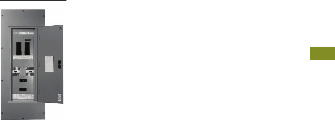
Volume 12—Aftermarket, Renewal Parts and Life Extension Solutions CA08100014E—November 2013 www.eaton.com V12-T4-1
1
2
3
4
5
6
7
8
9
10
11
12
13
14
15
16
17
18
19
20
21
22
23
24
25
Panelboards
Westinghouse PRL3
4 Panelboards
Product Description . . . . . . . . . . . . . . . . . . . . . . . . . . . . . . . . . . . . . . V12-T4-2
Product History . . . . . . . . . . . . . . . . . . . . . . . . . . . . . . . . . . . . . . . . . . V12-T4-2
Product History Time Line. . . . . . . . . . . . . . . . . . . . . . . . . . . . . . . . . . V12-T4-3
Replacement Capabilities . . . . . . . . . . . . . . . . . . . . . . . . . . . . . . . . . . V12-T4-4
CDP . . . . . . . . . . . . . . . . . . . . . . . . . . . . . . . . . . . . . . . . . . . . . . . . V12-T4-9
FDP. . . . . . . . . . . . . . . . . . . . . . . . . . . . . . . . . . . . . . . . . . . . . . . . . V12-T4-10
PB/PH/PH-L . . . . . . . . . . . . . . . . . . . . . . . . . . . . . . . . . . . . . . . . . . V12-T4-11
MP40 . . . . . . . . . . . . . . . . . . . . . . . . . . . . . . . . . . . . . . . . . . . . . . . V12-T4-12
EE . . . . . . . . . . . . . . . . . . . . . . . . . . . . . . . . . . . . . . . . . . . . . . . . . . V12-T4-13
EP . . . . . . . . . . . . . . . . . . . . . . . . . . . . . . . . . . . . . . . . . . . . . . . . . . V12-T4-14
PRL1 and PRL2 Panelboards . . . . . . . . . . . . . . . . . . . . . . . . . . . . . V12-T4-15
PRL1a and PRL2a Panelboards. . . . . . . . . . . . . . . . . . . . . . . . . . . . V12-T4-15
PRL3 . . . . . . . . . . . . . . . . . . . . . . . . . . . . . . . . . . . . . . . . . . . . . . . . V12-T4-16
PRL3a . . . . . . . . . . . . . . . . . . . . . . . . . . . . . . . . . . . . . . . . . . . . . . . V12-T4-17
PRL4B. . . . . . . . . . . . . . . . . . . . . . . . . . . . . . . . . . . . . . . . . . . . . . . V12-T4-18
PRL4F . . . . . . . . . . . . . . . . . . . . . . . . . . . . . . . . . . . . . . . . . . . . . . . V12-T4-19
Technology Upgrades . . . . . . . . . . . . . . . . . . . . . . . . . . . . . . . . . . . . . V12-T4-20
Surge Protection Device—SPD Series . . . . . . . . . . . . . . . . . . . . . . V12-T4-20
Pow-R-Command . . . . . . . . . . . . . . . . . . . . . . . . . . . . . . . . . . . . . . V12-T4-20
Panelboard Retrofits . . . . . . . . . . . . . . . . . . . . . . . . . . . . . . . . . . . . . . V12-T4-21
Pow-R-Line 1R and 2R Renovation Panel . . . . . . . . . . . . . . . . . . . . . . V12-T4-21
Product Support Services—Satellite Locations . . . . . . . . . . . . . . . . . . V12-T4-22
Further Information . . . . . . . . . . . . . . . . . . . . . . . . . . . . . . . . . . . . . . . V12-T4-22
Pricing Information . . . . . . . . . . . . . . . . . . . . . . . . . . . . . . . . . . . . . . . V12-T4-22
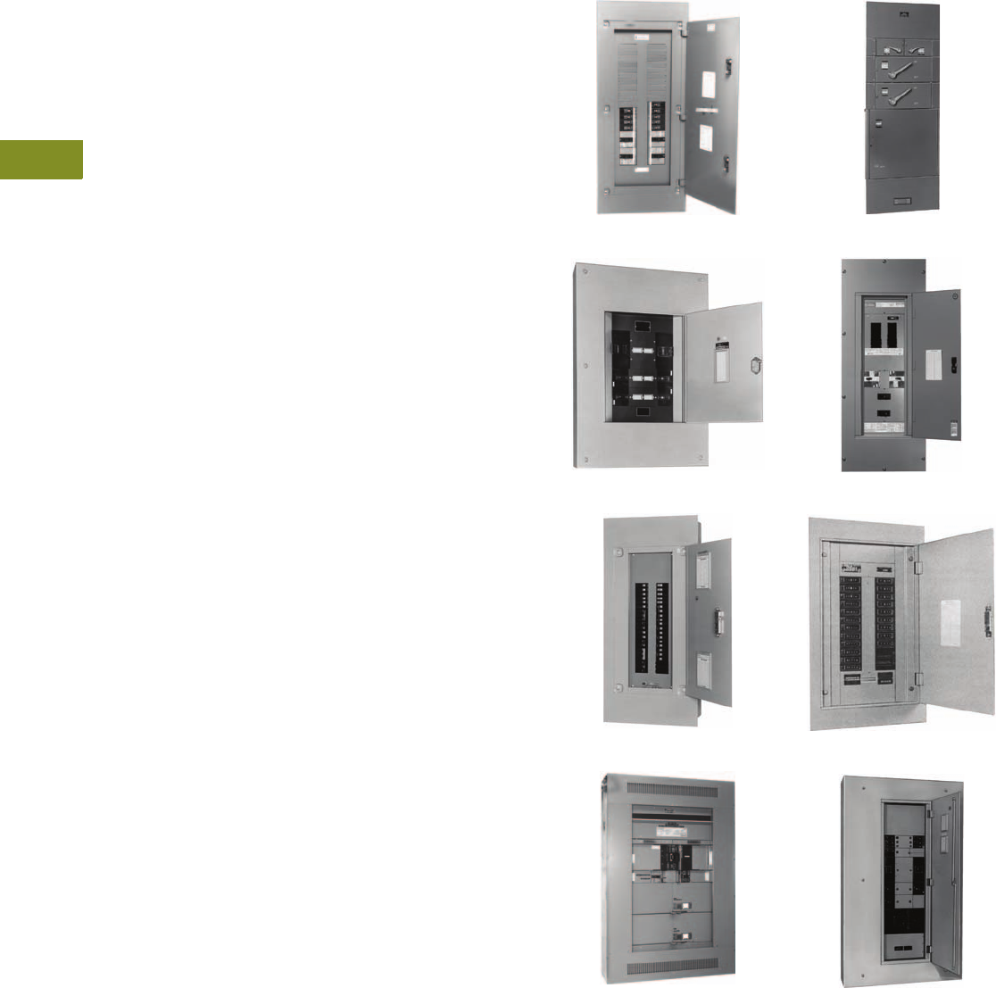
V12-T4-2 Volume 12—Aftermarket, Renewal Parts and Life Extension Solutions CA08100014E—November 2013 www.eaton.com
1
2
3
4
5
6
7
8
9
10
11
12
13
14
15
16
17
18
19
20
21
22
23
24
25
4
Panelboards
Product Description
Panelboards and switchboards
are enclosed assemblies for
lighting and distribution that
accept incoming power and
consist of a series of circuit
breakers and/or fusible
switches. These devices
protect each circuit by
providing overcurrent and
short-circuit protection.
Product History
In 1994, Eaton acquired
the Distribution and Control
Business Unit (DCBU) of
Westinghouse and integrated
it with their Cutler-Hammer®
business unit forming a
powerful new combination.
This product history tracks the
evolution of panelboard and
switchboard products for
both manufacturers.
In the 1920s, prior to the
development of circuit
breakers, Westinghouse
sold panelboards designed
for main and branch circuit
fuses. Circuit breakers were
first introduced in 1927 and
put Westinghouse in the
forefront of circuit breaker
technology. A few years later
the first Westinghouse
“NOFUSE” circuit
breakers
were introduced. “NOFUSE”
panelboards were initially
available in ratings up to 225A
at 250V. Panelboards were
designed at higher ratings as
circuit breakers’ ratings
became available. By 1958,
panelboards were available at
ratings up to 800A and 600V.
The most significant
panelboard types were the
CDP and FDP panels. For
more than 34 years, these
two types encompassed
most Westinghouse molded-
case circuit breakers and
fusible switches.
In 1962, Eaton’s electrical
business entered the
panelboard and switchboard
market with the purchase of
Mullenbach. Soon after the
Mullenbach acquisition,
Cutler-Hammer entered
into an agreement with
Westinghouse to supply
breakers and fusible
devices for panelboards
and switchboards, and Eaton
also began manufacturing
Westinghouse-type
panelboards under the
agreement. This relationship
made in the early 1960s
provided users of both trade
name products access to
aftermarket service for
add-on branch devices and
hardware. Classic Cutler-
Hammer panelboards and
switchboards were designed
and listed for use with
Westinghouse breakers.
In 1988, Westinghouse
redesigned the panelboard
and switchboard line
to incorporate the new
Series C® design breakers.
This new design became
a true family of products.
These new panelboards and
switchboards became today’s
Pow-R-Line® family, which
are manufactured in state-of-
the-art facilities strategically
located throughout the
United States.
Eaton’s unique Satellite
Plants support aftermarket
services for all current
Pow-R-Line panelboard
and switchboard products.
Aftermarket service for out-
of-production panelboards
and switchboards for both
the classic Westinghouse
and Cutler-Hammer
designs is supported
by the Aftermarket
Center in Sumter, SC,
(see Page V12-T4-22), and
is staffed with experienced
and knowledgeable
representatives.
Cutler-Hammer NFB
Cutler-Hammer MP40
Cutler-Hammer CHB
Cutler-Hammer EE
Westinghouse FDP
Westinghouse Pow-R-Line 3
Westinghouse WEB
Westinghouse CDP
Volume 12—Aftermarket, Renewal Parts and Life Extension Solutions CA08100014E—November 2013 www.eaton.com V12-T4-3
1
2
3
4
5
6
7
8
9
10
11
12
13
14
15
16
17
18
19
20
21
22
23
24
25
4
Panelboards
Product History Time Line
Westinghouse A2B
Westinghouse NM/NMM
Westinghouse NA1B
Westinghouse NLAB
Westinghouse NAB
Westinghouse ABH
Westinghouse NDP
Cutler-Hammer CDP
Westinghouse CDP/FDP
Westinghouse NQB/NQC/NQP
Westinghouse NEB/NHEB
Westinghouse WCA/WEB/WEHB/
WFB/WGB/WGHB
Cutler-Hammer CHP/CHB
Cutler-Hammer NFB
Cutler-Hammer MP40/MP100
Westinghouse B10B/Q10P
Cutler-Hammer PB
Cutler-Hammer PH
Cutler-Hammer EE
Westinghouse W10B/W10P
Cutler-Hammer EP
Westinghouse PRL3
Westinghouse PRL1, PRL2
Cutler-Hammer PRL1a, 2a
Cutler-Hammer PRL3a
Westinghouse PRL4B, F
Cutler-Hammer PRL5P
ProductPage 1935 1940 1945 1950 1955 1960 1965 1970 1975 1980 1985 1990 1995 2000 Present
V12-T4-7
V12-T4-7
V12-T4-7
V12-T4-7
V12-T4-7
V12-T4-7
V12-T4-4
V12-T4-7
V12-T4-7
V12-T4-7
V12-T4-7
V12-T4-4
V12-T4-4
V12-T4-5
V12-T4-7
V12-T4-5
V12-T4-5
V12-T4-6
V12-T4-7
V12-T4-6
V12-T4-8
V12-T4-8
V12-T4-8
V12-T4-8
V12-T4-8
V12-T4-5

V12-T4-4 Volume 12—Aftermarket, Renewal Parts and Life Extension Solutions CA08100014E—November 2013 www.eaton.com
1
2
3
4
5
6
7
8
9
10
11
12
13
14
15
16
17
18
19
20
21
22
23
24
25
4
Panelboards
Replacement Capabilities
Replacement
Capabilities
How to Select
Replacement Breakers
A complete line of new,
UL® Listed products,
physically and electrically
interchangeable molded-
case circuit breakers is
offered by Eaton.
To properly select the
breaker for your existing
panelboard:
1. Identify the panel
type and the existing
branch breaker.
2. Select the appropriate
breaker from the direct
replacement solution
column. As shown, three
options are available.
Option 1: Series C
breakers are available as
direct replacement for
installation in Cutler-
Hammer panelboards.
They are available at
your local distributors
and are the most
economical solution.
Option 2: Original,
but still-in-production
breakers, (sometimes
referred to as replace-
ment breakers) are
available from Eaton
national warehouses.
These are identical
to the existing
branch breakers.
Option 3: Panelboard
replacement breakers,
available for out-of-
production molded-
case breakers, are
physically and electrically
interchangeable with
the existing breaker.
Available in three-pole
only. Refer to Pages
V12-T3-80 through
V12-T3-87 for further
information.
3. For additional information,
contact Avery Creek, NC,
Technical Resource
Center at 1-800-356-1243
or your local Eaton
Satellite plant.
Original Cutler-Hammer Panelboard Breaker Replacement Chart
Notes
1New breakers that are a direct physical and electrical replacement for out-of-production breakers. Available in three-pole only.
See Pages V12-T3-80 through V12-T3-87 for further information.
2Connectors not available.
3Not rated for 100% rated breakers.
Cutler-Hammer
Panelboard Type
Original Branch
Circuit Breaker
Replacement Solutions
New
Panelboard Type
New
Breaker
Panelboard
Replacement Breaker 1
CHP 2CH PRL1a CH —
CHB 2 CHB PRL1a CHB —
NPLAB 2PPRL1a— —
NLAB 2QL PRL1a — —
NA1B 2E PRL3a — REH
EA PRL3a — REH
NH1B 2EH PRL3a — REH
NDP 2 E PRL3a — REH
EA PRL3a — REH
HNDP 2EH PRL3a — REH
NFB EB PRL3a or PRL4B EHD —
EHB PRL3a or PRL4B EHD —
EHC PRL3a or PRL4B FD —
EC PRL3a or PRL4B EHD —
CA PRL3a or PRL4B CA —
CC PRL3a or PRL4B CC —
FB PRL3a or PRL4B FD —
HFB PRL3a or PRL4B FD —
FD PRL3a or PRL4B FD —
FC PRL3a or PRL4B FD —
FH PRL3a or PRL4B HFD —
FS PRL3a or PRL4B FD —
HFC PRL3a or PRL4B HFD —
CCH PRL3a or PRL4B — —
CHH PRL3a or PRL4B CHH —
CDP 3 E PRL4B — REH
EA PRL4B — REH
EH PRL4B — REH
EB PRL4B EHD —
EHB PRL4B EHD —
F PRL4B — RHF
FA PRL4B — RHFA
HF PRL4B — RHF
HFA PRL4B — RHFA
FB PRL4B FDB —
HFB PRL4B FD —
CA PRL4B CA —
DA PRL4B DK —
JA PRL4B KDB —
KA PRL4B KD —
HKA PRL4B HKD —
HK PRL4B — RHK
HKL PRL4B — RHKL
LA PRL4B LD —
HLA PRL4B LD —
LAB PRL4B LDB —
LM PRL4B — RHLM
HLM PRL4B — RHLM
MA PRL4B MDL —
HMA PRL4B MDL —
NB PRL4B ND —
HNB PRL4B ND —
CC PRL4B CC —
CCH PRL4B — —
CHH PRL4B CHH —

Volume 12—Aftermarket, Renewal Parts and Life Extension Solutions CA08100014E—November 2013 www.eaton.com V12-T4-5
1
2
3
4
5
6
7
8
9
10
11
12
13
14
15
16
17
18
19
20
21
22
23
24
25
4
Panelboards
Replacement Capabilities
Original Cutler-Hammer Panelboard Breaker
Replacement Chart, continued
Notes
1See also Page V12-T4-12.
2See also Page V12-T4-11.
3Connectors not available.
Cutler-Hammer
Panelboard Type
Original Branch
Circuit Breaker
Replacement Solutions
New
Panelboard Type
New
Breaker
MP40 1 CC PRL4B ED
CCH PRL4B —
CHH PRL4B ED
EB PRL4B EHD
EHB PRL4B EHD
EC PRL4B EHD
EHC PRL4B FD
FB PRL4B FDB
HFB PRL4B FD
FC PRL4B FDB
HFC PRL4B HFD
FH PRL4B HFD
FS PRL4B FD
JA PRL4B KDB
JB PRL4B JB
JS PRL4B HJD
JH PRL4B HJD
JH PRL4B HJD
JL PRL4B JDC
KA PRL4B KD
KB PRL4B JD
HKB PRL4B JD
KS-D PRL4B KD
KH-D PRL4B KD
DA PRL4B DK
LA PRL4B LD
HLA PRL4B LD
HLA PRL4B LD
LAB PRL4B LDB
LB PRL4B KD
LBB PRL4B KDB
HLB PRL4B KD
Cutler-Hammer
Panelboard Type
Original Branch
Circuit Breaker
Replacement Solutions
New
Panelboard Type
New
Breaker
MP40 1 LC PRL4B LD
LS (A) PRL4B LD
LH (A) PRL4B HLD
MA PRL4B MDL
HMA PRL4B MDL
MC PRL4B MDL
HMC PRL4B MDL
MS PRL4B MDL
MH PRL4B MDL
NB PRL4B ND
HNB PRL4B ND
NC PRL4B ND
HNC PRL4B ND
NS PRL4B ND
NH PRL4B ND
MP100 M50
Fusible switch
PRL4F M50
Fusible switch
PH 2 CH PRL3a CH
CHB PRL3a CHB
CC PRL3a CC
CCH PRL3a CCH
CHH PRL3a CHH
EB PRL3a EHD
EHB PRL3a EHD
EC PRL3a EHD
EC PRL3a EHD
EHD PRL3a EHD
FC PRL3a FD
FS PRL3a FD
FH PRL3a HFD
FD PRL3a FD
PB 23 CH PRL1a CH
CHB PRL1a CHB

V12-T4-6 Volume 12—Aftermarket, Renewal Parts and Life Extension Solutions CA08100014E—November 2013 www.eaton.com
1
2
3
4
5
6
7
8
9
10
11
12
13
14
15
16
17
18
19
20
21
22
23
24
25
4
Panelboards
Replacement Capabilities
Plug-In Power Panelboards and Switchboards
Notes
1Not rated for 100% rated breakers.
2See also Page V12-T4-13.
3See also Page V12-T4-14.
Cutler-Hammer
Panelboard Type
Original Branch
Circuit Breaker
Replacement Solutions
New
Panelboard Type
New
Breaker
EE 12 FS PRL5P FD
FH PRL5P HFD
FL PRL5P HDC
JS PRL5P JD
JH PRL5P HJD
JL PRL5P JDC
KS PRL5P KD
KH PRL5P HKD
LS PRL5P LD
LS(A) PRL5P LD
LS(E) PRL5P LD
LH(B) PRL5P HLD
LH(A) PRL5P HLD
LL(E) PRL5P LDC
LS(B) PRL5P LD
LH(E) PRL5P HLD
MS PRL5P MDL
NS PRL5P ND
MH PRL5P —
CC PRL5P CC
CCH PRL5P —
CHH PRL5P CHH
Cutler-Hammer
Panelboard Type
Original Branch
Circuit Breaker
Replacement Solutions
New
Panelboard Type
New
Breaker
EP 13 FS PRL5P FD
FH PRL5P HFD
FL PRL5P FDC
JS PRL5P JD
JH PRL5P HJD
JL PRL5P JDC
KS PRL5P KD
KH PRL5P HKD
LS PRL5P LD
LS(A) PRL5P LD
LS(E) PRL5P LD
LH(B) PRL5P HLD
LH(A) PRL5P HLD
LL(E) PRL5P LDC
LS(B) PRL5P LD
LH(E) PRL5P HLD
MS PRL5P MDL
NS PRL5P ND
MH PRL5P —
NH PRL5P HND
CC PRL5P CC
CCH PRL5P —
CHH PRL5P CHH

Volume 12—Aftermarket, Renewal Parts and Life Extension Solutions CA08100014E—November 2013 www.eaton.com V12-T4-7
1
2
3
4
5
6
7
8
9
10
11
12
13
14
15
16
17
18
19
20
21
22
23
24
25
4
Panelboards
Replacement Capabilities
Original Westinghouse Panelboard Breaker Replacement Chart
Notes
1Not rated for 100% rated breakers.
Available in three-pole only. See
Pages V12-T3-80 through V12-T3-87
for further information.
2Connectors not available.
3See also Page V12-T4-9.
4Only breakers of the same frame size
can be installed across from each other
(i.e., in the same horizontal plane).
For other configurations, contact the
Aftermarket Center in Sumter, SC
(see Page V12-T4-22).
5Contact your local Eaton Field Sales office.
6KD breakers can be mounted across from
LB breakers if a TAD3 line side adapter
is used. All hardware works with
this configuration.
7See also Page V12-T4-10.
Westinghouse
Panelboard Type
Existing Branch
Circuit Breaker
Replacement Solutions
New Panelboard Type New Breaker Panelboard Replacement Breaker 1
Panelboards Manufactured Between 1937 and 1988
ABH 2 E PRL3a — REH
A2B 2 E PRL3a — REH
B10B 2 BA PRL1a BAB —
B10B-LX 2 BA PRL1aLX BAB —
B10B-LXX 2 BA PRL1aLX BAB —
B65B 2 HBA PRL1a — HBAW, HBAX
CDP/HCDP 23 E, EA, EH, F, FA PRL4B — REH, RHF, RHFA
CDP/HCDP 34 EB, EHB, EHD, FB, HFB, FDB, FD, HFD, FDC PRL4B EHD, FDB, FD, HFD, FDC 5
FB-P TRI-PAC PRL4B FB-P TRI-PAC 5
JB, KB, HKB, JDB, JD, HJD, JDC PRL4B JDB, JD, HJD, JDC 5
CA, CAH, HCA PRL4B ED, EDH, EDC 5
DA, LB, LBB, HLB 6PRL4B 65
JA, KA, HKA, DK, KD, HKD, KDC PRL4B DK, KD, HKD, KDC 5
LA, LAB, HLA (400A) PRL4B LD, HLD 5
LA-P TRI-PAC PRL4B LA-P TRI-PAC 5
LA, LC, HLA (600A) PRL4B LD, HLD, LDC 5
MA, HMA, MC, HMC PRL4B MDL 5
LCL PRL4B LCL 5
NB, HNB, NC, HNC PRL4B ND, HND 5
NB-P TRI-PAC®PRL4B NB-P TRI-PAC 5
FDP 7 Fusible switches PRL4F — Fusible switches
H10P 2 HQP PRL2a HQP —
H10B 2 BA PRL2a BAB —
NAB 2 E PRL3a — REH
NA1B 2 E PRL3a — REH
NDP 2 E, EA, EAH PRL3a — REH
NEB 2 EA PRL3a — REH
NHDP 2 EH PRL3a — REH
NHEB 2 EH, FA PRL3a — REH, RHFA
NH1B 2 E-277 PRL2a — REH
NLAB 2 QC PRL1a — —
NLAB-LX 2 QC PRL1aLX — —
NLAB-AB 2 QC PRL3a — —
NLAB-ABH 2 QC PRL3a — —
NPLAB 2 QP PRL1a HQP —
NPLAPQ 2 QP PRL1a HQP —
NQC 2 QC PRL1a — —
NQB 2 BA PRL1a BAB —
NQP 2 QP PRL1a HQP —
Q10P 2 QP PRL1a HQP —
Q22P 2 QPH PRL1a QPHW —
Q22B 2 QBH PRL1a QBHW —
Q65P 2 HP PRL2a QHPW —
W10B 2 BA PRL1a BAB —
W10P 2 HQP PRL1a HQP —
W22B 2 QBH PRL1a QBHW —
W22P 2 QPH PRL1a QPHW —
WCA CA PRL3a CA —
WEB EB PRL3a EB, EHD —
WEHB EHB PRL3a EHB, EHD —
WFB FB PRL3a FB, FDB —
WGB 2 GB PRL2a GB —
WGHB 2 GHB PRL2a GHB —

V12-T4-8 Volume 12—Aftermarket, Renewal Parts and Life Extension Solutions CA08100014E—November 2013 www.eaton.com
1
2
3
4
5
6
7
8
9
10
11
12
13
14
15
16
17
18
19
20
21
22
23
24
25
4
Panelboards
Replacement Capabilities
Original Westinghouse Panelboard Breaker Replacement Chart, continued
Notes
1See also Page V12-T4-15.
2See also Page V12-T4-16.
3See also Page V12-T4-17.
4See also Page V12-T4-18.
5See also Page V12-T4-19.
6400A, 600A, 800A, 1200A, FDP connectors are NOT compatible with FDPW switches.
Westinghouse
Panelboard Type
Original Branch
Circuit Breaker
Replacement Solutions
New Panelboard Type New Breaker Panelboard Replacement Breaker
Panelboards Manufactured After 1988
PRL1 1BAB, QBHW PRL1a 1BAB, QBHW —
HQP, QPHW PRL1a 1BAB, QBHW —
PRL2 1GB, GHB, GHBS PRL2a 1GB, GHB, GHBS-D —
PRL3 2BAB, QBH PRL3a 3BAB, QBHW —
GB, GHB, GHBS PRL3a 3GB, GHB, GHBS-D —
EHD, FD, FDB, HFD, FDC PRL3a 3EHD, FD, FDB, HFD, FDC —
ED, EDH, EDC PRL3a 3ED, EDH, EDC —
CA, HCA, CAH PRL3a 3ED —
PRL4B 4EHD, FD, FDB, HFD, FDC PRL4B EHD, FD, FDB, HFD, FDC —
ED, EDH, EDC PRL4B ED, EDH, EDC —
CA, CAH, HCA PRL4B CA, CAH, HCA —
FCL, FB-P, FDB/LFB PRL4B FCL, FB-P, FDB/LFB —
JD, JDB, HJD, JDC PRL4B JD, JDB, HJD, JDC —
DK, KDB, KD, HKD, KDC PRL4B DK, KDB, KD, HKD, KDC —
LCL PRL4B LCL —
LA-P TRI-PAC PRL4B LA-P TRI-PAC —
LC, HLC, LA, HLA PRL4B LC, HLC, LA, HLA —
LD, HLD, LDC, MD, MDS, ND, HND, NDC PRL4B LD, HLD, LDC, MDL, ND, HND, NDC —
MC, HMC, MA, HMA PRL4B MC, HMC, MA, HMA —
NC, HNC, NB, HNB PRL4B NC, HNC, NB, HNB —
NB-P TRI-PAC PRL4B NB-P TRI-PAC —
BAB, QBGF, QBHW, QBHGF, GB, GHB PRL4B BAB, QBGF, QBHW, QBHGF, GB, GHB —
PRL4F 5Fusible switches 6PRL4F — Fusible switches
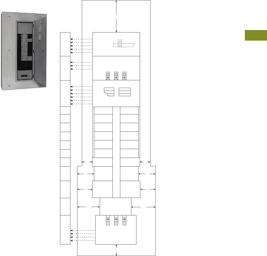
Volume 12—Aftermarket, Renewal Parts and Life Extension Solutions CA08100014E—November 2013 www.eaton.com V12-T4-9
1
2
3
4
5
6
7
8
9
10
11
12
13
14
15
16
17
18
19
20
21
22
23
24
25
4
Panelboards
Replacement Capabilities
CDP
Originally a
Westinghouse Product
Westinghouse CDP
The panel layouts shown on
this and the following pages
will aid in determining the
space available for the
addition of molded-case
circuit breakers into your
existing CDP panelboards.
●Determine the amount
of space available in the
panelboard for adding
circuit breakers.
1.38 inches (35.1 mm)
of panel height =
one X space
●Determine the type of
breaker needed for the
required ampere rating
and number of poles
Ratings
●1600A maximum
Replacement Capabilities
Breakers
Refer to renewal parts
data RP01400002E
for a
complete list of available
parts including branch device
retrofit kits, which include
the device, as well as, the
bus connectors and the
required mounting hardware.
Contact the Aftermarket
Center in Sumter, SC
(see Page V12-T4-22).
CDP Panel Layout
Notes
1When only one EB, EHB or HFB single-pole breaker is required in conjunction with other
frame size breakers, the single-pole breaker space required changes from 1X to 2X.
2Must use three-pole connector kit.
7-1/2"
Solid Neutral Bar
5X
7X
9X
13X
13X
225A
400A
600A
800A
1200, 1600A
Thru-Feed Lugs
225A
250–400A
600, 800A
10X
13X
17X
Total Number of Poles
12
18
24
30
36
42
13X
15X
17X
19X
21X
23X
30" Wide Box
1X
2X
2X
3X
3X
3X
3X
4X
6X
6X
5" 5"
9" 9"
8" 8"
11" 11"
5X
7X
9X
12X
225A
250–400A
600A
800, 1200, 1600A
7-1/2"
Main Lug
Section
2- or 3-Pole
MC, HMC
LCL
NC, HNC
2- or 3-Pole
LC, HLC
LA
2- or 3-Pole
LC, HLC
LA
2- or 3-Pole
DA
LBB, LB
HLB
2- or 3-Pole
DA
LBB, LB
HLB
2- or 3-Pole
JB, KB, HKB
2- or 3-Pole
JB, KB, HKB
3-Pole
CA, CAH
3-Pole
CA, CAH
2-Pole
CA, CAH
2-Pole
CA, CAH
2- and 3-Pole
HFB
3-Pole EB
EHB, FB
3-Pole
EHB, FB
2-Pole EB
EHB, FB
2-Pole EB
EHB, FB
1-Pole EB
EHB, HFB
1-Pole EB
EHB, HFB
/
2- and 3-Pole
HFB
30" Wide Box
0
48" Wide Box
48" Wide Box
One X space = 1.38 inches (35.1 mm).
Blank llers are required for unused X space.
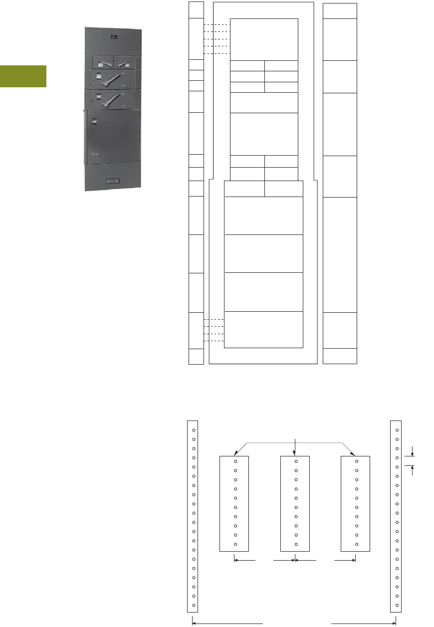
V12-T4-10 Volume 12—Aftermarket, Renewal Parts and Life Extension Solutions CA08100014E—November 2013 www.eaton.com
1
2
3
4
5
6
7
8
9
10
11
12
13
14
15
16
17
18
19
20
21
22
23
24
25
4
Panelboards
Replacement Capabilities
FDP
Originally a
Westinghouse Product
Westinghouse FDP
The panel layouts shown
on this and the following
pages will aid in determining
the space available for the
addition of fusible switches
into your existing FDP
panelboards.
●Determine the amount
of space available in the
panelboard for adding
fusible switches.
1.38 inches (35.1 mm)
of panel height =
one X space
●Determine the type of
fusible switch needed for
the required ampere rating
and number of poles
Ratings
●1600A maximum
Replacement Capabilities
Fusible Switches
Refer to renewal parts
data RP01400002E
for a
complete list of available
parts including branch device
retrofit kits, which include
the device, as well as, the
bus connectors and the
required mounting hardware.
Contact the Aftermarket
Center in Sumter, SC
(see Page V12-T4-22).
FDP Panel Layout
FDP and CDP Bus Dimensions
Top Gutter
5X
7X
9X
13X
13X
225A
400A
600A
800A
1200, 1600A
225A
250–400A
600A
800, 1200, 1600A
5X
8X
9X
12X
7-1/2"
4X
4X
4X
Solid
Neutral
Bar
5X
30A
60A
100A
30A
60A
100A
100A
2P, 3P
240 Vac
2P
250 Vdc
Side Gutters Tables F and G
2P, 3P
240V or
600 Vac
2P
250 Vdc
6X
Main or Branch
200A
(Horizontal Mounted)
2P, 3P
600 Vac
30A
60A
30A
60A
100A 10 0A
2P, 3P
240 or
600 Vac
2P
250 Vdc
Side Gutters Tables B and C
Main or Branch
400 or 600A
(Horizontal Mounted)
Main or Branch
800 or 1200A
(Horizontal Mounted)
Main or Branch
800 or 1200A
(Vertical Mounted)
4X
4X
5X
11X
16X
21X
Main Lug
Section
Bottom Gutter
7-1/2"
One X space = 1.38 inches (35.1 mm).
Blank llers are required for unused X space.
Vertical Busbar
1.38" TYP.
3.50"3.50"
Mounting Rails 19.50"
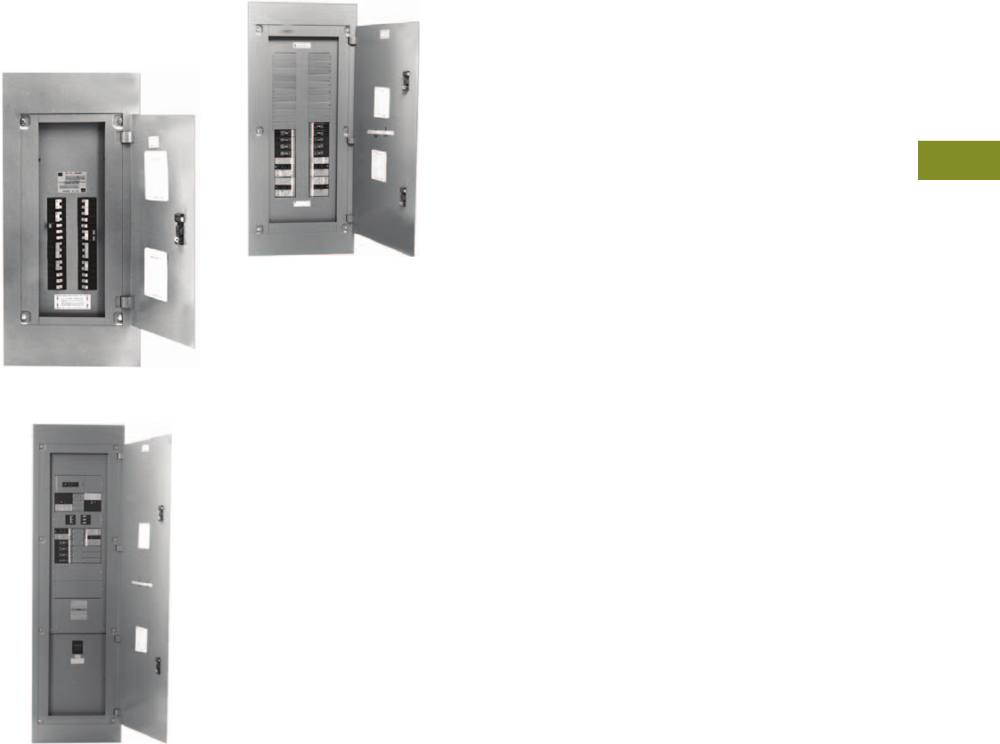
Volume 12—Aftermarket, Renewal Parts and Life Extension Solutions CA08100014E—November 2013 www.eaton.com V12-T4-11
1
2
3
4
5
6
7
8
9
10
11
12
13
14
15
16
17
18
19
20
21
22
23
24
25
4
Panelboards
Replacement Capabilities
PB/PH/PH-L
Originally a
Cutler-Hammer Product
15 or 21 Inches Wide
Cutler-Hammer PB
21 or 26 Inches Wide
Cutler-Hammer PH
21 Inches Wide
Cutler-Hammer PH-L
Ratings
●PB
400A maximum
●PH
800A main lug only or
600A main breaker
●PH-L
225A maximum
Replacement Capabilities
Breakers
Refer to renewal parts
data RP01400003E for a
complete list of available
parts including branch device
retrofit kits, which include
the device, as well as, the
bus connectors and the
required mounting hardware.
Contact the Aftermarket
Center in Sumter, SC
(see Page V12-T4-22).
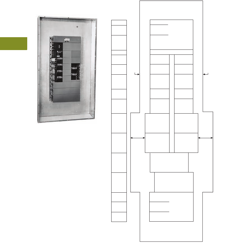
V12-T4-12 Volume 12—Aftermarket, Renewal Parts and Life Extension Solutions CA08100014E—November 2013 www.eaton.com
1
2
3
4
5
6
7
8
9
10
11
12
13
14
15
16
17
18
19
20
21
22
23
24
25
4
Panelboards
Replacement Capabilities
MP40
Originally a
Cutler-Hammer Product
Cutler-Hammer MP40
The panel layouts shown on
this and the following pages
will aid in determining the
space available for the
addition of molded-case
circuit breakers into your
existing MP40 panelboards.
●Determine the amount
of space available in the
panelboard for adding
circuit breakers.
1.38 inches (35.1 mm)
of panel height =
one X space
●Determine the type of
breakers needed for the
required ampere rating
and number of poles
Ratings
●1600A maximum
Replacement Capabilities
Breakers
Refer to renewal parts data
RP01400003E for a complete
list of available parts
including branch device
retrofit kits, which include
the device, as well as, the
bus connectors and the
required mounting hardware.
Contact the Aftermarket
Center in Sumter, SC
(see Page V12-T4-22).
MP40 Panel Layout
Notes
1If the panelboard has a main breaker, no neutral, no split bus, or no sub-feed or feed-through
lugs, add 1X to provide space for a nameplate.
2Breakers of the same frame size, regardless of poles, may be mounted opposite of each other.
3Only Type NC and HNC breakers require a 11.38-inch (289.1 mm) deep box. Standard box
depth is 10.50 inches (266.7 mm).
4When 1600A lug mains are for (4)–600 kcmil maximum copper cables per phase, the X unit
space can be reduced to 4X.
Top Gutter
6.50" through 400A
12.0" 600–1600A
None
225–
1200A
1600A
Neutral
Nameplate
/
1P EB
EHB, HFB
1P EB
EHB, HFB
2P EC
EHC, FC
2P EC
EHC, FC
3P EC, EMC,
FC, 2P or
3P HFB
3P EC, EMC,
FC, 2P or
3P HFB
2P CC
CCH
5" Side Gutters
5" Side Gutters
0
0
0
3P CC, CCH,
2P or 3P
JB, KB, HKB
2P or 3P
DA, LBB,
LB, HLB
2P or 3P
LA, HLA,
LC, HLC
This space is
not usable
when C.B. to
left is used
as a main
0
8-1/2" 8-1/2"
2P or 3P
MC, HMC
2P or 3P
NC, HNC
1
Main
Lugs
225,
600A
800,
1200A
1600A
2
Bottom Gutter
6.50" up through 400A
12.0" 600–1600A
26" Wide
9X
4X
3X
6X
6X
6X
4X
3X
3X
2X
2X
1X
7X
4X
0X
1X
26" Wide
38" Wide
38" Wide
30" Wide
30" Wide
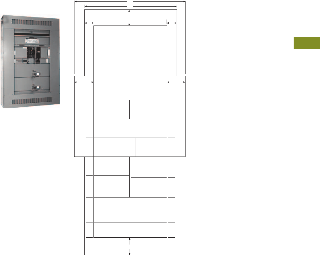
Volume 12—Aftermarket, Renewal Parts and Life Extension Solutions CA08100014E—November 2013 www.eaton.com V12-T4-13
1
2
3
4
5
6
7
8
9
10
11
12
13
14
15
16
17
18
19
20
21
22
23
24
25
4
Panelboards
Replacement Capabilities
EE
Originally a
Cutler-Hammer Product
Cutler-Hammer EE Panelboard
The panel layouts shown on
this and the following pages
will aid in determining the
space available for the
addition of molded-case
circuit breakers and fusible
switches into your existing
EE panelboards.
●Determine the amount
of space available in the
panelboard for adding
replacement devices.
1.38 inches (35.1 mm)
of panel height =
one X space
●Determine the type of
replacement device
needed for the required
ampere rating and number
of poles
Ratings
●1200A maximum
Replacement Capabilities
Breakers and
Fusible Switches
Refer to renewal parts data
RP01400003E for a complete
list of available parts
including branch device
retrofit kits, which include
the device, as well as, the
bus connectors and the
required mounting hardware.
Contact the Aftermarket
Center in Sumter, SC
(see Page V12-T4-22).
EE Panelboard Panel Layout
Notes
1Main device must be mounted at neutral end of double-bus panel.
2May be used in 30.00-inch (762.0 mm) wide single bus interiors.
Neutral—No X Space
(May Be At Bottom)
48"
42"
7" 7"
10" Gutter
10X 10X
20X
400–600A Main Switch
400–600A Branch Switch
10X 10X
7X 7X
10"10"
14X
1200A Lug Unit
/
200A Branch Switch
(600V With R Fusing)
20X
800A Main Switch
/
800A Branch Switch
8X 8X
6X 6X
6X 6X
600A
Branch
Lug Unit
600A
Branch
Lug Unit
12X
MS, MH Main Breaker
/
NS, NH Main Breaker
LS, LH
0
Breaker
LS, LH
0
Breaker
6X 6X
6X 5X
3X 3X
4X 4X
7X 8X
200A Branch
0
Switch
240V—R&T Fuse
600V—T-Fuse Only
400A
Branch
Lug Unit
100A
0
Branch
Switch
KS, KH
0
Breaker
KS, KH
0
Breaker
30A, 60A
Branch
Switch
CC, CCH, CHH
0
FS, FH, JS, JH, JL
CC, CCH, CHH
0
FS, FH, JS, JH, JL
12X
MS, MH
Main Breaker
10" Gutter
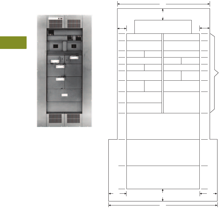
V12-T4-14 Volume 12—Aftermarket, Renewal Parts and Life Extension Solutions CA08100014E—November 2013 www.eaton.com
1
2
3
4
5
6
7
8
9
10
11
12
13
14
15
16
17
18
19
20
21
22
23
24
25
4
Panelboards
Replacement Capabilities
EP
Originally a
Cutler-Hammer Product
Cutler-Hammer EP Panelboard
The panel layouts shown on
this and the following pages
will aid in determining the
space available for the
addition of molded-case
circuit breakers into your
existing EP panelboards.
●Determine the amount
of space available in the
panelboard for adding
circuit breakers.
1.38 inches (35.1 mm)
of panel height =
one X space
●Determine the type of
breaker needed for the
required ampere rating
and number of poles
Ratings
●1200A maximum
Replacement Capabilities
Breakers
Refer to renewal parts data
RP01400003E for a complete
list of available parts
including branch device
retrofit kits, which include
the device, as well as, the
bus connectors and the
required mounting hardware.
Contact the Aftermarket
Center in Sumter, SC
(see Page V12-T4-22).
EP Panelboard Panel Layout
Notes
1Blank wireway fillers are required opposite any dual breaker unit or adapter.
2May be used in 30.00-inch (762.0 mm) wide single bus interiors.
3Main device must be mounted at neutral end of double-bus panel.
Neutral—No X Space
Top or Bottom
42"
2X
7"
10"
2X
2X 2X
2X 2X
3X 3X
2-Pole FS, FH, FL,
CC, CCH, CHH
2-Pole FS, FH, FL,
CC, CCH, CHH
3-Pole FS, FH, FL,
CC, CCH, CHH
3-Pole FS, FH, FL,
CC, CCH, CHH
2P FS, FH,
CC, CCH 2P FS, FH,
CC, CCH
2P FS, FH,
CC, CCH 2P FS, FH,
CC, CCH
Blank Wireway /
Blank Wireway /
Blank Wireway /
Blank Wireway /
Blank Wireway /
2-Pole
CHH 2-Pole
CHH
3-Pole
CHH 3-Pole
CHH
3-Poles
FS, FH,
CC, CHH
2X 2X
3X 3X
3X 3X
3X
6X
3-Poles
FS, FH,
CC, CHH
3 Poles
JS, JH, JL 2-3 Pole
LSB, LHB, LLB, LC
3X
6X6X 12X
800A MS, MH, MC
Main Breaker 1
Filler Plate
6X6X
12X
800A MS, MH, MC, HMC
Branch Breaker
6X6X 12X
1200A NS, NH, NC, HNC
Branch or Main Breaker 1
10" 10"
10"
48"
0
7"
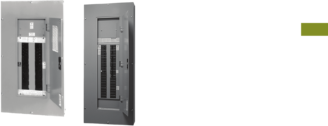
Volume 12—Aftermarket, Renewal Parts and Life Extension Solutions CA08100014E—November 2013 www.eaton.com V12-T4-15
1
2
3
4
5
6
7
8
9
10
11
12
13
14
15
16
17
18
19
20
21
22
23
24
25
4
Panelboards
Replacement Capabilities
PRL1 and PRL2 Panelboards
Originally a
Westinghouse Product
PRL2 with Trim
Ratings
●600A maximum
Replacement Capabilities
Breakers
Refer to renewal parts data
RP01400002E
for a complete
list of available parts including
branch device bus connectors
mounting hardware. For
further information, contact
the Aftermarket Center
in Sumter, SC. Refer to
Page V12-T4-22.
PRL1a and PRL2a
Panelboards
Current Product
PRL1a
Ratings
●400A maximum
Replacement Capabilities
Breakers
Refer to renewal parts
data RP01400001E and
RP01414001E for a complete
list of available parts including
branch device bus connectors
and mounting hardware.
Renewal parts are available
from your Eaton Satellite plant.
Refer to Page V12-T4-22.
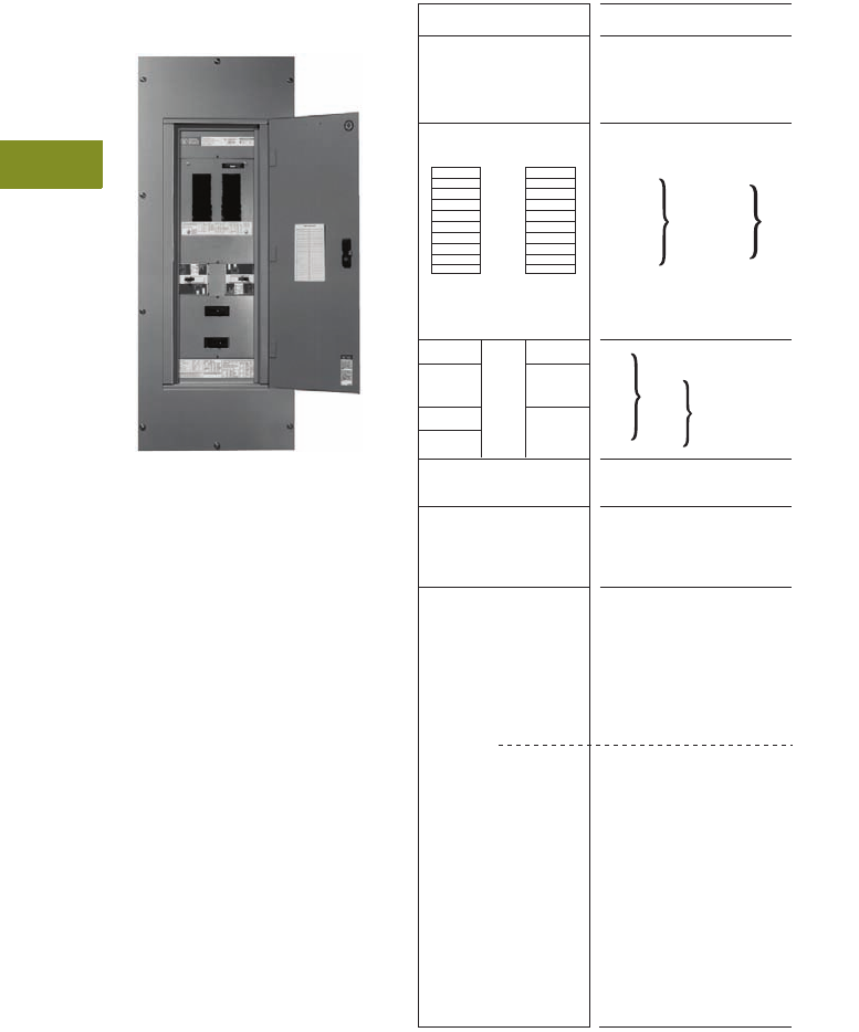
V12-T4-16 Volume 12—Aftermarket, Renewal Parts and Life Extension Solutions CA08100014E—November 2013 www.eaton.com
1
2
3
4
5
6
7
8
9
10
11
12
13
14
15
16
17
18
19
20
21
22
23
24
25
4
Panelboards
Replacement Capabilities
PRL3
Originally a
Westinghouse Product
Westinghouse PRL3
The panel layouts shown on
this and the following pages
will aid in determining the
space available for the
addition of molded-case
circuit breakers into your
existing PRL3 panelboards.
●Determine the amount
of space available in the
panelboard for adding
circuit breakers.
1.38 inches (35.1 mm)
of panel height =
one X space
●Determine the type of
breaker needed for the
required ampere rating
and number of poles
Ratings
●600A maximum
Replacement Capabilities
Breakers
Refer to renewal parts data
RP01400002E for a complete
list of available parts
including branch device
retrofit kits, which include
the device, as well as, the
bus connectors and the
required mounting hardware.
Contact the Aftermarket
Center in Sumter, SC
(see Page V12-T4-22).
PRL3 Panel Layout
Notes
1If panel contains only BAB or QBH branch breakers, use a PRL1 panelboard.
2BAB and QBH breakers with shunt trips require one additional pole space, i.e.; one-pole
is two-pole size, two-pole is three-pole size, and three-pole is four-pole size.
3GB and GHB breakers cannot be mixed on same subchassis as BAB or QBH.
4If panel contains only GB or GHB branch breakers, use a PRL2 panelboard.
5Not recommended for motor loads. Use JD circuit breaker.
6Horizontally mounted 15–150A main breakers EHD, FDB, FD, HFD and FDC will
be furnished as branch breaker construction. Branch breakers one, two or three poles as
required, may be located opposite these main breakers.
7FBP and LAP top mounting only.
8100% rated breaker.
9LCL main breaker requires 6.50-inch (165.1 mm) deep box.
No Neutral
Neutral Section
Sub Chassis
400A Maximum
Bus Rating
2X 100–600A
2X 100, 225A
8X 400, 600A
Poles
10X-12
13X-18
15X-24
17X-30
19X-36
21X-42
BAB/0
QBH/
GB12
GHB12
(100A Max.)
1-Pole
1-Pole
1-Pole
2-Pole
2-Pole
2-Pole
3-Pole
2- and 3-Pole
Main Lug
Section
Horizontal
Mounting
Main
Breaker
Section
Vertically
Mounted
FDB
FD
HFD
FDC
EHD (100A Max.)
1X
2X
3X
3X CA, CAH, HCA 3
(225A Max.)
2X 100, 225A
7X 400, 600A
3X 2P EHD (100A Max.) 4
3X 2P FDB, FD, HFD, FDC 4
(150A Max.)
4X 3P EHD (100A Max.) 4
4X 3P FDB, FD, HFD, FDC
(150A Max.) 4
4X 2P and 3P CA, CAH, HCA 4
(225A Max.)
7X EHD (100A Max.)
7X FDB, FD, HFD, FDC
(150A Max.)
9X CA, CAH
(225A Max.)
9X FCL, FB-P 5
(100A Max.)
14X JD, JDB, HJD, JDC
(250A Max.)
14X DK, KD, KDB, HKD,
KDC (400A Max.)
19X LC, HLC, LA
(600A Max.)
22X LCL 6, LA-P 7
(400A Max.)
(150A Max.)
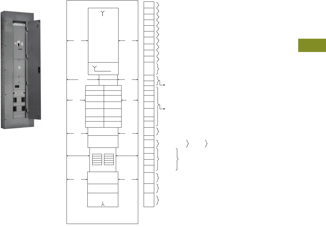
Volume 12—Aftermarket, Renewal Parts and Life Extension Solutions CA08100014E—November 2013 www.eaton.com V12-T4-17
1
2
3
4
5
6
7
8
9
10
11
12
13
14
15
16
17
18
19
20
21
22
23
24
25
4
Panelboards
Replacement Capabilities
PRL3a
Current Product
PRL3a
The panel layouts shown on
this and the following pages
will aid in determining the
space available for the
addition of molded-case
circuit breakers into your
existing PRL3a panelboards.
●Determine the amount
of space available in the
panelboard for adding
circuit breakers.
1.38 inches (35.1 mm)
of panel height =
one X space
●Determine the type of
breaker needed for the
required ampere rating
and number of poles
Ratings
●600A maximum
Replacement Capabilities
Breakers
Refer to renewal parts
data RP01400001E a
nd
RP01414001E for a complete
list of available parts
including branch device
retrofit kits, which include
the device, as well as, the
bus connectors and the
required mounting hardware.
Retrofit kits and renewal
parts are available from
your Eaton Satellite plant.
Refer to Page V12-T4-22.
PRL3a Panel Layout
Main Lugs
10.00" 3.92"
Neutral
2P
3P
2X
2X
2X
5X
5X
5X
6X
6X
8X
8X
8X
10X
10X
11X
3.92" 3.92"
(1)–1P
(2)–1P
(3)–1P
(3)–1P
(1)–1P
(1)–2P
2P
3P
(1)–1P
(2)–1P
(3)–1P
(1)–3P
2P
3P
(1)–3P
4.01" 4.01"
BAB–5.70" BAB–5.70"
GHB–5.68" GHB–5.68"
Split Bus
Meter Loop
ASCO
920
(Split Bus)
QUICKLAG
GHB
Twin
Subfeed
Breaker
Single Subfeed
Breaker
Through Feed
Lugs Size Per MLO Size Chart
Not Available With Subfeed Breaker
Size Per Main Breaker Layout
JD, JDB, HJD, JDC, 250A Max.
Same Cable Size as MLO
Bus Connected
6 Ckt.
12 Ckt.
18 Ckt.
24 Ckt.
BAB, QBGF, QBHW, QBHGF 100A Max.
or
GB, GHB 100A Max.
Note:
May Have Multiple Sections
Per Panel, Max. 24 Ckts. Per
Section.
225A Max.
100A Max.
ASCO 920 (30–225A)
For Lug Size See Main
Lug Size Chart
X
X
20X
10X
8X
5X
3X
3X
3X
2X
X
12X
19X
16X
3X
3X
3X
2X
1X
EHD 100A Max.
FD, HFD, FDC, FDB 150A Max.
ED, EDH, EDC
Note:
225A Max.
Line Side May Be Either Left or
Right. Distance From Load Side of
Breaker To Box Will Always Be 3.92 inches
Same Cable Size as MLO
100A Std #14–1/0
250A Std #6–350 kcmil
400A Std (2) 4/0–500
600A Std (2) 4/0–500
100A Oversized #6–350 kcmil
250A Oversized 4/0–500 kcmil
400A Oversized (2) 3/0–750 kcmil
600A Oversized (2) 3/0–750 kcmil
100A Subfeed (2) #14–1/0
250A Subfeed (2) #6–350 kcmil
4.01" 4.01"
4.01" 4.01"
Cable Connected
(Wireout)
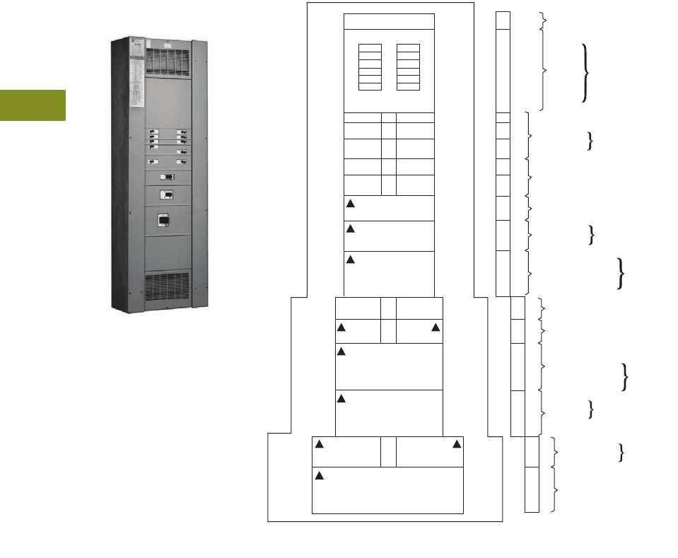
V12-T4-18 Volume 12—Aftermarket, Renewal Parts and Life Extension Solutions CA08100014E—November 2013 www.eaton.com
1
2
3
4
5
6
7
8
9
10
11
12
13
14
15
16
17
18
19
20
21
22
23
24
25
4
Panelboards
Replacement Capabilities
PRL4B
Current Product (Originally a
Westinghouse Product)
PRL4B
The panel layouts shown on
this and the following pages
will aid in determining the
space available for the
addition of molded-case
circuit breakers into your
existing PRL4B panelboards.
●Determine the amount
of space available in the
panelboard for adding
circuit breakers.
1.38 inches (35.1 mm)
of panel height =
one X space
●Determine the type of
breaker needed for the
required ampere rating
and number of poles
Ratings
●1200A maximum
Replacement Capabilities
Breakers
Refer to renewal parts
data RP01400001E
and
RP01414001E for a complete
list of available parts
including branch device
retrofit kits, which include
the device, as well as, the
bus connectors and the
required mounting hardware.
Retrofit kits and renewal
parts are available from
your Eaton Satellite plant.
Refer to Page V12-T4-22.
PRL4B Panel Layout
Notes
1Maximum amperes connected to any one connector cannot exceed 140A.
2GB and GHB breakers cannot be mixed on the same subchassis as BAB or QBHW.
3When only one single-pole breaker of the group is required on either side of chassis, the single-pole breaker
space required changes from 1X to 2X.
Filler
Sub Panel/
400 A Maximum
Bus Rating
1P
2P
3P
2P
3P
1P
2P
3P
2P
3P
2 or 3P
2 or 3P
2 or 3P
2 or 3P
2 or 3P
2 or 3P
2 or 3P
2 or 3P
2 or 3P
Load
2 or 3P
2 or 3P 2 or 3P
44" Wide Box
36" Wide Box
6X
4X
6X
6X
3X
3X
24" Wide Box
6X
3X
3X
3X
4X
2X
2X
1X
1X
11X
16X
20X
Poles
18
30
42
Breaker To Fusible
Transition, All Widths
BAB
QBGF
EHD 1 100 A Max.
FDB, FD1
HFD, FDC1
QBH
QBHGF
GB0
GHB0
100 A Max.
225 A Max.
CA, CAH, HCA 225 A Max.
JD, JDB, HJD, JDC 250 A Max.
FCL, FB-P 100 A Max.
LC, LCC, HLC,
HLCC, LCY, LD,
LDB, HLD, LDC, LA
DK, KD, KDB
HKD, KDC 400 A Max.
600 A Max.
JD, JDB, HJD, JDC 250 A Max.
LCL, LA-P, 400 A Max.
MC, MCC, HMC,
HMCC, MCY, MA 800 A Max.
NC, HNC,
NB, NCY 1200 A Max.
400 A Max.
NB-P 800 A Max.
DK, KD, KDB,
HKD, KDC
24" Wide Box
36" Wide Box
44" Wide Box
One X space = 1.38 inches (35.1 mm).
Blank llers are required for unused X space.
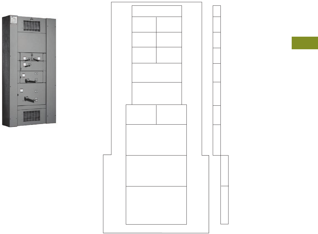
Volume 12—Aftermarket, Renewal Parts and Life Extension Solutions CA08100014E—November 2013 www.eaton.com V12-T4-19
1
2
3
4
5
6
7
8
9
10
11
12
13
14
15
16
17
18
19
20
21
22
23
24
25
4
Panelboards
Replacement Capabilities
PRL4F
Current Product (Originally a
Westinghouse Product)
PRL4F
The panel layouts shown
on this and the following
pages will aid in determining
the space available for the
addition of fusible switches
into your existing PRL4F
panelboards.
●Determine the amount
of space available in the
panelboard for adding
fusible switches.
1.38 inches (35.1 mm)
of panel height =
one X space
●Determine the type of
fusible switch needed for
the required ampere rating
and number of poles
Ratings
●1200A maximum
Replacement Capabilities
Fusible Switches
Refer to renewal parts
data RP01400001E
and
RP01414001E for a complete
list of available parts
including branch device
retrofit kits, which include
the device, as well as, the
bus connectors and the
required mounting hardware.
Retrofit kits and renewal
parts are available from
your Eaton Satellite plant.
Refer to Page V12-T4-22.
PRL4F Panel Layout
36" Wide Box
44" Wide Box
Fusible To Breaker
Transition, All Widths
30A
60A
30A
60A
1X
4X
4X
4X
5X
100A
250V Max.
100A
250V Max.
100A
36" Wide Box
6X
200A
Main or Branch
Switch
5X
11X
11X
100A
600 Vac
100A
600 Vac
400 or 600A
Branch Switch
400 or 600A
Main or Branch Switch
44" Wide Box
800 or 1200A
Branch Switch 16X
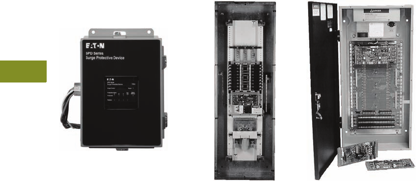
V12-T4-20 Volume 12—Aftermarket, Renewal Parts and Life Extension Solutions CA08100014E—November 2013 www.eaton.com
1
2
3
4
5
6
7
8
9
10
11
12
13
14
15
16
17
18
19
20
21
22
23
24
25
4
Panelboards
Technology Upgrades
Technology Upgrades
Surge Protection Devices—
SPD Series
Eaton SPD Series—
Surge Protection Device
The Eaton SPD Series of
surge protection products
ensures that equipment is
protected with the safest,
most reliable and most
advanced UL 1449 3rd
Edition certified surge
protectors. The array of
features, options and
configurations ensures
that there is a unit for
all electrical applications,
including service entrances,
distribution switchboards,
panelboards and point-of-use
applications. Field installation
is required.
Benefits
●The SPD Series can be
externally mounted to
existing distribution
equipment
●Surge ratings: 50, 80, 100,
120, 160, 200, 250, 300
and 400 kA
●Standard NEMA 1
enclosure, optional
NEMA 4 and 4X
●Surface or flush mounting
●Full range of diagnostic
and monitoring options
●Remote mountable
display panel
●Available with optional
internal disconnect
For more information about
the SPD Series surge
protection, contact your local
Eaton Field Sales office.
Pow-R-Command™
Pow-R-Command Lighting Control
Eaton’s Pow-R-Command is
a family of microprocessor-
based lighting control systems
designed for today’s modern
facilities. They may be used as
a standalone, or networked for
the control of lighting and
other branch circuits.
Existing facilities can be
retrofitted to include various
Pow-R-Command scenarios
allowing customers varying
degrees of control. For more
information on upgrading
your building to include the
energy savings and control
of Pow-R-Command lighting
control systems, contact your
local Eaton Field Sales office.
System Features
●Day/Date/Time of Day
scheduling
●Holiday scheduling—
up to 30 days/year
●Astronomical time
scheduling
●Real-time clock
●Hardware diagnostics
●Off warning by
blinking lights
●Manual load override
control
●Brownout and power
failure recovery
●Telephone override
of schedules
●Switch override of
schedules
●Remote access to system
●Dimming systems for
fluorescent fixtures
●Priority load management
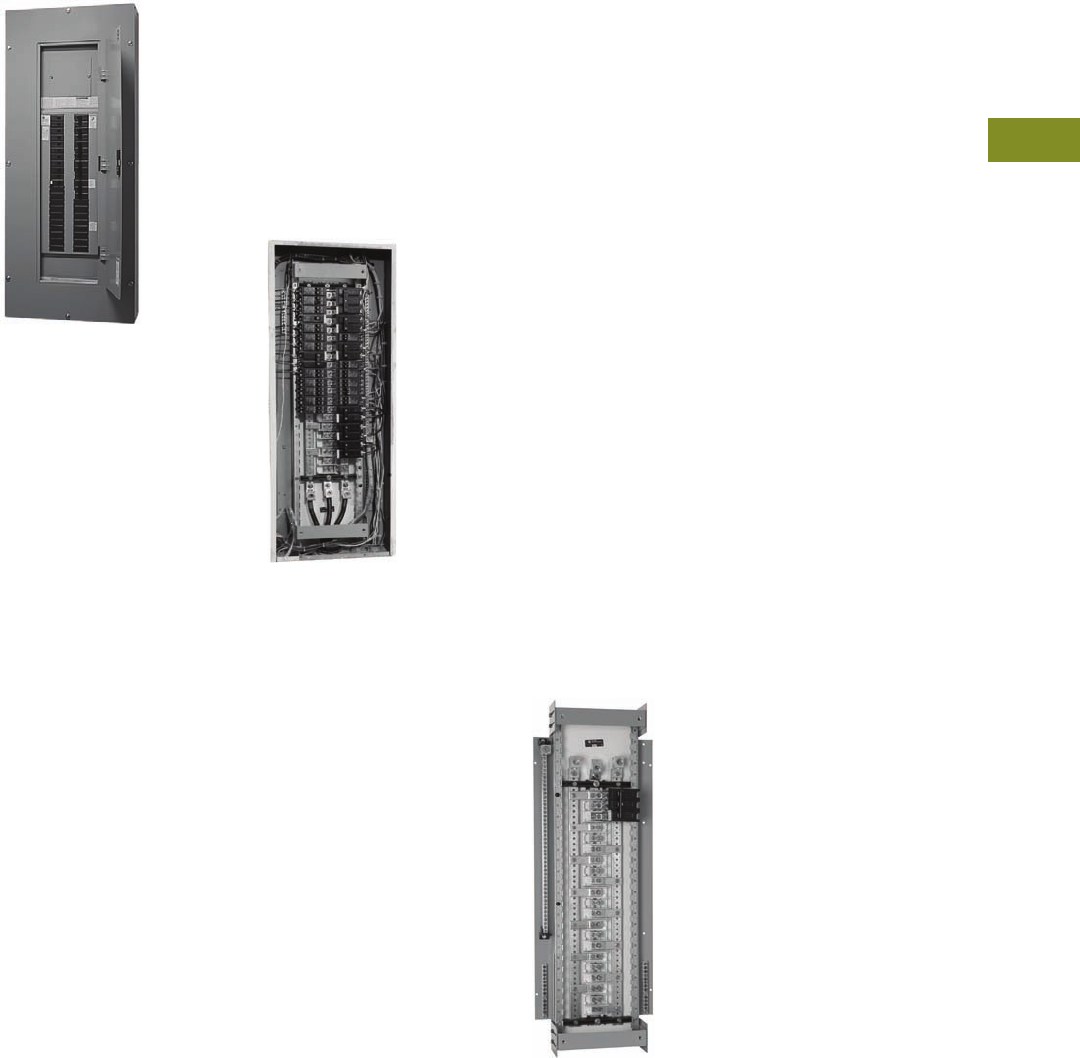
Volume 12—Aftermarket, Renewal Parts and Life Extension Solutions CA08100014E—November 2013 www.eaton.com V12-T4-21
1
2
3
4
5
6
7
8
9
10
11
12
13
14
15
16
17
18
19
20
21
22
23
24
25
4
Panelboards
Replacement Capabilities
Panelboard Retrofits
Type PRL1a
Another Custom-Assembled
Panelboard Capability from
Your Local Eaton Satellite
Save time and money when
upgrading and expanding
existing electrical services
by using existing panelboard
enclosures and conduit runs.
Retrofitting existing
panelboards can be an
effective solution for:
●Providing additional circuits
for load growth
●Replacing obsolete
equipment
●Upgrading protective
device interrupting ratings
●Accommodating system
change and additions
●Adding ground fault circuit
interrupters
●Adding lighting controls
●Adding surge protection
devices
The unique capabilities of
the Eaton Satellite plants can
provide special configurations
to meet the special needs
encountered in retrofit
applications.
Pow-R-Line 1R and 2R
renovation panelboards,
or custom-built panelboard
interiors and trims can be
provided to retrofit most
any manufacturer’s existing
panelboard enclosure.
Armed with the necessary
information about the existing
installation and the needed
upgrade, the professional
staff at your local Satellite
plant can offer the assistance
and application support to
ensure an accurate quotation
and on-time delivery of a
quality retrofit product.
Pow-R-Line 1R and 2R
Renovation Panel
Renovation Panel
Product Description
●240 and 480 Vac
●Single-phase three-wire or
single-phase two-wire
●Three-phase three-wire or
three-phase four-wire
●225A maximum
●100A maximum
branch breakers
●Fits existing box depths
from 4.50 to 6.00 inches
(114.3 to 152.4 mm) deep
●Integrally mounted
neutral assembly
●Ground bar and bonding
conductor included
●Neutral and ground
convertible from left-right
●Bolt-on branch breakers
●Factory assembled—
custom and standard
trims available
Application Description
●Lighting and appliance
branch panelboards
●Fully rated or series rated
●Interrupting capacities to
100 kA symmetrical
●Suitable for use as service
entrance equipment where
specified on the order
Standards and Certifications
●UL 67
●Federal Specification
W-P-115c
●CSA® C22.2 No. 29
The Pow-R-Line 1R and
2R retrofit panelboard is
designed specifically for use
in the
renovation of existing
electrical systems.
This
innovative solution employs a
chassis design that enables
the use of the existing back
box, conduit and cables. An
exclusive depth-adjusting
mechanism and an integrated
trim assembly provides for
fast, trouble-free
mounting of
the new panelboard interior
into any existing enclosure.
The panelboard chassis is
designed for the use of main
lugs or a main breaker and
can accommodate 18, 30 or
42 branch circuits.
Pow-R-Line 1R Retrofit Chassis
Chassis Features
Designed to accommodate
minimal box widths at
14.00 inches (355.6 mm).
Innovative telescoping chassis
accommodates depths from
4.50 to 6.00 inches (114.3 to
152.4 mm) without the need
for box modifications.
Universal mounting locations
allow the neutral and grounds
to be relocated from top to
bottom or left to right side of
back plate.
High quality laser cut trim
with lock.
Trim and door mount directly
to the chassis assembly.
Concealed trim hardware is
not dependent on back box
for mounting.
Refer to publication
CA01417001E for
complete information.

V12-T4-22 Volume 12—Aftermarket, Renewal Parts and Life Extension Solutions CA08100014E—November 2013 www.eaton.com
1
2
3
4
5
6
7
8
9
10
11
12
13
14
15
16
17
18
19
20
21
22
23
24
25
4
Panelboards
Satellite Locations
Product Support Services
Satellite Locations
Further Information Pricing Information
Price List for MP40 and MP-200—PL01400003E
Price List for PB, PH, PH-L, EP and EE—PL01400003E
Price List for CDP/HCDP, FDP, PRL1-LX, PRL1, PRL2 and
PRL3—PL01400002E
Price List for PRL1a, PRL2a, PRL3a, PRL4B, PRL4F and
PRL5P—PL01400001E
Discount Symbol CE9
Raleigh
9400 Globe Center Drive
Suite 121
Morrisville, NC 27560
(919) 544-7074
Fax (919) 572-9751
Atlanta
7000 Highlands Parkway SE
Suite 102
Smyrna, GA 30082
(678) 309-4260
Fax (770) 433-1863
Cleveland
12875 Corporate Drive
Parma, OH 44130
(216) 433-0 6 16
Fax (216) 433-0545
Dallas
631 Westport Parkway
Suite 100
Grapevine, TX 76051
(817) 251-6797
Fax (817) 251-6249
Denver
2450 Airport Boulevard
Unit C, Dock 8
Aurora, CO 80011
(303) 366-2080
Fax (303) 366-9993
Baltimore
7451 Coca Cola Drive
Suite C
Hanover, MD 21076
(410) 796-7777
Fax (410) 796-7755
Houston
10810 West Little York
Suite 100
Houston, TX 77041
(713) 939-9696
Fax (713) 939-0427
Los Angeles
11120 Philadelphia Street
Mira Loma, CA 91752
(951) 685-5788
Fax (951) 685-3775
Orlando
9436 South Ridge Park Court
Suite 100
Orlando, FL 32819
(407) 264-9306
Fax (407) 264-9310
San Francisco
20923 Cabot Boulevard
Hayward, CA 94545
(510) 784-8981
Fax (510) 784-8980
Seattle
1604 15th Street SW
Suite 114
Auburn, WA 98001
(253) 833-5021
Fax (253) 833-5058
St. Louis
56 Soccer Park Road
Fenton, MO 63026
(636) 717-3445
Fax (636) 717-3505
Hartford
40A International Drive
Windsor, CT 06095
(860) 298-1305
Fax (860) 298-1306
Phoenix
921 South Park Lane
Suite 1
Tempe, AZ 85281
(480) 449-4222
Fax (480) 449-4223
Sumter
(803) 481-6843
The Eaton satellite concept is unique to the industry and
remains the only manufacturer to provide this service. Eaton
manufactures and delivers standard and custom assembled
panelboards and switchboards within days. A phone call is all
that is necessary for immediate order entry.
Main manufacturing plant.
New Jersey
96 Stemmers Lane
Westampton, NJ 08060
(609) 835-4230
Fax (609) 835-4777
Chicago
220 Windy Point Drive
Glendale Heights, IL 60139
(630) 260-6303
Fax (630) 690-7453
Publication
Number Description
RP01400003E Renewal Parts Data for MP40 and MP-200
RP01400003E Renewal Parts Data for PB, PH, PH-L, EP and EE
RP01400002E Renewal Parts Data for CDP/HCDP, FDP, PRL1-LX, PRL1, PRL2 and PRL3
RP01400001E Renewal Parts Data for PRL1a, PRL2a, PRL3a, PRL4B, PRL4F and PRL5P
RP01414001E Panelboard Renewal Parts Supplement
Volume 12—Aftermarket, Renewal Parts and Life Extension Solutions CA08100014E—November 2013 www.eaton.com V12-T5-1
1
2
3
4
5
6
7
8
9
10
11
12
13
14
15
16
17
18
19
20
21
22
23
24
25
Loadcenters
BR Renovation and CH Loadcenters
5Loadcenters
Product Description. . . . . . . . . . . . . . . . . . . . . . . . . . . . . . . . . . . . . . . V12-T5-2
Product History . . . . . . . . . . . . . . . . . . . . . . . . . . . . . . . . . . . . . . . . . . V12-T5-2
Type CH Family . . . . . . . . . . . . . . . . . . . . . . . . . . . . . . . . . . . . . . . . V12-T5-2
Type BR Family . . . . . . . . . . . . . . . . . . . . . . . . . . . . . . . . . . . . . . . . V12-T5-2
Product History Time Line . . . . . . . . . . . . . . . . . . . . . . . . . . . . . . . V12-T5-3
Replacement Capabilities . . . . . . . . . . . . . . . . . . . . . . . . . . . . . . . . . . V12-T5-3
Type CH Replacement Parts and Mechanical Interlocks. . . . . . . . . V12-T5-4
Type CH Vintage Replacement Covers . . . . . . . . . . . . . . . . . . . . . . V12-T5-10
Type BR Replacement Parts and Covers . . . . . . . . . . . . . . . . . . . . V12-T5-12
Classified Replacement Breakers . . . . . . . . . . . . . . . . . . . . . . . . . . . . V12-T5-20
Type CL and CHQ . . . . . . . . . . . . . . . . . . . . . . . . . . . . . . . . . . . . . . V12-T5-20
Type CHNT . . . . . . . . . . . . . . . . . . . . . . . . . . . . . . . . . . . . . . . . . . . V12-T5-20
Type CTL and CHT . . . . . . . . . . . . . . . . . . . . . . . . . . . . . . . . . . . . . V12-T5-20
Technology Upgrades . . . . . . . . . . . . . . . . . . . . . . . . . . . . . . . . . . . . . V12-T5-21
Renovation Loadcenter. . . . . . . . . . . . . . . . . . . . . . . . . . . . . . . . . . V12-T5-21
Plug-On Neutral . . . . . . . . . . . . . . . . . . . . . . . . . . . . . . . . . . . . . . . V12-T5-22
Retrofit Interiors . . . . . . . . . . . . . . . . . . . . . . . . . . . . . . . . . . . . . . . V12-T5-23
Surge Panel . . . . . . . . . . . . . . . . . . . . . . . . . . . . . . . . . . . . . . . . . . . . . V12-T5-25
Further Information . . . . . . . . . . . . . . . . . . . . . . . . . . . . . . . . . . . . . . . V12-T5-26
Pricing Information . . . . . . . . . . . . . . . . . . . . . . . . . . . . . . . . . . . . . . . V12-T5-26
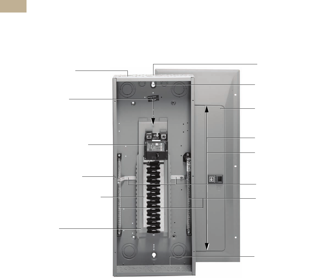
V12-T5-2 Volume 12—Aftermarket, Renewal Parts and Life Extension Solutions CA08100014E—November 2013 www.eaton.com
1
2
3
4
5
6
7
8
9
10
11
12
13
14
15
16
17
18
19
20
21
22
23
24
25
5
Loadcenters
Product Description
Loadcenters are enclosed
assemblies used for power
distribution and circuit
protection in residential,
commercial and light
industrial applications.
The assembly consists
of an enclosure, an interior
assembly and a cover. The
interior assembly consists
of a backpan where the bus
assembly is mounted.
Incoming power is
terminated at main lugs or a
main circuit breaker. Load
circuit protection is provided
by molded-case circuit
breakers that plug onto the
bus assembly. Loadcenters
are used on services
providing no more than
240 Vac, and are available
with bus rated from 40 to
600A. Loadcenter covers
are available as surface,
flush or combination.
Product History
Type CH Family
Eaton’s electrical business
began manufacturing the CH
series of loadcenters and
circuit breakers in 1962.
Changes have occurred over
the years due to code
changes, UL® listed
requirements
and product
enhancements. Three major
design changes occurred in
1969, 1982 and 1995. The
3/4-inch wide feeder circuit
breakers, silver flash plated
copper bus, sandalwood (tan)
painted box and industry-
leading warranties have
been the trademarks of this
premium product through
the years.
Type BR Family
With the acquisition of
Westinghouse’s Distribution
and Control Business Unit
(DCBU)
in 1994, Eaton
gained the circuit
breaker
and loadcenter manufacturing
and marketing operations of
Westinghouse. Prior to 1989,
these products were
manufactured by
Westinghouse’s Bryant
subsidiary in Bridgeport, CT.
The products from this facility
bore the Westinghouse and
Bryant nameplates. In 1988,
Westinghouse purchased
Challenger Electric,
redesigned the product, and
moved all production from
Bridgeport to Jackson, MS.
As Eaton integrated the
product lines in 1995, all
loadcenter production shifted
to the Lincoln, IL, facility.
Type CH Loadcenter
Extra 1.50-Inch (38.1 mm)
Knockout for Bundling
Provides for easier installation,
less installation time.
Top or Bottom Feed
■Straight-in wiring saves labor and material
■Only one panel for either application—
no modifications necessary
Commercial Grade Main Breaker
■35 kAIC series rated main breaker in
150 and 200A loadcenters
■42 and 100 kAIC series ratings available
Steel Backpan
■Provides positive, reliable breaker mounting
■One-piece designed for stability
One-Piece Silver Flash Plated Copper Bus
Provides superior conductivity throughout the
entire product line.
Drywall Marking on Enclosure
Indicates proper mounting depth for
flush applications.
Single Keyhole Mounting
Just one keyhole at top and bottom
for easier mounting and leveling.
Unique Sandalwood Finish
Immediately recognizable,
aesthetically appealing, scratch-
resistant powder coating.
Neutral Design
(for styles as indicated)
■Bonding strap is easily removable
for sub-panel applications
providing a ground and neutral
■Factory-bonded for service
entrance applications providing
a split neutral
■Ample additional 2/0 lugs
provided; no kits necessary
■200% size neutral
Separately Packaged Covers
■Full line of “true” surface and
combination covers
■Built-in flush leveling feature
■Choice of circuit identification by
breaker labels or circuit directory
Improved Endwall Knockouts
Larger KOs are balanced to enhance
installed appearance and to ease
use of existing wiring.
Convertible Styles Available
■Uses field-installable main breaker or main
lug kits
■Flexible inventory—same breaker is used in
loadcenter and circuit breaker enclosures
“Tangential” Center Knockout for
easier installation
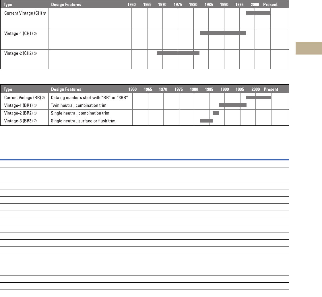
Volume 12—Aftermarket, Renewal Parts and Life Extension Solutions CA08100014E—November 2013 www.eaton.com V12-T5-3
1
2
3
4
5
6
7
8
9
10
11
12
13
14
15
16
17
18
19
20
21
22
23
24
25
5
Loadcenters
Product History Time Line
Originally a Cutler-Hammer Product—3/4-Inch Non-Interchangeable Product Line
Originally a Westinghouse Product—1-Inch Interchangeable Product Line
Replacement Capabilities
Replacement Capabilities
Notes
1CH and BR are the current product designations. CH1, CH2, BR1, BR2 and BR3 are used only to identify previous generations of the product described in the replacement capabilities chart above.
These are not actual product designations.
2Catalog number of loadcenter required to obtain correct part.
Type Loadcenter Generations
Part 2CH CH1 CH2 BR BR1 BR2 BR3
Breakers ■■■■■■■
Surge arresters ■■■■■■■
Covers ■■ ■■
Deadfronts (NEMA® 3R) ■■ ■■
Door assemblies (NEMA 3R) ■■ ■■
MCB kits ■■ ■■
Neutral bars ■■■■■■■
Ground bars ■■■■■■■
Breaker accessories ■■■■■■■
Labels ■■■■■■■
Lugs ■■ ■■
Door locks ■■■■
Door latches ■■
Paint ■■■■■■■
Closure plates ■■■■■■■
Hubs ■■ ■■
Spare parts kit ■■
Whole house AC surge protection ■■■■■■■
Door latch is tan plastic, twin neutrals,
CH8_S or F. (Blank is 1 letter indicating
box size, i.e., B, C, E, J, K.)
Metal latch, single neutral, CH7_S
or F. (Blank is 2 letters indicating box
size, i.e., BB, CC, JJ, KK.)
Cover catalog numbers CH7_S or F.
(Blank is 1 letter indicating box size,
i.e., B, C, D, 3, G, J, K.)
V12-T5-4 Volume 12—Aftermarket, Renewal Parts and Life Extension Solutions CA08100014E—November 2013 www.eaton.com
1
2
3
4
5
6
7
8
9
10
11
12
13
14
15
16
17
18
19
20
21
22
23
24
25
5
Loadcenters
Type C H
Type CH Replacement Parts
Mechanical Interlocks
Note
1 Must be purchased in multiples of ordering quantities indicated.
Description Ordering Quantity 1Catalog Number
Subfeed lug blocks—two-pole, 125A, 3/4-inch (19.1 mm) spaces needed 1 CHSF2125
Subfeed lug blocks—three-pole, 125A, 3/4-inch (19.1 mm) spaces needed 1 CHSF3125
Neutral/ground lug—add-on neutral or ground lug 1 NL20
1NL30
1NL300
Filler plates—3/4-inch (19.1 mm) space circuit breaker space 25 CHFP
CSR main circuit breaker filler plate (with hardware) 1 CSRFP
Door lock—12–42 circuits, and 100–225A 1 TDL
Sandlewood spray paint 1 SPCSW
ANSI-61 light gray touchup paint for outdoor loadcenters 1 SPC61
Isolated neutral assembly (computer circuits) 1 BINA
Circuit directory—adhesive backed 10 TCD
Cover screws 25 LCCS
Cover replacement latch 14-5/16 inch (363.55 mm) wide loadcenters only 1 CHRLS
Circuit marking strip (next to breakers) 10 CHMS
Circuit identification label (preprinted breaker labels next to breakers) 25 CHBL
Series rated caution label 25 SRL
Branch circuit numbering strip 20 CHNS
Bonding strap with screw 1 BSSUSE
125A retainer bracket for sub-fed devices 1 CH125RB
Replacement lock 400A devices 1 52-2751
Replacement latch for NEMA 3R—four circuits and above 1 CH3RLATCH
Lock for vintage CH7 cover 1 CH9FL
Type
Fits Loadcenter
Catalog Numbers
Mechanical Interlock Panel Cover Catalog Number
Flush Surface
A CH12L125B, CH16L125B, CH12L3125B, CH14B100B CH8BFM CH8BSM
CH20L125C, CH24L125C, CH18L3125C, CH24L3125C, CH22B100C, CH22N100C CH8CFM CH8CSM
CH24L150D, CH32L150D, CH24L3225D, CH30L3150D CH8DFM CH8DSM
CH42L225G, CH42L3225G CH8GFM CH8GSM
Inner cover of Box B raintight —CH8BRM
Inner cover of Box C raintight — CH8CRM
B CH24B150E, CH24B200E CH8EFM CH8ESM
CH32B150J, CH32B200J, CH3242B200J, CH32N200J, CH32B225J CH8JFM CH8JSM
CH42B200K, CH42N200K, CH42B225K CH8KFM CH8KSM
CHPC32B150L, CHPC32B200L, CHPC32N200L CHPC8B32LFM —
CHPC42B150L, CHPC42B200L, CHPC42N200L CHPC8B42LFM —
CH8B150RF, CH8B200RF, CH8N200RF, CH24B150R, CH24B200R CH3RDF7M —
CH32B150R, CH32B200R, CH32N200R, CH32B225R CH3RDF9M —
CH42B200R, CH42N200R, CH42B225R CH3RDF10M —
CHSF2125
CHSF3125
CHFP
TDL
BINA
CHRLS
CH8BRM Type A
CH8EFM Type B
Volume 12—Aftermarket, Renewal Parts and Life Extension Solutions CA08100014E—November 2013 www.eaton.com V12-T5-5
1
2
3
4
5
6
7
8
9
10
11
12
13
14
15
16
17
18
19
20
21
22
23
24
25
5
Loadcenters
Type CH
Replacement Rainproof Conduit Hubs
Replacement Ground Bar Kits
Ground Bar Legend
Replacement Grounded “B” Phase Adapters
Replacement Neutral Lugs for Vintage Loadcenters
Replacement Neutral Bar Accessories
Notes
1Must be purchased in multiples of ordering quantities indicated.
2Distance between mounting holes is 1-3/4 inches (44.5 mm).
3For single- and three-phase 400A loadcenters.
4Distance between mounting holes is 2-13/32 inches.
5Cannot be used in Safety Breaker Panels. Classic Plus Panels only.
Description
Conduit Size Ordering
Quantity 1
Catalog
NumberInches (mm)
Group 1—for use with 70, 100 and 125A MLO and MCB loadcenters and circuit breaker enclosures,
and the following 150 and 200A panels: CH8B150RF, CH8B200RF
0.75 (19.1) 1 DS075H1
1.00 (25.4) 1 DS100H1
1.25 (31.8) 1 DS125H1
1.50 (38.1) 1 DS150H1
2.00 (50.8) 1 DS200H1
Group 2—for use with 150, 200 and 225A MLO and MCB loadcenters and circuit breaker enclosure
except for the following 150 and 200A panels: CH8B150RF, CH8B200RF
2.00 (50.8) 1 DS200H2
2.50 (63.5) 1 DS250H2
3.00 (76.2) 1 DS300H2
Adapter kit—allows Installing a Group 1 hub on devices arranged for Group 2 hubs — 1 DS900AP
Group 1—small blank hub closure plate — 1 DS900CP1
Group 2 —þlarge blank hub closure plate — 1 DS900CP2
Description (See Legend)
Length Ordering
Quantity 2
Catalog
NumberInches (mm)
dssssds
dssssdsj
dssssdssssss
dssssdssssssj
dssssdssssssssss
dssssdssssssssssj
dssssdsssssssssssssssss
dssssdsssssssssssssssssj
ssssssssdssssssdsssssss
2.54 (64.5) 1 GBK5 2
3.59 (91.2) 1 GBK520 2
4.29 (109.0) 1 GBK10 2
5.34 (135.6) 1 GBK1020 2
4.61 (117.1) 1 GBK13 2
5.69 (144.5) 1 GBK14 2
6.74 (171.2) 1 GBK1420 2
8.14 (206.8) 1 GBK21 2
9.19 (233.4) 1 GBK2120 2
7.94 (201.7) 1 CH9GP21 34
DS100H1
GBK14
f
d
f
f
f
k
f
d
f
k
f
f
f
k
f
s
j
d
= (3) #14–#10 Cu/Al or (1) #14–#4 Cu/Al
= (1) #6–2/0 Cu/Al
= (1) 1/0–14 or (3) #10–12 Cu/Al
= (1) #14–1/0 Cu/Al or (3) #14–#10 Cu/Al
= Mounting hole
f k
Maximum
Amperes
Three-Phase Loadcenter
Types of Panels
Kit Catalog
Number 5
125 12–32 circuit main lug CHGRD1
225 Main lug and CHH main breaker panels CHGRD2
CC main CB panels CHGRD3
Description
Catalog
Number
Vintage 1 (CH1) 125A CH9CM1
Vintage 1 (CH1) 225A CH9CM2
Vintage 2 (CH2) 125A CH9SU3
Vintage 2 (CH2) 225A CH9SU2
Description
Catalog
Number 5
Split neutral kit for 22 circuit 125A maximum CHSN125C
Split neutral kit for 32 circuit 200A maximum CHSN225J
Split neutral kit for 42 circuit 200A maximum CHSN225K
Replacement neutral for all C type boxes CHN125C
Replacement neutral for all D type boxes CHN125D
Replacement neutral for all L type boxes CHN225L
Isolated Neutral Assembly (computer circuits) BINA
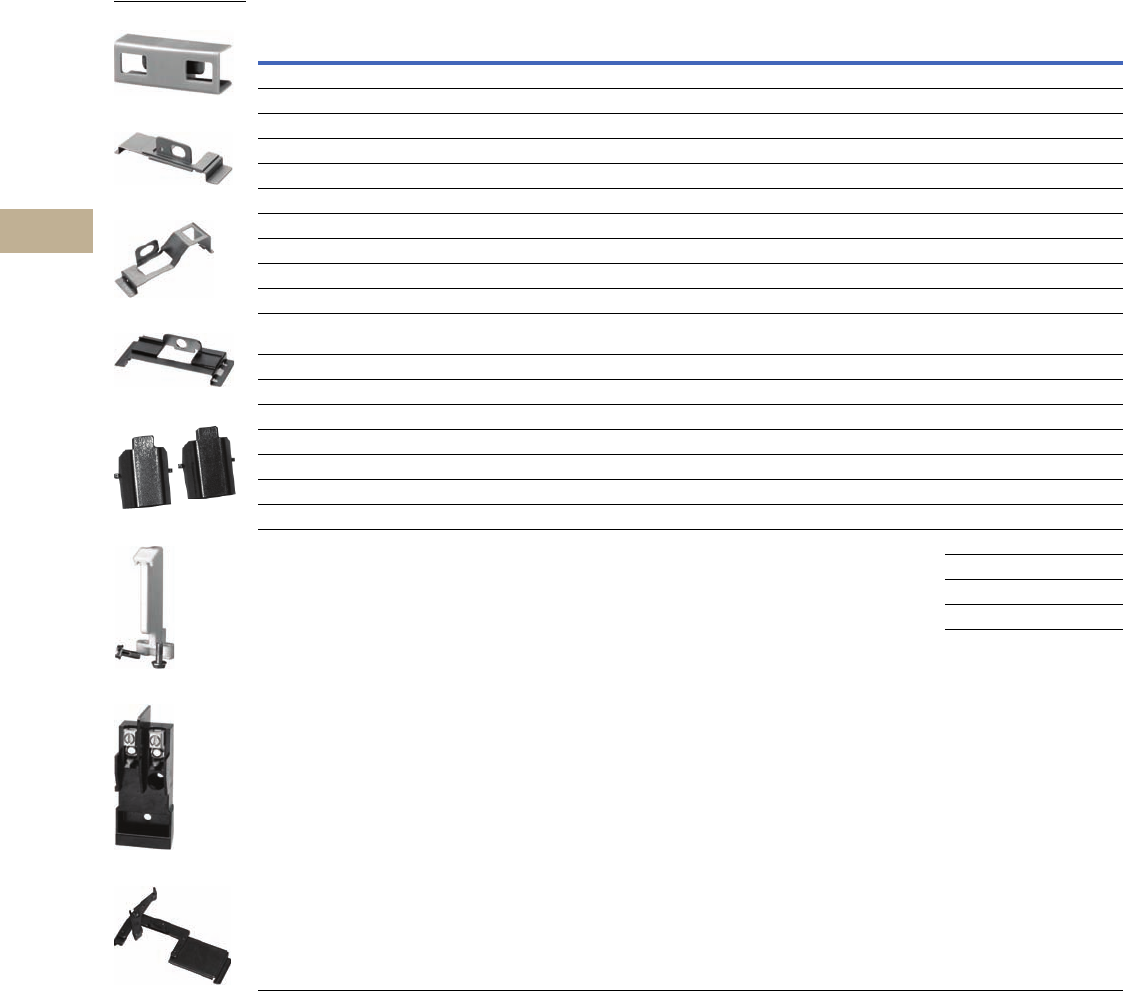
V12-T5-6 Volume 12—Aftermarket, Renewal Parts and Life Extension Solutions CA08100014E—November 2013 www.eaton.com
1
2
3
4
5
6
7
8
9
10
11
12
13
14
15
16
17
18
19
20
21
22
23
24
25
5
Loadcenters
Type C H
Breaker Replacement Accessories
Notes
1 Must be purchased in multiples of ordering quantities indicated.
2 Handle ties: typically used to join two similar independent single-pole breakers to form a two-pole noncommon trip breaker.
3 Handle lockoffs: devices that use a padlock to lock the circuit breaker’s handle in the ON or OFF position.
4 Requires one additional pole space.
5 Escutcheon mounted: device mounted semipermanently to the face of the circuit breaker and secured by the loadcenter deadfront.
6 Screw mounted: device permanently mounted to the face of the circuit breaker by the use of a non-removable screw.
7 Handle lockdogs: devices that are used to secure a circuit breaker’s handle in the ON or OFF position. Handle lockdogs are not padlockable devices.
8 Handle mounted: device mounted above or below handle using spring pressure.
9 Hold-down kits: devices used to secure the circuit breaker to the loadcenter for back-feed main application. See NEC Article 384.16(g).
Description
Ordering
Quantity 1
Catalog
Number
Handle Ties 2
Handle tie bar for physically joining the handles of two adjacent single-pole Type CH circuit breakers (molded plastic handle cover) 25 CHHT
Handle Lockoffs 34
Padlockable device for locking the handle of single-, two- or three-pole Type CH circuit breakers (escutcheon mounted) 5 1 CHPL
Padlockable device for locking the handle of a single-, two- or three-pole Type CHGFI circuit breaker (escutcheon mounted) 51CHPLGF
Padlockable device for locking the handle of main circuit breaker Types CC and CCH into the ON or OFF position.(screw mounted) 61CCPL
Padlockable device for locking the handle of main breaker Types BW and CSR into the ON or OFF position (escutcheon mounted) 51MCBPL
Handle Lockdogs 47
Device used to secure handle in ON or OFF position for single-pole Type CH circuit breakers (handle mounted) 810 CHLO
Hold-Down Kits 9
Hold-down retainer kit for single-, two-, three-pole Type CH circuit breakers. For 6–24 circuit 125A single- and three-phase,
12–42 circuit single-phase 225A and 24–42 circuit three-phase 225A MLO Type CH loadcenters
1CH125RB
Hold-down retainer kit for single-, two-, three-pole Type CH circuit breakers for 2–4 circuit MLO CH loadcenters. 1 CH125RB24
Mounting Bases
Mounting base for two-pole Type CH circuit breaker—70A maximum 1 CH9MB270
Main Breaker Lug Kits
Types CC and CCH main breaker lug kit (2) 300 kcmil 1 CCL300
Type CSR main breaker lug kit (2) 300 kcmil 1MCBL300
Mechanical Interlock
Type CH for two-, three- and four-pole breakers 10 CHML
10 CHPLOFF
10 CHPLOFFA
10 CHL1P
10 CHL2P
CHHT
CHPL
CHPLGF
MCBPL
CHLO
CH125RB
CH9MB270
CHML

Volume 12—Aftermarket, Renewal Parts and Life Extension Solutions CA08100014E—November 2013 www.eaton.com V12-T5-7
1
2
3
4
5
6
7
8
9
10
11
12
13
14
15
16
17
18
19
20
21
22
23
24
25
5
Loadcenters
Type CH
Renewal Parts List for Type CH Loadcenter Covers and Deadfronts
Single-Phase with Main Circuit Breaker
Catalog
Number
Combination
Covers
Surface
Covers
NEMA 3R
Covers
NEMA 3R
Deadfronts
Catalog
Number
Combination
Covers
Surface
Covers
NEMA 3R
Covers
NEMA 3R
Deadfronts
CH1420B100B CH8BF CH8BS — — CH30B125R — — CH3RDOOR10 CH3RDF6
CH1420B100R — — — CH3RDOOR5 CH3RDF4 CH3242B200J CH8JF CH8JS — —
CH14B100B CH8BF CH8BS — — CH3242B200R — — CH3RDOOR12 CH3RDF9
CH14B100R — — CH3RDOOR5 CH3RDF4 CH32B150J CH8JF CH8JS — —
CH1824B100C CH8CF CH8CS — — CH32B150R — — CH3RDOOR12 CH3RDF9
CH1824B100R — — CH3RDOOR8 CH3RDF5 CH32B200J CH8JF CH8JS — —
CH18B100C CH8CF CH8CS — — CH32B200R — — CH3RDOOR12 CH3RDF9
CH18B100R — — CH3RDOOR8 CH3RDF5 CH32B225J CH8JF CH8JS — —
CH20H100C CH8CF CH8CS — — CH32B225R — — CH3RDOOR12 CH3RDF9
CH20H100R — — CH3RDOOR7 CH3RDF5 CH32H150L CH8LF CH8LS — —
CH22B100C CH8CF CH8CS — — CH32H150R — — CH3RDOOR6 CH3RDF10
CH22B100R — — CH3RDOOR7 CH3RDF5 CH32H200L CH8LF CH8LS — —
CH22B125C CH8CF CH8CS — — CH32H200R — — CH3RDOOR6 CH3RDF11
CH22B125R — — CH3RDOOR8 CH3RDF5 CH42B200K CH8KF CH8KS — —
CH24B150E CH8EF CH8ES — — CH42B200R — — CH3RDOOR13 CH3RDF10
CH24B150R — — CH3RDOOR11 CH3RDF7 CH42B225K CH8KF CH8KS — —
CH24B200E CH8EF CH8ES — — CH42B225R — — CH3RDOOR13 CH3RDF10
CH24B200R — — CH3RDOOR11 CH3RDF7 CH42H200L CH8LF CH8LS — —
CH28H100D CH8DF CH8DS — — CH42H200R — — CH3RDOOR6 CH3RDF11
CH28H100R — — CH3RDOOR9 CH3RDF6 CH42H225L CH8LF CH8LS — —
CH28H125D CH8DF CH8DS — — CH42H225R — — CH3RDOOR6 CH3RDF11
CH28H125R — — CH3RDOOR9 CH3RDF6 CH42PM300 CH7PMF (flush) CH7PMS — —
CH30B100D CH8DF CH8DS — — CH42PM400 CH7PMF (flush) CH7PMS — —
CH30B100R — — CH3RDOOR10 CH3RDF6 CH8B150RF — — CH3RDOOR11 CH3RDF7
CH30B125D CH8DF CH8DS — — CH8B200RF — — CH3RDOOR11 CH3RDF7

V12-T5-8 Volume 12—Aftermarket, Renewal Parts and Life Extension Solutions CA08100014E—November 2013 www.eaton.com
1
2
3
4
5
6
7
8
9
10
11
12
13
14
15
16
17
18
19
20
21
22
23
24
25
5
Loadcenters
Type C H
Single-Phase with Main Lugs
Single-Phase Convertible
Catalog
Number
Combination
Covers
Surface
Covers
NEMA 3R
Covers
NEMA 3R
Deadfronts
Catalog
Number
Combination
Covers
Surface
Covers
NEMA 3R
Covers
NEMA 3R
Deadfronts
CH4L125RP — — CH3RDOOR2 CH3RDF2 CH2L125SP — CH82S — —
CH12L125B CH8BF CH8BS — — CH2L40FP ————
CH12L125R — — CH3RDOOR5 CH3RDF4 CH2L40RP — — BKRCVR —
CH12L200D CH8DF CH8DS — — CH2L40SP ————
CH12L200R — — CH3RDOOR9 CH4RDF6 CH2L70FP ————
CH1624L125B CH8BF CH8BS — — CH2L70RP — — BKRCVR —
CH1624L125R — — CH3RDOOR5 CH3RDF4 CH2L70SP ————
CH16L125B CH8BF CH8BS — — CH3242L225D CH8DF CH8DS — —
CH16L125R — — CH3RDOOR5 CH3RDF4 CH3242L225R — — CH3RDOOR11 CH3RDF6
CH16L200D CH8DF BH8DS — — CH32L150D CH8DF CH8DS — —
CH16L200R — — CH3RDOOR11 CH3RDF6 CH32L150R — — CH3RDOOR11 CH3RDF6
CH20L125C CH8CF CH8CS — — CH32L225D CH8DF CH8DS — —
CH20L125R — — CH3RDOOR8 CH3RDF5 CH32L225R — — CH3RDOOR11 CH3RDF6
CH24L125C CH8CF CH8CS — — CH42L225G CH8GF CH8GS — —
CH24L125R — — CH3RDOOR8 CH3RDF5 CH42L225R — — CH3RDOOR12 CH3RDF8
CH24L150D CH8DF CH8DS — — CH42PL400 CH7PF (flush) CH7PS — —
CH24L150R — — CH3RDOOR11 CH3RDF6 CH4L125FP CH84F (flush) — — —
CH24L225D CH8DF CH8DS — — CH4L125SP — CH84S — —
CH24L225R — — CH3RDOOR11 CH3RDF6 CH8L125FP CH88F (flush) — — —
CH2L125FP CH82F (FLUSH) — — — CH8L125RP — — CH3RDOOR4 CH3RDF3
CH2L125RE2P ————CH8L125SP — CH88S — —
CH2L125RP — — CH3RDOOR1 CH3RDF1
Catalog
Number
Combination
Covers
Surface
Covers
NEMA 3R
Covers
NEMA 3R
Deadfronts
CH22N125C CH8CF CH8CS — —
CH22N125R ————
CH32N200J CH8JF CH8JS — —
CH32N200R — — CH3RD00R12 CH3RDF9
CH42N225K CH8KF CH8KS — —
CH42N225R ————
CH8N200RF — — — CH3RDF7

Volume 12—Aftermarket, Renewal Parts and Life Extension Solutions CA08100014E—November 2013 www.eaton.com V12-T5-9
1
2
3
4
5
6
7
8
9
10
11
12
13
14
15
16
17
18
19
20
21
22
23
24
25
5
Loadcenters
Type CH
Three-Phase with Main Circuit Breakers Three-Phase with Main Lugs
Catalog
Number
Combination
Covers
Surface
Covers
NEMA 3R
Covers
NEMA 3R
Deadfronts
CH30B3150L CH8LF CH8LS — —
CH30B3150R — — CH3RDOOR6 CH3RDF11
CH30B3200L CH8LF CH8LS — —
CH30B3200R — — CH3RDOOR6 CH3RDF11
CH30B3225L CH8LF CH8LS — —
CH30B3225R — — CH3RDOOR6 CH3RDF11
CH30H3200L CH8LF CH8LS — —
CH30H3200R — — CH3RDOOR6 CH3RDF11
CH424PM300 CH7PMF (flush) CH7PMS — —
CH424PM400 CH7PMF (flush) CH7PMS — —
CH42B3200L CH8LF CH8LS — —
CH42B3200R — — CH3RDOOR6 CH3RDF11
CH42B3225L CH8LF CH8LS — —
CH42B3225R — — CH3RDOOR6 CH3RDF11
CH42H3200L CH8LF CH8LS — —
CH42H3200R — — CH3RDOOR6 CH3RDF11
CH42H3225L CH8LF CH8LS — —
CH42H3225R — — CH3RDOOR6 CH3RDF11
Catalog
Number
Combination
Covers
Surface
Covers
NEMA 3R
Covers
NEMA 3R
Deadfronts
CH12L3125B CH8BF CH8BS — —
CH12L3125R — — CH3RDOOR5 CH3RDF4
CH18L3125C CH8CF CH8CS — —
CH18L3125R — — CH3RDOOR8 CH3RDF5
CH24L3125C CH8CF CH8CS — —
CH24L3125R — — CH3RDOOR8 CH3RDF5
CH24L3225D CH8DF CH8DS — —
CH24L3225R — — CH3RDOOR11 CH3RDF6
CH30L3150D CH8DF CH8DS — —
CH30L3150R — — CH3RDOOR11 CH3RDF6
CH30L3225D CH8DF CH8DS — —
CH30L3225R — — CH3RDOOR11 CH3RDF6
CH424PL400 CH7PF (flush) CH7PS — —
CH42L3225R — — CH3RDOOR12 CH3RDF8
CH42L3225G CH8GF CH8GS — —
CH6L3125FP CH86F (flush) — — —
CH6L3125RP — — CH3RDOOR3 CH3RDF3
CH6L3125SP — CH86F — —

V12-T5-10 Volume 12—Aftermarket, Renewal Parts and Life Extension Solutions CA08100014E—November 2013 www.eaton.com
1
2
3
4
5
6
7
8
9
10
11
12
13
14
15
16
17
18
19
20
21
22
23
24
25
5
Loadcenters
Type C H
Renewal Parts List for Vintage Type CH Loadcenter Covers and Deadfronts
Single-Phase with Main Circuit Breaker Single-Phase with Main Lugs
Catalog
Number
Surface
Covers
Flush
Covers
Surface Covers
w/ Mechanical
Interlock
Flush Covers
w/ Mechanical
Interlock
CH22CCM100N CH7CCS CH7CCF CH7CCSM CH7CCFM
CH30JJM150N CH7JJS CH7JJF — —
CH30JJM200N CH7JJS CH7JJF — —
CH40KKM200N CH7KKS CH7KKF — —
CH14BBM100 CH7BBS CH7BBF CH7BBSM CH7BBFM
CH14BBM100R ————
CH18CCM100 CH7CCS CH7CCF — —
CH18CCM100R ————
CH22CCM125 CH7CCS CH7CCF — —
CH22CCM125R ————
CH20JJM150 CH7JJS CH7JJF — —
CH20JJM150R ————
CH20JJM200 CH7JJS CH7JJF — —
CH20JJM200R ————
CH24JJM150 CH7JJS CH7JJF — —
CH24JJM150R ————
CH24JJM200 CH7JJS CH7JJF — —
CH24JJM200R ————
CH30JJM150 CH7JJS CH7JJF — —
CH30JJM150R ————
CH30JJM200 CH7JJS CH7JJF — —
CH30JJM200R ————
CH30KKM225 CH7KKS CH7KKF — —
CH30KKM225R ————
CH40KKM200 CH7KKS CH7KKF — —
CH40KKM200R ————
CH42KKM225 CH7KKS CH7KKF — —
CH42KKM225R ————
CH42PM300 CH7PMS CH7PMF — —
CH42PM400 CH7PMS CH7PMF — —
CH20CCM100H2 CH7CCS CH7CCF — —
CH20CCM100H2R ————
CH26EEM125H2 CH7EES CH7EEF — —
CH26EEM125H2R ————
CH20CCM100H4 CH7CCS CH7CCF — —
CH20CCM100H4R ————
CH26EEM100H4 CH7EES CH7EEF — —
CH26EEM100H4R ————
CH26EEM125H4 CH7EES CH7EEF — —
CH26EEM125H4R ————
CH30JJM150H CH7JJS CH7JJF — —
CH30JJM150HR ————
CH30JJM200H CH7JJS CH7JJF — —
CH30JJM200HR ————
CH40KKM200H CH7KKS CH7KKF — —
CH40KKM200HR ————
CH42KKM225H CH7KKS CH7KKF — —
CH42KKM225HR ————
CH1420BBM100 CH7BBS CH7BBF — —
CH1420BBM100R ————
CH1824CCM100 CH7CCS CH7CCF — —
CH1824CCM100R ————
CH3040JJM200 CH7JJS CH7JJF — —
CH3040JJM200 ————
Catalog
Number
Surface
Covers
Flush
Covers
Surface Covers
w/ Mechanical
Interlock
Flush Covers
w/ Mechanical
Interlock
CH2S ————
CH2F ————
CH2R ————
CH2AS ————
CH2AF ————
CH2AR ————
CH2BS ————
CH2BF ————
CH2BR ————
CH4S ————
CH4F ————
CH4R ————
CH8S ————
CH8F ————
CH8R ————
CH12BB CH7BBS CH7BBF CH7BBSM CH7BBFM
CH12BBR ————
CH12EE200 CH7EES CH7EEF — —
CH12EE200R ————
CH16BB CH7BBS CH7BBF CH7BBSM CH7BBFM
CH16BBR ————
CH16EE200 CH7EES CH7EEF — —
CH16EE200R ————
CH20CC CH7CCS CH7CCF CH7CCSM CH7CCFM
CH20CCR ————
CH24CC CH7CCS CH7CCF CH7CCSM CH7CCFM
CH24CCR ————
CH24EE150 CH7EES CH7EEF CH7EESM CH7EEFM
CH24EE150R ————
CH24EE225 CH7EES CH7EEF — —
CH24EE225R ————
CH30EE CH7EES CH7EEF CH7EESM CH7EEFM
CH30EER ————
CH30EE225 CH7EES CH7EEF — —
CH30EE225R ————
CH42GG CH7GGS CH7GGF CH7GGSM CH7GGFM
CH42GGR ————
CH42PL400 CH7PS CH7PF — —
CH48S ————
CH48F ————
CH48R ————
CH816S ————
CH816F ————
CH816R ————
CH1624BB CH7BBS CH7BBF — —
CH1624BBR ————
CH3042EE225 CH7EES CH7EEF — —
CH3042EE225R ————

Volume 12—Aftermarket, Renewal Parts and Life Extension Solutions CA08100014E—November 2013 www.eaton.com V12-T5-11
1
2
3
4
5
6
7
8
9
10
11
12
13
14
15
16
17
18
19
20
21
22
23
24
25
5
Loadcenters
Type CH
Three-Phase with Main Lugs Three-Phase with Main Circuit Breaker
Type CH Loadcenter Interior Assemblies
Catalog
Number
Surface
Covers
Flush
Covers
Surface Covers
w/ Mechanical
Interlock
Flush Covers
w/ Mechanical
Interlock
CH64S ————
CH64R ————
CH124BB CH7BBS CH7BBF CH7BBSM CH7BBFM
CH124BBR ————
CH184CC CH7CCS CH7CCF CH7CCSM CH7CCFM
CH184CCR ————
CH244CC CH7CCS CH7CCF CH7CCSM CH7CCFM
CH244CCR ————
CH244EE225 CH7EES CH7EEF CH7EESM CH7EEFM
CH244EE225R ————
CH304EE CH7EES CH7EEF CH7EESM CH7EEFM
CH304EER ————
CH304EE225 CH7EES CH7EEF — —
CH304EE225R ————
CH424GG225 CH7GGS CH7GGF CH7GGSM CH7GGFM
CH424GG225R ————
CH424PL400 CH7PS CH7PF — —
Catalog
Number
Surface
Covers
Flush
Covers
Surface Covers
w/ Mechanical
Interlock
Flush Covers
w/ Mechanical
Interlock
CH304JJM150 CH7JJS CH7JJF — —
CH304JJM150R ——— —
CH304JJM200 CH7JJS CH7JJF — —
CH304JJM200R ——— —
CH304LLM225 CH7LLS CH7LLF — —
CH424KKM200 CH7KKS CH7KKF — —
CH424KKM200R ——— —
CH424LLM225 CH7LLS CH7LLF — —
CH424PM300 CH7PMS CH7PMF — —
CH424PM400 CH7PMS CH7PMF — —
CH304JJM200H CH7JJS CH7JJF — —
CH304JJM200HR ——— —
CH424KKM200H CH7KKS CH7KKF — —
CH424KKM200HR ——— —
CH424LLM225H CH7LLS CH7LLF — —
Catalog
Number
Ampere
Rating
Maximum Number 1.00-Inch (25.4 mm) UL File
Reference
Main Terminal Wire Size Range
(per phase) Cu/Al 60ºC or 75ºC
Standard
Package QuantitySpaces Single-Pole
Single-Phase, Single-Row Breaker Mounting—Copper Bus 120/24 Vac, Three-Wire
CH9MB270 70 2 2 E8741 (1) #8–#2 AWG Cu/Al 1
CH2L125INT 125 2 2 E8741 (1) 2/0–#6 AWG Cu/Al 20
Single-Phase, Double-Row Breaker Mounting—Copper Bus 120/240 Vac, Three-Wire
CH4L125INT 125 4 4 E8741 (1) 2/0–#14 AWG Cu/Al 20
CH8L125INT 125 8 8 E8741 (1) 2/0–#6 AWG Cu/Al 20
CH12L125INT 125 12 12 E8741 (1) 2/0–#6 AWG Cu/Al 20
CH16L125INT 125 16 16 E8741 (1) 2/0–#6 AWG Cu/Al 20
CH12L200INT 200 12 12 E8741 (1) 300 kcmil–#4 AWG Cu/Al 20
CH16L200INT 200 16 16 E8741 (1) 300 kcmil–#4 AWG Cu/Al 10
CH24L225INT 225 24 24 E8741 (1) 300 kcmil–#4 AWG Cu/Al 10
CH32L225INT 225 32 32 E8741 (1) 300 kcmil–#4 AWG Cu/Al 10
CH42L225INT 225 42 42 E8741 (1) 300 kcmil–#4 AWG Cu/Al 10
Three-Phase, Double-Row Breaker Mounting—Copper Bus 208Y/120 Vac, Four-Wire—240 Vac, Three-Wire—120/240 Vac, Four-Wire Delta
CH12L3125INT 125 12 12 E8741 (1) 2/0–#6 AWG Cu/Al 10
CH18L3125INT 125 18 18 E8741 (1) 2/0–#6 AWG Cu/Al 10
CH24L3125INT 125 24 24 E8741 (1) 2/0–#6 AWG Cu/Al 10
CH24L3225INT 225 24 24 E8741 (1) 300 kcmil–#4 AWG Cu/Al 10
CH30L3225INT 225 30 30 E8741 (1) 300 kcmil–#4 AWG Cu/Al 10
CH42L3225INT 225 42 42 E8741 (1) 300 kcmil–#4 AWG Cu/Al 10
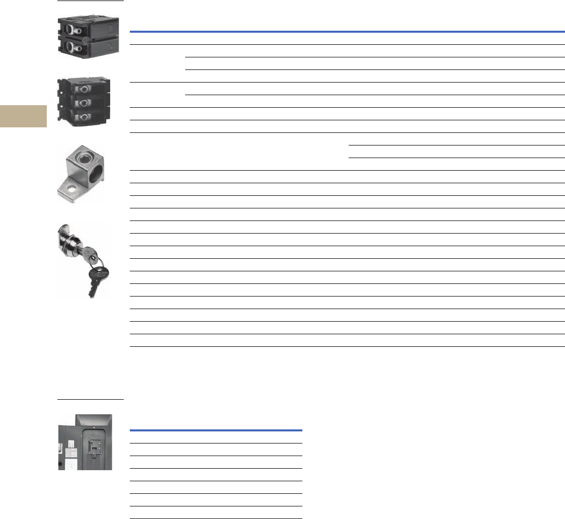
V12-T5-12 Volume 12—Aftermarket, Renewal Parts and Life Extension Solutions CA08100014E—November 2013 www.eaton.com
1
2
3
4
5
6
7
8
9
10
11
12
13
14
15
16
17
18
19
20
21
22
23
24
25
5
Loadcenters
Type BR
Type BR Replacement Parts and Covers
Mechanical Interlock Cover
Covers mechanically interlock two breakers—Type BW
or BWH main breaker with a Type BR branch breaker.
Mechanical Interlock Covers
Notes
1 Must be purchased in multiples of ordering quantities indicated.
2 #8–2/0 wire size range is 75°C rated only.
Number
of Poles
Ampere
Rating
Number of 1.00-Inch (25.4 mm)
Spaces Needed
Wire Size Range
Cu/Al 60°C or 75°C
Ordering
Quantity 2
Catalog
Number
Main and Subfeed Lug Blocks
2 125 2 #8–2/0 1 BRSF125
150 2 #8–2/0 1 BRSF150 2
225 4 #2–300 kcmil 1 BRS225
3 150 3 #8–2/0 1 3BRSF150 2
225 6 #2–300 kcmil 1 3BRS225
Main Lugs
Two-pole, 200A stud mounted (includes deadfront filler plate) #1–300 kcmil 1 BRL200
Neutral/ground lug
Add-on neutral or ground lug
#2/0 maximum 1 NL20
#3/0 maximum 1 NL30
300 kcmil maximum 1 NL300
Filler Plates
1.00-inch (25.4 mm) circuit breaker space 25 BRFP
BW main circuit breaker space (with hardware) 1 BWFP
Door lock —12–42 circuits, and 100–225A 1 TDL
Door lock—4–8 circuits, 125A 1CH9FL
ANSI-61 light gray touchup paint for current loadcenters 1 SPC61
Isolated neutral assembly (computer circuits) 1 BINA
Circuit directory—adhesive backed 10 TCD
Cover screws 25 LCCS
Cover replacement latch (gray) 14-5/16 (363.5 mm) wide loadcenters only 1 BRRL
Circuit marking strip (next to breaker) 10 BRMS
Circuit identification label (preprinted breaker labels) 25 CHBL
Series rated caution label 25 SRL
Bonding strip with screw 1BSSUSE
BRSF125
3BRS225
BRL200
TDL
Fits Loadcenter
Catalog Number
Mechanical Interlock Panel Cover
Catalog Number
BR816B200RF BR3RDF5M
BR2040B200R BR3RDF11M
BR3040B200R BR3RDF12M
BR4040B200R BR3RDF13M
BR2040B200 BRCOV20D1FM
BR3040B200 BRCOV30G1FM
BR4040B200 BRCOV40L1FM
BR4040B200
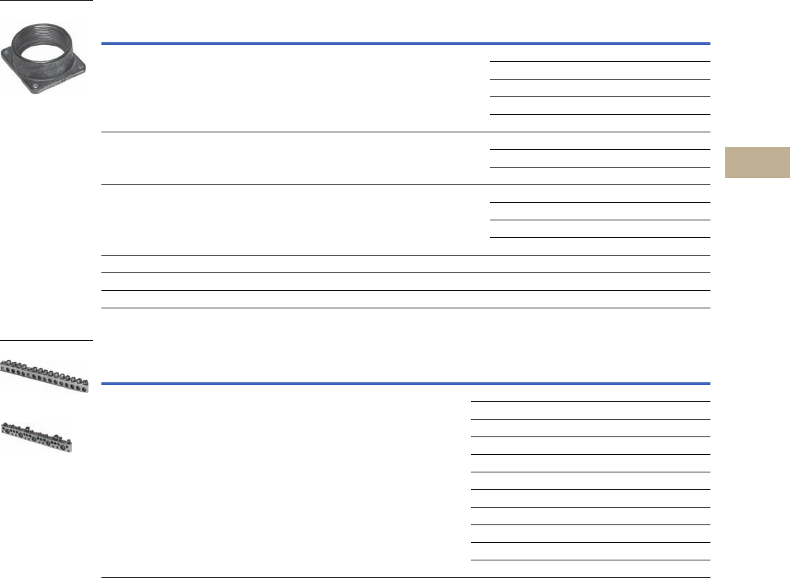
Volume 12—Aftermarket, Renewal Parts and Life Extension Solutions CA08100014E—November 2013 www.eaton.com V12-T5-13
1
2
3
4
5
6
7
8
9
10
11
12
13
14
15
16
17
18
19
20
21
22
23
24
25
5
Loadcenters
Type BR
Replacement Rainproof Conduit Hubs
Replacement Ground Bar Kits
Ground Bar Legend
Notes
1 Must be purchased in multiples of ordering quantities indicated.
2 Distance between mounting holes is 1.75 inches (44.5 mm).
3 For single- and three-phase 400 and 600A applications.
4 Distance between mounting holes is 2.34 inches (59.5 mm).
5 For non-metallic enclosures. Snaps into molded base.
Description
Conduit Size
Inches (mm)
Ordering
Quantity 1
Catalog
Number
Group 1—for use with 70, 100 and 125A MLO and MCB loadcenters and circuit breaker
enclosures and the following 150 and 200A panels: BR48B200RF
0.75 (19.1) 1 DS075H1
1.00 (25.4) 1 DS100H1
1.25 (31.8) 1 DS125H1
1.50 (38.1) 1 DS150H1
2.00 (50.8) 1 DS200H1
Group 2—for use with 150, 200 and 225A MLO and MCB loadcenters and circuit breaker enclosures
except for the following 200A loadcenters: BR48B200RF. Also for use with 400 and 600A loadcenters
and New York City loadcenters manufactured after November 1, 2005
2.00 (50.8) 1 DS200H2
2.50 (63.5) 1 DS250H2
3.00 (76.2) 1 DS300H2
Type H conduit hubs for loadcenters PL0724R and S3100RN 0.75 (19.1) 1 RH75P
1.00 (25.4) 1 RH100P
1.25 (31.8) 1 RH125P
1.50 (38.1) 1 RH150P
Adapter kit—Allows Installing a Group 1 hub on devices arranged for Group 2 hubs — 1 DS900AP
Group 1 small blank hub plate with bump — 1 DS900CP1
Group 2 Large blank hub plate with bump — 1 DS900CP2
Description
(See Legend)
Length
Inches (mm)
Ordering
Quantity 1
Catalog
Number
dssssds 2.54 (64.5) 1 GBK5 2
dssssdsj 3.59 (91.2) 1 GBK520 2
dssssdssssss 4.29 (109.0) 1 GBK10 2
dssssdssssssj 5.34 (135.6) 1 GBK1020 2
4.61 (117.1) 1 GBK13 2
dssssdssssssssss 5.69 (144.5) 1 GBK14 2
dssssdssssssssssj 6.74 (171.2) 1 GBK1420 2
dssssdsssssssssssssssss 8.14 (206.8) 1 GBK21 2
dssssdsssssssssssssssssj 9.19 (233.4) 1 GBK2120 2
5.78 (146.8) 1 BRGBK39512 34
sssss 1.84 (46.7) 1 GB4NM 5
s
j
d
(3) #14–10 Cu/Al or (1) #14–4 Cu/Al
(1) #6–2/0 Cu/Al
(1) #14–1/0 Cu/Al or (3) #14–10 Cu/Al
(1) #14–6 Cu/Al or (2) #14–12 Cu/Al
Mounting Hole
DS300H2
GBK14
BRGBK39512
f
d
f
f
f
k
f
d
f
k
f
f
f
f
k
f
d
f
k
f
f
f
k
f
d
f
k
f
f
f
k
f
k
f
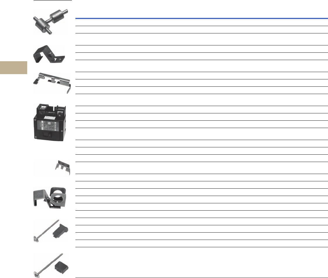
V12-T5-14 Volume 12—Aftermarket, Renewal Parts and Life Extension Solutions CA08100014E—November 2013 www.eaton.com
1
2
3
4
5
6
7
8
9
10
11
12
13
14
15
16
17
18
19
20
21
22
23
24
25
5
Loadcenters
Type BR
Replacement Breaker Accessories
Notes
1 Must be purchased in multiples of ordering quantities indicated.
2 Handle ties: typically used to join two similar independent single-pole breakers to form a two-pole noncommon trip breaker.
3 Handle lockoffs: devices that use a padlock to lock the circuit breaker’s handle in the ON or OFF position.
4 Escutcheon mounted: device mounted semipermanently to the face of the circuit breaker and secured by the loadcenter deadfront.
5 Handle mounted: device mounted directly to the handle by the use of a set screw.
6 Screw mounted: device permanently mounted to the face of the circuit breaker by the use of a non-removable screw.
7 Handle lockdogs: devices that are used to secure a circuit breaker’s handle in the ON or OFF position. Handle Lockdogs are not padlockable devices.
8 Hold-down kits: devices used to secure the circuit breaker to the loadcenter for back-feed main application. See NEC Article 384.16(g).
Description
Ordering
Quantity
1
Catalog
Number
Handle Ties 2
Handle tie bar for physically joining the handles of two adjacent single-pole Type BR circuit breakers (metal cylinder pin type)10BHT
Handle tie bar for joining two independent outside poles of Types BQ and BQC Quadplex and outside poles of two Type BD
duplex circuit breakers
10 THOW
Handle tie bar for joining two adjacent outside poles of Types BQ and BQC Quadplex and outside poles of two Type BD duplex circuit breakers 10 THS1
Handle Lockoffs 3
Padlockable device for locking the handle of single-, two- or three-pole Type BR Circuit Breakers and single-pole of a Type BD Duplex
or one independent outside pole of a Type BQ or BQC Quadplex circuit breakers (escutcheon mounted) 5
10 BRLW
Padlockable device for locking the handle of a single-pole Type BR circuit breaker.(handle mounted) 510 BRLW1
Padlockable device for locking the handle of a two- and three-pole Type BR circuit breaker (handle mounted) 510 BRLW2
Padlockable device for locking the handle of a single-pole Type BD Duplex, BQ or BQC Quadplex breaker (handle mounted) 510 BRDL1
Padlockable device for locking the handle of the two center poles and the two outer poles of a two-pole Types BQ and BQC quadplex
circuit breakers (escutcheon mounted) 4
10 BRQLW
Padlockable device for locking the handle of main circuit breaker Types CC and CHH into the ON or OFF position (screw mounted) 6 1 CCPL
Padlockable device for locking the handle of main breaker Types BW and BWH into the ON or OFF position (escutcheon mounted) 41MCBPL
Handle Lockdog 7
Device used to secure handle in ON or OFF position for single-, two- or three-pole Type BR circuit breakers and single-pole of Type BD
duplex and one independent outside pole of Type BQ or BQC Quadplex circuit breakers (escutcheon mounted) 5
10 BHLW
Device used to secure handle in ON or OFF position for single-pole Type BR circuit breakers (handle mounted) 510 BHLW1
Device used to secure handle in ON or OFF position for two- and three-pole Type BR circuit breakers (handle mounted) 510 BHLW2
Device used to secure handle in ON or OFF position for single-pole Type GFCB ground fault circuit breakers (handle mounted) 510 BHGW
Device used to secure handle in ON or OFF position for one independent outside pole of Types BQ and BQC Quadplex or single-pole
Type BD duplex circuit breakers (handle mounted) 5
10 HLW1
Hold-Down Kits 8
Hold-down retainer kit for three-pole Type BR circuit breakers in S3100 and 3100R loadcenters only 1 BRHDB
Hold-down screw kit for two-pole Type BR circuit breakers in single-phase MLO loadcenters through 125A 1 BREQS125
Hold-down screw kit for two-pole Type BR circuit breakers in MLO loadcenters 150–225A (single-phase only) 1 BRHDK125
Hold-down screw kit for two-pole Types BJ and BJH circuit breakers in MLO loadcenters 125–225A 1 BJHDS
Hold-down screw kit for three-pole Types BJ and BJH circuit breakers in MLO loadcenters 125–225A 1 BJHDS3P
Main Breaker Lug Kits
Types CC and CHH main breaker lug kit (2) 300 kcmil 1CCL300
Types BW/BWH main breaker lug kit (2) 300 kcmil 1MCBL300
Mechanical Interlock
Types BR for two-, three- and four-pole breakers 10 BRML
THS1
BHLW2
BRQLW
MCBPL (Installed)
BHLW
BRLW2
BREQS125
BRHDK125

Volume 12—Aftermarket, Renewal Parts and Life Extension Solutions CA08100014E—November 2013 www.eaton.com V12-T5-15
1
2
3
4
5
6
7
8
9
10
11
12
13
14
15
16
17
18
19
20
21
22
23
24
25
5
Loadcenters
Type BR
Renewal Parts for Type BR Loadcenter Covers and Deadfronts
Single-Phase with Main Circuit Breakers
Catalog
Number
Combination
Covers
Surface
Covers
NEMA 3R
Covers
NEMA 3R
Deadfronts
Catalog
Number
Combination
Covers
Surface
Covers
NEMA 3R
Covers
NEMA 3R
Deadfronts
B4242DFN 315-003-28 — — — BR2040B150R — — BR3RDOOR8 BR3RDF11
B4242DR1N — — Not available — BR2040B200 BRCOVC35 — — —
B4242DSN — 315-003-27 — — BR2040B200R — — BR3RDOOR9 BR3RDF11
B4242EFN 315-003-28 — — — BR2040H200 BRCOVC35 — — —
B4242ESN — 315-003-27 — — BR2430B150 BRCOVC40 — — —
BR1020B100RF — — BR3RDOOR2 BR3RDF1 BR2440B200 BRCOVC41 — — —
BR1212B100 BRCOVC12 — — — BR3030BC100 BRCOVC59
BR1220B100 BRCOVC12 — — — BR3030B150 BRCOVC40 — — —
BR1224B100R — BR3RDOOR2 BR3RDF1 BR3030B150R — — BR3RDOOR10 BR3RDF12
BR1224B100SFG 47-37466 47-37469 BR3030BC150 BRCOVC40 — — —
BR1616B100 BRCOVC16 — — — BR3040B150 BRCOVC40 — — —
BR1620B100 BRCOVC16 — — — BR3040B200 BRCOVC41 — — —
BR1624B100 BRCOVC16 — — — BR3040B200R — — BR3RDOOR11 BR3RDF12
BR1624B100R — — BR3RDOOR3 BR3RDF2 BR3040H200 BRCOVC41 — — —
BR1624B125 BRCOVC17 — — — BR304242F 315-003-28 — — —
BR1630B150 BRCOVC29 — — — BR304242S — 315-003-27 — —
BR1632B200 BRCOVC31 — — — BR4040B200 BRCOVC44 — — —
BR2020B100 BRCOVC22 — — — BR4040BC200 BRCOVC44 — — —
BR2024B100R — — BR3RDOOR4 BR3RDF4 BR4040B200R — — BR3RDOOR12 BR3RDF13
BR2024B125 BRCOVC23 — — — BR4040H200 BRCOVC44 — — —
BR2024B125R — — BR3RDOOR4 BR3RDF4 BR4242B225 BRCOVC53 (2) — — —
BR2024H100 BRCOVC22 — — — BR4242B225R — — BR3RDOOR13 BR3RDF15
BR2030B150 BRCOVC32 — — — BR48B200RF — — BR3RDOOR15 BR3RDF14
BR2030B150R — — BR3RDOOR8 BR3RDF11 BR816B100 BRCOVC10 — — —
BR2030H150 BRCOVC32 — — — BR816B150RF — — BR3RDOOR5 BR3RDF5
BR2040B150 BRCOVC40 — — — BR816B200RF — — BR3RDOOR6 BR3RDF5

V12-T5-16 Volume 12—Aftermarket, Renewal Parts and Life Extension Solutions CA08100014E—November 2013 www.eaton.com
1
2
3
4
5
6
7
8
9
10
11
12
13
14
15
16
17
18
19
20
21
22
23
24
25
5
Loadcenters
Type BR
Convertible
Catalog
Number
Combination
Covers
Surface
Covers
NEMA 3R
Covers
NEMA 3R
Deadfronts
3BR1224N125 BRCOVC20 — — —
3BR1224N125R — — BR3RDOOR29 BR3RDF2
3BR1224N125S — BRCOVS20 — —
3BR3030N100 BRCOVC37 — — —
3BR3030N100R — — BR3RDOOR30 —
3BR3030N100S — BRCOVS37 — —
BR1224N125 BRCOVC13 — — —
BR1224N125R — — BR3RDOOR2 BR3RDF1
BR1224NC125R BR3RDOOR2
BR1224N200 BRCOVC30 — — —
BR1224N200R — — BR3RDOOR6 BR3RDF5
BR1624N125 BRCOVC17 — — —
BR1624N125R — — BR3RDOOR3 BR3RDF2
BR1632N200 BRCOVC31 — — —
BR1632N200SFG 47-37460 47-37375
BR2024N125 BRCOVC23 — — —
BR2024N125R — — BR3RDOOR4 BR3RDF4
BR2040N200 BRCOVC35 — — —
BR2040N200R — — BR3RDOOR9 BR3RDF11
BR2440N200 BRCOVC41 — — —
BR3040N200 BRCOVC41 — — —
BR3040N200R — — BR3RDOOR11 BR3RDF12
BR4040N200 BRCOVC44 — — —
BR4040N200R — — BR3RDOOR12 BR3RDF13
BR816N200RF — — BR3RDOOR6 BR3RDF5
BR4040NL200G BRCOVC44 + BWFP — — —
Manufactured Housing Loadcenters
Single-Phase with Main Circuit Breaker
Note
1These covers are painted white (standard color is gray).
Catalog
Number
Cover
Number
BR1020B100GK MBCOVC10
BR1020B100PK MBCOVC10
BR1220B100GK MBCOVC11
BR1220B100PK MBCOVC11
BR1224B100PK MBCOVC24
BR1224B100GK MBCOVC24
BR1224B100GK MBCOVC25 1
BR1224B150GK MBCOVC12
BR1224B150PK MBCOVC12
BR1630B150GK MBCOVC13
BR1630B150PK MBCOVC13
BR1224B200GK MBCOVC14
BR1224B200PK MBCOVC14
BR1632B200GK MBCOVC15
BR1632B200PK MBCOVC15
BR2040B200GK MBCOVC16
BR2040B200PK MBCOVC16
BR1020B100PKW MBCOVC17 1
BR1220B100PKW MBCOVC18 1
BR1224B100PKW MBCOVC25 1
BR1224B150PKW MBCOVC19 1
BR1630B150PKW MBCOVC20 1
BR1224B200PKW MBCOVC21 1
BR1632B200PKW MBCOVC22 1
BR2040B200PKW MBCOVC23 1

Volume 12—Aftermarket, Renewal Parts and Life Extension Solutions CA08100014E—November 2013 www.eaton.com V12-T5-17
1
2
3
4
5
6
7
8
9
10
11
12
13
14
15
16
17
18
19
20
21
22
23
24
25
5
Loadcenters
Type BR
Single-Phase with Main Lugs
Catalog
Number
Combination
Covers
Surface
Covers
NEMA 3R
Covers
NEMA 3R
Deadfronts
Catalog
Number
Combination
Covers
Surface
Covers
NEMA 3R
Covers
NEMA 3R
Deadfronts
1224DRIN — — Not available — BR24L70RP — — Not available —
1224DSN — Not available — — BR24L70SGP — Not available — —
2442DSN — Not available — — BR24L70SP — Not available — —
2460FGNM — — — — BR1224L125RIS BRCOVC66
2460FNM — — — — BR1224L125RISBP BRCOVC66
2460RNM — — — — BR2024L125RIS BRCOVC66
2460SGNM — — — — BR3040L200 BRCOVC36 — — —
2460SNM — — — — BR3040L200G BRCOVC36 — — —
4242DFN 315-003-06 — — — BR3040L200R — — BR3RDOOR9 BR3RDF8
4242DRIN — Not available — — BR4040L200 BRCOVC42 — — —
4242DSN — 315-003-05 — — BR4040L200R — — BR3RDOOR11 BR3RDF9
4242ESN — 315-003-05 — — BR4242L225 BRCOVC45 — — —
BR1212L125 BRCOVC11 — — — BR4242L225R — — BR3RDOOR14 BR3RDF10
BR1224L125 BRCOVC11 — — — BR48L125FDP BRCOVC62 (flush) — — —
BR1224L125DG BRCOVC11 — — — BR48L125FGP BRCOVC63 (flush) — — —
BR1224L125G BRCOVC11 — — — BR48L125FP BRCOVC61 (flush) — — —
BR1224L125R — — BR3RDOOR1 BR3RDF3 BR48L125RP — — BR3RDOOR26 BR3RDF22
BR1224L200 BRCOVC15 — — — BR48L125SGP — BRCOVS60 — —
BR1224L200R — — BR3RDOOR7 BR3RDF6 BR48L125SP — BRCOVS59 — —
BR1616L125 BRCOVC14 — — — BR612L125FDGP BRCOVC08 — — —
BR1624L125 BRCOVC14 — — — BR612L125FDP BRCOVC08 — — —
BR1624L125G BRCOVC14 — — — BR612L125FGP BRCOVC63 — — —
BR1624L125R — — BR3RDOOR2 BR3RDF1 BR612L125FP BRCOVC08 — — —
BR1630L150 BRCOVC25 — — — BR612L125RP — — BR3RDOOR27 BR3RDF23
BR2020L125 BRCOVC18 — — — BR612L125SDGP — BRCOVS08 — —
BR2024L125 BRCOVC18 — — — BR612L125SDP — BRCOVS08 — —
BR2024L125G BRCOVC18 — — — BR612L125SGP — BRCOVS60 — —
BR2024L125R — — BR3RDOOR3 BR3RDF2 BR612L125SP — BRCOVS59 — —
BR2030L150 BRCOVC25 — — — BR816L125FDGP BRCOVC64 (flush) — — —
BR2040L200 BRCOVC25 — — — BR816L125FDP BRCOVC64 (flush) — — —
BR2040L200G BRCOVC25 — — — BR816L125FGP BRCOVC09 — — —
BR2040L200R — — BR3RDOOR6 BR3RDF7 BR816L125FP BRCOVC09 — — —
BR2424L125 BRCOVC24 — — — BR816L125RP BR3RDOOR28 BR3RDF23
BR2424L125G BRCOVC24 — — — BR816L125SDGP BRCOVS61 — —
BR2440L200 BRCOVC33 — — — BR816L125SDP — BRCOVS61 — —
BR24L125FP BRCOVC60 (FLUSH) — — — BR816L125SGP BRCOVS09 — —
BR24L125RP — — BR3RDOOR25 BR3RDF21 BR816L125SP BRCOVS09 — —
BR24L125RSE2P — — — BR3RDF21 BR816L200RF — — BR3RDOOR7 BR3RDF6
BR24L125RSEP — — — BR3RDF21 BR816LC125FDP BRCOVC64 (flush) — — —
BR24L125SP — BRCOVS62 — — TT120FLGNM ————
BR24L70FGP Not available — — — TT120SLGNM ————

V12-T5-18 Volume 12—Aftermarket, Renewal Parts and Life Extension Solutions CA08100014E—November 2013 www.eaton.com
1
2
3
4
5
6
7
8
9
10
11
12
13
14
15
16
17
18
19
20
21
22
23
24
25
5
Loadcenters
Type BR
Three-Phase with Main Lugs
Catalog
Number
Combination
Covers
Surface
Covers
NEMA 3R
Covers
NEMA 3R
Deadfronts
31836DFN Not available — — —
31836DR1N — — Not available —
31836DSN — Not available — —
32442DSN — Not available — —
34242DFN 315-003-06 — — —
34242DR1N — — Not available —
34242DSN — 315-003-05 — —
34242EFN 315-003-06 — — —
34242ESN — 315-003-05 — —
3BR1224L125 BRCOVC21 — — —
3BR1224L125R — — BR3RDOOR29 BR3RDF2
3BR1224L125S — BRCOVS21 — —
3BR1224L200 BRCOVC34 — — —
3BR1224L200R — — BR3RDOOR16 BR3RDF7
3BR1224L200S — BRCOVS34 — —
3BR1836L150 BRCOVC27 — — —
3BR1836L150R — — BR3RDOOR17 BR3RDF7
3BR1836L150S — BRCOVS27 — —
3BR1836L200 BRCOVC34 — — —
3BR1836L200R — — BR3RDOOR16 BR3RDF7
3BR1836L200S — BRCOVS34 — —
3BR2442L150 BRCOVC39 — — —
3BR2442L150R — — BR3RDOO18 BR3RDF16
3BR2442L150S — BRCOVS39 — —
3BR2442L200 BRCOVC43 — — —
3BR2442L200S —- BRCOVS43 — —
3BR3042L200 BRCOVC43 — — —
3BR3042L200R — — BR3RDOO19 BR3RDF18
3BR3042L200S — BRCOVS43 — —
3BR4242L200 BRCOVC48 — — —
3BR4242L200R — — BR3RDOOR21 BR3RDF20
3BR4242L200S — BRCOVS48 — —
3BR4242L225 BRCOVC49 — — —
3BR4242L225R — — BR3RDOOR24 BR3RDF20
3BR4242L225S — BRCOVS49 — —
Three-Phase with Main Circuit Breaker
Catalog
Number
Combination
Covers
Surface
Covers
NEMA 3R
Covers
NEMA 3R
Deadfronts
3B4242DFN 315-003-28 — — —
3B4242DR1N — — Not available —
3B4242DSN — 315-003-27 — —
3B4242EFN 315-003-28 — — —
3B4242ESN — 315-003-27 — —
3BR1224B100 BRCOVC19 — — —
3BR1224B100R — — BR3RDOOR29 BR3RDF2
3BR1224B100S — BRCOVS19 — —
3BR1224H100 BRCOVC19 — — —
3BR1224H100S — BRCOVS19 — —
3BR3042B125 BRCOVC54 — — —
3BR3042B125S — BRCOVS54 — —
3BR3042B150 BRCOVC55 — — —
3BR3042B150R — — BR3RDOOR20 BR3RDF17
3BR3042B150S — BRCOVS55 — —
3BR3042B200 BRCOVC56 — — —
3BR3042B200R — — BR3RDOOR21 BR3RDF17
3BR3042B200S — BRCOVS56 — —
3BR3042H150 BRCOVC55 — — —
3BR3042H150S — BRCOVS55 — —
3BR3042H200 BRCOVC56 — — —
3BR3042H200S — BRCOVS56 — —
3BR4242B200 BRCOVC57 — — —
3BR4242B200R — — BR3RDOOR22 BR3RDF19
3BR4242B200S — BRCOVS57 — —
3BR4242B225 BRCOVC58 — — —
3BR4242B225R — — BR3RDOOR23 BR3RDF19
3BR4242B225S — BRCOVS58 — —
3BR4242H200 BRCOVC57 — — —
3BR4242H200S — BRCOVS57 — —

Volume 12—Aftermarket, Renewal Parts and Life Extension Solutions CA08100014E—November 2013 www.eaton.com V12-T5-19
1
2
3
4
5
6
7
8
9
10
11
12
13
14
15
16
17
18
19
20
21
22
23
24
25
5
Loadcenters
Type BR
Replacement Interior Assembly
Type BR Loadcenter Interior Assemblies
Ampere
Rating
Maximum Number 1.00-Inch (25.4 mm) UL File
Reference
Main Terminal Size
(Per Phase)
Standard
Package Quantity
Catalog
NumberSpaces Single Poles
Single-Phase Single Row Breaker Mounting—Aluminum Bus—120/240 Vac, Three-Wire
70 2 4 — (1) #8–#2 AWG Cu/Al 20 24INT70B
125 2 4 E8741 (1) 1/0–#14 AWG Cu
2/0–12 AWG All
20 24INT125B
125 6 12 E52977 (1) 2/0–#14 AWG Cu/Al 20 612INT125SRB
Single-Phase Double Row Breaker Mounting—Aluminum Bus—120/240 Vac, Three-Wire
125 4 8 E8741 (1) 2/0–#14 AWG Cu/Al 20 48INT125B
125 6 12 E8741 (1) 2/0–#14 AWG Cu/Al 20 612INT125B
125 8 16 E8741 (1) 2/0–#14 AWG Cu/Al 20 816INT125B
125 12 12 E52977 (1) 2/0–#14 AWG Cu/Al 20 1212INT125B
125 12 24 E52977 (1) 2/0–#14 AWG Cu/Al 20 1224INT125B
125 16 24 E52977 (1) 2/0–#14 AWG Cu/Al 20 1624INT125B
125 20 24 E52977 (1) 2/0–#14 AWG Cu/Al 10 2024INT125B
125 24 24 E52977 (1) 2/0–#14 AWG Cu/Al 10 2424INT125B
200 8 16 E52977 (1) 300 kcmil–#1 AWG Cu/Al 20 816INT200B
200 12 24 E52977 (1) 300 kcmil–#1 AWG Cu/Al 20 1224INT200B
200 30 40 E52977 (1) 300 kcmil–#1 AWG Cu/Al 10 3040INT200B
200 42 42 E52977 (1) 300 kcmil–#1 AWG Cu/Al 10 4242INT225B
Single-Phase Double Row Breaker Mounting—Copper Bus—120/240 Vac, Three-Wire
125 8 16 E5297 (1) 2/0–#14 AWG Cu/Al 20 816INT125BC
125 12 12 E5297 (1) 2/0–#14 AWG Cu/Al 20 1212INT125BC
200 12 24 E5297 (1) 300 kcmil–#1 AWG Cu/Al 20 1224INT200BC
Three-Phase Double Row Breaker Mounting—Aluminum Bus—208Y/120 Vac, Four-Wire—240 Vac, Three-Wire—
120/240 Vac, Four-Wire Delta
125 12 34 E52977 (1) 2/0–#8 AWG Cu/Al 10 1224INT3125B
150 18 36 E52977 (1) 300 kcmil–#2 AWG Cu/Al 10 1836INT3150B
150 24 42 E52977 (1) 300 kcmil–#2 AWG Cu/Al 10 2442INT3150B
200 30 42 E52977 (1) 300 kcmil–#2 AWG Cu/Al 10 3042INT3200B
225 42 42 E52977 (1) 300 kcmil–#2 AWG Cu/Al 10 4242INT3225B
Three-Phase Double Row Breaker Mounting—Copper Bus—208Y/120 Vac, Four-Wire—240 Vac, Three-Wire—
120/240 Vac, Four-Wire Delta
125 12 24 E52977 (1) 2/0–#8 AWG Cu/Al 10 1224INT3125BC
200 12 24 E52977 (1) 300 kcmil–#2 AWG Cu/Al 10 1224INT3200BC
BR Loadcenter
Interior Assembly
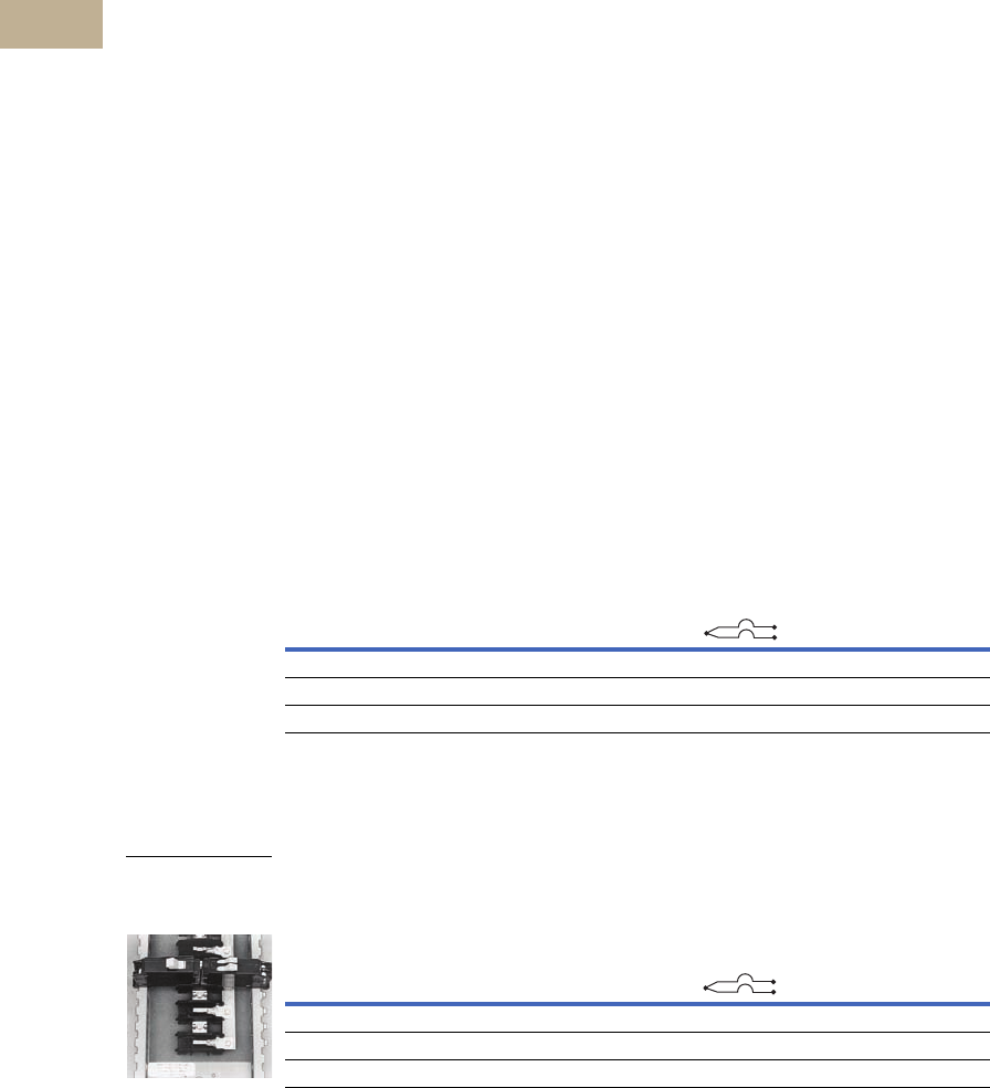
V12-T5-20 Volume 12—Aftermarket, Renewal Parts and Life Extension Solutions CA08100014E—November 2013 www.eaton.com
1
2
3
4
5
6
7
8
9
10
11
12
13
14
15
16
17
18
19
20
21
22
23
24
25
5
Loadcenters
Replacement Breakers
Product Description
Eaton UL classified
replacement circuit breakers
are available in both 3/4-inch
Type CHQ and 1.00-inch
Type CL, single- and two-pole
configurations. These
breakers are classified as
direct replacements by
Underwriters Laboratories.
In addition to a UL listing,
they also come with a
15-year warranty.
Specified vs. UL Classified
Specified breakers are listed
by the manufacturer of the
panelboard for use in a
particular panel. This doesn’t
mean that the panelboard
manufacturer produced the
specified breaker; it merely
means that the panelboard
manufacturer has tested the
breaker in the panel. In fact,
through the years, Eaton has
manufactured thousands of
breakers for other panelboard
manufacturers.
UL classified breakers
are produced by one
manufacturer for use in
place of the breakers
specified on the panelboard.
Like specified breakers, UL
classified breakers have been
tested in the panels for which
they are approved.
Testing
Classified breakers are tested
extensively in numerous
General Electric®, Siemens®,
Murray®, Thomas & Betts®,
Square D® and Crouse-
Hinds® panels. The tests
are conducted with
witnesses from Underwriters
Laboratories and involve
short circuit, temperature
and insertion/withdrawal
applications. This level of
testing ensures that the
breakers meet identified
standards and have been
found suitable by UL for
the specified
purpose.
Understanding Classified
Breaker Terminology
Definitions
Specified Circuit Breaker—
Each manufacturer lists the
brands of circuit breakers
that can be used in their
panelboards. Often,
manufacturers will not list
competitors as specified,
even though they are
suitable replacements.
Classified Circuit Breaker—
A breaker that is considered
suitable, by a qualified third-
party organization, for use
in another manufacturer’s
panelboard.
Listed Breaker—The listing
of a circuit breaker is by an
independent third party. Eaton
classified breakers are listed
by UL.
Labeled Breaker
—A breaker
with a label
affixed by an
independent third party.
Non-CTL Plug-On Replacement Circuit Breakers, Type CHNT 10 kAIC, 120/240 Vac
For use as replacement in loadcenters built prior to 1968 and within the current style
loadcenters as indicated in the loadcenter section.
3/4-Inch (19.1 mm) per Pole 120 Vac, Non-CTL 10 kAIC
CTL Plug-On Circuit Breakers, Type CHT Twin 10 kAIC, 120/240 Vac
All circuit breakers have rejection feature. Use only with loadcenters marked for use with CHT breakers.
Twin (CTL) 3/4-Inch (19.1 mm) per Pole 120 Vac Class CTL 10 kAIC
Notes
1 Switching duty rated.
2 HACR rated.
Ampere
Rating
Wire Size Range
Cu/Al 60ºC or 75°C
Single-Pole Requires
One 3/4-Inch (19.1 mm) Space
10 per Shelf Carton
Catalog Number
15–15 #14–8 CHNT1515 12
15–20 #14–8 CHNT1520 12
20–20 #14–8 CHNT2020 12
Ampere
Rating
Wire Size Range
Cu/Al 60ºC or 75°C
Single-Pole Requires
One 3/4-Inch (19.1 mm) Space
10 per Shelf Carton
Catalog Number
15–15 #14–8 CHT1515 12
15–20 #14–8 CHT1520 12
20–20 #14–8 CHT2020 12
120/240 Vac
120/240 Vac
Type CH and CHT
Circuit Breakers
Mounted in Twin
Breaker Panel
120/240 Vac
120/240 Vac
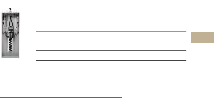
Volume 12—Aftermarket, Renewal Parts and Life Extension Solutions CA08100014E—November 2013 www.eaton.com V12-T5-21
1
2
3
4
5
6
7
8
9
10
11
12
13
14
15
16
17
18
19
20
21
22
23
24
25
5
Loadcenters
Type CH
Type CH Renovation
Loadcenter
Product Description
Eaton’s Renovation
Loadcenter is designed
for the service contractor.
With the addition of a five-
circuit terminal block factory
mounted in the top left
corner of the loadcenter, the
service contractor can
terminate short-circuit wires
instead of having to use
expensive wire nuts. Also,
the Renovation Loadcenter
incorporates a twin-stacked
neutral design that places the
neutral and ground
terminations higher in the
loadcenter. Both of these
features were added without
increasing any size from a
standard loadcenter. These
features will eliminate the
need for wire nuts and make
for a much neater installation.
There is a provision to field
mount a second five-circuit
terminal block (RN5TB) in
the top right corner of the
loadcenter. Choose amongst
Eaton’s Type CH breaker
family for use in the
Renovation Panel.
Product Selection
Single-Phase—Main Circuit Breaker Loadcenters 35 kAIC 1
Single-Phase, Three-Wire—120/240 Vac—Factory-Bonded Stacked
Split Neutral
Branch Circuit Breakers (CH)
See Volume 1—Residential and Light Commercial, CA08100002E, Tab 1.
Renovation Loadcenter
Notes
1100A main breaker is rated 10 kAIC.
2Combination style covers may be used in surface or flush applications.
All main circuit breaker loadcenters are listed for use as service entrance equipment.
Loadcenters are factory-bonded for service entrance applications. Remove bonding strap
for separate neutral and ground bars for sub-feed applications.
Main
Breaker
Type
Main
Ampere
Rating
Max.
Number
3/4-Inch
(19.1 mm)
of Poles
Enclosure
Type
Box
Size
Wire Size
Range Cu/Al
60 or 70ºC for
Main Breakers
Loadcenter
Catalog
Number
Cover
Catalog Number 2
Combination Surface
CH 100 20 Indoor C #6–1/0 CH22B100CRN CH8CFF CH8CS
CSH 150 32 Indoor J #2–300 kcmil CH32B150JRN CH8JF CH8JS
CSH 200 32 Indoor J #2–300 kcmil CH32B200JRN CH8J CH8JS
CSH 200 42 Indoor K #2–300 kcmil CH42B200KRN CH8KF CH8KS
Description Catalog Number
Five-circuit terminal block kit
Ground bar kits (two maximum per panel)
RN5TB
(See Page V12-T5-5)
Renovation Panel
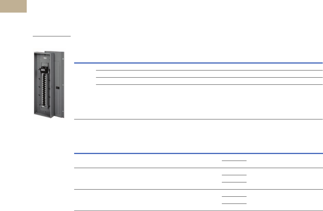
V12-T5-22 Volume 12—Aftermarket, Renewal Parts and Life Extension Solutions CA08100014E—November 2013 www.eaton.com
1
2
3
4
5
6
7
8
9
10
11
12
13
14
15
16
17
18
19
20
21
22
23
24
25
5
Loadcenters
Type C H
Plug-On Neutral
Loadcenter
Product Description
Code changes and higher
safety standards are leading
to more arc fault and ground
fault circuit interrupter
installations. Eaton offers a
unique product solution that
enables a direct connection of
the breaker to the neutral bar,
eliminating the need for
wiring a pigtail.
Features and Benefits
●Time savings up to 25%
per AFCI/GFCI installation
●Eliminates nuisance
tripping due to loose pigtail
connections
●Clean gutter space
●Easier troubleshooting
due to less wiring
●Backed by a limited
lifetime warranty
Product Selection
Main Breaker Plug-On Neutral Loadcenters
Main Lug Only/Convertible Plug-On Neutral Loadcenters—With Factory Installed Main Lugs
Note
1 Requires the use of type CHNT breakers.
Main
Breaker
Type
Main
Ampere
Rating
Max.
Number
3/4-Inch
Circuits
Max.
Number
of Poles
Enclosure
Type
Box
Size
Wire Size
Range Cu/Al
Catalog
Number
Cover
Catalog Number
Combination Surface
CSH 35
kAIC
100 24 24 Indoor E #2–300 kcmil CH24BPN100E CH8EF CH8ES
200 32 32 Indoor J #2–300 kcmil CH32BPN200J CH8JF CH8JS
200 42 42 Indoor K #2–300 kcmil CH42BPN200K CH8KF CH8KS
200 60 120 1Indoor N #2–300 kcmil CH60BPN200N CH8NF —
Max.
Ampere
Rating
Max.
Number
3/4-Inch
Poles
Enclosure
Type
Box
Size
Catalog
Number
Wire Size
Range for
Main Lug
Main
Breaker
Kit
Wire Size
Range
For Main
Breaker
Cover
Catalog Number
Combination Surface
125 24 Indoor E CH24NLPN125E #6–300 kcmil CSH2100N #2–300 kcmil CH8NLEF CH8NLES
CSH2125N
225 32 Indoor J CH32NLPN225J #6–300 kcmil CSH2125N #2–300 kcmil CH8NLJF CH8NLJS
CSH2200N
CSH2100N
225 42 Indoor K CH42NLPN225K #6–300 kcmil CSH2125N #2–300 kcmil CH8NLKF CH8NLKS
CSH2150N
CSH2200N
Plug-On Neutral
Loadcenter
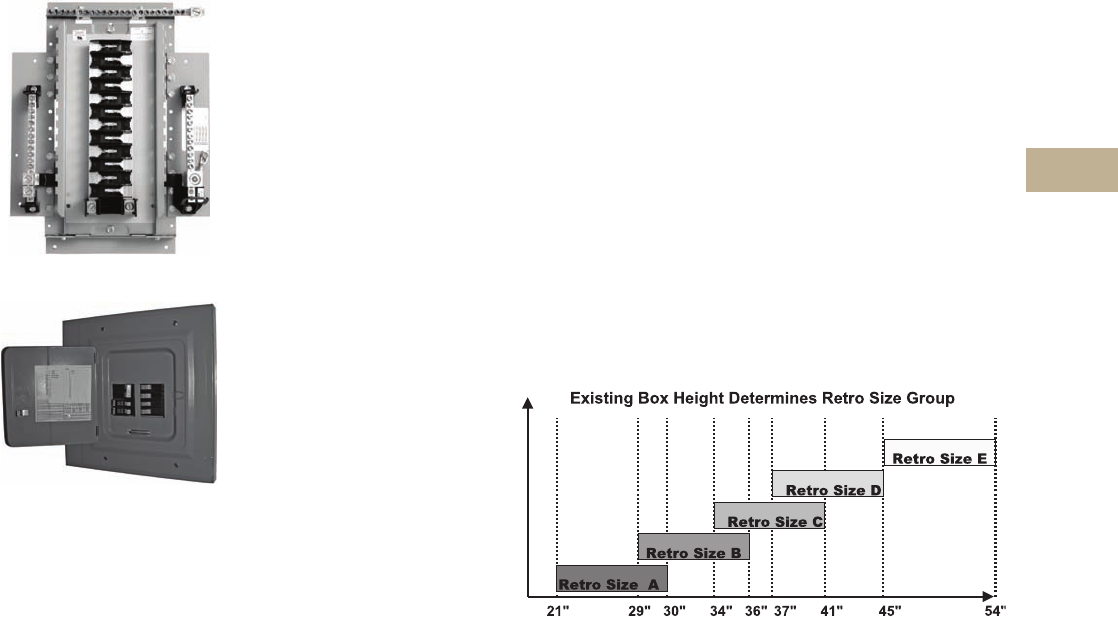
Volume 12—Aftermarket, Renewal Parts and Life Extension Solutions CA08100014E—November 2013 www.eaton.com V12-T5-23
1
2
3
4
5
6
7
8
9
10
11
12
13
14
15
16
17
18
19
20
21
22
23
24
25
5
Loadcenters
Type CH
Type CH Retrofit
Interior Kits
Type CH Retrofit Adjustable Interior
Type CH Retrofit Interior Collar
and Assembly with Trim
Product Description
Replacing existing
loadcenters and panelboards
can be a time consuming
and expensive job. CH retrofit
kits can be the solution to
save time and money. The
kit consists of a standard trim
to fit the interior, a picture
frame trim to fit the existing
box, and a field-adjustable
interior assembly that
includes neutral and ground
bars. These are especially
applicable when the existing
box is flush mounted in
drywall, plaster or block
wall. The existing box, and
many times existing wiring,
can remain.
Features and Benefits
Upgrading Existing Electrical
Infrastructure is Simple
●Replaces vintage brands
that have hard to find,
expensive replacement
breakers
●Allows safety upgrade
to arc fault and ground
fault breakers
●Maximizes number of
circuits available with
compact design
●Meets 2008 NEC wire
bending requirements
●Eco-friendly in asbestos-
filled environments
●Exclusive design
Save Time and Money
Throughout the Installation
●Uses existing panel
box and wires
●Eliminates expensive
drywall/paint repair
●Saves 2–3 hours compared
to a complete panel
changeout—get off the
job faster
●Eliminates precise
measurements with
field-adjustable kit
Detailed Product Guide
All standard retrofit kits are
suitable for a range of
existing box sizes:
●Box width ranging from
14.50 to 22.00 inches
(368.3 to 558.8 mm)
●Box depth ranging from
4.25 inches (108.0 mm)
for CH to 6.00 inches
(152.4 mm)
●Box height ranging from
21.00 to 45.00 inches
(533.4 to 1143.0 mm)
For box dimensions outside
of these ranges, contact
the Lincoln Flex Center at
800-330-6479. Be sure to
provide the existing incoming
line wire size.
Standards and Certifications
Interiors are UL Recognized
under UL 67, Panelboard
standard.
Product Selection
To select the retrofit kit:
1. From the existing box
size determine which
retrofit groups are
suitable (may be more
than one).
2. Use type of interior,
number of phases, and
type of main to find the
selection chart.
3. Select part number from
chart (if main breaker,
replace XXX with specific
amp rating).
4. Note that the overlap
of the existing wall is
the retro cover size
minus the existing
box size. If specific
measurements are
needed, communicate
that you need a custom
trim size.
5. Contact the Lincoln Flex
Center at 800-330-6479
for pricing, lead-times
and order entry
instructions.
Retro Size Groups

V12-T5-24 Volume 12—Aftermarket, Renewal Parts and Life Extension Solutions CA08100014E—November 2013 www.eaton.com
1
2
3
4
5
6
7
8
9
10
11
12
13
14
15
16
17
18
19
20
21
22
23
24
25
5
Loadcenters
Type C H
Retrofit Stocking Kits (BR and CH Kits Available) 12
Five recommended groups: existing box height determines retro group size.
Notes
1Other options are available.
2CH retrofit interiors and collar cartons are color coded to ensure accuracy of kit.
Description
Retrofit
Kit Interior
Catalog Number
Collar
Catalog
Number
Cover
Catalog
Number
Existing Enclosure Parameters—Inches (mm) Existing Box Height
Determines Retro
Size Group—Inches (mm)Height Width Depth
BR-Aluminum Bus/CH-Copper Bus
BR 125A MLO 12/24 circuit retro kit RAABR12L125 Included Included 14.00–18.00
(355.6–457.2)
10.50–12.50
(266.7–317.5)
3.50–5.25
(88.9–133.35)
Retro size AA/size
14.00–21.00 (355.6–533.4)
BR 100A MCB 10/20 circuit retro kit RAABR10B100 Included Included 14.00–18.00
(355.6–457.2)
10.50–12.50
(266.7–317.5)
3.50–5.25
(88.9–133.35)
Retro size AA/size
14.00–21.00 (355.6–533.4)
BR 125A MLO 12/24 circuit retro kit RAABR12L125A Included Included 14.00–21.00
(355.6–533.4)
10.50–15.50
(266.7–393.7)
3.50–5.25
(88.9–133.35)
Retro size AA/size
14.00–21.00 (355.6–533.4)
BR 100A MCB 10/20 circuit retro kit RAABR10B100A Included Included 14.00–21.00
(355.6–533.4)
10.50–15.50
(266.7–393.7)
3.50–5.25
(88.9–133.35)
Retro size AA/size
14.00–21.00 (355.6–533.4)
CH interior 125A MCB 22 circuits RACH22B125I RACHFRAME CH8CF 21.00–30.00
(533.4–762.0)
13.00–22.00
(330.2–558.8)
4.25–6.00
(108.0–152.4)
Retro size A/size
21.00–30.00 (533.4–762.0)
CH interior 125A MLO 24 circuits RACH24L125I RACHFRAME CH8CF 21.00–30.00
(533.4–762.0)
13.00–22.00
(330.2–558.8)
4.25–6.00
(108.0–152.4)
Retro size A/size
21.00–30.00 (533.4–762.0)
CH interior 150A MCB 24 circuits RBCH24B150I RACHFRAME CH8EF 29.00–36.00
(736.6–914.4)
13.00–22.00
(330.2–558.8)
4.25–6.00
(108.0–152.4)
Retro size B/size
29.00–36.00 (736.6–914.4)
CH interior 225A MLO 32 circuits RBCH32L225I RACHFRAME CH8DF 29.00–36.00
(736.6–914.4)
13.00–22.00
(330.2–558.8)
4.25–6.00
(108.0–152.4)
Retro size B/size
29.00–36.00 (736.6–914.4)
CH interior 200A MCB 32 circuits RCCH32B200I RCCHFRAME CH8JF 34.00–41.00
(863.3–1041.4)
13.00–22.00
(330.2–558.8)
4.25–6.00
(108.0–152.4)
Retro size C/size
34.00– 41.00 (863.3–1041.4)
CH interior 225A MLO 42 circuits RCCH42L225I RCCHFRAME CH8GF 34.00–41.00
(863.3–1041.4)
13.00–22.00
(330.2–558.8)
4.25–6.00
(108.0–152.4)
Retro size C/size
34.00– 41.00 (863.3–1041.4)
CH interior 200A MCB 42 circuits RDCH42B200I RDCHFRAME CH8KF 37.00–45.00
(939.8–1143.0)
13.00–22.00
(330.2–558.8)
4.25–6.00
(108.0–152.4)
Retro size D/size
37.00–45.00 (939.8–1143.0)
CH interior 225A MLO 42 circuits RDCH42L225I RDCHFRAME CH8KF 37.00–45.00
(939.8–1143.0)
13.00–22.00
(330.0–558.8)
4.25–6.00
(108.0–152.4)
Retro size D/size
37.00–45.00 (939.8–1143.0)
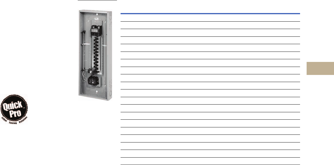
Volume 12—Aftermarket, Renewal Parts and Life Extension Solutions CA08100014E—November 2013 www.eaton.com V12-T5-25
1
2
3
4
5
6
7
8
9
10
11
12
13
14
15
16
17
18
19
20
21
22
23
24
25
5
Loadcenters
Type CH
Surge Panel
Product Description
Eaton’s Type CH Surge
Loadcenter includes a
factory-mounted and wired
surge suppressor device.
There is a knockout in the
cover that allows the user
to view the status indication
lights on the surge
suppressor. The CH Surge
Loadcenter reduces the
surge current, helping to
protect sensitive home
electronic equipment.
Save labor
by installing
a factory-
mounted surge
protective
device.
Factory-Installed
Surge Protection
●Includes a CHSPULTRA
and a two-pole 15A
circuit breaker
●Increases the
effectiveness of
surge protection due
to reduced lead length
●A modified deadfront
allows for easy viewing
of indicating lights
Surge Ready
●Provides a mounting
provision for CHSPULTRA
●A modified deadfront
allows for easy viewing
of indicating lights
Replacement Covers for Surge Panels
Catalog Number Cover Number Replacement Module
CHSUR22B100D CHPC8DF CHSPT2ULTRA
CHSUR24L125D CHPC8DF CHSPT2ULTRA
CHPC22B100D CHPC8DF CHSPT2ULTRA
CHPC24L125D CHPC8DF CHSPT2ULTRA
CHPC12L125C CHPC8CF CHSPT2ULTRA
CHPC30B100J CHPC8JF CHSPT2ULTRA
CHPC32L150J CHPC8JF CHSPT2ULTRA
CHSUR32B150L CHPC8B32LF CHSPT2ULTRA
CHSUR32B200L CHPC8B32LF CHSPT2ULTRA
CHSUR32L225L CHPC8B32LF CHSPT2ULTRA
CHPC32B125L CHPC8B32LF CHSPT2ULTRA
CHPC32B150L CHPC8B32LF CHSPT2ULTRA
CHPC32B200L CHPC8B32LF CHSPT2ULTRA
CHPC32N200L CHPC8B32LF CHSPT2ULTRA
CHSUR42B200L CHPC8B42LF CHSPT2ULTRA
CHPC42B150L CHPC8B42LF CHSPT2ULTRA
CHPC42B200L CHPC8B42LF CHSPT2ULTRA
CHPC42N200L CHPC8B42LF CHSPT2ULTRA
CHSUR42L225L CHPC8L42LF CHSPT2ULTRA
CHPC42L225L CHPC8L42LF CHSPT2ULTRA
Surge Panel

V12-T5-26 Volume 12—Aftermarket, Renewal Parts and Life Extension Solutions CA08100014E—November 2013 www.eaton.com
1
2
3
4
5
6
7
8
9
10
11
12
13
14
15
16
17
18
19
20
21
22
23
24
25
5
Loadcenters
Type C H
Further Information
Pricing Information
Price and Availability Digest (PAD)
Vista/VISTALINE™ Discount Symbol 22CD
Publication
Number Description
CA08100002E Volume 1—Residential and Light Commercial Catalog, Tab 1
CA08100011E Volume 9—OEM Product Guide
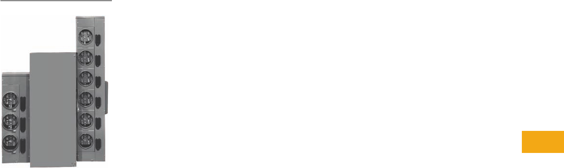
Volume 12—Aftermarket, Renewal Parts and Life Extension Solutions CA08100014E—November 2013 www.eaton.com V12-T6-1
1
2
3
4
5
6
7
8
9
10
11
12
13
14
15
16
17
18
19
20
21
22
23
24
25
Meter Centers
Group Metering Lineup
6 Meter Centers
Product Description. . . . . . . . . . . . . . . . . . . . . . . . . . . . . . . . . . . . . . . V12-T6-2
Product History . . . . . . . . . . . . . . . . . . . . . . . . . . . . . . . . . . . . . . . . . . V12-T6-2
Replacement Capabilities . . . . . . . . . . . . . . . . . . . . . . . . . . . . . . . . . . V12-T6-2
Meter Packs . . . . . . . . . . . . . . . . . . . . . . . . . . . . . . . . . . . . . . . . . . V12-T6-3
Main Devices . . . . . . . . . . . . . . . . . . . . . . . . . . . . . . . . . . . . . . . . . V12-T6-4
Residential Meter Stacks—Ring . . . . . . . . . . . . . . . . . . . . . . . . . . . V12-T6-7
Residential Meter Stacks—Ringless. . . . . . . . . . . . . . . . . . . . . . . . V12-T6-8
Commercial Meter Stacks . . . . . . . . . . . . . . . . . . . . . . . . . . . . . . . V12-T6-8
Miscellaneous Parts . . . . . . . . . . . . . . . . . . . . . . . . . . . . . . . . . . . . V12-T6-9
Further Information . . . . . . . . . . . . . . . . . . . . . . . . . . . . . . . . . . . . . . . V12-T6-9
Pricing Information . . . . . . . . . . . . . . . . . . . . . . . . . . . . . . . . . . . . . . . V12-T6-9
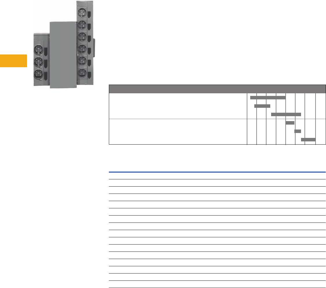
V12-T6-2 Volume 12—Aftermarket, Renewal Parts and Life Extension Solutions CA08100014E—November 2013 www.eaton.com
1
2
3
4
5
6
7
8
9
10
11
12
13
14
15
16
17
18
19
20
21
22
23
24
25
6
Meter Centers
Meter Centers
Product Description
WCG3 Meter Center
Cutler-Hammer® Meter
Centers from Eaton’s
electrical business are
designed for use where
an individually metered
distribution center is
required. Meter centers
house meter sockets that
measure power consumption
at service entrances.
Metering is designed for use
with multi-family dwelling
units, commercial units and
light industrial applications.
Product History
In the beginning, all multiple
metering applications were
assembled at the job site using
wire troughs, individual meter
sockets and enclosed circuit
breakers.
In the early 1960s, factory-
assembled meter packs
began to be made on a job-
by-job basis. Soon after,
modular metering was
introduced for single-phase
200A maximum ring-style
applications.
In 1981, a few utilities began
to require ringless meter
covers and, in 1983, the first
three-phase commercial meter
modules with lever type
bypass were introduced.
The Westinghouse Meter
Center designs,
Type WM
and/or WP, and facilities were
sold to Thomas & Betts in
1994. Today, wall-hung
multiple metering is used in
virtually all areas of the
country for both residential
and commercial applications.
Main ratings range from 250
to 2000A, and 125, 200 and
320A sockets are available in
both single-phase and three-
phase versions.
Product History Time Line
Replacement Capabilities
Westinghouse QS, QP
Cutler-Hammer CG2, 4
Cutler-Hammer CG3, 5, 7, 9, 11
Westinghouse WM, WP
Cutler-Hammer/Westinghouse WCG3, 5, 7, 9, 11
Cutler-Hammer 1MM, 3MM, 35MM, 37MM, 35SS, 37SS
Product 1970 1975 1980 1985 1990 1995 2000 Present
Type Accessories Covers Jaws
Bussed
End Caps
Tenant Breaker
Hinged Cover
Drip
Hoods
Socket
Replacement
CG3 ■■■■■ ■
CG5 ■■■ ■ ■
CG7 ■■ ■■ ■■
CG9 ■■ ■■ ■■
CG11 ■■ ■■ ■
WCG3 ■■■■■ ■■
WCG5 ■■■ ■ ■■
WCG7 ■■ ■■ ■■
WCG9 ■■ ■■ ■■
WCG11 ■■ ■■ ■
1MM ■■ ■■ ■■
3MM ■■ ■■ ■■
35MM ■■ ■■ ■■
37MM ■■ ■■ ■■
35SS ■■ ■■ ■■
37SS ■■ ■■ ■■
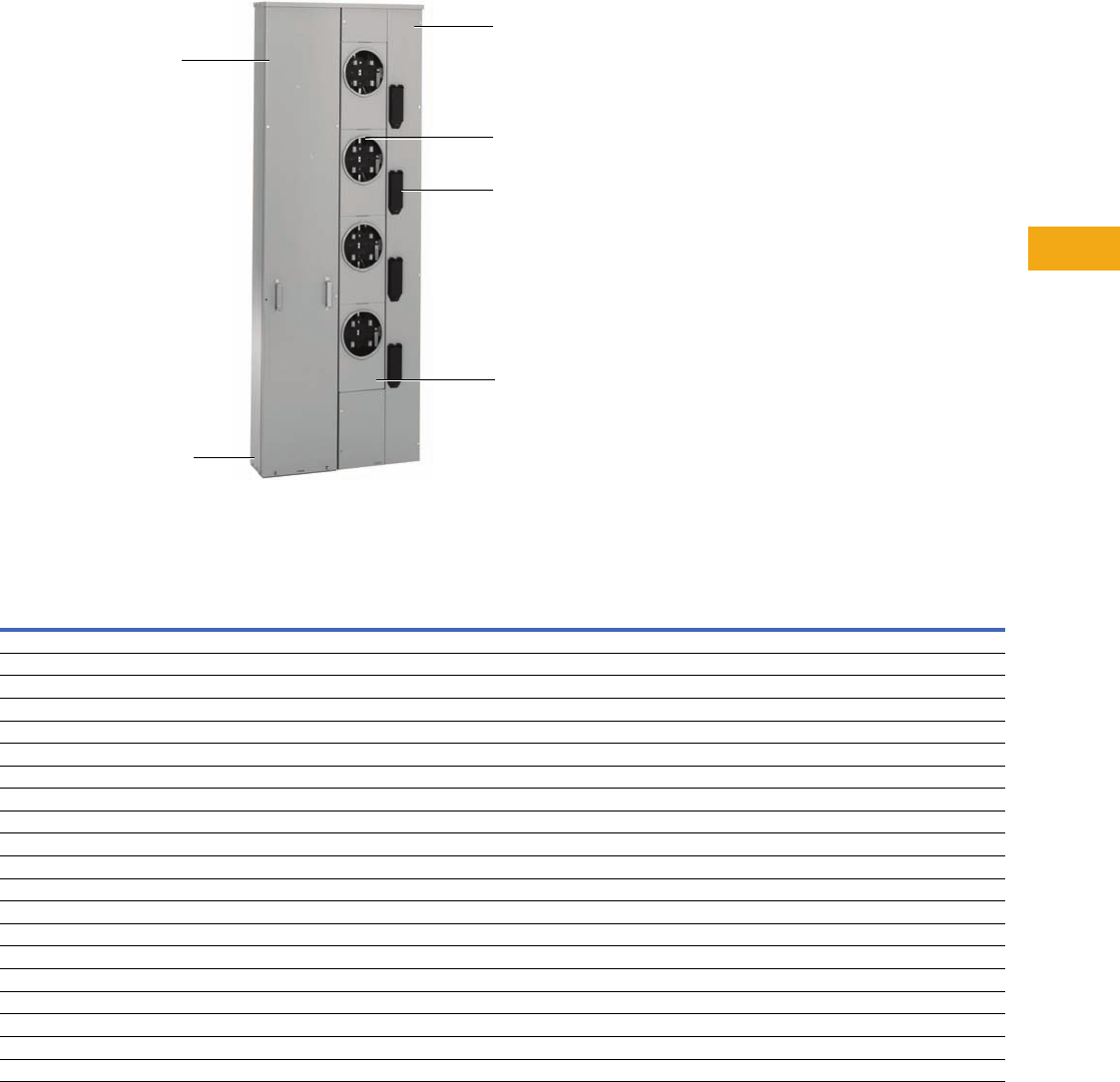
Volume 12—Aftermarket, Renewal Parts and Life Extension Solutions CA08100014E—November 2013 www.eaton.com V12-T6-3
1
2
3
4
5
6
7
8
9
10
11
12
13
14
15
16
17
18
19
20
21
22
23
24
25
6
Meter Centers
Meter Packs
Meter Pack
Meter Packs
Notes
1For top position, use meter socket cover 1MMCP1T.
2For center wireway cover, order MPCENCVR1.
3For top position, use meter socket cover 1MMCP1T.
4For center wireway cover, order MPCENCVR2.
5For catalog numbers with a “B” suffix (ringless with horn bypass), all replacement parts are the same with the exception of the meter socket assembly.
Refer to Footnote 6 for correct catalog number.
6For ringless style meter packs with horn bypass, order 1MMMSB.
7For top position, use meter socket cover 1MMRC200T.
Utility Pull Section Cover
Wireway Cover
Meter Socket Assembly
Ten a nt B r e a k e r C over
Endwall
Meter Cover
Catalog Number
Meter
Pack
Utility
Pull Section
Cover
Wireway
Cover
Meter
Socket
Assembly
Tenant
Breaker
Cover
Meter
Cover
Endwall
(with
Knockouts)
Endwall
(without
Knockouts)
Vertical
Busbars
1MP2122R MP2122UCVR MPCCVR01 1MMMS 1MMBC1 1MMCP1 1MP122NWLK MP122NWL MM1223VBUS
1MP3124R MP1234UCVR MPCCVR04 1MMMS 1MMBC1 1MMCP1 MP1234NWLK MP1234NWL MM1223VBUS
1MP4124R MP1234UCVR MPCCVR05 1MMMS 1MMBC1 1MMCP1 MP1234NWLK MP1234NWL MM1224VBUS
1MP5126R MP1256UCVR MPCCVR02 21MMMS 1MMBC1 1MMCP1 3MP1256NWLK MP1256NWL MM1223VBUS
1MP6126R MP1256UCVR MPCCVR03 21MMMS 1MMBC1 1MMCP1 3MP1256NWLK MP1256NWL MM1223VBUS
1MP2204R MP202UCVR MPCCVR06 1MMMS 1MMBC2 1MMCP2 MP2024NWLK MP2024NWL MM202VBUS
1MP3206R MP2034UCVR MPCCVR09 1MMMS 1MMBC2 1MMCP2 MP2024NWLK MP2024NWL MM2023VBUS
1MP4206R MP2034UCVR MPCCVR10 1MMMS 1MMBC2 1MMCP2 MP2024NWLK MP2024NWL MM204VBUS
1MP5206R MP2056UCVR MPCCVR07 41MMMS 1MMBC2 1MMCP2 MP2056NWLK MP2056NWL MM2023VBUS
1MP6206R MP2056UCVR MPCCVR08 41MMMS 1MMBC2 1MMCP2 MP2056NWLK MP2056NWL MM2023VBUS
1MP2122RRL 5MP2122LUCVR MPCCVR01 1MMMS 61MMBC1 1MMRC125 7MP122NWLK MP122NWL MM1223VBUS
1MP3124RRL 5MP1234UCVR MPCCVR04 1MMMS 61MMBC1 1MMRC125 7MP1234NWLK MP1234NWL MM1223VBUS
1MP4124RRL 5MP1234UCVR MPCCVR05 1MMMS 61MMBC1 1MMRC125 MP1234NWLK MP1234NWL MM124VBUS
1MP5126RRL 5MP1256UCVR MPCCVR02 1MMMS 61MMBC1 1MMRC125 7MP1256NWLK MP1256NWL MM1223VBUS
1MP6126RRL 5MP1256UCVR MPCCVR03 1MMMS 61MMBC1 1MMRC125 7MP1256NWLK MP1256NW MM1223VBUS
1MP2204RRL 5MP202UCVR MPCCVR06 1MMMS 61MMBC2 1MMRC200 7MP2024NWLK MP2024NWL MM202VBUS
1MP3206RRL 5MP2034UCVR MPCCVR09 1MMMS 61MMBC2 1MMRC200 MP2024NWLK MP2024NWL MM2023VBUS
1MP4206RRL 5MP2034UCVR MPCCVR10 1MMMS 61MMBC2 1MMRC200 MP2024NWLK MP2024NWL MM204VBUS
1MP5206RRL 5MP2056UCVR MPCCVR07 1MMMS 61MMBC2 1MMRC200 MP2056NWLK MP2056NWL MM2023VBUS
1MP6206RRL 5MP2056UCVR MPCCVR08 1MMMS 61MMBC2 1MMRC200 MP2056NWLK MP2056NWL MM2023VBUS
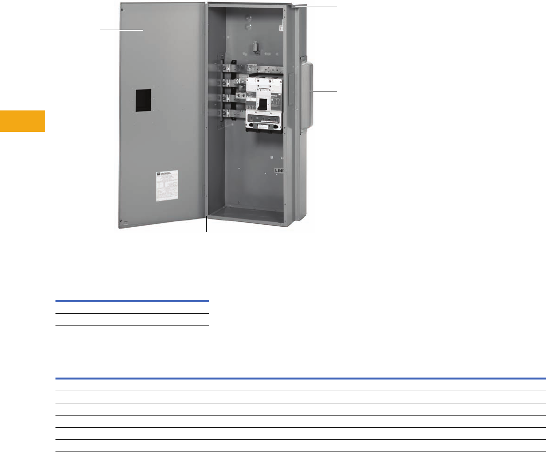
V12-T6-4 Volume 12—Aftermarket, Renewal Parts and Life Extension Solutions CA08100014E—November 2013 www.eaton.com
1
2
3
4
5
6
7
8
9
10
11
12
13
14
15
16
17
18
19
20
21
22
23
24
25
6
Meter Centers
Main Devices
Meter Main Device
End Caps
Terminal Box
Description
Catalog
Number
Right side (bumped) 47-28172-2A
Left side (flat) 47-24139A
Catalog Number
Terminal
Box
Front
Cover
Drip
Hood
Endwall
(with Knockouts)
Endwall
(without Knockouts)
1MTB800R MMFCVR1 MMDH1 MMEW1 MMEWNK01
1MTB1200R MMFCVR1 MMDH1 MMEW1 MMEWNK01
3MTB400R MTBFCVR1 MMDH4 MTBEW1 MTBEWNK01
3MTB600R MTBFCVR1 MMDH4 MTBEW1 MTBEWNK01
3MTB800R MMFCVR1 MMDH1 MMEW1 MMEWNK01
3MBT1200R MMFCVR1 MMDH1 MMEW1 MMEWNK01
Front Cover
Drip Hood
End Caps
Endwall

Volume 12—Aftermarket, Renewal Parts and Life Extension Solutions CA08100014E—November 2013 www.eaton.com V12-T6-5
1
2
3
4
5
6
7
8
9
10
11
12
13
14
15
16
17
18
19
20
21
22
23
24
25
6
Meter Centers
Main Circuit Breaker
Catalog Number
Circuit
Breaker
Front
Cover
Drip
Hood
Endwall
(with Knockouts)
Endwall
(without Knockouts)
Main
Breaker Cover
1MCB250R MCBFCVR1 MMDH1 MMEW1 MMEWNK01 49-7060
1MHCB250R MCBFCVR1 MMDH1 MMEW1 MMEWNK01 49-7060
1MCB300R MCBFCVR1 MMDH1 MMEW1 MMEWNK01 49-7060
1MHCB300R MCBFCVR1 MMDH1 MMEW1 MMEWNK01 49-7060
1MCB350R MCBFCVR1 MMDH1 MMEW1 MMEWNK01 49-7060
1MHCB350R MCBFCVR1 MMDH1 MMEW1 MMEWNK01 49-7060
1MCB400R MCBFCVR1 MMDH1 MMEW1 MMEWNK01 49-7060
1MHCB400R MCBFCVR1 MMDH1 MMEW1 MMEWNK01 49-7060
1MCB500R MCBFCVR1 MMDH1 MMEW1 MMEWNK01 49-7060
1MHCB500R MCBFCVR1 MMDH1 MMEW1 MMEWNK01 49-7060
1MCB600R MCBFCVR1 MMDH1 MMEW1 MMEWNK01 49-7060
1MHCB600R MCBFCVR1 MMDH1 MMEW1 MMEWNK01 49-7060
1MCB700R MCBFCVR2 MMDH1 MMEW1 MMEWNK01 49-7060
1MHCB700R MCBFCVR2 MMDH1 MMEW1 MMEWNK01 49-7060
1MCB800R MCBFCVR2 MMDH1 MMEW1 MMEWNK01 49-7060
1MHCB800R MCBFCVR2 MMDH1 MMEW1 MMEWNK01 49-7060
1MCB900R MCBFCVR2 MMDH1 MMEW1 MMEWNK01 49-7060
1MHCB900R MCBFCVR2 MMDH1 MMEW1 MMEWNK01 49-7060
1MCB1000R MCBFCVR2 MMDH1 MMEW1 MMEWNK01 49-7060
1MHCB1000R MCBFCVR2 MMDH1 MMEW1 MMEWNK01 49-7060
1MCB1200R MCBFCVR2 MMDH1 MMEW1 MMEWNK01 49-7060
1MHCB1200R MCBFCVR2 MMDH1 MMEW1 MMEWNK01 49-7060
1MCB1400RB MCBFCVR3 MCBDH1 — MMEWNK03 49-7060
1MCB1400RT MCBFCVR3 MCBDH1 — MMEWNK03 49-7060
1MCB1600RB MCBFCVR3 MCBDH1 — MMEWNK03 49-7060
1MCB1600RT MCBFCVR3 MCBDH1 — MMEWNK03 49-7060
1MCB2000RB MCBFCVR3 MCBDH1 — MMEWNK03 49-7060
1MCB2000RT MCBFCVR3 MCBDH1 — MMEWNK03 49-7060
3MCB250R MCBFCVR1 MMDH1 MMEW1 MMEWNK01 49-7060
3MHCB250R MCBFCVR1 MMDH1 MMEW1 MMEWNK01 49-7060
3MCB300R MCBFCVR1 MMDH1 MMEW1 MMEWNK01 49-7060
3MHCB300R MCBFCVR1 MMDH1 MMEW1 MMEWNK01 49-7060
3MCB350R MCBFCVR1 MMDH1 MMEW1 MMEWNK01 49-7060
3MHCB350R MCBFCVR1 MMDH1 MMEW1 MMEWNK01 49-7060
3MCB400R MCBFCVR1 MMDH1 MMEW1 MMEWNK01 49-7060
3MHCB400R MCBFCVR1 MMDH1 MMEW1 MMEWNK01 49-7060
3MCB500R MCBFCVR1 MMDH1 MMEW1 MMEWNK01 49-7060
3MHCB500R MCBFCVR1 MMDH1 MMEW1 MMEWNK01 49-7060
3MCB600R MCBFCVR1 MMDH1 MMEW1 MMEWNK01 49-7060
3MHCB600R MCBFCVR1 MMDH1 MMEW1 MMEWNK01 49-7060
3MCB700R MCBFCVR2 MMDH1 MMEW1 MMEWNK01 49-7060
3MHCB700R MCBFCVR2 MMDH1 MMEW1 MMEWNK01 49-7060
3MCB800R MCBFCVR2 MMDH1 MMEW1 MMEWNK01 49-7060
3MHCB800R MCBFCVR2 MMDH1 MMEW1 MMEWNK01 49-7060
3MCB900R MCBFCVR2 MMDH1 MMEW1 MMEWNK01 49-7060
3MHCB900R MCBFCVR2 MMDH1 MMEW1 MMEWNK01 49-7060
3MCB1000R MCBFCVR2 MMDH1 MMEW1 MMEWNK01 49-7060
3MHCB1000R MCBFCVR2 MMDH1 MMEW1 MMEWNK01 49-7060
3MCB1200R MCBFCVR2 MMDH1 MMEW1 MMEWNK01 49-7060
3MHCB1200R MCBFCVR2 MMDH1 MMEW1 MMEWNK01 49-7060
3MCB1400RB MCBFCVR3 MCBDH1 — MMEWNK03 —
3MCB1400RT MCBFCVR3 MCBDH1 — MMEWNK03 —
3MCB1600RB MCBFCVR3 MCBDH1 — MMEWNK03 —
3MCB1600RT MCBFCVR3 MCBDH1 — MMEWNK03 —
3MCB2000RB MCBFCVR3 MCBDH1 — MMEWNK03 —
3MCB2000RT MCBFCVR3 MCBDH1 — MMEWNK03 —

V12-T6-6 Volume 12—Aftermarket, Renewal Parts and Life Extension Solutions CA08100014E—November 2013 www.eaton.com
1
2
3
4
5
6
7
8
9
10
11
12
13
14
15
16
17
18
19
20
21
22
23
24
25
6
Meter Centers
Main Fusible Switch
Main Bolted Pressure Contact Switch
Main Fusible Switch with Pullbox
Pullbox
Catalog Number
Fusible
Switch
Front
Cover
Drip
Hood
Endwall
(with Knockouts)
Endwall
(without Knockouts)
1MFS400RB MMFCVR1 MMDH1 MMEW1 MMEWNKO1
1MFS400RT MFSFCVR1 MMDH1 — MMEWNKO1
1MFS600RB MMFCVR1 MMDH1 MMEW1 MMEWNKO1
1MFS600RT MFSFCVR1 MMDH1 — MMEWNKO1
1MFS800RB MMFCVR1 MMDH1 MMEW1 MMEWNKO1
1MFS800RT MFSFCVR1 MMDH1 — MMEWNKO1
1MFS1200RB MFSFCVR2 MMDH2 MMEW2 MMEWNKO2
3MFS400RB MMFCVR1 MMDH1 MMEW1 MMEWNKO1
3MFS400RT MFSFCVR1 MMDH1 — MMEWNKO1
3MFS600RB MMFCVR1 MMDH1 MMEW1 MMEWNKO1
3MFS600RT MFSFCVR1 MMDH1 — MMEWNKO1
3MFS800RB MMFCVR1 MMDH1 MMEW1 MMEWNKO1
3MFS800RT MFSFCVR1 MMDH1 — MMEWNKO1
3MFS1200RB MFSFCVR2 MMDH2 MMEW2 MMWENKO2
Catalog Number
Bolted Pressure
Contact Switch
Front
Cover
Drip
Hood
Endwall
(with Knockouts)
Endwall
(without Knockouts)
1BPS1200RB No replacement parts available at this time.
1BPS1200RT
3BPS1200RB
3BPS1200RT
3BPS1600RB No replacement parts available at this time.
3BPS1600RT
3BPS2000RB
3BPS2000RT
Catalog Number
Fusible Switch
with Pullbox
Front
Cover
Pullbox
Cover
Drip
Hood
Endwall
(with Knockouts)
Endwall
(without Knockouts)
1MFS400RUG MFPFCVR1 MFPBCVR1 MMDH1 MMEW1 MMEWNK01
1MFS600RUG MFPFCVR1 MFPBCVR1 MMDH1 MMEW1 MMEWNK01
1MFS800RUG MFPFCVR1 MFPBCVR1 MMDH1 MMEW1 MMEWNK01
1MFS1200RUG MFPFCVR2 MFPBCVR2 MMDH2 MMEW2 MMEWNK02
3MFS400RUG MFPFCVR1 MFPBCVR1 MMDH1 MMEW1 MMEWNK01
3MFS600RUG MFPFCVR3 MFPBCVR3 MMDH5 MMEW4 MMEWNK04
3MFS800RUG MFPFCVR3 MFPBCVR3 MMDH5 MMEW4 MMEWNK04
3MFS1200RUG MFPFCVR2 MFPBCVR2 MMDH2 MMEW2 MMEWNK02
Catalog Number
Pullbox
Front Cover
Pullbox Cover
Drip
Hood
Endwall
(with Knockouts)
Endwall
(without Knockouts)
1UGPB400R PBFCVR1 PBDH1 PBEW1 PBEWNK01
1UGPB800R PBFCVR2 PBDH2 PBEW2 PBEWNK02
1UGPB1200R PBFCVR3 PBDH3 PBEW3 PBEWNK03
3UGPB400R PBFCVR1 PBDH1 PBEW1 PBEWNK01
3UGPB800R PBFCVR2 PBDH2 PBEW2 PBEWNK02
3UGPB1200R PBFCVR3 PBDH3 PBEW3 PBEWNK03
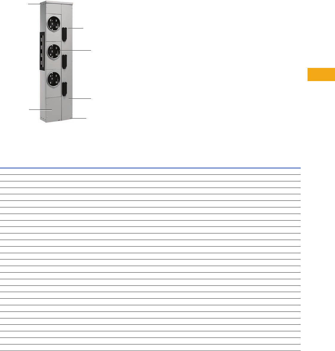
Volume 12—Aftermarket, Renewal Parts and Life Extension Solutions CA08100014E—November 2013 www.eaton.com V12-T6-7
1
2
3
4
5
6
7
8
9
10
11
12
13
14
15
16
17
18
19
20
21
22
23
24
25
6
Meter Centers
Residential Meter Stacks—Ring
Ring Style Meter Stack
Residential Meter Stacks—Ring
Notes
1Type 1 meter stacks do not come with breaker covers.
2For top position, order meter cover 1MMCP1T.
3For top position, order meter cover 1MMCP2T.
Catalog Number
Meter
Stack
Wireway
Cover
Meter
Socket
Assembly
Tenant
Breaker
Cover
Meter
Cover
Endwall
(with
Knockouts)
Endwall
(without
Knockouts)
Drip
Hood
Vertical
Busbar
3MM212 MMCCVR2123 — 11MMCP1 2MM12N1WLK MM12N1WL MMDH3 MM1223VBUS
3MM212R MMCCVR2123R 1MMMS 1MMBC1 1MMCP1 2MM12N1WLK MM12N1WL MMDH3 MM1223VBUS
1MM312 MMCCVR3121 1MMMS 11MMCP1 2MM12N1WLK MM12N1WL MMDH3 MM1223VBUS
1MM312R MMCCVR3121R 1MMMS 1MMBC1 1MMCP1 2MM12N1WLK MM12N1WL MMDH3 MM1223VBUS
3MM312 MMCCVR3123 1MMMS 11MMCP1 2MM12N1WLK MM12N1WL MMDH3 MM1223VBUS
3MM312R MMCCVR3123R 1MMMS 1MMBC1 1MMCP1 2MM12N1WLK MM12N1WL MMDH3 MM1223VBUS
1MM412 MMCCVR4121 1MMMS 11MMCP1 2MM12N1WLK MM12N1WL MMDH3 MM124VBUS
1MM412R MMCCVR4121R 1MMMS 1MMBC1 1MMCP1 2MM12N1WLK MM12N1WL MMDH3 MM124VBUS
3MM412 MMCCVR4123 1MMMS 11MMCP1 2MM12N1WLK MM12N1WL MMDH3 MM124VBUS
3MM412R MMCCVR4123R 1MMMS 1MMBC1 1MMCP1 2MM12N1WLK MM12N1WL MMDH3 MM124VBUS
1MM512 MMCCVR5121 1MMMS 11MMCP1 2MM12N1WLK MM12N1WL MMDH3 MM125VBUS
1MM512R MMCCVR5121R 1MMMS 1MMBC1 1MMCP1 2MM12N1WLK MM12N1WL MMDH3 MM125VBUS
3MM512 MMCCVR5123 1MMMS 11MMCP1 2MM12N1WLK MM12N1WL MMDH3 MM125VBUS
3MM512R MMCCVR5123R 1MMMS 1MMBC1 1MMCP1 2MM12N1WLK MM12N1WL MMDH3 MM125VBUS
1MM612 MMCCVR6121 1MMMS 11MMCP1 2MM12N1WLK MM12N1WL MMDH3 MM126VBUS
1MM612R MMCCVR6121R 1MMMS 1MMBC1 1MMCP1 2MM12N1WLK MM12N1WL MMDH3 MM126VBUS
3MM612 MMCCVR6123 1MMMS 11MMCP1 2MM12N1WLK MM12N1WL MMDH3 MM126VBUS
3MM612R MMCCVR6123R 1MMMS 1MMBC1 1MMCP1 2MM12N1WLK MM12N1WL MMDH3 MM126VBUS
3MM220 MMCCVR2203 1MMMS 11MMCP2 3MM20N1WLK MM20N1WL MMDH4 MM2023VBUS
3MM220R MMCCVR2203R 1MMMS 1MMBC2 1MMCP2 3MM20N1WLK MM20N1WL MMDH4 MM2023VBUS
1MM320 MMCCVR3201 1MMMS 11MMCP2 3MM20N1WLK MM20N1WL MMDH4 MM2023VBUS
1MM320R MMCCVR3201R 1MMMS 1MMBC2 1MMCP2 3MM20N1WLK MM20N1WL MMDH4 MM2023VBUS
3MM320 MMCCVR3203 1MMMS 11MMCP2 3MM20N1WLK MM20N1WL MMDH4 MM2023VBUS
3MM320R MMCCVR3203R 1MMMS 1MMBC2 1MMCP2 3MM20N1WLK MM20N1WL MMDH4 MM2023VBUS
1MM420 MMCCVR4201 1MMMS 11MMCP2 3MM20N1WLK MM20N1WL MMDH4 MM204VBUS
1MM420R MMCCVR4201R 1MMMS 1MMBC2 1MMCP2 3MM20N1WLK MM20N1WL MMDH4 MM204VBUS
3MM420 MMCCVR4203 1MMMS 11MMCP2 3MM20N1WLK MM20N1WL MMDH4 MM204VBUS
3MM420R MMCCVR4203R 1MMMS 1MMBC2 1MMCP2 3MM20N1WLK MM20N1WL MMDH4 MM204VBUS
Ten a n t B reaker Cov e r
Wireway Cover
Meter Socket Assembly
Drip Hood
Meter Cover
Endwall

V12-T6-8 Volume 12—Aftermarket, Renewal Parts and Life Extension Solutions CA08100014E—November 2013 www.eaton.com
1
2
3
4
5
6
7
8
9
10
11
12
13
14
15
16
17
18
19
20
21
22
23
24
25
6
Meter Centers
Residential Meter Stacks—Ringless
Residential Meter Stacks—Ringless
Commercial Meter Stacks
Commercial Meter Stacks (Lever Bypass)
Commercial Meter Stack (Test Bypass)
Notes
1For catalog numbers with a “B” suffix (ringless with horn bypass), all replacement parts are the same with the exception of the meter socket assembly.
Refer to Footnote 2 for correct catalog number.
2For ringless style meter stacks with horn bypass, order 1MMMSB meter socket assembly.
3For top position, use meter socket cover 1MMRC125T.
4Used for product built October 2002 and prior.
5Used for product built after October 2002.
Catalog Number
Meter
Stack
Wireway
Cover
Meter
Socket
Assembly
Tenant
Breaker
Cover
Meter
Cover
Endwall
(with
Knockouts)
Endwall
(without
Knockouts)
Drip
Hood
Vertical
Busbar
3MM212RRL 1MMCCVR2123R 1MMMS 21MMBC1 1MMRC125 3MM12NWLK MM12NWL MMDH3 MM1223VBUS
1MM312RRL 1MMCCVR3121R 1MMMS 21MMBC1 1MMRC125 3MM12NWLK MM12NWL MMDH3 MM1223VBUS
3MM312RRL 1MMCCVR3123R 1MMMS 21MMBC1 1MMRC125 3MM12NWLK MM12NWL MMDH3 MM1223VBUS
1MM412RRL 1MMCCVR3121R 1MMMS 21MMBC1 1MMRC125 MM12NWLK MM12NWL MMDH3 MM124VBUS
3MM412RRL 1MMCCVR4123R 1MMMS 21MMBC1 1MMRC125 MM12NWLK MM12NWL MMDH3 MM124VBUS
1MM512RRL 1MMCCVR5121R 1MMMS 21MMBC1 1MMRC125 MM12NWLK MM12NWL MMDH3 MM125VBUS
3MM512RRL 1MMCCVR5123R 1MMMS 21MMBC1 1MMRC125 MM12NWLK MM12NWL MMDH3 MM125VBUS
1MM612RRL 1MMCCVR6121R 1MMMS 21MMBC1 1MMRC125 MM12NWLK MM12NWL MMDH3 MM126VBUS
3MM612RRL 1MMCCVR6123R 1MMMS 21MMBC1 1MMRC125 MM12NWLK MM12NWL MMDH3 MM126VBUS
3MM220RRL 1MMCCVR2203R 1MMMS 21MMBC2 1MMRC200 MM20NWLK MM20NWL MMDH4 MM2023VBUS
1MM320RRL 1MMCCVR3201R 1MMMS 21MMBC2 1MMRC200 MM20NWLK MM20NWL MMDH4 MM2023VBUS
3MM320RRL 1MMCCVR3203R 1MMMS 21MMBC2 1MMRC200 MM20NWLK MM20NWL MMDH4 MM2023VBUS
1MM420RRL 1MMCCVR4201R 1MMMS 21MMBC2 1MMRC200 MM20NWLK MM20NWL MMDH4 MM204VBUS
3MM420RRL 1MMCCVR4203R 1MMMS 21MMBC2 1MMRC200 MM20NWLK MM20NWL MMDH4 MM204VBUS
Catalog Number
Meter
Stack
Wireway
Cover
Meter
Socket
Assembly
Tenant
Breaker
Cover
Meter
Cover
Endwall
(with
Knockouts)
Endwall
(without
Knockouts)
Drip
Hood
35MM120R12 MSLWCVR1 — MSLMSA1 MSBCVR1 MSLMCVR1 437MMSK1 5— MSLEW1 MSLDH1
35MM220R12 MSLWCVR2 — MSLMSA1 MSBCVR1 MSLMCVR1 437MMSK1 5— MSLEW1 MSLDH1
35MM320R12 MSLWCVR3 — MSLMSA1 MSBCVR1 MSLMCVR1 437MMSK1 5— MSLEW1 MSLDH1
35MM420R12 MSLWCVR4 4MSLWCVR13 5MSLMSA1 MSBCVR1 MSLMCVR1 437MMSK1 5— MSLEW2 MSLDH2
37MM140R12 MSLWCVR9 4MSLWCVR14 5MSLMSA2 MSBCVR1 MSLMCVR1 437MMSK1 5— MSLEW1 MSLDH1
37MM120R12 MSLWCVR5 4MSLWCVR15 5MSLMSA2 MSBCVR1 MSLMCVR1 437MMSK1 5— MSLEW1 MSLDH1
37MM220R12 MSLWCVR6 4MSLWCVR16 5MSLMSA2 MSBCVR1 MSLMCVR1 437MMSK1 5— MSLEW1 MSLDH1
37MM320R12 MSLWCVR7 4MSLWCVR17 5MSLMSA2 MSBCVR1 MSLMCVR1 437MMSK1 5— MSLEW1 MSLDH1
37MM420R12 MSLWCVR8 4MSLWCVR18 5MSLMSA2 MSBCVR1 MSLMCVR1 437MMSK1 5— MSLEW2 MSLDH2
Catalog Number
Meter Stack
Wireway
Cover
Meter
Socket
Assembly
Tenant
Breaker
Cover
Meter
Cover
Endwall
(with
Knockouts)
Endwall
(without
Knockouts)
Drip
Hood
35SS120RAB MSTWCVR1 MSTMSA1 MSBCVR1 MSTMCVR1 MSTEW1 MSTEWNK01 MSTDH1
35SS120RAC MSTWCVR2 MSTMSA1 MSBCVR1 MSTMCVR1 MSTEW1 MSTEWNK01 MSTDH1
35SS120RBC MSTWCVR3 MSTMSA1 MSBCVR1 MSTMCVR1 MSTEW1 MSTEWNK01 MSTDH1
35SS220RAB MSTWCVR4 MSTMSA1 MSBCVR1 MSTMCVR1 MSTEW2 MSTEWNK02 MSTDH1
35SS220RAC MSTWCVR5 MSTMSA1 MSBCVR1 MSTMCVR1 MSTEW2 MSTEWNK02 MSTDH1
35SS220RBC MSTWCVR6 MSTMSA1 MSBCVR1 MSTMCVR1 MSTEW2 MSTEWNK02 MSTDH1
35SS320RAB MSTWCVR7 MSTMSA1 MSBCVR1 MSTMCVR1 MSTEW2 MSTEWNK02 MSTDH1
35SS320RAC MSTWCVR8 MSTMSA1 MSBCVR1 MSTMCVR1 MSTEW2 MSTEWNK02 MSTDH1
35SS320RBC MSTWCVR9 MSTMSA1 MSBCVR1 MSTMCVR1 MSTEW2 MSTEWNK02 MSTDH1
37SS120R MSTWCVR10 MSTMSA2 MSBCVR1 MSTMCVR1 MSTEW1 MSTEWNK01 MSTDH1
37SS220R MSTWCVR11 MSTMSA2 MSBCVR1 MSTMCVR1 MSTEW2 MSTEWNK02 MSTDH1
37SS320R MSTWCVR12 MSTMSA2 MSBCVR1 MSTMCVR1 MSTEW2 MSTEWNK02 MSTDH1

Volume 12—Aftermarket, Renewal Parts and Life Extension Solutions CA08100014E—November 2013 www.eaton.com V12-T6-9
1
2
3
4
5
6
7
8
9
10
11
12
13
14
15
16
17
18
19
20
21
22
23
24
25
6
Meter Centers
Miscellaneous Parts
Miscellaneous Parts
Further Information
Pricing Information
Price and Availability Digest (PAD)
Vista/VISTALINE™ Discount Symbol 22-CD
Description
Part
Number
Phase balancing kit, single-phase commercial metering 99-4177-3
A and C phase balancing kit (3MM) 99-4184
Breaker mounting kit, commercial metering (one three-pole breaker per kit) 99-4176-2
Breaker mounting kit, 1MM/1MP, 200A, (one two-pole breaker per kit) 99-4176
Mounting kit, meter center 99-4172
Mounting kit, meter pack 99-4173
Bonding strap kit, all meter packs (except CECHA three and four socket) 99-4174
Bonding strap kit, CHECA three and four socket meter packs 99-2379
Sealing screw kit, ringless devices (six screws) 99-4175
Sealing screw kit, three and four meter sockets, ringless devices (four screws) 99-2589
Padlock bracket 99-2512-5
Mounting bracket kit—all breaker and fusible mains 99-4183
Mounting bracket kit—400 and 600A 3MTB 99-4183-3
Exterior breaker cover 49-6070
Publication
Number Description
RP32A01BTE Renewal parts data for new 1MM, 3MM, 35MM, 37MM, 35SS and 37SS
RP00501001E Renewal parts data for multiple metering
Volume 12—Aftermarket, Renewal Parts and Life Extension Solutions CA08105001E—November 2013 www.eaton.com V12-T7-1
1
2
3
4
5
6
7
8
9
10
11
12
13
14
15
16
17
18
19
20
21
22
23
24
25
Safety Switches
Safety Switch Product Family
7 Safety Switches
Product Description . . . . . . . . . . . . . . . . . . . . . . . . . . . . . . . . . . . . . . V12-T7-2
Product History . . . . . . . . . . . . . . . . . . . . . . . . . . . . . . . . . . . . . . . . . . V12-T7-2
Product History Time Line. . . . . . . . . . . . . . . . . . . . . . . . . . . . . . . . . . V12-T7-2
Replacement Capabilities . . . . . . . . . . . . . . . . . . . . . . . . . . . . . . . . . . V12-T7-2
Further Information . . . . . . . . . . . . . . . . . . . . . . . . . . . . . . . . . . . . . . . V12-T7-2
Pricing Information . . . . . . . . . . . . . . . . . . . . . . . . . . . . . . . . . . . . . . . V12-T7-2
V12-T7-2 Volume 12—Aftermarket, Renewal Parts and Life Extension Solutions CA08105001E—November 2013 www.eaton.com
1
2
3
4
5
6
7
8
9
10
11
12
13
14
15
16
17
18
19
20
21
22
23
24
25
7
Safety Switches
Safety Switches
Safety Switch Product Family
Product Description
Eaton’s Cutler-Hammer®
series of safety switches
have a number of applications
from service entrance to
branch circuit protection. They
are also horsepower rated for
use as motor circuit switches.
Non-fusible safety switches
provide a means to manually
connect or disconnect the
load from the source. Fusible
safety switches provide a
means to manually open and
close a circuit and overcurrent
protection by means of
installed fuses. Safety
switches offer a wide variety
of switching capabilities with
general-duty, heavy-duty and
double-throw switches.
Product History
Eaton began manufacturing
safety switches with the
4103 line in 1957. In 1977,
the new 4105 line was
moved from the New York
plant to the manufacturing
facility in Lincoln, IL. The last
design change came in 1983,
where the manufacture of
the new K-Series switch was
moved to Eaton’s Cleveland,
TN, facility. The K-Series
design represents our
current product offering and
is still manufactured at the
Cleveland plant.
The Westinghouse safety
switch design and facilities
were sold to Thomas & Betts
in 1994. Prior to this, there
were various design and code
changes that caused changes
in catalog numbering and
utilization of the switches. In
1984, an “N” was added to
the middle of the catalog
numbers to signify the
new National Electrical
Code® (NEC®) regulations.
During this time period,
Westinghouse’s safety
switches were manufactured
in Beaver, PA. In 1989, the
manufacture of the switches
was moved to Vidalia, GA.
There was then another
code change in 1992 that
necessitated another change
in catalog numbering. The
previous “N” in the middle
of the catalog number was
deleted for the 400 to
1200A units.
Product History Time Line
Replacement Capabilities
Note: Specific applicable renewal parts for safety switches are identified on the inside door label of the product.
Further Information
Pricing Information
Price and Availability Digest
(PAD)
Vista/VISTALINE™ Discount
Symbol SWD-1, SWD-2,
SWD-3 for Safety Switches
Type
Operating
Handle Ground Neutral
Fuse
Base
Fuse
Block
Line
Shield
Operating
Mechanism
Switching
Base
K-Series ■ ■■■■■■ ■
Publication Number Description
RP00801001E Safety Switch Renewal Parts
CA08100003E Commercial Distribution Catalog, Volume 2, Tab 1 (Switching Devices)
CA08104001E Consulting Application Guide
CA08100006E Motor Control & Protection Catalog, Volume 5, Tab 8 (Rotary Disconnects)
PG00802002E Rotary Disconnect Product Guide
Cutler-Hammer 4103
Cutler-Hammer 4105
Cutler-Hammer K-Series
Westinghouse HFN365N
(Bacalyte Base)
Westinghouse HFN365N
Westinghouse HF365N
(Red Base, 400–1200A)
Eaton R-Series
Rotary Disconnects
Cutler-Hammer C362/C363
Rotary Disconnects
Eaton’s Pringle® Bolted
Pressure Switches
Product 1955 1960 1965 1970 1975 1980 1985 1990 1995 2000 2005 2010 Present
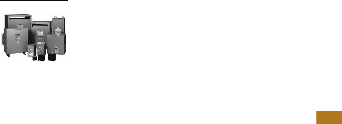
Volume 12—Aftermarket, Renewal Parts and Life Extension Solutions CA08100014E—November 2013 www.eaton.com V12-T8-1
1
2
3
4
5
6
7
8
9
10
11
12
13
14
15
16
17
18
19
20
21
22
23
24
25
Dry-Type Distribution Transformers
Family of Dry-Type
Distribution Transformers
8 Dry-Type Distribution Transformers
Product Description . . . . . . . . . . . . . . . . . . . . . . . . . . . . . . . . . . . . . . V12-T8-2
Product History . . . . . . . . . . . . . . . . . . . . . . . . . . . . . . . . . . . . . . . . . . V12-T8-2
Product History Time Line. . . . . . . . . . . . . . . . . . . . . . . . . . . . . . . . . . V12-T8-2
Replacement Capabilities . . . . . . . . . . . . . . . . . . . . . . . . . . . . . . . . . . V12-T8-3
Further Information . . . . . . . . . . . . . . . . . . . . . . . . . . . . . . . . . . . . . . . V12-T8-4
Pricing Information . . . . . . . . . . . . . . . . . . . . . . . . . . . . . . . . . . . . . . . V12-T8-4
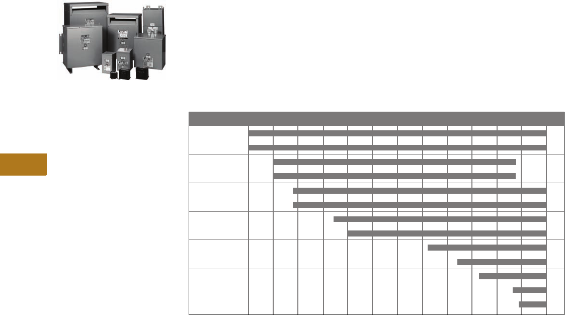
V12-T8-2 Volume 12—Aftermarket, Renewal Parts and Life Extension Solutions CA08100014E—November 2013 www.eaton.com
1
2
3
4
5
6
7
8
9
10
11
12
13
14
15
16
17
18
19
20
21
22
23
24
25
8
Dry-Type Distribution Transformers
Dry-Type Distribution
Transformers
Family of Dry-Type
Distribution Transformers
Product Description
Eaton’s Cutler-Hammer®
series of dry-type distribution
transformers are electrical
devices that transfer energy
by magnetic induction from
one circuit to another. They
are typically used to change
the voltage in an electric
power system from its
distribution level to the
proper level for practical
and safe use.
Typical loads for dry-type
distribution transformers
include lighting, heating,
air conditioning, fans and
machine tools. Such loads
are found in commercial,
institutional, industrial and
residential structures.
Different types of dry-type
distribution transformers
are used for various
applications throughout
facilities. Therefore, dry-type
distribution transformers are
classified in distinct product
groups as follows: general
purpose—sand and resin
encapsulated (EP and EPT);
general purpose—ventilated
(DS-3, DT-3, CSL3-2007,
NEMA® Premium®); energy
efficient (NEMA TP-1);
shielded isolation; motor
drive isolation (MD);
nonlinear (KT); mini–power
center (MPC); hazardous
location, Buck-Boost and
industrial control (MTA
and MTC).
Product History
Originally a
Westinghouse Product
The first transformer
built in the United States
was manufactured by
Westinghouse Electric in
1892. It was a 2 kVA dry-
type transformer. For over
a century, Westinghouse
manufactured numerous
varieties of transformers
for countless applications
worldwide.
The Westinghouse design
transformer is now available
through Eaton. Dry-type
transformers, the workhorse
of modern industry, are the
foundation of modern AC
power distribution. It is a
transformer that solves the
problems of maintenance,
installation, safety and
efficiency by using air to cool
the coils instead of liquids.
Many older transformers,
which in some cases pre-date
the product families listed
above, can be updated to the
modern designs currently
manufactured by Eaton.
Product History Time Line
DS-3
DT-3
MTA
MTC
EP
EPT
MPC
MD
KT
NEMA TP-1
HMT
CSL3
NEMA Premium
Type 1955 1960 1965 1970 1975 1980 1985 1990 1995 2000 2005 2010 Present

Volume 12—Aftermarket, Renewal Parts and Life Extension Solutions CA08100014E—November 2013 www.eaton.com V12-T8-3
1
2
3
4
5
6
7
8
9
10
11
12
13
14
15
16
17
18
19
20
21
22
23
24
25
8
Dry-Type Distribution Transformers
Replacement Capabilities
Replacement Capabilities
Replacement Parts
Terminal Lug Kits for Type DT-3 Transformers 1
Rodent Screens Replacement Parts for Mini–Power Centers
Notes
1Lugs are rated Al/Cu and are suitable for use with either aluminum or copper conductors.
2Effective June 1, 2001, frame numbers have a prefix of FR, i.e., FR819. Dimensions, accessories,
etc. are still applicable as if the FR did not exist.
Typical Sizing
Terminal Lugs
Cable Range
Terminal Lugs
Quantity
Hardware
Bolt Size
Hardware
Quantity
Catalog
Number
15–37.5 kVA single-phase
15–45 kVA three-phase
#14–#2
#6–250 kcmil
8
4
1/4–20 x 3/4 8 LKS1
50–75 kVA single-phase
75–112.5 kVA three-phase
#6–250 kcmil 12 1/4–20 x 3/4
1/4–20 x 1-3/4
8
8
LKS2
100–167 kVA single-phase
150–300 kVA three-phase
#6–250 kcmil
#2–600 kcmil
3
22
1/4–20 x 3/4
3/8–16 x 2
3
16
LKS3
500 kVA three-phase #2–600 kcmil 29 3/8–16 x 2 18 LKS4
Description
Frame
Size(s) 2
Catalog
Number
Rodent screens are used to discourage
entry by birds or rodents.
908, 909 RS01
910A, 911, 912 RS02
913B, 914B, 915B RS03
916 RS04
917, 918, 918A RS05
919, 920 RS06
916A, 916B RS07
922 RS08
923 RS09
814, 821 RS11
815 RS12
816 RS13
817, 818 RS14
819, 820 RS15
912B RS16
914D, 915D RS17
924 RS18
928 RS19
929 RS20
Frame
Deadfront Cover
(Breaker Cover)
Part Number
Front Cover
Part Number
283 47-37503 7074C98H04
284 47-37503-2 7074C98H01
285 47-37503-3 7074C98H02
286 47-37503-4 7074C98H02
287 47-37503-5 7074C98H03
289 47-37459 7074C44H01
290 47-37459-2 7074C44H02
291 47-37459-3 7074C44H03
289A 47-42072-1 7074C44H01
290A 47-42072-2 7074C44H02
291A 47-42072-3 7074C44H03

V12-T8-4 Volume 12—Aftermarket, Renewal Parts and Life Extension Solutions CA08100014E—November 2013 www.eaton.com
1
2
3
4
5
6
7
8
9
10
11
12
13
14
15
16
17
18
19
20
21
22
23
24
25
8
Dry-Type Distribution Transformers
Replacement Capabilities
Replacement Parts
Case Parts for Ventilated Transformers
Further Information Pricing Information
Price and Availability Digest (PAD)
Vista/VISTALINE™ (Discount Symbol DT-1)
Notes
1Effective June 1, 2001 frame numbers have a prefix of FR, i.e., FR819.
Dimensions, accessories, etc. are still applicable as if the FR did not exist.
Parts listed are for standard catalog listed transformers. Units with modifications may require
different parts. (Frame No. from transformer nameplate required.) Transformer nameplate and
UL® label are not field replaceable.
Frame(s) 1
Panels
Top Cover
Part Number
Front or Back
Part Number
Side (Two Required Per Transformer)
Part Number
Bottom
Part Number
Three-Phase, 600V Class
908, 909 7073C37P01 1714C44P03 7073C20P05 1714C45P01
910, 911, 912 1714C46P01 1714C44P01 7073C20P01 1714C45P01
913A, 914A, 915A 1714C47P03 1714C44P07 7073C20P02 1714C45P02
916 1714C60P01 1714C56P01 7073C20P03 1714C58P01
917, 918 1714C65P01 1714C64P01 7073C20P04 1714C67P01
918A 47-41801 47-41800 47-41799 47-41802
919, 920 2D46331P03 (upper panel)
2D46331P04 (lower panel)
2D46332P01
2D46331P01 (cutout cover plate)
—
—
2D46331P02
922 2D46391H03 (back upper panel)
2D46391H06 (front upper panel)
2D46391H08 (lower panel)
2D46392H01 —
—
—
2D46391H02
923 47-45927-1 47-45925-1 47-45759-1 47-45926-1
910A, 911A, 912A 47-40592 47-40591 47-40589 1714C45P01
913B, 914B, 915B 47-40580 47-40578
47-41789
47-41792 1714C45P02
916A 47-41790 47-41789 47-41788 47-41791
FR916B 47-47351-1 47-47350-1 47-47-347-1 47-41791
912B 47-49323-1 47-49321-1 47-51964-1 47-49322-1
914D, 915D 47-49317-1 47-49315-1 47-51965-1 47-49316-1
924 47-53089-2 (upper panel)
47-53089-1 (lower panel)
47-53088-1 47-53087-1 47-53089-1
928 47-53777-1 47-53779-1 47-53778-1 1714C67H15
929 47-53786-1 47-53788-1 47-53787-1 47-41802-3
Single-Phase, 600V Class
809 7073C16P03 7073C18P04 7073C14P03 7073C17P01
810, 811, 835 7073C16P01 7073C18P01 7073C14P01 7073C17P01
812, 813, 836, 837, 838 7073C16P02 7073C18P02 7073C14P02 7073C17P02
814 7073C54P01 7073C18P05 7073C14P04 7073C17P03
815 47-39433 47-39430 47-39429 47-39431
816 47-40452 47-40451 47-40449 47-40453
817, 818 47-40457 47-40456 47-40454 47-40458
819, 820 47-40574 47-40573 47-40459 47-40575
Publication
Number Description
B.36B.01.S.E K-Factor Dry-Type Distribution Transformer Brochure
CA08100003E Commercial Distribution Catalog, Volume 2, Tab 2
CA08104001E Consulting Application Guide
B1228A Industrial Control Transformer Binder
B.36F.01.S.E Mini–Power Center Brochure
B.36D.01.S.E Class 1, Division 2, Hazardous Location Transformer Brochure
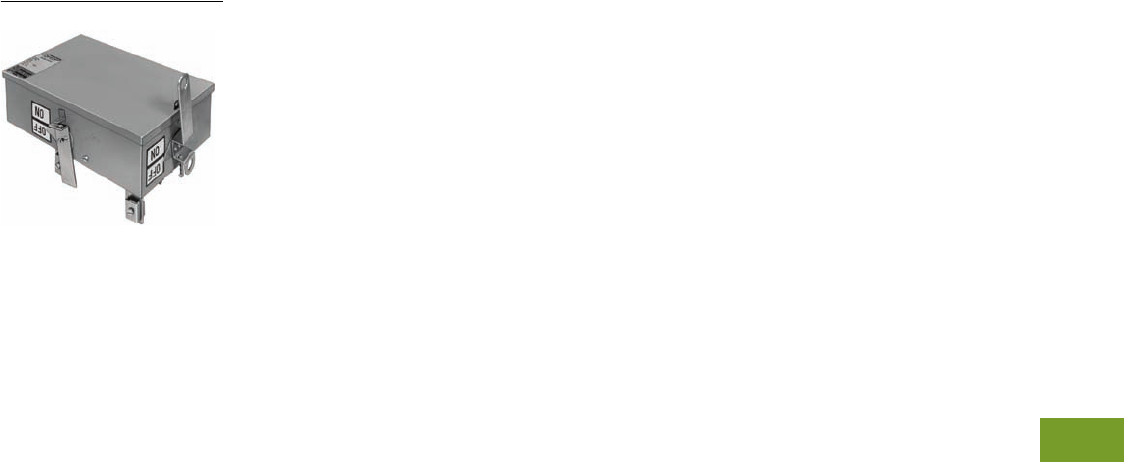
Volume 12—Aftermarket, Renewal Parts and Life Extension Solutions CA08100014E—November 2013 www.eaton.com V12-T9-1
1
2
3
4
5
6
7
8
9
10
11
12
13
14
15
16
17
18
19
20
21
22
23
24
25
Busway (Low Voltage)
Circuit Breaker Enclosure
9 Busway (Low Voltage)
Product Description . . . . . . . . . . . . . . . . . . . . . . . . . . . . . . . . . . . . . . V12-T9-2
Product History . . . . . . . . . . . . . . . . . . . . . . . . . . . . . . . . . . . . . . . . . . V12-T9-2
Product History Time Line . . . . . . . . . . . . . . . . . . . . . . . . . . . . . . . . . V12-T9-3
Replacement Capabilities . . . . . . . . . . . . . . . . . . . . . . . . . . . . . . . . . . V12-T9-4
Plug-In Units . . . . . . . . . . . . . . . . . . . . . . . . . . . . . . . . . . . . . . . . . V12-T9-4
Vintage Busway Products . . . . . . . . . . . . . . . . . . . . . . . . . . . . . . . V12-T9-4
100 Ampere Busway . . . . . . . . . . . . . . . . . . . . . . . . . . . . . . . . . . . V12-T9-6
Standard Plug-In Busway . . . . . . . . . . . . . . . . . . . . . . . . . . . . . . . . V12-T9-7
Standard and Low Impedance . . . . . . . . . . . . . . . . . . . . . . . . . . . . V12-T9-8
Quick-Assembled Plugs . . . . . . . . . . . . . . . . . . . . . . . . . . . . . . . . . V12-T9-10
CP2, CP3 or CP4 SAFETYBUS Busway Plug-In Units . . . . . . . . . . V12-T9-11
Technology Upgrades . . . . . . . . . . . . . . . . . . . . . . . . . . . . . . . . . . . . . V12-T9-14
Clipper Power Systems, Busway TVSS Protection . . . . . . . . . . . . V12-T9-14
IQ Energy Sentinel for Bus Plugs . . . . . . . . . . . . . . . . . . . . . . . . . V12-T9-15
Further Information . . . . . . . . . . . . . . . . . . . . . . . . . . . . . . . . . . . . . . . V12-T9-15
Pricing Information . . . . . . . . . . . . . . . . . . . . . . . . . . . . . . . . . . . . . . . V12-T9-15
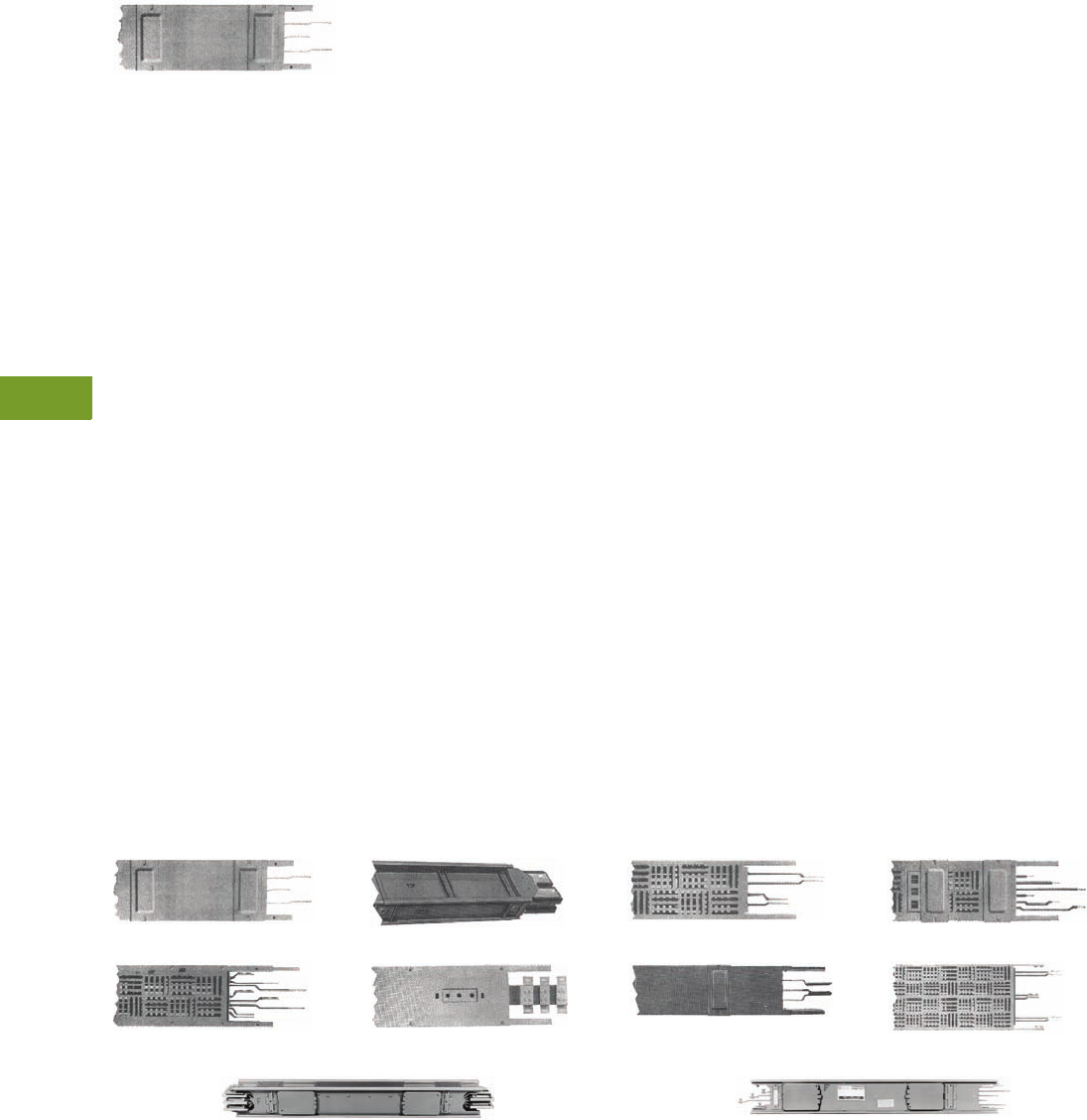
V12-T9-2 Volume 12—Aftermarket, Renewal Parts and Life Extension Solutions CA08100014E—November 2013 www.eaton.com
1
2
3
4
5
6
7
8
9
10
11
12
13
14
15
16
17
18
19
20
21
22
23
24
25
9
Busway (Low Voltage)
Busway (Low Voltage)
Standard Plug-In
Product Description
Eaton’s Cutler-Hammer®
low voltage busway consists
of aluminum or copper bars
inside a metal housing
used for power distribution.
Busway is available in
ampere ratings of 100–5000A.
Busway is available as feeder
(indoor or outdoor) and plug-in.
Feeder busway routes power
from point-to-point, whereas
plug-in busway allows for
power to be tapped off
along a run as needed.
Busway is typically used in
manufacturing buildings and
high-rise office buildings.
Product History
Westinghouse began
marketing low voltage
busway in 1938. The first
product offering was power
distribution busway, using a
multiple bolt joint that later
evolved into standard plug-in
busway. Victory bus duct was
developed during the Second
World War to comply with
federal limitations placed on
usage of materials such as
steel and copper, which were
critical to the war effort. In
1947, Westinghouse began
manufacturing busway at
the newly acquired facility in
Beaver, PA, with standard
plug-in and feeder bus in
ratings up to 1500A. All of
these early designs used
separated, uninsulated
busbars inside a totally
enclosed or perforated
steel housing.
In 1951, low impedance
feeder busway was
introduced as the first
design to use heat-shrinkable
tubing for insulation on the
busbars and a ventilated steel
housing. An internal ground
bus was not available with
this product line, but
provisions were made for
mounting an external ground
bus directly to the busway
housing. Low impedance
feeder and standard plug-in
busway accounted for the
majority of busway business
written by Westinghouse
through the 1950s and into
the 1960s. Low impedance
plug-in busway was
introduced in 1961. With
this design, the product
offering was expanded to
a maximum of 5000A for
feeder and 4000A for plug-in.
During the 1950s, various
other designs were introduced
to meet specific customer
needs. Westinghouse Lifeline
Unibus, rolled out in 1955,
provided low impedance
characteristics with plug-in
openings and incorporated
flexible armored cable
into the design for use as
elbows, offsets and flat to
edgewise adapters.
Westinghouse high frequency
busway was introduced in
1958 to address the inherent
problems of transmitting
power at frequencies from
180 to 20,000 Hz. Cutler-
Hammer high frequency BV
(balanced voltage) busway
was also marketed during
the late 1950s and early
1960s. Westinghouse high
frequency busway and
Cutler-Hammer BV busway
both found success in
aircraft manufacturing plants,
industrial induction heating
systems, military missiles
and radar bases.
Electric utility busway
was also introduced by
Westinghouse in 1958 and
was designed to conduct
direct current with low
voltage drop. By 1963,
electric utility busway had
been expanded to meet the
growing industrial market
for direct current power and
was marketed simply as DC
busway. This product line
was applied to feeding
plating processes, welding
installations, mill drives
and motors.
In 1958, Westinghouse sold
the rights to the Life Line
Unibus product line to EDP
of Allentown, PA, which
marketed EDP Unibus until
1962 when EDP became
a wholly owned subsidiary
of Eaton. Eaton successfully
marketed Unibus until
the product line was
discontinued in 1974.
In 1966, Westinghouse
introduced its first true
sandwich bus design with
H5000 feeder busway.
H5000 was also the first
single bolt joint design
offered by Westinghouse and
it initially used a PVC shrink
tubing and later a Mylar®
wrap for busbar insulation.
A combination of steel and
aluminum channels were
used to form a lightweight
non-magnetic housing. The
grounding method for H5000
was similar to low impedance
busway and an external
ground bus mounted onto
the housing was the only
offering. H5000 plug-in
busway rolled out in 1968
as a non-sandwich design
with separated and
uninsulated busbars.
In 1970, the Eaton’s Cutler-
Hammer Bethlehem, PA,
plant introduced CP2
SAFETYBUS that used an
innovative single bolt, bridge
joint design with a steel
housing for plug-in, and a
combination of steel and
aluminum channels for the
feeder housing. CP2 used
a Mylar wrap for busbar
insulation and an Alstan®
process for plating. The
feeder busway was a
sandwich design while the
plug-in design used separated
busbars that were braced and
supported by corrugations
formed in the housing sides.
Standard Plug-In
Low Impedance Feeder
H5000 Feeder
High Frequency
Electric Utility (DC)
H5000 Plug-In 225–1000A
Low Impedance Plug-In
Current Limiting
Typical Pow-R-Way Plug-In Straight Length Typical Pow-R-Way II Plug-In Straight Length
Volume 12—Aftermarket, Renewal Parts and Life Extension Solutions CA08100014E—November 2013 www.eaton.com V12-T9-3
1
2
3
4
5
6
7
8
9
10
11
12
13
14
15
16
17
18
19
20
21
22
23
24
25
9
Busway (Low Voltage)
Westinghouse introduced
the Pow-R-Way product
line in 1971. Pow-R-Way
employed the sandwich
design in both feeder and
plug-in. At that time, Pow-R-
Way used a combination of
PVC, applied by the fluidized
bed process, and Mylar
sheeting for busbar insulation
that achieved a Class A,
105°C rating. Silver-plating of
all joint and contact surfaces
was applied by a Zincate
process. Pow-R-Way is a
bolt-end/slot-end design with
a single bolt connection at
the joint and is rated from
600 to 5000A. Pow-R-Way II
was rolled out in 1975 with
ratings of 225A and 400A in
feeder and plug-in. Pow-R-
Way II is a single, captive
bolt per bar design for indoor,
horizontal applications only.
During 1980, the Cutler-
Hammer busway design was
upgraded and they began
marketing CP3 SAFETYBUS.
CP3 featured an improved
bridge joint package and a
polyethylene terephthalate
wrap for busbar insulation.
CP3 maintained the CP2
housing design with busbar
separation in the plug-in
product configuration.
Cutler-Hammer CP4
SAFETYBUS was introduced
in 1985 and incorporated
the sandwich design into the
plug-in busway. CP4 featured
a UL® recognized case ground
path rating and 130°C Mylar
busbar insulation. CP4 used
the CP3 bridge joint package
and accepted CP2 and CP3
bus plugs. The CP4 product
line was successful in both
the commercial and industrial
markets until it was
discontinued in 1994.
In 1988, Westinghouse
moved the busway product
line to the Greenwood, SC,
manufacturing facility.
At that time, an improved
Alstan plating process was
implemented for silver-
plating the joint and contact
surfaces. In 1993, the
automated fluidized bed
process was changed to
Class B, 130°C, epoxy
insulation.
Cutler-Hammer Pow-R-
Way III® was introduced in
1997. As in the past, specific
customer needs have driven
the design of this product
line. High short-circuit ratings,
finger-safe protection at the
plug-in openings, integral
housing ground path, two-
piece extruded aluminum
housing and an optional
200% neutral are just some
of the features with this
product line.
Product History Time Line
Power distribution bus
Victory bus duct
Standard plug-in
Low impedance bus
Life line Unibus
High frequency bus
Cutler-Hammer BV bus
Current limiting bus
Electric utility bus
DC busway
100 ampere busway
Low impedance plug-in
Cutler-Hammer Unibus
H5000 feeder
H5000 plug-in
Cutler-Hammer CP2
Pow-R-Way
Pow-R-Way II
Cutler-Hammer CP3
Cutler-Hammer CP4
Pow-R-Way III
Product 1935 1940 1945 1950 1955 1960 1965 1970 1975 1980 1985 1990 1995 2000 Present
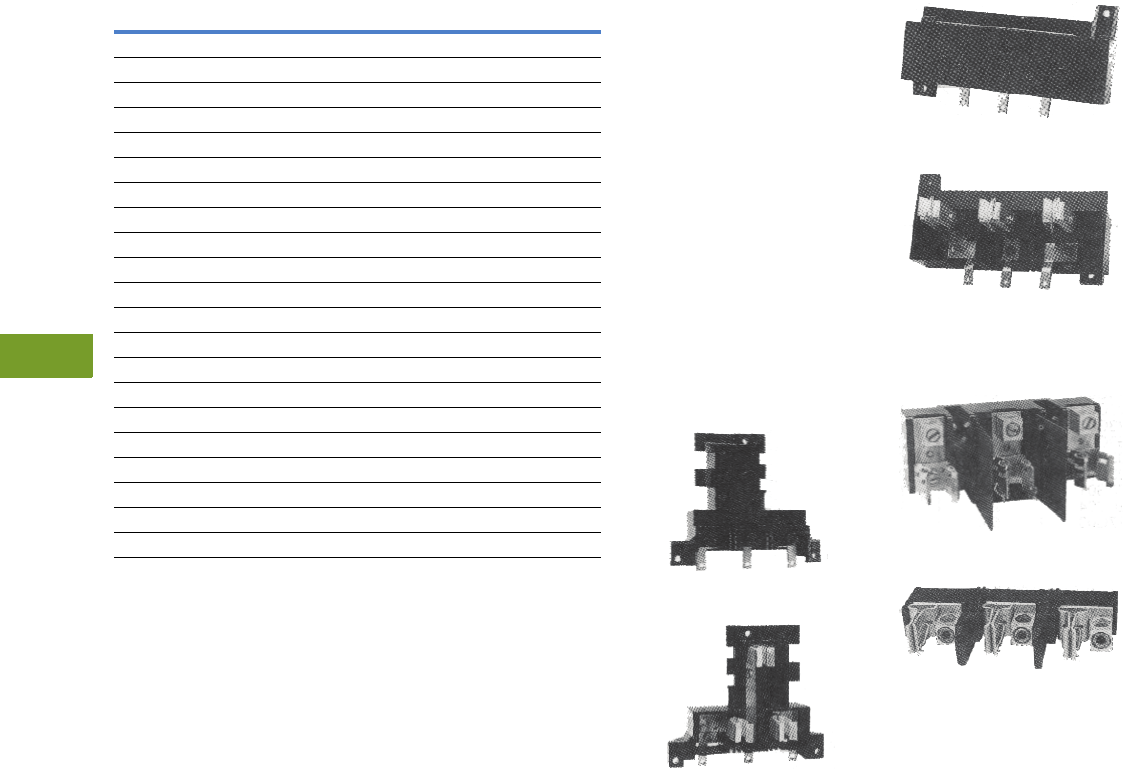
V12-T9-4 Volume 12—Aftermarket, Renewal Parts and Life Extension Solutions CA08100014E—November 2013 www.eaton.com
1
2
3
4
5
6
7
8
9
10
11
12
13
14
15
16
17
18
19
20
21
22
23
24
25
9
Busway (Low Voltage)
Replacement Capabilities—Plug-In Units
Replacement Capabilities
Plug-In Units
Replacement Capabilities
Notes
1Busway adapter (transposition) available from old line to Pow-R-Way III only.
2Fusible units only. No breaker units available.
Busway Types Bus Adapter 1Plugs
Power distribution bus No No No
Victory bus duct No No No
Standard plug-in Yes No Yes
Low impedance bus No Yes —
Life line Unibus No No No
High frequency bus No No No
Cutler-Hammer BV bus No No No
Current limiting bus No Yes —
Electric utility bus No No No
DC busway No No No
100 ampere busway Yes No Yes
Low impedance plug-in No Yes Yes
Cutler-Hammer Unibus No No No
H5000 feeder No No —
H5000 plug-in No No Yes
Cutler-Hammer CP2 No Yes Yes 2
Pow-R-Way Yes No Yes
Pow-R-Way II Yes No Yes
Cutler-Hammer CP3 No Yes Yes 2
Cutler-Hammer CP4 No Yes Yes 2
Pow-R-Way III Yes — Yes
Vintage Busway Products
●Replacement pieces or
additions to
vintage Cutler-
Hammer bus (CP2, CP3,
CP4) are being handled
whenever possible by
making transition to
Eaton’s current design
Pow-R-Way III bus
●Obtain style number
and complete nameplate
information from existing
busway and contact your
local Eaton Field Sales
office for pricing and
availability
●Plugs for vintage
Cutler-Hammer bus,
Pow-R-Way bus, and
Pow-R-Way III bus are
not interchangeable
Pow-R-Way Plug-In Unit
Stab base assembly for
breaker and fusible types.
Top View
Bottom View
Vintage Busway Plug-In Unit
Stab base assembly for
breaker and fusible types.
Top View
Bottom View
Fuse Base Assembly
For all busway.
30A Maximum
200A Maximum

Volume 12—Aftermarket, Renewal Parts and Life Extension Solutions CA08100014E—November 2013 www.eaton.com V12-T9-5
1
2
3
4
5
6
7
8
9
10
11
12
13
14
15
16
17
18
19
20
21
22
23
24
25
9
Busway (Low Voltage)
Replacement Capabilities—Plug-In Units
Originally a Westinghouse Product
Breaker Plug-In Units Fusible Plug-In Units
Notes
1Check Vista for pricing and minimum order quantities.
2Replacement stab base assembly and fuse base style numbers specified correspond to the
most recent design of the reference catalog number for the complete plug-in unit. For
verification that this style number is the correct replacement for your existing plug-in unit,
contact your local Eaton Field Sales office.
Reference Catalog Number for
Existing Complete Plug-In Unit 1
Replacement Stab
Base Assembly
Pow-R-Way
IBPFB 2528D04G01
IBPFBP 2528D04G01
IBPFCL 2528D04G01
IBPFD 2528D04G01
IBPJD 2528D04G12
IBPKB 2528D04G07
IBPKD 2554D03G06
IBPLAP 2532D45G06
IBPLB 2554D03G05
IBPLCL 2554D03G03
IBPMC 2537D17G03
IBPNBP 2537D17G07
Standard Plug-In and Low Impedance Busway 2
BPFB 2528D03G01
BPFBP 2528D03G01
BPFCL 2528D03G01
BPFD 2528D03G01
BPJD 2528D03G10
BPKB 2528D03G07
BPKD 2537D20G06
BPLB 2537D20G05
BPLCL 2537D20G01
BPMC 374D017G03
Reference Catalog Number
for Existing Complete Plug-In Unit 1
Replacement Stab
Base Assembly
Replacement
Fuse Base
Pow-R-Way
ITAP321 2528D04G02 5009D52G01
ITAP361 2528D04G02 5009D52G13
ITAP322 2528D04G02 5009D52G03
ITAP362 2528D04G02 5009D52G04
ITAP323 2528D04G02 5009D52G05
ITAP363 2528D04G02 5009D52G05
ITAP324 767A373G02 2532D78G01
ITAP364 767A373G02 2532D78G01
ITAP325 2554D03G03 627B426G02
ITAP365 2554D03G03 627B426G02
ITAP326 2554D03G02 627B426G04
ITAP366 2554D03G02 627B426G04
ITAP367 2554D03G01 2553D93G02
ITAP361H 2528D04G02 2535D92G09
ITAP362H 2528D04G02 2535D92G10
ITAP363H 2528D04G02 2535D92G11
ITAP364H 2568D13G09 2532D78G02
ITAP365H 2554D03G03 1205C02G02
ITAP366H 2554D03G02 2599D97G02
Standard Plug-In and Low Impedance Busway 2
TAP321 2528D03G02 5009D52G01
TAP361 2528D03G02 5009D52G13
TAP322 2528D03G02 5009D52G03
TAP362 2528D03G02 5009D52G04
TAP323 2528D03G02 5009D52G05
TAP363 2528D03G02 5009D52G05
TAP324 767A373G01 2532D78G01
TAP364 767A373G01 2532D78G01
TAP325 2537D20G04 627B426G02
TAP365 2537D20G04 627B426G02
TAP326 2584D73G01 627B426G04
TAP366 2584D73G01 627B426G02
TAP361H 2528D03G02 2535D92G09
TAP362H 2528D03G02 2535D92G10
TAP363H 2528D03G02 2535D92G11
TAP364H 767A373G01 2532D78G02
TAP365H 2537D20G04 1448D09G05
TAP366H 374D017G03 373D043G06
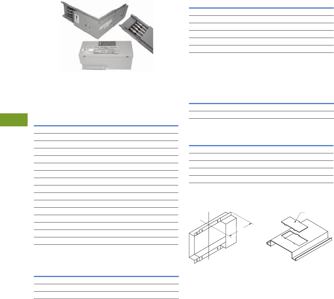
V12-T9-6 Volume 12—Aftermarket, Renewal Parts and Life Extension Solutions CA08100014E—November 2013 www.eaton.com
1
2
3
4
5
6
7
8
9
10
11
12
13
14
15
16
17
18
19
20
21
22
23
24
25
9
Busway (Low Voltage)
Replacement Capabilities—100 Ampere Busway
100 Ampere Busway
Elbow, Busway and Cable Tap Box
100 Ampere Busway—Copper
(Includes 50% Internal Ground Bar)
Cable Tap Boxes
Description
Three-Phase,
Three-Wire
600V Maximum
Catalog Number
Three-Phase,
Four-Wire FN
277/480V
Catalog Number
Single-Phase,
Three-Wire
120/240V
Catalog Number
Straight Lengths
10 ft (3048 mm) CST13G CST14G CST13NG
5 ft (1524 mm) CST135G CST145G CST13N5G
3 ft (914.4 mm) CST133G CST143G CST13N3G
2 ft (609.6 mm) CST132G CST142G CST13N2G
1 ft (304.8 mm) CST131G CST141G CST13N1G
Elbows
Forward CFE13G CFE14G CFE13NG
Rearward CRE13G CRE14G CRE13NG
Upward CUE13G CUE14G CUE13NG
Downward CDE13G CDE14G CDE13NG
Tees
Forward CFT13G CFT14G CFT13NG
Rearward CRT13G CRT14G CRT13NG
Upward CUT13G CUT14G CUT13NG
Downward CDT13G CDT14G CDT13NG
Description
Three-Wire or Four-Wire
Catalog Number
Ground (If Required)
Catalog Number
Plug-in PIB14 PIGS100
End EB14 GL100
Center CBIB14G (Included)
Fusible Plug-In Units
Circuit Breaker Plug-In Units
Accessories
End Closers—EC1 Replacement Outlet
Cover—OC1
Voltage
Rating
Ampere
Rating
Fusible Enclosure
Catalog Number
Ground (If Required)
Catalog Number
240 30 FAN321 PIGS100
240 60 FAN322 PIGS100
240 100 FAN323 PIGS100
600 30 FAN361 PIGS100
600 60 FAN362 PIGS100
600 100 FAN363 PIGS100
Voltage
Rating
Ampere
Rating
Circuit
Breaker
Enclosure
Catalog
Number
Receptacle
Enclosure
Catalog
Number
Ground
(If Required)
Catalog
Number
External Handle
(Required for
Hook-Stick
Operation)
Catalog
Number
QUICKLAG HQP 15–50 PINQP LCNQP PIGS100 HMQP
ED, EHD, FDB 15–100 PINFD LCNFD PIGS100 HMFD
Item Catalog Number
End closer EC1
Outlet cover OC1
Edgwise hanger EH1
“C” clamp hanger FH1
Slip-on wall flange WF1
C
LJoint
4.00
(101.6)
Outlet Cover
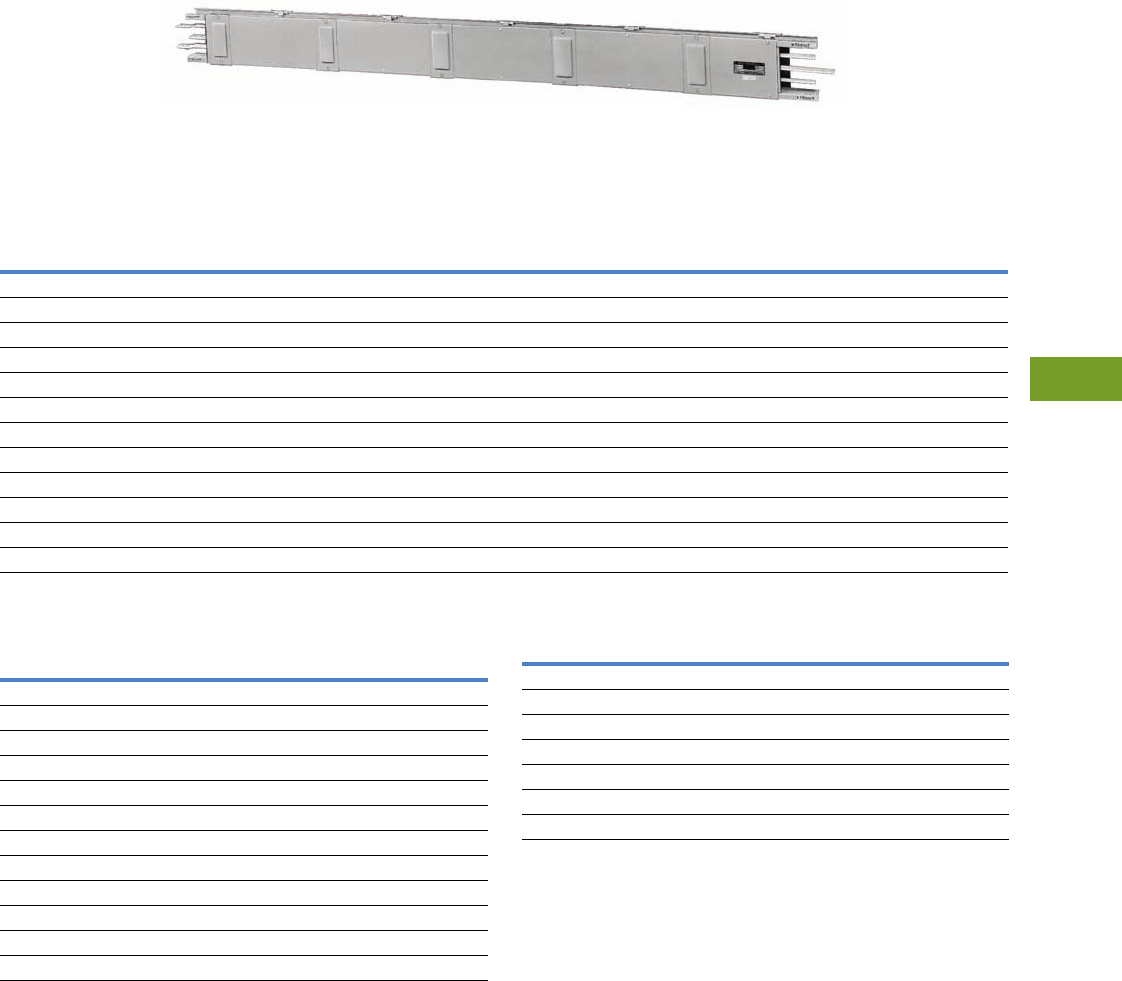
Volume 12—Aftermarket, Renewal Parts and Life Extension Solutions CA08100014E—November 2013 www.eaton.com V12-T9-7
1
2
3
4
5
6
7
8
9
10
11
12
13
14
15
16
17
18
19
20
21
22
23
24
25
9
Busway (Low Voltage)
Replacement Capabilities—Standard Plug-In Busway
Standard Plug-In Busway
Originally a Westinghouse Product
Typical Standard Plug-In Straight Length
Catalog Numbers
Cantilever Hangers Miscellaneous Accessories
Notes
1When ordering from stock, all hangers must be shown as a separate item marked included
in price.
2Suitable for horizontal mounting only. Contact your local Eaton Field Sales office for pricing
and lead times.
3If UCTB is used on end of run, an end closer must also be used for that end.
4Normally available from stock.
Duct Only Includes One Hanger
per 10 Feet of Busway 1
Catalog Number
for 10-Feet Lengths 2
Fittings
(Price of Footage Through Each Fitting Must be Added)
Ampere
Rating
Aluminum
Catalog Number
Copper
Catalog Number
Universal Cable Tap
Box (Lugs Included) 3
Catalog Number
End Closer
Aluminum
Catalog Number
Copper
Catalog Number
Three-Phase, Three-Wire, 600V with 50% Ground Bus
225 AST302G ST302G UCTB302G UEC10 UEC10
400 AST304G ST304G UCTB304G UEC20 UEC15
600 AST306G ST306G UCTB306G UEC35 UEC20
800 AST308G ST308G UCTB308G UEC50 UEC30
1000 AST310G ST310G UCTB310G UEC60 UEC40
Three-Phase, Four-Wire, Full Neutral, 277/480V with 50% Ground Bus
225 AST502G ST502G UCTB402G UEC10 UEC10
400 AST504G ST504G UCTB404G UEC20 UEC15
600 AST506G ST506G UCTB406G UEC35 UEC20
800 AST508G ST508G UCTB408G UEC50 UEC30
1000 AST510G ST510G UCTB410G UEC60 UEC40
Ampere
Rating
Aluminum
Catalog Number
Copper
Catalog Number
Three-Phase, Three-Wire, 600V
225 CLH10 CLH10
400 CLH20 CLH15
600 CLH35 CLH20
800 CLH50 CLH30
1000 CLH60 CLH40
Three-Phase, Four-Wire, Full Neutral, 277/480V
225 CLH10 CLH10
400 CLH20 CLH15
600 CLH35 CLH20
800 CLH50 CLH30
1000 CLH60 CLH40
Description
Wall/floor flange
Extra cantilever hangers
Hookstick kit (8–14 feet) HS8-14 4
Renewal Parts
Joint hardware–EXWK10
Access covers (two)
Splice plates (two)
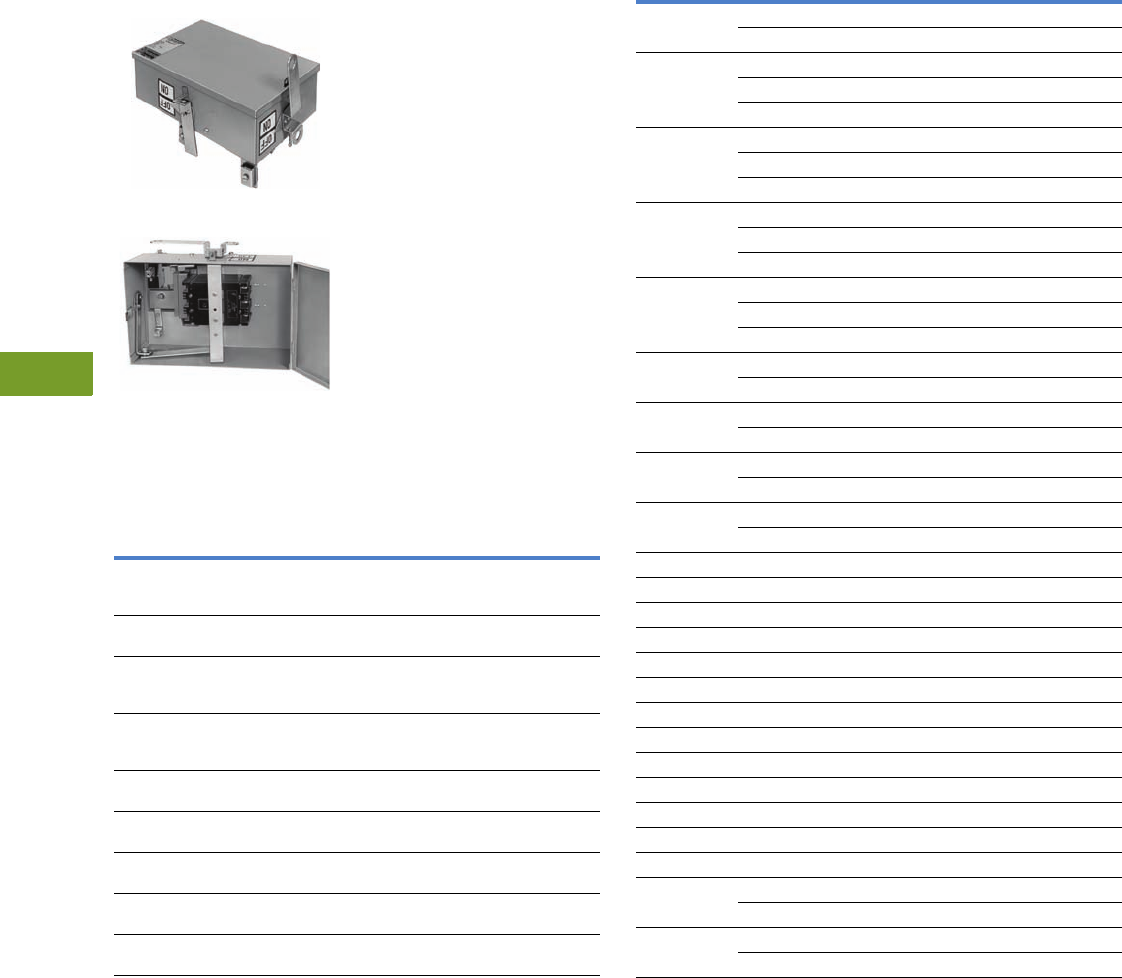
V12-T9-8 Volume 12—Aftermarket, Renewal Parts and Life Extension Solutions CA08100014E—November 2013 www.eaton.com
1
2
3
4
5
6
7
8
9
10
11
12
13
14
15
16
17
18
19
20
21
22
23
24
25
9
Busway (Low Voltage)
Replacement Capabilities—Standard and Low Impedance
Standard and Low Impedance
Originally a Westinghouse Product
Circuit Breaker Plug-In Units
Circuit Breaker Plug-In Unit (Closed)
Circuit Breaker Plug-In Unit (Open)
The enclosure, circuit
breaker, neutral and
ground are ordered and
shipped assembled.
Note: Breaker and fusible
plugs must be ordered as
assembled units. See V12-T9-10
for instructions on how to build
the assembled catalog numbers.
Note: For units mounting at the
joint and feeder type ducts, see
bolt-on units—standard plug-in,
low impedance and H5000.
Catalog Numbers
Breaker
Frame
Enclosure
Catalog
Number
Neutral (If Required) 1Ground
(If Required) 2
Catalog
Number
Standard Plug-In
Catalog Number
Low Impedance
Catalog Number
EHD, FDB,
FD, HFD, FDC
(15–150A)
BPFD 3N110 (15–110A) 3
N250KB (125–150A) 3
ZN110 (15–110A) 3
ZN250KB (125–150A)
GS104 3
JDB, JD, HJD,
JDC (70–250A)
BPJD 3N250KB (125–250A) 3ZN250KB (125–250A) 3GS104 3
KDB, KD,
HKD, KDC
(125–400A)
BPKD N400 (250–400A) 3ZN400 (250–400A) 3GS104 3
LDB, LD,
HLD, LDC
(300–600A)
BPLD 44 4
MC, HMC
(500–800A)
BPMD N/A 44
NC, HNC
(900–1200A)
BPND 44 4
FB (TRI-PAC®)
(15–100A)
BPFBP N110 (15–100A) 3ZN110 (15–100A) GS104 3
LA (TRI-PAC)
(125–400A)
BPLAP 5N400 (125–400A) 3ZN400 (125–400A) 3GS104 3
NB (TRI-PAC)
(500–800A)
BPNBP 44 GS104 3
Circuit Breaker Selection and Interrupting Ratings
Notes
1Full neutral. For half neutral, contact your local Eaton Field Sales office.
2Not available for low impedance bus duct.
3Normally available from stock.
4Contact your local Eaton Field Sales office for delivery. Order by description on suffix BUS.
5Obsolete; no longer available.
Breaker
Frame
Ampere
Rating
Symmetrical Amperes
240 Vac 480 Vac 600 Vac
EHD 15–60 18,000 14,000 —
70–100 18,000 14,000 —
FDB 15–60 18,000 14,000 14,000
70–100 18,000 14,000 14,000
110–150 18,000 14,000 14,000
FD 15–60 65,000 25,000 18,000
70–100 65,000 25,000 18,000
110–150 65,000 25,000 18,000
HFD 15–60 100,000 65,000 25,000
70–100 100,000 65,000 25,000
110–150 100,000 65,000 25,000
FDC 15–60 200,000 100,000 50,000
70–100 200,000 100,000 50,000
110–150 200,000 100,000 50,000
JDB 70–225 65,000 25,000 18,000
250 65,000 25,000 18,000
JD 70–225 65,000 25,000 18,000
250 65,000 25,000 18,000
HJD 70–225 100,000 65,000 25,000
250 100,000 65,000 25,000
JDC 70–225 200,000 100,000 50,000
250 200,000 100,000 50,000
KDB 250–400 65,000 35,000 25,000
KD 250–400 65,000 35,000 25,000
HKD 250–400 100,000 65,000 35,000
KDC 250–400 200,000 100,000 50,000
LDB 300–600 65,000 45,000 25,000
LD 300–600 65,000 45,000 25,000
HLD 300–600 100,000 65,000 35,000
LDC 300–600 200,000 100,000 50,000
MDL 400–800 65,000 50,000 25,000
HMDL 400–800 100,000 65,000 35,000
NP 400–1200 65,000 50,000 25,000
HND 400–1200 100,000 65,000 35,000
FB (TRI-PAC) 15–100 200,000 200,000 200,000
LA (TRI-PAC) 70–400 200,000 200,000 200,000
70–400 200,000 200,000 200,000
NB (TRI-PAC) 600–800 200,000 200,000 200,000
600–800 200,000 150,000 200,000
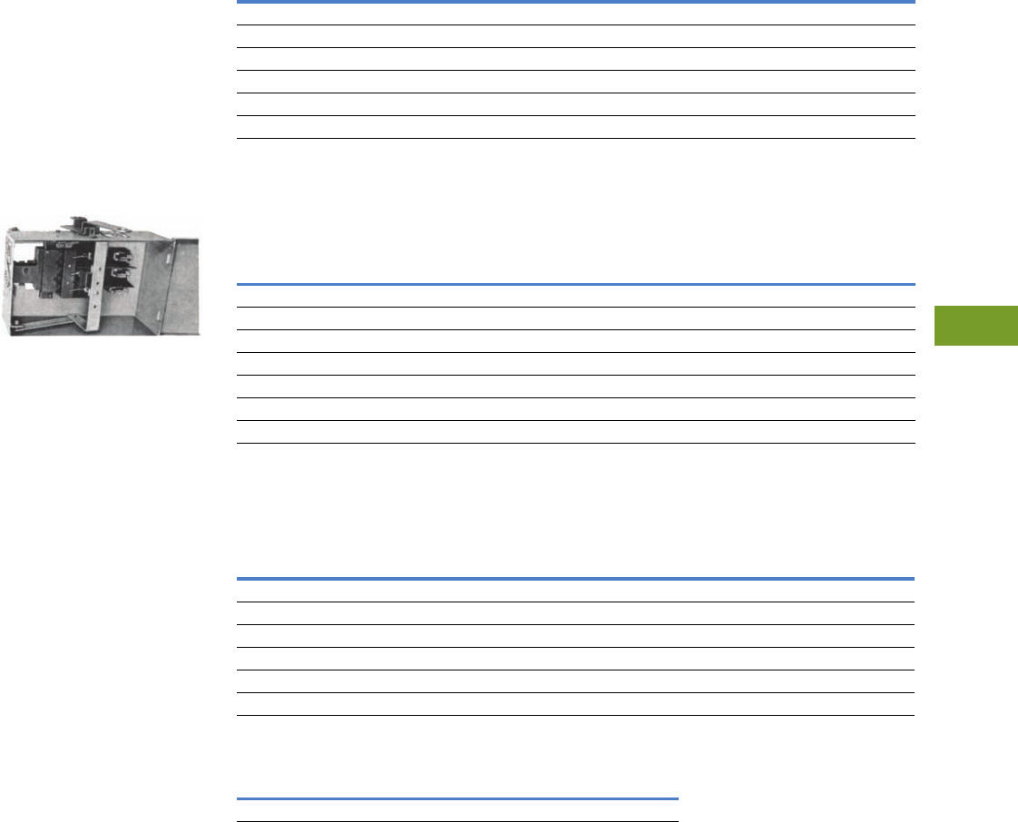
Volume 12—Aftermarket, Renewal Parts and Life Extension Solutions CA08100014E—November 2013 www.eaton.com V12-T9-9
1
2
3
4
5
6
7
8
9
10
11
12
13
14
15
16
17
18
19
20
21
22
23
24
25
9
Busway (Low Voltage)
Replacement Capabilities—Standard and Low Impedance
Originally a
Westinghouse Product
Fusible Plug-In Units
●For standard plug-in and
low impedance plug-in
busway (not for use on
Pow-R-Way busway.
Not available for low
impedance bus duct)
●Fuses not included
●Mechanical lugs only
●Plug-in unit, neutral and
ground can be ordered
separately and shipped
unassembled
Fusible TAP
Special Industry Fusible
Plug-In Units
●Special industry plugs
are I2t rated
●Knockouts are not provided
●Grounding lug included
on 200A and above
●Lugs ordered and
shipped separately
●Fuses are not included
●If neutral or ground
assembly is required,
contact your local Eaton
Field Sales office
Fusible Switch Horsepower Ratings
Fusible Plug-In Units 1
Special Industry Fusible Plug-In Units
Three-Wire—Ground Detector and Neutralizer Plug
Notes
1Not available for low impedance bus duct.
2Normally available from stock.
3Only half neutral available. For full neutral, use a TAP366BO or TAP326BO unit.
4Must be factory assembled. Order by description on suffix BUS.
5Plug-in unit not available. Contact your local Eaton Field Sales office for bolt-on type.
6Must be factory assembled. Order by description.
Ampere
Rating
240V 480V 600V
NEC®
Standard
Time
Delay
NEC
Standard
Time
Delay
NEC
Standard
Time
Delay
3037-1/25157-1/220
60 7-1/2 15 15 30 15 50
100153025603075
20025605012560150
400 50 100 100 250 125 350
600 75 100 200 400 200 500
Ampere
Rating
600V
Catalog
Number
240V
Catalog
Number
Neutral (If Required) Ground
(If Required)
Catalog
Number
Class R Fuse Clips
(If Required)
Standard Plug-In
Catalog
Number
Low Impedance
Catalog
Number
600V
Catalog
Number
240V
Catalog
Number
30 TAP361 2TAP321 2N110 2ZN110 2GS104 12 RFK161 2RFK121 2
60 TAP362 2TAP322 2N110 2ZN110 2GS104 12 RFK262 2RFK222 2
100 TAP363 2TAP323 2N110 2ZN110 2GS104 12 RFK464 2RFK464 2
200 TAP364 2TAP324 2N250KB 2ZN250KB GS104
12 RFK464 2RFK464 2
400 TAP365 TAP325 N400 22 GS104 12 RFK666 2RFK666 2
600 TAP366 TAP326 N400 23 ZN400 24 RFK666 2RFK666 2
800 55—4———
Three-Wire, 600V
Plug-In Unit
If Required Terminal Kits for Industry Fusible Plug-In Units
Neutral
Catalog
Number
Ground
Catalog
Number
Mechanical Lugs 2Compression Lugs 2
Ampere
Rating
Catalog
Number
Catalog
Number
Lugs Per
Phase
Wire
Size
Catalog
Number
Lugs Per
Phase
Wire
Size
30 TAP361H 66 MTK30SC 1 #14–#4 CTK30SC 1 #12–#10
60 TAP362H 66 MTK160SC 1 #14–1/0 CTK60SC 1#8
100 TAP363H 66MTK160SC 1 #14–1/0 CTK100SC 1#4
200 TAP364H 66MTK200SC 1 #6–350 kcmil CTK200BSC 12/0
400 TAP365H 66MTK400DPW 2 #2–4/0 CTK400SPW 1 750 kcmil
600 TAP366H 66MTK600DFW 2 500 kcmil CTK600DPM 2 500 kcmil
Maximum Volts Catalog Number
600 GND36
V12-T9-10 Volume 12—Aftermarket, Renewal Parts and Life Extension Solutions CA08100014E—November 2013 www.eaton.com
1
2
3
4
5
6
7
8
9
10
11
12
13
14
15
16
17
18
19
20
21
22
23
24
25
9
Busway (Low Voltage)
Replacement Capabilities—Quick-Assembled Plugs
Quick-Assembled Plugs
The Mod Center in
Spartanburg, SC, will perform
the assembly of the bus
plugs in 3 days or less for
most orders. Bid Manager™
enables you to “build” the
appropriate catalog number.
When the order is entered
in Bid Manager, it will
automatically transfer the
order to suffix “QAP.”
Please see the following
rules for building the
assembled catalog number.
Catalog Numbering Selection
Quick-Assembled Plugs—Breaker Unit 12
Quick-Assembled Plugs—Fusible Unit 234
Notes
1Do not leave space between characters. Example: P3BHFD3015GN.
2Contact your local Eaton Field Sales office for help in assigning a catalog number for a specific application.
3Do not leave space between characters. Example: P3F264RGN.
4“H” clips are standard for Pow-R-Way and vintage busway products unless specified by adding “R” or “J” in the catalog number.
Example: P3F264RGN, ITAP361JGN.
Neutral Options
N= 100% neutral
N2 = 200% neutral
(PRW III only)
ZN =Low Z
(old line only)
Trip Rating
(Example 015,
060, 150, 400)
Breaker Frame
(Example FD,
JDC, KDB)
P3B HFD 3015 G N
Bus Style
P3B =PRWIII
IBP =PRW
BP = Old-line
Three-Pole
Only
Ground Option
G= 50% internal
I= Isolated ground
(PRWIII only)
Neutral Options
N= 100% neutral
N2 = 200% neutral
(PRW III only)
ZN =Low Z
(old line only)
Fuse Clips
R or J ≤ 600A
T or L for 800A
Ground Options
G= 50%
I= Isolated (PRW III only)
Ampere
1 = 30
2 = 60
3 = 100
4 = 200
5 = 400
6 = 600
7 = 800
Voltage
6 = 600V
2 = 240V
P3F 3 6 4 R G N
Bus Style
P3F =PRWIII
ITAP =PRW
TAP = Old-line
Three-Pole Only

Volume 12—Aftermarket, Renewal Parts and Life Extension Solutions CA08100014E—November 2013 www.eaton.com V12-T9-11
1
2
3
4
5
6
7
8
9
10
11
12
13
14
15
16
17
18
19
20
21
22
23
24
25
9
Busway (Low Voltage)
Replacement Capabilities—CP2, CP3 or CP4 SAFETYBUS Busway Plug-In Units
CP2, CP3 or CP4 SAFETYBUS Busway Plug-In Units
Originally a Westinghouse Product
Bolt-On Units 1
Circuit Breaker Selection and Interrupting Ratings 6
Notes
1Factory assembled. Contact your local Eaton Field Sales office for delivery and order entry
information. When ordering, you must specify:
1. Load left or load right.
2. Front or rear mounting.
3. Type of busway to which unit is to be mounted.
2Full neutral. For half neutral, contact your local Eaton Field Sales office.
3Not available for low impedance bus duct.
4Order by description with bolt-on unit.
5These bolt-on units include an adapter for mounting at the joint. They do not require a power
take-off unit.
6Refer to the current Price and Availability Digest (PAD) for breaker list prices.
Breaker
Frame
Ampere
Rating
Enclosure
Catalog
Number
Neutral 2
(If Required)
Catalog
Number
Ground 3
(If Required)
Catalog
Number
Circuit Breaker Bolt-On Units (Breaker Not Included)
EHD, FDB, FD
HFD, FDC
15–150 BPFDBO 44
JDB, JD, HJD,
JDC
125–250 BPJDBO 44
KDB, KD, HKD,
KDC
250–400 BPKDBO 44
LDB, LD, HLD
LDC
300–600 BPLDBO 44
MDL, HMDL 400–800 BPMDBO 44
FB (TRI-PAC) 15–100 BPFBPBO 44
LA (TRI-PAC) 125–400 BPLAPBO 44
NB (TRI-PAC) 500–800 BPNBPBO 44
Fusible Bolt-On Units 5
240V 30 TAP321BO 44
60 TAP322BO 44
100 TAP323BO 44
200 TAP324BO 44
400 TAP325BO 44
600 TAP326BO 44
800 TAP327BO 44
600V 30 TAP361BO 44
60 TAP362BO 44
100 TAP363BO 44
200 TAP364BO 44
400 TAP365BO 44
600 TAP366BO 44
800 TAP367BO 44
Breaker
Frame
Ampere
Rating
Symmetrical Amperes
240 Vac 480 Vac 600 Vac
EHD 15–60 18,000 14,000 —
70–100 18,000 14,000 —
FDB 15–60 18,000 14,000 14,000
70–100 18,000 14,000 14,000
110–150 18,000 14,000 14,000
FD 15–60 65,000 25,000 18,000
70–100 65,000 25,000 18,000
110–150 65,000 25,000 18,000
HFD 15–60 100,000 65,000 25,000
70–100 100,000 65,000 25,000
110–150 100,000 65,000 25,000
FDC 15–60 200,000 100,000 50,000
70–100 200,000 100,000 50,000
110–150 200,000 100,000 50,000
JDB 70–225 65,000 25,000 18,000
250 65,000 25,000 18,000
JD 70–225 65,000 25,000 18,000
250 65,000 25,000 18,000
HJD 70–225 100,000 65,000 25,000
250 100,000 65,000 25,000
JDC 70–225 200,000 100,000 50,000
250 200,000 100,000 50,000
KDB 250–400 65,000 35,000 25,000
KD 250–400 65,000 35,000 25,000
HKD 250–400 100,000 65,000 35,000
KDC 250–400 200,000 100,000 50,000
LDB 300–600 65,000 45,000 25,000
LD 300–600 65,000 45,000 25,000
HLD 300–600 100,000 65,000 35,000
LDC 300–600 200,000 100,000 50,000
MDL 400–800 65,000 50,000 25,000
HMDL 400–800 100,000 65,000 35,000
NP 400–1200 65,000 50,000 25,000
HND 400–1200 100,000 65,000 35,000
FB (TRI-PAC) 15–100 200,000 200,000 200,000
LA (TRI-PAC) 70–400 200,000 200,000 200,000
70–400 200,000 200,000 200,000
NB (TRI-PAC) 600–800 200,000 200,000 200,000
600–800 200,000 150,000 200,000

V12-T9-12 Volume 12—Aftermarket, Renewal Parts and Life Extension Solutions CA08100014E—November 2013 www.eaton.com
1
2
3
4
5
6
7
8
9
10
11
12
13
14
15
16
17
18
19
20
21
22
23
24
25
9
Busway (Low Voltage)
Replacement Capabilities—CP2, CP3 or CP4 SAFETYBUS Busway Plug-In Units
Originally a Cutler-Hammer Product
Fusible Switch Plug-In Units
Plug-In Cable Tap Boxes—Plug Into CP2, CP3 or CP4 Busway 5—600A and 800A Sizes Also Have Bolt-On Clips
Notes
1Maximum hp ratings apply when time delay fuses are used.
2120–208V hp ratings are based on 200V motor usage.
3All units ship as three-phase, four-wire plugs.
4Requires two adjacent plug-in outlets that do not span a busway joint.
5For ground stab to engage internal ground bus, add suffix “G” to catalog number.
6Also accepts (2) #1–300 kcmil Al/Cu.
Class R Fuse Clip Included
Ampere Rating Maximum hp Rating 1Catalog Number Maximum hp Rating 12 Catalog Number 3
240V, Three-Phase, Three-Wire 120–208V, Three-Phase, Four-Wire
30 7-1/2 CP4HD321 5CP4HD421
60 15 CP4HD322 10 CP4HD422
100 30 CP4HD323 25 CP4HD423
200 60 CP4HD324 60 CP4HD424
400 100 CP4HD325 250 CP4HD425
600 4100 CP4HD326 400 CP4HD426
600V, Three-Phase, Three-Wire 277–480V, Three-Phase, Four-Wire
30 20 CP4HD361 15 CP4HD461
60 50 CP4HD362 30 CP4HD462
100 75 CP4HD363 60 CP4HD463
200 100 CP4HD364 100 CP4HD464
400 350 CP4HD365 250 CP4HD465
600 4500 CP4HD366 400 CP4HD466
Volts
Ampere
Rating
Approximate Dimensions in Inches
Conduit
Sizes
Load Lugs
Each Phase
Catalog
NumberWide High Deep
Mounting Clearance
Top Front
Three-phase, three-wire
600V maximum
225 15.50 8.10 6.90 6.30 10.50 1-1/2, 2, 2-1/2, 3 (1) #6–300 kcmil Al/Cu CP2SB34
400 22.30 8.10 7.90 7.00 11.30 1-1/2, 2, 2-1/2, 3 (1) #1/0–750 kcmil Al/Cu 6CP2SB35
600 37.20 15.80 11.70 12.50 16.80 1-1/2, 2, 2-1/2, 3 (2) #2–600 kcmil Al/Cu CP2SB36 4
800 37.20 15.80 11.70 12.50 16.80 1-1/2, 2, 2-1/2, 3 (3) #2–600 kcmil Al/Cu CP2SB37 4
Three-phase, four-wire
120/208V or 277/480V
100% neutral
225 15.50 8.10 6.90 6.30 10.50 1-1/2, 2, 2-1/2, 3 (1) #6–300 kcmil Al/Cu CP2SB44
400 22.30 8.10 7.90 7.00 11.30 1-1/2, 2, 2-1/2, 3 (1) #1/0–750 kcmil Al/Cu 6CP2SB45
600 37.20 15.80 11.70 12.50 16.80 1-1/2, 2, 2-1/2, 3 (2) #2–600 kcmil Al/Cu CP2SB46 4
800 37.20 15.80 11.70 12.50 16.80 1-1/2, 2, 2-1/2, 3 (3) #2–600 kcmil Al/Cu CP2SB47 4
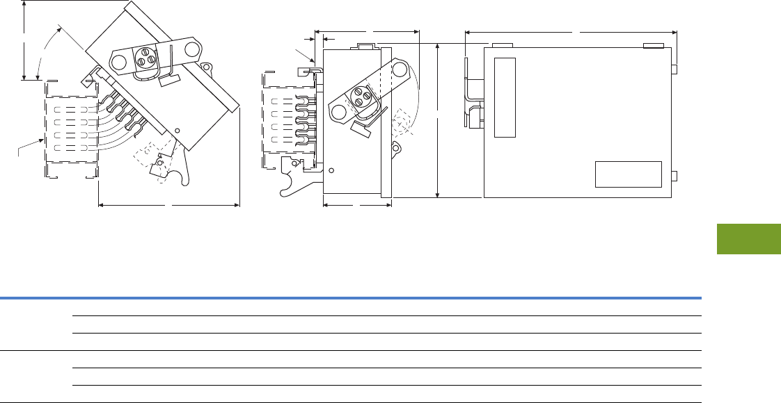
Volume 12—Aftermarket, Renewal Parts and Life Extension Solutions CA08100014E—November 2013 www.eaton.com V12-T9-13
1
2
3
4
5
6
7
8
9
10
11
12
13
14
15
16
17
18
19
20
21
22
23
24
25
9
Busway (Low Voltage)
Replacement Capabilities—CP2, CP3 or CP4 SAFETYBUS Busway Plug-In Units
Originally a Cutler-Hammer Product
Approximate Dimensions
Required Mounting Clearances Typical Side and Front
Plug-In Units—May be Used with Either CP2, CP3 or CP4 Plug-In Busway Sections—Fusible Switch Type
Notes
1Provided with busway bolt-on clip and straps for 0.50-inch hanger rods.
2Unit extends 10.50 inches below busway.
Frame
or Type
Maximum
Ampere
Rating
Dimensions in Inches
Conduit Sizes
Top, Bottom and Side
Wire Size Range
Al/CuABCDE F
CP4HD 30 19.30 11.50 8.80 5.20 7.00 9.00 1/2, 3/4, 1, 1-1/4, 1-1/2, 2 (1) #14–2
60 19.30 11.50 8.80 5.20 7.00 9.00 1/2, 3/4, 1, 1-1/4, 1-1/2, 2 (1) #14–2
100 19.30 11.50 8.80 5.20 7.00 9.00 1/2, 3/4, 1, 1-1/4, 1-1/2, 2 (1) #14–1/0
CP4HD 200 23.00 16.50 9.20 6.00 7.50 13.30 1-1/2, 2, 2-1/2, 3 (1) #6–300 kcmil
400 12 45.60 24.30 15.80 13.10 14.00 20.50 1-1/2, 2, 2-1/2, 3 (1) #1/0–300 kcmil or (1) 750 kcmil
600 12 45.60 24.30 15.80 13.10 14.00 20.50 1-1/2, 2, 2-1/2, 3 (2) #2–600 kcmil
OFF
ON
F
A
D
B
.34
Edge of
Busway
C
E
44° Ref.
Plug-in
Busway

V12-T9-14 Volume 12—Aftermarket, Renewal Parts and Life Extension Solutions CA08100014E—November 2013 www.eaton.com
1
2
3
4
5
6
7
8
9
10
11
12
13
14
15
16
17
18
19
20
21
22
23
24
25
9
Busway (Low Voltage)
Technology Upgrades—Clipper Power Systems (TVSS)
Technology Upgrades
Clipper Power Systems,
Busway TVSS Protection
The low voltage busway
aftermarket product offering
includes transient voltage
surge suppression (TVSS),
which is ideal for busway fed
distribution systems. Eaton
has developed the Clipper
Power System (CPS) family
of products to ensure that
the quality power required
to maximize productivity
in today’s competitive
environment is supplied
to commercial, industrial,
medical and institutional
facilities. Without power
protection devices,
microprocessors and
electronic-based loads are
not provided with the noise
and disturbance-free power
that they require. Because
microprocessor-based loads
are now common in every
facility, engineers must
ensure the AC power supply
is properly filtered. The CPS
busway family of products
consists of TVSS and filter
components (TVSS filter)
integrated into a bus plug
with a fusible disconnect.
TVSS bus plugs are available
for the following types of
plug-in busway:
●Westinghouse
standard plug-in
●Westinghouse low
impedance plug-in
●Westinghouse
H5000 plug-in
●Cutler-Hammer
CP2 plug-in
●Cutler-Hammer
CP3 plug-in
●Cutler-Hammer
CP4 plug-in
●Westinghouse
Pow-R-Way
●Westinghouse
Pow-R-Way II
●Cutler-Hammer
Pow-R-Way III
Significant performance
advantages are achieved
by integrating TVSS filters
into busway systems.
Because the TVSS unit is
directly connected to the
busway, the CPS minimizes
let-through voltage. This is a
significant performance
advantage compared to
cable-connected TVSS
solutions. Due to the
integrated design, the
CPS bus plug also saves
the user wall space and
greatly reduces the installed
project cost.
Catalog Numbering Selection
Visor Series Bus Plug
P3BCPS 250 480Y S A
Bus Style
P3BCPS = Pow-R-Way
TAPCPS = Std. plug-in
ZTAPCPS = Low impedance
HTAPCPS = H5000
CP4CPS = CP2/CP3/CP4
ITAPCPS = Pow-R-Way
Surge Rating
(kA/Phase)
100 = 100
120 = 120
160 = 160
200 = 200
250 = 250
300 = 300
400 = 400
500 = 500
Diagnostics Package
A =AdVisor complete with status indicator lights on each
phase. Form C. Audible Alarm—Enable/Disable
S =SuperVisor complete with status indicator lights
on each phase, 1-Form C. Audible Alarm—
Enable/Disable, Transient Counter, Push-to-Teat.
PQ Meter (no date stamp)
N =NetVisor complete with status indicator lights on
each phase. Form C. Audible Alarm—Enable/Disable,
Transient Counter, Push to Test, PQ Meter (no date
stamp). Modbus® and Ethernet Communications
Port, % Life Remaining, % Voltage THD
Voltage
Code
Voltage Requirements
120/208
240V
230/400
400V
277/480
480V
347/600
600V
Three-phase
wye (4W+G)
208Y 400Y 480Y 600Y
Three-phase
delta (4W+G)
240D —480D 600D
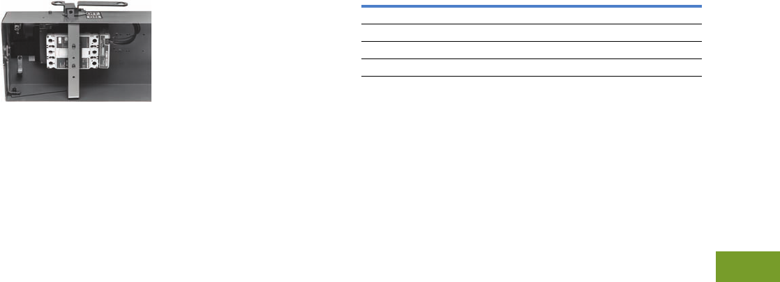
Volume 12—Aftermarket, Renewal Parts and Life Extension Solutions CA08100014E—November 2013 www.eaton.com V12-T9-15
1
2
3
4
5
6
7
8
9
10
11
12
13
14
15
16
17
18
19
20
21
22
23
24
25
9
Busway (Low Voltage)
Technology Upgrades—Submetering—IQ Energy Sentinel
IQ Energy Sentinel
for Bus Plugs
Bus Plug with Energy Sentinel
Customer Required Information
If Originally a
Westinghouse Product
1. Style number or shop
order number from
existing busway
nameplate and complete
nameplate information.
2. Height and width
dimensions of housing
from existing busway.
3. Order by style number
on suffix Q77.
If Originally a
Cutler-Hammer Product
1. Check Vista for pricing.
2. Order by catalog number
on suffix Q73.
The Cutler-Hammer IQ Energy
Sentinel™ was designed
as part of the PowerNet™
system and is a highly
accurate, microprocessor-
based submeter that monitors
power and energy. It offers
a centralized alternative
to individually mounted
wattmeters, watthour meters
and watt demand meters.
Key advantages include
unmatched savings in space,
lower installation costs, and
the capability to communicate
data readings in a variety of
ways. IQ Energy Sentinels
with built-in current
transformers (CTs) and
communications have the
added benefit of overall
system accuracy. The IQ
Energy Sentinel mounts on
the load side of Cutler-
Hammer F, J and K breakers
within the bus-plug enclosure.
The IQ Energy Sentinel is
also available with a universal
mounting that uses external
CTs and is offered for fusible
bus plug applications.
Sub-metering application
examples for the IQ Energy
Sentinel include energy
monitoring and demand
management, energy cost
analysis/allocation, and
tenant or interdepartmental
billing. To accomplish the
communications system,
the customer must provide
a twisted pair communication
cable in 1/2-inch conduit
between the IQ Energy
Sentinel bus plug and a
Cutler-Hammer Central
Energy Display, or customer
computer to display the
information. IQ Energy
Sentinel bus plugs are
available for Pow-R-Way,
Pow-R-Way II and
Pow-R-Way III busway.
Further Information
Pricing Information
Vista/VISTALINE™ Discount Symbols CE3 and CE4
Note: Contact your local Eaton Field Sales office.
Note: Additional information may be required for manufacturing.
Publication
Number Description
AD 30-560 Application Data for Pow-R-Way
AD 30-560 Application Data for Pow-R-Way II
TD01701001E Technical Data for Pow-R-Way III
TD01701002E Technical Data for 100 Ampere Busway

Volume 12—Aftermarket, Renewal Parts and Life Extension Solutions CA08100014E—November 2013 www.eaton.com V12-T10-1
1
2
3
4
5
6
7
8
9
10
11
12
13
14
15
16
17
18
19
20
21
22
23
24
25
IQ Products
Power Management Products
10 IQ Products
Product Description. . . . . . . . . . . . . . . . . . . . . . . . . . . . . . . . . . . . . . . V12-T10-2
Product History . . . . . . . . . . . . . . . . . . . . . . . . . . . . . . . . . . . . . . . . . . V12-T10-3
Product History Time Line. . . . . . . . . . . . . . . . . . . . . . . . . . . . . . . . . . V12-T10-3
General Information
Metering Selection Chart . . . . . . . . . . . . . . . . . . . . . . . . . . . . . . . . V12-T10-4
Protective Relay Selection Chart. . . . . . . . . . . . . . . . . . . . . . . . . . . V12-T10-12
Technology Upgrades
Power Xpert 4000/6000/8000 Series Meters . . . . . . . . . . . . . . . . . V12-T10-15
Power Xpert 2000 Series Meters . . . . . . . . . . . . . . . . . . . . . . . . . . V12-T10-17
Power Xpert Multi-Point Meter . . . . . . . . . . . . . . . . . . . . . . . . . . . . V12-T10-18
IQ 250/260 . . . . . . . . . . . . . . . . . . . . . . . . . . . . . . . . . . . . . . . . . . . V12-T10-19
IQ 130/140/150 . . . . . . . . . . . . . . . . . . . . . . . . . . . . . . . . . . . . . . . . V12-T10-20
IQ 150S/250S . . . . . . . . . . . . . . . . . . . . . . . . . . . . . . . . . . . . . . . . . V12-T10-21
IQ 35M . . . . . . . . . . . . . . . . . . . . . . . . . . . . . . . . . . . . . . . . . . . . . . V12-T10-22
Enclosed Meters . . . . . . . . . . . . . . . . . . . . . . . . . . . . . . . . . . . . . . V12-T10-23
Current Products
IQ Analyzer 6400/6600 . . . . . . . . . . . . . . . . . . . . . . . . . . . . . . . . . . V12-T10-24
IQ DP-4000/4100 . . . . . . . . . . . . . . . . . . . . . . . . . . . . . . . . . . . . . . V12-T10-25
IQ Energy Sentinel . . . . . . . . . . . . . . . . . . . . . . . . . . . . . . . . . . . . . V12-T10-26
IQ 230. . . . . . . . . . . . . . . . . . . . . . . . . . . . . . . . . . . . . . . . . . . . . . . V12-T10-27
MP-3000 Motor Protection. . . . . . . . . . . . . . . . . . . . . . . . . . . . . . . V12-T10-28
FP-5000 Feeder Protection . . . . . . . . . . . . . . . . . . . . . . . . . . . . . . . V12-T10-29
Digitrip 3000 (DT-3000) . . . . . . . . . . . . . . . . . . . . . . . . . . . . . . . . . . V12-T10-30
Accessories
IQ Flange . . . . . . . . . . . . . . . . . . . . . . . . . . . . . . . . . . . . . . . . . . . . V12-T10-31
IQ 250-PMAK . . . . . . . . . . . . . . . . . . . . . . . . . . . . . . . . . . . . . . . . . V12-T10-31
IQ DC Power Supply. . . . . . . . . . . . . . . . . . . . . . . . . . . . . . . . . . . . V12-T10-31
IQ Cable . . . . . . . . . . . . . . . . . . . . . . . . . . . . . . . . . . . . . . . . . . . . . V12-T10-31
IQ Floor-Mounted Enclosure. . . . . . . . . . . . . . . . . . . . . . . . . . . . . . V12-T10-31
Addressable Relay II . . . . . . . . . . . . . . . . . . . . . . . . . . . . . . . . . . . . V12-T10-32
Power Modules. . . . . . . . . . . . . . . . . . . . . . . . . . . . . . . . . . . . . . . . V12-T10-32
CTs . . . . . . . . . . . . . . . . . . . . . . . . . . . . . . . . . . . . . . . . . . . . . . . . . V12-T10-33
Discontinued Product—Recommended Replacement
IQ 2000. . . . . . . . . . . . . . . . . . . . . . . . . . . . . . . . . . . . . . . . . . . . . . V12-T10-36
IQ Analyzer 6000/6200 . . . . . . . . . . . . . . . . . . . . . . . . . . . . . . . . . . V12-T10-36
RTD Modules . . . . . . . . . . . . . . . . . . . . . . . . . . . . . . . . . . . . . . . . . V12-T10-36
IQ 1000 and IQ 1000 II . . . . . . . . . . . . . . . . . . . . . . . . . . . . . . . . . . V12-T10-37
IQ Data Plus and IQ Data Plus II . . . . . . . . . . . . . . . . . . . . . . . . . . V12-T10-37
IQ Data . . . . . . . . . . . . . . . . . . . . . . . . . . . . . . . . . . . . . . . . . . . . . . V12-T10-37
IQ Generator. . . . . . . . . . . . . . . . . . . . . . . . . . . . . . . . . . . . . . . . . . V12-T10-38
IQ 300. . . . . . . . . . . . . . . . . . . . . . . . . . . . . . . . . . . . . . . . . . . . . . . V12-T10-38
IQ 210/220 . . . . . . . . . . . . . . . . . . . . . . . . . . . . . . . . . . . . . . . . . . . V12-T10-39
IQ 110/115 . . . . . . . . . . . . . . . . . . . . . . . . . . . . . . . . . . . . . . . . . . . . V12-T10-40
IQ Power Sentinel. . . . . . . . . . . . . . . . . . . . . . . . . . . . . . . . . . . . . . V12-T10-41
IQ Multipoint Energy Submeter II . . . . . . . . . . . . . . . . . . . . . . . . . V12-T10-42
Further Information . . . . . . . . . . . . . . . . . . . . . . . . . . . . . . . . . . . . . . . V12-T10-43
Pricing Information . . . . . . . . . . . . . . . . . . . . . . . . . . . . . . . . . . . . . . . V12-T10-43
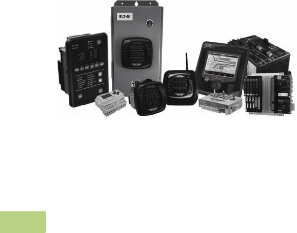
V12-T10-2 Volume 12—Aftermarket, Renewal Parts and Life Extension Solutions CA08100014E—November 2013 www.eaton.com
1
2
3
4
5
6
7
8
9
10
11
12
13
14
15
16
17
18
19
20
21
22
23
24
25
10
IQ Products
Electronic Metering and Protection
Power Management Products
Product Description
Eaton’s electrical business IQ Metering and Protection group
of Cutler-Hammer® series products are multifunctional
communicating products based on microprocessor technology.
They are designed to replace existing electromechanical devices
and can be applied at low, medium and high voltage points in
the electrical distribution system. These devices offer
communications capabilities to link electrical distribution
equipment to Eaton’s PowerNet™ Power Management
Software.
These products generally surpass capabilities available with
older analog/electromechanical technologies. Depending on
the features available from each device, information from these
devices may be used to record and analyze power system and
power quality events or problems and may improve power
systems protection and coordination. With communications,
these devices may be used for energy monitoring and
management with trended data for use in future power
system planning.
Volume 12—Aftermarket, Renewal Parts and Life Extension Solutions CA08100014E—November 2013 www.eaton.com V12-T10-3
1
2
3
4
5
6
7
8
9
10
11
12
13
14
15
16
17
18
19
20
21
22
23
24
25
10
IQ Products
Product History
Originally a
Westinghouse Product
In the early 1980s, power
metering and protective
relaying functions were
performed by electro-
mechanical devices. Analog
meters and induction disk
protective relays were found
on virtually every switchgear
lineup manufactured up to
that time. With the maturing
of solid-state electronics,
microprocessor-based
replacements for the electro-
mechanical devices became
available. These new devices
provided increased
functionality and flexibility,
in a smaller space, for less
cost. Westinghouse led the
movement toward electronic
metering and protection
devices with the introduction
of the IQ 2000 motor
protection and control
relay. In 1987, the IQ 2000
functions were split and
two new products were
introduced—the IQ 1000
and the IQ Data Plus. The
IQ 1000 provided all current
monitoring and motor
protection functions and
was developed for use on
AMPGARD® medium voltage
starters and low voltage motor
control assemblies. The IQ
Data Plus provided complete
electrical metering and
system voltage protection,
and was developed for use
on low and medium voltage
switchgear, as well as
AMPGARD and low voltage
motor control assemblies.
The latest next generation
addition to metering is the
Power Xpert® Meter product
series. The Power Xpert
Meter power quality
instrument monitors critical
aspects of an electrical
distribution system. This
premier power quality
metering instrument uses the
latest in advanced technology
to make it simple to use,
powerful, scalable and highly
flexible. Power Xpert Meters
offer a new level of intuitive
user interface design,
presenting critical
electrical
distribution system information
in a simple-to-navigate
and easy-to-understand
information architecture.
The Power Xpert Meter’s
4000/6000/8000 graphic
display visualizes the
information from up to 16
Power Xpert PQ instruments.
The embedded Web server
displays complex power
quality data using standard
Internet browsers and allows
for device configuration from
the browser. Both the local
graphic display and the
embedded Web server
present real time, historical
and event information in a
browser-style graphical format
to help the user interpret key
circuit information such as
current loading, voltage and
power levels, power factor,
energy usage, I/O status and
power quality measurements,
as well as harmonic plots,
disturbance and transient
waveforms, and an ITIC
disturbance summary screen.
The Power Xpert 2000 Series
Meter offers the same level
of intuitive user interface
design as the Power Xpert
4000/6000/8000 Meter with
its embedded Web server
to provide data logging and
e-mail and the ability to
visualize steady-state harmonic
content as well as waveform
recording that is critical for
power quality analysis.
Since then, the IQ Metering
and Protection product
family has grown to include
additional products for both
metering and protective
functions.
The IQ 250 and IQ 260
meters provide revenue
grade accuracy with standard
Modbus® communications
and optional I/O capability.
The IQ 130/140/150 meters
provide basic monitoring and
energy metering for feeder
applications and optional
Modbus communications.
The IQ 35M provides energy
monitoring at the panelboard
level as well as retrofit
applications.
The IQ 150S/250S provides
wireless energy metering.
The enclosed metering
offering adds flexibility in
monitoring with Eaton’s
latest line of meters where
metering is needed.
The IQ DP-4000 and the IQ
AnaIyzer provide advanced
metering functions including
the ability to monitor power
quality parameters. IQ Energy
Sentinels provide a low cost
method to monitor energy
usage for individual feeders
or loads.
The Power Xpert Multi-Point
Meter provides cost-effective
and space-saving energy
submetering for a wide
variety of applications.
The MP-3000 added
increased motor protection
capability. The FP-5000,
introduced in 2001, provides
overcurrent
protection for
distribution feeders.
Product History Time Line
V12-T10-36 IQ 2000 Model (A)
V12-T10-36 IQ 2000 Model (B)
V12-T10-37 IQ 1000
V12-T10-37 IQ 1000 II
V12-T10-28 MP-3000
V12-T10-37 IQ Data Plus
V12-T10-37 IQ Data Plus II
V12-T10-25 IQ DP-4000
AEM
AEM II
IQ 500
V12-T10-37 IQ Data
V12-T10-38 IQ Generator
AR (Addressable Relay)
V12-T10-32 ARII (Addressable Relay II)
V12-T10-26
IQ Energy Sentinel
(Breaker Mount)
V12-T10-26
IQ Energy Sentinel
(Universal Mount)
Digitrip MV
V12-T10-30 DT-3000
CED
CED II
V12-T10-24 IQ Analyzer
V12-T10-36 IQ Analyzer 6000/6200
V12-T10-24 IQ Analyzer 6400/6600
V12-T10-15 Power Xpert 4000/6000/8000
V12-T10-17 Power Xpert 2000
V12-T10-29 FP-5000
V12-T10-19 IQ 250/260
V12-T10-27 IQ 230
V12-T10-38 IQ 300
IQ Multipoint Energy
Submeter
V12-T10-42 IQ Multipoint Energy
Submeter II
V12-T10-40 IQ 110/115
V12-T10-41 IQ Power Sentinel
V12-T10-39 IQ 210/220
V12-T10-20 IQ 130/140/150
V12-T10-21 IQ 150S/250S
V12-T10-22 IQ 35M
V12-T10-23 Enclosed Meters
Page Product 1980 1985 1990 1995 2000 2005 2010 Present
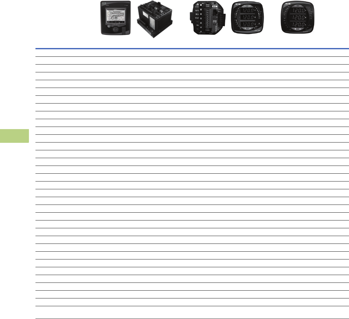
V12-T10-4 Volume 12—Aftermarket, Renewal Parts and Life Extension Solutions CA08100014E—November 2013 www.eaton.com
1
2
3
4
5
6
7
8
9
10
11
12
13
14
15
16
17
18
19
20
21
22
23
24
25
10
IQ Products
General Information
Metering Selection Chart—Dimensions in Inches (mm)
Notes
1Under typical operating conditions.
2PXM 2260 only.
3PXM 2270 only.
4PXM 2280 only.
5PXM 2290 only.
6IQ 260 only.
7Individual values reported to 85th
harmonic; anti-alias filtering prevents
higher frequencies from distorting
readings (see IEC 61000-4-7).
8PMX 6000 only.
9PXM 8000 only.
jOptional.
kAt computer only.
Device Name
Accessories
See Page V12-T10-31
Power Xpert 4000/6000/8000 Series Power Xpert 2000 IQ 250/260 Series
Section Page Number V12-T10-15 V12-T10-17 V12-T10-19
Electrical Parameters
Volts 0.1% of RV + 0.02% FS 0.1% of RV 0.1% of RV
Amperes 0.05% of RV + 0.01% FS 0.1% of RV 0.1% of RV
Current range (% of nominal) 0.005–20A (400%) 0.1–200% 0.1–200%
Watts 0.1% of RV + 0.0025% FS 0.2% of RV 0.2% of RV
VARs 0.1% of RV + 0.0025% FS 0.2% of RV 0.2% of RV
VA 0.1% of RV + 0.0025% FS 0.2% of RV 0.2% of RV
PF-apparent 0.1% 0.2% of RV 0.2% of RV
PF-displacement 0.1% — —
Frequency ±0.01 Hz ±0.03 Hz ±0.03 Hz
THD-voltage 127th 40th 2345 40th 6
THD-current 127th 40th 2345 40th 6
Watthours ±0.2% per ANSI C12.20 0.2 Class 1±0.2% per ANSI C12.20 0.2 Class 1±0.2% per ANSI C12.20 0.2 Class 1
VAR-hours ±0.2% per ANSI C12.20 0.2 Class 1±0.2% per ANSI C12.20 0.2 Class 1±0.2% per ANSI C12.20 0.2 Class 1
VA-hours ±0.2% per ANSI C12.20 0.2 Class 1±0.2% per ANSI C12.20 0.2 Class 1±0.2% per ANSI C12.20 0.2 Class 1
Ampere-demand 0.05% of RV + 0.01% FS ±0.1% per ANSI C12.20 0.2 Class ±0.1% per ANSI C12.20 0.2 Class
Watt-demand ±0.2% per ANSI C12.20 0.2 Class 1±0.2% per ANSI C12.20 0.2 Class 1±0.2% per ANSI C12.20 0.2 Class 1
VAR-demand ±0.2% per ANSI C12.20 0.2 Class 1±0.2% per ANSI C12.20 0.2 Class 1±0.2% per ANSI C12.20 0.2 Class 1
VA-demand ±0.2% per ANSI C12.20 0.2 Class 1±0.2% per ANSI C12.20 0.2 Class 1±0.2% per ANSI C12.20 0.2 Class 1
Revenue accuracy ±0.2% per ANSI C12.20 0.2 Class 1ANSI C12.20 (0.2%) ANSI C12.20 (0.2%)
Individual ampere harmonics 85th 740th 345 —
Individual voltage harmonics 85th 740th 345 —
Interharmonics Yes — —
Minimum and/or Maximum Values
Volts L-L, L-N, N-G, VAUX L-L L-L, L-N L-L, L-N
Current A, B, C, N, G A, B, C, N A, B, C
Power Watt, VAR, VA Watt, VAR, VA Watt, VAR, VA
Power Factor Apparent/displacement Apparent Apparent
Frequency Hertz Hertz Hertz
THD Amperes/volts (L-L, L-N, AUX L-L) Amperes/volts 2345 Amperes/volts 6
Demand values kW, kVAR, kVA, amperes kW, kVAR, kVA, amperes kW, kVAR, kVA, amperes
Trend analysis 2 / 4 8 / 8 9 GB 256 / 512 2 / 768 345 MB 128 KB
j
Event logging 2 / 4 8 / 8 9 GB 100,000 alarms/events with timestamp k
Disturbance recording 2 / 4 8 / 8 9 GB
60 cycles per event
768 MB 45
up to 64 cycles per event 45
—
Legend: PG = Programmable
FS = Full scale
RV = Read value
Auxiliary voltage
(optional) = Provides three additional voltage inputs to the
meter: Va2, Vb2, Vc2.
Interharmonics = Power Xpert Meter 6000/8000 supported.
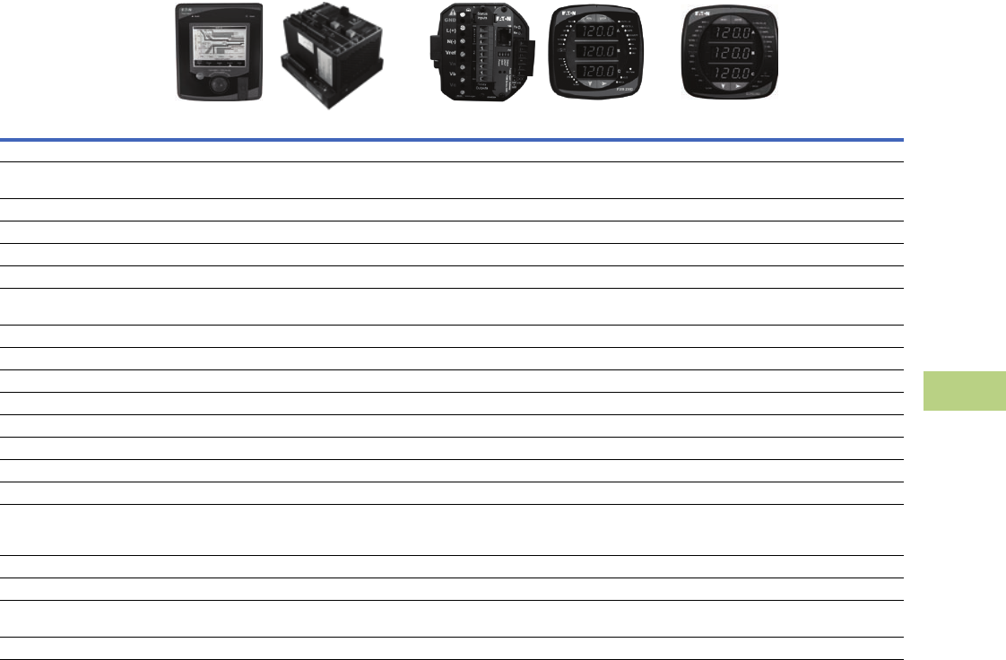
Volume 12—Aftermarket, Renewal Parts and Life Extension Solutions CA08100014E—November 2013 www.eaton.com V12-T10-5
1
2
3
4
5
6
7
8
9
10
11
12
13
14
15
16
17
18
19
20
21
22
23
24
25
10
IQ Products
General Information
Metering Selection Chart—Dimensions in Inches (mm), continued
Notes
1PXM 6000 only.
2PXM 8000 only.
3PXM 2260 only.
4PXM 2270 only.
5The auxiliary voltage option adds three additional voltage
input channels to Power Xpert Meters.
6At computer only.
7PXM 2280 only.
8PXM 2290 only.
9Optional.
Legend: PG = Programmable
FS = Full scale
RV = Read value
Auxiliary voltage
(optional) = Provides three additional voltage inputs to the
meter: Va2, Vb2, Vc2.
Interharmonics = Power Xpert Meter 6000/8000 supported.
Device Name
Accessories
See Page V12-T10-31
Power Xpert 4000/6000/8000 Series Power Xpert 2000 IQ 250/260 Series
Section Page Number V12-T10-15 V12-T10-17 V12-T10-19
Other Features
Storage 2 / 4 1 / 8 2 GB 256 / 512 3 / 768 4 MB Standard 128 KB for logging, up to 8 parameters every 15
minutes for 30 days
PG output relays 5 maximum Optional (2) Form C, 5A or (4) Form A, 120 mA Optional (2) Form C, 5A or (4) Form A, 120 mA
PG analog outputs — Optional (4) 4–20 mA or (4) 0–1 mA Optional (4) 4–20 mA or (4) 0–1 mA
Discrete contact inputs 8 Optional (2) or (4) Optional (2) or (4)
Analog inputs — — —
Synch-input kW utility Via status input Via end of interval pulse with optional digital inputs Via end of interval pulse with optional digital
inputs
Auxiliary voltage 5Yes — —
kWh pulse initiator Yes Yes Yes
Waveform display Local/computer 6—
Waveform capture, samples/cycle Yes, 512 (4096 oversampling) Yes, up to 64 7, up to 512 8—
Frequency distribution display — — —
Display type LCD 9Red LED Red LED
Display lines/character Graphic (320 x 240 pixels) 3 lines, 4 characters 3 lines, 4 characters
Display character height 5.5 mm H x 4 mm W 0.56 (14.2) H 0.56 (14.2) H
Communications Serial: Modbus RTU, Modbus ASCII
Network: Modbus TCP, Ethernet TCP/IP,
HTTP, SNMP, SMTP, FTP, DNP 3.0 9
Serial: Modbus RTU, Modbus ASCII, DNP 3.0
Network: Modbus TCP, BACnet/IP, Ethernet TCP/IP,
HTTP, HTTPS, SNMP, SMTP
Serial: Modbus RTU, Modbus ASCII, DNP 3.0
Network: Modbus TCP via Power Xpert Gateway
Setup configuration Via Web browser/display Via Web browser/display Via configuration software/display
Dimensions Refer to TD02601007E Refer to TD02601017E Refer to TD02601016E
Operating temperature range –20° to 60°C display unit
–20° to 70°C meter base unit
–20° to 70°C –20° to 70°C
Reference literature TD02601007E TD02601017E TD02601016E
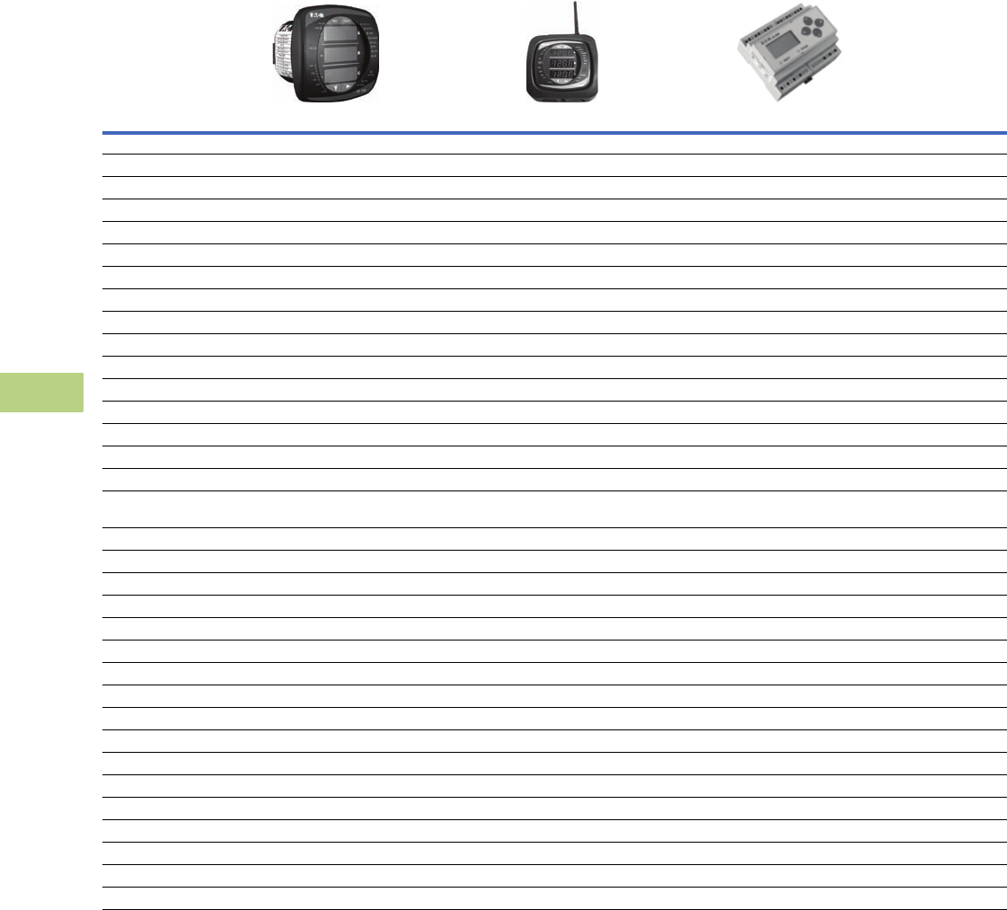
V12-T10-6 Volume 12—Aftermarket, Renewal Parts and Life Extension Solutions CA08100014E—November 2013 www.eaton.com
1
2
3
4
5
6
7
8
9
10
11
12
13
14
15
16
17
18
19
20
21
22
23
24
25
10
IQ Products
General Information
Metering Selection Chart, continued
Notes
1IQ 140 and IQ 150.
2IQ 150 only.
3At computer only.
4Optional.
5IQ 250S only.
Legend: PG = Programmable
FS = Full scale
RV = Read value
Device Name
Accessories
See Page V12-T10-31
IQ 130/140/150 Series IQ 150S/250S Series IQ 35M Series
Section Page Number V12-T10-20 V12-T10-21 V12-T10-22
Electrical Parameters
Volts ±0.25% of RV 0.1% of RV 0.4% +0.015% per °C deviation from 25°C
Amperes ±0.25% of RV 0.1% of RV 0.4% (5–100%), 0.8% (1–5%) +0.015% per °C from 25°C
Current range (% of nominal) 0.1–200% 0.1–200% 1–120%
Watts 0.5% of RV 10.2% of RV 0.5% per ANSI C12.20 and IEC 62053-22 Class 0.5S
VARs 0.5% of RV 10.2% of RV 2.0% per IEC 62053-23 Class 2
VA 0.5% of RV 10.2% of RV Calculated: vector sum of watts and VARs
PF-apparent 0.5% of RV 10.2% of RV Calculated: Watts / VAs
PF-displacement — — —
Frequency ±0.03% Hz 1±0.03 Hz ±0.02 Hz
THD-voltage — — —
THD-current — — —
Watthours ±0.5% per ANSI C12.20 0.5 Class 2±0.2% per ANSI C12.20 0.2 Class 0.5% per ANSI C12.20 and IEC 62053-22 Class 0.5S
Varhours ±0.5% per ANSI C12.20 0.5 Class 2±0.2% per ANSI C12.20 0.2 Class ±2.0% per IEC 62053-23 Class 2
VA-hours ±0.5% per ANSI C12.20 0.5 Class 2±0.2% per ANSI C12.20 0.2 Class —
Ampere-demand ±0.5% per ANSI C12.20 0.5 Class 2±0.1% per ANSI C12.20 0.2 Class —
Watt-demand ±0.5% per ANSI C12.20 0.5 Class 2±0.2% per ANSI C12.20 0.2 Class 0.5% per ANSI C12.20 and IEC 62053-22
Class 0.5S
VAR-demand ±0.5% per ANSI C12.20 0.5 Class 2±0.2% per ANSI C12.20 0.2 Class 2.0% per IEC 62053-23 Class 2
VA-demand ±0.5% per ANSI C12.20 0.5 Class 2±0.2% per ANSI C12.20 0.2 Class Calculated: vector sum of watts and VARs
Revenue accuracy ANSI C12.20 (0.5%) ANSI C12.20 (0.2%) 0.5% per ANSI C12.20 and IEC 62053-22 Class 0.5S
Individual ampere harmonics — — —
Individual voltage harmonics — — —
Interharmonics — — —
Minimum and/or Maximum Values
Volts L-L, L-N L-L, L-N —
Current A, B, C A, B, C —
Power Watt, VAR, VA Watt, VAR, VA —
Power factor Apparent 1Apparent Apparent (low alert)
Frequency Hertz 1Hertz Hertz (out of range alert)
THD Ampere/Volts — —
Demand values kW, kVAR, kVA, amperes 1kW, kVAR, kVA, amperes kW, kVAR, kVA; Maximum kW, kVAR, kVA
Trend analysis 32 MB 5—
Event logging 32 MB 5Logging on demand interval or Modbus command 4
Disturbance recording — — —
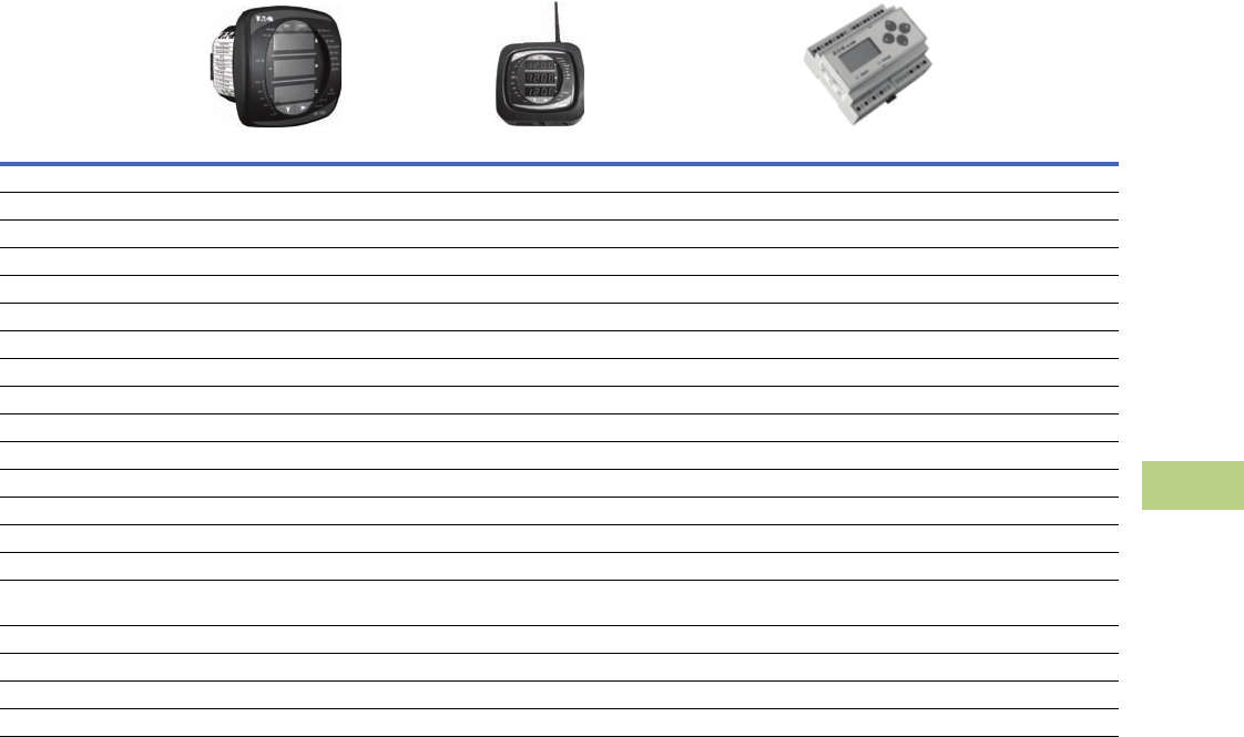
Volume 12—Aftermarket, Renewal Parts and Life Extension Solutions CA08100014E—November 2013 www.eaton.com V12-T10-7
1
2
3
4
5
6
7
8
9
10
11
12
13
14
15
16
17
18
19
20
21
22
23
24
25
10
IQ Products
General Information
Metering Selection Chart, continued
Notes
1Optional.
2IQ 250S only.
3The auxiliary voltage option adds three additional voltage input channels to
Power Xpert Meters.
Legend: PG = Programmable
FS = Full scale
RV = Read value
Device Name
Accessories
See Page V12-T10-31
IQ 130/140/150 Series IQ 150S/250S Series IQ 35M Series
Section Page Number V12-T10-20 V12-T10-21 V12-T10-22
Other Features
Storage — 2 MB 210 registers (16 bit) by 5760 entries each (115 KB) 1
PG output relays — — —
PG analog outputs — — —
Discrete contact inputs — — 2 pulse inputs with BACnet
Analog inputs — — —
Synch-input kW Utility — — Optional demand synchronization via Modbus
Auxiliary voltage 3—— —
kWh pulse initiator 1Yes Yes
Waveform display — — —
Waveform capture — — —
Frequency distribution display — — —
Display type Red LED Red LED Backlit LCD
Display lines/character 3 lines, 4 characters 3 lines, 4 characters 2 lines by 5 characters each (full alphanumeric top row)
Display character height 0.56 (14.2) H 0.56 (14.2) H 7.5 mm
Communications Serial: Modbus RTU, Modbus ASCII 1
Network: Modbus TCP 1
Serial: Modbus RTU, Modbus ASCII, DNP 3.0
Network: Modbus TCP, wired or wireless
Serial: Modbus RTU 1, BACnet MS/TP 1
Network: Modbus TCP via Power Xpert Gateway
Setup configuration Via configuration software/display Via configuration software/display Via display/configuration software
Dimensions 4.85 (123.2) H x 4.85 (123.2) W x 4.97 (126.2) D 7.90 (200.7) H x 7.50 (190.5) W x 3.10 (78.7) D 3.60 (91.4) H x 4.20 (106.7) W x 2.30 (58.4) D
Operating temperature range –20 to 70°C –20 to 70°C –20 to 70°C
Reference literature TD02601015E TD02601019E TD02601015E
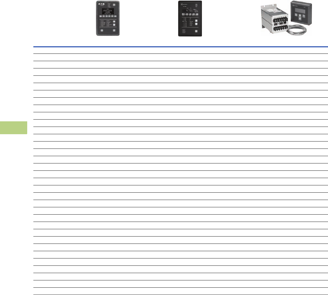
V12-T10-8 Volume 12—Aftermarket, Renewal Parts and Life Extension Solutions CA08100014E—November 2013 www.eaton.com
1
2
3
4
5
6
7
8
9
10
11
12
13
14
15
16
17
18
19
20
21
22
23
24
25
10
IQ Products
General Information
Metering Selection Chart—Dimensions in Inches (mm), continued
Notes
1From 3–300% of FS.
2At unity power factory and 5–300% of FS.
3At a power factor <±0.5 and 5–300% of FS.
4At computer only.
Legend: PG = Programmable
FS = Full scale
RV = Read value
Device Name
Accessories
See Page V12-T10-31
IQ Analyzer 6400/6600 Series IQ DP-4000 Series IQ 230 Series
Section Page Number V12-T10-24 V12-T10-25 V12-T10-27
Electrical Parameters
Volts ±0.2% FS 1±0.3% FS ±0.5% FS
Amperes ±0.2% FS 1±0.3% FS ±0.5% FS
Current range (% of nominal) 3–800% 10–250% 1–200%
Watts 0.4% FS, 6 RV 2±0.6% FS ±1.0% FS
VARs 0.4% FS, 6 RV 3±0.6% FS ±1.0% FS
VA 0.4% FS, 6 RV 2±0.6% FS ±1.0% FS
PF-apparent 0.8% FS 1±1.0% FS ±2.0% FS
PF-displacement 0.8% FS 1±1.0% FS ±2.0% FS
Frequency 0.04% 1 or 0.01 Hz ±0.17% FS ±0.1% Hz
THD-voltage 50th 31st —
THD-current 50th 31st —
Watthours 0.5% RV 2±0.6% FS ±1.0% per ANSI C12
Varhours 1% RV 3±0.6% FS ±1.0% per ANSI C12
VA-hours 0.5% RV 2±0.6% FS ±1.0% per ANSI C12
Ampere-demand ±0.2% FS 1±0.3% ±0.5% per ANSI C12
Watt-demand ±0.4% FS 1±0.6% ±1.0% per ANSI C12
VAR-demand ±0.4% FS 1±0.6% ±1.0% per ANSI C12
VA-demand ±0.4% FS 1±0.6% ±1.0% per ANSI C12
Revenue accuracy ANSI C12.20 (0.5%) — ANSI C12.1 (1%)
Individual ampere harmonics 50th — —
Individual voltage harmonics 50th — —
Interharmonics — — —
Minimum and/or Maximum Values
Volts L-L, L-N L-L, L-N L-L, L-N
Current A, B, C, N, G A, B, C A, B, C
Power Watt, VAR, VA Watt, VAR, VA Watt, VAR, VA
Power factor Apparent/displacement Apparent/displacement Apparent/displacement
Frequency Hertz Hertz Hertz
THD Amperes/volts Amperes/volts —
Demand values All All All
Trend analysis Time/date 2 alarms 4
Event logging 504 events w/timestamp 44
Disturbance recording 10 waveform events — —
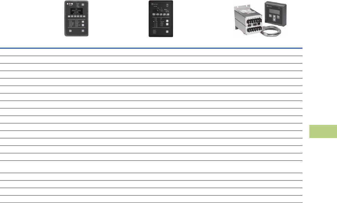
Volume 12—Aftermarket, Renewal Parts and Life Extension Solutions CA08100014E—November 2013 www.eaton.com V12-T10-9
1
2
3
4
5
6
7
8
9
10
11
12
13
14
15
16
17
18
19
20
21
22
23
24
25
10
IQ Products
General Information
Metering Selection Chart—Dimensions in Inches (mm), continued
Notes
1Relays programmable to operate on any measured function.
2Optional.
3An IPONI is required.
4IQ 230M only.
Legend: PG = Programmable
FS = Full scale
RV = Read value
Device Name
Accessories
See Page V12-T10-31
IQ Analyzer 6400/6600 Series IQ DP-4000 Series IQ 230 Series
Section Page Number V12-T10-24 V12-T10-25 V12-T10-27
Other Features
Storage 90 KB 15 parameters —
PG output relays (4) 10A Form C 1(3) 10A Form C 2(2) 100 mA Form A
PG analog outputs (4) 0–10/4–20 mA — —
Discrete contact inputs (3) + 30 Vdc differential (1) kW Demand 2(2) +30 Vdc differential
Analog inputs (1) 0–20/4–20 mA — (1) 4–20 mA
Synch-input kW Utility At device or via communications At device or via communications 2Via communications only
Auxiliary voltage — — —
kWh pulse initiator Yes Yes 2Yes
Waveform display Local 2/computer — —
Waveform capture, samples/cycle Yes, 128 — —
Frequency distribution display Local 2/computer — —
Display type Graphic LCD with LED backlight 7 Segment LED Backlit LCD
Display lines/character 7 lines, 147 characters 1 line, 7 characters 4 lines, 20 characters
Display character height Up to 7 lines 1 line 1.60 (40.6) H x.09 (2.3) W
Communications Serial: INCOM 3
Network: via Power Xpert Gateway 3
Serial: INCOM 3
Network: via Power Xpert Gateway 3
Serial: INCOM, Modbus RTU 4
Network: via Power Xpert Gateway
Setup configuration Via configuration software/display Via configuration software/display Via configuration software/display
Dimensions Refer to TD1702BTE Refer to TD1703ATE Refer to TD1706ATE
Operating temperature range –20° to 70°C –20° to 70°C 0° to 50°C
Reference literature TD1702BTE TD1703ATE TD1706ATE
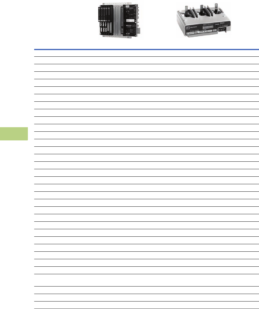
V12-T10-10 Volume 12—Aftermarket, Renewal Parts and Life Extension Solutions CA08100014E—November 2013 www.eaton.com
1
2
3
4
5
6
7
8
9
10
11
12
13
14
15
16
17
18
19
20
21
22
23
24
25
10
IQ Products
General Information
Metering Selection Chart—Dimensions in Inches (mm), continued
Note
1At computer only.
Legend: PG = Programmable
FS = Full scale
RV = Read value
Device Name
Accessories
See Page V12-T10-31
Power Xpert Multi-Point Meter IQ Energy Sentinel
Section Page Number V12-T10-18 V12-T10-26
Electrical Parameters
Volts ±0.2% RV —
Amperes ±0.2% RV —
Current range (% of nominal) — —
Watts ±0.5% RV ±1.0% FS
VARs ±0.5% RV —
VA ±0.5% RV —
PF-apparent ±0.5% RV —
PF-displacement — —
Frequency ±0.1 Hz —
THD-voltage — —
THD-current — —
Watthours ±0.5% per ANSI C12.20 0.5 class ±1.0% FS
VAR-hours ±0.5% per ANSI C12.20 0.5 class —
VA-hours ±0.5% per ANSI C12.20 0.5 class —
Ampere-demand — —
Watt-demand ±0.5% per ANSI C12.20 0.5 class ±1.0% FS
VAR-demand ±0.5% per ANSI C12.20 0.5 class —
VA-demand ±0.5% per ANSI C12.20 0.5 class —
Revenue accuracy ANSI C12.20 (0.5%) —
Individual ampere harmonics — —
Individual voltage harmonics — —
Interharmonics — —
Minimum and/or Maximum Values
Volts L-L, L-N —
Current A, B, C —
Power Watts, VAR, VA —
Power factor Apparent —
Frequency Hertz —
THD — —
Demand values Watts (Delivered & Received), Watts (Q1–Q4), VA
(Q1, Q4), VA (Q2, Q3)
—
Trend analysis Interval data 1
Event logging 20 latest events and historical 1
Disturbance recording — —
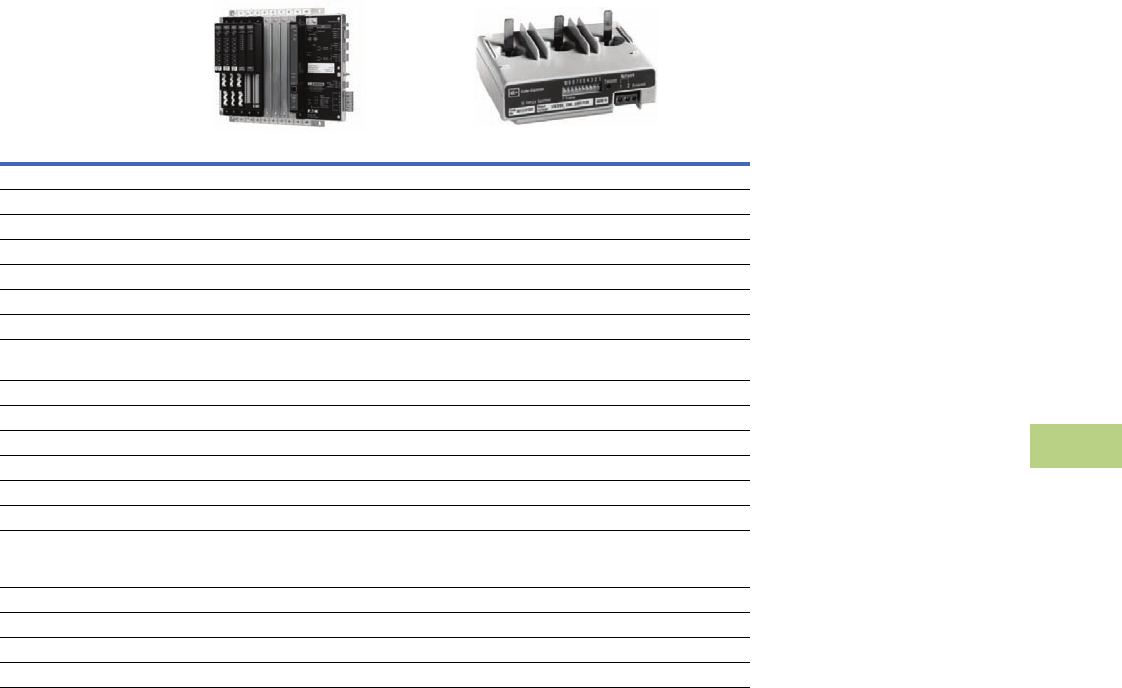
Volume 12—Aftermarket, Renewal Parts and Life Extension Solutions CA08100014E—November 2013 www.eaton.com V12-T10-11
1
2
3
4
5
6
7
8
9
10
11
12
13
14
15
16
17
18
19
20
21
22
23
24
25
10
IQ Products
General Information
Metering Selection Chart—Dimensions in Inches (mm), continued
Note
1Optional.
Legend PG = Programmable
FS = Full Scale
RV = Read Value
Device Name
Accessories
See Page V12-T10-31
Power Xpert Multi-Point Meter IQ Energy Sentinel
Section Page Number V12-T10-18 V12-T10-26
Other Features
Storage 256 MB standard, 2 GB optional —
PG output relays 1 standard, 8 each module 1—
Discrete contact inputs 3 standard, 8 each module 1—
Analog inputs — —
Synch-input kW utility Via communications and digital input Via communications only
Auxiliary voltage — —
kWh pulse initiator Aggregate or main-digital output, LED output on
meter modules (accuracy check)
—
Waveform display — —
Waveform capture — —
Frequency distribution display — —
Display type LCD color touchscreen —
Display lines/character 6-inch diagonal —
Display character height Graphics —
Communications Serial: Modbus RTU
1 Network: Modbus TCP, BACnet/IP, Ethernet TCP/
IP, HTTP, HTTPS, SNMP, SMTP, SFTP
Serial: INCOM
Network: via Power Xpert Gateway
Setup configuration Via PXMP configuration software Via configuration software
Dimensions Refer to TD150006EN Refer to TD1707TE
Operating temperature range –20° to 70°C –25° to 70°C
Reference literature TD150006EN TD1707TE
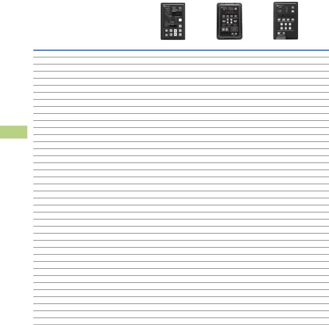
V12-T10-12 Volume 12—Aftermarket, Renewal Parts and Life Extension Solutions CA08100014E—November 2013 www.eaton.com
1
2
3
4
5
6
7
8
9
10
11
12
13
14
15
16
17
18
19
20
21
22
23
24
25
10
IQ Products
General Information
Protective Relay Selection Chart
For Further Details and Information,
See TD02600001TE. Device Name
DT-3000 FP-5000 MP-3000
Technical Data Number IEEE Device Number TD.17.10.T.E TD02602003E TD.17.11.T.E
Protection Functions
Directional power 32 ■
Phase directional 67 ■
Ground directional 67N ■
Phase inst. OC 50 ■■■
Phase TOC 51 ■■■
Calc. residual ground IOC 50G ■
Calc. residual ground TOC 51G ■
Ground inst. OC (measured) 50G (N) ■■
Ground TOC (measured) 51G (N) ■■■
Phase voltage restrained OC 51VR ■
No. of curves (ANSI/IEC/thermal) 11 10 1
TOC time reset ■
Negative sequence OC (unbalance) 46 ■■
Negative sequence voltage 47 ■
Overvoltage 59 ■
Undervoltage 27 ■
Underfrequency 81U ■
Overfrequency 81O ■
Breaker failure 50BF ■
Zone interlocking ■■
Thermal overload 49 ■
Locked rotor 49S/51 ■
Jam/stall 51R ■
Cold load pickup ■
Loss of load ■
Power factor 55 ■
Control Functions
Synchronization check 25 ■
Remote open/close ■■Trip only
Programmable I/O ■■■
Programmable logic ■
Multiple setting groups ■
Number of starts limit ■
Starts per hour ■
Time between starts ■
Emergency restart ■
Reduced voltage starting ■
Trip lockout ■■■
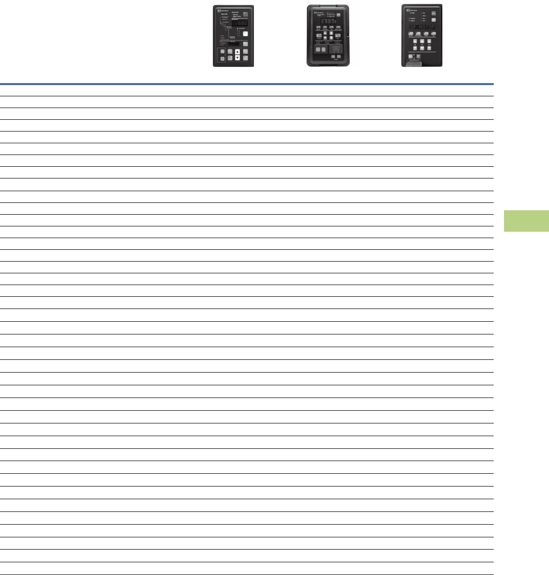
Volume 12—Aftermarket, Renewal Parts and Life Extension Solutions CA08100014E—November 2013 www.eaton.com V12-T10-13
1
2
3
4
5
6
7
8
9
10
11
12
13
14
15
16
17
18
19
20
21
22
23
24
25
10
IQ Products
General Information
Protective Relay Selection Chart, continued
For Further Details and Information,
See TD02600001TE. Device Name
DT-3000 FP-5000 MP-3000
Technical Data Number IEEE Device Number TD.17.10.T.E TD02602003E TD.17.11.T.E
Metering Functions
Amperes ■■■
Ampere demand ■■
Volts ■
Phase angle current voltage ■
Positive, negative and zero sequence ■
Watts ■
Watt demand ■
Watthour ■
VARs ■
VAR-demand ■
VAR-hour ■
VA ■
VA-demand ■
VA-hour ■
Frequency ■
Trending (load profile) ■
Minimum/maximum recording ■
Monitoring Functions
Trip circuit monitor ■
Breaker wear ■
Failure to close ■
Oscillography ■
Sequence of events ■■
Trip target data ■■■
Clock ■■
Number of starts ■
Acceleration time ■
RTD temperature ■
Hottest RTD ■
Communications
Local HMI ■■■
Local communication port RS-232 ■
Local communication port RS-485 ■
Remote communication port ■■■
FSK ■■Optional
Addressable ■■■
Protocols
INCOM™ ■■■
Modbus ■
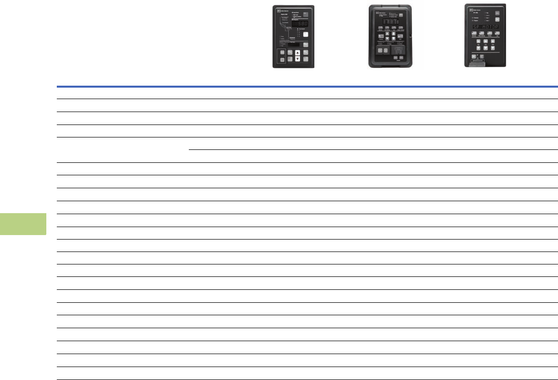
V12-T10-14 Volume 12—Aftermarket, Renewal Parts and Life Extension Solutions CA08100014E—November 2013 www.eaton.com
1
2
3
4
5
6
7
8
9
10
11
12
13
14
15
16
17
18
19
20
21
22
23
24
25
10
IQ Products
General Information
Protective Relay Selection Chart, continued)
For Further Details and Information,
See TD02600001TE. Device Name
DT-3000 FP-5000 MP-3000
Technical Data Number IEEE Device Number TD.17.10.T.E TD.17.30.T.E TD.17.11.T.E
Construction
Panel-mount case ■■■
Drawout Optional ■Optional
Operating temperature range –30°C to +55°C –40°C to +60°C –20°C to +60°C
Power supply options 120–240 Vac 48–125 Vac/Vdc 120–240 Vac
24–250 Vdc 100–240 Vac/Vdc
Dual source power supply Optional
AC current inputs ■■■
AC voltage inputs ■
Wye PTs ■
Delta/open delta PTs ■
Binary inputs 1 8 2
Alarm outputs 2 Form C 2 Form C 3
Trip outputs 2 5 1
Analog outputs Optional 1
Local display ■■■
LEDs (local targets) ■■■
Standards
ANSI ■■■
IEC ■■■
UL®■■■
CE DT-3030 only ■
CSA®■■■
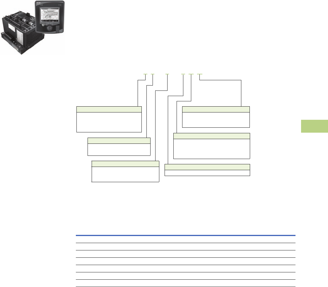
Volume 12—Aftermarket, Renewal Parts and Life Extension Solutions CA08100014E—November 2013 www.eaton.com V12-T10-15
1
2
3
4
5
6
7
8
9
10
11
12
13
14
15
16
17
18
19
20
21
22
23
24
25
10
IQ Products
Technology Upgrades
Power Xpert 4000/6000/
8000 Series Meters
Power Xpert 4000/6000/8000 Series
Display and Meter
General Description
The Power Xpert Meter
4000/6000/8000 Series
monitors the critical aspects
of an electrical distribution
system. This premier power
quality metering instrument
is simple to use, powerful,
scalable and highly flexible.
The Power Xpert Meter
4000/6000/8000 offers a new
level of intuitive user
interface design, presenting
critical electrical distribution
system information in
simple-to-navigate and easy-
to-understand information
architecture. The Power
Xpert Meter 4000/6000/8000
graphic display visualizes
the information from up
to 16 meter modules. The
embedded Web server
displays complex power
quality data using standard
Internet browsers and allows
for device configuration from
the browser.
Both the local graphic display
and the embedded Web
server present real time,
historical and event
information in a browser-
style graphical format to help
the user interpret key circuit
information, such as:
●Current loading
●Voltage and power levels
●Power factor
●Energy usage
●I/O status
●Power quality
measurements
●Harmonic plots
●Disturbance and transient
waveforms
●ITIC disturbance summary
screen
The Power Xpert Meter 4000/
6000/8000 graphic display
uses a simple “twist and
click” navigation control dial
to easily navigate the menus
and drill down into increasing
levels of important detail.
A “back” key enhances the
browser-like navigation of the
graphic display.
The Web server provides the
energy and demand readings
required to help manage
the cost of energy. It also
provides critical information
regarding power quality,
such as harmonic distortion,
flicker, crest factor, K-factor
and more.
Note: Features and functionality
may vary depending on the meter
model and options being used.
Review the Features and Benefits
chart on Page V12-T10-16 for
details.
Catalog Number Selection
Power Xpert 4000/6000/8000 Meter
Accessories
Power Xpert Meter 4000/6000/8000
Notes
1These items can be ordered separately or preinstalled in the meter by selecting option B in the model number.
Communication cable (standard Modbus RTU) is not included in the package for meter module connection.
Description
Catalog
Number
Graphic display module PXD-MMG
Communication expansion card for LAN/WAN Ethernet networking: 100FX fiber-optic, 10/100T, RS-485, RS-232 PXMCE-B 1
Digital I/O card: eight digital input, two solid-state output, three relay output PXMIO-B 1
Panel mounting bracket assembly for back-to-back meter to graphic display mounting PX-PMBA
Panel mounting bracket assembly for retrofitting a graphic display to an IQ Analyzer cutout PX-PMBB
Panel mounting bracket assembly for reduced graphic display rear clearance PX-PMBC
Power Xpert Meter 4000 to 6000 license upgrade key PXM-4KUPG
Example 1: PXM8251A1BB (PXM 8000 meter, w/ VAUX, std. pwr., com. exp. and I/O cards)
Example 2: PXM6251A1BA (PXM 6000 meter, w/ VAUX, std. pwr., com. exp.card)
PXM 8 0 5 1 A 1 B B
Model Series
4 = 4000 (Standard power quality, 2 GB)
6 = 6000 (Enhanced power quality, 4 GB)
8 = 8000 (Premium PQ with transient
capture, 8 GB)
Power Supply Configuration
1 = Standard 100–240 Vac or
110–250 Vdc power supply
4 = 24–48 Vdc option (future option)
Card Slot 1 Configuration
1 = Standard Communications Module with RS-485
Card Slot 2 Configuration
A = No card option
B = Communication expansion card for
LAN/WAN Ethernet networking with
10/100Base-T, 100F, RS-485, RS-232 ports
Card Slot 3 Configuration
A = No card option
B = I/O option card (8 digital inputs,
2 solid-state outputs, 3 relay outputs)
Voltage Input Configuration
0 = Standard (V1, V2, V3, V4)
2 = Standard plus auxiliary (V6, V7, V8)

V12-T10-16 Volume 12—Aftermarket, Renewal Parts and Life Extension Solutions CA08100014E—November 2013 www.eaton.com
1
2
3
4
5
6
7
8
9
10
11
12
13
14
15
16
17
18
19
20
21
22
23
24
25
10
IQ Products
Technology Upgrades
Features and Benefits
Power Xpert 4000/6000/8000 Meters
Notes
1Delta-Sigma A/D oversampling rate.
These specifications are subject to change without notice and represent the maximum capabilities of the product with all options installed. This is not a complete feature list. Features and functionality
may vary depending on selected options, firmware version and product model. Please refer to the technical data sheet and User Manual for detailed specifications.
Feature
Power Xpert
Benefit4000 6000 8000
General
Embedded Web server ■■■Use a standard Web browser to monitor and manage the meter over the network, Internet
TOU metering support ■■■Time of usage can be set up to support 4 different schedules
Firmware flash update support ■■■Enables you to flash the meter with the latest firmware updates
Self-learning capability (characterizes “normal” per circuit) ■■■The meter can automatically adjust to the environment and alarm only when
“real” events occur
Power, Energy and Demand
Voltage, current: per phase minimum, maximum, average, trend graph
analysis, export, print
■■■Review voltage and current trends, export, print and analyze parameters right on the meter or external
software
Energy and demand plot comparisons month-to-month, week-to-week ■ ■ ■ Plot two months or two weeks for vivid energy or demand comparison
Power: power factor, apparent, real, reactive, frequency ■■■Review power usage and power factor and avoid potential PF penalties
Energy, demand: forward, reverse, net, sum, tou, profile, previous month
comparison, graph analysis, export, print
■■■Keep track of your energy usage, compare time of usage and usage against previous month, identify
peaks to conserve energy usage
Power Quality Analysis
Statistical analysis (min., max., average) ■■■Review statistical trends, identify past and future problem areas
Sag and swell monitoring, management and recording ■■■Capture electrical sags and swells and analyze the waveforms
Symmetrical Components: Zero, Negative, Positive ■■■Analyze possibly unbalanced three-phase power systems
Low frequency transient detection and capture ■■■Capture lower frequency transient waveforms for retrospective analysis or e-mailing
Sampling rate, maximum samples/cycle 4096 14096 1100,000 Extremely high sampling rate will effectively capture impulsive transients
“Number of Nines” uptime data (e.g., 6 nines = 99.9999%) ■■■Review uptime availability per cent
K-factor ■ ■■Review the ratio of eddy current losses, e.g., when driving nonlinear and linear loads
Crest factor ■ ■■Review the peak-to-average ratio of the waveform
Security
Secure 5 level user access privileges ■■■Define appropriate security access level per user
Communications and I/O
Modbus TCP ■■■Easy integration with standard protocol to power management and other software
Modbus RTU ■■■Integrate meters to existing Modbus networks, daisy chain several (1–16) meters together
HTML ■■■Communicate to the meter over the Internet via standard Web browser
SNMP (simple network management protocol) ■■■Communicate with the meter via Simple Network Protocol; hook to existing NMS system
SMTP (simple mail transfer protocol) ■■■Send e-mail messages via standard Simple Mail Transfer Protocol
FTP (file transfer protocol) ■■■Access, copy, paste, cut waveform capture files on the meter with an FTP Client
NTP (network time protocol) ■■■Network Time Protocol support enables the meter to synchronize time over the network up to the 1
millisecond resolution
COMTRADE, open IEEE Standard file format for
Waveform capture export
■■■Import waveform captures in standard IEEE (C37.111-1999) COMTRADE file format to third-party
software
DNP 3.0 over Ethernet (Distributed Network Protocol) ■■■Communicate with the meter via DNP 3.0 over Ethernet; hook to existing utility systems
Trend measurements CSV file export ■■■Easily export trend measurements to third-party applications, e.g., Microsoft Excel in standard
CSV file format
I/O (8 digital inputs, 3 relay outputs, 2 solid-state KYZ outputs) ■■■The Power Xpert I/O Card is extremely flexible and can be used in a large variety of different
applications. Digital inputs and relay outputs can be programmed to interact during various
conditions defined by the user. Various third-party devices, such as alarm, pulse meters, trip units,
sensors can be easily integrated to the Power Xpert Meter. Triggers and events can be tied to the
meters standard functions such as e-mail, logs and trends
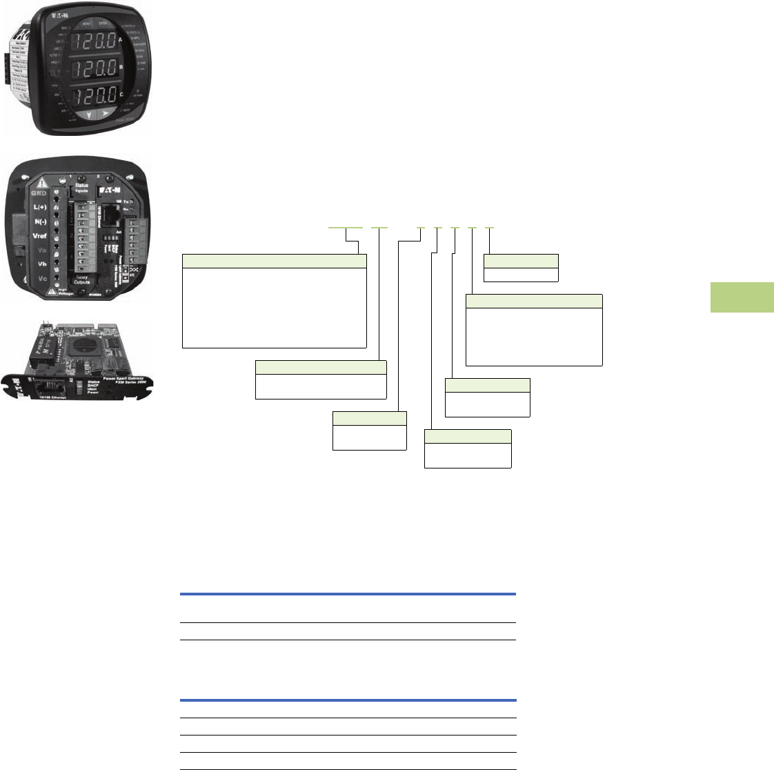
Volume 12—Aftermarket, Renewal Parts and Life Extension Solutions CA08100014E—November 2013 www.eaton.com V12-T10-17
1
2
3
4
5
6
7
8
9
10
11
12
13
14
15
16
17
18
19
20
21
22
23
24
25
10
IQ Products
Technology Upgrades
Power Xpert 2000 Series
Meters
Power Xpert 2000 Series
General Description
The Power Xpert Meter
2000 Series power quality
instrument monitors the
most critical aspects of an
electrical distribution system.
This premier power quality
metering instrument uses
the latest in advanced
technology to make it simple
to use, powerful, scalable
and highly flexible. The
Power Xpert Meter 2000
offers the same level of
intuitive user interface design
as the Power Xpert Meter
4000/6000/8000, presenting
critical electrical distribution
system information in a
simple to navigate and
easy-to-understand
information architecture.
The embedded Web server
displays comprehensive
power quality data using
standard Internet browsers
and allows for device
configuration from the
browser. The embedded
Web server presents real
time, historical and event
information in a browser-style
graphical format to help the
user interpret information
such as current loading,
voltage and power levels,
power factor, energy usage,
I/O status, power quality
measurements, as well as
harmonic plots. The embedded
Web server also allows for
waveform capture and for
visualizing steady-state
harmonic content that is critical
for power quality analysis.
The Web server provides the
energy and demand readings
required to help manage the
cost of energy.
Catalog Number Selection
Power Xpert 2000 Meter
Accessories
Power Xpert 2000 Meter
Power Xpert Meter 2000 I/O Cards
I/O Slot 2
5 = Gateway card
I/O Slot 1
0 = None
1 = 2 Relay outputs/2 status inputs
2 = 4 KYZ pulses/4 status inputs
3 = 4 Analog outputs: 0–1 mA
4 = 4 Analog outputs: 4–20 mA
Example 1: PXM2270MA65145 (PXM 2270 Meter/Display 60 Hz, 5A, 90–265 Vac/Vdc W/4AO)
Example 2: PXM2250MA65105 (PXM 2250 Meter/Display 60 Hz, 5A, 90–265 Vac/Vdc)
Power Supply
1 = 90–265 Vac/Vdc
4 = 24–60 Vdc
Frequency
5 = 50 Hz system
6 = 60 Hz system
Model Series
2250 = Energy meter
2260 = Power quality meter
2270 = Power quality plus meter
2280 = Power quality plus with up to 64 samples/
cycle waveform recording meter
2290 = Power quality plus with up to 512 samples/
cycle recording meter
Current Input
1 = 1 Amp secondary
5 = 5 Amp secondary
Meter Type
M= Meter (with integral display)
T = Transducer only (no display)
PXM 2250 M A 6 5 1 0 5
Description
Catalog
Number
Panel-mounting bracket assembly for retrofitting a PXM 2000 to an
IQ Analyzer/IQ DP-4000/IQ Data cutout
IQ250-PMAK
PXM 2000 Gateway Card kit to upgrade an IQ 250/260 to a PXM 2000 PXM2000-GCK
Description
Catalog
Number
PXM 2000 I/O card—2 relay outputs/2 status inputs IQ250/260-IO1
PXM 2000 I/O card—4 KYZ Pulses/4 status inputs IQ250/260-IO2
PXM 2000 I/O card—4 analog outputs—0–1 mA IQ250/260-IO3
PXM 2000 I/O card—4 analog outputs—4–20 mA IQ250/260-IO4
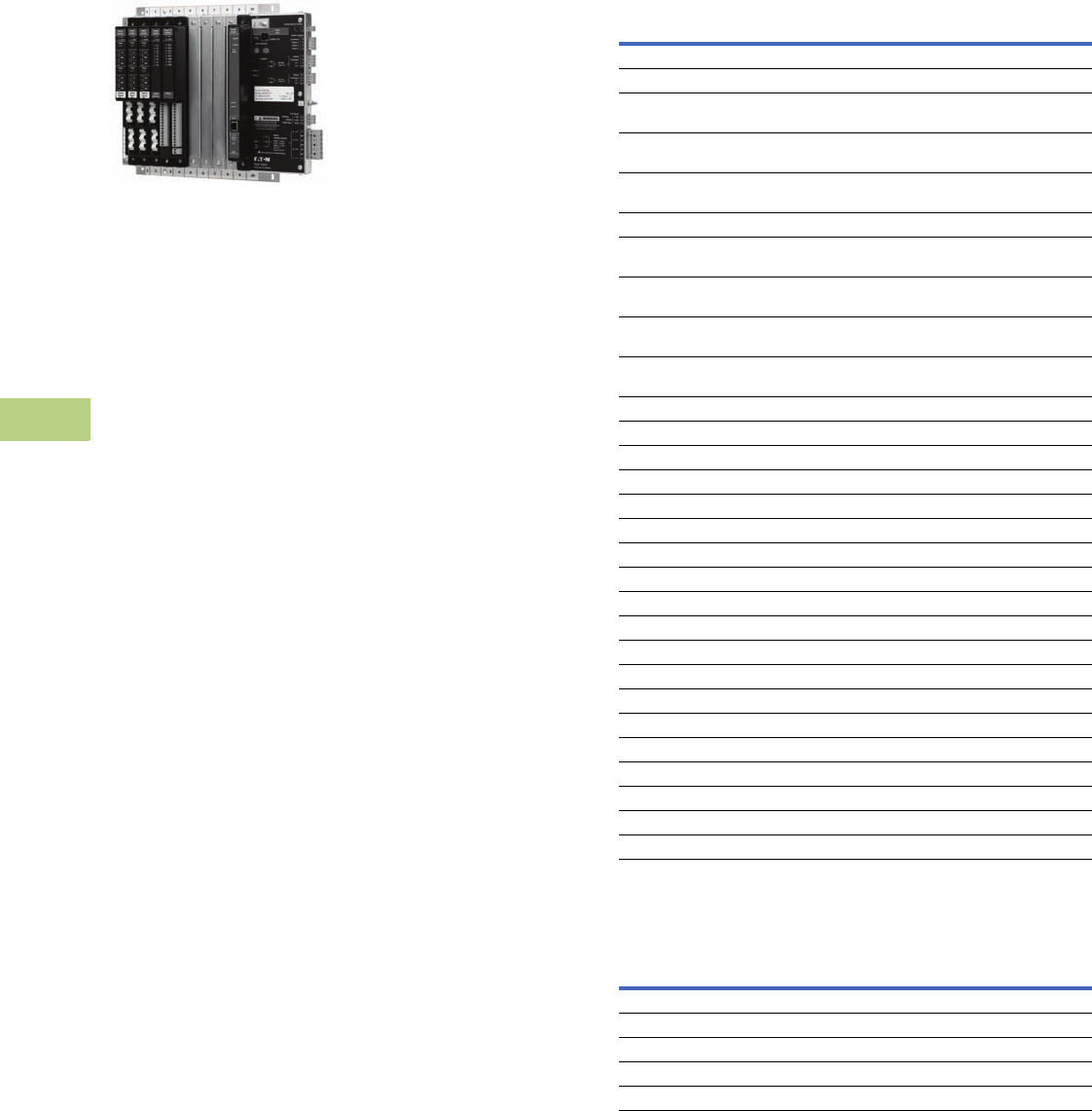
V12-T10-18 Volume 12—Aftermarket, Renewal Parts and Life Extension Solutions CA08100014E—November 2013 www.eaton.com
1
2
3
4
5
6
7
8
9
10
11
12
13
14
15
16
17
18
19
20
21
22
23
24
25
10
IQ Products
Technology Upgrades
Power Xpert™
Multi-Point Meter
Power Xpert Multi-Point Meter
General Description
Eaton’s Power Xpert Multi-Point
Meter is an ANSI C12.20
revenue class Web enabled
electronic submetering device
that can be mounted in
panelboards, switchboards or
enclosures. When mounted in
a panelboard or a switchboard,
the Power Xpert Multi-Point
Meter provides customers
with an integrated power
distribution and energy
metering solution that saves
space, reduces installation
labor and lowers total cost.
The Eaton Power Xpert Multi-
Point Meter (PXMP Meter)
offers a highly modular
approach to high-density
metering applications in
electrical power distribution
systems. The PXMP Meter is
compatible with most three-
phase industrial, commercial
and single-phase residential
low voltage electrical power
systems. The PXMP is
equipped with two Modbus
RTU communication ports
for local display and remote
serial communications.
The PXMP also has optional
pulse input and digital output
modules along with one
standard digital output and
three digital inputs. The
PXMP Energy Portal Module
is Web enabled, making it
suitable for use with Ethernet
networks and modems.
The Power Xpert Multi-Point
Meter can measure up to any
of the following number of
circuits:
●Sixty single-phase,
two-wire (single-pole)
●Thirty single-phase,
three-wire (two-pole)
●Twenty three-phase,
four-wire (three-pole)
The circuits listed above
can be mixed provided that
the total number of current
sensors does not exceed 60.
The Power Xpert Multi-Point
Meter can be used with three
different ratings of current
sensors: 100 mA, 10 mA
or 333 mV. Switchboard/
panelboard applications
will use the 100 mA current
sensors, which are highly
accurate, self-protecting in
the event of an open circuit
condition under load and
are supplied with an integral
plug-in connector. The PXMP
automatically detects the rating
of the current sensor that is
connected. The PXMP can also
use 10 mA current sensors
that were previously installed
for IQMESII retrofit applications.
Additionally the PXMP can
use 333 mV split core current
sensors for retrofit applications
where metering has not
previously existed. The 10 mA
and 333 mV current sensors
are also self-protecting in
the event of an open circuit
condition under load.
Application Description
The Power Xpert Multi-Point
Meter is ideally suited to
handle submetering in low
voltage power distribution
equipment applications with
the use of voltage and current
transformers.
The Power Xpert Multi-Point
Meter provides a cost-effective
solution for residential or
commercial metering
installations, including:
●High-rise buildings
●Government institutions
●K–12, universities and
campuses
●Office buildings
●Medical facilities
●Apartment and
condominium complexes
●Airports
●Shopping malls
●Industrial sites
●Mixed-use facilities
Product Selection
Power Xpert Multi-Point Meter Products
Note
Total sensor lead length must not exceed 28 ft (8.5m).
Power Xpert Multi-Point Meter Support Products
Description
Catalog
Number
Meter Bases and Meter Modules with ABCN Voltage Inputs
PXMP meter base—three-phase with ABCN voltage inputs PXMP-MB
PXMP meter module with six 100 mA inputs for use with PXMP
current sensors
PXMP-MM100MA
PXMP meter module with six 10 mA inputs for use with IQMESII
current sensors
PXMP-MM10MA
PXMP meter module with six 333 mV inputs for use with 333 mV
current sensors
PXMP-MM333MV
Meter Bases and Meter Modules with ABN Voltage Inputs
PXMP meter base—single-phase, three-wire with ABN
voltage inputs
PXMP-MB-AB
PXMP meter module with six 100 mA inputs for use with PXMP
current sensors
PXMP-MM100MA-AB
PXMP meter module with six 10 mA inputs for use with IQMESII
current sensors
PXMP-MM10MA-AB
PXMP meter module with six 333 mV inputs for use with 333 mV
current sensors
PXMP-MM333MV-AB
IO Modules
PXMP meter pulse input module with eight inputs PXMP-PIM
PXMP meter digital output module with eight outputs PXMP-DOM
Communication Module
PXMP meter energy portal module PXMP-EPM
Current Sensor Kits
KIT, PXMP CS125 sensor, quantity of 3 PXMP-CS125-3
KIT, PXMP CS250 sensor, quantity of 3 PXMP-CS250-3
KIT, PXMP CS400 sensor, quantity of 3 PXMP-CS400-3
Current Sensor Cable Kits
KIT, PXMP sensor cable, 4 ft (1.2m), quantity of 3 PXMP-SC4-3
KIT, PXMP sensor cable, 6 ft (1.8m), quantity of 3 PXMP-SC6-3
KIT, PXMP sensor cable, 8 ft (2.4m), quantity of 3 PXMP-SC8-3
KIT, PXMP sensor cable, 12 ft (3.7m), quantity of 3 PXMP-SC12-3
Current Sensor Extension Cable Kits
KIT, PXMP sensor extension cable, 8 ft (2.4m), quantity of 3 PXMP-SCE-8-3
KIT, PXMP sensor extension cable, 16 ft (4.9m), quantity of 3 PXMP-SCE-16-3
Interface Modules
PXMP current sensor interface module for 333 mV, kit X 3 PXMP-IM333MV-3
Description
Catalog
Number
Communication cable, 1000 ft (305m), 600V insulation IMPCABLE
PXMP meter display—6-inch color touchscreen (with cable) PXMP-DISP-6
Power supply—single-phase 90–264 Vac, 24 Vdc at 2.5A PSG60E
Power supply—three-phase 360–575 Vac, 24 Vdc at 2.5A PSG60F
Power supply—three-phase 600 Vac, 24 Vdc PSS55D
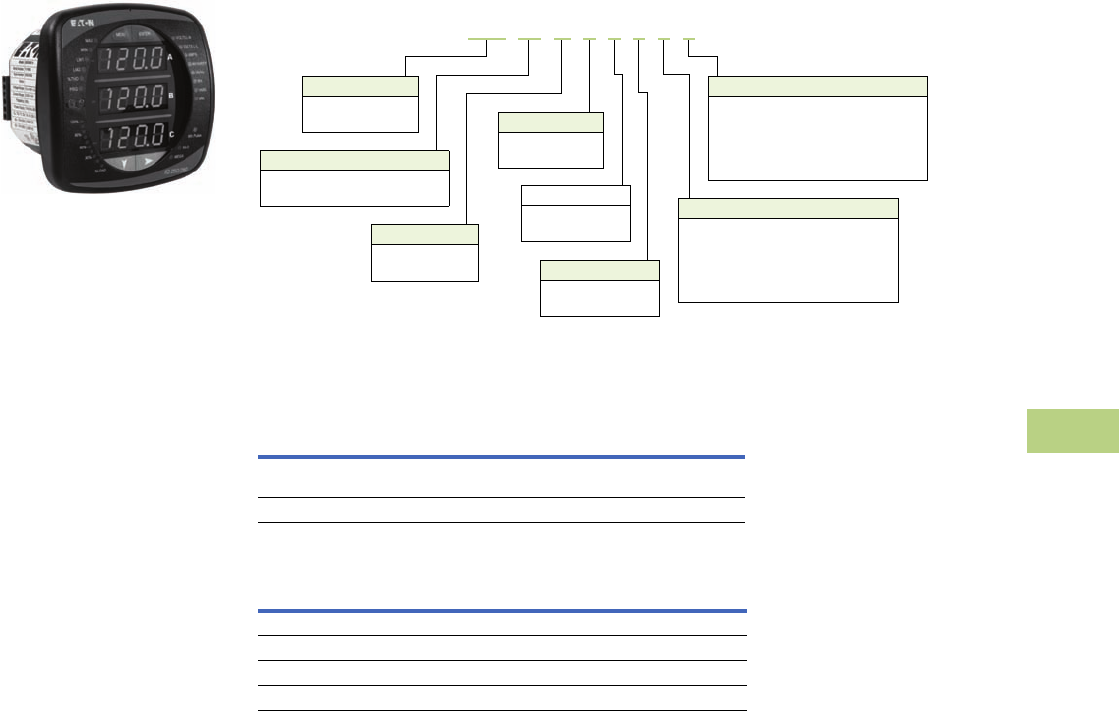
Volume 12—Aftermarket, Renewal Parts and Life Extension Solutions CA08100014E—November 2013 www.eaton.com V12-T10-19
1
2
3
4
5
6
7
8
9
10
11
12
13
14
15
16
17
18
19
20
21
22
23
24
25
10
IQ Products
Technology Upgrades
IQ 250/260 Electronic
Power Meters
IQ 250/260 Electronic Power Meter
General Description
The IQ 250 and IQ 260
Meters provide capabilities
you would not normally
expect in affordable, ultra-
compact meters, such as fast
sampling rate and accurate
metering for a full range of
power attributes. Providing
the first line of defense
against costly power
problems, Eaton’s IQ 250
and IQ 260 electronic power
meters can perform the work
of an entire wall of legacy
metering equipment using
today’s technology.
When space is at a premium,
yet you need ANSI C12.20
accuracy, the IQ 250/ 260
series fit the bill. These
meters are ideal for electrical
equipment assemblies,
machine control panels,
such as panelboard and
switchboard mains and
feeders, low voltage metal-
enclosed switchgear feeders
and motor control centers.
Requiring far less space than
other meters with similar
functionality, IQ 250/260
series fit into a standard
ANSI or IEC cutout on a
panelboard or other electrical
equipment, and therefore fit
easily into retrofit applications.
Catalog Number Selection
IQ 250/260 Meter
Accessories
IQ 250/260 Meter
IQ 250/260 Meter I/O Cards
Model Series
250 = Power
260 = Power quality Frequency
5 = 50 Hz system
6 = 60 Hz system
I/O Slot 2
0 = None
1 = Two relay outputs/two status inputs
2 = Four KYZ pulses/four status inputs
3 = Four analog outputs: 0–1 mA
4 = Four analog outputs: 4–20 mA
Power Supply
1 = 90–265 Vac/Vdc
4 = 24–48 Vdc
Current Input
1 = 1A secondary
5 = 5A secondary
Meter Type
M = Meter (with integral display)
T= Transducer only (no display) I/O Slot 1
0 = None
1 = Two relay outputs/two status inputs
2 = Four KYZ pulses/four status inputs
3 = Four analog outputs: 0–1 mA
4 = Four analog outputs: 4–20 mA
Data Logging
A = None
L = Data logging
IQ 250 M A 6 5 1 1 0
Description
Catalog
Number
Panel-mounting adapter for retrofitting an IQ 250/260 to an
IQ Analyzer/IQ DP-4000/IQ Data cutout
IQ250-PMAK
PXM 2000 Gateway Card kit to upgrade an IQ 250/260 to a PXM 2000 PXM2000-GCK
Description
Catalog
Number
IQ 250/260 I/O card—2 relay outputs/2 status inputs IQ250/260-IO1
IQ 250/260 I/O card—4 KYZ pulses/4 status inputs IQ250/260-IO2
IQ 250/260 I/O card—4 analog outputs—0–1 mA IQ250/260-IO3
IQ 250/260 I/O card—4 analog outputs—4–20 mA IQ250/260-IO4
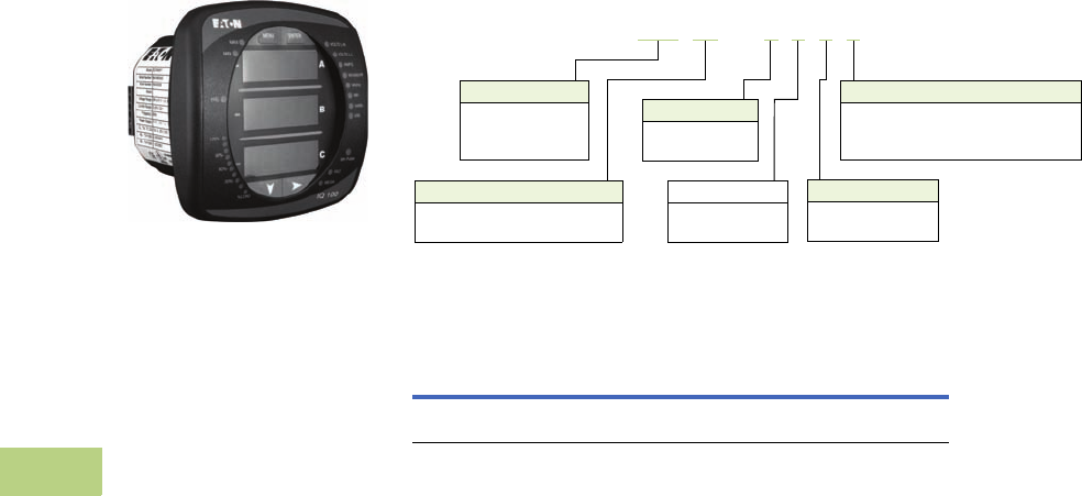
V12-T10-20 Volume 12—Aftermarket, Renewal Parts and Life Extension Solutions CA08100014E—November 2013 www.eaton.com
1
2
3
4
5
6
7
8
9
10
11
12
13
14
15
16
17
18
19
20
21
22
23
24
25
10
IQ Products
Technology Upgrades
IQ 130/140/150 Series
Electronic Power Meters
IQ 100 Electronic Power Meter
General Description
The IQ 100 Meter family
provides capabilities you
would not normally expect in
affordable, compact meters,
such as fast sampling rate
and accurate metering for a
full range of power attributes.
Providing the first line of
defense against costly power
problems, Eaton’s IQ 100
series electronic power
meters can perform the work
of an entire wall of legacy
metering equipment utilizing
today’s technology.
When space is at a premium,
yet you need ANSI C12.20
accuracy, the IQ 100 series
fit the bill. These meters are
ideal for electrical equipment
assemblies, machine control
panels, such as panelboard
and switchboard mains and
feeders, low voltage metal-
enclosed switchgear feeders
and motor control centers.
Requiring far less space than
other meters with similar
functionality, IQ 100 series fit
into a standard ANSI or IEC
cutout on a panelboard or
other electrical equipment,
and therefore fit easily into
retrofit applications.
Catalog Number Selection
IQ 130/140/150 Meters
Accessories
IQ 130/140/150 Meters
IQ 150 M A 6 5 1 1
Model Series
130 = Volts/amps
140 = Power
150 = Energy
Frequency
5 = 50 Hz system
6 = 60 Hz system
Communications
0 = None
1 = Modbus RTU and KYZ pulse
2 = Modbus TCP and KYZ output (RJ45)
Power Supply
1 = 90–265 Vac/Vdc
4 = 24–48 Vdc
Current Input
1 = 1A secondary
5 = 5A secondary
Meter Type
M = Meter (with integral display)
T = Transducer only (no display)
Description
Catalog
Number
Panel Mounting Adapter for retrofitting an IQ 100 to an
IQ Analyzer/IQ DP-4000/IQ Data Cutout
IQ250-PMAK
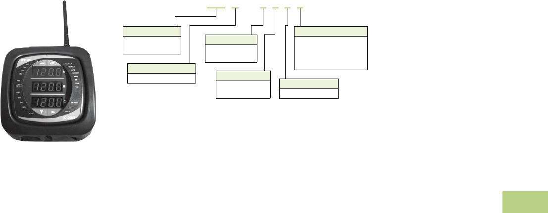
Volume 12—Aftermarket, Renewal Parts and Life Extension Solutions CA08100014E—November 2013 www.eaton.com V12-T10-21
1
2
3
4
5
6
7
8
9
10
11
12
13
14
15
16
17
18
19
20
21
22
23
24
25
10
IQ Products
Technology Upgrades
IQ 150S/250S Self-
Enclosed Electronic
Meters
IQ 150S/250S Self-Enclosed
Electronic Meters
General Description
With energy costs
skyrocketing, you need the
ability to verify the accuracy
of utility billing and allocation
of energy costs among
business units, different
manufacturing areas or
facilities, and tenants.
Production equipment and
IT systems are vulnerable to
power anomalies; therefore,
you must ensure that power
is always up to specifications.
If your infrastructure is an
established facility, you may
not currently have metering
or may have addressed these
concerns by deploying a
variety of analog gauges
and meters—one for volts,
one for amperes and so on,
with separate meters for
each measurement.
If you’re planning an upgrade
or a new power infrastructure,
no doubt you would like
to capitalize on the latest
technology to improve upon
that cumbersome architecture
and its patchwork view.
Catalog Number Selection
IQ 150S/250S Meter
IQ 150 S A 6 5 1 1
Model Series
150 = Energy
250 = Energy plus
Frequency
5 = 50 Hz system
6 = 60 Hz system
Communications
1 = Modbus RTU (RS-485)
2 = Modbus RTU (RS-485)
or TCP—(RJ45)
or 802.11b (Wi-Fi)
Power Supply
1 = 90–400 Vac/Vdc
Current Input
1 = 1A secondary
5 = 5A secondary
Meter Type
S = Self-enclosed meter
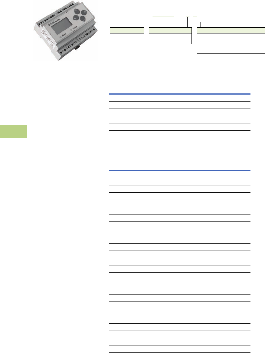
V12-T10-22 Volume 12—Aftermarket, Renewal Parts and Life Extension Solutions CA08100014E—November 2013 www.eaton.com
1
2
3
4
5
6
7
8
9
10
11
12
13
14
15
16
17
18
19
20
21
22
23
24
25
10
IQ Products
Technology Upgrades
IQ 35M
IQ 35M
General Description
The Eaton IQ 35M Meter is a
DIN rail meter that combines
exceptional performance and
easy installation to deliver
a cost-effective solution for
energy and power monitoring
applications, as well as sub-
metering applications. Most
models include pulse output,
alarm contact and phase
alarms for true versatility.
The BACnet version offers
two digital inputs for
accumulating other meter
pulses in place of the digital
output and alarm contact.
The Modbus output options
offer added flexibility for
configuration and data analysis.
The IQ 35M allows you to:
●Verify energy bills
●Make informed load
shifting and shedding
decisions
●Fairly and accurately
allocate energy costs to
users
●Identify wasteful practices
●Decrease unnecessary
usage
●Produce an energy profile
●Secure the optimum utility
rate structure
Catalog Number Selection
IQ 35M Meter
Accessories
IQ 35M Accessories
IQ 35M Current Transformers
Model Series Output Option
1 = Pulse output only
2 = Pulse output + Modbus
3 = Pulse output + Modbus + data logging
5 = Pulse inputs + BACnet + data logging
Enclosure Type
1 = Standard energy
2 = Four quadrant energy
IQ35M A 1 1
Description
Catalog
Number
IQ35M enclosure, NEMA 4X IQ35M-ENC
IQ35M fuse pack, single, 1/2A slow-blow IQ35M-FP1
IQ35M fuse pack, double, 1/2A slow-blow IQ35M-FP2
IQ35M fuse pack, triple, 1/2A slow-blow IQ35M-FP3
IQ35M replacement mounting clips IQ35M-RMC
IQ35M DIN rail IQ35M-DR
IQ35M DIN rail stop clips (10 pack) IQ35M-DRSC
Description
Catalog
Number
Solid Core
IQ35M CT, solid core, 5A:0.33 Vac, 0.30 inch IQ35M-SO-030-5
IQ35M CT, solid core, 20A:0.33 Vac, 0.30 inch IQ35M-SO-030-20
IQ35M CT, solid core, 50A:0.33 Vac, 0.50 inch IQ35M-SO-050-50
IQ35M CT, solid core, 50A:0.33 Vac, 0.75 inch IQ35M-SO-075-50
IQ35M CT, solid core, 100A:0.33 Vac, 1.25 inch IQ35M-SO-125-100
IQ35M CT, solid core, 200A:0.33 Vac, 1.25 inch IQ35M-SO-125-200
IQ35M CT, solid core, 250A:0.33 Vac, 1.25 inch IQ35M-SO-125-250
IQ35M CT, solid core, 300A:0.33 Vac, 1.25 inch IQ35M-SO-125-300
IQ35M CT, solid core, 400A:0.33 Vac, 1.25 inch IQ35M-SO-125-400
Split Core
IQ35M CT, split core, 5A:0.33 Vac, 0.75 inch IQ35M-SP-075-5
IQ35M CT, split core, 30A:0.33 Vac, 0.75 inch IQ35M-SP-075-30
IQ35M CT, split core, 50A:0.33 Vac, 0.75 inch IQ35M-SP-075-50
IQ35M CT, split core, 100A:0.33 Vac, 0.75 inch IQ35M-SP-075-100
IQ35M CT, split core, 200A:0.33 Vac, 0.75 inch IQ35M-SP-075-200
IQ35M CT, split core, 250A:0.33 Vac, 1.25 inch IQ35M-SP-125-250
IQ35M CT, split core, 300A:0.33 Vac, 1.25 inch IQ35M-SP-125-300
IQ35M CT, split core, 400A:0.33 Vac, 1.25 inch IQ35M-SP-125-400
IQ35M CT, split core, 600A:0.33 Vac, 1.25 inch IQ35M-SP-125-600
IQ35M CT, split core, 800A:0.33 Vac, 2.50 inch IQ35M-SP-253-800
IQ35M CT, split core, 1000A:0.33 Vac, 2.50 inch IQ35M-SP-255-1000
IQ35M CT, split core, 1200A:0.33 Vac, 2.50 inch IQ35M-SP-255-1200
IQ35M CT, split core, 1600A:0.33 Vac, 2.50 inch IQ35M-SP-255-1600
IQ35M CT, split core, 2000A:0.33 Vac, 2.50 inch IQ35M-SP-255-2000
IQ35M CT, split core, 2400A:0.33 Vac, 2.50 inch IQ35M-SP-255-2400
Note: Specifications are subject
to change without notice and
represent the maximum
capabilities of the product with all
options installed. This is not a
complete feature list. Features
and functionality may vary
depending on selected options,
firmware version and product
model. Please refer to User
Manual for detailed
specifications.
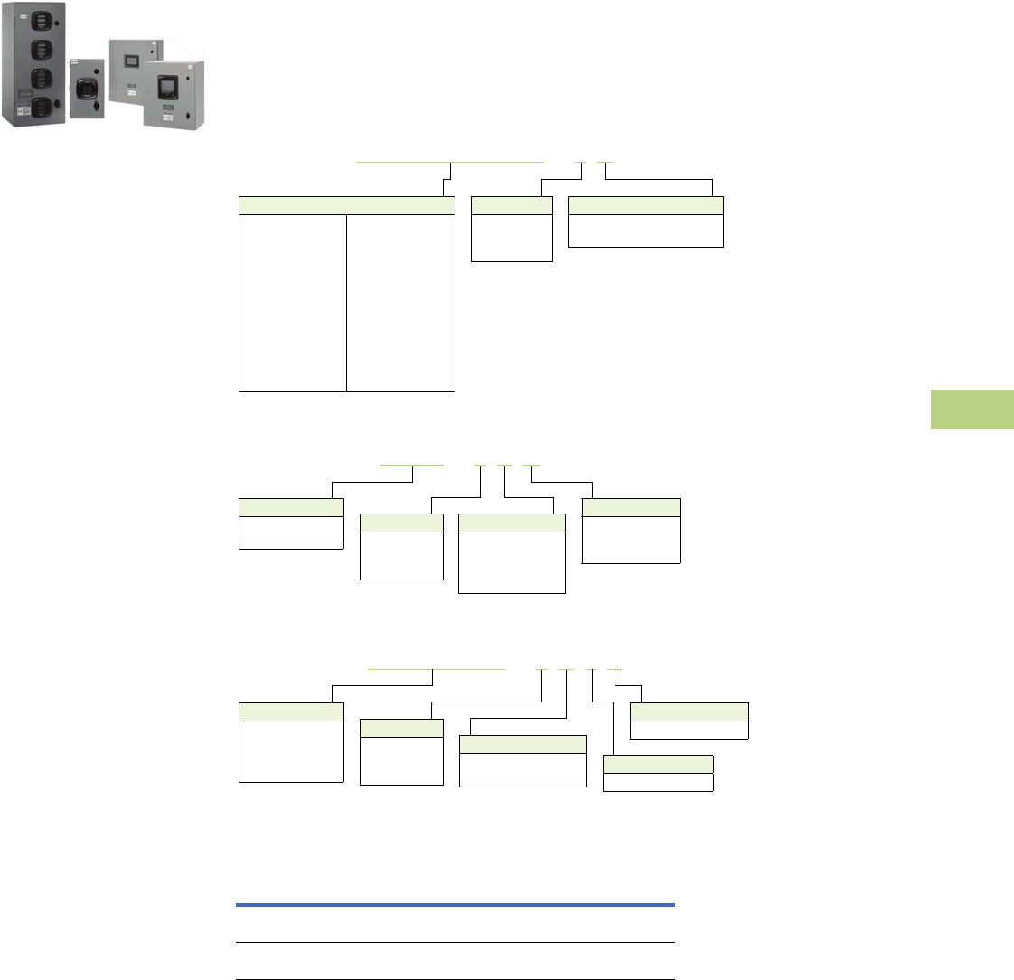
Volume 12—Aftermarket, Renewal Parts and Life Extension Solutions CA08100014E—November 2013 www.eaton.com V12-T10-23
1
2
3
4
5
6
7
8
9
10
11
12
13
14
15
16
17
18
19
20
21
22
23
24
25
10
IQ Products
Technology Upgrades
Enclosed Meters
NEMA 12 Single- and Multi-Unit
Enclosed Meters
General Description
The Eaton enclosed meter
line provides a complete
energy metering and data
acquisition solution in a
single enclosure. Designed
for Eaton’s IQ 35M, IQ 150,
IQ 250/260, and Power Xpert®
2000/4000/6000/8000 and
Multi-Point Meters, Eaton’s
enclosed meter line offers
mounting and installation
flexibility, especially in retrofit
applications where no
metering compartment or
mounting space is available
in the existing electrical
distribution equipment or
where installation time is a
premium. Factory designed
and wired, Eaton’s enclosed
meter line offers savings in
labor and installation costs
because input current and
voltage wiring as well as I/O
wiring is prewired to terminal
blocks inside the enclosure.
The enclosed meter line has
two standard offerings:
single-, prewired unit
(specific IQ 150, IQ 250/260,
PXM 2000, PXM 4000/6000/
8000 or PXMP) and a multi-
unit (specific IQ 150, IQ 250/
260 or IQ 35M models).
Because the multi-unit
automatically includes Eaton’s
Power Xpert Gateway 200E,
it facilitates measurement
and verification of the energy
usage on processes and in
buildings. This provides a
convenient way to monitor
energy usage from multiple
points, collect and log specific
energy use parameters, and
display and generate logs
for historical energy usage
reports. Simply put, Eaton’s
multi-unit enclosed meter
solution helps meet any
measurement and verification
requirement to show energy
efficiency improvements and
results. In addition to the
standard offering, Eaton can
also provide an enclosed
metering solution tailored
around your project needs.
Catalog Number Selection
Single Unit Enclosed Meter
Enclosed PXMP Meter
Multi Unit Enclosed Meter
Accessories
Meter Subpanel Assembly
Notes
1Not available with IQ 35M.
Other meter models available upon request in single- and multi-unit enclosed versions.
Meter Type
PXM4051A1BA
PXM4051A1BB
PXM6051A1BA
PXM6051A1BB
PXM8051A1BA
PXM8051A1BB
PXM2250MA65105
PXM2250MA65115
PXM2250MA65145
PXM2260MA65105
PXM2260MA65115
PXM2260MA65145
PXM2270MA65105
PXM2270MA65115
PXM2270MA65145
IQ250MA65100
IQ250MA65110
IQ250MA65114
IQ260MA65100
IQ260MA65110
IQ260MA65114
IQ150MA6511
IQ150MA6512
NEMA Rating
2 = NEMA 12
3 = NEMA 3R
4 = NEMA 4X
CPT Option
A= 120/240 Vac (no CPT)
B= 480 Vac (CPT)
PXM2250MA65105 -2B
Meter Type
PXMP-MB
PXMP-MB-AB
NEMA Rating
2 = NEMA 12
3 = NEMA 3R
4 = NEMA 4X
Display
A = None
D = 6-inch color
touchscreen
CPT Option
A = None
B = 120/240 Vac
C = 480 Vac
D = 600 Vac
PXMP -2B D
IQ150MA6511 -2B 4 C
Meter Type
IQ35MA12
IQ150MA6511
IQ250MA65100
IQ260MA65100
NEMA Rating
2 = NEMA 12 1
3 = NEMA 3R
4 = NEMA 4X
Communications
C = Includes PXG-200E
CPT Option
A = 120/240 Vac No CPT
B = 480 Vac CPT 1
Number of Meters
4 = 4 meters
Description
Catalog
Number
Meter subpanel assembly for PXM 2000
and IQ 150/250/260 Meters
PXM2K-MSPA-A
Meter subpanel assembly with CPT for PXM 2000
and IQ 150/250/260 Meters
PXM2K-MSPA-B
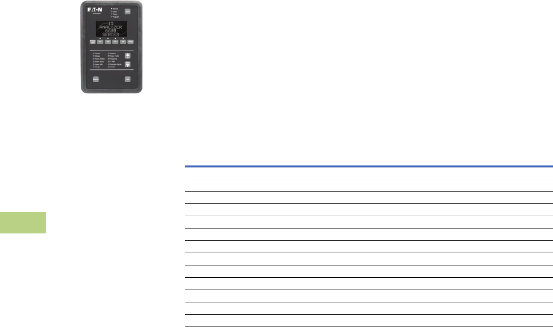
V12-T10-24 Volume 12—Aftermarket, Renewal Parts and Life Extension Solutions CA08100014E—November 2013 www.eaton.com
1
2
3
4
5
6
7
8
9
10
11
12
13
14
15
16
17
18
19
20
21
22
23
24
25
10
IQ Products
Current Products
IQ Analyzer 6400/6600
IQ Analyzer 6400/6600
General Description
Eaton’s IQ Analyzer 6400/
6600 is a complete solution
for users who want to
monitor all aspects of their
electrical distribution system.
It provides extensive
metering, power quality
analysis, remote input
monitoring, control relaying,
analog input/outputs and
communications capability.
All programming can be done
through the faceplate or
through the communications
option. Its online Help
pushbutton feature displays
information on device
operation, programming and
troubleshooting.
Features and Benefits
●All information is
accessible through the
communications port
●Quality true rms readings
through 50th harmonic
●Meets ANSI C12.16
Class 10 revenue metering
specifications
●Accurate readings for non-
sinusoidal waveforms with
up to 3.0 crest factor
●Screens display auto
ranging units, kilo units and
mega units as needed
●10-digit energy readings
●Displays multiple
parameters at the
same time
●Programmable custom
screens
The new IQ Analyzer Model
6600 with waveform display
at the device and sub-cycle
voltage disturbance capture
provides the capability to
monitor a wide range of
harmonic parameters. These
include harmonic voltage,
current magnitudes and
phase angles as well as
system disturbances such
as transient voltage
disturbances and
sub-cycle
voltage interruptions.
Product Selection
IQ Analyzer 6400/6600 Ordering Information
Description
Catalog
Number
IQ Analyzer, separate source power module IQA6410
IQ Analyzer, 24–48 Vdc power module IQA6420
IQ Analyzer, three-phase power module IQA6430
IQ Analyzer, separate source power module with waveform display and sub-cycle voltage distribution capture IQA6610
IQ Analyzer, 24–48 Vdc power module with waveform display and sub-cycle voltage distribution capture IQA6620
IQ Analyzer, three-phase power module with waveform display and sub-cycle voltage distribution capture IQA6630
IQ Flange, to provide extra clearance when mounting IQFLANGE
45.00-inch (114.3 mm) extension cable for remote mounting of power module IQA45CABLE
24–48 Vdc separate source power module IQMDCPM
100–240 Vac and 100–250 Vdc separate source power module IQMSSPM
Three-phase, self-powered power module IQM3PPM
INCOM communication module IPONI
RS-485 communication module with Modbus protocol MPONI
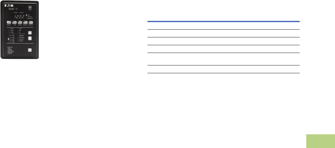
Volume 12—Aftermarket, Renewal Parts and Life Extension Solutions CA08100014E—November 2013 www.eaton.com V12-T10-25
1
2
3
4
5
6
7
8
9
10
11
12
13
14
15
16
17
18
19
20
21
22
23
24
25
10
IQ Products
Current Products
IQ DP-4000/4100
IQ DP-4000/4100
General Description
Eaton’s IQ DP-4000 is a
microprocessor-based meter
providing complete electrical
metering and system voltage
protection. In one compact,
standard package the IQ
DP-4000 provides an
alternative to individually
mounted and wired
conventional meters and
switches. The IQ DP-4000
also monitors apparent power
(VA), reactive energy
(VAR-
hours), apparent energy (VA-
hours),
and % total harmonic
distortion (THD) to provide the
user with basic power quality
information. The IQ DP-4000
meets and surpasses
UL/CSA/CE standards.
Features and Benefits
●Space savings in
structure—replaces
conventional individual
metering devices
●Standardization of
design—one door-
mounted device
●Direct voltage input up
to 600V
●New DIP switch design
●Standardization of CT and
PT connections
●With additional PTs and set
points the device can be
used in HV setting
●Relaying included in I/O
module (Model 4100)
●Optional interface capability
to computer network for
data collection, storage and/
or printout via PowerNet—
Eaton leading power
distribution monitoring
network
●Retains present
parameters through power
failure with non-volatile
memory
Product Selection
IQ DP-4000/4100 Ordering Information
Description
Catalog
Number
Separate source without I/O capability
IQDP4010
Separate source control power without I/O, DC supply
IQDP4020
Three-phase without I/O capability
IQDP4030
Separate source with I/O capability
IQDP4110
Separate source control power with three Form C relay output contacts
and one sync pulse input, DC supply
IQDP4120
Three-phase with I/O capability
IQDP4130
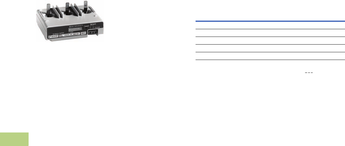
V12-T10-26 Volume 12—Aftermarket, Renewal Parts and Life Extension Solutions CA08100014E—November 2013 www.eaton.com
1
2
3
4
5
6
7
8
9
10
11
12
13
14
15
16
17
18
19
20
21
22
23
24
25
10
IQ Products
Current Products
IQ Energy Sentinels™
IQ Energy Sentinels
Eaton’s IQ Energy Sentinel
is a highly accurate,
microprocessor-based
submeter designed to monitor
power and energy readings.
It represents an alternative to
installing separate wattmeters,
watthour meters and watt-
demand meters.
Key advantages include
unmatched savings in
space, lower installation
costs, and the capability to
communicate data readings
in a variety of ways.
IQ Energy Sentinels
with built-in CTs and
communications have the
added benefit of greater
overall system accuracy.
Conventional metering often
is less accurate because
external CTs and separate
transducers may each have
inaccuracies of 1% or more.
The IQ Energy Sentinel
provides a unique and
cost-effective method to
implement energy
submetering at lower
levels in the distribution
system economically.
Submetering application
examples for the IQ Energy
Sentinel include energy
monitoring and demand
management, product cost
analysis, process/machine
tool efficiency and
productivity improvement.
Additional applications
include energy cost allocation
of tenant billing for
commercial, industrial,
recreational and residential
facilities.
Retrofitting
The space-saving design
characteristics of the breaker
mount IQ Energy Sentinels
allow them to be added to
existing Series C® circuit
breakers at any time—often
with no additional space or
modifications required. Or,
they may be installed when
upgrading to Series C from
older circuit breakers—often
with no additional space or
modifications required.
The Universal Mount IQ
Energy Sentinel with internal
CTs may be used wherever
breaker mounting is not
feasible or possible.
The Universal Mount
IQ Energy Sentinel for
external CTs may be used for
monitoring loads larger than
400A or for when the use of
existing CTs is desired.
Product Selection
IQ Energy Sentinels Ordering Information
Note
1Final three characters of catalog number are for voltage rating,i.e., 2 0 8 for 120/240, 240,
208Y/120 systems.
Description
Catalog
Number
For F-Frame breakers IQESF_ _ _ 1
For J-Frame breakers IQESJ_ _ _ 1
For K-Frame breakers IQESK_ _ _ 1
Universal with internal CTs IQESUI_ _ _ 1
Universal for external CTs IQESUE_ _ _ 1
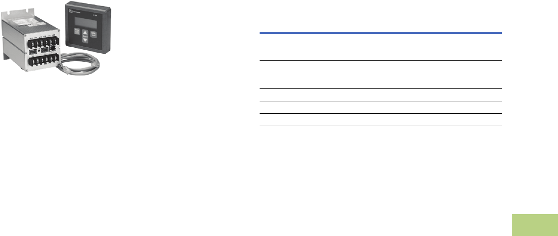
Volume 12—Aftermarket, Renewal Parts and Life Extension Solutions CA08100014E—November 2013 www.eaton.com V12-T10-27
1
2
3
4
5
6
7
8
9
10
11
12
13
14
15
16
17
18
19
20
21
22
23
24
25
10
IQ Products
Current Products
IQ 230
IQ 230
General Description
Eaton’s IQ 230 compact
size and flexible mounting
capabilities make it perfectly
suited for machine control
panels such as panelboard
and switchboard mains and
feeders, low voltage metal-
enclosed switchgear feeders,
motor control centers, and
especially for individual load
monitoring. The base module
can be display mounted, panel
mounted, DIN rail mounted or
side mounted. The display fits
into a standard 1/4 DIN cutout,
and for retrofit applications, a
100 mm ANSI collar is available.
One IQ 230 provides an
alternative to an assortment
of individually wired and
mounted ammeters,
voltmeters, ammeter and
voltmeter switches,
wattmeters, VAR-meters,
power factor meters,
frequency meters, watthour
and demand meters.
ANSI C12 Class 10 revenue
metering accuracy makes the
IQ 230 an ideal choice for
submetering and sub-
billing applications.
The IQ 230 can be easily
programmed and monitored
from the faceplate keypad
that features a 4 line x 20
character LED backlit LCD
display. Opting for the
compatible PowerNet system
allows the user to program and
monitor the meter remotely
from a PC.
Retrofit Opportunities
●Retrofit of existing electrical
distribution systems with
the IQ 230 for load and
energy monitoring
●Five mounting options
makes installation easier
Ratings
●Application to 200 kV,
no PTs to 600V
●CT ratios selectable 5 to
8000A
●Single-phase two- or
three-wire; three-phase
three- or four-wire
Product Selection
IQ 230 Ordering Information
Description
Catalog
Number
IQ 230 complete meter with base module, display and 14.00-inch
(355.6 mm) cable—with INCOM communications, pulse output,
two contact outputs, two digital inputs, one analog input and anti-tamper seal
IQ230
IQ 230M complete meter with base module, display and 14.00-inch
(355.6 mm) cable—with RS-485 Modbus communications, pulse output, two
contact outputs, two digital inputs, one analog input and anti-tamper seal
IQ230M
3 foot (0.9m) Category 5 cable
IQ23CABLE
6 foot (2.0m) Category 5 cable
IQ26CABLE
10 foot (3.0m) Category 5 cable
IQ210CABLE
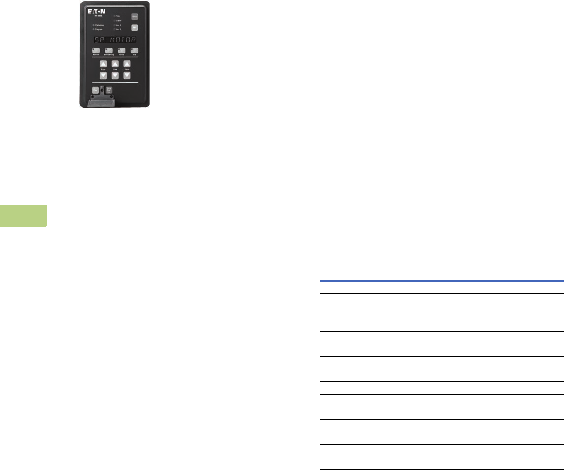
V12-T10-28 Volume 12—Aftermarket, Renewal Parts and Life Extension Solutions CA08100014E—November 2013 www.eaton.com
1
2
3
4
5
6
7
8
9
10
11
12
13
14
15
16
17
18
19
20
21
22
23
24
25
10
IQ Products
Current Products
MP-3000 Motor
Protection
MP-3000 Motor Protection
General Description
Eaton’s MP-3000 motor
protection relay is a
multi-functional
microprocessor-based
protective relay for the
protection of three-phase
AC motors. Though it may
be applied to any size motor
at any voltage level, it is most
commonly applied on medium
voltage or larger motors. The
MP-3000 relay is a current
only device that provides
complete and reliable motor
protection, monitoring and
starting control functions.
The MP-3000 motor
protection relay is available in
either a fixed mount, semi-
flush case or in a semi-flush
quick release drawout case.
Both housings
are compact
and fit a standard IQ cutout.
The optional quick release
drawout case features two-
stage contact disconnects
and self-shorting CT circuit
terminal blocks. A spare
self-shorting terminal pair
is available for use as relay
removal alarm or for continuous
motor operation (non-failsafe
mode) on relay removal.
The optional communication
module is externally mounted
on the fixed mount case and
internally mounted in the
drawout case.
The MP-3000 motor protection
relay has three phase and one
ground current inputs. Both a
5A and 1A version are available.
The ground protection and
metering functions can be used
with either a zero sequence
ground CT or from the residual
connection of the phase CTs.
The zero sequence ground CT
provides greater ground fault
sensitivity than the residual
connection. The unit is user-
programmable for 60 Hz or
50 Hz operation.
The MP-3000 motor protection
relay provides adaptive
overload trip characteristics
based on motor temperature
when motor RTDs are
connected through an optional
URTD module. Metering
of RTD inputs (individual
winding, motor bearing, load
and auxiliary temperatures)
is also provided.
The MP-3000 motor
protection relay has two
discrete inputs, four Form C
(1NO and 1NC) contacts and
one 4 to 20 mA analog
output. The relay provides
maximum user flexibility to
configure the I/O. All inputs
and outputs (except for the
trip output) are user-
programmable. In addition,
the relay has 10 LEDs for the
indication of protection on,
program mode, monitor
mode, view setting mode,
history mode, log mode, trip,
alarm, auxiliary 1 and auxiliary
2 operation. A test page in
the program mode provides
display indication of the
discrete input states and
testing of the output
relays, target LEDs and
analog circuit.
A user-friendly operator
interface and display provides
quick access to the settings,
monitored values, motor
history and operational logs.
Large LED alphanumeric
character display provides
easy viewing from any angle
in any light. Simple keypad
operation provides quick and
easy navigation through all
settings and stored data.
The program mode and
emergency override buttons
are access restricted via
sealing provisions and latched
cover. An integrated help
function provides an online
description display of
functions, abbreviations
and operations.
Optimum Motor Protection
The MP-3000 motor protection
relay has been designed for
maximum motor operation
and protection. It permits
running the motor as close
to its design limits while
protecting it against excessive
heating and damaging overload
conditions. The MP-3000
field-proven protection
algorithms were developed
based on motor designs
and operating parameters
for optimum operation and
protection while minimizing
nuisance tripping.
The MP-3000 motor protection
relay uses a protection
algorithm and measurement
technique based on proven
positive and negative
(unbalance) sequence
current sampling and true
rms calculations.
Product Selection
MP-3000 Motor Protection Ordering Information
Description
Catalog
Number
Motor protection in fixed case, 5A CT, communication capable with PONI MP-3000
Motor protection in drawout case, 5A CT, no communication MP-3001
Motor protection in drawout case, 5A CT, with INCOM PONI MP-3002
Motor protection in fixed case, 1A CT, communication capable with PONI MP-3100
Motor protection in drawout case, 1A CT, no communication MP-3101
Motor protection in drawout case, 1A CT, with INCOM PONI MP-3102
Motor protection drawout case inner chassis, 5A, CT, no communication MP3001-IC
Motor protection drawout case inner chassis, 5A, CT, with INCOM PONI MP3002-IC
Motor protection drawout case inner chassis, 1A, CT, no communication MP-3101-IC
Motor protection drawout case inner chassis, 1A, CT, with INCOM PONI MP3102-IC
Motor protection drawout case outer chassis MP3-OC
Motor protection, 5A, URTD, INCOM PONI, fiber optic link MP3000VPI
Motor protection, 1A, URTD, INCOM PONI, fiber optic link MP3100VPI
16-foot (5m) fiber optic cable for MP-3000/URTD communication MPFO-5
Universal RTD module URTP
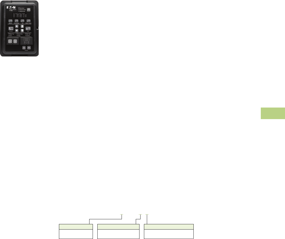
Volume 12—Aftermarket, Renewal Parts and Life Extension Solutions CA08100014E—November 2013 www.eaton.com V12-T10-29
1
2
3
4
5
6
7
8
9
10
11
12
13
14
15
16
17
18
19
20
21
22
23
24
25
10
IQ Products
Current Products
FP-5000 Feeder
Protection
Feeder Protection FP-5000
General Description
●Microprocessor-based
protection with monitoring
and control for medium
voltage main and feeder
applications
●Current, voltage,
frequency and power
protection for electric
power distribution
systems
●Complete metering of
voltage, currents, power,
energy, minimum/
maximum and demand
functions
●Programmable logic
control functions for main-
tie-main transfer schemes
●Trip logs, event logs and
waveform capture for
better fault analysis and
system restoration
●Data Logger to provide
energy usage profiles for
better planning, utilization
and energy usage
●Compact, drawout case
design
●Meets ANSI, UL and cUL®
standards
●Multiple setting groups
●ANSI, IEC and thermal
protection curves for
greater flexibility
Application Description
Eaton’s FP-5000 feeder
protection relay provides
complete three-phase and
ground overcurrent and
voltage protection plus
metering in a single, compact
drawout case. It may be used
as primary protection on
feeders, mains and tie circuit
breaker applications, and as
backup protection for
transformers, high voltage
lines and differential
protection. The relay is
most commonly used on
medium voltage switchgear
applications.
The FP-5000 takes full
advantage of its
microprocessor technology
providing the user new
freedoms and a wealth of data-
gathering features. The relay
performs self-checking of all
major hardware and firmware
protection elements to ensure
their operation in the event of a
system or component electrical
failure or fault. Protection
functions are well suited for
main and distribution feeder
circuit applications.
Programmable logic control
functions make the FP-5000
relay ideally suited for main-tie-
main and main 1/main 2
transfer schemes.
The multiple settings groups
can be used for arc flash
mitigation when an alternative
setting group, set to have
instantaneous elements only
is activated using a selector
switch and the programmable
I/O in the FP-5000.
Features and Benefits
The zone interlocking feature
can be used for bus
protection instead of an
expensive and complicated
bus differential (87B)
scheme. The FP-5000
works
directly with the Eaton
Digitrip
3000 and Digitrip MV relays.
Breaker failure logic provides
faster remote backup clearing
times for stuck breaker
operation.
The FP-5000 provides trip and
close circuit monitoring and
alarming features. It
continually monitors the
complete trip and close
circuits for continuity and
readiness to trip. Open and
close pushbuttons are
conveniently located on the
front of the relay for local
breaker operation.
Loss-of-vacuum monitoring is
activated when the breaker is
open. Residual current is
monitored and alarmed if
detected.
When an electrical fault
or disturbance occurs, the
FP-5000 begins to store the
following in non-volatile
memory:
●Voltage and current
sampled data
●Calculated values
●
Status of internal protection
functions,
logic, contact
inputs and outputs
Retrieval and viewing of the
data is easy, aiding in the quick
analysis and restoration of
your electric power system.
When the FP-5000 isn’t
responding to disturbances
in the power system, it’s
providing valuable metering
information at the relay and
remotely. It provides energy
usage and demand reading,
and can alarm when usage
reaches a set value. Power
factor measurements can
be used for capacitor bank
switching to control cover
demand. Inboard data
trending can provide load
profiles for up to 40 days.
Catalog Number Selection
FP-5000 Feeder Protection
Current Range
2 = 5 Amperes
3 = 1 Ampere
Control Voltage
0 = 48 – 125 Vac/Vdc
1 = 100 – 240 Vac/Vdc
Communications Protocol
0 = INCOM
1 = Modbus
FP5 2 00 - 0 1
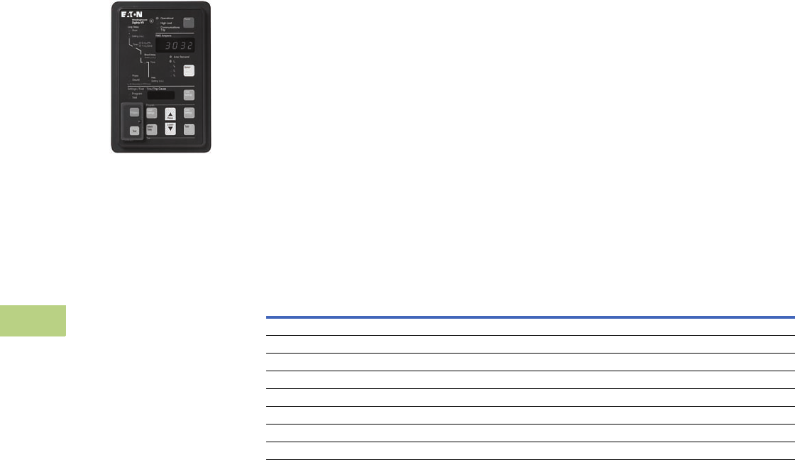
V12-T10-30 Volume 12—Aftermarket, Renewal Parts and Life Extension Solutions CA08100014E—November 2013 www.eaton.com
1
2
3
4
5
6
7
8
9
10
11
12
13
14
15
16
17
18
19
20
21
22
23
24
25
10
IQ Products
Accessories
Digitrip 3000 (DT-3000)
DT-3000
General Description
●Microprocessor-based,
three-phase and ground
overcurrent relay
●Independent phase and
ground measuring circuits
and operation
●ANSI, IEC and thermal
protection curves
●Fixed mount or
drawout design
●Dual-source power supply
option for AC control
power applications
Eaton’s Digitrip 3000 trip unit
(DT-3000) is a multifunction,
microprocessor-based
overcurrent trip unit designed
for both ANSI and IEC
applications. The DT-3000
design provides true rms
sensing design of each
phase and ground current.
It can be power from either
AC or DC control power. The
DT-3000 can be used for
any application where
instantaneous and/or time
overcurrent protection
is required.
The DT-3000 may be applied
as the transformer primary
protection or as backup to the
differential protection. The
DT-3000 also has zone
selective interlocking to
minimize equipment damage
resulting from a phase or
ground fault in an area where
long time and/or short time
delay is in use.
The integral Dual-Source
Power Supply allows
the DT-3000 to operate
solely from the main CTs
during a fault if the
normally connected
AC voltage is not available,
i.e., an electromechanical
or electronic “self
powered” relay.
Electrical Power System
Protection
The DT-3000 provides phase
and ground protection for
most types of medium
voltage electrical power
distribution systems.
Protection curves are similar
to those on low voltage
power circuit breaker trip
units, and provide close
coordination with
downstream devices, as well
as upstream fuse and/or
electromagnetic relays. Just
one DT-3000 replaces the
normal complement of three
or four conventional
electromagnetic overcurrent
relays, an ammeter, a
demand ammeter, an
ammeter switch and, in some
situations, a lockout relay
switch (device 86).
Product Selection
DT-3000 Ordering Information
Description
Catalog
Number
DT-3000 protective relay DT3000
DT-3000 protective relay Chicago version DT3100
DT-3030 protective relay (24–48 Vdc CE Mark version) DT3030
DT-3000 drawout case protective relay DT3001
DT-3000 Chicago version drawout case protective relay DT3101
DT-3030 drawout case protective relay (24–48 Vdc CE Mark version) DT3031
DT-3000 protective relay with 120 Vac dual-source power supply DT3010
DT-3000 protective relay with 240 Vac dual-source power supply DT3020
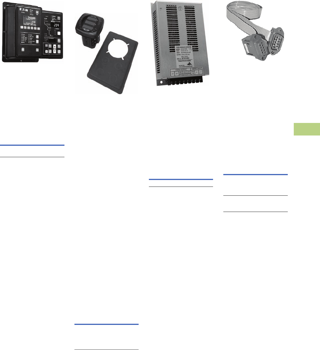
Volume 12—Aftermarket, Renewal Parts and Life Extension Solutions CA08100014E—November 2013 www.eaton.com V12-T10-31
1
2
3
4
5
6
7
8
9
10
11
12
13
14
15
16
17
18
19
20
21
22
23
24
25
10
IQ Products
Accessories
IQ Flange
IQ Flange
For applications where extra
door-mounting space is
required, a flange-mounting
unit is available. Eaton’s IQ
Flange provides an extra 2.50
inches (63.5 mm) of clearance
for the device.
Product Selection
IQ Flange
Panel Mounting Adapter
Kit for IQ 100/200 Series
and PXM 2000 Meters
Panel Mounting Adapter Kit
The flange adapter plate can
be installed as follows:
1. Remove the old meter
from the panel or door.
Many IQ metering
products use the typical
IQ drilling pattern shown
in for mounting.
2. Install the flange adapter
plate. Mount it from the
rear using the six screws
provided in the kit.
The flange adapter
plate screw hole pattern
should match the typical
IQ drilling pattern. If not,
perform the next step.
3. Drill six holes in the panel
or the door to mount
the flange adapter plate.
Follow the typical IQ
drilling pattern. You need
only the top, center and
bottom sets of holes.
4. Install the new IQ 100/
200 Series or PXM 2000
meter in the flange
adapter plate. Secure it
from behind with four flat
washers, lock washers
and nuts provided with
the meter.
Product Selection
Ordering Information
IQ DC Power Supply
IQ DC Power Supply
The IQ DC Power Supply is a
DC to AC inverter module
intended for use where DC
power is available, but some
AC is required. The unit will
operate an MP-3000 or other
AC powered IQ devices
requiring no more than 75 VA
of power at any power factor.
Product Selection
IQ DC Power Supply
IQ Cable
IQ Cable
For applications where
remote mounting of the
power supply is required, an
extension cable is available.
Two types of cable are
available. The first (catalog
number IQCABLE) is for the
obsolete IQ Data, Generator,
and Data Plus II. The
second (catalog number
IQA45CABLE) is for the
IQ Analyzer and IQ DP-4000.
Product Selection
IQ Cable
Description
Catalog
Number
IQ Flange option, to provide
extra clearance when mounting
IQFLANGE
Description
Catalog
Number
Panel mounting adapter kit
IQ 100/200 and PXM 2000
Series adapter kit to
IQ Analyzer/IQ DP-4000/
IQ Data
IQ250-PMAK
Description
Catalog
Number
IQ DC power supply IQDCPS
Description
Catalog
Number
36.00-inch (914.4 mm)
extension cable
IQ Data, Generator,
Data Plus II
IQCABLE
45.00-inch (1143.0 mm)
extension cable
IQ Analyzer/IQ DP-4000
IQA45CABLE
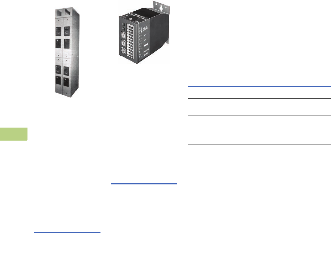
V12-T10-32 Volume 12—Aftermarket, Renewal Parts and Life Extension Solutions CA08100014E—November 2013 www.eaton.com
1
2
3
4
5
6
7
8
9
10
11
12
13
14
15
16
17
18
19
20
21
22
23
24
25
10
IQ Products
Accessories
IQ Floor-Mounted
Enclosure
Two 10-Inch Wide Enclosures (Shown
with Optional 10-Inch High Bus
Compartment)
Type 1
Standard AMPGARD
structure construction,
painted ASA-61. To be used
as a lineup extension for
mounting IQ products. Each
10.00-inch (254.0 mm) wide
section comes with (two)
doors with “works-in-a-
drawer” drawout panel. Each
door has three standard IQ
cutouts with device panels,
and can be supplied with or
without IQ devices.
Product Selection
IQ Floor-Mounted Enclosure
Addressable Relay II
Addressable Relay II
The Addressable Relay II has
two status inputs and a Form C
contact output.
●Input rating: 48–120 Vac,
48–125 Vdc
●Output contact rating: 10A
at 277 Vac, 10A at 30 Vdc
Features include a
communications watchdog
and relay pulse. Baud rate
is selectable.
Product Selection
Addressable Relay II
Description
Style
Number
10.00-inch W x 30.00-inch D
x 90.00-inch H
(254.0 mm W x 762.0 mm D
x 2286.0 mm H)
Bus compartment optional
2147A95G35
Description
Catalog
Number
Addressable Relay II ARII
Power Modules
Eaton and Westinghouse
have produced a number of
different meters dating back
to the 1980s. Many of these
meters used and continue to
use power modules to
provide voltage sensing
isolation and control power
to the meter.
Power modules are available
to power the meter directly
from the voltage source being
sensed or for separate control
power input. Renewal part
power modules are available
for the meters shown in the
table below.
Product Selection
Power Modules
Note
1The adjacent power modules will work with each basic meter style, regardless of the last
two digits of the meter style number.
Description
Used with Meter
Style Number
Power Module
Catalog Number
Old IQ DP-4000 and IQ Analyzer self-powered
three-phase power module
2D82302GXX
1
4D13110GXX
1
IQA3PPM
Old IQ DP-4000 and IQ Analyzer
separate source 110 to 240 Vac or 110 to 250 Vdc
power module
2D82302GXX
1
4D13110GXX
1
IQASSPM
New IQ DP-4000 and IQ Analyzer
self-powered three-phase
power module
66D2045GXX
1
66D2040GXX
1
IQM3PPM
New IQ DP-4000 and IQ Analyzer
24/48 Vdc power module
66D2045GXX
1
66D2040GXX
1
IQMDCPM
New IQ DP-4000 and IQ Analyzer
separate source 110 to 240 Vac or 110 to 250 Vdc
power module
66D2045GXX
1
66D2040GXX
1
IQMSSPM
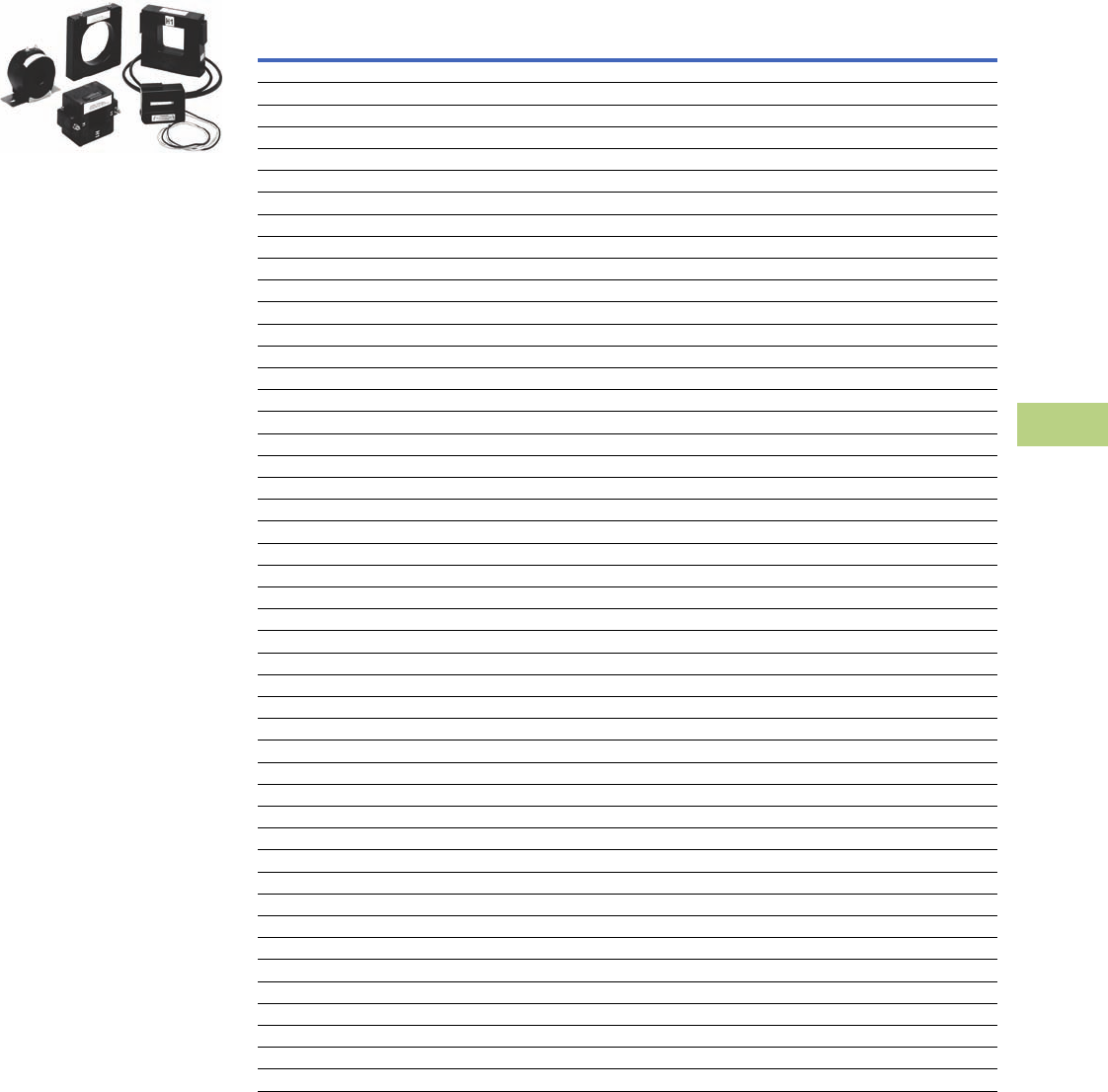
Volume 12—Aftermarket, Renewal Parts and Life Extension Solutions CA08100014E—November 2013 www.eaton.com V12-T10-33
1
2
3
4
5
6
7
8
9
10
11
12
13
14
15
16
17
18
19
20
21
22
23
24
25
10
IQ Products
Accessories
Current Transformers
(CTs)
Current Transformers (CTs)
General Description
Eaton’s low voltage current
transformers are available in
both solid core and split core
designs. Engineered for
electronic metering
applications, all solid core
designs and selected split
core designs offer ANSI
metering quality accuracy.
The solid core designs also
meet ANSI C57.13 relay
accuracy requirements
including over-ranging
capabilities. The current
transformer offering has a
5 ampere secondary at the
rated primary current.
Split core CTs are specifically
designed to be installed
around primary conductors
without disconnecting wires
or breaking the circuit to be
monitored. These current
transformers are perfect
solutions for energy
management applications
and are manufactured for
installation ease.
Product Selection
Solid Core ANSI Metering Accuracy
Note
1Contact Eaton for further information.
Primary
Current
Rating
ANSI B0.1
Metering Class at 60 Hz
(Accuracy in %)
Window Size
in Inches (mm)
Diameter
Catalog
Number
Mounting Bracket
Catalog
Number
1.25 (31.8) Window
50 1.2 1.25 (31.8) S060-500 1
100 0.6 1.25 (31.8) S060-101 1
150 0.3 1.25 (31.8) S060-151 1
200 0.3 1.25 (31.8) S060-201 1
1.56 (39.6) Window
300 0.3 1.56 (39.6) S050-301 S050BRAC
400 0.3 1.56 (39.6) S050-401 S050BRAC
500 0.3 1.56 (39.6) S050-501 S050BRAC
600 0.3 1.56 (39.6) S050-601 S050BRAC
750 0.3 1.56 (39.6) S050-751 S050BRAC
800 0.3 1.56 (39.6) S050-801 S050BRAC
1000 0.3 1.56 (39.6) S050-102 S050BRAC
1200 0.3 1.56 (39.6) S050-122 S050BRAC
3.25 (82.6) Window
400 0.3 3.25 (82.6) S080-401 S080BRAC
500 0.3 3.25 (82.6) S080-501 S080BRAC
600 0.3 3.25 (82.6) S080-601 S080BRAC
750 0.3 3.25 (82.6) S080-751 S080BRAC
800 0.3 3.25 (82.6) S080-801 S080BRAC
1000 0.3 3.25 (82.6) S080-102 S080BRAC
1200 0.3 3.25 (82.6) S080-122 S080BRAC
4.25 (108.0) Window
500 0.3 4.25 (108.0) S090-501 S090BRAC
600 0.3 4.25 (108.0) S090-601 S090BRAC
750 0.3 4.25 (108.0) S090-751 S090BRAC
800 0.3 4.25 (108.0) S090-801 S090BRAC
1000 0.3 4.25 (108.0) S090-102 S090BRAC
1200 0.3 4.25 (108.0) S090-122 S090BRAC
1500 0.3 4.25 (108.0) S090-152 S090BRAC
1600 0.3 4.25 (108.0) S090-162 S090BRAC
2000 0.3 4.25 (108.0) S090-202 S090BRAC
2500 0.3 4.25 (108.0) S090-252 S090BRAC
3000 0.3 4.25 (108.0) S090-302 S090BRAC
6.31 (160.3) Window
600 0.3 6.31 (160.3) S025-601 S025BRAC
750 0.3 6.31 (160.3) S025-751 S025BRAC
800 0.3 6.31 (160.3) S025-801 S025BRAC
1000 0.3 6.31 (160.3) S025-102 S025BRAC
1200 0.3 6.31 (160.3) S025-122 S025BRAC
1500 0.3 6.31 (160.3) S025-152 S025BRAC
1600 0.3 6.31 (160.3) S025-162 S025BRAC
2000 0.3 6.31 (160.3) S025-202 S025BRAC
2500 0.3 6.31 (160.3) S025-252 S025BRAC
3000 0.3 6.31 (160.3) S025-302 S025BRAC
3500 0.3 6.31 (160.3) S025-352 S025BRAC
4000 0.3 6.31 (160.3) S025-402 S025BRAC

V12-T10-34 Volume 12—Aftermarket, Renewal Parts and Life Extension Solutions CA08100014E—November 2013 www.eaton.com
1
2
3
4
5
6
7
8
9
10
11
12
13
14
15
16
17
18
19
20
21
22
23
24
25
10
IQ Products
Accessories
Split Core ANSI Metering Accuracy Split Core Current Transformers
Primary
Current
Rating
ANSI B0.1
Metering Class at 60 Hz
(Accuracy in %)
Window Size
in Inches (mm)
Catalog
Number
2.00 x 5.50 (50.8 x 139.7)
400 2.4 2.00 x 5.50 (50.8 x 139.7) M000-401
500 2.4 2.00 x 5.50 (50.8 x 139.7) M000-501
600 2.4 2.00 x 5.50 (50.8 x 139.7) M000-601
800 1.2 2.00 x 5.50 (50.8 x 139.7) M000-801
1000 1.2 2.00 x 5.50 (50.8 x 139.7) M000-102
1200 0.6 2.00 x 5.50 (50.8 x 139.7) M000-122
1500 0.6 2.00 x 5.50 (50.8 x 139.7) M000-152
1600 0.6 2.00 x 5.50 (50.8 x 139.7) M000-162
2000 0.6 2.00 x 5.50 (50.8 x 139.7) M000-202
4.10 x 7.10 (104.1 x 180.3)
600 4.8 4.10 x 7.10 (104.1 x 180.3) M050-601
750 4.8 4.10 x 7.10 (104.1 x 180.3) M050-751
800 2.4 4.10 x 7.10 (104.1 x 180.3) M050-801
1000 2.4 4.10 x 7.10 (104.1 x 180.3) M050-102
1200 1.2 4.10 x 7.10 (104.1 x 180.3) M050-122
1500 1.2 4.10 x 7.10 (104.1 x 180.3) M050-152
2000 0.6 4.10 x 7.10 (104.1 x 180.3) M050-202
2500 0.6 4.10 x 7.10 (104.1 x 180.3) M050-252
3000 0.6 4.10 x 7.10 (104.1 x 180.3) M050-302
3500 0.6 4.10 x 7.10 (104.1 x 180.3) M050-352
4000 0.3 4.10 x 7.10 (104.1 x 180.3) M050-402
Primary
Current
Rating
Accuracy
at 60 Hz (in %)
Window Size
in Inches (mm)
Catalog
Number
0.80 x 1.95 (20.3 x 49.5)
100 5.0 0.80 x 1.95 (20.3 x 49.5) M030-101
150 5.0 0.80 x 1.95 (20.3 x 49.5) M030-151
200 4.0 0.80 x 1.95 (20.3 x 49.5) M030-201
300 2.0 0.80 x 1.95 (20.3 x 49.5) M030-301
400 2.0 0.80 x 1.95 (20.3 x 49.5) M030-401
1.42 x 1.53 (36.1 x 38.9)
100 5.0 1.42 x 1.53 (36.1 x 38.9) M040-101
150 4.0 1.42 x 1.53 (36.1 x 38.9) M040-151
200 1.5 1.42 x 1.53 (36.1 x 38.9) M040-201
300 1.5 1.42 x 1.53 (36.1 x 38.9) M040-301
400 1.5 1.42 x 1.53 (36.1 x 38.9) M040-401
2.60 x 2.75 (66.0 x 69.9)
200 1.0 2.60 x 2.75 (66.0 x 69.9) M060-201
300 1.0 2.60 x 2.75 (66.0 x 69.9) M060-301
400 1.0 2.60 x 2.75 (66.0 x 69.9) M060-401
500 1.0 2.60 x 2.75 (66.0 x 69.9) M060-501
600 1.0 2.60 x 2.75 (66.0 x 69.9) M060-601
750 1.0 2.60 x 2.75 (66.0 x 69.9) M060-751
800 1.0 2.60 x 2.75 (66.0 x 69.9) M060-801
1000 1.0 2.60 x 2.75 (66.0 x 69.9) M060-102
1200 1.0 2.60 x 2.75 (66.0 x 69.9) M060-122
2.60 x 6.25 (66.0 x 158.8)
500 1.0 2.60 x 6.25 (66.0 x 158.8) M080-501
600 1.0 2.60 x 6.25 (66.0 x 158.8) M080-601
800 1.0 2.60 x 6.25 (66.0 x 158.8) M080-801
1000 1.0 2.60 x 6.25 (66.0 x 158.8) M080-102
1200 1.0 2.60 x 6.25 (66.0 x 158.8) M080-122
1500 1.0 2.60 x 6.25 (66.0 x 158.8) M080-152
1600 1.0 2.60 x 6.25 (66.0 x 158.8) M080-162
2000 1.0 2.60 x 6.25 (66.0 x 158.8) M080-202
2500 1.0 2.60 x 6.25 (66.0 x 158.8) M080-252
3000 1.0 2.60 x 6.25 (66.0 x 158.8) M080-302
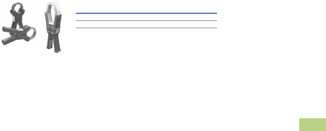
Volume 12—Aftermarket, Renewal Parts and Life Extension Solutions CA08100014E—November 2013 www.eaton.com V12-T10-35
1
2
3
4
5
6
7
8
9
10
11
12
13
14
15
16
17
18
19
20
21
22
23
24
25
10
IQ Products
Accessories
Clamp-On Current
Transformers
IQ Accessories—Clamp-On CTs
General Description
Eaton’s optional Clamp-on
Current Transformers (CTs)
are designed to be used in
cases where there are no
existing CTs or the existing
CTs cannot be accessed,
these clamp-on CTs can
be used.
These clamp-on CTs are
packaged individually. Most
applications will require at
least three clamp-on CTs,
one for each phase.
Product Selection
Ordering Information
Description
Catalog
Number
150–300–600A IQAPORT0600CT
500–1000–1500A IQAPORT1500CT
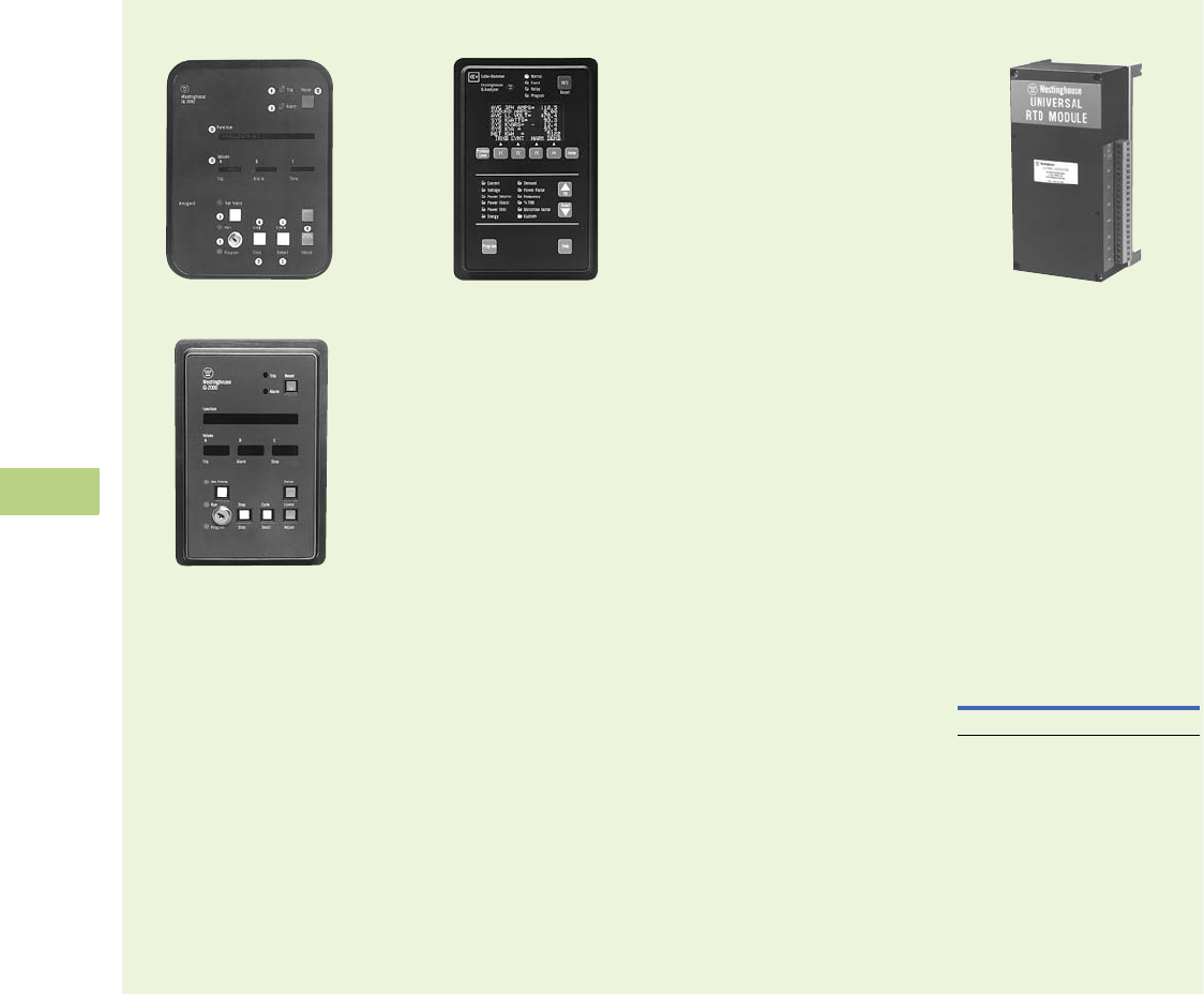
V12-T10-36 Volume 12—Aftermarket, Renewal Parts and Life Extension Solutions CA08100014E—November 2013 www.eaton.com
1
2
3
4
5
6
7
8
9
10
11
12
13
14
15
16
17
18
19
20
21
22
23
24
25
10
IQ Products
Replacement Capabilities—Discontinued Product—Recommended Replacement
■
Shaded area denotes obsolete or discontinued products and services.
IQ 2000
IQ 2000 Model A
IQ 2000 Model B
Recommended Replacement
Production of IQ 2000
devices has been
discontinued. The IQ 2000
can be replaced with the
MP-3000 electronic motor
protective relay and the
IQ DP-4000 electronic meter.
The MP-3000 provides motor
current protective relaying,
while the IQ DP-4000
provides complete electrical
metering and voltage
protective alarming
functions. For specific
application consideration,
contact your local Eaton
Field Sales office.
IQ Analyzer 6000/6200
IQ Analyzer 6000/6200
Eaton’s Cutler-Hammer
IQ Analyzer 6000/6200 is a
complete solution for users
who want to monitor all
aspects of their electrical
distribution system.
It provides extensive
metering, power quality
analysis, remote input
monitoring, control relaying,
analog input/outputs and
communications capability.
All programming can be done
through the faceplate or
through the communications
option. Its online Help
Pushbutton feature displays
information on device
operation, programming
and troubleshooting.
Features and Benefits
●All information accessible
through communications
port
●Quality true rms readings
through 50th harmonic
●Meets ANSI C12.16 Class
10 revenue metering spec
●Accurate readings for non-
sinusoidal waveforms with
up to 3.0 crest factor
●Screens display auto
ranging units, kilo units,
mega units as needed
●10-digit energy readings
●Displays multiple
parameters at the
same time
●Programmable custom
screens.The IQ Analyzer
Model 6200 with waveform
display at the device
and sub-cycle voltage
disturbance capture
provides the capability to
monitor a wide range of
harmonic parameters.
These include harmonic
voltage, current magnitudes
and phase angles, as well
as system disturbances
such as transient voltage
disturbances and sub-cycle
voltage interruptions. This
unit is also available in a
portable version.
Recommended Replacement
Eaton’s IQ Analyzer 6400/
6600
RTD Modules
Universal RTD Module
Recommended Replacement
The RTD Modules for
the IQ 2000 have been
discontinued. Now available
is the new Universal RTD
Module that replaces all of
the RTD modules for the
Model A and B IQ 2000
units, as well as the IQ 1000,
IQ 1000 II and all current
IQ metering and protection
products.
Product Selection
Universal RTD
Description
Catalog
Number
Universal module URTD
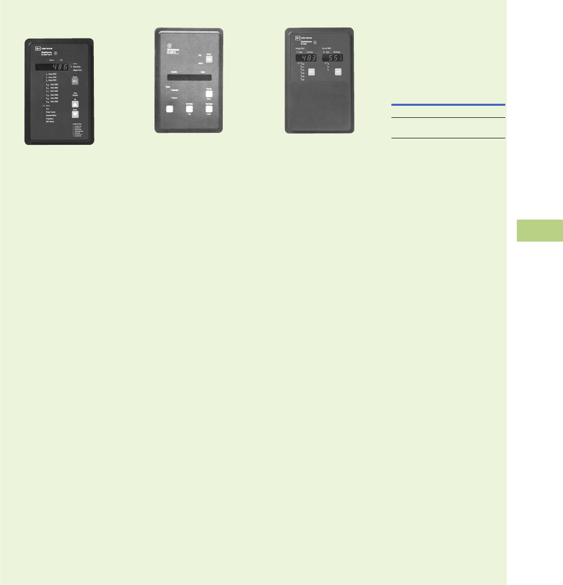
Volume 12—Aftermarket, Renewal Parts and Life Extension Solutions CA08100014E—November 2013 www.eaton.com V12-T10-37
1
2
3
4
5
6
7
8
9
10
11
12
13
14
15
16
17
18
19
20
21
22
23
24
25
10
IQ Products
Replacement Capabilities—Discontinued Product—Recommended Replacement
■
Shaded area denotes obsolete or discontinued products and services.
IQ Data Plus and
IQ Data Plus II
IQ Data Plus II
Eaton’s Cutler-Hammer IQ
Data Plus was discontinued
in 1989 and was replaced by
the IQ Data Plus II. The
IQ Data Plus II was
discontinued in 1998.
Recommended Replacement
IQ DP-4000
IQ 1000 and IQ 1000 II
IQ 1000 II
Recommended Replacement
Both the IQ 1000 and the
IQ 1000 II have been discon-
tinued and replaced by
the MP-3000 for complete
motor protection. A detailed
application note
(MP3K01R4.PDF) describing
replacement of the IQ 1000 II
with an MP-3000 is available
at www.eaton.com.
IQ Data
IQ Data
Eaton’s Cutler-Hammer IQ
Data provides simultaneous
current and voltage metering.
In one compact, standard
package, this device provides
an alternative to individually
mounted and wired ammeters,
voltmeters, and ammeter
and voltmeter switches.
Features and Benefits
●Space savings in
structure—replaces
ammeter, voltmeter,
selector switches
and frequency meter
(IQ Generator)
●Standardization of
design—one door-
mounted device
●Direct voltage input up
to 600V—no additional
potential transformers
(PTs) required
●User-friendly—field-
settable DIP switches
●Standard model derives
power from separate
source 120/240 Vac supply
●Only two style numbers
●No need to stock multiple
units for different current
transformers (CT)
and PT ratios
●Interface capability to
computer network for data
collection, storage and/or
printout via IMPACC
●Membrane faceplate,
designed and tested
to perform in a harsh
industrial environment
(Type 3R, 12)
●Retains preset parameters
through
power failure with
use of field-settable
DIP
switches (no batteries)
Product Selection
IQ Data
Recommended Replacement
IQ DP-4000
Description
Catalog
Number
Basic metering IQDATA
Basic metering with
three-phase power module
IQDATAPM
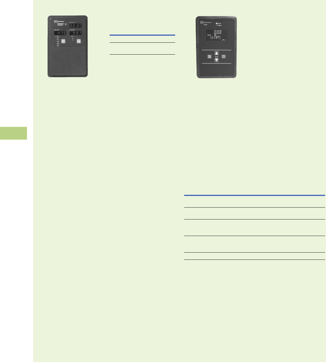
V12-T10-38 Volume 12—Aftermarket, Renewal Parts and Life Extension Solutions CA08100014E—November 2013 www.eaton.com
1
2
3
4
5
6
7
8
9
10
11
12
13
14
15
16
17
18
19
20
21
22
23
24
25
10
IQ Products
Replacement Capabilities—Discontinued Product—Recommended Replacement
■
Shaded area denotes obsolete or discontinued products and services.
IQ Generator
IQ Generator
Eaton’s Cutler-Hammer
IQ Generator provides
simultaneous current and
voltage metering. In addition,
the IQ Generator monitors
frequency. This device
provides an alternative to
individually mounted and
wired ammeters, voltmeters,
ammeter and voltmeter
switches, and frequency
meters.
Features and Benefits
●Space savings in
structure—replaces
ammeter, voltmeter,
selector switches
and frequency meter
(IQ Generator)
●Standardization of
design—one door-
mounted device
●Direct voltage input up
to 600V—no additional
PTs required
●User-friendly—field-
settable DIP switches
●Standard model derives
power from separate
source 120/240 Vac supply
●Only two style numbers
●No need to stock multiple
units for different CT and
PT ratios
●Interface capability to
computer network for data
collection, storage and/or
printout via IMPACC
●Membrane faceplate,
designed and tested to
perform in harsh industrial
environment (Type 3R, 12)
●Retains preset parameters
through
power failure with
use of field-settable
DIP
switches (no batteries)
Product Selection
IQ Generator
Recommended Replacement
IQ DP-4000
Description
Catalog
Number
Basic metering IQGEN
Basic metering with
three-phase power module
IQGENPM
IQ 300
IQ 300
Eaton’s Cutler-Hammer IQ
300’s thin display and flexible
mounting capabilities make it
perfectly suited for any
application where an
accurate, multifunction meter
is desired, such as
panelboard and switchboard
mains and feeders, motor
control centers, and both low
voltage and high voltage
metal-enclosed switchgear.
Features and Benefits
●Bright display with eight
large numeric digits along
with a 10-character
description of the
measured value makes the
IQ 300 ideal for switchgear
mounting
●Base unit can be display
mounted for simple, one-
hole installation
●Base unit can be mounted
up to 10 feet (3m) away
from display and has three
mounting options
Product Selection
IQ 300
Recommended Replacement
IQ DP-4000/4100
Description
Catalog
Number
IQ 310 complete meter with base module, display and 14.00-inch
(355.6 mm) cable—no communications, no pulse output
IQ310
IQ 320 complete meter with base module, display and 14.00-inch
(355.6 mm) cable—with INCOM communications and pulse output
IQ320
IQ 330 complete meter with base module, display and 14.00-inch
(355.6 mm) cable—with INCOM communications, pulse output, two contact
outputs, two digital inputs, one analog input and anti-tamper seal
IQ330
IQ 330M complete meter with base module, display and 14.00-inch
(355.6 mm) cable—with RS-485 Modbus communications, pulse output, two
contact outputs, two digital inputs, one analog input and anti-tamper seal
IQ330M
IQ 300D display module only IQ300D

Volume 12—Aftermarket, Renewal Parts and Life Extension Solutions CA08100014E—November 2013 www.eaton.com V12-T10-39
1
2
3
4
5
6
7
8
9
10
11
12
13
14
15
16
17
18
19
20
21
22
23
24
25
10
IQ Products
Replacement Capabilities—Discontinued Product—Recommended Replacement
■
Shaded area denotes obsolete or discontinued products and services.
IQ 210/220
IQ 210/220
General Description
Eaton’s IQ 210/220 compact
size and flexible mounting
capabilities make it perfectly
suited for machine control
panels such as panelboard
and switchboard mains and
feeders, low voltage metal-
enclosed switchgear feeders,
motor control centers, and
especially for individual load
monitoring. The base module
can be display mounted,
panel mounted, DIN rail
mounted or side mounted.
The display fits into a
standard 1/4 DIN cutout,
and for retrofit applications,
a 100 mm ANSI collar
is available.
One IQ 210/220 provides an
alternative to an assortment of
individually wired and mounted
ammeters, voltmeters,
ammeter and voltmeter
switches, wattmeters,
VAR-meters, power factor
meters, frequency meters,
watthour and demand meters.
ANSI C12 Class 10 revenue
metering accuracy makes
the IQ 200 an ideal choice
for submetering and sub-
billing applications.
The IQ 200 can be easily
programmed and monitored
from the faceplate keypad
that features a 4 line x 20
character LED backlit LCD
display. Opting for the
compatible PowerNet
system allows the user to
program and monitor the
meter remotely from a PC.
Retrofit Opportunities
●Retrofit of existing
electrical distribution
systems with the IQ 210/
220 for load and energy
monitoring
●Five mounting options
makes installation easier
Ratings
●Application to 200 kV,
no PTs to 600V
●CT ratios selectable
5 to 8000A
●Single-phase two- or
three-wire; three-phase
three- or four-wire
Product Selection
IQ 210/220 Ordering Information
Recommended Replacement
IQ 230
Description
Catalog
Number
IQ 210 complete meter — includes base, display and 14.00-inch (355.6 mm) cable
IQ210
IQ 220 complete meter — includes base display module and 14.00-inch
(355.6 mm)
cable
with INCOM
communications and KYZ output
IQ220
IQ 220 transducer base only with INCOM communications and KYZ output
IQ220TRAN
IQ 200D IQ 210/220 display module
IQ200D
3 foot (0.9m) Category 5 cable
IQ23CABLE
6 foot (2.0m) Category 5 cable
IQ26CABLE
10 foot (3.0m) Category 5 cable
IQ210CABLE
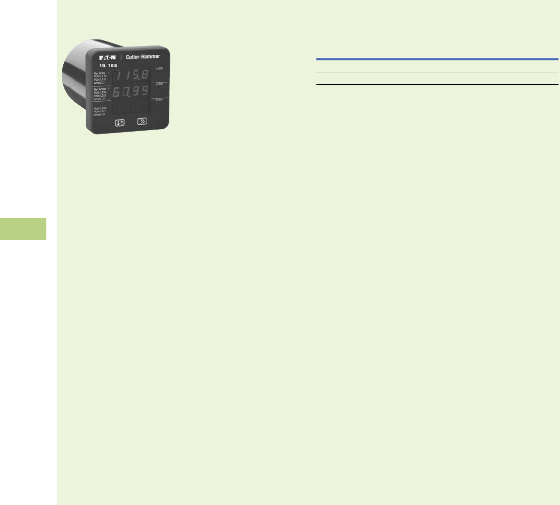
V12-T10-40 Volume 12—Aftermarket, Renewal Parts and Life Extension Solutions CA08100014E—November 2013 www.eaton.com
1
2
3
4
5
6
7
8
9
10
11
12
13
14
15
16
17
18
19
20
21
22
23
24
25
10
IQ Products
Replacement Capabilities—Discontinued Product—Recommended Replacement
■
Shaded area denotes obsolete or discontinued products and services.
IQ 110/115 Electronic
Power Meters
IQ 110 Electronic Power Meter
General Description
The IQ 100 Meter family
provides capabilities you
would not normally expect in
affordable, compact meters,
such as fast sampling rate
and accurate metering for a
full range of power
attributes. Providing the first
line of defense against costly
power problems, Eaton’s IQ
100 series electronic power
meters can perform the work
of an entire wall of legacy
metering equipment utilizing
today’s technology.
When space is at a premium,
yet you need ANSI C12.20
accuracy, the IQ 100 series
fit the bill. These meters are
ideal for electrical equipment
assemblies, machine control
panels, such as panelboard
and switchboard mains and
feeders, low voltage metal-
enclosed switchgear feeders
and motor control centers.
Requiring far less space than
other meters with similar
functionality, IQ 100 series fit
into a standard ANSI or IEC
cutout on a panelboard or
other electrical equipment,
and therefore fit easily into
retrofit applications.
Features and Benefits
●Measure and display real-
time information about
critical power parameters
with a sampling rate of
400 samples per cycle
●Monitor power utilization
and quality with ANSI
C12.20 accuracy (0.5%)
●Verify meter accuracy with
KYZ test pulse self-
certification capabilities
●Optional Modbus RTU
communications
●Available as transducer
only or with display
●Designed to
accommodate upgrades
●Integrate into Eaton’s
Power Xpert Architecture
for a holistic system-
level view
Product Selection
IQ 110/115 Ordering Information
Recommended Replacement
IQ 130/140
Description
Catalog
Number
Measures voltage and current
IQ 110
Measures voltage, current and frequency
IQ 115

Volume 12—Aftermarket, Renewal Parts and Life Extension Solutions CA08100014E—November 2013 www.eaton.com V12-T10-41
1
2
3
4
5
6
7
8
9
10
11
12
13
14
15
16
17
18
19
20
21
22
23
24
25
10
IQ Products
Replacement Capabilities—Discontinued Product—Recommended Replacement
■
Shaded area denotes obsolete or discontinued products and services.
IQ Power Sentinel
IQ Power Sentinal
General Description
Like the IQ Energy Sentinel,
the IQ Power Sentinel
is a highly accurate
microprocessor-based
submeter designed to monitor
power and energy. In addition
to watts, watthour and watt-
demand, the IQ power
sentinel monitors current,
voltage, reactive power
(VARs), apparent power (VA),
power factor and frequency.
The IQ Power Sentinel offers
an accurate and economic
alternative to separate
meters and transducers.
The IQ Power Sentinel is
only available in the universal
mount with internal CTs up to
400 amperes.
Features and Benefits
Features
●Monitors (accuracy stated
full scale)
●AC line current (each
phase) ±0.5%
●AC line-to-line voltage
±0.5%
●AC line-to-neutral
voltages ±0.5%
●Watts (each phase and
total) ±1.0%
●VARs (each phase and
total) ±1.0%
●VA (each phase and
total) ±1.0%
●Apparent Power Factor
(each phase and total)
±0.5%
●Displacement Power
Factor (each phase and
total) ±0.5%
●Demand (total watts)
±1.0%
●Frequency ±0.5%
●Watthours ±1.0%
●Built-in CTs version up to
400 amperes
●Panel or DIN rail mounted
●Powered directly off
the line
●Built-in communication
capability
●Address set by
DIP switches
●Communication at
9600 baud
●Noise immune
INCOM protocol
●Choice of operator
interfaces
●Subnetwork Master
Local Display
●Breaker Interface
Module
●Power Management
Energy Billing software
●Power Management
Software
●UL and CSA listed
●CE mark
Benefits
●One device replaces
multiple meters
and/or transducers
●Improved system accuracy
●Savings in product cost
●Savings in space
●Savings in installation cost
●No external power source
is needed
●Permits remote
monitoring and
interconnection with
programmable logic
controllers and building
management systems.
For further information
see section on Power
Management Software
Systems
●Designed to interface
directly with Power
Management Software
Energy Billing software
●Flexibility—displays what
is needed where it is
needed
●Power Management
Software
Product Selection
IQ Power Sentinal Ordering Information
Recommended Replacement
PM3
Description
Catalog
Number
Universal with internal CTs, 120/240, 240, 208Y/120 IQPSUI208
Universal with internal CTs, 220/380, 230/400, 240/415 IQPSUI400
Universal with internal CTs, 480, 480Y/277 IQPSUI480
Universal with internal CTs, 600, 600Y/347 IQPSUI600
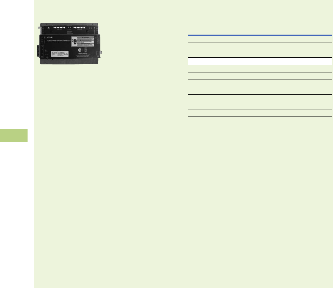
V12-T10-42 Volume 12—Aftermarket, Renewal Parts and Life Extension Solutions CA08100014E—November 2013 www.eaton.com
1
2
3
4
5
6
7
8
9
10
11
12
13
14
15
16
17
18
19
20
21
22
23
24
25
10
IQ Products
Replacement Capabilities—Discontinued Product—Recommended Replacement
■
Shaded area denotes obsolete or discontinued products and services.
IQ Multipoint Energy
Submeter II
IQ Multipoint Energy Submeter II
General Description
Eaton’s IQ Multipoint Energy
Submeter II is a revenue
class electronic submetering
device that can be mounted in
panelboards or switchboards.
When mounted in a
panelboard or switchboard,
the IQ Multipoint Energy
Submeter II provides
customers with an integrated
power distribution and energy
metering solution that saves
space, reduces installation
labor and lowers total cost.
Features and Benefits
The IQ Multipoint Energy
Submeter II offers low-cost
metering of kW and kWh
for multiple tenants of
residential and commercial
office buildings for one- to
three-phase voltage loads
not exceeding 347/600 volts.
The IQ Multipoint Energy
Submeter II contains INCOM
networking to chain together
multiple meters in locations
throughout the facility. See
above for a typical apartment
building layout.
●Multipoint electrical
energy metering
●Built-in communication
interface
●Flexible metering
configuration
●Monitors single-phase and
three-phase loads from
120 Vac to 600 Vac in
three voltage ranges
●Monitors power in watts
and energy in watthours
for up to 16 Current
Sensors
●Very low profile design,
less than 1.50 inches
(38.1 mm) in height
●Energy values stored in
non-volatile memory
●Stores extensive energy
profile data for each
metering point. Can
be used to identify
coincidental peak
demand contribution
●Space-saving stacking
design allows two units
to be mounted together
●Supports Time-of-Use
energy monitoring
●Demand interval adjustable
from 5 to 60 minutes
●Measures bus voltage
●Front panel LEDs provide
status of unit and
communication activity
●Meets rigid ANSI C12.1
and IEC 61036 accuracy
specifications for revenue
meters
●Can be directly mounted in
a UL-approved panelboard
or switchboard
Product Selection
IQ Multipoint Energy Submeter II Ordering Information
1CS005 is not discontinued and is still being used.
Recommended Replacement
Power Xpert Multi-Point Meter
Description
Catalog
Number
IQ Multipoint Energy Submeter II 120V with INCOM IQMESIIN1
IQ Multipoint Energy Submeter II 277V with INCOM IQMESIIN2
IQ Multipoint Energy Submeter II 347V with INCOM IQMESIIN3
Current Sensors—5 amperes, Qty. 3 CS005 1
Current Sensors—50 amperes, Qty. 6 CS050
Current Sensors—70 amperes, Qty. 6 CS070
Current Sensors—125 amperes, Qty. 3 CS125
Current Sensors—200 amperes, Qty. 3 CS200
Current Sensors—400 amperes, Qty. 3 CS400
Current Sensor Extensions—4 feet (1.2m), Qty. 6 CSET04
Current Sensor Extensions—8 feet (2.4m), Qty. 3 CSET08
Current Sensor Extensions—16 feet (4.9m), Qty. 3 CSET16

Volume 12—Aftermarket, Renewal Parts and Life Extension Solutions CA08100014E—November 2013 www.eaton.com V12-T10-43
1
2
3
4
5
6
7
8
9
10
11
12
13
14
15
16
17
18
19
20
21
22
23
24
25
10
IQ Products
Replacement Capabilities—Discontinued Product—Recommended Replacement
Further Information
Pricing Information
IQ/PXM Products
Vista/VISTALINE™ Discount
Symbol C10-S24.
DT-3000
Vista/VISTALINE Discount
Symbol MV-3.
Publication Number Description
Metering Devices
TD02600001E
TD02601007E
TD02601017E
TD150006EN
TD02601016E
TD02601015E
TD02601019E
TD02601018E
TD.17.02B.T.E
TD.17.03A.T.E
Selection Chart
Power Xpert 4000/6000/8000
Power Xpert 2000
Power Xpert Multi-Point Meter
IQ 250/260
IQ 130/140/150
IQ 150S/250S
IQ 35M
IQ Analyzer
IQ DP-4000
TD.17.31.T.E
TD.17.06A.T.E
TD02601003E
TD.17.07.T.E
IQ 300
IQ 200
IQ 110/115
IQ Sentinels
TD17C02TE
TD17C01TE
TD17C03TE
IQ Multipoint Energy Submeter II
Portable IQ Analyzer
Optional Clamp-on CTs
TD.17.08A.T.E
TD.17.08A.T.E
TD02601002E
IQ DP-4000 I/O Module
IQ Analyzer/IQ DP-4000 Auxiliary Power Supply
Current Transformers
Protective Relays
TD02600001E
TD.17.10.T.E
TD.17.11.T.E
Selection Chart
Digitrip 3000 Overcurrent Relay
MP-3000 Motor Protection Relay
TD.17.30.T.E
TD.17.12.T.E
TD.17.13.T.E
FP-5000 Feeder Relay
Dual-Source Power Supply
Digitrip 3000 Optional Drawout Case
TD.17.14.T.E
TD.17.08A.T.E
Universal RTD Module
IQ DC Power Supply

Volume 12—Aftermarket, Renewal Parts and Life Extension Solutions CA08100014E—November 2013 www.eaton.com V12-T11-1
1
2
3
4
5
6
7
8
9
10
11
12
13
14
15
16
17
18
19
20
21
22
23
24
25
Communication Systems
Monitoring Software
and Communications
11 Communication Systems
Product Description . . . . . . . . . . . . . . . . . . . . . . . . . . . . . . . . . . . . . . V12-T11-2
PowerNet Software . . . . . . . . . . . . . . . . . . . . . . . . . . . . . . . . . . . . V12-T11-2
Eaton’s Electrical Services & Systems . . . . . . . . . . . . . . . . . . . . . . V12-T11-3
Power Xpert Software. . . . . . . . . . . . . . . . . . . . . . . . . . . . . . . . . . . V12-T11-4
Power Xpert Reporting . . . . . . . . . . . . . . . . . . . . . . . . . . . . . . . . . . V12-T11-6
Technology Upgrades . . . . . . . . . . . . . . . . . . . . . . . . . . . . . . . . . . . . . V12-T11-8
Communications Hardware. . . . . . . . . . . . . . . . . . . . . . . . . . . . . . . . . V12-T11-12
mMINT . . . . . . . . . . . . . . . . . . . . . . . . . . . . . . . . . . . . . . . . . . . . . . V12-T11-12
Power Xpert Gateway 200E . . . . . . . . . . . . . . . . . . . . . . . . . . . . . . V12-T11-13
Power Xpert Gateway 400E/600E/800E . . . . . . . . . . . . . . . . . . . . . V12-T11-16
PONI Devices . . . . . . . . . . . . . . . . . . . . . . . . . . . . . . . . . . . . . . . . . V12-T11-25
IPONI/MPONI . . . . . . . . . . . . . . . . . . . . . . . . . . . . . . . . . . . . . . . . . V12-T11-25
MINT II . . . . . . . . . . . . . . . . . . . . . . . . . . . . . . . . . . . . . . . . . . . . . . V12-T11-25
Addressable Relay II . . . . . . . . . . . . . . . . . . . . . . . . . . . . . . . . . . . . V12-T11-25
IMPCABLE . . . . . . . . . . . . . . . . . . . . . . . . . . . . . . . . . . . . . . . . . . . V12-T11-26
Further Information . . . . . . . . . . . . . . . . . . . . . . . . . . . . . . . . . . . . . . . V12-T11-26
Pricing Information . . . . . . . . . . . . . . . . . . . . . . . . . . . . . . . . . . . . . . . V12-T11-26

V12-T11-2 Volume 12—Aftermarket, Renewal Parts and Life Extension Solutions CA08100014E—November 2013 www.eaton.com
1
2
3
4
5
6
7
8
9
10
11
12
13
14
15
16
17
18
19
20
21
22
23
24
25
11
Communication Systems
Product Description
PowerNet Software
Integrated PowerNet Support
PowerNet™ (available on the
Power Xpert® Software DVD).
Updates to the PowerNet
system are available;
however, the recommended
update path is to upgrade to
Power Xpert Software. See
Page V12-T11-4 for details
on Power Xpert Software.
General Description
The features of Eaton’s
PowerNet software suite
are available as a standard
part of Power Xpert Software.
PowerNet is a family of
software applications, client/
server configuration, that help
provide a window into an
electrical distribution system.
Existing PowerNet systems
can be easily integrated with
Power Xpert Software.
PowerNet Features
●Connectivity bundle
●Communication to 1000
INCOM™ devices
●Auto learn of all INCOM
connected devices for
maximum usability
●Security configuration
●Trending/logging
configurations
●Device set point editing/
printing/viewing
●MSDE/SQL data storage
●Dynamic Data Exchange
(DDE) server
●OLE for Process Control
(OPC) server
●Modbus RTU Gateway
to data from Eaton
INCOM communicating
devices
●Power quality bundle
●Viewing of captured
waveforms
●Up to eight cycles of
actual waveform
●Zoomed-in view of
high-speed waveform
samples
●Spectrum chart showing
frequency content and
magnitude (Fourier
analysis)
●CBEMA/ITIC
representation of events
●Top down access to
specific Waveform
events from event lists
and CBEMA/ITIC curves
●Trip curve display for
coordination and
selectivity needs
●Log-log coordination
curve plotted on-screen
for trip units and motor
protective relays with
the click of a button
●Online modification of
trip curve pickups and
time delays; instant
verification of
coordination with an
updated trip curve
●Automatic scale
adjustment based on
device pickup level
●Addition or removal of
trip curves directly from
the display screen
●Color-coded curves tied
to the device description
for added clarity
●Overlay multiple curves
●View motor start profiles
next to motor protection
relay trip curve
PowerNet Digitrip Screen Viewed
in Power Xpert Software
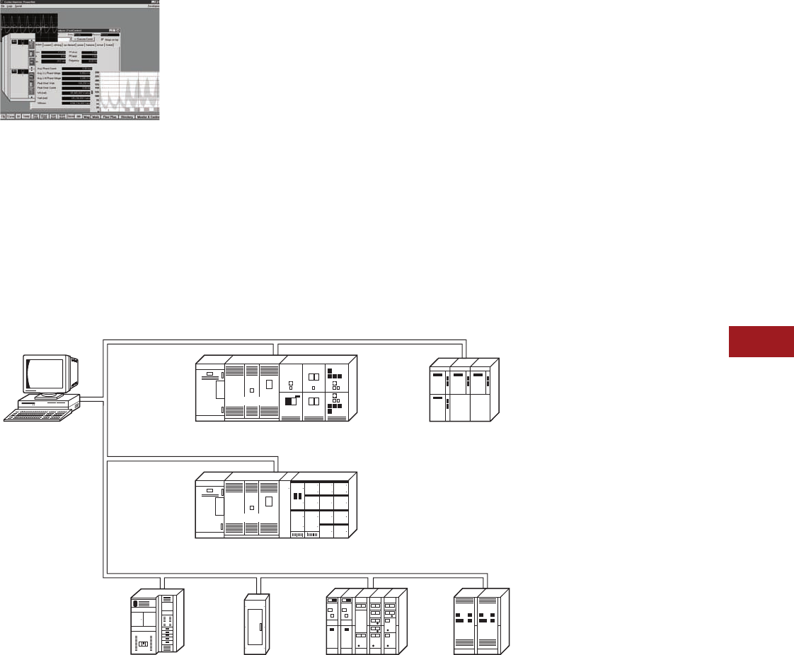
Volume 12—Aftermarket, Renewal Parts and Life Extension Solutions CA08100014E—November 2013 www.eaton.com V12-T11-3
1
2
3
4
5
6
7
8
9
10
11
12
13
14
15
16
17
18
19
20
21
22
23
24
25
11
Communication Systems
Product Description
Eaton’s Electrical
Services & Systems
PowerNet Software
Supplementing the hardware
and software, Eaton’s
Electrical Services & Systems
can provide local startup
and integration services to
customize the PowerNet
system to your specific
business needs. Basic
field startup, integration of
PowerNet into other plant
systems, and remote
monitoring of the plant with
industry experts in energy and
power quality are all services
provided by our local field
representatives. These
services will ensure that you
get maximum return on all of
your system investments.
Note: PowerNet systems do
not consist of exclusively Cutler-
Hammer® (Eaton) products.
Hundreds of drivers exist to
communicate with many third-
party meters, protective relays
and PLCs.
Flexible Network
Architecture
A PowerNet network
can be built in a variety of
configurations. Systems can
be built using existing Ethernet
networks
as the backbone,
as well as on a dedicated
twisted shielded pair running
throughout a facility.
Telephone, radio and fiber
modems can be used to
create networks where it
is cost prohibitive to run
dedicated cables. The most
flexible, highest performance
network architecture includes
a dedicated twisted shielded
pair network within the
switchboard or equipment
room connecting into a high
speed Ethernet backbone.
For a layout of a typical facility
network, refer to the 15th
Edition of the Consulting
Application Guide.
Ethernet Backbone
TCP/IP Ethernet networks
have become the worldwide
standard for moving
information. Industry has
recognized Ethernet as a high
speed, flexible, low-cost
network that is not vendor
dependent. The PowerNet
network uses a standard
TCP/IP Ethernet as the high
speed backbone for carrying
information to clients across
the plant or across the world.
Dedicated Twisted
Shielded Pair
Customers who desire to run
a dedicated network for the
power monitoring network
have a choice between a
dedicated Ethernet network
or running a twisted shielded
pair. A network of 1000
devices running up to
10,000 feet can be
networked through one
twisted shielded pair of wire.
Eaton PowerNet System
Medium Voltage
Unit Substation
Load Interrupter
Switchgear
Transformer
Adjustable
Frequency
Control
Low Voltage
Secondary Unit
Substation
Load Interrupter
Switchgear
Motor
Control
Center
Medium Voltage
Starter
Transformer
Low Voltage
Switchboard
Lighting
Control
Panelboard
■ Power quality
■ Metering data
■ Energy information
■ Switch/breaker starter status/control
■ Time stamped events
■ Breaker operations
■ Motor runtime
■ Motor winding/bearing temperature
■ Trip curve monitoring/configuration
■ Transformer data
■ Power quality
■ Metering data
■ Energy information
■ Starter/breaker status/control
■ Time stamped events
■ Breaker operations
■ Motor operations runtime
■ Trip curve monitoring/configuration
■ Drive status
■ Drive metering data
■ Drive speed adjustment/control
■ Power quality
■ Metering data
■ Energy information
■ Starter/breaker status/control
■ Time stamped events
■ Breaker operations
■ Trip curve monitoring/configuration
Personal Computer
with Eaton
PowerNet Software
V12-T11-4 Volume 12—Aftermarket, Renewal Parts and Life Extension Solutions CA08100014E—November 2013 www.eaton.com
1
2
3
4
5
6
7
8
9
10
11
12
13
14
15
16
17
18
19
20
21
22
23
24
25
11
Communication Systems
Product Description
Power Xpert Software
General Description
Power Xpert Software
aggregates the information
arriving from different types
of device families via various
communication methods. Its
unique Web-based design,
alarm bubble-up and
advanced trend and
waveform analysis tools
help you to quickly turn
your attention to the most
important events and to
identify reliability issues
and cost-saving opportunities.
The standard custom
graphic package, the
Layout Manager, with an
icon library and standard
vertical templates, allows
you to import and mimic
your physical environment
and gauges. Open protocol
support makes Power Xpert
Software compatible with
most newer generation
third-party equipment. Older
legacy, proprietary protocols
are supported by Power
Xpert Gateways (see
Page V12-T11-13), and
custom software drop-in
drivers made available by
Eaton. Power Xpert Software
is the first power system
software of this caliber
to put all these powerful
features at your fingertips.
Product Selection Guide
Power Xpert Software
Professional Edition
●Geared toward end users,
with built-in support for
Eaton power distribution
products such as
switchgear, UPSs,
breakers, PDUs, RPPs,
meters, relays, VFDs and
MCCs, among others
●Eaton products connect
with the software directly
via an Ethernet connection,
while legacy devices use
a Power Xpert Gateway
to Web-enable their
communications
●A subset of third-party
meters and devices are
supported as standard via
the gateway connection
Power Xpert Software
Enterprise Edition
●Geared toward advanced
power users, system
integrators and enterprises
with heterogeneous
device spectrum and
system developers who
can take advantage of
the included SNMP and
Modbus integration
development utilities
●Extensive support for
third-party devices via
standard SNMP and
Modbus TCP protocols
●Large variety of ready
made, optional third-party
drop in drivers available
Key Features
●Connects to your existing
network
●Data trending and graphing
for detailed information
for troubleshooting,
problem prevention
and costs savings
●Web-based views that
allow access to critical
information from any
location via a Web browser
●A modular, scalable
architecture that allows the
addition of capabilities and
devices as the power
system expands
●Alarm conditions bubble
up through the system to
allow personnel to identify
which device is in alarm
and where it is located
●All the functionality of
Eaton’s PowerNet
software suite
●Connectivity to a wide
range of Eaton and third-
party devices. For a full
list of compatible devices,
refer to the hardware
compatibility list found
at www.eaton.com/pxs
Power Xpert Software Layout Manager
The Power Xpert Software
Layout Manager module
provides the user a library
of powerful design tools and
standard templates for the
creation of custom Human–
Machine Interface (HMI)
graphical layouts. Objects can
be easily animated, various
gauges can be selected,
and custom bitmaps can be
imported with little effort.
Power Xpert Software Edition Features
Note: For a full list of supported devices, see the Hardware Compatibility
List at www.eaton.com/pxs.
For detailed information regarding Power Xpert Software
modules, system requirements, supported devices and more,
please see www.eaton.com/pxs or the Consulting Application
Guide, CA08104001E, Tab 2.
Feature Sets
Power Xpert
Software
Professional
Edition
Power Xpert
Software
Enterprise
Edition
Server module ■■
Trend viewer module ■■
Layout manager module ■■
Quality manager module ■■
Eaton device support (switchgear, UPSs, breakers,
ePDUs, meters, relays, VDFs, MCCs, etc.)
■■
Power Xpert Gateway third-party device support ■■
SNMP connector ■
Modbus connector ■
Optional third-party driver support ■
Custom third-party device driver support ■

Volume 12—Aftermarket, Renewal Parts and Life Extension Solutions CA08100014E—November 2013 www.eaton.com V12-T11-5
1
2
3
4
5
6
7
8
9
10
11
12
13
14
15
16
17
18
19
20
21
22
23
24
25
11
Communication Systems
Product Description
Power Xpert Software General Features
Features
General
Web browser user interface
Web-based monitoring capabilities
Downloadable software version updates
Event Notification
Event notification via e-mail notification
Event notification via pagers, text message or third-party interfaces
Alarm state management
Event indicator displayed without Web page active
Alarm/event searching and filtering
Waveform attached to applicable power event
Web browser based waveform viewing
Alarm capabilities based on device driven events
Analysis and Trending
Graphic trend viewer
Chart or data option selection
Multiple trends display
Multiple axis support
View multiple variables (i.e., Ia, Ib, Ic, Vab, Vbc, etc.) for a single waveform
Standard COMTRADE file format support
Customizable trend viewer look and feel
Fixed or custom time frames
Trend analysis capabilities
Data export
Custom Graphics and Layouts
Custom graphics development via Web browser
Four user view example templates included as standard
iFrame capability
Browser portal widget support
Streaming media support
Graphic object library included as standard
ISO standard electrical picture objects available
Graphic files import capability
Graphic object animation capability
Gauge object library support
External Web Links support
Alarm bubble-up support through several page layers
Features
UPS Shutdown
File saving during shutdown
Automatic, orderly and sequential shutdown
Parallel redundant UPS shutdown capability
Security and Administration
Windows authentication security
Two tier secure system access support
SSL
Secure Web browser access (support for HTTPS)
Trend object support
Time Synchronization
Time synchronization support for connected devices with 1 millisecond time resolution
Export and Integration
Extended Excel® spreadsheet support
SQL database query support
Logs
System log
Error log
Service
Eaton help desk services (1-877-ETN-CARE)
Turnkey startup service
System Backup
Power Xpert Software system backup
Documentation and Training Videos
System Administrator’s Guide
Power Xpert Software User’s Guide
Layout Manager Guide
Quick Start Guide
Power Xpert Software introduction and training video
Power Xpert Reporting introduction and training video
V12-T11-6 Volume 12—Aftermarket, Renewal Parts and Life Extension Solutions CA08100014E—November 2013 www.eaton.com
1
2
3
4
5
6
7
8
9
10
11
12
13
14
15
16
17
18
19
20
21
22
23
24
25
11
Communication Systems
Product Description
Power Xpert Reporting
Power Xpert Reporting
Architectural Overview
Power Xpert Reporting
brings the power system
information together to
compare and contrast.
Power Xpert Reporting
provides a standard set
of reports, including:
●Data Center Efficiency
Report: A summary of
data center infrastructure
efficiency and power usage
effectiveness, including
such information as
temperature and humidity,
and energy consumption
Data Center Efficiency Report
●Greenhouse Gas Report:
Captures the six offensive
greenhouse gasses:
carbon dioxide, sulfur
dioxide, nitrogen oxide,
mercury, methane and
nitrous oxide broken
down by selected locations
within a facility
Greenhouse Gas Report
●Utilities Report: Captures
consumption of water, air,
gas, electricity and steam
(WAGES)
Utilities Report
●Capacity Summary
Report: The summary of
top- and bottom-loaded
circuits, as well as loading
details for each circuit
according to user-defined
date/time range and facility
hierarchy location
Capacity Summary Report
●Branch Circuit Monitoring
Report: Determine branch
circuit loading levels at a
glance with color-coded
graphics indicating loading
status against capacity.
Redundant sources can be
reviewed, as well as single
source loads
Branch Circuit Monitoring Report
Foreseer
Software
(one or more
instances)
Power Xpert Reporting
Third-Party Devices, Non-Power Xpert Devices
Power Xpert
Software
(one or more
instances)
Device
Aggregators
(PowerNet,
Gateways)
Power Xpert
Devices
(Meters,
Gateways,
Other)
4CR Data
Acquisition
Engine
Volume 12—Aftermarket, Renewal Parts and Life Extension Solutions CA08100014E—November 2013 www.eaton.com V12-T11-7
1
2
3
4
5
6
7
8
9
10
11
12
13
14
15
16
17
18
19
20
21
22
23
24
25
11
Communication Systems
Product Description
●Energy Summary
Report: The summary of
consumption (kWh) and
demand (kW) for a user-
defined date/time range and
facility hierarchy location
Energy Summary Report
●Energy Cost Allocation
Report: The total energy
bill dollar value or a cost
per kWh across a facility
hierarchy for a user-defined
date/time range
Energy Cost Allocation Report
●Power Quality Report:
The distribution and trend
for amps, volts and THD
according to user-defined
date/time ranges and
facility hierarchy location
Power Quality Report
●Event Summary Report:
Provides a Pareto chart of
events according to user-
defined date/time ranges
and facility hierarchy
location
Event Summary Report
●Joint Commission
Report: Standard Joint
Commission Compliant
Report supports hospital
power test requirements.
It checks events, key
metrics of generators and
automatic transfer switches
(ATS) during generator
testing at user-defined
date/time ranges and
facility hierarchy location
Joint Commission Report
Service Offerings
Available Power Xpert Startup
Service Packs
At Eaton, we want to make
it as easy and non-disruptive
as possible to implement
our Power Xpert products.
Eaton offers several startup
service packs from partial
help to full turnkey solution
implementation.
All services are performed
by authorized Eaton’s
Electrical Services &
Systems group personnel.
Startup Service Packs Include
the Following Services
●Startup Scope
Determination: Eaton
services will help you
to evaluate your service
needs and check that the
service pack you have
selected has appropriate
coverage for your
circumstances
●Pre-Installation Checkup:
Eaton services will contact
you to go through the pre-
installation checklist, which
ensures efficient, prime
quality installation and
configuration services
●Installation and
Configuration: Eaton
services will install Power
Xpert Software and
configure it for operation
with your equipment
according to startup
scope determination.
Configuration may also
include creating custom
graphic layouts if necessary
and if required
●System Test: Eaton
services will test the
Power Xpert Software
for operability and will
validate communications
with key components
●Optional Hands-On
Training: If required,
Eaton services can provide
hands-on training for Power
Xpert Software, using the
software on-site or using
simulated demo systems
Selecting the Appropriate Service Pack 1
Notes
1Available and valid in continental United States only.
2Typical number of Eaton devices that can be configured in the Power Xpert Software during
the course of the selected Startup Service Pack.
3We strongly recommend a review of the latest Hardware Capability List at www.eaton.com/pxs.
4Please call the Technical Resource Center for custom Startup Service at 800-809-2772,
option 4, 1, for a price quote.
The number of devices that can be configured during the course of a selected Start Pack can vary
depending on the devices’ installation readiness levels. Maximum numbers indicated require full
configuration readiness levels defined in the Power Xpert Startup Services Checklist document
in the service’s brochure at www.eaton.com/pxs.
Startup Service Product
Number of Eaton Devices to be Integrated
<15 215–30 231–75 2>75 2
Non-Eaton
Devices 3
Power Xpert 1 Day ■
Power Xpert 2 Day ■
Power Xpert 5 Day ■
Customer Fixed Price Quote 4■ ■

V12-T11-8 Volume 12—Aftermarket, Renewal Parts and Life Extension Solutions CA08100014E—November 2013 www.eaton.com
1
2
3
4
5
6
7
8
9
10
11
12
13
14
15
16
17
18
19
20
21
22
23
24
25
11
Communication Systems
Technology Upgrades
Technology Upgrades
The INCOM network consists
of a twisted shielded pair
of conductors that interface
to one of the following
hardware devices:
●Master INCOM Network
Translator II (MINT II)
attached to the COM
port of computer
●Power Xpert Gateway
(PXG 200E, PXG 400E,
PXG 600E, PXG 800E)
When updating the software
at an existing installation,
careful consideration should
be administered and all new
PowerNet interface hardware
options considered when
constructing the update bill
of material.
In some instances, the
computer running the
Series III software is an
industrial computer that
has no monitor, keyboard
or mouse, and is installed
as a part of a larger system
solution. This device is
referred to as the Power
Xpert Gateway, catalog
numbers PXG 200E,
PXG 400E, PXG 600E
and PXG 800E. In these
situations, there is, typically,
a main system computer
that uses additional software
solutions to integrate the
system. The Power Xpert
Gateway is used as a way
of using the infrastructure of
the currently installed Local
Area Network (LAN) as a
means of collecting data
from remote substations.
This is not the only item that
will
require updating if existing
in the system.
Series III system solutions, in
some cases, incorporated a lot
of non-standard equipment
to meet various connectivity
needs. In some instances,
where multiple COM ports
are required, port splitters
were used to expand one
COM port into 8, or even
16, equivalent COM ports
for communications with
remote or local MINT II
devices (DIGIBOARD). These
various system configuration
requirements will have to be
ascertained and accounted
for before updating.
Update Path
Note: When updating the
computer for the new system
software, ISA slots may not be
available. In these instances,
PXG-E products are typically
employed.
●MINT II devices are
compatible with PowerNet
and will not require
updating
●NetLink products should
be replaced with PXG 600E
or PXG 800E hardware
●mMINT
For those unique applications
that may have Ethernet
and Modbus® on the same
gateway node. For Ethernet,
use the correct PXG-E model,
and for Modbus serial, use
the mMINT.
In all other instances where
custom third-party equipment
was used to achieve
connectivity solutions, third-
party vendors should be
consulted for appropriate
update paths and careful
consideration of compatibility
with the new PowerNet
software to ensure a smooth
update path.
Inventory Existing
Series III Software
Series III software consists
of the main Series III package
that includes the engine
communicating to the
devices through the MINT II
hardware. Series III came in
various packages supporting
20, 200 and/or 1000 devices.
The Series III software
included most functionality in
a single operator interface. It
included, but was not limited
to, the following features:
●Monitoring of all real-time
parameters from the
configured devices
●Access to change or to
view the set points of
those devices that
support this functionality
●Logging of selected
parameters to ASCII
Comma Separated Variable
(CSV) files
●Device Alarming
notification and
confirmation viewable
via user interface and
historically captured in
ASCII CSV files
●Built-in Dynamic Data
Exchange (DDE) server
capabilities
In addition to the basic
Series III software package,
add-on applications were
available that expanded
the basic functionality of
the monitoring software
including, but not limited
to, the following features:
●Energy billing and cost
allocation
●Waveform display
●Trip curve display
●Modbus Gateway
capabilities
Master PC Requirements
When planning to update
a Series III system,
replacement of the personal
computer will be required.
Due to the operating
system as well as memory
requirements, the Series III
computer will not meet
the requirements for a
PowerNet computer.
Update Path
The PC requirements may
change with later versions
of the PowerNet software
applications. Please refer
to the Eaton website for
updated information
on PC requirements:
www.eaton.com.

Volume 12—Aftermarket, Renewal Parts and Life Extension Solutions CA08100014E—November 2013 www.eaton.com V12-T11-9
1
2
3
4
5
6
7
8
9
10
11
12
13
14
15
16
17
18
19
20
21
22
23
24
25
11
Communication Systems
Technology Upgrades
Series III and Old NetPower Codes with PowerNet Product Codes
Identify Graphics
Interface Used
The IMPACC Series III
software was sold with an
option for an Enhanced
Graphics application, a
Wonderware InTouch
software HMI solution.
The screens were
typically
developed by
Eaton as a
turnkey solution, but this
software could be purchased
separately with development
performed by the customer,
or by independent local
integrators.
The graphics application
could be located on the
local Series III computer
or on remote networked
computers. It is important
to identify all computers in
the system that have the
Enhanced Graphics
application installed.
Update Path
PowerNet is compatible
with Wonderware InTouch
version 7.1 and above. All
HMI software locations will
require updating to the latest
version via the following
catalog numbers:
Note: When updating the
graphics application to interface
with the PowerNet DDE Server,
due to DDE Tag changes, a review
of the Tags displayed and used for
control will be required for proper
modification. Development time
must be allocated for this update.
For those computers
networked and running
Wonderware InTouch
runtime or view-only nodes,
PowerNet DDE can be
removed and local DDE
Server client applications
installed for more reliable
and quality local DDE
communications.
Identify Connectivity
Solutions Employed
Communication system
solutions will, in some cases,
implement software and/or
hardware equipment to share
the information gathered
from installed meters, relays
and I/O devices with other
software and/or systems
including Distributed Control
Systems (DCS), Building
Management Systems
(BMS) or Programmable
Logic Controllers (PLC).
Connectivity with the Series III
system solutions included the
following methods:
Dynamic Data
Exchange (DDE)
Used in conjunction with
Human Machine Interface
(HMI) software applications
such as Wonderware and
Intellusion. These applications
could also be installed on
remote computers when
PowerNet DDE is used
to share information over
a network.
When reviewing an
installation, this fact may
not be readily discernible
and some investigation may
be necessary.
Update Path
When updating the Series III
software in the section
above, DDE comes as a
part of the update path.
Note: For remote nodes running
Wonderware or any other
HMI software application, the
following catalog number can
be purchased and installed on
the remote PC, eliminating the
need for implementation of the
Microsoft® NETDDE solution.
NPDDE PowerNet DDE Server
client application software.
Locate this software on the same
computer as the HMI software.
Description
New PowerNet
v. 3.3x Product Codes
IMPACC Series III Product Codes PowerNet v.3.22 and Older Product Codes
Core Add-on Mods Energy Billing Core Add-on Mods Energy Billing
S3020
S30200
S31000
WDISP3
MODGATE3
TRIPDPS3
ELOG3
EBILL20
EBILL200
EBILLUL
ETREND
ETRACK
NPCORE2
NPCORE20
NPCORE100
NPCORE200
NPCORE1000
NPMONITOR
NPEVENT
NPWAVEFORM
NPSETPOINT
NPETREND
NPOPC
NPDDE
NPMODBUS
NPCOREMOD
NPBILL20
NPBILL200
NPBILL1000
NPBILLTRACK
NPBILLDDE
Connectivity Bundles Device Support
5-device PNCONNECT5 ■
10-device PNCONNECT10
32-device PNCONNECT34 ■ ■
100-device PNCONNECT100 ■
200-device PNCONNECT200 ■ ■
500-device PNCONNECT500
1000-device PNCONNECT1000 ■ ■
PowerNet Bundles
Standard client PNSTD ■ ■ ■ ■
Power quality PNPQ ■ ■ ■ ■
Integrator Package
Includes OPC,
DDE, and Modbus
Gateway
PNINTEGRATOR ■■■■■

V12-T11-10 Volume 12—Aftermarket, Renewal Parts and Life Extension Solutions CA08100014E—November 2013 www.eaton.com
1
2
3
4
5
6
7
8
9
10
11
12
13
14
15
16
17
18
19
20
21
22
23
24
25
11
Communication Systems
Technology Upgrades
Modbus (Series III Computer
as Modbus Gateway)
Used in conjunction with
Building Management
Systems, Distributed Control
Systems, or even PLCs
where the Modbus master
equipment is connected to
the communication serial port
of the Series III computer.
The Modbus add-on to
Series III enables the COM
port of the computer to be
configured as a Modbus
slave, providing the customer
the ability to configure input
and holding registers.
Update Path
NPMODBUS: Client
application that turns the
COM port of the computer
into a Modbus server
application. Client can be
located on any computer with
appropriate operating system
and on the same network as
the rest of the PowerNet
system software.
NPCOREMOD: Turns the
COM port of the computer
running the PowerNet
software core into a Modbus
server. This can only be
located where the Core
software application is located.
Modbus (Industrial PC
as Modbus Gateway)
Used in conjunction with
Building Management
Systems, Distributed Control
Systems or even PLCs where
the Modbus master
equipment is connected to
the communication serial port
of the Series III computer.
Available for sale was an
industrial computer (no
monitor, keyboard or mouse)
with a Modbus server
software application installed.
The functionality of the
software installed on the
industrial PC focuses
on Modbus register
configuration and availability.
Other monitor, DDE and
trending features common to
Series III are not available.
Update Path
Power Xpert Gateway
RS-232 (MINT II with Custom
Driver in Master System)
Used in conjunction with
Building Management
Systems, Distributed Control
Systems or even PLCs. In
this case, the customer has
written or contracted to have
written a custom driver that
communicates directly to the
installed INCOM devices via
the MINT II RS-232 interface.
Update Path
Series III software is not a
part of this configuration.
There is no update path;
the MINT II is still a viable
solution. For those
applications that connect
with the Johnson Controls®
Metasys® System via the
MINT II and Metasys
Integrator, the JMI should
be used.
RS-232 (Series III PC COM
Port Gateway, Custom Driver
in Master System)
Used in conjunction with
Building Management
Systems, Distributed Control
Systems or even PLCs. Most
common applications include
BMS software such as
Johnson Controls Metasys
System integration. Where
customers implemented this
solution, the need for the
functionality of the Series III
is apparent but the sharing
of data is required. When
updating to PowerNet,
customers must pay close
attention to this need.
Update Path
Series III had the ability to
configure the COM port of
the computer into a gateway,
which made the COM port
look like a MINT II to the
master communicating
software application. This
functionality is not included in
the PowerNet software suite
of applications. Connectivity is
left to DDE, OPC or Modbus
communications. Before
updating, the master software
suite vendor should be
consulted as to which of the
above protocols is supported
and the appropriate steps for
integration taken.
Volume 12—Aftermarket, Renewal Parts and Life Extension Solutions CA08100014E—November 2013 www.eaton.com V12-T11-11
1
2
3
4
5
6
7
8
9
10
11
12
13
14
15
16
17
18
19
20
21
22
23
24
25
11
Communication Systems
Technology Upgrades
PowerNet Device Selection Chart
Communicating Device
Function Selection Chart
Metering Devices LV Breaker Trip Units Protective Relays Miscellaneous Devices
IQ Analyzer
IQ DP-4000/
IQ DP-4100
IQ 200/IQ 300
Power Sentinel
Energy Sentinel
Digitrip 1150
Digitrip RMS 910
Digitrip RMS 810
Digitrip OPTIM 1050
Digitrip OPTIM 750
Network Protector
Relays
FP-5000
Digitrip 3000
MP-3000
IQ 500
RTD Module
Advantage
IQ Transfer Switch
Addressable Relay II
Power Manager
Quad XYZ
Voltage (phase-phase) ■■■■ ■■■■■ ■
Voltage (phase-neutral) ■■■■ ■■■■■ ■
Current phases ■■■■ ■■■■■■■■■■ ■
Current ground ■ ■ ■■■
Power
kW ■■■■■■■■■■■ ■
kWh ■■■■■■■■■ ■ ■
kVA ■■■■ ■ ■
kVAh ■■■ ■ ■
VARs ■■■■ ■■■
VARh ■■■ ■ ■
PF ■■■■ ■■■■■
Demand
kW demand ■■■■■■■■■ ■
kVA demand ■■■■■■
Ampere demand ■■■■■■ ■ ■
kVAR demand ■■■■■■ ■
Power Quality
THD 50 31 31 31 ■
Current THD ■■ ■ ■ ■
Voltage THD ■■ ■ ■
CBEMA/crest factor ■
Frequency ■■■■ ■ ■
Current waveform ■ ■ ■ ■
Voltage waveform ■ ■
Other Features
Downloadable set points ■■■■■■ ■■ ■■■ ■ ■
Operations count ■■■■■ ■ ■
High load ■■■■■ ■■
Trip target data ■■■■■ ■■■■ ■
Remote open/close ■■■■■■■■■ ■■■
Start profile ■
Auxiliaries ■■
Input/Output
Digital input 31 12 2 4
Digital output 4(3) 3 854 1
Analog input 111
Analog output 4 1
Communication Modules
IPONI ≥1.06 ■ ■ ■
INCOM communications std. ■■■■■■■■■■■■ ■■■
BIM ■■■■■■■
V12-T11-12 Volume 12—Aftermarket, Renewal Parts and Life Extension Solutions CA08100014E—November 2013 www.eaton.com
1
2
3
4
5
6
7
8
9
10
11
12
13
14
15
16
17
18
19
20
21
22
23
24
25
11
Communication Systems
Communication Hardware
Communications
Hardware
mMINT
mMINT Module
Product Description
The mMINT (Modbus Master
INCOM Network Translator)
Module is an Eaton accessory
product that will provide
communication between
a Modbus RTU network
and an INCOM (INdustrial
COMmunications) network
(see the mMINT in a
Communications Network
figure). This module is
transparent to the Modbus
network. It communicates
to a master on the Modbus
network using the Modbus
RTU (Remote Terminal Unit)
protocol. It communicates to
slave devices on the INCOM
network using the IMPACC
(Integrated Monitoring,
Protection, and Control
Communication) protocol.
The catalog number of this
product is mMINT.
Features
The mMINT module is a
slave device on the Modbus
network and as such requires
a master that will exchange
register objects with the
mMINT module.
●Handles generic pass-
through commands
(Modbus/INCOM/Modbus)
●Capable of passing
Modbus register objects
from Eaton’s existing
products
and newer PnP
(Plug-‘n-Play) products
to a
Modbus RTU master
●Data in IEEE® Floating
Point format and fixed
point
●Modbus RTU
communications data
transfer rates of 1200,
9600 or 19,200 baud with
one start bit, eight data
bits, no parity, and either
one or two stop bits
●Up to 32 products
connected to INCOM
network port (246 unique
addresses maximum)
●Flashing Status LED to
indicate an active module
●LED indicators for INCOM
transmit and receive
communications
exchanges
●LED indicators for Modbus
RS-485 transmit and
receive communications
exchanges
●Input power for the module
from either 120 Vac or
24–125 Vdc
●DIN rail mount package
●0° to 60°C ambient
operation
Module Mounting
When mounting the mMINT,
verify that an 11 mm H x 28 mm
W DIN rail is used and that it is
within an enclosed space.
Simplified Wiring Rules
INCOM Network
The following simplified
rules apply to a given system
consisting of a single daisy-
chained main cable link
between master and
slave devices (see figure
below). For more complex
considerations including
star configurations, please
refer to the IMPACC wiring
specification T.D. 17513.
mMINT in a
Communications Network
●Recommended INCOM
cable styles are Belden
9463 or C-H style
2A957805G01
●The maximum system
capacity is 10,000 feet of
communications cable and
32 slave devices on the
INCOM network under
the mMINT
●Non-terminated taps, up to
200 feet in length, off the
main link are permitted,
but add to the total cable
length
●Make sure that there
is twisted-pair wire that
is recommended for
IMPACC network use.
Use shielded twisted-pair
wire to connect each slave
to the INCOM network,
daisy-chain style. The
polarity of the twisted
pair is not important
Modbus RS-485 Network
The following simplified
rules apply to a given system
consisting of a cable link
between master and slave
devices (see figure below). For
more complex configurations,
please refer to standard
Modbus RTU wiring
specification rules for
the RS-485 network.
●The recommended
Modbus cable has twisted-
pair wires (24 AWG
stranded 7x32 conductors
with PVC insulation) having
an aluminum/mylar foil
shield with drain wire
●The maximum system
capacity is 4000 feet of
communications cable
and 247 devices on the
Modbus RTU network
●Make sure that there is
twisted-pair wire that is
recommended for Modbus
RTU network use. Use
shielded twisted-pair wire
to connect each slave to
the Modbus RTU network,
daisy-chain style. The
polarity of the twisted pair
is critically important
mMINT Module
Dimensions
Burden
●24 Vac/Vdc, 3 VA
Safety Standards
●UL®
●CSA®
●CE mark
Communications Speed
●INCOM: 1200, 9600 baud
●N2 bus: 9600 baud
Modbus RTU Serial Network
(Slave)
Modbus
mMINT
(Master)
Modbus
Master
INCOM Network
INCOM
Slaves
J1 J2
J3
4.25
(108.0)
RS-485
Modbus
3.54
(89.9)
24–125 Vdc
120 Vac
Shield INCOM
A B COM SHD
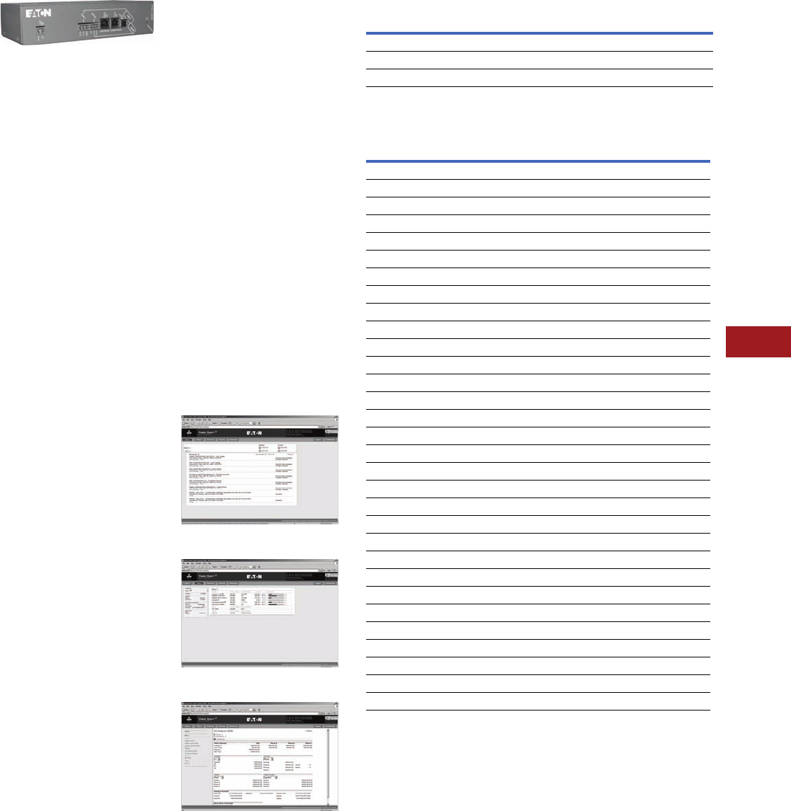
Volume 12—Aftermarket, Renewal Parts and Life Extension Solutions CA08100014E—November 2013 www.eaton.com V12-T11-13
1
2
3
4
5
6
7
8
9
10
11
12
13
14
15
16
17
18
19
20
21
22
23
24
25
11
Communication Systems
Communication Hardware
Power Xpert
Gateway 200E
Power Xpert Gateway 200E
Product Description
The Power Xpert Gateway
200E (PXG 200E) is designed
to provide a Web-enabled
gateway to serially
communicating energy
meters via a standard Web
browser. These can be new
or existing meters. The PXG
200E supports revenue grade
single and multipoint energy
meters via Modbus RTU and
INCOM. This product provides
a cost-effective, retrofit
hardware solution for better
energy management without
the need for software.
The PXG 200E allows you to:
●Monitor energy usage
patterns and reveal
opportunities for efficiency
improvements using
existing communicating
meters
●Remotely monitor real-time
conditions and profile
5-minute interval trend
logs, and export data in
csv, without a software
implementation
●Allocate energy costs to
departments or processes
●Reduce peak demand
surcharges
●Reduce power factor
penalties
●Identify billing
discrepancies
●Allows user to daisy-chain
multiple Ethernet
compatible downstream
devices via RJ-45 port
(for specifics, see
Page V12-T11-15, PXG-E
Daisy Chain Application)
●Connect to downstream
devices via a Web browser,
Modbus master or
SNMP client separately
or concurrently
Fixed list of supported
devices (no ability to add
new product support via
EDS upload); however,
new supported devices will
be added during firmware
updates.
●IQ 35M
●IQ Energy Sentinel
●IQ 130
●IQ 140
●IQ 150
●IQ 220/230
●IQ 220M/230M
●IQ 250
●IQ 260
●IQ MESII
●DIM KYZ (WAGES)
●EI NEXUS 1200 Series
●PM710
For detailed technical
specifications, please
reference the Technical
Data Sheet for this product
at www.eaton.com/pxg, then
the Power Xpert Gateway
200E link.
Power Xpert Gateway
Screenshots
Home Page
Bus Page
Device Page
Technical Data and Specifications
PXG 200E Part Numbers
Features
PXG 200E Features
Note
1Expected availability 2Q12.
Description
Style
Number
Catalog
Number
Power Xpert Gateway 200E 103008420-5591 PXG200E
Power supply—24 Vdc ELC-PS02 ELC-PS02
Mounting bracket kit 66B2146G01 PXGACC01
Features PXG 200E
Total number of supported devices 64
Maximum number of INCOM devices supported 64
Maximum number of Modbus devices supported 32
Protocols supported on downstream devices: (INCOM and Modbus RTU) Yes
Number of downstream communication ports 2
Number of downstream protocols supported simultaneously 2
USB port for configuration Yes
Two RJ-45 Ethernet ports—10/100Base-T Yes
Modbus TCP/IP protocols supported Yes
SNMP client access v.1 Yes
INCOM slave action commands supported Yes
INCOM date and time settings supported Yes
Modbus write commands supported from Modbus master Yes
Device summary screens per main, bus and device Yes
Event notification via the Web interface Yes
Secure Ethernet communications—SSL encryption Yes
Secure communication ports via access control/trusted host list Yes
IPv4 support Yes
Save and restore configuration file Yes
Interval logging—csv file format, downloadable to Excel Yes
Ability to upload additional or modified EDS files No
Device waveform access and storage—COMTRADE file format No
Set user-defined events No
Trend graph displayed Yes
Data logging—csv file format, downloadable to Excel No
Event logging—csv file format, downloadable to Excel No
E-mail notification on events and threshold alarms No
Custom summary Web page creation No
Ability to create custom events No
Supports SAM3Z energy meters No
BACnet/IP support 1Yes
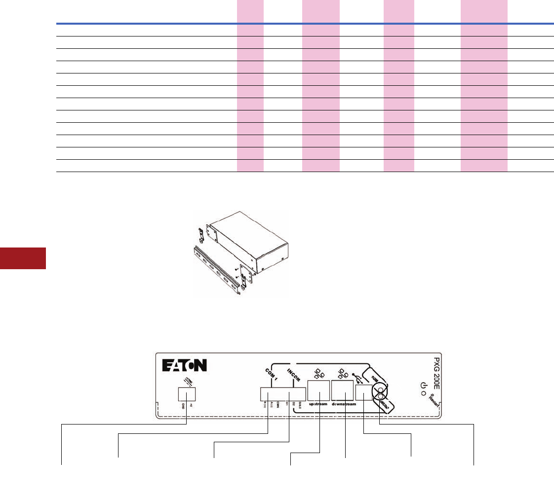
V12-T11-14 Volume 12—Aftermarket, Renewal Parts and Life Extension Solutions CA08100014E—November 2013 www.eaton.com
1
2
3
4
5
6
7
8
9
10
11
12
13
14
15
16
17
18
19
20
21
22
23
24
25
11
Communication Systems
Communication Hardware
Supported Devices
The Eaton Power Xpert
Gateway 200E Includes:
●The Power Xpert
Gateway module
●Mounting provisions and
required hardware for panel
and DIN rail mounting
●CD-ROM: contains the
user manual, Modbus
register maps, USB driver
and other associated files
Power Xpert Gateway
with DIN Rail Mounting
(Brackets Included)
Power Xpert Gateway—Dimensions in Inches (mm)
Power Xpert Gateway 200E
Supported Devices
HTTP
Web
Services MB TCP
INCOM
Pass-Thru SNMP
File
Export csv
Modbus
Pass-Thru BACnet/IPProtocol Device Type Device Name
INCOM I/O DIM KYZ (WAGES) ■■ ■■■■ ■
INCOM Meter IQ MESII ■■ ■■■■ ■
INCOM Meter IQ 220/230 ■■ ■■■■ ■
INCOM Meter IQ Energy Sentinel ■■ ■■■■ ■
Modbus Meter IQ 130 ■■ ■■■ ■■
Modbus Meter IQ 140 ■■ ■■■ ■■
Modbus Meter IQ 150 ■■ ■■■ ■■
Modbus Meter IQ 220M/230M ■■ ■■■ ■■
Modbus Meter IQ 250 ■■ ■■■ ■■
Modbus Meter IQ 260 ■■ ■■■ ■■
Modbus Meter EI NEXUS 1200 Series ■■ ■■■ ■■
Modbus Meter IQ 35M ■■ ■■■ ■■
24 Vdc
Input Power
COM 1 Port:
RS-485 Connection
for up to 32 Modbus
RTU Devices
INCOM Port:
RS-485 Connection
for up to 64 INCOM
Devices
RJ-45
Connection
to the LAN
USB Connection for
Local Configuration
Capability
Power and Traffic
Indicator Lights
RJ-45 Connection
to the Other
Ethernet Devices
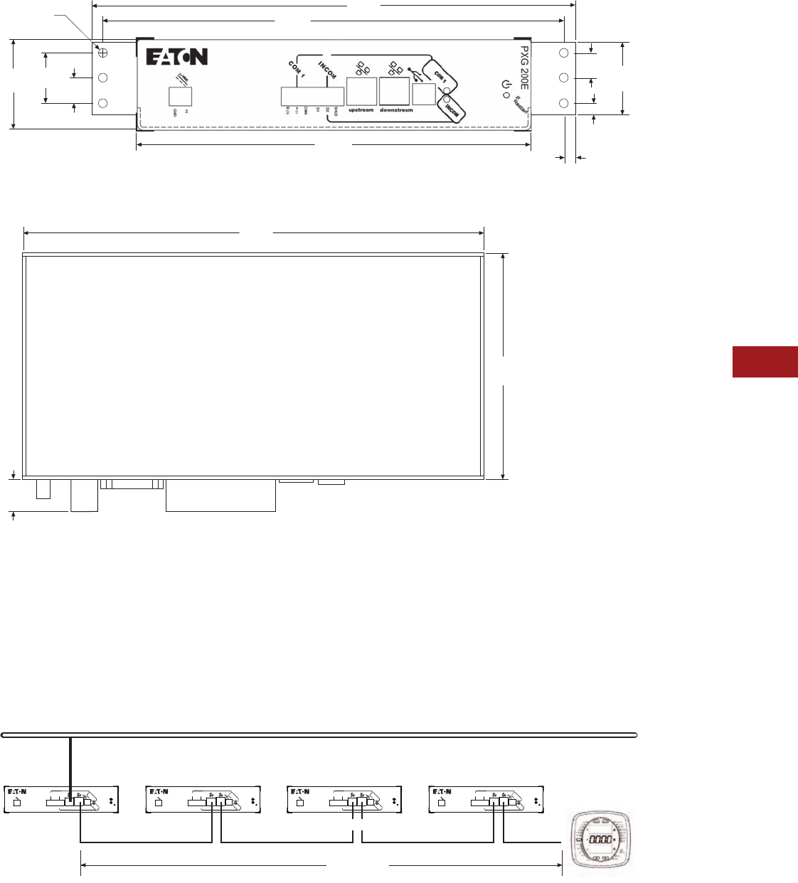
Volume 12—Aftermarket, Renewal Parts and Life Extension Solutions CA08100014E—November 2013 www.eaton.com V12-T11-15
1
2
3
4
5
6
7
8
9
10
11
12
13
14
15
16
17
18
19
20
21
22
23
24
25
11
Communication Systems
Communication Hardware
Power Xpert Gateway 200E with Standard Panel Mounting (Brackets Included)
Power Xpert Gateway 200E
PXG-E Daisy Chain Application
The PXG-E allows for units to
be connected together
through two RJ-45 10/100
connectors on the front of
the PXG-E series of products.
This arrangement is a
pass-through of Ethernet
communications allowing
a single network drop to
connect up to five Ethernet
communicating devices. The
maximum length of a copper
cable run should not exceed
295 ft (90m) total.
Note: In this configuration, if any
of the PXG-E units go offline or
lose power, the communication to
the downstream Ethernet devices
will lose connection to the LAN.
PXG-E Daisy Chain Application
0.56
(14.2)
1.12
(28.5)
2.00
(50.8)
Ø 0.19 (6)
(4.8)
0.56
(14.2) 1.60
(40.6)
0.25
(6.4)
0.24
(6.1)
Front
8.75
(222.3)
10.25
(260.4)
10.75
(273.1)
0.60
(15.2)
4.30
(109.2)
8.75
(222.3)
Ethernet LAN
LAN Connection
295 ft (90m)
Cat-5 Patch Cables
PXM2000
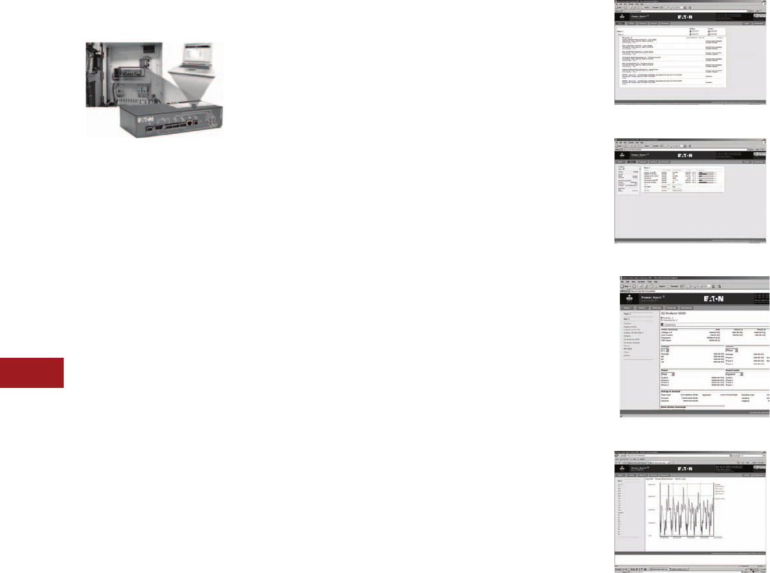
V12-T11-16 Volume 12—Aftermarket, Renewal Parts and Life Extension Solutions CA08100014E—November 2013 www.eaton.com
1
2
3
4
5
6
7
8
9
10
11
12
13
14
15
16
17
18
19
20
21
22
23
24
25
11
Communication Systems
Communication Hardware
Power Xpert Gateway
400E/600E/800E
Power Xpert Gateways 400E,
600E and 800E
Power Xpert Gateways 400E,
600E and 800E are typically
installed in an electrical
assembly—a motor control
center, low/medium voltage
switchgear or switchboard
to consolidate data available
from components such as
trip units, meters, motor
controllers and protective
relays. It can be installed
later to provide the same
valuable information.
Product Description
Power Xpert Gateways 400E,
600E and 800E (PXG 400E/
600E/800E) provide a cost-
effective method to easily
Web-enable Eaton and third-
party products.
The PXG 400E/600E/800E
series offers improved
performance over the
previously offered series,
including logging in the
PXG 600E/800E, daisy
chaining capabilities
(Page V12-T11-19,
Figure PXG-E Daisy Chain
Application) and design
enhancements including a
new processor and additional
RAM and Flash memory.
The gateway consists of an
embedded Web server that
allows the user to connect to
installed Eaton products such
as breakers, meters and relays
found in MCCs, LV and MV
switchgear and switchboards
—to name a few—that
communicate via Eaton
protocols INCOM and QCPort,
in addition to third-party
products that communicate
via Modbus RTU. The
Gateway provides the central
connection point for the
power metering/monitoring/
protective devices, allowing
their parameters to be
monitored via the Web.
The PXG 400E/600E/800E
provide data communications
to Eaton’s Power Xpert
Software and other third-
party systems to facilitate
centralizing and gathering
data for long-term data
archival, analysis and
trending features.
The PXG 400E/600E/800E
are compatible with and
facilitate integration with
many third-party building
and factory automation
systems via Modbus TCP
and Web services.
Note: Enclosed solution available.
Contact your Eaton sales office
for more details.
The PXG 600E/800E allow
you to enable pre-selected
parameters to be trended
for each supported device.
Selecting the trend symbol
will generate a real-time
graph for that parameter
and can be viewed for the
past 24 hours, seven days,
30 days or all past history.
The PXG 600E/800E
also offer direct e-mail
notifications to up to 10
users. Select from event
notifications, data logs,
interval log, event logs
and heartbeat e-mails.
The PXG 800E brings this
communication hardware-
only solution closer to those
requirements that have
previously only been met
by a software package. The
PXG 800E includes all the
functionality of the PXG 600E.
Additional features include:
●Creation of custom
summary Web pages
on the user interface
●Ability to create custom
events from existing
device parameters or
events
●Ability to communicate
wirelessly with the SAM3Z
submetering system
In the PXG 400E/600E/800E,
information is presented in
organized, user-friendly Web
pages and includes, but is not
limited to, the following:
●Device status
●Comm status
●Voltage
●Current
●Power
●Power factor
●Energy
●Power quality
●Temperature
●I/O states
Power Xpert Gateway
Screenshots
Downstream devices on the
Power Xpert Gateways often
report key operating status
information that warrants
immediate attention. The
PXG identifies a set of key
status values for each device
and generates “Events” in
response to changes in these
status values. An example of a
device event is an overcurrent
trip on a circuit breaker.
In addition to displaying
events on its home page,
the PXG reports events to
monitoring software such as
Power Xpert Software. These
events will then be integrated
with those from across the
power system, providing
unified enterprise level
event management.
Home Page
Bus Page
Device Page
Trending Page (PXG 600E/800E Only)
For detailed technical
specifications, please
reference the Technical Data
Sheet for this product series
at www.eaton.com/pxg, then
the Power Xpert Gateway
400E/600E/800E link.
Volume 12—Aftermarket, Renewal Parts and Life Extension Solutions CA08100014E—November 2013 www.eaton.com V12-T11-17
1
2
3
4
5
6
7
8
9
10
11
12
13
14
15
16
17
18
19
20
21
22
23
24
25
11
Communication Systems
Communication Hardware
Features of the PXG-E Product Offering
The Eaton Power Xpert
Gateway includes:
●The Power Xpert
Gateway module
●Mounting provisions
and required hardware
for panel and DIN rail
mounting
●CD-ROM: contains the
user manual, Modbus
register maps, USB driver
and other associated files
Power Xpert Gateway
with DIN Rail Mounting
(Brackets Included)
Note
1Expected availability 2Q12.
Features PXG 400E PXG 600E PXG 800E
Total number of supported devices 64 96 96
Maximum number of INCOM devices supported 64 64 64
Protocols supported on downstream devices: (INCOM, Modbus RTU and QCPort) Yes Yes Yes
Number of downstream communication ports 2 3 3
Number of downstream protocols supported simultaneously 2 3 3
USB port for configuration Yes Yes Yes
Two RJ-45 Ethernet ports—10/100Base-T Yes Yes Yes
Modbus TCP/IP protocols supported Yes Yes Yes
SNMP client access v.1 Yes Yes Yes
INCOM slave action commands supported Yes Yes Yes
INCOM date and time settings supported Yes Yes Yes
Modbus write commands supported from Modbus master Yes Yes Yes
Device summary screens per main, bus and device Yes Yes Yes
Event notification via the Web interface Yes Yes Yes
Secure Ethernet communications—SSL encryption Yes Yes Yes
Secure communication ports via access control/trusted host list Yes Yes Yes
IPv4 support Yes Yes Yes
Ability to upload additional or modified EDS files Yes Yes Yes
Save and restore configuration file Yes Yes Yes
Device waveform access and storage—COMTRADE file format No Yes Yes
Set user-defined events No Yes Yes
Trend graph displayed No Yes Yes
Data logging—csv file format, downloadable to Excel No Yes Yes
Interval logging—csv file format, downloadable to Excel No Yes Yes
Event logging—csv file format, downloadable to Excel No Yes Yes
E-mail notification on events and threshold alarms No Yes Yes
Custom summary Web page creation No No Yes
Ability to create custom events No No Yes
Supports SAM3Z energy meters No No Yes
BACnet/IP protocol supported 1———
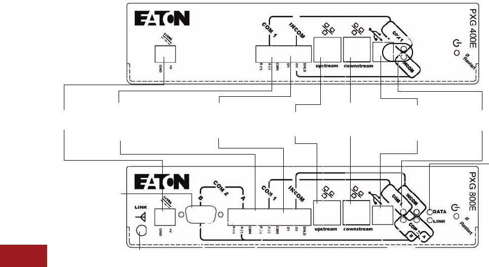
V12-T11-18 Volume 12—Aftermarket, Renewal Parts and Life Extension Solutions CA08100014E—November 2013 www.eaton.com
1
2
3
4
5
6
7
8
9
10
11
12
13
14
15
16
17
18
19
20
21
22
23
24
25
11
Communication Systems
Communication Hardware
Power Xpert Gateway 400E/600E/800E
24 Vdc
Input Power
COM 1 Port:
RS-485 Connection for
up to Either (32) QCPort
or Modbus RTU Devices
INCOM Port:
RS-485 Connection
for up to 64 INCOM
Devices
RJ-45
Connection
to the LAN
USB Connection
for Local
Configuration
Capability
Power and Traffic
Indicator Lights
Wireless antenna available only with
800E for communication to SAM3Z device
RJ-45
Connection
to the Other
Ethernet Devices
PXG 600E or 800E
Data and Link
Indicator Lights:
Available Only
with 800E
COM 2 Port: Either
RS-485
or RS-232
Connection
for up to Eith er (32)
QCPort or Modbus
RTU Devices
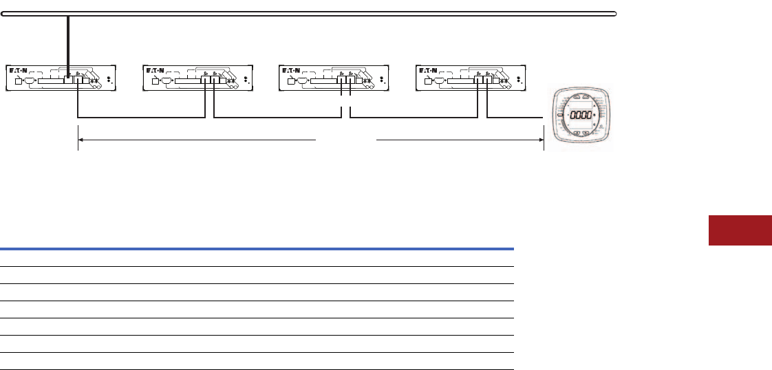
Volume 12—Aftermarket, Renewal Parts and Life Extension Solutions CA08100014E—November 2013 www.eaton.com V12-T11-19
1
2
3
4
5
6
7
8
9
10
11
12
13
14
15
16
17
18
19
20
21
22
23
24
25
11
Communication Systems
Communication Hardware
PXG-E Daisy Chain Application
The PXG-E allows for units
to be connected together
through two RJ-45 10/100
connectors on the front of the
PXG-E series of products. This
arrangement is a pass-through
of Ethernet communications
allowing a single network drop
to connect up to five Ethernet
communicating devices. The
maximum length of a copper
cable run should not exceed
295 ft (90m) total.
Note: In this configuration, if any
of the PXG-E units go offline or
lose power, the communication to
the downstream Ethernet devices
will lose connection to the LAN.
PXG-E Daisy Chain Application
Technical Data and Specifications
PXG Part Numbers
Description
Style
Number
Catalog
Number
Power Xpert Gateway 400E 103008421-5591 PXG400E
Power Xpert Gateway 600E 103008422-5591 PXG600E
Power Xpert Gateway 800E 103008423-5591 PXG800E
Wireless energy meter for PXG 800E P-103000007-591 SAM3Z
Wireless repeater module for SAM3Z P-103000008-591 EZR
Power supply—24 Vdc ELC-PS02 ELC-PS02
Mounting bracket kit 66B2146G01 PXGACC01
Ethernet LAN
LAN Connection
295 ft (90m)
Cat-5 Patch Cables
PXM2000
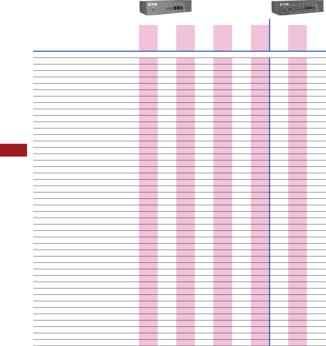
V12-T11-20 Volume 12—Aftermarket, Renewal Parts and Life Extension Solutions CA08100014E—November 2013 www.eaton.com
1
2
3
4
5
6
7
8
9
10
11
12
13
14
15
16
17
18
19
20
21
22
23
24
25
11
Communication Systems
Communication Hardware
Data Acquisition and Integration Table for Supported Devices
Notes
1Required IPONI for connection to the Power Xpert Gateway.
2Required a WPONI for connection to the Power Xpert Gateway.
Information subject to change without notice. Visit www.eaton.com/pxg for latest up-to-date
details on connectivity.
Supported Devices
Device Type Device Name
PXG 400E/600E/800E PXG 600E/800E Only
HTTP (Web
Browser)
Web Services
(Power Xpert
Software)
Modbus TCP
(BMS and
SCADA)
Pass-through
INCOM
(PowerNet)
Pass-through
QCPort
(CHStudio)
SNMP
(NMS)
BACnet/IP
SMTP
(E-mail
Client)
File Export
(Data File
Format)
File Export
(Waveform
File Export)
INCOM
Drive Accutrol 400 ■■■■ ■■■■
Drive AF97 ■■■■ ■■■■
I/O Universal RTD ■■■■ ■■■■
I/O DIM ■■■■ ■■■■
I/O DIM KYZ ■■■■ ■■■■
Meter IQ DP-4000 1■■■■ ■■■■
Meter IQ Energy Sentinel ■■■■ ■■■■
Meter IQ 220/IQ 320 ■■■■ ■■■■
Meter IQ 230/IQ 330 ■■■■ ■■■■
Meter IQ Analyzer (6000/6200) 1■■■■ ■■■■■
Meter IQ Analyzer (6400/6600) 1■■■■ ■■■■■
Meter IQ Data 1■■■■ ■■■■
Meter IQ Data Plus 1■■■■ ■■■■
Meter IQ Data Plus II 1■■■■ ■■■■
Meter Power Manager ■■■■ ■■■■
Meter IQ Power Sentinel ■■■■ ■■■■
Meter point IQ MES II ■■■■ ■■■■
Protective Digitrip 3000 ■■■■ ■■■■
Protective Digitrip 3200 ■■■■ ■■■■
Protective FP-6000 ■■■■ ■■■■■
Protective FP-5000 ■■■■ ■■■■■
Protective FP-4000 ■■■■ ■■■■■
Protective MP-3000 1■■■■ ■■■■
Protective MP-4000 1■■■■ ■■■■
Protective Digitrip 520MC ■■■■ ■■■■
Protective NRX520 ■■■■ ■■■■
Protective IQ 500 ■■■■ ■■■■
Protective MPCV Relay ■■■■ ■■■■
Protective Digitrip 1150/DT1150V ■■■■ ■■■■■
Protective Digitrip 810 ■■■■ ■■■■
Protective Digitrip 910 ■■■■ ■■■■
Protective Digitrip MV ■■■■ ■■■■
Protective Digitrip OPTIM 1050 ■■■■ ■■■■■
Protective Digitrip OPTIM 550 ■■■■ ■■■■
Protective Digitrip OPTIM 750 ■■■■ ■■■■
Starter Advantage 2■■■■ ■■■■
Starter Advantage ACM 2■■■■ ■■■■
Subnetwork master AEM II 1■■■■ ■ ■
Subnetwork master BIM II 1■■■■ ■ ■
Subnetwork master CMU 2■■■■ ■ ■
Subnetwork master IQ CED II 1■■■■ ■ ■
Subnetwork master IQ MES II ■■■■ ■■■■
Transfer switch ATC-400 1■■■■ ■■■■
Transfer switch ATC-600 1■■■■ ■■■■
Transfer Switch ATC-800 1■■■■ ■■■■
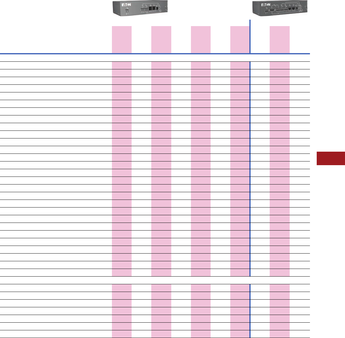
Volume 12—Aftermarket, Renewal Parts and Life Extension Solutions CA08100014E—November 2013 www.eaton.com V12-T11-21
1
2
3
4
5
6
7
8
9
10
11
12
13
14
15
16
17
18
19
20
21
22
23
24
25
11
Communication Systems
Technology Upgrades Communication Hardware
Data Acquisition and Integration Table for Supported Devices (continued)
Notes
1Requires a QSNAP for connection to the Power Xpert Gateway.
Information subject to change without notice. Visit www.eaton.com/pxg for latest up-to-date details on connectivity.
Additional supported devices will be available via firmware updates. Contact your local Eaton sales office for help with devices not currently listed in table above.
Supported Devices
Device Type Device Name
PXG 400E/600E/800E PXG 600E/800E Only
HTTP (Web
Browser)
Web Services
(Power Xpert
Software)
Modbus TCP
(BMS and
SCADA)
Pass-through
INCOM
(PowerNet)
Pass-through
QCPort
(CHStudio)
SNMP
(NMS)
BACnet/IP
SMTP
(E-mail
Client)
File Export
(Data File
Format)
File Export
(Waveform
File Export)
Modbus
Drive MVX9000 ■■■ ■ ■■■
Drive SVX9000 ■■■ ■ ■■■
Insulation monitor InsulGard ■■■ ■ ■■■
Meter IQ 130 ■■■ ■ ■■■
Meter IQ 140 ■■■ ■ ■■■
Meter IQ 150 ■■■ ■ ■■■
Meter IQ 220M/230M ■■■ ■ ■■■
Meter IQ 250 ■■■ ■ ■■■
Meter IQ 260 ■■■ ■ ■■■
Meter IQ 35M ■■■ ■ ■■■
Meter Nexus 1262 ■■■ ■ ■■■
Meter SQD CM3000 Series ■■■ ■ ■■■
Meter SQD CM4000 Series ■■■ ■ ■■■
Meter SQD PM710 ■■■ ■ ■■■
Meter SQD PM850 ■■■ ■ ■■■
Meter PML 7350 ■■■ ■ ■■■
Meter PML 7550 ■■■ ■ ■■■
Meter PML 7650 ■■■ ■ ■■■
Meter PM3 ■■■ ■ ■■■
Protective GE 369 Motor Relay ■■■ ■ ■■■
Protective GE 469 Motor Relay ■■■ ■ ■■■
Protective FP-4000/FP-5000 ■■■ ■ ■■■
Protective FP-6000 ■■■ ■ ■■■
Overload relay C441 ■■■ ■ ■■■
Temp monitor Qualitrol 118 ■■■ ■ ■■■
Temp monitor TC-50 ■■■ ■ ■■■
Temp monitor TC-100 ■■■ ■ ■■■
Transformer differential relay ABB TPU 2000 ■■■ ■ ■■■
QCPort
I/O D77A-AI16 ■■■■■■■■
I/O D77A-AI8 ■■■■■■■■
I/O D77A-DI16 ■■■■■■■■
I/O D77A-DI8 ■■■■■■■■
Starter IT. S811 (MV811) ■■■■■■■■
Starter IT. Starter 1■■■■■■■■
Starter IT. Starter QSNAP 1■■■■■■■■

V12-T11-22 Volume 12—Aftermarket, Renewal Parts and Life Extension Solutions CA08100014E—November 2013 www.eaton.com
1
2
3
4
5
6
7
8
9
10
11
12
13
14
15
16
17
18
19
20
21
22
23
24
25
11
Communication Systems
Technology Upgrades Communication Hardware
The table below represents many of the parameters displayed on the Web page for a given device; however, it is not exhaustive.
For the complete list of parameters display, per device, refer to the Device Data Map file at http://www.eaton.com/pxg.
Web UI Device Parameters Displayed via Power Xpert Gateway
Units
IQ Meters Circuit Breaker Trip Units Protective Relays
IQ Data Plus II
IQ Data Plus
IQ Data
IQ Analyzer 6000/6200
IQ Analyzer 6400/6600
IQ DP-4000
IQ 220/320
IQ 230/330
IQ 230/330M
IQ 250
IQ 260
IQ Power Sentinel
IQ Energy Sentinel
IQ MESII
IQ 130
IQ 140
IQ 150
IQ 35M
Power Manager
Digitrip 1150
Digitrip 520MC
Digitrip RMS 910
Digitrip RMS 810
Digitrip OPTIM 1050
Digitrip OPTIM 550
Digitrip OPTIM 750
Digitrip MV
Digitrip 3000
Digitrip 3200
IQ 500
MPVCV Relay
FP-4000
FP-5000
MP-3000
MP-4000
FP-6000
EDR-3000
Volt age
Average V ■ ■ ■ ■ ■ ■
Voltage (line-line) V ■■■■■■■■■■■■ ■■■■■ ■ ■ ■ ■ ■
Voltage (line-neutral) V ■■■■■■■■■■■■ ■■■■■■■■■ ■
Current
Average A ■ ■ ■ ■ ■■■
Phase A ■■■■■■■■■■■■ ■■■■ ■■■■■■■■■■■■■■■■ ■
Ground A ■ ■ ■ ■ ■■■■■■■■■■ ■■■■■
Neutral A ■■■■■■■■ ■ ■■■■■■■■■ ■ ■ ■
Peak A ■■■■■■■■■■■ ■ ■ ■■■■■ ■ ■ ■
Demand A ■■■■■■■■■■■ ■ ■ ■■ ■ ■ ■
Power
Apparent VA ■■■■■■■■ ■■■ ■ ■ ■ ■
Reactive VAR ■■ ■■■■■■■■■ ■■■ ■■■■ ■
Real W ■■ ■■■■■■■■■■■ ■■■■■ ■■■ ■■■ ■
Power Factor
Apparent PF ■■ ■■■■■■■■■ ■■■ ■ ■ ■ ■ ■
Displacement PF ■■■■■■■■■ ■ ■ ■ ■
Energy
Real Wh ■■ ■■■■■■■■■■■ ■■■■ ■■■ ■ ■ ■
Forward Wh ■■■■■■■■ ■ ■ ■ ■ ■ ■■ ■ ■
Reverse Wh ■■■■■■■■ ■ ■ ■ ■ ■■ ■ ■
Apparent Vah ■■■■■■■■■■ ■ ■ ■ ■
Reactive VARh ■■■■■■■■■■ ■ ■
Leading VARh ■■■■■■■■ ■ ■ ■ ■
Lagging VARh ■■■■■■■■ ■ ■ ■ ■
Power Quality
THD % ■■■ ■ ■ ■
Current THD % ■■■ ■ ■ ■ ■ ■
Voltage THD % ■■■ ■ ■ ■ ■
Frequency Hz ■■■■■■■■■■■■ ■■■ ■ ■
Waveform capture N/A ■■■ ■ ■ ■ ■
Temperature
Ambient C°
Auxiliary C° ■ ■
Load bearing C° ■ ■
Motor bearing C° ■ ■
Winding C° ■ ■
Phase (L, C, R) C°
Terminal block C°
Input Status
Number of inputs ■ ■ ■■■2 2 ■
Status/cause of trip ■■■■■■■■■■■■■■■■■
Thermal memory
Pole temperature
Winding temp.
Fan status
Alarm/trip relay ■
Volume 12—Aftermarket, Renewal Parts and Life Extension Solutions CA08100014E—November 2013 www.eaton.com V12-T11-23
1
2
3
4
5
6
7
8
9
10
11
12
13
14
15
16
17
18
19
20
21
22
23
24
25
11
Communication Systems
Communication Hardware
Web UI Device Parameters Displayed via Power Xpert Gateway (Continued)
Note: Information subject to change without notice. Visit www.eaton.com for latest information.
Units
Insulation
Monitor
Motor Starters
and VFDs
Transfer
Switches I/O Third-Party Devices
InsulGard
Accutrol 400
AF97
Advantage Starters
IT. S811
IT. Starters/QSNAP
C441 Overload Relay
SVX & MVX Drives
ATC-400
ACT-600
ACT-800
Digital Input Module
D77A-AI16
D77A-AI8
D77A-DI16
D77A-DI8
DIM KYZ
Universal RTD
SQD CM 3000 Series
SQD CM 4000 Series
SQD PM 710
SQD PM 850
PML 7350
PML 7550
PML 7650
GE 369 Motor Relay
GE 469 Motor Relay
ABB TPU 2000
Qualitrol 118
Nexus 1262/1272
PM3
TC-50
TC-100
Volta ge
Average V ■■■ ■■ ■■■■ ■ ■
Voltage (line-line) V ■ ■ ■■■■■■■■■■■■ ■ ■
Voltage (line-neutral) V ■■■■■■■ ■ ■ ■
Current
Average A ■■■■■ ■■■■■■■■ ■ ■
Phase A ■■■■■■■■■■■■■ ■ ■
Ground A ■■■ ■ ■
Neutral A ■■■■■■ ■
Peak A ■■■■■■■ ■
Demand A ■■■■■■■ ■ ■◗
Power
Apparent VA ■■■■■■■■■■ ■ ■
Reactive VAR ■■■■■■■■■■ ■ ■
Real W ■■■■■■■■■■ ■ ■
Power Factor
Apparent PF ■■■■■■■■■■ ■ ■
Displacement PF ■■■
Energy
Real Wh ■■■■■■■■■■■ ■ ■
Forward Wh ■■ ■■■■ ■ ■ ■
Reverse Wh ■■ ■■■■ ■ ■
Apparent Vah ■■■■■■■ ■
Reactive VARh ■■■■■ ■
Leading VARh ■■ ■■■■ ■ ■
Lagging VARh ■■ ■■■■ ■ ■
Power Quality
THD % ■
Current THD % ■
Voltage THD % ■ ■
Frequency Hz ■■ ■■■■■ ■ ■■■■■■■■■ ■
Waveform capture N/A
Temperature
Ambient C° ■ ■ ■ ■ ■
Auxiliary C° ■
Load bearing C° ■ ■ ■
Motor bearing C° ■ ■ ■
Winding C° ■ ■ ■
Phase (L, C, R) C° ■ ■ ■
Terminal block C° ■
Input Status
Number of inputs ■■ ■816 8 16 8 4 8 2
Status/cause of trip ■■■■ ■ ■
Thermal memory ■■■■
Pole temperature ■■ ■
Winding temp. ■ ■ ■ ■
Fan status ■ ■ ■ ■
Alarm/trip relay ■ ■ ■ ■
Partial discharge intensity (PDI) ■
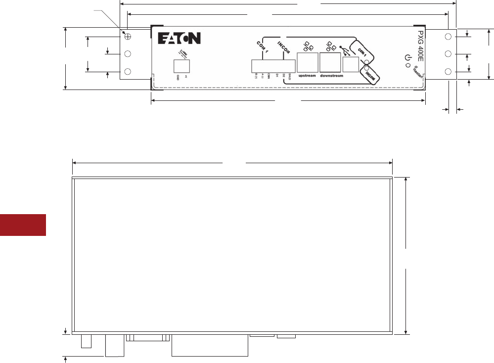
V12-T11-24 Volume 12—Aftermarket, Renewal Parts and Life Extension Solutions CA08100014E—November 2013 www.eaton.com
1
2
3
4
5
6
7
8
9
10
11
12
13
14
15
16
17
18
19
20
21
22
23
24
25
11
Communication Systems
Communication Hardware
Power Xpert Gateway—Dimensions in Inches (mm)
Power Xpert Gateway 400E/600E/800E with Standard Panel Mounting (Brackets Included)
Power Xpert Gateway 400E/600E/800E
0.56
(14.2)
1.12
(28.5)
2.00
(50.8)
Ø 0.19 (6)
(4.8)
0.56
(14.2) 1.60
(40.6)
0.25
(6.4)
0.24
(6.1)
Front
8.75
(222.3)
10.25
(260.4)
10.75
(273.1)
0.60
(15.2)
4.30
(109.2)
8.75
(222.3)
Volume 12—Aftermarket, Renewal Parts and Life Extension Solutions CA08100014E—November 2013 www.eaton.com V12-T11-25
1
2
3
4
5
6
7
8
9
10
11
12
13
14
15
16
17
18
19
20
21
22
23
24
25
11
Communication Systems
Communication Hardware
Product Operated
Network Interface
(PONI) Devices
PONI Family
The Product Operated
Network Interface (PONI)
cards attach to Cutler-
Hammer/Eaton devices to
enable communications.
These cards serve various
functions from Ethernet-type
applications, to non-Ethernet-
type applications, ultimately
playing a key role in facilitating
the access to information that
each of the Cutler-Hammer/
Eaton devices offer.
The IPONI enables
communications over a
twisted shielded pair INCOM
device network. Each PONI
attaches to its associated
product. The PONI modules
obtain power from the host
product. PONI modules can
be used as solutions for
various applications.
The non-Ethernet product
offerings include the IPONI
and the MPONI. These
devices are typically applied
where there are more than
one device connected in
a network of devices by
a dedicated twisted
shielded pair of conductors
(Ref. IMPCABLE).
The communications
medium is formatted to
enable clean noise-immune
communications even when
routed around areas of high
noise and typical electrical
communication disrupting
equipment. The IPONI and
MPONI daisy chain are in the
same format as that used
in devices that have built-in
communications such as the
Digitrip trip units and can be
used in series with these
communication network
wiring. To Ethernet enable
IPONI and MPONI products,
use the PXG-E series Power
Xpert Gateways.
The PXG-E with IPONI or
MPONI product offering puts
a Cutler-Hammer/Eaton
metering product on the Web.
No other software is required
when specifying a PXG-E. All
software needed to enable
any internet browser program
such as Microsoft Internet
Explorer or Mozilla Firefox is
packed into the PXG-E. The
data can then be viewed
directly in any Internet
Web browser window.
The WEBPONI provides live
updating data for the meter
being monitored, as well as
waveform display capabilities
and e-mail direct from the
device to defined key e-mail
addresses that need to know
when an event occurs.
IPONI/MPONI
With the addition of the
IPONI or the MPONI card,
a Cutler-Hammer/Eaton
device or series of devices
can communicate with the
PowerNet software via a
master unit such as a MINT II
and the PXG-E. The PONIs
can be easily mounted to
the appropriate Cutler-
Hammer/Eaton device
and daisy chain together to
form a robust deterministic
communication network
of devices in a system
solution. Systems employing
the IPONI/MPONI type
communications medium
provide deterministic
communication performance
relied on by those critical
solution applications,
where this is of the
utmost importance.
MINT II
Master INCOM Network Translator
(MINT) II
The MINT II interfaces the
IMPACC network to a master
control unit with an RS-232
port, such as a personal
computer serial port, a
programmable controller
RS-232 “smart card,”
building management system
interface card, etc. (Some
software will have to be
written in the master control
unit to request and receive
messages. The MINT II
protocol is 10-character,
ASCII coded hex.)
The MINT II can be used to
interface multiple IMPACC
devices to Broadband LANs,
telephone modem or short
haul modem. It can also be
used to allow additional
branches of the INCOM data
line (five additional branches
per MINT II). The MINT II
can be either table or panel
mounted and requires a
120 Vac, 60 Hz supply.
Selectable communication
rate of 1200 or 9600 baud is
available. The burden for the
MINT II is 7 VA.
Addressable Relay II (ARII)
Addressable Relay II
The Addressable Relay II
is designed for use where
information or control of
non-communicating devices
is required remotely. The
relays communicate on the
PowerNet system. Devices
are
assigned a three-digit
address to uniquely
identify
them on the daisy-chained
twisted shielded pair network.
The ARII has a Form C relay
on board with two status
indicating circuit inputs. The
output relay can be activated
and monitored remotely.
Input status 1 and 2 can
be monitored remotely.
V12-T11-26 Volume 12—Aftermarket, Renewal Parts and Life Extension Solutions CA08100014E—November 2013 www.eaton.com
1
2
3
4
5
6
7
8
9
10
11
12
13
14
15
16
17
18
19
20
21
22
23
24
25
11
Communication Systems
Communication Hardware
IMPCABLE
The IMPCABLE was
designed to be run in
switchgear where codes
require a 600V insulation
rating. Typical “blue hose”
cables are rated at 300V. The
IMPCABLE is an 18 AWG
cable with a 100 ohm
impedance at 100 kHz tuned
to work optimally with the
FSK signal from Cutler-
Hammer/Eaton devices.
The cable has been designed
with characteristics that
allow up to 1000 devices or
distances up to 10,000 feet
from the master.
IMPCABLE
Further Information
Pricing Information
Price and Availability Digest (PAD)
Vista/VISTALINE™ Discount Symbol C10-S25
Conductors
Tinned
Copper
Braid
PVC
Outer
Jacket
Polyethylene
Filler
Drain
Wire
Aluminum
Shield
Polyethylene
Insulator
Publication
Number Description
TD.17.15.T.E PowerNet
TD17B.01.T.E PowerPort
TD02603010E Power Xpert Gateway 200E
TB02603002E Power Xpert Gateway 400E/600E/800E
TB02603002E mMINT
TD.17.19.T.E MINT II RS-232 Converter
TD.17.20.T.E PONI Communication Modules
TB02603002E MPONI
TD.17.22.T.E Addressable Relay II
TD.17.24.T.E Breaker Interface Module (BIM)
TD.17.26.T.E Advantage Central Monitoring Unit (CMU)
TD.17.28.T.E IMPCABLE

Volume 12—Aftermarket, Renewal Parts and Life Extension Solutions CA08100014E—November 2013 www.eaton.com V12-T12-1
1
2
3
4
5
6
7
8
9
10
11
12
13
14
15
16
17
18
19
20
21
22
23
24
25
Programmable Logic Controllers
Programmable Logic Controllers
12 Programmable Logic Controllers
Product Description. . . . . . . . . . . . . . . . . . . . . . . . . . . . . . . . . . . . . . . V12-T12-2
D32LT . . . . . . . . . . . . . . . . . . . . . . . . . . . . . . . . . . . . . . . . . . . . . . . V12-T12-2
D320 . . . . . . . . . . . . . . . . . . . . . . . . . . . . . . . . . . . . . . . . . . . . . . . . V12-T12-2
Product History . . . . . . . . . . . . . . . . . . . . . . . . . . . . . . . . . . . . . . . . . . V12-T12-2
Product History Time Line. . . . . . . . . . . . . . . . . . . . . . . . . . . . . . . . . . V12-T12-3
Discontinued Products—Replacement Capabilities . . . . . . . . . . . . . . V12-T12-3
100/110 Series. . . . . . . . . . . . . . . . . . . . . . . . . . . . . . . . . . . . . . . . . V12-T12-3
300 Series. . . . . . . . . . . . . . . . . . . . . . . . . . . . . . . . . . . . . . . . . . . . V12-T12-3
400 Series. . . . . . . . . . . . . . . . . . . . . . . . . . . . . . . . . . . . . . . . . . . . V12-T12-4
D120 Series . . . . . . . . . . . . . . . . . . . . . . . . . . . . . . . . . . . . . . . . . . V12-T12-4
MPC1 Series. . . . . . . . . . . . . . . . . . . . . . . . . . . . . . . . . . . . . . . . . . V12-T12-4
D500 Series . . . . . . . . . . . . . . . . . . . . . . . . . . . . . . . . . . . . . . . . . . V12-T12-4
Product Support Services . . . . . . . . . . . . . . . . . . . . . . . . . . . . . . . . . . V12-T12-4
Further Information . . . . . . . . . . . . . . . . . . . . . . . . . . . . . . . . . . . . . . . V12-T12-4
Pricing Information . . . . . . . . . . . . . . . . . . . . . . . . . . . . . . . . . . . . . . . V12-T12-4
V12-T12-2 Volume 12—Aftermarket, Renewal Parts and Life Extension Solutions CA08100014E—November 2013 www.eaton.com
1
2
3
4
5
6
7
8
9
10
11
12
13
14
15
16
17
18
19
20
21
22
23
24
25
12
Programmable Logic Controllers
Programmable
Logic Controllers
Product Description
D32LT
D32LT
Cutler-Hammer® D32LT from
Eaton’s electrical business
handles applications that are
too large for a D50 but don’t
quite need the power and
performance of the D320.
The D32LT is expandable up
to 256 I/O points, capable of
handling analog, digital, high
speed inputs and outputs
making the D32LT one of the
more versatile PLCs on the
market. With access to the
real-time clock, 8 PID loops
and two communication ports
allow you to interface with
multiple networks including
Modbus® RTU, ASCII, binary,
or interface to a RS-232 to
Ethernet adapter.
D320
D320
The D320 PLC delivers
superior processing power,
modular flexibility, enhanced
scan speed, and advanced
functions and communications
capabilities with a combination
of 2K program memory, up to
2048 I/O expansion points,
real-time clock functionality
and PID loop control capability.
I/O modules cover all standard
control voltages and current
ranges for both digital and
analog signals. Special
function modules provide an
array of specific-purpose
solutions, such as networking
and remote I/O applications.
Product History
The company has offered
programmable controller
products since the
early 1970s.
These products have been
marketed under several trade
names such as Numa-Logic
and model names such
as D100.
Westinghouse entered the
solid-state logic and control
business with the Numa-
Logic 300 series products.
The 300 series was a set of
hardwired logic components
that could be custom wired
to perform the desired
logic functions.
Westinghouse NL-500
The Numa-Logic 500 was
a remote I/O system that
consisted of a “master”
chassis and a “slave” chassis
connected by a single twisted
pair cable. Signals entered
into one chassis would be
repeated over the twisted
pair and made available as a
signal at the opposite chassis.
Chronology
1975 through 1980 (largely
superseded by remote
I/O capabilities of PC700
and PC900).
Replacement
D320 Remote I/O PLC.
Note: NL-500 is different than
PC-500.
Westinghouse PC-700
The PC-700 was a
programmable controller
that supported up to 256
digital and 32 analog I/O,
either local or remote with
up 8K of memory.
Chronology
1980 through 1998.
Replacement
D32LT PLC.
Westinghouse PC-900
The PC-900 programmable
controller supported up to
128 digital and 16 analog I/O,
either local or remote with up
to 3.5K of memory.
Chronology
1981 through 1998.
Replacement
D32LT PLC.
Westinghouse PC-1100/1200/1250
This family of programmable
controllers featured built
in LAN, PID functions and
supported up to 16K memory.
Chronology
1982 through 1998.
Replacement
Direct replacement
unavailable, best replacement
D32LT or D320 PLC.
Westinghouse I/O Plus
Operator interface that was
originally manufactured by
Cincinnati Electrosystems
and brand-labeled with the
Westinghouse logo for
Westinghouse.
Chronology
1989 through 1992.
Replacement
No direct replacement
available, but the PanelMate
product family provides far
more functionality.
Westinghouse PC50/55
Programmable controller
manufactured by Siemens®
(S5-90, S5-95 for PC50 and
PC55, respectively) and
brand-labeled with
Westinghouse logo for
Westinghouse.
Chronology
1992 through 1994.
Replacement
Siemens still offers
replacement parts for
this system.
Westinghouse PC-500
Programmable controller
manufactured by Siemens
(S5-100U, S5-102U, S5-103
for PC500, PC502 and PC503
respectively) and brand-
labeled with Westinghouse
logo for Westinghouse.
Chronology
1988 through 1997.
Replacement
Siemens still offers
replacement parts for this
system.
Westinghouse PC-2000
Programmable controller
manufactured by Siemens
(S5-115U) and brand-labeled
with Westinghouse logo for
Westinghouse.
Chronology
1988 through 1997.
Replacement
Siemens still offers
replacement parts for
this system.
Eaton entered the market
with its first programmable
control in 1977. The unit was
called the D120 and was a
true programmable control
with no hardwiring required.
Many models have been
introduced since then.
Today, three PLC product
families are available: D50,
D32LT and D320. One
software package can
program each of these
platforms. Contact your
local Eaton salesperson or
distributor for more details.
Volume 12—Aftermarket, Renewal Parts and Life Extension Solutions CA08100014E—November 2013 www.eaton.com V12-T12-3
1
2
3
4
5
6
7
8
9
10
11
12
13
14
15
16
17
18
19
20
21
22
23
24
25
12
Programmable Logic Controllers
Product History Time Line
Replacement Capabilities
Discontinued Products
100/110 Series
100/110 Series
The Numa-Logic 100/110
Series, known as “the Pico,”
consisted of the PC-100
and PC-110 models. Both
products were “brick” style
PLCs and provided a small
number of digital inputs and
outputs mounted in the same
enclosure as the processor.
Various styles offered the
ability to select the type and
amount of l/O required. I/O
expanders were available to
expand the l/O capacity.
Chronology
The 100/110 Series PLCs
were offered as current
product from 1981 until
1989. In 1989 the product
was discontinued.
Replacement
No direct replacement
available, contact a local
Eaton salesperson or
distributor about upgrading to
a D50, D32LT or D320 PLC.
300 Series
300 Series
The Numa-Logic 300 Series
was Westinghouse’s original
solid-state controls offering.
The 300 Series consisted
of printed circuit boards
(modules) that performed
specific logic functions
(AND, OR, NOT, etc.).
These modules could then
be custom wired by the user
to perform the required
control functions.
All 300 Series components
can be identified by catalog
numbers of NL-3XX.
Chronology
The Numa-Logic 300 Series
products were manufactured
by Westinghouse beginning
in the early 1970s and
continuing until 1988.
Replacement products are
currently available from
Instrument Specialties, Inc.
Replacement
For replacement of the
300 Series, contact:
Instrument Specialties, Inc.
248-542-5640
Westinghouse PC50/55
Westinghouse NL100/110
Westinghouse NL300
Westinghouse PC400
Westinghouse NL500
Westinghouse PC700
Westinghouse PC900
Westinghouse PC1100
Westinghouse PC1200/1250
Westinghouse PC1500/1700
Westinghouse PC500
Westinghouse PC2000
Westinghouse I/O Plus
Cutler-Hammer D120
Cutler-Hammer MPC1
Cutler-Hammer D100
Cutler-Hammer D500
Cutler-Hammer D200
Cutler-Hammer D50
Cutler-Hammer D300
Cutler-Hammer D320
Cutler-Hammer D32LT
V12-T12-3
V12-T12-3
V12-T12-4
V12-T12-2
V12-T12-4
V12-T12-4
V12-T12-4
V12-T12-2
V12-T12-2
Product 1965 1970 1975 1980 1985 1990 1995 2000 PresentPage
V12-T12-4 Volume 12—Aftermarket, Renewal Parts and Life Extension Solutions CA08100014E—November 2013 www.eaton.com
1
2
3
4
5
6
7
8
9
10
11
12
13
14
15
16
17
18
19
20
21
22
23
24
25
12
Programmable Logic Controllers
400 Series
The Numa-Logic 400 Series
was Westinghouse’s first
PLC offering. After being
manufactured for twoyears,
the 400 Series was replaced
by the 700 Series of
products. Few, if any,
400 Series systems remain
in service today.
Chronology
The 400 Series was
manufactured by
Westinghouse in Madison
Heights, Ml from 1975 until
1978. The product was
no longer manufactured
after 1979.
Replacement
No direct replacement
available, contact a local
Eaton salesperson or
distributor about upgrading to
a D50, D32LT or D320 PLC.
D120 Series
D120 Series
The D120 family of PLCs
consisted of several l/O
cards and the racks used
to mount them.
The self-contained
troubleshooting was identical
in concept to the buzzer and
jumpers common to relay
controls. The D120 requires
no new language. It utilizes
decimal numbering and
memory size is determined
simply by adding all elements
on the ladder diagram.
Chronology
The Cutler-Hammer D120
products were offered from
1976 through 1983.
Replacement
For replacements of the D120
products, contact:
ATS Inc.
Peoria, lL
1-800-328-7287
MPC1 Series
MPC1 Series
The MPC1 was a complete
PLC system for applications
up to 128 I/O. Programmed in
easily understood relay ladder
logic with digital and analog
capabilities. Analog processor
has the same functions as
the discrete version and
supports “intelligent” analog
input and output modules.
Chronology
The Cutler-Hammer MPC1
products were offered from
1983 through 1993.
Replacement
For replacements of the
MPC1 products, contact:
ICS Inc.
Decatur, lL
217-422-6700
D500 Series
D500 Series
The D500 family of PLCs
consisted of several l/O
cards and the racks used to
mount them. The D500 was
a full function programmable
logic controller offering all
of the capabilities of larger
frame PLCs in a compact,
economical, space-saving
design.
Chronology
The Cutler-Hammer D500
products were offered from
1985 through 1994.
Replacement or parts
are no longer available
for D500 products.
Product Support Services
Technical Application
Assistance
Eaton can provide technical
application assistance via the
Technical Resource Center.
Available by telephone, Eaton
personnel quickly respond to
customer needs, including
troubleshooting, analyzing
system operation, and
coordi
nating component repair
or replacement.
The Technical
Resource Center can be
reached at: 1-800-356-1243
Further Information
Pricing Information
Vista/VISTALINE™ Discount
Symbol 2CD-3.
Publication
Number Description
CA08100011E Volume 9—OEM
Product Guide
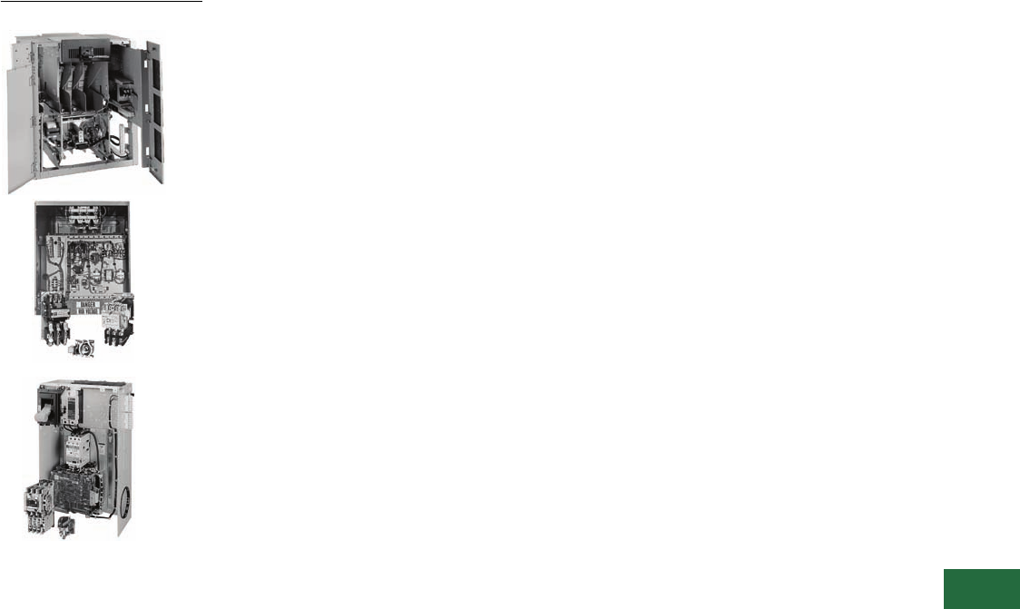
Volume 12—Aftermarket, Renewal Parts and Life Extension Solutions CA08100014E—November 2013 www.eaton.com V12-T13-1
1
2
3
4
5
6
7
8
9
10
11
12
13
14
15
16
17
18
19
20
21
22
23
24
25
Motor Control
Motor Control
13 Motor Control
Contactors, Starters and Brakes . . . . . . . . . . . . . . . . . . . . . . . . . . . . . V12-T13-2
Adjustable Frequency AC Drives . . . . . . . . . . . . . . . . . . . . . . . . . . . . . V12-T13-69
Synchronous . . . . . . . . . . . . . . . . . . . . . . . . . . . . . . . . . . . . . . . . . . . . V12-T13-73
Starters (Medium Voltage). . . . . . . . . . . . . . . . . . . . . . . . . . . . . . . . . . V12-T13-84
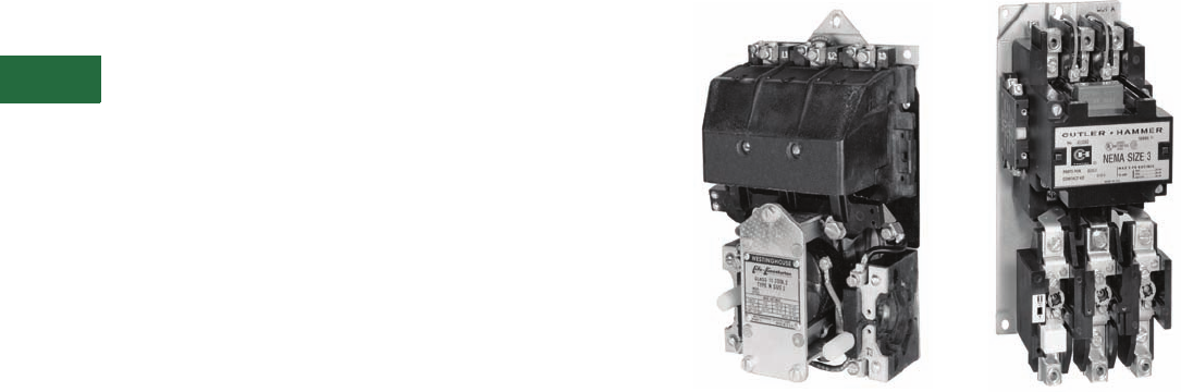
V12-T13-2 Volume 12—Aftermarket, Renewal Parts and Life Extension Solutions CA08100014E—November 2013 www.eaton.com
1
2
3
4
5
6
7
8
9
10
11
12
13
14
15
16
17
18
19
20
21
22
23
24
25
13
Motor Control
Contactors, Starters and Brakes
Contents
Description Page
Pre 3-Star
Product History Time Line, Replacement
Capabilities, Technology Upgrades . . . . . . . . . . . . . . V12-T13-4
3-Star
Product History Time Line, Replacement
Capabilities, Technology Upgrades . . . . . . . . . . . . . . V12-T13-5
Citation
Product History Time Line. . . . . . . . . . . . . . . . . . . . . V12-T13-6
Replacement Capabilities . . . . . . . . . . . . . . . . . . . . . V12-T13-7
Ty p e N
Product History Time Line, Replacement
Capabilities, Technology Upgrades . . . . . . . . . . . . . V12-T13-22
A200
Product History Time Line, Replacement
Capabilities . . . . . . . . . . . . . . . . . . . . . . . . . . . . . . . V12-T13-23
Technology Upgrades . . . . . . . . . . . . . . . . . . . . . . . V12-T13-26
A202
Product History Time Line, Replacement
Capabilities . . . . . . . . . . . . . . . . . . . . . . . . . . . . . . . V12-T13-33
V201 and V200
Replacement Capabilities . . . . . . . . . . . . . . . . . . . . V12-T13-36
Freedom
Product Description, Product History Time Line . . . V12-T13-37
Replacement Capabilities . . . . . . . . . . . . . . . . . . . . V12-T13-38
Technology Upgrades . . . . . . . . . . . . . . . . . . . . . . . V12-T13-46
IT. Electromechanical NEMA
Product Description, Product History Time Line,
Replacement Capabilities, Technology Upgrades . . V12-T13-47
IT. Electromechanical IEC
Product Description, Product History Time Line,
Replacement Capabilities, Technology Upgrades . . V12-T13-48
XT IEC Power Control
Product Description, Product History Time Line,
Replacement Capabilities, . . . . . . . . . . . . . . . . . . . V12-T13-49
Advantage
Product Description, Product History Time Line,
Replacement Capabilities, Technology Upgrades . . V12-T13-51
Definite Purpose
Product History Time Line, Replacement
Capabilities, Technology Upgrades . . . . . . . . . . . . . V12-T13-52
JF Autostarter
Product History Time Line, Replacement
Capabilities, Technology Upgrades . . . . . . . . . . . . . V12-T13-53
ME and MD dc Contactors
Product Description, Product History,
Product History Time Line, Replacement
Capabilities . . . . . . . . . . . . . . . . . . . . . . . . . . . . . . . V12-T13-54
Technology Upgrades . . . . . . . . . . . . . . . . . . . . . . . V12-T13-57
C80 Mill Type dc Contactors
Product Description, Product History Time Line,
Replacement Capabilities, Technology Upgrades . . V12-T13-58
Description Page
511 AC and DC Brakes
Product Description, Product History Time Line,
Replacement Capabilities, Technology Upgrades . . .V12-T13-61
DPM-Contactor
Product Description, Product History Time Line,
Replacement Capabilities, Technology Upgrades . . .V12-T13-62
AVD-Co nta ctor
Product Description, Product History,
Product History Time Line,
Replacement Capabilities, Technology Upgrades . . .V12-T13-63
D-Contactor
Product Description, Product History,
Product History Time Line, Replacement
Capabilities, Technology Upgrades . . . . . . . . . . . . . .V12-T13-64
Reversing/Assignment Contactors
Product Description, Product History,
Product History Time Line, Replacement
Capabilities, Technology Upgrades . . . . . . . . . . . . . .V12-T13-65
P- & S-Contactors
Product Description, Product History,
Product History Time Line, Replacement
Capabilities, Technology Upgrades . . . . . . . . . . . . . .V12-T13-66
Overview
Type N Contactor Citation Starter
Product Description
Cutler-Hammer® Starters and Contactors from Eaton’s electrical
business were and are designed to control functions of a
connected motor by starting, stopping, reversing, regulating and
protecting. When functions do not include speed regulation, this
device is known as a starter rather than a controller.
Applications for starter functions are fans, pumps, constant
horsepower, constant or variable torque machine tools, constant
torque metalworking machinery, variable torque and horsepower
fans and blowers, constant power heating, lighting, pumps and
motors for all types of applications.
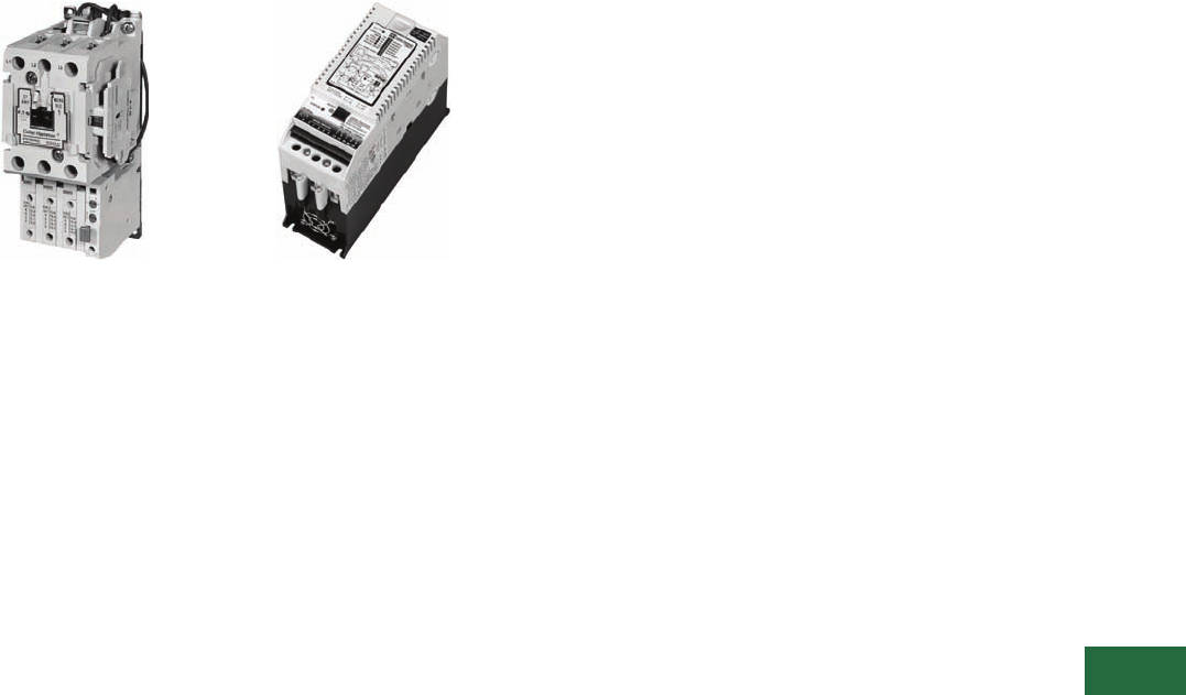
Volume 12—Aftermarket, Renewal Parts and Life Extension Solutions CA08100014E—November 2013 www.eaton.com V12-T13-3
1
2
3
4
5
6
7
8
9
10
11
12
13
14
15
16
17
18
19
20
21
22
23
24
25
13
Motor Control
Contactors, Starters and Brakes
Product History
Freedom
The Cutler-Hammer line of
contactors and starters dates
back to the early 1920s in
Milwaukee, WI. Changes
in coil construction, making
the first moisture-proof
vacuum with impregnated
coils, were innovations
in this line of contactors and
starters manufactured before
the 3-Star line (now known as
the Pre 3-Star). Eutectic alloy
overloads were used later in
this design with the design
change to the 3-Star line. A
few of the new features of
the 3-Star line of contactors
and starters were the first
standard three-coil overload
relays, new molding
compounds, new metals
and cast resin coils.
IT.
The Type F magnetic
contactor is the first
magnetically controlled
contactor in our
Westinghouse® records.
It was open in design,
simple in construction and
was state-of-the-art due to
its magnetically controlled
armature. The Type F
contactor was replaced by
the DE-ION® contactor, which
featured the Westinghouse
trademark DE-ION arc
quenching. The DE-ION was
followed by the Type DN,
Type N and the Type A, today
known as the A200. The Type
B was developed in the late
1970s and was obsoleted
two or three years later. The
A200 open control is still a
current offering. Prior to
1985, some of the larger
sizes (5–9) were known as
GCA and GCD.
The Citation line of contactors
and starters was introduced
in 1968 with many new
features: the new CI non-
wearing totally enclosed
permanent air gap magnet
structure; dual wound
magnet coil with plug-in
feature; color coded, twin
break dust-safe contacts;
and straight-through wiring.
Although the Citation line
was obsoleted in 1997,
replacement contact kits,
magnet coils and heater coils
will continue to be available.
Today, the Freedom™
contactor, launched in 1986,
coexists with the solid-state
heaterless IT. contactor, a
microprocessor-controlled
magnetic contactor
introduced in 2002.
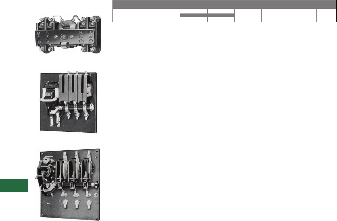
V12-T13-4 Volume 12—Aftermarket, Renewal Parts and Life Extension Solutions CA08100014E—November 2013 www.eaton.com
1
2
3
4
5
6
7
8
9
10
11
12
13
14
15
16
17
18
19
20
21
22
23
24
25
13
Motor Control
Contactors, Starters and Brakes
Pre 3-Star
Originally a Cutler-Hammer
Product
Size 1 Contactor
Size 2 Contactor
Size 5 Contactor
Parts are no longer available
for Pre-3 Star.
Product History Time Line for Pre 3-Star, Bulletin 9586 1
Replacement Capabilities
There are no replacement
parts available. Replace with
new contactor or starter.
Technology Upgrades
Size 00–3—Freedom or IT.
Sizes 4–5—Freedom,
Vacuum or IT.
Note
1For all NEMA® rated starters, please
contact Standard Open Control
Aftermarket at 1-800-535-8992.
Sizes 00 – 5
Size 1920 1940 1960 1980 2000 Present
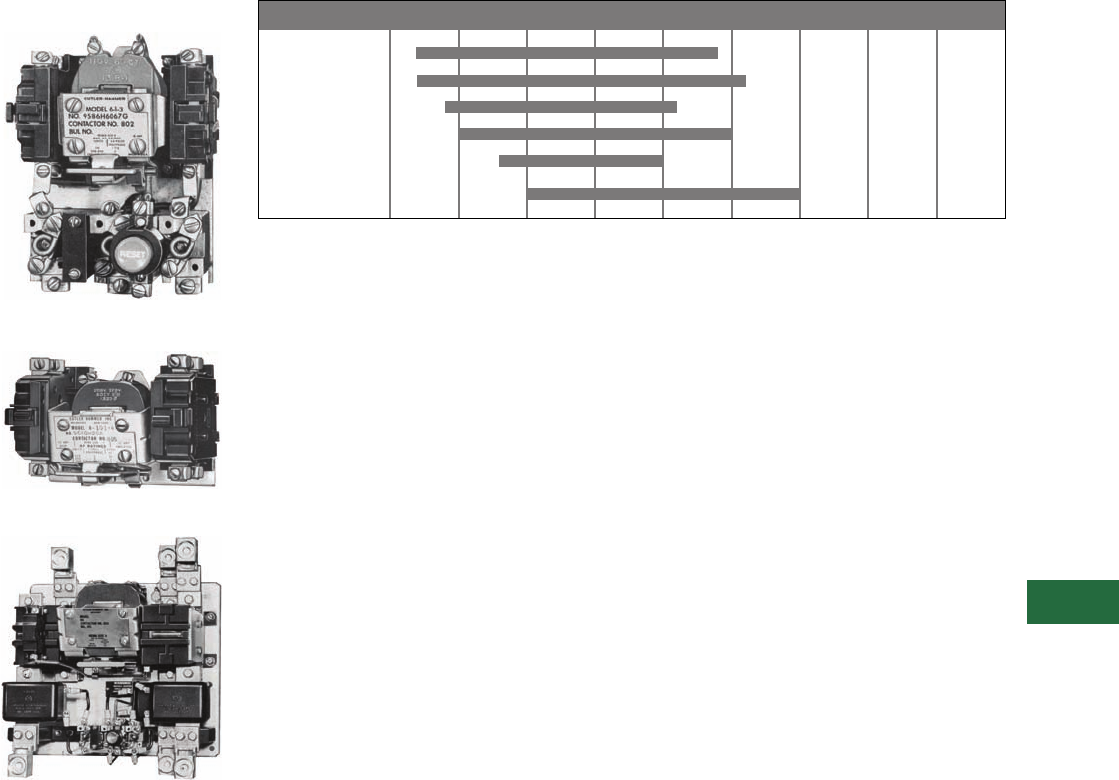
Volume 12—Aftermarket, Renewal Parts and Life Extension Solutions CA08100014E—November 2013 www.eaton.com V12-T13-5
1
2
3
4
5
6
7
8
9
10
11
12
13
14
15
16
17
18
19
20
21
22
23
24
25
13
Motor Control
Contactors, Starters and Brakes
3-Star
Originally a Cutler-Hammer
Product
Typical Size 0—Starter
Typical Size 1—Contactor
Typical Size 5—Starter
Product History Time Line for 3-Star, Bulletin 9560, 9586, 9589, 9591, 9556, 9658,
9736 and 9739 1
Replacement Capabilities
There are no replacement
parts available. Replace with
new contactor or starter.
Technology Upgrades
Sizes 00–3—Freedom or IT.
Sizes 4–5—Freedom,
Vacuum or IT.
Note
1For all NEMA rated Bulletin 9586
starters, please contact Standard
Open Control Aftermarket
at 1-800-535-8992.
Size 0
Size 1
Size 2
Size 3
Size 4
Size 5
Size 1950 1955 1960 1965 1970 1975 1985 2000 Present
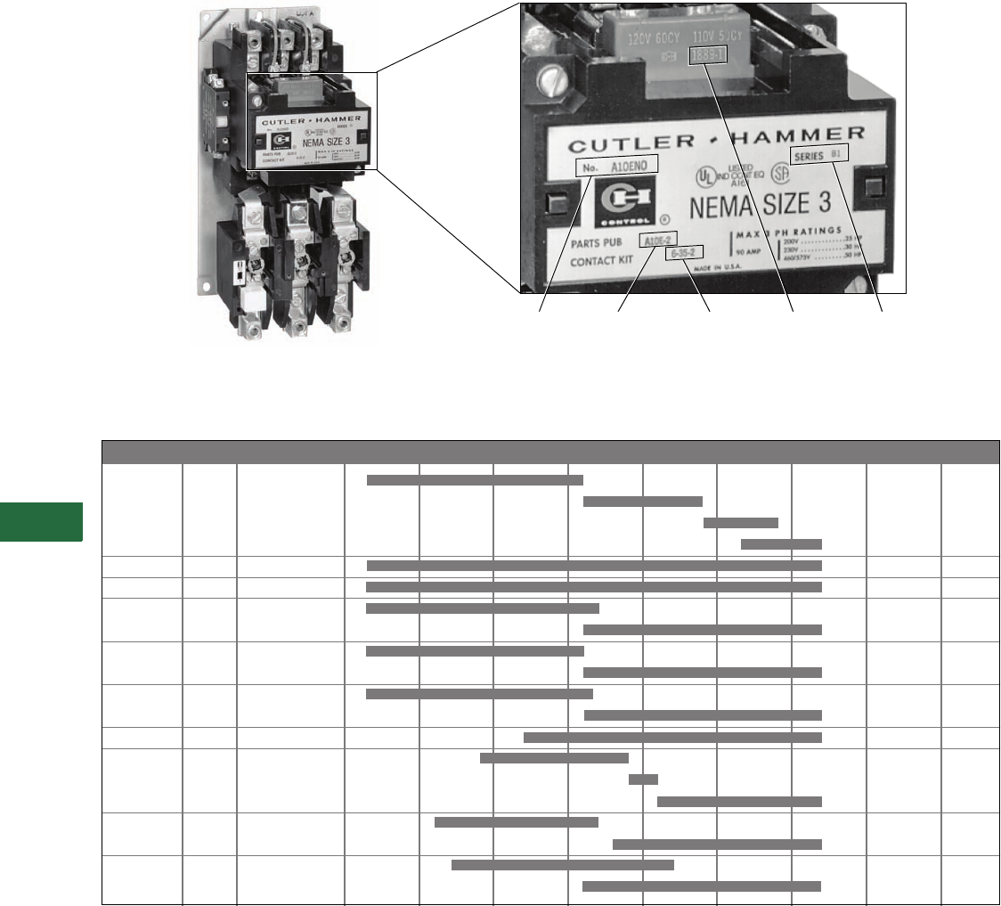
V12-T13-6 Volume 12—Aftermarket, Renewal Parts and Life Extension Solutions CA08100014E—November 2013 www.eaton.com
1
2
3
4
5
6
7
8
9
10
11
12
13
14
15
16
17
18
19
20
21
22
23
24
25
13
Motor Control
Contactors, Starters and Brakes
Citation
Originally a Cutler-Hammer Product
Citation Starter and Nameplate
Product History Time Line for Citation A10, A11, A13, A30, A31, A40, A41, A50, A51, A70, A71, A80, A81, B10, B11, B50, B51,
B52, C10, C30 and C50
Note
1Although the number “9” is not imprinted on the coil, it must be used when ordering. For example, the proper ordering number for a 120V, 60 Hz,
AC magnet coil would be 9-1887-1 (refer to the style numbers on Page V12-T13-7).
Catalog
Number
Parts
Publication
SeriesCoil 1
Contact
Kit
NEMA Size Series 1965 1970 1975 1980 1985 1990 1995 2000 Present
Size 00 A1
B1
C1
D1
Size 0 A1
Size 1 A1
Size 2 A1
B1
Size 3 A1
B1
Size 4 A1
B1
Size 5 A1
Size 6 A1
B1
C1
Size 7 A1
B1
Size 8 A1
B1

Volume 12—Aftermarket, Renewal Parts and Life Extension Solutions CA08100014E—November 2013 www.eaton.com V12-T13-7
1
2
3
4
5
6
7
8
9
10
11
12
13
14
15
16
17
18
19
20
21
22
23
24
25
13
Motor Control
Contactors, Starters and Brakes
Replacement Capabilities
Replacement Capabilities—Contacts and Coils
Replacement Capabilities—Contacts and Coils, continued
Notes
1Citation overload relays are no longer available. A Freedom overload may be an option. Contact Control Aftermarket at 1-800-535-8992.
2Replace complete contactor.
3Non-encapsulated coil.
4For use in existing DC operated devices. Not for conversion of existing AC operated devices to DC.
Description
Coil
Suffix
Style and Part Numbers
Size 00 Size 00 Size 00 Size 00 Size 0 Size 1 Size 2 Size 2 Size 3 Size 3
Series A1 1Series B1 Series C1 Series D1 Series A1 Series B1 Series A1 Series B1
Contact Kits
Part number on contactor or
starter nameplate
Two-pole without interlock — 6-21 222 6-22 6-23 6-24 6-34 6-25 6-35
Three-pole without interlock — 6-21-2 222 6-22-2 6-23-2 6-24-2 6-34-2 6-25-2 6-35-2
Three-pole with interlock — 6-21-3 22— ——————
Four-pole without interlock — — — — — 6-22-3 6-23-3 —6-34-3 ——
Five-pole without interlock — — — — — 6-22-4 6-23-4 —6-34-4 ——
Magnet Coils
120V, 60 Hz or 110V, 50 Hz A 9-1945-1 9-2183-1 9-2650-1 9-2823-1 9-1887-1 9-1887-1 9-1889-1 9-2526-1 9-1891-1 9-1889-1
240V, 60 Hz or 220V, 50 Hz B 9-1945-2 9-2183-2 9-2650-2 9-2823-2 9-1887-2 9-1887-2 9-1889-2 9-2526-2 9-1891-2 9-1889-2
480V, 60 Hz or 440V, 50 Hz C 9-1945-3 9-2183-5 9-2650-3 9-2823-3 9-1887-3 9-1887-3 9-1889-3 9-2526-3 9-1891-3 9-1889-3
600V, 60 Hz or 550V, 50 Hz D 9-1945-4 9-2183-19 9-2650-4 9-2823-4 9-1887-4 9-1887-4 9-1889-4 9-2526-4 9-1891-4 9-1889-4
208V, 60 Hz E 9-1945-5 9-2183-17 9-2650-5 9-2823-5 9-1887-5 9-1887-5 9-1889-13 9-2526-5 9-1891-13 9-1889-13
24V, 60 Hz T 9-1945-8 9-2183-16 9-2650-7 9-2823-18 9-1887-7 9-1887-7 9-1889-20 9-2526-6 9-1891-15 9-1889-20
380V, 50 Hz L 9-1945-6 9-2183-3 9-2650-6 9-2421-18 39-1887-8 9-1887-8 9-1889-14 9-2526-7 9-1891-14 9-1889-14
277V, 60 Hz H 9-1945-16 9-2183-18 9-2650-13 9-2823-12 9-1887-16 9-1887-16 9-1889-31 9-2526-15 9-1891-26 9-1889-31
9-2823-17
120 Vdc 4A1 — — — — 9-2024-2 9-2024-2 9-2025-2 9-2626-2 9-2026-2 9-2025-2
240 Vdc 4B1 — — — — 9-2024-1 9-2024-1 9-2025-1 9-2626-1 9-2026-1 9-2025-1
24 Vdc 4T1 — — — — 9-2024-4 9-2024-4 9-2025-4 9-2626-4 9-2026-4 9-2025-4
48 Vdc 4W1 — — — — 9-2024-3 9-2024-3 9-2025-3 9-2626-3 9-2026-3 9-2025-3
Description
Coil
Suffix
Style and Part Numbers
Size 4Size 4Size 5Size 6Size 6Size 6Size 7Size 7Size 8 Size 8
Series A1 Series B1 Series A1 Series B1 Series C1 Series A1 Series B1 Series A1 Series B1
Contact Kits
Part number on contactor or
starter nameplate
Two-pole — 6-26 6-36-3 6-27 6-28 —6-601-2 6-28 —— —
Three-pole — 6-26-2 6-36-4 6-27-2 6-28-2 6-570 6-601 6-28-2 6-570 646C829G05 6-571
Magnet Coils
120V, 60 Hz or 110V, 50 Hz A 9-1891-1 9-1891-1 9-1891-1 9-1875-1 9-2651 9-2698 9-1875-1 9-2651 438C805G12 9-2654
240V, 60 Hz or 220V, 50 Hz B 9-1891-2 9-1891-2 9-1891-2 9-1875-2 9-2651-2 9-2698-2 9-1875-2 9-2651-2 438C805G11 9-2654-2
480V, 60 Hz or 440V, 50 Hz C 9-1891-3 9-1891-3 9-1891-3 9-1875-3 9-2651-3 9-2698-3 9-1875-3 9-2651-3 438C805G10 9-2654-3
600V, 60 Hz or 550V, 50 Hz D 9-1891-4 9-1891-4 9-1891-4 9-1875-4 9-2651-4 9-2698-4 9-1875-4 9-2651-4 —9-2654-4
208V, 60 Hz E 9-1891-13 9-1891-13 9-1891-13 9-1875-14 9-2651-6 9-2698-5 9-1875-14 9-2651-6 438C805G11 9-2654-6
24V, 60 Hz T 9-1891-15 9-1891-15 9-1891-15 —————— —
380V, 50 Hz L 9-1891-14 9-1891-14 9-1891-14 —9-2651-5 9-2698-6 —9-2651-5 438C805G15 9-2654-5
277V, 60 Hz H 9-1891-26 9-1891-26 9-1891-26 —————— —
120 Vdc 4A1 9-2026-2 9-2026-2 9-2026-2 —————— —
240 Vdc 4B1 9-2026-1 9-2026-1 9-2026-1 —————— —
24 Vdc 4T1 9-2026-4 9-2026-4 9-2026-4 —————— —
48 Vdc 4W1 9-2026-3 9-2026-3 9-2026-3 —————— —
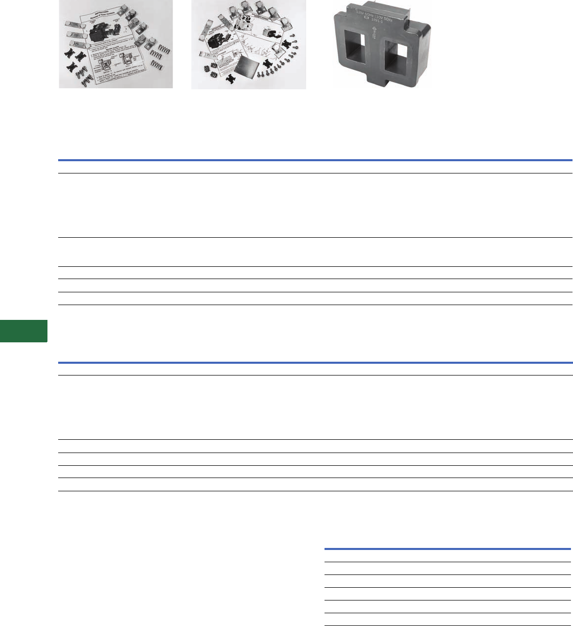
V12-T13-8 Volume 12—Aftermarket, Renewal Parts and Life Extension Solutions CA08100014E—November 2013 www.eaton.com
1
2
3
4
5
6
7
8
9
10
11
12
13
14
15
16
17
18
19
20
21
22
23
24
25
13
Motor Control
Contactors, Starters and Brakes
Three-Pole Contact Kit, Size 3, Series B1 Three-Pole Contact Kit, Size 5
Replacement Capabilities—Overload Relays
Replacement Capabilities—Overload Relays, continued
Technology Upgrades
Sizes 00–3—Freedom or IT.
Sizes 4–6—Freedom, Vacuum
or IT.
Sizes 7–8—Freedom
Adapter Plates
The adapter plates make it
possible to replace a Citation
starter
with a Freedom or
Advantage starter and
the
same mounting holes can
be used.
Notes
1Citation overload relays are no longer
available. Replace with up-to-date
starter, or contact Standard Open Control
Aftermarket at 1-800-535-8992
to determine Freedom overload relay
compatibility.
2No longer available. Replace with up-to-
date overload relay or starter.
3Will no longer be available once stock
is depleted. If stock is out, replace with
up-to-date overload relay or starter.
4On Vista; no price.
Description
Style and Part Numbers
Size 00 Size 00 Size 00 Size 00 Size 0 Size 1 Size 2 Size 2 Size 3 Size 3
Series A1 Series B1 Series C1 Series D1 Series A1 Series B1 Series A1 Series B1
Overload Relays
Without mounting plates—
for replacement on existing starters
Standard trip (Class 20)
Eutectic — 1 Element
3 Element
3 Element with
alarm circuit
11111 1 1111
Slow trip (Class 30)
Eutectic — 1 Element
3 Element
11111 1 1111
Replacement Thermal Elements
Standard trip eutectic
22222 2 2222
Slow trip eutectic
10-5018 310-5018 310-5018 310-5018 310-5018 310-5018 310-5018 310-5018 310-5018 310-5018 3
Description
Style and Part Numbers
Size 4 Size 4 Size 5 Size 6 Size 6 Size 6 Size 7 Size 7 Size 8 Size 8
Series A1 Series B1 Series A1 Series B1 Series C1 Series A1 Series B1 Series A1 Series B1
Overload Relays
Without mounting plates—
for replacement on existing starters
Standard trip (Class 20)
Eutectic — 1 Element
3 Element
3 Element with
alarm circuit
11111 1 1111
Replacement Thermal Elements
Standard trip eutectic
22222 2 2222
Slow trip eutectic
10-5018 310-5018 310-5018 3—— — ————
Current transformer — — — — 42-3418-3 442-3418-3 4————
Magnet Coil, 120V/60 Hz for Size 3,
Series A1
Adapter Plates Ordering Information
NEMA
Size
Adapter Plate Catalog Number
Freedom Advantage
00, 0 C321CMP0 —
1C321CMP1 WBASE12
2C321CMP2 WBASE 12
3C321CMP3 WBASE 34
4C321CMP4 WBASE 34
5C321CMP5 —

Volume 12—Aftermarket, Renewal Parts and Life Extension Solutions CA08100014E—November 2013 www.eaton.com V12-T13-9
1
2
3
4
5
6
7
8
9
10
11
12
13
14
15
16
17
18
19
20
21
22
23
24
25
13
Motor Control
Contactors, Starters and Brakes
Heaters
Overload relays do not include
heaters. Please see table for
heater element index.
Heater Selection
For Replacement in Existing
Applications Only
Heaters are rated to protect
40°C rise of motors; and,
open and drip-proof motors
having a service factor of
1.15 where the motor and
the controller are at the same
ambient temperature.
For other conditions:
1. For 50°C, 55°C and 75°C
(122°F, 131°F and 167°F)
rise motors and
enclosed motors having
a service factor of 1.0,
select one size smaller.
2. Ambient temperature of
the starter lower than
the motor by 26°C
(79°F), use one size
smaller.
3. Ambient temperature of
the starter higher than
the motor by 26°C
(79°F), use one size
larger.
Ultimate tripping current of
heaters is approximately 1.25
times the minimum current
rating listed in the tables.
Heater Selection Index
Note: Use this index to cross-reference tables on Pages V12-T13-9 through V12-T13-21.
Index of Overload Relay Heater Selection Tables
Notes
1Select heaters for 50% of rated full load current.
2Select heaters for 68% of rated full load current.
Individually boxed heaters master packed 10 per carton.
Starter
Type
Catalog
Prefix Type
Heater Selection Table Number
NEMA Size of Starter
00-0-1
(1-1/2)2345678
A10 Open ST-1 ST-3 ST-5 ST-7 ST-16 ST-10 ST-11 ST-12
Enclosed ST-2 ST-4 ST-6 ST-7 ST-16 ST-10 ST-11 ST-12
A11 Open BNC-1 BNC-3 BNC-5 BNC-7 BNC-9 — — —
Enclosed BNC-2 BNC-4 BNC-6 BNC-7 BNC-9 — — —
A13 Open LT-2 LT-4 LT-6 LT-7 LT-8 — — —
Enclosed LT-1 LT-3 LT-5 LT-7 LT-8 — — —
A30 and A40 Enclosed ST-9 ST-3 ST-6 ST-7 ST-16 ST-10 ST-11 ST-12
A31 and A41 Enclosed BNC-8 BNC-3 BNC-6 BNC-7 BNC-9 — — —
A50 Open ST-1 ST-3 ST-5 ST-7 ST-16 ST-10 ST-11 ST-12
Enclosed ST-2 ST-4 ST-6 ST-7 ST-16 ST-10 ST-11 ST-12
A51 Open BNC-1 BNC-3 BNC-5 BNC-7 BNC-9 — — —
Enclosed BNC-2 BNC-4 BNC-6 BNC-7 BNC-9 — — —
A70 and A80 Enclosed ST-9 ST-3 ST-6 ST-7 ST-16 ST-10 ST-11 ST-12
A71 and A81 Enclosed BNC-8 BNC-3 BNC-5 BNC-7 BNC-9 — — —
A400-A420 Enclosed — — ST-14 ST-15 ST-16 ST-10 ST-11 ST-12
A460 1Enclosed ST-2 1ST-4 1ST-6 1ST-7 1ST-16 1ST-10 1ST-11 1ST-12 1
A490 2Enclosed ST-2 2ST-4 2ST-6 2ST-7 2ST-16 2ST-10 2ST-11 2ST-12 2
A700 Open ST-1 ST-3 ST-5 ST-7 ST-16 — — —
Enclosed ST-2 ST-4 ST-6 ST-7 ST-16 ST-10 — —
A800-A803 Enclosed ST-9 ST-3 ST-5 ST-7 ST-16 ST-10 ST-11 —
A804-A806 Enclosed ST-9 ST-3 ST-5 — — — — —
A808-A809 Enclosed — ST-13 ST-5 ST-5 — — — —
B10 and B50 Enclosed ST-1 ST-3 ST-5 ST-7 — — — —
B11 and B51 Open BNC-1 — — — — — — —
Enclosed BNC-2 BNC-3 BNC-5 — — — — —
C300 Open and
enclosed
ST-1 ST-3 ST-5 ST-7 — — — —
C301 Open and
enclosed
BNC-1 BNC-4 BNC-5 BNC-7 — — — —
C303 Open and
enclosed
LT-2 LT-4 LT-6 LT-7 — — — —

V12-T13-10 Volume 12—Aftermarket, Renewal Parts and Life Extension Solutions CA08100014E—November 2013 www.eaton.com
1
2
3
4
5
6
7
8
9
10
11
12
13
14
15
16
17
18
19
20
21
22
23
24
25
13
Motor Control
Contactors, Starters and Brakes
Overload Relay Heater Selection Tables
Type ST Standard Trip Eutectic Alloy
For replacement in existing applications only; for motors with 1.15 service factor.
Notes
1For A460 controllers, select heaters at 50% of rated full load current.
2For A490 controllers, select heaters at 58% of rated full load current.
Individually boxed heaters master packed 10 per carton.
Table ST-1 Table ST-2 Table ST-3 Table ST-4 Table ST-5
Heater
Catalog
Number
NEMA Sizes 00, 0, 1, 1-1/2 NEMA Sizes 00, 0, 1, 1-1/2 NEMA Size 2 NEMA Size 2 NEMA Size 3
For Open Type
Catalog Prefix A10, A50,
A700, B10, B50, C300
For Enclosed Type
Catalog Prefix B10,
B50, C300
For Enclosed Type
Catalog Prefix A10, A50,
A460 1, A490 2, A700
For Open Type
Catalog Prefix A10, A50,
A700, B10, C300
For Enclosed Typ e
Catalog Prefix B10, C300, A30,
A40, A70, A80, A800-A803
For Enclosed Type
Catalog Prefix A10, A50,
A460 1, A490 2, A700
For Open Typ e
Catalog Prefix A10, A50,
A700, B10, C300
For Enclosed Type
Catalog Prefix A70, A80,
A800-A803, A808-A809, B10
Heater Ampere Range
0.167–0.187 0.155–0.173 — — — H1101
0.188–0.210 0.174–0.195 — — — H1102
0.211–0.237 0.196–0.220 — — — H1103
0.238–0.266 0.221–0.247 — — — H1104
0.267–0.298 0.248–0.278 — — — H1105
0.299–0.334 0.279–0.310 — — — H1106
0.335–0.376 0.311–0.349 — — — H1107
0.377–0.422 0.350–0.391 — — — H1108
0.423–0.474 0.392–0.441 — — — H1109
0.475–0.532 0.442–0.495 — — — H1110
0.533–0.598 0.496–0.555 — — — H1111
0.599–0.672 0.556–0.624 — — — H1112
0.673–0.757 0.625–0.703 — — — H1113
0.758–0.855 0.704–0.795 — — — H1114
0.865–0.959 0.796–0.895 — — — H1115
0.960–1.07 0.896–0.999 — — — H1116
1.08–1.21 1.00–1.12 — — — H1117
1.22–1.35 1.13–1.25 — — — H1018
1.36–1.52 1.26–1.41 — — — H1019
1.53–1.70 1.42–1.58 — — — H1020
1.71–1.90 1.59–1.77 — — — H1021
1.91–2.10 1.78–1.96 — — — H1022
2.11–2.33 1.97–2.17 — — — H1023
2.34–2.62 2.18–2.44 — — — H1024
2.63–2.93 2.45–2.72 — — — H1025
2.94–3.27 2.73–3.04 — — — H1026
3.28–3.64 3.05–3.38 — — — H1066
3.65–4.06 3.39–3.73 3.72–4.10 — — H1027
4.07–4.55 3.74–4.18 4.11–4.59 3.86–4.31 — H1028
4.56–5.03 4.19–4.63 4.60–5.07 4.32–4.77 — H1029

Volume 12—Aftermarket, Renewal Parts and Life Extension Solutions CA08100014E—November 2013 www.eaton.com V12-T13-11
1
2
3
4
5
6
7
8
9
10
11
12
13
14
15
16
17
18
19
20
21
22
23
24
25
13
Motor Control
Contactors, Starters and Brakes
Type ST Standard Trip Eutectic Alloy, continued
For replacement in existing applications only; for motors with 1.15 service factor.
Notes
1For A460 controllers, select heaters at 50% of rated full load current.
2For A490 controllers, select heaters at 58% of rated full load current.
Individually boxed heaters master packed 10 per carton.
Table ST-1 Table ST-2 Table ST-3 Table ST-4 Table ST-5
Heater
Catalog
Number
NEMA Sizes 00, 0, 1, 1-1/2 NEMA Sizes 00, 0, 1, 1-1/2 NEMA Size 2 NEMA Size 2 NEMA Size 3
For Open Type
Catalog Prefix A10, A50,
A700, B10, B50, C300
For Enclosed Type
Catalog Prefix B10,
B50, C300
For Enclosed Type
Catalog Prefix A10, A50,
A460 1, A490 2, A700
For Open Type
Catalog Prefix A10, A50,
A700, B10, C300
For Enclosed Type
Catalog Prefix B10, C300, A30,
A40, A70, A80, A800-A803
For Enclosed Type
Catalog Prefix A10, A50,
A460 1, A490 2, A700
For Open Type
Catalog Prefix A10, A50,
A700, B10, C300
For Enclosed Type
Catalog Prefix A70, A80,
A800-A803, A808-A809, B10
Heater Ampere Range
5.04–5.59 4.64–5.15 5.08–5.65 4.78–5.31 — H1030
5.60–6.25 5.16–5.68 5.66–6.29 5.32–5.90 — H1031
6.26–6.92 5.69–6.30 6.30–7.00 5.91–6.55 — H1032
6.93–7.75 6.31–7.05 7.01–7.82 6.56–7.33 — H1033
7.76–8.63 7.06–7.76 7.83–8.79 7.34–8.15 8.32–9.27 H1034
8.64–9.59 7.77–8.63 8.80–9.67 8.16–9.03 9.28–10.1 H1035
9.60–10.6 8.64–9.51 9.68–10.8 9.04–10.1 10.2–11.4 H1036
10.7–11.9 9.52–10.5 10.9–12.0 10.2–11.2 11.5–12.8 H1037
12.0–13.3 10.6–11.8 12.1–13.4 11.3–12.5 12.9–14.3 H1038
13.4–14.7 11.9–13.1 13.5–14.9 12.6–13.9 14.4–16.0 H1039
14.8–16.6 13.2–14.8 15.0–17.6 14.0–15.7 16.1–17.8 H1040
16.7–18.8 14.9–16.7 17.7–19.0 15.8–17.5 17.9–20.3 H1041
18.9–21.2 16.8–18.9 19.1–21.5 17.6–19.8 20.4–22.9 H1042
21.3–23.9 19.0–21.3 21.6–24.5 19.9–22.3 23.0–26.0 H1043
24.0–27.0 21.4–24.1 24.6–27.9 22.4–25.4 26.1–29.5 H1044
— 24.2–27.0 28.0–32.0 25.5–28.7 29.6–33.5 H1045
— — 32.1–36.6 28.8–32.5 33.6–37.8 H1046
— — 36.7–41.8 32.6–36.6 37.9–42.8 H1047
— — 41.9–45.0 36.7–41.0 42.9–48.5 H1048
— — — 41.1–45.0 48.6–55.1 H1049
— — — — 55.2–62.3 H1050
— — — — 62.4–69.5 H1051
— — — — 69.6–79.1 H1052
— — — — 79.2–90.0 H1054
——— —— H1055
——— —— H1056
——— —— H1057
——— —— H1058

V12-T13-12 Volume 12—Aftermarket, Renewal Parts and Life Extension Solutions CA08100014E—November 2013 www.eaton.com
1
2
3
4
5
6
7
8
9
10
11
12
13
14
15
16
17
18
19
20
21
22
23
24
25
13
Motor Control
Contactors, Starters and Brakes
Type ST Standard Trip Eutectic Alloy, continued
For replacement in existing applications only; for motors with 1.15 service factor.
Notes
1For A460 controllers, select heaters for 50% of rated full load current.
2For A490 controllers, select heaters for 58% of rated full load current.
Individually boxed heaters master packed 10 per carton.
Table ST-6 Table ST-7 Table ST-8 Table ST-9 Table ST-10
Heater
Catalog
Number
NEMA Size 3 NEMA Size 4 NEMA Size 5 NEMA Size 0 and 1 NEMA Size 6
For Enclosed Type
Catalog Prefix A10, A30,
A40, A50, A460 1, A490 2,
A700
For Open Type
Catalog Prefix A10, A50, C300
For Enclosed Type
Catalog Prefix A10, A30,
A40, A50, A70, A80, A460 1,
A490 2, A700, A800-A803
For Open and Enclosed
Catalog Prefix A10, A50,
A30-40, A70, A80, A400,
A410, A420, A460, A490,
A800-A801
For Enclosed Type
Catalog Prefix A30, A40,
A70, A80, A800-A803
For Open Typ e
Catalog Prefix A10, A50,
A700
For Enclosed Type
Catalog Prefix A10, A30,
A40, A50, A70, A80, A400,
A460 1, A490 2, A700
Heater Ampere Range
— — — 0.164–0.183 — H1101
— — — 0.184–0.205 — H1102
— — — 0.206–0.232 — H1103
— — — 0.233–0.260 — H1104
— — — 0.261–0.293 — H1105
— — — 0.294–0.328 — H1106
— — — 0.329–0.369 — H1107
— — — 0.370–0.414 — H1108
— — — 0.415–0.465 — H1109
— — — 0.466–0.522 — H1110
— — — 0.523–0.586 — H1111
— — — 0.587–0.659 — H1112
— — — 0.660–0.743 — H1113
— — — 0.744–0.839 — H1114
— — — 0.840–0.943 — H1115
— — — 0.944–1.05 — H1116
— — — 1.06–1.17 — H1117
— — — 1.18–1.31 — H1018
— — — 1.32–1.47 154–171 H1019
— — 92–101 1.48–1.66 172–192 H1020
— — 102–113 1.67–1.85 193–215 H1021
— — 114–125 1.86–2.04 216–237 H1022
— — 126–139 2.05–2.26 238–263 H1023
— — 140–157 2.27–2.54 264–295 H1024
— — 158–175 2.55–2.85 296–330 H1025
— — 176–196 2.86–3.18 331–369 H1026
— — 197–218 3.19–3.53 370–410 H1066
— — 219–243 3.54–3.95 411–458 H1027
— — 244–270 3.96–4.41 459–512 H1028
— — — 4.42–4.88 513–574 H1029

Volume 12—Aftermarket, Renewal Parts and Life Extension Solutions CA08100014E—November 2013 www.eaton.com V12-T13-13
1
2
3
4
5
6
7
8
9
10
11
12
13
14
15
16
17
18
19
20
21
22
23
24
25
13
Motor Control
Contactors, Starters and Brakes
Type ST Standard Trip Eutectic Alloy, continued
For replacement in existing applications only; for motors with 1.15 service factor.
Notes
1For A460 controllers, select heaters for 50% of rated full load current.
2For A490 controllers, select heaters for 58% of rated full load current.
Individually boxed heaters master packed 10 per carton.
Table ST-6 Table ST-7 Table ST-8 Table ST-9 Table ST-10
Heater
Catalog
Number
NEMA Size 3 NEMA Size 4 NEMA Size 5 NEMA Size 0 and 1 NEMA Size 6
For Enclosed Type
Catalog Prefix A10, A30,
A40, A50, A460 1, A490 2,
A700
For Open Type
Catalog Prefix A10, A50, C300
For Enclosed Type
Catalog Prefix A10, A30,
A40, A50, A70, A80, A460 1,
A490 2, A700, A800-A803
For Open and Enclosed
Catalog Prefix A10, A50,
A30-40, A70, A80, A400,
A410, A420, A460, A490,
A800-A801
For Enclosed Type
Catalog Prefix A30, A40,
A70, A80, A800-A803
For Open Type
Catalog Prefix A10, A50,
A700
For Enclosed Type
Catalog Prefix A10, A30,
A40, A50, A70, A80, A400,
A460 1, A490 2, A700
Heater Ampere Range
— — — 4.89–5.42 — H1030
— — — 4.89–5.42 — H1031
— — — 6.08–6.64 — H1032
— — — 6.65–7.43 — H1033
8.24–9.19 — — 7.44–8.23 — H1034
9.20–10.1 — — 8.24–9.19 — H1035
10.2–11.3 — — 9.20–10.1 — H1036
11.4–12.7 — — 10.2–11.3 — H1037
12.8–14.1 — — 11.4–12.6 — H1038
14.2–15.8 — — 12.7–14.0 — H1039
15.9–17.7 — — 14.1–15.7 — H1040
17.8–20.1 — — 15.8–17.7 — H1041
20.2–22.7 20.6–23.3 — 17.8–19.8 — H1042
22.8–25.5 23.4–26.3 — 19.9–22.0 — H1043
25.6–28.9 26.4–30.8 — 22.1–24.9 — H1044
29.0–32.5 30.9–34.0 — 25.0–27.0 — H1045
32.6–36.7 34.1–38.3 — — — H1046
36.8–41.0 38.4–43.4 — — — H1047
41.1–46.0 43.5–49.3 — — — H1048
46.1–51.8 49.4–55.8 — — — H1049
51.9–58.6 55.9–63.1 — — — H1050
58.7–64.6 63.2–70.4 — — — H1051
64.7–72.7 70.5–79.9 — — — H1052
72.8–83.1 80.0–92.7 — — — H1054

V12-T13-14 Volume 12—Aftermarket, Renewal Parts and Life Extension Solutions CA08100014E—November 2013 www.eaton.com
1
2
3
4
5
6
7
8
9
10
11
12
13
14
15
16
17
18
19
20
21
22
23
24
25
13
Motor Control
Contactors, Starters and Brakes
Type ST Standard Trip Eutectic Alloy, continued
For replacement in existing applications only; for motors with 1.15 service factor.
Notes
1For A460 controllers, select heaters for 50% of rated full load current.
2For A490 controllers, select heaters for 58% of rated full load current.
Individually boxed heaters master packed 10 per carton.
Table ST-11 Table ST-12 Table ST-13 Table ST-14 Table ST-15
Heater
Catalog
Number
NEMA Size 7 NEMA Size 8 NEMA Size 2 NEMA Size 3 NEMA Size 4
For Open Type
Catalog Prefix A10, A50, A700
For Enclosed Type
Catalog Prefix A10, A30,
A40, A50, A70, A80, A400,
A460 1, A490 2, A700
For Open Type
Catalog Prefix A10, A50, A700
For Enclosed Typ e
Catalog Prefix A10, A30,
A40, A50, A70, A80, A400,
A460 1, A490 2, A700
For Enclosed Type
Catalog Prefix A808, A809
For Enclosed Type
Catalog Prefix A400
For Enclosed Type
Catalog Prefix A400
Heater Ampere Range
—————H1101
—————H1102
—————H1103
—————H1104
—————H1105
—————H1106
—————H1107
—————H1108
—————H1109
—————H1110
—————H1111
—————H1112
—————H1113
—————H1114
—————H1115
—————H1116
—————H1117
229–255 — ———H1018
256–287 384–429 ———H1019
288–321 430–482 ———H1020
322–359 483–538 ———H1021
360–397 539–595 ———H1022
398–439 596–657 ———H1023
440–492 658–741 ———H1024
493–551 742–827 ———H1025
552–615 828–924 ———H1026
616–685 925–1027 ———H1066
686–763 1028–1147 ———H1027
764–855 1148–1285 3.89–4.35 — — H1028
——4.36–4.81 — — H1029

Volume 12—Aftermarket, Renewal Parts and Life Extension Solutions CA08100014E—November 2013 www.eaton.com V12-T13-15
1
2
3
4
5
6
7
8
9
10
11
12
13
14
15
16
17
18
19
20
21
22
23
24
25
13
Motor Control
Contactors, Starters and Brakes
Type ST Standard Trip Eutectic Alloy, continued
For replacement in existing applications only; for motors with 1.15 service factor.
Notes
1For A460 controllers, select heaters for 50% of rated full load current.
2For A490 controllers, select heaters for 58% of rated full load current.
Individually boxed heaters master packed 10 per carton.
Table ST-11 Table ST-12 Table ST-13 Table ST-14 Table ST-15
Heater
Catalog
Number
NEMA Size 7 NEMA Size 8 NEMA Size 2 NEMA Size 3 NEMA Size 4
For Open Type
Catalog Prefix A10, A50, A700
For Enclosed Type
Catalog Prefix A10, A30,
A40, A50, A70, A80, A400,
A460 1, A490 2, A700
For Open Type
Catalog Prefix A10, A50, A700
For Enclosed Type
Catalog Prefix A10, A30,
A40, A50, A70, A80, A400,
A460 1, A490 2, A700
For Enclosed Type
Catalog Prefix A808, A809
For Enclosed Type
Catalog Prefix A400
For Enclosed Type
Catalog Prefix A400
Heater Ampere Range
— — 4.82–5.35 — — H1030
— — 5.36–5.96 — — H1031
— — 5.97–6.63 — — H1032
— — 6.64–7.41 — — H1033
— — 7.42–8.23 7.84–8.71 — H1034
— — 8.24–9.19 8.72–9.67 — H1035
— — 9.20–10.2 9.68–10.8 — H1036
— — 10.3–11.4 10.9–12.0 — H1037
— — 11.5–12.8 12.1–13.5 — H1038
— — 12.9–14.1 13.6–15.0 — H1039
— — 14.2–15.9 15.1–16.8 — H1040
— — 16.0–18.1 16.9–19.1 — H1041
— — 18.2–20.4 19.2–21.6 19.5–21.9 H1042
— — 20.5–23.3 21.7–24.5 22.0–24.7 H1043
— — 23.4–26.5 24.6–27.8 24.8–29.0 H1044
— — 26.6–30.3 27.9–31.5 29.1–31.9 H1045
— — 30.4–34.7 31.6–35.5 32.0–36.1 H1046
— — 34.8–39.6 35.6–40.3 36.2–40.7 H1047
— — 39.7–45.0 40.4–45.6 40.8–46.2 H1048
— — — 45.7–51.8 46.3–52.4 H1049
— — — 51.9–58.6 52.5–59.2 H1050
— — — 58.7–65.2 59.3–66.3 H1051
— — — 65.3–74.3 66.4–75.1 H1052
— — — 74.4–86.3 75.2–87.1 H1054

V12-T13-16 Volume 12—Aftermarket, Renewal Parts and Life Extension Solutions CA08100014E—November 2013 www.eaton.com
1
2
3
4
5
6
7
8
9
10
11
12
13
14
15
16
17
18
19
20
21
22
23
24
25
13
Motor Control
Contactors, Starters and Brakes
Type BNC Bimetal
For replacement in existing applications only; for motors with 1.15 service factor.
Note
Individually boxed heaters master packed 10 per carton.
Table BNC-1 Table BNC-2 Table BNC-3 Table BNC-4
Heater
Catalog
Number
NEMA Sizes 00, 0, 1, 1-1/2 NEMA Sizes 00, 0, 1, 1-1/2 NEMA Size 2 NEMA Size 2
For Open Type
Catalog Prefix A11, A51, B11, B51, C301
For Enclosed Type
Catalog Prefix C301
For Enclosed Type
Catalog Prefix A11, A51, B11, B51
For Open Type
Catalog Prefix A11, A51, B11, C301
For Enclosed Typ e
Catalog Prefix A31, A41, A71, A81, B11
For Enclosed Type
Catalog Prefix A11, A51, C301
Heater Ampere Range
0.180–0.201 0.167–0.187 — — H1101
0.202–0.226 0.188–0.210 — — H1102
0.227–0.254 0.211–0.236 — — H1103
0.255–0.285 0.237–0.266 — — H1104
0.286–0.320 0.267–0.297 — — H1105
0.321–0.357 0.298–0.332 — — H1106
0.358–0.402 0.333–0.373 — — H1107
0.403–0.451 0.374–0.419 — — H1108
0.452–0.506 0.420–0.470 — — H1109
0.507–0.568 0.471–0.528 — — H1110
0.569–0.638 0.529–0.592 — — H1111
0.639–0.716 0.593–0.663 — — H1112
0.717–0.799 0.664–0.743 — — H1113
0.800–0.911 0.744–0.847 — — H1114
0.912–1.01 0.848–0.951 — — H1115
1.02–1.14 0.952–1.06 — — H1116
1.15–1.29 1.07–1.20 — — H1117
1.30–1.44 1.21–1.33 — — H1018
1.45–1.61 1.34–1.49 — — H1019
1.62–1.80 1.50–1.67 — — H1020
1.81–2.03 1.68–1.89 — — H1021
2.04–2.25 1.90–2.09 — — H1022
2.26–2.49 2.10–2.32 — — H1023
2.50–2.76 2.33–2.57 — — H1024
2.77–3.05 2.58–2.83 — — H1025
3.06–3.39 2.84–3.15 — — H1026
3.40–3.83 3.16–3.51 3.87–4.18 — H1066
3.84–4.22 3.52–3.87 4.19–4.60 3.94–4.33 H1027
4.23–4.63 3.88–4.25 4.61–5.10 4.34–4.78 H1028
4.64–5.19 4.26–4.76 5.11–5.60 4.79–5.27 H1029

Volume 12—Aftermarket, Renewal Parts and Life Extension Solutions CA08100014E—November 2013 www.eaton.com V12-T13-17
1
2
3
4
5
6
7
8
9
10
11
12
13
14
15
16
17
18
19
20
21
22
23
24
25
13
Motor Control
Contactors, Starters and Brakes
Type BNC Bimetal
For replacement in existing applications only; for motors with 1.15 service factor.
Note
Individually boxed heaters master packed 10 per carton.
Table BNC-1 Table BNC-2 Table BNC-3 Table BNC-4
Heater
Catalog
Number
NEMA Sizes 00, 0, 1, 1-1/2 NEMA Sizes 00, 0, 1, 1-1/2 NEMA Size 2 NEMA Size 2
For Open Type
Catalog Prefix A11, A51, B11, B51,
C301
For Enclosed Type
Catalog Prefix C301
For Enclosed Type
Catalog Prefix A11, A51, B11, B51
For Open Type
Catalog Prefix A11, A51, B11, C301
For Enclosed Type
Catalog Prefix A31, A41, A71, A81,
B11
For Enclosed Type
Catalog Prefix A11, A51, C301
Heater Ampere Range
5.20–5.73 4.77–5.27 5.61–6.20 5.28–5.83 H1030
5.74–6.49 5.28–5.90 6.21–6.92 5.84–6.51 H1031
6.50–7.32 5.91–6.63 6.93–7.76 6.52–7.29 H1032
7.33–8.07 6.64–7.35 7.77–8.63 7.30–8.07 H1033
8.08–9.03 7.36–8.15 8.64–9.67 8.08–9.03 H1034
9.04–9.99 8.16–8.87 9.68–10.5 9.04–9.99 H1035
10.0–11.1 8.88–9.99 10.6–11.8 10.0–11.1 H1036
11.2–12.5 10.0–11.1 11.9–13.2 11.2–12.3 H1037
12.6–14.1 11.2–12.5 13.3–15.0 12.4–14.1 H1038
14.2–15.9 12.6–14.1 15.1–17.2 14.2–16.1 H1039
16.0–18.0 14.2–16.1 17.3–19.1 16.2–17.8 H1040
18.1–19.8 16.2–17.7 19.2–21.5 17.9–19.9 H1041
19.9–22.2 17.8–19.8 21.6–23.6 20.0–21.9 H1042
22.3–25.0 19.9–22.2 23.7–27.0 22.0–24.7 H1043
25.1–27.0 22.3–25.0 27.1–30.6 24.8–27.9 H1044
— 25.1–27.0 30.7–35.1 28.0–31.6 H1045
— — 35.2–39.8 31.7–35.3 H1046
— — 39.9–45.0 35.4–39.4 H1047
— — — 39.5–44.4 H1048
— — — 44.5–45.0 H1049
——— —H1050
——— —H1051
——— —H1052
——— —H1054
——— —H1055
——— —H1056
——— —H1057
——— —H1058

V12-T13-18 Volume 12—Aftermarket, Renewal Parts and Life Extension Solutions CA08100014E—November 2013 www.eaton.com
1
2
3
4
5
6
7
8
9
10
11
12
13
14
15
16
17
18
19
20
21
22
23
24
25
13
Motor Control
Contactors, Starters and Brakes
Type BNC Bimetal, continued
For replacement in existing applications only; for motors with 1.15 service factor.
Note
Individually boxed heaters master packed 10 per carton.
Table BNC-5 Table BNC-6 Table BNC-7 Table BNC-8 Table BNC-9
Heater
Catalog
Number
NEMA Size 3 NEMA Size 3 NEMA Size 4 NEMA Sizes 0 and 1 NEMA Size 5
For Open Type
Catalog Prefix A11, B11, A51, C301
For Enclosed Type
Catalog Prefix B11, A71, A81
For Enclosed Type
Catalog Prefix A11, A31,
A41, A51
For Open Type
Catalog Prefix A11, A51, C301
For Enclosed Type
Catalog Prefix A11, A31, A41,
A51, A71, A81
For Enclosed Typ e
Catalog Prefix A31, A41,
A71, A81
For Open and
Enclosed Type
Catalog Prefix A11,
A31-41, A51, A71, A81
Heater Ampere Range
— — — 0.176–0.198 — H1101
— — — 0.199–0.221 — H1102
— — — 0.222–0.249 — H1103
— — — 0.250–0.279 — H1104
— — — 0.280–0.313 — H1105
— — — 0.314–0.350 — H1106
— — — 0.351–0.395 — H1107
— — — 0.396–0.442 — H1108
— — — 0.443–0.497 — H1109
— — — 0.498–0.556 — H1110
— — — 0.557–0.626 — H1111
— — — 0.627–0.703 — H1112
— — — 0.704–0.783 — H1113
— — — 0.784–0.895 — H1114
— — — 0.896–0.999 — H1115
— — — 1.00–1.12 — H1116
— — — 1.13–1.25 — H1117
— — — 1.26–1.40 — H1018
— — — 1.41–1.56 — H1019
— — — 1.57–1.74 96.8–108 H1020
— — — 1.75–1.97 109–121 H1021
— — — 1.98–2.19 122–135 H1022
— — — 2.20–2.42 136–149 H1023
— — — 2.43–2.68 150–166 H1024
— — — 2.69–2.95 167–182 H1025
— — — 2.96–3.29 183–203 H1026
— — — 3.30–3.72 204–229 H1066
— — — 3.73–4.10 230–253 H1027
— — — 4.11–4.49 254–283 H1028
— — — 4.50–5.04 — H1029

Volume 12—Aftermarket, Renewal Parts and Life Extension Solutions CA08100014E—November 2013 www.eaton.com V12-T13-19
1
2
3
4
5
6
7
8
9
10
11
12
13
14
15
16
17
18
19
20
21
22
23
24
25
13
Motor Control
Contactors, Starters and Brakes
Type BNC Bimetal, continued
For replacement in existing applications only; for motors with 1.15 service factor.
Note
Individually boxed heaters master packed 10 per carton.
Table BNC-5 Table BNC-6 Table BNC-7 Table BNC-8 Table BNC-9
Heater
Catalog
Number
NEMA Size 3 NEMA Size 3 NEMA Size 4 NEMA Sizes 0 and 1 NEMA Size 5
For Open Type
Catalog Prefix A11, B11, A51, C301
For Enclosed Type
Catalog Prefix B11, A71, A81
For Enclosed Type
Catalog Prefix A11, A31,
A41, A51
For Open Type
Catalog Prefix A11, A51, C301
For Enclosed Type
Catalog Prefix A11, A31, A41,
A51, A71, A81
For Enclosed Type
Catalog Prefix A31, A41,
A71, A81
For Open and
Enclosed Type
Catalog Prefix A11,
A31-41, A51, A71, A81
Heater Ampere Range
— — — 5.05–5.56 — H1030
— — — 5.57–6.23 — H1031
— — — 6.24–7.03 — H1032
7.57–8.47 7.57–8.39 — 7.04–7.75 — H1033
8.48–9.35 8.40–9.27 — 7.76–8.71 — H1034
9.36–10.1 9.28–10.1 — 8.72–9.59 — H1035
10.2–11.2 10.2–11.1 — 9.60–10.5 — H1036
11.3–12.2 11.2–12.1 — 10.6–11.8 — H1037
12.3–13.7 12.2–13.6 — 11.9–13.3 — H1038
13.8–15.7 13.7–15.5 — 13.4–14.9 — H1039
15.8–17.3 15.6–17.2 — 15.0–16.9 — H1040
17.4–19.9 17.3–19.8 — 17.0–18.5 — H1041
20.0–22.9 19.9–22.7 20.0–22.9 18.6–20.7 — H1042
23.0–26.4 22.8–26.0 23.0–26.4 20.8–23.0 — H1043
26.5–30.6 26.1–30.0 26.5–30.6 23.1–25.7 — H1044
30.7–35.5 30.1–34.4 30.7–35.5 25.8–27.0 — H1045
35.6–41.2 34.5–39.5 35.6–41.2 — — H1046
41.3–46.5 39.6–44.3 41.3–46.5 — — H1047
46.6–52.4 44.4–49.9 46.6–52.4 — — H1048
52.5–57.8 50.0–54.3 52.5–57.8 — — H1049
57.9–63.6 54.4–59.8 57.9–63.6 — — H1050
63.7–69.9 59.9–65.1 63.7–69.9 — — H1051
70.0–79.5 65.2–73.1 70.0–79.5 — — H1052
79.6–90.0 73.2–83.9 79.6–92.0 — — H1054

V12-T13-20 Volume 12—Aftermarket, Renewal Parts and Life Extension Solutions CA08100014E—November 2013 www.eaton.com
1
2
3
4
5
6
7
8
9
10
11
12
13
14
15
16
17
18
19
20
21
22
23
24
25
13
Motor Control
Contactors, Starters and Brakes
Type 8LT Slow Trip Eutectic Alloy
For replacement in existing applications only; for motors with 1.15 service factor.
Notes
Individually boxed heaters master packed 10 per carton.
Individually boxed heater coils master packed 10 per carton.
Table LT-1 Table LT-2 Table LT-3 Table LT-4 Table LT-5 Table LT-6 Table LT-7 Table LT-8
Heater
Catalog
Number
NEMA Size 00, 0, 1, 1-1/2 NEMA Size 2 NEMA Size 2 NEMA Size 3 NEMA Size 3 NEMA Size 4 NEMA Size 5
For Enclosed
Type
Catalog Prefix
A13
For Open Type
Catalog Prefix A13,
C303
For Enclosed Type
Catalog Prefix C303
For Enclosed
Type
Catalog Prefix
A13
For Open Type
Catalog Prefix A13,
C303
For Enclosed Type
Catalog Prefix C303
For Enclosed
Type
Catalog Prefix
A13
For Open Typ e
Catalog Prefix
A13, C303
For Open Type
Catalog Prefix A13,
C303
For Enclosed Type
Catalog Prefix A13
For Open and
Enclosed Type
Catalog Prefix A13
Heater Ampere Range
0.167–0.186 0.167–0.186 — — — — — — H1001
0.187–0.209 0.187–0.209 — — — — — — H1002
0.210–0.233 0.210–0.233 — — — — — — H1003
0.234–0.260 0.234–0.260 — — — — — — H1004
0.261–0.293 0.261–0.293 — — — — — — H1005
0.294–0.329 0.294–0.329 — — — — — — H1006
0.330–0.373 0.330–0.373 — — — — — — H1007
0.374–0.417 0.374–0.417 — — — — — — H1008
0.418–0.471 0.418–0.471 — — — — — — H1009
0.472–0.531 0.472–0.531 — — — — — — H1010
0.532–0.591 0.532–0.591 — — — — — — H1011
0.592–0.660 0.592–0.660 — — — — — — H1012
0.661–0.739 0.661–0.739 — — — — — — H1013
0.740–0.823 0.740–0.823 — — — — — — H1014
0.824–0.919 0.824–0.919 — — — — — — H1015
0.920–1.01 0.920–1.01 — — — — — — H1016
1.02–1.14 1.02–1.14 — — — — — — H1017
1.15–1.27 1.15–1.27 — — — — — — H1018
1.28–1.41 1.28–1.41 — — — — — — H1019
1.42–1.61 1.42–1.61 — — — — — — H1020
1.62–1.86 1.62–1.86 — — — — — 96.8–111 H1021
1.87–2.01 1.87–2.01 — — — — — 112–120 H1022
2.02–2.27 2.02–2.27 — — — — — 121–136 H1023
2.28–2.51 2.28–2.51 — — — — — 137–150 H1024
2.52–2.80 2.52–2.80 — — — — — 151–168 H1025
2.81–3.21 2.81–3.21 — — — — — 169–192 H1026
3.22–3.51 3.22–3.51 — — — — — 193–210 H1066
3.52–3.86 3.52–3.86 3.67–3.99 3.67–3.99 — — — 211–231 H1027
3.87–4.36 3.87–4.36 4.00–4.51 4.00–4.51 — — — 232–261 H1028
4.37–4.78 4.37–4.83 4.52–5.03 4.52–5.03 — — — 262–293 H1029

Volume 12—Aftermarket, Renewal Parts and Life Extension Solutions CA08100014E—November 2013 www.eaton.com V12-T13-21
1
2
3
4
5
6
7
8
9
10
11
12
13
14
15
16
17
18
19
20
21
22
23
24
25
13
Motor Control
Contactors, Starters and Brakes
Type LT Slow Trip Eutectic Alloy, continued
For replacement in existing applications only; for motors with 1.15 service factor.
Notes
Individually boxed heaters master packed 10 per carton.
Individually boxed heater coils master packed 10 per carton.
Table LT-1 Table LT-2 Table LT-3 Table LT-4 Table LT-5 Table LT-6 Table LT-7 Table LT-8
Heater
Catalog
Number
NEMA Size 00, 0, 1, 1-1/2 NEMA Size 2 NEMA Size 2 NEMA Size 3 NEMA Size 3 NEMA Size 4 NEMA Size 5
For Enclosed
Type
Catalog Prefix
A13
For Open Type
Catalog Prefix A13,
C303
For Enclosed Type
Catalog Prefix C303
For Enclosed
Type
Catalog Prefix
A13
For Open Type
Catalog Prefix A13,
C303
For Enclosed Type
Catalog Prefix C303
For Enclosed
Type
Catalog Prefix
A13
For Open Type
Catalog Prefix
A13, C303
For Open Type
Catalog Prefix A13,
C303
For Enclosed Type
Catalog Prefix A13
For Open and
Enclosed Type
Catalog Prefix A13
Heater Ampere Range
4.79–5.35 4.84–5.41 5.04–5.59 5.04–5.59 — — — — H1030
5.36–6.00 5.42–6.07 5.60–6.20 5.60–6.20 — — — — H1031
6.01–6.59 6.08–6.66 6.21–6.88 6.21–6.88 — — — — H1032
6.60–7.35 6.67–7.51 6.89–7.80 6.89–7.80 — — — — H1033
7.36–8.14 7.52–8.31 7.81–8.71 7.81–8.71 8.16–9.11 8.24–9.19 — — H1034
8.15–9.11 8.32–9.27 8.72–9.59 8.72–9.59 9.12–9.99 9.20–10.0 — — H1035
9.12–10.0 9.28–10.3 9.60–10.5 9.60–10.7 10.0–11.2 10.1–11.3 — — H1036
10.1–11.3 10.4–11.7 10.6–11.8 10.8–12.0 11.3–12.3 11.4–12.5 — — H1037
11.4–12.5 11.8–13.0 11.9–13.3 12.1–13.4 12.4–13.9 12.6–14.1 — — H1038
12.6–13.9 13.1–14.5 13.4–14.8 13.5–14.9 14.0–15.5 14.2–15.7 — — H1039
14.0–15.5 14.6–16.3 14.9–16.6 15.0–16.8 15.6–17.4 15.8–17.6 — — H1040
15.6–17.0 16.4–18.1 16.7–18.5 16.9–18.8 17.5–19.6 17.7–19.8 — — H1041
17.1–18.9 18.2–20.3 18.6–20.7 18.9–21.1 19.7–21.9 19.9–22.1 20.0–22.3 — H1042
19.0–21.2 20.4–23.0 20.8–23.3 21.2–24.1 22.0–24.7 22.2–25.2 22.4–25.5 — H1043
21.3–23.3 23.1–25.9 23.4–26.5 24.2–27.3 24.8–28.1 25.3–28.7 25.6–28.9 — H1044
23.4–26.1 26.0–27.0 26.6–30.0 27.4–31.3 28.2–31.8 28.8–32.7 29.0–33.7 — H1045
26.2–27.0 — 30.1–33.7 31.4–35.5 31.9–36.1 32.8–37.3 33.8–37.5 — H1046
— — 33.8–37.5 35.6–40.3 36.2–40.7 37.4–42.3 37.6–42.6 — H1047
— — 37.6–41.9 40.4–45.0 40.8–45.5 42.4–47.9 42.7–48.2 — H1048
— — 42.0–45.0 — 45.6–52.0 48.0–55.4 48.3–55.9 — H1049
—— — — 52.1–58.2 55.5–61.9 56.0–62.3 — H1050
— — — — 58.3–63.2 62.0–67.9 62.4–68.4 — H1051
— — — — 63.3–68.3 68.0–73.3 68.5–73.7 — H1052
— — — — 68.4–79.9 73.4–87.9 73.8–88.7 — H1054
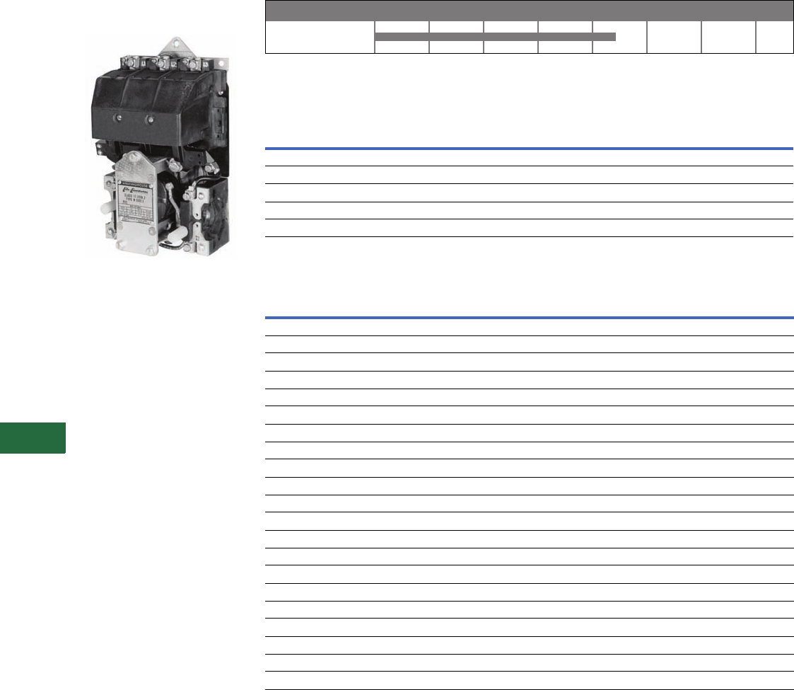
V12-T13-22 Volume 12—Aftermarket, Renewal Parts and Life Extension Solutions CA08100014E—November 2013 www.eaton.com
1
2
3
4
5
6
7
8
9
10
11
12
13
14
15
16
17
18
19
20
21
22
23
24
25
13
Motor Control
Contactors, Starters and Brakes
Type N
Originally a Westinghouse
Product
Type N Contactor
Product History Time Line for Type N
Replacement Capabilities
Contact Kits
AC Coils
Technology Upgrades
Sizes 00–3—Freedom or IT.
Sizes 4–5—Freedom,
Vacuum or IT.
0–4
Size 1940 1950 1960 1970 1980 1990 2000 Present
NEMA
Size Poles
Style
Number
031605226
131605212
231605202
331625563
431625564
Voltage Hz
Part Number
Two-, Three-Pole Four-, Five-Pole
Original New Original New
Sizes 0, 1
220/380/440 25/50/60 1470243 9969D90G03 1470263 9969D90G18
550 60 1470244 9969D90G04 N/A N/A
120 60 1605268 9969D90G09 N/A N/A
115/208/230 60/60/60 1605513 9969D90G15 N/A N/A
600 60 1470245 9969D90G20 N/A N/A
Size 2
110/208/220 25/60/60 1470202 9969D92G02 1470222 9969D93G02
220/380/440/480 25/50/60/60 1470203 9969D92G03 N/A N/A
600 60 1470205 9969D92G08 1470225 9969D93G08
120/110 60/50 1605478 9969D92G10 N/A N/A
Size 3
110/208/220 25/60/60 1490646 9969D96G05 1490646 9969D96G05
220/380/400/440 25/50/50/60 1490647 9969D96G06 1490647 9969D96G06
120/110 60/50 1600770 9969D96G09 1600770 9969D96G09
600/500 60/50 1490649 9969D96G21 1490649 9969D96G21
Size 4
110/208/220 25/60/60 1490658 9969D96G11 1597724 9969D96G02
600/500 60/50 1596635 9969D96G16 1490649 9969D96G21
440 60 1490659 9969D96G12 N/A N/A
120/110 60/50 1600771 9969D96G20 N/A N/A
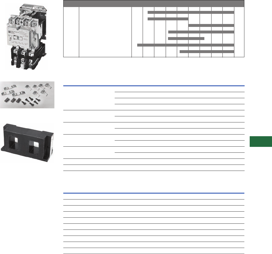
Volume 12—Aftermarket, Renewal Parts and Life Extension Solutions CA08100014E—November 2013 www.eaton.com V12-T13-23
1
2
3
4
5
6
7
8
9
10
11
12
13
14
15
16
17
18
19
20
21
22
23
24
25
13
Motor Control
Contactors, Starters and Brakes
A200
Originally a Westinghouse
Product
A200 Size 1 Starter
Contact Kit for A200 Model J,
Size Two-, Three-Pole
A200 AC Coil, 120/110V, 60/50 Hz,
Two-, Three-, Four-Pole, Sizes 00, 0 and 1
Product History Time Line for A200, A201, A203, A204, A206, A210, A211, A213, A214, A216,
A220, A223, A224, A226, A250, A251, A600, A603, A604, A606, A700, A703, A704, A706, A800,
A804 and A806
Replacement Capabilities
Kits for Model J, Sizes 00, 0, 1 and 2 1
AC Coils
Notes
1Model C contact kits and coils 00–4, two-, three-, four- and five-pole contactors are same as Model J.
All other parts are unavailable.
2Use quantity two—373B331G11 (two-pole kit).
3Use one each of 373B331G11 (two-pole kit) and 373B331G12 (three-pole kit).
4Mounting hardware included.
5Dual voltage coils. Use only on contactors or starters originally supplied with a dual voltage coil.
00–3 J
4 J
4 K
5–6 Electrically held
5–6 Mechanically held
7–8
9
Size Model 1960 1965 1970 1975 1980 1985 1990 1995 2000 Present
Description Poles Size 00 Size 0 Size 1 Size 2
Contact kit 2 373B331G17 373B331G02 373B331G07 373B331G11
3373B331G18 373B331G04 373B331G09 373B331G12
4373B331G18 373B331G04 373B331G09 373B331G13 2
5373B331G19 373B331G05 373B331G10 373B331G14 3
Arc box 42–4 6714C74G01 6714C74G02 6714C74G03 6714C74G07 (two-, three-pole)
56714C74G04 6714C74G05 6714C74G06 6714C74G08 (four-, five-pole)
Cross bar 2–3 N/A N/A N/A 672B788G32
4–5 N/A N/A N/A 672B788G34
Upper base (for single rated coils only) 2–3 N/A N/A N/A 672B788G33
4–5 N/A N/A N/A 672B788G35
Lower base 2–3 N/A N/A N/A 1250C33G09
4–5 N/A N/A N/A 1250C33G05
KO spring (pk. of 10) All N/A N/A N/A 503C796G01
Terminal line/load (pk. of 3) All N/A N/A N/A 371B870G03
Voltage Hz
Sizes 00, 0 and 1 Size 2
Two-, Three-, Four-Pole Five-Pole Two-, Three-Pole Four-, Five-Pole
120/110 60/50 505C806G01 505C808G01 505C806G01 505C818G01
208 60 505C806G02 505C808G02 505C806G02 505C818G02
600/550 60/50 505C806G05 505C808G05 505C806G05 505C818G05
380 50 505C806G07 505C808G07 505C806G07 505C818G07
240/220 60/50 505C806G12 505C808G12 505C806G12 505C818G12
480/440 60/50 505C806G13 505C808G13 505C806G13 505C818G13
24 60 505C806G16 N/A 505C806G16 505C818G15
277 60 505C806G18 505C808G16 505C806G18 505C818G16
240/480 560/60 505C806G03 505C808G03 505C806G03 505C818G03
120/240 560/60 505C806G10 505C808G10 505C806G10 505C818G10
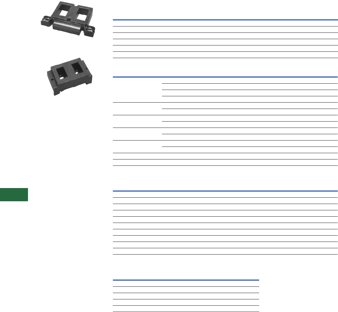
V12-T13-24 Volume 12—Aftermarket, Renewal Parts and Life Extension Solutions CA08100014E—November 2013 www.eaton.com
1
2
3
4
5
6
7
8
9
10
11
12
13
14
15
16
17
18
19
20
21
22
23
24
25
13
Motor Control
Contactors, Starters and Brakes
A200 AC Coil, 110/120V, 60 Hz, Size 6
A200 AC Coil, 120/110V, 60/50 Hz,
Two-, Three-Pole, Sizes 3 and 4, Model J
DC Coils 1
Kits for Model J–K, Sizes 3 and 4 3
AC Coils
DC Coils k
Notes
1Use only on contactors originally supplied with a DC coil.
2Dual voltage coils. Use only on contactors or starters originally supplied with a dual voltage coil.
3Model C contact kits and coils 00–4, two-, three-, four- and five-pole contactors are same as Model J.
All other parts are unavailable.
4Model K replaces Model J.
5Use quantity two–626B187G12 (two-pole kits).
6Use one of each of 626B187G12 (two-pole kit) and 626B187G13 (three-pole kit).
7Use quantity two–626B187G16 (two-pole kit).
8Use one each of 626B187G16 (two-pole kit) and 626B187G17 (three-pole kit).
9Model K replaces Model J.
jDual voltage coils. Use only on contactors or starters originally supplied with a dual voltage coil.
kUse only on units originally supplied with DC coil.
Voltage
Size 0Size 1Size 2
Single-, Two-, Three-, Four-Pole Single-, Two-, Three-, Four-Pole Single-, Two-, Three-, Four-Pole
12 1268C86G07 1268C86G07 1268C86G07
24 1268C86G04 1268C86G04 1268C86G04
48 1268C86G05 1268C86G05 1268C86G05
125 1268C86G02 1268C86G02 1268C86G02
250 1268C86G01 1268C86G01 1268C86G01
125/250 21268C86G03 1268C86G03 1268C86G03
Description Poles Size 3—Model J Size 4—Model J Size 4—Model K 4
Contact kit 2 626B187G12 626B187G16 5250C81G16
3626B187G13 626B187G17 5250C81G17
4626B187G14 5626B187G18 75250C81G18
5626B187G15 6626B187G19 85250C81G19
Arc box 2–3 6714C74G09 6714C74G11 6714C74G11
4–5 6714C74G10 6714C74G12 6714C74G12
Cross bar 2–3 672B788G36 672B788G36 672B788G40
4–5 672B788G38 672B788G38 —
Upper base 2–3 672B788G37 672B788G37 672B788G52
4–5 672B788G39 672B788G39 —
Lower base 2–3 1250C33G03 1250C33G03 1250C33G10
4–5 1250C33G06 1250C33G06 —
KO spring (pk. of 10) All 503C796G02 503C796G02 672B788G50
Terminals line/load (pk. of 3) All 372B357G12 372B357G13 372B357G13
Voltage Hz
Model J, Sizes 3–4 Model K, Size 4 9
Two-, Three-Pole Four-, Five-Pole Two-, Three-Pole Four-, Five-Pole
120/110 60/50 505C633G01 505C635G01 5250C79G01 5250C80G01
208 60 505C633G02 505C635G02 5250C79G02 5250C80G02
600/550 60/50 505C633G05 505C635G05 5250C79G05 5250C80G05
380 50 505C633G07 505C635G07 5250C79G07 5250C80G07
240/220 60/50 505C633G12 505C635G12 5250C79G12 5250C80G12
480/440 60/50 505C633G13 505C635G13 5250C79G13 5250C80G13
24 60 505C633G34 N/A 5250C79G34 N/A
277 60 505C633G14 N/A 5250C79G14 N/A
240/480 j60/60 505C633G03 505C635G03 5250C79G03 5250C80G03
120/240 j60/60 505C633G10 505C635G10 5250C79G10 5250C80G10
Voltage
Model J, Sizes 3–4
Two-, Three-Pole
24 1255C68G04
48 1255C68G05
125 1255C68G01
250 1255C68G02
125/250 1255C68G03

Volume 12—Aftermarket, Renewal Parts and Life Extension Solutions CA08100014E—November 2013 www.eaton.com V12-T13-25
1
2
3
4
5
6
7
8
9
10
11
12
13
14
15
16
17
18
19
20
21
22
23
24
25
13
Motor Control
Contactors, Starters and Brakes
Kits for GCA 530/630, Sizes 5–9—and GPD Sizes 7–9 1
Coils Coils
Notes
1Catalog No. A201/A200 Series replaces GCA/GPD Series. Renewal parts are the same.
2Use 477B477G06 for Silver Tungsten applications.
3CT Kit replaces the single molded one CT assembly used on the old Size 6 airbrake. The kit
includes a single molded three CT assembly, two busbars and hardware. This CT Kit also
replaces the single molded three CT assembly used on the present Size 6 airbrake and Size 6
vacuum contactor.
4Rectifier 125V 2018A40G01 (one required).
5Rectifier 250V 2018A40G02 (one required).
6Rectifier 600V 2018A40G03 (one required).
7These coils require an external rectifier. If the rectifier needs to be replaced, order by the
appropriate style number.
Kit Size 5 Size 6 Size 7 Size 8 Size 9
Contact kit (one per pole) 477B477G05 22066A10G11 461A757G17 646C829G05 5264C42G01 (rear connected)
— — — — 5264C42G02 (front connected)
Arc box 2050A15G45 2066A10G45 831D580G01 831D580G01 9917D69G02
Magnet assembly 2050A15G46 2050A15G46 N/A N/A N/A
Magnet spacing kit 2050A15G47 2050A15G47 N/A N/A N/A
Arc cup kit 2050A15G48 N/A N/A N/A N/A
Load connection kit 2050A15G49 2066A10G49 N/A N/A N/A
Line connection kit 2050A15G50 2066A10G50 N/A N/A N/A
KO spring-6 2050A15G51 2066A10G46 N/A N/A N/A
CT 300/5 655C285H03 N/A N/A N/A N/A
CT 400/5 655C285H04 — — — —
CT 600/5 N/A 2066A10G18 3N/A N/A N/A
CT 800/5 N/A 2066A10G19 3N/A N/A N/A
Phase barrier N/A N/A 640C441G01 640C441G01 5264C35G03 (rear connected)
Cross bar 2050A15G12 2066A10G15 N/A N/A N/A
Shunt N/A 2066A10G48 650C129G01 646C831G02 (set of three) 5264C39G02 (set of four)
Voltage Hz Size 5 Size 6
110/120 60 2050A14G05 2050A12G05
110/120 50 2050A14G06 2050A12G06
200/208 50 2050A14G07 2050A12G07
220/240 50 2050A14G08 2050A12G08
200/208 60 2050A14G09 2050A12G09
220/240 60 2050A14G10 2050A12G10
277/303 60 2050A14G12 2050A12G12
380/415 50 2050A14G14 2050A12G14
440/480 60 2050A14G15 2050A12G15
440/480 50 2050A14G16 2050A12G16
550/600 60 2050A14G17 2050A12G17
550/600 50 2050A14G18 2050A12G18
380/415 60 2050A14G19 2050A12G19
120/240 60 2050A14G20 2050A12G20
24 DC — 2050A14G21 2050A12G21
48 DC — 2050A14G22 2050A12G22
125 DC — 2050A14G25 2050A12G25
250 DC — 2050A14G27 2050A12G27
Line Voltage Sizes 7–8 Required Size 9
115 Vdc 438C805G01 2 100 Vdc
5264C34G01
(contains coil
and resistor)
125 Vdc 438C805G04 2
230 Vdc 438C805G02 2
250 Vdc 438C805G03 2
110/120 Vac 47 438C805G12 2
220/240 Vac 57 438C805G11 2
380 Vac 67 438C805G15 2
440/480 Vac 67 438C805G10 2
550/575 Vac 67 438C805G13 2
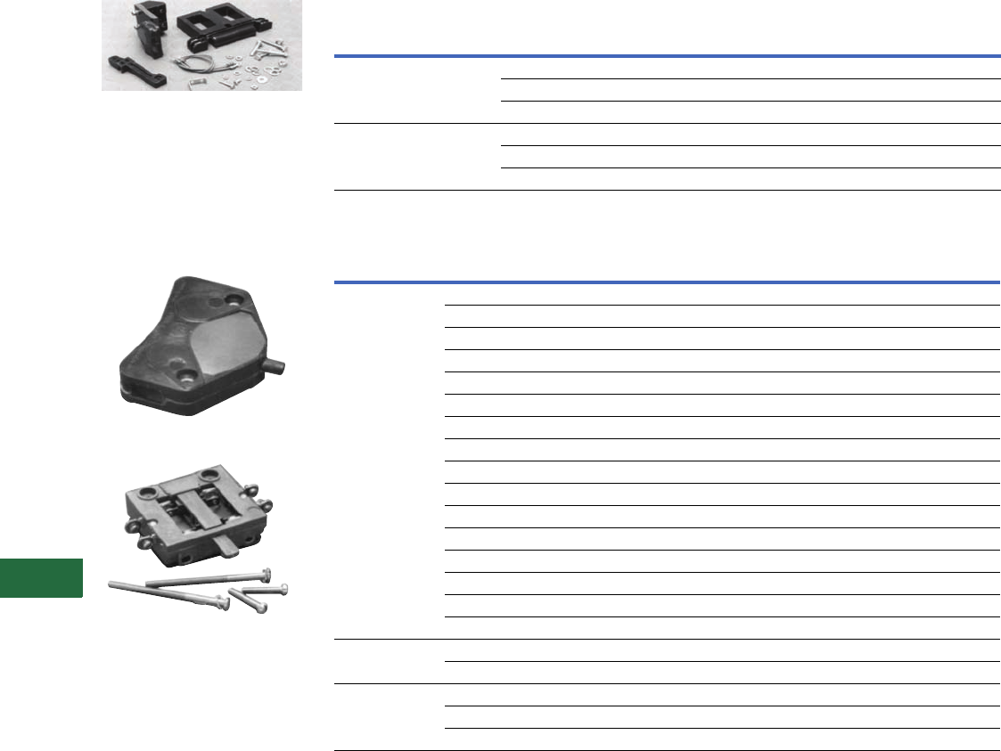
V12-T13-26 Volume 12—Aftermarket, Renewal Parts and Life Extension Solutions CA08100014E—November 2013 www.eaton.com
1
2
3
4
5
6
7
8
9
10
11
12
13
14
15
16
17
18
19
20
21
22
23
24
25
13
Motor Control
Contactors, Starters and Brakes
DC Coil Conversion Kit—
Style Number 7864A29G01
A rectifier circuit converts the
AC supply to DC supply. This
conversion provides quiet
operation and improves
pickup and dropout
characteristics. All necessary
parts are included in the kit.
L63—Style Number 578D461G01
L64—Style Number 843D943G04
Accessories for Size 5–9 AC Contactors—Coils
Accessories for Size 5–9 AC Contactors—Auxiliary Electrical Interlock
Technology Upgrades
Sizes 00–3—Freedom or IT.
Sizes 4–6—Freedom, Vacuum or IT.
Sizes 7–8—Freedom
Size 9—No upgrade available
AC Contactors Voltage
AC/DC Coil
Conversion Kit
Replacement
Coil
Size 5 120 Vac 7864A28G01 7856A15G05
240 Vac 7864A28G02 7856A15G10
480 Vac 7864A28G03 7856A15G15
Size 6 120 Vac 7864A29G01 7856A16G05
240 Vac 7864A29G02 7856A16G10
480 Vac 7864A29G03 7856A16G15
Contactor Size
Catalog
Number
(Obsolete)
Style Number
(Obsolete) Circuits
Catalog
Number
(Current)
Style
Number
(Current)
00–6 (L-56) (2609D01G01) 1NO and 1NC J11 9084A17G01
(L-56D) (2609D01G02) 2NO J20 9084A17G02
(L-56E) (2609D01G03) 1NO and 1NC J11 9084A17G01
(L-56B) (2609D01G04) 2NO J20 9084A17G02
(L-56H) (2609D01G05) 2NO J20 9084A17G02
(L-56J) (2609D01G06) 1NO and 1NC DB J1C N/A
(T-56A) (2609D01G07) N/A N/A N/A
(T-56A) (2609D01G07) N/A N/A N/A
(T-56B) (2609D01G08) N/A N/A N/A
(L-56F) (2609D01G09) N/A N/A N/A
(L-56G) (2609D01G10) 1NO and 1NC DB J1C 9084A17G04
(L-56C) (2609D01G11) 2NC J02 9084A17G03
(L-56M) (2609D01G12) N/A N/A N/A
(L-56P) (2609D01G17) 1NO and 1NC J11 9084A17G01
(L-56R) (2609D01G18) 2NC J02 9084A17G03
(L-56S) (2609D01G19) 1NO and 1NC J11 9084A17G01
7–8 L63 — NO — 578D461G01
L63 — NC — 578D461G03
9L64—NO/NC—843D943G04
L64 — 2NO — 843D943G05
L64 — 2NC — 843D943G06
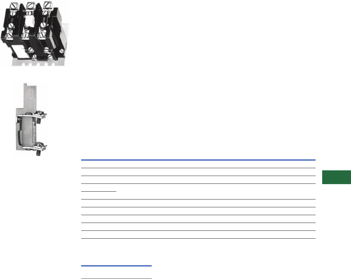
Volume 12—Aftermarket, Renewal Parts and Life Extension Solutions CA08100014E—November 2013 www.eaton.com V12-T13-27
1
2
3
4
5
6
7
8
9
10
11
12
13
14
15
16
17
18
19
20
21
22
23
24
25
13
Motor Control
Contactors, Starters and Brakes
Manual Reset, Class 20,
Thermal Type B Overload
Relay
Type B Overload Relay, Panel Mounted
Field-Mountable Alarm Contact
Note: Alarm contact available as
factory modification of field
mountable. For factory
modification, add suffix B.
Application Description
The Type B overload relay is
designed to protect industrial
motors against overload
conditions. Using modern
block-type, bimetallic design,
this relay will provide Class 20
operation in either single-
phase or three-phase
applications.
Features
●Ambient compensation
standard
●Alarm contact field
mountable
●Class 20—600V design
●Inverse time delay trip
●Test trip device for weld
check
●High visibility up-front trip
indication
●Trip-free reset mechanism
Operation
The Type B overload relay is a
bimetallic actuated device. The
bimetal elements are operated
by precisely calibrated heaters.
The heater elements connect
either directly in the circuit to
be measured, or through
current transformers on
applications NEMA Size 5
and larger.
As the bimetals are heated by
motor current flow, a
deflection force is produced.
Upon a sustained level of
abnormal current flow, the
deflection becomes great
enough to open the snap
action output contact.
Ambient Compensation
The Type B ambient
compensated design is
supplied as standard on all
A200 starters. This design
uses a second compensating
bimetal responsive to
ambient air temperature in
the surrounding enclosure.
This feature reduces
nuisance tripping in
applications using compact
control panels and motor
control centers where
internal temperature rise is
significant compared to
motor ambient temperature.
The compensating
characteristic is maintained in
ambient temperatures from
40°C to 77°C.
Design Standards
UL® 508, CSA®, ANSI/NEMA
ICS 2-222.
Overload Relay Selection Table
For replacement in existing applications only.
Alarm Contact Kit Selection Heaters
Price of overload relay does
not include heaters. Select
from the tables on Pages
V12-T13-30 to V12-T13-32.
Notes
1Includes contactor mounting bracket,
overload relay and connection straps
to contactor.
2For replacement on B200 sizes 00, 0
and 1, use BA23A instead of BA13A
and use BN23A instead of BN13A.
Motor Full
Load
Amperes
Panel Mounted
Catalog Number
Starter Mounted Catalog Number
Replacement for Type B
Overload Relays
Replacement for Type A Overload
Relays in Manual Reset Mode
(Three-Pole Only) 1
Ambient
Comp. Non-Comp.
Ambient
Comp. Non-Comp.
Ambient
Comp. Non-Comp.
Single-Pole (One NC Contact)
0.25–26.2 BA11JP BN11JP BA11A BN11A ——
26.3–45.0 BA21JP BN21JP BA21A BN21A ——
19.0–90.0 Use three-pole design, wire three-poles in series
19.0–135.0
Three-Pole (One NC Contact)
0.25–26.2 BA13JP BN13JP BA13A 2BN13A 2BA13J BN13J
26.3–45.0 BA23JP BN23JP BA23A BN23A BA23J BN23J
19.0–90.0 BA33P BN33P BA33A BN33A BA33A BN33A
19.0–135.0 BA43P BN43P BA43A BN43A BA43A BN43A
Type B Overload
Relay Size
Catalog
Number
1, 2
3, 4
B3NO-2
B3NO-4
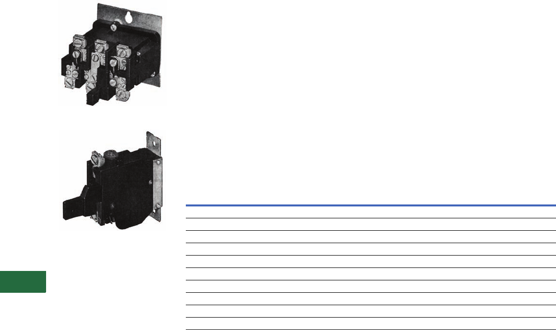
V12-T13-28 Volume 12—Aftermarket, Renewal Parts and Life Extension Solutions CA08100014E—November 2013 www.eaton.com
1
2
3
4
5
6
7
8
9
10
11
12
13
14
15
16
17
18
19
20
21
22
23
24
25
13
Motor Control
Contactors, Starters and Brakes
Auto/Manual Reset,
Class 20, Thermal Type A
Overload Relay
Three-Pole Panel Mounted
Single-Pole Panel Mounted
Application Description
The Type A overload relay is
designed to protect industrial
motors against overload
conditions. Using modern
block-type, bimetallic design,
this relay will provide Class 20
operation in either single-
phase or three-phase
applications.
Features
●Field selectable manual/
auto reset
●Alarm contact factory
available
●Class 20—600V design
●Inverse time delay trip
●Adjustable trip rating
±15%
●Color-coded reset rod:
Compensated (gray)
Non-compensated (red)
Operation
The Type A overload relay is a
bimetallic actuated device. The
bimetal elements are operated
by precisely calibrated heaters.
The heater elements
connected either directly in the
circuit to be measured, or
through current transformers
on applications NEMA Size 5
and larger.
As the bimetals are heated by
motor current flow, a
deflection force is produced.
Upon a sustained level of
abnormal current flow, the
deflection becomes great
enough to open the snap
action output contact.
Automatic Reset
The Type A overload relay can
be supplied as an option on all
A200 starters to provide
automatic reset operation.
The overload relay is always
shipped in the non-automatic
mode. To set up auto
operation, reposition the
reset rod by loosening and re-
tightening a hold-down clamp
at the base of overload relay.
Design Standards
UL 508, CSA, ANSI/NEMA
ICS 2-222.
Overload Relay Selection Table
For replacement in existing applications only.
Heaters
Price of overload relay does
not include heaters. Select
from the tables on Pages
V12-T13-30 to V12-T13-32.
Notes
1 Three-pole Type B Overload Relay is a
suitable alternative to a three-pole Type
A Overload Relay in Manual Reset Mode.
For example, use BA13JP for AA13P
and BN23J for AN23A, etc. (See
Page V12-T13-27.)
Alarm contact available only as factory
modification on Type A relay.
Motor Full
Load Amperes
Panel Mounted Catalog Number Starter Mounted Catalog Number
Ambient Comp. Non-Comp. Ambient Comp. Non-Comp.
Single-Pole (One NC Contact)
0.25–26.2 AA11P AN11P AA11A AN11A
26.3–45.0 AA21P AN21P AA21A AN21A
19.0–90.0 AA31P AN31P AA31A AN31A
19.0–135.0 AA41P AN41P AA41A AN41A
Three-Pole (One NC Contact) 1
0.25–26.2 AA13P AN13P AA13A AN13A
26.3–45.0 AA23P AN23P AA23A AN23A
19.0–90.0 AA33P AN33P AA33A AN33A
19.0–135.0 AA43P AN43P AA43A AN43A
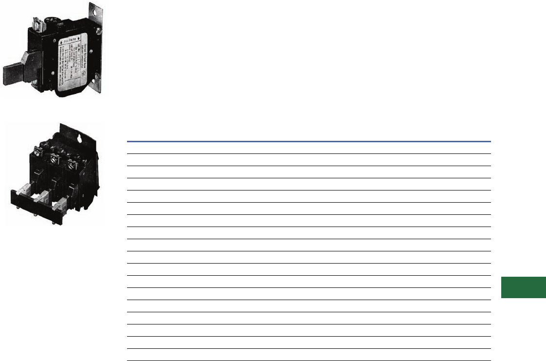
Volume 12—Aftermarket, Renewal Parts and Life Extension Solutions CA08100014E—November 2013 www.eaton.com V12-T13-29
1
2
3
4
5
6
7
8
9
10
11
12
13
14
15
16
17
18
19
20
21
22
23
24
25
13
Motor Control
Contactors, Starters and Brakes
Type FT Fast Trip,
Class 10
Overload Relay
Single-Pole Fast Trip, Panel Mounted
Three-Pole Fast Trip, Panel Mounted
Application Description
The Type FT overload relay is
designed to protect special
purpose motors having
restricted thermal and locked
rotor capabilities. Using
modern block-type, bimetallic
design, this relay will provide
Class 10 operation in single-
phase or three-phase
applications.
Features
●Class 10—600V design
●Inverse time delay trip
●Color-coded reset rod—
green
●Alarm contact factory
available
●Field selectable manual/
auto reset
●Adjustable trip rating
±20%
●Ambient compensation
included
Operation
The Type FT overload relay is
a bimetallic actuated device.
The bimetal elements are
operated directly from line
current, thus separate
calibrating heater elements
are not used. The overload
relay may be wired directly in
the motor circuit, or through
current transformers on
applications larger than 150A.
As the bimetals are heated
by motor current flow, a
deflection is produced. Upon
a sustained level of abnormal
current flow, the deflection
becomes great enough to
open the snap action output
contact.
Overload Relay Selection Table
For replacement in existing applications only.
Notes
1Single-pole (one NO–NC contact): Add suffix B.
2Three-pole (three NO–NC contacts): Add suffix B. Example: FT13PB-12.
Alarm contact available only as factory modification on FT relay.
Motor Full Load
Amperes
Panel Mounted Catalog Number Starter Mounted Catalog Number 1
Single-Pole 1Three-Pole 2NEMA Size Single-Pole
Single-Pole (One NC Contact); Three-Phase (Three NC Contacts in Series)
0.76–1.1 FT11P-1.1 FT13P-1.1 —FT11A-1.1
1.1–1.6 FT11P-1.6 FT13P-1.6 —FT11A-1.6
1.6–2.4 FT11P-2.4 FT13P-2.4 0, 1 FT11A-2.4
2.4–3.6 FT11P-3.6 FT13P-3.6 0, 1 FT11A-3.6
3.6–5.4 FT11P-5.4 FT13P-5.4 0, 1 FT11A-5.4
5.4–8.0 FT11P-8 FT13P-8 0, 1 FT11A-8
8.0–12 FT11P-12 FT13P-12 0, 1 FT11A-12
12–18 FT11P-18 FT13P-18 1FT11A-18
16–24 FT11P-24 FT13P-24 1FT11A-24
22–32 FT11P-32 FT13P-32 0, 1 FT11A-32
24–36 FT21P-36 FT23P-36 2FT21A-36
36–54 FT21P-54 FT23P-54 2FT21A-54
22–32 FT31P-32 FT33P-32 3FT31A-32
32–48 FT31P-48 FT33P-48 3FT31A-48
48–72 FT31P-72 FT33P-72 3FT31A-72
72–110 FT41P-110 FT43P-110 4FT41A-110
100–150 FT41P-150 FT43P-150 4FT41A-150

V12-T13-30 Volume 12—Aftermarket, Renewal Parts and Life Extension Solutions CA08100014E—November 2013 www.eaton.com
1
2
3
4
5
6
7
8
9
10
11
12
13
14
15
16
17
18
19
20
21
22
23
24
25
13
Motor Control
Contactors, Starters and Brakes
Heaters for Thermal
Types A and B Overload
Relays
Product Description
Each heater is identified by
a catalog number stamped
on one terminal. The heater
application table indicates
the range of full load motor
current to which a given
heater may be applied.
Heaters should be selected
on the basis of the actual
full load current and service
factor as shown on the
motor nameplate or in the
manufacturer’s published
literature.
When motor and overload
relay are in the same ambient
and the service factor of the
motor is 1.15 to 1.25, select
heaters from the heater
application table. If the service
factor of the motor is 1.0, or
there is no service factor
shown, or a maximum of
115% protection is desired,
select one size smaller
heater than indicated.
When motor and overload
relay are in different
ambients and when using
non-compensated overload
relays, select heaters from
the tables on Pages
V12-T13-30 through
V12-T13-32 using adjusted
motor currents as follows:
decrease rated motor current
1% for each °C motor
ambient exceeds controller
ambient. Increase rated
motor current 1% for each °C
controller ambient exceeds
motor ambient.
For temperature
compensated overload
relays, select heaters
according to the tables on
Pages V12-T13-30 through
V12-T13-32 and selection
information above regardless
of ambient.
Protect the starter against
short circuits by providing
branch circuit protection
per National Electrical
Code® (NEC®).
Heater Selection for Types A and B Overload Relays, Sizes 00, 0, 1 and 2 Starters
Notes
1Based on 60°C and 75°C wire for 30A or less.
2Based on 60°C wire for 31 to 95A.
Heaters are packaged in strips of six. Minimum ordering quantity is 12.
Non-Compensated Open Starters and
Ambient Compensated Open and Enclosed Starters
Non-Compensated
Enclosed Starters
Heater
Catalog
Number
Block-Type Overload
Using Three Heaters
Single-Pole
Type Overload
Block-Type Overload
Using Three Heaters
Single-Pole
Type Overload
Full Load Current of Motor (Amperes) 12
For Sizes 0, 1 and 2 Starters
0.25–0.27 0.29–0.31 0.24–0.25 0.28–0.30 FH03
0.28–0.31 0.32–0.35 0.26–0.28 0.31–0.34 FH04
0.32–0.34 0.36–0.39 0.29–0.31 0.35–0.37 FH05
0.35–0.38 0.40–0.43 0.32–0.35 0.38–0.42 FH06
0.39–0.42 0.44–0.48 0.36–0.39 0.43–0.47 FH07
0.43–0.46 0.49–0.53 0.40–0.43 0.48–0.52 FH08
0.47–0.50 0.54–0.58 0.44–0.47 0.53–0.56 FH09
0.51–0.55 0.59–0.64 0.48–0.51 0.57–0.63 FH10
0.56–0.62 0.65–0.71 0.52–0.57 0.64–0.70 FH11
0.63–0.68 0.72–0.79 0.58–0.63 0.71–0.77 FH12
0.69–0.75 0.80–0.87 0.64–0.70 0.78–0.85 FH13
0.76–0.83 0.88–0.96 0.71–0.77 0.86–0.94 FH14
0.84–0.91 0.97–1.06 0.78–0.85 0.95–1.03 FH15
0.92–1.00 1.07–1.16 0.86–0.93 1.04–1.13 FH16
1.01–1.11 1.17–1.28 0.94–1.03 1.14–1.25 FH17
1.12–1.22 1.29–1.41 1.04–1.13 1.26–1.38 FH18
1.23–1.34 1.42–1.55 1.14–1.25 1.39–1.52 FH19
1.35–1.47 1.56–1.71 1.26–1.37 1.53–1.67 FH20
1.48–1.62 1.72–1.87 1.38–1.51 1.68–1.83 FH21
1.63–1.78 1.88–2.06 1.52–1.65 1.84–2.01 FH22
1.79–1.95 2.07–2.26 1.66–1.81 2.02–2.21 FH23
1.96–2.15 2.27–2.48 1.82–1.99 2.22–2.43 FH24
2.16–2.35 2.49–2.72 2.00–2.19 2.44–2.66 FH25
2.36–2.58 2.73–2.99 2.20–2.39 2.67–2.92 FH26
2.59–2.83 3.00–3.28 2.40–2.63 2.93–3.21 FH27
2.84–3.11 3.29–3.60 2.64–2.89 3.22–3.53 FH28
3.12–3.42 3.61–3.95 2.90–3.17 3.54–3.87 FH29
3.43–3.73 3.96–4.31 3.18–3.47 3.88–4.22 FH30
3.74–4.07 4.32–4.71 3.48–3.79 4.23–4.61 FH31
4.08–4.39 4.72–5.14 3.80–4.11 4.62–4.9 FH32
4.40–4.87 5.15–5.6 4.12–4.55 5.0–5.5 FH33
4.88–5.3 5.7–6.2 4.56–5.0 5.6–6.0 FH34

Volume 12—Aftermarket, Renewal Parts and Life Extension Solutions CA08100014E—November 2013 www.eaton.com V12-T13-31
1
2
3
4
5
6
7
8
9
10
11
12
13
14
15
16
17
18
19
20
21
22
23
24
25
13
Motor Control
Contactors, Starters and Brakes
Heater Selection for Types A and B Overload Relays, Sizes 00, 0, 1 and 2 Starters, continued
Notes
1Based on 60°C and 75°C wire for 30A or less.
2Based on 60°C wire for 31 to 95A.
Heaters are packaged in strips of six. Minimum ordering quantity is 12.
Non-Compensated Open Starters and
Ambient Compensated Open and Enclosed Starters
Non-Compensated
Enclosed Starters
Heater
Catalog
Number
Block-Type Overload
Using Three Heaters
Single-Pole
Type Overload
Block-Type Overload
Using Three Heaters
Single-Pole
Type Overload
Full Load Current of Motor (Amperes) 12
For Sizes 0, 1 and 2 Starters
5.4–5.9 6.3–6.8 5.1–5.5 6.1–6.6 FH35
6.0–6.4 6.9–7.5 5.6–5.9 6.7–7.3 FH36
6.5–7.1 7.6–8.2 6.0–6.6 7.4–8.0 FH37
7.2–7.8 8.3–9.0 6.7–7.2 8.1–8.7 FH38
7.9–8.5 9.1–9.9 7.3–7.9 8.8–9.7 FH39
8.6–9.4 10.0–10.8 8.0–8.7 9.8–10.5 FH40
9.5–10.3 10.9–11.9 8.8–9.5 10.6–11.7 FH41
10.4–11.3 12.0–13.1 9.6–10.5 11.8–12.7 FH42
11.4–12.4 13.2–14.3 10.6–11.5 12.8–14.0 FH43
12.5–13.5 14.4–15.7 11.6–12.6 14.1–15.3 FH44
13.6–14.9 15.8–17.2 12.7–13.8 15.4–16.6 FH45
15.0–16.3 — 13.9–15.1 — FH46
16.4–18.0 — 15.2–16.7 — FH47
For Sizes 1 and 2 Starters
—17.3–18.9 — 16.7–18.3 FH46
—19.0–20.8 — 18.4–20.0 FH47
18.1–19.8 20.9–22.9 16.8–18.3 20.1–21.9 FH48
19.9–21.7 23.0–25.2 18.4–20.2 22.0–23.9 FH49
21.8–23.9 25.3–27.6 20.3–22.2 24.0–26.2 FH50
24.0–26.2 — 22.3–24.3 — FH51
— — 24.4–26.6 — FH52
For Size 2 Starters
—27.7–30.3 — 26.3–28.8 FH51
26.3–28.7 30.4–33.3 — 28.9–31.4 FH52
28.8–31.4 33.4–36.4 26.7–29.1 31.5–34.5 FH53
31.5–34.0 36.5–39.9 29.2–32.0 34.6–37.9 FH54
34.6–37.9 42.0–43.9 32.1–35.2 38.0–41.9 FH55
38.0–41.5 — 35.3–38.5 42.0–45.0 FH56
41.6–45.0 — 38.6–42.3 — FH57

V12-T13-32 Volume 12—Aftermarket, Renewal Parts and Life Extension Solutions CA08100014E—November 2013 www.eaton.com
1
2
3
4
5
6
7
8
9
10
11
12
13
14
15
16
17
18
19
20
21
22
23
24
25
13
Motor Control
Contactors, Starters and Brakes
Heater Selection for Types A and B Overload Relays,
Sizes 3 and 4 Starters 123
Ambient
Compensated
Enclosed Starters
Non-Compensated
Enclosed Starters Heater
Catalog
Number
All Applications
Full Load Current of Motor (Amperes) 1
For Sizes 3 and 4 Starters
12.8–14.1 11.9–13.0 FH68
14.2–15.5 13.1–14.3 FH69
15.6–17.1 14.4–15.9 FH70
17.2–18.9 16.0–17.4 FH71
19.0–20.8 17.5–19.1 FH72
20.9–22.9 19.2–21.1 FH73
23.0–25.2 21.2–23.2 FH74
25.3–27.8 23.3–25.6 FH75
27.9–30.6 25.7–28.1 FH76
30.7–33.5 28.2–30.8 FH77
33.6–37.5 30.9–34.5 FH78
37.6–41.5 34.6–38.2 FH79
41.6–46.3 38.3–42.6 FH80
46.4–50 42.7–46 FH81
51–55 47–51 FH82
56–61 52–56 FH83
62–66 57–61 FH84
67–73 62–67 FH85
74–78 68–72 FH86
79–84 73–77 FH87
85–92 78–84 FH88
— 85–91 FH89
For Size 4 Starters
93–101 — FH89
102–110 92–99 FH90
111–122 100–110 FH91
123–129 111–122 FH92
130–133 123–128 FH93
—129
–133 FH94
Heater Selection for Types A and B Overload Relays,
Sizes 5 and 6 Starters 4
Notes
1Based on 60°C and 75°C wire for 30A or less.
2Based on 60°C wire for 31 to 95A.
3Based on 75°C wire for greater than 95A.
4Based on 75°C wire.
Heaters are packaged in strips of six. Minimum ordering quantity is 12.
Compensated Overload Relay Heater
Catalog
Number
Open Starter Enclosed Starter
Full Load Current of Motor (Amperes)
Size 5 (With 300/5 Current Transformers)
——FH23
118–129 118–129 FH24
130–141 130–141 FH25
142–155 142–155 FH26
156–170 156–170 FH27
171–187 171–187 FH28
188–205 188–205 FH29
206–224 206–224 FH30
225–244 225–244 FH31
245–263 245–263 FH32
264–292 264–292 FH33
293–300 — FH34
Size 6 (With 600/5 Current Transformers)
——FH23
236–259 236–259 FH24
260–283 260–283 FH25
284–310 284–310 FH26
311–340 311–340 FH27
341–374 341–374 FH28
375–411 375–411 FH29
412–448 412–448 FH30
449–489 449–489 FH31
490–527 490–527 FH32
528–585 528–540 FH33
586–600 — FH34
Size 7 and Larger
Advise full load current
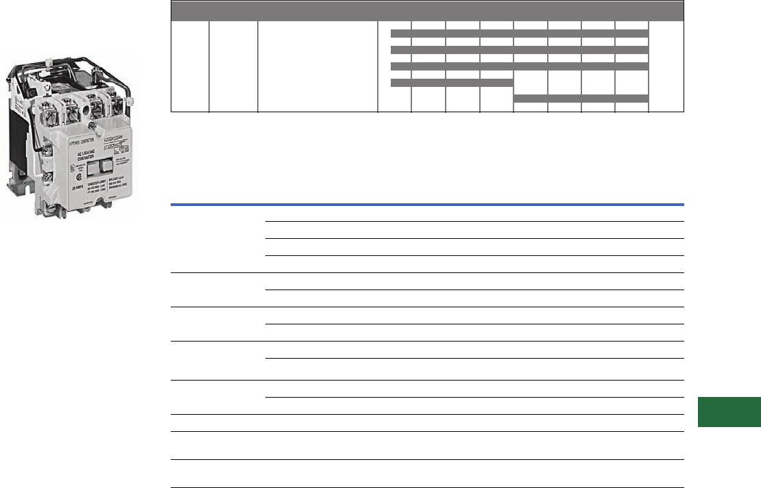
Volume 12—Aftermarket, Renewal Parts and Life Extension Solutions CA08100014E—November 2013 www.eaton.com V12-T13-33
1
2
3
4
5
6
7
8
9
10
11
12
13
14
15
16
17
18
19
20
21
22
23
24
25
13
Motor Control
Contactors, Starters and Brakes
A202 Lighting Contactor
(Electrically Held/
Magnetically Latched)
Originally a Westinghouse
Product
30A, Four-Pole Magnetically Latched
Product History Time Line for A202 Lighting Contactor
(Electrically Held/Magnetically Latched)
Replacement Capabilities
A202 Kits for 30 to 200A
Notes
1For 200A A202 Magnetically Latched Lighting Contactors, order three-pole contact kit style 672B788G07.
2Model K replaces Model J, offering superior design and life characteristics. Renewal parts are different.
Use parts for proper model only.
3Use quantity two–373B331G11 (two-pole kit).
4Use one each of 373B331G11 (two-pole kit) and 373B331G12 (three-pole kit).
5Use quantity two–626B187G12 (two-pole kit).
6Use one each of 626B187G12 (two-pole kit) and 626B187G13 (three-pole kit).
7Use quantity two–626B187G16 (two-pole kit).
8Use one each of 626B187G16 (two-pole kit) and 626B187G17 (three-pole kit).
Size Amperes Model 1965 1970 1975 1980 1985 1990 1995 2000 Present
Size 1 30
Size 2 60
Size 3 100
Size 4 200 J
Size 4 200 K
Description Poles 30A 60A 100A
200A—
Model J 1
200A—
Model K 2
Contact kit 2 373B331G07 373B331G11 626B187G12 626B187G16 5250C81G16
3373B331G09 373B331G12 626B187G13 626B187G17 5250C81G17
4373B331G09 3575250C81G18
5373B331G10 4685250C81G19
Arc box 2, 3, 4 6714C74G03 6714C74G07 6714C74G09 6714C74G11 6714C74G11
56714C74G06 6714C74G08 6714C74G10 6714C74G12 6714C74G12
Cross bar 2–3 — 672B788G32 672B788G36 672B788G36 672B788G40
4–5 — 672B788G34 672B788G38 672B788G38 —
Upper base
(for single rated
coils only)
2–3 — 672B788G33 672B788G37 672B788G37 672B788G52
4–5 — 672B788G35 672B788G39 672B788G39 —
Lower base 2–3 — 1250C33G09 1250C33G03 1250C33G03 1250C33G10
4–5 — 1250C33G05 1250C33G06 1250C33G06 —
Electrically Held Only
KO spring
(pack of 10)
All — 503C796G01 503C796G02 503C796G02 672B788G50
Terminal line/load
(pack of 3)
All — 371B870G03 372B357G12 372B357G13 372B357G13
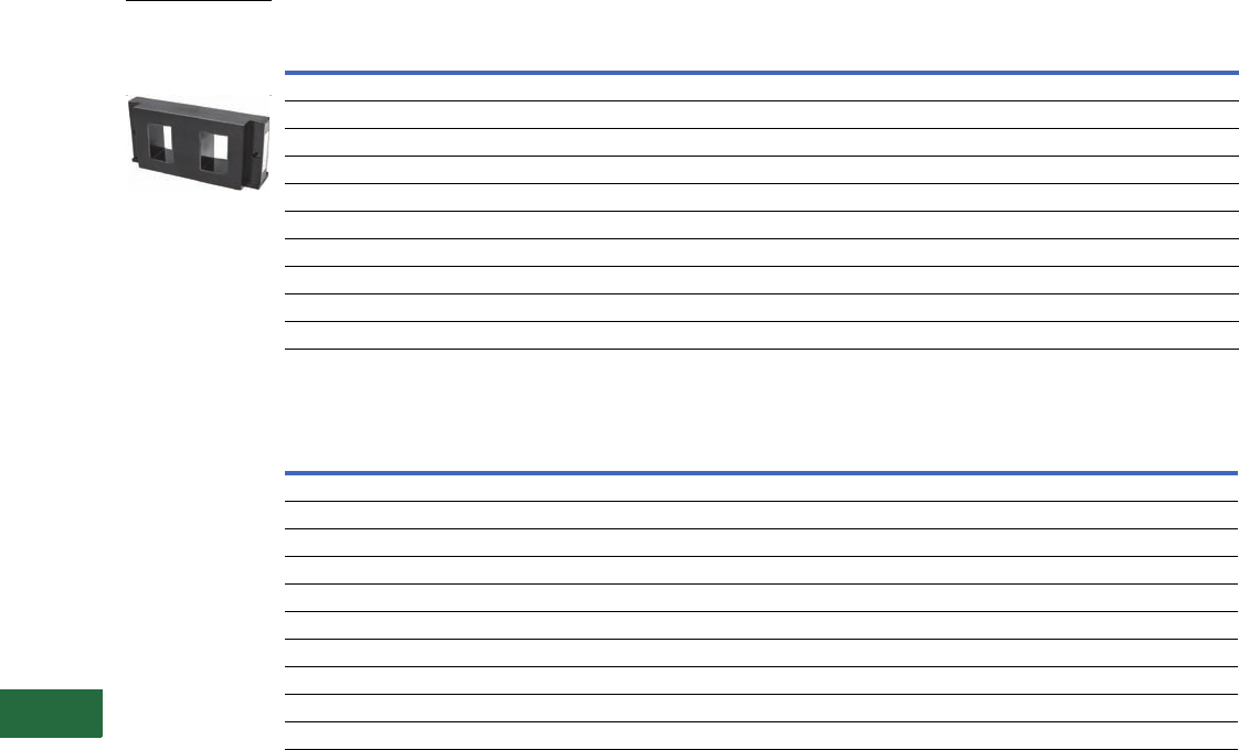
V12-T13-34 Volume 12—Aftermarket, Renewal Parts and Life Extension Solutions CA08100014E—November 2013 www.eaton.com
1
2
3
4
5
6
7
8
9
10
11
12
13
14
15
16
17
18
19
20
21
22
23
24
25
13
Motor Control
Contactors, Starters and Brakes
AC Coils Electrically Held
AC Coils Electrically Held, continued
Notes
1 Dual voltage coils. Use only on contactors or starters originally supplied with a dual voltage coil.
2 Model K replaces Model J. Renewal parts are different. Use parts for proper model only.
Voltage Hz
30A 60A
Two-, Three-, Four-Pole Five-Pole Two-, Three-Pole Four-, Five-Pole
120/110 60/50 505C806G01 505C808G01 505C806G01 505C818G01
208 60 505C806G02 505C808G02 505C806G02 505C818G02
600/550 60/50 505C806G05 505C808G05 505C806G05 505C818G05
380 50 505C806G07 505C808G07 505C806G07 505C818G07
240/220 60/50 505C806G12 505C808G12 505C806G12 505C818G12
480/440 60/50 505C806G13 505C808G13 505C806G13 505C818G13
24 60 505C806G16 N/A 505C806G16 505C818G15
227 60 505C806G18 505C808G16 505C806G18 505C818G16
240/480 160/60 505C806G03 505C808G03 505C806G03 505C818G03
120/240 160/60 505C806G10 505C808G10 505C806G10 505C818G10
Voltage Hz
100 and 200A—Model J 200A—Model K 2
Two-, Three-Pole Four-, Five-Pole Two-, Three-Pole Four-, Five-Pole
120/110 60/50 505C633G01 505C635G01 52050C79G01 5250C80G01
208 60 505C633G02 505C635G02 52050C79G02 5250C80G02
600/550 60/50 505C633G05 505C635G05 52050C79G05 5250C80G05
380 50 505C633G07 505C635G07 52050C79G07 5250C80G07
240/220 60/50 505C633G12 505C635G12 52050C79G12 5250C80G12
480/440 60/50 505C633G13 505C635G13 52050C79G13 5250C80G13
24 60 505C633G34 N/A 52050C79G34 N/A
227 60 505C633G14 N/A 52050C79G14 N/A
240/480 160/60 505C633G03 505C635G03 52050C79G03 5250C80G03
120/244 160/60 505C633G10 505C635G10 52050C79G10 5250C80G10
120V Coil for
Electrically Held
Lighting Contactor—
Style Number
505C633G01

Volume 12—Aftermarket, Renewal Parts and Life Extension Solutions CA08100014E—November 2013 www.eaton.com V12-T13-35
1
2
3
4
5
6
7
8
9
10
11
12
13
14
15
16
17
18
19
20
21
22
23
24
25
13
Motor Control
Contactors, Starters and Brakes
AC Coils Magnetically Latched
Terminals (Line and Load)
Other Accessories
Notes
1Order quantity of two for four-pole design.
2Group numbers for the five-pole terminals represent the combination of the two-pole and
three-pole number.
Voltage Hz Two-Pole Three-Pole Four-Pole Five-Pole
30A
110/120 50/60 7874A93G01 7874A93G01 7874A93G01 7874A89G01
208/240 50/60 7874A93G02 7874A93G02 7874A93G02 7874A89G02
277 50/60 7874A93G03 7874A93G03 7874A93G03 7874A89G03
440/480 50/60 7874A93G04 7874A93G04 7874A93G04 7874A89G04
575 50/60 7874A93G05 7874A93G05 7874A93G05 7874A89G05
60A
110/120 50/60 7874A93G01 7874A93G01 7874A87G01 7874A87G01
208/240 50/60 7874A93G02 7874A93G02 7874A87G02 7874A87G02
277 50/60 7874A93G03 7874A93G03 7874A87G03 7874A87G03
440/480 50/60 7874A93G04 7874A93G04 7874A87G04 7874A87G04
110/120 50/60 7874A93G01 7874A93G01 7874A87G01 7874A87G05
100 and 200A
110/120 50/60 7874A85G01 7874A85G01 7874A83G01 7874A83G01
208/240 50/60 7874A85G02 7874A85G02 7874A83G02 7874A83G02
277 50/60 7874A85G03 7874A85G03 7874A83G03 7874A83G03
440/480 50/60 7874A85G04 7874A85G04 7874A83G04 7874A83G04
550/575 50/60 7874A85G05 7874A85G05 7874A83G05 7874A83G05
Size Two-Pole Three-Pole Four-Pole Five-Pole
30A N/A N/A N/A N/A
60A 179C755G17 179C755G16 179C755G17 1179C755G16 + G17 2
100A 179C755G19 179C755G18 179C755G19 1179C755G18 + G19 2
200A Model K Model J Model K Model J Model K Model J Model K Model J
179C755G28 179C755G31 179C755G27 179C755G30 179C755G28 1179C755G3 1179C755G27 + G28 2179C755G30 + G3 2
Size Control Module (Rectifier)
30 to 200A 3915B98G01
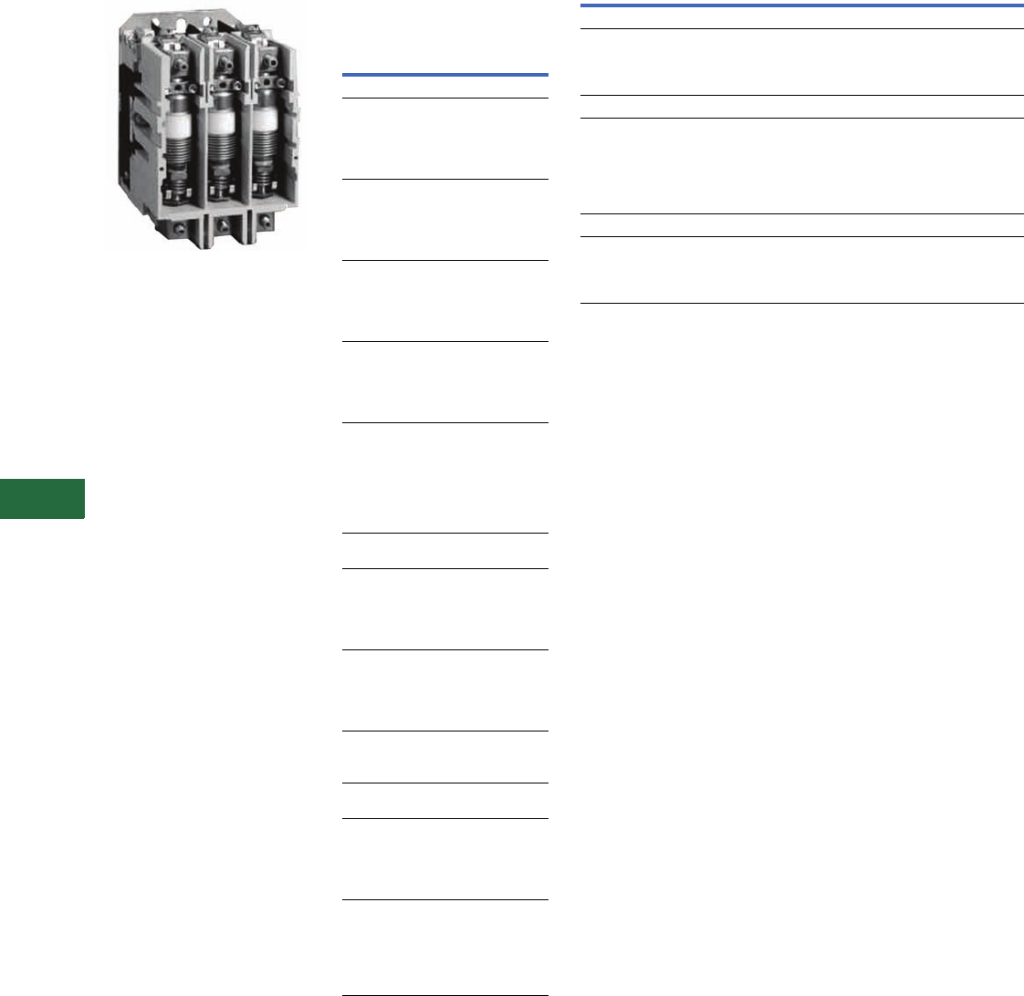
V12-T13-36 Volume 12—Aftermarket, Renewal Parts and Life Extension Solutions CA08100014E—November 2013 www.eaton.com
1
2
3
4
5
6
7
8
9
10
11
12
13
14
15
16
17
18
19
20
21
22
23
24
25
13
Motor Control
Contactors, Starters and Brakes
V201 and V200 Vacuum
Contactors and Starters
Originally a Westinghouse
Product
Size 4 Vacuum Contactors
Heater Coils
Heater Coil Selection for
Type B Overload Relay
Motor Full Load Current in Amperes for
Use with Three Heaters Only
Open Starter Heater
Catalog
Number 1
Ambient Compensated
Overload Relay
Size 4 and 160A
12.8–14.1
14.2–15.5
15.6–17.1
17.2–18.9
19.0–20.8
FH68
FH69
FH70
FH71
FH72
20.9–22.9
23.0–25.2
25.3–27.8
27.9–30.6
30.7–33.5
FH73
FH74
FH75
FH76
FH77
33.6–37.5
37.6–41.5
41.6–46.3
46.4–50
51–55
FH78
FH79
FH80
FH81
FH82
56–61
62–66
67–73
74–78
79–84
FH83
FH84
FH85
FH86
FH87
85–92
93–101
102–110
111–122
123–129
130–133
—
FH88
FH89
FH90
FH91
FH92
FH93
FH94
Size 5 and 320A with 300/5
Current Transformers
107–117
118–129
130–141
142–155
156–170
FH23
FH24
FH25
FH26
FH27
171–187
188–205
206–224
225–244
245–263
FH28
FH29
FH30
FH31
FH32
264–292
293–318
319–350
FH33
FH34
FH35
Size 6 and 540A with 600/5
Current Transformers
236–259
260–283
284–310
311–340
341–374
FH24
FH25
FH26
FH27
FH28
375–411
412–448
449–489
490–527
528–585
586–600
FH29
FH30
FH31
FH32
FH33
FH34
Replacement Coils
Vacuum Contactor—Replacement Coils
Notes
1Three are required per overload relay.
2125 Vdc can be directly applied to the Size 5 and 6 coil rated for 120V/60 Hz AC
(cannot be applied to Size 4).
3250 Vdc can be directly applied to the Size 5 and 6 coil rated for 240V/60 Hz AC
(cannot be applied to Size 4).
Description Suffix
Part
Number
Size 4
110/120 Vac, 50/60 Hz
220/240 Vac, 50/60 Hz
380/415 Vac, 50/60 Hz
440/480 Vac, 50/60 Hz
J
K
H
U
9085A57G01
9085A57G02
ID89221G07
9085A57G03
Size 5
24 Vdc
48 Vdc
110/120 Vac, 50/60 Hz
220/240 Vac, 50/60 Hz
380/415 Vac, 50/60 Hz
440/480 Vac, 50/60 Hz
—
—
J
K
H
U
7874A09G07
7874A09G08
7874A09G01 2
7874A09G04 3
7874A09G10
7874A09G05
Size 6
110/120 Vac, 50/60 Hz
220/240 Vac, 50/60 Hz
380/415 Vac, 50/60 Hz
440/480 Vac, 50/60 Hz
J
K
H
U
7874A24G01 2
7874A24G02 3
7874A24G07
7874A24G03
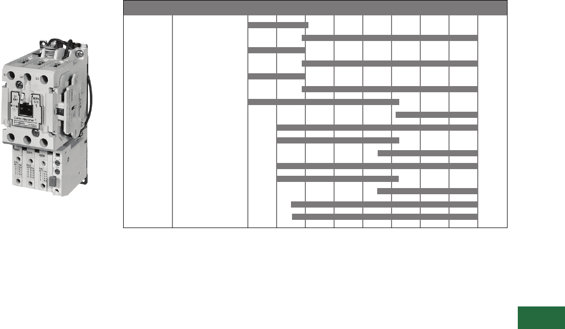
Volume 12—Aftermarket, Renewal Parts and Life Extension Solutions CA08100014E—November 2013 www.eaton.com V12-T13-37
1
2
3
4
5
6
7
8
9
10
11
12
13
14
15
16
17
18
19
20
21
22
23
24
25
13
Motor Control
Contactors, Starters and Brakes
Freedom Series—
NEMA and IEC
Originally a Cutler-Hammer
Product
Freedom
Product Description
The Cutler-Hammer Freedom
Series starters and
contactors feature a compact
space-saving design using
state-of-the-art technology
and the latest in high
strength, impact and
temperature-resistant
insulating materials. Starters
and contactors are available
in two rating/configuration
styles—NEMA (National
Electrical Manufacturers
Association) and IEC
(International
Electrotechnical
Commission). The NEMA
devices are sized based
on traditional NEMA
classifications and the IEC
devices on international
ratings. Internationally rated
starters and contactors, as
compared to NEMA devices,
generally are physically down-
sized to provide higher
ratings in a smaller package.
Product History Time Line for Freedom CN15 and AN15
Note: See contactor/starter nameplate to determine Series A1, B1 or C1.
Size 00 A1
B1
Size 0 A1
B1
Size 1 A1
B1
Size 2 A1
B1
Size 3 A1
Size 4 A1
B1
Size 5 A1
Size 6 A1
B1
Size 7 A1
Size 8 A1
NEMA Size Series 1986 1988 1990 1992 1994 1996 1998 2000 Present

V12-T13-38 Volume 12—Aftermarket, Renewal Parts and Life Extension Solutions CA08100014E—November 2013 www.eaton.com
1
2
3
4
5
6
7
8
9
10
11
12
13
14
15
16
17
18
19
20
21
22
23
24
25
13
Motor Control
Contactors, Starters and Brakes
Replacement Capabilities
NEMA Sizes 00, 0, 1, 2 and 3
NEMA Sizes 00 and 0—See Contactor/Starter Nameplate to Determine Series A1, B1 or C1
Note
1Replace with complete contactor.
Description
NEMA Size 00–0 NEMA Size 00 NEMA Size 00 NEMA Size 0 NEMA Size 0
Series A1 Series B1 Series C1 Series B1 Series C1
Part Number Part Number Part Number Part Number Part Number
Renewal Parts Publication Number None None None None None
Contact Kits
Two-pole 11111
Three-pole 11111
Four-pole 11111
Five-pole 11111
Magnet Coils Coil Suffix
120V, 60 Hz or 110V, 50 Hz A 9-2650-1 9-2875-1 9-2875-1 9-2876-1 9-2876-1
240V, 60 Hz or 220V, 50 Hz B 9-2650-2 9-2875-2 9-2875-2 9-2876-2 9-2876-2
480V, 60 Hz or 440V, 50 Hz C 9-2650-3 9-2875-3 9-2875-3 9-2876-3 9-2876-3
600V, 60 Hz or 550V, 50 Hz D 9-2650-4 9-2875-4 9-2875-4 9-2876-4 9-2876-4
208V, 60 Hz E 9-2650-5 9-2875-5 9-2875-5 9-2876-5 9-2876-5
277V, 60 Hz H 9-2650-13 9-2875-12 9-2875-12 9-2876-12 9-2876-12
208/240V, 60 Hz J — 9-2875-37 9-2875-37 9-2876-17 9-2876-17
240V, 50 Hz K 9-2650-12 9-2875-11 9-2875-11 9-2876-11 9-2876-11
380–415V, 50 Hz L 9-2650-6 9-2875-6 9-2875-6 9-2876-6 9-2876-6
380V, 50 Hz L — — — — —
415V, 50 Hz M — — — — —
550V, 50 Hz N — — — — —
24V, 60 Hz–24V, 50 Hz T —9-2875-36 9-2875-36 9-2876-36 9-2876-36
24V, 60 Hz T 9-2650-7 ————
24V, 50 Hz U 9-2650-14 9-2875-36 9-2875-36 9-2876-36 9-2876-36
32V, 50 Hz V 9-2650-9 9-2875-16 9-2875-16 9-2876-16 9-2876-16
48V, 60 Hz W 9-2650-8 9-2875-8 9-2875-8 9-2876-8 9-2876-8
48V, 50 Hz Y 9-2650-10 9-2875-9 9-2875-9 9-2876-9 9-2876-9
Magnet Frame Armature
Lower magnet frame 11111
Upper magnet frame 11111

Volume 12—Aftermarket, Renewal Parts and Life Extension Solutions CA08100014E—November 2013 www.eaton.com V12-T13-39
1
2
3
4
5
6
7
8
9
10
11
12
13
14
15
16
17
18
19
20
21
22
23
24
25
13
Motor Control
Contactors, Starters and Brakes
NEMA Sizes 1, 2 and 3—See Contactor/Starter Nameplate to Determine Series A1 or B1
Description
NEMA Size 1 NEMA Size 1 NEMA Size 2 NEMA Size 2 NEMA Size 3
Series A1 Series B1 Series A1 Series B1
Part Number Part Number Part Number Part Number Part Number
Renewal Parts Publication Number 20861 22177 20861 22177 20426
Contact Kits
Two-pole 6-65 6-65 6-65-7 6-65-7 6-43-5
Three-pole 6-65-2 6-65-2 6-65-8 6-65-8 6-43-6
Four-pole 6-65-9 6-65-9 6-65-15 6-65-15 —
Five-pole 6-65-10 6-65-10 6-65-16 6-65-16 —
Magnet Coils Coil Suffix
120V, 60 Hz or 110V, 50 Hz A 9-2703-1 9-2703-1 9-2703-1 9-2703-1 9-2756-1
240V, 60 Hz or 220V, 50 Hz B 9-2703-2 9-2703-2 9-2703-2 9-2703-2 9-2756-2
480V, 60 Hz or 440V, 50 Hz C 9-2703-3 9-2703-3 9-2703-3 9-2703-3 9-2756-3
600V, 60 Hz or 550V, 50 Hz D 9-2703-4 9-2703-4 9-2703-4 9-2703-4 9-2756-4
208V, 60 Hz E 9-2703-9 9-2703-9 9-2703-9 9-2703-9 9-2756-5
277V, 60 Hz H 9-2703-7 9-2703-7 9-2703-7 9-2703-7 9-2756-9
208/240V, 60 Hz J — — — — —
240V, 50 Hz K 9-2703-14 9-2703-14 9-2703-14 9-2703-14 9-2756-13
380–415V, 50 Hz L 99-2703-8 9-2703-8 9-2703-8 9-2703-8 —
380V, 50 Hz L — — — — 9-2756-12
415V, 50 Hz M — — — — 9-2756-8
550V, 50 Hz N — — — — 9-2756-14
24V, 60 Hz–24V, 50 Hz T —————
24V, 60 Hz T 9-2703-6 9-2703-6 9-2703-6 9-2703-6 9-2756-6
24V, 50 Hz U 9-2703-12 9-2703-12 9-2703-12 9-2703-12 9-2756-11
32V, 50 Hz V 9-2703-10 9-2703-10 9-2703-10 9-2703-10 9-2756-10
48V, 60 Hz W 9-2703-11 9-2703-11 9-2703-11 9-2703-11 9-2756-15
48V, 50 Hz Y 9-2703-13 9-2703-13 9-2703-13 9-2703-13 9-2756-7
Magnet Frame Armature
Lower magnet frame 17-18200 17-18200 17-18200 17-18200 17-8955-2
Upper magnet frame 48-1936 48-1936 48-1936 48-1936 48-1902

V12-T13-40 Volume 12—Aftermarket, Renewal Parts and Life Extension Solutions CA08100014E—November 2013 www.eaton.com
1
2
3
4
5
6
7
8
9
10
11
12
13
14
15
16
17
18
19
20
21
22
23
24
25
13
Motor Control
Contactors, Starters and Brakes
NEMA Sizes 4, 5 and 6—See Contactor/Starter Nameplate to Determine Series A1 or B1
Description
NEMA Size 4 NEMA Size 4 NEMA Size 5 NEMA Size 5 NEMA Size 6 NEMA Size 6
Series A1 Series B1 Series A1 Series B1 Series A1 Series B1
Part Number Part Number Part Number Part Number Part Number Part Number
Renewal Parts Publication Number 20428 20428 20429 20429 20146 20146
Contact Kits
Two-pole 6-44 6-26 6-45 6-45 6-601-2 6-648
Three-pole 6-44-2 6-26-2 6-45-2 6-45-2 6-601 —
Magnet Coils Coil Suffix
120V, 60 Hz or 110V, 50 Hz A 9-1891-1 9-1891-1 9-1891-1 9-1891-1 9-2698 9-2698
240V, 60 Hz or 220V, 50 Hz B 9-1891-2 9-1891-2 9-1891-2 9-1891-2 9-2698-2 9-2698-2
480V, 60 Hz or 440V, 50 Hz C 9-1891-3 9-1891-3 9-1891-3 9-1891-3 9-2698-3 9-2698-3
600V, 60 Hz or 550V, 50 Hz D 9-1891-4 9-1891-4 9-1891-4 9-1891-4 9-2698-4 9-2698-4
208V, 60 Hz E 9-1891-13 9-1891-13 9-1891-13 9-1891-13 9-2698-5 9-2698-5
277V, 60 Hz H 9-1891-26 9-1891-26 9-1891-26 9-1891-26 — —
208/240V, 60 Hz J ——————
240V, 50 Hz K 9-1891-20 9-1891-20 9-1891-20 9-1891-20 — —
380–415V, 50 Hz L ————9-2698-69-2698-6
380V, 50 Hz L 9-1891-14 9-1891-14 9-1891-14 9-1891-14 — —
415V, 50 Hz M 9-1891-21 9-1891-21 9-1891-21 9-1891-21 — —
550V, 50 Hz N 9-1891-8 9-1891-8 9-1891-8 9-1891-8 — —
24V, 60 Hz–24V, 50 Hz T ——————
24V, 60 Hz T 9-1891-15 9-1891-15 9-1891-15 9-1891-15 — —
24V, 50 Hz U 9-1891-16 9-1891-16 9-1891-16 9-1891-16 — —
32V, 50 Hz V 9-1891-27 9-1891-27 9-1891-27 9-1891-27 — —
48V, 60 Hz W ————9-2698-89-2698-8
48V, 50 Hz Y 9-1891-18 9-1891-18 9-1891-18 9-1891-18 — —
Overload Relays
For replacement on existing starters
three-pole—ambient compensated bimetallic 10-6530-4 10-6530-4 C306DN3B C306DN3B C306DN3B C306DN3B
Current Transformer
For replacement on existing starters only ——42-3564 42-3564 42-3598 42-3598
Magnet Frame Armature
Lower magnet frame 48-1030-2 48-1030-2 48-1030-2 48-1030-2 ——
Upper magnet frame 48-1029-4 48-1029-4 48-1029-4 48-1029-4 ——

Volume 12—Aftermarket, Renewal Parts and Life Extension Solutions CA08100014E—November 2013 www.eaton.com V12-T13-41
1
2
3
4
5
6
7
8
9
10
11
12
13
14
15
16
17
18
19
20
21
22
23
24
25
13
Motor Control
Contactors, Starters and Brakes
NEMA Sizes 7 and 8—See Contactor/Starter Nameplate to Determine Series A1 or B1
Note
1Contact Standard Open Control Aftermarket at 1-800-535-8992 for assistance.
Description
NEMA Size 7 NEMA Size 7 NEMA Size 8 NEMA Size 8
Series A1 Series B1 Series A1 Series B1
Part Number Part Number Part Number Part Number
Renewal Parts Publication Number 20848 20848 20849 20849
Contact Kits
Two-pole ————
Three-pole 6-613 6-613 6-571 6-571
Magnet Coils Coil Suffix
120V, 60 Hz or 110V, 50 Hz A 9-2698 9-2698 9-2654 9-2654
240V, 60 Hz or 220V, 50 Hz B 9-2698-2 9-2698-2 9-2654-2 9-2654-2
480V, 60 Hz or 440V, 50 Hz C 9-2698-3 9-2698-3 9-2654-3 9-2654-3
600V, 60 Hz or 550V, 50 Hz D 9-2698-4 9-2698-4 9-2654-4 9-2654-4
208V, 60 Hz E 9-2698-5 9-2698-5 9-2654-6 9-2654-6
277V, 60 Hz H ————
208/240V, 60 Hz J ————
240V, 50 Hz K ————
380–415V, 50 Hz L ————
380V, 50 Hz L 9-2698-6 9-2698-6 9-2654-5 9-2654-5
415V, 50 Hz M ————
550V, 50 Hz N ————
24V, 60 Hz–24V, 50 Hz T — — — —
24V, 60 Hz T — — — —
24V, 50 Hz U — — — —
32V, 50 Hz V — — — —
48V, 60 Hz W — — — —
48V, 50 Hz Y — — — —
Overload Relays
For replacement on existing starters
three-pole—ambient compensated bimetallic C306DN3B C306DN3B C306DN3B C306DN3B
Magnet Frame Armature 1
Lower magnet frame — — — —
Upper magnet frame ————

V12-T13-42 Volume 12—Aftermarket, Renewal Parts and Life Extension Solutions CA08100014E—November 2013 www.eaton.com
1
2
3
4
5
6
7
8
9
10
11
12
13
14
15
16
17
18
19
20
21
22
23
24
25
13
Motor Control
Contactors, Starters and Brakes
IEC Sizes A–F—See Contactor/Starter Nameplate to Determine Series A1, B1 or C1
Notes
1Non-encapsulated coils.
2Replace with complete contactor.
Description
IEC Sizes A–F IEC Sizes A–C 1IEC Sizes A–C 1IEC Sizes D–F 1IEC Sizes D–F 1
Series A1 Series B1 Series C1 Series B1 Series C1
Part Number Part Number Part Number Part Number Part Number
Renewal Parts Publication Number None None None None None
Contact Kits
Two-pole 22222
Three-pole 22222
Four-pole 22222
Five-pole 22222
Magnet Coils Coil Suffix
120V, 60 Hz or 110V, 50 Hz A 9-2650-1 9-2875-1 9-2875-1 9-2876-1 9-2876-1
240V, 60 Hz or 220V, 50 Hz B 9-2650-2 9-2875-2 9-2875-2 9-2876-2 9-2876-2
480V, 60 Hz or 440V, 50 Hz C 9-2650-3 9-2875-3 9-2875-3 9-2876-3 9-2876-3
600V, 60 Hz or 550V, 50 Hz D 9-2650-4 9-2875-4 9-2875-4 9-2876-4 9-2876-4
208V, 60 Hz E 9-2650-5 9-2875-5 9-2875-5 9-2876-5 9-2876-5
277V, 60 Hz H 9-2650-13 9-2875-12 9-2875-12 9-2876-12 9-2876-12
208/240V, 60 Hz J — 9-2875-37 9-2875-37 9-2876-37 9-2876-37
240V, 50 Hz K 9-2650-12 9-2875-11 9-2875-11 9-2876-11 9-2876-11
380–415V, 50 Hz L 9-2650-6 9-2875-6 9-2875-6 9-2876-6 9-2876-6
24V, 60 Hz–24V, 50 Hz T —9-2875-36 9-2875-36 9-2876-36 9-2876-36
24V, 60 Hz T 9-2650-7 ————
24V, 50 Hz U 9-2650-14 9-2875-13 9-2875-13 9-2876-13 9-2876-13
32V, 50 Hz V 9-2650-9 9-2875-16 9-2875-16 9-2876-16 9-2876-16
48V, 60 Hz W 9-2650-8 9-2875-8 9-2875-8 9-2876-8 9-2876-8
48V, 50 Hz Y 9-2650-10 9-2875-9 9-2875-9 9-2876-9 9-2876-9
Overload Relays
For replacement on existing starters:
three-pole—ambient compensated bimetallic C306DN3B C306DN3B C306DN3B C306DN3B C306DN3B
Current Transformer
Transformer — — — — —
Magnet Frame Armature
Lower magnet frame 22222
Upper magnet frame 22222

Volume 12—Aftermarket, Renewal Parts and Life Extension Solutions CA08100014E—November 2013 www.eaton.com V12-T13-43
1
2
3
4
5
6
7
8
9
10
11
12
13
14
15
16
17
18
19
20
21
22
23
24
25
13
Motor Control
Contactors, Starters and Brakes
IEC Sizes G and H—See Contactor/Starter Nameplate to Determine Series A1 and B1
Description
NEMA Size G NEMA Size G NEMA Size H NEMA Size H
Series A1 Series B1 Series A1 Series B1
Part Number Part Number Part Number Part Number
Renewal Parts Publication Number 20862 22178 20862 22178
Contact Kits
Two-pole 6-65-3 6-65-3 6-65-5 6-65-5
Three-pole 6-65-4 6-65-4 6-65-6 6-65-6
Four-pole 6-65-11 6-65-11 6-65-13 6-65-13
Five-pole 6-65-12 6-65-12 6-65-14 6-65-14
Magnet Coils Coil Suffix
120V, 60 Hz or 110V, 50 Hz A 9-2703-1 9-2703-1 9-2703-1 9-2703-1
240V, 60 Hz or 220V, 50 Hz B 9-2703-2 9-2703-2 9-2703-2 9-2703-2
480V, 60 Hz or 440V, 50 Hz C 9-2703-3 9-2703-3 9-2703-3 9-2703-3
600V, 60 Hz or 550V, 50 Hz D 9-2703-4 9-2703-4 9-2703-4 9-2703-4
208V, 60 Hz E 9-2703-9 9-2703-9 9-2703-9 9-2703-9
277V, 60 Hz H 9-2703-7 9-2703-7 9-2703-7 9-2703-7
240V, 50 Hz K 9-2703-14 9-2703-14 9-2703-14 9-2703-14
380–415V, 50 Hz L 9-2703-8 9-2703-8 9-2703-8 9-2703-8
24V, 60 Hz–24V, 50 Hz T ————
24V, 60 Hz T 9-2703-6 9-2703-6 9-2703-6 9-2703-6
24V, 50 Hz U 9-2703-12 9-2703-12 9-2703-12 9-2703-12
32V, 50 Hz V 9-2703-10 9-2703-10 9-2703-10 9-2703-10
48V, 60 Hz W 9-2703-11 9-2703-11 9-2703-11 9-2703-11
48V, 50 Hz Y 9-2703-13 9-2703-13 9-2703-13 9-2703-13
Overload Relays
For replacement on existing starters:
three-pole—ambient compensated bimetallic C306DN3B C306DN3B C306DN3B C306DN3B
Current Transformer
Transformer — — — —
Magnet Frame Armature
Lower magnet frame 17-18200 17-1820 17-18200 17-18200
Upper magnet frame 48-1936 48-1936 48-1936 48-1936

V12-T13-44 Volume 12—Aftermarket, Renewal Parts and Life Extension Solutions CA08100014E—November 2013 www.eaton.com
1
2
3
4
5
6
7
8
9
10
11
12
13
14
15
16
17
18
19
20
21
22
23
24
25
13
Motor Control
Contactors, Starters and Brakes
IEC Sizes J and K—See Contactor/Starter Nameplate to Determine Series A1 and B1
Description
NEMA Size J NEMA Size J NEMA Size K NEMA Size K
Series A1 Series B1 Series A1 Series B1
Part Number Part Number Part Number Part Number
Renewal Parts Publication Number 20862 22178 20862 22178
Contact Kits
Two-pole 6-65-7 6-65-7 6-65-18 6-65-20
Three-pole 6-65-8 6-65-8 6-65-17 6-65-19
Four-pole 6-65-15 6-65-15 ——
Five-pole 6-65-16 6-65-16 ——
Magnet Coils Coil Suffix
120V, 60 Hz or 110V, 50 Hz A 9-2703-1 9-2703-1 9-2703-1 9-2703-1
240V, 60 Hz or 220V, 50 Hz B 9-2703-2 9-2703-2 9-2703-2 9-2703-2
480V, 60 Hz or 440V, 50 Hz C 9-2703-3 9-2703-3 9-2703-3 9-2703-3
600V, 60 Hz or 550V, 50 Hz D 9-2703-4 9-2703-4 9-2703-4 9-2703-4
208V, 60 Hz E 9-2703-9 9-2703-9 9-2703-9 9-2703-9
277V, 60 Hz H 9-2703-7 9-2703-7 9-2703-7 9-2703-7
240V, 50 Hz K 9-2703-14 9-2703-14 9-2703-14 9-2703-14
380–415V, 50 Hz L 9-2703-8 9-2703-8 9-2703-8 9-2703-8
24V, 60 Hz–24V, 50 Hz T ————
24V, 60 Hz T 9-2703-6 9-2703-6 9-2703-6 9-2703-6
24V, 50 Hz U 9-2703-12 9-2703-12 9-2703-12 9-2703-12
32V, 50 Hz V 9-2703-10 9-2703-10 9-2703-10 9-2703-10
48V, 60 Hz W 9-2703-11 9-2703-11 9-2703-11 9-2703-11
48V, 50 Hz Y 9-2703-13 9-2703-13 9-2703-13 9-2703-13
Overload Relays
For replacement on existing starters:
three-pole—ambient compensated bimetallic C306GN3B C306GN3B C306GN3B C306GN3B
Current Transformer
Transformer — — — —
Magnet Frame Armature
Lower magnet frame 17-18200 17-18200 17-18200 17-18200
Upper magnet frame 48-1936 48-1936 48-1936 48-1936

Volume 12—Aftermarket, Renewal Parts and Life Extension Solutions CA08100014E—November 2013 www.eaton.com V12-T13-45
1
2
3
4
5
6
7
8
9
10
11
12
13
14
15
16
17
18
19
20
21
22
23
24
25
13
Motor Control
Contactors, Starters and Brakes
IEC Sizes L, M and N
Description
IEC Size L IEC Size M IEC Size N
Part Number Part Number Part Number
Contact Kits
Two-pole 6-43-3 6-43 6-43-5
Three-pole 6-43-4 6-43-2 6-43-6
Four-pole — — —
Five-pole — — —
Magnet Coils Coil Suffix
120V, 60 Hz or 110V, 50 Hz A 9-2756-1 9-2756-1 9-2756-1
240V, 60 Hz or 220V, 50 Hz B 9-2756-2 9-2756-2 9-2756-2
480V, 60 Hz or 440V, 50 Hz C 9-2756-3 9-2756-3 9-2756-3
600V, 60 Hz or 550V, 50 Hz D 9-2756-4 9-2756-4 9-2756-4
208V, 60 Hz E 9-2756-5 9-2756-5 9-2756-5
277V, 60 Hz H 9-2756-9 9-2756-9 9-2756-9
240V, 50 Hz K 9-2756-13 9-2756-13 9-2756-13
380–415V, 50 Hz L — — —
380V, 50 Hz L 9-2756-12 9-2756-12 9-2756-12
415V, 50 Hz M 9-2756-8 9-2756-8 9-2756-8
550V, 50 Hz N 9-2756-14 9-2756-14 9-2756-14
24V, 60 Hz–24V, 50 Hz T ———
24V, 60 Hz T 9-2756-6 9-2756-6 9-2756-6
24V, 50 Hz U 9-2756-11 9-2756-11 9-2756-11
32V, 50 Hz V 9-2756-10 9-2756-10 9-2756-10
48V, 60 Hz W 9-2756-15 9-2756-15 9-2756-15
48V, 50 Hz Y 9-2756-7 9-2756-7 9-2756-7
Overload Relays
For replacement on existing starters
three-pole—ambient compensated bimetallic 10-6530 10-6530-2 10-6530-3
Current Transformer
Transformer — — —
Magnet Frame Armature
Lower magnet frame 17-8955-2 17-8955-2 17-8955-2
Upper magnet frame 48-1902 48-1902 48-1902

V12-T13-46 Volume 12—Aftermarket, Renewal Parts and Life Extension Solutions CA08100014E—November 2013 www.eaton.com
1
2
3
4
5
6
7
8
9
10
11
12
13
14
15
16
17
18
19
20
21
22
23
24
25
13
Motor Control
Contactors, Starters and Brakes
IEC Sizes P, R and S
IEC Size T, U and V
Technology Upgrades
This product currently listed in Volume 5—Motor Control and Protection, CA08100006E, Tab 1.
Description
IEC Size P IEC Size R IEC Size S
Part Number Part Number Part Number
Renewal Parts Publication Number 22278 22278 22278
Contact Kits Size 6-294 6-288 6-286
Magnet Coils Coil Suffix
120V, 60 Hz or 110V, 50 Hz A 9-1891-1 9-1891-1 9-1891-1
200V, 50 Hz or 118V, 60 Hz E — ——
240V, 60 Hz or 220V, 50 Hz B 9-1891-2 9-1891-2 9-1891-2
254V, 50 Hz or 277V, 60 Hz H ———
380V, 50 Hz or 415V, 60 Hz L ———
480V, 60 Hz or 440V, 50 Hz C 9-1891-3 9-1891-3 9-1891-3
600V, 60 Hz or 550V, 50 Hz D 9-1891-4 9-1891-4 9-1891-4
208V, 60 Hz E 9-1891-13 9-1891-13 9-1891-13
277V, 60 Hz H 9-1891-26 9-1891-26 9-1891-26
240V, 50 Hz K 9-1891-20 9-1891-20 9-1891-20
380V, 50 Hz L 9-1891-14 9-1891-14 9-1891-14
415V, 50 Hz M 9-1891-21 9-1891-21 9-1891-21
24V, 60 Hz T 9-1891-15 9-1891-15 9-1891-15
Overload Relays
Reference C316 overload relays
Magnet Frame Armature
Lower magnet frame 48-1030-2 48-1030-2 48-1030-2
Upper magnet frame 48-1029-4 48-1029-4 48-1029-4
Description
IEC Size T IEC Size U IEC Size V
Part Number Part Number Part Number
Renewal Parts Publication Number 22275 22276 22586
Contact Kits Size 6-621 6-622 6-601
Magnet Coils Coil Suffix
120V, 60 Hz or 110V, 50 Hz A 9-3006 9-3006 9-2698
200V, 50 Hz or 118V, 60 Hz E 9-3006-5 9-3006-5 —
240V, 60 Hz or 220V, 50 Hz B 9-3006-2 9-3006-2 9-2698-2
254V, 50 Hz or 277V, 60 Hz H 9-3006-6 9-3006-6 9-2698-2
380V, 50 Hz or 415V, 60 Hz L 9-3006-7 9-3006-7 9-2698-6
480V, 60 Hz or 440V, 50 Hz C 9-3006-3 9-3006-3 9-2698-3
600V, 60 Hz or 550V, 50 Hz D 9-3006-4 9-3006-4 9-2698-4
208V, 60 Hz E — — 9-2698-5
277V, 60 Hz H — — —
240V, 50 Hz K — — —
380V, 50 Hz L — — —
415V, 50 Hz M — — —
24V, 60 Hz T — — —
Overload Relays
Reference C316 overload relays
Magnet Frame Armature
Lower magnet frame ———
Upper magnet frame ———
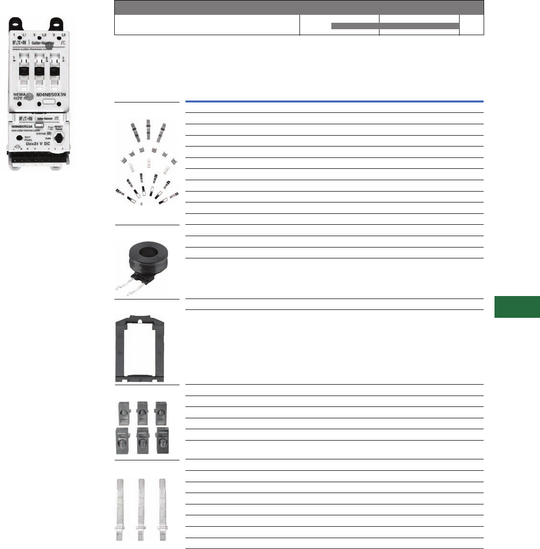
Volume 12—Aftermarket, Renewal Parts and Life Extension Solutions CA08100014E—November 2013 www.eaton.com V12-T13-47
1
2
3
4
5
6
7
8
9
10
11
12
13
14
15
16
17
18
19
20
21
22
23
24
25
13
Motor Control
Contactors, Starters and Brakes
IT. Electromechanical
NEMA
NEMA Full Voltage Non-reversing
Starter, Size 0
Product Description
The Cutler-Hammer
Intelligent Technologies® (IT.)
electromechanical starter
from Eaton’s electrical
business consists of an IT.
electromechanical contact
block or contactor and an IT.
electromechanical solid-state
overload relay as a full voltage
non-reversing (FVNR) or a full
voltage reversing (FVR)
device. Size 00 to Size 5
Starters are factory or field
assembled.
Product History Time Line for IT. Electromechanical NEMA
Replacement Capabilities
Replacements for NEMA Contacts and Starters
Notes
1 H = Hold-Open.
2 For reversing contactors and starters, order two.
Technology Upgrades
This product currently listed in Volume 5—Motor Control and Protection,
CA08100006E, Tab 2.
IT. Electromechanical NEMA
Product 2000 2005 Present
NEMA
Size Description
Catalog
Number
140A EMHCKT40 1
150A EMHCKT50 1
265A EMHCKT65 1
285A EMHCKT85 1
2100A EMHCKT100 1
3, 4 125A EMCKT125
3, 4 160A EMCKT160
3, 4 200A EMCKT200
5250A EMCKT250
5315A EMCKT315
5400A EMCKT400
1Coil EMCC
2Coil EMCD
3, 4 Coil EMCE
5Coil EMCF
00, 0, 1 Catch with leaf spring and pad EMDRCB
2 Catch with leaf spring and pad EMDRCD
1Lug EMLUGKTC
2Lug EMLUGKTD
3, 4 Lug EMLUGKTE
5 Horizontal box lug kit EMLUGKTFA
5 Vertical box lug kit EMLUGKTFB
5 Dual lug kit EMLUGKTFC
00, 0 For contactors and starters EMBBB
1 For starters EMBBC
1 For reversing contactors and reversing starters EMBBRC
2 For starters EMBBD
2 For reversing contactors and reversing starters EMBBRD
3, 4 For starters EMBBE
3, 4 For reversing contactors and reversing starters EMBBRE
5 Overload relay EMBBOF
Contact Kits
Coils 2
DIN Rail Catch
Lug Kits
Overload Busbars
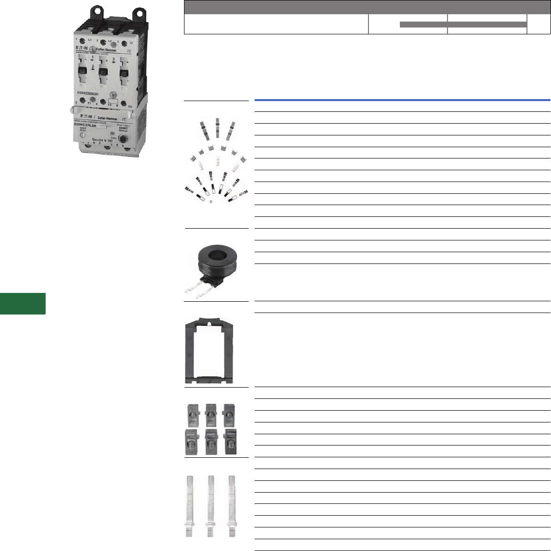
V12-T13-48 Volume 12—Aftermarket, Renewal Parts and Life Extension Solutions CA08100014E—November 2013 www.eaton.com
1
2
3
4
5
6
7
8
9
10
11
12
13
14
15
16
17
18
19
20
21
22
23
24
25
13
Motor Control
Contactors, Starters and Brakes
IT. Electromechanical IEC
IEC FVNR Starter, C-Frame
Product Description
The Cutler-Hammer
Intelligent Technologies (IT.)
electromechanical starter
from Eaton’s electrical
business consists of an IT.
electromechanical contact
block or contactor and IT.
electromechanical solid-state
overload relay as a full voltage
non-reversing (FVNR) or full
voltage reversing (FVR)
device. A-Frame (27 mm) to
F-Frame (140 mm) Starters
are factory or field
assembled.
Product History Time Line for IT. Electromechanical IEC
Replacement Capabilities
Replacements for IEC Contacts and Starters
Note
1 For reversing contactors and starters, order two.
Technology Upgrades
This product currently listed in Volume 5—Motor Control and Protection, CA08100006E, Tab 2.
IT. Electromechanical IEC
Product 2000 2005 Present
Frame
Size Description
Catalog
Number
C40A EMCKT40
C50A EMCKT50
D65A EMCKT65
D85A EMCKT85
D 100A EMCKT100
E 125A EMCKT125
E 160A EMCKT160
E 200A EMCKT200
F 250A EMCKT250
F 315A EMCKT315
F 400A EMCKT400
CCoil EMCC
DCoil EMCD
ECoil EMCE
FCoil EMCF
B, C Catch with leaf spring and pad EMDRCB
D Catch with leaf spring and pad EMDRCD
CLug EMLUGKTC
DLug EMLUGKTD
ELug EMLUGKTE
F Horizontal box lug kit EMLUGKTFA
F Vertical box lug kit EMLUGKTFB
F Dual lug kit EMLUGKTFC
B For contactors and starters EMBBB
C For starters EMBBC
C For reversing contactors and reversing starters EMBBRC
D For starters EMBBD
D For reversing contactors and reversing starters EMBBRD
E For starters EMBBE
E For reversing contactors and reversing starters EMBBRE
F Overload relay EMBBOF
Contact Kits
Coils 2
DIN Rail Catch
Lug Kits
Overload Busbars
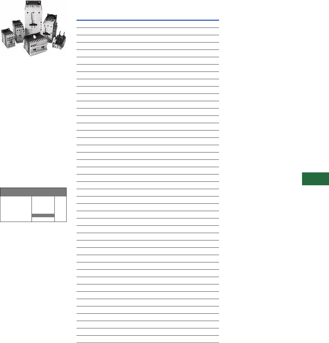
Volume 12—Aftermarket, Renewal Parts and Life Extension Solutions CA08100014E—November 2013 www.eaton.com V12-T13-49
1
2
3
4
5
6
7
8
9
10
11
12
13
14
15
16
17
18
19
20
21
22
23
24
25
13
Motor Control
Contactors, Starters and Brakes
XT IEC Power Control
XT Family of Contactors
Product Description
Eaton’s line of XT Contactors
and Starters includes non-
reversing and reversing
contactors, overload relay
and a variety of related
accessories. Because XT
meets IEC, UL, CSA, CCC
and CE standards, it is the
perfect product solution for
IEC applications all over the
world. The compact, space
saving and easy to install XT
line of IEC contactors and
starters is the efficient and
effective solution for
customer applications from
7A to 2000A.
Product History Time Line
for XT IEC Power Control
XT IEC
Power
Control
Product 2005 Present
Replacement Capabilities
Replacement Coils
Voltage
Coil
Suffix
Catalog
Number
Frame C
110/50 120/60 A XTCERENCOILCA
110–130 Vdc AD XTCERENCOILCAD
220/50 240/80 B XTCERENCOILCB
200–240 Vdc BD XTCERENCOILCBD
415/50 460/60 C XTCERENCOILCC
550/50 600/60 D XTCERENCOILCD
208/60 E XTCERENCOILCE
230/50 F XTCERENCOILCF
190/50 220/60 G XTCERENCOILCG
240/50 277/60 H XTCERENCOILCH
380/50 440/60 L XTCERENCOILCL
400/50 N XTCERENCOILCN
380/60 P XTCERENCOILCP
12/50 12/60 R XTCERENCOILCR
12–14 Vdc RD XTCERENCOILCRD
24/5024/60 T XTCERENCOILCT
24–27 Vdc TD XTCERENCOILCTD
24/50 42/50 U XTCERENCOILCU
48/60 W XTCERENCOILCW
48–60 Vdc WD XTCERENCOILCWD
48/50 Y XTCEBENCOILCY
Frame D
110/50 120/60 A XTCERENCOILDA
110–130 Vdc AD XTCERENCOILDAD
220/50 240/80 B XTCERENCOILDB
200–240 Vdc BD XTCERENCOILDBD
415/50 480/60 C XTCERENCOILDC
550/50 600/60 D XTCERENCOILDD
208/60 E XTCERENCOILDE
230/50 F XTCERENCOILDF
190/50 220/60 G XTCERENCOILDG
240/50 277/60 H XTCERENCOILDH
380/50 440/60 L XTCERENCOILDL
400/50 N XTCERENCOILDN
380/60 P XTCERENCOILDP
12/50 12/60 R XTCERENCOILOR
12–14 Vdc RD XTCERENCOILDRD
24/50 24/60 T XTCERENCOILDT
24–27 Vdc TD XTCERENCOILDTD
24/50 42/50 U XTCERENCOILDU
48/60 W XTCERENCOILDW
48–60 Vdc WD XTCERENCOILDWD
48/50 Y XTCERENCOILDY

V12-T13-50 Volume 12—Aftermarket, Renewal Parts and Life Extension Solutions CA08100014E—November 2013 www.eaton.com
1
2
3
4
5
6
7
8
9
10
11
12
13
14
15
16
17
18
19
20
21
22
23
24
25
13
Motor Control
Contactors, Starters and Brakes
Replacement Coils, continued
Voltage
Coil
Suffix
Catalog
Number
Frame F
110/50 120/60 A
XTCERENCOILFA
110–130 Vdc AD
XTCERENCOILFAD
220/50 240/60 B
XTCERENCOILFB
200–240 Vdc BD
XTCERENCOILFBD
415/50 480/60 C
XTCERENCOILFC
550/50 600/60 D
XTCEREN
COIL
FD
208/60 E
XTCERENCOILFE
230/50 F
XTCEREN
COIL
FF
190/50 220/60 G
XTCERENCOILFG
240/50 277/60 H
XTCERENCOILFH
380/50 440/60 L
XTCEREN
COIL
FL
400/50 N
XTCERENCOILFN
380/60 P
XTCERENCOILFP
12/50 12/60 R
XTCERENCOILFR
24/50 24/60 T
XTCERENCOILFT
24–27 Vdc TD
XTCERENCOILFTD
24/50 U
XTCERENCOILFU
42/50 48/60 W
XTCERENCOILFW
48–60 Vdc WD
XTCERENCOILFWD
48/50 Y
XTCERENCOILFY
Frame G
100–120V 50/60 A
XTCERENCOILGA
110–130 Vdc AD
XTCERENCOILGAD
190–240V 50/60 B
XTCERENCOILGB
200–240 Vdc BD
XTCEREN
COIL
GBD
480–500V 50/60 C
XTCEREN
COIL
GC
380–440V 50/60 L
XTCEREN
COIL
GL
24/50 24/60 T
XTCERENCOILGT
24–27 Vdc TD
XTCERENCOILGTD
42–48V 50/60 W
XTCERENCOILGW
48–60 Vdc WD
XTCERENCOILGWD
Frame L 1
110–250 Vac/Vdc
A
XTCERENCOILLA
250–500V 40–60
C
XTCERENCOILLC
24–48 Vdc
TD
XTCERENCOILLTD
48–110 Vac/Vdc
Y
XTCERENCOILLY
Frame M 1
110–250 Vac/Vdc
A
XTCERENCOILMA
250–500V 40–60
C
XTCERENCOILMC
24–48 Vdc
TD
XTCEREN
COIL
MTD
48–110 Vac/Vdc
Y
XTCEREN
COIL
MY
Frame N 1
110–250 Vac/Vdc
A
XTCERENCOILNA
250–500V 40–60
C
XTCERENCOILNC
48–110 Vac/Vdc
Y
XTCERENCOILNY
Replacement Contact Kits
Replacement Vacuum Tube Assembly
Replacement Arc Chambers
Note
1Electronic modules including coils.
For use with…
Catalog
Number
XTAE040D–XTAE065D
XTCERENCONTACTD
XTCE185L–XTCE250L
XTCERENCONTACTL
XTCE300M–XTCE500M
XTCERENCONTACTM
For use with…
Catalog
Number
XTCE580N XTCERENVACT580
XTCE650N XTCERENVACTBB0
XTCE750N XTCERENVACT750
XTCE820N XTCERENVACT820
For use with…
Catalog
Number
XTCE185L XTCERENARC185
XTCE225L XTCERENARC225
XTCE250L XTCERENARC250
XTCE300M XTCERENARC300
XTCE400M XTCERENARC400
XTCE500M XTCERENARC500
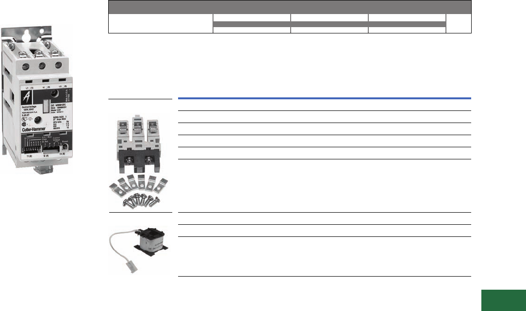
Volume 12—Aftermarket, Renewal Parts and Life Extension Solutions CA08100014E—November 2013 www.eaton.com V12-T13-51
1
2
3
4
5
6
7
8
9
10
11
12
13
14
15
16
17
18
19
20
21
22
23
24
25
13
Motor Control
Contactors, Starters and Brakes
Advantage™
Originally a Westinghouse
Product
Advantage Starter
Product Description
Setting a new standard in
motor control, revolutionary
in design, Advantage motor
starters employ state-of-the-
art technology in solving
motor control application
problems that have existed
for ages. Customer focus
group input and 66,000
man-hours of engineering
ingenuity have been
combined to create a motor
starter that dramatically
extends operating life in a
physical space requirement
one half the size of
conventional motor starters.
Product History Time Line for Advantage Contactors and Starters
Replacement Capabilities
Replacements for Contact Kits and Coils
Technology Upgrades
This product currently listed in Volume 5—Motor Control and Protection, CA08100006E, Tab 2.
Sizes 1–6
Size 1991 1995 2000 Present
Description
Catalog
Number
Replacement contact kit, size single, three-pole WCK13
Replacement contact kit, size two, three-pole WCK23
Replacement contact kit, size three, three-pole WCK33
Replacement contact kit, size four, three-pole WCK43
Replacement contact kit, size five, three-pole WCK53
Replacement contact kit, size six, three-pole WCK63
Size one and two, 110/120V, 60 Hz WCOIL12F
Size three and four, 110/120V, 60 Hz WCOIL34F
Size five and six, 110/120V, 60 Hz WCOIL56F
Contact Kits
Coils
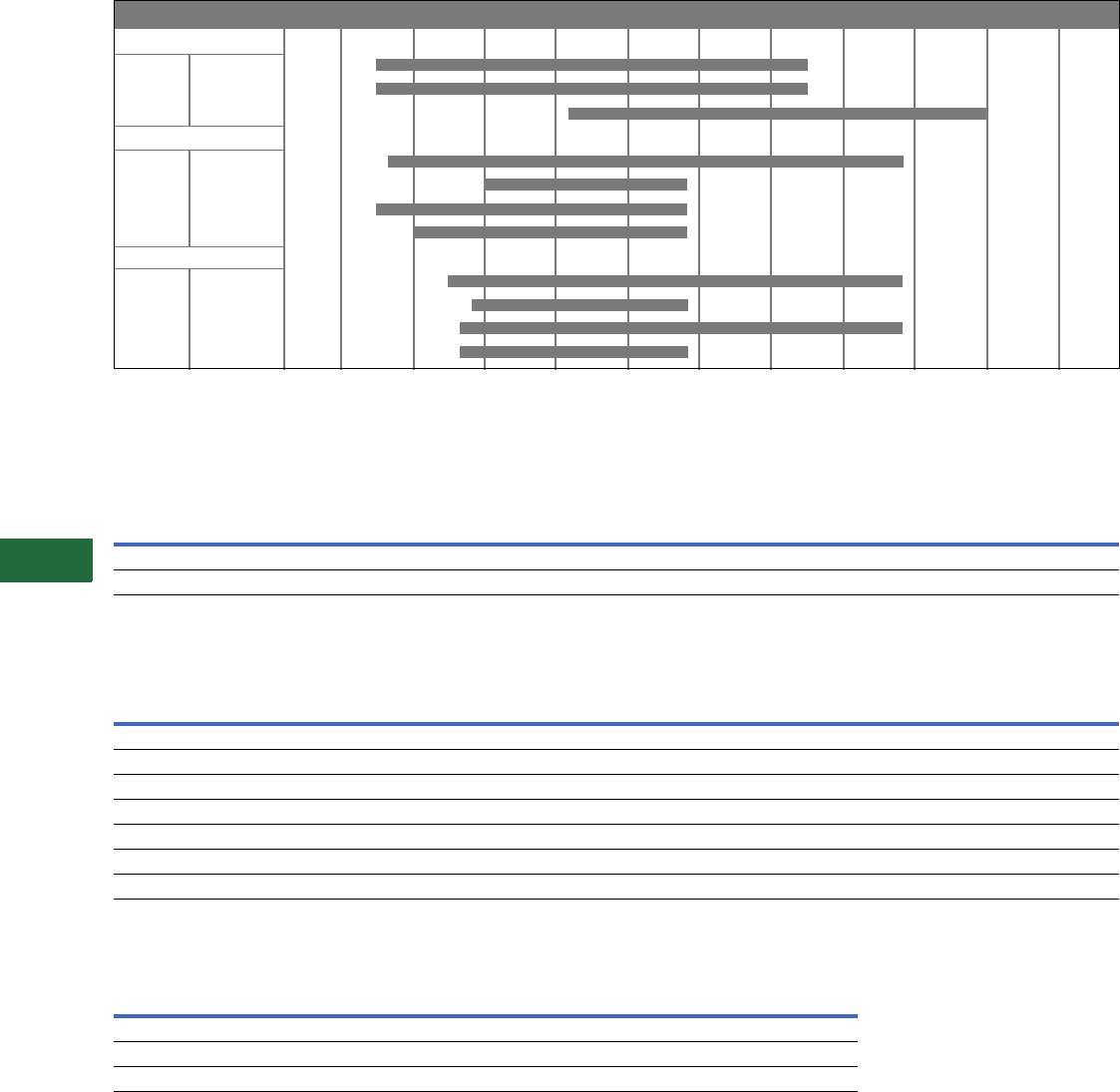
V12-T13-52 Volume 12—Aftermarket, Renewal Parts and Life Extension Solutions CA08100014E—November 2013 www.eaton.com
1
2
3
4
5
6
7
8
9
10
11
12
13
14
15
16
17
18
19
20
21
22
23
24
25
13
Motor Control
Contactors, Starters and Brakes
Definite Purpose
Originally a Cutler-Hammer Product
Product History Time Line for Definite Purpose, Bulletin 9560, 9584 and 9586
Replacement Capabilities
Contact Kits for Types 9560, 9584, 9586
Magnetic Coils for Types 9560, 9584 and 9586
Technology Upgrades
Definite Purpose Technology Upgrades
Note
1Replace with new Definite Purpose contactor or starter.
Pole Amperes 1955 1960 1965 1970 1975 1980 1985 1990 1995 2000 Present
9560 Contactors
2P, 3P, 4P 25, 30, 40
2P, 3P 50, 60
2P, 3P 75, 90
9584 Starters
1P 30
40
50
60
9586 Starters
1P 30
40
50
60
Description
Contact Kit Part Number
Contactor or Starter Size, Ampere Rating
12A Inductive
15A Resistive
25, 30A Inductive
30, 40A Resistive
40A Inductive
50A Resistive
50, 60A Inductive
60, 75A Resistive
75A Inductive
90A Resistive
90A Inductive
120A Resistive
Single-pole kit 16-331-3 6-331-4 —6-331-8 6-331-8
Three-pole kit 1——6-331-39 ——
Coil
Suffix
Coil Voltage
Coil Part Number
Ampere Rating
60 Hz 50 Hz
12, 25 and 30A Inductive
15, 30 and 40A Resistive
40A Inductive
50A Resistive
50, 60, 75 and 90A Inductive
60, 75, 90 and 120A Resistive
-7 — 380 111
-47 277 — 111
-49 104–120 104–120 111
-50 208–240 208–240 111
-69 24 24 111
-72 480 480 111
-74 600 600 111
Type A25 C25 C32 B25
9560 Contactors — 15–90A 120–350A —
9584 Starters — — — 25–40A
9586 Starters 25–60A — — —
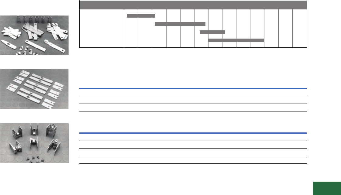
Volume 12—Aftermarket, Renewal Parts and Life Extension Solutions CA08100014E—November 2013 www.eaton.com V12-T13-53
1
2
3
4
5
6
7
8
9
10
11
12
13
14
15
16
17
18
19
20
21
22
23
24
25
13
Motor Control
Contactors, Starters and Brakes
JF Autostarter
Originally a Westinghouse
Product
Start Kit—Style Number 550D409G18
Run Kit—Style Number 550D409G19
Grid Kit—Style Number 3354D90G10
Product Description
Kits contain a complete
set of moving contacts,
stationary contacts
and springs.
Product History Time Line for JF Autostarter
Replacement Capabilities
Manual Autostarter Kits
Solenoid Assembly with Coil (All Sizes)
Technology Upgrades
ECN42–ECN44 reduced voltage auto-transformer starter or IT. solid-state reduced voltage starter.
Notes
1When replacing solenoid assembly series 416C160, use adapter plate style 9917D02H01—quantity one required.
2These styles replace coil style 296B892G_ _. When ordering new style as replacement, customer must order adapter plate 9917D02H01—
quantity one required.
AF
A
MB
JF
Type 1930 1935 1940 1945 1950 1955 1960 1965 1975 1985 1995 2000 Present
Frame
Size Required
Start
Contacts Required
Run
Contacts Required
Grid
Stack Kit
2–3 1 38A7018G12 138A7018G13 13354D90G10
4–5, 5L 1 550D409G18 1550D409G19 13354D90G10
5M–5MM 1 3354D90G08 13354D90G09 23354D90G10
Volt Hz Style 2
115 60 5264C05H01
230 60 5264C05H02
460 60 5264C05H03
575 60 5264C05H04
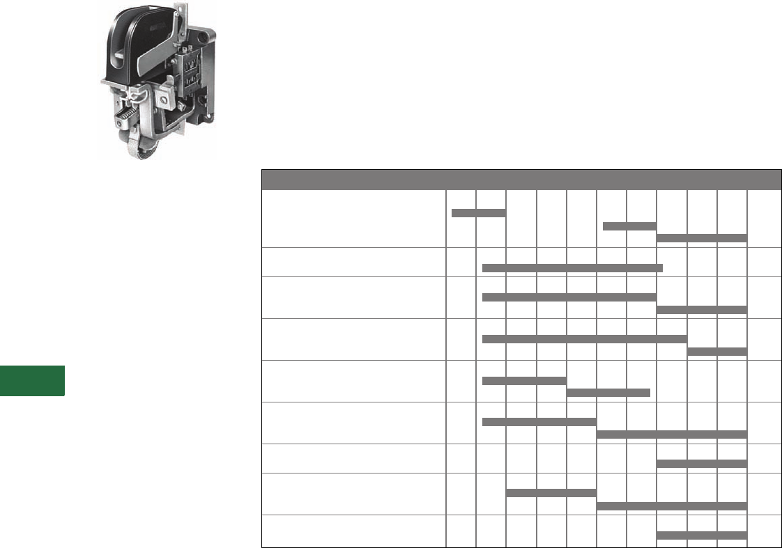
V12-T13-54 Volume 12—Aftermarket, Renewal Parts and Life Extension Solutions CA08100014E—November 2013 www.eaton.com
1
2
3
4
5
6
7
8
9
10
11
12
13
14
15
16
17
18
19
20
21
22
23
24
25
13
Motor Control
Contactors, Starters and Brakes
ME and MD
DC Contactors
Originally a Westinghouse
Product
Single-Pole, Cat. No. MD510 with
L-64 Auxiliary Contact
Product Description
The Cutler-Hammer ME and
MD line of DC contactors
were and are designed to
control functions of a
connected motor by starting,
stopping, reversing and
regulating. Motor protection
is provided when the
contactors are combined with
an appropriate protective
device such as an
overcurrent relay.
Application Description
Typical applications for the
contactor functions are as
variable voltage controller
disconnects, fans, pumps,
conveyors, rolling mills,
cranes, or anywhere a DC
motor is used.
Product History
The Cutler-Hammer ME and
MD line of DC contactors
dates back to the early 1940s
in East Pittsburgh, PA, where
the development of the M
contactors was begun by the
Westinghouse Electric
Corporation to be used in
steel rolling mills and
nicknamed “mill duty”
devices. Added frame sizes
were developed to complete
the line in Buffalo in the late
1940s. These devices were
primarily mounted on
insulating plates and were
rear connected for ease of
wiring the motor current
conductors. In the 1960s,
front-mounted MD versions
of the devices were
developed to mount devices
on steel panels because the
insulating panels were
expensive and difficult
to manufacture.
In the late 1970s, rear-
connected devices were rare
and the ME contactor line
was created for front
connection, with a rear
connection kit available and
the M rear connected version
discontinued. The MR
normally closed line was
also introduced as a standard
at that time.
Product History Time Line for M Series DC Contactors
NEMA Size 1941 1945 1948 1952 1958 1964 1977 1978 1993 2000 Present
Sizes 0–1 small frame
Type M
Type MD
Type ME
Large frame
Type M
Size 2 large frame
Type M
Type ME
Sizes 3–4
Type MME
Type ME
Sizes 3–4
Type M
Type MD
Size 5
front connected
Type M
Type MD
Rear connected
Type MR
Sizes 6–9
front connected
Type M
Type MD
Rear connected
Type MR

Volume 12—Aftermarket, Renewal Parts and Life Extension Solutions CA08100014E—November 2013 www.eaton.com V12-T13-55
1
2
3
4
5
6
7
8
9
10
11
12
13
14
15
16
17
18
19
20
21
22
23
24
25
13
Motor Control
Contactors, Starters and Brakes
Replacement Capabilities
ME Series Renewal Parts—Kits
ME Series Renewal Parts—Coils
Note
1If lower coils are required, order separately.
Description
1NO Pole 2NO Poles 1NC Pole 1NO/NC Pole
Qty.
Part
Number Qty.
Part
Number Qty.
Part
Number Qty.
Part
Number
Contact kit 1 2184A10G14 22184A10G14 12184A10G14 22184A10G14
Arc box 10/25/50A 1 2184A10G09 22184A10G09 12184A10G09 22184A10G09
Arc box 100/150A 1 2184A10G10 22184A10G10 12184A10G10 22184A10G10
Shunt kit 1 2184A10G21 12184A20G16 12084A01G07 12184A11G07
Armature kit 1 2184A10G19 12184A20G15 12084A01G06 12184A11G06
Blowout assembly
10A 1 2184A10G15 12184A20G11 12184A10G15 22184A10G15
25A 1 2184A10G16 12184A20G12 12184A10G16 22184A10G16
50A 1 2184A10G17 12184A20G13 12184A10G17 22184A10G17
110/150A 1 2184A10G18 12184A20G14 12184A10G18 22184A10G18
Rear connection kit 1 2184A10G08 12184A10G08 12184A10G08 12184A10G08
Voltage
Part Number
Operating Coils Holding Coils (Lower) 1 — 1NO/1NC Contactors Only
10/25/50/100/150
Ampere Sizes
10/25/50
Ampere Sizes
100/150
Ampere Sizes
65 30B4376G06 44A6366G10 30B4376G27
90/92 30B4376G25 44A6366G12 427C048G16
115 30B4376G07 44A6366G13 30B4376G01
125 30B4376G08 44A6366G19 30B4376G26
230/240 30B4376G09 44A6366G15 30B4376G02
250 30B4376G10 44A6366G23 30B4376G17
500 30B4376G14 N/A N/A
550 30B4376G11 44A6366G18 30B4376G03

V12-T13-56 Volume 12—Aftermarket, Renewal Parts and Life Extension Solutions CA08100014E—November 2013 www.eaton.com
1
2
3
4
5
6
7
8
9
10
11
12
13
14
15
16
17
18
19
20
21
22
23
24
25
13
Motor Control
Contactors, Starters and Brakes
MR and MD Series 1 Sizes 5–9 Renewal Parts—Kits
Notes
1MR = rear connected; MD = front connected.
2Type MR only.
3Type MD only.
Type MR
and MD
Part Number
Current
Contact Kit
501/501R 26D2610G22
510 26D2610G15
601/701 26D2610G24
610/710 26D2610G16
810 26D2610G18
810R 26D2610G19
910 26D2610G20
Shunt
501/501R 25A1650G02
510 25A1641G02
601 25A1666G03
610 25A1654G03
701 25A1666G04
710 25A1654G04
810/810R 25A1693G02
910 45A1425G02
Arc Box
501/510 25A1646G01
601/610, 701/710 25A1662G01
810/910 25A1677G05
Armature Kit
501/501R 25A1649G05
510 25A1640G05
601/701 25A1667G03
610/710 25A1655G04
810/810R 25A1694G05
910 38A2269G02
Blowout Coil Assembly Kit 2
M501/510 25A1644G05
M601/610 25A1659G05
M701/710 25A1660G03
M810/810R 25A1698G03
M910 238A2273G02
Blowout Coil Assembly Kit 3
M501/510 857D505G05
M601/610 857D506G08
M701/710 857D516G05
M810 857D508G07
M910 857D509G04

Volume 12—Aftermarket, Renewal Parts and Life Extension Solutions CA08100014E—November 2013 www.eaton.com V12-T13-57
1
2
3
4
5
6
7
8
9
10
11
12
13
14
15
16
17
18
19
20
21
22
23
24
25
13
Motor Control
Contactors, Starters and Brakes
M and MD Series Sizes 5–9—Coils
Technology Upgrades
This product currently listed in Volume 5—Motor Control and Protection, CA08100006E, Tab 4.
Notes
1Two coils connected in series.
2Two coils connected in parallel.
3Two resistors connected in parallel.
4Resistors connected in series.
Voltage
M and MD 501 M and MD 510 M and MD 610/710
Part
Number
Symmetrical
Wiring
Part
Number
Symmetrical
Wiring
Part
Number
Symmetrical
Wiring
65 N/A — 45A5515G11 ———
90/92 N/A — 45A5515G23 —30B4377G17 —
115 30B4375G04 —45A5515G01 —30B4377G04 —
125 30B4375G24 —45A5515G07 —30B4377G10 —
230 30B4375G05 —45A5515G04 —30B4377G05 —
250 30B4375G12 —45A5515G12 —30B4377G07 —
550 30B4375G06 —45A5515G05 —30B4377G08 —
Voltage
M and MD 601/701 M and MD 810 M and MD 910
Part
Number
Symmetrical
Wiring
Part
Number
Symmetrical
Wiring
Part
Number
Symmetrical
Wiring
92 — — 435A928G01 1435A930G01 1
115 30B4377G23 1435A929G01 1L483507G01 1
115 30B4377G01 2L482211G01 2L483507G01 2
125 30B4377G24 1435A966G01 1435A967G01 1
125 30B4377G13 2—— — —
230 30B4377G01 1L482211G01 1L483507G01 1
230 30B4377G02 2—— — —
250 30B4377G13 1334P064G01 1LR549720G01 2
250 30B4377G08 2—— — —
550 30B4377G25 1L482213G01 2L483508G01 2
550 30B4377G03 2—— — —
600 — — N/A — L548879G01 1
Voltage
M and MD 810R
Coil Resistor Resistor Mounting
Part
Number
Symmetrical
Wiring
Part
Number
Symmetrical
Wiring
Part
Number
Symmetrical
Wiring
115 N/A — N/A — N/A —
230 L482211G0 157D1336G10 357D1340G02 —
550 N/A 157D1336G12 457D1340G02 —
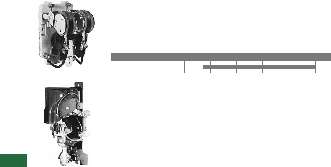
V12-T13-58 Volume 12—Aftermarket, Renewal Parts and Life Extension Solutions CA08100014E—November 2013 www.eaton.com
1
2
3
4
5
6
7
8
9
10
11
12
13
14
15
16
17
18
19
20
21
22
23
24
25
13
Motor Control
Contactors, Starters and Brakes
C80 Mill Type DC
Contactors
Originally a Cutler-Hammer
Product
Size 2—Two-Pole Contactor
NO Contactor
Product Description
These DC mill type
contactors are designed for
heavy industry service and
are suitable for use on
moving machinery. The
contactors listed in this
section are for surface
mounting on steel panels and
front-of-panel wiring. The
power stud assembly is
mounted on the side of the
contactor, rather than as part
of a separate mounting kit.
The contactors feature forged
steel armature levers and
magnet frames for superior
physical strength. Self-
lubricating bearings eliminate
the need for lubricating the
contactor.
New hot-molded arc chute
assemblies contain no
asbestos and have better arc
extinction characteristics for
longer contact life. The short
stroke armature results in a
mechanical life of more than
20 million operations.
Product History Time Line for C80 Mill Type DC Contactors
Note: The C80 contactors were renumbered in 1984 from the old 6002 Series, which date back to 1919.
Consult factory for old 6002 Series replacements and parts.
Sizes 2 – 8
Size 1980 1985 1990 1995 2000 Present
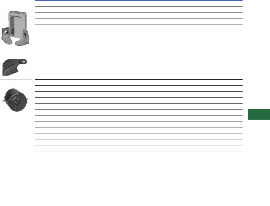
Volume 12—Aftermarket, Renewal Parts and Life Extension Solutions CA08100014E—November 2013 www.eaton.com V12-T13-59
1
2
3
4
5
6
7
8
9
10
11
12
13
14
15
16
17
18
19
20
21
22
23
24
25
13
Motor Control
Contactors, Starters and Brakes
Replacement Capabilities
Replacement Capabilities for C80 Mill Type DC Contactors
Technology Upgrades
This product currently listed in Volume 5—Motor Control and Protection, CA08100006E, Tab 4.
Notes
1Series resistor used with coil for voltage shown.
2Magnet closing coil only. If holdout coil is required, give number stamped on coil or advise
Bulletin or Serial Number of controller.
Description
Part Numbers
Size 2
Single-Pole,
Two-Pole,
Three-Pole and
Ltl® 25 and 50A
Size 3
Single-Pole
NO, NC
and Ltl 100A
Size 4
Single-Pole
NO, NC
and Ltl 150A
Size 5
Single-Pole
NO, NC
and Ltl 300A
Size 6
Single-Pole
NO, NC
and Ltl 600A
Size 6A
Single-Pole
NO, NC
and Ltl 810A
Size 8
Single-Pole
NO 1350A
Set of Contacts
Single-pole copper 6-599 6-189 6-189 6-189-3 6-189-4 6-189-4 6-215
Single-pole silver — 6-189-5 6-189-6 6-189-7 6-189-8 6-189-8 6-215-2
Two-pole copper 6-169-4 ——————
Three-pole copper 6-169-5 ——————
Arc Shield
Right hand 73-2676-2 62-791 62-791 62-793 62-840 62-840 62-804
Left hand 73-2676 62-791-2 62-791-2 62-793-2 62-840-2 62-840-2 62-804
Coils
Single-pole NO 100V 9-1549-18 9-1583-15 9-1583-15 9-1589-10 9-1688-8 9-1688-8 9-547-7 1
115V 9-1549-2 9-1583-2 9-1583-2 9-1589-2 9-1688-2 9-1688-2 9-547-7 1
115V 9-1549-2 9-1583-2 9-1583-2 9-1589-2 9-1688-2 9-1688-2 9-547-7 1
550V 9-1549-3 9-1583-3 9-1583-3 9-1589-3 9-1688-3 9-1688-3 9-547-28 1
Single-pole NC 100V — 9-1585-18 9-1585-18 9-967-13 9-1717-4 ——
115V — 9-1585-2 9-1585-2 9-967-8 9-1717-1 ——
230V — 9-1585-1 9-1585-1 9-967-7 9-1717-2 ——
550V — 9-1585-3 9-1585-3 9-967-12 9-1717-3 ——
Single-pole Ltl 2 100V 9-1549-18 9-1583-15 9-1583-15 9-1589-10 9-1688-8 ——
115V 9-1549-2 9-1583-2 9-1583-2 9-1589-2 9-1688-2 ——
230V 9-1549-1 9-1583-1 9-1583-1 9-1589-1 9-1688-1 ——
550V 9-1549-3 9-1583-3 9-1583-3 9-1589-3 9-1688-3 ——
Two-pole 100V 9-1585-18 ——————
115V 9-1585-2 ——————
230V 9-1585-1 ——————
550V 9-1585-3 ——————
Three-pole 100V 9-1585-18 ——————
115V 9-1585-2 ——————
230V 9-1585-1 ——————
550V 9-1585-3 ——————
Set of Contact
Arc Shield
Coils
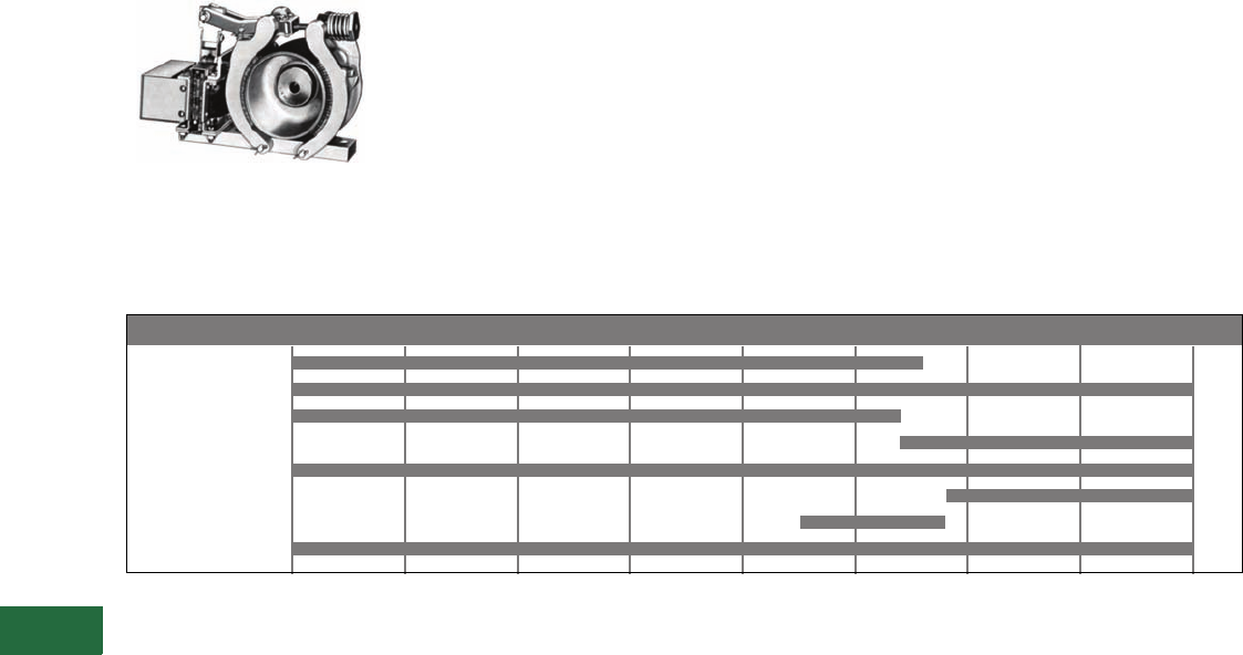
V12-T13-60 Volume 12—Aftermarket, Renewal Parts and Life Extension Solutions CA08100014E—November 2013 www.eaton.com
1
2
3
4
5
6
7
8
9
10
11
12
13
14
15
16
17
18
19
20
21
22
23
24
25
13
Motor Control
Contactors, Starters and Brakes
511 AC and DC Brakes
Originally a Cutler-Hammer
Product
Size 4-Inch Brake and Wheel
Product Description
Cutler-Hammer Type S
brakes are field-proven AC/
DC brakes. For applications
up to 1800 rpm/50 hp.
Precision holding and
stopping in 4, 5.5, 7 and
10-inch wheel sizes. With 15
standard bore sizes—straight
or tapered, non-asbestos
linings and off-the-shelf
availability, electrically
released and spring applied,
providing “fail-safe”
operation.
The retarding torque developed
is directly
proportional to the
spring pressure.
Typical applications include
conveyors, machine tools,
printing presses, small
cranes, overhead doors,
dumb waiters, vacuum
molding machines and
carnival rides.
Product History Time Line for 511 AC and DC Brakes
Types 1934 1940 1950 1960 1970 1980 1990 2000 Present
4-inch Small Solenoid
4-inch Large Solenoid
5-1/2-inch Old Style
5-1/2-inch Updated
7-inch
7-inch High Torque
8-1/2-inch
10-inch

Volume 12—Aftermarket, Renewal Parts and Life Extension Solutions CA08100014E—November 2013 www.eaton.com V12-T13-61
1
2
3
4
5
6
7
8
9
10
11
12
13
14
15
16
17
18
19
20
21
22
23
24
25
13
Motor Control
Contactors, Starters and Brakes
Replacement Capabilities
Renewal Parts for Cat. No. 511 Shoe Brakes 1
Technology Upgrades
This product currently listed in Volume 5—Motor Control and Protection, CA08100006E, Tab 2.
1Parts listed are for current line of 511 brakes.
2Kit contains two linings and rivets for one brake.
3Part number covers one shoe only.
Description
Part Numbers
4-Inch Brake 5-1/2-Inch Brake 7-Inch Brake 10-Inch Brake
3, 10 and 15 Lb
Torque
25 and 35 Lb
Torque
50 and 75 Lb
Torque
85 and 110 Lb
Torque
125 Lb
Torque
160 Lb
Torque
Magnet Coils Coil Suffix
120V, 60 Hz -39 9-591-9 9-585-9 9-941-20 9-941-8 9-758-36 9-758-37
110V, 50 Hz -5 9-591-9 9-585-9 9-585-9 9-941-39 9-758-26 9-758-10
120/110V, 50/60 Hz -66 9-591-9 9-585-9 ——— —
208V, 60 Hz -45 9-591-16 9-585-33 9-941-35 9-941-45 9-758-30 9-758-31
208/240V, 50/60 Hz -50 9-591-3 ———— —
240V, 60 Hz -40 9-591-10 9-585-10 9-941-15 9-941-4 9-758-2 9-758-30
220/240V, 50/60 Hz -67 9-591-10 9-585-10 ——— —
480V, 60 Hz -41 9-591-11 9-585-16 9-941-12 9-941-6 9-758-4 9-758-20
440/480V, 50/60 Hz -70 9-591-11 —————
600V, 60 Hz -58 9-591-12 9-585-26 9-941-32 9-941-25 9-758-13 9-758-5
550/600V, 50/60 Hz -71 9-591-12 —————
220V, 50 Hz -6 9-591-10 9-585-10 9-585-10 9-941-29 9-758-6 9-758-2
380V, 50 Hz -7 9-591-13 9-585-5 9-585-5 9-941-30 9-758-4 9-758-28
440V, 50 Hz -8 9-591-11 9-585-11 9-585-11 9-941-3 9-758-7 9-758-4
550V, 50 Hz -9 9-591-12 9-585-12 9-585-12 9-941-41 9-758-27 9-758-13
120 Vdc -97 9-1346-3 9-1347-10 9-1347-10 9-1347-12 ——
240 Vdc -98 9-1346-4 9-1347-11 9-1347-11 9-1347-13 ——
Lining kit with rivets 26-166 6-166-2 6-166-5 6-166-5 6-166-4
Shoe with lining 48-306 348-1787 348-1200-3 348-1200-3 324-2146-3 Inner 3
24-2146-4 Outer 3
Solenoid without coil AC 88-1553-8 88-2930-4 88-1342-11 88-1342-11 17-17199
DC 88-521-6 88-521-5 88-521-5 88-521-5 —
RP publication number 19320 AC 17377 AC 15475 AC 15475 AC 17379
13864 DC 17378 DC 15477 DC 15477 DC —
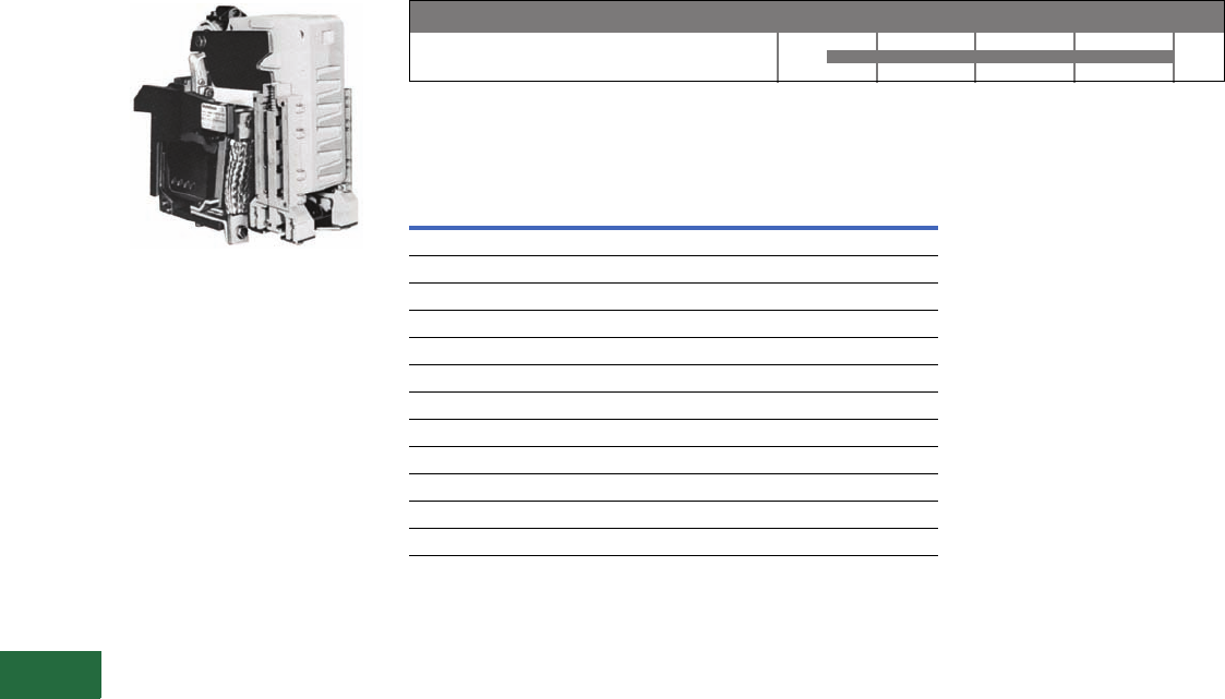
V12-T13-62 Volume 12—Aftermarket, Renewal Parts and Life Extension Solutions CA08100014E—November 2013 www.eaton.com
1
2
3
4
5
6
7
8
9
10
11
12
13
14
15
16
17
18
19
20
21
22
23
24
25
13
Motor Control
Contactors, Starters and Brakes
DPM-Contactor
DPM 1000 Vdc Contactor
Product Description
The Cutler-Hammer DPM
1000 Vdc Definite Purpose
Contactor has been designed
to meet severe environmental
and vibration conditions
found in your worst
applications. The contactor
is of unit construction,
assembled on a molded
insulated base, providing
maximum performance in
minimum space.
Product History Time Line for DPM-Contactor
Replacement Capabilities
DPM-Contactor Renewal Parts
Technology Upgrades
This product currently listed in Volume 5—Motor Control and
Protection, CA08100006E, Tab 4.
DPM-Contactor
Device 1970 1980 1990 2000 Present
Description
Catalog
Number
Contact kit 2131A94G10
Arc box 2131A94G03
Shunt 3534C86G01
Coils
28 Vdc 2114A92G04
36 Vdc 2114A92G05
55 Vdc 2114A92G06
74 Vdc 2114A92G09
110/115 Vdc 2114A92G14
125 Vdc 2114A92G15
275 Vdc 2114A92G16
600 Vdc 2114A92G20
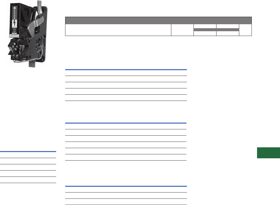
Volume 12—Aftermarket, Renewal Parts and Life Extension Solutions CA08100014E—November 2013 www.eaton.com V12-T13-63
1
2
3
4
5
6
7
8
9
10
11
12
13
14
15
16
17
18
19
20
21
22
23
24
25
13
Motor Control
Contactors, Starters and Brakes
AVD-Contactor
2000 Vdc Contactor
Product Description
The AVD-Contactor is a
single-pole normally open,
load break, bi-directional
definite purpose DC
contactor. The device is rated
at 1400A continuous and is
capable of switching up to
2000 Vdc loads.
Operating Coil
Characteristics
Coil
Voltage
Current Draw at
Nominal Voltage
(± 5% at 20°C)
Catalog
Number
28 1.87 9-3004-2
37 1.58 9-3004-3
74 0.79 9-3004-1
100 0.62 9-3004-5
230 0.25 9-3004-4
Product History
The Cutler-Hammer AVD (Advanced DC Contactor) was released for sale in 1995. The device has
not gone through any significant redesigns since its introduction.
Product History Time Line for AVD-Contactor
Replacement Capabilities
Replacement Coils
Auxiliary Contacts
Replacement Contacts and Arc Chute
Technology Upgrades
This product currently listed in Volume 5—Motor Control and
Protection, CA08100006E, Tab 4.
AVD-Contactor
Device 1993 1995 2000 Present
Coil Voltage (Vdc)
Catalog
Number
28 9-3004-2
37 9-3004-3
74 9-3004-1
100 9-3004-5
230 9-3004-4
Contact
Configuration
Terminal
Configuration
Catalog
Number
1NO/1NC Fast-on 10-3519-5
2NO Fast-on 10-3519-6
2NC Fast-on 10-3519-7
1NO/1NC Screw type 10-6817
2NO Screw type 10-6817-2
2NC Screw type 10-6817-3
Description
Quantity
Required per
Contactor
Catalog
Number
Stationary contact 1 23-7253
Movable contact 2 23-7255
Arc chute 1 62-1038
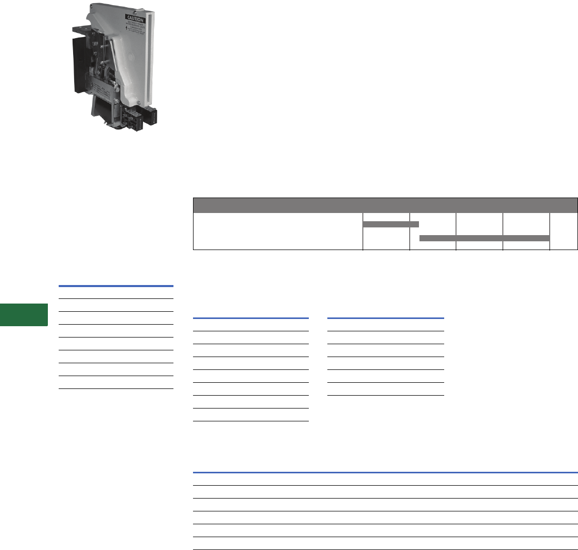
V12-T13-64 Volume 12—Aftermarket, Renewal Parts and Life Extension Solutions CA08100014E—November 2013 www.eaton.com
1
2
3
4
5
6
7
8
9
10
11
12
13
14
15
16
17
18
19
20
21
22
23
24
25
13
Motor Control
Contactors, Starters and Brakes
D-Contactor
750 Vdc Contactor
Product Description
The D-Contactor is a single-
pole normally open, load
break, bi-directional definite
purpose DC contactor. Two
devices are available rated at
1800 and 3000A at 750 Vdc.
Operating Coil
Characteristics
Coil
Voltage
Current Draw at
Nominal Voltage
(± 7.5% at 20°C)
Catalog
Number
12 3.96 9-1688-15
24 2.00 9-1688-7
32 1.44 9-1688-9
48 1.00 9-1688-12
74 .97 9-2064-3
100 .45 9-1688-8
115 .37 9-1688-2
230 .20 9-1688-1
Product History
The Cutler-Hammer
D-Contactor was released for
sale in early 1970s. The
original device included a
permanent magnet blowout
coil and square main
contacts. The permanent
magnet blowout coil device
was uni-directional or the
current could only flow
through the device in one
direction. As such, it
was
essential that the polarity as
marked
on the power
terminals be maintained. The
permanent magnet blowout
device is no longer offered.
The device was redesigned in
the early 1980s to include
round main contacts and an
intermittent duty blowout
coil in lieu of the permanent
magnet blowout. The
blowout coil device is
bi-directional or current can
flow through the device in
either direction. Although
contact life is maximized if
the +terminal is at the top of
the device, it is not essential
that polarity be maintained.
The present blowout coil
device is a form, fit, function
replacement for the original
permanent magnet blowout
device. In addition, the
present contact kits with the
round contacts can be used
on the original devices that
employed the square main
contacts. Subsequent minor
product enhancements
have been made with the
new parts being a direct
replacement for the parts
that they replaced.
Product History Time Line for D-Contactor
Replacement Capabilities
Replacement Coils Auxiliary Contacts
Replacement Contacts, Blowout Coil and Arc Chute
Technology Upgrades
This product currently listed in Volume 5—Motor Control and
Protection, CA08100006E, Tab 4.
Permanant Magnet Blowout Device
Blowout Coil Device
Device 1970 1980 1990 2000 Present
Coil Voltage
(Vdc)
Catalog
Number
12 9-1688-15
24 9-1688-7
32 9-1688-9
48 9-1688-12
74 9-2064-3
100 9-1688-8
115 9-1688-2
230 9-1688-1
Contact
Configuration
Terminal
Configuration
Catalog
Number
1NO/1NC Fast-on 10-3519-5
2NO Fast-on 10-3519-6
2NC Fast-on 10-3519-7
1NO/1NC Screw type 10-6817
2NO Screw type 10-6817-2
2NC Screw type 10-6817-3
Device Rating
Amperes
Main Contact
Configuration Contacts
Catalog
Number
1800 Two-main Main contacts 6-497
1800 Two-main Arcing contacts 23-5449
3000 Four-main Main contacts 6-496
3000 Four-main Arcing contacts 23-5448
1800 and 3000 Two- and four-main Blowout coil 9-2592
1800 and 3000 Two- and four-main Arc chute 62-822
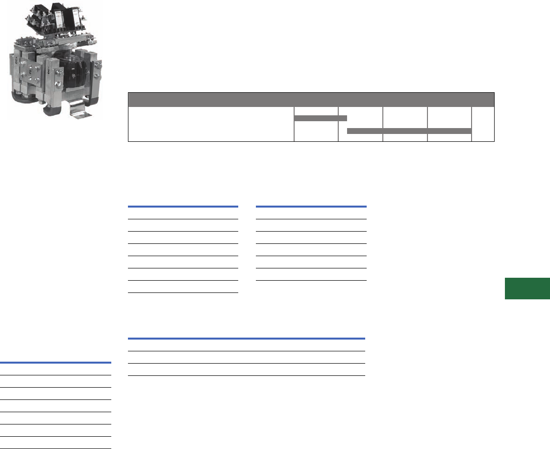
Volume 12—Aftermarket, Renewal Parts and Life Extension Solutions CA08100014E—November 2013 www.eaton.com V12-T13-65
1
2
3
4
5
6
7
8
9
10
11
12
13
14
15
16
17
18
19
20
21
22
23
24
25
13
Motor Control
Contactors, Starters and Brakes
Reversing/Assignment
Contactors
1000 Vdc Contactor
Product Description
The Reversing/Assignment
Contactor is a double-pole,
double-throw, non-load break
definite purpose DC
contactor. A three-position
center-off and a two-position
magnetically-latched
configuration is available.
The device is rated for
1100A, 1000 Vdc. The
Reversing Contactor includes
cross-over busbars for DC
motor reversing applications;
the Assignment Contactor
omits the cross-over busbars
for motor assignment
applications.
Operating Coil
Characteristics
Coil
Voltage
Current Draw at
Nominal Voltage
(± 7.5% at 20°C)
Catalog
Number
24 1.60 9-1903-9
28 1.30 9-1903-1
36 1.06 9-1903-3
74 0.49 9-1903-7
110 0.33 9-1903-6
125 0.33 9-1903-4
250 0.17 9-1903-8
Product History
The Cutler-Hammer
Reversing/Assignment
Contactor was released for
sale in the early 1970s. The
original device incorporated a
leaf spring contact assembly
and square contacts. The
device was redesigned in the
early 1980s to incorporate a
coil spring contact assembly
with round contacts. The
present device is a form, fit,
function replacement for the
original device. In addition,
the original leaf spring contact
assembly devices can be
upgraded to the new coil
spring contact assembly with
the one-time purchase of a
contact upgrade kit. The
standard contact kit can then
be used for subsequent
contact replacements.
Product History Time Line for Reversing/Assignment Contactors
Replacement Capabilities
Replacement Coils Auxiliary Contacts
Replacement Contacts
Technology Upgrades
This product currently listed in Volume 5—Motor Control and
Protection, CA08100006E, Tab 4.
Note
1The 6-602-3 contact kit will upgrade the three-position, reversing/assignment device from the
original design that incorporated a leaf spring contact structure to the present design that
incorporates a coil spring contact structure. The 6-602 contact kit can then be used after the
device has been upgraded for the subsequent contact replacement.
Leaf Spring Contact Assembly Device
Coil Spring Contact Assembly Device
Device 1970 1980 1990 2000 Present
Coil Voltage
(Vdc)
Catalog
Number
24 9-1903-9
28 9-1903-1
36 9-1903-3
74 9-1903-7
110 9-1903-6
125 9-1903-4
250 9-1903-8
Contact
Configuration
Terminal
Configuration
Catalog
Number
1NO/1NC Fast-on 10-3519-5
2NO Fast-on 10-3519-6
2NC Fast-on 10-3519-7
1NO/1NC Screw type 10-6817
2NO Screw type 10-6817-2
2NC Screw type 10-6817-3
Device Configuration
Catalog
Number
Reversing/assignment Three-position 6-602
Reversing/assignment upgrade kit 1Three-position 6-602-3
Magnetic latched reversing/assignment Two-position 6-602-5
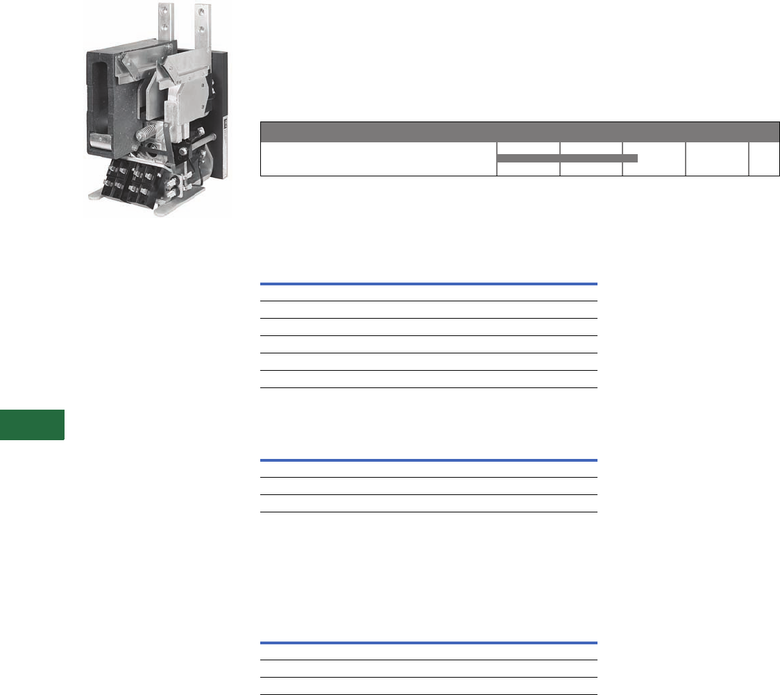
V12-T13-66 Volume 12—Aftermarket, Renewal Parts and Life Extension Solutions CA08100014E—November 2013 www.eaton.com
1
2
3
4
5
6
7
8
9
10
11
12
13
14
15
16
17
18
19
20
21
22
23
24
25
13
Motor Control
Contactors, Starters and Brakes
P- and S-Contactors
Power Contactor
Product Description
The P- and S-Contactors are
single-pole normally open,
load break DC contactors.
Although the devices have
two arc shields, they are
functionally single-pole
devices. The contactors
typically carried a 1000 Vdc,
1000A rating and were
applied in locomotive, rapid
transit and high horsepower
DC drive applications.
Product History
The Cutler-Hammer
P-Contactor and S-Contactor
were released for sale in the
1960s. These were single-
pole DC contactors that used
two arc chutes.
They typically carried a
1000 Vdc, 1200A rating and
were discontinued in the mid
1980s. A few renewal parts
are still available.
Product History Time Line for P- and S-Contactors
Replacement Capabilities
A few renewal parts are still available.
Auxiliary Contacts
Replacement Contacts, Blowout Coil and Arc Chute
Technology Upgrades
This product can potentially be replaced with the DPM-Contactor
or D-Contactor depending on the application. Please contact our
Technical Resource Center for replacement device selection.
Further Information
For further replacement parts information, contact Standard
Open Control Aftermarket at 1-800-535-8992.
Pricing Information
Price and Availability Digest (PAD)
Vista/VISTALINE Discount Symbols 1CD-5C, 1CD-1C, 15CD3
and 1CD-1
Contact
Configuration
Terminal
Configuration
Catalog
Number
1NO/1NC Fast-on 10-3519-5
2NO Fast-on 10-3519-6
2NC Fast-on 10-3519-7
1NO/1NC Screw type 10-6817
2NO Screw type 10-6817-2
2NC Screw type 10-6817-3
Description
Quantity
Required per
Contactor
Catalog
Number
Contact kit 1 6-332
Arc chute 2 62-469
Blowout coil 2 62-532
P- & S-Contactors
Device 1960 1970 1980 2000 Present
Publication
Number Description
PT03304001E Genuine Cutler-Hammer Replacement Contact Kits and Coils Wall Chart
B8F01SE Vacuum Starters and Contactors
CA08100006E Volume 5—Motor Control and Protection
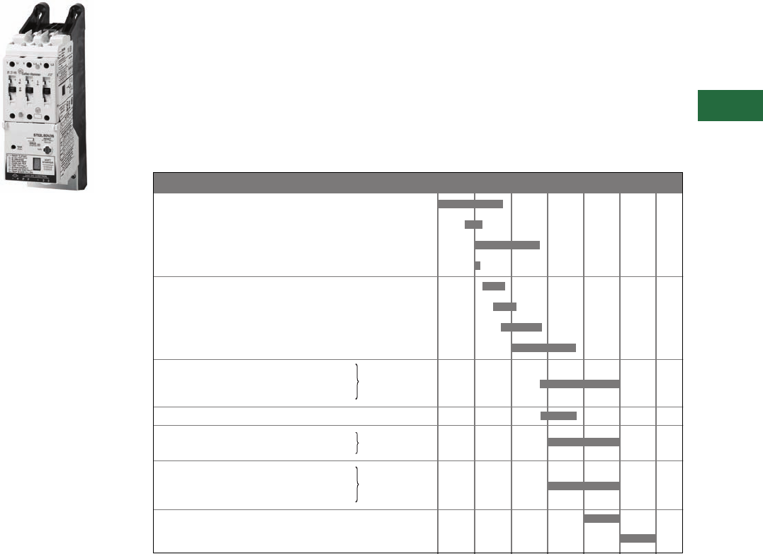
Volume 12—Aftermarket, Renewal Parts and Life Extension Solutions CA08100014E—November 2013 www.eaton.com V12-T13-67
1
2
3
4
5
6
7
8
9
10
11
12
13
14
15
16
17
18
19
20
21
22
23
24
25
13
Motor Control
Solid-State Low Voltage Reduced Voltage Motor Starters
Contents
Description Page
Low Voltage Reduced
Voltage Motor Starters
Product Description,
Product History,
Product History
Time Line . . . . .
V12-T13-67
Replacement
Capabilities,
Technology
Upgrades . . . . .
V12-T13-68
Low Voltage Adjustable
Frequency AC Drives
Product Description,
Product History
Time Line . . . . .
V12-T13-69
Replacement
Capabilities,
Technology
Upgrades . . . . .
V12-T13-71
Reduced Voltage Motor
Starters
IT. Reduced Voltage
Solid-State Motor Starter
Product Description
Reduced voltage solid-state
motor starters serve to
provide reduced voltage
starting, protection and
control for standard three-
phase induction motors.
They are commonly found in
applications like conveyors,
compressors, extruders,
pumps and blowers, etc.
Reduced voltage starting is
beneficial because current
and torque are reduced
during the motor starting
process. This reduces the
electrical and mechanical
shock experienced during
motor starting, prolonging
motor and equipment life.
Reduced voltage starters
also provide for maximum
efficiency of the motor duty
cycle by electronically
sensing the motor load and
reducing the voltage applied
to the motor when it is
running at less than full
load torque.
Solid-state motor starters
also provide short circuit and
various types of electronic
protective functions.
Common features include
phase loss, undervoltage,
current balance, phase
rotation, current limit,
overtemperature, etc.
Reduced voltage solid-state
controllers are similar to
reduced voltage motor
starters, except they include
no overload or short-circuit
protection. Motor controllers
are applied in series with
conventional electromechanical
starters to provide the
benefits of reduced voltage
starting at lower cost.
Electromechanical starter
contact life is also improved
by the reduced voltage motor
controller.
Product History
Eaton’s present line of Cutler-
Hammer reduced voltage
starters is the culmination of
38 years of product
development. In 1958,
Vectrol Engineering began
manufacturing SCR Gate
Driver circuitry and
progressed into their own
soft starter product line,
known as the Vectrol Motor
Starter (VMS). In 1980,
Vectrol was purchased by
Westinghouse. The VMS
was quickly phased out of
production and the Vectrol
ES (Energy Saver) solid-state
reduced voltage starter
was introduced. The Vectrol
ES combined features of
automatic power factor
adjustment and reduced
voltage, maximizing the
efficiency of the motor duty
cycle. The Vectrol ES starter
was actively manufactured
until 1988 when the Easy-
Start Motor Starter was
introduced.
Eaton entered the market in
1975 with the A415, A445
and A485 product lines. By
1983, Eaton had released the
A515/A545 Model A solid-
state reduced voltage starter
and followed up in late 1984
with the improved Model B
A515. This starter used a
solid-state controller, an
overload relay and a six SCR
full-wave power section. In
1988, Westinghouse
introduced its Easy-Start and
Easy-Start Jr. product lines
that also used a solid-state
control circuit and a six SCR
full-wave
power section. In
1995, the newly formed
Solid-
State Motor Control Division
(SSMC) of the new Eaton
released the Easy-Start EA
Reduced Voltage Starter,
combining the voltage control
of SCRs with the durability of
the Advantage motor starter
into a uniquely small package.
The EA, EJ and the ES
product lines have been
replaced by the IT. line of
solid-state reduced voltage
starters. Introduced in
October of 1999, the IT.
Starter is compact, easy to
install, easy to program and is
the most advanced solid-
state reduced voltage starter
available anywhere.
Product History Time Line
Cutler-Hammer A415/A445/A485
Westinghouse Vectrol VMS
Westinghouse Vectrol Energy Saver
Westinghouse Vectrol Startrol
Westinghouse Vectrol Startrol Power Miser
Cutler-Hammer A515/A545 Model A
Westinghouse Power Miser 2
Cutler-Hammer A515/A545 Model B
Westinghouse Easy-Start
Westinghouse Easy-Start 120
Cutler-Hammer Easy-Start ES
Westinghouse Power Miser 2, Model 3
Cutler-Hammer C514
Cutler-Hammer Easy-Start EC
Westinghouse Easy-Start Jr.
Westinghouse Easy-Start 100
Cutler-Hammer Easy-Start EJ
Cutler-Hammer Easy-Start EA
Cutler-Hammer IT. Starter
Product 1975 1980 1985 1990 1995 2000 Present

V12-T13-68 Volume 12—Aftermarket, Renewal Parts and Life Extension Solutions CA08100014E—November 2013 www.eaton.com
1
2
3
4
5
6
7
8
9
10
11
12
13
14
15
16
17
18
19
20
21
22
23
24
25
13
Motor Control
Solid-State Low Voltage Reduced Voltage Motor Starters
Replacement Capabilities
In most cases, recommended
replacement product is the
Cutler-Hammer IT. Soft Start
Starter. Eaton’s Electrical
Services & Systems (EESS)
has trained technicians
nation
wide. See
Ta b 2 2
in this
catalog for further
information
about EESS capabilities.
Technology Upgrades
The
IT.
line provides an easy-to-
program,
easy-to-install line of
reduced voltage Soft Starters
that is the most advanced
available anywhere in the
world. With a
range of 12–
850A and 13 models
in four
frame sizes, the IT. Soft
Starter provides advanced
functionality with
unsurpassed configuration
flexibility for open, enclosed
or motor control center
applications.
Support Chart for Non-Current Vintage Products
Advanced Technology Services, 8200 N. University, Peoria, IL 61615, now provides support for these products.
Their toll-free number is 1-877-645-3606.
Definitions
PCB Repair
Printed circuit boards may be
returned to Advanced
Technology Services for
repair. All PCBs are upgraded
to the most
current revision at
the time of the repair.
Upgrade Kits
Kits are available to upgrade
the basic
performance of
certain vintage products.
Contact Advanced
Technology Services for
more information.
Service Depot Repairs
Entire assemblies may be
returned to
Advanced
Technology Services
for
repair, upgrade or
refurbishment.
Field Service
Eaton’s Electrical Services &
Systems (EESS) has trained
technicians nation
wide. See
Ta b 2 2
in this catalog for further
information about EESS
capabilities.
Technical Support
The trained technicians at
Advanced Technology
Services are available to
provide assistance over
the telephone.
Spare Parts
Advanced Technology
Services main
tains a complete
inventory of spare parts.
Note
1Original printed circuit boards (PCBs) are
not available as spares. Please select the
appropriate upgrade board for
replacement.
Model
(See below for topic definitions)
PCB Repair Upgrade Kits Factory Repair Field Service Technical Support Spare Parts
Cutler-Hammer Solid-State Reduced Voltage Starters
A415/A445/A485 ■ ■■■ ■
A515/A545 Model A ■ ■■■ ■
A515/A545 Model B ■ ■■■ ■
C514 ■ ■■■ ■
Westinghouse Solid-State Reduced Voltage Starters
Vectrol VMS ■■
Vectrol Energy Saver ■■■ ■ 1
Easy-Start/Easy-Start 120 ■ ■■■ ■
Easy-Start Jr./Easy-Start 100 ■ ■■■ ■
Startrol
Startrol Power Miser
Power Miser 2 ■ ■■■ ■
Power Miser 2, Model 3 ■ ■■■ ■
Easy-Start Advantage ■■■■■ ■
Volume 12—Aftermarket, Renewal Parts and Life Extension Solutions CA08100014E—November 2013 www.eaton.com V12-T13-69
1
2
3
4
5
6
7
8
9
10
11
12
13
14
15
16
17
18
19
20
21
22
23
24
25
13
Motor Control
Adjustable Frequency AC Drives—Solid-State Low Voltage
Adjustable Frequency
AC Drives
Product Description
Cutler-Hammer Adjustable
Frequency Controllers (AFCs)
serve to provide adjustable
speed and control for
standard AC induction
motors. AFCs rectify the
incoming AC line voltage to
supply a fixed potential DC
bus. An inverter section is
employed to invert the DC
bus voltage to an adjustable
frequency output voltage.
The solid-state logic section
controls the inverter and
ultimately the magnitude and
frequency of the output
voltage to the motor. Input to
the solid-state logic can be
manual (from an operator
type keypad) or automatic
(from design features
programmed into the
drive logic).
The advent of
microprocessor-
based logic and the
advancements of solid-state
power technology have
dramatically reduced the
costs of AFCs and enhanced
their product features. This
has permitted a more
economical solution for
adjustable speed motor
applications because AFCs
permit the use of standard
squirrel cage induction
motors instead of DC motors,
which are more expensive
and harder to maintain. AFCs
are ideal for variable torque
applications like centrifugal
pumps and fans, and
constant torque applications
like conveyers and extruders.
Typical Adjustable
Frequency Controller
Block Diagram
Product History Time Line
To Motor
Pole A Pole B Pole C
AB C
Gate Driver
Converter
Microprocessor Logic
460 Volt, 60 Hertz
Operator Panel Status and Fault Indication Panel
Dynamatic AF-3000
Dynamatic VLT-5
Dynamatic AF-2000
Dynamatic AF-300 (Responder)
Dynamatic AF-6000
Westinghouse Accutrol 100
Dynamatic AF-7000
Dynamatic IS-7000
Dynamatic AF-8000
Westinghouse Accutrol 300
Westinghouse Accutrol 150
Westinghouse Accutrol 200
Westinghouse Accuow
Dynamatic AF-1000
Dynamatic AF-5000
Westinghouse Accutrol 110
Westinghouse Accuow Jr.
Dynamatic AF-1500
Westinghouse Accuow 110
Dynamatic AF-1600
Westinghouse Accutrol 400
Westinghouse Accutrol 700
Cutler-Hammer AF97
Dynamatic AF-5000+
Dynamatic IS-5000+
Cutler-Hammer AF93
Cutler-Hammer AF95
Cutler-Hammer AF91
Cutler-Hammer SV9000
Cutler-Hammer HV9000
Cutler-Hammer CP9000
Cutler-Hammer BP9000
Eaton CH MVX 9000
Eaton CH SVX 9000
Eaton CH HVX 9000
Product 1965 1970 1975 1980 1985 1990 1995 2000 2005 Present

V12-T13-70 Volume 12—Aftermarket, Renewal Parts and Life Extension Solutions CA08100014E—November 2013 www.eaton.com
1
2
3
4
5
6
7
8
9
10
11
12
13
14
15
16
17
18
19
20
21
22
23
24
25
13
Motor Control
Adjustable Frequency AC Drives—Solid-State Low Voltage
General Information
Notes
1Also available with a single-phase output.
2Standard 220V output only.
3Analog controls on pre-1988 models.
4Gate Turn-off Thyristor (GTO) output devices on pre-1986 models. Transistor versions have a T as the third character in the style number.
Model hp Range Input Voltage Output Devices Output Algorithm Control Type
VLT-5 1–5 240, 415 SCR VVI Analog
AF-1000 1–5 1230, 480 Transistors PWM Analog
AF-1500 1–30 240, 480 Transistors PWM Digital
AF-1600 1–20 240, 480 IGBT Vector PWM Digital
AF-2000 5–10 230 SCR VVI Analog
AF-300 N/A N/A SCR CSI Analog
AF-3000 230–250 230, (460 opt) SCR PWM Analog
AF-5000 5 –100 380–480 Transistor PWM Analog
AF-5000+ 5–600 380–480 Transistor PWM Digital
AF-6000 15–300 480 SCR VVI Analog
AF-7000 20–600 480, 575 Transistor VVI Analog
AF-8000 3 and 5 480 SCR PWM Analog
Accutrol 100 1–5 230 Transistor PWM Analog
Accutrol 110 1–75 230, 460 Transistor PWM Digital 3
Accutrol 150 3–50 460 Transistor 4PWM Analog
Accutrol 200 3–250 460 Transistor 4PWM Analog
Accutrol 300 15–600 460, 575 Gate turn-off thyristor VVI Analog
Accutrol 400 3–150 460 Transistor PWM Digital
Accutrol 700 100–600 480 IGBT Vector PWM Digital
AF93 2–20 240, 480 Insulated gate bipolar transistor Vector PWM Digital
AF95 15–200 480 Insulated gate bipolar transistor PWM Digital
AF97 100–600 480 Insulated gate bipolar transistor Vector PWM Digital
AF91 Fractional to 10 240, 460 Insulated gate bipolar transistor PWM Digital
MVX9000 Fractional to 10 120, 240, 480 Insulated gate bipolar transistor PWM Digital
9000 Series Fractional to 1100 208–575 Insulated gate bipolar transistor PWM Digital
SVX9000 Fractional to 2000 208–575 Insulated gate bipolar transistor PWM Digital

Volume 12—Aftermarket, Renewal Parts and Life Extension Solutions CA08100014E—November 2013 www.eaton.com V12-T13-71
1
2
3
4
5
6
7
8
9
10
11
12
13
14
15
16
17
18
19
20
21
22
23
24
25
13
Motor Control
Adjustable Frequency AC Drives—Solid-State Low Voltage
Replacement Capabilities
Replacement Capabilities
Model
Recommended
Replacement
Dynamatic Adjustable Frequency Drives
VLT-5 MVX9000
AF-1000 MVX9000
AF-1500
1
MVX9000
AF-1600 MVX9000
AF-2000 MVX9000
AF-300 (Responder) SV/HV/CP9000
AF-3000 SV/HV/CP9000
AF-5000 SV/HV/CP9000
AF-5000+ / IS-5000+ SV/HV/CP9000
AF-6000 SV/HV/CP9000
AF-7000 / IS-7000 SV/HV/CP9000
AF-8000 AF91SV
Westinghouse Adjustable Frequency Drives
Accutrol 100 MVX9000
Accutrol 110/Accuflow Jr.
1
MVX9000
Accutrol 150 SVX/HVX/CPX9000
Accutrol 200/Accuflow SVX/HVX/CPX9000
Accutrol 300 SVX/HVX/CPX9000
Accutrol 400 SVX/HVX/CPX9000
Accutrol 700 SVX/HVX/CPX9000
Cutler-Hammer Drives
AF91 MVX9000
AV91 MVX9000
AF93 SVX/HVX/CPX9000
AF95 SVX/HVX/CPX9000
AF97 SVX/HVX/CPX9000
SV9000 SVX9000
HV9000 HVX9000
CP9000 CPX9000
Eaton’s Electrical Services &
Systems (EESS) has trained
technicians nationwide. See
Tab 22 in this catalog for
further information about
EESS capabilities.
Technology Upgrades
The SVX9000 improves upon
the SV9000 with modular
construction and greater
program capability. Clean
power, 18-pulse
configurations are available to
meet IEEE-519 requirements
for electro-magnetic
compliance. The HVX9000
provides a simpler parameter
set geared toward the HVAC
industry, and the HVX
Intellipass provides automatic
bypass with 24 Vdc control.
Additionally, the MVX9000
gives customers a compact,
low-cost alternative to the
full-featured drives of 10 hp
or less. The same general
controls are available, with the
exception of closed-loop
(encoder) control. The
MVX9000 boasts a PLC-like
control in the form of a step
sequence program for
repeated process
applications.
These units combine digital
microprocessor control, a
user-friendly keypad, IGBT
technology, and a Windows®-
based programmer to provide
an adjustable frequency drive
that can be customized to
almost any application.
Note
1The AF-1500, Accutrol 110 and Accuflow
Jr. are identical units.

V12-T13-72 Volume 12—Aftermarket, Renewal Parts and Life Extension Solutions CA08100014E—November 2013 www.eaton.com
1
2
3
4
5
6
7
8
9
10
11
12
13
14
15
16
17
18
19
20
21
22
23
24
25
13
Motor Control
Adjustable Frequency AC Drives—Solid-State Low Voltage
Support Chart for Non-Current Vintage Products
Advanced Technology Services, 8200 N. University, Peoria, IL 61615, now provides support for these products.
Their toll-free number is 1-877-645-3606.
Definitions
PCB Repair
Printed circuit boards may be
returned to Advanced
Technology Services for
repair. All PCBs are upgraded
to the most
current revision at
the time of the repair.
Upgrade Kits
Kits are available to upgrade
the basic
performance of
certain vintage products.
Contact Advanced Technology
Services for more
information.
Service Depot Repairs
Entire assemblies may be
returned to
Advanced
Technology Services
for
repair, upgrade or
refurbishment.
Field Service
Eaton’s Electrical Services &
Systems (EESS) has trained
technicians nationwide. See
Ta b 2 2 in this catalog for
further information about
EESS capabilities.
Technical Support
The trained technicians at
Advanced Technology
Services are available to
provide assistance over
the telephone.
Spare Parts
Advanced Technology
Services main
tains a complete
inventory of spare parts.
Product Support Services
For all Product Support
Services for these “legacy”
products, contact Advanced
Technology Services at
1-877-645-3606. For technical
support with Eaton’s current
line of variable frequency
drives, contact the
Drives Technical Resource
Center at 1-800-322-4986.
Notes
1The AF-1500, Accutrol 110 and Accuflow
Jr. are identical units.
2No upgrades are available for Gate Turn-
off Thyristor (GTO) versions. Transistor
versions are identified by a leading “A1T”
or “A2T” in the model number.
3GTOs are not available as spare parts
for models below 100 hp.
Model
(See below for topic definitions)
PCB Repair Upgrade Kits Factory Repair Field Service Technical Support Spare Parts
Dynamatic Adjustable Frequency Drives
VLT-5
AF-1000
AF-1500 1■■■■■
AF-1600 ■■■■■
AF-2000
AF-300 (Responder)
AF-3000
AF-5000 ■■■■■
AF-5000+ / IS-5000+ ■■■■■
AF-6000
AF-7000 / IS-7000 ■■■■■
AF-8000
Westinghouse Adjustable Frequency Drives
Accutrol 100
Accutrol 110/Accuflow Jr. 1■■■■■
Accutrol 150 ■■ 2■■■ ■
Accutrol 200/Accuflow ■■ 2■■■ ■
Accutrol 300 ■■■■
■ 3
Accutrol 400 ■■■■■
Accutrol 700 ■■■■■ ■
Cutler-Hammer Drives
AF93
AF95 ■■■■■ ■
AF97 ■■■■■ ■

Volume 12—Aftermarket, Renewal Parts and Life Extension Solutions CA08100014E—November 2013 www.eaton.com V12-T13-73
1
2
3
4
5
6
7
8
9
10
11
12
13
14
15
16
17
18
19
20
21
22
23
24
25
13
Motor Control
Synchronous—Relay or Solid-State Mark V Slipsyn for Brush and Brushless Motors
Contents
Description Page
Brush Type Relay Slipsyn Class
14-100 Field Application Panel
Product
Description,
Technology
Upgrades . . . . .
V12-T13-75
Brush Type Mark
V
Solid-State
Slipsyn Class 14-100 Field
Application Panel
Product
Description . . . .
V12-T13-77
Replacement
Capabilities,
Technology
Upgrades . . . . .
V12-T13-78
Brush Type Mark
V
Solid-State
Slipsyn Class 14-100 Low
Voltage Motor Starters
Product
Description,
Technology
Upgrades . . . . .
V12-T13-79
Brushless Type Relay Slipsyn
Class 14-100 Field Application
Panel
Product
Description . . . .
V12-T13-80
Replacement
Capabilities,
Technology
Upgrades . . . . .
V12-T13-81
Brushless Type Mark
V
Solid-
State Slipsyn Class 14-100 Field
Application Panel
Product
Description,
Technology
Upgrades . . . . .
V12-T13-82
Relay and Solid-State Slipsyn
Control
Further
Information,
Pricing
Information . . . .
V12-T13-83
Synchronous—Relay or
Solid-State Mark V
Slipsyn for Brush and
Brushless Motors
Product Description
Synchronous Motors
Polyphase synchronous
motors are used primarily to
obtain high pullout torques,
constant operating speed, or
generation of leading reactive
kVA for power factor (PF)
correction. To bring a motor
to a constant speed, DC
power is applied to a special
winding in a synchronous
motor. This winding is called
a field coil winding and is
controlled by “field control.”
Power (DC) for a brush type
motor is usually supplied with
the starter and entails using
an exciter. Power (DC) for a
brushless type motor is
supplied by an exciter
mounted on the motor.
Synchronous Motor Control
Synchronous motor “field
application control” generally
includes a synchronous
device to apply DC power to
the motor field circuit at the
optimum speed. It may also
include protective features
such as locked rotor
protection, failure to
synchronize, incomplete
sequence, field failure,
pullout protection, etc.
depending on the type of field
application control selected.
Relay Type vs. Solid-State
Type—Mark V
Relay Type
The relay type used the ASR
synchronizing relay. Inherent
in using the relay type are the
problems that are associated
with using contacts or
mechanical closing devices
such as arcing, spring and
bearing deterioration and
wear, dirty atmospheres, etc.
Solid-State—Mark V
The Mark V is 100% solid-
state and features a “soft-
turn-on” circuit that applies
DC field voltage to the motor
field. It enables all required
functions for correct
synchronization to be
accomplished without the
use of moving contacts or
mechanical closing devices.
With the Mark V, the static
exciter power supply is
always supplied and is part of
the “system.”
Also available as a modification
with the Mark V is a VAR or
power factor, DC field current
regulator. The regulator
consists of a printed circuit
board, auxiliary devices
and potentiometers for
adjustment.
Product History
Originally a Westinghouse
Product
Synchronous Motor Control
Brush type synchronous field
control was originally
available in the 1940s. Motor
starters for brushless
synchronous motors have
been offered since the late
1960s. Synchronous motors
can be medium voltage
(2300–7200V) or low voltage
(600V and below). A
synchronous motor starter
includes the basic motor
control PLUS the
synchronous control and
protection functions.
Typically, the basic motor
control and the field
application control are
mounted in separate
compartments within
the starter. Ratings of
synchronous control are in
terms of the maximum DC
field amperes required by the
motor. Current ratings are 45,
90, 135, 160, 200 or 270A
DC, through 6000 hp at 5 kV.
Relay and Solid-State Type
Control
Relay type Slipsyn was
introduced in 1947 and uses
the ASR synchronizing relay.
Forms of solid-state type
Slipsyn were introduced in
the late 1950s and early
1960s, but were not
completely solid-state and
had some of the operation
problems that the relay type
control encountered. These
were called Mark I and Mark
II Static Slipsyn. In 1989, the
Mark V Solid-State Slipsyn
field control was introduced.
Medium Voltage (AMPGARD®
)
Starters
The AMI AMPGARD
synchronous starter (1957–
1970) used a 60-inch deep
enclosure with the
synchronous control in the
low voltage section in the
front bottom two thirds of the
starter enclosure. The basic
motor control was located in
the rear bottom two thirds of
the enclosure, barriered off
from the low voltage section.
The AMI AMPGARD for
synchronous motors used the
ASR relay type control.
The LF AMPGARD (1962–
1988) primarily used the ASR
field application relay control.
Mark I and Mark II Static
Slipsyn were also used during
their availability periods. The
LF AMPGARD for synchronous
motors included the basic
induction motor control (ISO®
switch, contactor and starter
control) in the bottom half of
the structure.

V12-T13-74 Volume 12—Aftermarket, Renewal Parts and Life Extension Solutions CA08100014E—November 2013 www.eaton.com
1
2
3
4
5
6
7
8
9
10
11
12
13
14
15
16
17
18
19
20
21
22
23
24
25
13
Motor Control
Synchronous—Relay or Solid-State Mark V Slipsyn for Brush and Brushless Motors
The upper half contained the
step-down
static excitation
transformer with current
limiting fuses, the Silicon
Controlled Rectifier (SCR)
type static exciter and the
synchronizing control and
motor field protection panel.
The SJ AMPGARD (1982–
2000) family of synchronous
control is very similar
to the
LF AMPGARD. Until the
availability
of the Mark V solid-
state synchronous control,
the SJ used the ASR relay
type field control. With the
advent of the
Mark
V
, most of
the synchronous starters
are
supplied with this type of
control. In both ASR and
Mark V control schemes,
the
synchronous gear is usually
mounted
in the top half of
the starter.
The SL AMPGARD (2000–
present) is similar to the SJ
AMPGARD but uses the
Mark V solid-state
synchronous controller,
exclusively.
Low Voltage Synchronous
Starters
Low voltage synchronous
starters are similar in nature
to high voltage synchronous
starters except in two
regards. High voltage
starters, unlike low voltage
starters, must isolate the low
voltage from the high voltage.
The components for the field
control are the same.
The second difference lies in
the primary disconnect used
in the starters. Low voltage
starters can be supplied with
no short-circuit protection,
with a non-fusible disconnect,
a fusible disconnect switch or
with a molded-case circuit
breaker. Low voltage
synchronous starters were
manufactured in the late
1940s with the introduction
of the ASR relay, until
September of 1989. In 1991,
the product was reintroduced
using the Mark V solid-state
field control.
Product History Time Line
V12-T13-73 ASR Relay Slipsyn (Brush Type)
Mark I Static Slipsyn (Brush Type)
Mark II Static Slipsyn (Brush Type)
V12-T13-78 Mark V Slipsyn
V12-T13-80 Brushless Motor Control
Page Product 1945 1955 1965 1975 1985 1995 2000 Present
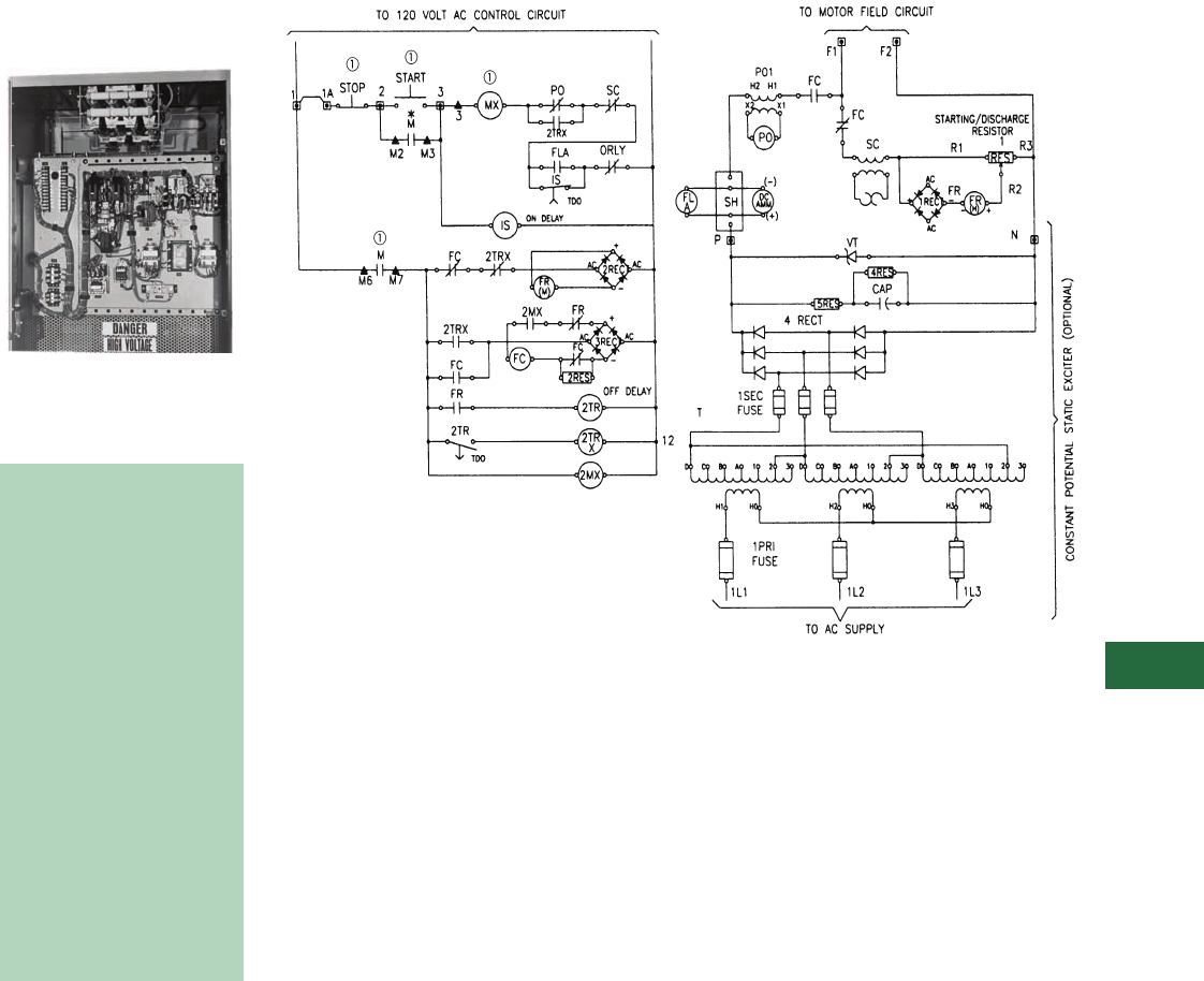
Volume 12—Aftermarket, Renewal Parts and Life Extension Solutions CA08100014E—November 2013 www.eaton.com V12-T13-75
1
2
3
4
5
6
7
8
9
10
11
12
13
14
15
16
17
18
19
20
21
22
23
24
25
13
Motor Control
Synchronous—Brush Type Relay Slipsyn Class 14-100 Panel
Relay Slipsyn Automatic
Field Application Panel
Product Description
Relay Field Panel
■
Shaded area denotes
obsolete or discontinued
products and services.
Automatic Field Application
Control
The field application panel
provides Slipsyn automatic
field application identical
to that in complete
synchronous motor
starters. It is designed for
use in conjunction with a
primary line closing device
such as a circuit breaker or
a linestarter. One interlock
on the primary device is
used to actuate the field
application control. When
the motor accelerates to
proper speed for pull-in, the
field is automatically applied.
The controller is available
for floor mounting. Floor-
mounted cabinets are
NEMA 1 with hinged front
door and removable
rear plates.
Ty p i c a l S ch e m a t i c
Note
1Not supplied with 14-100 panel or static exciter.
Typical 14-100 Panel with Constant Static Exciter
(Optional) for use with Primary Motor Starter

V12-T13-76 Volume 12—Aftermarket, Renewal Parts and Life Extension Solutions CA08100014E—November 2013 www.eaton.com
1
2
3
4
5
6
7
8
9
10
11
12
13
14
15
16
17
18
19
20
21
22
23
24
25
13
Motor Control
Synchronous—Brush Type Relay Slipsyn Class 14-100 Panel
■
Shaded area denotes
obsolete or discontinued
products and services.
Information Required from
Customer for Upgrade
Evaluation
1. Original assembly
nameplate data including
general order “GO”
number as well as any
drawing numbers.
2. Complete motor data
including horsepower,
phase, voltage/Hz, RPM,
FLA, LRA, full-load DC
amperes, power factor,
excitation voltage,
induced field amperes
at 95% speed and at 0%
speed, recommended
discharge resistor ohms
and maximum time at
zero speed (locked rotor).
3. Excitation control detail
such as
“constant-
potential” or “adjustable-
potential.” Adjustable-
potential usually requires
a field rheostat (motor
field-resistor).
4. Detail on the motor’s
function such as the
application data and
other service conditions
such as duty-cycle, etc.
The cabinets contain the
following equipment:
1– Polarized slip frequency
field application relay
type ASR (FR) with half-
wave rectifier (REC).
1– Time relay with contacts
available for unloader
circuit (2TR).
1– Pullout relay and
transformer (PO).
1– Field contactor, two-pole
(FC).
1–
Damper winding
protective relay (SC).
1– Starting and field
discharge resistor
when size permits;
otherwise, provided for
separate mounting)
(1RES).
1– DC field ammeter, panel
type, semi-flush
mounted (DC AMM).
1– DC field ammeter shunt
(SH).
1– DC field failure
protection (FLA).
2– Auxiliary relays (2TRX),
(2MX).
1– Incomplete sequence
relay (IS).
Static Excitation Power
Supply Panel
Constant Potential Type
Power conversion AC to DC
units are designed for
individual synchronous
motor field excitation.
These units are convection
cooled, solid-state and are
completely assembled and
wired as a self-contained
package with a relay Slipsyn
automatic field application
control. The connections
necessary to the external
circuits are line leads, motor
leads, field connections and
control interconnection.
The static system consists
of a convection-cooled
silicon rectifier three-phase
full-wave bridge assembly,
a set of current limiting
fuses in the secondary side
of the transformer and a set
of surge protecting devices.
The transformer has
secondary taps that are
adjustable with four course
taps that provide
approximately 12%
adjustment per tap, and
three fine taps that
provide 4% adjustment
per tap.
Adjustable Potential Type
An adjustable potential
exciter is similar to the
constant potential exciter
except that it uses SCRs
and the voltage adjustment
is made with a potentiometer
mounted on the door.
Technology Upgrades
For Brush-Type, Relay-Panel
Slipsyn (Class 14-100)
Upgrades
New synchronous field
controllers using the latest
solid-state technology are
usually available. Upgrades
for primary starter and
contactor components may
also be available.
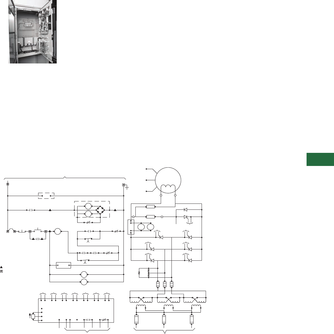
Volume 12—Aftermarket, Renewal Parts and Life Extension Solutions CA08100014E—November 2013 www.eaton.com V12-T13-77
1
2
3
4
5
6
7
8
9
10
11
12
13
14
15
16
17
18
19
20
21
22
23
24
25
13
Motor Control
Synchronous—Brush Type Mark V Solid-State Slipsyn Class 14-100 Panel
Slipsyn Automatic Field
Application Panel with
Static Exciter
Product Description
Mark V Field Controller
Automatic Field Application
Control
The Slipsyn panel provides
automatic field application
identical to that in complete
synchronous motor starters.
It is designed for use in
conjunction with a primary line
closing device, such as a
circuit breaker or a linestarter.
When the motor accelerates
to proper speed for pull-in, the
field is automatically applied.
The solid-state Mark V
Slipsyn controller will provide
the following protective
functions:
A. Locked rotor protection.
B. Incomplete sequence.
C. Failure to synchronize.
D. Fuse failure (Mark V).
E. Pullout protection.
F. DC current failure
protection.
Also the application of the DC
power to the motor field
windings is accomplished
without mechanically moving
parts, and the device features
a “soft-turn-on” circuit when
applying DC voltage to the
motor field.
Depending on the size of the
solid-state application panel,
the controller is available in
a NEMA 1 floor-mounted
enclosure or an AMPGARD
type cell construction.
In both designs, a hinged
front door with externally
ventilated heat sinks will
be provided.
The cabinets will contain
the following equipment:
1 – Step-down exciter
transformer—
three-phase (TX).
3 – Primary fuses (3 PRI).
3 – Secondary fuses (3 SEC).
1 – “SCR” power supply
panel.
1 – Synchronous control
board (CB).
1 – DC
ammeter—panel type
(DC AMM).
3 – “MOV” for surge
protection (MOV).
1 – Starting and field
discharge resistor (when
size permits; otherwise
provided for separate
mounting).
1 – Field failure relay (FLA).
1 – Incomplete SEQ Timer
(FLT).
1 – Start timer (SYTR).
1 – Potentiometer (P2).
Ty p i c a l S ch e m a t i c
Note
1Not supplied with Mark V.
IN
PSC
P2
1L21 1L22 1L23
_ _ AMPS
1x1
1x3
1x2
1x4
2x1
2x3
2x2
2x4
3x1
3x3
3x2
3x4
IH1 IH2 2HI 2H2 3H1 3H2
TX
1L11 1L12 1L13
1L1 1L2 1L3
_ _ AMPS
3 PRI
FUSE
3 SEC
FUSE
MOV
MOV
MOV
1L31 1L32 1L33
P
N
QA2
CA2
KA2
CB2
KB2
CC2
KC2
CA1
KA1
CB1
KB1
QA1
QB2QB1
QC2QC1
CC1
KC1
TO CB
TO CB
TO CB
TO CB
TO CB TO CB
TO CB
TO CB
VR
FLA
DC
AMM
SH
(–)
(+)
KQ4
CQ4
F2
F1
FIELD
MOTOR
T1
T2
T3
R1 Q4
D1
R3
STARTING/DISCHARGE
RESISTOR
1RES
RES
12
MB
OL
+RECT
–
AC
AC
D
M
C
A
MA
MA
M
MA
LN
FLA
11A
*
START
*
STOP 233
3MX
F
CB
M
M2 M3
FLA
11 14
FLT
TDO
MX
KK1
ST1 ST2 SQ1 SQ1
RLY1 RLY3
K2
SYTR
TDO
115
PW
HW
TO PRIMARY CONTROL CIRCUIT – 120 Vac
ON DELAY
.1 - 30 SEC
FLT
SY
TR
(SET 2 SEC LONGER THAN
ACCELERATION TIME)
SET @ .5 SEC
TO
QA2
TO
QB2
TO
QC2
TO
QA1
TO
QB1
TO
QC1
TO
Q4
KA2
CA2
KB2
CB2
KC2
CC2
KA1
CA1
KB1
CB1
KC1
CC1
CQ4
KQ4
(WB)
AV2
AV1
VPF
TO
D1
VR
115
IN–
IN+
ST1
RLY 1 RLY 3
ST2
SO1
SO2
TO 120 V CONTROL CIRCUIT
ON DELAY
.1 - 30 SEC
= REMOTE DEVICE
= TERM. BLOCK(S)
= CUST. TERM. BLK.
*
CW
TO ac SUPPL Y
햲
햲
햲
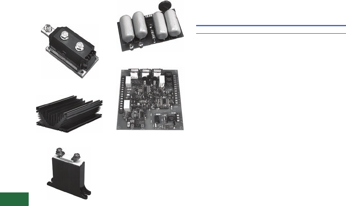
V12-T13-78 Volume 12—Aftermarket, Renewal Parts and Life Extension Solutions CA08100014E—November 2013 www.eaton.com
1
2
3
4
5
6
7
8
9
10
11
12
13
14
15
16
17
18
19
20
21
22
23
24
25
13
Motor Control
Synchronous—Brush Type Mark V Solid-State Slipsyn Class 14-100 Panel
Replacement Capabilities—
Typical Solid-State
Components
Power Module, 200A, Three Required
Heat Sink
MOV
Snubber for Thyristor Stack
Main Synchronizing Control/
Protection Board
Note: Typical solid-state
components used in Mark V
Slipsyn—Refer to RPD 8855S for
renewal parts for synchronous
control.
Field Panel with Static Exciter
20 kW Maximum—Approximate Dimensions in Inches
Technology Upgrades
For Brush Type Mark V Solid-
State Slipsyn (Class 14-100)
Upgrades
New synchronous field
controllers using the latest
solid-state technology are
available. Replacements and
upgrades for primary starter
and contactor components
are also available.
Information Required from
Customer for Upgrade
Evaluation
1. Original assembly
nameplate data including
general order “GO”
number as well as any
drawing numbers.
2. Complete motor data
including horsepower,
phase, voltage/Hz, RPM,
FLA, LRA, full-load DC
amperes, power factor,
excitation voltage,
induced field amperes
at 95% speed and at 0%
speed, recommended
discharge resistor ohms
and maximum time at
zero speed (locked rotor).
3. Excitation control detail
such as
“constant-
potential” or “adjustable-
potential.” Adjustable-
potential usually requires
a field rheostat (motor
field-resistor).
4. Detail on the motor’s
function such as the
application data and
other service conditions
such as duty-cycle, etc.
Open Cell Floor Mounted — NEMA 1
Height Width Depth Height Width Depth
45 36 30 90 36 30
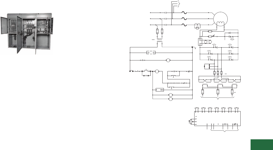
Volume 12—Aftermarket, Renewal Parts and Life Extension Solutions CA08100014E—November 2013 www.eaton.com V12-T13-79
1
2
3
4
5
6
7
8
9
10
11
12
13
14
15
16
17
18
19
20
21
22
23
24
25
13
Motor Control
Synchronous—Brush Type Mark V Solid-State Slipsyn Class 14-200 LV Motor Starters
Synchronous—Brush
Type Mark V Solid-State
Slipsyn Class 14-200 LV
Motor Starter
600V, NEMA Size 8,
Synchronous Starter
Product Description
Slipsyn magnetic starters
provide reliable, automatic
starting of synchronous
motors. Automatic
synchronization is provided by
the Mark V Solid-State Field
Panel, which ensures
application of the field at
proper motor speed, and at a
favorable angular position of
stator and rotor poles. As a
result, line disturbance
resulting from synchronization
is reduced and effective motor
pull-in torque is increased.
Application of DC power to
motor field windings is
accomplished without
mechanically moving parts,
and the device features a
“soft-turn on” circuit when
applying DC voltage to the
motor field.
The solid-state Mark V Slipsyn
controller will provide the
following protective
functions:
A. Locked rotor protection.
B. Incomplete sequence.
C. Failure to synchronize.
D. Fuse failure (Mark V).
E. Pullout protection.
F. DC current failure
protection.
The cabinet will contain the
following:
1 – Primary starter full voltage
or reduced voltage.
1 – Ammeter shunt (when
required).
1 – Auxiliary relay for main
line contactor (when
required) (MX).
1 – Starting and field
discharge resistor (IRES).
1 – Current transformer for
AC ammeter through
NEMA Size 4; Sizes 5 and
larger use three current
transformers for overload
relays and AC ammeter.
1 – Set control circuit terminal
blocks.
3 – Type AN manual reset
thermal overload relay and
three heater elements
(OL).
1 – Step-down exciter
transformer—three-phase
(TX).
3 – Primary fuses (3 PRI).
3 – Secondary fuses (3 SEC).
1 – SCR power supply panel.
1 – Synchronous control
board (CB).
3 – MOV for surge protection
(MOV).
1 – Starting and field
discharge resistor (when
size permits; otherwise
provided for separate
mounting).
1 – AC ammeter, panel type
(AM).
1 – DC ammeter, panel type
(DC AMM).
1 – Exciter field
potentiometer (P2).
1 – Field failure relay (FLA).
1 – Incomplete SEQ Timer
(FLT).
1 – Start timer (SYTR).
Typical Schematic Full Voltage Starter, Class 14-200,
Non-Combination Type
Technology Upgrades
For Brush-Type Mark V Solid-
State Slipsyn (Class 14-200) Low
Voltage Motor Starter Upgrades
New synchronous field
controllers using the latest
solid-state technology are
usually available.
Replacements and upgrades
for primary starter and
contactor components are
also usually available.
Information Required from
Customer for Upgrade
Evaluation
1. Original assembly
nameplate data including
General Order “GO”
number as well as any
drawing numbers.
2. Complete motor data
including horsepower,
phase, voltage/Hz, RPM,
FLA, LRA, full-load DC
amperes, power factor,
excitation voltage,
induced field amperes
at 95% speed and at 0%
speed, recommended
discharge resistor ohms
and maximum time at
zero speed (locked rotor).
3. Excitation control detail
such as
“constant-
potential” or “adjustable-
potential.” Adjustable-
potential usually requires
a field rheostat (motor
field-resistor).
4. Detail on the motor’s
function such as the
application data and
other service conditions
such as duty-cycle, etc.
Note
1Remote device.
TO
QA2
TO
QB2
TO
QC2
TO
QA1
TO
QB1
TO
QC1
TO
Q4
KA2
CA2
KB2
CB2
KC2
CC2
KA1
CA1
KB1
CB1
KC1
CC1
CQ4
KQ4
(WB)
VPF
AV1
AV2
PSC
CB
SYNCHRONIZING AND CONTROL CIRCUIT
VR
115
IN-
IN+
ST1
ST2
SQ1
SQ2
TO
D1 TO 120V CONTROL CIRCUIT
RLY 1 RLY 3
P2
CW
11A
햲
STOP 2START
3
MX F
M
M2 M3
FLA
11 14
OL
FLT
TDO
WX K
ST1
RLY1K1
ST2
SQ1
RLY3
SQ2
K2
SYTR
TDO
CB
115
3
ON DELAY
.1-30 SEC
(SET 2 SEC LONGER THAN
ACCELERATION TIME)
ON DELAY
.1-30 SEC SET @ .5 SEC
3SEC
FUSE
1L21 1L22 1L23
AMPS
1X1 1X3 1X21X4 2X12X3 2X2 2X4 3X1 3X3 3X2 3X4
TX
3PRI
FUSE
1L1 1L2 1L3
1L11 1L12 1L13
AMPS
TO AC SUPPLY
1H1 1H2 2H1 2H2 3H1 3H2
1L31
TO CB
1L32 1L33
P
N
QA1
KA1
CA1
TO CB
QA2
KA2
CA2
TO CB
QB1
KB1
CB1
TO CB
QB1
KB2
CB2
TO CB
QC1
KC1
CC1
TO CB
QC1
KC2
CC2
FLA
DC
AMM
(-)
(+)
SH
RES
1RES
TO CB
Q4
D1
TO CB
VR
R1 R3
STARTING/DISCHARGE
RESISTOR
F1 F2
MOTOR
T3
FIELD
T1
T2
1L1
1L2
1L3
TO
3 PRI
FUSE
M
C
B
A
L3
L2
L1
AC
SUPPLY
PRI FUSE
3 AMP
CPT
X1 X2
M
M
VA
H1 H2
OL
OL
OL
12
FLA
LN
MX
M
SY
TR
FLT
햲
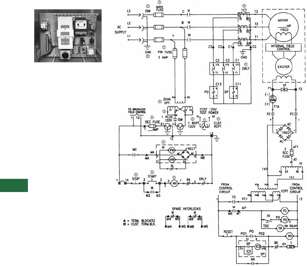
V12-T13-80 Volume 12—Aftermarket, Renewal Parts and Life Extension Solutions CA08100014E—November 2013 www.eaton.com
1
2
3
4
5
6
7
8
9
10
11
12
13
14
15
16
17
18
19
20
21
22
23
24
25
13
Motor Control
Synchronous — Brushless Type Relay Slipsyn Class 14-100 Panel
Relay Slipsyn Automatic
Field Application Panel
Brushless Field Panel
Product Description
This field application panel
provides DC power to the
exciter field and is designed
for use in conjunction with
a primary line closing device
such as a contactor motor
starter or a circuit breaker
motor starter. A normally
open electrical interlock on
the primary device is used to
actuate the field application
control. This panel utilizes
electromechanical devices to
apply DC power to the motor
exciter field circuit.
Note: The power rectifiers for the
motor field circuit and automatic
synchronizer are mounted on the
synchronous motor rotor.
Brushless Synchronous Control
The controller can be
supplied with or without
enclosure. Panel mounted
or open cell are suitable for
mounting within other
larger enclosures.
The cabinet or open panel
or open cell contains the
following equipment:
1 – Solar transformer (1 CPT).
1 – Power factor relay (PO).
1 – Auto-transformer (AT)
Powerstat.
1 – Damper winding
protection relay (DP).
1 – Field contactor (FC).
1 – Volt trap (VT).
1 – Rectifier (REC).
1 – Sequence relay (TR).
1 – Damper winding
protection hold-in relay
(DPX)—if required.
2 – Fuses (SEC FU),
(2 SEC FU).
1 – DC ammeter—panel type
(DC AMM).
Typical Starter Schematic
Notes
1Starter devices not supplied with field panel.
Devices shown without a a constitute 14-100 panel.
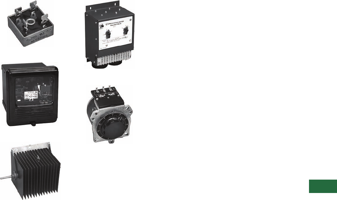
Volume 12—Aftermarket, Renewal Parts and Life Extension Solutions CA08100014E—November 2013 www.eaton.com V12-T13-81
1
2
3
4
5
6
7
8
9
10
11
12
13
14
15
16
17
18
19
20
21
22
23
24
25
13
Motor Control
Synchronous—Brushless Type Relay Slipsyn Class 14-100 Panel
Replacement Capabilities—Typical Components
Rectifier
Damper Winding Protection Relay
Volt Trap
Pullout/Power Factor Relay
Powerstat
Note: Typical components used in
Relay Slipsyn Brushless Control—
Refer to RPD 8855S for renewal
parts for synchronous control.
Technology Upgrades
For Brushless-Type Relay-Panel
Slipsyn (Class 14-100) Upgrades
New synchronous field
controllers using the latest
solid-state technology are
available. Replacements and
upgrades for primary starter
and contactor components
are also available.
Information Required from
Customer for Upgrade
Evaluation
1. Original assembly
nameplate data including
general order “GO”
number as well as any
drawing numbers.
2. Complete motor data
including horsepower,
phase, voltage/Hz, RPM,
FLA, LRA, full-load DC
amperes, power factor,
excitation voltage,
induced field amperes
at 95% speed and at 0%
speed, and maximum
time at zero speed
(locked rotor).
3. Excitation control detail
such as
“constant-
potential” or “adjustable-
potential.” Adjustable-
potential usually requires
a field rheostat (motor
field-resistor).
4. Detail on the motor’s
function such as the
application data and
other service conditions
such as duty-cycle, etc.
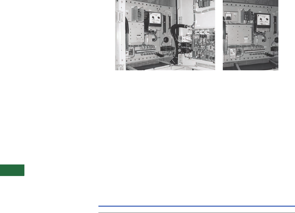
V12-T13-82 Volume 12—Aftermarket, Renewal Parts and Life Extension Solutions CA08100014E—November 2013 www.eaton.com
1
2
3
4
5
6
7
8
9
10
11
12
13
14
15
16
17
18
19
20
21
22
23
24
25
13
Motor Control
Synchronous—Brushless Type Mark V Solid-State Slipsyn Class 14-100 Panel
Slipsyn Automatic Field
Application Panel with
Static Exciter
Product Description
Automatic Field
Application Control
The field application panel
provides Slipsyn automatic
field application identical
to that in complete
synchronous motor starters.
It is designed for use in
conjunction with a primary
line closing device such as
a circuit breaker or a
linestarter. Automatic
synchronization is provided
by the Mark V solid-state
field panel, which ensures
application of the field at
proper motor speed and
at a favorable angular
position of stator and rotor
poles. As a result, line
disturbance resulting from
synchronization is reduced
and effective motor pull-in
torque is increased.
Application of DC power
to motor field windings is
accomplished without
mechanically moving parts,
and the device features a
“soft-turn-on” circuit when
applying DC field voltage to
the motor field.
This unit also comes
standard with a VAR or
power factor, DC field
current regulator. The VAR
regulator controls the AC
reactive current flow out of
the motor during varying load
conditions by varying the
motor field excitation. The PF
regulator controls the motor
power factor under varying
load conditions by varying the
motor field excitation. The
DC field current regulator
compensates for the motor
field resistance as the motor
field heats up by increasing
the motor field voltage.
Note: Power factor regulation—
cannot provide regulation below
50% of rated voltage and/or 25%
of rated current. Regulation
cannot be accomplished on light
loads, i.e., less than 20% load.
Mark V Brushless Field Controller
The solid-state Mark V Slipsyn
controller will provide the
following protective
functions:
A. Locked rotor protection.
B. Incomplete sequence.
C. Failure to synchronize.
D. Fuse failure (Mark V).
E. Pullout protection.
F. DC current failure
protection.
This control is available in a
NEMA 1 floor-mounted
enclosure or an AMPGARD
type cell construction. In both
designs, a hinged front door
with externally ventilated heat
sinks will be provided.
The cabinets will contain the
following equipment:
1 – Step-down exciter
transformer—three-phase
(TX).
3 – Primary fuses (3 PRI).
3 – Secondary fuses (3 SEC).
1 – SCR power supply panel.
1 – Synchronous control
board (CB).
3 – MOV for surge protection
(MOV).
1 – AC ammeter, panel type
(AM).
1 – DC ammeter, panel type
(DC AMM).
4 – Potentiometer (P2, P3,
P4, P5).
1 – Field failure relay (FLA).
1 – Incomplete SEQ Timer
(FLT).
1 – Start timer (SYTR).
1 – MP-3000 without RTD
module.
1 – DP-4000.
1 – VAR/PF/DC field current
board (CB1).
1 – Auto/manual selector
switch (SSI).
1 – Timer (AUTO).
1 – Pullout relay (PO).
Approximate Dimensions in Inches
Technology Upgrades
For Brushless-Type Mark V
Solid-State Slipsyn
(Class 14-100) Upgrades
New synchronous field
controllers using the latest
solid-state technology are
available. Replacements and
upgrades for primary starter
and contactor components
are also available.
Information Required from
Customer for Upgrade
Evaluation
1. Original assembly
nameplate data including
general order “GO”
number as well as any
drawing numbers.
2. Complete motor data
including horsepower,
phase, voltage/Hz, RPM,
FLA, LRA, full-load DC
amperes, power factor,
excitation voltage,
induced field amperes
at 95% speed and at 0%
speed, and maximum
time at zero speed
(locked rotor).
3. Excitation control detail
such as
“constant-
potential” or “adjustable-
potential.” Adjustable-
potential usually requires
a field rheostat (motor
field-resistor).
4. Detail on the motor’s
function such as the
application data and
other service conditions
such as duty-cycle, etc.
Open Cell Floor Mounted—NEMA 1
Height Width Depth Height Width Depth
45 36 30 90 36 30

Volume 12—Aftermarket, Renewal Parts and Life Extension Solutions CA08100014E—November 2013 www.eaton.com V12-T13-83
1
2
3
4
5
6
7
8
9
10
11
12
13
14
15
16
17
18
19
20
21
22
23
24
25
13
Motor Control
Synchronous—Relay or Solid-State Mark V Slipsyn for Brush and Brushless Motors
Identifying Renewal Parts
Renewal parts data for the
entire history of synchronous
control is contained in RPD
8855S, which provides the
proper identification of
standard parts that may be
required under normal
operation:
1. Identify the design of
synchronous control
(Relay, Mark I, Mark II
or Mark V Slipsyn) from
the synchronous panel
nameplate.
2. Now that you have
identified the type of the
synchronous control,
determine from the
photographs in RPD
8855S which parts are
required and identify
them by style number.
3. Because many starters
are supplied to meet
specific customer
requirements, other
parts not shown in
RPD 8855S might
occasionally be needed.
Price and availability of
parts not listed may be
obtained by providing a
complete description of
the part, along with the
complete data on the
starter nameplate, which
is found in the low
voltage area. Be sure to
include the following:
ratings, shop order and
diagram reference.
Further Information
Pricing Information
Price and Availability Digest (PAD)
Publication
Number Description
RP04304009E Common Replacement Parts for Mark V Synchronous Field Controller
RPD 8855S Renewal Parts Data for Synchronous Control
TD.48A.01.T.E Descriptive Bulletin for AMPGARD Starters
IL 17097 Instruction Leaflet for Relay Slipsyn
IB 48008 Instruction Leaflet for Solid-State Slipsyn
IB 48009 Instruction Leaflet for Mark V VAR/PF/DC Field Current Regulator
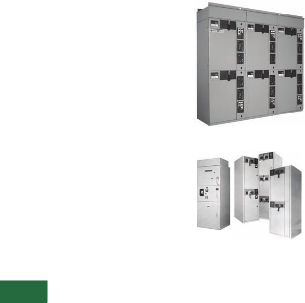
V12-T13-84 Volume 12—Aftermarket, Renewal Parts and Life Extension Solutions CA08100014E—November 2013 www.eaton.com
1
2
3
4
5
6
7
8
9
10
11
12
13
14
15
16
17
18
19
20
21
22
23
24
25
13
Motor Control
Medium Voltage Starters
Contents
Description Page
AMI AMPGARD
Product Description,
Technology
Upgrades . . . . .
V12-T13-88
LF Air AMPGARD
Product Description,
Replacement Capabilities,
Technology
Upgrades . . . . .
V12-T13-89
SL and SJ Vacuum
AMPGARD
Product Description,
Replacement
Capabilities. . . .
V12-T13-91
Technology
Upgrades . . . . .
V12-T13-92
Further Information,
Pricing
Information. . . .
V12-T13-96
AMPGARD
Originally a Westinghouse
Product
AMPGARD Motor Control Assembly
(AMI Vintage), 5000V 200A, 2500V 200A,
2500/5000V 400A (LF-Air Vintage)
Product Description
A medium voltage starter is an
assembly
used to control and
protect an alternating current
(AC) electric motor rated at
2300, 4160 or 7200V. The
controlling function is provided
by a magnetically held
contactor. The overload
protection is provided by an
overload relay of some type,
and the short-circuit protection
is provided by a non-load break
fused disconnect switch. 400A
starters are typically mounted
two-high in a 90-inch high
enclosure. 800A starters are
mounted one-high.
Product History
The AMPGARD starter line
originated in the early 1940s
and has undergone two major
design changes and one
major evolution.
Prior to the introduction of
the AMI, the AMPGARD was
simply a fused motor starter
in a cabinet with no
disconnect switch. It was
built in the early 1940s
through the 1950s. There
was no standard design.
The AMI AMPGARD (1950s
through 1960s) was a
standardized design. The AMI
was one starter per structure
designed to cover all ratings
and incor
porated a disconnect
switch (ISO-Switch)
in the
upper compartment and
either an air or oil contactor in
the bottom compartment.
In the mid 1960s, a full line of
starters was introduced,
tailored to the horsepower
requirement of the motor and
using the LF air contactor.
The starter incorporated the
ISO-Switch and power fuses
into the same cell as the air
contactor. Starters were one-,
two- or three-high per
structure, depending on the
rating required. The ratings of
the LF AMPGARD were 200,
400 and 700A.
Cutler-Hammer manufactured
MV motor
control from 1966–
1976. It was Bulletin 9950
Series, stacked two-high,
with no
specific trade name
(such as AMPGARD).
The manufacturing facility
moved from Buffalo, NY, to
Asheville, NC, in 1978.
In the 1980s with the advent
of vacuum technology, the LF
air contactor design
was
discontinued. The SJ vacuum
contactor
was matched with a
fused isolation switch. Now
two current ratings are
offered — 400 amperes, one-
or two- high, and 800
amperes, one-high. Starters
are sized per the motor
horsepower and full load
amperes.
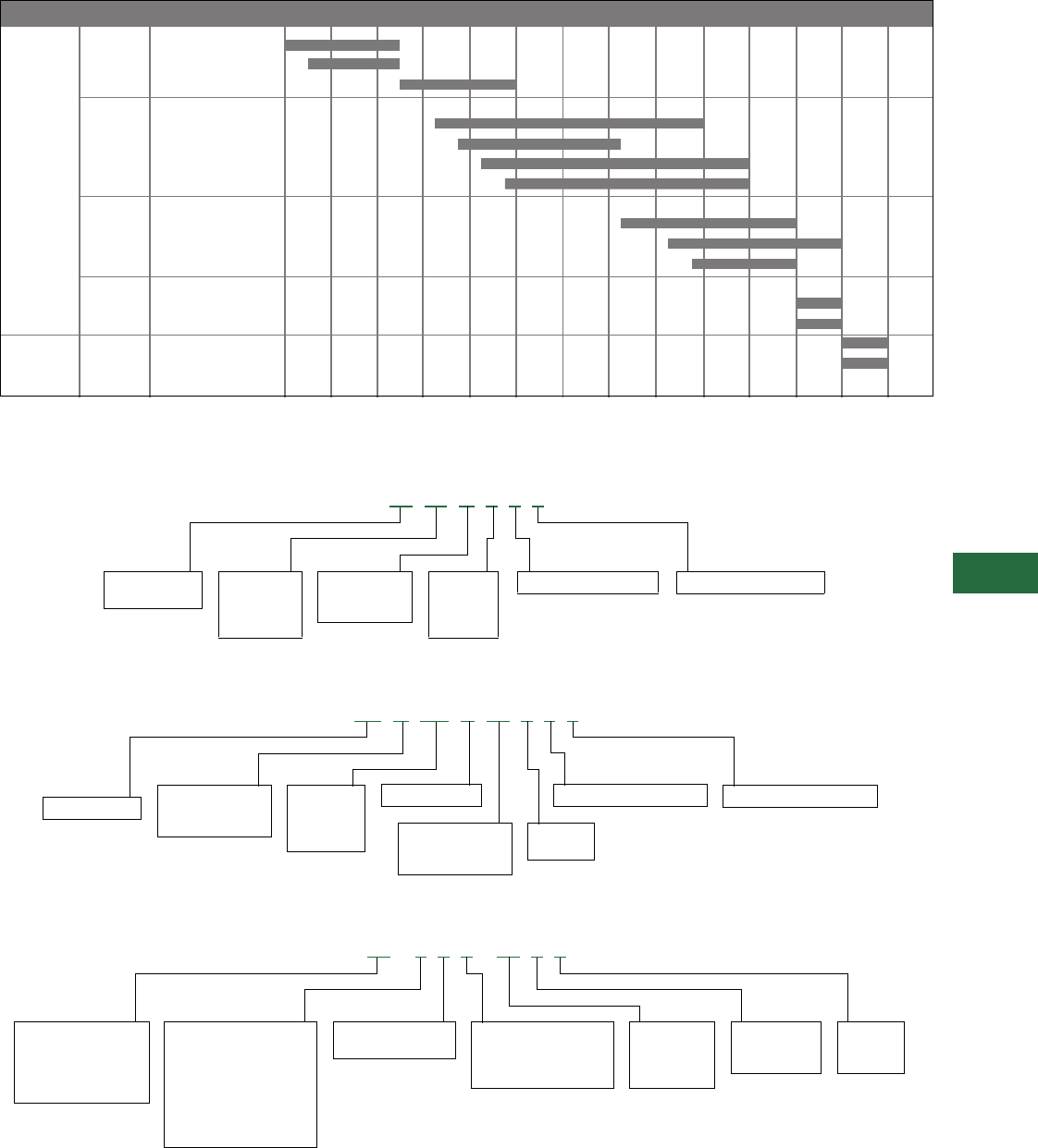
Volume 12—Aftermarket, Renewal Parts and Life Extension Solutions CA08100014E—November 2013 www.eaton.com V12-T13-85
1
2
3
4
5
6
7
8
9
10
11
12
13
14
15
16
17
18
19
20
21
22
23
24
25
13
Motor Control
Medium Voltage Starters
Product History Time Line
Catalog Number Selection
Old Catalog Numbering System—Contactors Only
Old Catalog Numbering System—Contactors Only
Old Catalog Numbering System—Starters (with Isolating Switch, Power Fuses, Contactor, etc.)
Page Product 1945 1950 1955 1960 1965 1970 1975 1980 1985 1990 1995 2000 2005 Present
AMPGARD OIL
AMPGARD AH
V12-T13-88 AMI AMPGARD
V12-T13-89, LF Air
V12-T13-90 – 25L2 200A
– 50L2 200A
– 25/50L4 400A
– 25/50L7 700A
V12-T13-91 SJ Vacuum
– SJA 400A (roll-out)
– SJA 800A (roll-out)
– SJS 400A (slide-out)
V12-T13-91 SL Vacuum
– SLW 400A (roll-out)
– SLF 400A (slide-out)
V12-T13-93 SLB (bolted)
SLS (stab)
Classic
AMPGARD
Next
Generation
AMPGARD
LF 25 H 4 3 0
Normally closed polesNormally open poles2 = 200A
4 = 400A
7 = 700A
8 = 800A
H = Air break
V = Vacuum
J = Vacuum
LF = Air break
SJ = Vacuum
25 = 2500V
33 = 3300V
50 = 5000V
72 = 7200V
Normally closed poles
W = Bottle
M = Metric bottle
(obsolete)
SJ A 5 0 V W 4 3 0
Normally opened poles
4 = 400A
8 = 800A
V = Vacuum break
25 = 2500V
33 = 3300V
50 = 5000V
72 = 7200V
SJ = Vacuum A = Roll-out
O = OEM design
S = Slide-out
2 = Non-load break,
fused switch
1 = Non-load break,
non-fused switch
L = Air break
V = Vacuum
J = Vacuum
2 = 200A
4 = 400A
7 = 700A
11 – 2 0 2 – 25 L 2
25 = 2500V
33 = 3300V
50 = 5000V
72 = 7200V
0 = Non-reversing
1 = Reversing
10 = Manual
11 = Magnetic
13 = Wound rotor
14 = Synchronous
17 = Air conditioning
2 = Full voltage
3 = Solid-state
4 = Resistor
5 = Reactor
6 = RV autotransformer
7 = RV part winding
8 = RV wye-delta
9 = FV multispeed
V12-T13-86 Volume 12—Aftermarket, Renewal Parts and Life Extension Solutions CA08100014E—November 2013 www.eaton.com
1
2
3
4
5
6
7
8
9
10
11
12
13
14
15
16
17
18
19
20
21
22
23
24
25
13
Motor Control
Medium Voltage Starters
Old Catalog Numbering System—Starters (with Isolating Switch, Power Fuses, Contactors, etc.)
Old Catalog Numbering System—Contactors Only
Voltage Class
E= 2400V, 60 Hz
G= 4160V, 60 Hz
K= 6900V, 60 Hz
L= 3300V, 60 Hz
Contactor
Ampere Rating
2 = 200A
4 = 400A
7 = 700A
8 = 800A
H = Air break (obsolete)
V = Vacuum break roll-out
S = Vacuum break
slide-out
S 202 S 4 G
Type of Starter
202 = FV non-reversing
212 = FV reversing
502 = Reactor
602 = Autotransformer
702 = Part winding
802 = Wye-delta
902 = Multispeed
Enclosure
S= NEMA 1
A= NEMA 1A
J= NEMA 12
R= NEMA 3
H= Air break
S= Vacuum, slide-out (standard)
V= Vacuum, roll-out (standard)
E= Vacuum, slide-out (OEM)
D= Vacuum, slide-out (with fingers)
T= Vacuum, slide-out (with long harness)
R= 50L2 vacuum retrofit
1 = 120V coil, 50/60 Hz
2 = 240V coil, 50/60 Hz
T1 = CPT, standard VA
T2 = CPT, 2 kVA
2 = 200A, air-break or 50L2 retrofit
4 = 400A, air-break
4 = 400A, Vacuum
7 = 700A, Air-break
8 = 800A, Vacuum
L= With line-fingers
or terminals
N= Without line-fingers
or terminals
F= With main fuse
provisions
N= Without main fuse
provisions
3 = Three-pole
2 = Two-pole
Models “A” & “B” Model “C”
E= 2300/2400 Vac 60 Hz A= 2400 Vac 60 Hz
Y= 3000 Vac 60 Hz B= 3000 Vac 60 Hz
F= 3300/3600 Vac 60 Hz C= 3300 Vac 60 Hz
G= 4000/4160 Vac 60Hz D= 3600 Vac 60 Hz
H= 4600/4800 Vac 60 Hz E= 4160 Vac 60 Hz
R=
6000/63000 Vac
60 Hz F= 4800 Vac 60 Hz
K= 6600/6900 Vac 60 Hz G= 5500 Vac 60 Hz
T= 2000 Vac 50 Hz H= 6000 Vac 60 Hz
J= 2300 Vac 50 Hz J= 6300 Vac 60 Hz
L= 3300 Vac 50 Hz K= 6600 Vac 60 Hz
V= 3600 Vac 50 Hz L=
6900/7200 Vac
60 Hz
N= 4000 Vac 50 Hz M= 2400 Vac 50 Hz
P= 4600 Vac 50 Hz N= 3000 Vac 50 Hz
S= 6000 Vac 50 Hz P= 3300 Vac 50 Hz
M= 6600 Vac 50 Hz Q= 3600 Vac 50 Hz
X= Unknown voltage R= 4160 Vac 50 Hz
S= 4800 Vac 50 Hz
T= 5500 Vac 50 Hz
U= 6000 Vac 50 Hz
V= 6300 Vac 50 Hz
W= 6600 Vac 50 Hz
X=
6900/7200 Vac
50 Hz
Z= Unknown voltage
MAN = Main
FWD = Forward
RVS = Reverse
RNR = Reactor
RNA = Autotransformer
BAR = Shorting contactor
SLW = Slow two-winding motor
FST = Fast two-winding motor
SLS = Slow single-winding motor
FAS = Fast single-winding motor
PWA = Part-winding motor, 1st contactor
PWB = Part-winding motor, 2nd contactor
PFC = Power factor capacitor contactor
XXX = Undefined application
V MAN 3 F L 4 A 1 – T1
Volume 12—Aftermarket, Renewal Parts and Life Extension Solutions CA08100014E—November 2013 www.eaton.com V12-T13-87
1
2
3
4
5
6
7
8
9
10
11
12
13
14
15
16
17
18
19
20
21
22
23
24
25
13
Motor Control
Medium Voltage Starters
New Catalog Numbering System—SL Contactors Only
New Catalog Numbering System—SL Starters Only
0 = None NC poles2 = 2NO poles
3 = 3NO poles
SL = SL contactor Volts
50 = 5000
72 = 7200
NEMA Size
2 = 200A
4 = 400A
Contactor Type/Rating
G= 200A, roll-out
W= 400A, roll-out
K= 200A, slide-out
F= 400A, slide-out
L= 200A, narrow-design with fingers
N= 400A, narrow-design with fingers
P= 200A, narrow-design without fingers
X= 400A, narrow-design without fingers
B= 200A, open/standalone
C= 400A, open/standalone
SL 50 W 4 3 0
Enclosure Type
A= No enclosure (NEMA 1 doors)
B= Type 1 general purpose
C= Type 1 with gasketed doors
D= Type 2 drip shield
E= Type 12 dust-tight
F= Type 3R outdoor non-walk-in
G= Type 3R outdoor non-walk-in, 72-inch high
H= Type 3R outdoor walk-in
J= Type 1 half-high (NEMA 1 only)
K= Type 1 half-high with gasketed door
L= No enclosure (NEMA 3/12 doors)
Disconnect Switch
S= Isolation switch
A= Mechanical future with cover plate
F= Electrical future with cover plate
G= Electrical future with isolation plate
P= No isolation switch, cover plate only
Synchronous Type
0 = Non-synchronous
1 = Brush-type solid-state panel (Mark V)
3 = Brush-type relay panel (no longer available)
4 = Brushless-type relay panel
5 = Brushless-type solid-state
Motor Type
1 = Induction, single-speed
2 = Induction, two-speed, two-winding
3 = Induction, two-speed, single-winding
4 = Synchronous
6 = Wound rotor
7 = Non-motor feeder (transformer, caps, etc.)
Starter Type
2 = FVNR
3 = FVR
4 = RVSS
5 = RV reactor-type
6 = RVAT
7 = RV reversing, reactor-type
8 = RVAT reversing
9 = RVSS reversing
X = FV with auxiliary special use three-pole contactor
(without mechanical interlock, with load panel)
Contactor Type/Rating
F= 400A vacuum, slide-out
W= Vacuum, roll-out
N= 400A vacuum, narrow-design with stabs
X= 400A vacuum, narrow-design without stabs
K= 200A vacuum, slide-out
G= 200A vacuum, roll-out
L= 200A vacuum, narrow-design with stabs
P= 200A vacuum, narrow-design without stabs
Voltage
A= 2400 Vac 60 Hz
B= 3000 Vac 60 Hz
C= 3300 Vac 60 Hz
D= 3600 Vac 60 Hz
E= 4160 Vac 60 Hz
F= 4800 Vac 60 Hz
G= 5500 Vac 60 Hz
H= 6000 Vac 60 Hz
J= 6300 Vac 60 Hz
K= 6600 Vac 60 Hz
L= 6900/7200 Vac 60 Hz
M= 2400 Vac 50 Hz
N= 3000 Vac 50 Hz
P= 3300 Vac 50 Hz
Q= 3600 Vac 50 Hz
R= 4160 Vac 50 Hz
S= 4800 Vac 50 Hz
T= 5500 Vac 50 Hz
U= 6000 Vac 50 Hz
V= 6300 Vac 50 Hz
W= 6600 Vac 50 Hz
X= 6900/7200 Vac 50 Hz
Z= Unknown voltage
W 2 1 0 S B A
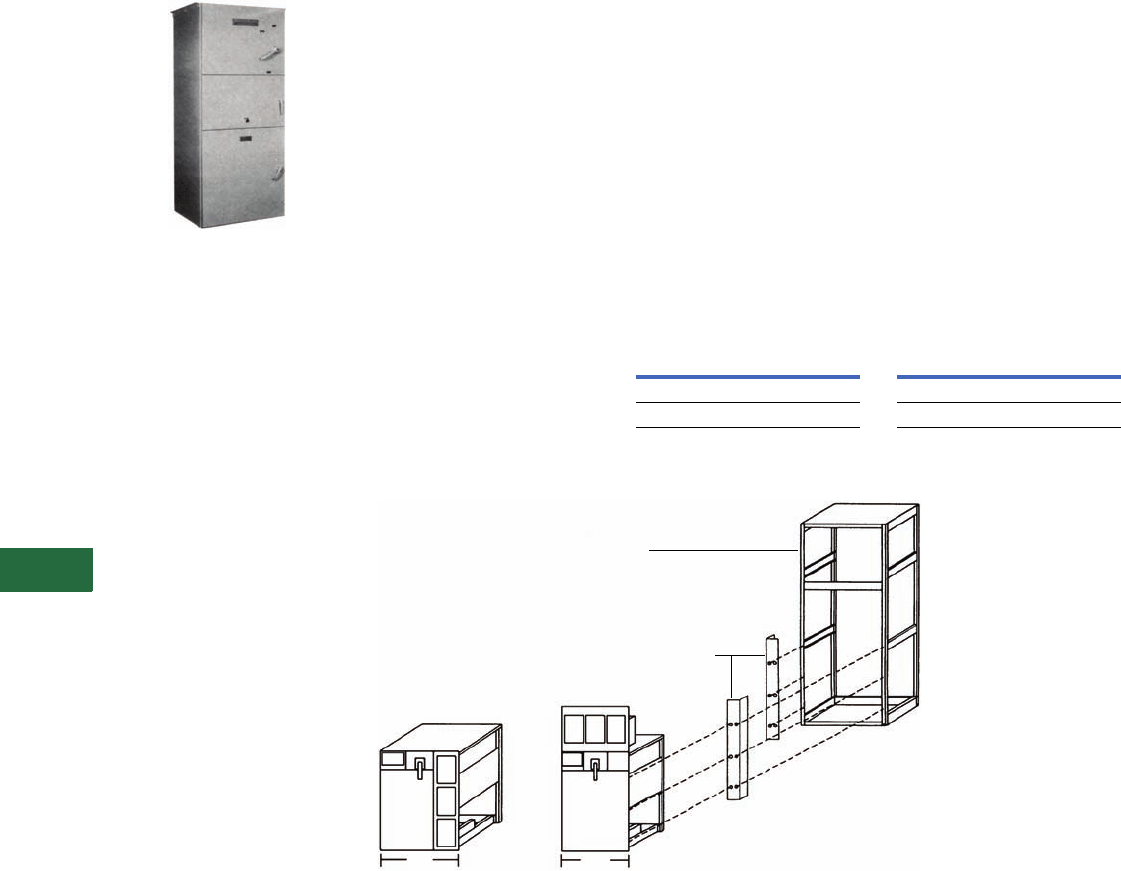
V12-T13-88 Volume 12—Aftermarket, Renewal Parts and Life Extension Solutions CA08100014E—November 2013 www.eaton.com
1
2
3
4
5
6
7
8
9
10
11
12
13
14
15
16
17
18
19
20
21
22
23
24
25
13
Motor Control
AMI AMPGARD Starters (Medium Voltage)
AMI AMPGARD
Originally a Westinghouse
Product
AMI AMPGARD Starter
Product Description
The AMI design AMPGARD
starter introduced in 1957 was
a complete line of starters for
magnetic control of squirrel
cage, wound rotor and
synchronous motors. The AMI
was the first front-accessible
starter and was available with
air break (Type H) or oil
immersed (Type K) contactors.
The standard AMI for full
voltage starting was 30 inches
deep, 38 inches wide and 90
inches high. All components
were accessible from the front
through three doors that
opened into separate
compartments. The top
compartment enclosed the
isolating switch and current
limiting power fuses. The
middle compartment enclosed
the AC low voltage control
panel and behind it the CTs.
The bottom compartment
housed the contactor.
Note: The pre-AMI design was a
rear-access assembly with two
compartments—current limiting
fuses on the top and the
contactor below.
Ratings (Maximum)
400A 1500 hp at 2500V;
2500 hp at 5000V.
Chronology
The AMI design AMPGARD
was manufactured from 1957
until 1970 at the General
Control Division in Buffalo, NY,
and Westinghouse
Manufacturing and Repair
(M&R) facilities around the
country. The air contactor was
available through 1966. The oil
contactor was available
through 1970.
Replacement Capabilities
The AMI vintage is obsolete
but upgrading to the latest
vacuum technology with a
cell-retrofill solution is
available. See Technology
Upgrades for further
information.
Add-On Structure
New add-on vacuum
structures as an extension to
the AMI type structure may
be connected directly to the
main bus without a transition
section using special bus
links. Contact your local Eaton
Field Sales office.
Technology Upgrades
Standard AMI 36-Inch Wide
Vacuum Starter Cell-Retrofill
This kit includes a standard
full-voltage non-reversing
vacuum starter in a welded
cell assembly with horizontal
top barriers and deep flanged
doors. Optional components
include a new electronic
motor protection relay
MP-3000 and electronic
meter DP-4000. It will retrofit
the AMI designs that are
at least 36 inches wide and
30 inches deep. The cell is
45 inches high.
Standard AMI 36-Inch Wide
Vacuum Starter Cell-
Retrofill Style Number
Narrow AMI 30-Inch Wide
Vacuum Starter Cell-Retrofill
This kit includes a standard full-
voltage non-reversing vacuum
starter in a welded cell
assembly with horizontal top
barriers and deep flanged
doors. Optional components
include a new electronic
motor protection relay
MP-3000 and electronic
meter DP-4000. It will retrofit
the AMI designs that are at
least 30 inches wide and
30 inches deep. The cell is
58 inches high.
Narrow AMI 30-Inch Wide
Vacuum Starter Cell-
Retrofill Style Number
AMI Starter Cell-Retrofill
Note
1Upper filler cover may require field modification.
Description
Style
Number
SJ Contactor 2147A95G41
SL Contactor 2147A95G61
Description
Style
Number
SJ Contactor 2147A95G42
SL Contactor 2147A95G62
36
Standard
30
Narrow
G42
G62
G41
G61
Replacement Vacuum Starter Cell with all
New Controls
New Filter
Strips 1
Existing Starter Structure
to be Stripped before Cell Retrofit
Westinghouse Type “H,” “AH”
or other Structure
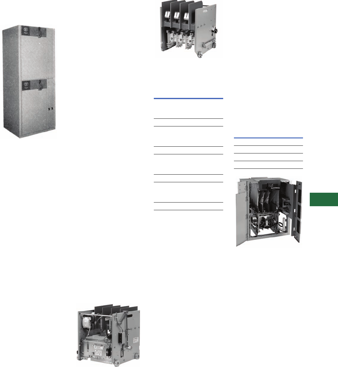
Volume 12—Aftermarket, Renewal Parts and Life Extension Solutions CA08100014E—November 2013 www.eaton.com V12-T13-89
1
2
3
4
5
6
7
8
9
10
11
12
13
14
15
16
17
18
19
20
21
22
23
24
25
13
Motor Control
LF Air AMPGARD Starters (Medium Voltage)
LF Air AMPGARD
Originally a Westinghouse
Product
The LF Air-Break Design
AMPGARD Starter
Product Description
The LF air-break design
AMPGARD starter was
introduced in 1962. The
LF design introduced the
component-to-component
circuitry concept. This design
greatly reduced the current-
carrying connections and
allowed for significant space
savings.
The 25L2 and 50L2 floor-
mounted NEMA 1 structures
were 26 inches wide x 30
inches deep x 90 inches high.
The 25L2 came in 1, 2 or 3
starters per structure. The
50L2 came in 1 or 2 starters
per structure.
The 25L4 and 50L4 floor-
mounted NEMA 1 starters
were 36 inches wide x 30
inches deep x 90 inches high.
These 400A starters could
have been mounted two-high
per structure.
The 25L7 and 50L7 floor-
mounted NEMA 1 starters
were 40 inches wide x 30
inches deep x 90 inches high.
These 700A starters were
mounted one per vertical
structure.
Ratings (Maximum)
200, 400 and 700A 2500 hp at
2500V; 4500 hp at 5000V.
Chronology
The LF air-break design
starter was introduced in
1962, first with the 2500V,
200A starter, then with the
5000V design and the 400
and 700A ratings. The
starters were built in Buffalo,
NY, until the operation was
transferred to Asheville, NC,
in 1978, where it was
discontinued in the late 1980s.
Replacement Capabilities
Renewal and Replacement Parts
for LF Design Starters
Refer to RPD 8855A for
identifying the parts needed.
Among the parts available
are:
●Current and potential
transformers
●Control transformers
●Fuses
●O/L relays and heaters
●Isolation switches
●Some air-break
contactor parts
Technology Upgrades
Add-On Vacuum Starter
Structures
New add-on vacuum
structures as an extension to
the LF type starter assembly
may be connected directly to
the main bus without a
transition section.
50L4 (400A) Vacuum
Replacement Contactor
For replacing an existing
400A LF air contactor with
the directly interchangeable
400A vacuum contactor.
50L4 Vacuum Replacement (Front)
50L4 Vacuum Replacement (Rear)
400A Air-to-Vacuum
Contactor Replacement
Note: Style numbers listed above
identify a basic contactor that
might not include other available
accessories that were specified
on a customer order. Contact
factory with original general order
number starter drawing number
and date of manufacture for
assistance.
400A Air-to-Vacuum Starter
Cell Kit
Complete full-voltage, non-
reversing, induction, vacuum
AMPGARD motor starter,
400A, 7200V maximum, for
mounting in existing 36-inch
wide enclosure. Includes
main contactor, isolation
switch, three power fuses,
MP-3000 motor protection
without RTD module, three-
phase current transformer,
vertical bus, high and low
voltage doors, and welded
cell assembly for mounting
in existing 36-inch wide
enclosure.
400A Air-to-Vacuum Starter
Cell Kit
Completely New Starter Cell
Description
Style
Number
Basic contactor 2300/120V,
750 VA transformer:
SJ contactor 2147A45G01
SL contactor 2147A50G01
Basic contactor 2300/120V,
2 kVA transformer:
SJ contactor 2147A45G02
SL contactor 2147A50G02
Basic contactor 4160/120V,
600 VA transformer:
SJ contactor 2147A45G03
SL contactor 2147A50G03
Basic contactor 4160/120V,
2 kVA transformer:
SJ contactor 2147A45G04
SL contactor 2147A50G04
Description
Style
Number
Slide-out with SJ 2147A95G01
Roll-out with SJ 2147A95G02
Slide-out with SL 2147A95G03
Roll-out with SL 2147A95G04
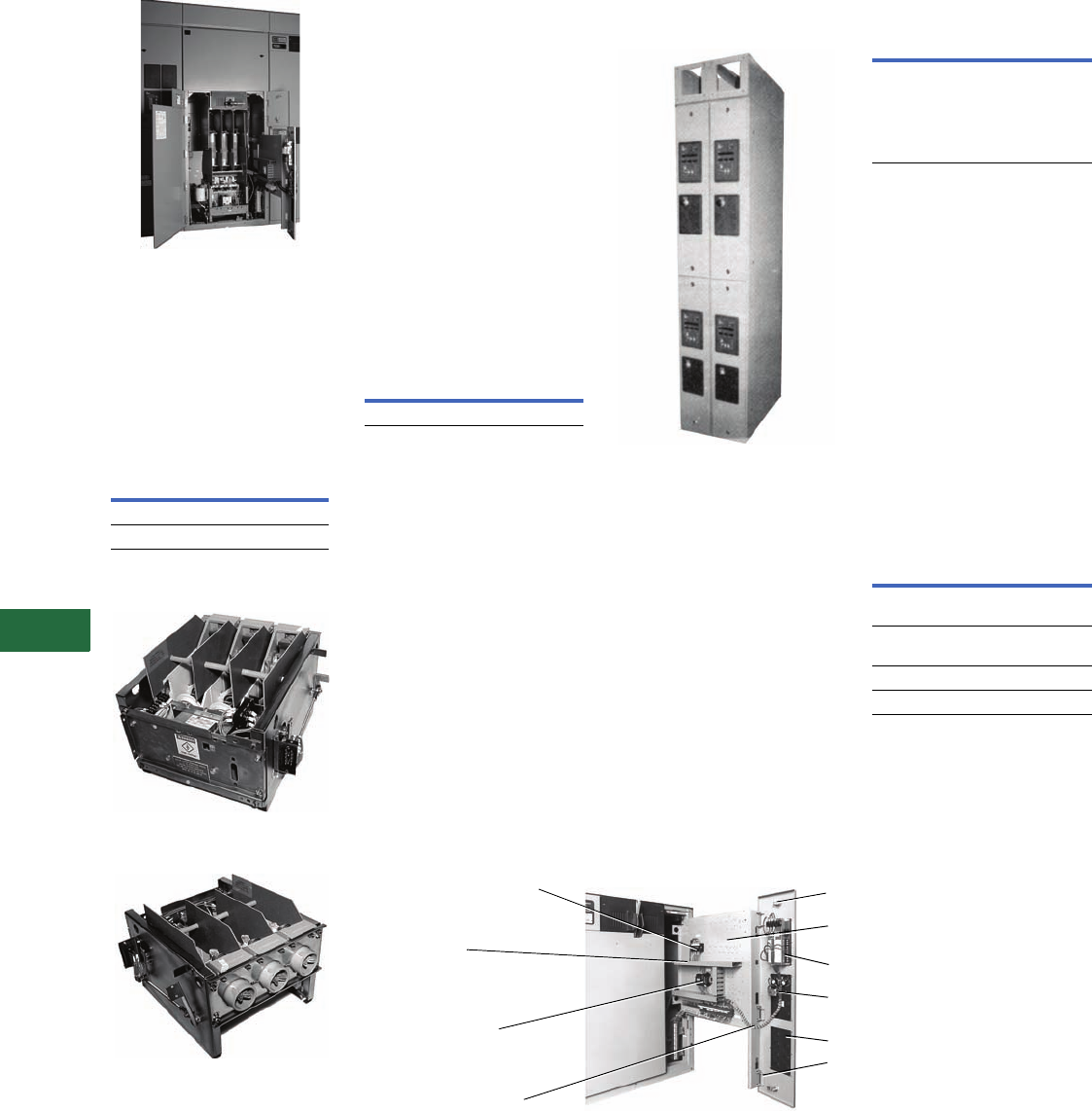
V12-T13-90 Volume 12—Aftermarket, Renewal Parts and Life Extension Solutions CA08100014E—November 2013 www.eaton.com
1
2
3
4
5
6
7
8
9
10
11
12
13
14
15
16
17
18
19
20
21
22
23
24
25
13
Motor Control
LF Air AMPGARD Starters (Medium Voltage)
50L7 Vacuum Retrofit
700A Air-to-Vacuum
Conversion Kits
These kits will convert an
existing full-voltage non-
reversing 700A air break
starter to vacuum.
700A Air-to-Vacuum
Conversion Kit
25L2 Vacuum Replacement
Contactor
25L2 Vacuum Replacement—
Front View
25L2 Vacuum Replacement—
Rear View
This solution uses the latest
technology “SL” contactor
and is designed to replace
vintage 25L2, 2500V, 200A,
1962 air-break contactors.
Description
Style
Number
450–630A maximum 2147A95G31
720A maximum 2147A95G32
50L2 Air-to-Vacuum Retrofit Kit
This kit replaces the out-of-
production 5000V, 200A
air-break contactor with an
SJ vacuum contactor, for
starters built after 1974
with ISO-Switch shutter
mechanism mounted
in the cell. The customer
keeps the existing starter
cell and isolation switch and
modifies the cell to accept
the SJ contactor that is
mechanically interlocked
with the isolation switch.
The rating remains 200A.
50L2 Air-to-Vacuum
Retrofit Kit
Ampacity upgrade to 320A
design for pre-1974 50L2
retrofit kits available.
Metering and Protective
Relay Upgrades
IQ Floor-Mounted Enclosure
IQ Floor-Mounted Enclosure
This kit is for mounting IQ
family products. Includes
standard AMPGARD structure
construction to be used as a
lineup extension. Each 90-
inch high x 30-inch deep
section comes with two
doors, each with a works-in-a-
drawer drawout panel. Each
door has a maximum of three
standard IQ cutouts with
device panels. Supplied with
or without IQ and PB devices.
(Photo left shows two
auxiliary sections with
optional bus enclosure,
IQ and PB devices.)
IQ Floor-Mounted Upgrade
MP-3000 and DP-4000
upgrades used for upgrading
overload-relay technology from
“Type-A,” IQ 2000A, IQ
2000B or IQ 1000II to the
latest technology. Also
upgrades with a new,
slideout, LV control panel.
The kit includes:
●Typical starter schematic
●0.50-inch deep, flange LV
door with three cut-outs for
new devices
●Works-in-a-drawer slide-out
panel for LV control devices
Metering and Protective
Relay Upgrades
Works-in-a-Drawer Metering and Protective Relay LV Device Panel
Description
Style
Number
200A maximum 2147A95G30
Description
Style
Number
Auxiliary section with
cutouts only. 10-inch
wide x 30-inch deep x
90-inch high (does not
include bus enclosure,
IQ or PB devices)
2147A95G35
Description
Style
Number
DP-4000 and MP-3000
(without RTD)
2147A95G37
MP-3000
(without RTD) only
2147A95G39
DP-4000 only 2147A95G48
IQ 300 only 2147A95G49
Current Transformer Shorting
Terminal Blocks (when specified)
Routing of
Control
Wire in
Wire Channel
Interposing
Control Relay
DIN Rail Mounted
Wiring is Protected
Between Low Voltage
Panel and Hinged Low
Voltage Door
Blank Device Panel
Indicating Lights and
Pushbuttons Rear View
MP-3000 Rear View
Predrilled Holes for
Additional Control Devices
Rear of 1/4 Turn Fastener
Note: Low voltage door is
hinged to slide-out control
panel.
Low Voltage Panel Completely Extended
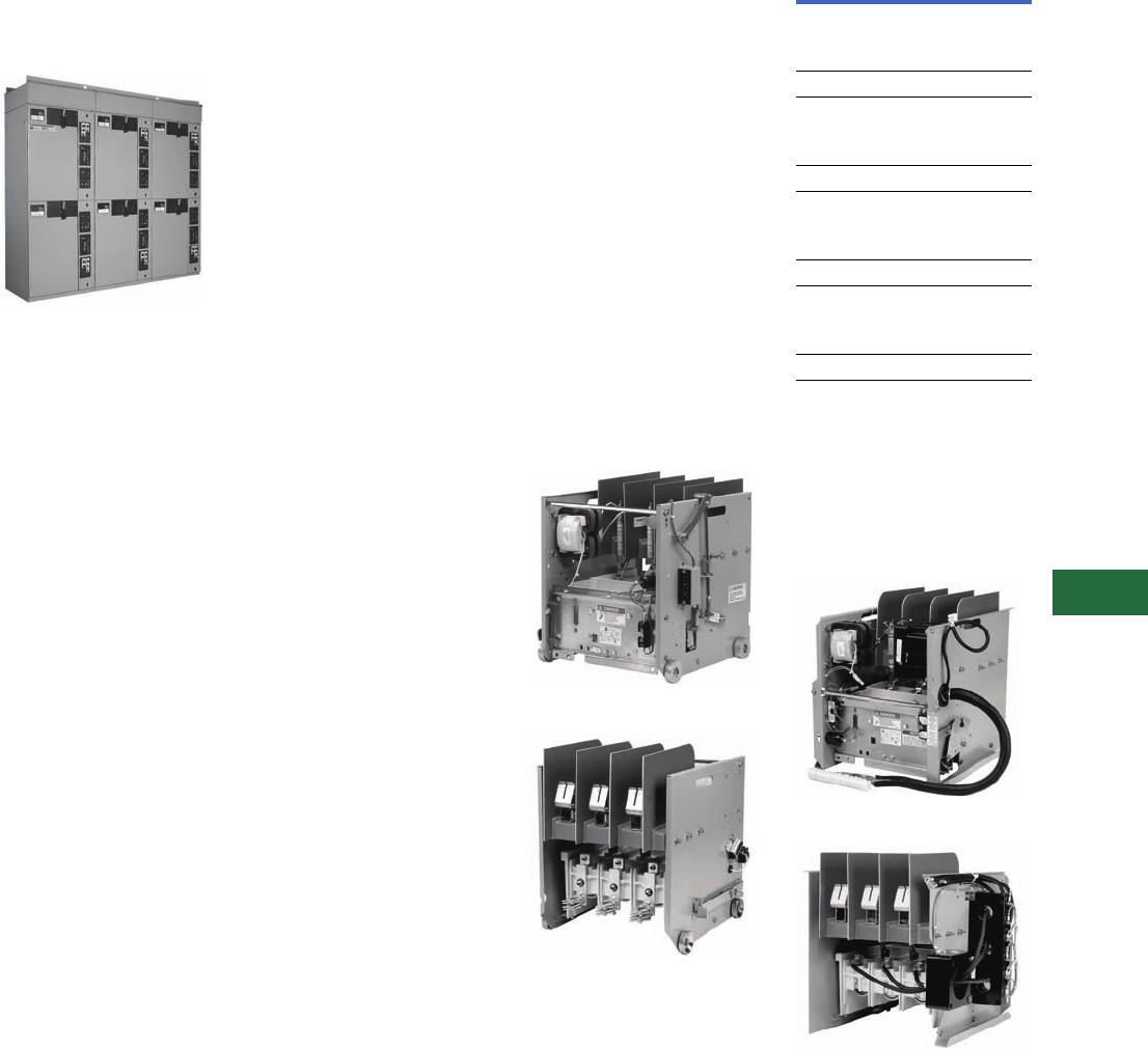
Volume 12—Aftermarket, Renewal Parts and Life Extension Solutions CA08100014E—November 2013 www.eaton.com V12-T13-91
1
2
3
4
5
6
7
8
9
10
11
12
13
14
15
16
17
18
19
20
21
22
23
24
25
13
Motor Control
SL and SJ Vacuum AMPGARD Starters (Medium Voltage)
Classic AMPGARD
SL and SJ Vacuum
AMPGARD
Originally a Westinghouse
Product
SJ Vacuum AMPGARD Assembly
Product Description
The SJ vacuum contactor was
designed and engineered
specifically for use in
AMPGARD starters. The
contactor is a low-chop design
that permits application
matching of the starter to the
motor for 2200–7200V and
ratings of 400 and 800A. The
400A contactor is available in
both slide-out and roll-out
configurations. The 800A
contactor is available in the
roll-out design only. The SJ
AMPGARD is a horsepower
specific starter design that
uses the component-to-
component circuitry concept.
The full-voltage 400A rating in a
NEMA 1 enclosure is 36 inches
wide x 30 inches deep x
90 inches high. These 400A
starters are mounted one- or
two-high per structure. The
800A rating in an enclosure is
40 inches wide x 30 inches
deep x 90 inches high in a
one-high construction for a
full-voltage starter.
Ratings (Maximum)
400 and 800A, 3000 hp at
2500V; 5500 hp at 5000V;
8000 hp at 7200V.
Chronology
The SJ vacuum design
AMPGARD starter
was
introduced in 1982 with the
400A rating. The 800A rating
followed in 1987. With the
introduction of the vacuum
contactor, the air-break starter
has been gradually phased out
and is rarely specified in an
assembly. The starters are built
in Asheville, NC.
AMPGARD assemblies were
made available with the new
SL Contactor in late 1999.
Except for the 400A
frame contactor, SJ and SL
AMPGARD assemblies are
virtually identical.
Replacement Capabilities
Renewal and Replacement Parts
for SJ Design Starters
Refer to RP.48J.01.T.E for
identifying the parts needed.
Common Replacement Parts for
SL Design Starters
Refer to RP02003002E
for identifying the parts
needed.
Add-On Vacuum Starter
Structures
New add-on vacuum
structures as an extension to
the SJ type structure may be
connected directly to the
main bus without a transition
section. Contact your local
Eaton Field Sales office.
Replacement Vacuum
Contactors
New replacement vacuum
break contactors are available
for all SJ model ratings.
400A SL Roll-Out Replacement (Front)
400A SL Roll-Out Replacement (Rear)
400A Vacuum Roll-out
Replacement Contactor
Note: Style numbers listed above
identify a basic contactor that
might not include other available
accessories that were specified
on a customer order. Contact
factory with original general order
number, starter drawing number,
and date of manufacture for
assistance.
400A SL Slide-Out Replacement (Front)
400A SL Slide-Out Replacement (Rear)
Description
Style
Number
Basic contactor 2300/120V,
750 VA transformer:
SJ contactor 2147A45G01
SL contactor 2147A50G01
Basic contactor 2300/120V,
2 kVA transformer:
SJ contactor 2147A45G02
SL contactor 2147A50G02
Basic contactor 4160/120V,
750 VA transformer:
SJ contactor 2147A45G03
SL contactor 2147A50G03
Basic contactor 4160/120V,
2 kVA transformer:
SJ contactor 2147A45G04
SL contactor 2147A50G04
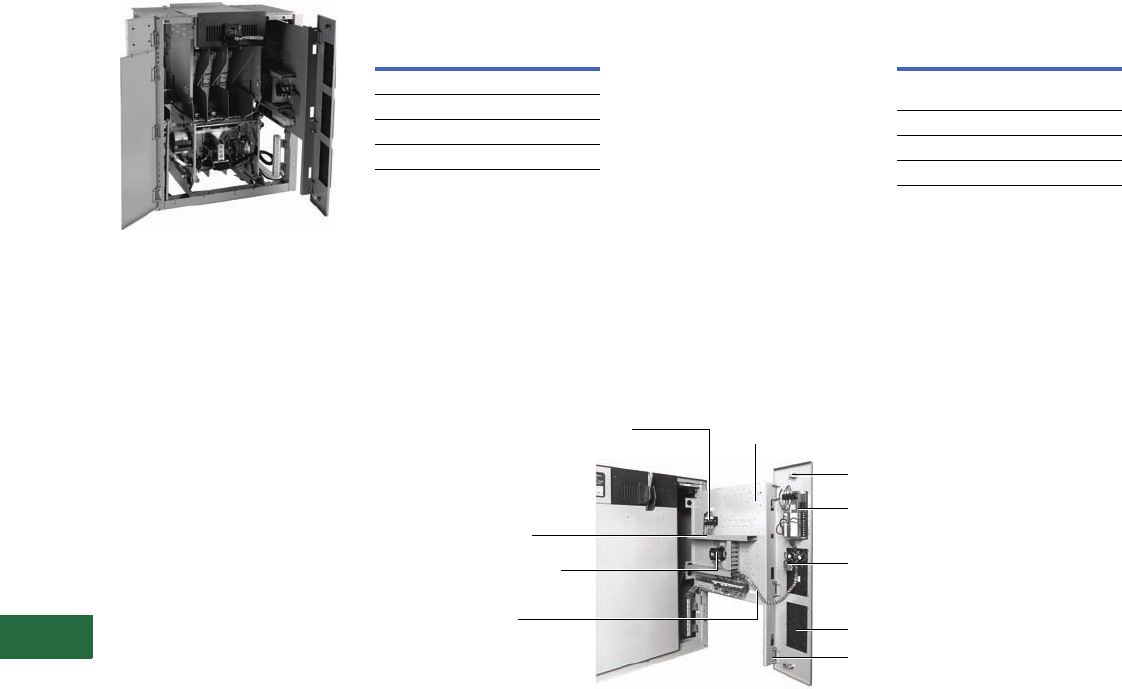
V12-T13-92 Volume 12—Aftermarket, Renewal Parts and Life Extension Solutions CA08100014E—November 2013 www.eaton.com
1
2
3
4
5
6
7
8
9
10
11
12
13
14
15
16
17
18
19
20
21
22
23
24
25
13
Motor Control
SL and SJ Vacuum AMPGARD Starters (Medium Voltage)
Completely New Starter Cell
400A Vacuum Starter Cell Kit
The 400A vacuum starter cell
kit is used to fill a blank cell in
an SL or SJ AMPGARD
assembly or to completely
replace an existing 400A SL or
SJ starter.
It is a complete full-voltage,
non-
reversing, induction,
vacuum AMPGARD
motor
starter, 400A, 7200V
maximum, for mounting in
existing 36-inch wide
enclosure. It includes main
contactor, isolation switch
three power fuses, MP-3000
motor protection without
RTD module, three-phase
current transformer, vertical
bus, high and low
voltage
doors, and welded cell
assembly
for mounting in
existing 36-inch
wide customer enclosure.
400A Vacuum Starter
Retrofit Kit Technology Upgrades
MP-3000 and DP-4000
upgrades used for
upgrading
overload-relay technology
from “Type-A,” IQ 2000A,
IQ 2000B or IQ 1000II to
the latest technology. Also
upgrades with a new,
slideout, LV control panel.
The kit includes:
●Typical starter schematic
●0.50-inch deep, flange LV
door with three cut-outs for
new devices
●Works-in-a-drawer slide-out
panel for LV control devices
Metering and Protective
Relay Upgrades
Works-in-a-Drawer Metering and Protective Relay LV Device Panel
Description
Style
Number
Slide-out with SJ 2147A95G01
Roll-out with SJ 2147A95G02
Slide-out with SL 2147A95G03
Roll-out with SL 2147A95G04
Description
Style
Number
DP-4000 and MP-3000
(without RTD)
2147A95G37
MP-3000 (without RTD) only 2147A95G39
DP-4000 only 2147A95G48
IQ Data only 2147A95G49
Current Transformer Shorting
Terminal Blocks (when
specified)
Routing of Control
Wire in Wire Channel
Interposing Control Relay
DIN Rail Mounted
Wiring is Protected
Between Low Voltage
Panel and Hinged Low
Voltage Door
Blank Device Panel
Indicating Lights and
Pushbuttons Rear View
(when specified)
MP-3000 Rear View
(when specified)
Predrilled Holes for
Additional Control Devices
Rear of 1/4 Turn Fastener
Note: Low voltage door is
hinged to slide-out
control panel.
Low Voltage Panel
Completely Extended
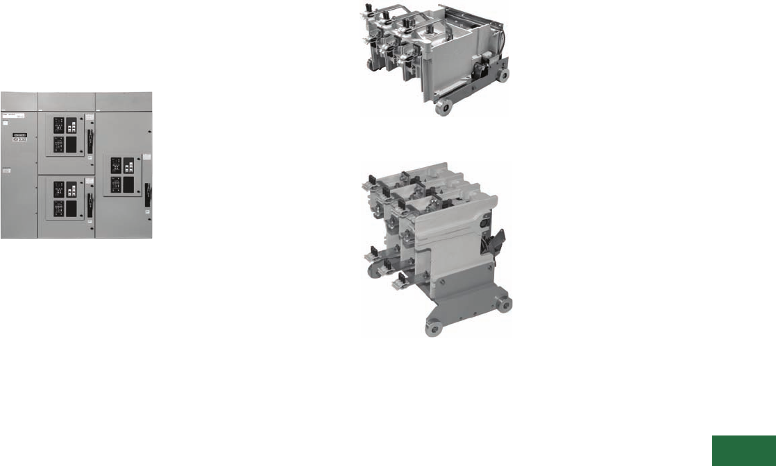
Volume 12—Aftermarket, Renewal Parts and Life Extension Solutions CA08100014E—November 2013 www.eaton.com V12-T13-93
1
2
3
4
5
6
7
8
9
10
11
12
13
14
15
16
17
18
19
20
21
22
23
24
25
13
Motor Control
SLB and SLS Contactors AMPGARD (Medium Voltage)
Next Generation
AMPGARD
SLB and SLS Contactors
AMPGARD
Next Generation AMPGARD Lineup—
Front View
Product Description
Medium voltage control
reaches a higher level of
design with the next
generation of Cutler-Hammer
AMPGARD
starters from
Eaton. This product
incorporates 60 years of
experience with over 75,000
units installed worldwide. The
SLB and SLS contactor is
a low-chop design that
controls 200–8000 hp motors
with ratings of 400 and 800A
vacuum contactors. The
contactor is available in a stab
(SLS) or bolted (SLB) design
within the starter cell. The
two-high structure design can
accommodate two 400A or
one 800A contactor/starter
designs. The two-high
structure is 36 W x 92 H x 30
D inches (914.4 x 2336.8 x
762.0 mm), which includes a
12-inch high top-mounted
main bus compartment.
Ratings (Maximum)
400 and 800A 3000 hp at
2500V; 5500 hp at 5000V;
8000 hp at 7200V.
Chronology
The SLB and SLS vacuum
design AMPGARD starter
was introduced in 2005 with
both 400 and 800A ratings to
be incorporated into the next
generation of AMPGARD
assembly. The starters are
built in Asheville, NC. The
new SLS and SLB contactors
will not be interchangeable
with the existing SJ or SL
contactors.
Replacement Capabilities
For further information,
contact the Asheville plant
at 1-800-523-3775.
Stab-In AMPGARD 400A
Contactor—Rear View
Stab-In AMPGARD 800A
Contactor—Rear View
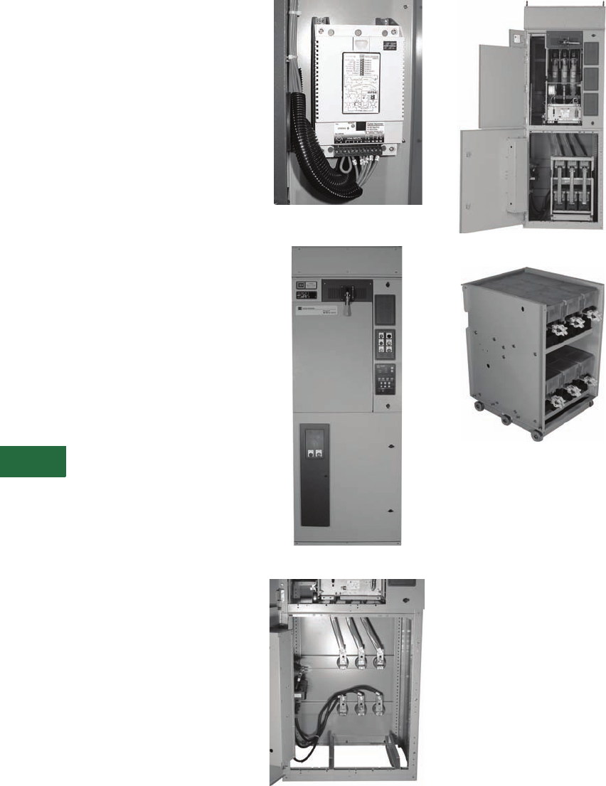
V12-T13-94 Volume 12—Aftermarket, Renewal Parts and Life Extension Solutions CA08100014E—November 2013 www.eaton.com
1
2
3
4
5
6
7
8
9
10
11
12
13
14
15
16
17
18
19
20
21
22
23
24
25
13
Motor Control
SL and SJ Vacuum AMPGARD Starters (Medium Voltage)
AMPGARD IT. Soft Start
Components
The Cutler-Hammer
AMPGARD IT. Soft Start
components are now
available for upgrading
existing full-voltage and
reduced-voltage starters. The
requirements to convert
starters into AMPGARD IT.
Soft Start will depend on
specific configurations of the
existing starter. Space will be
required for two 36-inch
wide, 45-inch high cells that
are ideally mounted in the
same vertical structure. The
upper compartment contains
the ‘M’ Contactor Cell and
the lower compartment
contains the SCR Truck Cell.
The new door provided with
the SCR Truck Cell includes
the MV801 control module
and is made to interlock with
the door on the upper
compartment.
If the targeted upgrade is for
a FVNR AMPGARD starter
presently located in the upper
compartment, then the
conversion is simplified by
using the existing FVNR
starter as the ‘M’ contactor
cell and converting the
bottom compartment into the
SCR truck cell. The ‘M’
contactor load terminals are
connected to the SCR truck
cell terminals using three
copper bus connectors.
Available SCR truck ratings
include 200A and 400A.
See Page V12-T13-95 for a
description of other existing
starter configurations. The
advanced diagnostics
included in the MV801
control module include:
●Phase loss
●Phase imbalance
●Jam
●Stall
●Over/undervoltage
●Motor overload
MV801 Control Module
AMPGARD IT. Soft Start
SCR Truck Cell
AMPGARD IT. Soft Start (Doors Open)
SCR Truck (Rear)
Volume 12—Aftermarket, Renewal Parts and Life Extension Solutions CA08100014E—November 2013 www.eaton.com V12-T13-95
1
2
3
4
5
6
7
8
9
10
11
12
13
14
15
16
17
18
19
20
21
22
23
24
25
13
Motor Control
Synchronous
Typical AMPGARD Starter Configurations
Example 1
(Before Retrofit)
Note: Example 1—Upper
Compartment must be converted
to ‘M’ contactor cell. Lower
compartment must be converted
into SCR truck cell.
Example 2
(Before Retrofit)
Note: Example 2—Upper
compartment FVNR can be used
as the ‘M’ contactor cell. Lower
compartment must be converted
to SCR truck cell.
Example 1 and 2
(After Retrofit)
Example 3 (Before Retrofit) Example 3 (After Retrofit)
Note: Example 3—‘M’
contactor cell can be relocated to
upper compartment. Lower
compartment must be converted
into SCR truck cell.
Upper
Compartment
Lower
Compartment
New
SCR
Truck Cell
‘M’
Contactor
‘M’
Contactor
‘R’ Contactor
(RVAT) Upper
Compartment
‘S’ (RVAT)
or
‘R’ (RVPR)
Autotransformer
or
Reactor
New
SCR
Truck Cell
‘M’
Contactor
Available for
Other Use

V12-T13-96 Volume 12—Aftermarket, Renewal Parts and Life Extension Solutions CA08100014E—November 2013 www.eaton.com
1
2
3
4
5
6
7
8
9
10
11
12
13
14
15
16
17
18
19
20
21
22
23
24
25
13
Motor Control
Synchronous
AMPGARD Solutions Overview
AMPGARD Selection Table
Notes
1Add-on structures contain vacuum starters only.
2Complete cell including frame, ISO-switch, vacuum or air contactor, and all components to complete a starter.
3Isolation switch only (LFR replaced LFM after 1974).
4Complete contactor, available in SJ or SL.
5New, genuine parts per original specs.
Vacuum replacements— OIL, AH, AMI (one-high starters) Complete Cell Retrofill
25L2 Vacuum Replacement Contactor
50L2 Vacuum Retrofit Kit
50V4 Vacuum Replacement Contactor
25/50L4 Vacuum Replacement Contactor
Synchronous Mark V Solid-State Control Retrofit
25/50L7 Vacuum Replacement Contactor and Some Cell Modification
6Check with factory.
Further Information
Pricing Information
Price and Availability Digest (PAD)
Installed
Equipment Vintage
AMPGARD Aftermarket Products Available
Reference
Material
Add-on
Structure 1Cell 2
Isolation
Switch 3Contactor 4Parts 5
Vacuum
Replace-
ments
Class 1
Recondi-
tioning
AMPGARD OIL 1945–1957 ■—
AMPGARD AH 1948–1957 ■—
AMPGARD AMI 1948–1957 ■—
AMPGARD 25L2 1962–1990 ■■ 6■■RPD8855A
AMPGARD 50L2 1963–1981 ■■ 6■■RPD8855A
AMPGARD 50V4 1972–1979 ■■■ ■■RP48J01TE
AMPGARD 25/50L4 1966–1989 ■■■ ■ 6■■RPD8855A
AMPGARD 25/50L7 1969–1989 ■■■ 6■■RPD8855A
AMPGARD V202 (SJ) 400A 1982–2000 ■ ■■■ ■■■RP48J01TE
AMPGARD S202 (SJ) 400A 1987–2000 ■ ■■■ ■■■RP48J01TE
AMPGARD W210 (SL) 400A 2000– ■ ■■■ ■■■RP02003002E
AMPGARD F210 (SL) 400A 2000– ■ ■■■ ■■■RP02003002E
AMPGARD V202 (SJ) 800A 1985– ■ ■■ ■■■RP48J01TE
Synchronous Control 1950– ■■ ■ RP04304009E
Publication
Number Description
RPD8855A Renewal Parts Data for AMPGARD LF Air-Break Vintage 200–700A
RPD8855S Renewal Parts Data for AMPGARD Slipsyn Synchronous Control
RP48J01TE Renewal Parts for AMPGARD SJ Vacuum-Break Vintage 400–800A
RP02003002E Common Renewal Parts for AMPGARD SL 400A Vacuum Contactors
TD48A01ATE Technical Data for AMPGARD MV Starters
PG48C01TE Product Guide “SL” Medium Voltage Vacuum Contactors
IB48008 Instructions for AMPGARD Mark V Solid-State, Brush-Type, Synchronous Motor Controllers
IB48009 Instructions for AMPGARD Synchronous Motor Field Regulator with VAR and PF Control

Volume 12—Aftermarket, Renewal Parts and Life Extension Solutions CA08100014E—November 2013 www.eaton.com V12-T14-1
1
2
3
4
5
6
7
8
9
10
11
12
13
14
15
16
17
18
19
20
21
22
23
24
25
Motor Control Centers
DeviceNet I/O Starter Unit Upgrade
14 Motor Control Centers
Product Description. . . . . . . . . . . . . . . . . . . . . . . . . . . . . . . . . . . . . . . V12-T14-2
Product History . . . . . . . . . . . . . . . . . . . . . . . . . . . . . . . . . . . . . . . . . . V12-T14-2
Product History Time Line. . . . . . . . . . . . . . . . . . . . . . . . . . . . . . . . . . V12-T14-2
General Information. . . . . . . . . . . . . . . . . . . . . . . . . . . . . . . . . . . . . . . V12-T14-3
Low Voltage MCCs
11-300—Product Description, Replacement Capabilities. . . . . . . . . . V12-T14-5
9800—Product Description, Replacement Capabilities . . . . . . . . . . . V12-T14-6
Type W—Product Description, Replacement Capabilities . . . . . . . . . V12-T14-7
F10—Product Description, Replacement Capabilities . . . . . . . . . . . . V12-T14-8
Freedom Unitrol—Product Description, Replacement Capabilities . . V12-T14-9
5 Star/Series 2100—Product Description, Replacement Capabilities V12-T14-10
Advantage™—Product Description, Replacement Capabilities . . . . . V12-T14-11
F2100—Product Description, Replacement Capabilities . . . . . . . . . . V12-T14-12
Replacement Capabilities (Structure/Bus/Unit Parts). . . . . . . . . . . . . . V12-T14-13
Technology Upgrades
IT. Soft Start . . . . . . . . . . . . . . . . . . . . . . . . . . . . . . . . . . . . . . . . . . V12-T14-14
IQ Retrofit Kits . . . . . . . . . . . . . . . . . . . . . . . . . . . . . . . . . . . . . . . . V12-T14-14
DeviceNet Interface Module Upgrade (DN65) . . . . . . . . . . . . . . . . V12-T14-14
SPD Upgrade . . . . . . . . . . . . . . . . . . . . . . . . . . . . . . . . . . . . . . . . . V12-T14-15
SV9000 Drives . . . . . . . . . . . . . . . . . . . . . . . . . . . . . . . . . . . . . . . . V12-T14-15
Advantage Technology . . . . . . . . . . . . . . . . . . . . . . . . . . . . . . . . . . V12-T14-15
Series C® Retrofit Kits . . . . . . . . . . . . . . . . . . . . . . . . . . . . . . . . . . V12-T14-15
How to Order, Catalog Numbering System . . . . . . . . . . . . . . . . . . V12-T14-17
Competitive Retrofit Upgrades. . . . . . . . . . . . . . . . . . . . . . . . . . . . V12-T14-18
Customer Required Information, . . . . . . . . . . . . . . . . . . . . . . . . . . . . V12-T14-18
Product Support Services . . . . . . . . . . . . . . . . . . . . . . . . . . . . . . . . . . V12-T14-19
Further Information and Pricing Information . . . . . . . . . . . . . . . . . . . . V12-T14-19
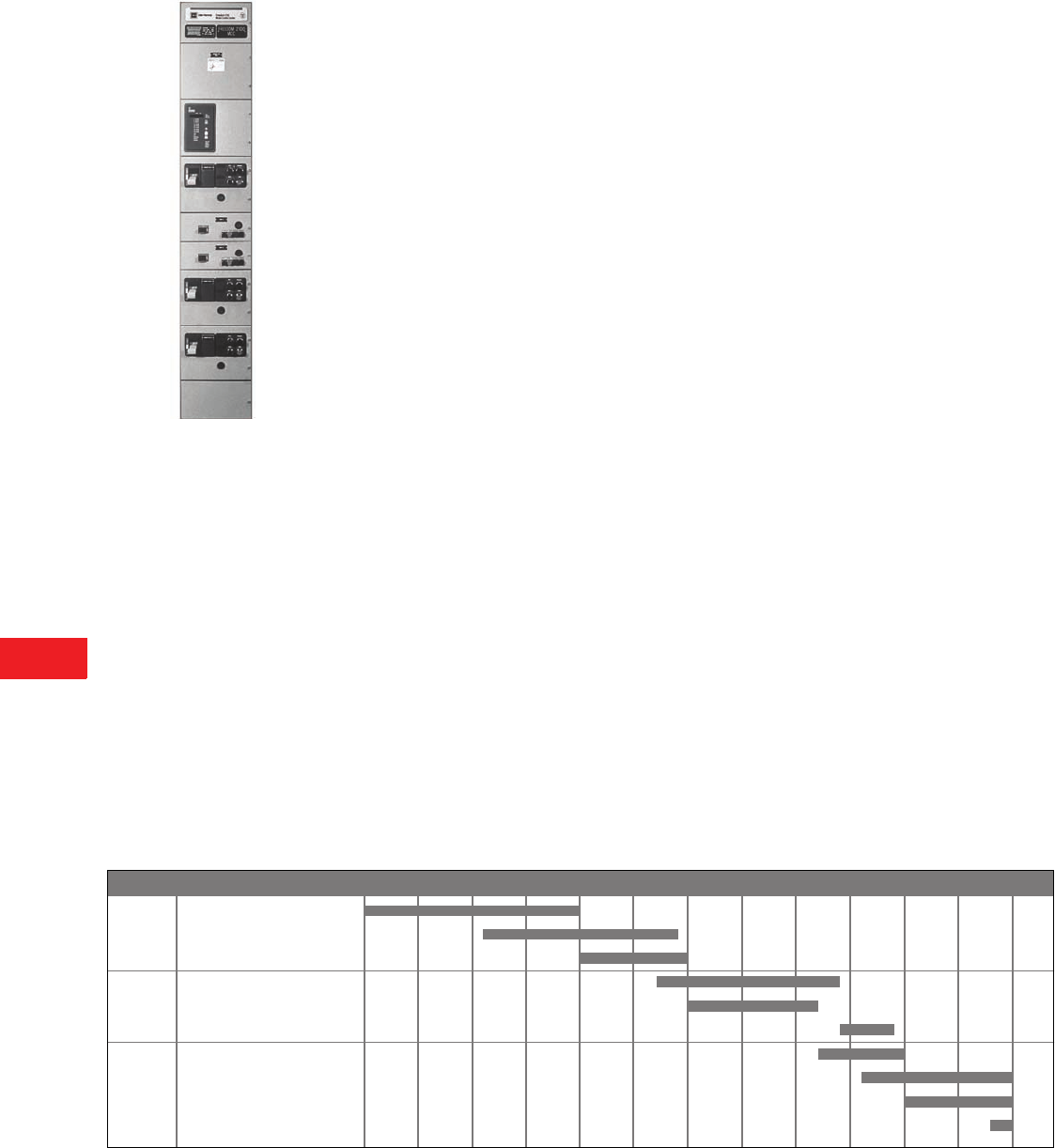
V12-T14-2 Volume 12—Aftermarket, Renewal Parts and Life Extension Solutions CA08100014E—November 2013 www.eaton.com
1
2
3
4
5
6
7
8
9
10
11
12
13
14
15
16
17
18
19
20
21
22
23
24
25
14
Motor Control Centers
Low Voltage MCCs
F2100
Product Description
Nearly 50 years ago, Eaton’s
electrical business and
Westinghouse® introduced
the low voltage motor control
center (MCC) assembly,
enabling the group mounting
of low voltage (600V class)
electrical controls. This
allowed for supervision and
safe operation of motor starter
units, feeder tap units and
auxiliary equipment in a
flexible structure arrangement
at a centralized location.
The foundation for today’s
MCCs is a modular plug-in
combination motor controller
assembly with components
of proven electrical and
mechanical integrity. These
assemblies are enclosed in
metal structures that prevent
accidental contact with live
electrical parts.
Eaton’s Cutler-Hammer® MCC
structure consists of structural
steel, horizontal and vertical
wireways for conduit and load
cable entry and exit, and
vertical and horizontal bus
systems for distributing power
throughout the MCC. The
starter unit consists of a
rugged steel shell (wrapper)
for mounting the unit
components, a combination
motor starter with factory
wired control, a handle
mechanism for ON/OFF
operation and a rigid unit door.
Product History
Group-mounted motor control
was originally developed by
Westinghouse in 1935. What
came to be known as motor
control centers were built in
14 manufacturing and repair
shops around the country,
including a plant in Chicago,
IL, that opened in 1941. In
1963, Chicago became the
primary MCC manufacturing
plant. The Fayetteville, NC,
operation was opened in
1980 to relieve some of
Chicago’s volume. The
Fayetteville plant was
expanded in 1984 and the
Chicago operation was
closed. Motor control centers
are currently manufactured
in Fayetteville and in eight
service centers around
the country.
The Westinghouse plug-in
starter design for group-
mounted control (called
motor control centers) was
first introduced in 1935,
and in 1950 became known
as the Type 11-300 motor
control center and used the
11-200 motor starter. The
Type W MCC replaced the
11-300 in 1965, first using
the 11-200 starter and then
moving to the A200 starter.
The 5 Star was introduced in
1975 to replace the Type W.
It, too, used the A200 motor
starter. The Series 2100
updated the 5 Star design
in 1987, but is mechanically
compatible with the 5 Star.
The Advantage MCC was
introduced as a sister product
to the Series 2100 in 1992
with the introduction of the
Advantage starter. It was also
mechanically compatible with
the 5 Star. With the merger
of Eaton’s electrical Cutler-
Hammer business unit and
Westinghouse’s Distribution
and Control Business Unit
(DCBU) in 1994, a new hybrid
motor control center line was
introduced. It was called the
F2100 MCC and featured the
Freedom™ starter.
The Cutler-Hammer plug-in
starter design motor control
center was introduced in the
late 1950s as the 9800 Series
Unitrol. These motor control
centers used the 3-Star type
motor starter. In 1968, the
Citation line of starters
replaced the 3-Star type in
the 9800 MCC. The motor
control center was totally
redesigned around the
Citation starter in 1972 and
was called the F10 Unitrol.
The next generation of MCC
was introduced in 1988, using
the Freedom line of starters
called the Freedom Unitrol.
Freedom Unitrol was
discontinued in 1994 and
replaced with the Cutler-
Hammer F2100 motor
control center.
Cutler-Hammer motor control
centers were originally built in
Milwaukee, WI. In 1962,
manufacturing moved out of
Milwaukee to plants in
Atlanta, GA;
Bethlehem, PA;
Chicago, IL; Los Angeles,
CA;
Dallas, TX; San Francisco, CA;
and Cleveland, TN. In 1972,
these plants consolidated to
Atlanta, Bethlehem, Chicago,
Dallas and Los Angeles. In
1984, another consolidation
left manu
facturing in only
Atlanta and Los Angeles.
With the introduction of the
Freedom starter in 1989, all
manufacturing was moved
to Atlanta. After the merger,
all motor control center
manufacturing moved to the
Fayetteville, NC, location.
Product History Time Line
Note
1No additional information at this time.
Product 1935 1950 1955 1960 1965 1970 1975 1980 1985 1990 1995 2000 Present
Page
Westinghouse 11-300
Cutler-Hammer 9800
Westinghouse Type W
Cutler-Hammer F10
Westinghouse 5 Star
Cutler-Hammer Freedom Unitrol
Westinghouse Series 2100
Westinghouse Advanage™
Cutler-Hammer F2100
Cutler-Hammer IT. MCC
햲
V12-T14-5
V12-T14-6
V12-T14-7
V12-T14-8
V12-T14-10
V12-T14-9
V12-T14-10
V12-T14-11
V12-T14-12

Volume 12—Aftermarket, Renewal Parts and Life Extension Solutions CA08100014E—November 2013 www.eaton.com V12-T14-3
1
2
3
4
5
6
7
8
9
10
11
12
13
14
15
16
17
18
19
20
21
22
23
24
25
14
Motor Control Centers
Identifying Types of Low Voltage MCCs
General Information
Procedure for Identifying Motor Control Center Types 1
Notes
1 In the event that the nameplate is missing, it is possible to identify the MCC design by the type of handle mechanism, starter type, bucket width and door width.
2 Contact 1-800-OLD-UNIT.
MCC
Type
Type of Handle
Mechanism
Starter
Type
Bucket
Width (Inches)
Door
Width (Inches)
Page
Number
11-300 Rotary 11-200 Life Line Type N 15-3/4 20 V12-T14-5
9800 Rotary and lever 3 Star 16-1/8 19-3/8 V12-T14-6
Type W Slider A200 or 11-200 11-3/4 13-3/8 V12-T14-7
F10 Slider and lever Citation 14 14-3/4 with wireway V12-T14-8
19-1/2 without wireway
Freedom Unitrol Slider Freedom Series 13-7/8 15-1/2 V12-T14-9
5 Star/Series 2100 Lever A200 13-3/4 15-5/8 V12-T14-10
Advantage Lever Advantage 13-3/4 15-5/8 V12-T14-11
F2100 Lever Freedom Series 13-3/4 15-5/8 V12-T14-12
IT. MCC Rotary IT-EM 13-3/4 15-5/8 2
11-300
9800
Type W
F10
Freedom Unitrol
5 Star/Series 2100
Advantage
F2100
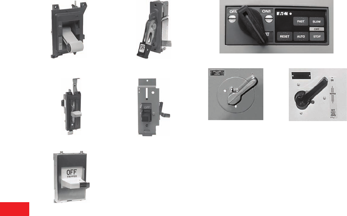
V12-T14-4 Volume 12—Aftermarket, Renewal Parts and Life Extension Solutions CA08100014E—November 2013 www.eaton.com
1
2
3
4
5
6
7
8
9
10
11
12
13
14
15
16
17
18
19
20
21
22
23
24
25
14
Motor Control Centers
Identifying Types of Low Voltage MCCs
Identification by Original Handle Mechanism
Freedom 2100, Advantage,
Series 2100, 5 Star
Freedom Unitrol
Type W
F10 Unitrol Lever (Obsolete)
F10 Unitrol Slider
IT-EM Handles
9800 Unitrol (Obsolete) 11-300
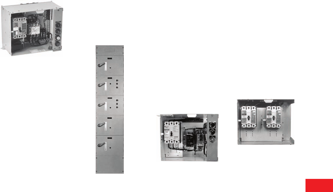
Volume 12—Aftermarket, Renewal Parts and Life Extension Solutions CA08100014E—November 2013 www.eaton.com V12-T14-5
1
2
3
4
5
6
7
8
9
10
11
12
13
14
15
16
17
18
19
20
21
22
23
24
25
14
Motor Control Centers
11-300
11-300
Originally a
Westinghouse Product
Unit with A200 Starter
Product Description
Introduced in 1937,
Westinghouse manufactured
the 11-300 MCC through
1965 and it was available as
match and lineup until 1974.
It used standard structures
each 20.00 inches wide,
90.38 inches high, and either
20.25 inches or 12.00 inches
deep for front mounted and
20.25 inches for back-to-back
mounting. Vertical sections
could be bolted together
to form a single lineup with
continuous horizontal bus and
open horizontal wireways.
Unit height was measured in
either 9.33-inch or 14.00-inch
increments up to a maximum
of 70.00 inches of usable
vertical space. ANSI 61 light
gray enamel
was used on
all structural parts. The unit
door hinged on the right and
covered the entire width
of the structure.
The 11-300 starter unit was
most easily recognized by
the rotary type of handle
mechanism. Bus and support
systems were typically
braced to withstand fault
currents of 25,000A.
Maximum Ratings
Three-phase, 600V, 600 hp,
2500A bus.
20.00-Inch Wide/Single 11-300
MCC Structure
Replacement Capabilities
Replacement Starter Units
Replacement starter cell units
are available for all plug-in
MCC designs. A complete
unit for adding to an existing
MCC includes a unit door,
a divider pan and all the
necessary mounting hardware.
Features of the replacement
unit include:
●Size 1–5 starter units
●UL® labeled
●Series C disconnect device
●
A200 standard—
IT.
,
Freedom or Advantage
starter optional
●New tin-plated copper stab
assembly
●New door, handle
mechanism and hardware
Unit with IT-EM Starter
Add-on MCCs
New IT., F2100 or Advantage
can be added to an existing
lineup. Cable connected only.
Replacement Feeder Units
Replacement feeder cell units
are available for all plug-in
MCC designs. A complete
unit for adding to an existing
MCC includes a unit door,
a divider pan and all the
necessary mounting hardware.
Features of the replacement
unit include:
●Feeder breakers and
fusible switches through
400A
●UL labeled
●Series C disconnect device
●New tin-plated copper
stab assembly
●New door, handle
mechanism and hardware
11-300 Dual Feeder
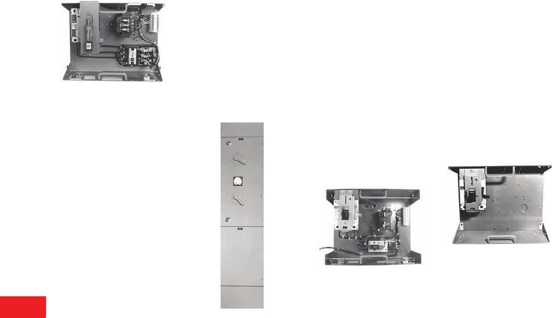
V12-T14-6 Volume 12—Aftermarket, Renewal Parts and Life Extension Solutions CA08100014E—November 2013 www.eaton.com
1
2
3
4
5
6
7
8
9
10
11
12
13
14
15
16
17
18
19
20
21
22
23
24
25
14
Motor Control Centers
9800
9800
Originally a Cutler-Hammer
Product
Unit with Citation Starter
Product Description
Introduced in 1956, the Cutler-
Hammer 9800 was the initial
offering in the motor control
center product grouping. The
door of the unit measured
19.38 inches wide and the
bucket width measured
16.13 inches. Unit height was
measured in 9.33-inch and
14.00-inch increments. The
MCC did not use a wireway.
ANSI 49 was applied to the
units, structural framework,
roof, side sheets and all
exterior doors.
9800 starter units were
originally supplied with a 3-Star
starter and a rotary handle
mechanism. Replacements
today use the newer Freedom
starter, and a slider handle
mechanism and a new door.
The rotary handle mechanism
is no longer available. Bus and
bus systems were typically
braced to withstand fault
currents of 25,000A.
Maximum Ratings
Three-phase, 600V, 100 hp,
2500A bus.
20.00-Inch Wide/Single 9800
MCC Structure
Replacement Capabilities
Replacement Starter Units
Replacement starter cell units
are available for all plug-in
MCC designs. A complete
unit for adding to an existing
MCC includes a unit door,
a divider pan and all the
necessary mounting
hardware. Features of the
replacement unit include:
●Sizes 1–4 starter units
●UL labeled
●Series C disconnect device
●Freedom standard—IT.,
A200 or Advantage starter
optional
●New tin-plated copper
stab assembly
●New door, handle
mechanism and hardware
Unit with IT-EM Starter
Note: Replacement 9800 units
will be supplied with slider handle
mechanism as shown.
Add-on MCCs
New
IT.
, F2100 or Advantage
can be added to an existing
lineup.
Cable connected only.
Replacement Feeder Units
Replacement feeder cell units
are available for all plug-in
MCC designs. A complete
unit for adding to an existing
MCC includes a unit door,
a divider pan and all the
necessary mounting hardware.
Features of the replacement
unit include:
●Feeder breakers and
fusible switches
through 400A
●UL labeled
●Series C disconnect device
●New tin-plated copper
stab assembly
●New door, handle
mechanism and hardware
9800 Feeder Unit
Note: Handle mechanism
pictured above is also used
with F10 Unitrol units.
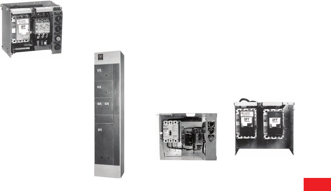
Volume 12—Aftermarket, Renewal Parts and Life Extension Solutions CA08100014E—November 2013 www.eaton.com V12-T14-7
1
2
3
4
5
6
7
8
9
10
11
12
13
14
15
16
17
18
19
20
21
22
23
24
25
14
Motor Control Centers
Type W
Type W
Originally a
Westinghouse Product
Unit with A200 Starter
Product Description
Manufactured from 1965 to
1975, this Westinghouse
MCC used standard
structures each 19.00 inches
wide, 90.00 inches high,
and either 15.00 inches or
20.00 inches deep for front
mounted or 20.00 inches deep
for back-to-back mounting.
Vertical sections were bolted
together forming a single
lineup with continuous
horizontal bus. Unit height
is measured in 6.00-inch
increments up to a maximum
of 72.00 inches of usable
vertical space. Starter units
are 13.50 inches wide.
A two-tone light/dark enamel
paint system was used with
an ANSI 70 off-white applied
to the structural framework
and cover plates. A dark gray
was used for unit and
wireway doors.
The Type W starter units are
easily recognized by their
sliding handle mechanism,
the MC motor control type.
Bus and bus support systems
were typically braced to
withstand fault currents of
22,000A.
Maximum Ratings
Three-phase, 600V, 400 hp,
2500A bus.
20.00-Inch Wide Type W MCC Structure
Replacement Capabilities
Replacement Starter Units
Replacement starter cell units
are available for all plug-in
MCC designs. A complete
unit for adding to an existing
MCC includes a unit door,
a divider pan and all the
necessary mounting hardware.
Features of the replacement
unit include:
●Size 1–5 starter units
●UL labeled
●Series C disconnect device
●A200 standard—IT.,
Freedom or Advantage
starter optional
●New tin-plated copper
stab assembly
●New door, handle
mechanism and hardware
Unit with IT-EM Starter
Add-on MCCs
New IT., F2100 or Advantage
MCCs can be added to an
existing lineup through a
10.00-inch bus transition
section.
Replacement Feeder Units
Replacement feeder cell units
are available for all plug-in
MCC designs. A complete
unit for adding to an existing
MCC includes a unit door,
a divider pan and all the
necessary mounting hardware.
Features of the replacement
unit include:
●Feeder breakers and
fusible switches through
400A
●UL labeled
●Series C disconnect device
●New tin-plated copper stab
assembly
●New door, handle
mechanism and hardware
Type W Dual Feeder
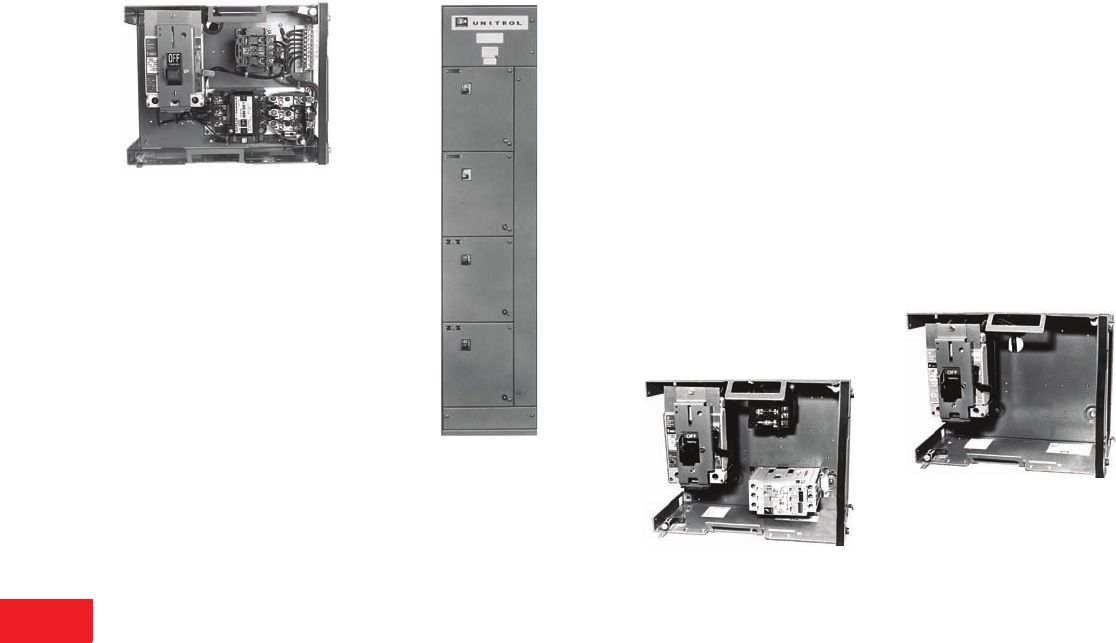
V12-T14-8 Volume 12—Aftermarket, Renewal Parts and Life Extension Solutions CA08100014E—November 2013 www.eaton.com
1
2
3
4
5
6
7
8
9
10
11
12
13
14
15
16
17
18
19
20
21
22
23
24
25
14
Motor Control Centers
F10
F10
Originally a
Cutler-Hammer Product
Unit with Citation Starter
Product Description
Introduced in 1972, this
Cutler-Hammer MCC was
available in both 16.00 inches
wide (with wireway) and
20.00 inches wide (without
wireway). Bucket width
is 14.00 inches and
replacement units are
available with both designs.
Unit height is measured in
6.00-inch increments.
ANSI 40 was applied to the
units, structural framework,
roof, side sheets and all
exterior doors.
The F10 MCC used the
Citation starter and was
identified by the slider type
handle mechanism. Bus and
bus support systems were
typically braced to withstand
fault currents of 42,000A.
Maximum Ratings
Three-phase, 600V, 150 hp,
2000A bus.
20.00-Inch Wide F10 MCC Structure
Replacement Capabilities
Replacement Starter Units
Replacement starter cell units
are available for all plug-in
MCC designs. A complete
unit for adding to an existing
MCC includes a unit door,
a divider pan and all the
necessary mounting hardware.
Features of the replacement
unit include:
●Size 1–5 starter units
●UL labeled
●Series C disconnect device
●
Freedom standard—
IT.
,
A200 or Advantage
starter optional
●New tin-plated copper
stab assembly
●New door, handle
mechanism and hardware
Unit with Advantage Starter
Add-on MCCs
New IT., F2100 or Advantage
MCCs can be added to an
existing lineup through a bus
splice kit and channel sills.
Replacement Feeder Units
Replacement feeder cell units
are available for all plug-in
MCC designs. A complete
unit for adding to an existing
MCC includes a unit door,
a divider pan and all the
necessary mounting hardware.
Features of the replacement
unit include:
●Feeder breakers 600A and
fusible switches 400A
●UL labeled
●Series C disconnect device
●New tin-plated copper stab
assembly
●New door, handle
mechanism and hardware
F10 Feeder Unit
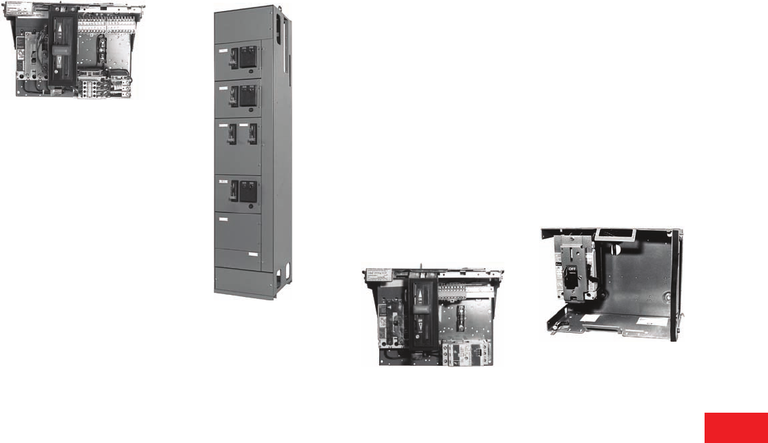
Volume 12—Aftermarket, Renewal Parts and Life Extension Solutions CA08100014E—November 2013 www.eaton.com V12-T14-9
1
2
3
4
5
6
7
8
9
10
11
12
13
14
15
16
17
18
19
20
21
22
23
24
25
14
Motor Control Centers
Freedom Unitrol
Freedom Unitrol
Originally a
Cutler-Hammer Product
Unit with Freedom Starter
Product Description
Introduced in 1989, this
Cutler-Hammer MCC had
vertical structures that
measured 20.00 inches wide,
91.50 inches high, and either
15.00 inches or 20.00 inches
deep. It allowed a 6.00-inch
Size 1 unit design.
ANSI 49 was applied to the
units, structural framework,
roof, side sheets and all
exterior doors.
The Freedom Unitrol used
the Freedom starter and was
identified by the slider type
handle mechanism. Bus and
bus support systems were
typically braced to withstand
fault currents of 42,000A
with the option to increase
to 65,000A.
Maximum Ratings
Three-phase, 600V, 400 hp,
2500A bus.
20.00-Inch Wide Freedom
Unitrol MCC Structure
Replacement Capabilities
Replacement Starter Units
Replacement starter cell units
are available for all plug-in
MCC designs. A complete
unit for adding to an existing
MCC includes a unit door,
a divider pan and all the
necessary mounting hardware.
Features of the replacement
unit include:
●Size 1–5 starter units
●UL labeled
●Series C disconnect device
●
Freedom standard—
IT.
,
A200 or Advantage
starter
optional
●New tin-plated copper stab
assembly
●New door, handle
mechanism and hardware
Unit with Advantage Starter
Add-on MCCs
New IT., F2100 or Advantage
MCCs can be added to an
existing lineup through
a bus splice kit.
Replacement Feeder Units
Replacement feeder cell units
are available for all plug-in
MCC designs. A complete
unit for adding to an existing
MCC includes a unit door,
a divider pan and all the
necessary mounting
hardware. Features of the
replacement unit include:
●Feeder breakers and
fusible switches
through 600A
●UL labeled
●Series C disconnect device
●New tin-plated copper
stab assembly
●New door, handle
mechanism and hardware
Freedom Unitrol Feeder Unit
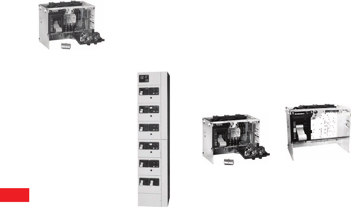
V12-T14-10 Volume 12—Aftermarket, Renewal Parts and Life Extension Solutions CA08100014E—November 2013 www.eaton.com
1
2
3
4
5
6
7
8
9
10
11
12
13
14
15
16
17
18
19
20
21
22
23
24
25
14
Motor Control Centers
5 Star/Series 2100
5 Star/Series 2100
Originally a
Westinghouse Product
Unit with A200 Starter
Product Description
The 5 Star MCC was
introduced by Westinghouse
in 1975. The structure design
was the basis for the Series
2100, Advantage and F2100
products later. The Series
2100 updated the 5 Star
design in 1987 with higher
ratings and newer
components.
The vertical structures are
normally 20.00 inches wide,
90.00 inches high, and
16.00 inches or 21.00 inches
deep. Vertical sections may
be bolted together forming a
single lineup with continuous
horizontal bus and open
horizontal wireways. Unit
height is measured in
6.00-inch increments up to
a maximum of 72.00 inches
of usable vertical space.
A two-tone light/dark enamel
paint system is used for
this design. ANSI 61 gray
is applied to the roof and
side sheets and all exterior
doors. Starter units are
13.75 inches wide.
The 5 Star/Series 2100 starter
unit’s handle mechanism is a
gray toggle type handle with
a black exterior mounting
panel and is used on the
Advantage and F2100
designs. Bus and bus support
systems are typically braced
to withstand fault currents of
42,000A on the 5 Star and
65,000A on the Series 2100.
Maximum Ratings
Three-phase, 600V, 600 hp,
2500A bus.
20.00-Inch Wide 5-Star MCC Structure
Replacement Capabilities
Replacement Starter Units
Replacement starter cell units
are available for all plug-in
MCC designs. A complete
unit for adding to an existing
MCC includes a unit door,
a divider pan and all the
necessary mounting hardware.
Features of the replacement
unit include:
●Size 1–5 starter units
●UL labeled
●Series C disconnect device
●A200 starter standard—IT.
starter optional
●New tin-plated copper
stab assembly
●New door, handle
mechanism and hardware
Unit with A200 Starter
Add-on MCCs
New IT., F2100 or Advantage
MCCs can be added to an
existing lineup through a bus
splice kit.
Replacement Feeder Units
Replacement feeder cell units
are available for all plug-in
MCC designs. A complete
unit for adding to an existing
MCC includes a unit door,
a divider pan and all the
necessary mounting
hardware. Features of the
replacement unit include:
●Feeder breakers and
fusible switches
through 600A
●UL labeled
●Series C disconnect device
●New tin-plated copper
stab assembly
●New door, handle
mechanism and hardware
5 Star/Series 2100 Feeder Unit
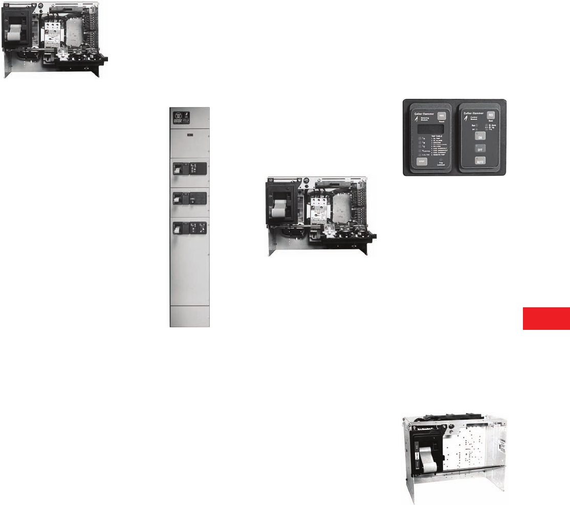
Volume 12—Aftermarket, Renewal Parts and Life Extension Solutions CA08100014E—November 2013 www.eaton.com V12-T14-11
1
2
3
4
5
6
7
8
9
10
11
12
13
14
15
16
17
18
19
20
21
22
23
24
25
14
Motor Control Centers
Advantage
Advantage
Originally a
Westinghouse Product
Unit with Advantage Starter
Product Description
Introduced in 1991 as a sister
to the Westinghouse Series
2100 MCC, the Advantage
starter design revolutionized
the industry. It uses state-of-
the-art technology to solve
motor control application
problems, such as coil
burnout and contact
chatter/welding.
The vertical structures are
normally 20.00 inches wide,
90.00 inches high, and
16.00 inches or 21.00 inches
deep. Vertical sections may
be bolted together forming a
single lineup with continuous
horizontal bus and open
horizontal wireways. Unit
height is measured in
6.00-inch increments up to
a maximum of 72.00 inches
of usable vertical space.
A two-tone light/dark enamel
paint system is used for this
design. ANSI 61 gray is
applied to all exterior back
sheets, side
sheets and doors.
Starter units are 13.75
inches
wide and are interchangeable
with the 5 Star and Series
2100 design.
The Advantage starter unit’s
handle mechanism is a gray
toggle type handle with a
black exterior mounting panel
and is used on the 5 Star/
Series 2100 and Freedom
2100 designs. Bus and bus
support systems were
typically braced to withstand
fault currents of 65,000A.
Maximum Ratings
Three-phase, 600V, 1100 hp,
3200A bus.
20.00-Inch Wide Advantage MCC
Structure
Replacement Capabilities
Replacement Starter Units
Replacement starter cell units
are available for all plug-in
MCC designs. A complete
unit for adding to an existing
MCC includes a unit door,
a divider pan and all the
necessary mounting
hardware. Features of the
replacement unit include:
●Size 1–5 starter units
●UL labeled
●Series C disconnect device
●Advantage starter
●New tin-plated copper
stab assembly
●New door, handle
mechanism and hardware
Unit with Advantage Starter
Device Panel Upgrade
While incorporating
Advantage starters, increase
the information shown on the
unit device panel with one or
two of the Advantage control
modules (ACMs) available.
These units fit into the
standard device panel cutout
and provide pushbutton, pilot
light and metering functions
with reduced wiring costs.
The device panel is hinged on
a horizontal rod extending
across the front of the unit.
With the unit door open,
loosening two captive
retaining screws at the top
of the panel and sliding it a
0.50-inch left permits it to
swing down. This provides
ready access to the rear of
the panel and increased
accessibility to the unit
interior.
Advantage Device Panel with ACM
and Metering Module
Replacement Feeder Units
Replacement feeder cell units
are available for all plug-in
MCC designs. A complete
unit for adding to an existing
MCC includes a unit door,
a divider pan and all the
necessary mounting
hardware. Features of the
replacement unit include:
●Feeder breakers and
fusible switches
through 600A
●UL labeled
●Series C disconnect device
●New tin-plated copper
stab assembly
●New door, handle
mechanism and hardware
Advantage Feeder Unit
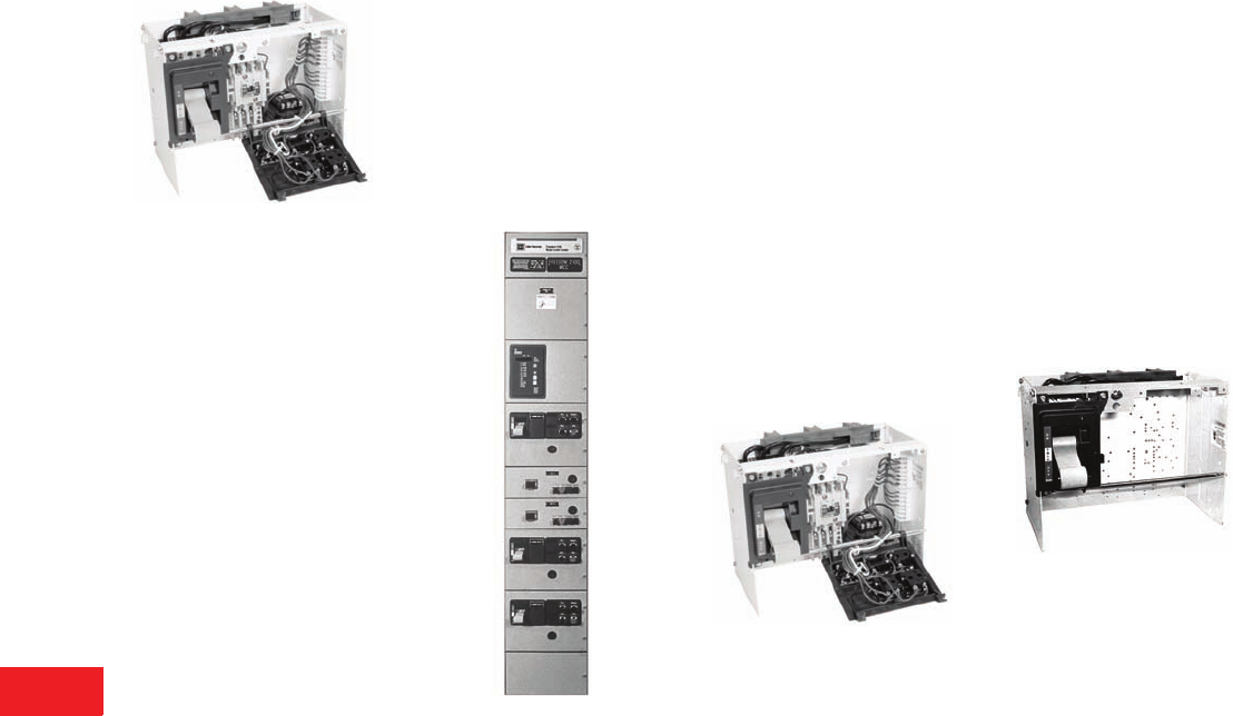
V12-T14-12 Volume 12—Aftermarket, Renewal Parts and Life Extension Solutions CA08100014E—November 2013 www.eaton.com
1
2
3
4
5
6
7
8
9
10
11
12
13
14
15
16
17
18
19
20
21
22
23
24
25
14
Motor Control Centers
F2100
F2100
The Cutler-Hammer F2100
was Introduced in 1995
Unit with Freedom Starter
Product Description
The structure is based on
the 5 Star, Series 2100 and
Advantage MCC design.
Vertical structures are
normally 20.00 inches wide,
90.00 inches high, and
16.00 inches or 21.00 inches
deep. Vertical sections may
be bolted together forming a
single lineup with continuous
horizontal bus and open
horizontal wireways. Unit
height is measured in
6.00-inch increments up to
a maximum of 72.00 inches
of usable vertical space.
A two-tone paint system is
used for this design. ANSI 61
gray is applied to the exterior
and doors. Starter units are
13.75 inches
wide with
4.63-inch wireways.
The Freedom starter is
used in this design along
with the HMCP motor
circuit protector.
The F2100 starter unit’s
handle mechanism is a gray
toggle type handle with a
black exterior mounting panel
and is used on the Advantage
and 5 Star/Series 2100
designs. Bus and bus support
systems are typically braced
to withstand fault currents of
65,000A.
Maximum Ratings
Three-phase, 600V, 1100 hp,
3200A bus.
20.00-Inch Wide F2100 MCC Structure
Replacement Capabilities
Replacement Starter Units
Replacement starter cell units
are available for all plug-in
MCC designs. A complete
unit for adding to an existing
MCC includes a unit door,
a divider pan and all the
necessary mounting
hardware. Features of the
replacement unit include:
●Size 1–5 starter units
●UL labeled
●Series C disconnect device
●Freedom starter
standard—IT. starter
optional
●New tin-plated copper stab
assembly
●New door, handle
mechanism and hardware
Unit with Freedom Starter
Replacement Feeder Units
Replacement feeder cell units
are available for all plug-in
MCC designs. A complete
unit for adding to an existing
MCC includes a unit door,
a divider pan and all the
necessary mounting
hardware. Features of the
replacement unit include:
●Feeder breakers and
fusible switches through
600A
●UL labeled
●Series C disconnect device
●New tin-plated copper
stab assembly
●New door, handle
mechanism and hardware
F2100 Feeder Unit
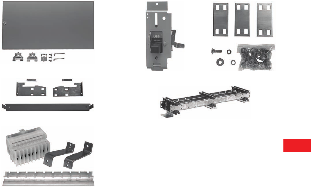
Volume 12—Aftermarket, Renewal Parts and Life Extension Solutions CA08100014E—November 2013 www.eaton.com V12-T14-13
1
2
3
4
5
6
7
8
9
10
11
12
13
14
15
16
17
18
19
20
21
22
23
24
25
14
Motor Control Centers
Replacement Parts
Replacement Capabilities
Replacement Parts
In addition to replacement
units, a large number of
replacement parts are
available for each vintage.
Note: For information on these
and additional parts, refer to
RPD listed on Page V12-T14-19
of this catalog. For parts not listed
or shown in the RPD, contact
your local Eaton Field Sales
office or Service Center. See
Page V12-T14-19 of this catalog.
Examples
F2100 Horizontal Wireway Door
9800 Unit Mounting Hardware Kit
Freedom Unitrol Terminal Block Mounting Kit
F10 Handle Mechanism Series 2100 Bus Splice Kit
Type W Horizontal Busbar
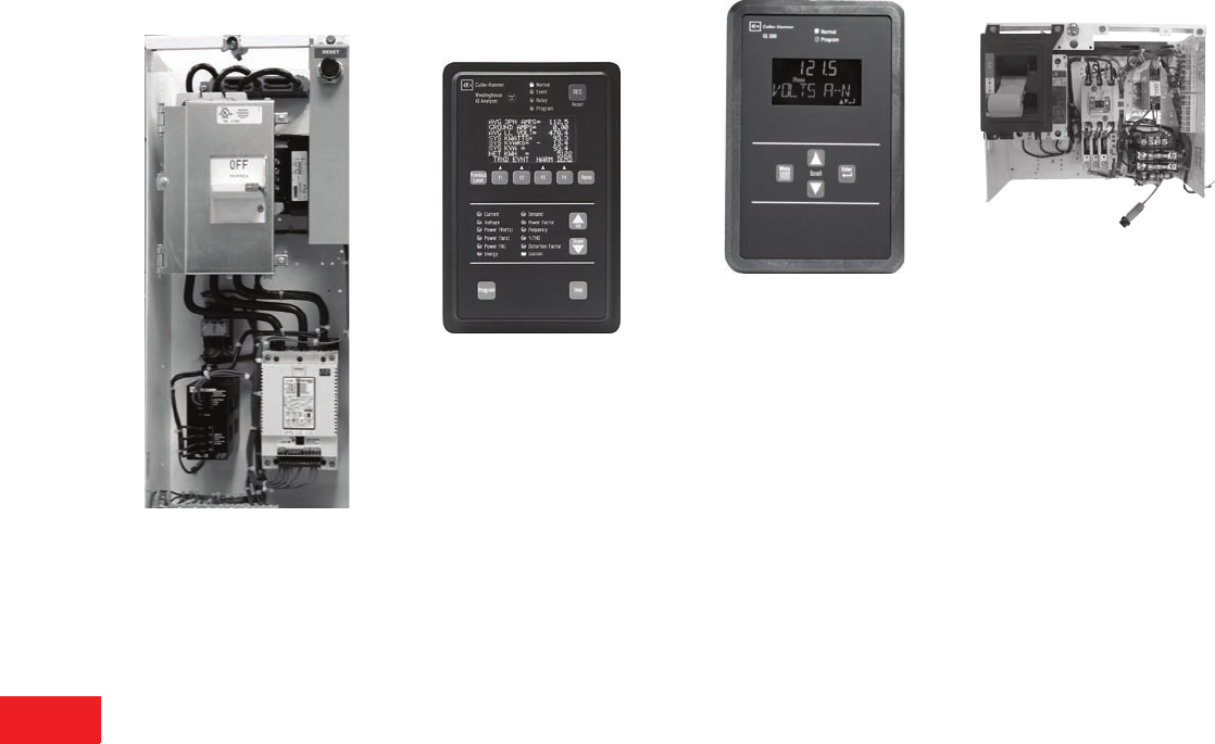
V12-T14-14 Volume 12—Aftermarket, Renewal Parts and Life Extension Solutions CA08100014E—November 2013 www.eaton.com
1
2
3
4
5
6
7
8
9
10
11
12
13
14
15
16
17
18
19
20
21
22
23
24
25
14
Motor Control Centers
Upgrades
Technology Upgrades
IT. Soft Start
Intelligent Technologies (IT.)
Soft Starters
Eaton’s Cutler-Hammer
Intelligent Technologies (IT.)
solid-state starters provide
high-performance motor
control in the most compact
packages in the industry.
The IT. Series of solid-state
starters are available in
retrofit units through 200 hp
in all Cutler-Hammer and
Westinghouse MCC vintages.
Each IT. solid-state starter
unit includes a disconnect,
starter, a DC power supply,
a 120 Vac interposing relay,
and a 100 VA CPT. The IT.
solid-state starter design
incorporates an integral,
parallel run contact that
engages once the starter
reaches full speed. Available
soft starter options include:
pump control software, line/
load MOV protection and
motor isolation contactor.
IQ Retrofit Kits
IQ Analyzer (The Ultimate
in Monitoring)
IQ Analyzer
The Cutler-Hammer IQ
Analyzer displays the most
comprehensive list of
metered parameters in its
class. The dot-matrix, gas
plasma display provides the
flexibility of exhibiting large
characters with high visibility
and small characters for
detailed descriptions. Multiple
parameters (e.g., currents
of phases A, B and C) are
displayed simultaneously
for more thorough real-time
monitoring. Custom screens
can also be configured.
Available information
includes current, voltage,
power, energy, demand
and an extensive array of
harmonic data.
IQ 320
IQ 320
The Cutler-Hammer IQ 320
is the most cost-effective
metering solution for
monitoring main incoming
line electrical values. Through
the bright two-line LCD
display, the IQ 320 provides
accurate readings for voltage,
amperes, watts, hertz, power
factor and VA. Key features
of the IQ 320 include ANSI
C312.16 revenue class
metering accuracy,
PowerNet™ capable
communications port and
user intuitive four-button
front panel interface.
DeviceNet Interface
Module Upgrade (DN65)
DeviceNet I/O Starter Unit Upgrade
Using the DN65 Discrete
DeviceNet™ I/O module,
all Cutler-Hammer and
Westinghouse vintage MCCs
may be upgraded with the
latest Freedom motor starters
to provide wire savings and
communications capability.
The DN65 DeviceNet I/O
Module adds increased
functionality and intelligence
in a small footprint.
Standard MCC starter units
accommodate the DN65
DeviceNet module and
provide the ability to perform
START/STOP control over an
open network. Additionally,
contactor, overload and
breaker status may be
communicated through
the DN65 upstream to a
host PC, PLC or DCS system.
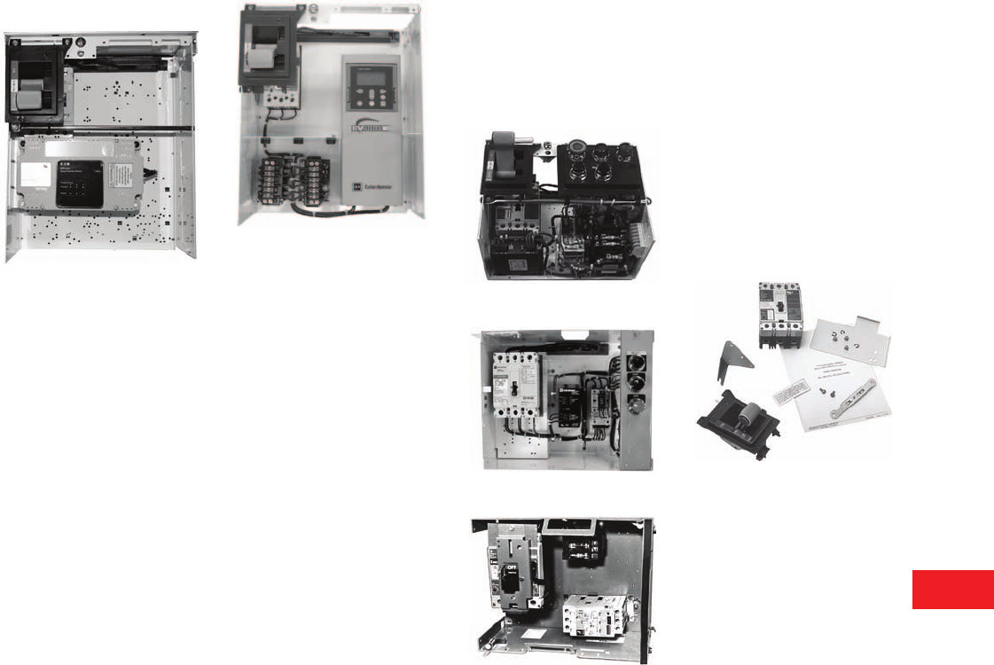
Volume 12—Aftermarket, Renewal Parts and Life Extension Solutions CA08100014E—November 2013 www.eaton.com V12-T14-15
1
2
3
4
5
6
7
8
9
10
11
12
13
14
15
16
17
18
19
20
21
22
23
24
25
14
Motor Control Centers
Upgrades
Technology Upgrades
SPD Upgrade
F2100 SPD Unit
Surge Protective
Device—MCC
The Eaton SPD Series surge
protective device is a hybrid
MOV filter-based suppression
system that protects sensitive
electronic equipment from
damaging transients, lightning
surges and electrical line
noise. The SPD is installed in
parallel to the electrical circuits
in a motor control center and
provides clean power to the
motor starting circuits. The
SPD only reacts and keeps
damaging surge current and
high frequency noise away
from motor starting circuits
when the system’s nominal
operating voltage is exceeded.
The latest Eaton SPD Series
protective devices are
substantially smaller, safer
and more compact than
their predecessors, providing
better performance and
easier installation.
The new Eaton SPD Series
are available in size ranges
from 50 to 400 kA and can
be retrofitted to all Cutler-
Hammer and Westinghouse
vintage MCCs. Consult the
factory for further information.
SV9000 Drives
SV9000 AC Drive
Cutler-Hammer SV9000
adjustable frequency drives
are available for retrofit units
in a number of MCC vintages.
For current vintage Freedom
and Advantage MCCs,
SV9000 drives are available
through 1100 hp at 480V.
Type W, F10, Freedom
Unitrol motor control center
vintage units are available
with SV9000 drive in plug-in
configurations through 30 hp
at 480V. Each retrofit unit
includes an SV9000 drive
(variable or constant torque)
disconnect, a CPT and a 3%
input and output line reactor.
SV9000 drives provide the
highest performance and
reliability available for flexible
and smooth motor control.
IT-EM Technology
In addition to standard retrofit
capabilities, every vintage
of MCC can be upgraded
with IT-EM motor starters.
Consult factory for other
manufacturer’s motor
control centers.
5 Star/Series 2100
Type W
F10
Series C Retrofit Kits
Series C retrofit kits are to
be used to upgrade existing
Type W, 5 Star and F10 motor
control center buckets by
changing out the old breakers
with the Series C. These kits
can be applied to both starter
and feeder units.
The old breakers that these
kits will upgrade include, but
are not limited to, the MCP,
F, FA, FB, HFB, K, KA, KB,
HKB, L, LA, LB and HLB
breakers.
5 Star Series C Retrofit Kit
5 Star Series C Retrofit Kit
The 5 Star Series C retrofit
kit includes:
●Series C device, 65 kA
(either HMCP or thermal-
magnetic breaker)
●Operating handle
mechanism, including
tripped indication and
push-to-trip
●Label stating that the MCC
unit has been retrofitted
with Series C device
suitable for 65 kA (similar
to UL quality label)
●Templates for desired
frame size
●Assembly instructions
Note: The upgrade interrupting
rating of the breaker does not
upgrade the withstand rating of
the existing bus.
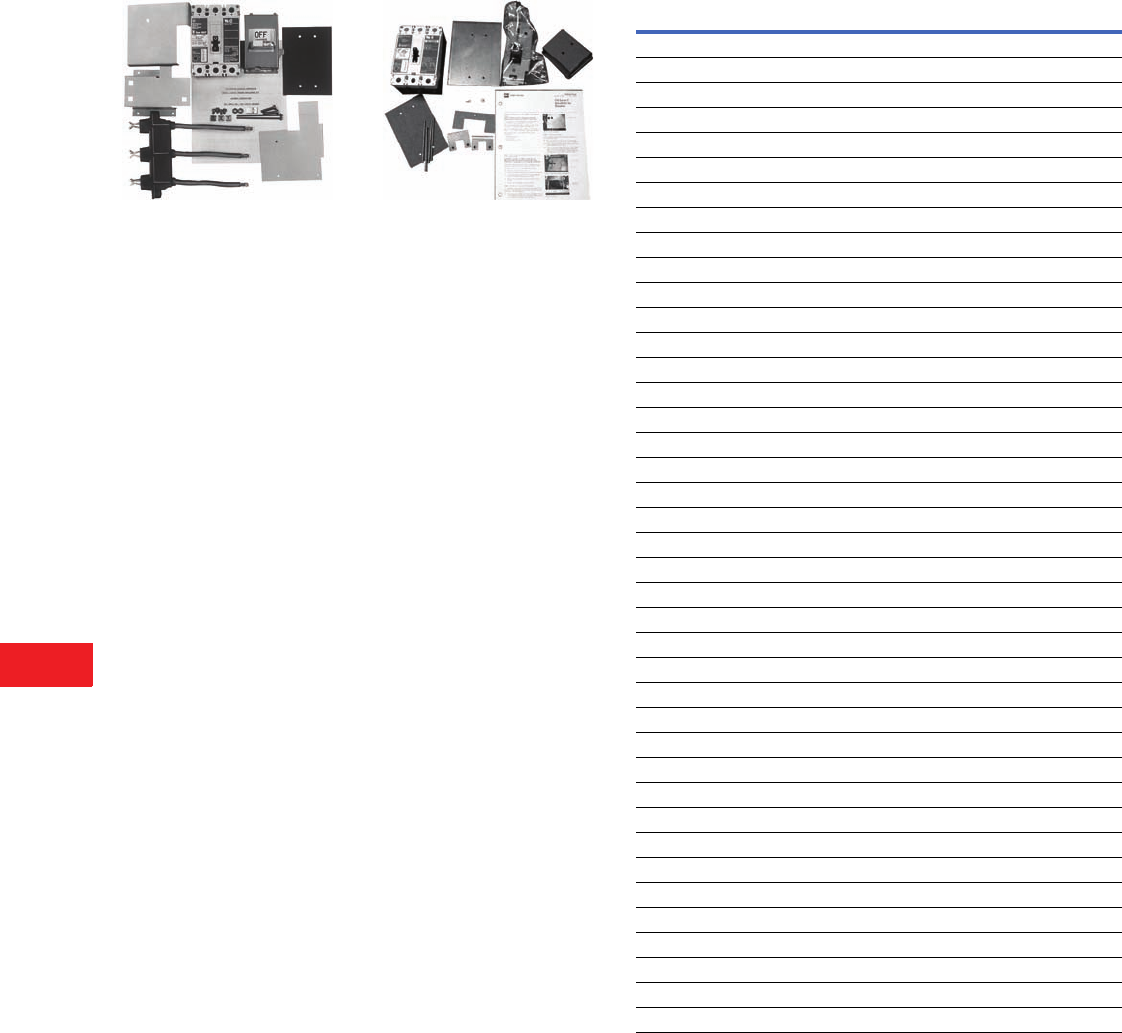
V12-T14-16 Volume 12—Aftermarket, Renewal Parts and Life Extension Solutions CA08100014E—November 2013 www.eaton.com
1
2
3
4
5
6
7
8
9
10
11
12
13
14
15
16
17
18
19
20
21
22
23
24
25
14
Motor Control Centers
Upgrades
Type W Series C Retrofit Kit
Type W Series C Retrofit Kit
The Type W Series C retrofit
kit includes:
●Series C device, 65 kA
(either HMCP or thermal-
magnetic breaker)
●Operating handle
mechanism, including
tripped indication and
push-to-trip
●Label stating that the MCC
unit has been retrofitted
with Series C device
suitable for 65 kA (similar
to UL quality label)
●Templates for proper hole
placement for desired
frame size
●Series C breaker mounting
hardware
●New door and hardware
●New stab assembly
●Assembly instructions
Note: The upgrade interrupting
rating of the breaker does not
upgrade the withstand rating of
the existing bus.
F10 Series C Retrofit Kit
F10 Series C Retrofit Kit
The F10 Series C retrofit
kit includes:
●Series C device, 65 kA
(either HMCP or thermal-
magnetic breaker)
●Operating handle
mechanism, including
tripped indication
push-to-trip
●Label stating that the MCC
unit has been retrofitted
with Series C device
suitable for 65 kA (similar
to UL quality label)
●Templates for desired
frame size
●Assembly instructions
Note: The upgrade interrupting
rating of the breaker does not
upgrade the withstand rating of
the existing bus.
Series C Molded-Case Circuit Breakers
Frame
Type
Interrupting Rating (kAIC) Trip Rating
Amperes
Catalog
Number240V 480V 600V
HFD 100 65 25 15 HFD3015
HFD 100 65 25 20 HFD3020
HFD 100 65 25 25 HFD3025
HFD 100 65 25 30 HFD3030
HFD 100 65 25 40 HFD3040
HFD 100 65 25 50 HFD3050
HFD 100 65 25 60 HFD3060
HFD 100 65 25 70 HFD3070
HFD 100 65 25 80 HFD3080
HFD 100 65 25 90 HFD3090
HFD 100 65 25 100 HFD3100
HFD 100 65 25 125 HFD3125
HFD 100 65 25 150 HFD3150
FDC 200 100 35 15 FDC3015
FDC 200 100 35 20 FDC3020
FDC 200 100 35 25 FDC3025
FDC 200 100 35 30 FDC3030
FDC 200 100 35 40 FDC3040
FDC 200 100 35 50 FDC3050
FDC 200 100 35 60 FDC3060
FDC 200 100 35 70 FDC3070
FDC 200 100 35 80 FDC3080
FDC 200 100 35 90 FDC3090
FDC 200 100 35 100 FDC3100
FDC 200 100 35 125 FDC3125
FDC 200 100 35 150 FDC3150
HJD 100 65 25 175 HJD3175
HJD 100 65 25 200 HJD3200
HJD 100 65 25 225 HJD3225
HJD 100 65 25 250 HJD3250
JDC 200 100 35 175 JDC3175
JDC 200 100 35 200 JDC3200
JDC 200 100 35 225 JDC3225
JDC 200 100 35 250 JDC3250
HKD 100 65 35 300 HKD3300
HKD 100 65 35 350 HKD3350
HKD 100 65 35 400 HKD3400
KDC 200 100 50 300 KDC3300
KDC 200 100 50 350 KDC3350
KDC 200 100 50 400 KDC3400
Volume 12—Aftermarket, Renewal Parts and Life Extension Solutions CA08100014E—November 2013 www.eaton.com V12-T14-17
1
2
3
4
5
6
7
8
9
10
11
12
13
14
15
16
17
18
19
20
21
22
23
24
25
14
Motor Control Centers
Upgrades
Series C Motor Circuit Protectors Catalog Numbering System
Series C Retrofits
How to Order
Step 1:
Select the correct Series C device
from the table in the
applicable RPD
5 Star—RP04304003E
Type W—RP04304006E
F10—RP04304005E
Step 2: Create a catalog number based on the MCC type,
device selected, modification, door size and device panel.
Step 3: Select price from PL04304002E.
Starter
Size
Magnetic Trip
Range Amperes
Continuous
Rating Amperes
Catalog
Number
09–30 3 HMCP003A0
0 21–70 7 HMCP007C0
0 45–150 15 HMCP015E0
0 40–60 25 HMCP025D0
1 90–300 30 HMCP030H1
2 80–120 50 HMCP050G2
2 150–500 50 HMCP050K2
2 115–170 70 HMCP070J2
2 210–700 70 HMCP070M2
3 160–240 100 HMCP100L3
3 300–1000 100 HMCP100R3
4 450–1500 150 HMCP150T4
4 750–2500 150 HMCP150U4
4, 5 350–700 250 HMCP250A5
5 450–900 250 HMCP250C5
5 500–1000 250 HMCP250D5
5 625–1250 250 HMCP250F5
5 750–1500 250 HMCP250G5
5 875–1750 250 HMCP250J5
5 1000–2000 250 HMCP250K5
5 1125–2250 250 HMCP250L5
5 1250–2500 250 HMCP250W5
5 500–1000 400 HMCP400D5
5 625–1250 400 HMCP400F5
5 750–1500 400 HMCP400G5
5 875–1750 400 HMCP400J5
5 1000–2000 400 HMCP400K5
5 1125–2250 400 HMCP400L5
5 1250–2500 400 HMCP400M5
5 1500–3000 400 HMCP400N5
5 1750–3500 400 HMCP400R5
5, 6 2000–4000 400 HMCP400X5
FT HMCP030H1 C 12 N
Modifications
C= Copper lugs for HMCP
L= Lugs for molded-case breaker
Door Size
Height of door in
inches, 6.00-inch
increments
Device Panel
D= With device
panel
N= No device
panel
MCC Type
FT = Type W
FS = 5 Star
FR = F10
Device Catalog
Number
Use tables
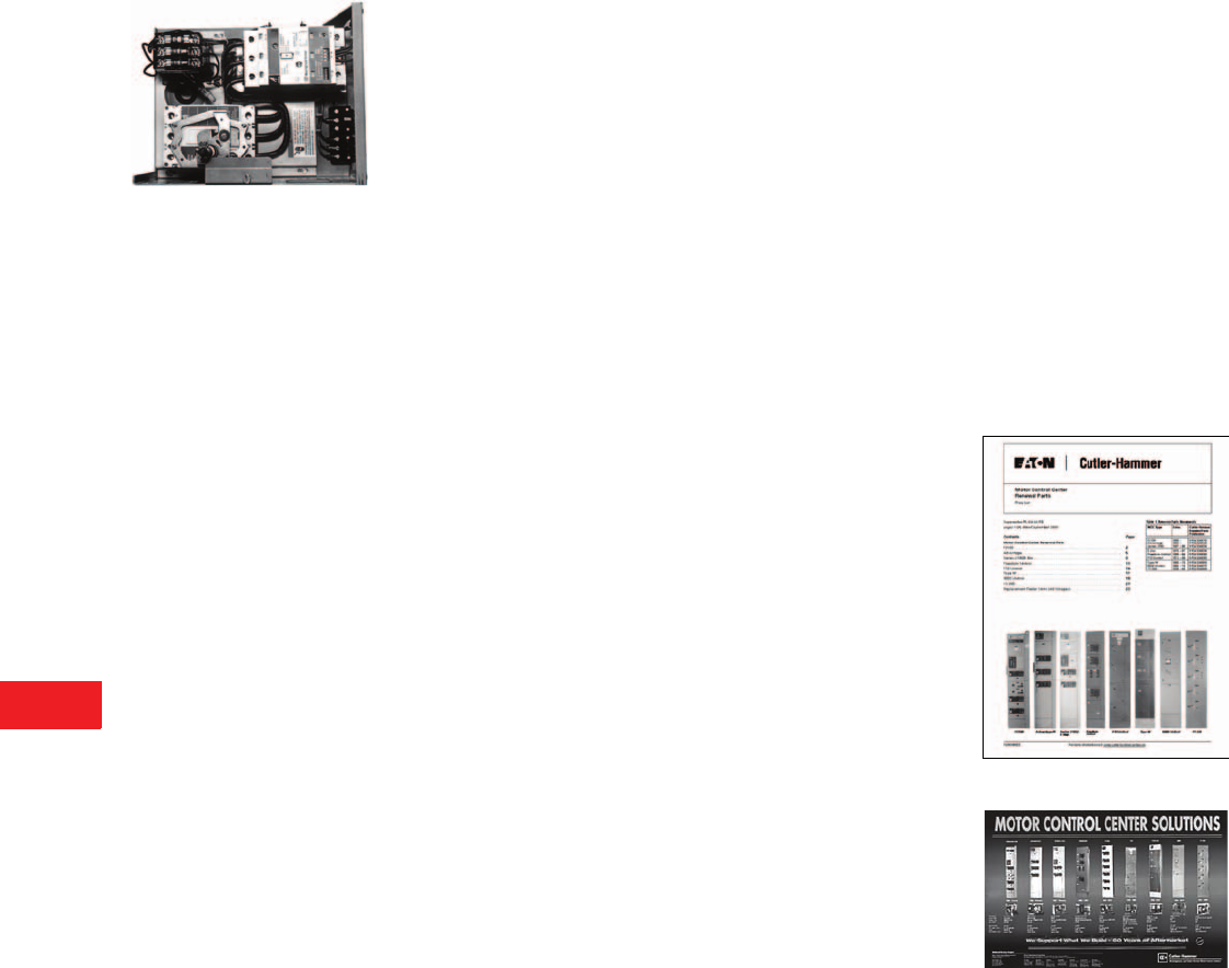
V12-T14-18 Volume 12—Aftermarket, Renewal Parts and Life Extension Solutions CA08100014E—November 2013 www.eaton.com
1
2
3
4
5
6
7
8
9
10
11
12
13
14
15
16
17
18
19
20
21
22
23
24
25
14
Motor Control Centers
Upgrades
Competitive Retrofit
Upgrades
GE7770 Unit Retrofitted with
Advantage and HMCP
The following competitive
retrofit units can be obtained
from the Fayetteville
manufacturing plant.
●Allis-Chalmers
●Allen-Bradley®
●Arrow Hart®
●General Electric®
●Klockner-Moeller®
●Siemens®
●Other
Factory Retrofit
We replace the starter,
the breaker and the handle
mechanism. A new door
is provided for most
competitor’s units. The
original unit, the pan and
the stabs are refurbished.
Panel Retrofit
New components are
mounted on a “panel” that
is easily installed into the
competitor’s unit. Included
are a new pan, a starter, a
breaker, a handle mechanism
and a door if available.
Requires field installation
by Eaton’s Electrical
Services & Systems (EESS)
or a qualified contractor.
Note: See Page V12-T14-19 for
most competitor retrofit units.
Note: Please consult factory for
additional retrofit opportunities.
New Units
Brand new ITET 5600, GE
7700/8000 and Allen-Bradley
Centerline™ replacement
units include:
●New bucket
●New stabs
●All new Cutler-Hammer
components
●Complete with
manufacturer UL label
Note: For additional information
and designs for other motor
control centers, call the
Aftermarket Products Center
in Fayetteville, NC.
Customer Required
Information
Procedure for identifying
renewal parts:
1.
Renewal parts listed in
PL04304002E
below
identify those
replacement parts
that are most frequently
ordered and that are
readily available from
manufacturing stock.
2. For parts not shown in
Aftermarket, Renewal
Parts and Life Extension
Solutions or listed in
Further Information
on Page V12-T14-19,
contact your local Eaton
Field Sales office or call
1-800-OLD-UNIT.
PL04304002E
Poster PST03A0ITE

Volume 12—Aftermarket, Renewal Parts and Life Extension Solutions CA08100014E—November 2013 www.eaton.com V12-T14-19
1
2
3
4
5
6
7
8
9
10
11
12
13
14
15
16
17
18
19
20
21
22
23
24
25
14
Motor Control Centers
Support Services
Product Support
Services
The following replacement
units can be obtained from the
Fayetteville manufacturing
plant and the service centers.
●F2100
●Advantage
●5 Star/Series 2100
●Freedom Unitrol
●F10
●Type W
●9800
●11- 3 0 0
●Technology Upgrade Kits
●Allen-Bradley Centerline
●Federal Pacific Electric®
(FPE)
●Sylvania® Clark (no UL)
●Square D® Model 3 (no UL)
●Telemecanique®
●Gould®
●ITE
●GE 7700/8000
Brand new ITE 5600, GE
7700/8000 and Allen-Bradley
Centerline replacement
units include:
●New bucket
●New stabs
●All new Cutler-Hammer
components
●Complete with
manufacturer UL label
Note: For additional information
and designs for other motor
control centers, call the
Aftermarket Products
Center in Fayetteville, NC,
1-800-OLD-UNIT. If you are in
Canada, call 1-855-656-2882.
New Units
Seven Customer Manufacturing Solution Centers
Atlanta
(678) 309-4270
Chicago
(847) 299-1911
Denver
(303) 366-9949
Hartford
(860) 683-4221
Houston
(713) 939-9696
Los Angeles
(562) 944-6413
Portland
(503) 636-8333
Support of Installed Equipment
Fayetteville
1-800-OLD-UNIT
Airdrie, Canada
1-855-656-2882
Further Information
Pricing Information
Price List–All MCC Vintages—PL04304002E
Price List–Freedom 2100—PL03A01EPE
Price List–Advantage MCC—PL04301001E
Price and Availability Digest (PAD)
Vista/VISTALINE™ Discount Symbol 1CD-2C
Publication Number Description
RP04304001E F2100—1995–Present
RP04304002E Advantage—1992–Present
RP04304003E Series 2100—1987–1995
RP04304003E 5 Star—1975–1987
RP04304004E Freedom Unitrol—1988–1994
RP04304005E F10 Unitrol—1972–1989
RP04304006E Type W—1965–1975
RP04304007E 9800 Unitrol—1956–74
RP04304008E 11-300—1935–1965
RP04304010E 5600—2003–Present
SA-11848 Sales Aid—Advantage MCC
SA-162 Sales Aid—F2100
SA.8K.02.S.E Sales Aid—QDS II sAftermarket Tri-fold
PST.03A.01.T.E Sales Aid—MCC Wall Poster
LEM002A Tri-fold Mailer “We Have The Solutions”
LEM005 Tri-fold Mailer “MCC Units with TVSS”
LEM006 Tri-fold Mailer “Technology Upgrades”
PA.8K.01.S.E MCC Competitive Retrofit Units

Volume 12—Aftermarket, Renewal Parts and Life Extension Solutions CA08100014E—November 2013 www.eaton.com V12-T15-1
1
2
3
4
5
6
7
8
9
10
11
12
13
14
15
16
17
18
19
20
21
22
23
24
25
Distribution Switchboards (Low Voltage)
Pow-R-M-S/F Switchboard
with Fixed SPB Breakers
15 Distribution Switchboards (Low Voltage)
Product Description. . . . . . . . . . . . . . . . . . . . . . . . . . . . . . . . . . . . . . . V12-T15-2
Product History . . . . . . . . . . . . . . . . . . . . . . . . . . . . . . . . . . . . . . . . . . V12-T15-2
Product History Time Line. . . . . . . . . . . . . . . . . . . . . . . . . . . . . . . . . . V12-T15-2
WRI, Pow-R-I, Pow-R-M-S/F, Pow-R-Line i
Assemblies Power Circuit Breakers . . . . . . . . . . . . . . . . . . . . . . . . . V12-T15-3
Product Description . . . . . . . . . . . . . . . . . . . . . . . . . . . . . . . . . . . . V12-T15-3
Replacement Capabilities . . . . . . . . . . . . . . . . . . . . . . . . . . . . . . . . V12-T15-3
Technology Upgrades . . . . . . . . . . . . . . . . . . . . . . . . . . . . . . . . . . . V12-T15-3
Pow-R-Gear, Pow-R-M-S Assemblies, SPB Circuit Breakers . . . . . . . . V12-T15-4
Product Description . . . . . . . . . . . . . . . . . . . . . . . . . . . . . . . . . . . . V12-T15-4
Replacement Capabilities . . . . . . . . . . . . . . . . . . . . . . . . . . . . . . . . V12-T15-4
Technology Upgrades . . . . . . . . . . . . . . . . . . . . . . . . . . . . . . . . . . . V12-T15-4
WF/WRP, ES, Pow-R-Line C® Assemblies, Circuit Breakers . . . . . . . . V12-T15-5
Product Description . . . . . . . . . . . . . . . . . . . . . . . . . . . . . . . . . . . . V12-T15-5
Replacement Capabilities . . . . . . . . . . . . . . . . . . . . . . . . . . . . . . . . V12-T15-5
Further Information . . . . . . . . . . . . . . . . . . . . . . . . . . . . . . . . . . . . . . . V12-T15-6
Pricing Information . . . . . . . . . . . . . . . . . . . . . . . . . . . . . . . . . . . . . . . V12-T15-6
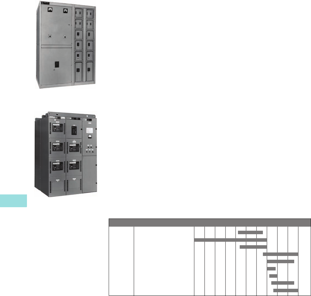
V12-T15-2 Volume 12—Aftermarket, Renewal Parts and Life Extension Solutions CA08100014E—November 2013 www.eaton.com
1
2
3
4
5
6
7
8
9
10
11
12
13
14
15
16
17
18
19
20
21
22
23
24
25
15
Distribution Switchboards (Low Voltage)
Assemblies and Circuit Breakers
Assemblies and
Circuit Breakers
WRI Switchboard, St. Louis Vintage
with Fixed Molded-Case Breakers
Pow-R-I is of similar look)
Pow-R-M-S/F Switchboard with
Fixed SPB Breakers
Product Description
Cutler-Hammer low voltage
distribution switchboards from
Eaton’s electrical business
serve to switch power and
to protect circuits in industrial
and commercial distribution
systems. Distribution switch-
boards can be classified into
two categories—power
distribution and service
distribution. The power
distribution switchboards
typically use insulated-case
SPB or air DS power circuit
breakers as mains and
individually compartment-
alized feeders. The service
distribution switchboards use
insulated-case SPB, air DS,
molded-case (all types), and
fusible switches as mains and
molded-case circuit breakers
as feeders.
Distribution switchboards
can be a free-standing
structure(s) or close coupled
as the secondary section
of a power center or
substation. Power distribution
switchboards primarily use
individually mounted, fixed
or drawout devices. Service
distribution switchboards
primarily use main devices
as individually mounted,
fixed or drawout with group-
mounted molded-case
circuit breakers. Numerous
combinations of devices
can be used depending on
the specification. Class III
(power distribution) and
Class II (service distribution)
switchboards are commonly
used descriptions for
the class of distribution
switchboards. Distribution
switchboards are built in
accordance with all applicable
provisions of UL® 891 and
NEMA® PB-2.
Product History
Distribution switchboards
have been around since the
1950s. Most of the original
switchboards were custom
assembled with very little
standardization of design.
From the mid-1970s through
the 1980s, distribution boards
became somewhat more
standardized and were
manufactured in St. Louis,
MO. These vintages included:
●WRI
●WF/WRP
●Pow-R-Gear
“WRI” used individually
mounted, molded-case
circuit breakers for both
mains and feeders.
“WF/WRP” used group-
mounted, molded-case circuit
breakers or FDP fusible
switches for the feeders.
For the mains, this design
used either DS, SPB, bolted-
pressure switch (CBC-type),
or MCCBs.
“Pow-R-Gear” used SPB
drawout, insulated-case
power circuit breakers for
both mains and feeders.
Some specialty switchboards,
including generator-control,
were manufactured in
Cincinnati, OH, until the
plant was closed in 1985.
During the mid-1980s,
some of the switchboard
manufacturing was moved
to a plant in Visalia, CA, and
another plant in Sumter, SC.
Those designs included
WF/WRP and WRI.
During the late 1980s and
early 1990s the switchboard
products were relocated to
two different locations:
●Asheville, NC
●Sumter, SC
The products that moved to
Asheville included the “Pow-
R-Gear,” which later evolved
into the “Pow-R-M-S” design
(the “Pow-R-M-S/F is the
fixed-mounted version).
Also included in the move
to Asheville was the “WRI”
product, which later evolved
into the “Pow-R-I” design.
The “Pow-R-I” design was
short-lived and in 1991 it
evolved into two different
products—the “Pow-R-M-S/F
mentioned
above and the
“Pow-R-Line
i
” mentioned
in
the next paragraph.
The first product that moved
to Sumter, SC, was the
“WF/WRP,” which evolved
into the “Pow-R-Line C”
design—it uses
Series C®
MCCBs. The second product
evolved from Asheville’s
“Pow-R-I” and is called
the “Pow-R-Line i” design.
Product History Time Line
WF/WRP Switchboard
WRI Switchboard
Pow-R-Gear Switchboard
Pow-R-line C Switchboard
Pow-R-M-S Switchboard
Pow-R-I Switchboard
ES Switchboard
Pow-R-M-S/F Switchboard
Pow-R-Line i Switchboard
Product 1955 1960 1965 1970 1975 1980 1985 1990 1995 2000 PresentPage
V12-T15-5
V12-T15-3
V12-T15-4
V12-T15-5
V12-T15-4
V12-T15-3
V12-T15-5
V12-T15-3
V12-T15-3
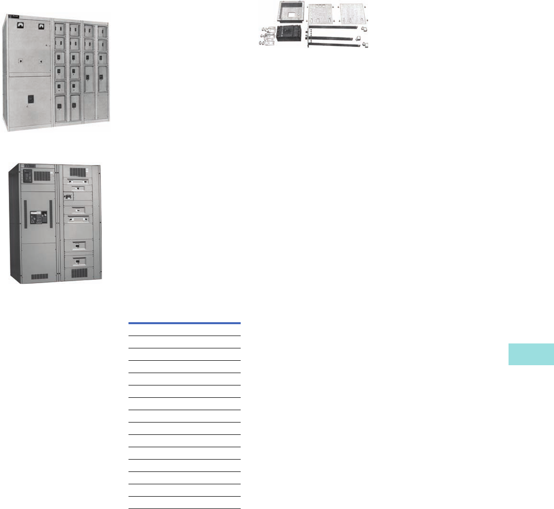
Volume 12—Aftermarket, Renewal Parts and Life Extension Solutions CA08100014E—November 2013 www.eaton.com V12-T15-3
1
2
3
4
5
6
7
8
9
10
11
12
13
14
15
16
17
18
19
20
21
22
23
24
25
15
Distribution Switchboards (Low Voltage)
WRI, Pow-R-I, Pow-R-M-S/F and Pow-R-Line
i
WRI, Pow-R-I, Pow-R-M-
S/F and Pow-R-Line i
WRI Switchboard with Individually
Mounted Molded-Case Breakers
Pow-R-Line i Switchboard
with Individually Mounted
Molded-Case Breakers
Product Description
This class of switchboard is
commonly called a Class III
switchboard. Generally
speaking, this means
individually mounted main
and feeder devices.
The WRI switchboard that
was built by
W,estinghouse
in St. Louis, MO consisted
of
rear- and front-accessible
enclosures with all sections
flush front to rear. The
WRI board was designed
for mounting away from
the wall.
Main devices could be DS,
SPB, SCB-II or molded-case
circuit breakers and (CBC)
bolted pressure or FDP
fusible switches. Individually
mounted feeders could be
either FDP fusible switches
or molded-case circuit
breakers. The WRI design
moved to Asheville, NC, as
the Pow-R-I design with little
change, except fusible was
not offered with Pow-R-I.
Some
different structural and
bussing methods
were used
on the Pow-R-I also.
The Pow-R-I product was
split in 1991. Switchboards
requiring main and individually
mounted feeders using SPB
breakers and the RD Series C
breaker were incorporated
in the Pow-R-M-S/F design
using the same design as
the drawout Pow-R-M-S
switchboard except fixed
devices. The smaller current
individually mounted devices
were incorporated into
the Pow-R-Line i design
introduced in 1991 at
Sumter, SC.
Ratings
Replacement Capabilities
Parts for WRI Switchboard
New Circuit Breakers
New SPB, DS and RD
molded-case circuit breakers
are available for replacement
provisions or to fill existing
cells. All breakers are newly
manufactured.
Circuit Breaker Cell Provisions
These are used to convert
blank cell compartments into
breaker cell compartments.
Provisions are no longer
available for WRI dated
1967 or earlier but might be
available for newer versions.
Cell provisions are no longer
available for Pow-R-I and
Pow-R-M-S/F (fix-mounted).
Provisions are sometimes
available for the Pow-R-Line i
design. In all cases, care
must be taken to properly
identify the original shop
order before proceeding or
making final determination.
Repair Service for SPB Breakers
Factory authorized non-
warranty repair for all SPB
breaker frames.
Class 1 Reconditioning for
DS Breakers
Repairs are available for
DS circuit breakers. This
service includes trip unit
replacements.
Circuit Breaker Parts
An extensive inventory of
newly manufactured breaker
renewal parts are available for
SPB, DS and RD molded-case
circuit breakers.
Technology Upgrades
IQ and PowerNet™
Communications Retrofits
Cutler-Hammer IQ products
replace existing analog
meters, instruments and
protective relays with
microprocessor-based
solid-state true rms sensing
devices. IQ products can
be furnished as components
for field installation on the
switchgear. The IQ products
include the IQ Analyzer, IQ
DP-4000, IQ 200 and IQ 300.
Communications can then be
tied to the Cutler-Hammer
PowerNet system.
Digitrip™ Trip Unit Retrofit Kits
Trip unit retrofit kits are
available for all SPB and DS
breaker frames. Refer to
Ta b 17 , Pages V12-T17-33
to V12-T17-36.
SPD Series Surge
Protective Devices
Refer to Page V12-T15-6 of
this publication.
Device Rating
WRI/Pow-R-I
Switchboard bus 800–4000A
Protective devices 400–4000A
Voltage 120–600V
Interrupting capacity 30–200 kA
Pow-R-M-S/F
Switchboard bus 800–5000A
SPB/RD breaker 400–5000A
Voltage 240–600V
Interrupting capacity 42–100 kA
Pow-R-Line i
Switchboard bus 800–4000A
Protective devices 70–4000A
Voltage 240–600V
Interrupting capacity 30–200 kA
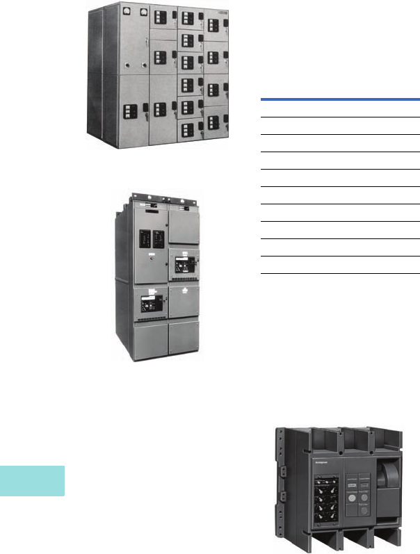
V12-T15-4 Volume 12—Aftermarket, Renewal Parts and Life Extension Solutions CA08100014E—November 2013 www.eaton.com
1
2
3
4
5
6
7
8
9
10
11
12
13
14
15
16
17
18
19
20
21
22
23
24
25
15
Distribution Switchboards (Low Voltage)
Pow-R-Gear, Pow-R-M-S and SPB
Pow-R-Gear, Pow-R-M-S
and SPB
Pow-R-Gear Switchboard, St. Louis
Vintage with Drawout SPB Breakers
Pow-R-M-S Switchboard,
Current Asheville Design with
Drawout SPB Breakers
Product Description
Pow-R-Gear, and now
Pow-R-M-S, switchboards
were/are designed exclusively
for the systems Pow-R
breaker line of encased
power circuit breakers.
These switchboards were/
are designed for high current
applications and include the
following features: drawout
breaker elements, individual
breaker compartmentalization,
in-gear breaker contact
inspection and minimum floor
space design. Both versions
were/are manufactured in
accordance with all applicable
provisions of UL 891 and
NEMA PB-2 covering low
voltage distribution
switchboards.
The primary differences
between the original
Pow-R-Gear and its
successor Pow-R-M-S are:
structural (frame design), trip
units (Pow-R-Gear used the
Pow-R-Trip 7; Pow-R-M-S
uses the Digitrip RMS
sensing trip family), bus
design (Pow-R-Gear used
aluminum of varying heights;
Pow-R-M-S uses bolted
copper of full height) and
vertical spacing (Pow-R-Gear
accommodated six-high 800A
breakers, Pow-R-M-S
accommodates four-high
800A breakers).
Ratings
Chronology
Pow-R-Gear was built
by Westinghouse in
St. Louis, MO, from 1977 to
1990. Pow-R-M-S was built
by Westinghouse, and later
Cutler-Hammer in Asheville,
NC, from 1990 to 2003.
Replacement Capabilities
Systems Pow-R Breaker Type SPB-65
with Pow-R-Trip 7 Trip Unit
Factory Repair Service for
SPB Breakers
These repair services apply to
breakers that have exceeded
the original factory warranty
and are now referred to as
non-warranty repairs. The
Systems Pow-R Breaker
family consists of fixed
breakers, either front
connected or rear connected,
and drawout breakers,
either behind-the-door or
through-the-door design.
Four-pole breakers are only
available in the fixed design
front or rear connected.
The Cutler-Hammer SPB
factory authorized non-
warranty repair service
features:
●Quality SPB repair specified
and audited by factory
engineers according to
procedures
●Only genuine new Cutler-
Hammer replacement
parts are used
●Original factory
specifications and design
drawings are used by
factory trained technicians
New SPB Circuit Breakers
New SPB breakers are
available for replacement
or to fill existing vacant
cells. All breakers are newly
manufactured and are
mechanically and electrically
the same as the breakers
originally specified and
supplied.
SPB Breaker Cell Provisions
These are used to convert
blank cell compartments into
breaker cell compartments.
Provisions are usually
available for Pow-R-M-S
drawout designs. However,
provisions are not available
for Pow-R-M-S/F fixed
designs or for the Pow-R-
Gear design. In all cases, care
must be taken to properly
identify the original shop
order before proceeding or
making final determination.
SPB Circuit Breaker Parts
An extensive inventory of
newly manufactured breaker
renewal parts is available for
SPB circuit breakers.
Technology Upgrades
Pow-R-Trip 7 Trip Unit Upgrades
Pow-R-Trip 7 was the
solid-state trip unit used on
Pow-R-Gear switchboards. An
upgrade from the Pow-R-Trip
7 trip unit is also available.
Modification to the breaker
and existing switchboard is
required. Refer to Ta b 17 ,
Pages V12-T17-35
to V12-T17-36.
Digitrip Trip Unit Retrofit Kits
Trip unit retrofit kits are
available for all SPB breaker
frames. Refer to Ta b 1 7 ,
Pages V12-T17-35
to V12-T17-36.
IQ and PowerNet
Communications Retrofits
Cutler-Hammer IQ products
replace existing analog
meters, instruments, and
protective relays with
microprocessor-based
solid-state true rms sensing
devices. IQ products can be
furnished as components for
field installation on the
switchgear. The IQ products
include the IQ Analyzer, IQ
DP-4000, IQ 200 and IQ 300.
Communications can then be
tied to the Cutler-Hammer
PowerNet system.
SPD Series Surge
Protective Devices
Refer to Page V12-T15-6 of
this publication.
Device Rating
Pow-R-Gear
Switchboard bus 800–4000A
Protective devices 100–5000A
Voltage 120–600V
Interrupting capacity 100 kA
Pow-R-M-S
Switchboard bus 800–5000A
SPB breaker 400–5000A
Voltage 240–600V
Interrupting capacity 42–100 kA
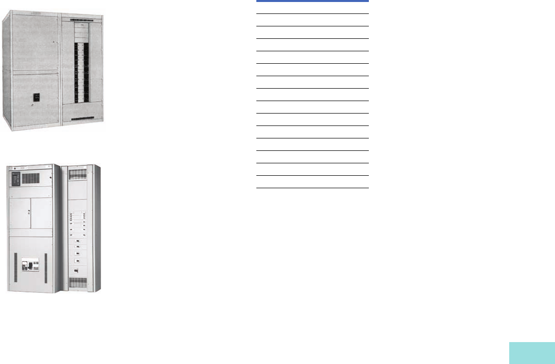
Volume 12—Aftermarket, Renewal Parts and Life Extension Solutions CA08100014E—November 2013 www.eaton.com V12-T15-5
1
2
3
4
5
6
7
8
9
10
11
12
13
14
15
16
17
18
19
20
21
22
23
24
25
15
Distribution Switchboards (Low Voltage)
WF/WRP, ES and Pow-R-Line C
WF/WRP, ES and
Pow-R-Line C
WRP Switchboard, Rear Access with
Panel-Mounted Molded-Case Breakers
Pow-R-Line C Switchboard,
Front Access with Panel-Mounted
Molded-Case Breakers
Product Description
This class of switchboard is
commonly called a Class II
switchboard. Generally
speaking, this means
individually or panel-mounted
main and panel-mounted
feeder devices.
The WF/WRP switchboard that
was built by Westinghouse in
St. Louis, MO, consisted of
front- or rear-accessible
enclosures with various depths
depending on the devices
within the structure. In the
front access design, Type WF,
the rear of the switchboard
was flush for all structures; the
rear access design, Type WRP,
was flush in the front and rear.
The WF/WRP switchboard
design accommodated the
use of DS, SPB, bolted
pressure switch (CBC),
molded-case circuit breaker
or FDP fusible switches as
main devices. Panel-mounted
feeder devices could be
either molded-case circuit
breakers or FDP fusible
switches. The WF/WRP
design was moved to
Sumter, SC, and Visalia, CA,
and consequently enhanced
with the introduction of
the Series C breaker
and some structural and
busing changes.
In 1962, Eaton entered the
switchboard
market with the
purchase of Mullenbach.
Soon after the Mullenbach
acquisition, Eaton entered
into an agreement with
Westinghouse to supply
breakers and fusible devices
for panelboards and
switchboards. This led to
the introduction of the ES
switchboard using exclusively
Westinghouse molded-case
circuit breakers.
In the late 1980s,
Westinghouse introduced
a new and improved version
of the WF/WRP switchboard
using the Series C breaker.
This new switchboard line,
Pow-R-Line C, designates a
family of service distribution
switchboards incorporating
new design concepts that
fit the ever increasing need
for applications on high
short-circuit systems,
while retaining maximum
standardization, safety and
convenience throughout
the line.
Ratings
Chronology
WF/WRP was introduced by
Westinghouse in St. Louis,
MO, in 1955. In 1988, the
design was transferred
to Sumter, SC, and
Visalia, CA, as Pow-R-Line C
switchboards. Consequently,
the Cutler-Hammer Type ES
switchboard version was
later introduced in 1991 as a
replacement for their version
of the WF/WRP switchboard.
Replacement Capabilities
Eaton offers an extensive
amount of products to
support WF/WRP, ES and
Pow-R-Line C switchboards.
Pow-R-Line C Match and
Lineup Cubicles
Newly manufactured
Pow-R-Line C switchboard
structures to match and
line up to existing WF/WRP
switchboards.
New Pow-R-
Line C structures can also
connect to existing
switchboards (Type ES)
with a transition section.
New Circuit Breakers
New SPB, DS and RD
molded-case circuit breakers
are available for replacement
or to fill existing vacant
cells. All breakers are
newly manufactured
and are mechanically and
electrically the same as
the breakers originally
specified and supplied.
Circuit Breaker
Provisions/Connector
Breaker provisions are
required in switchboards
when there is an existing
space in a structure that is
to be filled with a breaker.
Provisions/connectors are
available for most ratings
of the WF/WRP design.
Provisions are available for all
ratings of the Pow-R-Line C
designs including all parts
required to complete the
cell in accordance with the
switchboard as originally
supplied.
Factory Repair Service for
SPB Breakers
Factory authorized non-
warranty repair for all SPB
breaker frames. Refer to
Page V12-T15-4 of this
publication.
Circuit Breaker Parts
An extensive inventory of
newly manufactured breaker
renewal parts are available for
SPB, DS and RD molded-case
circuit breakers.
Switchboard Structure Parts
Switchboard parts are
available for most designs.
Newly manufactured
replacement parts (such as
doors, breaker provisions,
lift trucks, metering, etc.)
are available.
Device Rating
WF/WRP
Switchboard bus 600–4000A
Protective devices 15–4000A
Voltage 120–600V
Interrupting capacity 10–200 kA
ES
ES switchboard bus 600–4000A
Protective devices 15–4000A
Voltage 120–600V
Interrupting capacity 10–200 kA
Pow-R-Line C
Switchboard bus 600–6000A
Protective devices 15–6000A
Voltage 208–600V
Interrupting capacity 10–200 kA
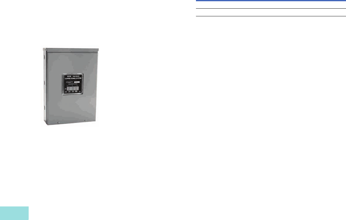
V12-T15-6 Volume 12—Aftermarket, Renewal Parts and Life Extension Solutions CA08100014E—November 2013 www.eaton.com
1
2
3
4
5
6
7
8
9
10
11
12
13
14
15
16
17
18
19
20
21
22
23
24
25
15
Distribution Switchboards (Low Voltage)
Clipper Power System—Visor Series, IQ and PowerNet Retrofits
Technology Upgrades
Digitrip Trip Unit Retrofit Kits
Trip unit retrofit kits are
available for all SPB and
DS breaker frames. Refer to
Ta b 17 , Pages V12-T17-33
to V12-T17-36.
SPD Series Surge
Protective Devices
Surge Protective Device
Product Description
Eaton SPD series of surge
protective devices ensures
that equipment is protected
with the safest, most reliable
and most advanced UL 1449
3rd Edition certified protectors.
The array of features, options
and configurations ensures
that there is a unit for all
electrical applications.
The SPD family protects
equipment from the
damaging effects of surges
and electrical line noise. Field
installation is required.
Benefits
●SPD Series can be
externally mounted to
existing distribution
equipment
●Surge ratings: 50, 80, 100,
120, 160, 200, 250, 300
and 400 kA
●Standard NEMA 1
enclosure, optional
NEMA 4 and NEMA 4X
enclosures.
●Surface or flush mounting
●Full range of diagnostic and
monitoring options
●Remote mountable
display panel
For more information about
the Eaton family of surge
products, contact your local
Eaton Field Sales office.
IQ and PowerNet
Communications Retrofits
Cutler-Hammer IQ products
replace existing analog
meters, instruments and
protective relays with
micropro
cessor-based
solid-state true rms sensing
devices. IQ products can
be furnished as components
for field installation on the
switchboard or can be
provided as new replacement
front panels. The new
replacement front panels
available for switchboard
assemblies include the IQ
devices mounted and wired.
The IQ products can be
matched in numerous
combinations to include the IQ
Analyzer, IQ DP-4000, IQ 200
and IQ 300. Communications
can then be tied to the Cutler-
Hammer PowerNet System.
Further Information
Pricing Information
Price List for Pow-R-M-S switchboard—PL 32-624A
Price List for SPB breakers—PL.22A.01.P.E
Publication
Number Description
CA08100003E Volume 2—Commercial Distribution, Switchboards, Tab 4
RP01301013E Systems Pow-R Breakers Renewal Parts and Accessories
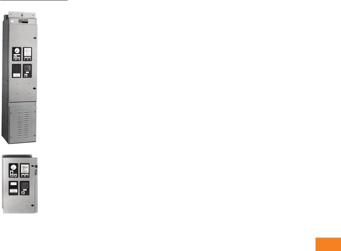
Volume 12—Aftermarket, Renewal Parts and Life Extension Solutions CA08100014E—November 2013 www.eaton.com V12-T16-1
1
2
3
4
5
6
7
8
9
10
11
12
13
14
15
16
17
18
19
20
21
22
23
24
25
High Resistance Grounding System
Type C-HRG Products
16 High Resistance Grounding System
Type C-HRG (Low Voltage) . . . . . . . . . . . . . . . . . . . . . . . . . . . . . . . . . V12-T16-2
Product Description . . . . . . . . . . . . . . . . . . . . . . . . . . . . . . . . . . . . V12-T16-2
Product History. . . . . . . . . . . . . . . . . . . . . . . . . . . . . . . . . . . . . . . . V12-T16-2
Product History Time Line . . . . . . . . . . . . . . . . . . . . . . . . . . . . . . . V12-T16-2
General Information . . . . . . . . . . . . . . . . . . . . . . . . . . . . . . . . . . . . V12-T16-2
Sequence of Operations. . . . . . . . . . . . . . . . . . . . . . . . . . . . . . . . . V12-T16-3
Catalog Numbering System . . . . . . . . . . . . . . . . . . . . . . . . . . . . . . V12-T16-4
Further Information. . . . . . . . . . . . . . . . . . . . . . . . . . . . . . . . . . . . . V12-T16-4
Type C-HRG (Medium Voltage) . . . . . . . . . . . . . . . . . . . . . . . . . . . . . . V12-T16-5
Product Description . . . . . . . . . . . . . . . . . . . . . . . . . . . . . . . . . . . . V12-T16-5
Product History. . . . . . . . . . . . . . . . . . . . . . . . . . . . . . . . . . . . . . . . V12-T16-5
Product History Time Line . . . . . . . . . . . . . . . . . . . . . . . . . . . . . . . V12-T16-5
General Information . . . . . . . . . . . . . . . . . . . . . . . . . . . . . . . . . . . . V12-T16-5
Sequence of Operations. . . . . . . . . . . . . . . . . . . . . . . . . . . . . . . . . V12-T16-6
Catalog Numbering System . . . . . . . . . . . . . . . . . . . . . . . . . . . . . . V12-T16-7
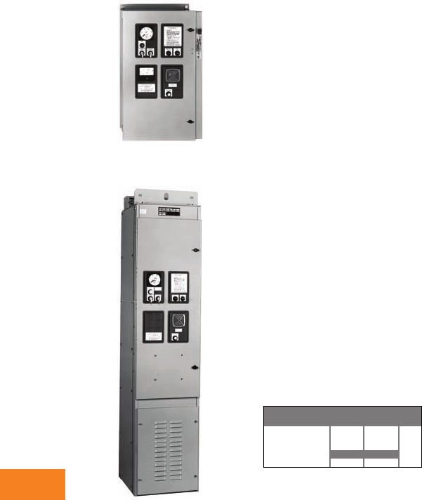
V12-T16-2 Volume 12—Aftermarket, Renewal Parts and Life Extension Solutions CA08100014E—November 2013 www.eaton.com
1
2
3
4
5
6
7
8
9
10
11
12
13
14
15
16
17
18
19
20
21
22
23
24
25
16
High Resistance Grounding System
Type C-HRG
(Low Voltage)
Originally a
Westinghouse Product
Wall-Mounted C-HRG
(resistors not shown)
Free-Standing C-HRG
Product Description
Cutler-Hammer® Type C-HRG
from Eaton’s electrical
business is designed to
improve the continuity of
electrical service to critical
processes. Systems designers
sometimes use ungrounded
distribution systems to avoid
interrupting service during
a ground fault. However,
ungrounded systems have
a significant disadvantage—
the distribution system is
subject to the harmful
effects of ground faults, like
high transient overvoltages.
The Type C-HRG helps
customers add the benefits
of a grounded system to their
ungrounded system.
Product History
High resistance grounding
technology has been offered
as an integral system within
Eaton low voltage switchgear
and switchboard products
since the early 1970s. In 1994,
Eaton adopted the technology
into the C-HRG, which is a
standalone or wall-mounted
product ideal for adapting to
the existing electrical system.
Product History Time Line
C-HRG
Low Voltage
Product 1994 2000 Present
General Information
Overview
Where continuity of service is
a high priority, high resistance
grounding can add the safety
of a grounded system while
minimizing the risk of service
interruptions due to grounds.
The concept is a simple one:
provide a path for ground
current via a resistance that
limits the current magnitude,
and monitor
to determine
when an abnormal
condition exists.
The ground current path is
provided at the point where
the service begins by placing
resistance in the connection
from system neutral-to-
ground. Control equipment
continuously measures
ground current; a relay
detects when the current
exceeds a predetermined
level. An alarm alerts building
personnel that a ground
exists. The system has
built-in fault tracing means
to assist in finding the
source of the ground. An
integral transformer provides
control power from the
primary source.
Minimum Criteria for Use
High resistance grounding
systems can be applied
to either grounded or
ungrounded three-wire
distribution systems.
Per NEC® 1996, 250.5(b)
exception No. 5, the following
criteria must be met before
using the C-HRG:
●The conditions of
maintenance and
supervision ensure that
only qualified persons will
service the installation
●Continuity of power
is required
●Ground detectors are
installed on the system
●Line-to-neutral loads are
not served
Wye or Delta System
Adding the Type C-HRG
to a wye connected system
requires only that the resistors
supplied be connected in
series with the neutral-to-
ground connection of the
power source. Adding
the Type C-HRG to an
ungrounded delta system
requires the creation of a
neutral point. Transformers
are supplied for that purpose
in the enclosure. The resistors
supplied are then connected
at that point. In both cases,
the components supplied are
chosen to limit the ground
current to a maximum value
of 5A.
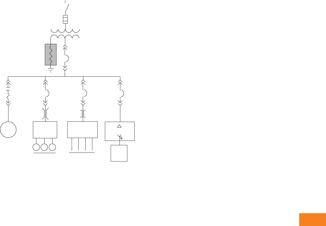
Volume 12—Aftermarket, Renewal Parts and Life Extension Solutions CA08100014E—November 2013 www.eaton.com V12-T16-3
1
2
3
4
5
6
7
8
9
10
11
12
13
14
15
16
17
18
19
20
21
22
23
24
25
16
High Resistance Grounding System
Typical C-HRG Application
Ground Fault Detection
When one phase of a system
becomes grounded, additional
current will flow. As all ground
current must flow through the
grounding resistor assembly,
a current sensing relay is
placed in this circuit, allowing
detection when a ground
fault occurs.If chosen, a
voltage-sensing relay can
be provided to accomplish
the same function.
Pulser Circuit
The pulser circuit offers a
convenient means to locate
the faulted feeder and to trace
the fault to its origin. The
pulser is available any time a
fault has been detected. The
“pulse” light flashes on and
off, corresponding to the
ON-OFF cycles of the
pulsing contactor. The pulser
contactor switches a bank of
resistors on and off, allowing
a momentary increase in the
ground current.
Ground Fault Location
The current pulses can
be noted with a clamp-on
ammeter when the ammeter
is placed around the cables or
the conduit feeding the fault.
The operation tests each
conduit or set of cables until
the pulsing current is noted.
By moving the ammeter
along the conduit, the fault
can be traced to its origin.
The fault may be located at
the point where the pulsing
current drops off or stops.
If little or no change in the
pulsing current is noted along
the entire length of a conduit,
then the fault may be in the
connected load.
DS-VSR
Motor
Starter
200 hp
Motor Loads
MMM
MCC
Bus Duct
Feeder
Breaker
Feeder
Breaker
Feeder
Breaker
ConduitConduit Cable Tray
Distribution
Switchboard Transformer
4W
Panel-
board
Misc. 3W
Loads
Main Breaker
600V (Max.)
HV
C-HRG—
High Resistance
Grounding
System
Source
System
Transformer
a
Sequence of Operations
Normal
●Green “normal” light on
●Red “ground fault” light off
●White “pulse” light off
●System control switch in
“normal” position
●Reset control switch in
either “auto” or “manual”
Test
●Turn and hold the system
control switch in the
“test” position. Phase B
will be grounded via the
test resistor
●The ground current will
activate the sensing
circuit, causing the green
“normal” light to turn off
and the red “ground fault”
light to turn on. The pulser
will be activated as well
●The white “pulse” light
will turn on and off as the
pulser contactor closes
and opens
●The ground current
ammeter will display
the total ground current,
including the incremental
pulse current
●When ready, return the
system control switch to
“normal.” The pulser will
stop. If the reset control is
in the “manual” position,
turn it to “reset” to reset
the fault sensing circuit
●The red “ground fault”
light will turn off, and the
green “normal” light will
turn on
●
Test mode is not available if
the system
is detecting a
ground. The sensing circuit
will disable the test circuit.
Ground Fault
●When the sensing circuit
detects a fault, the green
“normal” light will turn off
and the red “ground fault”
light will turn on
●The ground current
ammeter will indicate the
total ground current
●To use the pulser, turn the
system control switch to
“pulse.” The pulser
contactor will cycle on and
off as controlled by the
recycle timer relay
●Use the clamp-on ammeter
to locate the faulted feeder.
Open the feeder and clear
the fault
●If the reset control switch
is in the “manual” position,
turn it to “reset” to reset
the sensing circuit
Note: If reset control is in “auto,”
it will reset itself.
●When ready to restore
service to the load, close
the feeder
●
Return the system control
to “normal”
Note
1Phase-to-neutral loads cannot be fed
from the same system transformer to
which the C-HRG is connected. These
loads must be fed from a downstream,
delta-wye transformer with a solidly
grounded neutral on the secondary.
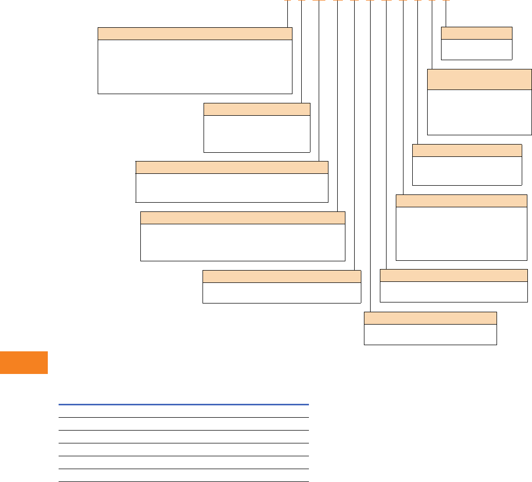
V12-T16-4 Volume 12—Aftermarket, Renewal Parts and Life Extension Solutions CA08100014E—November 2013 www.eaton.com
1
2
3
4
5
6
7
8
9
10
11
12
13
14
15
16
17
18
19
20
21
22
23
24
25
16
High Resistance Grounding System
Catalog Numbering System
Decoding the Catalog Numbering System
Further Information
Enclosure Type
F= Free-standing, Type 1
S= Free-standing, Type 1 with screened vents
R= Free-standing, Type 3R
W= Wall-mounted, Type 1
N= No enclosure (panel-mounted)
V= Wall-mounted, Type 1 with 3R resistor enclosure
F 4 W N C R N S F 4 6
System Neutral Point
W= Wye (and accessible at system)
Z= Delta (zig-zag grounding transformers)
D= Delta (wye-broken delta grounding transformers)
Distribution System Voltage
6 = 600V
4 = 480V
3 = 380V
2 = 208–240V
Distribution System Fault Current
6= 25 kA at 600V, 65 kA at 480 and 380V, 100 kA at 240V
1= 150 kA at 480 and 380V, 200 kA at 240V
2= 200 kA at 600V, 480V or 380/280V
N= Not applicable (when using “W” above)
Ground Fault Sensing
C= Current-sensing relay, with noise filter
D= Voltage sensing relay, double set point
System Frequency
5 = 50 Hz
6 = 60 Hz
Wire Harness Length for “N”
(No Enclosure)
4 = 4-foot harness
6 = 6-foot harness
8 = 8-foot harness
0 = 10-foot harness
2 = 12-foot harness
Wire Marker
M = Machine printed
F = Sleeve type
H = Heat shrink, sleeve type
Indicating Lights
S= Standard incandescent
L= Standard LED
P= Push-to-test incandescent
D= Push-to-test LED
T= Transformer-type incandescent
X= Push-to-test transformer-type
Loss of Control Power Relay (Alarm)
N= No relay
L= Alarm relay with 1NO/1NC contact
Audible Alarm
N= No audible alarm
R= Alarm horn with re-alarm timer
Publication
Number Description
SN.44C.01.S.E Sales Notes for C-HRG
— Bidman pricing
TD.44C.01.T.E Technical Data for C-HRG
SA-32-602B Sales Aid for high resistance grounding systems
IB 32-698C Instruction Booklet for high resistance grounding system
CA08104001E Eaton’s Consulting Application Guide
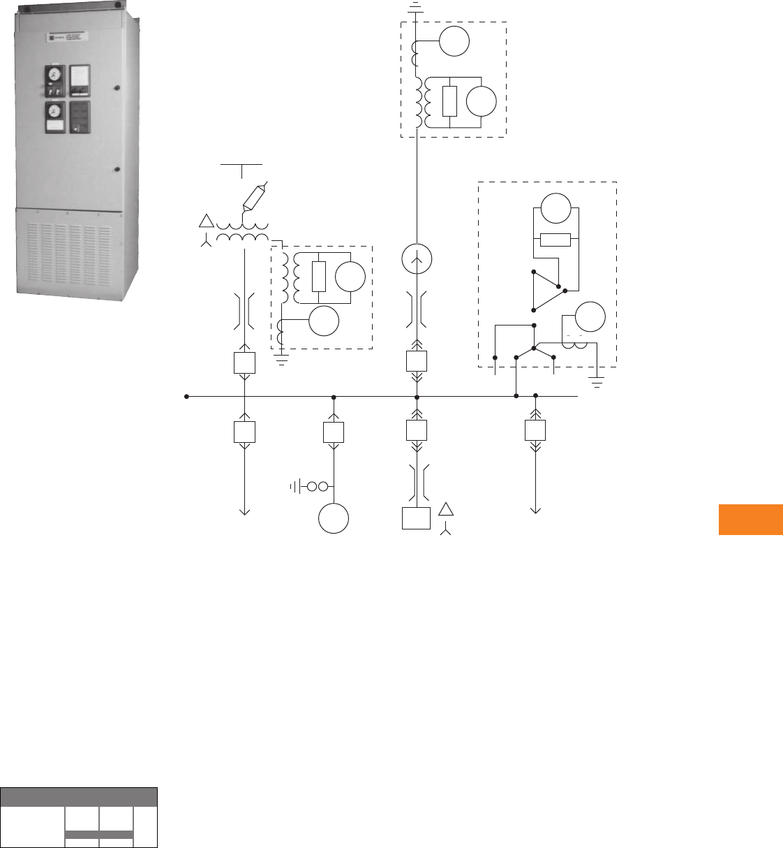
Volume 12—Aftermarket, Renewal Parts and Life Extension Solutions CA08100014E—November 2013 www.eaton.com V12-T16-5
1
2
3
4
5
6
7
8
9
10
11
12
13
14
15
16
17
18
19
20
21
22
23
24
25
16
High Resistance Grounding System
Type C-HRG
(Medium Voltage)
Free-Standing C-HRG
Product Description
The Type C-HRG is designed
to improve the continuity
of electrical service to
critical processes. Systems
designers sometimes use
ungrounded distribution
systems to avoid interrupting
service during a ground
fault. However, ungrounded
systems have a significant
disadvantage—the
distribution system is subject
to the harmful effects of
ground faults, like high
transient overvoltages.
The Type C-HRG helps
customers add the benefits
of a grounded system to their
ungrounded system.
Product History
High resistance grounding
technology has been offered
as an integral system within
medium voltage switchgear
for many years. In 1996, Eaton
adopted the technology into
the C-HRG, which is a stand-
alone product
ideal for
adapting to the existing
electrical system.
Product History Time Line
C-HRG
Low Voltage
Product 1995 2000 Present
General Information
High Resistance Grounding System
Overview
Where continuity of service
is a high priority, high
resistance grounding can
add the safety of a grounded
system while minimizing the
risk of service interruptions
due to grounds. The concept
is a simple one: provide a
path for ground current via a
grounding transformer (with
adjustable resistance across
its secondary) that limits the
current magnitude and a
monitor to determine when
an abnormal condition exists.
The ground current path is
provided at the point where
the service begins, by placing
a predominantly resistive
impedance in the connection
from system neutral to
ground. Control equipment
continuously measures
ground current; a relay
detects when the current
exceeds a predetermined
level. An alarm alerts building
personnel that a ground
exists. The system has built-
in fault tracing means to
assist in finding the source of
the ground. A 120 Vac supply
(remote) is required for
control power for the system.
Minimum Criteria for Use
The C-HRG MV is offered
at the 5 kV class rating. It
can be applied to delta or
wye ungrounded three-wire
distribution systems.
Standard dimensions are
36.00 W x 40.00 D x
92.00 H inches (914.4 W x
1016.0 D x 2336.8 H mm).
Wye HRG
51N
59
Delta HRG
59
51
GEN
Bus
Duct
Bus
Duct
To Power
Circuit
Conduit
5 kV Switchgear
To MCC
Cable
Bus
Duct
Wye HRG
51N
59
Utility
C-HRG—High Resistance
Grounding System

V12-T16-6 Volume 12—Aftermarket, Renewal Parts and Life Extension Solutions CA08100014E—November 2013 www.eaton.com
1
2
3
4
5
6
7
8
9
10
11
12
13
14
15
16
17
18
19
20
21
22
23
24
25
16
High Resistance Grounding System
Wye or Delta System
To add high resistance
grounding to a wye-connected
system, resistors are placed
across the secondary of a
grounding transformer whose
primary is placed in series
with the neutral-to-ground
connection of the power
source. To add high resistance
grounding to an ungrounded
delta-connected system,
a neutral point must be
created. Three single-
phase transformers can be
interconnected in a wye-
broken delta configuration to
provide such a neutral point.
Ground Fault Detection
When one phase becomes
grounded, additional current
above the charging level will
flow. As all ground current
must flow through the
grounding resistor/grounding
transformer assembly, an
ammeter in this circuit will
read the total amount of
ground current. By placing
a current-sensing relay in
series with the ammeter, the
current relay can be adjusted
to pick up at a level in excess
of the capacitive charging
current, thus indicating the
abnormal condition.
Alternatively, an optional
voltmeter relay can be
connected across the
grounding resistors, to
accomplish the same
function.
Pulser Circuit
The pulser circuit offers a
convenient means to locate
the faulted feeder and to trace
the fault to its origin. The
pulser is available any time a
fault has been detected. The
pulse intervals are controlled
by an adjustable recycle timer.
The “pulse” light flashes on
and off, corresponding to
the ON-OFF cycles of the
pulser contactor. The pulser
contactor switches a bank
of resistors on and off,
thus allowing a momentary
increase in the ground current.
Ground Fault Location
The current pulses can
be noted with a clamp-on
ammeter when the ammeter
is placed around the cables or
the conduit feeding the fault.
The operator tests each
conduit or set of cables until
the pulsing current is noted.
By moving the ammeter
along the conduit, or checking
the conduit periodically along
its length, the fault can be
traced to its origin. The fault
may be located at the point
where the pulsing current
drops off or stops. If little or
no change in the pulsing
current is noted along the
entire length of a conduit,
then the fault may be in the
connected load.
Standard Features
●Current sensing
ground fault detection
(2–10A pickup/0.5–20
second delay)
●Ground current
transformer
(10/10 ratio)
●Control circuit pull
fuseblock
●Ground current ammeter
(0–10A, 1% accuracy)
●Indicating lights Red
(ground fault), Green
(normal), White (pulse)
●Adjustable pulsing timer
(0–10 seconds)
●Tapped resistors (limits
primary current to 3–6A)
●Three-position selector
switch (normal, pulse, test)
●Control switch for manual
or automatic reset
●Ground fault contacts
(1NO/1NC)
●Shorting terminal block for
ground current CT
●UL® label
●Wiremarkers
Sequence of Operations
Normal
●Green “normal” light on
●Red “ground fault” light off
●White “pulse” light off
●System control switch in
“normal” position
●Reset control switch in
either “auto” or “manual”
Test
●Turn and hold the system
control switch in the “test”
position
●This mode will test the
control circuitry only. It will
bypass the sensing circuit
and cause the green
“normal” light to turn off
and the red “ground fault”
light to turn on. The pulser
will be activated as well
●The white “pulse” light will
turn on and off as the pulser
contactor closes and
opens. However, the
ground current ammeter
will not display the total
ground current, including
the incremental pulse
current
●When ready, return the
system control switch to
“normal.” The pulser will
stop. If the reset control is
in the “manual” position,
turn it to “reset” to reset
the fault sensing circuit
●The red “ground fault”
light will turn off, and the
green “normal” light will
turn on
●Test mode is not available if
the system is detecting a
ground. The sensing circuit
will disable the test circuit
Ground Fault
●When the sensing circuit
detects a fault, the green
“normal” light will turn off
and the red “ground fault”
light will turn on
●The ground current
ammeter will indicate the
total ground current
●To use the pulser, turn the
system control switch to
“pulse.” The pulser
contactor will cycle on and
off as controlled by the
recycle timer relay
●Use the clamp-on ammeter
to locate the faulted feeder.
Open the feeder and clear
the fault
●If the reset control switch
is in the “manual” position,
turn it to “reset” to reset
the sensing circuit
Note: If reset control is in “auto,”
it will reset itself.
●When ready to restore
service to the load, close
the feeder
●
Return the system control
to “normal”
Volume 12—Aftermarket, Renewal Parts and Life Extension Solutions CA08100014E—November 2013 www.eaton.com V12-T16-7
1
2
3
4
5
6
7
8
9
10
11
12
13
14
15
16
17
18
19
20
21
22
23
24
25
16
High Resistance Grounding System
Catalog Numbering System
Customer Required Information
A C-HRG High Resistance Grounding Assembly can be completely described by an 8-digit
catalog number: MVRG-_ _ _ _ _ _ _ _
Example: MVRG-FWWCLLTS defines a free-standing Type 1 enclosure, 4200 V/60 Hz, Wye-connected system, current-
sensing control scheme, alarm horn with re-alarm timer, alarm relay with 1NO and 1NC, transformer type incandescent lights,
wrap-on wiremarkers.
Enclosure Type
F = Free-standing NEMA® 1
R = Free-standing NEMA 3R non-walk in outdoor
Free-standing enclosure for mounting ground transformers
and resistors internally
System Neutral Point
W= Wye
D= D (Wye broken delta grounding transformers)
Choose wye when the neutral point of the power source is
accessible for direct connection to grounding transformer. Choose
Delta when there is no neutral or when neutral is not accessible.
Distribution System Voltage
W= 4200V 60 Hz
X= 2400V 60 Hz
Y= 3300V 60 Hz
Voltage of distribution system
Fault Sensing
C = Overcurrent relay (current sensing)
V = Single set point voltmeter relay (voltage sensing)
D = Indicating voltmeter only (voltage sensing)
Wire Markers
S= Standard wrap-on
T= Tube/heat shrink type
Marks all internal wiring for ease of
maintenance.
Indicating Lamps
L= LED lamps
T= Transformer-type incandescent lamps
X= Push-to-test transformer-type
Standard lights are industrial, oil-tight,
transformer type. Optional are the same type lights except
with a push-to-test feature.
Loss of Control Power Alarm
N= No relay
L= Alarm relay with 1NO/1NC
A relay is connected across the
customer’s 120 Vac supply.
Audible Alarm
N= No audible alarm
L= Alarm horn with re-alarm timer
Alarm contacts are standard on all assemblies.
F W W C L L T S
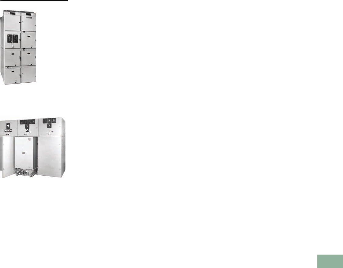
Volume 12—Aftermarket, Renewal Parts and Life Extension Solutions CA08100014E—November 2013 www.eaton.com V12-T17-1
1
2
3
4
5
6
7
8
9
10
11
12
13
14
15
16
17
18
19
20
21
22
23
24
25
Switchgear
DS Low Voltage Switchgear
DHP Medium Voltage Switchgear
17 Switchgear
Low Voltage Switchgear
Product Description, Product History, Product History Time Line . V12-T17-2
DB Assemblies and Power Circuit Breakers
Product Description, Replacement Capabilities . . . . . . . . . . . . . V12-T17-3
DS Assemblies and Power Circuit Breakers
Product Description, Replacement Capabilities . . . . . . . . . . . . . V12-T17-5
Technology Upgrades . . . . . . . . . . . . . . . . . . . . . . . . . . . . . . . . . . V12-T17-5
DSII Assemblies and Power Circuit Breakers
Product Description . . . . . . . . . . . . . . . . . . . . . . . . . . . . . . . . . . . V12-T17-6
Replacement Capabilities . . . . . . . . . . . . . . . . . . . . . . . . . . . . . . . V12-T17-7
Magnum DS Assemblies and Power Circuit Breakers
Product Description, Replacement Capabilities . . . . . . . . . . . . . V12-T17-8
Systems Pow-R Breaker (SPB)
Product Description . . . . . . . . . . . . . . . . . . . . . . . . . . . . . . . . . . . . V12-T17-14
Product History. . . . . . . . . . . . . . . . . . . . . . . . . . . . . . . . . . . . . . . . V12-T17-14
Product History Time Line . . . . . . . . . . . . . . . . . . . . . . . . . . . . . . . V12-T17-15
Replacement Capabilities, Technology Upgrades . . . . . . . . . . . . . . V12-T17-15
Product Support Services—Breaker Service Center . . . . . . . . . . . V12-T17-16
Further Information, Pricing Information. . . . . . . . . . . . . . . . . . . . . V12-T17-16
Trip Unit Retrofit Kits
Product Description, Product History . . . . . . . . . . . . . . . . . . . . . . . V12-T17-17
Medium Voltage Switchgear
Product Description, Product History,
Product History Time Line . . . . . . . . . . . . . . . . . . . . . . . . . . . . . . V12-T17-53
DH—Product Description, Replacement Capabilities . . . . . . . . . . . V12-T17-55
DHP—Product Description, Replacement Capabilities. . . . . . . . . . V12-T17-56
VCP—Product Description, Replacement Capabilities . . . . . . . . . . V12-T17-57
VCP-W—Product Description, Replacement Capabilities . . . . . . . . V12-T17-58
Technology Upgrades . . . . . . . . . . . . . . . . . . . . . . . . . . . . . . . . . . . V12-T17-59
Competitive Upgrades . . . . . . . . . . . . . . . . . . . . . . . . . . . . . . . . . . V12-T17-60
SURE CLOSE . . . . . . . . . . . . . . . . . . . . . . . . . . . . . . . . . . . . . . . . . V12-T17-62
Further Information, Pricing Information. . . . . . . . . . . . . . . . . . . . . V12-T17-64
Medium Voltage Load Interrupter
Product Description, Product History, Product History Time Line . V12-T17-65
LBF . . . . . . . . . . . . . . . . . . . . . . . . . . . . . . . . . . . . . . . . . . . . . . . . . V12-T17-66
Replacement Capabilities—WLI/MVS/MVS2 . . . . . . . . . . . . . . . . . V12-T17-67
Further Information, Pricing Information. . . . . . . . . . . . . . . . . . . . . V12-T17-70
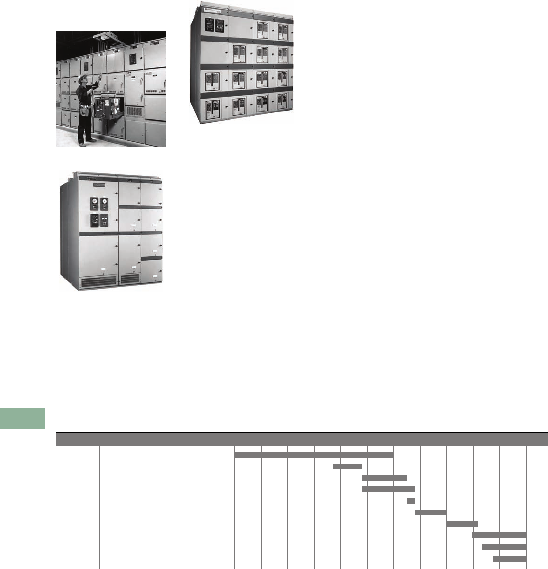
V12-T17-2 Volume 12—Aftermarket, Renewal Parts and Life Extension Solutions CA08100014E—November 2013 www.eaton.com
1
2
3
4
5
6
7
8
9
10
11
12
13
14
15
16
17
18
19
20
21
22
23
24
25
17
Switchgear
Low Voltage—Assemblies and Power Circuit Breakers
Assemblies and
Power Circuit Breakers
DS Switchgear
DSII Switchgear Assembly
Magnum DS Switchgear
Product Description
Cutler-Hammer® low voltage
switchgear assemblies from
Eaton’s electrical business are
metal enclosures that typically
contain power circuit breakers,
control/measuring devices
such as relays and meters,
and
the power bus work. The
rated maximum
voltage is
600V, for AC power systems.
Low voltage switchgear is
used to protect,
control and
monitor the electrical power
system. Present design low
voltage switchgear conforms
to the following standards:
ANSI C37.20.1, C37.51, UL®
1558, NEMA® SG3, NEMA
SG5 and CSA®.
Perhaps the most unique
benefit of switchgear is the
power circuit breakers within
—they have a “withstand
rating” and more flexible trip
units, all which provide better
coordination of downstream
circuit breakers. It is
also common to find
this switchgear coupled
to a power distribution
transformer, making the
entire assembly called a
secondary unit substation.
Product History
It is very uncommon to find
any more installed-base of
the Westinghouse® DA or
DK vintage switchgear—
both vintages preceded the
Westinghouse DB switchgear
design dated 1950.
It is very common to find
DB switchgear with hundreds
of thousands of DB circuit
breakers still in operation.
In 1967, Westinghouse
introduced DS switchgear
along with the DS and
DSL circuit breakers. The
first DS breakers used the
original solid-state trip unit
called the Amptector
®
. The
Amptector was
later replaced
by the microprocessor-based,
true rms sensing, Digitrip™
trip unit models 500, 600,
700 and 800.
In 1994, the DS breaker
became available
in the new
DSII switchgear assembly.
DSII switchgear is designed
to be much easier to install
and to maintain. It also uses
new “U” shape vertical bus
design. Perhaps the most
noticeable external difference
is the removable control
circuit terminal block tray,
which is charcoal-gray and
located above each breaker
door. Upon its arrival in 1996,
the DSII breaker became the
standard offering in DSII
switchgear assemblies. The
DSII breaker was the first
breaker to use the newer
family of Digitrip trip unit
models 510, 610, 810, 910,
OPTIM™
750 and 1050. DS
II
breakers also provide
genuine
standardization of breaker
wiring, particularly the
secondary contact points
,
without reducing features
and options.
In 1998, the Magnum™ DS
switchgear along with the
new Magnum DS breaker
was introduced. One major
advantage of the Magnum
DS design is higher ratings
in less space. Perhaps the
most visible difference with
Magnum is the “through-the-
door” design, permitting
visibility of the breaker’s
trip unit without opening the
door. Another new feature
of the Magnum design is
the secondary contact block
location at the top-front of
each cell, rather than in the
rear as with previous designs.
Magnum DS switchgear
assemblies also have an
isolated secondary control
wireway, uniquely located
at the side of each structure.
Product History Time Line
Page Product 1950 1955 1960 1965 1970 1975 1980 1985 1990 1995 2000 Present
DB Switchgear—East Pittsburgh
DS Switchgear—East Pittsburgh (Vintage 1)
DS Switchgear—East Pittsburgh (Vintage 2)
WPA Switchgear—St. Louis
DS Switchgear—St. Louis (Vintage 3)
DS Switchgear—St. Louis (Vintage 4)
DS Switchgear—Asheville (Vintage 5)
DSII Switchgear with DS Breaker—Asheville
DSII Switchgear with DSII Breaker—Asheville
Magnum DS Switchgear
V12-T17-3
V12-T17-4
V12-T17-4
V12-T17-4
V12-T17-4
V12-T17-4
V12-T17-4
V12-T17-6
V12-T17-6
V12-T17-8
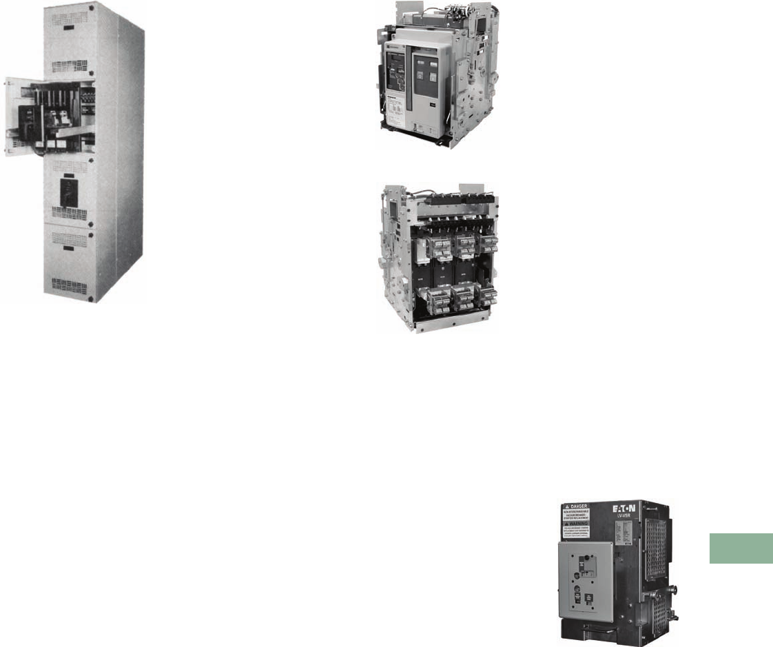
Volume 12—Aftermarket, Renewal Parts and Life Extension Solutions CA08100014E—November 2013 www.eaton.com V12-T17-3
1
2
3
4
5
6
7
8
9
10
11
12
13
14
15
16
17
18
19
20
21
22
23
24
25
17
Switchgear
DB Low Voltage Assemblies and Power Circuit Breakers
DB Assemblies and
Power Circuit Breakers
DB Switchgear with DB Air
Circuit Breakers
Product Description
DB switchgear should be
found only with the
Westinghouse logo and
nameplates. The last
assembly shipped about
15 years before the
acquisition by Eaton.
Many breakers were
originally shipped with
electromechanical trip
units, but it is common to
find many of them retrofitted
with Amptector or Digitrip
trip units.
One characteristic of this
switchgear is the viewable,
through-the-door breaker
handle, which could be
operated without opening
the door.
DB assemblies were offered
with either “Fixed-Mounted”
breakers or “Drawout
(three-position) type.
Fixed breakers have no
test position.
The breakers in this
switchgear design include:
●DB15, DB25, DB50, DB75,
DB100 (standard)
●DBL15, DBL25, DBL50
(current limiting)
Special application breakers
include:
●DBF6, DBF16, DBF40
(DC field discharge)
●DBW15, DBW25, DBW50
(resistance welding)
The DB switchgear
structures were
approximately 90 3/8-inch
high construction with a
universal frame that
accommodated breaker
compartment widths of
18.00, 26.00, 30.00 and
36.00 inches. All main bus
joints and tap connections
are silver plated and tightly
clamped with through-
bolts to ensure maximum
conductivity. The outdoor
switchgear was a walk-in
type with rear hinged
doors for easy access
to connections.
Ratings
●DB switchgear bus
800–4000A
●DB breaker 15–4000A
●Voltage 208–600V
●Interrupting capacity
15–150 kA
Chronology
This switchgear was
manufactured in East
Pittsburgh, PA, from
1950 to 1980.
Replacement Capabilities
DB-AR Replacement Breakers
DB25-AR600NM—Front View
DB25-AR600NM—Rear View
The DB-AR breakers are
brand new air replacements
(AR-Series) designed to
replace the original DB
breaker. This solution is
available for most three-
position drawout DB breakers
within original Westinghouse
switchgear. The new
AR-Series breaker permits
DB switchgear modernization
by using state-of-the-art
Eaton Magnum breaker
technology. The DB-AR is
designed, manufactured
and tested to applicable
IEEE/ANSI standards.
Class 1 Reconditioning
Reconditioning Service is
available for most frame sizes
of the DB breaker. Class 1
Reconditioning is Eaton’s
process of maintaining low
voltage power breakers to
their fullest capability. We
disassemble each breaker,
clean and test each part
using
component-specific methods,
then
reassemble and perform
final testing to ensure that
each breaker is restored to
operating condition—all using
the original manufacturer’s
instructions and parts. New trip
units can also be retrofitted
during this process.
DB Breaker Parts
DB breaker replacement parts
are available built from the
original drawings and design
specifications. Among the
items stocked are asbestos-
free arc chutes, complete
pole units, contacts, primary
disconnects and coils.
DB Air Circuit Breakers
New factory manufactured
breakers are available
in three-position drawout
configurations only for the
DB15, DBF6 and DBF16. Fix-
mounted and single-position
configuration breakers are
available for the DB15, DB25,
DBL25, DB50 or DBL50.
Technology Upgrades
Digitrip Trip Unit Retrofit Kits
Available for all DB breaker
frame sizes. Please see the
switchgear trip unit retrofit
kits on V12-T17-17 through
V12-T17-51 for more detail.
DB-VSR (Vacuum
Starter Retrofits)
For FVNR, motor-starting
applications ONLY—this
solution significantly lengthens
the life-span of the “motor
starter” and provides better
motor overload protection. The
DB25-LV-VSR contains the
V201 vacuum contactor and
the C440 motor overload relay.
DB25-LV-VSR

V12-T17-4 Volume 12—Aftermarket, Renewal Parts and Life Extension Solutions CA08100014E—November 2013 www.eaton.com
1
2
3
4
5
6
7
8
9
10
11
12
13
14
15
16
17
18
19
20
21
22
23
24
25
17
Switchgear
DS Low Voltage Assemblies and Power Circuit Breakers—Vintage
DS Switchgear Assemblies General Information
Description Ratings Chronology
DS Switchgear Vintage I and II, 1969–1984 at East Pittsburgh, PA
The first vintage of DS switchgear was the first switchgear that incorporated the DS breaker with a solid-state trip
unit (Amptector). During this time, the DS532 breaker was used. The DS532 breaker was a 3000A frame breaker with
an interrupting rating of 50,000 symmetrical amperes. The structures themselves were of a stepped roof design that
incorporated a standard bolted copper or flash welded aluminum bus design. Other characteristics of this switchgear
include the following: rear frame height was 87.50 inches, flat roof sheets, ventilated front doors, wire ducts,
removable instrument modules and a welded frame design. The breaker compartments were also different with fuse
trucks stacked above the mains, the DS840, DS532 and the newly developed DS632. The outdoor design
incorporated the use of a walk-in type side door entry.
The second vintage of switchgear was a new design that incorporated the use of both bolted copper and welded
extruded aluminum rise bus. It is basically the same as the first vintage but with a revised bus design.
800–4000A
208/600V
The first vintage was built from September of 1969 to
approximately September of 1973 in East Pittsburgh, PA,
using the shop order numbers with a prefix of 24Y. The
second DS vintage was also built in East Pittsburgh,
which used the 27Y prefix on shop orders. This vintage
was built the same time as the WPA design in St. Louis,
MO. The switchgear in East Pittsburgh was designed to
be used for industrial applications, whereas the St. Louis
design was built for commercial applications.
WPA Switchgear, 1973–1984 at St. Louis, MO
The WPA switchgear was designed for commercial applications that also used DS breakers. which was similar
to the East Pittsburgh design for industrial applications. The two designs differed structurally but used the same
breakers. Some characteristics of the WPA design are as follows: riser bus was tapered design, frames were bolted
and not welded, height of 9.00 inches, neutral bus mounted on rear frame, did not use removable instrument
compartments and outdoor design had front and rear doors. In all, the WPA design differed extensively compared
to the East Pittsburgh design.
800–4000A
208/600V
This vintage was built from February of 1973 to
approximately October of 1984 in St. Louis. Usually the
switchgear is identified by General Order and Item
numbers. Shop order numbers were not used.
DS Switchgear Vintage III, 1984 at St. Louis, MO
The third generation of DS switchgear was introduced due to the change of plant locations. It is classified as a
vintage because it was the beginning of the merge between two plants (St. Louis and East Pittsburgh). The
engineering was completed in East Pittsburgh and the assembly was built in St. Louis, along with the Cincinnati, OH,
plant to help pick up the slack until full production in St. Louis. This vintage was similar to the previous 27Y style with a
few modifications. It was the first time that both DS and DSL were used in switchgear by the use of a conjunction box.
The physical appearance also changed by increasing the height to 92.00 inches and adding top hat vents that protruded
4.00 inches above the switchgear. Internally the neutral bus was located in the bus compartment along with unified
breaker compartments for the variety of breakers.
800–4000A
208/600V
This vintage lasted from May of 1984 to approximately
October of 1984 in East Pittsburgh. Usually the switchgear
shop order number is defined by a prefix of 28Y.
DS Switchgear Vintage IV, 1984–1990 at St. Louis, MO
This vintage of switchgear was a combination of the St. Louis WPA and East Pittsburgh design. The design was
classified as a hybrid between the two that consisted of the East Pittsburgh design in the front compartments that
held the DS breaker, and the St. Louis design in the rear compartment that housed the bus. The rear compartment
still used the tapered riser bus (a characteristic of the St. Louis design), which was used right up until the DS
switchgear moved to Asheville, NC. The design was very similar to the design today except for the different riser
bus along with the height being 92.00 inches.
800–4000A
208/600V
This vintage was built from October of 1984 to
approximately May of 1990 in St. Louis. Usually the
switchgear is identified by general order and item
numbers. 28Y shop order numbers started in 1987 and
continued into the Asheville design.
DS Switchgear Vintage V, 1990–1996 at Asheville, NC
The vintage was built from May of 1990 to the end of 1996 in Asheville. The switchgear is identified by shop order
number 28Y. The switchgear incorporates both designs with the option for the variety of IQ products. The riser bus
went back to a full rated type that is bolted copper only. Aluminum bus work was initially done only on special orders
at customer request. The switchgear also has many improvements such as the design of an instrument panel door
that was able to accommodate three device panels across DS632 in the C and D compartments and a variety of
communication capabilities with IMPACC. The outdoor design changed with the concept of a side walk-in enclosure.
800–4000A
208/600V
This vintage was built from May of 1990 to the end of
1996 in Asheville. The switchgear is identified by shop
order number 28Y.
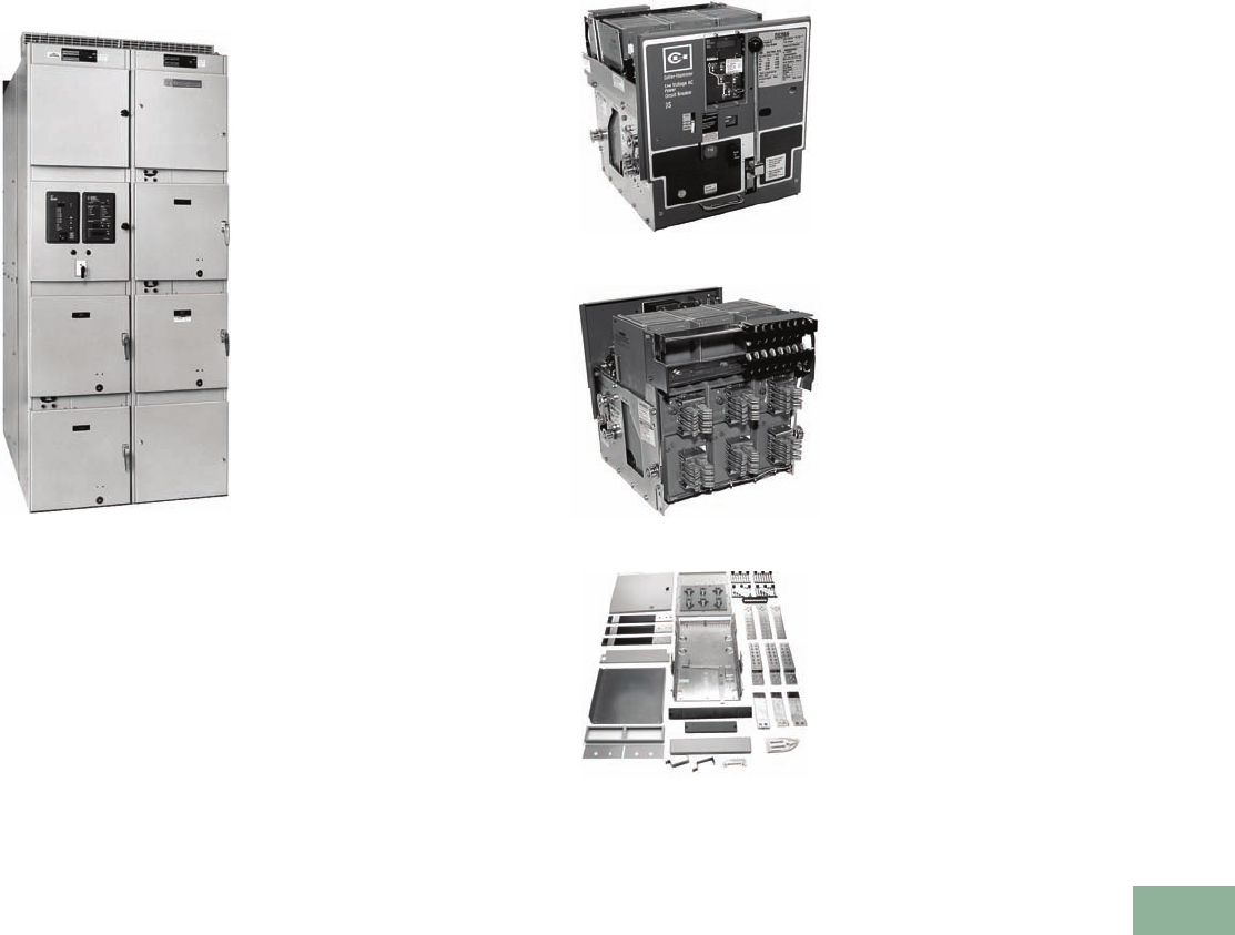
Volume 12—Aftermarket, Renewal Parts and Life Extension Solutions CA08100014E—November 2013 www.eaton.com V12-T17-5
1
2
3
4
5
6
7
8
9
10
11
12
13
14
15
16
17
18
19
20
21
22
23
24
25
17
Switchgear
DS Low Voltage Assemblies and Power Circuit Breakers
DS Assemblies and
Power Circuit Breakers
DS Switchgear Assembly
Typical Design, 1991
Product Description
DS switchgear was
introduced in 1969 and would
be found mostly with the
Westinghouse logo and
nameplates. However, some
assemblies shipped after the
1994 acquisition by Eaton
could likely have product labels
with both Westinghouse and
Cutler-Hammer product names.
DS switchgear uses the
drawout version
of the DS
and DSL low voltage power
breakers. Each breaker is
located within an individual
compartment. Each
compartment has extension
rails for supporting the
breaker while removing it
from the compartment. The
breaker can be in either of
the following positions with
the door closed:
●Connect
●Te s t
●Disconnect
●Remove
The original DS breaker
contained the original solid-
state trip unit—Amptector.
The Amptector was later
replaced by the original family
of microprocessor-based,
true rms sensing, Digitrip trip
unit models 500, 600, 700
and 800. In the late 1990s,
DS breakers started shipping
with Digitrip models 510,
610, 810 or 910.
The breakers in this design
included:
●DS206, 206H, 206E, 416,
416H, 416C, 420, 532, 632
or 840
●DSL206, 416, 420, 632
or 840
DS metal-enclosed
switchgear was designed to
meet the following standards:
●ANSI C37.20.1
●UL 1558
●NEMA SG5
DS low voltage power air
circuit breakers (LVPACB)
were designed to meet the
following standards:
●ANSI C37.13, C37.16,
C37.50 and C37.51
●UL 1066
●NEMA SG3
Chronology
There are five vintages of
DS switchgear. Please
see General Information
on Page V12-T17-4 for
more detail.
Replacement Capabilities
DS206H—Front
DS206H—Rear
DS Cell Provisions
New DS Air Circuit Breakers
New DS circuit breakers are
available for replacement or
to fill existing vacant cells.
All breakers are newly
manufactured and are
mechanically and electrically
the same as the breakers
as originally specified
and supplied.
DS Circuit Breaker Cell
Provisions
Breaker provisions are
required in switchgear
when there is an existing
space in a structure that is
to be filled with a breaker.
Provisions are available for
all ratings and include all
parts required to complete
the cell in accordance with
the switchgear as originally
supplied in vintages IV and
V only.
DS Breaker Parts
An extensive inventory of
newly manufactured renewal
parts for DS and DSL power
circuit breakers are available.
DS Switchgear Structure Parts
DS switchgear parts are
available for most DS
designs. Newly manufactured
replacement parts (such as
doors, breaker provisions,
lift trucks, metering, etc.)
are available.
Class 1 Reconditioning
Reconditioning Service is
available for the entire family
of DS breakers. Class 1
Reconditioning is Eaton’s
process of maintaining low
voltage power breakers to
their fullest capability. We
disassemble each breaker,
clean and test each part using
component-specific methods,
then reassemble and perform
final testing to ensure that
each breaker is restored to
operating condition—all using
the original manufacturer’s
instructions and parts.
New trip units can also be
retrofitted during this process.
Technology Upgrades
IQ and PowerNet™
Communications
Digital IQ-type products can
be used to upgrade existing
analog devices such as
meters. The new IQ-type
products can be furnished as
loose, individual components
for field retrofitting or can be
furnished on new replacement
doors, such as in the photo to
the left. The new instrument
compartment door will fit all
vintages of DS assemblies
from 1968 to the present.
Please see IQ products
Ta b 10 for further details
on the latest offerings.
Digitrip Trip Unit Retrofit Kits
Retrofit kits are available for
all DS breaker frame sizes.
Please see the switchgear
trip unit retrofit kits on
Pages V12-T17-17–
V12-T17-51 for more detail.
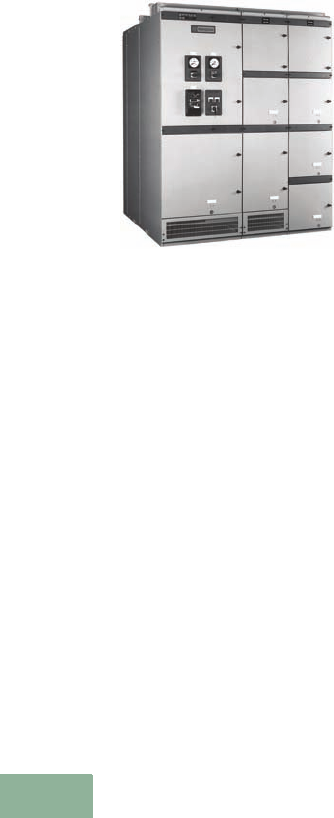
V12-T17-6 Volume 12—Aftermarket, Renewal Parts and Life Extension Solutions CA08100014E—November 2013 www.eaton.com
1
2
3
4
5
6
7
8
9
10
11
12
13
14
15
16
17
18
19
20
21
22
23
24
25
17
Switchgear
DS Low Voltage Assemblies and Power Circuit Breakers
DSII Assemblies and
Power Circuit Breakers
DSII Switchgear Assembly
Product Description
The DSII low voltage
switchgear design was first
introduced in 1994 but was
originally available with only
the DS or DSL breakers.
Upon its arrival in 1996, the
DSII breaker became the
standard offering in DSII
switchgear assemblies.
The DSII switchgear design
uses only the drawout version
of the power breakers. Each
breaker is located within an
individual compartment. Each
compartment has extension
rails for supporting the
breaker while removing it
from the compartment. The
breaker can be in either of
the following positions with
the door closed:
●Connect
●Te s t
●Disconnect
●Remove
The DSII switchgear is
basically designed for easier
installation and maintenance.
Control circuit terminal blocks
are mounted in a completely
removable tray located at the
front of the assembly above
each circuit breaker—helping
customers perform routine
inspection of control wires.
This tray is charcoal-gray
and is perhaps the most
noticeable external difference
between the DSII and the
DS designs.
The DSII breaker is very
similar to the DS. In fact,
the DSII breaker uses
most of the same internal
components—renewal parts
can often be shared. The
DSII breaker was the first to
include the newer family of
Digitrip RMS trip units: model
510, 610, 810, 910, and
OPTIM 750 or 1050. Unlike
the DS breaker, however,
the DSII breaker provides
genuine standardization of
breaker wiring, including
secondary contact points—
without reducing features
and options. This is achieved
with a larger secondary
contact block. The DSII
breaker has up to four
12-point, white secondary
contact blocks whereas the
DS breaker, has up to four
8-point, black secondary
contact blocks. DSII breakers
therefore cannot be installed
into a DS breaker cell.
DSII metal-enclosed
switchgear was designed to
meet the following standards:
●ANSI C37.20.1
●UL 1558
●NEMA SG5
DSII low voltage power air
circuit breakers (LVPACB)
were designed to meet the
following standards:
●ANSI C37.13, C37.16,
C37.50 and C37.51
●UL 1066
●NEMA SG3
●CSA
Ratings of DSII Switchgear
●2000–5000A vertical
and cross bus
●6000A cross bus option
●600V maximum
●100,000A bus bracing
standard
●200,000A bus bracing
optional
DSII Switchgear Assemblies
Dated 1994–Present with Shop
Order Numbers Ranging from
82Y1000 to 82Y3000
●Built from April of 1994 to
the present, these
assemblies contain the
following DS breakers:
●DS-206, DS-206H,
DS-206E, DS-416,
DS-416H, DS-420,
DS-632 or DS-840
●DSL-206, DSL-416,
DSL-420, DSL-632 (with
fuse truck) or DSL-840
(with fuse truck)
●DSII switchgear
assemblies dated
1996–present with
shop order numbers
82Y3001 and larger
DSII Switchgear Assemblies
Dated 1994–Present with
Shop Order Numbers 82Y3001
and Larger
●Built from April of 1996
to the present, these
assemblies contain the
following DSII breakers:
●DSII-308, DSII-508,
DSII-608, DSII-516,
DSII-616, DSII-620,
DSII-632, DSII-840
or DSII-850
●DSLII-308, DSLII-516,
DSLII-620, DSLII-632
(with fuse truck) or
DSLII-840 (with
fuse truck)
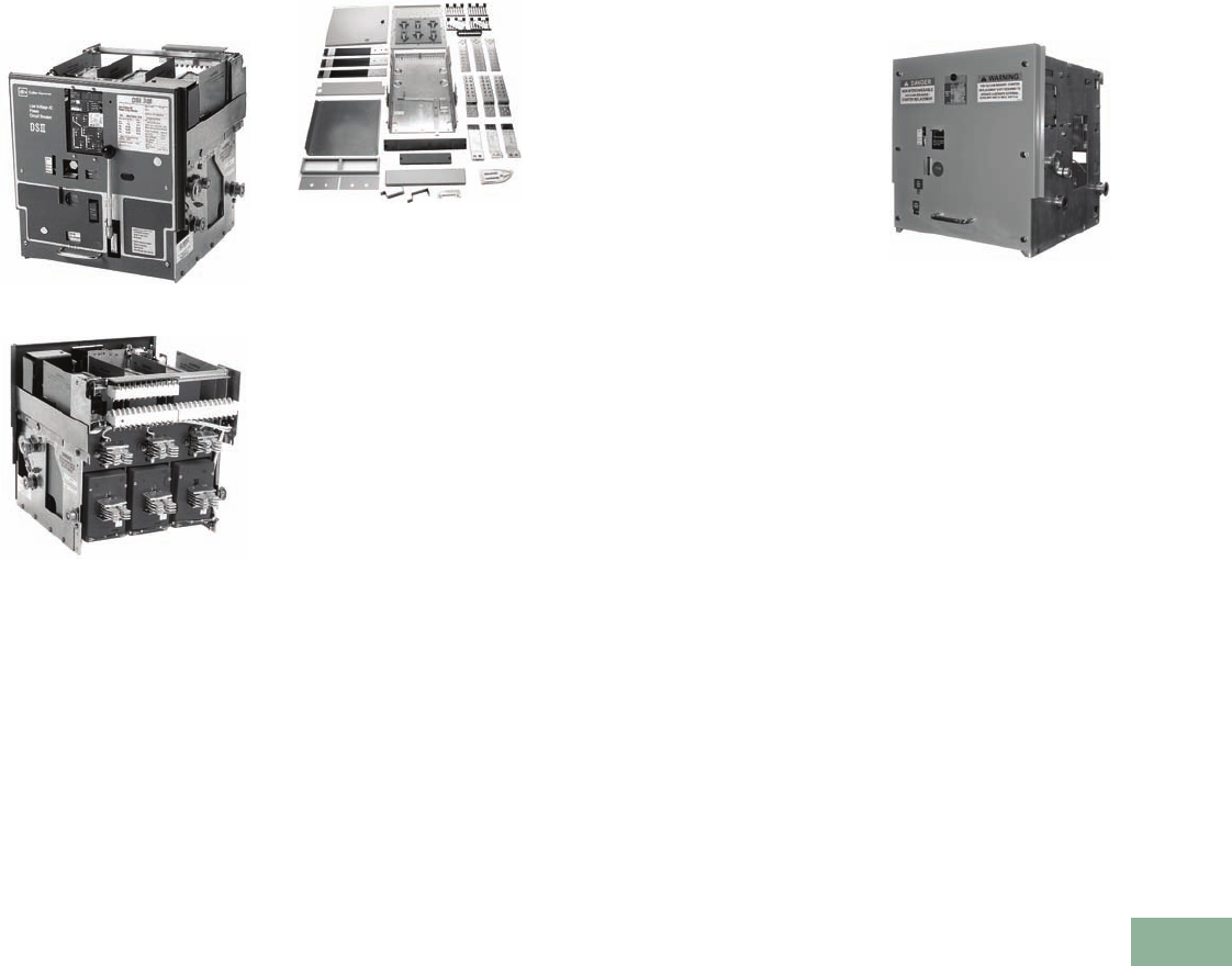
Volume 12—Aftermarket, Renewal Parts and Life Extension Solutions CA08100014E—November 2013 www.eaton.com V12-T17-7
1
2
3
4
5
6
7
8
9
10
11
12
13
14
15
16
17
18
19
20
21
22
23
24
25
17
Switchgear
DSII Low Voltage Assemblies and Power Circuit Breakers
Replacement Capabilities
DSII308—Front
DSII308—Rear
DSII Cell Provisions
New DSII Air Circuit Breakers
New DSII circuit breakers
are available for replacement
or to fill existing vacant
cells. All breakers are newly
manufactured and are
mechanically and electrically
the same as the breakers
originally specified and
supplied.
DSII Circuit Breaker Provisions
Breaker provisions are
required in switchgear
when there is an existing
space in a structure that is
to be filled with a breaker.
Provisions are available for
all ratings and include all
parts required to complete
the cell in accordance with
the switchgear as originally
supplied.
Class 1 Reconditioning
Reconditioning service is
available for the entire family
of DSII breakers. Class 1
Reconditioning is Eaton’s
process of maintaining low
voltage power breakers to
their fullest capability. We
disassemble each breaker,
clean and test each part using
component-specific methods,
then reassemble and perform
final testing to ensure that
each breaker is restored to
operating condition—all using
the original manufacturer’s
instructions and parts.
New trip units can also be
retrofitted during this process.
Please see Page V12-T17-9
for breaker accessories.
DSII Breaker Parts
An extensive inventory of
newly manufactured renewal
parts for DSII and DSLII
circuit breakers are available.
DSII Switchgear Structure Parts
DSII switchgear parts are
available for most DS
designs. Newly manufactured
replacement parts (such
as doors, breaker provisions,
lift trucks, metering, etc.)
are available.
Technology Upgrades
DSII-VSR—Front
DSII-VSR (Vacuum Starter
Replacement)
For FVNR, motor-starting
applications ONLY—this
solution might be available to
significantly lengthen the life-
span of the “motor starter”
as well as to provide better
motor overload protection.
The DSII-VSR is manufactured
as a new assembly and is
designed to rack into the
same switchgear cells that a
DSII breaker is removed from.
It will physically fit into any
of the “quarter-high” cells
ranging from the DSII-308
to the DSII-620. However,
the maximum FLA rating is
currently 425A. The current
design DS-VSR contains
the V201 vacuum contactor
and appropriate overload
protection.
Digitrip Trip Unit Retrofit Kits
Retrofit kits are available for
all DSII breaker frame sizes.
Please see the switchgear
trip unit retrofit kits on
Pages V12-T17-17–
V12-T17-51 for more detail.
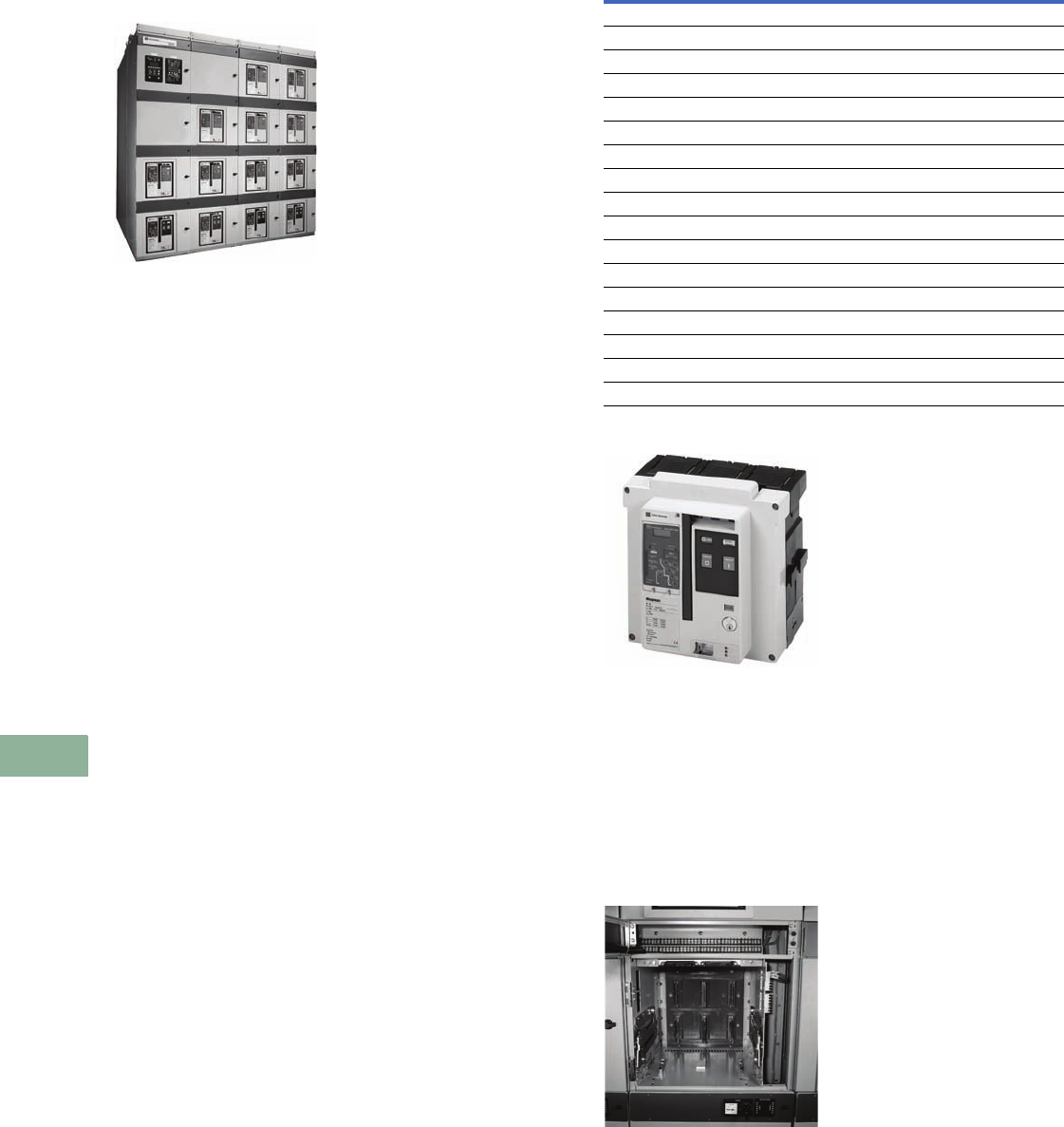
V12-T17-8 Volume 12—Aftermarket, Renewal Parts and Life Extension Solutions CA08100014E—November 2013 www.eaton.com
1
2
3
4
5
6
7
8
9
10
11
12
13
14
15
16
17
18
19
20
21
22
23
24
25
17
Switchgear
DSII Low Voltage Assemblies and Power Circuit Breakers
Magnum DS Assemblies
and Power Circuit
Breakers
Magnum DS Switchgear
Product Description
Cutler-Hammer Magnum DS
switchgear started shipping
in 1998. Perhaps the most
distinctive feature when
compared to the original DS
vintage is the “through-the-
door” design.
The following functions
may be performed without
opening the circuit breaker
door: levering the breaker
between positions; operating
manual charging system,
including viewing of the
spring charge status flag;
closing and opening the
breaker; viewing/adjusting
the trip unit and reading the
breaker rating nameplate.
The breakers are four-position
drawout design—connected,
test, disconnected or
removed.
The breakers can also
be equipped with ARMs
technologies, which will
reduce arc flash energy
available at downstream
devices during maintenance
periods.
A unique vertical and cross
bus configuration provides
an optional industry-leading
short-circuit withstand rating
of 200,000A without the
need for upstream current-
limiting fuses.
Vertical and cross bus ratings
are based on a UL and ANSI
standard temperature rise
of 65ºC above a maximum
ambient air temperature
of 40ºC.
Magnum DS switchgear
and breakers conform to
the following standards:
●ANSI C37.20.1, C37.51
●UL 1558, UL 1066
●NEMA SG5, SG3
●CSA
The assemblies have
undergone an extensive
seismic qualification program.
The test program used ANSI
standard C37.81, the Uniform
Building Code (UBC®) and
the California Building Code
(CBC) as a basis for the test
program. The assemblies have
been tested and qualified to
exceed these requirements.
Magnum DS Switchgear Ratings
●Cross bus ampacity
●2000, 3200, 4000,
5000, 6000
●Vertical bus ampacity
●2000, 3200, 4000, 5000
●Bus bracing
●100, 150 or 200 kA
Magnum DS Without Current Limiters
Replacement Capabilities
800–3200A Drawout Breaker
New Magnum DS Breakers
New breakers are readily
available for all frame sizes
and interruption ratings.
Renewal Parts and Accessories
New breaker parts and
accessories are readily
available for all frame sizes
and interrupting ratings.
Breaker Cell
Cell Provisions and Upgrades
Switchgear cell provisions are
required when an existing
structure blank space needs
to be filled with a new
Magnum DS circuit breaker.
Cell upgrades are required
when the provision already
exists, but the need to
upgrade ampacity and/or
interrupting rating is
necessary. Sometimes,
new riser bus must also be
installed with this offering.
Class 1 Reconditioning
Reconditioning service is
available for the entire family
of Magnum DS breakers.
Class 1 reconditioning is
Eaton’s process of
maintaining low voltage
power breakers to their
fullest capability. We
disassemble each breaker,
clean and test each part using
component-specific methods,
then reassemble and perform
final testing to ensure that
each breaker is restored to
operating condition—all using
the original manufacturer’s
instructions and parts.
Note
1Interrupting rating is 130 kA at 240V.
Maximum
Amperes
Breaker
Designation
Interrupting
Rating (kA)
Short-Time
Rating (kA)
800 MDS-408 42 42
800 MDS-608 65 65
800 MDS-808 85 85
800 MDS-C08 100 85
1600 MDS-616 65 65
1600 MDS-816 85 85
1600 MDS-C16 100 85
2000 MDS-620 65 65
2000 MDS-820 85 85
2000 MDS-C20 100 85
3200 MDS-632 65 65
3200 MDS-832 85 85
3200 MDS-C32 100 85
4000 MDS-840 85 185
4000 MDS-C40 100 1100
5000 MDS-850 85 185
5000 MDS-C50 100 1100
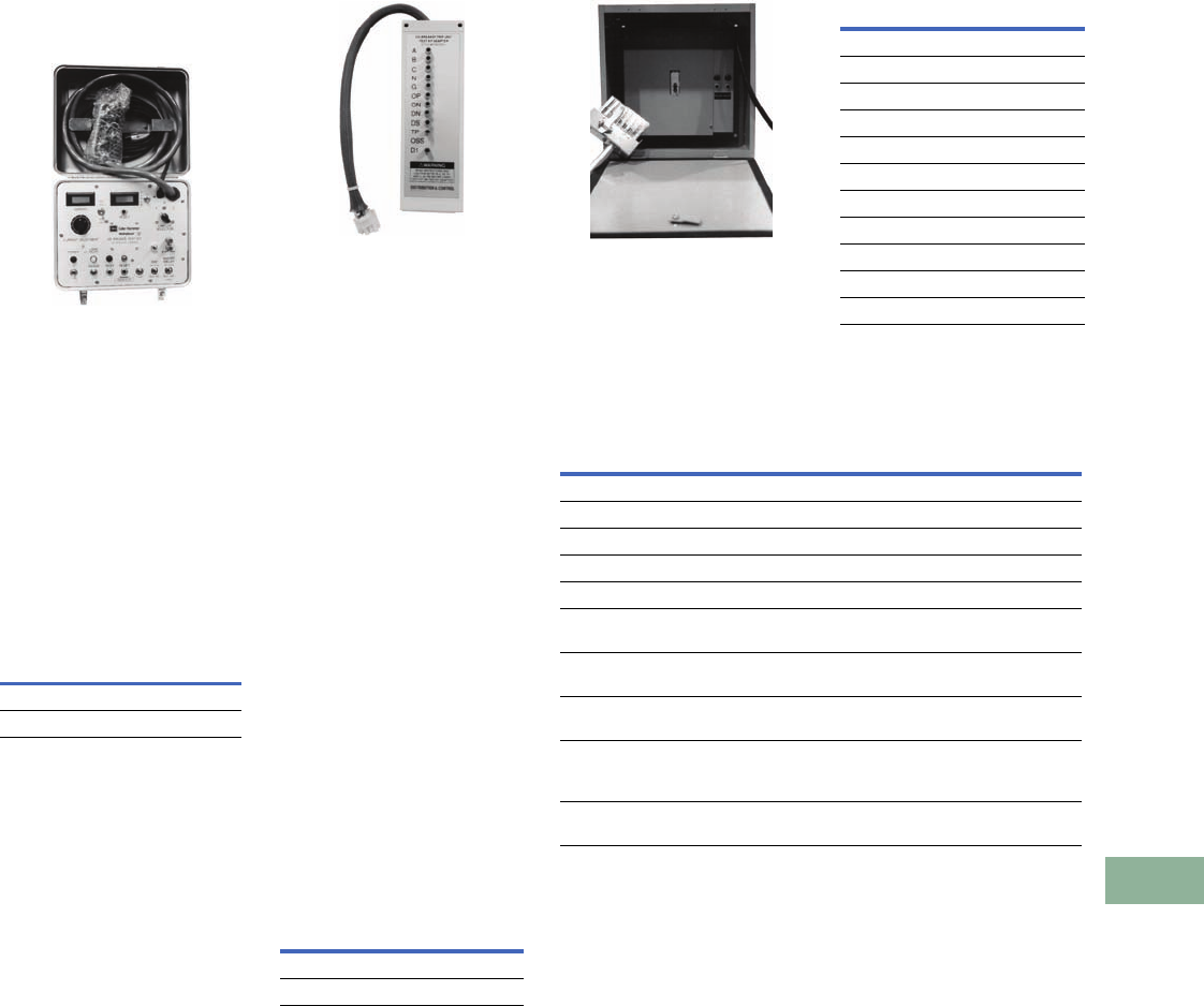
Volume 12—Aftermarket, Renewal Parts and Life Extension Solutions CA08100014E—November 2013 www.eaton.com V12-T17-9
1
2
3
4
5
6
7
8
9
10
11
12
13
14
15
16
17
18
19
20
21
22
23
24
25
17
Switchgear
Magnum DS Low Voltage Assemblies and Power Circuit Breakers
Breaker Accessories
Breaker Test Kits
Test Kit Unit
Test Kit
This test kit can be used
for testing DS, DSII and
Magnum breakers that are
equipped with either
Amptector or Digitrip RMS
trip units. Test kit2 includes
test unit and adapter.
Note: Each kit contains the
140D481G03 basic tester
(Amptector-Ready) and the
adapter for the selected breaker
Digitrip style.
Te s t K i t
Adapters
Adapter
In May of 1993, the test
port changed on DS circuit
breakers that have Digitrip
RMS trip units. The test port
was moved from the front
cover to the left-hand side,
as you face the front of the
breaker. The port was also
changed from an 11-pin
banana plug to a 9-pin plug.
The adapter is for using a
140D481(G02R), (G02RR)
or (G03) tester to test DS
breakers with Digitrip that
have the side-mounted, 9-pin
plug. The adapter converts
the banana plugs on the
tester to a 9-pin plug. DO
NOT use the adapter with
the old 140D481G01 or
140D481G02 tester.
On Magnum breakers, the
test port is located on the
front cover of the trip unit.
The port is a 14-pin plug;
the adapter converts the
banana plugs on the tester
to a 14-pin plug.
Adapters
Description
Catalog
Number
DS/DSII Digitrip test kit 8779CO2G02
Magnum Digitrip test kit 8779CO2G05
Description
Catalog
Number
DS/DSII 8779C02G03
Magnum 8779C02G05
Breaker Test Cabinet
Breaker Test Cabinet
Test cabinet for electrically
operated breakers, with
pushbuttons, control
cable and receptacle, for
separate mounting.
Breaker Test Cabinet
Background Information on Trip Unit Test Kits
Note
1These parts are used with any breaker that was upgraded with “Digitrip Retrofit Kits.”
Description
Catalog
Number
DS
120 Vac/125 Vdc 6500C57G01
240 Vac/125 Vdc 6500C57G02
DSII
120 Vac/125 Vdc 6500C57G03
240 Vac/125 Vdc 6500C57G04
Magnum
120 Vac/125 Vdc 9253C25G01
240 Vac/125 Vdc 9253C25G02
120 Vac capacitor trip 9253C25G03
Test breaker plug 9253C25G04
Description
Catalog
Number
Obsolete test unit, only for use with Amptector 140D481G01
Obsolete test unit, only for use with Amptector 140D481G02
Same as 140D481G02, except retrofitted to test both Amptector and Digitrip 140D481G02R
Same as 140D481G02, except retrofitted to test both Amptector and Digitrip 140D481G02RR
Obsolete Test Kit Adapter, superseded by 8779C02G03 8779C02G01
Wire harness with female banana plugs for temporary connection
direct from tester to the auxiliary CT module on the retrofitted breaker 1
6503C53G01
Adapter harness for converting banana from the tester to a 12-pin plug
for retrofitted breakers equipped with a 6503C55G01 1
6503C54G01
New adapter for converting 12-pin plug on 6503C55G01 into 9-pin plug
for connecting to the test unit adapter style # 8779C02G03 1
6503C54G02
Wire harness with 12-pin plug for permanent connection to auxiliary
CT module on the retrofitted breaker; plug connects to 6503C54G01
or 6503C54G02 1
6503C55G01
Current auxiliary power module for supplying power to Digitrip trip unit
during test procedures; also identical to catalog number PRTAAPM 1
1267C16G01

V12-T17-10 Volume 12—Aftermarket, Renewal Parts and Life Extension Solutions CA08100014E—November 2013 www.eaton.com
1
2
3
4
5
6
7
8
9
10
11
12
13
14
15
16
17
18
19
20
21
22
23
24
25
17
Switchgear
Procedure for Identifying Low Voltage Renewal Parts
Procedure for Identifying
Renewal Parts
For all switchgear requests,
include information from
the list below to ensure that
parts and breakers supplied
will consist of correct options
and settings. With the variety
of switchgear vintages, the
information is needed to
supply the correct parts.
There might be modifications
needed to the breaker
cell or to the bus work to
accommodate the breaker
that will only be recognized
by the drawings.
For all requests include
the following:
●Shop order number
●Front view drawing
number
●General order number
(G0#)
●Manufacturing date
●Item number
●Metering required
●Optional relays
●CTs
●What changes have been
made since equipment
was originally installed in
the field?
Requests requiring additional
or replacement breakers
also require the following
information:
●Breaker type
●Trip rating
●MO or EO
●Trip unit
●Three-wire or four-wire
●Trip settings (LSIG)
●Fixed or drawout
●Which compartment
●Any new options
Further Information
Publication
Number Description
DB Breakers
RPD 32-254 Renewal Parts Data for DB, DBL, DBF breakers
SA-11745 Sales Aid for custom fluidized switchgear bus
DS Breakers
RP.22B.01.T.E Renewal Parts Data for DS breakers
PL.22G.01.P.E Price List for DS breakers and accessories, discount symbol DS-1
DSII Breakers
RP.22B.02.T.E Renewal Parts Data for DSII breakers
IB 694C694-02 Instruction, operation and maintenance for DSII/DSLII breakers
IL 32-691C Instructions for DS-DSII (trip units 500-910) tester
PL.22B.01.P.E Price List for DSII breakers and accessories
DS/DSII Switchgear Assemblies
RP.44B.01.T.E Renewal Parts Data for DS/DSII switchgear accessories
DSII Switchgear and Breaker
SA-32-610A Sales Aid for DSII low voltage switchgear
AD 32-650A Application Data for DSII switchgear
DS Switchgear
IB 32-690F Instructions for DS metal-enclosed LV switchgear
DS and DSL Breakers
IB 33-790-1I Instruction, operation and maintenance for DS/DSL breakers
DSII Switchgear
TD.44B.01A.T.E Technical Data for DSII metal-enclosed LV switchgear
DSII Switchgear with DS Breakers
IB 32-695C Instructions for DSII switchgear containing DS breakers
DSII Switchgear with DSII Breakers
IB 32-694B Instructions for DSII switchgear containing DSII breakers
Magnum DS Switchgear
PA.44A.01.S.E Product Aid (1pg.) for Magnum DS switchgear
TD.44A.01B.T.E Technical Data for Magnum DS metal-enclosed LV switchgear
IB 32-697A Instructions for Magnum DS metal-enclosed LV switchgear
RP01901001E Magnum DS switchgear common replacement parts and accessories
Magnum DS Switchgear and Breakers
B.44A.01.S.E Brochure (20 pg.) for Magnum DS switchgear and breakers
Magnum DS Breakers
RP.22F.02.T.E Renewal parts and accessories catalog for Magnum DS breakers
IB 2C12060H03 Instructions, operation and maintenance for Magnum DS breakers
B.22F.01.S.U Brochure (16 pg.) for Magnum DS breakers
PL.22F.01A.P.E Price List for Magnum DS breakers
IB.44A.05.T.E Instructions for Magnum DS (trip units 520-1150) tester
IL 32-696A Instructions for Magnum DS breaker test cabinet
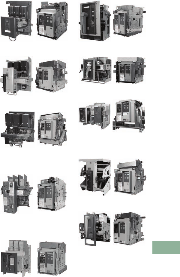
Volume 12—Aftermarket, Renewal Parts and Life Extension Solutions CA08100014E—November 2013 www.eaton.com V12-T17-11
1
2
3
4
5
6
7
8
9
10
11
12
13
14
15
16
17
18
19
20
21
22
23
24
25
17
Switchgear
Low Voltage Competitive Upgrades—AR-Series Replacement Breakers
Competitive Upgrades—
Low Voltage Power
Air Breakers
AR-Series
Replacement Breakers
The AR-Series (air-
replacement) breakers
are not retrofits. They are
100% new breakers used
to completely replace the
original drawout type power
air circuit breaker. This
solution uses state-of-the-art
Cutler-Hammer Magnum
breaker technology that
provides maximum life-
extension and switchgear
modernization. The offering
includes a new breaker, a
cassette with extension
rails and a standard door.
No modifications are required
to the original line/load
power stabs or the secondary
disconnect contacts.
This solution can eliminate
safety problems caused by
defective racking and/or
operator mechanisms.
Additional safety against
arc flash incidents can be
obtained by equipping
the breaker with ARMs
Technologies, thereby
reducing the arc flash energy
available at downstream
devices during maintenance
periods. Additional switchgear
maintenance problems
such as parts unavailability
and lengthy maintenance
procedures can be eliminated.
This solution often provides
a substantial total installed
cost savings when compared
to completely replacing the
switchgear assembly.
In many instances, the
AR-Series replacement
breaker can be combined
with engineering services
to provide continuous
current and/or interruption
rating upgrades.
The AR-Series breakers are
designed, manufactured
and tested to modern
IEEE/ANSI standards.
Designs are available for
a wide variety of drawout
type low voltage power air
circuit breakers (LVPACB)
originally manufactured by
Westinghouse, Federal Pacific
Electric, Allis-Chalmers, ITE
and General Electric.
Pictured on this page are
several examples of available
designs. Contact your local
Eaton sales representative
for information on other
breaker types.
Westinghouse
Original DB-25 DB25-AR600NM
Original DB-50 DB50-AR1600M
Original DB-75 DB75-AR3000M
Allis-Chalmers
Original LA-600 LA600-AR600NM
ITE
Original K-600 K-600-AR600NM
Federal Pacific Electric
Original FP-25 FP25-AR600NM
Original FP-50 FP50-AR1600M
Original FP-75 FP75-AR3000B
General Electric
Original AK-2A-50 AK2A50-AR1600M
Original AKR-4A-30 AKR4A30-AR800NM
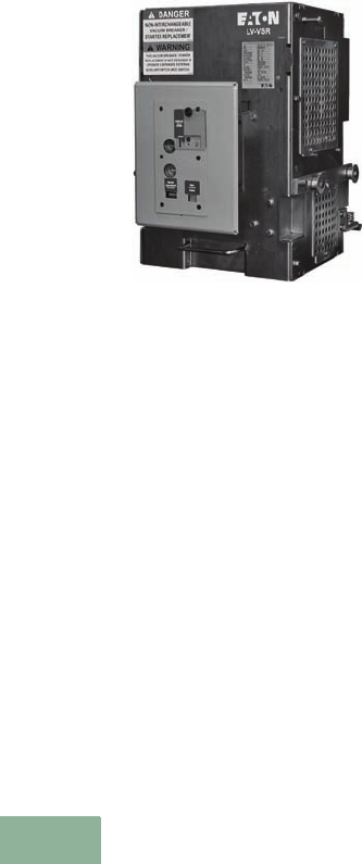
V12-T17-12 Volume 12—Aftermarket, Renewal Parts and Life Extension Solutions CA08100014E—November 2013 www.eaton.com
1
2
3
4
5
6
7
8
9
10
11
12
13
14
15
16
17
18
19
20
21
22
23
24
25
17
Switchgear
Low Voltage Breaker Drawout Vacuum Starter Replacement
Low Voltage Breaker
Drawout Vacuum
Starter Replacement
DB-25-LV-VSR Shown
Product Description
Eaton’s low voltage VSR
is a self-contained vacuum
starter replacement for a low
voltage drawout air circuit
breaker used for motor
starting applications.
In some cases, low voltage
air circuit breakers are
used for motor starting
applications. Air circuit
breakers are not designed
to withstand the frequent
switching service and
the mechanical stresses
associated with repetitive
motor starting duty. This
is due to the breaker
mechanism that must be
designed to close and latch
against a fault. In order to
meet these requirements,
the mechanism must close
at high speeds with a great
deal of force. Frequent
closing operations stress
and deteriorate the
breaker mechanisms.
Eaton’s LV-VSR is a self-
contained replacement
vacuum starter for a low
voltage drawout air circuit
breaker. The LV-VSR is
interchangeable with the
drawout breaker element and
requires no cell modifications.
Features
Advantages
The use of an LV-VSR
vacuum starter can prolong
device life and significantly
reduce maintenance repair
and downtime.
A low voltage air circuit
breaker has an effective life
of 4000 operations while an
LV-VSR vacuum starter has
an effective life of 1,000,000
operations. For example, a
motor starting application that
required two starts per hour
on continuous duty would
require a major rebuild of
the low voltage breaker
within three months. The
expected life of an LV-VSR
vacuum starter would be
over 50 years.
The LV-VSR vacuum starter
uses state-of-the-art Eaton
vacuum interrupters. The
interrupters employ the
latest vacuum technology
with long life, resistance to
environmental contaminants
and positive contact wear
indicators.
The integral, solid-state,
trip units used on the air
circuit breakers are designed
primarily for cable and
transformer protection.
Motors require more
precisely set overcurrent
devices that prevent motor
damage as well as avoiding
nuisance tripping. A solid-
state relay, Eaton Type C440,
provides overload protection
and phase unbalance
protection. This relay was
exclusively designed for
motor protection.
Motor Starter
The LV-VSR consists
of an Eaton V201 vacuum
contactor, Class J current
limiting fuses, multi-function
motor protective relay, three
current transformers and an
integral control power
transformer.
Vacuum Contactor
Eaton’s V201 vacuum
contactor is designed for
starting and controlling
three-phase, 50/60 Hz AC
motors. Current interruption
is contained within the
vacuum bottles and no
arc byproducts are vented
to the outside environment.
Contact condition is given
by wear indicators.
Series Current Limiting Fuses
Class J current limiting
fuses provide short-circuit
protection and allow a
combination rating of
100 kA at 480 or 600V.
C440 Electronic Overload Relay
Eaton’s C440 multi-function
electronic, motor protection
relay provides the following
features:
●Overload protection,
Class 10A, 10, 20 or 30
●Phase unbalance
protection, selectable
(ON/OFF)
●Ground fault selectable
(ON/OFF)
●Remote reset
●Alarm relay output contact
●LED status indication
●Communication
modules available
VSR Designs
●Westinghouse DB and DS
●GE
●ITE
●and others
Contact EESS at 877-276-9379
for more details.
Life
Exceptional electrical and
mechanical life is offered
by the V201 contactor—
up to 1,000,000 electrical
operations and 2,500,000
mechanical operations, even
under harsh conditions.
Drawout Capability
The LV-VSR is mounted on a
drawout frame and maintains
the safety interlocking system
of the low voltage switchgear.
Ease of Installation
The LV-VSR may be inserted
into a standard breaker
compartment without
modification to the
compartment. The primary
and secondary contact
structures and drawout
mechanism are identical.
The LV-VSR control scheme
will interface with standard
switchgear wiring with no cell
modifications and remote
control schemes, if existing,
are maintained.

Volume 12—Aftermarket, Renewal Parts and Life Extension Solutions CA08100014E—November 2013 www.eaton.com V12-T17-13
1
2
3
4
5
6
7
8
9
10
11
12
13
14
15
16
17
18
19
20
21
22
23
24
25
17
Switchgear
Low Voltage Breaker Drawout Vacuum Starter Replacement
Safety Features
The LV-VSR vacuum starter
retains all the safety features
of the low voltage switchgear
including:
●Racking the LV-VSR
vacuum starter is
prevented while the
contactor is in the closed
position. Closing the
LV-VSR vacuum starter is
prevented while racking
●Breaker position indication
is provided (connected,
test, disconnect, remove)
●The LV-VSR vacuum starter
is padlockable (optional) in
either the connect, test or
disconnect positions
●Positive ground connection
is maintained
●Closed door tripping
●Closed-door control, if
existing, can be maintained
LV-VSR Control Features
LV-VSR vacuum starter offers
the following standard control
features. Other devices can
be supplied on request.
●Start–stop pushbuttons
●Eaton C440 electronic
overload relay
●Provision for remote
control operation
●Custom-designed
wiring schemes
Ease of Maintenance
The LV-VSR control
components are front-
mounted for easy access.
The LV-VSR uses the
same line and load finger
clusters, secondary contact
assemblies and drawout
mechanism as the original
circuit breaker. Renewal
parts are readily available.
Technical Data
and Specifications
Ratings
The LV-VSR vacuum starter is
rated as follows:
●Maximum continuous
current—425A
●Maximum voltage
rating—600V
●Short-circuit rating at
240–600V, 200 kA
●Maximum motor hp at
550/575V, 400 hp
●Maximum motor hp at
440/460V, 300 hp
●Maximum motor hp at
220/230V, 150 hp
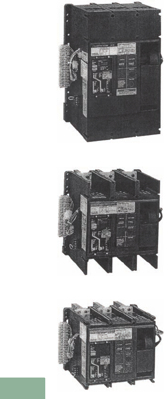
V12-T17-14 Volume 12—Aftermarket, Renewal Parts and Life Extension Solutions CA08100014E—November 2013 www.eaton.com
1
2
3
4
5
6
7
8
9
10
11
12
13
14
15
16
17
18
19
20
21
22
23
24
25
17
Switchgear
Systems Pow-R Breaker (SPB)
Systems Pow-R
Breaker (SPB)
SPB-100 Series—3000A
SPB-65 Series—1600A
SPB-50 Series—800A
Product Description
The Cutler-Hammer Systems
Pow-R Breaker is an encased
power breaker designed to
provide benefits of special
interest to distribution
systems designers.
Systems Pow-R Breakers
can be applied as individual
breakers in separate
enclosures or in switchboards
as mains, ties or feeder
breakers. They can be applied
in low voltage distribution
systems through 600 Vac,
50 or 60 Hz. Because they
combine high interrupting
capacity with short-time delay
tripping, Systems Pow-R
Breakers can be applied in
fully rated, selective systems
while providing full selectivity
through the applied breaker’s
short-time rating.
Both mechanical and
electrically operated versions
of the breaker feature a
true two-step stored energy
mechanism
with no change in
dimensions. This mechanism
allows maximum five-cycle
closing usually required for
generator paralleling.
An interrupting capacity of
150,000A at 480V without
fuses and short-time
capabilities of up to 85,000A
are available. Systems Pow-R
Breakers are UL Listed for
100% application.
Systems Pow-R Breakers
must be applied within
their published ratings in
accordance with UL and
NEMA Standards defined as
“Usual Service Conditions.”
Four basic frame sizes (400/
800/1200A, 1600/2000A,
2500/3000A and 4000/5000A)
cover the continuous ampere
range of 100 to 5000A.
The Systems Pow-R
Breakers use the proven
microprocessor-based
trip unit technology that
was pioneered by Eaton.
Developments in
microprocessor technology
have given us the new family
of Digitrip RMS electronic
trip units and the even
newer OPTIM programmable
trip unit.
All breakers come standard
with the Digitrip RMS 510 trip
units that have long time and
instantaneous (LI) tripping
functions. Short-time delay
and three- or four-wire ground
fault protec
tion can be
supplied as optional tripping
characteristics, thereby
providing for up to nine phase
and ground current settings.
This provides maximum
flexibility in trip curve shaping
and system coordination.
Any combination of these trip
functions (LI, LS, LSI, LIG,
LSG or LSIG) can be provided
within the Digitrip family of
trip units.
Optional trip units such as the
Digitrip RMS 610 that has a
large four-digit alphanumeric
display of load currents, cause
of trip and self diagnostics can
also be specified. The RMS
810, which in addition to the
610 features, displays
and
transmits via the IMPACC/
PowerNet
communications
network power and energy
values, may also be provided.
The RMS 910 also displays
power quality data, power
factor and phase-to-phase
voltages, and transmits
waveform capture
information.
The most technologically
advanced trip unit in the
Digitrip family is the Digitrip
OPTIM. The OPTIM 750
has features similar to the
Digitrip 610 and the OPTIM
1050 has features similar to
the Digitrip 910. Both have
the additional feature of being
programmable, rather than
having to be set by
discrete switches. This
programmability allows for
an almost infinite number
of trip settings, which in turn
provides for even closer
system coordination.
All trip units use completely
interchangeable rating plugs.
These plugs, when applied
with the appropriate sensors,
give the breakers a tripping
range of 100 to 5000A.
The Systems Pow-R Breaker
can be supplied in either
fixed or drawout mounting
configurations. The drawout
assembly consists of a
stationary frame and a moving
carriage with four positions:
connected, test, disconnected
and fully withdrawn. The
fixed configuration can be
supplied as either front or
rear connected.
The Systems Pow-R Breaker
has available a complete
family of integrally mounted
accessories. Shunt trip, spring
release solenoid, undervoltage
release, auxiliary switches,
key interlocks, mechanical
interlocks and covers
for the close and/or open
pushbuttons are just an
example of the accessories
that can be mounted on
the breaker.
Product History
Since its introduction to
the market in 1976, the
SPB has provided long and
reliable service. Tens of
thousands of SPBs have been
manufactured and placed into
service throughout the world
in switchboards, automatic
transfer switches and other
specialty OEM manufactured
power distribution products.
Systems Pow-R Breakers
can be identified using two
unique numbers. One is the
S.O. (shop order number).
The shop order number
is located either on the
breaker’s nameplate or on
the left side of the breaker.
An example of this number
is S.O. 74E2792.01.
The second number is a
30-digit feature and option
number. The first 10
characters of the feature
and option number are
considered to be the feature
or style number, the next 20
characters are the option or
edge number. This number is
also located on the breaker’s
nameplate or on the left side
of the breaker.
An example of this number is:
Feature and option
8702C35G012297240000000
1000144
Feature/style 8702C35G01
Option/edge
22972400000001000144
Volume 12—Aftermarket, Renewal Parts and Life Extension Solutions CA08100014E—November 2013 www.eaton.com V12-T17-15
1
2
3
4
5
6
7
8
9
10
11
12
13
14
15
16
17
18
19
20
21
22
23
24
25
17
Switchgear
Systems Pow-R Breaker (SPB)
Product History Time Line
Replacement Capabilities
Genuine new SPB
replacement parts and
accessories, including those
listed
in SPB Renewal Parts
Data RP01301013E,
dated
February 2006, are available.
Contact 1-800-222-9773
for price and availability, or
check Vista.
The following parts and
accessories are available:
Mechanism and Related Parts
●Charging handle
●Cover assembly
●Mechanism assembly
●Trip unit cover plate
assembly
Electrical Attachments
●Shunt trip assembly
●CT ground fault
●Undervoltage release
●Remote time delay
●Auxiliary switch
●Capacitor trip device
●Secondary connectors
●Plate assembly
●T-connectors
●Pressure terminals
Spring Release Solenoid
Electrical Operator
Breaker Accessories
●Key interlock
●Cover accessories
●Deadfront shield
●Door escutcheon
●Fixed-mounted breakers
●Behind-the-door and
through-the-door
drawout breakers
Trip Units
●Digitrip 500, 600, 700, 800
●Digitrip 510
●Digitrip 610
●Digitrip 810
●Digitrip 910
●OPTIM 750
●OPTIM 1050
●Pow-R-Trip 7 rating plugs
●Digitrip rating plugs for
500, 600, 700, 800
Technology Upgrades
Upgrade solutions for SPB
breakers include trip unit
upgrades. These solutions
focus on replacing the older
technology tripping systems
with the latest technology
offerings. The latest
technology permits
significant
improvements
to be realized in improved
coordination and protection,
remote metering and
monitoring, network
communications and energy
management information.
Is the old technology
breaker still good enough?
That depends on the answers
to the following questions.
Can the problem be solved
with renewal parts?
Some problems can be
solved quickly and simply
with the installation of
replacement parts and
accessories. Eaton continues
to manufacture new genuine
replacement parts and
accessories for SPBs.
Does the breaker reliably
perform as expected?
If the breaker does not
perform reliably even when
properly maintained or
serviced, the mechanism or
the entire breaker should be
considered for replacement.
Does the breaker trip
system perform reliably?
Older SPB breakers used trip
systems that are no longer
being supported by Eaton.
Due to changes in the typical
distribution system and the
addition of numerous
harmonic generating
loads, some early vintage
electronic trip systems could
experience unreliable or
inaccurate trip behavior.
If this is the case, the trip
system should be replaced.
Is there a need for energy
management?
Breakers with older
technology trip systems
could not support the
demands of energy
management. Modern trip
systems provide not only
improved protection, but
energy monitoring, power
quality measurement and
communications. If any of
these are desired, the trip
system should be replaced.
Are the recommended
maintenance intervals
being followed?
There is a tendency to stretch
the maintenance interval well
beyond the manufacturer’s
recommendations. This is
dangerous. Some studies
have shown that if a circuit
breaker is left closed for
a period of five to seven
years, it may not operate
as expected when needed
to do so.
If the answers to the above
questions all indicate that the
existing trip system or the
circuit breaker does not
need to be replaced, then
the old technology breaker
is still good enough, and
maintenance solutions
are recommended:
1. Maintain the breaker at
one- to two-year intervals
using original OEM parts.
2. Use factory authorized
service for more
extensive repair
needs and mechanism
replacement.
Eaton can provide loaner
breakers to maintain
system uptime while the
maintenance or factory
authorized service is being
performed. If any answer to
the above questions indicate
that the trip system or the
circuit breaker should be
replaced, then the old
technology breaker is no
longer good enough, and
Upgrade Solutions are
recommended.
Eaton offers a choice of two
upgrade solutions:
1. Trip system retrofit.
2. New SPB breaker.
Westinghouse SPB
Cutler-Hammer SPB
Product 1970 1975 1980 1985 1990 1995 2000 Present

V12-T17-16 Volume 12—Aftermarket, Renewal Parts and Life Extension Solutions CA08100014E—November 2013 www.eaton.com
1
2
3
4
5
6
7
8
9
10
11
12
13
14
15
16
17
18
19
20
21
22
23
24
25
17
Switchgear
Systems Pow-R Breaker (SPB)
In summary, how do we choose
the right upgrade solution?
Does the breaker perform
reliably except for the trip
system?
If “Yes,” then a Trip System
Retrofit is the preferred
solution.
Does the breaker perform
reliably but energy
management, power
quality measurement
or communications
are desired?
If “Yes,” then a Trip System
Retrofit is still the preferred
solution.
Is breaker reliability an
issue and will it require
extensive service or
repairs?
If “Yes,” then a new SPB
breaker is the appropriate
solution.
See Pages V12-T17-35 and
V12-T17-36 for information
on Digitrip retrofits.
Product Support Services
Factory authorized non-
warranty service is available
from the Breaker Service
Center in Skelton, WV.
The Breaker Service Center
can perform:
●All service and testing
needs
●Repairs to cracked and
broken cases and frames
●Repairs to damaged
contact assemblies
●Mechanism replacements
●Trip unit upgrades
The Breaker Service Center
also stocks a variety of loaner
SPB breakers to keep your
customer up and running
while their breaker is being
serviced.
If you have an opportunity
or need further information,
call Eaton’s Breaker Service
Center at 1-877-275-7782.
Field Service and Testing
(Performed at Customer
site): Provided by Eaton’s
Electrical Services & Systems
(EESS), Field Service and
Testing includes initial
inspection, secondary injection
testing, service to electrical
operators, handles and hub
assemblies, installation of
most renewal parts, and trip
unit upgrades to the Digitrip
510. Contact your local EESS
office for more information.
Service and Testing
(Performed at local EESS
facility): EESS has a variety
of service options for SPB
breakers including primary
injection testing, mechanism
replacement, replacement
of key interlocks and ground
fault CT, service to finger
clusters and stationary
contacts, and trip unit
upgrades to Digitrip 610/810/
910. Contact your local EESS
office for more information.
Further Information
Pricing Information
Newly manufactured
replacement SPB breakers
and cassettes for existing
switchgear manufactured in
Asheville, NC; St. Louis, MO;
or East Pittsburgh, PA, are
available through the
Aftermarket Product
Center in Asheville, NC.
Call 1-800-257-3278 for
price and availability.
New, genuine SPB
replacement parts and
accessories can be identified
in publication RP01301013E.
Call 1-800-222-9773 for price
and availability or check Vista.
Price and Availability
Digest (PAD)
Vista/VISTALINE™ (Discount
Symbol LVPCB)
Publication
Number Description
IL 15156B Removal and replacement of moving and stationary conductors and
operating mechanism in a Systems Pow-R breaker.
IL 6647C21H03 Key interlock installation instructions for through-the-door drawout
Systems Pow-R breakers.
LEM010 Problems with SPB breakers/we have the solutions tri-fold.
RP01301013E Systems Pow-R breakers renewal parts and accessories.

Volume 12—Aftermarket, Renewal Parts and Life Extension Solutions CA08100014E—November 2013 www.eaton.com V12-T17-17
1
2
3
4
5
6
7
8
9
10
11
12
13
14
15
16
17
18
19
20
21
22
23
24
25
17
Switchgear
Trip Unit Retrofit Kits
Trip Unit Retrofit Kits
Application Description
Digitrip RMS trip unit retrofit
kits are fully engineered, field-
installable retrofit kits that
enable the user to completely
replace an existing tripping
system. They are applicable
to (600 Vac) low voltage
power breakers and are
designed for application on
various manufacturers’
power breakers.
Digitrip RMS trip unit retrofit
kits provide true rms sensing,
the most accurate and current
state-of-the-art technology for
measuring amperage loads.
True rms sensing removes the
possibility of false tripping due
to harmonic distortion of the
power waveform and enables
greater accuracy in selective
coordination of the power
distribution system. The
microprocessor-based
Digitrip trip unit also allows
communications for remote
monitoring to a host
computer or local Assemblies
Electronic Monitor (AEM) via
the Integrated Monitoring
Protection and Control
Communications (PowerNet)
communication system.
Ratings
Digitrip RMS trip unit
retrofit kits are available
for a wide variety of various
manufacturers’ low voltage
power breaker frames.
Ratings range from 100 to
4000A. Multi-tapped CTs,
interchangeable rating plugs,
programmable pickup and
time delay settings provide
the user with flexibility.
Product History
Originally a
Westinghouse Product
In the past, there have been
three types of automatic
control for low voltage power
breakers: electromechanical
trip units, solid-state peak
sensing trip units and state-
of-the-art true rms sensing
trip units.
Electromechanical Trip Units
Electromechanical trip units
were initially used in the early
1940s and phased out by
all manufacturers in the
mid-1970s.
Westinghouse used these trip
devices on types DA and DK
power circuit breakers. They
were also used initially on the
DB power circuit breaker.
The electromechanical trip
units were the conventional
form of protection on all
manufacturers’ breakers,
up until the 1970s.
Electromechanical trip units
were composed of a solenoid,
springs, a diaphragm, seals
and air venting apertures.
Three trip units were required
per breaker. Due to age or
harsh environments these
devices would fail or lose
calibration. They required a
great deal of preventative
maintenance.
Solid-State Peak Sensing
Trip Units
In 1970, the Amptector Trip
Unit was introduced as the
standard trip unit on the
Westinghouse type DS
power circuit breaker. The
Amptector solid-state trip
system provided much
greater accuracy and
reliability, and included new
features like ground fault (G)
protection, mode of trip
indication and the ability
to perform secondary
injection testing.
Electromechanical trip
devices immediately became
obsolete, creating a retrofit
market. Amptector retrofit kits
were introduced to convert
the type DB breakers that had
been factory equipped with
the electromechanical type
trip units.
In 1976, the POW-R-Trip 7 trip
unit was introduced on the
Westinghouse SPB insulated-
case power circuit breaker. A
more simplified version with
only two trip functions, known
as the POW-R-Trip, became
available in 1978. Then in
1982, the POW-R Digitrip trip
unit became available and was
offered on the SPB breakers.
In 1985, RK trip units and
retrofit kits were introduced
to provide a solid-state trip
unit small enough to retrofit
General Electric breakers as
well as the Westinghouse
type DB breakers.
Peak sensing trip units were
an improvement and provided
improved reliability and
accuracy. Only one trip unit
was required per breaker;
however, peak sensing trip
units were not able to handle
harmonic conditions. They
caused nuisance tripping and
unnecessary downtime.
True rms Sensing Trip Units
In 1987, Westinghouse
introduced the Digitrip II RMS
trip unit (standard version)
for use on type DS and
SPB power circuit breakers.
Digitrip II RMS was the first
microprocessor-based true
rms sensing trip unit.
True rms trip units enabled
the measuring of current
rather than the sensing
of current.
Because they are
microprocessor-based
digital devices, they are
capable of taking discrete
samples of the current
waveform in each phase.
By applying a mathematical
algorithm, the current is
accurately mapped out and
measured. This method of
measurement provides the
ability to adapt to a changing
harmonic content while
providing repeatable and
reliable protection.
V12-T17-18 Volume 12—Aftermarket, Renewal Parts and Life Extension Solutions CA08100014E—November 2013 www.eaton.com
1
2
3
4
5
6
7
8
9
10
11
12
13
14
15
16
17
18
19
20
21
22
23
24
25
17
Switchgear
Trip Unit Retrofit Kits
Product History Time Line
General Information
State-of-the-Art Features
Digitrip RMS trip unit retrofit
kits come in several different
model types. Among these
types, they provide a variety of
accommodating features (see
table on Page V12-T17-20).
True rms measurement
and protection. Extremely
accurate and able to
compensate for harmonic
content and disturbances.
Ground fault may be added
to an existing power breaker.
Ground fault is offered in a
three-wire and a four-wire
version.
Zone interlocking is
available on the short time
and ground fault modes of
protection. This enables
enhanced selectivity for
high fault and ground fault
coordination between the
main and the feeder breakers.
Local monitoring
via a display.
A red light emitting diode (LED)
display enables the user to step
through and read currents and
energy readings for each phase
and ground.
Communications via the
PowerNet system allows
all pertinent information,
regarding static and dynamic
operation of the breaker, to
be remotely monitored either
by a host computer or an IQ
AEM. This facilitates energy
management and power
management. Remember,
“If you can’t measure it, you
can’t manage it.”
The Packaged Kit
Each Digitrip RMS trip unit
retrofit kit includes a Digitrip
trip unit, an auxiliary CT
module, a direct trip actuator
(DTA), quantity (three) current
sensors, a rating plug,
interconnecting wiring
harnesses, mounting
brackets, copper connectors
(when required), hardware,
and installation instructions.
Digitrip RMS retrofit kits are
complete tripping systems
engineered specifically for
each breaker type and frame
rating. All kits are designed
for field installation.
Application and
Service Condition
In order to ensure that Digitrip
RMS trip unit retrofit kits
are successfully applied,
installation must only be done
by a qualified individual.
Appropriate testing must
be performed to qualify the
retrofitted breaker prior to
placing the breaker in service.
Digitrip RMS trip unit retrofit
kits will provide protection
based on their published
time-current curves when
the breaker is properly
maintained and operated in
accordance with the original
manufacturer’s specification
and instructions.
Service Life
The physical structure, the
bus assemblies and control
wiring of switchgear are
normally in good condition.
The replacement of the trip
system coupled along with
either refurbishment or
reconditioning of the breaker
will prolong
the life of the
switchgear and provide
modern state-of-the-art
protection.
Availability
Digitrip RMS trip unit retrofit
kits are currently available for
select breaker frames from
the following manufacturers:
●Westinghouse
●General Electric
●ITE
●Allis-Chalmers
●Siemens-Allis
●Federal Pacific
●Roller-Smith
●Other manufacturers
Order Information
In order to obtain the proper
kit, the
following information
should be provided
to your
authorized Eaton distributor:
●Breaker manufacturer
●Breaker frame designation
●Breaker frame rating
●Breaker continuous
current rating
●Kit type (see table on
Page V12-T17-20)
(i.e., RMS 510...RMS 810)
●Modes of protection
●Sensor rating
●Rating plug rating
Product 1955 1960 1965 1970 1975 1980 1985 1990 1995 2000 PresentPage
Electromechanical Trip Devices (B Breakers)
Amptector Trip Units and Accessories (DS Breakers)
Amptector Retrofit Kits, Trip Units, and Accessories (DB Breakers)
POW-R-Trip 7 Trip Units (SPB Breakers)
POW-R-Trip Trip Units (SPB Breakers)
POW-R-Digitrip I Trip Units (SPB Breakers)
Rating Plugs
RK Retrofit Kits, Trip Units and Accessories (DB Breakers)
RK Retrofit Kits, Trip Units and Accessories (GE AK-2A Breakers)
Digitrip II RMS Trip Units (RMS500, RMS600, RMS700, RMS800)
Digitrip III RMS Trip Units (RMS510, RMS610, RMS710, RMS810)
Digitrip III RMS Retrofit Kits for:
• Westinghouse DA and DK Breakers
• Westinghouse DB Breakers
• Westinghouse DS Breakers
• Westinghouse SPB Breakers
• GE姞 AK-1, AK-2/2A, AK-3/3A, AKR-50. AL-2EO, AL-2-50 Breakers
• Allis-Chalmers LA Series Breakers
• ITE姞 K-Line Breakers
• Siemens姞 – Allis Breakers
• Federal Pacific姞 Breakers
• Other Breakers
V12-T17-24
V12-T17-21
V12-T17-21
V12-T17-29
V12-T17-31
V12-T17-33
V12-T17-35
V12-T17-33
V12-T17-41
V12-T17-43
V12-T17-47
V12-T17-49
V12-T17-51
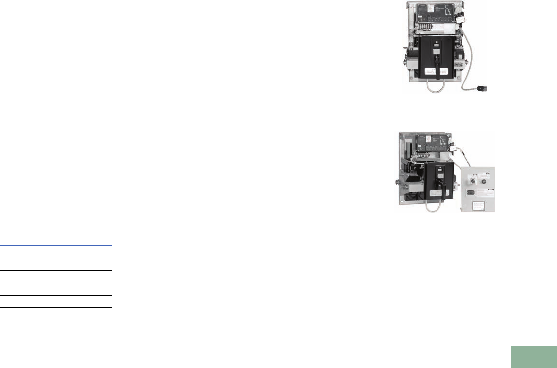
Volume 12—Aftermarket, Renewal Parts and Life Extension Solutions CA08100014E—November 2013 www.eaton.com V12-T17-19
1
2
3
4
5
6
7
8
9
10
11
12
13
14
15
16
17
18
19
20
21
22
23
24
25
17
Switchgear
Trip Unit Retrofit Kits
Definitions of Replacement
and Upgrade Capabilities
Replacement Digitrip Trip Units
and Rating Plugs
Replacement trip units and
rating plugs are available and
are used when replacing
components with similar
functionality and protective
features. A complete listing
of replacement trip units
and rating plugs is found
on Pages V12-T17-21–
V12-T17-27.
Digitrip Trip Unit Upgrades
Trip unit upgrades can be
used when upgrading the trip
system only requires a change
in trip unit with no additional
hardware. This option is used
to replace an obsolete Digitrip
500/600/700/800 or as
outlined in the table below.
Use the replacement trip
unit and rating plug tables
on Pages V12-T17-21–
V12-T17-27.
Digitrip Trip Unit Upgrades
For advanced upgrades
requiring more than just a trip
unit replacement, a trip unit
retrofit kit or upgrade retrofit
kit is the correct solution.
Digitrip RMS Trip Unit
Retrofit Kits
Digitrip RMS trip unit retrofit
kits are fully engineered, field-
installable retrofit kits that
enable the user to completely
retrofit an existing trip system
on low
voltage power breakers.
They are applied
on breakers
that do not have existing
Digitrip trip systems installed.
Reference Pages V12-T17-28
–V12-T17-51 for information
on retrofit kits.
For breakers previously
retrofitted or shipped from
the factory with a Digitrip trip
system, refer to trip unit and
rating plug replacement,
Digitrip trip unit upgrades
or upgrade retrofit kits.
Upgrade Retrofit Kits
An upgrade retrofit kit is used
when upgrading a breaker
(previously retrofitted or
supplied from the factory
with a Digitrip 500/510) to an
advanced Digitrip 610/810/
910. These are complete
kits minus the components
common with a basic Digitrip
500/510 retrofit kit. A “U” in
the last position of the catalog
number denotes an upgrade
retrofit kit. Reference Pages
V12-T17-28–V12-T17-51
for information on upgrade
retrofit kits.
Arcflash Reduction
Maintenance System™
NFPA® 70E-2004 defines
flash hazard as: “A dangerous
condition associated with
the release of energy caused
by an electric arc.” This is
primarily heat energy and
may result in serious or life
threatening burns.
When properly applied to a
power breaker, the Arcflash
Reduction Maintenance
System reduces fault-clearing
time and lowers the available
arc flash energy at the
connected downstream
devices. The result is a
reduction of the hazard
risk category, allowing for
improved personnel safety
while eliminating the need
for higher levels of costly
personal protective
equipment (PPE).
The Arcflash Reduction
Maintenance System is
controlled by a lockable switch
that can easily activate a faster
tripping time at the work
location and be incorporated
into a lock-out tag-out (LOTO)
procedure. This switch can be
applied to any low voltage
power breaker by modifying
the existing Digitrip trip
system, or retrofitting a
breaker with a Digitrip retrofit
kit (see Accessories table
on Page V12-T17-28).
For further information,
contact your local Eaton’s
Electrical Services & Systems
office (see Ta b 2 4 ), or the
Digitrip Retrofit Kit Service
Center at 1-800-937-5487.
Modified Digitrip Trip System
with Arcflash Reduction
Maintenance System
Digitrip Retrofit with Arcflash
Reduction Maintenance System
Digitrip Trip Unit
Existing Upgrade
500 510
600 610
700 810/910
800 810/910
810 910

V12-T17-20 Volume 12—Aftermarket, Renewal Parts and Life Extension Solutions CA08100014E—November 2013 www.eaton.com
1
2
3
4
5
6
7
8
9
10
11
12
13
14
15
16
17
18
19
20
21
22
23
24
25
17
Switchgear
Trip Unit Retrofit Kits
Functional Comparison of Trip Units
Past Technology
Features
Present Technology
RMS
500
RMS
500
Zone
RMS
600
RMS
700
RMS
800
RMS
510
RMS
510
Zone
RMS
610
RMS
810
RMS
910
Trip Unit Features
■■ ■■ Cause-of-trip LED indicators ■■ ■■■
■■ ■■■Integral self test ■■ ■■■
■■ ■■■Trip reset button ■■ ■■■
■■ ■■■Hardware driven thermal memory
Software driven thermal memory (sel. O/O) ■■ ■■■
■■ ■■■Discriminator circuit on LS and LSG protection modes
Discriminator circuit on LS and LSG protection modes selectable (on/off) ■■ ■■■
■ ■■■Zone protective interlocking for short time and ground fault modes of protection ■■■■
■ ■■■Auxiliary contact for long time, short circuit and ground fault functions ■■■
■■
Local display of phase currents ■■■
■■
Local display of ground currents ■■■
■■
Local display of cause of trip ■■■
■Local display of energy (MWh) ■■
■Local display of peak demand (MW) ■■
■Local display of present demand (MW) ■■
PowerNet Communication Features
■■Data communicated with PowerNet includes: all display values, trip unit status, high
load alarm, cause of trip, rating plug status, breaker status, reason for breaker status
■■
Trip settings ■■
Power factor ■■
■■Control via the PowerNet system (open/close) ■■
Voltage phase-to-phase, displayed on trip unit and communicated via
PowerNet communications
■
Total harmonic distortion (THD); phase A, B, C. Displayed on trip unit and
communicated via PowerNet communications
■
Total harmonic distortion per harmonic from the 2nd through the 27th harmonic
displayed on trip unit and communicated via PowerNet communications
■
System power factor. Displayed on trip unit and communicated via PowerNet communications ■
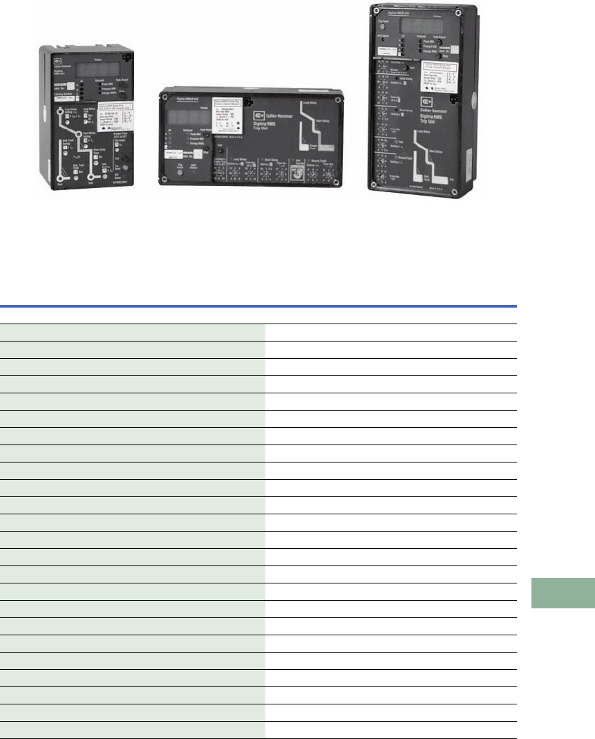
Volume 12—Aftermarket, Renewal Parts and Life Extension Solutions CA08100014E—November 2013 www.eaton.com V12-T17-21
1
2
3
4
5
6
7
8
9
10
11
12
13
14
15
16
17
18
19
20
21
22
23
24
25
17
Switchgear
Replacement Digitrip RMS Trip Units for Power Circuit Breakers
Replacement
Capabilities
Digitrip RMS Trip Units for
Power Circuit Breakers
Digitrip RMS Trip
Unit Replacement
When a Digitrip RMS trip unit
requires replacement, it can
be replaced directly using the
enclosed charts. Observe the
following restrictions:
The group function (G)
cannot be added in the field
just by changing the trip unit.
Trip Functions
All Digitrip RMS retrofit kit
types are available with the
necessary combinations of
long, short, instantaneous
and ground fault (LSIG)
modes of protection as
depicted and deemed
necessary by industry
standards.
The combinations of modes
of protection are:
●Ll
●LSI
●LS
●LIG
●LSG
●LSIG
Rating Plug Replacement
When changing or replacing
rating plugs, use the
charts provided on Pages
V12-T17-25–V12-T17-27
for DS, SPB and all other
retrofitted breakers.
Digitrip Units—Standard, Horizontal and Vertical Configurations
Standard Retrofit RMS Replacement Trip Units for DS and SPB Breakers
■
Shaded area denotes obsolete or discontinued products and services. 12
Notes
1At the time of this publication, the standard trip units for low voltage Digitrip retrofit kits are the RMS 510/610/810/910. From 1989 to 1996, the
standard trip units were the RMS 500/600/700/800. These trip units are no longer in production. Replacement orders for the 500/600/700/
800 trip units will be filled by the equivalent 510/610/810/910 trip units. Remember, when replacing a 500/600/700/800 unit with a 510/610/
810/910, the rating plug must also be replaced.
2Rating plugs for the 500/600/700/800 trip units will still be available. These rating plugs are not interchangeable with the 510/610/810/
910 trip units. Likewise, rating plugs for the 510/610/810/910 are not interchangeable with the 500/600/700/800 trip units.
3There is no direct replacement for Digitrip RMS 700. Use Digitrip RMS 810 or 910.
Digitrip
Model
Protective
Functions
Catalog
Number
Style
Number
Digitrip
Model
Protective
Functions
Catalog
Number
Style
Number
Past Technology Present Technology
RMS 500 Ll T51BLI 1230C97G01 RMS 510 Ll S51LI 7829C05G01
RMS 500 LSI T52BLSI 1230C97G02 RMS 510 LSI S52LSI 7829C05G02
RMS 500 LS T53BLS 1230C97G03 RMS 510 LS S53LS 7829C05G03
RMS 500 LIG T54BLIG 1230C97G04 RMS 510 LIG S54LIG 7829C05G04
RMS 500 LSG T55BLSG 1230C97G05 RMS 510 LSG S55LSG 7829C05G05
RMS 500 LSIG T56BLSIG 1230C97G06 RMS 510 LSIG S56LSIG 7829C05G06
RMS 600 Ll T61BLI 1230C97G07 RMS 610 Ll S61LI 7829C10G01
RMS 600 LSI T62BLSI 1230C97G08 RMS 610 LSI S62LSI 7829C10G02
RMS 600 LS T63BLS 1230C97G09 RMS 610 LS S63LS 7829C10G03
RMS 600 LIG T64BLIG 1230C97G10 RMS 610 LIG S64LIG 7829C10G04
RMS 600 LSG T65BLSG 1230C97G11 RMS 610 LSG S65LSG 7829C10G05
RMS 600 LSIG T66BLSIG 1230C97G12 RMS 610 LSIG S66LSIG 7829C10G06
RMS 700 3Ll T71BLI 1230C97G19 RMS 810 Ll S81LI 7829C08G01
RMS 700 3LSI T72BLSI 1230C97G20 RMS 810 LSI S82LSI 7829C08G02
RMS 700 3LS T73BLS 1230C97G21 RMS 810 LS S83LS 7829C08G03
RMS 700 3LIG T74BLIG 1230C97G22 RMS 810 LIG S84LIG 7829C08G04
RMS 700 3LSG T75BLSG 1230C97G23 RMS 810 LSG S85LSG 7829C08G05
RMS 700 3LSIG T76BLSIG 1230C97G24 RMS 810 LSIG S86LSIG 7829C08G06
RMS 800 Ll T81BLI 1230C97G13 RMS 910 Ll S91LI 7829C09G01
RMS 800 LSI T82BLSI 1230C97G14 RMS 910 LSI S92LSI 7829C09G02
RMS 800 LS T83BLS 1230C97G15 RMS 910 LS S93LS 7829C09G03
RMS 800 LIG T84BLIG 1230C97G16 RMS 910 LIG S94LIG 7829C09G0
RMS 800 LSG T85BLSG 1230C97G17 RMS 910 LSG S95LSG 7829C09G05
RMS 800 LSIG T86BLSIG 1230C97G18 RMS 910 LSIG S96LSIG 7829C09G06

V12-T17-22 Volume 12—Aftermarket, Renewal Parts and Life Extension Solutions CA08100014E—November 2013 www.eaton.com
1
2
3
4
5
6
7
8
9
10
11
12
13
14
15
16
17
18
19
20
21
22
23
24
25
17
Switchgear
Replacement Digitrip RMS Trip Units for Power Circuit Breakers
Horizontal Retrofit RMS/R Replacement Trip Units for all Other Breakers
■
Shaded area denotes obsolete or discontinued products and services. 12
Notes
1At the time of this publication, the standard trip units for low voltage Digitrip retrofit kits are the RMS 510/610/810/910. From 1989 to 1996, the standard trip units were the RMS 500/600/700/800.
These trip units are no longer in production. Replacement orders for the 500/600/700/800 trip units will be filled by the equivalent 510/610/810/910 trip units. Remember, when replacing a
500/600/700/800 unit with a 510/610/810/910, the rating plug must also be replaced.
2Rating plugs for the 500/600/700/800 trip units will still be available. These rating plugs are not interchangeable with the 510/610/810/910 trip units. Likewise, rating plugs for the
510/610/810/910 are not interchangeable with the 500/600/700/800 trip units.
3There is no direct replacement for Digitrip RMS 700. Use Digitrip RMS 810 or 910.
Digitrip
Model
Protective
Functions
Catalog
Number
Style
Number
Digitrip
Model
Protective
Functions
Catalog
Number
Style
Number
Past Technology Present Technology
RMS/R 500 Horizontal Ll RH51BLI 1232C84G01 RMS 510 Ll SRH51LI 7801C36G01
RMS/R 500 Horizontal LSI RH52BLSI 1232C84G02 RMS 510 LSI SRH52LSI 7801C36G02
RMS/R 500 Horizontal LS RH53BLS 1232C84G03 RMS 510 LS SRH53LS 7801C36G03
RMS/R 500 Horizontal LIG RH54BLIG 1232C84G04 RMS 510 LIG SRH54LIG 7801C36G04
RMS/R 500 Horizontal LSG RH55BLSG 1232C84G05 RMS 510 LSG SRH55LSG 7801C36G05
RMS/R 500 Horizontal LSIG RH56BLSIG 1232C84G06 RMS 510 LSIG SRH56LSIG 7801C36G06
RMS/R 600 Horizontal Ll RH61BLI 1232C84G07 RMS 610 Ll SRH61LI 7801C46G01
RMS/R 600 Horizontal LSI RH62BLSI 1232C84G08 RMS 610 LSI SRH62LSI 7801C46G02
RMS/R 600 Horizontal LS RH63BLS 1232C84G09 RMS 610 LS SRH63LS 7801C46G03
RMS/R 600 Horizontal LIG RH64BLIG 1232C84G10 RMS 610 LIG SRH64LIG 7801C46G04
RMS/R 600 Horizontal LSG RH65BLSG 1232C84G11 RMS 610 LSG SRH65LSG 7801C46G05
RMS/R 600 Horizontal LSIG RH66BLSIG 1232C84G12 RMS 610 LSIG SRH66LSIG 7801C46G06
RMS/R 700 Horizontal 3Ll RH71BLI 1232C84G19 RMS 810 Ll SRH81LI 7801C48G01
RMS/R 700 Horizontal 3LSI RH72BLSI 1232C84G20 RMS 810 LSI SRH82LSI 7801C48G02
RMS/R 700 Horizontal 3LS RH73BLS 1232C84G21 RMS 810 LS SRH83LS 7801C48G03
RMS/R 700 Horizontal 3LIG RH74BLIG 1232C84G22 RMS 810 LIG SRH84LIG 7801C48G04
RMS/R 700 Horizontal 3LSG RH75BLSG 1232C84G23 RMS 810 LSG SRH85LSG 7801C48G05
RMS/R 700 Horizontal 3LSIG RH76BLSIG 1232C84G24 RMS 810 LSIG SRH86LSIG 7801C48G06
RMS/R 800 Horizontal LI RH81BLI 1232C84G13 RMS 910 Ll SRH91LI 7801C49G01
RMS/R 800 Horizontal LSI RH82BLSI 1232C84G14 RMS 910 LSI SRH92LSI 7801C49G02
RMS/R 800 Horizontal LS RH83BLS 1232C84G15 RMS 910 LS SRH93LS 7801C49G03
RMS/R 800 Horizontal LIG RH84BLIG 1232C84G16 RMS 910 LIG SRH94LIG 7801C49G04
RMS/R 800 Horizontal LSG RH85BLSG 1232C84G17 RMS 910 LSG SRH95LSG 7801C49G05
RMS/R 800 Horizontal LSIG RH86BLSIG 1232C84G18 RMS 910 LSIG SRH96LSIG 7801C49G06

Volume 12—Aftermarket, Renewal Parts and Life Extension Solutions CA08100014E—November 2013 www.eaton.com V12-T17-23
1
2
3
4
5
6
7
8
9
10
11
12
13
14
15
16
17
18
19
20
21
22
23
24
25
17
Switchgear
Replacement Digitrip RMS Trip Units for Power Circuit Breakers
Vertical Retrofit RMS/R Replacement Trip Units for all Other Breakers
■
Shaded area denotes obsolete or discontinued products and services. 12
Notes
1At the time of this publication, the standard trip units for low voltage Digitrip retrofit kits are the RMS 510/610/810/910. From 1989 to 1996, the standard trip units were the RMS 500/600/700/800.
These trip units are no longer in production. Replacement orders for the 500/600/700/800 trip units will be filled by the equivalent 510/610/810/910 trip units. Remember, when replacing a
500/600/700/800 unit with a 510/610/810/910, the rating plug must also be replaced.
2Rating plugs for the 500/600/700/800 trip units will still be available. These rating plugs are not interchangeable with the 510/610/810/910 trip units. Likewise, rating plugs for the
510/610/810/910 are not interchangeable with the 500/600/700/800 trip units.
3There is no direct replacement for Digitrip RMS 700. Use Digitrip RMS 810 or 910.
Digitrip
Model
Protective
Functions
Catalog
Number
Style
Number
Digitrip
Model
Protective
Functions
Catalog
Number
Style
Number
Past Technology Present Technology
RMS/R 500 Vertical Ll RV51BLI 1232C97G01 RMS 510 Ll SRV51Ll 7801C37G01
RMS/R 500 Vertical LSI RV52BLSI 1232C97G02 RMS 510 LSI SRV52LSI 7801C37G02
RMS/R 500 Vertical LS RV53BLS 1232C97G03 RMS 510 LS SRV53LS 7801C37G03
RMS/R 500 Vertical LIG RV54BLIG 1232C97G04 RMS 510 LIG SRV54LIG 7801C37G04
RMS/R 500 Vertical LSG RV55BLSG 1232C97G05 RMS 510 LSG SRV55LSG 7801C37G05
RMS/R 500 Vertical LSIG RV56BLSIG 1232C97G06 RMS 510 LSIG SRV56LSIG 7801C37G06
RMS/R 600 Vertical Ll RV61BLI 1232C97G07 RMS 610 Ll SRV61Ll 7801C41G01
RMS/R 600 Vertical LSI RV62BLSI 1232C97G08 RMS 610 LSI SRV62LSI 7801C41G02
RMS/R 600 Vertical LS RV63BLS 1232C97G09 RMS 610 LS SRV63LS 7801C41G03
RMS/R 600 Vertical LIG RV64BLIG 1232C97G10 RMS 610 LIG SRV64LIG 7801C41G04
RMS/R 600 Vertical LSG RV65BLSG 1232C97G11 RMS 610 LSG SRV65LSG 7801C41G05
RMS/R 600 Vertical LSIG RV66BLSIG 1232C97G12 RMS 610 LSIG SRV66LSIG 7801C41G06
RMS/R 700 Vertical 3Ll RV71BLI 1232C97G19 RMS 810 Ll SRV81Ll 7801C42G01
RMS/R 700 Vertical 3LSI RV72BLSI 1232C97G20 RMS 810 LSI SRV82LSI 7801C42G02
RMS/R 700 Vertical 3LS RV73BLS 1232C97G21 RMS 810 LS SRV83LS 7801C42G03
RMS/R 700 Vertical 3LIG RV74BLIG 1232C97G22 RMS 810 LIG SRV84LIG 7801C42G04
RMS/R 700 Vertical 3LSG RV75BLSG 1232C97G23 RMS 810 LSG SRV85LSG 7801C42G05
RMS/R 700 Vertical 3LSIG RV76BLSIG 1232C97G24 RMS 810 LSIG SRV86LSIG 7801C42G06
RMS/R 800 Vertical Ll RV81BLI 1232C97G13 RMS 910 Ll SRV91Ll 7801C43G01
RMS/R 800 Vertical LSI RV82BLSI 1232C97G14 RMS 910 LSI SRV92LSI 7801C43G02
RMS/R 800 Vertical LS RV83BLS 1232C97G15 RMS 910 LS SRV93LS 7801C43G03
RMS/R 800 Vertical LIG RV84BLIG 1232C97G16 RMS 910 LIG SRV94LIG 7801C43G04
RMS/R 800 Vertical LSG RV85BLSG 1232C97G17 RMS 910 LSG SRV95LSG 7801C43G05
RMS/R 800 Vertical LSIG RV86BLSIG 1232C97G18 RMS 910 LSIG SRV96LSIG 7801C43G06
V12-T17-24 Volume 12—Aftermarket, Renewal Parts and Life Extension Solutions CA08100014E—November 2013 www.eaton.com
1
2
3
4
5
6
7
8
9
10
11
12
13
14
15
16
17
18
19
20
21
22
23
24
25
17
Switchgear
Replacement Digitrip RMS Rating Plugs
Digitrip RMS
Rating Plugs
Product Description
SPB Rating Plug and Details
Rating plugs for Digitrip RMS
trip units determine the
continuous current rating
of the circuit breaker. All
protection function settings
on the face of the trip unit
are expressed in per unit
multiples of the rating plug
ampere rating (In).
The rating plug is interlocked
with the tripping mechanism
to automatically “open” the
breaker when the plug is
removed. The breaker will
remain “trip free” with the
plug removed.
SPB rating plugs must be
selected to match the desired
continuous current rating of
the breaker, as well as the
frame rating and the system
frequency, i.e., 50 or 60 Hz.
DS and retrofit rating plugs
must be selected to match
the desired continuous
current rating of the breaker,
the sensor tap setting and
the system frequency, i.e.,
50 or 60 Hz.
Rating plugs are equipped
with a backup battery to
maintain the mode of trip
operation following a circuit
breaker tripping when
external power is not
available. The battery is
a long-life lithium type,
which is accessible from the
front of the trip unit, without
removing the rating plug.
Replacement types and
instructions are provided in
Application Data 33-855.
Rating Plug for All Other
Retrofitted Breakers
DS Rating Plug
Following a trip operation
and with no supplementary
control power available,
the battery will maintain
the mode of trip LED for
approximately 60 hours.
Note: At the time of this
publication, the standard trip units
for low voltage Digitrip retrofit kits
are the RMS 510/610/810/910.
From 1989 to 1996, the standard
trip units were the RMS 500/
600/700/800. These trip units
are no longer in production.
Replacement orders for the
500/600/700/800 trip units will be
filled by the equivalent 510/610/
810/910 trip units. Remember,
when replacing a 500/600/700/
800 unit with a 510/610/810/910,
the rating plug must also
be replaced.
Note: Rating plugs for the 500/
600/700/800 trip units will still
be available.These rating plugs
are not interchangeable with
the 510/610/810/910 trip units.
Likewise, rating plugs for
the 510/610/810/910 are not
interchangeable with the
500/600/700/800 trip units.

Volume 12—Aftermarket, Renewal Parts and Life Extension Solutions CA08100014E—November 2013 www.eaton.com V12-T17-25
1
2
3
4
5
6
7
8
9
10
11
12
13
14
15
16
17
18
19
20
21
22
23
24
25
17
Switchgear
Replacement Digitrip RMS Rating Plugs for DS Breakers
Replacement Capabilities
Rating Plugs for DS Breakers 1234
Notes
1Choose the rating plug to match the sensor tap selected and the continuous current rating.
2When ordering as part of a retrofit kit, refer to Pages V12-T17-28 through V12-T17-51.
3At the time of this publication, the standard trip units for low voltage Digitrip retrofit kits are the RMS 510/610/810/910. From 1989 to 1996, the standard trip units were the RMS 500/600/700/800.
These trip units are no longer in production. Replacement orders for the 500/600/700/800 trip units will be filled by the equivalent 510/610/810/910 trip units. Remember, when replacing a
500/600/700/800 unit with a 510/610/810/910, the rating plug must also be replaced.
4Rating plugs for the 500/600/700/800 trip units will still be available. These rating plugs are not interchangeable with the 510/610/810/910 trip units. Likewise, rating plugs for the
510/610/810/910 are not interchangeable with the 500/600/700/800 trip units.
550 Hz rating plugs are available. Contact your local Eaton Field Sales office for details.
6Rating plugs may be ordered separately by above style number or as part of a complete retrofit kit.
Past Technology (500/600/700/800) Present Technology (510/610/810/910)
Sensor
Tap Connection
Rating
Plug Rating
60 Hz
Catalog Number 5
60 Hz
Style Number 5
Sensor
Tap Connection
Rating
Plug Rating
50/60 Hz
Catalog Number 6
50/60 Hz
Style Number 6
200 100 PD6D02A010 2613D10G01 200 100 RP6D02A010 3D86734G01
200 200 PD6D02A020 2613D10G02 200 200 RP6D02A020 3D86734G02
300 200 PD6D03A020 2613D10G03 300 200 RP6D03A020 3D86734G03
300 250 PD6D03A025 2613D10G04 300 250 RP6D03A025 3D86734G04
300 300 PD6D03A030 2613D10G05 300 300 RP6D03A030 3D86734G05
400 200 PD6D04A020 2613D10G06 400 200 RP6D04A020 3D86734G06
400 250 PD6D04A025 2613D10G07 400 250 RP6D04A025 3D86734G07
400 300 PD6D04A030 2613D10G08 400 300 RP6D04A030 3D86734G08
400 400 PD6D04A040 2613D10G09 400 400 RP6D04A040 3D86734G09
600 300 PD6D06A030 2613D10G10 600 400 RP6D06A030 3D86734G10
600 400 PD6D06A040 2613D10G11 600 400 RP6D06A040 3D86734G11
600 600 PD6D06A060 2613D10G12 600 600 RP6D06A060 3D86734G12
800 400 PD6D08A040 2613D10G13 800 400 RP6D08A040 3D86734G13
800 600 PD6D08A060 2613D10G14 800 600 RP6D08A060 3D86734G14
800 800 PD6D08A080 2613D10G15 800 800 RP6D08A080 3D86734G15
1200 600 PD6D12A060 2613D10G16 1200 600 RP6D12A060 3D86734G16
1200 800 PD6D12A080 2613D10G17 1200 800 RP6D12A080 3D86734G17
1200 1000 PD6D12A100 2613D10G18 1200 1000 RP6D12A100 3D86734G18
1200 1200 PD6D12A120 2613D10G19 1200 1200 RP6D12A120 3D86734G19
1600 800 PD6D16A080 2613D10G20 1600 800 RP6D16A080 3D86734G20
1600 1000 PD6D16A100 2613D10G21 1600 1000 RP6D16A100 3D86734G21
1600 1200 PD6D16A120 2613D10G22 1600 1200 RP6D16A120 3D86734G22
1600 1600 PD6D16A160 2613D10G23 1600 1600 RP6D16A160 3D86734G23
2000 1000 PD6D20A100 2613D10G24 2000 1000 RP6D20A100 3D86734G24
2000 1200 PD6D20A120 2613D10G25 2000 1200 RP6D20A120 3D86734G25
2000 1600 PD6D20A160 2613D10G26 2000 1600 RP6D20A160 3D86734G26
2000 2000 PD6D20A200 2613D10G27 2000 2000 RP6D20A200 3D86734G27
2400 1600 PD6D24A160 2613D10G28 2400 1600 RP6D24A160 3D86734G28
2400 2000 PD6D24A200 2613D10G29 2400 2000 RP6D24A200 3D86734G29
2400 2400 PD6D24A240 2613D10G30 2400 2400 RP6D24A240 3D86734G30
3200 1600 PD6D32A160 2613D10G31 3200 1600 RP6D32A160 3D86734G31
3200 2000 PD6D32A200 2613D10G32 3200 2000 RP6D32A200 3D86734G32
3200 2400 PD6D32A240 2613D10G33 3200 2400 RP6D32A240 3D86734G33
3200 3200 PD6D32A320 2613D10G34 3200 3200 RP6D32A320 3D86734G34
4000 2000 PD6D40A200 2613D10G35 4000 2000 RP6D40A200 3D86734G35
4000 2400 PD6D40A240 2613D10G36 4000 2400 RP6D40A240 3D86734G36
4000 3200 PD6D40A320 2613D10G37 4000 3200 RP6D40A320 3D86734G37
4000 4000 PD6D40A400 2613D10G38 4000 4000 RP6D40A400 3D86734G38

V12-T17-26 Volume 12—Aftermarket, Renewal Parts and Life Extension Solutions CA08100014E—November 2013 www.eaton.com
1
2
3
4
5
6
7
8
9
10
11
12
13
14
15
16
17
18
19
20
21
22
23
24
25
17
Switchgear
Replacement Digitrip RMS Rating Plugs for DS Breakers
Rating Plugs for SPB Breakers 1234
Notes
1Choose the rating plug to match the sensor tap selected and the continuous current rating.
2When ordering as part of a retrofit kit, refer to Pages V12-T17-28 through V12-T17-51.
3At the time of this publication, the standard trip units for low voltage Digitrip retrofit kits are the RMS 510/610/810/910. From 1989 to 1996, the standard trip units were the RMS 500/600/700/800.
These trip units are no longer in production. Replacement orders for the 500/600/700/800 trip units will be filled by the equivalent 510/610/810/910 trip units. Remember, when replacing a
500/600/700/800 unit with a 510/610/810/910, the rating plug must also be replaced.
4Rating plugs for the 500/600/700/800 trip units will still be available. These rating plugs are not interchangeable with the 510/610/810/910 trip units. Likewise, rating plugs for the
510/610/810/910 are not interchangeable with the 500/600/700/800 trip units.
550 Hz rating plugs are available. Contact your local Eaton Field Sales office for details.
6Rating plugs may be ordered separately by above style number or as part of a complete retrofit kit.
Past Technology (500/600/700/800) Present Technology (510/610/810/910)
Sensor
Tap Connection
Rating
Plug Rating
60 Hz
Catalog Number 5
60 Hz
Style Number 5
Sensor
Tap Connection
Rating
Plug Rating
50/60 Hz
Catalog Number 6
50/60 Hz
Style Number 6
400 200 PD6S04A020 2613D09G01 400 200 RP6S04A020 3D86737G01
400 250 PD6S04A025 2613D09G02 400 250 RP6S04A025 3D86737G02
400 300 PD6S04A030 2613D09G03 400 300 RP6S04A030 3D86737G03
400 400 PD6S04A040 2613D09G04 400 400 RP6S04A040 3D86737G04
800 400 PD6S08A040 2613D09G05 800 400 RP6S08A040 3D86737G05
800 600 PD6S08A060 2613D09G07 800 600 RP6S08A060 3D86737G07
800 800 PD6S08A080 2613D09G08 800 800 RP6S08A080 3D86737G08
1200 600 PD6S12A060 2613D09G09 1200 600 RP6S12A060 3D86737G09
1200 800 PD6S12A080 2613D09G10 1200 800 RP6S12A080 3D86737G10
1200 1000 PD6S12A100 2613D09G11 1200 1000 RP6S12A100 3D86737G11
1200 1200 PD6S12A120 2613D09G12 1200 1200 RP6S12A120 3D86737G12
1600 800 PD6S16A080 2613D09G13 1600 800 RP6S16A080 3D86737G13
1600 1000 PD6S16A100 2613D09G14 1600 1000 RP6S16A100 3D86737G14
1600 1200 PD6S16A120 2613D09G15 1600 1200 RP6S16A120 3D86737G15
1600 1600 PD6S16A160 2613D09G16 1600 1600 RP6S16A160 3D86737G16
2000C 1000 PD6S21A100 2613D09G17 2000C 1000 RP6S21A100 3D86737G17
2000C 1200 PD6S21A120 2613D09G18 2000C 1200 RP6S21A120 3D86737G18
2000C 1600 PD6S21A160 2613D09G19 2000C 1600 RP6S21A160 3D86737G19
2000C 2000 PD6S21A200 2613D09G20 2000C 2000 RP6S21A200 3D86737G20
2000 1600 PD6S20A160 2613D09G21 2000 1600 RP6S20A160 3D86737G21
2000 2000 PD6S20A200 2613D09G22 2000 2000 RP6S20A200 3D86737G22
2500 1600 PD6S25A160 2613D09G23 2500 1600 RP6S25A160 3D86737G23
2500 2000 PD6S25A200 2613D09G24 2500 2000 RP6S25A200 3D86737G24
2500 2500 PD6S25A250 2613D09G25 2500 2500 RP6S25A250 3D86737G25
3000 1600 PD6S30A160 2613D09G26 3000 1600 RP6S30A160 3D86737G26
3000 2000 PD6S30A200 2613D09G27 3000 2000 RP6S30A200 3D86737G27
3000 2500 PD6S30A250 2613D09G28 3000 2500 RP6S30A250 3D86737G28
3000 3000 PD6S30A300 2613D09G29 3000 3000 RP6S30A300 3D86737G29
4000 2000 PD6S40A200 2613D09G30 4000 2000 RP6S40A200 3D86737G30
4000 2500 PD6S40A250 2613D09G31 4000 2500 RP6S40A250 3D86737G31
4000 3000 PD6S40A300 2613D09G32 4000 3000 RP6S40A300 3D86737G32
4000 3200 PD6S40A320 2613D09G33 4000 3200 RP6S40A320 3D86737G33
4000 4000 PD6S40A400 2613D09G34 4000 4000 RP6S40A400 3D86737G34
5000 3000 PD6S50A300 2613D09G35 5000 3000 RP6S50A300 3D86737G35
5000 3200 PD6S50A320 2613D09G36 5000 3200 RP6S50A320 3D86737G36
5000 4000 PD6S50A400 2613D09G37 5000 4000 RP6S50A400 3D86737G37
5000 5000 PD6S50A500 2613D09G38 5000 5000 RP6S50A500 3D86737G38

Volume 12—Aftermarket, Renewal Parts and Life Extension Solutions CA08100014E—November 2013 www.eaton.com V12-T17-27
1
2
3
4
5
6
7
8
9
10
11
12
13
14
15
16
17
18
19
20
21
22
23
24
25
17
Switchgear
Replacement Digitrip RMS Rating Plugs for DS Breakers
Rating Plugs for All Other Breakers 1234
Notes
1Choose the rating plug to match the sensor tap selected and the continuous current rating.
2When ordering as part of a retrofit kit, refer to Pages V12-T17-28 through V12-T17-51.
3At the time of this publication, the standard trip units for low voltage Digitrip retrofit kits are the RMS 510/610/810/910. From 1989 to 1996, the standard trip units were the RMS 500/600/700/800.
These trip units are no longer in production. Replacement orders for the 500/600/700/800 trip units will be filled by the equivalent 510/610/810/910 trip units. Remember, when replacing a
500/600/700/800 unit with a 510/610/810/910, the rating plug must also be replaced.
4Rating plugs for the 500/600/700/800 trip units will still be available. These rating plugs are not interchangeable with the 510/610/810/910 trip units. Likewise, rating plugs for the
510/610/810/910 are not interchangeable with the 500/600/700/800 trip units.
550 Hz rating plugs are available. Contact your local Eaton Field Sales office for details.
6Rating plugs may be ordered separately by above style number or as part of a complete retrofit kit.
Past Technology (500/600/700/800) Present Technology (510/610/810/910)
Sensor
Tap Connection
Rating
Plug Rating
60 Hz
Catalog Number 5
60 Hz
Style Number 5
Sensor
Tap Connection
Rating
Plug Rating
50/60 Hz
Catalog Number 6
50/60 Hz
Style Number 6
200 100 PR6A02A010 3D86709G01 200 100 RP6A02A010 3D86766G01
200 200 PR6A02A020 3D86709G02 200 200 RP6A02A020 3D86766G02
250 250 PR6A02A025 3D86709G11 250 250 RP6A02A025 3D86766G11
300 200 PR6A03A020 3D86709G36 300 200 RP6A03A020 3D86766G36
300 250 PR6A03A025 3D86709G12 300 250 RP6A03A025 3D86766G12
300 300 PR6A03A030 3D86709G37 300 300 RP6A03A030 3D86766G37
400 200 PR6A04A020 3D86709G13 400 200 RP6A04A020 3D86766G13
400 250 PR6A04A025 3D86709G14 400 250 RP6A04A025 3D86766G14
400 300 PR6A04A030 3D86709G15 400 300 RP6A04A030 3D86766G15
400 400 PR6A04A040 3D86709G03 400 400 RP6A04A040 3D86766G03
600 300 PR6A06A030 3D86709G16 600 300 RP6A06A030 3D86766G16
600 400 PR6A06A040 3D86709G17 600 400 RP6A06A040 3D86766G17
600 600 PR6A06A060 3D86709G04 600 600 RP6A06A060 3D86766G04
800 400 PR6A08A040 3D86709G18 800 400 RP6A08A040 3D86766G18
800 600 PR6A08A060 3D86709G19 800 600 RP6A08A060 3D86766G19
800 800 PR6A08A080 3D86709G05 800 800 RP6A08A080 3D86766G05
1200 600 PR6A12A060 3D86709G20 1200 600 RP6A12A060 3D86766G20
1200 800 PR6A12A080 3D86709G21 1200 800 RP6A12A080 3D86766G21
1200 1000 PR6A12A100 3D86709G22 1200 1000 RP6A12A100 3D86766G22
1200 1200 PR6A12A120 3D86709G10 1200 1200 RP6A12A120 3D86766G10
1600 800 PR6A16A080 3D86709G23 1600 800 RP6A16A080 3D86766G23
1600 1000 PR6A16A100 3D86709G24 1600 1000 RP6A16A100 3D86766G24
1600 1200 PR6A16A120 3D86709G25 1600 1200 RP6A16A120 3D86766G25
1600 1600 PR6A16A160 3D86709G06 1600 1600 RP6A16A160 3D86766G06
2000 1000 PR6A20A100 3D86709G26 2000 1000 RP6A20A100 3D86766G26
2000 1200 PR6A20A120 3D86709G27 2000 1200 RP6A20A120 3D86766G27
2000 1600 PR6A20A160 3D86709G28 2000 1600 RP6A20A160 3D86766G28
2000 2000 PR6A20A200 3D86709G07 2000 2000 RP6A20A200 3D86766G07
3000 1600 PR6A30A160 3D86709G29 3000 1600 RP6A30A160 3D86766G29
3000 2000 PR6A30A200 3D86709G30 3000 2000 RP6A30A200 3D86766G30
3000 2500 PR6A30A250 3D86709G31 3000 2500 RP6A30A250 3D86766G31
3000 3000 PR6A30A300 3D86709G08 3000 3000 RP6A30A300 3D86766G08
3200 1600 PR6A32A160 3D86709G39 3200 1600 RP6A32A160 3D86766G39
3200 2000 PR6A32A200 3D86709G40 3200 2000 RP6A32A200 3D86766G40
3200 2400 PR6A32A240 3D86709G41 3200 2400 RP6A32A240 3D86766G41
3200 3200 PR6A32A320 3D86709G42 3200 3200 RP6A32A320 3D86766G42
4000 2000 PR6A40A200 3D86709G32 4000 2000 RP6A40A200 3D86766G32
4000 2500 PR6A40A250 3D86709G33 4000 2500 RP6A40A250 3D86766G33
4000 3000 PR6A40A300 3D86709G34 4000 3000 RP6A40A300 3D86766G34
4000 3200 PR6A40A320 3D86709G35 4000 3200 RP6A40A320 3D86766G35
4000 4000 PR6A40A400 3D86709G09 4000 4000 RP6A40A400 3D86766G09

V12-T17-28 Volume 12—Aftermarket, Renewal Parts and Life Extension Solutions CA08100014E—November 2013 www.eaton.com
1
2
3
4
5
6
7
8
9
10
11
12
13
14
15
16
17
18
19
20
21
22
23
24
25
17
Switchgear
Trip Unit Retrofit Kits—Customer Required Information
Customer Required
Information
How to Select a Retrofit Kit
To properly select a retrofit
kit, the following information
is required:
●Breaker nameplate
information
●Manufacturer
●Breaker type
●Ampere frame size
●Manually or electrically
operated
●Drawout or fixed mounting
●Fused or non-fused
●Digitrip trip unit type
required
●510, 610, 810, 910
●Protective functions
required
●LI, LSI, LS, LIG, LSG,
LSIG
●Continuous current rating
required (trip rating of
breaker)
●Three- or four-wire system
(determines number of
sensors required)
To properly select options, the
following questions need to
be answered:
●Will customer supply
120 Vac control power
or is breaker-mounted
CPT needed?
●Applies only to Digitrip
610, 810 and 910
●Are zone interlocks
required?
●Does the application
require relay outputs from
the Digitrip 610, 810 or 910
for remote indication?
●Does the breaker have an
existing amptector or
Digitrip trip unit installed?
If so, what is it?
How to Generate a
Catalog Number
Refer to Pages V12-T17-30
to V12-T17-51 to view
the retrofit kit catalog
numbers for specific breaker
manufacturers and frames.
When used in conjunction
with the information obtained
from this page, these pages
contain all the information
necessary to generate
a catalog number.
How to Price a Kit
To correctly price a Low
voltage Digitrip retrofit kit,
refer to the Retrofit Kit
Product Guide. This product
guide includes base prices,
adders and options for all low
voltage Digitrip retrofit kits.
For a copy of the Retrofit Kit
Product Guide, contact your
local Eaton Field Sales
office or the Digitrip
Retrofit Kit Service Center
at 1-800-937-5487.
Accessories
Notes
At the time of this publication, the standard trip units for low voltage Digitrip retrofit kits are the RMS 510/610/810/910. From 1989 to 1996, the
standard trip units were the RMS 500/600/700/800. These trip units are no longer in production. Replacement orders for the 500/600/700/
800 trip units will be filled by the equivalent 510/610/810/910 trip units. Remember, when replacing a 500/600/700/800 unit with a 510/610/810/
910, the rating plug must also be replaced.
Rating plugs for the 500/600/700/800 trip units will still be available. These rating plugs are not interchangeable with the 510/610/810/
910 trip units. Likewise, rating plugs for the 510/610/810/910 are not interchangeable with the 500/600/700/800 trip units.
Description
Catalog
Number
Style
Number
Auxiliary power module PRTAAPM 1267C16G01
Amptector and Digitrip test set (tests for both) 8779C02G02
Amptector adapter harness 6503C53G01
Amptector two-piece adapter harness (test set half) 6503C54G01
Amptector two-piece adapter harness (breaker half) 6503C55G01
External harness (zone interlock shorting plug non-DS) 6502C83G01
Simplified cell harness 1 ft 6506C34G01
Simplified cell harness 6 ft 6506C34G02
Simplified cell harness 4 ft 6506C34G03
Arcflash Reduction Maintenance System (ARMS)
Non-DS 9A10160G01
DS with new Digitrip kit 9A10160G02
DS for existing Digitrip system 9A10160G03

Volume 12—Aftermarket, Renewal Parts and Life Extension Solutions CA08100014E—November 2013 www.eaton.com V12-T17-29
1
2
3
4
5
6
7
8
9
10
11
12
13
14
15
16
17
18
19
20
21
22
23
24
25
17
Switchgear
Westinghouse DA and DK Breakers—Trip Unit Retrofit Kits
Digitrip RMS Trip
Unit Retrofit Kits for
Westinghouse DA
and DK Breakers
Replacement and
Upgrade Capabilities
Replacement and upgrade
capabilities include
replacement Digitrip trip units
and rating plugs, Digitrip trip
unit upgrades, Digitrip RMS
trip unit retrofit kits and
upgrade retrofit kits. For
definitions of these solutions
see Page V12-T17-19.
For Digitrip RMS trip unit retrofit
kits and upgrade retrofit kits,
create the Digitrip RMS retrofit
kit catalog number to match
the Westinghouse DA or DK
breaker type, retrofit kit type,
protection function, rating plug
type, current sensor type, CPT,
and type of kit required for
application. See the example
provided on
Page
V12-T17-30
.
Application Notes for DA and
DK Power Circuit Breakers
1. Retrofit kits are for
use on 50 and 60 Hz
distribution systems.
2. All retrofit kits are
designed for drawout
power circuit breakers
only. Refer all fixed-
mounted breaker
applications to the
Digitrip retrofit kit
Technical Service Center
at 1-800-937-5487.
3. The breaker compartment
doors on the switchgear
assembly must be free
of panel-mounted
instruments and devices
(i.e., ammeters, switches,
etc.) or the retrofitted
breaker may interfere with
these devices when the
compartment door
is closed.
4. When the ground fault
(G) option is selected,
please observe the
following:
a. For three-phase,
three-wire solidly
grounded systems,
choose quantity three
current sensors in
the catalog number
development.
b. For three-phase, four-
wire solidly grounded
systems, choose
quantity four current
sensors in the catalog
number development.
Three sensors are
mounted on the
breaker and one
sensor is mounted on
the switchgear neutral.
Hardware to mount
the current sensor on
the switchgear neutral
and provisions to wire
it into the trip unit
circuit (including a
required pair of breaker
secondary disconnect-
ing contacts) are not
included in the kit.
5. RMS 510 Zone, 610,
810 and 910 retrofit kits
include a cell terminal
block assembly that must
be installed in the
switchgear assembly.
Internal switchgear
wiring to accommodate
the customer application
schemes must be added
in the field.
6. RMS 610, 810 and 910
retrofit kits require a
customer supplied
120 Vac source
connected to the cell
terminal block assembly
to power the Digitrip
RMS digital displays
and communications
functions (as applicable).
V12-T17-30 Volume 12—Aftermarket, Renewal Parts and Life Extension Solutions CA08100014E—November 2013 www.eaton.com
1
2
3
4
5
6
7
8
9
10
11
12
13
14
15
16
17
18
19
20
21
22
23
24
25
17
Switchgear
Westinghouse DA and DK Breakers—Trip Unit Retrofit Kits
Digitrip RMS Retrofit Kits for Westinghouse DA and DK Breakers Catalog Numbering System
Notes
1At the time of this publication, the standard trip units for low voltage Digitrip retrofit kits are the RMS 510/610/810/910.
2Maximum ampere rating is 200A.
Example shown is a Digitrip
retrofit kit for a DA-50-800
manual, with an RMS 810
trip unit, with LSIG protection,
with a 60 Hz plug, rated at
800A for a sensor tap of
800A, four sensors (for a
four-wire ground system)
that have a sensor tap of
800A, there is a breaker-
mounted CPT with the kit,
the cell wiring is simplified
(only 6 wires vs. 16), and
the breaker was previously
retrofitted with a Digitrip 500/
510, so this is an upgrade kit.
This information is subject to
change. Updated pricing and
availability information is
included in the Retrofit Kit
Product Guide. For a copy
of the Retrofit Kit Product
Guide, contact your local
Eaton Field Sales office or the
Digitrip Retrofit Kit Service
Center at 1-800-937-5487.
Trip Unit Type 1
5= 510 basic
Z= 510 zone int.
6= 610
8= 810
9= 910
Protection
1 = LI
2 = LSI
3 = LS
4 = LIG
5 = LSG
6 = LSIG
RP No Rating Plug
Cat.
Code
Current Rating
Tap Plug
21
22
32
3Q
33
42
4Q
43
44
63
64
66
84
86
88
C8
CA
CT
CC
HC
HD
HP
HH
200
200
300
300
300
400
400
400
400
600
600
600
800
800
800
1600
1600
1600
1600
3000
3000
3000
3000
100
200
200
250
300
200
250
300
400
300
400
600
400
600
800
800
1000
1200
1600
1600
2000
2500
3000
N= No rating plug
6= 50/60 Hz Plug
N= No sensors
3= Three sensors
4= Four sensors
T = Digitrip 510, 610, 810, 910
Code Breaker Frame Description Sensor
Code
Current Rating of
Sensor and Available Taps
ALL FRAMES SNO SENSORS PROVIDED
DK2 DK-15 22200
DE6 DK-25 6600
4400
2200
DT8
DW8
DA-50-800 manual
“Tulip” clusters
“Spring wrapped” finger cluster
8800, 400
DTC
DWC
DA-50-1600 manual
“Tulip” finger cluster
“Spring wrapped” finger cluster
C1600, 800
8800, 400
DEH DA-75 electric and manual H3000
N= No CPT supplied
C= Breaker-mounted CPT
N= Standard kit
U= Upgrade kit from Digitrip 500/510
N = Standard kit
S = Simplified cell harness
R = Cell harness removed
DT8 8 6 6 88 4 8 – T C S U
Volume 12—Aftermarket, Renewal Parts and Life Extension Solutions CA08100014E—November 2013 www.eaton.com V12-T17-31
1
2
3
4
5
6
7
8
9
10
11
12
13
14
15
16
17
18
19
20
21
22
23
24
25
17
Switchgear
Westinghouse DB Breakers—Trip Unit Retrofit Kits
Digitrip RMS Retrofit
Kits for Westinghouse
DB Breakers
DB-25 Breaker Retrofitted with
Digitrip RMS 810 Retrofit Kit
Typical Digitrip RMS 810 Retrofit Kit
for a DB-25 Power Circuit Breaker
Product Description
Digitrip RMS retrofit kits for
Westinghouse DB and DBL
power circuit
breakers were
first introduced in 1989.
For
a complete description of the
Digitrip
RMS trip system and
the features of models RMS
510, 610, 810 and 910, see
Page V12-T17-20.
Ratings
Digitrip RMS retrofit kits
are applied on DB breakers
with frame ratings from 225A
(DB-15) to 4000A (DB-100)
as identified below. The
rating plug and the current
sensor rating act in concert
to provide for a wide
spectrum of overload and
short-circuit settings.
Chronology
Digitrip RMS retrofit kits and
replacement trip units for
DB breakers became
available around 1989. The
Digitrip RMS 510 model is
the modern day replacement
for the Amptector and RK
trip systems.
Replacement and
Upgrade Capabilities
Replacement and upgrade
capabilities include replace-
ment Digitrip trip units and
rating plugs, Digitrip trip unit
upgrades, Digitrip RMS trip
unit retrofit kits and upgrade
retrofit kits. For definitions
of these solutions, see
Page V12-T17-19.
For Digitrip RMS trip unit
retrofit kits and upgrade
retrofit kits, create the
Digitrip RMS retrofit kit
catalog number to match the
Westinghouse DB breaker
type, retrofit kit type,
protection function, rating
plug type, current sensor
type, CPT and type of kit
required for application. See
the example provided on
Page V12-T17-32.
Application Notes for
Westinghouse DB and DBL
Power Circuit Breakers
1. Retrofit kits are for
use on 50 and 60 Hz
distribution systems.
2. All retrofit kits are
designed for drawout
power circuit breakers
only. Refer all fixed-
mounted breaker
applications to the Digitrip
Retrofit Kit Service Center
at 1-800-937-5487.
3. The breaker compartment
doors on the switchgear
assembly must be
free of panel-mounted
instruments and devices
(i.e., ammeters, switches,
etc.) or the retrofitted
breaker may interfere
with these devices
when the compartment
door is closed.
4. Type DB-15 and DBL
breaker components
may have a metal baffle
on the inside of the
compartment door.
If so, the baffle will
have to be removed
to accommodate the
retrofitted DB breaker.
5. Contact your local Eaton
office if the existing
DB breaker has both an
undervoltage trip device
(UVTA) and a shunt trip.
6. When the ground fault
(G) option is selected,
please observe the
following:
a. For three-phase, three-
wire solidly grounded
systems, choose
quantity three current
sensors in the catalog
number development.
b. For three-phase, four-
wire solidly grounded
systems, choose a
quantity of four current
sensors in the catalog
number development.
Three sensors are
mounted on the
breaker and one
sensor is mounted on
the switchgear neutral.
Hardware to mount
the current sensor on
the switchgear neutral
and provisions to wire
it into the trip unit
circuit (including a
required pair of
breaker secondary
disconnecting
contacts) are not
included in the kit.
7. RMS 510 Zone, 610, 810
and 910 retrofit kits
include a cell terminal
block assembly that must
be installed in the
switchgear assembly.
Internal switchgear
wiring to accommodate
the customer application
schemes must be added
in the field.
8. RMS 610, 810 and 910
retrofit kits require a
customer supplied
120 Vac source
connected to the cell
terminal block assembly
to power the Digitrip
RMS digital displays
and communications
functions (as applicable).
9. If the existing DB breaker
has been retrofitted
with an Amptector trip
system, and a Digitrip
RMS retrofit is desired,
contact the Digitrip
Retrofit Kit Service
Center at 1-800-937-5487
for details.
V12-T17-32 Volume 12—Aftermarket, Renewal Parts and Life Extension Solutions CA08100014E—November 2013 www.eaton.com
1
2
3
4
5
6
7
8
9
10
11
12
13
14
15
16
17
18
19
20
21
22
23
24
25
17
Switchgear
Westinghouse DB Breakers—Trip Unit Retrofit Kits
Digitrip RMS Retrofit Kits for Westinghouse DB Breakers Catalog Numbering System
Notes
1At the time of this publication, the standard trip units for low voltage Digitrip retrofit kits are the RMS 510/610/810/910.
2Maximum ampere rating is 200A.
Sample shown is a Digitrip
retrofit kit for a DB-25, with
an RMS 810 trip unit, with
LSIG protection, with a 60 Hz
Plug, rated at 250A for a
sensor tap of 400A, four
sensors (for a four-wire
ground system) that have
sensor taps of 600, 400, 300
and 200A, there is a breaker-
mounted CPT with the kit,
the cell wiring is simplified
(only 6 wires vs. 16), and
the breaker was previously
retrofitted with a Digitrip 500/
510, so this is an upgrade kit.
This information is subject to
change. Updated pricing and
availability information is
included in the Retrofit Kit
Product Guide. For a copy
of the Retrofit Kit Product
Guide, contact your local
Eaton Field Sales office or the
Digitrip Retrofit Kit Service
Center at 1-800-937-5487.
Code Breaker Frame Description Sensor
Code
Current Rating of
Sensor and Available Taps
ALL FRAMES SNO SENSORS PROVIDED
DB2 DB-15 22200
DB6 DB-25, DBL-25 6600, 400, 300, 200
DBC DB-50, DBL-50 C1600, 1200, 800, 600, 400
2200
DBH DB-75 H3000, 2000
DBK DB-100 K4000
WU2 DB-15 upgrade from Amptector 2200
WU6 DB-25, DBL-25 upgrade from Amptector 6600, 400, 300, 200
WUC DB-50, DBL-50 upgrade from Amptector C1600, 1200, 800, 600, 400
2200
WUH DB-75 upgrade from Amptector H3000, 2000
WUK DB-100 upgrade from Amptector K4000
DB6 8 6 6 4Q 4 4 – T C S U
RP No Rating Plug
Cat.
Code
Current Rating
Tap Plug
21
22
32
3Q
33
42
4Q
43
44
63
64
66
84
86
88
T6
T8
TA
TT
C8
CA
CT
CC
DA
DT
DC
DD
HC
HD
HP
HH
KD
KP
KH
KJ
KK
200
200
300
300
300
400
400
400
400
600
600
600
800
800
800
1200
1200
1200
1200
1600
1600
1600
1600
2000
2000
2000
2000
3000
3000
3000
3000
4000
4000
4000
4000
4000
100
200
200
250
300
200
250
300
400
300
400
600
400
600
800
600
800
1000
1200
800
1000
1200
1600
1000
1200
1600
2000
1600
2000
2500
3000
2000
2500
3000
3200
4000
Trip Unit Type 1
5= 510 basic
Z= 510 zone int.
6= 610
8= 810
9= 910
Protection
1 = LI
2 = LSI
3 = LS
4 = LIG
5 = LSG
6 = LSIG
N= No rating plug
6= 50/60 Hz plug
T = Digitrip 510, 610, 810, 910
N= No CPT supplied
C= Breaker-mounted CPT
N = Standard kit
S = Simplified cell harness
R = Cell harness removed
N= Standard kit
U= Upgrade kit from Digitrip 500/510
N= No sensors
3= Three sensors
4= Four sensors
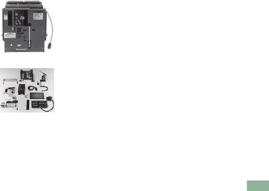
Volume 12—Aftermarket, Renewal Parts and Life Extension Solutions CA08100014E—November 2013 www.eaton.com V12-T17-33
1
2
3
4
5
6
7
8
9
10
11
12
13
14
15
16
17
18
19
20
21
22
23
24
25
17
Switchgear
Westinghouse DS Breakers—Trip Unit Retrofit Kits
Digitrip RMS Retrofit Kits
for Westinghouse DS
Breakers
DS Breaker Retrofitted with
Digitrip RMS 810 Retrofit Kit
Typical Digitrip RMS 810 Retrofit Kit
for a DS Power Circuit Breaker
Product Description
Digitrip RMS retrofit kits for
Westinghouse DS and DSL
power circuit breakers were
first introduced in 1987. For
a complete description of the
Digitrip RMS Trip System and
the features of models RMS
510, 610, 810 and 910, see
Page V12-T17-20.
Ratings
Digitrip RMS retrofit kits are
applied on DS breakers with
frame ratings from 800A
(DS-206) to 4000A (DS-840)
as identified below. The
rating plug and the current
sensor rating act in concert
to provide for a wide
spectrum of overload and
short-circuit settings.
Chronology
Digitrip RMS retrofit kits and
replacement trip units for DS
breakers became available
around 1987. The Digitrip
RMS 510 model is the
modern day replacement for
the Amptector trip systems.
Replacement and
Upgrade Capabilities
Replacement and upgrade
capabilities include
replacement Digitrip trip units
and rating plugs, Digitrip trip
unit upgrades, Digitrip RMS
trip unit retrofit kits and
upgrade retrofit kits. For
definitions of these solutions,
see Page V12-T17-19.
For Digitrip RMS trip unit
retrofit kits and upgrade
retrofit kits, create the
Digitrip RMS retrofit kit catalog
number to match the Cutler-
Hammer or Westinghouse
DS breaker type, retrofit kit
type, protection function,
rating plug type, current
sensor type, CPT, and type
of kit required for application.
See the example provided
on Page V12-T17-34.
Application Notes for Cutler-
Hammer or Westinghouse DS
and DSL Power Circuit Breakers
1. Retrofit kits are for
use on 50 and 60 Hz
distribution systems.
2. All retrofit kits are
designed for drawout
power circuit breakers
only. Refer all fixed-
mounted breaker
applications to the
Eaton Digitrip Retrofit
Kit Service Center
at 1-800-937-5487.
3. The breaker compartment
doors on the switchgear
assembly must be
free of panel-mounted
instruments and devices
(i.e., ammeters, switches,
etc.) or the retrofitted
breaker may interfere
with these devices
when the compartment
door is closed.
4. When the ground fault
(G) option is selected,
please observe the
following:
a. For three-phase, three-
wire solidly grounded
systems, choose
quantity three current
sensors in the catalog
number development.
b. For three-phase, four-
wire solidly grounded
systems, choose
quantity four current
sensors in the catalog
number development.
Three sensors are
mounted on the
breaker and one
sensor is mounted
on the switchgear
neutral. Hardware to
mount the current
sensor on the
switchgear neutral
and provisions to wire
it into the trip unit
circuit (including a
required pair of
breaker secondary
disconnecting
contacts) are not
included in the kit.
5. RMS 510, 610, 810 and
910 retrofit kits include
a cell terminal block
assembly that must
be installed in the
switchgear assembly.
Internal switchgear wiring
to accommodate the
customer application
schemes must be added
in the field.
6. RMS 610, 810 and 910
retrofit kits require a
customer supplied
120 Vac source
connected to the cell
terminal block assembly
to power the Digitrip
RMS digital displays and
communications
functions (as applicable).

V12-T17-34 Volume 12—Aftermarket, Renewal Parts and Life Extension Solutions CA08100014E—November 2013 www.eaton.com
1
2
3
4
5
6
7
8
9
10
11
12
13
14
15
16
17
18
19
20
21
22
23
24
25
17
Switchgear
Westinghouse DS Breakers—Trip Unit Retrofit Kits
Digitrip RMS Retrofit Kits for Westinghouse DS Breakers Catalog Numbering System
Notes
1At the time of this publication, the standard trip units for low voltage Digitrip retrofit kits are the RMS 510/610/810/910.
2If breaker has been previously retrofitted, call the Digitrip Retrofit Kit Service Center at 1-800-937-5487.
Sample shown is a Digitrip
retrofit kit for a DS-206, with
an RMS 810 trip unit, with
LSIG protection, with a 60 Hz
plug, rated at 250A for a
sensor tap of 400A, four
sensors (for a four-wire
ground system) that have a
sensor tap of 400A, and there
are no other features so this is
a standard original kit.
This information is subject to
change. Updated pricing and
availability information is
included in the Retrofit Kit
Product Guide. For a copy of
the Retrofit Kit Product
Guide, contact your local
Eaton Field Sales office or the
Digitrip Retrofit Kit Service
Center at 1-800-937-5487.
Trip Unit Type 1
1 = OPTIM 1050
5 = 510 basic
Z = 510 zone int.
6 = 610
7 = OPTIM 750
8 = 810
9 = 910
Protection
1 = LI
2 = LSI
3 = LS
4 = LIG
5 = LSG
6 = LSIG
7 = LSIA
RP No Rating Plug
Cat.
Code
Current Rating
Tap Plug
21
22
32
3Q
33
42
4Q
43
44
63
64
66
84
86
88
T6
T8
TA
TT
C8
CA
CT
CC
DA
DT
DC
DD
FC
FD
FF
JC
JD
JF
JJ
KD
KP
KJ
KK
200
200
300
300
300
400
400
400
400
600
600
600
800
800
800
1200
1200
1200
1200
1600
1600
1600
1600
2000
2000
2000
2000
2400
2400
2400
3200
3200
3200
3200
4000
4000
4000
4000
100
200
200
250
300
200
250
300
400
300
400
600
400
600
800
600
800
1000
1200
800
1000
1200
1600
1000
1200
1600
2000
1600
2000
2400
1600
2000
2400
3200
2000
2500
3200
4000
N= No rating plug
6= 50/60 Hz plug
N= No sensors
3= Three sensors
4= Four sensors
P= OPTIM
T= Digitrip 510, 610, 810, 910
N= No CPT supplied
C= Breaker-mounted CPT
N= Standard kit
U= Upgrade kit from factory
modular mounting 2
B= Upgrade kit from factory
box mounting 2
Code Breaker Frame Description Sensor
Code
Current Rating of
Sensor and Available Taps
ALL FRAMES SNO SENSORS PROVIDED
DR6 DS(L)-206 8800
6600
4400
3300
2200
DRC DS(L)-416 C1600
T1200
8800
6600
4400
3300
2200
DRD DS-420 D2000
C1600
T1200
8800
6600
4400
3300
2200
DRJ DS-632
(Must replace Amptector Sensors)
J3200
F2400
DRK DS-840 K4000
J3200
N = Standard kit
S = Simplified cell harness
R = Cell harness removed
DR6 8 6 6 4Q 4 4 – T N N N

Volume 12—Aftermarket, Renewal Parts and Life Extension Solutions CA08100014E—November 2013 www.eaton.com V12-T17-35
1
2
3
4
5
6
7
8
9
10
11
12
13
14
15
16
17
18
19
20
21
22
23
24
25
17
Switchgear
Westinghouse SPB Breakers—Trip Unit Retrofit Kits
Digitrip RMS Retrofit
Kits for Westinghouse
SPB Breakers
SPB-100 Series—3000A Frame
—Digitrip RMS
Rear View of Plug Adapter Box
and Digitrip RMS 510 (Typical Parts
of Retrofit Kit)
Product Description
Digitrip RMS retrofit kits for
Westinghouse SPB power
circuit breakers equipped
with Pow-R Trip 7 or
Pow-R Digitrip trip units
were first introduced in 1989.
Field retrofits are limited to
the RMS 510 model. For a
complete description of the
Digitrip RMS trip system,
see Page V12-T17-20.
Ratings
Digitrip RMS 510 retrofit kits
are applied on SPB breakers
with frame ratings from
400A (SPB-50) to 5000A
(SPB-150) as identified
on Page V12-T17-25. The
rating plug and the current
sensor rating act in concert
to provide for a wide
spectrum of overload and
short-circuit settings.
Chronology
Digitrip RMS retrofit kits
for SPB breakers became
available around 1989. The
Digitrip RMS 510 model
is the only model that is
available. Retrofits are limited
to SPB breakers equipped
with a Pow-R Trip 7 or
Pow-R Digitrip (also known
as Digitrip 1) trip units.
Replacement and
Upgrade Capabilities
Replacement and upgrade
capabilities include
replacement Digitrip trip units
and rating plugs, Digitrip trip
unit upgrades, Digitrip RMS
trip unit retrofit kits and
upgrade retrofit kits. For
definitions of these solutions
see Page V12-T17-19.
For Digitrip RMS trip unit
retrofit kits and upgrade
retrofit kits, create the Digitrip
RMS retrofit kit catalog
number to match the Cutler-
Hammer or Westinghouse
SPB breaker type, retrofit kit
type, protection function,
rating plug type, current
sensor type, CPT and type
of kit required for application.
See the example provided
on Page V12-T17-36.
Application Notes for Cutler-
Hammer or Westinghouse
SPB Power Circuit Breakers
1. Retrofit kits are for
use on 50 and 60 Hz
distribution systems.
2. Only SPB breakers
equipped with a Pow-R
Trip 7 or Pow-R Digitrip
(also known as Digitrip 1)
trip units are retrofittable
at this time. Breakers
equipped with a Pow-R
trip cannot be retrofitted.
3. SPB breakers installed in
automatic transfer
switches and equipped
with a belI alarm contact
cannot be retrofitted at
this time.
4. An automatic trip relay
(ATR) is a remote
mounted accessory
designed to provide
visual trip mode
indication, alarm and
lockout interlocking
circuitry following a
breaker automatic
tripping operation. SPB
breakers equipped with
Pow-R Trip 7 and this
ATR must purchase a
separate ATR adapter kit.
SPB adapter kit with
ground fault:
4A35718G02. SPB
adapter kit without
ground fault:
4A35718G01.
5. An SPB breaker with a
250A frame rating can
not be retrofitted.
6. Ground fault protection
cannot be added to the
SPB breaker. The breaker
must be originally
equipped with ground
fault protection, for
ground fault protection to
be selected. Changing the
ground fault protection
from three-wire to four-
wire is not permitted.
Interchanging between
Ll, LS, LSI, LIG, LSG or
LSIG is not permitted.
7. SPB breakers equipped
with zone interlocking for
short time and/or ground
fault time delays can
be retrofitted, provided
that the existing zone
interlock configuration
is not changed.
8. For Digitrip RMS trip unit
replacements, see
Page V12-T17-21. For
Pow-R Trip 7 trip unit
replacements, see
Page V12-T17-36.
9. A factory retrofit is
possible for applications
requiring Digitrip RMS
610, 810 and 910.
Call factory for more
information at
1-800-222-9773.
10. SPB breakers retrofitted
with Digitrip RMS can be
tested with primary
injection testing and trip
unit self test. Secondary
injection testing is not
available.
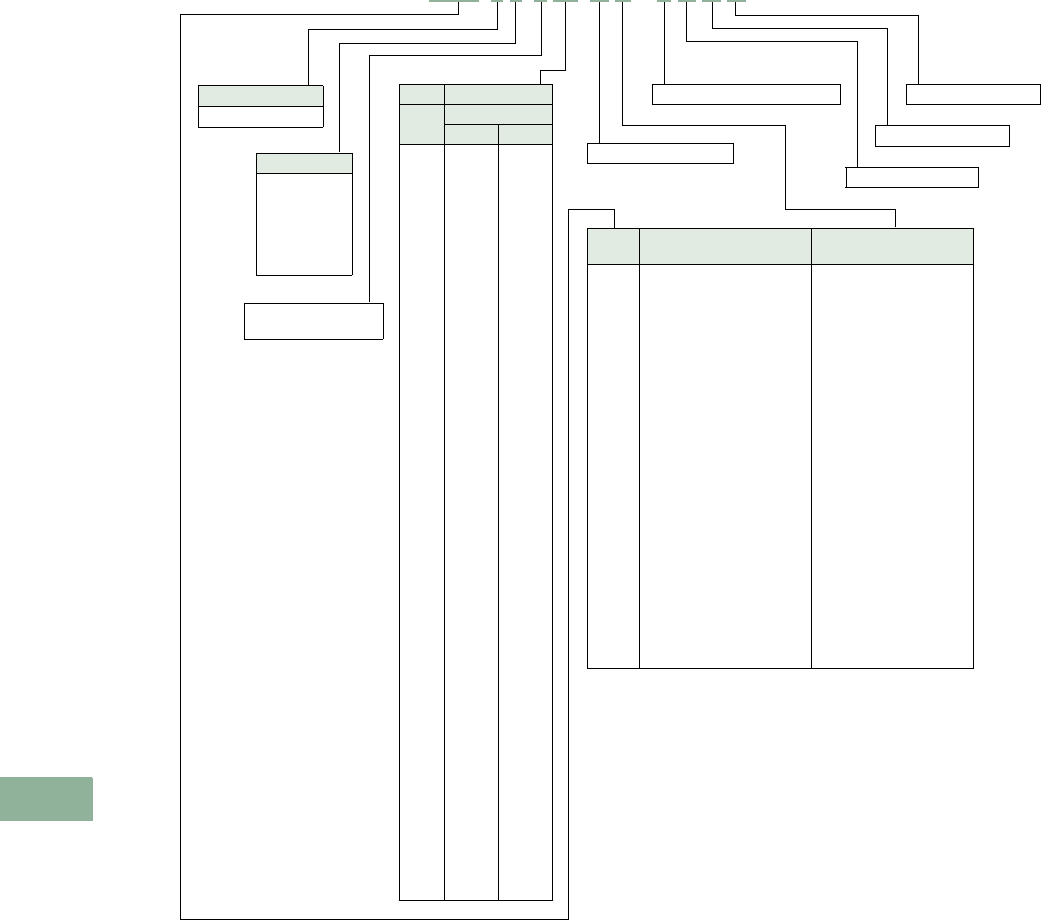
V12-T17-36 Volume 12—Aftermarket, Renewal Parts and Life Extension Solutions CA08100014E—November 2013 www.eaton.com
1
2
3
4
5
6
7
8
9
10
11
12
13
14
15
16
17
18
19
20
21
22
23
24
25
17
Switchgear
Westinghouse SPB Breakers—Trip Unit Retrofit Kits
Digitrip RMS Retrofit Kits for Westinghouse SPB Breakers Catalog Numbering System
Notes
1At the time of this publication, the standard trip units for low voltage Digitrip retrofit kits are the RMS 510/610/810/910.
2Digitrip 610, 810 and 910 are not available for SPB breaker retrofit kits. A factory upgrade program is available. Call factory for more information at 1-800-222-9773.
3SPB breakers supplied from factory without ground fault (G) cannot be retrofitted in the field to include ground fault.
This information is subject to
change. Updated pricing and
availability information is
included in the Retrofit Kit
Product Guide. For a copy of
the Retrofit Kit Product Guide,
contact your local Eaton Field
Sales office or the Digitrip
Retrofit Kit Service Center
at 1-800-937-5487.
Trip Unit Type 1
5 = 510 Basic 2
Protection
1 = LI
2 = LSI
3 = LS
4 = LIG 3
5 = LSG 3
6 = LSIG 3
RP No Rating Plug
Cat.
Code
Current Rating
Tap Plug
21
22
32
3Q
33
42
4Q
43
44
63
64
66
84
86
88
T6
T8
TA
TT
C8
CA
CT
CC
DA
DT
DC
DD
EA
ET
EC
EE
PC
PD
PP
HC
HD
HP
HH
KD
KP
KH
KJ
KK
LH
LJ
LK
LL
200
200
300
300
300
400
400
400
400
600
600
600
800
800
800
1200
1200
1200
1200
1600
1600
1600
1600
2000
2000
2000
2000
2000C
2000C
2000C
2000C
2500
2500
2500
3000
3000
3000
3000
4000
4000
4000
4000
4000
5000
5000
5000
5000
100
200
200
250
300
200
250
300
400
300
400
600
400
600
800
600
800
1000
1200
800
1000
1200
1600
1000
1200
1600
2000
1000
1200
1600
2000
1600
2000
2500
1600
2000
2500
3000
2000
2500
3000
3200
4000
3000
3200
4000
5000
N= No rating plug
6= 50/60 Hz plug
N = No sensors
T = Digitrip 510
N = Standard kit
N = Standard kit
N = Standard kit
Code Breaker Frame
Description
Breaker Frame Rating
and Sensor Tap
W34
W38
W4T
W4C
W4E
W54
W58
W5T
W5C
W5D
W5E
W5P
W5H
W5K
W5L
W64
W68
W6T
W6C
W6D
W6E
W6P
W6H
W6K
W6L
SPB-50-400
SPB-50-800
SPB-65-1200
SPB-65-1600
SPB-65-2000 compact
SPB-100-400
SPB-100-800
SPB-100-1200
SPB-100-1600
SPB-100-2000
SPB-100-2000 compact
SPB-100-2500
SPB-100-3000
SPB-100-4000
SPB-100-5000
SPB-150-400
SPB-150-800
SPB-150-1200
SPB-150-1600
SPB-150-2000
SPB-150-2000 compact
SPB-150-2500
SPB-150-3000
SPB-150-4000
SPB-150-5000
400
800
1200
1600
2000C
400
800
1200
1600
2000
2000C
2500
3000
4000
5000
400
800
1200
1600
2000
2000C
2500
3000
4000
5000
W58 5 6 6 88 N S – T N N N
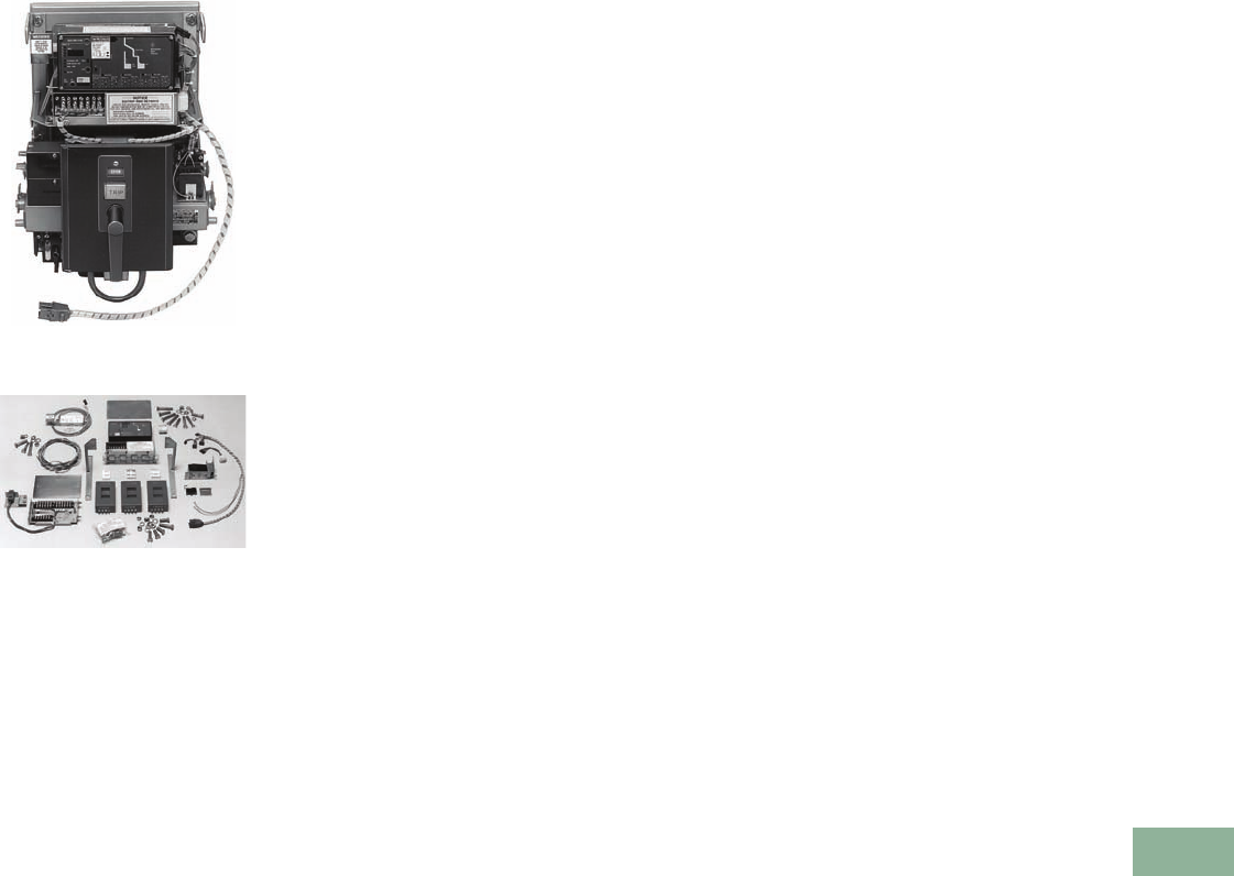
Volume 12—Aftermarket, Renewal Parts and Life Extension Solutions CA08100014E—November 2013 www.eaton.com V12-T17-37
1
2
3
4
5
6
7
8
9
10
11
12
13
14
15
16
17
18
19
20
21
22
23
24
25
17
Switchgear
General Electric AK Breakers—Trip Unit Retrofit Kits
Digitrip RMS Retrofit
Kits for Westinghouse
DB Breakers
DB-25 Breaker Retrofitted with
Digitrip RMS 810 Retrofit Kit
Typical Digitrip RMS 810 Retrofit Kit
for a DB-25 Power Circuit Breaker
Product Description
Digitrip RMS retrofit kits for
Westinghouse DB and DBL
power circuit
breakers were
first introduced in 1989.
For a
complete description of the
Digitrip
RMS trip system and
the features of models RMS
510, 610, 810 and 910, see
Page V12-T17-20.
Ratings
Digitrip RMS retrofit kits are
applied on DB breakers with
frame ratings from 225A
(DB-15) to 4000A (DB-100)
as identified below. The
rating plug and the current
sensor rating act in concert
to provide for a wide
spectrum of overload and
short-circuit settings.
Chronology
Digitrip RMS retrofit kits and
replacement trip units for DB
breakers became available
around 1989. The Digitrip
RMS 510 model is the
modern day replacement
for the Amptector and RK
trip systems.
Replacement and
Upgrade Capabilities
Replacement and upgrade
capabilities include
replacement Digitrip trip units
and rating plugs, Digitrip trip
unit upgrades, Digitrip RMS
trip unit retrofit kits and
upgrade retrofit kits. For
definitions of these solutions,
see Page V12-T17-19.
For Digitrip RMS trip unit
retrofit kits and upgrade
retrofit kits, create the Digitrip
RMS retrofit kit catalog
number to match the
Westinghouse DB breaker
type, retrofit kit type,
protection function, rating
plug type, current sensor
type, CPT and type of kit
required for application. See
the example provided on
Page V12-T17-32.
Application Notes for
Westinghouse DB and DBL
Power Circuit Breakers
1. Retrofit kits are for
use on 50 and 60 Hz
distribution systems.
2. All retrofit kits are
designed for drawout
power circuit breakers
only. Refer all fixed-
mounted breaker
applications to the Digitrip
Retrofit Kit Service Center
at 1-800-937-5487.
3. The breaker compartment
doors on the switchgear
assembly must be
free of panel-mounted
instruments and devices
(i.e., ammeters, switches,
etc.) or the retrofitted
breaker may interfere
with these devices
when the compartment
door is closed.
4. Type DB-15 and DBL
breaker components
may have a metal baffle
on the inside of the
compartment door.
If so, the baffle will
have to be removed to
accommodate the
retrofitted DB breaker.
5. Contact your local Eaton
office if the existing
DB breaker has both an
undervoltage trip device
(UVTA) and a shunt trip.
6. When the ground fault
(G) option is selected,
please observe the
following:
a. For three-phase, three-
wire solidly grounded
systems, choose
quantity three current
sensors in the catalog
number development.
b. For three-phase, four-
wire solidly grounded
systems, choose a
quantity of four current
sensors in the catalog
number development.
Three sensors are
mounted on the
breaker and one
sensor is mounted on
the switchgear neutral.
Hardware to mount
the current sensor on
the switchgear neutral
and provisions to
wire it into the trip
unit circuit (including
a required pair of
breaker secondary
disconnecting
contacts) are not
included in the kit.
7. RMS 510 zone, 610, 810
and 910 retrofit kits
include a cell terminal
block assembly that must
be installed in the
switchgear assembly.
Internal switchgear
wiring to accommodate
the customer application
schemes must be added
in the field.
8. RMS 610, 810 and
910 retrofit kits require
a customer supplied
120 Vac source
connected to the cell
terminal block assembly
to power the Digitrip
RMS digital displays
and communications
functions (as applicable).
9. If the existing DB breaker
has been retrofitted
with an Amptector trip
system, and a Digitrip
RMS retrofit is desired,
contact the Digitrip
Retrofit Kit Service
Center at 1-800-937-5487
for details.
V12-T17-38 Volume 12—Aftermarket, Renewal Parts and Life Extension Solutions CA08100014E—November 2013 www.eaton.com
1
2
3
4
5
6
7
8
9
10
11
12
13
14
15
16
17
18
19
20
21
22
23
24
25
17
Switchgear
General Electric AK Breakers—Trip Unit Retrofit Kits
Digitrip RMS Retrofit Kits for General Electric AK Breakers Catalog Numbering System
Notes
1At the time of this publication, the standard trip units for low voltage Digitrip retrofit kits are the RMS 510/610/810/910.
2Maximum ampere rating is 200A.
3Use GU6, GU7, GUC kits only for breakers with top-mounted fuses. For breakers with bottom-mounted fuses, use standard kit.
This information is subject to
change. Updated pricing and
availability information is
included in the Retrofit Kit
Product Guide. For a copy
of the Retrofit Kit Product
Guide, contact your local
Eaton Field Sales office or the
Digitrip Retrofit Kit Service
Center at 1-800-937-5487.
Trip Unit Type 1
5= 510 basic
Z= 510 zone int.
6= 610
8= 810
9= 910
Protection
1 = LI
2 = LSI
3 = LS
4 = LIG
5 = LSG
6 = LSIG
RP No Rating Plug
Cat.
Code
Current Rating
Tap Plug
21
22
32
3Q
33
42
4Q
43
44
63
64
66
84
86
88
C8
CA
CT
CC
DA
DT
DC
DD
HC
HD
HP
HH
KD
KP
KH
KJ
KK
200
200
300
300
300
400
400
400
400
600
600
600
800
800
800
1600
1600
1600
1600
2000
2000
2000
2000
3000
3000
3000
3000
4000
4000
4000
4000
4000
100
200
200
250
300
200
250
300
400
300
400
600
400
600
800
800
1000
1200
1600
1000
1200
1600
2000
1600
2000
2500
3000
2000
2500
3000
3200
4000
N= No rating plug
6= 50/60 Hz plug
N= No sensors
3= Three sensors
4= Four sensors
T = Digitrip 510, 610, 810, 910
N= No CPT supplied
C= Breaker-mounted CPT
N= Standard kit
U= Upgrade kit from
Digitrip 500/510
N = Standard kit
S = Simplified cell harness
R = Cell harness removed
Code Breaker Frame Description Sensor
Code
Current Rating of
Sensor and Available Taps
ALL FRAMES SNO SENSORS PROVIDED
G12 AK-1-15 manual 22200
G16 AK-1-25 6600, 400
G2C AK-1-50, AK-2/2A-50, AK-3/3A-50 C1600, 800
8800, 400
4400, 200
GMC AK-1-50 slow close no top frame C1600, 800
8800, 400
4400, 200
G2H AK-1-75, AK-2/2A-75, AK-3/3A-75 H3000, 2000
G2K AK-1-100, AK-2/2A-100, AK-3/3A-100 K4000
G22 AK-2/2A-15 manually operated 22200
G26 AK-2/2A-25 6600, 400, 300, 200
GTD AKT-2A-50 C2000
G36 AK-3/3A-25 6600, 400, 300, 200
GU6 AKU-2/2A-25 36600, 400, 300, 200
GU7 AKU-3/3A-25 36600, 400, 300, 200
GUC AKU-2A/3A-50 3C1600, 800
8800, 400
4400, 200
GS8 AKR(U)-6D/7D-30S 8800, 400
GA8 AKR-4A/5A-30 8800, 400
GAC AKR-4A/5A-50 C1600, 800/800, 400
GAD AKRT-4A/5A-50 D2000
GD8 AKR-6D/7D-30 8800, 400
GDC AKR-6D/7D-50 C1600, 800/800, 400
GDD AKRT-6D/7D-50 D2000
G36 8 6 6 4Q 4 6 – T C S U
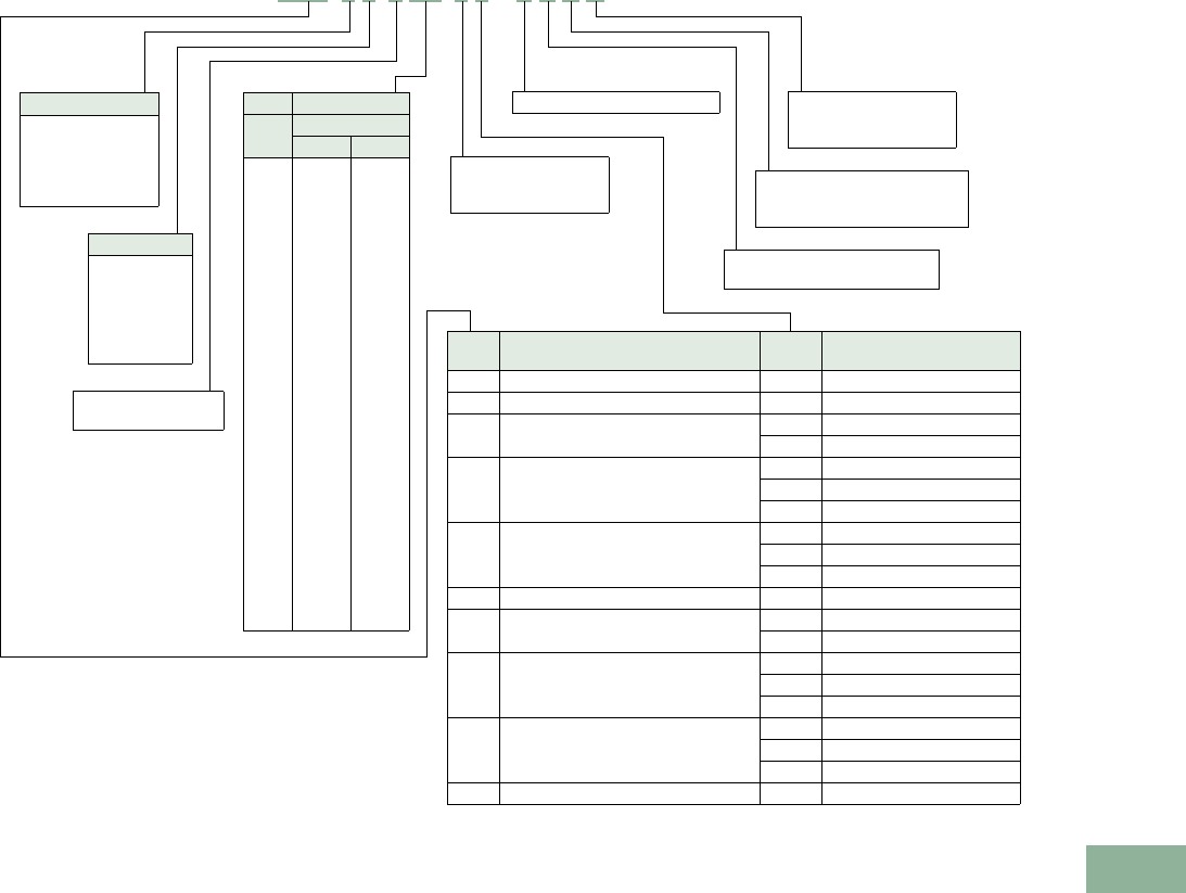
Volume 12—Aftermarket, Renewal Parts and Life Extension Solutions CA08100014E—November 2013 www.eaton.com V12-T17-39
1
2
3
4
5
6
7
8
9
10
11
12
13
14
15
16
17
18
19
20
21
22
23
24
25
17
Switchgear
General Electric AL-2-50-75 Breakers—Trip Unit Retrofit Kits
Digitrip RMS Retrofit Kits for General Electric AL-2-50-75 Breakers Catalog Numbering System
Note
1At the time of this publication, the standard trip units for low voltage Digitrip retrofit kits are the RMS 510/610/810/910.
Sample shown is a Digitrip
retrofit kit for an AL-2-50-600
manually operated, with an
RMS 810 trip unit, with LSIG
protection, with a 60 Hz plug,
rated at 250A for a sensor tap
of 400A, four sensors (for a
four-wire ground system)
that have sensor taps of 600,
400, 300 and 200A, there is
a breaker-mounted CPT with
the kit, the cell wiring is
simplified (only 6 wires vs.
16), and the breaker was
previously retrofitted with
a Digitrip 500/510, so this is
an upgrade kit.
This information is subject
to change. Updated pricing
and availability information
is included in the Retrofit Kit
Product Guide. For a copy
of the Retrofit Kit Product
Guide, contact your local
Eaton Field Sales office or the
Digitrip Retrofit Kit Service
Center at 1-800-937-5487.
GQ6 8 6 6 4Q 4 6 – T C S U
Trip Unit Type 1
5= 510 basic
Z= 510 zone int.
6= 610
8= 810
9= 910
Protection
1 = LI
2 = LSI
3 = LS
4 = LIG
5 = LSG
6 = LSIG
RP No Rating Plug
Cat.
Code
Current Rating
Tap Plug
21
22
32
3Q
33
42
4Q
43
44
63
64
66
84
86
88
T6
T8
TA
TT
C8
CA
CT
CC
DA
DT
DC
DD
200
200
300
300
300
400
400
400
400
600
600
600
800
800
800
1200
1200
1200
1200
1600
1600
1600
1600
2000
2000
2000
2000
100
200
200
250
300
200
250
300
400
300
400
600
400
600
800
600
800
1000
1200
800
1000
1200
1600
1000
1200
1600
2000
N= No rating plug
6= 50/60 Hz plug
N= No sensors
3= Three sensors
4= Four sensors
T = Digitrip 510, 610, 810, 910
N= No CPT supplied
C= Breaker-mounted CPT
N= Standard kit
U= Upgrade kit from
Digitrip 500/510
N= Standard kit
S= Simplified cell harness
R= Cell harness removed
Code Breaker Frame Description Sensor
Code
Current Rating of
Sensor and Available Taps
ALL FRAMES SNO SENSORS PROVIDED
GQ6 AL-2-50-600 manually operated 6600, 400, 300, 200
GQ8 AL-2-50-800 manually operated 8800, 600, 400
2200
GQT AL-2-50-1200 manually operated T1200, 600
8800, 600, 400
2200
GQC AL-2-50-1600 manually operated C1600, 1200
8800, 600, 400
2200
GL6 AL-2-600 electrically operated 6600, 400, 300, 200
GL8 AL-2-800 electrically operated 8800, 600, 400
2200
GLT AL-2-1200 electrically operated T1200, 600
8800, 600, 400
2200
GLC AL-2-1600 electrically operated C1600, 1200
8800, 600, 400
2200
GLD AL-2-75-2000 electrically operated D2000
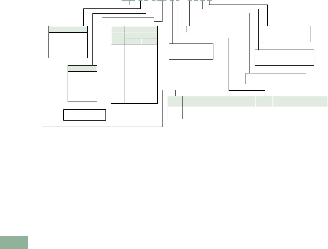
V12-T17-40 Volume 12—Aftermarket, Renewal Parts and Life Extension Solutions CA08100014E—November 2013 www.eaton.com
1
2
3
4
5
6
7
8
9
10
11
12
13
14
15
16
17
18
19
20
21
22
23
24
25
17
Switchgear
Other General Electric Breakers—Trip Unit Retrofit Kits
Digitrip RMS Retrofit Kits for Other General Electric Breakers Catalog Numbering System
Note
1At the time of this publication, the standard trip units for low voltage Digitrip retrofit kits are the RMS 510/610/810/910.
Sample shown is a Digitrip
retrofit kit for an AE-1-25,
with an RMS 810 trip unit,
with LSIG protection, with a
60 Hz plug, rated at 250A for
a sensor tap of 400A, four
sensors (for a four-wire
ground system) that have
sensor taps of 600, 400, 300
and 200A, there is a breaker-
mounted CPT with the kit,
the cell wiring is simplified
(only 6 wires vs. 16), and the
breaker was previously
retrofitted with a Digitrip 500/
510, so this is an upgrade kit.
This information is subject
to change. Updated pricing
and availability information is
included in the Retrofit Kit
Product Guide. For a copy
of the Retrofit Kit Product
Guide, contact your local
Eaton Field Sales office or the
Digitrip Retrofit Kit Service
Center at 1-800-937-5487.
Trip Unit Type 1
5= 510 basic
Z= 510 zone int.
6= 610
8= 810
9= 910
Protection
1 = LI
2 = LSI
3 = LS
4 = LIG
5 = LSG
6 = LSIG
RP No Rating Plug
Cat.
Code
Current Rating
Tap Plug
21
22
32
3Q
33
42
4Q
43
44
63
64
66
200
200
300
300
300
400
400
400
400
600
600
600
100
200
200
250
300
200
250
300
400
300
400
600
N= No rating plug
6= 50/60 Hz plug
N= No sensors
3= Three sensors
4= Four sensors
T = Digitrip 510, 610, 810, 910
N= No CPT supplied
C= Breaker-mounted CPT
N= Standard kit
U= Upgrade kit from
Digitrip 500/510
Code Breaker Frame Description Sensor
Code
Current Rating of
Sensor and Available Taps
ALL FRAMES SNO SENSORS PROVIDED
GE6 AE-1-25, AE-1B 6600, 400, 300, 200
N = Standard kit
S = Simplified cell harness
R = Cell harness removed
GE6 8 6 6 4Q 4 6 – T C S U
Volume 12—Aftermarket, Renewal Parts and Life Extension Solutions CA08100014E—November 2013 www.eaton.com V12-T17-41
1
2
3
4
5
6
7
8
9
10
11
12
13
14
15
16
17
18
19
20
21
22
23
24
25
17
Switchgear
Allis-Chalmers LA Breakers—Trip Unit Retrofit Kits
Digitrip RMS Retrofit
Kits for Allis-Chalmers
LA Breakers
Allis-Chalmers LA 600 Gold Breaker
Retrofitted with Digitrip
RMS 810 Retrofit Kit
Typical RMS 810 Retrofit Kit
for Allis-Chalmers
LA 600
Gold Power Circuit Breaker
Product Description
Digitrip RMS retrofit kits for
Allis-Chalmers LA power
circuit breakers were first
introduced in 1991. For a
complete description of the
Digitrip RMS trip system and
the features of models RMS
510, 610, 810 and 910, see
Page V12-T17-20.
Ratings
Digitrip RMS retrofit kits are
applied on Allis-Chalmers
breakers from 600A (LA 600)
to 3000A (LA 3000). The rating
plug and the current sensor
act in concert to provide for a
wide spectrum of overload
and short-circuit settings.
Chronology
Digitrip RMS retrofit kits and
replacement trip units for
Allis-Chalmers LA breakers
became available in 1991. The
Digitrip RMS 510 model is the
modern day replacement for
electromechanical trip device
or peak sensing solid-state
trip systems.
Replacement and
Upgrade Capabilities
Replacement and upgrade
capabilities include
replacement Digitrip trip units
and rating plugs, Digitrip trip
unit upgrades, Digitrip RMS
trip unit retrofit kits and
upgrade retrofit kits. For
definitions of these solutions,
see Page V12-T17-19.
For Digitrip RMS trip unit
retrofit kits and upgrade
retrofit kits, choose or create
the Digitrip RMS retrofit kit
catalog number to match the
Allis-Chalmers LA breaker
type, retrofit kit type,
protection function, rating
plug type, current sensor
type, CPT and type of kit
required for application.
See the example provided
on Page V12-T17-42.
Application Notes for
Allis-Chalmers
LA Power
Circuit Breakers
1. Retrofit kits are for
use on 50 and 60 Hz
distribution systems.
2. All retrofit kits are
designed for drawout
power circuit breakers
only. Refer all fixed-
mounted breaker
applications to the
Digitrip Retrofit Kit
Service Center at
1-800-937-5487.
3. The breaker compartment
doors on the switchgear
assembly must be
free of panel-mounted
instruments (i.e., meters,
instruments, control
switches, indicating
lamps, etc.) or the
retrofitted breaker may
interfere with these
devices when the
compartment door
is closed.
4. When the ground fault
(G) option is selected,
please observe the
following:
a. For three-phase, three-
wire solidly grounded
systems, choose
quantity three current
sensors in the catalog
number development.
b. For three-phase, four-
wire solidly grounded
systems, choose
quantity four current
sensors in the catalog
number development.
Three sensors are
mounted on the
breaker and one
sensor is mounted
on the switchgear
neutral. Hardware to
mount the current
sensor on the
switchgear neutral
and provisions to wire
it into the trip unit
circuit (including a
required pair of
breaker secondary
disconnecting
contacts) are not
included in the kit.
5. RMS 510 Zone, 610,
810 and 910 retrofit kits
include a cell terminal
block assembly that
must be installed in the
switchgear assembly.
Internal switchgear
wiring to accommodate
the customer application
schemes must be added
in the field.
6. RMS 610, 810 and 910
retrofit kits require
a customer supplied
120 Vac source
connected to the cell
terminal block assembly
to power the Digitrip
RMS digital displays
and communications
functions (as applicable).
7. R e f e r a l l L A F ( L A
breakers with current
limiters) breakers to
the Digitrip Retrofit
Kit Service Center
at 1-800-937-5487
for evaluation.
V12-T17-42 Volume 12—Aftermarket, Renewal Parts and Life Extension Solutions CA08100014E—November 2013 www.eaton.com
1
2
3
4
5
6
7
8
9
10
11
12
13
14
15
16
17
18
19
20
21
22
23
24
25
17
Switchgear
Allis-Chalmers LA Breakers—Trip Unit Retrofit Kits
Digitrip RMS Retrofit Kits for Allis-Chalmers LA Breakers Catalog Numbering System
Note
1At the time of this publication, the standard trip units for low voltage Digitrip retrofit kits are the RMS 510/610/810/910.
Sample shown is a Digitrip
retrofit kit for an LA-600 gold,
with an RMS 810 trip unit,
with LSIG protection, with a
60 Hz Plug, rated at 250A for
a sensor tap of 400A, four
sensors (for a four-wire
ground system) that have
sensor taps of 600, 400, 300
and 200A, there is a breaker-
mounted CPT with the kit,
the cell wiring is simplified
(only 6 wires vs. 16), and the
breaker was previously
retrofitted with a
Digitrip 500/
510, so this is an upgrade kit.
This information is subject to
change. Updated pricing and
availability information is
included in the Retrofit Kit
Product Guide. For a copy
of the Retrofit Kit Product
Guide, contact your local
Eaton Field Sales office or the
Digitrip Retrofit Kit Service
Center at 1-800-937-5487.
Trip Unit Type 1
5= 510 basic
Z= 510 zone int.
6= 610
8= 810
9= 910
Protection
1 = LI
2 = LSI
3 = LS
4 = LIG
5 = LSG
6 = LSIG
RP No Rating Plug
Cat.
Code
Current Rating
Tap Plug
21
22
32
3Q
33
42
4Q
43
44
63
64
66
84
86
88
T6
T8
TA
TT
C8
CA
CT
CC
DA
DT
DC
DD
HC
HD
HP
HH
FC
FD
FF
JC
JD
JF
JJ
KD
KP
KH
KJ
KK
200
200
300
300
300
400
400
400
400
600
600
600
800
800
800
1200
1200
1200
1200
1600
1600
1600
1600
2000
2000
2000
2000
3000
3000
3000
3000
2400
2400
2400
3200
3200
3200
3200
4000
4000
4000
4000
4000
100
200
200
250
300
200
250
300
400
300
400
600
400
600
800
600
800
1000
1200
800
1000
1200
1600
1000
1200
1600
2000
1600
2000
2500
3000
1600
2000
2400
1600
2000
2400
3200
2000
2500
3000
3200
4000
N= No rating plug
6= 50/60 Hz plug
N= No sensors
3= Three sensors
4= Four sensors
T = Digitrip 510, 610, 810, 910
N= No CPT supplied
C= Breaker-mounted CPT
N= Standard kit
U= Upgrade kit from
Digitrip 500/510
Code Breaker Frame Description Sensor
Code
Current Rating of
Sensor and Available Taps
ALL FRAMES SNO SENSORS PROVIDED
A16 LA-600 blue cover (plastic) 6600, 400, 300, 200
A1C LA-1600 blue cover (plastic) C1600, 1200, 800, 600, 400
2200
A26 LA-600 gold cover (metal) 6600, 400, 300, 200
A46 LA-600F (M.O.) 6600, 400, 300, 200
A4C LA-1600F blue C1600, 1200, 800, 600, 400
LAC LAF-1600C (M.O.) C1600, 1200, 800, 600, 400
A2C LA-1600 gold cover (metal) C1600, 1200, 800, 600, 400
2200
A2H LA-3000 gold/blue H3000, 2000
A4H LA-3000A H3000, 2000
A36 LA-25A manually operated 6600, 400, 300, 200
A3C LA-50A manually operated C1600, 1200, 800, 600, 400
8800, 600, 400
2200
A3H LA-75A manually operated H3000, 2000
A5C G-50A C1600
8800
AG6 G-25 manually operated 6600, 300
A4J LA-3200 J3200, 2400, 2000
LGF LG-3000 (with frame) H3000
LGH LG-3000 (frameless) H3000
A1K LA-4000F K4000
N = Standard kit
S = Simplified cell harness
R = Cell harness removed
A26 8 6 6 4Q 4 6 - T C S U

Volume 12—Aftermarket, Renewal Parts and Life Extension Solutions CA08100014E—November 2013 www.eaton.com V12-T17-43
1
2
3
4
5
6
7
8
9
10
11
12
13
14
15
16
17
18
19
20
21
22
23
24
25
17
Switchgear
ITE K-Line Breakers—Trip Unit Retrofit Kits
Digitrip RMS Retrofit Kits
for ITE K-Line Breakers
K-1600 Breaker Retrofitted with
Digitrip RMS 810 Retrofit Kit
Typical Digitrip RMS 810 Retrofit Kit for
ITE K-1600 Power Circuit Breaker
Product Description
Digitrip RMS retrofit kits for ITE
K-Line power circuit breakers
were first introduced in 1991.
For a complete description of
the Digitrip RMS trip system
and the features of models
RMS 510, 610, 810 and 910,
see Page V12-T17-20.
Ratings
Digitrip RMS retrofit kits are
applied on ITE K-Line breakers
from 225A (K-225) to 3000A
(K-3000), the rating plug and
the current sensor rating act
in concert to provide for a
wide spectrum of overload
and short-circuit settings.
Chronology
Digitrip RMS retrofit kits
and replacement trip units for
ITE K-Line breakers became
available in 1991. The Digitrip
RMS 510 model is the
modern day replacement for
electromechanical trip device
or peak sensing solid-state
trip systems.
Replacement and
Upgrade Capabilities
Replacement and
upgrade capabilities include
replacement Digitrip trip units
and rating plugs, Digitrip trip
unit upgrades, Digitrip RMS
trip unit retrofit kits
and upgrade retrofit kits. For
definitions of these solutions,
see Page V12-T17-19.
For Digitrip RMS trip unit
retrofit kits and upgrade
retrofit kits, choose or create
the Digitrip RMS retrofit kit
catalog number to match the
ITE K-Line and other breaker
types, retrofit kit type,
protection function, rating
plug type, current sensor
type, CPT and type of kit
required for application. See
the examples provided on
Page V12-T17-44.
Application Notes for ITE
K-Line and other Power
Circuit Breakers
1. Retrofit kits are for
use on 50 and 60 Hz
distribution systems.
2. All retrofit kits are
designed for drawout
power circuit breakers
only. Refer all fixed-
mounted breaker
applications to the
Digitrip Retrofit Kit
Service Center
at 1-800-937-5487.
3. The breaker compartment
doors on the switchgear
assembly must be
free of panel-mounted
instruments and devices
(i.e., ammeters, switches,
etc.) or the retrofitted
breaker may interfere
with these devices when
the compartment door
is closed.
4. When the ground fault
(G) option is selected,
please observe the
following:
a. For three-phase, three-
wire solidly grounded
systems, choose
quantity three current
sensors in the catalog
number development.
b. For three-phase, four-
wire solidly grounded
systems, choose
quantity four current
sensors in
the catalog
number development.
Three sensors are
mounted on the
breaker and one
sensor is mounted
on the switchgear
neutral. Hardware to
mount the current
sensor on the
switchgear neutral
and provisions to wire
it into the trip unit
circuit (including a
required pair of
breaker secondary
disconnecting
contacts) are not
included in the kit.
5. RMS 510 zone, 610,
810 and 910 retrofit kits
include a cell terminal
block assembly that
must be installed in the
switchgear assembly.
Internal switchgear
wiring to accommodate
the customer application
schemes must be added
in the field.
6. RMS 610, 810 and 910
retrofit kits require a
customer supplied
120 Vac source
connected to the cell
terminal block assembly
to power the Digitrip
RMS digital displays
and communications
functions (as applicable).
7. Refer all K-DON Series
(K-Line breakers with
current limiters) breakers
to the Digitrip Retrofit
Kit Service Center
at 1-800-937-5487
for evaluation.
V12-T17-44 Volume 12—Aftermarket, Renewal Parts and Life Extension Solutions CA08100014E—November 2013 www.eaton.com
1
2
3
4
5
6
7
8
9
10
11
12
13
14
15
16
17
18
19
20
21
22
23
24
25
17
Switchgear
ITE K-Line Breakers—Trip Unit Retrofit Kits
Digitrip RMS Retrofit Kits for ITE K-Line Breakers Catalog Numbering System
Notes
1At the time of this publication, the standard trip units for low voltage Digitrip retrofit kits are the RMS 510/610/810/910.
2Black and red refer to the color of the back plane insulation material.
3If your breaker is not solid-state, call the Digitrip Retrofit Kit Service Center at 1-800-937-5487 for technical clarification on these kits.
Sample shown is a Digitrip
retrofit kit for a K-600 with red
back plane insulation, with an
RMS 810 trip unit, with LSIG
protection, with a 60 Hz plug,
rated at 250A for a sensor tap
of 400A, four sensors (for a
four-wire ground system) that
have a sensor taps of 600,
400, 300 and 200A, there is a
breaker-mounted CPT with
the kit, the cell wiring is
simpli
fied (only 6 wires vs.
16), and the breaker
was
previously retrofitted with a
Digitrip 500/510, so this is an
upgrade kit.
This information is subject to
change. Updated pricing and
availability information is
included in the Retrofit Kit
Product Guide. For a copy
of the Retrofit Kit Product
Guide, contact your local
Eaton Field Sales office or the
Digitrip Retrofit Kit Service
Center at 1-800-937-5487.
K26 8 6 6 4Q 4 6 – T C S U
Trip Unit Type 1
5= 510 basic
Z= 510 zone int.
6= 610
8= 810
9= 910
Protection
1 = LI
2 = LSI
3 = LS
4 = LIG
5 = LSG
6 = LSIG
RP No Rating Plug
Cat.
Code
Current Rating
Tap Plug
21
22
32
3Q
33
42
4Q
43
63
64
66
84
86
88
T6
T8
TA
TT
C8
CA
CT
CC
DA
DT
DC
DD
HC
HD
HP
HH
KD
KP
KH
KJ
KK
200
200
300
300
300
400
400
400
600
600
600
800
800
800
1200
1200
1200
1200
1600
1600
1600
1600
2000
2000
2000
2000
3000
3000
3000
3000
4000
4000
4000
4000
4000
100
200
200
250
300
200
250
300
300
400
600
400
600
800
600
800
1000
1200
800
1000
1200
1600
1000
1200
1600
2000
1600
2000
2500
3000
2000
2500
3000
3200
4000
N= No rating plug
6= 50/60 Hz plug
N= No sensors
3= Three sensors
4= Four sensors
T = Digitrip 510, 610, 810, 910
N= No CPT supplied
C= Breaker-mounted CPT
N= Standard kit
U= Upgrade kit from
Digitrip 500/510
Code Breaker Frame Description Sensor
Code
Current Rating of
Sensor and Available Taps
ALL FRAMES SNO SENSORS PROVIDED
K12 2K-225 black 2200
K1C 2K-1600 black C1600, 1200
8800, 600, 400
2200
K22 2K-225 red 2200
K26 2K-600 red/black, KDON (bottom-mounted fuses) 6600, 400, 300, 200
K2C 2K-1600 red, KDON (bottom-mounted fuses) C1600, 1200
8800, 600, 400
2200
K2D 2K-2000 red D2000
K3H 3K-3000 red (solid-state only) H3000
K2K 3K-4000 red (solid-state only) K4000
K46 2KDON-600 black/red (top-mounted fuses) 6600, 400, 300, 200
K4C 2KDON-1600 red (top-mounted fuses) C1600, 1200
8800, 600, 400
2200
K5C 2KDON-1600 red (2000A round finger cluster),
(bottom-mounted fuses)
C1600, 1200
8800, 600, 400
2200
K6C KDON-1600 black (top-mounted fuses) C1600, 1200
8800, 600, 400
2200
K7C KDON-1600 red (2000A round)
(top-mounted fuses)
C1600, 1200
8800, 600, 400
2200
N= Standard kit
S= Simplified cell harness
R= Cell harness removed
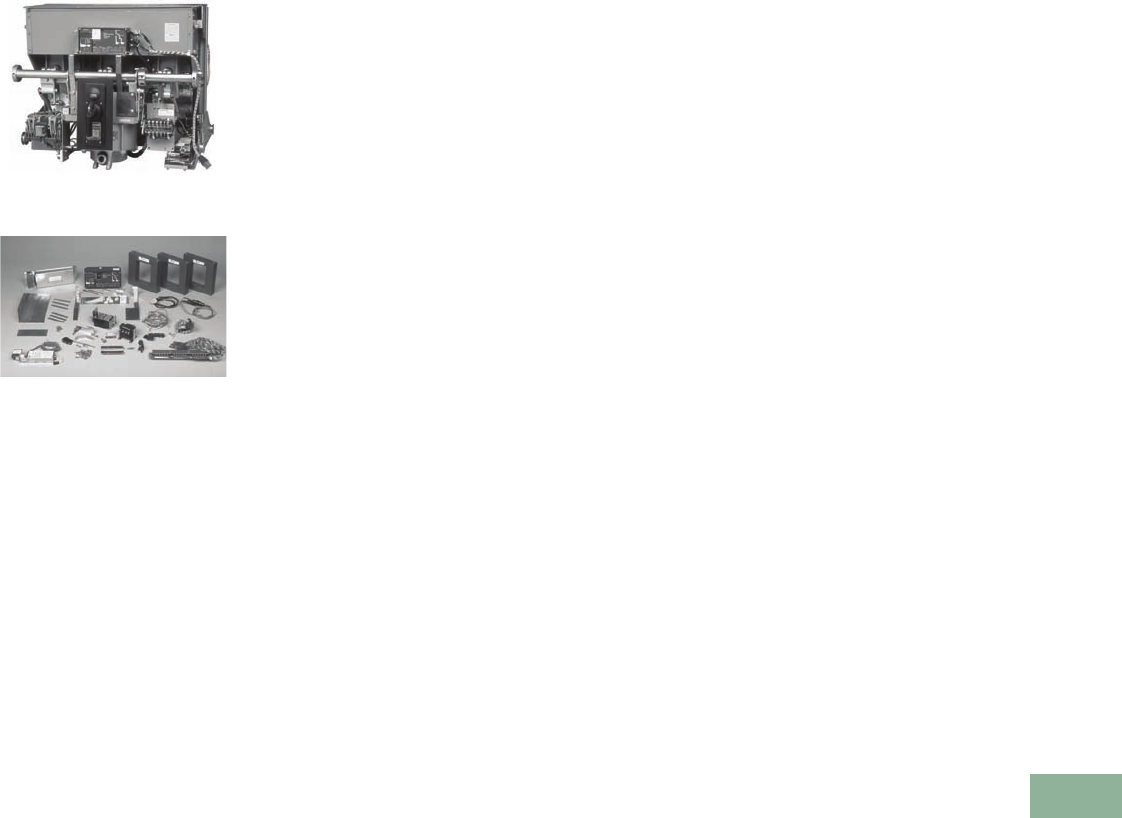
Volume 12—Aftermarket, Renewal Parts and Life Extension Solutions CA08100014E—November 2013 www.eaton.com V12-T17-45
1
2
3
4
5
6
7
8
9
10
11
12
13
14
15
16
17
18
19
20
21
22
23
24
25
17
Switchgear
Other ITE Breakers—Trip Unit Retrofit Kits
Digitrip Retrofit Kits for
Other ITE Breakers
KE-4000 Breaker Retrofitted with
Digitrip RMS 810 Retrofit Kit
Typical Digitrip RMS 810 Retrofit Kit for
ITE KE-4000 Power Circuit Breaker
Product Description
Digitrip retrofit kits for ITE
power circuit breakers were
first introduced in 1992.
For
a complete description of the
Digitrip
RMS trip system and
the features of models RMS
510, 610, 810 and 910, see
Page V12-T17-20.
Ratings
Digitrip RMS retrofit kits are
applied on ITE breakers from
600A (KB-600) to 3000A
(KE-4000), the rating plug and
the current sensor rating act
in concert to provide for a
wide spectrum of overload
and short-circuit settings.
Chronology
Digitrip retrofit kits and
replacement trip units
for ITE breakers became
available in 1992. The Digitrip
RMS 510 model is the
modern day replacement for
electromechanical trip device
or peak sensing solid-state
trip systems.
Replacement and
Upgrade Capabilities
Replacement and upgrade
capabilities include
replacement Digitrip trip units
and rating plugs, Digitrip trip
unit upgrades, Digitrip RMS trip
unit retrofit kits and upgrade
retrofit kits. For definitions
of these solutions, see
Page V12-T17-19.
For Digitrip RMS trip unit
retrofit kits and upgrade
retrofit kits, choose or create
the Digitrip RMS retrofit kit
catalog number to match the
ITE and other breaker types,
retrofit kit type, protection
function, rating plug type,
current sensor type, CPT
and type of kit required for
application. See the examples
provided on Page V12-T17-46.
Application Notes for ITE and
Other Power Circuit Breakers
1. Retrofit kits are for
use on 50 and 60 Hz
distribution systems.
2. All retrofit kits are
designed for drawout
power circuit breakers
only. Refer all fixed-
mounted breaker
applications to the
Digitrip Retrofit Kit
Service Center
at 1-800-937-5487.
3. The breaker compartment
doors on the switchgear
assembly must be
free of panel-mounted
instruments and devices
(i.e., ammeters, switches,
etc.) or the retrofitted
breaker may interfere
with these devices when
the compartment door
is closed.
4. When the ground fault
(G) option is selected,
please observe the
following:
a. For three-phase, three-
wire solidly grounded
systems, choose
quantity three current
sensors in the catalog
number development.
b. For three-phase, four-
wire solidly grounded
systems, choose
a quantity of four
current sensors in
the catalog number
development. Three
sensors are mounted
on the breaker
and one sensor is
mounted on the
switchgear neutral.
Hardware to mount
the current sensor on
the switchgear neutral
and provisions to wire
it into the trip unit
circuit (including
a required pair of
breaker secondary
disconnecting
contacts) are not
included in the kit.
5. RMS 510 Zone, 610, 810
and 910 retrofit kits
include a cell terminal
block assembly that
must be installed in the
switchgear assembly.
Internal switchgear
wiring to accommodate
the customer application
schemes must be added
in the field.
6. RMS 610, 810 and 910
retrofit kits require a
customer supplied
120 Vac source
connected to the cell
terminal block assembly
to power the Digitrip
RMS digital displays
and communications
functions (as applicable).
7. Refer all ITE breakers
with current limiters
to the Digitrip Retrofit
Kit Service Center
at 1-800-937-5487
for evaluation.
V12-T17-46 Volume 12—Aftermarket, Renewal Parts and Life Extension Solutions CA08100014E—November 2013 www.eaton.com
1
2
3
4
5
6
7
8
9
10
11
12
13
14
15
16
17
18
19
20
21
22
23
24
25
17
Switchgear
Other ITE Breakers—Trip Unit Retrofit Kits
Digitrip RMS Retrofit Kits for Other ITE Breakers Catalog Numbering System
Notes
1At the time of this publication, the standard trip units for low voltage Digitrip retrofit kits are the RMS 510/610/810/910.
2Call the Digitrip Retrofit Kit Service Center at 1-800-937-5487 for technical clarification on these kits.
Sample shown is a Digitrip
retrofit kit for a KB-600
drawout breaker, with an
RMS 810 trip unit, with LSIG
protection, with a 60 Hz plug,
rated at 250A for a sensor tap
of 400A, four sensors (for a
four-wire ground system)
that have sensor taps of 600,
400, 300 and 200A, there
is a breaker-mounted CPT
with the kit, the cell wiring
is simplified (only 6 wires vs.
16), and the breaker was
previously retrofitted with a
Digitrip 500/510, so this is an
upgrade kit.
This information is subject to
change. Updated pricing and
availability information is
included in the Retrofit Kit
Product Guide. For a copy
of the Retrofit Kit Product
Guide, contact your local
Eaton Field Sales office or the
Digitrip Retrofit Kit Service
Center at 1-800-937-5487.
Trip Unit Type 1
5= 510 basic
Z= 510 zone int.
6= 610
8= 810
9= 910
Protection
1 = LI
2 = LSI
3 = LS
4 = LIG
5 = LSG
6 = LSIG
RP No Rating Plug
Cat.
Code
Current Rating
Tap Plug
21
22
32
3Q
33
42
4Q
43
44
63
64
66
84
86
88
T6
T8
TA
TT
C8
CA
CT
CC
HC
HD
HP
HH
KD
KP
KH
KJ
KK
200
200
300
300
300
400
400
400
400
600
600
600
800
800
800
1200
1200
1200
1200
1600
1600
1600
1600
3000
3000
3000
3000
4000
4000
4000
4000
4000
100
200
200
250
300
200
250
300
400
300
400
600
400
600
800
600
800
1000
1200
800
1000
1200
1600
1600
2000
2500
3000
2000
2500
3000
3200
4000
N= No rating plug
6= 50/60 Hz plug
N= No sensors
3= Three sensors
4= Four sensors
T = Digitrip 510, 610, 810, 910
N= No CPT supplied
C= Breaker-mounted CPT
N= Standard kit
U= Upgrade kit from
Digitrip 500/510
Code Breaker Frame Description Sensor
Code
Current Rating of
Sensor and Available Taps
ALL FRAMES SNO SENSORS PROVIDED
KB6 KB-600 fixed 26600, 400, 300, 200
KB7 KB-600 drawout 26600, 400, 300, 200
KC6 KC-600 26600
4400
2200
KCC KC-1600 2C1600
T1200
8800
6600
KDH KD-3000 H3000
KEK KE-4000 K4000
N= Standard kit
S= Simplified cell harness
R= Cell harness removed
KB7 8 6 6 4Q 4 6 – T C S U
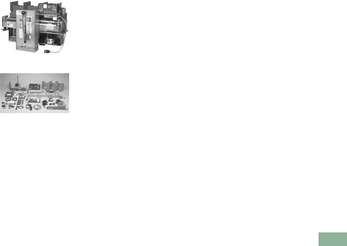
Volume 12—Aftermarket, Renewal Parts and Life Extension Solutions CA08100014E—November 2013 www.eaton.com V12-T17-47
1
2
3
4
5
6
7
8
9
10
11
12
13
14
15
16
17
18
19
20
21
22
23
24
25
17
Switchgear
Siemens and Siemens-Allis Breakers—Trip Unit Retrofit Kits
Digitrip Retrofit Kits for
Siemens and Siemens-
Allis Breakers
LAF-800 Breaker Retrofitted with
Digitrip RMS 810 Retrofit Kit
Typical Digitrip RMS 810 Retrofit Kit
for Siemens-Allis LAF-800
Power Circuit Breaker
Product Description
Digitrip retrofit kits for
Siemens and Siemens-Allis
power circuit breakers were
first introduced in 1993. For
a complete description of the
Digitrip RMS trip system
and the features of models
RMS 510, 610, 810 and 910,
see Page V12-T17-20.
Ratings
Digitrip RMS retrofit kits
are applied on Siemens and
Siemens-Allis breakers
from
800A (LAF-800) to 4000A
(RL-3000),
the rating plug and
the current sensor rating act
in concert to provide for a
wide spectrum of overload
and short-circuit settings.
Chronology
Digitrip retrofit kits and
replacement trip units for
Siemens and Siemens-Allis
breakers became available
in 1992. The Digitrip RMS
510 model is the modern
day replacement for
electromechanical trip
device or peak sensing
solid-state trip systems.
Replacement and
Upgrade Capabilities
Replacement and upgrade
capabilities include
replacement Digitrip trip units
and rating plugs, Digitrip trip
unit upgrades, Digitrip RMS
trip unit retrofit kits and
upgrade retrofit kits. For
definitions of these solutions,
see Page V12-T17-19.
For Digitrip RMS trip unit
retrofit kits and upgrade
retrofit kits, choose or create
the Digitrip RMS retrofit kit
catalog number to match the
Siemens and Siemens-Allis
breaker types, retrofit kit type,
protection function, rating
plug type, current sensor
type, CPT and type of kit
required for application. See
the examples provided on
Page V12-T17-48.
Application Notes for Siemens
and Siemens-Allis Power
Circuit Breakers
1. Retrofit kits are for
use on 50 and 60 Hz
distribution systems.
2. All retrofit kits are
designed for drawout
power circuit breakers
only. Refer all fixed-
mounted breaker
applications to the
Digitrip Retrofit Kit
Service Center
at 1-800-937-5487.
3. The breaker
compartment doors on
the switchgear assembly
must be free of panel-
mounted instruments
and devices (i.e.,
ammeters, switches,
etc.) or the retrofitted
breaker may interfere
with these devices
when the compartment
door is closed.
4. When the ground fault
(G) option is selected,
please observe the
following:
a. For three-phase, three-
wire solidly grounded
systems, choose
quantity three current
sensors in the catalog
number development.
b. For three-phase, four-
wire solidly grounded
systems, choose
a quantity of four
current sensors in
the catalog number
development. Three
sensors are mounted
on the breaker
and one sensor
is mounted on the
switchgear neutral.
Hardware to mount
the current sensor on
the switchgear neutral
and provisions to wire
it into the trip unit
circuit (including a
required pair of
breaker secondary
disconnecting
contacts) are not
included in the kit.
5. RMS 510 zone, 610,
810 and 910 retrofit kits
include a cell terminal
block assembly that
must be installed in the
switchgear assembly.
Internal switchgear
wiring to accommodate
the customer application
schemes must be added
in the field.
6. RMS 610, 810 and 910
retrofit kits require a
customer supplied
120 Vac source
connected to the cell
terminal block assembly
to power the Digitrip
RMS Digital displays
and communications
functions (as applicable).
7. Refer all Siemens and
Siemens-Allis breakers
with current limiters to
the Digitrip Retrofit
Kit Service Center
at 1-800-937-5487
for evaluation.
V12-T17-48 Volume 12—Aftermarket, Renewal Parts and Life Extension Solutions CA08100014E—November 2013 www.eaton.com
1
2
3
4
5
6
7
8
9
10
11
12
13
14
15
16
17
18
19
20
21
22
23
24
25
17
Switchgear
Siemens and Siemens-Allis Breakers—Trip Unit Retrofit Kits
Digitrip Retrofit Kits for Siemens and Siemens-Allis Breakers Catalog Numbering System
Notes
1At the time of this publication, the standard trip units for low voltage Digitrip retrofit kits are the RMS 510/610/810/910.
2Call the Digitrip Retrofit Kit Service Center at 1-800-937-5487 for technical clarification on these kits.
Sample shown is a Digitrip
retrofit kit for an LAF-800,
with an RMS 810 trip unit,
with LSIG protection, with
a 60 Hz plug, rated at 250A
for a sensor tap of 400A,
four sensors (for a four-wire
ground system) that have
sensor taps of 600, 400, 300
and 200A, there is a breaker-
mounted CPT with the kit,
the cell wiring is simplified
(only 6 wires vs. 16), and
the breaker was previously
retrofitted with a Digitrip 500/
510, so this is an upgrade kit.
This information is subject to
change. Updated pricing and
availability information is
included in the Retrofit Kit
Product Guide. For a copy
of the Retrofit Kit Product
Guide, contact your local
Eaton Field Sales office or the
Digitrip Retrofit Kit Service
Center at 1-800-937-5487.
Trip Unit Type 1
5= 510 basic
Z= 510 zone int.
6= 610
8= 810
9= 910
Protection
1 = LI
2 = LSI
3 = LS
4 = LIG
5 = LSG
6 = LSIG
RP No Rating Plug
Cat.
Code
Current Rating
Tap Plug
21
22
32
3Q
33
42
4Q
43
44
63
64
66
84
86
88
T6
T8
TA
TT
C8
CA
CT
CC
JC
JD
JF
JJ
KD
KP
KH
KJ
KK
200
200
300
300
300
400
400
400
400
600
600
600
800
800
800
1200
1200
1200
1200
1600
1600
1600
1600
3200
3200
3200
3200
4000
4000
4000
4000
4000
100
200
200
250
300
200
250
300
400
300
400
600
400
600
800
600
800
1000
1200
800
1000
1200
1600
1600
2000
2400
3200
2000
2500
3000
3200
4000
N= No rating plug
6= 50/60 Hz plug
N= No sensors
3= Three sensors
4= Four sensors
T = Digitrip 510, 610, 810, 910
N= No CPT supplied
C= Breaker-mounted CPT
N= Standard kit
U= Upgrade kit from
Digitrip 500/510
Code Breaker Frame Description Sensor
Code
Current Rating of
Sensor and Available Taps
ALL FRAMES SNO SENSORS PROVIDED
LA8 LAF-800 28800, 400
6600, 400, 300, 200
LC8 LAF-800C (M.O.) 8800, 400
6600, 400, 300, 200
RX8 RL(X)-800 28800
6600
4400
3300
2200
RXC RL(X)-1600 2C1600
T1200
8800
6600
4400
3300
2200
RLJ RL-3200 J3200
RLK RL-4000 K4000
N= Standard kit
S= Simplified cell harness
R= Cell harness removed
LA8 8 6 6 4Q 4 6 – T C S U
Volume 12—Aftermarket, Renewal Parts and Life Extension Solutions CA08100014E—November 2013 www.eaton.com V12-T17-49
1
2
3
4
5
6
7
8
9
10
11
12
13
14
15
16
17
18
19
20
21
22
23
24
25
17
Switchgear
Federal Pacific Breakers—Trip Unit Retrofit Kits
Digitrip Retrofit Kits for
Federal Pacific Breakers
FPS-75 Breaker Retrofitted with
Digitrip RMS 810 Retrofit Kit
Typical Digitrip RMS 810 Retrofit Kit
for Federal Pacific FPS-75
Power Circuit Breaker
Product Description
Digitrip RMS retrofit kits for
Federal Pacific power circuit
breakers were first introduced
in 1992. For a complete
description of the Digitrip
RMS trip system and the
features of models RMS 510,
610, 810 and 910, see
Page V12-T17-20.
Ratings
Digitrip RMS retrofit kits are
applied on Federal Pacific
breakers from 600A (FP-25)
to 3000A (FPS-75), the
rating plug and the current
sensor rating act in concert
to provide for a wide
spectrum of overload and
short-circuit settings.
Chronology
Digitrip retrofit kits and
replacement trip units for
Federal Pacific breakers
became available in 1992.
The Digitrip RMS 510
model is the modern
day replacement for
electromechanical trip
device or peak sensing
solid-state trip systems.
Replacement and
Upgrade Capabilities
Replacement and upgrade
capabilities include
replacement Digitrip trip units
and rating plugs, Digitrip trip
unit upgrades, Digitrip RMS
trip unit retrofit kits and
upgrade retrofit kits. For
definitions of these solutions,
see Page V12-T17-19.
For Digitrip RMS trip unit
retrofit kits and upgrade
retrofit kits, choose or create
the Digitrip RMS retrofit kit
catalog number to match the
Federal Pacific breaker types,
retrofit kit type, protection
function, rating plug type,
current sensor type, CPT
and type of kit required for
application. See the examples
provided on Page V12-T17-50.
Application Notes for Federal
Pacific Power Circuit Breakers
1. Retrofit kits are for
use on 50 and 60 Hz
distribution systems.
2. All retrofit kits are
designed for drawout
power circuit breakers
only. Refer all fixed-
mounted breaker
applications to the
Digitrip Retrofit Kit
Service Center
at 1-800-937-5487.
3. The breaker compartment
doors on the switchgear
assembly must be
free of panel-mounted
instruments and devices
(i.e., ammeters, switches,
etc.) or the retrofitted
breaker may interfere
with these devices when
the compartment door
is closed.
4. When the ground fault
(G) option is selected,
please observe the
following:
a. For three-phase, three-
wire solidly grounded
systems, choose
quantity three current
sensors in the catalog
number development.
b. For three-phase, four-
wire solidly grounded
systems, choose
quantity four current
sensors in
the catalog
number development.
Three sensors are
mounted on the
breaker and one
sensor is mounted
on the switchgear
neutral. Hardware to
mount the current
sensor on the
switchgear neutral
and provisions to wire
it into the trip unit
circuit (including a
required pair of
breaker secondary
disconnecting
contacts) are not
included in the kit.
5. RMS 510 zone, 610, 810
and 910 retrofit kits
include a cell terminal
block assembly that
must be installed in the
switchgear assembly.
Internal switchgear
wiring to accommodate
the customer application
schemes must be added
in the field.
6. RMS 610, 810 and 910
retrofit kits require a
customer supplied
120 Vac source
connected to the cell
terminal block assembly
to power the Digitrip
RMS digital displays
and communications
functions (as applicable).
7. Refer all Federal Pacific
breakers with current
limiters to the Digitrip
Retrofit Kit Service
Center at 1-800-937-5487
for evaluation.
V12-T17-50 Volume 12—Aftermarket, Renewal Parts and Life Extension Solutions CA08100014E—November 2013 www.eaton.com
1
2
3
4
5
6
7
8
9
10
11
12
13
14
15
16
17
18
19
20
21
22
23
24
25
17
Switchgear
Federal Pacific Breakers—Trip Unit Retrofit Kits
Digitrip Retrofit Kits for Federal Pacific Breakers Catalog Numbering System
Notes
1At the time of this publication, the standard trip units for low voltage Digitrip retrofit kits are the RMS 510/610/810/910.
2Call the Digitrip Retrofit Kit Service Center at 1-800-937-5487 for technical clarification on these kits.
Sample shown is a Digitrip
retrofit kit for an FP-25, with
an RMS 810 trip unit, with
LSIG protection, with a 60 Hz
plug, rated at 250A for a
sensor tap of 400A, four
sensors (for a four-wire
ground system) that have
sensor taps of 600, 400, 300
and 200A, there is a breaker-
mounted CPT with the kit,
the cell wiring is simplified
(only 6 wires vs. 16), and
the breaker was previously
retrofitted with a Digitrip 500/
510, so this is an upgrade kit.
This information is subject to
change. Updated pricing and
availability information is
included in the Retrofit Kit
Product Guide. For a copy
of the Retrofit Kit Product
Guide, contact your local
Eaton Field Sales office or the
Digitrip Retrofit Kit Service
Center at 1-800-937-5487.
Trip Unit Type 1
5= 510 basic
z= 510 zone int.
6= 610
8= 810
9= 910
Protection
1 = LI
2 = LSI
3 = LS
4 = LIG
5 = LSG
6 = LSIG
RP No Rating Plug
Cat.
Code
Current Rating
Tap Plug
21
22
32
3Q
33
42
4Q
43
44
63
64
66
84
86
88
T6
T8
TA
TT
C8
CA
CT
CC
DA
DT
DC
DD
HC
HD
HP
HH
200
200
300
300
300
400
400
400
400
600
600
600
800
800
800
1200
1200
1200
1200
1600
1600
1600
1600
2000
2000
2000
2000
3000
3000
3000
3000
100
200
200
250
300
200
250
300
400
300
400
600
400
600
800
600
800
1000
1200
800
1000
1200
1600
1000
1200
1600
2000
1600
2000
2500
3000
N= No rating plug
6= 50/60 Hz plug
N= No sensors
3= Three sensors
4= Four sensors
T = Digitrip 510, 610, 810, 910
N= No CPT supplied
C= Breaker-mounted CPT
N= Standard kit
U= Upgrade kit from
Digitrip 500/510
Code Breaker Frame Description Sensor
Code
Current Rating of
Sensor and Available Taps
ALL FRAMES SNO SENSORS PROVIDED
FP6 FP-25 (slate back) 6600, 400, 300, 200
FP8 FP-50-800 28800, 400
6600, 400, 300, 200
FPC FP-50-1600 2C1600, 1200
8800, 600, 400
2200
FS8 FPS-50-800 28800, 400
6600, 400, 300, 200
FSC FPS-50-1600 2C1600, 1200
8800, 600, 400
2200
FSH FPS-75 H3000, 2000
FC6 100HF Canadian 600A 6600
FX6 FP-25 (molded back) 6600, 400, 200
N= Standard kit
S= Simplified cell harness
R= Cell harness removed
FP6 8 6 6 4Q 4 6 – T C S U
Volume 12—Aftermarket, Renewal Parts and Life Extension Solutions CA08100014E—November 2013 www.eaton.com V12-T17-51
1
2
3
4
5
6
7
8
9
10
11
12
13
14
15
16
17
18
19
20
21
22
23
24
25
17
Switchgear
Other Breakers—Trip Unit Retrofit Kits
Digitrip Retrofit Kits for Other Breakers Catalog Numbering System
Note
1At the time of this publication, the standard trip units for low voltage Digitrip retrofit kits are the RMS 510/610/810/910.
Sample shown is a Digitrip
Retrofit Kit for an RS-25A,
with an RMS 810 trip unit,
with LSIG protection, with a
60 Hz plug, rated at 250A for
a sensor tap of 400A, four
sensors (for a four-wire
ground system) that have
sensor taps of 600, 400, 300
and 200A , there is a breaker-
mounted CPT with the kit,
the cell wiring is simplified
(only 6 wires vs. 16), and
the breaker was previously
retrofitted with a Digitrip 500/
510, so this is an upgrade kit.
This information is subject
to change. Updated pricing
and availability information
is included in the Retrofit Kit
Product Guide. For a copy
of the Retrofit Kit Product
Guide, contact your local
Eaton Field Sales office or the
Digitrip Retrofit Kit Service
Center at 1-800-937-5487.
Trip Unit Type 1
5= 510 basic
Z= 510 zone int.
6= 610
8= 810
9= 910
Protection
1 = LI
2 = LSI
3 = LS
4 = LIG
5 = LSG
6 = LSIG
RP No Rating Plug
Cat.
Code
Current Rating
Tap Plug
21
22
32
3Q
33
42
4Q
43
44
63
64
66
84
86
88
T6
T8
TA
TT
C8
CA
CT
CC
DA
DT
DC
DD
JC
JD
JF
JJ
200
200
300
300
300
400
400
400
400
600
600
600
800
800
800
1200
1200
1200
1200
1600
1600
1600
1600
2000
2000
2000
2000
3200
3200
3200
3200
100
200
200
250
300
200
250
300
400
300
400
600
400
600
800
600
800
1000
1200
800
1000
1200
1600
1000
1200
1600
2000
1600
2000
2400
3200
N= No rating plug
6= 50/60 Hz plug
N= No sensors
3= Three sensors
4= Four sensors
T = Digitrip 510, 610, 810, 910
N= No CPT supplied
C= Breaker-mounted CPT
N= Standard kit
U= Upgrade kit from
Digitrip 500/510
Code Breaker Frame Description Sensor
Code
Current Rating of
Sensor and Available Taps
ALL FRAMES SNO SENSORS PROVIDED
RS6 Roller-Smith RS-25A 6600, 400, 300, 200
SS8 GTE-Sylvania SSPB 800 8800, 400, 200
SSC GTE-Sylvania SSPB 1600 C1600, 1200
FH6 Federal Pioneer 25-H(L)-2 6600, 300
FH8 Federal Pioneer 30-H(L)-3 8800, 400
FHC Federal Pioneer 50-H(L)-2 C1600, 800
FHD Federal Pioneer 65-H(L)-2 D2000, 1200
LK8 B.B.C. LKD-8 8800
6600
4400
MBC B.B.C. MB-16 C1600
T1200
8800
LKJ A.B.B. MB-3200, B.B.C. LK-3200 J3200
N= Standard kit
S= Simplified cell harness
R= Cell harness removed
RS6 8 6 6 4Q 4 6 – T C S U

V12-T17-52 Volume 12—Aftermarket, Renewal Parts and Life Extension Solutions CA08100014E—November 2013 www.eaton.com
1
2
3
4
5
6
7
8
9
10
11
12
13
14
15
16
17
18
19
20
21
22
23
24
25
17
Switchgear
Other Breakers—Trip Unit Retrofit Kits
Further Information
Pricing Information
Price and Availability
Digest (PAD)
Retrofit Kit Product Guide
(Contact Digitrip Retrofit Kit
Service Center)
Vista/VISTALINE
discount symbol Y1-R
Publication
Number Description
B.22D.01.S.E Sales Brochure for Digitrip RMS retrofit kits
AD 33-855-3 Instructions for the Application of Digitrip RMS Retrofit Kits on power circuit breakers
SA-11581D Sales Aid for Digitrip trip units
IL 29-885-A Instruction Leaflet for Digitrip RMS 510 trip unit
IL 29-886-B Instruction Leaflet for Digitrip RMS 610 trip unit
IL 29-888-A Instruction Leaflet for Digitrip RMS 810 trip unit
IL 29-889-A Instruction Leaflet for Digitrip RMS 910 trip unit
AD 32-870 Application Data for time current curves for DS and DSL circuit breakers
PA01301011E Product Aid for Arcflash Reduction Maintenance System
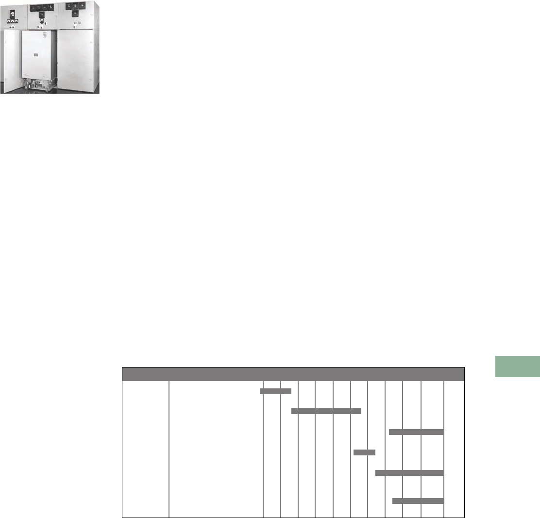
Volume 12—Aftermarket, Renewal Parts and Life Extension Solutions CA08100014E—November 2013 www.eaton.com V12-T17-53
1
2
3
4
5
6
7
8
9
10
11
12
13
14
15
16
17
18
19
20
21
22
23
24
25
17
Switchgear
Medium Voltage Metal-Clad—Assemblies and Power Circuit Breakers
Assemblies and Power
Circuit Breakers
Originally a
Westinghouse Product
Medium Voltage Switchgear Assembly
(Type DHP with Drawout Breaker)
Product Description
Medium voltage switchgear
serves to channel and
switch power in industrial,
commercial and utility
electrical distribution
systems. It is manufactured
to industry standards that
define the requirements
for its ratings, design,
construction and testing.
ANSI C37.20.2 is the current
applicable industry standard
for medium voltage metal-
clad switchgear, defining the
rated maximum voltage range
to be from 4.76 kV to 38 kV.
Medium voltage switchgear
consists of one or more metal
structures that house drawout
power circuit breakers, phase
bus conductors, auxiliary,
control, metering and
protective devices. These
switchgear components
are customized in various
combinations during
manufacturing to satisfy the
application requirements of
the switchgear user. Control
switches, meters, instruments
and protective relays are
generally mounted on the
switchgear front panels to
provide breaker control,
metering and circuit protection.
Medium voltage switchgear
is typically characterized
by metal-clad construction,
which means that the
switchgear compartments
enclosing primary voltage
are separated from adjacent
compartments by grounded
metal barriers.
Product History
In 1939, Westinghouse
introduced type DH medium
voltage air magnetic power
circuit breakers and associated
switchgear. Initially, DH
breakers were rated up to 5 kV
with a maximum interrupting
capacity of 150 MVA. Product
design enhancements evolved
and additional variations of the
DH breaker became available.
In 1946, the maximum rated
voltage of the DH breaker
was extended to 15 kV.
Eventually, the maximum
rated interrupting capacity
of the DH breaker reached
1000 MVA.
In 1963, Westinghouse
introduced type DHP medium
voltage Porcel-line® air
magnetic power circuit
breakers and associated
switchgear with all live parts
insulated to ground by high-
strength porcelain insulation.
Porcelain provided excellent
high dielectric, non-tracking,
non-combustible, non-
hygroscopic and non-aging
insulation characteristics.
This was a technological
improvement over the first
DH breakers, which were
furnished with a paper
phenolic insulation. DHP
switchgear was manufactured
in ratings from 5 kV, 75 MVA
to 15 kV, 1000 MVA. In 1978,
Westinghouse introduced the
DVP breaker, the first
Westinghouse medium
voltage power circuit breaker
to use vacuum interrupters.
The DVP vacuum breaker
was manufactured in 500
and 750 MVA interrupting
ratings and was directly
interchangeable with DHP
air magnetic breakers of the
same ratings.
In 1981, Westinghouse
introduced VacClad medium
voltage metal-clad switchgear
with type VCP vacuum power
circuit breakers. VCP breakers
were furnished with vacuum
interrupters, greatly reducing
breaker size and weight. The
reduced size permitted most
breaker ratings to be stacked
two-high in the switchgear
enclosure, saving on
switchgear installation space.
VCP breakers included a
design improvement called
the V-Flex current transfer
system, which eliminated the
transfer of primary current
over a moving hinge or a
sliding contact assembly
on the breaker. Porcelain
insulation was maintained on
the breaker elements and in
the switchgear, except for the
5 kV switchgear cell insulation
that was glass polyester. The
switchgear phase bus was
insulated with a fluidized bed
epoxy insulation system,
which was a technological
improvement over the epoxy
impregnated kraft paper or
noryl sleeving that was
used over phase busbars
in previous switchgear
designs. VacClad switchgear
was manufactured in ratings
from 5 kV, 250 MVA to 15 kV,
1000 MVA.
In 1986, Westinghouse
introduced VacClad-W World-
Class medium voltage metal-
clad switchgear with type
VCP-W vacuum power circuit
breakers. VCP-W switchgear
included product improvements
in manufacturing design
and product performance.
However, many of the
attractive design features
of VCP switchgear were
maintained, including two-high
breaker stacking, V-Flex breaker
current transfer and fluidized
epoxy insulation on the
switchgear phase buses.
VCP-W breakers and
switchgear were furnished
with high-grade glass polyester
insulation as standard. Optional
insulation upgrades included
cycloaliphatic epoxy insulation
for breaker element insulation
(VCP-WSE breakers) and
porcelain insulation for the
switchgear cell contact bottles.
VacClad-W switchgear is
manufactured in ratings from
5 kV, 250 MVA to 15 kV,
1500 MVA to 27 kV and
38 kV, 40 kA.
Product History Time Line
Westinghouse DH
Switchgear and Breakers
Westinghouse DHP
Switchgear and Breakers
DHP-VR
Replacement Breaker
Westinghouse VCP VacClad
Switchgear and Breakers
Cutler-Hammer VCP-W
VacClad Switchgear
and Breakers
Competitive Replacement
Breakers
Product 1955 1960 1965 1970 1975 1980 1985 1990 1995 2000 PresentPage
V12-T17-55
V12-T17-56
V12-T17-55
V12-T17-57
V12-T17-58
V12-T17-60

V12-T17-54 Volume 12—Aftermarket, Renewal Parts and Life Extension Solutions CA08100014E—November 2013 www.eaton.com
1
2
3
4
5
6
7
8
9
10
11
12
13
14
15
16
17
18
19
20
21
22
23
24
25
17
Switchgear
Medium Voltage Metal-Clad—Assemblies and Power Circuit Breakers
General Information
Medium Voltage Switchgear Support
Product Brand
Introduced
to Market
New
Structures
Assembly
Parts Breaker
Breaker
Parts Switch
Switch
Parts
Metal-Clad Switchgear
DH Westinghouse 1939 No No DH Breaker
Replacement
by DH-VR Breaker
No (contact
Homewood
Products at
412-665-2700)
N/A N/A
DHP Westinghouse 1963 No (contact
the factory)
Yes DHP breaker
replacement by
DHP-VR breaker.
Class I reconditioning
of DHP breakers and
repair service.
Yes (contact
the Power
Breaker Center
1-877-276-9379)
N/A N/A
VCP VacClad Westinghouse 1981 New VCP-W
structures can
be directly
coupled to
VCP structures
Some Yes Yes N/A N/A
VCP-W VacClad Westinghouse
Cutler-Hammer
1986
1995
Yes Yes Yes Yes N/A N/A
VCP-W VacClad
arc resistant
Cutler-Hammer 1995 Yes Yes Yes Yes N/A N/A
VCP-ND VacClad
narrow design
Cutler-Hammer 1994 Yes Yes Yes Yes N/A N/A
C-HRG high
resistance pulsing
ground system
Cutler-Hammer 1999 Yes Yes N/A N/A N/A N/A
Metal-Enclosed Switchgear—Switch
LBF Westinghouse 1952 No No (contact
Cleveland-Price at
724-864-4177)
N/A N/A No No (Contact
Cleveland-Price at
724-864-4177)
WLI Westinghouse
Cutler-Hammer
1972 No Yes N/A N/A Yes Yes
MVS Cutler-Hammer 1999 Yes Yes N/A N/A Yes Yes
UPC, Unitized
Power Center
Cutler-Hammer 1999 Yes Yes N/A N/A Yes Yes
Pad Mount Cutler-Hammer 1999 Yes Yes N/A N/A Yes Yes
Mini-MVS Cutler-Hammer 2003 Yes Yes N/A N/A Yes Yes
Metal-Enclosed Switchgear—Switch and Breaker
WVB Westinghouse 1991 No Yes Yes Yes Yes Yes
MEB Cutler-Hammer 1999 Yes Yes Yes—
VCP-W breaker
Yes—
VCP-W breaker
Yes Yes
Metal-Enclosed Switchgear—Breaker
Station Distribution
Breaker
Cutler-Hammer 1994 Yes Yes Yes—
VCP-W breaker
Yes—
VCP-W breaker
N/A N/A
MSB Cutler-Hammer 1999 Yes Yes Yes—VCP-TR
fixed-mounted
breaker
Yes—VCP-TR
fixed-mounted
breaker
N/A N/A
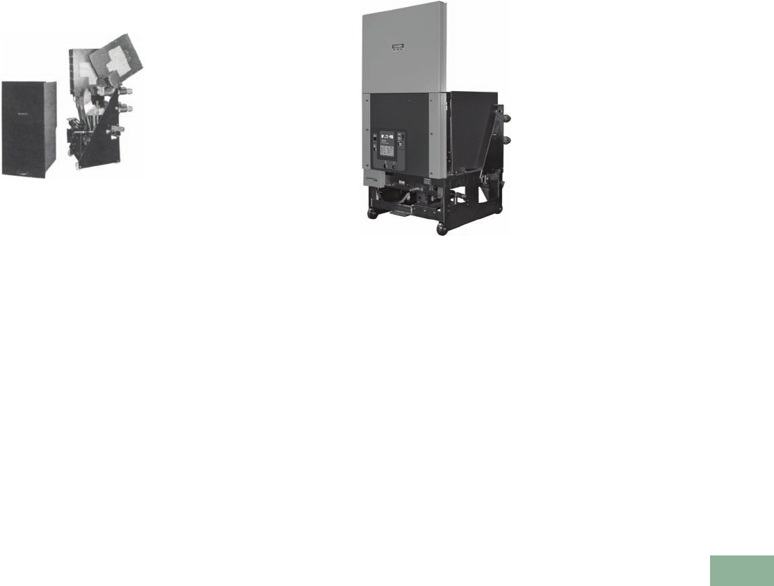
Volume 12—Aftermarket, Renewal Parts and Life Extension Solutions CA08100014E—November 2013 www.eaton.com V12-T17-55
1
2
3
4
5
6
7
8
9
10
11
12
13
14
15
16
17
18
19
20
21
22
23
24
25
17
Switchgear
DH Medium Voltage Metal-Clad—Assemblies and Power Circuit Breakers
DH Switchgear
Assemblies and Power
Circuit Breakers
Westinghouse DH Drawout
Air Magnetic Power Circuit Breaker
(Interphase Barrier Removed)
Product Description
Westinghouse DH medium
voltage metal-clad switchgear
with type DH “DE-ION®”
air circuit breakers was
introduced in 1939. The
drawout breaker element
consists of an operating
mechanism that drives a set
of three-pole units. When the
breaker is tripped, the moving
and stationary contacts
separate. The resulting arc on
each phase is drawn up and
into the arc chutes, which
dissipate the arc through
ceramic splitter plates.
The de-ionizing interruption
process is aided magnetically
by the arc chute blow out
coil assembly.
DH switchgear was available
in indoor and in sheltered
aisle and aisle-less outdoor
enclosures. DH metal-clad
switchgear structure
dimensions were standardized,
but varied with individual
breaker ratings. Widths varied
from 20.00 inches for the
50DH75 (1200A) light duty
rating, to 26.00 inches for
the 50DH250 (1200A)
rating, to 36.00 inches for
most 2000A and 7.5 and
15 kV ratings.
Ratings
DH switchgear ratings started
with the light duty 50DH75
(5 kV, 75 MVA) 1200A
breaker. The spectrum of
ratings also included 7.5 and
15 kV ratings. The maximum
breaker rating produced was
the 150DH1000 (15 kV,
1000 MVA) 3000A.
Chronology
DH switchgear was
introduced in 1939 and was
actively manufactured by
Westinghouse in complete
switchgear assemblies until
the introduction of DHP
switchgear in 1963. As
production activity tapered
after 1963, only match and
lineup additions to existing
DH switchgear were
manufactured along with
complete replacement circuit
breakers and renewal parts.
The last new manufactured
DH breakers and switchgear
cells were produced in 1983.
Replacement Capabilities
150DH-VR 1200A VR-Series
Circuit Breaker
Eaton offers the following to
support DH switchgear.
DH-VR Vacuum
Replacement Breakers
The DH-VR is a brand new
vacuum replacement breaker
(VR-Series) for DH air
magnetic breakers. The
DH-VR breaker permits DH
switchgear mod
ernization by
using state-of-the-art Eaton
VCP-W vacuum breaker
technology. The DH-VR is
designed, manufactured and
tested to applicable IEEE/
ANSI standards.
Ratings are available to
replace: 5 kV through
15 kV, 50DH150 through
150DH1000, 1200 through
3000A (4000A fan-cooled).
Additional VR-Series
breakers are available to
upgrade competitors’ air
magnetic breakers. See
Pages V12-T17-60 and
V12-T17-61.
SURE CLOSE
All VR Series breakers that
are furnished with MOC
operators incorporate
Eaton’s exclusive SURE
CLOSE MOC technology.
See additional information
on Page V12-T17-62.
Renewal Parts
Eaton no longer offers new
manufactured renewal parts
for DH switchgear structures.
For DH renewal parts, contact
Homewood Products
at 412-665-2700.
Note: New DH factory
manufactured switchgear
structures and breakers
are no longer available.
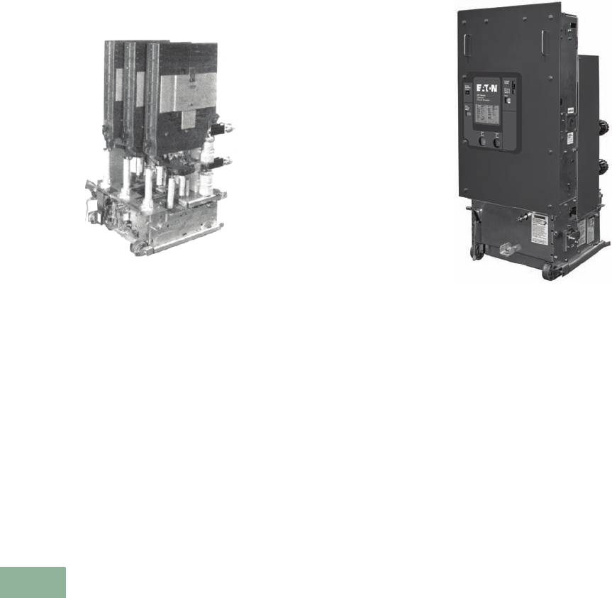
V12-T17-56 Volume 12—Aftermarket, Renewal Parts and Life Extension Solutions CA08100014E—November 2013 www.eaton.com
1
2
3
4
5
6
7
8
9
10
11
12
13
14
15
16
17
18
19
20
21
22
23
24
25
17
Switchgear
DHP Medium Voltage Metal-Clad—Assemblies and Power Circuit Breakers
DHP Switchgear
Assemblies and Power
Circuit Breakers
Type DHP Drawout Air Magnetic
Power Circuit Breaker
(Front Interphase Barrier Removed)
Product Description
Westinghouse DHP medium
voltage porcel-line metal-clad
switchgear with type DHP
air magnetic power circuit
breakers was introduced in
1963. DHP breakers and
switchgear were similar to,
but not interchangeable with,
the older DH product. DHP
was provided with porcelain
insulation on all live parts to
ground in the switchgear
and on the breaker element.
DHP switchgear was
available in indoor and in
sheltered aisle and aisle-less
outdoor enclosures.
DHP air magnetic breakers
were subject to three major
design changes that were
phased in during their
manufacturing life. The first
DHP breakers were furnished
with solenoid operated
mechanisms with cast parts
and monolithic pole units.
From 1964 to 1968, the stored
energy spring mechanism
gradually phased out the
solenoid operator. After 1968,
cast mechanisms were
phased out by fabricated
mechanisms. After 1970,
monolithic pole units were
phased out by the post-
insulator pole unit (PIP) design.
DVP vacuum breakers were
introduced in 1978. DVP
breakers were first generation
vacuum breakers that were
interchangeable in DHP
switchgear with DHP air
magnetic breakers of the
same ratings.
Ratings
●DHP breakers:
●5 kV (75, 250 and
350 MVA)
●7. 5 k V ( 5 0 0 M V A )
●15 kV (500, 750 and
1000 MVA)
●DVP breakers:
●7. 5 k V ( 5 0 0 M V A )
●15 kV (500 and
750 MVA)
Chronology
DHP switchgear was
introduced in 1963 and
was actively manufactured
by Westinghouse in complete
switchgear assemblies
until 1984.
Replacement Capabilities
DHP-VR VR-Series Circuit Breaker
Eaton offers the following to
support DHP switchgear.
DHP-VR Vacuum
Replacement Breakers
The DHP-VR is a brand new
vacuum replacement breaker
(VR-Series) for DHP air
magnetic and DVP vacuum
breakers. The DHP-VR breaker
permits DHP switchgear
modernization by using state-
of-the-art Cutler-Hammer
VCP-W vacuum breaker
technology. The DHP-VR is
designed, manufactured
and tested to applicable
IEEE/ANSI standards.
Ratings are available to
replace: 5 kV through
15 kV, 50DHP75 through
150DHP1000, 1200–3000A.
Additional VR-Series
breakers are available to
upgrade competitors’ air
magnetic breakers. See
Pages V12-T17-60 and
V12-T17-61.
SURE CLOSE
All VR Series breakers that
are furnished with MOC
operators incorporate
Eaton exclusive SURE
CLOSE MOC technology.
See additional information
on Page V12-T17-62.
Class 1 Reconditioned DHP
Breakers and Repair Service
Class 1 Reconditioning of
DHP breakers and repair
service for DHP breakers
are available.
Renewal Parts
Eaton offers an inventory of
newly manufactured renewal
parts for most DHP switchgear
structures and breakers.
Effective 12/17/2002, DHP
match and lineup cubicles,
DHP air magnetic breakers
and arc chutes will no longer
be available.
Fluidized Switchgear Bus
Eaton offers new fluidized
epoxy bus—insulated bus to
replace existing switchgear
phase bus insulation.
See Page V12-T17-59.
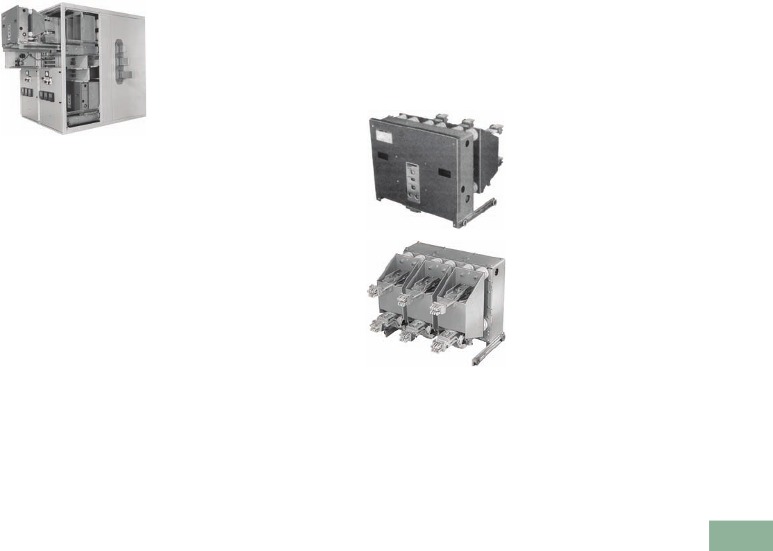
Volume 12—Aftermarket, Renewal Parts and Life Extension Solutions CA08100014E—November 2013 www.eaton.com V12-T17-57
1
2
3
4
5
6
7
8
9
10
11
12
13
14
15
16
17
18
19
20
21
22
23
24
25
17
Switchgear
VCP VacClad Medium Voltage Metal-Clad—Assemblies and Power Circuit Breakers
VCP VacClad Switchgear
Assemblies and Power
Circuit Breakers
VacClad Switchgear with
Type VCP Drawout Vacuum
Power Circuit Breakers
Product Description
Westinghouse VacClad
medium voltage metal-clad
switchgear with type VCP
vacuum power circuit
breakers was introduced in
1981. Vacuum interrupter
technology provided many
advantages over the previous
DH and DHP air magnetic
breaker designs. Vacuum
interrupters permitted the
breaker size and weight to
be significantly reduced,
allowing for two-high stacking
construction of most breaker
ratings in the switchgear
enclosure. VCP breakers
withdraw onto switchgear rail
assemblies for ease of
inspection. Maintenance
associated with air magnetic
arc chutes was eliminated
and contact maintenance was
reduced to visual inspection
of wear gap indicators.
VCP breakers included a
design improvement called
the V-Flex current transfer
system, which eliminated the
transfer of primary current
over a moving hinge (like
DHP breakers) or a sliding
contact assembly (like DVP
breakers). Porcelain insulation
was maintained on the
breaker elements and in
the switchgear except for
the 5 kV switchgear cell
insulation, which was glass
polyester as standard. The
switchgear phase bus was
insulated with a fluidized
bed epoxy insulation
system, which was a major
improvement over the epoxy
impregnated kraft paper
or noryl that was used as
sleeving on phase busbars in
previous switchgear designs.
VacClad switchgear was
manufactured in indoor and in
sheltered aisle and aisle-less
outdoor enclosures.
Ratings
VCP switchgear provided
the first complete line of
Westinghouse vacuum
breakers in the medium
voltage ratings:
●5 kV (250 and 350 MVA)
●7. 5 k V ( 5 0 0 M V A )
●15 kV (500, 750 and
1000 MVA)
Chronology
VacClad switchgear was
introduced in 1981 and
was manufactured by
Westinghouse in complete
switchgear assemblies until
the introduction of VacClad-W
switchgear in 1986. Today,
many capabilities still exist to
support VacClad switchgear.
Replacement Capabilities
Type VCP Vacuum Power Circuit
Breaker (Front and Rear Views)
Eaton offers the following to
support VacClad switchgear.
Remanufactured VCP Breakers
and Factory Repair Service
Factory remanufacturing of
VCP breakers and factory
repair service for VCP
breakers are available.
Renewal Parts
Eaton offers an extensive
inventory of newly
manufactured renewal
parts for VCP switchgear
structures and breakers.
Fluidized Switchgear Bus
Eaton offers new fluidized
epoxy bus—insulated bus
to replace existing switchgear
phase bus insulation. See
Page V12-T17-59.
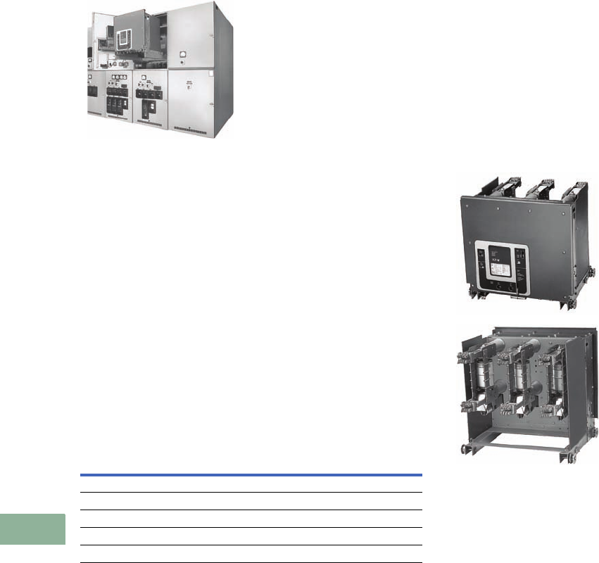
V12-T17-58 Volume 12—Aftermarket, Renewal Parts and Life Extension Solutions CA08100014E—November 2013 www.eaton.com
1
2
3
4
5
6
7
8
9
10
11
12
13
14
15
16
17
18
19
20
21
22
23
24
25
17
Switchgear
VCP-W VacClad Medium Voltage Metal-Clad—Assemblies and Power Circuit Breakers
VCP-W VacClad
Switchgear Assemblies
and Power Circuit
Breakers
VacClad-W Switchgear with
Type VCP-W Drawout Vacuum
Power Circuit Breakers
Product Description
VacClad-W world-class
medium voltage metal-clad
switchgear with type VCP-W
vacuum power circuit
breakers was introduced by
Westinghouse in 1986. VCP-
W breakers and switchgear
were similar to but not
interchangeable with the
original VacClad (VCP) product.
The VCP-W design
includes a consolidation of
improvements in product
design and performance that
enables the introduction
of IEC and 27 kV breaker
ratings. However, VCP-W
still includes many of the
proven product features
of VCP switchgear design,
including two-high breaker
stacking,V-Flex breaker
current transfer and fluidized
epoxy insulation on the
switchgear phase buses.
VCP-W breakers withdraw
onto removable switchgear
rail assemblies for ease of
inspection. VCP-W breakers
and switchgear were
furnished with high-grade
glass polyester insulation
as standard. Optional
insulation upgrades included
cycloaliphatic epoxy insulation
for breaker element insulation
(VCP-WSE breakers) and
porcelain insulation for the
switchgear cell contact
bottles. VacClad-W switchgear
is manufactured in indoor and
in outdoor sheltered aisle and
aisle-less enclosures. Another
option offered for VacClad
indoor switchgear is arc-
resistance. Eaton was a leader
in the development and design
of arc-resistant switchgear.
Arc-resistant metal-clad
switchgear is metal-clad
switchgear tested for
resistance to the effects of
arcing due to an internal fault.
ANSI and IEC Ratings
ANSI Ratings IEC Ratings
5 kV (250 and 350 MVA) 3.6 kV (25, 31.5, 40 kA rms SC Make)
7.5 kV (500 MVA) 7.2 kV (25, 31.5, 40 kA rms SC Make)
15 kV (500, 750, 1000 and 1500 MVA) 12 kV (25, 31.5, 40 kA rms SC Make)
27 kV (750, 1000 and 1250 MVA, and 40 kA) 17.5 kV (31.5, 40 kA rms SC Make)
38 kV (16, 21, 25, 31.5 and 40 kA) 24 kV (25 kA rms SC Make)
Chronology
VacClad-W switchgear was
introduced in 1986 and is the
current state-of-the-art Eaton
switchgear product. The VCP-
WSE breaker with special
cycloaliphatic epoxy insulation
and the 27 kV VCP-W rating
were introduced in 1990. IEC
VCP-W ratings were
introduced in 1991. 38 kV was
introduced in 1995.
Arc-resistant VCP-W
switchgear was introduced
in 1995.
Replacement Capabilities
Type VCP-W Vacuum Power Circuit
Breaker (Front and Rear Views)
Eaton offers the following to
support VacClad-W switchgear.
Complete New VacClad-W
Switchgear Assemblies
Complete new manufactured
VacClad-W
switchgear
assemblies are available
to replace obsolete existing
switchgear with new Cutler-
Hammer state-of-the-art
vacuum switchgear.
VacClad-W Match and
Lineup Cubicles
New manufactured VacClad-W
switchgear structures to
match and line up to existing
Westinghouse and Cutler-
Hammer VacClad-W
switchgear. New VCP-W
structures can also connect
to existing Westinghouse
indoor switchgear (types
DH, DHP and VCP) with a
transition section.
New VCP-W Vacuum Breakers
Completely new factory
manufactured VCP-W
vacuum power circuit
breakers are available
in all published ratings.
Renewal Parts
Eaton offers an extensive
inventory of newly
manufactured renewal
parts for VCP-W switchgear
structures and breakers.
Fluidized Switchgear Bus
Eaton offers new fluidized
epoxy bus—insulated bus to
replace existing switchgear
phase bus insulation. See
Page V12-T17-59.
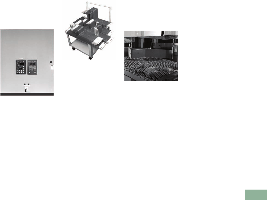
Volume 12—Aftermarket, Renewal Parts and Life Extension Solutions CA08100014E—November 2013 www.eaton.com V12-T17-59
1
2
3
4
5
6
7
8
9
10
11
12
13
14
15
16
17
18
19
20
21
22
23
24
25
17
Switchgear
Medium Voltage Metal-Clad Upgrades
Technology Upgrades
Front Panel Retrofit
with IQ Devices
and PowerNet
Communications
DHP, VCP, VCP-W
New VCW Front Panel with
Upgraded Control Devices
Eaton can provide an upgrade
to your system by replacing
existing analog meters,
instruments and protective
relays with microprocessor-
based solid-state true rms
sensing devices. New
replacement front panels are
available for DHP, VCP and
VCW switchgear assemblies,
and they can be provided
with devices mounted
and wired.
Wire markers and wiring
diagrams are provided for
the hinged panel. The existing
panel is removed, the new
panel is set in place and the
solid-state devices are wired
into the switchgear unit.
Fluidized Switchgear Bus
Any Busbar Shape or Configuration
is Uniformly Coated. There are
No Dielectric Weak Spots and
Taping is Not Necessary
Eaton offers a cost-effective
program that can extend the
life of any manufacturer’s
equipment by replacing the
bus and insulating it with
fluidized bed epoxy. The bus
insulation in many existing
switchgear assemblies may
be NORYL®, Micarta®,
redacta, heat shrink tubing
or fiberglass. These materials
are adversely affected by
aging, environment and
operating conditions. The
solution to these concerns
can be answered with the
high quality, state-of-the-art
system and superiority
offered by the fluidized bed
epoxy process.
Customers can use any
of the following services
to fit specific switchgear
applications from 600V
to 38 kV:
●Bus replacement
●Bus duct replacement
Coated Busbars Pass Through a Post-
heat Oven to Cure and Fuse the Epoxy
Switchgear Upgrades
DHP, VCP, VCP-W
Switchgear upgrades are
available to increase the
MVA and continuous
current ratings of the
entire assembly.
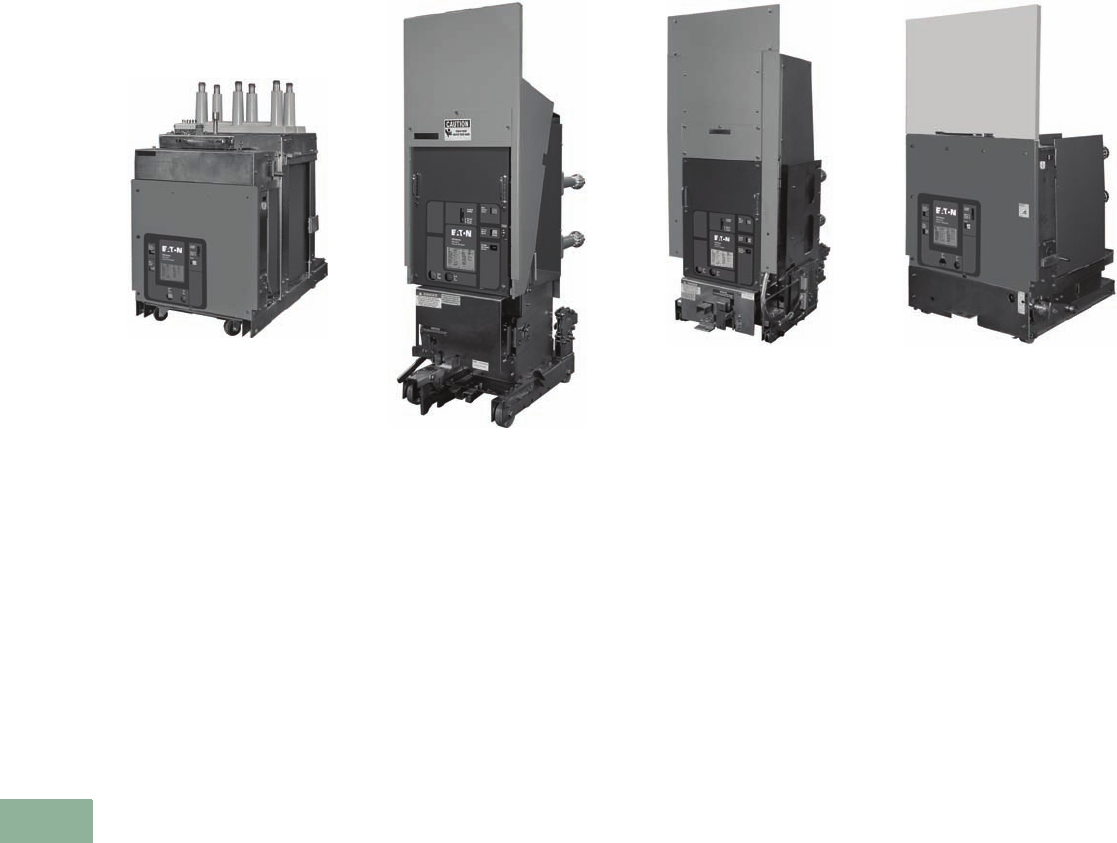
V12-T17-60 Volume 12—Aftermarket, Renewal Parts and Life Extension Solutions CA08100014E—November 2013 www.eaton.com
1
2
3
4
5
6
7
8
9
10
11
12
13
14
15
16
17
18
19
20
21
22
23
24
25
17
Switchgear
Medium Voltage Competitive Upgrades—Vacuum Replacement Breakers
Competitive Upgrades
Medium Voltage Vacuum
Replacement Breakers
General Electric MagneBlast
GE-AM13.8-VR VR-Series
Circuit Breaker
Eaton manufactures an
extensive line of VR-Series
breakers to replace General
Electric MagneBlast air
magnetic breakers.
Ratings are available
to replace:
●AM4.16 5 kV,
150–350 MVA,
1200–3000A
●AM5 5 kV, 150–250 MVA,
1200 and 2000A
●AM7.2 7.5 kV, 500 MVA,
1200 and 2000A.
●A M 7. 5 7. 5 k V ,
250–500 MVA,
1200 and 2000A
●AM13.8 15 kV,
250–1000 MVA,
1200 and 3750A (both
short and tall frames)
●AM15 15 kV,
250–750 MVA,
1200 and 2000A
Allis-Chalmers RUPTAIR
MA-VR VR-Series Circuit Breaker
An extensive line of Eaton
VR-Series breakers are
manufactured to replace
Allis-Chalmers RUPTAIR type
AM, MA, FA, FB and FC
air magnetic breakers.
Ratings are available
to replace:
●AM 5 kV, 100–250 MVA,
1200 and 2000A
●MA 5 kV, 150–350 MVA,
1200 and 2000A
●FA 5 kV, 350 MVA, 3000A
●FB 7.5 kV, 500 MVA,
1200 and 2000A
●FC 15 kV, 500–1000 MVA,
1200–3000A
Federal Pacific Electric
DST-2-VR VR-Series Circuit Breaker
An extensive line of Eaton
VR-Series breakers are
manufactured to replace
Federal Pacific Electric air
magnetic breakers.
Ratings are available to
replace:
●DST 5–15 kV,
150–750 MVA,
1200 and 2000A
●DST-2 5–15 kV,
150 000 MVA,
1200–2000A
SURE CLOSE
All VR-Series breakers that
are furnished with MOC
operators incorporate
Eaton’s exclusive SURE
CLOSE MOC technology.
See additional information
on Page V12-T17-62.
ITE
15HK-VR VR-Series Circuit Breaker
Eaton manufactures an
extensive line of VR-Series
breakers to replace ITE air
magnetic breakers.
Ratings are available
to replace:
●5HV 5 kV, 100–250 MVA,
600–2000A
●5HK-Model 03, 5 kV,
250–350 MVA,
1200 and 2000A
●15HK-Model 03, 15 kV,
500–1000 MVA,
1200 and 2000A
●15VHK-Model 20, 15 kV,
500–750 MVA, 1200A
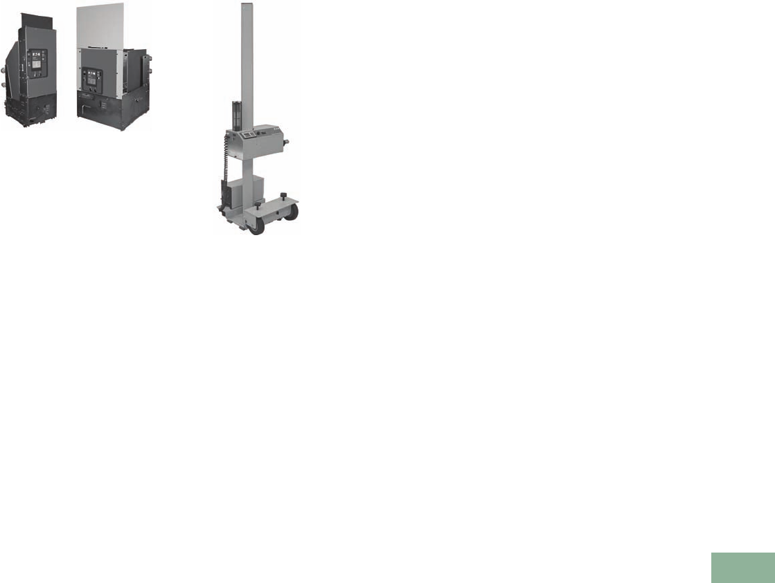
Volume 12—Aftermarket, Renewal Parts and Life Extension Solutions CA08100014E—November 2013 www.eaton.com V12-T17-61
1
2
3
4
5
6
7
8
9
10
11
12
13
14
15
16
17
18
19
20
21
22
23
24
25
17
Switchgear
Medium Voltage Competitive Upgrades—Vacuum Replacement Breakers
McGraw & Edison
PSD-VR and WSA-VR VR-Series
Circuit Breakers
An extensive line of Eaton
VR-Series breakers are
manufactured to replace
McGraw-Edison air
magnetic breakers.
Ratings are available to
replace:
●PSD-15 15 kV,
500–750 MVA,
1200 and 2000A
●WSA-5 5 kV, 250 MVA,
1200 and 2000A
●WSA-15 15 kV,
500–750 MVA,
1200 and 2000A
SURE CLOSE
All VR-Series breakers that
are furnished with MOC
operators incorporate
Eaton’s exclusive SURE
CLOSE MOC technology.
See additional information
on Page V12-T17-62.
Remote Power Racking
Remote Power Racking (RPR-2)
Eaton’s remote power
racking (RPR-2) unit provides
a means of remotely racking
most power circuit breakers
that use the rotation of
a shaft for insertion and
removal. Personnel can be up
to 25 feet (8m) or more away
from the switchgear door
during the racking process.
This need for distance away
from the switchgear is due
to safety precautions from
potential arc flash
occurrences.
Many arc flash incidences
with low voltage and medium
voltage switchgear occur
during the process of
inserting and removing
(racking) power circuit
breakers in switchgear
cubicles. Personnel are
typically within 2 feet (0.6m)
of the front of the power
circuit breaker during the
racking process and this close
proximity to an arc flash can
cause serious injury. The best
way to limit exposure to arc
flash during the process
of racking power circuit
breakers is to put more
distance between the
person and the possible
point of exposure.
NFPA 70E provides guidance
for the requirements of
personal protective equipment
(PPE) to protect personnel
from arc flash exposure.
Eaton’s RPR-2 allows
personnel to wear a lower
level of PPE, increasing worker
comfort and mobility, while
operating the RPR-2 from an
increased distance from the
power circuit breaker.
The RPR-2 system is the
solution that provides
the value and the features
that customers request.
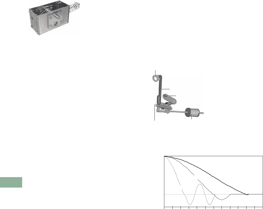
V12-T17-62 Volume 12—Aftermarket, Renewal Parts and Life Extension Solutions CA08100014E—November 2013 www.eaton.com
1
2
3
4
5
6
7
8
9
10
11
12
13
14
15
16
17
18
19
20
21
22
23
24
25
17
Switchgear
SURE CLOSE
SURE CLOSE
An Eaton Solution for an
Industry-Wide Problem
SURE CLOSE
Background
Mechanism Operated
Contacts (MOCs) are external
to the breaker (mounted
in the switchgear cell) and
are driven by the breaker
mechanism through a
mechanical interface. These
contacts are used to provide
extra contacts for breaker
status and for other control
functions. As the circuit
breaker closes, an MOC
operator causes the MOC
switches to operate.
Air-magnetic breakers have
massive mechanisms with
high forces and inertia. The
resultant travel times and
the velocities are slow. The
figure (A-M) shows the
closing curve of a typical
air-magnetic breaker and the
MOC operator. It closes in
approximately 100 msec
(a tenth of a second),
measured from the time
the breaker begins to close.
Problem
A vacuum replacement
breaker (VR) is much smaller
and lighter than the air-
magnetic breaker it replaces.
The vacuum contacts move
a smaller distance and much
faster. When a VR breaker
is applied to the cell that
originally contained an
air-magnetic breaker, the
resultant speed of operation
of the MOC becomes much
faster when it is directly
driven by the breaker
operating mechanism. The
result is higher impact loads
and mismatched
inertia with
the existing switchgear MOC.
The effect of the system
mismatch is shown in the
figure (VR Direct Drive).
When a VR breaker without
SURE CLOSE drives the
MOC, the breaker and the
MOC complete the closing
stroke in the same time;
25 msec, versus the
100 msec for the original
air-magnetic breaker. Notice
the over-travel with the direct
drive MOC. The velocity of the
MOC system is essentially
four times what it is with the
air-magnetic breaker. Because
kinetic energy (the energy
associated with motion) is
proportional to the velocity
squared, the kinetic energy
of the MOC has increased
to 16 times that of the
original design. This faster
operation causes:
●Significant MOC over-travel
and bounce
●MOC component wear
●A worn or broken MOC
could cause a breaker
to stall
Solution
SURE CLOSE is a stored
energy device, internal to
the breaker, which allows
the MOC to open and
close independently from
the speed of the breaker
mechanism and:
●Eliminates the possibility
of the MOC stalling
the breaker
●Slows down the
MOC operation
●Prevents damage to MOC
cell components
SURE CLOSE Components
Conclusion
In the figure below, you can
see that the SURE CLOSE
MOC drive approximates the
original air-magnetic MOC
response much better than
the VR direct drive. The
VR-Series breaker with the
SURE CLOSE drive does NOT
cause MOC switch contact
bounce or abnormal wear.
MOC Closing Times—Air-Magnetic, VR without SURE CLOSE
and VR with SURE CLOSE
Breaker Pole
Shaft Lever
Slotted Drive Links
MOC Lever Arm
Drive
Spring
Return Spring
MOC Timing–Closing
OPEN
Stroke
CLOSED
Air-Magnetic
Ti m e ( m S)
0102030405060708090100110120
SURE CLOSE
VR DIRECT Drive
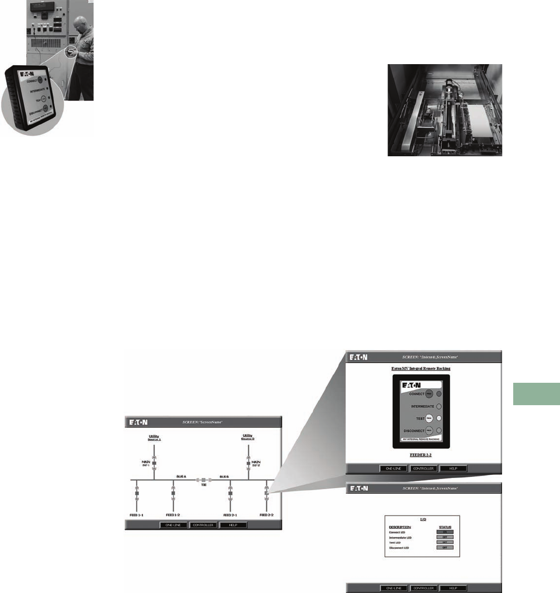
Volume 12—Aftermarket, Renewal Parts and Life Extension Solutions CA08100014E—November 2013 www.eaton.com V12-T17-63
1
2
3
4
5
6
7
8
9
10
11
12
13
14
15
16
17
18
19
20
21
22
23
24
25
17
Switchgear
VacClad-W Motor ized Remote Racking
VacClad-W Motorized
Remote Racking
(VCP-W MR2)
Remote Racking
Product Description
Eaton’s VCP-W MR2
motorized remote racking
device provides a means
of remotely inserting or
removing any drawout circuit
breaker used in VacClad-W
switchgear, to help mitigate
arc flash exposure.
The VCP-W MR2 permits
the operator to safely move
a VCP-W breaker between
three pre-determined
positions within the circuit
breaker compartment.
Standing at a safe distance,
well outside the arc flash
boundary of the equipment,
an operator can use remote
controls to select disconnect,
test or connected positions
for the circuit breaker.
The Danger
Electric arcs result from
thermal ionization that
occurs when current flow
is interrupted by the
separation of conductors.
Thermal ionization can
generate temperatures as
high as 35,000°F. Conductor
materials melt into metal
vapor and the surrounding
air is ionized.
External arcs create a
violent explosion, resulting
in an inferno of ionized
gases, molten debris,
metal shrapnel and a flash
of light (an arc flash). Inside
a switchgear/switchboard
cabinet, an arc event can
dislodge compartment
doors and turn hardware
into high-speed projectiles.
Increased safety precautions
and the need to protect
personnel from the dangers of
potential arc flash occurrences
suggest the need to increase
the distance between an
operator and the front of a
switchgear lineup during
racking operations.
Features
●Self powered when
switchgear is energized
●Provisions energize the
system racking motors
with an external 120 Vac
power source
●Available for all breakers in
VacClad-W switchgear
●Factory installed and
tested in circuit breaker
compartment
●Permanently installed
racking motors eliminate
the need to lift and
manipulate, and align
heavy, bulky equipment
●Simple hand-held pendant
controller is available with
indicating lights to clearly
indicate position and status
of the circuit breaker
●25 ft umbilical cord
between hand-held
controller and circuit
breaker compartment
●All circuit breaker safety
interlocks remain intact
per IEEE C37.20.2
●Logic is built into the
device to sense an
interference issue
●Logic will not accept a
command to connect a
circuit breaker that has
experienced interference
until after it has been moved
to the disconnect position
●Controls can be integrated
into switchgear secondary
control circuits, and/or
SCADA systems using
Modbus® interface or
discrete wiring
●Permissive circuit provision
for disabling remote racking
until the right system
conditions are satisfied
●Pendant will override
system when plugged into
a specific circuit breaker
Benefits
●Automatic racking reduces
installation effort
●Permanently installed
system will not get lost
between service intervals
●You do not lose the ability
to manually operate your
circuit breaker racking
mechanism
●Operators can open and
disconnect all circuit
breakers remotely before
entering the equipment
room, which ensures no
exposure to arc flash energy
Racking Pan
Motor, logic controller
and safety interlocks are
built into the circuit breaker
compartment. System is
factory installed and tested
with VCP-W circuit breakers.
Each switchgear system that
is purchased with remote
racking capabilities will come
with a hand-held pendant for
simple operation of a single
circuit breaker at a time.
PanelMate® Interface for Integrated Controls

V12-T17-64 Volume 12—Aftermarket, Renewal Parts and Life Extension Solutions CA08100014E—November 2013 www.eaton.com
1
2
3
4
5
6
7
8
9
10
11
12
13
14
15
16
17
18
19
20
21
22
23
24
25
17
Switchgear
Further Information
Further Information
Pricing Information
VCP-W Breaker
Price List for VCP-W Breaker Parts—PL 33-729
VCP-WR Breaker
Price List for VCP-WR Fixed Vacuum Breakers—PL 33-724
MV Air/Vacuum Switchgear Parts
Vista/VISTALINE Discount Symbol Y1
VR-Series Breakers
Price List for VR-Series Replacement Breakers—PL02707001E
Publication Number Description
DHP Switchgear and Breaker
RPD 32-253-4D Renewal Parts Data for DHP breaker and switchgear parts
PA02707017E Sales Aid for the DHP-VR vacuum replacement breaker
RP01301006E Renewal Parts Data for the DHP-VR vacuum replacement breaker
VCP Switchgear and Breaker
RPD 32-274 Renewal Parts Data for VCP breaker and switchgear parts
LEL007A Sales Aid for the VCP remanufacture program
VCP-W Switchgear and Breaker
RP02201001E VCP-W 5 and 15 kV switchgear common replacement parts
RP02204001E Renewal Parts Data for VCP-W switchgear parts
SA-11671 Sales Aid for VCP-W switchgear
DB 32-255 Descriptive Bulletin for VCP-W switchgear
AD 32-265 Application Data for VCP-W switchgear
Fluidized Bus
SA-11745 Sales Aid for custom fluidized switchgear bus
General Information
LEL004A Sales Aid for breaker remanufacture program
SA02204001E Sales Aid for MV switchgear replacement front panels with IQ devices
DH Breakers
PA02707011E Sales Aid for the DH-VR vacuum replacement breaker
GE MagneBlast Breakers
PA02707021E Sales Aid for GE AM4.16 and AM13.8 vacuum replacement breakers
Allis-Chalmers Breakers
PA02707032E Sales Aid for Allis-Chalmers Type MA vacuum replacement breakers
PA02707031E Sales Aid for Allis-Chalmers Type AM 250 vacuum replacement breakers
PA02707033E Sales Aid for Allis-Chalmers Type F-Series vacuum replacement breakers
Federal Pacific Electric Breakers
PA02707041E Sales Aid for Federal Pacific Electric Type DST vacuum replacement breakers
PA02707042E Sales Aid for Federal Pacific Electric Type DST-2 vacuum replacement breakers
ITE Breakers
PA02707052E Sales Aid for ITE Type HK (Model 03) vacuum replacement breakers
PA02707051E Sales Aid for ITE 5HV vacuum replacement breakers
McGraw-Edison Breakers
PA02707062E Sales Aid for McGraw-Edison PSD vacuum replacement breakers
PA02707061E Sales Aid for McGraw-Edison WSA vacuum replacement breakers
Universal Remote Power Racking
PA02707071E Sales Aid for universal remote power racking system (RPR-2)
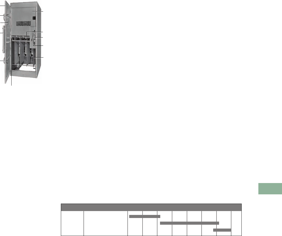
Volume 12—Aftermarket, Renewal Parts and Life Extension Solutions CA08100014E—November 2013 www.eaton.com V12-T17-65
1
2
3
4
5
6
7
8
9
10
11
12
13
14
15
16
17
18
19
20
21
22
23
24
25
17
Switchgear
Medium Voltage Metal-Enclosed Load Interrupter Switch Assembly and Switches
WLI Load Interrupter
Metal-Enclosed
Switchgear
Originally a
Westinghouse Product
WLI Design
Standard Manually Operated
Fused WLI Switch
1Switch position indicator/
operator mechanism
2Provisions for
padlocking door
3Inspection window
(4 x 16 inches)
4Full height main door
5Door stop, foot operated
6Grounded metal
safety barrier
7Door interlock
8Switch interlock
9Interphase barrier
jSwitch operator
mechanism access door
8
5
4
2
3
j
2
9
1
7
6
Product Description
The WLI (Westinghouse Load
Interrupter)
medium voltage
switchgear is generally
composed of a three-phase
load interrupter housed in a
metal-enclosed structure. The
switch is rated for use in four
voltage classes: 4 kV, 15 kV,
25 kV and 38 kV. 600A and
1200A current ratings are
available. The switch is
typically applied in series
with three medium voltage
fuses on the load side of
the switch. WLI switchgear
is used for economical
protection of unit substation
transformers and medium
voltage power distribution
(via a lineup of these
switches). The WLI product
line also offered a compact
Unitized Power Center (UPC)
that used the WLI switch
on the primary of the
UPC transformer.
LBF and WLl look similar
in design. They can be
differentiated by the
nameplate located behind
the operating handle access
door. The front is largely
covered by the main door,
with a 4 x 16-inch viewing
window, providing access
to the switch and fuse
compartment. A smaller
access door on the main door
allows access to the switch
operating mechanism. Upon
opening the main door, the
switch in the upper part
of the structure is covered
by a protective screen
barrier that allows visual
inspection. The fuses, when
provided, are located in the
lower part of the structure,
and are readily visible for easy
maintenance when the main
door is open. The rear of the
switch structure is generally
used for cable entrance and/
or exit. Access to the cable
entrance/exit area is via a rear
cover or door.
The MVS design offers
many enhancements over
the previous WLI design. A
few of the exterior features
include a galvanized base
and a larger viewing window.
Interior features include a
hinged barrier, rustproof
latches, nylon finned
insulators and a switch that
is a removable component.
The WVB (Westinghouse
Vacuum breaker) switchgear
was introduced in 1991,
providing a fixed-mounted
medium voltage vacuum
breaker on the load side of the
switch. The medium voltage
vacuum breaker was used
in lieu of fuses, providing the
capability to instantly reset the
breaker after a trip condition
and the ability to adjust to a
wide variety of coordination
curves in the field.
The MEB (Metal-Enclosed
Breaker) and MSB (Medium
Voltage Switch and Breaker)
designs replaced the WVB
product offering. The MEB
design uses the VCP-TR
medium voltage fixed-
mounted vacuum breaker.
The MSB offering employs
a three-phase
load interrupter
to provide a means to isolate
the fixed-mounted breaker.
Product History
Metal-enclosed load break
air interrupter switches were
first produced in 1952 under
the name Load Break Fusible
(LBF) at M & R facilities
around the country. In 1964,
the manufacturing of the
product was consolidated
in the Cincinnati, OH,
facility. The product was
discontinued in 1972 and
replaced with Westinghouse
Load Interrupter (WLI),
having many design changes
and improvements. Parts
for the two products are
incompatible, but the WLI
design can be added to
existing LBF lineups. The
WLI product line was
moved to the Sumter, SC,
manufacturing facility
in 1979.
The current MVS design
was first introduced in
Sumter, SC, in 1999 and
built concurrently with
the previous design until
December 2001. The
product line was relocated
to Greenwood, SC, in late
2001. As of January 2002,
only the current MVS design
was manufactured.
Product History Time Line
Westinghouse LBF
Westinghouse/C-H WLI
Cutler-Hammer MVS
Product 1950 1960 1970 1980 1990 1995 2000 PresentPage
V12-T17-66
V12-T17-66
V12-T17-66
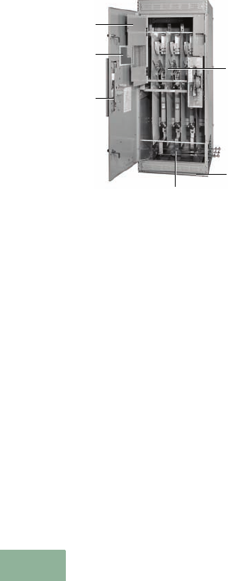
V12-T17-66 Volume 12—Aftermarket, Renewal Parts and Life Extension Solutions CA08100014E—November 2013 www.eaton.com
1
2
3
4
5
6
7
8
9
10
11
12
13
14
15
16
17
18
19
20
21
22
23
24
25
17
Switchgear
LBF/WLI/MVS Medium Voltage Metal-Enclosed Load Interrupter
WLI/MVS Load
Interrupter Switchgear
MVS Design
Standard Manually Operated
Fused MVS Improvements
1Standard hinged barrier
2Larger, lower window
(8.00 x 16.00-inch) double
viewing area
3Rustproof latches
4Removable switch
5Nylon finned insulators
6G90 galvanized base
LBF/WLI Product Description
The LBF (load break) switch
standard structure was
33.00 inches wide,
90.38 inches high (indoor)
and 98.88 inches high
outdoor. The WLI (Load
Interrupter) switch structure
was offered in both
33.00-inch and 36.00-inch
wide enclosures in the 5 kV
and 15 kV ratings. Both
designs used vertical sections
that were freestanding, close
coupled to transformers, and
bolted together in lineups.
Starting in 1984, ANSI 61 light
gray was the standard internal
and external color for all WLI
structures. Prior to 1984, the
exterior surfaces of outdoor
enclosures were ANSI 24 dark
gray. LBF was only offered in
the 5 kV and 15 kV voltage
ratings. WLI was offered in
5 kV, 15 kV, 25 kV and 38 kV
voltage ratings using 600A
and 1200A switches.
MVS Product Description
The MVS standard structures
for 5 kV and 15 kV gear is
33.00 to 48.00 inches wide,
90.38 inches high (indoor),
98.88 inches high (outdoor),
with varying depths. The
standard structures for
27 kV and 38 kV gear is 48.00
to 54.00 inches wide, 101.50
or 127.00 inches high (indoor),
110.00 or 135.50 inches high
(outdoor), with varying depths.
Vertical sections are
freestanding, close coupled
to transformers and bolted
together forming lineups.
Switch Ratings
●LBF
●5 kV
●15 kV
●WLI
●5 kV
●15 kV
●25 kV
●38 kV
●MVS
●5 kV (600 and 1200A)
●15 kV (600 and 1200A)
●27 kV (600A)
●38 kV (600A)
Replacement Capabilities
LBF
The LBF product line was
discontinued in 1972. Due to
design change and retooling,
replacement parts are only
available through Cleveland-
Price, Inc. at 724-864-4177.
WLI/MVS
Eaton offers an inventory of
newly manufactured renewal
parts of WLI/MVS switchgear.
See Pages V12-T17-67
through V12-T17-69.
1
2
3
4
6
5
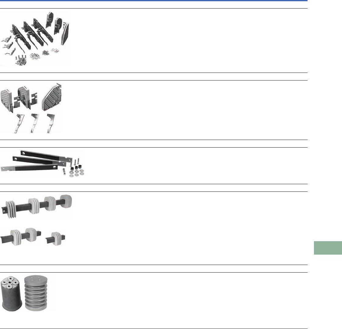
Volume 12—Aftermarket, Renewal Parts and Life Extension Solutions CA08100014E—November 2013 www.eaton.com V12-T17-67
1
2
3
4
5
6
7
8
9
10
11
12
13
14
15
16
17
18
19
20
21
22
23
24
25
17
Switchgear
WLI/MVS Medium Voltage Metal-Enclosed Load Break Switch Replacement Parts
Replacement Parts—WLI/MVS/MVS2 Load Break Switch
Description Part Description Quantity per Switch Style Number
Switch Pole Assemblies
Switch Pole Assemblies
Three-pole set includes main and flicker blades, break jaws and arc chutes.
(60 kV BIL or 95 kV BIL)
5 and 15 kV—600A
5 and 15 kV—1200A
(125 kV BIL or 150 kV BIL)
25 and 38 kV—600A
MVS2 5/15 kV—600A
MVS2 5/15 kV—1200A
1 set
1 set
1 set
1 set
1 set
7278A27G01
7278A27G02
7278A27G05
7278A27G43
7278A27G44
Arcing Contact Assemblies
Arcing Contact Assemblies
Three-pole set includes flicker blades and arc chutes.
This kit is not required when switch pole assemblies above are ordered.
(60 kV BIL or 95 kV BIL)
5 and 15 kV—600A
5 and 15 kV—1200A
(125 kV BIL or 150 kV BIL)
25 and 38 kV—600A
1 set
1 set
1 set
7278A27G06
7278A27G07
7278A27G08
Drive Rod Link (Polyester)
Drive Rod Link (polyester, set of three)
5 kV (60 kV BIL)
15 kV (95 kV BIL)
25 and 38 kV (125 kV BIL or 150 kV BIL)
MVS2 5/15 kV
MVS2 5/15 kV manufactured after May 2011
1 set
1 set
1 set
1 set
1 set
7278A27G09
7278A27G10
7278A27G12
7278A27G45
7278A27G53
Finned Bus Support
Finned Bus Support (one each)
36.00-inch wide (glass polyester)
Three-phase bus brace (glass polyester)
Two-phase bus brace (glass polyester)
36.00-inch wide (epoxy)
Three-phase bus brace (epoxy)
Two-phase bus brace (epoxy)
1 each
1 each
1 each
1 each
1 each
1 each
260C003H51
260C005H51
260C005H53
260C003H11
260C005H11
260C003H13
Insulators
Insulators (one each)
(60 kV BIL)
5 kV glass polyester
5 kV epoxy
(95 kV BIL)
15 kV glass polyester
15 kV epoxy
(125 kV BIL or 150 kV BIL)
25 and 38 kV epoxy
as required
as required
as required
as required
as required
4892A97H01
4892A97H07
4892A97H02
4892A97H08
4892A97H18
Finned Bus Support
Three-Phase
Bus Brace
Two-Phase
Bus Brace
Polyester Epoxy
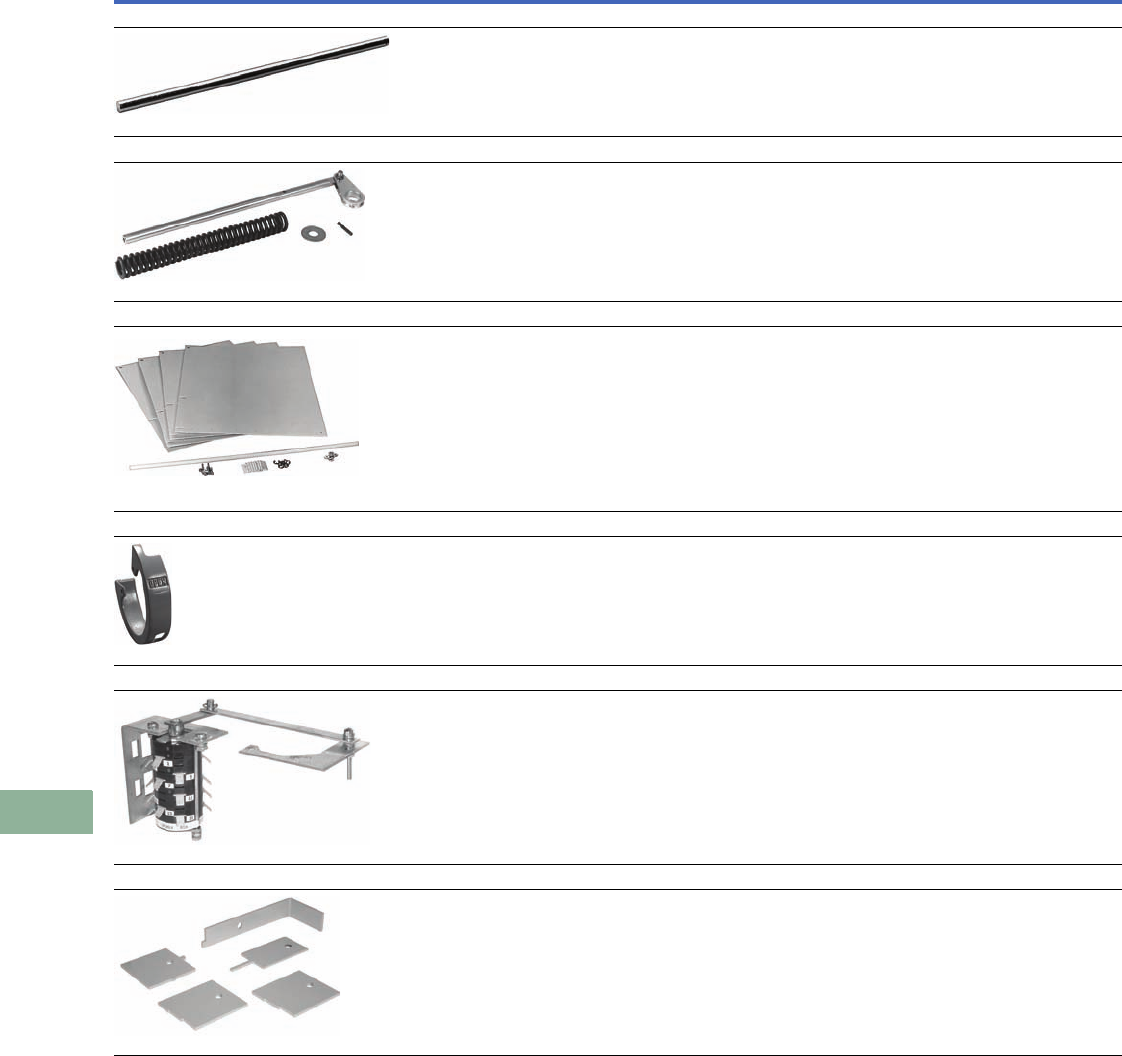
V12-T17-68 Volume 12—Aftermarket, Renewal Parts and Life Extension Solutions CA08100014E—November 2013 www.eaton.com
1
2
3
4
5
6
7
8
9
10
11
12
13
14
15
16
17
18
19
20
21
22
23
24
25
17
Switchgear
WLI/MVS Medium Voltage Metal-Enclosed Load Break Switch Replacement Parts
Replacement Parts—WLI/MVS/MVS2 Load Break Switch, Continued
Description Part Description Quantity per Switch Style Number
Removable Handle
Removable handle
All ratings 1 each 7274A49H01
Switch Spring Mounted Assembly
Switch Spring Mounting Assembly
5–15 kV—40 kA fault close
5–15 kV—61 kA fault close
25 kV—20 kA fault close
25 kV—40 kA fault close
25 kV—60 kA fault close
38 kV—20 kA fault close
38 kV—30 kA fault close
1 set
1 set
1 set
1 set
1 set
1 set
1 set
7278A27G16
7278A27G18
7278A27G19
7278A27G20
7278A27G21
7278A27G22
7278A27G23
Switch or Fuse Barrier Assembly
Switch Barrier Assembly
5 and 15 kV
25 and 38 kV
MVS2 5 kV
MVS2 15 kV
Fuse Barrier Assembly
15 kV (WLI design)
25 and 38 kV (WLI design)
15 kV (MVS/MVS2 design) (tightening knob or quick disconnect)
15kV (MVS2 design—bolt in fuses)
1 set
1 set
1 set
1 set
1 set
1 set
1 set
1 set
7278A27G24
7278A27G25
7278A27G46
7278A27G47
7278A27G26
7278A27G27
7278A27G43
7278A27G01
Open Close Indicator/Interlock Cam
WLI/MVS Standard Open-Close Indicator/lnterlock Cam
For lock open/close (top) or lock open (bottom)
MVS2 Standard Open-Close Indicator/lnterlock Cam
For lock close (top) or lock open (bottom)
1 each
1 each
220C934G01
220C934G02
Auxiliary Switch Assembly
Auxiliary Switch Assembly
(5NO and 5NC contacts) 1 each 7278A27G28
Switch Adjustment Tool Kit
Switch WLI/MVS Adjustment Tool Kit 1 each 221C113G031
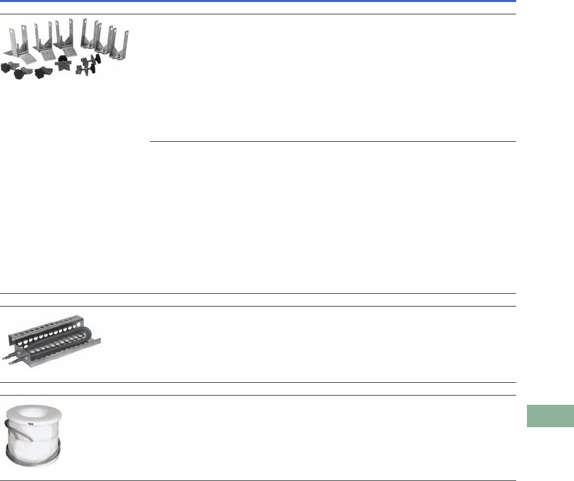
Volume 12—Aftermarket, Renewal Parts and Life Extension Solutions CA08100014E—November 2013 www.eaton.com V12-T17-69
1
2
3
4
5
6
7
8
9
10
11
12
13
14
15
16
17
18
19
20
21
22
23
24
25
17
Switchgear
WLI/MVS Medium Voltage Metal-Enclosed Load Break Switch Replacement Parts
Replacement Parts—WLI/MVS/MVS2 Load Break Switch, Continued
Other Replacement Parts
Other replacement parts
are available but shall be
considered on a job-by-job
basis.
Include switch nameplate
information located behind
the switch operating
handle access door with
any correspondence. Be
sure this includes the ”CN“
or ”SM“ number.
Description Part Description Quantity per Switch Style Number
Fuse Live Part Kit
Fuse Live Part Kit (WLI Design)
Non-disconnect (three-phase—top and bottom)
RBA200 5–15 kV
RBA400 5–15 kV
RBA200 25–38 kV
RBA400 25–38 kV
CLE-1 5–15 kV
CLE-2 5–15 kV
CX 5–15 kV
CXN-1 5–15 kV (single barrel—3.00-inch diameter)
CXN-1 5–15 kV (single barrel—4.00-inch diameter)
CXN-2 5–15 kV (double barrel—3.00-inch diameter)
CXN-2 5–15 kV (double barrel—4.00-inch diameter)
NX25 kV
EJO38 kV
1 each
1 each
1 each
1 each
1 each
1 each
1 each
1 each
1 each
1 each
1 each
1 each
1 each
7278A27G29
7278A27G30
7278A27G31
7278A27G32
7278A27G33
7278A27G34
7278A27G36
7278A27G37
7278A27G38
7278A27G39
7278A27G40
7278A27G41
7278A27G42
Fuse Live Part Kit (MVS Design)
Non-disconnect (three-phase—top and bottom)
RBA200 5 kV
RBA200 15 kV
RBA400 5 kV
RBA400 15 kV
RBA800 5 kV
RBA800 15 kV
CLE-1 5 kV
CLE-1 15 kV
CLE-2 5 kV
CLE-2 15 kV
CX 5 kV
CX 15 kV
CXN-1 5–15 kV (single barrel—3.00-inch diameter)
CXN-1 5–15 kV (single barrel—4.00-inch diameter)
CXN-2 5–15 kV (double barrel—3.00-inch diameter)
CXN-2 5–15 kV (double barrel—4.00-inch diameter)
1 each
1 each
1 each
1 each
1 each
1 each
1 each
1 each
1 each
1 each
1 each
1 each
1 each
1 each
1 each
1 each
98A1125G22
98A1125G23
98A1125G24
98A1125G25
98A1125G26
98A1125G27
98A1125G03
98A1125G04
98A1125G05
98A1125G06
98A1125G09
98A1125G10
98A1125G11
98A1125G12
98A1125G13
98A1125G14
Space Heaters
Space Heaters (low watt density)
125V (WLI design)
250V (WLI design)
125V (MVS design)
250V (MVS design)
as required
as required
as required
as required
220C974G03
220C974G04
3614A50H01
3614A50H02
Shunt Trip Coil
Shunt Trip Coil
48 Vdc
125 Vdc
250 Vdc
115 Vac
230 Vac
CAP TRIP
1 each
1 each
1 each
1 each
1 each
1 each
7278A78H01
7278A78H02
7278A78H03
7278A78H04
7278A78H05
7278A78H06

V12-T17-70 Volume 12—Aftermarket, Renewal Parts and Life Extension Solutions CA08100014E—November 2013 www.eaton.com
1
2
3
4
5
6
7
8
9
10
11
12
13
14
15
16
17
18
19
20
21
22
23
24
25
17
Switchgear
Additional Information
Renewal Parts
When ordering parts, specify the part description and mini-MVS
switchgear assembly catalog number found on the nameplate.
Enter on Suffix Q50.
Replacement Parts
Replacement Fuses
Torque Values
Tighten the hardware per the table below.
Torque Values
Further Information
Pricing Information
Vista/VISTALINE Discount Symbol Y2
Note
1Key interlock(s) provided by others.
Part
Description
Quantity
per Assembly
Style
Number
Switch pole assembly epoxy (three-pole set,
includes arc chute, switch blade, drive rod and insulators)
17997A57G03
Non-fused switch and CLE fused switch barrier assemblies
(set of four)
17997A57G06
Switch operator lever assembly 1 7997A57G11
Auxiliary switch assembly 1 7997A57G12
Space heater 1 7997A57G13
Filter (set of two) 1 7997A57G05
Key interlock provision kit 117826C86G01
Fuse Continuous
Ampere Rating
Quantity per
Assembly
CLE
Style Number
10 3 5981C29G01
15 3 5981C29G02
20 3 5981C29G03
25 3 5981C29G04
30 3 5981C29G05
40 3 5981C65G01
50 3 5981C65G02
65 3 5981C65G03
80 3 5981C65G04
100 3 5981C65G05
125 3 5981C65G06
150 3 5981C65G07
175 3 5981C65G08
200 3 5981C65G09
Bolt Diameter
in Inches
Nominal Torque,
ft lbs (Nm)
0.25 4 (5.42)
0.31 8 (10.85)
0.38 25 (33.90)
0.50 50 (67.79)
0.63 65 (88.13)
Publication
Number Description
DB 31-935 Descriptive bulletin for WLI load interrupter metal-enclosed switchgear
DB 31-950 Descriptive bulletin for unitized dry-type power centers
IL 31-930-D Instructions for WLI and WVB metal-enclosed switchgear

Volume 12—Aftermarket, Renewal Parts and Life Extension Solutions CA08100014E—November 2013 www.eaton.com V12-T18-1
1
2
3
4
5
6
7
8
9
10
11
12
13
14
15
16
17
18
19
20
21
22
23
24
25
Medium Voltage Fuses
Medium Voltage Fuses
18 Medium Voltage Fuses
Product Description . . . . . . . . . . . . . . . . . . . . . . . . . . . . . . . . . . . . . . V12-T18-2
Product History . . . . . . . . . . . . . . . . . . . . . . . . . . . . . . . . . . . . . . . . . . V12-T18-2
Product History Time Line. . . . . . . . . . . . . . . . . . . . . . . . . . . . . . . . . . V12-T18-2
Product Application and Naming . . . . . . . . . . . . . . . . . . . . . . . . . . . . . V12-T18-3
Current-Limiting Fuses . . . . . . . . . . . . . . . . . . . . . . . . . . . . . . . . . . . . V12-T18-4
Expulsion Fuses. . . . . . . . . . . . . . . . . . . . . . . . . . . . . . . . . . . . . . . . . . V12-T18-5
Product Selection . . . . . . . . . . . . . . . . . . . . . . . . . . . . . . . . . . . . . . . . V12-T18-6
Further Information . . . . . . . . . . . . . . . . . . . . . . . . . . . . . . . . . . . . . . . V12-T18-8
Pricing Information . . . . . . . . . . . . . . . . . . . . . . . . . . . . . . . . . . . . . . . V12-T18-8
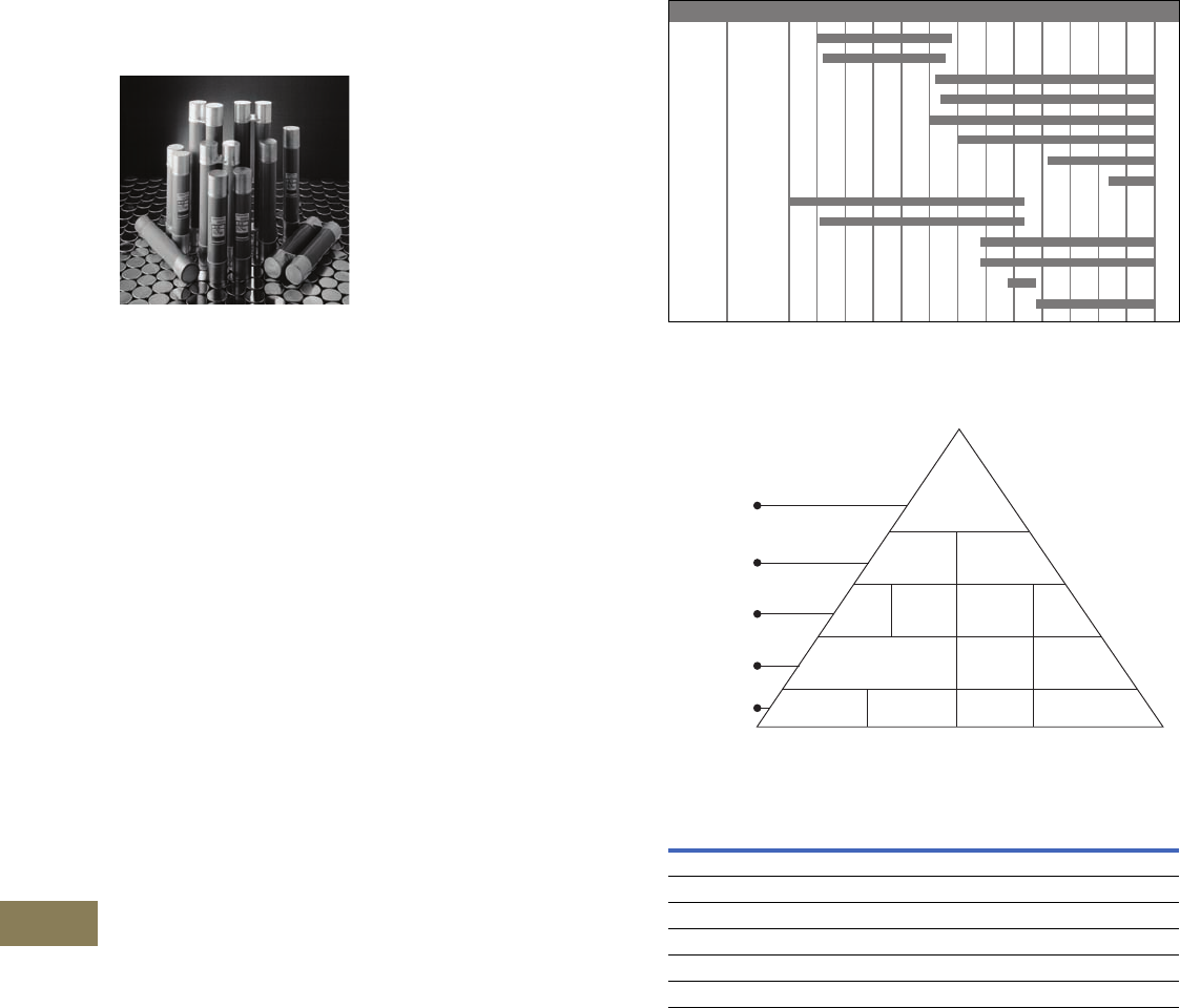
V12-T18-2 Volume 12—Aftermarket, Renewal Parts and Life Extension Solutions CA08100014E—November 2013 www.eaton.com
1
2
3
4
5
6
7
8
9
10
11
12
13
14
15
16
17
18
19
20
21
22
23
24
25
18
Medium Voltage Fuses
Current-Limiting and Expulsion Fuses
Current-Limiting and
Expulsion Fuses
Originally a
Westinghouse Product
Medium Voltage Fuses
Product Description
Eaton medium
voltage
fuses offer such a range of
characteristics that almost
any fuse application, within
the practical range of such
interrupting devices, may
be satisfied. This range of
characteristics is offered
in part by the production of
both expulsion and current-
limiting power fuses.
Expulsion and current-limiting
fuses provide such diverse
characteristics by employing
different areas of fuse
technology. These differences
in technology, along with the
diverse characteristics, require
that different questions be
answered when applying
expulsion and current-
limiting fuses.
Product History
The Eaton power fuse product
line was introduced in the
1930s by Westinghouse
Electric Corporation. As power
systems grew in size, the need
to sectionalize utility feeders
and to protect equipment
became apparent. The initial
fuse development efforts
resulted in the creation of
non-current-limiting, expulsion
type fuses. As the available
fault currents grew, the need
for a current-limiting fuse was
apparent and this resulted in
new interruption techniques.
While basic fuse technology
has not changed greatly
over the years, gradual
improvements have been
made to make the fuses
more current-limiting and
easier to manufacture and
install. Because standards
for fuses (ANSI C37) detail
only test methods and basic
performance requirements,
many different varieties of
fuses (length, diameter, short-
circuit interruption curves)
have been introduced over
the years.
Eaton presently manufactures
medium voltage fuses in
Haina, DR.
Product History Time Line
General Information
Fuses in Perspective
Advantages
Medium Voltage Fuse Comparison
Notes
1BAL superseded by CLE.
2BAL-R superseded by CLS.
3BA—Refills and holders only, new installations use RBA.
4DBA—Refills only.
5DBS—Superseded by DBU.
BAL 햲
BAL-R 햳
CLE
CLS
CLPT
CLT
CX/CXN
HLE
BA 햴
DBA 햵
RBA
RDB
DBS 햶
DBU
V12-T18-4
V12-T18-4
V12-T18-4
V12-T18-4
V12-T18-4
V12-T18-4
V12-T18-5
V12-T18-5
V12-T18-5
Product 1935 1940 1945 1950 1955 1960 1965 1970 1975 1980 1985 1990 2000 PresentPage
Medium
Voltage
Current
Limiting Expulsion
Backup General
Purpose
Cutouts
& Others
Boric
Acid
Distrbution
Power Power
C R E T
Voltage
Type
Class
Application
Amp Rating
Distrbution
K E
Expulsion Current-Limiting
Vented Sealed
Electromechanical Static
Expels gases/noise No gases/noise
Interrupts at natural current zero Limits fault current
Generally higher voltage/current applications Generally higher interrupting ratings
Differences in time/current characteristics Differences in time/current characteristics

Volume 12—Aftermarket, Renewal Parts and Life Extension Solutions CA08100014E—November 2013 www.eaton.com V12-T18-3
1
2
3
4
5
6
7
8
9
10
11
12
13
14
15
16
17
18
19
20
21
22
23
24
25
18
Medium Voltage Fuses
Current-Limiting and Expulsion Fuses
Application Guide
Guide to Names
BCLS—Bolt-in version of
CLS fuse.
BHLE—Bolt-in version of
HLE fuse.
CLE—Current-limiting E-rated.
HLE/HCL—Current-limiting
E-rated, interchangeable
with General Electric and
Gould Shawmut.
CX/CXN—Current-limiting
interchangeable with
McGraw-Edison’s NX
brand fuses, C-rated.
CLT—Current-limiting
transformer fuse.
CLPT—Current-limiting
E-rated for potential
transformers.
CLS—Current-limiting for
motor starters, R-rated.
RBA—Refillable boric acid
expulsion fuse (indoor use).
RDB—Refillable dropout
boric acid expulsion fuse
(outdoor use).
DBU—Dropout boric acid
fuse interchangeable with
S&C’s SMU-20 refill.
Guide to Ampere Ratings
“E” Designation
Fuse rated 100E or below
will melt in 300 seconds at
a current value between 2.0
and 2.4 times the E number.
Fuse rated above 100E will
melt in 600 seconds at a
current value between 2.2
and 2.64 times the E number.
If the current is higher
than 2.4 or 2.64 times the
E number, the user must
consult the time-current
curves for that particular fuse.
“R” Designation
The fuse will melt in 15
to 35 seconds when the
current equals 100 times
the R number.
If the current is higher than
100 times the R number, the
user must consult the time-
current curves for that fuse.
“C” Designation
The fuse will melt in
1000 seconds at a current
value, between 1.7 and
2.4 times the C number.
If the current is higher than
2.4 times the C number,
the user must consult the
time-current curves for that
particular fuse.
“A” Designation
Fuses that do not comply
with “E,” “R” or “C”
designations.
Expulsion fuses can also be
E-rated,
K-rated and T-rated,
and are also covered
in the
ANSI standards. The K and
T ratings refer, respectively,
to relatively “fast” and
“slow” melting expulsion
fuses. Detailed time-current
tables adequately define
these ratings.
Selection Guide Ratings Feeder
Circuit
Section-
alizing
Fused
Switches
Power
Trans-
formers
Substation
Service
Trans-
formers
DIP
Pole
Underground
Distribution
Transformers
Pole-
Mounted
Trans-
formers
Pad-
Mounted
Distribution
Transformers
Motor
Starters
Potential
Trans-
formers
Sub-
station
Capacitor
BanksType Class Use Brand
kV,
Ampere,
kA
Current
limiting
General
purpose
Power BHLE/
CLE/
HLE/
HCL
2.4–15.5 kV
10E–1350A
to 85 kA
■■ ■ ■ ■
Dist. CX/
CXN
4.3–15.5 kV
3.5C–300C
50 kA
■■
CLT 2.4–15.5 kV
4A–150A
25 kA
■
Backup Power CLPT 2.4–38 kV
0.25E–10E
to 80 kA
■
Power BCLS/
CLS
2.4–8.3 kV
2R–36R
50 kA
■
Expulsion Boric
acid
Power RBA 4.8–34.5 kV
0.5E–720E
■■ ■ ■
RDB 4.8–34.5 kV
0.5E–720E
■■■■ ■■
DBU 14.4–38 kV
5E–200E
15SE–200SE
3K–200K
■■ ■■ ■ ■
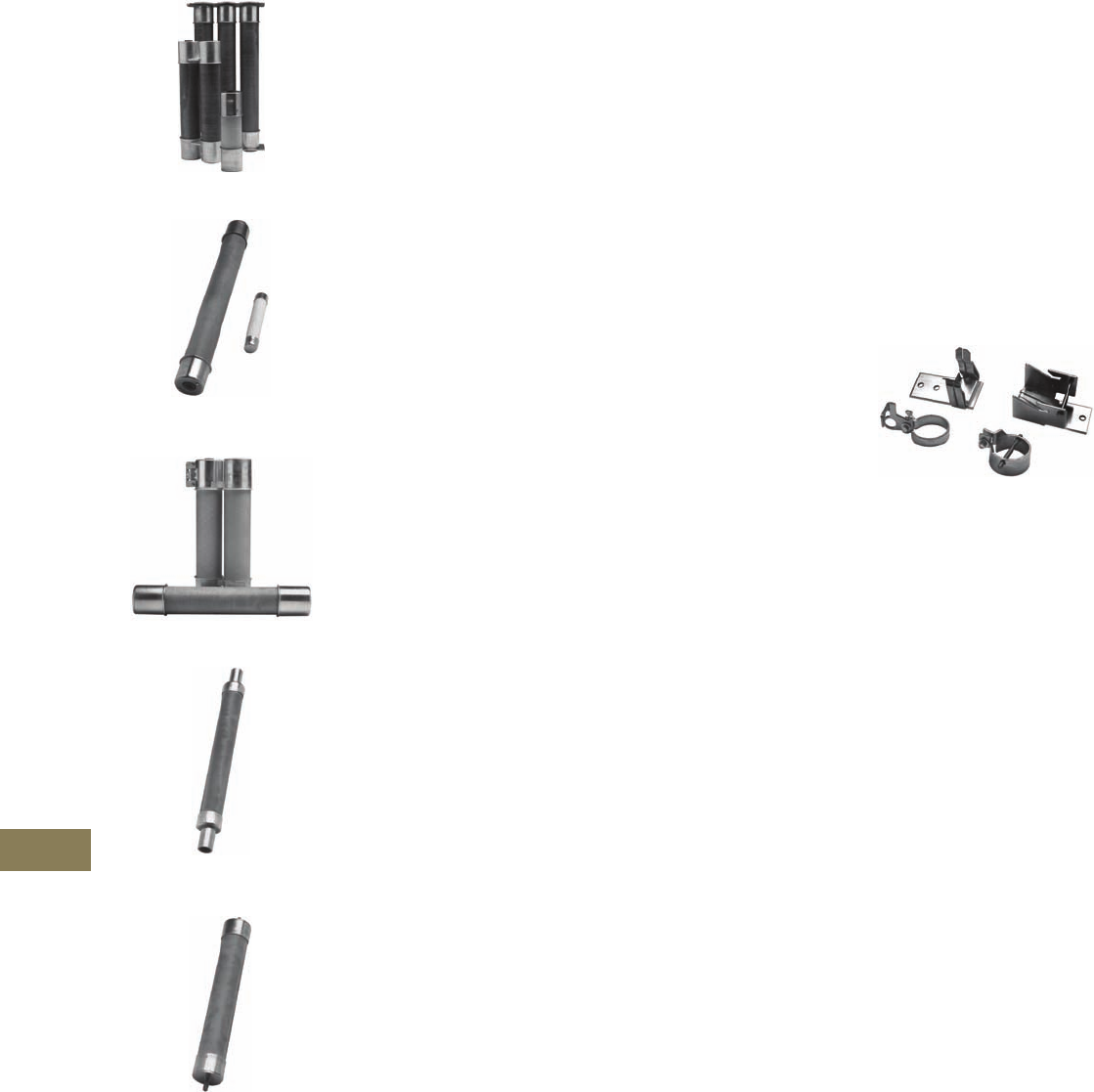
V12-T18-4 Volume 12—Aftermarket, Renewal Parts and Life Extension Solutions CA08100014E—November 2013 www.eaton.com
1
2
3
4
5
6
7
8
9
10
11
12
13
14
15
16
17
18
19
20
21
22
23
24
25
18
Medium Voltage Fuses
Current-Limiting Fuses
Current-Limiting Fuses
CLE and HLE Current-Limiting—E-Rated
CLPT Current-Limiting E-Rated for
Potential Transformer Protection
CLS Current-Limiting for Motor Starter
CX Current-Limiting—Interchangeable
with McGraw Edison’s NX Type
CLT Current-Limiting
for Transformer Protection
Product Description
Current-limiting fuses are
constructed with pure silver
fuse elements, a high-purity
silica sand filler, a specially
designed core and a glass
resin outer casing.
A high fault current melts the
silver element almost instantly
and loses energy to the
surrounding sand. The sand
melts and forms fulgurite,
a glass-like substance.
The arc voltage rapidly
increases to nearly three
times the fuse voltage rating
and forces the current to
zero. Low fault current melts
a solder drop on the silver
fuse element that, in turn,
melts the silver.
The element burns back until
there is a sufficient internal
gap to interrupt the current.
This is known as the M-effect.
Eaton current-limiting fuses
are offered in two basic
types: backup and general
purpose. Backup fuses
have a published minimum
interrupting current and
require a series device for
breaking the circuit for
currents below this minimum
level. General purpose fuses
have improved low current
interruption capability and are
designed to interrupt low fault
currents that cause the fuse to
melt in one hour or less.
General Information
Applications
Current-limiting technologies
can be used to meet almost
every fuse application. Typical
applications for utility,
industrial, construction and
OEM customers include:
●Feeder circuit
sectionalizing
●Power transformers
●Substation service
transformers
●Underground distribution
transformers
●Pole-mounted
transformers
●Pad-mounted distribution
transformers
●Fused switches
●DIP poles
●Motor starters
●Potential transformers
●Substation capacitor banks
Accessories
A wide assortment of
mountings, live parts and
end fittings are available
to facilitate power fuse
installation.
Mountings include a base,
porcelain or glass polyester
insulators and live parts. They
help enable the fuse to be
safely attached to the gear.
Mountings can be either
disconnect or nondisconnect.
Live Parts attach the fuse
to the mountings and are
considered part of the
mounting. All parts above
the insulators are live parts.
Live Parts
End Fittings are metal parts
that attach to each end of
the fuse at the ferrules.
They are used only on
disconnect fuses or when
converting a nondisconnect
to a disconnect fuse.

Volume 12—Aftermarket, Renewal Parts and Life Extension Solutions CA08100014E—November 2013 www.eaton.com V12-T18-5
1
2
3
4
5
6
7
8
9
10
11
12
13
14
15
16
17
18
19
20
21
22
23
24
25
18
Medium Voltage Fuses
Expulsion Fuses
Expulsion Fuses
RBA—Refillable Boric Acid
RDB—Refillable Dropout Boric Acid
DBU—Dropout Boric Acid—
Interchangeable with S&C’s SMU-20
Product Description
Eaton expulsion fuses
use boric acid as the
interrupting medium. Under
a fault condition, arc heat
decomposes the boric acid,
which produces gases and
boric anhydride. The water
vapor blast extinguishes the
arc in a deionizing action
and exits from the bottom
of the fuse.
Type RBA indoor expulsion
fuses are fitted with a filter
or condenser that moderates
the discharge exhaust. The
discharge filter limits the
exhaust to a small and
relatively inert amount of
gas and lowers the noise
level without affecting the
fuse interrupting rating.
Steam discharge, that can
affect the interrupting, is fully
restricted by the condenser.
Each type RDB outdoor
dropout fuse includes an
ejector pin that is forced
through the top of the fuse.
The ejector pin releases a
latch on the mounting and the
fuseholder is kicked outward
and swings into the dropout
position, through 180° with a
vertical mounting, or 90° with
an underslug mounting.
Refill units can be field
installed into RBA and RDB
expulsion fuses. Once the old
unit has been removed, the
separately purchased unit
can be easily installed into
the fuse holder.
General Information
Applications
Expulsion technologies can
be used to meet a number
of fuse applications. Typical
applications for utility,
industrial
construction and
OEM customers include:
●Feeder circuit
sectionalizing
●Fused switches
●Power transformers
●Substation service
transformers
●DIP poles
●Potential transformers
●Substation capacitor banks
Accessories
The following accessories are
available for expulsion fuses:
Mountings include a base,
porcelain or glass polyester
insulators and live parts. They
help enable the fuse to be
safely attached to the gear.
Mountings can be either
disconnect, nondisconnect
or dropout. Fuses may be
vertical or underhung.
Live Parts attach the fuse
to the mountings and are
considered part of the
mounting. All parts above
the insulators are live parts.
End Fittings must be
mounted on DBU fuse units
to enable them to be fitted
into the mounting.
Filters and Condensers
are for indoor applications of
RBA expulsion fuses. They
confine the arc within the
fuse and substantially reduce
the noise and exhaust when
the fuse interrupts.
Mufflers are used with DBU
fuses in indoor applications
to virtually eliminate offensive
noise and exhaust gases
when the fuse interrupts.
V12-T18-6 Volume 12—Aftermarket, Renewal Parts and Life Extension Solutions CA08100014E—November 2013 www.eaton.com
1
2
3
4
5
6
7
8
9
10
11
12
13
14
15
16
17
18
19
20
21
22
23
24
25
18
Medium Voltage Fuses
Current-Limiting and Expulsion Fuses
Product Selection
Easy to Use, Easy to Order!
Eaton’s fuse catalog
numbering system makes
it easy to order the right
fuse. The catalog numbers
are easy to remember,
unique to each fuse, and
are broken down in three
descriptive segments: fuse
type, voltage rating and
current rating.
These catalog numbers
can be entered directly
and easily:
●No change in order
processing will occur if you
use either a style number
or its corresponding
catalog number. You
will get the same fuse
●In the back of this ordering
guide is a style number
to catalog number cross-
reference chart
Current-Limiting Fuse Examples
●5CLE-30E
5.5 max. kV, CLE fuse unit,
30E amperes
●15CXN-45C
15.5 max. kV, CXN fuse
unit, 45C amperes
●5CLS-GDM-E
5.5 max. kV, CLS fuse
unit, glass polyester
nondisconnect mounting
●CLE-DL-D
CLE, disconnect live
parts, size D
Catalog Numbering System
Current-Limiting Fuses
Current-Limiting Fuse Accessories
Amperes
0.5–1350
Size
A
B
D
Class
E
R
C
X
Maximum kV
2 = (2.4, 2.5, 2.75)
4 = (4.3, 4.8)
5 = (5.08, 5.5)
7 =(7.2)
8 =(8.3)
15 = (15.5)
25 = (25.5)
38 = (38.0)
Type
CLE
HLE
BHLE
CLPT
NCLPT
CLS
BCLS
CLS70
CLS75
HCLS
LCLS
CX
CXN
CLT
AHLE
ACLS
15 CLE –100 E–(D)
Insulator
G= Glass polyester
P=Porcelain
H= High BIL
Diameter Size
A= 1-5/8 inches (41.3 mm)
0.5E–1.5E single barrel
B= 1-5/8 inches (41.3 mm)
3E–10E single barrel
C= 2.00-inch (50.8 mm)
single barrel
D= 3.00-inch (76.2 mm)
single barrel
E= 3.00-inch (76.2 mm)
double barrel
F= 4.00-inch (101.6 mm)
double barrel
G= 5/8-inch (15.9 mm)
ferrule (CX/CXN only)
Hardware
DM = Disconnect mounting
NM = Nondisconnect mounting
DL = Disconnect live parts
NL = Nondisconnect live parts
DF = Disconnect end fittings
Type
CLE
HLE
CLPT
NCLPT
CLS
HCLS
LCLS
CX
CXN
CLT
Maximum kV
2 = (2.4, 2.5, 2.75)
4 = (4.3, 4.8)
5 = (5.08, 5.5)
7 =(7.2)
8 =(8.3)
15 = (15.5)
25 = (25.5)
38 = (38.0)
15 CLE –P NM –(C)
Volume 12—Aftermarket, Renewal Parts and Life Extension Solutions CA08100014E—November 2013 www.eaton.com V12-T18-7
1
2
3
4
5
6
7
8
9
10
11
12
13
14
15
16
17
18
19
20
21
22
23
24
25
18
Medium Voltage Fuses
Current-Limiting and Expulsion Fuses
Product Selection
Expulsion Fuse Examples
●8RBA2-10E
8.3 max. kV, RBA-200 refill,
10E amperes
●DBU17-30K
17.1 max. kV, DBU fuse
unit, 30 amperes
●15RBA8-INH
15.5 max. kV,
RBA-800, indicating
nondisconnect holder
●RBA4-FLTR
RBA-400 filter
Catalog Numbering System
Expulsion Fuse Units
Expulsion Fuse Accessories
Note
1Maximum kV occurs after DBU or before BA, DBA, RBA, RBT or RDB.
DBU 17 –100 E
Amperes
0.5
3
5
6
7
8
10
12
15
20
25
30
40
50
65
80
100
125
140
150
175
200
250
300
400
Speed
E
K
SE
Type
RBA
DBU
DBA
RBT
BA
Maximum kV 1
8
15
17
25
27
38
48
72
92
121
145
Insulator
G=Glass
polyester
P= Porcelain
HP = High LIWL
porcelain
Bolt-In
B= 1-5/8 inches (41.3 mm),
3E–10E, single barrel
Hardware
UM = Underhung mounting
DL = Disconnect live parts
NL = Nondisconnect
live parts
DH = Disconnect holder
NH = Nondisconnect holder
NM = Nondisconnect
mounting
UL = Underhung live parts
VL = Vertical live parts
I= Indicating
FLTR = Filter
COND = Condenser
MFLR = Muffler
SHNT = Shunt and spring
assembly
Type
RBA
DBU
RDB
BA
Maximum kV 1
8
15
17
25
27
38
15 RBA2 –P NM –(B)

V12-T18-8 Volume 12—Aftermarket, Renewal Parts and Life Extension Solutions CA08100014E—November 2013 www.eaton.com
1
2
3
4
5
6
7
8
9
10
11
12
13
14
15
16
17
18
19
20
21
22
23
24
25
18
Medium Voltage Fuses
Current-Limiting and Expulsion Fuses
Further Information
Pricing Information
Price and Availability Digest (PAD)
Vista/VISTALINE™ Discount Symbols Y1-F, Y1-FE, Y1-FH
Publication
Number Description
Current-Limiting Fuses
CA08100016E Fuse Catalog, Volume 14, Tab 3
Expulsion Fuses
CA08100016E Fuse Catalog, Volume 14, Tab 2
General Information
CA08100016E Fuse Catalog, Volume 14
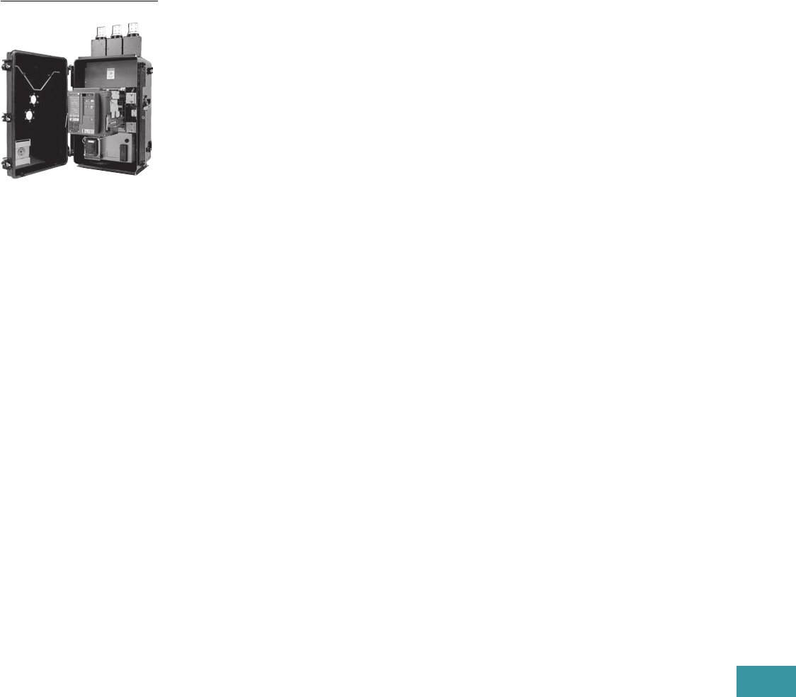
Volume 12—Aftermarket, Renewal Parts and Life Extension Solutions CA08100014E—November 2013 www.eaton.com V12-T19-1
1
2
3
4
5
6
7
8
9
10
11
12
13
14
15
16
17
18
19
20
21
22
23
24
25
Network Protectors
CM52 Network Protector
19 Network Protectors
Product Description . . . . . . . . . . . . . . . . . . . . . . . . . . . . . . . . . . . . . . V12-T19-2
Product History . . . . . . . . . . . . . . . . . . . . . . . . . . . . . . . . . . . . . . . . . . V12-T19-2
Product History Time Line. . . . . . . . . . . . . . . . . . . . . . . . . . . . . . . . . . V12-T19-2
Replacement Capabilities . . . . . . . . . . . . . . . . . . . . . . . . . . . . . . . . . . V12-T19-3
Technology Upgrades—Relays and Communications . . . . . . . . . . . . . V12-T19-3
Further Information . . . . . . . . . . . . . . . . . . . . . . . . . . . . . . . . . . . . . . . V12-T19-4
Pricing Information . . . . . . . . . . . . . . . . . . . . . . . . . . . . . . . . . . . . . . . V12-T19-4
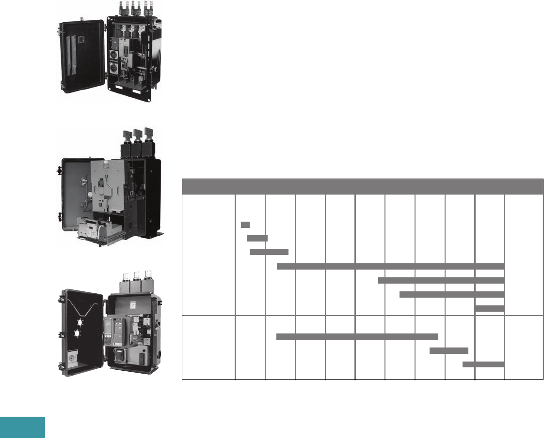
V12-T19-2 Volume 12—Aftermarket, Renewal Parts and Life Extension Solutions CA08100014E—November 2013 www.eaton.com
1
2
3
4
5
6
7
8
9
10
11
12
13
14
15
16
17
18
19
20
21
22
23
24
25
19
Network Protectors
Retro-Build, Replacement Parts and Relays
Network Protectors
Originally a
Westinghouse Product
CM-22
CMD
CM52
Product Description
Cutler-Hammer® network
protectors from Eaton’s
electrical business are special
self-contained air breaker units
having a full complement of
current, potential and control
transformers, as well as
relay functions. The network
protector enables the
paralleling of two or more
primary feeders on the same
low voltage bus. They are
available for transformer
mounting in submersible or
non-submersible housings,
or suitable for mounting within
a low voltage switchgear
assembly. The protective relay
automatically closes the
protector if power flow is
forwarded into the collector
bus. It also trips the protector
upon flow of reverse fault or
magnetizing currents.
Product History
The network protector product
line began manufacturing in
1922 under the name of
Westinghouse Electric and
Manufacturing Company.
Over the years a number of
different production models
were produced. The most
widely installed model is the
type CM-22, which was first
marketed in 1934 and is still
manufactured today.
New production CM-22,
CMD, CMR-8 and CM52
units are available from
the Greenwood, SC, facility.
Renewal parts are also
available for these units.
The old type
electromechanical relays
which have a large installed
base, are field replaceable
with the current solid- state
Type MPCV relays.
Eaton has also developed
parts and relays to support
old style GE Type MG-8 and
MG-9 network protectors. GE
discontinued the manufacture
of these products in 1996.
Product History Time Line
Network
Protector
CM
CM-1
CM-2
CM-22
CMR-8
CMD
CM52
Relays
CNJ, CN-33
MPCR
MPCV
Product 1920 1930 1940 1950 1960 1970 1980 1990 2000 Present
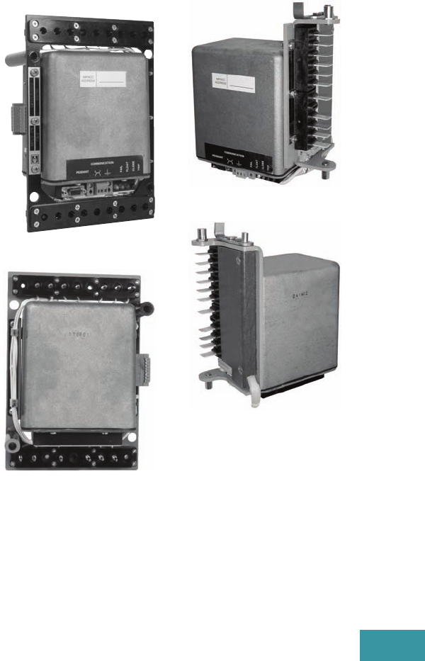
Volume 12—Aftermarket, Renewal Parts and Life Extension Solutions CA08100014E—November 2013 www.eaton.com V12-T19-3
1
2
3
4
5
6
7
8
9
10
11
12
13
14
15
16
17
18
19
20
21
22
23
24
25
19
Network Protectors
Retro-Build, Replacement Parts and Relays
Replacement Capabilities
New
Several current Cutler-Hammer
production designs of network
protectors are available:
●CM52
●CMD
●CMR-8
●CM-22
Retro-Build
Retro-building is a complete
reworking of all the major
components of a network
protector including preliminary
inspection, rebuilding, and re-
testing equipment. Included
in the process: removing all
asbestos materials (where
applicable), applying a new
wiring harness, rebuilding the
complete mechanism with
motor and shunt trip, replacing
the relay panel and completely
reconditioning any enclosure.
Modern components change
the “as built” vintage to
current production designs.
Cutler-Hammer and
Westinghouse
●CM-22
●CMD
●CMR-8
General Electric®
●MG-8
●MG-9
Retrofit
General Electric MG-8 and
MG-9 network protectors
up to 2000A are retrofittable
with a new CM52 roll-in
replacement breaker. This
retrofitting option uses
existing enclosures and bus,
replacing the remaining with
the most recent technology
of the CM52.
CMD style network protectors
are retrofittable with a new
CM52 drawout circuit breaker
and is available for all ampere
ratings and voltages.
Contact the Network
Protector Group for
additional information
and availability at
1-800-525-6821 or
1-877-737-8328.
Technology Upgrades—
Relays
Electromechanical and older
solid-state relays can be
replaced with new micro-
processor MPCV designs.
The MPCV network relay
can be field installed into
ANY network protector
regardless of the age or
the manufacturer. Field
installation is accomplished
without breaker modification
or any rewiring of the breaker
control harness.
Communications Capability
The MPCV relay has the
capability of communicating
information over a wide range
of media.
Hardwire (fiber or twisted
pair), wireless (cellular or
radio) are options available
using Eaton’s VaultGard
Communication platform.
This system provides data
for extensive engineering
analysis, vault diagnostics,
preventive maintenance
and additionally provides
DNP 3.0 objects direct to a
SCADA system.
MPCV Relay for Cutler-Hammer
and Westinghouse Network
Protectors
Front View
Rear View
MPCV Relay for
GE Network Protectors
Front View
Rear View
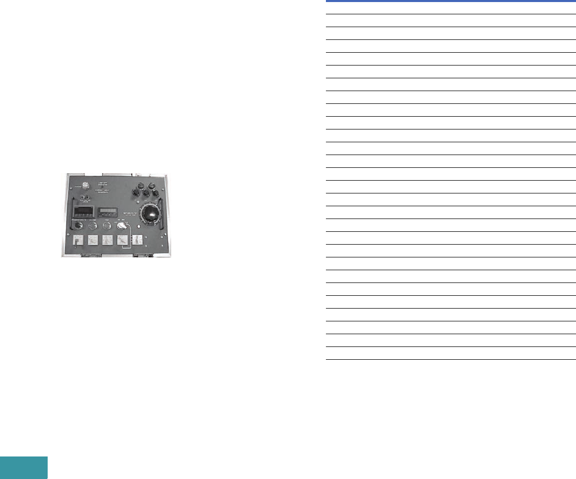
V12-T19-4 Volume 12—Aftermarket, Renewal Parts and Life Extension Solutions CA08100014E—November 2013 www.eaton.com
1
2
3
4
5
6
7
8
9
10
11
12
13
14
15
16
17
18
19
20
21
22
23
24
25
19
Network Protectors
Retro-Build, Replacement Parts and Relays
Parts
Eaton offers an extensive
inventory of newly
manufactured renewal
parts for the following
network protectors:
Cutler-Hammer and
Westinghouse
●CM-22
●CMD
●CMR-8
●CM52
General Electric
●MG-8
●MG-9
Test Sets
HWT-500 Test Kit
The HWT-500 test kit is
offered to provide complete
testing capabilities for
network protectors with 208
through 480V delta or wye
connected systems. This is
supplied in a rugged, wheeled
case with retractable handle.
Training
The product line offers the
following network protector
training seminars:
●Safety and Maintenance
Seminar—This two-
day seminar covers
fundamentals of network
systems, network relay
history and theory and
maintenance overview of
the CM-22, CMD, CM52
and MPCV relay
●Troubleshooting Network
Protector Seminar—
This three-day seminar
encompasses all material
included in the safety and
maintenance seminar
and also covers the
GE network protectors.
A combination of
classroom and hands-on
troubleshooting are
provided
Further Information
Pricing Information
Call Eaton’s Network
Protector Group in
Greenwood, SC.
Toll Free: 1-800-525-6821
or 1-877-737-8328.
Publication Number Description
CM-22
DB 35-550G Descriptive Bulletin
RPD 35-550H Renewal Parts Data Book
RP02401002E Renewal Parts Guide
IB 35-5001E Instruction Book
CMD
DB 35-552B Descriptive Bulletin
RPD 35-552 Renewal Parts Data Book
RP02401001E Renewal Parts Guide
IB 35-552-G Instruction Book
CMR-8
RPD 35-575(E) Renewal Parts Data Book
IB 35-575-A Instruction Book
CM52
B.52.01.S.E Sale Brochure
IB 52-01-TE Instruction Book
MPCR Relay
IB 35-581A Instruction Book
MPCV Relay
IB 35-581B Instruction Book
ST-156 Sales Engineer’s Notes
SA-376 Sales Aid MPCV Relay
SA.52.01.S.E T&D Reprint—Pepco System
HWT-500 Test Kit
IB 35-557 Instruction Book
LW T- 4 5 0 Te s t K i t
IB 35-556-C Instruction Book
SA-11898 Sales Aid

Volume 12—Aftermarket, Renewal Parts and Life Extension Solutions CA08100014E—November 2013 www.eaton.com V12-T19-5
1
2
3
4
5
6
7
8
9
10
11
12
13
14
15
16
17
18
19
20
21
22
23
24
25
19
Network Protectors
Retro-Build, Replacement Parts and Relays
CMD Network Protector Renewal Parts
Eaton’s Cutler-Hammer CMD Network Protector
Description
Current
Catalog Number
Electrical Components
Finger cluster assembly (800–1875A) 593C841G01
Finger cluster assembly (2000–3000A) 682C347G02
Micro-switch assembly 436B162G01
Anti-close coil and switch (800–1875A) 436B169G01
Anti-close coil and switch (2000–3000A) 436B169G02
Auxiliary switch assembly (800–3000A) 591C950G01
Anti-close relay assembly 765A881G03
Motor close relay 765A880G01
Trip coil assembly (1875–3000A) 8230A23G02
Trip coil only 677C903G03
Capacitor only 8310A96H01
BN dummy plate (CMD) 435D857G03
CNJ dummy plate (CMD) 508B559G01
Mechanical Devices
Motor assembly—two lead only (800–3000A) 437B494G01
Operations counter 592C040H02
Levering-in assembly (800–1875A) 442D145G01
Levering-in assembly (2000–3000A) 6897D33G01
Hardware
Network relay hold-down nuts 5765A44G01
Combination nuts 1087024
Breaker crank 589C063G01
X-washer and contact grease kit 8264A32G01
Breaker rollers 349A473H01
Breaker blocking bar 3670A85H01
Breaker contact test gauge (1875A) 3670A81G01
Control Resistors and Rectifiers
Diode 8310A96H03
Rectifier 3615A35H01
Electromechanical resistor assembly 664A956G01
3100 ohm resistor 499A067H04
Motor close rheostat 8230A16G01
Fuses (125–216V and 277/480V)
NPL fuse (800A) 140D318G04
NPL fuse (1200A) 140D318G05
NPL fuse (1600–1875A) 140D318G01
NPL fuse (2000–2825A) 140D318G02
NPL fuse (3000A) 140D318G06
Transformers
Current transformer (multi-ratio: 800/1200/1600A) 8230A85H01
Current transformers (2000A) 8313A73G02
Current transformers (2500A) 8313A73G01
Current transformers (3000A) 8313A73G03
Potential transformer 7526A14G01
Control power transformer 8230A18H01
Description
Current
Catalog Number
Current Carrying Components
Moving arcing contact (800–1875A) 695C128G02
Moving arcing contact (2000–3000A) 695C134G01
Stationary arcing contact assembly (800–1875A) 593C842G01
Stationary arcing contact assembly (2000–3000A) 6897D10G02
Arc chute (800–1875A) 6914D18G02
Arc chute (2000–3000A) 9147D18G01
Enclosure Parts—NEMA and Submersible (800–3000A)
Fuse housing (800–1875A) 595F152G01
Fuse housing (2000–3000A) 693C719G01
Spade terminal (800–1875A) 437B477G01
Stud terminal (800–1875A) 589C074G01
Spade terminal (2000 – 3000A) 690C292G01
Stud terminal (2000–3000A) 506B827G01
Fuse housing cover with gasket (800–1875A) 6390C82G01
Fuse housing cover with gasket (2000–3000A) 6390C84G01
Fuse housing cover with window (800–1875A) 592C092G01
Fuse housing cover with window (2000–3000A) 592C092G02
Fuse housing tank gasket (800–1875A) 505B339H01
Fuse housing tank gasket (2000–3000A) 590C508H01
8-point stationary secondary contact 591C497G01
8-point moving secondary contact (breaker mounted) 591C498G06
12-point moving secondary contact (breaker mounted) 693C618G01
12-point stationary secondary contact 9246C47G01
Door hinge and clamp kit (open side) 6418C71G01
Door hinge and clamp kit (hinge side) 6418C71G02
Hinge bolt only 1640799
Tank window kit 545B314G02
Tank window only 310C536H12
Tank window gasket only 5863A16H01
Submersible Tank Door Gasketing
Flat molded, pre 12/87 (800–1875A) 437C089H01
Flat molded, pre 12/87 (2000–3000A) 590C512H01
1.25-inch (31.8 mm) diameter tubular Sep. MDT.
—166 inches (4216.4 mm) (800–1875A)
8309A37H01
1.25-inch (31.8 mm) diameter tubular Sep. MDT.
—140 inches (3556.0 mm) (800–1875A)
8309A37H02
1.25-inch (31.8 mm) diameter tubular Sep. MDT.
—152 inches (3860.8 mm) (2000–3000A)
8309A37H01
Flat molded, pre 12/87 (2000–3000A) 437C089H01
Barrier assembly tanking (800–1875A) 567F830G01
Barrier assembly tanking (2000A plus) 693C717G02

V12-T19-6 Volume 12—Aftermarket, Renewal Parts and Life Extension Solutions CA08100014E—November 2013 www.eaton.com
1
2
3
4
5
6
7
8
9
10
11
12
13
14
15
16
17
18
19
20
21
22
23
24
25
19
Network Protectors
Retro-Build, Replacement Parts and Relays
CM-22 Network Protector Renewal Parts
Eaton’s Cutler-Hammer CM-22 Network Protector
Description
Current
Catalog Number
Electrical Components
Motor contactor assembly (replaces G01, G02 and SG relay) 503B286G03
“J” switch assembly (664A948H01) 1572037
“J” switch contact only 657A239H01
Motor cutoff “W” switch assembly (for three lead motor) 310C629G01
Motor cutoff “W” switch assembly (for two lead motor) 310C629G03
Auxiliary switch 12-pole 46A5916G13 + G14 310C626G02
Auxiliary switch eight-pole (replaces type “W”) 310C626G03
Network relay terminal block (lower) 310C356G05
Network relay terminal block (upper) 310C356G03
CNJ terminal block 310C356G02
BN terminal block (lower) 310C356G01
BN terminal block (upper) 310C356G04
BN dummy plate 435D857G03
CNJ dummy plate 508B559G01
Mechanical Devices
Motor—three lead 592C071G03
Motor—three lead with amp plug 592C071G01
Motor—two lead 592C071G02
Shunt trip device (208V) 1114739
Shunt trip device (250V) 1630111
Shunt trip coil only (208V) 0918738
Shunt trip coil only (250V) 1041078
Operations counter 592C040H03
Hardware
Mechanical links, springs and caps 8312A08G01
Fuse disconnect nut 1087025
Fuse disconnect nut 1087024
Relay combo nut (large) 5765A44G01
Overtoggle link assembly 436D164G02
Micarta® link (left side of overtoggle assembly) 1572053
Micarta link (right side of overtoggle assembly) 1572054
Operating handle 17B9956G01
Mechanism bumper and pins pack (sold in packs of three) 6419C75G01
Control Resistors and Rectifiers
Phasing resistor—3 ohm 499A067H05
Phasing resistor—3100 ohm 499A067H04
Motor circuit—3 ohm resistor assembly 664A956G02
Motor circuit—3 ohm fixed and adjustable resistor assembly 664A956G01
Transformers
Lighting transformer assembly (250V) 542B075G01
Lighting transformer assembly (125V) 542B075G02
Potential transformer (single only, six required in assembly) 7526A14G01
Potential transformer assembly (left and right) 60A3930G03
Control power transformer (sold separately) 8234A01G01
Control power transformer with mounting kit 508B560G02
Description
Current
Catalog Number
Current Transformers
Multi-ratio 1600/1200/800A:5A 745C148G01
Fixed ratio 1600A:5A 592C554G01
Fixed ratio 2000A:5A 6109C13G01
Fixed ratio 2500A:5A 592C556G01
Fixed ratio 3000A:5A 592C557G01
Current Carrying Components
Stationary conductor (800–1875A, left and right) 310C352G02
Stationary conductor (800–1875A, center) 310C352G01
Stationary main contact assembly (2000–3000A, includes arcing contact) 310C358G02
Stationary main contact assembly (3500A, includes arcing contact) 310C358G01
Moving contact (800–1875A, left and right) 310C353G01
Moving contact (800–1875A, center) 310C353G02
Moving contact assembly (2000–3500A, right) 436D166G01
Moving contact assembly (2000–3500A, left and center) 436D166G02
Arcing contact moving (2000–3500A) 09A2605G05
Arcing contact stationary (800–1875A) 1529542
Arcing and main stationary contact assembly (2000–3500A) 310C357G01
Arc chute (all sizes) 17B9967G01
Enclosure Parts—NEMA and Submersible
Breaker barrier kit (800–1875A) 6549C10G01
Breaker barrier kit (2000–3000A) 6914D10G01
4-point stationary disconnect device (left hand) 678C170G03
4-point stationary disconnect device (right hand) 678C170G04
Moving disconnect device (left hand) 678C169G02
Moving disconnect device (right hand) 678C169G03
Round sight glass kit (tempered glass) 545B314G02
Door hinge and clamp kit (open side) 6418C71G01
Door hinge and clamp kit (hinge side) 6418C71G02
Submersible Tank Door Gasketing
0.75-inch (19.1 mm) diameter tubular, pre '62 only
—139 inches (3530.6 mm) (800–1875A)
8311A01H01
1.25-inch (31.8 mm) diameter tubular
—139 inches (3530.6 mm) (800–1875A)
6337C85H40
1.25-inch (31.8 mm) diameter tubular
— 61 inches (4089.4 mm) (2000–3000A)
6337C95H40
1.25-inch (31.8 mm) diameter tubular
—181 inches (4597.4 mm) (2000–3000A)
6337C97H40

Volume 12—Aftermarket, Renewal Parts and Life Extension Solutions CA08100014E—November 2013 www.eaton.com V12-T20-1
1
2
3
4
5
6
7
8
9
10
11
12
13
14
15
16
17
18
19
20
21
22
23
24
25
Automatic Transfer Switches
Automatic Transfer Switch
Product Family
20 Automatic Transfer Switches
Product Description. . . . . . . . . . . . . . . . . . . . . . . . . . . . . . . . . . . . . . . V12-T20-2
Product History . . . . . . . . . . . . . . . . . . . . . . . . . . . . . . . . . . . . . . . . . . V12-T20-2
Product History Time Line. . . . . . . . . . . . . . . . . . . . . . . . . . . . . . . . . . V12-T20-2
Replacement Capabilities . . . . . . . . . . . . . . . . . . . . . . . . . . . . . . . . . . V12-T20-3
Further Information . . . . . . . . . . . . . . . . . . . . . . . . . . . . . . . . . . . . . . . V12-T20-3
Pricing Information . . . . . . . . . . . . . . . . . . . . . . . . . . . . . . . . . . . . . . . V12-T20-3
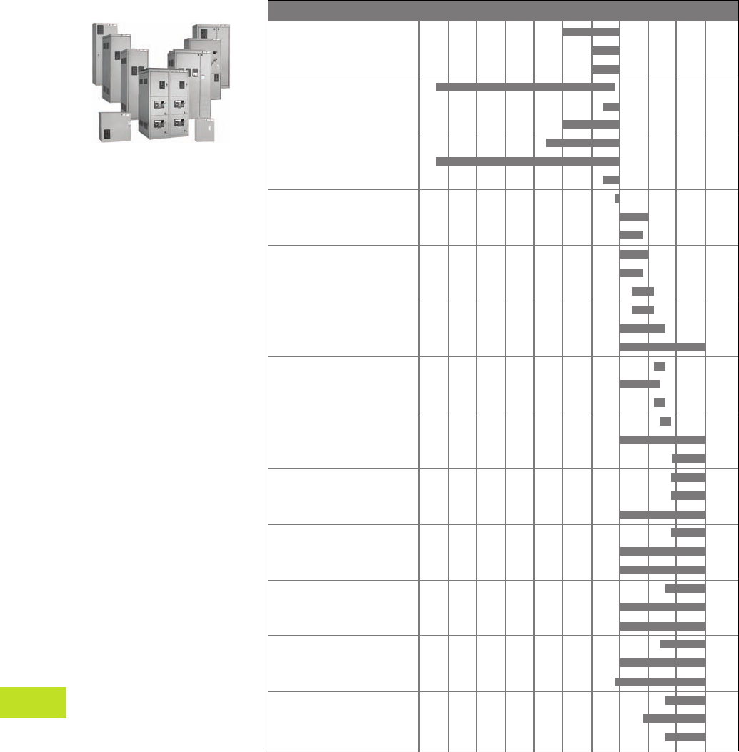
V12-T20-2 Volume 12—Aftermarket, Renewal Parts and Life Extension Solutions CA08100014E—November 2013 www.eaton.com
1
2
3
4
5
6
7
8
9
10
11
12
13
14
15
16
17
18
19
20
21
22
23
24
25
20
Automatic Transfer Switches
Automatic
Transfer Switches
Automatic Transfer Switch Family
Product Description
Eaton’s Cutler-Hammer®
automatic transfer switches
are reliable, rugged, versatile
and compact assemblies for
transferring essential loads
and electrical distribution
systems from one power
source to another.
Product History
A transfer switch is a
critical component of any
emergency or standby power
system. When the normal
(preferred) source of power is
lost, a transfer switch quickly
and safely shifts the load
circuit from the normal
source of power to the
emergency (alternate) source
of power. This permits critical
loads to continue running
with minimal or no outage.
After the normal source of
power has been restored, the
re-transfer process returns
the load circuit to the normal
power source.
Eaton is one of the pioneering
electrical manufacturers
and has been focused on
providing reliable backup
power systems with transfer
switch equipment for over
75 years. The automatic
transfer switches provide a
safe and reliable means to
automatically start your
generator, and transfer loads
to a standby power source
when normal power is
available. Eaton offers three
reliable and sophisticated
transfer switch options for
you to choose from—
contactor-based, molded-
case and circuit breaker
style switches.
Product History Time Line
ATSRM/DTSRM
ATSRD/DTSRD
ATSBI/DTSBI
ATSBM/DTSBM
ATSBR
MTSRM/MTSRD
MTSBM
MTSSM/MTSDM
MBS
ATVE/ATHA
BIHS
ATVSSP
ATVS/ATHS
RTHE
PPVA/PPHA
ATVA/ATHA
ATVM/ATHM
NTVSSP
PPV2/PPH2
NTVS/NTHS
ATV2/ATH2
ATV4/ATH4
CBVI
CTVIMG
NTVESP
ATVIMG
ATVISP/CTVISP
BIVIMG
BIVISP
BIHI
PPV3/PPH3
PPVX/PPHX
MBHE
NTVE/NTHE
MTVX/MTHX
ATVI/ATHI
ATV3/ATH3
RTHM
RLCM
Product (Catalog Prefix) 1960 1965 1970 1975 1980 1985 1990 1995 2000 2005 Present

Volume 12—Aftermarket, Renewal Parts and Life Extension Solutions CA08100014E—November 2013 www.eaton.com V12-T20-3
1
2
3
4
5
6
7
8
9
10
11
12
13
14
15
16
17
18
19
20
21
22
23
24
25
20
Automatic Transfer Switches
Replacement Capabilities
Note: Specific applicable renewal parts for automatic transfer switches are identified on the inside door label of the product.
Further Information
Pricing Information
Priced using Eaton’s Bid
Manager™ configuration tool,
Vistaline on the Web
(accessible by your local
Distributor or Manufacturer’s
Rep.), or Eaton’s website.
Type Logic Power Panel Transformer Panel Wiring Enclosure Lugs
All Styles ■■■■■■
Publication
Number Description
IB01602008E ATC-300 automatic transfer switch controller
IB01602001E ATC-400 automatic transfer switch controller
5715B46.PDF ATC-600 automatic transfer switch controller (IB ATS-I005)
8165A37.PDF ATC-800 automatic transfer switch controller (IB ATS-CI03)
IB01602010E O & M Manual for the RLCM automatic transfer switch
IB01602009E ATC-300 automatic transfer switch
IB01602001E ATC-400 automatic transfer switch
IB01602015E Automatic transfer switch contactor-based switch
IB01602011E Magnum™ transfer switches
CA08100003E Volume 2—Commercial Distribution, Tab 5
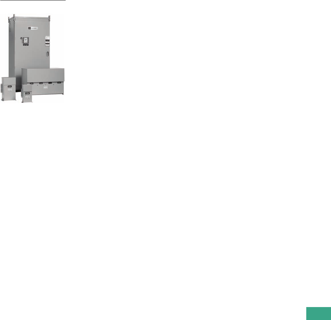
Volume 12—Aftermarket, Renewal Parts and Life Extension Solutions CA08100014E—November 2013 www.eaton.com V12-T21-1
1
2
3
4
5
6
7
8
9
10
11
12
13
14
15
16
17
18
19
20
21
22
23
24
25
Power Factor Correction Capacitors
Low Voltage Fixed and Automatic
Power Factor Correction Systems
21 Power Factor Correction Capacitors
Product Description. . . . . . . . . . . . . . . . . . . . . . . . . . . . . . . . . . . . . . . V12-T21-2
Product History . . . . . . . . . . . . . . . . . . . . . . . . . . . . . . . . . . . . . . . . . . V12-T21-2
Product History Time Line. . . . . . . . . . . . . . . . . . . . . . . . . . . . . . . . . . V12-T21-2
Replacement Capabilities . . . . . . . . . . . . . . . . . . . . . . . . . . . . . . . . . . V12-T21-3
Technology Upgrades . . . . . . . . . . . . . . . . . . . . . . . . . . . . . . . . . . . . . V12-T21-4
Further Information . . . . . . . . . . . . . . . . . . . . . . . . . . . . . . . . . . . . . . . V12-T21-5
Pricing Information . . . . . . . . . . . . . . . . . . . . . . . . . . . . . . . . . . . . . . . V12-T21-5
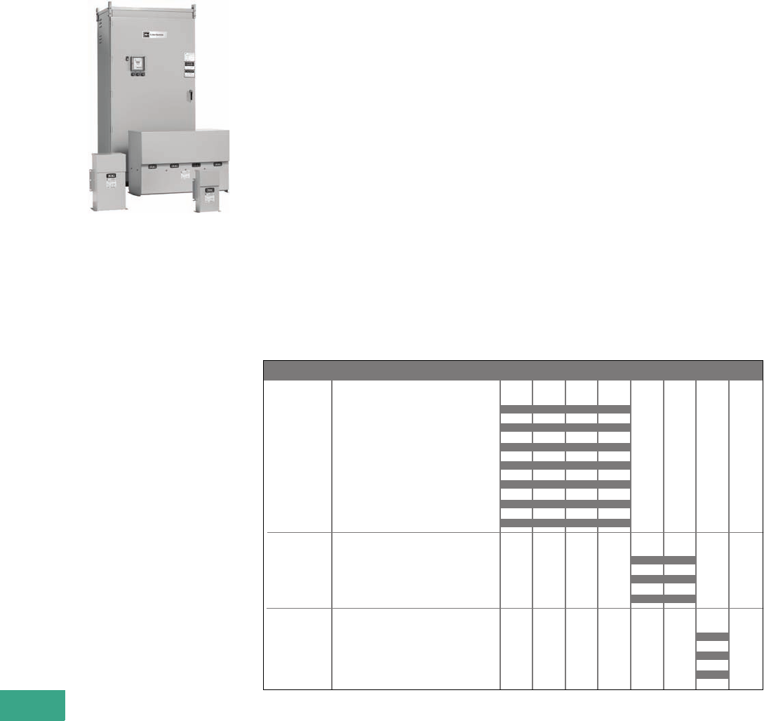
V12-T21-2 Volume 12—Aftermarket, Renewal Parts and Life Extension Solutions CA08100014E—November 2013 www.eaton.com
1
2
3
4
5
6
7
8
9
10
11
12
13
14
15
16
17
18
19
20
21
22
23
24
25
21
Power Factor Correction Capacitors
Power Factor
Correction Capacitors
UNIPAK and AUTOVAR
Product Description
Power factor correction
capacitors and harmonic
filters are an essential part
of modern electric power
systems. Power factor
correction capacitors are
the simplest and most
economical means of
increasing the transmission
capacity of a power system,
minimizing energy losses and
correcting load power factor.
In addition, power factor
penalties can be reduced
and power quality can be
greatly enhanced.
There are two main reasons
to correct poor power factor.
The first is to reduce or
eliminate a power factor
penalty charged by your local
utility. Another reason is that
your existing transformer
is, or shortly will be, at full
capacity and installing power
factor correction capacitors
can be a very cost-effective
solution to installing a brand
new service.
Depending on the amount
of power factor correction
(amount of kVAR required
for the electrical system to
improve the power factor)
and the dynamic nature of the
load, a fixed or switched
capacitor bank may be the
best solution. When capacity
becomes a problem, the
choice of a solution will be
dependent upon the size of
the increase needed. Like
all power quality solutions,
there are many factors that
need to be considered when
determining which solution
will be best to solve your
power factor problem.
Harmonic Filtering
As the world becomes more
dependent on electric and
electronic equipment, the
likelihood that the negative
impact of harmonic distortion
increases dramatically. The
efficiency and productivity
gains from these increasingly
sophisticated pieces of
equipment have a negative
side effect—increased
harmonic distortion in the
power lines. The difficult
thing about harmonic
distortion is determining the
cause. Once this has been
determined, the solution can
be easy. Passive harmonic
filtering equipment will
mitigate specific harmonic
issues, and correct poor
power factor as well.
Product History
Eaton’s Cutler-Hammer®
power factor
correction
product line began as Sprague
Electric in Massachusetts in
1942. They were the first
manufacturers of dry
capacitor cells in the United
States. Throughout the next
40 years, they manufactured
capacitors in both the dry and
oil-filled designs.
In 1986, the company was
purchased and renamed
Commonwealth Sprague.
Eaton’s Cutler-Hammer
Power Quality Division began
a name brand relationship
with Commonwealth Sprague
in
2001, and purchased the
Commonwealth
Sprague
capacitor systems business
in 2003. At that time,
manufacturing was moved
to the Asheville, NC,
manufacturing plant.
Product History Time Line
Sprague Electric
UNIPAK
Eccol UNIPAK
Eccopak
Eccovar
UNIVAR
Eccol UNIVAR
UNIVAR AUTOVAR
Commonwealth Sprague
UNIPAK
AUTOVAR
UNIVAR
Eaton/Cutler-Hammer
UNIPAK
AUTOVAR
UNIVAR
Product 1940 1950 1960 1970 1980 1990 2000 PresentPage
V12-T21-4
V12-T21-4
V12-T21-4
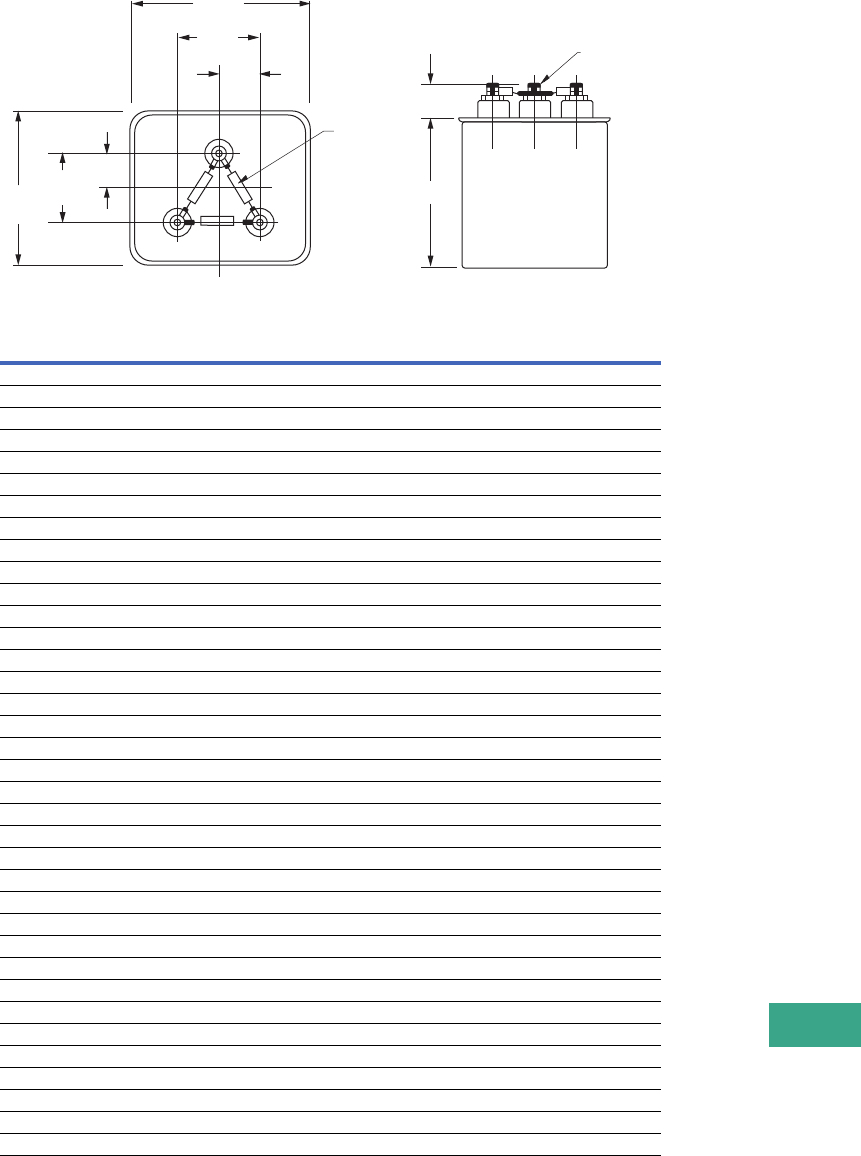
Volume 12—Aftermarket, Renewal Parts and Life Extension Solutions CA08100014E—November 2013 www.eaton.com V12-T21-3
1
2
3
4
5
6
7
8
9
10
11
12
13
14
15
16
17
18
19
20
21
22
23
24
25
21
Power Factor Correction Capacitors
Replacement Capabilities
Capacitor Cells—Dry-Type
●Te r m i n a l s : Threaded for
secure connection, all
sizes. 10 kVAC stand-off
terminal bushings. Rated
for 30 kV BIL
●Dielectric fill:
Thermosetting
polymer resin
●Flash point: +415°F
(+212°C)
●Fire point: +500°F
(+260°C)
●Dielectric film:
Self-healing metallized
polypropylene. Losses less
than 1/2 watt per kVAR
●Pressure-sensitive
interrupter: Built-in, three-
phase interrupter design.
UL® Recognized. Removes
capacitor from line before
internal pressures can
cause case rupture
●Discharge resistors:
Reduce residual voltage to
less than 50V within one
minute of deenergization.
Mounted on terminal stud
assemblies. Selected for
20-year nominal life.
Exceeds NEC®
requirements
●Capacitor operating
temperature:
–40°F (–40°C) to
+115°F (+46°C)
PCDM Cell Showing Threaded Nut and Stud Terminal Connection
Dry Cell Chart
Notes
1kVAR rating standard. NEMA® kVAR
tolerance is +15%–0%.
2Catalog number as shown is for
three-phase units.
Dry-type. Thermoplastic encapsulation
medium. On all units, customer must provide
overcurrent protection as tabulated or
equivalent (fuse interruption rating shall be
100,000A or greater). All units supplied
unpainted. Case material terne plate steel
approximately 0.017 thick.
Voltage
Rating kVAR 1
Height—
Inches (mm)
Approximate
Weight—Lbs (kg)
Catalog
Number 2
240 0.50 4.00 (101.6) 2.1 (1.0) 243PCDMF
240 1.00 4.00 (101.6) 2.1 (1.0) 443PCDMF
240 1.50 4.00 (101.6) 2.1 (1.0) 643PCDMF
240 2.00 4.00 (101.6) 2.1 (1.0) 843PCDMF
240 2.50 4.50 (114.3) 2.6 (1.2) 1043PCDMF
240 3.00 5.50 (139.7) 3.2 (1.5) 12X43PCDMF
240 4.00 6.00 (152.4) 3.5 (1.6) 16S43PCDMF
240 5.00 5.00 (127.0) 2.6 (1.2) 523PCDMF
240 6.25 6.00 (152.4) 3.2 (1.5) 6A23PCDMF
240 7.50 6.00 (152.4) 3.5 (1.6) 7X23PCDMF
240 8.33 7.00 (177.8) 3.5 (1.6) 8B23PCDMF
480 1.00 4.00 (101.6) 2.1 (1.0) 143PCDMF
480 2.00 4.00 (101.6) 2.1 (1.0) 243PCDMF
480 2.50 4.00 (101.6) 2.1 (1.0) 2X43PCDMF
480 3.00 4.00 (101.6) 2.1 (1.0) 343PCDMF
480 4.00 4.00 (101.6) 2.1 (1.0) 443PCDMF
480 5.00 4.00 (101.6) 2.1 (1.0) 543PCDMF
480 6.00 4.00 (101.6) 2.1 (1.0) 643PCDMF
480 7.50 4.00 (101.6) 2.1 (1.0) 7X43PCDMF
480 8.00 4.00 (101.6) 2.1 (1.0) 843PCDMF
480 10.00 5.00 (127.0) 2.6 (1.2) 1043PCDMF
480 12.50 5.50 (139.7) 3.2 (1.5) 12X43PCDMF
480 15.00 6.00 (152.4) 3.2 (1.5) 1543PCDMF
480 16.67 6.00 (152.4) 3.5 (1.6) 16S43PCDMF
480 17.50 7.00 (177.8) 3.5 (1.6) 17X43PCDMF
480 20.00 7.00 (177.8) 4.2 (1.9) 2043PCDMF
600 2.00 4.00 (101.6) 2.1 (1.0) 263PCDMF
600 2.50 4.00 (101.6) 2.1 (1.0) 2X63PCDMF
600 5.00 4.00 (101.6) 2.1 (1.0) 563PCDMF
600 7.50 4.00 (101.6) 2.1 (1.0) 7X63PCDMF
600 10.00 5.00 (127.0) 2.6 (1.2) 1063PCDMF
600 12.50 6.00 (152.4) 3.2 (1.5) 12X63PCDMF
600 15.00 6.00 (152.4) 3.5 (1.6) 1563PCDMF
600 16.67 7.00 (177.8) 3.5 (1.6) 16S63PCDMF
600 17.50 7.00 (177.8) 3.5 (1.6) 17X63PCDMF
600 20.00 8.75 (222.3) 5.0 (2.3) 2063PCDMF
Discharge
Resistors
1.00
(25.4)
0.75
(19.1)
1.50
(38.1)
3.78
(96.0)
2.00
(50.8)
4.59
(116.6)
#12-24
“H“
1.25
(31.8)
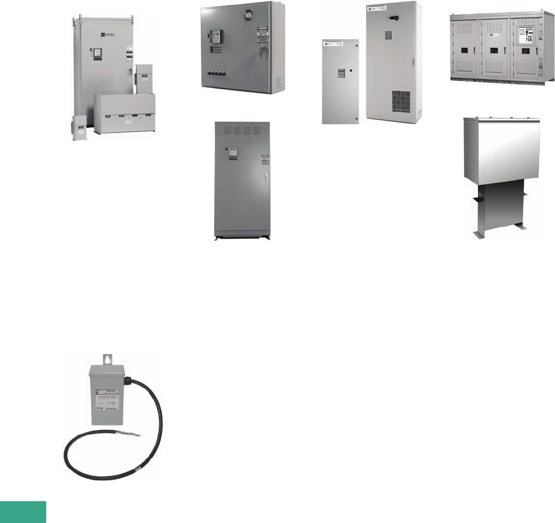
V12-T21-4 Volume 12—Aftermarket, Renewal Parts and Life Extension Solutions CA08100014E—November 2013 www.eaton.com
1
2
3
4
5
6
7
8
9
10
11
12
13
14
15
16
17
18
19
20
21
22
23
24
25
21
Power Factor Correction Capacitors
Technology Upgrades
UNIPAK
UNIPAK
Fixed power factor correction
for retrofit and upgrades.
Units are available in 240–
600V and 1–400 kVAR ratings
for retail, commercial and
industrial applications for
single point correction. Units
can also be configured to
include harmonic filters in
order to reduce harmonics
in applications with large
amounts of nonlinear loads,
such as variable speed drives.
They are most commonly
applied to low voltage
motors, motor control
centers and incoming
switchboards.
UNIPUMP
UNIPUMP
Fixed power factor correction
for retrofit or upgrade of
indoor or outdoor pump
motor applications. Units
are available in 240–600V
and 2–20 kVAR ratings. Units
include mounting brackets
and a 4-foot flexible power
cable attached for simple
mounting and connection.
AUTOVAR
AUTOVAR 300
AUTOVAR 600
Switched power factor
correction for retrofit or
upgrade at the substation
of facility level. An intelligent
controller senses the
customer’s current power
factor, and automatically
steps on and off stages
of capacitance in order to
achieve the customer’s
programmed target power
factor. Units are available in
240–600V and 25–840 kVAR
ratings in wall and floor-mount
designs. Higher ratings are
available—contact the factory
for assistance. Units can
also be configured to include
harmonic filters in order
to reduce harmonics in
applications with large
amounts of nonlinear loads,
such as variable speed drives.
Harmonic Correction Unit
Harmonic Correction Units
Active harmonic filters
provide active harmonic
control. The active harmonic
filter will monitor the distorted
electrical signal, determine
the frequency and magnitude
of the harmonic content, and
then cancel those harmonics
with the dynamic injection
of opposing current. Active
harmonic control provides
the benefit of traditional
passive filters with simpler
engineering requirements,
easier and less expensive
installation, comprehensive
control, and assured
compliance with the IEEE®
519-1992 standard.
Medium Voltage UNIVAR
and AUTOVAR
Metal-Enclosed Medium Voltage
Power Factor Correction System
UNIVAR Fixed Medium Voltage PFC Unit
Eaton’s Cutler-Hammer metal-
enclosed medium voltage
capacitors, systems and
harmonic filters are designed
for
indoor or outdoor
commercial, industrial
and
utility power systems
requiring motor start support,
power factor correction,
harmonic filtering, IEEE 519
compliance and increased
system capacity. Fixed motor
start capacitors are available
to assist in motor starting
applications. Engineered
designs are available with
a host of options and
accessories to fit the
requirements and the desired
configurations of virtually any
installation. Single-stage and
multi-stage,
tuned or de-tuned
filter banks can be supplied.
Metal-enclosed medium
voltage capacitor banks
are designed for industrial,
commercial and utility
power systems involving
motors, feeder circuits, and
transmission and distribution
lines where power factor
improvement is required.

Volume 12—Aftermarket, Renewal Parts and Life Extension Solutions CA08100014E—November 2013 www.eaton.com V12-T21-5
1
2
3
4
5
6
7
8
9
10
11
12
13
14
15
16
17
18
19
20
21
22
23
24
25
21
Power Factor Correction Capacitors
Further Information
Pricing Information
Price and Availability Digest (PAD)
Vista/VISTALINE™ Discount Symbol C10-S27 for Systems
Vista/VISTALINE Discount Symbol C10-ST for Replacement Capacitor Cells
Price List—PL02607002E
Publication
Number Description
TD02607001E Low voltage power factor correction capacitor banks and harmonic filters
TD02607011E Metal-enclosed medium voltage power factor correction and harmonic filter systems

Volume 12—Aftermarket, Renewal Parts and Life Extension Solutions CA08100014E—November 2013 www.eaton.com V12-T22-1
1
2
3
4
5
6
7
8
9
10
11
12
13
14
15
16
17
18
19
20
21
22
23
24
25
Eaton’s Electrical Services & Systems
Protection and Control Solutions
22 Eaton’s Electrical Services & Systems
Solving the Operating Performance Puzzle . . . . . . . . . . . . . . . . . . . . . V12-T22-2
PowerChain Management® Solutions . . . . . . . . . . . . . . . . . . . . . . . . V12-T22-2
Power Systems Engineering Solutions . . . . . . . . . . . . . . . . . . . . . . . . V12-T22-4
Predictive Maintenance . . . . . . . . . . . . . . . . . . . . . . . . . . . . . . . . . . . . V12-T22-5
Continuous and Remote Partial Discharge
Monitoring for Medium Voltage Equipment . . . . . . . . . . . . . . . . . . . V12-T22-5
Medium Voltage Vacuum Replacement Breakers (MVVR) . . . . . . . . . V12-T22-6
Class 1 Reconditioning . . . . . . . . . . . . . . . . . . . . . . . . . . . . . . . . . . . . V12-T22-7
Automation Services . . . . . . . . . . . . . . . . . . . . . . . . . . . . . . . . . . . . . . V12-T22-7
Integrated Project Solutions . . . . . . . . . . . . . . . . . . . . . . . . . . . . . . . . V12-T22-7
Replacement and Upgrading . . . . . . . . . . . . . . . . . . . . . . . . . . . . . . . . V12-T22-8
Additional Services . . . . . . . . . . . . . . . . . . . . . . . . . . . . . . . . . . . . . . . V12-T22-8
Eaton’s Electrical Services & Systems . . . . . . . . . . . . . . . . . . . . . . . . V12-T22-8
Further Information . . . . . . . . . . . . . . . . . . . . . . . . . . . . . . . . . . . . . . . V12-T22-8
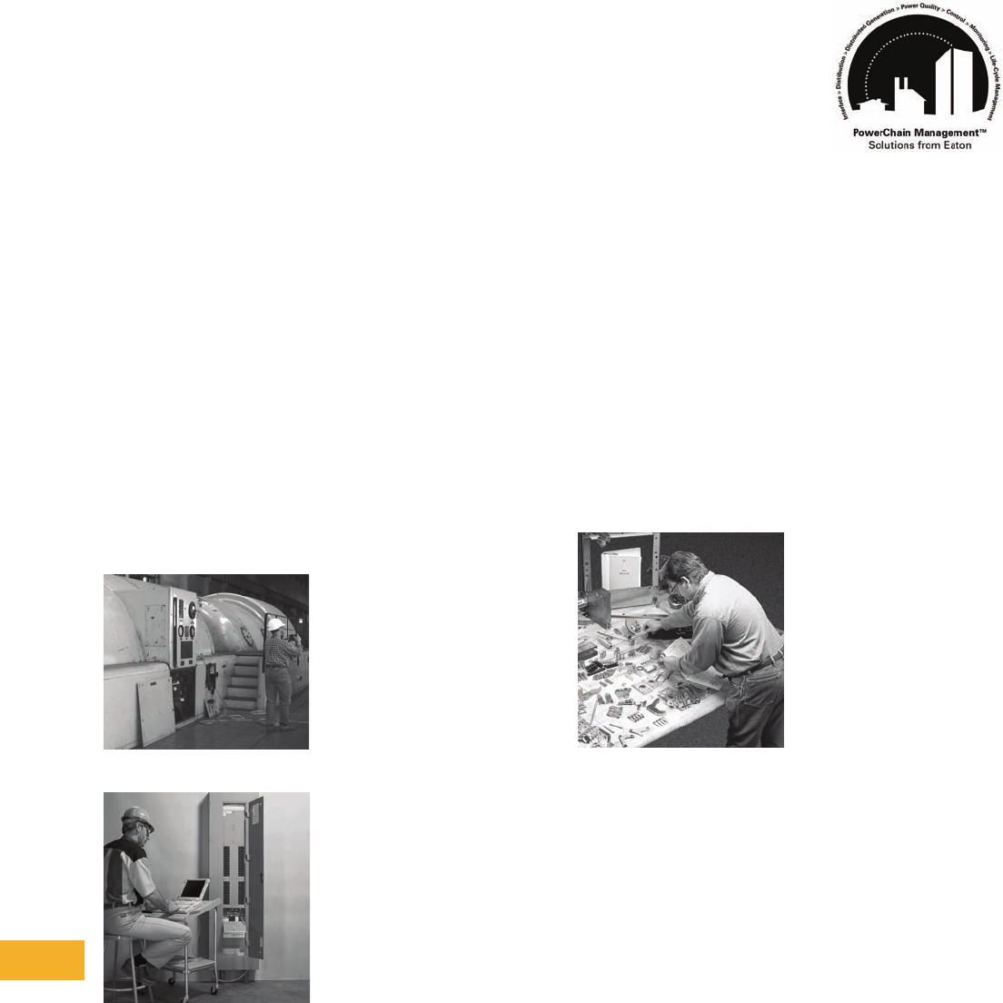
V12-T22-2 Volume 12—Aftermarket, Renewal Parts and Life Extension Solutions CA08100014E—November 2013 www.eaton.com
1
2
3
4
5
6
7
8
9
10
11
12
13
14
15
16
17
18
19
20
21
22
23
24
25
22
Eaton’s Electrical Services & Systems
Power Equipment Services and PowerChain Management Solutions
Solving the Operating
Performance Puzzle
As electrical equipment and
systems become increasingly
sophisticated and complex,
so too does the challenge of
maintaining peak levels of
availability, performance,
security and protection.
Eaton’s Electrical Services
& Systems (EESS) recognizes
that superior hardware is only
part of the answer. Effective
power strategies require
intelligent system design,
integration, coordination and
control. That means working
with a dedicated service
partner who understands
on-site and remote access
diagnostics, installation,
modernization and predictive
maintenance. Whether
it’s a single power strategy
application or a total
Integrated Project Solution,
EESS has the method by
which to enhance power
performance, to reduce
operating costs and to
maximize the reliability,
safety and integrity of your
electrical equipment and
system assets.
Uptime
Reliability
EESS is a one-stop service
provider focused on
integrating and maintaining
power quality. In addition to
complying with IEEE® and
ANSI standards, many EESS
engineers and technicians are
1E-certified to perform a full
scope of on-site service
operations in nuclear plants,
including hardware retrofits.
EESS
offers intelligent
solutions for maximizing
operating performance. Some
of these solutions include:
Power Equipment Services
Critical electrical equipment
requires systematic
maintenance to ensure
maximum performance
and in-service life… while
minimizing unscheduled
downtime, aging, wear
related hazards and total
operating costs.
EESS is the ideal complement
to your existing in-house
service. For more complex
projects, they can act as a
single point outsource for
all of your facility’s ongoing
maintenance needs, including:
●Installation/Startup
EESS can install any make
or manufacturer of power
equipment to precise
vendor specifications,
with minimal disruption of
ongoing facility operations
●Routine/Emergency
Service
EESS is on call 24/7,
providing an unrivaled
array of services, including
disaster recovery and
crisis response. One call
to 1-800-498-2678, and
uptime engineers and
technicians can be
assembled with the
sole purpose of bringing
electrical systems back
online quickly
●Warranty Service
EESS delivers a new
level of confidence to
customers by adding
an additional one-year
warranty extension to the
Eaton products they install
●Strategic Alliances
because Eaton is truly
universal in presence,
scope and capability,
EESS offers exceptional
partnership opportunities
to customers who operate
multiple facilities on
a regional, national or
international level. As
a dedicated service
extension, EESS can
establish and maintain
consistent levels of
availability, reliability and
performance across your
operation. Additionally,
EESS can create uniform
methods and procedures
for performance
benchmarking, predictive
maintenance programs,
inventory m
anagement and
an array of other services
designed to help maximize
your investment
Life Extension
PowerChain
Management Solutions
PowerChain Benefits
How Managing the PowerChain
Empowers Business
By actively managing
an enterprise’s power
infrastructure in a holistic
manner, PowerChain
Management solutions offer
a company these advantages:
Greater Reliability
Among the clear advantages
of a PowerChain Management
solution are enhanced
reliability and availability
afforded by state-of-the-art
technologies, such as
predictive analysis and
remote monitoring, to
ensure business continuity.
Operating Cost Efficiencies
PowerChain Management
solutions encompass savings
that begin with intelligent
design and innovation and
continue through heightened
energy management and a
system-wide approach to
cost-effective management
practices, including life-cycle
management.
Effective Use of Capital
By providing a single point of
coordination, a PowerChain
Management solution
speeds the time from
planning to installation and
commissioning. In terms of
life-cycle management, this
approach provides for timely
upgrades to avert the high
cost of complete rebuilds.

Volume 12—Aftermarket, Renewal Parts and Life Extension Solutions CA08100014E—November 2013 www.eaton.com V12-T22-3
1
2
3
4
5
6
7
8
9
10
11
12
13
14
15
16
17
18
19
20
21
22
23
24
25
22
Eaton’s Electrical Services & Systems
Power Equipment Services and PowerChain Management Solutions
Safety
A PowerChain Management
solution enhances safety by
working at the system level,
applying the right equipment,
supporting technology,
training and procedures.
By definition, it always
optimizes system design
and engineering for safety.
Risk Mitigation
With a single point of
accountability for every
aspect of the PowerChain,
enterprises gain broad
improvements in managing
risks, including: meeting
critical schedules, launch
windows and compliance
requirements; protecting
critical data and equipment;
and ensuring safety and
regulatory compliance.
PowerChain
End-to-End Capabilities
End-to-End Capabilities for Your
PowerChain’s Entire Life Cycle
Eaton has over 100 years of
experience and support behind
its products. Our vast team of
field engineers and a global
service network ensures the
highest level of responsive-
ness to your PowerChain
needs. In addition, Eaton offers
replacement part depots that
make it easy to keep your
electrical system running at
peak performance.
With an exceptionally broad
portfolio of award-winning AC
and DC products, Eaton is an
industry leader. From the
invention of the circuit breaker,
our roots are steeped in
innovation. Our worldwide
research centers continue to
deliver advanced hardware
and software solutions that are
enabling new generations of
proactive, intelligent electrical
systems. And Eaton’s global
brands are helping our
customers meet their needs
for global standards such as
IEEE, NFPA®, UL®, ANSI, IEC,
NEMA® and CNCA.
Optimizing your
organization’s electrical
system via PowerChain
Management solutions offers
you a breadth of resources
including the following
services and products.
Services
Engineering and Consulting
Services provide upfront
analysis and design prior
to project implementation.
Through a PowerChain
Management Audit, our
power system engineers will
help you to quickly diagnose
problems or proactively
identify ways to improve
your electrical system’s
performance and operation.
Included are:
●System design engineering
●Power audits and studies
●Arc flash and safety
studies
●Energy management
●Consulting support
Turnkey and Modernization
Services offer field resources
to get your project plan
underway. From project
management on a rebuild
or refurbishment, to turnkey
services for a new facility
or upgrade, we can help
you reduce time and costs.
Included are:
●Project management
●Switchgear and UPS
modification
●Integrated project
solutions
●Existing equipment
upgrades and rebuilding
●Installation, startup and
commissioning assistance
Contract and Support
Services ensure that your
PowerChain continues to
operate optimally around
the clock. In addition to
scheduled maintenance
programs, Eaton offers a
world-class service and
emergency response
capability with 24/7
monitoring so that you
have peace of mind and
confidence. Included are:
●Factory trained and
certified field technicians
●Predictive and calendar-
based preventive
maintenance programs
●Spare part kits,
modifications and
upgrades
●On-site training and
technical support
●Remote monitoring and
diagnostic support
●Battery monitoring with
replacement coverage
(asset optimization)
●Parts and labor service
contracts with on-site
response times
PowerChain
Life-Cycle Approach
Eaton’s PowerChain
Management Solutions—
A Life-Cycle Approach
Because Eaton’s PowerChain
Management solutions bring
a system-wide view, address
all decision points —planning,
design, finance, engineering,
construction, installation,
upgrading and monitoring—
and consider life-cycle
impacts to the PowerChain,
they free up businesses
to concentrate on core
capabilities. This provides
a far more strategic
partnership, one in which
Eaton brings to bear its wide
range of expertise and field-
proven performance for
which it has been known
for over a century.
The ease of doing business
with a single point of account-
ability gains enterprises these
advantages: better schedule
management over the
course of an entire project;
an advanced ability to
anticipate and solve problems;
and a more comprehensive
approach to prevention
and troubleshooting.
Eaton’s electrical group
has recognized the criticality
of addressing the entire
PowerChain
in an integrated
way to give
organizations the
benefits of greater reliability,
operating cost efficiencies,
effective use of capital,
safety and risk mitigation.
Through a combination of
acquisitions, alliances and
internal development, Eaton
now delivers the products,
services, in-depth expertise
and exceptional performance
to address complete
PowerChain needs.
Eaton’s PowerChain
Management solutions
encompass:
●Power Audits
Eaton’s extensive audit
capabilities assess an
enterprise’s complete
PowerChain in terms of
reliability,
safety and energy
management issues.
●System Design/
Build/Engineering/
Construction/Installation
Eaton is renowned for
innovation. Our specialized
knowledge transforms
concepts into practical
PowerChain solutions
that take into account
cost/benefit, multi-vendor
integration and equipment
selection. On-site
construction management
and engineering staff are
well versed in the practical
aspects of integrating
power protection into
existing buildings, as well
as in new construction.
●Monitoring and Analysis
Assessing the status of
equipment, predicting
imminent failures and
identifying power anomalies
are critical to a PowerChain
Management solution.
Eaton provides a full
complement of these
services.
●Life-Cycle Management
Life-cycle management
services begin with product
design and engineering,
and continue through
monitoring, maintenance,
upgrades and, ultimately,
replacement
●End-to-End
Equipment Capabilities
Eaton’s PowerChain
Management solutions
extend from research,
design, enhancement and
factory testing, to on-site
installation

V12-T22-4 Volume 12—Aftermarket, Renewal Parts and Life Extension Solutions CA08100014E—November 2013 www.eaton.com
1
2
3
4
5
6
7
8
9
10
11
12
13
14
15
16
17
18
19
20
21
22
23
24
25
22
Eaton’s Electrical Services & Systems
Power Equipment Services and PowerChain Management Solutions
PowerChain Audit
The PowerChain
Management Audit
Many facilities have gone
through upgrades and
changes over the years.
Electrical loads have
been added to automate
processes, computer loads
have been added to the
facilities, harmonics have
been introduced to the
system, and the loads are
often much more susceptible
to power quality issues.
Dealing with these issues
is most efficiently done
systematically by performing
a site audit looking for
specific problems and
potential areas of
improvement. By using
proven techniques and
strategic monitoring, Eaton
will identify the areas of
greatest vulnerability and
will address the options for
providing protection from
utility issues, as well as
system protection from
new and ever-changing
load requirements.
Eaton offers PowerChain
Management Audits to
evaluate power system
designs and to improve the
availability and reliability
of the power system. This
method uses proven IEEE
Gold Book methods for
analysis and helps to
determine whether upgrading
critical elements of the
power system, modernizing
the system or simply
rehabilitating the system
is the most cost-effective
method of improving
reliability prior to a failure.
Eaton’s PowerChain
Management Audits consist
of visual inspections, electrical
measurements using power
quality monitoring equipment,
interviews with on-site
personnel, and reviews
of utility bills and data.
Specifically, Eaton will
address interruptions,
voltage sags, harmonics,
surge protection, grounding,
energy management and
arc flash safety.
Eaton will investigate
methods of improving the
reliability of the power system
to help you avoid costly
downtime and repairs. The
present state of the existing
personal protective equipment
is also evaluated. Cost and
payback information will be
presented where appropriate.
Eaton reviews energy
consumption to determine
possible savings with utility
rate structures, energy
usage, time of use (on-
or off-peak), power factor
correction and various
methods of metering. By
monitoring trouble areas of
the facility, Eaton will identify
other potential areas for
improvement and savings.
Eaton’s electrical group
recognizes the criticality
of addressing the entire
PowerChain to give
organizations the benefits
of greater reliability, operating
cost efficiencies, effective
use of capital, safety and
risk mitigation. With a
PowerChain Management
Audit, power management
problems can be resolved
through a single, integrated
solution at every level in a
facility, delivering products,
services, expertise and
exceptional performance
to address your complete
PowerChain needs. The
purpose of this audit is to
show areas of improvement
in the electrical infrastructure
and to point out areas that are
well designed, maintained
and operating at or above
expectations.
PowerChain Management
Audit Features
●Evaluate wiring and
grounding methods
●Evaluate backup protection
including the use of UPS
power, backup generation,
sag correction and power
conditioning
●Review energy
management processes
to determine demand-side
management opportunities
and analyze energy-
efficient electrical loads
●Evaluate surge protection
at the utility connection
point and at the
downstream loads
●Evaluate the use of
harmonic solutions
including tuned filters,
line reactors and phase
shifting transformers
●Evaluate and review
present arc flash safety
compliance status
●Evaluate the quality of the
voltage and current at the
main service equipment
●Interview key electrical
personnel on
site to
determine the type of
operating
problems, the
equipment affected, and
the time of occurrences
Power Systems
Engineering Solutions
As technology advances
and more businesses come
to rely on sophisticated
equipment, the demand for
consistent, top-quality power
increases. Power systems
that were installed 15, 10 or
even 5 years ago were not
designed to handle today’s
power demand. The key to
a healthy power system is
consistent configuration and
familiarity with the operating
power system. The most
definitive way to accomplish
this is through a Protection
and Coordination Study by
Eaton’s Power Systems
Engineers.
Energy Efficiency
EESS provides methodical
testing and monitoring
practices on power systems.
Tests are run to analyze safety,
reliability, power quality and
energy management.
These services have proven
to be an effective way of
protecting expensive
equipment and preventing
downtime.
Screen Shot
Preventing future system
distress and creating a safe
power environment that will
be both economical and
electrically sound is another
reason to bring in the power
systems specialists. It is a
proactive, system conscious
move involving power
systems engineers and
technicians when upgrading
to a new distribution system,
adding additional loads or
processes to the current
power system, or contracting
with a utility. Power quality
and energy management
studies can take place during
normal plant operation or
scheduled around an annual
plant shutdown.
The first step to consistent
and safe power is to fully
understand the intricacies
of the power system. No
one can do that better than
Eaton’s Electrical Services
& Systems.
System Testing

Volume 12—Aftermarket, Renewal Parts and Life Extension Solutions CA08100014E—November 2013 www.eaton.com V12-T22-5
1
2
3
4
5
6
7
8
9
10
11
12
13
14
15
16
17
18
19
20
21
22
23
24
25
22
Eaton’s Electrical Services & Systems
Power Equipment Services and PowerChain Management Solutions
Predictive Maintenance
Eaton predictive maintenance
applies the latest technologies
to support online condition
assessment of critical
electrical distribution
equipment. Advancements
have resulted in new
applications that allow
for predictive diagnostics
measurements via existing
electrical components.
●Performance-based
maintenance
●PM program design
and implementation
●Periodic testing and
PM services
●Thermographic survey
●Troubleshooting
●Te s t i n g
●Predictive diagnostics
●Transformer oil processing
With extensive field experience,
EESS can quickly develop a
customized application to
schedule and document
essential system services,
which allows for cost savings
while improving system
reliability. Limited maintenance
dollars are prioritized for
equipment that is critical and
is in greater need of service.
By implementing our
predictive maintenance
software with complete
monitoring capabilities,
equipment outages are
anticipated and averted
before they happen.
Continuous and Remote
Partial Discharge
Monitoring for Medium
Voltage Equipment
Eaton InsulGard
Eaton understands the
pressures that you face trying
to reduce costs while at the
same time maximizing your
electrical system’s uptime
and reliability. That’s why
we invented the Eaton
InsulGard™, a system that
changes the rules of power
equipment maintenance.
Until now, there were only
two options.
1. Wait for equipment to
break down and fix it
and/or
2. Periodically take
equipment out of service
to perform tests and
maintenance—whether
it’s needed or not.
Now there is a third,
revolutionary option.
InsulGard is the first
continuous, online,
medium voltage, predictive
maintenance system that
can be used in a variety of
applications including
switchgear, bus duct, power
centers, generators and
motors. Through monitoring,
it can ascertain the relative
condition of insulation, the
deterioration of which is the
leading cause of electrical
failures. And, it can monitor
these conditions better than
alternative testing methods.
Further, you won’t have to
take equipment out of service
or send personnel to conduct
tests. In effect, the InsulGard
system is a lower-cost
alternative to forced outages
and rigid, and sometimes
unnecessary, maintenance
schedules. We believe that
you will find the InsulGard
system to be the best
planning tool available today.
At the heart of the system
is the InsulGard monitor.
Whether you use it to monitor
switchgear or rotating
equipment, only some internal
circuitry changes. The variable
part of the system is the broad
array of sensors we’ve
developed to function with
key electrical assets. Yet,
each sensor is specifically
designed to work with the
InsulGard monitor to provide
seamless and accurate data.
They are also designed to
work with existing Resistive
Temperature Devices (RTDs)
already present within the
windings of generators and
the motor. Design integrity is
important when it comes to
protecting your investment.
The InsulGard system has it.
Generators and Motors
The InsulGard system is
available with a variety of
sensors appropriate for
motors and generators. One
of these is the RTD module
that connects to existing
resistive temperature devices
(RTDs) already embedded
within the windings of the
generator or the motor.
Another sensor that checks
for partial discharge is the
coupling capacitor, which
is used on the line side.
A third sensor, ideal for
generators and motors, is
the radio frequency current
transformer (RFCT). The
RFCT embraces cable
shielding and is used in the
line part of the winding. Used
alone or in combination, the
sensors connect to the
InsulGard monitor where
partial discharges and other
variables such at humidity,
load and temperature are
monitored and recorded
for analysis.
Specifically, here are the
issues that partial discharge
analysis can tell you about
your rotating equipment:
●Early stages of insulation
deterioration
●Sparks in voids and
between windings
●Corona on end windings
Switchgear
Available sensors for
switchgear include coupling
capacitors or a combination
of radio frequency voltage
sensors (RFVSs) and
radio frequency current
transformers (RFCTs).
Coupling capacitors detect
partial discharges in a cubicle
and/or adjacent cubicles and
are typically installed on
the load side of the feeder
breakers or on the main
bus. Radio frequency voltage
sensors (RFVSs) are also used
to detect discharges within
the cubicle. They are typically
installed on the load side of
the feeder breakers, or on the
main bus. They are connected
to the current or the potential
transformer’s secondary
neutral terminal.
Large Power Transformers
Eaton lnsulGard G is available
for transformers that contain
a capacitive tap at the base
of the bushing. This top is
normally used for power-
factor measurements.
Transformers with a primary
voltage of 13.8 kV can be
monitored using our standard
partial discharge sensors.
Software
InsulGard software is part
of the InsulGard system.
It allows you to view the
dynamics captured by the
monitor and to analyze
the condition of insulation
based on the guidelines
and parameters provided by
Eaton predictive diagnostics
specialists. The eventual goal
of predictive diagnostics is to
create a Web-based service
whereby you can statistically
compare the relative condition
of your equipment to others
who have similar equipment in
operation by equipment type,
manufacturer, voltage class
ratings, partial discharge
activity longevity, etc. Users
will benefit by comparing
their own measured partial
discharge data with our
extensive database to predict
outcomes and to plan
maintenance. This database
will not identify customer
sites or locations in order
to guard the privacy of
our customers.
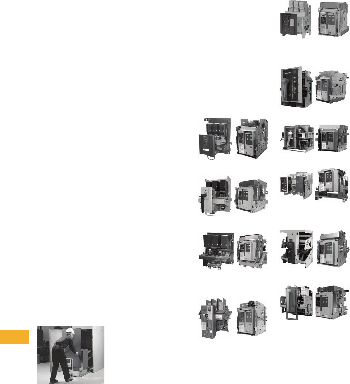
V12-T22-6 Volume 12—Aftermarket, Renewal Parts and Life Extension Solutions CA08100014E—November 2013 www.eaton.com
1
2
3
4
5
6
7
8
9
10
11
12
13
14
15
16
17
18
19
20
21
22
23
24
25
22
Eaton’s Electrical Services & Systems
Power Equipment Services and PowerChain Management Solutions
Medium Voltage
Vacuum Replacement
Breakers (MVVR)
New Replacement Breakers
from the Ground Up
VR-Series medium voltage
vacuum replacement (MVVR)
breakers are brand new
breakers that have been
designed, manufactured and
fully tested to be functional
electrical and mechanical
replacements for almost
any manufacturers’ original
air magnetic and some
vacuum circuit breakers.
However, if cell structure
modifications are required,
they are reversible.
Unnecessary downtime is
avoided because the breakers
are new, and only require
one outage for removal and
installation. By only replacing
the breakers, equipment
costs are reduced while the
life of the existing switchgear
is extended.
Many circuit breakers
require additional contacts,
mechanism operated
contacts (MOCs), that are
mounted external to the
circuit breaker mechanism.
When these contacts are
operated by high speed
vacuum breakers, they travel
almost four times faster than
existing air magnetic circuit
breakers and can transfer
up to 16 times the kinetic
energy to the MOC switch.
The increased forces can
damage the existing MOC
switch and cell components,
and in some cases, stall the
breaker when trying to close.
A SURE CLOSE MOC system
balances the speed and
force of the breaker’s MOC
operator to prevent stalling
and damage to the cell and
the MOC switch.
Replacement
Eaton manufactures over 158
different models of VR-Series
MVVR breakers that replace
air magnetic circuit breakers
originally manufactured by:
Westinghouse®, General
Electric®, Allis-Chalmers,
Federal Pacific Electric®, ITE®
and McGraw-Edison®.
Competitive Upgrades—
Low Voltage Power
Air Breakers
AR-Series
Replacement Breakers
The AR-Series (air-
replacement) breakers
are not retrofits. They are
100% new breakers used
to completely replace the
original drawout type power
air circuit breaker. This
solution uses state-of-the-art
Eaton Magnum™ breaker
technology that provides
maximum life-extension and
switchgear modernization.
The offering includes a new
breaker, a cassette with
extension rails and a standard
door. No modifications
are required to the original
line/load power stabs or to
the secondary disconnect
contacts.
This solution can eliminate
safety problems caused by
defective racking and/or
operator mechanisms.
Additional safety against
arc flash incidents can be
obtained by equipping
the breaker with ARMs
Technologies, thereby
reducing the arc flash energy
available at downstream
devices during maintenance
periods. Additional switchgear
maintenance problems
such as parts unavailability
and lengthy maintenance
procedures can be eliminated.
This solution often provides
a substantial total installed
cost savings when compared
to completely replacing the
switchgear assembly.
In many instances, the
AR-Series replacement
breaker can be combined
with engineering services
to provide continuous
current and/or interruption
rating upgrades.
The AR-Series breakers are
designed, manufactured
and tested to modern
IEEE/ANSI standards.
Designs are available for
a wide variety of drawout
type low voltage power air
circuit breakers (LVPACB)
originally manufactured by
Westinghouse, Federal Pacific
Electric, Allis-Chalmers, ITE
and General Electric.
Pictured on this page are
several examples of available
designs. Contact your local
Eaton sales representative
for information on other
breaker types.
Westinghouse
Original DB-25 DB25-AR600NM
Original DB-50 DB50-AR1600M
Original DB-75 DB75-AR3000M
Allis-Chalmers
Original LA-600 LA600-AR600NM
ITE
Original K-600 K-600-AR600NM
Federal Pacific Electric
Original FP-25 FP25-AR600NM
Original FP-50 FP50-AR1600M
Original FP-75 FP75-AR3000B
General Electric
Original AK-2A-50 AK2A50-AR1600M
Original AKR-4A-30 AKR4A30-AR800NM

Volume 12—Aftermarket, Renewal Parts and Life Extension Solutions CA08100014E—November 2013 www.eaton.com V12-T22-7
1
2
3
4
5
6
7
8
9
10
11
12
13
14
15
16
17
18
19
20
21
22
23
24
25
22
Eaton’s Electrical Services & Systems
Power Equipment Services and PowerChain Management Solutions
Class 1 Reconditioning
Better Than New
The useful life capacity and
performance of vintage or
damaged motor controls and
power distribution equipment
can be extended and
enhanced through Eaton’s
Aftermarket Centers of
Excellence (ACE). Their
strategic locations enable
rapid response through a
cost-effective program of
selective hardware retrofits.
Each ACE strictly adheres
to all national standards
and quality processes.
Field experts use evolving
technology to ensure the
most advanced retrofit
upgrade possible. Access
to vintage parts won’t be
a problem; each ACE has
both Cutler-Hammer and
Westinghouse renewal
parts available.
Proven
In the ongoing battle of
maximizing operating
performance and safety,
Eaton‘s Class 1 reconditioning
service helps to restore
the integrity of electrical
protection equipment to its
required level of reliability.
Automation Services
Effectively applying leading-
edge technologies is often
the key to enhanced
performance, improved
output, and reduced
frequency and severity
of outages. Engineering
these new technologies
into an existing equipment
configuration is an EESS
specialty.
System Integrator
EESS is a full service systems
integrator
with proven
expertise in power and
energy management
systems.
EESS provides a unique
alternative to conventional
manufacturer-integrator-
contractor teams. With
project management
expertise, EESS offers single-
point responsibility from a
major controls manufacturer.
Industry knowledge allows
for seamless integration of
new products, regardless of
equipment manufacturer.
Process Improvement
EESS has the capabilities to
address the entire scope of
integration and automation
needs, including:
●Power management
systems (IQ, IMPACC,
Power Xpert® Software,
Foreseer® Services)
●Automatic transfer
schemes
●Distributed generation/
generator control systems
●Demand management—
load shedding/peak
shaving systems
●Generator and ATS system
monitoring and testing
●Health care emergency
power supply systems
●PLC systems (Eaton,
Allen-Bradley®, Modicon®,
GE Fanuc® and Siemens®)
Integrated Project
Solutions
The project management
group within EESS provides
integrated project solutions to
customers in the government,
industrial, commercial and
utility sectors. Eaton’s
Federal Systems Group also
focuses on mission-critical
government installations,
providing project solutions,
on-going maintenance and
remote monitoring.
●New substation design
and construction
●Integrated emergency
power requirements,
including UPS, generators
and alternate feeders
●Plant automation
●PLC control and load
shedding
●Electrical plant monitoring
and control
●Process automation and
system integration
Design
The integrated project
solutions engineers manage
the technical and commercial
risk inherent in meeting project
objectives. These engineers
focus on performance,
cost and time goals, while
controlling or maintaining
the scope of the project.
Speed of Response
By hiring the EESS project
management group, you
can release the burden of
multi-supplier coordination.
EESS offers single-point
accountability for all technical,
financial and commercial
coordination within the scope
of the project.

V12-T22-8 Volume 12—Aftermarket, Renewal Parts and Life Extension Solutions CA08100014E—November 2013 www.eaton.com
1
2
3
4
5
6
7
8
9
10
11
12
13
14
15
16
17
18
19
20
21
22
23
24
25
22
Eaton’s Electrical Services & Systems
Power Equipment Services and PowerChain Management Solutions
Replacement
and Upgrading
OEM Equipment Serviced
and Upgraded
●Westinghouse
●Cutler-Hammer
●Square D®
●General Electric
●ITE
●ABB®
●Allis-Chalmers
●Siemens
●Federal Pacific
●and others...
Plant Life Extension
●MV vacuum breaker
replacement
●MV motor starter
upgrading
●Generator excitation and
motor control
●System metering and
control—PowerNet/
IMPACC
●LV breaker (all OEMs)
trip systems
●Class 1 circuit breaker
reconditioning
●Nuclear equipment
services
●UPS or battery systems
Additional Services
Consulting and
Advisory Support
●Arc flash studies and
solutions
●Power system studies,
design and analysis
●Failure/root cause analysis
●Reliability analysis
●Power quality and
harmonic analysis
●Reliability centered
maintenance (RCM)
●Short-circuit/coordination
studies
●Power systems training
Startup and Commissioning
●Installation support and
supervision
●Acceptance testing
(NETA equivalent)
●Startup and training
●Ground-fault certifications
●Installation construction
services
Instant Response Center
●Monitoring and diagnostics
●24 hours a day, 7 days a
week, 365 days a year
●Power quality experts
●Energy management
Eaton’s Electrical
Services & Systems
Asset Optimization
Outsource the responsibility
for the electrical distribution
system and the associated
equipment to Eaton’s
Electrical Services & Systems.
Offerings involve cost savings
and performance guarantees
for greater focus on the core
business. Asset optimization
uses all the tools and
capabilities within the other
service platforms, resulting
in improved reliability, life
expectancy and overall cost.
Knowledge Management
Collect and transform your
system data to useful
knowledge; allow for
proactive planning, energy
management, optimized
decision-making, failure
prediction and, ultimately,
cost savings.
Integrated Project Solutions
Engineering, design,
procurement, installation
and commissioning of power
systems equipment; a total
turnkey approach.
Power Systems
Engineering Solutions
Power systems automation,
design engineering, training,
predictive diagnostics,
power quality and power
systems studies/analysis
to decrease costs and
increase productivity.
Power Systems
Modernization
Keep systems operating
at peak efficiency, reliability
and safety; extend the life of
the electrical asset through
equipment life extension
and upgrade solutions using
new technologies.
New Equipment Services
Installation, testing and
commissioning of virtually
any electrical equipment.
Field Services
Power system and
equipment service,
maintenance programs,
testing, upgrades and
Aftermarket solutions;
24/7 emergency service;
crisis response and
disaster recovery.
Further Information
For further information on
Eaton Service Solutions,
call 1-800-498-2678 or
visit our website at:
www.eaton.com/EESS.
SM

Volume 12—Aftermarket, Renewal Parts and Life Extension Solutions CA08100014E—November 2013 www.eaton.com V12-T23-1
1
2
3
4
5
6
7
8
9
10
11
12
13
14
15
16
17
18
19
20
21
22
23
24
25
Pushbuttons and Indicating Lights
E22/EM22 Pilot Devices
23 Pushbuttons and Indicating Lights
Product Description . . . . . . . . . . . . . . . . . . . . . . . . . . . . . . . . . . . . . . V12-T23-2
Product History . . . . . . . . . . . . . . . . . . . . . . . . . . . . . . . . . . . . . . . . . . V12-T23-2
Product History Time Line. . . . . . . . . . . . . . . . . . . . . . . . . . . . . . . . . . V12-T23-2
Replacement Capabilities . . . . . . . . . . . . . . . . . . . . . . . . . . . . . . . . . . V12-T23-3
Further Information . . . . . . . . . . . . . . . . . . . . . . . . . . . . . . . . . . . . . . . V12-T23-14
Pricing Information . . . . . . . . . . . . . . . . . . . . . . . . . . . . . . . . . . . . . . . V12-T23-14
V12-T23-2 Volume 12—Aftermarket, Renewal Parts and Life Extension Solutions CA08100014E—November 2013 www.eaton.com
1
2
3
4
5
6
7
8
9
10
11
12
13
14
15
16
17
18
19
20
21
22
23
24
25
23
Pushbuttons and Indicating Lights
Pushbuttons and
Indicating Lights
E22/EM22 Pilot Devices
Product Description
Eaton’s Cutler-Hammer®
22.5 mm industrial heavy-duty
pushbutton line offers a wide
array of functional, smartly
styled illuminated and non-
illuminated pushbuttons,
selector switches, push-pulls,
alternate action and twist-
to-release operators. The
complete line also includes
transformer, full voltage,
resistor, LED or neon
light units.
E22 operators are available
with either a traditional
chrome or matte black front-
of-panel appearance. The
space-saving design and
modular construction of
the E22 line makes on-
the-job assembly fast and
simplifies the stocking
of both components and
complete devices.
Eaton’s Cutler-Hammer
EM22 metal series is a
rugged line of metal
construction 22.5 mm
pushbutton devices. They
are an extension of the
industrially proven E22 heavy-
duty double insulated 22.5
mm pushbutton family.
EM22 operators are
heavy-duty zinc die-cast
construction plated with
a corrosion-resistant
chromate finish. Operators
are complete with a very
durable chrome-plated metal
bezel. Indicating light units
in the EM22 series feature
smartly styled round
lenses that enhance their
appearance and brightness.
All EM22 operators are
compatible with existing E22
contact blocks, light units,
accessories and enclosures.
EM22 metal operators and
indicating lights are grounded
when mounted to metal
panels through the toothed
mounting nut. They are not
grounded when mounted to
plastic panels.
Product History
E22 was first sold in 1983.
The line has had one major
change in the mid 1990s to
increase the size of the
button plates to be roughly
equivalent to a 30mm
pushbutton. Then in 2002,
the EM22 extension of the
line was introduced. Since
then, only minor changes/
additions have occurred.
While the entire product
breadth is not available
anymore as aftermarket,
most functionality is available
in the products shown in this
catalog.
Product History Time Line
E22
EM22
Product 1980 1985 1990 1995 2000 2005 Present
Volume 12—Aftermarket, Renewal Parts and Life Extension Solutions CA08100014E—November 2013 www.eaton.com V12-T23-3
1
2
3
4
5
6
7
8
9
10
11
12
13
14
15
16
17
18
19
20
21
22
23
24
25
23
Pushbuttons and Indicating Lights
Replacement Capabilities
Replacement Capabilities
Momentary Contact Pushbuttons, Non-Illuminated—UL (NEMA) Type 3, 3R, 4, 4X, 12, 13
Will accept maximum of three contact blocks (six circuits) when used with supplied three-way
adapter and optional operator plug.
25 mm Diameter Flush Button
25 mm Diameter Extended Button
40 mm Diameter Mushroom Head Button
50 mm Diameter Mushroom Head Button—Plastic
Note
Operator plug E22BA2 required if third contact block is used. See Page V12-T23-11.
Color
E22 Series—Plastic Operators EM22 Series—Metal Operators
Black Bezel
Catalog Number
Chrome Bezel
Catalog Number
Chrome Bezel
Catalog Number
Black E22PB1 E22P1 EM22P1
Red E22PB2 E22P2 EM22P2
Green E22PB3 E22P3 EM22P3
Color
E22 Series—Plastic Operators EM22 Series—Metal Operators
Black Bezel
Catalog Number
Chrome Bezel
Catalog Number
Chrome Bezel
Catalog Number
Red E22EB2 E22E2 EM22E2
Color
E22 Series—Plastic Operators EM22 Series—Metal Operators
Black Bezel
Catalog Number
Chrome Bezel
Catalog Number
Chrome Bezel
Catalog Number
Black E22LB1 E22L1 EM22L1
Red E22LB2 E22L2 EM22L2
Color
E22 Series—Plastic Operators EM22 Series—Metal Operators
Black Bezel
Catalog Number
Chrome Bezel
Catalog Number
Chrome Bezel
Catalog Number
Red E22JPB2 E22JP2 EM22JP2
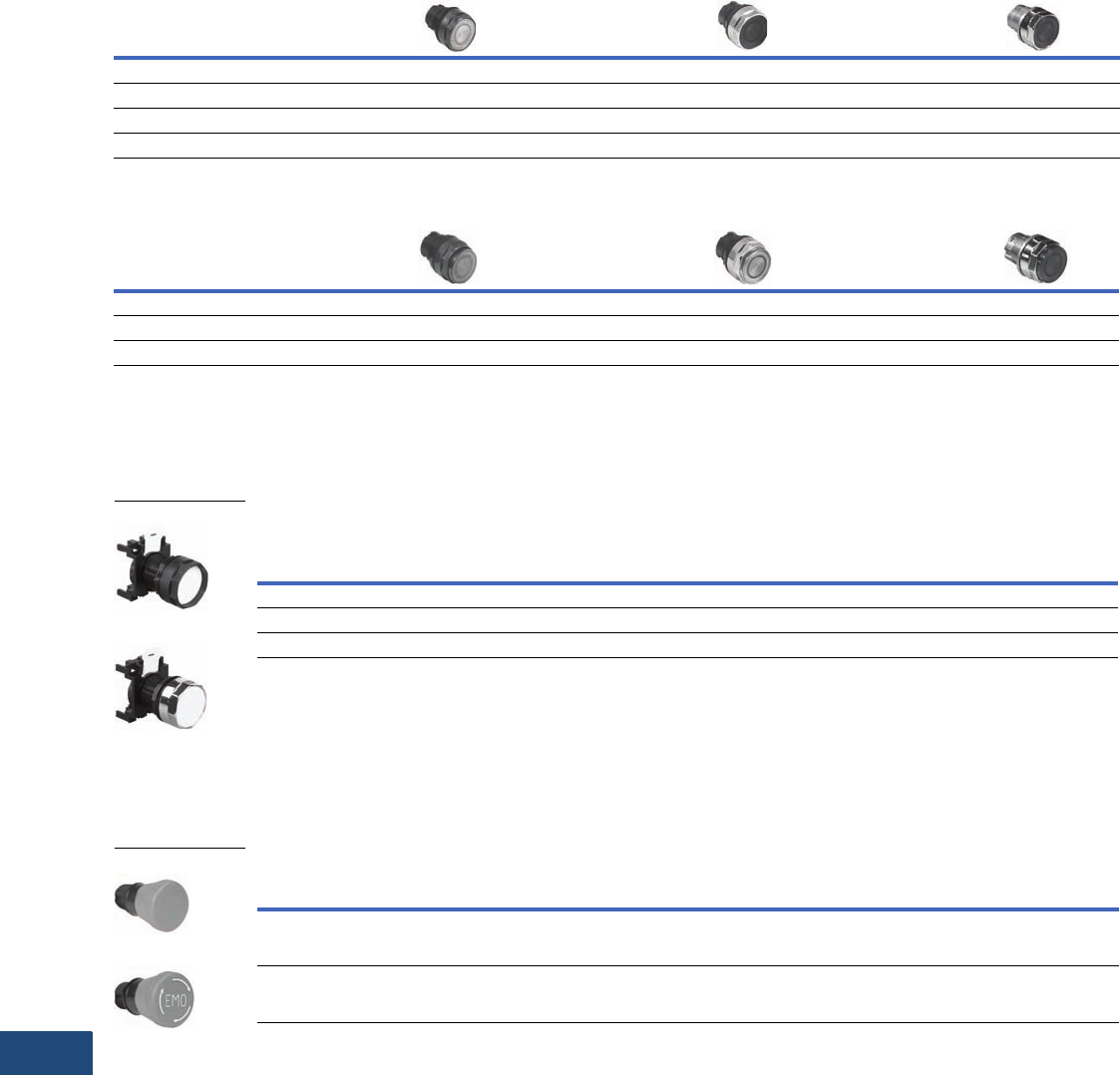
V12-T23-4 Volume 12—Aftermarket, Renewal Parts and Life Extension Solutions CA08100014E—November 2013 www.eaton.com
1
2
3
4
5
6
7
8
9
10
11
12
13
14
15
16
17
18
19
20
21
22
23
24
25
23
Pushbuttons and Indicating Lights
Replacement Capabilities
Illuminated Pushbuttons, Non-Illuminated—UL (NEMA) Type 3, 3R, 4, 4X, 12, 13
Will accept maximum of two contact blocks (four circuits) when used with supplied three-way adapter.
25 mm Diameter Flush Lens
25 mm Diameter Extended Lens
Alternate Action (Push-Push) Components
Non-Illuminated Push-Push Operators
Will accept a maximum of two contact blocks when used with supplied three-way adapter, five-way mounting adapters are not to be used.
Flush, Non-Illuminated Push-Push Operators—UL (NEMA) Type 3, 3R, 4, 4X, 12, 13 1
Emergency Stop Components
Maximum of two contact blocks (four circuits) when used with supplied three-way adapter (unless otherwise noted).
Standard Emergency Stop and Emergency OFF Operators—UL (NEMA) Type 3, 3R, 4, 4X, 12, 13
Notes
1 In order to comply with NFPA 79 and IEC 60204-1 requirements: The colors black, white or gray shall be used for Push-Push operators that act alternately as
START/ON and STOP/OFF pushbuttons. White shall be used for illuminated Push-Push operators. Push-Push operators shall only be used for functions that
cannot result in a hazardous condition.
IEC 60204-1 recommends that Push-Push operators acting alternately as START/ON and STOP/OFF pushbuttons be marked with the IEC symbol for
Push-Push pushbuttons.
2 Compliant with EN418 Machinery Safety Directive.
Color
E22 Series—Plastic Operators EM22 Series—Metal Operators
Black Bezel
Catalog Number
Chrome Bezel
Catalog Number
Chrome Bezel
Catalog Number
Red E22NB2 E22N2 EM22N2
Green E22NB3 E22N3 EM22N3
White E22NB5 E22N5 EM22N5
Amber E22NB9 E22N9 EM22N9
Color
E22 Series—Plastic Operators EM22 Series—Metal Operators
Black Bezel
Catalog Number
Chrome Bezel
Catalog Number
Chrome Bezel
Catalog Number
Red E22TB2 E22T2 EM22T2
Green E22TB3 E22T3 EM22T3
Amber E22TB9 E22T9 EM22T9
Color
E22 Series—Plastic Operators
Black Bezel
Catalog Number
Chrome Bezel
Catalog Number
Black E22PPB1 E22PP1
White E22PPB5 E22PP5
Gray E22PPB7 E22PP7
Black Bezel
Chrome Bezel
Action Color
Button Diameter/
Material
Legend/
Engraving
Plastic—Black Bezel
Catalog Number
Maintained
Trigger action
Twist-to-release
Red 40 mm/plastic — E22LTA2 2
Maintained
Trigger action
Twist-to-release
Red 40 mm/plastic EMO E22LTA2N123 2
E22LTA2
E22LTA2N123
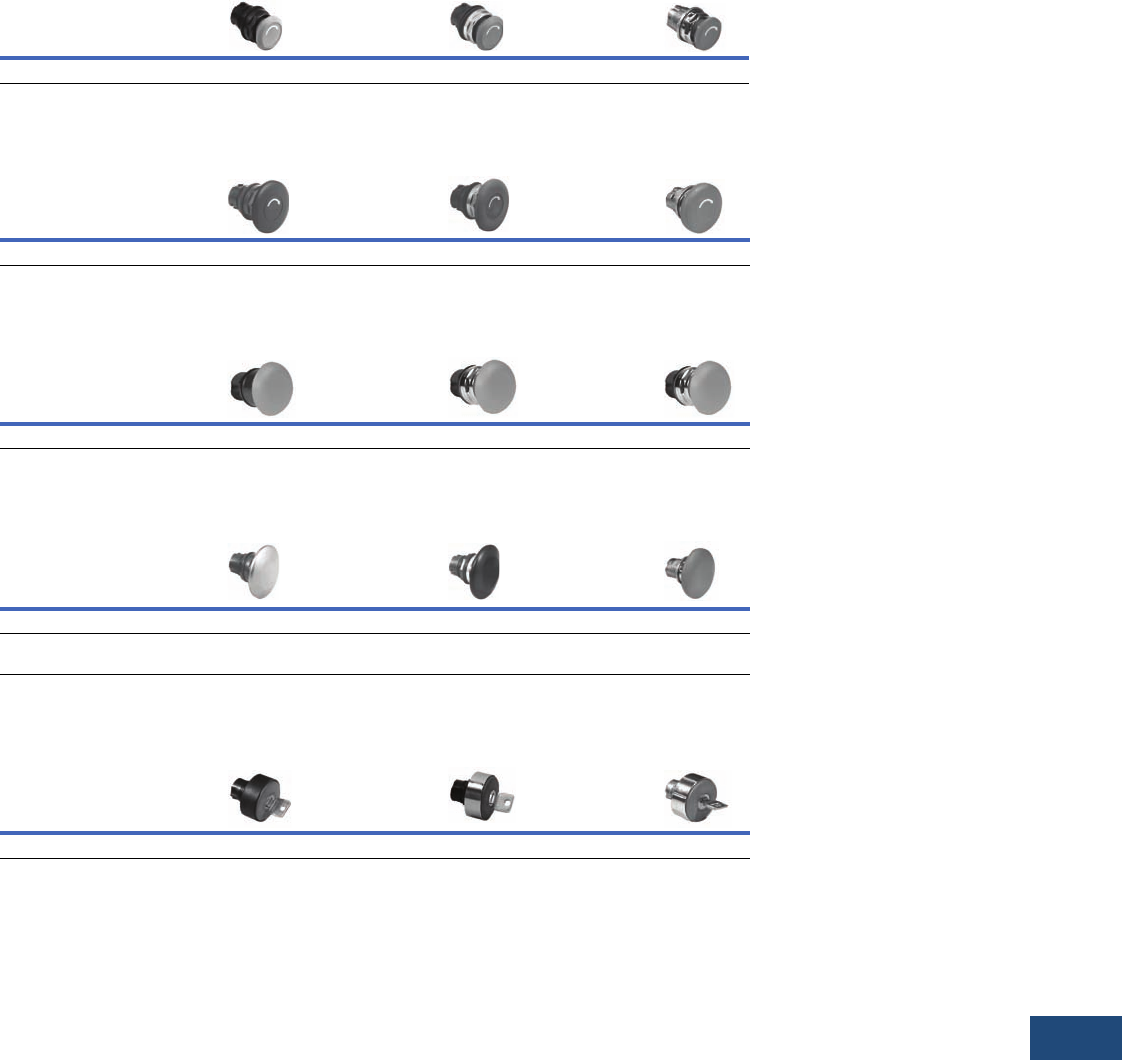
Volume 12—Aftermarket, Renewal Parts and Life Extension Solutions CA08100014E—November 2013 www.eaton.com V12-T23-5
1
2
3
4
5
6
7
8
9
10
11
12
13
14
15
16
17
18
19
20
21
22
23
24
25
23
Pushbuttons and Indicating Lights
Replacement Capabilities
Twist-to-Release, Push-Pull and Key Release Components
Maintained Contact Mushroom Head Operators, Non-Illuminated—UL (NEMA) Type 3, 3R, 4, 4X, 12, 13
Will accept maximum of two contact blocks (four circuits) when used with supplied three-way adapter.
Twist-to-Release—28 mm Diameter Button (Push to Latch—Twist to Release)
Twist-to-Release—40 mm Diameter Button (Push to Latch—Twist to Release)
Push-Pull—40 mm Diameter Button (Push to Latch—Pull to Release)
Push-Pull—50 mm Diameter Button (Push to Latch—Pull to Release)
Key Release—40 mm Diameter Button (Push to Latch—Turn Key to Release) 1
Note
1For legend plates, use oversize plates, Catalog Numbers E22VA2 or VA8 listed on Page V12-T23-11.
Color
E22 Series—Plastic Operators EM22 Series—Metal Operators
Black Bezel
Catalog Number
Chrome Bezel
Catalog Number
Chrome Bezel
Catalog Number
Red E22MLB2 E22ML2 EM22ML2
Color
E22 Series—Plastic Operators EM22 Series—Metal Operators
Black Bezel
Catalog Number
Chrome Bezel
Catalog Number
Chrome Bezel
Catalog Number
Red E22LLB2 E22LL2 EM22LL2
Color
E22 Series—Plastic Operators EM22 Series—Metal Operators
Black Bezel
Catalog Number
Chrome Bezel
Catalog Number
Chrome Bezel
Catalog Number
Red E22LPB2 E22LP2 EM22LP2
Color
E22 Series—Plastic Operators EM22 Series—Metal Operators
Black Bezel
Catalog Number
Chrome Bezel
Catalog Number
Chrome Bezel
Catalog Number
Red E22JPLB2 E22JPL2 EM22JPL2
Red (metal)
EMERGENCY STOP
E22JLB2N8 E22JL2N8 EM22JL2N8
Color
E22 Series—Plastic Operators EM22 Series—Metal Operators
Black Bezel
Catalog Number
Chrome Bezel
Catalog Number
Chrome Bezel
Catalog Number
Red E22GB2 E22G2 EM22G2
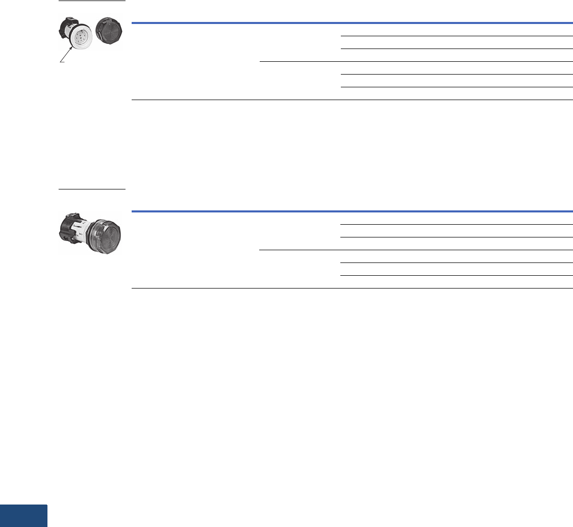
V12-T23-6 Volume 12—Aftermarket, Renewal Parts and Life Extension Solutions CA08100014E—November 2013 www.eaton.com
1
2
3
4
5
6
7
8
9
10
11
12
13
14
15
16
17
18
19
20
21
22
23
24
25
23
Pushbuttons and Indicating Lights
Replacement Capabilities
Indicating Light Units—One-Piece LED
●One-piece body style
●Plastic operators
●Full voltage LEDs
●Cluster-style integrated LED (non-removable)
●Plastic lenses
Cluster LED Type Indicating Lights—Non-Removable LEDs—UL (NEMA) Type 3, 3R, 4, 4X, 12, 13
Indicating Light Units—One-Piece Incandescent
●One-piece body style
●Plastic operators
●Full voltage
●Bayonet base incandescent lamp
Incandescent Standard Lens Type Indicating Lights—UL (NEMA) Type 3, 3R, 4, 4X, 12, 13
Note
1 Published theoretical lamp lives are based on ideal laboratory conditions and should be used for comparison only. Actual life may be shorter due to
application conditions.
Description Supply Voltage LED Color Lamp Life 1Catalog Number
Includes permanently attached lens and
board mounted, cluster style LEDs
24 Vac/Vdc Red 100,000 E22HL2X4
Green 100,000 E22HL3X4
Amber 100,000 E22HL9X4
110/120 Vac/Vdc Red 100,000 E22HL2X8
Green 100,000 E22HL3X8
Amber 100,000 E22HL9X8
Description Supply Voltage Color Lamp Life 1Catalog Number
Includes lens and T 3-1/4 bayonet
base lamp
24 Vac/Vdc
#1819 lamp
Red 2500 E22HV2X4
Green 2500 E22HV3X4
Amber 2500 E22HV9X4
110/120 Vac/Vdc
W1121 lamp
Red 1000 E22HV2X8
Green 1000 E22HV3X8
Amber 1000 E22HV9X8
Non-Removable LED
Non-Removable LED
Incandescent
Standard Lens
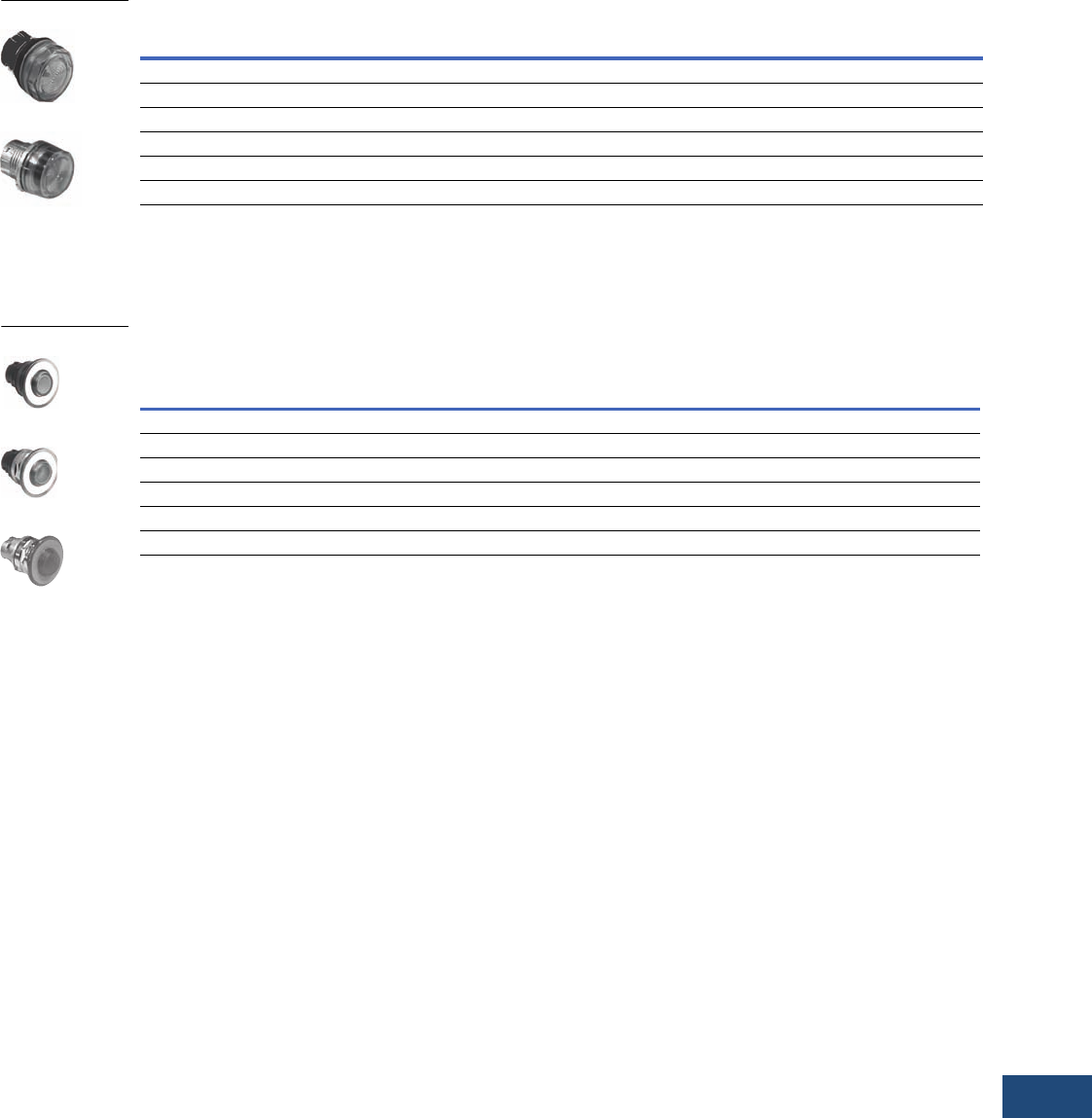
Volume 12—Aftermarket, Renewal Parts and Life Extension Solutions CA08100014E—November 2013 www.eaton.com V12-T23-7
1
2
3
4
5
6
7
8
9
10
11
12
13
14
15
16
17
18
19
20
21
22
23
24
25
23
Pushbuttons and Indicating Lights
Replacement Capabilities
Indicating Light Components
Indicating Lights—Without Light Unit—UL (NEMA) Type 3, 3R, 4, 4X, 12, 13
Push-Pull Components—Illuminated Operators
Will accept a maximum of two contact blocks when used with supplied three-way adapter. Five-way mounting adapters are not to be
used with three-position operators.
Illuminated Push-Pull Operators—UL (NEMA) Type 3, 3R, 4, 4X, 12, 13
Notes
1 For LED/incandescent lamps, see Page V12-T23-10.
2 All illuminated Push-Pull operators require tall LEDs from Page V12-T23-10.
Color
E22 Series—Plastic Operators
Catalog Number
EM22 Series—Metal Operators
Catalog Number
25 mm Diameter Standard Lens 1
Red E22H2 EM22H2
Green E22H3 EM22H3
White E22H5 EM22H5
Amber E22H9 EM22H9
Clear E22H0 EM22H0
Color
E22 Series—Plastic Operators EM22 Series—Metal Operators
Black Bezel
Catalog Number
Chrome Bezel
Catalog Number
Chrome Bezel
Catalog Number
Two-Position—40 mm Diameter Lens 2 (Maintained)
Red E22GDB2 1E22GD2 1EM22GD2 1
Green E22GDB3 E22GD3 EM22GD3
Three-Position—40 mm Diameter Lens 2 (Spring Return to Center)
Red E22HDB2 E22HD2 —
Green E22HDB3 E22HD3 —
E22
EM22
E22 Black
E22 Chrome
EM22 Chrome
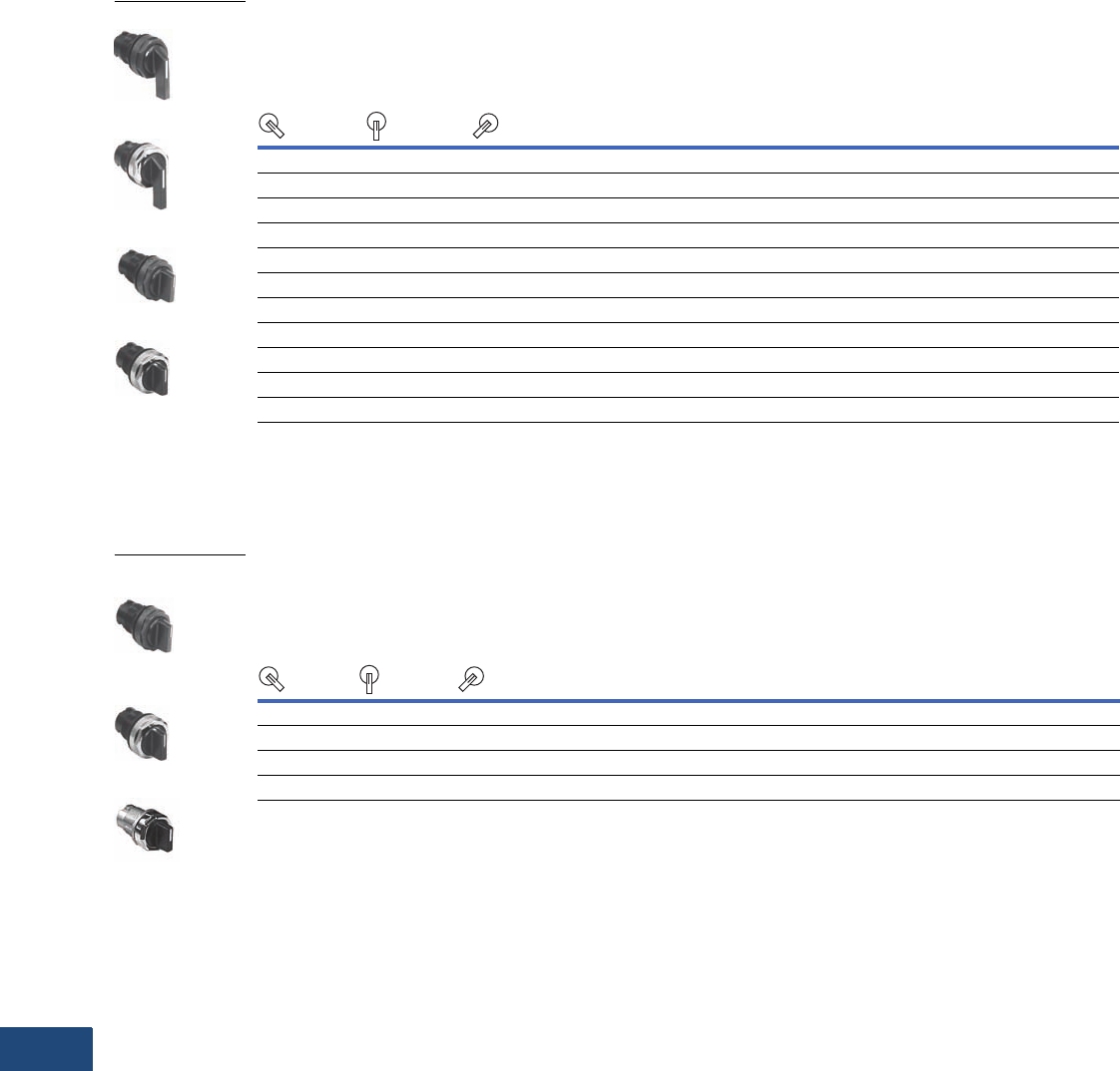
V12-T23-8 Volume 12—Aftermarket, Renewal Parts and Life Extension Solutions CA08100014E—November 2013 www.eaton.com
1
2
3
4
5
6
7
8
9
10
11
12
13
14
15
16
17
18
19
20
21
22
23
24
25
23
Pushbuttons and Indicating Lights
Replacement Capabilities
Selector Switches
45° Throw Non-Illuminated Lever and Knob Operated Selector Switches—Plastic
Will accept a maximum of two contact blocks (four circuits) with supplied three-way mounting adapter.
Optional five-way adapter will accept a maximum of five contact blocks (10 circuits).
45° Throw Non-Illuminated Lever and Knob Operated Selector Switches—
UL (NEMA) Type 3, 3R, 4, 4X, 12, 13
60° Throw Non-Illuminated Lever and Knob Operated Selector Switches
Will accept a maximum of two contact blocks (four circuits) with supplied three-way mounting adapter.
Optional five-way adapter will accept a maximum of five contact blocks (10 circuits).
60° Throw Non-Illuminated Lever and Knob Operated Selector Switches—
UL (NEMA) Type 3, 3R, 4, 4X, 12, 13
Operating Mode
M = Maintained
S = Momentary
Cam
Code
Plastic—Black Bezel
Catalog Number
Plastic—Chrome Bezel
Catalog Number
Left Center Right
Two-Position—45° Throw—Black Lever
—MM2 E22VBF1 E22VF1
M—M2 E22VB51 E22V51
Three-Position—45° Throw—Black Lever
MMM1 E22VBG1 E22VG1
SMS1E22VBL1 E22VL1
Two-Position—45° Throw—Black Knob
M—M2 E22XB51 E22X51
Three-Position—45° Throw—Black Knob
MMM1 E22XBG1 E22XG1
SMS1E22XBL1 E22XL1
Operating Mode
M = Maintained
S = Momentary
Cam
Code
E22 Series—Plastic Operators EM22 Series—Metal Operators
Black Bezel
Catalog Number
Chrome Bezel
Catalog Number
Chrome Bezel
Catalog Number
Left Center Right
Two-Position—60° Throw—Black Knob
M—M2E22XB561 E22X561 EM22X561
Three-Position—60° Throw—Black Knob
MMM1E22XBG61 E22XG61 EM22XG61
Black Bezel, Lever
Chrome Bezel, Lever
Black Bezel, Lever
Chrome Bezel, Lever
E22 Black Bezel,
Knob
E22 Chrome Bezel,
Knob
EM22 Black Knob
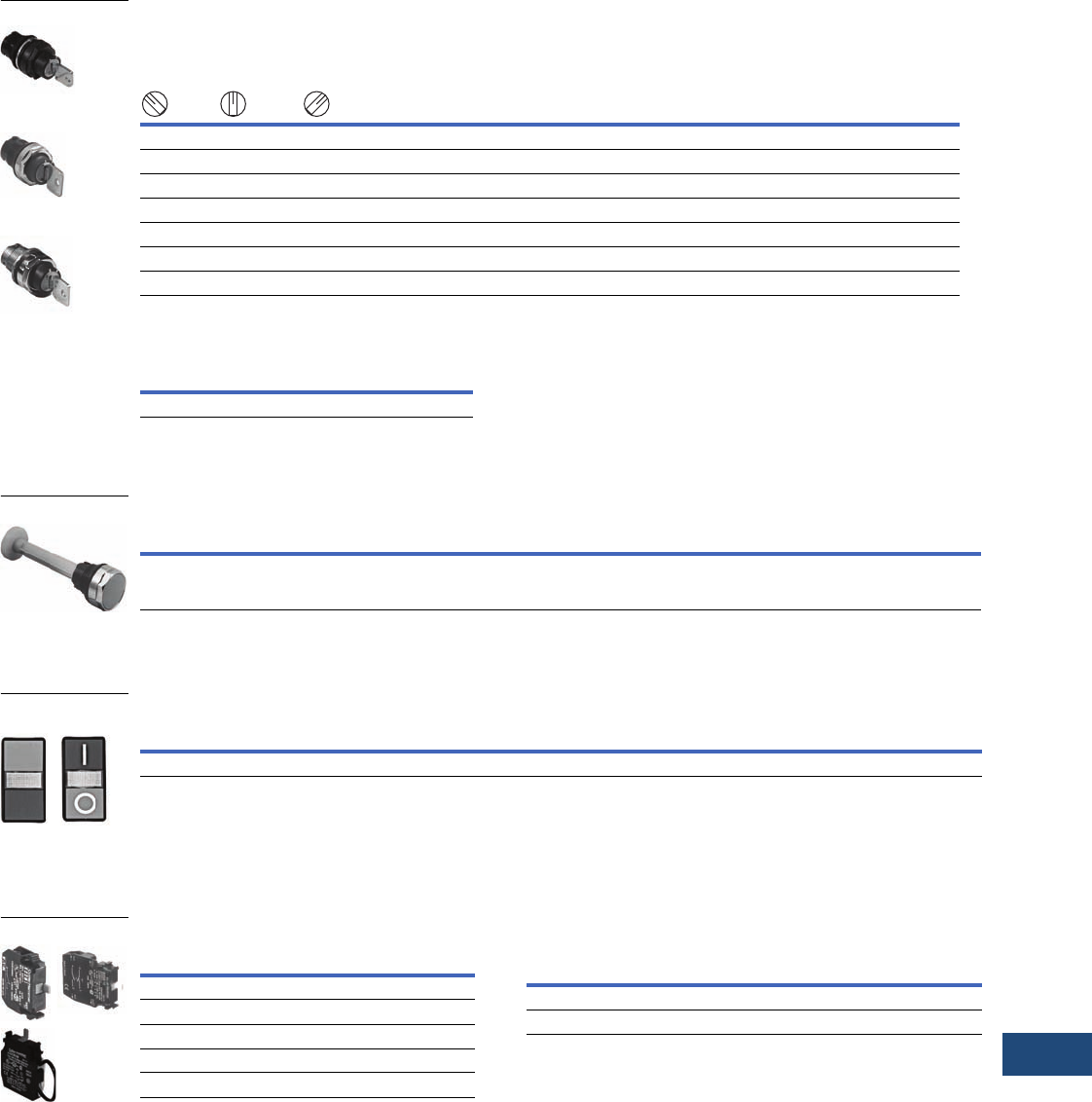
Volume 12—Aftermarket, Renewal Parts and Life Extension Solutions CA08100014E—November 2013 www.eaton.com V12-T23-9
1
2
3
4
5
6
7
8
9
10
11
12
13
14
15
16
17
18
19
20
21
22
23
24
25
23
Pushbuttons and Indicating Lights
Replacement Capabilities
Key Operated Selector Switches
Key removal from maintained positions only—will accept a maximum of two contact blocks (four circuits) with
supplied three-way mounting adapter. Optional five-way adapter will accept a maximum of five contact blocks (10 circuits).
Key Operated Selector Switches—UL (NEMA) Type 3, 3R, 4, 4X, 12, 13
Spare Key
Specialty Operators
Flush Pushbutton Operators with Mechanical Push Rod—UL (NEMA) Type 3, 3R, 4, 4X, 12, 13
Double-Headed Pushbuttons
Illuminated and Non-Illuminated Double-Headed Pushbuttons—UL (NEMA) Type 1; IP40
Contact Blocks
Contact Blocks Notes
1Final digit of catalog number represents key removal position per the chart below.
2Marked with direct opening action (DOA) symbol per IEC 60947-5-1 (Annex K) and
NEMA ICS 5 (Part 6).
3For use with trigger action emergency stop (E22LTA2) operators.
Operating Mode
M = Maintained
S = Momentary
Cam
Code
E22 Series—Plastic Operators EM22 Series—Metal Operators
Left Center Right
45° Black Bezel
Catalog Number 1
45° Chrome Bezel
Catalog Number 1
60° Chrome Bezel
Catalog Number 1
Two-Position
M— M2E22KB52 E22K52 —
M— M2E22KB53 E22K53 EM22K53
M— S 2E22KB62 E22K62 EM22K62
—M M 2E22KBF4 E22KF4 EM22KF4
Three-Position
MM M1E22KBG7 E22KG7 —
Description
Reference Number
Stamped on Key
Catalog
Number
Standard lock 92239 E22KS2
Description Color
Plastic—Black Bezel
Catalog Number
Plastic—Chrome Bezel
Catalog Number
25 mm diameter flush pushbutton
Operators supplied with mechanical push rod—suitable for external
mechanical reset of overload relays. Push rod must be cut to desired length
Gray E22PB7L E22P7L
Plastic Black Bezel
Plastic Chrome Bezel
Metal Chrome Bezel
Mechanical Push Rod
Description Operator Colors Marking
Plastic—Black Bezel
Catalog Number
Non-illuminated double-headed pushbutton Green—Red I E22DB1A21
Double-Headed
Pushbuttons
Description
Catalog
Number
1NC E22B1 2
1NO E22B2
1NO-1NC E22B11 2
2NO E22B20
One self-monitoring 1NC E22CB1M 23
Contact Blocks
Key Removal Position Code Suffix Key Removal Position Code Suffix
Left only 2 Center only 4
Right and left 3 Right, left and center 7
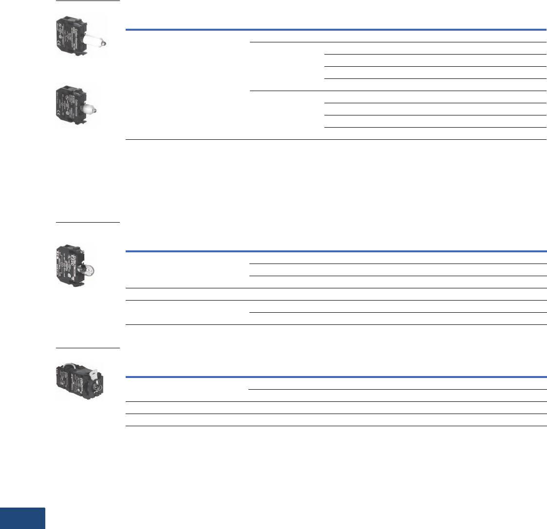
V12-T23-10 Volume 12—Aftermarket, Renewal Parts and Life Extension Solutions CA08100014E—November 2013 www.eaton.com
1
2
3
4
5
6
7
8
9
10
11
12
13
14
15
16
17
18
19
20
21
22
23
24
25
23
Pushbuttons and Indicating Lights
Replacement Capabilities
Light Units and Lamps
E22 light units consist of two versions—standard size LED lamps and tall LED lamps. Select the standard LED light units for all
indicating lights, illuminated pushbuttons, push-push (alternate action) or double-headed pushbutton operators. Select the tall LED
light units for all illuminated selector switches and push-pull operators.
LED Light Units—Includes a T3-1/4 (BA9) Bayonet Base LED
E22 light units consist of two versions—with standard bulb or with tall bulbs. Select the standard bulb light units for all indicating lights,
illuminated pushbuttons, push-push (alternate action) or double-headed pushbutton operators. Select the tall bulb light units for all
illuminated selector switches and push-pull operators.
Caution: Please note that 120V full voltage light units (E22D120) are only suitable for indicating light operators and will overheat in other operators.
Incandescent Light Units—Includes a T3-1/4 (BA9) Bayonet Base Lamp (Except When Noted)
PresTest Units—Includes Prewired 1NO-1NC Contact Blocks
Notes
1 Use tall LEDs for Pull/Push operators. For all other illuminated devices, use standard LEDs.
2 E22D120 light units are suitable for indicating light operators only.
Type Supply Voltage LED Color
Standard LED 1
Catalog Number
Tall LED 1
Catalog Number
Full voltage Unit without lamp — E22DE E22DE
24 Vac/Vdc Red E22DL24R E22DLT24R
Green E22DL24G E22DLT24G
Yellow E22DL24Y —
White E22DL24W —
120 Vac/Vdc Red E22DL120R E22DLT120R
Green E22DL120G E22DLT120G
Yellow E22DL120Y —
White E22DL120W —
Type
Supply Voltage
50/60 Hz
Lamp
Voltage
Standard Bulb
Catalog Number
Full voltage AC/DC Unit without lamp — E22D
24 24 E22D24
120 120 E22D120 2
Resistor AC/DC 120 60 E22R2
Transformer AC only 120 6 E22TL1
240 6 E22TL2
Type
Supply Voltage
50/60 Hz
Lamp
Voltage
Standard Bulb
Catalog Number
Full voltage AC/DC Unit without lamp — E22D0C
24 24 E22D24C
Resistor AC/DC 120 60 E22R2C
Transformer AC only 120 6 E22TL1C
Tall LED Light Unit
Standard LED
Light Unit
Incandescent
Light Units
PresTest Unit
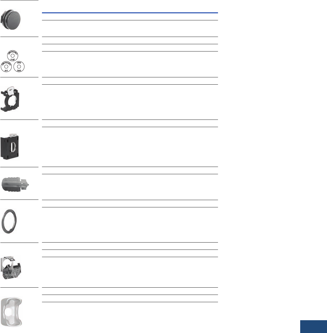
Volume 12—Aftermarket, Renewal Parts and Life Extension Solutions CA08100014E—November 2013 www.eaton.com V12-T23-11
1
2
3
4
5
6
7
8
9
10
11
12
13
14
15
16
17
18
19
20
21
22
23
24
25
23
Pushbuttons and Indicating Lights
Replacement Capabilities
Accessories
EM22 and E22 Series Accessories
Note
1 Yellow plates comply with EN418 machine safety standard background requirements for E-Stops.
Description Catalog Number
Hole Plug
Forms oil- and watertight seal for unused panel holes —
UL Listed Type 4-4X-13 black nylon
E22BHP
Oversize Yellow Legend Plates 1
1.77 inches (45 mm) blank E22VA2
2.76 inches (70 mm) printed EMERGENCY STOP E22VA8
Mounting Adapter
Supplied as standard with E22 operators.
Provides contact block and light unit mounting.
E22BA1
Auto Latch Mounting Adapter
Supplied as standard with EM22 operators.
Provides contact block and light unit mounting.
E22BA1A
Operator Plug
Must be inserted into rear of momentary action pushbutton and mushroom head operators
when third contact block is installed in center position. Not to be used with maintained action or
illuminated operators—minimum order quantity 10 pieces. To assemble, push plug into the
rear of the operator. On mushroom operators, cut down the plug to 0.62 inches (15.2 mm)
prior to assembly. Plug is notched to indicate cut down length.
E22BA2
Locating Ring
Provides additional anti-rotation features when using optional panel mounting
hole notch—minimum order quantity 10 pieces (metal)
E22LRM
Padlockable Transparent Cover
Suitable for use with 25 mm flush and extended pushbutton operators only E22PCM
Suitable for use with 28 mm mushroom operators, knob and key selector switches E22BA9
Mushroom Guard
For 40 mm trigger action switch—to be used with E22LTA2 and E22LTA2N123 operators E22MGTA
Hole Plug
Oversize Yellow
Legend Plates
Mounting Adapter
Auto Latch
Mounting Adapter
Operator Plug
Locating Ring
Padlockable
Transparent Cover
Mushroom Guard
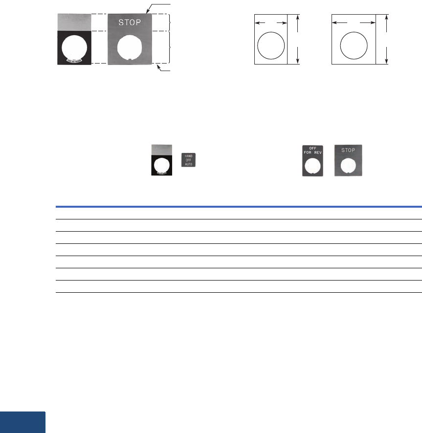
V12-T23-12 Volume 12—Aftermarket, Renewal Parts and Life Extension Solutions CA08100014E—November 2013 www.eaton.com
1
2
3
4
5
6
7
8
9
10
11
12
13
14
15
16
17
18
19
20
21
22
23
24
25
23
Pushbuttons and Indicating Lights
Replacement Capabilities
Options
Engraved Legend Plates with Standard Markings—1/8-Inch High Character Size
Aluminum—Aluminum
legend plates have a plastisol
backing to help prevent
rotation of the operator when
installed in an unnotched
hole. Operators installed with
aluminum legend plates and
legend plates with clip-in
inserts maintain their UL
Listed Type 4-4X-13 rating.
Plastic—Both the laminated
plastic legend plates and the
legend plates with clip-in
inserts offer the choice
of four background colors.
Either side of the legend
plate or insert can be field
engraved.
Color Diagram and Approximate Dimensions in Inches (mm)
Engraved Legend Plates
Note
1To order jumbo legend plates, replace the fifth character with an L. For example E22NL87 is an aluminum, Jumbo legend plate marked “FASTER.”
Nameplate Type
Standard Aluminum with Plastisol Backing
NEMA 3, 3R, 4, 4X, 12, 13 1
Standard Plastic,
NEMA 1 Only
Letter Color
Background Color
Field Color
Black
Silver
Black
Black
Silver
Red
White
Black
Black
White
Red
Red
Pushbutton
No engraving E22NS36 E22NS37 E22NSP77 E22NSP77
CLOSE E22NS11 — — —
DOWN E22NS12 — — —
EMERG. STOP — E22NS13 — —
FORWARD E22NS15 — — —
JOG E22NS19 — — —
Letter Color
Background Color
Field Color
Split Field Color
Standard Aluminum Jumbo Aluminum
Standard
Aluminum
Jumbo
Plastic
1.17
(30)
1.77
(45)
1.57
(40)
1.77
(45)
Volume 12—Aftermarket, Renewal Parts and Life Extension Solutions CA08100014E—November 2013 www.eaton.com V12-T23-13
1
2
3
4
5
6
7
8
9
10
11
12
13
14
15
16
17
18
19
20
21
22
23
24
25
23
Pushbuttons and Indicating Lights
Replacement Capabilities
Engraved Legend Plates, Continued
Approximate Dimensions in Inches (mm)
Legend Plates and Legend Plate Carriers
Enclosures
These totally insulated, NEMA 4, 4X, 12, 13 rated polycarbonate
enclosures are available in 1, 2, 3, 4, 6 and 9 hole configurations
in single or double depth.
Enclosures—UL (NEMA) 4, 4X, 12, 13
Notes
1To order jumbo legend plates, replace the fifth character with
an L. For example, E22NL87 is an aluminum, jumbo legend plate
marked “FASTER.”
2One carrier required for each clip-in insert.
3Yellow covers comply with background requirements for EN418
Safety of Machinery Standard.
Nameplate Type
Standard Aluminum with Plastisol Backing NEMA 3, 3R,
4, 4X, 12, 13 and Self-Adhesives Used on Enclosures 1
Letter Color
Background Color
Field Color
Black
Silver
Black
Black
Silver
Red
Pushbutton
MOTOR RUN E22NS81 —
MOTOR STOP E22NS82 —
ON E22NS25 —
OPEN E22NS26 —
POWER ON E22NS80 —
REVERSE E22NS30 —
RUN E22NS31 —
START E22NS33 —
STOP — E22NS34
UP E22NS35 —
Two-Position Selector Switch
FOR/REV E22NS38 —
HAND/AUTO E22NS39 —
JOG/ RUN E22NS41 —
OFF/ON E22NS42 —
OPEN/CLOSE E22NS43 —
UP/DOWN E22NS48 —
Three-Position Selector Switch
FOR/OFF/REV E22NS50 —
HAND/OFF/AUTO E22NS51 —
Nameplate Type
Plastic with Clip-In Insert without Carrier
NEMA 3, 3R, 4, 4X, 12, 13
Letter Color
Background Color
Field Color
White
Black
Black
Pushbutton
Legend plate carrier 2E22ND
1.1
(27.5) 0.44
(11.2)
Standard
Cover Holes,
Centerlines and
Legend Plate Selection
Usable Depth
Inches (mm)
Catalog
Number
Will accommodate
2.65 inch (65 mm)
legend plates listed
on Page V12-T23-11
2.5 (64) E22CSP1
3.4 (87) E22CDP1
With safety yellow cover 2.2 (57) E22CSP1Y 3
3.15 (80) E22CDP1Y 3
1.42 inch (36 mm)
Will accommodate
self-adhesive legend
plates listed on
Pages V12-T23-12
and V12-T23-13
2.2 (57) E22CSP2
1.18 inch (30 mm)
Will accommodate
self-adhesive legend
plates listed on
Pages V12-T23-12
and V12-T23-13
2.2 (57) E22CSP4
E22CSP1
E22CSP1Y
E22CSP2
E22CSP4

V12-T23-14 Volume 12—Aftermarket, Renewal Parts and Life Extension Solutions CA08100014E—November 2013 www.eaton.com
1
2
3
4
5
6
7
8
9
10
11
12
13
14
15
16
17
18
19
20
21
22
23
24
25
23
Pushbuttons and Indicating Lights
Replacement Capabilities
Further Information
Pricing Information
For pricing information,
please consult Eaton’s Price
and Availability Digest (PAD)
or your local authorized
Eaton distributor.
Publication
Number Description
TD04712001E E22/EM22 Technical Data

Volume 12—Aftermarket, Renewal Parts and Life Extension Solutions CA08100014E—November 2013 www.eaton.com V12-T24-1
1
2
3
4
5
6
7
8
9
10
11
12
13
14
15
16
17
18
19
20
21
22
23
24
25
Sales & Service Locations
Global Sales & Service
24 Sales & Service Locations
Sales Locations
Alabama–Iowa . . . . . . . . . . . . . . . . . . . . . . . . . . . . . . . . . . . . . . . . V12-T24-2
Kansas–Oklahoma . . . . . . . . . . . . . . . . . . . . . . . . . . . . . . . . . . . . . V12-T24-3
Oregon–Wisconsin . . . . . . . . . . . . . . . . . . . . . . . . . . . . . . . . . . . . V12-T24-4
Service Locations
Alabama–Canada . . . . . . . . . . . . . . . . . . . . . . . . . . . . . . . . . . . . . . V12-T24-5
Satellite Plants
Arizona–Washington . . . . . . . . . . . . . . . . . . . . . . . . . . . . . . . . . . . V12-T24-6
Service Centers
California–Texas . . . . . . . . . . . . . . . . . . . . . . . . . . . . . . . . . . . . . . . V12-T24-6

V12-T24-2 Volume 12—Aftermarket, Renewal Parts and Life Extension Solutions CA08100014E—November 2013 www.eaton.com
1
2
3
4
5
6
7
8
9
10
11
12
13
14
15
16
17
18
19
20
21
22
23
24
25
24
Sales & Service Locations
Sales Locations
Alabama
Birmingham (Pelham)
Tel: (205) 403-3850
Fax: (205) 403-3899
Mobile (Theodore)
Tel: (251) 443-6379
Fax: (251) 443-8845
Alaska
Anchorage
Tel: (907) 562-8558
Fax: (907) 562-8553
Arizona
Phoenix
Tel: (480) 449-4200
Fax: (480) 449-4203
Tucson
Tel: (520) 744-9962
Fax: (520) 744-9963
Arkansas
Fayetteville
Tel: (479) 271-6259
Fax: (479) 271-6241
Jonesboro
Tel: (870) 934-9903
Fax: (870) 934-0824
Little Rock
Tel: (501) 791-2880
Fax: (501) 791-2434
California
Bakersfield
Tel: (661) 617-1818
Fax: (661) 617-1819
Los Angeles (Pomona)
Tel: (909) 869-8200
Fax: (909) 869-8259
Sacramento (Roseville)
Tel: (916) 780-4100
Fax: (916) 780-4141
San Diego
Tel: (619) 542-7355
Fax: (619) 542-7323
San Francisco (Livermore)
Tel: (925) 454-3700
Fax: (925) 454-3791
Santa Rosa
Tel: (707) 528-9000
Fax: (707) 528-3131
Colorado
Denver (Littleton)
Tel: (303) 738-2300
Fax: (303) 738-2324
Connecticut
Hartford (Rocky Hill)
Tel: (860) 298-1300
Fax: (860) 298-1301
Florida
Deerfield Beach
Tel: (954) 570-3680
Fax: (954) 421-3539
Jacksonville
Tel: (904) 292-5350
Fax: (904) 292-2884
Orlando (Longwood)
Tel: (407) 264-9320
Fax: (407) 264-9330
Miami (Miami Lakes)
Tel: (305) 781-3872
Pensacola
Tel: (850) 479-3264
Fax: (850) 479-3374
Sarasota
Tel: (941) 378-5404
Fax: (941) 378-2798
Tampa
Tel: (813) 287-7000
Fax: (813) 287-7038
Georgia
Atlanta (Smyrna)
Tel: (678) 309-4201
Fax: (770) 433-1644
Columbus
Tel: (706) 322-7382
Fax: (706) 322-2656
Macon
Tel: (478) 471-0500
Fax: (478) 471-0501
Savannah
Tel: (912) 232-7290
Fax: (912) 232-7965
Hawaii
Honolulu
Tel: (808) 594-4500
Fax: (808) 593-1115
Idaho
Boise
Tel: (208) 323-2802
Fax: (208) 376-4863
Illinois
Chicago (Glendale Heights)
Tel: (630) 260-6301
Fax: (630) 260-6445
Decatur
Tel: (217) 872-1965
Fax: (217) 872-1975
Peoria
Tel: (309) 649-1831
Fax: (309) 649-1833
Rockford
Tel: (815) 398-6585
Fax: (815) 398-2074
Indiana
Evansville
Tel: (812) 476-7591
Fax: (812) 476-7581
Ft. Wayne
Tel: (260) 420-5500
Fax: (260) 420-5506
Indianapolis
Tel: (317) 334-4500
Fax: (317) 334-4544
South Bend
Tel: (574) 583-0601
Fax: (574) 583-0611
Iowa
Bettendorf
Tel: (563) 344-7800
Fax: (563) 344-8775
Cedar Rapids
Tel: (319) 378-9554
Fax: (319) 378-9602
Des Moines (Urbandale)
Tel: (515) 334-8950
Fax: (515) 334-8945

Volume 12—Aftermarket, Renewal Parts and Life Extension Solutions CA08100014E—November 2013 www.eaton.com V12-T24-3
1
2
3
4
5
6
7
8
9
10
11
12
13
14
15
16
17
18
19
20
21
22
23
24
25
24
Sales & Service Locations
Sales Locations
Kansas
Kansas City (Lenexa)
Tel: (913) 327-3600
Fax: (913) 327-3699
Wichita
Tel: (316) 263-0611
Fax: (316) 267-1084
Kentucky
Lexington
Tel: (859) 278-2115
Fax: (859) 278-6523
Louisville
Tel: (502) 961-5500
Fax: (502) 961-5515
Paducah
Tel: (270) 898-8322
Fax: (270) 898-4079
Louisiana
Baton Rouge
Tel: (225) 295-9060
Fax: (225) 295-9068
New Orleans (Metairie)
Tel: (504) 849-3360
Fax: (504) 834-6086
Shreveport
Tel: (318) 864-9987
Fax: (318) 868-7487
Maine
Augusta (Winthrop)
Tel: (207) 330-7100
Fax: (207) 782-5497
Portland
Tel: (207) 657-7721
Fax: (207) 253-5051
Maryland
Baltimore (Columbia)
Tel: (410) 720-6700
Fax: (410) 720-6740
Massachusetts
Boston (Franklin)
Tel: (774) 235-0200
Fax: (508) 520-1980
Michigan
Detroit (Novi)
Tel: (248) 374-5100
Fax: (248) 374-5177
Grand Rapids
Tel: (616) 559-3535
Fax: (616) 559-3544
Saginaw
Tel: (517) 753-5355
Fax: (517) 753-5928
Minnesota
Duluth
Tel: (218) 722-5300
Fax: (218) 722-5700
Minneapolis (Minnetonka)
Tel: (952) 939-5400
Fax: (952) 939-5457
Mississippi
Jackson
Tel: (601) 919-1102
Fax: (601) 919-1067
Missouri
Springfield
Tel: (417) 882-8880
Fax: (417) 882-8881
St. Louis
Tel: (636) 717-3400
Fax: (636) 717-3546
Montana
Bozeman
Tel: (406) 585-8087
Fax: (406) 585-7994
Nebraska
Omaha
Tel: (402) 339-3208
Fax: (402) 339-0595
Nevada
Las Vegas
Tel: (702) 309-4089
Fax: (702) 222-0771
New Hampshire
Derry
Tel: (603) 458-1751
Fax: (603) 898-0806
New Jersey
Edison
Tel: (732) 767-9600
Fax: (732) 205-2642
New Mexico
Albuquerque
Tel: (505) 828-3800
Fax: (505) 828-3838
New York
Albany (Clifton Park)
Tel: (518) 348-1752
Fax: (518) 348-1758
Buffalo (Amherst)
Tel: (716) 691-4511
Fax: (716) 691-6969
New York
Tel: (212) 319-2100
Fax: (212) 833-0250
Rochester
Tel: (585) 381-0510
Fax: (585) 381-0499
Syracuse (East Syracuse)
Tel: (315) 437-7201
Fax: (315) 437-0924
North Carolina
Asheville (Avery Creek)
Tel: (828) 651-0500
Fax: (828) 651-0980
Charlotte
Tel: (704) 529-3515
Fax: (704) 529-3532
Greensboro
Tel: (336) 852-8849
Fax: (336) 852-8868
Raleigh
Tel: (919) 544-7074
Fax: (919) 206-7339
Wilmington
Tel: (910) 343-1955
Fax: (910) 343-3348
North Dakota
Fargo
Tel: (701) 281-0090
Fax: (701) 281-5772
Ohio
Cincinnati
Tel: (513) 387-2000
Fax: (513) 387-2055
Cleveland (Parma)
Tel: (216) 265-2741
Fax: (216) 265-2770
Columbus (Westerville)
Tel: (614) 899-4104
Fax: (614) 899-5374
Dayton
Tel: (937) 431-3260
Fax: (937) 431-3299
Toledo
Tel: (419) 887-6509
Oklahoma
Oklahoma City
Tel: (405) 947-3729
Fax: (405) 947-3723
Tulsa
Tel: (918) 627-3312
Fax: (918) 622-7618

V12-T24-4 Volume 12—Aftermarket, Renewal Parts and Life Extension Solutions CA08100014E—November 2013 www.eaton.com
1
2
3
4
5
6
7
8
9
10
11
12
13
14
15
16
17
18
19
20
21
22
23
24
25
24
Sales & Service Locations
Sales Locations
Oregon
Eugene
Tel: (541) 451-4634
Fax: (541) 451-4641
Medford
Tel: (541) 776-4849
Fax: (541) 773-9925
Portland (Wilsonville)
Tel: (503) 582-2700
Fax: (503) 570-2918
Pennsylvania
Allentown
Tel: (610) 336-4080
Fax: (610) 391-8983
Philadelphia (Boothwyn)
Tel: (610) 497-6100
Fax: (610) 497-6187
Pittsburgh (Moon Township)
Tel: (412) 893-3300
York
Tel: (717) 757-1071
Fax: (717) 757-4448
Puerto Rico
Canovanas
Tel: (787) 257-4422
Fax: (787) 257-4465
South Carolina
Charleston
Tel: (843) 529-1632
Fax: (843) 529-1634
Columbia
Tel: (803) 799-2684
Fax: (803) 799-1515
Greenville
Tel: (864) 232-5698
Fax: (864) 232-9284
South Dakota
Sioux Falls
Tel: (605) 271-4100
Fax: (605) 271-4102
Tennessee
Knoxville
Tel: (865) 980-7200
Fax: (865) 980-7222
Memphis (Cordova)
Tel: (901) 737-0200
Fax: (901) 737-4544
Nashville
Tel: (615) 333-5457
Fax: (615) 333-5485
Texas
Austin
Tel: (512) 453-5800
Fax: (512) 453-0682
Corpus Christi
Tel: (361) 887-5005
Fax: (361) 887-5023
Dallas (Grapevine)
Tel: (817) 410-1724
Fax: (817) 410-1760
El Paso
Tel: (915) 779-5016
Fax: (915) 779-4655
Houston
Tel: (713) 849-1600
Fax: (713) 849-1675
Lubbock
Tel: (806) 765-0092
Fax: (806) 765-0093
San Antonio
Tel: (210) 366-0093
Fax: (210) 366-0677
Tyler
Tel: (903) 534-1800
Fax: (903) 534-6022
Utah
Salt Lake City
Tel: (801) 238-4500
Fax: (801) 363-4795
Virginia
Norfolk (Chesapeake)
Tel: (757) 424-5556
Fax: (757) 424-2938
Richmond (Sandstone)
Tel: (804) 328-6111
Fax: (804) 328-5384
Roanoke
Tel: (540) 345-7809
Fax: (540) 345-1711
Washington
Kennewick
Tel: (509) 374-8511
Fax: (509) 735-8450
Seattle (Bellevue)
Tel: (425) 644-5800
Fax: (425) 644-6220
Spokane
Tel: (509) 922-4055
Fax: (509) 922-1561
West Virginia
Charleston (Hurricane)
Tel: (304) 757-9556
Fax: (304) 757-9879
Wisconsin
Appleton
Tel: (920) 380-2400
Fax: (920) 380-2420
Madison
Tel: (608) 370-6600
Fax: (608) 370-6602
Milwaukee (Brookfield)
Tel: (414) 443-3500
Fax: (414) 257-1844

Volume 12—Aftermarket, Renewal Parts and Life Extension Solutions CA08100014E—November 2013 www.eaton.com V12-T24-5
1
2
3
4
5
6
7
8
9
10
11
12
13
14
15
16
17
18
19
20
21
22
23
24
25
24
Sales & Service Locations
Service Locations
Alabama
Birmingham (Pelham)
Tel: (205) 403-3800
Fax: (205) 403-3836
Arizona
Phoenix (Tempe)
Tel: (480) 449-4271
Fax: (480) 449-4285
California
Los Angeles (Diamond Bar)
Tel: (909) 348-0405
Fax: (909) 348-0410
San Diego
Tel: (619) 291-4211
Fax: (619) 692-6291
San Francisco (Livermore)
Tel: (925) 454-3650
Fax: (925) 454-3655
Colorado
Denver (Littleton)
Tel: (303) 738-2360
Fax: (303) 762-0419
Connecticut
Hartford
Tel: (860) 298-1300
Fax: (860) 298-1301
Florida
Jacksonville
Tel: (904) 292-5351
Fax: (904) 292-2884
Miami (Deerfield Beach)
Tel: (954) 571-8282
Fax: (954) 419-9881
Georgia
Atlanta (Smyrna)
Tel: (678) 309-4242
Fax: (770) 433-0627
Illinois
Chicago (Glendale Heights)
Tel: (630) 260-6302
Fax: (630) 690-7407
Iowa
Des Moines
Tel: (515) 334-8958
Fax: (515) 334-8945
Indiana
Indianapolis
Tel: (502) 961-5500
Fax: (502) 961-5520
Kansas
Kansas City
Tel: (913) 327-3650
Fax: (913) 327-3670
Kentucky
Louisville
Tel: (502) 961-5500
Fax: (502) 961-5520
Louisiana
Baton Rouge
Tel: (225) 756-1541
Fax: (225) 756-0178
Maine
Augusta (Winthrop)
Tel: (207) 330-7100
Fax: (207) 330-7199
Maryland
Baltimore (Columbia)
Tel: (410) 720-6700
Fax: (410) 720-6740
Massachusetts
Boston (Franklin)
Tel: (774) 235-0255
Fax: (774) 235-0276
Minnesota
Duluth
Tel: (218) 722-5300
Fax: (218) 722-5700
Minneapolis (Minnetonka)
Tel: (952) 912-1320
Fax: (952) 912-1355
Missouri
St. Louis
Tel: (636) 717-3403
Fax: (636) 717-3450
New York
New York City (Union, NJ)
Tel: (908) 624-2370
Fax: (908) 624-2341
Syracuse (East Syracuse)
Tel: (315) 437-7204
Fax: (315) 437-0924
North Carolina
Raleigh (Durham)
Tel: (919) 741-4378
Fax: (919) 882-1488
Ohio
Cleveland (Independence)
Tel: (216) 642-5251
Fax: (216) 642-5238
Oklahoma
Oklahoma City
Tel: (405) 947-3729
Fax: (405) 947-3723
Oregon
Portland (Wilsonville)
Tel: (425) 644-6280
Pennsylvania
Philadelphia (Boothwyn)
Tel: (610) 364-2608
Fax: (610) 364-1739
Pittsburgh (Warrendale)
Tel: (724) 779-5811
Fax: (724) 779-5828
Texas
Austin
Tel: (512) 302-4011
Fax: (512) 302-4150
Dallas (Grapevine)
Tel: (817) 410-1625
Fax: (817) 410-1640
Houston
Tel: (713) 948-8240
Fax: (713) 948-8245
San Antonio
Tel: (210) 366-0093
Fax: (210) 366-0677
Washington
Seattle (Bellevue)
Tel: (425) 644-6260
Fax: (425) 644-6255
West Virginia
Skelton
Tel: (304) 256-3918
Fax: (304) 256-3920
Wisconsin
Appleton
Tel: (920) 380-2430
Fax: (920) 380-2420
Canada
Toronto, Ontario
Tel: (416) 798-0112
Fax: (416) 798-0063
Montreal, Quebec (Laval)
Tel: (450) 668-0853
Fax: (450) 663-5858
Ottawa, Ontario
Tel: (613) 739-1115
Fax: (613) 739-7339
Kitchener, Ontario
Tel: (519) 893-4848
Fax: (519) 893-2992
Calgary, Alberta
Tel: (403) 717-4931
Fax: (403) 717-3962

V12-T24-6 Volume 12—Aftermarket, Renewal Parts and Life Extension Solutions CA08100014E—November 2013 www.eaton.com
1
2
3
4
5
6
7
8
9
10
11
12
13
14
15
16
17
18
19
20
21
22
23
24
25
24
Sales & Service Locations
Satellite Plants and Service Centers
Satellite Plants
Arizona
Phoenix
Tel: (480) 449-4222
California
Los Angeles
Tel: (951) 685-5788
San Francisco
Tel: (510) 784-8981
Colorado
Denver
Tel: (303) 366-2080
Connecticut
Hartford
Tel: (860) 298-1305
Fax: (860) 298-1306
Florida
Orlando
Tel: (407) 264-9300
Georgia
Atlanta
Tel: (678) 309-4260
Illinois
Chicago
Tel: (630) 260-6303
Maryland
Baltimore
Tel: (410) 796-7777
Missouri
St. Louis
Tel: (636) 717-3500
New Jersey
West Hampton
Tel: (609) 835-4230
North Carolina
Raleigh
Tel: (919) 544-7074
Ohio
Cleveland
Tel: (216) 433-0616
Texas
Dallas
Tel: (817) 251-6733
Houston
Tel: (713) 688-8430
Washington
Seattle
Tel: (253) 833-5021
Service Centers
California
Los Angeles
Tel: (562) 944-6413
Colorado
Denver
Tel: (303) 366-9949
Connecticut
Hartford
Tel: (860) 683-4221
Georgia
Atlanta
Tel: (678) 309-4270
Illinois
Chicago
Tel: (630) 260-6304
Ohio
Cincinnati
Tel: (513) 682-4000
Texas
Houston
Tel: (713) 939-9690

Volume 12—Aftermarket, Renewal Parts and Life Extension Solutions CA08100014E—November 2013 www.eaton.com V12-A1-1
Appendix 1—Eaton Terms & Conditions
Effective Date: November 1, 2008
Eaton Terms & Conditions
Contents
Description Page
Terms and Conditions of Sale. . . . . . . . . . . . . . . . . V12-A1-1
Terms of Payment . . . . . . . . . . . . . . . . . . . . . . . . . V12-A1-2
Freight . . . . . . . . . . . . . . . . . . . . . . . . . . . . . . . . . . V12-A1-3
Warranty . . . . . . . . . . . . . . . . . . . . . . . . . . . . . . . . . V12-A1-3
Selling Policy (Supersedes Selling Policy 25-000, dated February 20, 2006)
Terms and Conditions of Sale
The Terms and Conditions of
Sale set forth herein, and any
supplements which may be
attached hereto, constitute
the full and final expression
of the contract for the sale
of products or services
(hereinafter referred to as
Product(s) or Services by
Eaton Corporation
(hereinafter referred to as
Seller) to the Buyer, and
supersedes all prior
quotations, purchase orders,
correspondence or
communications whether
written or oral between the
Seller and the Buyer.
Notwithstanding any contrary
language in the Buyer’s
purchase order,
correspondence or other
form of acknowledgment,
Buyer shall be bound by
these Terms and Conditions
of Sale when it sends a
purchase order or otherwise
indicates acceptance of this
contract, or when it accepts
delivery from Seller of the
Products or Services.
THE CONTRACT FOR SALE
OF THE PRODUCTS OR
SERVICES IS EXPRESSLY
LIMITED TO THE TERMS
AND CONDITIONS OF SALE
STATED HEREIN. ANY
ADDITIONAL OR DIFFERENT
TERMS PROPOSED BY
BUYER ARE REJECTED
UNLESS EXPRESSLY
AGREED TO IN WRITING BY
SELLER. No contract shall
exist except as herein
provided.
Complete Agreement
No amendment or
modification hereto nor any
statement, representation or
warranty not contained herein
shall be binding on the Seller
unless made in writing by an
authorized representative of
the Seller. Prior dealings,
usage of the trade or a course
of performance shall not be
relevant to determine the
meaning of this contract even
though the accepting or
acquiescing party had
knowledge of the nature
of the performance and
opportunity for objection.
Quotations
Written quotations are valid
for 30 days from its date
unless otherwise stated in
the quotation or terminated
sooner by notice.
Verbal quotations, unless
accepted, expire the same
day they are made.
A complete signed order
must be received by Seller
within 20 calendar days of
notification of award,
otherwise the price and
shipment will be subject to
re-negotiation.
Termination and Cancellation
Any order may be terminated
by the Buyer only by written
notice and upon payment
of reasonable termination
charges, including all costs
plus profit.
Seller shall have the right to
cancel any order at any time
by written notice if Buyer
breaches any of the terms
hereof, becomes the subject
of any proceeding under state
or federal law for the relief
of debtors, or otherwise
becomes insolvent or
bankrupt, generally does not
pay its debts as they become
due or makes an assignment
for the benefit of creditors.
V12-A1-2 Volume 12—Aftermarket, Renewal Parts and Life Extension Solutions CA08100014E—November 2013 www.eaton.com
Appendix 1—Eaton Terms & Conditions
Effective Date: November 1, 2008
Prices
All prices are subject to
change without notice. In the
event of a price change, the
effective date of the change
will be the date of the new
price or discount sheet, letter
or telegram. All quotations
made or orders accepted
after the effective date will be
on the new basis. For existing
orders, the price of the
unshipped portion of an order
will be the price in effect at
time of shipment.
Price Policy—Products and
Services
When prices are quoted as
firm for quoted shipment, they
are firm provided the following
conditions are met:
1. The order is released
with complete
engineering details.
2. Shipment of Products are
made, and Services
purchased are provided
within the quoted
lead time.
3. When drawings for
approval are required
for any Products, the
drawings applicable to
those Products must be
returned within 30*
calendar days from the
date of the original
mailing of the drawings
by Seller. The return
drawings must be
released for manufacture
and shipment and must
be marked “APPROVED”
or “APPROVED AS
NOTED.” Drawing
re-submittals which are
required for any other
reason than to correct
Seller errors will not
extend the 30-day period.
* 60 days for orders
through contractors
to allow time for their
review and approval
before and after
transmitting them
to their customers.
If the Buyer initiates or in
any way causes delays
in shipment, provision of
Services or return of approval
drawings beyond the periods
stated above, the price of the
Products or Services will be
increased 1% per month
or fraction thereof up to a
maximum of 18 months from
the date of the Buyer’s order.
For delays resulting in
shipment or provision of
Services beyond 18 months
from the date of the Buyer’s
order, the price must be
renegotiated.
Price Policy—BLS
Refer to Price Policy 25-050.
Minimum Billing
Orders less than $1,000 will
be assessed a shipping and
handling charge of 5% of the
price of the order, with a
minimum charge of $25.00
unless noted differently on
Product discount sheets.
Taxes
The price does not include
any taxes. Buyer shall be
responsible for the payment
of all taxes applicable to, or
arising from the transaction,
the Products, its sale, value,
or use, or any Services
performed in connection
therewith regardless of
the person or entity
actually taxed.
Terms of Payment
Products
Acceptance of all orders is
subject to the Buyer meeting
Seller’s credit requirements.
Terms of payment are subject
to change for failure to meet
such requirements. Seller
reserves the right at any time
to demand full or partial
payment before proceeding
with a contract of sale as a
result of changes in the
financial condition of the
Buyer. Terms of Payment are
either Net 30 days from the
date of invoice of each
shipment or carry a cash
discount based on Product
type. Specific payment terms
for Products are outlined in
the applicable Product
discount schedules.
Services
Terms of payment are net
within 30 days from date of
invoice for orders amounting
to less than $50,000.00.
Terms of payment for orders
exceeding $50,000.00 shall
be made according to the
following:
1. Twenty percent (20%) of
order value with the
purchase order payable
30 days from date of
invoice.
2. Eighty percent (80%) of
order value in equal
monthly payments over
the performance period
payable 30 days from
date of invoice.
Except for work performed (i)
under a firm fixed price basis
or (ii) pursuant to terms of a
previously priced existing
contract between Seller and
Buyer, invoices for work
performed by Seller shall
have added and noted on
each invoice a charge of 3%
(over and above the price of
the work) which is related
to Seller compliance with
present and proposed
environmental, health, and
safety regulations associated
with prescribed requirements
covering hazardous materials
management and employee
training, communications,
personal protective
equipment, documentation
and record keeping
associated therewith.
Adequate Assurances
If, in the judgment of Seller,
the financial condition of the
Buyer, at any time during the
period of the contract, does
not justify the terms of
payment specified, Seller
may require full or partial
payment in advance.
Delayed Payment
If payments are not made in
accordance with these terms,
a service charge will, without
prejudice to the right of Seller
to immediate payment, be
added in an amount equal to
the lower of 1.5% per month
or fraction thereof or the
highest legal rate on the
unpaid balance.
Volume 12—Aftermarket, Renewal Parts and Life Extension Solutions CA08100014E—November 2013 www.eaton.com V12-A1-3
Appendix 1—Eaton Terms & Conditions
Effective Date: November 1, 2008
Freight
Freight policy will be listed on
the Product discount sheets,
or at option of Seller one of
the following freight terms
will be quoted.
F.O.B.—P/S—Frt./Ppd. and
Invoiced
Products are sold F.O.B. point
of shipment freight prepaid
and invoiced to the Buyer.
F.O.B.—P/S—Frt./Ppd.
and Allowed
Products sold are delivered
F.O.B. point of shipment,
freight prepaid and included
in the price.
F.O.B. Destination—Frt./Ppd.
and Allowed
At Buyer’s option, Seller will
deliver the Products F.O.B.
destination freight prepaid
and 2% will be added to the
net price.
The term “freight prepaid”
means that freight charges
will be prepaid to the
accessible common carrier
delivery point nearest the
destination for shipments
within the United States and
Puerto Rico unless noted
differently on the Product
discount sheets. For any
other destination contact
Seller’s representative.
Shipment and Routing
Seller shall select the point of
origin of shipment, the
method of transportation, the
type of carrier equipment and
the routing of the shipment.
If the Buyer specifies a
special method of
transportation, type of carrier
equipment, routing, or
delivery requirement, Buyer
shall pay all special freight
and handling charges.
When freight is included in
the price, no allowance will
be made in lieu of
transportation if the Buyer
accepts shipment at factory,
warehouse, or freight station
or otherwise supplies its own
transportation.
Risk of Loss
Risk of loss or damage to the
Products shall pass to Buyer
at the F.O.B. point.
Concealed Damage
Except in the event of F.O.B.
destination shipments, Seller
will not participate in any
settlement of claims for
concealed damage.
When shipment has been
made on an F.O.B. destination
basis, the Buyer must unpack
immediately and, if damage is
discovered must:
1. Not move the Products
from the point of
examination.
2. Retain shipping container
and packing material.
3. Notify the carrier in
writing of any apparent
damage.
4. Notify Seller
representative within
72 hours of delivery.
5. Send Seller a copy of
the carrier’s inspection
report.
Witness Tests/Customer
Inspection
Standard factory tests may be
witnessed by the Buyer
at Seller’s factory for an
additional charge calculated
at the rate of $2,500 per day
(not to exceed eight (8) hours)
per Product type. Buyer may
final inspect Products at the
Seller’s factory for $500 per
day per Product type.
Witness tests will add one (1)
week to the scheduled
shipping date. Seller will
notify Buyer fourteen (14)
calendar days prior to
scheduled witness testing
or inspection. In the event
Buyer is unable to attend, the
Parties shall mutually agree
on a rescheduled date.
However, Seller reserves
the right to deem the witness
tests waived with the right to
ship and invoice Products.
Held Orders
For any order held, delayed
or rescheduled at the request
of the Buyer, Seller may, at
its sole option (1) require
payment to be based on any
reasonable basis, including
but not limited to the contract
price, and any additional
expenses, or cost resulting
from such a delay; (2) store
Products at the sole cost and
risk of loss of the Buyer; and/
or (3) charge to the Buyer
those prices under the
applicable price policy.
Payment for such price,
expenses and costs, in any
such event, shall be due by
Buyer within thirty (30) days
from date of Seller’s invoice.
Any order so held delayed or
rescheduled beyond six (6)
months will be treated as a
Buyer termination.
Drawing Approval
Seller will design the
Products in line with, in
Seller’s judgment, good
commercial practice. If at
drawing approval Buyer
makes changes outside of
the design as covered in their
specifications, Seller will then
be paid reasonable charges
and allowed a commensurate
delay in shipping date based
on the changes made.
Drawing Re-Submittal
When Seller agrees to do so
in its quotation, Seller shall
provide Buyer with the first
set of factory customer
approval drawing(s) at Seller’s
expense. The customer
approval drawing(s) will be
delivered at the quoted
delivery date. If Buyer
requests drawing changes
or additions after the initial
factory customer approval
drawing(s) have been
submitted by Seller, the
Seller, at its option, may
assess Buyer drawing
charges. Factory customer
approval drawing changes
required due to
misinterpretation by Seller
will be at Seller’s expense.
Approval drawings generated
by Bid Manager are excluded
from this provision.
Warranty
Warranty for Products
Seller warrants that the
Products manufactured by
it will conform to Seller’s
applicable specifications and
be free from failure due to
defects in workmanship and
material for one (1) year from
the date of installation of
the Product or eighteen (18)
months from the date of
shipment of the Product,
whichever occurs first.
In the event any Product fails
to comply with the foregoing
warranty Seller will, at its
option, either (a) repair or
replace the defective
Product, or defective part or
component thereof, F.O.B.
Seller’s facility freight
prepaid, or (b) credit Buyer
for the purchase price of the
Product. All warranty claims
shall be made in writing.
Seller requires all non-
conforming Products be
returned at Seller’s expense
for evaluation unless
specifically stated otherwise
in writing by Seller.
This warranty does not
cover failure or damage
due to storage, installation,
operation or maintenance not
in conformance with Seller’s
recommendations and
industry standard practice
or due to accident, misuse,
abuse or negligence. This
warranty does not cover
reimbursement for labor,
gaining access, removal,
installation, temporary power
or any other expenses, which
may be incurred in connection
with repair or replacement.
This warranty does not
apply to equipment not
manufactured by Seller.
Seller limits itself to
extending the same warranty
it receives from the supplier.
V12-A1-4 Volume 12—Aftermarket, Renewal Parts and Life Extension Solutions CA08100014E—November 2013 www.eaton.com
Appendix 1—Eaton Terms & Conditions
Effective Date: November 1, 2008
Extended Warranty for Products
If requested by the Buyer and
specifically accepted in
writing by Seller, the
foregoing standard warranty
for Products will be extended
from the date of shipment for
the period and price indicated
below:
●24 months—2% of
Contract Price
●30 months—3% of
Contract Price
●36 months—4% of
Contract Price
Special Warranty (In and Out)
for Products
If requested by the Buyer
and specifically accepted in
writing by Seller, Seller will,
during the warranty period
for Products, at an additional
cost of 2% of the contract
price, be responsible for the
direct cost of:
1. Removing the Product
from the installed
location.
2. Transportation to the
repair facility and return
to the site.
3. Reinstallation on site.
The total liability of Seller for
this Special Warranty for
Products is limited to 50%
of the contract price of the
particular Product being
repaired and excludes
expenses for removing
adjacent apparatus, walls,
piping, structures, temporary
service, etc.
Warranty for Services
Seller warrants that the
Services performed by it
hereunder will be performed
in accordance with generally
accepted professional
standards.
The Services, which do not
so conform, shall be
corrected by Seller upon
notification in writing by the
Buyer within one (1) year
after completion of the
Services.
Unless otherwise agreed to in
writing by Seller, Seller
assumes no responsibility
with respect to the suitability
of the Buyer’s, or its
customer’s, equipment or
with respect to any latent
defects in equipment not
supplied by Seller. This
warranty does not cover
damage to Buyer’s, or its
customer’s, equipment,
components or parts
resulting in whole or in part
from improper maintenance
or operation or from their
deteriorated condition. Buyer
will, at its cost, provide Seller
with unobstructed access
to the defective Services,
as well as adequate free
working space in the
immediate vicinity of the
defective Services and such
facilities and systems,
including, without limitation,
docks, cranes and utility
disconnects and connects,
as may be necessary in order
that Seller may perform its
warranty obligations. The
conducting of any tests shall
be mutually agreed upon and
Seller shall be notified of, and
may be present at, all tests
that may be made.
Warranty for Power Systems
Studies
Seller warrants that any
power systems studies
performed by it will conform
to generally accepted
professional standards. Any
portion of the study, which
does not so conform, shall
be corrected by Seller upon
notification in writing by the
Buyer within six (6) months
after completion of the study.
All warranty work shall be
performed in a single shift
straight time basis Monday
through Friday. In the event
that the study requires
correction of warranty items
on an overtime schedule,
the premium portion of such
overtime shall be for the
Buyer’s account.
Limitation on Warranties for
Products, Services and Power
Systems Studies
THE FOREGOING
WARRANTIES ARE
EXCLUSIVE EXCEPT FOR
WARRANTY OF TITLE.
SELLER DISCLAIMS ALL
OTHER WARRANTIES
INCLUDING ANY IMPLIED
WARRANTIES OF
MERCHANTABILITY
AND FITNESS FOR A
PARTICULAR PURPOSE.
CORRECTION OF NON-
CONFORMITIES IN THE
MANNER AND FOR THE
PERIOD OF TIME PROVIDED
ABOVE SHALL CONSTITUTE
SELLER’S SOLE LIABILITY
AND BUYER’S EXCLUSIVE
REMEDY FOR FAILURE OF
SELLER TO MEET ITS
WARRANTY OBLIGATIONS,
WHETHER CLAIMS OF
THE BUYER ARE BASED
IN CONTRACT, IN TORT
(INCLUDING NEGLIGENCE
OR STRICT LIABILITY), OR
OTHERWISE.
Asbestos
Federal Law requires that
building or facility owners
identify the presence,
location and quantity of
asbestos containing material
(hereinafter “ACM”) at work
sites. Seller is not licensed to
abate ACM. Accordingly, for
any contract which includes
the provision of Services,
prior to (i) commencement of
work at any site under a
specific Purchase Order, (ii) a
change in the work scope of
any Purchase Order, the
Buyer will certify that the
work area associated with the
Seller’s scope of work
includes the handling of Class
II ACM, including but not
limited to generator wedges
and high temperature gaskets
which include asbestos
materials. The Buyer shall, at
its expense, conduct
abatement should the
removal, handling,
modification or reinstallation,
or some or all of them, of said
Class II ACM be likely to
generate airborne asbestos
fibers; and should such
abatement affect the cost
of or time of performance
of the work then Seller shall
be entitled to an equitable
adjustment in the schedule,
price and other pertinent
affected provisions of
the contract.
Compliance with Nuclear
Regulation
Seller’s Products are sold as
commercial grade Products
not intended for application in
facilities or activities licensed
by the United States Nuclear
Regulatory Commission for
atomic purposes. Further
certification will be required
for use of the Products in any
safety-related application in
any nuclear facility licensed
by the U.S. Nuclear
Regulatory Commission.
Volume 12—Aftermarket, Renewal Parts and Life Extension Solutions CA08100014E—November 2013 www.eaton.com V12-A1-5
Appendix 1—Eaton Terms & Conditions
Effective Date: November 1, 2008
Returning Products
Authorization and shipping
instructions for the return
of any Products must be
obtained from Seller before
returning the Products.
When return is occasioned
due to Seller error, full credit
including all transportation
charges will be allowed.
Product Notices
Buyer shall provide the user
(including its employees) of
the Products with all Seller
supplied Product notices,
warnings, instructions,
recommendations, and
similar materials.
Force Majeure
Seller shall not be liable for
failure to perform or delay
in performance due to fire,
flood, strike or other labor
difficulty, act of God, act of
any governmental authority or
of the Buyer, riot, embargo,
fuel or energy shortage, car
shortage, wrecks or delays in
transportation, or due to any
other cause beyond Seller’s
reasonable control. In the
event of delay in performance
due to any such cause, the
date of delivery or time for
completion will be extended
by a period of time reasonably
necessary
to overcome the
effect of such delay.
Liquidated Damages
Contracts which include
liquidated damage clauses for
failure to meet shipping or job
completion promises are not
acceptable or binding on
Seller, unless such clauses
are specifically accepted in
writing by an authorized
representative of the Seller at
its headquarters office.
Patent Infringement
Seller will defend or, at its
option, settle any suit or
proceeding brought against
Buyer, or Buyer’s customers,
to the extent it is based upon
a claim that any Product or
part thereof, manufactured by
Seller or its subsidiaries and
furnished hereunder,
infringes any United States
patent, other than a claim of
infringement based upon use
of a Product or part thereof in
a process, provided Seller is
notified in reasonable time
and given authority,
information and assistance
(at Seller’s expense) for the
defense of same. Seller shall
pay all legal and court costs
and expenses and court-
assessed damages awarded
therein against Buyer
resulting from or incident to
such suit or proceeding. In
addition to the foregoing, if at
any time Seller determines
there is a substantial question
of infringement of any United
States patent, and the use of
such Product is or may be
enjoined, Seller may, at its
option and expense: either (a)
procure for Buyer the right to
continue using and selling the
Product; (b) replace the
Product with non-infringing
apparatus; (c) modify the
Product so it becomes non-
infringing; or (d) as a last
resort, remove the Product
and refund the purchase
price, equitably adjusted for
use and obsolescence. In no
case does Seller agree to pay
any recovery based upon its
Buyer’s savings or profit
through use of Seller’s
Products whether the use be
special or ordinary. The
foregoing states the entire
liability of Seller for patent
infringement.
The preceding paragraph
does not apply to any claim of
infringement based upon: (a)
any modification made to a
Product other than by Seller;
(b) any design and/or
specifications of Buyer to
which a Product was
manufactured; or (c) the use
or combination of Product
with other products where
the Product does not itself
infringe. As to the above-
identified claim situations
where the preceding
paragraph does not apply,
Buyer shall defend and hold
Seller harmless in the same
manner and to the extent as
Seller’s obligations described
in the preceding paragraph.
Buyer shall be responsible for
obtaining (at Buyer’s
expense) all license rights
required for Seller to be able
to use software products in
the possession of Buyer
where such use is required in
order to perform any Service
for Buyer.
With respect to a Product or
part thereof not manufactured
by Seller or its subsidiaries,
Seller will attempt to obtain
for Buyer, from the supplier(s),
the patent indemnification
protection normally provided
by the supplier(s) to
customers.
Limitation of Liability
THE REMEDIES OF THE
BUYER SET FORTH IN THIS
CONTRACT ARE EXCLUSIVE
AND ARE ITS SOLE
REMEDIES FOR ANY
FAILURE OF SELLER
TO COMPLY WITH ITS
OBLIGATIONS HEREUNDER.
NOTWITHSTANDING
ANY PROVISION IN THIS
CONTRACT TO THE
CONTRARY, IN NO EVENT
SHALL SELLER BE LIABLE
IN CONTRACT, IN TORT
(INCLUDING NEGLIGENCE
OR STRICT LIABILITY) OR
OTHERWISE FOR DAMAGE
TO PROPERTY OR
EQUIPMENT OTHER THAN
PRODUCTS SOLD
HEREUNDER, LOSS OF
PROFITS OR REVENUE,
LOSS OF USE OF
PRODUCTS, COST OF
CAPITAL, CLAIMS OF
CUSTOMERS OF THE
BUYER OR ANY SPECIAL,
INDIRECT, INCIDENTAL OR
CONSEQUENTIAL
DAMAGES WHATSOEVER,
REGARDLESS OF WHETHER
SUCH POTENTIAL
DAMAGES ARE
FORESEEABLE OR IF
SELLER HAS BEEN ADVISED
OF THE POSSIBILITY OF
SUCH DAMAGES.
THE TOTAL CUMULATIVE
LIABILITY OF SELLER
ARISING FROM OR
RELATED TO THIS
CONTRACT WHETHER
THE CLAIMS ARE BASED
IN CONTRACT, IN TORT
(INCLUDING NEGLIGENCE
OR STRICT LIABILITY) OR
OTHERWISE, SHALL NOT
EXCEED THE PRICE OF THE
PRODUCT OR SERVICES
ON WHICH SUCH LIABILITY
IS BASED.
Volume 12—Aftermarket, Renewal Parts and Life Extension Solutions CA08100014E—November 2013 www.eaton.com V12-A2-1
Appendix 2—Alphabetical Product Index
A
A (Type) . . . . . . . . . . . . . . . . . . . . . . . . . . . . . . . . . . . . . . V12-T13-53
A.B.B. Breaker—Retrofit Kits . . . . . . . . . . . . . . . . . . . . . V12-T17-51
A10 Contactors and Starters . . . . . . . . . . . . . . . . . . . . . . . V12-T13-6
A11 Contactors and Starters . . . . . . . . . . . . . . . . . . . . . . . V12-T13-6
A13 Contactors and Starters . . . . . . . . . . . . . . . . . . . . . . . V12-T13-6
A200 Contactors and Starters . . . . . . . . . . . . . . . . . . . . . V12-T13-23
A200 Starter Replacement Capabilities
Arc Box . . . . . . . . . . . . . . . . . . . . . . . . V12-T13-23–V12-T13-25
Arc Cup Kit . . . . . . . . . . . . . . . . . . . . . . . . . . . . . . . V12-T13-25
Auxiliary Electrical Interlock . . . . . . . . . . . . . . . . . . V12-T13-26
Coils . . . . . . . . . . . . . . . . . . . . . . . . . . V12-T13-23–V12-T13-26
Contact Kits. . . . . . . . . . . . . . . . . . . . . V12-T13-23–V12-T13-25
Cross Bar . . . . . . . . . . . . . . . . . . . . . . V12-T13-23–V12-T13-25
Current Transformers . . . . . . . . . . . . . . . . . . . . . . . V12-T13-25
Heaters . . . . . . . . . . . . . . . . . . . . . . . . V12-T13-30–V12-T13-32
KO Spring . . . . . . . . . . . . . . . . . . . . . . V12-T13-23–V12-T13-25
Line Connection Kit. . . . . . . . . . . . . . . . . . . . . . . . . V12-T13-25
Load Connection Kit . . . . . . . . . . . . . . . . . . . . . . . . V12-T13-25
Lower Base. . . . . . . . . . . . . . . . . . . . . V12-T13-23, V12-T13-24
Magnet Assembly . . . . . . . . . . . . . . . . . . . . . . . . . . V12-T13-25
Magnet Spacing Kit . . . . . . . . . . . . . . . . . . . . . . . . . V12-T13-25
Overload Relay . . . . . . . . . . . . . . . . . . V12-T13-27, V12-T13-28
Phase Barrier. . . . . . . . . . . . . . . . . . . . . . . . . . . . . . V12-T13-25
Shunt. . . . . . . . . . . . . . . . . . . . . . . . . . . . . . . . . . . . V12-T13-25
Terminals . . . . . . . . . . . . . . . . . . . . . . V12-T13-23, V12-T13-24
Upper Base . . . . . . . . . . . . . . . . . . . . . V12-T13-23, V12-T13-24
A201 Contactors and Starters . . . . . . . . . . . . . . . . . . . . . V12-T13-23
A202 Contactors and Starters . . . . . . . . . . . . . . . . . . . . . V12-T13-33
A202 Lighting Contactor (Electrically Held
Magnetically Latched)
Replacement Capabilities . . . . . . . . . . . . . . . . . . . . V12-T13-33
A203 Contactors and Starters . . . . . . . . . . . . . . . . . . . . . V12-T13-23
A204 Contactors and Starters . . . . . . . . . . . . . . . . . . . . . V12-T13-23
A206 Contactors and Starters . . . . . . . . . . . . . . . . . . . . . V12-T13-23
A210 Contactors and Starters . . . . . . . . . . . . . . . . . . . . . V12-T13-23
A211 Contactors and Starters . . . . . . . . . . . . . . . . . . . . . V12-T13-23
A213 Contactors and Starters . . . . . . . . . . . . . . . . . . . . . V12-T13-23
A214 Contactors and Starters . . . . . . . . . . . . . . . . . . . . . V12-T13-23
A216 Contactors and Starters . . . . . . . . . . . . . . . . . . . . . V12-T13-23
A220 Contactors and Starters . . . . . . . . . . . . . . . . . . . . . V12-T13-23
A223 Contactors and Starters . . . . . . . . . . . . . . . . . . . . . V12-T13-23
A224 Contactors and Starters . . . . . . . . . . . . . . . . . . . . . V12-T13-23
A226 Contactors and Starters . . . . . . . . . . . . . . . . . . . . . V12-T13-23
A25 . . . . . . . . . . . . . . . . . . . . . . . . . . . . . . . . . . . . . . . . . V12-T13-52
A250 Contactors and Starters . . . . . . . . . . . . . . . . . . . . . V12-T13-23
A251 Contactors and Starters . . . . . . . . . . . . . . . . . . . . . V12-T13-23
A2B Panelboard. . . . . . . . . . . . . . . . . . . . . . . . . . . . . . . . . . V12-T4-7
A30 Contactors and Starters . . . . . . . . . . . . . . . . . . . . . . . V12-T13-6
A31 Contactors and Starters . . . . . . . . . . . . . . . . . . . . . . . V12-T13-6
A40 Contactors and Starters . . . . . . . . . . . . . . . . . . . . . . . V12-T13-6
A41 Contactors and Starters . . . . . . . . . . . . . . . . . . . . . . . V12-T13-6
A415/A445/A485 . . . . . . . . . . . . . . . . . . . . . V12-T13-67, V12-T13-68
A50 Contactors and Starters . . . . . . . . . . . . . . . . . . . . . . . V12-T13-6
A51 Contactors and Starters . . . . . . . . . . . . . . . . . . . . . . . V12-T13-6
A515/A545 Model A . . . . . . . . . . . . . . . . . . V12-T13-67, V12-T13-68
A515/A545 Model B . . . . . . . . . . . . . . . . . . V12-T13-67, V12-T13-68
A600 Contactors and Starters . . . . . . . . . . . . . . . . . . . . . V12-T13-23
A603 Contactors and Starters . . . . . . . . . . . . . . . . . . . . . V12-T13-23
A604 Contactors and Starters . . . . . . . . . . . . . . . . . . . . . V12-T13-23
A606 Contactors and Starters . . . . . . . . . . . . . . . . . . . . . V12-T13-23
A70 Contactors and Starters . . . . . . . . . . . . . . . . . . . . . . . V12-T13-6
A700 Contactors and Starters . . . . . . . . . . . . . . . . . . . . . V12-T13-23
A703 Contactors and Starters . . . . . . . . . . . . . . . . . . . . . V12-T13-23
A704 Contactors and Starters . . . . . . . . . . . . . . . . . . . . . V12-T13-23
A706 Contactors and Starters . . . . . . . . . . . . . . . . . . . . . V12-T13-23
A71 Contactors and Starters . . . . . . . . . . . . . . . . . . . . . . . V12-T13-6
A80 Contactors and Starters . . . . . . . . . . . . . . . . . . . . . . . V12-T13-6
A800 Contactors and Starters . . . . . . . . . . . . . . . . . . . . . V12-T13-23
A804 Contactors and Starters . . . . . . . . . . . . . . . . . . . . . V12-T13-23
A806 Contactors and Starters . . . . . . . . . . . . . . . . . . . . . V12-T13-23
A81 Contactors and Starters . . . . . . . . . . . . . . . . . . . . . . . V12-T13-6
AA . . . . . . . . . . . . . . . . . . . . . . . . . . . . . . . . . . . . . . . . . . V12-T13-28
ABH . . . . . . . . . . . . . . . . . . . . . . . . . . . . . . . . . . . . . . . . . . . V12-T4-7
ABH Panelboard. . . . . . . . . . . . . . . . . . . . . . . . . . . . . . . . . . V12-T4-7
ABH Panelboard, Replacement Breaker . . . . . . . . . . . . . . . V12-T4-7
AC Coils Electrically Held. . . . . . . . . . . . . . . . . . . . . . . . . V12-T13-34
AC Coils Magnetically Latched . . . . . . . . . . . . . . . . . . . . V12-T13-35
AC Drives. . . . . . . . . . . . . . . . . . . . . . . . . . . V12-T13-69–V12-T13-72
Accessories
Metering Devices, IQ 130/140/150 Series
Panel Mounting Adapter . . . . . . . . . . . . . . . . . . . . V12-T10-20
Metering Devices, Power Xpert
Meter 4000/6000/8000
Communication Expansion Card . . . . . . . . . . . . . . V12-T10-15
Digital I/O Card . . . . . . . . . . . . . . . . . . . . . . . . . . . V12-T10-15
Graphic Display Module . . . . . . . . . . . . . . . . . . . . V12-T10-15
Panel Mounting Bracket . . . . . . . . . . . . . . . . . . . . V12-T10-15
Power Xpert Meter 4000 to 6000
License Upgrade Key . . . . . . . . . . . . . . . . . . . . . V12-T10-15
Type BR Loadcenters and Circuit Breakers
Filler Plates . . . . . . . . . . . . . . . . . . . . . . . . . . . . . . . V12-T5-12
Ground Bar Kits. . . . . . . . . . . . . . . . . . . . . . . . . . . . V12-T5-13
Handle Lockoffs . . . . . . . . . . . . . . . . . . . . . . . . . . . V12-T5-14
Handle Ties . . . . . . . . . . . . . . . . . . . . . . . . . . . . . . . V12-T5-14
Hold-Down Kits . . . . . . . . . . . . . . . . . . . . . . . . . . . . V12-T5-14
Main and Subfeed Lug Blocks . . . . . . . . . . . . . . . . V12-T5-12
Main Breaker Lug Kits. . . . . . . . . . . . . . . . . . . . . . . V12-T5-14
Main Lugs . . . . . . . . . . . . . . . . . . . . . . . . . . . . . . . . V12-T5-12
Mechanical Interlock Covers. . . . . . . . . . . . . . . . . . V12-T5-12
Rainproof Conduit Hubs . . . . . . . . . . . . . . . . . . . . . V12-T5-13
Type CH Loadcenters and Circuit Breakers
Handle Lockdogs . . . . . . . . . . . . . . . . . . . . . . . . . . . V12-T5-6
Handle Lockoffs . . . . . . . . . . . . . . . . . . . . . . . . . . . . V12-T5-6
Handle Ties . . . . . . . . . . . . . . . . . . . . . . . . . . . . . . . . V12-T5-6
V12-A2-2 Volume 12—Aftermarket, Renewal Parts and Life Extension Solutions CA08100014E—November 2013 www.eaton.com
Appendix 2—Alphabetical Product Index
Hold-Down Kits . . . . . . . . . . . . . . . . . . . . . . . . . . . . V12-T5-6
Main Breaker Lug Kits . . . . . . . . . . . . . . . . . . . . . . . V12-T5-6
Mechanical Interlocks. . . . . . . . . . . . . . . . . . . . . . . . V12-T5-6
Mounting Bases . . . . . . . . . . . . . . . . . . . . . . . . . . . . V12-T5-6
Phase Adapters . . . . . . . . . . . . . . . . . . . . . . . . . . . . V12-T5-5
Replacement Neutral Bar Accessories . . . . . . . . . . . V12-T5-5
Replacement Neutral Lug
for Vintage Loadcenters. . . . . . . . . . . . . . . . . . . . . V12-T5-5
Accessories and
Modifications . . . . . . . . . . . . . . . V12-T3-3, V12-T3-17–V12-T3-48,
V12-T3-51, V12-T3-53, V12-T3-55,
V12-T3-57, V12-T3-59,
V12-T3-63–V12-T3-79
Accessories and Renewal Parts for
Magnum DS Breakers . . . . . . . . . . . . . . . . . . . . . . . . . . V12-T17-8
Accessories for Low Voltage Breakers . . . . . . . . . . . . . . . V12-T17-9
Accessories for Trip Unit Retrofit Kits. . . . . . . . . . . . . . . V12-T17-28
Accuflow . . . . . . . . . . . . . . . . . . . . . . . . . . . V12-T13-69–V12-T13-72
Accuflow 110 . . . . . . . . . . . . . . . . . . . . . . . . . . . . . . . . . V12-T13-69
Accuflow Jr. . . . . . . . . . . . . . . . . . . . . . . . . V12-T13-69–V12-T13-72
Accutrol 100 . . . . . . . . . . . . . . . . . . . . . . . . V12-T13-69–V12-T13-72
Accutrol 110 . . . . . . . . . . . . . . . . . . . . . . . . V12-T13-69–V12-T13-72
Accutrol 150 . . . . . . . . . . . . . . . . . . . . . . . . V12-T13-69–V12-T13-72
Accutrol 200 . . . . . . . . . . . . . . . . . . . . . . . . V12-T13-69–V12-T13-72
Accutrol 300 . . . . . . . . . . . . . . . . . . . . . . . . V12-T13-69–V12-T13-72
Accutrol 400 . . . . . . . . . . . . . . . . . . . . . . . . V12-T13-69–V12-T13-72
Accutrol 700 . . . . . . . . . . . . . . . . . . . . . . . . V12-T13-69–V12-T13-72
ACM and Metering Module
for Advantage Unit . . . . . . . . . . . . . . . . . . . . . . . . . . . . V12-T14-11
Active Harmonic Filter. . . . . . . . . . . . . . . . . . . . . . . . . . . . V12-T21-4
Adapters—DS Breaker Test Kit . . . . . . . . . . . . . . . . . . . . . V12-T17-9
Adding C-HRG to a Wye System . . . . . . . . . . . . . . . . . . . V12-T16-2
Adding High Resistance to a
Wye or Delta System . . . . . . . . . . . . . . . . . . . . . . . . . . . V12-T16-6
Additional Information for
Medium Voltage Switchgear . . . . . . . . . . . . . . . . . . . . V12-T17-64
Addressable Relay II . . . . . . . . . . . . . . . . . V12-T10-32, V12-T11-11,
V12-T11-25
Adjustable Frequency AC Drives. . . . . . . . . V12-T13-69–V12-T13-72
Advanced Technology Services . . . . . . . . . V12-T13-68, V12-T13-72
Advantage . . . . . . . . . . . . . . . . . . . . . . . . . . V12-T11-11, V12-T14-11
Device Panel Upgrade. . . . . . . . . . . . . . . . . . . . . . . V12-T14-11
Feeder Breaker Units . . . . . . . . . . . . . . . . . . . . . . . V12-T14-11
Handle Mechanism . . . . . . . . . . . . . . . . . . . . . . . . . . V12-T14-4
MCC Product Description . . . . . . . . . . . . . . . . . . . . V12-T14-11
MCC Replacement Capabilities. . . . . . . . . . . . . . . . V12-T14-11
Motor Control Center . . . . . . . . . . . . . . . . . . . . . . . . V12-T14-3
Replacement Capabilities . . . . . . . . . . . . . . . . . . . . V12-T13-51
Replacement Starter Units . . . . . . . . . . . . . . . . . . . V12-T14-11
Starter . . . . . . . . . . . . . . . . . . . . . . . . . . . . . . . . . . . V12-T13-51
AE-1 General Electric Breaker . . . . . . . . . . . . . . . . . . . . . V12-T17-40
AF . . . . . . . . . . . . . . . . . . . . . . . . . . . . . . . . . . . . . . . . . . V12-T13-53
AF Adjustable Frequency AC Drives . . . . . . V12-T13-69–V12-T13-72
AF-1000 . . . . . . . . . . . . . . . . . . . . . . . . . . . . V12-T13-69–V12-T13-72
AF-1500 . . . . . . . . . . . . . . . . . . . . . . . . . . . . V12-T13-69–V12-T13-72
AF-1600 . . . . . . . . . . . . . . . . . . . . . . . . . . . . V12-T13-69–V12-T13-72
AF-2000 . . . . . . . . . . . . . . . . . . . . . . . . . . . . V12-T13-69–V12-T13-72
AF-300 . . . . . . . . . . . . . . . . . . . . . . . . . . . . . V12-T13-69, V12-T13-70
AF-300 (Responder) . . . . . . . . V12-T13-69, V12-T13-71, V12-T13-72
AF-3000 . . . . . . . . . . . . . . . . . . . . . . . . . . . . V12-T13-69–V12-T13-72
AF-5000 . . . . . . . . . . . . . . . . . . . . . . . . . . . . V12-T13-69–V12-T13-72
AF-5000+ . . . . . . . . . . . . . . . . . . . . . . . . . . . V12-T13-69–V12-T13-72
AF-6000 . . . . . . . . . . . . . . . . . . . . . . . . . . . . V12-T13-69–V12-T13-72
AF-7000 . . . . . . . . . . . . . . . . . . . . . . . . . . . . V12-T13-69–V12-T13-72
AF-8000 . . . . . . . . . . . . . . . . . . . . . . . . . . . . V12-T13-69–V12-T13-72
AF91 . . . . . . . . . . . . . . . . . . . . . . . . . . . . . . V12-T13-69–V12-T13-71
AF93 . . . . . . . . . . . . . . . . . . . . . . . . . . . . . . V12-T13-69–V12-T13-72
AF95 . . . . . . . . . . . . . . . . . . . . . . . . . . . . . . V12-T13-69–V12-T13-72
AF97 . . . . . . . . . . . . . . . . . . . . . . . . . . . . . . V12-T13-69–V12-T13-72
AH—AMPGARD . . . . . . . . . . . . . . . . . . . . . . . . . . . . . . . V12-T13-96
Air Magnetic Breaker MOC Closing Times . . . . . . . . . . . V12-T17-62
Air Replacement Breakers . . . . . . . . . . . . . . . V12-T17-11, V12-T22-6
Air Replacement Breakers—Type DB . . . . . . . . . . . . . . . . V12-T17-3
Air-to-Vacuum Conversion Kit . . . . . . . . . . . . . . . . . . . . . V12-T13-90
Air-to-Vacuum Starter Cell Kit . . . . . . . . . . . . . . . . . . . . . V12-T13-89
AK-1 General Electric Breaker . . . . . . . . . . . . . . . . . . . . . V12-T17-38
AK-2/2A General Electric Breaker . . . . . . . . . . . . . . . . . . V12-T17-38
AK-3/3A General Electric Breaker . . . . . . . . . . . . . . . . . . V12-T17-38
AKR(U)-6D/7D General Electric Breaker . . . . . . . . . . . . . V12-T17-38
AKR-4A/5A General Electric Breaker . . . . . . . . . . . . . . . . V12-T17-38
AKR-6D/7D General Electric Breaker . . . . . . . . . . . . . . . . V12-T17-38
AKRT-4A/5A General Electric Breaker . . . . . . . . . . . . . . . V12-T17-38
AL-2 General Electric Breaker . . . . . . . . . . . . . . . . . . . . . V12-T17-39
Alarm Lockout Switch . . . . . . . . . . . . . . . . . . . . . . . . . . . . . V12-T3-3
Alarm Switch . . . . . . . . . . . . . . . . . . . . . . . . . . . . . . . . . . . V12-T3-76
Allis-Chalmers
AM Vacuum Replacement Breaker . . . . . . . . . . . . . V12-T17-60
FA Vacuum Replacement Breaker. . . . . . . . . . . . . . V12-T17-60
FB Vacuum Replacement Breaker. . . . . . . . . . . . . . V12-T17-60
FC Vacuum Replacement Breaker. . . . . . . . . . . . . . V12-T17-60
MA Vacuum Replacement Breaker . . . . . . . . . . . . . V12-T17-60
RUPTAIR Vacuum Replacement Breaker . . . . . . . . V12-T17-60
Allis-Chalmers AR-Series
Replacement Breakers . . . . . . . . . . . . . . . . V12-T17-11, V12-T22-6
Allis-Chalmers G Breaker . . . . . . . . . . . . . . . . . . . . . . . . . V12-T17-42
Allis-Chalmers LA Breaker . . . . . . . . . . . . . . . . . . . . . . . . V12-T17-42
Allis-Chalmers LA Breakers Replacement
and Upgrade Capabilities. . . . . . . . . . . . . . . . . . . . . . . . V12-T17-41
Allis-Chalmers LA Breakers with Digitrip
RMS Retrofit Kits . . . . . . . . . . . . . . . . . . . . . . . . . . . . . V12-T17-42
Allis-Chalmers LG Breaker . . . . . . . . . . . . . . . . . . . . . . . . V12-T17-42
Ambient Compensating . . . . . . . . . . . . . . . . . . . . . . . . . . . V12-T3-33
Volume 12—Aftermarket, Renewal Parts and Life Extension Solutions CA08100014E—November 2013 www.eaton.com V12-A2-3
Appendix 2—Alphabetical Product Index
Ambient Compensating Breakers . . . . . . . . . V12-T3-17, V12-T3-41,
V12-T3-42
AMI AMPGARD . . . . . . . . . . . . . . . . . . . . V12-T13-73, V12-T13-84,
V12-T13-88, V12-T13-96
AMPGARD . . . . . . . . . . . . . . . . . . . . . . . . . V12-T13-84, V12-T13-92
AMPGARD 25/50 L4 . . . . . . . . . . . . . . . . . . . . . . . . . . . . V12-T13-96
AMPGARD 25/50 L7 . . . . . . . . . . . . . . . . . . . . . . . . . . . . V12-T13-96
AMPGARD 25L2 . . . . . . . . . . . . . . . . . . . . . . . . . . . . . . . V12-T13-96
AMPGARD 50L2 . . . . . . . . . . . . . . . . . . . . . . . . . . . . . . . V12-T13-96
AMPGARD 50V4 . . . . . . . . . . . . . . . . . . . . . . . . . . . . . . . V12-T13-96
AMPGARD AH . . . . . . . . . . . . . . . . . . . . . . V12-T13-85, V12-T13-96
AMPGARD AMI . . . . . . . . . . . . . . . . . . . . V12-T13-73, V12-T13-84,
V12-T13-88, V12-T13-96
AMPGARD IT. . . . . . . . . . . . . . . . . . . . . . . . . . . . . . . . . . V12-T13-94
AMPGARD IT. Soft Start . . . . . . . . . . . . . . . . . . . . . . . . . V12-T13-94
AMPGARD MV Motor Control . . . . . . . . . . . . . . . . . . . . V12-T13-84
AMPGARD OIL . . . . . . . . . . . . . . . . . . . . . . V12-T13-85, V12-T13-96
AMPGARD S202 (SJ) . . . . . . . . . . . . . . . . . . . . . . . . . . . V12-T13-96
AMPGARD Solutions Overview . . . . . . . . . . . . . . . . . . . V12-T13-96
AMPGARD Starters. . . . . . . . . . . . . . . . . . . . . . . . . . . . . V12-T13-73
AMPGARD V202 (SJ) . . . . . . . . . . . . . . . . . . . . . . . . . . . V12-T13-96
AMT Fixed Width Handle Mechanism . . . . . . . . . . . . . . . V12-T3-96
AMT Vari-Depth Handle Mechanisms. . . . . . V12-T3-95, V12-T3-96,
V12-T3-104–V12-T3-106
AN—A200 Overload Relay . . . . . . . . . . . . . . . . . . . . . . . V12-T13-28
ANSI and IEC Rating Table for VCP-W Breakers. . . . . . . V12-T17-58
Application Guide for Medium Voltage Fuses. . . . . . . . . . V12-T18-3
Application Notes for
Allis-Chalmers LA Power Circuit Breakers . . . . . . . V12-T17-41
Federal Pacific Circuit Breakers . . . . . . . . . . . . . . . V12-T17-49
ITE K-Line Power Circuit Breakers . . . . . . . . . . . . . V12-T17-43
Other ITE Power Circuit Breakers . . . . . . . . . . . . . . V12-T17-45
Siemens-Allis Circuit Breakers . . . . . . . . . . . . . . . . V12-T17-47
Westinghouse DB and DBL
Power Circuit Breakers. . . . . . . . . . . V12-T17-31, V12-T17-37
Westinghouse DS and DSL
Power Circuit Breakers. . . . . . . . . . . . . . . . . . . . . V12-T17-33
Westinghouse SPB Power
Circuit Breakers . . . . . . . . . . . . . . . . . . . . . . . . . . V12-T17-35
Application of Trip Unit Retrofit Kits . . . . . . . . . . . . . . . . V12-T17-17
Arcflash Reduction
Maintenance System . . . . . . . . . . . . . . . . V12-T17-19, V12-T17-28
ARII . . . . . . . . . . . . . . . . . . . . . . . . . . . . . . . V12-T10-32, V12-T11-25
ARMS . . . . . . . . . . . . . . . . . . . . . . . . . . . . . . . . . . . . . . . V12-T17-28
AR-Series Replacement Breakers
Allis-Chalmers . . . . . . . . . . . . . . . . . . . . V12-T17-11, V12-T22-6
Federal Pacific Electric . . . . . . . . . . . . . V12-T17-11, V12-T22-6
General Electric. . . . . . . . . . . . . . . . . . . V12-T17-11, V12-T22-6
ITE. . . . . . . . . . . . . . . . . . . . . . . . . . . . . V12-T17-11, V12-T22-6
Westinghouse. . . . . . . . . . . . . . . . . . . . V12-T17-11, V12-T22-6
ASCII . . . . . . . . . . . . . . . . . . . . . . . . . . . . . . . . . . . . . . . . . V12-T12-2
ASR Relay, Synchronous
Motor Control . . . . . . . . . . . . . . . . . . . . . . V12-T13-73–V12-T13-76
AST . . . . . . . . . . . . . . . . . . . . . . . . . . . . . . . . . . . . . . . . . . . V12-T9-7
ATS . . . . . . . . . . . . . . . . . . . . . . . . . . . . . . . . . V12-T20-1–V12-T20-3
ATS Inc. . . . . . . . . . . . . . . . . . . . . . . . . . . . . . . . . . . . . . . . V12-T12-4
Auto/Manual Reset, Class 20,
Thermal Type A Overload Relay . . . . . . . . . . . . . . . . . . V12-T13-28
Automatic Field Application Control. . . . . . . . . . . . . . . . . V12-T13-82
Automatic Synchronization . . . . . . . . . . . . . . . . . . . . . . . V12-T13-82
Automatic Transfer Switches . . . . . . . . . . . . . V12-T20-1–V12-T20-3
Automation Services . . . . . . . . . . . . . . . . . . . . . . . . . . . . . V12-T22-7
Demand Management Systems . . . . . . . . . . . . . . . . V12-T22-7
PLC Systems . . . . . . . . . . . . . . . . . . . . . . . . . . . . . . . V12-T22-7
Power Management Systems. . . . . . . . . . . . . . . . . . V12-T22-7
Systems Integration . . . . . . . . . . . . . . . . . . . . . . . . . V12-T22-7
AUTOVAR Filter . . . . . . . . . . . . . . . . . . . . . . . . . . . . . . . . . V12-T21-4
AUTOVAR MV . . . . . . . . . . . . . . . . . . . . . . . . . . . . . . . . . . V12-T21-4
Auxiliary Contact Kits
Definite Purpose . . . . . . . . . . . . . . . . . V12-T13-62–V12-T13-66
Auxiliary Switch . . . . . . . . . . . . . . . . . . . . . . . . . V12-T3-3, V12-T3-76
AVD-Contactor . . . . . . . . . . . . . . . . . . . . . . . . . . . . . . . . . V12-T13-63
B
B.B.C. Breaker—Retrofit Kits. . . . . . . . . . . . . . . . . . . . . . V12-T17-51
B10 Contactors and Starters . . . . . . . . . . . . . . . . . . . . . . . V12-T13-6
B10B Panelboard . . . . . . . . . . . . . . . . . . . . . . . . . . . . . . . . . V12-T4-7
B10B Panelboard, Replacement Breaker. . . . . . . . . . . . . . . V12-T4-7
B10B-LX Panelboard . . . . . . . . . . . . . . . . . . . . . . . . . . . . . . V12-T4-7
B10B-LX Panelboard, Replacement Breaker . . . . . . . . . . . . V12-T4-7
B10B-LXX Panelboard . . . . . . . . . . . . . . . . . . . . . . . . . . . . . V12-T4-7
B10B-LXX Panelboard, Replacement Breaker . . . . . . . . . . . V12-T4-7
B11 Contactors and Starters . . . . . . . . . . . . . . . . . . . . . . . V12-T13-6
B25 . . . . . . . . . . . . . . . . . . . . . . . . . . . . . . . . . . . . . . . . . V12-T13-52
B3NO . . . . . . . . . . . . . . . . . . . . . . . . . . . . . . . . . . . . . . . . V12-T13-27
B50 Contactors and Starters . . . . . . . . . . . . . . . . . . . . . . . V12-T13-6
B51 Contactors and Starters . . . . . . . . . . . . . . . . . . . . . . . V12-T13-6
B52 Contactors and Starters . . . . . . . . . . . . . . . . . . . . . . . V12-T13-6
B65B Panelboard . . . . . . . . . . . . . . . . . . . . . . . . . . . . . . . . . V12-T4-7
B65B Panelboard, Replacement Breaker. . . . . . . . . . . . . . . V12-T4-7
BA—Medium Voltage Fuses . . . . . . . . . . . . . . . . . . . . . . . V12-T18-2
BA—A200 Overload Relay. . . . . . . . . . . . . . . . . . . . . . . . V12-T13-27
BAB . . . . . . . . . . . . . . . . . . . . . . . . . . . . . . . . . . . . . . . . . . . V12-T3-7
Back-up Power Switches—
see Automatic Transfer Switches. . . . . . . . . . . . . . . . . . V12-T20-1
BAL . . . . . . . . . . . . . . . . . . . . . . . . . . . . . . . . . . . . . . . . . . V12-T18-2
BAL-R. . . . . . . . . . . . . . . . . . . . . . . . . . . . . . . . . . . . . . . . . V12-T18-2
Base Mounting Hardware . . . . . . . . . . . . . . . . . . . . . . . . . V12-T3-70
BCLS . . . . . . . . . . . . . . . . . . . . . . . . . . . . . . . . . . . . . . . . . V12-T18-3
BHLE . . . . . . . . . . . . . . . . . . . . . . . . . . . . . . . . . . . . . . . . . V12-T18-3
BIM . . . . . . . . . . . . . . . . . . . . . . . . . . . . . . . . . . . . . . . . . V12-T11-11
V12-A2-4 Volume 12—Aftermarket, Renewal Parts and Life Extension Solutions CA08100014E—November 2013 www.eaton.com
Appendix 2—Alphabetical Product Index
BN—A200 Overload Relay . . . . . . . . . . . . . . . . . . . . . . . V12-T13-27
Bolt-on Units—Busway . . . . . . . . . . . . . . . . . . . . . . . . . . . V12-T9-11
BP . . . . . . . . . . . . . . . . . . . . . . . . . . . V12-T9-5, V12-T9-8, V12-T9-11
BP9000 . . . . . . . . . . . . . . . . . . . . . . . . . . . . . . . . . . . . . . V12-T13-69
BPONI . . . . . . . . . . . . . . . . . . . . . . . . . . . . . . . . . . . . . . . V12-T11-25
BR Loadcenters. . . . . . . . . . . . . . . . . . . . . . . . V12-T5-12–V12-T5-19
Brakes—511 Type. . . . . . . . . . . . . . . . . . . . . . . . . . . . . . V12-T13-60
Breaker
Molded-Case
Current Limiting . . . . . . . . . . . . . . . . . . V12-T3-13, V12-T3-14
Rating Plugs . . . . . . . . . . . . . . . . . . . . . . . . . . . . . . . V12-T3-60
Breaker Accessories . . . . . . . . . . . . . . . . . . . . . V12-T5-6, V12-T17-9
Breaker Cell Provisions for
SPB Breakers . . . . . . . . . . . . . . . . . . . . . . . . . . . . . . . . . V12-T15-4
Breaker Guide
Panelboard
Replacement Breakers . . . . . . . . . . . . . V12-T3-80–V12-T3-82
Breaker Identification . . . . . . . . . . . . . . . . . . . . . . . . . . . . . V12-T3-3
Breaker Plug-in Units. . . . . . . . . . . . . . . . . . . . . . . . . . . . . . V12-T9-5
Pow-R-Way . . . . . . . . . . . . . . . . . . . . . . . . . . . . . . . . . V12-T9-5
Standard Plug-in and
Low Impedance Busway . . . . . . . . . . . . . . . . . . . . . V12-T9-5
Breaker Reconditioning and
Trip System Upgrades . . . . . . . . . . . . . . . . . . . . . . . . . . . V12-T2-2
Breaker Renewal Parts
DB Breakers . . . . . . . . . . . . . . . . . . . . . . . . . . . . . . . V12-T17-3
DH Breakers . . . . . . . . . . . . . . . . . . . . . . . . . . . . . . V12-T17-55
DHP Breakers . . . . . . . . . . . . . . . . . . . . . . . . . . . . . V12-T17-56
DS Breakers . . . . . . . . . . . . . . . . . . . . . . . . . . . . . . . V12-T17-5
DSII Breakers . . . . . . . . . . . . . . . . . . . . . . . . . . . . . . V12-T17-7
Magnum DS Breakers. . . . . . . . . . . . . . . . . . . . . . . . V12-T17-8
VCP Breakers . . . . . . . . . . . . . . . . . . . . . . . . . . . . . V12-T17-57
VCP-W Breakers . . . . . . . . . . . . . . . . . . . . . . . . . . . V12-T17-58
Breaker Replacement Chart,
Panelboards . . . . . . . . . . . . . . . . . . . . . . . . . . . V12-T4-4–V12-T4-8
Breaker Retrofit Kits
5 Star MCCs . . . . . . . . . . . . . . . . . . . . . . . . . . . . . . V12-T14-15
F10 MCCs . . . . . . . . . . . . . . . . . . . . . . . . . . . . . . . . V12-T14-16
Type W MCCs. . . . . . . . . . . . . . . . . . . . . . . . . . . . . V12-T14-16
Breaker Service Center . . . . . . . . . . . . . . . . . . . . . . . . . . V12-T3-112
Breaker Test Cabinet. . . . . . . . . . . . . . . . . . . . . . . . . . . . . V12-T17-9
Breaker Test Kit Adapters . . . . . . . . . . . . . . . . . . . . . . . . . V12-T17-9
Breaker Test Kits. . . . . . . . . . . . . . . . . . . . . . . . . . . . . . . . V12-T17-9
Breakers
Accessories, Molded-Case . . . . . . . . . . . V12-T3-3, V12-T3-17,
V12-T3-48, V12-T3-51,
V12-T3-53, V12-T3-55, V12-T3-57,
V12-T3-59, V12-T3-63
Current Limiting . . . . . . . . . . . . . . . . . . . V12-T3-13, V12-T3-14
Medium Voltage
Vacuum Replacement . . . . . . . . . . . . . . . . . . . . . . . V12-T2-2
Miniature, QUICKLAG . . . . . . . . . . . . . . . . . V12-T3-6, V12-T3-7
Molded-Case . . . . . . . . . . . . . . . . . . . . . . V12-T3-1–V12-T3-168
Molded-Case Circuit
Handle Extension . . . . . . . . . . . . . . . . . . . . . . . . . V12-T3-112
Handle Mechanisms . . . . . . . . . . . . . . V12-T3-95–V12-T3-112
Motor Circuit Protectors . . . . . . . . . . . . . . . . . . . . . . V12-T3-63
Motor Control Center Replacement . . . . . . . . . . . . . V12-T3-88
Nameplate Data . . . . . . . . . . . . . . . . . . . . . . . . . . . . . . V12-T3-3
Panelboard Replacement. . . . . . . . . . . . V12-T3-80–V12-T3-82,
V12-T3-84–V12-T3-87
Rating Plugs. . . . . . . . . . . . . . . . . . . . . . . . . . . . . . . . V12-T3-60
Replacement Capabilities . . . . . . . . . . . V12-T3-15–V12-T3-167
Replacement Circuit . . . . . . . . . . . . . . . . V12-T3-15–V12-T3-60
Replacement Cross-Reference . . . . . . V12-T3-113–V12-T3-167
Replacement Guide . . . . . . . . . . . . . . . . . V12-T3-10–V12-T3-14
Replacement, SELTRONIC . . . . . . . . . . . . . . . . . . . . V12-T3-12
Vacuum Replacement
Medium Voltage . . . . . . . . . . . . . . . . . . . . . . . . . . . . V12-T2-2
Brush Type Mark V . . . . . . . . . . . . . . . . . . V12-T13-73, V12-T13-77,
V12-T13-78
Brush Type Mark V Solid-State Slipsyn
Class 14-100 Field Application Panel . . . . . . . . . . . . V12-T13-77
Brush Type Relay Slipsyn
Class 14-100 Application Field Panel . . . . . . . . . . . . V12-T13-77
Class 14-100 Application Panel . . . . . . . . . . . . . . . . V12-T13-75
Brushless Motor Control . . . . . . . . . . . . . . . . . . . . . . . . . V12-T13-74
Brushless Synchronous Control. . . . . . . . . . . . . . . . . . . . V12-T13-80
Brushless Type Mark V Solid-State Slipsyn
Class 14-100 Field Application Panel . . . . . . . . . . . . V12-T13-82
Brushless Type Relay Slipsyn
Class 14-100 Field Application Panel . . . . . . . . . . . . V12-T13-80
Brushless-Type Relay-Panel Slipsyn
(Class 14-100) . . . . . . . . . . . . . . . . . . . . . . . . . . . . . . . . V12-T13-81
Bryant . . . . . . . . . . . . . . . . . . . . . . . . . . . . . . . . . . . . . . . V12-T3-114
Buck-Boost Transformers . . . . . . . . . . . . . . . . . . . . . . . . . . V12-T8-2
Bucket Retrofits—Motor Control Center . . . . . . . . . . . . . . . V12-T2-2
Bulletin 9950 MV Motor Control . . . . . . . . . . . . . . . . . . . V12-T13-84
Bus Plugs—see Low Voltage Bus Plugs
Bus, Fluidized Switchgear . . . . . . . . . . . . . . . . . . . . . . . . . . V12-T2-2
Busbar Connectors . . . . . . . . . . . . . . . . . . . . . V12-T3-48, V12-T3-59
Bus—Fluidized
Switchgear. . . . . . . . . . . . . . . . . . . . . . . . . . . . . . . . . . V12-T2-2
Bussed End Caps. . . . . . . . . . . . . . . . . . . . . . . . . . . . . . . . . V12-T6-2
Busway (Low Voltage)
Bolt-on Units . . . . . . . . . . . . . . . . . . . . . . . . . . . . . . . V12-T9-11
Busway TVSS Protection . . . . . . . . . . . . . . . . . . . . . . V12-T9-14
Clipper Power Systems . . . . . . . . . . . . . . . . . . . . . . . V12-T9-14
Current Limiting . . . . . . . . . . . . . . . . . . . . . . . . . . . . . . V12-T9-2
Electric Utility (DC). . . . . . . . . . . . . . . . . . . . . . . . . . . . V12-T9-2
H5000 Feeder . . . . . . . . . . . . . . . . . . . . . . V12-T9-2, V12-T9-4,
V12-T9-8
H5000 Plug-in 225–1000A . . . . . . . . . . . . . . . . . . . . . . V12-T9-2
High Frequency . . . . . . . . . . . . . . . . . . . . . . . . . . . . . . V12-T9-2
IQ Energy Sentinels . . . . . . . . . . . . . . . . . . . . . . . . . . V12-T9-15
Low Impedance Feeder. . . . . . . . . . . . . . . . . . . . . . . . V12-T9-2
Low Impedance Plug-in . . . . . . . . . . . . . . . . . . . . . . . . V12-T9-2
Plug-in Units. . . . . . . . . . . . . . . . . . . . . . . . . . . . . . . . V12-T9-12
CP2 . . . . . . . . . . . . . . . . . . . . V12-T9-3, V12-T9-12–V12-T9-14
CP3 . . . . . . . . . . . . . . . . . . . . V12-T9-3, V12-T9-12–V12-T9-14
Volume 12—Aftermarket, Renewal Parts and Life Extension Solutions CA08100014E—November 2013 www.eaton.com V12-A2-5
Appendix 2—Alphabetical Product Index
CP4. . . . . . . . . . . . . . . . . . . . V12-T9-3, V12-T9-12–V12-T9-14
Pow-R-Way II Plug-in
Straight Length. . . . . . . . . . . . . . . . . . . . . . . . . . . . . V12-T9-2
Pow-R-Way Plug-in
Straight Length. . . . . . . . . . . . . . . . . . . . . . . . . . . . . V12-T9-2
Standard Plug-in . . . . . . . . . . . . . . . . . . . . . V12-T9-2, V12-T9-9
Busway—see Low Voltage Busway
BV Bus . . . . . . . . . . . . . . . . . . . . . . . . . . . . . . . . . . . . . . . . V12-T9-3
Bypass Isolation Switches—
see Automatic Transfer Switches . . . . . . . . . . . . . . . . . V12-T20-1
C
C10 Contactors and Starters . . . . . . . . . . . . . . . . . . . . . . . V12-T13-6
C25 . . . . . . . . . . . . . . . . . . . . . . . . . . . . . . . . . . . . . . . . . V12-T13-52
C30 Contactors and Starters . . . . . . . . . . . . . . . . . . . . . . . V12-T13-6
C306 . . . . . . . . . . . . . . . . . . . . . . . . . . . . . . V12-T13-40–V12-T13-44
C316 Overload Relays. . . . . . . . . . . . . . . . . . . . . . . . . . . V12-T13-46
C32 . . . . . . . . . . . . . . . . . . . . . . . . . . . . . . . . . . . . . . . . . V12-T13-52
C321 . . . . . . . . . . . . . . . . . . . . . . . . . . . . . . . . . . . . . . . . . V12-T13-8
C371 Handle Mechanisms . . . . . . . . . . . . . . . . . . . . . . . V12-T3-108
C50 Contactors and Starters . . . . . . . . . . . . . . . . . . . . . . . V12-T13-6
C514 . . . . . . . . . . . . . . . . . . . . . . . . . . . . . . V12-T13-67, V12-T13-68
C80 DC Contactors . . . . . . . . . . . . . . . . . . . . . . . . . . . . . V12-T13-58
C80 Mill Type DC Contactors
Replacement Capabilities . . . . . . . . . . . . . . . . . . . . V12-T13-59
CA Molded-Case Circuit Breakers. . . . . . . . . . . . . . . . . . . V12-T3-10
CA Molded-Case Switch . . . . . . . . . . . . . . . . . . . . . . . . . . V12-T3-62
CA Replacement Breaker . . . . . . . . . . . . . . . . . . . . . . . . . V12-T3-10
CAH Molded-Case Circuit Breakers . . . . . . . . . . . . . . . . . V12-T3-10
CAH Replacement Breaker . . . . . . . . . . . . . . . . . . . . . . . . V12-T3-10
Calibration, 50°C . . . . . . . . . . . . . V12-T3-17, V12-T3-20, V12-T3-22,
V12-T3-24, V12-T3-26, V12-T3-28,
V12-T3-30, V12-T3-31, V12-T3-33,
V12-T3-36, V12-T3-38, V12-T3-39,
V12-T3-41, V12-T3-44, V12-T3-45,
V12-T3-48, V12-T3-83, V12-T3-87
Cantilever Hangers . . . . . . . . . . . . . . . . . . . . . . . . . . . . . . . V12-T9-7
Capacitor Cells . . . . . . . . . . . . . . . . . . . . . . . . . . . . . . . . . V12-T21-3
Capacitors . . . . . . . . . . . . . . . . . . . . . . . . . . . . . . . . . . . . . V12-T21-3
Catalog Numbering System
Type C-HRG (Low Voltage) . . . . . . . . . . . . . . . . . . . . V12-T16-4
Type C-HRG (Medium Voltage) . . . . . . . . . . . . . . . . . V12-T16-7
Catalog Numbering Systems
AMPGARD Contactors
and Starters . . . . . . . . . . . . . . . . . . . V12-T13-85–V12-T13-87
Series C Retrofit Kits
for MCCs . . . . . . . . . . . . . . . . . . . . . . . . . . . . . . . V12-T14-17
CDP Panelboard . . . . . . . . . . . . . . . . . . . . . . . . V12-T4-2, V12-T4-4,
V12-T4-9
CDP Panelboard (Cutler-Hammer). . . . . . . . . . . . . . . . . . . . V12-T4-4
CDP Panelboard (Westinghouse) . . . . . . . . . . . . V12-T4-2, V12-T4-7
CDP Panelboard,
Replacement Breaker . . . . . . . . . . . . . . . . . . . V12-T4-2, V12-T4-4,
V12-T4-9
CDP/HCDP Panelboard . . . . . . . . . . . . . . . . . . . . . . . . . . . . V12-T4-7
CDP/HCDP Panelboard,
Replacement Breaker . . . . . . . . . . . . . . . . . . . . . . . . . . . . V12-T4-7
Cell Provisions for
DS Circuit Breakers. . . . . . . . . . . . . . . . . . . . . . . . . . . . . V12-T17-5
Cell Provisions,
Low Voltage Switchgear . . . . . . . . . . . . . . . V12-T17-5, V12-T17-7,
V12-T17-8
Cell-Retrofill, MV Motor Starter . . . . . . . . . . . . . . . . . . . . V12-T13-88
Center Studs . . . . . . . . . . . . . . . . . . . . . . . . . . . . . . . . . . . V12-T3-77
CG11 . . . . . . . . . . . . . . . . . . . . . . . . . . . . . . . . . . . . . . . . . . V12-T6-2
CG2 . . . . . . . . . . . . . . . . . . . . . . . . . . . . . . . . . . . . . . . . . . . V12-T6-2
CG2, 4 . . . . . . . . . . . . . . . . . . . . . . . . . . . . . . . . . . . . . . . . . V12-T6-2
CG3 . . . . . . . . . . . . . . . . . . . . . . . . . . . . . . . . . . . . . . . . . . . V12-T6-2
CG3, 5, 7, 9, 11 . . . . . . . . . . . . . . . . . . . . . . . . . . . . . . . . . . V12-T6-2
CG4 . . . . . . . . . . . . . . . . . . . . . . . . . . . . . . . . . . . . . . . . . . . V12-T6-2
CG5 . . . . . . . . . . . . . . . . . . . . . . . . . . . . . . . . . . . . . . . . . . . V12-T6-2
CG7 . . . . . . . . . . . . . . . . . . . . . . . . . . . . . . . . . . . . . . . . . . . V12-T6-2
CG9 . . . . . . . . . . . . . . . . . . . . . . . . . . . . . . . . . . . . . . . . . . . V12-T6-2
CH Loadcenters . . . . . . . . . . . . . . . . . . . . . . . . . . . . . . . . . . V12-T5-4
Challenger—Breaker Cross-Reference . . . . . . . . . . . . . . V12-T3-113
CHB Miniature Circuit Breakers. . . . . . . . . . . . . . V12-T3-9, V12-T4-4
CHB Panelboard. . . . . . . . . . . . . . . . . . . . . . . . . . V12-T4-2, V12-T4-4
CHB Panelboard, Replacement Breaker . . . . . . . . . . . . . . . V12-T4-4
CHP Panelboard. . . . . . . . . . . . . . . . . . . . . . . . . . . . . . . . . . V12-T4-4
CHP Panelboard, Replacement Breaker . . . . . . . . . . . . . . . V12-T4-4
C-HRG (Low Voltage) High Resistance
Grounding Systems . . . . . . . . . . . . . . . . . . . V12-T16-2–V12-T16-4
C-HRG (Medium Voltage) High
Resistance Grounding Systems . . . . . . . . . . V12-T16-5–V12-T16-7
Circuit Breaker Cell Provisions. . . . . . . . . . . . . . . . . . . . . . V12-T15-3
Circuit Breaker Plug-in Unit (Closed) . . . . . . . . . . . . . . . . . . V12-T9-8
Circuit Breaker Plug-in Unit (Open) . . . . . . . . . . . . . . . . . . . V12-T9-8
Circuit Breaker Provisions for WF/WRP,
ES and Pow-R-Line C
Distribution Switchboards . . . . . . . . . . . . . . . . . . . . . . . . V12-T15-5
Circuit Breaker Repair . . . . . . . . . . . . . . . . . . . . . . . . . . . V12-T3-112
Circuit Breaker Test Kits
for DS Breakers. . . . . . . . . . . . . . . . . . . . . . . . . . . . . . . . V12-T17-9
Circuit Breaker, DB . . . . . . . . . . . . . . . . . . . . . V12-T17-2, V12-T17-3
Circuit Breaker, DS . . . . . . . . . . . . . . . . . . . . V12-T17-2, V12-T17-4,
V12-T17-5
Circuit Breaker, DSII . . . . . . . . . . . . . . . . . . . V12-T17-2, V12-T17-6,
V12-T17-7
Circuit Breaker, Low Voltage Power
Air Circuit Breakers (LVPACB). . . . . . . . . . . . V12-T17-5, V12-T17-6
Circuit Breaker, Magnum DS . . . . . . . . . . . . . . V12-T17-2, V12-T17-8
V12-A2-6 Volume 12—Aftermarket, Renewal Parts and Life Extension Solutions CA08100014E—November 2013 www.eaton.com
Appendix 2—Alphabetical Product Index
Circuit Breakers
Molded-Case . . . . . . . . . . . . . . . . . . . . . . V12-T3-1–V12-T3-168
Current Limiting . . . . . . . . . . . . . . . . . . V12-T3-13, V12-T3-14
Miniature, QUICKLAG . . . . . . . . . . . . . . . V12-T3-6, V12-T3-7
Replacements . . . . . . . . . . . . . . . . . . . . . . . . . . . . . V12-T2-3
Citation Adapter Plates . . . . . . . . . . . . . . . . . . . . . . . . . . . V12-T13-8
Citation Starter Replacement Capabilities
Coils . . . . . . . . . . . . . . . . . . . . . . . . . . . . . . . . . . . . . V12-T13-7
Contacts . . . . . . . . . . . . . . . . . . . . . . . . . . . . . . . . . . V12-T13-7
Current Transformers . . . . . . . . . . . . . . . . . . . . . . . . V12-T13-8
Heaters . . . . . . . . . . . . . . . . . . . . . . . . . V12-T13-9–V12-T13-21
Clamp-On CTs . . . . . . . . . . . . . . . . . . . . . . . . . . . . . . . . . V12-T10-35
Clamp-On Current Transformers
Metering Devices . . . . . . . . . . . . . . . . . . . . . . . . . . V12-T10-35
Class 1 Reconditioning
Aftermarket Centers of Excellence (ACE) . . . . . . . . . V12-T22-7
DB Breakers . . . . . . . . . . . . . . . . . . . . . . . . . . . . . . . V12-T17-3
DHP Breakers . . . . . . . . . . . . . . . . . . . . . . . . . . . . . V12-T17-56
DS Breakers . . . . . . . . . . . . . . . . . . . . . . V12-T15-3, V12-T17-5
DSII Breakers . . . . . . . . . . . . . . . . . . . . . . . . . . . . . . V12-T17-7
Magnum DS Breakers. . . . . . . . . . . . . . . . . . . . . . . . V12-T17-8
Renewal Parts . . . . . . . . . . . . . . . . . . . . . . . . . . . . . . V12-T22-7
Class 1, Division 2,
Hazardous Location Transformer . . . . . . . . . . . . . . . . . . . V12-T8-4
Class 10—A200 Overload Relay . . . . . . . . . . . . . . . . . . . V12-T13-29
Class 20—A200 Overload Relay . . . . . . . . . V12-T13-27, V12-T13-28
Classic AMPGARD . . . . . . . . . . . . . . . . . . . . . . . . . . . . . V12-T13-91
CLE . . . . . . . . . . . . . . . . . . . . . . . . . . . . . . . . . V12-T18-2–V12-T18-4
CLH . . . . . . . . . . . . . . . . . . . . . . . . . . . . . . . . . . . . . . . . . . . V12-T9-7
Clipper Power Systems—Visor Series
Low Voltage Busway . . . . . . . . . . . . . . . . . . . . . . . . V12-T9-14
CLPT . . . . . . . . . . . . . . . . . . . . . . . . . . . . . . . . V12-T18-2–V12-T18-4
CLS . . . . . . . . . . . . . . . . . . . . . . . . . . . . . . . . . V12-T18-2–V12-T18-4
CLT . . . . . . . . . . . . . . . . . . . . . . . . . . . . . . . . . V12-T18-2–V12-T18-4
CM . . . . . . . . . . . . . . . . . . . . . . . . . . . . . . . . . V12-T19-2–V12-T19-4
CM-1 . . . . . . . . . . . . . . . . . . . . . . . . . . . . . . . . . . . . . . . . . V12-T19-2
CM-2 . . . . . . . . . . . . . . . . . . . . . . . . . . . . . . . . . . . . . . . . . V12-T19-2
CM-22 . . . . . . . . . . . . . . . . . . . . . . . . . . . . . . . V12-T19-2–V12-T19-4
CM52 . . . . . . . . . . . . . . . . . . . . . . . . . . . . . . . V12-T19-2–V12-T19-4
CMCU . . . . . . . . . . . . . . . . . . . . . . . . . . . . . . . . . . . . . . . V12-T3-103
CMD . . . . . . . . . . . . . . . . . . . . . . . . . . . . . . . . V12-T19-2–V12-T19-4
CMR-8 . . . . . . . . . . . . . . . . . . . . . . . . . . . . . . . V12-T19-2–V12-T19-4
CN-33 . . . . . . . . . . . . . . . . . . . . . . . . . . . . . . . . . . . . . . . . V12-T19-2
CNJ . . . . . . . . . . . . . . . . . . . . . . . . . . . . . . . . . . . . . . . . . . V12-T19-2
Coils
A202 Lighting Contactor . . . . . . . . . . . V12-T13-33, V12-T13-34
AVD . . . . . . . . . . . . . . . . . . . . . . . . . . . . . . . . . . . . . V12-T13-63
Citation . . . . . . . . . . . . . . . . . . . . . . . . . . . . . . . . . . . V12-T13-7
D . . . . . . . . . . . . . . . . . . . . . . . . . . . . . . . . . . . . . . . V12-T13-64
Definite Purpose . . . . . . . . . . . . . . . . . . . . . . . . . . . V12-T13-52
DPM . . . . . . . . . . . . . . . . . . . . . . . . . . . . . . . . . . . . V12-T13-62
Freedom (IEC) . . . . . . . . . . . . . . . . . . . . . . . . . . . . . V12-T13-42
Freedom (NEMA) . . . . . . . . . . . . . . . . . . . . . . . . . . V12-T13-38
JF Autostarter . . . . . . . . . . . . . . . . . . . . . . . . . . . . . V12-T13-53
Reversing/Assignment. . . . . . . . . . . . . . . . . . . . . . . V12-T13-65
Type N . . . . . . . . . . . . . . . . . . . . . . . . . . . . . . . . . . . V12-T13-22
V200/V201 . . . . . . . . . . . . . . . . . . . . . . . . . . . . . . . . V12-T13-36
Communication Expansion Card
Metering Devices, Power Xpert
Meter 4000/6000/8000
Accessories. . . . . . . . . . . . . . . . . . . . . . . . . . . . . . V12-T10-15
Communication Network Devices . . . . . . . . V12-T11-12–V12-T11-26
Communication Ports—PLCs . . . . . . . . . . . . . . . . . . . . . . V12-T12-2
Communication Systems. . . . . . . . . . . . . . . . V12-T11-1–V12-T11-26
PowerNet. . . . . . . . . . . . . . . . . . . . . . . . . . . . . . . . . . . V12-T2-3
Communications via the
PowerNet System—Retrofit Kits . . . . . . . . . . . . . . . . . V12-T17-18
Consulting and Advisory Support. . . . . . . . . . . . . . . . . . . . V12-T22-8
Contact Blocks. . . . . . . . . . . . . . . . . . . . . . . . V12-T23-9–V12-T23-10
Contact Kits
A200 . . . . . . . . . . . . . . . . . . . . . . . . . . V12-T13-23–V12-T13-25
Advantage . . . . . . . . . . . . . . . . . . . . . . . . . . . . . . . . V12-T13-51
AVD . . . . . . . . . . . . . . . . . . . . . . . . . . . . . . . . . . . . . V12-T13-63
Citation. . . . . . . . . . . . . . . . . . . . . . . . . . . . . . . . . . . . V12-T13-7
Contactors and Starters . . . . . . . . . . . . . . . . . . . . . . . . V12-T2-3
D . . . . . . . . . . . . . . . . . . . . . . . . . . . . . . . . . . . . . . . V12-T13-64
DPM. . . . . . . . . . . . . . . . . . . . . . . . . . . . . . . . . . . . . V12-T13-62
Freedom (IEC) . . . . . . . . . . . . . . . . . . . . . . . . . . . . . V12-T13-42
Freedom (NEMA). . . . . . . . . . . . . . . . . . . . . . . . . . . V12-T13-38
Reversing/Assignment. . . . . . . . . . . . . . . . . . . . . . . V12-T13-65
Contactor
25L2 Medium Voltage . . . . . . . . . . . . V12-T13-85, V12-T13-89,
V12-T13-90
25L4 Medium Voltage . . . . . . . . . . . . V12-T13-85, V12-T13-89,
V12-T13-90
25L7 Medium Voltage . . . . . . . . . . . . V12-T13-85, V12-T13-89,
V12-T13-90
50L2 Medium Voltage . . . . . . . . . . . . V12-T13-85, V12-T13-89,
V12-T13-90
50L4 Medium Voltage . . . . . . . . . . . . V12-T13-85, V12-T13-89,
V12-T13-90
50L7 Medium Voltage . . . . . . . . . . . . V12-T13-85, V12-T13-89,
V12-T13-90
LF Air-Break Medium Voltage . . . . . . V12-T13-84, V12-T13-89,
V12-T13-90
Medium Voltage . . . . . . . . . . . . . . . . . . . . . . . . . . V12-T13-84,
V12-T13-89–V12-T13-94
SJ Vacuum Medium Voltage . . . . . . . . V12-T13-84, V12-T13-91
SL Vacuum Medium Voltage . . . . . . . V12-T13-84, V12-T13-87,
V12-T13-91
Contactors and Starters—
Parts, Contact Kit . . . . . . . . . . . . . . . . . . . . . . . . . . . . . . . V12-T2-3
Contactors, Starters and Brakes . . . . . . . . . . V12-T13-2–V12-T13-66
Coordination Study . . . . . . . . . . . . . . . . . . . . . . . . . . . . . . V12-T22-4
Covers—Loadcenters . . . . . . . . . . . . . . . . . . . . . . . . . . . . . V12-T5-3
CP . . . . . . . . . . . . . . . . . . . . . . . . . . . . . . . . . . . . . . . . . . . V12-T9-12
CP2 . . . . . . . . . . . . . . . . . . . . . . . . . V12-T9-2, V12-T9-12–V12-T9-14
CP2 Plug-in . . . . . . . . . . . . . . . . . . . . . . . . . . . . . . . . . . . . V12-T9-14
Volume 12—Aftermarket, Renewal Parts and Life Extension Solutions CA08100014E—November 2013 www.eaton.com V12-A2-7
Appendix 2—Alphabetical Product Index
CP2 SAFETYBUS . . . . . . . . . . . . . . . . . . . . . . . . . . . . . . . . V12-T9-2
CP3 . . . . . . . . . . . . . . . . . . . . . . . . . V12-T9-3, V12-T9-12–V12-T9-14
CP3 Plug-in . . . . . . . . . . . . . . . . . . . . . . . . . . . . . . . . . . . . V12-T9-14
CP3 SAFETYBUS . . . . . . . . . . . . . . . . . . . . . . . . . . . . . . . . V12-T9-3
CP4 . . . . . . . . . . . . . . . . . . . . . . . . . V12-T9-3, V12-T9-12–V12-T9-14
CP4 Plug-in . . . . . . . . . . . . . . . . . . . . . . . . . . . . . . . . . . . . V12-T9-14
CP4 SAFETYBUS . . . . . . . . . . . . . . . . . . . . . . . . . . . . . . . . V12-T9-3
Cross-Reference
Industrial MCB/MCCBs, Residential
MCBs, Mining Breakers . . . . . . . . . . V12-T3-113–V12-T3-167
CTK . . . . . . . . . . . . . . . . . . . . . . . . . . . . . . . . . . . . . . . . . . . V12-T9-9
Current Limiter Attachment . . . . . . . . . . . . . . . . . . . . . . . V12-T3-63
Current Limiting Breakers
Replacement Guide . . . . . . . . . . . . . . . . . . . V12-T3-13, V12-T3-14
Current Limiting Bus . . . . . . . . . . . . . . . . . . . . . . . . . . . . . . V12-T9-3
Current Limiting Circuit Breakers . . . . . . . . . . V12-T3-13, V12-T3-14
Current Limit-R Circuit Breakers . . . . . . . . . . . . V12-T3-2, V12-T3-13
Current Transformers . . . . . . . . . . . . . . . . . . . . . . . . . . . V12-T10-43
Current Transformers (CTs). . . . . . . . . . . . . . . . . . . . . . . V12-T10-33
Metering Devices . . . . . . . . . . . . . . . . . . . . . . . . . . V12-T10-33
Current-Limiting Fuses . . . . . . . . . . . . . . . . . . . . . . . . . . . V12-T18-4
Customer Required Information
for Trip Unit Retrofit Kits . . . . . . . . . . . . . . . . . . . . . . . V12-T17-28
Cutler-Hammer PowerNet and
Zone Interlock Kits (OPTIM 550 only). . . . . . . . . . . . . . . V12-T3-94
CX/CXN . . . . . . . . . . . . . . . . . . . . . . . . . . . . . . V12-T18-2–V12-T18-4
D
D100 . . . . . . . . . . . . . . . . . . . . . . . . . . . . . . . . . . . . . . . . . V12-T12-2
D120 . . . . . . . . . . . . . . . . . . . . . . . . . . . . . . . . V12-T12-2, V12-T12-4
D200 . . . . . . . . . . . . . . . . . . . . . . . . . . . . . . . . . . . . . . . . . V12-T12-3
D300 . . . . . . . . . . . . . . . . . . . . . . . . . . . . . . . . . . . . . . . . . V12-T12-3
D320 . . . . . . . . . . . . . . . . . . . . . . . . . . . . . . . . V12-T12-2, V12-T12-3
D32LT . . . . . . . . . . . . . . . . . . . . . . . . . . . . . . . V12-T12-2, V12-T12-3
D50 . . . . . . . . . . . . . . . . . . . . . . . . . . . . . . . . . V12-T12-2, V12-T12-3
D500 . . . . . . . . . . . . . . . . . . . . . . . . . . . . . . . . V12-T12-3, V12-T12-4
DA Molded-Case Circuit Breakers. . . . . . . . . V12-T3-11, V12-T3-31,
V12-T3-116
DA Molded-Case Switch . . . . . . . . . . . . . . . . . . . . . . . . . . V12-T3-61
DA Replacement Breaker . . . . . . . . . . . . . . . . . . . . . . . . . V12-T3-11
DA-50-1600 Westinghouse Breaker . . . . . . . . . . . . . . . . V12-T17-30
DA-50-800 Westinghouse Breaker . . . . . . . . . . . . . . . . . V12-T17-30
DA-75 Westinghouse Breaker. . . . . . . . . . . . . . . . . . . . . V12-T17-30
Damper Winding Protective Relay,
Synchronous. . . . . . . . . . . . . . . . . . . . . . V12-T13-76, V12-T13-80,
V12-T13-81
DB Breaker
Class 1 Reconditioning . . . . . . . . . . . . . . . . . . . . . . . V12-T17-3
Digitrip Trip Unit Retrofit Kits . . . . . . . . . . . . . . . . . . V12-T17-3
Parts . . . . . . . . . . . . . . . . . . . . . . . . . . . . . . . . . . . . . V12-T17-3
Technology Upgrades . . . . . . . . . . . . . . . . . . . . . . . . V12-T17-3
DB Low Voltage Switchgear Assemblies
and Power Circuit Breakers . . . . . . . . . . . . . . . . . . . . . . V12-T17-3
DB Power Circuit Breaker . . . . . . . . . . . . . . . . V12-T17-2, V12-T17-3
DB Retrofit Kits Upgrades
from Amptector . . . . . . . . . . . . . . . . . . . . . . . . . . . . . . V12-T17-32
DB Switchgear. . . . . . . . . . . . . . . . . . . . . . . . . . . . . . . . . . V12-T17-2
DB VSR . . . . . . . . . . . . . . . . . . . . . . . . . . . . . . . . . . . . . . . V12-T17-3
DB-100 Westinghouse Breaker . . . . . . . . . . . . . . . . . . . . V12-T17-32
DB-15 Westinghouse Breaker . . . . . . . . . . . . . . . . . . . . . V12-T17-32
DB-25 Westinghouse Breaker . . . . . . . . . . . . . . . . . . . . . V12-T17-32
DB25-AR600NM . . . . . . . . . . . . . . . . . . . . . V12-T17-3, V12-T17-11,
V12-T22-6
DB25-LV-VSR Vacuum Starter Retrofit . . . . . . . . . . . . . . . V12-T17-3
DB-50 Westinghouse Breaker . . . . . . . . . . . . . . . . . . . . . V12-T17-32
DB50-AR1600M. . . . . . . . . . . . . . . . . . . . . . . V12-T17-11, V12-T22-6
DB-75 Westinghouse Breaker . . . . . . . . . . . . . . . . . . . . . V12-T17-32
DB75-AR3000M. . . . . . . . . . . . . . . . . . . . . . . V12-T17-11, V12-T22-6
DBA . . . . . . . . . . . . . . . . . . . . . . . . . . . . . . . . . . . . . . . . . . V12-T18-2
DB-AR Replacement Breakers. . . . . . . . . . . . . . . . . . . . . . V12-T17-3
DBL-25 Westinghouse Breaker . . . . . . . . . . . . . . . . . . . . V12-T17-32
DBL-50 Westinghouse Breaker . . . . . . . . . . . . . . . . . . . . V12-T17-32
DBS . . . . . . . . . . . . . . . . . . . . . . . . . . . . . . . . . . . . . . . . . . V12-T18-2
DBU . . . . . . . . . . . . . . . . . . . . . . . . . . . . . . . . V12-T18-2, V12-T18-3,
V12-T18-5
DC Busway . . . . . . . . . . . . . . . . . . . . . . . . . . . . . . . . . . . . . V12-T9-3
DC Coils for Contactors and Starters. . . . . . . . . . . . . . . . V12-T13-62
DC Contactors
ME and MD . . . . . . . . . . . . . . . . . . . . . . . . . . . . . . . V12-T13-54
D-Contactor . . . . . . . . . . . . . . . . . . . . . . . . . . . . . . . . . . . V12-T13-64
Definitions of Replacement and Upgrade
Capabilities for Trip Unit Retrofit Kits . . . . . . . . . . . . . . V12-T17-19
DeviceNet Interface Module Upgrade (DN65). . . . . . . . . V12-T14-14
DH Breaker Renewal Parts . . . . . . . . . . . . . . . . . . . . . . . V12-T17-55
DH Medium Voltage Switchgear
Assemblies and Power Circuit Breakers . . . . . . . . . . . . V12-T17-55
DHP Breaker
Class 1 Reconditioning . . . . . . . . . . . . . . . . . . . . . . V12-T17-56
Renewal Parts . . . . . . . . . . . . . . . . . . . . . . . . . . . . . V12-T17-56
DHP Medium Voltage Switchgear
Assemblies and Power Circuit Breakers . . . . . . . . . . . . V12-T17-56
DHP Switchgear Fluidized Switchgear Bus . . . . . . . . . . . V12-T17-56
DHP, VCP, VCP-W Front Panel Retrofits
with IQ Devices and PowerNet . . . . . . . . . . . . . . . . . . V12-T17-59
DHP, VCP, VCP-W MVA Upgrades
for Medium Voltage Switchgear . . . . . . . . . . . . . . . . . . V12-T17-59
DHP-VR Ratings. . . . . . . . . . . . . . . . . . . . . . . . . . . . . . . . V12-T17-56
DHP-VR Replacement Breakers . . . . . . . . . . . . . . . . . . . V12-T17-56
Digital I/O Card
Metering Devices, Power Xpert
Meter 4000/6000/8000
Accessories. . . . . . . . . . . . . . . . . . . . . . . . . . . . . . V12-T10-15
V12-A2-8 Volume 12—Aftermarket, Renewal Parts and Life Extension Solutions CA08100014E—November 2013 www.eaton.com
Appendix 2—Alphabetical Product Index
Digitrip 1150 . . . . . . . . . . . . . . . . . . . . . . . . . . . . . . . . . . V12-T11-11
Digitrip 3000 . . . . . . . . . . . . . . . . . . . . . . . V12-T10-29, V12-T10-30,
V12-T11-11
Digitrip 3000 Optional Drawout Case . . . . . . . . . . . . . . . V12-T10-43
Digitrip 3000 Overcurrent Relay . . . . . . . . . . . . . . . . . . . V12-T10-43
Digitrip 3000 Trip Unit . . . . . . . . . . . . . . . . . . . . . . . . . . . V12-T10-30
Digitrip 550 . . . . . . . . . . . . . . . . . . . . . . . . . . . . . . . . . . . . V12-T3-94
Digitrip MV . . . . . . . . . . . . . . . . . . . . . . . . . . . . . . . . . . . V12-T10-29
Digitrip OPTIM 1050 . . . . . . . . . . . . . . . . . . . . . . . . . . . . V12-T11-11
Digitrip OPTIM 750 . . . . . . . . . . . . . . . . . . . . . . . . . . . . . V12-T11-11
Digitrip Retrofit Kits . . . . . . . . . . . . . . . . . . . V12-T17-17–V12-T17-52
Accessories. . . . . . . . . . . . . . . . . . . . . . . . . . . . . . . V12-T17-28
Rating Plugs . . . . . . . . . . . . . . . . . . . . V12-T17-24–V12-T17-27
Retrofit Kits
Allis-Chalmers LA Breakers . . . . . . . V12-T17-41, V12-T17-42
Federal Pacific Breakers . . . . . . . . . . V12-T17-49, V12-T17-50
General Electric Breakers . . . . . . . . . V12-T17-37–V12-T17-40
ITE Breakers . . . . . . . . . . . . . . . . . . . V12-T17-43–V12-T17-46
Other Manufacturers . . . . . . . . . . . . . . . . . . . . . . V12-T17-51
Siemens and
Siemens-Allis Breakers . . . . . . . . . V12-T17-47, V12-T17-48
Westinghouse Breakers . . . . . . . . . . V12-T17-29–V12-T17-36
Digitrip Retrofit Kits for Pow-R-Gear,
Pow-R-M-S and SPB. . . . . . . . . . . . . . . . . . . . . . . . . . . . V12-T15-4
Digitrip Retrofit Kits for WRI, Pow-R-I,
Pow-R-M-S/F and Pow-R-Line i . . . . . . . . . . . . . . . . . . . V12-T15-3
Digitrip Retrofit Kits Further Information . . . . . . . . . . . . . V12-T17-52
Digitrip Retrofit Kits Pricing Information . . . . . . . . . . . . . V12-T17-52
Digitrip RMS 810. . . . . . . . . . . . . . . . . . . . . . . . . . . . . . . V12-T11-11
Digitrip RMS 910. . . . . . . . . . . . . . . . . . . . . . . . . . . . . . . V12-T11-11
Digitrip RMS Retrofit Kit Catalog
Numbering System
Allis-Chalmers LA Breakers. . . . . . . . . . . . . . . . . . . V12-T17-42
Federal Pacific Breakers . . . . . . . . . . . . . . . . . . . . . V12-T17-50
General Electric AK Breakers . . . . . . . . . . . . . . . . . V12-T17-38
General Electric AL Breakers . . . . . . . . . . . . . . . . . V12-T17-39
ITE K-Line Breakers. . . . . . . . . . . . . . . . . . . . . . . . . V12-T17-44
Other Breakers . . . . . . . . . . . . . . . . . . . . . . . . . . . . V12-T17-51
Other ITE Breakers . . . . . . . . . . . . . . . . . . . . . . . . . V12-T17-46
Siemens and Siemens-Allis Breakers . . . . . . . . . . . V12-T17-48
Westinghouse DA/DK Breakers . . . . . . . . . . . . . . . V12-T17-30
Westinghouse DB Breakers . . . . . . . . . . . . . . . . . . V12-T17-32
Westinghouse DS Breakers . . . . . . . . . . . . . . . . . . V12-T17-34
Westinghouse SPB Breakers . . . . . . . . . . . . . . . . . V12-T17-36
Digitrip RMS Retrofit Kits
Allis-Chalmers LA Breakers. . . . . . . . . . . . . . . . . . . V12-T17-42
Federal Pacific Breakers . . . . . . . . . . . . . . . . . . . . . V12-T17-50
General Electric AK Breakers . . . . . . . . . . . . . . . . . V12-T17-38
General Electric AL Breakers . . . . . . . . . . . . . . . . . V12-T17-39
ITE K-Line Breakers. . . . . . . . . . . . . . . . . . . . . . . . . V12-T17-44
Other Breakers . . . . . . . . . . . . . . . . . . . . . . . . . . . . V12-T17-51
Other General Electric Breakers . . . . . . . . . . . . . . . V12-T17-40
Other ITE Breakers . . . . . . . . . . . . . . . . . . . . . . . . . V12-T17-46
Siemens and Siemens-Allis Breakers . . . . . . . . . . . V12-T17-48
Westinghouse DA and DK Breakers . . . . . . . . . . . . V12-T17-30
Westinghouse DB Breakers . . . . . . . . . . . . . . . . . . V12-T17-32
Westinghouse DS Breakers. . . . . . . . . . . . . . . . . . . V12-T17-34
Westinghouse SPB Breakers. . . . . . . . . . . . . . . . . . V12-T17-36
Digitrip RMS Trip Unit Replacement . . . . . . V12-T17-21, V12-T17-22
Digitrip Trip Unit Retrofit Kit
DB Breakers. . . . . . . . . . . . . . . . . . . . . . . . . . . . . . . . V12-T17-3
DS Breakers. . . . . . . . . . . . . . . . . . . . . . . . . . . . . . . . V12-T17-5
DSII Breakers . . . . . . . . . . . . . . . . . . . . . . . . . . . . . . V12-T17-7
Digitrip Trip Unit Retrofit Kits
for SPB and DS Breakers . . . . . . . . . . . . . . . . . . . . . . . . V12-T15-6
Digitrip Trip Unit Upgrade Table. . . . . . . . . . . . . . . . . . . . V12-T17-19
Dimensions for MCC Buckets and Doors . . . . . . . . . . . . . V12-T14-3
Direct (Close-Coupled)
Handle Mechanisms . . . . . . . . . . . . . . . . . . . . . . . . . . . V12-T3-111
Discharge Resistor,
Starting and Field . . . . . . . . . . . . . . . . . . V12-T13-76, V12-T13-77,
V12-T13-79
Distribution Switchboards
(Low Voltage) . . . . . . . . . . . . . . . . . . . . . . . . V12-T15-1–V12-T15-6
ES . . . . . . . . . . . . . . . . . . . . . . . . . . . . . . . . . . . . . . . V12-T15-5
IQ and PowerNet
Communications Retrofits . . . . . . . . . . . . . . . . . . . V12-T15-6
Pow-R-Gear . . . . . . . . . . . . . . . . . . . . . . . . . . . . . . . . V12-T15-4
Pow-R-I . . . . . . . . . . . . . . . . . . . . . . . . . . . . . . . . . . . V12-T15-3
Pow-R-Line C . . . . . . . . . . . . . . . . . . . . . . . . . . . . . . . V12-T15-5
Pow-R-Line i. . . . . . . . . . . . . . . . . . . . . . . . . . . . . . . . V12-T15-3
Pow-R-M-S. . . . . . . . . . . . . . . . . . . . . . . . . . . . . . . . . V12-T15-4
Pow-R-M-S/F . . . . . . . . . . . . . . . . . . . . . . . . . . . . . . . V12-T15-3
Product Description . . . . . . . . . . . . . . . . . . . . . . . . . . V12-T15-2
Product History . . . . . . . . . . . . . . . . . . . . . . . . . . . . . V12-T15-2
Product History Time Line . . . . . . . . . . . . . . . . . . . . . V12-T15-2
WF/WRP . . . . . . . . . . . . . . . . . . . . . . . . . . . . . . . . . . V12-T15-5
WRI . . . . . . . . . . . . . . . . . . . . . . . . . . . . . . . . . . . . . . V12-T15-3
Distribution System Overview . . . . . . . . . . . . . . . V12-T2-2–V12-T2-4
DK Molded-Case Circuit Breakers . . . . . . . . . . . . . . . . . . V12-T3-116
DK Series C Breaker . . . . . . . . . . . . . . . . . . . . . . . . . . . . . V12-T3-11
DK-15 Westinghouse Breaker . . . . . . . . . . . . . . . . . . . . . V12-T17-30
DK-25 Westinghouse Breaker . . . . . . . . . . . . . . . . . . . . . V12-T17-30
DN . . . . . . . . . . . . . . . . . . . . . . . . . . . . . . . . . . . . . . . . . . . V12-T13-3
DN65 DeviceNet Interface
Module for MCC Upgrades . . . . . . . . . . . . . . . . . . . . . . V12-T14-14
DP-4000 . . . . . . . . . . . . . . . . . . . . . . . . . . . V12-T10-36, V12-T13-90,
V12-T13-92
DPM Definite Purpose Contactor . . . . . . . . . . . . . . . . . . V12-T13-62
Drawout Mounting Breakers . . . . . . . . . . . . . . . . . . . . . . . V12-T3-57
Drip Hoods—Meter Centers . . . . . . . . . . . . . . . . . . . . . . . . V12-T6-2
Drives—see Adjustable Frequency Drives
Dry-Type Distribution Transformers. . . . . . . . . . . . . . . . . . . V12-T8-2
DS-3 . . . . . . . . . . . . . . . . . . . . . . . . . . . . . . . . . . . . . . . V12-T8-2
DT-3 . . . . . . . . . . . . . . . . . . . . . . . . . . . . . . . . . . . . . . . V12-T8-2
EP . . . . . . . . . . . . . . . . . . . . . . . . . . . . . . . . . . . . . . . . V12-T8-2
EPT . . . . . . . . . . . . . . . . . . . . . . . . . . . . . . . . . . . . . . . V12-T8-2
KT. . . . . . . . . . . . . . . . . . . . . . . . . . . . . . . . . . . . . . . . . V12-T8-2
MD. . . . . . . . . . . . . . . . . . . . . . . . . . . . . . . . . . . . . . . . V12-T8-2
MPC. . . . . . . . . . . . . . . . . . . . . . . . . . . . . . . . . . . . . . . V12-T8-2
MTA . . . . . . . . . . . . . . . . . . . . . . . . . . . . . . . . . . . . . . . V12-T8-2
Volume 12—Aftermarket, Renewal Parts and Life Extension Solutions CA08100014E—November 2013 www.eaton.com V12-A2-9
Appendix 2—Alphabetical Product Index
MTC . . . . . . . . . . . . . . . . . . . . . . . . . . . . . . . . . . . . . . V12-T8-2
NEMA TP-1 . . . . . . . . . . . . . . . . . . . . . . . . . . . . . . . . . V12-T8-2
DS and DSL-206 Westinghouse Breaker . . . . . . . . . . . . V12-T17-34
DS and DSL-416 Westinghouse Breaker . . . . . . . . . . . . V12-T17-34
DS Breaker Class 1 Reconditioning. . . . . . . . . . . . . . . . . . V12-T15-3
DS Breaker Parts. . . . . . . . . . . . . . . . . . . . . . . . . . . . . . . . V12-T17-5
DS Breaker Standard Retrofit RMS
Replacement Trip Units . . . . . . . . . . . . . . . . . . . . . . . . V12-T17-21
DS Breakers . . . . . . . . . . . . . . . . . . . . . . . . . . . . . . . . . . . V12-T17-5
DS Breakers Class 1 Reconditioning. . . . . . . . . . . . . . . . . V12-T17-5
DS Breakers with Digitrip Trip
Unit Retrofit Kits . . . . . . . . . . . . . . . . . . . . . . . . . . . . . . . V12-T17-5
DS Breakers with IQ and
PowerNet Communications . . . . . . . . . . . . . . . . . . . . . . V12-T17-5
DS Circuit Breaker Cell Provisions . . . . . . . . . . . . . . . . . . V12-T17-5
DS Low Voltage Switchgear
Assemblies and Power
Circuit Breakers . . . . . . . . . . . . . . . . . . . . . . V12-T17-4–V12-T17-5
DS Parts . . . . . . . . . . . . . . . . . . . . . . . . . . . . . V12-T15-3, V12-T15-5
DS Power Circuit Breaker . . . . . . . . . . . . . . . V12-T17-2, V12-T17-4,
V12-T17-5
DS Rating Plugs . . . . . . . . . . . . . . . . . . . . . V12-T17-24, V12-T17-25
DS Switchgear Structure Parts . . . . . . . . . . . . . . . . . . . . . V12-T17-5
DS-3 . . . . . . . . . . . . . . . . . . . . . . . . . . . . . . . . . . . . . . . . . . V12-T8-2
DS-420 Westinghouse Breaker. . . . . . . . . . . . . . . . . . . . V12-T17-34
DS-632 Westinghouse Breaker. . . . . . . . . . . . . . . . . . . . V12-T17-34
DS-840 Westinghouse Breaker. . . . . . . . . . . . . . . . . . . . V12-T17-34
DSII
Breaker Parts . . . . . . . . . . . . . . . . . . . . . . . . . . . . . . V12-T17-7
Breakers . . . . . . . . . . . . . . . . . . . . . . . . . . . . . . . . . . V12-T17-7
Breakers Class 1 Reconditioning . . . . . . . . . . . . . . . V12-T17-7
Breakers with Digitrip Trip Unit Retrofit Kits . . . . . . . V12-T17-7
Circuit Breaker Provisions . . . . . . . . . . . . . . . . . . . . . V12-T17-7
DSII Low Voltage Switchgear
Assemblies and Power
Circuit Breakers . . . . . . . . . . . . . . . . . . . . . V12-T17-2, V12-T17-6,
V12-T17-7
DSII Switchgear Structure Parts . . . . . . . . . . . . . . . . . . . . V12-T17-7
DSII VSR . . . . . . . . . . . . . . . . . . . . . . . . . . . . . . . . . . . . . . V12-T17-7
DT . . . . . . . . . . . . . . . . . . . . . . . . . . . . . . . . . . . . . . . . . . V12-T10-30
DT-3. . . . . . . . . . . . . . . . . . . . . . . . . . . . . . . . . . . . . . . . . . . V12-T8-2
DT-3000. . . . . . . . . . . . . . . . . . . . . . . . . . . . V12-T10-12–V12-T10-14,
V12-T10-30
Dual-Source Power Supply . . . . . . . . . . . . . . . . . . . . . . . V12-T10-43
Dynamatic Adjustable Frequency
AC Drives . . . . . . . . . . . . . . . . . . . . . . . . . . . . . . . . . . . V12-T13-69
Dynamic Data Exchange . . . . . . . . . . . . . . . . . V12-T11-8, V12-T11-9
E
E Out-of-Production Circuit Breaker . . . . . . . . V12-T3-10, V12-T3-81
E2F Mining Breakers. . . . . . . . . . . . . . . . . . . . . . . . . . . . V12-T3-164
E2FM Mining Breakers . . . . . . . . . . . . . . . V12-T3-162, V12-T3-166,
V12-T3-167
E2K Mining Breakers . . . . . . . . . . . . . . . . . V12-T3-164, V12-T3-166,
V12-T3-167
E2KE Mining Breakers . . . . . . . . . . . . . . . . . V12-T3-162–V12-T3-164
E2KEM Mining Breakers . . . . . . . . . . . . . . V12-T3-163, V12-T3-164,
V12-T3-167
E2LE Mining Breakers . . . . . . . . . . . . . . . . V12-T3-163, V12-T3-166,
V12-T3-167
E2LEM Mining Breakers . . . . . . . . . . . . . . . V12-T3-163, V12-T3-167
E2N Mining Breakers. . . . . . . . . . . . . . . . . V12-T3-162–V12-T3-164,
V12-T3-166, V12-T3-167
E2NM Mining Breakers . . . . . . . . . . . . . . . V12-T3-162, V12-T3-164,
V12-T3-166, V12-T3-167
EA . . . . . . . . . . . . . . . . . . . . . . . . . . . . . . . . . . . . . . . . . . V12-T13-67
EA Out-of-Production Circuit Breaker . . . . . . . V12-T3-10, V12-T3-81
Easy-Start
100. . . . . . . . . . . . . . . . . . . . . . . . . . . . . . . . . . . . . . V12-T13-67
120. . . . . . . . . . . . . . . . . . . . . . . . . . . . V12-T13-67, V12-T13-68
Advantage . . . . . . . . . . . . . . . . . . . . . . . . . . . . . . . . V12-T13-68
EA . . . . . . . . . . . . . . . . . . . . . . . . . . . . . . . . . . . . . . V12-T13-67
EC . . . . . . . . . . . . . . . . . . . . . . . . . . . . . . . . . . . . . . V12-T13-67
EJ. . . . . . . . . . . . . . . . . . . . . . . . . . . . . . . . . . . . . . . V12-T13-67
ES . . . . . . . . . . . . . . . . . . . . . . . . . . . . . . . . . . . . . . V12-T13-67
Jr.. . . . . . . . . . . . . . . . . . . . . . . . . . . . . . . . . . . . . . . V12-T13-67
Jr./Easy-Start 100 . . . . . . . . . . . . . . . . . . . . . . . . . . V12-T13-68
Eaton Terms & Conditions. . . . . . . . . . . . . . . . . . . . . . . . . . V12-T1-1
Freight . . . . . . . . . . . . . . . . . . . . . . . . . . . . . . . . . . . . . V12-T1-3
Limitation of Liability . . . . . . . . . . . . . . . . . . . . . . . . . . V12-T1-5
Terms and Conditions of Sale . . . . . . . . . . . . . . . . . . . V12-T1-1
Terms of Payment . . . . . . . . . . . . . . . . . . . . . . . . . . . . V12-T1-2
Warranty . . . . . . . . . . . . . . . . . . . . . . . . . . . . . . . . . . . V12-T1-3
Eaton’s Electrical Services & Systems . . . . . . . . . . . . . . . V12-T11-3
EB Molded-Case Circuit Breakers . . . . . . . . . V12-T3-10, V12-T3-15,
V12-T3-116, V12-T3-117
EB Molded-Case Switch . . . . . . . . . . . . . . . . . . . . . . . . . . V12-T3-61
EB Replacement Breaker. . . . . . . . . . . . . . . . . . . . . . . . . . V12-T3-10
EC Out-of-Production Cutler-Hammer Breaker . . . . . . . . . V12-T3-10
ECN42–ECN44. . . . . . . . . . . . . . . . . . . . . . . . . . . . . . . . . V12-T13-53
ED Series C Breaker . . . . . . . . . . . . . . . . . . . . . . . . . . . . . V12-T3-10
EDC Series C Breaker . . . . . . . . . . . . . . . . . . . . . . . . . . . . V12-T3-10
EDH Series C Breaker . . . . . . . . . . . . . . . . . . . . . . . . . . . . V12-T3-10
EE Panelboard . . . . . . . . . . . . . . . . . . . . . . . . . . V12-T4-2, V12-T4-6,
V12-T4-13
EE Panelboard, Replacement Breaker . . . . . . . . V12-T4-2, V12-T4-6,
V12-T4-13
EESS (Eaton’s Electrical Services & Systems) . . . . . . . . . V12-T22-2
EG Series C Breaker . . . . . . . . . . . . . . . . . . . . . . . . . . . . . V12-T3-10
EH Out-of-Production Circuit Breaker . . . . . . . V12-T3-10, V12-T3-81
EHB Molded-Case Circuit Breakers . . . . . . . . V12-T3-10, V12-T3-15,
V12-T3-117
V12-A2-10 Volume 12—Aftermarket, Renewal Parts and Life Extension Solutions CA08100014E—November 2013 www.eaton.com
Appendix 2—Alphabetical Product Index
EHB Molded-Case Switch. . . . . . . . . . . . . . . . . . . . . . . . . V12-T3-61
EHB Replacement Breaker . . . . . . . . . . . . . . . . . . . . . . . . V12-T3-10
EHC Out-of-Production
Cutler-Hammer Breaker . . . . . . . . . . . . . . . . . . . . . . . . . V12-T3-10
EHD Molded-Case Circuit Breakers . . . . . . V12-T3-116, V12-T3-117
EHD Series C Breaker . . . . . . . . . . . . . . . . . . . . . . . . . . . . V12-T3-10
EJ . . . . . . . . . . . . . . . . . . . . . . . . . . . . . . . . . . . . . . . . . . V12-T13-67
Electric Utility Bus . . . . . . . . . . . . . . . . . . . . . . . . . . . . . . . . V12-T9-3
Electrical Power System Protection . . . . . . . . . . . . . . . . V12-T10-30
Electronic Metering—see IQ Products
Electronic Metering and Protection. . . . . . . . . . . . . . . . . . V12-T10-2
Electronic Motor Protective Relay. . . . . . . . . . . . . . . . . . V12-T10-36
Electronic Power Meters
IQ 250 and IQ 260. . . . . . . . . . . . . . . . . . . . . . . . . . V12-T10-19
Electronic Self-Enclosed Meters
IQ 150S/250S . . . . . . . . . . . . . . . . . . . . . . . . . . . . . V12-T10-21
Enclosed Meters
Metering Devices . . . . . . . . . . . . . . . . . . . . . . . . . . V12-T10-23
Energy Saver . . . . . . . . . . . . . . . . . . . . . . . . . . . . . . . . . . V12-T13-67
Energy Sentinel . . . . . . . . . . . . . . . . . . . . . . . . . . . . . . . . V12-T11-11
EP Panelboard . . . . . . . . . . . . . . . . . . . . . . . . . V12-T4-6, V12-T4-14,
V12-T8-2
EP Panelboard, Replacement Breaker . . . . . . V12-T4-6, V12-T4-14,
V12-T8-2
EPONI . . . . . . . . . . . . . . . . . . . . . . . . . . . . . . . . . . . . . . . V12-T10-24
Equipment Services and Upgrades . . . . . . . . . . . . . . . . . . V12-T22-8
ES . . . . . . . . . . . . . . . . . . . . . . . . . . . . . . . . . . . . . . . . . . V12-T13-67
ES Distribution Switchboard Rating Table. . . . . . . . . . . . . V12-T15-5
Ethernet
Adapter . . . . . . . . . . . . . . . . . . . . . . . . . . . . . . . . . . . V12-T12-2
Euro IEC Direct Handle Mechanism . . . . . . . V12-T3-95, V12-T3-111
Eutectic Alloy Overloads . . . . . . . . . . . . . . . . . . . . . . . . . . V12-T13-3
Excitation Control . . . . . . . . . . . . . . . . . . . . . . . . . . . . . . V12-T13-76
Exciter/Excitation Control,
Synchronous Motor Control . . . . . . . . . . . V12-T13-73–V12-T13-83
Expulsion Fuses . . . . . . . . . . . . . . . . . . . . . . . . . . . . . . . . V12-T18-5
Extended Line Terminal Shields . . . . . . . . . . . . . . . . . . . . V12-T3-70
Extension Handle . . . . . . . . . . . . . . . . . . . . . . . . . . . . . . V12-T3-112
F
F Out-of-Production Circuit Breaker . . . . . . . V12-T3-10, V12-T3-81,
V12-T3-88
F TRI-PAC Out-of-Production Circuit Breaker . . . . . . . . . . V12-T3-13
F10 Motor Control Center
Add-on Structures . . . . . . . . . . . . . . . . . . . . . . . . . . . V12-T14-8
Feeder Breaker Units . . . . . . . . . . . . . . . . . . . . . . . . V12-T14-8
Handle Mechanism . . . . . . . . . . . . . . . . . . . . . . . . . . V12-T14-4
MCC Product Description . . . . . . . . . . . . . . . . . . . . . V12-T14-8
MCC Replacement Capabilities. . . . . . . . . . . . . . . . . V12-T14-8
MCCs with Series C Retrofit Kits . . . . . . . . . . . . . . V12-T14-16
Replacement Starter Units . . . . . . . . . . . . . . . . . . . . V12-T14-8
Series C Retrofit Kit . . . . . . . . . . . . . . . . . . . . . . . . . . V12-T3-92
F2100 Motor Control Center
Feeder Breaker Units. . . . . . . . . . . . . . . . . . . . . . . . V12-T14-12
Handle Mechanism . . . . . . . . . . . . . . . . . . . . . . . . . . V12-T14-4
MCC Product Description . . . . . . . . . . . . . . . . . . . . V12-T14-12
MCC Replacement Capabilities . . . . . . . . . . . . . . . . V12-T14-12
Replacement Starter Units . . . . . . . . . . . . . . . . . . . V12-T14-12
FA Out-of-Production Circuit Breaker . . . . . . V12-T3-10, V12-T3-11,
V12-T3-81, V12-T3-88
FA TRI-PAC Out-of-Production
Circuit Breaker. . . . . . . . . . . . . . . . . . . . . . . . . . . . . . . . . V12-T3-13
Factory Original—Identification
for MCCBs . . . . . . . . . . . . . . . . . . . . . . . . . . . . . . . . . . . . V12-T3-4
Factory Repair Services
for SPB Breakers. . . . . . . . . . . . . . . . . . . . . . V12-T15-4, V12-T15-5
Factory Retrofits for
Competitive MCCs . . . . . . . . . . . . . . . . . . . . . . . . . . . . V12-T14-18
FB Current Limiting Breaker . . . . . . . . . . . . . . . . . . . . . . . V12-T3-13
FB Molded-Case Circuit Breakers . . . . . . . . . V12-T3-10, V12-T3-16,
V12-T3-119, V12-T3-120
FB Molded-Case Switch . . . . . . . . . . . . . . . . . . . . . . . . . . V12-T3-61
FB Replacement Breaker. . . . . . . . . . . . . . . . . V12-T3-10, V12-T3-11
FC Out-of-Production Circuit Breaker . . . . . . . . . . . . . . . . V12-T3-11
FC Out-of-Production
Cutler-Hammer Breaker . . . . . . . . . . . . . . . . . . . . . . . . . V12-T3-10
FCL Current Limiting Breaker . . . . . . . . . . . . . . . . . . . . . . V12-T3-13
FD Series C Breaker . . . . . . . . . . . . . . . . . . . . V12-T3-10, V12-T3-11
FDB Series C Breaker . . . . . . . . . . . . . . . . . . . V12-T3-10, V12-T3-11
FDC . . . . . . . . . . . . . . . . . . . . . . . . . . . . . . . . . . . . . . . . . V12-T14-16
FDC Series C Breaker . . . . . . . . . . . . . . . . . . . V12-T3-10, V12-T3-11
FDP Panelboard . . . . . . . . . . . . . . . . V12-T4-2, V12-T4-7, V12-T4-10
FDP Panelboard,
Replacement Breaker . . . . . . . . . . . . . . . . . . . . V12-T4-2, V12-T4-7
Features of PowerNet Communications . . . . . . . . . . . . . V12-T17-20
Federal Pacific
100HF Breaker. . . . . . . . . . . . . . . . . . . . . . . . . . . . . V12-T17-50
FP-25 Breaker . . . . . . . . . . . . . . . . . . . . . . . . . . . . . V12-T17-50
FP-50 Breaker . . . . . . . . . . . . . . . . . . . . . . . . . . . . . V12-T17-50
FPS-50 Breaker . . . . . . . . . . . . . . . . . . . . . . . . . . . . V12-T17-50
FPS-75 Breaker . . . . . . . . . . . . . . . . . . . . . . . . . . . . V12-T17-50
Federal Pacific Breakers Replacement
and Upgrade Capabilities. . . . . . . . . . . . . . . . . . . . . . . . V12-T17-49
Federal Pacific Breakers with
Digitrip RMS Retrofit Kits . . . . . . . . . . . . . . . . . . . . . . . V12-T17-50
Federal Pacific Electric
DST Vacuum Replacement Breaker . . . . . . . . . . . . V12-T17-60
DST-2 Vacuum Replacement Breaker . . . . . . . . . . . V12-T17-60
Federal Pacific Electric AR-Series
Replacement Breakers . . . . . . . . . . . . . . . . V12-T17-11, V12-T22-6
Federal Pioneer Breaker . . . . . . . . . . . . . . . . . . . . . . . . . V12-T17-51
Federal Specification Classifications . . . . . . . . . . . . . . . . . V12-T3-17
Feeder Breaker Units
11-300 . . . . . . . . . . . . . . . . . . . . . . . . . . . . . . . . . . . . V12-T14-5
Volume 12—Aftermarket, Renewal Parts and Life Extension Solutions CA08100014E—November 2013 www.eaton.com V12-A2-11
Appendix 2—Alphabetical Product Index
5 Star/Series 2100. . . . . . . . . . . . . . . . . . . . . . . . . . V12-T14-10
Advantage . . . . . . . . . . . . . . . . . . . . . . . . . . . . . . . . V12-T14-11
F10 . . . . . . . . . . . . . . . . . . . . . . . . . . . . . . . . . . . . . . V12-T14-8
F2100 . . . . . . . . . . . . . . . . . . . . . . . . . . . . . . . . . . . V12-T14-12
Freedom Unitrol . . . . . . . . . . . . . . . . . . . . . . . . . . . . V12-T14-9
Type W . . . . . . . . . . . . . . . . . . . . . . . . . . . . . . . . . . . V12-T14-7
FH . . . . . . . . . . . . . . . . . . . . . . . . . . . . . . . V12-T13-30, V12-T13-32,
V12-T13-36
FH Out-of-Production Circuit Breaker . . . . . . . V12-T3-10, V12-T3-11
Field Control Panel, Synchronous . . . . . . . . V12-T13-73–V12-T13-83
Field-Mountable Attachments—
MCCBs . . . . . . . . . . . . . . . . . . . . . . . . . . . . V12-T3-51, V12-T3-53,
V12-T3-55, V12-T3-59
Filler Plates
Type BR Loadcenters and Circuit Breakers
Accessories . . . . . . . . . . . . . . . . . . . . . . . . . . . . . . V12-T5-12
FL Out-of-Production Circuit Breaker . . . . . . . . . . . . . . . . V12-T3-10
Flex Shaft Handle Mechanisms . . . . . . . . . . V12-T3-95, V12-T3-107
Fluidized Switchgear Bus . . . . . . . . . . . . . . . . V12-T2-2, V12-T17-59
DHP Switchgear . . . . . . . . . . . . . . . . . . . . . . . . . . . V12-T17-56
VCP Switchgear . . . . . . . . . . . . . . . . . . . . . . . . . . . V12-T17-57
VCP-W Switchgear . . . . . . . . . . . . . . . . . . . . . . . . . V12-T17-58
FP . . . . . . . . . . . . . . . . . . . . . . . . . . . . . . . . . . . . . . . . . . V12-T17-11
FP-25 Federal Pacific Breaker . . . . . . . . . . . . . . . . . . . . . V12-T17-50
FP25-AR600NM . . . . . . . . . . . . . . . . . . . . . . V12-T17-11, V12-T22-6
FP-50 Federal Pacific Breaker . . . . . . . . . . . . . . . . . . . . . V12-T17-50
FP-5000 . . . . . . . . . . . . . . . . . . . . . . . . . . . . V12-T10-12–V12-T10-14,
V12-T10-29, V12-T11-11
FP-5000 Feeder Protection . . . . . . . . . . . . . . . . . . . . . . . V12-T10-29
FP-5000 Feeder Relay . . . . . . . . . . . . . . . . . . . . . . . . . . . V12-T10-43
FP50-AR1600M. . . . . . . . . . . . . . . . . . . . . . . V12-T17-11, V12-T22-6
FP75-AR3000B . . . . . . . . . . . . . . . . . . . . . . . V12-T17-11, V12-T22-6
FPE . . . . . . . . . . . . . . . . . . . . . . . . . . . . . . . . . . . . . . . . . . V12-T22-6
FPS-50 Federal Pacific Breaker . . . . . . . . . . . . . . . . . . . . V12-T17-50
FPS-75 Federal Pacific Breaker . . . . . . . . . . . . . . . . . . . . V12-T17-50
Freedom Starter—IEC—
Replacement Capabilities
Coils . . . . . . . . . . . . . . . . . . . . . . . . . . V12-T13-42–V12-T13-46
Contact Kits. . . . . . . . . . . . . . . . . . . . . V12-T13-42–V12-T13-46
Current Transformer . . . . . . . . . . . . . . V12-T13-42–V12-T13-45
Magnet Frame Armature . . . . . . . . . . V12-T13-42–V12-T13-46
Overload Relays . . . . . . . . . . . . . . . . . V12-T13-42–V12-T13-46
Freedom Starter—NEMA—
Replacement Capabilities
Coils . . . . . . . . . . . . . . . . . . . . . . . . . . V12-T13-38–V12-T13-41
Contact Kits. . . . . . . . . . . . . . . . . . . . . V12-T13-38–V12-T13-41
Current Transformer . . . . . . . . . . . . . . . . . . . . . . . . V12-T13-40
Magnet Frame Armature . . . . . . . . . . V12-T13-38–V12-T13-41
Overload Relays . . . . . . . . . . . . . . . . . V12-T13-40, V12-T13-41
Freedom Unitrol . . . . . . . . . . . . . . . . . . . . . . . V12-T14-3, V12-T14-9
Add-on Structures . . . . . . . . . . . . . . . . . . . . . . . . . . . V12-T14-9
Feeder Breaker Units . . . . . . . . . . . . . . . . . . . . . . . . V12-T14-9
Handle Mechanism . . . . . . . . . . . . . . . . . . . . . . . . . . V12-T14-4
MCC Product Description . . . . . . . . . . . . . . . . . . . . . V12-T14-9
MCC Replacement Capabilities . . . . . . . . . . . . . . . . . V12-T14-9
Replacement Starter Units . . . . . . . . . . . . . . . . . . . . V12-T14-9
Front Panel Retrofits with IQ Devices
and PowerNet for DHP, VCP, VCP-W . . . . . . . . . . . . . . V12-T17-59
FS Out-of-Production Circuit Breaker. . . . . . . . V12-T3-10, V12-T3-11
FT. . . . . . . . . . . . . . . . . . . . . . . . . . . . . . . . . . . . . . . . . . . V12-T13-29
Fuse Base . . . . . . . . . . . . . . . . . . . . . . . . . . . . . . . . . . . . . . V12-T7-2
Fuse Block . . . . . . . . . . . . . . . . . . . . . . . . . . . . . . . . . . . . . . V12-T7-2
Fused WLI Switch . . . . . . . . . . . . . . . . . . . . . . . . . . . . . . V12-T17-65
Fuses . . . . . . . . . . . . . . . . . . . . . . . . . . . . . . . . V12-T18-1–V12-T18-8
Fusible Bolt-on Units . . . . . . . . . . . . . . . . . . . . . . . . . . . . . V12-T9-11
Fusible Plug-in Units . . . . . . . . . . . . . . . . . . . . . . V12-T9-5, V12-T9-9
Pow-R-Way . . . . . . . . . . . . . . . . . . . . . . . . . . . . . . . . . V12-T9-5
Standard Plug-in and
Low Impedance Busway . . . . . . . . . . . . . . . . . . . . . V12-T9-5
Fusible Switch Plug-in Units . . . . . . . . . . . . . . . . . . . . . . . V12-T9-12
FV Multispeed . . . . . . . . . . . . . . . . . . . . . . . . . . . . . . . . . V12-T13-85
G
G Allis-Chalmers Breaker . . . . . . . . . . . . . . . . . . . . . . . . . V12-T17-42
G Direct Handle Mechanism . . . . . . . . . . . . . V12-T3-95, V12-T3-111
G Out-of-Production Circuit Breaker . . . . . . . . . . . . . . . . . V12-T3-10
Gate Turn-off Thyristor. . . . . . . . . . . . . . . . . . . . . . . . . . . V12-T13-70
GCA . . . . . . . . . . . . . . . . . . . . . . . . . . . . . . . . V12-T13-3, V12-T13-25
GCA 530/630, Sizes 5–9 . . . . . . . . . . . . . . . . . . . . . . . . . V12-T13-25
GCA/GPD . . . . . . . . . . . . . . . . . . . . . . . . . . . . . . . . . . . . . V12-T13-25
GCD . . . . . . . . . . . . . . . . . . . . . . . . . . . . . . . . . . . . . . . . . . V12-T13-3
GD Series C Breaker . . . . . . . . . . . . . . . . . . . . . . . . . . . . . V12-T3-10
GE AKR4A30-AR800NM . . . . . . . . . . . . . . . . V12-T17-11, V12-T22-6
GE MG-8 . . . . . . . . . . . . . . . . . . . . . . . . . . . . . V12-T19-2–V12-T19-4
GE MG-9 . . . . . . . . . . . . . . . . . . . . . . . . . . . . . V12-T19-2–V12-T19-4
GE—AK . . . . . . . . . . . . . . . . . . . . . . . . . . . . . V12-T17-11, V12-T22-6
GE-AK2A50-AR1600M. . . . . . . . . . . . . . . . . . V12-T17-11, V12-T22-6
GE—AKR . . . . . . . . . . . . . . . . . . . . . . . . . . . . V12-T17-11, V12-T22-6
General Electric
AK-1 Breaker . . . . . . . . . . . . . . . . . . . . . . . . . . . . . . V12-T17-38
AK-2/2A Breaker . . . . . . . . . . . . . . . . . . . . . . . . . . . V12-T17-38
AK-3/3A Breaker . . . . . . . . . . . . . . . . . . . . . . . . . . . V12-T17-38
AKR(U)-6D/7D Breaker . . . . . . . . . . . . . . . . . . . . . . V12-T17-38
AKR-4A/5A Breaker . . . . . . . . . . . . . . . . . . . . . . . . . V12-T17-38
AKR-6D/7D Breaker . . . . . . . . . . . . . . . . . . . . . . . . . V12-T17-38
AKRT-4A/5A Breaker . . . . . . . . . . . . . . . . . . . . . . . . V12-T17-38
AM13.8 Vacuum Replacement Breaker . . . . . . . . . V12-T17-60
AM15 Vacuum Replacement Breaker . . . . . . . . . . . V12-T17-60
AM4.16 Vacuum Replacement Breaker . . . . . . . . . V12-T17-60
AM5 Vacuum Replacement Breaker . . . . . . . . . . . . V12-T17-60
AM7.2 Vacuum Replacement Breaker . . . . . . . . . . V12-T17-60
AM7.5 Vacuum Replacement Breaker . . . . . . . . . . V12-T17-60
MagneBlast Vacuum Replacement Breaker . . . . . . V12-T17-60
General Electric AE-1 Breaker . . . . . . . . . . . . . . . . . . . . . V12-T17-40
General Electric AK Breakers with
Digitrip RMS Retrofit Kits . . . . . . . . . . . . . . . . . . . . . . . V12-T17-38
V12-A2-12 Volume 12—Aftermarket, Renewal Parts and Life Extension Solutions CA08100014E—November 2013 www.eaton.com
Appendix 2—Alphabetical Product Index
General Electric AL Breakers
with Digitrip RMS Retrofit Kits . . . . . . . . . . . . . . . . . . . V12-T17-39
General Electric AL-2 Breaker . . . . . . . . . . . . . . . . . . . . . V12-T17-39
General Electric AR-Series
Replacement Breakers . . . . . . . . . . . . . . . . V12-T17-11, V12-T22-6
Genuine Breakers—Identification
for MCCBs . . . . . . . . . . . . . . . . . . . . . . . . . . . . . . . . . . . . V12-T3-4
G-Frame Vari-Depth Handle Mechanism. . . . . . . . . . . . . . V12-T3-95
GHC Series C Breaker. . . . . . . . . . . . . . . . . . . . . . . . . . . . V12-T3-10
GND36 . . . . . . . . . . . . . . . . . . . . . . . . . . . . . . . . . . . . . . . . V12-T9-9
GPD Sizes 7–9. . . . . . . . . . . . . . . . . . . . . . . . . . . . . . . . . V12-T13-25
Graphic Display Module
Metering Devices, Power Xpert
Meter 4000/6000/8000
Accessories . . . . . . . . . . . . . . . . . . . . . . . . . . . . . V12-T10-15
Ground Bar Kits
Type BR Loadcenters and Circuit Breakers
Accessories . . . . . . . . . . . . . . . . . . . . . . . . . . . . . . V12-T5-13
Ground Bars—Loadcenters . . . . . . . . . . . . . . . . . . . . . . . . . V12-T5-3
Ground Fault . . . . . . . . . . . . . . . . . . . . . . . . . . . . . . . . . . V12-T17-18
Ground Fault Detection with
High Resistance Grounding (C-HRG) . . . . . . . . . . . . . . . V12-T16-6
GS104 . . . . . . . . . . . . . . . . . . . . . . . . . . . . . . . . . V12-T9-8, V12-T9-9
GTE-Sylvania SSPB Breaker . . . . . . . . . . . . . . . . . . . . . . V12-T17-51
H
H1 . . . . . . . . . . . . . . . . . . . . . . . . . . . . . . . . V12-T13-10–V12-T13-21
H1000 Series Starters and Brakes . . . . . . . . . . . . . . . . . V12-T13-18
H10B Panelboard . . . . . . . . . . . . . . . . . . . . . . . . . . . . . . . . V12-T4-7
H10B Panelboard, Replacement Breaker . . . . . . . . . . . . . . V12-T4-7
H10P Panelboard. . . . . . . . . . . . . . . . . . . . . . . . . . . . . . . . . V12-T4-7
H10P Panelboard, Replacement Breaker . . . . . . . . . . . . . . V12-T4-7
H1100 Series Starters and Brakes . . . . . . . . . . . . . . . . . V12-T13-18
H5000 Feeder . . . . . . . . . . . . . . . . . . . . . . . . . . . . . . . . . . . V12-T9-3
H5000 Plug-in . . . . . . . . . . . . . . . . . . . . . . . . . . V12-T9-3, V12-T9-14
Handle Extensions Series C . . . . . . . . . . . . . . . . . . . . . . V12-T3-112
Handle Lockdogs
Type CH Loadcenters and Circuit Breakers
Accessories . . . . . . . . . . . . . . . . . . . . . . . . . . . . . . . V12-T5-6
Handle Lockoffs
Type BR Loadcenters and
Circuit Breakers
Accessories . . . . . . . . . . . . . . . . . . . . . . . . . . . . . . V12-T5-14
Type CH Loadcenters and
Circuit Breakers
Accessories . . . . . . . . . . . . . . . . . . . . . . . . . . . . . . . V12-T5-6
Handle Mechanism for Motor Control
Center Buckets
11-300 . . . . . . . . . . . . . . . . . . . . . . . . . . . . . . . . . . . . V12-T14-4
5 Star/Series 2100. . . . . . . . . . . . . . . . . . . . . . . . . . . V12-T14-4
9800 . . . . . . . . . . . . . . . . . . . . . . . . . . . . . . . . . . . . . V12-T14-4
F10 . . . . . . . . . . . . . . . . . . . . . . . . . . . . . . . . . . . . . . V12-T14-4
Freedom Unitrol . . . . . . . . . . . . . . . . . . . . . . . . . . . . V12-T14-4
Type W . . . . . . . . . . . . . . . . . . . . . . . . . . . . . . . . . . . V12-T14-4
Handle Mechanisms . . . . . . . . . . . . . . . . . . . V12-T3-95–V12-T3-111
AMT Vari-Depth . . . . . . . . . . . . . . . . . . . . . . . . . . . . . V12-T3-95
Direct (Close-Coupled) . . . . . . . . . . . . . . . . . . . . . . . V12-T3-111
Euro IEC Direct . . . . . . . . . . . . . . . . . . . V12-T3-95, V12-T3-111
Extensions . . . . . . . . . . . . . . . . . . . . . . . . . . . . . . . . V12-T3-112
Flex-Shaft Type . . . . . . . . . . . . . . . . . . . . . . . . . . . . . V12-T3-95
G Direct . . . . . . . . . . . . . . . . . . . . . . . . . V12-T3-95, V12-T3-111
G-Frame Vari-Depth . . . . . . . . . . . . . . . . . . . . . . . . . . V12-T3-95
Series C Rotary and
Universal Rotary . . . . . . . . . . . . . . . . . V12-T3-95, V12-T3-109
Slide Plate Type . . . . . . . . . . . . . . . . . . . . . . . . . . . . . V12-T3-95
Type AMT Vari-Depth . . . . . . . . . . . . . . . . . . . . . . . . V12-T3-95
Type MC Motor Control. . . . . . . . . . . . . V12-T3-95, V12-T3-103
Type SM Safety Handle . . . . . . . . . . . . . . . . . . . . . . . V12-T3-95
Universal Direct . . . . . . . . . . . . . . . . . . . V12-T3-95, V12-T3-111
Universal Rotary Type . . . . . . . . . . . . . . V12-T3-95, V12-T3-109
Vari-Depth Type . . . . . . . . . . . . . . . . . . . . . . . . . . . . . V12-T3-95
Handle Ties
Accessories
Type CH Loadcenters and Circuit Breakers . . . . . . . V12-T5-6
Type BR Loadcenters and Circuit Breakers . . . . . . V12-T5-14
Harmonic Correction Unit . . . . . . . . . . . . . . . . . . . . . . . . . V12-T21-4
Hazardous Location—Dry-Type Transformers . . . . . . . . . . . V12-T8-2
HBAW . . . . . . . . . . . . . . . . . . . . . . . . . . . . . . . . . . . . . . . . . V12-T3-7
HBAX . . . . . . . . . . . . . . . . . . . . . . . . . . . . . . . . . . . . . . . . . . V12-T3-7
HCA Molded-Case Circuit Breakers . . . . . . . . . . . . . . . . . . V12-T3-10
HCA Replacement Breaker . . . . . . . . . . . . . . . . . . . . . . . . V12-T3-10
HCDP Panelboard . . . . . . . . . . . . . . . . . . . . . . . . V12-T4-7, V12-T4-9
HCL . . . . . . . . . . . . . . . . . . . . . . . . . . . . . . . . . . . . . . . . . . V12-T18-3
Heater Selection for Types A
and B Overload Relays
Sizes 00, 0, 1 and 2 Starters . . . . . . . . V12-T13-30, V12-T13-31
Sizes 3 and 4 Starters . . . . . . . . . . . . . . . . . . . . . . . V12-T13-32
Sizes 5 and 6 Starters . . . . . . . . . . . . . . . . . . . . . . . V12-T13-32
Heaters, A200 . . . . . . . . . . . . . . . . . . . . . . . V12-T13-30–V12-T13-32
Heaters, Citation . . . . . . . . . . . . . . . . . . . . . . V12-T13-9–V12-T13-21
Heaters, V201 . . . . . . . . . . . . . . . . . . . . . . . . . . . . . . . . . V12-T13-36
HF Out-of-Production Circuit Breaker . . . . . . V12-T3-10, V12-T3-81,
V12-T3-88
HFA Out-of-Production Circuit Breaker . . . . . V12-T3-10, V12-T3-11,
V12-T3-81, V12-T3-88
HFB Molded-Case Circuit Breakers . . . . . . . . V12-T3-10, V12-T3-16,
V12-T3-117, V12-T3-120
HFB Replacement Breaker . . . . . . . . . . . . . . V12-T3-10, V12-T3-11,
V12-T3-119
HFC Out-of-Production Circuit Breaker . . . . . . . . . . . . . . . V12-T3-11
HFC Out-of-Production
Cutler-Hammer Breaker . . . . . . . . . . . . . . . . . . . . . . . . . V12-T3-10
HFD . . . . . . . . . . . . . . . . . . . . . . . . . . . . . . . . . . . . . . . . . V12-T14-16
HFD Series C Breaker . . . . . . . . . . . . . . . . . . . V12-T3-10, V12-T3-11
High Frequency Bus . . . . . . . . . . . . . . . . . . . . . . . . . . . . . . V12-T9-3
High Resistance Grounding System—
Low Voltage . . . . . . . . . . . . . . . . . . . . . . . . . . . . . . . . . . . V12-T2-3
Volume 12—Aftermarket, Renewal Parts and Life Extension Solutions CA08100014E—November 2013 www.eaton.com V12-A2-13
Appendix 2—Alphabetical Product Index
HJD . . . . . . . . . . . . . . . . . . . . . . . . . . . . . . . . . . . . . . . . . V12-T14-16
HJD Series C Breaker . . . . . . . . . . . . . . . . . . . . . . . . . . . . V12-T3-11
HK Out-of-Production Circuit Breaker . . . . . . . V12-T3-11, V12-T3-82
HKA Molded-Case Circuit Breakers . . . . . . . V12-T3-11, V12-T3-25,
V12-T3-122
HKA Replacement Breaker . . . . . . . . . . . . . . . . . . . . . . . . V12-T3-11
HKB Molded-Case Circuit Breakers . . . . . . . V12-T3-11, V12-T3-21,
V12-T3-123
HKB Replacement Breaker . . . . . . . . . . . . . . . . . . . . . . . . V12-T3-11
HKD. . . . . . . . . . . . . . . . . . . . . . . . . . . . . . . . . . . . . . . . . V12-T14-16
HKD Series C Breaker . . . . . . . . . . . . . . . . . . . . . . . . . . . . V12-T3-11
HKL Out-of-Production
Circuit Breaker . . . . . . . . . . . . . . . . . . . . . . . V12-T3-11, V12-T3-82
HLA Molded-Case
Circuit Breakers . . . . . . . . . . . . V12-T3-11, V12-T3-34–V12-T3-39,
V12-T3-124–V12-T3-126
HLA Replacement Breaker . . . . . . . . . . . . . . V12-T3-11, V12-T3-80,
V12-T3-124–V12-T3-126
HLB Molded-Case Circuit Breakers. . . . . . . . V12-T3-11, V12-T3-29,
V12-T3-126
HLB Replacement Breaker . . . . . . . . . . . . . . . . . . . . . . . . V12-T3-11,
V12-T3-126–V12-T3-128
HLC Molded-Case Circuit Breakers. . . . . . . . V12-T3-11, V12-T3-49,
V12-T3-128
HLC Replacement Breaker . . . . . . . . . . . . . . V12-T3-11, V12-T3-128
HLCA Molded-Case Circuit Breakers . . . . . . V12-T3-49, V12-T3-128
HLCA Replacement Breaker . . . . . . . . . . . . . . . . . . . . . . V12-T3-128
HLCC Molded-Case Circuit Breakers . . . . . . V12-T3-49, V12-T3-128
HLCC Replacement Breaker . . . . . . . . . . . . . . . . . . . . . . V12-T3-128
HLCCA Molded-Case Circuit Breakers . . . . . V12-T3-49, V12-T3-128
HLCCG Molded-Case Circuit Breakers . . . . . V12-T3-50, V12-T3-128
HLCCGA Molded-Case Circuit Breakers . . . . V12-T3-50, V12-T3-128
HLCG Molded-Case Circuit Breakers . . . . . . V12-T3-50, V12-T3-128
HLCGA Molded-Case Circuit Breakers . . . . . V12-T3-50, V12-T3-129
HLD Series C Breaker . . . . . . . . . . . . . . . . . . . . . . . . . . . . V12-T3-11
HLE . . . . . . . . . . . . . . . . . . . . . . . . . . . . . . . . . V12-T18-2–V12-T18-4
HLE/HCL . . . . . . . . . . . . . . . . . . . . . . . . . . . . . . . . . . . . . . V12-T18-3
HLM Out-of-Production Circuit Breaker . . . . V12-T3-11, V12-T3-12,
V12-T3-82
HMA Molded-Case Circuit Breakers . . . . . . . V12-T3-12, V12-T3-40,
V12-T3-42, V12-T3-129
HMA Replacement Breaker . . . . . . . . . . . . . V12-T3-12, V12-T3-129
HMC Molded-Case Circuit Breakers . . . . . . . V12-T3-52, V12-T3-131
HMC Replacement Breaker . . . . . . . . . . . . . . . . . . . . . . V12-T3-131
HMCA Molded-Case Circuit Breakers. . . . . . V12-T3-52, V12-T3-131
HMCC Molded-Case Circuit Breakers. . . . . . V12-T3-52, V12-T3-131
HMCCA Molded-Case Circuit Breakers . . . . V12-T3-52, V12-T3-131
HMCCG Molded-Case Circuit Breakers . . . . V12-T3-53, V12-T3-131
HMCCGA Molded-Case
Circuit Breakers. . . . . . . . . . . . . . . . . . . . . . V12-T3-53, V12-T3-131
HMCG Molded-Case
Circuit Breakers. . . . . . . . . . . . . . . . . . . . . . V12-T3-53, V12-T3-131
HMCGA Molded-Case
Circuit Breakers. . . . . . . . . . . . . . . . . . . . . . V12-T3-53, V12-T3-131
HMCP . . . . . . . . . . . . . . . . . . . . . . . . . . . . . . . . . . . . . . . V12-T14-17
HMDL Series C Breaker . . . . . . . . . . . . . . . . . . . . . . . . . . V12-T3-12
HNB Molded-Case Circuit Breakers. . . . . . . . V12-T3-12, V12-T3-43,
V12-T3-45, V12-T3-131
HNB Replacement Breaker . . . . . . . . . . . . . . V12-T3-12, V12-T3-131
HNC Molded-Case Circuit Breakers. . . . . . . . V12-T3-12, V12-T3-54,
V12-T3-55, V12-T3-131
HNC Replacement Breaker . . . . . . . . . . . . . . V12-T3-12, V12-T3-131
HNCA Molded-Case Circuit Breakers . . . . . . V12-T3-54, V12-T3-55,
V12-T3-132
HNCG Molded-Case Circuit Breakers . . . . . . V12-T3-54, V12-T3-55,
V12-T3-132
HNCGA Molded-Case Circuit Breakers . . . . . V12-T3-54, V12-T3-55,
V12-T3-132
HND Series C Breaker . . . . . . . . . . . . . . . . . . . . . . . . . . . . V12-T3-12
HNDP Panelboard . . . . . . . . . . . . . . . . . . . . . . . . . . . . . . . . V12-T4-4
HNDP Panelboard, Replacement Breaker . . . . . . . . . . . . . . V12-T4-4
Hold-Down Kits
Type BR Loadcenters and Circuit Breakers
Accessories. . . . . . . . . . . . . . . . . . . . . . . . . . . . . . . V12-T5-14
How to Generate a Trip Unit
Retrofit Kit Catalog Number . . . . . . . . . . . . . . . . . . . . . V12-T17-28
How to Identify Motor Control
Center Buckets . . . . . . . . . . . . . . . . . . . . . . . . . . . . . . . . V12-T14-3
How to Order a Series C Retrofit Kit
for MCCs. . . . . . . . . . . . . . . . . . . . . . . . . . . . . . . . . . . . V12-T14-17
How to Price a Trip Unit Retrofit Kit . . . . . . . . . . . . . . . . V12-T17-28
How to Select a Retrofit Kit . . . . . . . . . . . . . . . . . . . . . . . V12-T17-28
HQP Miniature Circuit Breaker . . . . . . . . . . . . . . . . . . . . . . V12-T3-7
Hubs—Loadcenters . . . . . . . . . . . . . . . . . . . . . . . . . . . . . . . V12-T5-3
HVX9000 . . . . . . . . . . . . . . . . . . . . . . . . . . . . . . . . . . . . . V12-T13-71
HWT-500 . . . . . . . . . . . . . . . . . . . . . . . . . . . . . . . . . . . . . . V12-T19-4
I
I/O Modules . . . . . . . . . . . . . . . . . . . . . . . . . . . . . . . . . . . . V12-T12-2
I/O Plus . . . . . . . . . . . . . . . . . . . . . . . . . . . . . . . . . . . . . . . V12-T12-3
IBP . . . . . . . . . . . . . . . . . . . . . . . . . . . . . . . . . . . . . . . . . . . . V12-T9-5
ICS Inc. . . . . . . . . . . . . . . . . . . . . . . . . . . . . . . . . . . . . . . . V12-T12-4
Identifying Genuine Factory Original MCCBs . . . . . . . . . . . V12-T3-4
Identifying Renewal Parts for MCCs . . . . . . . . . . . . . . . . V12-T14-18
IMPCABLE. . . . . . . . . . . . . . . . . . . . . . . . . . V12-T11-25, V12-T11-26
INCOM Network . . . . . . . . . . . . . . . . . . . . . V12-T11-8, V12-T11-11,
V12-T11-25
Indicating Lights. . . . . . . . . . . . . . . . . . . . . . . . V12-T23-6–V12-T23-7
V12-A2-14 Volume 12—Aftermarket, Renewal Parts and Life Extension Solutions CA08100014E—November 2013 www.eaton.com
Appendix 2—Alphabetical Product Index
Industrial Control Transformer . . . . . . . . . . . . . . . . . . . . . . V12-T8-4
Installation and Startup Services . . . . . . . . . . . . . . . . . . . . . V12-T2-3
Installation/Startup . . . . . . . . . . . . . . . . . . . . . . . . . . . . . . V12-T22-2
Instant Response Center . . . . . . . . . . . . . . . . . . . . . . . . . V12-T22-8
Instrument Specialties, Inc.. . . . . . . . . . . . . . . . . . . . . . . . V12-T12-3
Integrated Project Solutions . . . . . . . . . . . . . . . . . . . . . . . V12-T22-7
Design . . . . . . . . . . . . . . . . . . . . . . . . . . . . . . . . . . . . V12-T22-7
Speed of Response. . . . . . . . . . . . . . . . . . . . . . . . . . V12-T22-7
Interrupting Rating, Magnum DS
without Current Limiters . . . . . . . . . . . . . . . . . . . . . . . . V12-T17-8
Introduction . . . . . . . . . . . . . . . . . . . . . . . . . . . . . . . V1-T1-i, V1-T1-ii,
V12-T1-1–V12-T1-3
IPONI. . . . . . . . . . . . . . . . . . . . V12-T10-24, V12-T11-11, V12-T11-25
IQ . . . . . . . . . . . . . . . . . . . . . . . . . . . . . . . V12-T10-26, V12-T10-31,
V12-T10-39, V12-T11-11
IQ 1000 . . . . . . . . . . . . . . . . . . . . . . . . . . . . V12-T10-36, V12-T10-37
IQ 1000 II . . . . . . . . . . . . . . . . . . . . . . . . . . V12-T10-36, V12-T10-37
IQ 110 Electronic Power Meter . . . . . . . . . . . . . . . . . . . V12-T10-40
IQ 110/115 . . . . . . . . . . . . . . . . . . . . . . . . . . . . . . . . . . . V12-T10-43
IQ 110/115 Electronic Power Meters . . . . . . . . . . . . . . . V12-T10-40
IQ 130/140/150 . . . . . . . . . . . . . . . . . . . . . . . . . . . . . . . . V12-T10-43
IQ 130/140/150 Series Electronic
Power Meters
Metering Devices . . . . . . . . . . . . . . . . . . . . . . . . . . V12-T10-20
IQ 150S/250S . . . . . . . . . . . . . . . . . . . . . . . . . . . . . . . . . V12-T10-43
IQ 200 . . . . . . . . . . . . . . . . . . . . . . . . . . . . . V12-T10-43, V12-T11-11
IQ 200/IQ 300 . . . . . . . . . . . . . . . . . . . . . . . . . . . . . . . . . V12-T11-11
IQ 2000 . . . . . . . . . . . . . . . . . . . . . . . . . . . . . . . . . . . . . . V12-T10-36
IQ 210/220 . . . . . . . . . . . . . . . . . . . . . . . . . . . . . . . . . . . V12-T10-39
IQ 230 . . . . . . . . . . . . . . . . . . . . . . . . . . . . . . V12-T10-8, V12-T10-9,
V12-T10-27
IQ 250 and IQ 260 Electronic
Power Meters. . . . . . . . . . . . . . . . . . . . . . . . . . . . . . . . V12-T10-19
IQ 250/260 . . . . . . . . . . . . . . . . . . . . . . . . . . . . . . . . . . . V12-T10-19
IQ 300 . . . . . . . . . . . . . . . . . . . . . . . . . . . . V12-T10-38, V12-T10-43,
V12-T11-11
IQ 320 for MCCs . . . . . . . . . . . . . . . . . . . . . . . . . . . . . . . V12-T14-14
IQ 35M . . . . . . . . . . . . . . . . . . . . . . . . . . . . . . . . . . . . . . V12-T10-43
Metering Devices . . . . . . . . . . . . . . . . . . . . . . . . . . V12-T10-22
IQ 500 . . . . . . . . . . . . . . . . . . . . . . . . . . . . . . . . . . . . . . . V12-T11-11
IQ Analyzer . . . . . . . . . . . . . . . . . . . . . . . . V12-T10-24, V12-T10-36,
V12-T10-43, V12-T11-11
IQ Analyzer 6000/6200 . . . . . . . . . . . . . . . . . . . . . . . . . . V12-T10-36
IQ Analyzer 6400/6600 . . . . . . . . . . . . . . . . . . V12-T10-8, V12-T10-9,
V12-T10-24
IQ Analyzer 6400/6600 Series . . . . . . . . . . . . V12-T10-8, V12-T10-9,
V12-T10-24
IQ Analyzer for MCCs . . . . . . . . . . . . . . . . . . . . . . . . . . . V12-T14-14
IQ and PowerNet Communications
for DS Breakers . . . . . . . . . . . . . . . . . . . . . . . . . . . . . . . V12-T17-5
IQ and PowerNet Communications
Retrofits for Distribution Switchboards. . . . . . . . . . . . . . V12-T15-6
IQ and PowerNet Communications
Retrofits for Pow-R-Gear,
Pow-R-M-S and SPB . . . . . . . . . . . . . . . . . . . . . . . . . . . . V12-T15-4
IQ and PowerNet Communications
Retrofits for WRI, Pow-R-I, Pow-R-M-S/F
and Pow-R-Line i. . . . . . . . . . . . . . . . . . . . . . . . . . . . . . . V12-T15-3
IQ Cable . . . . . . . . . . . . . . . . . . . . . . . . . . . . . . . . . . . . . . V12-T10-31
IQ Data. . . . . . . . . . . . . . . . . . . . . . . . . . . . . V12-T10-37, V12-T13-92
IQ Data Only . . . . . . . . . . . . . . . . . . . . . . . . . . . . . . . . . . V12-T13-92
IQ Data Plus. . . . . . . . . . . . . . . . . . . . . . . . . . . . . . . . . . . V12-T10-37
IQ Data Plus II . . . . . . . . . . . . . . . . . . . . . . . . . . . . . . . . . V12-T10-37
IQ DC Power Supply . . . . . . . . . . . . . . . . . . V12-T10-31, V12-T10-43
IQ DP-4000 . . . . . . . . . . . . . . . . . . . . . . . . . . V12-T10-8, V12-T10-9,
V12-T10-25, V12-T10-36,
V12-T10-43, V12-T11-11
IQ DP-4000 Auxiliary Power Supply. . . . . . . . . . . . . . . . . V12-T10-43
IQ DP-4000 I/O Module . . . . . . . . . . . . . . . . . . . . . . . . . . V12-T10-43
IQ DP-4000/4100 . . . . . . . . . . . . . . . . . . . . . . . . . . . . . . . V12-T10-25
IQ DP-4000/IQ DP-4100. . . . . . . . . . . . . . . . . . . . . . . . . . V12-T11-11
IQ DP-4100 . . . . . . . . . . . . . . . . . . . . . . . . . V12-T10-25, V12-T11-11
IQ Energy Sentinel. . . . . . . . . . . . . . . . . . . . . V12-T2-3, V12-T10-10,
V12-T10-11, V12-T10-26
IQ Energy Sentinel (Universal Mount) . . . . . . . . . . . . . . . V12-T10-26
IQ Energy Sentinel for Bus Plugs . . . . . . . . . . . . . . . . . . . V12-T9-15
IQ Flange . . . . . . . . . . . . . . . . . . . . . . . . . . . . . . . . . . . . . V12-T10-31
IQ Floor-Mounted Enclosure . . . . . . . . . . . . V12-T10-32, V12-T13-90
IQ Generator . . . . . . . . . . . . . . . . . . . . . . . . . . . . . . . . . . V12-T10-38
IQ Metering and Protection . . . . . . . . . . . . . . . . . . . . . . . V12-T10-36
IQ Multipoint Energy Submeter II . . . . . . . . . . . . . . . . . . V12-T10-43
Metering Devices . . . . . . . . . . . . . . . . . . . . . . . . . . V12-T10-42
IQ Power Sentinal . . . . . . . . . . . . . . . . . . . . . . . . . . . . . . V12-T10-41
IQ Products . . . . . . . . . . . . . . . . . . . . . . . . . . . . . . . . . . . . V12-T2-3,
V12-T10-1–V12-T10-43
Addressable Relay . . . . . . . . . . . . . . . . . . . . . . . . . . V12-T11-11
Addressable Relay
(AR and ARII) . . . . . . . . . . . . . . . . . . . V12-T10-3, V12-T10-32
AEM. . . . . . . . . . . . . . . . . . . . . . . . . . . . . . . . . . . . . . V12-T10-3
AEM II . . . . . . . . . . . . . . . . . . . . . . . . . . . . . . . . . . . . V12-T10-3
CED . . . . . . . . . . . . . . . . . . . . . . . . . . . . . . . . . . . . . . V12-T10-3
Current Transformers . . . . . . . . . . . . . . . . . . . . . . . V12-T10-43
Digitrip 3000 (DT-3000) . . . . . . . . . . . . . . . . . . . . . . V12-T10-3,
V12-T10-12–V12-T10-14,
V12-T10-30, V12-T11-11
Digitrip 3000 Optional
Drawout Case . . . . . . . . . . . . . . . . . . . . . . . . . . . . V12-T10-43
Digitrip 3000 Overcurrent Relay . . . . . . . . . . . . . . . V12-T10-43
Digitrip MV. . . . . . . . . . . . . . . . . . . . . . . . . . . . . . . . . V12-T10-3
DT-3000 . . . . . . . . . . . . . . . . . . . . . . . . . . . . . . . . . . V12-T10-3,
V12-T10-12–V12-T10-14,
V12-T10-30, V12-T11-11
Dual-Source Power Supply . . . . . . . . . . . . . . . . . . . V12-T10-43
Volume 12—Aftermarket, Renewal Parts and Life Extension Solutions CA08100014E—November 2013 www.eaton.com V12-A2-15
Appendix 2—Alphabetical Product Index
Energy Sentinel . . . . . . . . . . . . . . . . . . . . . . . . . . . . V12-T10-26
FP-5000. . . . . . . . . . . . . . . . . . . . . . . . . . . . . . . . . . . V12-T10-3,
V12-T10-12–V12-T10-14,
V12-T10-29
FP-5000 Feeder Relay. . . . . . . . . . . . . . . . . . . . . . . V12-T10-43
IQ 1000 . . . . . . . . . . . . . . . . . . . . . . . . V12-T10-3, V12-T10-36,
V12-T10-37
IQ 1000 II . . . . . . . . . . . . . . . . . . . . . . V12-T10-3, V12-T10-36,
V12-T10-37
IQ 110/115 . . . . . . . . . . . . . . . . . . . . . . . . . . . . . . . V12-T10-43
IQ 110/115 Electronic Power Meters . . . . . . . . . . . V12-T10-40
IQ 130/140/150 . . . . . . . . . . . . . . . . . . . . . . . . . . . . V12-T10-43
IQ 150S/250S . . . . . . . . . . . . . . . . . . . . . . . . . . . . . V12-T10-43
IQ 200 . . . . . . . . . . . . . . . . . . . . . . . . . V12-T10-3, V12-T10-43,
V12-T11-11
IQ 2000 . . . . . . . . . . . . . . . . . . . . . . . . . V12-T10-3, V12-T10-36
IQ 210/220 . . . . . . . . . . . . . . . . . . . . . . . . . . . . . . . V12-T10-39
IQ 230 . . . . . . . . . . . . . . . . . . . . . . . . . . V12-T10-8, V12-T10-9,
V12-T10-27
IQ 250/260 . . . . . . . . . . . . . . . . . . . . . . . . . . . . . . . V12-T10-43
IQ 300 . . . . . . . . . . . . . . . . . . . . . . . . . V12-T10-3, V12-T10-38,
V12-T10-43, V12-T11-11
IQ 35M . . . . . . . . . . . . . . . . . . . . . . . . . . . . . . . . . . V12-T10-43
IQ 500 . . . . . . . . . . . . . . . . . . . . . . . . . . V12-T10-3, V12-T11-11
IQ Analyzer . . . . . . . . . . . . . . . . . . . . . V12-T10-3, V12-T10-24,
V12-T10-43, V12-T11-11
IQ Analyzer 6400/6600Series . . . . . . . . . V12-T10-8, V12-T10-9
IQ Cable . . . . . . . . . . . . . . . . . . . . . . . . . . . . . . . . . V12-T10-31
IQ Data . . . . . . . . . . . . . . . . . . . . . . . . . V12-T10-3, V12-T10-37
IQ Data Plus . . . . . . . . . . . . . . . . . . . . . V12-T10-3, V12-T10-37
IQ Data Plus II. . . . . . . . . . . . . . . . . . . . V12-T10-3, V12-T10-37
IQ DC Power Supply . . . . . . . . . . . . . . V12-T10-31, V12-T10-43
IQ DP-4000 . . . . . . . . . . . . . . . . . . . . . . V12-T10-3, V12-T10-8,
V12-T10-9, V12-T10-25, V12-T10-36,
V12-T10-43, V12-T11-11
IQ DP-4000 Auxiliary Power Supply . . . . . . . . . . . . V12-T10-43
IQ DP-4000 I/O Module . . . . . . . . . . . . . . . . . . . . . V12-T10-43
IQ DP-4100 . . . . . . . . . . . . . . . . . . . . . . . . . . . . . . . V12-T10-25
IQ Energy Sentinel . . . . . . . . . . . . . . . V12-T10-3, V12-T10-10,
V12-T10-11, V12-T10-26
IQ Flange. . . . . . . . . . . . . . . . . . . . . . . . . . . . . . . . . V12-T10-31
IQ Generator . . . . . . . . . . . . . . . . . . . . . V12-T10-3, V12-T10-38
IQ Multipoint Energy Submeter II. . . . . . . . . . . . . . V12-T10-43
IQ Power Sentinel . . . . . . . . . . . . . . . . . . . . . . . . . . V12-T11-11
IQ Sentinels . . . . . . . . . . . . . . . . . . . . . . . . . . . . . . V12-T10-43
MP-3000 . . . . . . . . . . . . . . . . . . . . . . . . . . . . . . . . . . V12-T10-3,
V12-T10-12–V12-T10-14,
V12-T10-28, V12-T11-11
MP-3000 Motor Protection Relay . . . . . . . . . . . . . . V12-T10-43
Optional Clamp-on CTs . . . . . . . . . . . . . . . . . . . . . . V12-T10-43
Panel Mounting Adapter Kit for
IQ 100/200 Series and
PXM 2000 Meters . . . . . . . . . . . . . . . . . . . . . . . . V12-T10-31
Portable IQ Analyzer . . . . . . . . . . . . . . . . . . . . . . . . V12-T10-43
Power Xpert 2000 . . . . . . . . . . . . . . . . . . . . . . . . . . V12-T10-43
Power Xpert 4000/6000/8000 . . . . . . . . . . . . . . . . . V12-T10-43
Power Xpert Multi-Point Meter . . . . . . . . . . . . . . . . V12-T10-43
Universal RTD Module . . . . . . . . . . . . . . . . . . . . . . V12-T10-43
URTD . . . . . . . . . . . . . . . . . . . . . . . . . V12-T10-36, V12-T11-11
IQ Retrofit Kits for MCC Unit Upgrades . . . . . . . . . . . . . V12-T14-14
IQ Sentinels . . . . . . . . . . . . . . . . . . . . . . . . . . . . . . . . . . . V12-T10-43
IQ Transfer Switch. . . . . . . . . . . . . . . . . . . . . . . . . . . . . . V12-T11-11
IQDATA . . . . . . . . . . . . . . . . . . . . . . . . . . . . . . . . . . . . . . V12-T10-37
IQGEN . . . . . . . . . . . . . . . . . . . . . . . . . . . . . . . . . . . . . . . V12-T10-38
IS-5000+ . . . . . . . . . . . . . . . . . . . . . . . . . . V12-T13-69, V12-T13-71,
V12-T13-72
IS-7000. . . . . . . . . . . . . . . . . . . . . . . . . . . . V12-T13-69, V12-T13-71,
V12-T13-72
ISO-Switch
(AMPGARD Isolation Switch) . . . . . . . . . . V12-T13-84, V12-T13-89
IT. . . . . . . . . . . . . . . . . . . . . . . . . . . . . . . . . . V12-T13-3, V12-T13-53,
V12-T13-67, V12-T13-68
IT. Soft Start . . . . . . . . . . . . . . . . . . . . . . . . . V12-T13-94, V12-T14-14
IT. Starter . . . . . . . . . . . . . . . . . . . . . . . . . . . . . . . . . . . . . V12-T13-67
ITAP . . . . . . . . . . . . . . . . . . . . . . . . . . . . . . . . . . . . . . . . . . . V12-T9-5
ITE
15HK Vacuum Replacement Breaker . . . . . . . . . . . V12-T17-60
5HK Vacuum Replacement Breaker . . . . . . . . . . . . V12-T17-60
5HV Vacuum Replacement Breaker . . . . . . . . . . . . V12-T17-60
KB Breaker. . . . . . . . . . . . . . . . . . . . . . . . . . . . . . . . V12-T17-46
KC Breaker. . . . . . . . . . . . . . . . . . . . . . . . . . . . . . . . V12-T17-46
KD Breaker . . . . . . . . . . . . . . . . . . . . . . . . . . . . . . . V12-T17-46
KDON Breaker . . . . . . . . . . . . . . . . . . . . . . . . . . . . . V12-T17-44
KE Breaker. . . . . . . . . . . . . . . . . . . . . . . . . . . . . . . . V12-T17-46
Vacuum Replacement Breaker . . . . . . . . . . . . . . . . V12-T17-60
ITE AR-Series Replacement Breakers . . . . . . V12-T17-11, V12-T22-6
ITE K-Line Breaker . . . . . . . . . . . . . . . . . . . . . . . . . . . . . . V12-T17-44
ITE K-Line Breakers Replacement
and Upgrade Capabilities . . . . . . . . . . . . . . . . . . . . . . . V12-T17-43
ITE K-Line Breakers with
Digitrip RMS Retrofit Kits . . . . . . . . . . . . . . . . . . . . . . . V12-T17-44
J
J Out-of-Production Circuit Breaker . . . . . . . . . V12-T3-11, V12-T3-82
J02 . . . . . . . . . . . . . . . . . . . . . . . . . . . . . . . . . . . . . . . . . . V12-T13-26
J11 . . . . . . . . . . . . . . . . . . . . . . . . . . . . . . . . . . . . . . . . . . V12-T13-26
J1C. . . . . . . . . . . . . . . . . . . . . . . . . . . . . . . . . . . . . . . . . . V12-T13-26
J20 . . . . . . . . . . . . . . . . . . . . . . . . . . . . . . . . . . . . . . . . . . V12-T13-26
JA Molded-Case Circuit Breakers . . . . . . . . . V12-T3-11, V12-T3-23,
V12-T3-132, V12-T3-133
JA Molded-Case Switch . . . . . . . . . . . . . . . . . . . . . . . . . . V12-T3-61
JA Replacement Breaker . . . . . . . . . . . . . . . . . . . . . . . . . . V12-T3-11
Jaws . . . . . . . . . . . . . . . . . . . . . . . . . . . . . . . . . . . . . . . . . . V12-T6-2
JB Molded-Case Circuit Breakers . . . . . . . . . V12-T3-11, V12-T3-19,
V12-T3-134–V12-T3-136
JB Molded-Case Switch . . . . . . . . . . . . . . . . . . . . . . . . . . V12-T3-61
JB Replacement Breaker . . . . . . . . . . . . . . . . . . . . . . . . . V12-T3-11,
V12-T3-134–V12-T3-136
JD Series C Breaker. . . . . . . . . . . . . . . . . . . . . . . . . . . . . . V12-T3-11
JDB Series C Breaker . . . . . . . . . . . . . . . . . . . . . . . . . . . . V12-T3-11
V12-A2-16 Volume 12—Aftermarket, Renewal Parts and Life Extension Solutions CA08100014E—November 2013 www.eaton.com
Appendix 2—Alphabetical Product Index
JDC . . . . . . . . . . . . . . . . . . . . . . . . . . . . . . . . . . . . . . . . . V12-T14-16
JDC Series C Breaker . . . . . . . . . . . . . . . . . . . . . . . . . . . . V12-T3-11
JF Autostarter
Replacement Capabilities . . . . . . . . . . . . . . . . . . . . V12-T13-53
JH Out-of-Production Circuit Breaker . . . . . . . . . . . . . . . . V12-T3-11
JK Out-of-Production Circuit Breaker . . . . . . . . . . . . . . . . V12-T3-11
JKL Out-of-Production Circuit Breaker . . . . . . . . . . . . . . . V12-T3-11
JL Out-of-Production Circuit Breaker . . . . . . . . . . . . . . . . V12-T3-11
JMI . . . . . . . . . . . . . . . . . . . . . . . . . . . . . . . . . . . . . . . . . V12-T11-10
JS Out-of-Production Circuit Breaker . . . . . . . . . . . . . . . . V12-T3-11
K
K Out-of-Production Circuit Breaker . . . . . . . . V12-T3-11, V12-T3-82
K TRI-PAC Out-of-Production
Circuit Breaker . . . . . . . . . . . . . . . . . . . . . . . . . . . . . . . . V12-T3-13
KA Molded-Case Circuit Breakers . . . . . . . . . V12-T3-11, V12-T3-25,
V12-T3-136, V12-T3-137
KA Molded-Case Switch . . . . . . . . . . . . . . . . . . . . . . . . . . V12-T3-61
KA Replacement Breaker . . . . . . . . . . . . . . V12-T3-11, V12-T3-136,
V12-T3-137
KB ITE Breaker . . . . . . . . . . . . . . . . . . . . . . . . . . . . . . . . V12-T17-46
KB Molded-Case Circuit Breakers . . . . . . . . . V12-T3-11, V12-T3-21,
V12-T3-137
KB Molded-Case Switch . . . . . . . . . . . . . . . . . . . . . . . . . . V12-T3-61
KB Replacement Breaker . . . . . . . . . . . . . . . V12-T3-11, V12-T3-137
KC ITE Breaker . . . . . . . . . . . . . . . . . . . . . . . . . . . . . . . . V12-T17-46
KD ITE Breaker . . . . . . . . . . . . . . . . . . . . . . . . . . . . . . . . V12-T17-46
KD Replacement Breaker . . . . . . . . . . . . . . . . . . . . . . . . V12-T3-128
KD Series C Breaker . . . . . . . . . . . . . . . . . . . V12-T3-11, V12-T3-128
KDB Series C Breaker . . . . . . . . . . . . . . . . . . . . . . . . . . . . V12-T3-11
KDC . . . . . . . . . . . . . . . . . . . . . . . . . . . . . . . . . . . . . . . . . V12-T14-16
KDC Series C Breaker . . . . . . . . . . . . . . . . . . . . . . . . . . . . V12-T3-11
KDON ITE Breaker . . . . . . . . . . . . . . . . . . . . . . . . . . . . . V12-T17-44
KE ITE Breaker . . . . . . . . . . . . . . . . . . . . . . . . . . . . . . . . V12-T17-46
KES Series C Breaker . . . . . . . . . . . . . . . . . . . . . . . . . . . V12-T3-128
K-Factor Dry-Type Distribution . . . . . . . . . . . . . . . . . . . . . . V12-T8-4
KH Out-of-Production Circuit Breaker . . . . . . . . . . . . . . . . V12-T3-11
KH-D Out-of-Production Circuit Breaker . . . . . . . . . . . . . . V12-T3-11
KL Out-of-Production Circuit Breaker . . . . . . . V12-T3-11, V12-T3-82
KL TRI-PAC Out-of-Production
Circuit Breaker . . . . . . . . . . . . . . . . . . . . . . . . . . . . . . . . V12-T3-14
K-Line ITE Breaker. . . . . . . . . . . . . . . . . . . . . . . . . . . . . . V12-T17-44
KS Out-of-Production Circuit Breaker . . . . . . . . . . . . . . . . V12-T3-11
KS-D Out-of-Production Circuit Breaker . . . . . . . . . . . . . . V12-T3-11
K-Series Safety Switches . . . . . . . . . . . . . . . . . . . . . . . . . . V12-T7-2
L
L Out-of-Production Circuit Breaker . . . . . . . . . . . . . . . . . V12-T3-11
L TRI-PAC Out-of-Production Circuit Breaker . . . . . . . . . . V12-T3-14
L-56 . . . . . . . . . . . . . . . . . . . . . . . . . . . . . . . . . . . . . . . . . V12-T13-26
L-56B . . . . . . . . . . . . . . . . . . . . . . . . . . . . . . . . . . . . . . . . V12-T13-26
L-56C . . . . . . . . . . . . . . . . . . . . . . . . . . . . . . . . . . . . . . . . V12-T13-26
L-56D . . . . . . . . . . . . . . . . . . . . . . . . . . . . . . . . . . . . . . . . V12-T13-26
L-56E . . . . . . . . . . . . . . . . . . . . . . . . . . . . . . . . . . . . . . . . V12-T13-26
L-56F . . . . . . . . . . . . . . . . . . . . . . . . . . . . . . . . . . . . . . . . V12-T13-26
L-56G . . . . . . . . . . . . . . . . . . . . . . . . . . . . . . . . . . . . . . . . V12-T13-26
L-56H . . . . . . . . . . . . . . . . . . . . . . . . . . . . . . . . . . . . . . . . V12-T13-26
L-56J . . . . . . . . . . . . . . . . . . . . . . . . . . . . . . . . . . . . . . . . V12-T13-26
L-56M . . . . . . . . . . . . . . . . . . . . . . . . . . . . . . . . . . . . . . . V12-T13-26
L-56P . . . . . . . . . . . . . . . . . . . . . . . . . . . . . . . . . . . . . . . . V12-T13-26
L-56R . . . . . . . . . . . . . . . . . . . . . . . . . . . . . . . . . . . . . . . . V12-T13-26
L-56S . . . . . . . . . . . . . . . . . . . . . . . . . . . . . . . . . . . . . . . . V12-T13-26
L63. . . . . . . . . . . . . . . . . . . . . . . . . . . . . . . . . . . . . . . . . . V12-T13-26
L64. . . . . . . . . . . . . . . . . . . . . . . . . . . . . . . . . . . . . . . . . . V12-T13-26
LA Allis-Chalmers Breaker . . . . . . . . . . . . . . . . . . . . . . . . V12-T17-42
LA Current Limiting Breaker . . . . . . . . . . . . . . V12-T3-13, V12-T3-14
LA Molded-Case Circuit Breakers . . . . . . . . . V12-T3-11, V12-T3-34,
V12-T3-36, V12-T3-37,
V12-T3-137, V12-T3-139
LA Molded-Case Switch . . . . . . . . . . . . . . . . . . . . . . . . . . V12-T3-62
LA Replacement Breaker. . . . . . . . . . . . . . . V12-T3-11, V12-T3-138,
V12-T3-139
LA600-AR600NM. . . . . . . . . . . . . . . . . . . . . . V12-T17-11, V12-T22-6
LAB Molded-Case Circuit Breakers . . . . . . . . V12-T3-11, V12-T3-32,
V12-T3-139–V12-T3-141
LAB Molded-Case Switch . . . . . . . . . . . . . . . . . . . . . . . . . V12-T3-62
LAB Replacement Breaker . . . . . . . . . . . . . . . . . . . . . . . . V12-T3-11
LAF Siemens Breaker . . . . . . . . . . . . . . . . . . . . . . . . . . . V12-T17-48
LAY Molded-Case Circuit Breakers . . . . . . . V12-T3-39, V12-T3-141,
V12-T3-142
LB and HLB . . . . . . . . . . . . . . . . . . . . . . . . . . . . . . . . . . . . V12-T3-29
LB Molded-Case Circuit Breakers . . . . . . . . . V12-T3-11, V12-T3-29,
V12-T3-142, V12-T3-143
LB Molded-Case Switch . . . . . . . . . . . . . . . . . . . . . . . . . . V12-T3-61
LB Replacement Breaker. . . . . . . . . . . . . . . . . . . . . . . . . . V12-T3-11
LBB Molded-Case Circuit Breakers . . . . . . . . V12-T3-11, V12-T3-27,
V12-T3-143–V12-T3-146
LBB Molded-Case Switch . . . . . . . . . . . . . . . . . . . . . . . . . V12-T3-61
LBB Replacement Breaker . . . . . . . . . . . . . . . . . . . . . . . . V12-T3-11
LBF Load Break Switch . . . . . . . . . . . . . . . . . . . . . . . . . . V12-T17-66
LBF/WLI/MVS Load Interrupter
Switchgear . . . . . . . . . . . . . . . . . . . . . . . . . . . . . . . . . . V12-T17-66
LC Molded-Case Circuit Breakers . . . . . . . . . V12-T3-11, V12-T3-49,
V12-T3-146
LC Molded-Case Switch . . . . . . . . . . . . . . . . . . . . . . . . . . V12-T3-62
LC Replacement Breaker. . . . . . . . . . . . . . . . . . . . . . . . . . V12-T3-11
LCA Molded-Case Circuit Breakers . . . . . . . . V12-T3-49, V12-T3-146
Volume 12—Aftermarket, Renewal Parts and Life Extension Solutions CA08100014E—November 2013 www.eaton.com V12-A2-17
Appendix 2—Alphabetical Product Index
LCC Molded-Case Circuit Breakers. . . . . . . V12-T3-49, V12-T3-146,
V12-T3-147
LCC Molded-Case Switch . . . . . . . . . . . . . . . . . . . . . . . . . V12-T3-62
LCCA Molded-Case Circuit Breakers . . . . . . V12-T3-49, V12-T3-147
LCCG Molded-Case Circuit Breakers . . . . . . V12-T3-50, V12-T3-147
LCCGA Molded-Case Circuit Breakers . . . . . V12-T3-50, V12-T3-147
LCG Molded-Case Circuit Breakers. . . . . . . . V12-T3-50, V12-T3-147
LCGA Molded-Case Circuit Breakers . . . . . . V12-T3-50, V12-T3-147
LCL Current Limiting Breaker . . . . . . . . . . . . . . . . . . . . . . V12-T3-13
LCY Molded-Case Circuit Breakers . . . . . . . . . . . . . . . . . V12-T3-147
LCYA Molded-Case Circuit Breakers. . . . . . . . . . . . . . . . V12-T3-147
LCYG Molded-Case Circuit Breakers . . . . . . . . . . . . . . . V12-T3-147
LCYGA Molded-Case Circuit Breakers . . . . . . . . . . . . . . V12-T3-147
LD Series C Breaker . . . . . . . . . . . . . . . . . . . V12-T3-11, V12-T3-128
LDB Series C Breaker . . . . . . . . . . . . . . . . . . . . . . . . . . . . V12-T3-11
LES Series C Breaker . . . . . . . . . . . . . . . . . . . . . . . . . . . V12-T3-128
LF Air AMPGARD . . . . . . . . . . . . . . . . . . . V12-T13-84, V12-T13-89,
V12-T13-90
LF Air-Break Contactor . . . . . . . . . . . . . . . . . . . . . . . . . . V12-T13-89
LF Air-Break Design Starter. . . . . . . . . . . . . . . . . . . . . . . V12-T13-89
LF AMPGARD . . . . . . . . . . . . . . . . . . . . . . . . . . . . . . . . . V12-T13-73
LFB Current Limiter Attachment. . . . . . . . . . . . . . . . . . . . V12-T3-17
LG Allis-Chalmers Breaker . . . . . . . . . . . . . . . . . . . . . . . V12-T17-42
LH(A) Out-of-Production Circuit Breaker . . . . . . . . . . . . . . V12-T3-11
LH(E) Out-of-Production Circuit Breaker . . . . . . . . . . . . . . V12-T3-11
Life Extension . . . . . . . . . . . . . . . . . . . . . . . . . V12-T22-2, V12-T22-8
Life Line Unibus . . . . . . . . . . . . . . . . . . . . . . . . . . . . . . . . . V12-T9-3
Light Units. . . . . . . . . . . . . . . . . . . . . . . . . . . V12-T23-9–V12-T23-10
Lighting Control System,
Pow-R-Command . . . . . . . . . . . . . . . . . . . . . . . . . . . . . . V12-T4-20
Line Shield. . . . . . . . . . . . . . . . . . . . . . . . . . . . . . . . . . . . . . V12-T7-2
LM Out-of-Production Circuit Breaker. . . . . . V12-T3-11, V12-T3-12,
V12-T3-82
Load Break Switch . . . . . . . . . . . . . . . . . . . . . . . . . . . . . V12-T17-66
Load Interrupter . . . . . . . . . . . . . . . . . . . . . . . . . . . . . . . V12-T17-65
Load Interrupter—
Replacement Parts . . . . . . . . . . . . . . . . . . V12-T17-67–V12-T17-69
Loadcenter History . . . . . . . . . . . . . . . . . . . . . . . . . . . . . . . V12-T5-3
Loadcenters
BR Family . . . . . . . . . . . . . . . . . . . . . . . . . . . . . . . . . . V12-T5-2
CH Family . . . . . . . . . . . . . . . . . . . . . . . . . . . . . . . . . . V12-T5-2
Loadcenters and Circuit Breakers
Type CH
Renovation Loadcenter . . . . . . . . . . . . . . . . . . . . . V12-T5-21
Retrofit Interior Kits . . . . . . . . . . . . . . . . . . . . . . . . V12-T5-23
Surge Panel . . . . . . . . . . . . . . . . . . . . . . . . . . . . . . V12-T5-25
Local Monitoring—Retrofit Kits. . . . . . . . . . . . . . . . . . . . V12-T17-18
Low Impedance Busway. . . . . . . . . . . . . . . . . . . . . . . . . . . V12-T9-8
Low Impedance Plug-in Bus . . . . . . . . . . . . . . . . . . . . . . . . V12-T9-3
Low Voltage Adjustable
Frequency Drives . . . . . . . . . . . . . . . . . . . V12-T13-69–V12-T13-72
Low Voltage Breaker Drawout
Vacuum Starter Replacement
Retrofit Services . . . . . . . . . . . . . . . . . V12-T17-12, V12-T17-13
Low Voltage Breaker Test Kit . . . . . . . . . . . . . . . . . . . . . . V12-T17-9
Low Voltage Bus Plugs
Bolt-on Units . . . . . . . . . . . . . . . . . . . . . . . . . . . . . . . V12-T9-11
Circuit Breaker . . . . . . . . . . . . . . . . . . . . . . V12-T9-6, V12-T9-8,
V12-T9-10, V12-T9-11
Fusible . . . . . . . . . . . . . . . . . . . . V12-T9-6, V12-T9-9–V12-T9-13
Renewal Parts . . . . . . . . . . . . . . . . . . . . . . . . . . . . . . . V12-T9-4
Low Voltage Busway . . . . . . . . . . . . . . . . . . . . . V12-T9-1–V12-T9-15
Bolt-on Units . . . . . . . . . . . . . . . . . . . . . . . . . . . . . . . V12-T9-11
Clipper Power Systems . . . . . . . . . . . . . . . . . . . . . . . V12-T9-14
CP2 . . . . . . . . . . . . . . . . . . . . . . . . . . . . . . V12-T9-2, V12-T9-4,
V12-T9-12–V12-T9-14
CP3 . . . . . . . . . . . . . . . . . . . . . . . . . . . . . . V12-T9-3, V12-T9-4,
V12-T9-12–V12-T9-14
CP4 . . . . . . . . . . . . . . . . . . . . . . . . . . . . . . V12-T9-3, V12-T9-4,
V12-T9-12–V12-T9-14
H5000 . . . . . . . . . . . . . . . . . . . . . V12-T9-2–V12-T9-4, V12-T9-8
Low Impedance. . . . . . . . . . . . . . . . . . . . . V12-T9-2–V12-T9-5,
V12-T9-8, V12-T9-9, V12-T9-11
Standard Plug-in. . . . . . . . . . . . . . . . . . . . . . V12-T9-2–V12-T9-9
Low Voltage DB Switchgear
Assemblies and Power
Circuit Breakers. . . . . . . . . . . . . . . . . . . . . . . . . . . . . . . . V12-T17-3
Low Voltage Distribution
Switchboards . . . . . . . . . . . . . . . . . . . . . . . . V12-T15-2–V12-T15-6
Low Voltage DS Switchgear
Assemblies and Power
Circuit Breakers. . . . . . . . . . . . . . . . . . . . . . V12-T17-4–V12-T17-5,
V12-T17-8
Low Voltage DSII Switchgear
Assemblies and Power
Circuit Breakers. . . . . . . . . . . . . . . . . . . . . . . V12-T17-6, V12-T17-7
Low Voltage High Resistance
Grounding Systems . . . . . . . . . . . . . . . . . . . . . . . . . . . . . V12-T2-3
Low Voltage Magnum DS Switchgear
Assemblies and Power Circuit Breakers . . . . . . . . . . . . . V12-T17-8
Low Voltage MCC Support Services . . . . . . . . . . . . . . . . V12-T14-19
Low Voltage MCCs . . . . . . . . . . . . . . . . . . . . . . . . . . . . . . V12-T14-2
Low Voltage Power Air
Circuit Breakers (LVPACB) . . . . . . . . . . . . . . V12-T17-5, V12-T17-6
Low Voltage Power Air
Replacement Breakers . . . . . . . . . . . . . . . . V12-T17-11, V12-T22-6
Low Voltage Power Breakers
DB Power Circuit Breaker . . . . . . . . . . . . . . . . . . . . . . V12-T2-2
DS Power Circuit Breaker . . . . . . . . . . . . . . . . . . . . . . V12-T2-2
DSII Power Circuit Breaker . . . . . . . . . . . . . . . . . . . . . V12-T2-2
Magnum DS Power Circuit Breaker . . . . . . . . . . . . . . V12-T2-2
Replacement . . . . . . . . . . . . . . . . . . . . . . . . . . . . . . . . V12-T2-2
SPB Power Circuit Breaker . . . . . . . . . . . . . . . . . . . . . V12-T2-2
Low Voltage Power Factor Correction. . . . . . . . . . . . . . . . V12-T21-5
Low Voltage Starters . . . . . . . . . . . . . . . . . . . . . . . . . . . . . V12-T14-5
V12-A2-18 Volume 12—Aftermarket, Renewal Parts and Life Extension Solutions CA08100014E—November 2013 www.eaton.com
Appendix 2—Alphabetical Product Index
Low Voltage Switchgear . . . . . . . . . . . . . . . V12-T17-2–V12-T17-11,
V12-T22-6
Low Voltage Switchgear Assemblies
and Power Circuit Breakers . . . . . . . . . . . . . . . . . . . . . . V12-T17-2
Low Voltage Switchgear
Cell Provisions . . . . . . . . . . . . . . . . . . . . . . V12-T17-5, V12-T17-7,
V12-T17-8
Low Voltage Switchgear
Competitive Upgrades . . . . . . . . . . . . . . . . V12-T17-11, V12-T22-6
Low Voltage Switchgear Procedure
for Identifying Renewal Parts . . . . . . . . . . . . . . . . . . . . V12-T17-10
Low Voltage Synchronous Starters . . . . . . . . . . . . . . . . . V12-T13-74
Low Voltage Vacuum Starters. . . . . . . . . . . . . . . . . . . . . V12-T13-36
Lower Base . . . . . . . . . . . . . . . . . . . . . . . . . . . . . . . . . . . V12-T13-24
LS(A) Out-of-Production Circuit Breaker . . . . . . . . . . . . . . V12-T3-11
LS(E) Out-of-Production Circuit Breaker . . . . . . . . . . . . . . V12-T3-11
LV MCC Technology Upgrades . . . . . . . . . . V12-T14-14, V12-T14-15
LWT-450 . . . . . . . . . . . . . . . . . . . . . . . . . . . . . . . . . . . . . . V12-T19-4
M
M (Type) . . . . . . . . . . . . . . . . . . . . . . . . . . . V12-T13-54, V12-T13-57
M Out-of-Production Circuit Breaker . . . . . . . . . . . . . . . . . V12-T3-12
MA Molded-Case Circuit Breakers . . . . . . . . V12-T3-12, V12-T3-40,
V12-T3-147, V12-T3-148
MA Molded-Case Switches . . . . . . . . . . . . . . . . . . . . . . . V12-T3-62
MA Out-of-Production Circuit Breaker . . . . . . . . . . . . . . . V12-T3-12
MA Replacement Breaker . . . . . . . . . . . . . . . . . . . . . . . . . V12-T3-12
MA TRI-PAC Out-of-Production
Circuit Breaker . . . . . . . . . . . . . . . . . . . . . . . . . . . . . . . . V12-T3-14
Magnetic Only and Ambient
Compensating Breakers . . . . . . . . . . . . . . . . V12-T3-24, V12-T3-42
Magnetic Only Breakers . . . . . . . V12-T3-16, V12-T3-20–V12-T3-26,
V12-T3-28, V12-T3-30, V12-T3-33,
V12-T3-35–V12-T3-38,
V12-T3-41–V12-T3-44, V12-T3-48
Magnum DS Breaker Parts . . . . . . . . . . . . . . . . . . . . . . . . V12-T17-8
Magnum DS Breakers . . . . . . . . . . . . . . . . . . . V12-T17-2, V12-T17-8
Magnum DS Breakers
Class 1 Reconditioning . . . . . . . . . . . . . . . . . . . . . . . . . . V12-T17-8
Magnum DS Breakers Renewal Parts
and Accessories . . . . . . . . . . . . . . . . . . . . . . . . . . . . . . . V12-T17-8
Magnum DS Circuit Breaker Provisions . . . . . . . . . . . . . . V12-T17-8
Magnum DS Interrupting Rating
without Current Limiters . . . . . . . . . . . . . . . . . . . . . . . . V12-T17-8
Magnum DS Low Voltage Switchgear
Assemblies and Power Circuit Breakers . . . . . . . . . . . . V12-T17-8
Magnum DS Switchgear Structure Parts . . . . . . . . . . . . . V12-T17-8
Main and Subfeed Lug Blocks
Type BR Loadcenters and
Circuit Breakers
Accessories . . . . . . . . . . . . . . . . . . . . . . . . . . . . . . V12-T5-12
Main Breaker Lug Kits
Type BR Loadcenters and Circuit Breakers
Accessories. . . . . . . . . . . . . . . . . . . . . . . . . . . . . . . V12-T5-14
Type CH Loadcenters and Circuit Breakers
Accessories. . . . . . . . . . . . . . . . . . . . . . . . . . . . . . . . V12-T5-8
Main Lugs
Type BR Loadcenters and Circuit Breakers
Accessories. . . . . . . . . . . . . . . . . . . . . . . . . . . . . . . V12-T5-12
Maintenance, Predictive . . . . . . . . . . . . . . . . . . . . . . . . . . V12-T22-5
Manual Reset, Class 20,
Thermal Type B Overload Relay . . . . . . . . . . . . . . . . . . V12-T13-27
Mark. . . . . . . . . . . . . . . . . . . . . . . . . . . . . . . V12-T13-78, V12-T13-79
MARK 75 Molded-Case
Circuit Breakers. . . . . . . . . . . . . . . . . . . . . . V12-T3-16, V12-T3-21,
V12-T3-22, V12-T3-25, V12-T3-29,
V12-T3-34, V12-T3-37, V12-T3-40,
V12-T3-41, V12-T3-43,
V12-T3-49–V12-T3-55
Mark I and Mark II Static Slipsyn. . . . . . . . . . . . . . . . . . . V12-T13-73
Mark I Static Slipsyn (Brush Type). . . . . . . . . . . . . . . . . . V12-T13-74
Mark II Static Slipsyn (Brush Type) . . . . . . . . . . . . . . . . . V12-T13-74
Mark V Brushless Field Controller . . . . . . . V12-T13-73, V12-T13-74,
V12-T13-77–V12-T13-79,
V12-T13-82, V12-T13-83
Mark V Solid-State Field Panel . . . . . . . . . . V12-T13-79, V12-T13-82
Mark V Solid-State Slipsyn . . . . . . . . . . . . . . . . . . . . . . V12-T13-73,
V12-T13-77–V12-T13-79,
V12-T13-82, V12-T13-83
Master INCOM Network Translator II . . . . . . . . . . . . . . . . V12-T11-8
Match and Lineup Cubicles for
Pow-R-Line C Distribution Switchboards . . . . . . . . . . . . V12-T15-5
Match and Lineup Cubicles for VCP-W . . . . . . . . . . . . . . V12-T17-58
MAY Molded-Case Circuit Breakers . . . . . . . V12-T3-42, V12-T3-148
MB . . . . . . . . . . . . . . . . . . . . . . . . . . . . . . . . . . . . . . . . . . V12-T13-53
MC Handle Mechanism . . . . . . . . . . . . . . . . . . . . . . . . . . . V12-T3-96
MC Molded-Case Circuit Breakers . . . . . . . . V12-T3-12, V12-T3-52,
V12-T3-148
MC Molded-Case Switches . . . . . . . . . . . . . . . . . . . . . . . . V12-T3-62
MC Replacement Breaker . . . . . . . . . . . . . . . . . . . . . . . . . V12-T3-12
MC Type Motor Control
Handle Mechanism . . . . . . . . . . . . . . . . . . . . . . . . . . . . V12-T3-103
MCA Molded-Case Circuit Breakers . . . . . . . V12-T3-52, V12-T3-148
MCC Competitive Retrofit Upgrades . . . . . . . . . . . . . . . . V12-T14-18
MCC Molded-Case Circuit Breakers . . . . . . . V12-T3-52, V12-T3-148
MCC Molded-Case Switch . . . . . . . . . . . . . . . . . . . . . . . . V12-T3-62
MCC Regional Manufacturing Locations . . . . . . . . . . . . . V12-T14-19
MCC Replacement Breaker . . . . . . . . . . . . . . . . . . . . . . . . V12-T3-12
MCC Replacement Parts . . . . . . . . . . . . . . . . . . . . . . . . . V12-T14-13
MCC Service Centers . . . . . . . . . . . . . . . . . . . . . . . . . . . V12-T14-19
MCC Support Services . . . . . . . . . . . . . . . . . . . . . . . . . . V12-T14-19
Volume 12—Aftermarket, Renewal Parts and Life Extension Solutions CA08100014E—November 2013 www.eaton.com V12-A2-19
Appendix 2—Alphabetical Product Index
MCC Units with IT. Soft Start Upgrades . . . . . . . . . . . . . V12-T14-15
MCC Units with SPD. . . . . . . . . . . . . . . . . . . . . . . . . . . . V12-T14-15
MCC Upgrade with SV9000
Adjustable Frequency Drives . . . . . . . . . . . . . . . . . . . . V12-T14-15
MCCA Molded-Case Circuit Breakers . . . . . . V12-T3-52, V12-T3-148
MCCG Molded-Case Circuit Breakers. . . . . . V12-T3-53, V12-T3-148
MCCGA Molded-Case Circuit Breakers . . . . V12-T3-53, V12-T3-148
MCG Molded-Case Circuit Breakers . . . . . . . V12-T3-53, V12-T3-149
MCGA Molded-Case Circuit Breakers. . . . . . V12-T3-53, V12-T3-149
McGraw & Edison
PSD-15 Vacuum Replacement Breaker . . . . . . . . . V12-T17-61
WSA-15 Vacuum Replacement Breaker . . . . . . . . . V12-T17-61
WSA-5 Vacuum Replacement Breaker . . . . . . . . . . V12-T17-61
MCP Motor Circuit Protectors. . . . . . . . . . . . . . . . . . . . . . V12-T3-63
MD . . . . . . . . . . . . . . . . . . . . . . . . . . . . . . . . V12-T8-2, V12-T13-54,
V12-T13-56
MD 810R. . . . . . . . . . . . . . . . . . . . . . . . . . . . . . . . . . . . . V12-T13-57
MD Replacement Breaker. . . . . . . . . . . . . . . . . . . . . . . . . V12-T3-12
MDL Series C Breaker . . . . . . . . . . . . . . . . . V12-T3-12, V12-T3-129
MDS Breaker. . . . . . . . . . . . . . . . . . . . . . . . . . V12-T17-2, V12-T17-8
MDS Replacement Breaker . . . . . . . . . . . . . . . . . . . . . . . V12-T3-12
ME and MD DC Contactors . . . . . . . . . . . . . . . . . . . . . . V12-T13-54
Replacement Capabilities . . . . . . . . . . . . . . . . . . . . V12-T13-55
MEB . . . . . . . . . . . . . . . . . . . . . . . . . . . . . . . . . . . . . . . . V12-T17-65
Mechanical Interlock Covers
Type BR Loadcenters and Circuit Breakers
Accessories . . . . . . . . . . . . . . . . . . . . . . . . . . . . . . V12-T5-12
Mechanical Interlocks
Kirk Key Interlock . . . . . . . . . . . . . . . . . . . . . . . . . . . V12-T3-77
Sliding Bar Type . . . . . . . . . . . . . . . . . . . . . . . . . . . . V12-T3-77
Type CH Loadcenters and Circuit Breakers
Accessories . . . . . . . . . . . . . . . . . . . . . . . . . . . . . . . V12-T5-6
Medium Voltage (AMPGARD) Starters . . . . . . . . . . . . . . V12-T13-73
Medium Voltage AUTOVAR . . . . . . . . . . . . . . . . . . . . . . . V12-T21-4
Medium Voltage DH Switchgear
Assemblies and Power Circuit Breakers . . . . . . . . . . . V12-T17-55
Medium Voltage DHP Switchgear
Assemblies and Power Circuit Breakers . . . . . . . . . . . V12-T17-56
Medium Voltage Fuses . . . . . . . . . . . . . . . . . . V12-T18-1–V12-T18-8
Medium Voltage Load Interrupter . . . . . . . . . . . . . . . . . . V12-T17-65
Medium Voltage Motor Control (2300–7200V) . . . . . . . . V12-T13-73
Medium Voltage Power Factor Correction . . . . . . . . . . . . V12-T21-4
Medium Voltage Starter . . . . . . . . . . . . . . . . . . . . . . . . . V12-T13-84
Medium Voltage Starter Upgrades . . . . . . . . . . . . . . . . . . . V12-T2-2
Medium Voltage Switchgear. . . . . . . . . . . . V12-T17-53–V12-T17-64
Medium Voltage Switchgear
Assemblies and Power
Circuit Breakers . . . . . . . . . . . . . . . . . . . . V12-T17-53–V12-T17-58
Medium Voltage Switchgear
Competitive Upgrades . . . . . . . . . . . . . . . . . . . . . . . . . V12-T17-60
Medium Voltage Switchgear Fluidized Bus. . . . . . . . . . . V12-T17-59
Medium Voltage Vacuum Replacement
SURE CLOSE. . . . . . . . . . . . . . . . . . . . . . . . . . . . . . . V12-T22-6
VR-Series . . . . . . . . . . . . . . . . . . . . . . . . . . . . . . . . . . V12-T22-6
Medium Voltage Vacuum
Replacement Breakers . . . . . . . . . . . . . . . . . V12-T2-2, V12-T17-60
Medium Voltage VCP Switchgear
Assemblies and Power Circuit Breakers . . . . . . . . . . . . V12-T17-57
Medium Voltage VCP-W Switchgear
Assemblies and Power
Circuit Breakers. . . . . . . . . . . . . . . . . . . . . . . . . . . . . . . V12-T17-58
Metal-Enclosed Switchgear . . . . . . . . . . . . . V12-T17-65–V12-T17-69
Meter Centers . . . . . . . . . . . . . . . . . . . . . . . . . . . V12-T6-1–V12-T6-9
Meter Main Devices . . . . . . . . . . . . . . . . . . . . . . . . . . . . . . V12-T6-4
Meter Packs. . . . . . . . . . . . . . . . . . . . . . . . . . . . . V12-T6-2, V12-T6-3
Meter Sockets . . . . . . . . . . . . . . . . . . . . . . . . . . . . . . . . . . . V12-T6-2
Metering . . . . . . . . . . . . . . . . . . . . . . . . . . . . . . . . . . . . . . . V12-T2-3
Metering Devices
Clamp-On Current Transformers . . . . . . . . . . . . . . . V12-T10-35
Current Transformers (CTs) . . . . . . . . . . . . . . . . . . . V12-T10-33
Enclosed Meters . . . . . . . . . . . . . . . . . . . . . . . . . . . V12-T10-23
IQ 130/140/150 Series
Electronic Power Meters . . . . . . . . . . . . . . . . . . . V12-T10-20
IQ 150S/250S . . . . . . . . . . . . . . . . . . . . . . . . . . . . . V12-T10-21
IQ 250/260. . . . . . . . . . . . . . . . . . . . . . . V12-T10-4, V12-T10-5,
V12-T10-19
IQ 35M . . . . . . . . . . . . . . . . . . . . . . . . V12-T10-22, V12-T10-23
IQ Multipoint Energy Submeter II . . . . . . . . . . . . . . V12-T10-42
Power Xpert Multi-Point Meter . . . . . V12-T10-10, V12-T10-11,
V12-T10-18
PXM 2000 . . . . . . . . . . . . . . . . . . . . . . . V12-T10-4, V12-T10-5,
V12-T10-17
Metering Selection Chart. . . . . . . . . . . . . . . . V12-T10-4–V12-T10-11
Metering, Protection and
Control Devices
IQ 250/260. . . . . . . . . . . . . . . . . . . . . . . V12-T10-4, V12-T10-5,
V12-T10-19
Modbus Master INCOM
Network Translator (mMINT) . . . . . . . . . . . . . . . . V12-T11-12
PXM 2000 . . . . . . . . . . . . . . . . . . . . . . . . V12-T10-4, V12-T10-5
MG. . . . . . . . . . . . . . . . . . . . . . . . . . . . . . . . . . V12-T19-3, V12-T19-4
MG-8 . . . . . . . . . . . . . . . . . . . . . . . . . . . . . . . . V12-T19-2–V12-T19-4
MG-9 . . . . . . . . . . . . . . . . . . . . . . . . . . . . . . . . V12-T19-2–V12-T19-4
MH Out-of-Production Circuit Breaker. . . . . . . . . . . . . . . . V12-T3-12
Microprocessor-Based Overcurrent Trip . . . . . . . . . . . . . V12-T10-30
Microprocessor-Based Protection . . . . . . . . . . . . . . . . . . V12-T10-29
Miniature
CHB . . . . . . . . . . . . . . . . . . . . . . . . . . . . . . . . . . . . . . . V12-T3-9
QUICKLAG. . . . . . . . . . . . . . . . . . . . . . . . . . V12-T3-6, V12-T3-7
Mining Breaker Repair . . . . . . . . . . . . . . . . . . . . . . . . . . . V12-T3-112
Mining Breakers. . . . . . . . . . . . . . . . . . . . . . V12-T3-162–V12-T3-167
Mini–Power Center . . . . . . . . . . . . . . . . . . . . . . . . . . . . . . . V12-T8-4
MINT II . . . . . . . . . . . . . . . . . . . . . . . . . . . . V12-T11-8, V12-T11-10,
V12-T11-25
MME . . . . . . . . . . . . . . . . . . . . . . . . . . . . . . . . . . . . . . . . V12-T13-54
V12-A2-20 Volume 12—Aftermarket, Renewal Parts and Life Extension Solutions CA08100014E—November 2013 www.eaton.com
Appendix 2—Alphabetical Product Index
MOC Closing Times
Air Magnetic Breakers. . . . . . . . . . . . . . . . . . . . . . . V12-T17-62
Vacuum Replacement Breakers
with SURE CLOSE . . . . . . . . . . . . . . . . . . . . . . . . V12-T17-62
Vacuum Replacement Breakers
without SURE CLOSE . . . . . . . . . . . . . . . . . . . . . V12-T17-62
MOC Operators and Vacuum
Replacement Breakers . . . . . . . . . . . . . . V12-T17-55, V12-T17-56,
V12-T17-60–V12-T17-62
Modbus . . . . . . . . . . . . . . . . . . . . . . . . . . . . . . . . . . . . . . V12-T11-10
Modbus Gateway . . . . . . . . . . . . . . . . . . . . . . . . . . . . . . V12-T11-10
Modbus MINT (mMINT) . . . . . . . . . . . . . . . . . . . . . . . . . V12-T11-12
Modbus RTU . . . . . . . . . . . . . . . . . . . . . . . . . . . . . . . . . . . V12-T12-2
Modular Metering . . . . . . . . . . . . . . . . . . . . . . . . . . . . . . . . V12-T6-2
Moisture-Fungus-Corrosion Treatment . . . . . . . . . . . . . . . V12-T3-77
Molded-Case Circuit Breakers. . . . . . . . . . . . . V12-T3-1–V12-T3-168
Accessories. . . . . . . . . . . . . . V12-T3-3, V12-T3-17–V12-T3-48,
V12-T3-51, V12-T3-53, V12-T3-55,
V12-T3-57, V12-T3-59,
V12-T3-63–V12-T3-79
Alarm Switch . . . . . . . . . . . . . . . . . . . . . . . . . . . . . V12-T3-76
Auxiliary Switch . . . . . . . . . . . . . . . . . . . V12-T3-3, V12-T3-76
Base Mounting Hardware . . . . . . . . . . . . . . . . . . . V12-T3-70
Center Studs . . . . . . . . . . . . . . . . . . . . . . . . . . . . . V12-T3-77
Extended Line Terminal Shields . . . . . . . . . . . . . . . V12-T3-70
Fuse Mounting Base for PB Breakers . . . . . . . . . . V12-T3-70
Handle Locks . . . . . . . . . . . . . . . . . . . . . . . . . . . . . V12-T3-70
Mechanical Interlocks, Kirk Key Interlock. . . . . . . . V12-T3-77
Mechanical Interlocks, Sliding Bar Type. . . . . . . . . V12-T3-77
Mechanical Interlocks, Walking Beam Type. . . . . . V12-T3-77
Moisture-Fungus-Corrosion Treatment . . . . . . . . . V12-T3-77
Molded Type Handle Extension . . . . . . . . . . . . . . . V12-T3-71
Motor Operators. . . . . . . . . . . . . . . . . . . . . . . . . . . V12-T3-78
Panelboard Connecting Straps . . . . . . . . . . . . . . . . V12-T3-68
Plug-In Adapter Kits . . . . . . . . . . . . . . . . . . . . . . . . V12-T3-69
Rear-Connected Studs . . . . . . . . . . . . . . . . . . . . . . V12-T3-66
Shunt Trip . . . . . . . . . . . . . . . . . . . . . . . . . . . . . . . . V12-T3-71
Standard Undervoltage Release . . . . . . . . . . . . . . . V12-T3-74
Cross-Reference . . . . . . . . . . . . . . . . . V12-T3-113–V12-T3-167
Current Limiting . . . . . . . . . . . . . . . . . . . V12-T3-13, V12-T3-14
Factory Original . . . . . . . . . . . . . . . . . . . . . . . . . . . . . . V12-T3-4
Genuine. . . . . . . . . . . . . . . . . . . . . . . . . . . . . . . . . . . . V12-T3-4
Handle Mechanisms . . . . . . . . . . . . . . . V12-T3-95–V12-T3-112
Identifying Genuine . . . . . . . . . . . . . . . . . . . . . . . . . . . V12-T3-4
Miniature, CHB . . . . . . . . . . . . . . . . . . . . . . . . . . . . . . V12-T3-9
Miniature, QUICKLAG . . . . . . . . . . . . . . . . . V12-T3-6, V12-T3-7
Mining Replacement Breakers . . . . . . V12-T3-162–V12-T3-167
Modifications. . . . . . . . . . . . . . . . . . . . . V12-T3-17, V12-T3-48,
V12-T3-51, V12-T3-53, V12-T3-55,
V12-T3-57, V12-T3-59, V12-T3-87
Motor Circuit Protectors . . . . . . . . . . . . . . . . . . . . . . V12-T3-63
Motor Control Center
Series C . . . . . . . . . . . . . . . . . . . . . . . . . . . . . . . . . V12-T3-91
Motor Control Center
Replacement Breakers . . . . . . . . . . . . . V12-T3-88–V12-T3-90
Nameplate Data . . . . . . . . . . . . . . . . . . . . . . . . . . . . . V12-T3-3
Catalog Number . . . . . . . . . . . . . . . . . . . . . . . . . . . . V12-T3-3
Shop Order Number . . . . . . . . . . . . . . . . . . . . . . . . . V12-T3-3
OPTIM 550 Trip Unit Upgrades . . . . . . . . . . . . . . . . . V12-T3-94
Panelboard Replacement. . . . . . . . . . . . . . . . . . . . . . V12-T3-80
Panelboard Replacement Breakers . . . . . V12-T3-80–V12-T3-82
Rating Plug Selection Data . . . . . . . . . . . . . . . . . . . . V12-T3-60
Replacement
DA . . . . . . . . . . . . . . . . . . . . . . . . . . . . . . . . . . . . . . V12-T3-31
EB and EHB . . . . . . . . . . . . . . . . . . . . . . . . . . . . . . V12-T3-15
FB and HFB. . . . . . . . . . . . . . . . . . . . . . . . . . . . . . . V12-T3-16
JA . . . . . . . . . . . . . . . . . . . . . . . . . . . . . . . . . . . . . . V12-T3-23
JB . . . . . . . . . . . . . . . . . . . . . . . . . . . . . . . . . . . . . . V12-T3-19
KA and HKA . . . . . . . . . . . . . . . . . . . . . . . . . . . . . . V12-T3-25
KB and HKB . . . . . . . . . . . . . . . . . . . . . . . . . . . . . . V12-T3-21
LA and HLA. . . . . . . . . . . . . . . . . . . . . . V12-T3-34, V12-T3-37
LAB . . . . . . . . . . . . . . . . . . . . . . . . . . . . . . . . . . . . . V12-T3-32
LAY . . . . . . . . . . . . . . . . . . . . . . . . . . . . . . . . . . . . . V12-T3-39
LB and HLB. . . . . . . . . . . . . . . . . . . . . . . . . . . . . . . V12-T3-29
LBB . . . . . . . . . . . . . . . . . . . . . . . . . . . . . . . . . . . . . V12-T3-27
MA and HMA . . . . . . . . . . . . . . . . . . . . . . . . . . . . . V12-T3-40
NB and NHB . . . . . . . . . . . . . . . . . . . . . . . . . . . . . . V12-T3-43
NBY. . . . . . . . . . . . . . . . . . . . . . . . . . . . . . . . . . . . . V12-T3-45
PB . . . . . . . . . . . . . . . . . . . . . . . . . . . . . . . . . . . . . . V12-T3-46
PBF . . . . . . . . . . . . . . . . . . . . . . . . . . . . . . . . . . . . . V12-T3-47
Types LA and HLA . . . . . . . . . . . . . . . . V12-T3-34, V12-T3-37
Replacement Capabilities . . . . . . . . . . . . . . . . . . . . . . V12-T3-5
Current Production . . . . . . . . . . . . . . . . . . . . . . . . . . V12-T3-5
MCC Replacement . . . . . . . . . . . . . . . . . . . . . . . . . . V12-T3-5
Panelboard Replacement . . . . . . . . . . . . . . . . . . . . . V12-T3-5
Series C. . . . . . . . . . . . . . . . . . . . . . . . . . . . . . . . . . . V12-T3-5
Replacement Circuit Breakers . . . . . . . . . V12-T3-15–V12-T3-60
Replacement Cross-Reference . . . . . . V12-T3-113–V12-T3-167
Replacement Guide . . . . . . . . . . . . . . . . . V12-T3-10–V12-T3-14
Replacement, SELTRONIC . . . . . . . . . . . V12-T3-49–V12-T3-59
Series C . . . . . . . . . . . . . . . . . . . . . . . . . . . V12-T3-3, V12-T3-5,
V12-T3-10–V12-T3-12,
V12-T3-91–V12-T3-96,
V12-T3-109, V12-T3-110
Molded-Case Circuit Breakers—
Replacement . . . . . . . . . . . . . . . . . . . . . . . . . . . . . . . . . . . V12-T2-3
Molded-Case Switches . . . . . . . . . . . . . . . . . . . . . . . . . . . V12-T3-61
Molded-Type Handle Extension . . . . . . . . . . . . . . . . . . . . . V12-T3-71
Monitoring and Testing . . . . . . . . . . . . . . . . . . V12-T22-2–V12-T22-7
Monitoring Systems (Power Xpert) . . . . . . . . . V12-T11-4–V12-T11-7
Motor Circuit Protector Catalog Numbers . . . . . . . . . . . . V12-T14-17
Motor Circuit Protectors . . . . . . . . . . . . . . . . . . . . . . . . . . V12-T3-63
Motor Circuit Protectors,
Replacement . . . . . . . . . . . . . . . . . . . . . . . . V12-T3-63, V12-T3-102
Motor Control Center
Bucket Dimensions . . . . . . . . . . . . . . . . . . . . . . . . . . V12-T14-3
Bucket Handle Mechanism . . . . . . . . . . . . . . . . . . . . V12-T14-4
Bucket Identification . . . . . . . . . . . . . . . . . . . . . . . . . V12-T14-3
Bucket Retrofits. . . . . . . . . . . . . . . . . . . . . . . . . . . . . . V12-T2-2
Motor Control Center
Replacement Circuit Breakers. . . . . . . . . . . . . . . . . . . . V12-T14-16
Motor Control Center
Types of Handle Mechanism . . . . . . . . . . . . . . . . . . . . . V12-T14-4
Motor Control Centers. . . . . . . . . . . . . . . . . . V12-T14-1–V12-T14-19
Competitive Factory Retrofit . . . . . . . . . . . . . . . . . . V12-T14-18
Volume 12—Aftermarket, Renewal Parts and Life Extension Solutions CA08100014E—November 2013 www.eaton.com V12-A2-21
Appendix 2—Alphabetical Product Index
Series C Circuit Breaker Retrofit Kits
5 Star . . . . . . . . . . . . . . . . . . . . . . . . . V12-T3-91, V12-T14-15
F10 Series C Retrofit Kit. . . . . . . . . . . V12-T3-92, V12-T14-16
Type W . . . . . . . . . . . . . . . . . . . . . . . . V12-T3-91, V12-T14-16
Motor Protection Relay . . . . . . . . . . . . . . . . . . . . . . . . . . V12-T10-28
Motor Starters. . . . . . . . . . . . . . . . . . . . . . . . . . . . . . . . . V12-T13-67
Medium Voltage (2300–7200V). . . . . . . . . . . . . . . . V12-T13-73
Synchronous . . . . . . . . . . . . . . . . . . . . . . . . . . . . . . V12-T13-73
Mounting Bases
Type CH Loadcenters and Circuit Breakers
Accessories . . . . . . . . . . . . . . . . . . . . . . . . . . . . . . . V12-T5-6
MP100 Panelboard . . . . . . . . . . . . . . . . . . . . . . . . . . . . . . . V12-T4-5
MP100 Panelboard,
Replacement Breaker. . . . . . . . . . . . . . . . . . . . . . . . . . . . V12-T4-5
MP-3000 Motor Protection Relay . . . . . . . . V12-T10-12–V12-T10-14,
V12-T10-28, V12-T10-36,
V12-T10-43, V12-T11-11, V12-T13-88,
V12-T13-90, V12-T13-92
MP40 Panelboard . . . . . . . . . . . . . . . V12-T4-2, V12-T4-5, V12-T4-12
MP40 Panelboard,
Replacement Breaker. . . . . . . . . . . . . . . . . . . V12-T4-2, V12-T4-5,
V12-T4-12
MPC . . . . . . . . . . . . . . . . . . . . . . . . . . . . . . . . . . . . . . . . . . V12-T8-2
MPC1 . . . . . . . . . . . . . . . . . . . . . . . . . . . . . . . V12-T12-3, V12-T12-4
MPC1 Series . . . . . . . . . . . . . . . . . . . . . . . . . . . . . . . . . . . V12-T12-4
MPCR . . . . . . . . . . . . . . . . . . . . . . . . . . . . . . . V12-T19-2, V12-T19-4
MPCR Relay . . . . . . . . . . . . . . . . . . . . . . . . . . V12-T19-2, V12-T19-4
MPCV . . . . . . . . . . . . . . . . . . . . . . . . . . . . . . . V12-T19-2, V12-T19-4
MPCV Relay . . . . . . . . . . . . . . . . . . . . . . . . . . V12-T19-3, V12-T19-4
MPONI . . . . . . . . . . . . . . . . . . . . . . . . . . . . V12-T10-24, V12-T11-25
MR . . . . . . . . . . . . . . . . . . . . . . . . . . . . . . . V12-T13-54, V12-T13-56
MS Out-of-Production Circuit Breaker. . . . . . . . . . . . . . . . V12-T3-12
MSB . . . . . . . . . . . . . . . . . . . . . . . . . . . . . . . . . . . . . . . . V12-T17-65
MTA . . . . . . . . . . . . . . . . . . . . . . . . . . . . . . . . . . . . . . . . . . V12-T8-2
MTC . . . . . . . . . . . . . . . . . . . . . . . . . . . . . . . . . . . . . . . . . . V12-T8-2
MTK. . . . . . . . . . . . . . . . . . . . . . . . . . . . . . . . . . . . . . . . . . . V12-T9-9
Multiple Metering . . . . . . . . . . . . . . . . . . . . . . . . . . . . . . . . V12-T6-2
MV Motor Control . . . . . . . . . . . . . . . . . . . . V12-T13-84–V12-T13-96
MV801 Control Module. . . . . . . . . . . . . . . . . . . . . . . . . . V12-T13-94
MVA Upgrades for DHP, VCP, VCP-W . . . . . . . . . . . . . . V12-T17-59
MVVR (Medium Voltage Vacuum Replacement) . . . . . . . V12-T22-6
MVX9000 . . . . . . . . . . . . . . . . . . . . . . . . . . . . . . . . . . . . V12-T13-71
N
N (Contactor) . . . . . . . . . . . . . . . . . . . . . . . . . . . . . . . . . . . V12-T13-2
N110 . . . . . . . . . . . . . . . . . . . . . . . . . . . . . . . . . . V12-T9-8, V12-T9-9
N250KB . . . . . . . . . . . . . . . . . . . . . . . . . . . . . . . . V12-T9-8, V12-T9-9
N400 . . . . . . . . . . . . . . . . . . . . . . . . . . . . . . . . . . V12-T9-8, V12-T9-9
NA1B Panelboard (Cutler-Hammer) . . . . . . . . . . . . . . . . . . V12-T4-4
NA1B Panelboard (Westinghouse) . . . . . . . . . . . . . . . . . . . V12-T4-7
NA1B Panelboard, Replacement Breaker . . . . . . V12-T4-4, V12-T4-7
NAB Panelboard. . . . . . . . . . . . . . . . . . . . . . . . . . . . . . . . . . V12-T4-7
NAB Panelboard, Replacement Breaker . . . . . . . . . . . . . . . V12-T4-7
Narrow AMI
Vacuum Starter Cell-Retrofill . . . . . . . . . . . . . . . . . . V12-T13-88
NB Current Limiting Breaker . . . . . . . . . . . . . . . . . . . . . . . V12-T3-14
NB Molded-Case Circuit Breakers . . . . . . . . . V12-T3-12, V12-T3-43,
V12-T3-149
NB Molded-Case Switch . . . . . . . . . . . . . . . . . . . . . . . . . . V12-T3-62
NB Replacement Breaker . . . . . . . . . . . . . . . . . . . . . . . . . V12-T3-12
NBY Molded-Case Circuit Breakers . . . . . . . . V12-T3-45, V12-T3-150
NC Molded-Case Circuit Breakers . . . . . . . . . V12-T3-12, V12-T3-54,
V12-T3-55, V12-T3-150
NC Molded-Case Switch . . . . . . . . . . . . . . . . . . . . . . . . . . V12-T3-62
NC Replacement Breaker . . . . . . . . . . . . . . . . . . . . . . . . . V12-T3-12
NCA Molded-Case Circuit Breakers. . . . . . . . V12-T3-54, V12-T3-55,
V12-T3-150
NCG Molded-Case Circuit Breakers. . . . . . . . V12-T3-54, V12-T3-55,
V12-T3-150
NCGA Molded-Case Circuit Breakers . . . . . . V12-T3-54, V12-T3-55,
V12-T3-150
ND Series C Breaker . . . . . . . . . . . . . . . . . . . . . . . . . . . . . V12-T3-12
NDC Series C Breaker . . . . . . . . . . . . . . . . . . . . . . . . . . . . V12-T3-12
NDP Panelboard (Cutler-Hammer) . . . . . . . . . . . . . . . . . . . . V12-T4-4
NDP Panelboard (Westinghouse) . . . . . . . . . . . . . . . . . . . . V12-T4-7
NDP Panelboard, Replacement Breaker . . . . . . . V12-T4-4, V12-T4-7
NEB Panelboard. . . . . . . . . . . . . . . . . . . . . . . . . . . . . . . . . . V12-T4-7
NEB Panelboard, Replacement Breaker . . . . . . . . . . . . . . . V12-T4-7
Network Protector Relays—
Communications . . . . . . . . . . . . . . . . . . . . . . . . . . . . . . V12-T11-11
Network Protectors . . . . . . . . . . . . . . . . . . . . . V12-T19-1–V12-T19-6
Retro-Build. . . . . . . . . . . . . . . . . . . . . . . . . . . . . . . . . V12-T19-3
Neutral Bars—Loadcenters . . . . . . . . . . . . . . . . . . . . . . . . . V12-T5-3
New Circuit Breakers for WF/WRP,
ES and Pow-R-Line C Distribution Switchboards
DS Molded-Case Circuit Breakers . . . . . . . . . . . . . . . V12-T15-5
RD Molded-Case Circuit Breakers . . . . . . . . . . . . . . . V12-T15-5
SPB Molded-Case Circuit Breakers . . . . . . . . . . . . . . V12-T15-5
New DB Breakers . . . . . . . . . . . . . . . . . . . . . . . . . . . . . . . V12-T17-3
New DS Breakers . . . . . . . . . . . . . . . . . . . . . . . . . . . . . . . V12-T17-5
New DSII Breakers . . . . . . . . . . . . . . . . . . . . . . . . . . . . . . V12-T17-7
New Magnum DS Breakers. . . . . . . . . . . . . . . . . . . . . . . . V12-T17-8
New Units for Competitive MCCs . . . . . . . . V12-T14-18, V12-T14-19
New VCP-W Switchgear Assemblies . . . . . . . . . . . . . . . V12-T17-58
New VCP-W Vacuum Breakers . . . . . . . . . . . . . . . . . . . . V12-T17-58
Next Generation AMPGARD . . . . . . . . . . . . . . . . . . . . . . V12-T13-93
NFB Panelboard . . . . . . . . . . . . . . . . . . . . . . . . . . V12-T4-2, V12-T4-4
NFB Panelboard, Replacement Breaker . . . . . . . V12-T4-2, V12-T4-4
NH Out-of-Production Circuit Breaker . . . . . . . . . . . . . . . . V12-T3-12
V12-A2-22 Volume 12—Aftermarket, Renewal Parts and Life Extension Solutions CA08100014E—November 2013 www.eaton.com
Appendix 2—Alphabetical Product Index
NH1B Panelboard (Cutler-Hammer) . . . . . . . . . . . . . . . . . . V12-T4-4
NH1B Panelboard (Westinghouse) . . . . . . . . . . . . . . . . . . . V12-T4-7
NH1B Panelboard, Replacement Breaker . . . . . . V12-T4-4, V12-T4-7
NHB Molded-Case Circuit Breakers . . . . . . . . . . . . . . . . . V12-T3-43
NHDP Panelboard . . . . . . . . . . . . . . . . . . . . . . . . . . . . . . . . V12-T4-7
NHDP Panelboard, Replacement Breaker . . . . . . . . . . . . . . V12-T4-7
NHEB Panelboard . . . . . . . . . . . . . . . . . . . . . . . . . . . . . . . . V12-T4-7
NHEB Panelboard, Replacement Breaker . . . . . . . . . . . . . . V12-T4-7
NL-3XX . . . . . . . . . . . . . . . . . . . . . . . . . . . . . . . . . . . . . . . V12-T12-3
NLAB Panelboard (Cutler-Hammer) . . . . . . . . . . . . . . . . . . V12-T4-4
NLAB Panelboard (Westinghouse) . . . . . . . . . . . . . . . . . . . V12-T4-7
NLAB Panelboard, Replacement Breaker . . . . . . V12-T4-4, V12-T4-7
NLAB-AB Panelboard . . . . . . . . . . . . . . . . . . . . . . . . . . . . . V12-T4-7
NLAB-AB Panelboard, Replacement Breaker . . . . . . . . . . . V12-T4-7
NLAB-ABH Panelboard . . . . . . . . . . . . . . . . . . . . . . . . . . . . V12-T4-7
NLAB-ABH Panelboard, Replacement Breaker . . . . . . . . . . V12-T4-7
NLAB-LX Panelboard . . . . . . . . . . . . . . . . . . . . . . . . . . . . . . V12-T4-7
NLAB-LX Panelboard, Replacement Breaker . . . . . . . . . . . V12-T4-7
NPCOREMOD. . . . . . . . . . . . . . . . . . . . . . . . . . . . . . . . . V12-T11-10
NPLAB Panelboard (Cutler-Hammer) . . . . . . . . . . . . . . . . . V12-T4-4
NPLAB Panelboard (Westinghouse) . . . . . . . . . . . . . . . . . . V12-T4-7
NPLAB Panelboard,
Replacement Breaker . . . . . . . . . . . . . . . . . . . . V12-T4-4, V12-T4-7
NPLAPQ Panelboard . . . . . . . . . . . . . . . . . . . . . . . . . . . . . . V12-T4-7
NPLAPQ Panelboard, Replacement Breaker. . . . . . . . . . . . V12-T4-7
NPMODBUS . . . . . . . . . . . . . . . . . . . . . . . . . . . . . . . . . . V12-T11-10
NQB Panelboard . . . . . . . . . . . . . . . . . . . . . . . . . . . . . . . . . V12-T4-7
NQB Panelboard, Replacement Breaker . . . . . . . . . . . . . . . V12-T4-7
NQC Panelboard . . . . . . . . . . . . . . . . . . . . . . . . . . . . . . . . . V12-T4-7
NQC Panelboard, Replacement Breaker . . . . . . . . . . . . . . . V12-T4-7
NQP Panelboard . . . . . . . . . . . . . . . . . . . . . . . . . . . . . . . . . V12-T4-7
NQP Panelboard, Replacement Breaker . . . . . . . . . . . . . . . V12-T4-7
NS Out-of-Production Circuit Breaker . . . . . . . . . . . . . . . . V12-T3-12
Numa-Logic . . . . . . . . . . . . . . . . . . . . . . . . . . . V12-T12-2–V12-T12-4
Numa-Logic 300 Series . . . . . . . . . . . . . . . . . . . . . . . . . . . V12-T12-3
Numa-Logic 400 Series . . . . . . . . . . . . . . . . . . . . . . . . . . . V12-T12-4
Numa-Logic 700 Series . . . . . . . . . . . . . . . . . . . . . . . . . . . V12-T12-4
O
OIL . . . . . . . . . . . . . . . . . . . . . . . . . . . . . . . . . . . . . . . . . V12-T13-96
Operating Handle—Safety Switches. . . . . . . . . . . . . . . . . . V12-T7-2
Operating Mechanism—Safety Switches . . . . . . . . . . . . . . V12-T7-2
OPTIM 550 Trip Unit Upgrades . . . . . . . . . . . . . . . . . . . . . V12-T3-94
OPTIM Trip Unit Upgrades . . . . . . . . . . . . . . . . . . . . . . . . V12-T3-94
Optional Clamp-on CTs . . . . . . . . . . . . . . . . . . . . . . . . . . V12-T10-43
Ordering Process for Series C
Retrofit Kits for MCC Units. . . . . . . . . . . . . . . . . . . . . . V12-T14-17
Other Breakers Rating Plugs . . . . . . . . . . . . . . . . . . . . . . V12-T17-27
Other Breakers with Digitrip RMS Retrofit Kits . . . . . . . . V12-T17-51
Other Breakers—Horizontal Retrofit
RMS Replacement Trip Units . . . . . . . . . . . . . . . . . . . . V12-T17-22
Other Breakers—Vertical Retrofit
RMS Replacement Trip Units . . . . . . . . . . . . . . . . . . . . V12-T17-23
Other General Electric Breakers
with Digitrip RMS Retrofit Kits . . . . . . . . . . . . . . . . . . . V12-T17-40
Other ITE Breakers Replacement
and Upgrade Capabilities. . . . . . . . . . . . . . . . . . . . . . . . V12-T17-45
Other ITE Breakers with Digitrip
RMS Retrofit Kits . . . . . . . . . . . . . . . . . . . . . . . . . . . . . V12-T17-46
Overcurrent Trip Unit . . . . . . . . . . . . . . . . . . . . . . . . . . . . V12-T10-30
Overload . . . . . . . . . . . . . . . . . . . . . . . . . . . . . . . . . . . . . V12-T13-28
Overload Relay Selection Table . . . . . . . . . . V12-T13-27–V12-T13-29
Overload Relays
Type FT Fast Trip . . . . . . . . . . . . . . . . . . . . . . . . . . . V12-T13-29
Overview of High Resistance Grounding
C-HRG (Medium Voltage) . . . . . . . . . . . . . . . . . . . . . . . . V12-T16-5
P
P- and S-Contactors . . . . . . . . . . . . . . . . . . . . . . . . . . . . . V12-T13-66
PA Out-of-Production Circuit Breaker . . . . . . . . . . . . . . . . V12-T3-12
PA TRI-PAC Out-of-Production Circuit Breaker . . . . . . . . . V12-T3-14
Panel Mounting Adapter
Metering Devices, IQ 130/140/150 Series
Accessories. . . . . . . . . . . . . . . . . . . . . . . . . . . . . . V12-T10-20
Panel Mounting Adapter Kit. . . . . . . . . . . . . . . . . . . . . . . V12-T10-31
Panel Mounting Bracket
Metering Devices, Power Xpert
Meter 4000/6000/8000
Accessories. . . . . . . . . . . . . . . . . . . . . . . . . . . . . . V12-T10-15
Panelboard Breaker Replacement Chart . . . . . . . V12-T4-4–V12-T4-8
Panelboard Connecting Straps. . . . . . . . . . . . . . . . . . . . . . V12-T3-68
Panelboard Replacement Breakers
Selection Guide . . . . . . . . . . . . . . . . . . . . V12-T3-80–V12-T3-82
Types RFA, RF, RHFA and RHF. . . . . . . . V12-T3-84–V12-T3-87
Panelboards . . . . . . . . . . . . . . . . . . . . . . . . . . . . V12-T4-1–V12-T4-22
A2B . . . . . . . . . . . . . . . . . . . . . . . . . . . . . . . . . . . . . . . V12-T4-7
ABH . . . . . . . . . . . . . . . . . . . . . . . . . . . . . . . . . . . . . . . V12-T4-7
B10B . . . . . . . . . . . . . . . . . . . . . . . . . . . . . . . . . . . . . . V12-T4-7
B10B-LX. . . . . . . . . . . . . . . . . . . . . . . . . . . . . . . . . . . . V12-T4-7
B10B-LXX. . . . . . . . . . . . . . . . . . . . . . . . . . . . . . . . . . . V12-T4-7
B65B . . . . . . . . . . . . . . . . . . . . . . . . . . . . . . . . . . . . . . V12-T4-7
Breaker Replacement Chart. . . . . . . . . . . . . V12-T4-4–V12-T4-8
CDP . . . . . . . . . . . . . . . . . . . . . . . . . . . . . . V12-T4-2, V12-T4-4,
V12-T4-9
CDP/HCDP. . . . . . . . . . . . . . . . . . . . . . . . . . . . . . . . . . V12-T4-7
CHB . . . . . . . . . . . . . . . . . . . . . . . . . . . . . . . V12-T4-2, V12-T4-4
EE . . . . . . . . . . . . . . . . . . . . . . V12-T4-2, V12-T4-6, V12-T4-13
EP . . . . . . . . . . . . . . . . . . . . . . . . . . . . . . . . . . . . . . . V12-T4-14
FDP . . . . . . . . . . . . . . . . . . . . . V12-T4-2, V12-T4-7, V12-T4-10
H10B . . . . . . . . . . . . . . . . . . . . . . . . . . . . . . . . . . . . . . V12-T4-7
H10P . . . . . . . . . . . . . . . . . . . . . . . . . . . . . . . . . . . . . . V12-T4-7
MP40 . . . . . . . . . . . . . . . . . . . . V12-T4-2, V12-T4-5, V12-T4-12
NA1B . . . . . . . . . . . . . . . . . . . . . . . . . . . . . . . . . . . . . . V12-T4-7
Volume 12—Aftermarket, Renewal Parts and Life Extension Solutions CA08100014E—November 2013 www.eaton.com V12-A2-23
Appendix 2—Alphabetical Product Index
NAB. . . . . . . . . . . . . . . . . . . . . . . . . . . . . . . . . . . . . . . V12-T4-7
NDP. . . . . . . . . . . . . . . . . . . . . . . . . . . . . . . . . . . . . . . V12-T4-7
NEB. . . . . . . . . . . . . . . . . . . . . . . . . . . . . . . . . . . . . . . V12-T4-7
NFB . . . . . . . . . . . . . . . . . . . . . . . . . . . . . . . V12-T4-2, V12-T4-4
NH1B . . . . . . . . . . . . . . . . . . . . . . . . . . . . . . . . . . . . . V12-T4-7
NHDP . . . . . . . . . . . . . . . . . . . . . . . . . . . . . . . . . . . . . V12-T4-7
NHEB . . . . . . . . . . . . . . . . . . . . . . . . . . . . . . . . . . . . . V12-T4-7
NLAB. . . . . . . . . . . . . . . . . . . . . . . . . . . . . . . . . . . . . . V12-T4-7
NLAB-AB. . . . . . . . . . . . . . . . . . . . . . . . . . . . . . . . . . . V12-T4-7
NLAB-ABH . . . . . . . . . . . . . . . . . . . . . . . . . . . . . . . . . V12-T4-7
NLAB-LX . . . . . . . . . . . . . . . . . . . . . . . . . . . . . . . . . . . V12-T4-7
NPLAB . . . . . . . . . . . . . . . . . . . . . . . . . . . . . . . . . . . . V12-T4-7
NPLAPQ . . . . . . . . . . . . . . . . . . . . . . . . . . . . . . . . . . . V12-T4-7
NQB . . . . . . . . . . . . . . . . . . . . . . . . . . . . . . . . . . . . . . V12-T4-7
NQC . . . . . . . . . . . . . . . . . . . . . . . . . . . . . . . . . . . . . . V12-T4-7
NQP . . . . . . . . . . . . . . . . . . . . . . . . . . . . . . . . . . . . . . V12-T4-7
PB . . . . . . . . . . . . . . . . . . . . . . . . . . . . . . . V12-T4-5, V12-T4-11
PB/PH/PH-L. . . . . . . . . . . . . . . . . . . . . . . . . . . . . . . . V12-T4-11
PH . . . . . . . . . . . . . . . . . . . . . . . . . . . . . . . V12-T4-5, V12-T4-11
PH-L . . . . . . . . . . . . . . . . . . . . . . . . . . . . . . . . . . . . . V12-T4-11
Pow-R-Line 3. . . . . . . . . . . . . . . . . . . . . . . . . . . . . . . . V12-T4-2
PRL1 and PRL2 . . . . . . . . . . . . . . . . . . . . . . . . . . . . . V12-T4-15
PRL3 . . . . . . . . . . . . . . . . . . . . . . . . . . . . . . . . . . . . . V12-T4-16
PRL3a . . . . . . . . . . . . . . . . . . . . . . . . . . . . . . . . . . . . V12-T4-17
PRL4B . . . . . . . . . . . . . . . . . . . . . . . . . . . . . . . . . . . . V12-T4-18
PRL4F . . . . . . . . . . . . . . . . . . . . . . . . . . . . . . . . . . . . V12-T4-19
Q10P . . . . . . . . . . . . . . . . . . . . . . . . . . . . . . . . . . . . . . V12-T4-7
Q22B. . . . . . . . . . . . . . . . . . . . . . . . . . . . . . . . . . . . . . V12-T4-7
Q22P . . . . . . . . . . . . . . . . . . . . . . . . . . . . . . . . . . . . . . V12-T4-7
Q65P . . . . . . . . . . . . . . . . . . . . . . . . . . . . . . . . . . . . . . V12-T4-7
Retrofits . . . . . . . . . . . . . . . . . . . . . . . . . . . . . . . . . . V12-T4-21
Satellite Plants . . . . . . . . . . . . . . . . . . . . . . . . . . . . . V12-T4-22
Technology Upgrades
Pow-R-Command . . . . . . . . . . . . . . . . . . . . . . . . . . V12-T4-20
Surge Protection Devices—SPD Series . . . . . . . . . V12-T4-20
W10B . . . . . . . . . . . . . . . . . . . . . . . . . . . . . . . . . . . . . V12-T4-7
W10P . . . . . . . . . . . . . . . . . . . . . . . . . . . . . . . . . . . . . V12-T4-7
W22B . . . . . . . . . . . . . . . . . . . . . . . . . . . . . . . . . . . . . V12-T4-7
W22P . . . . . . . . . . . . . . . . . . . . . . . . . . . . . . . . . . . . . V12-T4-7
WCA . . . . . . . . . . . . . . . . . . . . . . . . . . . . . . . . . . . . . . V12-T4-7
WEB . . . . . . . . . . . . . . . . . . . . . . . . . . . . . . V12-T4-2, V12-T4-7
WEHB . . . . . . . . . . . . . . . . . . . . . . . . . . . . . . . . . . . . . V12-T4-7
WFB . . . . . . . . . . . . . . . . . . . . . . . . . . . . . . . . . . . . . . V12-T4-7
WGB . . . . . . . . . . . . . . . . . . . . . . . . . . . . . . . . . . . . . . V12-T4-7
WGHB. . . . . . . . . . . . . . . . . . . . . . . . . . . . . . . . . . . . . V12-T4-7
Parts for SPB, DS and RD . . . . . . . . . . . . . . . . V12-T15-3–V12-T15-5
Past Technology for Trip Unit
Retrofit Kits . . . . . . . . . . . . . . . . . . . . . . . . . . . . . . . . . V12-T17-20
PB Current Limiting Breaker . . . . . . . . . . . . . . . . . . . . . . . V12-T3-14
PB Molded-Case Circuit Breakers . . . . . . . . . V12-T3-12, V12-T3-46,
V12-T3-48, V12-T3-150,
V12-T3-151
PB Molded-Case Switch . . . . . . . . . . . . . . . . . . . . . . . . . . V12-T3-62
PB Panelboard. . . . . . . . . . . . . . . . . . . . . . . . . . V12-T4-5, V12-T4-11
PB Panelboard, Replacement Breaker . . . . . . . . . . . . . . . . V12-T4-5
PB Replacement Breaker . . . . . . . . . . . . . . . V12-T3-12, V12-T3-151
PB/PH/PH-L, Panelboards . . . . . . . . . . . . . . . . . . . . . . . . . V12-T4-11
PBF Molded-Case Circuit Breakers . . . . . . . . V12-T3-47, V12-T3-48,
V12-T3-151
PBF Molded-Case Switch . . . . . . . . . . . . . . . . . . . . . . . . . V12-T3-62
PBF Replacement Breaker. . . . . . . . . . . . . . . . . . . . . . . . V12-T3-151
PC Molded-Case Circuit Breakers . . . . . . . . . V12-T3-12, V12-T3-56,
V12-T3-59, V12-T3-151,
V12-T3-152
PC Molded-Case Switch . . . . . . . . . . . . . . . . . . . . . . . . . . V12-T3-62
PC Replacement Breaker. . . . . . . . . . . . . . . V12-T3-12, V12-T3-151,
V12-T3-152
PC-100 . . . . . . . . . . . . . . . . . . . . . . . . . . . . . . . . . . . . . . . . V12-T12-3
PC-110 . . . . . . . . . . . . . . . . . . . . . . . . . . . . . . . . . . . . . . . . V12-T12-3
PCA Molded-Case Circuit Breakers . . . . . . . . V12-T3-56, V12-T3-152
PCA Replacement Breaker . . . . . . . . . . . . . . . . . . . . . . . V12-T3-152
PCC Molded-Case Circuit Breakers . . . . . . . . V12-T3-12, V12-T3-56,
V12-T3-152
PCC Molded-Case Switch . . . . . . . . . . . . . . . . . . . . . . . . . V12-T3-62
PCC Replacement Breaker . . . . . . . . . . . . . . V12-T3-12, V12-T3-152
PCCA Molded-Case Circuit Breakers. . . . . . . V12-T3-56, V12-T3-152
PCCA Replacement Breaker . . . . . . . . . . . . . . . . . . . . . . V12-T3-152
PCCF Molded-Case Circuit Breakers . . . . . . . . . . . . . . . . V12-T3-152
PCCFA Molded-Case Circuit Breakers. . . . . . . . . . . . . . . V12-T3-152
PCCFA Replacement Breaker . . . . . . . . . . . . . . . . . . . . . V12-T3-152
PCCFG Molded-Case Circuit Breakers. . . . . . . . . . . . . . . . V12-T3-58
PCCFG Replacement Breaker . . . . . . . . . . . . . . . . . . . . . V12-T3-153
PCCFGA Molded-Case Circuit Breakers . . . . . . . . . . . . . V12-T3-153
PCCG Molded-Case Circuit Breakers. . . . . . . V12-T3-58, V12-T3-153
PCCGA Molded-Case Circuit Breakers . . . . . . . . . . . . . . V12-T3-153
PCF Molded-Case Circuit Breakers . . . . . . . . V12-T3-56, V12-T3-58,
V12-T3-153
PCF Molded-Case Switch . . . . . . . . . . . . . . . . . . . . . . . . . V12-T3-62
PCF Replacement Breaker. . . . . . . . . . . . . . . . . . . . . . . . V12-T3-153
PCFA Molded-Case Circuit Breakers . . . . . . . . . . . . . . . . V12-T3-153
PCFA Replacement Breaker . . . . . . . . . . . . . . . . . . . . . . V12-T3-153
PCFG Molded-Case Circuit Breakers . . . . . . . . . . . . . . . . V12-T3-153
PCFG Replacement Breaker . . . . . . . . . . . . . . . . . . . . . . V12-T3-153
PCFGA Molded-Case Circuit Breakers. . . . . . . . . . . . . . . V12-T3-153
PCFGA Replacement Breaker . . . . . . . . . . . . . . . . . . . . . V12-T3-153
PCG Molded-Case Circuit Breakers . . . . . . . . V12-T3-58, V12-T3-153
PCGA Molded-Case Circuit Breakers. . . . . . . V12-T3-58, V12-T3-153
Personal Protective Equipment (PPE) . . . . . V12-T17-19, V12-T17-61
PFC . . . . . . . . . . . . . . . . . . . . . . . . . . . . . . . . . . . . . . . . . V12-T13-86
PH Panelboard . . . . . . . . . . . . . . . . . . . . . . . . . . V12-T4-5, V12-T4-11
PH Panelboard, Replacement Breaker. . . . . . . . . . . . . . . . . V12-T4-5
Phase Adapters
Type CH Loadcenters and Circuit Breakers
Accessories. . . . . . . . . . . . . . . . . . . . . . . . . . . . . . . . V12-T5-5
PH-L Panelboard . . . . . . . . . . . . . . . . . . . . . . . . . . . . . . . . V12-T4-11
V12-A2-24 Volume 12—Aftermarket, Renewal Parts and Life Extension Solutions CA08100014E—November 2013 www.eaton.com
Appendix 2—Alphabetical Product Index
PH-L Panelboard, Replacement Breaker . . . . . . . . . . . . . . V12-T4-11
PLCs . . . . . . . . . . . . . . . . . . . . . . . . . . . . . . . . V12-T12-1–V12-T12-4
Plug-In Adapter Kits. . . . . . . . . . . . . . . . . . . . . . . . . . . . . . V12-T3-69
Plug-in Cable Tap Boxes . . . . . . . . . . . . . . . . . . . . . . . . . . V12-T9-12
PONI . . . . . . . . . . . . . . . . . . . . . . . . . . . . . . . . . . . . . . . . V12-T11-25
PONI Communication Modules . . . . . . . . . . . . . . . . . . . V12-T11-25
Portable IQ Analyzer . . . . . . . . . . . . . . . . . . . . . . . . . . . . V12-T10-43
Portable Test Kit . . . . . . . . . . . . . . . . . . . . . . . . . . . . . . . . V12-T3-65
Power Air Circuit Breaker,
Low Voltage . . . . . . . . . . . . . . . . . . . . . . . . . V12-T17-5, V12-T17-6
Power Air Replacement Breakers . . . . . . . . . V12-T17-11, V12-T22-6
Power Breaker Replacement . . . . . . . . . . . . . . . . . . . . . . . V12-T2-2
Power Breaker Replacement,
Low Voltage . . . . . . . . . . . . . . . . . . . . . . . . . . . . . . . . . . . V12-T2-2
Power Distribution Bus . . . . . . . . . . . . . . . . . . . . . . . . . . . . V12-T9-3
Power Equipment Services . . . . . . . . . . . . . . . . . . . . . . . . V12-T22-2
Installation/Startup . . . . . . . . . . . . . . . . . . . . . . . . . . V12-T22-2
Routine/Emergency Service . . . . . . . . . . . . . . . . . . . V12-T22-2
Strategic Alliances. . . . . . . . . . . . . . . . . . . . . . . . . . . V12-T22-2
Warranty Service. . . . . . . . . . . . . . . . . . . . . . . . . . . . V12-T22-2
Power Factor Correction Capacitors . . . . . . . . V12-T21-1–V12-T21-4
Power Fuses . . . . . . . . . . . . . . . . . . . . . . . . . . . . . . . . . . . V12-T18-2
Power Management Products . . . . . . . . . . . . V12-T2-3, V12-T10-1,
V12-T10-2
Power Management Systems . . . . . . . . . . . . . . . . . . . . . V12-T22-7
Power Manager. . . . . . . . . . . . . . . . . . . . . . . . . . . . . . . . V12-T11-11
Power Miser . . . . . . . . . . . . . . . . . . . . . . . . . . . . . . . . . . V12-T13-68
Power Miser 2. . . . . . . . . . . . . . . . . . . . . . . V12-T13-67, V12-T13-68
Power Modules. . . . . . . . . . . . . . . . . . . . . . . . . . . . . . . . V12-T10-32
Power Quality and Energy
Management Studies . . . . . . . . . . . . . . . . . . . . . . . . . . . V12-T22-4
Power Racking . . . . . . . . . . . . . . . . . . . . . . . . . . . . . . . . V12-T17-61
Power Sentinel . . . . . . . . . . . . . . . . . . . . . . . . . . . . . . . . V12-T11-11
Power Systems Engineering . . . . . . . . . . . . . . . . . . . . . . . V12-T22-4
Energy Management. . . . . . . . . . . . . . . . . . . . . . . . . V12-T22-4
Power Quality . . . . . . . . . . . . . . . . . . . . . . . . . . . . . . V12-T22-4
Power Xpert 2000 . . . . . . . . . . . . . . . . . . . . V12-T10-17, V12-T10-43
Power Xpert 2000 Series . . . . . . . . . . . . . . V12-T10-17, V12-T10-43
Power Xpert 4000/6000/8000 . . . . . . . . . . . . . . . . . . . . . V12-T10-43
Power Xpert Meter 4000 to 6000
License Upgrade Key
Metering Devices, Power Xpert
Meter 4000/6000/8000
Accessories . . . . . . . . . . . . . . . . . . . . . . . . . . . . . V12-T10-15
Power Xpert Multi-Point Meter . . . . . . . . . . V12-T10-3, V12-T10-10,
V12-T10-11, V12-T10-18,
V12-T10-43
PowerChain Audit . . . . . . . . . . . . . . . . . . . . . . . . . . . . . . . V12-T22-4
PowerChain Benefits . . . . . . . . . . . . . . . . . . . . . . . . . . . . V12-T22-2
PowerChain End-to-End Capabilities . . . . . . . . . . . . . . . . . V12-T22-3
PowerChain Life-Cycle Approach . . . . . . . . . . . . . . . . . . . V12-T22-3
PowerChain Management Solutions . . . . . . . . . . . . . . . . . V12-T22-2
PowerNet. . . . . . . . . . . . . . . . . . . . . . . . . . . . . . V12-T2-3, V12-T10-2
PowerNet Communication Devices
IQ 250/260 . . . . . . . . . . . . . . . . . . . . . . . . V12-T10-4, V12-T10-5
PXM 2000 . . . . . . . . . . . . . . . . . . . . . . . . V12-T10-4, V12-T10-5
PowerNet Communication Features—
Retrofit Kits . . . . . . . . . . . . . . . . . . . . . . . . . . . . . . . . . . V12-T17-20
PowerNet Communications. . . . . . . . . . . . . . . . . . . . . . . . . V12-T2-3
PowerNet Device Selection Chart . . . . . . . . . . . . . . . . . . V12-T11-11
PowerNet Kits . . . . . . . . . . . . . . . . . . . . . . . . . . . . . . . . . . V12-T3-94
Powerstat . . . . . . . . . . . . . . . . . . . . . . . . . . . . . . . . . . . . V12-T13-81
POW-R Trip . . . . . . . . . . . . . . . . . . . . . . . . . . . . . . . . . . . V12-T17-18
Pow-R-Command, Lighting Control System . . . . . . . . . . . V12-T4-20
Pow-R-Gear Distribution Switchboard
Rating Table . . . . . . . . . . . . . . . . . . . . . . . . . . . . . . . . . . V12-T15-4
Pow-R-Gear Switchboard. . . . . . . . . . . . . . . . . . . . . . . . . . V12-T15-4
Pow-R-Gear, Pow-R-M-S and
SPB Replacement Breakers . . . . . . . . . . . . . . . . . . . . . . V12-T15-4
Pow-R-Gear, Pow-R-M-S and
SPB Technology Upgrades
Digitrip Trip Unit Retrofit Kits. . . . . . . . . . . . . . . . . . . V12-T15-4
IQ and PowerNet
Communications Retrofits . . . . . . . . . . . . . . . . . . . V12-T15-4
Pow-R-Trip Unit Upgrades . . . . . . . . . . . . . . . . . . . . . V12-T15-4
SPD Series Surge
Protective Devices . . . . . . . . . . . . . . . . . . . . . . . . . V12-T15-4
Pow-R-I Switchboard . . . . . . . . . . . . . . . . . . . . V12-T15-2, V12-T15-3
Pow-R-Line 1R . . . . . . . . . . . . . . . . . . . . . . . . . . . . . . . . . . V12-T4-21
Pow-R-Line 2R . . . . . . . . . . . . . . . . . . . . . . . . . . . . . . . . . . V12-T4-21
Pow-R-Line 3 . . . . . . . . . . . . . . . . . . . . . . . . . . . . . . . . . . . . V12-T4-2
Pow-R-Line 3 Panelboard,
Replacement Breaker . . . . . . . . . . . . . . . . . . . . . . . . . . . . V12-T4-2
Pow-R-Line C Distribution Switchboards
Match and Lineup Cubicles. . . . . . . . . . . . . . . . . . . . . . . V12-T15-5
Pow-R-Line C Switchboard . . . . . . . . . . . . . . . V12-T15-2, V12-T15-5
Pow-R-Line i Switchboard . . . . . . . . . . . . . . . . V12-T15-2, V12-T15-3
Pow-R-M-S Distribution Switchboard
Rating Table . . . . . . . . . . . . . . . . . . . . . . . . . . . . . . . . . . V12-T15-4
Pow-R-M-S Switchboard . . . . . . . . . . . . . . . . . V12-T15-2, V12-T15-4
Pow-R-M-S/F Switchboard. . . . . . . . . . . . . . . . V12-T15-2, V12-T15-3
Pow-R-Way Bus. . . . . . . . . . . . . . . . V12-T9-3, V12-T9-5, V12-T9-14
Pow-R-Way II Bus . . . . . . . . . . . . . . . . . . . . . . . V12-T9-3, V12-T9-14
Pow-R-Way III Bus . . . . . . . . . . . . . . . . . . . . . . V12-T9-3, V12-T9-14
PPE . . . . . . . . . . . . . . . . . . . . . . . . . . . . . . . V12-T17-19, V12-T17-61
Pre 3-Star Control . . . . . . . . . . . . . . . . . . . . . . . . . . . . . . . V12-T13-4
Predictive Maintenance . . . . . . . . . . . . . . . . . . . . . . . . . . . V12-T22-5
Online Assessment . . . . . . . . . . . . . . . . . . . . . . . . . . V12-T22-5
Partial Discharge . . . . . . . . . . . . . . . . . . . . . . . . . . . . V12-T22-5
PRL1 Panelboard . . . . . . . . . . . . . . . . . . . . . . . . V12-T4-8, V12-T4-15
PRL1 Panelboard,
Replacement Breaker . . . . . . . . . . . . . . . . . . . V12-T4-8, V12-T4-15
PRL2 Panelboard . . . . . . . . . . . . . . . . . . . . . . . . V12-T4-8, V12-T4-15
Volume 12—Aftermarket, Renewal Parts and Life Extension Solutions CA08100014E—November 2013 www.eaton.com V12-A2-25
Appendix 2—Alphabetical Product Index
PRL2 Panelboard,
Replacement Breaker. . . . . . . . . . . . . . . . . . . V12-T4-8, V12-T4-15
PRL3 Panelboard. . . . . . . . . . . . . . . . . . . . . . . . V12-T4-8, V12-T4-16
PRL3 Panelboard,
Replacement Breaker. . . . . . . . . . . . . . . . . . . V12-T4-8, V12-T4-16
PRL3a Panelboard . . . . . . . . . . . . . . . . . . . . . . . . . . . . . . . V12-T4-17
PRL3a Panelboard, Replacement Breaker . . . . . . . . . . . . V12-T4-17
PRL4B Panelboard . . . . . . . . . . . . . . . . . . . . . . V12-T4-8, V12-T4-18
PRL4B Panelboard,
Replacement Breaker. . . . . . . . . . . . . . . . . . . V12-T4-8, V12-T4-18
PRL4F Panelboard. . . . . . . . . . . . . . . . . . . . . . . V12-T4-8, V12-T4-19
PRL4F Panelboard,
Replacement Breaker. . . . . . . . . . . . . . . . . . . V12-T4-8, V12-T4-19
Procedure for Identifying
Renewal Parts for Power Breakers . . . . . . . . . . . . . . . V12-T17-10
Product Operated Network Interface . . . . . . . . . . . . . . . V12-T11-25
Programmable Logic Control Functions . . . . . . . . . . . . . V12-T10-29
Programmable Logic Controllers. . . . . . . . . . . V12-T12-1–V12-T12-4
Protection and Coordination Study . . . . . . . . . . . . . . . . . . V12-T22-4
Protective Relay Selection Chart. . . . . . . . . V12-T10-12–V12-T10-14
Protective Relaying . . . . . . . . . . . . . . . . . . . . . . . . . . . . . . . V12-T2-3
Provisions for DSII Circuit Breakers . . . . . . . . . . . . . . . . . V12-T17-7
Provisions for Magnum DS Circuit Breakers. . . . . . . . . . . V12-T17-8
Provisions, LV Switchgear Cell . . . . . . . . . . . . . . . . . . . . . V12-T17-8
Pullout Relay/Protection,
Synchronous Motor Control . . . . . . . . . . . V12-T13-76–V12-T13-82
Pullout/Power Factor Relay . . . . . . . . . . . . . . . . . . . . . . . V12-T13-81
Pushbuttons . . . . . . . . . . . . . . . . . . . . . . . . . . V12-T23-2–V12-T23-7
Pushbuttons and Pilot Devices
(22 mm) . . . . . . . . . . . . . . . . . . . . . . . . . . . V12-T23-1–V12-T23-10
Accessories. . . . . . . . . . . . . . . . . . . . . V12-T23-11–V12-T23-13
PWA . . . . . . . . . . . . . . . . . . . . . . . . . . . . . . . . . . . . . . . . V12-T13-86
PWB . . . . . . . . . . . . . . . . . . . . . . . . . . . . . . . . . . . . . . . . V12-T13-86
Q
Q10P Panelboard . . . . . . . . . . . . . . . . . . . . . . . . . . . . . . . . V12-T4-7
Q10P Panelboard, Replacement Breaker . . . . . . . . . . . . . . V12-T4-7
Q22B Panelboard . . . . . . . . . . . . . . . . . . . . . . . . . . . . . . . . V12-T4-7
Q22B Panelboard, Replacement Breaker . . . . . . . . . . . . . . V12-T4-7
Q22P Panelboard . . . . . . . . . . . . . . . . . . . . . . . . . . . . . . . . V12-T4-7
Q22P Panelboard, Replacement Breaker . . . . . . . . . . . . . . V12-T4-7
Q65P Panelboard . . . . . . . . . . . . . . . . . . . . . . . . . . . . . . . . V12-T4-7
Q65P Panelboard, Replacement Breaker . . . . . . . . . . . . . . V12-T4-7
QBGF . . . . . . . . . . . . . . . . . . . . . . . . . . . . . . . . . . . . . . . . . V12-T3-7
QBGFEP . . . . . . . . . . . . . . . . . . . . . . . . . . . . . . . . . . . . . . . V12-T3-8
QBHGF . . . . . . . . . . . . . . . . . . . . . . . . . . . . . . . . . . . . . . . . V12-T3-8
QBHGFEP . . . . . . . . . . . . . . . . . . . . . . . . . . . . . . . . . . . . . . V12-T3-8
QBHW. . . . . . . . . . . . . . . . . . . . . . . . . . . . . . . . . . . . . . . . . V12-T3-7
QBHW QUICKLAG Miniature
Circuit Breaker . . . . . . . . . . . . . . . . . . . . . . . . . . . . . . . . . V12-T3-6
QC QUICKLAG Miniature
Circuit Breaker . . . . . . . . . . . . . . . . . . . . . . . . . V12-T3-6, V12-T3-9
QCC Out-of-Production Circuit Breaker . . . . . . . . . . . . . . . V12-T3-10
QCF QUICKLAG Miniature Circuit Breaker . . . . . . . . . . . . . V12-T3-6
QCGF . . . . . . . . . . . . . . . . . . . . . . . . . . . . . . . . . . . . . . . . . . V12-T3-8
QCGFEP. . . . . . . . . . . . . . . . . . . . . . . . . . . . . . . . . . . . . . . . V12-T3-8
QCHGF . . . . . . . . . . . . . . . . . . . . . . . . . . . . . . . . . . . . . . . . V12-T3-8
QCHGFEP . . . . . . . . . . . . . . . . . . . . . . . . . . . . . . . . . . . . . . V12-T3-8
QCHW QUICKLAG Miniature Circuit Breaker . . . . . . . . . . . V12-T3-6
QCR QUICKLAG Miniature
Circuit Breaker . . . . . . . . . . . . . . . . . . . . . . . . . V12-T3-6, V12-T3-9
QHCW QUICKLAG Miniature Circuit Breaker . . . . . . . . . . . V12-T3-6
QHCX QUICKLAG Miniature Circuit Breaker . . . . . . . . . . . . V12-T3-6
QHPW QUICKLAG Miniature Circuit Breaker . . . . . . . . . . . V12-T3-6
QHPX Miniature Circuit Breaker . . . . . . . . . . . . . . . . . . . . . V12-T3-6
QP . . . . . . . . . . . . . . . . . . . . . . . . . . . . . . . . . . . . . . . . . . . . V12-T6-2
QPGF . . . . . . . . . . . . . . . . . . . . . . . . . . . . . . . . . . . . . . . . . . V12-T3-7
QPGFEP. . . . . . . . . . . . . . . . . . . . . . . . . . . . . . . . . . . . . . . . V12-T3-7
QPHGF. . . . . . . . . . . . . . . . . . . . . . . . . . . . . . . . . . . . . . . . . V12-T3-7
QPHGFEP . . . . . . . . . . . . . . . . . . . . . . . . . . . . . . . . . . . . . . V12-T3-7
QPHW Miniature Circuit Breaker. . . . . . . . . . . . . . . . . . . . . V12-T3-6
QS, QP. . . . . . . . . . . . . . . . . . . . . . . . . . . . . . . . . . . . . . . . . V12-T6-2
Quad XYZ. . . . . . . . . . . . . . . . . . . . . . . . . . . . . . . . . . . . . V12-T11-11
Quick-Assembled Plugs. . . . . . . . . . . . . . . . . . . . . . . . . . . V12-T9-10
QUICKLAG Breakers . . . . . . . . . . . . . . . . . . . . . . V12-T3-6, V12-T3-7
BAB . . . . . . . . . . . . . . . . . . . . . . . . . . . . . . . . . . . . . . . V12-T3-6
FAZ . . . . . . . . . . . . . . . . . . . . . . . . . . . . . . . . . . . . . . . V12-T3-6
HBAW . . . . . . . . . . . . . . . . . . . . . . . . . . . . . . . . . . . . . V12-T3-6
HBAX . . . . . . . . . . . . . . . . . . . . . . . . . . . . . . . . . . . . . . V12-T3-6
HQP . . . . . . . . . . . . . . . . . . . . . . . . . . . . . . . . . . . . . . . V12-T3-6
QBHW . . . . . . . . . . . . . . . . . . . . . . . . . . . . . . . . . . . . . V12-T3-6
QC . . . . . . . . . . . . . . . . . . . . . . . . . . . . . . . . V12-T3-6, V12-T3-9
QCF . . . . . . . . . . . . . . . . . . . . . . . . . . . . . . . V12-T3-6, V12-T3-9
QCHW . . . . . . . . . . . . . . . . . . . . . . . . . . . . . . . . . . . . . V12-T3-6
QCR . . . . . . . . . . . . . . . . . . . . . . . . . . . . . . . V12-T3-6, V12-T3-9
QHCW . . . . . . . . . . . . . . . . . . . . . . . . . . . . . . . . . . . . . V12-T3-6
QHCX. . . . . . . . . . . . . . . . . . . . . . . . . . . . . . . . . . . . . . V12-T3-6
QHPW . . . . . . . . . . . . . . . . . . . . . . . . . . . . . . . . . . . . . V12-T3-6
QHPX. . . . . . . . . . . . . . . . . . . . . . . . . . . . . . . . . . . . . . V12-T3-6
QPHW . . . . . . . . . . . . . . . . . . . . . . . . . . . . . . . . . . . . . V12-T3-6
WMT . . . . . . . . . . . . . . . . . . . . . . . . . . . . . . . . . . . . . . V12-T3-6
WMZ . . . . . . . . . . . . . . . . . . . . . . . . . . . . . . . . . . . . . . V12-T3-6
R
Racking Crank . . . . . . . . . . . . . . . . . . . . . . . . . . . . . . . . . . V12-T3-59
Rainproof Conduit Hubs
Type BR Loadcenters and Circuit Breakers
Accessories. . . . . . . . . . . . . . . . . . . . . . . . . . . . . . . V12-T5-13
Rating Plug Replacement . . . . . . . . . . . . . . . . . . . . . . . . V12-T17-21
Rating Plug Selection Data . . . . . . . . . . . . . . . . . . . . . . . . V12-T3-60
Rating Plugs for DS Breakers . . . . . . . . . . . V12-T17-24, V12-T17-25
Rating Plugs for Molded-Case
Circuit Breakers. . . . . . . . . . . . . . . . . . . . . . . . . . . . . . . . V12-T3-60
V12-A2-26 Volume 12—Aftermarket, Renewal Parts and Life Extension Solutions CA08100014E—November 2013 www.eaton.com
Appendix 2—Alphabetical Product Index
Rating Plugs for Other Breakers . . . . . . . . . . . . . . . . . . . V12-T17-27
Rating Plugs for SPB Breakers . . . . . . . . . . V12-T17-24, V12-T17-26
Rating Table for
ES Distribution Switchboards . . . . . . . . . . . . . . . . . . . . . V12-T15-5
Rating Table for Pow-R-Gear
Distribution Switchboards . . . . . . . . . . . . . . . . . . . . . . . V12-T15-4
Rating Table for WF/WRP
Distribution Switchboards . . . . . . . . . . . . . . . . . . . . . . . V12-T15-5
Ratings for DHP-VR. . . . . . . . . . . . . . . . . . . . . . . . . . . . . V12-T17-56
Ratings for DH-VR . . . . . . . . . . . . . . . . . . . . . . . . . . . . . . V12-T17-55
Ratings of Trip Unit Retrofit Kits . . . . . . . . . . . . . . . . . . . V12-T17-17
RBA/RDB. . . . . . . . . . . . . . . . . . . . . . . . . . . . V12-T18-2, V12-T18-3,
V12-T18-5
RD Parts . . . . . . . . . . . . . . . . . . . . . . . . . . . . . V12-T15-3, V12-T15-5
RD Series C Breaker . . . . . . . . . . . . . . . . . . . . . . . . . . . . . V12-T3-12
RE Molded-Case Circuit Breakers . . . . . . . . V12-T3-153, V12-T3-154
RE Panelboard Replacement Breakers . . . . . V12-T3-80, V12-T3-81,
V12-T3-83
RE Replacement Breaker . . . . . . . . . . . . . . V12-T3-153, V12-T3-154
REA Molded-Case Circuit Breakers. . . . . . . V12-T3-154, V12-T3-155
REA Panelboard
Replacement Breakers . . . . . . . . . . . . . . . . V12-T3-80, V12-T3-81,
V12-T3-83
REA Replacement Breaker . . . . . . . . . . . . . V12-T3-154, V12-T3-155
Rear-Connected Studs . . . . . . . . . . . . . . . . . . . . . . . . . . . V12-T3-66
Reconditioning, Class 1. . . . . . . . . V12-T17-3, V12-T17-5, V12-T17-7
Rectifier. . . . . . . . . . . . . . . . . . . . . . . . . . . . . . . . . . . . . . V12-T13-81
Reduced Voltage Solid-State
Motor Starters . . . . . . . . . . . . . . . . . . . . . V12-T13-67, V12-T13-68
Regional Manufacturing
Locations for MCCs . . . . . . . . . . . . . . . . . . . . . . . . . . . V12-T14-19
REH Molded-Case Circuit Breakers . . . . . . . . . . . . . . . . V12-T3-155
REH Panelboard
Replacement Breakers . . . . . . . . . . . . . . . . V12-T3-80, V12-T3-81,
V12-T3-83
REH Replacement Breaker . . . . . . . . . . . . . . . . . . . . . . . V12-T3-155
Relay and Solid-State Slipsyn Control . . . . . . . . . . . . . . . V12-T13-83
Relay Field Panel, Synchronous
Motor Control . . . . . . . . . . . . . . . . . . . . . . . . . . . . . . . . V12-T13-75
Relay Slipsyn, Synchronous
Motor Control . . . . . . . . . . . . . . . . . . . . . V12-T13-73, V12-T13-75,
V12-T13-80, V12-T13-81
Relay, Motor Protection . . . . . . . . . . . . . . . . . . . . . . . . . V12-T10-28
Remanufactured VCP Breakers. . . . . . . . . . . . . . . . . . . . V12-T17-57
Remote Ground Fault Trip Indicator . . . . . . . . . . . . . . . . . V12-T3-65
Remote Power Racking . . . . . . . . . . . . . . . . . . . . . . . . . V12-T17-61
Renewal Parts and Accessories
for Magnum DS Breakers. . . . . . . . . . . . . . . . . . . . . . . . V12-T17-8
Renovation Loadcenter
Type CH
Loadcenters and Circuit Breakers . . . . . . . . . . . . . V12-T5-21
Renovation Panel . . . . . . . . . . . . . . . . . . . . . . . . . . . . . . . . V12-T4-21
Repair Services for SPB Breakers . . . . . . . . . . . . . . . . . . . V12-T15-3
Replacement . . . . . . . . . . . . . . . . . . . . . . . . . . . . . . . . . . V12-T13-47
Breakers, Motor Control Center . . . . . . . . . . . . . . . . V12-T3-88
Breakers, Panelboard. . . . . . . . . . . . . . . . . . . . . . . . . V12-T3-80
Capabilities, Molded-Case
Circuit Breakers. . . . . . . . . . . . . . . . . . . . . . . . . . . . . V12-T3-5
Circuit Breakers . . . . . . . . . . . . . . . . . . . . V12-T3-10–V12-T3-14
Mining Breakers. . . . . . . . . . . . . . . . . . V12-T3-162–V12-T3-167
Molded-Case Switches . . . . . . . . . . . . . . . . . . . . . . . V12-T3-61
Motor Circuit Protectors . . . . . . . . . . . . . . . . . . . . . . V12-T3-63
SELTRONIC . . . . . . . . . . . . . . . . . . . . . . . . . . . . . . . . V12-T3-12
Replacement and Upgrading . . . . . . . . . . . . . . . . . . . . . . . V12-T22-8
Replacement Breakers
Type DB-AR . . . . . . . . . . . . . . . . . . . . . . . . . . . . . . . . V12-T17-3
Type DHP-VR . . . . . . . . . . . . . . . . . . . . . . . . . . . . . . V12-T17-56
Type DH-VR . . . . . . . . . . . . . . . . . . . . . . . . . . . . . . . V12-T17-55
Type DS-AR . . . . . . . . . . . . . . . . . . . . . . . . . . . . . . . . V12-T17-5
Replacement Circuit Breakers
for MCCs. . . . . . . . . . . . . . . . . . . . . . . . . . . . . . . . . . . . V12-T14-15
Replacement Digitrip RMS
Trip Units. . . . . . . . . . . . . . . . . . . . . . . . . . V12-T17-21, V12-T17-22
Replacement Feeder Breaker Units
11-300 . . . . . . . . . . . . . . . . . . . . . . . . . . . . . . . . . . . . V12-T14-5
5 Star/Series 2100 . . . . . . . . . . . . . . . . . . . . . . . . . . V12-T14-10
9800. . . . . . . . . . . . . . . . . . . . . . . . . . . . . . . . . . . . . . V12-T14-6
Advantage . . . . . . . . . . . . . . . . . . . . . . . . . . . . . . . . V12-T14-11
F10. . . . . . . . . . . . . . . . . . . . . . . . . . . . . . . . . . . . . . . V12-T14-8
F2100. . . . . . . . . . . . . . . . . . . . . . . . . . . . . . . . . . . . V12-T14-12
Freedom Unitrol. . . . . . . . . . . . . . . . . . . . . . . . . . . . . V12-T14-9
Type W . . . . . . . . . . . . . . . . . . . . . . . . . . . . . . . . . . . V12-T14-7
Replacement Fuse Base . . . . . . . . . . . . . . . . . . . . . . . . . . . V12-T9-5
Replacement Guide
Current Limiting . . . . . . . . . . . . . . . . . . . . V12-T3-13, V12-T3-14
Series C . . . . . . . . . . . . . . . . . . . . . . . . . . V12-T3-10–V12-T3-12
Replacement Molded-Case
Circuit Breakers and Parts. . . . . . . . . . . . . . . . . . . . . . . . . V12-T2-3
Replacement Neutral Bar Accessories
Type CH Loadcenters and Circuit Breakers
Accessories. . . . . . . . . . . . . . . . . . . . . . . . . . . . . . . . V12-T5-5
Replacement Nuetral Lug for Vintage Loadcenters
Type CH Loadcenters and Circuit Breakers
Accessories. . . . . . . . . . . . . . . . . . . . . . . . . . . . . . . . V12-T5-5
Replacement Parts for MCCs . . . . . . . . . . . . . . . . . . . . . V12-T14-13
Replacement Power Breakers . . . . . . . . . . . . . . . . . . . . . . . V12-T2-2
Replacement Starter Units
11-300 MCCs. . . . . . . . . . . . . . . . . . . . . . . . . . . . . . . V12-T14-5
5 Star/Series 2100 MCCs . . . . . . . . . . . . . . . . . . . . V12-T14-10
9800 MCCs . . . . . . . . . . . . . . . . . . . . . . . . . . . . . . . . V12-T14-6
Advantage MCCs. . . . . . . . . . . . . . . . . . . . . . . . . . . V12-T14-11
F10 MCCs . . . . . . . . . . . . . . . . . . . . . . . . . . . . . . . . . V12-T14-8
F2100 MCCs . . . . . . . . . . . . . . . . . . . . . . . . . . . . . . V12-T14-12
Freedom Unitrol MCCs . . . . . . . . . . . . . . . . . . . . . . . V12-T14-9
Type W MCCs . . . . . . . . . . . . . . . . . . . . . . . . . . . . . . V12-T14-7
Replacement Vacuum Breakers . . . . . . . . . . . . . . . . . . . . . V12-T2-2
Replacement Vacuum Contactors . . . . . . . . . . . . . . . . . . V12-T13-91
Volume 12—Aftermarket, Renewal Parts and Life Extension Solutions CA08100014E—November 2013 www.eaton.com V12-A2-27
Appendix 2—Alphabetical Product Index
Residential Meter Stacks
Ring. . . . . . . . . . . . . . . . . . . . . . . . . . . . . . . . . . . . . . . V12-T6-7
Resistor, Starting and Field
Discharge for Synchronous . . . . . . . . . . V12-T13-76, V12-T13-77,
V12-T13-79
Retro-build—see Network Protectors
Retrofit Interior Kits
Type CH
Loadcenters and Circuit Breakers . . . . . . . . . . . . . V12-T5-23
Retrofit Kits
Trip Units. . . . . . . . . . . . . . . . . . . . . . . . . . . . . . . . . . . V12-T2-2
Retrofit Kits, Series C for Motor
Control Centers . . . . . . . . . . . . . . . . . . . . . . . . . . . . . . . V12-T3-91
Retrofit Services
Low Voltage Breaker Drawout
Vacuum Starter Replacement . . . . . V12-T17-12, V12-T17-13
Retrofits
Motor Control Center . . . . . . . . . . . . . . . . . . . . . . . . . V12-T2-2
Motor Control Center Buckets . . . . . . . . . . . . . . . . . . V12-T2-2
Panelboards . . . . . . . . . . . . . . . . . . . . . . . . . . . . . . . V12-T4-21
Power Breaker Trip Units . . . . . . . . . . V12-T17-21, V12-T17-22
SPD . . . . . . . . . . . . . . . . . . . . . . . . . . . . . . . . . . . . . . . V12-T2-3
Submetering . . . . . . . . . . . . . . . . . . . . . . . . . . . . . . . . V12-T2-3
Retrofit—Trip System . . . . . . . . . . . . . . . . . . . . . . . . . . . . . V12-T2-2
Reversing/Assignment Contactor . . . . . . . . . . . . . . . . . . V12-T13-65
RF Molded-Case Circuit Breakers . . . . . . . . V12-T3-155, V12-T3-156
RF Panelboard
Replacement Breakers . . . . . . . . . . . . . . . . V12-T3-80, V12-T3-81,
V12-T3-84
RF Replacement Breaker . . . . . . . . . . . . . . . . . . . . . . . . V12-T3-156
RFA Molded-Case Circuit Breakers. . . . . . . . . . . . . . . . . V12-T3-156
RFA Panelboard
Replacement Breakers . . . . . . . . . . . . . . . . V12-T3-80, V12-T3-81,
V12-T3-84
RFK . . . . . . . . . . . . . . . . . . . . . . . . . . . . . . . . . . . . . . . . . . . V12-T9-9
RH . . . . . . . . . . . . . . . . . . . . . . . . . . . . . . . . . . . . . . . . . . V12-T17-22
RHF Molded-Case Circuit Breakers. . . . . . . V12-T3-156, V12-T3-157
RHF Panelboard
Replacement Breakers . . . . . . . . . . . . . . . . V12-T3-80, V12-T3-81,
V12-T3-85
RHFA Molded-Case Circuit Breakers . . . . . . . . . . . . . . . V12-T3-157
RHFA Panelboard
Replacement Breakers . . . . . . . . . . . . . . . . V12-T3-80, V12-T3-81,
V12-T3-84
RHK Molded-Case Circuit Breakers . . . . . . V12-T3-157, V12-T3-158
RHK Panelboard
Replacement Breakers . . . . . . . . . . . . . . . . V12-T3-80, V12-T3-82,
V12-T3-86
RHKL Molded-Case Circuit Breakers . . . . . . . . . . . . . . . V12-T3-158
RHKL Panelboard
Replacement Breakers . . . . . . . . . . . . . . . . V12-T3-80, V12-T3-82,
V12-T3-86
RHLM Molded-Case
Circuit Breakers. . . . . . . . . . . . . . . . . . . . . V12-T3-158, V12-T3-159
RHLM Panelboard
Replacement Breakers . . . . . . . . . . . . . . . . V12-T3-80, V12-T3-82,
V12-T3-87
RJ Molded-Case Circuit Breakers . . . . . . . . . . . . . . . . . . V12-T3-159
RJ Panelboard
Replacement Breakers . . . . . . . . . . . . . . . . V12-T3-80, V12-T3-82,
V12-T3-85
RK Molded-Case Circuit Breakers . . . . . . . . V12-T3-159, V12-T3-160
RK Panelboard
Replacement Breakers . . . . . . . . . . . . . . . . V12-T3-80, V12-T3-82,
V12-T3-85
RKL Molded-Case Circuit Breakers . . . . . . . . . . . . . . . . . V12-T3-160
RKL Panelboard
Replacement Breakers . . . . . . . . . . . . . . . . V12-T3-80, V12-T3-82,
V12-T3-85
RL Siemens Breaker . . . . . . . . . . . . . . . . . . . . . . . . . . . . V12-T17-48
RLM Molded-Case Circuit Breakers . . . . . . V12-T3-160, V12-T3-161
RLM Panelboard
Replacement Breakers . . . . . . . . . . . . . . . . V12-T3-80, V12-T3-82,
V12-T3-86
RLX Siemens-Allis Breaker . . . . . . . . . . . . . . . . . . . . . . . V12-T17-48
RMCF Motor Control Center
Replacement Breakers . . . . . . . . . . . . . . . . . V12-T3-88, V12-T3-89
RMCFA Motor Control Center
Replacement Breakers . . . . . . . . . . . . . . . . . V12-T3-88, V12-T3-89
RMCHF Motor Control Center
Replacement Breakers . . . . . . . . . . . . . . . . . V12-T3-88, V12-T3-90
RMCHFA Motor Control Center
Replacement Breakers . . . . . . . . . . . . . . . . . V12-T3-88, V12-T3-90
RMS 500 . . . . . . . . . . . . . . . . . . . . . . . . . . V12-T17-21, V12-T17-23,
V12-T17-25–V12-T17-28
RMS 510 . . . . . . . . . . . . . . . . . . . . . . . . . . V12-T17-21, V12-T17-23,
V12-T17-25–V12-T17-28
RMS 600 . . . . . . . . . . . . . . . . . . . . . . . . . . V12-T17-21, V12-T17-23,
V12-T17-25–V12-T17-28
RMS 610 . . . . . . . . . . . . . . . . . . . . . . . . . . V12-T17-21, V12-T17-23,
V12-T17-25–V12-T17-28
RMS 700 . . . . . . . . . . . . . . . . . . . . . . . . . . V12-T17-21, V12-T17-23,
V12-T17-25–V12-T17-28
RMS 800 . . . . . . . . . . . . . . . . . . . . . . . . . . V12-T17-21, V12-T17-23,
V12-T17-25–V12-T17-28
RMS 810 . . . . . . . . . . . . . . . . . . . . . . . . . . V12-T17-21, V12-T17-23,
V12-T17-25–V12-T17-28
RMS 910 . . . . . . . . . . . . . . . . . . . . . . . . . . V12-T17-21, V12-T17-23,
V12-T17-25–V12-T17-28
RNA . . . . . . . . . . . . . . . . . . . . . . . . . . . . . . . . . . . . . . . . . V12-T13-86
RNR . . . . . . . . . . . . . . . . . . . . . . . . . . . . . . . . . . . . . . . . . V12-T13-86
Roller-Smith RS-25A Breaker. . . . . . . . . . . . . . . . . . . . . . V12-T17-51
V12-A2-28 Volume 12—Aftermarket, Renewal Parts and Life Extension Solutions CA08100014E—November 2013 www.eaton.com
Appendix 2—Alphabetical Product Index
Roll-out with SJ . . . . . . . . . . . . . . . . . . . . . . . . . . . . . . . . V12-T13-92
Routine/Emergency Service . . . . . . . . . . . . . . . . . . . . . . . V12-T22-2
RPR-2 (Remote Power Racking) . . . . . . . . . . . . . . . . . . . V12-T17-61
RS-232. . . . . . . . . . . . . . . . . . . . . . . . . . . . . . V12-T11-10, V12-T12-2
RS-25A Roller-Smith Breaker . . . . . . . . . . . . . . . . . . . . . V12-T17-51
RTD Modules . . . . . . . . . . . . . . . . . . . . . . . V12-T11-11, V12-T10-36
RV Autotransformer . . . . . . . . . . . . . . . . . . . . . . . . . . . . V12-T13-85
RV Part Winding . . . . . . . . . . . . . . . . . . . . . . . . . . . . . . . V12-T13-85
RV Wye-Delta . . . . . . . . . . . . . . . . . . . . . . . . . . . . . . . . . V12-T13-85
RVS . . . . . . . . . . . . . . . . . . . . . . . . . . . . . . . . . . . . . . . . . V12-T13-86
S
S202 . . . . . . . . . . . . . . . . . . . . . . . . . . . . . . . . . . . . . . . . V12-T13-86
Safety Switches . . . . . . . . . . . . . . . . . . . . . . . . . . . . . . . . . V12-T7-2
Saf-T-Vue Breakers . . . . . . . . . . . . . . . . . . . . V12-T3-15, V12-T3-16,
V12-T3-19–V12-T3-29,
V12-T3-32–V12-T3-34, V12-T3-37,
V12-T3-40–V12-T3-43
Sales Locations . . . . . . . . . . . . . . . . . . . . . . . . V12-T24-2–V12-T24-4
Satellite Locations . . . . . . . . . . . . . . . . . . . . . . . . . . . . . . . V12-T4-22
Satellite Plants, Panelboards . . . . . . . . . . . . . . . . . . . . . . . V12-T4-22
SCB 1200A Out-of-Production
Circuit Breaker . . . . . . . . . . . . . . . . . . . . . . . . . . . . . . . . V12-T3-12
SCB 2000–3000A Out-of-Production
Circuit Breaker . . . . . . . . . . . . . . . . . . . . . . . . . . . . . . . . V12-T3-12
SCB 600A Out-of-Production Circuit Breaker . . . . . . . . . . V12-T3-11
SCR . . . . . . . . . . . . . . . . . . . . . . . . . . . . . . . . . . . . . . . . . V12-T13-70
SCR Truck Cell . . . . . . . . . . . . . . . . . . . . . . . . . . . . . . . . V12-T13-94
Selecting a Retrofit Kit . . . . . . . . . . . . . . . . . . . . . . . . . . V12-T17-28
Selection . . . . . . . . . . . . . . . . . . . . . . . . . . . . . . . . . . . . . V12-T13-31
Selection Guide . . . . . . . . . . . . . . . . . . . . . . . . V12-T3-80–V12-T3-82
Selector Switches . . . . . . . . . . . . . . . . . . . . . . V12-T23-8–V12-T23-9
Self-Enclosed Electronic Meters
IQ 150S/250S . . . . . . . . . . . . . . . . . . . . . . . . . . . . . V12-T10-21
SELTRONIC Breakers . . . . . . . . . . . . . . . . . . V12-T3-49–V12-T3-60,
V12-T3-65, V12-T3-73
SELTRONIC Ground Fault Trip Indicator . . . . . . . . . . . . . . V12-T3-65
SELTRONIC Replacement Breaker . . . . . . . . . . . . . . . . . . V12-T3-12
Sensing and Measurement
IQ 250/260 . . . . . . . . . . . . . . . . . . . . . . . V12-T10-4, V12-T10-5
PXM 2000 . . . . . . . . . . . . . . . . . . . . . . . . V12-T10-4, V12-T10-5
Sequence of Operation for C-HRG
(Low Voltage)
High Resistance Ground. . . . . . . . . . . . . . . . . . . . . V12-T16-3
(Medium Voltage)
High Resistance Ground. . . . . . . . . . . . . . . . . . . . . V12-T16-6
Series 2100 Motor Control Centers . . . . . . . V12-T14-3, V12-T14-10
Add-on Structures . . . . . . . . . . . . . . . . . . . . . . . . . . V12-T14-10
Feeder Breaker Units . . . . . . . . . . . . . . . . . . . . . . . V12-T14-10
Handle Mechanism . . . . . . . . . . . . . . . . . . . . . . . . . . V12-T14-4
Replacement Starter Units . . . . . . . . . . . . . . . . . . . V12-T14-10
Series C
Molded-Case Circuit Breakers
Interrupting . . . . . . . . . . . . . . . . . . . . . . . . . . . . . . V12-T14-16
Motor Circuit Protectors
Magnetic . . . . . . . . . . . . . . . . . . . . . . . . . . . . . . . . V12-T14-17
Series C Circuit Breakers . . . . . . . . . . . . . . . . . V12-T3-10–V12-T3-12
Breaker Replacement Guide . . . . . . . . . . . . . . . . . . . V12-T3-10
Flex Shaft Handle Mechanism. . . . . . . . . . . . . . . . . . V12-T3-96
Handle Extensions . . . . . . . . . . . . . . . . . . . . . . . . . . V12-T3-112
Replacement Capabilities . . . . . . . . . . . . . . . . . . . . . . V12-T3-5
Retrofit Kits . . . . . . . . . . . . . . . . . . . . . . . . . . . . . . . . V12-T3-91
Rotary Accessories . . . . . . . . . . . . . . . . . . . . . . . . . V12-T3-110
Rotary and Universal Rotary
Handle Mechanisms . . . . . . . . . . . . . V12-T3-109, V12-T3-110
Rotary Handle Mechanism . . . . . . . . . . V12-T3-95, V12-T3-96,
V12-T3-109
Series C MCC Retrofit Kit Ordering
Process . . . . . . . . . . . . . . . . . . . . . . . . . . . . . . . . . . . . . V12-T14-17
Series C MCP Catalog Numbers . . . . . . . . . . . . . . . . . . . V12-T14-17
Series C Retrofit Kits . . . . . . . . . . . . . . . . . . . . . . . . . . . . V12-T14-15
Series C Retrofit Kits Catalog
Numbering System . . . . . . . . . . . . . . . . . . . . . . . . . . . . V12-T14-17
Series C Retrofit Kits for 5 Star MCCs. . . . . . . . . . . . . . . V12-T14-15
Series C Retrofit Kits for F10 MCCs . . . . . . . . . . . . . . . . V12-T14-16
Series C Retrofit Kits for
Motor Control Centers . . . . . . . . . . . . . . . . . . . . . . . . . V12-T14-15
Series C Retrofit Kits for Type W MCCs . . . . . . . . . . . . . V12-T14-16
Series Programmable Logic Controllers . . . . . . . . . . . . . . V12-T12-2
Service
Installation and Startup . . . . . . . . . . . . . . . . . . . . . . . . V12-T2-3
Service Locations. . . . . . . . . . . . . . . . . . . . . . . . . . . . . . . . V12-T24-5
Service Solutions . . . . . . . . . . . . . . . . . . . . . . . . . . . . . . . . V12-T22-8
Shielded Isolation. . . . . . . . . . . . . . . . . . . . . . . . . . . . . . . . . V12-T8-2
Shunt Trip . . . . . . . . . . . . . . . . . . . . . . . . . . . . . . . . . . . . . . V12-T3-3
Siemens and Siemens-Allis Breakers
with Digitrip RMS Retrofit Kits . . . . . . . . . . . . . . . . . . . V12-T17-48
Siemens LAF Breaker . . . . . . . . . . . . . . . . . . . . . . . . . . . V12-T17-48
Siemens RL Breaker . . . . . . . . . . . . . . . . . . . . . . . . . . . . V12-T17-48
Siemens-Allis Breakers Replacement
and Upgrade Capabilities. . . . . . . . . . . . . . . . . . . . . . . . V12-T17-47
Siemens-Allis RLX Breaker . . . . . . . . . . . . . . . . . . . . . . . V12-T17-48
SJ. . . . . . . . . . . . . . . . . . . . . . . . . . . . . . . . V12-T13-88, V12-T13-90,
V12-T13-91
SJ AMPGARD . . . . . . . . . . . . . . . . . . . . . . . . . . . . . . . . . V12-T13-74
SJ Vacuum-Break Contactor . . . . . . . . . . . . V12-T13-84, V12-T13-91
SL. . . . . . . . . . . . . . . . . . . . . . . . . . . . . . . . V12-T13-88, V12-T13-89,
V12-T13-91
SL and SJ Vacuum AMPGARD . . . . . . . . . . . . . . . . . . . . V12-T13-91
SL Vacuum-Break Contactor . . . . . . . . . . . V12-T13-84, V12-T13-87,
V12-T13-91
SL50. . . . . . . . . . . . . . . . . . . . . . . . . . . . . . . . . . . . . . . . . V12-T13-87
SLB and SLS Contactors AMPGARD. . . . . . . . . . . . . . . . V12-T13-93
Volume 12—Aftermarket, Renewal Parts and Life Extension Solutions CA08100014E—November 2013 www.eaton.com V12-A2-29
Appendix 2—Alphabetical Product Index
Slide Plate Type
Handle Mechanisms. . . . . . . . . . . . . . . . . . V12-T3-95, V12-T3-96,
V12-T3-99
Slide-out with SJ . . . . . . . . . . . . . . . . . . . . . . . . . . . . . . . V12-T13-92
Slipsyn. . . . . . . . . . . . . . . . . . . . . . . . . . . . . . . . . . . . . . . V12-T13-79
Slipsyn Automatic Field Application
Panel
Static Exciter . . . . . . . . . . . . . . . . . . . . V12-T13-77, V12-T13-82
Slipsyn Class 14-200 Low Voltage
Motor Starters . . . . . . . . . . . . . . . . . . . . . . . . . . . . . . . V12-T13-79
Slipsyn, Synchronous Motor Control. . . . . . . . . . . . . . . . V12-T13-73
SLS . . . . . . . . . . . . . . . . . . . . . . . . . . . . . . . . . . . . . . . . . V12-T13-86
SLW . . . . . . . . . . . . . . . . . . . . . . . . . . . . . . . . . . . . . . . . V12-T13-86
SM Type Safety Handle Mechanism. . . . . . . V12-T3-95, V12-T3-96,
V12-T3-101, V12-T3-102
SMCU . . . . . . . . . . . . . . . . . . . . . . . . . . . . . . . . . . . . . . . V12-T3-103
Socket Replacement . . . . . . . . . . . . . . . . . . . . . . . . . . . . . . V12-T6-2
Soft Starter . . . . . . . . . . . . . . . . . . . . . . . . V12-T13-67, V12-T13-68,
V12-T13-94, V12-T14-14
Solid-State Low Voltage Motor Control
Adjustable Frequency
AC Drives . . . . . . . . . . . . . . . . . . . . . V12-T13-69–V12-T13-72
Reduced Voltage
Motor Starters . . . . . . . . . . . . . . . . . V12-T13-67, V12-T13-68
Solid-State—Mark V . . . . . . . . . . . . . . . . . . . . . . . . . . . . V12-T13-73
SPB and DS Breaker
Digitrip Trip Unit Retrofit Kits . . . . . . . . . . . . . . . . . . . . . V12-T15-6
SPB Breaker Cell Provisions . . . . . . . . . . . . . . . . . . . . . . . V12-T15-4
SPB Breaker Standard Retrofit
RMS Replacement Trip Units . . . . . . . . . . . . . . . . . . . . V12-T17-21
SPB Factory Repair Service. . . . . . . . . . . . . . V12-T15-4, V12-T15-5,
V12-T17-15
SPB Parts . . . . . . . . . . . . . . . . . . . . . . . . . . . V12-T15-3, V12-T15-4,
V12-T15-5, V12-T17-15
SPB Rating Plugs . . . . . . . . . . . . . . . . . . . . V12-T17-24, V12-T17-26
SPB Repair Services . . . . . . . . . . . . . . . . . . . V12-T15-3, V12-T17-15
SPB-100 Westinghouse Breaker. . . . . . . . . . . . . . . . . . . V12-T17-36
SPB-150 Westinghouse Breaker. . . . . . . . . V12-T17-14, V12-T17-36
SPB-50 Westinghouse Breaker. . . . . . . . . . . . . . . . . . . . V12-T17-36
SPB-65 Westinghouse Breaker. . . . . . . . . . V12-T17-14, V12-T17-36
SPCB 1200A Out-of-Production
Circuit Breaker . . . . . . . . . . . . . . . . . . . . . . . . . . . . . . . . V12-T3-12
SPCB 2000–3000A Out-of-Production
Circuit Breaker . . . . . . . . . . . . . . . . . . . . . . . . . . . . . . . . V12-T3-12
SPCB 600A Out-of-Production Circuit Breaker . . . . . . . . . V12-T3-11
SPD Series Surge Protective Devices. . . . . . . . . . . . . . . . V12-T15-6
SPD System Retrofits . . . . . . . . . . . . . . . . . . . . . . . . . . . . . V12-T2-3
SPD Upgrade for MCC Units. . . . . . . . . . . . . . . . . . . . . . V12-T14-15
Special Calibrations . . . . . . . . . . . . . . . . . . . . . V12-T3-17–V12-T3-36,
V12-T3-38, V12-T3-39, V12-T3-41,
V12-T3-44, V12-T3-45, V12-T3-48
Specified Circuit Breaker . . . . . . . . . . . . . . . . . . . . . . . . . . V12-T5-20
SRH . . . . . . . . . . . . . . . . . . . . . . . . . . . . . . . . . . . . . . . . . V12-T17-22
SSPB GTE-Sylvania Breaker. . . . . . . . . . . . . . . . . . . . . . . V12-T17-51
ST. . . . . . . . . . . . . . . . . . . . . . . . . . . . . . . . . . . . . . . . . . . . . V12-T9-7
Stab Base Assembly . . . . . . . . . . . . . . . . . . . . . . . . . . . . . . V12-T9-5
Standard AMI
Vacuum Starter Cell-Retrofill . . . . . . . . . . . . . . . . . . V12-T13-88
Standard Plug-in. . . . . . . . . . . . . . . . . . . . . . . . . . V12-T9-3, V12-T9-8
Standard Plug-in Straight Length . . . . . . . . . . . . . . . . . . . . . V12-T9-7
Standard Retrofit RMS Replacement
Trip Units for DS Breakers . . . . . . . . . . . . . . . . . . . . . . V12-T17-21
Standard Retrofit RMS Replacement
Trip Units for SPB Breakers . . . . . . . . . . . . . . . . . . . . . V12-T17-21
Starter Units
11-300 . . . . . . . . . . . . . . . . . . . . . . . . . . . . . . . . . . . . V12-T14-5
5 Star/Series 2100 . . . . . . . . . . . . . . . . . . . . . . . . . . V12-T14-10
9800. . . . . . . . . . . . . . . . . . . . . . . . . . . . . . . . . . . . . . V12-T14-6
Advantage . . . . . . . . . . . . . . . . . . . . . . . . . . . . . . . . V12-T14-11
F10. . . . . . . . . . . . . . . . . . . . . . . . . . . . . . . . . . . . . . . V12-T14-8
F2100. . . . . . . . . . . . . . . . . . . . . . . . . . . . . . . . . . . . V12-T14-12
Freedom Unitrol. . . . . . . . . . . . . . . . . . . . . . . . . . . . . V12-T14-9
Type W . . . . . . . . . . . . . . . . . . . . . . . . . . . . . . . . . . . V12-T14-7
Starting and Field Discharge
Resistor, Synchronous . . . . . . . . . . . . . . V12-T13-76, V12-T13-77,
V12-T13-79
Startrol Power Miser . . . . . . . . . . . . . . . . . . . . . . . . . . . . V12-T13-68
Startup Services and Commissioning . . . . . . . . V12-T2-3, V12-T22-8
State-of-the-Art Features of
Trip Unit Retrofit Kits . . . . . . . . . . . . . . . . . . . . . . . . . . V12-T17-18
Static Excitation Power Supply Panel . . . . . . . . . . . . . . . V12-T13-76
Static Exciter . . . . . . . . . . . . . . . . . . . . . . . . . . . . . . . . . . V12-T13-78
Static Exciter, Synchronous
Motor Control . . . . . . . . . . . . . . . . . . . . . . . . . . . . . . . V12-T13-73,
V12-T13-76–V12-T13-79,
V12-T13-81, V12-T13-82
Strategic Alliances . . . . . . . . . . . . . . . . . . . . . . . . . . . . . . . V12-T22-2
Structure Parts for DS Switchgear. . . . . . . . . . . . . . . . . . . V12-T17-5
Structure Parts for DSII Switchgear . . . . . . . . . . . . . . . . . V12-T17-7
Structure Parts for Magnum DS Switchgear . . . . . . . . . . . V12-T17-8
Structure Parts for WF/WRP, ES
and Pow-R-Line C Distribution Switchboards . . . . . . . . . V12-T15-5
Submetering Retrofits—IQ Energy Sentinel . . . . . . . . . . . . V12-T2-3
Support Services for MCCs . . . . . . . . . . . . . . . . . . . . . . . V12-T14-19
SURE CLOSE. . . . . . . . . . . . . . . . . . . . . . . V12-T17-55, V12-T17-56,
V12-T17-60, V12-T17-61,
V12-T17-62
SURE CLOSE MOC . . . . . . . . . . . . . . . . . . . . . . . . . . . . . . V12-T22-6
Surge Panel
Type CH
Loadcenters and Circuit Breakers . . . . . . . . . . . . . . V12-T5-25
Surge Protection Devices—SPD Series. . . . . . . . . . . . . . . V12-T4-20
Surge Protective Device—MCC . . . . . . . . . . . . . . . . . . . V12-T14-15
V12-A2-30 Volume 12—Aftermarket, Renewal Parts and Life Extension Solutions CA08100014E—November 2013 www.eaton.com
Appendix 2—Alphabetical Product Index
SV9000 . . . . . . . . . . . . . . . . . . . . . . . . . . . . . . . . . . . . . . V12-T13-71
SV9000 Adjustable Frequency Drives
for MCC Upgrades . . . . . . . . . . . . . . . . . . . . . . . . . . . . V12-T14-15
SVX9000 . . . . . . . . . . . . . . . . . . . . . . . . . . . . . . . . . . . . . V12-T13-71
Switchboards, Distribution . . . . . . . . . . . . . . . V12-T15-1–V12-T15-6
Switches
Molded-Case . . . . . . . . . . . . . . . . . . . . . . . . . . . . . . . V12-T3-61
CA. . . . . . . . . . . . . . . . . . . . . . . . . . . . . . . . . . . . . . V12-T3-62
DA . . . . . . . . . . . . . . . . . . . . . . . . . . . . . . . . . . . . . V12-T3-61
EB. . . . . . . . . . . . . . . . . . . . . . . . . . . . . . . . . . . . . . V12-T3-61
EHB . . . . . . . . . . . . . . . . . . . . . . . . . . . . . . . . . . . . V12-T3-61
FB . . . . . . . . . . . . . . . . . . . . . . . . . . . . . . . . . . . . . . V12-T3-61
JA . . . . . . . . . . . . . . . . . . . . . . . . . . . . . . . . . . . . . . V12-T3-61
JB . . . . . . . . . . . . . . . . . . . . . . . . . . . . . . . . . . . . . . V12-T3-61
KA. . . . . . . . . . . . . . . . . . . . . . . . . . . . . . . . . . . . . . V12-T3-61
KB. . . . . . . . . . . . . . . . . . . . . . . . . . . . . . . . . . . . . . V12-T3-61
LA . . . . . . . . . . . . . . . . . . . . . . . . . . . . . . . . . . . . . . V12-T3-62
LAB. . . . . . . . . . . . . . . . . . . . . . . . . . . . . . . . . . . . . V12-T3-62
LB . . . . . . . . . . . . . . . . . . . . . . . . . . . . . . . . . . . . . . V12-T3-61
LBB. . . . . . . . . . . . . . . . . . . . . . . . . . . . . . . . . . . . . V12-T3-61
LC . . . . . . . . . . . . . . . . . . . . . . . . . . . . . . . . . . . . . . V12-T3-62
LCC. . . . . . . . . . . . . . . . . . . . . . . . . . . . . . . . . . . . . V12-T3-62
MA . . . . . . . . . . . . . . . . . . . . . . . . . . . . . . . . . . . . . V12-T3-62
MC . . . . . . . . . . . . . . . . . . . . . . . . . . . . . . . . . . . . . V12-T3-62
MCC . . . . . . . . . . . . . . . . . . . . . . . . . . . . . . . . . . . . V12-T3-62
NB . . . . . . . . . . . . . . . . . . . . . . . . . . . . . . . . . . . . . V12-T3-62
NC . . . . . . . . . . . . . . . . . . . . . . . . . . . . . . . . . . . . . V12-T3-62
PB. . . . . . . . . . . . . . . . . . . . . . . . . . . . . . . . . . . . . . V12-T3-62
PBF. . . . . . . . . . . . . . . . . . . . . . . . . . . . . . . . . . . . . V12-T3-62
PC. . . . . . . . . . . . . . . . . . . . . . . . . . . . . . . . . . . . . . V12-T3-62
PCC . . . . . . . . . . . . . . . . . . . . . . . . . . . . . . . . . . . . V12-T3-62
PCF. . . . . . . . . . . . . . . . . . . . . . . . . . . . . . . . . . . . . V12-T3-62
Switches—see Automatic Transfer Switches
Switchgear
DB . . . . . . . . . . . . . . . . . . . . . . . . . . . . . . V12-T17-2, V12-T17-3
DHP. . . . . . . . . . . . . . . . . . . . . . . . . . . . . . . . . . . . . V12-T17-56
DS . . . . . . . . . . . . . . . . . . . . . V12-T17-2, V12-T17-4–V12-T17-6
DSII . . . . . . . . . . . . . . . . . . . . V12-T17-2, V12-T17-6, V12-T17-7
Magnum DS . . . . . . . . . . . . V12-T17-2, V12-T17-8, V12-T17-10
WPA . . . . . . . . . . . . . . . . . . . . . . . . . . . . . . . . . . . . . V12-T17-2
Switchgear—Low Voltage
Competitive Upgrades . . . . . . . . . . . . . . . . . . . . . . . . . . V12-T22-6
Switchgear Assemblies and
Power Circuit Breakers—
Low Voltage . . . . . . . . . . . . . . . . . . . . . . . . . . . . . . . . . . V12-T17-2
Switchgear Assemblies and
Power Circuit Breakers—
Medium Voltage . . . . . . . . . . . . . . . . . . . . V12-T17-53–V12-T17-58
Switchgear Fluidized Epoxy Bus . . . . . . . . . . . . . . . . . . . . . V12-T2-2
Switchgear Trip Unit Retrofit Kits . . . . . . . . V12-T17-17–V12-T17-52
Switchgear—Low Voltage. . . . . . . . . . . . . . . . . . . . . . . . V12-T17-10
Switchgear—Low Voltage
Competitive Upgrades . . . . . . . . . . . . . . . . . . . . . . . . . V12-T17-11
Switchgear—Medium Voltage
Competitive Upgrades . . . . . . . . . . . . . . . . . . . . . . . . . V12-T17-60
Switching Base . . . . . . . . . . . . . . . . . . . . . . . . . . . . . . . . . . V12-T7-2
Synchronous Motor Control . . . . . . . . . . . . V12-T13-73–V12-T13-96
Systems Pow-R Breaker (SPB) . . . . . . . . . . V12-T17-14–V12-T17-16
Systems—Distribution . . . . . . . . . . . . . . . . . . . . . . . . . . . . . V12-T2-4
T
T-56A . . . . . . . . . . . . . . . . . . . . . . . . . . . . . . . . . . . . . . . . V12-T13-26
T-56B . . . . . . . . . . . . . . . . . . . . . . . . . . . . . . . . . . . . . . . . V12-T13-26
TA225 . . . . . . . . . . . . . . . . . . . . . . . . . . . . . . . . . . . . . . . . V12-T3-24
TAP . . . . . . . . . . . . . . . . . . . . . . . . . V12-T9-5, V12-T9-9, V12-T9-11
TCP/IP Ethernet network . . . . . . . . . . . . . . . . . . . . . . . . . . V12-T11-3
Technical Resource Center . . . . . . . . . . . . . . . . . . . . . . . . V12-T12-4
Terminals . . . . . . . . . . . . . . . . . . . . . . . . . . . . V12-T3-17–V12-T3-40,
V12-T3-42–V12-T3-45, V12-T3-51,
V12-T3-53, V12-T3-55,
V12-T3-61–V12-T3-63,
V12-T3-83, V12-T3-87
Test Kit Adapters . . . . . . . . . . . . . . . . . . . . . . . . . . . . . . . . V12-T17-9
Test Kit Unit . . . . . . . . . . . . . . . . . . . . . . . . . . . . . . . . . . . . V12-T17-9
Testing . . . . . . . . . . . . . . . . . . . . . . . . . . . . . . . V12-T22-5, V12-T22-7
Test-Kit, DS/DSII (Amptector-Digitrip) . . . . . . . . . . . . . . . . V12-T17-9
Thermographic Survey. . . . . . . . . . . . . . . . . . . . . . . . . . . . V12-T22-5
TP-1 . . . . . . . . . . . . . . . . . . . . . . . . . . . . . . . . . . . . . . . . . . . V12-T8-2
Transfer Switches—
see Automatic Transfer Switches . . . . . . . . . . . . . . . . . . V12-T20-1
Transformers
Accessories . . . . . . . . . . . . . . . . . . . . . . . . . . . . . . . . . V12-T8-3
Case Parts, Ventilated Units . . . . . . . . . . . . . . . . . . . V12-T8-4
Rodent Screen . . . . . . . . . . . . . . . . . . . . . . . . . . . . . V12-T8-3
Terminal Lug . . . . . . . . . . . . . . . . . . . . . . . . . . . . . . . V12-T8-3
Buck-Boost . . . . . . . . . . . . . . . . . . . . . . . . . . . . . . . . . V12-T8-2
Class 1, Division 2 . . . . . . . . . . . . . . . . . . . . . . . . . . . . V12-T8-4
Dry-Type . . . . . . . . . . . . . . . . . . . . . . . . . . . . . . . . . . . V12-T8-4
DS-3 . . . . . . . . . . . . . . . . . . . . . . . . . . . . . . . . . . . . . V12-T8-2
DT-3 . . . . . . . . . . . . . . . . . . . . . . . . . . . . . . . . . . . . . V12-T8-2
EP . . . . . . . . . . . . . . . . . . . . . . . . . . . . . . . . . . . . . . . V12-T8-2
EPT . . . . . . . . . . . . . . . . . . . . . . . . . . . . . . . . . . . . . . V12-T8-2
KT . . . . . . . . . . . . . . . . . . . . . . . . . . . . . . . . . . . . . . . V12-T8-2
MD . . . . . . . . . . . . . . . . . . . . . . . . . . . . . . . . . . . . . . V12-T8-2
MPC . . . . . . . . . . . . . . . . . . . . . . . . . . . . . . . . . . . . . V12-T8-2
MTA . . . . . . . . . . . . . . . . . . . . . . . . . . . . . . . . . . . . . V12-T8-2
MTC . . . . . . . . . . . . . . . . . . . . . . . . . . . . . . . . . . . . . V12-T8-2
NEMA TP-1 . . . . . . . . . . . . . . . . . . . . . . . . . . . . . . . . V12-T8-2
Hazardous Location . . . . . . . . . . . . . . . . . . . . . . . . . . . V12-T8-2
Industrial Control (MTA and MTC) . . . . . . . . . . . . . . . . V12-T8-2
Mini–Power Center (MPC). . . . . . . . . . . . . . . . . . . . . . V12-T8-2
Motor Drive Isolation (MD) . . . . . . . . . . . . . . . . . . . . . V12-T8-2
Nonlinear (KT) . . . . . . . . . . . . . . . . . . . . . . . . . . . . . . . V12-T8-2
Shielded Isolation. . . . . . . . . . . . . . . . . . . . . . . . . . . . . V12-T8-2
TP-1 . . . . . . . . . . . . . . . . . . . . . . . . . . . . . . . . . . . . . . . V12-T8-2
Transient voltage surge suppression (TVSS) . . . . . . . . . . . V12-T9-14
Trip System Upgrades . . . . . . . . . . . . . . . . . . . . . . . . . . . . . V12-T2-2
Trip Unit Features for Trip Unit Retrofit Kits . . . . . . . . . . V12-T17-20
Trip Unit Retrofit Kit Applications. . . . . . . . . . . . . . . . . . . V12-T17-17
Trip Unit Retrofit Kit Catalog
Number Development. . . . . . . . . . . . . . . . . . . . . . . . . . V12-T17-28
Volume 12—Aftermarket, Renewal Parts and Life Extension Solutions CA08100014E—November 2013 www.eaton.com V12-A2-31
Appendix 2—Alphabetical Product Index
Trip Unit Retrofit Kit Ratings . . . . . . . . . . . . . . . . . . . . . . V12-T17-17
Trip Unit Retrofit Kits. . . . . . . . . . . . . . . . . . V12-T17-17–V12-T17-52
Accessories. . . . . . . . . . . . . . . . . . . . . . . . . . . . . . . V12-T17-28
Rating Plugs . . . . . . . . . . . . . . . . . . . . V12-T17-24–V12-T17-27
Retrofit Kits
Allis-Chalmers LA Breakers . . . . . . . V12-T17-41, V12-T17-42
Federal Pacific Breakers . . . . . . . . . . V12-T17-49, V12-T17-50
General Electric Breakers . . . . . . . . . V12-T17-37–V12-T17-40
ITE Breakers . . . . . . . . . . . . . . . . . . . V12-T17-43–V12-T17-46
Other Manufacturers . . . . . . . . . . . . . . . . . . . . . . V12-T17-51
Siemens and
Siemens-Allis Breakers . . . . . . . . . V12-T17-47, V12-T17-48
Westinghouse Breakers . . . . . . . . . . V12-T17-30–V12-T17-36
Trip Units. . . . . . . . . . . . . . . . . . . . . . . V12-T17-21, V12-T17-22
Trip Unit Retrofit Kits Accessories . . . . . . . . . . . . . . . . . V12-T17-28
Trip Unit Retrofit Kits Definitions for
Replacement and Upgrade Capabilities . . . . . . . . . . . . V12-T17-19
Trip Unit Retrofit Kits Past Technology . . . . . . . . . . . . . . V12-T17-20
Trip Unit Retrofit Kits Trip Unit Features . . . . . . . . . . . . . V12-T17-20
Trip Unit Retrofit Kits with
Digitrip RMS Trip Units. . . . . . . . . . . . . . . V12-T17-21–V12-T17-27
Trip Unit Retrofits . . . . . . . . . . . . . . . . . . . . . . . . . . . . . . . . V12-T2-2
Trip, Microprocessor-Based . . . . . . . . . . . . . . . . . . . . . . V12-T10-30
TRI-PAC Breakers . . . . . . . . . . . . . . . . . . . . . . . . . . . . . . . V12-T3-13
Troubleshooting . . . . . . . . . . . . . . . . . . . . . . . . . . . . . . . . V12-T22-5
Truck Cell, SCR . . . . . . . . . . . . . . . . . . . . . . . . . . . . . . . . V12-T13-94
True rms . . . . . . . . . . . . . . . . . . . . . . . . . . . . . . . . . . . . . V12-T17-18
Type A Overload Relay . . . . . . . . . . . . . . . . . . . . . . . . . . V12-T13-28
Type B Overload Relay . . . . . . . . . . . . . . . . . . . . . . . . . . V12-T13-27
Type CH
Loadcenters and Circuit Breakers
Renovation Loadcenter . . . . . . . . . . . . . . . . . . . . . V12-T5-21
Retrofit Interior Kits . . . . . . . . . . . . . . . . . . . . . . . . V12-T5-23
Surge Panel . . . . . . . . . . . . . . . . . . . . . . . . . . . . . . V12-T5-25
Type F Magnetic Contactor. . . . . . . . . . . . . . . . . . . . . . . . V12-T13-3
Type FT Fast Trip, Class 10 Overload Relay . . . . . . . . . . V12-T13-29
Type H, Medium Voltage Contactor . . . . . . . . . . . . . . . . V12-T13-88
Type K, Medium Voltage Contactor . . . . . . . . . . . . . . . . V12-T13-88
Type MC Motor Control
Handle Mechanisms. . . . . . . . . . . . . . . . . . V12-T3-95, V12-T3-103
Type N Control . . . . . . . . . . . . . . . . . . . . . . . . . . . . . . . . . V12-T13-3
Type N Starter Replacement Capabilities
Coils . . . . . . . . . . . . . . . . . . . . . . . . . . . . . . . . . . . . V12-T13-22
Contact Kits. . . . . . . . . . . . . . . . . . . . . . . . . . . . . . . V12-T13-22
Type S 511 AC and DC Brakes . . . . . . . . . . . . . . . . . . . . V12-T13-60
Type SM Safety Handle Mechanisms. . . . . . . . . . . . . . . V12-T3-101
Type W Motor Control Centers
Add-on Structures . . . . . . . . . . . . . . . . . . . . . . . . . . . V12-T14-7
Feeder Breaker Units . . . . . . . . . . . . . . . . . . . . . . . . V12-T14-7
Handle Mechanism . . . . . . . . . . . . . . . . . . . . . . . . . . V12-T14-4
MCCs with Series C Retrofit Kits . . . . . V12-T3-91, V12-T14-16
Types LC, LCC, LCA, LCCA, MARK 75
Types HLC, HLCC, HLCA, HLCCA SELTRONIC. . . . . . . V12-T3-49
Types LCG, LCCG, LCGA, LCCGA,
MARK 75 Types HLCG, HLCCG,
HLCGA, HLCCGA SELTRONIC . . . . . . . . . . . V12-T3-50, V12-T3-51
Types MC, MCC, MCA, MCCA,
MARK 75 Types HMC, HMCC,
HMCA, HMCCA SELTRONIC . . . . . . . . . . . . . . . . . . . . . V12-T3-52
Types MCG, MCCG, MCGA, MCCGA
and MARK 75 Types HMCG, HMCCG,
HMCGA, HMCCGA SELTRONIC . . . . . . . . . . . . . . . . . . V12-T3-53
Types NC, NCA, NCG, NCGA,
MARK 75 Type HNC, HNCA, HNCG,
HNCGA SELTRONIC. . . . . . . . . . . . . . . . . . . V12-T3-54, V12-T3-55
Types PC, PCA, PCC, PCCA SELTRONIC . . . . . . . . . . . . . V12-T3-56
Types PCG, PCGA, PCCG, PCCGA SELTRONIC . . . . . . . . V12-T3-58
U
UCTB . . . . . . . . . . . . . . . . . . . . . . . . . . . . . . . . . . . . . . . . . . V12-T9-7
UEC . . . . . . . . . . . . . . . . . . . . . . . . . . . . . . . . . . . . . . . . . . . V12-T9-7
Undervoltage Release (UVR) . . . . . . . . . . . . . . . . . . . . . . . . V12-T3-3
Unibus . . . . . . . . . . . . . . . . . . . . . . . . . . . . . . . . . . . . . . . . . V12-T9-3
UNIPAK . . . . . . . . . . . . . . . . . . . . . . . . . . . . . . . . . . . . . . . V12-T21-4
UNIPUMP . . . . . . . . . . . . . . . . . . . . . . . . . . . . . . . . . . . . . V12-T21-4
UNIVAR and Filter . . . . . . . . . . . . . . . . . . . . . . . . . . . . . . . V12-T21-4
Universal Cable Tap Box . . . . . . . . . . . . . . . . . . . . . . . . . . . V12-T9-7
Universal Direct Handle Mechanisms . . . . . . . . . . . . . . . V12-T3-111
Universal Module. . . . . . . . . . . . . . . . . . . . . . . . . . . . . . . V12-T10-36
Universal Mount IQ Energy Sentinel . . . . . . . . . . . . . . . . V12-T10-26
Universal Remote Power Racking . . . . . . . . . . . . . . . . . . V12-T17-61
Universal Rotary Type
Handle Mechanisms . . . . . . . . . . . . . . . . . . V12-T3-95, V12-T3-109
Universal RTD Module. . . . . . . . . . . . . . . . . V12-T10-36, V12-T10-43
Upgrades
Medium Voltage Starter . . . . . . . . . . . . . . . . . . . . . . . V12-T2-2
URTD . . . . . . . . . . . . . . . . . . . . . . . . . . . . . . . . . . . . . . . . V12-T10-36
V
V201 and V200 Vacuum Contactors and Starters
Heaters . . . . . . . . . . . . . . . . . . . . . . . . . . . . . . . . . . V12-T13-36
Vacuum . . . . . . . . . . . . . . . . . . . . . . . . . . . . . . . . . . . . . . V12-T13-90
Vacuum Break Roll-out . . . . . . . . . . . . . . . . . . . . . . . . . . V12-T13-86
Vacuum Break Slide-out. . . . . . . . . . . . . . . . . . . . . . . . . . V12-T13-86
Vacuum Contactor Replacement Coils . . . . . . . . . . . . . . V12-T13-36
Vacuum Replacement Breakers . . . . . . . . . . . V12-T2-2, V12-T17-60
Allis-Chalmers AM . . . . . . . . . . . . . . . . . . . . . . . . . . V12-T17-60
Allis-Chalmers FA . . . . . . . . . . . . . . . . . . . . . . . . . . V12-T17-60
Allis-Chalmers FB . . . . . . . . . . . . . . . . . . . . . . . . . . V12-T17-60
Allis-Chalmers FC . . . . . . . . . . . . . . . . . . . . . . . . . . V12-T17-60
Allis-Chalmers MA . . . . . . . . . . . . . . . . . . . . . . . . . . V12-T17-60
Allis-Chalmers RUPTAIR . . . . . . . . . . . . . . . . . . . . . V12-T17-60
Federal Pacific DST . . . . . . . . . . . . . . . . . . . . . . . . . V12-T17-60
Federal Pacific DST-2. . . . . . . . . . . . . . . . . . . . . . . . V12-T17-60
General Electric AM13.8 . . . . . . . . . . . . . . . . . . . . . V12-T17-60
General Electric AM15. . . . . . . . . . . . . . . . . . . . . . . V12-T17-60
V12-A2-32 Volume 12—Aftermarket, Renewal Parts and Life Extension Solutions CA08100014E—November 2013 www.eaton.com
Appendix 2—Alphabetical Product Index
General Electric AM4.16 . . . . . . . . . . . . . . . . . . . . . V12-T17-60
General Electric AM5 . . . . . . . . . . . . . . . . . . . . . . . V12-T17-60
General Electric AM7.2 . . . . . . . . . . . . . . . . . . . . . . V12-T17-60
General Electric AM7.5 . . . . . . . . . . . . . . . . . . . . . . V12-T17-60
General Electric MagneBlast. . . . . . . . . . . . . . . . . . V12-T17-60
ITE . . . . . . . . . . . . . . . . . . . . . . . . . . . . . . . . . . . . . . V12-T17-60
ITE 15HK . . . . . . . . . . . . . . . . . . . . . . . . . . . . . . . . . V12-T17-60
ITE 5HK . . . . . . . . . . . . . . . . . . . . . . . . . . . . . . . . . . V12-T17-60
ITE 5HV . . . . . . . . . . . . . . . . . . . . . . . . . . . . . . . . . . V12-T17-60
McGraw & Edison PSD-15 . . . . . . . . . . . . . . . . . . . V12-T17-61
McGraw & Edison WSA-15. . . . . . . . . . . . . . . . . . . V12-T17-61
McGraw & Edison WSA-5. . . . . . . . . . . . . . . . . . . . V12-T17-61
Vacuum Replacement Breakers
with MOC Operators . . . . . . . . . . . . . . . V12-T17-55, V12-T17-56,
V12-T17-60–V12-T17-62
Vacuum Replacement Breakers
with SURE CLOSE . . . . . . . . . . . . . . . . . . . . . . . . . . . . V12-T17-62
Vacuum Starter Replacement for DB Breakers. . . . . . . . . V12-T17-3
Vacuum Starter Replacement
for DSII Breakers . . . . . . . . . . . . . . . . . . . . . . . . . . . . . . V12-T17-7
Vacuum Starter Retrofit—DB25-LV-VSR. . . . . . . . . . . . . . V12-T17-3
Vacuum Starter Structures . . . . . . . . . . . . . . . . . . . . . . . V12-T13-91
Vacuum Starters . . . . . . . . . . . . . . . . . . . . . . . . . . . . . . . V12-T13-36
Vacuum, Roll-out (standard) . . . . . . . . . . . . . . . . . . . . . . V12-T13-86
Vacuum, Slide-out (standard) . . . . . . . . . . . . . . . . . . . . . V12-T13-86
Vari-Depth Handle Mechanism . . . . . . . . . . . . V12-T3-95–V12-T3-98
VCP Breaker Renewal Parts . . . . . . . . . . . . . . . . . . . . . . V12-T17-57
VCP Medium Voltage Switchgear
Assemblies and Power Circuit Breakers . . . . . . . . . . . V12-T17-57
VCP Remanufactured Breakers. . . . . . . . . . . . . . . . . . . . V12-T17-57
VCP Switchgear Fluidized Switchgear Bus . . . . . . . . . . . V12-T17-57
VCP-W ANSI and IEC Rating Table . . . . . . . . . . . . . . . . . V12-T17-58
VCP-W Breaker Renewal Parts . . . . . . . . . . . . . . . . . . . . V12-T17-58
VCP-W Match and Lineup Cubicles . . . . . . . . . . . . . . . . V12-T17-58
VCP-W Medium Voltage Switchgear
Assemblies and Power Circuit Breakers . . . . . . . . . . . V12-T17-58
VCP-W Switchgear Fluidized
Switchgear Bus . . . . . . . . . . . . . . . . . . . . . . . . . . . . . . V12-T17-58
VCP-W Vacuum Breakers . . . . . . . . . . . . . . . . . . . . . . . . V12-T17-58
Vectrol Energy Saver. . . . . . . . . . . . . . . . . . V12-T13-67, V12-T13-68
Vectrol Startrol . . . . . . . . . . . . . . . . . . . . . . . . . . . . . . . . V12-T13-67
Vectrol Startrol Power Miser . . . . . . . . . . . . . . . . . . . . . . V12-T13-67
Vectrol VMS . . . . . . . . . . . . . . . . . . . . . . . . V12-T13-67, V12-T13-68
Vertical Retrofit RMS Replacement
Trip Units for Other Breakers . . . . . . . . . . . . . . . . . . . . V12-T17-23
Victory Bus Duct . . . . . . . . . . . . . . . . . . . . . . . . . . . . . . . . . V12-T9-3
VLT-5 . . . . . . . . . . . . . . . . . . . . . . . . . . . . . . V12-T13-69–V12-T13-72
VMAN . . . . . . . . . . . . . . . . . . . . . . . . . . . . . . . . . . . . . . . V12-T13-86
VMS . . . . . . . . . . . . . . . . . . . . . . . . . . . . . . V12-T13-67, V12-T13-68
Volt Trap . . . . . . . . . . . . . . . . . . . . . . . . . . . . . . . . . . . . . V12-T13-81
VR-Series Medium Voltage Vacuum
Replacement (MVVR) Breakers . . . . . . . . . . . . . . . . . . . V12-T22-6
VSR, DB . . . . . . . . . . . . . . . . . . . . . . . . . . . . . . . . . . . . . . . V12-T17-3
VSR, DSII . . . . . . . . . . . . . . . . . . . . . . . . . . . . . . . . . . . . . . V12-T17-7
W
W10B Panelboard . . . . . . . . . . . . . . . . . . . . . . . . . . . . . . . . V12-T4-7
W10B Panelboard, Replacement Breaker . . . . . . . . . . . . . . V12-T4-7
W10P Panelboard . . . . . . . . . . . . . . . . . . . . . . . . . . . . . . . . V12-T4-7
W10P Panelboard, Replacement Breaker . . . . . . . . . . . . . . V12-T4-7
W210 . . . . . . . . . . . . . . . . . . . . . . . . . . . . . . . . . . . . . . . . V12-T13-87
W22B Panelboard . . . . . . . . . . . . . . . . . . . . . . . . . . . . . . . . V12-T4-7
W22B Panelboard, Replacement Breaker . . . . . . . . . . . . . . V12-T4-7
W22P Panelboard . . . . . . . . . . . . . . . . . . . . . . . . . . . . . . . . V12-T4-7
W22P Panelboard, Replacement Breaker . . . . . . . . . . . . . . V12-T4-7
Warranty Service, Power Equipment Services . . . . . . . . . V12-T22-2
WBASE . . . . . . . . . . . . . . . . . . . . . . . . . . . . . . . . . . . . . . . V12-T13-8
WCA Panelboard . . . . . . . . . . . . . . . . . . . . . . . . . . . . . . . . . V12-T4-7
WCA Panelboard, Replacement Breaker . . . . . . . . . . . . . . . V12-T4-7
WCG3, 5, 7, 9, 11 . . . . . . . . . . . . . . . . . . . . . . . . . . . . . . . . V12-T6-2
WCK. . . . . . . . . . . . . . . . . . . . . . . . . . . . . . . . . . . . . . . . . V12-T13-51
WCOIL . . . . . . . . . . . . . . . . . . . . . . . . . . . . . . . . . . . . . . . V12-T13-51
WEB Panelboard . . . . . . . . . . . . . . . . . . . . . . . . . V12-T4-2, V12-T4-7
WEB Panelboard, Replacement Breaker . . . . . . . V12-T4-2, V12-T4-7
WEHB Panelboard . . . . . . . . . . . . . . . . . . . . . . . . . . . . . . . . V12-T4-7
WEHB Panelboard, Replacement Breaker. . . . . . . . . . . . . . V12-T4-7
Westinghouse 50/55,100/110, 300,
400, 500, 700, 900, 1100, 1200/1250,
1500/1700, 2000 . . . . . . . . . . . . . . . . . . . . . . . . . . . . . . . V12-T12-3
Westinghouse AR-Series
Replacement Breakers . . . . . . . . . . . . . . . . V12-T17-11, V12-T22-6
Westinghouse Breaker
Type DA-50-1600 . . . . . . . . . . . . . . . . . . . . . . . . . . . V12-T17-30
Type DA-50-800 . . . . . . . . . . . . . . . . . . . . . . . . . . . . V12-T17-30
Type DA-75 . . . . . . . . . . . . . . . . . . . . . . . . . . . . . . . V12-T17-30
Type DB-100 . . . . . . . . . . . . . . . . . . . . . . . . . . . . . . V12-T17-32
Type DB-25 . . . . . . . . . . . . . . . . . . . . . . . . . . . . . . . V12-T17-32
Type DB-50 . . . . . . . . . . . . . . . . . . . . . . . . . . . . . . . V12-T17-32
Type DB-75 . . . . . . . . . . . . . . . . . . . . . . . . . . . . . . . V12-T17-32
Type DBL-25 . . . . . . . . . . . . . . . . . . . . . . . . . . . . . . V12-T17-32
Type DBL-50 . . . . . . . . . . . . . . . . . . . . . . . . . . . . . . V12-T17-32
Type DK-15 . . . . . . . . . . . . . . . . . . . . . . . . . . . . . . . V12-T17-30
Type DK-25 . . . . . . . . . . . . . . . . . . . . . . . . . . . . . . . V12-T17-30
Type DS and DSL-206 . . . . . . . . . . . . . . . . . . . . . . . V12-T17-34
Type DS and DSL-416 . . . . . . . . . . . . . . . . . . . . . . . V12-T17-34
Type DS-420 . . . . . . . . . . . . . . . . . . . . . . . . . . . . . . V12-T17-34
Type DS-632 . . . . . . . . . . . . . . . . . . . . . . . . . . . . . . V12-T17-34
Type DS-840 . . . . . . . . . . . . . . . . . . . . . . . . . . . . . . V12-T17-34
Type SPB-100 . . . . . . . . . . . . . . . . . . . . . . . . . . . . . V12-T17-36
Type SPB-150 . . . . . . . . . . . . . . . . . . . . . . . . . . . . . V12-T17-36
Type SPB-50 . . . . . . . . . . . . . . . . . . . . . . . . . . . . . . V12-T17-36
Type SPB-65 . . . . . . . . . . . . . . . . . . . . . . . . . . . . . . V12-T17-36
Westinghouse DA and DK Breakers
with Digitrip RMS Retrofit Kits . . . . . . . . . . . . . . . . . . . V12-T17-30
Westinghouse DB Breakers
with Digitrip RMS Retrofit Kits . . . . . . . . . . . . . . . . . . . V12-T17-32
Volume 12—Aftermarket, Renewal Parts and Life Extension Solutions CA08100014E—November 2013 www.eaton.com V12-A2-33
Appendix 2—Alphabetical Product Index
Westinghouse DS Breakers
with Digitrip RMS Retrofit Kits . . . . . . . . . . . . . . . . . . . V12-T17-34
Westinghouse SPB Breakers
with Digitrip RMS Retrofit Kits . . . . . . . . . . . . . . . . . . . V12-T17-36
Westinghouse, Challenger
and Bryant Cross-Reference . . . . . . . . . . . . . . . . . . . . V12-T3-113
WF/WRP Switchboards. . . . . . . . . . . . . . . . . . . . . . . . . . . V12-T15-5
WFB Panelboard . . . . . . . . . . . . . . . . . . . . . . . . . . . . . . . . . V12-T4-7
WFB Panelboard, Replacement Breaker. . . . . . . . . . . . . . . V12-T4-7
WGB Panelboard. . . . . . . . . . . . . . . . . . . . . . . . . . . . . . . . . V12-T4-7
WGB Panelboard, Replacement Breaker . . . . . . . . . . . . . . V12-T4-7
WGHB Panelboard . . . . . . . . . . . . . . . . . . . . . . . . . . . . . . . V12-T4-7
WGHB Panelboard, Replacement Breaker . . . . . . . . . . . . . V12-T4-7
WLI Load Interrupter. . . . . . . . . . . . . . . . . . . . . . . . . . . . V12-T17-65
WM . . . . . . . . . . . . . . . . . . . . . . . . . . . . . . . . . . . . . . . . . . . V12-T6-2
WM, WP . . . . . . . . . . . . . . . . . . . . . . . . . . . . . . . . . . . . . . . V12-T6-2
Works-in-a-Drawer, MV Motor
Control Device Panel . . . . . . . . . . . . . . . . V12-T13-90, V12-T13-92
WP . . . . . . . . . . . . . . . . . . . . . . . . . . . . . . . . . . . . . . . . . . . V12-T6-2
WPA Switchgear . . . . . . . . . . . . . . . . . . . . . . . . . . . . . . . . V12-T17-4
WRI Switchboards . . . . . . . . . . . . . . . . . . . . . V12-T15-2, V12-T15-3
Digitrip Trip Unit Retrofit Kits . . . . . . . . . . . . . . . . . . V12-T15-3
IQ and PowerNet
Communications Retrofits . . . . . . . . . . . . . . . . . . . V12-T15-3
SPD Series Surge Protective Devices. . . . . . . . . . . . V12-T15-3
WVB . . . . . . . . . . . . . . . . . . . . . . . . . . . . . . . . . . . . . . . . V12-T17-65
Wye or Delta Systems with
High Resistance Grounding Addition (C-HRG) . . . . . . . . V12-T16-6
X
XT IEC Contactors and Starters . . . . . . . . . . . . . . . . . . . V12-T13-49
XT IEC Power Control. . . . . . . . . . . . . . . . . . . . . . . . . . . V12-T13-49
Z
ZN110 . . . . . . . . . . . . . . . . . . . . . . . . . . . . . . . . . V12-T9-8, V12-T9-9
ZN250KB . . . . . . . . . . . . . . . . . . . . . . . . . . . . . . . V12-T9-8, V12-T9-9
ZN400 . . . . . . . . . . . . . . . . . . . . . . . . . . . . . . . . . V12-T9-8, V12-T9-9
Zone Interlock Kits . . . . . . . . . . . . . . . . . . . . . . . . . . . . . . V12-T3-94
Zone Interlocking. . . . . . . . . . . . . . . . . . . . . . . . . . . . . . . V12-T17-18
Numerics
100 Ampere Busway. . . . . . . . . . . . . . . . . . . . . . V12-T9-3, V12-T9-6
100/110 . . . . . . . . . . . . . . . . . . . . . . . . . . . . . . . . . . . . . . . V12-T12-3
100/110 Series . . . . . . . . . . . . . . . . . . . . . . . . . . . . . . . . . V12-T12-3
100HF Federal Pacific Breaker . . . . . . . . . . . . . . . . . . . . V12-T17-50
11–202 . . . . . . . . . . . . . . . . . . . . . . . . . . . . . . . . . . . . . . V12-T13-85
11-300 Motor Control Centers . . . . . . . . . . . . . . . . . . . . . V12-T14-4
Add-on Structures . . . . . . . . . . . . . . . . . . . . . . . . . . . V12-T14-5
Feeder Breaker Units . . . . . . . . . . . . . . . . . . . . . . . . V12-T14-5
Handle Mechanism . . . . . . . . . . . . . . . . . . . . . . . . . . V12-T14-5
Replacement Starter Units . . . . . . . . . . . . . . . . . . . . V12-T14-5
1MM . . . . . . . . . . . . . . . . . . . . . . . . . . . . . . . . . . . . . . . . . . V12-T6-2
1MM, 3MM, 35MM, 37MM, 35SS, 37SS. . . . . . . . . . . . . . V12-T6-2
202. . . . . . . . . . . . . . . . . . . . . . . . . . . . . . . . . . . . . . . . . . V12-T13-86
2100 Series Motor Control Centers. . . . . . . . V12-T14-3, V12-T14-10
Add-on Structures . . . . . . . . . . . . . . . . . . . . . . . . . . V12-T14-10
Feeder Breaker Units. . . . . . . . . . . . . . . . . . . . . . . . V12-T14-10
Handle Mechanism . . . . . . . . . . . . . . . . . . . . . . . . . . V12-T14-4
Replacement Starter Units . . . . . . . . . . . . . . . . . . . V12-T14-10
212. . . . . . . . . . . . . . . . . . . . . . . . . . . . . . . . . . . . . . . . . . V12-T13-86
2225TA . . . . . . . . . . . . . . . . . . . . . . . . . . . . . . . . . . . . . . V12-T3-125
25/50L4 . . . . . . . . . . . . . . . . . . . . . . . . . . . . V12-T13-89, V12-T13-96
25/50L7 . . . . . . . . . . . . . . . . . . . . . . . . . . . . V12-T13-89, V12-T13-96
25L2. . . . . . . . . . . . . . . . . . . . . . . . . . . . . . . V12-T13-89, V12-T13-96
25L2 Vacuum
Replacement Contactor . . . . . . . . . . . . . . . . . . . . . . . . V12-T13-90
300 Series . . . . . . . . . . . . . . . . . . . . . . . . . . . . . . . . . . . . . V12-T12-3
35MM . . . . . . . . . . . . . . . . . . . . . . . . . . . . . . . . . . . . . . . . . V12-T6-2
35SS . . . . . . . . . . . . . . . . . . . . . . . . . . . . . . . . . . . . . . . . . . V12-T6-2
37MM . . . . . . . . . . . . . . . . . . . . . . . . . . . . . . . . . . . . . . . . . V12-T6-2
37SS . . . . . . . . . . . . . . . . . . . . . . . . . . . . . . . . . . . . . . . . . . V12-T6-2
3MM . . . . . . . . . . . . . . . . . . . . . . . . . . . . . . . . . . . . . . . . . . V12-T6-2
3-Star Contactors and Starters. . . . . . . . . . . . . . . . . . . . . . V12-T13-5
400 Series . . . . . . . . . . . . . . . . . . . . . . . . . . . . . . . . . . . . . V12-T12-4
400A Air-to-Vacuum Contactor Replacement . . . . . . . . . V12-T13-89
400A SL Roll-out Replacement . . . . . . . . . . . . . . . . . . . . V12-T13-91
400A SL Slide-out Replacement . . . . . . . . . . . . . . . . . . . V12-T13-91
400A Vacuum Starter Cell Kit . . . . . . . . . . . . . . . . . . . . . V12-T13-92
5 Star Motor Control Centers . . . . . . . . . . . V12-T14-3, V12-T14-10,
V12-T14-15
Series C Retrofit Kits . . . . . . . . . . . . . . . V12-T3-91, V12-T14-15
50°C Calibration . . . . . . . . . . . . . . V12-T3-17, V12-T3-20, V12-T3-22,
V12-T3-24, V12-T3-26, V12-T3-28,
V12-T3-30, V12-T3-31, V12-T3-33,
V12-T3-36, V12-T3-38, V12-T3-39,
V12-T3-41, V12-T3-44, V12-T3-45,
V12-T3-48, V12-T3-83, V12-T3-87
502. . . . . . . . . . . . . . . . . . . . . . . . . . . . . . . . . . . . . . . . . . V12-T13-86
50L2. . . . . . . . . . . . . . . . . . . . . . . . . . . . . . . V12-T13-89, V12-T13-96
50L2 Air-to-Vacuum Retrofit Kit . . . . . . . . . . . . . . . . . . . . V12-T13-90
50L2 Vacuum Retrofit . . . . . . . . . . . . . . . . . . . . . . . . . . . V12-T13-86
50L4. . . . . . . . . . . . . . . . . . . . . . . . . . . . . . . . . . . . . . . . . V12-T13-89
50V4. . . . . . . . . . . . . . . . . . . . . . . . . . . . . . . . . . . . . . . . . V12-T13-96
511 AC and DC Brakes
Replacement Capabilities . . . . . . . . . . . . . . . . . . . . V12-T13-61
602. . . . . . . . . . . . . . . . . . . . . . . . . . . . . . . . . . . . . . . . . . V12-T13-86
700 Series . . . . . . . . . . . . . . . . . . . . . . . . . . . . . . . . . . . . . V12-T12-4
700A Air-to-Vacuum Conversion Kits. . . . . . . . . . . . . . . . V12-T13-90
702. . . . . . . . . . . . . . . . . . . . . . . . . . . . . . . . . . . . . . . . . . V12-T13-86
7200V. . . . . . . . . . . . . . . . . . . . . . . . . . . . . . . . . . . . . . . . V12-T13-84
802. . . . . . . . . . . . . . . . . . . . . . . . . . . . . . . . . . . . . . . . . . V12-T13-86
V12-A2-34 Volume 12—Aftermarket, Renewal Parts and Life Extension Solutions CA08100014E—November 2013 www.eaton.com
Appendix 2—Alphabetical Product Index
9000 Series . . . . . . . . . . . . . . . . . . . . . . . . . . . . . . . . . . . V12-T13-70
902 . . . . . . . . . . . . . . . . . . . . . . . . . . . . . . . . . . . . . . . . . V12-T13-86
9556 Contactors and Starters . . . . . . . . . . . . . . . . . . . . . . V12-T13-5
9560 Contactors and Starters . . . . . . . . . . . . V12-T13-5, V12-T13-52
9584 Contactors and Starters . . . . . . . . . . . . . . . . . . . . . V12-T13-52
9586 Contactors and Starters . . . . . . . . . . . . V12-T13-5, V12-T13-52
9589 Contactors and Starters . . . . . . . . . . . . . . . . . . . . . . V12-T13-5
9591 Contactors and Starters . . . . . . . . . . . . . . . . . . . . . . V12-T13-5
9658 Contactors and Starters . . . . . . . . . . . . . . . . . . . . . . V12-T13-5
9736 Contactors and Starters . . . . . . . . . . . . . . . . . . . . . . V12-T13-5
9739 Contactors and Starters . . . . . . . . . . . . . . . . . . . . . . V12-T13-5
9800 Motor Control Centers . . . . . . . . . . . . . . . . . . . . . . . V12-T14-6
Add-on Structures . . . . . . . . . . . . . . . . . . . . . . . . . . . V12-T14-6
Feeder Breaker Units. . . . . . . . . . . . . . . . . . . . . . . . . V12-T14-6
Handle Mechanism . . . . . . . . . . . . . . . . . . . . . . . . . . V12-T14-4
Replacement Starter Units . . . . . . . . . . . . . . . . . . . . V12-T14-6
Regardless of the vintage
or the original manufacturer,
we provide solutions that will
extend the useful life of your
existing electrical equipment.
Eaton’s Aftermarket Centers
of Excellence (ACEs) provide
not only complete rebuilds of
breakers, but also state-of-
the-art upgrades that ensure
that your breaker electrical
system is reliable and safe.
Our network of strategically
located centers means
that you benefit from short
turnaround times as we
perform the most complete
and thorough breaker
rebuilds in the industry.
Follow us on social media to receive and discuss
the latest product and support information.
Don’t replace it,
extend it

Eaton is a registered trademark.
All other trademarks are property
of their respective owners.
Eaton
1000 Eaton Boulevard
Cleveland, OH 44122
United States
Eaton.com
© 2013 Eaton
All Rights Reserved
Printed in USA
Publication No. CA08100014E / Z14460
November 2013
