Data Sheet S85005 0126 E FSC
2014-09-27
: Pdf 91074-Attachment 1 91074-Attachment_1 782640 Batch8 unilog
Open the PDF directly: View PDF ![]() .
.
Page Count: 8
Page 1 of 8 DATA SHEET S85005-0126
Not to be used for installation purposes. Issue 2
Edwards Signaling Catalog u Fire Alarm Control Panels
06-27-13
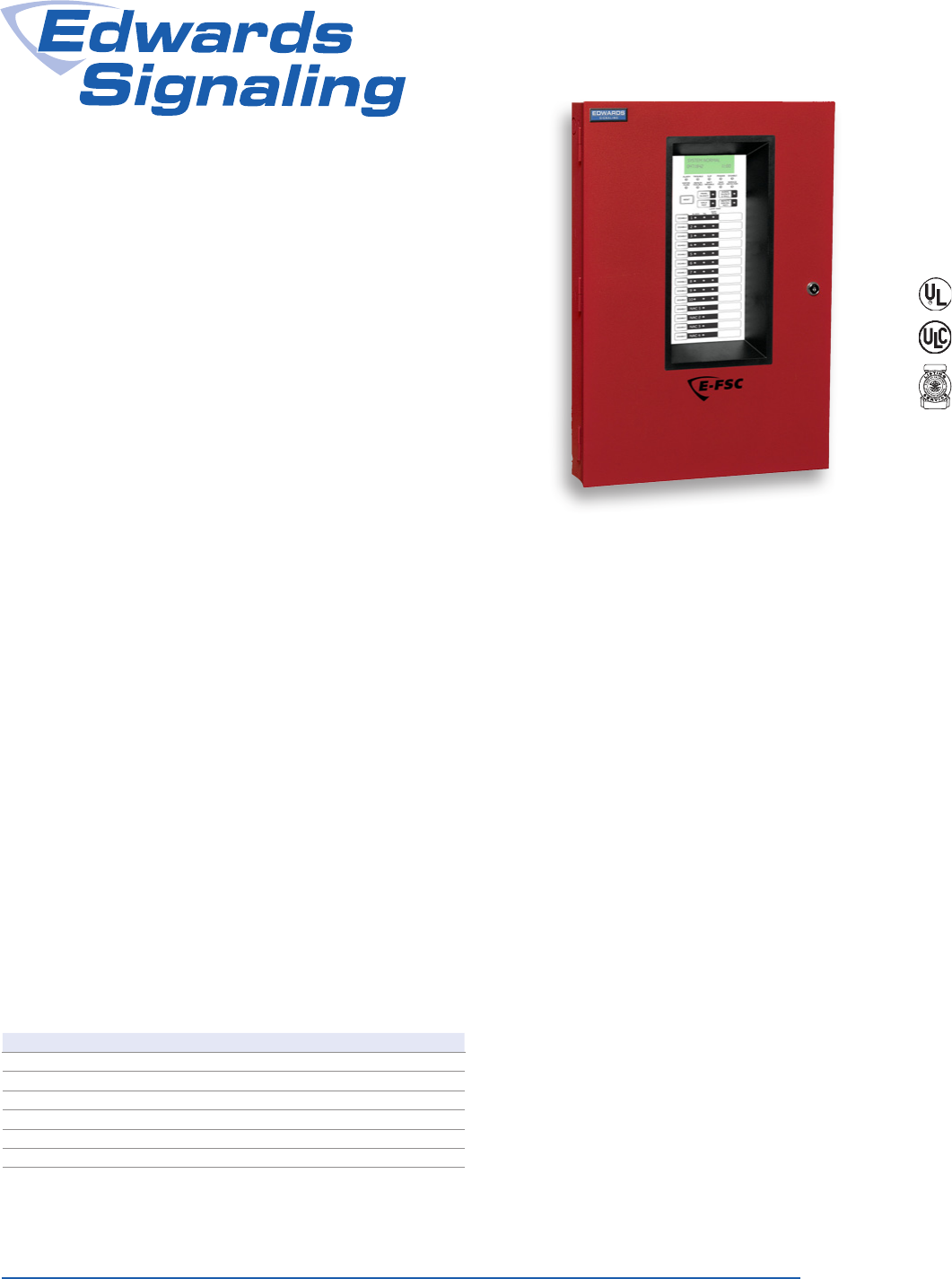
Overview
The E-FSC fire alarm family consists of 3, 5 and 10 zone conven-
tional fire alarm control panels, an integrated DACT/Dialer, serial
annunciator modules, and serial remote relay modules. All of these
components are microprocessor-controlled. The E-FSC family is
ideal for both new and retrofit installations alike.
E-FSC incorporates features designed to simplify installation, opera-
tion and maintenance. These include front panel programming, one
person walk testing, and selectable IDC and NAC types. In addition,
when used with Edwards CleanMe® -compatible smoke detectors,
E-FSC provides analog type features such as remote maintenance
alert and automatic drift compensation that reduces false alarms
and simplifies maintenance calls.
E-FSC502 and E-FSC1004 panels support Class A operation by
combining pairs of on-board initiating curcuits (IDCs) or notifica-
tion circuits (NACs) to provide the necessary Class A circuits. For
example, the E-FSC1004 comes factory set to support 10 Class
B IDCs and four NACs. But it can be field-configured to provide
five Class A IDCs, no Class B IDCs, and two Class A NACs – or
any other combination of circuits that fall within the circuit-pairing
parameters.
E-FSC1004 E-FSC502 E-FSC302
Class B IDCs Up to 10 Up to 5 3
Class A IDCs Up to 5 Up to 2 Not supported
Class B NACs Up to 4 Up to 2 2
Class A NACs Up to 2 1 Not supported
NAC Power 3.5 amps* 3.5 amps 3.5 amps
Auxiliary power 0.5 amps 0.5 amps 0.5amps
Note: Class A operation will reduce the number of available Class B IDCs and/or
NACs, depending on the panel configuration. See Specifications on page 5 for
details.
*Expandable to 7.0 amps
Standard Features
• Available in 3, 5, and 10 IDC models
• IDC or NAC pairs convertible to single Class A circuits (10 and
5 IDC panels only)
• CleanMe® provides remote annunciation if a detector drifts out
of UL/ULC limits reducing the chance of a false alarm
• Combination Waterflow and Supervisory IDCs reduces wire and
zone counts
• NACs programmable by zone and individually selectable for
Genesis, continuous, temporal outputs, or coded
• Front panel programmable simplifies installation and servicing
• Optional fully integrated DACT/Dialer for remote PC
programming
• Genesis option allows precision synchronization and audible
silence over two wires without additional modules
• On-board relays for Alarm, Supervisory and Trouble
• Optional serial bus relay modules are programmable for com-
mon or zone activation
• Optional serial bus remote annunciator family
• One person walk-test (audible or silent)
• Expandable power supply on 10 IDC panel reduces booster
power costs
• Trim ring available for semi-flush mounting
• Supports 2M, “SC", 2400, 500, and 700 series detectors
E-FSC
Conventional Fire Alarm
Control Panels
Page 2 of 8 DATA SHEET S85005-0126
Not to be used for installation purposes. Issue 2
Application
E-FSC provides smoke and fire detection, occupant notification
and off-premises signaling for small- to medium-sized buildings.
Each IDC can be configured for either Class B or Class A opera-
tion and one of eight operating modes:
• Alarm –with or without smoke detector verification including
discrimination of contact devices
• Waterflow Alarm;
• Waterflow Alarm/Supervisory (Combination IDC);
• Supervisory (Latching/non-latching);
• Monitor (non alarm or supervisory)
• Signal Silence
• Drill
• Cross zoning
NACs may also be configured for either Class B or Class A opera-
tion (5 and 10 zone panels). Additionally, NACs can be individually
configured for one of six outputs. These are Genesis, Genesis
(A/V silenceable), Continuous, Temporal, Coded, and City Tie.
The Genesis selection allows independent horn control over two
wires and provides precision synchronization for Genesis devices,
all without the need for a Genesis Signal Master accessory.
When configured for Genesis notification appliances, E-FSC’s
Alarm Silence function will silence connected Genesis audible
appliances but Genesis strobes will remain active until the panel is
reset. When Genesis Mode is selected, both the horns and strobes
on Genesis and Enhanced Integrity notification appliances will be
synchronized across all NACs.
Note: zones may be selected for either latching
or non-latching operation.
Panel LED Display
The following system LEDs display the panel’s status:
• Alarm – panel is in the alarm state;
• Trouble – panel is in the trouble state;
• Supervisory – panel is in the supervisory state;
• Power – indicates the status of the AC power source;
• Disable – indicates when any IDC, NAC, relay or the DACT is
disabled;
• Annunciator Trouble – indicates trouble on the remote an-
nunciator bus;
• Battery Trouble – indicates battery or charging problems;
• Ground Fault – indicates a short between any panel circuit
and ground;
• Walk Test – indicates that one or more IDCs are in the walk
test mode;
• Alarms Silenced – indicates that the panel is in the alarm
state with one or more NACs silenced.
• Waterflow – indicates that one or more circuits have detected
an active waterflow switch.
• Service Detector – indicates the presence of a dirty detector.
• Remote Disconnect – indicates off site communication has
been disabled.
Each IDC has a disable switch and three LEDs:
• Alarm – red – indicates that the IDC is in the alarm state;
• Trouble – yellow – indicates that the IDC is in the trouble state
or is disabled (when flashing);
• Supervisory/Monitor – yellow – indicates that the IDC is in the
supervisory state or the monitor state (when flashing).
Each NAC also has a disable switch and a trouble/disable LED.
Status indication with the DACT/Dialer installed
The dialer’s LCD display provides two lines x 16 characters of
text. For programming, the top line displays the programming
step and the lower line displays the selected option. All system
events are displayed on the LCD with custom zone messages.
During normal operation, the LCD will display any off-normal con-
dition present in the panel.
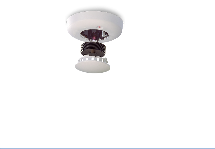
Detectors with intelligent features
at a conventional price
When combined with Edwards
CleanMe® -compatible smoke
detectors, E-FSC provides intel-
ligent features at a conventional
price. If a CleanMe® detector
drifts out of the UL/ULC sensi-
tivity range, Edwards Signaling's
patented remote maintenance
reporting sends an alert to
the E-FSC control panel. This
feature reduces the chance of a
false alarm and simplifies service
calls. In addition, CleanMe® -compatible smoke detectors have
built-in drift compensation that extends the time between clean-
ings. If cleaning is ever necessary, it is literally a snap with Edwards
Signaling's exclusive replaceable optical chamber.
Replaceable
optical
chamber!

Page 3 of 8 DATA SHEET S85005-0126
Not to be used for installation purposes. Issue 2
J4
TB1
L
N
Fuse
N2 L2
N L
Main AC
wiring block
and fuse
holder
Dual transformer
AC wiring block
Tie wrap
mounts
Plug connector
Main
transformer
XTR
(optional
transformer)
Cabinet
Main
controller
board
Mounting
studs
From 120 Vac, 15 A, 60 Hz
Dedicated branch circuit
–OR–
From 230 Vac, 15 A, 50/60 Hz
Dedicated branch circuit
Power
Connections
Options
Off-premise communication
A fully integrated E-FSC DACT/dialer is available for reporting
events to a monitoring facility. The DACT also supports uploading
or downloading of system configuration, status and event history.
The DACT is programmable for either single or dual line opera-
tion. It also supports split and dual reporting for two digital alarm
receivers.
The DACT brings additional features to the panel including a
32-character alphanumeric LCD display, remote PC programming
and an event history log.
Remote Annunciators and Relays
The serial bus standard on all E-FSC models is another installation
time-saver. This circuit allows the connection of Remote System
Indicators (FSRSI), Remote Zone Indicators (FSRZI-A, FSRZI-SA) and
Remote Relay Modules (FSRRM24) over a four-wire (data and power)
circuit. Annunciator and relay modules can be installed up to 1,000
feet from the panel on 18-gauge wire.
Modules are also available for City Tie (CTM) and Reverse Polarity
(RPM) connections.
Remote Relay Module
The Remote Relay Module (FSRRM24)
is one component of the system that
sets E-FSC apart from other panels in
its class. This module has five Form
C relays rated at 1 amp each. It can
be configured to function in either a
zone relay mode or a common system
mode.
When configured in the zone relay
mode, relays energize when the as-
sociated IDC is active. The module can
be configured for activation by IDCs 1
through 5 or IDCs 6 through 10. One
relay is automatically associated with
each IDC.
When configured in the common
system mode, relays energize or de-
energize when the panel
changes state. One relay
is available for each of the
following functions: Alarm,
Supervisory, Trouble, Power
Loss, Monitor.
The FSRRM24 mounts on a
plastic snap track and can
be installed in an MFC-A or
other listed fire alarm enclo-
sure. The panel will support
two RRMs of each configu-
ration for a total of six on the
10-zone panel.
The DACT/Dialer installs be-
hind the front panel display.
The Remote Relay Module
mounts on a plastic track
inside an MFC-A cabinet.
J2
Line 1 Line 2
To wall
phone jack
Phone cables
(supplied)
RJ31 jacks
RJ31 jacks
Snap track
RRM
24V IN
+ - C IN
- + C OUT
- + OUT 3
NO C NC OUT 1
NO C NC
OUT 2
NO C NC
OUT 4
NO C NC
OUT 5
NO C NC
24V OUT
+ - X
Power in +
Power in -
Communication in -
Communication in +
Power out +
Power out -
Communication out -
Communication out +
From control panel
or previous device
{
{
To next device
To next device
{
DACT/Dialer
The optional DACT/Dialer is a multi-
function module that provides commu-
nications, modem capability, and LCD
display functions. Its primary function
is as a Digital Alarm Communica-
tor Transmitter (DACT). As a DACT, it
transmits event messages to a Digital
Alarm Communicator Receiver (DACR)
at a monitoring facility. The monitoring
facility then notifies the fire department
and other responsible parties of the
event. Programmable options include
single or dual line operation, and split
or dual reporting to two DACRs.
The DACT module can also be used
as a modem to connect the panel to
remote computers for uploading and
downloading of configuration data
(programming), panel status and event
history. For security, the modem can be
configured to accept programming on
incoming calls or it can be required to
call a preprogrammed number before
accepting downloads and sending
uploads.
The DACT module can be configured
to work as all of the above, or as only
an LCD display or LCD display and
modem.
Up to 4 RRM24s
can be mounted
in an FSRRM-S11
snap track. Up to
two FSRRM-S11s
can be mounted
in an MFC-A.
Note: All panel versions
are available with factory
installed DACT. See order
table for ordering informa-
tion.
Page 4 of 8 DATA SHEET S85005-0126
Not to be used for installation purposes. Issue 2
-24V +24V C+ C-
TB1
IN
OUT
TB2
J5#1 IN
#2 OUT
J4
ZONE 1-5
J3
ZONE 6-10
J2
ZONE 11-15
Power out +
Power out -
24V IN
- + C IN
+ -
C OUT
+ -
24V OUT
- +
Power in +
Power in -
Communication in -
Communication in +
Communication out +
Communication out -
From control panel
or previous device
{
{
To next device
-24V +24V C+ C- TB1
LINE
IN
LINE
OUT
TB2 J2
GROUP
#1 IN
#2 OUT
Power out +
Power out -
24V IN
- + C IN
+ -
C OUT
+ -
24V OUT
- +
Power in +
Power in -
Communication in -
Communication in +
Communication out +
Communication out -
From control panel
or previous device
{
{
To next device
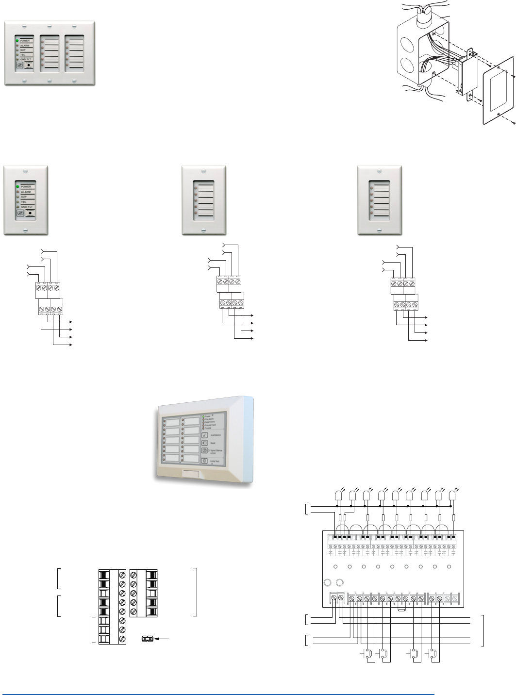
Remote Annunciators
The E-FSC family has several remote annunciation options. The serial
remote annunciator bus can be run up to 1000 feet (305 m) on untwisted
non-shielded 18-gauge cable. Serial annunciator models round out the
family to provide a range of features and functions. As many as three an-
nunciator modules may be mounted in a standard electrical box, sharing
an attractive trim plate that blends with any decor.
Compatible electrical box
FSRZI
or
FSRSI
The FSRSI can be installed alone or with one or more FSRZIs. The
FSRSI and FSRZI-A require trim plates (ordered separately). These
are available in one, two or three gang models. Each panel will sup-
port two FSRSIs.
Remote System Indicator
(FSRSI)
The FSRSI is ideal for com-
mon system annunciation.
It includes five LEDs and
a local silence/lamp test
switch. The LEDs indicate
power status, alarm, super-
visory, trouble and ground
fault. The silence switch will
silence the onboard trouble
buzzer if active. The switch
can also be used to initiate
a lamp test of the LEDs on
all connected FSRSIs and
FSRZIs.
Remote Zone Indicator
(FSRZI-A)
The FSRZI-A is used to
indicate zones in the alarm
state. It contains five red
LEDs. Depending on the
jumper setting selected,
the LEDs will indicate either
IDCs 1 through 5 or IDCs 6
through 10. The panel can
support two modules pro-
grammed for each selection.
FSRA10, FSRA10C
Remote LED annunciators
The FSRA10 is a remote annunciator with
capacity for up to ten zones. It includes ten
bi-color LEDs (red/yellow) for indicating
active zones, and ten yellow LEDs for indi-
cating zone troubles. The (C) option adds
common control switches. Both versions
mount to standard North American 4-inch
square electrical boxes. A surface box is
also available.
FSUIM Graphic Driver/Interface
The FSUIM is a universal interface module that can be used by
E-FSC to drive graphic annunciators. It also allows E-FSC con-
trol panels to control, or be controlled by, other control panels.
The FSUIM provides five supervised switch inputs and nine dry
contact relay outputs. Nine LEDs provide visual confirmation when
each relay is energized. The FSUIM is shipped with a plastic snap
track for mounting in an MFC-A cabinet or other listed fire alarm
enclosure.
+– C+C–Reset
Signal
Silence
Panel
Silence
Lamp
Test
TBLNot used
+ + + + + + + ++
Note:
4.7 k EOLR
C+
C
+
To next
remote module
C+
C
+
From
control panel
or 24VDC power
supply
[5]
[7][7]
4.7 k EOLR
AlarmTrblSupMonitorPowerResetSig SilPanel SilGnd Flt
+
From
control panel
or 24VDC power
supply
From
control panel
+– C+C–Reset
Signal
Silence
Panel
Silence
Lamp
Test
TBLNot used
4.7 kEOLR
Dry contact outputs to secondary control panel
(Used when controlling other control panels)
Dry contact outputs from primary control panel
(Used when controlled by other control panels)
[7][7]
AlarmTrblSupMonitorPowerResetSig SilPanel SilGnd Flt
C+
C
+
To next
remote module
C+
C
+
From
control panel
or 24VDC power
supply
From
control panel
-24V +24V C+ C-
TB1
IN
OUT
TB2
J5#1 IN
#2 OUT
J4
ZONE 1-5
J3
ZONE 6-10
J2
ZONE 11-15
Power out +
Power out -
24V IN
- + C IN
+ -
C OUT
+ -
24V OUT
- +
Power in +
Power in -
Communication in -
Communication in +
Communication out +
Communication out -
From control panel
or previous device
{
{
To next device
Remote Zone Indicator
(FSRZI-SA)
The FSRZI-SA is used
to indicate zones in the
alarm or supervisory state.
It contains five bi-color
LEDs. Depending on the
jumper setting selected,
the LEDs will indicate either
IDCs 1 through 5 or IDCs
6 through 10. The panel
supports two modules
programmed for each se-
lection, and can be jumper
selected to provide Alarm
or Supervisory indications
From
control panel
or 24VDC supply 24V
24V
C
C
24V
24V
C
C
To next
remote module
ON: Group 1
OFF: Group 2
N.U.
N.U.
N.U.
From
control panel
FSRA10, FSRA10C Wiring

Page 5 of 8 DATA SHEET S85005-0126
Not to be used for installation purposes. Issue 2
Remote Annunciators FSRSI Remote System Indicator FSRZI-A/FSRZI-SA Remote Zone Indicator
Maximum per System All panels: 2 10 zone panel: 4 3 or 5 zone panel: 2
Current Requirements Standby: 17 mA Alarm: 56 mA Standby: 8 mA Alarm 76 mA
Voltage Range Minimum: 18.8 Vdc; Maximum: 27.3 Vdc
Maximum Circuit Capacitance 0.03 µF
Maximum Circuit Resistance 13 Ohms
Wire Size 18 - 12 AWG (0.75 mm² - 2.5 mm²)
Mounting ANSI/NEMA OS1-1996 1-3 gang electrical box
Operating Environment Temperature: 32 - 120° F (0 - 49° C); Humidity: 93% RH, non-condensing
Remote Relay Module – FSRRM24 Configured for Zone Mode Configured for Common Mode
Maximum per system 10 zone panel: 4; 3 or 5 zone panel: 2 All panels: 2
Current Requirements Standby: 10 mA; Alarm: 70 mA Standby: 26 mA; Alarm: 70 mA
Voltage Range Minimum: 18.8 Vdc; Maximum: 27.3 Vdc
Contact Rating 1 A @ 30 Vdc
Maximum Circuit Capacitance 0.03 µF
Maximum Circuit Resistance 13 Ohms
Wire Size 18 - 12 AWG (0.75 mm² - 2.5 mm²)
Mounting
Single FSRRM24 mounts in plastic track (included) or up to four FSRRM24s in an FSRRM-S11
11” track ordered separately. FSRRM24s should be installed in an MFC-A or other listed fire alarm
enclosure.
Operating Environment Temperature: 32 - 120° F (0 - 49° C); Humidity: 93% RH, non-condensing
Dimensions 2-3/4” W x 3-3/8” H x 1-1/2” D (65.9 mm W x 85.7 mm H x 38.1 mm D)
Remote Annunciator Specifications
F-Series Remote Annunciators FSRA10 FSRA10C
Common Controls No Yes
Dimensions 5-5/8" x 8½" x 1 ½" in (14.3 cm x 21.4 cm x 3.8 cm)
Mounting North American 4-inch square electrical box or listed enclosure
Power Wiring 18 to 12 AWG (0.75 to 2.50 sq mm)
Data Wiring 18 to 12 AWG (0.75 to 2.50 sq mm) twisted pair (6 twists per foot minimum)
Operating voltage
18.8 to 27.3 Vdc
Supply must be UL/ULC listed for fire protective signaling systems.
Do not use FACP accessory power outputs that are interrupted when the panel is reset.
Standby current 17 mA
Alarm current 98 mA
Operating environment Temperature: 32 to 120 °F (0 to 49 °C); Humidity: 0 to 93% RH, noncondensing at 90 °F (32 °C)
FSUIM Universal Input Module
Mounting MFC-A cabinet or listed fire alarm enclosure
Wire size 12 to 18 AWG (0.75 to 2.5 sq mm)
Operating voltage 21.2 to 27.3 Vdc
Circuit capacitance 0.03 μF, max.
Circuit resistance 13 ohms, max.
Switch inputs Quantity: 5 End-of-line resistor: 4.7 k ohms ½ W
Relay outputs Quantity: 9 Type: Common Style: Form C
Contact rating 30 Vdc at 1 A (resistive load)
Standby Curent 53 mA
Alarm Current 114 mA
Operating environment Temperature: 0 to 49 °C (32 to 120 °F); Humidity: 0 to 93% RH, noncondensing at 32 °C (90 °F)
General
Agency Listings UL864 (53000), ULC-S527, CSFM

Page 6 of 8 DATA SHEET S85005-0126
Not to be used for installation purposes. Issue 2
Control Panel Specifications
DACT – F-DACT (mounts in panel)
Receivers Supports two receivers with two phone numbers each
Communications Protocol Contact ID (SIA DC-05), 4/2 (SIA DC-02 P3)
Programming Front panel controls or PC with appropriate software
Telephone line connection Two RJ31X (plug-to-plug) cords supplied with DACT
Telephone lines Two or one loop start lines on the public switched telephone network. Pulse or DTMF.
Telephone wall connector RJ31X/CA31X equiv. or RJ38X/CA38X equiv.
Communications Compliance Industry Canada CS-03; FCC/CFR 47 Parts 15 & 68; NFPA 72; UL 864; ULC S527
Operating Environment Temperature: 32-120° F (0-49° C); Humidity: 93% RH, non-condensing
Current requirements Standby: 65 mA; Alarm: 107 mA
Agency Listings UL864 (53000), ULC-S527, CSFM
Control Panels E-FSC1004 E-FSC502 E-FSC302
Initiating Device Circuits – IDCs
(Available combinations shown at right)
Class B 10 8 6 4 2 0 5 3 1 Three Class B IDCs
Class A 0 1 2 3 4 5 0 1 2
Notification Appliance Circuits – NACs
(Available combinations shown at right)
Class B 4 2 2 0 2 0 Two Class B NACs
Class A 0 1 1 2 0 1
Power Supply 4.25 amps expandable to 7.5 amps 4.25 amps total 4.25 amps total
NAC Voltage Rating 24 Vfwr
Maximum NAC current 2.0 amps each, 3.5 amps total
7.0 amps w/ optional transformer
2.0 amps each
3.5 amps total
2.0 amps each
3.5 amps total
AC Input, 120 Vac 60 Hz 2.2 amps w/ optional transformer 1.25 amps 1.2 amps
Base Panel Current Draw Standby...
Alarm...
128 mA
242 mA
104 mA
224 mA
96 mA
180 mA
Panel Battery Charge Capacity
(sealed lead acid only)
Up to two 24 Ah batteries,
18 Ah in cabinet
Up to 24 Ah,
10 Ah max in cabinet *
Auxiliary Current 0.5 amps max. May be programmed as resettable.
Auxiliary Output 24 Vdc regulated
IDC Alarm Current 3.0 mA (Consult detector compatibility list p/n 3100468 for maximum detectors per circuit)
IDC Circuit Maximum loop resistance: 13 Ohms; Maximum loop capacitance: 0.03 µF
IDC Operating Voltage 16.9 to 29 Vdc
UL Detector ID 100
Alarm Contact (normally open Form C) 30 Vdc @ 1 A (resistive load)
Trouble Contact (Form C) 30 Vdc @ 1 A (resistive load)
Supervisory Contact (normally open Form C) 30 Vdc @ 1 A (resistive load)
Operating Environment Temperature: 32 - 120° F (0 - 49° C); Humidity: 5 - 93% RH, non-condensing
Terminals (wire gauge) 18 - 12 AWG (0.75 mm² - 2.5 mm²)
Asynchronous Serial Communications Maximum resistance: 13 Ohms; Maximum capacitance: 0.03 µF
Agency Listings UL864 (53000), ULC-S527, CSFM
* If larger batteries are required, use an external battery cabinet.
Dimensions
D1
D2 D3
D4
D5
Surface mounting holes
Semi-flush mounting holes
Model D1* D2 D3 D4 D5*
Three- &
five- zone
19.5 in
(49.5 cm)
3.75 in
(9.5 cm)
9.13 in
(23.2 cm)
10.5 in
(26.67
cm)
14.23 in
(36.14
cm)
Ten-zone 30 in
(76.2 cm)
3.75 in
(9.5 cm)
7.75 in
(19.7 cm)
21.27 in
(54.0 cm)
15.0 in
(38.1 cm)
*Add 1½ inches (3.81 cm) to D1 and D5 dimensions for trim kit.

Page 7 of 8 DATA SHEET S85005-0126
Not to be used for installation purposes. Issue 2
Ordering Information
Part Number Description Ship Wt. lb.
(kg.)
Control Panels
E-FSC1004* Conventional Fire Alarm Control Panel – 10 Class B IDCs and 4 Class B NACs
(Pairs of IDCs and NACs convertible to single Class A circuits), 120 Vac 30.5 (13.8)
E-FSC502* Conventional Fire Alarm Control Panel – 5 Class B IDCs and 2 Class B NACs
(Pairs of IDCs and NACs convertible to single Class A circuits), 120 Vac 18.5 (8.4)
E-FSC302* Conventional Fire Alarm Control Panel – 3 Class B IDCs and 2 Class B NACs, 120 Vac 18.0 (8.2)
F-TRIM35* Semi-flush trim ring for E-FSC302 and E-FSC502 1.7 (0.8)
F-TRIM10* Semi-flush trim ring for E-FSC1004 2.2 (1.0)
* Insert “G” for Gray cabinet or “R” for Red cabinet.
Insert “GD” or “RD” for red and gray cabinets with dialer installed.
Related Items
F-XTR120 Expander Transformer, 120 Vac - For E-FSC1004* only 4.0 (1.8)
EOL3.6-1.1 Required UL listed End of Line Resistors – One 3.6K Ohm and one 1.1K Ohm.
One required for each IDC configured as combination waterflow and supervisory. 0.1 (0.5)
EOL-P1 Required ULC listed End of Line Resistor Plate - includes one 1.1K, 3.6K and 4.7K Ohm resistor 1.0 (0.5)
Off Premises Communications
F-DACT Digital Communicator/Modem/LCD module (Mounts in control panel) 1.0 (0.5)
CTM City Tie Module (Requires 4” square or 2-gang North American electrical box) 1.0 (0.5)
RPM Reverse Polarity Module (Requires MFC-A or other listed fire alarm enclosure) 3.0 (1.4)
Remote Annunciation
FSRSI
Remote System Indicator – Includes LEDs for display of Power, Alarm, Supervisory, Trouble and Ground Fault,
trouble sounder and silence/lamp test switch. Single gang trim plate included, multi-gang plates ordered
separately. Mounts in a single or multi-gang North American electrical box.
0.3 (0.1)
FSRZI-A Remote Zone Indicator – Includes red LEDs for five IDCs. Single gang trim plate included, multi-gang plates
ordered separately. Mounts in single or multi-gang North American electrical box. 0.3 (0.1)
FSRZI-SA
Remote Zone Indicator – Includes LEDs for five IDCs. Single gang trim plate included, multi-gang plates ordered
separately. Mounts in single or multi-gang North American electrical box. Jumper selected Alarm (red) or
Supervisory (amber) indications.
0.3 (0.1)
FSAT1 Annunciator Trim Plate, 1 gang 0.1 (0.05)
FSAT2 Annunciator Trim Plate, 2 gang 0.1 (0.05)
FSAT3 Annunciator Trim Plate, 3 gang 0.1 (0.05)
FSAT4 Annunciator Trim Plate, 4 gang 0.1 (0.05)
FSRA10 Single Unit 10 zone remote annunciator for E-FSC1004
FSRA10C Single Unit 10 zone remote annunciator for E-FSC1004 (with common controls)
FSUIM Common Function Graphic Driver/Interface - 9 relays and 5 switch inputs for common system indicators and controls
Remote Relay Module
FSRRM24 Remote Relay Module – Five Form C relays. Configurable for IDCs 1-5, or 6-10, or common system indications.
Requires MFC-A or other listed fire alarm enclosure. 0.4 (0.2)
FSRRM-S11 11” Mounting track. Holds up to 4 FSRRM24s. 0.4 (0.2)
Accessories
MFC-A Multi-function Cabinet (fire alarm accessory enclosure) 7.0 (3.2)

Page 8 of 8 DATA SHEET S85005-0126
Not to be used for installation purposes. Issue 2
06-27-13
Contact us...
Phone: 1-800-336-4206
Web: www.edwardssignaling.com
Edwards Signaling is
an EDWARDS brand.
3 Farm Glen Boulevard
Farmington, CT 06032
In Canada, contact Chubb Edwards...
Email: inquiries@chubbedwards.com
Web: www.chubbedwards.com
© 2013 UTC Fire & Security Americas
Corporation, Inc. All rights reserved.
Specifications subject to change
without notice. Edwards is part of UTC
Climate, Controls & Security, a unit of
United Technologies Corporation.
