T&B Fittings Catalog 93457
83012-Catalog- 1 83012-Catalog-_1 83012-Catalog-_1 786209 Batch2_1 unilog cesco-content
83012-Catalog 1 83012-Catalog_1 83012-Catalog_1 786209 Batch2_1 unilog cesco-content
2014-05-16
: Pdf 93457-Catalog 93457-Catalog 786209 Batch2_1 unilog
Open the PDF directly: View PDF ![]() .
.
Page Count: 178 [warning: Documents this large are best viewed by clicking the View PDF Link!]
- T&B Conduit Fittings
- Back to Main Contents
- Rigid Metal & Intermediate Metal Conduit Fittings
- T&B Conduit Fittings for Ordinary & Hazardous Locations
- Conduit Outlet Bodies
- Form 7, Form 8, and Red•Dot Conduit Outlet Bodies
- Mogul Conduit Outlet Bodies
- FS/FD Cast Device Boxes and Covers
- XJG-TB Rigid Conduit Expansion Coupling
- Conduit Outlet Boxes Explosionproof, Dust-Ignitionproof
- RE, PLG, REC Reducers, Plugs and Adapters Explosionproof, Dust-Ignitionproof
- Three-Piece Couplings Explosionproof, Dust-Ignitionproof
- Elbows Explosionproof, Dust-Ignitionproof
- Flexible Couplings Explosionproof, Dust-Ignitionproof
- Sealing Fittings Explosionproof, Dust-Ignitionproof
- Sealing Cement and Fiber for Red•Dot ® Sealing Fittings
- Kopr-Shield™ Compound
- Metal Clad Cable Termination Fittings
- Electrical Metallic Tubing (EMT) Fittings T&B Fittings
- Liquidtight Flexible Metal Conduit Fittings
- XTRAFLEX® System – Conduit, Tubing, Fittings for Nonmetallic Liquidtight Conduit
- Flexible Cords and Cable Fittings
- Wiremesh Grips
- Non-Metallic Cable Glands
- Service Entrance Cable Fittings
- Armored Cable and Flexible Metal Conduit Fittings
- Non-Metallic Sheathed Cable Fittings
- Conduit Dimensional Data
Introduction. . . . . . . . . . . . . . . . . . . . . . . . . . . . . . . . . A2
Tables and Specifications . . . . . . . . . . . . . . . . . . . . . . A3
Rigid Metal Conduit/Intermediate
Metal Conduit Fittings . . . . . . . . . . . . . . . . . . . A4-A38
Conduit Outlet Bodies . . . . . . . . . . . . . . . . . . . . A39-A40
Form 7, Form 8, and Red•Dot®
Conduit Outlet Bodies . . . . . . . . . . . . . . . . . . A41-A49
Mogul Conduit Outlet Bodies . . . . . . . . . . . . . . A50-A51
Aluminum Mogul Conduit Outlet Bodies . . . . . . A52-A53
FS/FD Cast Device Boxes and Covers. . . . . . . A54-A56
FS/FD Aluminum Device Boxes and Covers . . A57-A65
Conduit Expansion Coupling. . . . . . . . . . . . . . . A66-A67
Conduit Outlet Boxes
Explosion-Proof,
Dust-Ignition-Proof . . . . . . . . . . . . . . . . . . . . . A68-A69
Aluminum Conduit Outlet Boxes
Explosion-Proof, Dust-Ignition-Proof . . . . . . . A70-A79
Conduit Outlet Bodies
Explosion-Proof,
Dust-Ignition-Proof . . . . . . . . . . . . . . . . . . . . . A80-A81
Conduit Outlet Elbows
Explosion-Proof, Dust-Ignition-Proof . . . . . . . . . . . A82
RE, PLG, REC Reducers,
Plugs and Adapters
Explosion-Proof, Dust-Ignition-Proof . . . . . . . . . . . A83
Three-Piece Couplings
Explosion-Proof, Dust-Ignition-Proof . . . . . . . A84-A85
Aluminum Three-Piece Couplings
Explosion-Proof, Dust-Ignition-Proof . . . . . . . A86-A87
Elbows
Explosion-Proof, Dust-Ignition-Proof . . . . . . . . . . . A88
Flexible Couplings
Explosion-Proof, Dust-Ignition-Proof . . . . . . . . . . . A89
Sealing Fittings
Explosion-Proof,
Dust-Ignition-Proof . . . . . . . . . . . . . . . . . . . . . A90-A92
Aluminum Sealing Fittings
Explosion-Proof, Dust-Ignition-Proof . . . . . . . A93-A96
Kopr Shield™Compound. . . . . . . . . . . . . . . . . . . . . . A97
Metal Clad Cable Termination Fittings . . . . . . A98-A108
Electrical Metallic Tubing (EMT) Fittings . . . . A109-A114
Liquidtight Flexible Metal
Conduit Fittings . . . . . . . . . . . . . . . . . . . . . A115-A131
XTRAFLEX®System – Conduit,
Tubing, Fittings for Nonmetallic
Liquidtight Conduit
Material – PVC. . . . . . . . . . . . . . . . . . . . . . A132-A139
Flexible Cords and Cable Fittings . . . . . . . . . A140-A151
Flexible Cords and Cable Fittings
Non-Metallic . . . . . . . . . . . . . . . . . . . . . . . A152-A153
WireMesh Grips . . . . . . . . . . . . . . . . . . . . . . . . . . . A154
Non-Metallic Cable Glands. . . . . . . . . . . . . . . . . . . A155
Service Entrance Cable Fittings . . . . . . . . . . A156-A160
Armored Cable and Flexible Metal
Fittings Conduit . . . . . . . . . . . . . . . . . . . . . A161-A169
Non-Metallic Sheathed Cable Fittings. . . . . . A170-A175
Conduit Dimensional Data . . . . . . . . . . . . . . A176-A178
A
412031.A01 FIT 3/12 3/20/03 3:02 PM Page 1
A2 © 2002 Thomas & Betts Corporation. Specifications are subject to change without notice. www.tnb.com
Introduction
Thomas & Betts … The Complete Product Line
Since the turn of the century, Thomas & Betts has been a recognized
leader in electrical fittings. Industry standards such as Chase®
Nipples and Erickson®Couplings were introduced by Thomas &
Betts and are still registered trademarks. This leadership con-
tinues. Here’s why.
Innovative Designs
The real test of product design of electrical fittings lies in
two areas: Job-suited installation and life of the job reli-
ability. Thomas & Betts Fittings provide both because
we listen. We listen to problems and suggestions
from the field. Most of the products in this section
result from the good suggestions of knowledgeable
electrical people. Many were customer specials to
solve particular installation and performance prob-
lems. You can benefit from their experience.
Approvals and Listings
Electrical raceways require accessory fittings that
provide the mechanical strength, ground continu-
ity, and environmental integrity of the system. As
new raceways have been introduced, Thomas &
Betts engineers have designed fittings which
meet the requirements of the National Electrical
Code as well as the listing requirements of the
Underwriters’ Laboratories and the Canadian
Standards Association. You can use Thomas &
Betts Fittings with confidence.
High Performance Products
Quality and performance result when engineering
design skills are combined with the manufacturing
technologies required to produce them. The Thomas
& Betts Fittings in this section are produced from many
materials and by many manufacturing methods, each
carefully selected for its end use suitability. This combina-
tion gives you the reliable performance you expect from
Thomas & Betts Raceway Fittings.
Lower Installed Cost
It is a function of purchase cost, availability, installation advantage, and
performance. Lower installed cost comes in every carton of Thomas &
Betts Raceway Fittings.
A
T&B ®Fittings
T&B®Fittings
A
412031.A01 FIT 3/12 3/13/03 4:45 PM Page 2
Tables and Specifications – Rigid Metal Conduit/Intermediate Metal Conduit Fittings
DURA-PLATE™ Finish – Corrosion Resistant Finish Protects
Fittings in Harsh Environments
DURA-PLATE™Corrosion Resistant
Fittings have a T&B plating process
that provides excellent corrosion resis-
tance on threaded steel and malleable
iron fittings for use in harsh environ-
ments.
DURA-PLATE™Corrosion Resistant
Fittings utilize an electro-plating
process which insures a uniform thick-
ness of protective material over the
entire part. Conventional hot dip coat-
ings deposit an uncontrolled build-up
of material on the part, especially in
threaded areas. This excess build-up
must be removed to allow mating parts
to function.
The process of removing this build-up
in the threads in turn damages the
coating and compromises the effec-
tiveness of the protection.
An additional drawback of hot dip
coating is the lower ductility of the
alloyed interface layer which is formed
during the hot dip process which can
cause spalling if the item is deformed
after coating.
In addition to the uniformity of the coat-
ing, the distinctive gold color of the
plating allows immediate recognition
that the part has been prepared for
exposure to harsh environments and
confirms the extra protection by visual
inspection.
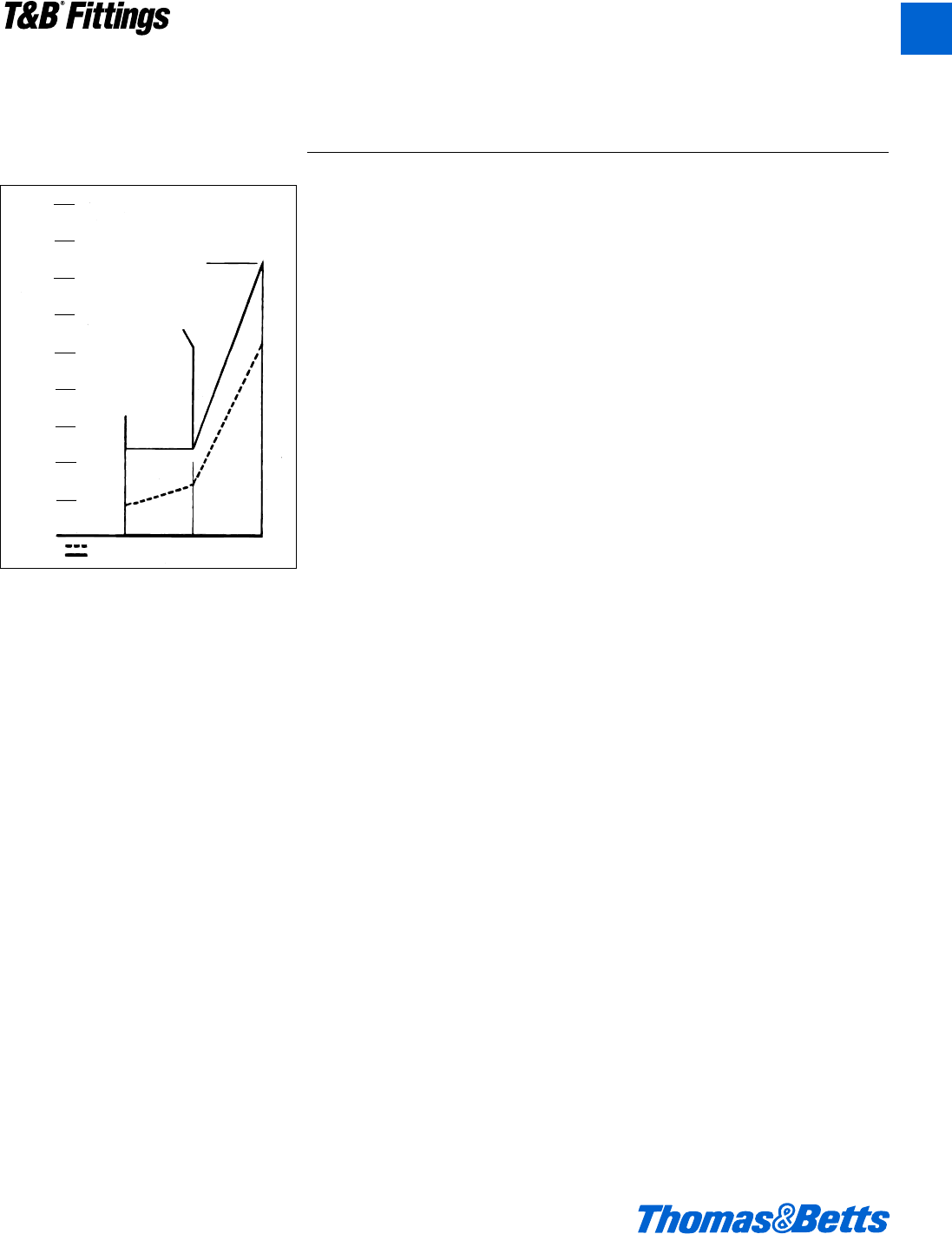
DURA-PLATE™Corrosion Resistant
Fittings have been subjected to salt
spray tests conducted according to
ASTM Specification B-117. The results
of Corrosion Resistant Fittings tests,
along with galvanized parts, appears
below:
Ordering Information
• Add the prefix “040-” to the standard
catalog number; for example a 5332
with DURA-PLATE™Corrosion
Resistant Fittings protection would be
ordered as “040-5332”.
• Check for catalog numbers in stock.
• Allow 6-8 weeks for delivery, on non-
stock items.
• Add 20% to price of standard item.
• Minimum order is standard package
quantity.
HOURS OF SALT SPRAY
DURA–PLATE™
Corrosion Resistant Fittings
Mechanical
Galvanize
Standard
Zinc Plating
Indicates hours to white corrosion
Indicates hours to first apperance of red rust
500
450
400
350
300
250
150
100
50
0
411
293
130 130
75
48
Comparative Resistance to Salt Spray per ASTM B-117
© 2002 Thomas & Betts Corporation. Specifications are subject to change without notice. www.tnb.com A3
T&B®Fittings
A
412031.A01 FIT 3/12 3/13/03 4:45 PM Page 3
A4 © 2002 Thomas & Betts Corporation. Specifications are subject to change without notice. www.tnb.com
T&B®Fittings
A
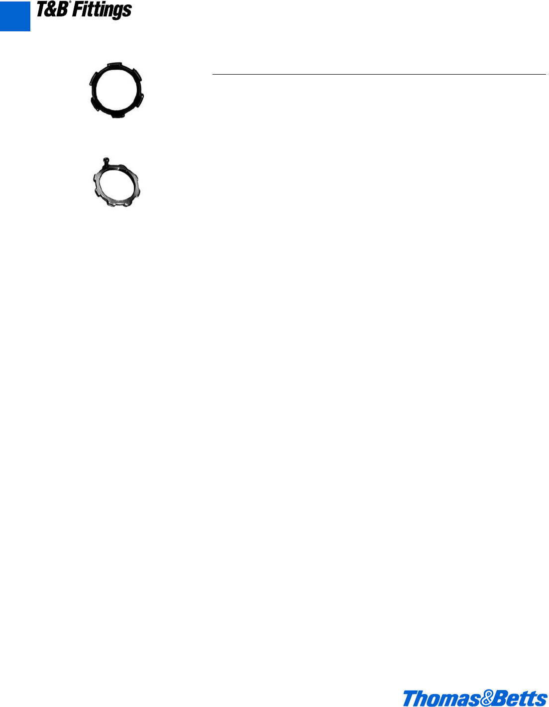
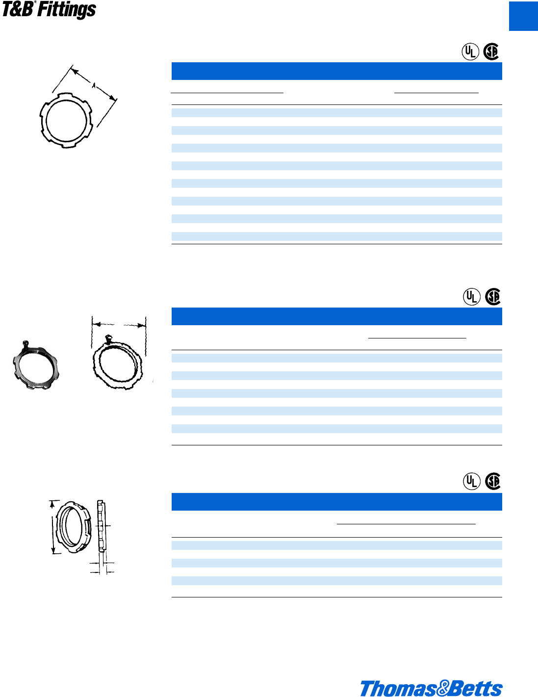
Rigid and Intermediate Metal Conduit Fittings
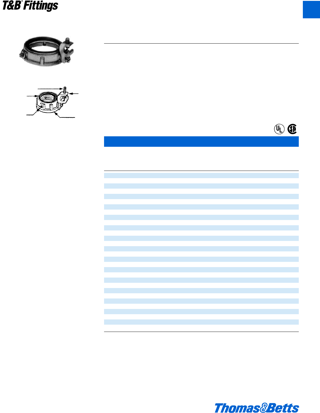
106 Series
Locknuts
140 Series
141AL Series
Application
• To connect externally threaded con-
duit or connector to a threadless
opening in a box or enclosure.
• To effectively bond conduit or con-
nector to box or enclosure.
Features
• Hardened Steel/Malleable
Iron/Copper free Aluminum
construction.
• Tightens without deformation.
• Locknuts specially designed to:
(i) Provide extended reach for
clamping on thin boxes and
enclosures.
(ii) Cut through protective coating on
box and enclosure thereby insur-
ing ground continuity.
(iii) Permit tightening from outside.
(iv) Prevent loosening under vibration
• 106 Series provided with a hardened
cone point screw.
Standard Material
140 Series & 106 Series
c" thru 2" steel (hardened)
2d" thru 6" Malleable Iron
All screws steel
141AL Series
All copper-free aluminum
Standard Finish
All Steel and Malleable Iron locknuts
including
Electro Zinc Plated bonding screws
& Chromate Coated
All Aluminum locknuts . . . . degreased
Range
3⁄8" through 6" conduit (All threads
straight pipe [NPS]) (140 Series)
1⁄2" through 4" conduit (106 Series &
141AL Series)
Listed/Certified by:
U.L. (U.L. File No. E-23018)
CSA [catalog numbers 108, 109 & 111.
All 140 Series except catalog number
140.] (LR-2884, LR-4484)
Conforms to:
U.L. 514B
CSA C22.2 No. 18
NEMA FB1
NFPA 70-1999 (ANSI)
Federal Specification replaced by
A-A-50553
Federal Standard H-28 (Threads)
“Case Hardened Locknuts”
Case hardened locknuts make fit-
tings faster and easier to install. Case
hardened locknuts do not slip or turn
thereby protecting the biting edge.
Case hardened locknuts bite through
paint into the enclosure providing
excellent continuity of ground (typical
T&B/Thomas & Betts fitting with case
hardened locknuts successfully passed
minimum fault current of 10,000 amps
RMS). Case hardened locknuts when
assembled in the intended manner will
not vibrate loose thereby insuring excel-
lent ground continuity.
412031.A01 FIT 3/12 3/13/03 4:45 PM Page 4
© 2002 Thomas & Betts Corporation. Specifications are subject to change without notice. www.tnb.com A5
T&B®Fittings
A
Rigid and Intermediate Metal Conduit Fittings
Locknuts
Cat. No. Dimensions (in.)
Stl. or M.I. Alum. Size A B
139* – b" f !
140* – c" n !
141** 141AL d" 1ƒ q
142** 142AL f" 1c i
143 143AL 1" 1L $
144 144AL 1b" 2q $
145 145AL 1d" 2d $
146 146AL 2" 3 r
147 147AL 2d" 3l u
148 148AL 3" 4i u
149 149AL 3d" 4m v
150 150AL 4" 5j v
151 151AL 4d" 5n w
152 152AL 5" 6d w
153 153AL 6" 7f x
* Hex shape
** Case hardened locknuts
Aluminum locknuts comply with federal standard of copper free aluminum; less than .5% copper.
Available with DURA-PLATE®Finish.
U.L. File E-23018
CSA File No. 2884
Bonding Locknuts
Cat. Dimensions (in.)
No. Size AB
106† d" 1c .125
107† f" 1e .140
108 1" 1n .170
109 1b" 2q .170
110 1d" 2d .170
111 2" 3 .187
112† 2d" 3u .375
113† 3" 4m .375
114† 3d" 4C .438
115† 4" 5r .438
† Not CSA certified.
Available with DURA-PLATE®Finish.
U.L. File No. E-3060
CSA File No. 638
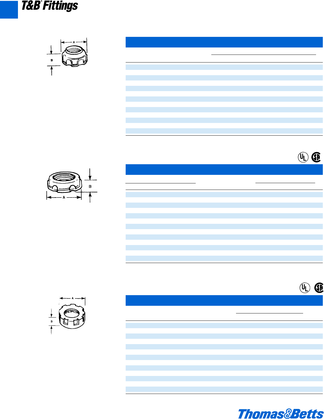
Sealing Locknuts
Cat. Dimensions (in.)
No. Size ABC
141SL d1.140 ab
142SL f1.420 qs
143SL 11.770 ™s
144SL 1b 2.281 ™j
145SL 1d 2.598 ™s
146SL 23.175 i∫
U.L. File No. E-23018
CSA File No. 2884
(B) Thickness
Steel or malleable iron (steel thru 2") or
Aluminum 624.
®
®
A
(B) Thickness
Steel or malleable iron (steel thru 2").
Use anywhere an ordinary locknut is installed
to insure positive bonding of conduit to box and
prevent loosening due to vibration. Also can be
used for Service Entrance applications in con-
formance with Code. T&B rigid conduit and
E.M.T. (thinwall) fittings comply with Federal
Specification WF 408c.
Molded Santoprene Seal
Color: Blue
Provides positive seal against water and oil.
For use with rigid and intermediate metal
conduits, or fittings to provide watertight or
rain tight seal at all enclosures.
B
C
A
®
®
®
®
412031.A01 FIT 3/12 3/13/03 4:45 PM Page 5
A6 © 2002 Thomas & Betts Corporation. Specifications are subject to change without notice. www.tnb.com
T&B®Fittings
A
Rigid and Intermediate Metal Conduit Fittings
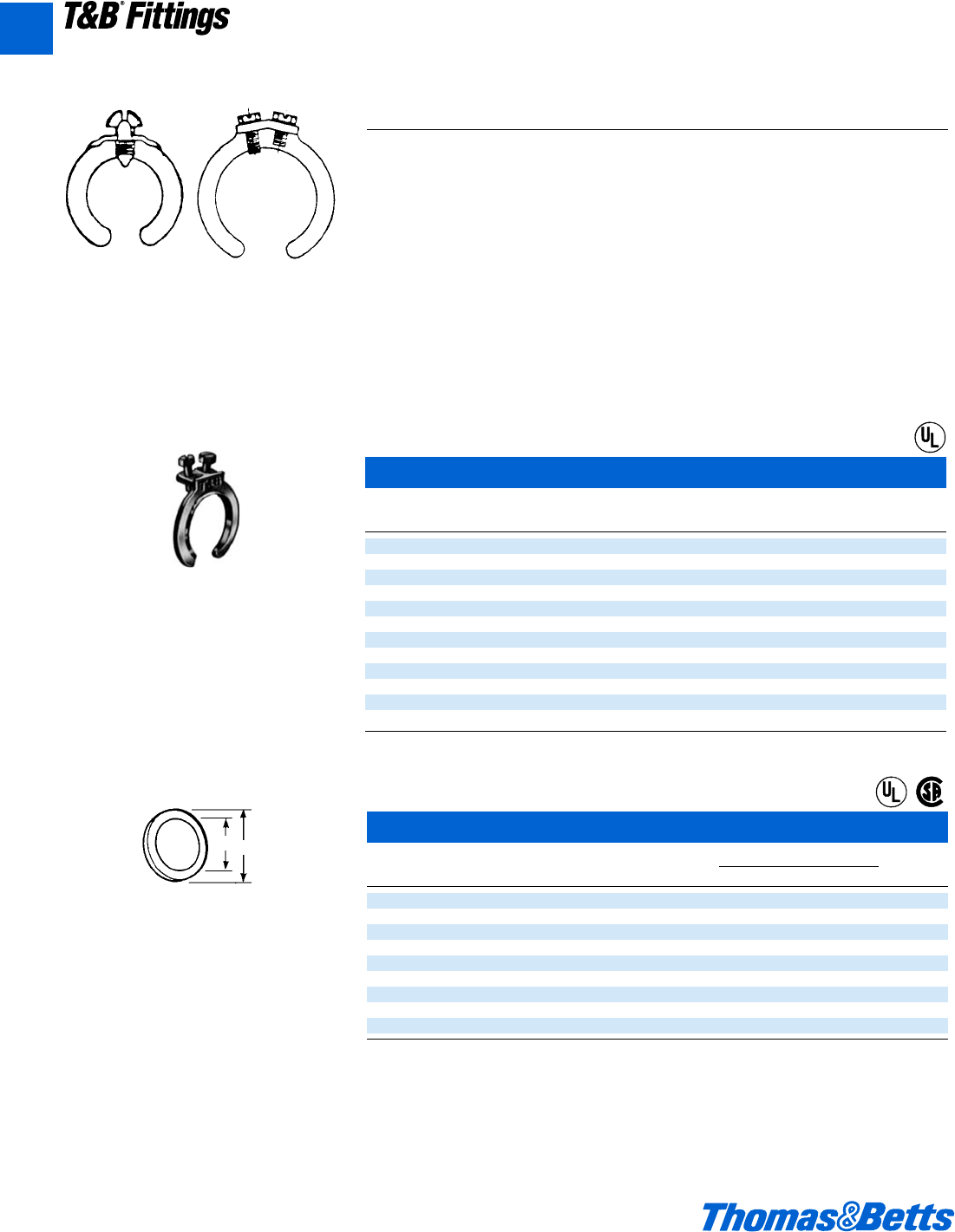
Bonding & Grounding Wedges
Sealing Ring – Santoprene
Thermoplastic Rubber
These sealing rings provide a liquid tight, dust
tight, seal of fitting at enclosures.
Sealing Rings with Stainless Steel Retainer
Cat. Conduit Dimensions (in.)
No. Size AB ±
1
/64
5302 d" 1™ f
5303 f" 1d n
5304 1" 1f 1™
5305 1b" 2! 1d
5306 1d" 2& 1f
5307 2" 2∂ 2%
5308 2d" 3k 2H
5309 3" 4Z 3∫
5311 4" 5s 4∫
NEMA 3R, 4, 6 & 13
U.L. File No. E-13938
CSA File No. 2884
A
B
Application
To effectively bond terminating fitting
or conduit to a box or enclosure.
Features
• Sizes f" thru 6" equipped with an
additional bonding screw to install
bonding jumper where required.
• Can be added to an existing installa-
tion without disconnecting conductors.
Standard Material/Finish
d"size Steel/Electro Zinc Plated
f"thru 6" size Bronze/Tin Plated
Range
d" thru 6" conduit
Listed/Certified by:
U.L File #E3060
CSA File #638
Conforms to:
U.L. 467
CSA C22.2 No. 41
NFPA-70 1999 (ANSI)
Federal Specification W-F-406
Especially suited for grounding old work, but
equally convenient for new, grounding wedges
provide grounding without a jumper except in
concentric knockouts. When a jumper is
required, it fits under a set screw in the
grounding wedge.
Update existing installations to meet code
requirements for bonding (NEC Sect. 250-72e)
without disconnecting wiring. Use on new
wiring also.
1. Loosen bushing … position wedge.
2. Tighten bushing and bonding screw.
Series 3650 Series 3651
Grounding Wedges
Cat.
No. Size
3650 d"
3651 f"
3652 1"
3653 1b"
3654 1d"
3655 2"
3656 2d"
3657 3"
3658 3d"
3659 4"
3661 5"
3662 6"
U.L. File No. E-3060
®
®
®
412031.A01 FIT 3/12 3/13/03 4:45 PM Page 6
© 2002 Thomas & Betts Corporation. Specifications are subject to change without notice. www.tnb.com A7
T&B®Fittings
A
Rigid and Intermediate Metal Conduit Fittings
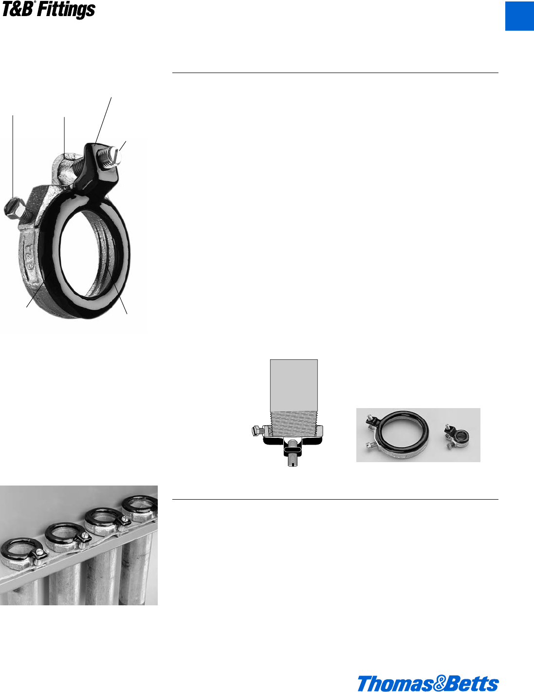
Blackjack®– Grounding Bushing
Innovative design makes installation
quicker, easier.
The Blackjack®Grounding Bushing
never has to be threaded onto a
conduit. It is simply placed in position
on either a threaded or non-threaded
rigid or IMC conduit, with the ground-
ing lug in perfect position to accept the
grounding wire. Even in tight installa-
tions.
It’s as simple as one, two, three.
Compare the installation with conven-
tional bushings that must be threaded
onto the conduit. In tight areas, you
may have to remove the grounding lug,
keep up with the loose parts, and then
reattach the lug. Then you still have to
twist and turn the bushing to get the
lug in position to accept the grounding
wire.
The Blackjack bushing does away with
these needless delays for good, mak-
ing it the ideal grounding bushing. And
the only logical choice for small
spaces, corners, and multiple conduit
runs. And, because the grounding lug
is an integral part of the bushing, it is
designed not to fall off or get lost.
Lug Screw:
14-4: Slotted
14-2/0: Slotted
6-4/0: Internal Hex Drive
Standard Material/Finish
Body: Malleable Iron or Aluminum
Mounting Screw: (1
/2"-2") Stainless Steel,
(21
/2"-6") Brass
Lug Screw: Stainless Steel
Finish: Zinc Plated or Mechanical Galvanized
Range
Conduit: d" thru 6" threaded or thread-
less rigid/IMC
Wire Range: #14 AWG to 4/0 AWG
CU/AL
Listed/Certified by:
U.L File #E3060
CSA File #LR2884
Conforms to:
U.L. 514B & U.L. 467
CSA C22.2 No. 18 &
CSA C22.2 No. 41
Mounting
screw with
nylon locking
patch has a
cone point to
lock bushing
securely in
place.
Insulator surface
features a rounded
design to reduce
drag and prevent
abrasion during
wire pulling.
Cast “threads”
opposite the
mounting screw
tighten the fit dur-
ing installation.
Angle of lug
screw improves
accessibility
when securing
grounding wire.
Integral grounding
lug enhances
ground continuity.
Added ground
wire range taking
reduces inventory.
Accepts copper or
aluminum ground
wires.
Insulating nylon
surface is 150°C
rated and covers top
of bushing, including
lug corners.
Innovative design improves
performance.
The Blackjack®bushing provides
superior ground continuity.
The design of the Blackjack bushing
has an integral, cast-on grounding lug
for better ground continuity. This
means that the Blackjack bushing
stands up to
intense loads.
Secure grip
forms lasting
bond.
The Blackjack
bushing’s cone-
point mounting
screw bites
securely into both
threaded and non-threaded rigid con-
duits. And the Blackjack bushing’s
nylon locking patch is designed to pre-
vent the screw from loosening due to
vibration.
Reduce inventory.
Because the Blackjack Grounding
Bushing is designed for threaded and
non-threaded conduits, and the
ground lugs are designed to handle an
extended range, the number of parts in
inventory is reduced by up to two-
thirds without losing any application
coverage.
Blackjack®– Conduit Grounding Bushing
412031.A01 FIT 3/12 3/13/03 4:45 PM Page 7
A8 © 2002 Thomas & Betts Corporation. Specifications are subject to change without notice. www.tnb.com
T&B®Fittings
A
Rigid and Intermediate Metal Conduit Fittings
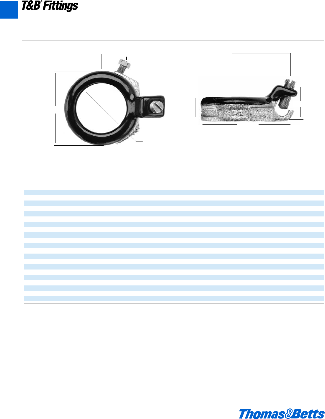
Blackjack™Grounding Bushing technical information
D
C
Lug Screw
14-4: Slotted
14-2/0: Slotted
6-4/0: Internal hex drive
For Threaded & Threadless Rigid & IMC Conduit.
Nylon Insulator (150oC) Mounting Screw
E
ØA
ØB
Throat I.D.
Zinc ØB
Plated Conduit ØA Min. C D E Wire
Malleable Iron Aluminum Size Max. Throat I.D. Max. Max. Max. Range
BG050-14-20 BGA050-14-20 d" 1.251 .569 1.181 2.134 .696 14-2/0
BG050-14-4 BGA050-14-4 d" 1.251 .569 1.027 1.940 .696 14-4
BG075-14-20 BGA075-14-20 f" 1.533 .772 1.221 2.414 .696 14-2/0
BG075-14-4 BGA075-14-4 f" 1.533 .772 1.030 2.168 .696 14-4
BG100-14-20 BGA100-14-20 1" 1.783 .993 1.181 2.581 .696 14-2/0
BG100-14-4 BGA100-14-4 1" 1.783 .993 1.027 2.368 .696 14-4
BG125-14-20 BGA125-14-20 1b" 2.220 1.319 1.181 2.987 .759 14-2/0
BG150-14-20 BGA150-14-20 1d" 2.470 1.553 1.181 3.236 .696 14-2/0
BG200-14-20 BGA200-14-20 2" 2.830 2.010 1.181 3.766 .696 14-2/0
BG250-14-20 BGA250-14-20 2d" 3.418 2.412 1.181 4.341 .978 14-2/0
BG250-6-40 BGA250-6-40 2d" 3.418 2.412 1.524 4.526 .978 6-4/0
BG300-14-20 BGA300-14-20 3" 4.042 3.022 1.181 4.966 .978 14-2/0
BG300-6-40 BGA300-6-40 3" 4.042 3.022 1.524 5.139 .978 6-4/0
BG350-14-20 BGA350-14-20 3d" 4.542 3.491 1.181 5.467 .978 14-2/0
BG350-6-40 BGA350-6-40 3d" 4.542 3.491 1.524 5.639 .978 6-4/0
BG400-14-20 BGA400-14-20 4" 5.042 3.975 1.181 5.966 .978 14-2/0
BG400-6-40 BGA400-6-40 4" 5.042 3.975 1.524 6.139 .978 6-4/0
BG500-14-20 BGA500-14-20 5" 6.136 4.991 1.181 7.045 .978 14-2/0
BG500-6-40 BGA500-6-40 5" 6.136 4.991 1.524 7.207 .978 6-4/0
BG600-14-20 BGA600-14-20 6" 7.199 6.009 1.181 8.087 .978 14-2/0
BG600-6-40 BGAT600-6-40 6" 7.199 6.009 1.524 8.409 .978 6-4/0
Suggested Specifications
Insulated grounding and bonding bushing
(Series BG050-BG600)
Where code requires bonding and grounding of single or multiple metal conduits, or positive bonding and grounding of metal conduit to the box, enclosure or auxiliary gutter, the end of the conduit shall be
equipped with an insulated metallic grounding and bonding bushing series BG050-14-20 as manufactured by Thomas & Betts.
Grounding and bonding bushings used shall be approved for the purpose and
(i) Shall be of malleable iron/steel/aluminum construction adequately protected against corrosion.
(ii) Bushing insulator shall be listed or certified for 150°C/302°F application with a flammability rating of 94V-O. Insulator must be positively locked in place.
Please consult factory for mechanically galvanized.
▼
▼
▼
▼
▼
▼
▼
▼
▼
▼
412031.A01 FIT 3/12 3/13/03 4:45 PM Page 8
© 2002 Thomas & Betts Corporation. Specifications are subject to change without notice. www.tnb.com A9
T&B®Fittings
A
Threaded Insulated Grounding Bushing
Threaded Insulated Grounding Bushing
Wire
Range
Cat. Conduit Bushing Throat Lug Swing Bushing AWG
No. Size Dia. Dia. Length Radius Height CU/AL
3870-TB d1.125 .560 1.310 1.212 .657 14-4
3861 d1.125 .560 1.675 1.402 .657 8-2/0
3871-TB f1.420 .742 1.310 1.360 .660 14-4
3862 f1.420 .742 1.675 1.550 .660 8-2/0
3872 11.770 .944 1.310 1.535 .735 14-4
3882 11.770 .944 1.675 1.725 .735 8-2/0
3873 1b 2.190 1.242 1.310 1.745 .735 14-4
3883 1b 2.190 1.242 1.675 1.935 .735 8-2/0
3874 1d 2.468 1.449 1.310 1.884 .770 14-4
3884 1d 2.468 1.449 1.675 2.074 .770 8-2/0
3875 23.031 1.860 1.310 2.165 .770 14-4
3889 23.031 1.860 1.675 2.355 .770 8-2/0
3876 2d 3.516 2.222 1.310 2.408 .940 14-4
3886 2d 3.516 2.222 1.675 2.598 .940 8-2/0
3993 2d 3.516 2.222 2.230 2.928 .940 6-4/0
3877 34.234 2.761 1.310 2.767 .975 14-4
3887 34.234 2.761 1.675 2.957 .975 8-2/0
3994 34.234 2.761 2.230 3.287 .975 6-4/0
3878 3d 4.781 3.193 1.310 3.040 .975 14-4
3863 3d 4.781 3.193 1.675 3.230 .975 8-2/0
3995 3d 4.781 3.193 2.230 3.560 .975 6-4/0
3879 45.328 3.623 1.310 3.314 .980 14-4
3864 45.328 3.623 1.675 3.504 .980 8-2/0
3996 45.328 3.623 2.230 3.834 .980 6-4/0
3880 56.328 4.542 1.310 3.814 .985 14-4
3865 56.328 4.542 1.675 4.000 .985 8-2/0
3998 56.328 4.542 2.230 4.334 .985 6-4/0
3881 67.406 5.458 1.310 4.353 1.200 14-4
3866 67.406 5.458 1.675 4.543 1.200 8-2/0
3999 67.406 5.458 2.230 4.875 1.200 6-4/0
Temperature rating 150°C.
Meets Coast Guard Regulation CG293
Available with DURA-PLATE®Finish.
For mechanically galvanized iron, add suffix-MG.
Rigid and Intermediate Metal Conduit Fittings
Application
• For quick installation of bonding
jumper to multiple metal conduits
(Rigid and IMC).
• Designed to bush conductors and
prevent insulation damage.
Features
• Ease of installation, lay in lug design.
• Cast malleable iron body designed to
lock insulator in place within body
reducing common assembly problem
resulting in dislodging of insulator.
• Insulator rated for 150°C/302°F
application.
Standard Material/Finish:
Body Electro zinc plated
Lay in lug Aluminum/tin plated
Insulator Thermoplastic
150°C/302°F
Application with 94V-0
flammability
Wire
Clamping Screw
Insulator
Set Screw
(one)
3870 Series
Lay-In
Lug
Bushing
Casting
®
®
412031.A01 FIT 3/12 3/13/03 4:45 PM Page 9
A10 © 2002 Thomas & Betts Corporation. Specifications are subject to change without notice. www.tnb.com
T&B®Fittings
A
Rigid and Intermediate Metal Conduit Fittings
Insulated Throat Fittings
Cat. Dimensions (in.)
No. Alum. Size A B
1222 1222AL d" 1o S
1223 1223AL f" 1s M
1224 1224AL 1" 1x X
1225 1225AL 1b" 1n y
1226 1226AL 1d" 2i z
1227 1227AL 2" 2L g
1228 1228AL 2d" 3i O
1229 1229AL 3" 3B n
1230 1230AL 3d" 4k 1h
1231 1231AL 4" 4g 1p
1232† 1232AL† 4d" – –
586 586AL 5" 5O 1s
587 587AL 6" 7i 1X
† Not CSA Certified
Catalog series 1222 thru 1232, 586 and 587 are available in aluminum. Add suffix AL to Cat. No.
The aluminum series are not CSA certified.
Metallic Bushings
Cat. No. Dimension (in.)
Stl. or M.I. Alum. Size AB
122 122AL d" 1o u
123 123AL* f" 1b k
124 124AL** 1" 1l d
125-TB 125AL 1b" 1C l
126 126AL 1d" 2q x
127 127AL 2" 2y e
128 128AL 2d" 3i f
129 129AL 3" 3B m
130-TB 130AL 3d" 4c n
131-TB 131AL 4" 4n 1
132-TB – 4d" 5k 1Z
133-TB 133AL 5" 6 1i
134-TB 134AL 6" 7b 1b
* Not U.L. Listed or CSA Certified
** Not CSA Certified
Available with DURA-PLATE®Finish.
U.L. File No. E-23018
CSA File No. 2884
Nylon insulated
metallic bushings
Steel or malleable iron (Steel thru 11⁄2")
The National Electric Code paragraph 373-6C
calls for protection of ungrounded conductors
by means of smoothly rounded insulating sur-
faces at the entrance to raceways, pull boxes,
junction boxes, etc. T&B insulated throat fit-
tings, recognizable by the distinctive trade-
marked blue insulating liner in the throat,
meet and surpass this Code requirement. In
addition, T&B insulated fittings also reduce
wire pulling effort by as much as 50%.
Temperature rating 105°C.
Aluminum, steel or malleable iron (steel
thru 11⁄2").
Smoothly rounded shoulder covers end of con-
duit: broad flange covers knockout hole. High
ribs make tightening easy with fingers or with
wrench. 1⁄2" - 11⁄2" size, formed in steel, have
extra smooth shoulders. Locknut-type base
gives improved bonding and resists loosening
under conditions of vibration.
®
®
Plastic Insulating Bushings
Cat. Dimensions (in.)
No. Size A B
222-TB d" 1h c
223-TB f" 1s u
224 1" 1l l
225-TB 1b" 1C l
226 1d" 2r l
227 2" 2A e
228-TB 2d" 3c f
229-TB 3" 4h f
230-TB 3d" 4e g
231 4" 5a g
232 4d" 5L 1
233 5" 6j 1
234 6" 7k 1
Flame retardant. U.L. Rated 94V-1.
All Plastic
Insulating
Bushings
Impact resistant plastic insulation. These
bushings have ribs for gripping when
installing. Perfect threads for easy thread
on. U.L. Listed 105°C.
®
®
412031.A01 FIT 3/12 3/13/03 4:45 PM Page 10
© 2002 Thomas & Betts Corporation. Specifications are subject to change without notice. www.tnb.com A11
T&B®Fittings
A
Rigid and Intermediate Metal Conduit Fittings
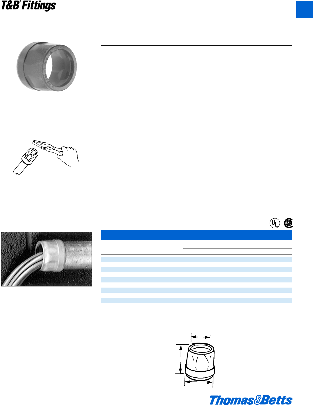
TRIB50 Series
1. Cut conduit end squarely. Remove sharp
edges and burrs on inside and outside diam-
eters by reaming or filing.
2. Slip the pop-on bushing over the end of the
conduit.
3. Using the flat surface of any standard utility
tool such as an electricians pliers (or a ham-
mer with a block of wood for the larger
sizes), strike the bushing on its top surface
using a series of light blows until the end of
the conduit rests against the bushing throat
& conduit stop.
Insulating Bushing
(For Threadless Rigid Conduit and Intermediate Metal Conduit)
Insulated Metallic Bushing
Cat. Dimensions (in.)
No. Size ABC
TRIB-50 d" x 1s 1h
TRIB-75 f" A 1ç 1b
TRIB-100 1" 1 1d 1l
TRIB-125 1b 1j 1e 1∂
TRIB-150 1d" 1w 1y 2™
TRIB-200 2" 1O 1m 2L
TRIB-250 2d" 2R 2 3b
TRIB-300 3" 2∂ 2r 3C
TRIB-350 3d" 3c 2j 4S
TRIB-400 4" 3B 2u 5
I.M.C. sizes d" thru 4"
U.L. Rated flame retardant 94V-1.
U.L. File No. E-13938
CSA File No. 2884
Application
• When assembled to the end of a
threadless conduit, provides a well
rounded insulating surface over
which conductors may be pulled or
on which conductors may bear while
in service.
Features
• Designed to be popped onto, and
bush, conduit end.
• Fast, easy installation without screws.
• High impact thermoplastic
construction.
Standard Material
High impact thermoplastic listed for
105°C (221°F) application.
Flammability Classification 94 V-1.
Standard Finish
As molded.
Range
d" through 4" conduit
Listed by:
U.L. (U.L. File No. E-13938)
CSA (LR-2884, LR-4484)
Conforms to:
U.L. 514B
NFPA 70-1999 (ANSI)
Pop-on Bushing
Threadless Rigid (and IMC) Insulating
Bushings.
C
B
A
®
®
412031.A01 FIT 3/12 3/13/03 4:45 PM Page 11
A12 © 2002 Thomas & Betts Corporation. Specifications are subject to change without notice. www.tnb.com
T&B®Fittings
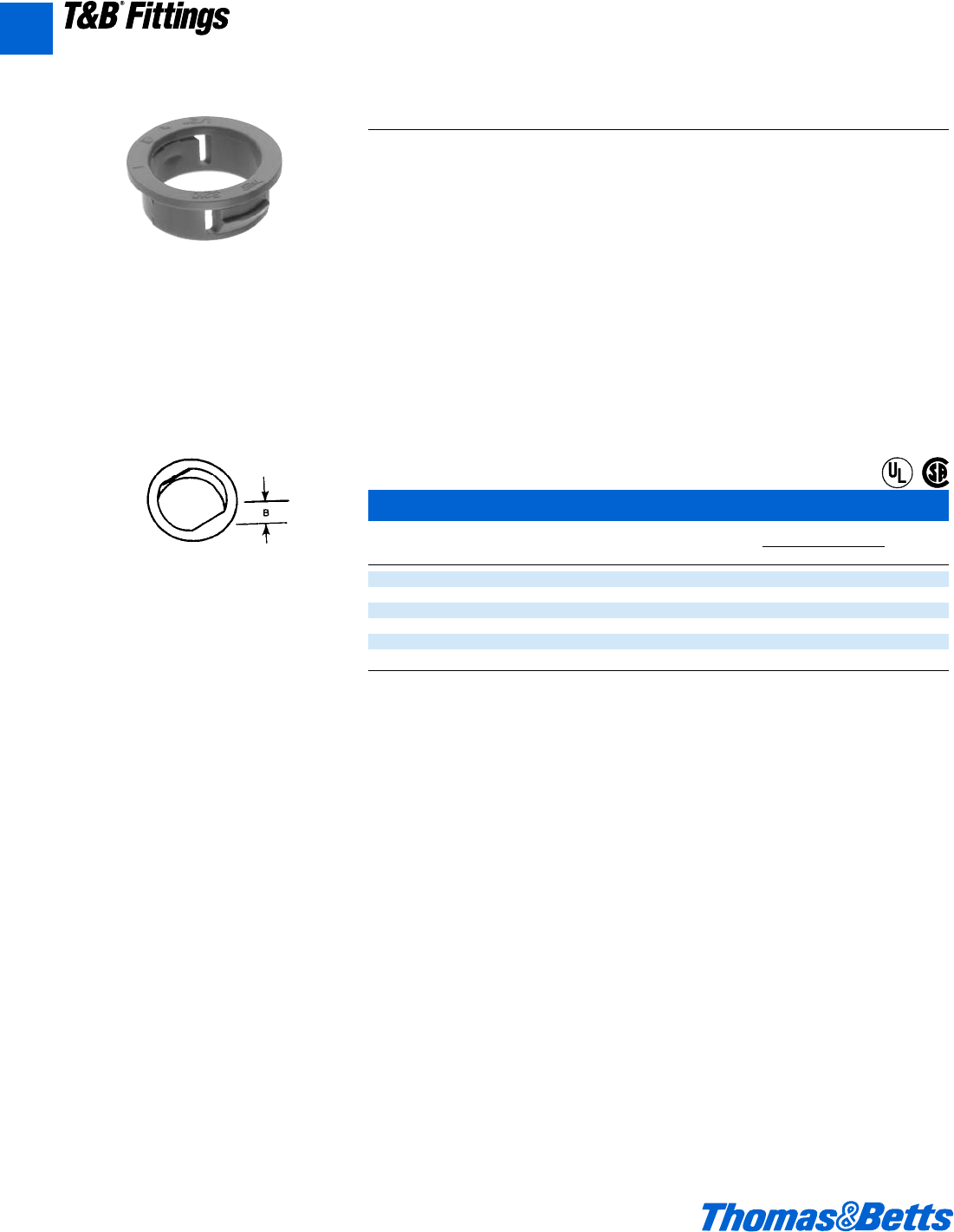
Rigid and Intermediate Metal Conduit Fittings
Knockout Bushings
Knockout Bushing
Cat. For use in Dimension (in.)
No. KO Size* B
3210 .875 .360
3211 1.109 .360
3212 1.375 .360
3213 1.734 .400
3214 1.984 .520
3215 2.469 .520
* Per U.L. and NEMA standards. Refer to “KNOCKOUT” table on page A14.
Oxygen index >28°
U.L. 94V-1
U.L. File No. E-3803
CSA File No. 589
3210 Series
One-piece knockout bushing quickly snaps into
outlet box, switch box, or other enclosure left
vacant by wiring modifications or maintenance
changes. Provides smooth, rounded insulation
surface for easy wire pulling. Easily installed
by hand, they are available to fit 1⁄2" through 2"
knockouts. U.L. Listed 105°C. High impact
thermoplastic.
Application
• To bush knockout openings in metal
boxes or enclosures.
Features
• One piece construction designed to
snap in place.
• High impact strength self extinguish-
ing non-dripping (per U.L. 94) ther-
moplastic construction.
Standard Material
Thermoplastic rated for 105°C (221°F)
application.
Standard Finish
As molded.
Range
.875" through 2.469" nominal diameter
knockout opening (d" through 2" trade
size knockouts).
Wall thickness of box or enclosure
.095" max. up to 1" trade size.
.140" max. 1b" through 2" trade size.
Listed/Certified by:
U.L. (U.L. File No. E-3803)
CSA (LR-589, LR-4484)
Conforms to:
U.L. 514B
CSA C22.2 No. 18
NFPA 70-1999 (ANSI)
®
®
A
412031.A01 FIT 3/12 3/13/03 4:45 PM Page 12
© 2002 Thomas & Betts Corporation. Specifications are subject to change without notice. www.tnb.com A13
T&B®Fittings
Rigid and Intermediate Metal Conduit Fittings
Capped Bushings
Cat. Dimension (in.)
No. Size AB
1460 d" 1o u
1461 f" 1b k
1462 1" 1l d
1463 1b" 1C l
1464 1d" 2q x
1465 2" 2y e
U.L. File No. E-23018
CSA File No. 2884
Makes a workmanlike seal against grit, plaster,
and mischief. Removable with pliers. As shown
1⁄2" through 11⁄2" in steel: 11⁄2" and 2" in mal-
leable iron.
Slip over wires – insert
into bushing – snaps
into place
High dielectric nylon, 105°C.
An insuliner sleeve snapped into a regular
bushing makes a U.L. Listed insulated bushing.
For standard rigid conduit, E.M.T. (thinwall
conduit) or any standard bushed outlet.
Especially suitable for use with flexible metal-
lic conduit.
Converts ordinary bushing to code approved
insulated bushing without disturbing wiring.
®
®
®
®
INSULINER®Sleeves
Cat. Dimension (in.)
No. Size AB
422 d" e .025
423 f" L .025
424 1" g .025
425 1b" 1 .030
426 1d" 1 .030
427 2" 1a .030
428 2d" 1b .040
429 3" 1d .040
430 3d" 1A .055
431 4" 2o .055
433 5" 2d .070
434 6" 2d .070
Oxygen index >28°
U.L. File No. E-23018
CSA File No. 589
A
412031.A01 FIT 3/12 3/13/03 4:45 PM Page 13
A14 © 2002 Thomas & Betts Corporation. Specifications are subject to change without notice. www.tnb.com
T&B®Fittings
Rigid and Intermediate Metal Conduit Fittings
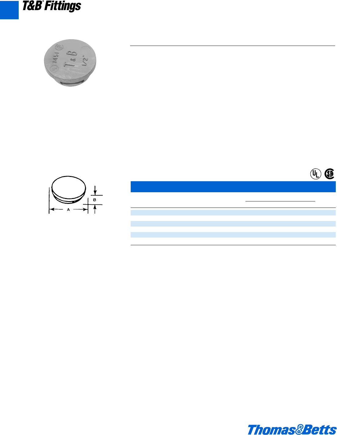
Knockout Plugs
Application
• To plug unused knockout openings in
a box or enclosure.
Features
• One piece construction designed to
snap in place.
• High impact strength self-extinguish-
ing non-dripping (per U.L.-94) ther-
moplastic construction.
Standard Material
Thermoplastic rated for 105°C (221°F)
application.
Standard Finish
As molded.
Range
.875" through 2.469" Nominal Diameter
Knockout opening (d" through 2" trade
size knockouts).
Wall thickness of box or enclosure
.095" max. up to 1" trade size
.140" max. through 2" trade size.
Listed/Certified by:
U.L. (U.L. FILE No. E13938)
CSA (LR589)
Conforms to:
U.L. 514B
NFPA 70-1999 (ANSI)
105°C rated by U.L. Made from flame retardant,
non-dripping thermoplastic.
1451 Series
Knock-out Plugs
Cat. Dimensions (in.)
No. Size AB
1451 d" 1.060 .400
1452 f" 1.300 .400
1453 1" 1.590 .400
1454 1b" 1.860 .450
1455 1d" 2.240 .570
1456 2" 2.740 .570
Wall thickness of electrical box .095 max.
Meets Coast Guard Regulation CB293.
U.L. File No. E-13938
CSA File No. 4484
®
®
A
412031.A01 FIT 3/12 3/20/03 3:03 PM Page 14
© 2002 Thomas & Betts Corporation. Specifications are subject to change without notice. www.tnb.com A15
T&B®Fittings
A
Rigid and Intermediate Metal Conduit Fittings
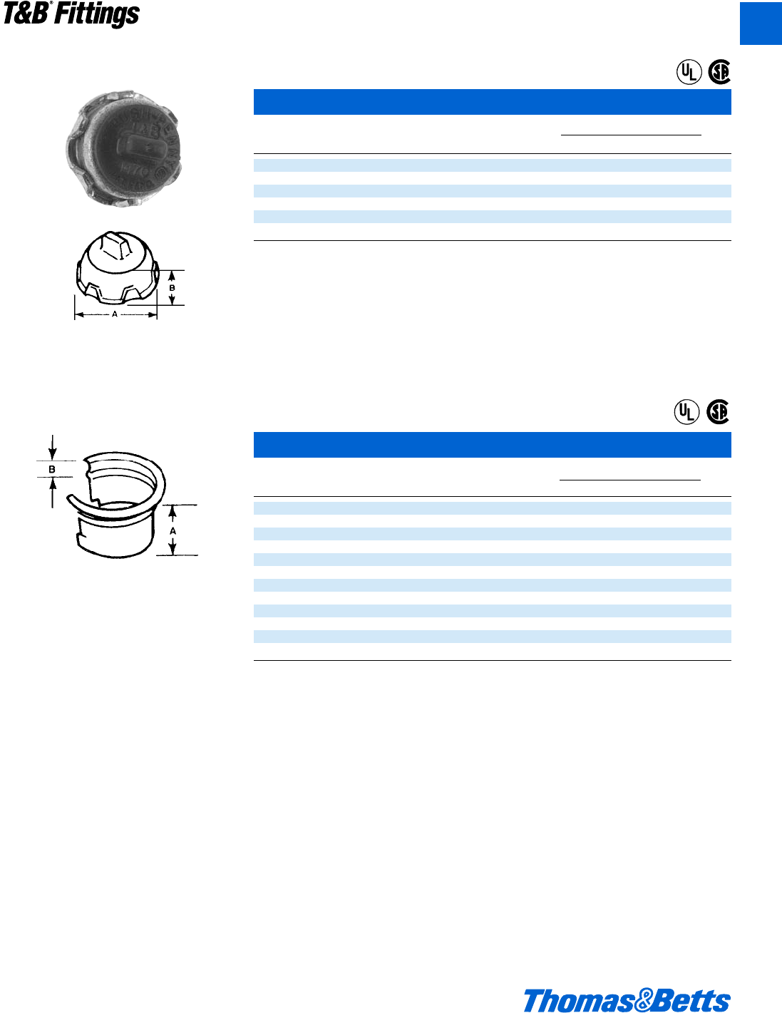
Plug, Conduit, Connectors (Push Penny®Plugs)
Push-Penny®Plugs
Cat.
No. Size
1470 d"
1471 f"
1472 1"
1473 1b"
1474 1d"
1475 2"
1476* 2d"
1477* 3"
1478* 3d"
1479* 4"
* Not CSA Certified
CSA File No. 2884
UL not applicable
Pennies – Steel
Cat.
No. Size
815-TB d"
816 f"
817 1"
818 1b"
819 1d"
820 2"
821 2d"
822 3"
824 3d"
823 4"
U.L. not applicable
CSA File No. 2884
Application
• To plug open end of conduit or con-
nector in order to prevent ingress of
trash, dirt or moisture during con-
struction and remodeling.
Features
• Wide range of application; can be
used with rigid metal conduit, inter-
mediate metal conduit, electrical
metallic tubing, all connnectors and
all bushings.
• Designed to stand up to normal
handling and is functionally unaffected
by moisture.
Standard Material
Polyethylene
Standard Finish
As molded
Listed/Certified by:
CSA (LR2884, LR4484)
Conforms to:
U.L. 514B
CSA C22.2 No. 18
NFPA 70-1999 (ANSI)
NEMA FB1
Economically seal out grout and plaster from
any fitting or raceway conforming to CSA
dimensional tolerances. Made of flexible plas-
tic, they push into place and are held fast by
pressure against internal surface of fitting or
raceway. Eliminates need for separate capped
bushing or steel penny and bushing.
A penny under a bushing will seal the end of
the conduit during construction. Made to fit any
bushing. Completely salvageable.
412031.A01 FIT 3/12 3/13/03 4:45 PM Page 15
A16 © 2002 Thomas & Betts Corporation. Specifications are subject to change without notice. www.tnb.com
T&B®Fittings
A
Rigid and Intermediate Metal Conduit Fittings
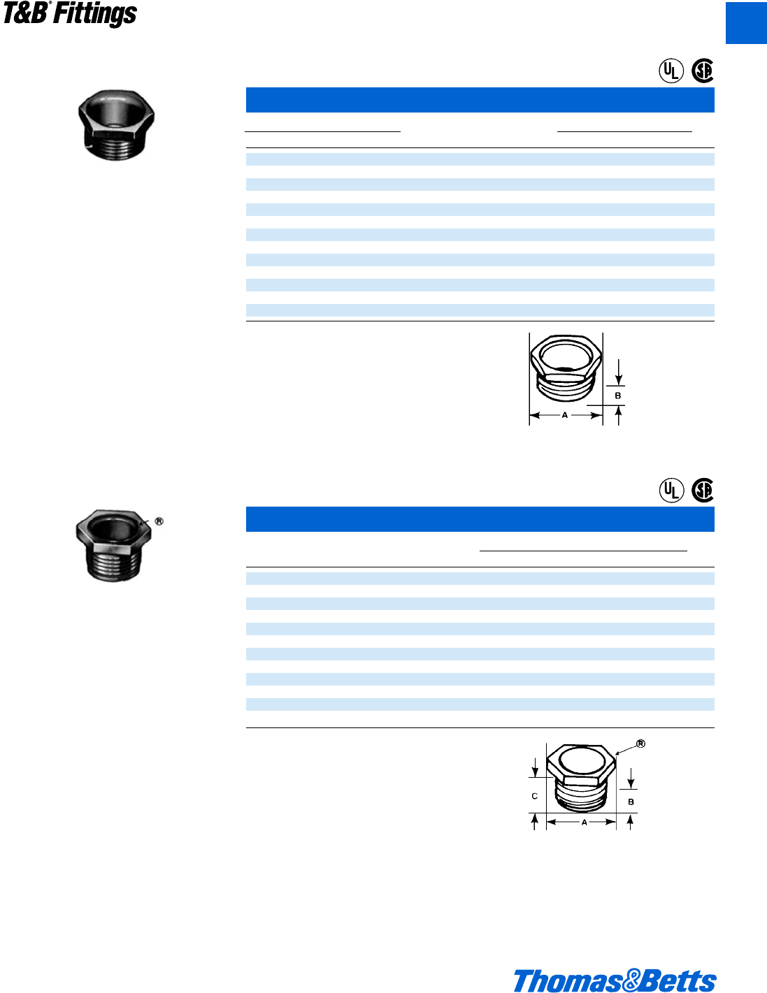
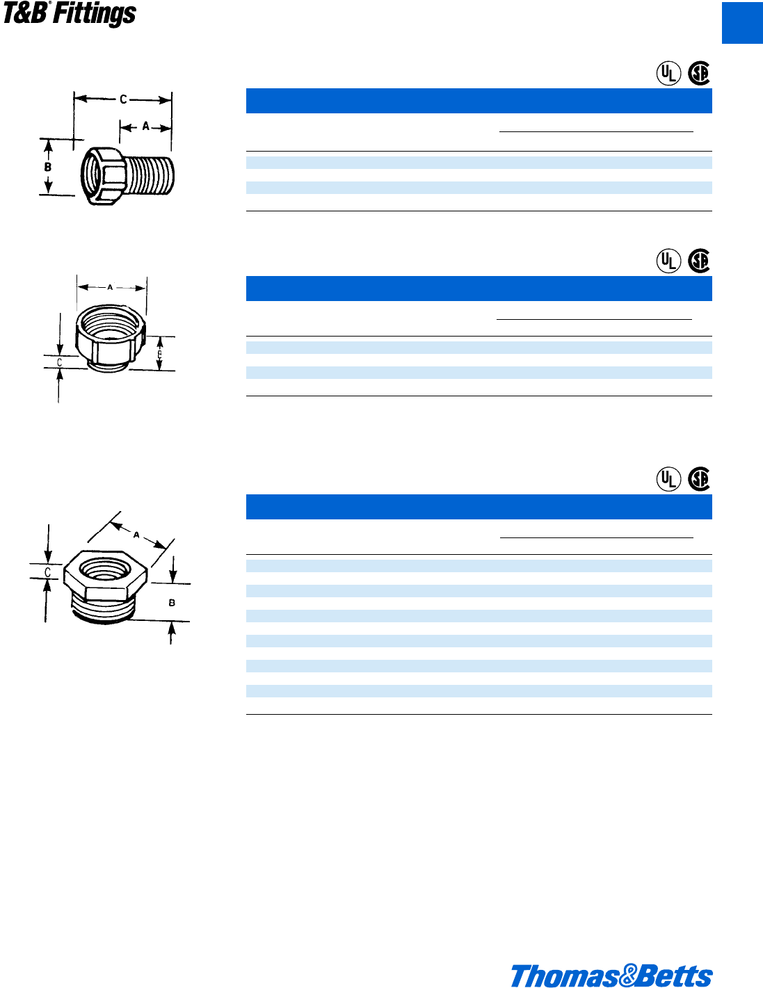
Nipple (CHASE®Nipple)
1942 Series
842AL Series
(Non Insulated)
Application
• To effectively bush factory or field-
punched, cut, or drilled holes in
metal boxes or enclosures.
• To couple boxes back-to-back.
Features
• Rugged construction.
• Insulator curled over to:
Bush conductors entering/leaving
at any angle.
Reduce wire pull effort.
Protect threads against damage
in handling.
Standard Material
1942 Series
Body.........................................d" Steel
f" through 6" Malleable Iron
Insulator ......................................Nylon
842AL Series
All Copper free Aluminum
Standard Finish
1942 Series.............Electro Zinc Plated
& Chromate Coated
842AL Series.......................Degreased
Range
1942 & 842AL Series
d" through 6"
All hub threads straight pipe (NPS)
Listed/Certified by:
U.L. [All except for Catalog No. 842AL,
844AL & 845AL]
(U.L. File No. E-23018)
CSA (LR-2884, LR-4484)
Conforms to:
U.L. 514B
CSA C22.2 No. 18
Federal Specification W-F-408
NFPA 70-1999 (ANSI)
NEMA FB1
Federal Standard H-28 (Threads)
412031.A01 FIT 3/12 3/13/03 4:45 PM Page 16
© 2002 Thomas & Betts Corporation. Specifications are subject to change without notice. www.tnb.com A17
T&B®Fittings
A
CHASE®Nipples
Cat. No. Dimensions (in.)
Stl. or M.I. Alum. Size AB
841TB – c" n k
842TB 842ALTB† d" 1a u
843TB 843ALTB f" 1c x
844 844AL† 1" 1L y
845 845AL† 1b" 2 A
846 846AL 1d" 2c m
847 847AL 2" 2n O
848 848AL 2d" 3l 1h
849 849AL 3" 4c 1b
850 850AL 3d" 5a 1j
851 851AL 4" 5 1j
853 853AL 5" 6d 1j
854 854AL 6" 7d 1c
† Not UL Listed
Available with DURA-PLATE®Finish.
U.L. File No. E-23018
CSA File No. 2884
CHASE®Nipples – Nylon Insulated
Cat. Dimensions (in.)
No. Size ABC
1942 d" 1p k l
1943 f" 1c w z
1944 1" 1L y g
1945 1b" 2o A 1o
1946 1d" 2c m 1p
1947 2" 2n O 1X
1948 2d" 3l 1h 1k
1949 3" 4c 1i 1x
1950 3d" 5a 1j 1A
1951 4" 5a 1j 1m
1953 5" 6c 1j 1m
1954 6" 7e 1c 1g
U.L. File No. E-23018
CSA File No. 2884
Rigid and Intermediate Metal Conduit Fittings
Steel or malleable iron or aluminum.
Steel or malleable iron or aluminum.
®
®
®
®
412031.A01 FIT 3/12 3/13/03 4:45 PM Page 17
A18 © 2002 Thomas & Betts Corporation. Specifications are subject to change without notice. www.tnb.com
T&B®Fittings
A
Rigid and Intermediate Metal Conduit Fittings
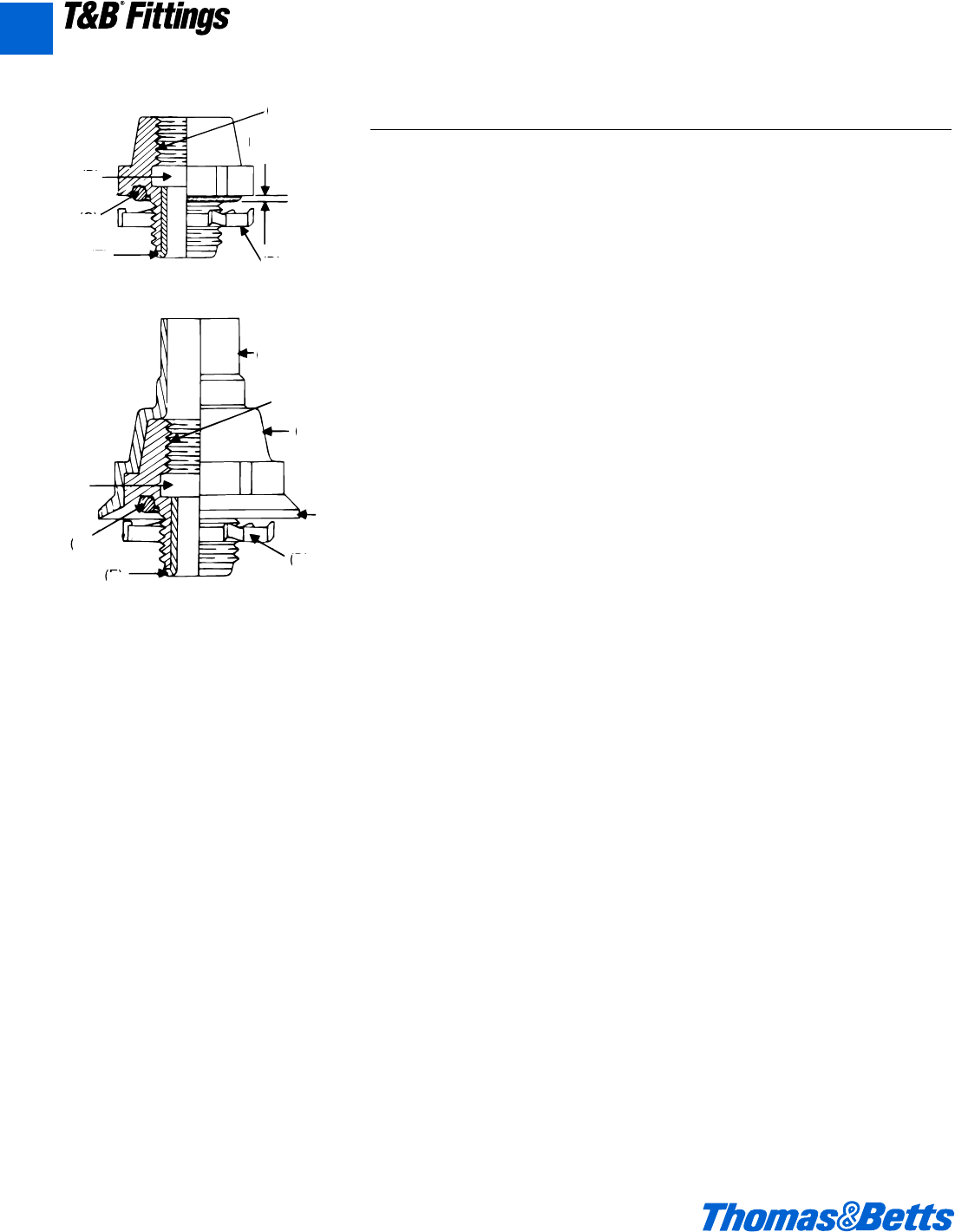
Threaded Hubs (Bullet®Hubs)
(For Threaded Rigid Metal Conduit/IMC/PVC Coated Rigid Metal Conduit)
Application
• To connect threaded metal conduit
(ferrous rigid/non-ferrous rigid/PVC
coated/or intermediate metal) to a
threadless opening in a box or enclo-
sure in outdoors or indoor location
exposed to continuous or intermittent
moisture.
• To positively bond conduit to box or
enclosure.
Features
• Rugged steel/malleable iron/copper
free aluminum construction.
• Tapered internal threads for water-
tight/dust tight union (A).
• Threads relieved to prevent bottom-
ing of conduit ensuring sound
assembly (B).
• Recessed sealing ring at box end.
Sealing ring captivated (C).
• Hardened steel/malleable iron/cop-
per free aluminum locknuts designed
to provide high quality ground conti-
nuity; extended reach of locknut per-
mits clamping on thin boxes and
enclosures (D).
• Insulated throat, insulates conductors,
prevents abrasion and thinning of
conductor insulation, reduces wire
pull effort (E).
• Suitable for hazardous location use
per following:
(i) Class I Division 2, Class II
Division 1 & 2, Class III Division
1 & 2 per N.E.C. 501-4 (b); 502-4
(a) and 503-3 (a).
(ii) Class II Groups E, F, G, & Class
III locations per CEC 18-202; 18-
252; 18-302; 18-352.
• PVC coated 485 Series
(i) Protects connector from
extremely corrosive surroundings
without affecting integrity of elec-
trical grounding path (F).
(ii) Provided with overlapping sleeve
for additional seal (G).
National Electrical Code states that,
“Where practicable, dissimilar metals
in contact anywhere in the system shall
be avoided to eliminate the possibility
of galvanic action”, the only exceptions
Aluminum fittings and enclosures, are
permitted to be used with steel conduit.
Joint Industrial Council (JIC)
Electrical Standards also forbid dissim-
ilar metals in contact for the same rea-
son and require that the fittings for
metal conduit be of malleable iron or
ductile iron and have impact strength
comparable to that of the conduit.
“Copper Free Aluminum”
Copper free aluminum castings for
fittings have a maximum of 0.4% cop-
per. The most detrimental effect of
higher percentage of copper on alu-
minum base alloy is its decrease in
corrosion resistance.
(B)
(C)
(E)
(A)
Predetermined
Compression
(B)
(C)
(E)
(D)
(G)
(F)
(A)
(G)
485 Series
(D)
370 Series
370AL Series
412031.A01 FIT 3/12 3/13/03 4:45 PM Page 18
© 2002 Thomas & Betts Corporation. Specifications are subject to change without notice. www.tnb.com A19
T&B®Fittings
A
Rigid and Intermediate Metal Conduit Fittings
Threaded Hubs (Bullet®Hubs) – (Continued)
(For Threaded Rigid Metal Conduit/IMC/PVC Coated Rigid Metal Conduit)
Standard Material
370-485 Series 370AL
Body 1⁄2" thru 1" Steel All Copper-Free Aluminum
11⁄4" thru 6" Malleable Iron
Locknut 1⁄2" thru 2" Steel (hardened) 1⁄2" thru 2" Steel (hardened)
21⁄2" thru 6" Malleable Iron 21⁄2" thru 4" Copper Free Aluminum
Screws Steel (hardened)
‘O’ Ring Buna N
Insulator Nylon
Coating PVC
Standard Finish
370 Series 370AL Series 485 Series
Hub Electro Zinc Plated As Cast PVC – Outside. Electro Zinc
Chromate Coated Plated Chromate Coated Inside
Locknuts All Ferrous Locknuts Electro Zinc Plated and Chromate Coated
Screws All Electro Zinc Plated & Chromate Coated
Range
370 Series ..........................d" thru 6" Conduit
370AL & 485 Series ...........d" thru 4" Conduit
All hub threads – straight pipe
All female threads – taper pipe
(NPT)
Listed/Certified by:
U.L. (U.L. File No: E-23018)
CSA (LR-637, LR-23086)
Conforms To:
U.L. 514B
CSA C22.2 No. 18
NFPA 70-1999
NEMA FB-1
JIC EGP1; JIC EMP 1
Federal Specification W-F-408
Federal Standard H-28 (Threads)
412031.A01 FIT 3/12 3/13/03 4:45 PM Page 19
A20 © 2002 Thomas & Betts Corporation. Specifications are subject to change without notice. www.tnb.com
T&B®Fittings
A
Rigid and Intermediate Metal Conduit Fittings
Steel/Malleable Iron and Aluminum Hub Connectors*†
Wall
Cat. No. Dimensions (in.) Thk.
Stl. or M.I. Alum.** Size A B C (max.)
370 370AL d" 1c 1b f j
371 371AL f1e1b f j
372 372AL 1" 2p 1c g j
373 373AL 1a" 2l 1e 1 j
374 374AL 1d" 3p 1e 1 j
375 375AL 2" 3e 1e 1 j
376 376AL 2d" 4a 1g 1a c
377 377AL 3" 5 2d 1d d
378 378AL 3d" 5l 2d 1d d
379 379AL 4" 6i 2d 1d d
381 – 5" 8 3a d
382 – 6" 9i 3a d
* Suitable for hazardous locations use in Class I, Div. 2; Class II, Div. 2; Class III, Div. 1 and 2 where general purpose equipment is
specifically permitted per NEC Section 500-2(a).
** Aluminum not available with insulated throat.
† U.L. Listed rain tight and CSA Certified watertight and dust tight
Available with DURA-PLATE®Finish.
U.L. File No. E-23018
For Stl.: CSA File No. 2284
For AL.: CSA File No. 0637
PVC Coated Hub for Rigid Conduit
Cat. Dimensions (in.)
No. Conduit Size AB C
485 d" 1Q 2a 1g
486 f" 1x 2a 2a
487 1" 1B 2f 2c
488 1b" 2v 3c 3a
489 1d" 2C 3e 3d
490 2" 3c 3f 4
491 2d" 3B 4 4d
492 3" 4y 4e 5e
493 3d" 5! 4m 5g
494 4" 5f 4l 6k
Suitable for hazardous locations use per Class I, Div. 2; Class II, Div. 1 & 2; Class III, Div. 1 & 2 NEC 501-4(b); 502-4(a) (2); 503-3(a)
where general purpose equipment is specifically permitted per NEC Section 500-2(a).
Nylon insulated
Aluminum, steel, or malleable iron (steel
through 1"). With Neoprene “O” Ring provides
a watertight threaded hub on enclosures. U.L.
Listed 105°C.
Steel or malleable iron (steel thru 11⁄4").
INSULATOR
SEALING RING
NFS THREAD
LOCKNUT PLASTIC
COATING
A
B
C
®
®
412031.A01 FIT 3/12 3/13/03 4:45 PM Page 20
© 2002 Thomas & Betts Corporation. Specifications are subject to change without notice. www.tnb.com A21
T&B®Fittings
A
Rigid and Intermediate Metal Conduit Fittings
Spacing Chart for Bullet®Hubs
Center to Center Spacing Min. Space from
Center of KO
Conduit Sizes Bullet®Hub to Diameters
1
⁄23
⁄411
1
⁄411
⁄222
1
⁄233
1
⁄24 Wall of Box (min.)
1
⁄21k 1e 1f 2a 2c 2e 2g 3j 3d 3g f g
3
⁄4– 1f 1g 2b 2d 2f 3 3d 3f 4a g 1a
1– – 2 2c2e2g3a3e3g4b 1a 1c
11
⁄4– – – 2L 2n 3b 3d 4 4b 4d 1c 1f
11
⁄2– – – – 3a 3d 3f 4a 4c 4f 1e 2
2– – – – – 3f 4 4d 4f 5 1g 2d
21
⁄2– – – – – – 4b 4f 5 5c 2a 3
3– – – – – – – 5a 5c 5f 2e 3e
31
⁄2– – – – – – – – 5e 6 2g 4a
4– – – – – – – – – 6b 3b 4e
BULLET®Hub Connectors – Nylon Insulated
Size Packaging Wt.
Cat. No. (in.) Description Carton Std. per 100
401 d" 25 100 20
402 f" 25 50 26
403 1" Steel or malleable iron (steel through 5 25 44
404-TB 1b" 1 inch). Used with a neoprene “O” ring 5 25 75
405 1d" to provide a watertight* threaded hub 2 10 100
406-TB 2" on enclosures. Supplied with 106 series 1 5 138
407 2d" bonding locknut. Temperature rating: 105°C. 1 5 200
408 3" 1 5 375
409 3d" – 1 425
410-TB 4" – 1 500
*CSA LR2884. Certified watertight and dust tight.
®
Spacing Chart for Bullet®Sealing Hubs
Center to Center Spacing Min. Space from
Center of KO
Conduit Sizes Bullet®Hub to Diameters
1
⁄23
⁄411
1
⁄411
⁄222
1
⁄233
1
⁄24 5 6 Wall of Box (min.)
1
⁄21k 1e 1f 2a 2c 2e 2g 3j 3d 3g 4g 5j f g
3
⁄4– 1f 1g 2b 2d 2f 3 3d 3f 4a 4m 5d g 1a
1– – 2 2c 2e 2g 3a 3e 3g 4b 4n 5L 1a 1c
11
⁄4– – – 2L 2n 3b 3d 4 4b 4d 5j 5f 1c 1f
11
⁄2– – – – 3a 3d 3f 4a 4c 4f 7k 6i 1e 2
2– – – – – 3f 4 4d 4f 5 5f 6d 1g 2d
21
⁄2– – – – – – 4b 4f 5 5c 6 6f 2a 3
3– – – – – – – 5a 5c 5f 6c 7a 2e 3e
31
⁄2– – – – – – – – 5e 6 6f 7d 2g 4a
4– – – – – – – – – 6b 7a 7g 3b 4e
5– – – – – – – – – – 8 8f 4 5d
6– – – – – – – – – – 8f 9d 4f 6d
412031.A01 FIT 3/12 3/13/03 4:45 PM Page 21
A22 © 2002 Thomas & Betts Corporation. Specifications are subject to change without notice. www.tnb.com
T&B®Fittings
A
Rigid and Intermediate Metal Conduit Fittings
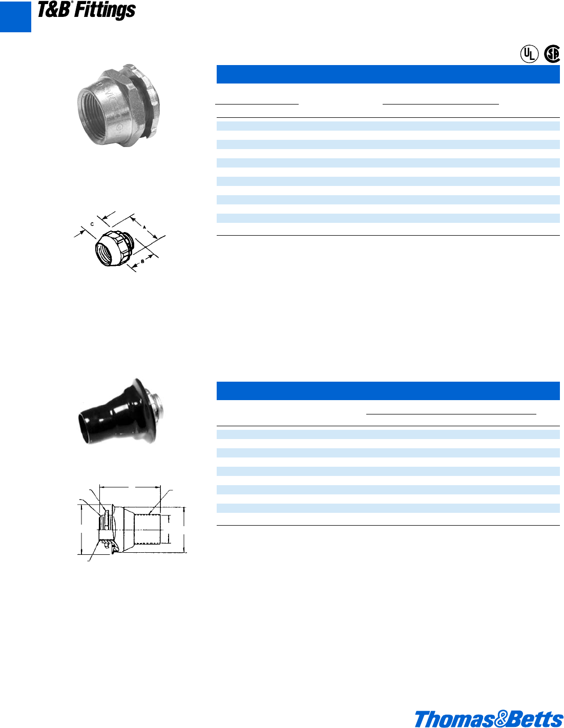
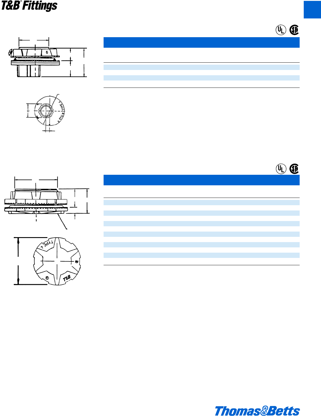
T&B Hub
ABCDE
Cat. Trade Max. Panel Throat
No. Size Dia. Thickness Dia.
H050-TB d1k1l g i x
H075-TB f1y1xCi A
H100-TB 12 1m1hb 1
H125-TB 1b 2c 1g 1h b 1j
H150-TB 1d 2f 1g 1h b 1w
H200-TB 23b 1n1qb 1O
H250-TB 2d 3f 2l 1l b 2u
H300-TB 34c 2y1xb 2O
H350-TB 3d 5 2z 1e b 3u
H400-TB 45d 2z1eb 3g
H500-TB 56g 3o1nb 4n
H600-TB 67L3q2 j6
Material – Hub and Locknut: zinc or copper free aluminum
Insulating Throat: thermoplastic temp. rating – 105°C
Flammability Rating: – 94V-0
Sealing Ring Nitrile (BUNA “N”)
For Aluminum Hubs add suffix A(i.e. H050A). For Chrome Plated Hubs add suffix CP (i.e. H050CP). For 316 Stainless Steel Hubs add
suffix GRSST (i.e. H050GRSST). (d" through 2" only.) Meets NEMA sealing requirements for NEMA 3R, 4 & 13 enclosures.
U.L. Listed and CSA Certified. CSA Certified for hazardous locations Class II Groups E.F.G. Class III.
U.L. File No. E-23018 CSA File No. 4484
Chrome Plated Hubs (suffix-“CP”) are rated NEMA 4X.
Throat Dia. E
B
DC
A
®
®
Never before has a single hub fit like this
one. Designed for unequalled perfor-
mance. The innovative engineering of
the T&B®Hub will, quite simply, raise
your performance expectations for
threaded hubs.
Sealing Ring And Groove with inno-
vative profile outperforms standard
‘O’ ring design. Sealing ring is capti-
vated in place before installation and
resists buckling or slipping during
installation. The seal groove is
designed for optimum compression
of the sealing ring. The sealing ring is
designed to provide a complete 360°
seal, even when the conduit is not
perpendicular with the enclosure.
(See Figure 1)
Locknut Design with peripheral
slots and a hexagonal/angled spline
spaced every 30° enables easy
application of torque with wrench or
hammer and screwdriver. (See
Figures 2 & 3)
Sharper and Deeper Teeth on lock-
nut and body designed for a more
penetrating bite for improved bond-
ing to the enclosure.
Hexagonal/Splined Body Design
for fast, easy installation with wrench
or hammer and screwdriver.
Precision Machined Tapered
Threads designed to create water-
tight union.
Insulated Throat molded from 105°
C rated thermoplastic with a flamma-
bility rating of 94 V-O.
Fig. 1
4
1
2
5
3
6
Fig. 2 Fig. 3
1
2
3
4
5
6
412031.A01 FIT 3/12 3/13/03 4:45 PM Page 22
© 2002 Thomas & Betts Corporation. Specifications are subject to change without notice. www.tnb.com A23
T&B®Fittings
A
Rigid and Intermediate Metal Conduit Fittings
T&B Grounding Hub
ABC
DE
Cat. Trade Max. Panel Throat
No. Size Dia. Thickness Dia.
H050GR-TB d1k 1l g i x
H075GR-TB f1y 1x C i A
H100GR-TB 1 2 1m 1h b 1
H125GR-TB 1b 2c 1g 1h b 1j
H150GR-TB 1d 2f 1g 1h b 1w
H200GR-TB 23b 1n1q b1O
H250GR-TB 2d 3f 2l 1l b 2u
H300GR-TB 34c 2y1xb2O
H350GR-TB 3d 5 2z 1e b 3u
H400GR-TB 45d 2z1e b3g
H500GR-TB 56g 3o1nb4n
H600GR-TB 67L 3q2 j6
Material – Hub and Locknut: zinc or copper free aluminum
Insulating Throat: thermoplastic temp. rating – 105°C
Flammability Rating: – 94V-0
Sealing Ring Nitrile (BUNA “N”)
For Aluminum Hubs add suffix A(i.e. H050A). For Chrome Plated Hubs add suffix CP (i.e. H050CP). For 316 Stainless Steel Hubs add
suffix GRSST (i.e. H050GRSST). (d" through 2" only.) Meets NEMA sealing requirements for NEMA 3R, 4 & 13 enclosures.
U.L. Listed and CSA Certified. CSA Certified for hazardous locations Class II Groups E.F.G. Class III.
U.L. File No. E-23018 CSA File No. 4484
Chrome Plated Hubs (suffix-“CP”) are rated NEMA 4X.
T&B Grounding and Bonding Locknut
Cat. Trade ABGround Max. Conductor
No. Size Dia. Height Screw Size
L050GR d 1d u #10-32 xb" #10
L075GR f 1L u #10-32 xb" #10
L100GR 1 2 u #10-32 xb" #10
L125GR 1b 2c v b-20 xb" #10
L150GR 1d 2f v b-20 xj" #8
L200GR 2 3b v b-20 xj" #8
L250GR 2d 3f L b-20 xj" #6
L300GR 3 4c z b-20 xj" #6
L350GR 3d 5 z b-20 xj" #6
L400GR 4 5d z b-20 xj" #4
L500GR 5 6e z c-16 xc" #2
L600GR 6 7L z c-16 xc" #1
Material – Locknut: zinc or copper free aluminum U.L. File No. E-3060
For Aluminum Locknuts add suffix A. (i.e. L050GRA) CSA File No. 4484
For Chrome Plated Locknuts add suffix CP. (i.e. L050CP). For 316 Stainless Steel Locknuts add suffix SST (d" through 2" only.)
Grounding Locknut for Hubs
B
A
Throat Dia.
B
EC
A
®
®
T&B Hub Centerline Spacing Chart
Conduit
Trade Size 1
⁄2"3
⁄4"1"1
1
⁄4"1
1
⁄2"2"2
1
⁄2"3"3
1
⁄2"4" 5"6"
1
⁄2"1l
3
⁄4"1H 1A
1" 1B 1V 2a
11
⁄4"2o 2! 2j 2d
11
⁄2"2r 2Q 2d 2L 2g
2" 2v 2F 2f 2n 3a 3c
21
⁄2"2z 2K 3 3i 3c 3e 3g
3" 3o 3! 3j 3d 3L 3n 4i 4d
31
⁄2"3X 3Q 3e 3m 4 4b 4d 4m 5a
4" 3x 3} 3g 4h 4b 4d 4f 5h 5c 5e
5" 4s 3ç 4l 4f 4n 5i 5k 5f 6h 6j 7
6" 4L 4J 4O 5q 5X 5x 5B 6q 6v 6z 7u 7m
Nearest Obstruction B V 1a 1j 1d 1f 2 2j 2e 2g 2l 3O
to Center of Hub
412031.A01 FIT 3/12 3/13/03 4:45 PM Page 23
A24 © 2002 Thomas & Betts Corporation. Specifications are subject to change without notice. www.tnb.com
T&B®Fittings
A
Rigid and Intermediate Metal Conduit Fittings
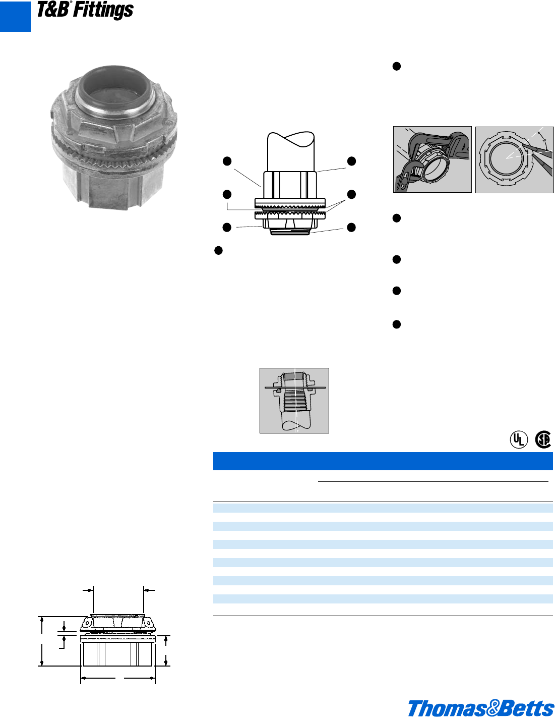
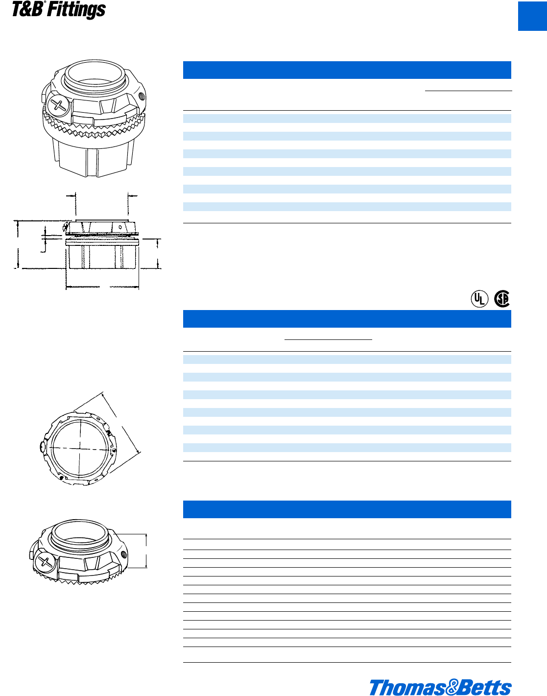
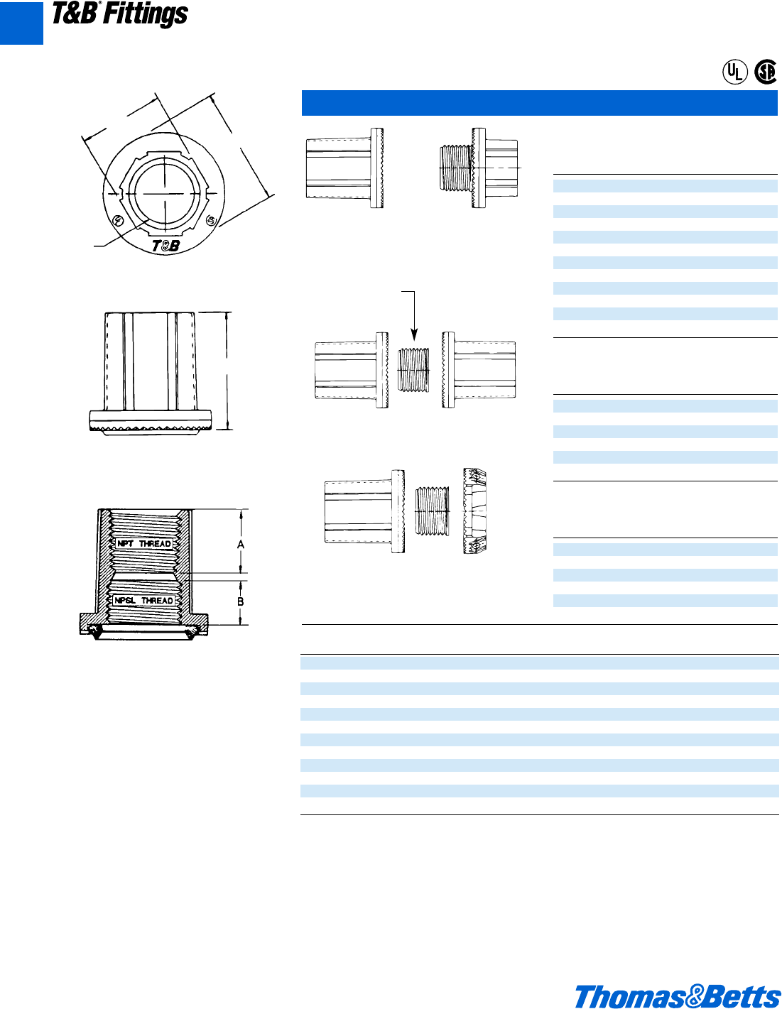
T&B Bulkhead Fittings
Bulkhead Fitting
Cat. Trade
No. Size
H050BHD d"
H075BHD f"
H100BHD 1"
H125BHD 1b"
H150BHD 1d"
H200BHD 2"
H250BHD 2d"
H300BHD 3"
H350BHD 3d"
H400BHD 4"
H500BHD 5"
H600BHD 6"
Thru Bulkhead Fitting
Cat. Trade
No. Size
H050TBF d
H075TBF f"
H100TBF 1"
H125TBF 1b"
H150TBF 1d"
H200TBF 2"
Thru Bulkhead Hub
Cat. Trade
No. Size
H050TBH d"
H075TBH f"
H100TBH 1"
H125TBH 1b"
H150TBH 1d"
H200TBH 2"
Across Flats
Height
Diameter
Thread
Nipple Nut
Included
Trade Across
Size Thread Height Diameter Flats A B
d" d"-14 1u 1k 1 f d
f" f"-14 1v 1L 1b A w
1" 1"-11d 1L 2 1w C x
1b" 1b"-11d 1A 2c 1B C y
1d" 1d"-11d 1m 2f 1a C y
2" 2"-11d 1B 3b 2e n y
2d" 2d"-8 2s 3f 3a 1r g
3" 3"-8 2l 4c 3A 1j C
3d" 3d"-8 2l 5 4s 1c g
4" 4"-8 2l 5d 4B 1c g
5" 5"-8 2z 6e 5C 1v g
6" 6"-8 3 7L 7o 1d O
Material – Hub, Body and Locknut: zinc or copper free aluminum
Insulating Throat: Thermoplastic temp. rating – 105°C
Flammability Rating: – 94V-0
Sealing Ring Nitrile (BUNA “N”)
For Aluminum Bulkheads add suffix A.
For Chrome Plated Bulkheads add suffix CP.
Meets NEMA sealing requirements for NEMA 3R. 4 & 13 enclosures.
CSA Certified for hazardous locations Class II Groups E.F.G. Class III.
U.L. File No. E-3060
CSA File No. 4484
®
®
412031.A01 FIT 3/12 3/13/03 4:45 PM Page 24
© 2002 Thomas & Betts Corporation. Specifications are subject to change without notice. www.tnb.com A25
T&B®Fittings
A
Offset Reducers
Trade A
Cat. No. Size Height Dia. (Ø) Dia. B C D E
H150-H075ORGR 1d"-f" 1y 2f n z 1C 1s X
H150-H100ORGR 1s"-1" 1A 2f 1h z 1C 1l r
H150-H125ORGR 1s"-1b" 1A 2f 1h z 1C 1g o
H250-H200ORGR 2d"-2" 2a 3f 1i n 2C 2y p
Material – Offset Reducer and Locknut: Zinc or copper free aluminum
Insulating Throat: Thermoplastic Temp. Rating – 105°C
Flammability Rating – 94V-0
Sealing Ring Nitrile (BUNA “N”)
For Aluminum Offset Reducer add suffix A.
For Chrome Plated Offset Reducer add suffix CP.
Meets NEMA sealing requirements for NEMA 3R. 4 & 13 enclosures.
CSA Certified for hazardous locations Class II Groups E.F.G. Class III.
U.L. File No. E-3060
CSA File No. 4484
Capoffs
Cat. Trade
No. Size Height Diameter A B C
H050CAP d" 1u 1k x B i
H075CAP f" 1v 1L x 1h i
H100CAP 1" 1L 2 L 1j b
H125CAP 1b" 1A 2c z 1y b
H150CAP 1d" 1m 2f z 1C b
H200CAP 2" 1B 3b z 2c b
H250CAP 2d" 2s 3f g 2C b
H300CAP 3" 2l 4c g 3o X
H350CAP 3d" 2l 5 C 4o X
H400CAP 4" 2l 5d C 4d X
H500CAP 5" 2z 6e C 5l X
H600CAP 6" 3 7e O 6e X
Material – Capoff and Locknut: zinc or copper free aluminum
Insulating Throat: Thermoplastic temp. rating – 105°C
Flammability Rating – 94V-0
Sealing Ring Nitrile (BUNA “N”)
For Aluminum Capoff add suffix A.
For Chrome Plated Capoff add suffix CP.
Meets NEMA sealing requirements for NEMA 3R. 4 & 13 enclosures.
CSA Certified for hazardous locations Class II Groups E.F.G. Class III.
U.L. File No. E-3060
CSA File No. 4484
Rigid and Intermediate Metal Conduit Fittings
Dia. (Ø)
Height
Capoff
Height
Dia. (0)
Dia.
A
C
B
C
B
A
E
®
®
®
®
412031.A01 FIT 3/12 3/13/03 4:45 PM Page 25
A26 © 2002 Thomas & Betts Corporation. Specifications are subject to change without notice. www.tnb.com
T&B®Fittings
A
Rigid and Intermediate Metal Conduit Fittings
Threadless Connector/Coupling
(For Threadless Rigid Metal Conduit and Intermediate Metal Conduit)
8123 Series
8120 Series
8130 Series
Application
• To connect and effectively bond
threadless rigid metal conduit/inter-
mediate metal conduit to a box or
enclosure, or to couple ends of
threadless conduit.
Features
• Steel/Malleable Iron Construction.
• Case hardened ring bites into conduit
for high quality continuity and grip.
• Nylon insulator firmly secured in
place protects conductors and
reduces wire pulling effort by as
much as 50%; prevents thread dam-
age in handling.
• Case hardened steel locknut or mal-
leable iron locknut designed to pro-
vide a positive bond.
• Suitable for concrete tight application.
• Capable of carrying ground fault cur-
rents up to 10,000 amps RMS (1⁄2"
through 11⁄2" size) and 20,000 amps
RMS (2" and above sizes). …duration
of current 3 cycles.
Listed/Certified by:
U.L. (U.L. File No: E-23018)
CSA (LR-2884, LR-4484)
Standard Material
Nut, Gland. . . . d" to 1" Steel – 1b" to
4" Malleable Iron
Body . . . . . . . . . . . All Malleable Iron
Ring. . . . . . . . Steel (case hardened)
Insulator. . . . . . . . . . . . . . . . . . Nylon
Locknut . . . . . . . . . . . d" thru 2" Steel
(hardened) 2" thru
4" Malleable Iron
Standard Finish
Electro Zinc Plated & Chromate Coated
Range
8123 & 8120 Series . . . . . d" through
4" Size Conduit
8130 Series . . . . . . . . . . . d" through
2" Size Conduit
All hub threads . . . . . . . . . . . Straight
Pipe (NPS)
Conforms to:
U.L. 514B
CSA C22.2 No. 18
NFPA 70-1999 (ANSI)
NEMA FB1
Federal Specification W-F-408
Federal Standard H-28 (Threads)
412031.A01 FIT 3/12 3/13/03 4:45 PM Page 26
© 2002 Thomas & Betts Corporation. Specifications are subject to change without notice. www.tnb.com A27
T&B®Fittings
A
Rigid and Intermediate Metal Conduit Fittings
A split steel ring with diagonal serrations grips
the conduit and bites into it for positive ground.
Makes a permanent connection and eliminates
the need for cutting a thread on the conduit.
Insulation helps to guarantee continuity of ser-
vice with protection of the conductor at the crit-
ical point – the connector bushing. Malleable
iron construction.
Nylon Insulated Threadless Connectors
Cat. No.
Nylon Non- Conduit Dimensions (in.)
Insul. Insul. Size ABC
8123 8121 d" 1r 1L 1d
8223 8221 f" 1w 1f 1d
8323 8321 1" 1C 2 l
8423 8421 1b" 2c 2k L
8523 8521 1d" 2L 2e f
8623 8621 2" 3b 2m B
8723-TB 8721 2d" 4a 3m 1a
8823 8821 3" 4g 4 1r
8853 8851 3d" 5d 4a 1a
8973 8971 4" 6o 4g 1a
Available with DURA-PLATE®Finish.
U.L. File No. E-23018
CSA File No. 2884
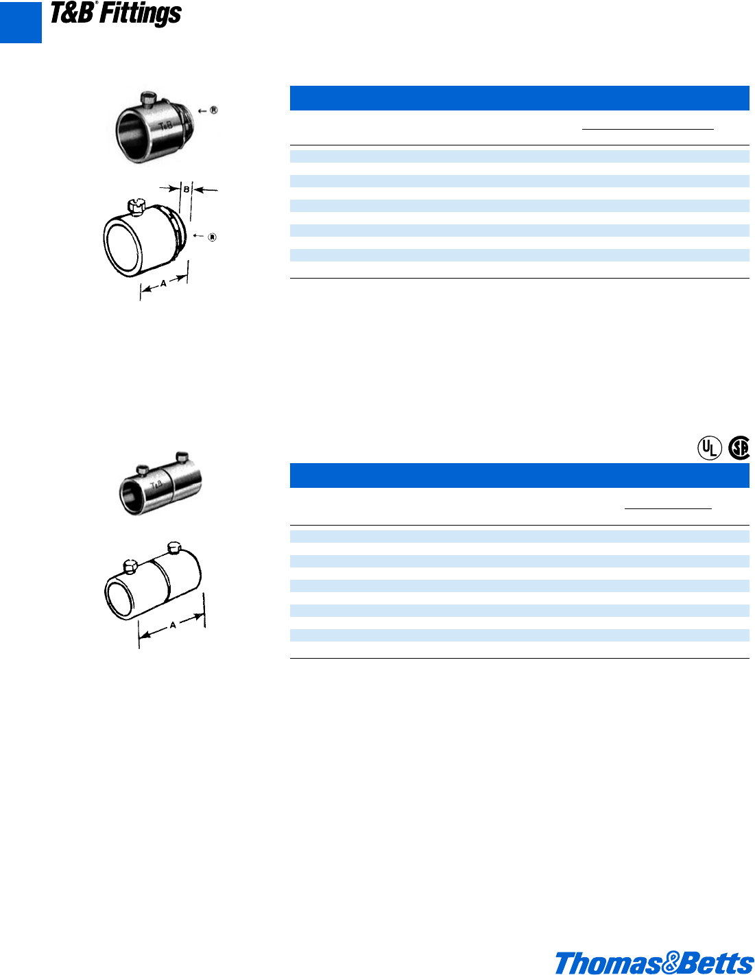
Threadless Couplings
Cat. Dimensions (in.)
No. Size AB
8120 d" 1s 2
8220 f" 1x 2j
8320 1" 1g 2L
8420 1b" 2c 2m
8520 1d" 2e 3e
8620 2" 3b 3m
8720 2d" 3n 5c
8820 3" 4L 5d
8850 3d" 5i 5d
8970 4" 5L 5d
Available with DURA-PLATE®Finish.
U.L. File No. E-23018
CSA File No. 2884
Eliminate conduit threading. Tightened with
a wrench they make a U.L. Listed and CSA
Certified concrete-tight connection.
Malleable iron.
®
®
®
®
412031.A01 FIT 3/12 3/13/03 4:45 PM Page 27
A28 © 2002 Thomas & Betts Corporation. Specifications are subject to change without notice. www.tnb.com
T&B®Fittings
A
Rigid and Intermediate Metal Conduit Fittings
Threadless Short Elbows – Nylon Insulated
Cat. Dimensions (in.)
No. Size ABC
8130 d" 1X 1d d
8131 f" 1e 1f l
Available with DURA-PLATE®Finish.
U.L. File No. E-23018
CSA File No. 2884
Threadless Short Elbows
Cat. Dimensions (in.)
No. Size ABC
8030 d" 1c 1d k
8031 e" 1L 1f d
Available with DURA-PLATE®Finish.
U.L. File No. E-23018
CSA File No. 2884
Ideal for entering enclosure or conduit body
at right angles. Eliminates need to thread
conduit. As with straight couplings, this con-
nector makes a concrete-tight connection.
Malleable iron.
This elbow has all of the advantages of the
insulated short elbow except for the insulation.
Malleable iron.
®
®
®
®
412031.A01 FIT 3/12 3/13/03 4:45 PM Page 28
© 2002 Thomas & Betts Corporation. Specifications are subject to change without notice. www.tnb.com A29
T&B®Fittings
A
Rigid and Intermediate Metal Conduit Fittings
Set Screw Connector/Coupling
(For Threadless Rigid Metal Conduit and Intermediate Metal Conduit)
8125 Series
8124 Series
Application
• To connect and effectively bond
threadless rigid metal conduit or
intermediate metal conduit to a box
or enclosure or to couple ends of
threadless conduit.
Features
• Thickwall steel or malleable iron
body.
• Hardened hex head cup point screw
to provide high quality bond.
• Screw captivated, will not vibrate
loose.
• Nylon insulated throat meets and
exceeds all code requirements for
bushing:
(i) Prevents thinning of insulation.
(ii) Reduces installation effort.
(iii)Prevents first thread damage.
• Coupling provided with positive cen-
ter stop.
• Suitable for concrete tight applica-
tion.
• Capable of carrying ground fault cur-
rents up to 10,000 amps RMS
(d" through 1d" size) and 20,000
amps RMS (2" and above sizes).
Standard Material
Body..............................d" thru 2" Steel
2d" thru 4" Malleable Iron
Locknut ......d" thru 2" Steel (hardened)
2d" thru 4" Malleable Iron
Screw .........................Steel (hardened)
Insulator.......................................Nylon
Standard Finish
Electro Zinc Plated & Chromate Coated
Listed/Certified by:
U.L. (U.L. File No: E-23018)
CSA (LR-2884, LR-4484)
Conforms to:
U.L. 514B
CSA C22.2 No. 18
NFPA 70-1999 (ANSI)
NEMA FB1
Federal Specification W-F-408
Federal Standard H-28 (Threads)
412031.A01 FIT 3/12 3/13/03 4:45 PM Page 29
A30 © 2002 Thomas & Betts Corporation. Specifications are subject to change without notice. www.tnb.com
T&B®Fittings
A
Rigid and Intermediate Metal Conduit Fittings
Eliminate conduit threading with these set
screw connectors. Captive hex head screws
tighten down onto conduit for positive holding
strength and ground. The connectors are fur-
nished with insulated throats reducing wire
pulling effort by as much as 50%. Approved
concrete tight.
Insulated Set-Screw Connector
Cat. Conduit Dimensions (in.)
No. Size AB
8125 d" 1c u
8225 f" 1d k
8325 1" 1m {
8425 1b" 2 e
8525 1d" 2j e
8625-TB 2" 2k L
8725-TB 2d" 3c 1
8825 3" 3k 1
8855 3d" 3g 1h
8975 4" 4i 1a
Sizes d"-2" made of steel. Sizes 2d"-4" are malleable iron.
Available with DURA-PLATE®Finish.
U.L. File No. E-23018
CSA File No. 2884
Set Screw Coupling
Cat. Conduit Dimension (in.)
No. Size A
8124 d" 2d
8224 f" 2L
8324-TB 1" 2B
8424 1b" 3
8524 1d" 3c
8624 2" 3e
8724 2d" 3g
8824-TB 3" 4b
8854 3d" 4n
8974 4" 5c
Sizes d"-2" made of steel; sizes 2d"-4" are malleable iron.
Available with DURA-PLATE®Finish.
U.L. File No. E-23018
CSA File No. 2884
Eliminate the need for threading conduit ends
when joining rigid conduit with these set screw
couplings. Captive hex head screws provide
positive holding strength and ground continuity.
Approved concrete tight.
®
®
412031.A01 FIT 3/12 3/13/03 4:45 PM Page 30
© 2002 Thomas & Betts Corporation. Specifications are subject to change without notice. www.tnb.com A31
T&B®Fittings
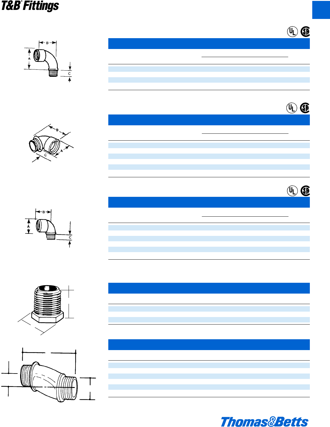
Conduit Nipples – Die Cast Zinc 1" Long
Cat. No. Size A B
HA-211 d" 1" n"
HA-212 f" 1" 1i"
HA-213 1" 1" 1k"
U.L. File No. E-1275 d" & f" only
Offset Nipples – Die Cast Zinc
Cat. No. Size A B
HO-221 d" 2.60" 1.00"
HO-222 f" 2.62" 1.32"
HO-223 1" 2.68" 1.51"
HO-224 1b" 2.85" 1.85"
HO-225 1d" 2.88" 2.08"
HO-226 2" 3.19" 2.71"
f" offset.
U.L. File No. E-1275
B
A
A
B
3/4"
Rigid and Intermediate Metal Conduit Fittings
The non-insulated elbow has smoothly rounded
shoulders to protect conductor insulation.
Malleable iron.
Bushed Elbows
Cat. Dimension (in.)
No. Size ABC
460-TB d" 1a 1m e
461TB f" 1d 2b e
462 1" 1m 2L f
463 1b" 2b 3a f
Available with DURA-PLATE®Finish.
U.L. File No. E 23018
CSA File No. 2884
Short Elbows – Nylon Insulated
Cat. Dimension (in.)
No. Size ABC
4290 d" 1r 1b d
4291 f" 1k 1j l
4292 1" 1z 1l L
4293 1b" 2r 2h m
4294 1d" 2v 2i m
4295 2" 3 2l m
Available with DURA-PLATE®Finish.
Not U.L. or CSA.
Short Elbows
Cat. Dimension (in.)
No. Size ABC
4250 d" 1j 1b k
4251 f" 1w 1j d
4252 1" 1m 1l e
4253 1b" 2s 2h L
4254 1d" 2l 2i L
4255 2" 3p 2l L
Available with DURA-PLATE®Finish.
U.L. File #E-23018
CSA File No. 589
The integral insulation of the insulated elbow is
a guarantee that the bushing of every fitting
will be smooth. Malleable iron.
When an insulated elbow is not desired, the
non-insulated short elbow should be used.
Malleable iron.
®
®
®
®
®
A
®
412031.A01 FIT 3/12 3/20/03 3:03 PM Page 31
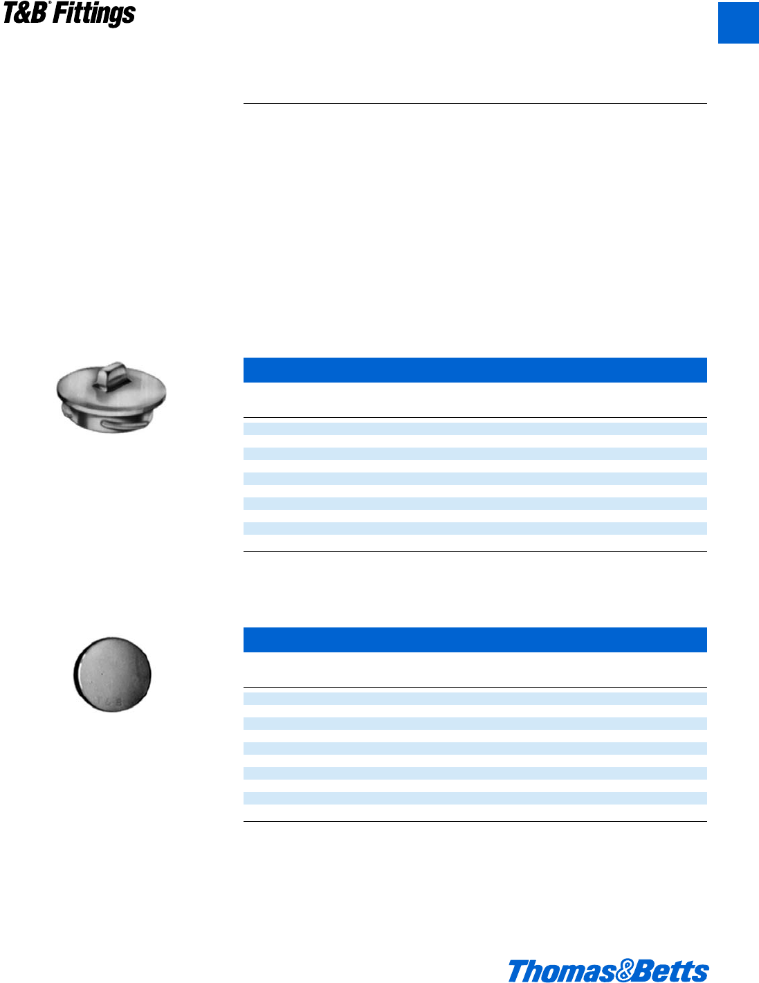
Application
• To couple and effectively bond
threaded ends of rigid metal
conduit/intermediate metal conduit
where neither length of conduit can
be rotated.
Features
• Malleable Iron/Steel/Copper free
Aluminum Construction.
• Free fitting threads insure easy
assembly.
• Permits conduit coupling without
rotating either conduit.
• Provides rigid in-line coupling with
high quality grounding; will not loosen
under vibration.
• Suitable for concrete tight application.
• Capable of carrying ground fault cur-
rents up to 10,000 amps RMS (d"
through 1d" size) and up to 20,000
amps RMS (2" and above) (duration
of fault current 3 cycles) (674 series
tested).
Standard Material
674 Series
Bushing & Case .............Malleable Iron
Ring ...................Steel & Malleable Iron
675AL Series
Bushing & Case....................Aluminum
Ring ......................................Aluminum
Standard Finish
674 Series: Electro Zinc Plated &
Chromate Coated
675AL Series: Degreased
Range
c" thru 6" Conduit (malleable iron)
d" thru 6" Conduit (aluminum)
All straight pipe threads (NPS)
Listed/Certified by:
U.L. (U.L. File No. E-23018)
CSA (LR-2884, LR-4484)
Conforms to:
U.L. 514B
CSA C22.2 No. 18
NEMA FB1
NFPA 70-1999 (ANSI)
Federal Specification W-F-408
Federal Standard H-28 (Threads)
Rigid and Intermediate Metal Conduit Fittings
With an ERICKSON®coupling, a conduit run
may be completed when neither conduit can be
turned. A conduit run may also be broken with-
out taking down the whole run. Conduit joined
with ERICKSON®Couplings is rigid and in line
and vibration will not loosen the connections.
Malleable iron.
ERICKSON®Couplings
Cat.
Cat. No. Dimensions (in.)
No. Alum.* Size AB
674 – c" 1a 1a
675 675AL d" 1v 1b
676 676AL f" 1l 1u
677 677AL 1" 1C 1e
678 678AL 1b" 2c 1m
679 679AL 1d" 2e 1O
680TB 680AL 2" 3r 2r
681 681AL 2d" 3O 2L
682 682AL 3" 4k 2C
683 683AL 3d" 5 3
684 684AL 4" 5d 3i
685 685AL 4d" 6b 3v
686 686AL 5" 6A 3f
687 687AL 6" 8 4o
* Copper Free Aluminum.
U.L. Listed and CSA Certified concrete-tight.
U.L. File No. E-23018
CSA File No. 2884
Threaded Coupling (Erickson®Coupling)
(For Threaded Rigid Metal Conduit and Intermediate Metal Conduit)
674 Series
675AL Series
®
®
A32 © 2002 Thomas & Betts Corporation. Specifications are subject to change without notice. www.tnb.com
T&B®Fittings
A
412031.A01 FIT 3/12 3/13/03 4:45 PM Page 32
© 2002 Thomas & Betts Corporation. Specifications are subject to change without notice. www.tnb.com A33
T&B®Fittings
A
Rigid and Intermediate Metal Conduit Fittings
Ideal when longer thread length is needed.
Will combine with any fitting having a male
thread. Male thread of panel connector exten-
sion is 1" long. Malleable iron.
Panel Connector Extensions
Cat. Dimensions (in.)
No. Size ABC
1440 d" 1b 1p 1g
1441 f" 1c 1X 2
1442 1" 1b 1x 1n
1443 1b" 1b 1n 1j
U.L. File No. E-23018
CSA File No. 2884
Male Enlargers*
Cat. Dimensions (in.)
No. Size ABC
1245 d" to f" 1u 1h d
1246 f" to 1" 1L 1b v
1244 1" to 1b" 2h 1X d
1247 1b" to 1d" 2j 1c l
* All items shown in this chart are suitable for use in hazardous locations where general purpose equipment is specifically permitted by
the NEC; Class I, Div. 2; Class II, Div. 1 & 2; Class III, Div. 1 & 2, NEC 501-4(b); 502-4(a)(b); 503-3(a)(b).
Available with DURA-PLATE®Finish.
U.L. File No. E-23018
CSA File No. 2884
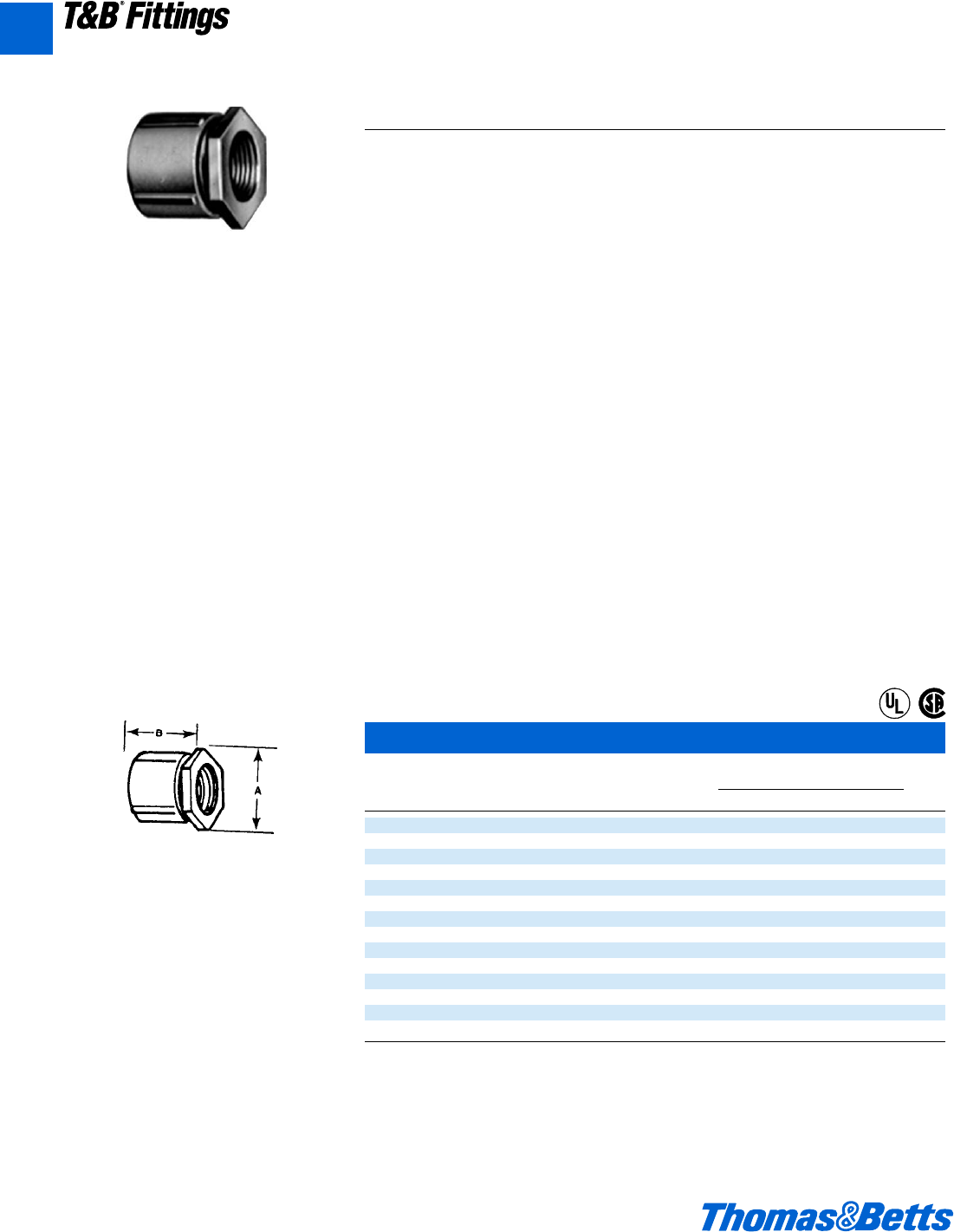
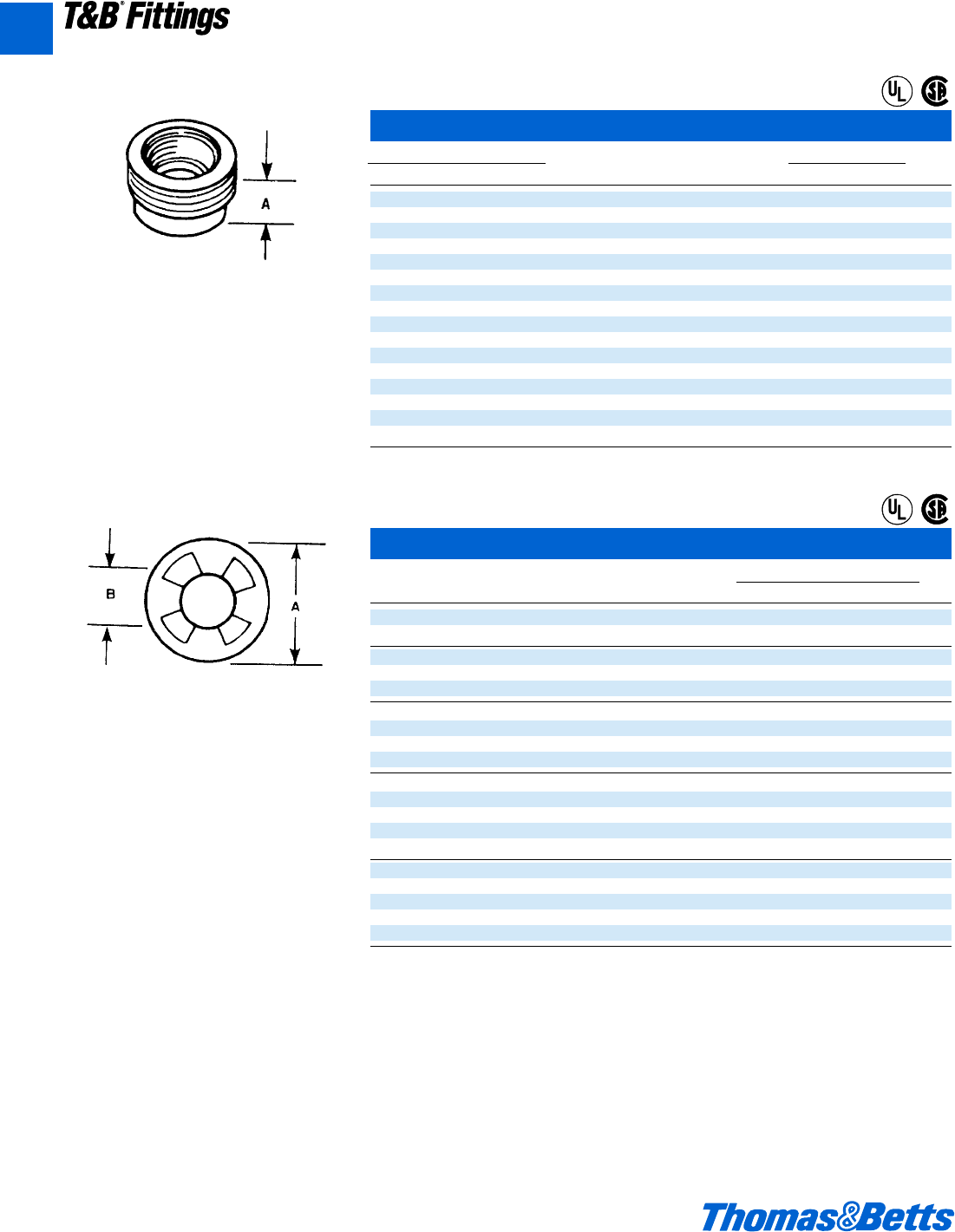
Female Reducers*
Cat. Dimensions (in.)
No. Size ABC
1250 f" to d" 1a e i
1261 1" to d" 1k y i
1251 1" to f" 1c L i
1262 1b" to d" 1m z i
1263 1b" to f" 1m z i
1252 1b" to 1" 1f A r
1253 1d" to 1b" 2 m b
1254 2" to 1d" 2c 1i s
1255 2d" to 2" 3 1b c
1256 3" to 2d" 3e 1d d
1257 3d" to 3" 4a 1l d
1258 4" to 3d" 4e 1l d
* All items shown in this chart are suitable for use in hazardous locations where general purpose equipment is specifically permitted by
the NEC; Class I, Div. 2; Class II, Div. 1 & 2; Class III, Div. 1 & 2, NEC 501-4(b); 502-4(a)(b); 503-3(a)(b).
Available with DURA-PLATE®Finish.
U.L. File No. E-23018
CSA File No. 2884
Adapt an outlet hole to the next larger size of
conduit. Rough ends of conduit carefully cov-
ered by built-in bushing. Malleable iron.
Adapt any outlet to the next smaller size of con-
duit. Hex shoulder makes wrench tightening
convenient. Malleable iron.
®
®
®
®
®
®
412031.A01 FIT 3/12 3/13/03 4:45 PM Page 33
A34 © 2002 Thomas & Betts Corporation. Specifications are subject to change without notice. www.tnb.com
T&B®Fittings
A
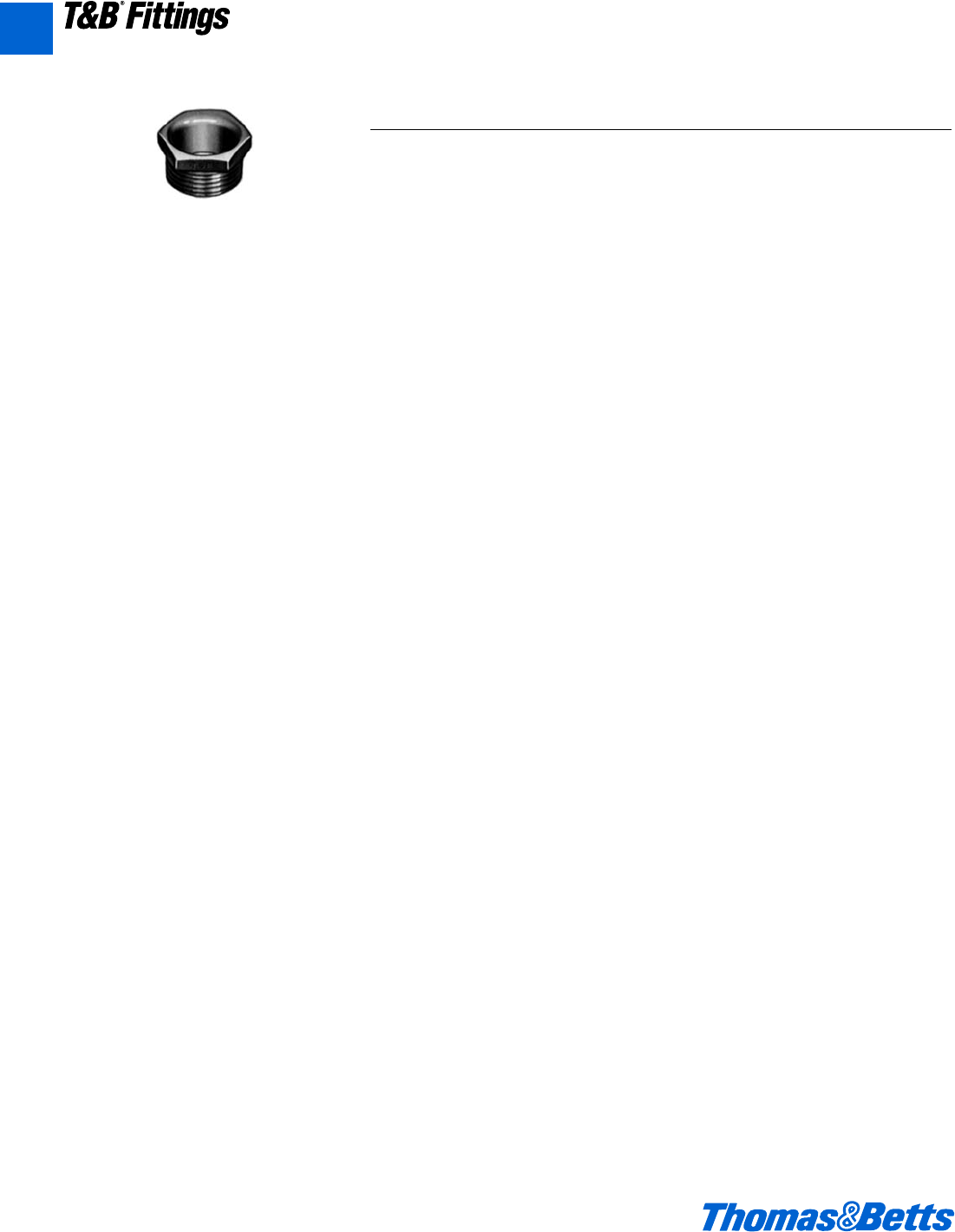
Rigid and Intermediate Metal Conduit Fittings
For reducing the threaded opening in conduit
bodies or any female threaded fitting. Smooth,
built-in bushing completely covers rough ends
of conduit. Iron or steel construction. Steel thru
606, also 614 & 615.
Threaded Reducers*
Cat. No. Dimension (in.)
Stl. on MI Alum. Size A
600TB 600ALTB d" to c" l
601TB 601ALTB f" to d" l
602TB 602ALTB 1" to d" e
603TB 603ALTB 1" to f" e
604TB 604ALTB 1b" to d" m
605 605AL 1b" to f" g
606 606AL 1b" to 1" n
607 607AL 1d" to d" m
608 608AL 1d" to f" m
609 609AL 1d" to 1" n
610 610AL 1d" to 1b" f
611 611AL 2" to d" n
612 612AL 2" to f" n
613 613AL 2" to 1" n
614 614AL 2" to 1b" n
615 615AL 2" to 1d" g
U.L. File No. E-23018
CSA File No. 2884
Reducing Washers
Cat. Dimensions (in.)
No. Size AB
3700 f" to c" 1c }
3701 f" to d" 1c g
3702 1" to c" 1e }
3703 1" to d" 1e g
3704 1" to f" 1e 1p
3705 1b" to c" 2 }
3706 1b" to d" 2 g
3707 1b" to f" 2 1p
3708 1b" to 1" 2 1R
3709 1d" to c" 2b }
3710 1d" to d" 2b g
3711 1d" to f" 2b 1p
3712 1d" to 1" 2b 1R
3713 1d" to 1b" 2b 1z
3714 2" to d" 2f g
3715 2" to f" 2f 1p
3716 2" to 1" 2f 1R
3717 2" to 1b" 2f 1z
3718 2" to 1d" 2f 1O
U.L. File No. E-13938
CSA File No. 2884
Washers reduce knockout hole in outlet box.
Newly designed of galvanized steel. These
washers, used in pairs, interlock and form a
rib which centers the washers and conduit in
the knockout.
®
®
®
®
412031.A01 FIT 3/12 3/13/03 4:45 PM Page 34
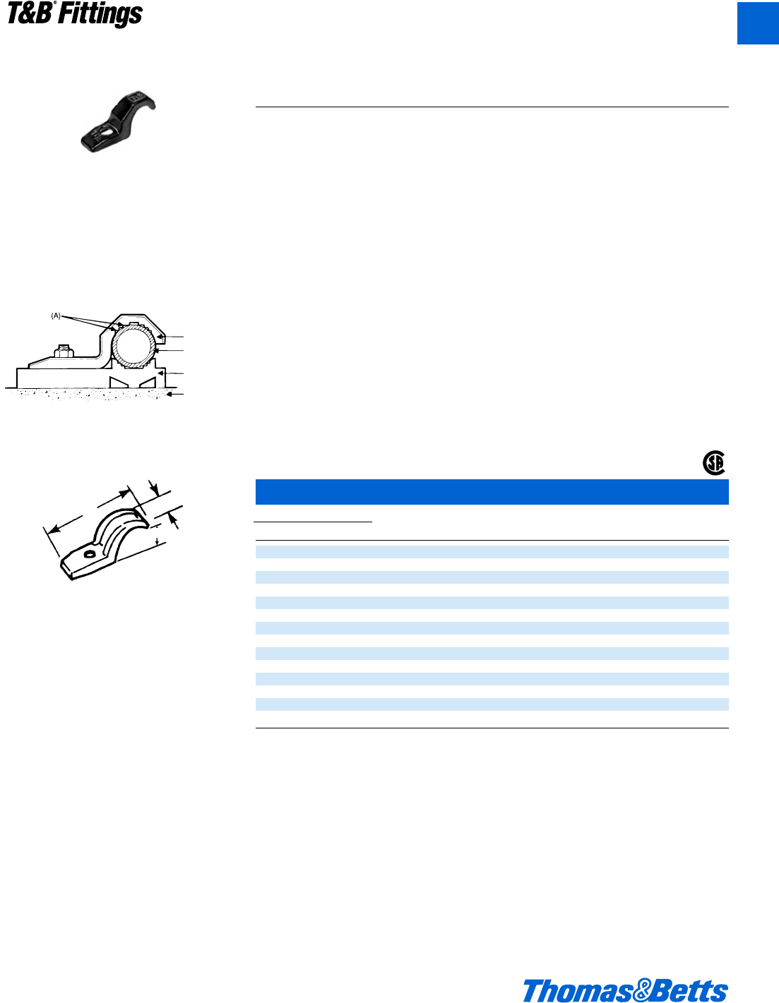
© 2002 Thomas & Betts Corporation. Specifications are subject to change without notice. www.tnb.com A35
T&B®Fittings
A
Rigid and Intermediate Metal Conduit Fittings
Pipe Straps – Malleable Iron or Aluminum
Cat. No. Screw
Mal. Iron Alum. Size A B C Size
1275†1275AL c" 1g" L" f" #12
1276†1276AL†d" 2q" y" 1o" b"
1277†1277AL†f" 2l" L" 1r" b"
1278†1278AL†1" 3" f" 1w" b"
1279†1279AL†1b" 3f" m" 1g" j"
1280†1280AL 1d" 4i" n" 2a" c"
1281 1281AL 2" 5i" 1a" 2å" k"
1282* 1282AL 2d" 5n" 1d" 2f" d"
1283* 1283AL 3" 6L" 1e" 3X" d"
1284 1284AL 3d" 7x" 1f" 3C" e"
1285* 1285AL 4" 8j" 1g" 4u" e"
1286 1286AL 4d" 9i" 1n" 4n" e"
1287 1287AL 5" 9n" 2" 5v" e"
1288 1288AL 6" 11d" 2k" 6w" e"
* May be used with EMT of same size.
† Not snap on type.
U.L. not applicable.
CSA File No. 2884
Conduit Strap
Conduit
Conduit
Spacer
Supporting
Wall
Conduit Straps
(For Rigid Metal Conduit and Intermediate Metal Conduit)
1275 Series
1276AL Series
Designed to fit each size of conduit snugly.
High reinforcing ribs on each side increase
strength, reduce weight. Hot-dipped galvanized
finish. Malleable iron.
A
C
B
Application
• To support and securely fasten rigid
metal conduit and intermediate metal
to the supporting surface.
Features
• Rugged malleable iron/copper free
aluminum construction – snugly fits
on the conduit.
• Designed to prevent accumulation of
moisture and start of corrosion on
vertical run of conduit (A).
• Galvanized finish…1275 Series.
• Copper free aluminum…1276AL
Series.
Standard Material
1275 Series . . . . . . . . . 1976AL Series
Malleable Iron . . . . . . . . All copper free
aluminum
Standard Finish
1275 Series . . . . . . . . . 1276AL Series
Hot Dipped . . . . . . . . . . . . . . . As Cast
Galvanized
Range
1275 Series . . . . . . . . 1276AL Series
c" through . . . . . d" through 6" conduit
6" conduit
Listed/Certified by:
CSA (LR-2884, LR-4484)
Conforms to:
CSA C22.2 No. 18
NFPA 70-1999 (ANSI)
®
412031.A01 FIT 3/12 3/13/03 4:46 PM Page 35
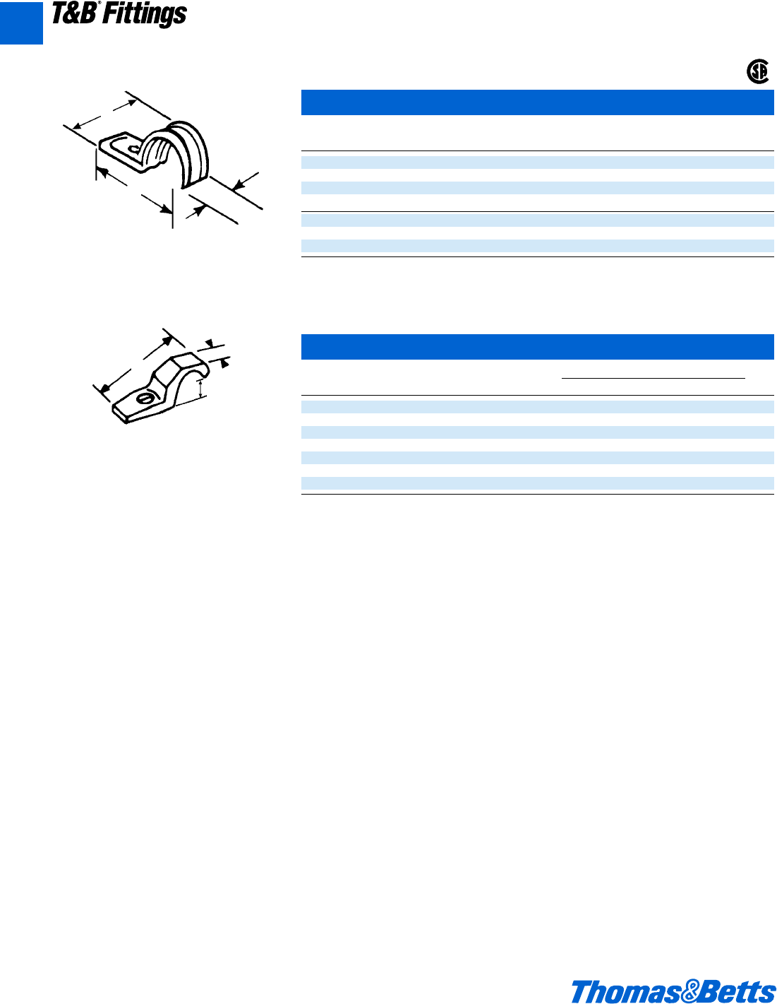
A36 © 2002 Thomas & Betts Corporation. Specifications are subject to change without notice. www.tnb.com
T&B®Fittings
A
Rigid and Intermediate Metal Conduit Fittings
Pipe Straps – Steel
Cat. Conduit Screw
No. Size A B C Size
1210†c" 1v f L b"
1211 d" 2 f n b"
1212 f" 2j 3f 1" b"
1213 1" 3m f 1å b"
1214 1b" 2O 1l 1l c"
1215 1d" 3z 1m 1m c"
1216 2" 4k 2j 2j c"
† Not snap on type.
U.L. not applicable.
CSA File No. 2884
Corrosion Resistant PVC Coated Rigid Conduit Straps
Cat. Bolt Dimensions (in.)
No. Size Size ABC
1275CR c" b" 1g L f
1276CR d" b" 2q y 1o
1277CR f" b" 2l L 1r
1278CR 1" b" 3 f 1w
1279CR 1b" c" 3f m 1g
1280CR 1d" c" 4i n 2a
1281CR 2" d" 5i 1a 2å
U.L. not applicable.
Malleable iron. Designed to fit each size of
conduit snugly. High reinforcing ribs on each
side increase strength, reduce weight.
A
B
C
A
B
C
Elongated bolt hole makes alignment easy,
even when holes in mounting surface are off
center. Snap on features. Steel.
®
412031.A01 FIT 3/12 3/13/03 4:46 PM Page 36
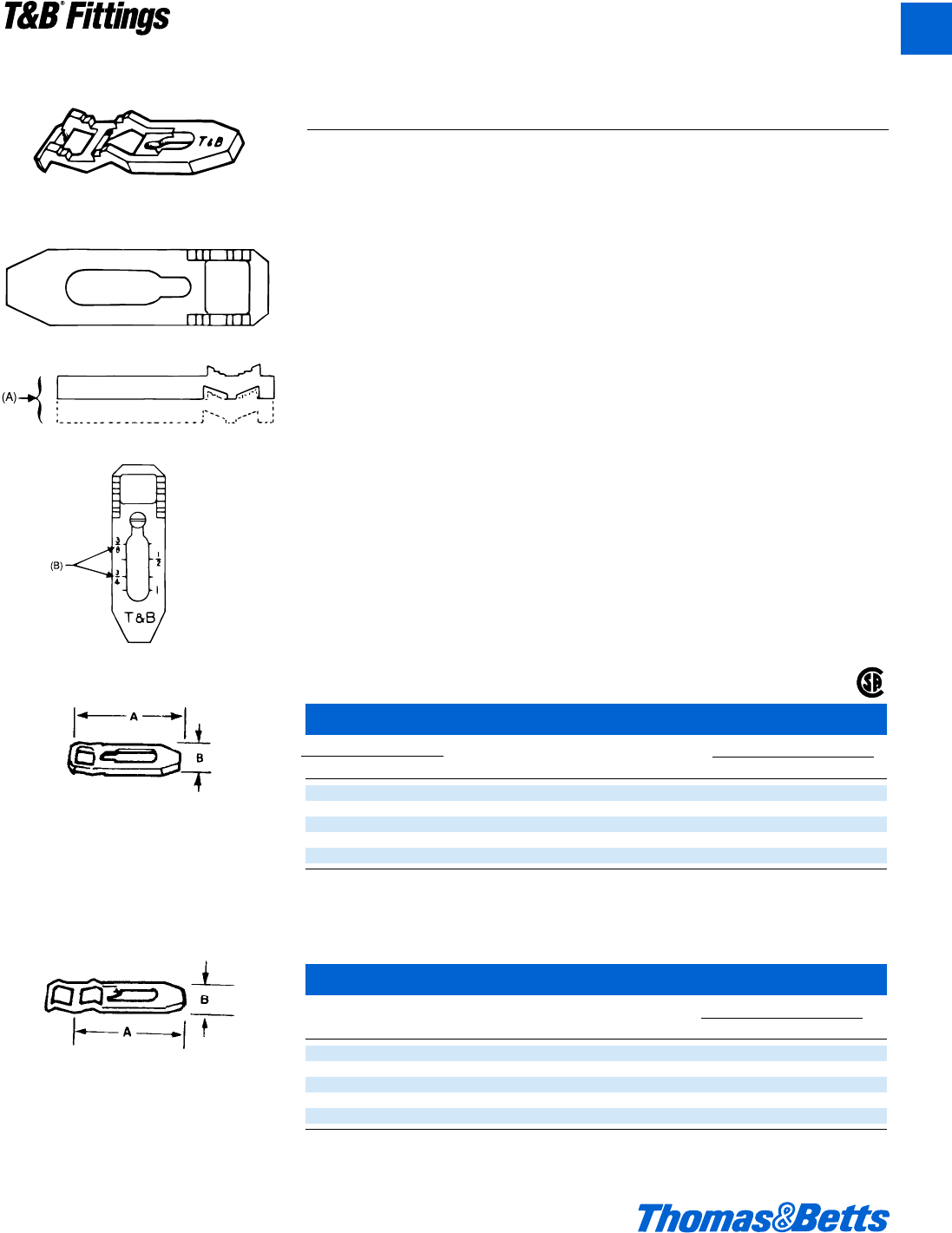
© 2002 Thomas & Betts Corporation. Specifications are subject to change without notice. www.tnb.com A37
T&B®Fittings
A
Used with T&B conduit straps to permit space
between conduit and mounting surface.
Eliminates need for costly offset-bending con-
duit and possible corrosive moisture traps
when conduit is mounted directly to a surface.
Hot-dipped galvanized finish, premountable
and stackable to eliminate offsetting.
Malleable iron.
Pipe Spacers
Cat. No. Screw Dimensions (in.)
Mal. Iron Alum. Size Size A B
1350 1350AL d", f", 1" #7 3" g"
1351 1351AL 1b"-1d"-2" #12 5" 1i"
1352 1352AL 2d"-3" #12 9l" 1f"
1353 1353AL 3d"-4" #14 7l" 2"
1354 1354AL 4d"-5"-6" #16 10l" 2l"
Conforms to NEC SECT. 300-5-c
U.L. not applicable.
CSA File Nos. 2884 and 4484
Pipe Spacers – PVC coated
Cat. Conduit Screw Dimensions (in.)
No. Size Size AB
1350CR d"-f"-1" #7 3 g
1351CR 1b"-1d"-2" #12 5 c
1352CR 2d"-3" #12 6l 1f
1353CR 3d"-4" #14 7l 2
1354CR 4d"-5"-6" #16 10l 2l
U.L. not applicable.
Conforms to NEC SECT. 300-5-c.
Corrosion-resistant, PVC-coated, malleable
iron. Pre-mountable, stackable to elimi-
nate offsetting.
Spacers can be stacked for offsets on wall
or into outlet box. Prevents conduit rusting
from wall condensation. Eliminates offset-
ting of conduit.
Rigid and Intermediate Metal Conduit Fittings
1350 Series
1350AL Series
Conduit Spacers
(For Rigid Metal Conduit, Intermediate Metal Conduit and Electrical
Metallic Tubing)
Application
• Provides mounting surface for con-
duit where installation requires air
space between conduit and support-
ing surface.
Features
• Prevents conduit rusting from wall
condensation.
• Spacers can be stacked one atop
the other facilitating installation and
eliminating expensive conduit off set-
ting (A).
• Designed to cover wide range;
marked with accurate size marking
for proper positioning (B).
• Galvanized finish on 1350 Series.
• Copper free aluminum alloy,
1350AL Series.
Standard Material
1350 Series . . . . . . . . 1350AL Series
Malleable Iron . Copper free aluminum
Standard Finish
1350 Series . . . . . . . . 1350AL Series
Hot Dipped . . . . . . . . . . . . . . As Cast
Galvanized
Range
d" through 6" conduit
Listed/Certified by:
CSA (LR-2884, LR-4484, LR-4484)
Conforms to:
CSA C22.2 No. 18
NFPA 70-1999 (ANSI)
®
412031.A01 FIT 3/12 3/13/03 4:46 PM Page 37
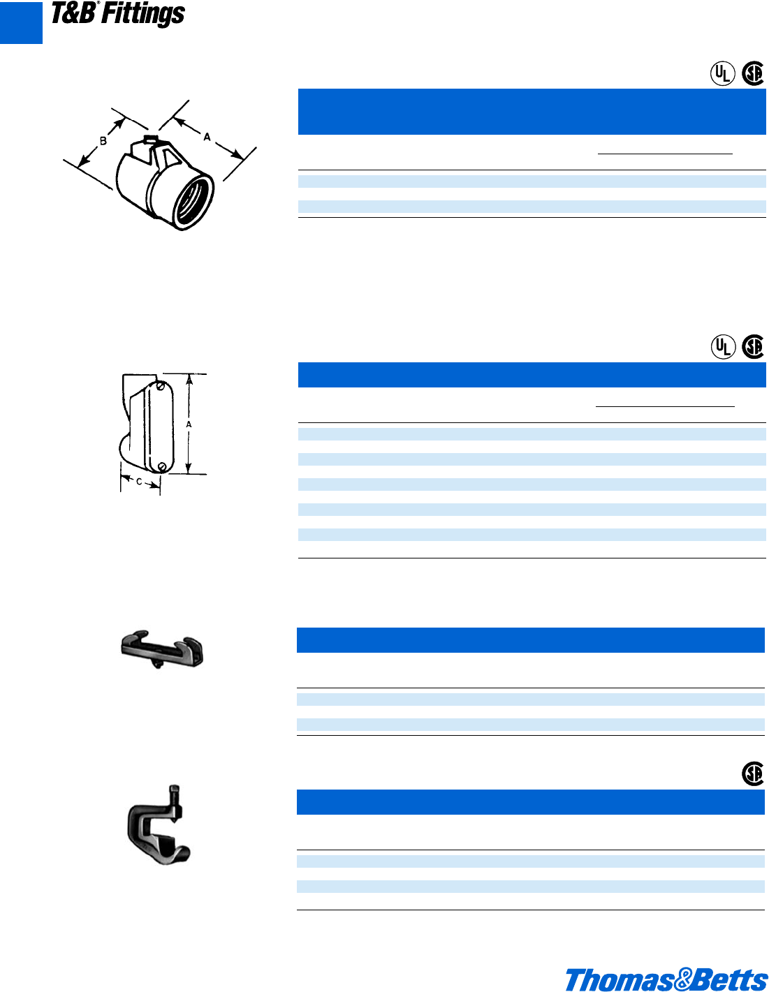
A38 © 2002 Thomas & Betts Corporation. Specifications are subject to change without notice. www.tnb.com
T&B®Fittings
A
Beam Clamps Adjustable
Cat.
No. Description
700TB Fits Flange 2f"-7c"
701 Fits Flange 7"-12"
703 Special Bolt and 3 Nuts
CSA File No. 2884.
Conduit Supports
Cat.
No. Size
690 d"
691TB f"
692TB 1"
693TB 1b"
CSA File No. 2884
Includes bolts. Steel
These supports will fit any flange, tapered or
straight up to 5⁄8" thick. The broad hook holds
the conduit at any desired angle. Holds stan-
dard rigid conduit, E.M.T., or I.M.C.
Malleable iron.
Rigid and Intermediate Metal Conduit Fittings
A one-piece fitting that couples armored cable
or flexible conduit to threaded rigid conduit.
Tite-Bite®wedge holds conduit securely with a
double grip. With a Chase®nipple this fitting
will connect flexible conduit to outlet boxes,
allowing more wiring space in the box than the
usual connector. U.L. Listed as a grounding
means under NEC 350-5. Malleable iron.
TITE-BITE®Combination Couplings –
Armored Cable for Threaded Rigid
Cat. Dimensions (in.)
No. Size AB
440 d" 1e 1B
441 f" 1f 2a
442 1" 2 2w
U.L. File No. E-23018
CSA File No. 2884
Entrance Ells
Cat. Conduit Dimensions (in.)
No. Size AC
1490 d" 3™ 1x
1491 f" 3l 1g
1492 1" 4b 2r
1493 1b" 5M 2m
1494 1d" 6b 2g
1495 2" 6f 3&
1496 2d" 13! 5g
1497 3" 13! 6d
1498 3d" 16S 7w
1499 4" 16S 7w
U.L. File No. E-23018
CSA File Nos. 2884 and 589
T&B entrance ells mount flat against the wall
eliminating the need for offsetting the conduit.
Designed for a straight pull in either direction
and carefully bushed, these entrance ells make
it easy to pull heavy wires without damage to
the insulation. Made of copper free aluminum.
®
®
®
®
®
412031.A01 FIT 3/12 3/13/03 4:46 PM Page 38
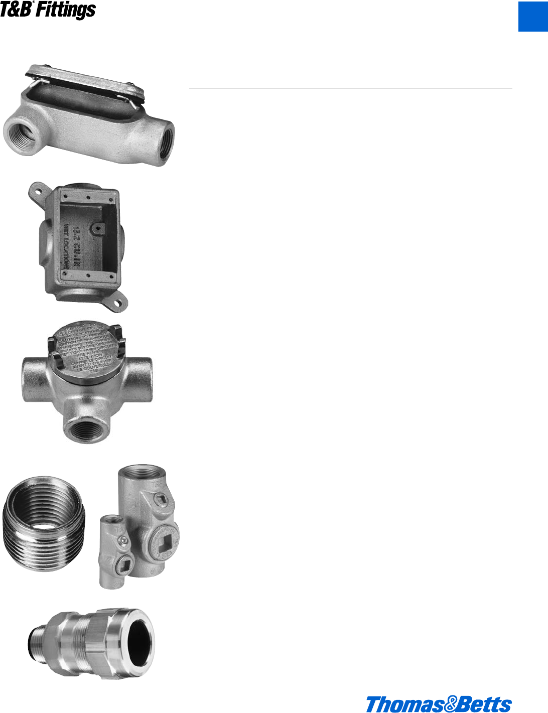
Conduit Outlet Bodies
T&B Conduit Fittings for Ordinary and
Hazardous Locations
Thomas & Betts offers a broad range of conduit bodies, conduit boxes, conduit
fittings, unions, sealing fittings, drains and cable fittings for both ordinary and
hazardous locations. Complete information on applications, features, materials,
finishes, size range and certifications is provided in the following pages.
Conduit Bodies (for ordinary locations)
For raceway systems to provide pull outlets, 90° bends, splices, taps, mounting
outlets, etc.
FORM 7 For neat, compact installation of rigid threaded conduit.
FORM 8 For heavier conductors using rigid threaded conduit.
Red•Dot®Aluminum For rigid threaded conduit installation – copper-free
Die-Cast aluminum.
Red•Dot®Thinwall For set-screw installation using thinwall conduit.
(EMT) (EMT) – copper-free aluminum.
Mogul For larger conduits, spacious, accessible wiring chambers.
Conduit Fittings
Cast Device Boxes (for ordinary locations)
For raceway systems to accommodate wiring devices, serve as pull boxes, and
provide entrances for taps and splices.
FS/FD Single and Double Gang Cast Device Boxes
Cast Conduit Outlet Boxes (for hazardous locations)
Round cast outlet boxes used with rigid conduit to serve as pull and splice
boxes, easy access to wiring, act as a housing for instruments, apparatus, etc.
GUA Conduit Outlet Bodies
Reducers, Plugs, Unions (for ordinary and hazardous locations)
Includes reducers for connecting conduit of dissimilar dimensions, plugs for
unused conduit openings and hubs, and unions for threaded conduit systems.
RE, PLG REC Reducers, Plugs and Adapters, UNY/UNF Unions
Sealing Fittings and Drains (for ordinary and hazardous locations)
Cast fittings used with rigid conduit to seal sections from passage of vapors,
flame or gases or explosions. Drains provide ventilation as a breather and as a
drain in moist locations.
EYS/EYD Sealing Fittings & ECD Drains
Cable Fittings (for ordinary and hazardous locations)
For armored, metal clad, jacketed or unjacketed and unarmored cables through
a bulkhead or enclosure in ordinary or hazardous areas.
© 2002 Thomas & Betts Corporation. Specifications are subject to change without notice. www.tnb.com A39
T&B®Fittings
A
412031.A01 FIT 3/12 3/13/03 4:46 PM Page 39
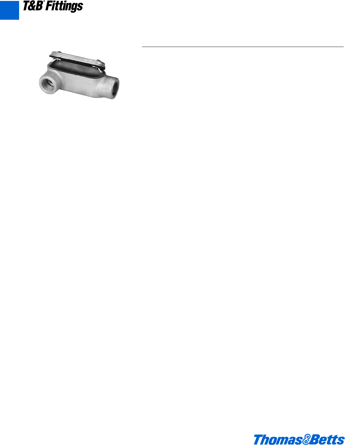
Form 7, Form 8, and Red•Dot®Conduit Outlet Bodies
Conduit Outlet Bodies
Application
Conduit Bodies are installed in conduit systems to:
• Connect conduit sections.
• Act as pull outlets when conductors are being installed.
• Provide easy access for splices in branch conductors.
• Make 90-degree bends in conduit runs.
• Act as mounting outlets for wiring devices and lighting fixtures.
• Provide access to conductors for maintenance and future system changes.
Features
• Standard features include tapered (NPT) threads, integral bushings to protect
wire insulation.
• T&B Form 7 bodies and covers are interchangeable with other manufacturer’s
Form 7 bodies and covers.
• T&B Form 8 bodies and covers are interchangeable with other manufacturer’s
Form 8 bodies and covers.
Materials
• Conduit Bodies (Form 7 and Form 8) - Sand cast class 30 Gray iron alloy.
• Red•Dot®die cast aluminum, copper-free.
• Covers – Sand cast gray iron alloy, and stamped sheet steel-stainless steel
screws.
• Gaskets – Neoprene
Finish
• Conduit Bodies – zinc-plating with an aluminum acrylic coating.
• Covers – gray iron zinc-plating with an aluminum acrylic coating, and
stamped steel zinc-plating with a clear chromate coating.
Compliances
• UL Standard: 514A, 514B
• Fed. Spec: W-C-586D
• CSA Standard: C22.2 No. 18
A40 © 2002 Thomas & Betts Corporation. Specifications are subject to change without notice. www.tnb.com
T&B®Fittings
A
412031.A01 FIT 3/12 3/13/03 4:46 PM Page 40
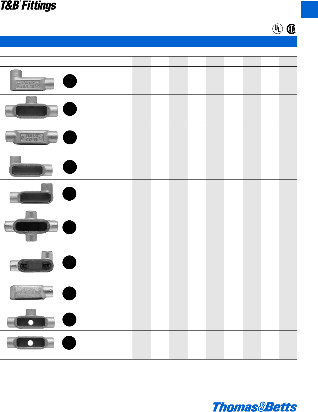
Form 7, Form 8, and Red•Dot®Conduit Outlet Bodies
Threaded Rigid Bodies
Shape Hub Size
1/2 3/4 1 1-1/4 1-1/2 2 2-1/2 3 3-1/2 4
Form 7 LB17 LB27 LB37 LB47 LB57 LB67 LB77 LB87 LB97 LB107
Form 8 LB18 LB28 LB38 LB448 LB58 LB68 LB78 LB888 LB98 LB108
Threaded Aluminum ALB1 ALB2 ALB3 ALB4 ALB5 ALB6 ALB7 ALB8 ALB9 ALB10
EMT Aluminum BLB1 BLB2 BLB3 BLB4 BLB5 BLB6 BLB7 BLB8 BLB9 BLB10
Form 7 T17 T27 T37 T47 T57 T67 T77 T87 T97 T107
Form 8 T18 T28 T38-TB T448 T58 T68 T78 T88-TB
Threaded Aluminum AT1 AT2 AT3 AT4 AT5 AT6 AT7 AT8 AT9 AT10
EMT Aluminum BT1 BT2 BT3 BT4 BT5 BT6
Form 7 C17 C27 C37 C47 C57 C67 C77-TB C87
Form 8 C18 C28 C38 C448 C58-TB C68 C78 C88
Threaded Aluminum AC1 AC2 AC3 AC4 AC5 AC6 AC7 AC8 AC9 AC10
EMT Aluminum BC1 BC2 BC3 BC4 BC5 BC6
Form 7 LL17 LL27 LL37 LL47 LL57 LL67 LL77 LL87 LL97 LL107
Form 8 LL18 LL28 LL38 LL448 LL58 LL68 LL78 LL888
Threaded Aluminum ALL1 ALL2 ALL3 ALL4 ALL5 ALL6 ALL7 ALL8 ALL9 ALL10
EMT Aluminum BLL1 BLL2 BLL3 BLL4 BLL5 BLL6
Form 7 LR17 LR27 LR37 LR47 LR57 LR67 LR77 LR87 LR97 LR107
Form 8 LR18 LR28 LR38 LR448 LR58 LR68 LR78 LR888
Threaded Aluminum ALR1 ALR2 ALR3 ALR4 ALR5 ALR6 ALR7 ALR8 ALR9 ALR10
EMT Aluminum BLR1 BLR2 BLR3 BLR4 BLR5 BLR6
Form 7 X17 X27 X37 X47 X57 X67
Form 8 X18 X28 X38 X448 X58 X68
Form 7 L17-TB L27-TB L37-TB L47-TB L57-TB L67-TB
Threaded Aluminum ALRL1 ALRL2 ALRL3 ALRL4 ALRL5 ALRL6
EMT Aluminum BLRL1 BLRL2 BLRL3 BLRL4 BLRL5 BLRL6
Form 7 E17 E27 E27
Threaded Aluminum AE1 AE2 AE3
Form 7 TA17 TA27 TA37 TA47 TA57 TA67
Form 7 TB17-TB TB27 TB37 TB47 TB57 TB67
TB18 TB28 TB38 TB48 TB58 TB68
*Furnished with one stamped steel cover
LB
T
C
LL
LR
X
*L
E
TA
TB
®
®
© 2002 Thomas & Betts Corporation. Specifications are subject to change without notice. www.tnb.com A41
T&B®Fittings
A
412031.A01 FIT 3/12 3/13/03 4:46 PM Page 41
Form 7, Form 8, and Red•Dot®Conduit Outlet Bodies
Stamped Steel
Gray Iron
Gasket
Covers and Gaskets
Shape Hub Size
1/2 3/4 1 1-1/4 1-1/2 2 2-1/2 3 3-1/2 4
Form 7 170S 270S 370S 470S 570S 670S 870S 870S 970S 970S
Form 8 180 280 380 480 580 680 880 880 980 980
Red•Dot®SCV1 SCV2 SCV3 SCV4 SCV4 SCV5 CV6 CV6 CV7 CV7
Form 7 170F 270F 370F 470F 570F 670F 870F 870F 970F 970F
Form 8 180F 280F 380F 480F 580F 680F 880F 880F 980F 980F
Form 7 GASK GASK GASK GASK GASK GASK GASK GASK GASK GASK
571 572 573 574 575 576 578 578 579 579
Form 8 GASK GASK GASK GASK GASK GASK GASK GASK GASK GASK
581N 582N 583N 584N 585N 586N 588N 588N 589N 589N
Red•Dot®GKN1 GKN2 GKN3 GKN4 GKN4 GKN5 GKN6 GKN6 GKN7 GKN7
For ordering purposes please use GASK in the catalog number. (Example: GASK 571)
A42 © 2002 Thomas & Betts Corporation. Specifications are subject to change without notice. www.tnb.com
T&B®Fittings
A
412031.A01 FIT 3/12 3/13/03 4:46 PM Page 42
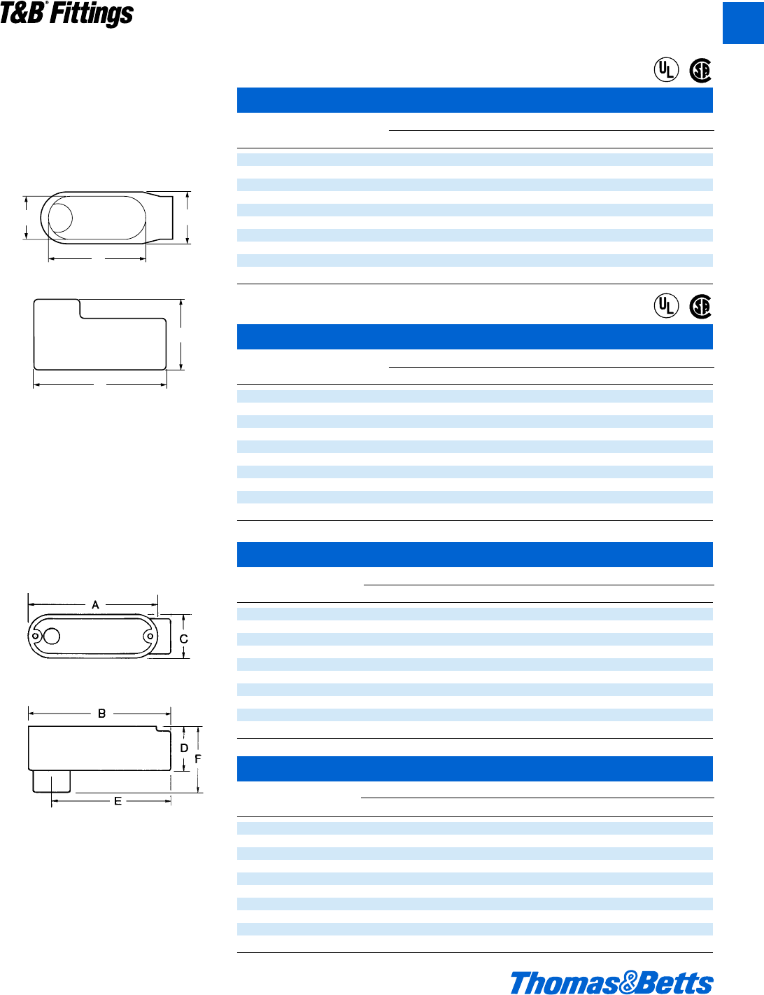
Form 7, Form 8, and Red•Dot®Conduit Outlet Bodies
LB Threaded Aluminum
Cat. Dimensions (in.)
No. Size A B C D E F CI
ALB1 d 3g 4s 1j 1k 3d 2h 4.3
ALB2 f 4e 5a 1w 1e 4b 2k 7.3
ALB3 1 5c 5n 1f 17g 4n 2f 11.8
ALB4 1b 7b 7g 2d 2d 6d 3l 32.0
ALB5 1d 7b 7g 2d 2f 6j 3m 32.0
ALB6 2 9d 9m 3a 3k 8 4d 69.5
ALB7 2d 12b 13 4d 3g 10B 5b 190.0
ALB8 3 12b 13 4d 4d 10d 5g 190.0
ALB9 3d 15 16j 5d 5l 13d 6n 366.0
ALB10 4 15 16j 5d 5l 13d 6n 366.0
LB Threaded Aluminum
and EMT Aluminum
LB EMT Aluminum
Cat. Dimensions (in.)
No. Size A B C D E F CI
BLB1 d 3g 4s 1j 1k 3d 2h 4.3
BLB2 f 4e 5a 1w 1e 4b 2k 7.3
BLB3 1 5c 5n 1f 17g 4n 2f 11.8
BLB4 1b 7b 7g 2d 2d 6d 3l 32.0
BLB5 1d 7b 7g 2d 2f 6j 3m 32.0
BLB6 2 9d 9m 3a 3k 8 4d 69.5
BLB7 2d 12b 13 4d 3g 10B 5b 190.0
BLB8 3 12b 13 4d 4d 10d 5g 190.0
BLB9 3d 15 16j 5d 5l 13d 6n 366.0
BLB10 4 15 16j 5d 5l 13d 6n 366.0
© 2002 Thomas & Betts Corporation. Specifications are subject to change without notice. www.tnb.com A43
T&B®Fittings
A
LB Form 7
Cat. Dimensions (in.)
No. Size A B C D E CI
LB17 d 4.60 2.20 1.35 .95 3.20 4.0
LB27 f 5.25 2.40 1.65 1.15 3.80 6.6
LB37 1 6.00 2.65 1.80 1.35 4.55 10.6
LB47 1b 6.45 3.20 2.20 1.80 5.00 18.8
LB57 1d 7.25 3.90 2.45 2.05 5.45 26.4
LB67 2 8.30 4.45 3.10 2.45 6.40 51.0
LB77 2d 10.55 5.20 4.25 3.60 8.40 102.0
LB87 3 10.55 5.95 4.25 3.60 8.40 132.0
LB97 3d 12.85 6.70 5.25 4.55 10.25 210.0
LB107 4 12.85 7.20 5.25 4.55 10.25 243.0
B
A
C
D
E
LB Form 8
Cat. Dimensions (in.)
No. Size A B C D E CI
LB18 d 4n 2.219 1c 1 3j 4.9
LB28 f 5l 2.438 1l 1i 3j 8.0
LB38 1 6d 2.813 1f 1c 4l 13.0
LB48 1b 7w 3X 2i 1f 5j 23.5
LB58 1d 9a 4o 2f 2a 6d 45.0
LB68 2 11 4u 3f 3 8l 88.0
LB78 2d 13n 6a 5 4b 10g 110.0
LB888 3 13n 6d 5 4b 10g 110.0
LB98 3d 16g 7l 6b 5k 13k 250.0
LB108 4 16g 7m 6b 5k 13k 250.0
LB Form 7 and Form 8
®
®
®
®
412031.A01 FIT 3/12 3/13/03 4:46 PM Page 43
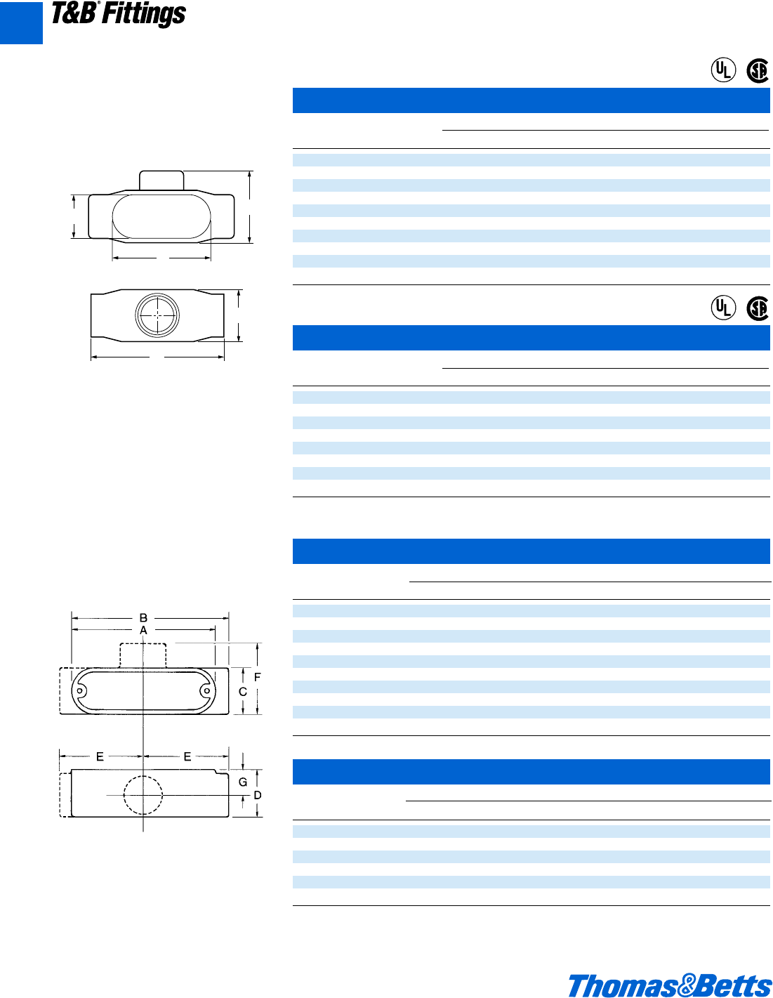
Form 7, Form 8, and Red•Dot®Conduit Outlet Bodies
T Threaded Aluminum
Cat. Dimensions (in.)
No. Size A B C D E F G CI
AT1 d 3g 4c 1Q 1c 2u 2h m 4.3
AT2 f 4e 5a 1w 1e 2A 2X n 7.3
AT3 1 5c 5n 1f 1g 3b 2e 1 11.8
AT4 1b 7b 7g 2d 2d 4i 3w 1c 32.0
AT5 1d 7b 7g 2d 2f 4i 3w 1d 32.0
AT6 2 9d 10i 3a 3l 5u 4 1O 69.5
AT7 2d 12b 13 4d 4d 6g 5A 2k 190.0
AT8 3 12b 13 4d 4d 6g 5A 2k 190.0
AT9 3d 15 16j 5d 5l 8m 6m 3 366.0
AT10 4 15 16j 5d 5l 8m 6m 3 366.0
T EMT Aluminum
Cat. Dimensions (in.)
No. Size A B C D E F G CI
BT1 d 3g 4c 1Q 1c 2u 2h m 4.3
BT2 f 4e 5a 1w 1e 2A 2X n 7.3
BT3 1 5c 5n 1f 1g 3b 2e 1 11.8
BT4 1b 7b 7g 2d 2d 4i 3w 1c 32.0
BT5 1d 7b 7g 2d 2f 4i 3w 1d 32.0
BT6 2 9d 10i 3a 3l 5u 4 1O 69.5
T Threaded Aluminum
and EMT Aluminum
A44 © 2002 Thomas & Betts Corporation. Specifications are subject to change without notice. www.tnb.com
T&B®Fittings
A
T Form 7
Cat. Dimensions (in.)
No. Size A B C D E CI
T17 d 5.60 1.80 2.35 .95 3.20 6.0
T27 f 6.20 2.00 2.60 1.15 3.80 9.1
T37 1 7.35 2.30 3.10 1.35 4.55 16.9
T47 1b 7.30 2.30 3.05 1.80 5.00 19.3
T57 1d 8.60 2.60 3.80 2.05 5.45 27.5
T67 2 9.50 3.20 4.25 2.45 6.40 50.0
T77 2d 12.10 3.65 5.80 3.60 8.40 102.0
T87 3 12.10 4.40 5.80 3.60 8.40 132.0
T97 3d 14.65 4.90 7.05 4.55 10.25 210.0
T107 4 14.65 5.40 7.05 4.55 10.25 243.0
T Form 8
Cat. Dimensions (in.)
No. Size A B C D E CI
T18 d 5W 1f 2q 1 3j 6.0
T28 f 6s 2 2j 1i 3n 9.0
T38-TB 1 7j 2b 2e 1c 4l 15.0
T48 1b 8d 2e 3q 1f 5j 24.0
T58 1d 10c 2A 4 2a 6d 46.5
T68 2 12b 3l 5 3 8l 88.0
T78 2d 15e 4k 6W 4b 10g 110.0
T88-TB 3 15e 4m 6W 4b 10g 110.0
T Form 7 and Form 8
C
A
B
D
E
®
®
®
®
412031.A01 FIT 3/12 3/13/03 4:46 PM Page 44
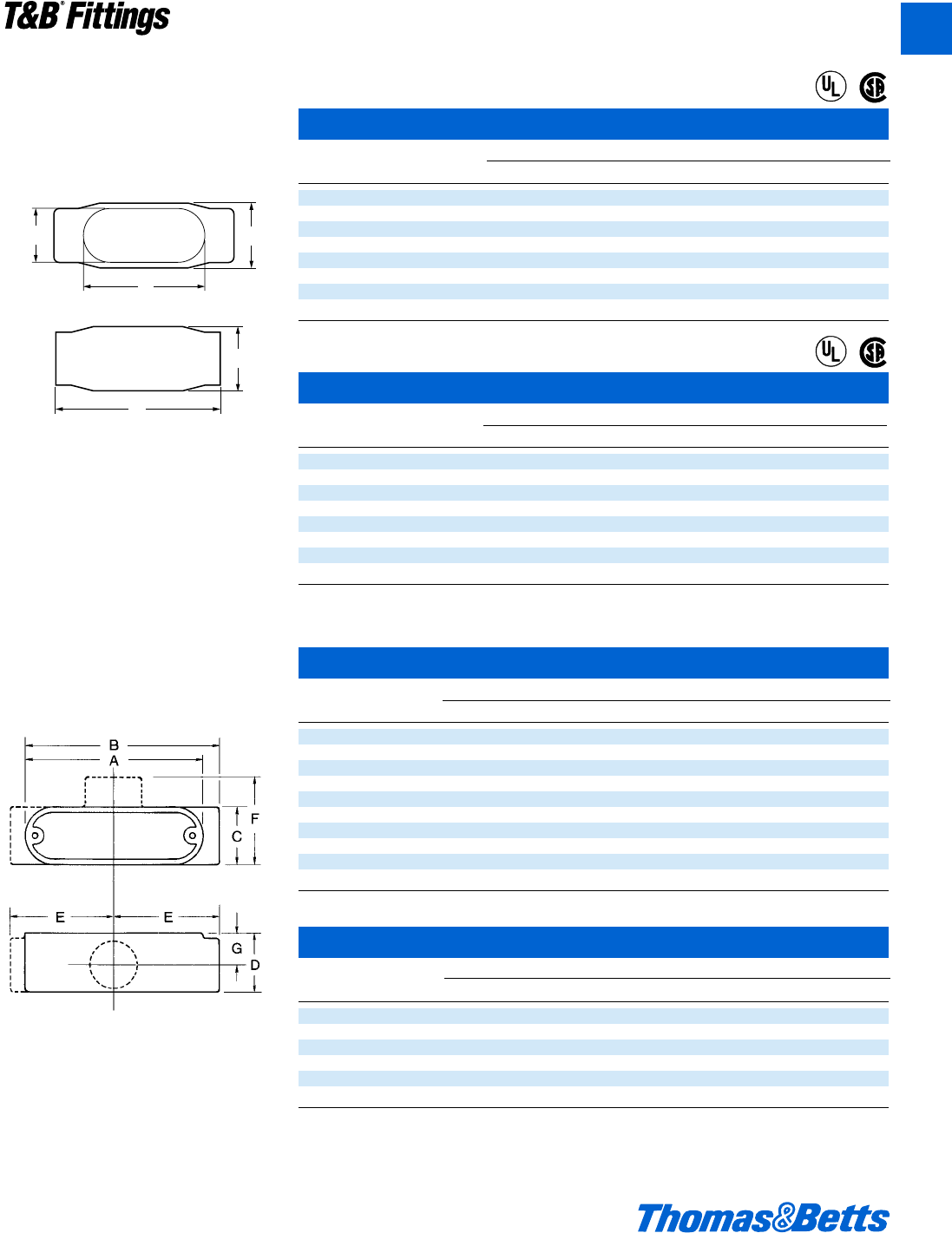
Form 7, Form 8, and Red•Dot®Conduit Outlet Bodies
C Threaded Aluminum
Cat. Dimensions (in.)
No. Size A B C D E F G CI
AC1 d 3g 4c 1Q 1c 2u 2h m 4.3
AC2 f 4e 5a 1w 1e 2A 2X n 7.3
AC3 1 5c 5n 1f 1g 3b 2e 1 11.8
AC4 1b 7b 7g 2d 2d 4i 3w 1c 32.0
AC5 1d 7b 7g 2d 2f 4i 3w 1d 32.0
AC6 2 9d 10i 3a 3l 5u 4 1O 69.5
AC7 2d 12b 13 4d 4d 6g 5A 2k 190.0
AC8 3 12b 13 4d 4d 6g 5A 2k 190.0
AC9 3d 15 16j 5d 5l 8m 6m 3 366.0
AC10 4 15 16j 5d 5l 8m 6m 3 366.0
C EMT Aluminum
Cat. Dimensions (in.)
No. Size A B C D E F G CI
BC1 d 3g 4c 1Q 1c 2u 2h m 4.3
BC2 f 4e 5a 1w 1e 2A 2X n 7.3
BC3 1 5c 5n 1f 1g 3b 2e 1 11.8
BC4 1b 7b 7g 2d 2d 4i 3w 1c 32.0
BC5 1d 7b 7g 2d 2f 4i 3w 1d 32.0
BC6 2 9d 10i 3a 3l 5u 4 1O 69.5
T Threaded Aluminum
and EMT Aluminum
© 2002 Thomas & Betts Corporation. Specifications are subject to change without notice. www.tnb.com A45
T&B®Fittings
A
C Form 7
Cat. Dimensions (in.)
No. Size A B C D E CI
C17 d 5.45 1.40 1.45 .95 3.20 4.0
C27 f 6.05 1.60 1.65 1.15 3.80 6.6
C37 1 6.75 1.90 1.80 1.35 4.55 10.6
C47 1b 7.30 2.30 2.20 1.80 5.00 18.8
C57 1d 8.60 2.60 2.45 2.05 5.45 26.4
C67 2 9.50 3.20 3.05 2.45 6.40 51.0
C77-TB 2d 12.10 3.65 4.25 3.60 8.40 102.0
C87 3 12.10 4.40 4.25 3.60 8.40 132.0
C Form 8
Cat. Dimensions (in.)
No. Size A B C D E CI
C18 d 5W 1k 1c 1 3j 4.9
C28 f 6s 1W 1i 1i 3n 8.0
C38 1 7j 1n 1f 1c 4l 13.0
C48 1b 8d 2c 2i 1f 5j 23.5
C58-TB 1d 10c 2A 2f 2a 6d 45.0
C68 2 12b 3l 3f 3 8l 88.0
C78 2d 15e 4k 5 4b 10g 110.0
C88 3 15e 4m 5 4b 10g 110.0
C Form 7 and Form 8
C
A
B
D
E
®
®
®
®
412031.A01 FIT 3/12 3/13/03 4:46 PM Page 45
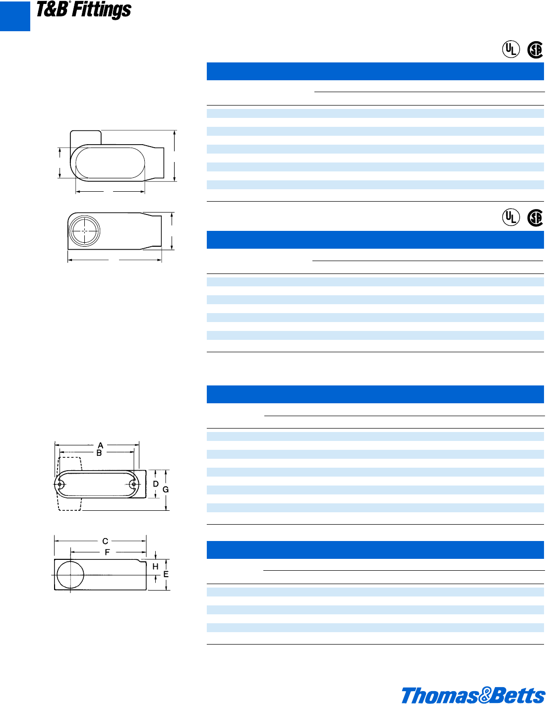
Form 7, Form 8, and Red•Dot®Conduit Outlet Bodies
LL Threaded Aluminum
Cat. Dimensions (in.)
No. Size A B C D E F G H CI CI
ALL1 d 3g 3d 4j 1j 1c 3l 2 A 4.3 4.8
ALL2 f 4e 4a 5a 1w 1e 4a 2j g 7.3 7.5
ALL3 1 5c 4g 5j 1f 1g 4g 2d 1 11.8 12.5
ALL4 1b 7b 6d 7g 2d 2f 6j 3c 1d 32.0 36.5
ALL5 1d 7b 6d 7g 2d 2f 6j 3c 1d 32.0 36.5
ALL6 2 9d 8l 10i 3a 3k 8i 3n 1n 69.5 73.8
ALL7 2d 12b 11b 13 4d 4d 10b 5d 2g 190.0
ALL8 3 12b 11b 13 4d 4d 10b 5d 2g 190.0
ALL9 3d 15 14k 16b 5d 5d 12f 6d 3 366.0
ALL10 4 15 14k 16b 5d 5d 12f 6d 3 366.0
LL EMT Aluminum
Cat. Dimensions (in.)
No. Size A B C D E F G H CI CI
BLL1 d 3g 3d 4j 1j 1c 3l 2 A 4.3 4.8
BLL2 f 4e 4a 5a 1w 1e 4a 2j g 7.3 7.5
BLL3 1 5c 4g 5j 1f 1g 4g 2d 1 11.8 12.5
BLL4 1b 7b 6d 7g 2d 2f 6j 3c 1d 32.0 36.5
BLL5 1d 7b 6d 7g 2d 2f 6j 3c 1d 32.0 36.5
BLL6 2 9d 8l 10i 3a 3k 8i 3n 1n 69.5 73.8
LL Threaded Aluminum
and EMT Aluminum
LRL Style
Only
LRL Style
Only
A46 © 2002 Thomas & Betts Corporation. Specifications are subject to change without notice. www.tnb.com
T&B®Fittings
A
LL Form 7
Cat. Dimensions (in.)
No. Size A B C D E CI
LL17 d 4.60 1.40 1.45 .95 3.20 4.0
LL27 f 5.25 1.60 1.65 1.15 3.80 6.6
LL37 1 6.00 1.90 2.60 1.35 4.55 10.6
LL47 1b 6.45 2.30 3.05 1.80 5.00 18.6
LL57 1d 7.90 2.60 3.80 2.05 5.45 26.4
LL67 2 8.30 3.20 4.25 2.45 6.40 51.0
LL77 2d 10.55 3.65 5.80 3.60 8.40 102.0
LL87 3 10.55 4.40 5.80 3.60 8.40 132.0
LL97 3d 12.85 4.90 7.03 4.55 10.25 210.0
LL107 4 12.85 5.40 7.03 4.55 10.25 243.0
LL Form 8
Cat. Dimensions (in.)
No. Size A B C D E CI
LL18 d 4n 1k 2q 1 3j 4.9
LL28 f 5l 1W 2j 1i 3n 8.0
LL38 1 6v 1n 2e 1c 4l 13.0
LL48 1b 7w 2c 3q 1f 5j 23.5
LL58 1d 9a 2A 4 2a 6d 45.0
LL68 2 11 3l 5 3 8l 88.0
LL78 2d 13n 4k 6W 4b 10g 110.0
LL888 3 13n 4m 6W 4b 10g 110.0
LL Form 7 and Form 8
A
B
C
D
E
®
®
®
®
412031.A01 FIT 3/12 3/13/03 4:46 PM Page 46
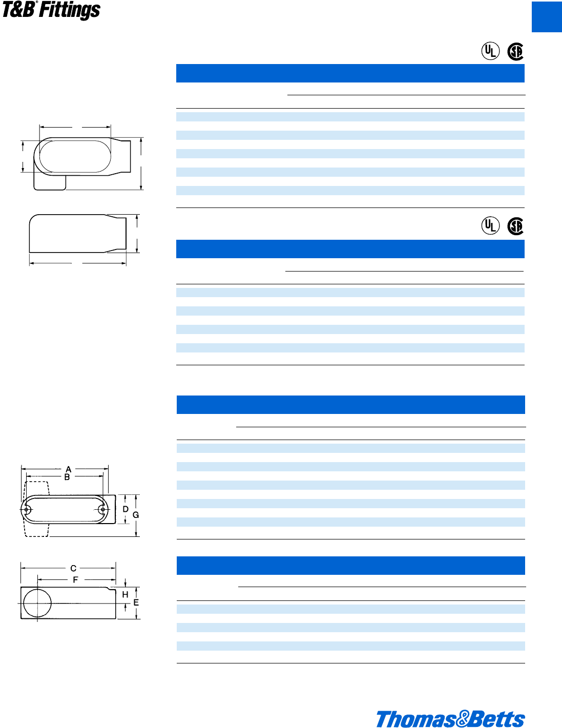
Form 7, Form 8, and Red•Dot®Conduit Outlet Bodies
LR Threaded Aluminum
and EMT Aluminum
LR Threaded Aluminum
Cat. Dimensions (in.)
No. Size A B C D E F G H CI CI
ALR1 d 3g 3d 4j 1j 1c 3l 2 A 4.3 4.8
ALR2 f 4e 4a 5a 1w 1e 4a 2j g 7.3 7.5
ALR3 1 5c 4g 5j 1f 1g 4g 2d 1 11.8 12.5
ALR4 1b 7b 6d 7g 2d 2f 6j 3c 1d 32.0 36.5
ALR5 1d 7b 6d 7g 2d 2f 6j 3c 1d 32.0 36.5
ALR6 2 9d 8l 10i 3a 3k 8i 3n 1n 69.5 73.8
ALR7 2d 12b 11b 13 4d 4d 10b 5d 2g 190.0
ALR8 3 12b 11b 13 4d 4d 10b 5d 2g 190.0
ALR9 3d 15 14k 16b 5d 5d 12f 6d 3 366.0
ALR10 4 15 14k 16b 5d 5d 12f 6d 3 366.0
LR EMT Aluminum
Cat. Dimensions (in.)
No. Size A B C D E F G H CI CI
BLR1 d 3g 3d 4j 1j 1c 3l 2 A 4.3 4.8
BLR2 f 4e 4a 5a 1w 1e 4a 2j g 7.3 7.5
BLR3 1 5c 4g 5j 1f 1g 4g 2d 1 11.8 12.5
BLR4 1b 7b 6d 7g 2d 2f 6j 3c 1d 32.0 36.5
BLR5 1d 7b 6d 7g 2d 2f 6j 3c 1d 32.0 36.5
BLR6 2 9d 8l 10i 3a 3k 8i 3n 1n 69.5 73.8
LRL Style
Only
LRL Style
Only
© 2002 Thomas & Betts Corporation. Specifications are subject to change without notice. www.tnb.com A47
T&B®Fittings
A
LR Form 7
Cat. Dimensions (in.)
No. Size A B C D E CI
LR17 d 4.60 1.40 1.45 .95 3.20 4.0
LR27 f 5.25 1.60 1.65 1.15 3.80 6.6
LR37 1 6.00 1.90 2.60 1.35 4.55 10.6
LR47 1b 6.45 2.30 3.05 1.80 5.00 18.8
LR57 1d 7.90 2.60 3.80 2.05 5.45 26.4
LR67 2 8.30 3.20 4.25 2.45 6.40 51.0
LR77 2d 10.55 3.65 5.80 3.60 8.40 102.0
LR87 3 10.55 4.40 5.80 3.60 8.40 132.0
LR97 3d 12.85 4.90 7.03 4.55 10.25 210.0
LR107 4 12.85 5.40 7.03 4.55 10.25 243.0
LR Form 8
Cat. Dimensions (in.)
No. Size A B C D E CI
LR18 d 4n 1k 2q 1 3j 4.4
LR28 f 5l 1W 2j 1i 3n 8.0
LR38 1 6v 1n 2e 1c 4l 13.0
LR48 1b 7w 2c 3q 1f 5j 23.6
LR58 1d 9a 2A 4 2a 6d 45.0
LR68 2 11 3l 5 3 8l 88.0
LR78 2d 13n 4k 6W 4b 10g 110.0
LR888 3 13n 4m 6W 4b 10g 110.0
LR Form 7 and Form 8
A
B
C
D
E
®
®
®
®
412031.A01 FIT 3/12 3/13/03 4:46 PM Page 47
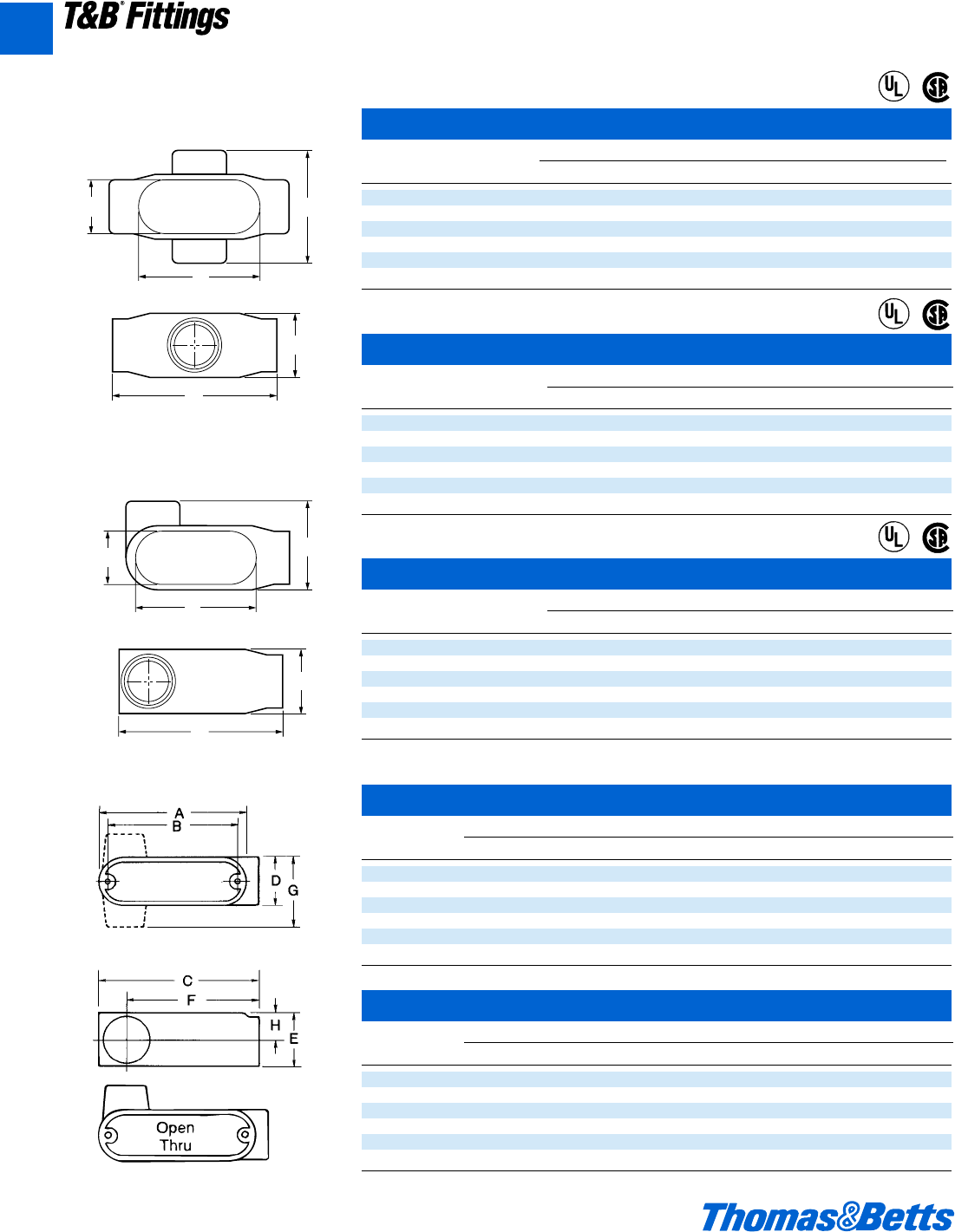
Form 7, Form 8, and Red•Dot®Conduit Outlet Bodies
L Threaded Aluminum
Cat. Dimensions (in.)
No. Size A B C D E F G H CI CI
ALRL1 d 3g 3d 4j 1j 1c 3l 2 A 4.3 4.8
ALRL2 f 4e 4a 5a 1w 1e 4a 2j g 7.3 7.5
ALRL3 1 5c 4g 5j 1f 1g 4g 2d 1 11.8 12.5
ALRL4 1b 7b 6d 7g 2d 2f 6j 3c 1d 32.0 36.5
ALRL5 1d 7b 6d 7g 2d 2f 6j 3c 1d 32.0 36.5
ALRL6 2 9d 8l 10i 3a 3k 8i 3n 1n 69.5 73.8
L EMT Aluminum
Cat. Dimensions (in.)
No. Size A B C D E F G H CI CI
BLRL1 d 3g 3d 4j 1j 1c 3l 2 A 4.3 4.8
BLRL2 f 4e 4a 5a 1w 1e 4a 2j g 7.3 7.5
BLRL3 1 5c 4g 5j 1f 1g 4g 2d 1 11.8 12.5
BLRL4 1b 7b 6d 7g 2d 2f 6j 3c 1d 32.0 36.5
BLRL5 1d 7b 6d 7g 2d 2f 6j 3c 1d 32.0 36.5
BLRL6 2 9d 8l 10i 3a 3k 8i 3n 1n 69.5 73.8
LRL Threaded Aluminum and
EMT Aluminum
LRL Style
Only
LRL Style
Only
A48 © 2002 Thomas & Betts Corporation. Specifications are subject to change without notice. www.tnb.com
T&B®Fittings
A
X Form 7
Cat. Dimensions (in.)
No. Size A B C D E CI
X17 d 5.60 1.80 3.05 .95 3.20 6.0
X27 f 6.20 2.00 3.30 1.15 3.80 9.1
X37 1 7.35 2.30 3.80 1.35 4.55 16.9
X47 1b 7.30 2.30 3.85 1.80 5.00 19.3
X57 1d 8.60 2.60 5.05 2.05 5.45 27.5
X67 2 9.50 3.20 5.45 2.45 6.40 52.8
X Form 8
Cat. Dimensions (in.)
No. Size A B C D E CI
X18 d 5L 1f 2C 1 3j 6.0
X28 f 6s 2 3h 1c 3n 9.0
X38 1 7j 2b 3d 1c 4l 15.0
X48 1b 8d 2e 4a 1f 5j 24.0
X58 1d 10c 2v 5b 2a 6d 46.5
X68 2 12b 3l 6b 3 8l 88.0
C
A
B
D
E
X Form 7 and Form 8
L Form 7
Cat. Dimensions (in.)
No. Size A B C D E
L17-TB d 4.60 1.40 1.45 .95 3.20
L27-TB f 5.25 1.60 1.65 1.15 3.80
L37-TB 1 6.00 1.90 2.60 1.35 4.55
L47-TB 1b 6.45 2.30 3.05 1.80 5.00
L57-TB 1d 7.90 2.60 3.80 2.05 5.45
L67-TB 2 8.30 3.20 4.25 2.45 6.40
A
B
C
D
E
L Form 7
®
®
®
®
®
®
412031.A01 FIT 3/12 3/13/03 4:46 PM Page 48
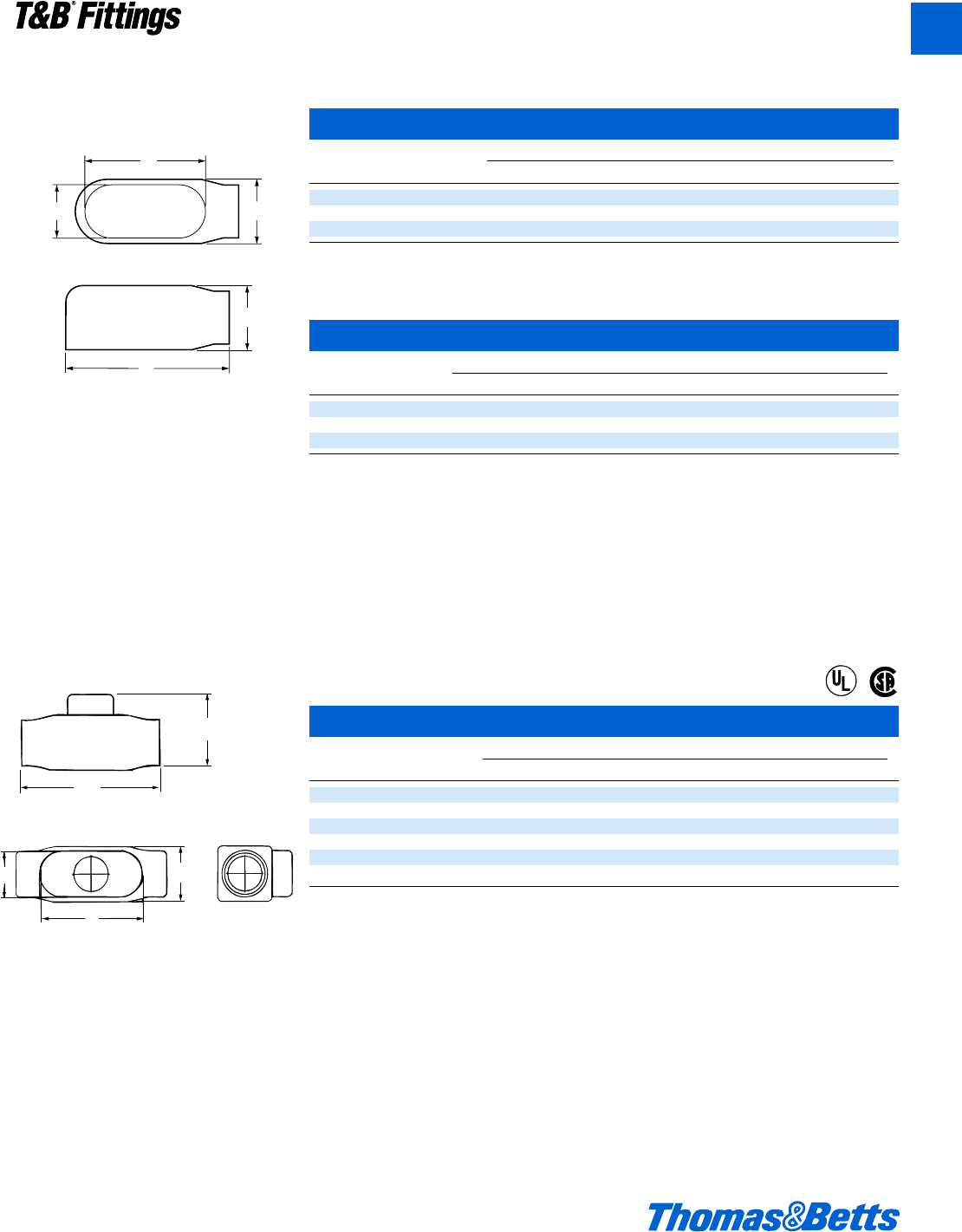
Form 7, Form 8, and Red•Dot®Conduit Outlet Bodies
E Threaded Aluminum
Cat. Dimensions (in.)
No. Size A B C D E F G CI
AE-1 d 3g 4c 1Q 1c 2u 2h m 4.3
AE-2 f 4e 5a 1w 1e 2A 2X n 7.3
AE-3 1 5c 5n 1f 1g 3b 2e 1 11.8
A
B
C
D
E
E Form 7
© 2002 Thomas & Betts Corporation. Specifications are subject to change without notice. www.tnb.com A49
T&B®Fittings
A
E Form 7
Cat. Dimensions (in.)
No. Size A B C D E CI
E17 d 4.60 1.40 1.45 .95 3.20 6.0
E27 f 5.25 1.60 1.65 1.15 3.80 9.1
E37 1 6.00 1.90 1.80 1.35 4.55 16.9
TB Form 8
Cat. Dimensions (in.)
No. Size A B C D E CI
TB18 d 5W 2e 1c 1 3j 6.0
TB28 f 6s 2g 1i 1i 3n 9.0
TB38 1 7j 3b 1f 1c 4l 15.0
TB484 1b 8d 3j 2i 1f 5j 24.0
TB58 1d 10c 3W 2f 2a 6d 46.5
TB68 2 12b 4b 3f 3 8l 88.0
A
B
D
E
C
TB Form 8
®
®
412031.A01 FIT 3/12 3/13/03 4:46 PM Page 49
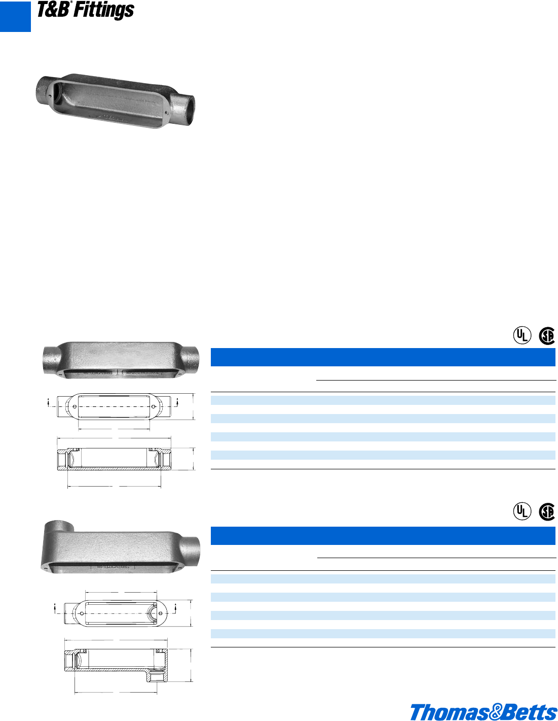
Mogul Conduit Outlet Bodies
A50 © 2002 Thomas & Betts Corporation. Specifications are subject to change without notice. www.tnb.com
T&B®Fittings
A
Application
Mogul bodies are installed in conduit systems to:
• Act as pull outlets for conductors that are stiff, due to large size or type of insulation.
• Provide the longer openings needed when pulling large conductors.
• Prevent sharp bends and kinks in large conductors (protects insulation during
installation.)
• Provide ample openings for splices and taps.
• Provide access to wiring for maintenance, and future system changes.
Features
Mogul bodies have:
• Long openings.
• Provision for easy bends.
• Tapered tapped hubs with integral bushings.
• Stainless Steel cover screws.
• Covers and gaskets included.
Standard Materials
• Class 30 Gray iron alloy.
Standard Finishes
• Electrogalvanized and aluminum acrylic paint.
Certifications and Compliances:
• UL Standard: 514B
• Fed. Spec.: W-C-586d
• CSA Standard: C22.2 No.18
• UL listed for wet locations.
E
A
C
D
B
SECTION A-A
A
B
E
C
D
SECTION A-A
D
BC Mogul Series
Cat. Dimensions (in.)
No. Size A B C D E CI
BC3-TB 19.56 1.88 2.25 7.84 6 20.0
BC4-TB 1b 9.56 2.31 2.25 7.84 6 25.0
BC5-TB 1d 13.75 2.56 3 11.45 10 60.0
BC6-TB 213.75 3.31 3 11.45 10 78.0
BC7-TB 2d 18.38 3.63 4.25 15.61 15 180.0
BC8-TB 318.38 4.38 4.25 15.82 15 225.0
BC9-TB 3d 23.75 4.88 5.25 20.50 20 410.0
BC10-TB 423.75 5.38 5.25 20.50 20 460.0
BLB†Mogul Series
Cat. Dimensions (in.)
No. Size A B C D E CI
BLB3-TB 1 8.66 2.80 2.25 6.92 6 20.0
BLB4-TB 1b 8.66 2.70 2.25 6.70 6 25.0
BLB5-TB 1d 12.58 2.56 3 10.36 10 62.0
BLB6-TB 2 12.58 4.16 3 10.13 10 78.0
BLB7-TB 2d 16.94 5.10 4.25 13.89 15 170.0
BLB8-TB 3 16.94 5.81 4.25 13.59 15 210.0
BLB9-TB 3d 22.16 6.50 5.25 18.32 20 410.0
BLB10-TB 4 22.16 7.00 5.25 18.06 20 460.0
BC
BLB
®
®
®
®
412031.A01 FIT 3/12 3/13/03 4:46 PM Page 50
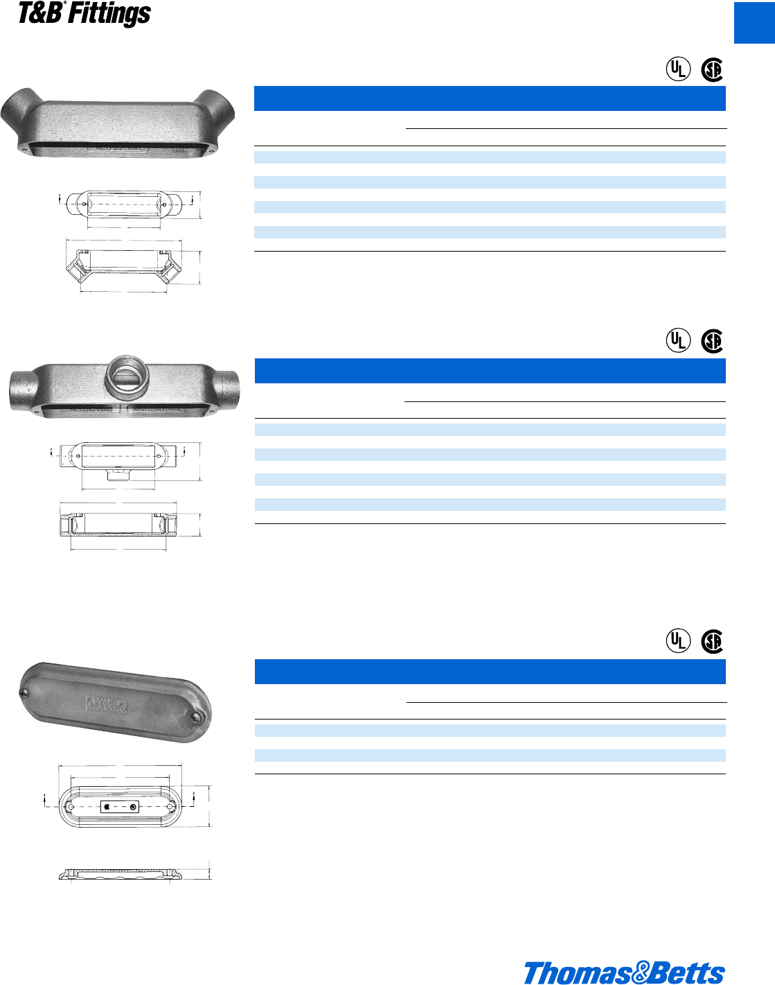
Mogul Conduit Outlet Bodies
© 2002 Thomas & Betts Corporation. Specifications are subject to change without notice. www.tnb.com A51
T&B®Fittings
A
A
E
C
B
D
SECTION A-A
A
E
SECTION A-A
C
D
B
BUB Mogul Series
Cat. Dimensions (in.)
No. Size A B C D E CI
BUB3-TB 19.49 2.75 2.25 7.01 6 20.0
BUB4-TB 1b 9.55 3.21 2.25 6.71 6 25.0
BUB5-TB 1d 16.68 6.67 3 10.47 10 62.0
BUB6-TB 213.68 4.28 3 10.20 10 78.0
BUB7-TB 2d 18.30 5.03 4.25 13.97 15 170.0
BUB8-TB 318.30 5.67 4.25 13.50 15 210.0
BUB9-TB 3d 23.74 6.72 5.25 18.07 20 385.0
BUB10-TB 423.74 7.22 5.25 17.73 20 430.0
BT Mogul Series
Cat. Dimensions (in.)
No. Size A B C D E CI
BT3-TB 1 9.56 1.88 3.16 7.84 6 20.0
BT4-TB 1b 9.56 2.31 3.16 7.84 6 25.0
BT5-TB 1d 13.75 2.56 4.06 11.45 10 62.0
BT6-TB 2 13.75 3.31 4.06 11.45 10 78.0
BT7-TB 2d 18.38 3.63 5.59 15.61 15 180.0
BT8-TB 3 18.38 4.38 5.72 15.82 15 225.0
BT9-TB 3d 23.75 4.88 6.88 20.50 20 410.0
BT10-TB 4 23.75 5.38 6.88 20.50 20 460.0
BUB
BT
A
B
C
D
SECTION A-A
BG
BG Mogul Series Replacement Covers
Cat. Dimensions (in.)
No. Size A B C D E
BG48T-B 1 to 1b 8.27 6.62 2.77 .67 –
BG68-TB 1d to 2 12 10.62 3.60 .82 –
BG88-TB 2d to 3 16.22 12.44 4.97 .85 2.75
BG98-TB 3d to 4 21.21 16.63 5.96 .87 3.75
®
®
®
®
®
®
412031.A01 FIT 3/12 3/13/03 4:46 PM Page 51
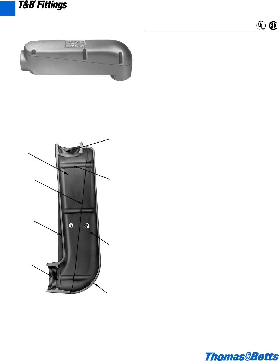
Aluminum Mogul Conduit Outlet Bodies
Application
• Raintight junction for bringing electrical service into a location.
• Spacious, accessible wiring chamber provides a convenient
location to pull conductors and make splices.
Features/Benefits
• Copper-free* aluminum provides increased corrosion resistance.
• Precision cast and machined surfaces permit safer wire pulling.
• Clean cover edges provide good gasket sealing.
• Precision NPT threaded hubs allow trouble-free field installation
for rigid and IMC conduit.
• Deep slotted stainless steel cover screws for faster installation.
• Clear UL, CSA and cubic content markings speed approval by
inspectors.
• Dome style cover permits easy wire pulling.
• Meets NEC Article 370-28, 6-1 ratio.
Standard Materials
• Mogul Pulling Elbows: Die cast aluminum alloy A360 with less
than .004 copper content (copper-free). Stainless steel screws.
• Gaskets: Composition
Standard Finish
• Aluminum lacquer finish
Compliances
• UL Listed
• CSA Certified
• Federal Spec. W-C-586
• NEC Article 370-28
Sample Specifications
• Mogul Pulling Elbows shall be die cast copper-free* aluminum
alloy A360. All conduit stops shall be coined and free of rough
edges. Mogul Pulling Elbows shall be finished with aluminum
lacquer.
Mogul Pulling Elbows shall be Red•Dot®Catalog No. __________
*Less than .004 copper content
MALB
Copper-free
aluminum
Clean
cover
edges
Strong
“I” beam
construction
Smooth
conduit
stops
Precision
machined
threads
Deep
slotted
stainless
steel
screws
Large
dome
cover
Clear
markings
NEMA 3RMeets NEC Article 370-28,
6-1 Ratio
Suitable for use in
Wet Locations
®
®
®
®
A52 © 2002 Thomas & Betts Corporation. Specifications are subject to change without notice. www.tnb.com
T&B®Fittings
A
412031.A01 FIT 3/12 3/13/03 4:46 PM Page 52
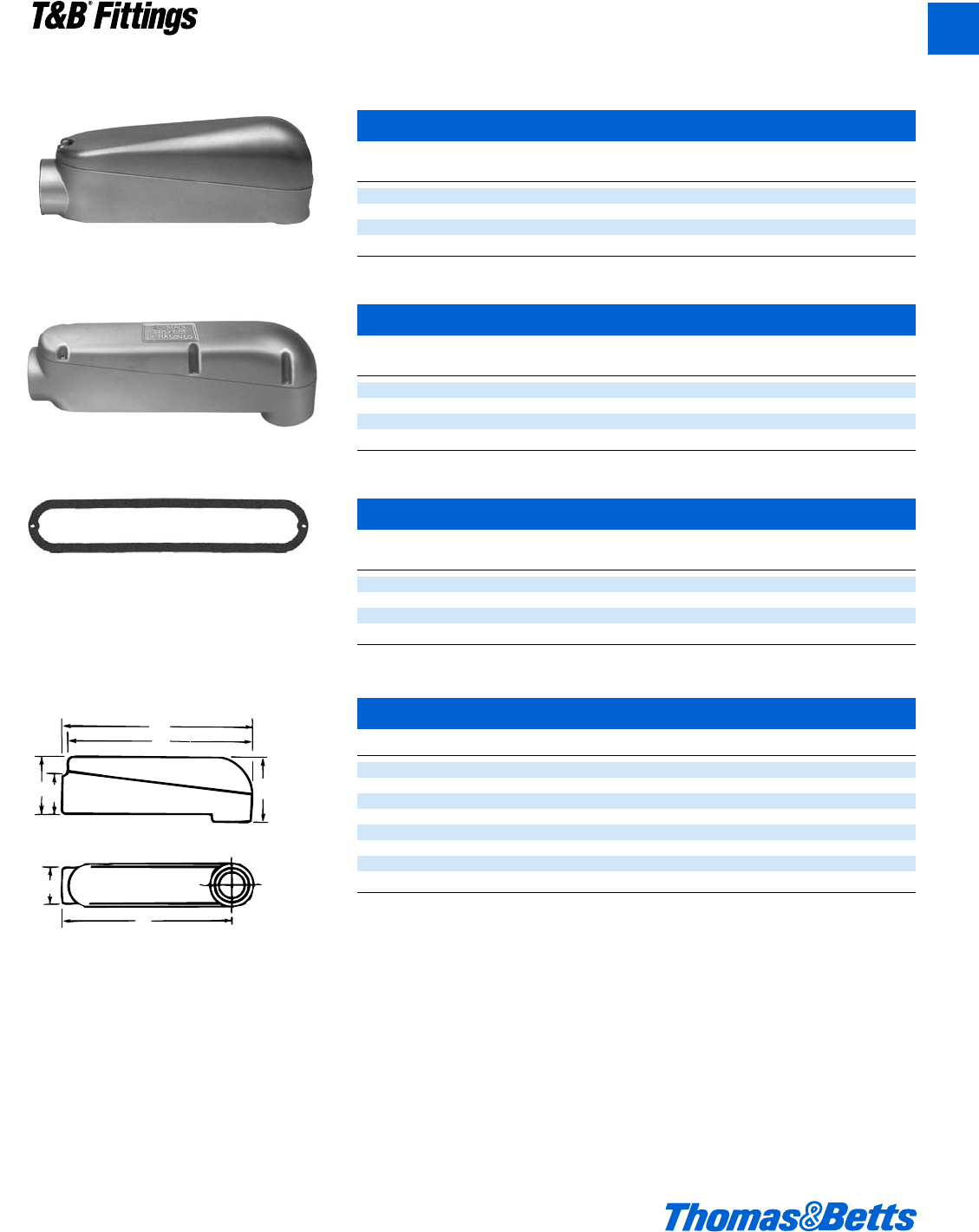
Aluminum Mogul Conduit Outlet Bodies
MALB-3 through -6
Complete with Cover, Gasket and Screws – Raintight
Cat. Hub Unit Std. Wt. lbs.
No. Size Qty. Pkg. per 100
MALB-3 1" 1 10 174
MALB-4 1b" 2 10 160
MALB-5 1d" 1 1 400
MALB-6 2" 1 1 375
Cat. Hub Unit Std. Wt. lbs.
No. Size Qty. Pkg. per 100
MALB-7 2d' 1 1 1100
MALB-8 3" 1 1 1060
MALB-9 3d" 1 1 1900
MALB-10 4" 1 1 1800
Cat. Hub Unit Std. Wt. lbs.
No. Size Qty. Pkg. per 100
MGKV-4 1" or 1b" 153
MGKV-5 1d" or 2" 154
MGKV-6 2d" or 3" 155
MGKV-7 3d" or 4" 155
MALB-7 through -10
MGKV-4 through -7
A
B
F
G
C
E
D
MALB
MALB
Size A B C D E F G
1" 9e 9h 2d 2f 2h 8d 3e
1b" 9e 9h 2d 2f 2h 8d 3e
1d" 14w 14b 2f 4 2m 13 5r
2" 14w 14b 2f 4 2m 13 5r
2d" 21W 21u 4d 5e 4c 18 7z
3" 21W 21u 4d 5e 4c 18 7z
3d" 28e 28W 5d 6d 5c 24 9z
4" 28e 28W 5d 6d 5c 24 9z
NEMA 3RMeets NEC Article 370-28,
6-1 Ratio
Suitable for use in
Wet Locations
© 2002 Thomas & Betts Corporation. Specifications are subject to change without notice. www.tnb.com A53
T&B®Fittings
A
412031.A01 FIT 3/12 3/13/03 4:46 PM Page 53
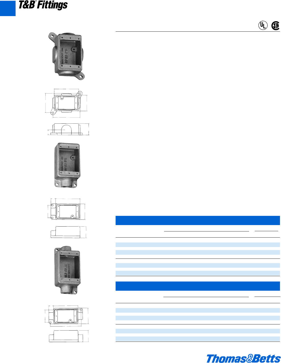
FS/FD Cast Device Boxes and Covers
A54 © 2002 Thomas & Betts Corporation. Specifications are subject to change without notice. www.tnb.com
T&B®Fittings
A
Application
Cast device boxes are installed to:
• Accommodate wiring devices.
• Act as pull boxes for conductors in a threaded rigid conduit system, including
an internal ground screw.
• Provide openings to make splices and taps in conductors.
• Provide access to conductors for maintenance and future system changes.
• Connect conduit sections.
Features
All hubs have NPT Threads with a minimum of five full threads and integral
bushing. Internal grounding screw standard on boxes.
• Suitable for wet locations when used with gasketed covers.
• Available in shallow (FS) or deep (FD) boxes. Use FD if device to be enclosed
exceeds 1e" in depth.
• Use blank bodies where special arrangements of conduit hubs or entrances
are required.
• All cover holes are #6-32.
• Mounting lugs are standard on all FS and FD boxes.
Size Range
• Hubs - d" to 1" NPT
Materials
• Boxes: Class 30 Gray iron alloy
• Covers: Sand cast AL alloy and sheet steel
• Gaskets: Neoprene
Finish
• Zinc-plated with aluminum acrylic paint
Listing Certifications
• UL: 514A (wet locations when used with gasketed covers)
• CSA: C22.2 No.18
Shallow Single Gang Cast Device Boxes
Cat. Hub Dimensions (Inches) Throat Dia.
No. Fig. Size A B C D E F G Min. Max.
Dead-End
FS019-TB A Blank 2 2f 4s – 3c 4z g N/A N/A
FS1-TB B d 2 2f 4s g 2i – – 0.570 0.610
FS2-TB B f 2 2f 4s g 2i – – 0.755 0.810
FS3-TB B 1 2 2f 4s g 2i – – 0.935 1.035
Thru-Feed
FSC1-TB C d22f4sg2i5c–0.570 0.610
FSC2-TB C f22f4sg2i5c–0.755 0.810
FSC3-TB C 122f4sg2i5c–0.935 1.035
Deep Single Gang Cast Device Boxes
Cat. Hub Dimensions (Inches) Throat Dia.
No. Fig. Size A B C D E F G Min. Max.
Dead-End
FD019-TB A Blank 2m 2f 4s – 3c 4z 1c N/A N/A
FD1-TB B d2m2f 4sg 2i – – 0.570 0.610
FD2-TB B f2m2f 4sg 2i – – 0.755 0.810
FD3-TB B 12m2f4sg2i – –0.935 1.035
Thru-Feed
FDC1-TB C d 2m 2f 4s g 2i 5c – 0.570 0.610
FDC2-TB C f 2m 2f 4s g 2i 5c – 0.755 0.810
FDC3-TB C 1 2m 2f 4s g 2i 5c – 0.935 1.035
C
EB
F
G
A
DC
EB
A
DC
EB
A
F
A
Dead-End
B
C
Dead-End
Thru-Feed
®
®
412031.A01 FIT 3/12 3/13/03 4:46 PM Page 54
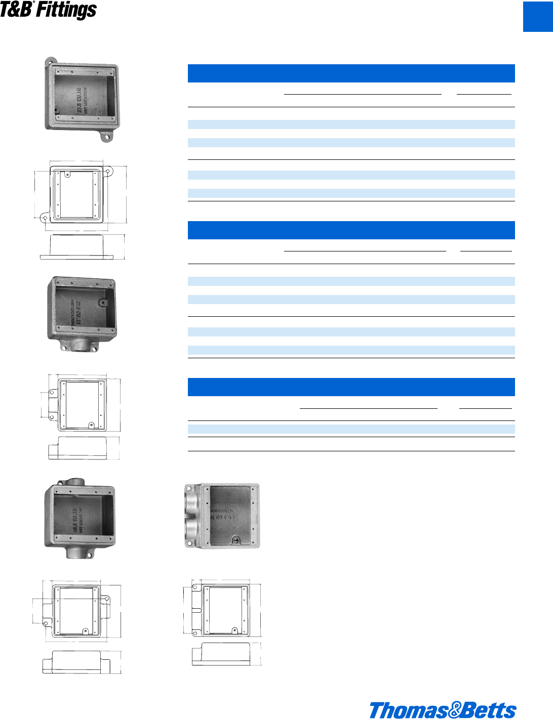
FS/FD Cast Device Boxes and Covers
© 2002 Thomas & Betts Corporation. Specifications are subject to change without notice. www.tnb.com A55
T&B®Fittings
A
Shallow Double Gang Cast Device Boxes
Cat. Hub Dimensions (Inches) Throat Dia.
No. Fig. Size A B C D E F Min. Max.
Dead-End
FS062-TB A Blank 2 4e 4s – 4a 5d N/A N/A
FS12-TB B d 2 4e 4s g 2i – 0.570 0.610
FS22-TB B f 2 4e 4s g 2i – 0.755 0.810
FS32-TB B 1 2 4e 4s g 2i – 0.935 1.035
Thru-Feed
FSC12-TB C d 2 4e 4s g 2i 5c 0.570 0.610
FSC222-TB C f 2 4e 4s g 2i 5c 0.755 0.810
FSC32-TB C 1 2 4e 4s g 2i 5c 0.935 1.035
Deep Double Gang Cast Device Boxes
Cat. Hub Dimensions (Inches) Throat Dia.
No. Fig. Size A B C D E F Min. Max.
Dead-End
FD062-TB A Blank 2m 4e 4s – 4a 5d N/A N/A
FD12-TB B d2m4e 4s g 2i – 0.570 0.610
FD22-TB B f2m4e 4s g 2i – 0.755 0.810
FD32-TB B 1 2m 4e 4s g 2i – 0.935 1.035
Thru-Feed
FDC12-TB C d2m4e 4s g 2i 5c 0.570 0.610
FDC222-TB C f2m4e 4s g 2i 5c 0.755 0.810
FDC32-TB C 1 2m 4e 4s g 2i 5c 0.935 1.035
Double Gang Cast Device Boxes, Double Hub
Cat. Hub Dimensions (Inches) Throat Dia.
No. Fig. Size A B C D E Min. Max.
FSS222-TB D f 2 4e 4s g 4h 0.755 0.810
FDS222-TB D f2m4e4sg 4h 0.755 0.810
C
E
B
A
F
DC
EB
A
DC
B
E
A
F
A
Dead-End
B
C
D
DC
EB
A
Dead-End
Dead-End
Thru-Feed
412031.A01 FIT 3/12 3/13/03 4:46 PM Page 55
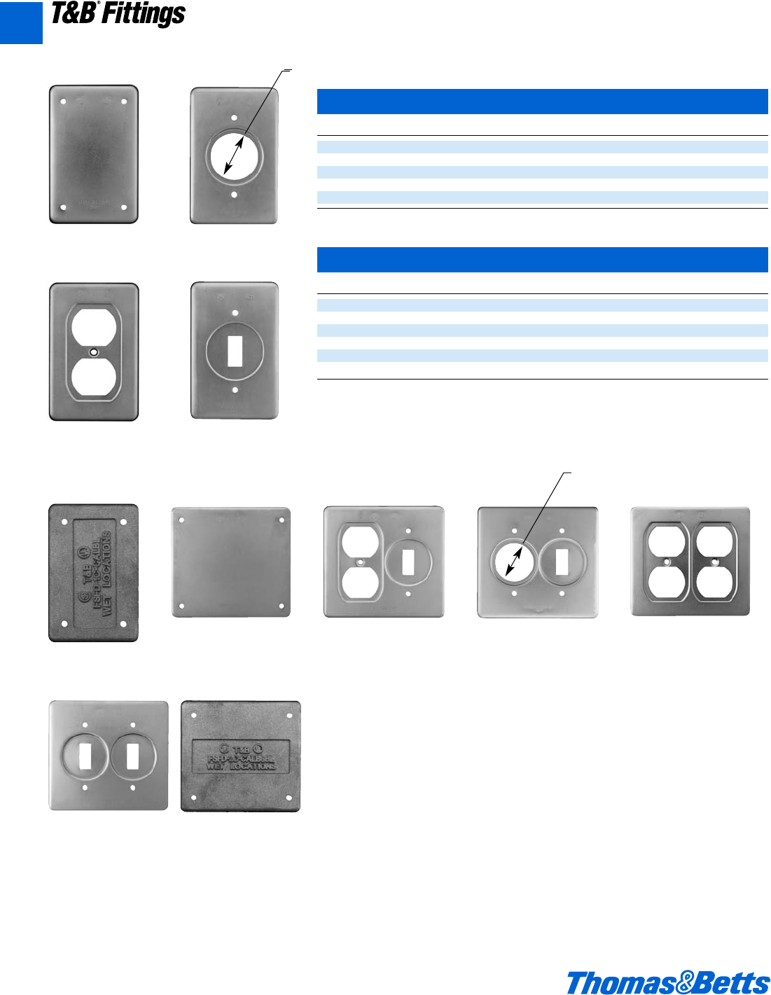
FS/FD Cast Device Boxes and Covers
A56 © 2002 Thomas & Betts Corporation. Specifications are subject to change without notice. www.tnb.com
T&B®Fittings
A
Single Gang Covers
Cat. No. Description
DSS100-TB Blank, Sheet Steel
DS21-TB Round Receptacle, Sheet Steel
DS23-TB Duplex Receptacle, Sheet Steel
DS32-TB Single Switch, Sheet Steel
DS100G-TB Blank, Cast Aluminum
Double Gang Covers
Cat. No. Description
S1002-TB Blank, Sheet Steel
S32232-TB 2 Receptacle/Switch, Sheet Steel
S32212-TB Single Receptacle/Switch, Sheet Steel
S232-TB 2 Dual Receptacle, Sheet Steel
S322-TB 2 Switch, Sheet steel
S1002GSA-TB Blank, Cast Aluminum with Gasket
DSS100-TB DS21-TB
DS23-TB DS32-TB
DS100G-TB
S1002-TB S32232-TB S32212-TB S232-TB
S322 S1002GSA-TB
1.405 dia. hole
1.405 dia. hole
412031.A01 FIT 3/12 3/13/03 4:46 PM Page 56
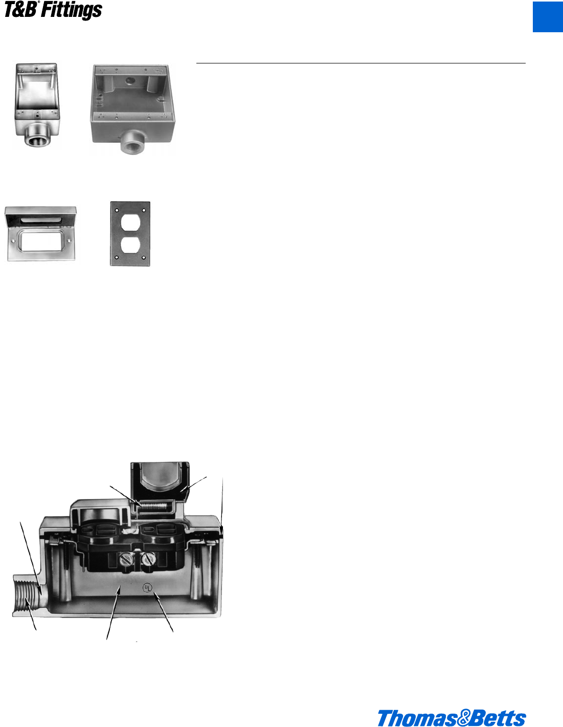
AFS 2AFSC
CWP-G CDR
FS/FD Aluminum Device Boxes and Covers
Application
• Industrial grade FS device boxes and raintight covers protect wiring devices,
switches, electronic components, and terminal blocks in Dry, Damp and Wet
Locations.
• Spacious, accessible wiring chamber provides a convenient location to main-
tain or change a system, pull conductors and make splices.
• Junction for branch conduits.
• Aluminum boxes can be used with steel rigid conduit.
Features/Benefits
• Copper-free* aluminum, stainless steel cover springs and hinge pins provide
increased corrosion resistance.
• Die cast construction, boxes with securely fastened mounting plates and
industrial designed covers combine to produce a rugged protective enclosure
for devices on industrial and OEM applications.
• Clean cover edges provide good gasket sealing.
• Precision NPT threaded hubs allow trouble-free field installation for rigid or
IMC conduit.
• Clear UL, CSA and cubic content markings speed approval by inspectors.
• Boxes - external hub design provides increased wiring room.
Standard Materials
• Die cast aluminum alloy A360 with less than .004 copper content (copper-free).
• Cover hinge pins and springs: Stainless steel.
Standard Finish
• Aluminum lacquer finish.
Compliances:
• UL Listed
• Boxes CSA Certified with factory installed ground screw **
• Covers CSA Certified
• Federal Spec. W-C-586
Sample Specifications
• Industrial grade FS device boxes and covers shall be die
cast copper-free* aluminum alloy A360. All conduit stops
shall be coined and free of rough edges. Raintight covers
shall have stainless steel springs and hinge pins and are
suitable for use in wet locations with cover closed (CFSB,
CFST and CFSTF suitable for wet locations). Industrial grade
FS device boxes and covers shall be finished with aluminum
lacquer. Industrial grade FS device boxes and covers shall
be Red•Dot®Catalog No. _______
**Less than .004 copper content
**Consult factory for lead time and minimum quantity.
Stainless
steel
springs
Smooth
conduit
stops
High
quality
gaskets
Precision
machined
threads
Copper-free*
aluminum
Clear
marking
© 2002 Thomas & Betts Corporation. Specifications are subject to change without notice. www.tnb.com A57
T&B®Fittings
A
412031.A01 FIT 3/12 3/13/03 4:46 PM Page 57
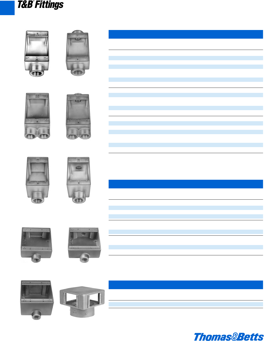
AFS AFSC
AFSS AFSCC
ADFS ADFSC
2AFS 2AFSC
2ADFS
Single Gang Boxes *Raintight
Cat. Hub Unit Std. Wt. lbs.
No. Size Qty. Pkg. per 100
Standard, 1 Hole Box, Dead End
* AFS-1 d" 52568
* AFS-2 f" 52574
* AFS-3 1" 52572
Standard, 2 Hole Box, Through Feed
* AFSC-1 d" 52572
* AFSC-2 f" 52588
* AFSC-3 1" 52579
Standard, 2 Hole Box, Dead End
* AFSS-1 d" 52580
* AFSS-2 f" 52576
Standard, 3 Hole Box, Through Feed
* AFSCC-1 d" 52588
* AFSCC-2 f" 52580
Deep, 1 Hole Box, Dead End
* ADFS-1 d" 574
* ADFS-2 f" 578
* ADFS-3 1" 580
Deep, 2 Hole Box, Through Feed
* ADFSC-1 d" 576
* ADFSC-2 f" 590
* ADFSC-3 1" 590
*Raintight when used with appropriate Red•Dot®covers.
FS/FD Aluminum Device Boxes and Covers
Two Gang Boxes *Raintight
Cat. Hub Unit Std. Wt. lbs.
No. Size Qty. Pkg. per 100
Standard, 1 Hole Box, Dead End
* 2AFS-1 d" 2 10 115
* 2AFS-2 f" 21095
* 2AFS-3 1" 21090
Standard, 2 Hole Box, Through Feed
* 2 AFSC-1 d" 2 10 104
* 2AFSC-2 f" 2 10 102
Deep, 1 Hole Box, Dead End
* 2ADFS-1 d" 3 128
* 2ADFS-2 f" 3 143
* 2ADFS-3 1" 3 129
*Raintight when used with appropriate Red•Dot®covers.
Suitable for use
in Wet Locations
NEMA 3R
A58 © 2002 Thomas & Betts Corporation. Specifications are subject to change without notice. www.tnb.com
T&B®Fittings
A
Multi-Gang Boxes *Raintight
Cat. Hub Std. Wt. lbs.
No. Size Pkg. per 100
FSMG-TB 4" threadless Conduit 1 242
*Raintight when used with appropriate Red•Dot®covers.
FSMG-TB
412031.A01 FIT 3/12 3/13/03 4:46 PM Page 58
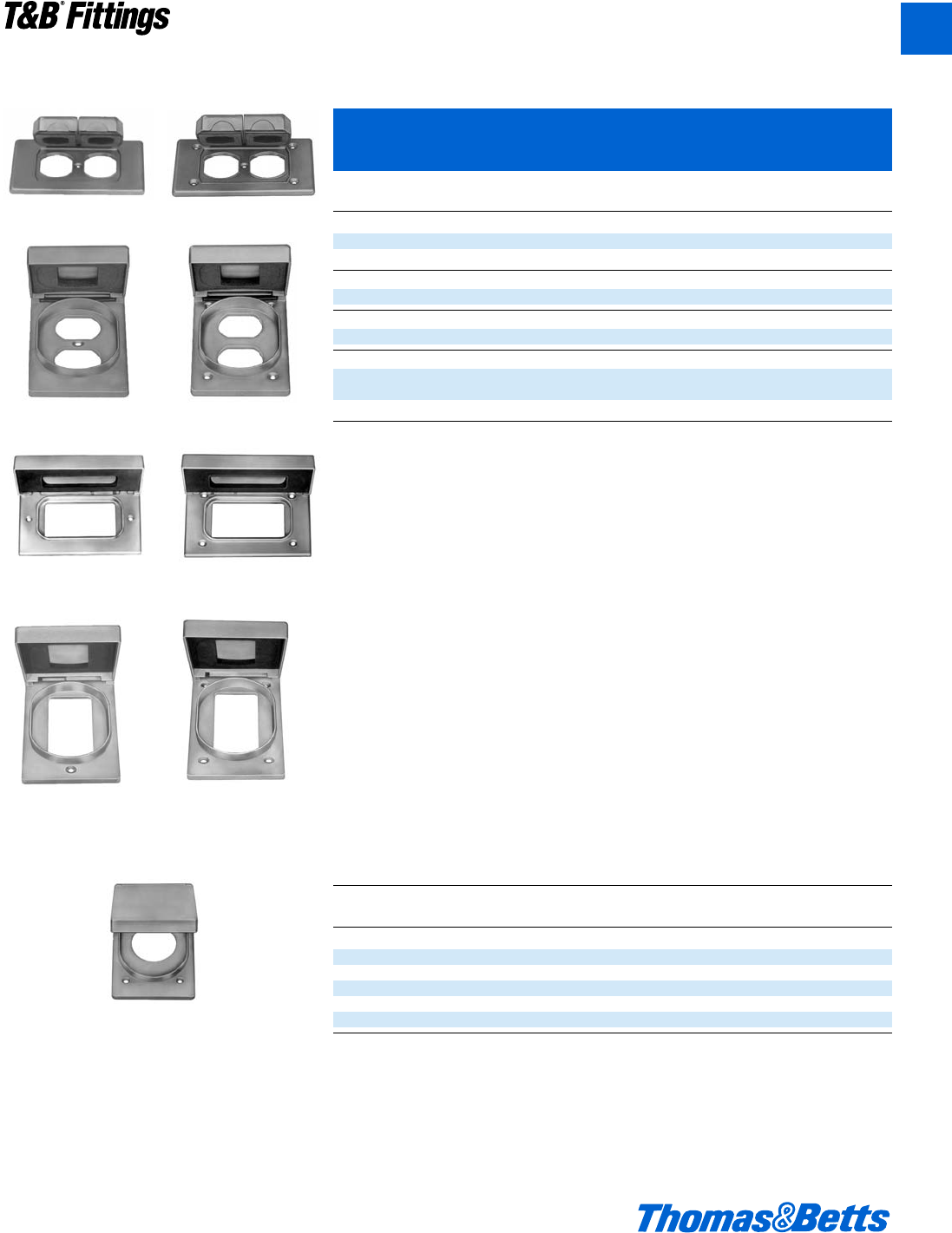
CWPDR
CWPV-DR CFSDR
CWP-G CFSH-G
CWPV-G CFSR-G
CFSR Series
CWPDR-FS
Single Gang Covers Complete with Gasket and
Screws *Raintight
Cat. Unit Std. Wt. lbs.
No. Description Qty. Pkg. per 100
For Duplex Receptacles, Horizontal
* CWPDR Duplex receptacle cover with 2 spring doors, Device Mount 1 25 40
* CWPDR-FS Box Mount 1 25 40
For Duplex Receptacles, Vertical
* CFSDR Box Mount 1 25 38
For GFCI Receptacles Horizontal
* CFSH-G Box Mount 1 25 40
For GFCI Receptacles Vertical
* CWPV-G GFCI receptacle cover 2y” x 1X” rectangular opening 1 25 40
Device Mount
* CFSR-G Box Mount 1 25 40
*Raintight when used with appropriate Red•Dot®boxes.
Cat. Nominal Max. Device Unit Std. Wt. lbs
No. Size Face Dia. Qty. Pkg. per 100
For Single Receptacles Vertical (Box Mount Only)
* CFSR-L 1l" 1.600” 1 25 40
* CFSR-S 1c" 1.395” 1 25 40
* CFSR-X 1B" 1.865” 1 25 40
* CFSR-XL 2a" 2.145” 1 25 40
* CFSR-Y 1f" 1.750 1 25 40
*Raintight when used with appropriate Red•Dot®boxes.
FS/FD Aluminum Device Boxes and Covers
Suitable for use in
Wet Locations with Cover
Closed NEMA 3R
© 2002 Thomas & Betts Corporation. Specifications are subject to change without notice. www.tnb.com A59
T&B®Fittings
A
412031.A01 FIT 3/12 3/13/03 4:46 PM Page 59
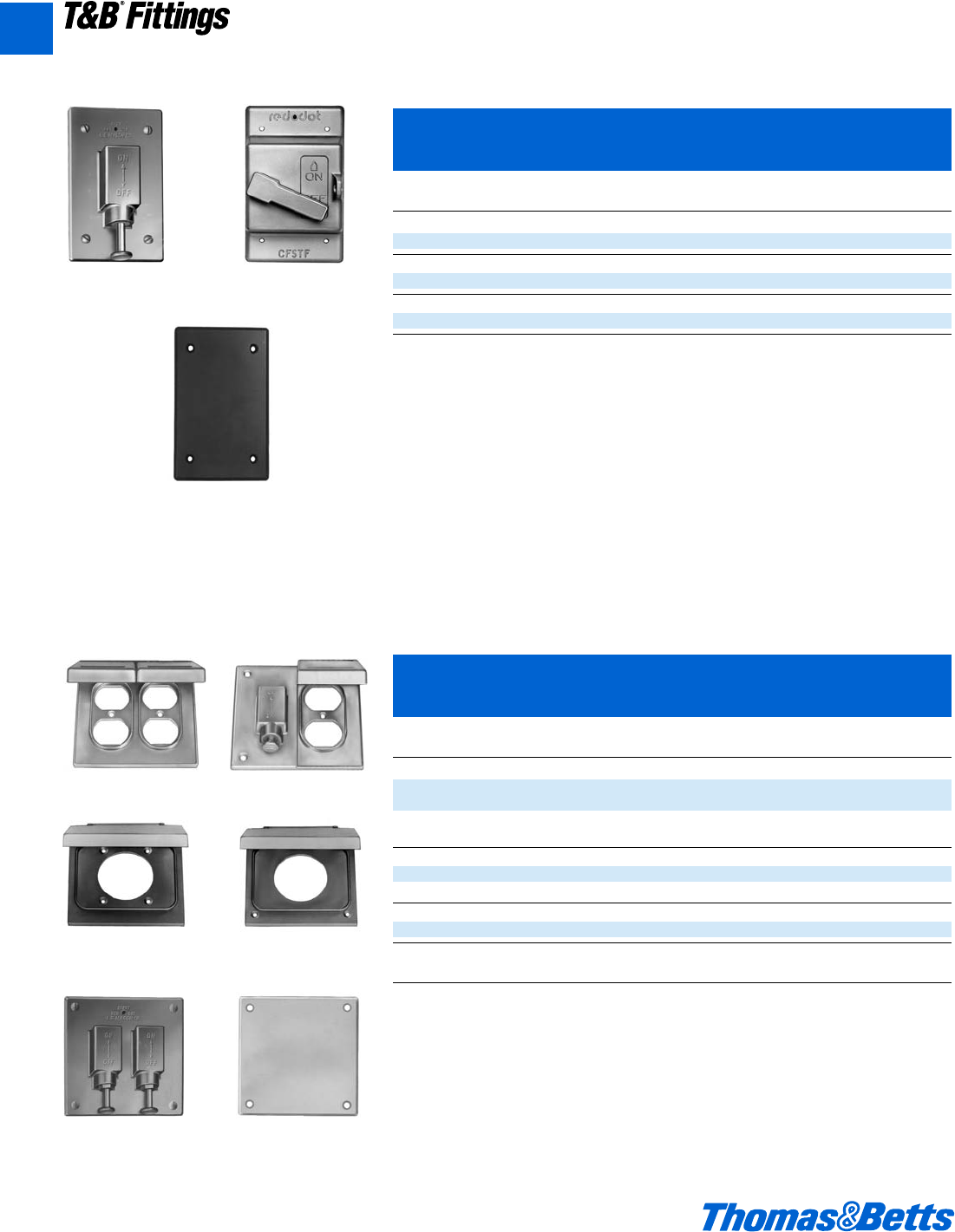
CFSTF
CFSB
FS/FD Aluminum Device Boxes and Covers
Single Gang Covers Complete with Gasket and Screws
*Raintight
Cat. Unit Std. Wt. lbs.
No. Description Qty. Pkg. per 100
Switch Cover
* CFST Plunger Style, Switch Cover, Box Mount NEMA 3R 1 25 40
Switch Cover
* CFSTF Front Lever, Switch Cover, Box Mount NEMA 4 1 25 40
Blank Cover
* CFSB Blank Cover, Box Mount, NEMA 3R 20 100 14
*Raintight when used with appropriate Red•Dot®boxes.
CFST
Suitable for use in
Wet Locations with Cover
Closed NEMA 3R
2CWPDR 2CWTDR
2CWPR-M 2CFSR-M
2CFST 2CFSB
FS/FD Aluminum Device Boxes and Covers
Two Gang Covers Complete with Gasket and Screws
*Raintight
Cat. Unit Std. Wt. lbs.
No. Description Qty. Pkg. per 100
For Two Duplex Receptacles
* 2CWPDR Two Duplex Receptacle Cover with 2 Spring Doors, 1 10 48
Device Mount
For Switch and Duplex Receptacle
* 2CWTDR Switch and Duplex Receptacle Cover, Box/Device Mount 1 10 48
For Single Receptacle
* 2CWPR-M Single Receptacle Cover, Hole Dia. 2b”, Device Mount 1 10 48
* 2CFSR-M Single Receptacle Cover, Hole Dia. 2b”, Box Mount 1 10 48
For Two Switches
* 2CFST Plunger Style Switch Cover, Box Mount 1 10 26
Blank
* 2CFSB Blank Cover, Box Mount 10 50 25
*Raintight when used with appropriate Red•Dot®boxes.
A60 © 2002 Thomas & Betts Corporation. Specifications are subject to change without notice. www.tnb.com
T&B®Fittings
A
412031.A01 FIT 3/12 3/13/03 4:46 PM Page 60
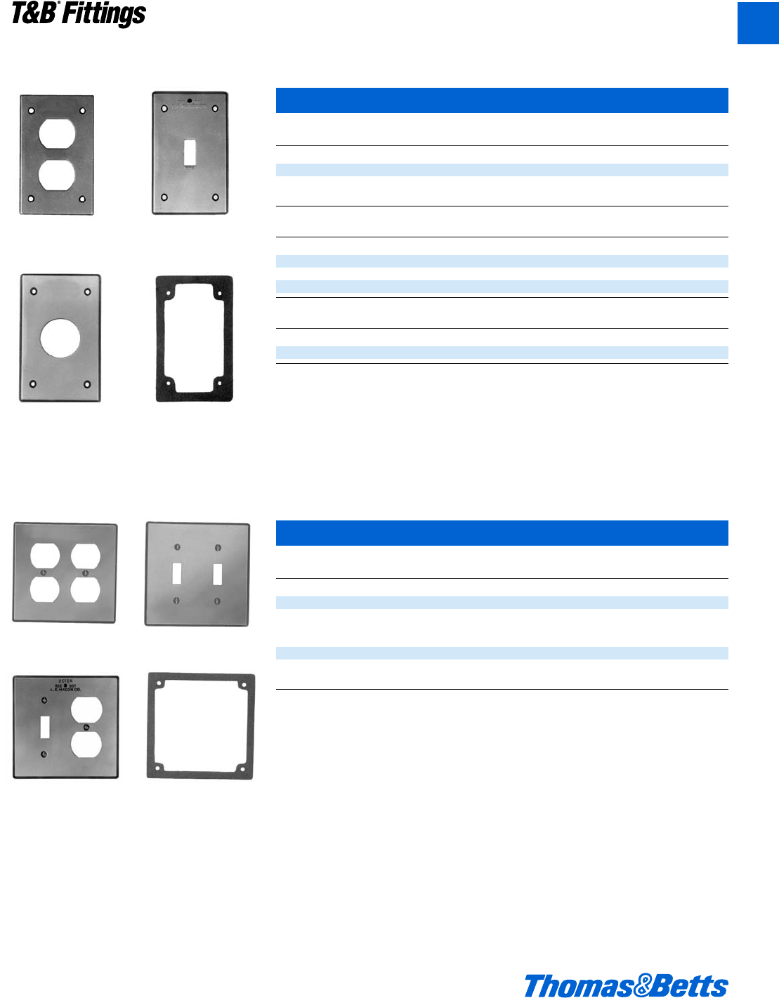
CDR CTS
CR Series FS-GKV
FS/FD Aluminum Device Boxes and Covers
Single Gang Covers Complete with Gasket and Screws
Cat. Unit Std. Wt. lbs.
No. Description Qty. Pkg. per 100
For Duplex Receptacles
CDR Duplex receptacle Cover, Box Mount 20 100 11
For Switches
CTS Switch Cover, Box Mount 20 100 14
Cat. Nominal Max. Device Unit Std. Wt. lbs.
No. Size Face Dia. Qty. Pkg. per 100
For Single Receptacles (Box Mount Only)
CRL 1l" 1.600” 20 100 12
CRS 1c" 1.395” 20 100 12
CRX-L 2a" 2.145” 20 100 12
Cat. Std. Wt. lbs.
No. Description Pkg. per 100
Gasket
FS-GKV Composition Gasket 100 2
2CDR 2CTS
2CTDR 2FS-GKV
Two Gang Covers Complete with Gasket and Screws
Cat. Unit Std. Wt. lbs.
No. Description Qty. Pkg. per 100
For Two Duplex Receptacles
2CDR Two Duplex Receptacle Cover, Device Mount 10 50 24
For Two Switches
2CTS Switch Cover, Device Mount 10 50 24
For Switch and Duplex Receptacles
2CTDR Switch and Duplex Receptacle Cover, Device Mount 10 50 24
Gasket
2FS-GKV Composition Gasket 50 3
© 2002 Thomas & Betts Corporation. Specifications are subject to change without notice. www.tnb.com A61
T&B®Fittings
A
412031.A01 FIT 3/12 3/13/03 4:46 PM Page 61
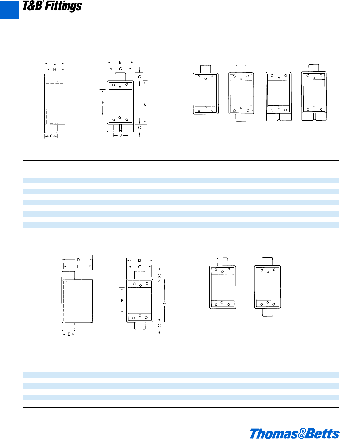
Cat. Hub
No. Size A B C D E F G H J CI
AFS-1 d" 4l 2m m 2h 1a 2g 2l 1n 21.6
AFS-2 f" 4l 2m m 2h 1L 2g 2l 1n 21.6
AFS-3 1” 4l 2m m 2h 1L 2g 2l 1n 21.6
AFSC-1 d" 4l 2m m 2h 1a 2g 2l 1n 21.6
AFSC-2 f" 4l 2m m 2h 1L 2g 2l 1n 21.6
AFSC-3 1" 4l 2m m 2h 1L 2g 2l 1n 21.6
AFSS-1 1d" 4l 2m m 2h 1c 2g 2l 1n 1d 21.6
AFSS-2 f" 4l 2m m 2h 1c 2g 2l 1n 1d 21.6
AFSCC-1 d" 4l 2m m 2h 1c 2g 2l 1n 1d 21.6
AFSCC-2 f" 4l 2m m 2h 1c 2g 2l 1n 1d 21.6
AFS, AFSC, AFSS, AFSCC
ADFS, ADFSC
ADFS ADFSC
FS/FD Aluminum Device Boxes and Covers
AFS AFSC AFSS AFSCC
Cat. Hub
No. Size A B C D E F G H CI
ADFS-1 d" 4l 2m g 3h 1a 2g 2l 2n 31.3
ADFS-2 f" 4l 2m g 3h 1L 2g 2l 2n 31.3
ADFS-3 1" 4l 2m g 3h 1L 2g 2l 2n 31.3
ADFSC-1 1d" 4l 2m g 3h 1a 2g 2l 2n 31.3
ADFSC-2 f" 4l 2m g 3h 1L 2g 2l 2n 31.3
ADFSC-3 1" 4l 2m g 3h 1L 2g 2l 2n 31.3
Dimensions and Cubic Inches (CI) Single Gang Boxes
A62 © 2002 Thomas & Betts Corporation. Specifications are subject to change without notice. www.tnb.com
T&B®Fittings
A
412031.A01 FIT 3/12 3/13/03 4:46 PM Page 62
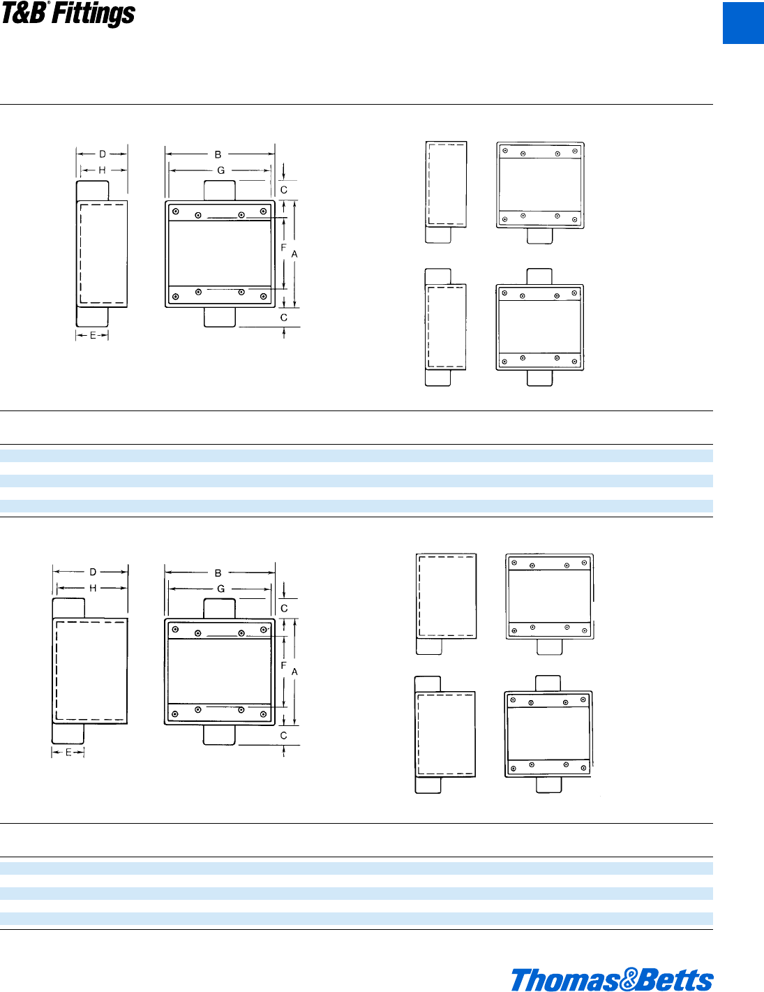
2AFS, 2AFSC
2AFS
2AFSC
2ADFS
2ADFSC
2ADFS, 2ADFSC
FS/FD Aluminum Device Boxes and Covers
Cat. Hub
No. Size A B C D E F G H CI
2AFS-1 d" 4l 4e m 2h 1c 2g 4c 1n 36.0
2AFS-2 f" 4l 4e m 2h 1c 2g 4c 1n 36.0
2AFS-3 1" 4l 4e g 2h 1L 2g 4c 1n 36.0
2AFSC-1 d" 4l 4e m 2h 1c 2g 4c 1n 36.0
2AFSC-2 f" 4l 4e m 2h 1c 2g 4c 1n 36.0
Cat. Hub
No. Size A B C D E F G H CI
2ADFS-1 d" 4l 4e m 3p 1c 2g 4c 2O 54.0
2ADFS-2 f" 4l 4e m 3p 1c 2g 4c 2O 54.0
2ADFS-3 1” 4l 4e g 3p 1L 2g 4c 2O 54.0
2ADFSC-2 f" 4l 4e m 3p 1c 2g 4c 2O 54.0
2ADFSC-3 1" 4l 4e g 3p 1L 2g 4c 2O 54.0
Dimensions and Cubic Inches (CI) Two Gang Boxes
© 2002 Thomas & Betts Corporation. Specifications are subject to change without notice. www.tnb.com A63
T&B®Fittings
A
412031.A01 FIT 3/12 3/13/03 4:47 PM Page 63
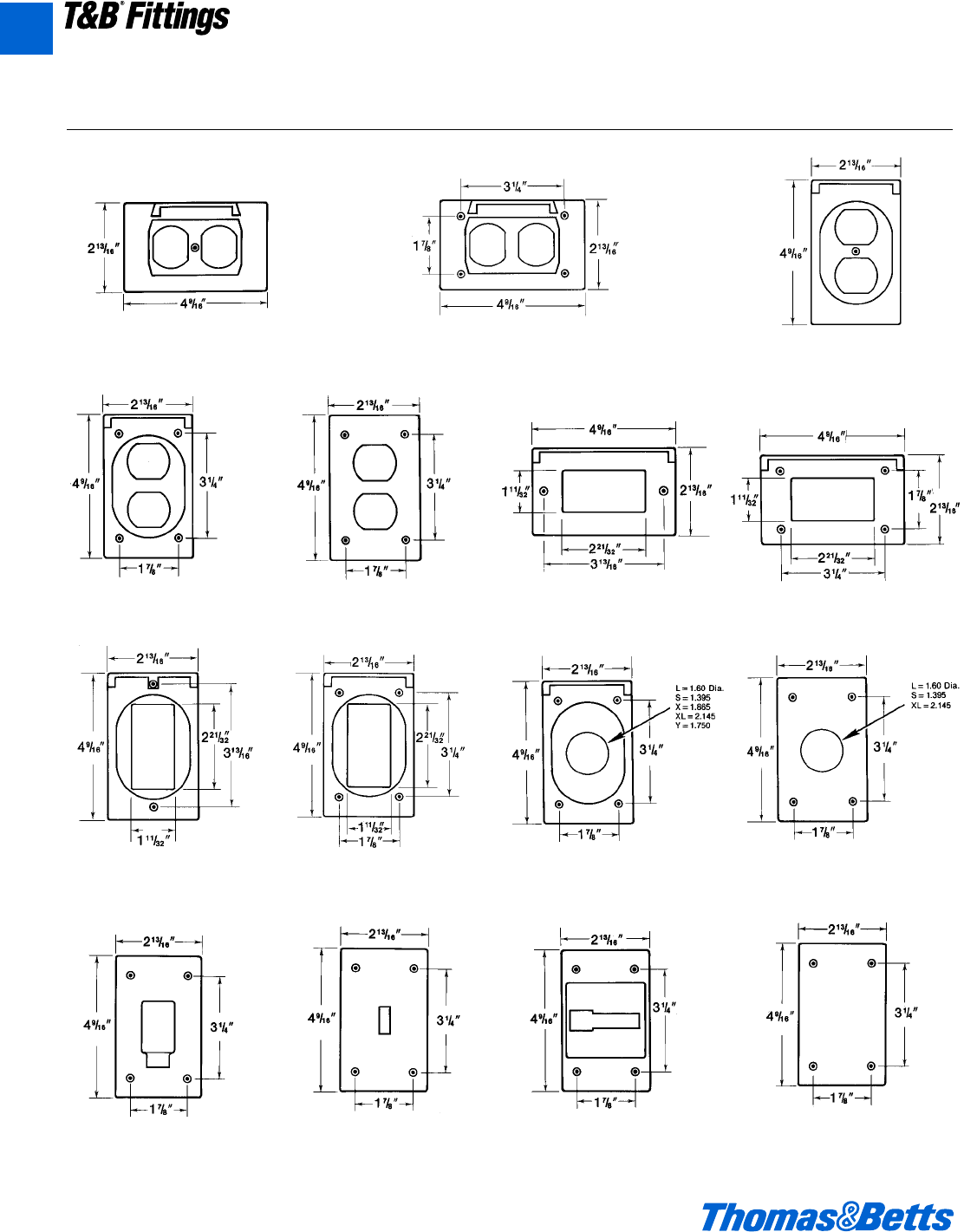
Dimensions Single Gang Covers
CWPDR CWPDR-FS CWPV-DR
CFSDR CDR CWP-G CFSH-G
CWPV-G CFSR-G CFSR Series CR Series
CFST CTS CFSTF CFSB
FS/FD Aluminum Device Boxes and Covers
A64 © 2002 Thomas & Betts Corporation. Specifications are subject to change without notice. www.tnb.com
T&B®Fittings
A
412031.A01 FIT 3/12 3/13/03 4:47 PM Page 64
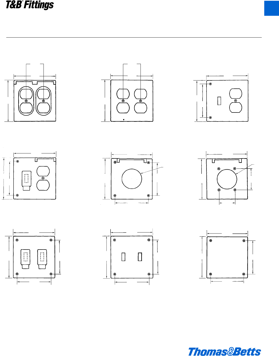
Dimensions Two Gang Covers
1m"
4e"
4l"
4e"
4l"
3L"
4e"
l"
3L"
4e"
2b"
Dia.
4l"
1m"
2c"
2b"
Dia.
FS/FD Aluminum Device Boxes and Covers
1m"
4e"
4l"
4l"
3f"
3L"
4e"
4e"
4l" 3L"
3f"
4e"
4l" 3L"
3f"
4e"
4l" 3L"
3f"
2CWPDR 2CDR 2CTDR
2CWTDR 2CFSR-M 2CWPR-M
2CFST 2CTS 2CFSB
© 2002 Thomas & Betts Corporation. Specifications are subject to change without notice. www.tnb.com A65
T&B®Fittings
A
412031.A01 FIT 3/12 3/13/03 4:47 PM Page 65
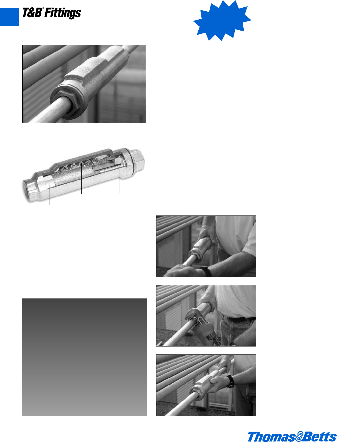
A66 © 2002 Thomas & Betts Corporation. Specifications are subject to change without notice. www.tnb.com
Conduit Expansion Coupling
XJG-TB Rigid Conduit Expansion Coupling
New
T&B®Fittings
No Disassembly Required.
Whenever you install a rigid
expansion coupling in a long con-
duit run, you normally need three
hands, two strong backs and lots
of patience. Now you can relax.
T&B introduces the new, no-has-
sle Rigid Conduit Expansion
Coupling. Installation’s just a few
turns and you’re done. The T&B
Rigid Conduit Expansion Coupling
features innovations that provide
conveniences to the installer, sav-
ing time and money on the job.
There’s no disassembly needed
during the installation, requiring
fewer tools and less opportunities
for lost pieces.
The new XJG-TB Rigid Conduit
Expansion Coupling also packs an
added punch: It’s the only fitting of
its kind that features a true internal
bonding jumper. This eliminates
the need for additional external
bonding jumpers, so there’s fewer
parts to buy and install.
If you need a fitting that can give
and take without a lot of hassle,
reach for T&B’s new XJG-TB Rigid
Conduit Expansion Coupling. It’s
the latest breakthrough in the
industry’s leading line of conduit
fittings. Contact your local repre-
sentative for more information
regarding the XJG-TB Rigid
Conduit Expansion Coupling and
the complete line of conduit fit-
tings from the name you trust for
quality design and manufacturing,
Thomas & Betts.
8" Movement
4" Movement
Innovative Design Makes
Installations Easier.
• No disassembly necessary to install
• Fast, simple, and requires fewer steps
• True Internal Bonding Jumper - no
external grounding strap required
• Tamper-proof internal jumper protected
from the environment
• Exceeds code requirements for long
conduit runs to permit linear movement
1
Slide the fitting onto the conduit
until it stops at the internal sliding
bushing. Tighten and you’re
ready. No parts to reassemble!
2
With a wrench, tighten the gland
nut to compress the Teflon pack-
ing, creating a rain-tight seal
around the conduit.
3
Thread the next length of conduit
into the other end of the fitting
and tighten. You’re done!
Internal Sliding
Bushing (keyed)
Internal Bonding
Jumper
Bonding
Bushing
Gland
Nut
A
412031.A01 FIT 3/12 3/13/03 4:47 PM Page 66
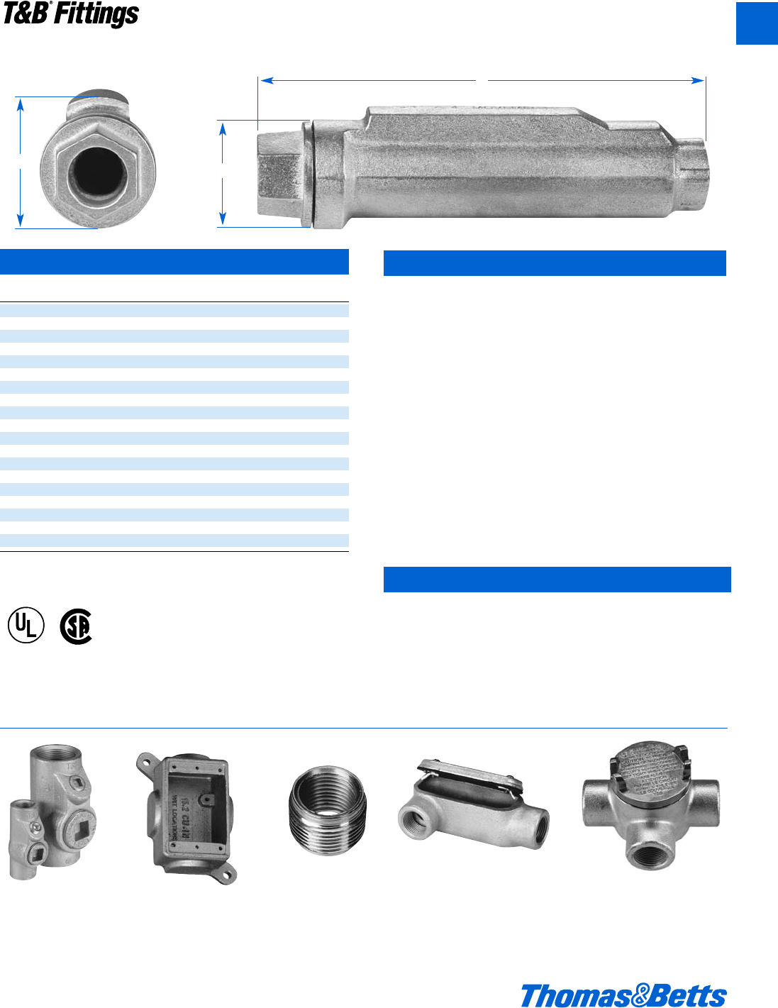
XJG Conduit Expansion Coupling
ABC
Cat No. Size Movement Diameter Length Height
XJG24-TB f" 4" 2.43 10.00 2.75
XJG28-TB f" 8" 2.43 14.00 2.75
XJG34-TB 1" 4" 2.67 10.00 2.99
XJG38-TB 1" 8" 2.67 14.00 2.99
XJG44-TB 1b" 4" 3.36 10.56 3.68
XJG48-TB 1b" 8" 3.36 14.56 3.68
XJG54-TB 1d" 4" 3.36 10.56 3.68
XJG58-TB 1d" 8" 3.36 14.56 3.68
XJG64-TB 2" 4" 3.86 11.25 4.18
XJG68-TB 2" 8" 3.86 15.25 4.18
XJG74-TB 2d" 4" 4.96 12.12 5.25
XJG78-TB 2d" 8" 4.96 16.12 5.25
XJG84-TB 3" 4" 4.96 12.12 5.25
XJG88-TB 3" 8" 4.96 16.12 5.25
XJG94-TB 3d" 4" 6.37 12.87 6.75
XJG98-TB 3d" 8" 6.37 16.87 6.75
XJG104-TB 4" 4" 6.37 12.87 6.75
XJG108-TB 4" 8" 6.37 16.87 6.75
XJG1208-TB 5" 8" 7.99 18.87 8.56
Please consult Technical Services for special orders and availability of products not shown in
this list.
© 2002 Thomas & Betts Corporation. Specifications are subject to change without notice. www.tnb.com A67
T&B®Fittings
Conduit Expansion Coupling
Suggested Specifications
Expansion Fittings for Rigid Steel or Intermediate Metal Conduit
Where raceways require expansion fittings to compensate for
thermal expansion and contraction and where expansion fittings
and telescoping sections of metal raceway shall be made electri-
cally continous by bonding jumpers or other means:
• Fitting will be constructed from malleable or ductile iron with
exterior and interior zinc plating for corrosion protection.
• The fitting shall be constructed so that disassembly is not
required during installation.
• Fitting shall be raintight after installation.
• The fitting shall have an internal bonding jumper constructed of
a tinned copper braid, sized to meet UL fault current test require-
ments and comply with bonding requirements - NEC article
250.98
• External bonding jumper shall not be required to comply with
NEC requirements.
• Accepted Manufacturers: Thomas & Betts - XJG-TB Series
Standard Materials / Finish
Body . . . . . . . . . . . . . . . . . Malleable or Ductile Iron,
available PVC Coated
Internal Bonding Jumper . . . Tinned Copper Braid
Exterior and Interior Finish .Zinc Plating, Aluminum Acrylic Paint
Packing . . . . . . . . . . . . . . . . PTFE/Synthetic Fiber Material
(Teflon®) Coated)
Listed / Certified By:
UL (File E23018, Std. 514B)
Suitable for Wet Locations
CSA (File LR2884, Std. C22.2 No. 18)
C
B
A
Our complete line makes specifying easy too.
Thomas & Betts offers a wide variety of quality fittings suitable
for outdoor use and hazardous locations.
®
®
A
412031.A01 FIT 3/12 3/20/03 3:17 PM Page 67
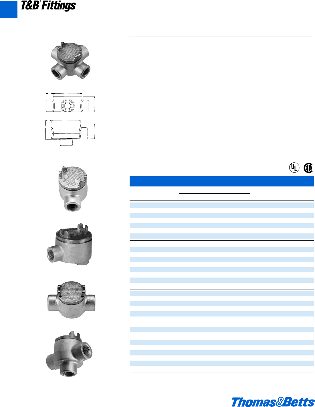
A68 © 2002 Thomas & Betts Corporation. Specifications are subject to change without notice. www.tnb.com
T&B®Fittings
GUA
GUAD
CB
A
GUA Conduit Outlet Boxes
Cat. Hub Dimensions (Inches) Throat Dia. Cubic In.
No. Size A B C D Min. Max. Capacity
GUA14-TB d 1m 2d g 1W .570 .610 5.5
GUA16-TB d 2 3d g 2 .570 .610 13.5
GUA24-TB f 2 2d g 1g .755 .810 5.3
GUA26-TB f 2 3d g 2 .755 .810 13.3
GUA36-TB 1 2j 3d g 2j .935 1.035 16.2
GUA47-TB 1b 2W 4c 1 2z 1.260 1.360 29
GUA59-TB 1d 3m 5f 1h 3J 1.470 1.590 70
GUAB14-TB d 2b 2d g 2ƒ .570 .610 6.9
GUAB16-TB d 2 3d g 2 .570 .610 13.5
GUAB24-TB f 2d 2d g 2c .755 .810 7.9
GUAB26-TB f 2 3d g 2 .755 .810 13.5
GUAB36-TB 1 2j 3d 1 2n .935 1.035 15.4
GUAB47-TB 1b 2W 4c 1 2z 1.260 1.360 27.5
GUAB59-TB 1d 3m 5f 1h 3J 1.470 1.590 73.6
GUAB69-TB 2 4h 5f 1h 4Y 1.880 2.047 80
GUAB79-TB 2d 4h 5f 1a 4Y 2.320 2.380 98
GUAC14-TB d 2b 2d g 2ƒ .570 .610 6.8
GUAC16-TB d 2 3d g 2 .570 .610 13.1
GUAC24-TB f 2 2d g 1g .755 .810 5.3
GUAC26-TB f 2 3d g 2 .755 .810 13.3
GUAC36-TB 1 2j 3d g 2j .935 1.035 16.2
GUAC47-TB 1b 2W 4c 1 2z 1.260 1.360 29.3
GUAC49-TB 1b 3m 5f 1 3m 1.260 1.360 73.6
GUAC59-TB 1d 3m 5f 1h 3m 1.470 1.590 74
GUAC69-TB 2 4h 5f 1h 4Y 1.880 2.047 77.8
GUAD14-TB d 1m 2d g 1W .570 .610 5.6
GUAD16-TB d 2 3d g 2 .570 .610 12.5
GUAD24-TB f 2 2d g 1g .755 .810 5.2
GUAD26-TB f 2 3d g 2 .755 .810 13.1
GUAD36-TB 1 2j 3d g 2j .935 1.035 16
GUAD49-TB 1b 3m 5f 1 3m 1.260 1.360 76
CI.I, Div. 1 & 2, Groups C, D
CI.II, Div. 1, Groups E, F, G
CI.III, Div. 1 & 2
NEMA 3, 4, 7 CD, 9 EFG
Explosionproof
Dust-Ignitionproof
Raintight
Wet Locations
Conduit Outlet Boxes
Explosionproof, Dust-Ignitionproof
Application
GUA boxes can be used for haz-
ardous location conduit runs for the
following:
• Allows for mounting of fixture outlets
(when used with appropriate covers).
• Provides easy access to wiring.
• Provides junction in conduit for wire
pulling and splices.
• Changes direction in rigid conduit
systems.
• Attaches two or more pieces of con-
duit in long runs.
• Guards against damage to wires in
rigid conduit.
Features
• All hubs have a minimum of five full
threads and integral bushing.
• All boxes are furnished with internal
grounding screw.
• Cover supplied with “O” ring gasket.
Size Range
•d" NPT to 2" NPT
• Access opening 2" to 5" diameter
Materials
• Bodies: Grade 60-45-10 Ductile Iron
(Complies with ASTM standard
A536)
• Covers: Die cast aluminum
Finish
• Boxes: Zinc-plated with aluminum
acrylic paint
• Covers: Natural
Listing Certifications
• UL514A (wet locations when used
with gasketed covers)
• UL886
• CSA: C22.2 No. 30
GUAC
CB
A
GUAB
®
®
A
412031.A01 FIT 3/12 3/13/03 4:47 PM Page 68
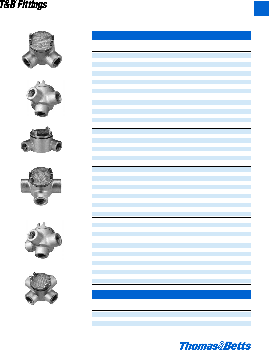
© 2002 Thomas & Betts Corporation. Specifications are subject to change without notice. www.tnb.com A69
T&B®Fittings
GUA Conduit Outlet Boxes (continued)
Cat. Hub Dimensions (Inches) Throat Dia. Cubic In.
No. Size A B C D Min. Max. Capacity
GUAL14-TB d 2b 2d g 2ƒ .570 .610 7.1
GUAL16-TB d 2 3d g 2 .570 .610 13.4
GUAL24-TB f 2 2d g 1g .755 .810 5.3
GUAL26-TB f 2 3d g 2 .755 .810 13.3
GUAL36-TB 1 2j 3d g 2j .935 1.035 16.2
GUAL47-TB 1b 2W 4c 1 2z 1.260 1.360 30
GUAL49-TB 1b 3m 5f 1 3J 1.260 1.360 74.5
GUAL59-TB 1d 3m 5f 1h 3J 1.470 1.590 74
GUAL69-TB 2 4h 5f 1h 4Y 1.880 2.047 77.8
GUAM14-TB d 1m 2d g 1W .570 .610 5.6
GUAM16-TB d 2 3d g 2 .570 .610 12.5
GUAM24-TB f 2 2d g 1g .755 .810 6.2
GUAM26-TB f 2 3d g 2 .755 .810 12.5
GUAM36-TB 1 2j 3d g 2j .935 1.035 14
GUAM47-TB 1b 2W 4c 1 2z 1.260 1.360 29.2
GUAM69-TB 2 4h 5f 1h 4Y 1.880 2.047 80
GUAN14-TB d 2a 2d g 2 .570 .610 6.8
GUAN16-TB d 2 3d g 2 .570 .610 13.5
GUAN24-TB f 2j 2d g 2i .755 .810 7.7
GUAN26-TB f 2 3d g 2 .755 .810 14
GUAN36-TB 1 2j 3d g 2j .935 1.035 16.9
GUAN47-TB 1b 2W 4c 1 2z 1.260 1.360 31.5
GUAN59-TB 1d 4h 5f 1h 4Y 1.470 1.590 84
GUAN69-TB 2 4h 5f 1h 4Y 1.880 2.047 84
GUAT14-TB d 2b 2d g 2ƒ .570 .610 7
GUAT16-TB d 2 3d g 2 .570 .610 13.5
GUAT24-TB f 2 2d g 1g .755 .810 5.3
GUAT26-TB f 2 3d g 2 .755 .810 13.3
GUAT36-TB 1 2j 3d 1 2j .935 1.035 15.9
GUAT37-TB 1 2j 3d g 2j .935 1.035 23.3
GUAT47-TB 1b 2W 4c 1 2z 1.260 1.360 29.3
GUAT49-TB 1b 3m 5f 1 3J 1.260 1.360 77.2
GUAT59-TB 1d 3m 5f 1h 3J 1.470 1.590 77.7
GUAT69-TB 2 4h 5f 1h 3J 1.880 2.047 77.8
GUAT79-TB 2d 4h 5f 1h 4Y 2.320 2.380 95
GUAW14-TB d 1m 2d g 1W .570 .610 5.2
GUAW16-TB d 2 3d g 2 .570 .610 13
GUAW24-TB f 2 2d g 1g .755 .810 6.5
GUAW26-TB f 2 3d g 2 .755 .810 13
GUAX14-TB d 1m 2d g 1W .570 .610 5.2
GUAX16-TB d 2 3d g 2 .570 .610 13.5
GUAX24-TB f 2 2d g 1g .755 .810 5.3
GUAX26-TB f 2 3d g 2 .755 .810 13.3
GUAX36-TB 1 2j 3d 1 2j .935 1.035 16
GUAX37-TB 1 2j 3d g 2j .935 1.035 23.3
GUAX47-TB 1b 2W 4c 1 2I 1.260 1.360 30
GUAX49-TB 1b 3m 5f 1 3J 1.260 1.360 72
GUAX59-TB 1d 3m 5f 1h 3J 1.470 1.590 71
GUAX69-TB 2 4h 5f 1h 4Y 1.880 2.047 77.8
GUA Conduit Device Box Replacement Covers
Cat. Opening
No. Dia.
GUA04-TB 2
GUA06-TB 3
GUA07-TB 3e
GUA09-TB 5
GUAT
GUAL
GUAX
Conduit Outlet Boxes
Explosionproof, Dust-Ignitionproof
GUAN
GUAW
GUAM
CI.I, Div. 1 & 2, Groups C, D
CI.II, Div. 1, Groups E, F, G
CI.III, Div. 1 & 2
NEMA 3, 4, 7 CD, 9 EFG
Explosionproof
Dust-Ignitionproof
Raintight
Wet Locations
A
412031.A01 FIT 3/12 3/13/03 4:47 PM Page 69
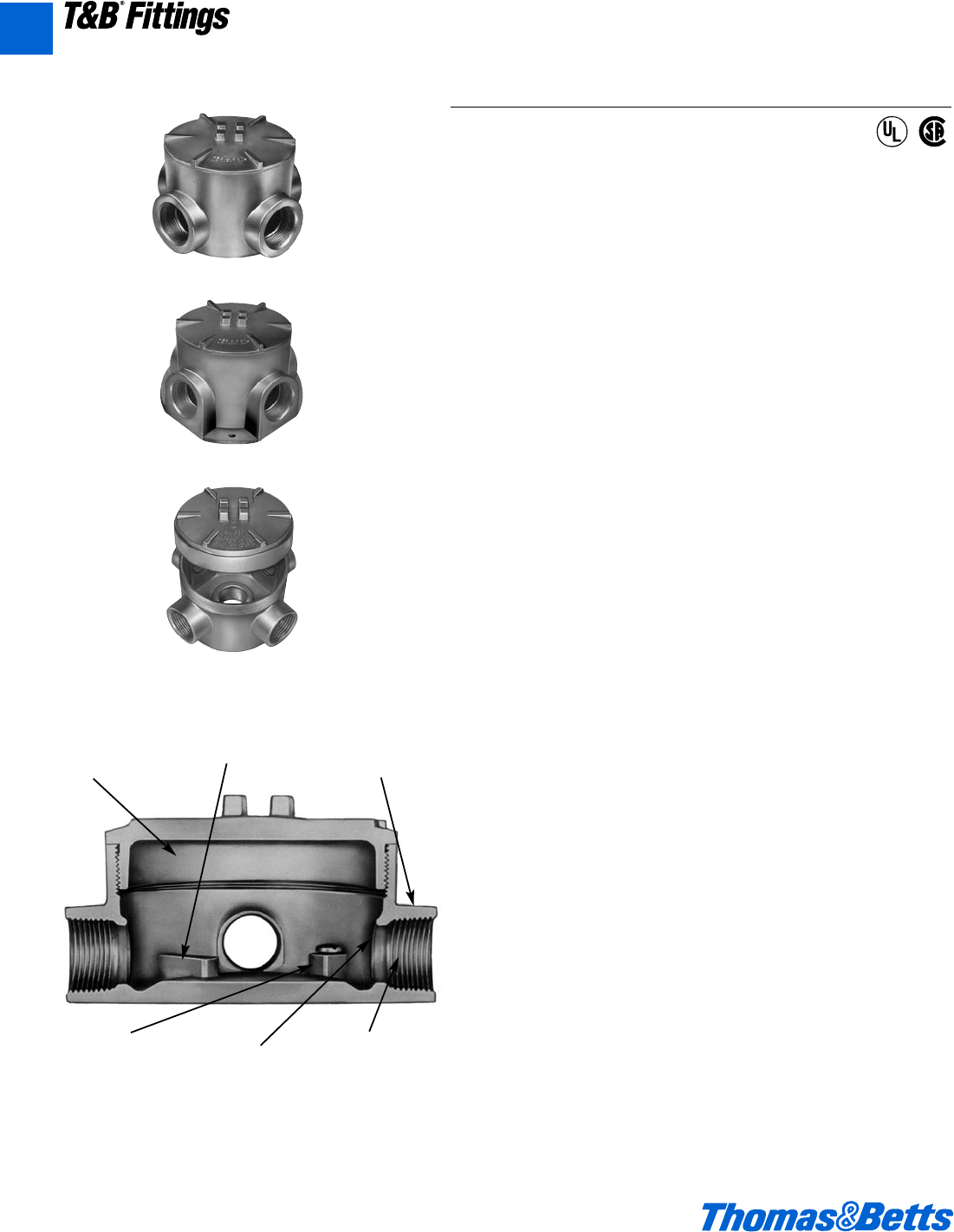
A70 © 2002 Thomas & Betts Corporation. Specifications are subject to change without notice. www.tnb.com
T&B®Fittings
A
Aluminum Conduit Outlet Boxes
Explosion-Proof, Dust-Ignition-Proof
GAX
GAFX
GAJU
Copper-free
aluminum External
hub design
Smooth
conduit
stops
Precision
machined
threads
Internal
ground
boss and
screw
Unique
mounting
pads
Application
• Junction for branch conduits in hazardous locations.
• Accessible wiring chamber provides a convenient location to maintain
or change a system, pull conductors and make splices.
• Unique mounting pads and external hub design ideal for installations
of OEM devices or instruments.
Features/Benefits
• Copper-free* aluminum provides increased corrosion resistance.
• Precision cast and machined surfaces permit safer wire pulling.
• Precision NPT threaded hubs allow trouble-free field installation for
rigid or IMC conduit.
• Die cast construction and industrial design combine to produce a
rugged protective enclosure for devices on industrial and OEM
applications.
• Clear UL, CSA and cubic content markings speed approval by
inspectors.
Standard Materials
• Die cast aluminum alloy A360 with less than .004 copper content
(copper-free).
Standard Finish
• Aluminum lacquer finish
Compliances
• UL Listed
• CSA Certified
• Suitable for hazardous locations
• NEMA 4 rated when ordered with O-ring installed
• Federal Spec W-C-586
Sample Specifications
• Outlet boxes for hazardous locations shall be die cast copper- free*
aluminum alloy A360 and suitable for use in Class I, Groups C, D,
Class II, Groups E, F, G and Class III areas. All conduit stops shall be
coined and free of rough edges. Outlet boxes for hazardous locations
shall be finished with aluminum lacquer. Outlet boxes shall be
Red•Dot®Catalog No. __________
*Less than .004 copper content.
®
®
CI.I, Div. 1 & 2, Groups C, D
CI.II, Div. 1, Groups E, F, G
CI.III, Div. 1 & 2
NEMA 3, 4, 7 CD, 9 EFG
Explosionproof
Dust Ignition-proof
Raintight
Wet Locations
412031.A01 FIT 3/12 3/13/03 4:47 PM Page 70
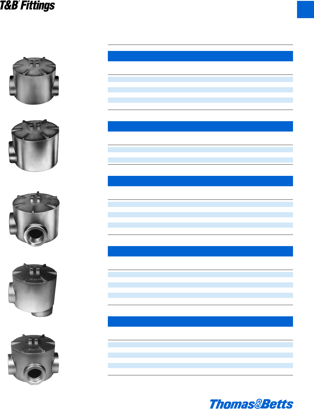
© 2002 Thomas & Betts Corporation. Specifications are subject to change without notice. www.tnb.com A71
T&B®Fittings
A
Aluminum Conduit Outlet Boxes
Explosion-Proof, Dust-Ignition-Proof
External Hubs with Installed Green Ground Screw
Through Feed with Surface Cover
Cat. Hub Unit Std. Wt. lbs.
No. Size Qty. Pkg. per 100
◗GAC-1 d" 1 5 115
◗GAC-2 f" 1 5 115
◗• GAC-3 1" 1 5 115
◗• GAC-4 1b" 1 5 175
◗• GAC-5 1d" 1 4 247
◗• GAC-6 2" 1 4 253
Dead End with Surface Cover
Cat. Hub Unit Std. Wt. lbs.
No. Size Qty. Pkg. per 100
◗• GAE-1 d" 1 5 110
◗• GAE-2 f" 1 5 110
◗• GAE-3 1" 1 5 110
L Style with Surface Cover
Cat. Hub Unit Std. Wt. lbs.
No. Size Qty. Pkg. per 100
◗GAL-1 d" 1 5 115
◗GAL-2 f" 1 5 115
◗• GAL-3 1" 1 5 115
◗• GAL-4 1b" 1 5 175
◗• GAL-5 1d" 1 4 247
◗• GAL-6 2" 1 4 253
LB Style with Surface Cover
Cat. Hub Unit Std. Wt. lbs.
No. Size Qty. Pkg. per 100
◗GALB-1 d" 1 5 115
◗GALB-2 f" 1 5 115
◗GALB-3 1" 1 5 115
◗• GALB-4 1b" 1 5 175
◗• GALB-5 1d" 1 4 247
◗• GALB-6 2" 1 4 253
T Style with Surface Cover
Cat. Hub Unit Std. Wt. lbs.
No. Size Qty. Pkg. per 100
◗GAT-1 d" 1 5 120
◗GAT-2 f" 1 5 120
◗GAT-3 1" 1 5 120
◗GAT-4 1b" 1 5 180
◗GAT-5 1d" 1448
◗GAT-6 2" 1 4 406
• Made to order items. Consult factory for lead time and minimum quantities.
◗ Suffix-OR: O-ring available for NEMA 4 rating. Consult factory for lead time and price.
GAC
GAE
GAL
GALB
GAT
CI.I, Div. 1 & 2, Groups C, D
CI.II, Div. 1, Groups E, F, G
CI.III, Div. 1 & 2
NEMA 3, 4, 7 CD, 9 EFG
Explosionproof
Dust Ignition-proof
Raintight
Wet Locations
412031.A01 FIT 3/12 3/13/03 4:47 PM Page 71
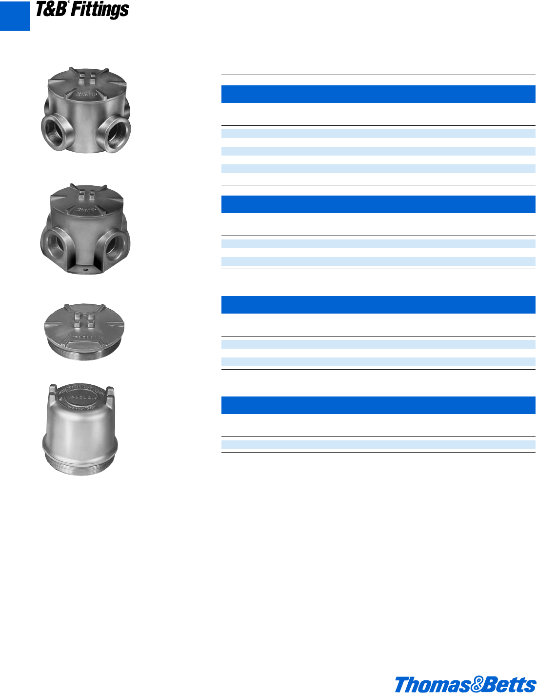
A72 © 2002 Thomas & Betts Corporation. Specifications are subject to change without notice. www.tnb.com
T&B®Fittings
A
Aluminum Conduit Outlet Boxes
Explosion-Proof, Dust-Ignition-Proof
External Hubs with Installed Green Ground Screw and Covers
X Style with Surface Cover
Cat. Hub Unit Std. Wt. lbs.
No. Size Qty. Pkg. per 100
† GAX-1 d" 1 5 125
† GAX-2 f" 1 5 125
† GAX-3 1" 1 5 125
† • GAX-4 1b" 1 5 210
† • GAX-5 1d" 1 4 257
† • GAX-6 2" 1 4 413
X Style with Flange and Surface Cover
Cat. Hub Unit Std. Wt. lbs.
No. Size Qty. Pkg. per 100
† GAFX-1 d" 1 4 135
† GAFX-2 f" 1 4 135
† GAFX-3 1" 1 4 135
Surface Style Cover
Cat. Cover Fits Std. Wt. lbs.
No. Opening Boxes Pkg. per 100
• GAS-123 3W" d", f", 1" 136
• GAS-4 3C" 1b" 152
• GAS-56 5i" 1d", 2" 169
Dome Style Cover (Class I, Group D only)
Cat. Cover Fits Inside Std. Wt. lbs.
No. Opening Boxes Height Pkg. per 100
• GAD-123 3W" d", f", 1" 2e" 171
• Made to order items. Consult factory for lead time and minimum quantities.
† Suffix-OR: O-ring available for NEMA 4 rating. Consult factory for lead time and price.
GAX
GAFX
GAS
GAD
CI.I, Div. 1 & 2, Groups C, D
CI.II, Div. 1, Groups E, F, G
CI.III, Div. 1 & 2
NEMA 3, 4, 7 CD, 9 EFG
Explosionproof
Dust Ignition-proof
Raintight
Wet Locations
412031.A01 FIT 3/12 3/13/03 4:47 PM Page 72
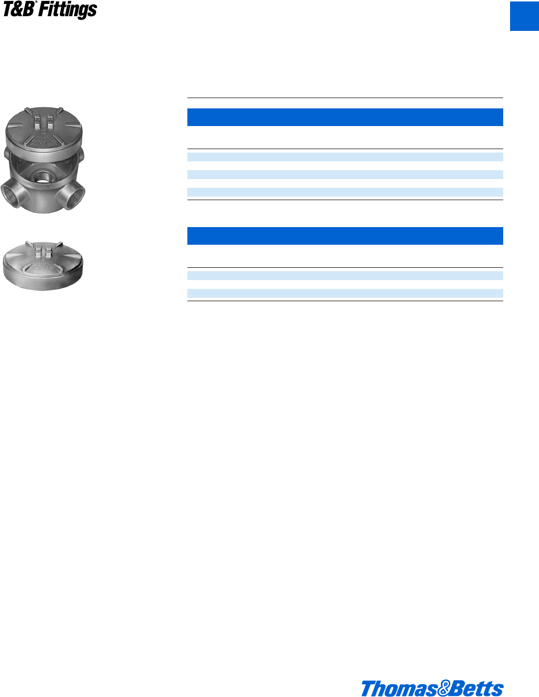
© 2002 Thomas & Betts Corporation. Specifications are subject to change without notice. www.tnb.com A73
T&B®Fittings
A
Aluminum Conduit Outlet Boxes
Explosion-Proof, Dust-Ignition-Proof
External Hubs with Installed Green Ground Screw,
Covers and Plugs
U Style with Canopy Cover
Cat. Hub Unit Std. Wt. lbs.
No. Size Qty. Pkg. per 100
• GAJU-1 d" 1 5 130
• GAJU-2 f" 1 5 130
GAJU-3 1" 1 5 130
• GAJU-5 1d" 1 267
GAJU-6 2" 1 273
Canopy Style Cover
Cat. Cover Fits Unit Std. Wt. lbs.
No. Opening Boxes Qty. Pkg. per 100
• GAJ-123 3W" d", f", 1" 11044
• GAJ-4 3C" 1b" 1561
• GAJ-56 5i" 1d", 2" 1578
• Made to order items. Consult factory for lead time and minimum quantities.
GAJU
GAJ
CI.I, Div. 1 & 2, Groups C, D
CI.II, Div. 1, Groups E, F, G
CI.III, Div. 1 & 2
NEMA 3, 4, 7 CD, 9 EFG
Explosionproof
Dust Ignition-proof
Raintight
Wet Locations
412031.A01 FIT 3/12 3/13/03 4:47 PM Page 73
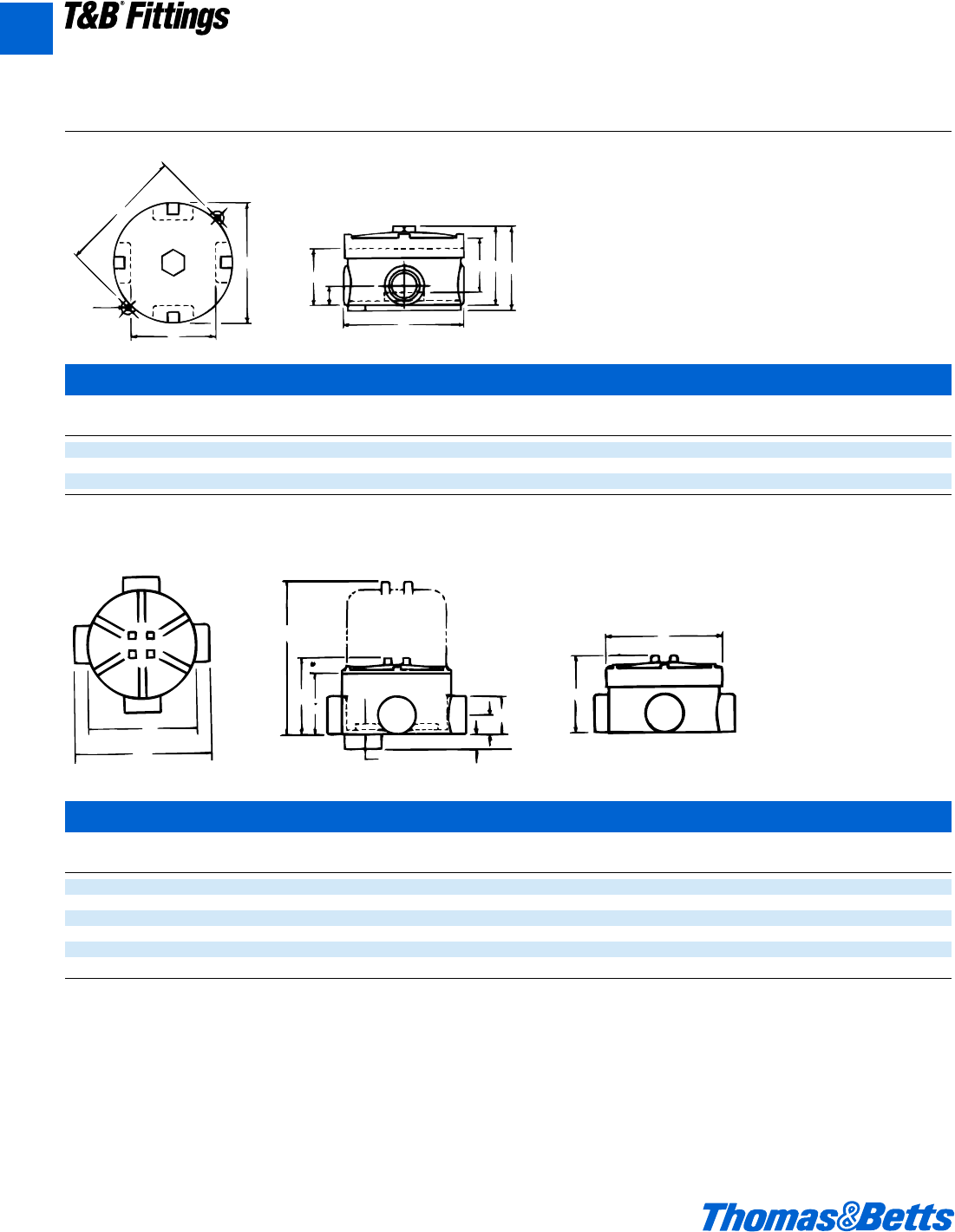
A74 © 2002 Thomas & Betts Corporation. Specifications are subject to change without notice. www.tnb.com
T&B®Fittings
A
Aluminum Conduit Outlet Boxes
Explosion-Proof, Dust-Ignition-Proof
Dimensions and Cubic Inches (CI)
G
A
K
H
D
C
E
JBF
A
G
H
CB
L
F
D
E
K
J
EXUN & EXUNL
Hub
Size A B C D E F G H J K CI
d" 3O" 3a" 2y" 2h" 4 3c" 4b" 1b" 1l" å" 20.3
f" 3O" 3a" 2y" 2h" 4 3c" 4b" 1b" 1l" å" 20.3
1" 3O" 3j" f" 2b" 4 3l" 4b" 1h" 1l" å" 20.0
GAC, GAE, GAL, GALB, GAT, GAX
Cover Hub
Opening Size A B C D E F G H J K L CI
3W" d" 4" 2b" 2n" 1c" W" W" 5i" 5l" 4i" 3j" l" 18.8
3W" f" 4" 2b" 2n" 1c" W" W" 5i" 5l" 4i" 3j" l" 18.8
3W" 1" 4" 2b" 2n" 1e" m" B" 5d" 5l" 4i" 3j" l" 18.8
3C" 1b" 4j" 3" 3W" 2h" 1o" g" 5W" – 4l"" 3n" e" 28.0
5i" 1d" 5f" 4b" 5h" 2g" 1k" g" 6e" – 6k" 5v" m" 69.3
5i" 2" 5f" 4b" 5h" 2g" 1k" g" 6e" – 6k" 5v" m" 69.3
Dimensions of all styles
when GAJ cover is used
CI.I, Div. 1 & 2, Groups C, D
CI.II, Div. 1, Groups E, F, G
CI.III, Div. 1 & 2
NEMA 3, 4, 7 CD, 9 EFG
Explosionproof
Dust Ignition-proof
Raintight
Wet Locations
412031.A01 FIT 3/12 3/13/03 4:47 PM Page 74
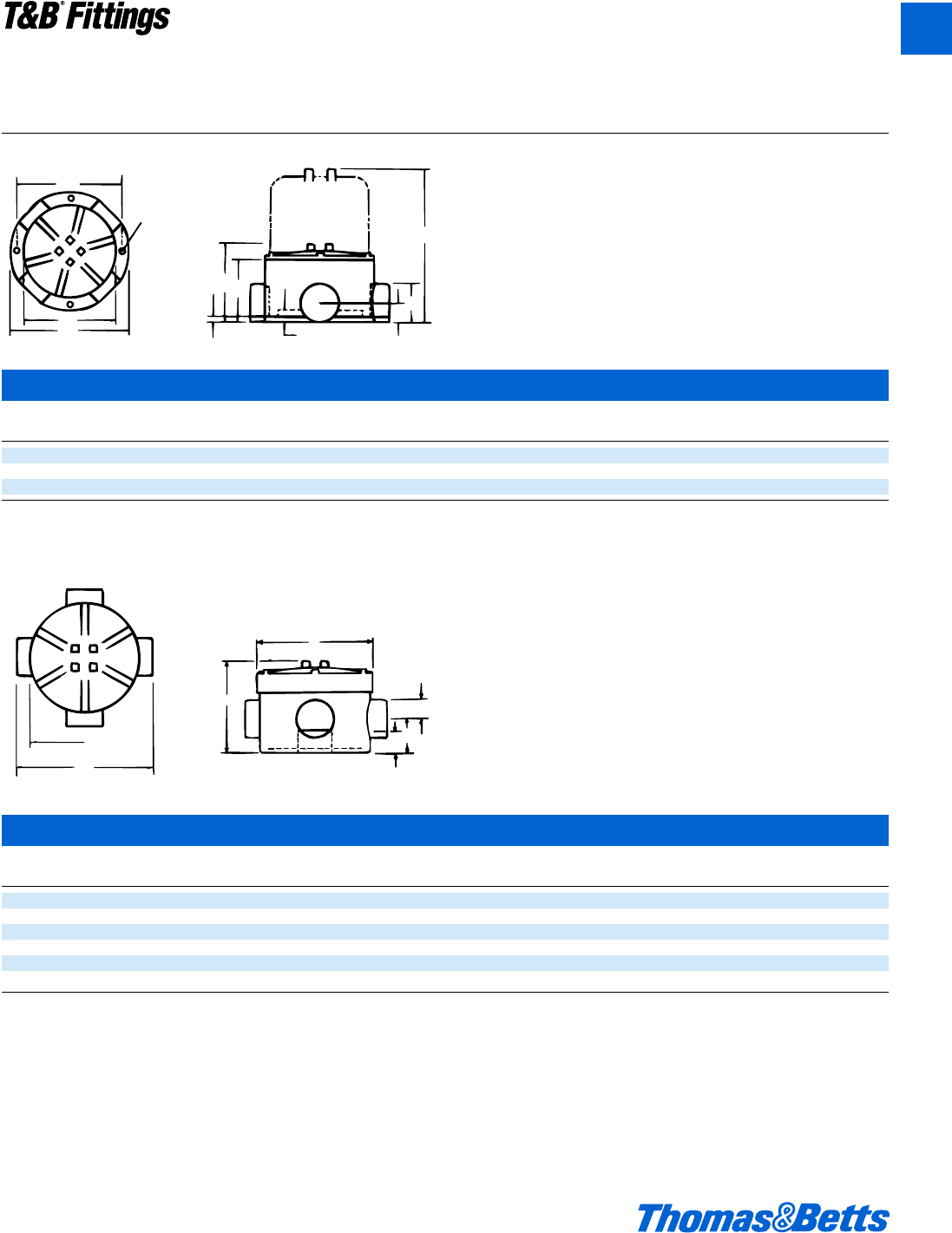
© 2002 Thomas & Betts Corporation. Specifications are subject to change without notice. www.tnb.com A75
T&B®Fittings
A
Aluminum Conduit Outlet Boxes
Explosion-Proof, Dust-Ignition-Proof
GAFX
Cover Hub
Opening Size A B C D E F G H L M CI
3W" d" 4" 2b" 2n" 5l" W" 4d" b" 1c" l" 5i" 20.0
3W" f" 4" 2b" 2n" 5l" W" 4d" b" 1c" l" 5i" 20.0
3W" 1" 4" 2b" 2n" 5l" m" 4f" j" 1e" l" 5d" 19.0
Note: All GAF units supplied as X configuration with proper number of
explosion-proof close-up plugs to make C, T or L.
GAJU
Cover Hub
Opening Size A D E F G J K CI
3W" d" 4" m" 1d" O" 5i" 4i" 4" 23.8
3W" f" 4" m" 1d" O" 5i" 4i" 4" 23.8
3W" 1" 4" m" 1d" O" 5i" 4i" 4" 23.8
3C" 1b" 4j" 2h" 1o" g" 5W" 4f" 3n" 33.3
5i" 1d" 5f" 1k" 2h" 1d" 6e" 6k" 6i" 82.8
5i" 2" 5f" 1k" 2h" 1d" 6e" 6k" 6i" 82.8
Note: All GA & GAF series boxes are supplied with GAS or GAJ style covers.
To order these boxes with GAD dome cover, consult factory.
F
A
G
DIA
M
CB
i
L
D
H
E
G
A
K
J
D
E
F
Dimensions and Cubic Inches (CI)
CI.I, Div. 1 & 2, Groups C, D
CI.II, Div. 1, Groups E, F, G
CI.III, Div. 1 & 2
NEMA 3, 4, 7 CD, 9 EFG
Explosionproof
Dust Ignition-proof
Raintight
Wet Locations
412031.A01 FIT 3/12 3/13/03 4:47 PM Page 75
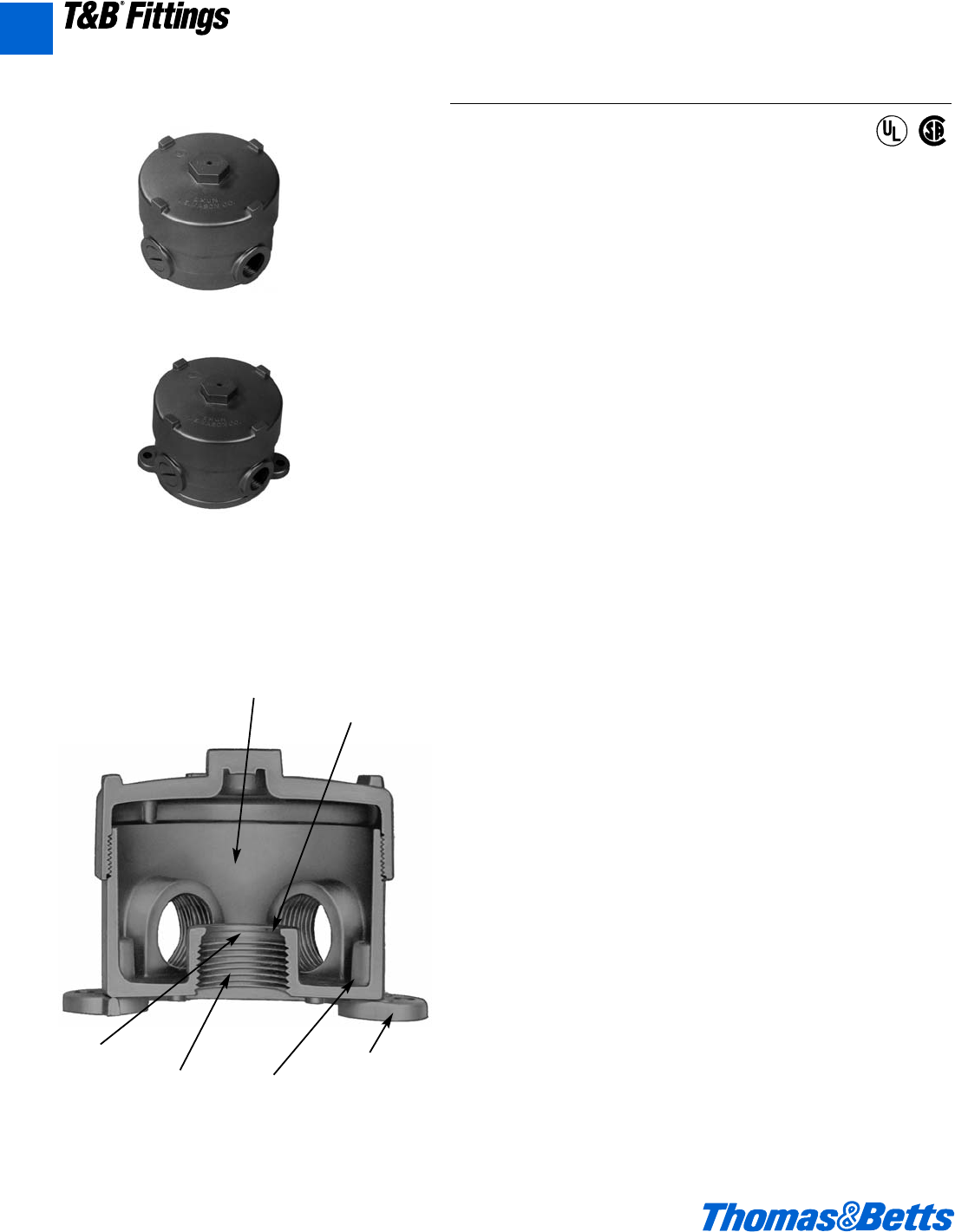
A76 © 2002 Thomas & Betts Corporation. Specifications are subject to change without notice. www.tnb.com
T&B®Fittings
A
Application
• Junction for branch conduits in hazardous locations.
• Accessible wiring chamber provides a convenient location to maintain
or change a system, pull conductors and make splices.
• Internal hub design ideal for installation where space is limited.
Features/Benefits
• Copper-free* aluminum provides increased corrosion resistance.
• Precision cast and machined surfaces permit safer wire pulling.
• Precision NPT threaded hubs allow trouble-free field installation for
rigid or IMC conduit.
• Die cast construction and industrial design combine to produce a
rugged protective enclosure for devices on industrial and OEM
applications.
• Clear UL, CSA and cubic content markings speed approval by
inspectors.
Standard Materials
• Die cast aluminum alloy A360 with less than .004 copper content
(copper-free).
Standard Finish
• Aluminum lacquer finish
Compliances
• UL Listed
• CSA Certified
• Suitable for hazardous locations
• Federal Spec W-C-586
Sample Specifications
• Outlet boxes for hazardous locations shall be die cast copper-free*
aluminum alloy A360 and suitable for use in Class I, Groups C, D,
Class II, Groups E, F, G and Class III areas. All conduit stops shall be
coined and free of rough edges. Outlet boxes for hazardous locations
shall be finished with aluminum lacquer. Outlet boxes shall be
Red•Dot®Catalog No. __________
*Less than .004 copper content.
EXUN
EXUNL
Copper-free
aluminum
Internal hub
design
Smooth
conduit
stops Precision
machined
threads
Internal
ground
boss and
screw
Die cast
lugs
Aluminum Conduit Outlet Boxes
Explosion-Proof, Dust-Ignition-Proof
CI.I, Div. 1 & 2, Groups C, D
CI.II, Div. 1, Groups E, F, G
CI.III, Div. 1 & 2
NEMA 3, 4, 7 CD, 9 EFG
Explosionproof
Dust Ignition-proof
Raintight
Wet Locations
®
®
412031.A01 FIT 3/12 3/13/03 4:47 PM Page 76
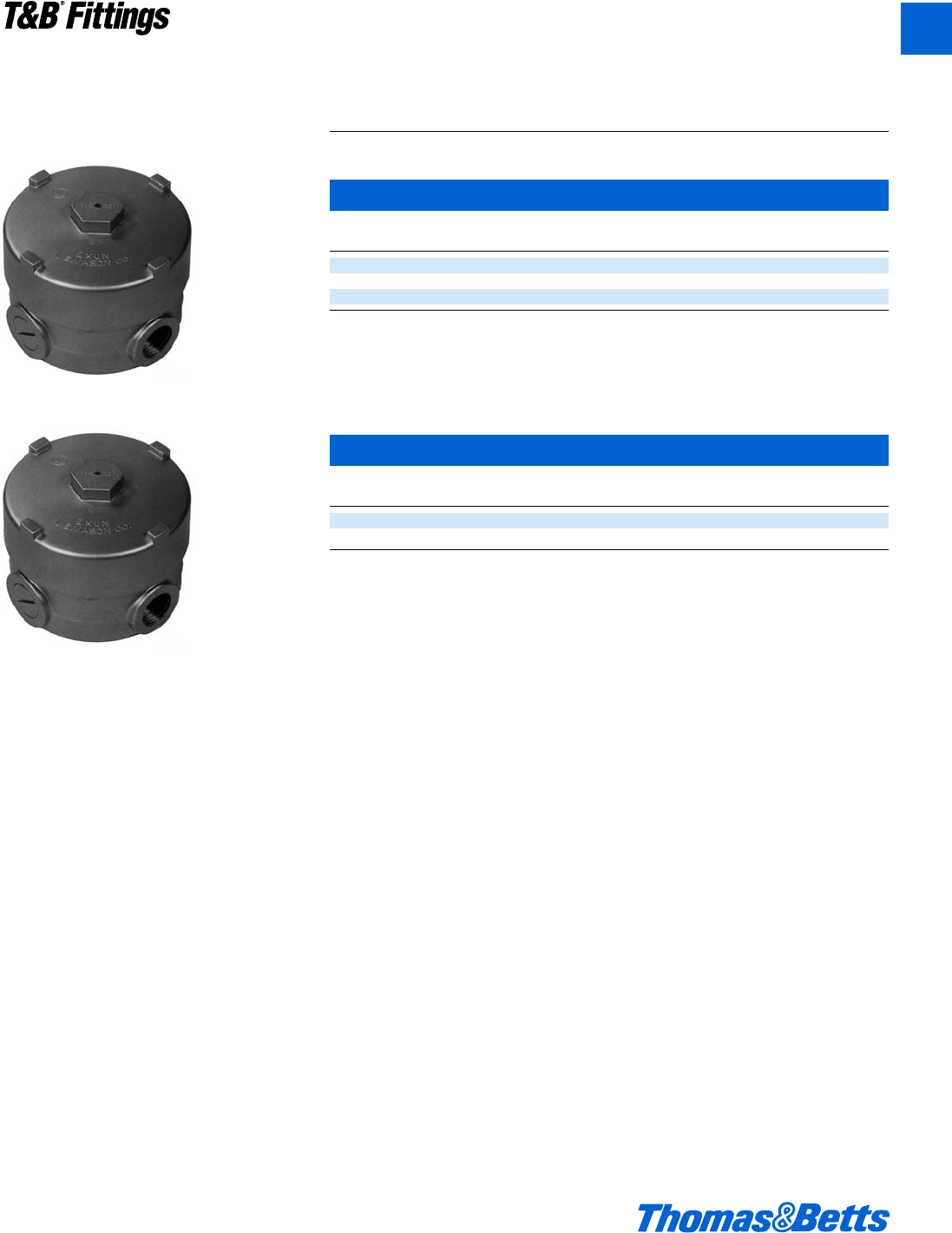
© 2002 Thomas & Betts Corporation. Specifications are subject to change without notice. www.tnb.com A77
T&B®Fittings
A
Aluminum Conduit Outlet Boxes
Explosion-Proof, Dust-Ignition-Proof
EXUN-1
Internal Hubs with Installed Green Ground Screw
5 Hole Box
Cat. Hub Unit Std. Wt. lbs.
No. Size Description Qty. Pkg. per 100
EXUN-1 d" 5 outlets 1 5 140
EXUN-2 f" with 3 close-up plugs 1 5 140
EXUN-3 1" with 3 close-up plugs 1 5 140
EXUN-11
4 Hole Box
Cat. Hub Unit Std. Wt. lbs.
No. Size Description Qty. Pkg. per 100
EXUN-11 d" 4 outlets 1 5 140
EXUN-22 f" with 2 close-up plugs 1 5 140
CI.I, Div. 1 & 2, Groups C, D
CI.II, Div. 1, Groups E, F, G
CI.III, Div. 1 & 2
NEMA 3, 4, 7 CD, 9 EFG
Explosionproof
Dust Ignition-proof
Raintight
Wet Locations
412031.A01 FIT 3/12 3/13/03 4:47 PM Page 77
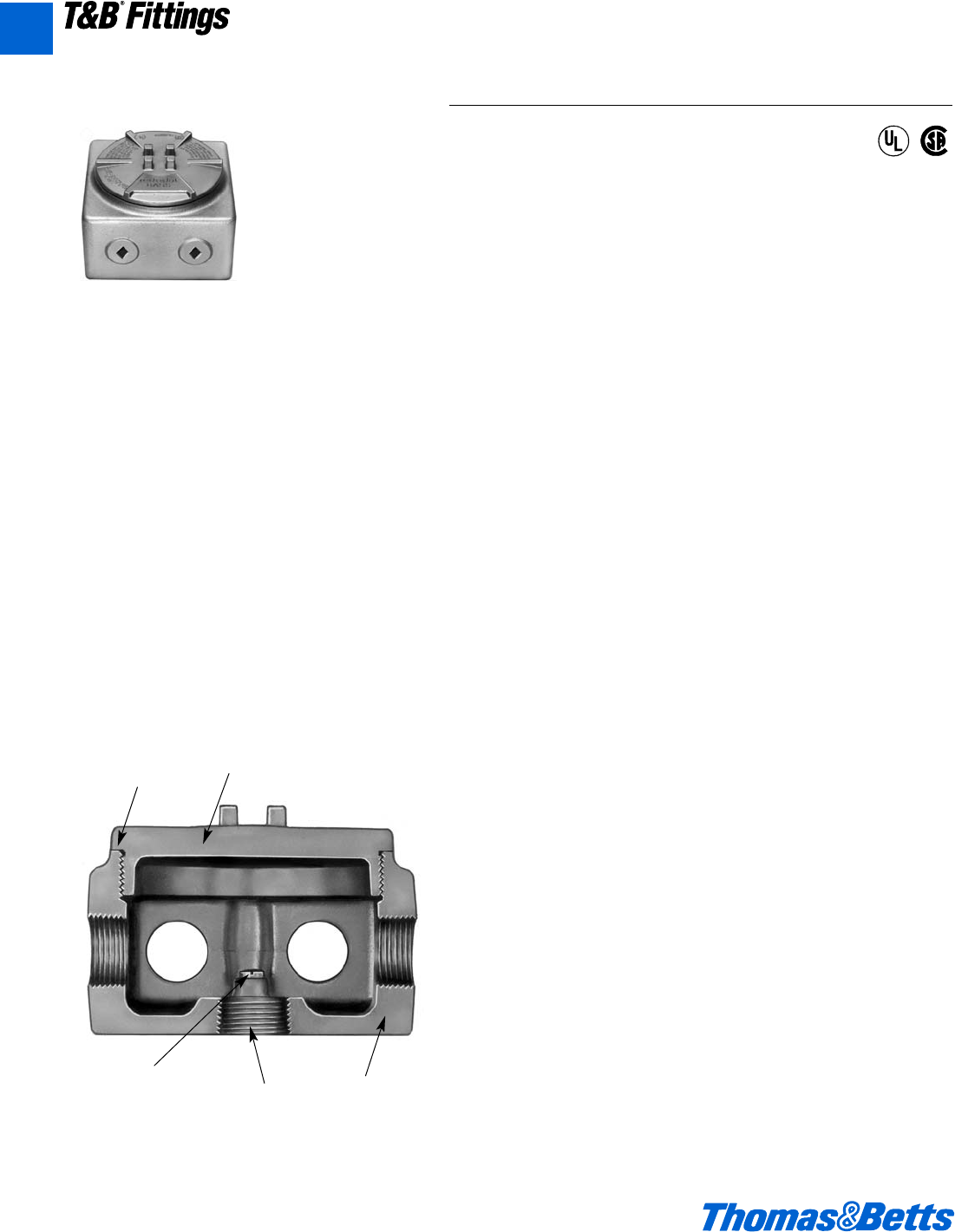
A78 © 2002 Thomas & Betts Corporation. Specifications are subject to change without notice. www.tnb.com
T&B®Fittings
Aluminum Conduit Outlet Boxes
Explosion-Proof, Dust-Ignition-Proof
Application
• Junction for branch conduits in hazardous locations.
• Accessible wiring chamber provides a convenient location to maintain
or change a system, pull conductors and make splices.
Features/Benefits
• Copper-free* aluminum alloy provides increased corrosion resistance.
• Extra wide 3f" opening provides more hand space for easy access to
the wiring chamber.
• Precision cast and machined surfaces permit safer wire pulling.
• Large capacity 31 cu. in. chamber provides more wiring space.
• Precision NPT threaded hubs allow trouble-free field installation for
rigid or IMC conduit.
• Sand cast construction and industrial design combine to produce a
rugged protective enclosure for devices on industrial and OEM
applications.
• Clear UL, CSA and cubic content markings speed approval by
inspectors.
• Hub spacing allows use of EXFU and EXMU unions.
Standard Materials
• Box - Sand Cast aluminum alloy A356. 2-T6
• Cover - Die Cast aluminum alloy A360 with less than .004 copper
content (copper-free)
Standard Finish
• Aluminum lacquer finish
Compliances
• UL Listed
• CSA Certified
• NEC
Sample Specifications
• Enclosure for hazardous locations. The box shall be cast copper-free*
aluminum alloy A356.2-T6 . Suitable for use in hazardous locations:
Suitable for use in Class I, Groups C, D; Class II, Groups E, F, G; and
Class III areas. Enclosures shall be finished with aluminum lacquer.
Outlet boxes shall be Red•Dot®Catalog No. ______
*Less than .004 copper content.
GASS
Copper-free
aluminum
Clean
cover
edges
Precision
machined
threads
Internal
ground
boss and
screw
Heavy wall
construction
®
®
CI.I, Div. 1 & 2, Groups C, D
CI.II, Div. 1, Groups E, F, G
CI.III, Div. 1 & 2
NEMA 3, 4, 7 CD, 9 EFG
Explosionproof
Dust Ignition-proof
Raintight
Wet Locations
A
412031.A01 FIT 3/12 3/20/03 3:04 PM Page 78
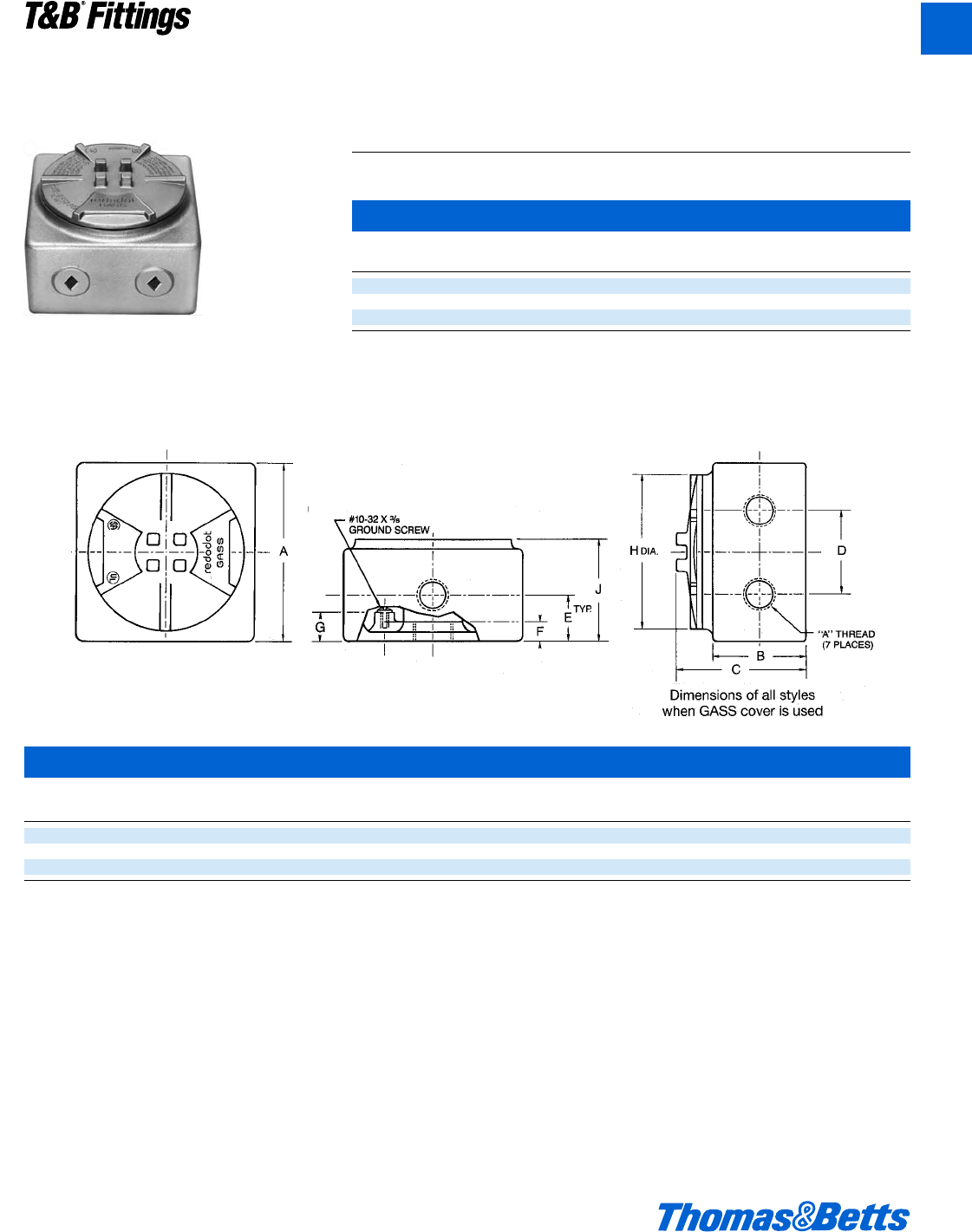
© 2002 Thomas & Betts Corporation. Specifications are subject to change without notice. www.tnb.com A79
T&B®Fittings
Aluminum Conduit Outlet Boxes
Explosion-Proof, Dust-Ignition-Proof
GASS
GASS
Cover Hub
Opening Size A B C D E F G H J CI
4” d" 4e 2c 3c 2i 1i d f 4 2e 31
4” f" 4e 2c 3c 2i 1i d f 4 2e 31
4” 1" 4e 2c 3c 2i 1i d f 4 2e 31
Internal Hubs with Installed Green Ground Screw,
Cover and Plugs
Cat. Hub Unit Std. Wt. lbs.
No. Size Qty. Pkg. per 100
GASS-1 d" 1 5 282
GASS-2 f" 1 5 278
GASS-3 1" 1 5 274
CI.I, Div. 1 & 2, Groups C, D
CI.II, Div. 1, Groups E, F, G
CI.III, Div. 1 & 2
NEMA 3, 4, 7 CD, 9 EFG
Explosionproof
Dust Ignition-proof
Raintight
Wet Locations
A
412031.A01 FIT 3/12 3/13/03 4:47 PM Page 79
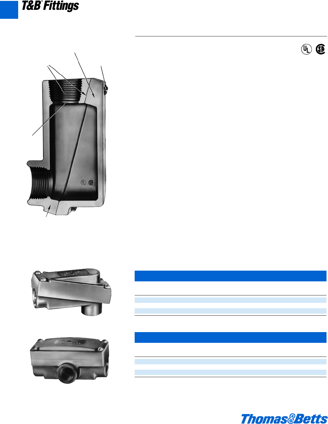
A80 © 2002 Thomas & Betts Corporation. Specifications are subject to change without notice. www.tnb.com
T&B®Fittings
A
LB Style Conduit Body – Aluminum
Cat. Hub Std. Wt. lbs.
No. Size Pkg. per 100
EXLB-1 d" 576
EXLB-2 f" 594
EXLB-3 1" 5 132
T Style Conduit Body – Aluminum
Cat. Hub Unit Std. Wt. lbs.
No. Size Qty. Pkg. per 100
EXT-1 d" 525 92
EXT-2 f" 5 25 115
EXT-3 1" 5 172
EXLB
EXT
Aluminum Conduit Outlet Bodies
Explosion-Proof, Dust-Ignition-Proof
Application
• Junction for branch conduits.
• Accessible wiring chamber provides a convenient location to pull conductors
and make splices.
Features/Benefits
• Copper-free* aluminum provides increased corrosion resistance.
• Precision cast and machined surfaces permit safer wire pulling.
• Precision NPT threaded hubs allow trouble-free field installation for rigid or
IMC conduit.
• Deep slotted cover screws for faster installation.
• Clear UL, CSA and cubic content markings speed approval by inspectors.
Standard Materials
• Die cast aluminum alloy A360 with less than .004 copper content
(copper-free).
Standard Finish
• Aluminum lacquer finish
Compliances
• UL Listed
• CSA Certified
• Suitable for hazardous locations
Sample Specifications
• Conduit fittings for hazardous locations shall be die cast copper free* alu-
minum alloy A360. Suitable for use in hazardous locations: Class I, Groups C,
D; Class II, Groups E, F, G and Class III. All conduit stops shall be coined and
free of rough edges. Conduit fittings shall be finished with aluminum lacquer.
Conduit fittings shall be Red•Dot®Catalog No. __________
*Less than .004 copper content.
Copper-free
aluminum
Smooth
conduit
stops
Precision
machined
threads and
surfaces
Heavy wall
construction
Deep
slotted
screws
®
®
CI.I, Div. 1 & 2, Groups C, D
CI.II, Div. 1, Groups E, F, G
CI.III, Div. 1 & 2
NEMA 3, 4, 7 CD, 9 EFG
Explosionproof
Dust Ignition-proof
Raintight
Wet Locations
412031.A01 FIT 3/12 3/13/03 4:47 PM Page 80
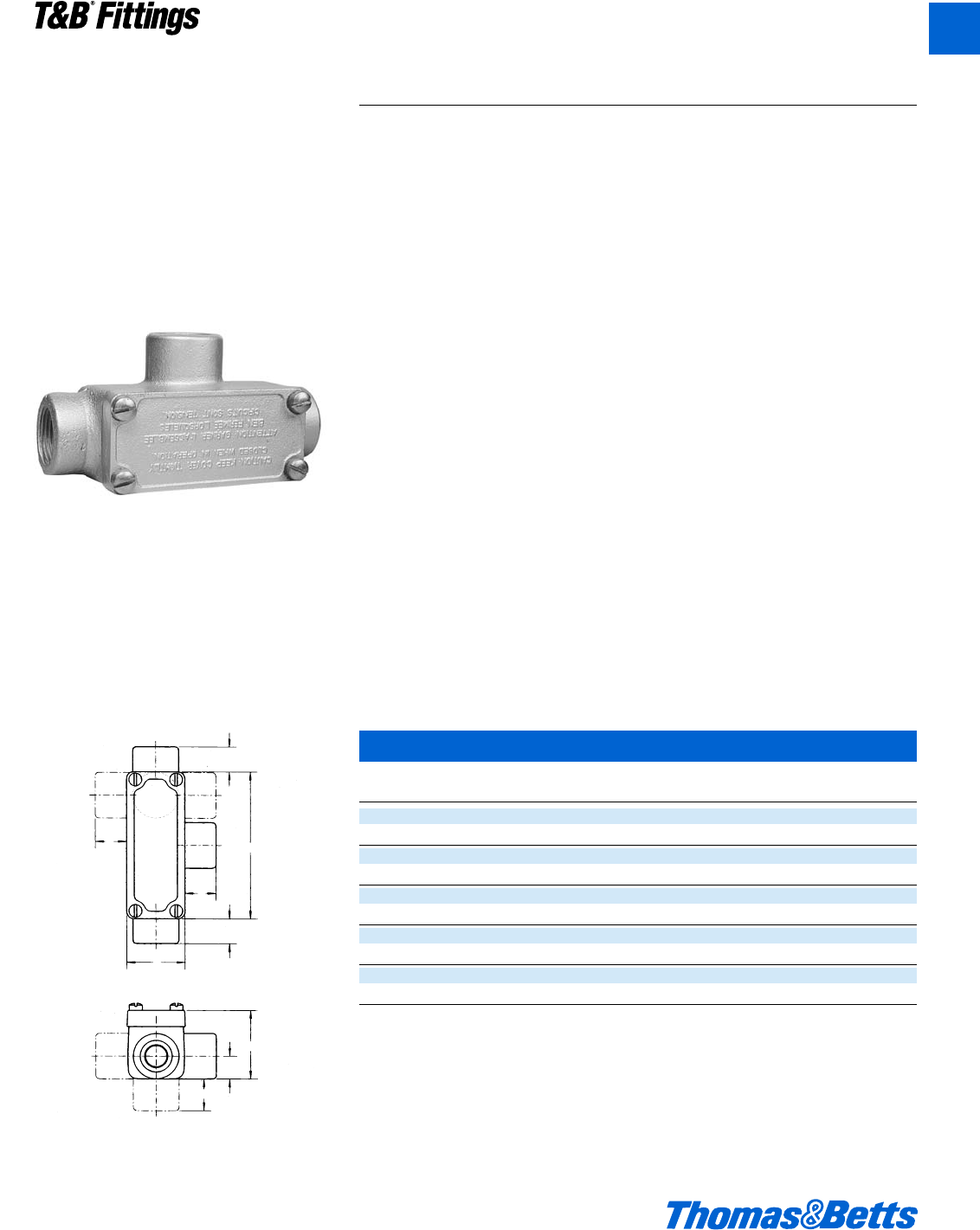
© 2002 Thomas & Betts Corporation. Specifications are subject to change without notice. www.tnb.com A81
T&B®Fittings
A
Conduit Outlet Bodies
Explosionproof, Dust-Ignitionproof
OE Series – Iron Conduit Outlet Bodies
Cat. Hub
No. Size A B C D E F
OEC1-TB d" 4.06 1.62 1.90 0.69 0.88 0.63
OEC2-TB f" 4.35 1.88 2.19 0.69 0.88 0.76
OET1-TB d" 4.06 1.62 1.90 0.69 0.88 0.63
OET2-TB f" 4.35 1.88 2.19 0.69 0.88 0.76
OELL1-TB d" 4.06 1.62 1.90 0.69 0.88 0.63
OELL2-TB f" 4.35 1.88 2.19 0.69 0.88 0.76
OELR1-TB d" 4.06 1.62 1.90 0.69 0.88 0.63
OELR2-TB f" 4.35 1.88 2.19 0.69 0.88 0.76
OELB1-TB d" 4.06 1.62. 1.90 0.69 0.88 0.63
OELB2-TB f" 4.35 1.88 2.19 0.69 0.88 0.76
Application
OE series are installed in conduit systems within hazardous areas to:
• Protect conductors in threaded rigid conduit.
• Act as pulling and splice fittings.
• Interconnect lengths of conduit.
• Change direction of conduit.
• Provide access for maintenance and future system changes.
Features
OE conduit bodies have:
• Tapered threaded hubs for ground continuity.
• Smooth integral hub bushings to protect conductor insulation when pulling.
• Five different hub arrangements.
• Accurately machined body with blind tapped screw holes.
• Most compact design of all hazardous area outlet bodies.
• Sizes up to 1".
Standard Materials
• Bodies: Grade 60-45-10 Ductile Iron (Complies with ASTM standard A536)
Standard Finish
• Electrogalvanized and aluminum acrylic paint.
Size Ranges
• Hub – d" and f"
Certifications and Compliances
• NEC/CEC:Class I, Division 1 & 2, Groups C, D
Class II, Division 1, Groups E, F, G
Class II, Division 2, Groups F, G
Class III
B
D
A
E
C
F
E
D
E
CI.I, Div. 1 & 2, Groups C, D
CI.II, Div. 1, Groups E, F, G
CI.III, Div. 1 & 2
NEMA 3, 4, 7 CD, 9 EFG
Explosionproof
Dust-Ignitionproof
Raintight
Wet Locations
412031.A01 FIT 3/12 3/13/03 4:47 PM Page 81
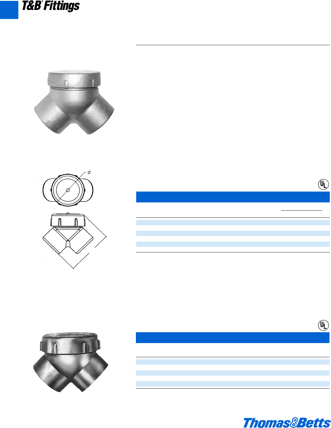
A82 © 2002 Thomas & Betts Corporation. Specifications are subject to change without notice. www.tnb.com
T&B®Fittings
A
Conduit Outlet Elbows
Explosionproof, Dust-Ignitionproof
Capped Iron Elbow – Female to Female
Cat. Hub Throat Dim.
No. Size A B Min Max
LBY15-TB d 2l 2 0.570 0.610
LBY25-TB f 2m 2b 0.755 0.810
LBY35-TB 1 3p 2d 0.955 1.035
LBY45-TB 1b 3f 2n 1.260 1.360
LBY55-TB 1d 4b 3c 1.470 1.590
LBY65-TB 2 5d 4 1.880 2.047
B
A
LBY Elbows have:
• Maximum volume for bends within a compact over-
all size.
• Screw on cover for ease of installation and removal.
• Cover opening on an angle, permitting conductors to
be pulled straight through either hub.
• Tapered threaded hubs and integral bushing for
rigid threaded conduit.
Conduit Bodies and Capped Elbows
Application
LBY/GYF elbows are installed in conduit systems within hazardous areas to:
• Make 90° bends in conduit systems where space is limited.
• Act as pull outlets.
• Provide access to conductors for maintenance and future system changes.
Features
• Maximum volume for bends within a compact overall size.
• Screw on cover for ease of installation and removal.
• Cover opening on an angle, permitting conductors to be pulled straight
through either hub.
• Tapered threaded hubs and integral bushing for rigid threaded conduit.
LBY –
Class I, Division 1 & 2, Groups C,D
Class II, Division 1, Groups F,G
Class III
Class I, Division 1 & 2, Groups C,D
Class II, Division 1, Groups F,G
Class III
CI.I, Div. 1 & 2, Groups C, D
CI.II, Div. 1, Groups E, F, G
CI.III, Div. 1 & 2
NEMA 3, 4, 7 CD, 9 EFG
Explosionproof
Dust-Ignitionproof
Raintight
Wet Locations
LBY
®
GYF
Capped Aluminum Elbow – Female to Female
Cat. Hub Unit Std. Wt. lbs.
No. Size Qty. Pkg. per 100
GYF-1 d" 10 50 23
GYF-2 f" 525 40
GYF-3 1" 525 60
• GYF-4 1b" 210 80
GYF-5 1d" 210 95
• Made to order items. Consult factory for lead time and minimum quantities.
®
412031.A01 FIT 3/12 3/13/03 4:47 PM Page 82
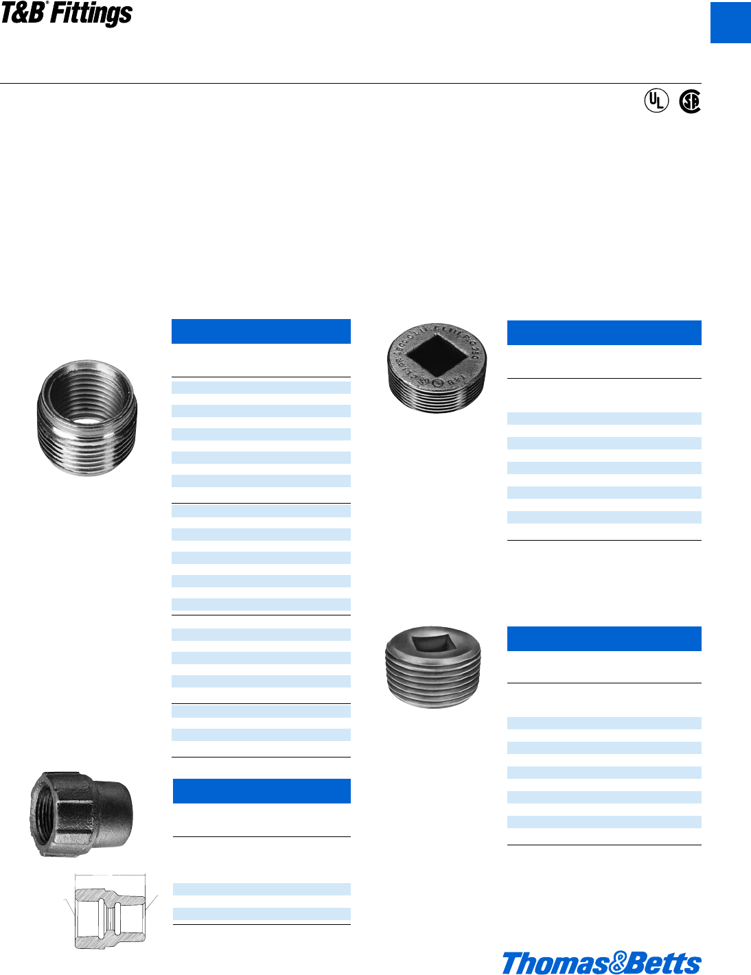
© 2002 Thomas & Betts Corporation. Specifications are subject to change without notice. www.tnb.com A83
T&B®Fittings
A
Aluminum Recessed Plugs
Cat. Hub
No. Size
With Flush Head for Hazardous and
Non-Hazardous Locations
XPLG-1† d"
XPLG-2† f"
XPLG-3† 1"
XPLG-4* 1b"
XPLG-5* 1d"
XPLG-6* 2"
XPLG-7* 2d"
XPLG-8* 3"
XPLG-9* 3d"
XPLG-10* 4"
Made to order items. Consult factory for lead time and
minimum quantities.
† Not U.L. Listed
* U.L. Listed E 34438
RE, PLG, REC Reducers, Plugs and Adapters
Explosionproof, Dust-Ignitionproof
CI.I, Div. 1 & 2, Groups A, B, C, D
CI.II, Div. 1, Groups E, F, G
CI.III, Div. 1 & 2
Explosionproof
Dust-Ignitionproof
Application
• RE and REC reducers are used in threaded heavy wall
conduit systems.
• RE reduces conduit hubs to a smaller size.
• REC connects two different sizes of conduit together or is
used to replace a coupling and reducer in an installation.
• PLG plugs are used for closing threaded conduit hubs.
Features
• All Hubs have NPT threads with a minimum of five full threads
and integral bushing for preventing damage to wires.
Materials
• Machined Reducers: Steel
• Cast Reducers: Gray Iron
• Funnel Reducers: Iron
• Recessed Plugs: Gray Iron
• red•dot®Recessed Plugs: Copper-free Aluminum
Standard Finishes
• Cast zinc-plated with aluminum acrylic paint
• Machine zinc-plated with clear chromate finish
Listing Certifications
• UL: 886
• CSA: C22.2 No.30
• NEC/CEC: CI.I, Div. 1 & 2, Groups A, B, C, D
CI.II, Div. 1, Groups E, F, G
CI.III
For hazardous and non-hazardous locations
Reducing Bushings
Cat. A Male B Female
No. (NPT) (NPT)
RE21-TB fd
RE31-TB 1d
RE32-TB 1f
RE41-TB 1b d
RE42-TB 1b f
RE43-TB 1b 1
RE51-TB 1d d
RE52-TB 1d f
RE53-TB 1d 1
RE54-TB 1d 1b
RE61-TB 2d
RE62-TB 2f
RE63-TB 21
RE64-TB 21b
RE65-TB 21d
RE73-TB 2d 1
RE74-TB 2d 1b
RE75-TB 2d 1d
RE76-TB 2d 2
RE83-TB 31
RE84-TB 31b
RE85-TB 31d
RE86-TB 32
RE87-TB 32d
RE96-TB 3d 2
RE97-TB 3d 2d
RE98-TB 43
RE106-TB 42
RE107-TB 42d
RE108-TB 43
REC Series Reducers
Cat. A B
No. (NPT) (NPT) C
Funnel Shaped Reducers for
Hazardous and Non-Hazardous
Locations
REC21-TB f d - 14 1g
REC31-TB 1 d - 14 2
REC32-TB 1 f - 14 2
Recessed Plugs
Cat. Threads
No. (NPT)
With Flush Head for Hazardous and
Non-Hazardous Locations
PLG1-TB d
PLG2-TB f
PLG3-TB 1
PLG4-TB 1b
PLG5-TB 1d
PLG6-TB 2
PLG7-TB 2d
PLG8-TB 3
PLG9-TB 3d
PLG10-TB 4
A
C
B
®
®
412031.A01 FIT 3/12 3/13/03 4:48 PM Page 83
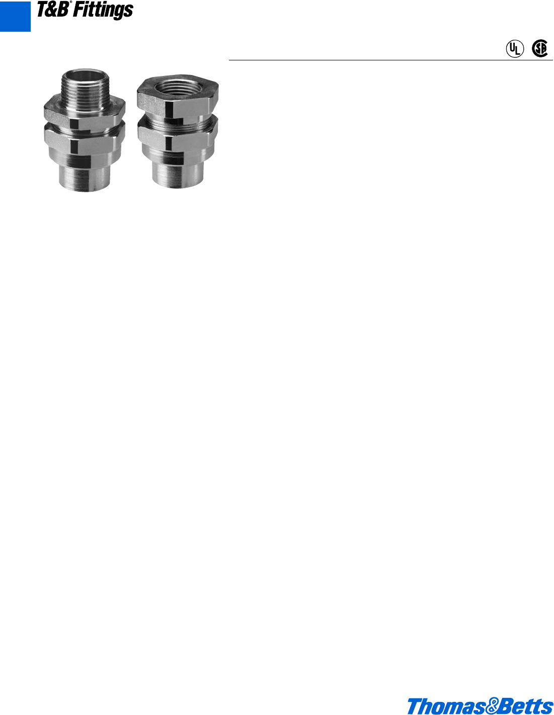
A84 © 2002 Thomas & Betts Corporation. Specifications are subject to change without notice. www.tnb.com
T&B®Fittings
Three-Piece Couplings
Explosionproof, Dust-Ignitionproof
Application
UNY and UNF unions are installed in threaded thickwall conduit systems:
• UNY – to connect conduit to a conduit fitting, junction box, or device enclosure.
• UNF – to connect conduit to conduit, or to provide a means for future modifi-
cation of the conduit system.
Standard Finishes
• Steel – electrogalvanized with chromate treatment.
• Iron alloy, malleable iron – electrogalvanized and aluminum
acrylic paint
Certifications and Compliances*
• NEC/CEC
Class I, Division 1 & 2, Groups A,B,C,D
Class II, Division 1, Groups E,F,G
Class III
UNF, UNY d" – 1"
•UL – Conduit unions for use in Cat. Nos. UNF/UNY
followed by 105, 205, or 305; for use in:
Class I, Division 1 & 2, Groups A,B,C,D
Class II, Division 1, Groups E,F,G
Class III
UNF,UNY d", f", 1"
•CSA – Conduit unions for use in Cat. Nos. UNF/UNY
followed by 105, 205, 305, 405 or 505; for use in:
Class I, Division 1 & 2, Groups B,C,D
Class II, Division 1, Groups E,F,G
Class III
UNF,UNY d", f", 1", 1b", 1d"
•UL – Conduit unions for use in Cat. Nos. UNF/UNY
followed by 405 or 505; for use in:
Class I, Division 1 & 2, Groups B,C,D
Class II, Division 1, Groups E,F,G
Class III
UNF,UNY 1b", 1d"
•UL & CSA – Conduit unions for use in Cat. Nos. UNF/UNY, EL Series
followed by 605, 905, or 1005; for use in:
Class I, Division 1 & 2, Groups C,D
Class II, Division 1, Groups E,F,G
Class III
UNF,UNY 2", 2d", 3", 3d", 4"
UNY
CI.I, Div. 1 & 2, Groups A,B,C,D
CI.II, Div. 1, Groups E, F, G
CI.III, Div. 1 & 2
Explosionproof
Dust-Ignitionproof
®
®
UNF
A
412031.A01 FIT 3/12 3/13/03 4:48 PM Page 84
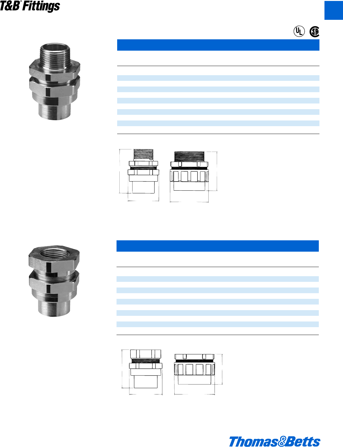
© 2002 Thomas & Betts Corporation. Specifications are subject to change without notice. www.tnb.com A85
T&B®Fittings
UNY Male Unions
Cat. Overall Overall
No. TR Size Length/Inches Dia./Inches
For Hazardous and Non-Hazardous Locations
UNY105-TB d2ç1d
UNY205-TB f2k1m
UNY305-TB 12f2
UNY405-TB 1b 3h 2f
UNY505-TB 1d 3e 3h
UNY605-TB 23d3m
UNY705-TB 2d 4m 4j
UNY805-TB 35X5h
UNY905-TB 3d 5d 5W
UNY1005-TB 45e6i
LENGTH LENGTH
MAX. DIA. MAX. DIA.
Three-Piece Couplings
Explosionproof, Dust-Ignitionproof
LENGTH
MAX. DIA. MAX. DIA.
LENGTH
CI.I, Div. 1 & 2, Groups C, D
CI.II, Div. 1, Groups E, F, G
CI.III, Div. 1 & 2
NEMA 3, 4, 7 CD, 9 EFG
Explosionproof
Dust-Ignitionproof
Raintight
Wet Locations
UNY
UNF
UNF Female Unions
Cat. Overall Overall
No. TR Size Length/Inches Dia./Inches
For Hazardous and Non-Hazardous Locations
UNF105-TB d1g1d
UNF205-TB f2a1m
UNF305-TB 12q2
UNF405-TB 1f 2b 2f
UNF505-TB 1d 2f 3h
UNF605-TB 22d3m
UNF705-TB 2d 3d 4j
UNF805-TB 345h
UNF905-TB 3d 4q 5W
UNF1005-TB 44b6i
®
®
A
412031.A01 FIT 3/12 3/13/03 4:48 PM Page 85
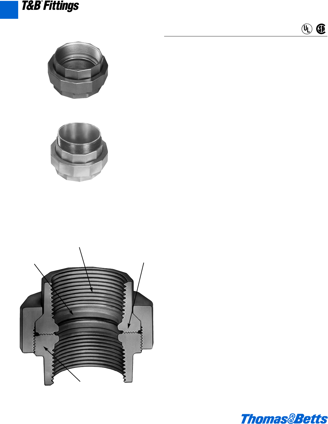
A86 © 2002 Thomas & Betts Corporation. Specifications are subject to change without notice. www.tnb.com
T&B®Fittings
A
Aluminum Three-Piece Couplings
Explosion-Proof, Dust-Ignition-Proof
Application
• Unions are used as connecting elements between enclosures, fit-
tings or boxes which permit future changes to the system in both
hazardous and non-hazardous areas.
Features/Benefits
• Copper-free* aluminum provides increased corrosion resistance.
• Precision cast and machined surfaces permit safer wire pulling.
• Precision NPT threaded hubs allow trouble-free field installation for
rigid or IMC conduit.
• Clear UL, CSA and cubic content markings speed approval by
inspectors.
• Unique concentric ring design insures critical flame path control.
Standard Materials
• Die cast aluminum alloy A360 with less than .004 copper content
(copper-free).
• EXMU nipples are galvanized steel.
Standard Finish
• Aluminum lacquer finish
Compliances
• UL Listed
• CSA Certified
• Suitable for hazardous locations
• Federal Spec W-C-586
Sample Specifications
• Conduit unions for hazardous locations shall be die cast copper-
free* aluminum alloy A360. Suitable for use in hazardous loca-
tions: Class I, Groups C, D; Class II, Groups E, F, G and Class III.
All conduit stops shall be coined and free of rough edges. Conduit
unions shall be finished with aluminum lacquer. Conduit unions
shall be Red•Dot®Catalog No. __________
*Less than .004 copper content.
EXFU
EXMU
Copper-free
aluminum
Precision
machined
threads
Unique con-
centric ring
design
Smooth
conduit
stops
®
®
CI.I, Div. 1 & 2, Groups C, D
CI.II, Div. 1, Groups E, F, G
CI.III, Div. 1 & 2
NEMA 3, 4, 7 CD, 9 EFG
Explosionproof
Dust Ignition-proof
Raintight
Wet Locations
412031.A01 FIT 3/12 3/13/03 4:48 PM Page 86
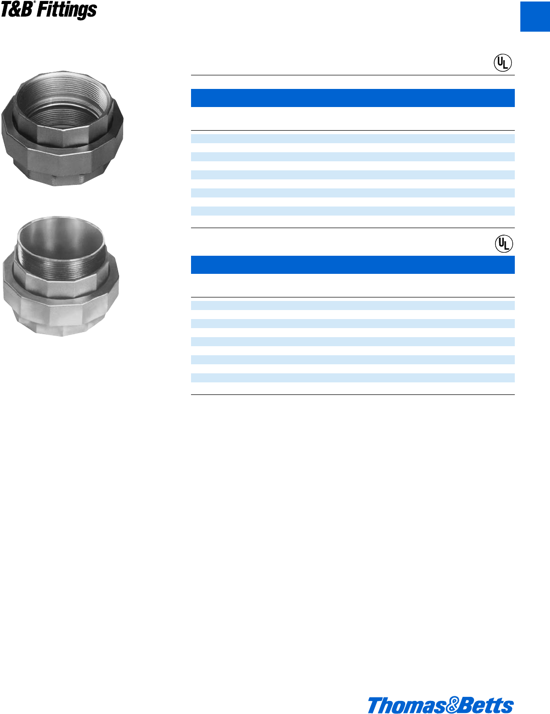
© 2002 Thomas & Betts Corporation. Specifications are subject to change without notice. www.tnb.com A87
T&B®Fittings
A
Aluminum Three-Piece Couplings
Explosion-Proof, Dust-Ignition-Proof
Male and Female Unions
Female to Female
Cat. Hub Unit Std. Wt. lbs.
No. Size Qty. Pkg. per 100
EXFU-1 d’ 525 24
EXFU-2 f" 525 33
EXFU-3 1" 525 42
EXFU-4 1b" 525 53
EXFU-5 1d" 525 68
• EXFU-6 2" 2 10 130
• EXFU-7 2d" 2 10 270
• EXFU-8 3" 1 5 310
• EXFU-9 3d" 1 5 340
• EXFU-10 4" 1 374
Male to Female
Cat. Hub Unit Std. Wt. lbs.
No. Size Qty. Pkg. per 100
EXMU-1 d" 525 24
EXMU-2 f" 525 35
EXMU-3 1" 525 45
• EXMU-4 1b" 525 64
• EXMU-5 1d" 525 84
• EXMU-6 2" 2 10 155
• EXMU-7 2d" 2 10 300
• EXMU-8 3" 1 5 340
• EXMU-9 3d" 1 5 400
• EXMU-10 4" 1 410
• Made to order items. Consult factory for lead time and minimum quantities.
EXFU
EXMU
®
®
CI.I, Div. 1 & 2, Groups C, D
CI.II, Div. 1, Groups E, F, G
CI.III, Div. 1 & 2
NEMA 3, 4, 7 CD, 9 EFG
Explosionproof
Dust Ignition-proof
Raintight
Wet Locations
412031.A01 FIT 3/12 3/13/03 4:48 PM Page 87
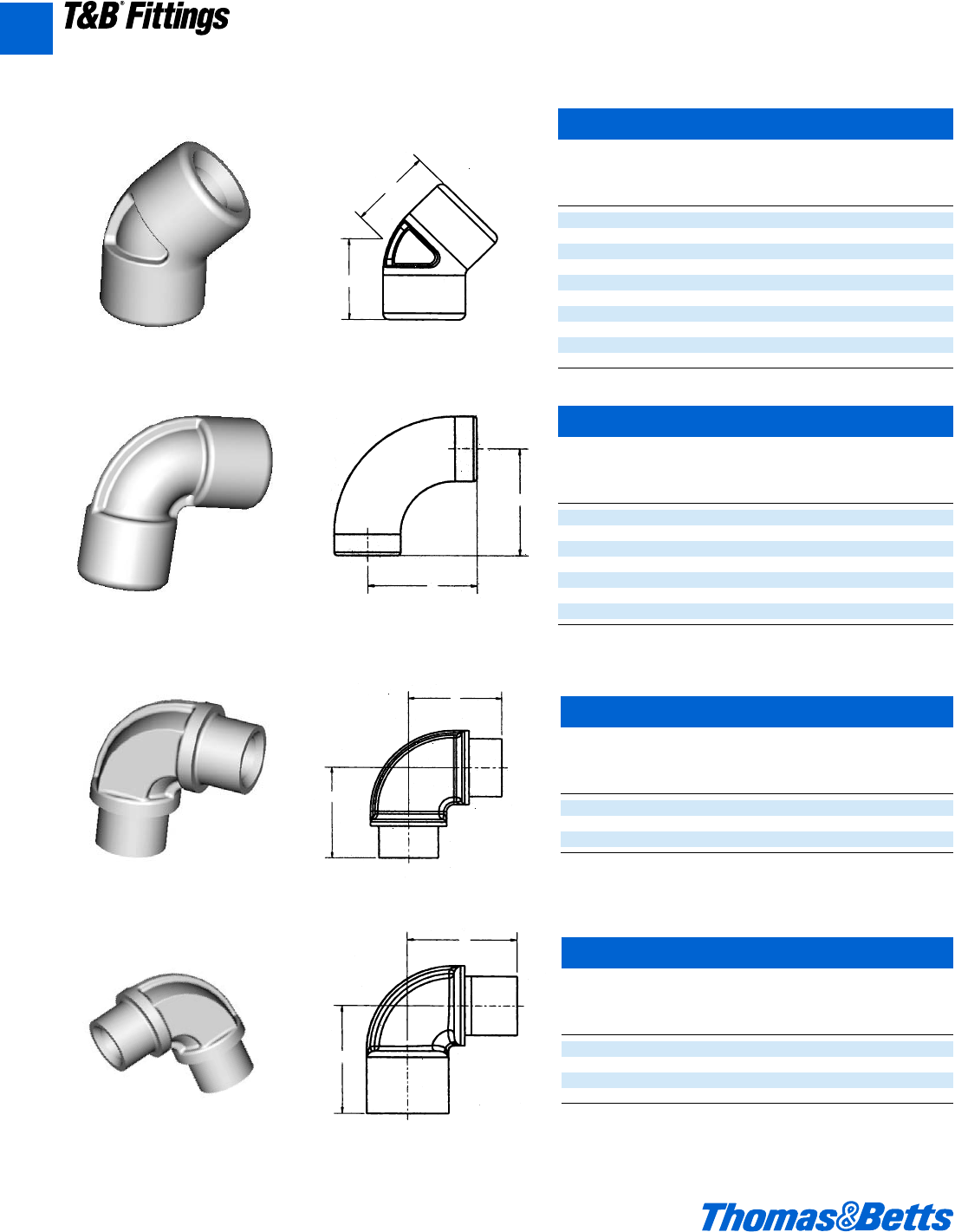
A88 © 2002 Thomas & Betts Corporation. Specifications are subject to change without notice. www.tnb.com
T&B®Fittings
A
45° Female Elbow
in ounces per hub.
Cat. Hub
No. Size A
EL1-TB d 1.268
EL2-TB f 1.402
EL3-TB 1 1.643
EL4-TB 1b 1.846
EL5-TB 1d 2.14
EL6-TB 2 2.326
EL7-TB 2d 2.848
EL8-TB 3 3.149
EL9-TB 3d 3.533
EL10-TB 4 3.975
A
A
90° Female Elbow
in ounces per hub.
Cat. Hub
No. Size A
EL19-TB 1d 1.75
EL29-TB f 1.965
EL39-TB 1 2.15
EL49-TB 1b 2.425
EL59-TB 1d 4.047
EL69-TB 2 5.02
EL79-TB 2d 6.375
A
A
90° Male Elbow
in ounces per hub.
Cat. Hub
No. Size A
EL195-TB d 1.422
EL295-TB f 1.625
EL395-TB 1 1.875
A
A
90° Male & Female Elbow
in ounces per hub.
Cat. Hub
No. Size A B
EL196-TB d 1.695 1.675
EL296-TB f 1.933 1.813
EL396-TB 1 2.085 2.17
EL496-TB 1b 2.46 2.281
B
A
Elbows
Explosionproof, Dust-Ignitionproof
CI.I, Div. 1 & 2, Groups C, D
CI.II, Div. 1, Groups E, F, G
CI.III, Div. 1 & 2
NEMA 3, 4, 7 CD, 9 EFG
Explosionproof
Dust-Ignitionproof
Raintight
Wet Locations
412031.A01 FIT 3/12 3/13/03 4:48 PM Page 88
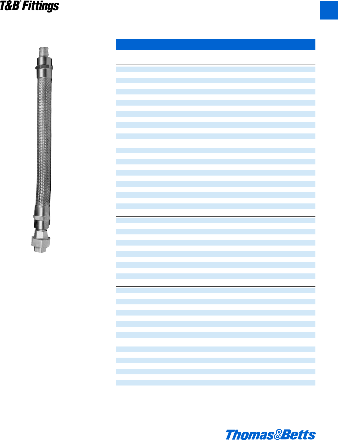
© 2002 Thomas & Betts Corporation. Specifications are subject to change without notice. www.tnb.com A89
T&B®Fittings
A
Flexible Couplings
Explosionproof, Dust-Ignitionproof
EXFC Series
Male to Male
Cat. Conduit Flex Std. Wt. lbs
No. Size Length Pkg. per 100
• EXFC-104 d" 4” 1 175
EXFC-106 d" 6” 1 200
EXFC-108 d" 8” 1 225
EXFC-110 d" 10” 1 238
EXFC-112 d" 12” 1 250
EXFC-115 d" 15” 1 262
EXFC-118 d" 18” 1 300
• EXFC-121 d" 21” 1 312
EXFC-124 d" 24” 1 325
EXFC-127 d" 27” 1 337
• EXFC-130 d" 30” 1 350
• EXFC-133 d" 33” 1 375
EXFC-136 d" 36” 1 400
• EXFC-204 f" 4” 1 200
EXFC-206 f" 6” 1 225
EXFC-208 f" 8” 1 237
EXFC-210 f" 10” 1 250
EXFC-212 f" 12” 1 262
EXFC-215 f" 15” 1 300
EXFC-218 f" 18” 1 312
• EXFC-221 f" 21” 1 325
EXFC-224 f" 24” 1 337
• EXFC-227 f" 27” 1 350
• EXFC-230 f" 30” 1 375
• EXFC-233 f" 33” 1 400
EXFC-236 f" 36” 1 450
EXFC-306 1" 6” 1 225
EXFC-308 1" 8” 1 250
EXFC-310 1" 10” 1 262
• EXFC-312 1" 12” 1 275
• EXFC-315 1" 15” 1 300
• EXFC-318 1" 18” 1 325
EXFC-321 1" 21” 1 350
• EXFC-324 1" 24” 1 375
• EXFC-327 1" 27” 1 412
• EXFC-330 1" 30” 1 450
• EXFC-333 1" 33” 1 487
EXFC-336 1" 36” 1 525
• EXFC-412 1b" 12” 1 650
• EXFC-415 1b" 15” 1 700
• EXFC-418 1b" 18” 1 750
• EXFC-421 1b" 21” 1 825
• EXFC-424 1b" 24” 1 875
• EXFC-427 1b" 27” 1 950
• EXFC-430 1b" 30” 1 1025
• EXFC-433 1b" 33” 1 1075
• EXFC-436 1b" 36” 1 1125
• EXFC-512 1d" 12” 1 825
• EXFC-515 1d" 15” 1 900
• EXFC-518 1d" 18” 1 1000
• EXFC-521 1d" 21” 1 1100
• EXFC-524 1d" 24” 1 1200
• EXFC-527 1d" 27” 1 1300
• EXFC-530 1d" 30” 1 1400
• EXFC-533 1d" 33” 1 1500
• EXFC-536 1d" 36” 1 1600
• Made to order items. Consult factory for lead time and minimum quantities.
Unions are not supplied with flexible couplings as shown in photo.
NEMA7 ABCD
9EFG
12
Cl. I, Div. 1 & 2, Groups A, B, C, D
Cl. II, Div. 1, Groups E, F, G
Cl. III, Div. 1 & 2
412031.A01 FIT 3/12 3/13/03 4:48 PM Page 89
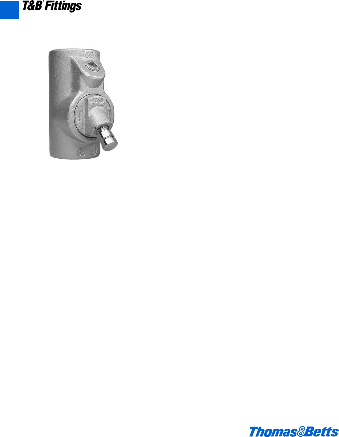
A90 © 2002 Thomas & Betts Corporation. Specifications are subject to change without notice. www.tnb.com
T&B®Fittings
A
Application
EYD drain and inspection sealing fittings:
• Restrict the passage of gases, vapors or flames from one portion of
the electrical installation to another at atmospheric pressure and
normal ambient temperatures.
• Limit explosions to the sealed-off enclosure.
• Prevent precompression or “pressure piling” in conduit systems.
Drain sealing fittings are installed in vertical conduit runs and at low
points in conduit systems to prevent accumulation of condensate
above seal.
Features:
EYD drain sealing fittings include:
• Drain to provide continuous, automatic drainage of condensate.
• Large openings with threaded closures to provide easy access to
conduit hubs for making dams.
• Integral bushings to protect conductor insulation from damage.
• Tapered-tapped hubs to ensure ground continuity.
Standard Materials
• Bodies, and inspection or drain covers – Gray iron alloy and/or
ductile iron.
• Closure for drain – copper-free aluminum or ductile iron.
• Small closure plug – Gray iron alloy and/or steel.
• Drain – stainless steel.
• Removable nipples – steel.
Standard Finish
• Gray iron alloy and ductile iron – electrogalvanized and aluminum
acrylic paint.
• Copper-free aluminum – natural.
• Stainless steel – natural
• Steel – electrogalvanized.
Options
• Copper-free aluminum bodies, nipples and enclosures –
see listings
Size Ranges
• EYD – d" – 4"
Certifications and Compliances*
NEC/CEC:
• EYD11 – 31-TB
Class I, Division 1 & 2, Groups A,B,C,D.
Class II, Division 1, Groups E,F,G.
Class III.
• EYD41 – 101-TB
Class I, Division 1 & 2, Groups C,D.
Class II, Division 1, Groups E,F,G.
Class II, Division 2, Groups F,G.
Class III.
• UL Standard: 886
• CSA Standard: C22.2
• Seals are approved to be used with Crouse-Hinds®Sealing
Compound and Fiber.
Crouse-Hinds®is a trademark of Cooper Industries, Inc.
Sealing Fittings
Explosionproof, Dust-Ignitionproof
412031.A01 FIT 3/12 3/13/03 4:48 PM Page 90
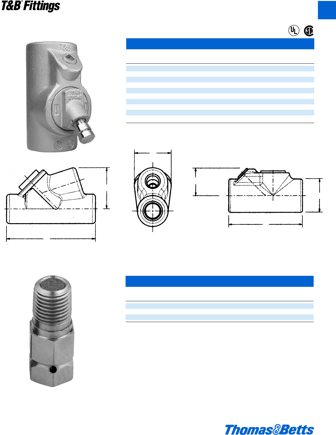
© 2002 Thomas & Betts Corporation. Specifications are subject to change without notice. www.tnb.com A91
EYD Drain Seals
Cat. Turning
No. Size A B Radius
EYD11-TB d3.81 1.50 1.75
EYD21-TB f4.08 1.75 1.98
EYD31-TB 14.85 2.19 2.19
EYD41-TB 1b 5.00 2.25 1.80
EYD51-TB 1d 5.44 2.44 2.00
EYD61-TB 26.25 3.00 2.32
EYD71-TB 2d 7.50 3.50 2.69
EYD81-TB 38.50 4.25 3.15
EYD91-TB 3d 9.19 4.75 3.38
EYD101-TB 49.75 5.25 3.64
A
B
Turning
Radius
B
A
Turning
Radius
Sealing Fittings
Explosionproof, Dust-Ignitionproof
NEMA7
9EFG
12
Cl. I, Div. 1 & 2, Groups A, B, C, D*
Cl. II, Div. 1, Groups E, F, G
Cl. III, Div. 1 & 2
EYD d" - 1" EYD 1b" - 4"
EYD d" - 1"
Drains/Breathers for Hazardous Locations
Cat.
No. Size Dim. “D”
ECD15 d.975
ECD384 c.407
ECD284 b.327
Application
The Thomas & Betts Universal drain/breather fittings can be used as drains
or breathers depending on the installation.
• To use as a drain, the product must be installed in the bottom of the enclo-
sure or the lowest point where an NPT threaded opening exists. It can also
be used in a seal fitting or a “T” conduit body. These must be in a lower sec-
tion of the conduit system. This will allow moisture inside the conduit system
to drain out.
• To use as a breather, installation should be done at the top of an enclosure
or in upper sections of conduit systems. This will permit air exchange and
keep moisture accumulation inside the conduit system to a minimum,
Thomas & Betts recommends the use of at least 2 devices (one drain and
one breather) for maximum efficency.
®
®
T&B®Fittings
A
412031.A02 FIT 3/5 3/13/03 4:55 PM Page 91
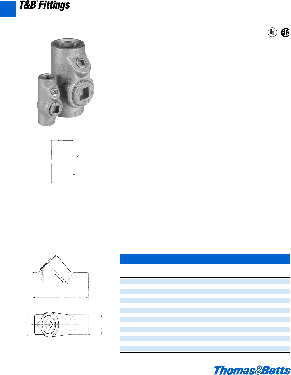
A92 © 2002 Thomas & Betts Corporation. Specifications are subject to change without notice. www.tnb.com
T&B®Fittings
Sealing Fittings
Explosionproof, Dust-Ignitionproof
EYS Sealing Fittings
Application
EYS sealing fittings can be installed in either vertical or horizontal applications.
• Seals sections of conduit runs from passage of vapors, flame, or gases.
• Seals off sections of conduit system during explosion.
• Limits precompression or pressure piling in conduit system.
Features
• All hubs have a minimum of five full threads, integral bushings to protect con-
ductor insulation from damage, and large access openings for easier packing
of sealing medium.
• Seals are approved to be used with Crouse-Hinds®Sealing Compound
and Fiber.
Size Range
•d" NPT to 4" NPT
Materials
• Bodies: Ductile Iron
• Plugs: Gray Iron
• Nipples: Steel, supplied with EYS fittings
Finish
• Bodies: Zinc-plated with aluminum acrylic paint
• Plugs: Zinc-plated with aluminum acrylic paint
• Nipples: Zinc-plated
Listing Certifications and Compliances
• UL886
• CSA: C22.2 No. 30
* EYS seals are approved to be used with Crouse-Hinds®Chico®A compound
and Chico®X fiber.
CHCHICO – X6 (8 oz. Chico X Fiber)
CHCHICO – A3 (1 lb. can Sealing Compound
CHCHICO – A4 (1 lb. can/1 oz. Chico X Fiber)
EYS Sealing Fittings
Cat. Hub Dimensions (Inches) Turning
No. Size A B C Radius
EYS1-TB* d 3.31 1.25 1.50 1.66
EYS2-TB* f 3.65 1.50 1.75 1.96
EYS3-TB* 1 4.25 1.75 2.19 2.40
EYS4-TB* 1b 5.00 2.25 2.45 3.11
EYS5-TB* 1d 5.69 2.45 3.00 3.62
EYS11-TB d3e1b –1p
EYS21-TB f3y1d –1b
EYS31-TB 14b1f –1X
EYS41-TB 1b 5 2b – 1m
EYS51-TB 1d 5k 2k – 2
EYS61-TB 26b3 –2j
EYS71-TB 2d 7d 3d – 2L
EYS81-TB 38d4b –3q
EYS91-TB 3d 9i 4f – 3c
EYS101-TB 49f5b –3w
Crouse-Hinds®and Chico®are trademarks of Cooper Industries, Inc.
*Vertical Only
B
A
Explosionproof
Dust-Ignitionproof
Cl. I, Div. 1 & 2, Groups A, B, C, D*
Cl. II, Div. 1, Groups E, F, G
Cl. III, Div. 1 & 2
A
CB
EYS11-TB – EYS101-TB
EYS1-TB – EYS5-TB
NEC/CEC:
EYS1-3TB*
Cl. I, Div. 1 & 2, Groups A, B, C, D
EYS4-5TB*
Cl. I, Div. 1 & 2, Groups C, D
EYS11-31TB*
Cl. I, Div. 1 & 2, Groups A, B, C, D
Cl. II, Div. 1, Groups E, F, G
Cl. III
EYS41-101TB*
Cl. I, Div. 1 & 2, Groups C, D
Cl. II, Div. 1, Groups E, F, G
Cl. III
®
®
A
412031.A02 FIT 3/5 3/13/03 4:55 PM Page 92
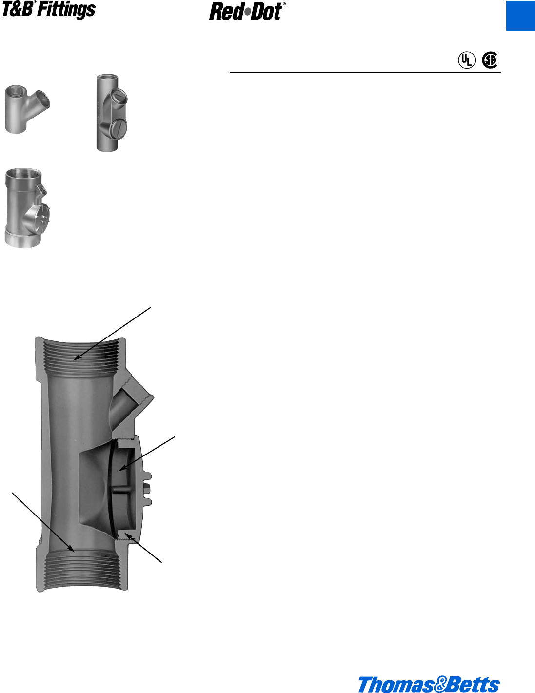
© 2002 Thomas & Betts Corporation. Specifications are subject to change without notice. www.tnb.com A93
T&B®Fittings
Aluminum Sealing Fittings
Explosion-Proof, Dust-Ignition-Proof
Application
• Limits flames and/or explosions to area within electrical system
where they originate.
• Limits pressure piling.
• Required by NEC for conduit systems in hazardous locations 18"
from an enclosure housing a heat producing or arcing device; on
2” and larger system which enters an enclosure containing splices;
wherever conduit leaves a Class I, Division I area and enters a non-
hazardous area.
Features/Benefits
• Copper-free* aluminum provides increased corrosion resistance.
• Precision cast and machined surfaces permit safer wire pulling.
• Precision NPT threaded hubs allow trouble-free field installation for
rigid or IMC conduit.
• Large opening provides maximum working room for creating dam
and seal pouring to speed up installation.
• Compact design permits close construction of parallel conduit runs.
Standard Materials
• Sealing Fittings: Die cast aluminum alloy A360 with less than .004
copper content (copper-free).
• Sealing Cement
• Fiber: Flame retardant Kaowool Type A fiber.
Standard Finish
• Aluminum lacquer finish
Compliances
• UL Listed
• CSA Certified
• Suitable for hazardous locations
• Federal Spec W-C-586
Sample Specifications
• Sealing fittings for hazardous locations shall be die cast copper-
free* aluminum alloy A360. Suitable for use in hazardous locations:
Class I, Groups C, D; Class II, Groups E, F, G and Class III. All con-
duit stops shall be coined and free of rough edges. Sealing fittings
for hazardous locations shall be finished with aluminum lacquer.
Sealing fittings shall be Red•Dot®Catalog No. __________
*Less than .004 copper content.
EYVF
EVHF
EVHF
Precision
machined
threads
Large aper-
ture for
easy instal-
lation
Copper-free
aluminum
Smooth
conduit
stops
®
®
CI.I, Div. 1 & 2, Groups C, D
CI.II, Div. 1, Groups E, F, G
CI.III, Div. 1 & 2
NEMA 3, 4, 7 CD, 9 EFG
Explosionproof
Dust Ignition-proof
Raintight
Wet Locations
A
412031.A02 FIT 3/5 3/13/03 4:55 PM Page 93
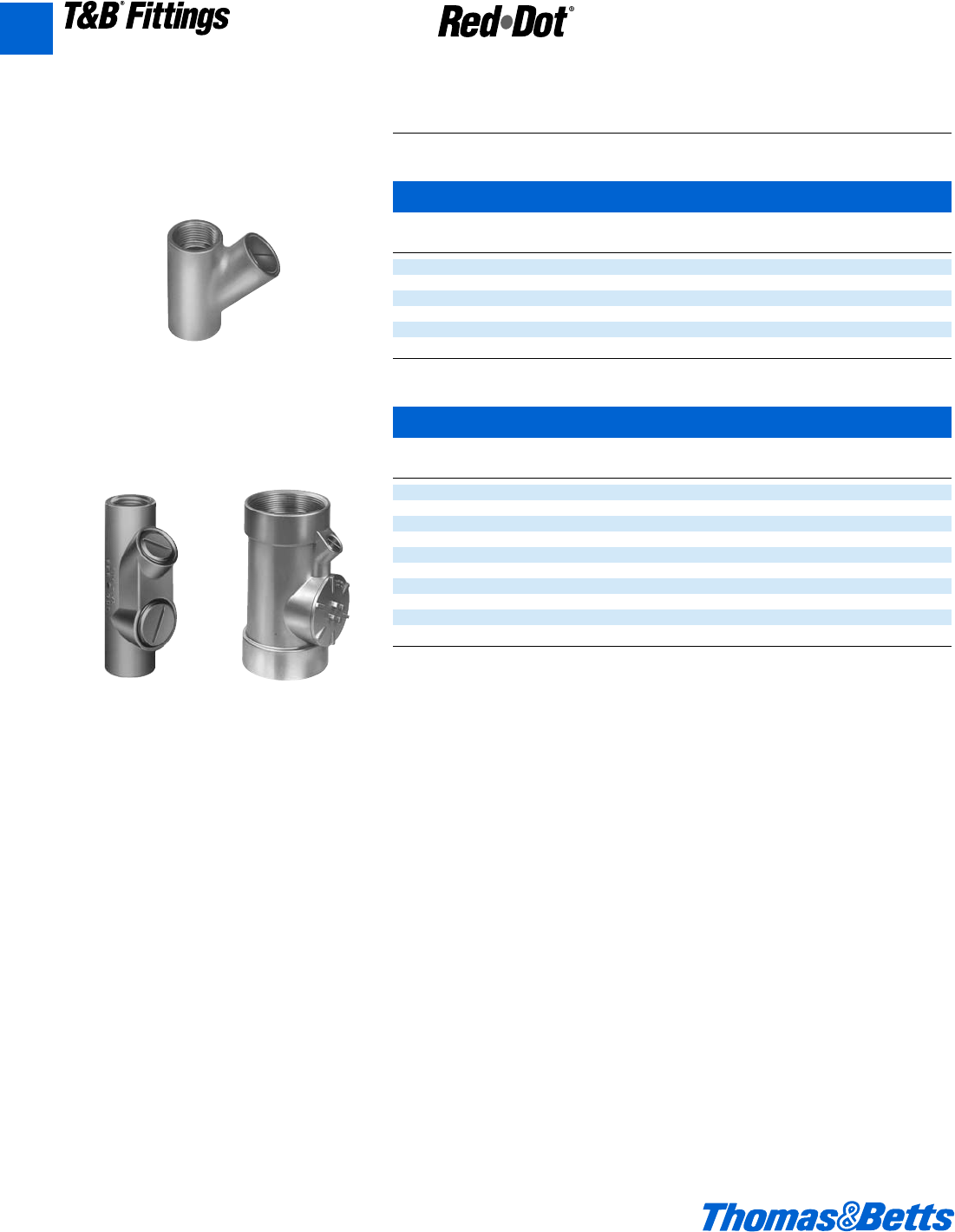
A94 © 2002 Thomas & Betts Corporation. Specifications are subject to change without notice. www.tnb.com
T&B®Fittings
Aluminum Sealing Fittings
Explosion-Proof, Dust-Ignition-Proof
Vertical and Horizontal
Vertical
Cat. Hub Unit Std. Wt. lbs.
No. Size Qty. Pkg. per 100
† EYVF-1 d" 525 50
† EYVF-2 f" 525 54
† EYVF-3 1" 5 25 100
EYVF-11 d" 10 50 35
EYVF-22 f" 10 50 40
EYVF-33 1" 420 60
Vertical/Horizontal
Cat. Hub Unit Std. Wt. lbs.
No. Size Qty. Pkg. per 100
EVHF-1 d" 10 50 41
EVHF-2 f" 525 50
EVHF-3 1" 525 60
EVHF-4 1b" 420 70
EVHF-5 1d" 15 60
EVHF-6 2" 1 1 125
• EVHF-7 2d" 1 1 150
• EVHF-8 3" 1 1 250
• EVHF-9 3d" 1 1 300
• EVHF-10 4" 1 1 400
• Made to order items. Consult factory for lead time and minimum quantities.
† Packaged with an adequate amount of sealing compound and plugs installed.
EYVF
EVHF-1 through -3 EVHF-4 through -10
CI.I, Div. 1 & 2, Groups C, D
CI.II, Div. 1, Groups E, F, G
CI.III, Div. 1 & 2
NEMA 3, 4, 7 CD, 9 EFG
Explosionproof
Dust Ignition-proof
Raintight
Wet Locations
A
412031.A02 FIT 3/5 3/13/03 4:55 PM Page 94
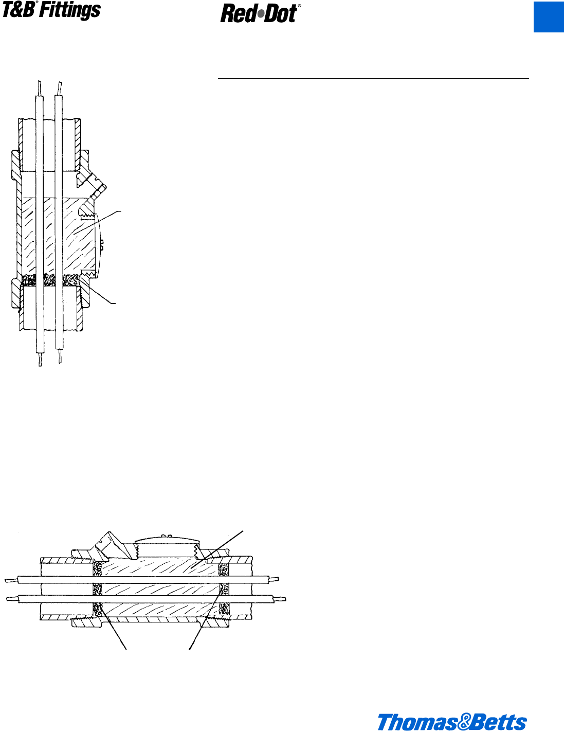
© 2002 Thomas & Betts Corporation. Specifications are subject to change without notice. www.tnb.com A95
T&B®Fittings
Preparation
Applications
Red•Dot®sealing cement is used for making seals in sealing fittings.
The insulation in the conductors sealed in the cement may be approved
thermoplastic or rubber, with or without lead covering. The sealing cement
should not be used for insulating.
Characteristics
Red•Dot®sealing cement is not affected by gasoline, alcohol, acetone,
ether, naptha, petroleum, benzol or lacquer solvent.
Preparation
(1) Use a clean mixing vessel for each batch.
(2) Thoroughly mix powder before adding water.
(3) Do not use if temperature is below 40°F.
(4) Mix 1 part water to 2 parts cement.
(5) Allow cement to set for 72 hours before use.
Standard Dams
(1) Push the conductors away from the filling opening and force them apart
so that they do not touch each other or the walls of the fitting or conduit
along their length. If the conductors do touch, the sealing cement will
not form a closed path between them.
(2) Force the packing fiber between each conductor and the inside walls.
Be sure that the dam is strong enough and tight enough to prevent the
considerable weight of the fluid sealing cement from seeping out.
Pouring
(1) Pour the mixed cement into the fitting slowly so as not to trap air in the
seal.
(2) Replace the close-up plugs to insure that they engage not less than 5
full threads.
Sealing Cement
Packing Fiber
Vertical Installation
for EYVF or EVHF Fittings
Sealing
Cement
Packing Fiber
Horizontal EVF Installation
Aluminum Sealing Fittings
Explosion-Proof, Dust-Ignition-Proof
CI.I, Div. 1 & 2, Groups C, D
CI.II, Div. 1, Groups E, F, G
CI.III, Div. 1 & 2
NEMA 3, 4, 7 CD, 9 EFG
Explosionproof
Dust Ignition-proof
Raintight
Wet Locations
A
412031.A02 FIT 3/5 3/13/03 4:55 PM Page 95
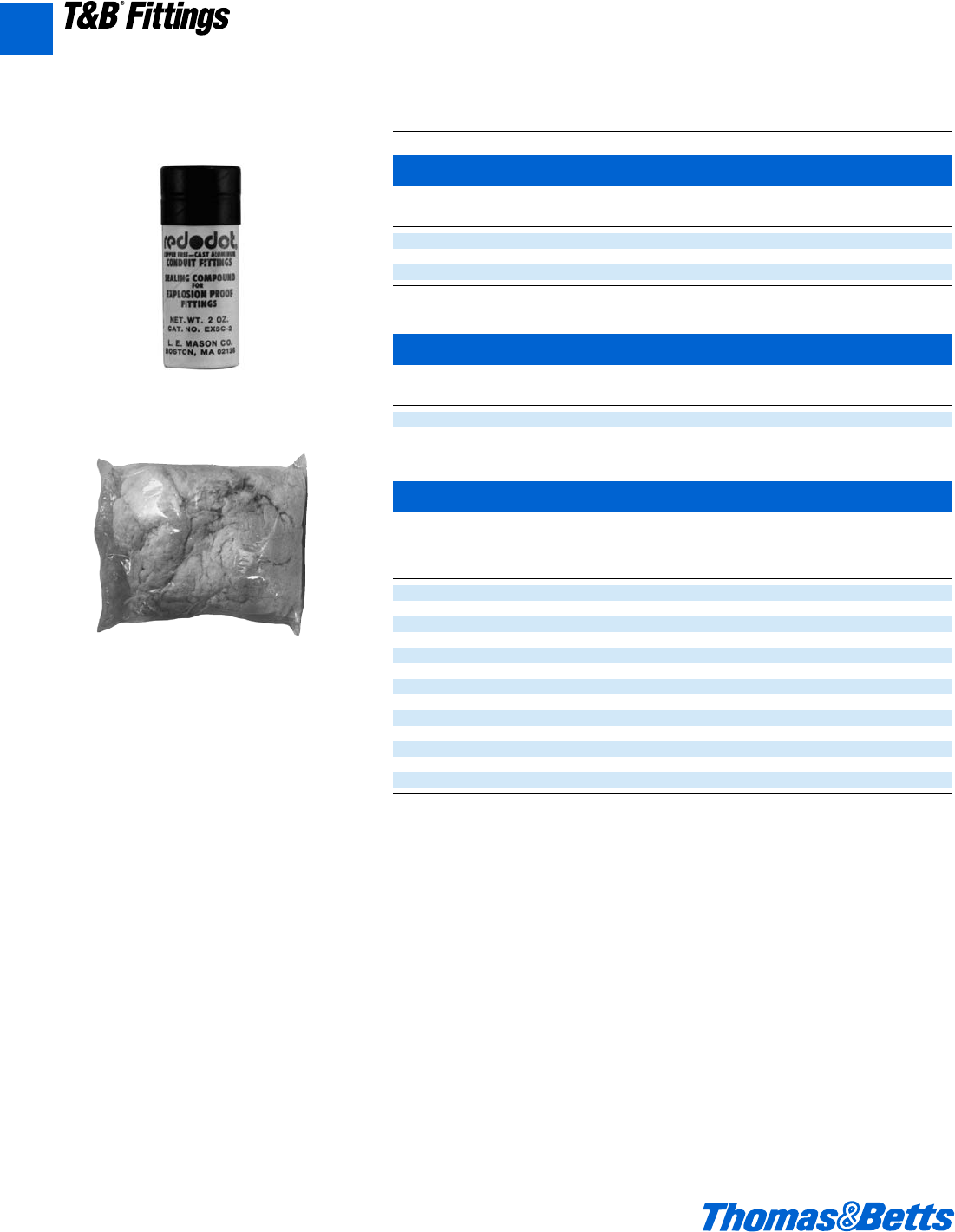
A96 © 2002 Thomas & Betts Corporation. Specifications are subject to change without notice. www.tnb.com
T&B®Fittings
Sealing Fittings
Explosion-Proof, Dust-Ignition-Proof
Sealing Cement and Fiber for Red•Dot ®Sealing Fittings
Sealing Cement • Can be used on Red•Dot®EYV, EVH series fittings only.
Cat. Volume Std. Wt. lbs
No. Quantity Cubic Inches Pkg. per 100
EXSC-2 3.2 oz. 2.75” 25 20
EXSC-8 13 oz. 11.50” 15 81
EXSC-16 1 lb., 10 oz. 23.00” 10 163
Packing Fiber • Can be used on Red•Dot®EYV, EVH series fittings only.
Cat. Volume Std. Wt. lbs
No. Quantity Cubic Inches Pkg. per 100
EXPF-16 1 lb. 1 112
Approximate amount of cement and fiber required
in ounces per hub.
Cat. Hub Cement Fiber
No. Size Quantity Quantity
EYVF-11 d" 2 oz. o oz.
EYVF-22 f" 3 oz. h oz.
EYVF-33 1" 4 oz. a oz.
EVHF-1 d" 2 oz. o oz.
EVHF-2 f" 2 oz. o oz.
EVHF-3 1" 4 oz. b oz.
EVHF-4 1b" 4 oz. b oz.
EVHF-5 1d" 6 oz. d oz.
EVHF-6 2" 12 oz. 1 oz.
EVHF-7 2d" 15 oz. 1d oz.
EVHF-8 3" 40 oz. 2 oz.
EVHF-9 3d" 45 oz. 3 oz.
EVHF-10 4" 50 oz. 4 oz.
EXSC
EXPF
CI.I, Div. 1 & 2, Groups C, D
CI.II, Div. 1, Groups E, F, G
CI.III, Div. 1 & 2
NEMA 3, 4, 7 CD, 9 EFG
Explosionproof
Dust Ignition-proof
Raintight
Wet Locations
A
412031.A02 FIT 3/5 3/13/03 4:55 PM Page 96
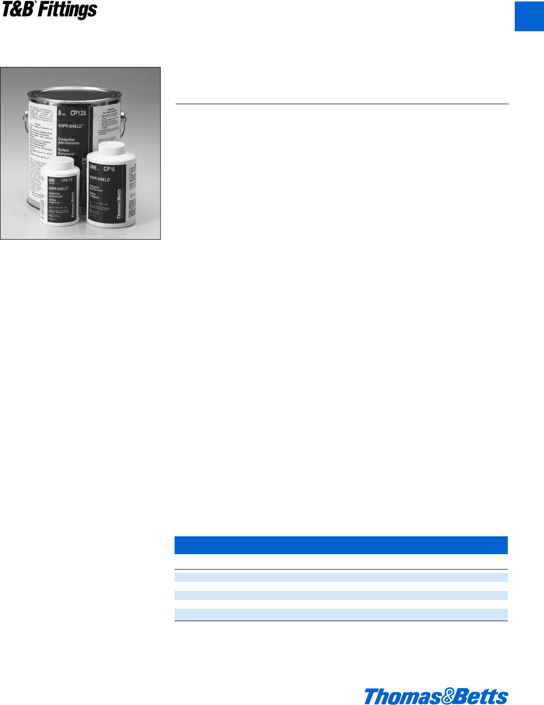
© 2002 Thomas & Betts Corporation. Specifications are subject to change without notice. www.tnb.com A97
T&B®Fittings
The Copper Colloidal Surface Treatment That Protects,
Lubricates and Enhances Conductivity Between All Electrical
Connections
Good connections are one of the most important aspects of electrical work.
Mechanics know how much down-time is caused when fluids or oils leak into the
raceway system or looking for a weak link in a ground system caused by a high
resistance connection. Mechanics also know how much time is spent keeping con-
tacts, switches, lugs and other connectors clean or replacing parts because of
“green scourge” build-up. Thomas & Betts has the solution to improve connections
made in thousands of electrical and raceway installations made each day by elec-
tricians everywhere.
Kopr-Shield™compound is a unique homogenized blend of pure, polished colloidal
copper, rust and corrosion inhibitors that simultaneously protects, lubricates and
enhances the conductivity of the mating surfaces to which it is applied. Extremely
adhesive, Kopr-Shield™compound flows smoothly into uneven contours and voids,
making application easy, protection and lubrication complete and positive. A sta-
ble compound, it will not settle-out, thin, thicken, harden, or dry out under the most
severe environmental conditions.
Kopr-Shield™Compound has excellent temperature characteristics – brushed on at
–50F to 250F (other compounds either turn solid or run like water at these
extremes). Even at 1800F, Kopr-Shield™remains intact for short terms.
Kopr-Shield™Compound may be used to advantage in all electrical installations.
When the environment is hostile to good electrical and mechanical connections,
Kopr-Shield™Compound is a must!
Use Kopr-Shield™Compound for Battery Lugs and Cables.
• Prevention of “Green Scourge” corrosion.
• Reduction of resistance.
• Ease of terminal installation and removal.
Use Kopr-Shield™Compound for Raceways.
• Lubrication – Ease of assembly and disassembly.
• Grounding Continuity Improved – Exceeds code requirements.
Use Kopr-Shield™Compound for Fuse Clips.
• Even Heat Distribution – Elimination of hot spots.
• Oxidation Prevention – Prevents carbon path formation.
• Lubrication – Easy installation and removal of fuses.
Use Kopr-Shield™Compound for Wiping Contacts, Drum Switches and Slip
Rings.
• Prevention of galling, burning, pitting and discoloration.
• Suppression of arching and dissipation of coronas.
• Lubrication for ease of operation.
Kopr-Shield™
Cat. No. Description Std. Pkg. Wt. Lbs./C
201-31879 1doz. Container with brush 96 11.46
201-31879-1 4 oz. Container with brush 24 38.54
CP8-TB 8 oz. Container with brush 12 64.58
CP16 16 oz. Container with brush 12 120.83
CP128 1 Gallon Can 4 952.00
Kopr-Shield™is a product of Jet Lube, Inc.
Kopr-Shield™Compound
Kopr-Shield™by Thomas & Betts meets the
requirements of Section 300.6(A) in the
2002 NEC Code for Protection Against
Corrosion.
“Where corrosion protection is
necessary and the conduit is
threaded in the field, the threads
shall be coated with an
approved electrically conductive,
corrosion-resistant compound.”
A
412031.A02 FIT 3/5 3/13/03 4:55 PM Page 97

Metal Clad Cable Termination Fittings
Metal Clad Cable Teck Cable Aluminum Sheathed Cable
Metal Clad Cable
(Type MC)
Ref. NEC Article 334*
“Metal Clad Cable Type MC is a factory
assembly of one or more conductors,
each individually insulated and enclosed
in a metallic sheath of interlocking tape,
or a smooth or corrugated tube.”
Metal Clad Cable Type MC is rated
for use up to 5,000 volts. The National
Electrical Code permits use of metallic
sheath as an equipment grounding
conductor.
Metal Clad Cables are available with
a variety of phase conductor insulations
such as crosslinked polyethylene, and
silicone rubber ethylene propylene,
depending on rated temperature of con-
ductors and working potential. Metallic
sheath can be of galvanized steel, alu-
minum, copper or bronze. A special
outer covering such as PVC or
Neoprene over metallic sheath is usual-
ly provided for environmental protection.
Metal clad cable is not permitted in
locations where it could be subject to
physical damage. Metal clad cable
can be used exposed, concealed, in
cable tray, in any approved raceway,
and with minor exceptions in haz-
ardous locations. Type MC cable can
also be used for services, feeders,
branch circuits, power, lighting, control
and signal circuits.
Use of metal clad cable is permitted
in wet locations, or where exposed to
destructive corrosive conditions or can
be directly buried in earth, concrete or
exposed to cinder fills, strong chlo-
rides, caustic alkalis, vapors, chlorine
or hydrochloric acids provided the
construction of cable, the conductors
within the metallic sheath, the metallic
sheath and protective cover over
metallic sheath comply with require-
ments enumerated in Sec. 334-3 of the
National Electrical Code.
Bend radius restrictions are depen-
dent on the size of the cable and the
type of sheath, i.e. smooth, interlocked
armor, corrugated sheath or shielded
conductors and varies from 7 times to
15 times cable external diameter.
NEC Article 334 requires that
approved fittings be used for termina-
tion. Where single-conductor cables
carrying alternating current enter a fer-
rous metal box or enclosure, proce-
dures described in NEC Section 300-
20 must be followed to reduce effects
of heating due to induced currents.
These procedures include recom-
mended arrangements of conductors,
cutting of slots in metal between indi-
vidual conductor holes, passing of
conductors through insulating walls, or
use of non-magnetic aluminum
sheathed cable and aluminum termi-
nating fittings.
Portions of this section reprinted by
permission from NFPA 70-1999,
National Electrical Code®,
Copyright © 1977, National Fire
Protection Association, Boston, MA.
Please refer to the following for further
details and complete information:
1. NEC Article 334…Metal Clad
Cable (Type MC)
2. U.L. 4, ANSI C33.9…Safety
Standards for Type MC Metal Clad
Cable
3. U.L. 514B, Safety Standards for
Outlet Boxes & Fittings
4. W-F-406…Federal Specification.
Fittings for Cable, Power
Electrical & Conduit Metal, Flexible
5. NEMA FM-1…Standards
Publication. Fittings and Supports
for Conduit and Cable Assemblies
• In the 1978 National Electric Code,
Aluminum Sheathed Cable is classi-
fied as type MC metal clad cable
(NEC Article 334); however in 1975
National Electric Code Aluminum
Sheathed Cable was classified as
type ALS cable and covered under a
separate article (NEC Article 331)
A98 © 2002 Thomas & Betts Corporation. Specifications are subject to change without notice. www.tnb.com
A
T&B®Fittings
412031.A02 FIT 3/5 3/13/03 4:55 PM Page 98
© 2002 Thomas & Betts Corporation. Specifications are subject to change without notice. www.tnb.com A99
T&B®Fittings
A
Metal Clad Cable Termination Fittings
Please Note
The excerpts and other material herein, whether relating
to the National Electrical Code, the Underwriters
Laboratories, Inc. listing, to industry practice or otherwise, is
not intended to provide all relevant information required for
use and installation. Reference to original or primary source
material and data is mandatory before any application or
use is made of the product.
Metal Clad Cable Teck Cable Aluminum Sheathed Cable – continued
Teck Cables
Teck cable derived its name from one
of its first users, the Teck-Hughes Gold
Mines in Kirkland Lake, Ontario. Teck
90 is CSA Type designation. Trade des-
ignation of this cable is Armored Cable.
Teck cables up to 5,000 volt working
potential are manufactured in accor-
dance with CSA Standard C22.2 No.
131 and are provided with a bare
ground conductor and an optional
outer jacket. Depending on phase con-
ductor insulation the cables are desig-
nated as Teck 90 (X-LINK) when insu-
lation is cross-linked polyethylene and
Teck 90 (EP) when insulation is ethyl-
ene propylene. Both cables are rated
for 90°C service (dry location) and
75°C (wet locations). When Teck cable
is suitable for installation down to
minus 40°F the cables are marked
Teck 90 (X-LINK) minus 40 or Teck 90
(EP) minus 40.
Over 5,000 volts working potential
Teck cables are manufactured in accor-
dance with IPCEA standards and are
certified by CSA. Cables are provided
with or without ground wire as required.
Teck cables with outer jacket may
be used for exposed or concealed
wiring in wet or dry locations,
indoors/outdoors and in corrosive envi-
ronments. Teck cables are suitable for
use in ventilated, non-ventilated and
ladder type cable troughs, in ventilated
flexible cable ways in both dry and wet
locations. Teck cable with outer jacket
is suitable for direct earth burial and for
Class II Division 2, Class III Division 1
& 2 hazardous locations per Canadian
Electric Code.
Some of the features of Teck cable
are its flexibility and ease of installa-
tion. Absence of dead air space within
cable increases heat transfer and mini-
mize condensation. Overall protective
covering provides good environmental
protection.
Bend radii for permanent training
during installation usually varies
between 7 times to 12 times the cable
diameter depending on cable con-
struction and manufacturer’s recom-
mendations. Larger radii bends are
required for other conditions.
Section 12-3028 of the Canadian
Electric Code requires that the termi-
nating fittings used must provide ade-
quate strain relief to terminal connec-
tions and ensure electrical continuity
without injury to non-metallic sheath.
Continuity is mandatory whether or not
the armour is used as a grounding
conductor. Except for dry locations free
from corrosive atmosphere, the non-
metallic jacket is not permitted to be
stripped back to a point where armour
is exposed after installation.
Where single conductor cables car-
rying 200 amps or more enter metal
boxes through separate openings cer-
tain precautions are required to pre-
vent overheating of the metal by induc-
tion. Use of non-ferrous or non-metallic
box connectors, locknuts and bush-
ings and installation of non-magnetic
panel inserts is suggested in the code.
Please refer to the following for further
details and complete information:
1. CEC Section 12…Wiring Methods
CEC Section 4…Conductors
2. CSA C22.2 No. 131 & 131S
(Supplement #1)…Safety
Standard for Type Teck Cable
3. CSA C22.2 No. 18…Safety
Standards for Outlet Boxes,
Conduit Boxes and Fittings
412031.A02 FIT 3/5 3/13/03 4:55 PM Page 99
Metal Clad Cable Termination Fittings
The Star®Teck Extreme™STE/STEX Series Cable Fitting
The Star Teck STE cable fitting series is designed for optimum integrity
in ordinary applications. The STEX series is specially designed for
classified hazardous areas. Both are designed to stand up to the
harshest and most corrosive environment.
Application
• Provides means for passing armored, metal clad, jacketed or unjacketed
and unarmored cables through a bulkhead or enclosure in hazardous
areas. (These fittings are suitable for hazardous areas when used with
T&B sealing compound.)
• Forms a mechanical grip and water and/or oil-resistant termination.
• Provides grounding continuity of cable armor.
Features
• Removable armor-stop for greater cable ranges.
• Built-in sealing device.
• Patented Elastomeric collar ring/bushing.
• Built-in jacket stripping gauge.
• Patented powergrip grounding ring.
Range
• Star Teck Extreme fittings are designed to accommodate a broad range
of cables. Each hub range overlaps the adjacent hub range, thereby
minimizing the possibility of mismatched cables and fittings in the field.
They are available in hub sizes from d" to 4" and will handle outer jacket
diameters form 0.525" to 4.340".
Materials
• Aluminum is standard material.
Cord & Cable Type
• JMC, MC
Environment Classification
• STE* Series
–Ordinary Location
–Class I, Division 2†
• –NEMA 4, 4X, 6P
• –STE050 - STE200
NEMA 6P
• –STE250 - 400
NEMA 4
• –STE050 - 400
NEMA 4X
• STEX** Series
–Ordinary Location
–Class I, Division 1, Groups A,B,C,D
–Class II, Division 1, Groups E,F,G
–NEMA 4, 4X, 6P
* These fittings are suitable for Class I hazardous locations when used in combination with a certified Class I hazardous
location sealing fitting.
** May be used in hazardous areas approved MC type cable (or equal) when installed in accordance with NEC/CEC requirements.
Not applicable to all STEX series.
A100 © 2002 Thomas & Betts Corporation. Specifications are subject to change without notice. www.tnb.com
A
T&B®Fittings
412031.A02 FIT 3/5 3/13/03 4:56 PM Page 100
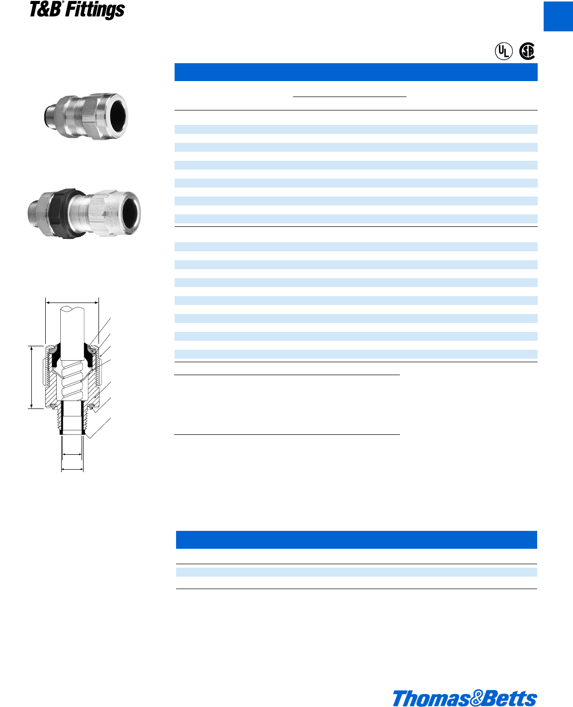
© 2002 Thomas & Betts Corporation. Specifications are subject to change without notice. www.tnb.com A101
T&B®Fittings
A
Metal Clad Cable Termination Fittings
To specify other material, add the appropriate suffix to the category number.
Desired Material Suffix Example
Aluminum fitting with ground lock nut GR STE-050GR
Steel with zinc plate S STE-050S
Brass with nickle plate BN STE-050BN
Aluminum with-pvc coating PVC STE-050PVC
Steel with pvc coating S-PVC STE-050S-PVC
Star®Teck Extreme™Jacketed Metal-Clad Cable Fittings
Hub Strip Gland Range Over Jacket Range Over Armor A1: Throat A2: Throat B* C
Cat. Size Length Torque Dia. Min. Dia. Min. Overall Max.
No. a.p.† (lb.-In.) Min. Max. Min. Max. w/End Stop wo/End Stop Alum.
Ordinary
ST050-462* d1b 300 .525 .650 .415 .570 N/A* .395 2.020 1.224
STE050* d1b 300 .600 .985 .520 .895 .505 .612 2.650 1.630
STE075* f1b 600 .860 1.205 .780 1.125 .655 .816 2.900 2.080
STE100* 11b700 .950 1.375 .870 1.295 .785 1.044 3.020 2.300
STE125* 1b 1b 1000 1.150 1.625 .990 1.465 .970 1.250 4.010 2.820
STE150* 1d 1f 1200 1.440 1.965 1.280 1.805 1.260 1.562 4.290 3.250
STE200* 21f1600 1.825 2.375 1.665 2.215 1.645 1.995 4.120 3.600
STE250 2d 2d 1600 2.265 2.840 2.105 2.680 2.075 2.424 5.320 4.750
STE300 32d1600 2.670 3.270 2.545 3.145 2.531 2.890 5.400 5.400
STE350 3d 2d 1600 3.220 3.870 3.090 3.640 3.065 3.460 5.360 5.900
STE400 42d1600 3.665 4.340 3.550 4.225 3.525 3.941 5.415 6.400
Hazardous Locations
STX050-462* d1b 300 .525 .650 .415 .570 N/A* .395 2.500 1.630
STX050-464* d1b 300 .600 .760 .490 .680 N/A* .485 2.530 1.630
STEX075* f1b 600 .600 .985 .520 .895 .504 .678 3.400 1.820
STEX100* 11b700 .860 1.205 .780 1.125 .650 .833 3.580 2.300
STEX125* 1b 1b 1000 .950 1.375 .870 1.295 .834 1.065 3.920 2.510
STEX150* 1d 1f 1200 1.150 1.625 .990 1.465 .958 1.273 5.020 3.260
STEX200* 21f1600 1.440 1.965 1.280 1.805 1.250 1.560 5.120 3.620
STEX250† 2d 2d 1600 1.825 2.375 1.665 2.215 1.640 1.995 5.170 4.580
STEX300† 32d1600 2.265 2.840 2.105 2.680 2.075 2.461 6.610 5.100
STEX350† 3d 2d 1600 2.670 3.270 2.545 3.145 2.531 2.864 7.380 5.790
STEX400† 42d1600 3.220 3.870 3.090 3.640 3.055 3.461 7.650 6.190
STX400-484† 4–1600 3.810 4.030 3.680 3.870 – – – –
STX400-485† 4–1600 3.965 4.185 3.835 4.025 – – – –
Collar Ring
(elastomeric)
Bushing
(elastomeric)
Gland Nut
(aluminum)
Grounding Ring
(stainless steel or
bronze with nickel plate)
Body
(aluminum)
Sealing Ring
(elastomeric)
Removable
Armor-Stop
(nylon d"-1")
(aluminum 1b"-4")
C
B
A1
A2
STE Series
Ordinary
STEX Series
Hazardous Locations
UL Listed #84H3
* These products are UL Listed
Watertight NEMA Type 6P
* The 1/2 fittings do not have a removable armor stop.
† CSA approved for hazardous location.
Sealing Compounds – Used for Hazardous Locations
Cat. No. Description Volume
SC4-KIT Liquid type sealing compound for use in control cable applications 2.8 fl. oz.
SC65 Putty Type Sealing Compound 60 grams
®
®
412031.A02 FIT 3/5 3/13/03 4:56 PM Page 101
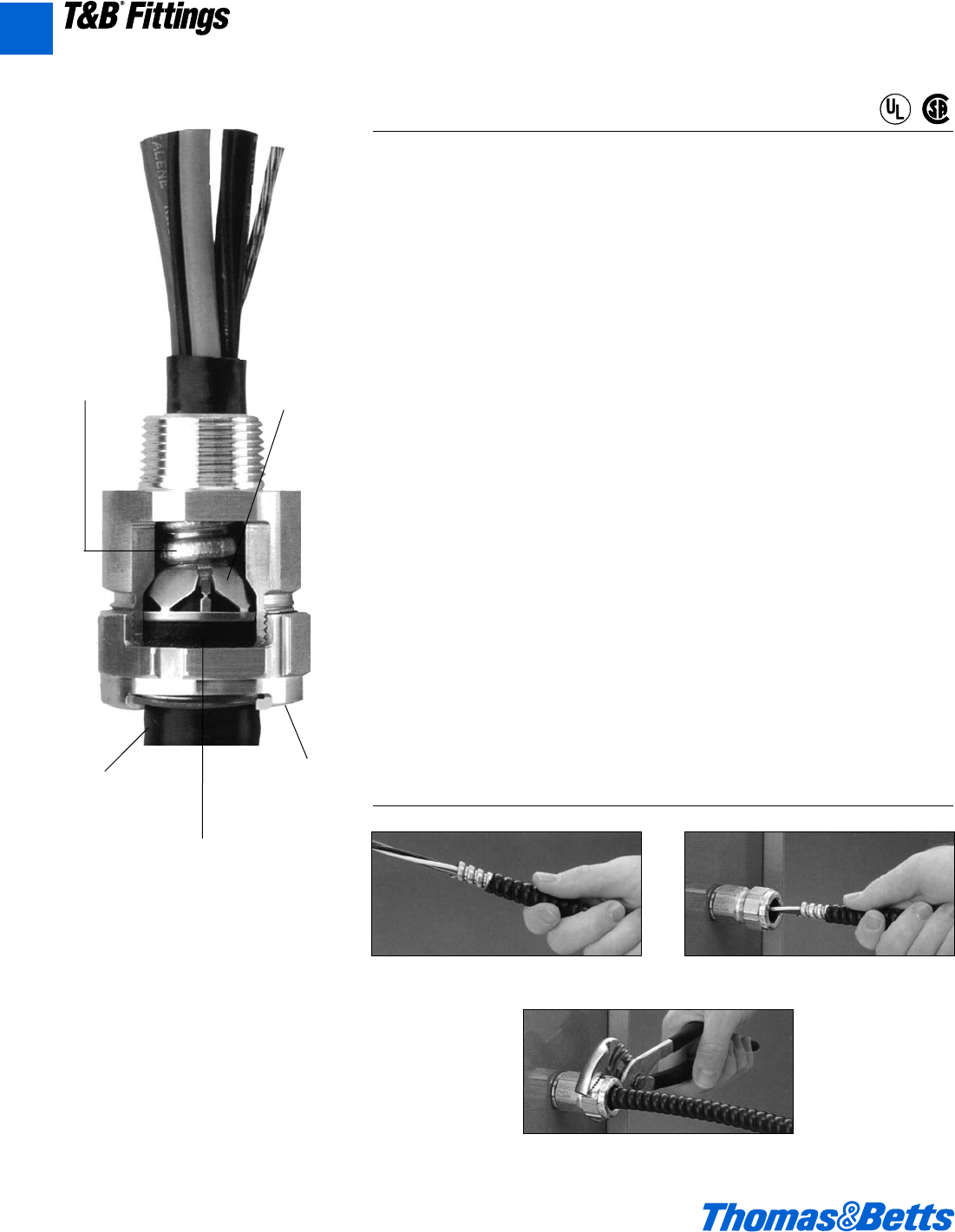
Metal Clad Cable Termination Fittings
Star®Teck Jacketed Metal-Clad Cable Fittings
Overlapping range of sizes. Star®Teck jacketed metal-clad cable fittings are
designed to accommodate a broad range of cables, thereby minimizing the possi-
bility of mismatched cables and fittings in the field.
Application
• Provide means for passing aarmored,
metal clad, jacketed or unjacketed
and unarmored cables through a
bulkhead or enclosure in hazardous
areas (These fittings are suitable for
hazardous areas when used with T&B
sealing compound.)
• Form a mechanical grip and water
and/or oil-resistant termination
• Provide grounding continuity of
cable armor
Cord & Cable Type
• JMC, MC
Features
•Easy Installation
Exclusive power-grip. Provides a grip
that’s high up on the cable—not on
the first convolution—so strip length
and cutting of cable are not critical.
•Dependable Service
Stainless steel retaining ring.
Withstands corrosive environments.
Non-magnetic.
•Dependable Grounding
Power-Grip grounding ring is non-
magnetic stainless steel. Provides
360° long-term dependable ground-
ing. It makes immediate contact with
the cable.
•Watertight
Tapered bushing. Cone shaped to
provide a secure, tight fit while elimi-
nating cupping or water in vertical
installations.
•Easy to Install in Tight Spaces
Low profile gland nut fits tight spaces.
Has grooves for screwdriver installa-
tion, and flats for a wrench. Durable
and reusable with funnel entry for
easy cable insertion.
Materials
Aluminum is standard material. The
body and gland nut on hub sizes d" to
1" are made of steel and 1b" to 4" are
made of malleable iron.
Environment Classification
• Suitable for hazardous locations.
Class 1 Div. 2; Class II Div. 2; Class III.
Where explosion proof or dust proof
fittings are required by code use Star
Teck XP fittings (STX Series).
Range
• They are available in hub sizes from
dto 4 inches, and will handle outer
jacket diameters from 0.525 to
4.340 inches.
Installing the STAR®TECK Fitting
1. Prepare cable
3. Tighten gland nut
2. Insert cable
Watertight
Tapered bush-
ing. Cone
shaped to pro-
vide a secure,
tight fit while
eliminating
cupping or
water in verti-
cal installa-
tions.
Easy
Installation
Exclusive
power-grip.
Provides a grip
that’s high up
on the cable –
not on the first
convolution –
so strip length
and cutting of
cable are not
critical.
Dependable
Service
Stainless steel
retaining ring.
Withstands cor-
rosive environ-
ments. Non-
magnetic.
Dependable
Grounding
Power-Grip
grounding ring
is non-magnet-
ic stainless
steel. Provides
360° long-term
dependable
grounding. It
makes immedi-
ate contact with
the cable.
Easy to Install in
Tight Spaces
Low profile
gland nut fits
tight spaces.
Has grooves for
screwdriver
installation, and
flats for a
wrench. Durable
and reusable
with funnel entry
for easy cable
insertion.
®
®
A102 © 2002 Thomas & Betts Corporation. Specifications are subject to change without notice. www.tnb.com
A
T&B®Fittings
412031.A02 FIT 3/5 3/13/03 4:56 PM Page 102
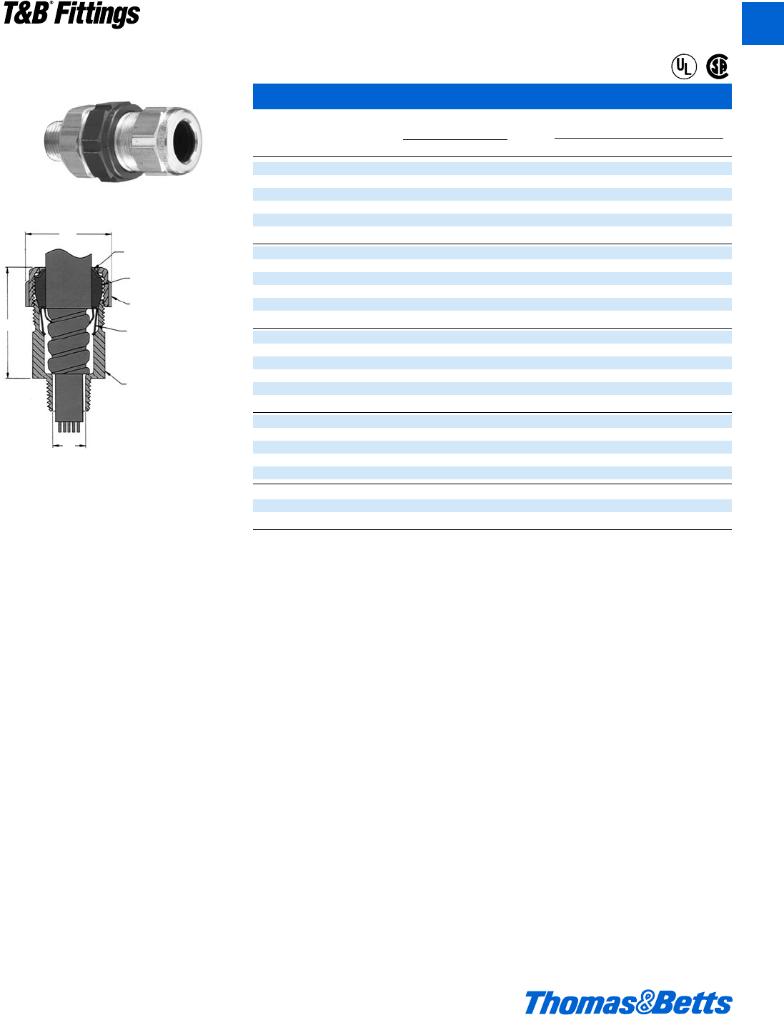
© 2002 Thomas & Betts Corporation. Specifications are subject to change without notice. www.tnb.com A103
T&B®Fittings
A
Star®Teck Jacketed Metal-Clad Cable Fittings
Hub Range Over
Cat. Size Jacket (in.) Dimensions (in.)
No. NPT min. max. A B* C
ST050-462 d0.525 0.650 0.395 2.020 1.224
ST050-464 d0.600 0.760 0.485 2.020 1.363
ST050-465 d0.725 0.885 0.612 2.133 1.633
ST050-466 d0.825 0.985 0.612 2.133 1.633
ST075-467 f0.880 1.065 0.819 2.450 2.080
ST075-468 f1.025 1.205 0.819 2.450 2.080
ST100-469 11.187 1.375 1.039 2.601 2.230
ST125-470 1b 1.350 1.625 1.182 3.282 2.824
ST125-550 1b 1.500 1.625 1.370 3.282 2.824
ST125-471 1b 1.600 1.875 1.370 3.282 2.824
ST150-472 1d 1.700 1.965 1.557 3.620 3.260
ST150-473 1d 1.900 2.187 1.600 3.620 3.260
ST200-551 21.900 2.187 1.715 3.640 3.620
ST200-474 22.100 2.375 1.995 3.640 3.620
ST200-475 22.300 2.565 2.057 3.640 4.020
ST200-476 22.500 2.750 2.057 3.640 4.020
ST250-477 2d 2.380 2.640 2.230 4.700 4.750
ST250-478 2d 2.580 2.840 2.430 4.700 4.750
ST300-479 32.790 3.060 2.630 4.700 5.050
ST300-480 33.000 3.270 2.860 4.790 5.480
ST300-481 33.210 3.480 3.032 4.790 5.480
ST350-482 3d 3.420 3.690 3.260 4.790 5.980
ST350-483 3d 3.610 3.870 3.430 4.790 5.980
ST400-484 43.810 4.030 3.590 4.840 6.435
ST400-485 43.965 4.185 3.745 4.840 6.435
ST400-486 44.120 4.340 3.900 4.840 6.435
* Approximate dimension before installation.
U.L. File No. E 38947
CSA File No. LR 23086
Suggested specifications for metal-clad cable fitting.
1. All metal-clad cable fittings for jacketed interlocked armor cable or continuous corrugated cable shall be approved by a nationally rec-
ognized testing laboratory, inspection agency or product evaluation organization.
2. Where corrugated-jacketed metal-clad cable exposed to intermittent or continuous moisture is terminated into a threaded opening, the
fitting shall be watertight type furnished with:
a. An elastomeric beveled bushing.
b. A funnel entry, splined gland nut.
c. A non-magnetic stainless steel grounding device with dual grounding action.
d. A taper threaded hub.
e. A hexagonal body and gland nut as manufactured by Thomas & Betts (aluminum series
ST050-464).
3. Where cable is terminated into a threadless opening, a suitable moisture resistant elastomeric gasket as manufactured by Thomas &
Betts, series 5262, shall be provided between the outside of enclosure and fitting shoulder.
4. With single conductor cable and/or in corrosive environments, aluminum fittings such as Thomas & Betts series ST050-464 shall be
installed.
Class I Div 2; Class II Div. 2; Class III. Where explosion-proof or dust-ignition-proof boxes are required by Teck fitting must be used in
conjunction with an approved sealing fitting.
Metal Clad Cable Termination Fittings
Retaining ring
(stainless steel)
Bushing
(neoprene)
Gland nut
(aluminum)
Grounding ring
(stainless steel)
Body
(aluminum)
Overlapping range of sizes. Star®Teck jacketed
metal-clad cable fittings are designed to
accommodate a broad range of cables, thereby
minimizing the possibility of mismatched
cables and fittings in the field. They are avail-
able in hub sizes from 1⁄2to 4 inches, and will
handle outer jacket diameters from 0.525 to
4.340 inches.
Suitable for hazardous locations. Class 1 Div.
2; Class II Div. 2; Class III. Where explosion
proof or dust proof boxes are required by code
use Star Teck XP fittings (STX050-462 Series).
B
C
A
®
®
412031.A02 FIT 3/5 3/13/03 4:56 PM Page 103
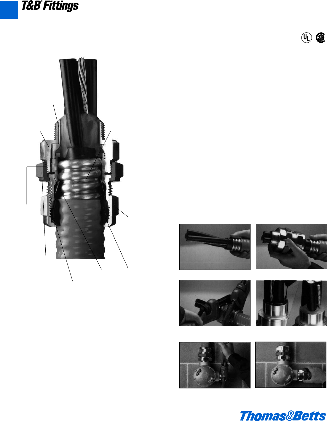
Star ®Teck XP Jacketed Metal-Clad Cable Fittings
Metal Clad Cable Termination Fittings
Application
• Provide means for passing
armored, metal clad, jacketed or
unjacketed and unarmored cables
through a bulkhead or enclosure in
hazardous areas (These fittings are
suitable for hazardous areas when
used with T&B sealing compound.)
• Form a mechanical grip and water
and/or oil-resistant termination.
• Provide grounding continuity of
cable armor.
Cord & Cable Type
• JMC, MC
Features
• Sealing chamber is easier to fill,
requires less sealing compound—
saves time, material. Flame path is
optimally designed to allow for
easy insertion into hub. Quick-
turn lock.
• Internal splines.
• Union features twist-on action; red
color for high visibility.
• Exclusive Power Grip. Provides
grip that’s high up on cable armor.
Non-magnetic stainless steel
Power Grip grounding ring.
• Low profile gland nut.
Materials
Aluminum is standard material. The
body and gland nut on hub sizes d"
to 1" are made of aluminum and 1b"
to 4" are made of aluminum.
Environment Classification
• Suitable for hazardous locations.
Class 1 Div. 2; Class II Div. 2;
Class III. Where explosion proof or
dust proof fittings are required by
code use Star Teck XP fittings
(STX Series).
Range
• They are available in hub sizes
from dto 4 inches, and will handle
outer jacket diameters from 0.525
to 4.185 inches.
Easy installation saves time, money!
1. Prepare cable
3. Tighten gland nut 4. Pot cable (using liquid
or putty)
5. Install hub on enclosure 6. Insert cable and tighten
red union
2. Install Star®Teck XP on cable
Sealing cham-
ber is easier to
fill, requires
less sealing
compound –
saves time,
material. Flame
path is optimal-
ly designed to
allow for easy
insertion into
hub. Quick-turn
lock secures
assembly dur-
ing installation.
Hub has
hexagonal
shape for
depend-
able tool
grip.
Internal
splines
allow
installer
to tighten
gland nut
either on
or off
enclosure.
Union features
twist-on action
for easy connec-
tion and discon-
nection; red
color assures
high visibility,
easy recogni-
tion. Union also
serves as a
“puller” during
disassembly.
Stainless
steel retain-
ing ring.
Withstands
corrosive
environ-
ments. Non-
magnetic.
Low profile
gland nut fits
tightest spaces.
Has grooves for
hammer/screw-
driver installa-
tion and flats for
wrench-gripping.
Durable and
reusable with
funnel entry for
easy cable
insertion.
Exclusive
Power Grip.
Provides grip
that’s high up
on cable armor
– not on first
convolution –
so precise
cable prepara-
tion is not criti-
cal. Non-mag-
netic stainless
steel Power
Grip grounding
ring assures
360° long-term
dependable
grounding. It
provides phe-
nomenal ten-
sile pullout
resistance.
Tapered
bushing.
Cone-shaped
to provide
secure, tight
fit while elimi-
nating cup-
ping of water
in vertical
installations.
®
®
Copper-free
construc-
tion. All-alu-
minum body
and gland
nut resist
corrosion,
oxidation.
A104 © 2002 Thomas & Betts Corporation. Specifications are subject to change without notice. www.tnb.com
A
T&B®Fittings
412031.A02 FIT 3/5 3/13/03 4:56 PM Page 104
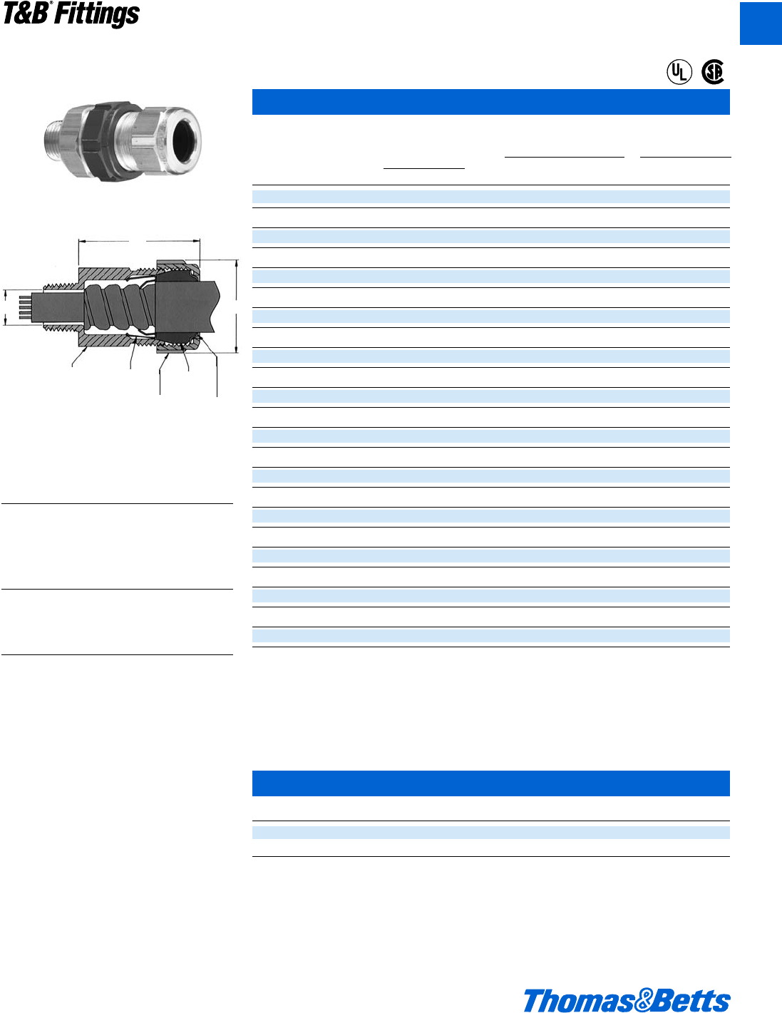
© 2002 Thomas & Betts Corporation. Specifications are subject to change without notice. www.tnb.com A105
T&B®Fittings
A
Star®Teck XP Jacketed Metal Clad Cable Fittings
Sealing Compound
Required
Hub Range Over Dimensions (in.) SC65** SCA-KIT**
Cat. Size Jacket (in.) A Putty Liquid
No. N.P.T. min. max. min. B C (grams) (cc)
STX050-462 d0.525 0.650 0.395 2.50 1.63 7 4
STX050-464 d0.600 0.760 0.485 2.50 1.63 7 4
STX075-465 f0.725 0.885 0.612 2.62 1.82 14 7
STX075-466 f0.825 0.985 0.720 2.62 1.82 14 7
STX100-467 10.880 1.065 0.755 2.83 2.30 30 16
STX100-468 11.025 1.205 0.900 2.83 2.30 30 16
STX125-469 1b 1.187 1.375 1.062 3.05 2.51 45 22
STX150-470 1d 1.357 1.625 1.182 3.76 3.26 80 43
STX150-550 1d 1.500 1.625 1.370 3.76 3.26 80 43
STX150-471 1d 1.600 1.875 1.470 3.76 3.26 80 43
STX200-472 21.700 1.965 1.557 4.05 3.62 125 66
STX200-473 21.900 2.187 1.757 4.05 3.62 125 66
STX200-474 22.100 2.375 1.995 4.15 4.02 150 80
STX250-475 2d 2.300 2.565 2.185 4.31 4.58 341 164
STX250-476 2d 2.500 2.750 2.365 4.31 4.58 341 164
STX300-478 32.580 2.840 2.460 5.64 5.10 497 239
STX300-479 32.790 3.060 2.660 5.80 5.33 609 293
STX350-480 3d 3.000 3.270 2.864 6.32 5.79 965 464
STX350-481 3d 3.210 3.480 3.062 6.32 5.79 965 464
STX400-482 43.420 3.690 3.290 6.63 6.19 1323 636
STX400-483 43.610 3.870 3.460 6.63 6.19 1323 636
STX400-484 43.810 4.030 3.630 7.09 6.90 1645 791
STX400-485 43.965 4.185 3.775 7.09 6.90 1645 791
* Approximate dimension before installation.
** 1 unit of SC65 putty type sealing compound contains 50 g. 1 unit of SC4-Kit liquid type sealing compound contains 66 cc. and
includes a dispensing syringe and fibre damming material.
U.L. File No. E-38947
CSA File No. LR 23086
CAUTION: Star®Teck XP fittings must be installed with Thomas & Betts catalog numbers SC4-Kit or SC65 sealing compound (purchase
separately). See installing instructions.
Sealing Compounds
Cat. No. Description Volume
SC4-KIT Liquid type sealing compound for use in control cable applications 2.8 fl. oz.
SC65 Putty Type Sealing Compound 60 grams
U.L. File No. E-82038
CSA File No. LR 638
Hub
(aluminum) Grounding Ring
(stainless steel)
Gland Nut
(aluminum)
Bushing
(elastomer)
Retaining Ring
(stainless steel)
B
C
A
Metal Clad Cable Termination Fittings
®
®
U.L. Connectors When Used With Putty Type
Listed or Liquid Type Compound
For:
1⁄2thru 3" Class I Div. 2 Groups A, B,
C, D
Class II Div. 2 Groups F, G
Class III
Enclosure Type 4
Connectors When Used With Putty Type
or Liquid Type Compound
31⁄2" & 4" Class I Div. 2 Groups B, C, D
Class II Div. 2 Groups F, G
Class III
Enclosure Type 4
CSA Certified For:
Class I Division Groups A, B,
1 and 2 C, D
Class II Division Groups E,
1 and 2 F, G
Class III, SL (Integral Seal)
Enclosure Type 4
412031.A02 FIT 3/5 3/13/03 4:56 PM Page 105
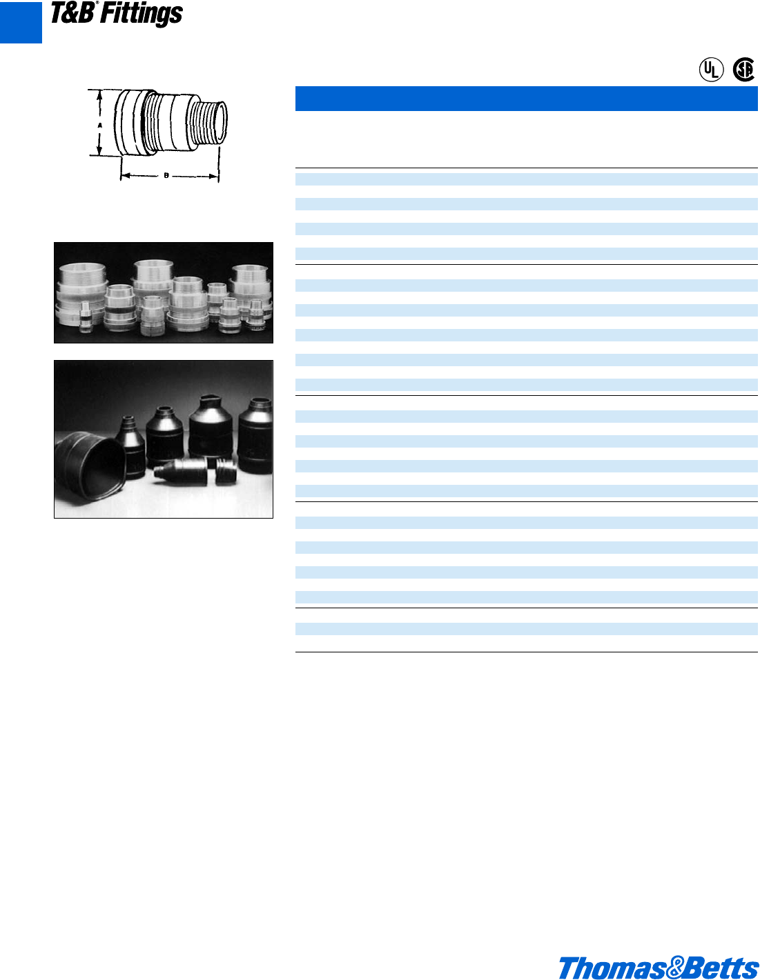
Metal Clad Cable Termination Fittings
Connector
Aluminum
Spin-On®Series II Connectors and Accessories
Optional
Hub Cable Range A Corrosion
Cat. Size Over Armor Dia. B Resistant Boot
No. (in.) (in.) (in.) (in.) Cat. No.
2-050-008 d.380-.435 1b 1g NB050
2-050-010 d.436-.500 1b 1g NB050
2-050-020 d.501-.580 1b 1g NB050
2-050-030 d.581-.650 1b 1g NB050
2-075-040 f.651-.730 1e 2a NB075
2-075-050 f.731-.820 1e 2a NB075
2-075-060 f.821-.880 1e 2a NB075
2-100-070 1.881-0.960 22aNB100
2-100-080 1.961-1.030 22aNB100
2-100-090 11.031-1.100 22aNB100
2-100-100 11.101-1.180 22aNB100
2-125-110 1b 1.181-1.240 2b 2d NB125
2-125-120 1b 1.241-1.310 2b 2d NB125
2-125-130 1b 1.311-1.390 2b 2d NB125
2-150-140 1d 1.391-1.480 2e 2e NB150
2-150-150 1d 1.481-1.570 2e 2e NB150
2-150-160 1d 1.571-1.660 2e 2e NB150
2-200-170 21.661-1.750 32gNB200
2-200-180 21.751-1.840 32gNB200
2-200-190 21.841-1.930 32gNB200
2-200-200 21.931-2.030 32gNB200
2-250-210 2d 2.031-2.150 3g 3c NB250
2-250-220 2d 2.151-2.270 3g 3c NB250
2-250-230 2d 2.271-2.390 3g 3c NB250
2-250-240 2d 2.391-2.510 3g 3c NB250
2-300-250 32.511-2.640 4d 3c NB300
2-300-260 32.641-2.770 4d 3c NB300
2-300-270 32.771-2.900 4d 3c NB300
2-300-280 32.901-3.040 4d 3c NB300
2-350-390 3d 3.041-3.170 53gNB350
2-350-300 3d 3.171-3.310 53gNB350
2-350-310 3d 3.311-3.450 53gNB350
2-350-320 3d 3.451-3.590 53gNB350
2-400-330 43.591-3.730 5c 3g NB400
2-400-340 43.731-3.870 5c 3g NB400
2-400-350 43.871-4.010 5c 3g NB400
U.L. File No. E38947
CSA File No. LR 2884
In corrosive environments, the T&B neoprene
boot provides maximum corrosion protection to
the connector. Simply match the connector hub
size to the boot hub size to select the proper
boot.
®
®
A106 © 2002 Thomas & Betts Corporation. Specifications are subject to change without notice. www.tnb.com
A
T&B®Fittings
412031.A02 FIT 3/5 3/13/03 4:56 PM Page 106
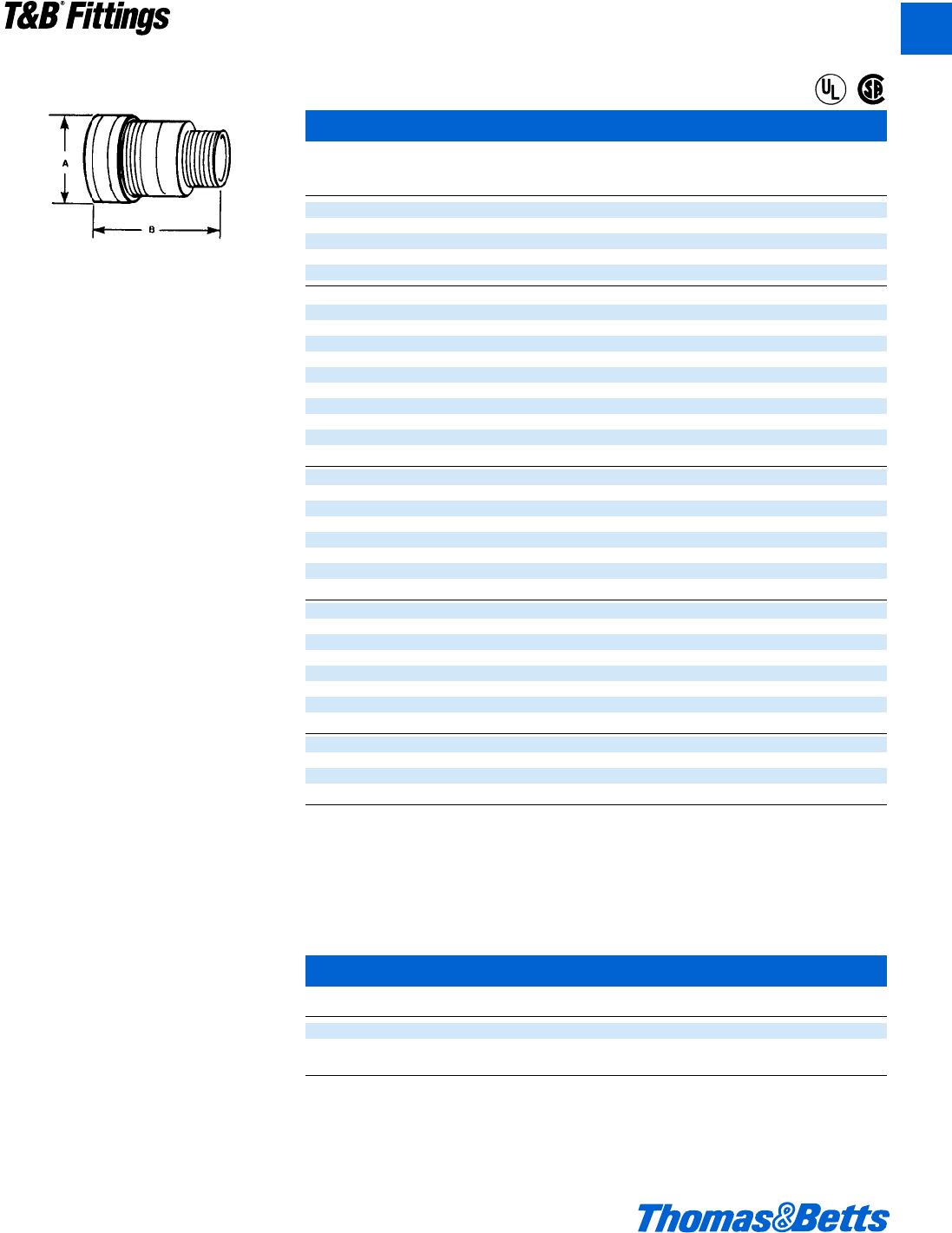
© 2002 Thomas & Betts Corporation. Specifications are subject to change without notice. www.tnb.com A107
Metal Clad Cable Termination Fittings
Compound filled connector kit.
Each SPIN-ON ®X catalog number is a complete
kit. Used to install a complete gas blocked con-
nector in a hazardous location.
• Red anodized gland identifies the hazardous
location fitting.
• Three-piece construction; Gland-Body-Insert
with O Ring.
• Overall length 2⁄3less than conventional.
• Installation time 50% less than conventional.
• Full tapered hub threads – gas tight thread
engagement.
• Machined Aluminum Construction, good
looks – corrosion resistance.
• Furnished complete – includes compound.
• Factory-Packaged compound – no other on-
site materials.
• Sealing Compound consistency pre-mixed –
no job site variations.
• Neoprene boots available; additional corro-
sion protection.
• For control cable applications order liquid
compound separately.
Spin-On®X Connectors for Hazardous Locations
Hub Cable Range
Cat. Size Over Armor A Dia. B
No. (in.) (in.) (in.) (in.)
4-075-008 f" .380-.435 1e 2a
4-075-010 f" .436-.500 1e 2a
4-075-020 f" .501-.580 1e 2a
4-075-030 f" .581-.650 1e 2a
4-075-040 f" .651-.730 1e 2a
4-100-050 1" .731-820 22a
4-100-060 1" .821-880 22a
4-100-070 1" .881-960 22a
4-100-080 1" .916-1.030 22a
4-125-090 1b" 1.031-1.100 2b 2d
4-125-100 1b" 1.101-1.880 2b 2d
4-125-110 1b" 1.181-1.240 2b 2d
4-125-120 1b" 1.241-1.310 2b 2d
4-150-130 1d" 1.311-1.390 2e 2e
4-150-140 1d" 1.181-1.240 2e 2e
4-150-150 1b" 1.241-1.310 2e 2e
4-200-160 2" 1.571-1.660 32g
4-200-170 2" 1.661-1.750 32g
4-200-180 2" 1.751-1.840 32g
4-200-190 2" 1.841-1.930 32g
4-250-200 2d" 1.931-2.030 3g 3c
4-250-210 2d" 2.031-2.150 3g 3c
4-250-220 2d" 2.151-2.270 3g 3c
4-250-230 2d" 2.271-2.390 3g 3c
4-300-240 3" 2.391-2.510 4d 3c
4-300-250 3" 2.511-2.640 4d 3c
4-300-260 3" 2.641-2.770 4d 3c
4-300-270 3" 2.771-2.900 4d 3c
4-350-280 3d" 2.901-3.040 53g
4-350-290 3d" 3.041-3.170 53g
4-350-300 3d" 3.171-3.310 53g
4-350-310 3d" 3.311-3.450 53g
4-400-320 4" 3.451-3.590 5c 3g
4-400-330 4" 3.591-3.730 5c 3g
4-400-340 4" 3.731-3.870 5c 3g
4-400-350 4" 3.871-4.010 5c 3g
Kit contains: The SPIN-ON®X connector, and new Putty Type Compound.
Suffix Cat. No. with S for steel, B for brass.
SPIN-ON®X is U.L. Listed for: Class I, Div. 2, Groups A, B, C, & D in f", 1", 1b", 1d", 2", 2d" Hub sizes. Class I, Div. 2, Groups C & D
in 3", 3d", and 4" Hub sizes. The entire line is U.L. listed for Class II, Div. 2, Groups F & G and Class III. CSA certified through 4" Hub
size for Class I, Groups A, B, C, D; Class II, Groups E, F, G; and Class III.
U.L. File No. E 82038
CSA File No. LR 638
Liquid Type Sealing Compounds
Cat. No. Description Volume
SC4-KIT Liquid type sealing compound for use in control cable applications 2.8 fl. oz.
SC65 Putty Type Sealing Compound 60 grams
Same as Spin-On®X Blue Compound
®
®
T&B®Fittings
A
412031.A02 FIT 3/5 3/13/03 4:56 PM Page 107
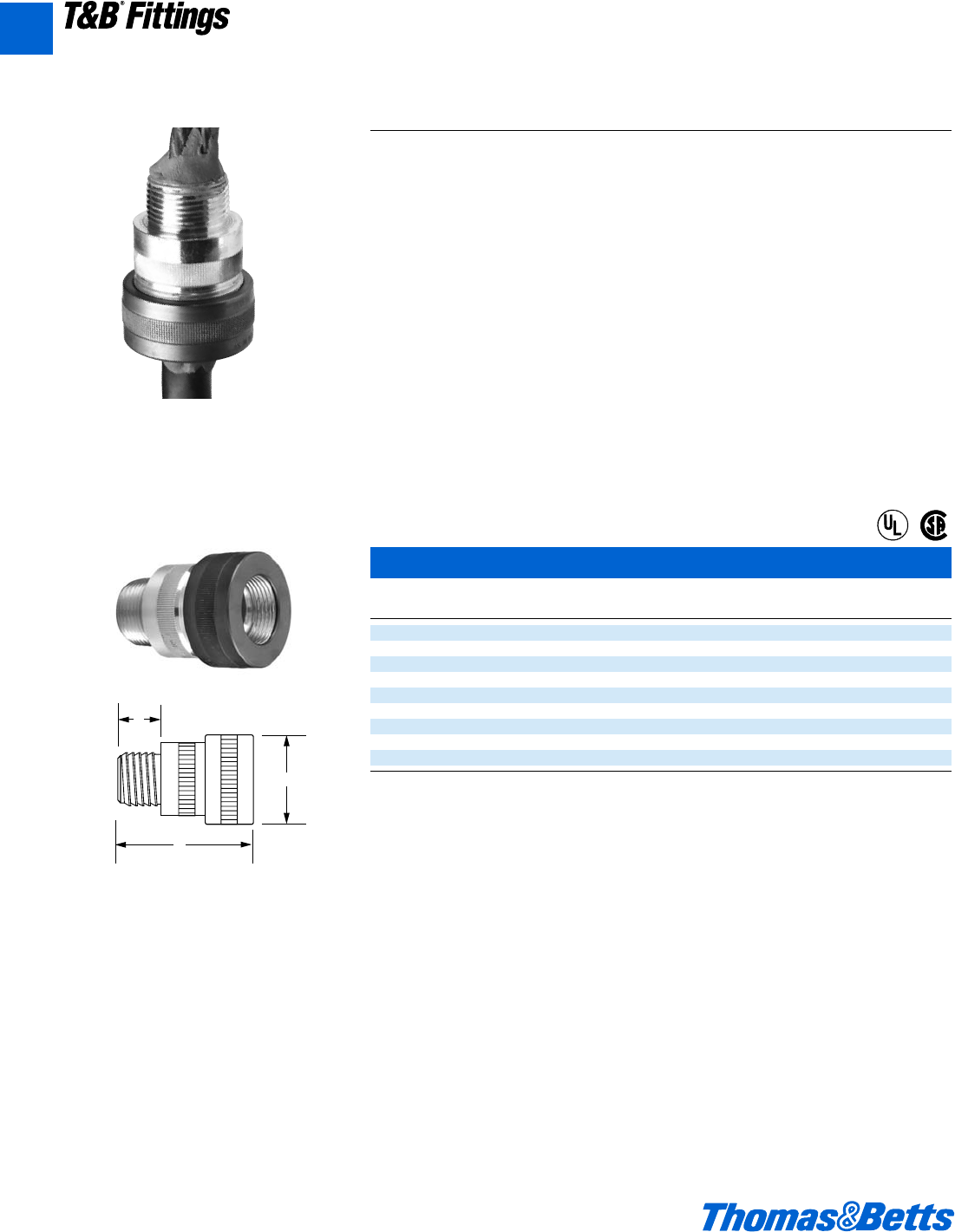
Metal Clad Cable Termination Fittings
Tray Cable Connectors
Cat. A B Cable Range
No. Hub Size ±.062 ±.062 Dia. (inches)
4-075TC f" 1.72 2.10 .275-.600
4-100TC 1" 2.10 2.33 .575-.900
4-125TC 1b" 2.35 2.70 .860-1.180
4-150TC 1d" 2.78 2.87 1.095-1.420
4-200TC 2" 3.16 3.17 1.280-1.780
4-250TC 2d" 4.00 3.80 1.700-2.200
4-300TC 3" 4.69 3.86 2.150-2.700
4-350TC 3d" 5.22 4.10 2.650-3.230
4-400TC 4" 5.63 4.00 3.180-3.790
NOTE: When installed with the two part epoxy in the intended manner the fittings are suitable for the following hazardoud locations:
f" thru 2d" – Class I Div. 2, Groups A, B, C, D
Class II Div. 2, Groups F, G
3" thru 4" – Class I Div. 2, Groups C, D
Class II Div. 2, Groups F, G.
• Suitable for use with sunlight-oil resistant tray cable
• Suitable for 90° Cable
• CSA Certified – Class I Div. 2, Groups A, B, C, D
Class II Div. 2, Groups E, F, G
Class III
• “SL” Integral Seal
C
B
A
The T&B TC Series Tray Cable Connector
The Thomas & Betts TC Series of connectors are designed specifically for transi-
tioning tray cable from horizontal cable tray to terminations in enclosures. The
precision machined aluminum interiors are ideally suited for use with sunlight-oil
resistant cable.
Application
• Provides means for passing TC type
cable from cable tray installations
into an enclosure or threaded bulk-
head
Cord & Cable Type
• TC (rated for 90°C cable)
Features
• Precision machined parts
• Full tapered hub threads
• Gas tight thread engagement
Materials
Body, gland nut and insert copper free
aluminum
Environment Classification
• Ordinary Locations
• Class I, Division 2†, Groups A, B, C,
D (f" - 2d")
• Class I, Division 2, Groups C, D (3" - 4")
• Class II, Division 2, Groups F, G
Range
.225" - 3.790"
®
®
A108 © 2002 Thomas & Betts Corporation. Specifications are subject to change without notice. www.tnb.com
T&B®Fittings
A
412031.A02 FIT 3/5 3/13/03 4:56 PM Page 108

© 2002 Thomas & Betts Corporation. Specifications are subject to change without notice. www.tnb.com A109
Ref. NEC Article 348
Electrical Metallic Tubing (EMT) is simi-
lar to rigid steel conduit but is much
lighter, weighing approximately 40 per-
cent as much as rigid steel conduit of
the same nominal size. EMT can be
used for both exposed or concealed
work provided, where during installa-
tion or afterwards, it is not subjected to
severe physical damage. Use of EMT
is restricted to systems not exceeding
600 volts and to non-hazardous loca-
tions except (Class II Division 2 NEC
Section 502-4 (b).
Galvanized Steel EMT installed in
concrete on grade or above generally
requires no supplementary corrosion
protection. However, when installed in
concrete below grade level and in con-
tact with soil or cinders supplementary
corrosion protection consisting of a
protective coating of bitumastic or
asphalt base paint or plastic is gener-
ally applied. According to NEC Section
348-1, EMT run in or under permanent-
ly moist cinder fill must be encased in
at least two inches of cinder free con-
crete unless the conduit is at least 18
inches below the fill.
Aluminum EMT cannot be directly
embedded in concrete containing sol-
uble chlorides such as calcium chlo-
ride, unwashed beach sand, sea water
or coral bearing aggregates. When
adequately treated with a protective
coating of bitumastic or asphalt base
paint or plastic coating the raceway
can be installed in concrete containing
chlorides.
NEC Sections 384-4 and 300-6
require that in wet locations where
walls are frequently washed or where
there are surfaces of absorbent materi-
al the entire wiring system including
boxes, fittings, conduits and cables
must be supported such that there is at
least 1⁄4inch air space between it and
the supporting surface.
Connectors and couplings are
required to be of concrete tight type
when embedded in masonry or con-
crete or in dry locations and of the rain
tight type when installed in wet loca-
tions (NEC Section 348-8).
According to NEC Section 373-6,
where No. 4 or larger underground
conductors enter or leave a conduit, an
insulating bushing with a smooth well
rounded insulating surface must be
provided to protect conductors, unless
the terminating fitting is equipped with
an insulated throat, firmly secured in
place providing equivalent protection.
The insulating bushing or insulating
material must have a temperature rat-
ing of not less than the insulation tem-
perature rating of installed conductors.
NEC Section 300-10 requires that
the raceways be metallically joined
together into a continuous electric con-
ductor and must be mechanically con-
nected to all boxes, fittings and cabi-
nets as to provide effective electrical
continuity.
EMT is not permitted to be thread-
ed. Cut ends of tubing are required to
be reamed. Code requires that EMT be
adequately supported and restricts
bends in one run to the equivalent of
four quarters i.e. 360 degrees total.
Portions of this section reprinted by
permission from NFPA 70-1978,
National Electrical Code®, Copyright©
1977, National Fire Protection
Association, Boston, MA.
For further details and complete infor-
mation please refer to the following:
1. NEC Article 348…Electrical
Metallic Tubing
2. ANSI C80.3…Electrical Metallic
Tubing, Zinc Coated,
Specifications for
3. ANSI C33.98, UL797…Standards
for Safety. Electrical Metallic
Tubing.
4. Fittings for Rigid Metal Conduit
and Electrical Metallic Tubing,
Specifications for
5. U.L. 514B, Standards for Safety,
Outlet Boxes and Fittings
6. WW-C-563…Conduit, Metal, Rigid,
and Bend and Elbow, Electrical
Conduit, Thin-wall Type (EMT)
7. W-F-408…Fittings for Conduit,
Metal, Rigid, (Thickwall & Thinwall
(EMT) Type)
8. NEMA FB-1…Standards
Publication. Fittings and Supports
for Conduit & Cable Assemblies.
9. CEC Section 12-1500…Electrical
Metallic Tubing
10. CSA C22.2 No. 83…Safety
Standards for Electrical Metallic
Tubing
11. CSA C22.2 No. 18…Safety
Standards for Outlet Boxes,
Conduit Boxes and Fittings
Electrical Metallic Tubing (EMT) Fittings
Electrical Metallic Tubing (EMT)
Please Note
The excerpts and other material herein, whether relating to the
National Electrical Code, the Underwriters Laboratories, Inc. list-
ing, to industry practice or otherwise, is not intended to provide all
relevant information required for use and installation. Reference to
original or primary source material and data is mandatory before
any application or use is made of the product.
A
T&B®Fittings
412031.A02 FIT 3/5 3/20/03 3:05 PM Page 109
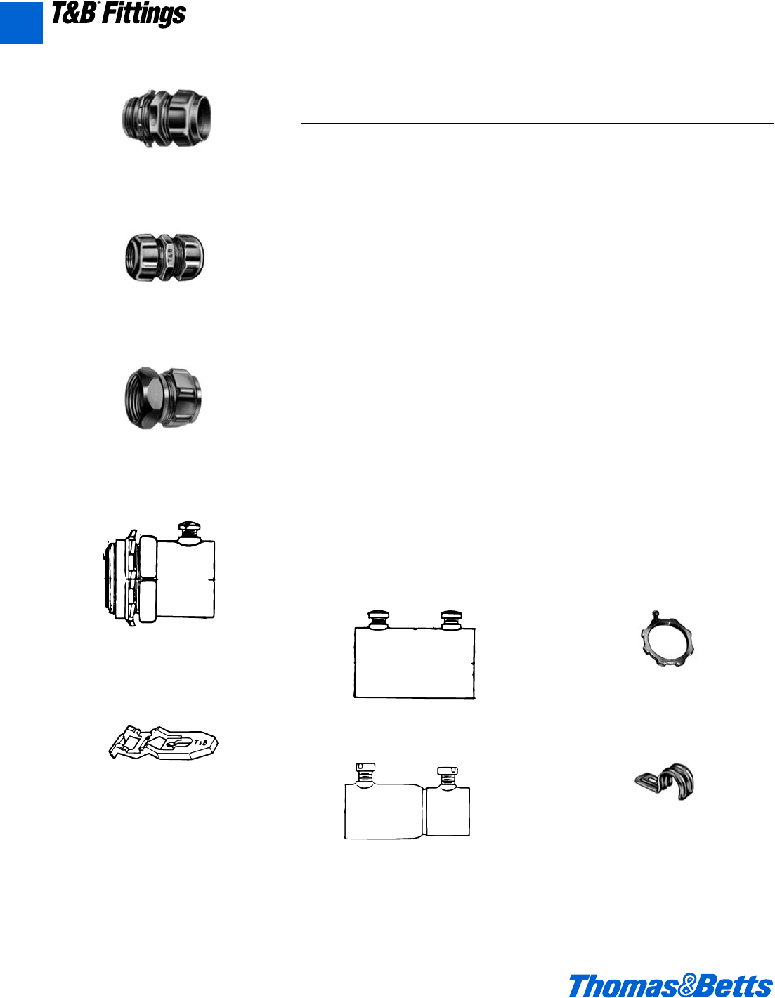
A110 © 2002 Thomas & Betts Corporation. Specifications are subject to change without notice. www.tnb.com
A
T&B®Fittings
Electrical Metallic Tubing (EMT) Fittings
Series 5123 Insulated
EMT Connector (Rain tight)
(Compression Type)
Series 5120
EMT Coupling (Rain tight)
(Compression Type)
Series 4176
Pipe Straps
Series 1350
Pipe Spacers
Series 530
Combination Coupling
(Rain tight)
Rigid/IMC to EMT
Series TC121-E or TC721-E
Insulated EMT Connector
(Concrete tight)
(Set Screw Type) Series 106
Bonding Locknut
Series TK121-E
EMT Coupling (Concrete tight)
(Set Screw Type)
Series HT-221
Combination Coupling
(Concrete tight)
Rigid/IMC to EMT
(Set Screw Type)
Zinc Die Cast
• Ferrous Electrical Metallic Tubing
(E.M.T.) shall be of the hot dipped
galvanized type conforming to applic-
able specifications WW-563/ANSI
C33.98/ANSI C80.3/U.L. 797/CSA
C22.2 No. 83. E.M.T. protected solely
by enamel shall not be used.
• Where lengths of EMT are coupled
together or connected to boxes or
enclosures or where EMT is coupled
to threaded rigid metal conduit or
IMC, fittings approved for intended
applications shall be used, and:
(1) Shall be of rugged steel/malleable
iron construction electro zinc plat-
ed inside/outside including
threads. Connector throat shall be
bushed with a nylon insulator.
(2) Shall be of rain tight type for instal-
lations exposed to weather or wet
locations such as Thomas & Betts
series 5123, 5120 and 530.
(3) Shall be of concrete tight type for
installations in poured concrete
such as Thomas & Betts series
TC121, TC721, or TK121.
Rain tight type fittings may be substi-
tuted for concrete tight application.
• Where electrical metallic tubing and
associated fittings are used as part of
equipment grounding system:
(1) A bonding type locknut such as
Thomas & Betts series 106 shall
be installed where hub type fitting
terminates into a threadless
opening.
(2) Compression ring type fittings
such as Thomas & Betts series
5123 and 5120 shall be used for
terminating and coupling.
• EMT shall be securely fastened in
place at intervals as specified by the
code using straps, hangers and other
supporting assemblies as indicated
on plans, and as manufactured by
Thomas & Betts, series 4176 straps.
In wet locations or where supporting
surfaces are of absorbent materials
vertical and horizontal runs of conduit
shall be firmly supported such that
there is at least b" air space between
conduit and supporting surface.
• Spacers and supporting straps shall
be of rugged malleable iron or steel
construction hot dipped galvanized
and conforming to requirements of
Canadian Standards Association
Standard C22.2 No. 18 as manufac-
tured by Thomas & Betts, series 4176
straps and series 1350 spacers.
Suggested Specifications for Electrical Metallic Tubing
(EMT) Fittings
412031.A02 FIT 3/5 3/13/03 4:56 PM Page 110
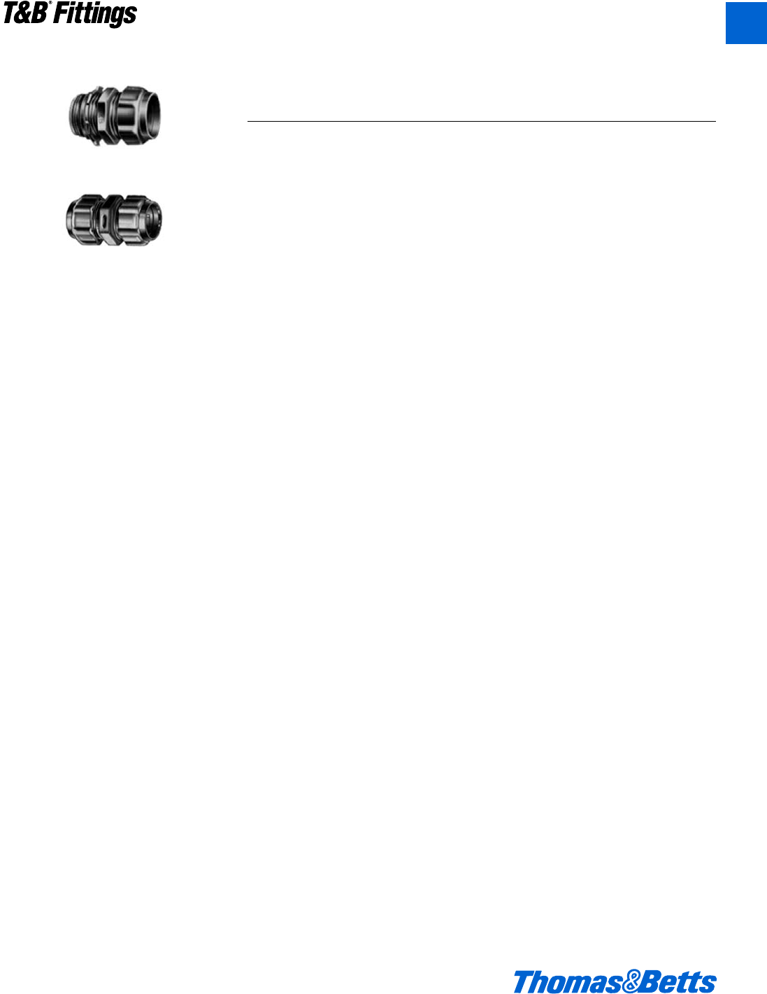
© 2002 Thomas & Betts Corporation. Specifications are subject to change without notice. www.tnb.com A111
T&B®Fittings
A
Electrical Metallic Tubing (EMT) Fittings
Standard Finish
All Steel Parts .........Electro Zinc Plated
& Chromate Coated
Insulator...............................As Molded
Range
Conduit Size… d" thru 2"
Hub Size… d" thru 2" NPS
Hubs provided with straight pipe
threads NPS.
Listed/Certified by:
U.L. (U.L. File No. E-16592)
CSA (LR-4484, LR-8994)
Conforms to:
U.L. 514B
CSA C22.2 No. 18
NFPA 70-1999 (ANSI)
NEMA FB1
Federal Specification W-F-408
Federal Standard H-28 (Threads)
Application
• To connect and effectively bond
electrical metallic tubing to a box or
an enclosure.
• To provide a rain tight connection
between tubing and the connector.
• To couple ends of tubing.
Features
• Rugged all steel construction.
• Rings designed to positively bond
conduit to fitting; unique locknut
design provides effective bond
between fitting and box or enclosure;
ground continuity is assured.
• Nylon insulator firmly secured in
place – protects conductors,
reduces wire pulling effort and pre-
vents thread damage in handling.
• Locknuts are designed with extend-
ed reach to lock fitting on to a thin
box or an enclosure.
• Locknuts tighten without deforma-
tion; will not vibrate loose.
Standard Material
All Steel except Insulator.
Insulator.................Thermoplastic, U.L.
Rated 105°C
Fittings for Electrical Metallic Tubing (EMT)
Compression Type, Rain tight
5123 Series*
5120 Series
* 4230 Series – 90° Connectors
412031.A02 FIT 3/5 3/13/03 4:56 PM Page 111
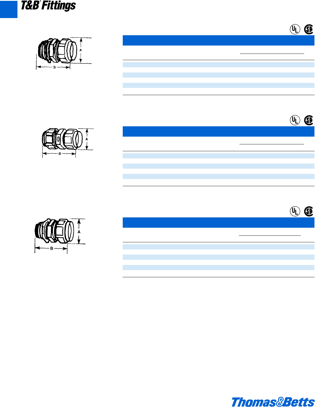
A112 © 2002 Thomas & Betts Corporation. Specifications are subject to change without notice. www.tnb.com
A
T&B®Fittings
EMT Connectors – Nylon Insulated
Cat. Dimensions (in.)
No. Size AB
5123 d" 1Y 1y
5223 f" 1Q 1B
5323 1" 1L 1g
5423 1b" 2h 2X
5523 1d" 2j 2z
5623 2" 2A 2m
U.L. Listed and CSA Certified rain tight.
U.L. File No. E 9043
CSA File No. 8994
EMT Couplings
Cat. Dimensions (in.)
No. Size AB
5120 d" 1h 1B
5220 f" 1j 2a
5320 1" 1L 2a
5420 1b" 2h 2C
5520 1d" 2j 3h
5620 2" 2f 3r
U.L. Listed and CSA Certified rain tight.
U.L. File No. E 9043
CSA File No. 8994
EMT Connectors
Cat. Dimensions (in.)
No. Size AB
5121 d" 1h 1l
5221 f" 1j 1y
5321 1" 1L 1f
5421 1b" 2h 1X
5521 1d" 2j 2l
5621 2" 2f 2f
U.L. Listed and CSA Certified rain tight.
T&B E.M.T. (thinwall) fittings comply with Federal Spec. WF408B.
U.L. File No. E 9043
CSA File No. 8994
Electrical Metallic Tubing (EMT) Fittings
Across
Corners
Across
Corners
®
®
®
®
®
®
412031.A02 FIT 3/5 3/13/03 4:56 PM Page 112
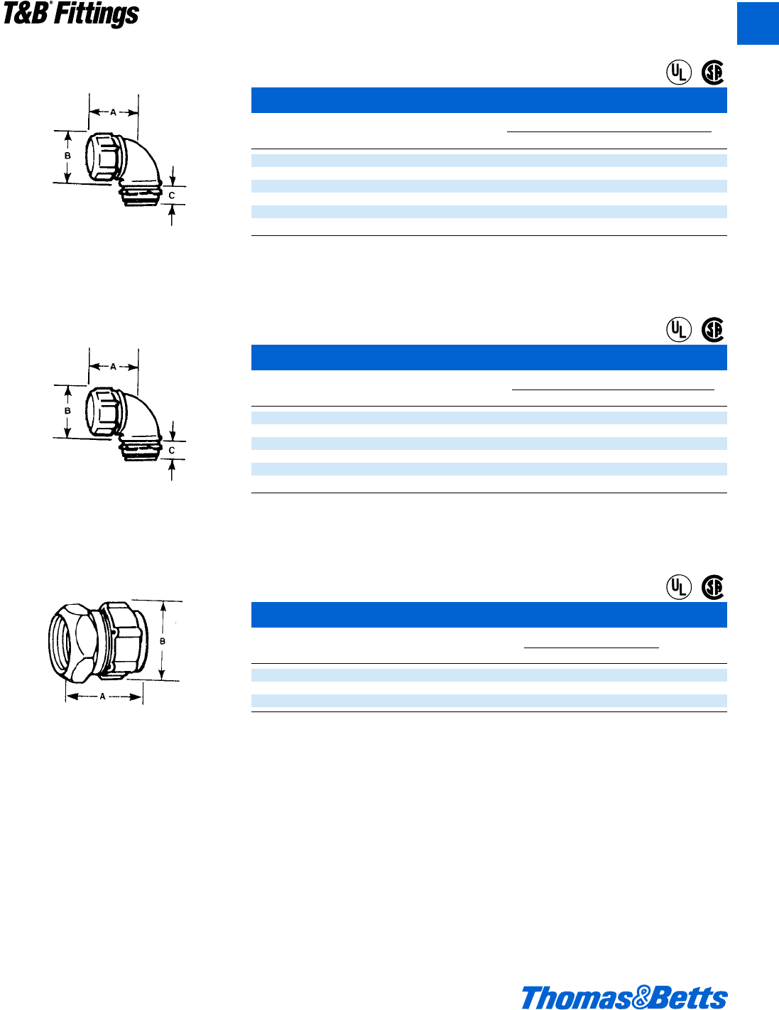
© 2002 Thomas & Betts Corporation. Specifications are subject to change without notice. www.tnb.com A113
T&B®Fittings
A
Ideal for cramped locations or tight corners
where large radius conduit elbows will not fit or
would appear unworkmanlike. Shoulders on
body of 1⁄2" size are hex-shaped to provide posi-
tive holding for standard installation tools. Use
insulated type for simple, and safe, installa-
tions. Malleable iron. U.L. rated 105°C.
Ideal for cramped locations or tight corners
where large radius conduit elbows will not fit or
would appear unworkmanlike. Shoulders on
body of 1⁄2" size are hex-shaped to provide posi-
tive holding for standard installation tools.
Short Elbows – Insulated*
Cat. Dimension (in.)
No. Size ABC
4240 d" 1k 1s k
4241-TB f" 1L 1x d
4242 1" 1g 1B e
4243 1b" 2f 2v L
4244 1d" 3h 2f L
4245 2" 3c 3j L
U.L. Listed and CSA Certified rain tight.
U.L. File No. E 09043
CSA File No. 2884
Short Elbows Malleable Iron*
Cat. Dimension (in.)
No. Size ABC
4230 d" 1k 1s k
4231 f" 1L 1x d
4232 1" 1g 1B e
4233 1b" 2f 2v L
4234 1d" 3h 2f L
4235 2" 3c 3j L
U.L. Listed and CSA Certified rain tight.
U.L. File No. E 09043
CSA File No. 2884
Combination Coupling – Steel*
Cat. Dimensions (in.)
No. Size AB
530-TB d" 1c 1h
531 f" 1d 1X
532 1" 1x 1y
U.L. Listed and CSA Certified rain tight.
U.L. File No. E 09043
CSA File No. 2884
* All items shown on this page are suitable for use in hazardous locations where general purpose equipment is specifically permitted by
the NEC; Class I, Div. 2; Class II, Div. 1 & 2; Class III, Div. 1 & 2, 502-4(a)(b); 503-3(a)(b).
For connecting EMT to threaded rigid and inter-
mediate metal conduit.
Across
Corners
Electrical Metallic Tubing (EMT) Fittings
®
®
®
®
®
®
412031.A02 FIT 3/5 3/13/03 4:56 PM Page 113
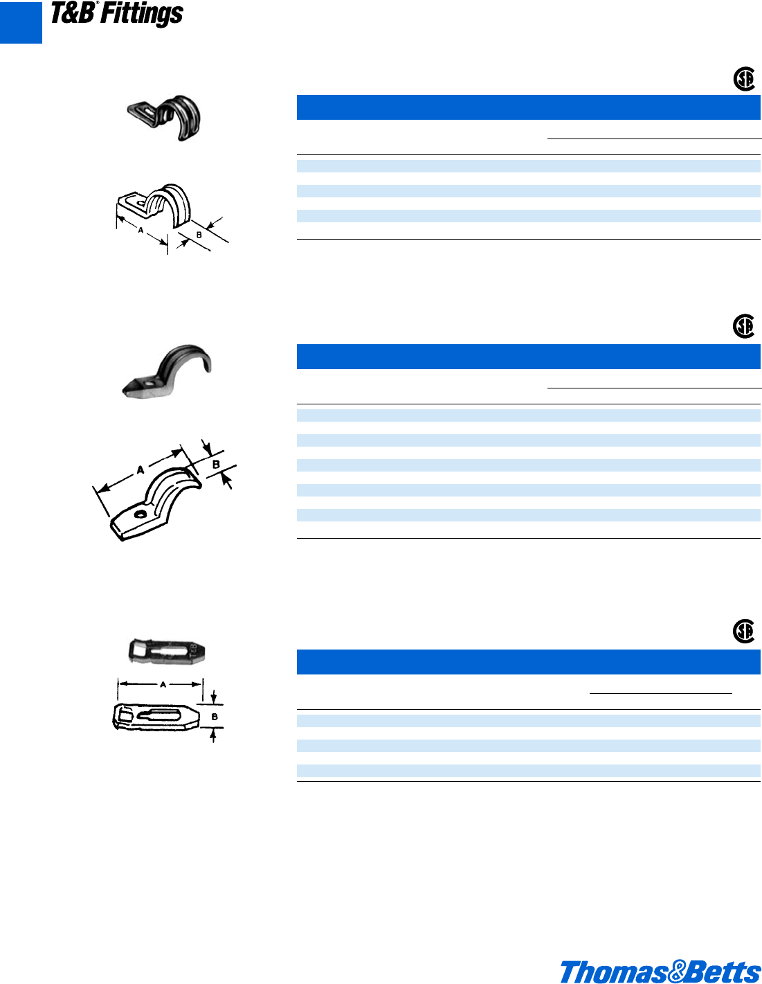
A114 © 2002 Thomas & Betts Corporation. Specifications are subject to change without notice. www.tnb.com
T&B®Fittings
Pipe Straps – Steel
Cat. Dimensions (in.)
No. Size A B C (Bolt Hole)
4159 d" 1B f b
4160 f" 2o f b
4161 1" 2X f b
4162 1b" 2g f b
4163 1d" 3L 1b X
4164 2" 4h 1a u
Not U.L. Listed
CSA File No. 2884 and 4484
Oval Hole for
Screw Size (C)
Elongated bolt hole makes alignment easy, even
when holes in mounting surface are out of align-
ment. Snap on features hold strap in place.
Oval Hole for Screw Size (C)
Designed to fit each size of conduit snugly. High
reinforcing ribs on each side increase strength,
reduce weight. Hot dipped galvanized finish.
Used with T&B conduit straps to permit space
between conduit and mounting surface.
Eliminates need for costly offset-bending conduit
and possible corrosive moisture traps when con-
duit is mounted directly to a surface. Malleable
iron. Hot-dipped galvanized finish, pre-mount-
able and stackable to eliminate offsetting.
Electrical Metallic Tubing (EMT) Fittings
®
®
®
Pipe Straps – Malleable Iron
Cat. Dimensions (in.)
No. Size A B C (Bolt Hole)
4176 d" 2q y b
4177 f" 2l L b
4178 1" 3 f b
4179 1b" 3f m j
4180 1d" 4i n c
4181 2" 5i 1a k
1282 2d" 5n 1d d
1283 36L1ed
1284 3d 7x 1f e
1285 4" 8j 1g e
Not U.L. Listed.
CSA File No. 2884 and 4484
Pipe Spacers
Cat. Dimensions (in.)
No. Size AB
1350 d", f", 1" 3" g
1351 1b"-1d"-2" 5" 1i"
1352 2d"-3" 9l" 1f"
1353 3d"-4" 7l" 2"
1354 4d"-5"-6" 10l" 2l"
Conforms to NEC 300-5-C.
CSA File No. 2884
A
412031.A02 FIT 3/5 3/13/03 4:56 PM Page 114
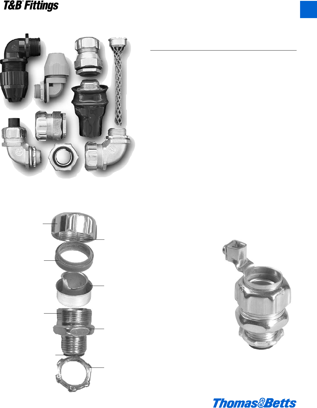
© 2002 Thomas & Betts Corporation. Specifications are subject to change without notice. www.tnb.com A115
T&B®Fittings
Liquidtight Flexible Metal Conduit Fittings
All our high-performance products are designed to deliver
excellent reliability as well as ease of installation in virtually any
application. And you benefit from our expertise through our liq-
uidtight and dust-tight connections available for a variety of
conduits as well as portable cord.
Thomas & Betts offers the largest and most technologically
advanced line of liquidtight fittings in the industry, including
connectors for highly-specialized applications such as power
and petrochemical plants, paper mills, robot manufacturers,
packaging equipment, machine tool building, and other OEM
and MRO applications. At Thomas & Betts, we integrate the
latest manufacturing technologies with the highest quality
materials available. So you can be assured of reliable, liq-
uidtight products that offer improved on-the-job performance
and reduced installation time and costs.
The Revolver™Grounding Fitting Is The Latest Labor-
Saving Innovation From Thomas & Betts.
The Revolver liquidtight grounding fitting is our latest break-
through in convenience to save time and money on the job.
The grounding lug of the Revolver can be rotated in a full cir-
cle, for convenient positioning that doesn’t change when you
tighten it. It’s the newest innovation in Thomas & Betts’ versatile
line of Liquidtight Connectors– fittings you can count on for
liquidtight and dust-tight connections. Because all our prod-
ucts revolve around your needs.
Our Liquidtight Line is the End-All for
Liquidtight Dust-Tight Connections.
Sure-Tight Gland Cone
deflects water away from
connector and prevents
“pooling” of moisture.
Double Beveled Sealing
Ring cannot be installed
backwards.
Precision Rolled Threads
makes installation smooth
and much easier than cut
threads.
Heat Formed Insulator curled
inside body for excellent wire
protection; will not pull out of
fitting.
Self-Cleaning Threads
inside gland nut keep dirt
and grime out of fitting.
Safe Edge Ground Cone
provides superior boding,
stronger pullout, easy
threading, and protects
conductors.
Double Plating for superi-
or corrosion protection;
Zinc plating with clear
Chromate finish.
Case Hardened Locknut
with Teeth provides supe-
rior strength and electrical
bonding, and can be
installed without a wrench
in the enclosure.
Revolver™
Grounding Fitting
saves time and
money with rotat-
ing ground lug
A
412031.A02 FIT 3/5 3/13/03 4:56 PM Page 115
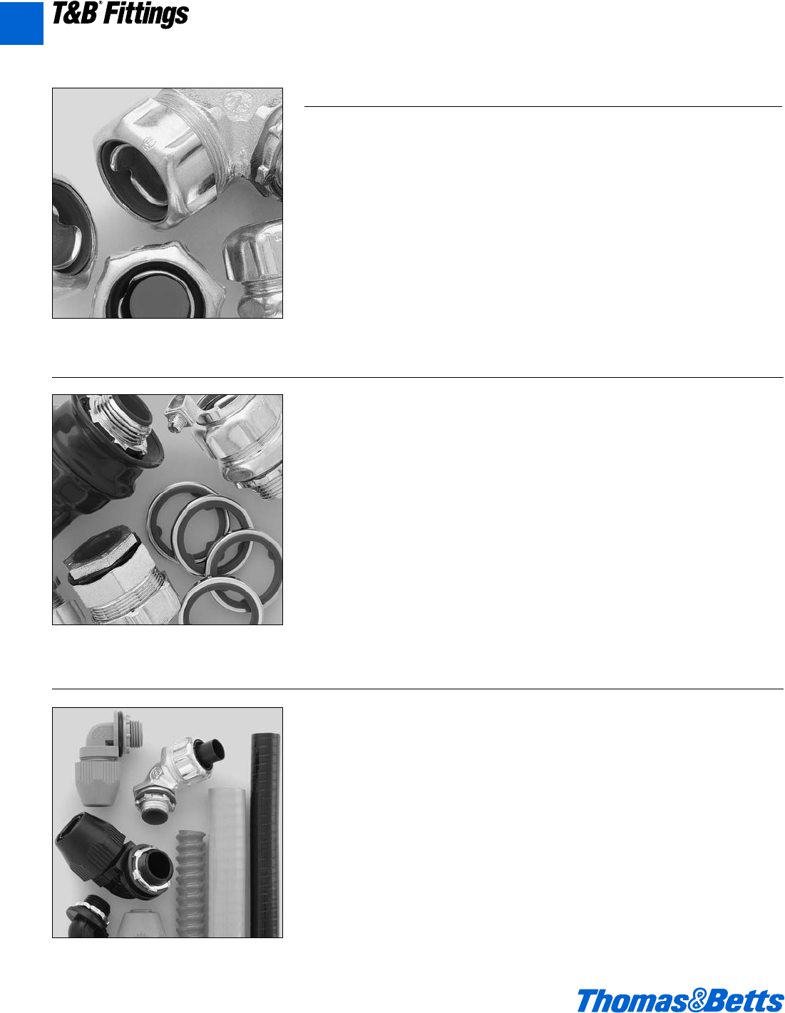
A116 © 2002 Thomas & Betts Corporation. Specifications are subject to change without notice. www.tnb.com
T&B®Fittings
Liquidtight Flexible Metal Conduit Fittings
Liquidtight Flexible Metal Conduit
Fittings
Thomas & Betts Liquidtight fittings for
flexible metal conduits are suitable for
a wide range of installations, including
heavy industrial applications. Our
Liquidtight fittings are designed to
stand up to demanding, wet or corro-
sive environments, including power
and petrochemical plants, paper mills,
and anywhere high performance is a
requirement.
Features of Thomas & Betts Liquidtight
fittings include:
• Safe EdgeTM ground cone design that
accepts variations in raceway convo-
lutions and provides a positive bond.
• Continuous sealing ring which com-
pletely surrounds the conduit to
ensure a liquid-tight seal.
• Zinc chromatic plating for longer life
and exceptional appearance.
• The broadest liquid-tight line in the
industry, including PVC coated, exter-
nally grounded, aluminum series,
Chase®style, non-metallic Bullet
series, wire mesh grips, and more.
Liquidtight Connectors
Liquidtight Fittings for Special
Applications
The Revolver™ Externally Grounded
Fitting
The grounding lug of the new Revolver
connector can be rotated in a full circle
for convenient positioning that doesn’t
change when you tighten it. Plus, it’s
available for the first time in aluminum.
It’s a major breakthrough in conve-
nience that saves time and money on
the job while delivering a quality con-
nection.
Chase-Style Fittings
Where space is tight, our Chase fittings
allow for compact connections within
an enclosure.
PVC-Coated Connectors
When environmental conditions are
particularly harsh and corrosive, our
PVC-coated connectors are the best
choice for both indoor and outdoor
applications. The PVC coating protects
exposed surfaces for long-lasting, reli-
able connections.
Sealing Gaskets
Thomas & Betts sealing gaskets are
resistant to oil, coolants, and hydraulic
fluids as well as water, with a stainless
steel retaining clip that assures a quali-
ty seal. They’re the ideal match to our
Liquidtight connectors for a safe and
secure seal.
Liquidtight Flexible Non-Metallic
Conduit Fittings
When non-metallic, Type A or EFC con-
duits are called for, Thomas & Betts’
XTRAFLEX System has our outstanding
Bullet fittings and conduits for liquid-
and dust-tight connections.
Bullet fittings:
• Feature one piece construction and a
captive o-ring for ease of installation.
• Provide a positive seal between the
conduit and the connector.
• Have a tapered thread hub and seal-
ing o-ring for a tight seal to the box or
other enclosure.
• Are constructed of non-burning, non-
dripping thermoplastic for high
strength chemical resistance.
• Feature a smooth insulated body for
maximum dielectric strength.
• Have a patented, serrated design
that provides high mechanical pullout
strength.
• Include a complete range of flexible,
non-metallic conduits – including both
smooth and corrugated varieties – to
complete our XTRAFLEX System.
A
412031.A02 FIT 3/5 3/13/03 4:56 PM Page 116
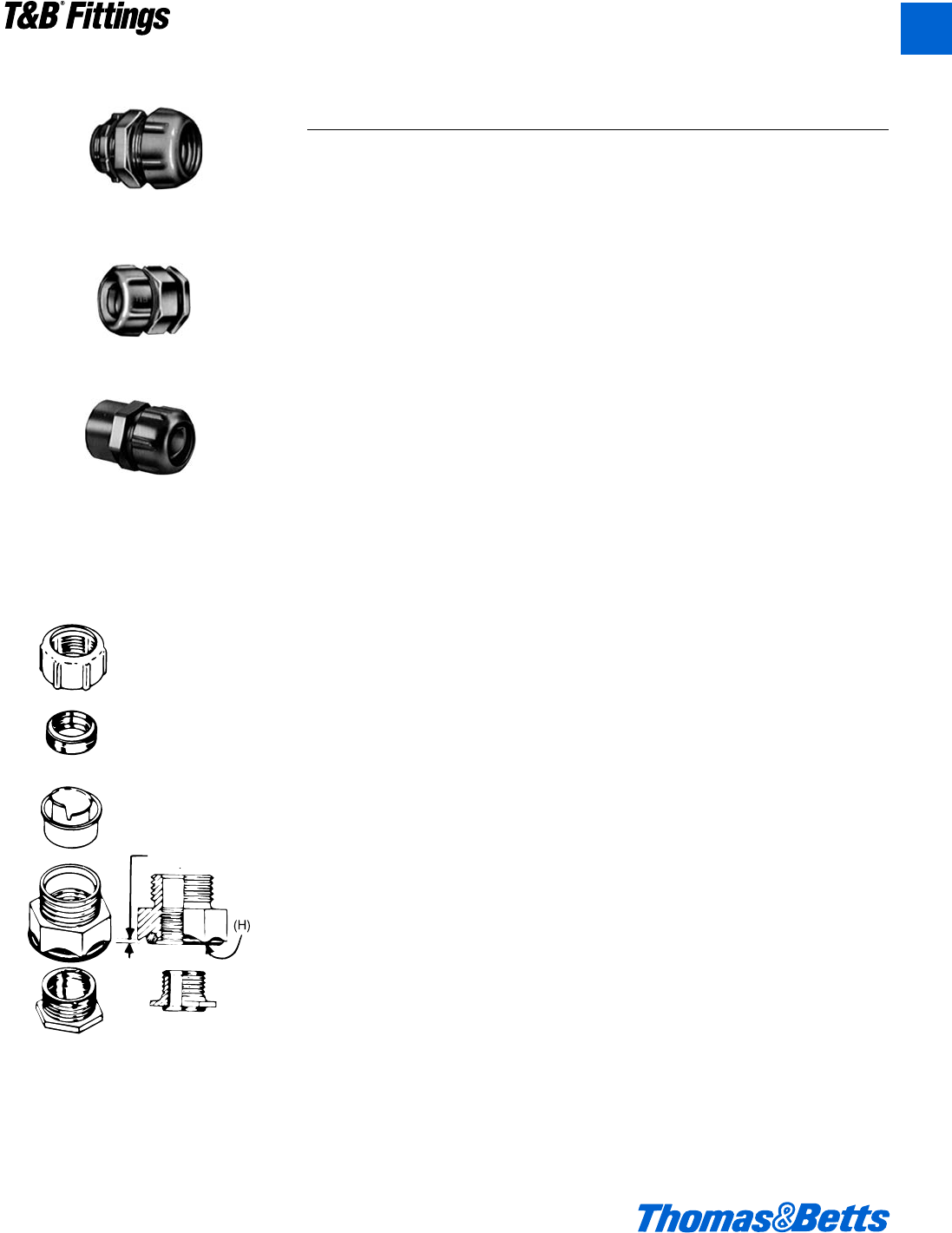
© 2002 Thomas & Betts Corporation. Specifications are subject to change without notice. www.tnb.com A117
T&B®Fittings
Liquidtight Flexible Metal Conduit Fittings
5331 Series*
5231 AL Series
5361 Series
5271 Series
* 5341 Series…
same as 5331, except 45° Connectors
5351 Series…
same as 5331, except 90° Connectors
5361 Series
Chase®Style
Liquidtight Flexible Metal Conduit Connectors
Predetermined
Compression
Application
• Used where flexible metal raceway is
installed in outdoor or indoor loca-
tions where exposed to continuous or
intermittent moisture.
• To positively bond conduit to box or
enclosure.
Features
• Ability to install quickly with low
torque effort.
• Ground cone design offers following
advantages:
(1) Compresses metallic convolu-
tions; provides high quality
ground contact with low imped-
ance and high raceway holding
power (A).
(2) Single helical thread on ground
cone is easy to install without
cross thread; accepts variations in
raceway diameters and convolu-
tion pitch (B).
(3) Rolled over edge protects con-
ductors (C).
Sealing ring design has following
exclusive features:
(1) Grips and seals at leading and
trailing edge – will not abrade
raceway jacket (D).
(2) Provided with grooves on inside
diameter for anti-sleeving (E).
(3) Shoulders on both ends for extra
sealing (F).
(4) Symmetrical shape assures fool-
proof assembly.
• Can be disconnected and reused.
• Watertight/oil tight installation at box or
enclosure termination is assured by:
(1) External taper thread hub on 5331
series and use of sealing gasket
5262 series (G).
(2) Captivated sealing ‘O’ ring on
5361 series (H).
(3) Taper tapped hole on 5271 series.
• Suitable for use in Class I Division 2,
Class II Division 1 and 2 and Class III
Division 1 and 2 Hazardous
Locations per N.E.C. Section 500.
• Suitable as a grounding means per
N.E.C. Section 351-9 (up to 1b" trade
size on).
•d" & 1b" sizes Laboratory tested to
carry ground fault current of up to
1000 amps RMS with duration of fault
current 3 cycles.
• Conforms with JIC requirements.
• Available with imperial, I.S.O. & PG
threaded hub.
Standard Material
5331-5361-5271 Series
Body, Gland, Locknut & Ground Cones:
All steel or malleable iron.
Sealing Ring and Insulator: All thermo-
plastic
Sealing Gasket: Stainless Steel and
Buna N
5231 AL Series
All Copper-free Aluminum (non-
insulated)
5332SST Series
31L Stainless Steel insulated
5332B Series
Marine grade brass insulated avant
Standard Finish
5331-5361-5271 Series
Electro Zinc Plated & Chromate Coated
5231 AL Series
Copper-free Aluminum
Range
5331 Series ..............c" thru 6"* conduit
5341 Series................c" thru 4" conduit
5351 Series................c" thru 4" conduit
5361 Series................c" thru 4" conduit
5271 Series..............c" thru 11⁄4" conduit
5231 AL Series ..........c" thru 4" conduit
5332SST Series.............d" & f" conduit
5332B Series.................d" & f" conduit
All hubs provided with taper pipe
threads (NPT)
Listed/Certified by:
U.L.…(U.L. File No. E-23018)
CSA…(LR-2884, LR-4484, LR-9555)
Conforms to:
U.L. 514B
CSA C22.2 No. 18
NEMA FB-1
NFPA 70-1999 (ANSI)
JIC EGP1
JIC EMP1
Federal Specification W-F-406
Federal Standard H-28 (Threads)
A
412031.A02 FIT 3/5 3/13/03 4:56 PM Page 117
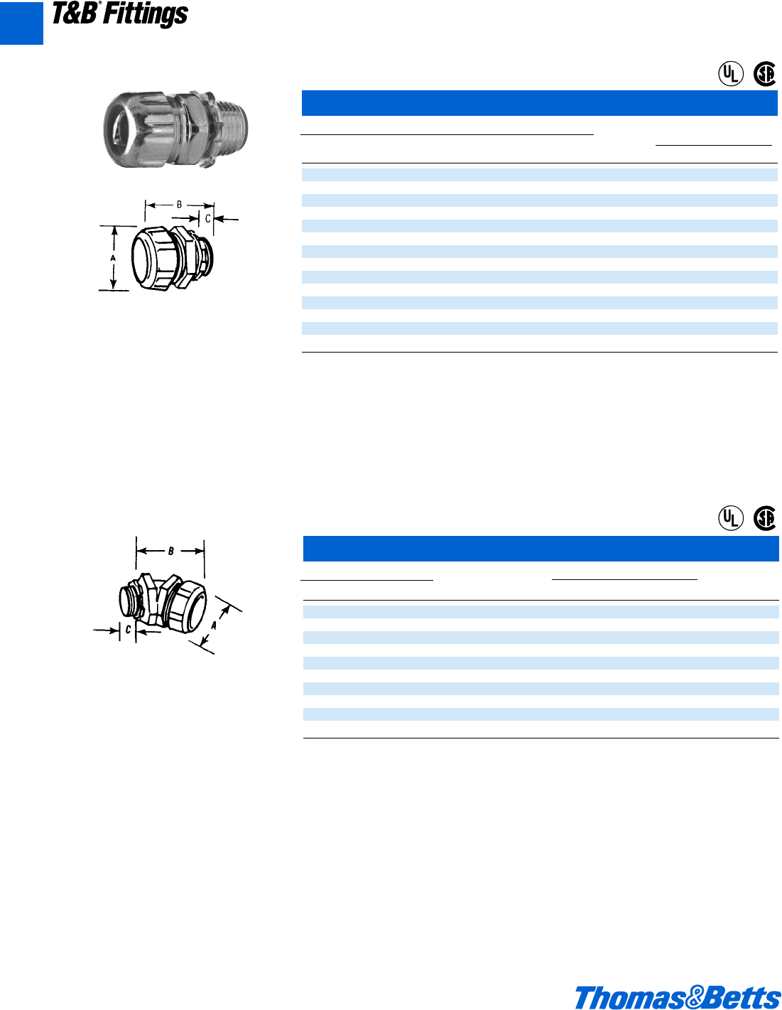
A118 © 2002 Thomas & Betts Corporation. Specifications are subject to change without notice. www.tnb.com
T&B®Fittings
Liquidtight Flexible Metal Conduit Fittings
Straight Connectors*
Cat. No.
Insulated Non-Insulated Stainless Conduit Dimensions (in.)
Steel Aluminum Steel Steel Brass Size A B C
5229‡– – – – b B 1c v
5330‡– – – – j © 1c v
5331†** 5231AL 5231†– – c1q1dl
5332†5232AL 5232†5332SST 5332B d1c1ll
5333†5233AL 5233†5333SST 5333B f1y1el
5334†5234AL 5234†– – 11g2hf
5335†5235AL 5235†– – 1b 2s 2d m
5336 5236AL 5236 – – 1d 2z 2L m
5337 5237AL 5237 – – 23b3hg
5338 5238AL 5238 – – 2d 3f 4a 1
5339 5239AL 5239 – – 34d4b1
5340 5240AL 5240 – – 45d4d1a
5385‡– 5285 – – 58f71g
5386‡– – – – 68f8d2
Steel malleable iron, or aluminum tapered hub
threads. With safe-edge ground thru 4" cone
and double bevel seating ring (through 2").
Malleable iron, tapered hub threads. With safe-
edge ground cone and double bevel sealing
ring (through 2").
®
®
®
®
45° Angle Connectors*
Cat. No. Conduit Dimensions (in.)
Insulated Non-Insulated Size A B C
5341†** 5241†c1q1ll
5342†5242†d1c1gl
5343†5243†f1y2al
5344†5244†11g2bf
5345†5245†1b 2s 2f m
5346 5246 1d 2z 3c m
5347 5247 23b3gg
5348 5248 2d 3f 4b 1
5349 5249 34d4b1
5350 5250 45d4e1a
* Suitable for hazardous locations use in Class I, Div. 2; Class II, Div. 1 and 2; Class III, Div. 1 and 2, where general purpose equipment is
specifically permitted per NEC Section 500-2(a).
** c" Conduit Fitting has d" hub.
†U.L. Listed as grounding means under NEC 351-7.
‡Not U.L. Listed.
Note: U.L. Listed liquidtight; and CSA Certified watertight.
Available with DURA-PLATE®Finish.
U.L. File No. E-23018
CSA File No. 2884
For Wiremesh Grips refer to pages A119, A154.
A
412031.A02 FIT 3/5 3/20/03 3:05 PM Page 118
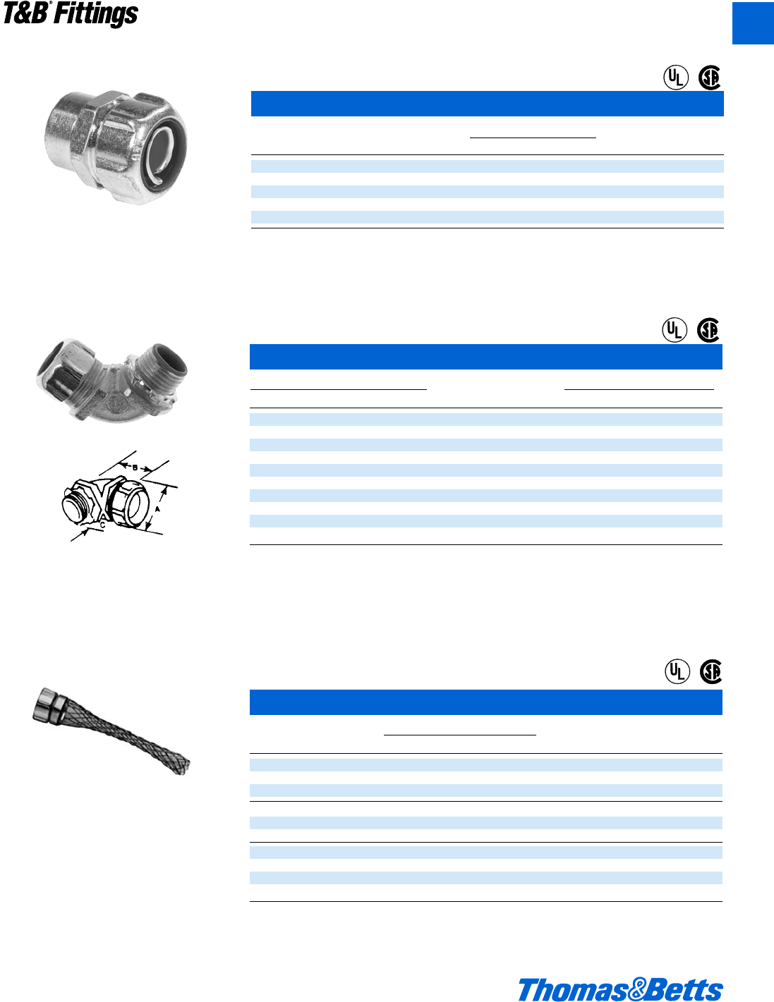
© 2002 Thomas & Betts Corporation. Specifications are subject to change without notice. www.tnb.com A119
T&B®Fittings
90° Angle Connectors
Cat. No. Hub Conduit Dimensions (in.)
Insulated Non-Insulated Aluminum Size Size A B C
5351 5251 5251AL d" c" 1q 1c l
5352 5252 5252AL d" d" 1c 1l l
5353 5253 5253AL f" f" 1y 1f l
5354 5254 5254AL 1" 1" 1g 2i f
5355 5255 5255AL 1b" 1b" 2s 2f m
5356 5256 5256AL 1d" 1d" 2z 2n m
5357 5257 5257AL 2" 2" 3b 3k g
5358 5258 – 2d" 2d" 3f 8g 1
5359 5259 – 3" 3" 4d 10b 1
5360 5260 – 4" 4" 5d 12e 1a
* Suitable for hazardous locations use in Class I, Div. 2; Class II, Div. 1 and 2; Class III, Div. 1 and 2, where general purpose equipment is
specifically permitted per NEC Section 500-2(a).
** c" Conduit Fitting has d" hub.
†U.L. Listed as grounding means under NEC 351-7.
‡Not U.L. Listed.
Note: U.L. Listed liquidtight; and CSA Certified watertight.
Available with DURA-PLATE®Finish.
U.L. File No. E-23018
CSA File No. 2884
For Wiremesh Grips refer to pages A119, A154.
Wiremesh Grips for Liquidtight Fittings
Cat. Conduit Liquidtight Connectors 90°
No. Size Straight 45° 90° Chase Chase Adapter
WMG-LT1 c" 5331 5341 5351 5361 5371 5271
WMG-LT2 d" 5332 5342 5352 5362 5372 5272
WMG-LT3 f" 5333 5343 5353 5363 5373 5273
WMG-LT4 1" 5334 5344 5354 5364 5374 5274
WMG-LT5 1b" 5335 5345 5355 5365 – 5275
WMG-LT6 1d" 5336 5346 5356 5366 – 5276
WMG-LT7 2" 5337 5347 5357 5367 – 5277
WMG-LT8 2d" 5338 5348 5358 5368 – 5278
WMG-LT9 3" 5339 5349 5359 5369 – 5279
WMG-LT10 4" 5340 5350 5360 5370 – 5282
Order wiremesh grip separately: no need to duplicate inventory.
U.L. File No. E23018
CSA File No. 2884 & 4484
Liquidtight Flexible Metal Conduit Fittings
Prevents severe conduit bends and pullout.
®
®
®
®
®
®
Standard Liquid Tight – Female Hub Adapter
Cat. No. Conduit Dimensions (in.)
Size A B
5271†c1q1l
5272†d1c1W
5273†f1y1f
5274†11g2a
5275†1b 2s 2d
†U.L. Listed as grounding means under NEC 351-7.
A
412031.A02 FIT 3/5 3/13/03 4:56 PM Page 119
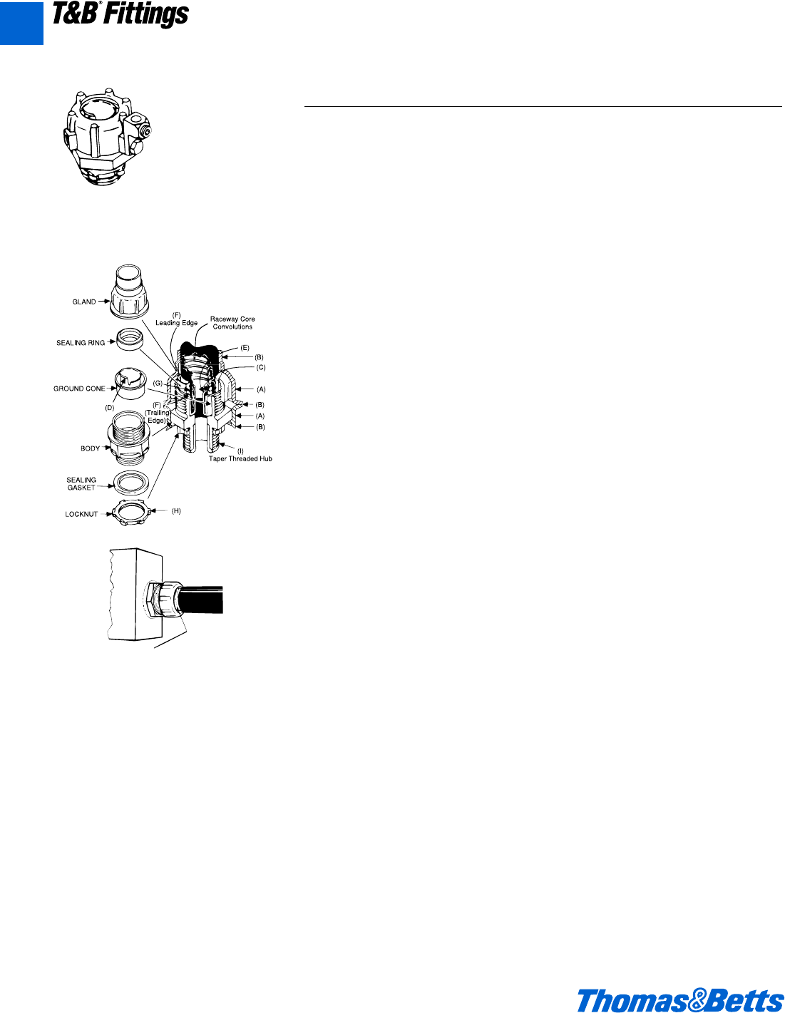
Liquidtight Flexible Metal Conduit Fittings
Sleeving
Raceway Jacket pulls off – exposing core and
affecting liquidtight termination. Feature (E) on
sealing ring helps overcome this problem.
Series 5331GR
External Bonding Liquidtight Flexible Metal Conduit Connectors
Application
• Used where external bonding jumper
is required around liquidtight flexible
metal conduit.
• To positively bond conduit to box or
enclosure.
• Used where flexible raceway is
installed in outdoor or indoors loca-
tion where exposed to continuous or
intermittent moisture.
Features
• Designed with provision to install
bonding jumper in several positions.
• Designed to accept mechanical or
compression lug.
• Ability to install quickly with low
torque effort.
(i) Compressed metallic convolu-
tions; assures ground contact with
low impedance and high raceway
holding power (A).
(ii) Single helical thread on ground
cone is easy to install without
cross thread; accepts variations in
raceway diameters and convolu-
tion pitch (B).
(iii) Rolled over edge protects con-
ductors (C).
• Sealing ring design has following
exclusive features:
(i) Grips and seals at leading and
trailing edge – will not abrade
raceway jacket (D).
(ii) Provided with grooves on inside
diameter for anti-sleeving (E).
(iii) Shoulders on both ends for extra
sealing (F).
(iv) Symmetrical shape assures fool-
proof assembly.
• Can be disconnected and reused.
• Watertight/oil tight installation at box or
enclosure termination is assured by:
1. External taper thread hub on
5331GR series and use of sealing
gasket 5262 series (G).
2. Taper tapped hole on 5271 series.
• Suitable for use in Class I Division 2,
Class II Division 1 & 2 and Class III
Division 1 & 2 Hazardous Locations
per NEC Article 500.
• Suitable as a bonding means per
U.L. 467 and NEC Article 351-9.
• Conforms with JIC requirements.
Standard Material
Lugs: High conductivity copper (for
copper conductor only).
Body, Gland, Locknut & Ground Cones:
All steel or malleable iron.
Sealing Ring and Insulator: All thermo-
plastic.
Sealing Gasket: Stainless Steel and
Santoprene.
Strap: Steel.
Standard Finish
All Electro Zinc Plated and Chromate
Coated except lugs.
Lugs: Bright Dipped.
Range
5331GR Series (straight connectors
with male hub): c" thru 6" conduit.
5341GR Series (45°): c" thru 4" conduit.
5351GR Series (90°): c" thru 4" conduit.
5232ALGR Series: c" thru 1" conduit.
All hubs provided with taper pipe
threads (NPT).
Listed/Certified by:
U.L. File #E-23018
CSA
Conforms to:
U.L. 467
U.L. 514B
CSA C22.2 No. 18
CSA22.2 No. 41
NEMA FB-1
NFPA 70-1999 (ANSI)
JIC EGP1
JIC EMP1
Federal Specification W-F-406
Federal Standard H-28 (threads)
1Per C.E. Code, this method
is not permissible.
A120 © 2002 Thomas & Betts Corporation. Specifications are subject to change without notice. www.tnb.com
T&B®Fittings
A
412031.A02 FIT 3/5 3/13/03 4:56 PM Page 120
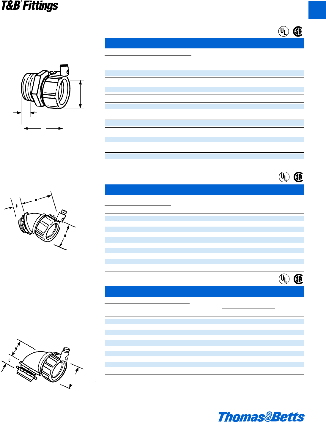
© 2002 Thomas & Betts Corporation. Specifications are subject to change without notice. www.tnb.com A121
T&B®Fittings
90° Angle Grounding Fittings
Cat. No.
Dimensions (in.) Ground
Steel Steel Aluminum Conduit Wire
Insulated Non-Insulated Non-Insulated Size A B C D
5351GR** 5251GR** 5251ALGR c" 1q 1b l 14-8
5352GR 5252GR 5252ALGR d" 1c 1k l 14-8
5353GR 5253GR 5253ALGR f" 1y 1m l 14-4
5354GR 5254GR 5254ALGR 1" 1g 2h f 14-4
5355GR 5255GR 1b" 2b 2d m 8-1/0
5356GR 5256GR 1d" 3b 2n m 4-2/0
5357GR 5257GR 2" 3m 3k g 4-2/0
5358GR 5258GR 2d" 4k 8g 1 2-4/0
5359GR 5259GR 3" 5i 10b 1 2-4/0
5360GR 5260GR 4" 6a 12e 1a 2-4/0
** c" conduit fittings have d" trade size hub. With safe-edge ground cone (through 4") and double bevel sealing ring (through 2").
U.L. Listed liquidtight; and CSA Certified watertight. Suitable for hazardous locations use in Class I, Div. 2; Class II, Div. 1 and 2; Class
III, Div. 1 and 2, where general purpose equipment is specifically permitted per NEC Section 500-2(a). Available with DURA-PLATE®Finish.
U.L. File No. E 3060. CSA File No. 638
Note: c"-1" fittings include Revolver™grounding device. For sizes 1b" and up, fittings are supplied with a copper mechanical lug.
Straight Grounding Fittings*
Cat. No.
Dimensions (in.) Ground
Steel Steel Aluminum Conduit Wire
Insulated Non-Insulated Non-Insulated Size A B C D
5331GR** 5231GR 5231 ALGR c" 1q 1d l 14-8
5332GR 5232GR 5232ALGR d" 1c 1l l 14-8
5333GR 5233GR 5233ALGR f" 1y 1e l 14-4
5334GR 5234GR 5234ALGR 1" 1g 2h f 14-4
5335GR 5235GR 1b" 2b 2d m 8-1/0
5336GR 5236GR 1d" 3b 2L m 4-2/0
5337GR 5237GR 2" 3m 3h g 4-2/0
5338GR 5238GR 2d" 4k 4a 1 2-4/0
5339GR 5239GR 3" 5i 4b 1 2-4/0
5340GR 5240GR 4" 6a 4d 1a 2-4/0
5385GR 5285GR 5" 8l 7 1g 2-4/0
5386GR – 6" 8w 8d 2 2-4/0
Liquidtight Flexible Metal Conduit Fittings
Malleable iron, tapered hub threads.
C
A
B
®
®
Malleable iron, tapered hub threads.
45° Angle Grounding Fittings
Ground
Cat. No. Conduit Dimensions (in.) Wire
Insulated Non-Insulated Size A B C D
5341GR** 5241GR** c" 1q 1l l 14-8
5342GR 5242GR d" 1c 1g l 14-8
5343GR 5243GR f" 1y 2a l 14-4
5344GR 5244GR 1" 1g 2b f 14-4
5345GR 5245GR 1b" 2b 2f m 8-1/0
5346GR 5246GR 1d" 3b 3c m 4-2/0
5347GR 5247GR 2" 3m 3g g 4-2/0
5348GR 5248GR 2d" 4k 4b 1 2-4/0
5349GR 5249GR 3" 5i 4b 1 2-4/0
5350GR 5250GR 4" 6a 4e 1a 2-4/0
Ground Wire
Max. over Ribs
Malleable iron tapered hub threads.
Ground Wire
Max. over Ribs
®
®
®
®
A
412031.A02 FIT 3/5 3/13/03 4:56 PM Page 121
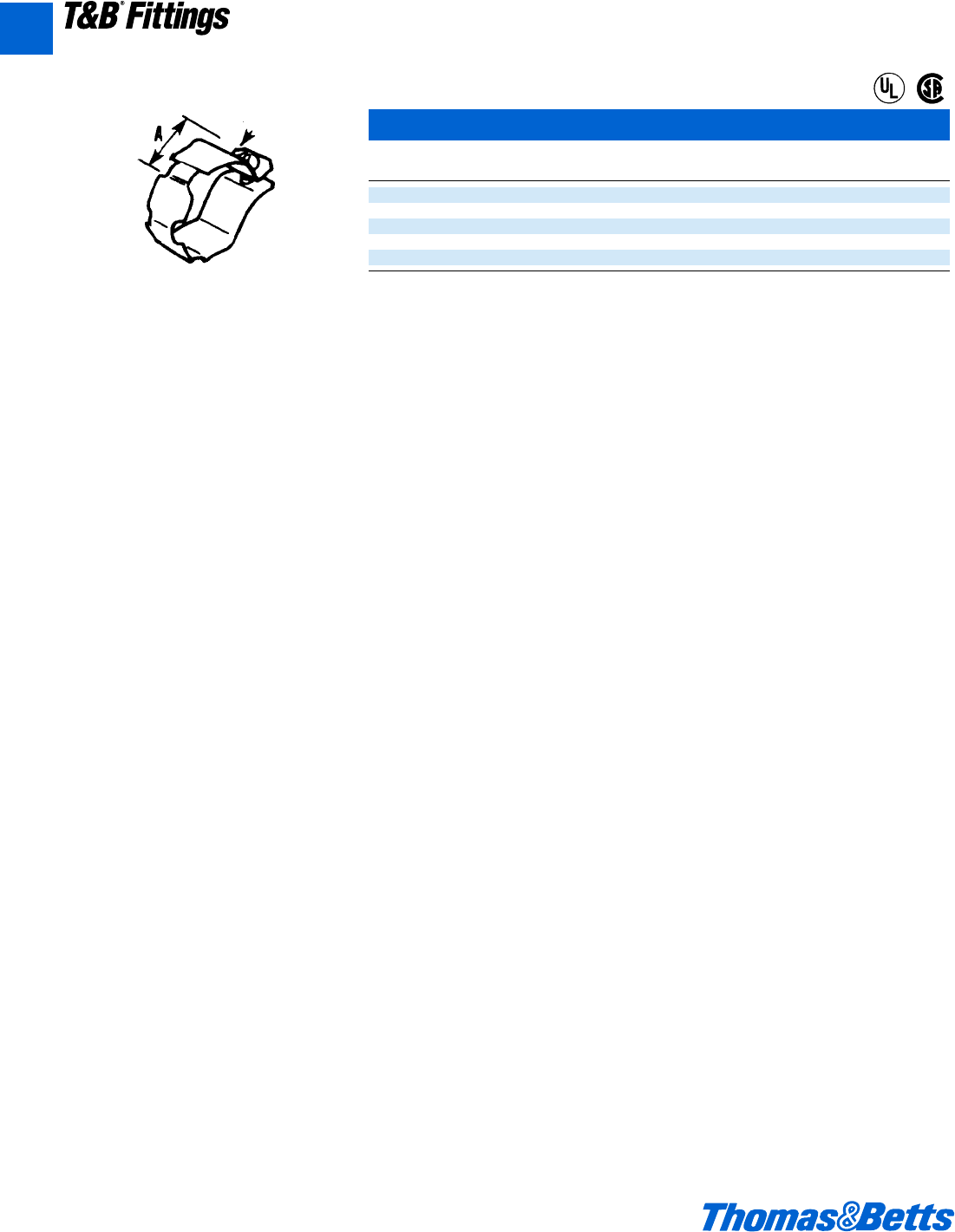
A122 © 2002 Thomas & Betts Corporation. Specifications are subject to change without notice. www.tnb.com
T&B®Fittings
Liquidtight Flexible Metal Conduit Fittings
For retrofit applications. Includes strap, nut
and bolt.
Swing
Radius Bolt External Grounding Strap
Cat. Conduit B
No. Size A Bolt Size
GR1W c" 1 10-24
GR2W d" 1h 10-24
GR3W f" 1c b-20
GR4W 1" 1d b-20
GR5W 1b" 1g j-18
U.L. File No. E-3060
CSA File No. 638
®
®
A
412031.A02 FIT 3/5 3/13/03 4:56 PM Page 122
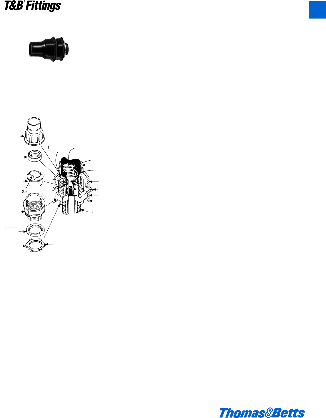
© 2002 Thomas & Betts Corporation. Specifications are subject to change without notice. www.tnb.com A123
T&B®Fittings
Liquidtight Flexible Metal Conduit Fittings
3321 Series*
*3361 Series...
same as 3321, except 90°
3341 Series...
same as 3321, except 45°
Gland
Sealing Ring
Ground Cone
(D)
Body
Sealing
Gasket
Locknut (H)
3321 Series
(B)
(B)
(A)
(C)
(B)
(E)
(A)
(F)
Leading
Edge Raceway Core
Convolutions
(G)
Liquidtight Flexible Metal Conduit Connectors (PVC Coated)
(I)
Taper Threaded Hub
(F)
(Trailing
Edge)
Application
• Used where liquidtight flexible metal
conduit is installed in outdoor or
indoor locations where exposed to
environmental conditions that are
more than normally corrosive to
exposed surfaces.
• To positively bond conduit to box or
enclosure.
Features
• PVC coated to protect connector
from extremely corrosive surround-
ings without effecting integrity of
electrical grounding path (A).
• Provided with overlapping sleeve
for additional seal (B).
• Ability to install quickly with low
torque effort.
• Ground cone design offers following
advantages:
(1) Compresses metallic convolu-
tions; provides high quality
ground contact with low imped-
ance & high raceway holding
power (C).
(2) Single helical thread on ground
cone is easy to install without
cross threading; accepts varia-
tions in raceway diameters and
convolution pitch (D).
(3) Rolled over edge protects con-
ductors (E).
• Sealing ring design has following
exclusive features:
(1) Grips and seals at leading and
trailing edge – will not abrade
raceway jacket (F).
(2) Provided with grooves on inside
diameter for anti-sleeving (G).
(3) Shoulders on both ends for extra
sealing.
(4) Symmetrical shape assures fool-
proof assembly.
• Hardened steel or malleable iron
locknut (H).
• Can be disconnected and reused.
• Watertight/oil tight installation at box
or enclosure termination is provided
by – external taper thread hub and
sealing gasket (I).
• Suitable for use in Class I Division 2,
Class II Division 1 & 2 and Class III
Division 1 & 2 Hazardous Locations
per N.E.C. Article 500.
• Suitable as a grounding means per
N.E.C. Section 351-9 (up to 1b"
trade size).
• Conforms with JIC requirements.
Standard Material
Body, Gland, Locknut & Ground
Cones: All steel or malleable iron.
Sealing Ring and Insulator: All ther-
moplastic.
Sealing Gasket, Retainer – Stainless
Steel: Resilient Seal: Santoprene.
Coating – PVC.
Outside of body & gland…PVC
Coated.
Inside of body & gland…Electro Zinc
Plated & Chromate Coated.
Locknut & Sealing Gasket,
Retainer…Electro Zinc Plated
& Chromate Coated.
Range
3321, 3361 & 3341 Series…c" thru 4"
conduit.
All hubs provided with taper pipe
threads (NPT).
Listed/Certified by:
U.L.........................(U.L. File E23018)
CSA ....................(LR-2884, LR-4484)
Conforms to:
U.L. 514B
CSA C22.2 No. 18
NEMA FB-1
NFPA 70-1999 (ANSI)
JIC EGP1
JIC EMP1
Federal Specification W-F-406
Federal Standard H-28 (THREADS)
A
412031.A02 FIT 3/5 3/13/03 4:56 PM Page 123
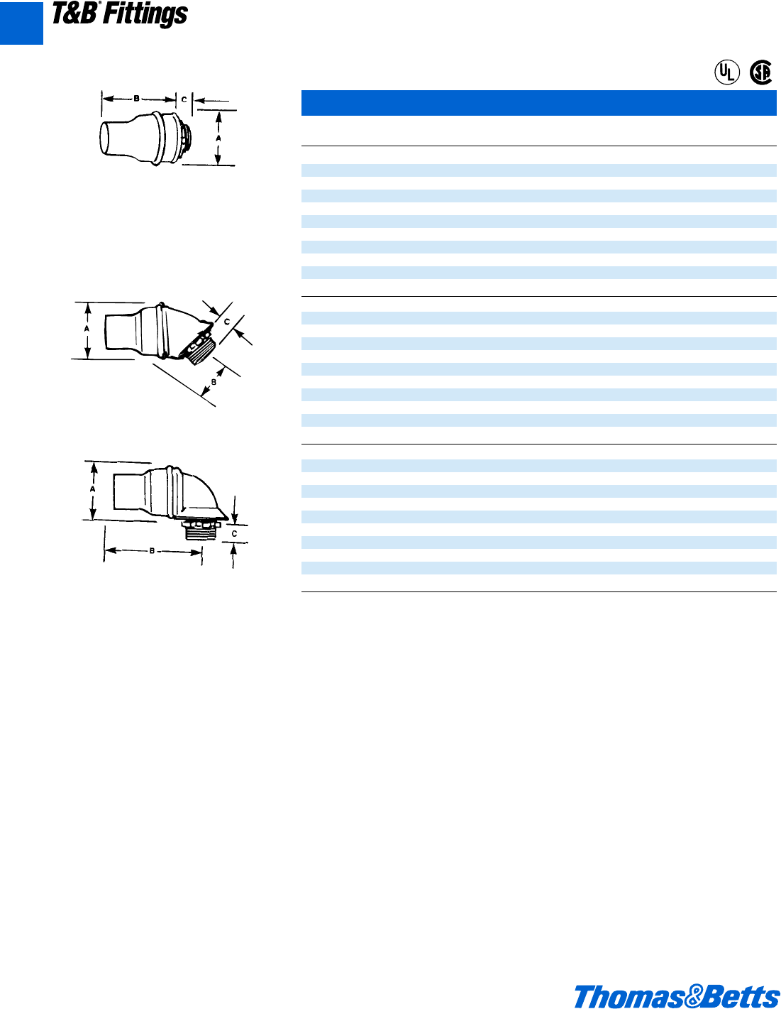
A124 © 2002 Thomas & Betts Corporation. Specifications are subject to change without notice. www.tnb.com
Liquidtight Flexible Metal Conduit Fittings
Corrosion Resistant PVC Jacketed Liquidtight Connectors
Cat. Conduit
No. Size A B C
Straight PVC Coated
3321†c" 1v" 2j" l"
3322†d" 1e" 2d" l"
3323†f" 1n" 2A" l"
3324†1" 2b" 3v" f"
3325†1b" 2L" 4b" m"
3326 1d" 3a" 4L" m"
3327 2" 3e" 5j" g"
3328 2d" 4c" 6c" 1"
3329 3" 5i" 6d" 1"
3331 4" 6k" 6f" 1a"
45° PVC Coated
3341†c" 1v 1a" l"
3342†d" 1e" 1b" l"
3343†f" 1n" 1k" l"
3344†1" 2b" 1m" f"
3345†1b" 2L" 2h" m"
3346 1d" 3a" 2L" m"
3347 2" 3e" 3i" g"
3348 2d" 4c" 3m" 1"
3349 3" 5i" 4l" 1"
3352 4" 6k" 5f" 1a"
90° PVC Coated
3361†c" 1v" 2i" l"
3362†d" 1e" 2d" l"
3363†f" 1n" 2C" l"
3364†1" 2b" 3x" f"
3365†1b" 2L" 4d" m"
3366 1d" 3a" 4n" m"
3367 2" 3e" 5L" g"
3368 2d" 4c" 11a" 1"
3369 3" 5i" 12d" 1"
3371 4" 6k" 14g" 1a"
† U.L. Listed as grounding means per NEC. SECT. 351.7
Complies with J.I.C. standards and Federal Specs WF 406B, WF 408B
Suitable for hazardous locations use in Class I, Div. 2; Class II, Div. 1 and 2; Class III, Div. 1 and 2, where general purpose equipment is
specifically permitted per NEC Section 500-2(a).
Meets Coast Guard CG293
U.L. File No. E 23018
CSA File No. 2884
®
®
Straight PVC Coated
Nylon Insulated
Steel or Malleable
NPT hub threads
45° PVC Coated
Nylon Insulated
NPT hub threads
90° PVC Coated
Nylon Insulated
NPT hub threads
A
T&B®Fittings
412031.A02 FIT 3/5 3/13/03 4:56 PM Page 124
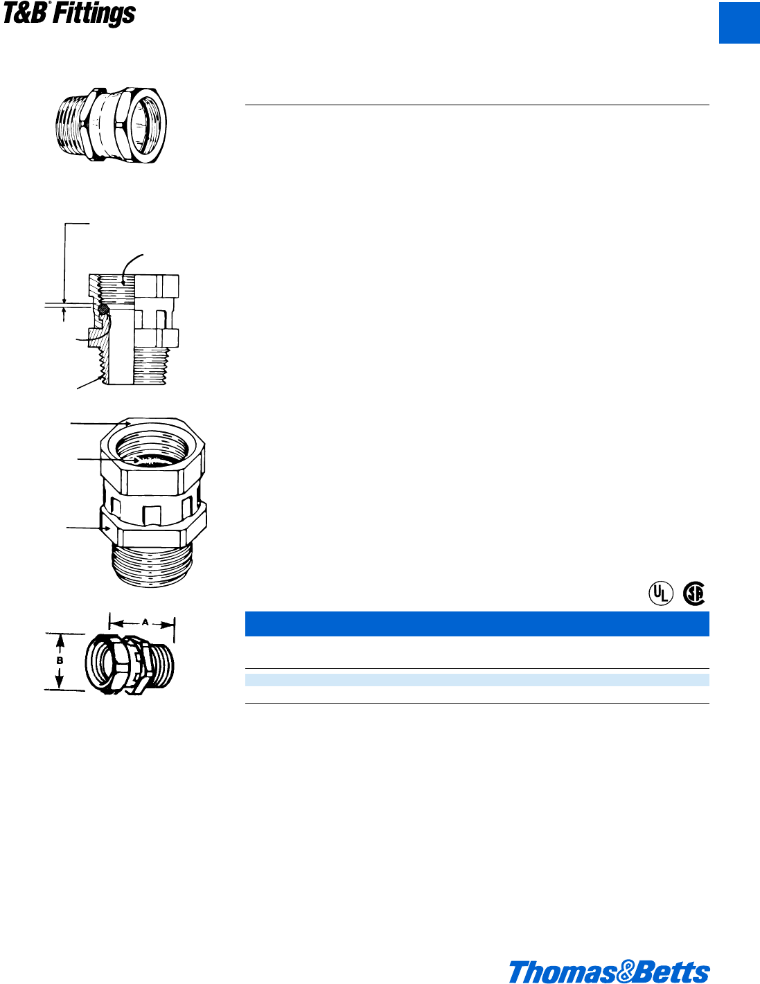
© 2002 Thomas & Betts Corporation. Specifications are subject to change without notice. www.tnb.com A125
Liquidtight Flexible Metal Conduit Fittings
41 Series
(E)
(C)
(D)
Gland
Resilient Seal
(A)
Body
Liquidtight Union for Threaded Hub
(B)
Controlled Deformation
of Resilient Seal
Liquidtight Union for Threaded Hub
Cat. Conduit
No. Size A B
41-TB d" 1S" 1"
42-TB f" 1n" 1b"
U.L. File No. E 23018
CSA File No. 2884
Steel, zinc plated and chromated. Ideal for
angle fittings where swing clearance is not
available.
Application
• To couple threaded end of a fitting or
a pipe to a tapped opening in a box
or enclosure where rotation of fitting
or pipe is limited or restricted.
Features
• Design provides high quality bond
between fitting or pipe to the union.
• Provided with resilient seal (A).
• Resilient seal subjected to controlled
deformation; positive seal and
reusability are assured (B).
• Unique design centralizes throat open-
ings of threaded hub and union (C).
• Permits orientation of fitting in any
predetermined direction for a safe,
functional and neat assembly.
• Provided with taper threaded hub for
liquidtight assembly (D).
• Straight pipe threads on gland accept
a straight or taper threaded hub on fit-
ting or pipe to be coupled (E).
• Suitable for hazardous location use
per NEC Article 501 Class I, Division
2, Article 502 Class II, Division 1 & 2
and Article III Division 1 & 2.
Standard Material/Finish
Gland…Steel/Electro Zinc Chromate
Coated
Body…Steel/Electro Zinc Chromate
Coated
‘O’ Ring…Buna N/As Molded
Range
Hub (External Thread)…d" & f" NPT
Gland (Internal Threads)…d" & f" NPS
Listed/Certified by:
U.L.…(U.L. File No. E-23018)
CSA…(LR-2884, LR-4484)
Conforms to:
U.L. 514B
CSA C22.2 No. 18
NEMA FB1
NFPA 70-1999 (ANSI)
Federal Standard W-F-408
Federal Standard W-F-406
Federal Standard H-28 (Threads)
Note: For additional product information
refer to Thomas & Betts publication 600.1
®
®
T&B®Fittings
A
412031.A02 FIT 3/5 3/13/03 4:56 PM Page 125
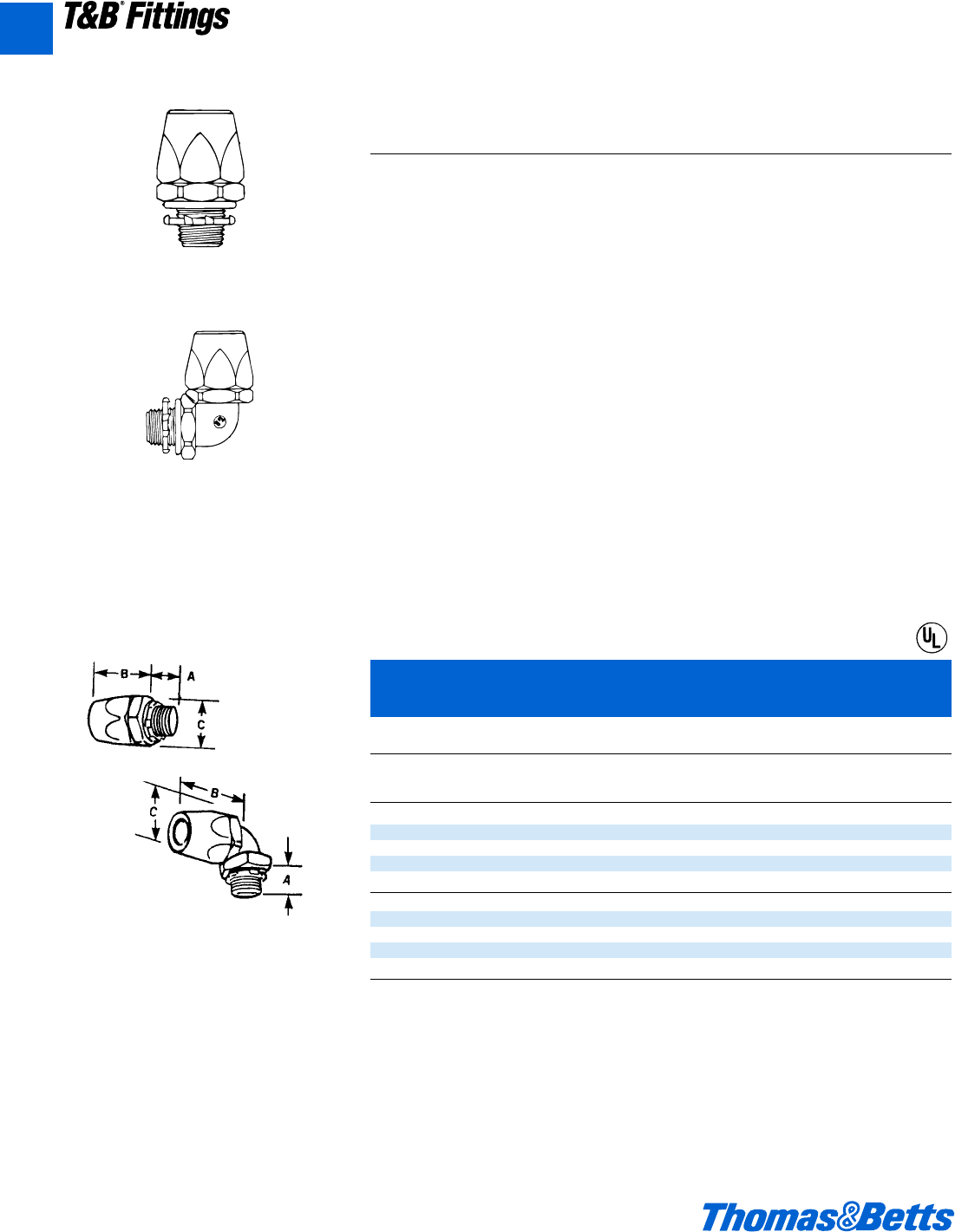
A126 © 2002 Thomas & Betts Corporation. Specifications are subject to change without notice. www.tnb.com
T&B®Fittings
Liquidtight Flexible Metal Conduit Fittings
Series 6302
Liquidtight Flexible Non-Metallic
Conduit Connectors
Liquidtight Flexible Non-Metallic Liquidtight Type A
Conduit Connectors
Application
• To provide a liquidtight, dust tight
connection between flexible, non-
metallic conduit and a box or an
enclosure.
Features
• Serrated, design provides high
mechanical pullout strength (A).
• Unique component parts (body/-
gland) design insures positive seal
between conduit and connector (B).
• Tapered thread hub and sealing ‘O’
ring provide a liquidtight/dust tight
seal to a box or an enclosure (C).
• High strength, chemical resistant,
non-burning, non-dripping thermo-
plastic construction.
• Smooth insulated body throughout for
maximum dielectric strength.
• Captive ‘O’ ring and reduced number
of parts save installation time (D).
Standard Material
Body…Thermoplastic
Gland…Thermoplastic
‘O’ Ring…Neoprene
Locknut…Steel (Case Hardened)
Standard Finish
Body, Gland & ‘O’ Ring .......As Molded
Locknut ..............................Electro Zinc
Range
Conduit Size ........................d" thru 1b"
Hub Size ....................d" thru 1b" N.P.T.
Series 6322
Liquidtight Flexible Non-Metallic
Conduit Connectors
Thermoplastic Fittings for Liquidtight Flexible
Non-Metallic Conduit Type A
Corrosion Resistant Applications
C
Cat. Conduit Cross
No. Size A B Corners
Straight Connector
6302 d" .60" 1.68" 1.48"
6303 f" .61" 1.85" 1.76"
6304 1" .77" 1.89" 2.10"
6305 1b" .79" 2.30" 2.67"
90° Angle Connector
6322 d" .60" 1.56" 1.48"
6323 f" .61" 1.74" 1.76"
6324 1" .77" 1.78" 2.10"
6325 1b" .79" 2.13" 2.67"
Meets Coast Guard CG293
U.L. File No. E 23018
90° Angle Connector
Straight Connector
Designed especially for the Type A, all plastic
raceways now in use for dynamic machine tool
applications.
Fittings are constructed of a high-strength,
chemically resistant thermoplastic tougher than
the raceway itself.
Neoprene sealing ring is furnished with con-
nector providing a liquidtight seal for knockout
applications.
®
A
412031.A02 FIT 3/5 3/13/03 4:56 PM Page 126
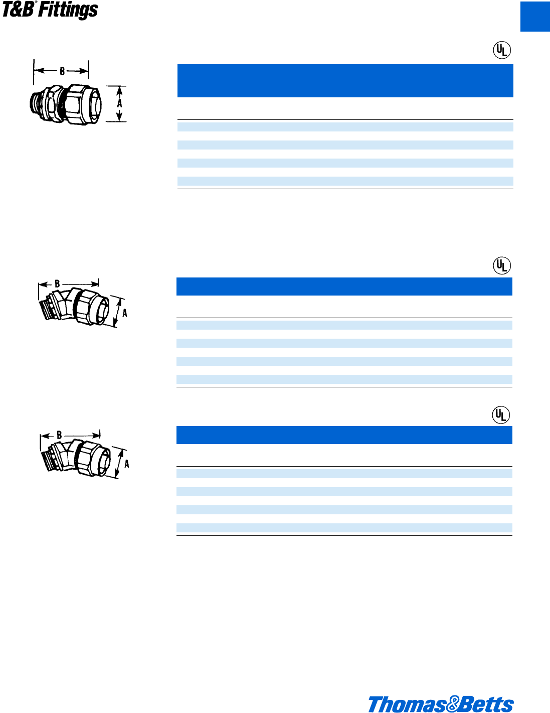
© 2002 Thomas & Betts Corporation. Specifications are subject to change without notice. www.tnb.com A127
T&B®Fittings
Liquidtight Flexible Metal Conduit Fittings
• Nylon insulated throat.
• T&B Sealing Ring to seal knockouts.
• Steel or malleable iron.
• U.L. Listed.
• NPT hub threads to seal in female threads.
• High mechanical pull-out strength.
• Provides positive seal against water, oil
and dust.
®
Steel/Malleable Iron Liquidtight Flexible
Non-Metallic Conduit Type A
Cat. Conduit
No. Size Hub Thread A B
3720-TB* c" d – 14 NPT 1q" 2"
3721-TB d" d – 14 NPT 1c" 2a"
3722-TB f" f – 14 NPT 1e" 2b"
3723 1" 1 – 11d NPT 1g" 2d"
3724-TB 1b" 1b – 11d NPT 2c" 2"
3725 1d" 1d – 11d NPT 2f" 3c"
3726 2" 2 – 11d NPT 3w" 3e"
* Not U.L. Listed
U.L. File No. E 23018
See charts below for 45 and 90 degree fittings for this series
45° Metallic Connector for Non-Metallic Conduit Type A
Cat. Conduit
No. Size Hub Thread A B
3730-TB* c" d – 14 NPT 1q" 2u"
3731-TB d" d – 14 NPT 1c" 2l"
3732 f" f – 14 NPT 1e" 3"
3733-TB 1" 1 – 11d NPT 1g" 3d"
3734-TB 1b" 1b – 11d NPT 2c" 4a"
3735-TB 1d" 1d – 11d NPT 2f" 4g"
3736 2" 2 – 11d NPT 3w" 5d"
* Not U.L. Listed
U.L. File No. E 23018
90° Metallic Connector for Non-Metallic Conduit Type A
Cat. Conduit
No. Size Hub Thread A B
3740* c" d – 14 NPT 1q" 1e"
3741 d" d – 14 NPT 1c" 1f"
3742 f" f – 14 NPT 1e" 2b"
3743-TB 1" 1 – 11d NPT 1g" 2l"
3744-TB 1b" 1b – 11d NPT 2c" 3b"
3745 1d" 1d – 11d NPT 2f" 3d"
3746-TB 2" 2 – 11d NPT 2w" 4a"
* Not U.L. Listed
U.L. File No. E 23018
®
®
A
412031.A02 FIT 3/5 3/13/03 4:56 PM Page 127
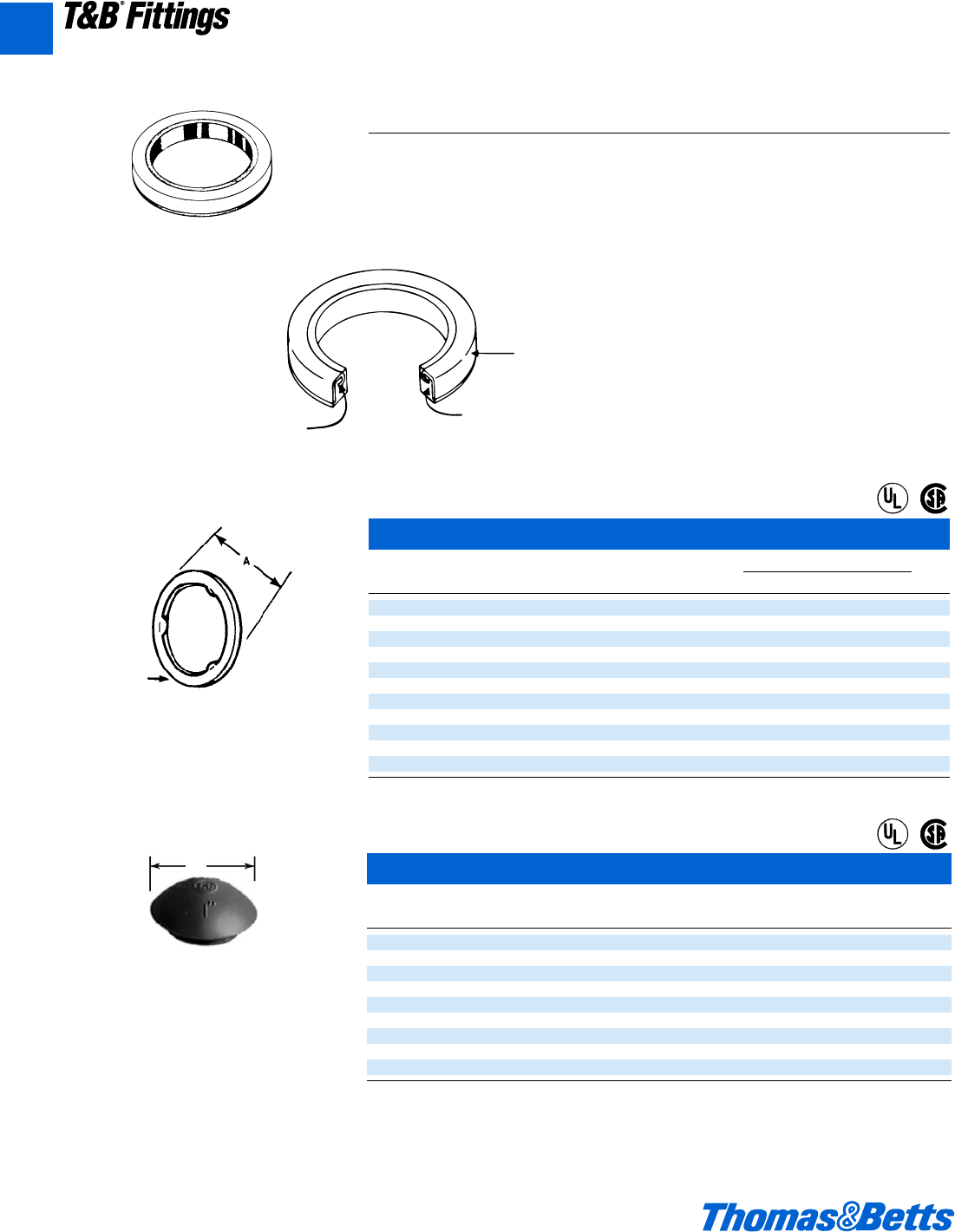
A128 © 2002 Thomas & Betts Corporation. Specifications are subject to change without notice. www.tnb.com
A
T&B®Fittings
Liquidtight Flexible Metal Conduit Fittings
5262 Series
Features
• Design locks resilient sealing materi-
al in steel.
• Steel retainer protects seal from
extruding out under torque and lim-
its compression to an optimum pre-
determined value; provides high
quality seal.
• Resilient material flows and seals
rough surfaces.
Standard Material
Retainer .........................Stainless Steel
Sealing Material..................Santoprene
Thermoplastic Rubber
Range
d" thru 4" Hub Size
Application
• When used with an externally thread-
ed connector provides a tight seal
against oil, fumes or moisture at the
knockout opening.
Stainless Steel Retainer
Resilient Seal
Resilient Sealing
Material Locked in Steel Retainer
Liquidtight Sealing Gasket
Sealing Ring with Stainless Steel Retainer
Cat. Conduit Dimension (in.)
No. Size A B
5299** b" .80" .11"
5261** c" .95" .11"
5262 d" 1.16" .18"
5263 f" 1.49" .19"
5264 1" 1.75" .19"
5265 1b" 2.15" .22"
5266 1d" 2.42" .23"
5267 2" 2.92" .23"
5268 2d" 3.44" .23"
5269 3" 4.08" .23"
5270 4" 5.29" .31"
** U.L. not applicable
U.L. File No. E 13938
CSA File No. 2884
NEMA 3R, 4, 6 & 13
For use with T&B Fittings. Sealing material
resists oil, coolants, and hydraulic fluids as
well as water.
B Thickness
NEMA 3R, 4, 6 & 13
Made of flame retardant neoprene, these new
K.O. plugs meet U.L. 514 flammability test.
They provide a raintight, dust, and oil-tight re-
usable seal for electrical knockouts. NEMA 3R,
4, 6 & 13 boxes can be saved or re-used when-
ever a K.O. is no longer used. No tools needed
to install; just push into hole … they snap in.
Temperature range – 30°C to 105°C.
ALiquidtight K.O. Plug
Cat.
No. Size A
5710 d" 1s"
5711 f" 1d"
5712 1" 1B"
5713 1b" 2r"
5714 1d" 2d"
5715 2" 3p"
5716 2d" 3y"
5717 3" 4∫"
5718 4" 5∫"
U.L. Listed raintight
CSA not applicable
Meets Coast Guard Regulation CG293
U.L. File No. E 13938
CSA File No. 2884
®
®
®
®
412031.A02 FIT 3/5 3/13/03 4:56 PM Page 128
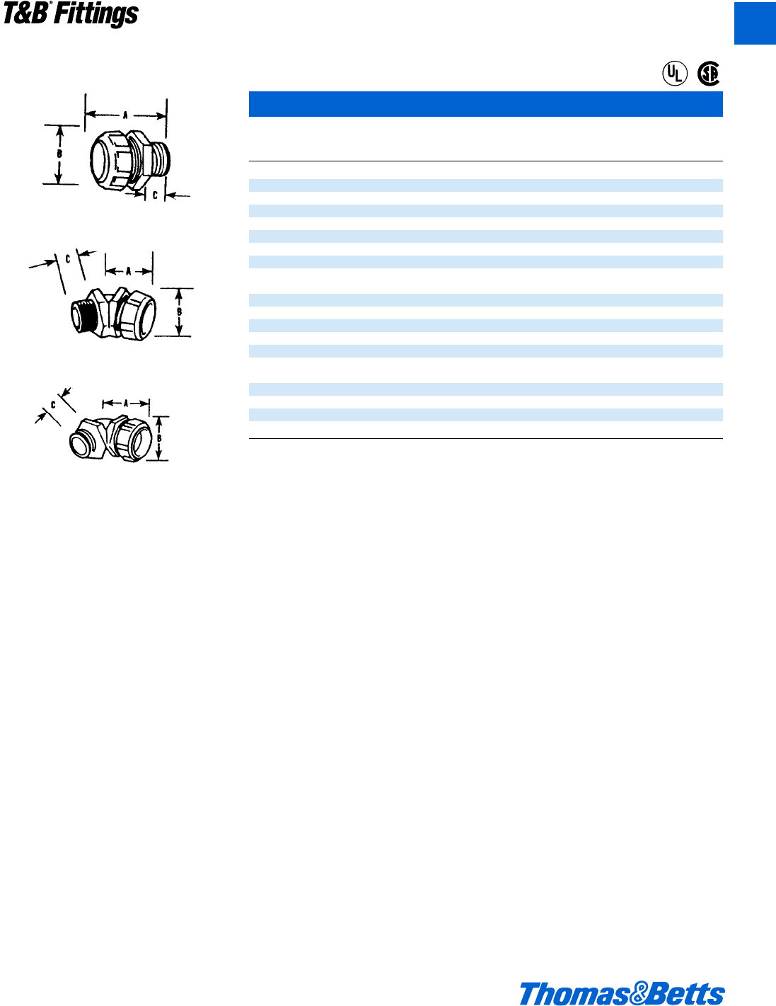
© 2002 Thomas & Betts Corporation. Specifications are subject to change without notice. www.tnb.com A129
T&B®Fittings
A
Liquidtight Flexible Metal Conduit Fittings
ISO Metric Thread Liquidtight Fittings*
Flexible Metric
Cat. Conduit ISO A B C
No. Size Thread mm mm mm
Nylon insulated straight connectors
9330 b" 16 36 21 12
9331 b" 20 36 21 12
9306 j" 16 36 26 12
9360 3c" 16 40 29 16
9361 c" 20 40 29 16
9362 d" 20 42 35 16
9363 f" 25 45 42 16
9364 1" 32 54 47 23
Nylon insulated 45° angle connectors
9340 c" 16 27 29 16
9341 c" 20 27 29 16
9342 d" 20 27 35 16
9343TB f" 25 31 42 16
9344 1" 32 34 47 23
Nylon insulated 90° angle connectors
9350 c" 16 35 29 16
9351 c" 20 35 29 16
9352TB d" 20 39 35 16
9353TB f" 25 43 42 16
9354TB 1" 32 48 47 23
U.L. Listed Liquidtight.
CSA certified watertight.
* All items shown on this page are suitable for use in hazardous location where general purpose equipment is specifically permitted by
the NEC; Class I Div. 2, Class II, Div. 1 & 2; Class III, Div. 1 & 2, NEC 501-4(b); 502-4(a)(b); 503-3(a)(b).
U.L. File No. E 23018
CSA File No. 2884
Fittings for Liquidtight flexible metal conduit
with metric threads of ISO Form (BS-4568-SA
BS 162).
®
®
412031.A02 FIT 3/5 3/13/03 4:56 PM Page 129
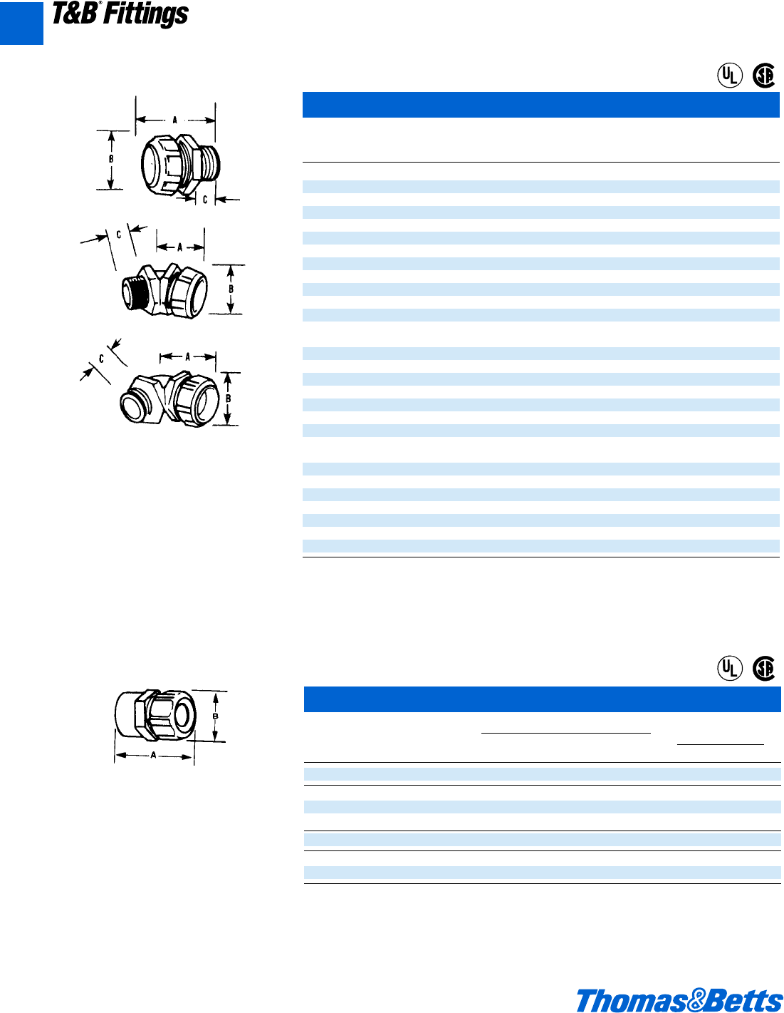
A130 © 2002 Thomas & Betts Corporation. Specifications are subject to change without notice. www.tnb.com
T&B®Fittings
PG Metric Thread Liquidtight Fittings*
Flexible Metric
Cat. Conduit PG A B C
No. Size Thread mm mm mm
Nylon insulated straight connectors
7330 b" 9 362112
7331 b" 11 36 21 12
7360 j" 9 362612
7361 c"†11 40 29 14
7362 c"†13.5 40 29 14
7363 1d"†16 41 35 14
7364 f"†21 43 42 14
7365 1"†29 56 47 19
7366 1b"†36 67 58 21
7367 1d" 42 72 69 21
7368 2" 48 81 83 21
Nylon insulated 45° angle connectors
7341 c"†11 27 29 14
7342 c"†13.5 27 29 14
7343 d"†16 30 35 14
7344-TB f"†21 34 42 14
7345 1" 29 44 47 19
7346 1b"†36 51 58 19
7347 1d" 42 60 69 21
7348-TB 2" 48 73 76 24
Nylon insulated 90° angle connectors
7351 c"†11 37 29 14
7352 c"†13.5 37 29 14
7353 d"†16 40 35 14
7354 f"†21 44 42 14
7355 1"†29 56 47 21
7356 1b†36 70 58 21
7357 1d" 42 75 69 21
7358 2" 48 87 83 24
* All items shown on this page are suitable for use in hazardous location where general purpose equipment is specifically permitted by
the NEC; Class I Div. 2, Class II, Div. 1 & 2; Class III, Div. 1 & 2, NEC 501-4(b); 502-4(a)(b); 503-3(a)(b).
†U.L. Listed as grounding means under NEC 351-7.
U.L. Listed liquidtight.
CSA Certified watertight.
U.L. File No. E-23018
CSA File No. 2884
Liquidtight Flexible Metal/MS Connectors
Internal Thread
Cat. Trade AN-MS Conn. Dimensions (in.)
No. Size Shell Size Thread Size A B
LTA03810 c" 10SL, 12, 12Se" – 24 UNEF-2B 1q 1
LTA05014 d" 14, 14Sf" – 20 UNEF-2B 1j 1b
LTA05016 d" 16, 16Sg" – 20 UNEF-2B 1j 1b
LTA05018 d" 18 1" – 20 UNEF-2B 1j 1b
LTA07520 f" 20, 221i" – 18 UNEF-2B 1k 1d
LTA10020 1" 20, 221i" – 18 UNEF-2B 1f 1z
LTA10024 1" 25, 281k" – 18 UNEF-2B 1f 1z
U.L. File No. E 23018
CSA File No. 2884
T&B Liquidtight flexible metal and Liquidtight
flexible nonmetallic fittings with internal
threads to accept AN-MS connector shells.
Material: Steel
Liquidtight Flexible Metal Conduit Fittings
Fittings for Liquidtight flexible metal conduit
with metric threads of PG Form (DIN 40430).
®
®
®
®
A
412031.A02 FIT 3/5 3/13/03 4:56 PM Page 130
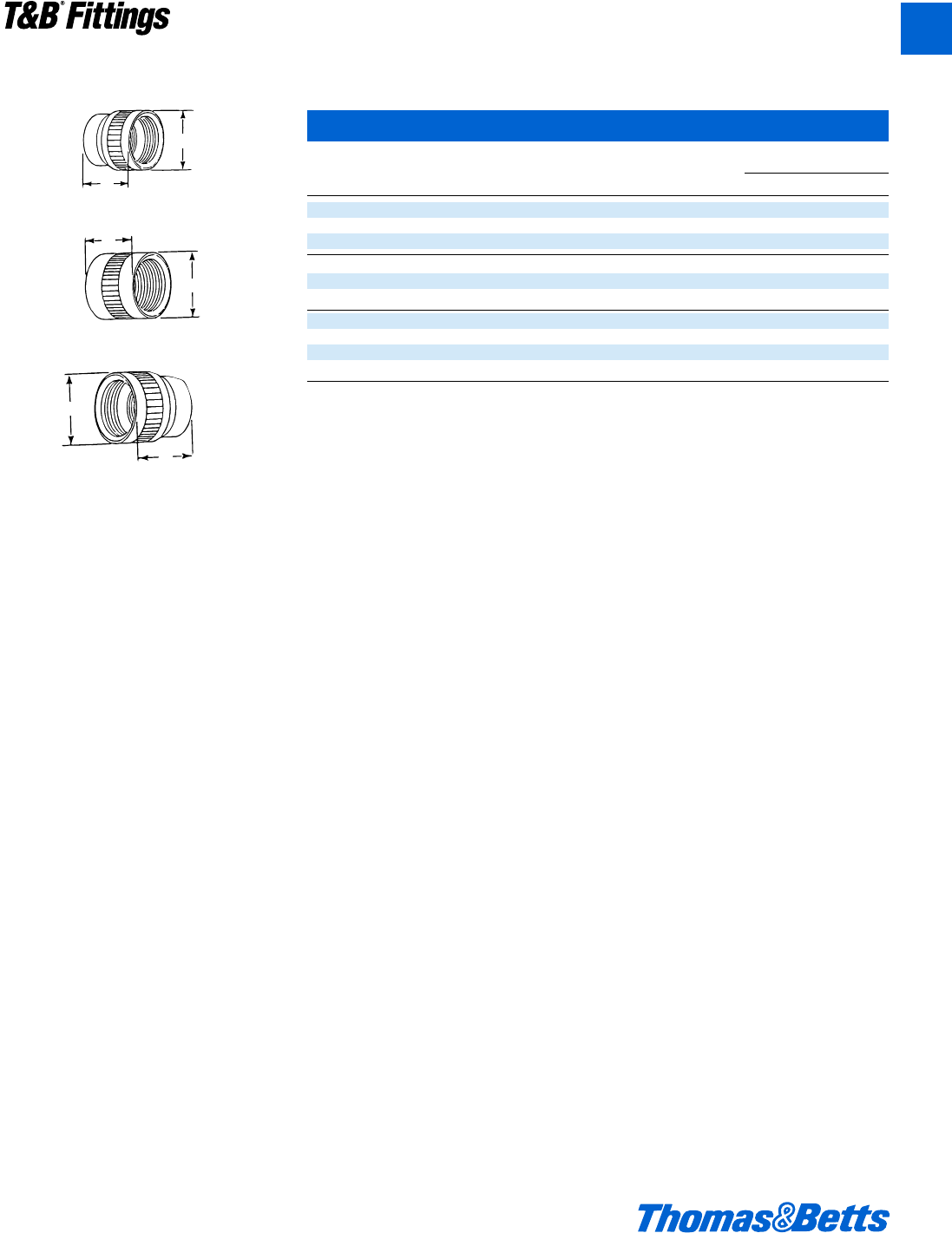
© 2002 Thomas & Betts Corporation. Specifications are subject to change without notice. www.tnb.com A131
T&B®Fittings
Liquidtight Flexible Metal Conduit Fittings
NPT/MS Connector Adapters
AN-MS
Cat. N.P.T. Connector Thread Std. Dimensions (in.)
No. Thread Shell Size Size Pkg. A Fig. B
MSA05014 d" 14, 14S f" – 20 UNEF-2B 10 1.000 1 1.175
MSA05016 d" 16, 16S g" – 20 UNEF-2B 10 1.000 2 1.175
MSA05018 d" 18 1" – 20 UNEF-2B 10 1.125 3 1.175
MSA07516 f" 16, 16S g" – 20 UNEF-2B 10 1.250 1 1.356
MSA07518 f" 18 1" – 20 UNEF-2B 10 1.250 1 1.300
MSA07520 f" 20, 22 1i" – 18 UNEF-2B 10 1.375 3 1.300
MSA10020 1"20, 22 1i" – 18 UNEF-2B 10 1.500 1 1.431
MSA10024 1"24, 28 1k" – 18 UNEF-2B 10 1.625 3 1.313
MSA10032 1"32 1f" – 18 UNS-2B 10 2.000 3 1.576
MSA10036 1"36 2" – 18 UNS-2B 10 2.250 3 1.738
All items shown on this page are suitable for use in hazardous location where general purpose equipment is specifically permitted by the
NEC; Class I Div. 2; Class II, Div. 1 & 2; Class III, Div. 1 & 2, NEC 501-4(b); 502-4(a)(b); 503-3(a)(b).
Fig. 1
Fig. 2
A
B
A
B
A
B
Fig. 3
Mechanical adapter with internal threads to
mate with NPT threaded fittings and MS type
connectors.
Material: aluminum
A
412031.A02 FIT 3/5 3/13/03 4:56 PM Page 131
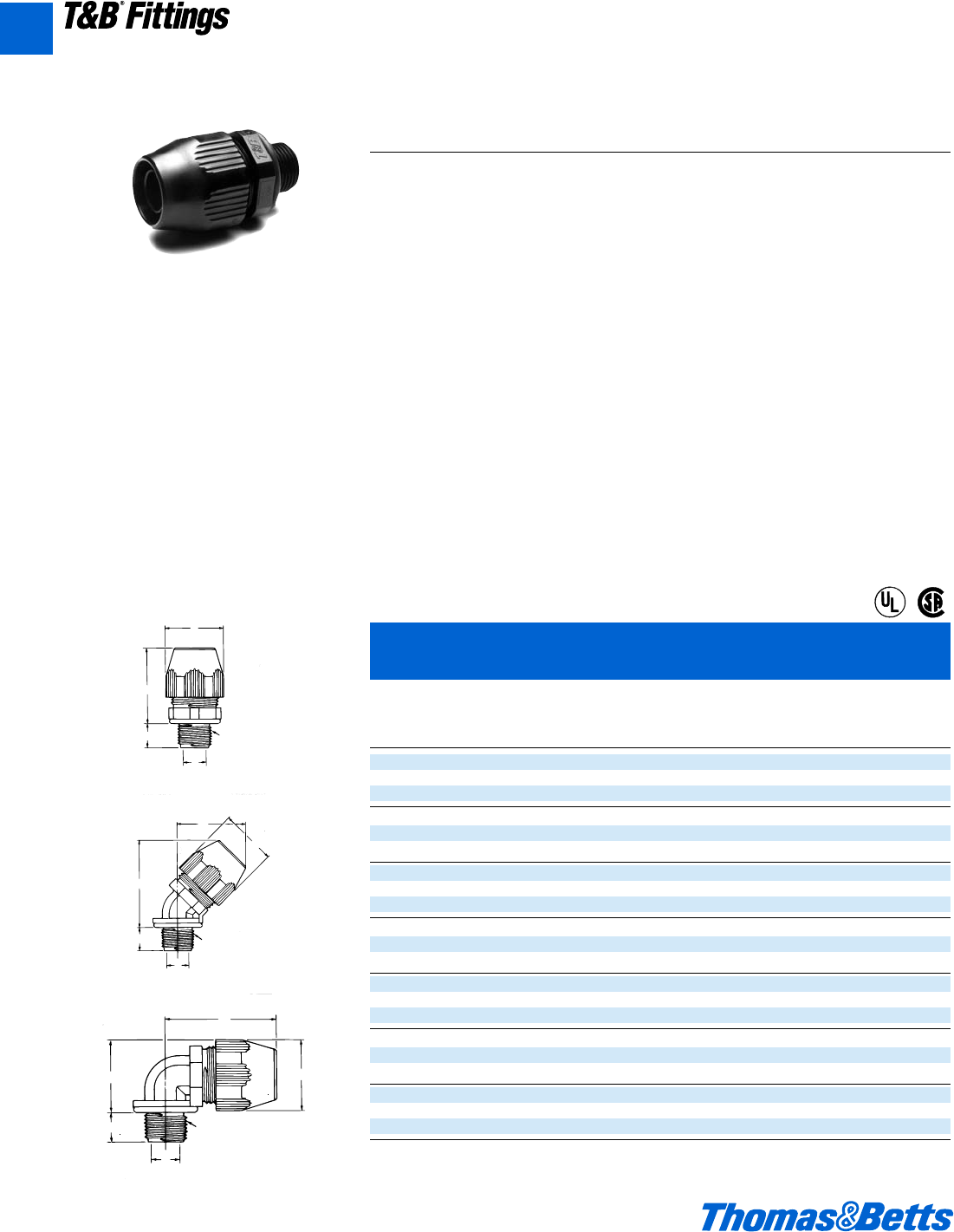
A132 © 2002 Thomas & Betts Corporation. Specifications are subject to change without notice. www.tnb.com
A
T&B®Fittings
XTRAFLEX®System – Conduit, Tubing, Fittings for Nonmetallic Liquidtight Conduit
Plastic Bullet®Liquidtight Fittings for T&B LTC Nonmetallic
Liquidtight Conduit Type B and T&B EFC Flexible Tubing
C ±.015 (0.40) Min. E
Trade A ±.015 Across Throat Thread F*
Cat. Size (.040) *B ±.035 (0.90) Corners Dia. D NPT (in.) (mm)
No. Fig. (in) (in.) (mm) (in.) (mm) (in.) (mm) (in.) (mm) (in.) Approx.
LT38P 1 .570 1.595 (40.51) 1.354 .417 –
LT438P 2c(14.48) 2.012 (51.10) (34.39) (10.59) d-14 1.534 (38.95)
LT938P 3 1.380 (35.05) 1.880 (47.75)
LT50P 1 .570 1.636 (41.55) 1.448 .550 –
LT450P 2d(14.48) 2.092 (53.14) (36.78) (13.97) d-14 1.590 (40.39)
LT950P 3 1.489 (37.82) 1.986 (50.44)
LT75P 1 .582 1.757 (44.63) 1.740 .740 –
LT475P 2f(14.78) 2.452 (62.28) (44.20) (18.80) f-14 1.821 (46.25)
LT975P 3 1.790 (45.47) 2.212 (56. )
LT100P 1 .726 1.923 (48.84) 2.068 .940 –
LT4100P 21(18.44) 2.684 (68.17) (52.53) (23.88) 1-11d 2.034 (51.66)
LT9100P 3 2.104 (53.44) 2.508 (63.70)
LT125P 1 .750 2.164 (54.97) 2.494 1.257 –
LT4125P 21b (19.05) 3.264 (82.91) (63.35) (31.93) 1b-11d 2.385 (60.58)
LT9125P 3 2.564 (65.13) 2.856 (72.54)
LT150P 1 .767 2.353 (59.77) 2.784 1.453 –
LT4150P 21d (19.48) 3.605 (91.57) (70.71) (36.91) 1d-11d 2.604 (66.14)
LT9150P 3 2.854 (72.49) 3.144 (79.86)
LT200P 1 .794 2.605 (66.17) 3.362 1.883 –
LT4200P 22(20.17) 4.210 (106.93) (85.39) (47.83) 2-8 3.050 (77.47)
LT9200P 3 3.432 (87.17) 3.675 (93.34)
* After Assembly
U.L. File No. E-23018
CSA File No. 52391
®
®
The BULLET®nonmetallic liquidtight fitting –
easy to use, built to take it.
This engineering breakthrough meets
the demand for a tough, reusable, non-
metallic liquidtight fitting for use with
XTRAFLEX®Type B conduit or flexible
tubing.
The BULLET®nonmetallic fitting pro-
vides a reliable liquidtight seal that
combines high pullout resistance and
ease of installation.
Engineered to meet your needs.
The BULLET®nonmetallic fitting meets
your performance requirements when
terminating Type B liquidtight nonmetal-
lic conduit or flexible nonmetallic tubing
to a box or enclosure with knockout
opening or threaded hub. Fittings meet
the watertight requirements for NEMA
type 4 and type 6 enclosures and con-
form to UL514B, and CSA No. 22.2
#227.2 specifications.
Ease of installation.
Installations can be performed quickly
and easily because BULLET®liquid-
tight fittings can be installed without
disassembly. BULLET®nonmetallic fit-
tings are resistant to numerous caus-
tics and solvents.
And the BULLET®fitting is economical
because it can be used over and over
again without sacrificing the quality of
the original seal. When used with the
XTRAFLEX®raceway system you can
meet most machine or industrial
requirements where liquidtight protec-
tion is needed.
Corrosion resistant. Built to take it.
The BULLET®liquidtight fitting is manu-
factured from weather resistant thermo-
plastic materials, and is suitable for
indoor or outdoor corrosive environments.
The BULLET®fitting is resistant to
detergents, cleaners, oils, sanitizers,
paints, cutting fluids and wiring pulling
compounds–just about any liquid usu-
ally found in industrial, plant or marine
environments. It also surpasses indus-
try standards for cold impact and simu-
lated hammer blows.
• Clamping fingers. Outside surface has friction
reducing ridges; inner surface teeth bite into
conduit or tubing to enhance clamping and
sealing action.
• Fitting ferrule is designed to accept variations
in conduit sizes and field conduit cuts.
• Ferrule profile is smooth, reducing friction to
assure a tight conduit-to-fitting seal.
• Friction reducing ridges and teeth provide a
true double seal and high pullout resistance.
• Elongated gland nut provides additional strain
relief for 90° pull and easy hand grip.
• Rugged low-profile nonmetallic body and
gland construction provides space savings.
• Captivated sealing “O” ring features predeter-
mined compression to provide a reliable seal
at enclosure.
• Steel locknut firmly secures fitting to box or
enclosure.
C
B*
AE
THREAD
D
FIGURE 1
(STRAIGHT)
C
F*
B*
AE
THREAD
D
FIGURE 2
(45 DEGREE)
C
F*
B*
AE
THREAD
D
FIGURE 3
(90 DEGREE)
412031.A02 FIT 3/5 3/13/03 4:56 PM Page 132
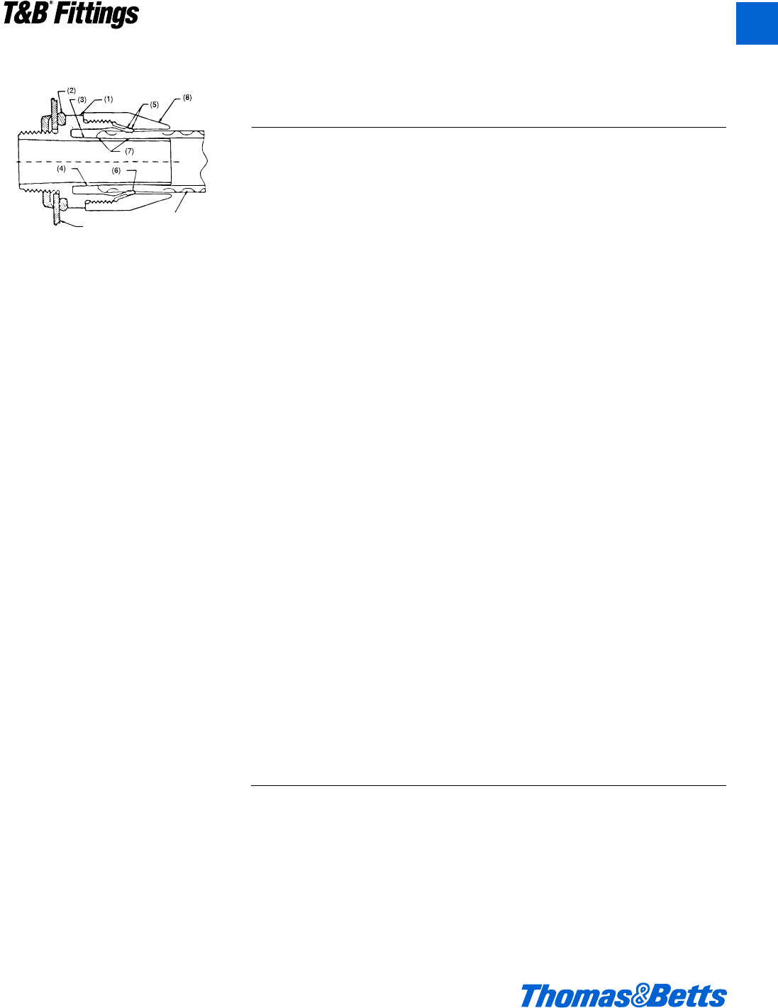
© 2002 Thomas & Betts Corporation. Specifications are subject to change without notice. www.tnb.com A133
T&B®Fittings
A
XTRAFLEX®System – Conduit, Tubing, Fittings for Nonmetallic Liquidtight Conduit
Specification Sheet – Bullet®Liquidtight Fittings or Liquidtight
Flexible Nonmetallic Conduit and Tubing
Box or
Enclosure
Wall
Conduit
or Tubing
Application
A series of non-metallic connectors
designed to provide a liquidtight seal
when terminating liquidtight non-metal-
lic conduit (U.L. Type B) or liquidtight
non-metallic tubing to a box or enclo-
sure with knockout opening or a
threaded hub.
Plastic Bullet®Liquidtight Fittings Feature
• Connector assembles to conduit
without disassembly and is designed
to be installed with a positive installa-
tion criteria (gland bottoms on body
shoulder).
• Rugged low profile non-metallic body
and gland construction (1); the con-
nector is equipped with a steel locknut
to firmly secure connector to box or an
enclosure and a sealing “O” ring.
• Captivated sealing “O” ring (2) with
predetermined compression for a reli-
able seal at enclosure.
• Connector ferrule designed to accept
variations in conduit inside diameter
and is tolerant of field conduit cuts (3).
• The profile of ferrule is designed to
reduce friction between conduit I.D.
and ferrule (4) allowing conduit to
seat properly for an effective seal.
• Outer surface of the clamping fingers
provided with friction reducing ridges
(5) for ease of installation; the inner
surface is designed with conduit bit-
ing teeth to enhance clamping and
sealing action (6).
• Performance of connectors tested to
simulate adverse installation conditions.
• Provides a double sealing action (7).
• Elongated gland nut profile (8) de-
signed to provide additional strain relief
for 90° pull and an easy hand grip.
• Performance of connector unaffected
by exposure to detergents, cleaners,
and sanitizers commonly encoun-
tered in food processing plants and
typical industrial environment; also
unaffected by cutting fluids, wiring
pulling compounds and Marine envi-
ronment. The connector meets indus-
try standards for cold impact and
simulated hammer blow.
Standard Material/Finish
• Body Gland – weather stabilized ther-
moplastic (black).
• “O” Ring – nitrile (blue).
• Locknut – Steel/electro zinc plated.
• Material temperature rating – thermo-
plastic -40°C to 105°C.
• Material Flammability Rating:
U.L. 94-V2.
Listed/Certified by:
U.L. (File# E23018);
CSA (File# LR52391)
Conforms to:
• CSA 22.2 #227.2 & CSA 22.2 #227.3
• ANSI/U.L.514B-1988
• Watertight requirements of NEMA
Type 4 and NEMA Type 6 enclosures.
• Federal Standard H28 (NPT threads).
• Suitable for hazardous locations –
Class I Div. 2; Class II Div. 1 & 2;
Groups E,F, & G; Class III per N.E.C.;
Article 501-4, 502-4 and 503-3.
Suggested Specification:
Where liquidtight flexible nonmetallic conduit (U.L. Type B) or liquidtight flexible nonmetallic
tubing is terminated to a box or enclosure, the nonmetallic connectors used shall be able to
be installed without disassembly and provide a positive installation criteria. In the installed
condition, the connector must provide a seal meeting watertight requirements of NEMA Type
4 and Type 6 enclosures. The performance of connectors shall be unaffected by exposure to
detergents, sanitizers, cutting fluids, wire pulling compounds and oil base industrial paints.
The connector must also be capable of withstanding Marine environment and cold impact
simulating a hammer blow. Installed connectors shall be of the elongated gland type as
manufactured by Thomas & Betts LT38P series.
412031.A02 FIT 3/5 3/13/03 4:56 PM Page 133
A134 © 2002 Thomas & Betts Corporation. Specifications are subject to change without notice. www.tnb.com
A
T&B®Fittings
Table 2 – Behavior of EMS20-1B.1 IN: Acids,
Bases, Halogens, etc.
Reagent Temp °F Visual Change Ratings*
Sulfuric Acid (Conc) 75 Dissolves S, NR
Sulfuric Acid (Dilute) 75 Partially dissolves P, NR
Hydrochloric Acid (Conc) 75 Dissolves S, NR
Hydrochloric Acid (Dilute) 75 Partially dissolves P, NR
Hydrochloric Acid (20-40%) 73 Etched after 1 sec. P
Phosphoric Acid (Conc) 75 Dissolves S, NR
Nitric Acid (Conc) 75 Dissolves S, NR
Acetic Acid (Conc) 75 Partially Dissolves P, NR
Acetic Acid (Conc) 200 Dissolves S, NR
Acetic Acid (Dilute) 75 Etched F, NR
Formic Acid (Conc) 75 Dissolves S, NR
Formic Acid (Dilute) 75 Partially Dissolves P, NR
Chlorine – Strong Attack NR
Bromine – Strong Attack NR
Phenol 75 Dissolves S, NR
O-Chlorophenol 75 Dissolves S, NR
m-Chlorophenol 75 Dissolves S, NR
p-Chlorophenol 75 Dissolves S, NR
Cresol 75 Dissolves S, NR
Dimethylformamide 75 Strong Attack NR
gamma-Butyrolactone 75 Strong Attack NR
Xylenols 75 Dissolves S, NR
Sodium Hydroxide (1%) 73 Unchanged E
Sodium Hydroxide (5%) 73 Minimal effect E
Sodium Hydroxide (5%) 158 Minimal effect E
Sodium Hydroxide (10%) 73 Minimal effect E
Sodium Hydroxide (10%) 158 Some “crazing” after 30 days P
Potassium Hydroxide (5%) 73 Minimal effect E
Potassium Hydroxide (5%) 158 Minimal effect E
Potassium Hydroxide (10%) 73 Minimal effect E
Potassium Hydroxide (10%) 158 Some “crazing” after 30 days P
Hydrogen Peroxide (0.5%) 73 Unchanged G
Hydrogen Peroxide (1%) 73 Brittle after 54 days NR
Hydrogen Peroxide (3%) 73 Brittle after 54 days NR
Hydrogen Peroxide (10%) 73 Degrades NR
Hydrogen Peroxide (30%) 73 Degrades NR
* These abbreviations are used for the ratings:
E- Excellent P- Poor
G- Good NR- Not Recommended
F- Fair S- Solvent
Table 1 – Behavior of EMS20-1B.1 IN: Aqueous Solutions of Inorganic Salts at Room Temperature
Salt Solutions Visual Change Ratings*
10% Ammonium Chloride Unchanged F
10% Aluminum Chloride Unchanged F
10% Sodium Hypochlorite (0.1% Cl2)White coating after 18 days G
10% Calcium Chloride Unchanged F
10% Chrome Alum Unchanged G
10% Ferric Chloride Unchanged yellowing P
5% Potassuim Dichromate Unchanged yellowing P
10% Potassium Nitrate Unchanged G
1% Potassium Permanganate Decomposed NR
10% Copper Sulfate Unchanged G
10% Magnesium Chloride Unchanged G
10% Magnanese Sulfate Unchanged G
10% Sodium Sulfate Unchanged G
10% Sodium Bisulfite Unchanged G
5% Mercuric Chloride Swelled P
10% Zinc Chloride Unchanged F
* These abbreviations are used for the ratings:
E- Excellent P- Poor
G- Good NR- Not Recommended
F- Fair S- Solvent
XTRAFLEX®System – Conduit, Tubing, Fittings for Nonmetallic Liquidtight Conduit
Table 3 – Behavior of EMS20-1B.1 IN:
Organic Solvents at Room Temperature
Reagent Visual Change Ratings*
Benzyl Alcohol Coarse surface after 2 days NR
Butyl Alcohol Temporary loss of stiffness G
Ethyl Alcohol Temporary loss of stiffness G
Isopropyl Alcohol Temporary loss of stiffness G
Methyl Alcohol Temporary loss of stiffness G
Butyl Acetate Temporary loss of stiffness G
Ethyl Acetate Unchanged E
Methyl Acetate Unchanged E
Amyl Acetate Unchanged E
Ether (Diethyl) Unchanged E
Tetrahydrofuran Unchanged E
Acetone Unchanged E
Benzaldyhyde Unchanged E
Cyclohexanone Unchanged E
Dichlorethylene Unchanged E
Trichlorethylene Temporary loss of stiffness G
Perchlorethylene Temporary loss of stiffness G
Dichlormethane Unchanged E
Chloroform Temporary loss of stiffness G
Carbon Tetrachloride Temporary loss of stiffness G
Carbon Disulfide Unchanged E
Pyridine Unchanged E
Benzene Unchanged E
Monochlorbenzene Unchanged E
Toluene Unchanged E
Xylene Unchanged E
Kerosene Unchanged E
Turpentine Unchanged E
Tetralin Unchanged E
Decalin Unchanged E
Gasoline Unchanged E
Petroleum Unchanged E
Mineral Oil Unchanged E
Resorcinol Dissolves NR
* These abbreviations are used for the ratings:
E- Excellent P- Poor
G- Good NR- Not Recommended
F- Fair S- Solvent
412031.A02 FIT 3/5 3/13/03 4:56 PM Page 134
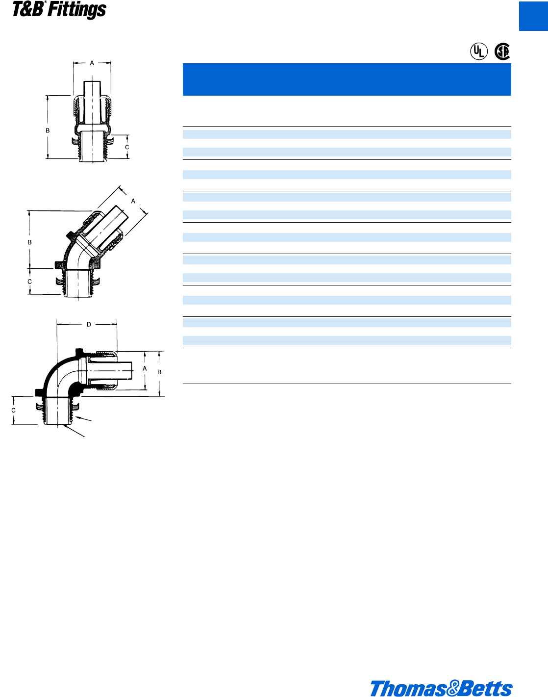
© 2002 Thomas & Betts Corporation. Specifications are subject to change without notice. www.tnb.com A135
T&B®Fittings
A
XTRAFLEX®System – Conduit, Tubing, Fittings for Nonmetallic Liquidtight Conduit
Figure 1
Metallic Bullet®Liquidtight Connectors for T&B LTC Nonmetallic
Liquidtight Conduit Type B and T&B EFC Flexible Tubing
Trade A ±.030 *B ±.060 C ±.045 Thread
Cat. Size (.80) (1.50) (1.15) D NPT
No. Fig. (in.) (in.) (mm) (in.) (mm) (in.) (mm) (in.) (mm) (in.)
LT38M 1 1.156 1.500 (38.1) 0.562 (14.3) –
LT438M 2c(29.4) 1.962 (49.8) 0.562 (14.3) d-14
LT938M 3 1.312 (33.3) 0.625 (15.9) 1.375 (34.9)
LT50M 1 1.375 1.562 (39.7) 0.562 (14.3) –
LT450M 2d(34.9) 1.875 (47.6) 0.562 (14.3) d-14
LT950M 3 1.437 (36.5) 0.625 (15.9) 1.562 (39.7)
LT75M 1 1.656 1.625 (41.2) 0.625 (15.9) –
LT475M 2f(42.1) 2.125 (54.0) 0.562 (14.3) f-14
LT975M 3 1.750 (44.4) 0.625 (15.9) 1.750 (44.4)
LT100M 1 1.875 2.062 (52.4) 0.750 (19.0) –
LT4100M 21(47.6) 2.250 (57.1) 0.812 (20.6) 1-11d
LT9100M 3 1.937 (49.2) 0.812 (20.6) 2.187 (55.5)
LT125M 1 2.375 2.500 (63.5) 0.812 (20.6) –
LT4125M 21b (60.3) 2.750 (69.8) 0.812 (20.6) 1b-11d
LT9125M 3 2.500 (63.5) 0.812 (20.6) 2.750 (69.8)
LT150M 1 2.750 2.687 (68.2) 0.812 (20.6) –
LT4150M 21d (69.8) 2.750 (69.8) 0.812 (20.6) 1d-11d
LT9150M 3 2.812 (71.4) 0.812 (20.6) 2.937 (74.6)
LT200M 1 3.468 3.062 (77.8) 0.812 (20.6) –
LT4200M 22(88.1) 3.875 (98.4) 0.875 (22.2) 2-11d
LT9200M 3 3.500 (88.9) 0.875 (22.2) 3.437 (87.3)
* After Assembly
U.L. File No. E-23018
CSA File No. 52391
Suggested Specification:
Where liquidtight flexible nonmetallic conduit (U.L. Type B) or liquidtight flexible nonmetallic
tubing is terminated to a box or enclosure, the metallic connectors used shall be able to be
installed without disassembly and provide a positive installation criteria. In the installed condi-
tion, the connector must provide a seal, meeting watertight requirements of NEMA Type 4 and
Type 6 enclosures with conduit and NEMA Type 4 enclosures with tubing. Installed connec-
tors shall be as manufactured by Thomas & Betts LT38M series.
Material: Body/Gland–Steel/MI
Insert–Nylon
NPT Thread
Figure 3
®
®
Figure 2
412031.A02 FIT 3/5 3/13/03 4:56 PM Page 135
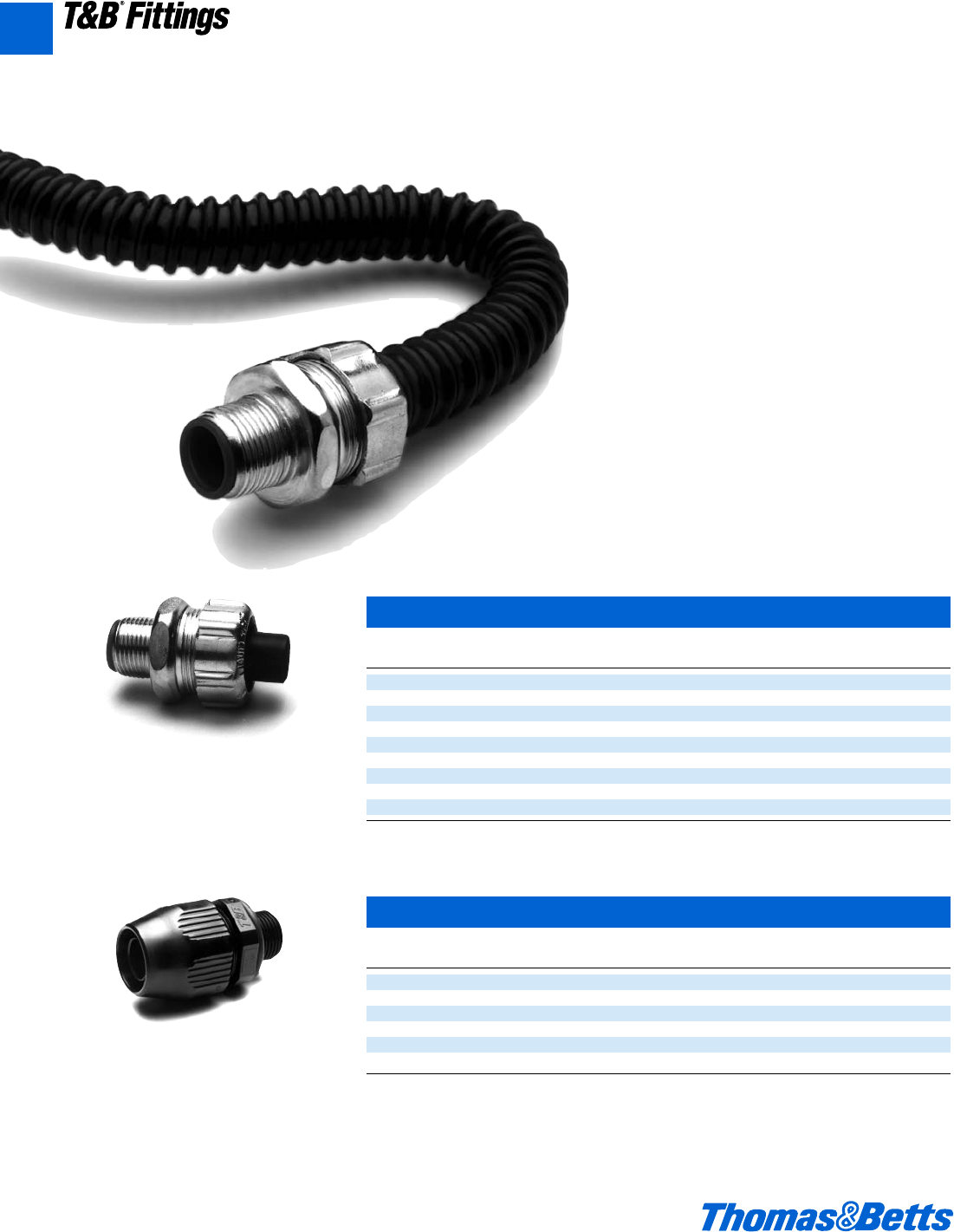
A136 © 2002 Thomas & Betts Corporation. Specifications are subject to change without notice. www.tnb.com
When you have a conduit application in a liquidtight environment, it's time to load up
the T&B Bullet®. Thomas & Betts introduces the ISO Metric Bullet®liquidtight fittings for
use with the c", d", and f" Xtraflex®EFC and LTC nonmetallic
liquidtight conduit series.
The T&B Bullet®liquidtight fitting and EFC non-metallic
conduit are suited for OEM applications as in the
machine tool industry where environments include
continuous motion, vibration, and exposure to mois-
ture, oil, dirt and dust.
The T&B Bullet®liquidtight fitting and LTC non-
metallic conduit are also suitable for construction
applications where ISO metric threading and liq-
uidtight systems are installed.
The Xtraflex®system offers a lightweight, liquidtight
flexible conduit solution for industrial applications. The
Xtraflex®system allows fast, easy installation and high per-
formance in demanding industrial applications.
XTRAFLEX®System – Conduit, Tubing, Fittings for Nonmetallic Liquidtight Conduit
Material – PVC
ISO Metric Bullet®Liquidtight Fitting
Cat. Angle Conduit Knockout Unit Standard UPC
No. of Fitting Size Size Package Package Number
LT38M-ISO20 Straight c" d" 25 100 786210-62281
LT50M-ISO20 Straight d" d" 25 100 786210-62282
LT75M-ISO25 Straight f" f" 25 50 786210-62283
LT438M-ISO20 45° c" d" 25 50 786210-62284
LT450M-ISO20 45° d" d" 25 50 786210-62285
LT475M-ISO25 45° f" f" 10 50 786210-62286
LT938M-ISO20 90° c" d" 25 50 786210-62288
LT950M-ISO20 90° d" d" 25 50 786210-62289
LT975M-ISO25 90° f" f" 10 50 786210-62290
*Meets watertight requirements of NEMA Type 4 enclosure or IP 56 rating with LTC conduit or EFC tubing with installed T&B Bullet liq-
uidtight fittings. Connector Locknut not included.
ISO Metric Bullet®Liquidtight Fitting Non-Metallic
Cat. Angle Conduit Knockout Unit Standard UPC
No. of Fitting Size Size Package Package Number
LT38P-ISO20 Straight c" d" 25 100 786210-66444
LT50P-ISO20 Straight d" d" 25 100 786210-66613
LT75P-ISO25 Straight f" f" 25 50 786210-66443
LT938P-ISO20 90° c" d" 25 50 786210-66612
LT950P-ISO20 90° d" d" 25 50 786210-66640
LT975M-ISO25 90° f" f" 10 50 786210-66611
*Testing: UL and CSA listed; NEMA 4, 6, 6P; IP 67 when used with LTC conduit or EFC tubing with installed T&B Bullet liquidtight fitting.
A
T&B®Fittings
412031.A02 FIT 3/5 3/13/03 4:56 PM Page 136
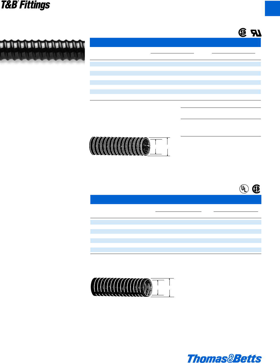
© 2002 Thomas & Betts Corporation. Specifications are subject to change without notice. www.tnb.com A137
T&B®Fittings
Commercial Grade Type B Nonmetallic Liquidtight Conduit
Cat. I.D. (in.) O.D. (in.)
No. Size min. max. min. max.
LTC038GY c" .484 .504 .690 .710
LTC050GY d" .622 .642 .820 .840
LTC075GY f" .820 .840 1.030 1.050
LTC100GY 1" 1.041 1.066 1.290 1.315
LTC125GY 1b" 1.380 1.410 1.630 1.660
LTC150GY 1d" 1.575 1.600 1.865 1.900
LTC200GY 2" 2.020 2.045 2.340 2.375
U.L. Listed, U.L. File No. 95745
CSA Certified, CSA File No. LL 80349
See technical tables on next page.
Corrugated Flexible Nonmetallic Tubing
Conduit I.D. (in.) O.D. (in.)
Cat. No. Size min. max. min. max.
EFC025* b" .390 .405 .560 .575
EFC038 c" .484 .504 .690 .710
EFC050 d" .622 .642 .820 .840
EFC075 f" .820 .840 1.030 1.050
EFC100 1" 1.041 1.066 1.290 1.315
EFC125 1b" 1.380 1.410 1.630 1.660
EFC150 1d" 1.575 1.600 1.865 1.900
EFC200 2" 2.020 2.045 2.340 2.375
* Not CSA Certified.
Underwriters Recognized
U.L. File No. 96548
CSA File No. 067241
See technical data next page.
Use with Bullet®Liquidtight Fittings.
Commercial Grade U.L./CSA Listed
• Gray color standard
• 80°C temperature rated
• UV resistant
• Material – PVC
O.D.
I.D.
XTRAFLEX®System – Conduit, Tubing, Fittings for Nonmetallic Liquidtight Conduit
Material – PVC
Available Colors
Cat. No. Color of
LTC – Conduit
w/o suffix Black
-1 Orange
-2 Blue
OEM Grade U.L. Recognized
• Material – PVC.
• Black color standard.
• Maximum flexibility in tight applications.
• Extremely fast installation.
• Liquidtight with specified fittings.
• Good tensile strength provides excellent pullout
protection.
• Smooth inner diameter allows easy wire pulling.
• Broad operating temperature range – 18°C to
+60°C (-2°F to +140°F).
• Flammability Rating VW-1 (Vertical Wire) UL224.
Recommended industrial applications
• Protection of fiber optic cable.
• Installation of instrumentation and control
cable.
• Indoor/outdoor lighting.
• Packaging equipment.
• Marine and shipboard wiring.
• Flexing – component wiring protection on
robots, graphic arts equipment, etc.
®
®
®
®
O.D
I.D.
A
412031.A02 FIT 3/5 3/13/03 4:56 PM Page 137
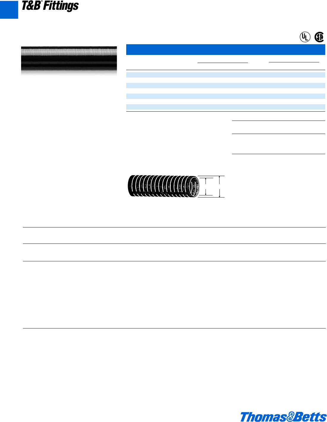
A138 © 2002 Thomas & Betts Corporation. Specifications are subject to change without notice. www.tnb.com
A
T&B®Fittings
XTRAFLEX®System – Conduit, Tubing, Fittings for Nonmetallic Liquidtight Conduit
Material – PVC
XTRAFLEX®Conduit and Tubing Technical Data*
LTFNMC = Liquidtight flexible nonmetallic conduit.
LTFNMT = Liquidtight flexible nonmetallic tubing.
Xtraflex®
Conduit & Size U.L. Temp CSA Temp Voltage U.L. Oil U.L. U.L. Direct
Tubing Style Color Range Rating Rating Rating Resistant Outdoor Burial
LTC038 Series UL Type B Black c"-2" 105°C Dry 75°C-18 C 600V Yes Yes Yes
LTFNMC Black 60°C Wet
70°C Oil
LTC038-1, -2 UL Type B Orange, d"-1" 105°C Dry – 600V Yes No Yes
Series LTFNMC Blue 60°C Wet
70°C Oil
LTC038GY UL Type B Grey c"-2" 80°C Dry – 600V Yes Yes Yes
Series LTFNMC 60°C Wet
70°C Oil
EFC025 Series** LTFNMT Black b"-2" 105°C 75°C-18 C 300V Yes Yes No
EFC025-1, -2** LTFNMT Orange, d"-1" 105°C – 300V Yes No No
Series Blue
* For a complete test report, contact Customer Service.
** U.L. Component Recognized
Industrial Grade U.L./CSA Listed
• Material – PVC.
• Liquidtight nonmetallic conduit Type B.
• Black color standard.
• Fast installation – even in tight, cramped
spaces.
• Smooth inner diameter allows easy wire
pulling.
• Smooth outer jacket – uses material approved
for outdoor use, is sunlight resistant and oil
resistant.
• Tested to CSA and U.L. requirements.
• Lightweight and liquidtight.
• Temperature range of -18°C to +105°C
(-2°F to +221°F).
• Flammability Rating – UL1660.
• Marked at one-foot intervals for fast, easy
measuring and cutting.
Recommended industrial applications
• Machine tools.
• Motor hookups.
• Food processing equipment.
• Extensions from wireways.
• Sensor and microswitch wiring found in
control consoles.
Smooth Liquidtight Nonmetallic Conduit Type B
Conduit I.D. (in.) O.D. (in.)
Cat. No. Size min. max. min. max.
LTC038 c" .484 .504 .690 .710
LTC050 d" .622 .642 .820 .840
LTC075 f" .820 .840 1.030 1.050
LTC100 1" 1.041 1.066 1.290 1.315
LTC125 1b" 1.380 1.410 1.630 1.660
LTC150 1d" 1.575 1.600 1.865 1.900
LTC200 2" 2.020 2.045 2.340 2.375
Rated at 600V
XTRAFLEX®Type B suitable for use in hazardous location (for LTC
Series only) where general purpose equipment is specifically permitted
by the NEC; Class I Div. 2; Class II, Div. 1 & 2; Class III, Div. 1 & 2,
NEC 501-4(b); 502-4(a)(b); 503-3(a)(b).
U.L. Listed, U.L. File No. E95745
CSA Certified, CSA File No. LL80349
See technical data below.
Use with Bullet®Liquidtight Fittings.
Available Colors
Cat. No. Color of Color of
LTC – Conduit Marking
w/o suffix Black Orange
-1 Orange Black
-2 Blue Black
®
®
O.D.
I.D.
412031.A02 FIT 3/5 3/13/03 4:56 PM Page 138

© 2002 Thomas & Betts Corporation. Specifications are subject to change without notice. www.tnb.com A139
T&B®Fittings
A
XTRAFLEX®System – Conduit, Tubing, Fittings for Nonmetallic Liquidtight Conduit
Material – PVC
XTRAFLEX®Nonmetallic Conduit Type B and Flexible Tubing
A = Satisfactory B = Be Expected to Change C = Not Recommended
Chemical Chemical Chemical
Acetate Solvents . . . . . . . . . . . . . . . . . . . . . . . . C Cottonseed Oil . . . . . . . . . . . . . . . . . . . . . . . . . B Lubricating Oils . . . . . . . . . . . . . . . . . . . . . . . . . A
Acetic Acid (10%). . . . . . . . . . . . . . . . . . . . . . . A Creosote. . . . . . . . . . . . . . . . . . . . . . . . . . . . . . C Magnesium Chloride . . . . . . . . . . . . . . . . . . . . . A
Acetic Acid (Glacial) . . . . . . . . . . . . . . . . . . . . . B Cresol . . . . . . . . . . . . . . . . . . . . . . . . . . . . . . . . A Magnesium Hydroxide. . . . . . . . . . . . . . . . . . . . A
Acetone . . . . . . . . . . . . . . . . . . . . . . . . . . . . . . C Cresylic Acid . . . . . . . . . . . . . . . . . . . . . . . . . . C Magnesium Sulphate. . . . . . . . . . . . . . . . . . . . . A
Acrylonitrile . . . . . . . . . . . . . . . . . . . . . . . . . . . A Cyclohexane . . . . . . . . . . . . . . . . . . . . . . . . . . . A Malic Acid . . . . . . . . . . . . . . . . . . . . . . . . . . . . . A
Adipic Acid . . . . . . . . . . . . . . . . . . . . . . . . . . . . A Cyclohexanone. . . . . . . . . . . . . . . . . . . . . . . . . C Methyl Acetate. . . . . . . . . . . . . . . . . . . . . . . . . . C
Alcohol Butyl . . . . . . . . . . . . . . . . . . . . . . . . . . A DDT Weed Killer . . . . . . . . . . . . . . . . . . . . . . . . A Methyl Bromide. . . . . . . . . . . . . . . . . . . . . . . . . C
Alcohol Ethyl . . . . . . . . . . . . . . . . . . . . . . . . . . A Detergent Synthetic. . . . . . . . . . . . . . . . . . . . . . A Methyl Ethyl Ketone. . . . . . . . . . . . . . . . . . . . . . C
Alcohol Isopropyl . . . . . . . . . . . . . . . . . . . . . . . A Developers Photographic . . . . . . . . . . . . . . . . . A Methylene Chloride. . . . . . . . . . . . . . . . . . . . . . C
Alcohol Methyl . . . . . . . . . . . . . . . . . . . . . . . . . A Dextrin . . . . . . . . . . . . . . . . . . . . . . . . . . . . . . . A Mineral Oils. . . . . . . . . . . . . . . . . . . . . . . . . . . . A
Aluminum Acetate. . . . . . . . . . . . . . . . . . . . . . . A Dextrose . . . . . . . . . . . . . . . . . . . . . . . . . . . . . . A Monochlorobenzene . . . . . . . . . . . . . . . . . . . . . C
Aluminum Chloride . . . . . . . . . . . . . . . . . . . . . A Dibutyle Phthalate . . . . . . . . . . . . . . . . . . . . . . C Naphtha . . . . . . . . . . . . . . . . . . . . . . . . . . . . . . . B
Aluminum Hydroxide . . . . . . . . . . . . . . . . . . . . A Dichlorobenzene. . . . . . . . . . . . . . . . . . . . . . . . C Naphthalene . . . . . . . . . . . . . . . . . . . . . . . . . . . C
Aluminum Sulfate . . . . . . . . . . . . . . . . . . . . . . . A Diesel Oil . . . . . . . . . . . . . . . . . . . . . . . . . . . . . B Nitric Acid (10%). . . . . . . . . . . . . . . . . . . . . . . . A
Aliyl Chloride . . . . . . . . . . . . . . . . . . . . . . . . . . C Diethylene Glycol . . . . . . . . . . . . . . . . . . . . . . . A Nitric Acid (40%). . . . . . . . . . . . . . . . . . . . . . . . A
Ammonia (0.88S.G.Aqueous) . . . . . . . . . . . . . . A Diethyl Ether. . . . . . . . . . . . . . . . . . . . . . . . . . . C Nitric Acid (70%) . . . . . . . . . . . . . . . . . . . . . . . C
Ammonia (Dry Gas) . . . . . . . . . . . . . . . . . . . . . A Di-isodecyl Phthalate . . . . . . . . . . . . . . . . . . . . C Nitrobenzene . . . . . . . . . . . . . . . . . . . . . . . . . . . C
Ammonia (Liquid) . . . . . . . . . . . . . . . . . . . . . . C Dioctyle Phthalate. . . . . . . . . . . . . . . . . . . . . . . C Nitrogen Fertilizers . . . . . . . . . . . . . . . . . . . . . . A
Ammonium Chloride . . . . . . . . . . . . . . . . . . . . A Emulsifiers . . . . . . . . . . . . . . . . . . . . . . . . . . . . A Oleic Acid . . . . . . . . . . . . . . . . . . . . . . . . . . . . . A
Ammonium Hydroxide . . . . . . . . . . . . . . . . . . . A Emulsions Photographic. . . . . . . . . . . . . . . . . . A Oxalic Acid . . . . . . . . . . . . . . . . . . . . . . . . . . . . A
Animal Oils. . . . . . . . . . . . . . . . . . . . . . . . . . . . A Ethyl Acetate. . . . . . . . . . . . . . . . . . . . . . . . . . . C Palmitic Acid . . . . . . . . . . . . . . . . . . . . . . . . . . . A
Amyl Acetate. . . . . . . . . . . . . . . . . . . . . . . . . . . C Ethylene Dichloride . . . . . . . . . . . . . . . . . . . . . C Paraffin . . . . . . . . . . . . . . . . . . . . . . . . . . . . . . . A
Aniline Oils. . . . . . . . . . . . . . . . . . . . . . . . . . . . B Ethylene Glycol. . . . . . . . . . . . . . . . . . . . . . . . . A Pentane . . . . . . . . . . . . . . . . . . . . . . . . . . . . . . . B
Aromatic Hydrocarbons . . . . . . . . . . . . . . . . . . C Fatty Acid . . . . . . . . . . . . . . . . . . . . . . . . . . . . . A Perchloroethylene . . . . . . . . . . . . . . . . . . . . . . . C
Asphalt . . . . . . . . . . . . . . . . . . . . . . . . . . . . . . . C Ferric Chloride . . . . . . . . . . . . . . . . . . . . . . . . . A Phenol . . . . . . . . . . . . . . . . . . . . . . . . . . . . . . . . B
ASTM Fuel A . . . . . . . . . . . . . . . . . . . . . . . . . . B Ferric Sulphate . . . . . . . . . . . . . . . . . . . . . . . . . A Phosphoric Acid . . . . . . . . . . . . . . . . . . . . . . . . A
ASTM Fuel B . . . . . . . . . . . . . . . . . . . . . . . . . . C Ferrous Chloride. . . . . . . . . . . . . . . . . . . . . . . . A Pitch . . . . . . . . . . . . . . . . . . . . . . . . . . . . . . . . . A
ASTM #1 Oil. . . . . . . . . . . . . . . . . . . . . . . . . . . A Ferrous Sulphate . . . . . . . . . . . . . . . . . . . . . . . A Potassium Hydroxide. . . . . . . . . . . . . . . . . . . . . A
ASTM #3 Oil. . . . . . . . . . . . . . . . . . . . . . . . . . . B Fixing Solution Photographic . . . . . . . . . . . . . . A Propane . . . . . . . . . . . . . . . . . . . . . . . . . . . . . . . A
Barium Chloride . . . . . . . . . . . . . . . . . . . . . . . . A Fluorine . . . . . . . . . . . . . . . . . . . . . . . . . . . . . . C Sea Water . . . . . . . . . . . . . . . . . . . . . . . . . . . . . A
Barium Hydroxide. . . . . . . . . . . . . . . . . . . . . . . A Formaldehyde (40%) . . . . . . . . . . . . . . . . . . . . C Sodium Hydroxide (10%) . . . . . . . . . . . . . . . . . A
Barium Sulfide . . . . . . . . . . . . . . . . . . . . . . . . . A Formic Acid (40%) . . . . . . . . . . . . . . . . . . . . . . A Sodium Hydroxide (50%) . . . . . . . . . . . . . . . . . A
Benzene . . . . . . . . . . . . . . . . . . . . . . . . . . . . . . C Formic Acid (50%) . . . . . . . . . . . . . . . . . . . . . . B Sodium Cyanide . . . . . . . . . . . . . . . . . . . . . . . . A
Benzine. . . . . . . . . . . . . . . . . . . . . . . . . . . . . . . B Formic Acid (100%). . . . . . . . . . . . . . . . . . . . . C Soybean Oil . . . . . . . . . . . . . . . . . . . . . . . . . . . . A
Bordeaux Mixture . . . . . . . . . . . . . . . . . . . . . . . A Fuel Oil . . . . . . . . . . . . . . . . . . . . . . . . . . . . . . . B Stearic Acid . . . . . . . . . . . . . . . . . . . . . . . . . . . . A
Borax . . . . . . . . . . . . . . . . . . . . . . . . . . . . . . . . A Glacial Acetic Acid . . . . . . . . . . . . . . . . . . . . . . B Styrene . . . . . . . . . . . . . . . . . . . . . . . . . . . . . . . C
Boric Acid. . . . . . . . . . . . . . . . . . . . . . . . . . . . . A Glucose . . . . . . . . . . . . . . . . . . . . . . . . . . . . . . A Sulphur Dioxide (Dry) . . . . . . . . . . . . . . . . . . . . A
Brine. . . . . . . . . . . . . . . . . . . . . . . . . . . . . . . . . A Glycerine . . . . . . . . . . . . . . . . . . . . . . . . . . . . . A Sulphur Dioxide (Moist) . . . . . . . . . . . . . . . . . . B
Bromine Traces. . . . . . . . . . . . . . . . . . . . . . . . . C Grape Sugar . . . . . . . . . . . . . . . . . . . . . . . . . . . A Sulphur Dioxide (Liquid). . . . . . . . . . . . . . . . . . C
Butyl Acetate. . . . . . . . . . . . . . . . . . . . . . . . . . . C Grease . . . . . . . . . . . . . . . . . . . . . . . . . . . . . . . A Sulphuric Acid (45%) . . . . . . . . . . . . . . . . . . . . A
Calcium Hydroxide . . . . . . . . . . . . . . . . . . . . . . A Heptane . . . . . . . . . . . . . . . . . . . . . . . . . . . . . . B Sulphuric Acid (60%) . . . . . . . . . . . . . . . . . . . . B
Calcium Hypochlorite . . . . . . . . . . . . . . . . . . . . A Hexane . . . . . . . . . . . . . . . . . . . . . . . . . . . . . . . B Sulphuric Acid (98%) . . . . . . . . . . . . . . . . . . . . C
Carbonic Acid. . . . . . . . . . . . . . . . . . . . . . . . . . B Hydrobromic Acid. . . . . . . . . . . . . . . . . . . . . . . A Sulphurous Acid (30%). . . . . . . . . . . . . . . . . . . A
Carbon Dioxide. . . . . . . . . . . . . . . . . . . . . . . . . A Hydrochloric Acid (10%) . . . . . . . . . . . . . . . . . A Tannic Acid . . . . . . . . . . . . . . . . . . . . . . . . . . . . A
Carbon Disulphite . . . . . . . . . . . . . . . . . . . . . . C Hydrochloric Acid (40%) . . . . . . . . . . . . . . . . . A Tartaric Acid. . . . . . . . . . . . . . . . . . . . . . . . . . . . A
Carbon Monoxide. . . . . . . . . . . . . . . . . . . . . . . A Hydrofluoric Acid (10%). . . . . . . . . . . . . . . . . . A Tetrahydrofuran . . . . . . . . . . . . . . . . . . . . . . . . . C
Carbon Tetrachloride . . . . . . . . . . . . . . . . . . . . C Hydrofluoric Acid (40%). . . . . . . . . . . . . . . . . . B Toluene . . . . . . . . . . . . . . . . . . . . . . . . . . . . . . . C
Casein . . . . . . . . . . . . . . . . . . . . . . . . . . . . . . . A Hydrofluoboric Acid . . . . . . . . . . . . . . . . . . . . . A Trichlorethylene. . . . . . . . . . . . . . . . . . . . . . . . . C
Chlorine (Dry). . . . . . . . . . . . . . . . . . . . . . . . . . A Hydrofluosilicic Acid . . . . . . . . . . . . . . . . . . . . A Triethanolamine . . . . . . . . . . . . . . . . . . . . . . . . . A
Chlorine (Wet Gas) . . . . . . . . . . . . . . . . . . . . . . B Hydrogen Peroxide . . . . . . . . . . . . . . . . . . . . . . A Tricresyl Phosphate . . . . . . . . . . . . . . . . . . . . . . C
Chlorine (Water). . . . . . . . . . . . . . . . . . . . . . . . C Hydrogen Sulphide. . . . . . . . . . . . . . . . . . . . . . A Turpentine . . . . . . . . . . . . . . . . . . . . . . . . . . . . . B
Chlorobenzene . . . . . . . . . . . . . . . . . . . . . . . . . C Iso-octan . . . . . . . . . . . . . . . . . . . . . . . . . . . . . A Urea. . . . . . . . . . . . . . . . . . . . . . . . . . . . . . . . . . A
Chlorinated Hydrocarbons . . . . . . . . . . . . . . . . C Isopropyl Acetate . . . . . . . . . . . . . . . . . . . . . . . C Vinegar . . . . . . . . . . . . . . . . . . . . . . . . . . . . . . . A
Chloroform. . . . . . . . . . . . . . . . . . . . . . . . . . . . C Kerosene. . . . . . . . . . . . . . . . . . . . . . . . . . . . . . B Vinyl Acetate . . . . . . . . . . . . . . . . . . . . . . . . . . . C
Chromic Acid . . . . . . . . . . . . . . . . . . . . . . . . . . A Ketones . . . . . . . . . . . . . . . . . . . . . . . . . . . . . . C Vinyl Chloride . . . . . . . . . . . . . . . . . . . . . . . . . . C
Citric Acid. . . . . . . . . . . . . . . . . . . . . . . . . . . . . A Lactic Acid (10%). . . . . . . . . . . . . . . . . . . . . . . A Water . . . . . . . . . . . . . . . . . . . . . . . . . . . . . . . . . A
Coal Tar . . . . . . . . . . . . . . . . . . . . . . . . . . . . . . C Lactic Acid (100%). . . . . . . . . . . . . . . . . . . . . . C Xylene . . . . . . . . . . . . . . . . . . . . . . . . . . . . . . . . C
Copper Chloride . . . . . . . . . . . . . . . . . . . . . . . . A Lacquer Solvents . . . . . . . . . . . . . . . . . . . . . . . B Zinc Chloride. . . . . . . . . . . . . . . . . . . . . . . . . . . A
Copper Nitrate . . . . . . . . . . . . . . . . . . . . . . . . . A Linseed Oil . . . . . . . . . . . . . . . . . . . . . . . . . . . . A Zinc Sulphate. . . . . . . . . . . . . . . . . . . . . . . . . . . A
Copper Sulphate. . . . . . . . . . . . . . . . . . . . . . . . A
Note: These chemical resistance ratings are based upon information supplied by the raw material manufacturers. It is intended as a general guideline only. To determine specific suitability, samples should be
tested by user under actual conditions. Operating Condition: 70°F.
412031.A02 FIT 3/5 3/13/03 4:56 PM Page 139
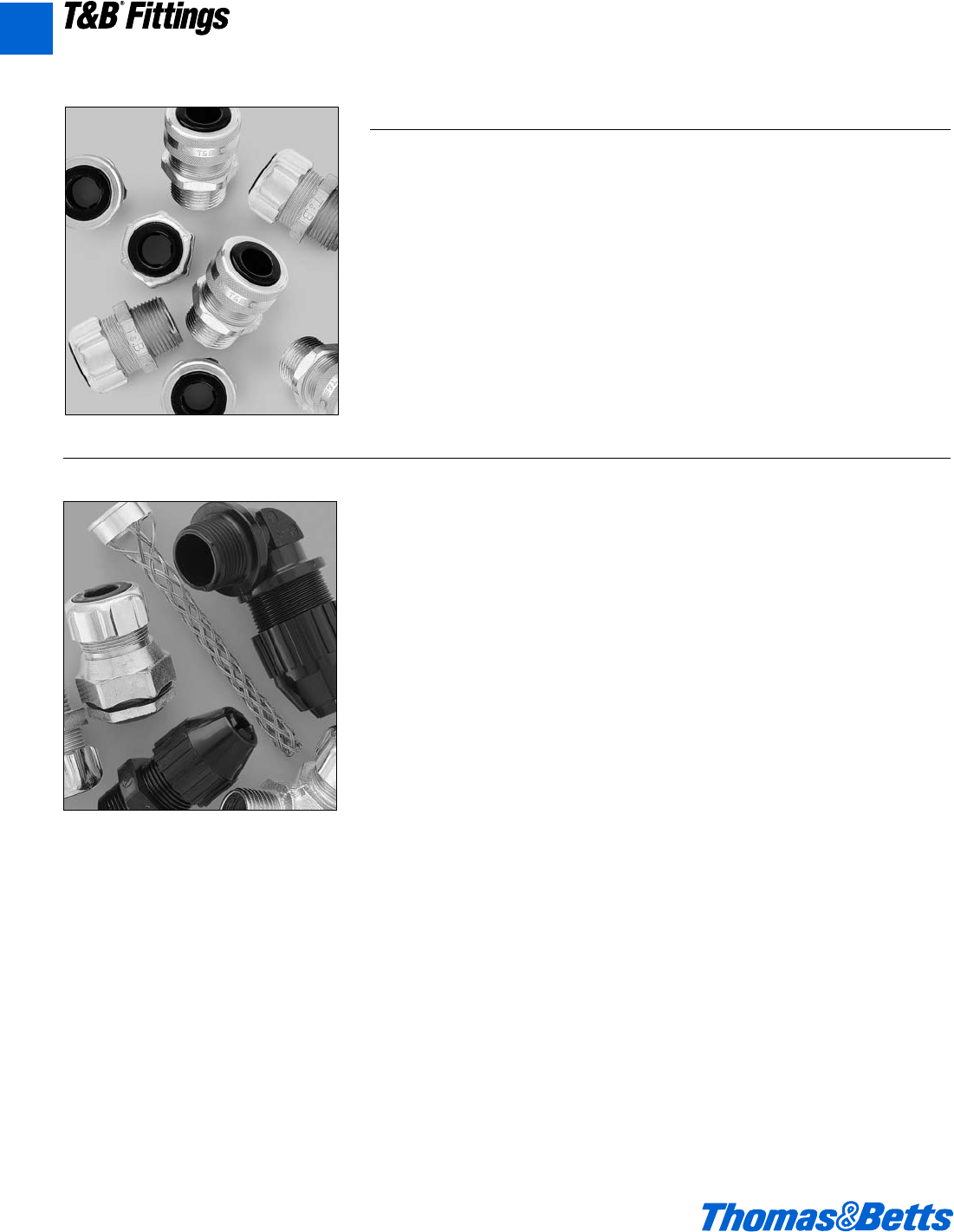
A140 © 2002 Thomas & Betts Corporation. Specifications are subject to change without notice. www.tnb.com
T&B®Fittings
Flexible Cords and Cable Fittings
Liquidtight Flexible Cord and Power
Cable Fittings
We also offer Liquidtight fittings
designed to handle the unique con-
nection demands of flexible cords
and power cables applications, where
exceptional mechanical strain relief is
needed in addition to a dependable
seal against dust, oil, and other liquids.
The patented design of our flexible
cord and power cable fittings are ideal
for installations such as robot manufac-
turers, packaging equipment, machine
tool building and other industrial OEM
and MRO applications.
The advantages these fittings offer
include:
• Neoprene bushing to make liquid-
tight installations by applying pres-
sure against the cable for the full
length of the bushing.
• CSA certified water tight, and U.L.
listed for liquid-tightness strain relief
and as an outlet bushing.
• Metal and plastic assemblies capable
of accepting a wide range of cords.
• Black Beauty™ non-metallic cord con-
nector offers the convenience of tool-
free installation, with a segmented
chuck for high mechanical pullout per-
formance, and neo-prene bushings for
a secure, liquid-tight installation.
Flexible Cord Connectors
The Ranger™ Series Cord Connector
Fittings
Our Ranger Liquidtight fittings are the
only connectors able to take a .250
inch cable range.
These unique connectors feature:
• Connectors which take twice the
cable range of ordinary strain relief
connectors.
• Smaller overall size which makes it
easy to fit into tight spaces.
• Gland nut design that restricts cable
bending.
• Choice of aluminum, steel and non-
metallic materials.
• Straight, 45° and 90° designs.
A
412031.A02 FIT 3/5 3/13/03 4:56 PM Page 140
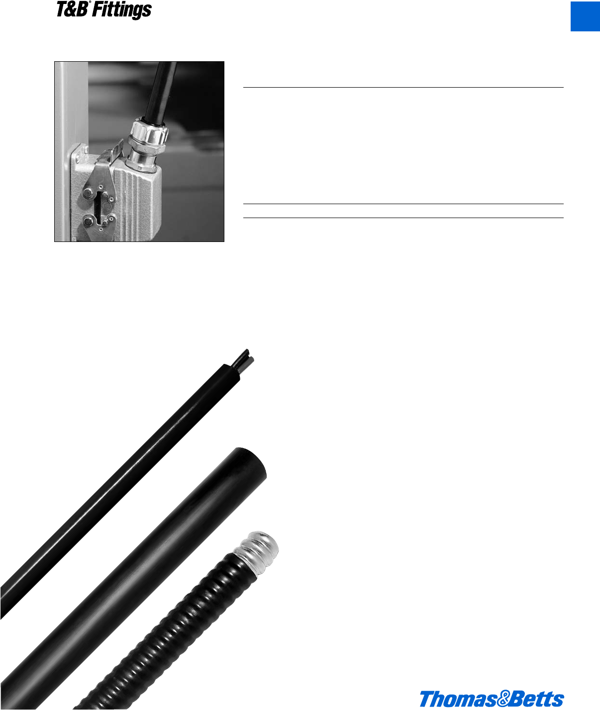
© 2002 Thomas & Betts Corporation. Specifications are subject to change without notice. www.tnb.com A141
T&B®Fittings
Whatever the application. Whatever the size. Thomas & Betts
is your connection to tough, versatile cord and cable fittings.
Thomas & Betts offers a complete line of rugged, reliable cord and cable fit-
tings. All fittings are produced to the highest standards, combining innovative
design and precision manufacturing methods to provide the products you need
for your specific applications. Combining proven performance, installation
advantages and availability of ranges, T&B is also your connection to lower
installed costs for the life of your cord and cable requirements.
Use this guide to help you specify the fitting you need for your cord and cable
requirements.
Cord and Cable Requirements
Cord and Cable Type T&B Fitting
S, SO, SV, ST, STD, SJ, Ranger™2920NM# Series, 2920# Series
SJO, SJT, SJTO, SVO Liquidtight Strain Relief 2500# Series
TC Tray Cable TC Series
JMC, MC Star®Teck Extreme™STE/STEX Series
S, SO, SV, ST, STD, SJ, Wire Mesh Grips WMG-PC Series
SJO, SJT, SJTO, SVO for Portable Cord
Considerations for Selection
• Selection of the proper device or fitting involves consideration of the type of
cable to be installed and the environment that will surround the cable
installation.
• A proper matching of the cable and its fitting is necessary to prevent
physical damage to the cable when installed.
Cord and Cable Descriptions
Type TC power and control tray cable is a factory assembly of two or more insulat-
ed conductors, with or without associated bare or covered grounding conductors
under a nonmetallic sheath, for installation in cable trays, in raceways, or where
supported by a messenger wire.
Type MC metal clad cable is a factory assembly of one or more insulated cir-
cuit conductors with or without optical-fiber members enclosed in a metallic
sheath of interlocking tape, or a smooth or corrugated tube.
Type SJ, tradename is Junior Hard Service Cord. The outer covering is
Thermoset and it is a pendant or portable cord used in damp locations for
hard usage.
Type SJO, tradename is Junior Hard Service Cord. The outer covering is
oil-resistant Thermoset.
Type SJT, tradename is Junior Hard Service Cord. The outer covering
is Thermoplastic.
Type SJTO, tradename is Junior Hard Service Cord. The outer covering is oil
resistant Thermoplastic.
Type SO, tradename is Hard Service Cord. The outer covering is oil-resistant
Thermoset and it is a pendant or portable cord used in damp locations for extra
hard usage.
Flexible Cords and Cable Fittings
A
412031.A02 FIT 3/5 3/13/03 4:56 PM Page 141
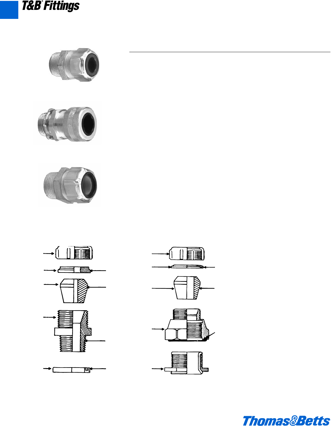
A142 © 2002 Thomas & Betts Corporation. Specifications are subject to change without notice. www.tnb.com
A
T&B®Fittings
Flexible Cords and Cable Fittings
Standard Material
Gland, Body ..Steel/Malleable Iron/Zinc
Die Cast
Retaining Ring ..............Thermoplastic/
Stainless Steel
Bushing.................................Neoprene
‘O’ Ring .....................................Buna N
Standard Finish
Electro Zinc Plated & Chromate
Coated
Range
2520 Series, straight .........125" outside
diameter to 3.200"
outside diameter Cord or Cable
2200 Series, 45°................125" outside
diameter to 1.485"
outside diameter Cord or Cable
2267 Series, 90°................125" outside
diameter to 1.875"
outside diameter Cord or Cable
Cord/Cable Type.............S, SO, SV, ST,
STO, SJ, SJO, SJT,
SJTO, SVO & SVT
Listed/Certified by:
U.L....................(U.L. File No. E-13938)
CSA ...........................LR-589, LR-4484
Conforms to:
U.L. 514
CSA 22.2 No. 18
ANSI C33.84, NFPA 70-1978 (ANSI)
Application
• A liquidtight connector to connect
flexible cord or cable to an enclosure
and provide adequate strain relief
Features
• Liquidtight connection with enclosure
is assured by:
(A) Taper threaded hub on 2520
series for female hub application
(B) Using sealing ring series 5262
with 2520 series for knockout
application
(C) Captivated sealing ‘O’ ring on
2631 series
(D) Neoprene bushing makes liq-
uidtight installation; applies pres-
sure against cable the full length
of bushing
(E) Thermoplastic or stainless steel
retaining ring
(1) Will not abrade cord/cable
jacket
(2) Reduces installing torque
effort
• U.L. Listed liquidtight, strain relief
and as an outlet bushing; CSA certi-
fied watertight
Gland
Retaining
Ring
Bushing
Body
Sealing
Gasket
(E)
(D)
(A)
(B)
2520 Series
Liquidtight Flexible Cord and Cable Connectors
2920 Series
2920AL Series
2516 Series
Gland
Retaining
Ring
Bushing
Body
Nipple
2631 Series
(E)
(D)
(C)
412031.A02 FIT 3/5 3/13/03 4:56 PM Page 142
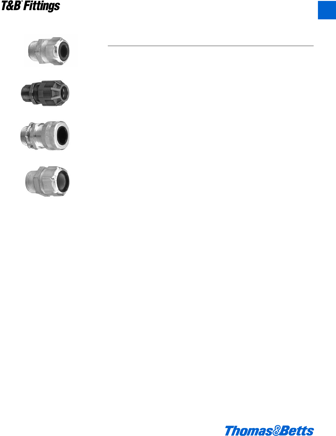
© 2002 Thomas & Betts Corporation. Specifications are subject to change without notice. www.tnb.com A143
T&B®Fittings
A
Flexible Cords and Cable Fittings
Suggested Specifications for Flexible Cord and Cable Fittings
• Flexible cord or cable and associat-
ed fittings shall be suitable for condi-
tions of use and location and
approved for the purpose by a
nationally recognized testing labora-
tory, inspection agency or product
evaluation organization.
• Flexible cord or cable shall be so
connected to the device or fitting that
tension will not be transmitted to
joints or terminal screws. Sufficient
slack shall be provided to avoid
sharp flexing and straining. Cord or
cable shall be installed in such a
manner that liquid will tend to run off
the surface instead of draining
towards the fitting.
• Where flexible cord or cable exposed
to intermittent or constant moisture
and subjected to mechanical strain is
terminated into a threaded or thread-
less opening, terminating fittings
shall be of watertight strain relief type
such as Thomas & Betts series 2920,
2920AL, 2920NM, 2520, 2631 or
2672. Fittings shall be equipped with
a beveled moisture resistant/oil resis-
tant synthetic rubber bushing.
• Where space is limited inside the
enclosure, a female hub type fitting
such as Thomas & Betts series 2631
shall be furnished. A captivated
resilient sealing ‘O’ ring shall be
included to positively protect against
damage from overtorquing.
2920 Series
2920NM Series
2920AL Series
2516 Series
412031.A02 FIT 3/5 3/13/03 4:56 PM Page 143
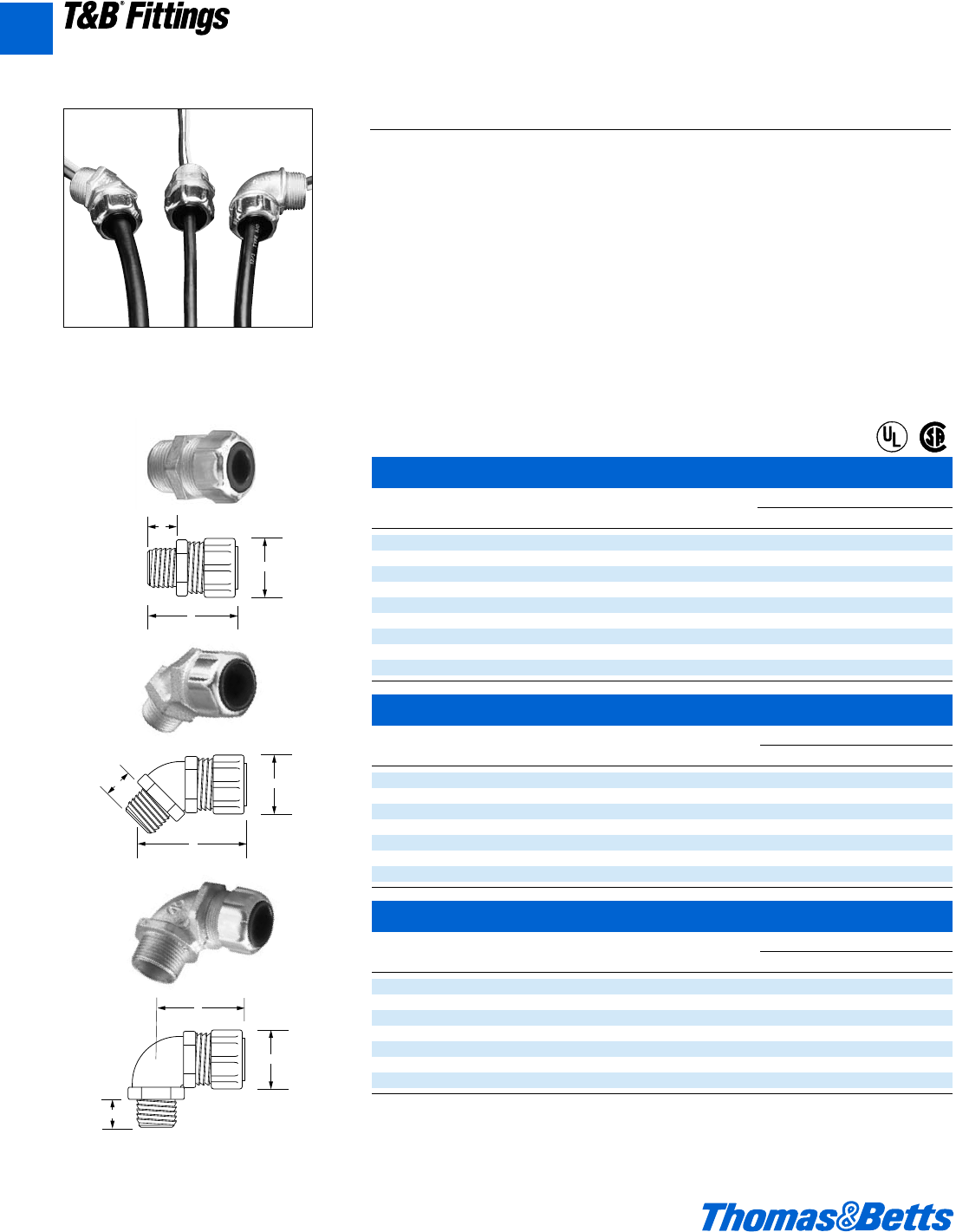
A144 © 2002 Thomas & Betts Corporation. Specifications are subject to change without notice. www.tnb.com
T&B®Fittings
Flexible Cords and Cable Fittings
Steel Liquidtight Strain Relief Connectors – straight
Cat. Hub Throat Dimensions (in.)
No. Size Dia. Cord Range A B C
2920 d l .125-.375 1a 1f e
2921 d l .310-.560 1a 1f e
2922 d l .500-.750 1c 1f e
2930 f m .125-.375 1c 1A f
2931 f m .310-.560 1c 1A f
2932 f m .500-.750 1c 1A f
2940 1 L .310-.560 1c 1f 1h
2941 1 L .500-.750 1c 1f 1h
2942 1 O .700-.950 1e 1g O
Steel Liquidtight Strain Relief Connectors – 45° angle
Cat. Hub Throat Dimensions (in.)
No. Size Dia. Cord Range A B C
4920 d F .125-.375 1a 1j l
4921 d F .310-.560 1a 1j l
4922 d F .500-.750 1c 1k l
4930 f A .125-.375 1c 1k e
4931 f A .310-.560 1c 1k e
4932 f A .500-.750 1c 1k e
4940 1 n .310-.560 1c 1w A
Steel Liquidtight Strain Relief Connectors – 90° angle
Cat. Hub Throat Dimensions (in.)
No. Size Dia. Cord Range A B C
4960 d x .125-.375 1a 1f e
4961 d x .310-.560 1a 1f e
4962 d x .500-.750 1c 1R e
4970 f A .125-.375 1c 1A L
4971 f A .310-.560 1c 1A L
4972 f A .500-.750 1c 1A L
4980 1 1 .310-.560 1c 2o m
All items shown on this page are suitable for use in hazardous locations where general purpose equipment is specifically permitted by the NEC.
NEC 501-4(b).
U.L. File No. E-13938
CSA File No. 52391
C
B
A
C
A
B
C
B
A
The Ranger™ Series of Steel Liquidtight Cord Connectors
The Ranger Series Steel Liquidtight Connector takes twice the cable range of most
ordinary strain relief connectors. T&B’s Ranger Connectors allow you to reduce
your inventory and save time, with one connector that can do the work of two.
Application
• Provide means for passing a cord cable
(armored or unarmored) into an enclosure,
through a bulkhead or into a rigid conduit.
• Form a mechanical grip and water and/or oil-
resistant seal for cord and unarmored or jack-
eted armored round cables.
• Form a non-slip connection or termination for
flexible cord, cable (armored or unarmored).
• Provide grounding continuity of cable armor.
Cord & Cable Type
• S, SO, SV, ST, STD, SJ, SJO, SJT, SJTO, SVD
Features
• Extended range with superior strain relief.
• Reduced overall size, fits into tighter spaces.
• Gland nut designed to restrict cable bending.
Materials
Body: Steel-2920 series, Malleable Iron-4920 &
4960 series
Gland Nut, Grip: Steel-all series
Bushing: Rubber
Environment Classification
• Ordinary Locations
• Wet or dry locations
Range
Cord Range .125" to .950"
Hub Size Range d" to 1"
®
®
For wire mesh grips refer to pages A119, A154.
A
412031.A02 FIT 3/5 3/13/03 4:56 PM Page 144
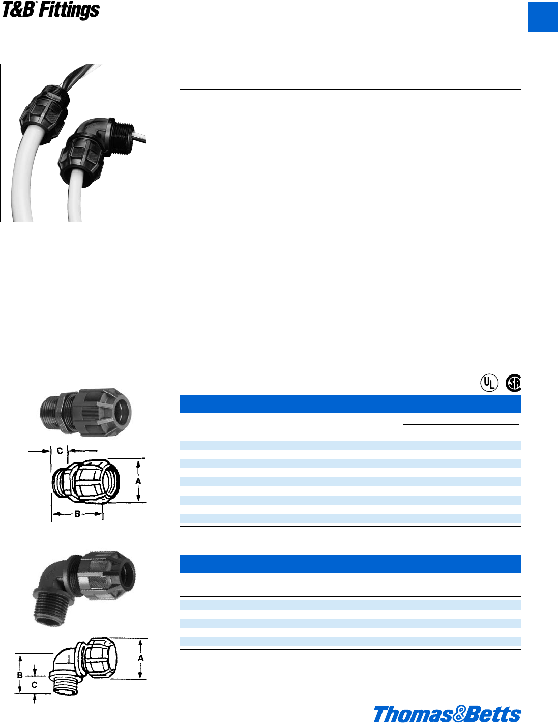
© 2002 Thomas & Betts Corporation. Specifications are subject to change without notice. www.tnb.com A145
T&B®Fittings
Flexible Cords and Cable Fittings
Nonmetallic Liquidtight Strain Relief Connector – straight
Cat. Trade or Throat Dimensions (in.)
No. Hub Size Dia. Cord Range A B C
2920NM d" .55 .125-.375 1r 2a e
2921NM d" .55 .310-.560 1r 2a e
2922NM d" .55 .500-.750 1u 2q e
2930NM f" .79 .125-.375 1u 2i e
2931NM f" .79 .310-.560 1u 2i e
2932NM f" .79 .500-.750 1u 2i e
2940NM 1" .98 .310-.560 1u 2X A
2941NM 1" .98 .500-.750 1u 2X A
2942NM 1" .98 .700-.950 1H 2c A
Nonmetallic Liquidtight Strain Relief Connector – 90° elbow
Cat. Trade or Throat Dimensions (in.)
No. Hub Size Dia. Cord Range A B C
4960NM d" .55 .125-.375 1r 1b e
4961NM d" .55 .310-.560 1r 1b e
4970NM f" .79 .125-.375 1u 1c e
4971NM f" .79 .310-.560 1u 1c e
4972NM f" .79 .500-.750 1u 1c e
U.L. File No. E 13938
CSA File No. 52391
Meets Coast Guard CG293
The Ranger™ Series of Nonmetallic Liquidtight
Cord Connectors
The Ranger Series Nonmetallic Liquidtight Cord Connector takes twice the cable
range of most ordinary strain relief connectors. T&B’s Ranger Connectors allow you
to reduce your inventory and save time, with one connector that can do the work of
two. The sturdy nylon material adds corrosion resistance to your installation.
Application
• Provide means for passing a cord
cable (armored or unarmored) into
an enclosure, through a bulkhead or
into a rigid conduit.
• Form a mechanical grip and water
and/or oil-resistant seal for cord and
unarmored or jacketed armored
round cables.
• Form a non-slip connection or termi-
nation for flexible cord, cable
(armored or unarmored).
• Provide grounding continuity of cable
armor.
Cord & Cable Type
• S, SO, SV, ST, STD, SJ, SJO, SJT,
SJTO, SVD
Features
• Extended range with superior strain relief.
• Reduced overall size, fits into tighter
spaces.
• Gland nut designed to restrict cable
bending.
Materials
Weather Stabilized Nylon, Temperature
rated -34°C to 105°C
Bushing: Rubber
Environment Classification
• Ordinary Locations
• Wet or dry locations
Range
Cord Range .Straight -.125" to .950"
90° -.125" to .750"
Hub Size Range Straight -d" to 1"
90° - d" to f"
®
®
A
412031.A02 FIT 3/5 3/13/03 4:56 PM Page 145
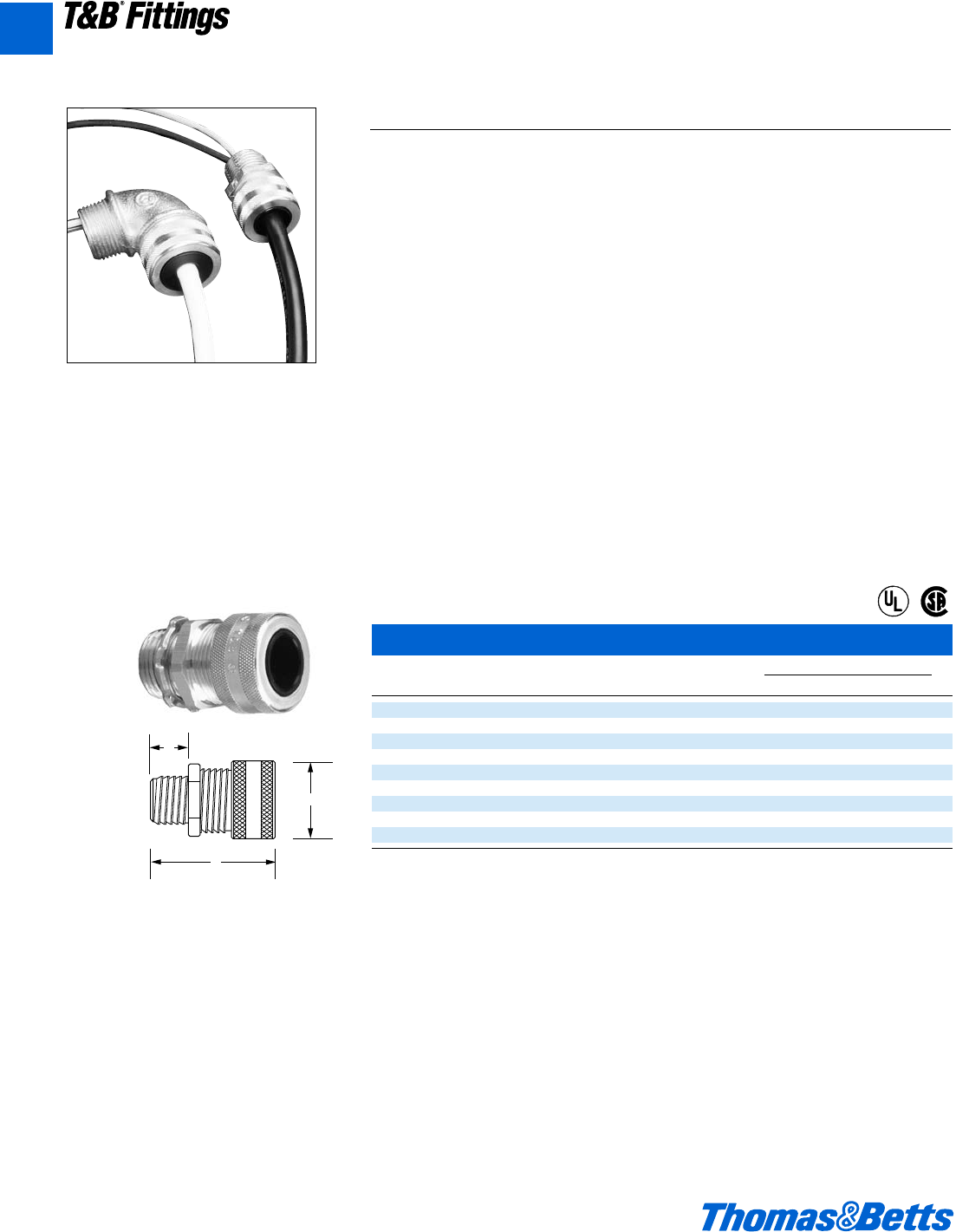
A146 © 2002 Thomas & Betts Corporation. Specifications are subject to change without notice. www.tnb.com
T&B®Fittings
Aluminum Liquidtight Strain Relief Connectors – straight
Cat. Hub Throat Dimensions (in.)
No. Size Dia. Cord Range A B C
2920AL d l .125-.375 1a 1f e
2921AL d l .310-.560 1a 1f e
2922AL* d l .500-.750 1j 1f e
2930AL f m .125-.375 1j 1A c
2931AL f m .310-.560 1j 1A f
2932AL f m .500-.750 1j 1A f
2940AL 1 L .310-.560 1j 1f 1h
2941AL 1 L .500-.750 1j 1f 1h
2942AL 1 O .700-.950 1l 1g O
For 1-2" Aluminum Strain Relief Connectors, see next page.
Flexible Cords and Cable Fittings
C
B
A
The Ranger™ Series of Aluminum Liquidtight Cord Connectors
The Ranger Series Aluminum Liquidtight Connector takes twice the cable range of
most ordinary strain relief connectors. T&B’s Ranger Connectors allow you to
reduce your inventory and save time, with one connector that can do the work of
two. The sturdy aluminum material adds corrosion resistance to your installation.
Application
• Provide means for passing a cord cable
(armored or unarmored) into an enclosure,
through a bulkhead or into a rigid conduit.
• Form a mechanical grip and water and/
or oil-resistant seal for cord and unar-
mored or jacketed armored round cables.
• Form a non-slip connection or termina-
tion for flexible cord, cable (armored or
unarmored).
• Provide grounding continuity of cable
armor.
Cord & Cable Type
• S, SO, SV, ST, STD, SJ, SJO, SJT, SJTO,
SVD
Features
• Extended range with superior strain relief.
• Reduced overall size, fits into tighter
spaces.
• Gland nut designed to restrict cable
bending.
Materials
Body: Aluminum
Gland Nut, Grip: Aluminum-all series
Bushing: Rubber
Environment Classification
• Ordinary Locations
• Wet or dry locations
Range
Cord Range .125" to .950"
Hub Size Range d" to 1"
®
®
A
412031.A02 FIT 3/5 3/13/03 4:57 PM Page 146
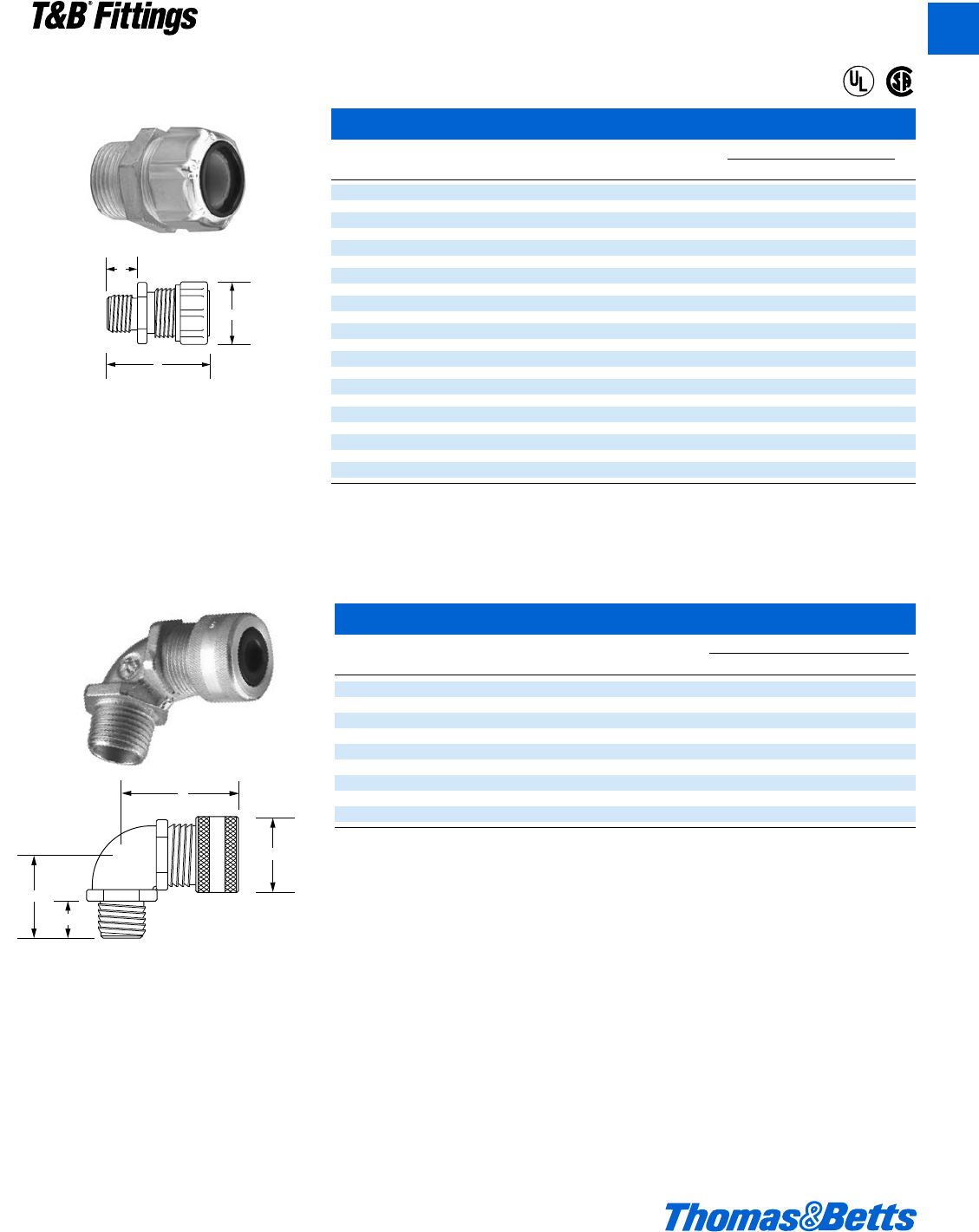
© 2002 Thomas & Betts Corporation. Specifications are subject to change without notice. www.tnb.com A147
T&B®Fittings
Flexible Cords and Cable Fittings
C
D
A
B
Aluminum Liquidtight Strain Relief Connectors – straight
Cat. Hub Throat Dimensions (in.)
No. Size Dia. Cord Range A B C
2541AL (.250-.375) 1" ?" 1L 1z l
2542AL (.375-.500) 1" ?" 1L 1z l
2544AL (.500-.625) 1" ?" 1L 1z l
2545AL (.625-.750) 1" ?" 1L 1z l
2546AL (.750-.880) 1" ©" 1L 1g l
2547AL (.875-.985) 1" ©" 1L 1g l
2548AL* (.880-1.065) 1" C" 2h 2c A
2549AL* (1.065-1.205) 1" C" 2h 2c A
2558AL (.880-1.065) 1b" 1å" 2a 2q e
2559AL (1.065-1.205) 1b" 1å" 2h 2q e
2556AL* (1.187-1.375) 1b" 1b" 2j 2d m
2557AL* (1.375-1.485) 1b" 1b" 2j 2d m
2562AL (.812-1.000) 1d" 1k" 2j 2d m
2563AL (1.000-1.187) 1d" 1k" 2j 2k L
2564AL (1.187-1.375) 1d" 1k" 2b 2k L
2565AL* (1.375-1.625) 1d" 1S" 2f 2e m
2573AL (1.125-1.375) 2" 1g" 2f 2e m
2574AL (1.375-1.625) 2" 1g" 2f 2e m
2575AL (1.625-1.875) 2" 1g" 2f 3d m
2576AL* (1.750-1.965) 2" 1C" 3r 3d m
2577AL* (1.937-2.187) 2" 1C" 3r 3d m
®
®
C
B
A
Aluminum Liquidtight Strain Relief Connectors – 90° elbow
Cat. Trade or Throat Dimensions (in.)
No. Hub Size Diam. Cord Range A B C D
4960AL d x .125-.375 1a 1f e 1j
4961AL d x .360-.560 1a 1f e 1j
4962AL* d x .500-.750 1j 1R e 1c
4970AL f A .125-.375 1j 1A L 1v
4971AL f A .310-.560 1j 1A L 1v
4972AL f A .500-.750 1j 1A L 1v
4980AL 1 1 .310-.560 1j 2o m 1f
4981AL 1 1 .500-.750 1j 2o m 1f
4982AL 1 1 .700-.950 1l 2L m 2
* It may be necessary to remove sufficient outer covering of cable to permit conductors to pass through connector body.
All items shown on this page are suitable for use in hazardous locations where general purpose equipment is specifically permitted by
the NEC. NEC 501-4(b).
U.L. File No. E-13938
CSA File No. 52391
For wire mesh grips refer to pages A119, A154.
A
412031.A02 FIT 3/5 3/13/03 4:57 PM Page 147
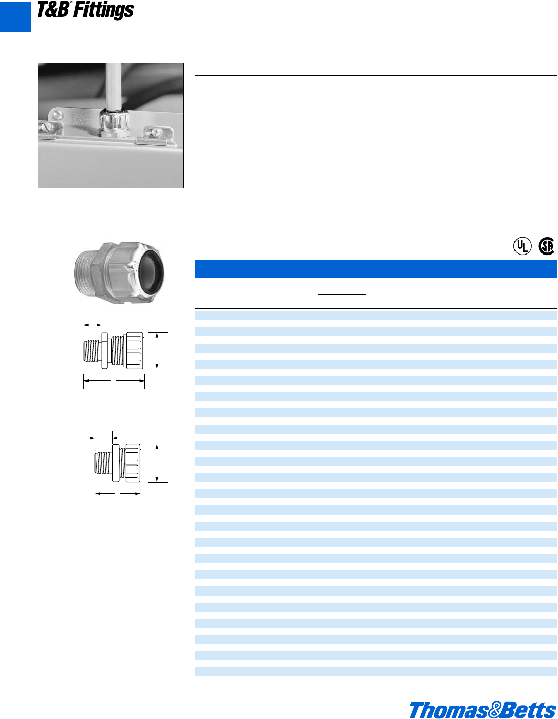
A148 © 2002 Thomas & Betts Corporation. Specifications are subject to change without notice. www.tnb.com
T&B®Fittings
Flexible Cords and Cable Fittings
Liquidtight Strain Relief Connectors
Cable Size Throat Dimensions (in.) Bushing Gland-Nut Retainer Body
Cat. Range Hub Dia. Part Model Model Model
No. min.-max. Size (min.) Fig. A B C No. No. No. No.
2516† (.060-.125) b" R" 2 E 1k v 035-73377-5 035-73377-3 035-73377-9 035-73377-1
2517† (.120-.250) b" R" 2 $ 1k v 035-73377-6 035-73377-3 035-73377-9 035-73377-1
2518† (.060-.150) c" S" 2 O 1d v 035-73377-7 035-73377-4 035-73377-9 035-73377-2
2519† (.150-.300) c" S" 2 O 1d v 035-73377-8 035-73377-4 035-73377-9 035-73377-2
2520 (.125-.250) d" l" 1 1y e 053-71411-1 053-71411-37 035-72735-1 053-71411-43
2521 (.250-.375) d" l" 1 1a 1y e 053-71411-2 053-71411-37 035-72735-1 053-71411-43
2522 (.375-.500) d" l" 1 1a 1y e 053-71411-3 053-71411-37 035-72735-2 053-71411-43
2523 (.450-.560) d" l" 1 1a 1y e 053-71411-4 053-71411-37 035-72735-2 053-71411-43
2524* (.500-.625) d" e" 1 1c 1f e 053-71411-59 053-71411-38 035-72735-3 033-72259-21
2525* (.625-.750) d" e" 1 1c 1f e 053-71411-60 053-71411-38 035-72735-3 033-72259-21
2530 (.125-.250) f" m" 1 1c 1f l 033-72259-1 053-71411-38 035-72735-4 053-71411-44
2531 (.250-.375) f" m" 1 1c 1f l 053-71411-5 053-71411-38 035-72735-4 053-71411-44
2532 (.375-.500) f" m" 1 1c 1f l 053-71411-58 053-71411-38 035-72735-4 053-71411-44
2534 (.500-.625) f" m" 1 1c 1f l 053-71411-59 053-71411-38 035-72735-3 053-71411-44
2535 (.625-.750) f" m" 1 1c 1f l 053-71411-60 053-71411-38 035-72735-3 053-71411-44
2536* (.750-.880) f" f" 1 1c 1n e 053-71411-61 053-71411-39 035-72735-5 033-72259-22
2541 (.250-.375) 1" ?" 1 1L 1z l 053-71411-5 053-71411-38 035-72735-4 053-71411-45
2542 (.375-.500) 1" ?" 1 1L 1z l 053-71411-58 053-71411-38 035-72735-4 053-71411-45
2544 (.500-.625) 1" ?" 1 1L 1z l 053-71411-59 053-71411-38 035-72735-3 053-71411-45
2545 (.625-.750) 1" ?" 1 1L 1z l 053-71411-60 053-71411-38 035-72735-3 053-71411-45
2546 (.750-.880) 1" ©" 1 1L 1g l 053-71411-61 053-71411-39 035-72735-5 053-71411-46
2547 (.875-.985) 1" ©" 1 1L 1g l 053-71411-62 053-71411-39 035-72735-5 053-71411-46
2548* (.880-1.065) 1" C" 1 2h 2c A 053-71411-63 053-71411-40 035-72735-6 033-72259-23
2549* (1.065-1.205) 1" C" 1 2h 2c A 053-71411-64 053-71411-40 035-72735-6 033-72259-23
2558 (.880-1.065) 1b" 1å" 1 2a 2q e 053-71411-63 053-71411-40 035-72735-6 053-71411-47
2559 (1.065-1.205) 1b" 1å" 1 2h 2q e 053-71411-64 053-71411-40 035-72735-6 053-71411-47
2556* (1.187-1.375) 1b" 1b" 1 2j 2d m 053-71411-18 053-71411-41 035-72735-7 033-72259-24
2557* (1.375-1.485) 1b" 1b" 1 2j 2d m 033-72259-2 053-71411-41 035-72735-7 033-72259-24
2562 (.812-1.000) 1d" 1k" 1 2j 2d m 033-72259-3 053-71411-41 035-72735-7 053-71411-48
2563 (1.000-1.187) 1d" 1k" 1 2j 2k L 053-71411-17 053-71411-41 035-72735-7 053-71411-48
2564 (1.187-1.375) 1d" 1k" 1 2b 2k L 053-71411-18 053-71411-41 035-72735-7 053-71411-48
2565* (1.375-1.625) 1d" 1S" 1 2f 2e m 053-71411-65 053-71411-42 035-72735-8 033-72259-25
2573 (1.125-1.375) 2" 1g" 1 2f 2e m 053-71411-66 053-71411-42 035-72735-8 053-71411-49
2574 (1.375-1.625) 2" 1g" 1 2f 2e m 053-71411-65 053-71411-42 035-72735-8 053-71411-49
2575 (1.625-1.875) 2" 1g" 1 2f 3d m 053-71411-67 053-71411-42 035-72735-8 053-71411-49
2576* (1.750-1.965) 2" 1C" 1 3r 3d m 033-72259-5 033-72259-17 035-72735-9 033-72259-26
2577* (1.937-2.187) 2" 1C" 1 3r 3d m 033-72259-6 033-72259-17 035-72735-9 033-72259-26
2584 (1.750-1.965) 2d" 2" 1 3r 3f 1o 033-72259-5 033-72259-17 035-72259-14 033-72259-27
2585 (1.937-2.187) 2d" 2" 1 3r 3f 1o 033-72259-6 033-72259-18 033-72259-14 033-72259-27
2586* (2.156-2.360) 2d" 2q" 1 3n 4b 1o 033-72259-7 033-72259-19 033-72259-15 033-72259-28
2587* (2.350-2.565) 2d" 2q" 1 3n 4b 1o 033-72259-8 033-72259-19 033-72259-15 033-72259-28
2592 (2.156-2.360) 3" 2u" 1 3n 4b 1o 033-72259-7 033-72259-19 033-72259-15 033-72259-29
2593 (2.350-2.565) 3" 2u" 1 3n 4b 1o 033-72259-8 033-72259-19 033-72259-15 033-72259-29
2594 (2.535-2.750) 3" 2u" 1 3n 4b 1o 033-72259-9 033-72259-19 033-72259-15 033-72259-29
2595* (2.735-2.985) 3" 2m" 1 4L 4m 1a 033-72259-10 033-72259-20 033-72259-16 033-72259-30
2596* (2.970-3.220) 3" 2m" 1 4L 4m 1a 033-72259-11 033-72259-20 033-72259-16 033-72259-30
For wire mesh grips refer to pages A119, A154.
C
B
A
C
B
A
T&B Liquidtight Strain Relief Cord Connectors
The T&B Steel Liquidtight Strain Relief Cord Connector is suited for most general control
and power cable applications. This series features sturdy neoprene bushings and
tapered hub threads.
Application
• Provide means for passing a cord cable
(armored or unarmored) into an enclosure,
through a bulkhead or into a rigid conduit.
• Form a mechanical grip and water and/or oil-
resistant seal for cord and unarmored or jack-
eted armored round cables.
• Form a non-slip connection or termination for
flexible cord, cable (armored or unarmored).
• Provide grounding continuity of cable armor.
Cord & Cable Type
• S, SO, SV, ST, STD, SJ, SJO, SJT, SJTO, SVD
Features
• Extended range with superior strain relief.
• Reduced overall size, fits into tighter spaces.
• Gland nut designed to restrict cable bending.
Materials
Body: Steel-2920 series, Malleable Iron-4920 &
4960 series
Gland Nut, Grip: Steel-all series
Bushing: Rubber
Environment Classification
• Ordinary Locations
• Wet or dry locations
Range
Cord Range .125" to .950"
Hub Size Range d" to 1"
®
®
Fig. 1
Fig. 2
A
412031.A02 FIT 3/5 3/13/03 4:57 PM Page 148
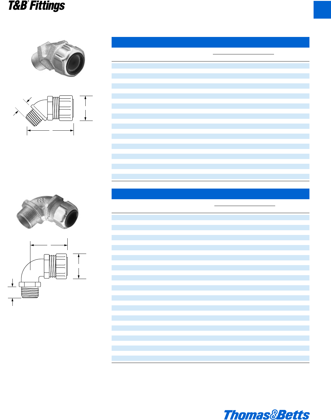
© 2002 Thomas & Betts Corporation. Specifications are subject to change without notice. www.tnb.com A149
T&B®Fittings
Liquidtight Strain Relief Connectors – 90°
Cat. Cable Size Hub Dimensions (in.) Throat
No. min.-max. Size A B C Dia.
2267 (.125-.250) d" 1a 1z e x
2268 (.250-.375) d" 1a 1z e x
2269 (.375-.500) d" 1a 1z e x
2270 (.450-.560) d" 1a 1z e x
2250* (.500-.625) d" 1c 1L l T
2251* (.625-.750) d" 1c 1L l T
2252 (.125-.250) f" 1c 1f d A
2271 (.250-.375) f" 1c 1e d A
2272 (.375-.500) f" 1c 1e d A
2273 (.500-.625) f" 1c 1e d A
2274* (.620-.750) f" 1c 1e d A
2253* (.750-.880) f" 1L 1O l A
2254 (.375-.500) 1" 1c 2 A 1
2255 (.500-.625) 1" 1c 2 A 1
2256* (.625-.750) 1" 1c 2 A 1
2275 (.750-.875) 1" 1L 2 e 1
2276 (.875-.985) 1" 1L 2 e 1
2257* (.880-1.065) 1" 2h 2y A n
2258* (1.065-1.205) 1" 2h 2y A n
2277 (.880-1.065) 1b" 2h 2g L 1j
2278 (1.065-1.205) 1b" 2h 2g L 1j
2279* (1.187-1.375) 1b" 2j 2m m 1X
2280* (1.375-1.485) 1b" 2j 2m m 1X
2281 (.812-1.000) 1d" 2j 2g m 1v
2282 (1.000-1.187) 1d" 2j 2g m 1v
2283* (1.187-1.375) 1d" 2j 2g m 1v
2284 (1.125-1.375) 2" 2A 3b B 1O
2285 (1.375-1.625) 2" 2A 3b B 1O
2286 (1.625-1.875) 2" 2A 3b B 1O
* Remove sufficient outer covering of cable to permit conductors to pass thru connector body.
† U.L. not applicable.
Complies with JIC standards.
U.L. Listed as liquidtight strain relief, and outlet bushing. CSA certified watertight.
Temperature rating 105°C.
Suitable for hazardous locations use where general purpose equipment is specifically permitted per NEC Section 501-4(b).
U.L. File No. E 13938
CSA File No. 589 & 4484
Flexible Cords and Cable Fittings
Liquidtight Strain Relief Connectors – 45°
Cat. Cable Size Hub Dimensions (in.) Throat
No. min.-max. Size A B C Dia.
2200 (.125-.250) d" 1a 1s l F
2201 (.250-.375) d" 1a 1s l F
2202 (.375-.500) d" 1a 1s l F
2203 (.450-.560) d" 1a 1s l F
2204* (.500-.625) d" 1c 1u l F
2205* (.625-.750) d" 1c 1u l F
2206 (.125-.250) f" 1c 1u e A
2207 (.250-.375) f" 1c 1u e A
2208 (.375-.500) f" 1c 1u e A
2209 (.500-.625) f" 1c 1u e A
2210 (.625-.750) f" 1c 1u e A
2211* (.750-.880) f" 1L 1d 1d f
2213 (.375-.500) 1" 1c 1d A n
2214 (.500-.625) 1" 1c 1d A n
2215 (.625-.750) 1" 1c 1d A n
2216 (.750-.875) 1" 1L 1v A n
2217* (.875-.985) 1" 1L 1v A n
2218* (.880-1.065) 1" 2h 1O A n
2219* (1.065-1.205) 1" 2h 1O A n
2220* (.880-1.065) 1b" 2h 1C m 1j
2221* (1.065-1.205) 1b" 2h 1C m 1j
2222* (1.187-1.375) 1b" 2h 2b m 1Q
2223* (1.375-1.485) 1b" 2h 2b m 1Q
C
A
B
C
A
B
For wire mesh grips refer to pages A119, A154.
A
412031.A02 FIT 3/5 3/13/03 4:57 PM Page 149
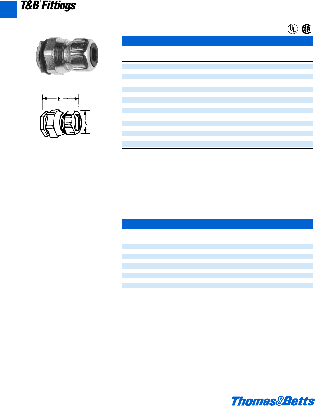
A150 © 2002 Thomas & Betts Corporation. Specifications are subject to change without notice. www.tnb.com
A
T&B®Fittings
CHASE®Liquidtight Cord Connectors
Cat. Cable Size Range Throat Dimensions (in.)
No. Size (in.) Dia. Cord Range B C
2631 (.125-.250) d" l" 1h 1e
2632 (.250-.375) d" l" 1h 1e
2633 (.375-.500) d" l" 1h 1e
2634 (.450-.560) d" l" 1h 1e
2637 (.125-.250) f" A" 1j 1f
2638 (.250-.375) f" A" 1j 1f
2639 (.375-.500) f" A" 1j 1f
2640 (.500-.625) f" A" 1j 1f
2641 (.625-.750) f" A" 1j 1f
2644 (.250-.375) 1" 1" 1e 1m
2645 (.375-.500) 1" 1" 1e 1m
2646 (.500-.625) 1" 1" 1e 1m
2647 (.625-.750) 1" 1" 1e 1m
2648 (.750-.880) 1" 1" 1e 1m
2649 (.885-.985) 1" 1" 1e 1m
Suitable for hazardous locations use in Class I, Div. 2; Class II, Div. 1 and 2; Class III, Div. 1 and 2, where general purpose equipment is
specifically permitted per NEC Section 500-2(a).
Complete with “O” Ring seal and nylon insulated throat, and neoprene bushing.
U.L. Listed as liquidtight strain relief, and outlet bushing. CSA certified watertight.
Temperature Rating; 105°C.
U.L. File No. E 13938
CSA File No. 589
CHASE®Liquidtight Cord Connectors are ideal for installation where space is limited
inside the enclosure.
Flexible Cords and Cable Fittings
®
®
Multi-Hole Flexible Cord and Cable Connectors
Cat. Hub Dia. Cord
No. Size, In. No. Dia.
2520-2 d" 2 .220
2530-2 f" 2 .220
2531-2 f" 2 .260
2531-3 1" 3 .260
2541-2 1" 2 .300
2542-2 1" 2 .375
2540-3 1" 3 .225
2541-3 1" 3 .300
2540-4 1" 4 .220
2555-2 1b" 2 .500
Note: Range of cord dia. ± .010.
In many applications you have only room for one fitting but you need to run two cables, for example, proximity switches. Now you can
provide strain relief and liquidtight protection with T&B’s new multi-hole liquidtight strain relief connectors. With the ever increasing
number of signal cables, now you have a solution to the problem of how to strain relieve multiple cables in one fitting.
412031.A02 FIT 3/5 3/13/03 4:57 PM Page 150
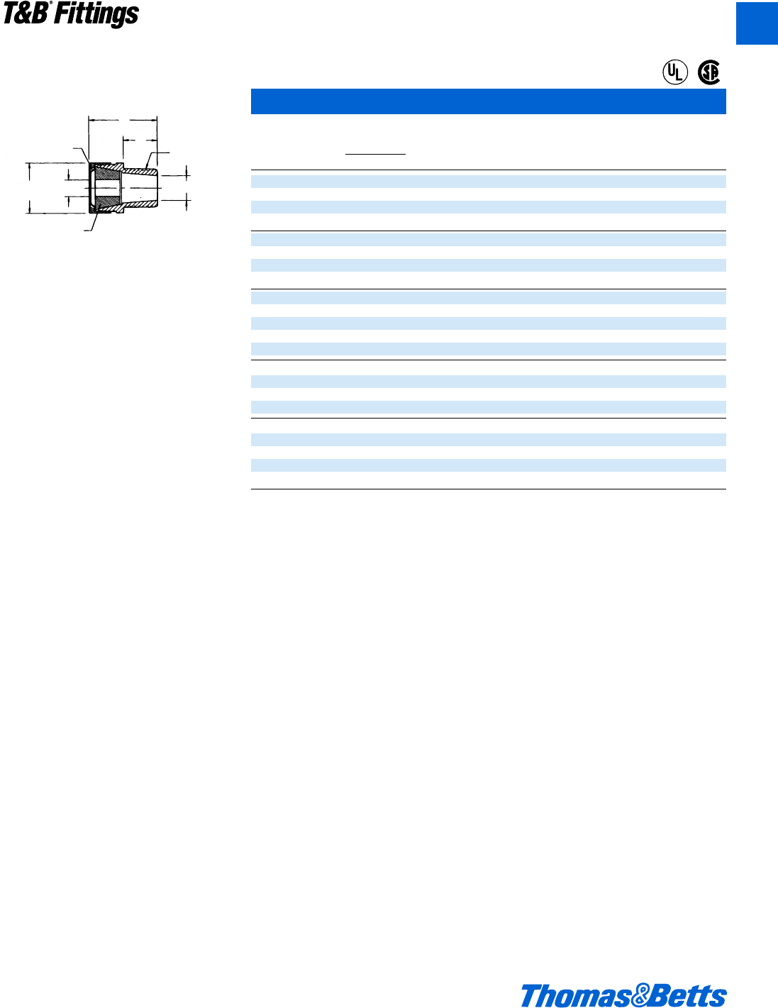
© 2002 Thomas & Betts Corporation. Specifications are subject to change without notice. www.tnb.com A151
T&B®Fittings
A
Flexible Cords and Cable Fittings
Retaining Ring
Plastic (See Note 3)
B
A
Across
Corners
Cable
Size
Bushing
Neoprene
Hub TH'D Size
Taper Pipe Thread
Throat DIA
C
Watertight Strain Relief Connectors (Straight)
Hub
THD Size Marking Throat
Cat. (Taper Cable Size B on Bushing Dia.
No. THD) Min. Max. A Max. C Bushing Part. No. (Min.)
2558AL 1b .880 1.065 2p 2q m .880-1.065 053-71411-63 1å
2559AL 1b 1.065 1.205 2p 2q m 1.065-1.205 053-71411-64 1å
2556AL 1b 1.187 1.375 2X 2d m 2564 053-71411-18 1b
2557AL 1b 1.375 1.485 2X 2d m None 033-72259-2 1b
2562AL 1d .812 1.000 2X 2d L None 033-72259-3 1k
2563AL 1d 1.000 1.187 2X 2k L 2563 053-71411-17 1k
2564AL 1d 1.187 1.375 2X 2k L 2564 053-71411-18 1k
2565AL 1d 1.375 1.625 2m 2e m 1.375-1.625 053-71411-65 1S
2573AL 21.125 1.375 2m 2e m 1.125-1.375 053-71411-66 1g
2574AL 21.375 1.625 2m 2e L 1.375-1.625 053-71411-65 1g
2575AL 21.625 1.875 2m 2e L 1.625-1.875 053-71411-67 1g
2576AL 21.750 1.965 3r 3d B 10412 033-72259-5 1C
2577AL 21.937 2.187 3r 3d B 10413 033-72259-6 1C
2584AL 2d 1.750 1.965 3r 3f 1o 10412 033-72259-5 2
2585AL 2d 1.937 2.187 3r 3f 1o 10413 033-72259-6 2
2586AL 2d 2.156 2.360 3n 4b 1o 10414 033-72259-7 2q
2587AL 2d 2.350 2.565 3n 4b 1o 10415 033-72259-8 2q
2592AL 32.156 2.360 3n 4b 1o 10414 033-72259-7 2u
2593AL 32.350 2.565 3n 4b 1o 10415 033-72259-8 2u
2594AL 32.535 2.750 3n 4b 1o 10416 033-72259-9 2u
2595AL 32.735 2.985 4L 4m 1a None 033-72259-10 2m
2596AL 32.990 3.220 4L 4m 1a None 033-72259-11 2m
Notes:
1. Cord or cable will not pass thru body without removing outer covering.
2. Listed under “UL” file No. E13938A and “CSA” file No. 589 except Cat. No.'s 2516, 2517, 2518, and 2519.
3. 2d" and 3" sizes have stainless steel retaining rings.
4. Cat. No. 2558AL through 2575AL have machined aluminum body with stamped sheet aluminum gland. All others have cast aluminum
body and gland. All bodies and glands are etched clean and wax coated for easy assembly.
5. Alumishield to be on gland to prevent galling of threads.
®
®
412031.A02 FIT 3/5 3/13/03 4:57 PM Page 151
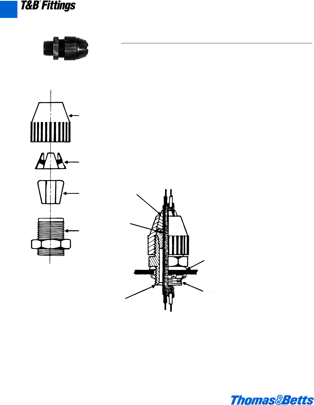
A152 © 2002 Thomas & Betts Corporation. Specifications are subject to change without notice. www.tnb.com
T&B®Fittings
Application
• A liquidtight connector to connect
flexible cord to a box or enclosure
and provide adequate strain relief.
Features
• Taper Thread hub seals in female hub
(A).
• Neoprene bushing provides liq-
uidtight installation (B).
• Hand tightens – no tools needed for
assembly.
• Segmented chuck provides high
mechanical pullout performance –
will not cut or damage cord jacket
(C).
• Corrosion and weather resistant plas-
tic is excellent for outdoor/indoor use.
• Plastic parts improve dielectric strength
and provide insulated throat (D).
• Wide range – reduces inventories.
Listed/Certified by:
U.L....................(U.L. File No. E-23018)
CSA .........................LR-2884, LR-4484
Standard Material
Body, Gland &
Segmented Chuck ..Weather stabilized
thermoplastic rated for -34°C (-29°F)
to 105°C (221°F) application.
Bushing.................................Neoprene
Standard Finish
All parts as molded.
Range
.250 outside diameter
to 1.020 outside
diameter .......Type S, SO, SV, ST, STO,
SJ, SJO, SJT, SJTO,
SVTO, SVO, SVT Flexible
Cords & Cables
Conforms to:
U.L. 514B
CSA C22.2 No. 18
NFPA 70-1999 (ANSI)
Federal Standard H-28 (Threads)
Flexible Cords and Cable Fittings – Non-Metallic
2672 Series
Gland
Segmented
Chuck
Bushing
Body
2672 Series
Note:
Series 5262
Sealing Gasket
(Not provided
with connector)
(C)
(B)
(D)
(A)
Typical Installation
Liquidtight Flexible Cord Connectors – Black Beauty™Series
A
412031.A02 FIT 3/5 3/13/03 4:57 PM Page 152
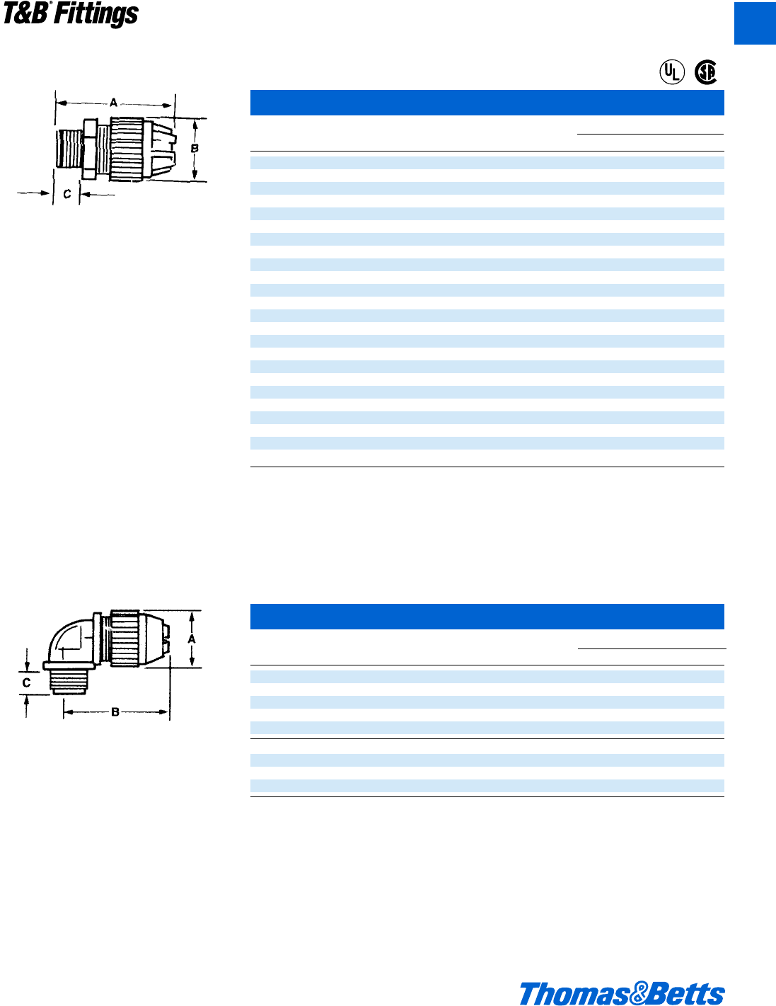
© 2002 Thomas & Betts Corporation. Specifications are subject to change without notice. www.tnb.com A153
T&B®Fittings
Flexible Cords and Cable Fittings – Non-Metallic
Nonmetallic Liquidtight Strain Relief Connector – straight
Cat. Trade or Throat Dimensions (in.)
No. Hub Size Diam. (in.) Cord Range (in.) A B C
2671 c" 0.33 .125-.275 2.0 .90 .46
2690 d" 0.33 .125-.275 2.3 .90 .60
2672 d" 0.55 .250-.400 2.6 1.27 .60
2673* d" 0.55 .400-.560 2.6 1.27 .60
2691* d" 0.54 .660-.780 3.0 1.57 .60
2692* d" 0.54 .660-.780 3.0 1.57 .60
2693 f" 0.55 .250-.400 2.7 1.27 .62
2694* f" 0.55 .400-.560 2.7 1.27 .62
2674 f" 0.79 .560-.690 3.0 1.57 .62
2675 f" 0.79 .660-.780 3.0 1.57 .62
2696* f" 0.76 .770-.895 3.2 1.89 .62
2676 1" 0.98 .660-.780 3.3 1.89 .77
2677 1" 0.98 .770-.895 3.3 1.89 .77
2678* 1" 0.98 .870-1.020 3.3 1.89 .77
2699 1" 0.98 .890-1.090 4.2 2.58 .77
2702 1b" 1.25 .890-1.090 4.2 2.58 .80
2703 1b" 1.25 1.080-1.280 4.0 2.58 .80
2704 1b" 1.25 1.270-1.470 4.0 2.58 .80
2705-TB 1d" 1.47 .890-1.150 4.2 2.95 .82
2706 1d" 1.47 1.140-1.400 4.3 2.95 .82
2707 1d" 1.47 1.390-1.650 4.3 2.95 .82
2708 2" 1.89 1.190-1.530 5.1 3.50 .84
2709 2" 1.89 1.520-1.860 4.9 3.50 .84
2710* 2" 1.89 1.850-2.190 4.9 3.50 .84
* Remove sufficient outer covering of cable to permit conductors to pass thru connector body.
U.L. File No. E 13938
CSA File No. 52391
All items shown on this page are suitable for use in hazardous location where general purpose equipment is specifically permitted by the
NEC. Class I, Div. 2. Class II, Div. 1 & 2. Class III, Div. 1 & 2. NEC 501-4(b), 502-4(a)(b), 503-3(a)(b).
Nonmetallic Liquidtight Strain Relief Connector – 90° elbow
Cat. Trade or Throat Dimensions (in.)
No. Hub Size Diam. (in.) Cord Range (in.) A B C
2680 c" .33 .125-.275 C 1f .460
2681 d" .55 .250-.400
2682* d" .55 .400-.560
2683 f" .78 .560-.690
2684 f" .78 .660-.780
2688 1" .98 .560-.690 1B 3b .770
2685 1" .98 .660-.780 1B 3b .770
2686 1" .98 .770-.895 1B 3i .770
2687* 1" .98 .870-1.020 1B 3 .770
* Remove sufficient outer covering of cable to permit conductors to pass thru connector body. 90° angle, standard size body.
U.L. File No. E 13938
CSA File No. 52391
All items shown on this page are suitable for use in hazardous locations where general purpose equipment is specifically permitted by the
NEC. Class I, Div. 2. Class II, Div. 1 & 2. Class III, Div. 1 & 2. NEC 501-4(b), 502-4(a)(b), 503-3(a)(b).
• Weather Stabilized Nylon.
• U.L. 94-V2.
• Temperature Rating: -34˚C to +105˚C.
• Meets Coast Guard CG293.
90° angle, standard size body.
• Weather Stabilized Nylon.
• U.L. 94-V2.
• Temperature Rating: -34˚C to +105˚C.
• Meets Coast Guard CG293.
®
®
A
412031.A02 FIT 3/5 3/13/03 4:57 PM Page 153
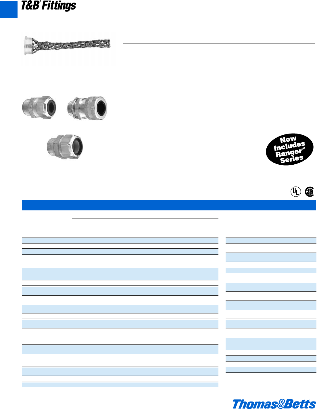
A154 © 2002 Thomas & Betts Corporation. Specifications are subject to change without notice. www.tnb.com
A
T&B®Fittings
Wiremesh Grips
How to select proper wiremesh grip:
1. Determine O.D. of portable cord e.g. .200
2. Determine size of knockout or threaded hub e.g. d"
3. Select Cat. No. of strain relief connector e.g. 2520, 2920AL.
4. Match up O.D. with grip range and strain relief to determine Cat. No.
of Wiremesh Grip (e.g. .200 + 2520 = WMP-PC1)
The T&B WMG-PC Series Wiremesh Grips for Portable Cord
T&B Wiremesh grips are ordered separately and fit with your existing inventory of
Ranger™ connectors and liquidtight strain relief connectors. There’s no need to
duplicate inventory.
Application
• Provides high gripping strength for ade-
quate cable support and strain relief
without damage to the cable sheath
• Compression of a tapered neoprene
bushing, assures the watertight
integrity of the fittings
• To meet National Electric Code or
NEC requirements for electrical instal-
lations in hazardous atmospheres, a
sealing fitting may be required in con-
junction with the cable and cord fitting
Cord & Cable Type
• S, SO, SV, ST, STD, SJ, SJO, SJT,
SJTO, SVD
Features
• Prevents severe cord bends and
pullouts
• Used in aluminum and/or steel fittings
Materials
Wiremesh made of stainless steel.
Retaining rings made of aluminum.
Environment Classification
• Ordinary Locations
Range
.187 – 3.220
®
®
2920 Series 2920AL Series
2516 Series
Wiremesh grips support the following
Liquidtight Cord Fittings Series.
Strain Relief Connector
Straight 90°
Cat. Grip T&B T&B
No. Range Steel Steel
WMG-PC18* 1.250-1.375 2573 2284
WMG-PC19* 1.375-1.500 2565 2285
2574
WMG-PC20* 1.500-1.625 2565 2285
2574
WMG-PC21* 1.625-1.750 2575 2286
WMG-PC22* 1.750-1.875 2575 2286
WMG-PC23 1.750-1.875 2576
2584
WMG-PC24 1.875-2.000 2576
2584
WMG-PC25 1.937-2.062 2577
2585
WMG-PC26* 2.062-2.187 2577
2585
WMG-PC27 2.125-2.250 2586
2592
WMG-PC28 2.250-2.375 2586
2592
WMG-PC29 2.350-2.475 2587
2593
2587
WMG-PC30 2.475-2.600 2593
2594
WMG-PC31* 2.625-2.750 2594
WMG-PC32* 2.735-2.860 2595
WMG-PC33* 2.860-2.985 2595
WMG-PC34* 2.970-3.095 2596
WMG-PC35* 3.095-3.220 2596
*Replacement Gland Nut Supplied With
These Cat alog Numbers Only
Wiremesh Grips for Portable Cord
Strain Relief Connector
Straight 45° 90°
Cat. Grip Ranger™ Ranger™ T&B Ranger™ T&B Ranger™ Ranger™ T&B
No. Range Steel Aluminum Steel Steel Steel Steel Aluminum Steel
WMG-PC1 .187-.250 2920 2920AL 2520 4920 2200 4960 4960AL 2267
WMG-PC2 .250-.375 2920 2920AL 2521 4920 2201 4960 4960AL 2268
WMG-PC3 .375-.500 2921 2921AL 2522 4921 2202 4961 4961AL 2269
2922 2922AL 2524 4922 2204 4962 4962AL 2250
WMG-PC4 .500-.625 2932 2932AL 2534 4932 2209 4972 4972AL 2273
2941 2941AL 2544 4941 2214 4981 4981AL 2255
2922 2922AL 2525 4922 2205 4962 4962AL 2251
WMG-PC5 .625-.750 2932 2932AL 2535 4932 2210 4972 4972AL 2274
2941 2941AL 2545 4941 2215 4981 4981AL 2256
WMG-PC6 .187-.250 2930 2930AL 2530 4930 2206 4970 4970AL 2252
WMG-PC7 .250-.375 2930 2930AL 2531 4930 2207 4970 4970AL 2271
2541
WMG-PC8 .375-.500 2931 2931AL 2532 4931 2208 4961 4961AL 2272
2940 2940AL 2542 4940 2213 4980 4980AL 2254
WMG-PC9 .750-.875 2536 2211 2253
2942 2942AL 2546 4942 2216 4982 4982AL 2275
WMG-PC10 .875-1.000 2547 2217 2276
WMG-PC11 .875-1.000 2548 2218 2257
2558 2220 2277
2548 2218 2257
WMG-PC12 1.000-1.125 2558 2220 2277
2549 2219 2258
2559 2221 2278
WMG-PC13 1.125-1.250 2549 2258 2258 2219
2559 2221 2278
2556 2279 2279 2222
WMG-PC14 1.125-1.250 2563 – 2282
2564 – 2283
WMG-PC15 1.250-1.375 2256 2222 2279
2564 — 2283
WMG-PC16* 1.375-1.500 2557 2223 2280
WMG-PC17* 1.125-1.250 2573 – 2284
412031.A02 FIT 3/5 3/13/03 4:57 PM Page 154
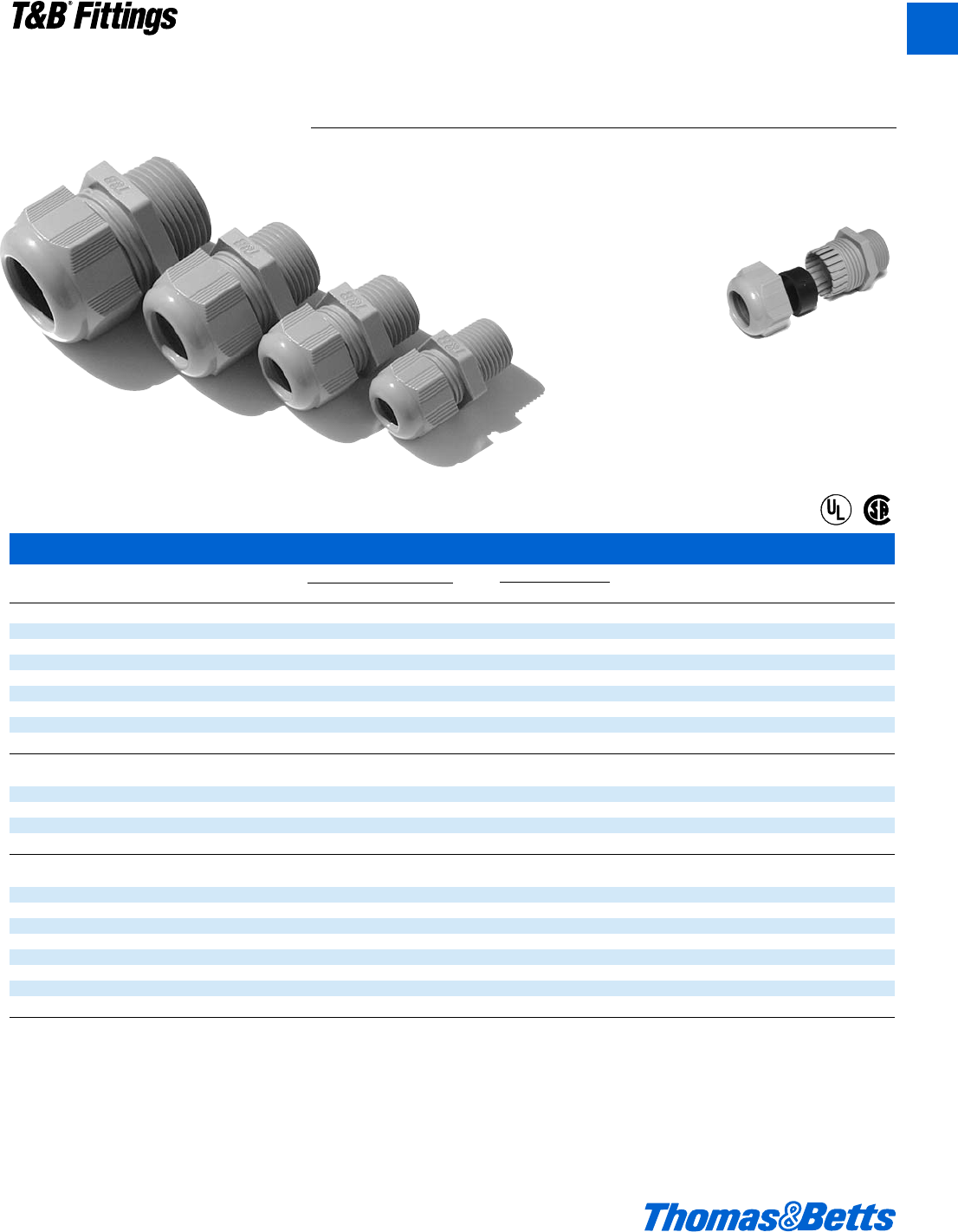
© 2002 Thomas & Betts Corporation. Specifications are subject to change without notice. www.tnb.com A155
T&B®Fittings
A
Non-Metallic Cable Glands
Non-Metallic Cable Glands
Catalog No. Thread Cord Range Length of Thread Use T&B Unit Std.
Fittings Size Color In. MM In. MM Locknut Cat. No. Pkg. Pkg.
NPT Threads
CC-NPT38-B c" BLACK .197-.394 5-10mm .590 15mm –50 250
CC-NPT38-G c" GRAY .197-.394 5-10mm .590 15mm –50 250
CC-NPT12-B d" BLACK .394-.551 10-14mm .590 15mm LN501 50 250
CC-NPT12-G d" GRAY .394-.551 10-14mm .590 15mm LN501 50 250
CC-NPT34-B f" BLACK .512-.709 13-18mm .590 15mm LN502 25 100
CC-NPT34-G f" GRAY .512-.709 13-18mm .590 15mm LN502 25 100
CC-NPT1-B 1" BLACK .709-.984 18-25mm .709 18mm LN503 20 100
CC-NPT1-G 1" GRAY .709-.984 18-25mm .709 18mm LN503 20 100
ISO/Metric Threads
CC-ISO16-G 16 GRAY .197-.394 5-10mm .394 10mm LN-ISO16-G 50 200
CC-ISO20-G 20 GRAY .236-.473 6-12mm .590 15mm LN-ISO20-G 50 200
CC-ISO25-G 25 GRAY .512-.709 13-18mm .590 15mm LN-ISO25-G 25 100
CC-ISO32-G 32 GRAY .709-.984 18-25mm .590 15mm LN-ISO32-G 20 100
PG Threads
CC-PG7-G 7GRAY .118-.256 3-6.5mm .315 8mm LN-PG7-G 50 200
CC-PG9-G 9GRAY .157-.315 4-8mm .315 8mm LN-PG9-G 50 200
CC-PG11-G 11 GRAY .197-.394 5-10mm .315 8mm LN-PG11-G 25 100
CC-PG135-G 13d GRAY .236-.473 6-12mm .354 9mm LN-PG135-G 25 100
CC-PG16-G 16 GRAY .394-.551 10-14mm .394 10mm LN-PG16-G 25 100
CC-PG21-G 21 GRAY .512-.709 13-18mm .433 11mm LN-PG21-G 10 50
CC-PG29-G 29 GRAY .709-.984 18-25mm .433 11mm LN-PG29-G 10 50
CC-PG36-G 36 GRAY .867-1.26 22-32mm .512 13mm LN-PG36-G 10 50
*Listed under UL file E13938, control #137B NPT and PG threaded Cable Glands are UL Listed, ISO/Metric Threaded Cable Glands are not UL Listed.
Low profile cable gland perfect for tight spots
T&B Nylon Cable Glands have a sturdy cable sealing mechanism which results in
superior strain relief. The compact size ensures quick and easy installation in
cramped spaces. The non-metallic construction provides excellent corrosion,
chemical and impact resistance. The glands have long threads and locknuts are
available.
• Halogen free
• Flame Retardant UL 94V0
• Rated IP 68 5 BAR, suitable for
NEMA 4 enclosures
• UL Listed*, CSA listed
for certain ranges of cable
• Working Temperatures -30˚C(-86F) to
+80˚C(176˚F)
Continuous, +150˚C(276˚F) Intermittent
• Meets VDE ratings
Sturdy Nylon 6 for strong, lightweight
construction. Gray color shown, also
available in black.
®
®
412031.A02 FIT 3/5 3/13/03 4:57 PM Page 155
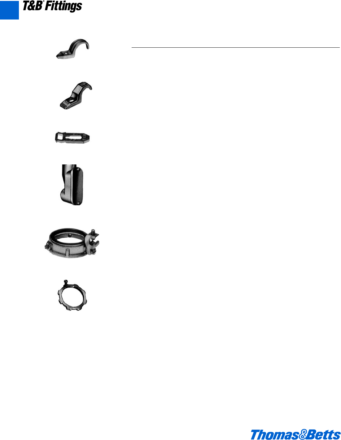
A156 © 2002 Thomas & Betts Corporation. Specifications are subject to change without notice. www.tnb.com
A
T&B®Fittings
Service Entrance Cable Fittings
• All service fittings shall be approved for
the purpose by a nationally recognized
testing laboratory, inspection agency,
or product evaluation organization.
• Where service raceway consists of a
rigid metal conduit, intermediate
metal conduit, electrical metallic tub-
ing or where service entrance cable
is used as service conductors, a suit-
able rain tight service head conform-
ing to Federal Standard W-C-586
shall be provided.
• Service raceway shall be securely
fastened in place to the supporting
surface at intervals as specified by
the Code using suitable straps and
spacers; straps and spacers shall be
of malleable iron or steel construction,
hot dipped galvanized or electro zinc
plated conforming to Canadian
Standards Association Standard
C22.2 No. 18 and as manufactured
by Thomas & Betts: series 1275 or
4175 straps and series 1350 spacers;
aluminum straps or spacers such as
series 1275AL and series 1350AL
may be substituted when installed in
environmental conditions that are
more than normally corrosive.
• Where threaded rigid metal service
raceway enters the building the race-
way shall be equipped with a cast
malleable iron/copper free aluminum
entrance ell suitably bushed with a
burr free end stop and taper tapped
holes as manufactured by Thomas &
Betts, series 1490.
• For grounding and bonding of ser-
vice raceway, end of raceway or the
terminating fitting shall be equipped
with bonding locknuts and insulated
metallic grounding and bonding
bushing as required.
Bonding locknuts shall be of hard-
ened steel or malleable iron construc-
tion, electro zinc plated, and provid-
ed with hardened bonding screws as
manufactured by Thomas & Betts,
series 106 bonding locknuts.
Insulated metallic grounding and
bonding bushing shall be of malleable
iron/steel construction, electro zinc
plated and assembled with an insula-
tor listed or certified for 150°C/302°F
service as manufactured by Thomas
& Betts, series 3870.
Suggested Specifications for Service Entrance Fittings
Series 4175
Pipe Strap (EMT)
Series 1275/1275AL
Pipe Strap
(Rigid Metal Conduit & I.M.C.)
Series 1350/1350AL
Pipe Spacer
(Rigid Metal Conduit I.M.C. & EMT)
Series 1490
Entrance ELL
Series 3870
Bonding & Grounding Bushing – Insulated
Series 106
Bonding Locknut
412031.A02 FIT 3/5 3/13/03 4:57 PM Page 156
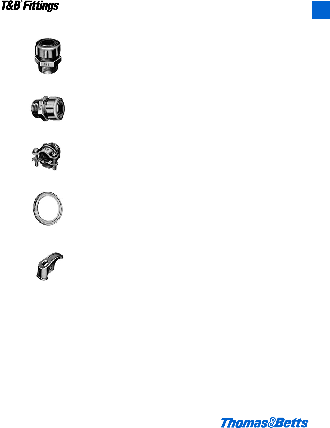
© 2002 Thomas & Betts Corporation. Specifications are subject to change without notice. www.tnb.com A157
T&B®Fittings
A
Service Entrance Cable Fittings
• Where service entrance cable is used
as overhead service conductors and
code requires use of a service head,
entrance caps shall be installed; caps
shall be cast metal type of suitable
ferrous or non ferrous metal equipped
with thermoset insulators and proper
knockout openings; caps when
installed with proper drip loop must
assure rain tight conditions.
• Terminating fittings for service
entrance cable (Type SE or USE) or
underground feeder and branch – cir-
cuit cable (Type UF) in locations
where exposed to intermittent or con-
stant moisture or in dry locations and
subjected to mechanical strain shall
be of watertight strain relief type as
manufactured by Thomas & Betts,
series 2111 or 2116; fittings shall be
constructed of ferrous or non ferrous
metal and equipped with taper thread-
ed hub, beveled moisture resistant/oil
resistant synthetic rubber bushing.
In dry locations nylon insulated two
screw type fittings of malleable
iron/steel construction electro zinc
plated inside outside including
threads such as series 3302M man-
ufactured by Thomas & Betts may
be substituted.
•Where service entrance cable is ter-
minated into a threadless opening
using hub type fittings, a gasket shall
be provided between the outside of
box or enclosure and fitting shoulder;
gasket shall be of moisture
resistant/oil resistant synthetic rubber
type adequately protected by and
permanently retained to a metallic
retainer as manufactured by Thomas
& Betts, series 5262 or 5302.
• Service entrance cable shall be ade-
quately supported at intervals enu-
merated in code using cable straps
conforming to requirements of
Canadian Standards Association
Standard CSA 22.2 No. 18; cable
straps shall be of malleable iron/steel
construction, hot dipped galvanized
or electro zinc plated as manufactured
by Thomas & Betts, series 1341.
• At the point where the service cable
enters the building a suitable sill
plate shall be provided; sill/wall
plate shall be sealed to assure rain
tight conditions.
Series 2111
Service Entrance Cable Connector
Series 2116
Underground Feeder Cable Connector
Series 3302M
Two Screw Connector (Insulated)
Series 5262, 5302
Sealing Gasket
Series 1341
Cable Strap
Suggested Specifications for Service Entrance Fittings –
(Continued)
412031.A02 FIT 3/5 3/13/03 4:57 PM Page 157
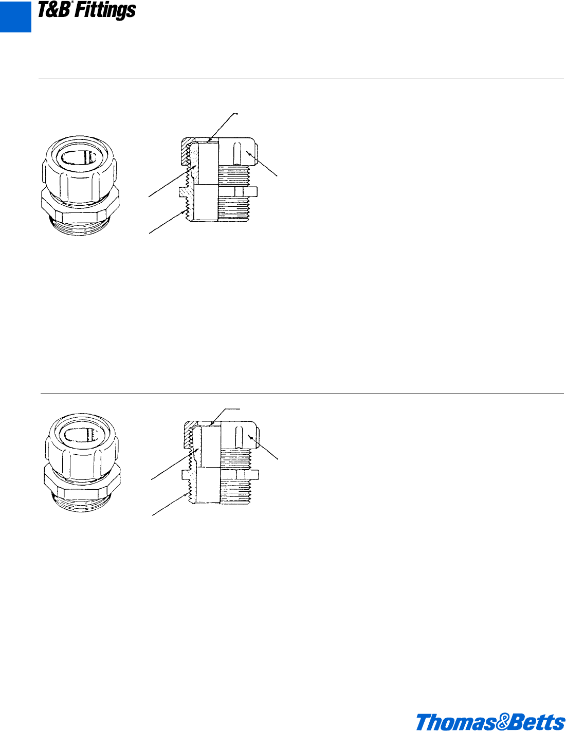
A158 © 2002 Thomas & Betts Corporation. Specifications are subject to change without notice. www.tnb.com
A
T&B®Fittings
Service Entrance Cable Fittings
2111 Series
Application
• To connect service entrance cables to a meter box or an
enclosure.
Standard Material/Finish
Body…Zinc Die Cast/as cast
Gland…Steel/Electro Zinc Plated & Chromate Coated
Retaining Ring…Stainless Steel/Passivated
Bushing…Neoprene/as molded
2116 Series
Application
• To connect underground feeder cables to a box or an
enclosure.
Standard Material/Finish
Body…Zinc Die Cast/as cast
Gland…Steel/Electro Zinc Plated & Chromate Coated
Retaining Ring…Stainless Steel/Passivated
Bushing…Neoprene/as molded
Service Entrance Cable Connector
(Type SE/Type Use)
Underground Feeder Cable Connectors
Range
Oval (Flat) Cable Size….260 x .500 thru 1.062 x 1.765
Type USE Cable Size…3 #12 thru 3-4/0 AWG Conductors
Hub Size…d" thru 2" NPT (taper pipe threads)
Features
• Neoprene bushing, resists oil and water; grips cable the
full length of the bushing providing adequate strain relief
without damaging outer jacket (A).
• Taper threaded body (B).
• Stainless steel retaining ring protects cable jacket against
abrasion; reduces installing torque effort (C).
• Rugged ribbed steel gland construction (D).
• Suitable for Type SE & USE Service Entrance Cable.
Listed by:
U.L. (U.L. File No. E15170)
CSA (LR589, LR4484)
Conforms to:
UL514, NEMA FB1, Federal Standard
H-28 (Threads), NFPA70-1999 (ANSI)
Range
Oval (Flat) Cable Size….235 x .500 thru .260 x .740
Hub Size…d" thru 1" NPT (tapered pipe threads)
Features
• Neoprene bushing resists oil and water; grips cable the full
length of the bushing providing adequate strain relief with-
out damaging outer jacket (A).
• Taper threaded body (B).
• Stainless steel retaining ring protects cable jacket against
abrasion; reduces installing torque effort (C).
• Rugged ribbed steel gland construction (D).
Listed by:
U.L.
CSA (LR2884)
Conforms to:
UL514B, NEMA FB1, Federal Standard
H-28 (Threads), NFPA70-1999 (ANSI)
(c)
(a)
(b)
(d)
(c)
(a)
(b)
(d)
412031.A02 FIT 3/5 3/13/03 4:57 PM Page 158
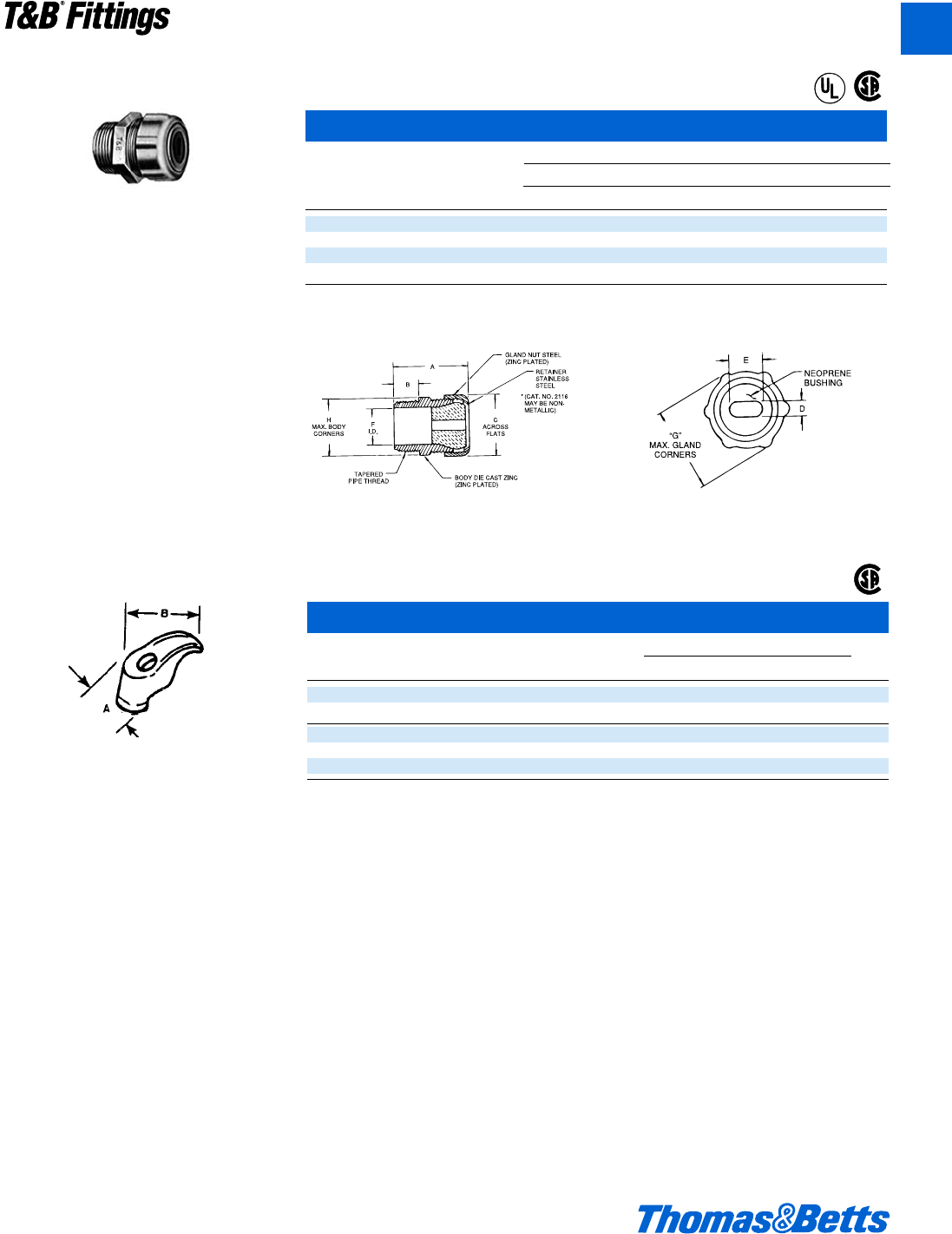
© 2002 Thomas & Betts Corporation. Specifications are subject to change without notice. www.tnb.com A159
T&B®Fittings
A
Underground Liquidtight Feeder Cable Fittings
Dimensions (in.)
Cat. Hub Cable ABC D E FGH
No. Size Opening min. max. min. max
2116-TB* d" .235 x .500 1L e 1 .060 .235 .350 .500 l1a1a
2237 f" .230 x .430 1l l 1r .080 .230 .320 .430 m1c1c
2238 f" .235 x .465 1l l 1r .050 .235 .340 .465 m1c1c
2239 f" .240 x .685 1l l 1r .060 .240 .500 .685 m1c1c
* Not CSA Certified.
U.L. File No. E-23017
CSA File No. 2884
Service Entrance Cable Fittings
Oil and water resistant neoprene bushing is
especially designed for sealing around under-
ground feeder cable. Stainless steel retaining
ring provides a bearing surface for the glandnut
and eliminates cable twist. Ribbed glandnut is
strong and easily tightened with a wrench to
make a connection of high strength.
Each strap takes a wide range of sizes because
of the rocking action of the foot. Hole is for 1⁄4"
screw. Malleable iron, hot dipped galvanized
construction.
Cable Straps
Cat. Dimensions (in.)
No. Wire Size A B
1341-TB 2-#10 e1a
1344 3-#6 or 3-#8 e1n
1345* 3-#4 or 3-#2 m1∂
1346 3-1/0 f2k
1347 3-4/0 f2A
* Steel, hot dipped galvanized.
U.L. not applicable.
CSA Certified.
®
®
®
412031.A02 FIT 3/5 3/13/03 4:57 PM Page 159
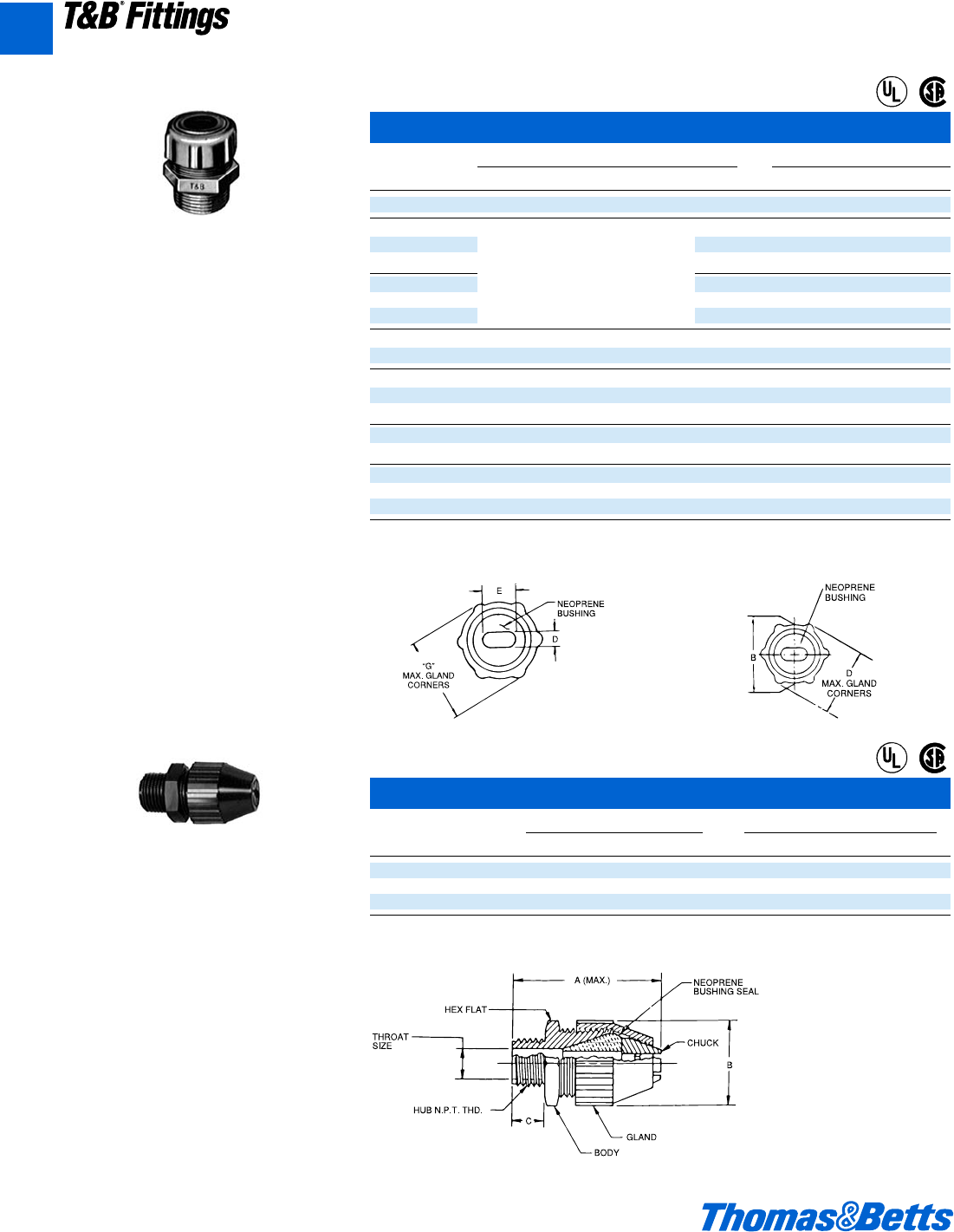
A160 © 2002 Thomas & Betts Corporation. Specifications are subject to change without notice. www.tnb.com
A
T&B®Fittings
Service Entrance Cable Fittings
Nylon UF Cable Fittings for Corrosive Environments
Cat. Hub UF Cable Range A B C
No. Size max. min. max. ± .060 ± .060
2827 d" .550 x .280 .400 x .190 2.60 1.270 .600
2828 f" .675 x .280 .525 x .190 3.00 1.570 .620
2829 f" .775 x .280 .625 x .190 3.00 1.570 .620
U.L. File No. 15170
CSA File No. 589
• Tapered threaded hub.
• Liquidtight and Dust tight; hand tightens – no
tools required.
• Corrosive and weather resistant nylon for out-
door and indoor applications.
Watertight Connectors for Oval Cable
Cat. Hub Dimensions (in.) Oval Cable Range
No. Size A B C D E max. min.
2111 d" 1f 1b e 1c 1c .420 x .560 .380 x .520
2232 f" .385 x .600 .260 x .500
2233 f" 1c .500 x .750 .375 x .625
2234 f" .555 x .800 .490 x .675
2432 1" .385 x .600 .260 x .500
2433 1" 1f .500 x .750 .375 x .625
2434 1" .555 x .800 .430 x .675
2438 1" 1f 1d A 1L 1f .565 x .855 .440 x .730
2439 1" .635 x .975 .510 x .850
2442 1b" .635 x .975 .510 x .850
2443 1b" 2h 1n e 2h 2a .640 x 1.050 .490 x .900
2446 1b" .750 x 1.150 .565 x .965
2454 1d" 2b 2a 2j 2j .840 x 1.275 .655 x 1.090
2447 1d" .880 x 1.425 .695 x 1.240
2448 2" L .968 x 1.500 .790 x 1.390
2449 2" 2c 2e 2f 2u 1.062 x 1.765 .850 x 1.550
2450 2" 1.820 x 1.190 1.700 x 1.050
U.L. File No. E-15170
CSA File No. 589
Note/Reminder: These may be obsoleted and replaced.
A design with two tapers inside the body – a
slow one and a fast one – permits the stocking
of fewer connectors for varied cable sizes and
allows maximum take-up. The tapered neo-
prene bushings are resistant to oil, sunlight,
and water. Hex gland and body take the same
wrench opening and a stainless steel slip ring
prevents cable from twisting as gland ring is
being tightened. Threads on the body are
tapered for watersealing.
1L 1b l 1c
®
®
®
®
412031.A02 FIT 3/5 3/13/03 4:57 PM Page 160

© 2002 Thomas & Betts Corporation. Specifications are subject to change without notice. www.tnb.com A161
T&B®Fittings
A
Please Note
The excerpts and other material herein, whether relating
to the National Electrical Code, the Underwriters
Laboratories, Inc. listing, to industry practice or otherwise, is
not intended to provide all relevant information required for
use and installation. Reference to original or primary source
material and data is mandatory before any application or
use is made of the product.
Armored Cable and Flexible Metal Conduit
Armored Cable (Type AC) – Ref. NEC
Article 333
National Electric Code defines type AC
armored cable as, “A fabricated
assembly of insulated conductors in a
flexible metallic enclosure.”
ACT indicates an armored cable
employing conductors having
thermoplastic (Type T) insula-
tion.
AC indicates an armored cable
employing conductors having
rubber insulation of code
grade.
ACH indicates an armored cable
employing conductors having
rubber insulation of the heat
resistant (75°C) grade.
ACHH indicates an armored cable
employing conductors having
rubber insulation of the heat
resistant (90°C) grade.
ACU indicates an armored cable
employing conductors having
rubber insulation of latex grade.
‘L’ used as a suffix indicates
that a lead covering has
been applied over the con-
ductor assembly.
All above cables may employ copper
or aluminum or copperclad aluminum
conductors with the following sizes and
are rated for 600 volts or less:
No. 14 AWG to No. 1 AWG Copper
No. 12 AWG to No. 1 AWG Aluminum
or Copperclad Aluminum
Type AC cables except ACL carry
an internal bonding strip of copper or
aluminum in intimate contact with the
armor for its entire length. Armored
cable can be used for both exposed or
concealed locations. With lead cov-
ered conductors (Type ACL) the cable
can be embedded in masonry or con-
crete and can be used in damp loca-
tions or where exposed to oil.
Armored cable is not permitted in
locations where it will be subjected to
physical damage or corrosive fumes.
Armored cable cannot be used for
direct burial in earth.
With minor exceptions armored
cable is also not permitted to be used
in hoists or elevators, storage battery
rooms, any hazardous locations, in
commercial garages and in theaters or
similar locations.
Codes require that cable shall be
supported with straps or staples with-
out damaging conductors and also
limit the minimum bend radius to 5
times the diameter of type AC cable.
Certain precautions are prescribed in
code where cable is installed through
joist rafters or similar wood members.
According to NEC 333-9 where
armored cable is terminated, a fitting
is required to protect conductors from
abrasion. In addition a bushing is
required between the conductors and
armor. Design of fitting has to be such
that the insulating bushing is visible for
inspection. Bushing is not required
with lead covered cables when prop-
erly installed.
Portions of this section reprinted by
permission from NFPA 70-1999,
National Electrical Code®, Copyright ©
1977, National Fire Protection
Association, Boston, MA.
Please refer to the following for further
details and complete information:
1. NEC Article 333…Armored Cable
(Type AC Cable)
2. U.L. 4, ANSI C33.9…Safety
Standards for Armored Cable
3. U.L. 514B, Safety Standards for
Outlet Boxes and Fittings
4. W-F-406…Federal Specification.
Fittings for Cable, Power,
Electrical and Conduit, Metal,
Flexible
5. NEMA FB-1…Standards
Publication. Fittings & Supports for
Conduit
and Cable Assemblies
6. CEC Section 12-700…Wiring
Methods (Armored Cable)
7. CSA C22.2 No. 51…Safety
Standards for Armored Cables
8. CSA C22.2 No. 18…Safety
Standards for Outlet Boxes,
Conduit Boxes and Fittings
Armored Cable and Flexible Metal Conduit Fittings
412031.A02 FIT 3/5 3/13/03 4:57 PM Page 161

A162 © 2002 Thomas & Betts Corporation. Specifications are subject to change without notice. www.tnb.com
A
T&B®Fittings
Armored Cable and Flexible Metal Conduit Fittings
Armored Cable and Flexible Metal Conduit – continued
Flexible Metal Conduit – Ref. NEC Article 350
Flexible metal conduit can be used for
exposed or concealed work in dry
locations. It can be used for wet loca-
tions provided conductors within are
lead covered or other approved type.
Flexible metal conduit cannot be
used underground or embedded in
poured concrete or aggregate. With
rubber covered conductors the conduit
cannot be exposed to oil, gasoline or
other materials having a deteriorating
effect on rubber.
With minor exceptions use of flexible
metal conduit is not permitted in hoists,
in storage battery rooms and in any
hazardous locations. Use of flexible
metal conduit is restricted to systems
under 600 volts.
According to NEC Article 350-5, flexi-
ble metal conduit no longer than six feet
and containing circuit conductors pro-
tected by overcurrent device rated for
20 amps or less is suitable as a ground-
ing means provided, it is terminated in
fittings approved for the purpose.
Flexible metal conduit longer than
six feet is permitted to be used as a
grounding means provided the conduit
and the fitting are approved for the
purpose. To date there is no flexible
metal conduit approved for the pur-
pose by the Underwriters Laboratories.
In Class I & II, Division 2 hazardous
areas, the conduit itself cannot be
used as the grounding means. A bond-
ing jumper must be installed in accor-
dance with NEC Section 250-79(e).
Flexible metal conduit is available with
steel or aluminum armor in trade size
j" to 4". With few exceptions where j"
and c" trade sizes are used, Code pro-
hibits use of conduit less than d" trade
size. Bends in concealed work are
restricted to 360 degrees total. No
angle connectors are permitted in con-
cealed raceway installations.
Portions of this section reprinted by
permission from NFPA 70-1999,
National Electrical Code®,
Copyright © 1977, National Fire
Protection Association, Boston, MA.
Please refer to the following for further
details and complete information:
1. NEC Article 350…Flexible Metal
Conduit
2. U.L. 1, ANSI C33.92…Safety
Standards for Flexible Metal
Conduit
3. U.L. 514B, Safety Standards for
Outlet Boxes and Fittings
4. W-F-406…Federal Specification.
Fittings for Cable, Power, Electrical
and Conduit, Metal Flexible
5. WW-C-566…Federal Specification.
Conduit, Metal, Flexible
6. NEMA FB1…Standards
Publication. Fittings and Supports
for Conduit and Cable Assemblies
7. CEC 12-1100…Wiring Method
(Rigid & Flexible Conduit)
8. CSA C22.2 No. 56…Safety
Standards for Flexible Metallic
Conduit and Liquid-Tight Flexible
Metal Conduit
9. CSA C22.2 No. 18…Safety
Standards for Outlet Boxes,
Conduit Boxes and Fittings
412031.A02 FIT 3/5 3/13/03 4:57 PM Page 162
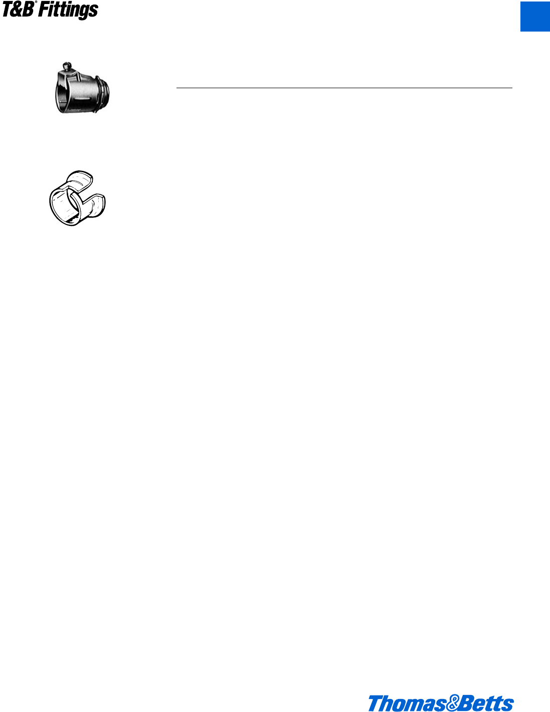
© 2002 Thomas & Betts Corporation. Specifications are subject to change without notice. www.tnb.com A163
T&B®Fittings
A
Armored Cable and Flexible Metal Conduit Fittings
Series 3110
Armored Cable Connector &
Flexible Metal Conduit
Series 422
Insuliner®Sleeve
Series 390
Anti Short Bushing
Suggested Specifications for Armored Cable and
Flexible Metal Conduit Fittings
• Armored cable (metal clad cable type
AC) and flexible metal conduit shall
conform to provisions of following
applicable standards:
Armored Cable…U.L. 4/ANSI
C33.9/CSA 22.2 No. 51
Flexible Metal Conduit…U.L. 1/ANSI
C33.92/WW-C-566/CSA 22.2 No. 56
Type of cable used and conductors
within flexible metal conduit shall be
suitable for conditions of use and
location.
• Where armored cable or flexible
metal conduit terminates into a
threadless or threaded opening, it
shall be assembled with approved fit-
tings; fittings shall be of malleable
iron/steel construction, electro zinc
plated inside outside, equipped with
nylon insulated throat and shall be of
angled saddle type as manufactured
by Thomas & Betts, series 3110.
Direct bearing screw type fittings
shall not be used.
Suitable bushing as manufactured by
Thomas & Betts, series 422 or 390,
shall be provided between the con-
ductors and armor.
• Where approved armored cable or
flexible metal conduit is used as an
equipment grounding conductor ter-
minating fitting used shall be of the
grounding type as manufactured by
Thomas & Betts, series 3110.
412031.A02 FIT 3/5 3/13/03 4:57 PM Page 163
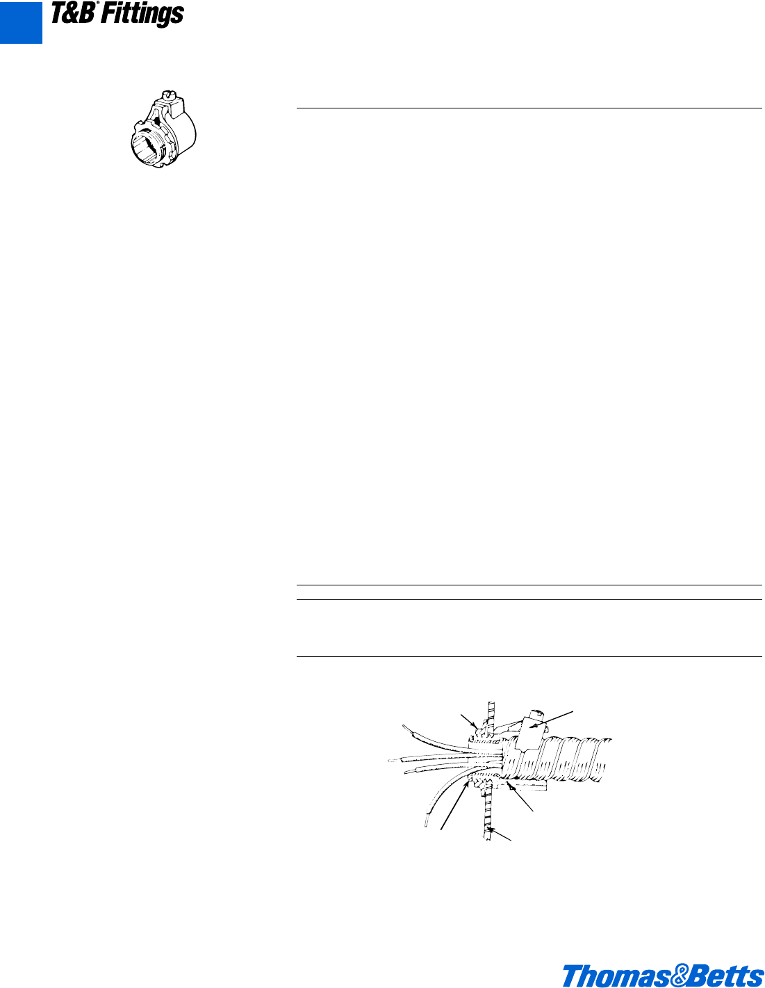
A164 © 2002 Thomas & Betts Corporation. Specifications are subject to change without notice. www.tnb.com
A
T&B®Fittings
Armored Cable and Flexible Metal Conduit Fittings
3110 Series
Range Hub Size Conduit Size Cable Opening
3110 Series Straight Connectors b" thru 5" NPS c" thru 5" .437" to 5.500"
3130 Series 90° Connectors b" thru 4" NPS c" thru 4" .437" to 4.560"
(All hubs provided with
straight pipe threads NPS.)
Locknut Saddle
Typical
Installation
Body
Box or Enclosure Wall
Insulated Throat
Armored Cable & Flexible Metal Conduit Connectors
Application
• To connect and effectively bond
armored cable or flexible metal con-
duit to a box or an enclosure.
Features
• Provided with a saddle designed to:
(1) Firmly secure conduit in place
without damaging cable armor
(Mechanical holding power of
angled wedge assembly increas-
es with increased strain.).
(2) Provide high quality bond
between conduit or cable and is
unaffected by vibrations.
(3) Centralize conduit or cable with
respect to throat opening for
conductors.
• Insulated throat protects conductors
during and after installation, reduces
wire pull effort and prevents thread
damage in handling.
• Locknuts designed to provide effec-
tive bond between connector and box
or enclosure, will not vibrate loose.
• Designed with fewer screws –
reduces installation time and cost.
• Rugged all steel or malleable iron
construction.
• Suitable as a grounding means per
N.E.C. Article 350-5 (thru 3" trade
size only).
• Suitable for hazardous location use per
Class 1 Division 2 N.E.C. 501-4 (b).
Standard Material/Finish
Body.................Steel or malleable iron/
Electro Zinc Plated &
Chromate Coated
Saddle ...........Steel/Electro Zinc Plated
& Chromate Coated
Screws .......Steel/Electro Zinc Plated &
Chromate Coated
Insulator.......Thermoplastic/As Molded
Conforms to:
U.L. 514B
CSA C22.2 No. 18
NEMA FB1
Listed/Certified by:
U.L. (U.L. File No. 23018)
CSA (LR-2884, LR-4484)
412031.A02 FIT 3/5 3/13/03 4:57 PM Page 164
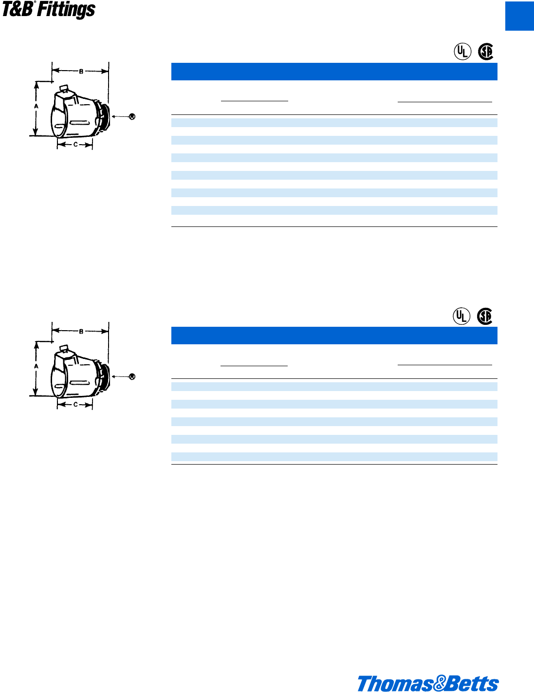
© 2002 Thomas & Betts Corporation. Specifications are subject to change without notice. www.tnb.com A165
T&B®Fittings
A
Armored Cable and Flexible Metal Conduit Fittings
Steel or malleable iron.
The tough lining of insulation and the Tite-Bite®
principles make these connectors a “must”
when conductors are subject to conditions of
vibration or strain.
TITE-BITE®Connectors* – Nylon Insulated
Cable
Cat. Opening Trade K.O. Dimensions (in.)
No. max. min. Size Size A†BC
3110** .656 .437 c" d" 1b 1a g
3112 .937 .750 d" d" 1b 1a g
3115 1.125 .906 f" f" 1A 1f 1r
3117 1.468 1.250 1" 1" 2c 1f 1a
3118*** 1.750 1.562 1b" 1b" 2f 2 1b
3119*** 2.031 1.812 1d" 1d" 3a 2e 1f
3120*** 2.500 2.312 2" 2" 3f 2f 1m
3121*** 3.062 2.812 2d" 2d" 4c 3b 2b
3122*** 3.562 3.312 3" 3" 5 3b 2b
3123***†† 4.060 3.620 3d" 3d" – – –
3124*** 4.560 4.120 4" 4" – – –
3125††† 5.500 4.600 5" 5" – – –
* U.L. Listed as a grounding means under NEC 350-5.
** U.L. Listed for armored cable only.
*** U.L. Listed for flexible metal conduit only.
Material: Steel thru f" trade size.
†Approximate dimension with screw at minimum height.
U.L. File No. E 23018
CSA File No. 2884
†† CSA not applicable.
††† Not U.L. Listed or CSA Certified.
TITE-BITE®Connectors*
Cable
Cat. Opening Trade K.O. Dimensions (in.)
No. max. min. Size Size A†BC
300TB** .656 .437 c" d" 1b 1j k
302 .937 .750 d" d" 1e 1L 1ƒ
304 1.093 .906 f" f" 1g 1L 1r
306 1.468 1.250 1" 1" 2h 1f 1a
308*** 1.750 1.562 1b" 1b" 2j 2o 1b
310*** 2.031 1.812 1d" 1d" 2e 2l 1f
312*** 2.500 2.312 2" 2" 3a 2m 1m
314*** 3.062 2.812 2d" 2d" 3d 3a 2b
316*** 3.562 3.312 3" 3" 4h 3i 2b
* U.L. Listed as a grounding means under NEC 350-5.
** U.L. Listed for armored cable only.
*** U.L. Listed for flexible metal conduit only.
†Approximate dimension with screw at minimum height.
U.L. File No. E 23018
CSA File No. 2884
Material: Steel thru f" trade size.
Steel or malleable iron.
Easy to install with double grip saddle. These
connectors are completely salvageable. The 2⁄3"
and 1⁄2" sizes are made of formed steel which
produce a uniform high quality and a smooth
throat that protects conductor insulation. 3⁄4"
and larger size are malleable iron.
®
®
®
®
412031.A02 FIT 3/5 3/13/03 4:57 PM Page 165
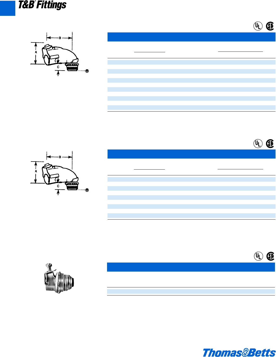
A166 © 2002 Thomas & Betts Corporation. Specifications are subject to change without notice. www.tnb.com
T&B®Fittings
TITE-BITE®Connectors* – 90° angle nylon insulated
Cable
Cat. Opening Trade K.O. Dimensions (in.)
No. max. min. Size Size A†BC
3130* .656 .437 c" d" 1X 1x n
3132* .937 .750 d" d" 1g 2j n
3135* 1.093 .906 f" f" 2a 2a l
3137 1.468 1.250 1" 1" 2y 2a d
3138*** 1.750 1.562 1b" 1b" 3j 3s l
3139*** 2.031 1.812 1d" 1d" 4 4a L
3140*** 2.500 2.312 2" 2" 4n 5h L
3141*** 3.062 2.812 2d" 2d" 6s 6 f
3142*** 3.562 3.312 3" 3" 7X 7h f
3143††† 4.060 3.620 3d" 3d" – – –
3144*** 4.560 4.120 4" 4" – – –
* U.L. Listed as a grounding means under NEC 350-5.
*** U.L. Listed for flexible metal conduit only.
†Approximate dimension with screw at minimum height.
††† Not U.L. Listed or CSA Certified.
U.L. File No. E 23018
CSA File No. 2884
TITE-BITE®Connectors* – 90° angle
Cable
Cat. Opening Trade K.O. Dimensions (in.)
No. max. min. Size Size A†BC
321 .656 .437 c" d" 1X 1d c
323 .937 .750 d" d" 1g 2c w
325 1.093 .906 f" f" 2a 2a f
326TB 1.468 1.250 1" 1" 2y 2a 1
327*** 1.750 1.562 1b" 1b" 3a 3e –
328*** 2.031 1.812 1d" 1d" 4a 4a –
329*** 2.500 2.312 2" 2" 4c 4O –
330*** 3.062 2.812 2d" 2d" 6d 6 –
331*** 3.562 3.312 3" 3" 5A 7 –
* U.L. Listed as a grounding means under NEC 350-5.
*** U.L. Listed for flexible metal conduit only.
†Approximate dimension with screw at minimum height.
U.L. File No. E 23018
CSA File No. 2884
Armored Cable and Flexible Metal Conduit Fittings
Steel or malleable iron.
Available with or without insulated throat, this
Tite-Bite®connector line is by far the easiest
and best to install when making sharp bends at
the enclosure or equipment. It has all of the
advantages of the straight connector with only
one screw to tighten, except in the larger sizes
where there are two. A peep hole on top pro-
vides for easy inspection of the ABC bushing.
Narrow design makes it easy to install connec-
tors in adjacent knockouts.
The angle clip gives secure mechanical grip
that tightens under tension or vibration.
Throat is long enough to install in cast hous-
ing knockouts. The 3⁄8" and 1⁄2" sizes are of
steel construction. The 3⁄4" and larger sizes
are malleable iron.
®
®
®
®
• Unique saddle design firmly secures cable in
place, provides holding power in excess of
listing agency requirements, and assures
high quality bonding.
• Removable bushing design covers wide
range, reduces inventories.
• Can be used on smooth or corrugated alu-
minum sheathed and steel MC cable.
• One screw provides quick installation.
TITE-BITE®Aluminum Sheathed Cable Connectors
Dia. Range
Alum. Hub
Cat. No. Sheath (in.) Size
2492 (.370-.500) d"
U.L. Listed as a grounding means for steel MC cable and ALS. For dry location.
U.L. File No. E 36017
CSA File No. 589
Tite-Bite®Connectors are approved for continous sheathed corrugated MC cable.
®
®
A
412031.A02 FIT 3/5 3/13/03 4:57 PM Page 166
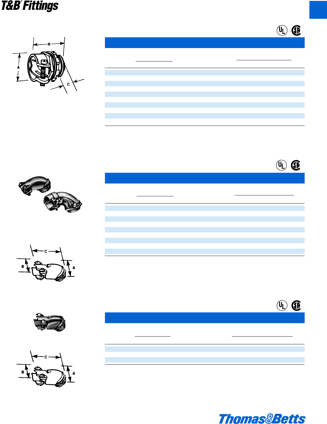
© 2002 Thomas & Betts Corporation. Specifications are subject to change without notice. www.tnb.com A167
T&B®Fittings
Armored Cable and Flexible Metal Conduit Fittings
T&B squeeze connectors will fit every size of
armored cable, leaded cable and flexible con-
duit. Malleable iron or steel construction. Part
No. 253 is steel.
Squeeze Connectors*
Cable
Cat. Opening Trade K.O. Dimensions (in.)
No. max. min. Size Size A†BC
252*** .531 .437 j" c" m A X
253TB** .585 .455 c" d" O 1$ e
254-TB .938 .812 d" d" 1r 1c u
255 1.094 .938 f" f" 1b 1w k
256 1.375 1.250 1" 1" 1x 1e d
257*** 1.656 1.500 1b" 1b" 1g 1z w
258*** 1.875 1.688 1d" 1d" 2b 1k l
259*** 2.500 2.313 2" 2" 2O 2e L
249*** 3.062 2.812 2d" 2d" 3j 2L f
277*** 3.563 3.312 3" 3" 3m 2g f
* U.L. Listed as a grounding means under NEC 350-5.
** U.L. Listed for armored cable only. Fitting material steel.
*** U.L. Listed for flexible metal conduit only.
†Approximate dimension with screw at minimum height.
U.L. File No. E 23018
CSA File No. 2884
Squeeze Connectors – 90° angle
Cable
Cat. Opening Trade K.O. Dimensions (in.)
No. max. min. Size Size A B C
266-TB* .656 .406 c" d" 1d 1u 1k
272** .812 .688 c" d" 1l 100 –
268-TB .937 .813 d" d" 1L 1m 1g
279 1.000 .875 f" f" 1m 2h 1m
270 1.125 1.000 f" f" 1g 1f 1m
273TB 1.406 1.187 1" 1" 2c 2r 2k
274*** 1.656 1.375 1b" 1b" 3 3 3
275*** 1.875 1.625 1d" 1d" 3c 3j 4
276*** 2.500 2.125 2" 2" 4d 3m 4g
* U.L. Listed as a grounding means under NEC350-5.
** U.L. Listed for armored cable only.
*** U.L. Listed for flexible metal conduit only.
U.L. File No. E23018
CSA File No. 2884
Squeeze Connector – 45° angle
Cable
Cat. Opening Trade K.O. Dimensions (in.)
No. max. min. Size Size A B C
265* .656 .406 c" d" 1w v 1a
267 .937 .813 d" d" 1z d 1b
269 1.125 1.000 f" f" 2 w 1l
* U.L. Listed as a grounding means under NEC350-5.
U.L. File No. E-23018
CSA File No. 2884
3⁄8" and 1⁄2" sizes made in steel. Cap lifts off by
simply loosening screws part way. Only two
screws to tighten. 3⁄4" size and larger made of
malleable iron.
3⁄8" and 1⁄2" sizes made in steel. Cap lifts off by
simply loosening screws part way.
®
®
®
®
®
®
A
412031.A02 FIT 3/5 3/13/03 4:57 PM Page 167
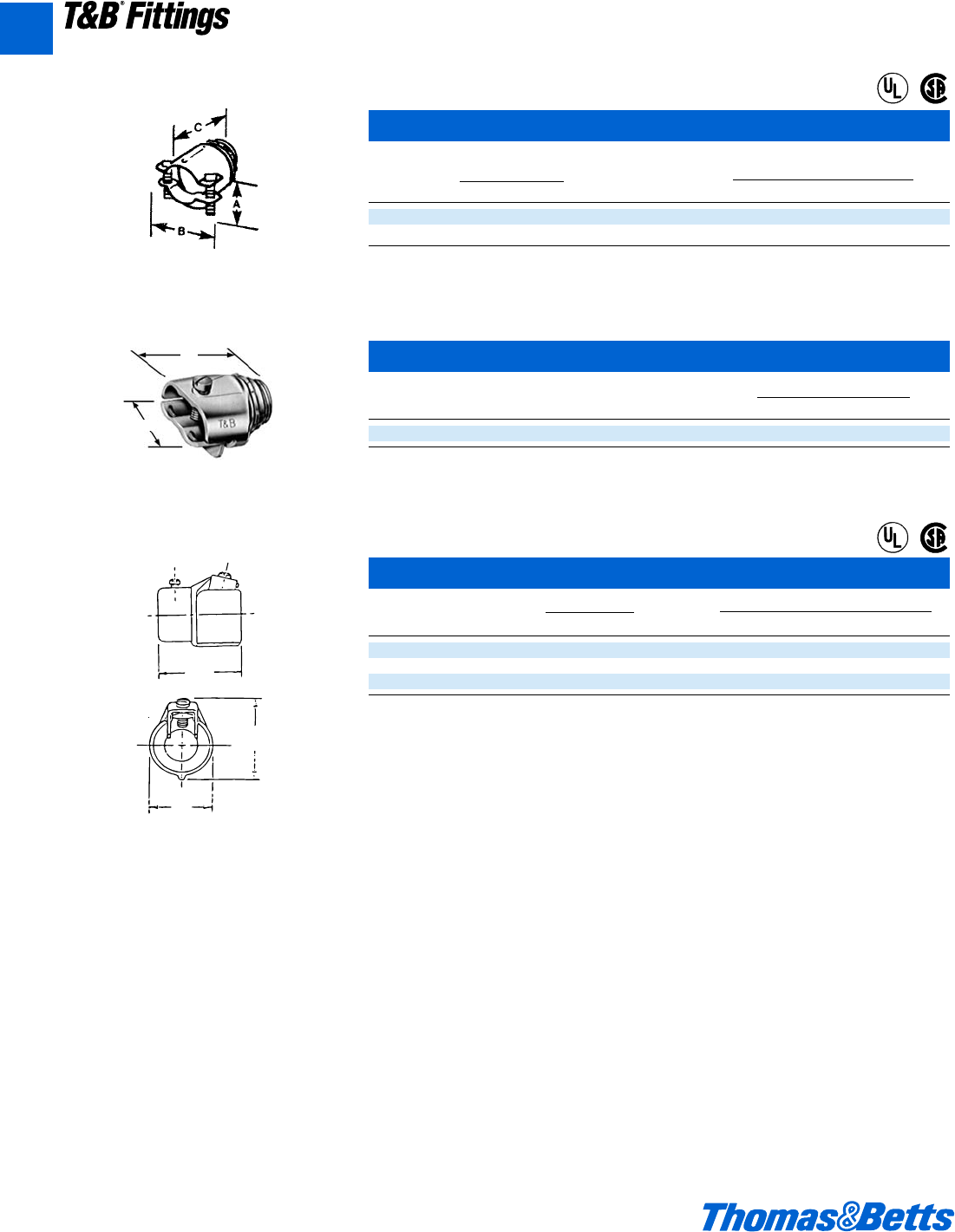
A168 © 2002 Thomas & Betts Corporation. Specifications are subject to change without notice. www.tnb.com
A
T&B®Fittings
Two-Screw Connectors
Cable
Cat. Opening Trade K.O. Dimensions (in.)
No. max. min. Size Size A B C
3301-TB** .656 .250 c" d" O 1j 1h
3312-TB .937 .500 d" d" 1p 1e 1c
** U.L. Listed for armored cable only.
U.L. File No. E 1383
CSA File No. 2884
Duplex Clamp Connector
Cat. Dimensions (in.)
No. K.O. Size A B
291-TB d" 1u" 1L"
* U.L. Listed as grounding means under NEC 350-5.
U.L. File No. E 1383
CSA File No. 2884
Adapter – EMT to Flex
Cat. Size Dimensions (in.)
No. Flex to EMT A B C
503TB d" - d" 1y 1i 1g
504 f" -f" 1A 1k 2a
505-TB 1" - 1" 2o 2h 2e
CSA File No. 8994
U.L. File No. E-23018
Armored Cable and Flexible Metal Conduit Fittings
Formed steel body with carefully round bush-
ing. The armor gripping saddle stays open by
itself when cable is being inserted.
Malleable iron.
For non-metallic and armored cable.
A
B
A
B
C
(MAX)
TITE-BITE®Connector design holds flexible
metal cable firmly in place with a single screw
rather than two screws.
®
®
®
®
412031.A02 FIT 3/5 3/13/03 4:57 PM Page 168
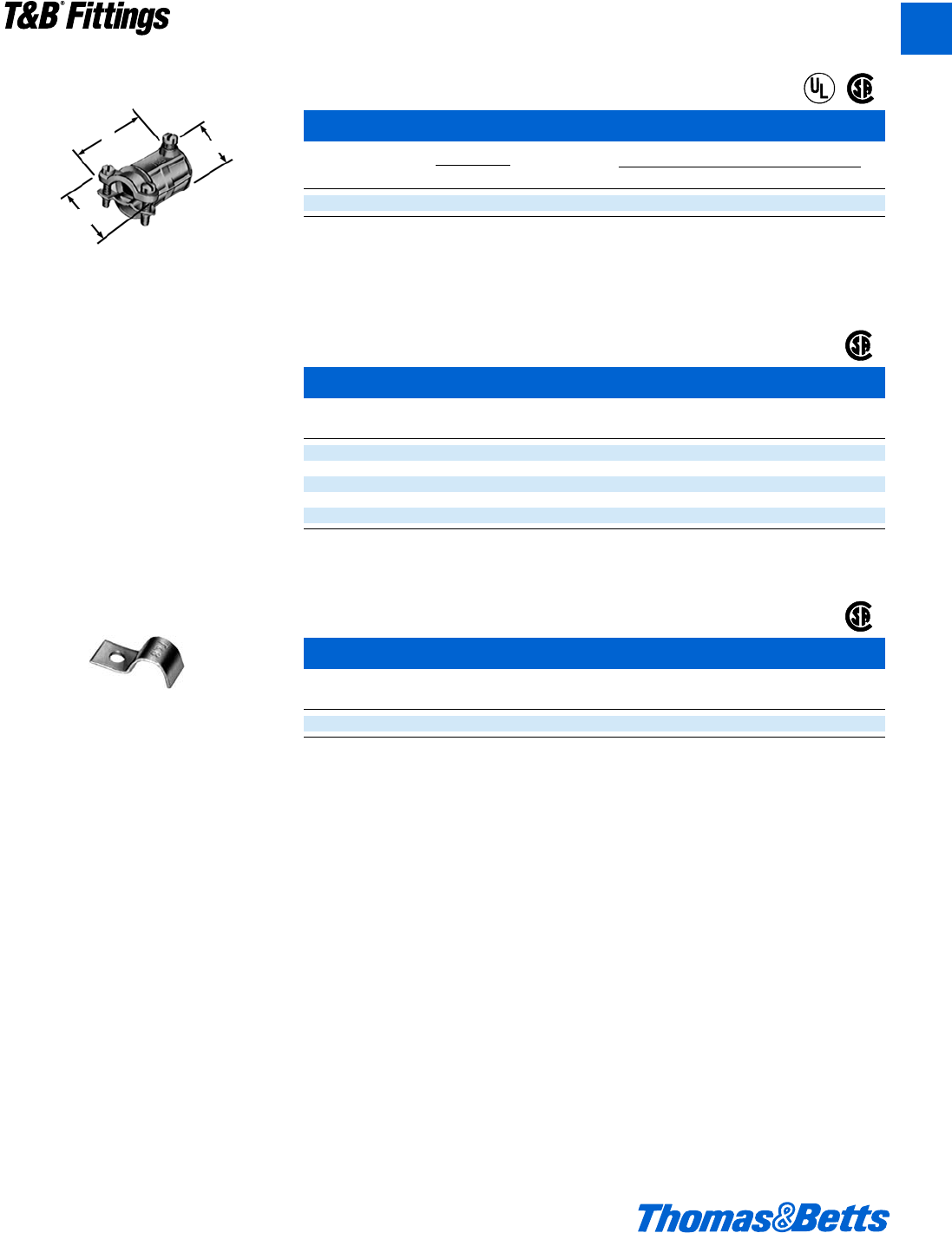
© 2002 Thomas & Betts Corporation. Specifications are subject to change without notice. www.tnb.com A169
T&B®Fittings
A
Armored Cable and Flexible Metal Conduit Fittings
A one piece fitting that couples 3⁄8" flexible
metal conduit to 1⁄2" electrical metallic tubing
(EMT).
Combination Coupling
Cat. Size Dimensions (in.)
No. Flex to EMT A B C
449-TB* c" - d" 1y 1X n
* U.L. Listed as a grounding means under NEC 350-5.
Cable opening: max. .656, min. .250
U.L. File No. E-23018
CSA File No. 2884
Anti-Short Bushing
Cat.
No. Size
390 14-2, 14-3, 12-2
391 14-4, 12-3, 6-1, and 4-1
392 12-4, 10-2, 10-3 and 2-1
393 10-4, 8-2, 8-3, and 1-1
394 8-4, 6-2, 6-3, 4-2, 4-3, and 6-4
Colorized
Temperature Rating: 240°F
CSA File No. 589
U.L. not applicable.
Strap
Cat.
No. Size
65-TB c" Flex
Anti-short bushings are made of smooth plas-
tic, and designed to protect conductor insula-
tion from rough edges of armored cable and
flexible metal conduit.
Elongated bolt hole makes alignment easy,
even when holes in mounting surface are off
center. Snap on features hold strap in place.
A
B
C
®
®
®
®
412031.A02 FIT 3/5 3/13/03 4:57 PM Page 169

A170 © 2002 Thomas & Betts Corporation. Specifications are subject to change without notice. www.tnb.com
A
T&B®Fittings
Non-Metallic Sheathed Cable Fittings
Please Note
The excerpts and other material herein, whether relating
to the National Electrical Code, the Underwriters
Laboratories, Inc. listing, to industry practice or otherwise, is
not intended to provide all relevant information required for
use and installation. Reference to original or primary source
material and data is mandatory before any application or
use is made of the product.
Non-Metallic Sheathed Cable
Ref. NEC Article 336
Code defines Non-Metallic Sheathed
Cable as, “A factory assembly of two
or more insulated conductors having
an outer sheath of moisture resistant,
flame retardant, non-metallic material.”
Non-metallic sheathed cable is con-
structed of insulated conductors (14 to
2 AWG Copper or 12 to 2 AWG
Aluminum or Copperclad Aluminum),
and an outer non-metallic sheath clas-
sified as Type NM or Type NMC.
Non-metallic sheath cable is provid-
ed with or without a bare or insulated
equipment grounding conductor. Non-
metallic sheathed cable is rated for
60°C service with voltage limitation of
600 volts.
Type NM – has flame retardant
moisture resistant sheath.
Type NMC – has flame retardant
moisture resistant, fungus resistant –
and corrosion resistant sheath.
Non-metallic sheathed cable is per-
mitted by code to be used exposed or
concealed in one, two or multifamily
dwellings or other structures not
exceeding three floors. Use of Type NM
cable is restricted to dry locations where
as Type NMC can be used in dry, moist,
damp or corrosive environments.
Non-metallic sheath cable (both
Type NM & NMC) is not permitted to
be used as a service conductor, in
commercial garages, in hoists or can-
not be embedded in cement, concrete
or aggregate. With minor exceptions
use of non-metallic sheathed cable is
also prohibited in theaters or any haz-
ardous locations.
NEC Section 336-5 requires that cable
be secured in place by suitable means
so as not to injure the cable. Adequate
protection for cable is also required when
run is exposed, through joists or rafters,
through floors, in unfinished basements
and accessible attics.
Cable bends are limited to a minimum
of five times the diameter of the cable.
NEC 300-4(b) requires that cable be
protected from physical damage when
it passes through factory or field
punched, cut or drilled holes in metal
members. A bushing or grommet firmly
secured in place is recommended.
Portions of this section reprinted by
permission from NFPA 70-1999,
National Electrical Code®,
Copyright © 1977, National Fire
Protection Association, Boston, MA.
Please refer to the following for further
details and complete information:
1. NEC Article 336…Non-Metallic
Sheathed Cable (Type NM & NMC)
2. NEC Article 300…Wiring Methods
3. U.L. 719, ANSI C33.56…Safety
Standards for Non-Metallic
Sheathed Cable
4. U.L. 514B, Safety Standards for
Outlet Boxes and Fittings
5. NEMA FB-1…Standards
Publication. Fittings and Supports
for Conduit and Cable Assemblies
6. CEC Section 12-600…Wiring
methods (Non-Metallic Sheathed
Cable)
7. CSA C22.2 No. 48…Safety
Standards for Non-Metallic
Sheathed Cable
8. CSA C22.2 No. 18…Safety
Standards for Outlet Boxes,
Conduit Boxes and Fittings
412031.A02 FIT 3/5 3/13/03 4:57 PM Page 170
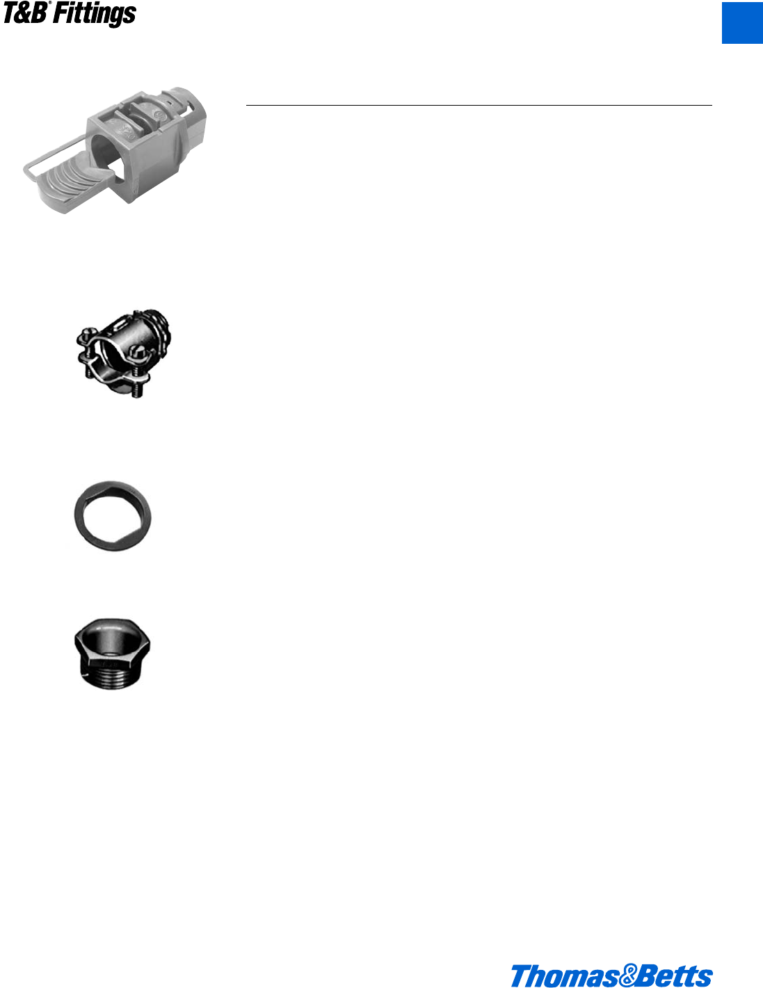
© 2002 Thomas & Betts Corporation. Specifications are subject to change without notice. www.tnb.com A171
T&B®Fittings
A
Non-Metallic Sheathed Cable Fittings
Series 3300
Non-Metallic Sheathed Cable
and Flexible Cord Connectors
(All Plastic)
Series 3302M
Non-Metallic Sheathed Cable
and Flexible Cord Connectors
(Steel)
Series 3210
Knockout Bushings
Series 1942
Insulated Nipples
Suggested Specifications for Non-Metallic Sheathed Cable
• Where non-metallic sheathed cable or
flexible cord terminates into a thread-
ed or threadless opening, terminating
fittings used shall be approved for the
purpose by nationally recognized lab-
oratory, inspection agency or product
evaluation organization.
• Terminating fittings shall be of mal-
leable iron, steel, or thermoplastic con-
struction designed to provide adequate
strain relief and positively prevent dam-
age to jacket or conductor insulation
such as series 3300 or 3302M manu-
factured by Thomas & Betts.
Ferrous metal fittings shall be electro
zinc plated inside/outside including
threads and bushed with a nylon
insulated throat.
Thermoplastic material used for con-
nector construction shall be of high
impact strength suitable for
105°C/221°F service with a U.L. flam-
mability rating of 94V-1.
• Where non-metallic sheathed cable
passes through either factory or field
punched, cut or drilled holes in
metallic members, the cable shall be
protected by thermoplastic bushing
such as series 3210 manufactured by
Thomas & Betts. Bushing shall be
firmly secured in opening. Nylon
bushed metallic fittings such as
Thomas & Betts series 1942 may be
substituted as required.
412031.A02 FIT 3/5 3/13/03 4:57 PM Page 171
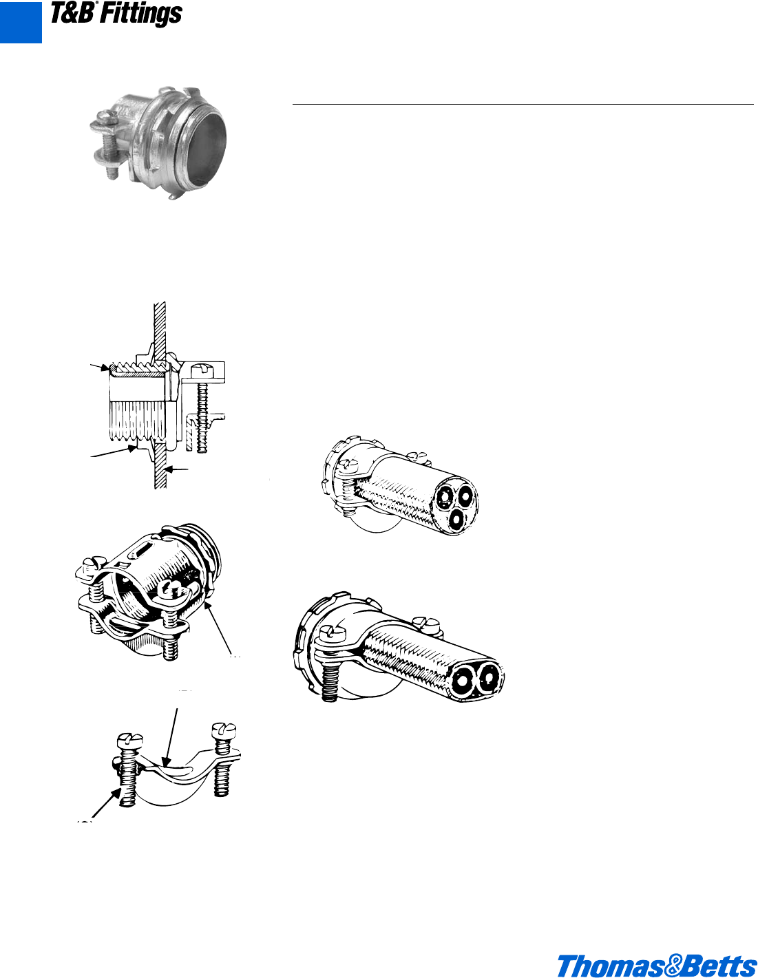
A172 © 2002 Thomas & Betts Corporation. Specifications are subject to change without notice. www.tnb.com
A
T&B®Fittings
Application
• To connect non-metallic sheathed
cable and flexible cord to a box or an
enclosure.
Features
• Rugged all steel/malleable iron con-
struction (A).
• Rounded cable clamp grip provides
superior mechanical holding power
without damaging conductor insula-
tion or outer jacket (B).
• Clamp designed to cover body open-
ing for a neat and safe installation
• Screws thread into clamp and not
body; screw heads are snug with
body and ends of screws do not pro-
ject beyond the body (C).
• Insulator firmly secured in place pro-
tects conductors and reduces wire
pulling effort; protects threads from
damaging during handling (D).
• Locknut designed to secure connec-
tor to a box or enclosure; will not
vibrate loose.
Standard Material
Body ...............d" thru 1" Steel; 1b" thru
2" Malleable Iron
Clamp...........d" thru 1b" Steel; 1b" thru
2" Malleable Iron
Locknut ....................................All Steel
Insulator .........................Thermoplastic
Standard Finish
All steel and malleable iron parts –
Electro Zinc Plated & Chromate
Coated
Range
Hub Size .......................d" thru 2" Hubs
provided with straight
pipe threads (NPS.)
Cable.............2 #14 thru 4 #4 Type NM
Cable Outside Diameter ................250"
to 1.150"
Listed/Certified by:
U.L. (U.L. File No: E-23017)
CSA (LR-589, LR-2884)
Conforms to:
U.L. 514B
CSA C22.2 No. 18
NFPA 70-1999 (ANSI)
NEMA FB1
Federal Standard H-28 (Threads)
Non-Metallic Sheathed Cable Fittings
3302M Series
Non-Metallic Sheathed
Cable Connector
Typical Installation
Typical Installation
(Flexible Cord)
Typical Installation
(NM-Sheathed Cable)
(D)
Locknut Box or
Enclosure Wall
(A)
Non-Metallic Sheathed Cable & Flexible Cord Connectors (Steel)
(B)
(C)
412031.A02 FIT 3/5 3/13/03 4:57 PM Page 172
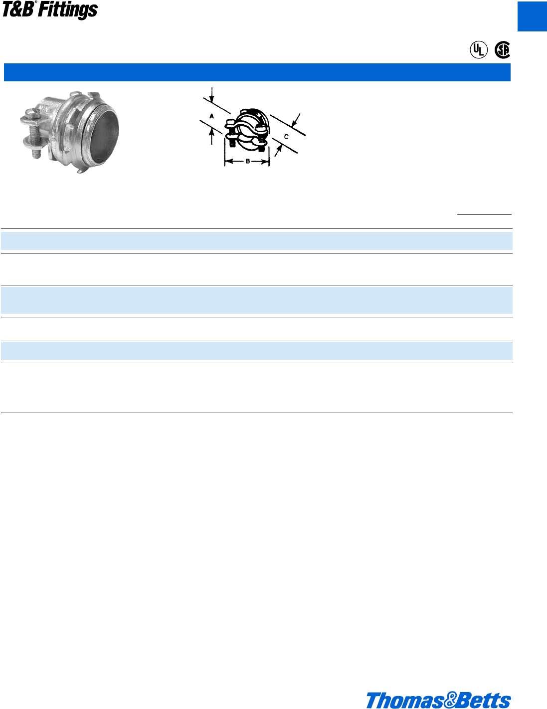
© 2002 Thomas & Betts Corporation. Specifications are subject to change without notice. www.tnb.com A173
Non-Insulated Insulated U.L. Listed & CSA Certified U.L. Listed & CSA
Cat. Cat. K.O. for the following Single (1) Certified for the following Cable Opening
No. No. Size and Pairs of (2) NM & NMC Cable Service Entrance Cables A B C max. min.
3302-TB* 3302M-TB d" (1) 2#14, 2#12, 2#10, 3#14, 2#12 thru 2#4, 3#12, 3#10 O" 1c" 1" .590 .250
3#12, 3#10, (2) 2#14, 2#12
3303-TB 3303M f" (1) 2#8, 2#6, 3#8 2#8 thru 2#1/0, 3#8, 3#6, 1b" 1e" 1i" .750 .530
(2) 2#12, 2#10, 2#8, 3#14 2#6 + #8 GND
(1) 3#8, 3#6, 3#4 2#1, 2#1/0, 3#6 thru 3#2,
3304 3304M 1" (2) 2#8, 3#10 2#4 + #6 GND, 2#3 + #5 1v" 1g" 1b" .990 .690
GND, 2#2 + #4 GND
(1) 3#8, 3#6, 3#4 3#2 thru 3#2/0, 2#1 + #3
3305 3305M 1b" (2) 2#8, 2#6, 2#4, 3#8 GND, 2#1/0 + #2 GND, 1n" 2r" 1s" 1.320 .850
2#2/0 + #1 GND
3306 3306M 1d" (1) 3#4 3#3/0, 3#4/0, 2#3/0 + #1/0 2q" 2y" 1e" 1.515 .930
GND, 2#4/0 + #2/0 GND
3307 3307M 2" Max. 1.98", Min. 1.15"
3308† – 2d" Max. 2.38", Min. 1.5"
3309† – 3" Max. 2.88", Min. 1.75" – 2A" 3j" 1C" 1.980 1.150
3310† – 3d" Max. 3.38", Min. 2.25"
3311† – 4" Max. 3.88", Min. 2.5"
* U.L. Listed for use with rubber and thermoplastic flexible cords (both single and multiple cords and 2 oval cables).
†Not U.L. Listed or CSA certified.
U.L. Listed for multiple cords and cables.
CSA File No. 2884
U.L. File No. E-23013 – d" – 1d"; U.L. File No. E-15170 – 2"
Non-Metallic Sheathed Cable Fittings
Steel or malleable iron.
Rounded cable grip and smooth bushing protect
the cable sheath and wire insulation. Since sad-
dle is threaded, screws do not travel or extend
beyond the connector body as it is clamped to
the cable. An extra lip on the saddle closes the
unused part of the connector opening.
Two-screw Connectors
®
®
A
T&B®Fittings
412031.A02 FIT 3/5 3/20/03 3:06 PM Page 173
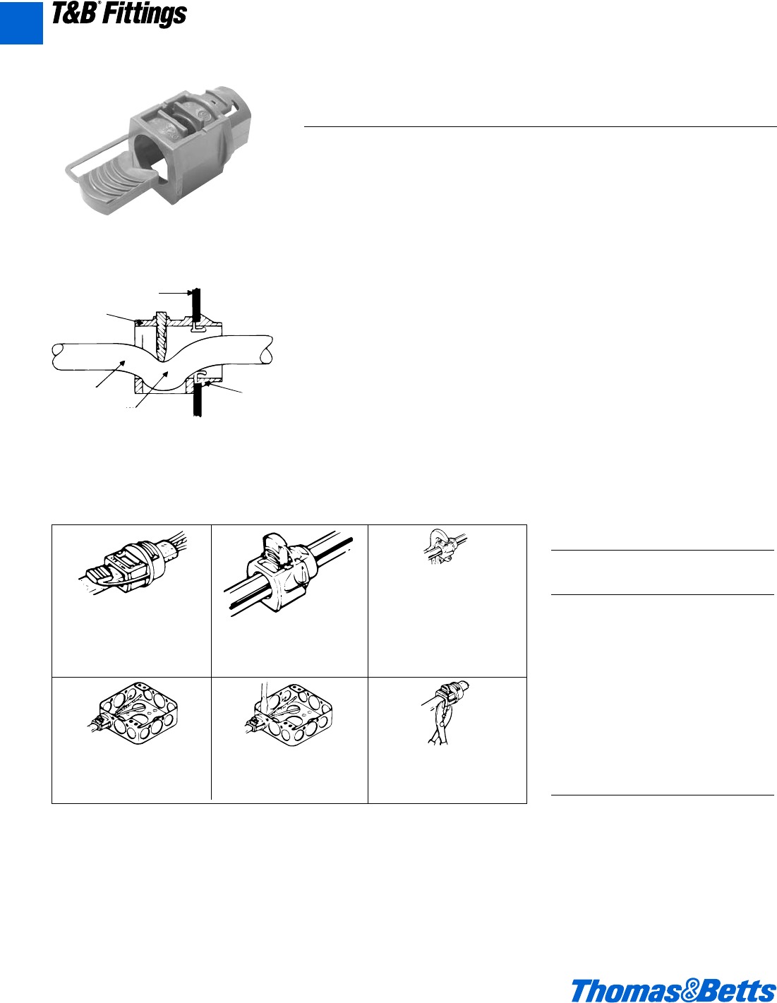
A174 © 2002 Thomas & Betts Corporation. Specifications are subject to change without notice. www.tnb.com
T&B®Fittings
Non-Metallic Sheathed Cable Fittings
3300 Series
Box or
Enclosure Wall
(C)
Cable or Cord
(A)
(B)
1. Remove sheath from end of
cable (4" or more as
required). Insert cable
through connector as shown
(Cable under button).
4. Snap connector into knockout
box. If desired this step can
be done prior to Step 1.
3. With grooved pliers, or paral-
lel jaw type pliers (commer-
cially available) squeeze
button into cord or wires as
far into connector body as
possible.
Note: It may be necessary to
re-adjust pliers to insure
button is properly installed.
6. To remove from cable cut
connector as shown.
2. Insert button into cavity.
5. To remove from knockout box
depress ears.
Non-Metallic Sheathed Cable and Flexible Cord Connectors
(All Plastic)
Typical Installation
Application
• To connect non-metallic sheathed
cable and flexible cord to a box or an
enclosure.
Features
• Design provides strain relief by par-
tially deflecting cable (A); therefore:
(1) Connector will not damage outer
covering or jacket of cable, or
conductor insulation; designed to
give safe trouble free installation.
(2) Holding power and cable strain
relief are not effected by surface
finish of outer covering or cable
jacket.
(3) Connector provides superior
holding power far in excess of
listing agency requirements.
• Snap-in one piece design; accom-
modates variation in knockout dimen-
sions, saves installation time (B).
• All high impact thermoplastic con-
struction provides:
(1) Insulated throat; conductors are
protected from abrasion.
(2) Improved dielectric strength, and
eliminates potential shorts.
(3) Corrosion resistance.
• Wide range – reduces inventories.
• Connector may be pre-installed in
box K.O., or on cable.
Standard Material
All high impact thermoplastic – U.L.
Class 94V-1 suitable for 105°C appli-
cation.
Standard Finish
As Molded
Listed/Certified by:
U.L. (U.L. File No: E-23017)
CSA (Cat. #3201, 3350) for factory
installation
(LR-589, LR-2884)
Conforms to:
U.L. 514B
CSA C22.2 #18 (Where applicable)
ANSI C33.84, NFPA 70-1999 (ANSI)
Range
Cable/
Cat. Knockout Cord
No. Size Range
3300 d" 10-2, 12-2 & 14-2 type
NM Cable.
.125" to .300" outside
diameter cord
3201 & d" 10-3, 12-3, 14-3, 10-2,
3350 12-2, 14-2 Type NM
Cable; also multiple
(2) 12-2 and 14-2 Type
NM Cable; .300" to .600"
outside diameter cord
3202 f" 8-3 and 6-3 type NM
cables; also Multiple (2)
14-3 and 10-2 Type NM
Cable; .500" to .850"
outside diameter cord
A
412031.A02 FIT 3/5 3/13/03 4:57 PM Page 174
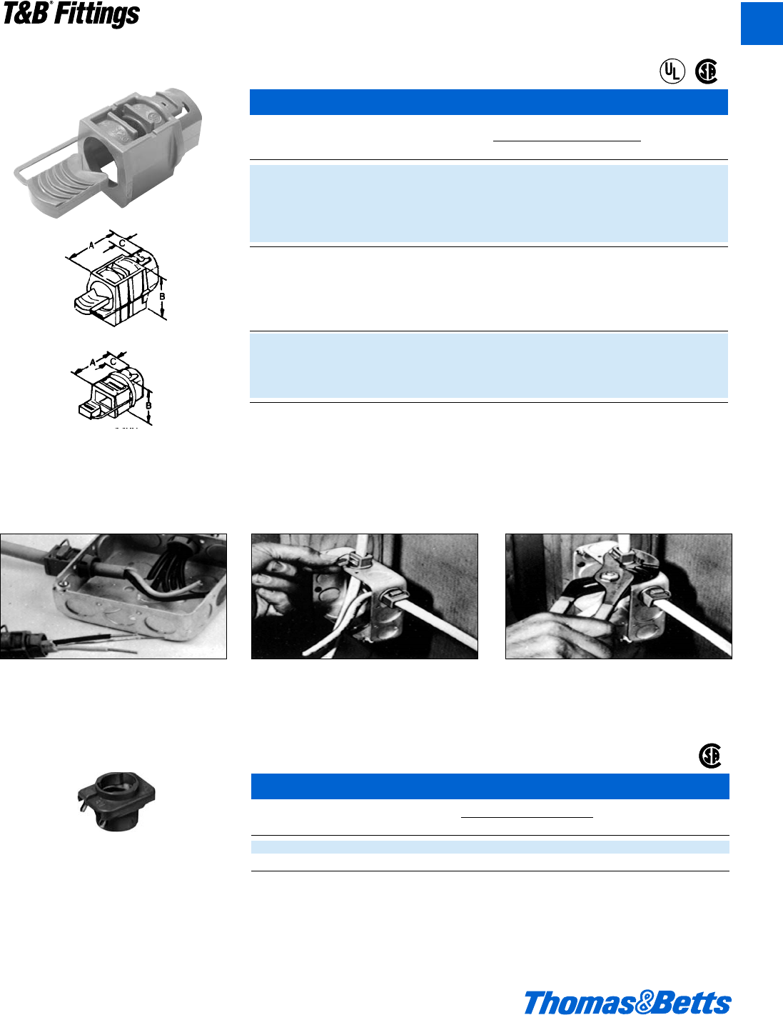
© 2002 Thomas & Betts Corporation. Specifications are subject to change without notice. www.tnb.com A175
T&B®Fittings
Non-Metallic Sheathed Cable Fittings
Figure 2
High impact thermoplastic. U.L. 94-V1.
Features push-in design. Captive locking wedge
secures cable with single squeeze of standard
electrician’s pliers. Provides excellent insula-
tion, strain-relief and high pull-out value.
All Plastic Connector for NM Cable and Flexible Cord
F
Cat. K.O. Dimensions (in.) Max. Thk.
No. Size Range Size Fig. A B C D E Enclosure H
3300 For use with 10-2, 12-2 and d" 2 1o n c .880 .795 .080 j" xl"
14-2 NM cables; 18-2 and
18-3 SJ and SJO cords and
18-2 SV, SVO, SJT and SJTO
cords, single or multiple; cord
capacity .125-.300 diameter
3201 For use with 10-3, 12-3, 14-3, d" 1 1X 1 k .880 .795 .080 y dia.
10-2, 12-2, 4-2 NM cables;
multiple (2) 12-2 and 14-2 NM
cables; single and multiple
flexible cords in wire
range .300 in. to .600 in.
3202 For use with 8-3 and 6-3 NM f" 1 1d 1j k 1.100 1.005 .090 g dia.
cables; (2) 14-3, 14-2, 12-2
and 10-2 NM cables; single
and multiple flexible cords in
wire range .500 in. to .850 in.
U.S. Pat. 3,493,205
Temperature Rating: 105°C
CSA File Nos. 584 and 2884
U.L. File No. E-23017
Figure 1
H
Hole
Size
H
Hole Size
Snap captive locking wedge into connector’s
cavity. Press locking wedge into cavity which locks
onto cable.
Cat. No. 3201 is ideal for multiple flexible
cords and cable.
®
®
No locknut required. No special tools required.
High impact thermoplastic with steel insert.
Snap-In Connector for Flexible Metal Conduit
Cat. Dimensions (in.) Unit
No. Conduit Size K.O. Size A B C Quan.
100-TB c" d" B 1u 1O 50
100BP c" d" B 1u 1O 250
100BP sold in multiples of unit package.
Temperature Rating: 105°C
U.L. 94-V1
CSA File No. 0589
®
A
412031.A02 FIT 3/5 3/13/03 4:57 PM Page 175
A176 © 2002 Thomas & Betts Corporation. Specifications are subject to change without notice. www.tnb.com
A
T&B®Fittings
U.L. Recommended Dimensions and Weights of Rigid Metal Conduit
Min. wt. at
100' Lengths
with One
Wall Coupling
Trade Thds. I.D. O.D. Thickness Attached
Size (in.) per in. (in.) (in.) (in.) (lbs.)
b180.364 .540 .088 38.5
c180.493 .675 .091 51.5
d140.622 .840 .109 79.0
f140.824 1.050 .113 105.0
1 11d 1.049 1.315 .133 153.0
1b 11d 1.380 1.660 .140 201.0
1d 11d 1.610 1.900 .145 249.0
2 11d 2.067 2.375 .154 332.0
2d 8 2.469 2.875 .203 527.0
383.068 3.500 .216 682.6
3d 8 3.548 4.000 .226 831.0
484.026 4.500 .237 972.3
4d 8 4.506 5.000 .247 1150.0
585.047 5.563 .258 1313.6
686.065 6.625 .280 1745.3
U.L. Dimensions for Intermediate Metallic Conduit†– Type I (10 ft. lgths.)
Wall
Trade O.D. (in.) Thickness
Size (in.) min. max. (in.)
d.810 .820 .070*
f1.024 1.034 .075*
11.285 1.295 .085*
1b 1.630 1.645 .085*
1d 1.875 1.890 .090*
22.352 2.367 .095*
2d 2.847 2.867 .130**
33.466 3.486 .130**
3d 3.961 3.981 .130**
44.456 4.476 .130**
* (+.015. -.000)
** (+.020. -.000)
† IMC Threads are the same as Rigid Metal Conduit Threads.
U.L. Dimensions for Intermediate Metallic Conduit – Type II (10 ft. lgths.)
Wall
Trade O.D. (in.) Thickness
Size (in.) min. max. (in.)
d.825 .840 .085*
f1.035 1.050 .085*
11.300 1.315 .108*
1b 1.645 1.660 .108*
1d 1.885 1.900 .108*
22.360 2.375 .108*
2d 2.850 2.875 .155**
33.475 3.500 .155**
3d 3.975 4.000 .160**
44.475 4.500 .160**
* (+.020. -.000)
** (+.025. -.000)
Conduit Dimensional Data
412031.A02 FIT 3/5 3/13/03 4:57 PM Page 176
© 2002 Thomas & Betts Corporation. Specifications are subject to change without notice. www.tnb.com A177
T&B®Fittings
A
Knockout (sliphole) Sizes for Electrical Conduits and Connectors
Trade Knockout Diameter
Size (in.) nom. min. max.
b.575 .559 .605
c.718 .703 .734
d.875 .859 .906
f1.109 1.094 1.141
11.375 1.359 1.406
1b 1.734 1.719 1.766
1d 1.984 1.958 2.000
22.469 2.433 2.500
2d 2.969 2.938 3.000
33.594 3.563 3.625
3d 4.125 4.063 4.156
44.641 4.563 4.672
4d 5.109 5.063 5.166
55.719 5.625 5.750
66.813 6.700 6.844
Sizes b" thru 1b" are per U.L. 514.
Sizes d" thru 6" per proposed revision to NEMA Engineering Bulletin No. 71, Aug. 1976.
U.L. Recommended Dimensions and Weight of Electrical Metallic Tubing (EMT)
Wall Min. Accept
Trade O.D. I.D.* Thickness Wt. Ft.
Size (in.) (in.) (in.) (in.) (lbs.)
c.577 ± .005 .493 .042 .230
d.706 ± .005 .622 .042 .285
f.922 ± .005 .824 .049 .435
11.163 ± .005 1.049 .057 .640
1b 1.510 ± .005 1.380 .065 .950
1d 1.740 ± .005 1.610 .065 1.100
22.197 ± .005 2.067 .065 1.400
2d 2.875 ± .010 2.731 .072 2.050
33.500 ± .015 3.356 .072 2.500
3d 4.000 ± .020 3.834 .083 3.250
44.500 ± .020 4.334 .083 3.700
* Not a requirement – included for information only.
Conduit Dimensional Data
412031.A02 FIT 3/5 3/13/03 4:57 PM Page 177
A178 © 2002 Thomas & Betts Corporation. Specifications are subject to change without notice. www.tnb.com
A
T&B®Fittings
U.L. Recommended Diameters for Flexible Metal Conduit (Greenfield)
Max.
Trade O.D. O.D. (in.)
Size (in.) (in.) min. max.
j.510 .312 .393
c.610 .375 .645
d.920 .625 .835
f1.105 .812 –
11.380 1.000 –
1b 1.630 1.250 –
1d 1.950 1.500 –
22.450 2.000 –
2d 3.060 3.500 –
33.560 3.000 –
3d 4.060 3.500 –
44.560 4.000 –
U.L. Recommended Diameters for Liquidtight Flexible Metal Conduit
Trade I.D. (in.) O.D. (in.)
Size (in.) min. max. min. max.
c.484 .504 .690 .710
d.622 .642 .820 .840
f.820 .840 1.030 1.050
11.041 1.066 1.290 1.315
1b 1.380 1.410 1.630 1.660
1d 1.575 1.600 1.865 1.900
22.020 2.045 2.340 2.375
2d 2.480 2.505 2.840 2.875
33.070 3.100 3.460 3.500
3d 3.500 3.540 3.960 4.000
44.000 4.040 4.460 4.500
Diameter of Liquidtight Non-Metallic Flexible Conduit
Trade I.D. (in.) O.D. (in.)
Size (in.) min. max. min. max.
c.485 .505 .755 .775
d.620 .640 .910 .930
f.815 .835 1.150 1.170
11.030 1.055 1.415 1.440
1b 1.370 1.395 1.800 1.825
1d 1.585 1.620 2.045 2.080
22.045 2.080 2.605 2.640
Conduit Dimensional Data
412031.A02 FIT 3/5 3/13/03 4:57 PM Page 178
