94641 Catalog
137889-Attachment 137889-Attachment 137889-Attachment Batch10 unilog cesco-content
2014-05-17
: Pdf 94641-Catalog 94641-Catalog 781810 batch2_2 unilog
Open the PDF directly: View PDF ![]() .
.
Page Count: 62
- MECHANICAL
- TYPES KS & KS-3
- TYPE SC
- TYPE KSU
- TYPE KSA
- TYPE KVS
- TYPE KVSU
- TYPE KVSW
- TYPE KVS-A
- TYPE QPX
- TYPE QPX-Y
- TYPE KPA
- TYPE KPA-UP
- TYPE KLU
- TYPE KA
- TYPE EA
- TYPE BGBL
- TYPE CL50-1 & CL50-1TN
- TYPE CL
- TYPES QA, QQA
- TYPE Q2A
- TYPE Q3A
- TYPE QB
- TYPE Q2B
- TYPE QDA
- TYPE QR
- TYPE VT
- TYPE E-C-G
- TYPES VA, VVA
- TYPE HFB-P1
- TYPE HFB-N
- TYPES KA-U, KKA-U
- TYPES KA-UAR
- TYPE K2A-U
- TYPES K3A-U, KK3A-U
- TYPES K4A-U, KK4A-U
- TYPES K11A-U, K21A-U,K22A-U
- TYPES K6A-U, K8A-U,KK6A-U, KK8A-U
- TYPE KAU-KIT
- TYPES K-AG1
- TYPES K-G1
- TYPE AMS
- TYPE AGSKIT
- TYPE UGSKIT
- Direct Burial UNITAP™ Connectors
- TYPE UGSKIT8
- TYPE UGS350ULDB
- BURNDY UNITAP™ THE MOLE™
- TYPE QGFL
- TERMINAL BLOCKS
- POWER DISTRIBUTION BLOCKS U-BLOK™
- U-BLOK™ MOUNTING PLATFORMS
- SPEC-BLOK™ POWER DISTRIBUTION CONNECTORS
- SPEC-BLOK™ MOUNTING PLATFORMS
- Questionnaire for SPEC-BLOK™ Applications
- UL LISTED POWER DISTRIBUTION BLOCKS VERSIPOLE™
- VERSIPOLE™ POWER DISTRIBUTION BLOCKS
- TYPES BIT, BITO, BISR
- TYPE BIBS
- TYPE BIBD
- TYPE BIBS-MT, BIBD-MT
- UV RATED BLACK UNITAP™
- TYPE BWTE
- TYPE BPTE

BURNDY®
Blue highlighted items are industry standard and most frequently ordered.
Canada: 1-800-387-6487 www.burndy.com US: 1-800-346-4175
Mechanical
A-1
TABLE OF CONTENTS
A-3
A-4
A-5
A-6
A-7
A-8
A-9
A-10
A-11
A-12
A-13
A-14
A-15
A-16
A-17
A-18
A-19
A-20
A-21
A-22
A-23
A-24
Types KS, KS-3, SC
Type KSU
Type KSA
Types KVS, KVSU
Types KVSW, KVS-A
Type QPX
Type QPX-Y
Types KPA, KPA-UP
Type KLU
Types KA, EA
Type BGBL
Types CL50-1, CL50-1TN, CL
Types QA, QQA
Types Q2A, Q3A
Types QB, Q2B
Types QDA, QR
Types VT, E-C-G
Types VA, VVA
Type HFB-P1
Type HFB-N
Types KA-U, KKA-U
Type KA-UAR
Type K2A-U
Types K3A-U, KK3A-U
Types K4A-U, KK4A-U,
K11A-U, K21A-U, K22A-U
Types K6A-U, K8A-U,
KK6A-U, KK8A-U
Type KAU-KIT
Type K-AG1
Type K-G1
Type AMS
Types AGSKIT, UGSKIT
Type BIBS-DB
Types UGSKIT8,
UGS350ULDB
Type BISR-DB
Types QGFL, FCB
Types KPU-AC, UCU-AC
Type BIPC
Terminal Blocks
U-BLOK™ and Platforms
SPEC-BLOK™
UL Listed Distribution
Blocks
Power Distribution Blocks,
Splice/Reducer Blocks
Types BIT, BITO, BISR
Type BIBS
Type BIBD
Types BIBS-MT, BIBD-MT
Type 1PL
Type BWTE
Type BPTE
A-25
A-26
A-27
A-28
A-29
A-30
A-31
A-32
A-33
A-34
A-35
A-36
A-37
A-38
A-39
A-40
A-41,
A-42
A-43
to
A-46
A-47
to
A-50
A-51
to
A-55
A-56
A-57
A-58
A-59
A-60
A-61
A-62
BURNDY®
Blue highlighted items are industry standard and most frequently ordered.
US: 1-800-346-4175 www.burndy.com Canada: 1-800-387-6487
Mechanical
A-2 LIGHTNING PROTECTION INFO.
Basic rules for selection are:
1. Must be like material to the conductor.
2. Two bolts to ground rod - minimum.
3. Cable to cable connections can be anything,
one bolt, two bolt, compression, etc.
4. Cable to steel structure must have 8 square
inch contact with steel.
Complies with NFPA 78-86 Ordinary Structures.
Complies with NFPA 78-86 Heavy Duty
Stacks. (Order: LD for Lead Plating for Heavy
Duty Stack applications.)
5. Heavy duty stacks - mechanical only.
6. On all connectors with heavy duty stack
rating, we must offer 1/16” thick lead plating
as an option. The reason for that is closest
25 ft. to stack opening must use lead coated
product.
SPECIAL FEATURES
Other features are also available for products
listed, such as undrilled or special drilling, 45° or
90° pad angles, belling for extra exible cable,
smooth or special threaded studs, special label-
ALL OTHER SPECIAL REQUESTS
PLEASE CONTACT
BURNDY CUSTOMER SERVICE
1-800-346-4175
REVOLUTIONARY
BURNDY® DESIGN
MEETS STRICT UL486B
STANDARDS
... and puts the bite on
aluminum connections
forever!
For use on all combinations
• Aluminum to aluminum
• Aluminum to copper
• Copper to copper
Patented
Unique “bite and grip”
TRITAP™ SERVIT® contact
delivers safe, long-term
reliability — even without
scratch brushing ... without
oxide inhibiting compounds.†
Available in sizes from #10 through 500 kcmil
Spacer provides built-in
separation to retard
galvanic corrosion
Triangular edges bite into
cable to break through
surface oxides:
• provide low contact
resistance
• produces gas tight
seal
Tin-plated contact
surface inhibits oxide
formation
Special heat-treated hard,
aluminum alloy
Anti-galling, high
efciency threaded
components result
in high contact force.
Easily installed using
standard, everyday
wrenches.
† When used in NEC applications of insulated
cables only.
ing or packaging, extra long braid, and nuclear
certication. Please contact BURNDY Customer
Service for any inquiries.
BURNDY®
Blue highlighted items are industry standard and most frequently ordered.
Canada: 1-800-387-6487 www.burndy.com US: 1-800-346-4175
Mechanical
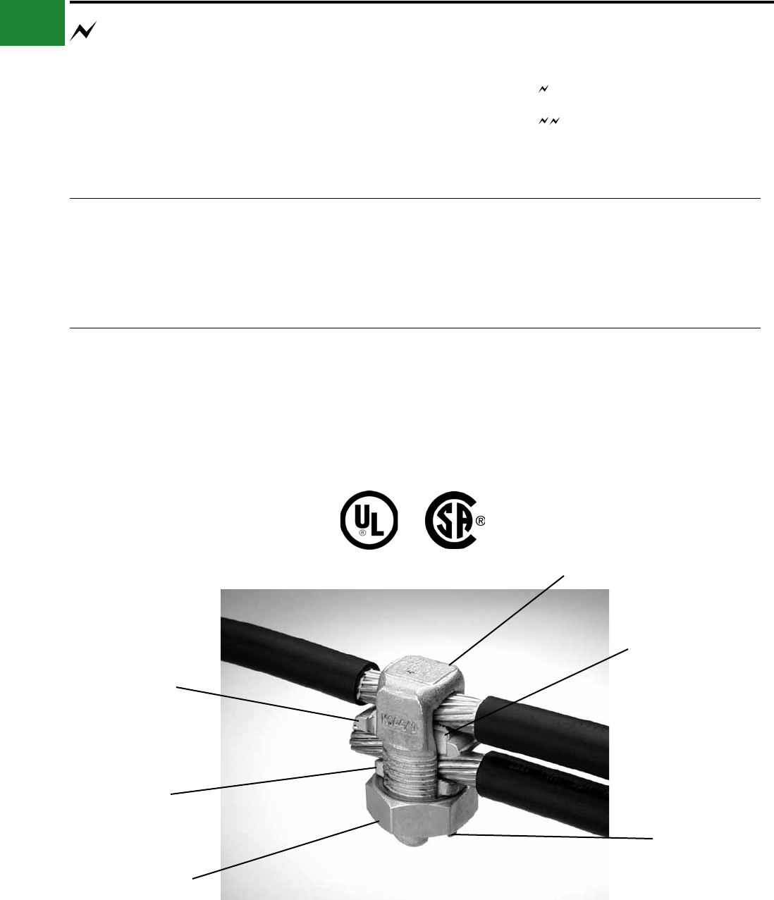
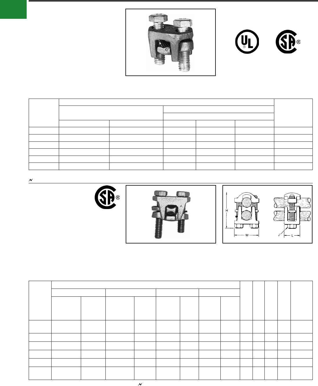
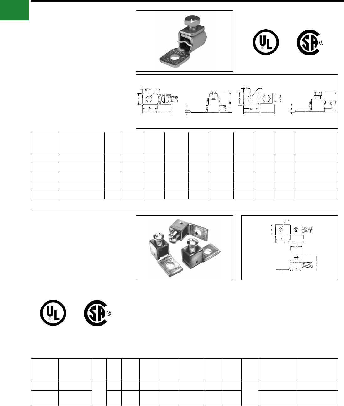
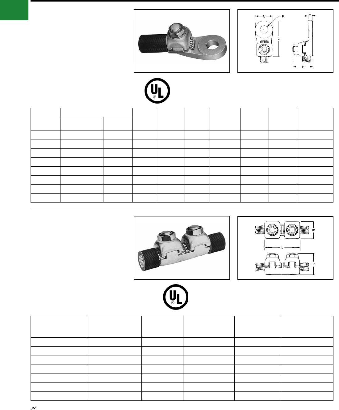
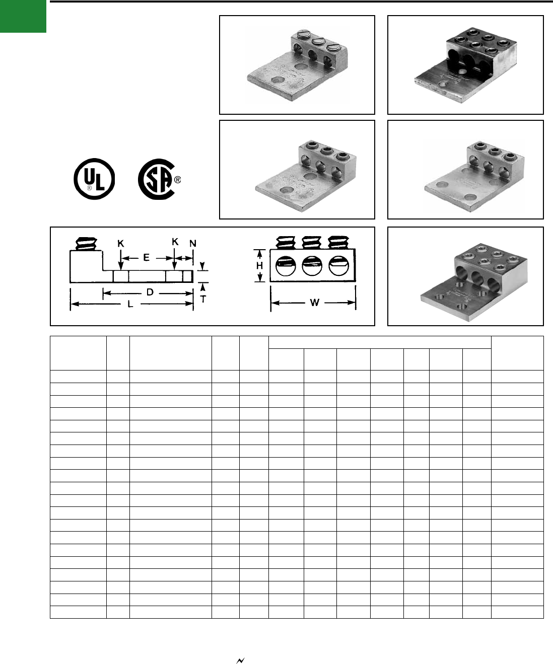
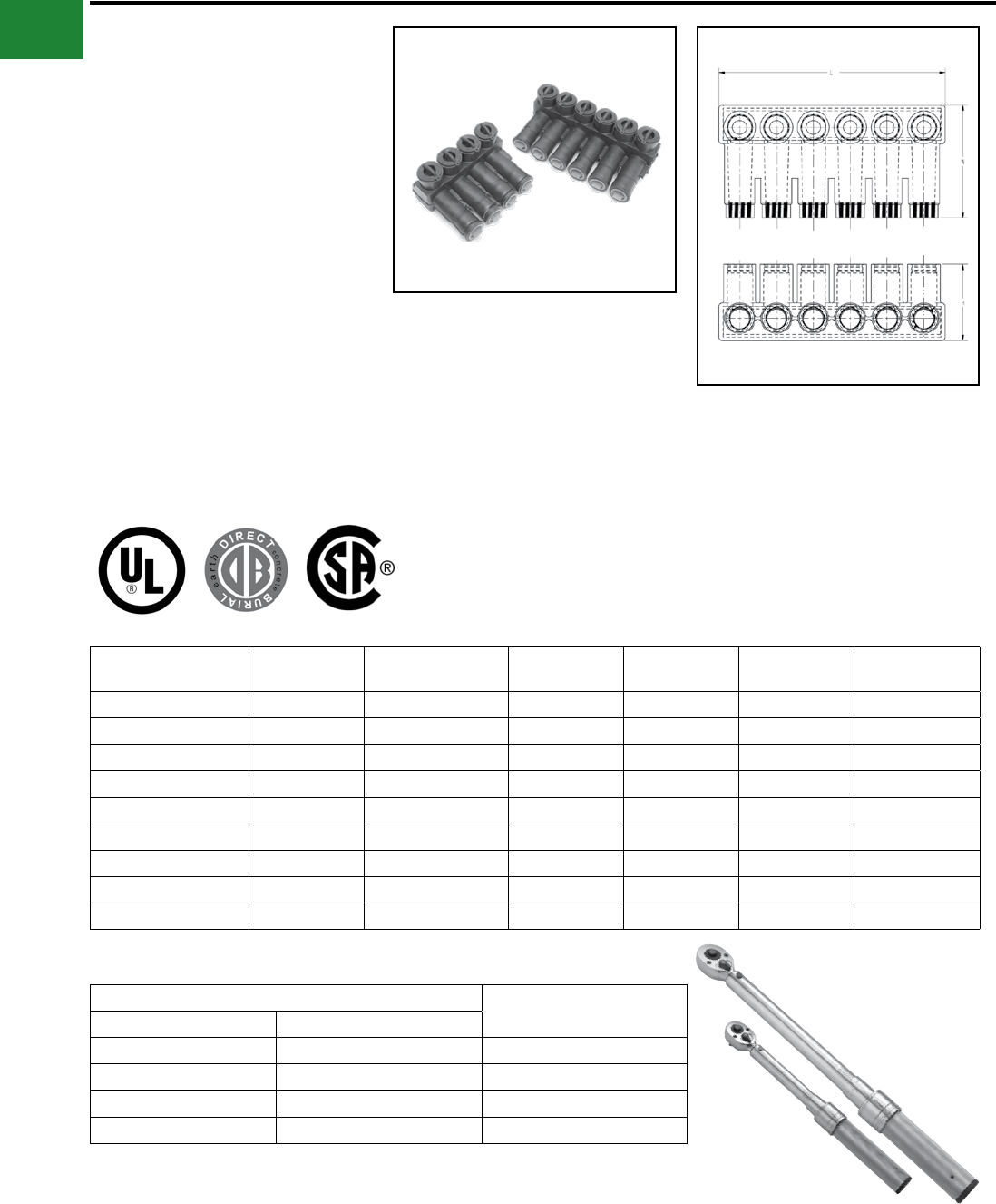
TYPES KS & KS-3
SERVIT®
For Copper, Copperweld
Compact, high strength, high copper alloy SERVIT®
split-bolt has free-running threads and easy to grip
wrench ats. Highly resistant to season cracking
and corrosion, the SERVIT® provides maximum
pressure and assures a secure connection on
all combinations of run and tap conductors. Type
KS-3 accommodates 3 maximum size conductors.
Catalog
Number
Cross
Flats L W
Conductor ▲
Recommended
Tightening
Torque (in-lb)
Copper Copperweld
Equal Run & Tap Min Tap with
Max Run
Maximum Run and Tap
Sol. Str. Type A Type D
† KS90 0.50 0.85 0.38 12 - 10 Str. 16 Str. #10 — — — 80
† KS15 0.50 0.85 0.38 10 - 8 Str. 14 Str. #8 — — — 80
† KS17 0.63 1.14 0.45 8 Str. - 6 Sol. 14 Str. #6 3 #12 8A 9-1/2D 165
* KS17-3 0.62 0.98 0.70 8 Str. - 6 Sol. 16 Str. #6 3 #12 8A 9-1/2D 165
† KS20 0.69 1.20 0.51 8 Str. - 4 Sol. 14 Str. #4 3 #10 6A 8D 165
* KS20-3 0.68 1.17 0.78 8 Str. - 4 Sol. 14 Str. #4 3 #10 6A 8D 165
† KS22 0.75 1.50 0.60 6 Str. - 2 Sol. 14 Str. #2 3 #8 4A 6D 275
* KS22-3 0.74 1.33 0.84 6 Str. - 2 Sol. 14 Str. #2 3 #8 4A 6D 275
† KS23 0.82 1.54 0.62 6 Str. - 2 Str. 14 Str. #1 3 #7 3A 5D 275
† KS25 0.94 1.77 0.73 4 Str. - 1/0 Str. 14 Str. 2/0 3 #5 2A 4D 385
† KS26 1.05 1.94 0.82 2 Str. - 2/0 Str. 14 Str. 3/0 7 #7 — — 385
† KS27 1.36 1.86 1.17 1 Str. - 3/0 Str. 8 Sol. — — — — 500
† KS29 1.36 2.07 1.17 1 Str. - 250 8 Str. 4/0 7 #5 — — 650
† KS31 1.70 2.51 1.41 1/0 Str. - 350 1/0 Str. — 19 #8 — — 650
† KS34 1.82 2.79 1.48 2/0 Str. - 500 2/0 Str. — 19 #6 — — 825
KS39 2.31 3.29 1.94 4/0 Str. - 750 4/0 Str. — 19 #5 — — 1000
KS44 2.56 3.73 2.19 300 - 1000 4/0 Str. — — — — 1100
▲ Listed torque values are for maximum conductor combinations accommodated. Consult UL486 Tables 7-4, 7-5, 7-6 for smaller conductor combinations.
See note LIGHTNING PROTECTION INFO.
* Not UL Listed or CSA Certied.
† In addition to UL Listed for wire connectors and CSA Certied, these items are also UL rated for direct burial.
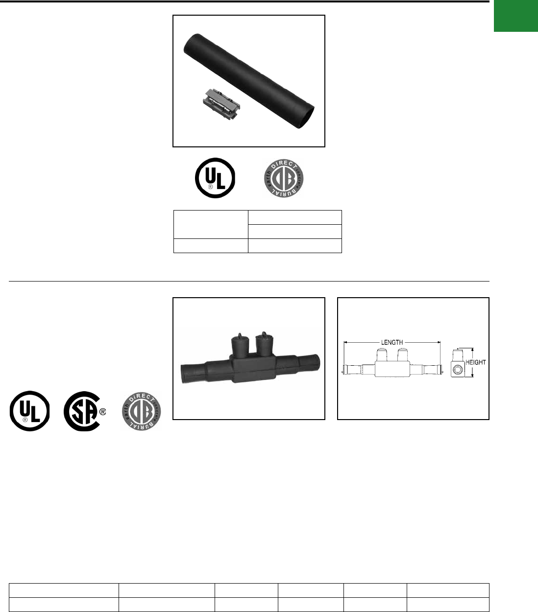
TYPE SC
SERVIT® COVER
HUG-A-BUG
Used indoors or outdoors, this compact, one-piece
plastic SERVIT® cover saves time and material,
eliminates costly taping of split-bolts. Positive latch
snaps easily and quickly over connector, ideal for
tight quarters. Self-positioning plastic ngers wrap
around wires fully insulating joint. UL Listed for 600
volt indoor application with type KS. Three covers
accommodate a range of 6 SERVIT® sizes through
2/0 Str.
Catalog
Number For Use With
SC4 KS17, KS17-3, KS20, KSU17, KSU20
SC2 KS22, KS20-3, KS23, KS22-3, KSA6, KSA4,
KSU22, KSU23
SC2/0 KS25, KS26, KSA2, KSA1/0, KSU25, KSU26
A-3
BURNDY®
Blue highlighted items are industry standard and most frequently ordered.
US: 1-800-346-4175 www.burndy.com Canada: 1-800-387-6487
Mechanical
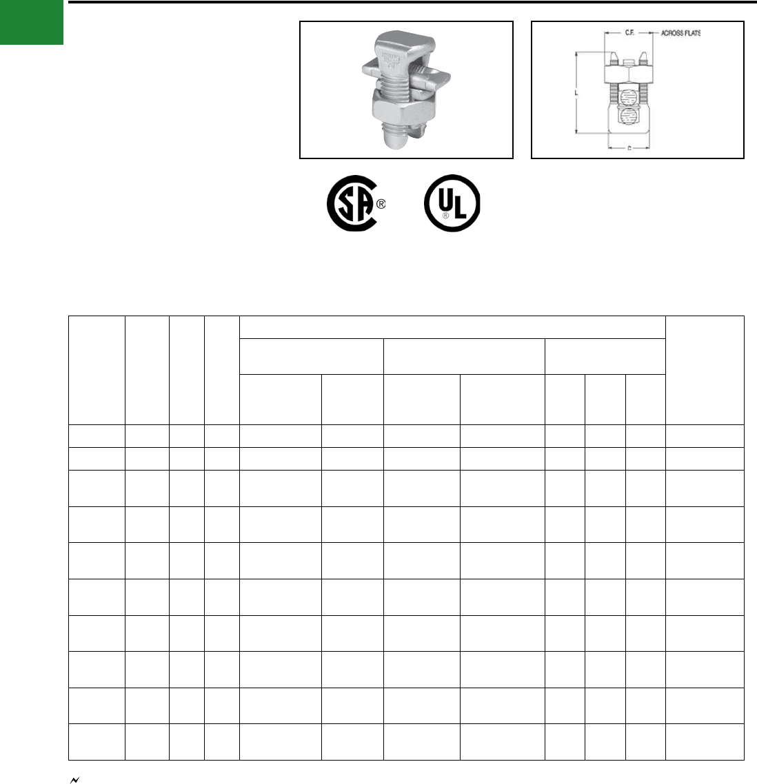
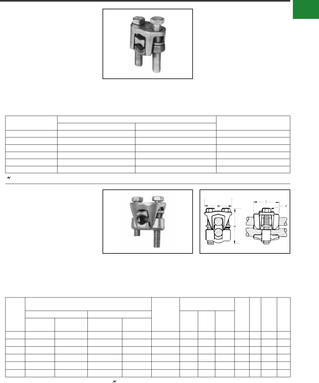
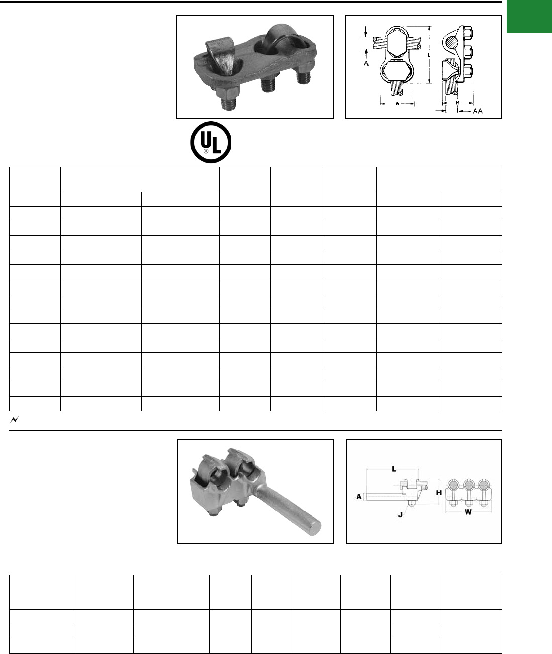
TYPE KSU
UNIVERSAL SERVIT®
For Use On All Combinations of
Copper, Aluminum, ACSR, AAAC,
5005, and Steel
Tin-plated, high strength, copper alloy SERVIT®
with spacer. Spacer separates dissimilar
conductors and provides long contact length that
prevents high pressure point contacts between run
and tap conductors.
Use of PENETROX™ joint compound
recommended with Aluminum and ACSR.
Catalog
Number
Cross
Flats L W
Conductor
Recommended
Tightening
Torque (in-lb)
Run Tap Steel
(Max Conductor)
Copper &
Aluminum
ACSR
AAAC
5005
Copper &
Aluminum
ACSR AAAC
5005
Sol.
BWG
3 Str.
BWG
Nom.
Dia.
KSU17 0.62 0.92 0.42 12 Sol. - 6 Sol. 8 (6-1) 12 Sol. - 6 Sol. 8 (6-1) 8 — 5/32 165
KSU20 0.69 1.05 0.48 10 Sol. - 4 Sol. 6 (6-1) 10 Sol. - 4 Sol. 6 (6-1) 6 8 7/32 165
KSU22 0.74 1.25 0.57 10 Sol. - 2 Sol. 6 (6-1) -
4 (7-1) 10 Sol. - 2 Sol. 6 (6-1) - 4 (7-1) 4 6 1/4 275
KSU23 0.81 1.48 0.59 8 Str. - 2 Str. 3 (6-1) -
2 (6-1) 8 Sol. - 2 Str. 6 (6-1) - 2 (6-1) — 4 5/16 275
KSU25 0.93 1.77 0.70 2 Str. - 1/0 Str. 3 (6-1) -
1 (6-1) 10 Str. - 1/0 Str. 6 (6-1) - 1 (6-1) — — 3/8 385
KSU26 1.04 1.93 0.79 2 Str.-2/0 Str. 1 (6-1) -
1/0 (6-1) 8 Str. - 2/0 Str. 6 (6-1) - 1/0 (6-1) — — 7/16 385
KSU27 1.38 2.34 1.12 1 Str. - 3/0 Str. 1 (6-1) -
2/0 (6-1) 8 Sol. - 3/0 Str. 8 (6-1) - 2/0 (6-1) — — 1/2 500
KSU29 1.38 2.50 1.58 1Str. -250 kcmil 2/0 (6-1) -
4/0 (6-1) 8 Str. - 250 6 (6-1) - 4/0 (6-1) — — 1/2 650
KSU31 1.69 2.88 1.36 1/0 Str. -
350 kcmil
3/0 (6-1) -
4/0 (6-1) 4 Str. - 350 4 (6-1) - 4/0 (6-1) — — 5/8 650
KSU34 2.00 3.12 1.47 400 - 500 kcmil 336 (30-7) -
477 (18-1) 2 Str. - 500 2 (6-1) - 477
(18-1) — — — 825
Copper Only 486A
Copper Only
Accommodates compressed conductors within conductor ranges.
See note LIGHTNING PROTECTION INFO.
A-4
BURNDY®
Blue highlighted items are industry standard and most frequently ordered.
Canada: 1-800-387-6487 www.burndy.com US: 1-800-346-4175
Mechanical
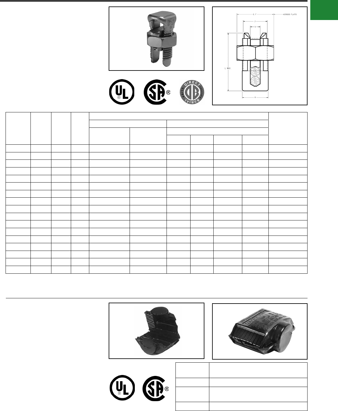
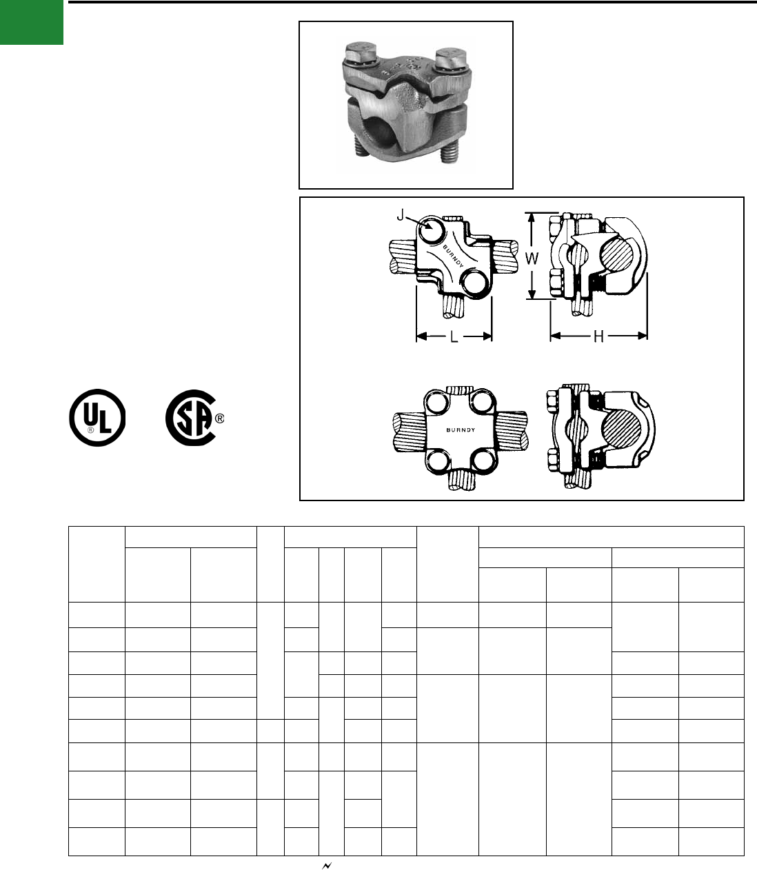
TYPE KSA
TRITAP™ SERVIT®
For All Combinations of Aluminum to
Aluminum, Aluminum to Copper and
Copper to Copper, Aluminum Alloy Tin
Plated
PATENTED TRIANGULAR
PENETRATION TECHNOLOGY
CONTACT
Catalog
Number
Cross
Flats L W
Alum. to Alum., Alum. to Copper, Copper to Copper Conductors Recommended
▲ Tightening
Torque (in-lb)
Max Run to Max Tap Min Run to Min Tap Max Run to Min Tap
KSA6 0.75 1.58 0.56 #6 Str. (0.184) -
#6 Str. (0.184)
#10 Sol. (0.102) -
#10 Sol. (0.102)
#6 Str. (0.184) -
#10 Sol. (0.102) 165
KSA4 0.81 1.38 0.62 #4 Str. (0.232) -
#4 Str. (0.232)
#8 Sol. (0.129) -
#10 Sol. (0.102)
#4 Str. (0.232) -
#10 Sol. (0.102) 165
KSA2 0.94 1.58 0.69 #2 Str. (0.292) -
#2 Str. (0.292)
#6 Sol. (0.169) -
#8 Str. (0.146)
#2 Str. (0.292) -
#8 Sol. (0.146) 275
KSA1/0 1.00 1.92 0.75 #1/0 Str. (0.373) -
#1/0 Str. (0.373)
#2 Str. Compact (0.268) -
#8 Sol. (0.129)
#1/0 Str. (0.373) -
#8 Sol. (0.129) 385
KSA2/0 1.12 1.92 0.88 #2/0 Str. (0.418) -
#2/0 Str. (0.418)
#2 Str. Compact (0.268) -
#8 Str. (0.146)
#2/0 Str. (0.418) -
#8 Str. (0.146) 385
KSA4/0 1.49 2.54 1.13 #4/0 Str. (0.528) -
#4/0 Str. (0.528)
#2 Str. Compact (0.268) -
$6 Str. (0.184)
#4/0 Str. (0.528) -
$6 Str. (0.184) 500
KSA350 1.69 3.24 1.50 350 kcmil (0.681) -
350 kcmil (0.681)
#1/0 Str. Compact (0.336) -
#4 Str. (0.232)
350 kcmil (0.681) -
#4 Str. (0.232) 650
KSA500 2.00 3.62 1.73 500 kcmil (0.813) -
500 kcmil (0.813)
400 kcmil Compact (0.659) -
#2 Str. Compact (0.268)
500 kcmil (0.813) -
#2 Str. Compact (0.268) 825
Features & Benets
• No scratch brushing required.
• No oxide inhibitor required.
• Orients the conductor.
• Provides maximum pressure and
assures a secure connection of run and
tap conductors.
• Facilitates piercing the aluminum
conductor surface oxides.
• UL 486B listed, 90°C rated.
• Provides a low contact resistance.
• Provides equal coefcient of expansion
• Inhibits the reformation of oxides by
producing a gas-tight seal.
• Provides improved retention of minimum
to maximum conductor combinations.
▲ Listed torque values are for maximum conductor combinations accommodated. Consult UL486 Tables 7-4, 7-5, 7-6 for smaller conductor combinations.
** No scratch brushing or oxide inhibiting compounds required for insulated 90° C max. rated conductor for N.E.C. applications.
A-5
BURNDY®
Blue highlighted items are industry standard and most frequently ordered.
US: 1-800-346-4175 www.burndy.com Canada: 1-800-387-6487
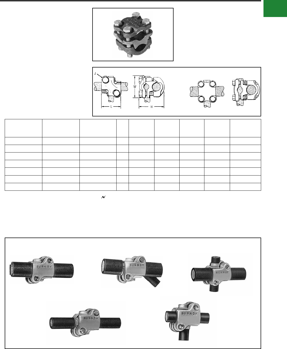
Mechanical
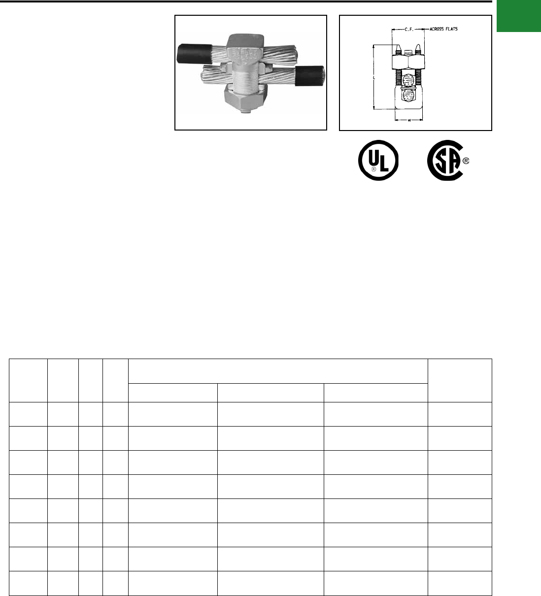
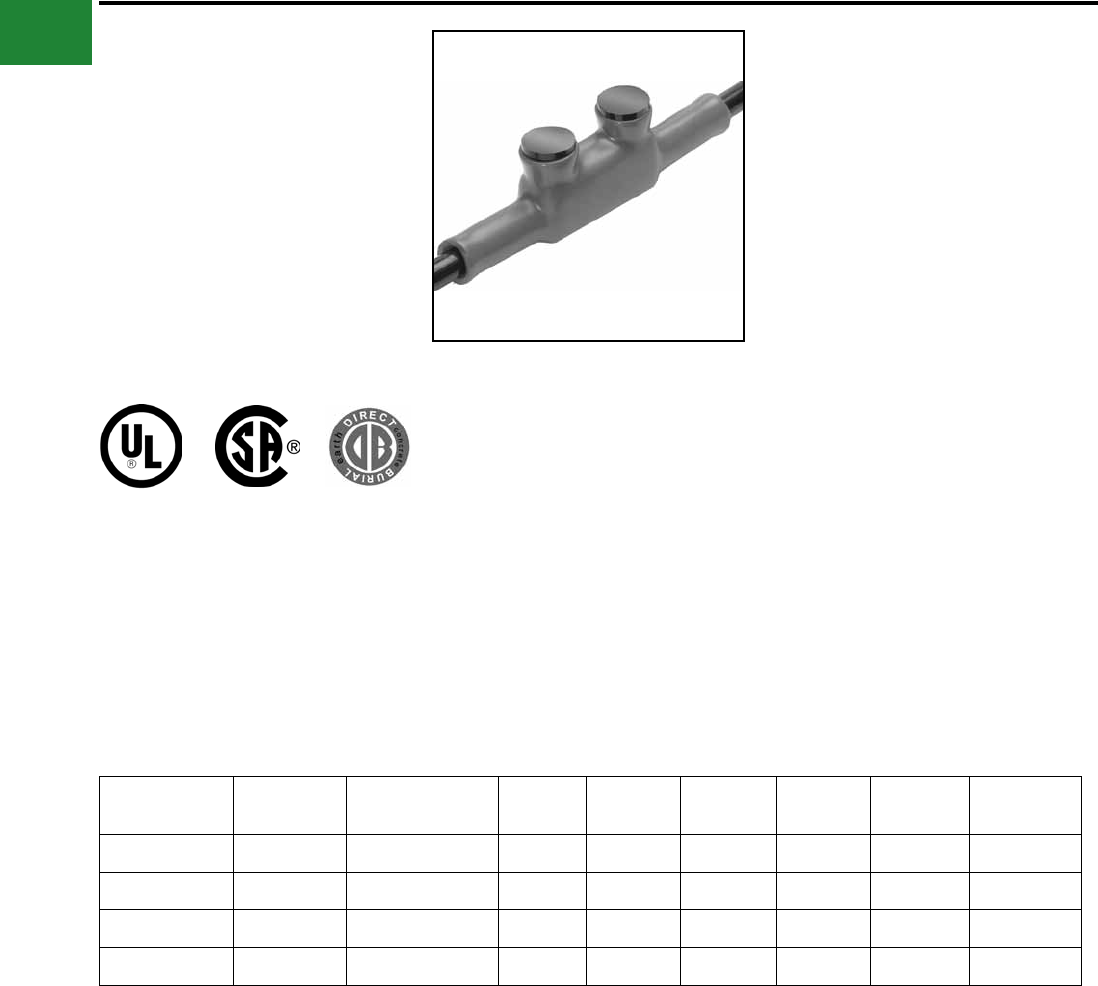
TYPE KVS
OKLIP™
Copper & Copperweld
Compact, two-piece, high strength, high copper
alloy BURNDY® OKLIP™ recommended for heavy
duty connections. Neoprene rings hold DURIUM™
bolts in place during installation. Installed with
ordinary wrench.
Catalog
Number
Conductor ▲
Recommended
Tightening
Torque (in-lb)
Copper Copperweld
Max Run & Tap
Run Tap Sol. Str. Type V
KVS26 2 Str. - 2/0 Str. 6 Str. - 2/0 Str. 3/0 7 #8 — 180
KVS28 1/0 Str. - 4/0 Str. 10 Str. - 4/0 Str. 4/0 7 #6 V3/0 250
KVS31 250 - 350 kcmil 10 Str. - 350 kcmil — 19 #8 V250 325
KVS34 400 - 500 kcmil 10 Str. - 500 kcmil — 19 #6 V350 375
KVS40 400- 800 kcmil 3/0 Str. - 800 kcmil — 19 #5 — 500
KVS44 500 - 1000 kcmil 3/0 Str. - 1000 kcmil — — — 500
▲ Listed torque values are for maximum conductor combinations accommodated. Consult UL486 Tables 7-4, 7-5, 7-6 for smaller conductor combinations.
See note LIGHTNING PROTECTION INFO.
TYPE KVSU
UNIVERSAL OKLIP™
Mechanical Connector All
Combinations of Copper, Aluminum,
ACSR, AAAC & 5005
Compact, high strength, tin plated copper alloy two-
piece connector with spacer and tin-plated silicon
bronze DURIUM™ hardware. Recommended
for heavy duty connections. Spacer separates
dissimilar conductors and provides long contact
length. Neoprene ring prevents loss of shorter
bolt during installation. Longer peened bolt
Catalog
Number
Conductor
H J L W
Rec.
Tightening
Torque
(in-lb)
Run Tap Run Tap
Copper &
Alum
ACSR,
AAAC, &
5005
Copper & Alum
ACSR,
AAAC,
& 5005
Copper
Sol.,
Copperweld
Sol.
Steel
Nom.
Dia.
Copper
Sol.,
Copper-
weld Sol.
Steel
Nom.
Dia.
KVSU26 2 Str. - 2/0 Str. 3 - 2/0 6 Str. - 2/0 Str. 6 - 2/0 1 - 3/0 5/16 -
7/16 #6 - 3/0 3/16 -
7/16 2 5/16 1 1-1/2 180
KVSU28 1/0 Str. - 4/0 Str. 1/0 - 4/0 6 Str. - 4/0 Str. 6 - 4/0 2/0 - 4/0 3/8 - 1/2 #6 - 4/0 5/32 - 1/2 2-3/8 3/8 1-1/8 1-3/4 250
KVSU31 250 - 350 kcmil 4/0 - 300 #6 - 350 6 - 300 - 9/16 - 5/8 #6 - 4/0 3/16 - 5/8 2-5/8 1/2 1-3/8 2-1/8 325
KVSU34 400 - 500 kcmil 336.4 - 397.5 #4 - 500 5 - 397.5 - 3/4 - 3/4 #4 - 4/0 7/32 - 3/4 3 1/2 1-1/2 2-1/4 375
KVSU40 400 - 800 kcmil 4/0 - 800 4/0 - 800 3/0 - 715.5 - 3/4 - 1 - 1/2 - 1 3-1/2 1/2 1-5/8 2-1/2 500
KVSU44 500 - 1000
kcmil 4/0 - 1000 4/0 - 1000 kcmil 4/0 - 900 - 7/8 - 1
1/8 -1/2 - 1
1/8 4 3/8 2 3 500
permits swivel action for easier installation. Use
of PENETROX™ joint compound recommended
with aluminum and ACSR.
See note LIGHTNING PROTECTION INFO.Accomodates compressed conductors within diameter range.
A-6
BURNDY®
Blue highlighted items are industry standard and most frequently ordered.
Canada: 1-800-387-6487 www.burndy.com US: 1-800-346-4175
Mechanical
See note LIGHTNING PROTECTION INFO.
TYPE KVSW
OKLIP™
Mechanical Connector
For Copper and Copperweld
Similiar to OKLIP™ Type KVS except for a high
copper alloy spacer that separates run and tap
conductors. Provides high contact pressure,
connes conductor strands, and assures vibration-
proof connection. Longer peened bolt, permits
swivel action for easier installation. Silicon bronze
DURIUM™ hardware.
Catalog
Number
Conductor Recommended Tightening
Torque (in-lb)Run Tap
KVSW26 2 Str. - 2/0 Str. 6 Sol. - 2/0 Str. 180
KVSW28 1/0 Str. - 4/0 Str. 6 Sol. - 4/0 Str. 250
KVSW31 250 - 350 kcmil 4 Sol. - 350 kcmil 325
KVSW34 400 - 500 kcmil 4 Str. - 500 kcmil 375
KVSW40 400 - 800 kcmil AWG 4/0 - 800 kcmil 500
KVSW44 500 - 1000 kcmil 250 - 1000 kcmil 500
See note LIGHTNING PROTECTION INFO.
TYPE KVS-A
ALUMINUM OKLIP™
For Use On All Combinations of
Copper, Aluminum†, ACSR†, AAAC
and 5005
Three-piece, high-conductivity, non-copper
bearing aluminum alloy connector with thick spacer
and aluminum hardware. Hardware in KVS26A
and KVS28A is stainless steel. Recommended for
heavy duty dissimilar metal applications. Spacer
separates conductors and provides long contact
length. Belled entrances prevent chang, permit
easier assembly of conductors. Longer peened
bolt permits swivel action for easier installation.
Neoprene ring prevents loss of shorter bolt.
PENETROX™ joint compound recommended
with aluminum and ACSR.
Catalog
Number
Conductor
Rec.
Tightening
Torque (in-lb)
Conductor Range by
Diameter
H J L W
Run Tap Min.
Run
Dia.
Min.
Tap
Dia.
Max.
Run &
Tap Dia.
Copper,
& Alum.†
ACSR†,
AAAC, & 5005
Copper,
& Alum.†
ACSR†,
AAAC & 5005
KVS26A 2 Str. - 2/ 0 Str. #4 - 2/0 10 Str. - 2/0 Str. #6 - 2/0 180 0.28 0.12 0.45 2-1/4 5/16 1-1/4 1-5/8
KVS28A 1/0 Str. - 4/0 Str. 1/0 - 4/0 10 Str. - 4/0 Str. #6 - 4/0 240 0.36 0.12 0.56 3 3/8 1-5/8 2-1/16
KVS31A 250 - 350 4/0 - 336.4 6 Str. - 350 kcmil #6 - 336.4 kcmil 300 0.57 0.18 0.68 3-1/16 1/2 1-15/16 2-7/16
KVS34A 400 - 500 336.4 - 397.5 4 Str. - 500 kcmil #5 -397.5 kcmil 300 0.73 0.22 0.81 3-9/16 1/2 2-5/16 2-5/8
KVS40A 400 - 800 336.4 - 715.5 kcmil 3/0 Str. - 800 kcmil #3/0 - 715.5 300 0.73 0.47 1.04 4-1/16 1/2 2-7/16 2-7/8
KVS44A 500 - 1000 397.5 - 900 kcmil 3/0 Str. - 1000 kcmil #3/0 - 900 kcmil 480 0.80 0.47 1.16 4-7/8 5/8 2-1/2 3-1/8
† Accommodates compressed conductors within diameter range.
THESE CONNECTORS CAN ACCOMMODATE
ACSR CONDUCTORS OVER ARMOR ROD
WITHIN THE DIAMETER RANGE INDICATED.
APPLICATION OVER ARMOR ROD
A-7
BURNDY®
Blue highlighted items are industry standard and most frequently ordered.
US: 1-800-346-4175 www.burndy.com Canada: 1-800-387-6487
Mechanical
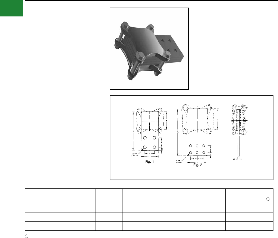
TYPE QPX
VERSITAP™
Parallel Clamp For Copper,
Copperweld, Copperweld-Copper
The VERSITAP™ Type QPX is
recommended for Tee, Cross, Parallel,
Butt and Tap connections. Range-
taking, only 10 connectors required to
accommodate conductor sizes from #6
Str. to 1000 kcmil. Edges are rounded
for easy taping. Made of high strength,
high-conductivity copper alloy and silicon
bronze DURIUM™ hardware.
Catalog
Number
Copper Conductor
Fig.
No.
Dimensions Rec.
Tightening
Torque
in-lb ▲
Conductor
Run Tap H J L W
Run Tap
Copperweld Copperweld
- Copper Copperweld Copperweld
- Copper
QPX2C2C 6 Str. - 2 Str. 6 Str. - 2 Str.
1
1-1/2
5/16 1-5/16
1-3/8 150 5 Sol. - 3 #7 8A - 4A
5 Sol. - 3 #7 8A - 4A
QPX282C 1 Str. - 4/0 Str. 6 Str. - 2 Str. 2-1/16 1-9/16
250 7 #9 - 7 #5 3A - 3/0V
QPX2828 1 Str. - 4/0 Str. 1 Str. - 4/0 Str.
2-3/8
3/8 1-13/16 1-13/16 7 #9 - 7 #5 3A - 3/0V
QPX342C 250 - 500 kcmil 6 Str. - 2 Str. 5/16 1-3/8 1-7/8
375 19 #19 - 19 #6 4/0 EK
5 Sol. - 3 #7 8A - 4A
QPX3428 250 - 500 kcmil 1 Str. - 4/0 Str. 2-3/4
3/8
1-3/4 2-1/16 7 #9 - 7 #5 3A - 3/0 V
QPX3434 250 - 500 kcmil 250 - 500 kcmil 2 3 2-1/16 2-3/16 19 #19 - 19 #6 4/0 EK
QPX442C 500 - 1000
kcmil 6 Str. - 2 Str.
1
2-11/16 5/16 1-3/8 2-1/4
500 19 #6 —
5 Sol. - 3 #7 8A - 4A
QPX4428 500 - 1000
kcmil 1 Str. - 4/0 Str. 2-7/8
3/8
1-13/16
2-7/16
7 #9 - 7 #5 3A - 3/0V
QPX4434 500 - 1000
kcmil 250 - 500 kcmil
2
3-1/16 2-1/16 19 #19 - 19 #6 4/0 EK
QPX4444 500 - 1000
kcmil
500 - 1000
kcmil 3-7/16 2-5/8 2-9/16 19 #6 —
▲ Listed torque values are for maximum conductor combinations
accommodated. Consult UL486 Tables 7-4, 7-5, 7-6 for smaller
conductor combinations.
See note LIGHTNING PROTECTION INFO.
Fig. 1
Fig. 2
* For various congurations, see page
TYPE QPX-Y
A-8
BURNDY®
Blue highlighted items are industry standard and most frequently ordered.
Canada: 1-800-387-6487 www.burndy.com US: 1-800-346-4175
Mechanical
TYPE QPX-Y
UNIVERSAL VERSITAP™
Universal Parallel Clamp For Copper
and Aluminum
High copper alloy cast connector, tin-plated for use
with copper or aluminum cable. Makes parallel,
tap, tee, cross or end-to-end connections. Edges
rounded for easy taping. PENETROX™ joint
compound recommended.
Catalog
Number Run Tap
Fig.
No. H J L W
Recommended
Tightening
Torque in-lb ▲
QPX2C2C-Y 6 Str.-2 Str. 6 Str.-2 Str. 1 1-5/8 5/16 1-1/2 1-5/8 150
QPX282C-Y 1 Str. - 4/0 Str. 6 Str.-2 Str. 1 1-7/8 5/16 1-1/2 1-7/8 150
QPX2828-Y 1 Str. - 4/0 Str. 1 Str. - 4/0 Str. 1 2 3/8 2 2-1/8 250
QPX342C-Y 250 - 500 kcmil 6 Str.-2 Str. 1 2-1/4 5/16 1-1/2 2-1/8 375
QPX3428-Y 250 - 500 kcmil 1 Str. - 4/0 Str. 1 2-1/2 3/8 2 2-1/2 375
QPX3434-Y 250 - 500 kcmil 200 - 500 kcmil 2 2-7/8 3/8 2-1/2 2-5/8 375
QPX4444-Y 750 - 1000 kcmil 750 - 1000 kcmil 2 3-7/8 1/2 3-1/2 3-1/2 500
Fig. 1 Fig. 2
▲ Listed torque values are for maximum conductor
combinations accommodated. Consult UL486 Tables
7-4, 7-5 7-6 for smaller conductor combinations.
See note LIGHTNING PROTECTION INFO.
APPLICATION
VARIATIONS
PARALLEL
SPLICE
CROSSTAP
TEE
A-9
BURNDY®
Blue highlighted items are industry standard and most frequently ordered.
US: 1-800-346-4175 www.burndy.com Canada: 1-800-387-6487
Mechanical
TYPE KPA
SCRULUG™
For Copper Cable
High copper alloy tin-plated terminal for joining
a wide range of cable to equipment pads or
terminal blocks. Especially good in light industrial
applications. The tongue and body are a one-piece
design. The pressure bar equalizes pressure over
the conductor and prevents the screw from cutting
into the cable.
Catalog
Number Wire Range Fig.
No. C D H K Stud
Hole Size L N T
Recommended
Tightening
Torque (in-lb)
KPA8C 14 Sol. - 8 Str. 1 0.38 0.47 0.72 0.21 #10 0.97 0.22 0.06 25
KPA4C 14 Sol. - 4 Str. 1 0.50 0.59 0.94 0.27 1/4 1.22 0.30 0.06 35
KPA25 4 Str. - 1/0 Str. 2 0.75 0.81 1.25 0.33 5/16 1.82 0.41 0.10 180
KPA28 1/0 Str. - 4/0 Str. 2 0.97 1.12 1.66 0.39 3/8 2.40 0.53 0.13 250
KPA34 4/0 Str. - 500 kcmil 2 1.38 1.38 2.44 0.54 1/2 3.32 0.75 0.20 375
Fig. 1 Fig. 2
TYPE KPA-UP
SCRULUG™
For Copper Cable
High copper alloy terminal for joining a wide range
of cable to equipment pads or terminal blocks.
Plain copper nish. Features & Benets
• One piece design.
◊ Superior torque and pull out
performance.
• Convenient range taking design.
◊ Reduces catalog numbers. One
catalog number accommodates several
conductor sizes.
• High conductivity copper alloy.
◊ Long lasting, reliable contact.
• Compact design.
◊ Easy to use.
• Slot Robertson screw, hex head, hex
socket bolt.
◊ No special installation tools required.
Eliminates over-torquing/potential
conductor damage.
Catalog
Number Wire Range
Fig.
No. C D H K
Stud Hole
Size L N T Hardware
Recommended
Tightening
Torque (in-lb)
KPA8CUP 14 Sol. - 6 Str.
1
0.38 0.56 0.81 0.20 #10 1.04 0.22
0.07
# 12-24 SLOT 35
KPA4CUP 14 Sol. - 4 Str. 0.50 0.71 1.00 0.28 1/4 1.28 0.33 5/16 DIA.SLOT
ROBERTSON 45
NOTE: For tin plating drop “-UP” sufx and add “-TP” sufx
(example: KPA4CTP).
For use in grounding applications with a green screw, contact
factory. Listed for grounding per UL467.
Fig. 1
NOTE: For unplated version add “UNPL” sufx.
A-10
BURNDY®
Blue highlighted items are industry standard and most frequently ordered.
Canada: 1-800-387-6487 www.burndy.com US: 1-800-346-4175
Mechanical
TYPE KLU
SCRULUG™
FOR COPPER CABLE -
OFFSET TONGUE - NON-PLATED
High copper alloy terminal with offset tongue for
joining a wide range of cable to equipment pads
or bar. Easy to install with screwdriver or wrench.
Connector is reusable. Plain copper nish.
Catalog
Number Conductor
Fig.
No.
B
(MM/IN)
C
(MM/IN)
K
(MM/IN)
L
(MM/IN)
N
(MM/IN)
T
(MM/IN)
Rec.
Tightening
Torque
(in-lb) Hardware
Stud
Hole
Size
Strip
Length
(in)
KLU25 14 Sol. .064 Dia.to
10 Sol. .102 Dia. CU 37.00
0.28
8.00
0.31
4.00
0.14
26.0
1.02
5.00
0.21
2.00
0.07 20 No. 8-32 Slotted Round
Machine Screw #6 7/16
KLU25TP
KLU35 14 Sol. .0641 Dia.to
6 Str. .184 Dia. CU 211.0
0.43
10.0
0.39
5.00
0.20
31.0
1.24
6.00
0.22
2.00
0.07 35 1/4 UNF Slotted Set
Screw #10 5/8
KLU35TP
KLU70 8 Sol. .129 Dia. to
2 Str. .292 Dia. CU 213.0
0.50
12.0
0.47
7.00
0.26
39.0
1.55
6.00
0.25
2.00
0.08 40 5/16 UNF Slotted Set
Screw 1/4 3/4
KLU70TP
KLU125 2 Str. .292 Dia. to
1/0 Str. .372 Dia. CU 215.0
0.61
16.0
0.62
7.00
0.26
50.0
1.98
11.0
0.42
3.00
0.11 50 3/8 UNF Slotted Set
Screw 1/4 15/16
KLU125TP
KLU175 4 Str. .232 Dia. to
3/0 Str. .470 Dia. CU 118.0
0.72
19.0
0.75
10.0
0.39
56.0
2.20
11.0
0.43
4.00
0.16 250 3/8 UNF Socket/Hex
Screw 3/8 1
KLU175TP
KLU225 2 Str. .292 Dia. to
4/0 Str. .528 Dia. CU 124.0
0.94
25.0
0.99
9.00
0.34
65.0
2.55
13.0
0.51
3.00
0.12 250 7/16 UNF Socket/Hex
Screw 5/16 1-5/16
KLU225TP
KLU300 1/0 Str. .372 Dia. to
350 kcmil .681 Dia. CU 131.0
1.22
25.0
0.99
10.0
0.39
72.0
2.83
13.0
0.52
3.00
0.12 325 5/8 UNF Socket/Hex
Screw 3/8 1-5/8
KLU300TP
KLU400 1/0 Str. .372 Dia. to
500 kcmil .813 Dia. CU 136.0
1.42
38.0
1.50
10.0
0.39
104.0
4.09
23.0
0.91
5.00
0.18 375 5/8 UNF Socket/Hex
Screw 3/8 1-5/32
KLU400TP
Features & Benets
• Convenient range-taking design.
◊ Reduces catalog numbers.
One conductor accommodates several
conductor sizes.
• High conductivity copper alloy
◊ Long lasting reliable contact.
• Compact design
◊ Easy to use. Reduces labor time.
• Slot Robertson screw, hex head/hex
socket bolt
◊ No special installation tools required.
eliminates over-torquing/potential
conductor damage.
NOTES:
Sufx “-TP” on catalog number denotes tin plate (example: KLU400TP).
2 Material: Copper alloy.
1
1
A-11
BURNDY®
Blue highlighted items are industry standard and most frequently ordered.
US: 1-800-346-4175 www.burndy.com Canada: 1-800-387-6487
Mechanical
TYPE KA
KA-LUG™
For Copper Cable
Compact, economical, high copper alloy terminal
for joining a wide range of cable to equipment pads
or terminal blocks.
Catalog
Number Conductor Fig.
No. C H J K
Stud
Hole
Size
L N T
Recommended
Tightening
Torque (in-lb)
KA8C # 14 Sol. (0.064 Dia.) -
8 Str. (0.416 Dia.) 1 3/8 5/8 #12 7/32 #10 13/16 3/16 3/32 25
KA4C # 14 Sol. (0.064 Dia.) -
4 Str. (0.232 Dia.) 1 9/16 3/4 5/16" 9/32 1/4 1-1/8 1/4 7/64 45
KA25 # 4 Str. (0.232 Dia.) -
1/0 Str. (0.373 Dia.) 2 3/4 15/16 1/2"27/64 3/8 1-11/16 3/8 1/8 200
KA25-2TC38 # 4 Str. (0.232 Dia.) -
1/0 Str. (0.373 Dia.) 3 3/4 15/16 1/2" 27/64 3/8 2-13/16 3/8 1/8 200
KA28 # 1 Str. (0.332 Dia.) -
4/0 Str. (0.528 Dia.) 2 15/16 1-1/4 5/8" 27/64 3/8 1-15/16 7/16 3/16 275
KA34 4/0 Str. (0.528 Dia.) -
500 kcmil (0.814 Dia.) 2 1-3/8 2-3/32 13 /16" 9/16 1/2 2-9/16 9/16 9/32 375
TYPE EA
VERSILUG™
For Copper Cable
Compact, high copper alloy terminal for joining
a wide range of cable to equipment pads or bar.
Clamping element adjustable to several angles.
One-wrench installation.
Catalog
Number Wire Range
No. of
holes in
pad
C D E H K
Stud
Hole
Size
L N T
Rec.
Tightening
Torque (in-lb)
EA2C 8 AWG-2 AWG 1 13/16 1-1/16 — 1-3/8 7/16 3/8 2-1/2 13/32 1/4 150
EA25 2 AWG-1/0 1 7/8 1-1/8 — 1-7/16 7/16 3/8 2-11/16 7/16 1/4 180
EA28 1/0 -4/0 AWG 1 1-1/16 1-3/8 — 1-3/4 7/16 3/8 3-3/16 17/32 5/16 250
EA28-2N 1/0 -4/0 AWG 2 1-1/16 3-5/8 1-3/4 1-3/4 9/16 1/2 5-1/8 5/8 5/16 250
EA34 250 kcmil-500 kcmil 1 1-3/8 1-5/8 — 2-1/4 9/16 1/2 4 13/16 3/8 375
EA34-2N 250 kcmil-500 kcmil 2 1-3/8 3-5/8 1-3/4 2-1/4 9/16 1/2 5-5/8 5/8 3/8 375
▲ Listed torque values are for maximum conductor sizes
accommodated.
Consult UL486 Tables 7-4, 7-5, 7-6 for smaller conductor sizes.
* “N” indicates NEMA standard stud holes.
▲ Listed torque values are for maximum conductor sizes
accommodated.
Consult UL486 Tables 7-4, 7-5, 7-6 for smaller conductor sizes.
Fig. 1 Fig. 2 Fig. 3
A-12
BURNDY®
Blue highlighted items are industry standard and most frequently ordered.
Canada: 1-800-387-6487 www.burndy.com US: 1-800-346-4175
Mechanical
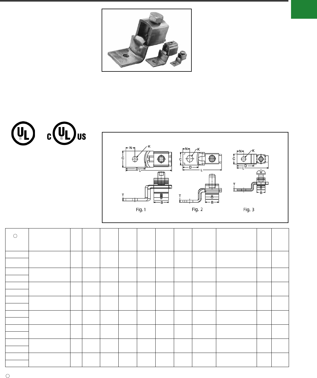
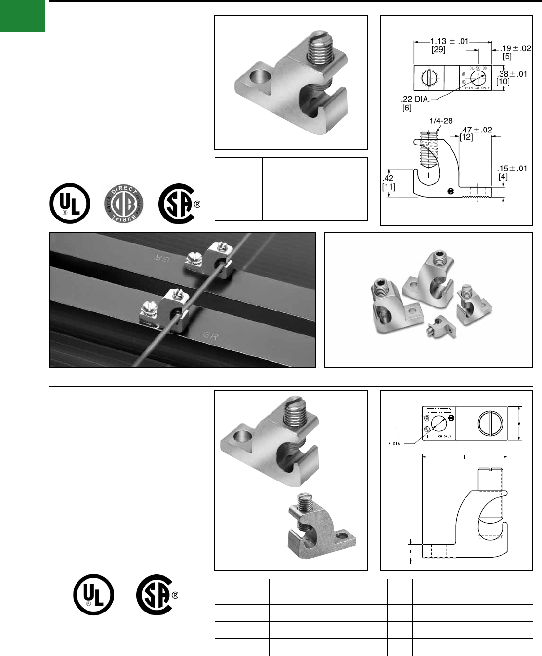
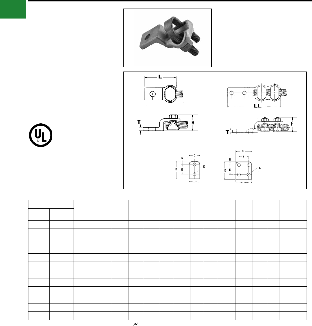
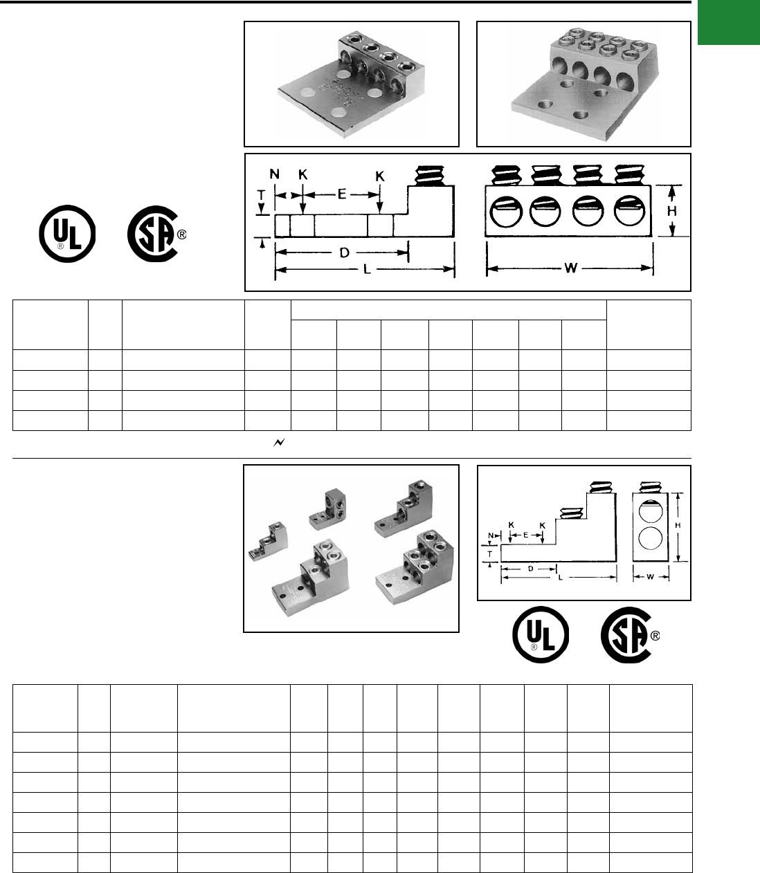
TYPE BGBL
LAY-IN QIKLUG™
UL LISTED 90° C, 600 V
The Lay-In QIKLUG™, Type BGBL is
manufactured from high strength 6061-T6
aluminum, and is ideally suited for grounding and
bonding applications accommodating both copper
and aluminum conductor sizes #14 AWG to 250
kcmil. The BGBL4SS with Stainless Steel screw is
UL 467 Listed for grounding and bonding.
Catalog
Number
Conduc-
tor Range C H J K L N T Hex
Size
BGBL-4 14 - 4 0.38
[10]
0.78
[20] 1/4 - 28 0.22
[6]
1.07
[27]
0.19
[5]
0.15
[4] Slot
BGBL4SS* 14 - 4 0.38
[10]
0.78
[20] 1/4 - 28 0.22
[6]
1.07
[27]
0.19
[5]
0.15
[4] Slot
BGBL-1/0 14 - 1/0 0.60
[15]
1.17
[30] 3/8 - 24 0.27
[7]
1.50
[38]
0.30
[8]
0.22
[6] Slot
BGBL-250 6 - 250
kcmil
0.80
[20]
1.79
[45] 9/16 - 18 0.33
[8]
2.20
[56]
0.40
[10]
0.30
[8] 5/16
Features & Benets
• UL 486B listed, AL9CU rated
◊ For copper and aluminum conductor
combinations up to 90° C, 600 Volt
applications.
• UL Recognized for grounding and
bonding
◊ Ensures reliability.
• Electro-tin plated
◊ Provides low contact resistance.
• Lay-in feature
◊ Eases installation.
* Suitable for copper conductors only.
L
T
N
H
REF
K DIA.
C
J
A-13
BURNDY®
Blue highlighted items are industry standard and most frequently ordered.
US: 1-800-346-4175 www.burndy.com Canada: 1-800-387-6487
Mechanical
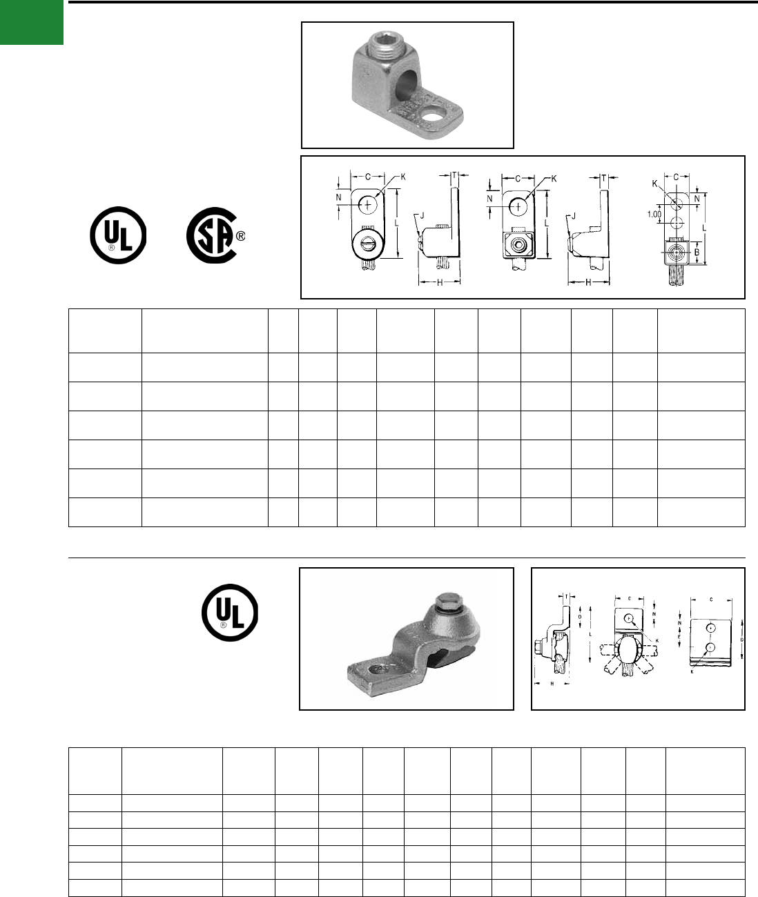
TYPE CL50-1 & CL50-1TN
COPPER LAY-IN QIKLUG™
For Copper
The Lay-In QIKLUG™ is manufactured from
high strength pure electrolytic copper to ensure
maximum strength and conductivity. UL467
Listed for direct burial in earth or concrete. The
open-faced design allows for fast lay-in of the
conductor without the need for cutting or breaking.
Stainless steel screws used for excellent corrosion
resistance. Catalog
Number
Conductor
Range
Stud
Hole
CL50-1 14 AWG-4 AWG #10
CL50-1TN 14 AWG-4 AWG #10
TYPE CL
COPPER LAY-IN QIKLUG™
For Copper
Manufactured for maximum strength and
conductivity, these lay-in lugs allow for continuous
runs of conductor and are well suited as
terminations as well. Tin-plated, set screw style
connectors, three sizes cover a range from
#14AWG to 250 kcmil. CL3/0-516TN and CL250-
516TN are UL Listed and CSA certied. CL1/0-
14TN UL Listed for grounding and CSA certied.
90° C rated. Suitable for copper conductors only.
Photo above shows a typical solar panel installation using CL50-1 connectors.
Catalog
Number
Wire Range
Copper H W L T K
Dia Hex Size
CL1/0-14TN #14 - 1/0 AWG 1.17 0.60 1.50 0.22 0.27 7/16-20 (Slotted)
CL3/0-516TN #6 - 3/0 AWG 1.56 0.80 2.00 0.30 0.33 9/16-18 (0.25 Hex)
CL250-516TN #6 AWG - 250 kcmil 1.79 0.80 2.20 0.30 0.33 9/16-18 (0.25 Hex)
A-14
BURNDY®
Blue highlighted items are industry standard and most frequently ordered.
Canada: 1-800-387-6487 www.burndy.com US: 1-800-346-4175
Mechanical
TYPES QA, QQA
QIKLUG™
Copper Cable
Type QA heavy duty, compact, high copper
alloy terminal for joining a wide range of cable
to equipment pads or bar. Fast one-wrench
installation. Type QQA heavy duty, high copper
alloy terminal for joining cable to equipment
pads or bar. Twin clamping elements secure joint
vibration and exing. One-wrench installation.
Catalog Number* Conductor Holes
in Pad C D E & F H K
Stud
Hole
Size
L LL N T Torque
(in-lb)
Type QA Type QQA Commercial Navy
QA8C-B QQA8C 14 Sol. - 8 Str. 4-14 1 9/16 9/16 — 11/16 7/32 #10 1-3/8 2-5/16 9/32 5/32 75
QA8C-2B QQA8C-2 14 Sol. - 8 Str. 4-14 2 9/16 1-1/14 5/8 11/16 7/32 #10 2 3 5/16 5/32 75
QA4C-B QQA4C 8 Str. - 4 Str. 23-40 1 5/8 5/8 — 3/4 9/32 1/4 1-7/16 2-3/8 5/16 3/16 110
QA4C-2B QQA4C-2 8 Str. - 4 Str. 23-40 2 5/8 1-3/16 5/8 3/4 9/32 1/4 2 2-15/16 5/16 3/16 110
QA1C-B QQA1C 4 Str. - 1 Str. 50-75 1 5/8 3/4 — 1 9/32 1/4 1-3/4 2-13/16 11/32 7/32 150
QA1C-2B QQA1C-2 4 Str. - 1 Str. 50-75 2 5/8 1-9/16 7/8 1 11/32 5/16 2-9/16 3-5/8 11/32 7/32 150
QA26-B QQA26 1/0 Str. - 2/0 Str. 100-125 1 13/16 1 — 1-3/16 13/32 3/8 2 3-3/16 7/16 7/32 180
QA26-2B QQA26-2 1/0 Str. - 2/0 Str. 100-125 2 13/16 1-15/16 1 1-3/16 13/32 3/8 3 4-3/16 7/16 7/32 180
QA28-B QQA28 3/0 Str. - 4/0 Str. 150-200 1 1 1-1/16 — 1-5/16 13/32 3/8 2-1/4 3-9/16 17/32 1/4 250
QA28-2B — 3/0 Str. - 4/0 Str. — 2 1 2 1 1-9/29 13/32 3/8 3-1/5 — 7/16 1/4 250
QA28-2N* QQA28-2N* 3/0 Str. - 4/0 Str. 150-200 2 1 3-1/8 1-3/4 1-5/16 9/16 1/2 4-5/16 5-5/8 5/8 1/4 250
QA31-B QQA31 250 - 350 kcmil 250-350 1 1-3/16 1-3/8 — 1-11/16 17/32 1/2 2-11/36 4-1/8 11/16 5/16 325
QA31-2B — 250 - 350 kcmil 250-350 2 1-3/16 1-31/32 1 1-11/16 7/16 3/8 3-3/8 — 7/16 5/16 325
QA31-2N QQA31-2N* 250 - 350 kcmil 250-350 2 1-3/16 3 1-3/4 1-11/16 9/16 1/2 4-7/16 5-7/8 5/8 5/16 325
QA34-B — 400 - 500 kcmil 400-500 1 1-3/8 1-5/8 — 2 17/32 1/2 3-3/16 4-7/8 13/16 5/16 375
QA34-2B — 400 - 500 kcmil 400-500 2 1-3/8 2 1 2 13/32 3/8 3-9/16 — 7/16 5/16 375
QA34-4B QQA34 400 - 500 kcmil 400-500 4 1-7/8 1-15/16 1 2 7/16 3/8 3-1/2 — 7/16 5/16 375
QA34-2N* QQA34-2N* 400 - 500 kcmil 400-500 2 1-3/8 3-3/32 1-3/4 2 9/16 1/2 4-11/16 6-9/32 5/8 5/16 375
QA40-B — 600 - 800 kcmi 650-800 1 1-5/8 1-7/8 — 2-7/16 11/16 5/8 3-11/16 — 27/32 3/8 500
QA40-2N* QQA40-2N* 600 - 800 kcmi 650-800 2 1-5/8 3 1-3/4 2-7/16 9/16 1/2 4-14/16 7-3/32 5/8 3/8 500
QQA40-4N* — 600 - 800 kcmi 650-800 4 3 3 1-3/4 2-7/16 9/16 1/2 — 7-3/32 5/8 3/8 500
QA44-B — 850 - 1000 kcmil 1000 1 1-7/8 2 — 2-3/4 11/16 5/8 3-15/16 — 1 1/2 500
QA44-2N* QQA44-2N* 850 - 1000 kcmil 1000 2 1-7/8 3 1-3/4 2-3/4 9/16 1/2 5 7-1/8 5/8 1/2 500
QA44-4N* QQA44-4N* 850 - 1000 kcmil 1000 4 3 3-1/16 1-3/4 2-3/4 9/16 1/2 5 7-1/8 5/8 1/2 500
QA46-2N* — 1100 - 1500 kcmil 1300 2 2-1/8 3 1-3/4 3-1/8 9/16 1/2 5-1/4 — 5/8 9/16 600
QA46-B — 1100 - 1500 kcmil 1300 1 2-1/8 2-1/8 — 3-1/8 13/16 3/4 4-3/8 — 1-1/16 9/16 600
* ‘‘N’’ indicates NEMA standard stud holes. All 4N items see note LIGHTNING PROTECTION INFO.
Type QA Type QQA
A-15
BURNDY®
Blue highlighted items are industry standard and most frequently ordered.
US: 1-800-346-4175 www.burndy.com Canada: 1-800-387-6487
Mechanical
TYPE Q2A
QIKLUG™
For Copper Cable
Compact, high copper alloy terminal for joining two
cables to equipment pads or bars. Each element
accommodates a wide range of cable. One-
wrench installation.
Catalog
Number* Conductor
No. of
Holes in
Pad
C D E & F H K
Stud
Hole
Size
L N T W
Recommended
Tightening
Torque in-lb
Q2A1C-2 4 Str. - 1 Str.
2
1-1/2 1-7/8 1 1-1/16 7/16 3/8 2-7/8 7/16 7/32 1-13/16 150
Q2A26-2N 1/0 Str. - 2/0 Str. 1-5/8
3-1/8
3/4 1-3/16
9/16 1/2
4-3/16
5/8
1-15/16 180
Q2A28-2N 3/0 Str. - 4/0 Str. 1-7/8
1-3/4
1-3/8 4-3/8 1/4 250
Q2A28-4N 4 3
4-1/2 2-1/8
Q2A31-2N 250 - 350 kcmil 2 2-3/8 1-11/16 5/16 325
Q2A31-4N 4 3 3
Q2A34-2N 400 - 500 kcmil 2 2-1/2 2 4-11/16 3/8 375
Q2A34-4N 4
33-3/4
Q2A40-2N 600 - 800 kcmil 22-7/16 5 7/16 500Q2A40-4N
44-11/32
Q2A44-4N 850 - 1000 kcmil 3-1/4 2-3/4 5-1/4 1/2
Q2A46-4N 1100 - 1500 kcmil 3-1/2 3-1/4 3-1/8 5-1/2 11/16 5 600
TYPE Q3A
QIKLUG™
For Copper Cable
Compact, high copper alloy terminal for joining
three cables to equipment pads or bar. Each
element accommodates a wide range of cable.
One-wrench installation.
Catalog
Number* Conductor
No. of
Holes in
Pad
C D E & F H K
Stud
Hole
Size
L N T W
Recommended
Tightening
Torque in lb
Q3A28-2N 3/0 Str. - 4/0 Str. 2 1-7/8
3-1/8
1-3/4
1-3/8
9/16 1/2
4-5/16
5/8
1/4 3-3/16 250
Q3A28-4N 3/0 - 4/0 Str. 4 3 4-3/8
Q3A31-2N 250 - 350 kcmil 2 2-3/8 1-11/16 4-7/16 5/16 4-1/16 325
Q3A31-4N 4 3
Q3A34-2N 400 - 500 kcmil 2 2-1/2 1-15/16 4-3/4 3/8 4-9/16 375
Q3A34-4N
4
3
Q3A40-4N 600 - 800 kcmil 2-7/16 5 7/16 5-13/16 500
Q3A44-4N 850 - 1000 kcmil 3-1/4 2-3/4 5-1/4 1/2 6-5/8
Q3A46-4N 1100 - 1500 kcmil 3-1/2 3-1/4 3-1/8 5-1/2 11/16 7-7/8 600
* ‘‘N’’ indicates NEMA standard stud holes. All 4N items see note LIGHTNING PROTECTION INFO.
* ‘‘N’’ indicates NEMA standard stud holes.
A-16
BURNDY®
Blue highlighted items are industry standard and most frequently ordered.
Canada: 1-800-387-6487 www.burndy.com US: 1-800-346-4175
Mechanical
TYPE QB
QIKLUG™
For Copper Cable
Compact, high copper alloy side entrance terminal
for joining a range of cable at right angles to
terminal blocks. One-wrench installation.
Catalog
Number* Conductor
No. of
Holes in
Pad
C D E H K
Stud
Hole
Size
L N T
Recommended
Tightening
Torque in-lb
QB8C 14 Sol. - 8 Str. 1 9/16 9/16 — 7/8 7/32 #10 1-1/8 9/32 5/32 75
QB4C 8 Str. - 4 Str. 1 11/16 27/32 — 13/16 9/32 1/4 1-3/8 11/32 1/4 110
QB1C 4 Str. - 1 Str. 1 11/16 13/16 — 1 9/32 1/4 1-1/2 11/32 7/32 150
QB26 1/0 Str. - 2/0 Str. 1 13/16 1 — 1-1/32 13/32 3/8 1-13/16 7/16 7/32 180
QB28 3/0 Str. - 4/0 Str. 1 1 1-1/16 — 1-5/16 13/32 3/8 2-1/16 17/32 1/4 250
QB31-2N 250 - 350 kcmil 2 13/16 3-1/4 1-3/4 1-11/16 9/16 1/2 4-1/2 5/8 5/16 325
* ‘‘N’’ indicates NEMA standard stud holes.
TYPE Q2B
QIKLUG™
For Copper Cable
Compact, high copper alloy terminal for joining two
cables at right angles to a single terminal block.
Each element accommodates a range of cable.
One-wrench installation.
Catalog
Number* Conductor
No. of
Holes in
Pad
C D E & F H K
Stud
Hole
Size
L N T
Recommended
Tightening
Torque in-lb
Q2B28-2N 3/0 Str. - 4/0 Str. 2 1-7/8 3-1/8 1-3/4 1-3/8 9/16 1/2 5-3/16 5/8 1/4 250
Q2B31-2N 250 - 350 kcmil 2 2-3/8 3-3/16 1-11/16 1-3/8 9/16 9/16 5-7/8 5/8 5/16 325
Q2B40-4N 600 - 800 kcmil 4 3 3-1/16 1-3/8 2-5/16 9/16 3/4 6-11/16 5/8 7/16 500
* ‘‘N’’ indicates NEMA standard stud holes. All 4N items see note LIGHTNING PROTECTION INFO.
A-17
BURNDY®
Blue highlighted items are industry standard and most frequently ordered.
US: 1-800-346-4175 www.burndy.com Canada: 1-800-387-6487
Mechanical
TYPE QDA
QIKLUG™
For Copper Cable
Compact, high copper alloy terminal for joining a
wide range of cable to equipment studs. Provides
low contact resistance when gripped between two
contact nuts. One wrench installation.
Catalog
Number
Conductor
C H K
Stud
Hole
Size
L T
Recommended
Tightening
Torque in-lb
Commercial Navy
QDA8C 14 Sol. - 8 Str. 3 - 14 1 11/16 7/16 3/8 1-7/8 3/16 75
QDA4C 8 Str. - 4 Str. 23 - 40 1 3/4 7/16 3/8 1-7/8 7/32 110
QDA1C 4 Str. - 1 Str. 50 - 75 1 1 7/16 3/8 2-3/16 9/32 150
QDA26 1/0 Str. - 2/0 Str. 100 - 125 1-1/4 1-3/16 9/16 1/2 2-1/2 5/16 180
QDA28 3/0 Str. - 4/0 Str. 150 - 200 1-1/4 1-5/16 9/16 1/2 2-5/8 5/16 250
QDA31 250 - 350 kcmil 250 - 350 1-1/2 1-11/16 11/16 5/8 3 5/16 325
QDA34 400 - 500 kcmil 400 - 500 1-7/8 2 13/16 3/4 3-5/8 5/16 375
QDA40 600 - 800 kcmil 650 - 800 2-1/8 2-5/16 1-1/16 1 4-3/16 3/8 500
TYPE QR
QIKLINK™ SPLICE OR REDUCER
For Copper Cable to Cable
High copper alloy splicer/reducer for joining a
range of cable end to end. Neat, compact easy to
tape installation. One-wrench installation.
Catalog Number Conductor
Either Side H L W
Recommended
Tightening
Torque in-lb
QR4C 6 Sol. - 4 Str. 3/4 1-11/16 5/8 110
QR1C 4 Str. - 1 Str. 1-1/16 1-15/16 11/16 150
QR26 1/0 Str. - 2/0 Str. 1-3/16 2-1/8 13/16 180
QR28 3/0 Str. - 4/0 Str. 1-3/8 2-3/8 1 250
QR31 250 - 350 kcmil 1-11/16 2-5/8 1-1/4 325
QR34 400 - 500 kcmil 1-15/16 3-1/16 1-7/16 375
QR40 600 - 800 kcmil 2-7/16 3-5/8 1-7/8 500
See note LIGHTNING PROTECTION INFO.
A-18
BURNDY®
Blue highlighted items are industry standard and most frequently ordered.
Canada: 1-800-387-6487 www.burndy.com US: 1-800-346-4175
Mechanical
TYPE VT
VARITAP™ T-CONNECTOR
For Copper Cable to Cable
High copper alloy T-connector for cable run, cable
tap. V-bolt clamping elements accommodate large
range of cable and are particularly suited for extra
exible cable. One-wrench installation.
Catalog
Number
Conductor H L W
Recommended
Tightening Torque
Run (A) Tap (AA) Run Tap
VT2C2C 8 AWG-2 AWG 8 AWG-2 AWG 1-5/16 2-5/16 1-5/16 275 275
VT2525 6 AWG-1/0 6 AWG-1/0 1-5/8 2-5/8 1-7/16 385 385
VT2825 1/0 -4/0 AWG 6 AWG-1/0 1-5/8 3-1/8 1-1/4 250 385
VT2828 1/0 -4/0 AWG 1/0 -4/0 AWG 1-5/8 3-1/16 1-11/16 250 250
VT3025 1/0 -300 kcmil 6 AWG-1/0 1-7/8 3-3/8 1-3/8 325 385
VT3030 1/0 -300 kcmil 1/0 -300 kcmil 1-7/8 3-5/16 1-15/16 325 325
VT3425 300 kcmil-500 kcmil 6 AWG-1/0 3-11/32 3-11/16 1-1/2 375 385
VT3428 300 kcmil-500 kcmil 1/0 -4/0 AWG 3-11/32 3-1/2 1-11/16 375 250
VT3430 300 kcmil-500 kcmil 1/0 -300 kcmil 3-11/32 3-5/8 1-15/16 375 325
VT3434 300 kcmil-500 kcmil 300 kcmil-500 kcmil 3-11/32 3-3/4 2-1/4 375 375
VT4040 500 kcmil-800 kcmil 500 kcmil-800 kcmil 2-9/16 4-1/2 2-5/8 500 500
VT4425 750 kcmil-1000 kcmil 6 AWG-1/0 2-7/8 4-5/16 1-3/16 500 385
VT4428 750 kcmil-1000 kcmil 1/0 -4/0 AWG 2-7/8 4-1/8 1-11/16 500 250
VT4834 1500 kcmil-2000 kcmil 300 kcmil-500 kcmil 4-1/4 5-1/4 2-1/4 600 375
TYPE E-C-G
TRANSFORMER TAP ADAPTER
For Copper
Multi-tap, range-taking cast copper alloy connector
designed to take 2, 3 or 4 conductors from a single
secondary transformer outlet.
See note LIGHTNING PROTECTION INFO.
Catalog Number Number of
Conductors
Conductor
Size A dia H J L W
Recommended
Tightening
Torque
E2C34G1 2
1/0 Sol. - 500 kcmil 0.78 2-7/8 1/2"-13 6-1/4
3-1/2
480E3C34G1 3 5-1/4
E4C34G1 4 6-7/8
A-19
BURNDY®
Blue highlighted items are industry standard and most frequently ordered.
US: 1-800-346-4175 www.burndy.com Canada: 1-800-387-6487
Mechanical
TYPES VA, VVA
VARILUG™
For Copper Cable
High copper alloy terminal for joining a wide range
of cable to equipment pads or bar. Particularly
suitable for use on extra exible cable. One-
wrench installation. Type VVA, twin elements
secure joint against vibration and exing.
Particularly recommended for use on extra exible
cables. One-wrench installation.
Catalog Number*
Conductor
No. of
Holes
in Pad
C D E&F H K
Stud
Hole
Size
L LL N T
Rec.
Tightening
Torque
Type VA Type VVA
VA2C VVA2C 8 AWG-2 AWG 1 13/16 1-1/4 — 1-1/2 7/16 3/8 2-3/4 4-1/16 13/32 1/4 275
VA25 VVA25 6 AWG-1/0 1 7/8 1-5/16 — 1-7/8 7/16 3/8 2-7/8 4-5/16 7/16 1/4 385
VA28 VVA28 1/0 -4/0 AWG 1 1-1/16 1-1/2 — 2-1/4 7/16 3/8 2-7/8 4-1/8 17/32 5/16 250
VA28-2N VVA28-2N 1/0 -4/0 AWG 2 1-1/16 3-1/2 1-3/4 2-1/4 9/16 1/2 4-15/16 6-1/5 5/8 5/16 250
VA30 VVA30 1/0 -300 kcmil 1 1-1/8 1-5/8 — 2-3/16 7/16 3/8 3-1/4 4-5/8 5/8 5/16 325
VA30-2N VVA30-2N 1/0 -300 kcmil 2 1-1/8 3-9/16 1-3/4 2-3/16 9/16 1/2 5-3/16 6-9/16 5/8 5/16 325
VA34 VVA34 300 kcmil-500 kcmil 1 1-3/8 2 — 3-11/32 9/16 1/2 3-13/16 5-5/16 13/16 3/8 375
VA34-2N VVA34-2N 300 kcmil-500 kcmil 2 1-3/8 3-5/8 1-3/4 3-11/32 9/16 1/2 5-3/8 6-7/8 5/8 3/8 375
VA34-4N VVA34-4N 300 kcmil-500 kcmil 4 3 3-5/8 1-3/4 3-11/32 9/16 1/2 5-3/8 6-7/8 5/8 3/8 375
VA40 VVA40 500 kcmil-800 kcmil 1 1-5/8 2-5/16 — 2-7/8 11/16 5/8 4-1/2 6-3/8 15/16 3/8 500
VA40-2N VVA40-2N 500 kcmil-800 kcmil 2 1-5/8 3-5/8 1-3/4 2-7/8 9/16 1/2 5-13/16 7-11/16 5/8 3/8 500
VA40-4N VVA40-4N 500 kcmil-800 kcmil 4 3 2-5/8 1-3/4 2-7/8 9/16 1/2 5-13/16 7-11/16 5/8 3/8 500
All 4N items see note LIGHTNING PROTECTION INFO.* “N” indicates NEMA standard stud holes.
Type VA Type VVA
A-20
BURNDY®
Blue highlighted items are industry standard and most frequently ordered.
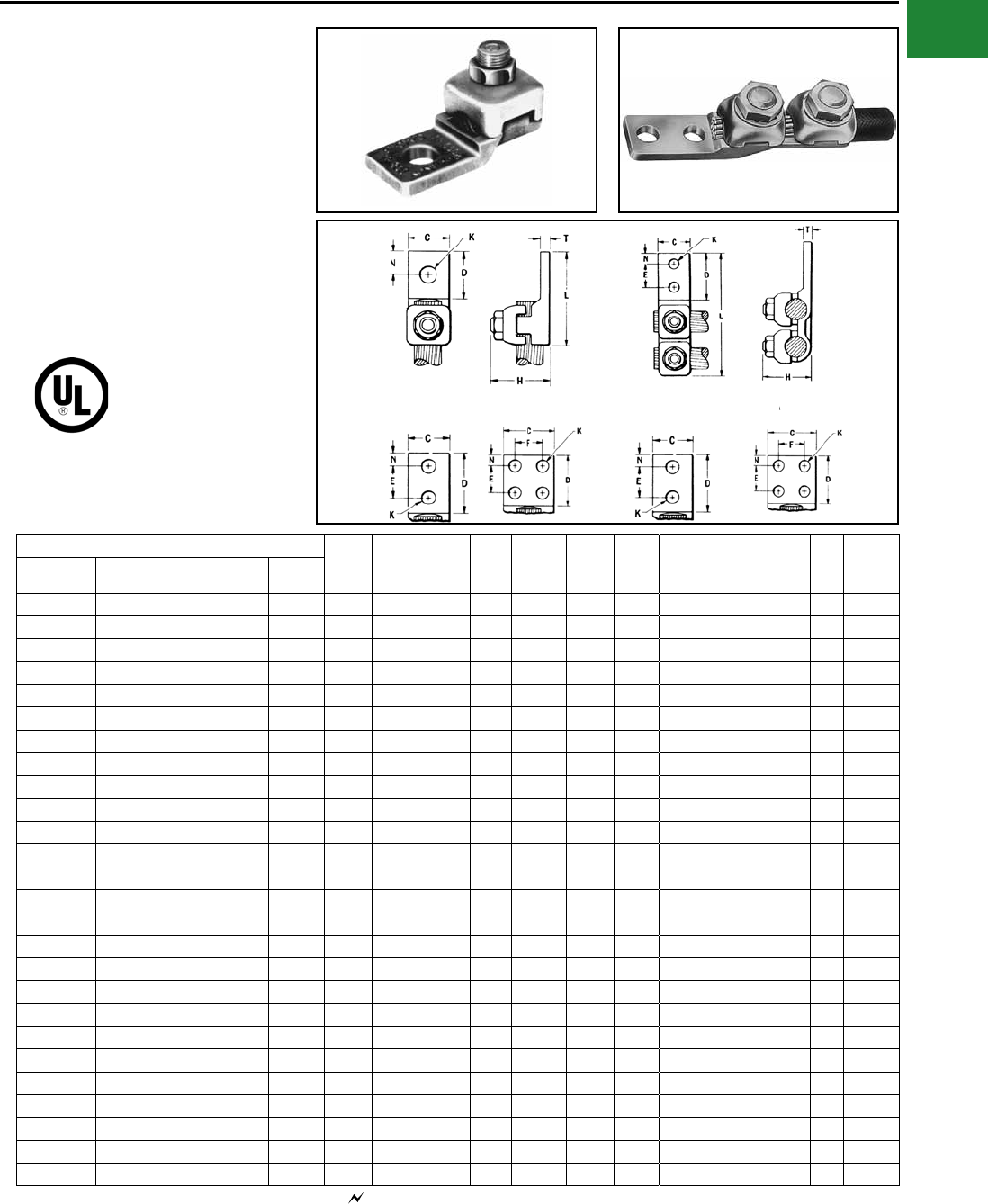
Canada: 1-800-387-6487 www.burndy.com US: 1-800-346-4175
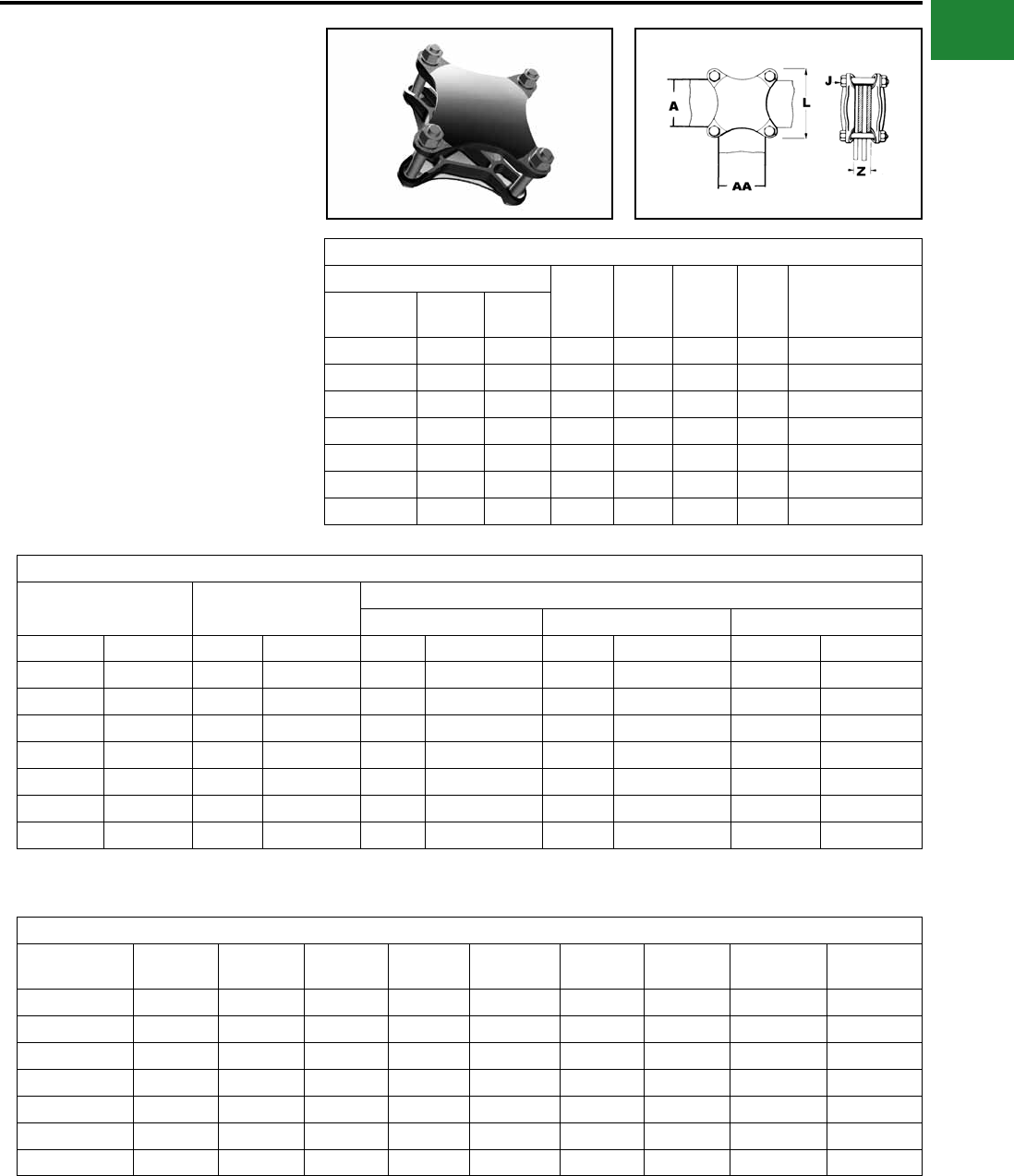
Mechanical
TYPE HFB-P1
BAR CLAMP ASSEMBLY
COMPONENTS
For Copper Bar
To build your own high strength clamp assembly
for multiple at bar using type HFB-P1 bar clamps
and clamping hardware, the following tables have
been provided. The clamp assembly eliminates the
need for drilling the at bar and is used in indoor
and outdoor applications.
One Clamp Half
Bar Clamp Bar “J” Bolt
Dia. L W Z
Recommended
Tightening
Torque in-lb
Catalog
Number Run ‘A’ Tap ‘AA’
HFB22P1 2 2 3/8 4.38 4.38 * 240
HFB33P1 3 3 3/8 4.38 4.38 * 240
HFB42P1 4 2 3/8 5.75 5.75 * 240
HFB44P1 4 4 1/2 5.75 5.75 * 480
HFB63P1 6 3 1/2 7.75 4.75 * 480
HFB66P1 6 6 5/8 8.12 8.12 * 660
HFB88P1 8 8 3/4 10.50 10.50 * 1990
Bar Clamp Assembly Components †
Copper Bus Bar Width (in) Bar Clamp Silicon Bronze Clamping Hardware
Bolts Nuts Split Lock Washers
Run-A Tap-AA Qty Cat. No. Qty Cat. No. Qty Cat. No. Qty Cat. No.
2 2 2 HFB22P1 438 X (*) HEB 438CHEN 438SW
3 3 2 HFB33P1 438 X (*) HEB 438CHEN 438SW
4 2 2 HFB42P1 438 X (*) HEB 438CHEN 438SW
4 4 2 HFB44P1 450 X (*) HEB 450CHEN 450SW
6 3 2 HFB63P1 450 X (*) HEB 450CHEN 450SW
6 6 2 HFB66P1 462 X (*) HEB 462CHEN 462SW
8 8 2 HFB88P1 475 X (*) HEB 475CHEN 475SW
Bolt Length
Clamp
Number
“J”
Bolt Dia.
When
Z = 1.25
When
Z = 1.50
When
Z = 1.75
When
Z = 2.00
When
Z = 2.25
When
Z = 2.50
When
Z = 2.75
When
Z = 3.00
HFB22P1 3/8 3.00 3.25 3.50 4.00 4.00 4.50 4.50 5.00
HFB33P1 3/8 3.00 3.25 3.50 4.00 4.00 4.50 4.50 5.00
HFB42P1 3/8 3.00 3.25 3.50 4.00 4.00 4.50 4.50 5.00
HFB44P1 1/2 3.25 3.50 3.75 4.00 4.50 4.50 5.00 5.00
HFB63P1 1/2 3.25 3.50 3.75 4.00 4.50 4.50 5.00 5.00
HFB66P1 5/8 3.50 4.00 4.00 4.50 4.50 5.00 5.00 5.50
HFB88P1 3/4 3.75 4.00 4.50 4.50 5.00 5.00 5.50 5.50
*Z=Space between the bar clamp contact surfaces
† Ordered separately from BURNDY®.
* See table below when ordering assembly clamping
bolts to specify correct bolt length in Cat. #.
NOTE: When ordering assembly bolts specify correct bolt
length in catalog number as indicated in table.
A-21
BURNDY®
Blue highlighted items are industry standard and most frequently ordered.
US: 1-800-346-4175 www.burndy.com Canada: 1-800-387-6487
Mechanical
TYPE HFB-N
BAR CLAMP TAP PAD ADAPTER
For Copper Bar
High conductivity copper, tap pad adapter provides
a NEMA drilled contact pad when assembled to the
HFB-P1 clamps. Tap connections can be made
from copper bus bar(s) without drilling, by bolting
standard mechanical or compression terminal
pads directly to the pre-drilled tap pad adapter.
Catalog
Number Fig. # A & C E & F L N Use with ‘H’ Clamp
Catalog Number
HFB33-4N 1 3.00 1.75 7.00 0.62 HFB33P1
HFB44-4N 1 4.00 1.75 9.12 1.12 HFB44P1
HFB66-6N 2 6.00 1.75 11.31 1.12 HFB66P1
‘H’ Clamp (two required per assembly) and hardware
(as shown) not included with bar clamp tap pad, order
separately.
1
1
A-22
BURNDY®
Blue highlighted items are industry standard and most frequently ordered.
Canada: 1-800-387-6487 www.burndy.com US: 1-800-346-4175
Mechanical
TYPES KA-U, KKA-U
UNIVERSAL TERMINAL
For Aluminum and Copper
Conductors
These dual-rated one-conductor lugs are
constructed from high strength aluminum alloy
and electro tin-plated to provide low contact
resistance.
AL9CU
Catalog
Number*
Fig.
No.
Wire Range
Aluminum or Copper
Stud
Hole
Size
D L N **
W
E T **
H
Recommended
Tightening ▲
Torque (in-lb)
KA6U 1 14 AWG-6 AWG 1/4 0.63 1.06 0.25 0.50 — 0.09 0.51 45
KA2U 1 14-2 1/4 0.63 1.16 0.31 0.50 — 0.10 0.56 50
KA25U 1 14 AWG-1/0 1/4 0.81 1.50 0.44 0.63 — 0.19 0.92 50
KA26U 2 6-2/0 1/4 0.81 1.47 0.45 0.63 — 0.19 0.80 120
KA29U 2 6-250 5/16 0.94 2.00 0.47 1.00 — 0.25 1.14 275
KA30U 2 6 AWG-300 kcmil 5/16 0.94 2.00 0.45 1.00 — 0.25 1.14 275
KA31U 2 6 AWG-350 kcmil 3/8 1.03 2.25 0.52 1.13 — 0.25 1.27 275
KA34U 2 4 AWG-500 kcmil 3/8 1.50 2.81 0.88 1.51 — 0.31 1.58 500
KA36U 2 2 AWG-600 kcmil 3/8 1.72 3.19 0.78 1.50 — 0.44 1.58 500
KA40U 2 300 kcmil-800 kcmil 1/2 1.85 3.50 0.81 1.75 — 0.50 1.95 550
KA44U 2 500 kcmil-1000 kcmil 1/2 1.69 3.50 0.88 1.75 — 0.50 1.95 550
KKA31U-2N 3 6 AWG-350 kcmil 1/2 3.16 5.50 0.63 1.25 1.75 0.38 1.52 275
KA36U-2N 4 2 AWG-600 kcmil 1/2 3.22 4.69 0.63 1.50 1.75 0.44 1.57 500
KA40U-2N 4 300 kcmil-800 kcmil 1/2 3.03 4.75 0.63 1.75 1.75 0.50 1.95 500
KA44U-2N 4 500 kcmil-1000 kcmil 1/2 3.03 4.75 0.63 1.75 1.75 0.50 1.95 550
KA30226U 52 Str. - 300 kcmil or
(2) 4 Str. - 2/0 Str. 5/16 1.31 2.31 2.00 0.86 – 0.25 1.50 275
KA36229U 54 Str. - 600 kcmil or
(2) 250 kcmil - 1/0 Str. 5/8 1.50 2.81 1.00 1.38 – 0.31 1.81 375
KA39229U 51/0 Str. - 750 kcmil or
(2) 1/0 Str. - 250 kcmil 1/2 1.50 2.81 1.00 1.38 – 0.31 1.81 375
Fig. 1
Fig. 3
Fig. 5
Fig. 2
Fig. 4
* “N” indicates NEMA standard stud holes.
▲ Listed torque values are for maximum conductor sizes accommodated.
Consult UL486 Tables 7-4, 7-5, 7-6 for smaller conductor sizes.
** Maximum dimension.
A-23
BURNDY®
Blue highlighted items are industry standard and most frequently ordered.
US: 1-800-346-4175 www.burndy.com Canada: 1-800-387-6487
Mechanical
TYPES KA-UAR
UNIVERSAL ANTI-ROTATE
TERMINALS
(One Conductor)
For Aluminum and Copper
Conductors
These dual-rated one-conductor lugs are
constructed from high strength aluminum alloy and
electro tin-plated to provide low contact resistance.
These lugs also contain a bottom anti-turn tab.
Catalog
Number
Wire Range
Aluminum or Copper
Stud
Hole
Size
Depth Width Height
Recommended
Tightening ▲
Torque (in-lb)
KA4UAR 14 - 4 1/4 1.16 0.50 0.55 45
KA25UAR 14 - 1/0 1/4 1.47 0.63 0.81 50
KA26UAR 14 - 2/0 1/4 1.47 0.63 0.81 120
KA30UAR 6 - 300 1/4 1.56 0.94 1.13 275
KA31UAR 6 - 350 5/16 1.19 1.00 1.13 275
KA36UAR 4 - 600 3/8 2.75 1.38 1.57 375
AL9CU
Listed torque values are for maximum conductor sizes
accommodated. Consult UL486 Tables 7-4, 7-5, 7-6 for
smaller conductor sizes.
A-24
BURNDY®
Blue highlighted items are industry standard and most frequently ordered.
Canada: 1-800-387-6487 www.burndy.com US: 1-800-346-4175
Mechanical
TYPE K2A-U
UNIVERSAL TERMINAL
(Two Conductor)
For Aluminum and Copper
Conductors
These dual-rated two-conductor lugs are
constructed from high strength aluminum alloy and
electro tin-plated to provide low contact resistance.
AL9CU
Catalog
Number*
Fig.
No.
TWO: Wire Range
(Aluminum or Copper)
Stud
Hole
Size
D L N **
WE T **
H
Recommended
Tightening ▲
Torque (in-lb)
K2A25U 1 14 AWG-1/0 1/4 0.81 1.47 0.44 1.13 — 0.19 0.79 50
K2A26U 2 14 AWG-2/0 AWG 1/4 0.81 1.47 0.44 1.25 — 0.19 0.80 120
K2A29U 2 6 AWG-250 kcmil 3/8 1.50 2.56 0.50 1.66 — 0.25 1.20 275
K2A31U 2 6 AWG-350 kcmil 1/2 1.69 2.88 0.88 1.94 — 0.25 1.26 275
K2A36U 2 2 AWG-600 kcmil 1/2 1.75 3.20 0.63 2.41 — 0.44 1.58 375
K2A40U 2 300 kcmil-800 kcmil 5/8 1.66 3.38 0.88 3.19 — 0.50 1.95 500
K2A44U 2 500 kcmil-1000 kcmil 5/8 1.66 3.50 0.88 3.52 — 0.50 1.95 500
K2A31U-2N 3 6 AWG-350 kcmil 1/2 3.00 4.50 0.63 2.31 1.75 0.31 1.39 275
K2A36U-2N 3 2 AWG-600 kcmil 1/2 3.22 4.69 0.63 2.41 1.75 0.44 1.39 375
K2A40U-2N 3 300 kcmil-800 kcmil 1/2 3.03 4.75 0.63 3.19 1.75 0.50 1.95 375
K2A44U-2N 3 500 kcmil-1000 kcmil 1/2 3.03 4.75 0.63 3.19 1.75 0.50 1.95 375
* “N” indicates NEMA standard stud holes.
▲ Listed torque values are for maximum conductor sizes
accommodated. Consult UL486 Tables 7-4, 7-5, 7-6 for
smaller conductor sizes.
** Maximum dimension.
Fig. 1
Fig. 3
Fig. 2
A-25
BURNDY®
Blue highlighted items are industry standard and most frequently ordered.
US: 1-800-346-4175 www.burndy.com Canada: 1-800-387-6487
Mechanical
TYPES K3A-U, KK3A-U
UNIVERSAL TERMINAL
(Three Conductor)
For Aluminum and Copper Conductors
Dual-rated three-conductor lugs are constructed
from high strength aluminum alloy and electro tin-
plated to provide low contact resistance.
Catalog
Number**
Fig.
No.
THREE: Wire Range
(Aluminum or Copper) K
Stud
Hole
Size
Dimensions Rec.
Tightening ▲
Torque (in-lb)
D L N W E T H
K3A2U-2* 1 14 AWG-2 AWG 11/32 5/16 1.63 2.19 0.34 1.59 0.88 0.19 0.62 50
K3A25U-2* 1 14 AWG-1/0 7/16 3/8 2.09 2.91 0.34 1.94 1.00 0.25 0.88 50
K3A26U-2N 3 14 AWG-2/0 AWG 9/16 1/2 3.06 3.75 0.63 1.95 1.75 0.19 1.79 50
K3A27U-2N 3 6 AWG-3/0 AWG 9/16 1/2 3.00 3.88 0.63 2.81 1.75 0.31 1.12 275
K3A29U-2N 3 6 AWG-250 kcmil 9/16 1/2 3.16 4.00 0.63 2.81 1.75 0.31 1.19 275
K3A31U-2N 3 6 AWG-350 kcmil 9/16 1/2 3.16 4.31 0.63 3.52 1.75 0.31 1.38 275
K3A36U-2N 3 2 AWG-600 kcmil 9/16 1/2 3.22 4.69 0.63 3.63 1.75 0.44 1.56 375
KK3A36U-2N 2 2 AWG-600 kcmil 9/16 1/2 3.00 5.50 0.63 4.22 1.75 0.38 1.52 375
KK3A40U-2N 2 300 kcmil-800 kcmil 9/16 1/2 3.34 6.19 0.63 4.81 1.75 0.56 1.89 375
KK3A44U-2N 2 500 kcmil-1000 kcmil 9/16 1/2 3.34 6.19 0.63 4.75 1.75 0.56 1.90 500
K3A2U-4* 4 14 AWG-2 AWG 11/32 5/16 1.63 2.19 0.34 1.59 0.88 0.19 0.62 50
K3A25U-4* 4 14 AWG-1/0 7/16 3/8 2.09 2.91 0.34 1.94 1.00 0.25 0.88 50
K3A27U-4N 4 6 AWG-3/0 AWG 9/16 1/2 3.00 3.88 0.63 2.81 1.75 0.31 1.12 275
K3A29U-4N 4 6 AWG-250 kcmil 9/16 1/2 3.00 4.00 0.63 2.81 1.75 0.31 1.19 275
K3A31U-4N 4 6 AWG-350 kcmil 9/16 1/2 3.00 4.31 0.63 3.00 1.75 0.31 1.38 275
K3A36U-4N 4 2 AWG-600 kcmil 9/16 1/2 3.22 4.69 0.63 3.63 1.75 0.44 1.56 375
K3A40U-4N 4 300 kcmil-800 kcmil 9/16 1/2 3.03 4.75 0.63 4.81 1.75 0.50 1.94 375
KK3A36U-4N 5 2 AWG-600 kcmil 9/16 1/2 3.00 5.50 0.63 4.22 1.75 0.38 1.52 375
KK3A40U-4N 5 300 kcmil-800 kcmil 9/16 1/2 3.34 6.19 0.63 5.34 1.75 0.56 1.89 500
KK3A44U-4N 5 500 kcmil-1000 kcmil 9/16 1/2 3.34 6.19 0.63 4.75 1.75 0.56 1.90 500
* Slotted screw.
** ‘‘N” indicates NEMA standard stud holes.
▲ Listed torque values are for maximum conductor sizes
accommodated. Consult UL486 Tables 7-4, 7-5, 7-6 for
smaller conductor sizes.
AL9CU
All 4N items see note LIGHTNING PROTECTION INFO.
Fig. 1
Fig. 3
Fig. 2
Fig. 4
Fig. 5
A-26
BURNDY®
Blue highlighted items are industry standard and most frequently ordered.
Canada: 1-800-387-6487 www.burndy.com US: 1-800-346-4175
Mechanical
TYPES K4A-U, KK4A-U
UNIVERSAL TERMINAL
(Four Conductor)
For Aluminum and Copper Conductors
These dual-rated four conductor lugs are
constructed from high strength aluminum alloy and
electro tin-plated to provide low contact resistance.
Catalog
Number*
Fig.
No.
FOUR: Wire Range
(Aluminum or Copper)
Stud
Hole
Size
Dimensions Recommended
Tightening
Torque (in-lb)
D L N W E T H
K4A29U-4N 1 6 AWG-250 kcmil 1/2 3.16 4.25 0.63 3.69 1.75 0.31 1.19 275
K4A31U-4N 1 6 AWG-350 kcmil 1/2 3.00 4.50 0.63 5.04 1.75 0.31 1.38 275
KK4A36U-4N 2 2 AWG-600 kcmil 1/2 3.34 5.63 0.63 5.00 1.75 0.44 1.51 375
KK4A40U-4N 2 300 kcmil-800 kcmil 1/2 3.41 6.19 0.63 6.00 1.75 0.56 1.88 375
AL9CU
TYPES K11A-U, K21A-U,
K22A-U
UNIVERSAL TERMINAL
For Aluminum and Copper Conductors
Dual-rated panelboard lugs are constructed from
high strength extruded aluminum alloy and electro
tin-plated to provide low contact resistance.
Catalog
Number
Fig.
No.
# of
Conductors
Wire Range
(Aluminum or Copper)
Stud
Hole
Size
D L N W E T H
Recommended
Tightening ▲
Torque (in-lb)
K11A30U 1 2 6 AWG-300 kcmil 5/16 0.94 3.00 0.47 1.00 — 0.50 2.03 275
K11A34U-2 2 2 4/0 AWG-500 kcmil 1/4 2.31 2.91 0.25 1.44 0.69 0.63 2.40 375
K11A36U-2 3 2 2 AWG-600 kcmil 3/8 2.31 4.91 0.38 1.50 1.38 0.75 3.02 375
K21A36U-2 4 3 2 AWG-600 kcmil 3/8 2.31 4.91 0.38 2.50 1.38 0.75 3.03 375
K22A36U-2 5 4 2 AWG-600 kcmil 3/8 2.31 4.91 0.38 2.50 1.38 0.75 3.03 375
K11A39U-2 3 2 1/0 -750 kcmil 3/8 2.31 4.91 0.38 1.69 1.38 0.75 3.02 375
K22A39U-2 5 4 1/0 -750 kcmil 3/8 2.31 4.91 0.38 3.06 1.38 0.75 3.02 375
* ‘‘N” indicates NEMA standard stud holes. All 4N items see note LIGHTNING PROTECTION INFO.
AL9CU
▲ Listed torque values are for maximum conductor sizes accommodated. Consult UL486
Tables 7-4, 7-5, 7-6 for smaller conductor sizes.
Fig. 1 Fig. 2
Fig. 1
Fig. 2 Fig. 3
Fig. 4 Fig. 5
A-27
BURNDY®
Blue highlighted items are industry standard and most frequently ordered.
US: 1-800-346-4175 www.burndy.com Canada: 1-800-387-6487
Mechanical
TYPES K6A-U, K8A-U,
KK6A-U, KK8A-U
UNIVERSAL TERMINALS
(Six and Eight Conductor)
For Aluminum and
Copper Conductors
These dual-rated six and eight conductor lugs are
constructed from high strength aluminum alloy and
electro tin-plated to provide low contact resistance.
Catalog
Number
Fig.
No.
No. of
Conductors
No. of
Mtg
Holes
Wire Range
Aluminum
or Copper
Stud
Hole
Size
Depth Width Height
Rec.
Tightening
Torque
in-lb ♦
K6A34U-8 1 6 8 2 AWG - 500 kcmil 9/16 4.63 6.75 1.56 375
K8A34U-10 1 8 10 2 AWG - 500 kcmil 9/16 4.63 8.75 1.56 375
KK6A31U-8 2 6 8 6 AWG - 350 kcmil 9/16 5.31 6.38 1.50 275
KK8A31U-10 2 8 10 6 AWG - 350 kcmil 9/16 5.31 8.13 1.50 275
KK6A34U-8 2 6 8 2 AWG - 500 kcmil 9/16 5.50 6.75 1.50 375
KK8A34U-10 2 8 10 2 AWG - 500 kcmil 9/16 5.50 8.75 1.50 375
KK8A39U-10 2 6 10 2 AWG - 750 kcmil 9/16 6.19 8.25 1.88 550
KK8A39U-12 2 8 12 2 AWG - 750 kcmil 9/16 6.19 10.25 1.88 550
KK6A44U-12 2 6 12 350 kcmil - 1000 kcmil 9/16 6.19 10.00 1.88 550
KK8A44U-14 2 8 14 350 kcmil - 1000 kcmil 9/16 6.19 12.12 1.88 550
♦ Listed torque values are for maximum conductor sizes
accommodated. Consult UL486 Tables 7-4, 7-5, & 7-6
for smaller conductor sizes
Fig. 1
Fig. 2
A-28
BURNDY®
Blue highlighted items are industry standard and most frequently ordered.
Canada: 1-800-387-6487 www.burndy.com US: 1-800-346-4175
Mechanical
TYPE KAU-KIT
TRANSFORMER LUG KIT
These dual-rated lugs are constructed from
high strength aluminum alloy and electro tin-
plated to provide low contact resistance. Lugs and
mounting hardware packaged together in these
kits.
Features & Benets
• UL Listed AL9CU dual rated set screw
terminals and CSA Certied
◊ Ensure the transformer feeders and
taps are terminated properly.
• Plated steel cap screws and hex nuts
with captive conical washers or individual
Belleville washers
◊ Terminal to bus connections are made
using proper hardware resulting in true
torque to pressure performance -
compensates for dissimilar metal
expansion and contraction.
Catalog
Number
Transformer
KVA Rating
Terminals Wire Range
Aluminum
or Copper
Hardware
Qty Catalog
Number Qty Bolt Size Qty Nut Qty Washer
KAU-KIT1 15 - 37.5 1Ø
15 - 45 3Ø
8
4
KA2U
KA29U
14 AWG-250
kcmil 8 1/4-20 X 3/4 HH 8 1/4 X 20 HN - Captive to Nut
KAU-KIT2 50 - 75 1Ø
75 - 112.5 3Ø 12 KA29U 6 AWG-250
kcmil
8
8
1/4-20 X 3/4 HH
1/4-20 X 2 HH 16 1/4 X 20 HN - Captive to Nut
KAU-KIT3 100 - 167 1Ø
150 - 300 3Ø
6
7
K2A31U
K2A40U
6 AWG-800
kcmil
5
6
1/2-13 X 3 HH
1/2-13 X 2-1/2 HH 11 1/2-13 HN 22
11
1/2 FW
1/2 Belleville
KAU-KIT4 400 - 500 3Ø 15 K2A40U 300 kcmil-800
kcmil
7
4
1/2-13 X 2 HH
1/2-13 X 2-1/2 HH 11 1/2-13 HN 22
11
1/2 FW
1/2 Belleville
HH = Hex Head
HN = Hex Nut
FW = Flat Washer
• Hardware packed in plastic bag
◊ No lost hardware prior to installation.
• Larger 800 kcmil lugs in KIT3 and KIT4
◊ Accommodates common 750 kcmil tap
conductors in larger transformers.
A-29
BURNDY®
Blue highlighted items are industry standard and most frequently ordered.
US: 1-800-346-4175 www.burndy.com Canada: 1-800-387-6487
Mechanical
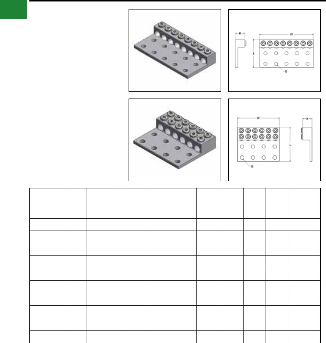
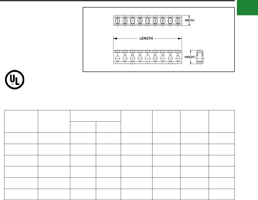
TYPES K-AG1
ALUMINUM NEUTRAL BAR
These aluminum neutral bars are dual rated
for copper and aluminum conductors, and
are manufactured from high strength 6061-T6
aluminum alloy and are electro tin plated to provide
low contact resistance and protection against
corrosion.
AL9CU
Catalog
Number Fig. Wire Range
Aluminum or Copper
Total Number
of Holes
Total Number
of Circuits
Mount Hole
Locations Height Width Length
K2P4CAG1 1 14 - 4 3 2 2 0.44 0.31 1.09
K3P4CAG1 1 14 - 4 5 3 1, 5 0.44 0.31 1.67
K9P4CAG1 1 14 - 4 11 9 4, 8 0.44 0.31 3.53
K13P4CAG1 1 14 - 4 15 13 6, 12 0.44 0.31 4.77
K15P4CAG1 1 14 - 4 17 15 6, 14 0.44 0.31 6.01
K5P6C2P1/0CAG1 214 - 1/0
14 - 6 7(5) 14 - 6
(2) 14 - 1/0 – 0.62 0.38 2.26
K12P6C3P1/0CAG1 214 - 1/0
14 - 6 15 (12) 14 - 6
(3) 14 - 1/0 – 0.62 0.38 4.34
K14P6C5P1/0CAG1 214 - 1/0
14 - 6 19 (14) 14 - 6
(5) 14 - 1/0 – 0.62 0.38 5.77
K16P6C5P1/0CAG1 214 - 1/0
14 - 6 23 (16) 14 - 6
(5) 14 - 1/0 – 0.62 0.38 6.97
KAG1MTGBRKT ♦ 3 – – – – – –
♦ (2) KAG1MTGBRKT are necessary to mount neutral bars into enclosure
Fig. 1 Fig. 2
Fig. 3
A-30
BURNDY®
Blue highlighted items are industry standard and most frequently ordered.
Canada: 1-800-387-6487 www.burndy.com US: 1-800-346-4175
Mechanical
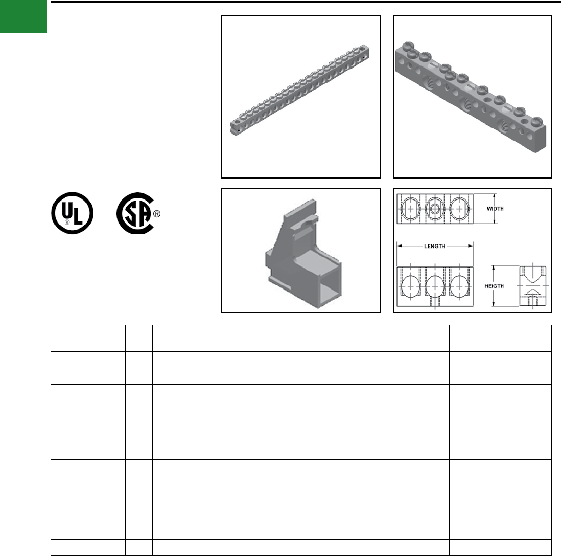
TYPES K-G1
COPPER NEUTRAL BAR
These copper neutral bars are manufactured from
high strength pure electrolytic copper to insure
maximum strength and conductivity.
AL9CU
Catalog
Number
Number of
Outlets
Conductor Range Mounting
Holes Dimensions Width Length
Line Circuit
K6P4CG1 6 14 - 4 6 - 14 0.20 0.23 0.34 3.56
K8P4CG1 8 14 - 4 6 - 14 0.20 0.47 0.34 4.37
K10P4CG1 10 14 - 4 6 - 14 0.20 0.75 0.34 5.15
K12P4CG1 12 14 - 4 6 - 14 0.20 0.75 0.34 5.94
K14P4CG1 14 14 - 4 6 - 14 0.20 0.75 0.34 6.75
K174P4CG1 174 14 - 4 6 - 14 none 0.47 0.34 69.00
A-31
BURNDY®
Blue highlighted items are industry standard and most frequently ordered.
US: 1-800-346-4175 www.burndy.com Canada: 1-800-387-6487
Mechanical
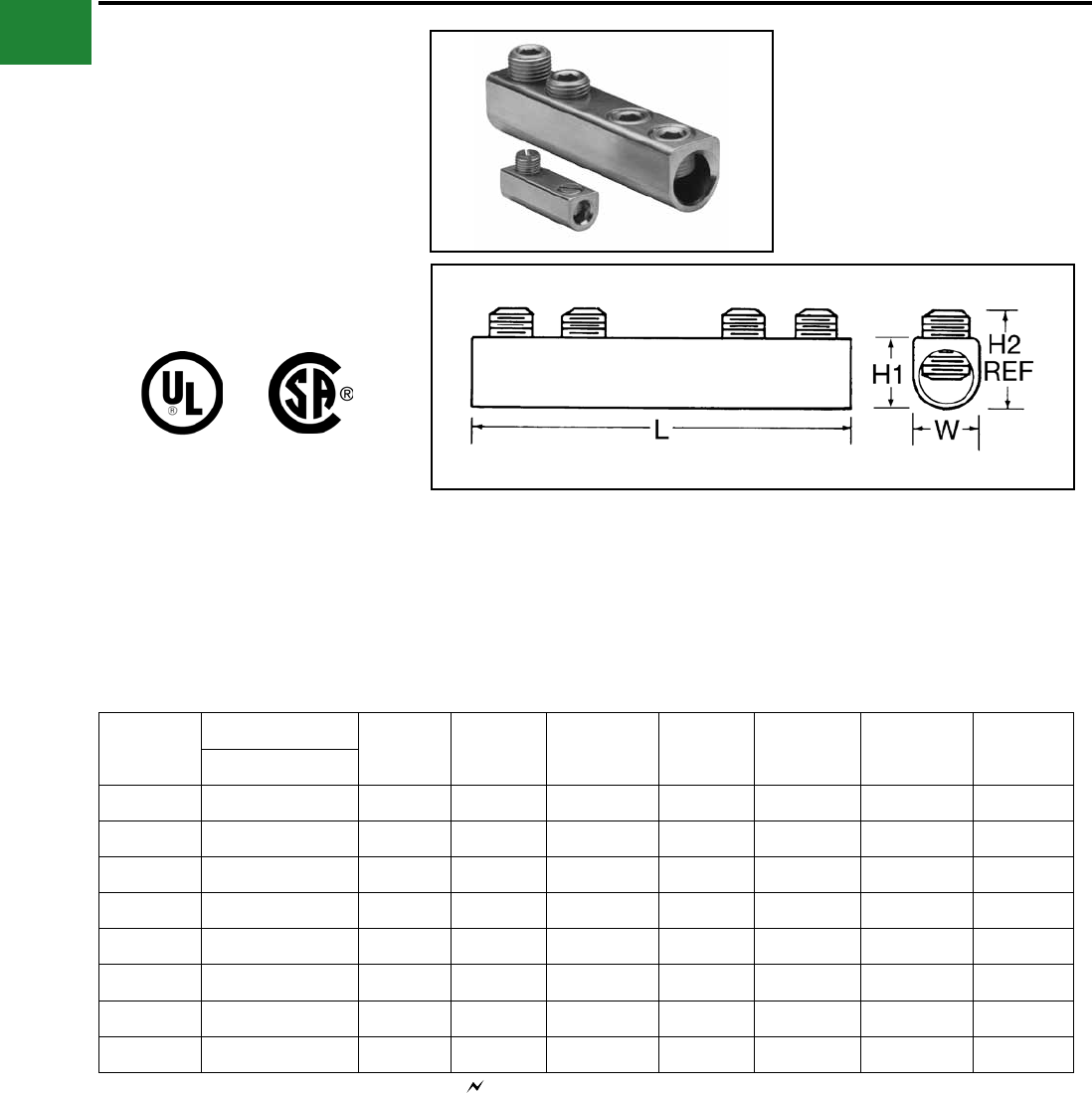
TYPE AMS
DUAL RATED SPLICER/REDUCER
For Copper and Aluminum Cable
All splicer/reducers are dual rated for use
with aluminum and copper conductors and
are constructed from high strength, tin plated
aluminum. PENETROX™ oxide inhibiting joint
compounds are recommended for all aluminum
applications.
Catalog
Number
Wire Range
L W H1 H2 Max Number of
Screws
Screw
Diameter
Hex
Size
Aluminum & Copper
AMS-2*14 AWG-2 AWG 1-19/32 9/16 9/16 0.79 2 3/8 Slot
AMS-0*14 AWG-1/0 1-29/32 3/4 3/4 0.86 2 7/16 Slot
AMS-4/0 6 AWG-4/0 AWG 2-5/16 1 1-3/32 1.28 2 9/16 5/16
AMS-250 6 AWG-250 kcmil 4-3/32 1 1-3/32 1.29 4 5/8 5/16
AMS-350 6 AWG-350 kcmil 4-11/32 1 1-3/32 1.3 4 11/16 5/16
AMS-500 3/0 AWG-500 kcmil 4-25/32 1-1/4 1-3/8 1.48 4 13/16 3/8
AMS-750 250 kcmil-750 kcmil 6-1/6 1-7/16 1-5/8 1.98 4 15/16 1/2
AMS-1000 500 kcmil-1000 kcmil 8-11/16 1-21/32 1-7/8 2.34 6 1-1/8 9/16
Features & Benets
• All connectors are tin-plated
◊ Provide low contact resistance and
prevents galvanic corrosion
• Connectors feature rounded bottoms
◊ Facilitates taping
• Solid center barrier
◊ Prevents contact of dissimilar metals
• Large screw diameters
◊ Ensures greater surface contact with
wires for maximum pullout force
• Large cable ranges
◊ Each splice is also an effective
reducing connector
* Slotted Screws. H2 measured with maximum conductors,
reference only.
Complies with NFPA 78-86.
A-32
BURNDY®
Blue highlighted items are industry standard and most frequently ordered.
Canada: 1-800-387-6487 www.burndy.com US: 1-800-346-4175
Mechanical
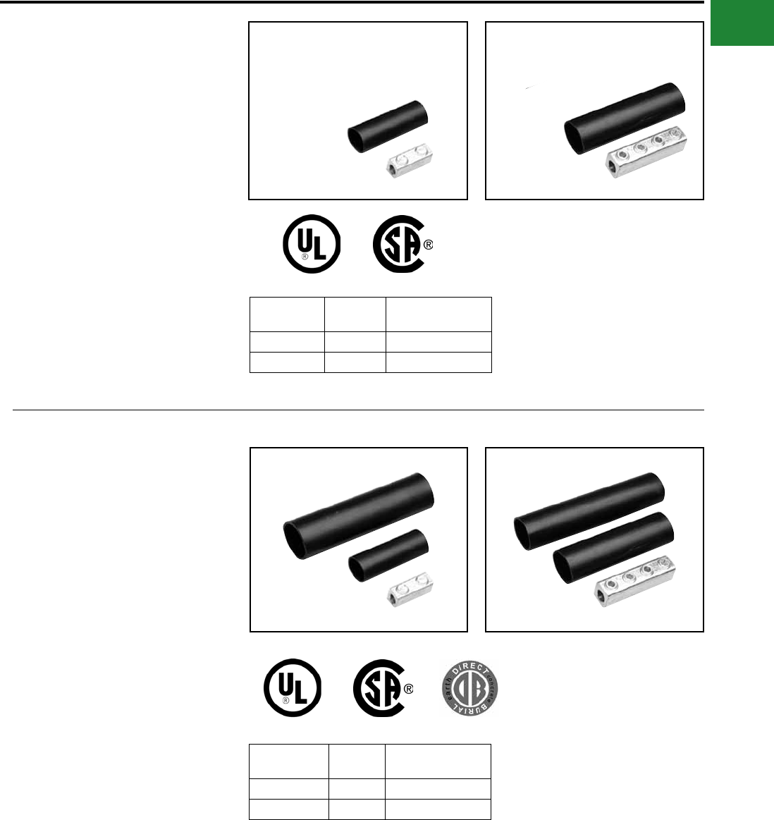
TYPE AGSKIT
ABOVE GRADE SPLICE KITS
For all Aluminum or Copper/Aluminum
Combinations
Type AGS Above Grade Splice Kit consists of a
standard AMS splice/reducer and a heavy wall
heat-shrink sleeve. The AMS Splice is dual rated
for use with aluminum and copper conductors
and are constructed from high strength, tin plated
aluminum that provides low contact resistance
and reduces the effects of galvanic corrosion.
Connector is installed with common installation
tools. The heavy wall heat shrink sleeve is lined
with adhesive material, providing a positive seal
against moisture egress. Heat shrink sleeve is
installed with standard propane torch, or electric
heat gun.
Catalog
Number
Figure
Number Wire Range
AGSKIT2 1 8 AWG-2 AWG
AGSKIT250 2 1 AWG-250 kcmil
Fig. 1
Fig. 1
Fig. 2
Fig. 2
TYPE UGSKIT
WATERTIGHT/
UNDERGROUND SPLICE KITS
For all Aluminum or Copper/Aluminum
Combinations
Type UGS Watertight Underground Splice Kit
consists of a standard AMS splice/reducer and
two heavy wall heat-shrink sleeves. The AMS
Splice is dual rated for use with aluminum and
copper conductors and are constructed from
high strength, tin plated aluminum that provides
low contact resistance and reduces the effects
of galvanic corrosion. Connector installed with
common installation tools. Both heavy wall heat
shrink sleeves are lined with adhesive material,
providing a watertight splice that can withstand
abrasions that may occur during direct burial
applications. Heat shrink sleeve installed with
standard propane torch, or electric heat gun.
Catalog
Number
Figure
Number Wire Range
UGSKIT2*1 8 AWG-2 AWG
UGSKIT250*2 1 AWG-250 kcmil
*UL486D Listed for Direct Burial
A-33
BURNDY®
Blue highlighted items are industry standard and most frequently ordered.
US: 1-800-346-4175 www.burndy.com Canada: 1-800-387-6487
Mechanical
Direct Burial UNITAP™
Connectors
UNITAP™
Dual Rated Multiple Tap Connector
These rubber insulated, dual rated connectors are
for use in networks up to 600V. Suitable in light
xture pole bases in commercial, industrial, or
residential markets. Distribution within strip malls,
for use in any multi-tenant facility. No taping or
heat shrink required.
Catalog Number # of Ports Wire Range
(AWG/kcmil) L W H Wire Strip Length
(in)
BIBS3502DB 2 12 AWG-350 kcmil 2.61 4.06 2.46 1.125
BIBS3503DB 3 12 AWG-350 kcmil 3.82 4.06 2.46 1.125
BIBS3504DB 4 12 AWG-350 kcmil 5.03 4.06 2.46 1.125
BIBS3505DB 5 12 AWG-350 kcmil 6.24 4.06 2.46 1.125
BIBS3506DB 6 12 AWG-350 kcmil 7.45 4.06 2.46 1.125
BIBS5003DB 3 10 AWG-500 kcmil 4.31 4.58 3.13 1.50
BIBS5004DB 4 10 AWG-500 kcmil 5.69 4.58 3.13 1.50
BIBS5005DB 5 10 AWG-500 kcmil 7.06 4.58 3.13 1.50
BIBS5006DB 6 10 AWG-500 kcmil 8.44 4.58 3.13 1.50
Features & Benets
• Dual rated for aluminum or copper
conductors
• Each unit is individually marked for
ease of identication
• Supplied with aluminum set-screws
• Covering is the highest quality
EPDM rubber
• Supplied with oxide inhibitor pre-
installed
• Suitable for direct burial
• Meets ANSI C119.1 and C119.4
requirements
• Rated 600V and 90° C; UL Listed
and CSA Certied
• For use in wet or damp locations
• Silicone provided for conductor
insertion
Recommended Torque Values for Direct Burial UNITAP™ Recommended BURNDY®
Torque Wrench
Conductor Size Recommended Torque Range
#12 - #6 AWG 125 - 150 in-lbs BTW30150
#4 - 3/0 AWG 180 - 240 in-lbs BTW150750
4/0 - 350 AWG 275 - 450 in-lbs BTW150750
400 - 1000 AWG 475 - 550 in-lbs BTW150750
A-34
BURNDY®
Blue highlighted items are industry standard and most frequently ordered.
Canada: 1-800-387-6487 www.burndy.com US: 1-800-346-4175
Mechanical
TYPE UGSKIT8
UF DIRECT BURIAL
SPLICE KIT
Type UGS UF Splice Kit consists of a UF splice
connector and a heavy wall heat-shrink sleeve.
The UF splice connector can accommodate up to
four UF conductors and is installed with common
installation tools. The heavy wall heat shrink
sleeve is lined with an adhesive material, providing
a water-tight splice that can withstand abrasions
that may occur during direct burial applications.
Heat shrink sleeve installed with standard propane
torch, or electric heat gun.
Catalog
Number
Wire Range
Copper
UGSKIT8*14 AWG-8 AWG
*UL486D Listed for Direct Burial
TYPE UGS350ULDB
IN-LINE SPLICE/REDUCER
For Direct Burial
Catalog Number Wire Range Length Height Hex Size Torque (In. Lbs.)
UGS350ULDB 12 AWG-350 kcmil 8.50 2.81 5/16 350
Features & Benets
• EPDM rubber covered 6061-T6
aluminum connector
• Dual rated AL9CU for copper or
aluminum conductor
• UL Listed and CSA Certied for Direct
Burial
• Broad range taking capability
• Low installation cost
A-35
BURNDY®
Blue highlighted items are industry standard and most frequently ordered.
US: 1-800-346-4175 www.burndy.com Canada: 1-800-387-6487
Mechanical
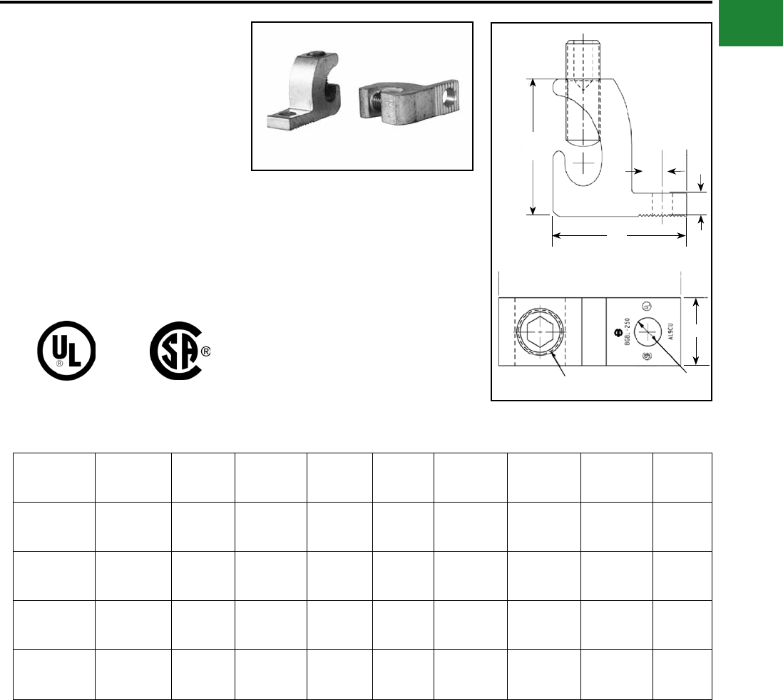
BURNDY UNITAP™
THE MOLE™
For Direct Burial
600V, 90° C
Designed specically for direct burial applications,
the MOLE™ in-line splice/reducer is made with a
specialized plastisol material that forms a rugged
weathertight connection.
Catalog
Number
Number of
Ports
Wire Range (AWG/
kcmil) L W H Hex Key Torque
(In.-lbs.)
Wire Strip
Length
BISR4-DB 2 #6 AWG-#4 AWG 4.30 0.68 1.39 1/8 50 7/8"
BISR1-DB 2 #2 AWG-#1 AWG 6.30 0.88 1.75 5/32 130 1-3/32"
BISR3/0-DB 2 1/0 -3/0 AWG 6.25 0.99 1.96 3/16 220 1-3/32"
BISR250-DB 2 4/0 AWG-250 kcmil 6.70 1.18 2.17 5/16 360 1-5/16"
Features & Benets
• UL486D Listed for direct burial.
• AL9CU Dual-rated for copper and
aluminum applications. 600V 90°C.
• Plastisol covered AL6061-T6 aluminum
body saves time by eliminating the need
for heat shrink.
• Oxide inhibitor pre-installed preventing
moisture and contaminants from entering
contact area.
• Range-taking capability reduces the
number of connectors carried in inventory.
BISR-DB = BURNDY Inline Splice/Reducer Direct Burial.
UNITAP™ rated for code conductor only.
A-36
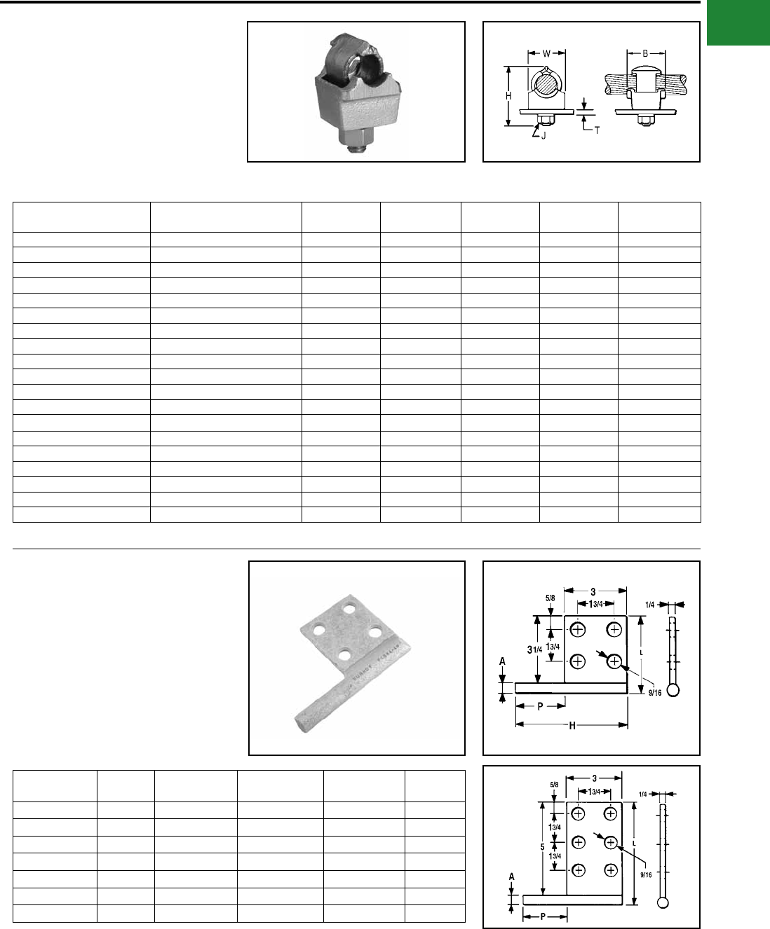
BURNDY®
Blue highlighted items are industry standard and most frequently ordered.
Canada: 1-800-387-6487 www.burndy.com US: 1-800-346-4175
Mechanical
QGFL
BARTAP™
For Copper Cable to Flat Bar or
Pad
High copper alloy BARTAP™ for joining a range
of cable to bar or pad. One-wrench installation.
DURIUM™ nut and lockwasher.
Catalog
Number
Copper
Conductor B H J T
(Max) W
QGFL1CB1 #10 Sol-#1 Str 1-1/8 1-7/8 3/8 1/4 1
QGFL1CB1T6 #10 Sol-#1 Str 1-1/8 2-3/8 3/8 3/4 1
QGFL26B1 #8 Sol-#2/0 Str 1-1/4 2-1/8 3/8 1/4 1-1/8
QGFL26B1T6 #8 Sol-#2/0 Str 1-1/4 2-5/8 3/8 3/4 1-1/8
QGFL26B2* #8 Sol-#2/0 Str 1-1/4 2-8/25 1/2 1/4 1-1/8
QGFL26B2T6* #8 Sol-#2/0 Str 1-1/2 2-40/50 1/2 3/4 1-1/8
QGFL29B1* #6 Str-250 kcmil 1-2/5 2-5/8 1/2 1/4 1-3/8
QGFL29B1T6* #6 Str-250 kcmil 1-5/8 3-1/8 1/2 3/4 1-3/8
QGFL31B1* 2 AWG-350 kcmil 1-3/4 2-7/8 1/2 1/4 1-5/8
QGFL31B1T6* 2 AWG-350 kcmil 1-3/4 3-1/4 1/2 3/4 1-5/8
QGFL34B1 1/0 -500 kcmil 2 3-1/8 1/2 1/4 1-3/4
QGFL34B1T6 1/0 -500 kcmil 2 3-5/8 1/2 3/4 1-3/4
QGFL39B1 350 kcmil-750 kcmil 2-1/4 3-1/4 1/2 1/4 1-3/4
QGFL39B1T6 350 kcmil-750 kcmil 2-1/4 3-5/8 1/2 3/4 1-3/4
QGFL44B1 750 kcmil-1000 kcmil 2-1/4 3-3/8 1/2 1/4 2-1/8
QGFL44B1T6 750 kcmil-1000 kcmil 2-1/4 4-1/8 1/2 3/4 2-1/8
QGFL46B1 1000 kcmil-1500 kcmil 2-1/4 4 1/2 1/4 2-1/2
QGFL46B1T6 1000 kcmil-1500 kcmil 2-1/4 4-1/2 1/2 3/4 2-1/2
QGFL48B1 1500 kcmil-2000 kcmil 2-1/4 4-3/4 1/2 1/4 3
* Can be installed side by side or in-line on NEMA drilled bar.
FCB
TRANSFORMER TAP ADAPTER
Copper and Aluminum
Cast in one piece from copper alloy. Transformer
tap adapter designed to accommodate from 1
to 6 NEMA drilled copper or aluminum terminal
taps from a single secondary transformer outlet.
Tin-plated. Order mounting hardware and tap
terminals separately.
Catalog
Number
Fig.
No.
A
Diameter
H
Ref. L P
FCB63-4N 1 0.50 5.25 3.75 2.25
FCB63-6N 2 0.50 5.25 5.50 2.25
FCB64-4N 1 0.75 5.75 4.00 2.75
FCB64-6N 2 0.75 5.75 5.75 2.75
FCB65-4N 1 1.00 7.00 4.25 4.00
FCB63-2NP300 Not Shown 0.50 5.00 3.50 3.00
FCB64-44NP50 Not Shown 0.75 9.00 5.00 5.00
NOTE: All pads are NEMA drilled.
Fig. 1
Fig. 2
A-37
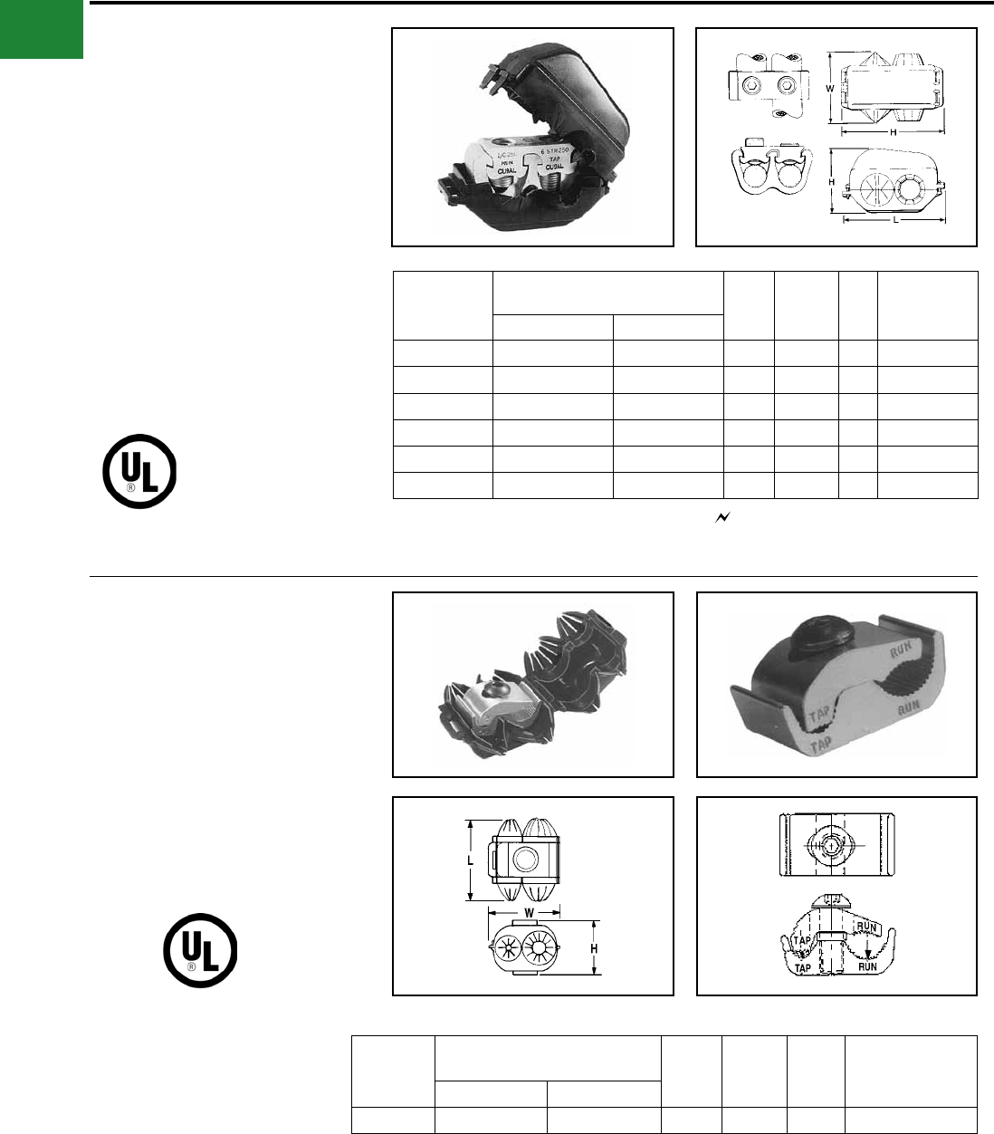
BURNDY®
Blue highlighted items are industry standard and most frequently ordered.
US: 1-800-346-4175 www.burndy.com Canada: 1-800-387-6487
Mechanical
TYPE KPU-AC
POLYTAP™
Insulated Gutter Tap for All Copper
and Aluminum Combinations
Wide range-taking tin-plated aluminum parallel
clamp and insulating cover assembly for industrial
and multiple story structure applications. Only
six connectors cover the entire 14 Sol.-750 kcmil
range. Covers having exible ngers that conform
to conductor, fully insulating the connection.
UL486B Listed for 600 volts maximum 90° C
service. Cover and connector are packaged
together. No taping required.
600 Volt Max. 90° C
Catalog
Number
Conductor
Copper or Aluminum W H L
Rec.
Tightening
▲ Torque in-lb
Run Tap
KPU29A26AC 1/0 -250 kcmil 14 AWG-2/0 AWG 3-1/8 3-3/8 4.24 375
KPU29A29AC 1/0 -250 kcmil 6 AWG-250 kcmil 3-1/8 3-3/8 4.24 375
KPU34A26AC 4/0 AWG-500 kcmil 14 AWG-2/0 AWG 3-1/2 3-1/2 4.58 450
KPU34A34AC 4/0 AWG-500 kcmil 6 AWG-500 kcmil 3-1/2 3-1/2 4.58 450
KPU39A26AC 500 kcmil-750 kcmil 14 AWG-2/0 AWG 3-1/2 3-83/100 5.06 600
KPU39A39AC 500 kcmil-750 kcmil 1/0 -750 kcmil 3-1/2 3-83/100 5.06 600
▲ Listed torque values are for maximum conductor
combinations accommodated. Consult UL486 Tables
7-4, 7-5, 7-6 for smaller combinations.
▲ Listed torque values are for maximum conductor
combinations accommodated. Consult UL486 Tables
7-4, 7-5, 7-6 for smaller combinations.
See note LIGHTNING PROTECTION INFO.
TYPE UCU-AC
RISER TAP
600 VOLT MAX. 90° C MAX.
Parallel-groove riser tap and insulation cover for
copper and aluminum. Wide range-taking assembly
for apartment house and light industrial applications.
Cover and connector are packaged together. Covers
having insulating ngers that conform to conductors,
fully insulating the connection. UL486B Listed for 600
volts max. 90° C service.
Catalog
Number
Conductor
Copper or Aluminum W H L
Recommended
Tightening ▲
Torque in-lb
Run Tap
UCU28AC #2 Str.- 4/0 Str. #10 Sol. - #2 Str. 2-1/4 1-13/16 2-5/8 120
A-38
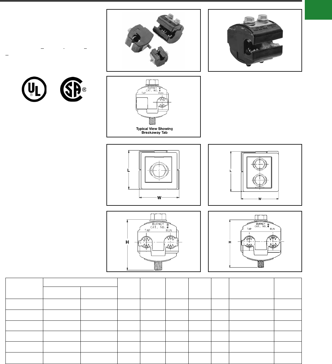
BURNDY®
Blue highlighted items are industry standard and most frequently ordered.
Canada: 1-800-387-6487 www.burndy.com US: 1-800-346-4175
Mechanical
TYPE BIPC
UL Listed 90° C, *600 Volt
The Type BIPC, BURNDY® Insulation Piercing
Connector is ideally suited for splicing and tapping
aluminum and copper conductor wire sizes: #10
AWG to 500 kcmil.
Catalog
Number
Conductor Range
Bolt Size Socket
Size H L W
Recommended
Tightening
Torque
Max.
Voltage
Rating
Run Tap
BIPC1/0-2* 1/0 - 8 AWG 2 - 8 AWG 5/16 1/2 2.00 1.53 1.53 180 600 V
BIPC4/0-6 4/0 - 1/0 AWG 1/0 - 6 AWG 5/16 1/2 2.50 2.12 2.00 250 300 V
BIPC4/0-1/0 4/0 - 1/0 AWG 4/0 - 1/0 AWG 5/16 1/2 2.50 2.12 2.06 250 300 V
BIPC350-4/0 350 - 4/0 AWG 4/0 - 10 AWG 3/8 9/16 3.00 1.59 2.50 375 300 V
BIPC350-350 350 - 4/0 AWG 350 - 4/0 AWG 3/8 9/16 3.00 2.62 2.75 300 300 V
BIPC500-4/0* 500 - 350 kcmil 4/0 - 4 AWG 3/8 9/16 3.25 1.80 2.62 400 600 V
Features & Benets
• Insulation piercing capability
◊ Eliminates the need for conductor
insulation stripping.
• UL486B Listed, AL9CU rated
◊ For copper and aluminum conductor
combinations up to 90° *600 Volt
applications.
• Insulation piercing design
◊ For use on hot-line applications -
eliminates the need for taping.
• Easy snap-out tabs
◊ Eases installation, protects connection
from dirt and debris.
• Simple bolt-on connection
◊ Eases installation.
Fig. 1 Fig. 2
* 600 Volt
A-39
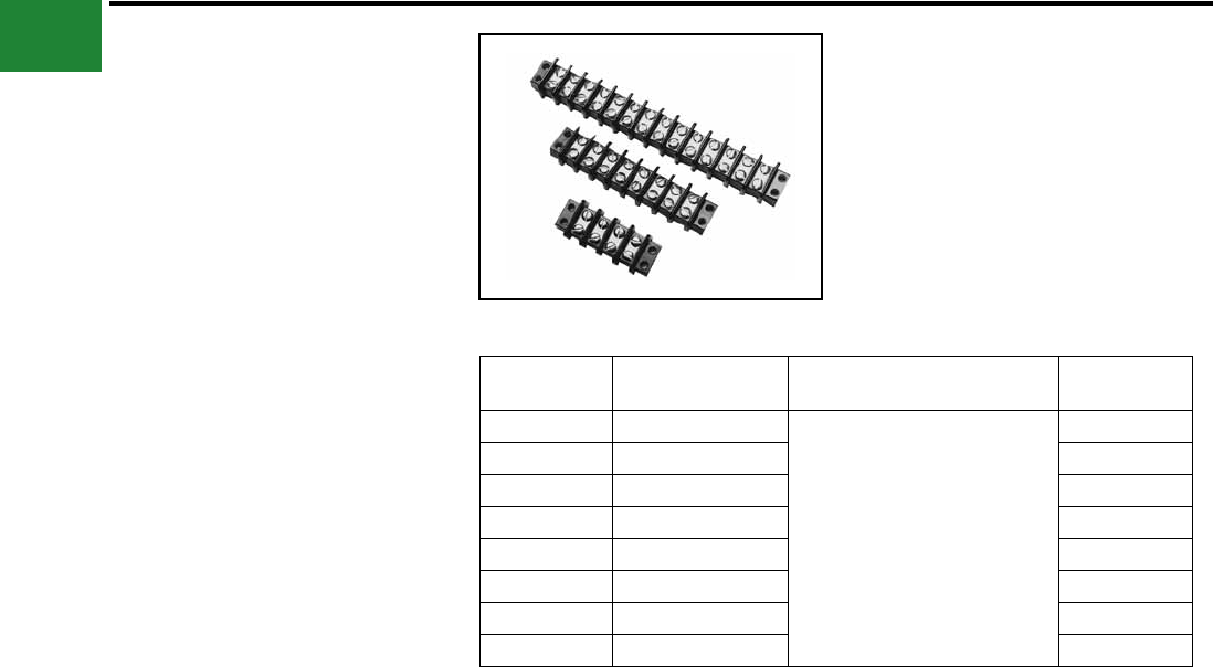
BURNDY®
Blue highlighted items are industry standard and most frequently ordered.
US: 1-800-346-4175 www.burndy.com Canada: 1-800-387-6487
Mechanical
MISCELLANEOUS
ACCESSORIES
TERMINAL BLOCKS
Molded General Purpose Phenolic Base 30
amps,
#10 studs, 1 piece per card, 300-volt rating
Meets UL component requirements
CLASS B:
Commercial Equipment 300 V RMS
CLASS C:
General Industrial 300 V RMS
Withstands volts, Vdc 10,500
Steel nickel plated screws
Catalog
Number Number of Circuits General Description Overall Length
RK149-2 2
Molded General Purpose
Phenolic Base 30 amps, #10 studs
1 piece, per card 300-volt rating
2-3/32"
RK150-2 4 3-7/32"
RK225-2 6 4-11/32"
RK151-2 8 5-15/32"
RK152-2 10 6-19/32"
RK226-2 12 7-23/32"
RK153-2 14 8-27/32"
RK227-2 16 9-31/32"
For bulk pack contact factory.
A-40
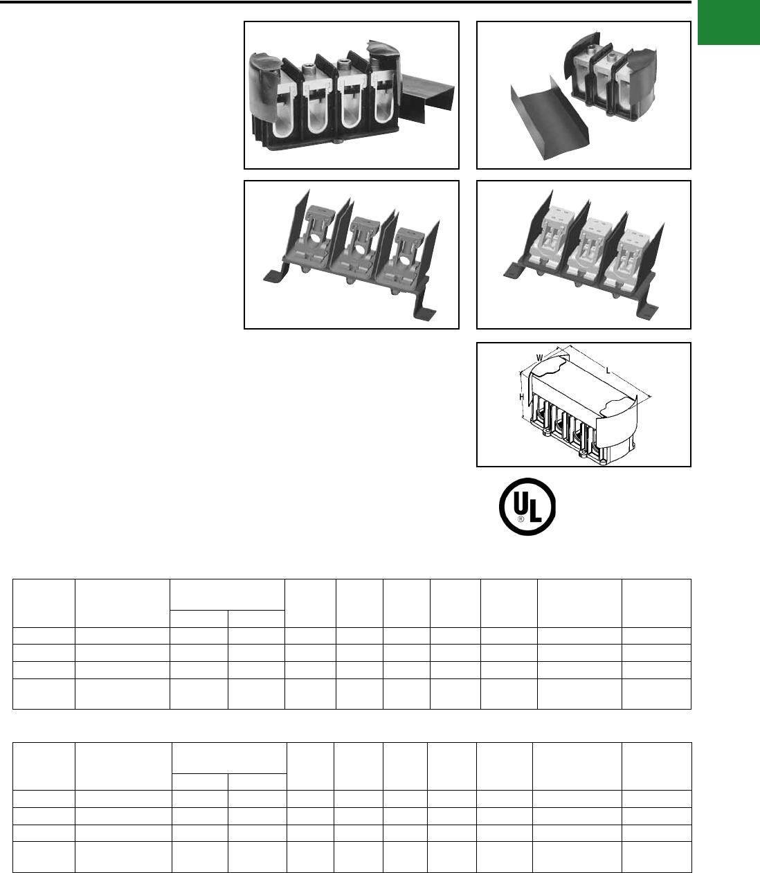
BURNDY®
Blue highlighted items are industry standard and most frequently ordered.
Canada: 1-800-387-6487 www.burndy.com US: 1-800-346-4175
Mechanical
POWER DISTRIBUTION
BLOCKS
U-BLOK™
For Junction Box Applications
The U-BLOK™ system is a modern, state-of-
the-art approach to multi-load power distribution
applications. Among typical uses are multi-story
or multi-unit buildings, HVAC, refrigeration,
control panels, motor control, switch gear, elevator
systems and materials handling equipment.
U-BLOK™ is UL Listed for Copper or Aluminum
conductors and rated for 600-volt applications.
U-BLOK™ can be mounted on bases for use in
troughs or bolted directly to junction boxes. AL9CU
rated.
Catalog
Number
Max. Number of
Wires per Phase
Conductor
Copper or Aluminum* W L H Weight
Each
Allen
Wrench
Size
Recommended
Tightening
Torque
Strip Length
Run Tap
FT3B4/0 2 3/0 - 4/0 6 - 4/0 3-7/8 5-7/8 4-1/8 1-1/4 1/4 200 1-1/2
FT3B500 2 400 - 500 6 - 500 3-7/8 5-7/8 4-1/8 2-1/8 3/8 375 2-5/16
3S 2 250 - 350 6 - 350 3-5/8 9-3/4 4-7/8 3 1/4 200 1-3/4
3U 1 Run / 8 Tap 3/0 - 500 6 - 1/0 4-3/4 9-3/4 5-1/2 3 5/32 110 2-5/16 (Run);
1-5/32 (Tap)
Features & Benets
• Connector top slides OFF/ON for quick
cable lay-in
◊ Labor savings. Easy access for
installation, modications or retrot.
• Electro-tin plated connectors in each
pole
◊ Durability. High-conductivity and
resistance to corrosion.
• Compact size
◊ Requires less space than traditional
connection methods.
• Trough installations can be mounted on
raised platforms
◊ Passage of cables under block means
through-cables need not be terminated
• Insulating covers and mounting blocks
rated 94-VO
◊ Saves costly taping, time and material.
Conforms to or exceeds building codes.
• Connectors accommodate a wide range
of wire sizes
◊ Reduces parts inventory requirements.
• Feeder conductors can be cut or fed
through on a continuous run
◊ Ease of installation.
FT4B500
3S 3U
FT3B4/0
Catalog
Number
Max. Number of
Wires per Phase
Conductor
Copper or Aluminum* W L H Weight
Each
Allen
Wrench
Size
Recommended
Tightening
Torque
Strip
Length
Run Tap
FT4B4/0 2 3/0 - 4/0 6 - 4/0 3-7/8 7-7/8 4-1/8 2 1/4 200 1-1/2
FT4B500 2 400 - 500 6 - 500 3-7/8 7-7/8 4-1/8 2-3/4 3/8 375 2-5/16
4S 2 250 - 350 6 - 350 3-5/8 11-3/4 4-7/8 3-1/2 1/4 200 1-3/4
4U 1 Run / 8 Tap 3/0 - 500 6 - 1/0 4-3/4 11-3/4 5-1/2 3-1/2 5/32 110 2-5/16 (Run);
1-5/32 (Tap)
3 WIRE POWER DISTRIBUTION BLOCKS
4 WIRE POWER DISTRIBUTION BLOCKS
PENETROX™ inhibitor is recommended for all aluminum
wire connections.
For two wire tap range is 8 through 1/0.
* Aluminum and copper conductors cannot be assembled
under the same pressure plate or t-bar.
A-41
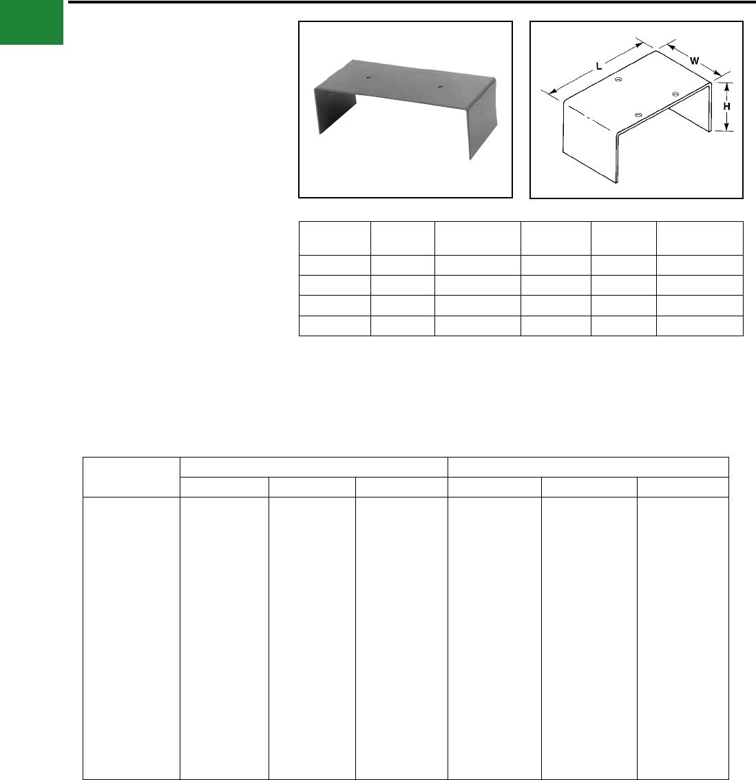
BURNDY®
Blue highlighted items are industry standard and most frequently ordered.
US: 1-800-346-4175 www.burndy.com Canada: 1-800-387-6487
Mechanical
U-BLOK™ MOUNTING
PLATFORMS
For Trough Applications
Catalog
Number W L H Gutter
Size Weight Each (lb)
TBPT6* 4-1/4 5-7/8 1-1/2 6'3/4
TBPT8 4-1/4 7-7/8 3-1/2 8"1-1/4
TBPT10 4-1/4 9-7/8 4 10"1-1/2
TBPT12 4-1/4 11-7/8 4 12"1-3/4
Hole pattern shown is for reference only.
* Supercedes TBPT4/0-6 and TBPT350/500-6.
FLEXI-TAP™
ALLOWABLE AMPACITIES OF INSULATED CONDUCTOR, 60° TO 90° C **
Size AWG
kcmil
Copper Al or Copper Clad Al
60 deg. C 75 deg. C 90 deg. C 60 deg. C 75 deg. C 90 deg. C
12
10
8
6
4
3
2
1
1/0
2/0
3/0
4/0
250
300
350
400
500
600
700
750
25
30
40
55
70
85
95
110
125
145
165
195
215
240
260
280
320
355
385
400
25
35
50
65
85
100
115
130
150
175
200
230
255
285
310
335
380
420
460
475
30
40
55
75
95
110
130
150
170
195
225
260
290
320
350
380
430
475
520
535
20
25
30
40
55
65
75
85
100
115
130
150
170
190
210
225
260
285
310
320
20
30
40
50
65
75
90
100
120
135
155
180
205
230
250
270
310
340
375
385
25
35
45
60
75
85
100
115
135
150
175
205
230
255
280
305
350
385
420
435
** NOTE: Values referenced from Article 310 of the National Electric Code, Table 310-16, 1996. The above
chart is to be used for REFERENCE ONLY. Please consult Table 310-16 of the National Electric Code (lat-
est revision) for information regarding insulation type, voltage range, and conductor housings/surroundings.
U-TAP™, U-BLOK™, and SPEC-BLOK™ connectors are rated for 90 deg. C by Underwriters’ Laboratories.
Use of 60 deg. C and 75 deg. C conductor(s) is valid, though only as determined by the National Electric
Code.
A-42
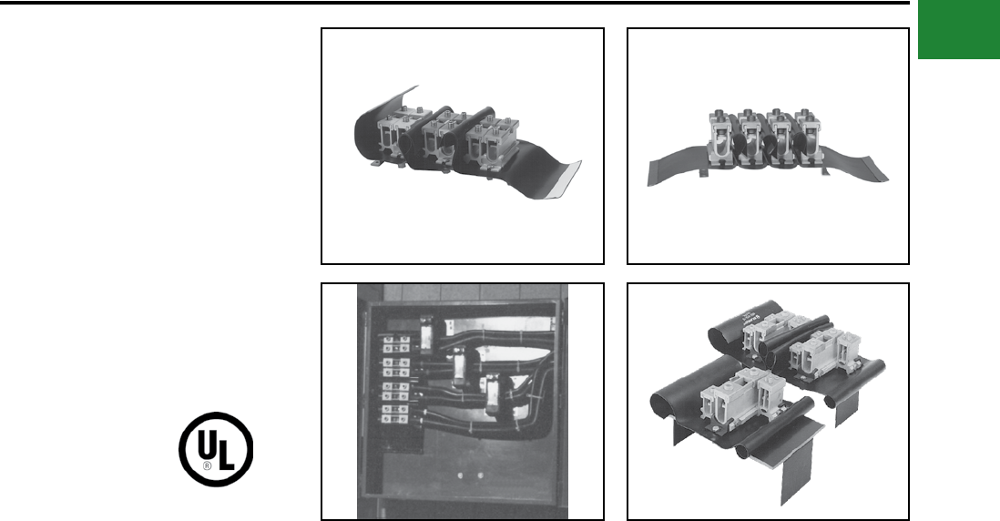
BURNDY®
Blue highlighted items are industry standard and most frequently ordered.
Canada: 1-800-387-6487 www.burndy.com US: 1-800-346-4175
Mechanical
SPEC-BLOK™
POWER DISTRIBUTION
CONNECTORS
Unique, modular, made-to-order, power distribution
assemblies accommodate any number of supply
and load conductors in any number of poles.
Capacity matches the conductors accommodated
and SPEC-BLOK™ assures uniform loading.
Adjacent poles are separated by easy-to handle,
wrap-around insulating covers which eliminate
taping and reduce heat build-up by allowing air to
ow freely around connectors. SPEC-BLOK™ is
UL Listed for copper or aluminum conductors for
600 volts. (AL9CU) Assemblies are mounted on
platforms suitable for easy installation in wireway
or junction box.
Features & Benets
• Accommodate unlimited conductors
◊ Fits wide range of applications.
Eliminates need for non-UL-Listed
improvisation.
• Connector elements tin-plated
◊ Provides high reliability,
low-resistance connections.
• User friendly, space-saving design
◊ Easy to install - saves labor.
• 94-VO rated insulation folds into
place insulating the components
◊ Saves time and material. Allows
easy installation.
• Connector caps removable for easy
cable lay-in
◊ Saves labor. Makes installation
easier - allows installation of
straight-through conductors.
Eases retrot.
• Belleville washers built-in on
pressure screw assemblies, except
in assemblies installed with a 5/32"
Allen wrench
◊ Provides high-integrity connections.
• Conductors can be cut or fed straight
through
◊ Straight through installation ideal
for riser applications.
Contact BURNDY® or Technical Services: 1-800-451-4956,
or BURNDY® Customer Service: 1-800-346-4175
A-43
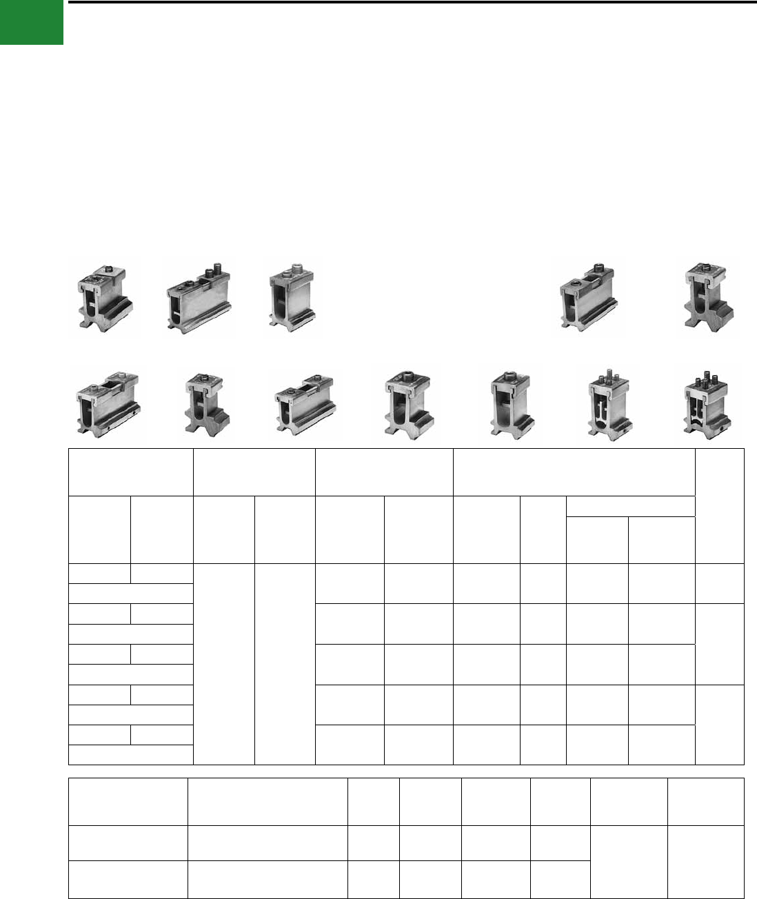
BURNDY®
Blue highlighted items are industry standard and most frequently ordered.
US: 1-800-346-4175 www.burndy.com Canada: 1-800-387-6487
Mechanical
SPEC-BLOK™ Features & Benets
• The SPEC-BLOK™ system includes
12 connector elements
◊ A wide variety of conductor sizes can
be accommodated
• Each element can be bolted together
in parallel
◊ Provides an efcient ow of current
from one element to another
• AL9CU rated for Copper or Aluminum
conductors
◊ Dual-rated system, with UL486B’s
highest temperature rating
• 2 Wire (series), 4 (parallel), and
Multi-Tap versions available
◊ Nearly any conductor combination can
be terminated
• Tin-plated Aluminum Alloy Construction
◊ High-strength, corrosion-resistant
connector elements
• All SPEC-BLOK™ connectors are
custom made for nearly any Power
Distribution system requirement
◊ Time savings — pre-assembled in our
factory for immediate installation!
SPEC-BLOK™ CONNECTORS
E W D S
C B R
A
Q U P
Catalog Designation
(Maximum
Conductor)
Number of
Conductors
Accommodated
AL or CU
Wire Range Under
Each Cap
Dimensions
Allen
Wrench
Size
4
Conductor
2
Conductor
4
Conductor
2
Conductor
First
Conductors
MUST Be
Second
Conductor
(if required)
May Be
Height On
Max
Conductors
Width
Length Without Insulator
4
Conductor
2
Conductor
A Q
1 to 4
(0, 1 or 2
per cap)
1 or 2
per cap
1/0 - 2/0 #12 - 2/0 2-9/16" 1-1/2" 2-1/8" 7/8" 5/32"
(2/0)
B R 3/0 - 250 #6 - 250 3-1/8" 1-11/16" 4-1/4" 1-3/8"
1/4"
(250)
C S 250 - 350 #6 - 350 3-5/16" 1-13/16" 4-5/8" 1-1/2"
(350)
D T 400 - 500 #6 - 500 4-1/16" 2" 5-5/8" 1-3/4"
3/8"
(500)
E W 600 - 750 3/0 - 750 4-7/8" 2-1/4" 7-1/4" 2-5/8"
(750)
Catalog Designation
(Maximum Conductor)
Number of Conductors
Accommodated
Large
Groove
Small
Grooves**
Height On
Maximum
Conductors
Width
Length
Without
Insulator
Allen
Wrench
Size
P (1/0) 1 to 8 (0, 1 or 2 under each screw) __ 6 - 1/0 3-1/2" 2"
1-3/4" 5/32"
U (1/0 & 500) 2 to 9 (0, 1 or 2 under each screw
plus one large conductor) 3/0 - 500 6 - 1/0 4-1/8" 2"
** This range may be expanded to include #8 provided two conductors are being installed in that particular element.
T
A-44
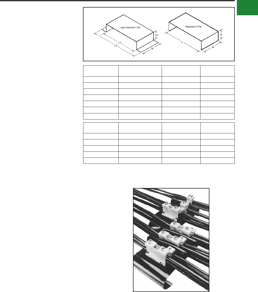
BURNDY®
Blue highlighted items are industry standard and most frequently ordered.
Canada: 1-800-387-6487 www.burndy.com US: 1-800-346-4175
Mechanical
SPEC-BLOK™
MOUNTING PLATFORMS
SPEC-BLOK™ Mounting Platforms
are rigid steel construction with a
black nish.
They can be supplied for junction box mounting or
wireway construction allowing trough conductors
to pass underneath the assemblies.
SPEC-BLOK™ IS A SYSTEM THAT CAN SOLVE MOST POWER DISTRIBUTION APPLICATIONS!
SPEC-BLOK™ catalog numbers describe exactly how
the distribution block is assembled: 5DR-NDST-GQP-12 (assembly pictured)
5 Total number of poles in the
completed assembly
DR One ‘D’ unit and one ‘R’ unit, bolted in parallel,
forming each phase pole (3 phase poles)
NDenotes the beginning of the neutral pole (where
required)
DST One ‘D’ unit, one ‘S’ unit, and one ‘T’ unit, bolted
in parallel, forming the neutral pole
GDenotes the beginning of the ground pole
description (where required)
QP One ‘Q’ unit and one ‘P’ unit,
bolted in parallel, forming the ground pole
12
Size (inches) of the wireway or trough that is need-
ed to enclose the assembly. If a junction box en-
closure is used, no number is used to denote the
size of the enclosure
Catalog
Number
L
(Nominal)
L
(Overall)
W
(Overall)
CPB6 6 7-3/4 2-1/2
CPB8 8 9-3/4 2-1/2
CPB10 10 11-3/4 2-1/2
CPB12 12 13-3/4 3-1/2
CPB14 14 15-3/4 3-1/2
CPB16-5/8 16-5/8 18-3/8 3-1/2
CPB21-1/4 21-1/4 23 3-1/2
Catalog
Number
L
(Nominal) HW
(Overall)
CPT6 5-7/8 2-1/4 2-1/2
CPT8 7-7/8 3 3-1/2
CPT10 9-7/8 3-1/2 3-1/2
CPT12 11-7/8 4 3-1/2
CPT16 15-7/8 4 3-1/2
(CPT-)(CPB-)
A-45
BURNDY®
Blue highlighted items are industry standard and most frequently ordered.
US: 1-800-346-4175 www.burndy.com Canada: 1-800-387-6487
Mechanical
How many poles in the system? (3-wire, 4-wire, single phase, etc.)?___________ poles
Are neutral conductors (when required) different sizes (AWG/kcmil) than the phase conductors?
___________ same size ___________ different size
Is a ground connection required? □ Yes □ No
What are the quantities, sizes (AWG/kcmil) and material (AI/Cu) of the incoming line conductors
and outgoing load conductors?
Are any conductors continuous? □ Yes □ No
If yes, which ones? ______________________________________________________________________________________
_______________________________________________________________________________________________________
What kind of enclosure is the connection assembly being mounted in and what are the inside space dimensions?
Wireway/trough size _______________________________________________________________________________________
Box, panel, cabinet, other size _______________________________________________________________________________
When is a quotation required? Date ______________ _____ When is the material required? Date __________________
Name of requestor ______________ ____________________ Job name/reference _____________ ___________________
Is there a preference for a particular BURNDY distributor? □ Yes □ No
If yes, please give the name, location and telephone number
Name ________________________________________________________________ Phone______________________________
Address ________________________________________________________________________________________________
________________________________________________________________________________________________
PER PHASE
PER PHASE
PER PHASE
LINE
LOAD
LINE
LOAD
LINE
LOAD
QUANTITY SIZE CONDUCTOR TYPE
For SPEC-BLOK™ Applications
Questionnaire
Questions? Call BURNDY® Technical Services at 800-451-4956.
A-46
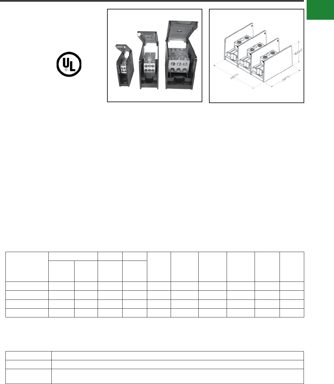
BURNDY®
Blue highlighted items are industry standard and most frequently ordered.
Canada: 1-800-387-6487 www.burndy.com US: 1-800-346-4175
Mechanical
UL LISTED
POWER DISTRIBUTION
BLOCKS
VERSIPOLE™
These Power Distribution Blocks are Listed to the
Power Distribution Block Standard UL 1953. They
contain the same features and characteristics
as the non-Listed blocks however, these have
spacings that are suitable for installations in
most industrial control panel feeder and branch
circuits, HVAC systems, and Wireways (with
optional cover; sold separately). They are
available in one, two, or three pole congurations.
An “Adder” is also available with optional End
Barrier (sold separately), to allow user customized
congurations.
Catalog Number
Connector Run Tap
Width Height Depth
Ampere
Rating per
Pole
Number
of Poles SCCR1
Number
of Run(s)
Number
of Tap(s)
Wire
Range
AL9CU
Wire
Range
AL9CU
BDCSHC142/01 1 4 14-2/0 14-4 1.05 2.81 3.08 175 1 100kA
BDASHC142/01 1 4 14-2/0 14-4 0.93 2.81 3.08 175 Adder 100kA
BDCSHC112/01 1 1 14-2/0 14-2/0 1.05 2.81 3.08 175 1 100kA
BDASHC112/01 1 1 14-2/0 14-2/0 0.93 2.81 3.08 175 Adder 100kA
Features & Benets
• Single or dual run connections allow the
user to minimize the number of connections
required
• Suitable for use with aluminum or copper
conductors providing maximum versatility
• Available in 3 sizes for optimization of space
• 600V, ALCU Rated; meets or exceeds
industry standard requirements
• Range taking designs to accommodate wire
sizes up to 600 kcmil
• High Short-Circuit Rating up to 100kA with
proper fusing
• Meets spacing requirements of Industrial
Control Panel Standard UL 508A (spacing
of 1” through air and 2” over surface)
• Adders and End Barriers available sepa-
rately for all 3 sizes providing capability to
create as many poles as required
• Hinged Covers available separately to cover
3 sizes providing user protection and easy
access to connector terminal block
1 Short-Circuit Current Rating with proper fusing
Small Series:
Small Series Hinged Cover and End Barrier:
Catalog Number Description
BDASHCEB End Barrier for Small Series Adder Distribution Blocks
BDBSHCCOVER Hinged Cover for use with Small Series Distribution Blocks and Adders (use of End Barrier necessary with Adders to attach
cover). Order 1 cover per pole
A-47
BURNDY®
Blue highlighted items are industry standard and most frequently ordered.
US: 1-800-346-4175 www.burndy.com Canada: 1-800-387-6487
Mechanical
UL LISTED
POWER DISTRIBUTION
BLOCKS
VERSIPOLE™
Medium Series:
Catalog Number
Connector Run Tap
Width Height Depth
Ampere
Rating per
Pole
Number of
Poles SCCR1
Number
of Run(s)
Number
of Tap(s)
Wire
Range
AL9CU
Wire
Range
AL9CU
BDBMHC162/01 1 6 14-2/0 14-2 1.85 3.25 5 175 1 100kA
BDBMHC162/02 1 6 14-2/0 14-2 3.57 3.25 5 175 2 100kA
BDBMHC162/03 1 6 14-2/0 14-2 5.28 3.25 5 175 3 100kA
BDAMHC162/0 1 6 14-2/0 14-2 1.72 3.25 5 175 Adder 100kA
BDBMHC112/01 1 1 14-2/0 14-2/0 1.85 3.25 5 175 1 100kA
BDBMHC112/02 1 1 14-2/0 14-2/0 3.57 3.25 5 175 2 100kA
BDBMHC112/03 1 1 14-2/0 14-2/0 5.28 3.25 5 175 3 100kA
BDAMHC112/0 1 1 14-2/0 14-2/0 1.72 3.25 5 175 Adder 100kA
BDBMHC113501 1 1 6-350 6-350 1.85 3.25 5 310 1 100kA
BDBMHC113502 1 1 6-350 6-350 3.57 3.25 5 310 2 100kA
BDBMHC113503 1 1 6-350 6-350 5.28 3.25 5 310 3 100kA
BDAMHC11350 1 1 6-350 6-350 1.72 3.25 5 310 Adder 100kA
BDBMHC262/01 2 6 14-2/0 14-2 1.85 3.25 5 350 1 100kA
BDBMHC262/02 2 6 14-2/0 14-2 3.57 3.25 5 350 2 100kA
BDBMHC262/03 2 6 14-2/0 14-2 5.28 3.25 5 350 3 100kA
BDAMHC262/0 2 6 14-2/0 14-2 1.72 3.25 5 350 Adder 100kA
BDBMHC222/01 2 2 14-2/0 14-2/0 1.85 3.25 5 350 1 100kA
BDBMHC222/02 2 2 14-2/0 14-2/0 3.57 3.25 5 350 2 100kA
BDBMHC222/03 2 2 14-2/0 14-2/0 5.28 3.25 5 350 3 100kA
BDAMHC222/0 2 2 14-2/0 14-2/0 1.72 3.25 5 350 Adder 100kA
BDBMHC145001 1 4 4-500 14-2/0 1.85 3.25 5 380 1 100kA
BDBMHC145002 1 4 4-500 14-2/0 3.57 3.25 5 380 2 100kA
BDBMHC145003 1 4 4-500 14-2/0 5.28 3.25 5 380 3 100kA
BDAMHC14500 1 4 4-500 14-2/0 1.72 3.25 5 380 Adder 100kA
BDBMHC1625001 1 6 4-500 14-2 1.85 3.25 5 380 1 100kA
BDBMHC1625002 1 6 4-500 14-2 3.57 3.25 5 380 2 100kA
BDBMHC1625003 1 6 4-500 14-2 5.28 3.25 5 380 3 100kA
BDAMHC162500 1 6 4-500 14-2 1.72 3.25 5 380 Adder 100kA
Medium Series Hinged Cover and End Barrier:
Catalog Number Description
BDAMHCEB End Barrier for Medium Series Adder Distribution Blocks
BDBMHCCOVER Hinged Cover for use with Medium Series Distribution Blocks and Adders (use of End Barrier necessary with Adders to attach
cover). Order 1 cover per pole
A-48
BURNDY®
Blue highlighted items are industry standard and most frequently ordered.
Canada: 1-800-387-6487 www.burndy.com US: 1-800-346-4175
Mechanical
UL LISTED
POWER DISTRIBUTION
BLOCKS
VERSIPOLE™
Catalog Number
Connector Run Tap
Width Height Depth
Ampere
Rating per
Pole
Number
of Poles SCCR1
Number
of Run(s)
Number
of Tap(s)
Wire
Range
AL9CU
Wire
Range
AL9CU
BDBLHC1123501 1 12 6-350 14-4 2.73 3.55 5.7 310 1 100kA
BDBLHC1123502 1 12 6-350 14-4 5.31 3.55 5.7 310 2 100kA
BDBLHC1123503 1 12 6-350 14-4 7.89 3.55 5.7 310 3 100kA
BDALHC112350 1 12 6-350 14-4 2.58 3.55 5.7 310 Adder 100kA
BDBLHC163501 1 6 6-350 4-2/0 2.73 3.55 5.7 310 1 100kA
BDBLHC163502 1 6 6-350 4-2/0 5.31 3.55 5.7 310 2 100kA
BDBLHC163503 1 6 6-350 4-2/0 7.89 3.55 5.7 310 3 100kA
BDALHC16350 1 6 6-350 4-2/0 2.58 3.55 5.7 310 Adder 100kA
BDBLHC115001 1 1 4-500 4-500 2.73 3.55 5.7 380 1 100kA
BDBLHC115002 1 1 4-500 4-500 5.31 3.55 5.7 380 2 100kA
BDBLHC115003 1 1 4-500 4-500 7.89 3.55 5.7 380 3 100kA
BDALHC11500 1 1 4-500 4-500 2.58 3.55 5.7 380 Adder 100kA
BDBLHC165001 1 6 4-500 4-2/0 2.73 3.55 5.7 380 1 100kA
BDBLHC165002 1 6 4-500 4-2/0 5.31 3.55 5.7 380 2 100kA
BDBLHC165003 1 6 4-500 4-2/0 7.89 3.55 5.7 380 3 100kA
BDALHC16500 1 6 4-500 4-2/0 2.58 3.55 5.7 380 Adder 100kA
BDBLHC2125001 2 12 4-500 14-4 2.73 3.55 5.7 760 1 100kA
BDBLHC2125002 2 12 4-500 14-4 5.31 3.55 5.7 760 2 100kA
BDBLHC2125003 2 12 4-500 14-4 7.89 3.55 5.7 760 3 100kA
BDALHC212500 2 12 4-500 14-4 2.58 3.55 5.7 760 Adder 100kA
BDBLHC263501 2 6 6-350 14-2/0 2.73 3.55 5.7 620 1 100kA
BDBLHC263502 2 6 6-350 14-2/0 5.31 3.55 5.7 620 2 100kA
BDBLHC263503 2 6 6-350 14-2/0 7.89 3.55 5.7 620 3 100kA
BDALHC26350 2 6 6-350 14-2/0 2.58 3.55 5.7 620 Adder 100kA
BDBLHC223501 2 2 6-350 6-350 2.73 3.55 5.7 620 1 100kA
BDBLHC223502 2 2 6-350 6-350 5.31 3.55 5.7 620 2 100kA
BDBLHC223503 2 2 6-350 6-350 7.89 3.55 5.7 620 3 100kA
BDALHC22350 2 2 6-350 6-350 2.58 3.55 5.7 620 Adder 100kA
BDBLHC225001 2 2 4-500 4-500 2.73 3.55 5.7 760 1 100kA
BDBLHC225002 2 2 4-500 4-500 5.31 3.55 5.7 760 2 100kA
BDBLHC225003 2 2 4-500 4-500 7.89 3.55 5.7 760 3 100kA
BDALHC22500 2 2 4-500 4-500 2.58 3.55 5.7 760 Adder 100kA
Large Series:
A-49
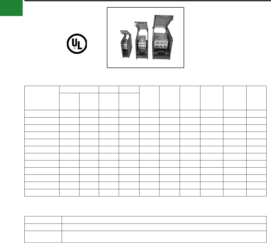
BURNDY®
Blue highlighted items are industry standard and most frequently ordered.
US: 1-800-346-4175 www.burndy.com Canada: 1-800-387-6487
Mechanical
Large Series (continued):
Catalog Number
Connector Run Tap
Width Height Depth
Ampere
Rating per
Pole
Number of
Poles SCCR1
Number
of Run(s)
Number
of Tap(s)
Wire
Range
AL9CU
Wire
Range
AL9CU
BDBLHC265001 2 6 4-500 14-2/0 2.73 3.55 5.7 760 1 100kA
BDBLHC265002 2 6 4-500 14-2/0 5.31 3.55 5.7 760 2 100kA
BDBLHC265003 2 6 4-500 14-2/0 7.89 3.55 5.7 760 3 100kA
BDALHC26500 2 6 4-500 14-2/0 2.58 3.55 5.7 760 Adder 100kA
BDBLHC245001 2 4 4-500 6-4/0 2.73 3.55 5.7 760 1 100kA
BDBLHC245002 2 4 4-500 6-4/0 5.31 3.55 5.7 760 2 100kA
BDBLHC245003 2 4 4-500 6-4/0 7.89 3.55 5.7 760 3 100kA
BDALHC24500 2 4 4-500 6-4/0 2.58 3.55 5.7 760 Adder 100kA
BDBLHC226001 2 2 2-600 2-600 2.73 3.55 5.7 840 1 100kA
BDBLHC226002 2 2 2-600 2-600 5.31 3.55 5.7 840 2 100kA
BDBLHC226003 2 2 2-600 2-600 2.73 3.55 5.7 840 3 100kA
BDALHC22600 2 2 2-600 2-600 2.58 3.55 5.7 840 Adder 100kA
UL LISTED
POWER DISTRIBUTION
BLOCKS
VERSIPOLE™
Large Series Hinged Cover and End Barrier:
Catalog Number Description
BDALHCEB End Barrier for Large Series Adder Distribution Blocks
BDBLHCCOVER Hinged Cover for use with Large Series Distribution Blocks and Adders (use of End Barrier necessary with Adders to attach cover).
Order 1 cover per pole
A-50
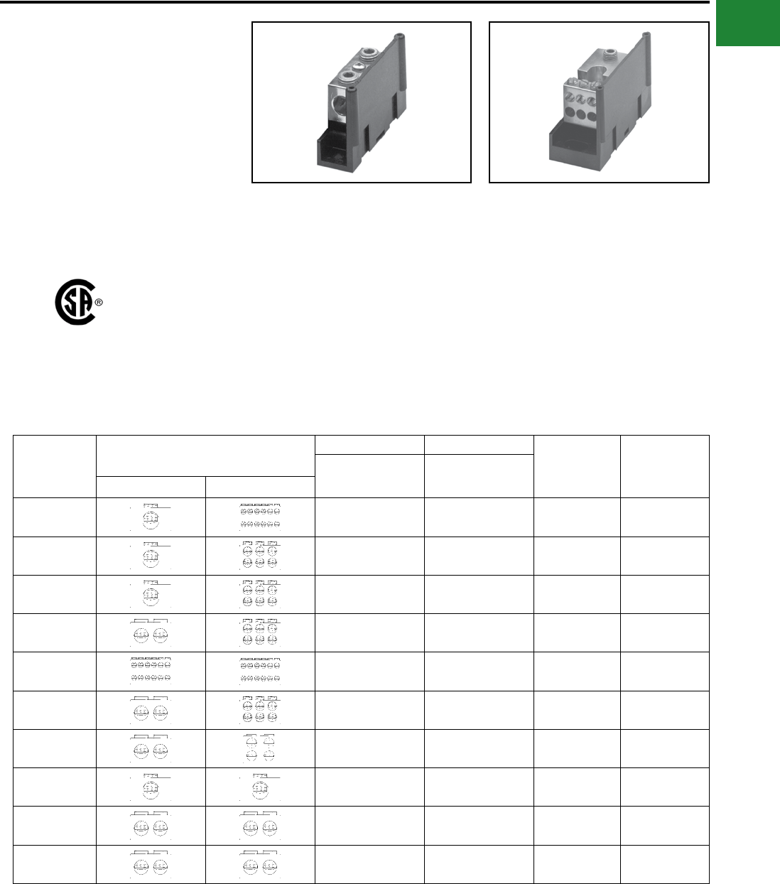
BURNDY®
Blue highlighted items are industry standard and most frequently ordered.
Canada: 1-800-387-6487 www.burndy.com US: 1-800-346-4175
Mechanical
VERSIPOLE™
POWER DISTRIBUTION
BLOCKS
VERSIPOLE™ Power Distribution Blocks are
designed to provide modular solutions to power
distribution applications. Each connector element
is made from a high conductivity aluminum alloy
which is insulated with a high strength polymer
housing. One, two, and three pole versions
available. “Add” a pole (snap-together) blocks are
also available for wire sizes up to 500 kcmil. For
use with Cu or Al. 600 V, AL9CU rated.
• “Add” a pole feature available
◊ Provides capability to create as many
poles as required
• Up to 30 tap conductors accommodated
◊ Ideal for current distribution to multiple
locations
• Single or dual run connections
◊ Allows user to minimize the number of
connectors needed to do the job
• Suitable for use with aluminum or copper
conductors
Features and Benets
◊ Provides maximum versatility
• 600 V, AL9CU rated*
◊ Meets or exceeds industry standard
requirements
• Dead-front covers available
◊ Provides user protection – one cover
per pole
Catalog
Number
Connector Run Tap Ampere
Rating per
Pole
Number of
Poles
Wire Range
AL9CU
Wire Range
AL9CU
Run Tap
BDA-112-350 AWG 6 - 350 kcmil AWG 14 - 4 310 ADDER
BDA-16-350 AWG 6 - 350 kcmil AWG 14 - 2/0 310 ADDER
BDA-16-500 AWG 4 - 500 kcmil AWG 4 - 2/0 380 ADDER
BDA-26-350 AWG 6 - 350 kcmil AWG 14 - 2/0 620 ADDER
BDA-212-500 AWG 4 - 500 kcmil AWG 14 - 4 760 ADDER
BDA-26-500 AWG 4 - 500 kcmil AWG 14 - 2/0 760 ADDER
BDA-24-500 AWG 4 - 500 kcmil AWG 6 - 4/0 760 ADDER
BDA-11-500 AWG 4 - 500 kcmil AWG 4 - 500 kcmil 380 ADDER
BDA-22-350 AWG 6 - 350 kcmil AWG 6 - 350 kcmil 620 ADDER
BDA-22-500 AWG 4 - 500 kcmil AWG 4 - 500 kcmil 760 ADDER
VERSIPOLE™
Snap-Together Blocks
NOTES:
1. Order Optional BDB COVER1 per pole if desired.
2. Snap-together blocks can also be assembled to 1, 2, 3
pole blocks to create multi-pole distribution blocks.
* BDB-430-500-1 not CSA certied
A-51
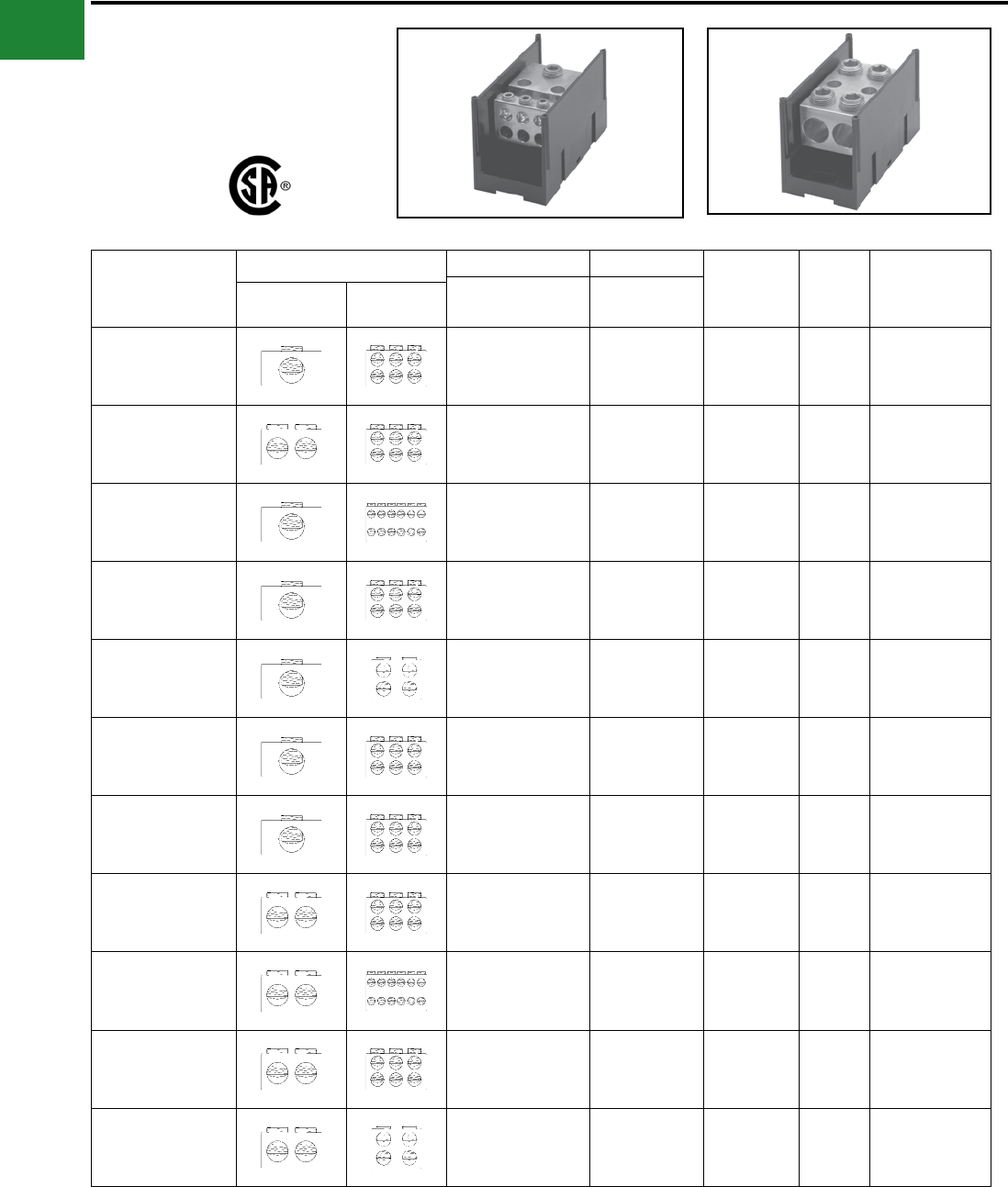
BURNDY®
Blue highlighted items are industry standard and most frequently ordered.
US: 1-800-346-4175 www.burndy.com Canada: 1-800-387-6487
Mechanical
VERSIPOLE™
VERSIPOLE™ 1, 2, 3 Pole
Distribution Blocks
Catalog
Number
Connector Run Tap Ampere
Rating per
Pole
Number
of
Poles
Optional
Cover Order
1 per Pole
Wire Range
AL9CU
Wire Range
AL9CURun Tap
BDB-16-2/0-1
BDB-16-2/0-2
BDB-16-2/0-3
AWG 12 - 2/0 AWG 14 - 4 175
1
2
3
BDBCOVER2
BDB-26-2/0-1
BDB-26-2/0-2
BDB-26-2/0-3
AWG 14 - 2/0 AWG 14 - 2 350
1
2
3
BDBCOVER2
BDB-112-350-1
BDB-112-350-2
BDB-112-350-3
AWG 6 - 350 kcmil AWG 14 - 4 310
1
2
3
BDBCOVER1
BDB-16-350-1
BDB-16-350-2
BDB-16-350-3
AWG 6 - 350 kcmil AWG 14 - 2/0 310
1
2
3
BDBCOVER1
BDB-14-500-1
BDB-14-500-2
BDB-14-500-3
AWG 4 - 500 kcmil AWG 14 - 2/0 380
1
2
3
BDBCOVER2
BDB-16-500-1
BDB-16-500-2
BDB-16-500-3
AWG 4 - 500 kcmil AWG 14 - 2/0 380
1
2
3
BDBCOVER1
BDB-162-500-1
BDB-162-500-2
BDB-162-500-3
AWG 4 - 500 kcmil AWG 14 - 2 380
1
2
3
BDBCOVER2
BDB-26-350-1
BDB-26-350-2
BDB-26-350-3
AWG 6 - 350 kcmil AWG 14 - 2/0 620
1
2
3
BDBCOVER1
BDB-212-500-1
BDB-212-500-2
BDB-212-500-3
AWG 4 - 500 kcmil AWG 14 - 4 760
1
2
3
BDBCOVER1
BDB-26-500-1
BDB-26-500-2
BDB-26-500-3
AWG 4 - 500 kcmil AWG 14 - 2/0 760
1
2
3
BDBCOVER1
BDB-24-500-1
BDB-24-500-2
BDB-24-500-3
AWG 4 - 500 kcmil AWG 6 - 4/0 760
1
2
3
BDBCOVER1
A-52
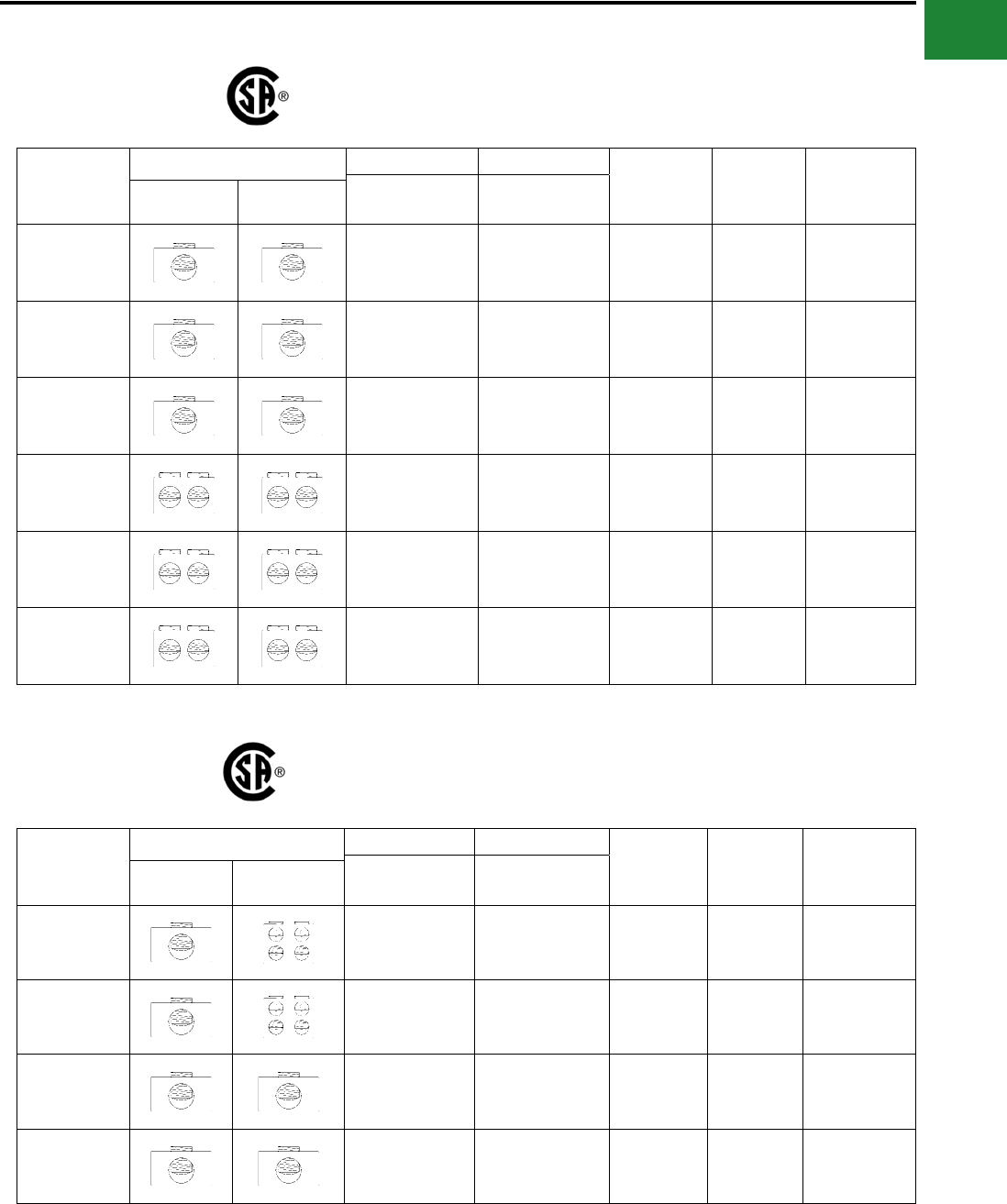
BURNDY®
Blue highlighted items are industry standard and most frequently ordered.
Canada: 1-800-387-6487 www.burndy.com US: 1-800-346-4175
Mechanical
VERSIPOLE™
VERSIPOLE™ 1, 2, 3
Splice/Reducer Blocks
Catalog
Number
Connector Run Tap Ampere
Rating per
Pole
Number of
Poles
Optional
Cover Order
1 per Pole
Wire Range
AL9CU
Wire Range
AL9CURun Tap
BDB-11-2/0-1
BDB-11-2/0-2
BDB-11-2/0-3
AWG 14 - 2/0 AWG 14 - 2/0 175
1
2
3
BDBCOVER2
BDB-11-350-1
BDB-11-350-2
BDB-11-350-3
AWG 6 - 350 kcmil AWG 6 - 350 kcmil 310
1
2
3
BDBCOVER2
BDB-11-500-1
BDB-11-500-2
BDB-11-500-3
AWG 6 - 500 kcmil AWG 6 - 500 kcmil 380
1
2
3
BDBCOVER1
BDB-22-2/0-1
BDB-22-2/0-2
BDB-22-2/0-3
AWG 14 - 2/0 AWG 14 - 2/0 350
1
2
3
BDBCOVER2
BDB-22-350-1
BDB-22-350-2
BDB-22-350-3
AWG 6 - 350 kcmil AWG 6 - 350 kcmil 620
1
2
3
BDBCOVER1
BDB-22-500-1
BDB-22-500-2
BDB-22-500-3
AWG 4 - 500 kcmil AWG 4 - 500 kcmil 760
1
2
3
BDBCOVER1
SNAP TOGETHER
SPLICE/REDUCER
BLOCKS
Catalog
Number
Connector Run Tap Ampere
Rating per
Pole
Number of
Poles
Optional
Cover Order
1 per Pole
Wire Range
AL9CU
Wire Range
AL9CURun Tap
BDC-14-2/0-1 AWG 14 - 2/0 AWG 14 - 4 175 1 BDBCOVER3
BDA-14-2/0-1 AWG 14 - 2/0 AWG 14 - 4 175 ADDER BDBCOVER3
BDC-11-2/0-1 AWG 14 - 2/0 AWG 14 - 2/0 175 1 BDBCOVER3
BDA-11-2/0-1 AWG 14 - 2/0 AWG 14 - 2/0 175 ADDER BDBCOVER3
A-53
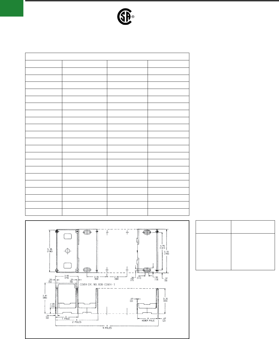
BURNDY®
Blue highlighted items are industry standard and most frequently ordered.
US: 1-800-346-4175 www.burndy.com Canada: 1-800-387-6487
Mechanical
VERSIPOLE™
(Continued)
VERSIPOLE™ 1, 2, 3
Splice/Reducer Blocks
The Figure to the Lower Right is Applicable to the Following:
Catalog Number Number of Poles Catalog Number Number of Poles
BDA-11-500 1 (adder) BDB-16-500-3 3
BDA-112-350 1 (adder) BDB-212-500-1 1
BDA-16-350 1 (adder) BDB-212-500-2 2
BDA-16-500 1 (adder) BDB-212-500-3 3
BDA-212-500 1 (adder) BDB-22-350-1 1
BDA-22-350 1 (adder) BDB-22-350-2 2
BDA-22-500 1 (adder) BDB-22-350-3 3
BDA-24-500 1 (adder) BDB-22-500-1 1
BDA-26-350 1 (adder) BDB-22-500-2 2
BDA-26-500 1 (adder) BDB-22-500-3 3
BDB-11-500-1 1BDB-24-500-1 1
BDB-11-500-2 2BDB-24-500-2 2
BDB-11-500-3 3BDB-24-500-3 3
BDB-112-350-1 1BDB-26-350-1 1
BDB-112-350-2 2BDB-26-350-2 2
BDB-112-350-3 3BDB-26-350-3 3
BDB-16-350-1 1BDB-26-500-1 1
BDB-16-350-2 2BDB-26-500-2 2
BDB-16-350-3 3BDB-26-500-3 3
BDB-16-500-1 1BDB-430-500-1* 1
BDB-16-500-2 2
No. of
Poles
Dimensions A
Inches
Adder
1
2
3
N
2.50
2.81
5.31
7.81
(2.50 X N) + 0.31
Example for 10 poles:
A = (2.50 X 10) + 0.31 = 25
These tables and illustrations refer to the specic
VERSIPOLE™ Power Distribution Blocks listed.
* BDB-430-500-1 not CSA certied
A-54
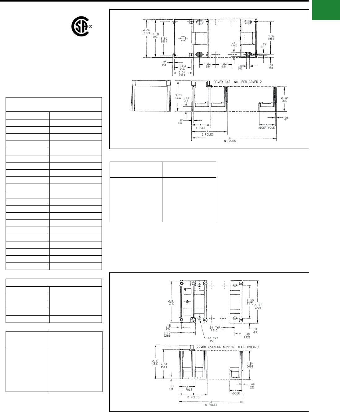
BURNDY®
Blue highlighted items are industry standard and most frequently ordered.
Canada: 1-800-387-6487 www.burndy.com US: 1-800-346-4175
Mechanical
VERSIPOLE™
(Continued)
VERSIPOLE™ 1, 2, 3
Splice/Reducer Blocks
These tables and illustrations refer to the specic
VERSIPOLE™ Power Distribution Blocks listed.
The Figure to the Lower Right is
Applicable to the Following:
Catalog Number Number of Poles
BDB-11-2/0-1 1
BDB-11-2/0-2 2
BDB-11-2/0-3 3
BDB-11-350-1 1
BDB-11-350-2 2
BDB-11-350-3 3
BDB-14-500-1 1
BDB-14-500-2 2
BDB-14-500-3 3
BDB-16-2/0-1 1
BDB-16-2/0-2 2
BDB-16-2/0-3 3
BDB-162-500-1 1
BDB-162-500-2 2
BDB-162-500-3 3
BDB-22-2/0-1 1
BDB-22-2/0-2 2
BDB-22-2/0-3 3
BDB-26-2/0-1 1
BDB-26-2/0-2 2
BDB-26-2/0-3 3
Applicable VERSI-POLETM Items
Catalog Number Number of Poles
BDA-14-2/0-1 1 (adder)
BDC-14-2/0-1 1
BDA-11-2/0-1 1 (adder)
BDC-11-2/0-1 1
No. of
Poles
Dimensions A
Inches
Adder
1
2
3
N
0.81
1.08
1.89
2.70
(0.81 X N) + 0.27
Example for 10 poles:
A = (.81 X 10) + 0.30 = 8.37
No. of
Poles
Dimensions A
Inches
Adder
1
2
3
N
1.64
1.94
3.57
5.20
(1.64 X N) + 0.30
Example for 10 poles:
A = (1.64 X 10) + 0.30 = 16.20
A-55
BURNDY®
Blue highlighted items are industry standard and most frequently ordered.
US: 1-800-346-4175 www.burndy.com Canada: 1-800-387-6487
Mechanical
TYPES BIT, BITO, BISR
UNITAP™
Clear Insulated Multiple Tap
Connectors
Tap connections and in-line splice/reductions are
made quickly and easily with the UNITAP™ line
of connectors. UL486B Listed. Dual-rated AL9CU
for any stranded copper or stranded aluminum
applications. 600 Volt, 90° C.
Features & Benets
• Clear Plastisol covered AL6061-T6
aluminum body
◊ Saves time, lowers installation
costs, eliminates taping.
• Clear Plastisol
◊ Allows visual conrmation that
conductor is properly inserted.
• Oxide inhibitor pre-installed
◊ Inhibits moisture and contaminants
from entering the contact area.
• Range-taking
◊ Reduces number of connectors
carried in inventory.
Catalog
Number
# of
Ports
Wire Range
(AWG/kcmil) L W H Hex
Key
Figure
Number
BIT4 214 AWG-4 AWG 1.16 1.16 1.25 1/8 1
BITO4 2 1.50 2
BIT2/0 214 AWG-2/0 AWG 1.52 1.40 1.38 3/16
1
BITO2/0 2 1.56 2
BIT250 210 AWG-250 kcmil 2.03 2.07 2.13 1
BITO250 2 2.64 5/16 2
BIT350 210 AWG-350 kcmil 2.22 2.32 2.50 3/16 1
BITO350 2 3.00 5/16 2
BIT600 24 AWG-600 kcmil 2.72 2.38 2.75 3/16 1
BITO600 2 3.00 3/8 2
BIT750 * 22 AWG-750 kcmil 2.87 2.70 3.00 3/16 1
BITO750 * 2 3.38 3/8 2
Fig. 1 Fig. 2
2 Port, 1 or 2 Sided Entry
* BIT750 and BITO750 are not UL Listed.
UNITAP™ rated for code conductor only.
Catalog
Number
Wire Range
(AWG/kcmil) L W H Hex Key
BISR2 #14-2 2.38 0.75 1.22 5/32
BISR1/0 #14-1/0 2.91 0.91 1.38 3/16
BISR250 #10-250 4.01 1.19 2.10 5/16
BISR350 #10-350 4.63 1.34 2.35 5/16
BISR500 #6-500 5.00 1.62 2.62 3/8
In-Line Splicer/Reducer
A-56
BURNDY®
Blue highlighted items are industry standard and most frequently ordered.
Canada: 1-800-387-6487 www.burndy.com US: 1-800-346-4175
Mechanical
TYPE BIBS
UNITAP™
Clear Insulated Multiple Tap
Connectors
Tap connections and in-line splice/reductions are
made quickly and easily with the UNITAP™ line
of connectors. UL486B Listed. Dual-rated AL9CU
for any stranded copper or stranded aluminum
applications. 600 Volt, 90° C.
Features & Benets
• Clear Plastisol covered AL6061-T6
aluminum body
◊ Saves time, lowers installation
costs, eliminates taping
• Clear Plastisol
◊ Allows visual conrmation that
conductor is properly inserted
Catalog
Number
# of
Ports
Wire Range
(AWG/kcmil) L W H Hex
Key
BIBS4-3 3 14 AWG-4 AWG 1.51 1.25 1.25 1/8
BIBS4-4 4 14 AWG-4 AWG 1.95 1.25 1.25 1/8
BIBS4-5 5 14 AWG-4 AWG 2.39 1.25 1.25 1/8
BIBS4-6 6 14 AWG-4 AWG 2.83 1.25 1.25 1/8
BIBS4-8 8 14 AWG-4 AWG 3.71 1.25 1.25 1/8
BIBS2/0-3 3 14 AWG-2/0 Str 2.19 1.31 1.38 3/16
BIBS2/0-4 4 14 AWG-2/0 Str 2.86 1.31 1.38 3/16
BIBS2/0-5 5 14 AWG-2/0 Str 3.53 1.31 1.38 3/16
BIBS2/0-6 6 14 AWG-2/0 Str 4.20 1.31 1.38 3/16
BIBS2/0-8 8 14 AWG-2/0 Str 5.55 1.31 1.38 3/16
BIBS2/0-10 10 14 AWG-2/0 Str 6.89 1.31 1.38 3/16
BIBS2/0-12 12 14 AWG-2/0 Str 8.24 1.31 1.38 3/16
BIBS2/0-14 14 14 AWG-2/0 Str 9.58 1.31 1.38 3/16
BIBS250-3 3 10 AWG-250 kcmil 2.97 2.07 2.13 5/16
BIBS250-4 4 10 AWG-250 kcmil 3.91 2.07 2.13 5/16
BIBS250-5 5 10 AWG-250 kcmil 4.84 2.07 2.13 5/16
BIBS250-6 6 10 AWG-250 kcmil 5.78 2.07 2.13 5/16
BIBS250-8 8 10 AWG-250 kcmil 7.66 2.07 2.13 5/16
BIBS250-10 10 10 AWG-250 kcmil 9.53 2.07 2.13 5/16
BIBS250-12 12 10 AWG-250 kcmil 11.41 2.07 2.13 5/16
BIBS250-14 14 10 AWG-250 kcmil 13.29 2.07 2.13 5/16
BIBS350-3 3 10 AWG-350 kcmil 3.13 2.32 2.50 5/16
BIBS350-4 4 10 AWG-350 kcmil 4.04 2.32 2.50 5/16
BIBS350-5 5 10 AWG-350 kcmil 4.95 2.32 2.50 5/16
BIBS350-6 6 10 AWG-350 kcmil 5.86 2.32 2.50 5/16
BIBS350-8 8 10 AWG-350 kcmil 7.68 2.32 2.50 5/16
BIBS350-10 10 10 AWG-350 kcmil 9.50 2.32 2.50 5/16
Catalog
Number
# of
Ports
Wire Range
(AWG/kcmil) L W H Hex
Key
BIBS350-12 12 10 AWG-350 kcmil 11.32 2.32 2.50 5/16
BIBS350-14 14 10 AWG-350 kcmil 13.14 2.32 2.50 5/16
BIBS600-3 3 4 AWG-600 kcmil 4.00 2.38 2.75 3/8
BIBS600-4 4 4 AWG-600 kcmil 5.28 2.38 2.75 3/8
BIBS600-5 5 4 AWG-600 kcmil 6.56 2.38 2.75 3/8
BIBS600-6 6 4 AWG-600 kcmil 7.84 2.38 2.75 3/8
BIBS600-8 8 4 AWG-600 kcmil 10.41 2.38 2.75 3/8
BIBS600-10 10 4 AWG-600 kcmil 12.97 2.38 2.75 3/8
BIBS600-12 12 4 AWG-600 kcmil 15.53 2.38 2.75 3/8
BIBS600-14 14 4 AWG-600 kcmil 18.09 2.38 2.75 3/8
BIBS750-3* 3 2 AWG-750 kcmil 4.00 2.70 3.00 3/8
BIBS750-4* 4 2 AWG-750 kcmil 5.38 2.70 3.00 3/8
BIBS750-6* 6 2 AWG-750 kcmil 8.13 2.70 3.00 3/8
BIBS750-8* 8 2 AWG-750 kcmil 10.88 2.70 3.00 3/8
BIBS750-10* 10 2 AWG-750 kcmil 13.63 2.70 3.00 3/8
BIBS750-12* 12 2 AWG-750 kcmil 16.38 2.70 3.00 3/8
BIBS750-14* 14 2 AWG-750 kcmil 19.13 2.70 3.00 3/8
MULTI-PORT
Single-Sided Entry
NOTE: Only 1 conductor per port allowed.
* Not UL Listed.
UNITAP™ rated for code conductor only.
• Oxide inhibitor pre-installed
◊ Inhibits moisture and contaminants
from entering the contact area
• Range-taking
◊ Reduces number of connectors
carried in inventory
A-57
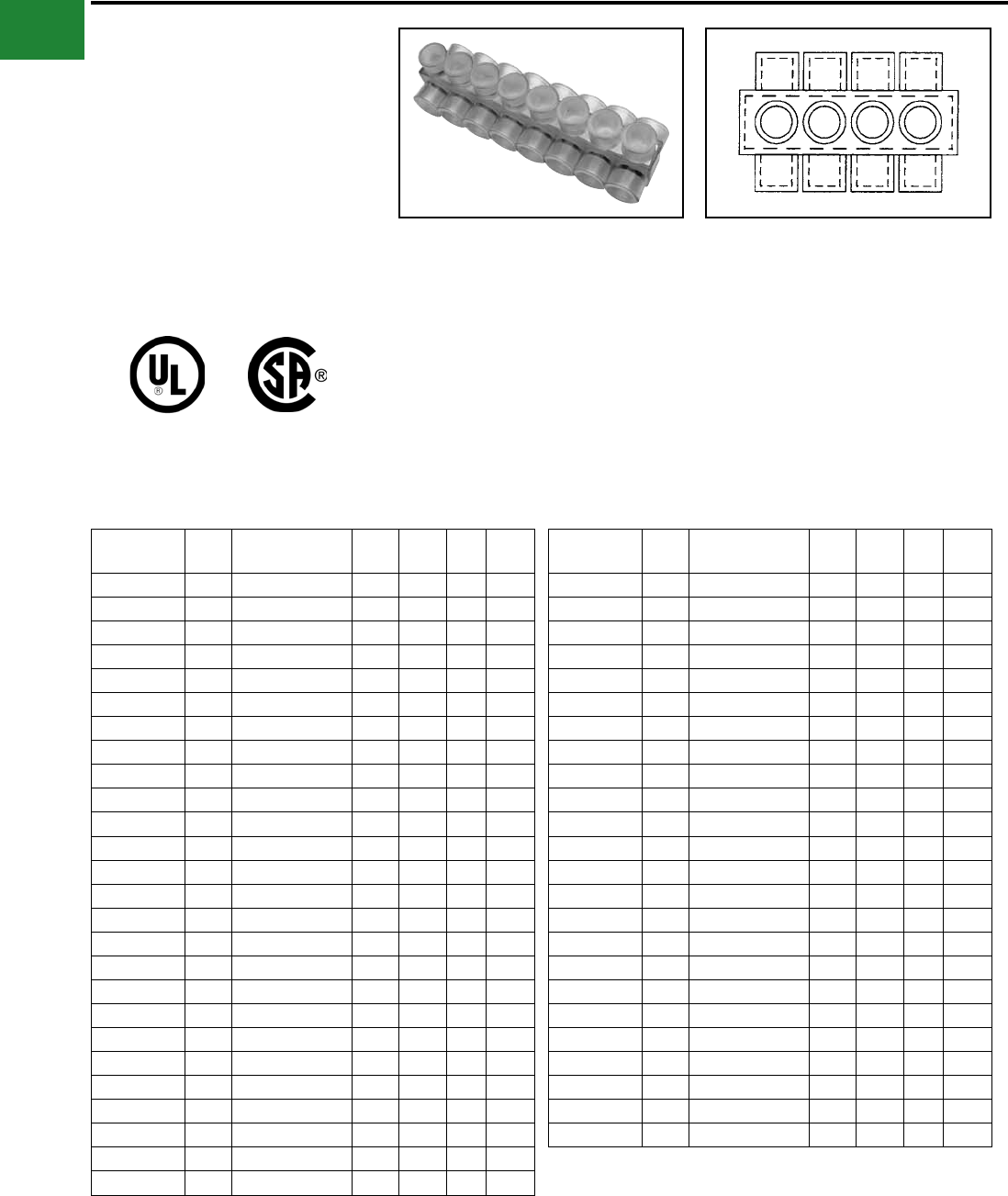
BURNDY®
Blue highlighted items are industry standard and most frequently ordered.
US: 1-800-346-4175 www.burndy.com Canada: 1-800-387-6487
Mechanical
TYPE BIBD
UNITAP™
Clear Insulated Multiple Tap
Connectors
Tap connections and in-line splice/reductions are
made quickly and easily with the UNITAP™ line
of connectors. UL486B Listed. Dual-rated AL9CU
for any stranded copper or stranded aluminum
applications. 600 Volt, 90° C.
Features & Benets
• Clear Plastisol covered AL6061-T6
aluminum body
◊ Saves time, lowers installation costs,
eliminates taping
• Clear Plastisol
◊ Allows visual conrmation that
conductor is properly inserted
MULTI-PORT
Double-Sided Entry
Catalog
Number
# of
Ports
Wire Range
(AWG/kcmil) W L H Hex
Key
BIBD4-2 2 14 AWG-4 Str 1.50 1.08 1.25 1/8
BIBD4-3 3 14 AWG-4 Str 1.50 1.51 1.25 1/8
BIBD4-4 4 14 AWG-4 str 1.50 1.95 1.25 1/8
BIBD4-5 5 14 AWG-4 Str 1.50 2.39 1.25 1/8
BIBD4-6 6 14 AWG-4 Str 1.50 2.83 1.25 1/8
BIBD4-8 8 14 AWG-4 str 1.50 3.71 1.25 1/8
BIBD2/0-2 2 14 AWG-2/0 Str 1.56 1.52 1.38 3/16
BIBD2/0-3 3 14 AWG-2/0 Str 1.56 2.19 1.38 3/16
BIBD2/0-4 4 #14-2/0 Str 1.56 2.86 1.38 3/16
BIBD2/0-5 5 #14-2/0 Str 1.56 3.53 1.38 3/16
BIBD2/0-6 6 14 AWG-2/0 Str 1.56 4.20 1.38 3/16
BIBD2/0-8 8 14 AWG-2/0 Str 1.56 5.55 1.38 3/16
BIBD2/0-10 10 14 AWG-2/0 Str 1.56 6.89 1.38 3/16
BIBD2/0-12 12 14 AWG-2/0 Str 1.56 8.24 1.38 3/16
BIBD2/0-14 14 14 AWG-2/0 Str 1.56 9.58 1.38 3/16
BIBD250-2 2 10 AWG-250 kcmil 2.64 2.03 2.13 5/16
BIBD250-3 3 10 AWG-250 kcmil 2.64 2.97 2.13 5/16
BIBD250-4 4 10 AWG-250 kcmil 2.64 3.91 2.13 5/16
BIBD250-5 5 10 AWG-250 kcmil 2.64 4.84 2.13 5/16
BIBD250-6 6 10 AWG-250 kcmil 2.64 5.78 2.13 5/16
BIBD250-8 8 10 AWG-250 kcmil 2.64 7.66 2.13 5/16
BIBD250-10 10 10 AWG-250 kcmil 2.64 9.53 2.13 5/16
BIBD250-12 12 10 AWG-250 kcmil 2.64 11.41 2.13 5/16
BIBD250-14 14 10 AWG-250 kcmil 2.64 13.29 2.13 5/16
BIBD350-2 2 10 AWG-350 kcmil 3.00 2.22 2.50 5/16
BIBD350-3 3 10 AWG-350 kcmil 3.00 3.13 2.50 5/16
Catalog
Number
# of
Ports
Wire Range
(AWG/kcmil) W L H Hex
Key
BIBD350-4 4 10 AWG-350 kcmil 3.00 4.04 2.50 5/16
BIBD350-5 5 10 AWG-350 kcmil 3.00 4.95 2.50 5/16
BIBD350-6 6 10 AWG-350 kcmil 3.00 5.86 2.50 5/16
BIBD350-8 8 10 AWG-350 kcmil 3.00 7.68 2.50 5/16
BIBD350-10 10 10 AWG-350 kcmil 3.00 9.50 2.50 5/16
BIBD350-12 12 10 AWG-350 kcmil 3.00 11.32 2.50 5/16
BIBD350-14 14 10 AWG-350 kcmil 3.00 13.14 2.50 5/16
BIBD600-2 2 4 AWG-600 kcmil 3.00 2.56 2.75 3/8
BIBD600-3 3 4 AWG-600 kcmil 3.00 3.77 2.75 3/8
BIBD600-4 4 4 AWG-600 kcmil 3.00 4.97 2.75 3/8
BIBD600-5 5 4 AWG-600 kcmil 3.00 6.17 2.75 3/8
BIBD600-6 6 4 AWG-600 kcmil 3.00 7.37 2.75 3/8
BIBD600-8 8 4 AWG-600 kcmil 3.00 9.78 2.75 3/8
BIBD600-10 10 4 AWG-600 kcmil 3.00 12.97 2.75 3/8
BIBD600-12 12 4 AWG-600 kcmil 3.00 15.53 2.75 3/8
BIBD600-14 14 4 AWG-600 kcmil 3.00 18.09 2.75 3/8
BIBD750-2* 2 2 AWG-750 kcmil 3.38 2.87 3.00 3/8
BIBD750-3* 3 2 AWG-750 kcmil 3.38 4.25 3.00 3/8
BIBD750-4* 4 2 AWG-750 kcmil 3.38 5.63 3.00 3/8
BIBD750-6* 6 2 AWG-750 kcmil 3.38 8.37 3.00 3/8
BIBD750-8* 8 2 AWG-750 kcmil 3.38 11.13 3.00 3/8
BIBD750-10* 10 2 AWG-750 kcmil 3.38 13.87 3.00 3/8
BIBD750-12* 12 2 AWG-750 kcmil 3.38 16.63 3.00 3/8
BIBD750-14* 14 2 AWG-750 kcmil 3.38 19.37 3.00 3/8
NOTE: Only 1 conductor per port allowed.
* Not UL Listed.
UNITAP™ rated for code conductor only.
• Oxide inhibitor pre-installed
◊ Inhibits moisture and contaminants
from entering the contact area
• Range-taking
◊ Reduces number of connectors
carried in inventory
A-58
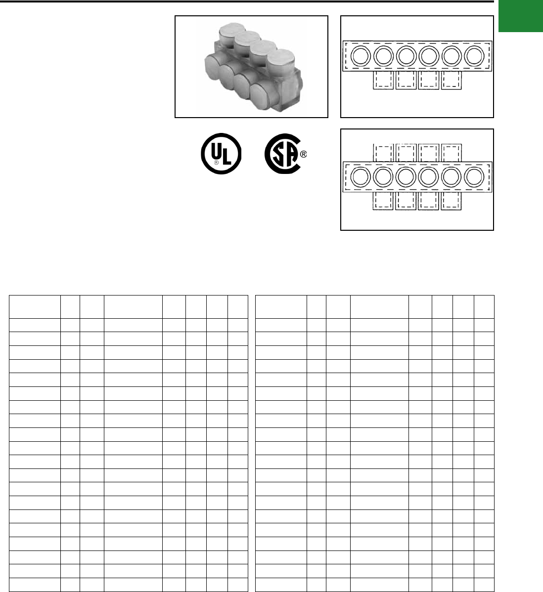
BURNDY®
Blue highlighted items are industry standard and most frequently ordered.
Canada: 1-800-387-6487 www.burndy.com US: 1-800-346-4175
Mechanical
TYPE BIBS-MT, BIBD-MT
UNITAP™
Clear Insulated Multiple Tap
Connectors Mounting Version
The BIBS-MT and BIBD-MT series UNITAP™
offer the same multi-port capabilities as the
standard UNITAP™ connectors except these -MT
types are provided with two isolated mounting
holes at both ends of the connector for direct
mounting to a trough, gutter or wireway. They will
accommodate up to standard 1/4" hardware.
Fig. 1
Fig. 2
Catalog
Number
Fig.
#
# of
Ports
Wire Range
(AWG/kcmil) L W H Hex
Key
BIBS2/04MT 1 4 #14 -2/0 Str 4.20 1.25 1.50 3/16
BIBS2/06MT 1 6 #14 -2/0 Str 5.54 1.25 1.50 3/16
BIBS2/08MT 1 8 14 AWG-2/0 Str 6.89 1.25 1.50 3/16
BIBS2/010MT 1 10 14 AWG-2/0 Str 8.23 1.25 1.50 3/16
BIBS2/012MT 1 12 14 AWG-2/0 Str 9.58 1.25 1.50 3/16
BIBS2504MT 1 4 10 AWG-250 kcmil 5.78 1.95 2.63 5/16
BIBS2506MT 1 6 10 AWG-250 kcmil 7.65 1.95 2.63 5/16
BIBS2508MT 1 8 10 AWG-250 kcmil 9.53 1.95 2.63 5/16
BIBS25010MT 1 10 10 AWG-250 kcmil 11.41 1.95 2.63 5/16
BIBS25012MT 1 12 10 AWG-250 kcmil 13.28 1.95 2.63 5/16
BIBS3504MT 1 4 10 AWG-350 kcmil 5.86 2.19 2.63 5/16
BIBS3506MT 1 6 10 AWG-350 kcmil 7.68 2.19 2.63 5/16
BIBS3508MT 1 8 10 AWG-350 kcmil 9.50 2.19 2.63 5/16
BIBS35010MT 1 10 10 AWG-350 kcmil 11.32 2.19 2.63 5/16
BIBS35012MT 1 12 10 AWG-350 kcmil 13.41 2.19 2.63 5/16
BIBS6004MT 1 4 4 AWG-600 kcmil 7.84 2.25 2.88 3/8
BIBS6006MT 1 6 4 AWG-600 kcmil 10.41 2.25 2.88 3/8
BIBS6008MT 1 8 4 AWG-600 kcmil 12.97 2.25 2.88 3/8
BIBS60010MT 1 10 4 AWG-600 kcmil 15.53 2.25 2.88 3/8
BIBS60012MT 1 12 4 AWG-600 kcmil 18.09 2.25 2.88 3/8
Catalog
Number
Fig.
#
# of
Ports
Wire Range
(AWG/kcmil) L W H Hex
Key
BIBD2/04MT 2 4 14 AWG-2/0 AWG 4.20 1.56 1.50 3/16
BIBD2/06MT 2 6 14 AWG-2/0 AWG 5.54 1.56 1.50 3/16
BIBD2/08MT 2 8 14 AWG-2/0 AWG 6.89 1.56 1.50 3/16
BIBD2/010MT 2 10 14 AWG-2/0 AWG 8.23 1.56 1.50 3/16
BIBD2/012MT 2 12 14 AWG-2/0 AWG 9.58 1.56 1.50 3/16
BIBD2504MT 2 4 10 AWG-250 kcmil 5.78 2.64 2.26 5/16
BIBD2506MT 2 6 10 AWG-250 kcmil 7.65 2.64 2.26 5/16
BIBD2508MT 2 8 10 AWG-250 kcmil 9.53 2.64 2.26 5/16
BIBD25010MT 2 10 10 AWG-250 kcmil 11.41 2.64 2.26 5/16
BIBD25012MT 2 12 10 AWG-250 kcmil 13.28 2.64 2.26 5/16
BIBD3504MT 2 4 10 AWG-350 kcmil 5.86 3.00 2.63 5/16
BIBD3506MT 2 6 10 AWG-350 kcmil 7.68 3.00 2.63 5/16
BIBD3508MT 2 8 10 AWG-350 kcmil 9.50 3.00 2.63 5/16
BIBD35010MT 2 10 10 AWG-350 kcmil 11.32 3.00 2.63 5/16
BIBD35012MT 2 12 10 AWG-350 kcmil 13.41 3.00 2.63 5/16
BIBD6004MT 2 4 4 AWG-600 kcmil 7.84 3.00 2.88 3/8
BIBD6006MT 2 6 4 AWG-600 kcmil 10.41 3.00 2.88 3/8
BIBD6008MT 2 8 4 AWG-600 kcmil 12.97 3.00 2.88 3/8
BIBD60010MT 2 10 4 AWG-600 kcmil 15.53 3.00 2.88 3/8
BIBD60012MT 2 12 4 AWG-600 kcmil 18.09 3.00 2.88 3/8
MULTI-PORT
Single-Sided Entry
MULTI-PORT
Double-Sided Entry
UNITAP™ rated for code conductor only. UNITAP™ rated for code conductor only.
A-59
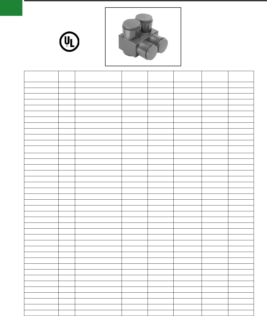
BURNDY®
Blue highlighted items are industry standard and most frequently ordered.
US: 1-800-346-4175 www.burndy.com Canada: 1-800-387-6487
Mechanical
UV RATED
BLACK UNITAP™
UNITAP™
600V, 90°C
Features & Benets
• UV Rated Plastisol covered AL6061-T6
aluminum body saves time by eliminating
the need for taping.
• Oxide inhibitor pre-installed inhibits
moisture and contaminants from entering
the contact area.
• Range-taking capability reduces the
number of connectors carried in inventory.
• UL486B Listed, AL9CU, 600V 90°C.
Catalog Number # of
Ports
Wire Range
(AWG/kcmil) L W H Hex Key Torque
1PL42 2 14 AWG-4 AWG 1.08 1.16 1.25 1/8 45
1PLO42 2 14 AWG-4 AWG 1.08 1.50 1.25 1/8 45
1PL2/02 2 14 AWG-2/0 AWG 1.52 1.40 1.38 3/16 120
1PLO2/02 2 14 AWG-2/0 AWG 1.52 1.56 1.38 3/16 120
1PL2502 2 10 AWG-250 kcmil 2.03 2.07 2.13 5/16 275
1PLO2502 2 10 AWG-250 kcmil 2.03 2.64 2.13 5/16 275
1PL3502 2 10 AWG-350 kcmil 2.22 2.32 2.50 5/16 275
1PLO3502 2 #10-350 kcmil 2.22 3.00 2.50 5/16 275
1PL6002 2 10 AWG-600 kcmil 2.72 2.38 2.75 3/8 375
1PLO6002 2 4 AWG-600 kcmil 2.72 3.00 2.75 3/8 375
1PBS2 2 14 AWG-2 AWG 2.38 0.75 1.22 5/32 45
1PBS1/0 2 14 AWG-1/0 2.91 0.91 1.38 3/16 120
1PBS250 2 10 AWG-250 kcmil 4.01 1.19 2.10 5/16 120
1PBS350 2 10 AWG-350 kcmil 4.63 1.34 2.35 1/3 275
1PBS500 2 6 AWG-500 kcmil 5.00 1.62 2.62 3/8 375
1PL43 3 14 AWG-4 AWG 1.51 1.25 1.25 1/8 45
1PL44 4 14 AWG-4 AWG 1.95 1.25 1.25 1/8 45
1PL2/03 3 14 AWG-2/0 AWG 2.19 1.31 1.38 3/16 120
1PL2503 3 10 AWG-250 kcmil 2.97 2.07 2.13 1/3 275
1PLD43 3 14 AWG-4 AWG 1.51 1.50 1.25 1/8 45
1PLD44 4 14 AWG-4 AWG 1.95 1.50 1.25 1/8 45
1PLD2/02 2 14 AWG-2/0 AWG 1.52 1.56 1.38 1/5 120
1PLD2/03 3 14 AWG-2/0 AWG 2.19 1.56 1.38 3/16 120
1PLD2/04 4 14 AWG-2/0 AWG 2.86 1.56 1.38 3/16 120
1PLD2/06 6 14 AWG-2/0 AWG 4.20 1.56 1.38 3/16 120
1PLD2502 2 10 AWG-250 kcmil 2.03 2.64 2.13 5/16 275
1PLD2503 3 10 AWG-250 kcmil 2.97 2.64 2.13 5/16 275
1PLD2504 4 10 AWG-250 kcmil 3.91 2.64 2.13 5/16 275
1PLD2506 6 10 AWG-250 kcmil 5.78 2.64 2.13 5/16 275
1PLD3502 2 10 AWG-350 kcmil 2.22 3.00 2.50 5/16 375
1PLD3503 3 10 AWG-350 kcmil 3.13 3.00 2.50 5/16 375
1PLD3504 4 10 AWG-350 kcmil 4.04 3.00 2.50 5/16 375
1PLD3506 6 10 AWG-350 kcmil 5.86 3.00 2.50 5/16 375
1PLD3508 8 10 AWG-350 kcmil 7.68 3.00 2.50 5/16 375
1PLD6002 2 4 AWG-600 kcmil 2.72 3.00 2.75 3/8 375
1PLD6003 3 4 AWG-600 kcmil 4.00 3.00 2.75 3/8 375
1PLD6004 4 4 AWG-600 kcmil 5.28 3.00 2.75 3/8 375
1PLD6005 5 4 AWG-600 kcmil 6.56 3.00 2.75 3/8 375
1PLD6006 6 4 AWG-600 kcmil 7.84 3.00 2.75 3/8 375
1PLD6008 8 4 AWG-600 kcmil 10.40 3.00 2.75 3/8 375
1PL = 2 Port Single Sided Entry
1PLO = 2 Port Offset Entry
1PLD = Multi-Port Double Sided Entry
UNITAP™ rated for code conductor only.
1PBS = In-line Splice/Reducer
1PL = Multi-Port Single Sided Entry
A-60
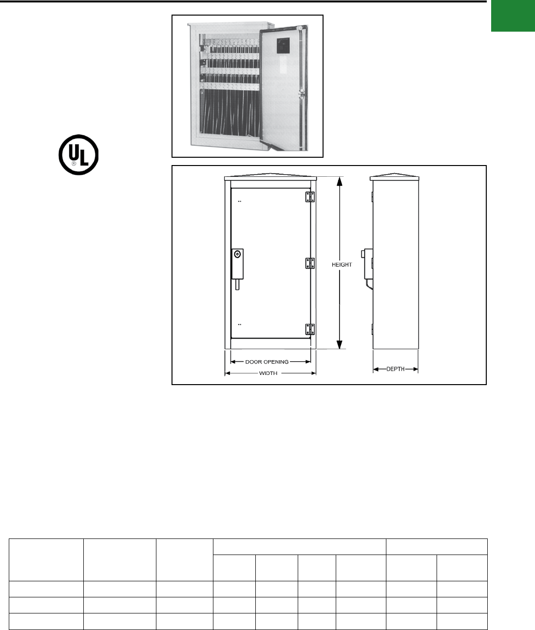
BURNDY®
Blue highlighted items are industry standard and most frequently ordered.
Canada: 1-800-387-6487 www.burndy.com US: 1-800-346-4175
Mechanical
TYPE BWTE
WALL-MOUNTED TERMINATION
ENCLOSURES
These are three-phase, NEMA 3R
(rain-proof), 600 Volt Rated wall
mounted termination enclosures.
Features and Benets
• Aluminum mechanical bar connectors
eliminates need for compressions tools,
lugs, and bolt assemblies
• Aluminum enclosure is lightweight, low
maintenance and has excellent corrosion
resistance
• Ample working space, allowing for easier
termination with a removeable swinging
door
• All-welded construction: welds and
seams are ground smooth
• Manufactured to meet or exceed ANSI
C57-12.28 for wall-mounted equipment
enclosure integrity
• Three-point positive latch mechanism
(secured and operated by a half-turn,
captive and recessed penta-head bolt)
and shielded padlock shackle
• Finish meets or exceeds proposed EEI
paint specication
• Finish is gray, oven cured powder coat
• All mounting hardware is 18-8 stainless
steel
Catalog
Number
Conductor
Range (AWG)
Number of
Conductors
per phase
Dimensions UL Listed Amp Rating
W D H Door
Opening Copper Aluminum
BWTE21-500 10 - 500 kcmil 21 32.00 16.00 51.00 28.00 3800 3100
BWTE21-750 2 - 750 kcmil 14 32.00 16.00 51.00 28.00 3325 2695
BWTE21-1000 1/0 - 1000 kcmil 14 32.00 16.00 51.00 28.00 3815 3115
AL9CU
A-61
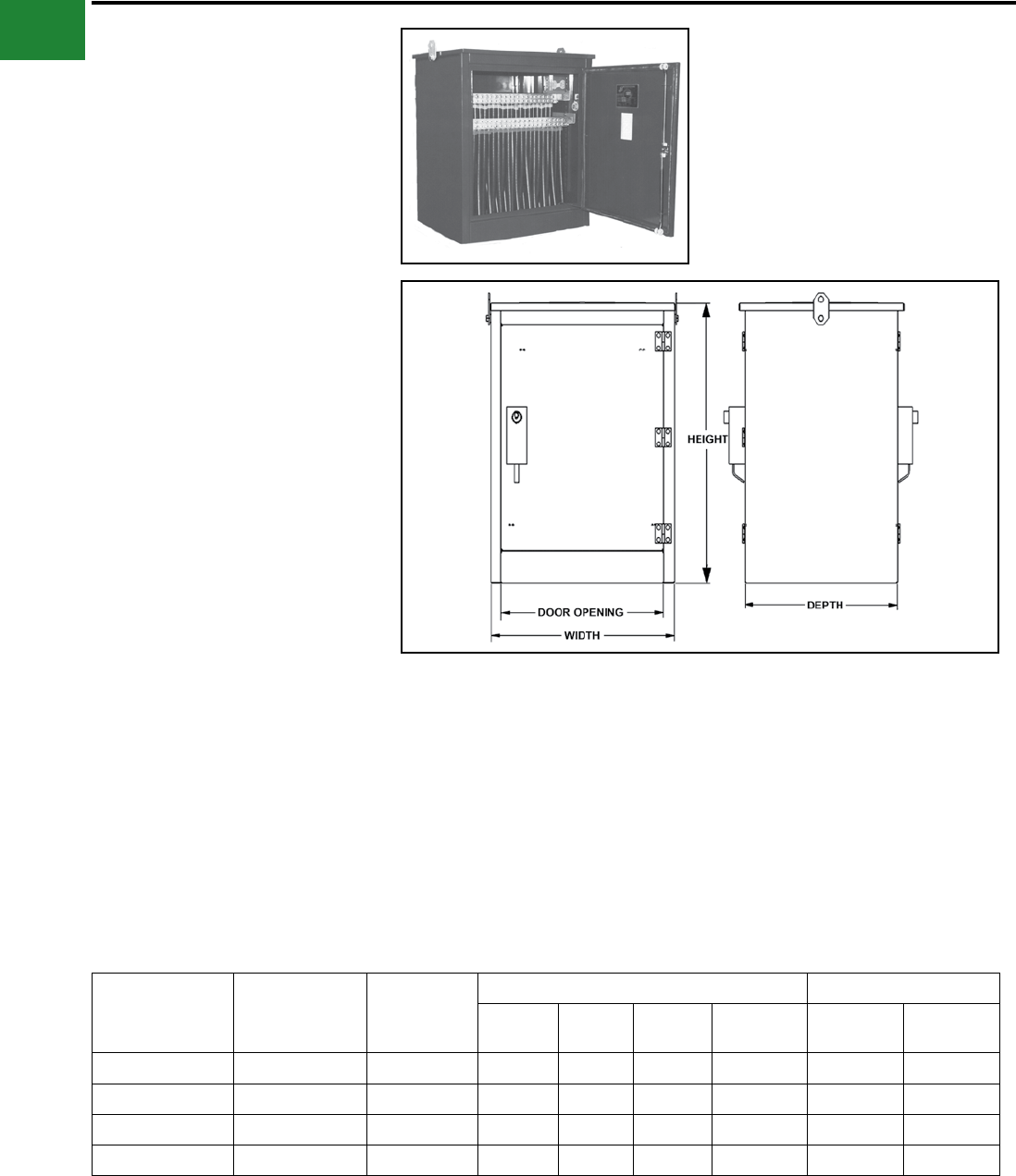
BURNDY®
Blue highlighted items are industry standard and most frequently ordered.
US: 1-800-346-4175 www.burndy.com Canada: 1-800-387-6487
Mechanical
TYPE BPTE
PAD-MOUNTED TERMINATION
ENCLOSURES
These are three-phase, NEMA 3R
(rain-proof), 600 Volt Rated pad
mounted termination enclosures.
Features and Benets
• Aluminum mechanical bar connectors
eliminates need for compressions tools,
lugs and bolt assemblies
• Aluminum enclosure is lightweight, low
maintenance and has excellent corrosion
resistance
• Ample working space, allowing for easier
termination with a removeable swinging
door
• All-welded construction: welds and
seams are ground smooth
• Manufactured to meet or exceed ANSI
C57-12.28 for wall-mounted equipment
enclosure integrity
• Removable swinging doors - doors have
stainless steel lift off hinges with
stainless steel three point locking
handles and recessed stainless steel
penta-head bolts for security
• Finish is Munsell green, oven cured
powder coat
• All mounting hardware is 18-8 stainless
steel
Catalog
Number
Conductor
Range (AWG)
Number of
Conductors
per phase
Dimensions UL Listed Amp Rating
W D H Door
Opening Copper Aluminum
BPTE26-500 10 - 500 kcmil 26 36.00 30.00 44.00 30.00 4560 3720
BPTE22-750 2 - 750 kcmil 22 36.00 30.00 44.00 30.00 5225 4235
BPTE20-1000 350 - 1000 kcmil 20 36.00 30.00 44.00 30.00 4905 4005
BPTE14-750 2 - 750 kcmil 14 25.00 24.00 44.00 19.00 3800 3100
A-62
