WRC_4 08 96747 Catalog
2014-07-05
: Pdf 96747-Catalog 96747-Catalog 784572 Batch5 unilog
Open the PDF directly: View PDF ![]() .
.
Page Count: 128 [warning: Documents this large are best viewed by clicking the View PDF Link!]
Meter Mounting Equipment
Western Region Area

1
MILBANK OVERVIEW
MILBANK OVERVIEW
1
Charles A. Milbank
1879-1966
Bill Martin
1916-1998
Robert F. Waldrop
1922-2002
Robert F. Waldrop, II
Chairman
Katrina Waldrop Henke
Vice Chairman
Milbank–Quality Metering Products for 80 Years
ilbank Manufacturing
Company was estab-
lished in 1927 by
Charles A. Milbank.
Originally, the company
manufactured high voltage
switches; however, by 1941
Milbank devoted itself primarily
to the manufacture of sheet metal
enclosures and related equipment
for the electrical generation and
distribution industry. Today we
are an industry leader in the
manufacture of electrical meter
sockets. Through a national
network of manufacturer’s
representatives we provide
wholesale electrical distributors
with quality electrical products
for the utility, contractor,
industrial and OEM markets.
As the meter standards have
changed, Milbank has been
successful in adapting its product
line to these changes. Our full
scale engineering department
designs products to meet
customer specifications and
satisfy all utility requirements.
Milbank’s employee base of over
1,000 workers, along with our
five manufacturing facilities
comprising almost 550,000
square feet give us the flexibility
to schedule, produce, and ship
orders quickly. Currently,
Milbank manufactures over
10,000 different catalog items,
and this list continues to grow.
Our unique product offering
includes: Residential &
Commercial Meter Sockets;
Residential & Commercial Meter
Pedestals; RV/MH Power Outlets,
Service Pedestals, and
Transformers; Commercial &
Industrial Electrical Enclosures;
Circuit Breakers; Disconnects &
Safety Switches; Safety Sockets;
Utility & Residential Secondary
Pedestals; Hubs, and related
accessories. If you don’t find a
unit in this catalog to service your
needs, send us your specifications
and we will be happy to work
with you.
Our success has come from a
loyal customer base that can rely
on us to build quality products at
a fair price in a timely manner.
Our willingness and ability to
design and produce new products
to meet our customer demands is
an important factor to remain
competitive in today’s electrical
market.
Milbank has been serving the
electric utility & wholesale
distribution industries for 80 years
with innovative, quality
engineered products. So
remember us for all of your meter
mounting and related
requirements, and we will be
happy to serve you as we have in
the past – with dependable
service and quality products!
We take great pride in being
one of the few family-owned
businesses left in our industry.
We are a third generation run
business and truly believe that...
FAMILY MAKES A
DIFFERENCE!
M

2
PRODUCT INDEX BY CATEGORY
PRODUCT INDEX BY CATEGORY
AC DISCONNECTS SECTION A
30 & 60 Amp – Fusible/Non-Fusible Air Conditioner Disconnects....................................................................................1
Combination AC Disconnect / 20 Amp GFCI Receptacle..................................................................................................2
Hot Tub Disconnect or Sub Panel Breaker Enclosure – Type 3R .......................................................................................2
METER SOCKETS SECTION B
SINGLE POSITION (NO BYPASS)
30-100 Amp – Economy Cast Socket – Ring Type, 4T.......................................................................................................1
125-200 Amp, Ringless, 4T, 5T & 7T.............................................................................................................................2-3
125-200 Amp, Ring Type, 4T & 7T................................................................................................................................2,4
125-200 Amp, Ring Type with Manual Circuit Closing Blocks, 4T & 7T ...........................................................................9
200 Amp, Ring Type, Flush Mount, 4T .............................................................................................................................5
320 Amp, Ringless (Non-Lever Bypass), 4T.....................................................................................................................10
SINGLE POSITION (WITH BYPASS)
125-200 Amp, Ringless (Non-Jaw Clamping Lever Bypass), 4T, 5T & 7T .......................................................................6-7
200 Amp, Ringless (Jaw Clamping Lever Bypass), 4T, 5T & 7T .........................................................................................8
320 Amp, Ringless (Lever Bypass), 4T.............................................................................................................................10
320 Amp, Ring Type (Link Bypass), 4T ...........................................................................................................................11
320 Amp, Ringless (Lever Bypass), Side Wireway, 7T .....................................................................................................11
MULTIPLE POSITION
100-125 Amp, Ringless/Ring Type Horizontal Gang Sockets, 4T ....................................................................................12
200 Amp, Ringless/Ring Type Horizontal Gang Sockets, 4T ...........................................................................................13
125-200 Amp, Condominium Metering Banks, Ringless............................................................................................15-16
METER MAINS AND SERVICE ENTRANCE EQUIPMENT SECTION C
100/150/200 Amp, Ringless/Ring Type Meter Main, 4T & 5T – 22K AIC...........................................................................2
200 Amp, Ring Type, 4T & 7T ..........................................................................................................................................1
200 Amp, Unmetered, Service Entrance Main Breaker, 4T ...............................................................................................3
400 Amp, 320 Amp Continuous, Ringless Meter Main with Split Load, 4T .......................................................................4
400 Amp, 320 Amp Continuous, Ring Type Meter Main with Split Load, 4T ....................................................................5
400 Amp, 320 Amp Continuous, Ring Type Plug-In Socket – Meter Main with Split Load, 4T ..........................................6
400 Amp, 320 Amp Continuous, Ring Type Meter Main Combination, 4T ....................................................................7-8
COMMERCIAL METERING –
SAFETY SOCKETS, METER MAINS, TERMINATION BOXES, BUSSED GUTTERS SECTION D
SAFETY SOCKETS
100/200 Amp – TB Series – 600 Volt Self-Contained / Socket Only, 4T, 5T & 7T..............................................................1
100 Amp, MTB Series – 10K AIC – 240 Volt Self-Contained Meter Main / CB, 4T, 5T & 7T..............................................2
100 Amp, MTB Series – 22K AIC – 240 Volt Self-Contained Meter Main / CB, 4T & 7T....................................................3
100 Amp, MTB Series – 14K AIC – 480 Volt Self-Contained Meter Main / CB, 4T, 5T & 7T..............................................4
100 Amp, MTB-P & MTB-P48 Series – 200K AIC – 240 & 480 Volt Self-Contained Meter Main /
T-Fuse Pullout, 4T, 5T & 7T.........................................................................................................................................5
200 Amp, MTB Series – 10K AIC – 240 Volt Self-Contained Meter Main / CB, 4T, 5T & 7T..............................................6
200 Amp, MTB Series – 22K AIC – 240 Volt Self-Contained Meter Main / CB, 4T & 7T....................................................7
200 Amp, MTB Series – 35K AIC – 480 Volt Self-Contained Meter Main / CB, 4T & 7T....................................................8
200 Amp, Test Block Bypass – MTB-P & MTB-P48 Series – 200K AIC – 240/480 Volt Self-Contained Meter Main /
T-Fuse Pullout, 4T, 5T & 7T.........................................................................................................................................9
100 & 200 Amp, MTBL All-In-One Series, 10K & 200K AIC – 240 Volt Meter Main – Circuit Breaker /
T-Fuse Pullout ................................................................................................................................................................10
Safety Socket Replacement Circuit Breakers & Pullouts .............................................................................................14-15
Safety Socket & T-Fuse Replacement Parts......................................................................................................................16
UNDERGROUND TERMINATION BOXES & BUSSED GUTTERS
Underground Termination Boxes – 600 VAC..................................................................................................................11
Bussed Gutters – Type 3R - 3Ø4W – 600 VAC ...............................................................................................................12
Bussed Gutters – Type 3R - 3Ø4W – 600 VAC ...............................................................................................................13
COMMERCIAL METER PEDESTALS SECTION E
Commercial Meter Pedestals Overview ............................................................................................................................1
Applications & Accessories...............................................................................................................................................2
Catalog Number Logic......................................................................................................................................................3
ML Series – Main Load Center ..........................................................................................................................................4
SL Series – Switched Load Center .....................................................................................................................................5
400 Amp Series ................................................................................................................................................................6
IR Series – Irrigation Control .............................................................................................................................................7
BBS/UPS Series.................................................................................................................................................................8
2

3
PRODUCT INDEX BY CATEGORY
PRODUCT INDEX BY CATEGORY
Power Transfer Series – Metered & Unmetered.................................................................................................................9
General Specifications....................................................................................................................................................10
Commercial Meter Pedestal Drawings – 16” Metered & Unmetered...............................................................................11
Commercial Meter Pedestal Drawings – 24” Metered & Unmetered...............................................................................12
Commercial Meter Pedestal Drawings – 32” Metered.....................................................................................................13
Commercial Meter Pedestal Drawings – Metered ...........................................................................................................14
CT CABINETS, TEST SWITCHES, POLYPHASE ENCLOSURES SECTION F
Current Transformer Cabinets – Type 3R – Door Mount CT Rated Socket .........................................................................1
Current Transformer Cabinets ...........................................................................................................................................2
Current Transformer Cabinets – Mounting Racks ..............................................................................................................3
Metered Transformer Cabinets – Overhead & Underground .............................................................................................4
20 Amp – 4, 5, 6, 7, 8 & 13 Terminal Current Transformer Rated – Ringless/Ring Type ....................................................5
20 Amp – 600 VAC – 5, 6, 8, 13 & 15 Terminal Current Transformer – Test Switch Provision ..........................................6
Milbank Test Switches – 4, 7 & 10 Pole............................................................................................................................7
Test Switches – 4, 7 & 10 Pole – 600 VAC – Per ANSI C12.9 Standard.............................................................................8
Milbank Test Switch Worksheet........................................................................................................................................9
SERVICE PEDESTALS SECTION G
125 Amp – Mobile Home Metered Pedestal – Hardwired – 120/240VAC.........................................................................1
200 Amp – Mobile Home Metered Pedestal – Hardwired – 120/240VAC.........................................................................2
100/200 Amp – Load Center Power Pedestals – All Purpose & RV Applications ...............................................................3
200 Amp Series U5240 & U5241 Ring Type Metered Pedestals ....................................................................................4-5
200 Amp Series U5136 & 5137 Ringless Metered Pedestals ..........................................................................................6-7
U5706 & U5707 Temp to Final Service Pedestal – Ringless/Ring Type..........................................................................8-9
Mobile Home Rebuild Kits ........................................................................................................................................10-11
RV SECTION H
Series U5000 – Unmetered – Surface Mount Power Outlet ...........................................................................................1-2
Series U5100 – Metered – Surface Mount Power Outlet ................................................................................................3-4
Series U5200 – Unmetered – Pedestal Power Outlet .....................................................................................................5-6
Series U5300 – Metered – Pedestal Power Outlet..........................................................................................................7-8
Millennium Features....................................................................................................................................................9-10
600/1200 Amp – Pad Mounted Panel Board...................................................................................................................11
100, 200 & 400 Amp – Terminal Box .............................................................................................................................12
Lighting Accessories .......................................................................................................................................................13
Telecommunications and Pedestal Accessories...............................................................................................................14
Pedestal Mounting Accessories.......................................................................................................................................15
Metering & Single Receptacle Accessories......................................................................................................................16
RV Replacement Parts & Accessories.........................................................................................................................17-18
RV Product Information – Wiring Diagram Label – Warranty.........................................................................................19
TEMPORARY POWER SECTION I
U4908/U4909 Underground Service Power Outlet – Ringless/Ring Type ......................................................................1-2
Series U5000 – Unmetered – Surface Mount Power Outlet ...........................................................................................3-4
Series U5001 – Unmetered – Surface Mount Power Outlet...............................................................................................5
Series U5100 & U5101 Overhead – Ringless/Ring Type – Metered – Surface Mount Power Outlet ...............................6-7
Replacement Parts for MPAP/MPRV/HP Pedestals ............................................................................................................8
TRANSFORMERS SECTION J
Galvanized Steel Distribution Transformer – 1∅...............................................................................................................1
MISCELLANEOUS SECTION K
Accessories....................................................................................................................................................................1,2
UQFP Plug-In Series Circuit Breakers ...............................................................................................................................3
UQFB Bolt-On Series Circuit Breakers..............................................................................................................................4
Conduit, Ampacity, SCCR Information..............................................................................................................................5
Energization of Electrical Equipment.................................................................................................................................6
Materials and Finishes ......................................................................................................................................................7
Meter Forms .....................................................................................................................................................................8
Watthour Meter Forms – Standard Forms, Transformer Rated or Self-Contained ...............................................................9
Standard NEMA Configurations ......................................................................................................................................10
Additional Milbank Products ..........................................................................................................................................11
ALPHA-NUMERIC INDEX SECTION L
Alpha-Numeric Index....................................................................................................................................................1-2
3
4
4
CATALOG NUMBER LOGIC
CATALOG NUMBER LOGIC
A1
AC DISCONNECTS
SECTION A
30 & 60 AMP–FUSIBLE / NON-FUSIBLE–AIR CONDITIONER DISCONNECTS
U3800
(No deadfront required)
Milbankʼs air conditioner disconnect has a removable hinged cover which makes wiring a breeze. Our
compact design meets all wire bending space requirements in the NEC and, also, complies with article
440-14 in the NEC. To insure the safest conditions, we designed our disconnect pullers to be
removable or they may be reinstalled in the off position. Another safety feature is the padlock provision
on the front cover. As with all Milbank products, our enclosure is constructed of G90U galvanized steel
and finished with an attractive, light gray, baked powder coating. Our state of the art finish combines
epoxy and polyester hybrid resins into a hybrid powder coating which is then electrostatically applied.
This offers a durable, nonfading finish.
TECHNICAL INFORMATION
AMP TYPE CATALOG
NUMBER
MAX
H.P.
WT.
@
#
30 FUSIBLE U3830 32.7
60 FUSIBLE U3860 10 3.3
60
NONFUSIBLE
U3800 10 3.25
LINE & LOAD
WIRE RANGE
GROUND
WIRE RANGE DIMENSIONS WIRE RATING
CU AL CU/AL
#14-#3
AWG #14-#3
AWG #14-3 AWG
#14-#3
AWG #14-#3
AWG #14-3 AWG
#14-#2
AWG #12-#2
AWG #14-3 AWG
D" W" H" CU °CAL °C
2-5/8 5760°/75°60°/75°
3 5 91
⁄
460°/75°60°/75°
35860°/75°60°/75°
PROFILE
U/L listed as Enclosed Pullout Switch
1∅, 240 VAC
Type 3R Rainproof
Six one-inch concentric knockouts
U3801
U3860
60
NONFUSIBLE
U3801 10 2.5 #14-#3
AWG #14-#3
AWG #14-3 AWG 2-3/8 56-3/4 60°/75°60°/75°
Utility requirements for this equipment may vary. Always consult the serving utility for their requirements before ordering or
installing equipment in this catalog.
A1
A2
AC DISCONNECTS
A2
SECTION A
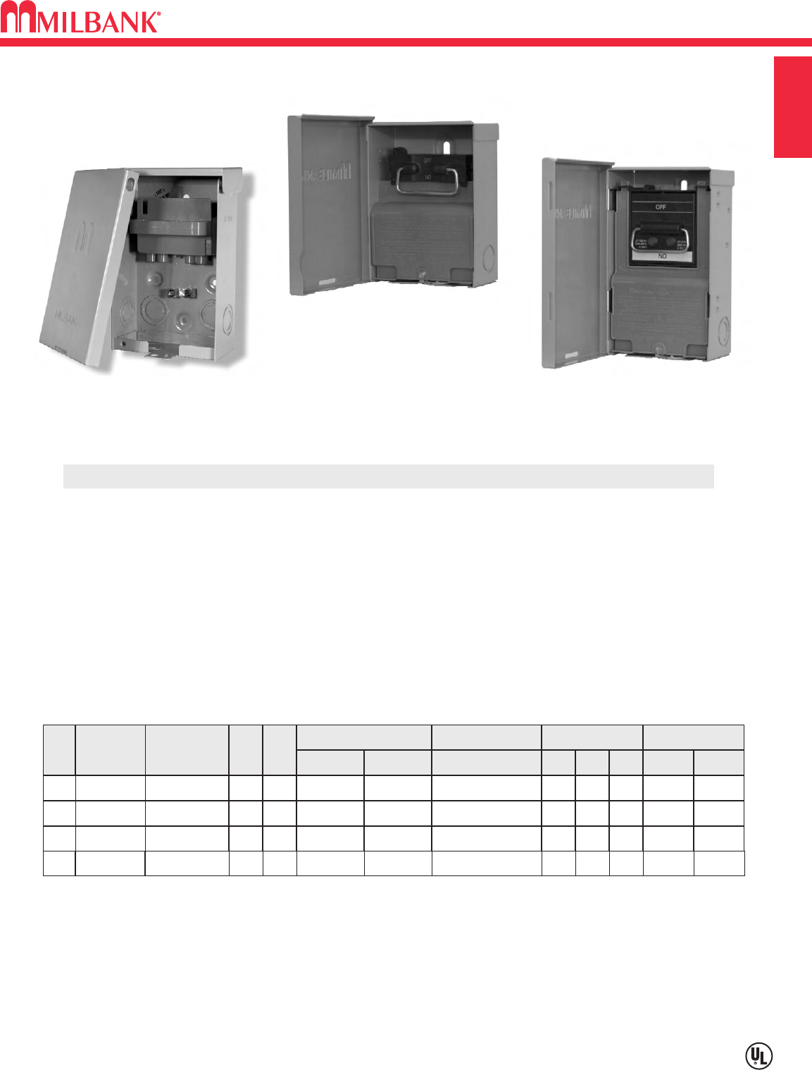
AC DISCONNECT / SPA BOX
• Meets NEC # 210.63 Requirements *
• UL Listed as Power Outlet
• Type 3R Enclosure
• In-Use Cover**
• Duplex Ground Connector
• 1” Concentric Knockouts
AC DISCONNECT
•1
∅
, 240 Volt
• 60 amp, Non-Fused
GFCI RECEPTACLE
• 20 amp
• Reset/Test Button
• Padlock provision
Combination AC Disconnect / 20 Amp GFCI Receptacle–Together in 1 Box
To ensure the safest conditions, Milbank disconnect pullers are designed to be reversible so they may be reinstalled in the OFF position.
All units are designed with a padlock provision on the cover for security.
**Note: U3822-20GR cover rated as
IN-USE COVER
(Cover may be closed with cords plugged into receptacle).
*Reprinted with permission from NFPA 70-2002,
National Electrical Code
®, Copyright 2001, National Fire Protection Association, Quincy, MA 02269. This reprinted material is not the complete
and official position of the NFPA on the referenced subject, which is represented only by the standard in its entirety. National Electrical Code®and NEC®are registered trademarks of the
National Fire Protection Association, Quincy, MA.
* NEC®#210.63 Heating, Air-
Conditioning and Refrigeration
Equipment Outlet.
...The receptacle shall be
located on the same level and
within 7.5 m (25 ft.) of the
heating, air-conditioning and
refrigeration equipment.
* NEC®#210.08 Ground-Fault
Circuit– Interruptor protection
for personnel.
U4881-O-50GB
AMP TYPE CATALOG
NUMBER
WT.
#
LINE & LOAD CONNECTOR
WIRE RANGE
GROUND CONNECTOR
WIRE RANGE DIMENSIONS
CU AL CU/AL D"
W
"H"
50
60
BREAKER
BREAKER
U4881-O-50GB
U4881-O-60GB
8
8
#14-1/0
#14-1/0
#14-1/0
#14-1/0
#14-1/0
#14-1/0
3 3
⁄
4
3 3
⁄
4
71
⁄
2
71
⁄
2
81
⁄
2
81
⁄
2
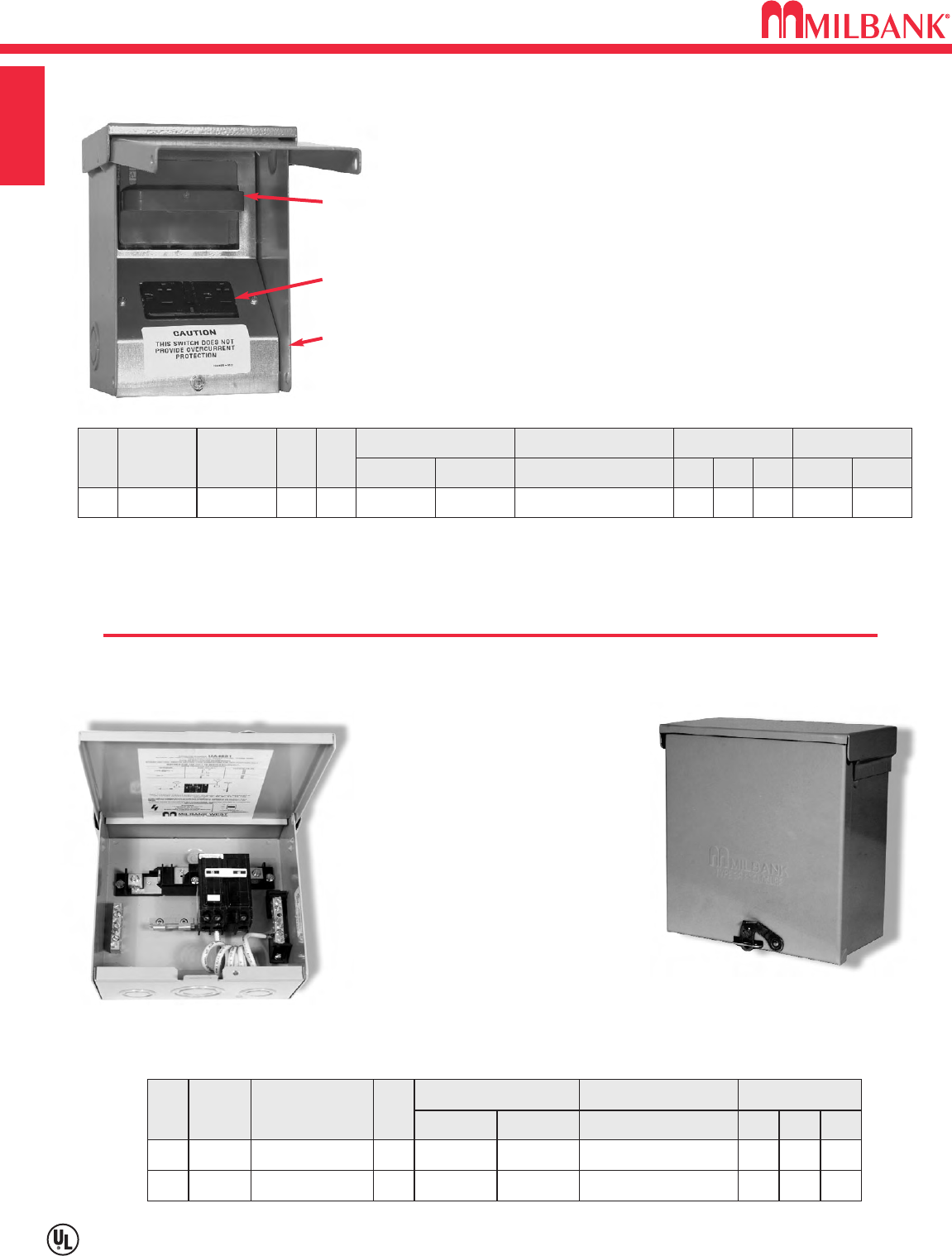
•
240 volt ground fault protection
•
UL listed, Type 3R rainproof
•
Milbank reliability
•
Easy installation
•
2 pole, 50 amp GFCI breaker protection
•
Compact size:
8-1/2” H x 7-1/2” W x 3-3/4” D
•
3 or 4 wire installation
•
1
∅
, 120 / 240 VAC
•
Standard package of 12
•
2 extra one-pole breaker spaces
•
100 amp overall rating
Sub Panel Breaker Enclosure
•
Use as a 100 amp, 4 circuit sub panel
enclosure
Hot Tub Disconnect or Sub Panel Breaker Enclosure–Type 3R
Spa Box with GFCI Protection
U3822-20GR
60 amp,
Non-Fused
AC Disconnect
Duplex 20 amp
GFCI Receptacle
Type 3R
Enclosure with
In-Use Cover
AMP TYPE CATALOG
NUMBER
MAX
H.P.
WT.
#
60
NONFUSIBLE
U3822-20GR
10 6
LINE & LOAD CONNECTOR
WIRE RANGE
GROUND CONNECTOR
WIRE RANGE DIMENSIONS WIRE RATING
CU AL CU/AL
#14-#2 #12-#2 #14-4
D" W" H" CU °CAL °C
4.8 5.25 7.4 60°/75°60°/75°
B1
30/60/100 AMP—4 TERMINAL—ECONOMY CAST SOCKET—RING TYPE
Utility requirements for this equipment may vary. Always consult the serving utility for their requirements before ordering or
installing equipment in this catalog.
B1
METER SOCKETS
SECTION B
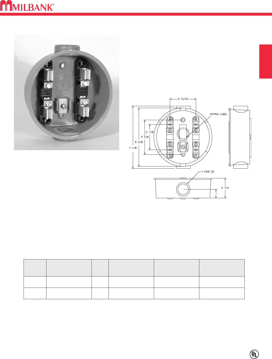
Our enclosure is made of die cast aluminum. The electrostatically applied epoxy and
polyester resins, which are baked on, form a durable, light gray exterior. The current carrying
parts are of copper alloy. The ground connector is designed to insure a positive electrical
connection by effectively clamping the conductor against a serrated surface.
FOR USE WITH SINGLE PHASE
SELF-CONTAINED 4 TERMINAL METERS
100 amp max rated is ideal for use on:
Temporary Service
Outdoor Advertising
Small Customer Service
Other Low Amperage Requirements
ECONOMY SOCKET
FIFTH & SIXTH TERMINAL: Contact factory.
SEALING RING: Supplied with a snap action sealing ring.
HUB: Units supplied with cast in hub on top and bottom. Consult factory for availability of other hub sizes.
BYPASS: Also available with auto bypass. Contact factory.
30-100 AMP—4 TERMINAL—ECONOMY CAST SOCKET—RING TYPE
SERVICE CATALOG
NUMBER
HUB
SIZE
CONNECTOR
CU/AL
QUANTITY
PER PACKAGE
CONCENTRIC
KNOCKOUTS
OH/UG AP2300-03 1"#12-#1 12 3/4", 1"
OH/UG AP2300-04 11⁄4"#12-#1 12 3/4", 1"
125 AMP—4 & 7 TERMINAL—SINGLE POSITION—RINGLESS / RING TYPE—600 VAC
B2
Utility requirements for this equipment may vary. Always consult the serving utility for their requirements before ordering or
installing equipment in this catalog.
B2
METER SOCKETS SECTION B
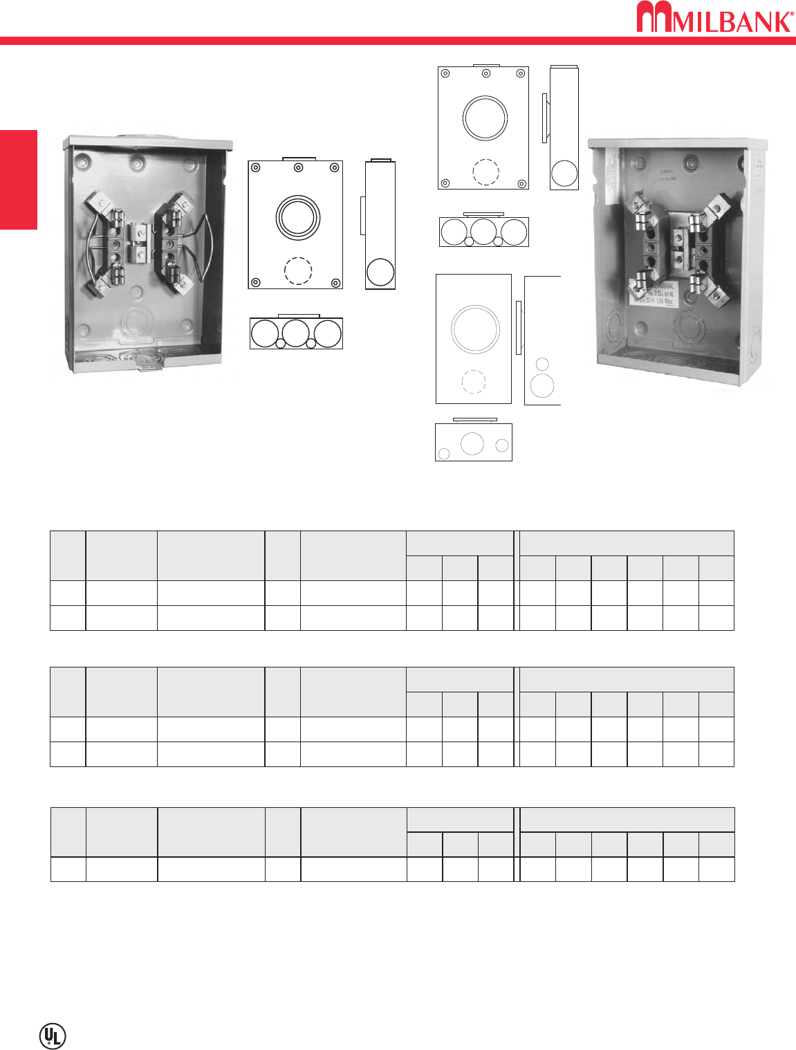
FIFTH TERMINAL: For field mounted fifth terminal on the U7487 & U7490 order catalog number 5T8K2 to fit into round
opening at the 9 oʼclock position.
HUBS: For proper hub selection see the hub suffix chart on the accessory page.
CONNECTORS: Extruded aluminum connectors are tin plated.
SEALING RINGS: Ring type units supplied with an MR-2 snap action sealing ring as standard.
125 AMP–7 TERMINAL–RING TYPE
AMP
125
SERVICE CATALOG
NUMBER HUB
OH U1681-RL H.O.
CONNECTORS
CU/AL
DIMENSIONS CONCENTRIC K.O.ʼS
1 2 3 4 5 6
2 2 2 —1
⁄
4,1
⁄
23
⁄
4
D" W" H"
10 181
⁄
2
#6-2/0
12
34 4
56
12
3
5
6
6
AMP SERVICE CATALOG
NUMBER HUB CONNECTORS
CU/AL
DIMENSIONS CONCENTRIC K.O.ʼS
1 2 3 4 5 6D" W" H"
125 OH/UG U7490-RL H.O. 11
⁄
211
⁄
2211
⁄
4—1
⁄
4
8111
⁄
2
#6-2/0
125 UG U7490-O BLANK 11
⁄
211
⁄
2211
⁄
4—1
⁄
4
8111
⁄
2
#6-2/0
7490
1681
U7490-O
AMP
125
SERVICE CATALOG
NUMBER HUB
UG U7487-O BLANK
CONNECTORS
CU/AL
DIMENSIONS CONCENTRIC K.O.ʼS
1 2 3 4 5 6
11
⁄
211
⁄
2211
⁄
4—1
⁄
4
D" W" H"
8111
⁄
2
#6-2/0
125 OH/UG U7487-RL H.O. 11
⁄
211
⁄
2211
⁄
4—1
⁄
4
8111
⁄
2
#6-2/0
125 AMP–SINGLE POSITION–4 TERMINAL–RINGLESS
12
34 4
56
7487
U7487-RL
125 AMP–SINGLE POSITION–4 TERMINAL–RING TYPE
47
⁄
8
35
⁄
16
35
⁄
16
35
⁄
16
35
⁄
16
B3
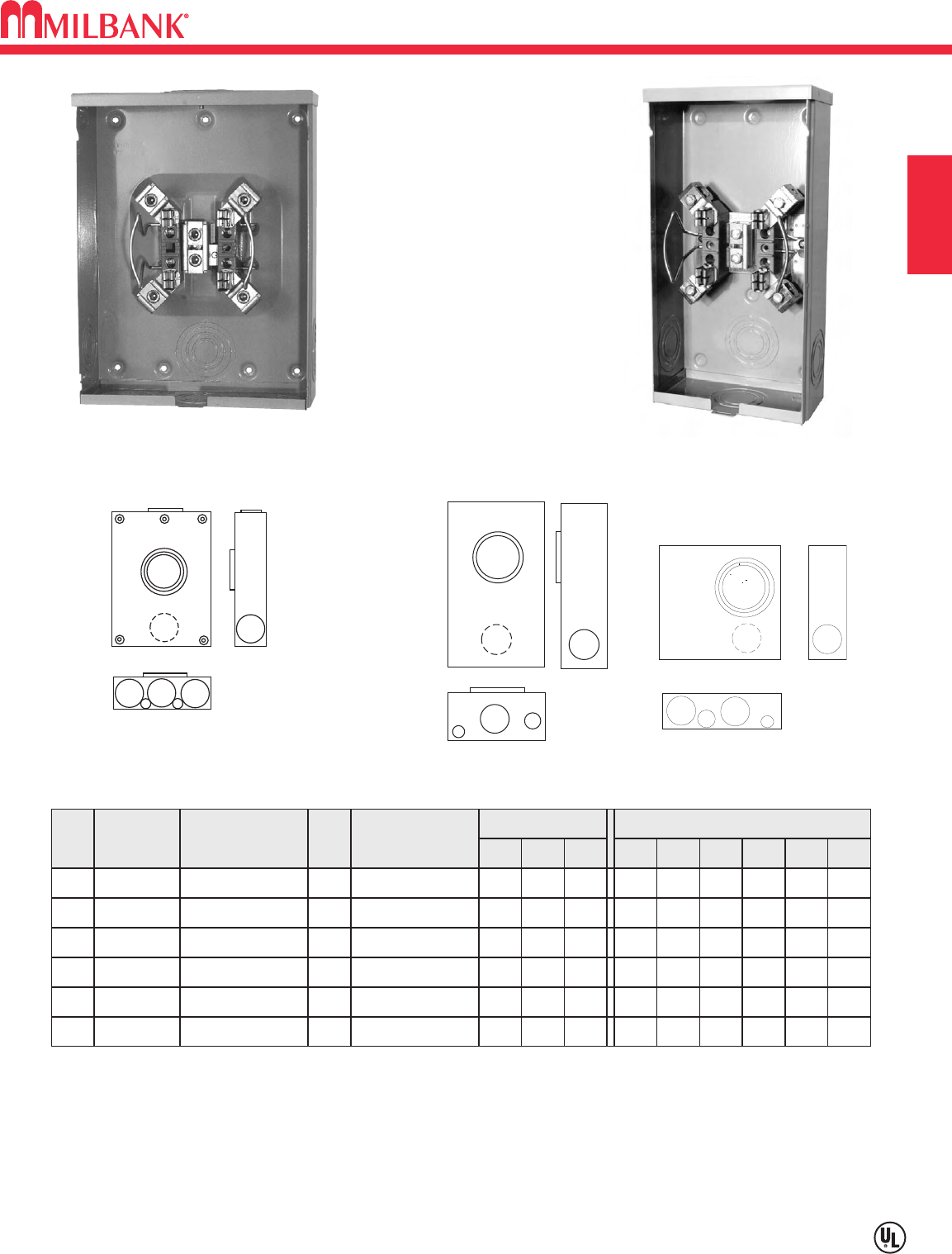
200 AMP—4 TERMINAL—SINGLE POSITION—RINGLESS—600 VAC
Utility requirements for this equipment may vary. Always consult the serving utility for their requirements before ordering or
installing equipment in this catalog.
B3
METER SOCKETS
SECTION B
AMP
200
SERVICE CATALOG
NUMBER HUB
OH U1060-RL H.O.
CONNECTORS
CU/AL
DIMENSIONS CONCENTRIC K.O.ʼS
1 2 3 4 5 6
2 2 2 — — 1
⁄
4
D" W" H"
41
⁄
88151
⁄
2
#2-350
200 UG U1527-O BLANK 2 2 2 21
⁄
21
⁄
4,1
⁄
21
⁄
4
41
⁄
811 151
⁄
2
#2-350
200 UG U1980-O BLANK 21
⁄
221
⁄
2311
⁄
221
⁄
21
⁄
4,1
⁄
2
41
⁄
213 151
⁄
4
#6-350
200 OH U7021-RL-TG H.O. 21
⁄
221
⁄
221
⁄
2—1
⁄
41
⁄
4,1
⁄
2
41
⁄
88151
⁄
2
#6-350
200 OH/UG U7040-XL-TG C.P. 21
⁄
221
⁄
221
⁄
221
⁄
21
⁄
4,1
⁄
21
⁄
4
41
⁄
811 151
⁄
2
#6-350
200 OH/UG U7043-XL-TG C.P. 21
⁄
221
⁄
23 3 1
⁄
41
⁄
4,1
⁄
2
47
⁄
813 151
⁄
2
#6-350
200 AMP–SINGLE POSITION–4 TERMINAL–RINGLESS
FIFTH TERMINAL: For field mounted fifth terminal order catalog number K5T to fit into square opening at the 9 oʼclock
position.
HUBS: For proper hub selection see the hub suffix chart on accessory page.
CONNECTORS: Extruded aluminum connectors are tin plated.
12
3456
1980
U7040-XL-TG U1060-RL
12
3
56
1060
7021
12
34 4
56
7040
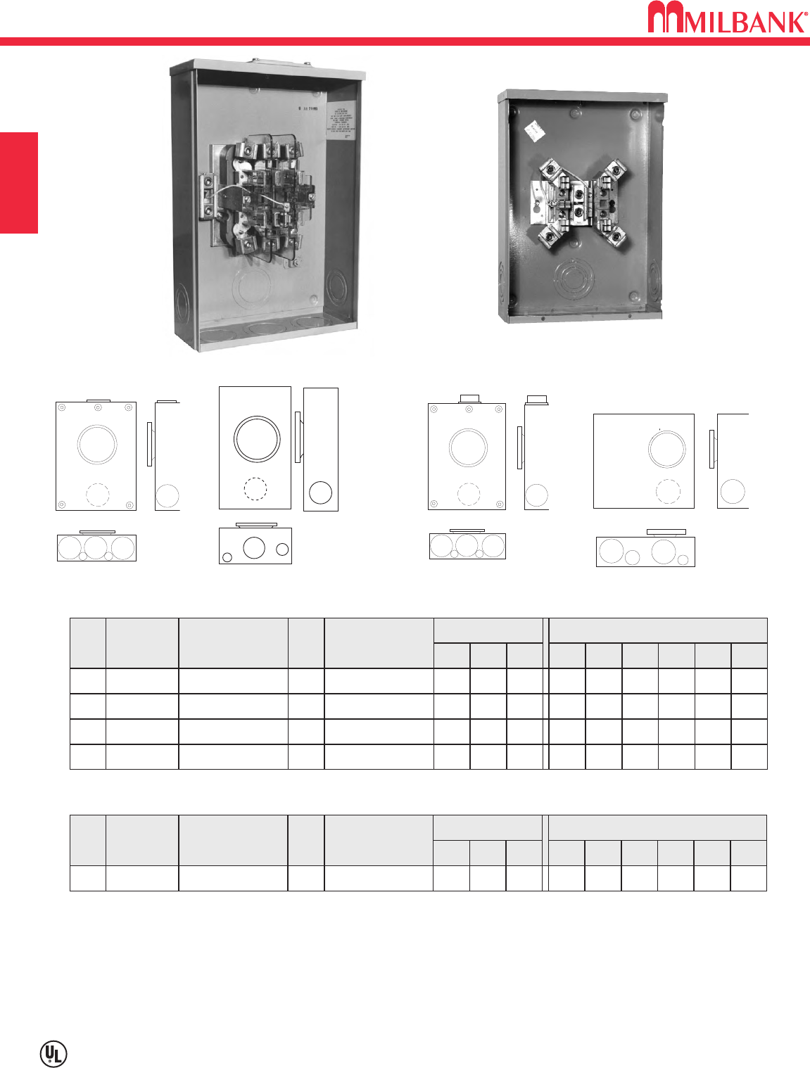
200 AMP—4 & 7 TERMINAL—SINGLE POSITION—RING TYPE—600 VAC
B4
Utility requirements for this equipment may vary. Always consult the serving utility for their requirements before ordering or
installing equipment in this catalog.
B4
METER SOCKETS SECTION B
FIFTH TERMINAL: For field mounted fifth terminal order catalog number K5T to fit into square opening at the 9 oʼclock
position.
HUBS: For proper hub selection see the hub suffix chart on the accessory page.
CONNECTORS: Extruded aluminum connectors are tin plated.
SEALING RINGS: The above ring type units are supplied with an MR-4 screw type sealing ring as standard.
12
34 4
56
3328
2
346
5
1
4015
12
3
56
4518
AMP SERVICE CATALOG
NUMBER HUB CONNECTORS
CU/AL
DIMENSIONS CONCENTRIC K.O.ʼS
1 2 3 4 5 6D" W" H"
200 OH U4517-DL-M4 2" 21
⁄
221
⁄
221
⁄
2—1
⁄
41
⁄
4,1
⁄
2
41
⁄
88151
⁄
2
#6-350
200 OH/UG U4518-XL-W C.P. 2 2 2 21
⁄
21
⁄
4,1
⁄
2
1
⁄
4
41
⁄
811 151
⁄
2
#6-350
200 UG U4518-O-W BLANK 2 2 2 21
⁄
21
⁄
4,1
⁄
2
1
⁄
4
41
⁄
811 151
⁄
2
#6-350
200 UG U4015-O BLANK 21
⁄
221
⁄
2311
⁄
221
⁄
21
⁄
4,1
⁄
2
614 161
⁄
4
#6-350
200 AMP–SINGLE POSITION–4 TERMINAL–RING TYPE
200 AMP–7 TERMINAL–RING TYPE
AMP
200
SERVICE CATALOG
NUMBER HUB
OH/UG U3328-RXL C.P.
CONNECTORS
CU/AL
DIMENSIONS CONCENTRIC K.O.ʼS
1 2 3 4 5 6
321
⁄
23 3 1
⁄
41
⁄
4,1
⁄
2
D" W" H"
47
⁄
813 19#6-350
12
33 4
56
4517
U3328-RXL
U4518-O-W
B5
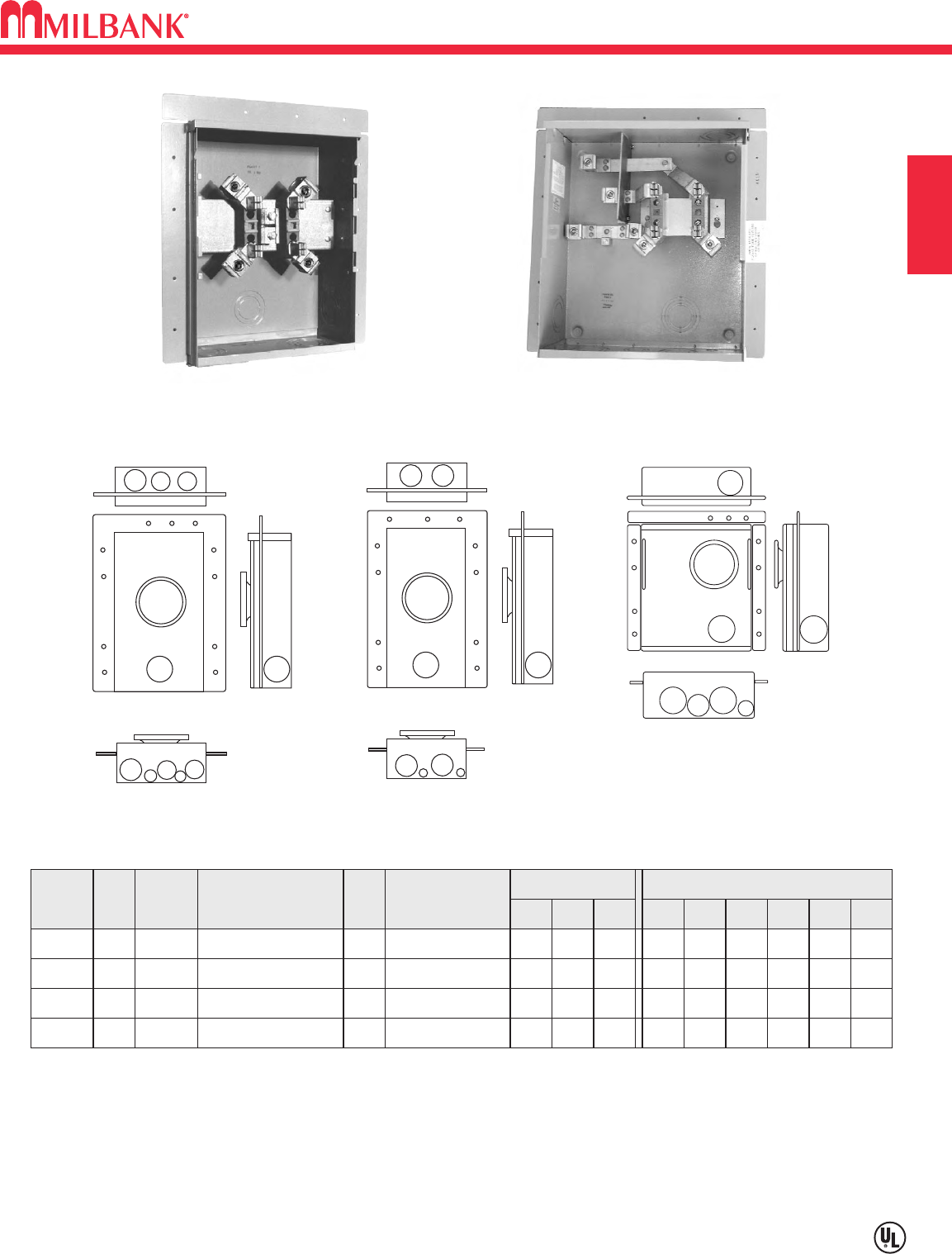
200 AMP—4 TERMINAL–FLUSH MOUNT—SINGLE POSITION–RING TYPE—600 VAC
Utility requirements for this equipment may vary. Always consult the serving utility for their requirements before ordering or
installing equipment in this catalog.
B5
METER SOCKETS
SECTION B
200 AMP—4 (1∅3W) TERMINAL—FACTORY WELDED FLUSH MOUNT—RING TYPE
AMP
SERVICE
CATALOG
NUMBER HUB CONNECTORS
CU/AL
DIMENSIONS CONCENTRIC K.O.ʼS
1 2 3 4 5 6D" W" H"
TERM.
200
200
OH
OH/UG
UF4517-KO
UF4518-KO
K.O.
K.O.
2
2
2
2
2
21
⁄
2
2
2
1
⁄
4
1
⁄
4,1
⁄
2
1
⁄
4,1
⁄
2
1
⁄
4
51
⁄
8
51
⁄
8
8
11
151
⁄
2
151
⁄
2
#6-350
#6-350
200 UG UF4015-KO K.O. 21
⁄
221
⁄
221
⁄
221
⁄
211
⁄
21
⁄
4,1
⁄
2
514 161
⁄
4
#6-350
200
4
4
4
4UG UF4969-KO* K.O. 21
⁄
221
⁄
221
⁄
2311
⁄
21
⁄
4,1
⁄
2
71
⁄
214 161
⁄
4
#6-350
FIFTH TERMINAL: For field mounted fifth terminal order catalog number K5T to fit into square opening at the 9 oʼclock position.
CONNECTORS: Extruded aluminum connectors are tin plated.
SEALING RINGS: Ring type units supplied with an MR-4 screw type sealing ring as standard.
* UF4969 can only be used in a 2 x 6 wall.
12
3
6
4
4
5
3
4517
12
3
43
56
4015
4969
12
34 4
344
56
4518
UF4518-KO UF4015-KO
200 AMP—4 & 5 TERMINAL—SINGLE POSITION—RINGLESS
NON-JAW CLAMPING LEVER BYPASS—600 VAC
B6
Utility requirements for this equipment may vary. Always consult the serving utility for their requirements before ordering or
installing equipment in this catalog.
B6
METER SOCKETS
TERM SERVICE CATALOG
NUMBER HUB
CONNECTORS
CU/AL
LINE & LOAD
BY-
PASS
DIMENSIONS CONCENTRIC K.O.ʼS
123456D" W" H"
4OH/UG U1211-RXL C.P. LEVER 321
⁄
23 3 1
⁄
41
⁄
4,1
⁄
247
⁄
813 19#6-350
5OH/UG U9319-XL C.P. LEVER 321
⁄
23 3 1
⁄
41
⁄
4,1
⁄
247
⁄
813 19#6-350
200 AMP—4 & 5 TERMINAL—RINGLESS—1∅3W OR 3∅3W
1
5
5
3
4
6
2
4
U9319-XL
1211
9319
FIFTH TERMINAL: For field mounted fifth terminal, order as extra K3866 for the U1211.
HUBS: For proper hub selection see the hub suffix chart on the accessory page.
BYPASS: 200 amp continuous duty bypass. Lever operates bypass only. Not jaw clamping.
CONNECTORS: Units are supplied with extruded aluminum connectors and bonded, triplex neutral.
FIFTH TERMINAL: Fifth terminal is not available for this unit.
TRIPLEX GROUND: Factory installed as standard.
TERM SERVICE CATALOG
NUMBER HUB
CONNECTORS
CU/AL
LINE & LOAD
BY-
PASS
DIMENSIONS CONCENTRIC K.O.ʼS
123456D" W" H"
4OH/UG U3852-XL C.P. LEVER 321
⁄
221
⁄
221
⁄
21
⁄
41
⁄
4,1
⁄
247
⁄
813 19#2-350
200 AMP—4 TERMINAL—RINGLESS—1∅3W
2
3
4
6
4
5
1
3852
SECTION B
B7
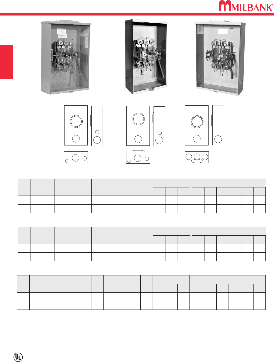
125-200 AMP–7 TERMINAL–SINGLE POSITION–RINGLESS
NON-JAW CLAMPING LEVER BYPASS–600 VAC
Utility requirements for this equipment may vary. Always consult the serving utility for their requirements before ordering or
installing equipment in this catalog.
B7
METER SOCKETS
12
3
56
6
1
5
5
3
4
6
2
4
7573
8100
9320
7422
7423
HUBS: For proper hub selection, see hub suffix chart in accessories page.
BYPASS: 200 amp continuous duty bypass. Lever operates bypass only. Not jaw clamping.
CONNECTORS: Extruded aluminum connectors are tin plated. Units supplied with bonded, duplex neutral.
125 AMP—7 TERMINAL—RINGLESS—3∅4W
AMP
125
125
125
SERVICE CATALOG
NUMBER HUB
OH
OH
OH/UG
U7573-RL
U8100-RL
U9320-RXL
H.O.
H.O.
C.P.
CONNECTORS
CU/AL
BY-
PASS
LEVER
NONE
LEVER
DIMENSIONS CONCENTRIC K.O.ʼS
1 2 3 4 5 6
2
2
3
2
2
21
⁄
2
2
2
3
—
—
3
1
⁄
4,1
⁄
2
1
⁄
4,1
⁄
2
1
⁄
4
3
⁄
4
3
⁄
4
1
⁄
4,1
⁄
2
D" W" H"
47
⁄
8
47
⁄
8
47
⁄
8
10
10
13
181
⁄
2
181
⁄
2
19
#6-2/0
#6-2/0
#6-2/0
200 AMP—7 TERMINAL—RINGLESS—3∅4W
AMP SERVICE CATALOG
NUMBER HUB CONNECTORS
CU/AL
BY-
PASS
DIMENSIONS CONCENTRIC K.O.ʼS
1 2 3 4 5 6D" W" H"
200 OH/UG U7422-RXL C.P. NONE 321
⁄
23 3 1
⁄
41
⁄
4,1
⁄
2
47
⁄
813 19#6-350
200 OH/UG U7423-RXL C.P. LEVER 321
⁄
23 3 1
⁄
41
⁄
4,1
⁄
2
47
⁄
813 19#6-350
U7573-RL U7423-RXL
SECTION B
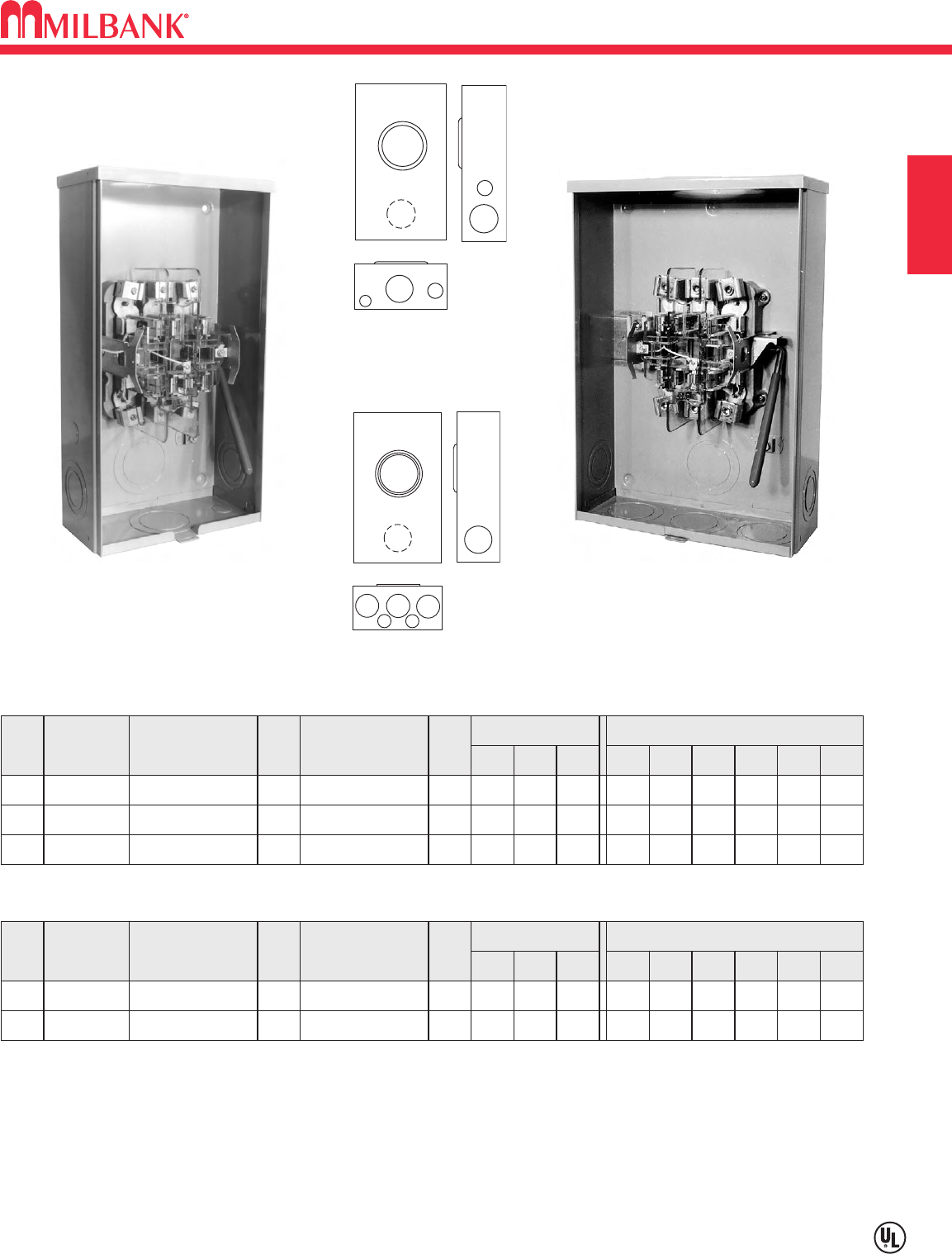
200 AMP—4, 5 & 7 TERMINAL—SINGLE POSITION—RINGLESS
JAW CLAMPING LEVER BYPASS–600 VAC
B8
Utility requirements for this equipment may vary. Always consult the serving utility for their requirements before ordering or
installing equipment in this catalog.
B8
METER SOCKETS SECTION B
200 AMP—5 TERMINAL—RINGLESS—1∅3W OR 3∅3W
AMP
200
200
SERVICE CATALOG
NUMBER HUB
OH
OH/UG
U9550-RRL
U9551-RXL
H.O.
C.P.
CONNECTORS
CU/AL
BY-
PASS
LEVER
LEVER
DIMENSIONS CONCENTRIC K.O.ʼS
1 2 3 4 5 6
3
3
21
⁄
2
21
⁄
2
3
3
—
3
1
⁄
4,1
⁄
2
1
⁄
4
3
⁄
4
1
⁄
4,1
⁄
2
D" W" H"
47
⁄
8
47
⁄
8
10
13
181
⁄
2
19
#6-350
#6-350
200 AMP—4 TERMINAL—RINGLESS—1∅3W OR 3∅3W
AMP
200
200
SERVICE CATALOG
NUMBER HUB
OH
OH/UG
U9800-RRL
U9801-RXL
H.O.
C.P.
CONNECTORS
CU/AL
BY-
PASS
LEVER
LEVER
DIMENSIONS CONCENTRIC K.O.ʼS
1 2 3 4 5 6
3
3
21
⁄
2
21
⁄
2
3
3
—
3
1
⁄
4,1
⁄
2
1
⁄
4
3
⁄
4
1
⁄
4,1
⁄
2
D" W" H"
47
⁄
8
47
⁄
8
10
13
181
⁄
2
19
#6-350
#6-350
200 AMP—7 TERMINAL—RINGLESS—3∅4W
AMP
200
200
SERVICE CATALOG
NUMBER HUB
OH
OH/UG
U9700-RRL
U9701-RXL
H.O.
C.P.
CONNECTORS
CU/AL
BY-
PASS
LEVER
LEVER
DIMENSIONS CONCENTRIC K.O.ʼS
1 2 3 4 5 6
3
3
21
⁄
2
21
⁄
2
3
3
—
3
1
⁄
4,1
⁄
2
1
⁄
4
3
⁄
4
1
⁄
4,1
⁄
2
D" W" H"
47
⁄
8
47
⁄
8
10
13
181
⁄
2
19
#6-350
#6-350
1
5
5
3
4
6
2
4
9551
9701
HUBS: For proper hub selection, see hub suffix chart in accessories page.
BYPASS: Lever supplies clamping action and also operates bypass device.
CONNECTORS: Extruded aluminum connectors are tin plated. U9550 and U9551 units are supplied with duplex neutral, with
removable bonding strap for insulated neutral. U9700 series units are supplied with duplex neutral.
Internal Hex Connectors. For main and/or service disconnect, use with U5484-O enclosed circuit breaker.
U9701-RXL U9551-RXL
12
3
56
6
9550
9700
U9800-RRL
12
3
5
6
6
9800
B9
125-200 AMP—4 & 7 TERMINAL
MANUAL CIRCUIT CLOSING BLOCKS—RING TYPE—600 VAC
Utility requirements for this equipment may vary. Always consult the serving utility for their requirements before ordering or
installing equipment in this catalog.
B9
METER SOCKETS
SECTION B
125 AMP—RING TYPE
SERVICETERM. CATALOG
NUMBER HUB
OH/UG4
OH/UG7
U3504-XL
U3507-XL
C.P.
C.P.
CONNECTORS
CU/AL BY-
PASS
LINK
LINK
DIMENSIONS CONCENTRIC K.O.ʼS
123456
2
2
2
2
2
2
2
2
—
1
⁄
4
1
⁄
4
—
D" W" H"
47
⁄
8
47
⁄
8
10
10
181
⁄
2
21
#6-2/0
#6-2/0
200 AMP—RING TYPE
4
7
SERVICETERM. CATALOG
NUMBER HUB
OH/UG
OH/UG
C.P.
C.P.
CONNECTORS
CU/AL BY-
PASS
LINK
LINK
DIMENSIONS CONCENTRIC K.O.ʼS
1 2 3 4 5 6
21
⁄
2
21
⁄
2
21
⁄
2
21
⁄
2
3
21
⁄
2
3
21
⁄
2
1
⁄
4
1
⁄
4
1
⁄
2
1
⁄
2
D" W" H"
47
⁄
8
47
⁄
8
13
13
21
241
⁄
2
#6-350
#6-350
1
5
3
2
44
6
U3504-XL U3517-XL
FIFTH TERMINAL: For field mounted fifth terminal order catalog number 5T8K2 for the U3504; order K5T for the U3514.
CONNECTORS: Extruded aluminum connectors are tin plated.
SEALING RINGS: Ring type units supplied with an MR-4 screw type sealing ring as standard.
LINK BYPASS: Links provided by utility.
U3514-XL
U3517-XL
3504
3507
3514
3517
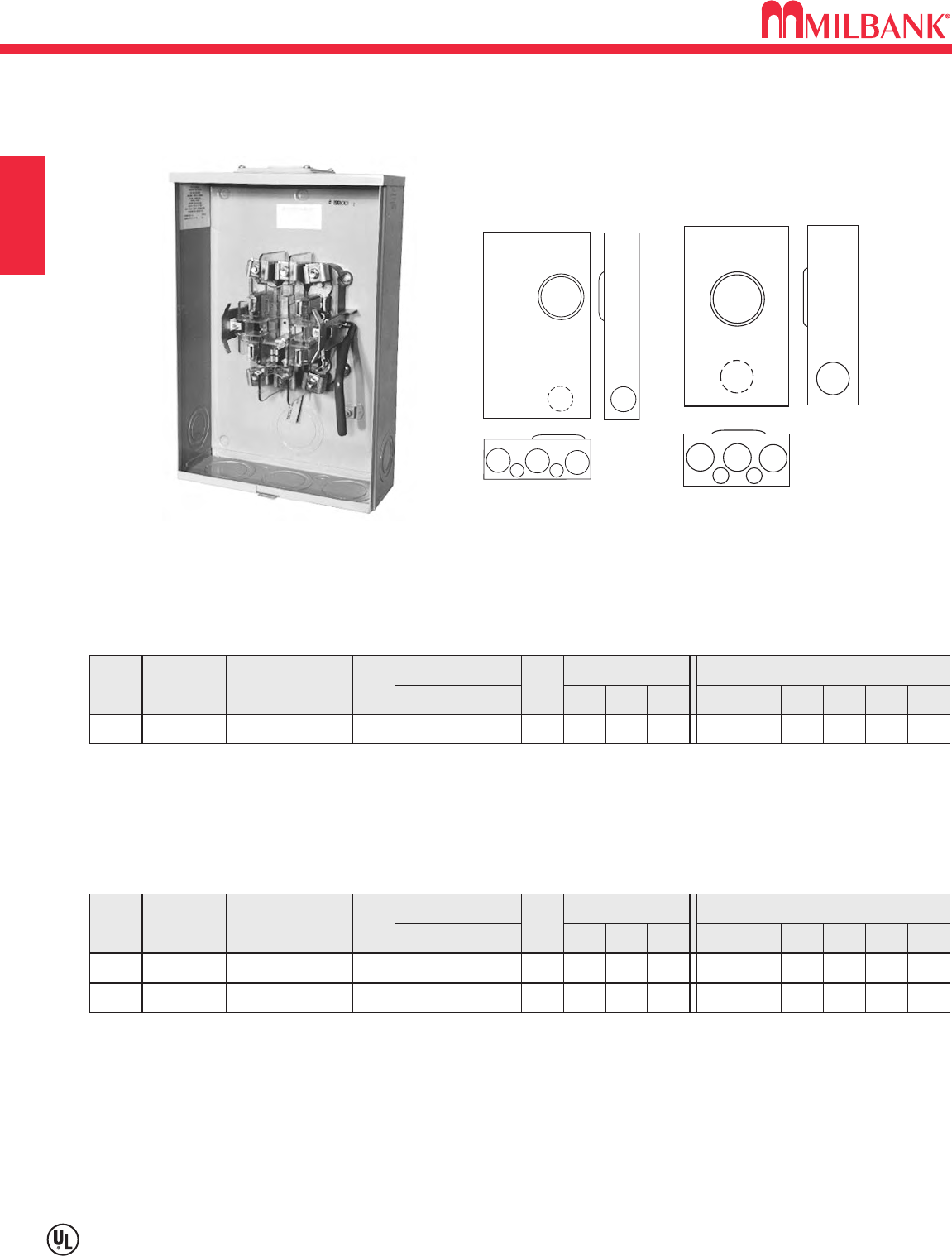
320 AMP—4 TERMINAL—SINGLE POSITION—RINGLESS—600 VAC
B10
Utility requirements for this equipment may vary. Always consult the serving utility for their requirements before ordering or
installing equipment in this catalog.
B10
METER SOCKETS
TWIN
#6-350
TWIN
#6-350
HUBS: For proper hub selection, see hub suffix chart in accessories page.
BYPASS: *Lever supplies clamping action on meter spades only on the U1431, U1432 and U1819. Lever supplies clamping
action and also operates bypass device on the U1079, U1129 & U1797.
CONNECTOR KITS: Stud type units are supplied with 3
⁄
8"-16 hex head nuts with Belleville washers. Order two connector kits to
cover both line and load. Order K1539 (single #350), K1540 (single #600) or K1350 (twin #350). See accessories page.
NOTE: The U1129 unit has a single connector on the line side only.
FIFTH TERMINAL: For field mounted fifth terminal, order as extra K3866 for the U1079 & U1431. Order as extra K3865 for units
U1129, U1432, U1819, and U1797.
LUG SIZE RANGE: See accessories page for lug size range for the U1129 & U1797 units.
320 AMP—4 TERMINAL—RINGLESS—600 VAC
AMP
320
320
SVC. CATALOG
NUMBER HUB
OH
UG
U1079-R
U1129-O-K3L-K2L
H.O.
BLANK
CONNECTORS
CU/AL
LINE LOAD
BY-
PASS
LEVER
LEVER
DIMENSIONS CONCENTRIC K.O.ʼS
1 2 3 4 5 6
3
3
21
⁄
2
21
⁄
2
3
3
3
3
1
⁄
4
1
⁄
4
1
⁄
4,1
⁄
2
1
⁄
4,1
⁄
2
D" W" H"
47
⁄
8
47
⁄
8
13
15
383
⁄
4
30
3
⁄
8"-16 STUDS
#4-600 or
(2) 1/0-250
320 OH/UG U1431-R* H.O. NONE 321
⁄
23 3 1
⁄
41
⁄
4,1
⁄
2
47
⁄
813 383
⁄
4
3
⁄
8"-16 STUDS
320 UG U1432-O*
BLANK
NONE 321
⁄
23 3 1
⁄
41
⁄
4,1
⁄
2
47
⁄
813 293
⁄
4
3
⁄
8"-16 STUDS
320 UG U1819-X* C.P. NONE 3 3 3 3 1
⁄
41
⁄
4,1
⁄
2
47
⁄
815 30
3
⁄
8"-16 STUDS
320 UG
U1797-O-K3L-K2L
FIFTH
TERM.
K3866
K3865
K3866
K3865
K3865
K3865
BLANK LEVER
3 3 3 3 1
⁄
41
⁄
4,1
⁄
2
47
⁄
815 30
#4-600 or
(2) 1/0-250
2
3
4
6
4
5
1
1129
1797
1819
1
6
5
3
34
2
1079
1432
1431
U1797-O-K3L-K2L U1129-O-K3L-K2L
400 AMP MAX
320 AMP CONTINUOUS
SECTION B
B11
320 AMP—4 & 7 TERMINAL—SINGLE POSITION–RINGLESS / RING TYPE—600 VAC
Utility requirements for this equipment may vary. Always consult the serving utility for their requirements before ordering or
installing equipment in this catalog.
B11
METER SOCKETS
SECTION B
320 AMP—4 TERMINAL—LINK BYPASS—RING TYPE—1∅3W
SERVICE CATALOG
NUMBER
OH/ UG
UG
U3548-X*
U5056-O**
HUB
C.P.
BLANK
CONNECTORS
CU/AL
LOAD
BY-
PASS
LINK
LINK
DIMENSIONS CONCENTRIC K.O.ʼS
123456
3
3
3
—
3
4
3
1
⁄
4,1
⁄
2
1
⁄
4
1
⁄
4
1
⁄
4,1
⁄
2
—
D" W" H"
6
6
14
24
33
32
#4-600 or
twin 1/0-250
LINE
SINGLE = 4-600
PARALLEL = 1/0-250
BYPASS: Lever supplies clamping action on meter spades and operates bypass device.
CONNECTOR KITS: Stud type units are supplied with 3
⁄
8"-16 hex head nuts with Belleville washers. Order two connector kits to
cover both line and load. For single lug connector kits for the U2120 and U2594 units, order as extra K3082 (350 kcmil) or
K3441 (600 kcmil). For twin lug connectors order as extra: K3442 (350 kcmil). Separate kits are required for both line and load.
320 AMP—7 TERMINAL—SIDE WIREWAY—RINGLESS
AMP
320
SERVICE CATALOG
NUMBER HUB
UG U2120-X C.P.
CONNECTORS
CU/AL
BY-
PASS
LEVER
DIMENSIONS CONCENTRIC K.O.ʼS
1 2 3 4 5 6
4 3 4 4 1
⁄
41
D" W" H"
61
⁄
2173
⁄
4313
⁄
4
3
⁄
8"-16 STUDS
320 OH/UG U2594-X C.P. LEVER —3 4 4 1
⁄
41
⁄
2,3
⁄
4,1
61
⁄
219 341
⁄
8
3
⁄
8"-16 STUDS
1
5
3
2
44
6
1
3548
U3548-X
U5056-O
12
34
5
6
2120
2594
U2120-X
SEALING RING: Ring type units are supplied with an MR-4, screw type, sealing ring as standard.
TRIPLE TAP LUG: For triple tap lug kit order K5049.
LINK BYPASS: Links provided by utility.
*FLUSH MOUNT KIT: For field mounted flush mount kit order K4086.
**This is a PP&L approved unit.
1
⁄
2"-13 STUDS
3 3
4
5
1
5056
100-125 AMP—4 TERMINAL—HORIZONTAL GANGS–RINGLESS / RING TYPE—300 VAC
B12
Utility requirements for this equipment may vary. Always consult the serving utility for their requirements before ordering or
installing equipment in this catalog.
B12
METER SOCKETS SECTION B
100 AMP / POSITION—CONTINUOUS—4 TERMINAL—RINGLESS
NO.
OF
POS.
2
3
4
SERVICE CATALOG
NUMBER HUB
OH/UG
OH/UG
OH/UG
U8032-XL
U8033-XL
U8034-XL
C.P.
C.P.
C.P.
CONNECTORS
CU/AL
LINE LOAD
DIMENSIONS CONCENTRIC K.O.ʼS
1 2 3 4 5 6 7
2
2
2
2
2
2
21
⁄
2
21
⁄
2
21
⁄
2
2
(3) 2
(4) 2
1
⁄
2
1
⁄
2
1
⁄
2
1
⁄
4,1
⁄
25
⁄
16
5
⁄
16
5
⁄
16
5
⁄
16
5
⁄
16
1
⁄
4,1
⁄
2
1
⁄
4,1
⁄
2
D" W" H"
41
⁄
2
41
⁄
2
41
⁄
2
241
⁄
2
323
⁄
4
407
⁄
8
16
16
16
#2-350 #6-2/0
#6-2/0
#6-2/0
#6-2/0
#6-2/0
#2-350
#2-350
5OH/UG U8035-XL C.P. 2 2 21
⁄
2(5) 21
⁄
21
⁄
4,1
⁄
2
41
⁄
2491
⁄
16 16
#2-350
6OH/UG U8036-XL C.P. 2 2 21
⁄
2(6) 21
⁄
21
⁄
4,1
⁄
2
41
⁄
2571
⁄
416
#2-350
125 AMP / POSITION—CONTINUOUS—4 TERMINAL—RING TYPE
NO.
OF
POS.
2
3
4
SERVICE CATALOG
NUMBER HUB
OH/UG
OH/UG
OH/UG
U3522-XL-K1
U3523-XL-K1
U3524-XL-K2
C.P.
C.P.
C.P.
CONNECTORS
CU/AL
LINE LOAD
DIMENSIONS CONCENTRIC K.O.ʼS
1 2 3 4 5 6
11
⁄
2
11
⁄
2
11
⁄
2
11
⁄
2
11
⁄
2
11
⁄
2
21
⁄
2
21
⁄
2
21
⁄
2
21
⁄
2
(3)21
⁄
2
(4)21
⁄
2
1
⁄
4,1
⁄
2
1
⁄
4,1
⁄
2
1
⁄
4,1
⁄
2
—
—
—
D" W" H"
41
⁄
2
41
⁄
2
41
⁄
2
241
⁄
2
323
⁄
4
407
⁄
8
14
14
14
#2-350 #6-2/0
#6-2/0
#6-2/0
#6-2/0
#2-350
#2-350
5UG U3525-XL-K2* C.P. 11
⁄
211
⁄
221
⁄
2(5)21
⁄
21
⁄
4,1
⁄
2—
41
⁄
2491
⁄
16 16
#2-350
112
3
556
644
77
77
1112
3
55
44
8032 3522
*FOR OVERHEAD SERVICE: The U3525 is factory configured for underground service. If overhead service is desired,
an extension kit is required. Order separately, catalog number K3937.
FIFTH TERMINAL: For field mounted fifth terminal, order catalog number 5T8K2 (6 oʼclock only on 100 amp units,
9 oʼclock only on 125 amp units.)
HUBS: For proper hub selection, see the hub suffix chart in accessories page.
SEALING RINGS: Ring type units are supplied with one MR-4 screw type sealing ring per position.
MAIN BUS RATING: See general engineering page.
U8032-XL U3522-XL
B13
200 AMP—4 TERMINAL—HORIZONTAL GANGS–RINGLESS / RING TYPE—300 VAC
Utility requirements for this equipment may vary. Always consult the serving utility for their requirements before ordering or
installing equipment in this catalog.
B13
METER SOCKETS
SECTION B
200 AMP / POSITION—4 TERMINAL—RINGLESS
NO.
OF
POS.
2
3
4
SERVICE CATALOG
NUMBER HUB
OH/UG
OH/UG
UG
U1252-X-K1
U1253-X-K3
U1254-X-K3*
C.P.
C.P.
C.P.
CONNECTORS
CU/AL
LINE LOAD
DIMENSIONS CONCENTRIC K.O.ʼS
123456
21
⁄
2
21
⁄
2
21
⁄
2
3
3
3
21
⁄
2
(3)21
⁄
2
(4)21
⁄
2
1
⁄
2
1
⁄
2
1
⁄
2
1
⁄
4
1
⁄
4
1
⁄
4
1
1
1
D" W" H"
51
⁄
8
51
⁄
8
51
⁄
8
261
⁄
2
343
⁄
4
427
⁄
8
14
14
16
#6-350 #2-350
#2-350
#2-350
#2-350
#2-350
#4-600
#4-600
5UG U1255-X-K4* C.P. 21
⁄
23(5)21
⁄
21
⁄
21
⁄
41
51
⁄
8547
⁄
816
(2)#2-600
6UG U1256-X-K4* C.P. 21
⁄
23(6)21
⁄
21
⁄
21
⁄
41
51
⁄
8631
⁄
16 18
(2)#2-600
200 AMP / POSITION—4 TERMINAL—RING TYPE
NO.
OF
POS.
2
3
SERVICE CATALOG
NUMBER HUB
OH/UG
OH/UG
U3532-X-K1
U3533-X-K3
C.P.
C.P.
CONNECTORS
CU/AL
LINE LOAD
DIMENSIONS CONCENTRIC K.O.ʼS
1 2 3 4 5 6
21
⁄
2
21
⁄
2
3
3
21
⁄
2
(3)21
⁄
2
—
—
1
⁄
4
1
⁄
4
1
1
D" W" H"
51
⁄
8
51
⁄
8
261
⁄
2
343
⁄
4
14
14
#6-350 #2-350
#2-350#4-600
*FOR OVERHEAD SERVICE: These units are factory configured for underground service. If overhead service is
desired, an extension kit is required. Order as extra, K3923 (4 & 5 position), K3955 (6 position).
FIFTH TERMINAL: For field mounted fifth terminal order catalog number K5T to fit into square opening at the 9 oʼclock
position.
HUBS: For proper hub selection, see the hub suffix chart in accessories page.
SEALING RINGS: Ring type units are supplied with one MR-4 screw type sealing ring per position.
MAIN BUS RATING: See general engineering page. U1252 & U3532
only
rated 400 amp overall.
111
2
33
56
4 4
111
2
35
6
44
1
33
4
U1252-X-K1
1253-6
3533-6
1252
3532
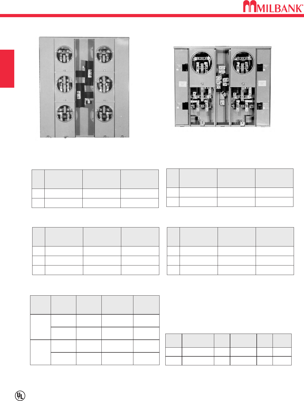
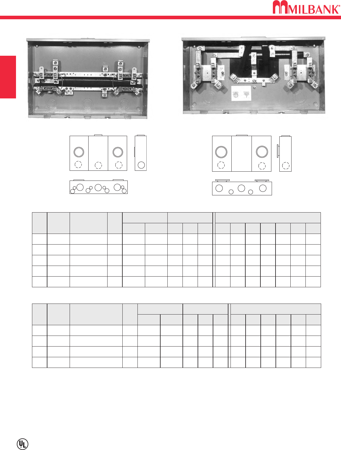
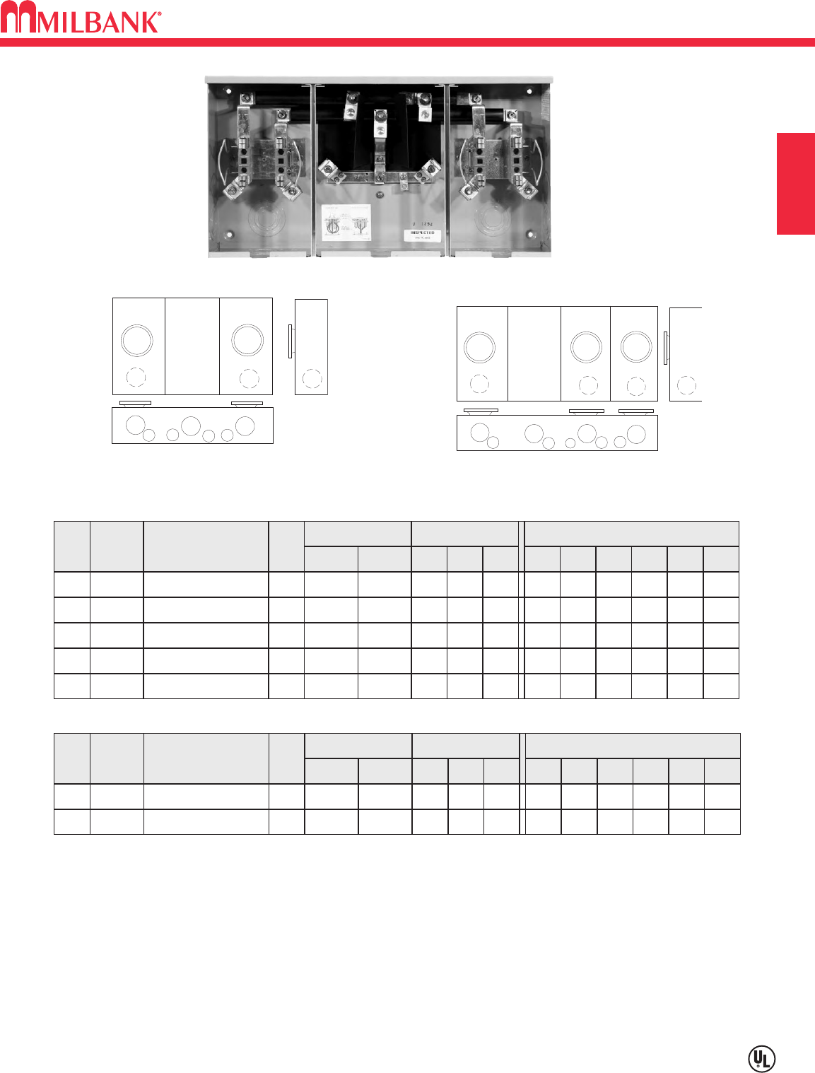
CONDOMINIUM METERING BANKS—RINGLESS
B14
Utility requirements for this equipment may vary. Always consult the serving utility for their requirements before ordering or
installing equipment in this catalog.
B14
CONDOMINIUM METERING BANKS—RINGLESS SECTION B
CATALOG
NUMBER
NO.
OF
POS.
MAIN BUS
RATING
LINE
CONNECTOR
SIZE
CATALOG
NUMBER
NO.
OF
POS.
MAIN BUS
RATING
LINE
CONNECTOR
SIZE
2
3
U2852-X 200 AMP
U2853-X 200 AMP
*3/8"-16 STUD
*3/8"-16 STUD
2
3
U2862-X 250 AMP
U2863-X 300 AMP
*3/8"-16 STUD
*3/8"-16 STUD
125 AMP/POSITION 200 AMP/POSITION
U2854-X-4/125
(Order circuit breakers as extra)
U2866-X
CATALOG
NUMBER
NO.
OF
POS.
4
5
6
MAIN BUS
RATING
LINE
CONNECTOR
SIZE
U2854-X 400 AMP
U2855-X 400 AMP
U2856-X 400 AMP
*3/8"-16 STUD
*3/8"-16 STUD
*3/8"-16 STUD
CATALOG
NUMBER
NO.
OF
POS.
4
5
6
MAIN BUS
RATING
LINE
CONNECTOR
SIZE
U2864-X 400 AMP
U2865-X 600 AMP
U2866-X 600 AMP
*3/8"-16 STUD
*3/8"-16 STUD
*3/8"-16 STUD
SIZE SUFFIX
SINGLE
TWIN
K1539-K1
-K3
-K2
-K4
K1540
K1350
K1541
U2852-56
U2862-66
U2854-56
U2864-66
U2854-56
U2863-66
U2864-66
#6-350
#4-600
#6-350
#2-600
KIT
NUMBER
COMPATIBLE
WITH
WIRE
RANGE
*CONNECTORS: For line wire connector kits, order separately.
FIFTH TERMINALS: For field mounted fifth terminal order catalog
number K2381. Order one per meter position (9 oʼclock position
only).
BREAKERS: Units have provision for one double pole main per
meter position. Breakers not included. Order as extra Milbank.
125 AMP/POSITION 200 AMP/POSITION
CONNECTOR KITS *
VERTICAL
RECTANGULAR
PLUG-IN BREAKER COMPATIBILITY CHART
AMPS
CUTLER-HAMMER
(WESTINGHOUSE)
SIEMENS
(ITE)
SIEMENS
MURRAY /
CROUSE-HINDS
G.E.
SQ-D
125-200
HQP / BR / WBJ
—
MD
THQ
—
≤ 100
QP / BR / HQP
QP
MP
THQ
HOMELINE
B15
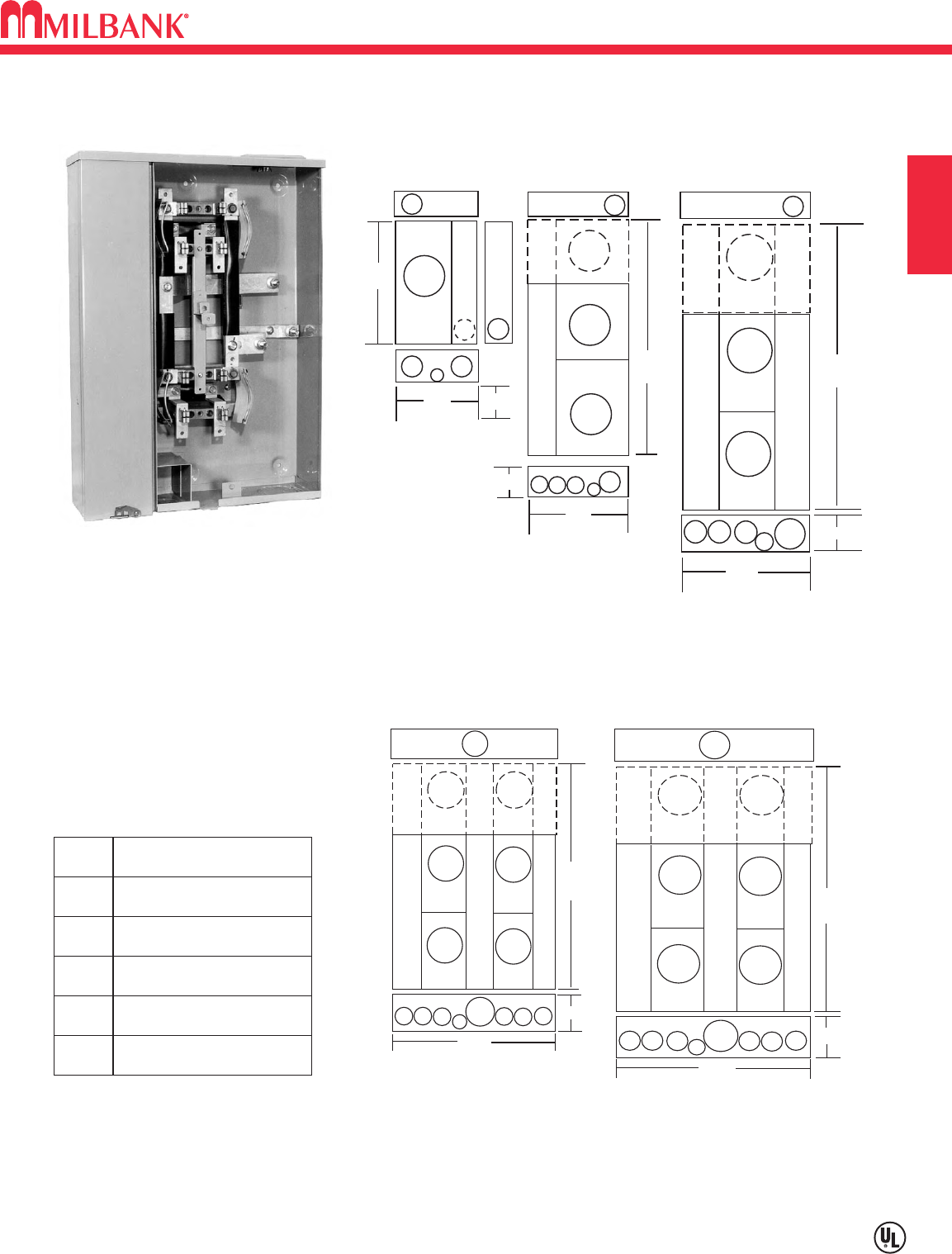
CONDOMINIUM METERING BANKS
Utility requirements for this equipment may vary. Always consult the serving utility for their requirements before ordering or
installing equipment in this catalog.
B15
CONDOMINIUM METERING BANKS
SECTION B
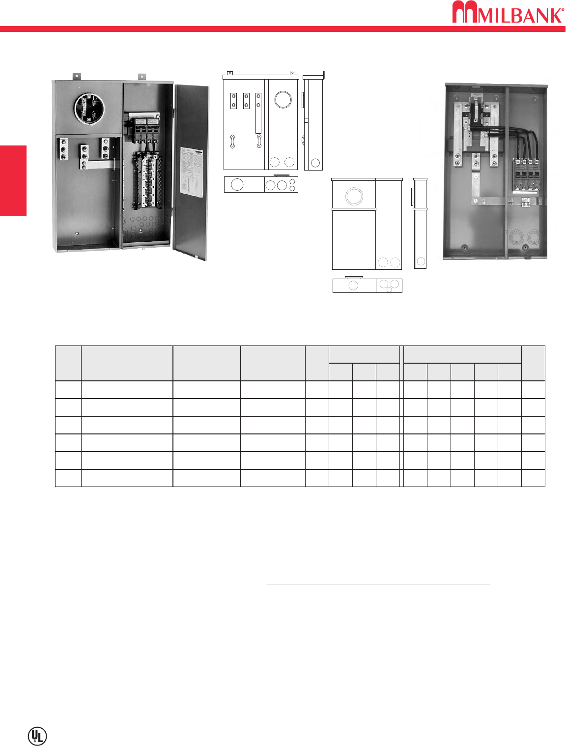
AA
C
B
E
E
E
B
CC
DDD
B
EE E C
29" or
41"
5 13/16"
13"
or
18"
21"
25" or
37"
5 13/16"
18"
21"
5 13/16"
C
B
D
A
C
B
D
EE E EEE
AAA A
A
29" or
41"
4 7/8"
36"
37" or
25"
4 7/8"
31"
VERTICAL
RECTANGULAR
125 &200 amp/pos.
(single position)
125 amp/pos.
(2-3 position)
200 amp/pos.
(2-3 position)
125 amp/pos.
(4,5 & 6 position)
200 amp/pos.
(4,5 & 6 position)
CONDOMINIUM
METERING BANKS
U2852-X
FIG.
A
B
C
D
E
DIMENSIONS
11
⁄
4"CONCENTRIC K.O.
1
⁄
4,1
⁄
2"CONCENTRIC K.O.
3"CONCENTRIC K.O.
4"HUB OPENING
2"CONCENTRIC K.O.

NOTES
B16
B16
NOTES SECTION B
C1
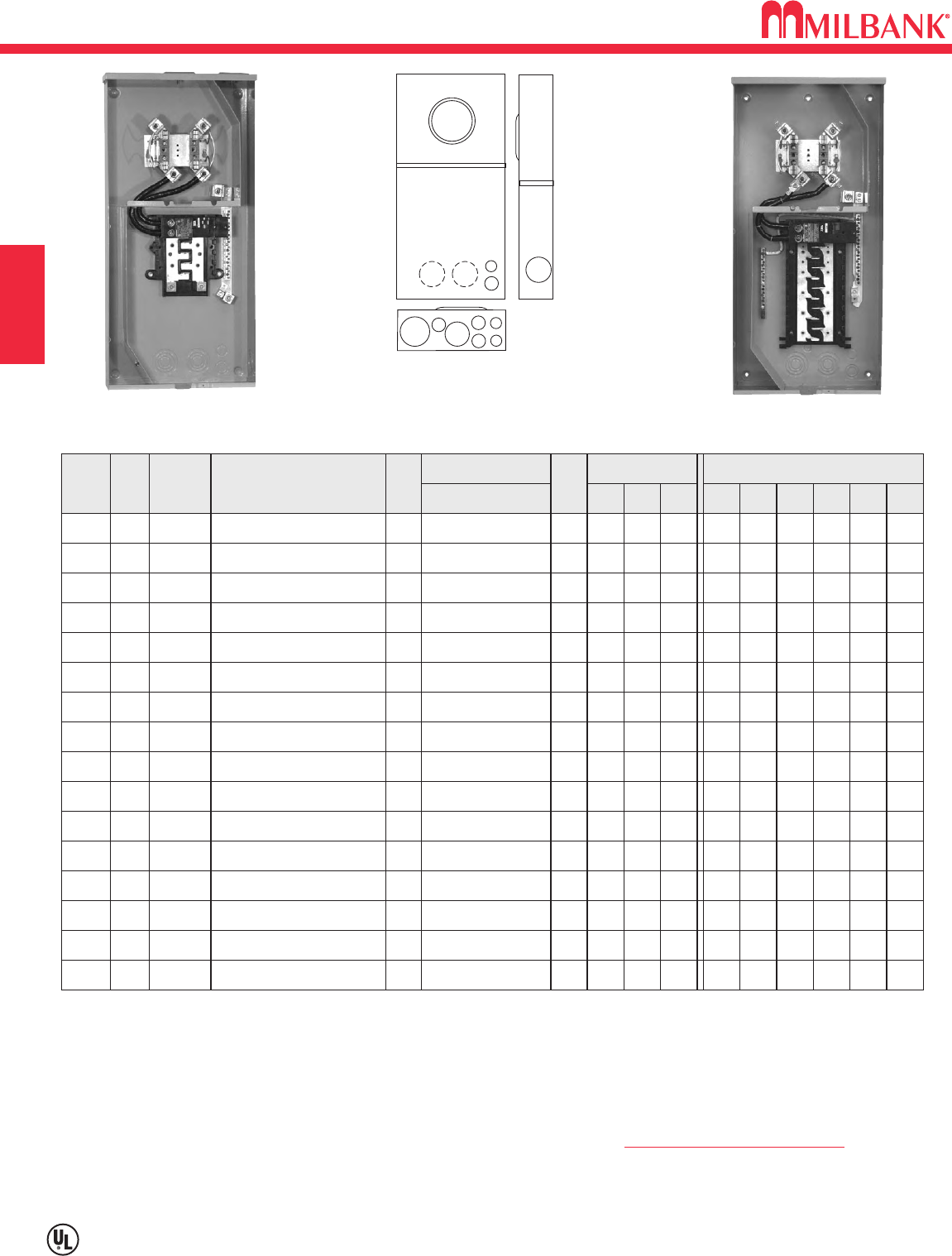
200 AMP—4 & 7 TERMINAL—METER MAIN—RING TYPE—240 VOLT
Utility requirements for this equipment may vary. Always consult the serving utility for their requirements before ordering or
installing equipment in this catalog.
C1
METER MAINS AND SERVICE ENTRANCE EQUIPMENT
SECTION C
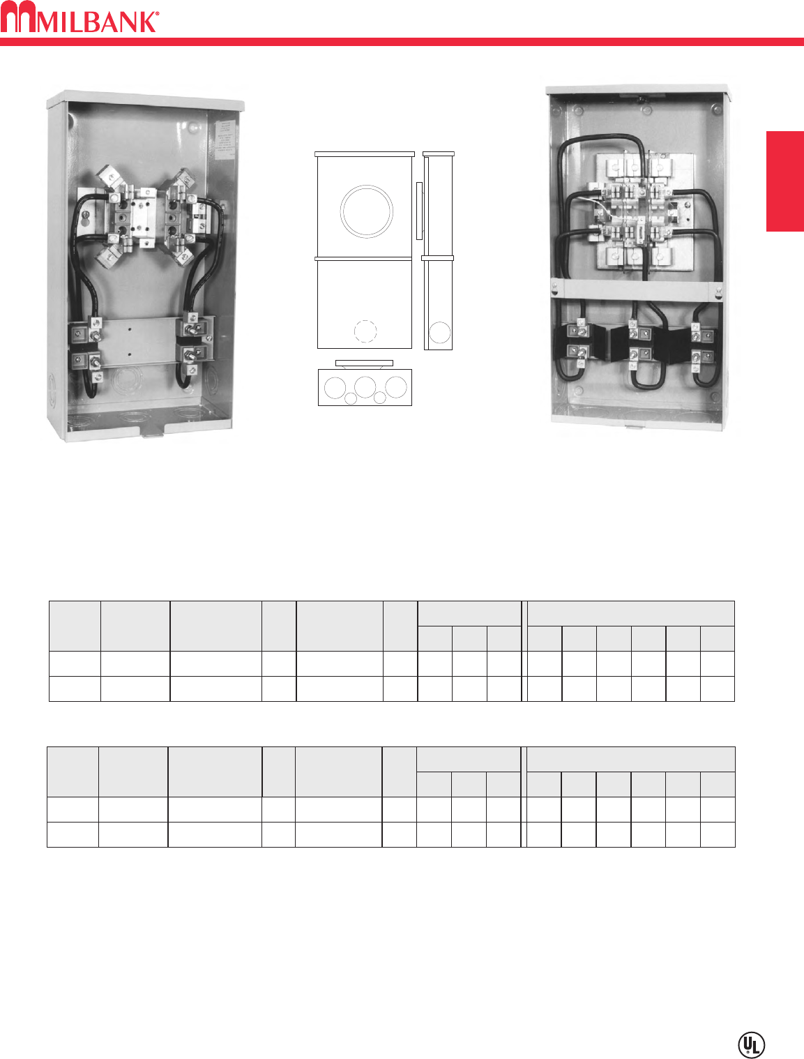
200 AMP—4 & 7 TERMINAL—RING TYPE
SERVICE
NO.
OF
TERMS
CATALOG
NUMBER BREAKER
OH4U3574-RL-200 200A-2P
CONNECTORS
CU/AL
LINE LOAD
DIMENSIONS CONCENTRIC K.O.ʼS
1 2 3 4 5 6
2 2 21
⁄
21
⁄
41
⁄
4,1
⁄
2—
D" W" H"
41
⁄
8830
#2-350 #3-300
OH7U3577-RL-200 200A-3P 2 2 21
⁄
21
⁄
41
⁄
4,1
⁄
2—
47
⁄
810 34
#3-300#2-350
UG4U3584-O-200 200A-2P 3 3 3 1
⁄
4,1
⁄
2— —
51
⁄
2141
⁄
826
#3-300#6-350
UG7U3587-O-200 200A-3P 3 3 3 1
⁄
4,1
⁄
2— —
51
⁄
2141
⁄
826
#3-300#6-350
BREAKERS: Units are supplied with bolt-on 200 amp circuit breakers where specified above.
SEALING RINGS: Units are supplied with an MR-4 screw type sealing ring.
1
4
3
2
5
1
4
32
4
3574
3577
3584
3587
U3574-RL-200
C2
Utility requirements for this equipment may vary. Always consult the serving utility for their requirements before ordering or
installing equipment in this catalog.
C2
METER MAINS AND SERVICE ENTRANCE EQUIPMENT SECTION C
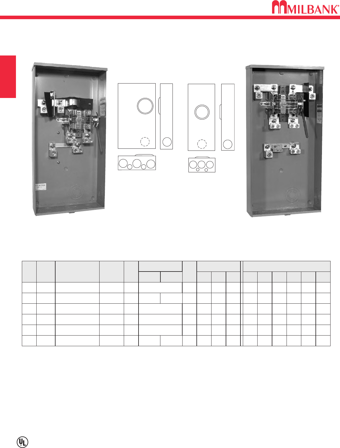
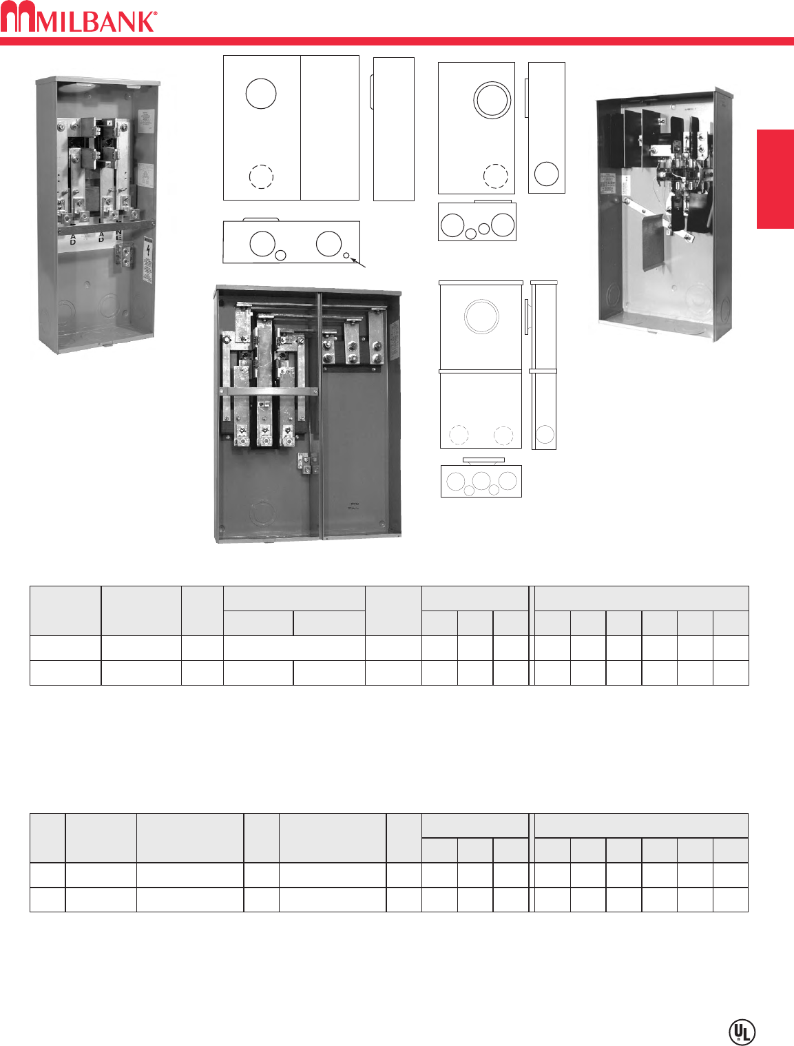
100/150/200 AMP–RING TYPE / RINGLESS METER MAINS–4 & 5 TERMINAL–22K AIC
CIRCUITS
CATALOG
NUMBER
HUB
CONNECTORS
LINE
BY-
PASS
DIMENSIONS
CONCENTRIC K.O.ʼS
1 2 3 4 5 6D
"
W
"
H
"
HUB: Supplied with (2) closing plates packed inside. Order hubs as a separate item. See accessory page for hub options.
INTERIOR: U5168 units have 8-circuit interior; U5268 units have 20-circuit interior.
FIFTH TERMINAL: Order K5T and field install for 208Y/120 network systems. Installs in the 9 oʼclock position only.
BREAKERS: Rated 22K AIC with Milbank QNR2200H main installed.
INTERLOCK KIT: For generator auxiliary circuit breaker interlock, order K5815 for large QN with small frame Q; order K5820 for
large frame QN with large frame QN.
SUB-FEED LUGS: #6-350 kcmil sub-feed lugs provided on 8 and 10 circuit interior. Not available on 20 circuit interior.
*Amperage rating limited to main breaker rating. Interior has 10 branch circuit breaker provisions.
**RINGLESS
2
35
4
5
11
5
6
6
5
6
10
U5168-XTL-100
**
C.P.
NONE
2 2 3 21
⁄
21
⁄
2
,
3
⁄
4
41
⁄
2141
⁄
832
#6-350
1
⁄
2
,
3
⁄
4,
1
AMP
100
NO. OF
TERMS
4
8
U5168-XTL-150
**
C.P.
NONE
2 2 3 21
⁄
21
⁄
2
,
3
⁄
4
41
⁄
2141
⁄
832
#6-350
1
⁄
2
,
3
⁄
4,
1
1504
8
U5168-XTL-200
**
C.P.
NONE
2 2 3 21
⁄
21
⁄
2
,
3
⁄
4
41
⁄
2141
⁄
832
#6-350
1
⁄
2
,
3
⁄
4,
1
2004
10
U5168-XTL-100-KK
**
C.P.
HORN
2 2 3 21
⁄
21
⁄
2
,
3
⁄
4
41
⁄
2141
⁄
832
#6-350
1
⁄
2
,
3
⁄
4,
1
1004
8
U5168-XTL-150-KK
**
C.P.
HORN
2 2 3 21
⁄
21
⁄
2
,
3
⁄
4
41
⁄
2141
⁄
832
#6-350
1
⁄
2
,
3
⁄
4,
1
1504
8
U5168-XTL-200-KK
**
C.P.
HORN
2 2 3 21
⁄
21
⁄
2
,
3
⁄
4
41
⁄
2141
⁄
832
#6-350
1
⁄
2
,
3
⁄
4,
1
2004
10
U5168-XTL-100-KK-5T
**
C.P.
HORN
2 2 3 21
⁄
21
⁄
2
,
3
⁄
4
41
⁄
2141
⁄
832
#6-350
1
⁄
2
,
3
⁄
4,
1
1005
8
U5168-XTL-150-KK-5T
**
C.P.
HORN
2 2 3 21
⁄
21
⁄
2
,
3
⁄
4
41
⁄
2141
⁄
832
#6-350
1
⁄
2
,
3
⁄
4,
1
1505
U5168-XTL-200
U5268-XTL-200-KK
5168
5169
5268
5269
100/150/200 AMP–4 & 5 TERMINAL–METER MAIN–22K AIC–120/240 VOLT–1∅3W–RINGLESS / RING TYPE
OVERHEAD / UNDERGROUND–8 & 20 CIRCUIT INTERIOR
10
U5169-XTL-100
C.P.
NONE
2 2 3 21
⁄
21
⁄
2
,
3
⁄
4
41
⁄
2141
⁄
832
#6-350
1
⁄
2
,
3
⁄
4,
1
1004
8
U5169-XTL-150
C.P.
NONE
2 2 3 21
⁄
21
⁄
2
,
3
⁄
4
41
⁄
2141
⁄
832
#6-350
1
⁄
2
,
3
⁄
4,
1
1504
8
U5169-XTL-200
C.P.
NONE
2 2 3 21
⁄
21
⁄
2
,
3
⁄
4
41
⁄
2141
⁄
832
#6-350
1
⁄
2
,
3
⁄
4,
1
2004
20
U5268-XTL-150
**
C.P.
NONE
2 2 3 21
⁄
21
⁄
2
,
3
⁄
4
41
⁄
2141
⁄
832
#6-350
1
⁄
2
,
3
⁄
4,
1
1504
20
U5268-XTL-200
**
C.P.
NONE
2 2 3 21
⁄
21
⁄
2
,
3
⁄
4
41
⁄
2141
⁄
832
#6-350
1
⁄
2
,
3
⁄
4,
1
2004
20
U5268-XTL-150-KK
**
C.P.
HORN
2 2 3 21
⁄
21
⁄
2
,
3
⁄
4
41
⁄
2141
⁄
832
#6-350
1
⁄
2
,
3
⁄
4,
1
1504
20
U5268-XTL-200-KK
**
C.P.
HORN
2 2 3 21
⁄
21
⁄
2
,
3
⁄
4
41
⁄
2141
⁄
832
#6-350
1
⁄
2
,
3
⁄
4,
1
2004
20
U5269-XTL-200
C.P.
NONE
2 2 3 21
⁄
21
⁄
2
,
3
⁄
4
41
⁄
2141
⁄
832
#6-350
1
⁄
2
,
3
⁄
4,
1
2004
C3
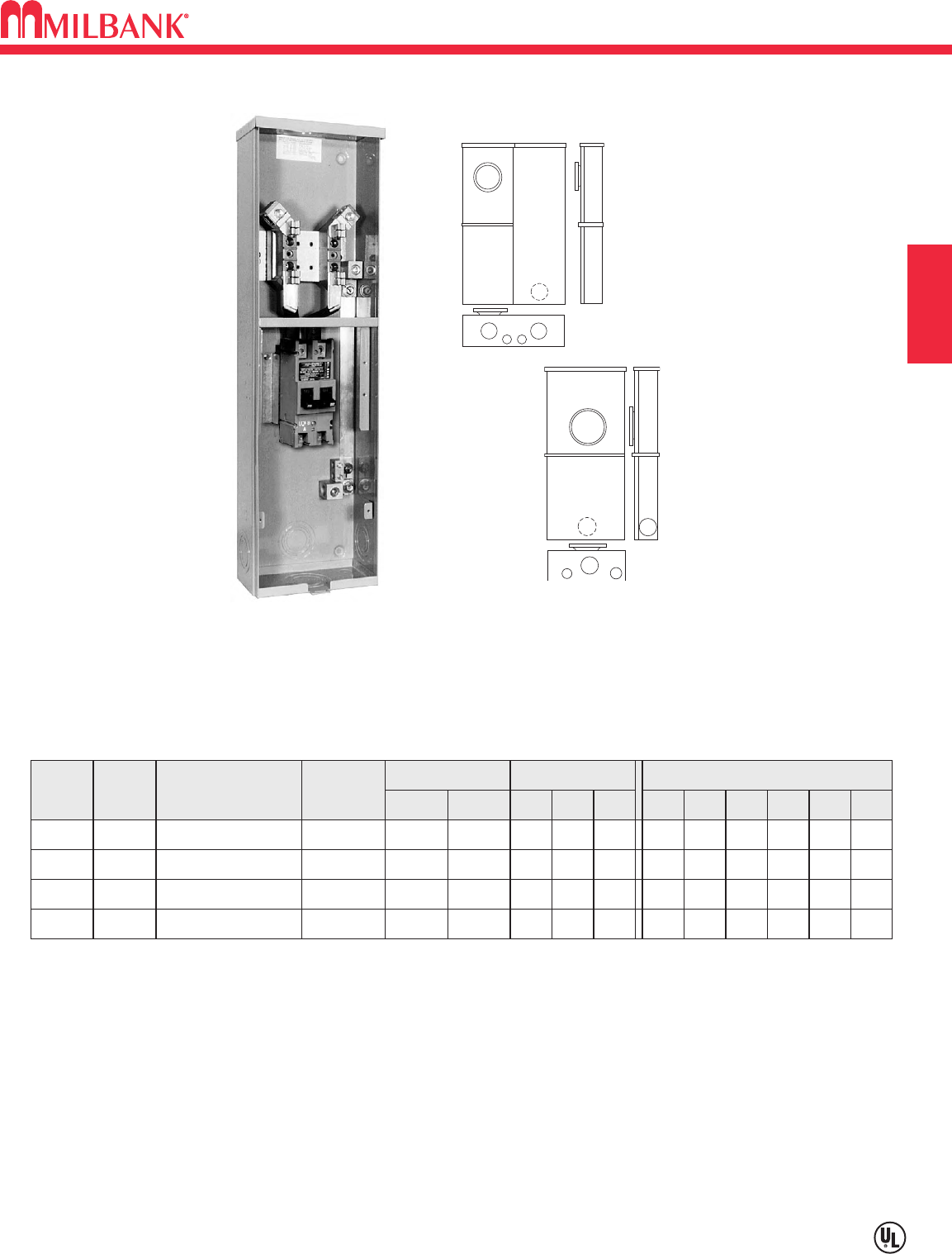
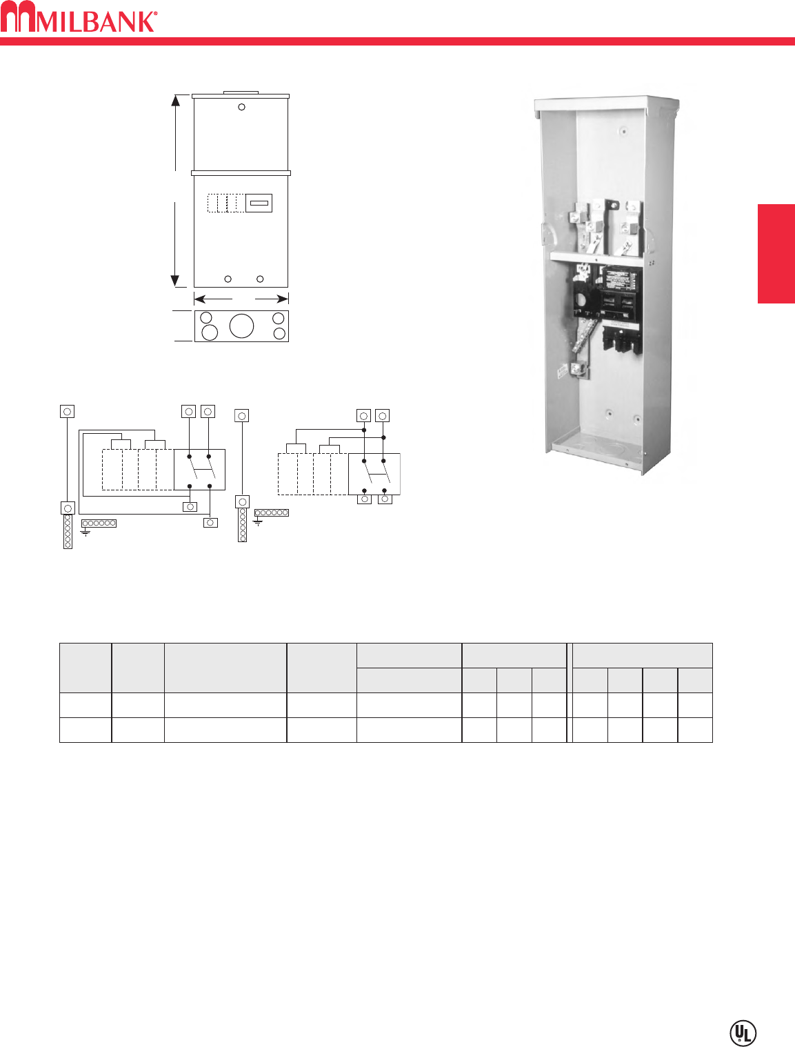
200 AMP—4 TERMINAL—SERVICE ENTRANCE
MAIN BREAKER—UNMETERED—120/240 VAC
Utility requirements for this equipment may vary. Always consult the serving utility for their requirements before ordering or
installing equipment in this catalog.
C3
METER MAINS AND SERVICE ENTRANCE EQUIPMENT
SECTION C
26"
USE-AP
8"
5" 12
34
4
AB
N
G
USE-AP-200-MB
AB
N
G
USE-AP-200-ML
USE-AP-200-ML
200 AMP—4 TERMINAL—BREAKER ENCLOSURE—1∅3W, 120/240V—10K AIC RATING
SERVICE CATALOG
NUMBER
OH
OH
USE-AP-200-MB
USE-AP-200-ML
CONNECTORS
LINE
DIMENSIONS CONCENTRIC K.O.ʼS
1234
1
1
2
2
1
⁄
2,3
⁄
4
1
⁄
2,3
⁄
4
1
⁄
2,3
⁄
4
1
⁄
2,3
⁄
4
D" W" H"
5
5
8
8
26
26
#4-250
#4-250
NO.
OF
TERM.
4
42"
2"
HUB
NOTE: The neutral bus / ground bar is factory installed.
USE-AP-200-MB: 200 Amp main wired in series with plug-in style bus. UQFP-M-200 factory installed Additional 4
branch circuits available for (1) two-pole and (2) one-pole, or (4) one pole breakers. One 2" hub included.
USE-AP-200-ML: 200 Amp breaker wired in parallel with plug-in style bus. UQFP-200 factory installed. Additional 4
branch circuits available for (1) two-pole and (2) one-pole, or (4) one pole breakers. One 2" hub included.
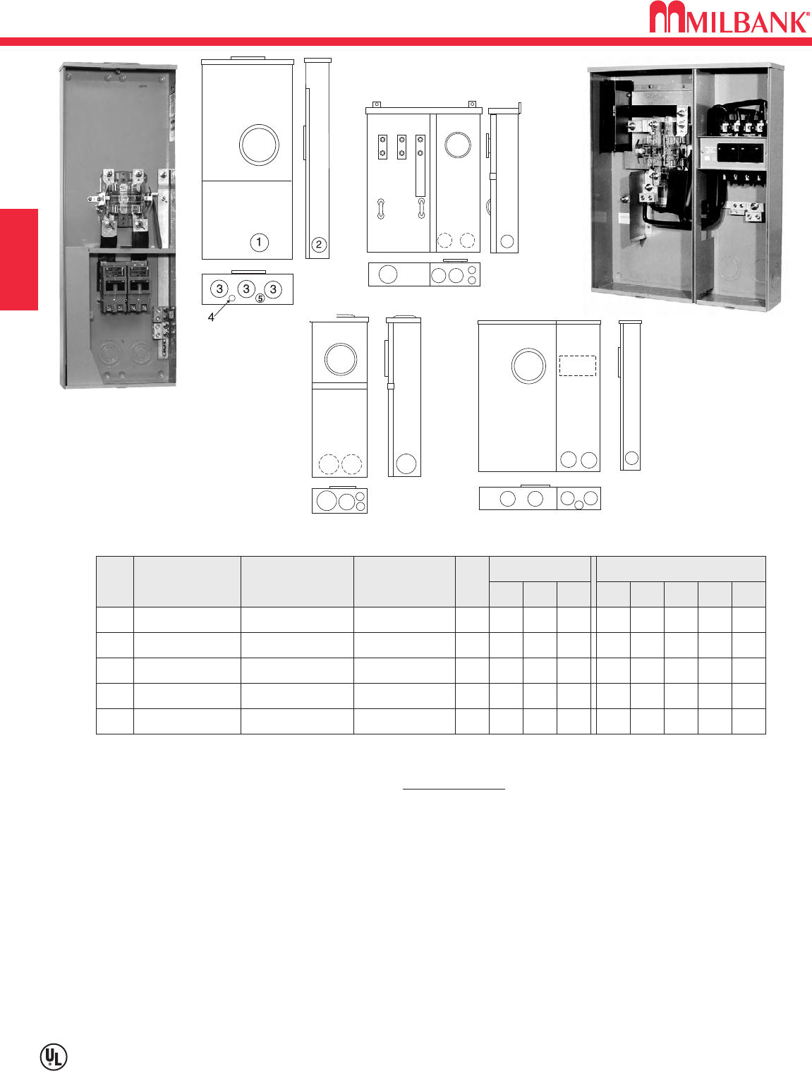
400 AMP—320 AMP CONTINUOUS
METER MAIN WITH SPLIT LOAD—120/240 VAC
C4
Utility requirements for this equipment may vary. Always consult the serving utility for their requirements before ordering or
installing equipment in this catalog.
C4
METER MAINS AND SERVICE ENTRANCE EQUIPMENT SECTION C
4 TERMINAL—1∅3W—RINGLESS / 22K AIC
SERV. CATALOG
NUMBER
PRIMARY
DISCONNECT
OH M400-PAR 200 Amp / 2 Pole
Circuit Breaker
SECONDARY
DISCONNECT
BY-
PASS
LEVER
DIMENSIONS CONCENTRIC K.O.ʼS
12345
22211
⁄
21
⁄
2,3
⁄
4
D" W" H"
61
⁄
891
⁄
2471
⁄
8
See note
UG M400-PAR-UG**200 Amp / 2 Pole
Circuit Breaker
LEVER
21
⁄
221
⁄
2421
⁄
21
⁄
2,3
⁄
4
61
⁄
8221
⁄
836
See note
UG U4031-O-2/200 200 Amp / 2 Pole
Circuit Breaker
LEVER
33431
⁄
4,1
⁄
2
53
⁄
425 30
200 Amp / 2 Pole
Circuit Breaker
OH/UG
U5059-X-2/200 200 Amp / 2 Pole
Circuit Breaker
LEVER
3331
⁄
41
⁄
4,1
⁄
2
47
⁄
815 42
200 Amp / 2 Pole
Circuit Breaker
OH/UG
U5759-X-2/200*200 Amp / 2 Pole
Circuit Breaker
NONE
3331
⁄
41
⁄
4,1
⁄
2
47
⁄
815 42
200 Amp / 2 Pole
Circuit Breaker
NEUTRAL: Bonded neutral and ground factory Installed.
FLUSH MOUNT: Flush mounting available on underground units. Order catalog number FK-M400-UG separately.
SHORT CIRCUIT CURRENT WITHSTAND RATING: 22K AIC Standard.
BYPASS: Lever supplies clamping action and operates bypass device.
FIFTH TERMINAL: For field installed fifth terminal for the U5059 & U5759, order separately catalog number K3866.
CONVERSION KIT: To field convert M400 UG units to OH, order K4787-R. Includes connectors (#2-600).
200 amp primary disconnect factory installed. Order secondary disconnect separately. Specify UQFPH-100, 125, 150,
175 or 200.
OVERHEAD: Includes one 3" hub.
Provided with connectors for #4-600 or twin 1/0-250.
LINE SIDE CONNECTOR KITS: Two 1/2" studs per phase on 1 3/4" centers. Factory installed for the U5759, for
the U5059 order anti-rotation connector kit K1540L to accommodate #4-600 kcmil single or K1350L for twin 350
kcmil connectors.
*Lever supplies clamping action only–does NOT operate bypass on the U5759.
**LUG KIT: Mechanical lug kit available for M400-APS-UG, order K4920 (#2-500).
34 4
11 2
5
5
112
345
5
M400-PAR-UG
M400-PAR
5059
5759
1
3
2
5
1
4 4
2
3
4031
U5059-X-2/200
U4031-O-2/200
C5
400 AMP—320 AMP CONTINUOUS
METER MAIN WITH SPLIT LOAD—120/240 VAC
Utility requirements for this equipment may vary. Always consult the serving utility for their requirements before ordering or
installing equipment in this catalog.
C5
METER MAINS AND SERVICE ENTRANCE EQUIPMENT
SECTION C
4 TERMINAL—1∅3W—TYPE 3R—RING TYPE —120/240 VAC
OH
OH
M400-APS-BS
M400-APS
200 Amp / 2 Pole
Circuit Breaker
200 Amp / 2 Pole
Circuit Breaker
LINK
NONE
1-21
⁄
2
2
2-21
⁄
2
2
3-3
2
4-3
11
⁄
2
51
⁄
2
1
⁄
2,3
⁄
4
6
61
⁄
8
111
⁄
2
91
⁄
2
47
471
⁄
8
See note
See note
SERV CATALOG
NUMBER
PRIMARY
DISCONNECT
BY-
PASS
CONCENTRIC K.O.ʼS
12345
3
⁄
4
—
6
DIMENSIONS
D" W" H"
SECONDARY
DISCONNECT
M400-APS-BS
112
345
5
EUSERC: Meets EUSERC requirements. Consult local utility for acceptability before ordering or installing.
NEUTRAL: Bonded neutral and ground factory Installed.
LINE SIDE CONNECTORS: Connectors provided for 4-600 or twin 1/0-250.
OVERHEAD: Overhead units include one 3" hub.
200 amp primary disconnect factory installed. Order secondary disconnect separately. Specify UQFPH-100, 125, 150,
175 or 200.
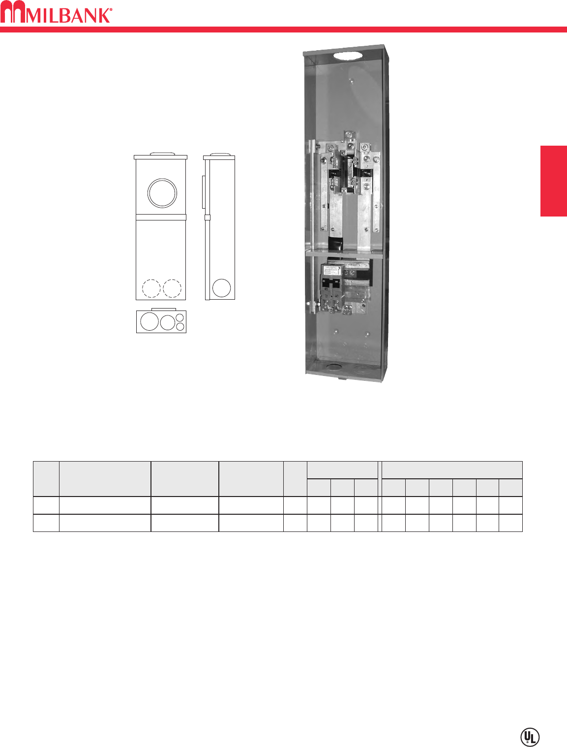
400 AMP—320 AMP CONTINUOUS
METER MAIN WITH SPLIT LOAD—120/240 VAC
C6
Utility requirements for this equipment may vary. Always consult the serving utility for their requirements before ordering or
installing equipment in this catalog.
C6
METER MAINS AND SERVICE ENTRANCE EQUIPMENT SECTION C
4 TERMINAL—1∅3W–TYPE 3R—RING TYPE PLUG-IN SOCKETS—120/240 VAC
UG M400-UG-APS-F 200 Amp / 2 Pole
Circuit Breaker NONE 21
⁄
221
⁄
2421
⁄
21
⁄
2,3
⁄
41
61
⁄
8221
⁄
836
See note
SERV CATALOG
NUMBER
PRIMARY
DISCONNECT
BY-
PASS
CONCENTRIC K.O.ʼS
12345
FIG.
DIMENSIONS
D" W" H"
SECONDARY
DISCONNECT
UG M400-UG-APS-P 200 Amp
2 Pole—T-Fuse NONE 21
⁄
221
⁄
2421
⁄
21
⁄
2,3
⁄
41
61
⁄
8221
⁄
836
200 Amp
2 Pole—T-Fuse
UG U3251-O-200-CB 200 Amp / 2 Pole
Circuit Breaker LINK 33431
⁄
2,3
⁄
42
63
⁄
424 401
⁄
4
200 Amp / 2 Pole
Circuit Breaker
UG
M400-UG-APS-LC
200 Amp / 2 Pole
Circuit Breaker NONE 11
⁄
221
⁄
243
⁄
41—
629 417
⁄
16
200 Amp / 2 Pole
Circuit Breaker
UG M400-UG-APS-F-BS200 Amp / 2 Pole
Circuit Breaker LINK 11
⁄
221
⁄
243
⁄
41—
629 417
⁄
16
See note
UG
M400-UG-APS-LC-BS
200 Amp / 2 Pole
Circuit Breaker LINK 11
⁄
221
⁄
243
⁄
41—
629 417
⁄
16
200 Amp / 2 Pole
Circuit Breaker
U3251-O-200-CB
M400-UG-APS-LC
(see next page for dwg. & chart)
34 4
11 2
5
5
FIG. 1
1
3
2
5
1
4 4
2
FIG. 2
EUSERC: Meets EUSERC requirements. Consult local utility for acceptability before ordering or installing.
NEUTRAL: Bonded neutral and ground factory Installed.
LINE SIDE CONNECTORS: Two 1/2" studs per phase on 1 3/4" centers.
LOAD SIDE CONNECTORS: 1/0-300
FLUSH MOUNT: Flush mount kit included with M400-UG-APS-F, M400-UG-APS-BS, M400-UG-APS-LC and
M400-UG-APS-LC-BS. Available for other underground units. Order catalog number FK-M400-UG separately.
SHORT CIRCUIT CURRENT WITHSTAND RATING: 22K AIC standard, 200K AIC standard on T-fuse models.
LUG KIT: Mechanical lug kit available, order K4920 (#2-500).
CONVERSION KIT: To field convert M400 UG units to OH, order K4787-R. Includes connectors (#2-600).
200 amp primary disconnect factory installed. Order secondary disconnect separately. Specify UQFPH-100, 125, 150, 175 or 200.
Two 200 amp T-fuse pull-outs factory installed as primary and secondary disconnects.
Two 200 amp 2-pole bolt-on UQFBH main breakers factory installed.
BREAKERS: Two 200 Amp 2-pole main breakers factory installed, and semi-flush flange kit packed inside meter section.
Universal Copper 24 / 40 Circuit interior accepts Challenger, GE, Murrary, Siemens / ITE, and Cutler-Hammer / Westinghouse
universal type plug-in branch circuit breakers.
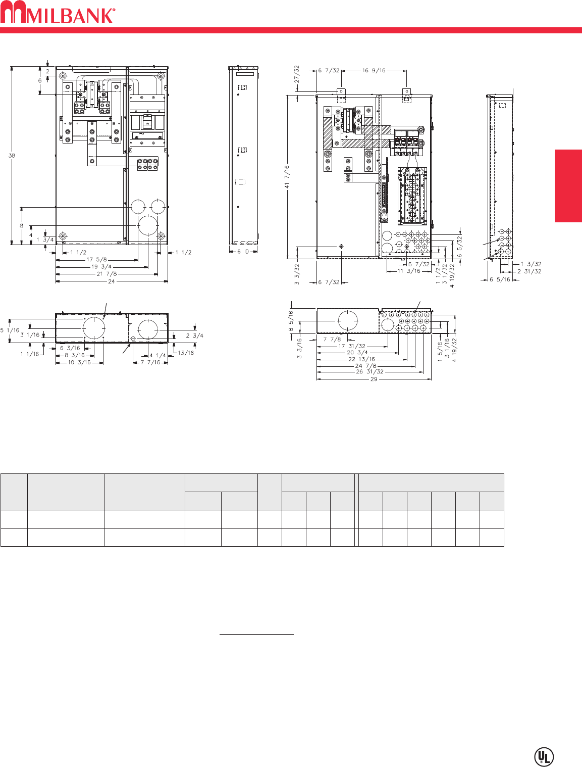
C7
400 AMP—320 AMP CONTINUOUS—METER MAIN COMBINATION
Utility requirements for this equipment may vary. Always consult the serving utility for their requirements before ordering or
installing equipment in this catalog.
C7
METER MAINS AND SERVICE ENTRANCE EQUIPMENT
SECTION C
1
2
3
4
1
5
6
(4)
1
2
3
4
5
24
(32)
(9)
400 AMP MAIN BREAKER—4 TERMINAL—1∅3W—TYPE 3R—RING TYPE–120/240 VAC
SERV. CATALOG
NUMBER
MAIN
DISCONNECT
UG M401-UG (1) 400 AMP
2 POLE BREAKER
CONNECTORS
CU/AL
LINE LOAD
BY-
PASS
NONE
DIMENSIONS CONCENTRIC K.O.ʼS
12345
21
⁄
231
⁄
231
⁄
241
⁄
4
D" W" H"
624 38
STUDS C.B.
UG M401-UG-BS (1) 400 AMP
2 POLE BREAKER LINK 21
⁄
231
⁄
231
⁄
241
⁄
4
6
1
⁄
2
1
⁄
2
624 38
STUDS C.B.
EUSERC: Meets EUSERC requirements. Consult local utility for acceptability before ordering or installing.
NEUTRAL: Bonded neutral and ground factory installed.
LINE SIDE CONNECTORS: Two 1/2" studs per phase on 1-3/4" centers.
LUG KIT: Mechanical lug kit available, order K4920 (#2-500).
FLUSH MOUNT: Flush mount kits are NOT available for these units.
SHORT CIRCUIT CURRENT WITHSTAND RATING: 22K AIC standard.
CB load side (1) or (2) copper conductors 3/0-500, (2) aluminum conductors 4/0-500 or (1) aluminum conductor 250-500.
M401-UG M400-UG-APS-LC
(see previous page for details)
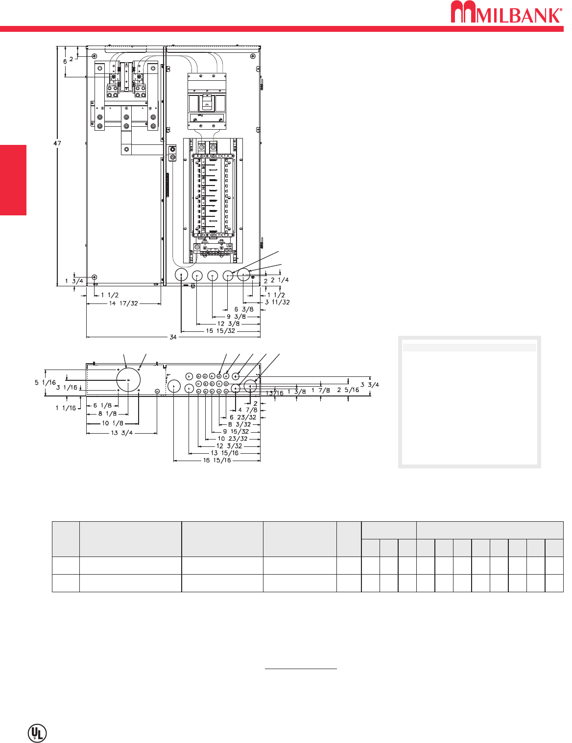
400 AMP—320 AMP CONTINUOUS—METER MAIN COMBINATION
C8
Utility requirements for this equipment may vary. Always consult the serving utility for their requirements before ordering or
installing equipment in this catalog.
C8
METER MAINS AND SERVICE ENTRANCE EQUIPMENT SECTION C
400 AMP MAIN WITH CIRCUIT LOAD CENTER—4 TERMINAL—1∅3W
RING TYPE—120/240 VAC
SERV. CATALOG
NUMBER
PRIMARY
DISCONNECT
UG M404-UG-LC* 400 AMP
2 POLE BREAKER
SECONDARY
DISCONNECT
BY-
PASS
NONE
DIMENSIONS
CONCENTRIC K.O.ʼS
12345
1
⁄
21
⁄
2,3
⁄
4111
⁄
411
⁄
2
D" W" H"
634 47N/A
UG M404-UG-LC-BS* 400 AMP
2 POLE BREAKER LINK 1
⁄
21
⁄
2,3
⁄
4111
⁄
411
⁄
2
6
2
2
7
4
4
8
1
⁄
4
1
⁄
4
634 47N/A
EUSERC: Meets EUSERC requirements. Consult local utility for acceptability before ordering or installing.
NEUTRAL: Bonded neutral and ground factory installed.
LINE SIDE CONNECTORS: (2) 1/2" studs per phase on 1-3/4" centers.
LUG KIT: Mechanical lug kit available, order K4920 (#2-500).
FLUSH MOUNT: Flush mounting available on underground units. Order catalog number FK-M404-UGLC separately.
SHORT CIRCUIT CURRENT WITHSTAND RATING: 22K AIC standard.
BRANCH BREAKERS: Use Siemens, Cutler-Hammer, GE or Siemens/Murray breakers to maintain 22K rating.
*Includes a 30-circuit load center.
78
5
2
14
3
6
6
CONCENTRIC K.O.ʼS
1= (12) 1/2" K.O.
2= (4) 1/2, 3/4
3= (4) 3/4, 1"
4= (2) 1/2, 3/4, 1, 1 1/4"
5= (3) 3/4, 1, 1 1/4, 1 1/2"
6= (4) 1, 1 1/4, 1 1/2, 2"
7= (1) 3, 3 1/2, 4"
8= (4) 1/4 diameter hole
M404-UG-LC
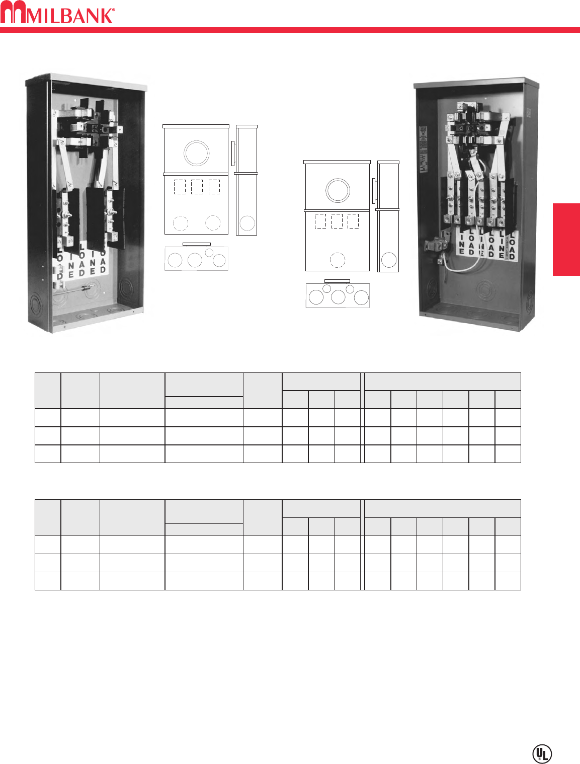
D1
TEST BLOCK BYPASS—TB SERIES
100/200 AMP—600 VOLT SELF CONTAINED / SOCKET ONLY
Utility requirements for this equipment may vary. Always consult the serving utility for their requirements before ordering or
installing equipment in this catalog.
D1
SECTION D
These UL Listed products
are for use in areas
requiring Electrical Utility
Service Equipment
Requirements Committee
(EUSERC) compliance.
100 AMP—4, 5 & 7 TERMINAL— FOR USE WITH REMOTE MAIN—RING TYPE
SHORT CIRCUIT CURRENT WITHSTAND RATING UP TO 200K AIC DEPENDING ON
OVERCURRENT PROTECTION DEVICE USED
TYPE
OF
SERVICE
CATALOG
NUMBER
OH/UG
OH/UG
NO.
OF
TERM.
4
5
114TB*
115TB
CONNECTORS
CU/AL
LINE & LOAD
TYPE
OF
SERVICE
1∅3W *
3∅3W
DIMENSIONS CONCENTRIC K.O.ʼS
123456
2
2
2
2
11
⁄
2
11
⁄
2
2
2
1
⁄
2
1
⁄
2
—
—
D" W" H"
45
⁄
8
45
⁄
8
12
12
25
25
#6-1/0
#6-1/0
OH/UG7117TB 3∅4W 2 2 11
⁄
221
⁄
2—
45
⁄
812 25#6-1/0
200 AMP—4, 5 & 7 TERMINAL—FOR USE WITH REMOTE MAIN—RING TYPE
TYPE
OF
SERVICE
CATALOG
NUMBER
OH/UG
OH/UG
NO.
OF
TERM.
4
5
124TB*
125TB
CONNECTORS
CU/AL
LINE & LOAD
TYPE
OF
SERVICE
1∅3W *
3∅3W
DIMENSIONS CONCENTRIC K.O.ʼS
123456
21
⁄
2
21
⁄
2
21
⁄
2
21
⁄
2
3
3
3
3
9
⁄
32
9
⁄
32
1
⁄
2
1
⁄
2
D" W" H"
6
6
14
14
30
30
#1/0-250
#1/0-250
OH/UG7127TB 3∅4W 21
⁄
221
⁄
23 3 9
⁄
32 1
⁄
2
614 30#1/0-250
HUBS: OH units use hub up to 21
⁄
2"(see accessory page). Units provided with closing plates.
SEALING RINGS: Units furnished with MR-2 snap style sealing rings.
NEUTRAL: “Lay-in” connectors will accommodate #6-2/0 (for 100 amp units) and #2-250 (for 200 amp units) copper or
aluminum wire.
RING PROTECTOR: Add suffix -RP to catalog number for factory installed ring protector (ex. 117TB becomes 117TB-RP).
*For 3W (208Y/120) network service, install field mounted fifth terminal catalog number 105J. See accessories page.
2
11
5
3
44
2
1
5
3
4
4
6
124TB
125TB
127TB
114TB
115TB
117TB
114TB 127TB
COMMERCIAL METERING–SAFETY SOCKETS, METER MAINS,
TERMINATION BOXES, BUSSED GUTTERS
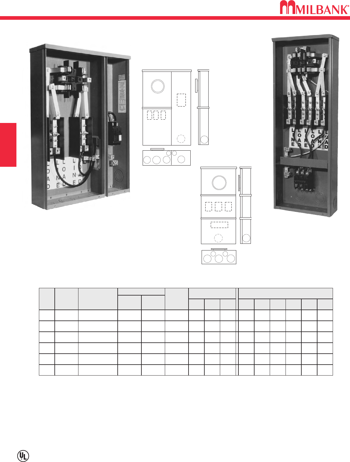
TEST BLOCK BYPASS—MTB SERIES—100 AMP—10K AIC
240 VOLT SELF CONTAINED METER MAIN / CIRCUIT BREAKERS
D2
Utility requirements for this equipment may vary. Always consult the serving utility for their requirements before ordering or
installing equipment in this catalog.
D2
SECTION D
These UL Listed products
are for use in areas
requiring Electrical Utility
Service Equipment
Requirements Committee
(EUSERC) compliance.
COMMERCIAL METERING–SAFETY SOCKETS, METER MAINS,
TERMINATION BOXES, BUSSED GUTTERS
100 AMP—4, 5, & 7 TERMINAL—240 VOLT—BREAKER INSTALLED—RING TYPE
TYPE
OF
SERVICE
CATALOG
NUMBER
OH
OH
NO.
OF
TERM.
4
5
214MTB*
215MTB
CONNECTORS
LINE
LOAD
NEUTRAL
TYPE
OF
SERVICE
1∅3W *
3∅3W
DIMENSIONS CONCENTRIC K.O.ʼS
1 2 3 4 5 6
2
2
2
2
2
2
11
⁄
2
11
⁄
2
9
⁄
32
9
⁄
32
1
⁄
2
1
⁄
2
D" W" H"
45
⁄
8
45
⁄
8
12
12
34
34
#6-2/0 #14-1/0
#14-1/0
#14-1/0
#14-1/0
#14-1/0
#14-1/0
#6-2/0
OH7217MTB 3∅4W 2 2 2 11
⁄
29
⁄
32 1
⁄
2
45
⁄
812 34#6-2/0
OH/UG4U214MTB* 1∅3W * 2 2 21
⁄
223
⁄
42
45
⁄
818 25#6-2/0
OH/UG5U215MTB 3∅3W 2 2 21
⁄
223
⁄
42
45
⁄
818 25#6-2/0
OH/UG7U217MTB 3∅4W 2 2 21
⁄
223
⁄
42
45
⁄
818 25#6-2/0
REPLACEMENT MAIN DISCONNECTS: For replacement main disconnect see pages D14 & D15.
HUBS: OH units use hub up to 21
⁄
2" (see accessory page). Units provided with closing plate.
SEALING RINGS: Units furnished with MR-2 snap style sealing rings.
NEUTRAL: “Lay-in” connectors will accommodate #6-2/0 (for 100 amp units) and #2-250 (for 200 amp units) copper or
aluminum wire.
* For 3W (208Y/120) network service, install field mounted fifth terminal catalog number 105J. See accessories page.
3
2
4
4
1
5 6
214MTB
215MTB
217MTB
U214MTB
217MTB
1
3
2
44
55
6
U214MTB
U215MTB
U217MTB
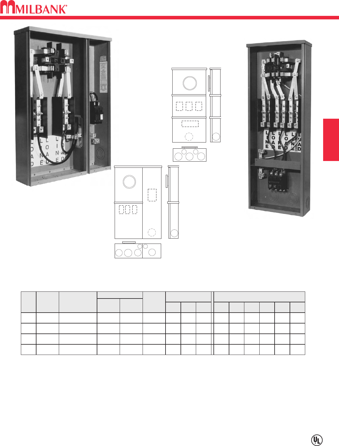
D3
TEST BLOCK BYPASS—MTB SERIES—100 AMP—22K AIC
240 VOLT—SELF CONTAINED METER MAIN / CIRCUIT BREAKER
Utility requirements for this equipment may vary. Always consult the serving utility for their requirements before ordering or
installing equipment in this catalog.
D3
SECTION D
These UL Listed products
are for use in areas
requiring Electrical Utility
Service Equipment
Requirements Committee
(EUSERC) compliance.
100 AMP—4 & 7 TERMINAL—240 VOLT—BREAKER INSTALLED—RING TYPE
TYPE
OF
SERVICE
CATALOG
NUMBER
OH
NO.
OF
TERM.
4214MTB/22*
CONNECTORS
LINE
LOAD
NEUTRAL
TYPE
OF
SERVICE
1∅3W *
DIMENSIONS CONCENTRIC K.O.ʼS
1 2 3 4 5 6
2 2 2 11
⁄
29
⁄
32 1
⁄
2
D" W" H"
45
⁄
812 34#6-2/0 #14-1/0
#14-1/0
#14-1/0
#14-1/0
OH7217MTB/22 3∅4W 2 2 2 11
⁄
29
⁄
32 1
⁄
2
45
⁄
812 34#6-2/0
OH/UG4U214MTB/22* 1∅3W * 2 2 21
⁄
223
⁄
42
45
⁄
818 25#6-2/0
OH/UG7U217MTB/22 3∅4W 2 2 21
⁄
223
⁄
42
45
⁄
818 25#6-2/0
REPLACEMENT MAIN DISCONNECTS: For replacement main disconnect see pages D14 & D15.
* For 3W (208Y/120) network service, install field mounted fifth terminal catalog number 105J. See accessories page.
HUBS: OH units use hub up to 21
⁄
2"(see accessory page). Units provided with closing plate.
SEALING RINGS: Units furnished with MR-2 snap style sealing rings.
NEUTRAL: “Lay-in” connectors will accommodate #6-2/0 (for 100 amp units) and #2-250 (for 200 amp units) copper or
aluminum wire.
U214MTB/22
217MTB/22
3
2
4
4
1
5 6
214MTB/22
217MTB/22
1
3
2
44
55
6
U214MTB/22
U217MTB/22
COMMERCIAL METERING—SAFETY SOCKETS, METER
MAINS, TERMINATION BOXES, BUSSED GUTTERS
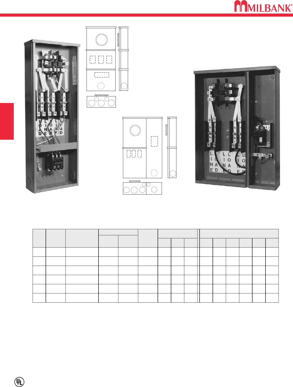
TEST BLOCK BYPASS—MTB SERIES—100 AMP—14K AIC
480 VOLT—SELF CONTAINED METER MAIN / CIRCUIT BREAKER
D4
Utility requirements for this equipment may vary. Always consult the serving utility for their requirements before ordering or
installing equipment in this catalog.
D4
SECTION D
These UL Listed products
are for use in areas
requiring Electrical Utility
Service Equipment
Requirements Committee
(EUSERC) compliance.
COMMERCIAL METERING–SAFETY SOCKETS, METER MAINS,
TERMINATION BOXES, BUSSED GUTTERS
REPLACEMENT MAIN DISCONNECTS: For replacement main disconnect see pages D14 & D15.
HUBS: OH units use hub up to 21
⁄
2" (see accessory page.) Units provided with closing plate.
SEALING RINGS: Units furnished with MR-2 snap style sealing rings.
NEUTRAL: “Lay-in” connectors will accommodate #6-2/0 aluminum wire.
* For 3W (208Y/120) network service, install field mounted fifth terminal catalog number 105J. See accessory page.
100 AMP—4, 5 & 7 TERMINAL—480 VOLT—BREAKER INSTALLED—RING TYPE
TYPE
OF
SERVICE
CATALOG
NUMBER
OH
OH
NO.
OF
TERM.
4
5
214MTB-48*
215MTB-48
CONNECTORS
LINE LOAD
NEUTRAL
TYPE
OF
SERVICE
1∅3W
3∅3W
DIMENSIONS CONCENTRIC K.O.ʼS
1 2 3 4 5 6
21
⁄
2
21
⁄
2
21
⁄
2
21
⁄
2
3
3
3
3
9
⁄
32
9
⁄
32
1
⁄
2
1
⁄
2
D" W" H"
6
6
14
14
48
48
#6-250 #14-1/0
#14-1/0
#14-1/0
#14-1/0
#14-1/0
#14-1/0
#6-250
OH7217MTB-48 3∅4W 21
⁄
221
⁄
23 3 9
⁄
32 1
⁄
2
614 48#6-250
OH/UG4U214MTB-48* 1∅3W 2 2 21
⁄
223
⁄
42
45
⁄
818 25#6-250
OH/UG5U215MTB-48 3∅3W 2 2 21
⁄
223
⁄
42
45
⁄
818 25#6-250
OH/UG7U217MTB-48 3∅4W 2 2 21
⁄
223
⁄
42
45
⁄
818 25#6-250
217MTB-48 U214MTB-48
1
3
2
44
55
6
U214MTB-48
U215MTB-48
U217MTB-48
3
2
4
4
1
5 6
214MTB-48
215MTB-48
217MTB-48
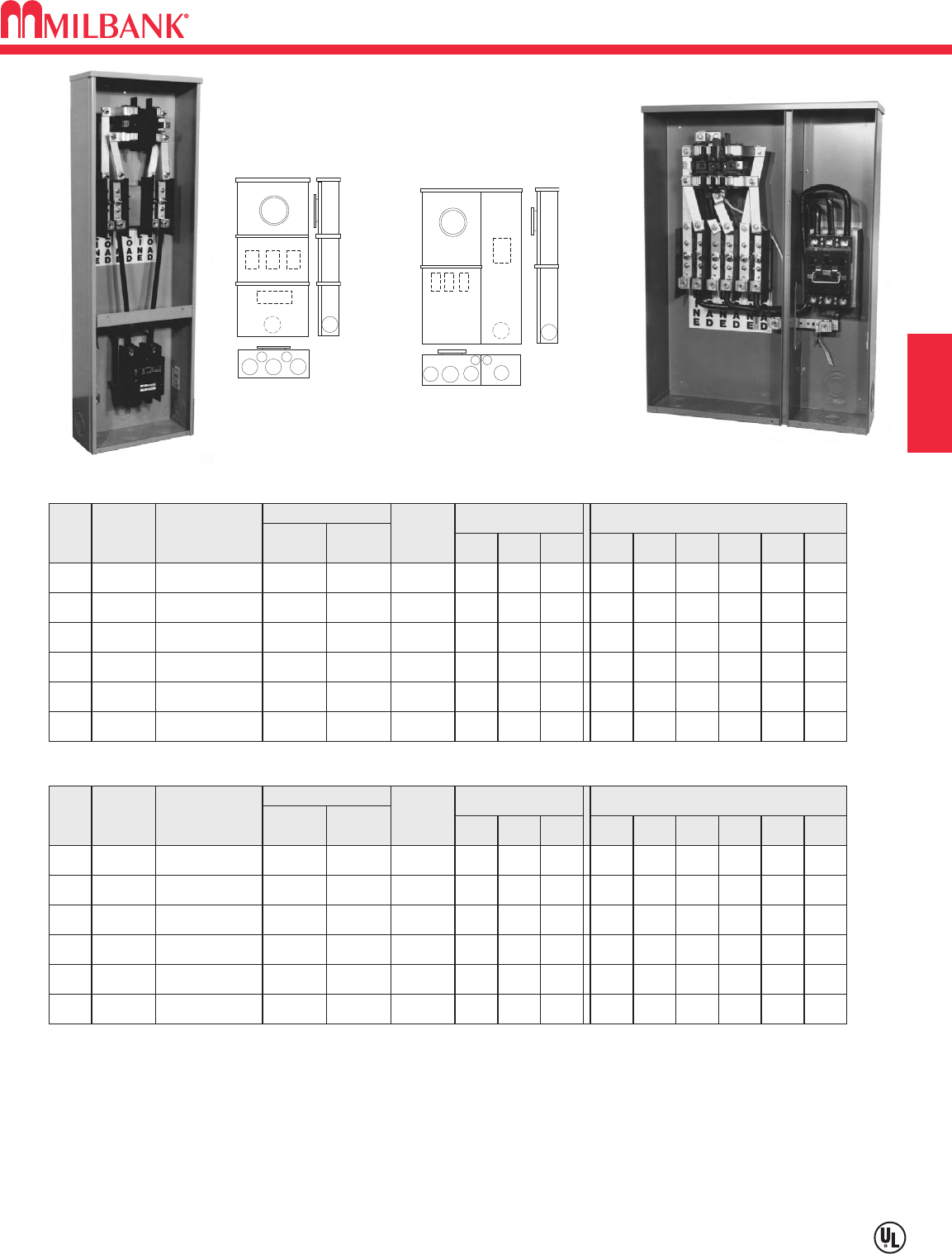
D5
TEST BLOCK BYPASS—MTB-P & MTB-P48 SERIES—100 AMP—200K AIC
240 & 480 VOLT—SELF CONTAINED METER MAIN / T-FUSE PULLOUT
Utility requirements for this equipment may vary. Always consult the serving utility for their requirements before ordering or
installing equipment in this catalog.
D5
SECTION D
These UL Listed products are for use in areas requiring
Electrical Utility Service Equipment Requirements Committee
(EUSERC) compliance.
200K Short Circuit Current Withstand Rating
REPLACEMENT MAIN DISCONNECTS: For replacement main disconnect see pages D14 & D15.
* For 3W (208Y/120) network service, install field mounted fifth terminal catalog number 105J. See accessory page.
HUBS: OH units use hub up to 21
⁄
2" (see accessory page). Units provided with closing plate.
SEALING RINGS: Units furnished with MR-2 snap style sealing rings.
NEUTRAL: “Lay-in” connectors will accommodate #6-2/0 aluminum wire.
PULL-OUTS: For use with T-fuses only. Fuses are included with fused safety sockets.
100 AMP—4, 5, & 7 TERMINAL—240 VOLT—PULL-OUT INSTALLED—RING TYPE
TYPE
OF
SERVICE
CATALOG
NUMBER
OH
OH
NO.
OF
TERM.
4
5
214MTB-P*
215MTB-P
CONNECTORS
LINE LOAD
NEUTRAL
TYPE
OF
SERVICE
1∅3W *
3∅3W
DIMENSIONS CONCENTRIC K.O.ʼS
1 2 3 4 5 6
21
⁄
2
21
⁄
2
21
⁄
2
21
⁄
2
3
3
3
3
9
⁄
32
9
⁄
32
1
⁄
2
1
⁄
2
D" W" H"
6
6
14
14
48
48
#1/0-250 #14-1/0
#14-1/0
#14-1/0
#14-1/0
#14-1/0
#14-1/0
#1/0-250
OH7217MTB-P 3∅4W 21
⁄
221
⁄
23 3 9
⁄
32 1
⁄
2
614 48
#1/0-250
OH/UG4U214MTB-P* 1∅3W * 2 2 21
⁄
223
⁄
42
45
⁄
818 25#6-2/0
OH/UG5U215MTB-P 3∅3W 2 2 21
⁄
223
⁄
42
45
⁄
818 25#6-2/0
OH/UG7U217MTB-P 3∅4W 2 2 21
⁄
223
⁄
42
45
⁄
818 25#6-2/0
100 AMP—4, 5, & 7 TERMINAL—480 VOLT—PULL-OUT INSTALLED—RING TYPE
TYPE
OF
SERVICE
CATALOG
NUMBER
OH
OH
NO.
OF
TERM.
4
5
214MTB-P48*
215MTB-P48
CONNECTORS
LINE LOAD
NEUTRAL
TYPE
OF
SERVICE
1∅3W *
3∅3W
DIMENSIONS CONCENTRIC K.O.ʼS
1 2 3 4 5 6
21
⁄
2
21
⁄
2
21
⁄
2
21
⁄
2
3
3
3
3
9
⁄
32
9
⁄
32
1
⁄
2
1
⁄
2
D" W" H"
6
6
14
14
48
48
#6-250 #14-1/0
#14-1/0
#14-1/0
#14-1/0
#14-1/0
#14-1/0
#6-250
OH7217MTB-P48 3∅4W 21
⁄
221
⁄
23 3 9
⁄
32 1
⁄
2
614 48#6-250
OH/UG4U214MTB-P48* 1∅3W * 2 2 21
⁄
223
⁄
42
45
⁄
818 25#6-250
OH/UG5U215MTB-P48 3∅3W 2 2 21
⁄
223
⁄
42
45
⁄
818 25#6-250
OH/UG7U217MTB-P48 3∅4W 2 2 21
⁄
223
⁄
42
45
⁄
818 25#6-250
1
3
2
44
55
6
U214MTB-P
U215MTB-P
U217MTB-P
U214MTB-P48
U215MTB-P48
U217MTB-P48
214MTB-P U217MTB-P
3
2
4
4
1
5 6
214MTB-P
215MTB-P
217MTB-P
214MTB-P48
215MTB-P48
217MTB-P48
COMMERCIAL METERING–SAFETY SOCKETS, METER MAINS,
TERMINATION BOXES, BUSSED GUTTERS
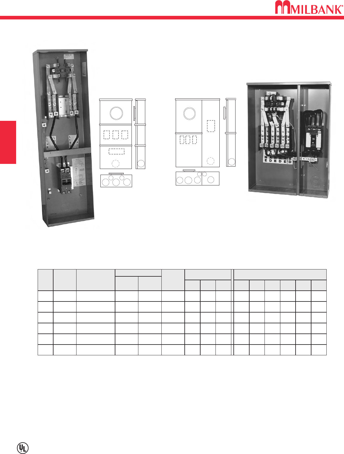
TEST BLOCK BYPASS—MTB SERIES—200 AMP—10K AIC
240 VOLT—SELF CONTAINED METER MAIN / CIRCUIT BREAKER
D6
Utility requirements for this equipment may vary. Always consult the serving utility for their requirements before ordering or
installing equipment in this catalog.
D6
SECTION D
These UL Listed products
are for use in areas
requiring Electrical Utility
Service Equipment
Requirements Committee
(EUSERC) compliance.
COMMERCIAL METERING–SAFETY SOCKETS, METER MAINS,
TERMINATION BOXES, BUSSED GUTTERS
REPLACEMENT MAIN DISCONNECTS: For replacement main disconnect see pages D14 & D15.
HUBS: OH units use hub up to 21
⁄
2" (see accessory page). Units provided with closing plate.
SEALING RINGS: Units furnished with MR-2 snap stye sealing rings.
NEUTRAL: “Lay-in” connectors will accommodate #2-250 copper or aluminum wire.
*For 3W (208Y/120) network service, install field mounted fifth terminal catalog number 105J. See accessory page.
200 AMP—4, 5 & 7 TERMINAL—240 VOLT—BREAKER INSTALLED—RING TYPE
TYPE
OF
SERVICE
CATALOG
NUMBER
OH
OH
NO.
OF
TERM.
4
5
224MTB*
225MTB
CONNECTORS
LINE LOAD
NEUTRAL
TYPE
OF
SERVICE
1∅3W *
3∅3W
DIMENSIONS CONCENTRIC K.O.ʼS
1 2 3 4 5 6
21
⁄
2
21
⁄
2
21
⁄
2
21
⁄
2
3
3
3
3
9
⁄
32
9
⁄
32
1
⁄
2
1
⁄
2
D" W" H"
6
6
14
14
48
48
#6-250 #2/0-250
#2/0-250
#2/0-250
#2/0-250
#2/0-250
#2/0-250
#6-250
OH7227MTB 3∅4W 21
⁄
221
⁄
23 3 9
⁄
32 1
⁄
2
614 48#6-250
OH/UG4U224MTB* 1∅3W * 21
⁄
221
⁄
2321
⁄
23
⁄
421
⁄
2
6223
⁄
430#6-250
OH/UG5U225MTB 3∅3W 21
⁄
221
⁄
2321
⁄
23
⁄
421
⁄
2
6223
⁄
430#6-250
OH/UG7U227MTB 3∅4W 21
⁄
221
⁄
2321
⁄
23
⁄
421
⁄
2
6223
⁄
430#6-250
224MTB
U227MTB
1
3
2
44
55
6
U224MTB
U225MTB
U227MTB
3
2
4
4
1
5 6
224MTB
225MTB
227MTB
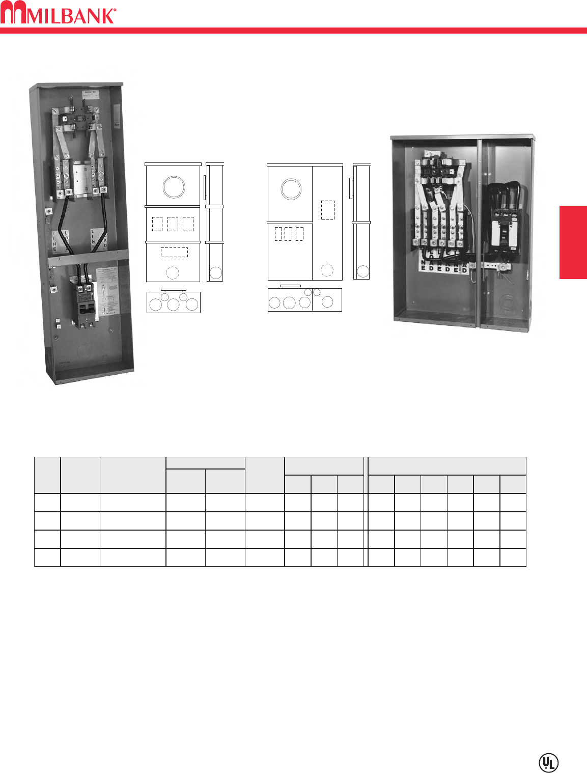
D7
TEST BLOCK BYPASS—MTB SERIES—200 AMP—22K AIC
240 VOLT—SELF CONTAINED METER MAIN / CIRCUIT BREAKER
Utility requirements for this equipment may vary. Always consult the serving utility for their requirements before ordering or
installing equipment in this catalog.
D7
SECTION D
These UL Listed products
are for use in areas
requiring Electrical Utility
Service Equipment
Requirements Committee
(EUSERC) compliance.
COMMERCIAL METERING–SAFETY SOCKETS, METER MAINS,
TERMINATION BOXES, BUSSED GUTTERS
224MTB/22
U227MTB/22
REPLACEMENT MAIN DISCONNECTS: For replacement main disconnect see pages D14 & D15.
HUBS: OH units use hub up to 21
⁄
2" (see accessory page). Units provided with closing plate.
SEALING RINGS: Units furnished with MR-2 snap stye sealing rings.
NEUTRAL: “Lay-in” connectors will accommodate #2-250 copper or aluminum wire.
*For 3W (208Y/120) network service, install field mounted fifth terminal catalog number 105J. See accessory page.
200 AMP—4 & 7 TERMINAL—240 VOLT—BREAKER INSTALLED—RING TYPE
TYPE
OF
SERVICE
CATALOG
NUMBER
OH
NO.
OF
TERM.
4224MTB/22*
CONNECTORS
LINE LOAD
NEUTRAL
TYPE
OF
SERVICE
1∅3W *
DIMENSIONS CONCENTRIC K.O.ʼS
1 2 3 4 5 6
21
⁄
221
⁄
23 3 9
⁄
32 1
⁄
2
D" W" H"
614 48#6-250 #2/0-250
#2/0-250
#2/0-250
#2/0-250
OH7227MTB/22 3∅4W 21
⁄
221
⁄
23 3 9
⁄
32 1
⁄
2
614 48#6-250
OH/UG4U224MTB/22* 1∅3W * 21
⁄
221
⁄
2321
⁄
23
⁄
421
⁄
2
6223
⁄
430#6-250
OH/UG7U227MTB/22 3∅4W 21
⁄
221
⁄
2321
⁄
23
⁄
421
⁄
2
6223
⁄
430#6-250
1
3
2
44
55
6
U224MTB/22
U227MTB/22
3
2
4
4
1
5 6
224MTB/22
227MTB/22
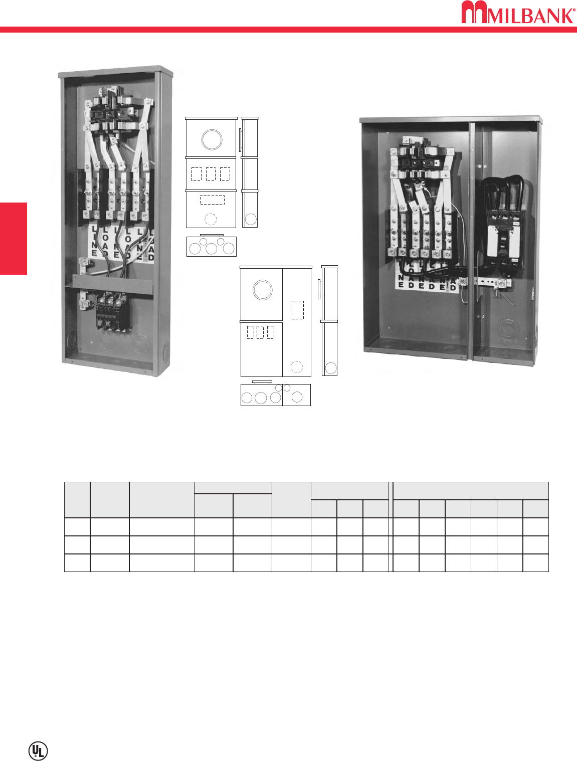
TEST BLOCK BYPASS—MTB SERIES—200 AMP—35K AIC
480 VOLT—SELF CONTAINED METER MAIN / CIRCUIT BREAKER
D8
Utility requirements for this equipment may vary. Always consult the serving utility for their requirements before ordering or
installing equipment in this catalog.
D8
SECTION D
These UL Listed products are for use in areas requiring
Electrical Utility Service Equipment Requirements
Committee (EUSERC) compliance.
35K Short Circuit Current Withstand Rating
COMMERCIAL METERING–SAFETY SOCKETS, METER MAINS,
TERMINATION BOXES, BUSSED GUTTERS
REPLACEMENT MAIN DISCONNECTS: For replacement main disconnect see pages D14 & D15.
HUBS: OH units use hub up to 21
⁄
2" (see accessory page). Units provided with closing plate.
SEALING RINGS: Units furnished with MR-2 snap style sealing rings.
NEUTRAL: “Lay-in” connectors will accommodate #2-250 copper or aluminum wire.
* For 3W (208Y/120) network service, install field mounted fifth terminal catalog number 105J. See accessory page.
200 AMP—4 & 7 TERMINAL—480 VOLT—BREAKER INSTALLED—RING TYPE
TYPE
OF
SERVICE
CATALOG
NUMBER
NO.
OF
TERM.
CONNECTORS
LINE LOAD
NEUTRAL
TYPE
OF
SERVICE
DIMENSIONS CONCENTRIC K.O.ʼS
123456D" W" H"
#2/0-250
#2/0-250
#2/0-250
OH7227MTB-48 3∅4W 21
⁄
221
⁄
23 3 9
⁄
32 1
⁄
2
614 48#6-250
OH/UG4U224MTB-48* 1∅3W * 21
⁄
221
⁄
2321
⁄
23
⁄
421
⁄
2
6223
⁄
430#6-250
OH/UG7U227MTB-48 3∅4W 21
⁄
221
⁄
2321
⁄
23
⁄
421
⁄
2
6223
⁄
430#6-250
227MTB-48 U227MTB-48
3
2
4
4
1
5 6
224MTB-48
227MTB-48
1
3
2
44
55
6
U224MTB-48
U227MTB-48
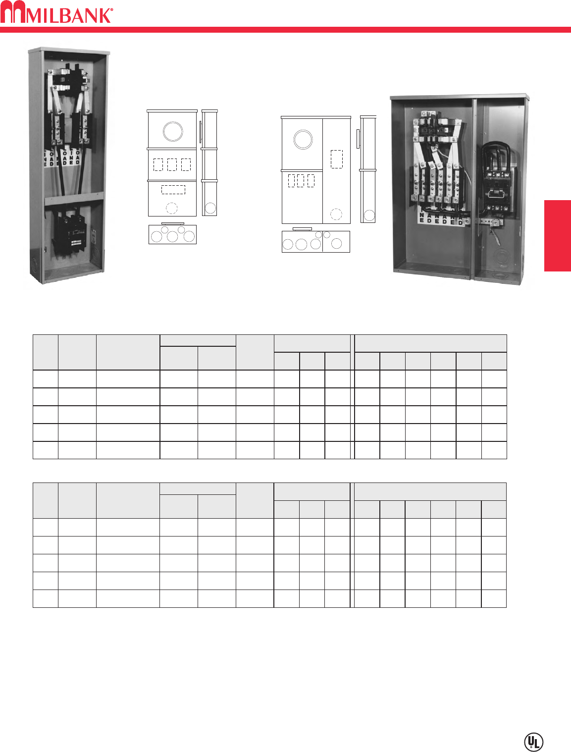
D9
TEST BLOCK BYPASS—MTB-P SERIES & MTB-P48 SERIES—200 AMP—200K AIC
240/480 VOLT—SELF-CONTAINED METER MAIN / T-FUSE PULLOUT
Utility requirements for this equipment may vary. Always consult the serving utility for their requirements before ordering or
installing equipment in this catalog.
D9
COMMERCIAL METERING–SAFETY SOCKETS, METER MAINS,
TERMINATION BOXES, BUSSED GUTTERS
SECTION D
REPLACEMENT MAIN DISCONNECTS: For replacement main disconnect see pages D14 & D15.
HUBS: OH units use hub up to 21
⁄
2" (see accessory page). Units provided with closing plate.
SEALING RINGS: Units furnished with MR-2 snap style sealing rings.
NEUTRAL: “Lay-in” connectors will accommodate #2-250 copper or aluminum wire.
PULL-OUTS: For use with T-fuses only. Fuses are included with fused safety sockets.
* For 3W (208Y/120) network service, install field mounted fifth terminal catalog number 105J. See accessory page.
200 AMP—4, 5 & 7 TERMINAL—240 VOLT PULLOUT INSTALLED—RING TYPE
TYPE
OF
SERVICE
CATALOG
NUMBER
OH
OH
NO.
OF
TERM.
4
5
224MTB-P*
225MTB-P
CONNECTORS
LINE LOAD
NEUTRAL
TYPE
OF
SERVICE
1∅3W *
3∅3W
DIMENSIONS CONCENTRIC K.O.ʼS
1 2 3 4 5 6
21
⁄
2
21
⁄
2
21
⁄
2
21
⁄
2
3
3
3
3
9
⁄
32
9
⁄
32
1
⁄
2
1
⁄
2
D" W" H"
6
6
14
14
48
48
#6-250 #1/0-250
#1/0-250
#1/0-250
#1/0-250
#1/0-250
#6-250
OH7227MTB-P 3∅4W 21
⁄
221
⁄
23 3 9
⁄
32 1
⁄
2
614 48#6-250
OH/UG4U224MTB-P* 1∅3W * 2 2 21
⁄
223
⁄
426 223
⁄
430#6-250
OH/UG7U227MTB-P 3∅4W 2 2 21
⁄
223
⁄
426 223
⁄
430#6-250
200 AMP—4, 5 & 7 TERMINAL—200 AMP-480 VOLT PULLOUT INSTALLED —RING TYPE
TYPE
OF
SERVICE
CATALOG
NUMBER
OH
OH
NO.
OF
TERM.
4
5
224MTB-P48*
225MTB-P48
CONNECTORS
LINE LOAD
NEUTRAL
TYPE
OF
SERVICE
1∅3W *
3∅3W
DIMENSIONS CONCENTRIC K.O.ʼS
1 2 3 4 5 6
21
⁄
2
21
⁄
2
21
⁄
2
21
⁄
2
3
3
3
3
9
⁄
32
9
⁄
32
1
⁄
2
1
⁄
2
D" W" H"
6
6
14
14
48
48
#6-250 #1/0-250
#1/0-250
#1/0-250
#1/0-250
#1/0-250
#6-250
OH7227MTB-P48 3∅4W 21
⁄
221
⁄
23 3 9
⁄
32 1
⁄
2
614 48#6-250
OH/UG4U224MTB-P48* 1∅3W * 2 2 21
⁄
223
⁄
426 223
⁄
430#6-250
OH/UG7U227MTB-P48 3∅4W 2 2 21
⁄
223
⁄
426 223
⁄
430#6-250
1
3
2
44
55
6
3
2
4
4
1
5 6
224MTB-P
225MTB-P
227MTB-P
224MTB-P48
225MTB-P48
227MTB-P48
U224MTB-P
U227MTB-P
U224MTB-P48
U227MTB-P48
224MTB-P U227MTB-P
These UL Listed products are for use in areas requiring
Electrical Utility Service Equipment Requirements Committee
(EUSERC) compliance.
200K Short Circuit Current Withstand Rating
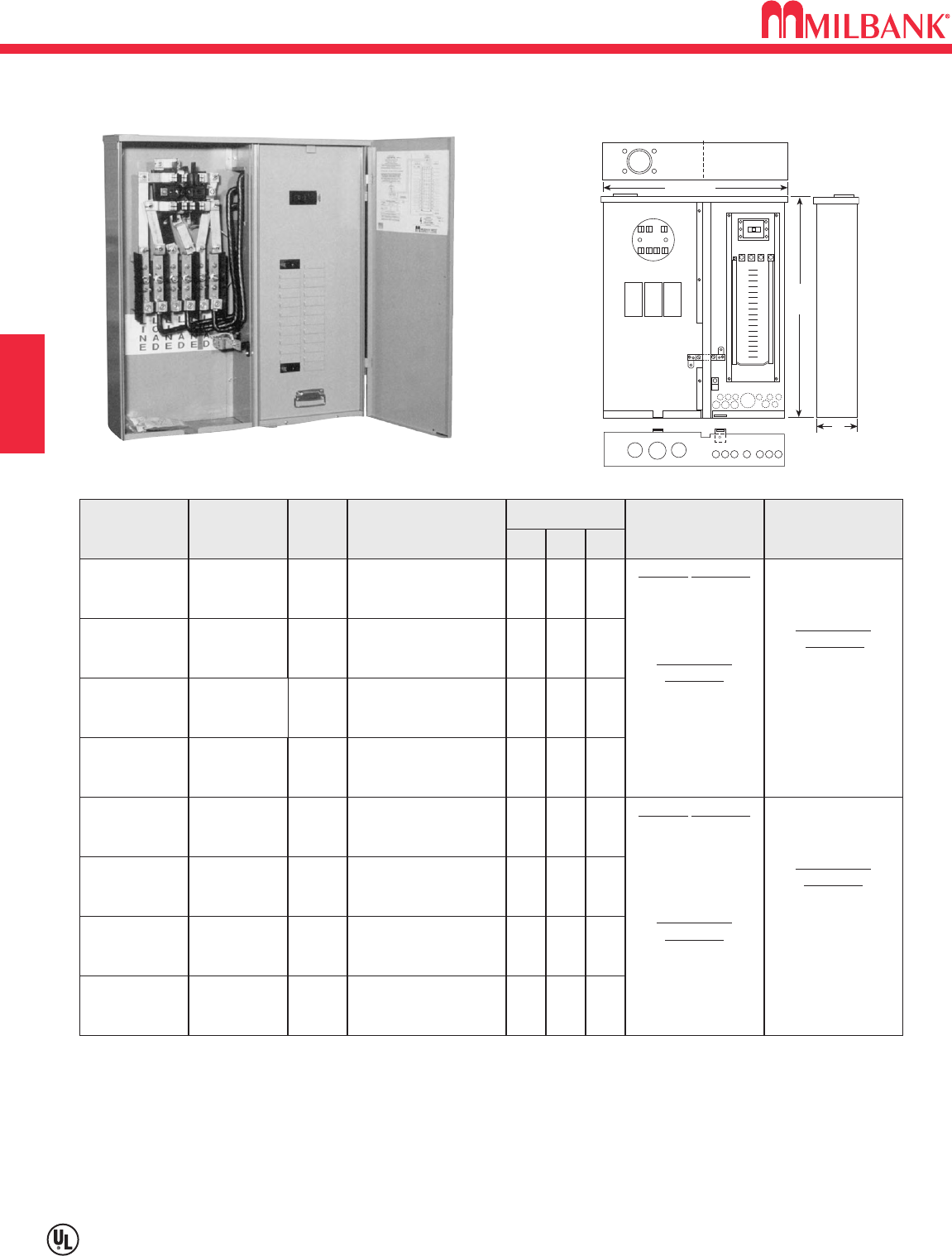
TEST BLOCK BYPASS—MTBL ALL-IN-ONE SERIES—100 & 200 AMP—10K & 200K AIC
240 VOLT METER MAIN—CIRCUIT BREAKER / T-FUSE PULLOUT
D10
Utility requirements for this equipment may vary. Always consult the serving utility for their requirements before ordering or
installing equipment in this catalog.
D10
SECTION D
These UL Listed products are for use in areas requiring
Electrical Utility Service Equipment Requirements
Committee (EUSERC) compliance.
COMMERCIAL METERING–SAFETY SOCKETS, METER MAINS,
TERMINATION BOXES, BUSSED GUTTERS
ON OFF
4 5/8"
or
6"
25" or
27"
24 3/4"
or
30"
CATALOG
NUMBER
U214MTBL
RATING
100A,120/240
VAC 1∅3W
NO.
INTERNAL
CIRCUITS
12/24
MAIN CIRCUIT BREAKER
OR
FUSE PULLOUT
100A, 2P, 10K
Milbank
Q2100
DIMENSIONS BOTTOM
CONDUIT K.O.ʼS
BACK
CONDUIT K.O.ʼS
D"
45⁄825 243⁄4
U214MTBPL100A,120/240
VAC 1∅3W 12/24 100A, 2P, 100K
Boltswitch
PT223 45⁄825 243⁄4
U217MTBL
100A,
240Δ/120;
208Y/120 VAC
3∅4W
18/36 100A, 3P, 10K
Siemens
BQ3100 45⁄825 243⁄4
U217MTBPL
100A,
240Δ/120;
208Y/120 VAC
3∅4W
18/36 100A, 3P, 100K
Boltswitch
PT323 45⁄825 243⁄4
U224MTBL200A,120/240
VAC 1∅3W 20/40 200A, 2P, 10K
Milbank
UQFP-200 627 30
U224MTBPL200A,120/240
VAC 1∅3W 20/40 200A, 2P, 100K
Boltswitch
PT224 627 30
U227MTBL
200A,
240Δ/120;
208Y/120 VAC
3∅4W
24/42 200A, 3P, 10K
Siemens
QJ23B200 627 30
U227MTBPL
200A,
240Δ/120;
208Y/120 VAC
3∅4W
24/42 200A, 3P, 100K
Boltswitch
PT324 627 30
UTILITY SECTION
(1) 1/2"
(3) 11/4",11/2",2",21/2"
CUSTOMER
SECTION
(3) 1/2", 3/4"
(1) 1/2",
3/4" ,1",11/4"
(2) 3/4",1",11/4",11/2"
UTILITY SECTION
(1) 1/2", 3/4"
(2) 11/4",11/2", 2",21/2"
(1) 21/2",3"
CUSTOMER
SECTION
(11) 1/2"
(2) 1/2", 3/4"
(1) 1/2",
3/4",1",11/4"
(2) 3/4",1",11/4",11/2"
CUSTOMER
SECTION
(7) 1/2"
(4) 1/2",
3/4"
(1) 3/4" ,1",11/4",11/2"
CUSTOMER
SECTION
(6) 1/2"
(4) 1/2",
3/4"
(1) 3/4" ,1",11/4",11/2"
W"H"
LINE: Underground or overhead service. Line Lug: 100A, 14-2/0 and 200A 1/0-250
LOAD: Underground only.
BRANCH BREAKERS: Single phase units—approved for Siemens/ITE Type Q, Challenger, Cutler-Hammer/Westinghouse,
General Electric, Murray. Three phase units—approved for Siemens/ITE Type Q.
HUBS: OH units use hub up to 21
⁄
2" (see accessory page). Units provided with closing plate.
PULL-OUTS: For use with T-fuses only. Fuses are included with fused safety sockets.
For 208Y/120 applications, order separately and field install kit 105J.
U227-MTBL
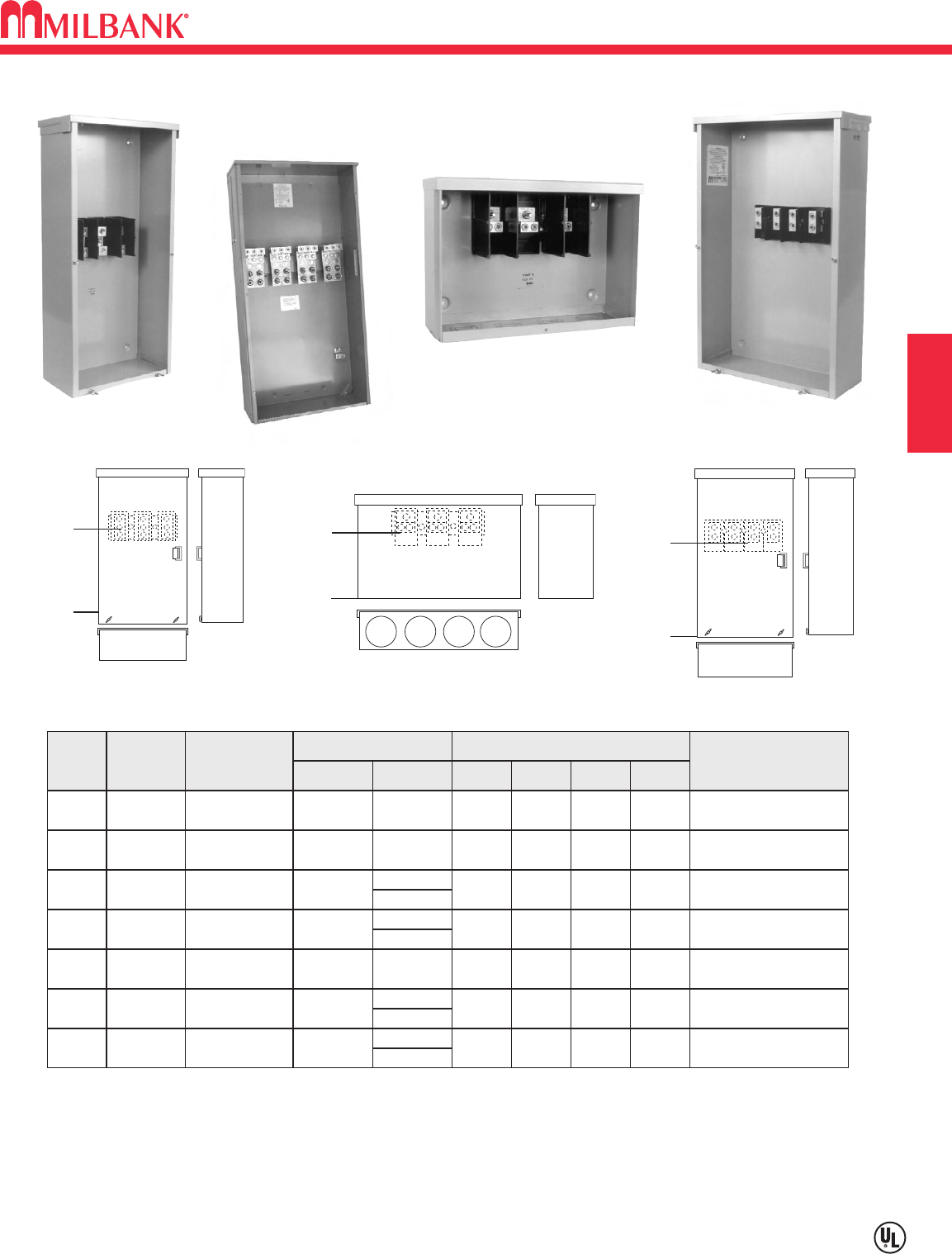
D11
UNDERGROUND TERMINATION BOXES—600 VAC
Utility requirements for this equipment may vary. Always consult the serving utility for their requirements before ordering or
installing equipment in this catalog.
D11
SECTION D
These UL Listed products are for use in areas requiring
Electrical Utility Service Equipment Requirements
Committee (EUSERC) compliance.
COMMERCIAL METERING–SAFETY SOCKETS, METER MAINS,
TERMINATION BOXES, BUSSED GUTTERS
UNDERGROUND TERMINATION BOXES
AMPS
TYPE
OF
SERVICE
CATALOG
NUMBER
CONNECTORS DIMENSIONS SHORT CIRCUIT
CURRENT
WITHSTAND RATING
100 1∅-3W PB-01110K AMPS
D" W" H"LINE LOAD
412 81⁄2
#14-1/0 #14-1/0
200 1∅-3W PB-012 10K AMPS612 26#6-250 #6-250
400 1∅-3W PB-014
PB-014-NK 50K AMPS616 36
1/2"-13
studs
#4-600
twin 1⁄0-250
#4-600
twin 1⁄0-250
800 1∅-3W PB-018
PB-018-NK 50K AMPS
11 24 48
1/2"-13
studs
200 3∅-4W PB-032 10K AMPS616 26#6-250 #6-250
400 3∅-4W PB-034
PB-034-NK 50K AMPS616 36
1/2"-13
studs
#4-600
twin 1⁄0-250
#4-600
twin 1⁄0-250
800 3∅-4W PB-03850K AMPS *
11 24 48
X"
33⁄4
141⁄4
22
26
1411⁄16
22
26
1/2"-13
studs
CONNECTORS AND BUSSING: Extruded aluminum connectors and bus bars are tin plated.
For no knockouts, add suffix -NK to the above catalog numbers.
No lift handles provided on the PB-011.
2 studs per lug position provided for 400 amp units. 4 studs per lug position provided for 800 amp units.
PB-011
PB-012 PB-032
X-dim.
1 1/4" 1 1/4" 1 1/4" 1 1/4"
X-dim.
PB-038
X- dim.
PB-012
PB-011
PB-032
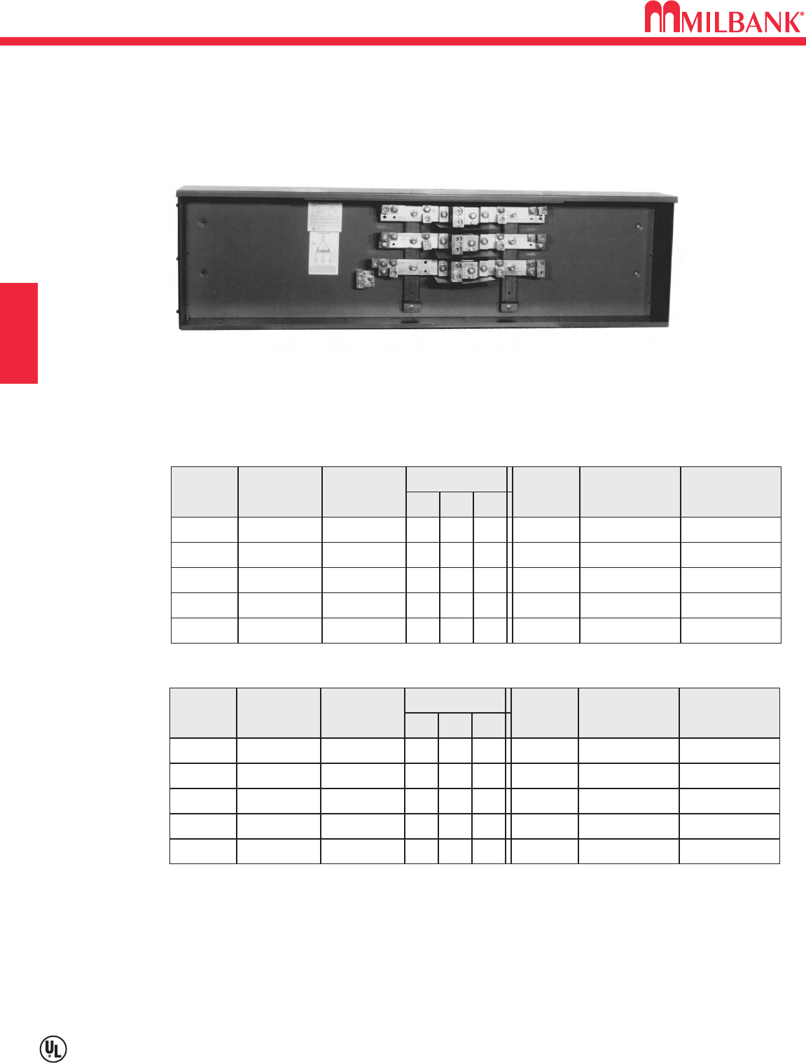
BUSSED GUTTERS—TYPE 3R—1
∅
3W AND 3
∅
4W—600 VAC
D12
Utility requirements for this equipment may vary. Always consult the serving utility for their requirements before ordering or
installing equipment in this catalog.
D12
SECTION D
These UL Listed products
are for use in areas
requiring Electrical Utility
Service Equipment
Requirements Committee
(EUSERC) compliance.
COMMERCIAL METERING–SAFETY SOCKETS, METER MAINS,
TERMINATION BOXES, BUSSED GUTTERS
BC418
1∅3W—BUSSED GUTTERS—TYPE 3R—600 VAC
METER
POSITION
2BC214 400 6285
⁄
8151
⁄
220" Bar (1) 600
3BC318 800 643 151
⁄
2(2) 20" Bars (2) 600
4BC418 800 6571
⁄
4151
⁄
2(2) 20" Bars (2) 600
5BC518 800 6715
⁄
8151
⁄
2(2) 20" Bars (2) 600
6BC618 800 6857
⁄
8151
⁄
2(2) 20" Bars (2) 600
CATALOG
NUMBER
AMPERE
RATING
DIMENSIONS LENGTH
OF
BUS
LINE LUGS
PER
EACH BUS
(2) 6-250
(3) 6-250
(4) 6-250
(5) 6-250
(6) 6-250
LOAD LUGS
PER
EACH BUS
D" W" H"
3∅4W—BUSSED GUTTERS—TYPE 3R—600 VAC
METER
POSITION
2BC234 400 6285
⁄
8151
⁄
220" Bar (1) 600
3BC338 800 643 151
⁄
2(2) 20" Bars (2) 600
4BC438 800 6571
⁄
4151
⁄
2(2) 20" Bars (2) 600
5BC538 800 6715
⁄
8151
⁄
2(2) 20" Bars (2) 600
6BC638 800 6857
⁄
8151
⁄
2(2) 20" Bars (2) 600
CATALOG
NUMBER
AMPERE
RATING
DIMENSIONS LENGTH
OF
BUS
LINE LUGS
PER
EACH BUS
(2) 6-250
(3) 6-250
(4) 6-250
(5) 6-250
(6) 6-250
LOAD LUGS
PER
EACH BUS
D" W" H"
SHORT CIRCUIT CURRENT WITHSTAND RATING: Standard bracing is 42K AIC.
CONNECTORS AND BUSSING: Extruded aluminum connectors and bus bars are tin plated.
COVER: Lift handles provided along with a cover sealing provision. A removable, sealable
cover is provided at both ends for pull box assembly.
HARDWARE: Meter socket mounting hardware included.
SUITABLE FOR USE ON LINE SIDE OF SERVICE EQUIPMENT.
FOR COMMERCIAL SAFETY SOCKET APPLICATIONS
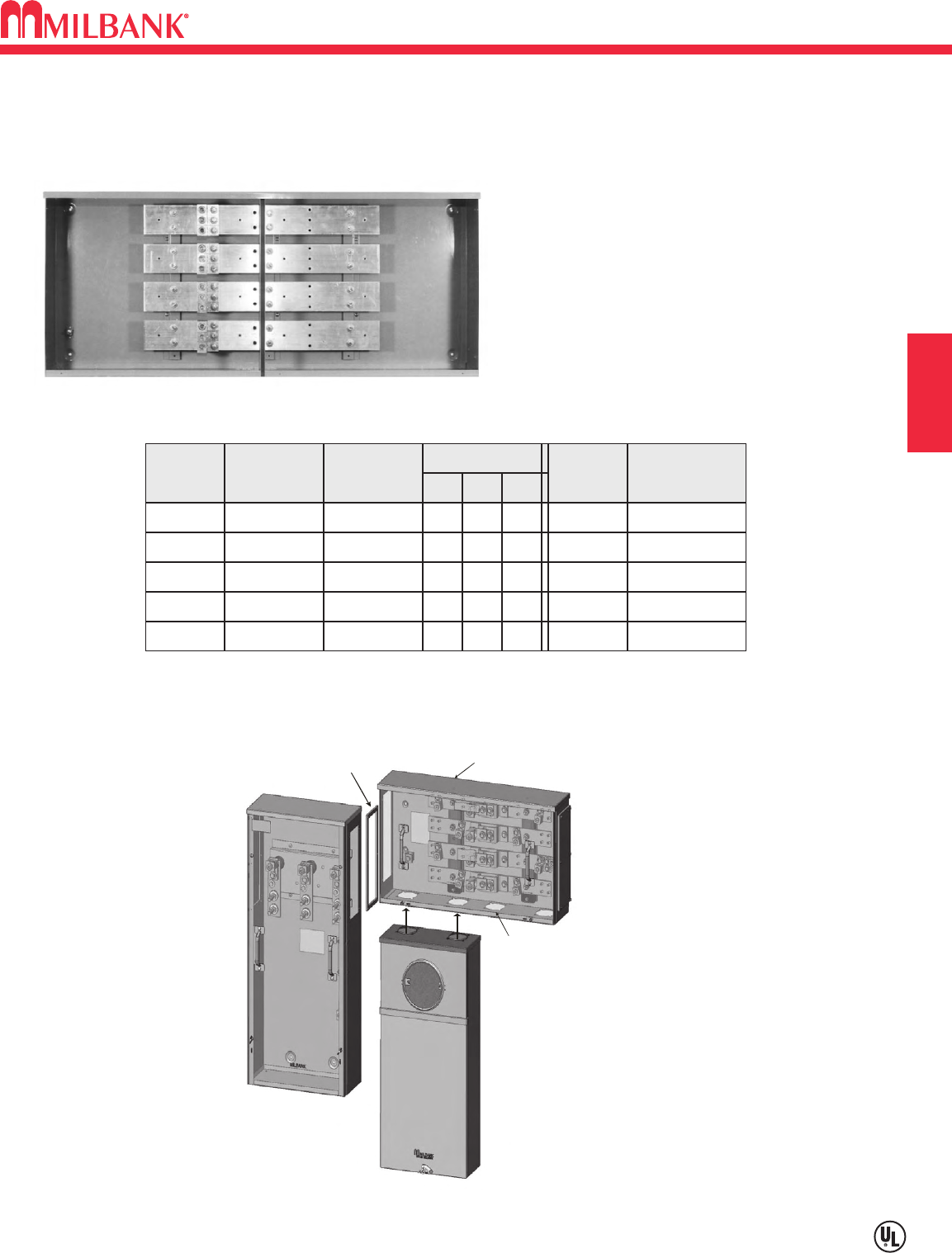
D13
BUSSED GUTTERS—TYPE 3R—3
∅
4W—600 VAC
Utility requirements for this equipment may vary. Always consult the serving utility for their requirements before ordering or
installing equipment in this catalog.
D13
SECTION D
These UL Listed products
are for use in areas
requiring Electrical Utility
Service Equipment
Requirements Committee
(EUSERC) compliance.
COMMERCIAL METERING–SAFETY SOCKETS, METER MAINS,
TERMINATION BOXES, BUSSED GUTTERS
3∅4W—BUSSED GUTTERS—TYPE 3R—600 VAC
METER
POSITION
2U3462-O 400 624 24 17" Bar (1) 600
3U3463-O 600 636 24 24" Bars (2) 600
4U3464-O 800 648 24 32" Bars (3) 600
5U3465-O 800 660 24 40" Bars (3) 600
6U3466-O 800 672 24 56" Bars (3) 600
CATALOG
NUMBER
AMPERE
RATING
DIMENSIONS LENGTH
OF
BUS
LINE LUGS
PER
EACH BUS
D" W" H"
SHORT CIRCUIT CURRENT WITHSTAND RATING: The 400 and 600 amp units have a
withstand rating of 50K amps, and the 800 amp units have a rating of 65K amps.
SUITABLE FOR USE ON LINE SIDE OF SERVICE EQUIPMENT.
•
Enclosure without knockouts
•
Tin plated aluminum bus bars
•
Furnished with line lugs only
•
Bus is drilled and tapped for easy
installation of load lugs
Meter Socket
Pull Box
Bussed Gutter
Knockouts
Gasket attached
to Pull Box
Typical Application of
Safety Sockets
with Multi-Metering
(shown with KOs)
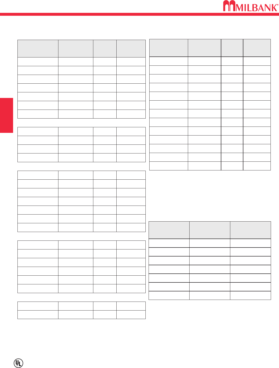
D14
D14
SECTION D
SAFETY SOCKET REPLACEMENT CIRCUIT BREAKERS & PULLOUTS
214MTB
CATALOG
NUMBER
BQ2B100L
CIRCUIT
BREAKER
Milbank
MFG.
917930-MO
PART
NUMBER
214MTB-48 ED42B100 Siemens 705831-MO
214MTB/22 BQ2B100HL Milbank 917960-MO
U214MTB BQ2B100L Milbank 917930-MO
U214MTB-48 ED42B100 Siemens 705831-MO
U214MTB/22 BQ2B100HL Milbank 917960-MO
U214MTBL BQ2B100L Milbank 917915-MO
215MTB BQ3B100L Milbank 917990-MO
215MTB-48 ED43B100 Siemens 708571-MO
U215MTB BQ3B100L Milbank 917990-MO
U215MTB-48 ED43B100 Siemens 708571-MO
217MTB BQ3B100L Milbank 917990-MO
217MTB-48 ED43B100 Siemens 708571-MO
217MTB/22 BQ3B100HL Milbank 918020-MO
U217MTB BQ3B100L Milbank 917990-MO
U217MTB-48 ED43B100 Siemens 708571-MO
U217MTB/22 BQ3B100HL Milbank 918020-MO
U217MTBL BQ3B100L Milbank 917990-MO
224MTB UQFB-200 Milbank 915548-MO
224MTB/22 UQFBH-200 Milbank 915748-MO
U224MTB UQFB-200 Milbank 915548-MO
U224MTB-48 FXD62B200 Siemens 705747-MO
U224MTB/22 UQFBH-200 Milbank 915748-MO
U224MTBL UQFB-200 Milbank 915548-MO
U225MTB UQFB-3200 Milbank 916777-MO
CATALOG
NUMBER
CIRCUIT
BREAKER MFG. PART
NUMBER
U225MTBL QJ23B200 Siemens 707403-MO
227MTB UQFB-3200 Milbank 916777-MO
227MTB-125 UQFB-3125 Milbank 916759-MO
227MTB-150 UQFB-3150 Milbank 916765-MO
227MTB-175 UQFB-3175 Milbank 926772-MO
227MTB-48 FXD63B200 Siemens 706036-MO
227MTB/22 QJH23B200L Siemens 707503-MO
227MTB UQFB-3200 Milbank 916777-MO
U227MTB-125 UQFB-3125 Milbank 916759-MO
U227MTB-150 UQFB-3150 Milbank 916765-MO
U227MTB-175 UQFB-3175 Milbank 926772-MO
U227MTB-48 FXD63B200 Siemens 706036-MO
U227MTB/22 QJH23B200L Siemens 707503-MO
U227MTBL
SIEMENS
CIRCUIT
BREAKER
NUMBER OF
LUG COLLARS
REQUIRED
PART NUMBER
ED42B100 (2) LN13100 705831-MO
ED43B100 (3) LN1E100 708572-AC
FXD62B200 (4) TA1FD350 708573-AC
FXD63B200 (6) TA1FD350 706036-MO
QJ22B200H (2) TA1Q300 707523-MO
QJ23B200 (1) TA1Q300 707403-MO
QJH23B200L (1) TA1Q300 707503-MO
QJ23B200 Siemens 707403-MO
REPLACEMENT CIRCUIT BREAKERS REPLACEMENT CIRCUIT BREAKERS, cont.
When replacing Siemens Circuit Breaker (FXD,ED,QJ) in
safety sockets, lug collars must be ordered separately.
LUG KITS FOR CIRCUIT BREAKERS
COMMERCIAL METERING–SAFETY SOCKETS, METER MAINS,
TERMINATION BOXES, BUSSED GUTTERS
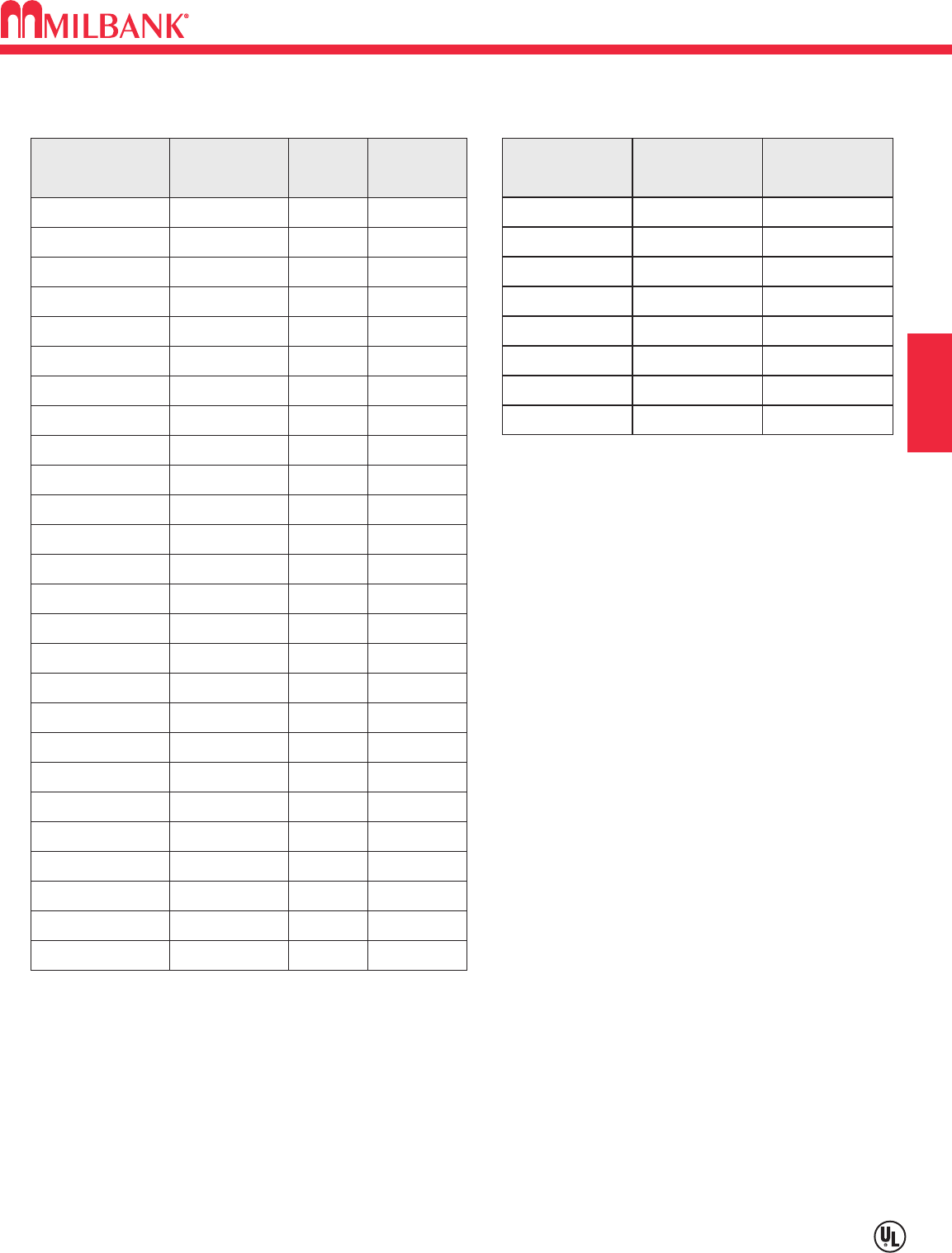
D15
D15
COMMERCIAL METERING–SAFETY SOCKETS, METER MAINS,
TERMINATION BOXES, BUSSED GUTTERS
SECTION D
SAFETY SOCKET REPLACEMENT CIRCUIT BREAKERS & PULLOUTS
T-FUSE
PULLOUTS
NUMBER OF
LUG COLLARS
REQUIRED
PART NUMBER
PT223 (2) TK100P 707682-AC
PT224 (2) TK200P 708570-AC
PT263 (2) TK100P 707682-AC
PT264 (2) TK200P 708570-AC
PT323 (3) TK100P 707682-AC
PT324 (3) TK200P 708570-AC
PT363 (3) TK100P 707682-AC
PT364 (3) TK200P 708570-AC
214MTB-P
CATALOG
NUMBER
PT223
T-FUSE
PULLOUT
Boltswitch
MFG.
707674-MO
PART
NUMBER
214MTB-P48 PT263 Boltswitch 708564-MO
U214MTB-P PT223 Boltswitch 707674-MO
U214MTB-P48 PT263 Boltswitch 708564-MO
U214MTBPL PT223 Boltswitch 707674-MO
215MTB-P PT323 Boltswitch 708565-MO
215MTB-P48 PT363 Boltswitch 708566-MO
U215MTB-P PT323 Boltswitch 708565-MO
U215MTB-P48 PT363 Boltswitch 708566-MO
217MTB-P PT323 Boltswitch 708565-MO
217MTB-P48 PT363 Boltswitch 708566-MO
U217MTB-P PT323 Boltswitch 708565-MO
U217MTB-P48 PT363 Boltswitch 708566-MO
U217MTBPL PT323 Boltswitch 708565-MO
224MTB-P PT224 Boltswitch 707684-MO
224MTB-P48 PT264 Boltswitch 708567-MO
U224MTB-P PT224 Boltswitch 707684-MO
U224MTB-P48 PT264 Boltswitch 708567-MO
U224MTBPL PT224 Boltswitch 707684-MO
225MTB-P48 PT364 Boltswitch 708569-MO
U225MTBPL PT324 Boltswitch 708568-MO
227MTB-P PT324 Boltswitch 708568-MO
227MTB-P48 PT364 Boltswitch 708569-MO
U227MTB-P PT324 Boltswitch 708568-MO
U227MTB-P48 PT364 Boltswitch 708569-MO
U227MTBPL PT324 Boltswitch 708568-MO
REPLACEMENT T-FUSE PULLOUTS
NOTE: T-Fuse pullouts provided with load side lugs.
Order line side lugs separately from above chart.
LUG KITS FOR T-FUSE PULLOUTS
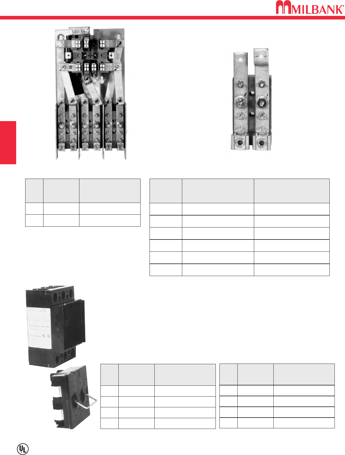
SAFETY SOCKET & T-FUSE REPLACEMENT PARTS
D16
Utility requirements for this equipment may vary. Always consult the serving utility for their requirements before ordering or
installing equipment in this catalog.
D16
SECTION D
These UL Listed products
are for use in areas
requiring Electrical Utility
Service Equipment
Requirements Committee
(EUSERC) compliance.
COMMERCIAL METERING–SAFETY SOCKETS, METER MAINS,
TERMINATION BOXES, BUSSED GUTTERS
TENANT METER SOCKETS REPLACEMENT TEST BLOCKS
AMPS
200 MS-24-TB 600V / 1∅3W
200 MS-27-TB 600V / 3∅4W
CATALOG
NUMBER VOLTAGE / SYSTEM AMPS
100 TB100-47 PHASE A, B & C
100 TB100-5
CENTER BLOCK ONLY PHASE B—3∅3W
200 TB200-47 PHASE A, B & C
200 TB200-5
CENTER BLOCK ONLY PHASE B—3∅3W
200 TB200-LL LUG—LUG
—TB-BARR
#Z707371-MO TEST BLOCK BARRIER
CATALOG
NUMBER PHASE
MS-27-TB TB200-47
AMPS
100 PT223 2 POLE—240 VOLT
200 PT224 2 POLE—240 VOLT
100 PT323 3 POLE—240 VOLT
200 PT324 3 POLE—240 VOLT
CATALOG
NUMBER RATING
240 VOLT
MAIN DISCONNECTS
PULLOUT SWITCH
(USES TYPE “T” FUSE)
AMPS
100 PT263 2 POLE, 480 VOLT
200 PT264 2 POLE, 480 VOLT
100 PT363 3 POLE, 480 VOLT
200 PT364 3 POLE, 480 VOLT
CATALOG
NUMBER RATING
480 VOLT
MAIN DISCONNECTS
PULLOUT SWITCH
(USES TYPE “T” FUSE)
PT324
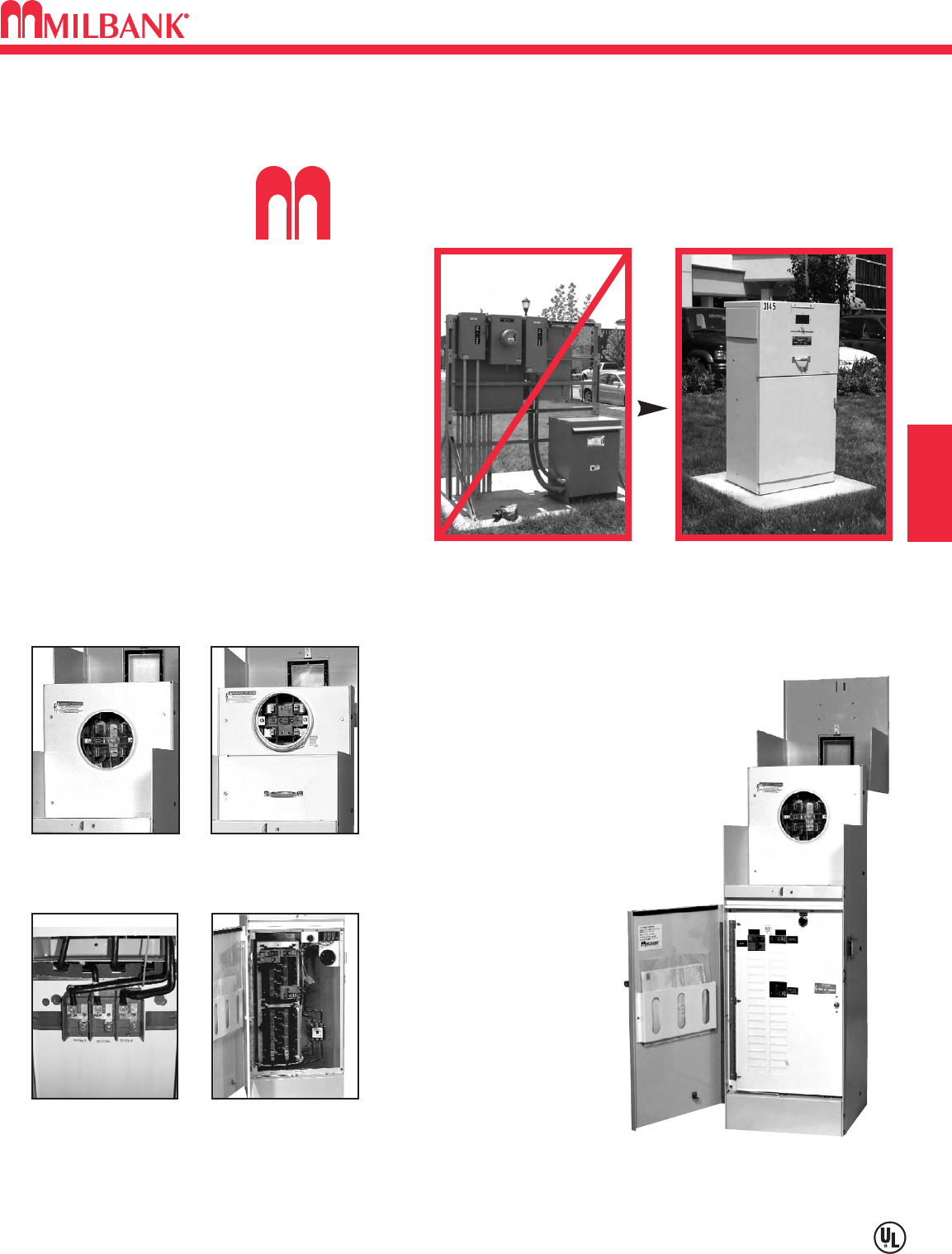
E1
Utility requirements for this equipment may vary. Always consult the serving utility for their requirements before ordering or
installing equipment in this catalog.
E1
SECTION E COMMERCIAL METER PEDESTALS
OVERVIEW
ilbank Commercial Pedestals are pad-mounted, weatherproof electrical
enclosures consisting of a utility pull section with optional meter socket, and
a customer section containing distribution and control equipment. Milbank
Commercial Pedestals
are an attractive, secure,
easy to install and cost-
effective solution when
underground remote
site power distribution
and control equipment
is required, replacing
unsightly and inefficient
strut and backboard
structures.
Un-Strut
Your
Stuff...
Commercial Pedestals
• Attractive • Easy to install • Secure • Cost effective
STANDARD FEATURES –COMMERCIAL PEDESTALS
• Type 3R rainproof, vandal-resistant cabinet of
polyurethane powder-coated steel (aluminum or
stainless steel also available)
• UL listed as enclosed industrial control
equipment (UL508)
• Isolated, lockable & sealable utility metering &
lug landing sections
• Lockable customer section for distribution &
control equipment with internal deadfront
• Print pocket inside customer section door
contains wiring schematics
and installation instructions
• Most load centers are UL
listed for use with various
manufacturers’ circuit
breakers
• All stainless steel external
hardware (screws, bolts,
hinges, handles, hasps and
sealing screws)
• Meets EUSERC 308 and other
utility standards.
Ringless Socket Ring-type Socket
Utility Lug Landing Customer Interior
UL Listed as Industrial Control Equipment (File E113855).
Strut and backboard design Commercial Pedestal
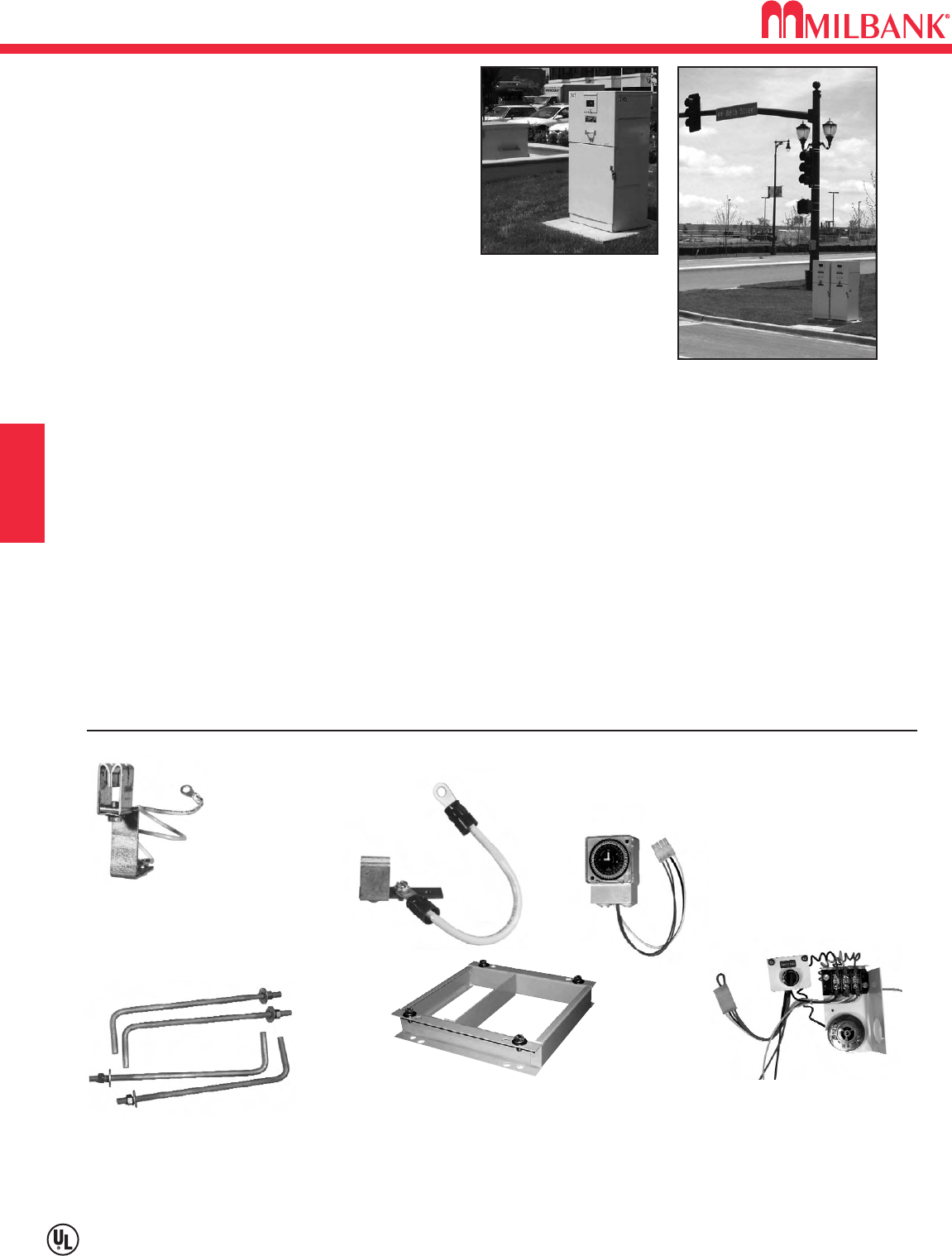
APPLICATIONS & ACCESSORIES
E2
Utility requirements for this equipment may vary. Always consult the serving utility for their requirements before ordering or
installing equipment in this catalog.
E2
SECTION E
COMMERCIAL METER PEDESTALS
CP-16PDMNT-CALT
Pedestal mounting base for 16" pedestal
CP-24PDMNT-CALT
Pedestal mounting base for 24" pedestal
(includes mounting hardware)
CP-ABK5/8
Anchor bolt kit (includes four 5/8-
13 x 18" anchor bolts)
CP-PE-HOA-3POS
HOA switch – for field
installation
ACCESSORIES
CP-TC7D 7-day time clock kit
CP-TC24H 24-hour time clock kit
CP-TCWIRE Male four-pin connector
and wiring harness for use
with time clocks other than
shown
K3865
Fifth terminal kit for
use with ringless
meter sockets
105J
Fifth terminal
kit for use
with ring-type
meter sockets
• Meter sockets – ring type or ringless, to 400 amp (unmetered
pedestals also available)
•Main and branch breakers or T fuses
• Distribution – copper load centers & panel boards
• Clocks / timers / relays
• Photoelectric cells and controls
• Power receptacles – pin & sleeve, twist lock or straight blade
• Contactors – definite purpose, electrical or mechanically
held, IEC and mercury types
• Surge protection & lightning arrestors
• Reserve inlet generator receptacle with interlocked circuit
breakers
• Motor starters, relays
• Push button controls
• Thermostat controls, fans and heating strips
• Power blocks and terminal blocks
• Steel, aluminum and plywood back boards
• Transformers
• Interlock devices for circuit breakers
• Available in steel, aluminum (raw painted or anodized) or
stainless steel construction with powder-coated finish
available in 8 standard colors or special ordered RAL colors.
• Available for applications up to 400 amp, 120V, 208V,
240V, 277V, 480V – 1Ø or 3Ø.
APPLICATIONS
These units are ideal for controlling and metering:
• Traffic signals
• Street lighting
• Irrigation / sprinkler systems
• Cell towers / telephone vaults
• Pump stations
• Temporary power for fairgrounds, swap meets, outdoor
markets, portable offices, holiday lights, etc.
• Outdoor lighting for athletic fields, tennis and basketball courts, parking lots,
landscaping and subdivision entrances, etc.
AVAILABLE FACTORY-INSTALLED OPTIONS
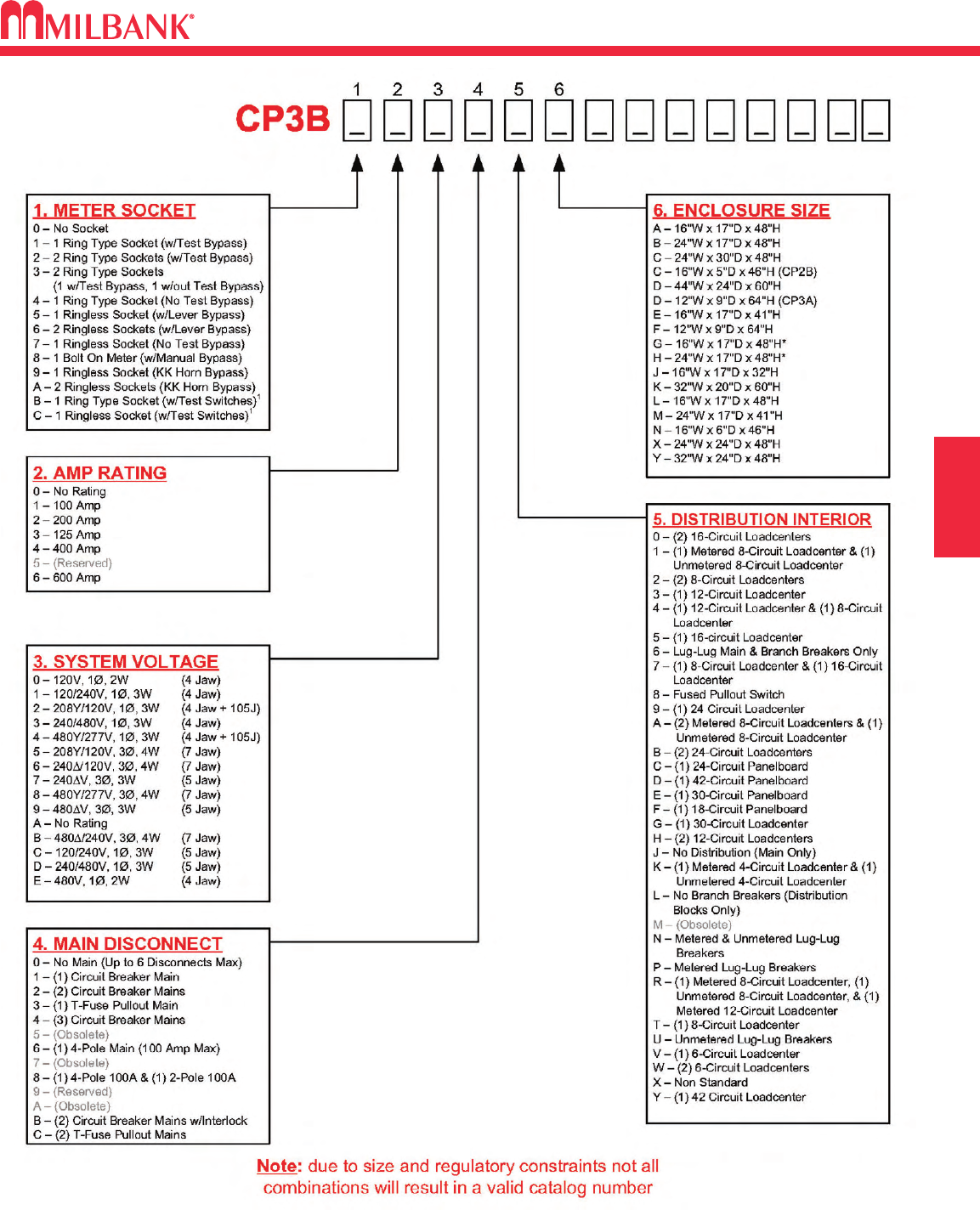
E3
COMMERCIAL METER PEDESTALS
CATALOG NUMBER LOGIC
Logic description subject to change and factory interpretation.
E3
SECTION E
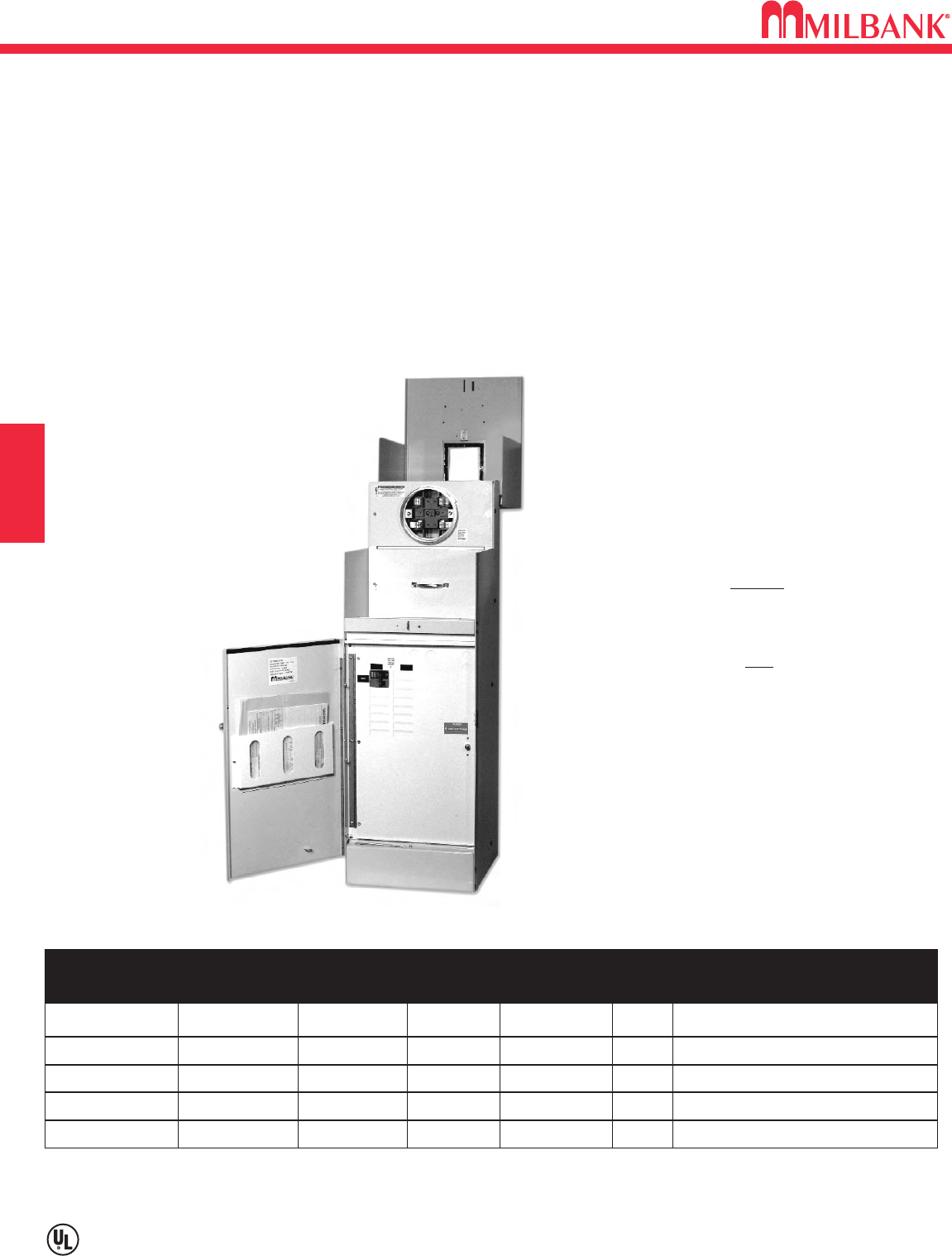
E4
Utility requirements for this equipment may vary. Always consult the serving utility for their requirements before ordering or
installing equipment in this catalog.
E4
SECTION E
COMMERCIAL METER PEDESTALS
The Milbank Main Load Center Commercial
Pedestals are designed to handle the vast majority of
all requirements in a standard, stocked configuration.
• No waiting or extra charge
• Units all feature a load center with a plug-
on, back-fed main breaker.
• Load center has 16 positions for the
100 amp pedestals and 24 circuits for
the 200 amp pedestals.
• Both sizes include sub-feed lugs to
allow feeding an external panel
If your application requires
turning loads on based on “dusk-to-
dawn” requirements, be sure to see
the Milbank Switched Load Center
Commercial Pedestal
products on the
following page.
ML SERIES–MAIN LOAD CENTER
CP3B “ML” Series
Main Load Center Series
1∅3 wire 120/240 or 208Y/120 volt
Typical applications: Remote site service
for multiple loads
NEMA 3R construction
Expandable – Load centers allow for future
expansion without costly modifications
All units feature 200 amp meter socket with
optional field-installable fifth terminal kit
available
22K ampere interrupting capacity (AIC)
standard
Optional mounting base can be embedded in
concrete for fast, easy installation
Separate sealable and lockable utility
termination section
Separate sealable and lockable metering
section with the option of:
EITHER
Milbank ring-type socket with test / bypass
blocks (conforms to EUSERC 308)
OR
Milbank heavy duty ringless socket with
lever bypass
A separate sealable and lockable customer
section with a load center for “always on”
loads that includes:
• Main circuit breaker
• Twenty (200 or 125 amp model) or
fourteen (100 amp model) blank breaker
spaces
• A circuit directory to document
configuration
Features:
These units include everything required for
remote site service:
STOCKED OPTIONAL FIFTH MAIN CB LOAD CENTER AIC METER SOCKET TYPE
PEDESTALS* TERMINAL KIT AMPS SPACES CIRCUITS
CP3B11115A22 105J 100 1,2 16 22K Ring-type with test / bypass blocks
CP3B11115A42 105J 100 1,2 16 42K Ring-type with test / bypass blocks
CP3B12119A22 105J 200 1,2,3,4 24 22K Ring-type with test / bypass blocks
CP3B51115A22 K3865 100 1,2 16 22K Ringless socket with lever bypass
CP3B52119A22 K3865 200 1,2,3,4 24 22K Ringless socket with lever bypass
*NOTE: Chart shows standard, stocked items. Other options and features are available. Contact factory for options details and
availability.
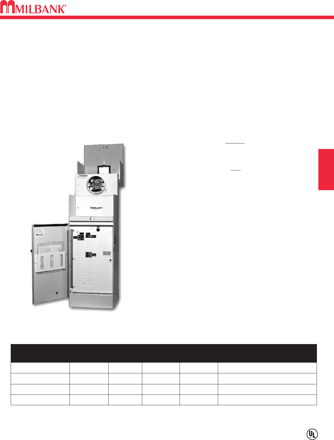
E5
SL SERIES–SWITCHED LOAD CENTER
Utility requirements for this equipment may vary. Always consult the serving utility for their requirements before ordering or
installing equipment in this catalog.
E5
SECTION E COMMERCIAL METER PEDESTALS
*NOTE: Chart shows standard, stocked items. Other options and features are available. Contact factory for options details and
availability.
The Milbank Switched Load Center Commercial
Pedestals are designed to not only provide power for
various loads, but also to switch specific loads on and
off under certain conditions. A photoelectric cell is
used for these controlled loads, and an optional time
clock is also available.
CP3B “SL” Series
Switched Load Center Series
1∅3 wire 120/240 or 208Y/120 volt
Typical applications: Traffic signal, parking
lot, highway, & athletic field lighting
Features:
These units include everything required for remote service:
NEMA 3R construction
Expandable – Load centers allow for future expansion
without costly modifications
All units feature 200 amp meter socket with optional
field-installable fifth terminal kit available
22K ampere interrupting capacity (AIC) standard
Optional mounting base can be embedded in concrete
for fast, easy installation
Separate sealable and lockable utility termination section
Separate sealable and lockable metering section with the
option of:
EITHER
Milbank ring-type socket with test / bypass blocks
(conforms to EUSERC 308)
OR
Milbank heavy duty ringless socket with lever bypass
A separate sealable and lockable customer section with:
Control circuit including:
• PE receptacle, Lexan®window and glare shield
• Hand-Off-Auto (HOA) switch
• Contactor controlling a 16-circuit load center for
controlled loads
• Pre-mounted DIN rail and pre-wired connector to
add an optional “plug and play” time clock kit for PE
on and TC off operation
• A circuit directory to document configuration
A load center for “always on” loads that includes:
• Main circuit breaker
• Control power circuit breaker
• Switched load center main breaker
• Nine (200 amp model) or eleven (100 amp model)
blank breaker spaces
• A circuit directory to document configuration
STOCKED OPTIONAL FIFTH MAIN CB CONTACTOR METER SOCKET TYPE
PEDESTALS* TERMINAL KIT AMPS SPACES AMPERAGE
CP3B11110A22SL1 105J 100 (1,3) 60 Ring-type with test / bypass blocks
CP3B12110A22SL1 105J 200 (1,2,3,4) 100 Ring-type with test / bypass blocks
CP3B51110A22SL1 K3865 100 (1,3) 60 Ringless socket with lever bypass
CP3B52110A22SL1 K3865 200 (1,2,3,4) 100 Ringless socket with lever bypass
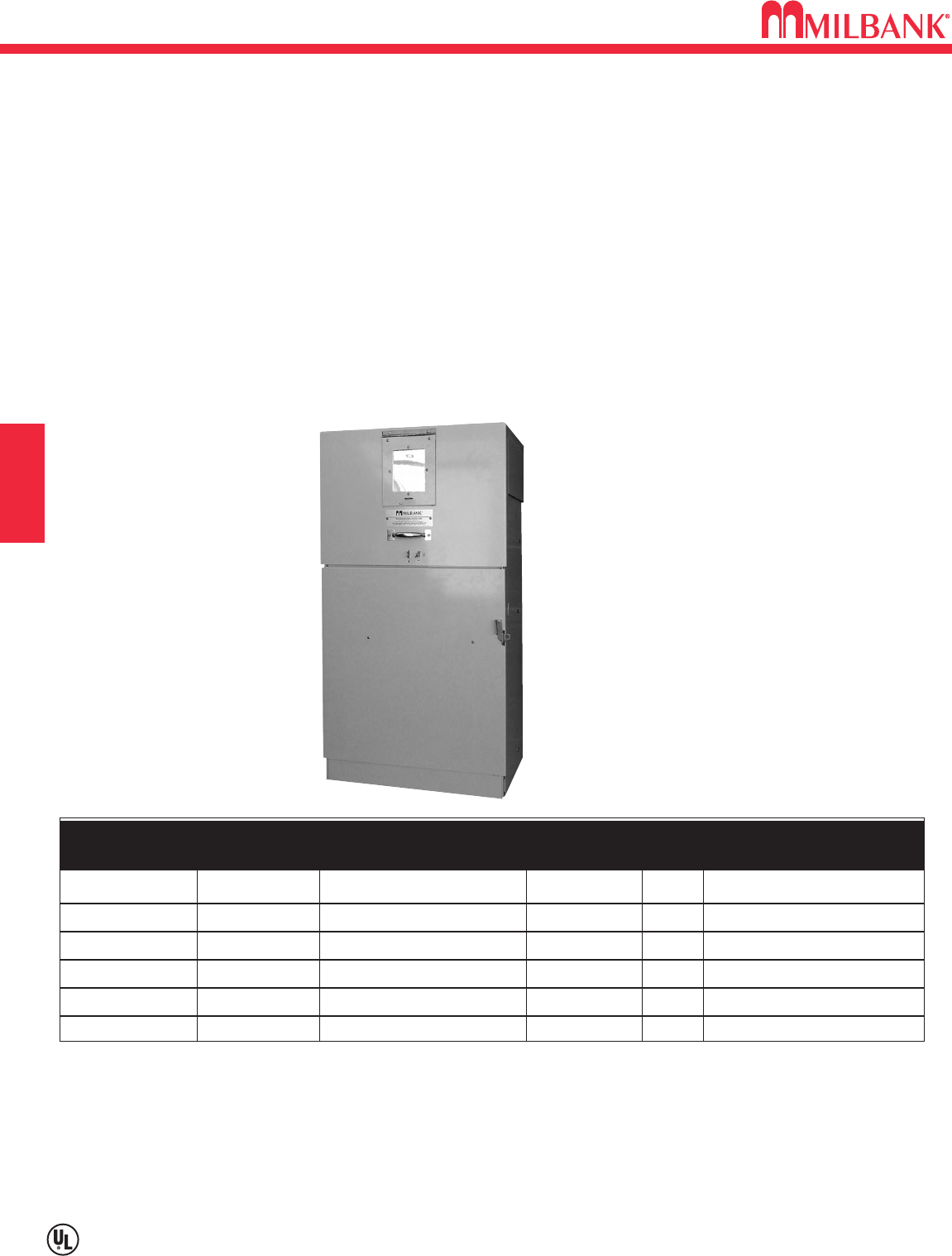
E6
COMMERCIAL METER PEDESTALS
Utility requirements for this equipment may vary. Always consult the serving utility for their requirements before ordering or
installing equipment in this catalog.
E6
SECTION E
400 AMP SERIES
CP3B “400” Series
400 amp Series
1∅3 wire 120/240 or 208Y/120 volt
Typical applications: Remote site service for
residential and commercial jobsites
The Milbank 400 amp Commercial Pedestal is designed
to provide a weather and vandal resistant metered enclosure
for various loads and distribution. Each pedestal has been
designed to handle a wide range of applications using
standard, stocked configurations.
• Choice of a single main breaker or twin service disconnect
breakers gives flexibility to the pedestal design.
• Optional distribution with feed-
thru lugs below the service
disconnect breakers allows the
pedestal to handle numerous
applications.
•Typical applications include
remote homes where the
metering is best located at the
curb side or other remote area.
The pedestal can also provide
power to secondary residence,
on-site business, workshop,
irrigation, lighting, security or
other secondary load.
• Available in custom colors to
match home or landscaping.
Features:
These units include everything required for
remote site service:
NEMA 3R construction
Main circuit breaker or dual service
disconnects
Expandable – Load center units allow for
future expansion without costly modifications
22K ampere interrupting capacity (AIC)
standard
Optional mounting base can be embedded in
concrete for fast, easy installation
Separate sealable and lockable utility
termination section with lug termination
Separate sealable and lockable metering
section
A separate sealable and lockable customer
section with a circuit directory and a print
pocket to hold all documentation
Meter Socket Options:
• Ring type with bypass studs
• Ringless with heavy duty lever bypass
• K type bolt-on
STOCKED OPTIONAL FIFTH MAIN CB LOAD CENTER AIC METER SOCKET TYPE
PEDESTALS* TERMINAL KIT CIRCUITS
CP3B1411JB22 N/A 320 amp (400 max) 0 22K
Ring type with test / bypass studs
CP3B14120B22 N/A 2-200 amp (2) 12 ckt 22K
Ring type with test / bypass studs
CP3B5411JB22 K3865 320 amp (400 max) 0 22K Ringless with lever bypass
CP3B54120B22 K3865 2-200 amp (2) 12 ckt 22K Ringless with lever bypass
CP3B8411JB22 400 amp 0 22K K4 Bolt-on
CP3B84120B22 2-200 amp (2) 12 ckt 22K K4 Bolt-on
*NOTE: Chart shows standard, stocked items. Other options and features are available. Contact factory for options details and
availability.
Stud utility landing is standard. Lug kits are available from factory.
Units with load centers have (2) #6-250 sub-feed lugs on each load center. (Each load center is 200 amp rated and UL Listed
with: Siemens, General Electric and Cutler-Hammer plug-in style circuit breakers.)
When ordering, specify lugs or studs for utility landings.
Three phase units available — contact factory.

E7
IR SERIES–IRRIGATION CONTROL
Utility requirements for this equipment may vary. Always consult the serving utility for their requirements before ordering or
installing equipment in this catalog.
E7
SECTION E COMMERCIAL METER PEDESTALS
CP3B “IR” Series
Irrigation Control Pedestals
1∅ 3 wire 120/240 or 208Y/120 volt
Typical application: Metered Power Pedestal for
Irrigation Systems
The Milbank “IR” series Commercial Pedestals are
designed to provide a weather and vandal resistant
metered enclosure for irrigation controllers. Breakers and
a GFI duplex receptacle are provided to power the
irrigation controllers supplied
by others. A plywood
backboard is mounted behind
the deadfront door for
mounting the irrigation
controller. A large plan pocket
is mounted inside the
customer section door to
hold plans and
specifications. Light green
powder coated steel or
stainless steel pedestals are
normally in stock.
NEMA 3R construction
2 each 20 amp single pole circuit breakers:
one breaker for standard 20 amp GFCI
receptacle and one breaker for irrigation
control circuit
Large plywood back panel for mounting
irrigation controller
All units feature 200 amp meter socket
with optional field-installable fifth terminal
kit available
10K ampere interrupting capacity (AIC)
standard
Optional mounting base can be embedded
in concrete for fast, easy installation
Separate sealable and lockable utility
termination section
Separate sealable and lockable metering
section with the option of
EITHER:
Milbank ring-type socket with test /
bypass blocks (conforms to EUSERC 308)
OR
Milbank heavy duty ringless socket with
lever bypass
Features:
These units include everything required for
remote site service:
STOCKED OPTIONAL FIFTH** EXTERIOR METER SOCKET TYPE
PEDESTALS* TERMINAL KIT CABINET
CP3B111IRASP 105J Steel, Light Green Ring type meter socket with
test / bypass blocks
CP3B111IRASS 105J Stainless Steel Ring type meter socket with
test / bypass blocks
CP3B511IRASP K3865 Steel, Light Green Ringless heavy duty meter socket
with lever bypass
*NOTE: Chart shows standard, stocked items. Other options and features are available. Contact factory for options details and
availability.
*See page E2 for options (accessories) details.
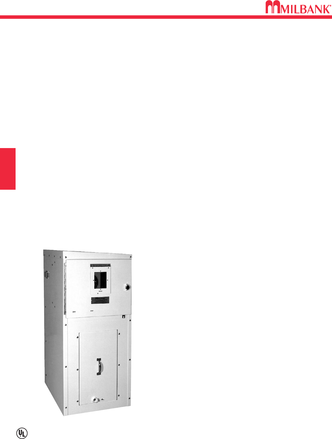
BBS/UPS SERIES
E8
Utility requirements for this equipment may vary. Always consult the serving utility for their requirements before ordering or
installing equipment in this catalog.
E8
SECTION E
COMMERCIAL METER PEDESTALS
CP3B BBS & UPS Series
1Ø3 wire 120/240 or 120/208 volt
Typical applications: Metered emergency
uninterrupted power for traffic intersections,
wireless - phone, communication equipment,
parking lots, camera and security locations.
The Milbank BBS / UPS Series Commercial Pedestals
are designed to provide continuous power for various
loads, and also to switch specific loads on and off under
certain conditions. A photoelectric cell or time clock may
be used to control lighting circuits as an example.
Metered and non-metered power distribution options are
available. The back-up power pedestal is designed to
handle the vast majority of todays back-up power
requirements. By using 19” rack design, shelves can be
adjusted to accommodate the required batteries and
manufactures DC to AC inverters, transfer switches and
other related equipment. This design gives the user a
wide range of design and configuration options.
Complete turnkey, ready to power-up pedestals are
offered along with basic and custom configurations.
Features:
NEMA 3R construction, UL listed as “Enclosed
Industrial Control Equipment”
100 through 320 amp meter socket with the option
of either:
Milbank ring type socket (conforms to EUSERC 309)
with or without test / bypass blocks
Milbank heavy duty ringless socket with lever bypass
Separate sealable utility termination compartment
An isolated separate customer section with:
Service disconnects
Power distribution options
Power control
19” wide rack in customer compartment for easy
layout of equipment
Battery trays
Thermostat with cooling fan
Filtered louvers for heat rise flow through ventilation
(UL Listed 508A)
Three point door latch (key or pad lockable)
Options:
Manual Bypass switch (used for maintenance of
BBS/UPS)
Transfer switch for generator power back-up
Generator inlet receptacles 30 amps through 200 amps
Pad lockable provision for receptacles
Police access door
Metered load center distribution
Non metered load center distribution
Photo electric controls (for street lighting)
Time clocks
HOA switches
Contactors
GFI duplex receptacles
Thermostat for heating control
Heating pads or elements
Roll out shelves for batteries
Surge arrestors and lighting arrestors
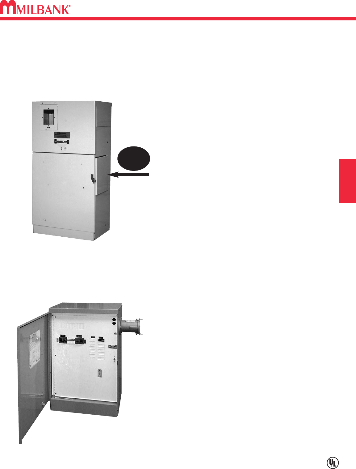
E9
POWER TRANSFER SERIES–METERED & UNMETERED
Utility requirements for this equipment may vary. Always consult the serving utility for their requirements before ordering or
installing equipment in this catalog.
E9
SECTION E
The Milbank Commercial Pedestal “Power Transfer Series”
provides metered AC power, distribution, surge suppression,
mechanical interlock and stand by generator receptacle. All
electrical equipment including the generator receptacle is built
inside the pedestal, giving it a clean appearance and making it
extremely vandal resistant.
Features & Options:
120/240v 1∅3W thru 277/480v 3∅4W ratings
Choice of EUSERC ring type or ringless meter sockets
60 amps thru 400 amp ratings
10K AIC up to 50K AIC ratings
UL Listed 508A, NEMA 3R rated
Pad lockable, isolated utility compartments
20 amp GFI convenience receptacle
Lockable recessed generator receptacle door
Utility and generator indicator light options
All stainless steel hardware
Galvanized steel, aluminum or stainless steel cabinet options
Custom designs available
CP3B “Power Transfer” Series – Metered
CP3B “Power Transfer” Series
1Ø3W 120/240 volt thru 3Ø4W 277/480 volt
Typical applications: Traffic intersections,
Cell sites, Phone company broadband service,
Cable TV, Pump and Lift stations requiring
utility power with back up generator power
Generator
Receptacle
Inside!
COMMERCIAL METER PEDESTALS
CP3B “Power Transfer” Series – Unmetered
The Milbank Commercial Pedestal “Power Transfer Series”
provides non metered AC power, distribution, surge
suppression, mechanical interlock and stand-by generator
receptacle – all in a neat, compact pedestal.
Features & Options:
120/240v 1∅3W thru 277/480v 3∅4W ratings
60 amps thru 400 amp ratings
10K AIC up to 50K AIC ratings
UL listed 508A, NEMA 3R rated
Pad lockable, isolated utility compartments
20 amp GFI convenience receptacle
Utility and generator indicator light options
All stainless steel hardware
Galvanized steel, aluminum or stainless steel cabinet options
Custom designs available

GENERAL SPECIFICATIONS
E10
COMMERCIAL METER PEDESTALS
E10
SECTION E
Example of specifications for a Metered Commercial
Pedestal
Commercial pedestal shall be type ______________ .
Catalog # _________________
Voltage rating :____(120/240v 1P 3W)__
AIC rating: ____10__
Amperage rating :____(100 amps)__
The pedestal shall be of NEMA Type 3R rainproof
construction and shall be UL Listed as “Enclosed
Industrial Control Equipment” (UL 508A). External
construction shall comply with UL50 requirements and
shall be of G90 galvanized steel with light green #14672
Federal Specification 595 polyurethane industrial grade
powder paint of 1.7 mil minimum thickness (unless
otherwise specified). Aluminum and stainless steel are
other factory options available. Internal construction shall
be G90 galvanized steel and 1.7 mil minimum thickness
polyurethane industrial grade powder coat painted or
bare aluminum. No fasteners except sealing screws
shall be removable by external access. Hinges shall be
stainless steel and of the continuous piano hinge type.
The pedestal mounting bolts shall not be externally
accessible. The pedestal shall be offered with an
optional base designed to be embedded in concrete in
place of anchor bolts. Either pedestal mounting base or
anchor bolt kit is required for installation.
The service pedestal must have three separate isolated
sections for metering equipment, utility termination and
customer equipment.
The metering section must be pad-lockable and sealable
and have a hinged swing back hood with an integral
hinged polycarbonate sealable window for access to
demand meters. An external nameplate shall be
permanently attached to the hood. A stainless steel
handle shall be provided on the front exterior of the hood.
Meter socket type shall meet the requirements of the
serving utility.
The utility termination section must be pad-lockable and
sealable and shall have a stainless steel handle provided
on a lift-off cover. Sufficient clearance shall be provided
for a 4-inch diameter conduit for utility cables entrance.
Utility landing lugs shall be UL listed and shall
accommodate #6 – 350 kcmil conductors.
The customer compartment door to be hinged on the left
hand side. A stainless pad-lockable hasp provided to
secure customer compartment. A door keeper provided
to keep the door in an open position. A print pocket on
the inside of the door shall hold all wiring schematics,
circuit directories and instructions in a clear,
weatherproof sleeve. Required UL labeling shall be
located on the inside of the customer door. Distribution
and control equipment shall be behind an internal dead-
front door with a quarter-turn securing latch and be
hinged to open more than 90 degrees. The dead-front
door shall be hinged on the same side as the customer
section door. All distribution and control equipment shall
be factory wired using 600 volt wire sized to NEC and UL
requirements.
The service pedestal shall be rated for operation at 10K
minimum (AIC) amps interrupting capacity. The provided
documentation shall list circuit breaker combinations and
those to be used for de-rated operation for series ratings.
Circuit breakers shall be permanently labeled with
engraved name plates.
Utility requirements for this equipment vary. Always
consult the serving utility for their requirements before
ordering or installing this equipment.
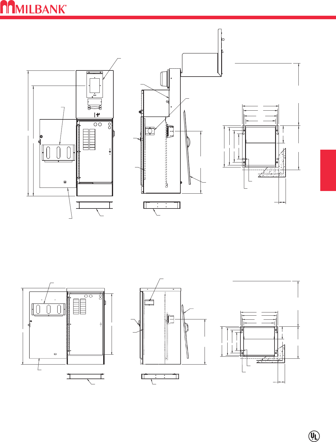
E11
COMMERCIAL METER PEDESTAL DRAWINGS–16" METERED & UNMETERED
Utility requirements for this equipment may vary. Always consult the serving utility for their requirements before ordering or
installing equipment in this catalog.
E11
SECTION E COMMERCIAL METER PEDESTALS
17"
ENCLOSURE
DEPTH
ALL SIDES. 6" REC.
FOUNDATION EXTENSION
RECOMMENDED MIN.3"
REQUIRED PER
N.E.C 110-16
TYPICAL
36" MIN.
CLEARANCE
FRONT & BACK
42"
23.5" UTILITY
TERMINATION
LANDING MIN.
MOUNTING BASE MOUNTING BASE
ANCHOR BOLT
MOUNTING HOLES
MOUNTING BASE DETAIL
MOUNTING HOLES
PEDESTAL
9 3/4"
15"
16"
14 1/2"
12 1/4"16"
14 1/2"
13"
6 3/4"
UTILITY
SECTION
CUSTOMER
SECTION
WITH
COVER
PRINT
WINDOW
POCKET
HINGED
DEMAND
METER
RESET
HINGED EXTERIOR DOOR
WITH DOOR STOP TO HOLD
DOOR IN OPEN POSITION
48"
HINGED
DEADFRONT
SECURITY
(IF APPLICABLE)
LIFT-OFF
PHOTO CELL WINDOW
FOR
WITH SHIELD
DOOR
COVER
SERVICE
COVER
FULLY HINGED
THROUGH
METER SECTION
PADLOCK
BRACKET
EXTENDS
REMOVEABLE
TEST BYPASS
BLOCK COVER
(IF APPLICABLE)
Pad Mount Base or (4) 5/8-11 X 18” Anchor Bolts Recommended
CP-16PDMNT-CALT
CP-16PDMNT-CALT
23 7/8" UTILITY
TERMINATION
LANDING MIN.
N.E.C 110-16
TYPICAL
FRONT & BACK
MINIMUM DEPTH.
ALL SIDES. 6" REC.
FOUNDATION EXTENSION
RECOMMENDED MIN.3"
36" MIN.
CLEARANCE
REQUIRED PER
17"
ENCLOSURE
DEPTH
CP-16PDMNT-CALT
MOUNTING BASE
POCKET
PRINT
HINGED
EXTERIOR
DOOR
40 1/2"
32 1/4"
Pad Mount Base or (4) 5/8-11 X 18" Anchor Bolts Recommended
WITH SHIELD
(IF APPLICABLE)
COVER
SERVICE
LIFT-OFF
SECURITY
DOOR FOR
THROUGH
LATCH HASP
EXTENDS
PHOTO CELL WINDOW
HINGED
DEADFRONT
CP-16PDMNT-CALT
MOUNTING BASE
MOUNTING HOLES
SECTION
UTILITY
MOUNTING BASE DETAIL
CUSTOMER
MOUNTING HOLES
ANCHOR BOLT
SECTION
PEDESTAL
14 1/2"
12 1/4"
9 3/4"
16"
15"
14 1/2"
13"
16"
6 3/4"
“A” Style 16" Metered Commercial Pedestal
“E” Style 16" Unmetered Commercial Pedestal–Low Profile
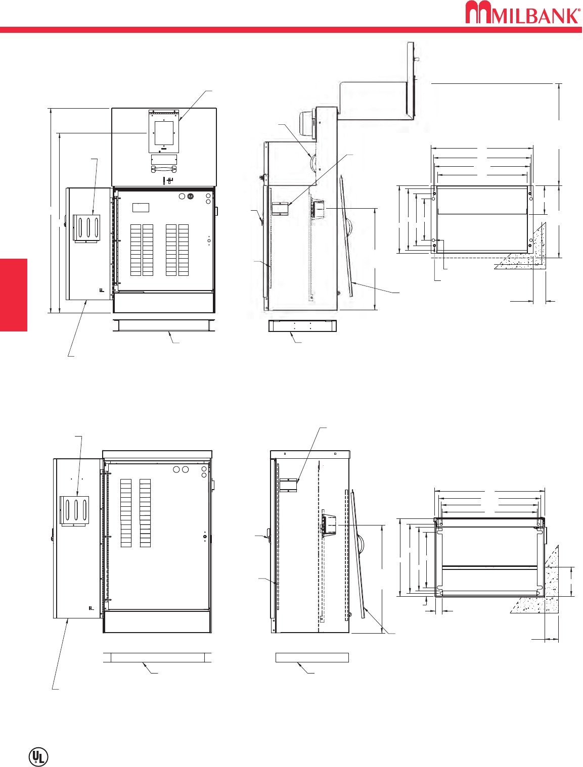
COMMERCIAL METER PEDESTAL DRAWINGS–24" METERED & UNMETERED
E12
Utility requirements for this equipment may vary. Always consult the serving utility for their requirements before ordering or
installing equipment in this catalog.
E12
SECTION E
COMMERCIAL METER PEDESTALS
23.5" UTILITY
TERMINATION
LANDING MIN.
CLEARANCE
REQUIRED PER
N.E.C 110-16
DEPTH
ENCLOSURE
17"
TYPICAL
FRONT & BACK
36" MIN.
3" RECOMMENDED MIN.
FOUNDATION EXTENSION
ALL SIDES. 6" REC.
MINIMUM DEPTH.
42"
THROUGH
COVER
FULLY HINGED
PHOTO CELL WINDOW
HINGED
“B” Style 24" Metered Commercial Pedestal
METER SECTION
COVER
SERVICE
LIFT-OFF
DEADFRONT
WITH SHIELD
SECURITY
FOR
DOOR
(IF APPLICABLE)
PADLOCK
BRACKET
EXTENDS
REMOVEABLE
TEST BYPASS
BLOCK COVER
(IF APPLICABLE)
MOUNTING BASE
MOUNTING HOLES
SECTION
CUSTOMER
SECTION
UTILITY
MOUNTING BASE DETAIL
MOUNTING HOLES
ANCHOR BOLT
PEDESTAL
9 3/4"
12 1/4"
14 1/2"
22 1/2"
21"
23"
24"
6 3/4"
16"
MOUNTING BASE
COVER WITH
PRINT
POCKET
WINDOW
HINGED DEMAND
METER RESET
HINGED EXTERIOR DOOR
WITH DOOR STOP TO HOLD
DOOR IN OPEN POSITION
48"
Pad Mount Base or (4) 5/8-11 X 18" Anchor Bolts Recommended
CP-24PDMNT-CALT CP-24PDMNT-CALT
22 1/2"
UTILITY
TERMINATION
LANDING
3" RECOMMENDED MIN.
FOUNDATION EXTENSION
ALL SIDES. 6" RECOMMENDED
MINIMUM DEPTH.
CUSTOMER
SECTION
MOUNTING BASE DETAIL
“M” Style 24" Metered Commercial Pedestal
LIFT-OFF
SERVICE
COVER
PADLOCK
BRACKET
EXTENDS
THROUGH
DOOR
FOR
SECURITY
PHOTO CELL WINDOW
WITH SHIELD
(IF APPLICABLE)
HINGED
DEADFRONT
PRINT
POCKET
HINGED EXTERIOR DOOR
WITH DOOR STOP TO HOLD
DOOR IN OPEN POSITION
MOUNTING BASE MOUNTING BASE
UTILITY TERM.
SECTION
36" MIN.
CLEARANCE
REQUIRED PER
N.E.C 110-16
TYPICAL
FRONT & BACK
21 1/2"
12 1/4"
15 3/8"
17"
"
"
6 1/2"
14 1/4"
24"
22 1/2"
1 7/8"
1 1/2"
21"
Pad Mount Base or (4) 5/8-11 X 18" Anchor Bolts Recommended
CP-24PDMNT-CALTCP-24PDMNT-CALT
“B” Style 24" Metered Commercial Pedestal
(With one or two meters)
“M” Style 24" Unmetered Commercial Pedestal
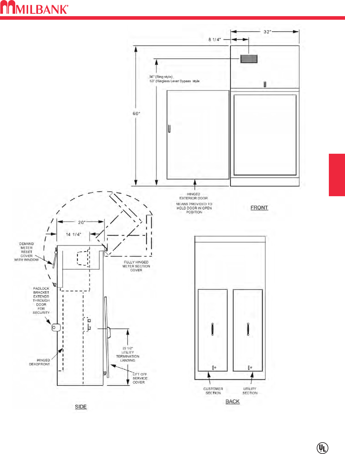
E13
COMMERCIAL METER PEDESTAL DRAWINGS–32" METERED
Utility requirements for this equipment may vary. Always consult the serving utility for their requirements before ordering or
installing equipment in this catalog.
E13
SECTION E COMMERCIAL METER PEDESTALS
“K” Style 32" Metered Commercial Pedestal
(With one or two meters)
(4) 5/8-11 X 18" Anchor Bolts Recommended
Catalog Number CP-ABK5/8
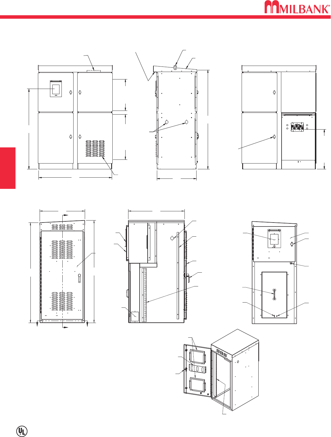
COMMERCIAL METER PEDESTAL DRAWINGS–METERED
E14
Utility requirements for this equipment may vary. Always consult the serving utility for their requirements before ordering or
installing equipment in this catalog.
E14
SECTION E
COMMERCIAL METER PEDESTALS
SLOPED ROOF
LIFTING EYES
VENTILATION FAN
SECTION 3SECTION 1
SECTION 2 SECTION 6
SECTION 5
SECTION 7
SECTION 4
VENTILATED OPENINGS
W/ SOFFIT
PE SOCKET
KNOCK-
OUTS
VENTILATION
LOUVERS
WITH FILTER
1/4 TURN
PADLOCKABLE
HANDLES
44.38 24.00
60.00
48.56
19.06
AVAILABLE
EQUIPMENT
SPACE
27.31
AVAILABLE
EQUIPMENT SPACE
24.12
TO BOTTOM OF LUG
CUSTOMER DOOR
55.50
24.50
54.25
A
ABB
UTILITY PULL
PE WINDOW
PADLOCK-ABLE
METER DOOR
FOR INSTALLATION
SCALE 1 : 16
CUSTOMER
19" RACK
SECTION
SECTION A-A
3-POINT CAM LATCH
DEMAND METER
COVER PLATES
METER
DOOR
SECTION
DOOR
19" RACK
REMOVEABLE
30.50
REMOVEABLE
3-POINT
AIR FILTERS
PRINT
POCKET
CAM LATCH
19" RACK
UTILITY COVER
SEAL STUD
PADLOCK-ABLE
WINDOW
SEAL STUD
CAM LATCH
METER DOOR
DEMAND METER
REMOVEABLE
PADLOCK HASP
“D” Style Metered Commercial Pedestal
“C” Style 54" Metered Commercial Pedestal

E15
COMMERCIAL METER PEDESTALS WORKSHEET
E15
SECTION E COMMERCIAL METER PEDESTALS
Please answer all of the questions as best as you can. Additional comments as to application and future requirements
will help Milbank will determine the best product for your job.
Distributor: __________________________ Phone: _________________ Fax: ___________________
Contact Name: _____________________________ Application: ______________________________
Milbank Representative: _______________________________ Salesmen: ______________________
Job Name & Location: _________________________________________________________________
Agency Specications: (DOT-City-Other) _________________________________________________
Unit Amperage: ___________ Voltage: ____________ Phase: ____________ Wire: _____________
Meter socket (200 Amp) RING-TYPE RINGLESS Fifth Terminal? NO YES (at _____ o’clock)
Meter socket (200 Amp) RING-TYPE RINGLESS Fifth Terminal? NO YES (at _____ o’clock)
Main breaker requirements: Amp: __________ Poles: __________ KAIC: __________
Main breaker requirements: Amp: __________ Poles: __________ KAIC: __________
Interior #1 0-42 circuits ________ Load center ________ Panel board ________ Metered? YES NO
Interior #2 0-42 circuits ________ Load center ________ Panel board ________ Metered? YES NO
Branch breakers: Amps: Poles: KAIC: Label & Special requirements:
Qty _____Breakers ______ ______ ______ __________________________
Qty _____Breakers ______ ______ ______ __________________________
Qty _____Breakers ______ ______ ______ __________________________
Qty _____Breakers ______ ______ ______ __________________________
Qty _____Breakers ______ ______ ______ __________________________
Qty _____Breakers ______ ______ ______ __________________________
Controls:
Qty _____ Time Clock: 24 Hr _____ 7 Day _____ 365 Day Astro _____ Description: _______________
Qty _____ Photo Electric Control Receptacle
Qty _____ Test switch: 2 Pos. _____ 3 Pos. _____ HOA Type _____ Other ________________________
Qty _____ Control Transformer ___________ Voltage ___________VA Size (required for all 277/480v)
Contactors:
Type: Lighting - LT / Denite Purpose - DP / Mechanical Held - MH / Mercury - MV / IEC - IC
Qty ______ Type ______ Amps ______ Poles ______ Coil voltage ______ Other ________
Qty ______ Type ______ Amps ______ Poles ______ Coil voltage ______ Other ________
Qty ______ Type ______ Amps ______ Poles ______ Coil voltage ______ Other ________
Cabinet / Finish requirements: Alum – Untreated = AO / Alum Anodized = AL / Stainless Steel = SS
Aluminum – Painted = A / GALVANIZED STEEL PAINTED (STANDARD) _______ (specify paint below)
MINT GREEN (STANDARD) = G / Pine Green = PG / Dark Green = DG / Black = BK / Desert Tan = DT
White = W / Gray = P / Summerland Gray = SG / Other (RAL nish number) ____________________
Other Requirements: ___________________________________________________________________
_____________________________________________________________________________________
Please send any drawings, plans, specications, and load/panel board schedules with worksheet
Commercial Pedestal Worksheet
Phone (816)483-5314 Fax (816)483-6357

NOTES
E16
E16
SECTION E
NOTES
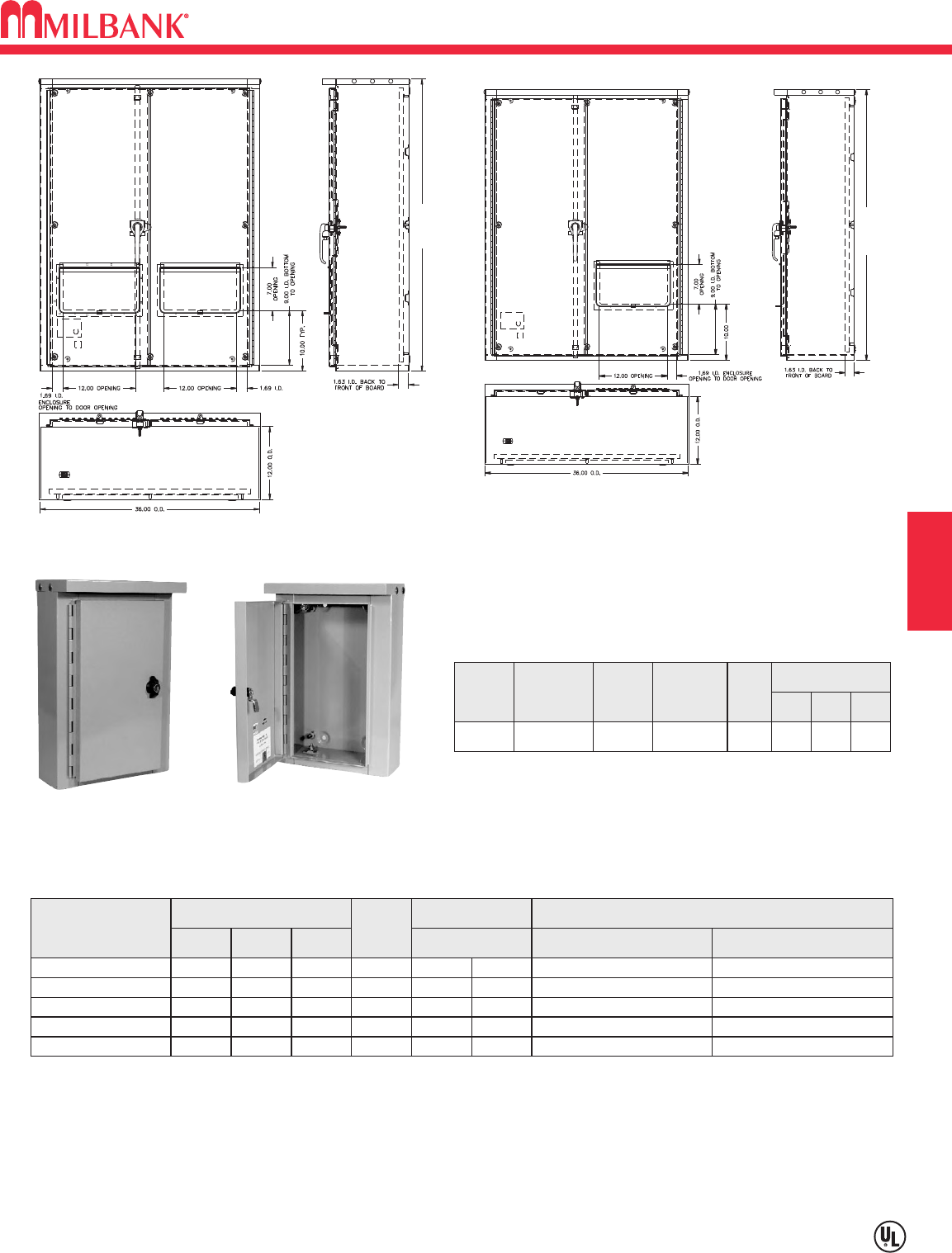
F1
CURRENT TRANSFORMER CABINETS–TYPE 3R–DOOR MOUNT CT RATED SOCKET
Utility requirements for this equipment may vary. Always consult the serving utility for their requirements before ordering or
installing equipment in this catalog.
F1
SECTION F CT CABINETS, TEST SWITCHES, POLYPHASE ENCLOSURES
36.00 or 48.00
36 or 48
363612-CT3R-SP
364812-CT3R-SP2
243210-LC3R-SP 24 3210 14 21 29 A-24P32 A-24P32W
CATALOG
NUMBER
DIMENSIONS
D"W"H"
GAUGE
OF
STEEL
PANEL SIZE PANEL & BACKBOARD CATALOG NUMBERS
PAINTED STEEL PANEL WOOD BACKBOARDW"xH
"
A-32P36 A-32P36W14323610-LC3R-SP 32 3610 29 33
A-36P30 A-36P30W14363016-CT3R 36 3016 33 27
CURRENT TRANSFORMER RATED CABINETS—TYPE 3R
12184-LC3R
DOOR MOUNT C.T. RATED SOCKET
BP: The -BP suffix indicates plunger bypass.
CATALOG
NUMBER
AMPS
DIMENSIONS
D" W" H"
BYPASS
CONNECTORS
NO. OF
TERMS.
K4806-BP Plunger #14-4 Max
13 20 A 21⁄277⁄871⁄2
A-36P36 A-36P36W INCLUDED14363612-CT3R-SP 36 3612 33 33
A-48P36 A-48P36W INCLUDED14364812-CT3R-SP2 36 4812 33 45
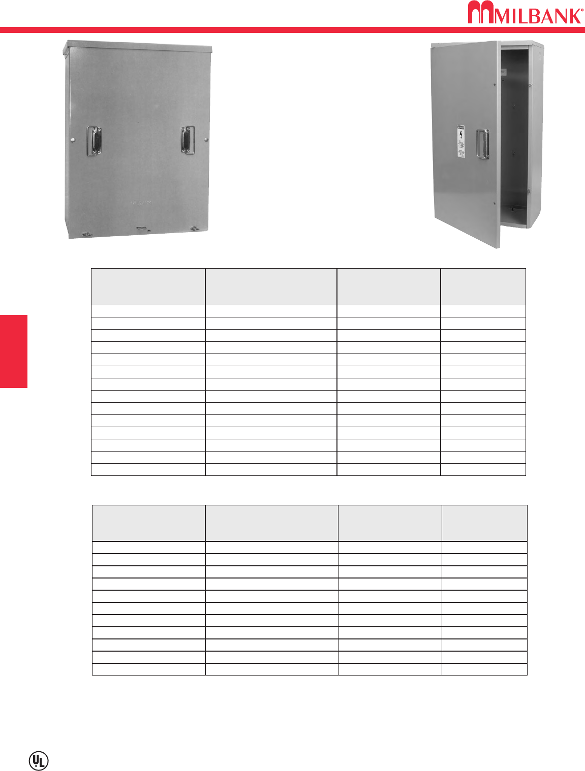
CURRENT TRANSFORMER CABINETS
F2
Utility requirements for this equipment may vary. Always consult the serving utility for their requirements before ordering or
installing equipment in this catalog.
F2
CT CABINETS, TEST SWITCHES, POLYPHASE ENCLOSURES
CATALOG
NUMBER
C.T.
RACKS
SIZE
W" X H" X D"
FRONT
COVER
CT24329-SC C, M 24 X 32 X 9 1 PIECE
CT242411-SC A4, C, M 24 X 24 X 11 1 PIECE
CT243011-SC A4, C, M 24 X 30 X 11 1 PIECE
CT243611-SC A4, C, J, M 24 X 36 X 11 1 PIECE
CT244811-SC A, C, D, G, J, M 24 X 48 X 11 1 PIECE
CT303011-SC A4, B4, C, E, L, M 30 X 30 X 11 1 PIECE
CT303611-SC A4, B4, C, E, J, K, L, M 30 X 36 X 11 1 PIECE
CT303614-SC A4, B4, C, E, J, K, L, M 30 X 36 X 14 1 PIECE
CT363611-SC A4, B4, C, E, J, K, L, M 36 X 36 X 11 1 PIECE
CT364211-SC A4, B4, C, E, J, K, L, M 36 X 42 X 11 2 PIECES
CT364811-SC A, B, C, D, E, F, G, H, J, K, L, M 36 X 48 X 11 2 PIECES
CT364814-SC A, B, C, D, E, F, G, H, J, K, L, M 36 X 48 X 14 2 PIECES
CT424211-SC A4, B4, C, E, J, K, L, M 42 X 42 X 11 2 PIECES
CT484811-SC A, B, C, D, E, F, G, H, J, K, L, M 48 X 48 X 11 2 PIECES
CATALOG
NUMBER
C.T.
RACKS
SIZE
W" X H" X D"
FRONT
COVER
CT203611-HC C20 X 36 X 11 1 PIECE
CT243011-HC A4, C, M 24 X 30 X 11 1 PIECE
CT244811-HC A, C, D, G, J, M 24 X 48 X 11 1 PIECE
CT303611-HC A4, B4, C, E, J, K, L, M 30 X 36 X 11 1 PIECE
CT304811-HC A, B, C, D, E, F, G, H, J, K, L, M 30 X 48 X 11 1 PIECE
CT363611-HC A4, B4, C, E, J, K, L, M 36 X 36 X 11 1 PIECE
CT364811-HC A, B, C, D, E, F, G, H, J, K, L, M 36 X 48 X 11 1 PIECE
CT243611-HC C, M 24 X 36 X 11 1 PIECE
CT484811-HC A, B, C, D, E, F, G, H, J, K, L, M 48 X 48 X 11 2 PIECE
CT364814-HC A, B, C, D, E, F, G, H, J, K, L, M 36 X 48 X 14 2 PIECE
CT484814-HC A, B, C, D, E, F, G, H, J, K, L, M 48 X 48 X 14 2 PIECE
SCREW COVER
HINGE COVER
CT18249-SC CT203611-HC
ENCLOSURE: These units are rated Type 3R, powder coated, and constructed of galvanized steel.
MOUNTING RACK: Select CT mounting rack from next page.
MOUNTING: 1/4-20 welded studs.
SECTION F
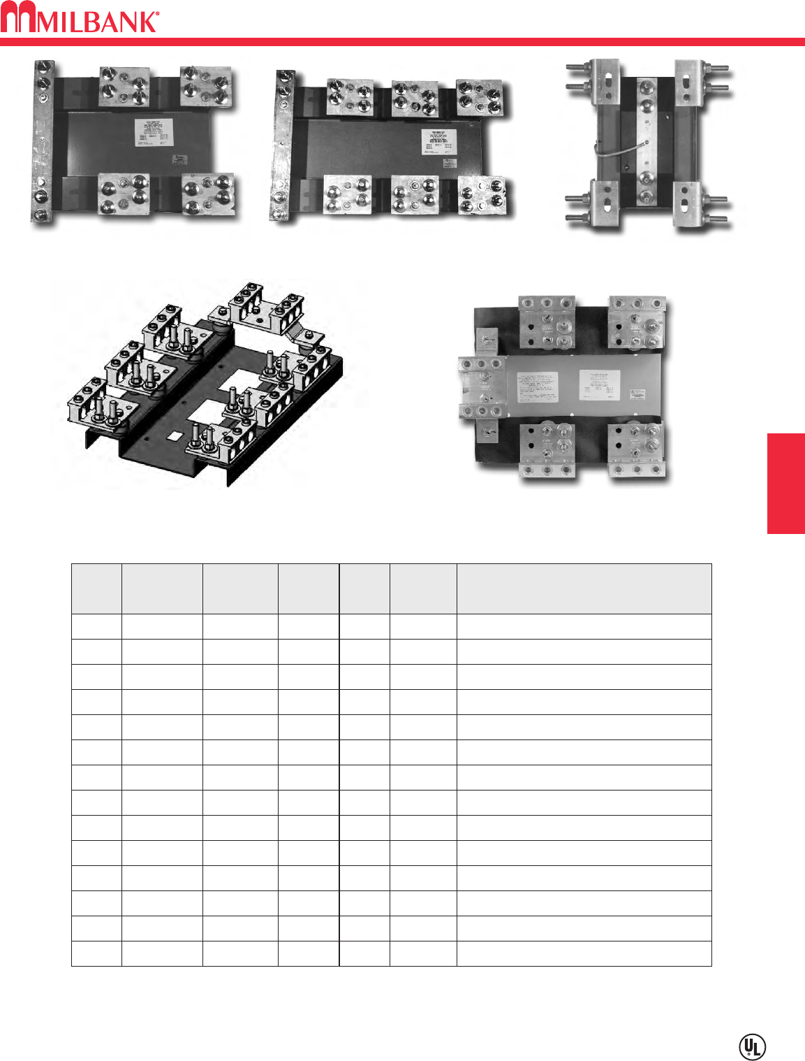
F3
CURRENT TRANSFORMER CABINETS–MOUNTING RACKS
Utility requirements for this equipment may vary. Always consult the serving utility for their requirements before ordering or
installing equipment in this catalog.
F3
SECTION F CT CABINETS, TEST SWITCHES, POLYPHASE ENCLOSURES
K4729
K4793 / K4795K4798
K4797
K4722
CATALOG
NUMBER
AIC
RATING AMPS
400
TYPE OF
SERVICE
1∅3W
TERMINATION TYPE
1/2-13 studs on 1-3/4" centersK4797 50K
800
VOLTS
600
600 1∅3W 1/2-13 studs on 1-3/4" centersK4797
CODE
A4
A50K
400 600 3∅4W 1/2-13 studs on 1-3/4" centersK4798B4 50K
800 600 3∅4W 1/2-13 studs on 1-3/4" centersK4798B50K
201-400 600 1∅3W 1/2-13 studs on 1-3/4" centersK4793C10K
401-800 600 1∅3W 1/2-13 studs on 1-3/4" centersK4795D10K
201-400 600 3∅4W 1/2-13 studs on 1-3/4" centersK4794E10K
401-800 600 3∅4W 1/2-13 studs on 1-3/4" centersK4796F10K
400 600 1∅3W (1) #4 - 600 or (2) #1 - 250 K4903J50K
800 600 1∅3W (3) #4 - 600 or (6) #1 - 250 K4729G50K
400 600 3∅4W (1) #4 - 600 or (2) #1 - 250
K4904
K50K
800 600 3∅4WK5747L50K
800 600 1∅3W
K5752
M50K
800 600 3∅4W (3) #4 - 600 or (6) #1 - 250 K4722H50K
Select CT enclosures from previous page.
CURRENT TRANSFORMER ENCLOSURE MOUNTING RACKS
Line: 1/2-13 studs on 1-3/4" centers
Load: (3) #4 - 600 or (6) #1 - 250
Line: 1/2-13 studs on 1-3/4" centers
Load: (3) #4 - 600 or (6) #1 - 250
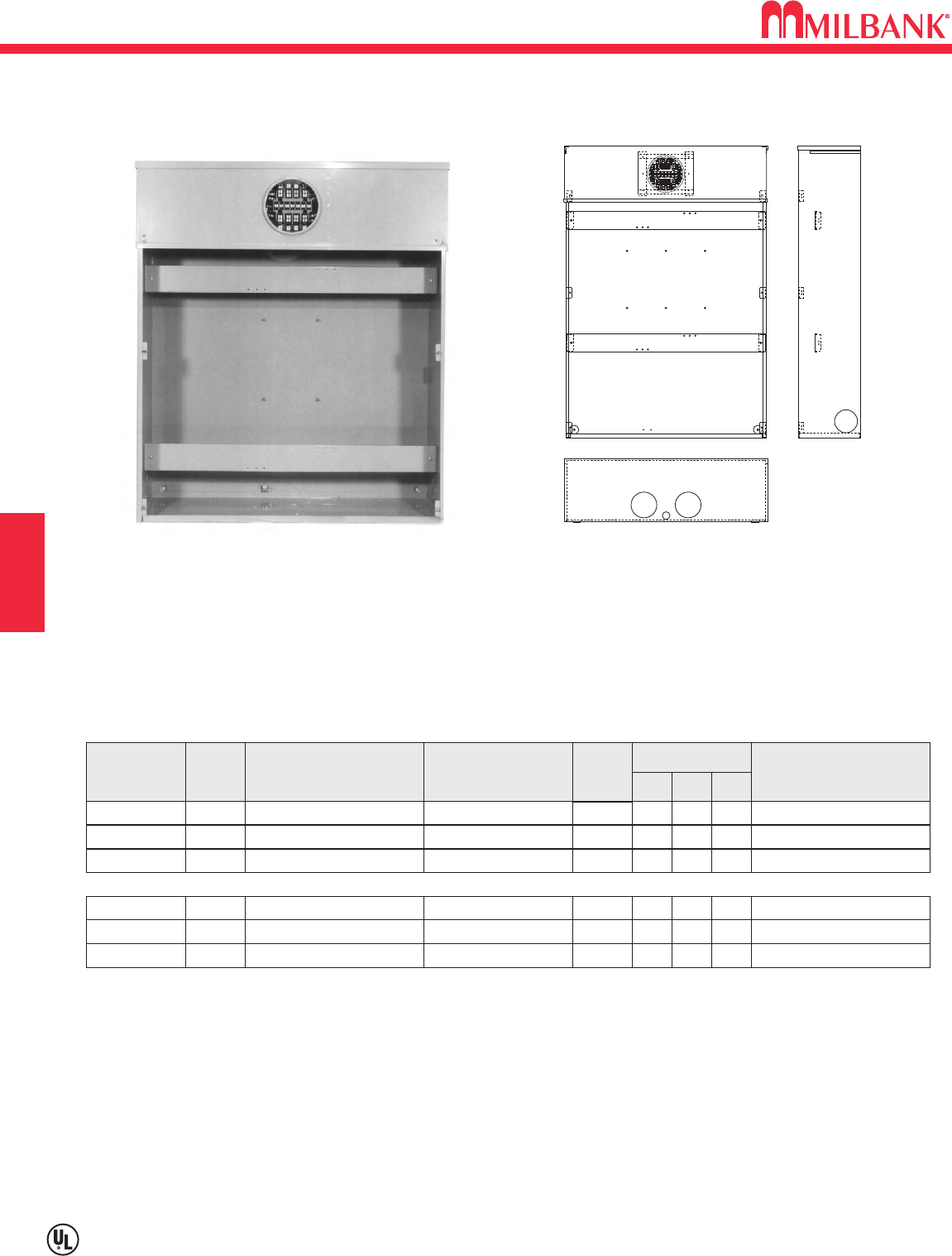
METERED TRANSFORMER CABINETS–OVERHEAD & UNDERGROUND
F4
Utility requirements for this equipment may vary. Always consult the serving utility for their requirements before ordering or
installing equipment in this catalog.
F4
CT CABINETS, TEST SWITCHES, POLYPHASE ENCLOSURES
U3565-O
CATALOG
NUMBER
HUB C.T.
RACKS
NO.
OF
TERMS
6
13
15
DIMENSIONS TYPE OF
SERVICE
1∅3W
3∅4W Υor Δ
3∅4W Υor Δ
D" W" H"
11 24 42
11 36 42
11 36 42
H.O.
H.O.
H.O.
U3320-R A, C, D, J, L, M
U3322-R B, E, F, G, H, L, M
U3555-R B, E, F, G, H, L, M
6
13
15
1∅3W
3∅4W Υor Δ
3∅4W Υor Δ
11 24 52
11 36 52
11 36 52
NONE
NONE
NONE
SERVICE
OH
OH
OH
UG
UG
UG
U3340-O A, C, D, J, L, M
U3342-O B, E, F, G, H, L, M
U3565-O B, E, F, G, H, L, M
METERED TRANSFORMER CABINETS—RING TYPE
METER SOCKET: 20 amp current transformer meter socket built in.
ENCLOSURE: NEMA Type 3R with screw cover.
CURRENT TRANSFORMER MOUNTING: 1/4-20 welded studs.
HUBS: For proper hub selection, see hub suffix chart in the accessory section.
SEALING RINGS: Supplied with MR-4 screw type sealing ring.
MOUNTING RACKS: For mounting rack information refer to previous page.
SECTION F
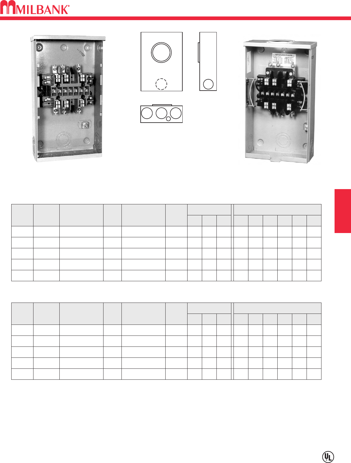
F5
20 AMP— 4, 5, 6, 7, 8, & 13 TERMINAL
CURRENT TRANSFORMER RATED—RINGLESS / RING TYPE
Utility requirements for this equipment may vary. Always consult the serving utility for their requirements before ordering or
installing equipment in this catalog.
F5
CT CABINETS, TEST SWITCHES, POLYPHASE ENCLOSURES
1
43
5
2
4
RINGLESS—PLUNGER TYPE BYPASS–OVERHEAD / UNDERGROUND
NO.
OF
TERMS
METER
FORM
CATALOG
NUMBER HUB CONNECTORS
CU
BY-
PASS
DIMENSIONS CONCENTRIC K.O.ʼS
123456D" W" H"
53S UC1290-XL C.P. #14 - #10
PLUNGER*
11
⁄
211
⁄
411
⁄
4211
⁄
41
⁄
4
35
⁄
16 814
64S UC1299-XL C.P. #14 - #10
PLUNGER*
11
⁄
211
⁄
411
⁄
4211
⁄
41
⁄
4
35
⁄
16 814
77,14,15 &
24S UC7233-XL C.P. #14 - #10
PLUNGER*
11
⁄
211
⁄
411
⁄
4211
⁄
41
⁄
4
35
⁄
16 814
85S UC7235-XL C.P. #14 - #10
PLUNGER*
11
⁄
211
⁄
411
⁄
4211
⁄
41
⁄
4
35
⁄
16 814
13 6,8,9S &
(ALT) 10S UC7237-XL C.P. #14 - #10
PLUNGER*
11
⁄
211
⁄
411
⁄
4211
⁄
41
⁄
4
35
⁄
16 814
RING TYPE–PLUNGER TYPE BYPASS–OVERHEAD / UNDERGROUND
13 6,8,9S &
(ALT) 10S UC7582-XL C.P. #14 - #10 NONE 11
⁄
211
⁄
411
⁄
4211
⁄
41
⁄
4
35
⁄
16 814
UC7582-XL UC7237-RL
NO.
OF
TERMS
METER
FORM
CATALOG
NUMBER HUB CONNECTORS
CU
BY-
PASS
DIMENSIONS CONCENTRIC K.O.ʼS
123456D" W" H"
53S UC1291-RL H.O. #14 - #4 MAX
PLUNGER*
11
⁄
211
⁄
411
⁄
4211
⁄
41
⁄
4
35
⁄
16 814
64S UC1300-RL H.O. #14 - #4 MAX
PLUNGER*
11
⁄
211
⁄
411
⁄
4211
⁄
41
⁄
4
35
⁄
16 814
85S UC7544-RL H.O. #14 - #4 MAX
PLUNGER*
11
⁄
211
⁄
411
⁄
4211
⁄
41
⁄
4
35
⁄
16 814
13 6,8,9S &
(ALT) 10S UC7545-RL H.O. #14 - #4 MAX
PLUNGER*
11
⁄
211
⁄
411
⁄
4211
⁄
41
⁄
4
35
⁄
16 814
HUBS: For proper hub selection see the hub suffix chart on the accessory page.
*BYPASS: Plunger type bypass automatically closes when meter is removed.
CONNECTORS: Units are supplied with sleeve type connectors (#14-#2)
SECTION F
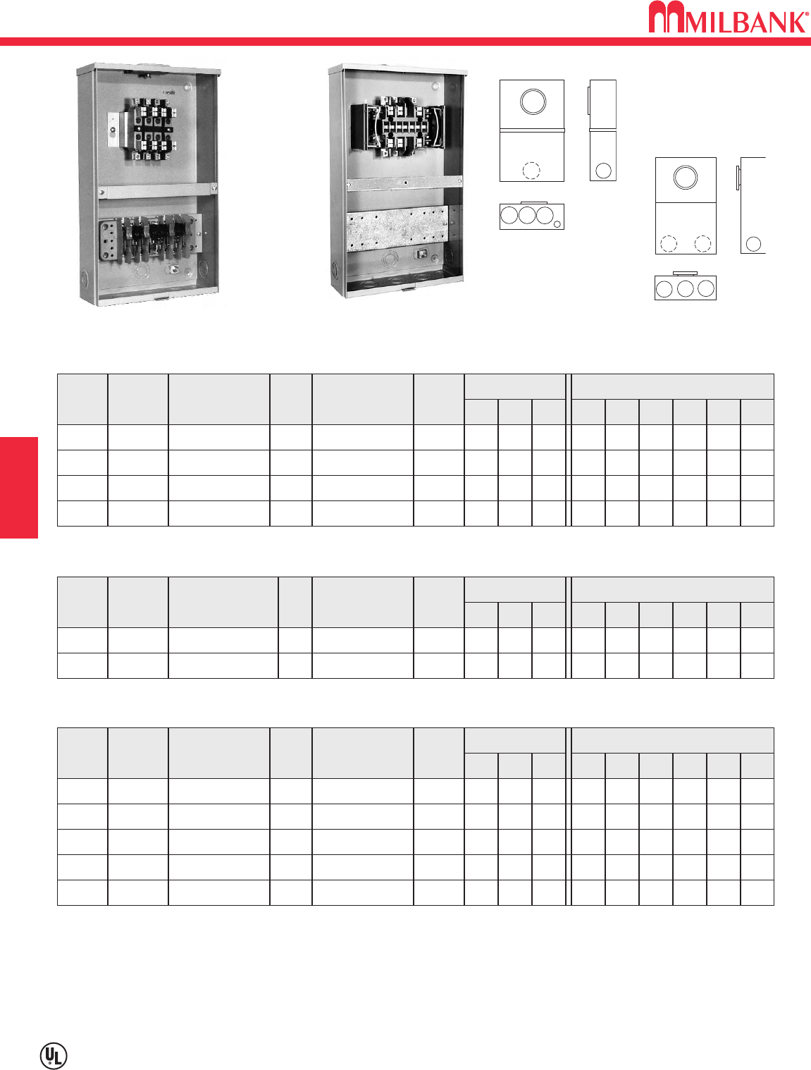
F6
Utility requirements for this equipment may vary. Always consult the serving utility for their requirements before ordering or
installing equipment in this catalog.
F6
CT CABINETS, TEST SWITCHES, POLYPHASE ENCLOSURES SECTION F
20 AMP–600 VAC–5, 6, 8, 13, & 15 TERMINAL
CURRENT TRANSFORMER—TEST SWITCH PROVISION
*RING TYPE—WITH PROVISIONS FOR TEST SWITCH—EUSERC COMPLIANT–TWO PIECE FRONT
NO.
OF
TERMS
SERVICE CATALOG
NUMBER HUB CONNECTORS BY-
PASS
5OH / UG UC3435-XL C.P. #14 - #2 NONE
DIMENSIONS CONCENTRIC K.O.ʼS
123456
22222—
D" W" H"
51
⁄
812 20
6OH / UG UC3436-XL C.P. #14 - #2 NONE 22222—
51
⁄
812 20
8OH / UG UC3438-XL C.P. #14 - #2 NONE 22222—
51
⁄
812 20
13 OH / UG UC3433-XL C.P. #14 - #2 NONE 22222—
51
⁄
812 20
15 OH / UG UC3434-XL C.P. #14 - #2 NONE 22222—
51
⁄
812 20
RINGLESS—WITH PROVISION FOR TEST SWITCH–TWO PIECE FRONT
NO.
OF
TERMS
SERVICE CATALOG
NUMBER HUB CONNECTORS BY-
PASS
5OH / UG UC3425-XL C.P. #14 - #2 NONE
DIMENSIONS CONCENTRIC K.O.ʼS
123456
11
⁄
411
⁄
411
⁄
411
⁄
411
⁄
41
⁄
4,1
⁄
2
D" W" H"
51
⁄
812 20
6OH / UG UC3426-XL C.P. #14 - #2 NONE 11
⁄
411
⁄
411
⁄
411
⁄
411
⁄
41
⁄
4,1
⁄
2
51
⁄
812 20
8OH / UG UC3428-XL C.P. #14 - #2 NONE 11
⁄
411
⁄
411
⁄
411
⁄
411
⁄
41
⁄
4,1
⁄
2
51
⁄
812 20
13 OH / UG UC3423-XL C.P. #14 - #2 NONE 11
⁄
411
⁄
411
⁄
411
⁄
411
⁄
41
⁄
4,1
⁄
2
51
⁄
812 20
*RING TYPE—TEST SWITCH FACTORY PREWIRED—TWO PIECE FRONT
APPROVED FOR TUCSON ELECTRIC POWER
NO.
OF
TERMS
SERVICE CATALOG
NUMBER HUB CONNECTORS BY-
PASS
6 OH
UC7636-YL-TGE-DES
11
⁄
4"#14 - #2 TEST
SWITCH
DIMENSIONS CONCENTRIC K.O.ʼS
123456
11
⁄
411
⁄
411
⁄
411
⁄
411
⁄
41
⁄
4,1
⁄
2
D" W" H"
41
⁄
812 20
13 OH
UC7461-YL-TGE-DES
11
⁄
4"#14 - #2 TEST
SWITCH 11
⁄
411
⁄
411
⁄
411
⁄
411
⁄
41
⁄
4,1
⁄
2
41
⁄
812 20
1
345
6
2
2
5
4
3
1 1
3425
3426
3428
3423
7636
7461
3435
3436
3438
3433
3434
UC3438-XL-TS080025
(with test switch factory installed)
UC3423-XL
*SEALING RINGS: Ring type units are supplied with one MR-4, screw type, sealing ring.
PREWIRING: If factory prewiring is required consult factory before ordering. Please include meter socket catalog number, test
switch number, meter form number, and a copy of your wiring diagram.
TEST SWITCH COVERS: Units on this page can be used with clear lexan cover (except units 7636 and 7461).
CONNECTORS: Units are supplied with sleeve type connectors (#14-#2)
HUBS: For proper hub selection see the hub suffix chart in accessory section.
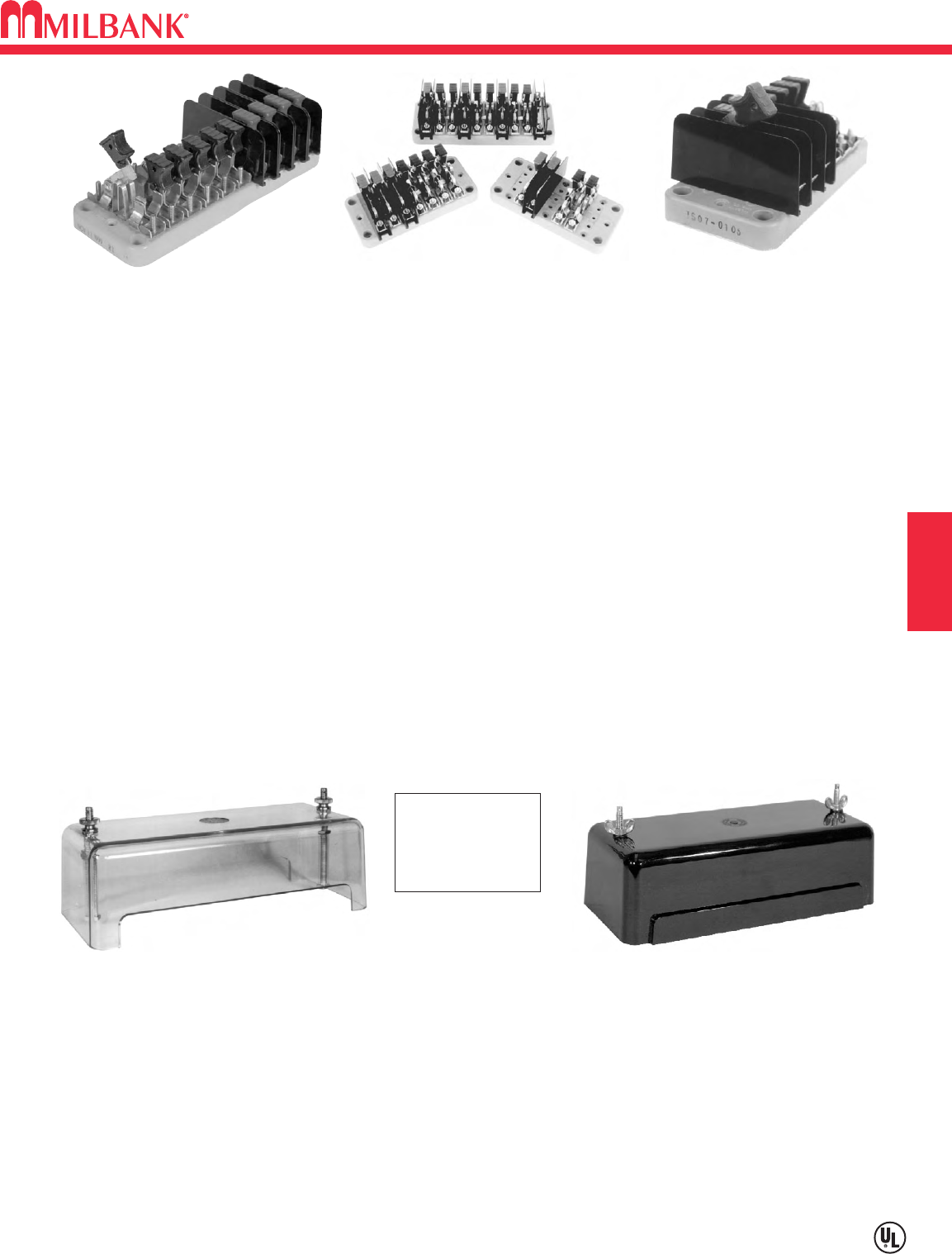
F7
MILBANK TEST SWITCHES—4, 7, & 10 POLE
Utility requirements for this equipment may vary. Always consult the serving utility for their requirements before ordering or
installing equipment in this catalog.
F7
SECTION F CT CABINETS, TEST SWITCHES, POLYPHASE ENCLOSURES
SWITCH BLADES
Two dimples coined into one side
of the switch blade ensure
positive contact in corrosive,
sooty environments—even after
years of inactivity.
SWITCH JAWS
The switch blade jaw clips are
constructed from spring grade
copper alloy. The material and
design ensure excellent contact
which prevents overheating.
Units must be
5 1/8" deep
for Cover
TEST SWITCH BASE
The base is molded from a high
strength, fiberglass reinforced,
thermoset polyester. This
material is track resistant, flame
retardant and has low water
absorption qualities. Bases are
available in 7 pole and 10 pole
sizes.
TEST SWITCH COVERS
Standard test switch covers are
made from break resistant, clear,
thermal plastic which has
excellent tracking and moisture
resistant properties. If covers are
required, add suffix “-WC” (with
cover) to the catalog number or
order separately catalog number
K3388. Black flush mount
covers are also available. Order
catalog number K3388-BLK-FL.
10 pole base only.
POLARITY BARRIER
For maximum protection potential
circuits are supplied with
permanently mounted, rigid
barriers made from high tensile
strength, polycarbonate.
CURRENT CARRYING PARTS
Highly conductive copper and
copper alloy materials are used
on all current carrying parts. This
ensures conductivity and deters
corrosion. Spring grades are
used where appropriate. Plating
is available if required. Contact
general offices to special order.
The MILBANK test switch is designed to meet the critical requirements of the electric utility industry. Not only do they meet EEI,
ANSI C12.9, and UL standards but they combine several special features giving the MILBANK test switch increased safety,
durability and reliability. One such feature is our unique switch blade contact points which cut through residue that builds up after
years of service. Another distinction is our polarity barrier which is designed to be flexible as well as offer exceptional insulating
qualities. Our test switches are constructed from the latest materials available using modern fabricating and assembly methods.
STANDARD COVER
FLUSH MOUNT COVER
BLACK
K3388
FACTORY INSTALLED: For cover installed add the suffix -WC or -WCFL to the catalog number of
desired test switch
FIELD INSTALLED: For field installed cover order kit number K3388 or K3388-BLK-FL.
K3388-BLK-FL
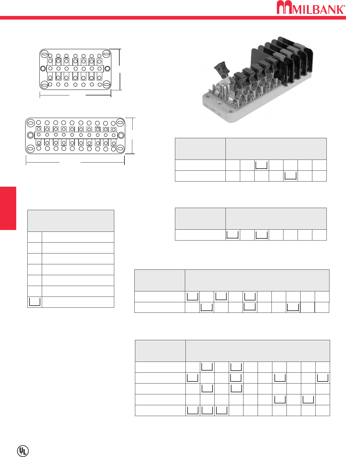
TEST SWITCHES—4, 7 & 10 POLE—600 VAC–PER ANSI C12.9 STANDARD
F8
Utility requirements for this equipment may vary. Always consult the serving utility for their requirements before ordering or
installing equipment in this catalog.
F8
SECTION F
CT CABINETS, TEST SWITCHES, POLYPHASE ENCLOSURES
CATALOG
NUMBER
TS04-0101
4-POLE
X P Pn X C+ C X
CATALOG
NUMBER
TS07-0105
7-POLE
P P Pn C+ CC+ C
X P C+ C P C+ C Pn X XTS07-0106
CATALOG
NUMBER
TS10-0109
10-POLE
P P P Pn C+ CC+
PC+ C P C+ C P
P P P Pn C C+ C
C+ CC+ CC+ C P
C
C+
C+
P
C+
C
C
P
C
Pn
C+
Pn
TS10-0110
TS10-0111
TS10-0112
CATALOG
NUMBER
TS07-0049
7-POLE ON A 10 POLE BASE
P X P X Pn X C+ C C C+
KEY
PPotential Switch
C+ Line side current switch with
short circuit assembly
CLoad side current switch with
test jack assembly
NNeutral bar ( no switch )
Pn Neutral potential switch
XUnused position on base
Insulating barrier, isolates both
sides of switch
CUSTOM POLE ARRANGEMENTS:
The key may be used to diagram your
own pole arrangement. Be sure to
specify base size and whether all C+
line side, current switch / shunt circuit
assemblies are to be bussed together.
The catalog numbers shown above are
connected in line-load pairs; therefore,
if bussed is required, different catalog
numbers will apply.
3 1/2"
9 1/2"
7 1/2"
3 1/2"
XC+ C X P Pn XTS04-0104
P P P PN C C+ CC+ CC+TS10-0016
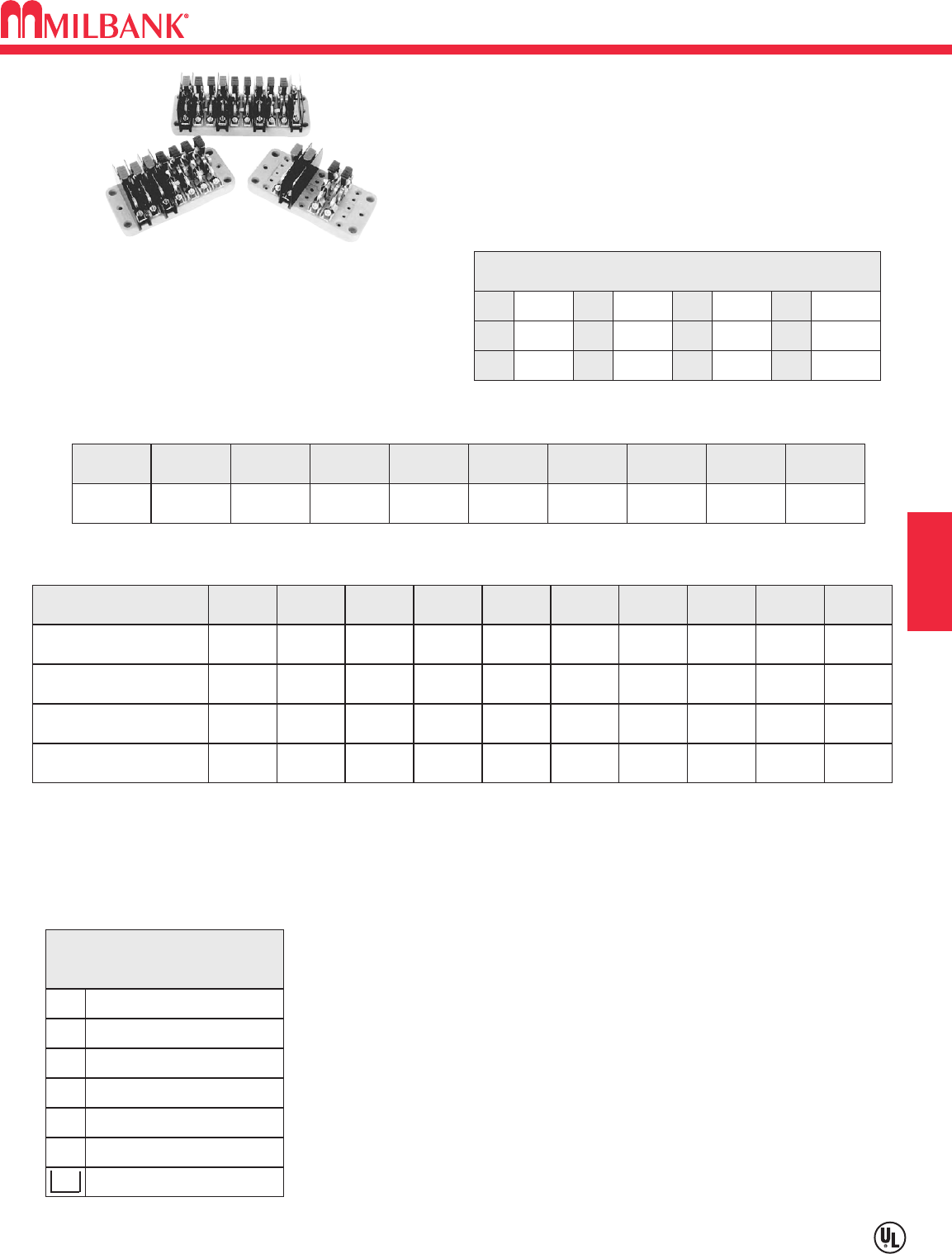
F9
MILBANK TEST SWITCH WORKSHEET
Utility requirements for this equipment may vary. Always consult the serving utility for their requirements before ordering or
installing equipment in this catalog.
F9
SECTION F CT CABINETS, TEST SWITCHES, POLYPHASE ENCLOSURES
TEST SWITCH BASE
The base is molded from a high strength, fiberglass
reinforced, thermoset polyester. This material is
track-resistant, flame-retardant and has low water
absorption qualities. Bases are available in two
standard sizes following NEMA mounting
classifications.
KEY
PPotential Switch
C+ Line side current switch with
short circuit assembly
CLoad side current switch with
test jack assembly
NNeutral bar ( no switch )
Pn Neutral potential switch
XUnused position on base
Insulating barrier, isolates both
sides of switch
NUMBER OF POLES
TEST SWITCH COVER*
POLE POSITION CHART
12345678910
1
FEATURE
45°ANGLE STOPS
2 3 4 5 6 7 8 9 10
GANGED HANDLES (C)
BUSSING
COLORED HANDLES
SPECIAL FEATURES
ENGINEERING INFORMATION:____________________________________________________________________________
______________________________________________________________________________________________________
______________________________________________________________________________________________________
______________________________________________________________________________________________________
______________________________________________________________________________________________________
CUSTOMER NAME: __________________________________________
ADDRESS: __________________________________________________
____________________________________________________________
PHONE / FAX:_____________________ / ________________________
HANDLE COLOR KEY
BK Black PPurple
BL Blue
GR Grey
YYellow
WWhite
OOrange
GN Green
BKS BK/Stripe
WS W/Stripe
Red
Brown
R
BR
CUSTOM POLE ARRANGEMENTS: The key may be used to diagram your own pole
arrangement. Be sure to specify base size and whether all C+ line side, current switch /
shunt circuit assemblies are to be bussed together. The catalog numbers shown above
are connected in line-load pairs; therefore, if bussed is required, different catalog
numbers will apply.
4
7
10
OTHER ______
YES ___ CLEAR ___ BLACK
NO
BASE SIZE
7 POLE
10 POLE
*Test switch covers are only
available for 10 pole bases.

NOTES
F10
F10
NOTES SECTION F
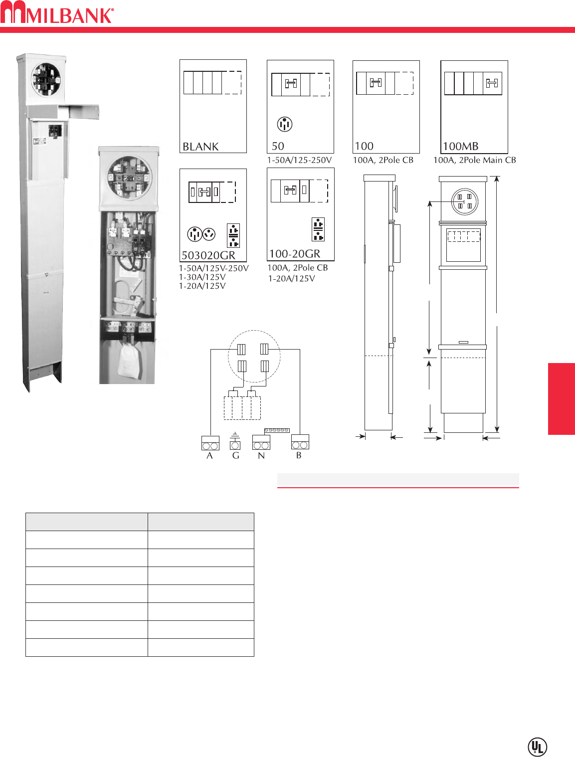
G1
125 AMP–MOBILE HOME METERED PEDESTAL–HARDWIRED–120/240 VAC
Utility requirements for this equipment may vary. Always consult the serving utility for their requirements before ordering or
installing equipment in this catalog.
G1
SERVICE PEDESTALS SECTION G
GRADE LEVEL
78"
8"
4"
24"
49-1/2"
MPRV-100-MB-78
STANDARD CONFIGURATIONS
SINGLE
SPECIFICATIONS
•UL Listed 100 amp continuous duty meter socket.
•120/240 volt single phase service.
•Twin line termination lugs #6-350 kcmil CU/AL per phase
for looping.
•Space for four (4) single, or one double (240V C/B center-
positions only) and two (2) single pole universal style,
plug-in circuit breakers.
•Ringless version equipped with horn bypass as standard.
•For fifth terminal field installed order kit 105J in the
3 oʼclock or 9 oʼclock position.
•Direct rear feed kit PF-KR included.
•Specify MPRV-100-78 for 100 amp service pedestal with
direct feed kit and 100 amp CB wired in parallel. Space
for two additional single pole CBs provided. Series wiring
available; specify MPRV-100-MB-78.
•MR-2 sealing ring standard with ring type cover.
•No knockouts.
CATALOG NUMBER
MPRV-BLANK-78
DESCRIPTION
Ring type, parallel wired
MPRV-BLANK-78-R-5T Ringless, horn bypass
MPRV-100-78 Ring type, parallel wired
MPRV-100-MB-78 Ring type, series wired
MPRV-100-20GR-78 Ring type, parallel wired
MPRV-50-78 Ring type
MPRV-503020GR-78 Ring type
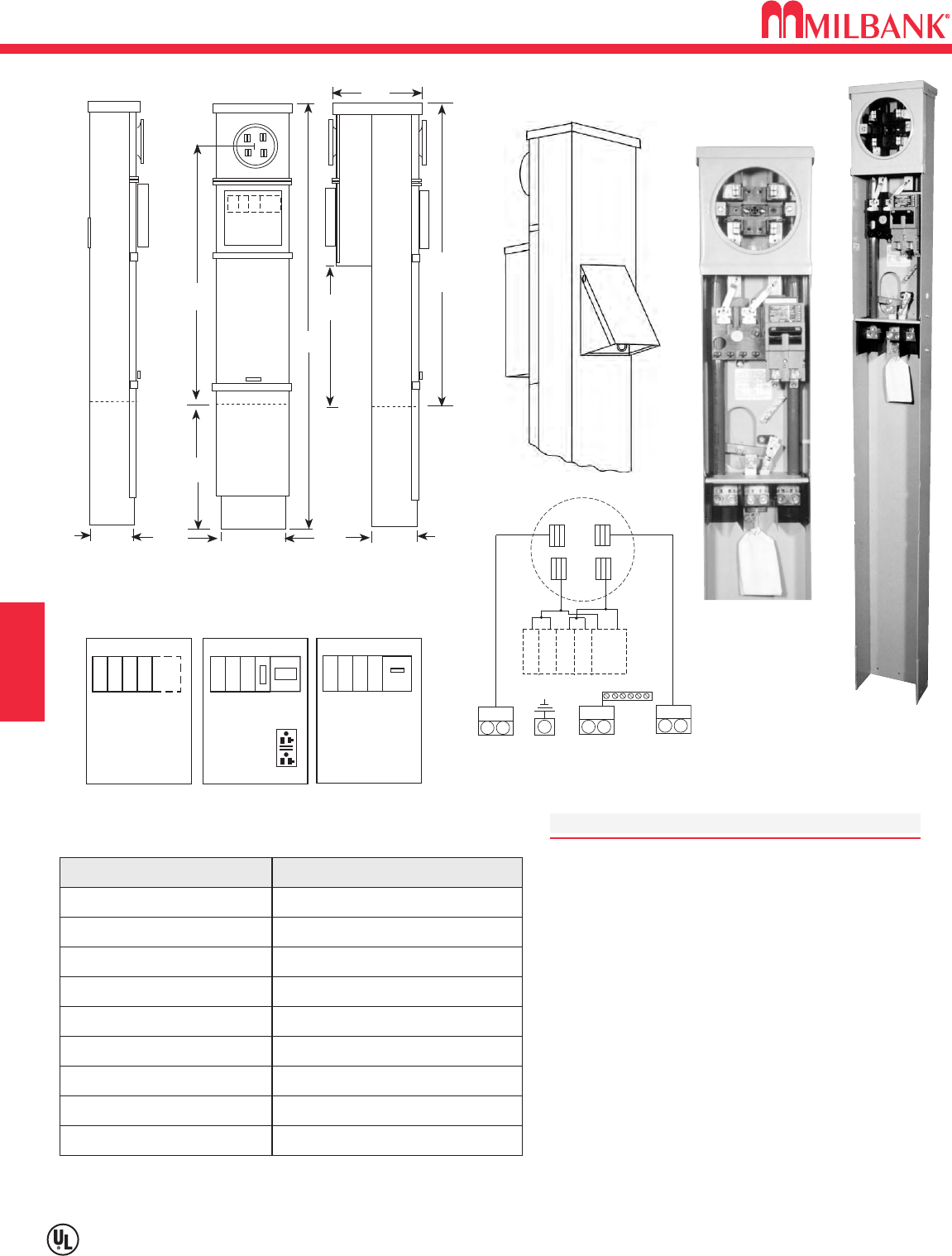
200 AMP–MOBILE HOME METERED PEDESTAL—HARDWIRED—120/240VAC
G2
Utility requirements for this equipment may vary. Always consult the serving utility for their requirements before ordering or
installing equipment in this catalog.
G2
SERVICE PEDESTALS
SECTION G
SPECIFICATIONS
•120/240 volt single phase service.
•Twin line termination lugs #6-350 CU/AL per phase
for looping.
• UQFP breaker provisions factory wired in parallel with
branch breaker bus. Series wiring available. Specify
MB after breaker rating, ex. MPAP-200-MB.
•Furnished with space for four single or one double
(240V C/B center-positions only) and two single pole
universal style, plug-in circuit breakers in addition to
main.
•Ringless version equipped with horn bypass as
standard.
•For fifth terminal field installed order kit 105J in the
3 oʼclock or 9 oʼclock position.
•Direct rear feed kit PF-KR included.
•MR-2 sealing ring standard with ring type cover.
200-20GR 100A thru 200A
BLANK
1-20A/125V
GRADE LEVEL
27"
78"
4"
8"
4"
24"
49-1/2"
9"
54"
AGN B
STANDARD CONFIGURATIONS MPAP-200-78
SINGLE DOUBLE
CATALOG NUMBER
MPAP-BLANK-78
DESCRIPTION
Ring type, parallel wired
MPAP-BLANK-78-R Ringless, horn bypass, parallel wired
MPAP-100-78 Ring type, parallel wired
MPAP-100-MB-78 Ring type, series wired
MPAP-200-78 Ring type, parallel wired
MPAP-200-MB-78 Ring type, series wired
MPAP-200-20GR-78
MPAPD-BLANK-78
MPAPD-BLANK-78R
Ring type, parallel wired
Ring type, parallel wired
Ringless, horn bypass, parallel wired
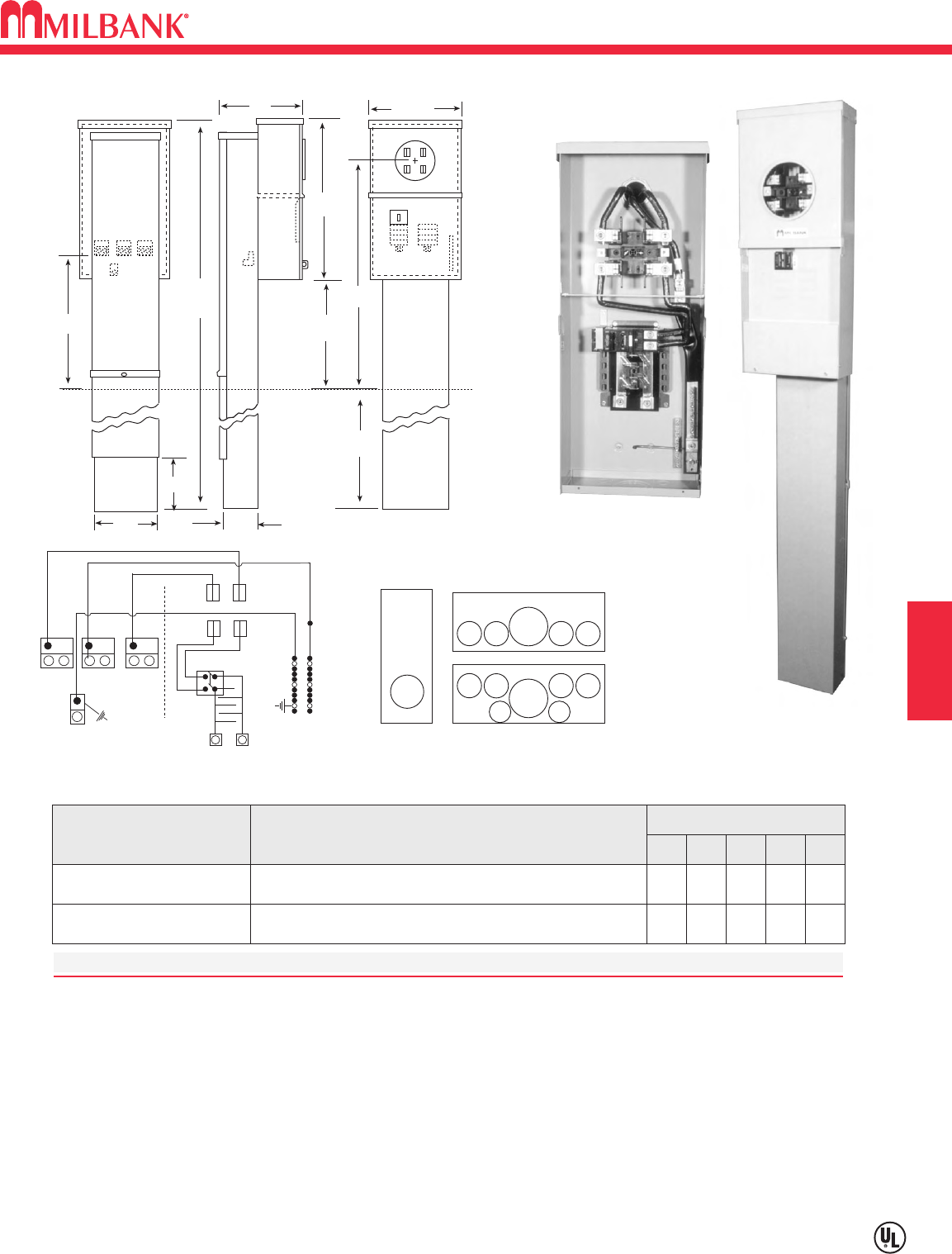
G3
100 / 200 AMP—LOAD CENTER POWER PEDESTALS
ALL PURPOSE & RV APPLICATIONS
Utility requirements for this equipment may vary. Always consult the serving utility for their requirements before ordering or
installing equipment in this catalog.
G3
SERVICE PEDESTALS SECTION G
Grade Level
23-3/4"
10" 12 5/8"
??"
??"
??"
8"
6"
80"
4"
24"
SPECIFICATIONS
•UL Listed 100 / 200 amp continuous duty meter socket.
•Approved for 120/240 volt single phase service.
•Twin line termination lugs #6-350 CU/AL per phase for looping. Rear termination
•Space for (8) single, or (4) double and two single pole universal style plug-in circuit breakers
•Series main breaker factory installed.
•Direct feed lugs standard.
MPAP-200-MBLC-80
CATALOG
NUMBER DESCRIPTION
CONCENTRIC K.O.ʼS
(INCHES)
12345
200 Amp Metered Pedestal with (8) Circuit Load Center
100 Amp Metered Pedestal with (8) Circuit Load Center
21⁄2
21⁄2
2
2
11⁄2
11⁄2
11⁄4
11⁄4
1⁄2,3⁄4
1⁄2,3⁄4
MPRV-100-MBLC-80
100 & 200 AMP—LOAD CENTER POWER OUTLETS
MPAP-200-MBLC-80
AB
N
G
G1 N1
2
3
5555
1
5555
44
Left
Side
Only
MPAP
MPRV
MPAP
30"
27"
48"
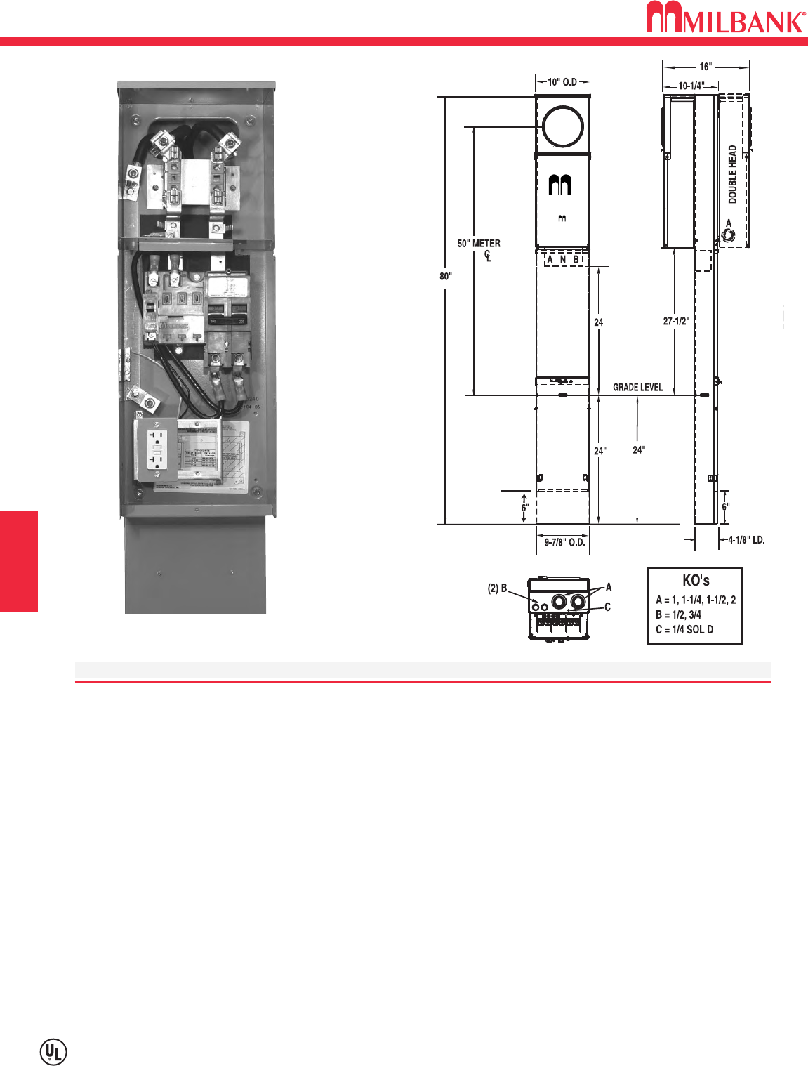
G4
Utility requirements for this equipment may vary. Always consult the serving utility for their requirements before ordering or
installing equipment in this catalog.
G4
SERVICE PEDESTALS
SECTION G
200 AMP SERIES U5240 & U5241 RING TYPE METERED PEDESTALS
SPECIFICATIONS
• UL Listed – conforms to EUSERC drawing number 307
• 200 amp maximum, 120/240 volt, single phase, three wire meter socket
• Ring type meter socket with stainless steel screw-type sealing ring
• Short circuit withstand rating 22K AIC.
• Type 3R construction for durable outdoor use, one piece post – lockable and sealable
• Milbank grey polyester powder coat finish
• Wire terminations accept copper or aluminum conductors
• Line & Neutral: (2) #6-350 kcmil per phase
• Line Ground: (4) #14-1/0
• Load (CB): 2/0 to 300 kcmil per pole
• Load Neutral: (1) #6-350 kcmil
• Load Ground: (2) #14-1/0, (4) #14/6
• Milbank plug-in main circuit breaker. Available in 100, 125, 150 & 200 amp. Type UQFPH-M.
• Four-circuit plated copper interior accepts (2) 2-pole or (4) 1-pole standard plug-in type circuit breakers up to a
total of 125 amps maximum. Acceptable manufacturers: Cutler-Hammer, GE or Siemens
• Factory or field installable receptacle bridge and receptacle / circuit breaker kits available. See accessories.
U5240-O-200S with series wired
main & K5400-520GR kit
G5
Utility requirements for this equipment may vary. Always consult the serving utility for their requirements before ordering or
installing equipment in this catalog.
G5
200 AMP SERIES U5240 & U5241 RING TYPE METERED PEDESTALS
SINGLE PEDESTAL (Direct Burial)
CATALOG NUMBER MAIN BREAKER MAIN CB BRANCH WEIGHT (lbs)
U5240-O-100S
UQFPH-M-100 100 4 Circuit 82
U5240-O-200S
UQFPH-M-200 200 4 Circuit 82
U5240-O (parallel wired)
provision for UQFPH-M Series — 4 Circuit 80
SINGLE PEDESTAL (Pad Mount)
U5242-O-200S
UQFPH-M-200 200 4 Circuit 82
U5242-O (parallel wired)
provision for UQFPH-M Series — 4 Circuit 80
DOUBLE PEDESTAL (Direct Burial)
CATALOG NUMBER MAIN BREAKER MAIN CB BRANCH WEIGHT (lbs)
U5241-O-100S
(2) UQFPH-M-100 100 4 Circuit 115
U5241-O-200S
(2) UQFPH-M-200 200 4 Circuit 115
U5241-O (parallel wired)
provision for (2) UQFPH-M Series — 4 Circuit 111
DOUBLE PEDESTAL (Pad Mount)
U5243-O (parallel wired)
provision for (2) UQFPH-M Series — 4 Circuit 111
RECEPTACLE / CIRCUIT BREAKER KITS AND ACCESSORIES (ORDER SEPARATELY)
CATALOG # RECEPTACLE CIRCUIT BREAKER CONDUCTOR CONFIGURATION
K5400-520GR
5-20R Duplex GFI 20 Amp, 1 Pole 12 Awg GFI Rec.
K5400-TT30
TT30R 30 Amp, 1 Pole 10 Awg
K5400-1450
14-50R 50 Amp, 2 Pole 8 Awg
K5400-BRIDGE-1POS
Self-grounded one position receptacle bridge with hardware
K5400-BRIDGE-2POS
Self-grounded two position receptacle bridge with hardware
K5415
Stabilizer Foot with hardware
K5035
Pad Mount Kit with hardware for U5242/43 pad mount pedestals required
K5T
5th Terminal for 208y / 120 volt 3-wire service
K5193
Bus kit to convert series-wired main breaker to parallel
K5194
Wire kit to convert parallel-wired main breaker to series
K3450
Telephone / CATV mounting bracket (mounts left or right)
K5039
Penta bolt utility cover
• Up to two receptacle / circuit breaker kits can be field-installed in each powerhead. Order mounting bridge and
receptacle kits separately from above. For three receptacles or factory-installed kits, contact factory.
• Receptacle / circuit breaker kits include receptacle, circuit breaker, connected wire, cover plate and mounting
screws. Other receptacle / circuit breaker kits available.
•K5415 Stabilizer Foot sold separately. Recommended for double pedestals.
• Pad mount pedestals require K5035 pad mount kit. Order separately.
Stock item – availability subject to prior sale.
Non-stock items – minimum order quantity required.
SERVICE PEDESTALS SECTION G
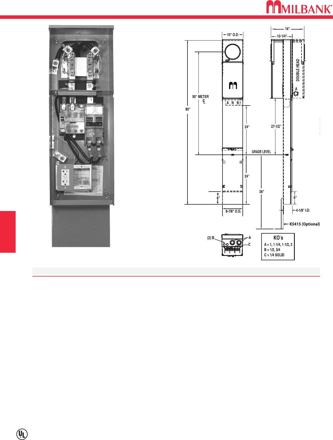
G6
Utility requirements for this equipment may vary. Always consult the serving utility for their requirements before ordering or
installing equipment in this catalog.
G6
SERVICE PEDESTALS
SECTION G
200 AMP SERIES U5136 & U5137 RINGLESS METERED PEDESTALS
SPECIFICATIONS
• UL Listed – conforms to EUSERC drawing number 307
• 200 amp maximum, 120/240 volt, single phase, three wire meter socket
• Ringless meter socket with horn bypass and stainless steel latch
• Short circuit withstand rating 22K AIC.
• Type 3R construction for durable outdoor use, one piece post – lockable and sealable
• Milbank grey polyester powder coat finish
• Wire terminations accept copper or aluminum conductors
• Line & Neutral: (2) #6-350 kcmil per phase
• Line Ground: (4) #14-1/0
• Load (CB): 2/0 to 300 kcmil per pole
• Load Neutral: (1) #6-350 kcmil
• Load Ground: (2) #14-1/0, (4) #14/6
• Milbank plug-in main circuit breaker. Available in 100, 125, 150 & 200 amp. Type UQFPH-M.
• Four-circuit plated copper interior accepts (2) 2-pole or (4) 1-pole standard plug-in type circuit breakers up to a
total of 125 amps maximum. Acceptable manufacturers: Cutler-Hammer, GE or Siemens
• Factory or field installable receptacle bridge and receptacle / circuit breaker kits available. See accessories.
U5136-O-200S with series wired
main & K5400-520GR kit
G7
200 AMP SERIES U5136 & U5137 RINGLESS METERED PEDESTALS
Utility requirements for this equipment may vary. Always consult the serving utility for their requirements before ordering or
installing equipment in this catalog.
G7
SERVICE PEDESTALS SECTION G
SINGLE PEDESTAL (Direct Burial)
CATALOG NUMBER MAIN BREAKER MAIN CB BRANCH WEIGHT (lbs)
U5136-O-100S
UQFPH-M-100 100 4 Circuit 82
U5136-O-200S
UQFPH-M-200 200 4 Circuit 82
U5136-O (parallel wired)
provision for UQFPH-M Series — 4 Circuit 80
SINGLE PEDESTAL (Pad Mount)
U5138-O-200S
UQFPH-M-200 200 4 Circuit 82
U5138-O (parallel wired)
provision for UQFPH-M Series — 4 Circuit 80
DOUBLE PEDESTAL (Direct Burial)
CATALOG NUMBER MAIN BREAKER MAIN CB BRANCH WEIGHT (lbs)
U5137-O-100S
(2) UQFPH-M-100 100 4 Circuit 115
U5137-O-200S
(2) UQFPH-M-200 200 4 Circuit 115
U5137-O (parallel wired)
provision for (2) UQFPH-M Series — 4 Circuit 111
RECEPTACLE / CIRCUIT BREAKER KITS AND ACCESSORIES (ORDER SEPARATELY)
CATALOG # RECEPTACLE CIRCUIT BREAKER CONDUCTOR CONFIGURATION
K5400-520GR
5-20R Duplex GFI 20 Amp, 1 Pole 12 Awg GFI Rec.
K5400-TT30
TT30R 30 Amp, 1 Pole 10 Awg
K5400-1450
14-50R 50 Amp, 2 Pole 8 Awg
K5400-BRIDGE-1POS
Self-grounded one position receptacle bridge with hardware
K5400-BRIDGE-2POS
Self-grounded two position receptacle bridge with hardware
K5415
Stabilizer Foot with hardware
K5035
Pad Mount Kit with hardware for U5138/39 pad mount pedestals required
K5T
5th Terminal for 208y / 120 volt 3-wire service
K5193
Bus kit to convert series-wired main breaker to parallel
K5194
Wire kit to convert parallel-wired main breaker to series
K3450
Telephone / CATV mounting bracket (mounts left or right
K5039
Penta bolt utility cover
• Up to two receptacle / circuit breaker kits can be field-installed in each powerhead. Order mounting bridge and
receptacle kits separately from above. For three receptacles or factory-installed kits, contact factory.
• Receptacle / circuit breaker kits include receptacle, circuit breaker, connected wire, cover plate and mounting
screws. Other receptacle / circuit breaker kits available.
•K5415 Stabilizer Foot sold separately. Recommended for double pedestals.
• Pad mount pedestals require K5035 pad mount kit. Order separately.
Stock item – availability subject to prior sale.
Non-stock items – minimum order quantity required.
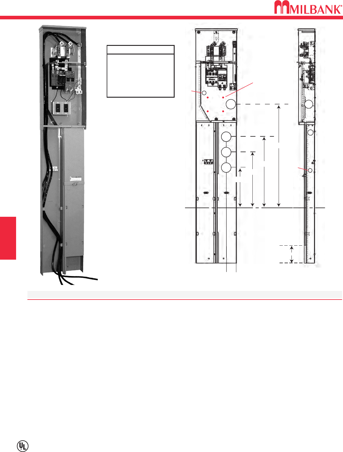
G8
Utility requirements for this equipment may vary. Always consult the serving utility for their requirements before ordering or
installing equipment in this catalog.
G8
SERVICE PEDESTALS
SECTION G
U5706 & U5707 TEMP TO FINAL SERVICE PEDESTAL–RINGLESS/RING TYPE
SPECIFICATIONS
• 200 amp, 1∅, 120/240 volt, 22K AIC, underground service only.
• U5706 has Ringless meter socket available with or without horn bypass (-KK).
• U5707 has Ring type meter socket with MR-4 screw type meter ring.
• Suitable for use as service equipment, mobile home service equipment and temporary power
service equipment.
*• Provisions for up to two Type 3R in-use receptacle kits.
*• Order receptacle and bridge kits separately. See ordering information.
• Direct burial pedestal suitable for free standing or structure mounted installation.
• Separate line and load wireways are removable, lockable and sealable for security.
• Left side is for utility connection. Right side is for customer underground load exit.
• Convenient knockouts in post for thru-wall load exit requirements.
• Type 3R enclosure constructed with type G90 galvanized steel.
• Repaintable light gray polyester powder coat finish.
• Wire terminations accept copper or aluminum conductors: Line & Neutral: #6-350 Ground: (4) #14-1/0.
• Main circuit breaker can be series or parallel connected.
• Universal 4 circuit branch 125 amp interior (up to (2) 2-pole) accepts most manufacturers plug-in type
circuit breakers. See wiring diagram.
U5706-O-200P
*(Shown with (2) K5400-520GR receptacles,
K5400-BRIDGE-2POS & line side
conductor installed.)
8-1/2”
13-1/4”
19”
A
A
A
A
A
30-3/16”
E
Bridge Kit
(4) .173” Extr. Holes
3-1/2”
B
C
D
OPEN
Concentric Knockouts
A (4) = 1, 1-1/2, 2, 2-1/2”
B (1) = 1-1/4, 1-1/2, 2”
C (1) = 3/4”, 1”
D (1) = 1/4”, 1/2”
E (1) = 1” Solid
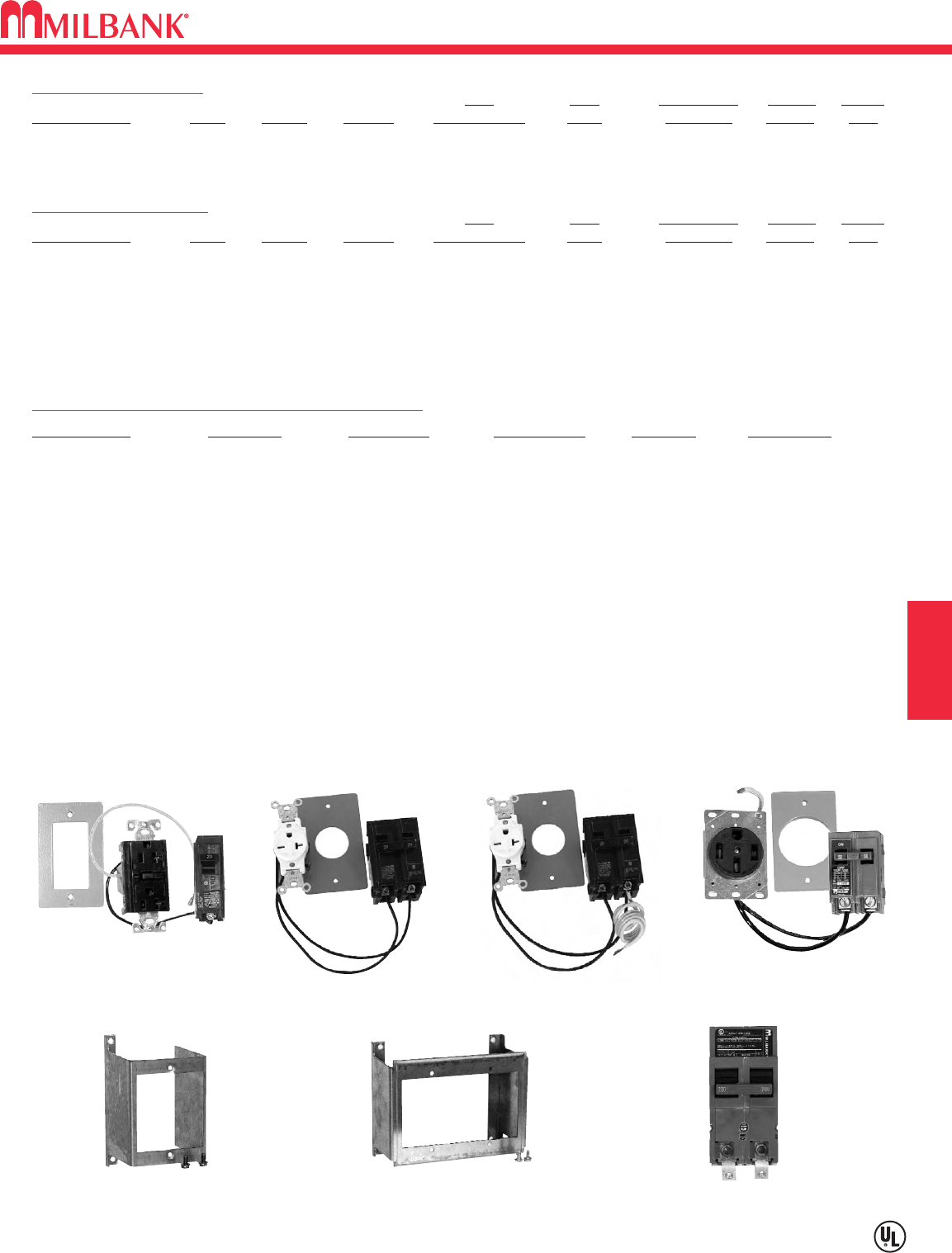
G9
U5706 & U5707 TEMP TO FINAL SERVICE PEDESTAL–RINGLESS/RING TYPE
Utility requirements for this equipment may vary. Always consult the serving utility for their requirements before ordering or
installing equipment in this catalog.
G9
U5706 Ringless Pedestal
Main Main Replacement Branch Weight
Catalog Number Amps Service By-Pass Circuit Breaker Wired Main Type* Circuits LBS.
U5706-O-200S 200 120/240 None 200a 2p Series UQFPH-M 4 79
U5706-O-200S-KK 200 120/240 Horn 200a 2p Series UQFPH-M 4 79
U5707 Ring Type Pedestal
Main Main Replacement Branch Weight
Catalog Number Amps Service By-Pass Circuit Breaker Wired Main Type* Circuits LBS.
U5707-O-200S 200 120/240 None 200a 2p Series UQFPH-M 4 79
Up to two receptacle/circuit breaker kits can be field or factory installed. See below for ordering information. Contact factory for factory installed kits.
To increase pedestal height, order field-installed post extension kit K5708.
For field installed fifth terminal in the 9 oʼclock position, order kit K5T.
For field converting from parallel to series wired, order kit K5194. For field converting from series to parallel wired, order kit K5193.
Receptacle / Circuit Breaker Kits & Receptacle Bridge Kits
Catalog Number Amps/ Volts NEMA Config Circuit Breaker Conductor Configuration
K5400-520GR 20a 120v 5-20R Duplex GFI 20a 1p 12 awg Fig. 1
K5400-620 20a 240v 6-20R Simplex 20a 2p 12 awg Fig. 2
K5400-620GB 20a 240v 6-20R Simplex 20a 240v GFI 12 awg Fig. 3
K5400-1450 50a 120/240v 14-50R 50a 120/240v 8 awg Fig. 4
K5400-1450GB 50a 120/240v 14-50R 50a 120/240v GFI 8 awg Fig. 4
K5400-BRIDGE-1POS Self-grounded ONE position bridge with hardware and instructions. Fig. 5
K5400-BRIDGE-2POS Self-grounded TWO position bridge with hardware and instructions. Fig. 6
Receptacle kits include: receptacle, circuit breaker, connected wire, cover plate, mounting screws and instructions. Contact factory for other kits.
NOTE: Receptacle grounding is provided by metal contact with bridge and pedestal. Be sure to torque all fasteners per torque requirements.
Stock item – availability subject to prior sale.
Non-stock items – minimum order quantity required.
Fig. 1 Fig. 2 Fig. 3 Fig. 4
K5400-520GR K5400-620 K5400-620GB K5400-1450
Fig. 5 Fig. 6 Fig. 7
K5400-BRIDGE-1POS K5400-BRIDGE-2POS UQFPH-M-200
SERVICE PEDESTALS SECTION G
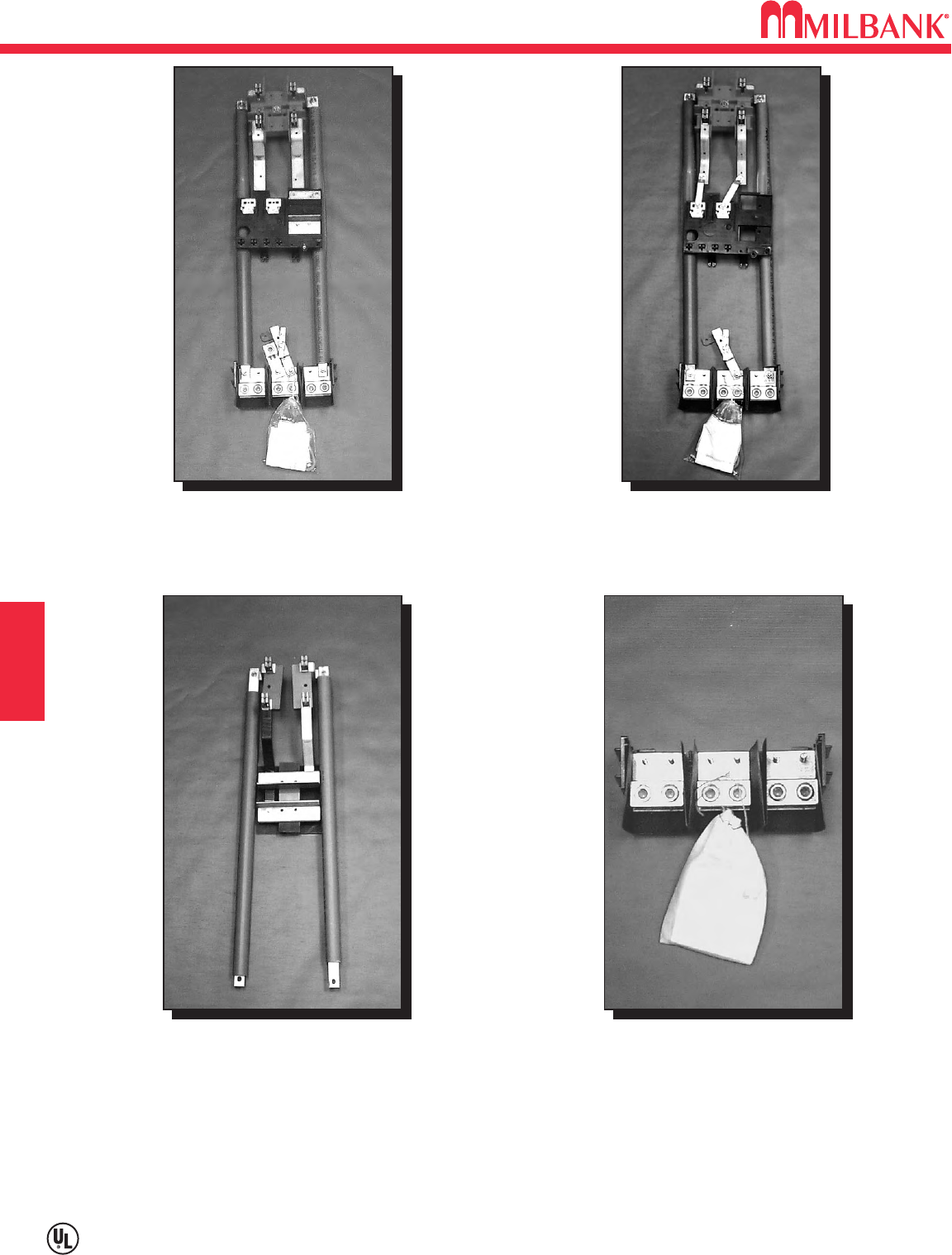
MOBILE HOME REBUILD KITS
G10
Utility requirements for this equipment may vary. Always consult the serving utility for their requirements before ordering or
installing equipment in this catalog.
G10
SERVICE PEDESTALS
SECTION G
Catalog # 020-148-00-00-0
MPAP 200A interior rebuild kit
Catalog # 020-147-00-00-0
MPRV 100A interior rebuild kit
Catalog # RBK-1
Unicorn MPP (pre-1969)
interior rebuild kit
Catalog # Z1048284
MPAP, MPRV & Unicorn MPP
lug landing assembly with grounding kit
Above items sold as complete assemblies only. Individual components not available.
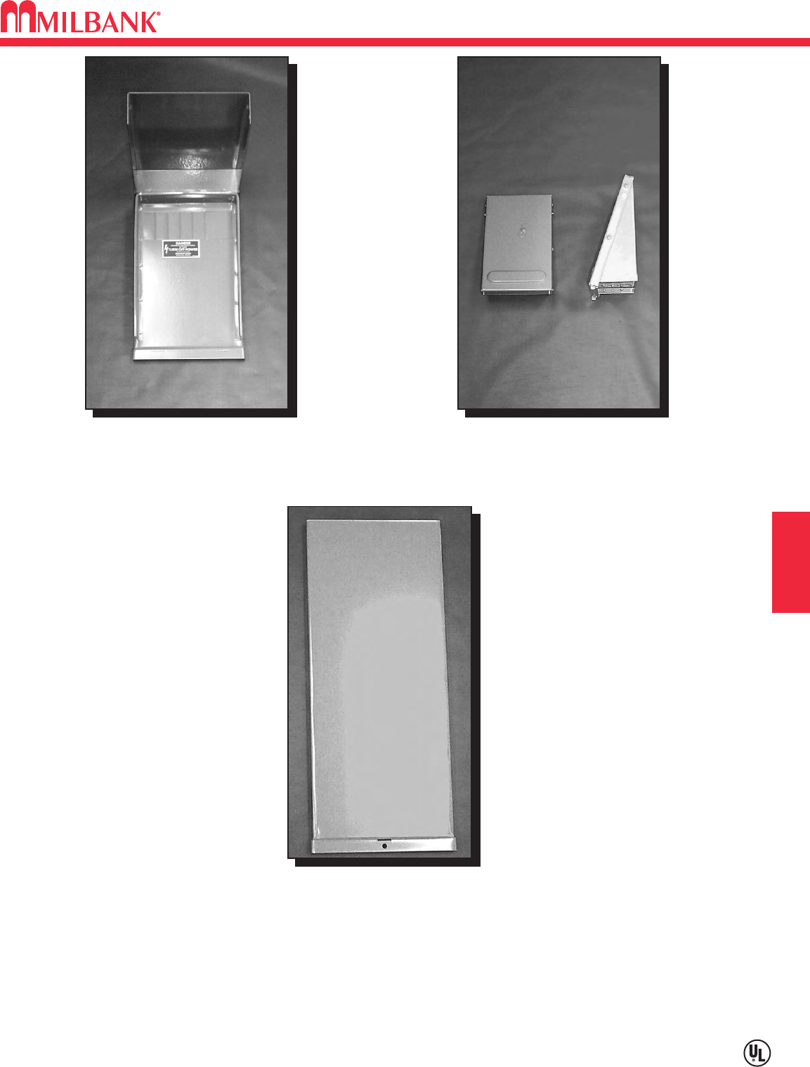
G11
MOBILE HOME REBUILD KITS
Utility requirements for this equipment may vary. Always consult the serving utility for their requirements before ordering or
installing equipment in this catalog.
G11
SERVICE PEDESTALS SECTION G
Catalog # PF-BL
MPAP / MPRV blank deadfront
with hinged cover
Catalog # PF-KR
MPAP / MPRV rear connector kit
Lug cover for MPAP / MPRV
Order Catalog # 403456-SC
(81
⁄
2" W x 201
⁄
2" H) for 72" pedestals
and Cat. # 403457-SC (81
⁄
2" W x 261
⁄
2" H)
for 78" pedestals.
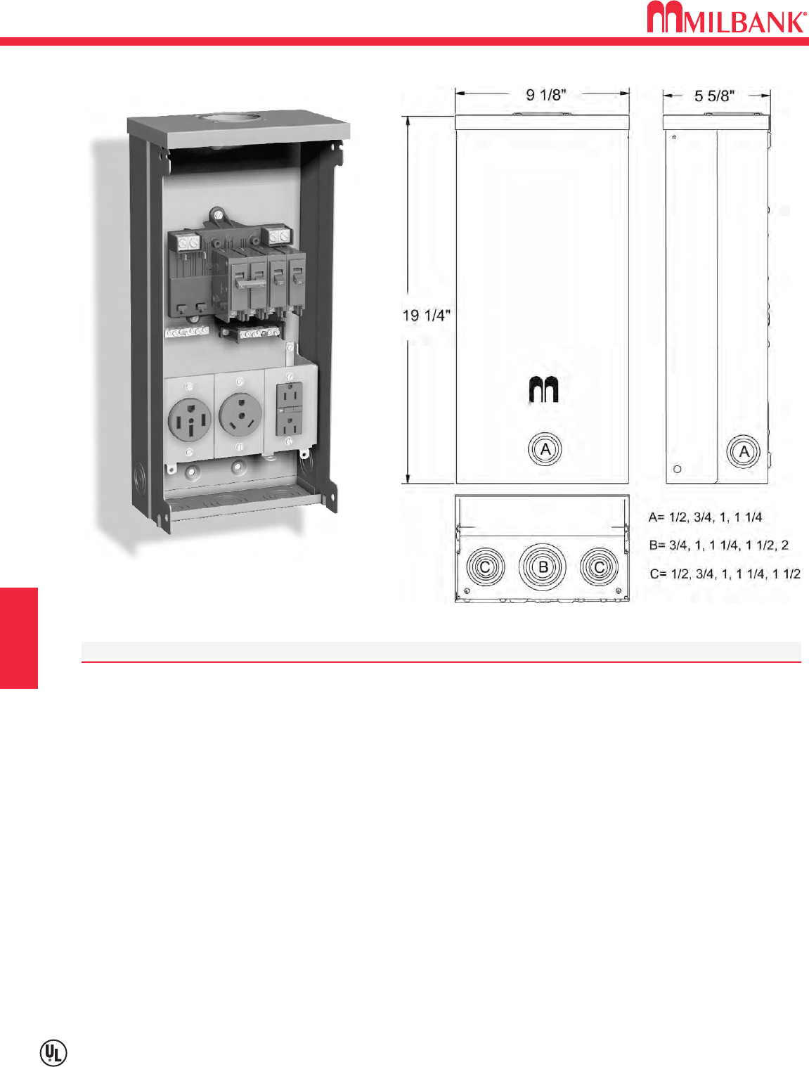
H1
Utility requirements for this equipment may vary. Always consult the serving utility for their requirements before ordering or
installing equipment in this catalog.
H1
RV
SERIES U5000–UNMETERED–SURFACE MOUNT POWER OUTLET
SPECIFICATIONS:
UL Listed 125 Amp, 120/240 Volt, 1∅Power Outlet.
Short circuit current withstand rating 10K RMS symmetrical amperes.
Type 3R welded enclosure for durable outdoor use.
Enclosure constructed with galvanized 16 gauge steel.
ASA 61 grey polyester powder coat finish.
Convenient concentric knock-out configurations and mounting embosses.
Hub opening with closure plate allows for meter retrofit.
Wire terminations accept copper or aluminum conductors for loop feed wiring.
Line: (2) 1/0-#12 Ground: (2) 1/0-#14 & (4) #6-#14 Neutral: (2) 1/0-#14 & (4) #6-#14
Six circuit plated copper interior accepts standard plug-in type circuit breakers. Rated up to 125 amps.
Three position self-grounded receptacle bridge accepts most standard NEMA receptacles with mounting plates.
Components factory wired with stranded copper wire.
Lockable hinge cover and dead front are removable for installation and maintenance. Stay-open hinge cover has
safety interlock on dead front. Dead front cover must be removed before hinge cover can be removed.
Low wattage, 120 Volt fluorescent site light available. Factory or field installable.
Unit weight: 21 lbs.
U5000-XL-75
SECTION H
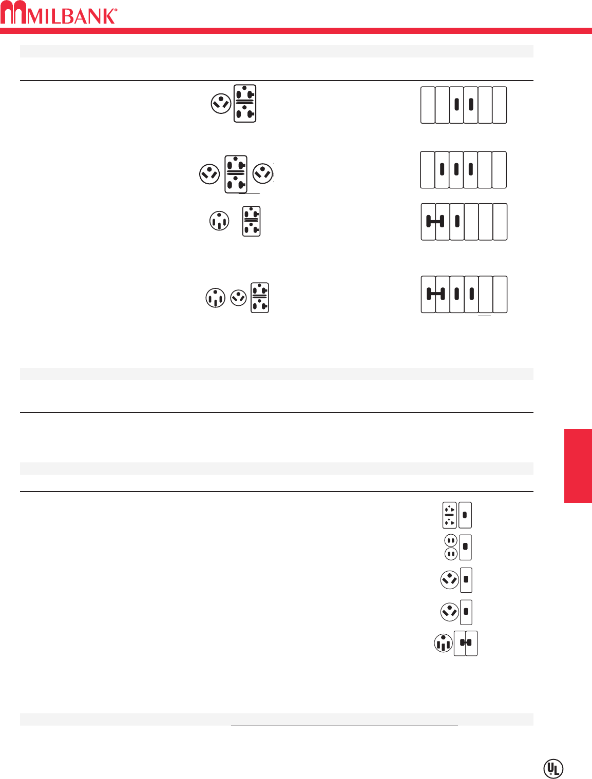
H2
SERIES U5000–UNMETERED–SURFACE MOUNT POWER OUTLET
Utility requirements for this equipment may vary. Always consult the serving utility for their requirements before ordering or
installing equipment in this catalog.
H2
RV SECTION H
U5000 STANDARD MODELS
CATALOG # RECEPTACLES CIRCUIT BREAKERS
U5000-XL-41
(1) TT30R (1) 30A, 1P, 120V
(1) 5-20R GFI (1) 20A, 1P, 120V
U5000-XL-332
(2) TT30R (2) 30A, 1P, 120V
(1) 5-20R GFI (1) 20A, 1P, 120V
U5000-XL-55
(1) 14-50R (1) 50A, 2P, 120/240V
(1) 5-20R GFI (1) 20A, 1P, 120V
U5000-XL-75
(1) 14-50R (1) 50A, 2P, 120/240V
(1) TT30R (1) 30A, 1P, 120V
(1) 5-20R GFI (1) 20A, 1P, 120V
U5000-XL-75GB
(1) 14-50R (1) 50A, 2P, 120/240V
(1) TT30R (1) 30A, 1P, 120V
(1) 5-20R (1) 20A, 1P, 120V, GFI
U5000 STANDARD BASE MODEL
Order up to (3) receptacle / breaker kits. Sold separately for field installation.
CATALOG # DESCRIPTION
U5000-XL
Base model without receptacles or circuit breakers.
RECEPTACLE & CIRCUIT BREAKER KITS
CATALOG # RECEPTACLES CIRCUIT BREAKERS CONDUCTORS CONFIGURATION
K5400-520GR
5-20R Duplex GFI 20 Amp, 1 Pole 12 Awg GFI Rec.
K5400-520GB
5-20R Duplex 20 Amp, 1 Pole GFI 12 Awg GFI CB
K5400-TT30
TT30R 30 Amp, 1 Pole 10 Awg
K5400-TT30GB
TT30R 30 Amp, 1 Pole GFI 10 Awg GFI CB
K5400-1450
14-50R 50 Amp, 2 Pole 8 Awg
Stock model. Availability subject to prior sale.
Note: 20 Amp GFI required at each RV site by UL and NEC 551-71
INTERNAL LIGHT KITS Factory or field installed. See accessory page.
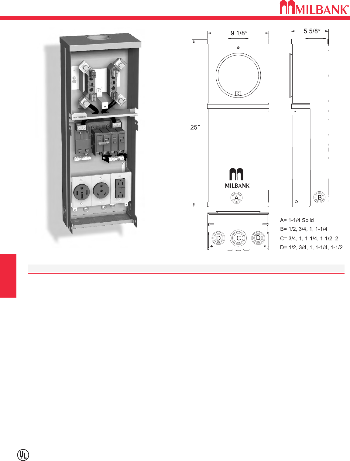
H3
Utility requirements for this equipment may vary. Always consult the serving utility for their requirements before ordering or
installing equipment in this catalog.
H3
RV
SECTION H
SERIES U5100–METERED–SURFACE MOUNT POWER OUTLET
SPECIFICATIONS
UL Listed 125 Amp, 120/240 Volt—1∅Power Outlet.
This is an overhead only unit.
Short circuit current withstand rating 10K RMS symmetrical amperes.
Type 3R welded enclosure for durable outdoor use.
Enclosure constructed with galvanized 16 gauge steel.
ASA 61 grey polyester powder coat finish.
Convenient concentric knock-out configurations and mounting embosses.
Hub opening with closure plate.
Wire terminations accept copper or aluminum conductors. Loop feed not available.
Line: (1) #6-250 kcmil Ground: (2) 1/0-#14 & (4) #6-#14 Neutral: (2) 1/0-#14 & (4) #6-#14
Six circuit plated copper interior accepts standard plug-in type circuit breakers. Rated up to 125 amps.
Three position self-grounded receptacle bridge accepts most standard NEMA receptacles with mounting plates.
Four terminal, drawn ring type meter socket with aluminum sealing ring. Ringless meter socket available. Use
U5101 prefix.
Components factory wired with stranded copper wire.
Lockable hinge cover and dead front are removable for installation and maintenance. Stay-open hinge cover has
safety interlock on dead front. Dead front must be removed before hinge cover can be removed.
Low wattage, 120 Volt fluorescent site light available. Factory or field installable.
Unit weight: 26 lbs.
U5100-XL-75
Loop
feed not
available.
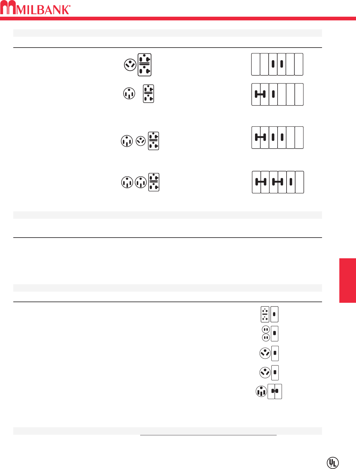
H4
Utility requirements for this equipment may vary. Always consult the serving utility for their requirements before ordering or
installing equipment in this catalog.
H4
RV SECTION H
SERIES U5100–METERED–SURFACE MOUNT POWER OUTLET
U5100 STANDARD MODELS
CATALOG # RECEPTACLES CIRCUIT BREAKERS
U5100-XL-41
(1) TT30R (1) 30A, 1P, 120V
(1) 5-20R GFI (1) 20A, 1P, 120V
U5100-XL-55
(1) 14-50R (1) 50A, 2P, 120/240V
(1) 5-20R GFI (1) 20A, 1P, 120V
U5100-XL-75
(1) 14-50R (1) 50A, 2P, 120/240V
(1) TT30R (1) 30A, 1P, 120V
(1) 5-20R GFI (1) 20A, 1P, 120V
U5100-XL-75GB
(1) 14-50R (1) 50A, 2P, 120/240V
(1) TT30R (1) 30A, 1P, 120V
(1) 5-20R (1) 20A, 1P, 120V, GFI
U5100-XL-552GR
(2) 14-50R (2) 50A, 2P, 120/240V
(1) 5-20R GFI (1) 20A, 1P, 120V, GFI
U5100 STANDARD BASE MODELS
Order up to (3) receptacle / breaker kits. Sold separately for field installation.
CATALOG # DESCRIPTION
U5100-XL
Ring-type base model without receptacles or circuit breakers.
U5101-XL
Ringless-type base model without receptacles or circuit breakers.
RECEPTACLE & CIRCUIT BREAKER KITS
CATALOG # RECEPTACLES CIRCUIT BREAKERS CONDUCTORS CONFIGURATION
K5400-520GR
5-20R Duplex GFI 20 Amp, 1 Pole 12 Awg GFI Rec.
K5400-520GB
5-20R Duplex 20 Amp, 1 Pole GFI 12 Awg GFI CB
K5400-TT30
TT30R 30 Amp, 1 Pole 10 Awg
K5400-TT30GB
TT30R 30 Amp, 1 Pole GFI 10 Awg GFI CB
K5400-1450
14-50R 50 Amp, 2 Pole 8 Awg
Stock model. Availability subject to prior sale.
Note: 20 Amp GFI required at each RV site by UL and NEC 551-71
INTERNAL LIGHT KITS Factory or field installed. See accessory page.
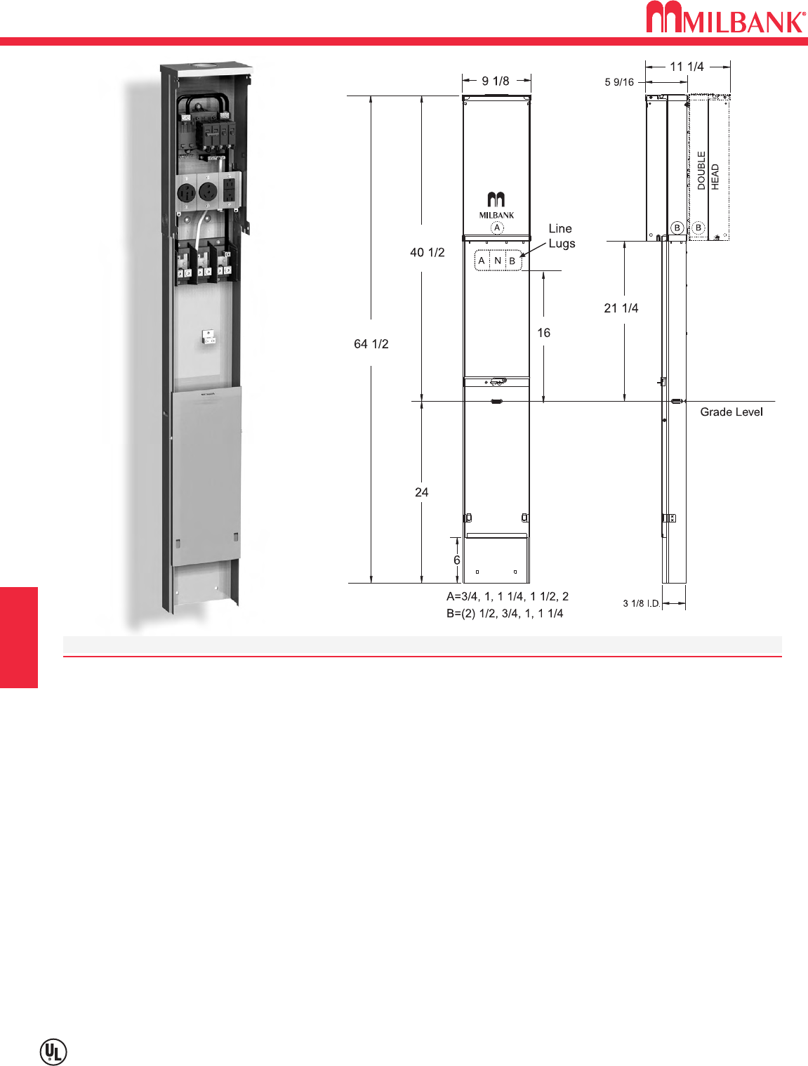
SERIES U5200–UNMETERED–PEDESTAL POWER OUTLET
H5
Utility requirements for this equipment may vary. Always consult the serving utility for their requirements before ordering or
installing equipment in this catalog.
H5
RV
SPECIFICATIONS
UL Listed 125 Amp, 120/240 Volt—1∅Power Outlet.
Short circuit current withstand rating 10K RMS symmetrical amperes.
Type 3R welded enclosure for durable outdoor use.
Enclosure constructed with galvanized 16 gauge steel.
Direct burial or pad mounted post constructed with 14 gauge galvanized steel. Two removable front covers for
ease of installation. Accepts up to (3) 2 1/2” conduits.
ASA 61 grey polyester powder coat finish.
Convenient concentric knock-out configurations. See note A & B above.
Hub opening with closure plate allows for meter retrofit.
Wire terminations accept copper or aluminum conductors for loop feed wiring.
Line: (2) #6-350 kcmil Ground: (2) #14-2/0 Neutral: (2) #6-350 kcmil
Six circuit plated copper interior accepts standard plug-in type circuit breakers. Rated up to 125 amps.
Three position self-grounded receptacle bridge accepts most standard NEMA receptacles with mounting plates.
Components factory wired with stranded copper wire.
Lockable hinge cover and dead front are removable for installation and maintenance. Stay-open hinge cover has
safety interlock on dead front. Dead front must be removed before hinge cover can be removed.
Low wattage, 120 Volt fluorescent site light available. Factory or field installable.
Unit weight: Single–48 lbs. Double–70 lbs.
U5200-XL-75
DIRECT BURIAL
SECTION H
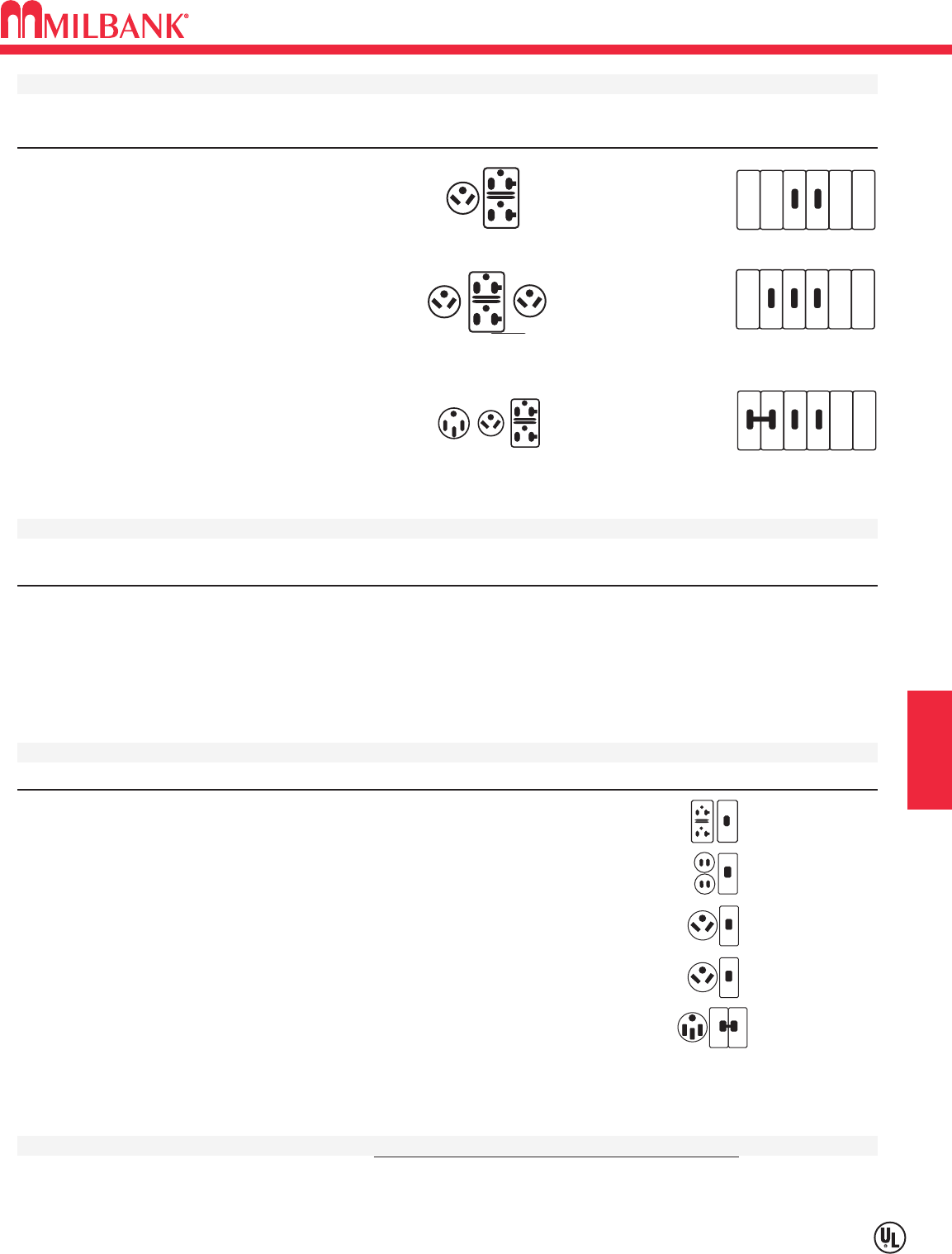
H6
Utility requirements for this equipment may vary. Always consult the serving utility for their requirements before ordering or
installing equipment in this catalog.
H6
RV SECTION H
SERIES U5200–UNMETERED–PEDESTAL POWER OUTLET
U5200 STANDARD MODELS
SINGLE HEAD DBL. HEAD
CATALOG # CATALOG# RECEPTACLES CIRCUIT BREAKERS
U5200-XL-41
U5220-XL-41
(1) TT30R (1) 30A, 1P, 120V
(1) 5-20R GFI (1) 20A, 1P, 120V
U5200-XL-41GB
(1) TT30R (1) 30A, 1P, 120V
(1) 5-20R (1) 20A, 1P, 120V, GFI
U5200-XL-332
(2) TT30R (2) 30A, 1P, 120V
(1) 5-20R GFI (1) 20A, 1P, 120V
U5200-XL-75
U5220-XL-75
(1) 14-50R (1) 50A, 2P, 120/240V
(1) TT30R (1) 30A, 1P, 120V
(1) 5-20R GFI (1) 20A, 1P, 120V
U5200-XL-75GB
(1) 14-50R (1) 50A, 2P, 120/240V
(1) TT30R (1) 30A, 1P, 120V
(1) 5-20R (1) 20A, 1P, 120V,GFI
U5200 STANDARD BASE MODELS
Order up to (3) receptacle / breaker kits. Sold separately for field installation.
CATALOG # DESCRIPTION
U5200-XL
Single head base model on direct burial post.
U5210-XL
Single head base model on pad mount post. Order K5410 pad mount base separately.
U5220-XL
Double head base model on direct burial post.
U5230-XL
Double head base model on pad mount post. Order K5410 pad mount base separately.
RECEPTACLE & CIRCUIT BREAKER KITS
CATALOG # RECEPTACLES CIRCUIT BREAKERS CONDUCTORS CONFIGURATION
K5400-520GR
5-20R Duplex GFI 20 Amp, 1 Pole 12 Awg GFI Rec.
K5400-520GB
5-20R Duplex 20 Amp, 1 Pole GFI 12 Awg GFI CB
K5400-TT30
TT30R 30 Amp, 1 Pole 10 Awg
K5400-TT30GB
TT30R 30 Amp, 1 Pole GFI 10 Awg GFI CB
K5400-1450
14-50R 50 Amp, 2 Pole 8 Awg
Stock model. Availability subject to prior sale.
Note: 20 Amp GFI required at each RV site by UL and NEC 551-71
INTERNAL LIGHT KITS Factory or field installed. See accessory page.
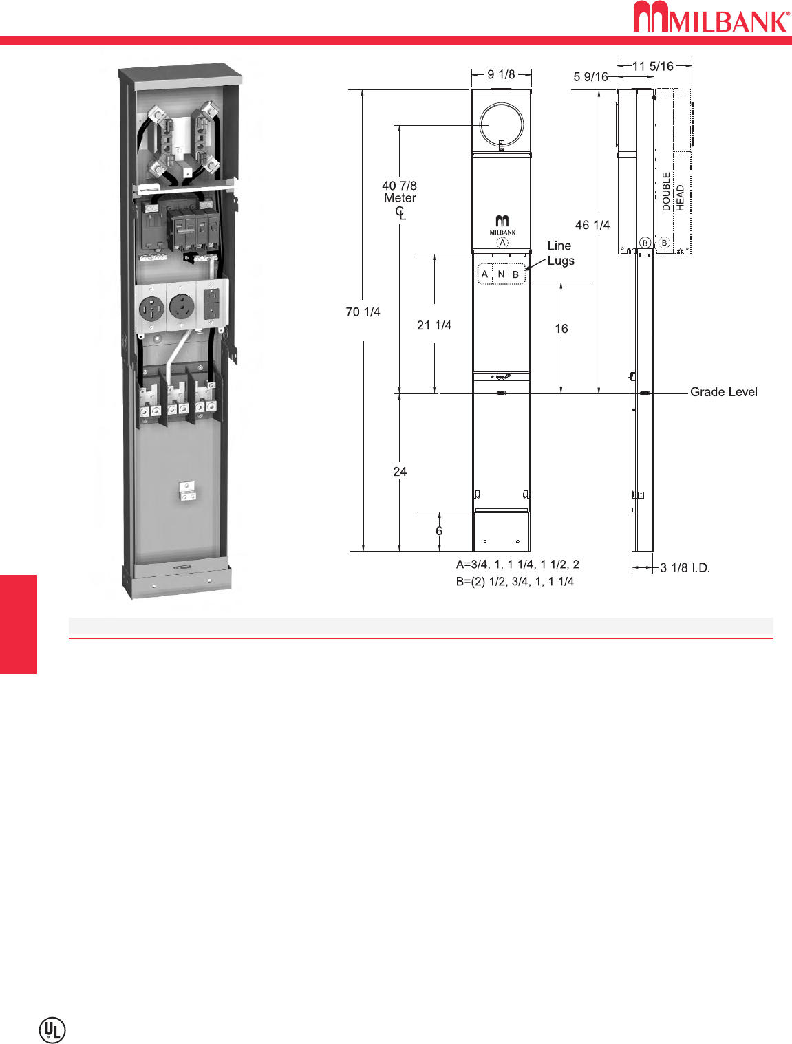
SERIES U5300–METERED–PEDESTAL POWER OUTLET
H7
Utility requirements for this equipment may vary. Always consult the serving utility for their requirements before ordering or
installing equipment in this catalog.
H7
RV
SPECIFICATIONS
UL Listed 125 Amp, 120/240 Volt—1∅Power Outlet.
Short circuit current withstand rating 10K RMS symmetrical amperes.
Type 3R welded enclosure for durable outdoor use.
Enclosure constructed with galvanized 16 gauge steel.
Direct burial or pad mounted post constructed with 14 gauge galvanized steel. Two removable front covers for
ease of installation. Accepts up to (3) 2 1/2” conduits.
ASA 61 grey polyester powder coat finish.
Wire terminations accept copper or aluminum conductors for loop feed wiring.
Line: (2) #6-350 kcmil Ground: (2) #14-2/0 Neutral: (2) #6-350 kcmil
Six circuit plated copper interior accepts standard plug-in type circuit breakers. Rated up to 125 amps.
Three position self-grounded receptacle bridge accepts most standard NEMA receptacles with mounting plates.
Four terminal, drawn ring type meter socket with aluminum sealing ring.
Components factory wired with stranded copper wire.
Lockable hinge cover and dead front are removable for installation and maintenance. Stay-open hinge cover has
safety interlock on dead front. Dead front must be removed before hinge cover can be removed.
Low wattage, 120 Volt fluorescent site light available. Factory or field installable.
Unit weight: Single–53 lbs. Double–80 lbs.
U5310-O-75
PAD MOUNT
DIRECT BURIAL
SECTION H
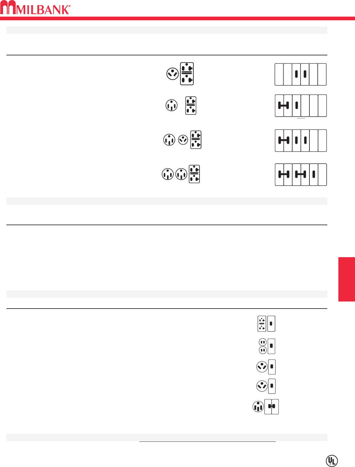
H8
SERIES U5300–METERED–PEDESTAL POWER OUTLET
Utility requirements for this equipment may vary. Always consult the serving utility for their requirements before ordering or
installing equipment in this catalog.
H8
RV SECTION H
U5300 STANDARD MODELS
SINGLE HEAD DBL. HEAD
CATALOG # CATALOG# RECEPTACLES CIRCUIT BREAKERS
U5300-O-41
(1) TT30R (1) 30A, 1P, 120V
(1) 5-20R GFI (1) 20A, 1P, 120V
U5300-O-55
(1) 14-50R (1) 50A, 2P, 120/240V
(1) 5-20R GFI (1) 20A, 1P, 120V
U5300-O-75
U5320-O-75
(1) 14-50R (1) 50A, 2P, 120/240V
(1) TT30R (1) 30A, 1P, 120V
(1) 5-20R GFI (1) 20A, 1P, 120V
U5300-O-552GR
(2) 14-50R (2) 50A, 2P, 120/240V
(1) 5-20R GFI (1) 20A, 1P, 120V
U5300 STANDARD BASE MODELS
Order up to (3) receptacle / breaker kits. Sold separately for field installation.
CATALOG # DESCRIPTION
U5300-O
Single head base model on direct burial post.
U5310-O
Single head base model on pad mount post. Order K5410 pad mount base separately.
U5320-O
Double head base model on direct burial post.
U5330-O
Double head base model on pad mount post. Order K5410 pad mount base separately.
RECEPTACLE & CIRCUIT BREAKER KITS
CATALOG # RECEPTACLES CIRCUIT BREAKERS CONDUCTORS CONFIGURATION
K5400-520GR
5-20R Duplex GFI 20 Amp, 1 Pole 12 Awg GFI Rec.
K5400-520GB
5-20R Duplex 20 Amp, 1 Pole GFI 12 Awg GFI CB
K5400-TT30
TT30R 30 Amp, 1 Pole 10 Awg
K5400-TT30GB
TT30R 30 Amp, 1 Pole GFI 10 Awg GFI CB
K5400-1450
14-50R 50 Amp, 2 Pole 8 Awg
Stock model. Availability subject to prior sale.
Note: 20 Amp GFI required at each RV site by UL and NEC 551-71
INTERNAL LIGHT KITS Factory or field installed. See accessory page.
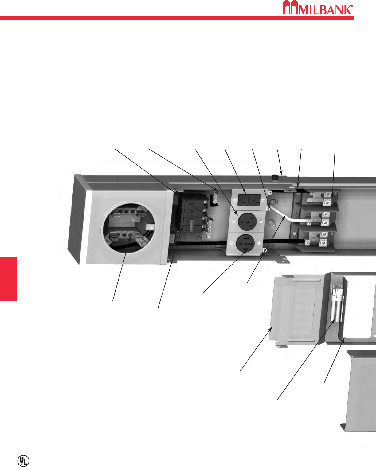
H9
H9
RV
SECTION H
H9 MILLENNIUM FEATURES
MILBANK UTILITY GRADE 125 AMP
DRAWN RING TYPE METER SOCKET
MILLENNIUM SERIES BY MILBANK
SIX CIRCUIT 125 AMP INTERIOR WITH PLATED
COPPER STABS & GLASS FILLED C/B BASE
MULTIPLE HOLE GROUNDING BAR
INSULATED BONDABLE MULTIPLE
HOLE NEUTRAL BAR
SELF-GROUNDED UNIVERSAL BRIDGE FOR UP
TO THREE RECEPTACLES
GFI RECEPTACLE WITH MISWIRE / TRIP
INDICATOR LIGHT
PAD LOCKABLE DEADFRONT PROVISION
STANDARD COPPER
FACTORY WIRING ON ALL
RECEPTACLES AND
CIRCUIT BREAKERS
OPTIONAL LEFT OR RIGHT INSTALLATION
PHOTO-ELECTRIC LIGHT CONTROL
LEFT & RIGHT LOCKING COVER PROVISIONS
GLASS FILLED LUG LANDING WITH
TWIN #6-350 KCMIL LINE CONNECTORS
FOR LOOP FEED WIRING
TAMPER PROOF BARRIER BETWEEN
RECEPTACLES & BREAKERS
LOW WATTAGE
FLUORESCENT
LIGHT
(OPTIONAL)
REMOVABLE DEADFRONT
RECEPTACLES MOLDED
FROM DURABLE NYLON
MATERIAL
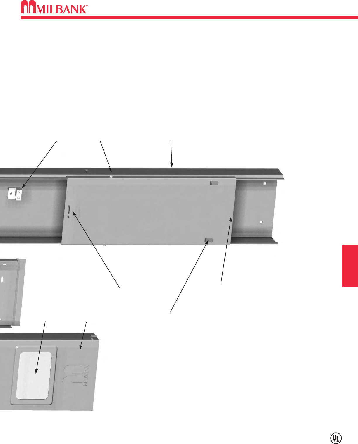
H10
H10
RV SECTION H
MILLENNIUM FEATURES
TWIN #14-2/0 GROUND LUG
ONE PIECE WELDED POST
CONSTRUCTION
U5300-O-75
(Illustrated)
EASY TWO SCREW LOWER COVER REMOVAL
ROLLED EDGE WIREWAY
(NO SHARP EDGES)
SLIP-ON LOCKING TABS FOR
LOWER COVER
STAINLESS STEEL LOCKING
HASP& SEALING SCREW
REMOVABLE HINGE
COVER
WITH STAY OPEN &
CLOSED SNAPS
LIGHT LENS
(OPTIONAL)
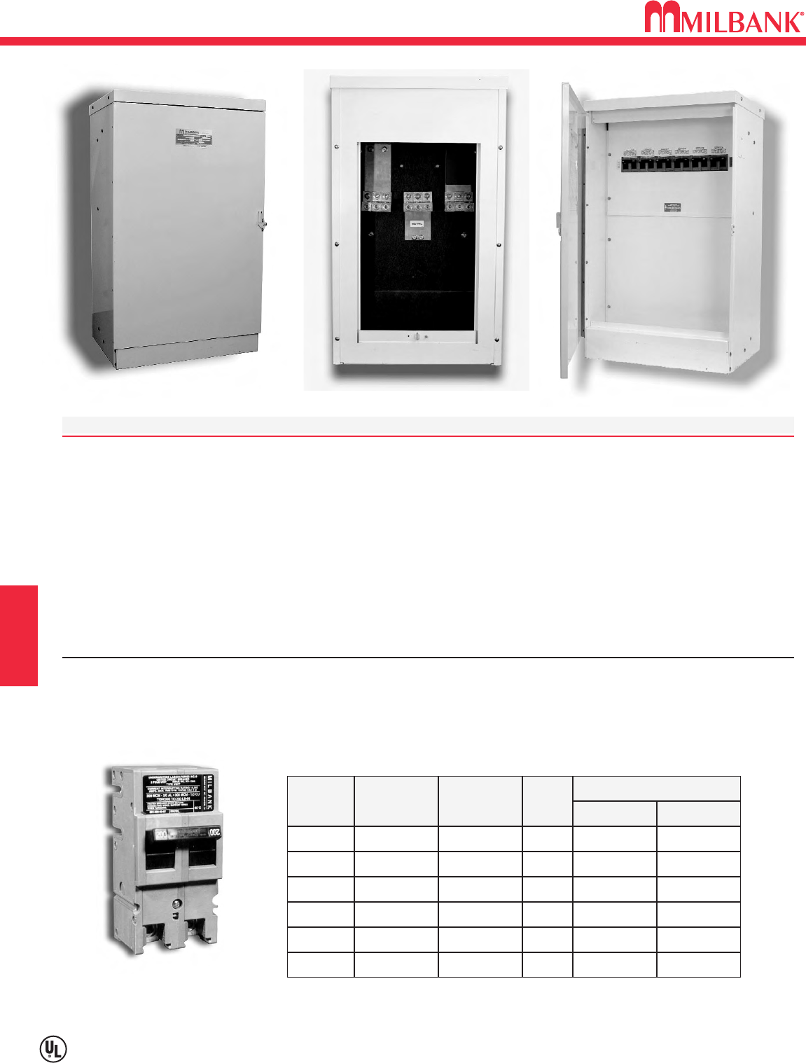
600 / 1200 AMP–PAD MOUNTED PANEL BOARD–120 / 240 VOLT–1
∅
H11
Utility requirements for this equipment may vary. Always consult the serving utility for their requirements before ordering or
installing equipment in this catalog.
H11
RV
2-POLE
RATING
100 UQFP-100
125 UQFP-125
150 UQFP-150
175 UQFP-175
200 UQFP-200
10K AIC
PLUG-IN
UQFPH-100
UQFPH-125
UQFPH-150
UQFPH-175
UQFPH-200
22K AIC
PLUG-IN
#3-#1 #1-1/0
#3-#1 #1-1/0
1/0-300 2/0-300
1/0-300 2/0-300
1/0-300 2/0-300
1/0-300 2/0-300
225 UQFP-225 UQFPH-225
WIRE RANGE
CU AL
1
1
1
1
1
1
PKG
QTY
200 AMP FRAME—PLUG-IN—10K AIC & 22K AIC
TWO-POLE—COMMON TRIP
UQFP
SPECIFICATIONS
600 to 1200 amp, 120/240 Volt, 1∅distribution bus accepts up to (6) 2 pole, 200 amp circuit breakers. Order from chart below.
Costly main breaker not required per NEC 230-71.
Economical alternative to costly wall hung or strut-mounted panel boards and load centers.
Low profile, aesthetic design can be located near utility transformers or fed from a main service to a convenient location.
Pad mounted Type 3R powder coated aluminum enclosure – Standard color is gray.
Hinge door and lift off rear service door are lockable and sealable for security.
NOTE:
Consult local code enforcement for pad size requirements. Order Catalog # CP-24-PDMNT-CALT pad mount base or
Catalog # CP-ABK
5/8
anchor bolt kit separately.
CIRCUIT BREAKERS
CATALOG # AMPS PHASE VOLTS LINE CONNECTORS D W H
CP3B-AUX-1200
1200 1∅120/240 (3) 1-600 kcmil / ∅or 17" 24" 41"
(3) 2-250 kcmil / ∅
SECTION H
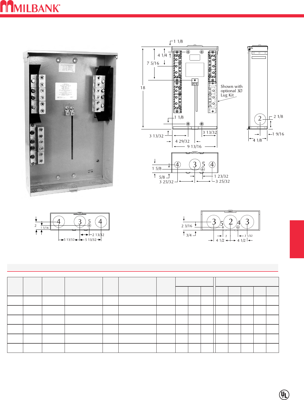
H12
100, 200 & 400 AMP–TERMINAL BOX–1
∅
& 3
∅
–120 / 240 VOLT–600 VAC
Utility requirements for this equipment may vary. Always consult the serving utility for their requirements before ordering or
installing equipment in this catalog.
H12
RV SECTION H
U4540-XL
AMPS
PHASE
VOLTS CATALOG
NUMBER HUB CONNECTORS
CU7AL
1∅TO
3∅KIT
1001
3
120/240 U4544-XL C.P. (6) #12-1/0 K4543
DIMENSIONS CONCENTRIC K.O.ʼS
12345
— 2 2 1 1
⁄
4,1
⁄
2
D" W" H"
41
⁄
8913
⁄
16 18
100 600 U4546-XL C.P. (6) #12-1/0 N/A — 2 2 1 1
⁄
4,1
⁄
241
⁄
8913
⁄
16 18
1200 120/240 U4540-XL C.P. (6) #6-350 K4539 —11
⁄
421
⁄
221
⁄
21
⁄
4,1
⁄
241
⁄
81413
⁄
16 23
3200 600 U4542-XL C.P. (6) #6-350 N/A —11
⁄
421
⁄
221
⁄
21
⁄
4,1
⁄
241
⁄
81413
⁄
16 23
1400 120/240 U4548-RXL C.P. (3) #6-350 or
(2) #4-600 K4547 3331
⁄
4,1
⁄
21
⁄
4
5151
⁄
227
3400 600 U4549-RXL C.P. (3) #6-350 or
(2) #4-600 N/A 3331
⁄
4,1
⁄
21
⁄
4
5151
⁄
227
HUB: Standard hub opening on top with closing plate attached.
FEATURES: UL Listed pad lockable Type 3R enclosure.
3∅120/240V APPLICATION: Field installable 3∅lug kit converts 1∅unit to 3∅unit.
U4540
U4542
U4548
U4549
100, 200, & 400 AMP—TERMINAL BOXES—1
∅
& 3
∅
—120/240 VOLT
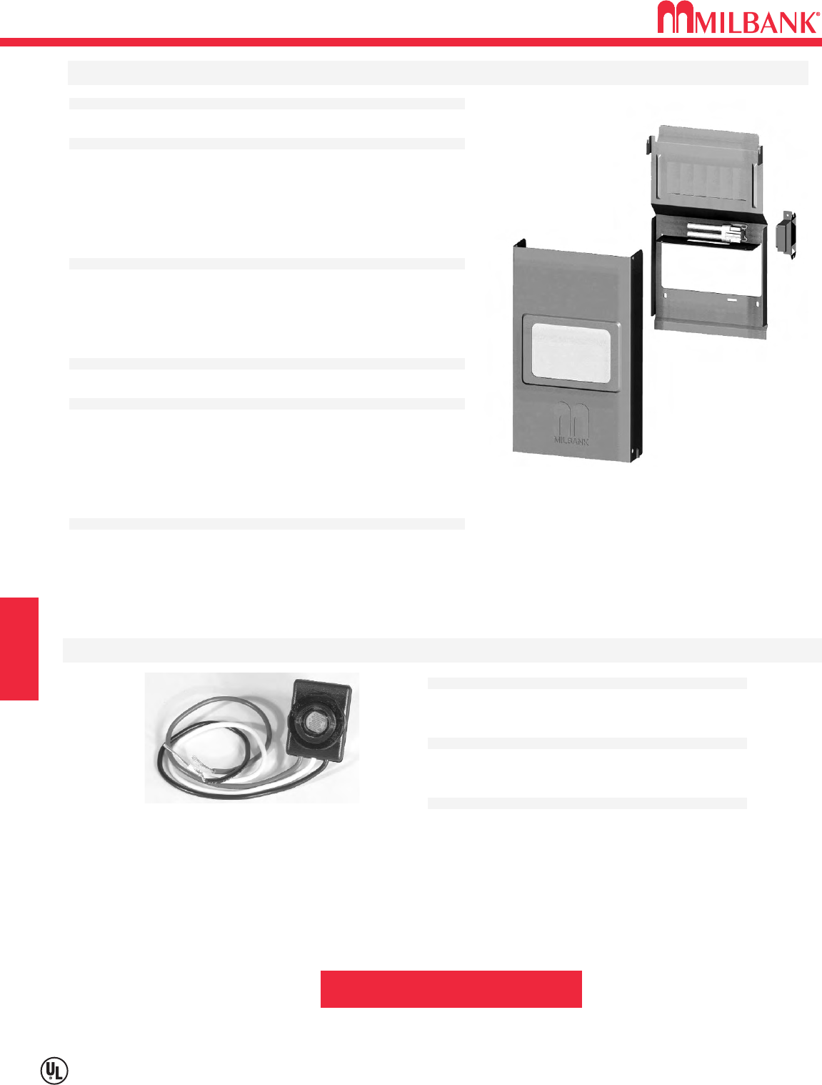
LIGHTING ACCESSORIES
H13
Utility requirements for this equipment may vary. Always consult the serving utility for their requirements before ordering or
installing equipment in this catalog.
H13
RV
SECTION H
Application:
• Internal light kit for U5000 & U5200
UNMETERED
power outlets.
Features:
• Includes 5 watt fluorescent lamp socket, ballast, lamp shield and
opaque hinge cover lens. Factory wired to 20 amp GFI circuit. May
be wired to separate 20 amp circuit breaker. Order Q120
separately.
• Cover on unmetered power outlet is 19 1/8” in height.
Ordering:
• Order with
-L
suffix (after catalog number) for factory installed.
• Order catalog number
K5411
for field installed.
Application:
• Internal light kit for U5100 & U5300
METERED
power outlets.
Features:
• Includes 5 watt fluorescent lamp socket, ballast, lamp shield and
opaque hinge cover lens. Factory wired to 20 amp GFI circuit. May
be wired to separate 20 amp circuit breaker. Order Q120
separately.
• Cover on metered power outlet is 15 1/4” in height.
Ordering:
• Order with
-L
suffix (after catalog number) for factory installed.
• Order catalog number
K5412
for field installed.
INTERNAL LIGHT KITS FOR POWER OUTLETS
Application:
• Photoelectric light control kit for K5411 & K5412
light kits.
Features:
• 2.5 amp, 120 Volt photo electrical control wired in
series with K5411& K5412 light kits.
Ordering:
• Order with -LPC suffix for factory installed light and
PE control.
• Order catalog number K5413 for field installed.
PHOTOELECTRIC LIGHT CONTROL KIT
WARNING: Always disconnect power
prior to installing these devices.
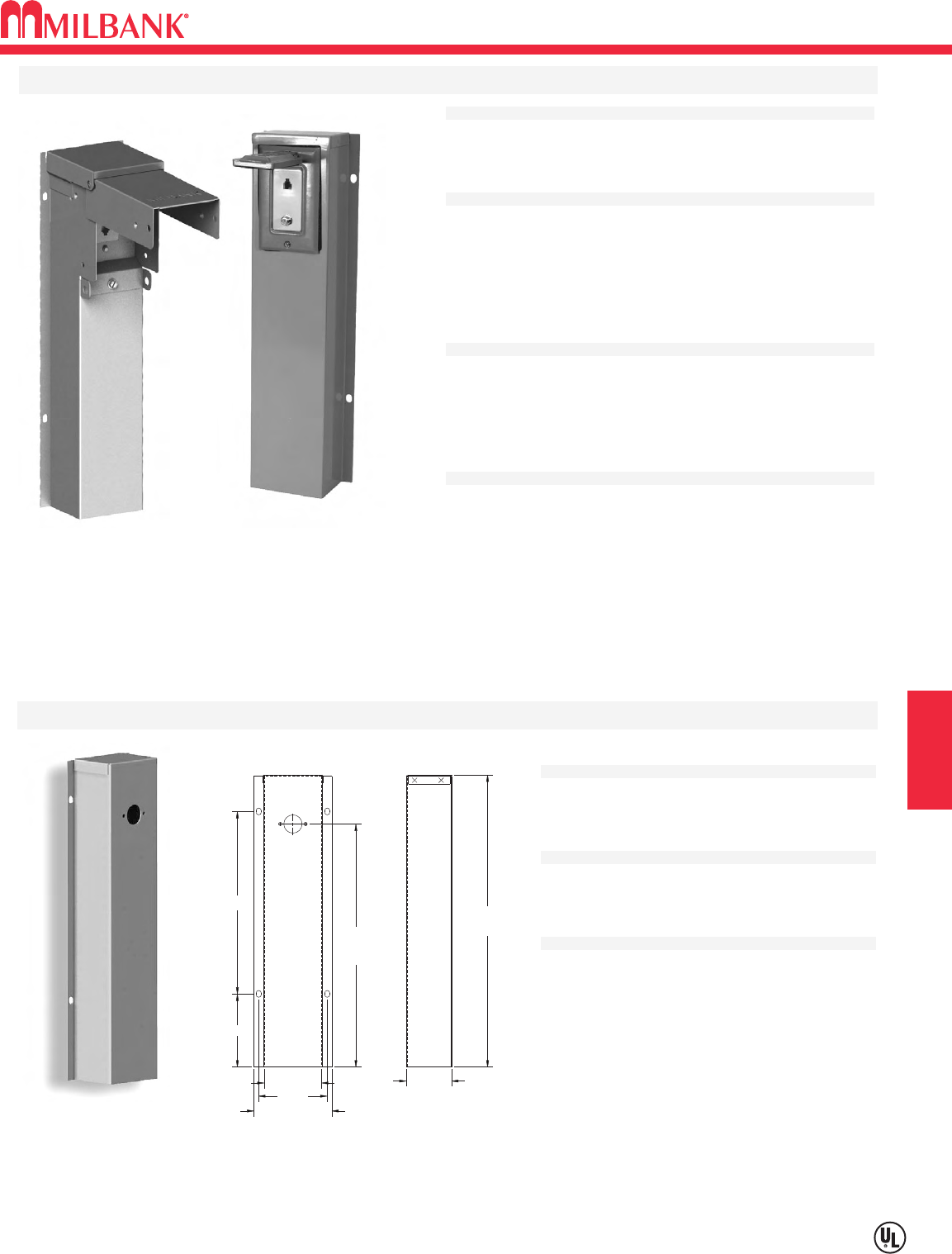
H14
TELECOMMUNICATIONS AND PEDESTAL ACCESSORIES
Utility requirements for this equipment may vary. Always consult the serving utility for their requirements before ordering or
installing equipment in this catalog.
H14
RV SECTION H
Application:
• Used to cover water pipe and provide means to
mount hose bib to rear of pedestal.
Features:
• Includes mounting hardware and instructions.
•Matches
K4709
kits when mounted side by side.
Ordering:
• Order catalog number
K4709-WS.
WATER SHROUD WITH HARDWARE
10
4
3 5/32 ID
3 3/4
4 9/32 OD ref
2 1/2 OD
13 5/16
16 OD
Application:
• Mounts to rear of pedestal series U5200 & U5300. May also be
adaptable to a wooden or similar structure.
Features:
• Single: 16” galvanized raceway, (1) RJ11 telephone jack
& (1) Type F coaxial CATV jack.
• Dual: 16” galvanized raceway, (2) RJ11 telephone jack
& (1) Type F coaxial CATV jack.
• Includes mounting hardware & instructions.
Ordering:
• Single Line Telephone & Cable TV kit order
catalog number
K4709-02.
• Weatherproof Type 3R “in-use” cover available. Add -3R to
catalog numbers above.
NOTE:
•
Confirm acceptability with Cable TV & Telephone provider
before ordering or installing these devices.
TELEPHONE AND CABLE TV KIT
K4709-02
K4709-02-3R
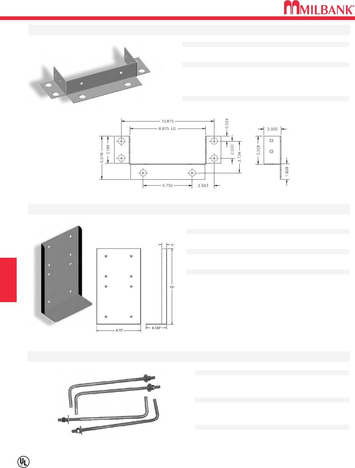
PEDESTAL MOUNTING ACCESSORIES
H15
Utility requirements for this equipment may vary. Always consult the serving utility for their requirements before ordering or
installing equipment in this catalog.
H15
RV
Application:
• Field installed pad mount kit with (6) 3/4” mounting holes.
Features:
• Includes 1/4-20 stainless steel hardware to attach pad mount
base to post.
• Anchor bolt kit sold separately (order catalog number
K5421
).
Ordering:
• Order catalog number
K5410.
FIELD INSTALLED PAD MOUNT KIT
Application:
• Stabilizes direct burial type posts in unstable soil conditions.
Features:
• Includes 1/4-20 hardware to attach to U5200 & U5300 pedestals.
Ordering:
• Order catalog number
K5415.
STABILIZER FOOT WITH HARDWARE
Application:
• Concrete anchor bolt kit designed to attach pad
mount base to concrete.
Features:
• (4) sets of zinc-plated 5/8-11 x 10” bolt with 2” toe.
• Includes nut and flat washer.
Ordering:
• Order catalog number
K5421.
ANCHOR BOLT KIT
SECTION H
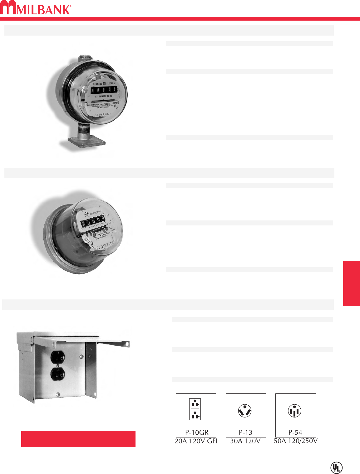
H16
METERING & SINGLE RECEPTACLE ACCESSORIES
H16
RV SECTION H
Utility requirements for this equipment may vary. Always consult the serving utility for their requirements before ordering or
installing equipment in this catalog.
Application:
• Field installed meter kit for U5000 & U5200 power outlets.
Features:
• 100 amp cast meter socket, CL200 E-Z Read Meter,sealing ring,
security seal, 1” Milbank hub, nipple and mounting screws.
• Optional 1” liquid-tight hub available for existing units without
extruded hub opening. See ordering information.
• See CL200 for Watt-hour meter specifications.
Ordering:
• Order catalog number
K4800-01.
FIELD INSTALLED METER KITS
Application:
• 200 Amp E-Z read watt-hour meter designed to be field installed
on the U5100 & U5300 metered power outlets.
Features:
• 200 Amp Form 2S 120/240 Volt.
• Numeric read-out in full kilowatt increments. No “tenths” dial.
• Remanufactured to 1% accuracy.
Ordering:
• Order catalog number
CL200.
Sold in multiples of (4) per carton.
E-Z READ WATT-HOUR METER
WARNING: Always disconnect power
prior to installing these devices.
*SINGLE RECEPTACLE ONLY POWER OUTLET
Application:
• Overhead/underground power outlet receptacle, suitable for RV,
temporary service, campground, marina & boatyard equipment.
Features:
• Type 3R, 120/240 Volt single phase.
•Lockable cover.
Ordering:
• Order catalog number from chart below.
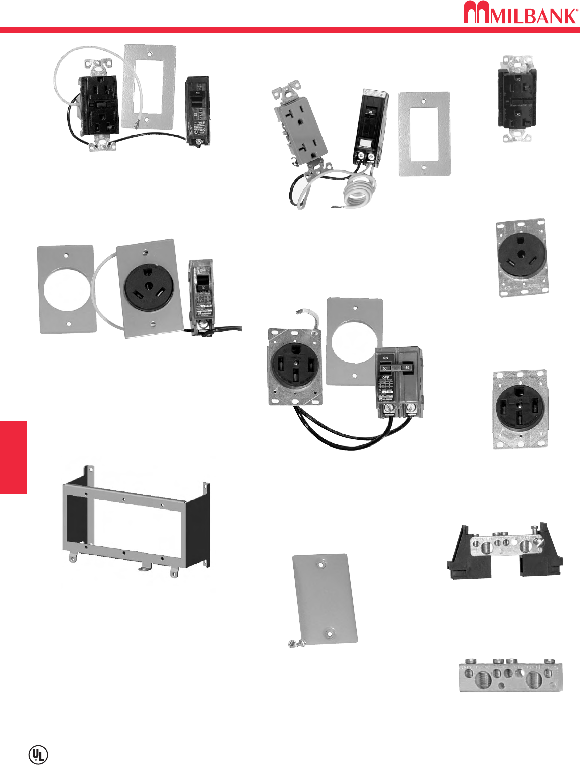
RV REPLACEMENT PARTS & ACCESSORIES
H17
Utility requirements for this equipment may vary. Always consult the serving utility for their requirements before ordering or
installing equipment in this catalog.
H17
RV
K5400-1450
50 amp 120 / 240V
receptacle and circuit
breaker kit
708767-MO
50 amp receptacle
NEMA 1450
708080-MO
20 amp GFI receptacle
NEMA 520
K5400-NEUTRAL
Neutral assembly
K5400-TT30
30 amp 120V receptacle
and circuit breaker kit
701776-MO
30 amp receptacle
NEMA TT30
K5400-520GR
20 amp 120V GFI receptacle and
circuit breaker kit
K5400-BLANK
K5400-520GB
20 amp 120V receptacle
and GFI circuit breaker kit
K5400-BRIDGE
Receptacle bridge (3) position
SECTION H
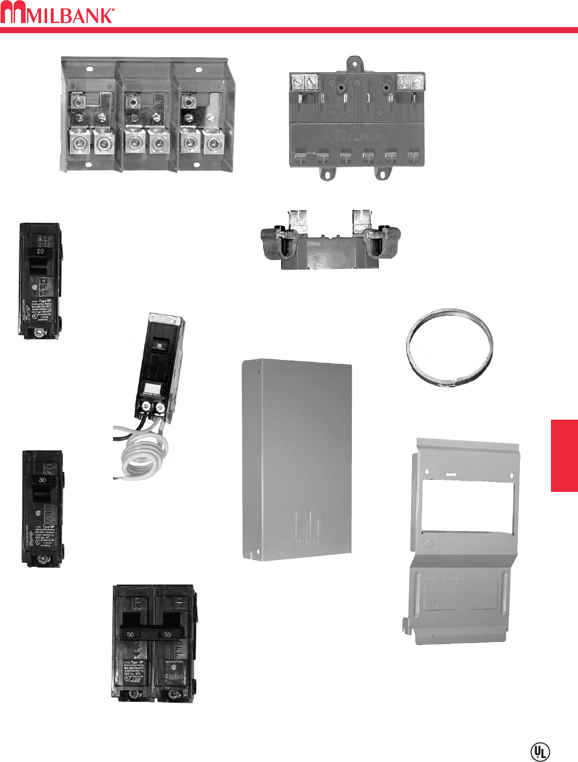
H18
RV REPLACEMENT PARTS & ACCESSORIES
Utility requirements for this equipment may vary. Always consult the serving utility for their requirements before ordering or
installing equipment in this catalog.
H18
RV SECTION H
Q120
20 amp 1 pole
circuit breaker
708784-MO
20 amp 1 pole GFI
circuit breaker
Q130
30 amp 1 pole
circuit breaker
Q250
50 amp 2 pole
circuit breaker
Z915141-AC
Left or right
meter block assembly
HINGE COVER
Z918449-SC 19” Unmetered
Z918447-SC 15” Metered
Z918466-AC
Lug landing base
Z917602-AC
Circuit breaker base
(6 circuit)
DEADFRONT
Z818052-SC 19” Unmetered
Z818480-SC 15” Metered
SEALING RING
SNAP ACTION
MR-2
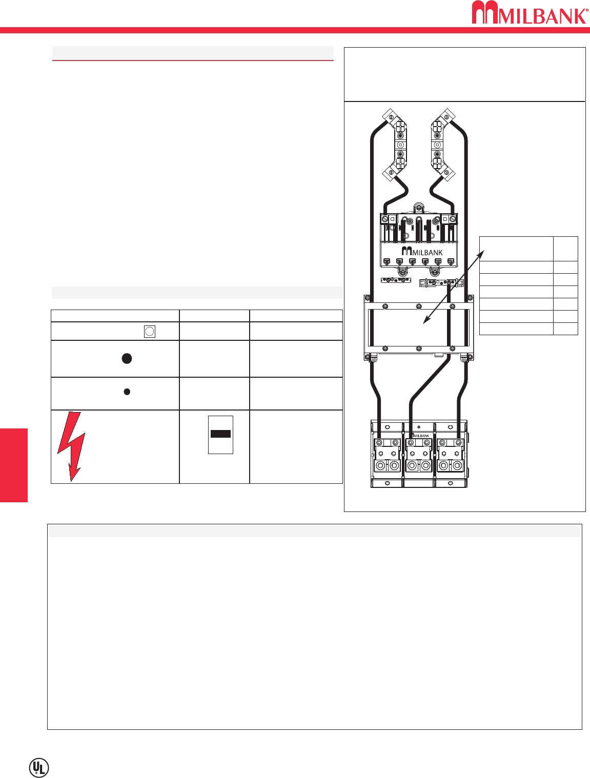
RV PRODUCT INFORMATION–WIRING DIAGRAM LABEL–WARRANTY
H19
Utility requirements for this equipment may vary. Always consult the serving utility for their requirements before ordering or
installing equipment in this catalog.
H19
RV
U5300-O SERIES
RATING: 125 amps maximum–120/240 VAC–1∅3W
METER SOCKET: 100 amp continuous–600 VAC–Rainproof NEMA
Type 3R
SHORT CIRCUIT CURRENT RATING: 10,000 RMS symmetrical
amperes at 240 VAC maximum, but is limited to the lowest short
circuit current rating of any installed circuit breaker. Watthour
meter not included in short circuit current rating.
REPLACEMENT CIRCUIT BREAKER: Must be the same type and
rating. Use Milbank: UCP; Siemens/ITE: QP, QT; Cutler-Hammer
/Westinghouse: QP, BD, BR; General Electric: TQ, THQ, THQL;
Challenger: C, Q, QC, QP, A.
SUITABLE FOR USE AS: Service equipment, mobile home service
equipment, temporary power service equipment and recreational
vehicle site supply power. See rating label below.
WIRE TERMINAL INFORMATION—USE AL-CU CONDUCTORS
WARRANTY
If any equipment manufactured by seller fails due to defects in material or workmanship within one year from the date seller shipped the
equipment, such equipment will be replaced or repaired at seller’s option. This warranty is limited to the repair or replacement of the
equipment or component part or parts of the equipment and becomes void if any equipment failure is due to improper installation, purchaser’s
negligence, unreasonable use, damage (not resulting from defects in material or workmanship) or misapplication. This warranty does not
include reimbursement for the expense of installation, removal of the equipment from the line, transportation, or any other expenses which
may be incurred.
In no event shall seller be liable for consequential or incidental damages and seller’s liability for any and all losses and damages sustained by
the purchaser or any other person arising out of or by reason of the use of the equipment, a defect in the equipment (whether discoverable or
latent), a claim of negligence or for any other reason, shall not exceed the purchase price paid by the purchaser.
THIS WARRANTY IS MADE EXPRESSLY IN LIEU OF ANY OTHER WARRANTY AND SELLER MAKES NO OTHER REPRESENTATION OR
WARRANTY OF ANY OTHER KIND, EXPRESS OR IMPLIED, WITH RESPECT TO THE EQUIPMENT, WHETHER AS TO MERCHANTABILITY,
FITNESS FOR A PARTICULAR PURPOSE OR ANY OTHER MATTER.
AUTHORIZATION MUST BE OBTAINED FROM MILBANK’S GENERAL OFFICE BEFORE EQUIPMENT IS RETURNED.
TERMINAL WIRE RANGE TORQUE LB. / IN.
Line & Neutral
Twin
350 kcmil - #6
250
Load, Neutral
and
Ground
14 - 10
8
6 - 4
3 - 1/0
35
40
45
50
Load, Neutral
and
Ground
DANGER
Hazard of Electrical
Shock or Burn
TURN OFF POWER
Supplying this equipment
before working inside
14 - 10
8
6
On
Trip
Off
To reset breaker
move to “off”
then to “on”
20
25
35
Shipping tends to
loosen bolted
connections.
Check and tighten
all hardware before
energizing unit.
(large hole)
(small hole)
Size of field installed conductors shall be 60°,75°, or
90°C sized to 60°C rating for 110 Amps or less, and
75°C or 90°C sized to 75°C
for 125 Amps and above.
A
= Acceptable
R
= Required
K5400-520GR or
K5400-520GB required
FOR
UNDERGROUND
FEED ONLY
RECEPTACLE
KIT
K5400-520GR
K5400-520GB
K5400-TT30
K5400-TT30GB
K5400-1450
K5400-BLANK
RV
R
R
A
A
A
A
SECTION H
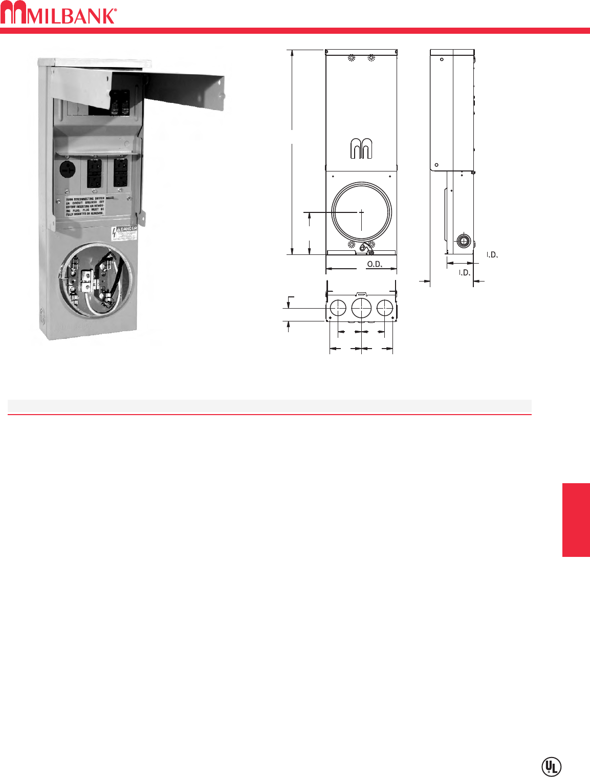
I1
U4908/U4909 UNDERGROUND SERVICE POWER OUTLET–RINGLESS/RING TYPE
Utility requirements for this equipment may vary. Always consult the serving utility for their requirements before ordering or
installing equipment in this catalog.
I1
TEMPORARY POWER SECTION I
MILBANK
MILBANK
25 15/16
5 3/8
9”
1 5/8
4
4
33
5 1/4
3 5/16
C
L
SPECIFICATIONS
Available in ringless style (U4908 series) or ring type (U4909 series)
UL Listed 100 Amp, 120/240 Volt – 1∅Underground Service Power Outlet
Short circuit current withstand rating 10K RMS symmetrical amperes
Type 3R welded enclosure for durable outdoor use
Enclosure constructed with galvanized 16 gauge steel
ASA 61 grey polyester powder coat finish
Convenient concentric knock-out configurations and mounting embosses
Wire terminations accept copper or aluminum conductors
Service–Line & Neutral: (1) #6-2/0 Load Ground: (2) 1/0-#14 & (4) #6-#14
Load Neutral: (2) 1/0-#14 & (4) #6-#14 Service Ground: #2-#8
Six circuit plated copper interior accepts standard plug-in type circuit breakers
Three position self-grounded receptacle bridge accepts most standard NEMA receptacles with mounting plates
Four terminal, ringless meter socket with stainless steel locking hasp. Ring type socket has aluminum MR-2 snap
action sealing ring
Lockable hinge cover and deadfront are removable for installation and maintenance. Stay-open hinge cover has
safety interlock on deadfront. Deadfront must be removed before hinge cover can be removed.
Tamper proof fastening available
U4909-O-11GR
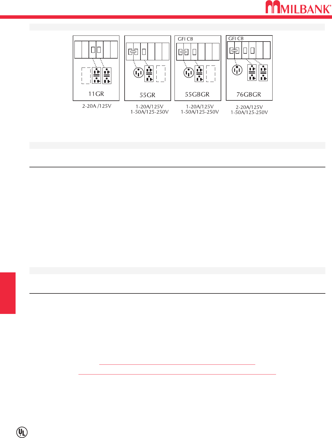
U4908/U4909 UNDERGROUND SERVICE POWER OUTLET–RINGLESS/RING TYPE
I2
Utility requirements for this equipment may vary. Always consult the serving utility for their requirements before ordering or
installing equipment in this catalog.
I2
TEMPORARY POWER
U4908 / U4909 STANDARD CONFIGURATIONS
ORDERING INFORMATION
CATALOG # SOCKET TYPE DESCRIPTION
U4908-O Ringless Order base model and up to three factory installed receptacle/breaker kit separately
from list below. Other kits available. Consult factory.
U4908-O-11GR Ringless
U4908-O-55GBGR Ringless
U4909-O Ring type Order base model and up to three factory installed receptacle/breaker kit separately
from list below. Other kits available. Consult factory.
U4909-O-11GR Ring type
U4909-O-55GBGR Ring type
RECEPTACLE & CIRCUIT BREAKER KITS
CATALOG NEMA
NUMBER AMP BLADE VOLTAGE CONFIG. TYPE CIRCUIT BREAKER TYPE
K5400-520 20 Straight 120 5-20 Std. Duplex 20 Amp 1 Pole
K5400-520GR 20 Straight 120 5-20 GFI Duplex 20 Amp 1 Pole
K5400-620 20 Straight 240 6-20 Single 20 Amp 2 Pole
K5400-620GB 20 Straight 240 6-20 Single 20 Amp 2 Pole GFI
K5400-1450 50 Straight 120/240 14-50 Single 30 Amp 2 Pole
K5400-1450GB 50 Straight 120/240 14-50 Single 30 Amp 2 Pole GFI
Flat cover may not close completely with twist locking devices in use.
Order slope-front 3R cover # 1107681 separately to use with twist lock type receptacles.
Stock item – availability subject to prior sale.
Non-stock items – minimum order quantity required
SECTION I
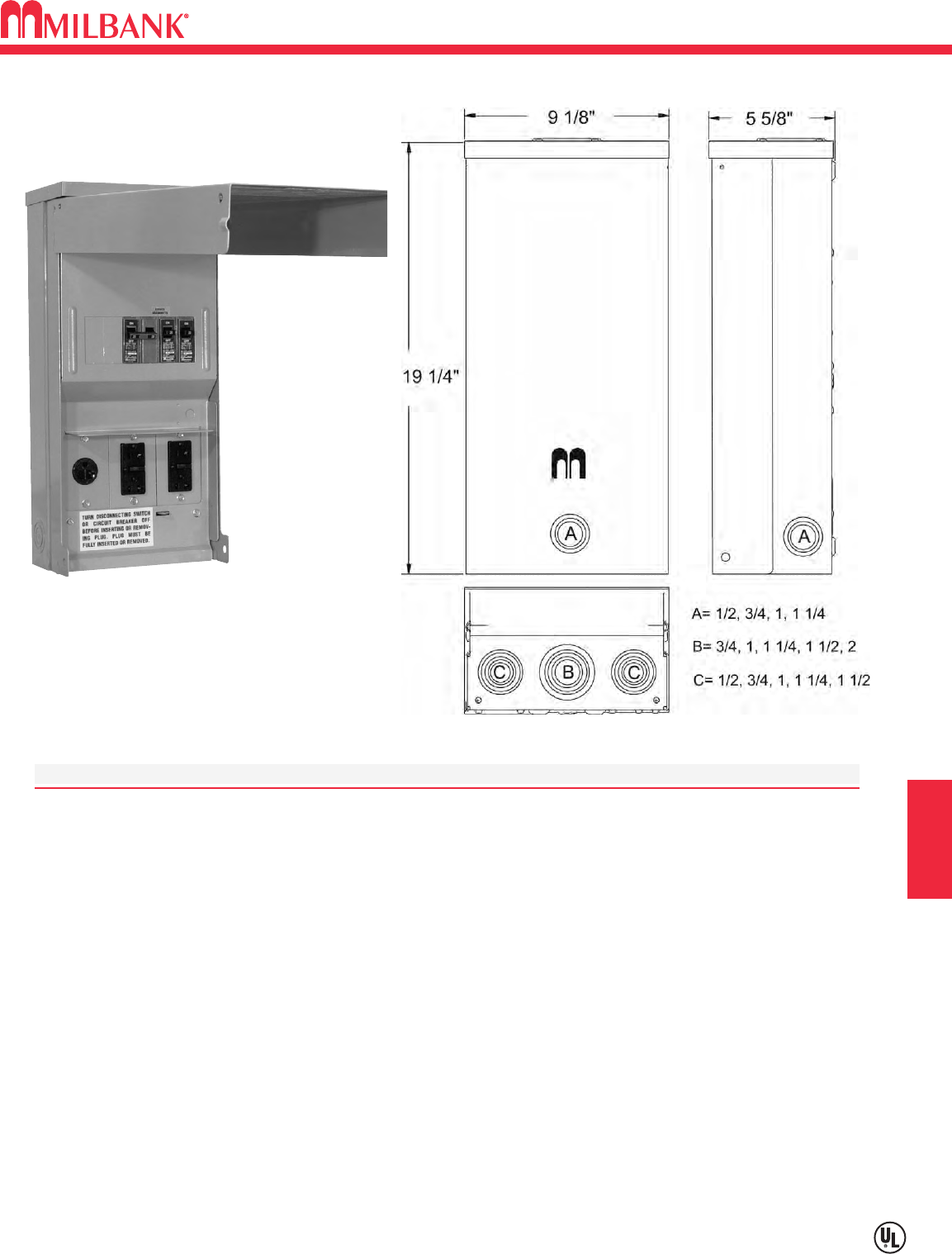
I3
SERIES U5000–UNMETERED–SURFACE MOUNT POWER OUTLET
Utility requirements for this equipment may vary. Always consult the serving utility for their requirements before ordering or
installing equipment in this catalog.
I3
TEMPORARY POWER SECTION I
SPECIFICATIONS:
UL Listed 125 Amp, 120/240 Volt, 1∅Power Outlet.
Short circuit current withstand rating 10K RMS symmetrical amperes.
Type 3R welded enclosure for durable outdoor use.
Enclosure constructed with galvanized 16 gauge steel.
ASA 61 grey polyester powder coat finish.
Convenient concentric knock-out configurations and mounting embosses.
Hub opening with closure plate installed.
Wire terminations accept copper or aluminum conductors for loop feed wiring.
Line: (2) 1/0-#12 Ground: (2) 1/0-#14 & (4) #6-#14 Neutral: (2) 1/0-#14 & (4) #6-#14
Six circuit plated copper interior accepts standard plug-in type circuit breakers.
Three position self-grounded receptacle bridge accepts most standard NEMA receptacles with mounting plates.
Components factory wired with stranded copper wire.
Lockable hinge cover and dead front are removable for installation and maintenance. Stay-open hinge cover
has safety interlock on dead front. Dead front cover must be removed before hinge cover can be removed.
NOTE: Cover may not close completely with twist-locking devices in use.
Tamper proof fastening available.
U5000-XL-38GR
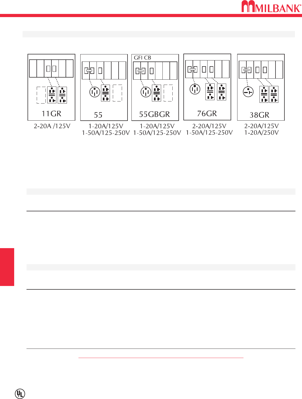
SERIES U5000–UNMETERED–SURFACE MOUNT POWER OUTLET
I4
Utility requirements for this equipment may vary. Always consult the serving utility for their requirements before ordering or
installing equipment in this catalog.
I4
TEMPORARY POWER
SECTION I
U5000 STANDARD CONFIGURATIONS
ORDERING INFORMATION
CATALOG # DESCRIPTION
U5000-XL-(*)
(*) Add suffix from above chart to complete catalog number (ie: U5000-XL-11GR)
U5000-XL
Order base model and up to three factory installed receptacle/breaker kit separately from list
below. Other kits available. Consult factory.
RECEPTACLE & CIRCUIT BREAKER KITS
CATALOG NEMA
NUMBER AMP BLADE VOLTAGE CONFIG. TYPE CIRCUIT BREAKER TYPE
K5400-520
20 Straight 120 5-20 Std. Duplex 20 Amp 1 Pole
K5400-520GR
20 Straight 120 5-20 GFI Duplex 20 Amp 1 Pole
K5400-620
20 Straight 240 6-20 Single 20 Amp 2 Pole
K5400-620GB
20 Straight 240 6-20 Single 20 Amp 2 Pole GFI
K5400-1450
50 Straight 120/240 14-50 Single 30 Amp 2 Pole
K5400-1450GB
50 Straight 120/240 14-50 Single 30 Amp 2 Pole GFI
* Cover may not close completely while in use with Twist-Locking devices.
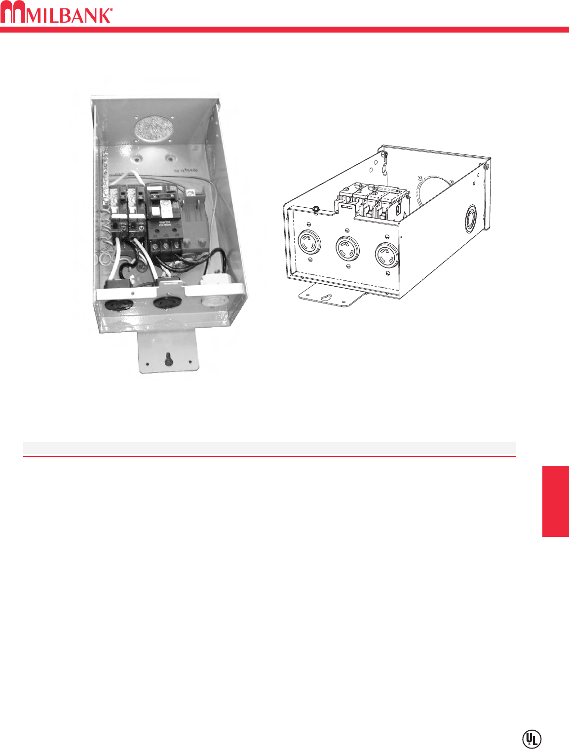
I5
SERIES U5001–UNMETERED–SURFACE MOUNT POWER OUTLET
Utility requirements for this equipment may vary. Always consult the serving utility for their requirements before ordering or
installing equipment in this catalog.
I5
TEMPORARY POWER SECTION I
SPECIFICATIONS:
UL Listed 125 Amp, 120/240 Volt, 1∅Power Outlet.
Short circuit current withstand rating 10K RMS symmetrical amperes.
Type 3R welded enclosure for durable outdoor use.
ASA 61 grey polyester powder coat finish.
Wire terminations accept copper or aluminum conductors.
Line: 1/0-#4 Ground/Neutral: (4) 1/0-#14 & (11) #14-#6
Six circuit plated copper interior accepts standard plug-in type circuit breakers.
Components factory wired with stranded copper wire.
Lockable hinge cover and dead front are removable for installation and maintenance.
U5001-RL-01 includes:
(1) L6-30 (1) 30A, 2P, 240V GFI Breaker
(2) L5-20 (2) 20A, IP, 120V GFI Breaker
U5001-RL-01
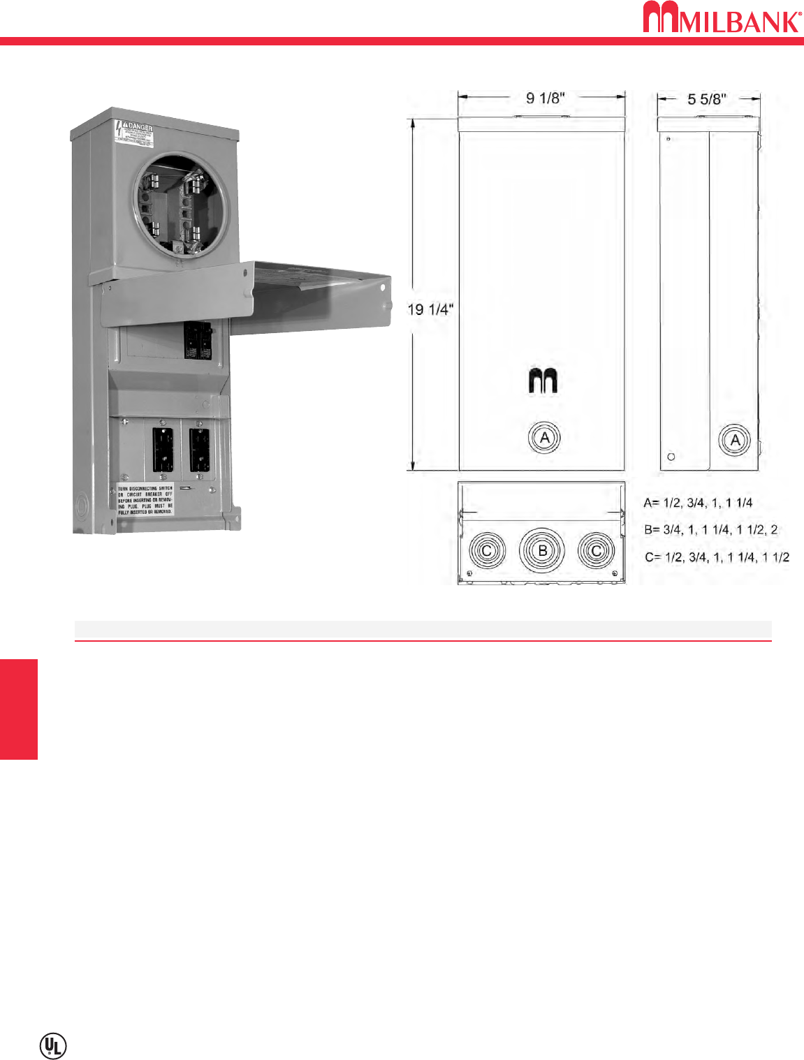
SERIES U5100 & U5101–OVERHEAD–RING & RINGLESS–
METERED–SURFACE MOUNT POWER OUTLET
I6
Utility requirements for this equipment may vary. Always consult the serving utility for their requirements before ordering or
installing equipment in this catalog.
I6
TEMPORARY POWER
SPECIFICATIONS
Available in ringless style (U5101 series) or ring type (U5100 series).
UL Listed 125 Amp, 120/240 Volt—1∅Power Outlet.
Short circuit current withstand rating 10K RMS symmetrical amperes.
Type 3R welded enclosure for durable outdoor use.
Enclosure constructed with galvanized 16 gauge steel.
ASA 61 grey polyester powder coat finish.
Convenient concentric knock-out configurations and mounting embosses.
Hub opening with closure plate installed.
Wire terminations accept copper or aluminum conductors.
Line: (1) #6-250 kcmil Ground: (2) 1/0-#14 & (4) #6-#14 Neutral: (2) 1/0-#14 & (4) #6-#14
Six circuit plated copper interior accepts standard plug-in type circuit breakers.
Three position self-grounded receptacle bridge accepts most standard NEMA
receptacles with mounting plates.
Four terminal, ringless meter socket with stainless steel locking hasp.
Components factory wired with stranded copper wire.
Lockable hinge cover and dead front are removable for installation and maintenance. Stay-open hinge
cover has safety interlock on dead front. Dead front must be removed before hinge cover can be removed.
NOTE: Cover may not close completely with twist-locking devices in use.
Tamper proof fastening available.
U5100-XL-11GR
SECTION I
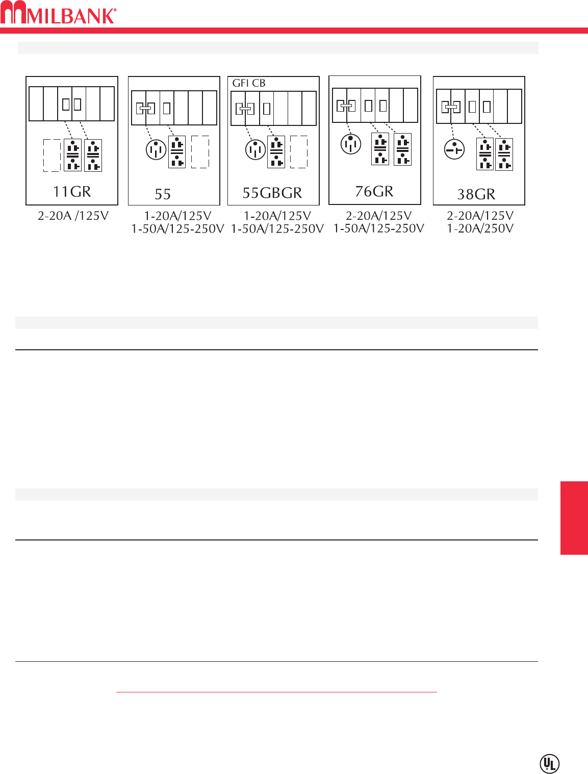
I7
MILBANK
Utility requirements for this equipment may vary. Always consult the serving utility for their requirements before ordering or
installing equipment in this catalog.
I7
TEMPORARY POWER SECTION I
ORDERING INFORMATION
CATALOG # SOCKET TYPE DESCRIPTION
U5100-XL-(*)
Ring type (*) Add suffix from above chart to complete catalog number (ie: U5100-XL-11GR)
U5100-XL
Ring type Order base model and up to three factory installed receptacle/breaker kit separately
from list below. Other kits available. Consult factory.
U5101-XL-(*)
Ringless (*) Add suffix from above chart to complete catalog number (ie: U5101-XL-11GR)
U5101-XL
Ringless Order base model and up to three factory installed receptacle/breaker kit separately
from list below. Other kits available. Consult factory.
RECEPTACLE & CIRCUIT BREAKER KITS
CATALOG NEMA
NUMBER AMP BLADE VOLTAGE CONFIG. TYPE CIRCUIT BREAKER TYPE
K5400-520
20 Straight 120 5-20 Std. Duplex 20 Amp 1 Pole
K5400-520GR
20 Straight 120 5-20 GFI Duplex 20 Amp 1 Pole
K5400-620
20 Straight 240 6-20 Single 20 Amp 2 Pole
K5400-620GB
20 Straight 240 6-20 Single 20 Amp 2 Pole GFI
K5400-1450
50 Straight 120/240 14-50 Single 30 Amp 2 Pole
K5400-1450GB
50 Straight 120/240 14-50 Single 30 Amp 2 Pole GFI
* Cover may not close completely while in use with Twist-Locking devices.
U5100 & U5101 STANDARD CONFIGURATIONS
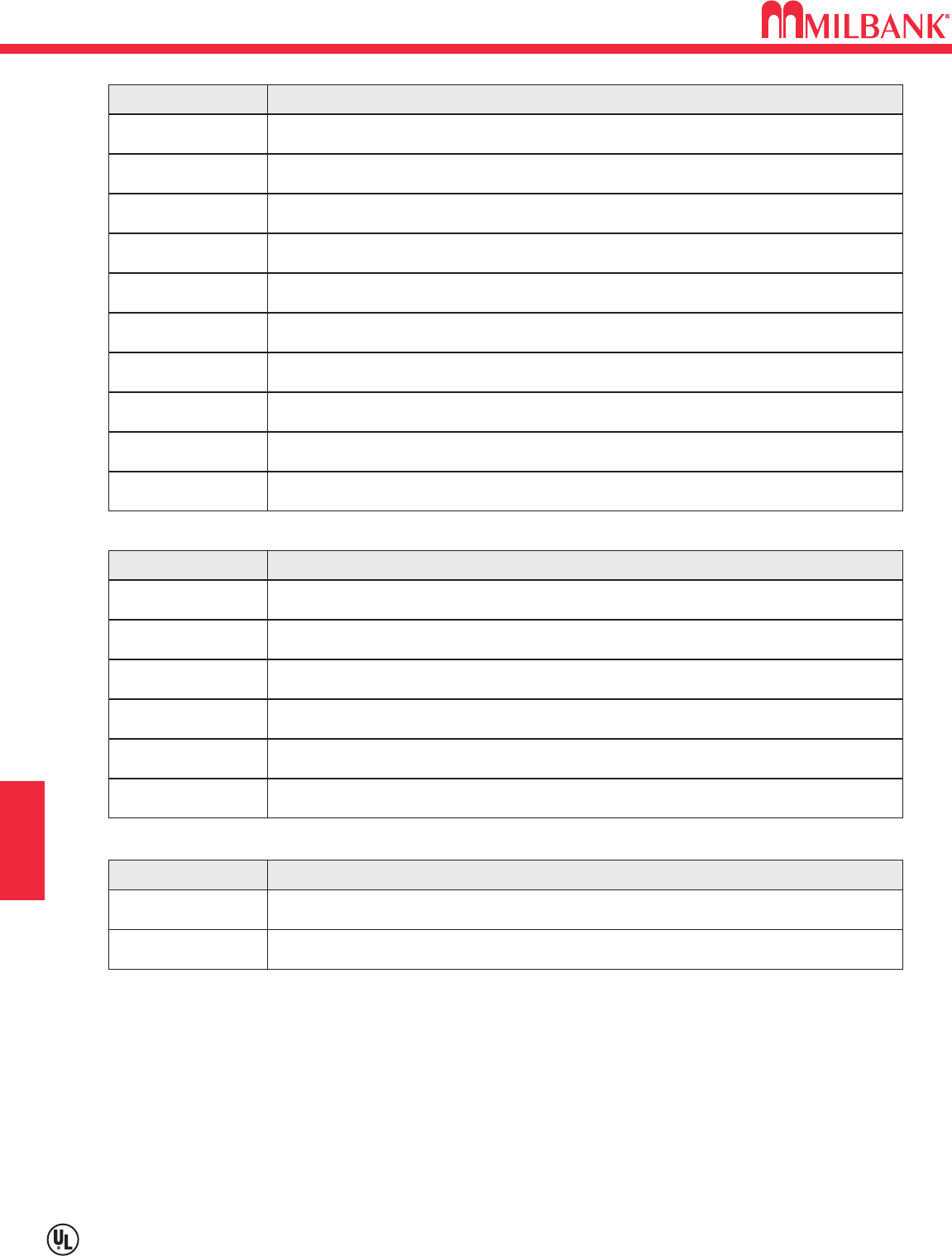
I8
Utility requirements for this equipment may vary. Always consult the serving utility for their requirements before ordering or
installing equipment in this catalog.
I8
TEMPORARY POWER
SECTION I
REPLACEMENT PARTS FOR MPAP / MPRV / HP PEDESTALS
CATALOG # CIRCUIT BREAKER DESCRIPTION
Q115 15 Amp—1 Pole—120/240—Plug-In Circuit Breaker
Q120 20 Amp—1 Pole—120/240—Plug-In Circuit Breaker
Q130 30 Amp—1 Pole—120/240—Plug-In Circuit Breaker
Q220 20 Amp—2 Pole—120/240—Plug-In Circuit Breaker
Q250 50 Amp—2 Pole—120/240—Plug-In Circuit Breaker
Q2100 100 Amp—2 Pole—120/240—Plug-In Circuit Breaker
708784-MO 20 Amp—GFCI—1 Pole—120/240—Plug-In Circuit Breaker
708785-MO 30 Amp—GFCI—1 Pole—120/240—Plug-In Circuit Breaker
707915-MO 50 Amp—GFCI—2 Pole—120/240—Plug-In Circuit Breaker
703997-MO 50 Amp—Quad—2 Pole—120/240—Circuit Breaker
708777-MO 20 Amp—120V—NEMA 5-20R—Duplex Receptacle
CATALOG # RECEPTACLE DESCRIPTION
708080-MO 20 Amp—120V—NEMA 5-20—GFCI Duplex Receptacle
704995-MO 20A—250V—NEMA 6-20R—Single Receptacle
701776-MO 30 Amp—120V—NEMA TT-30R—Travel Trailer Receptacle
706761-MO 50A—120V—3 Pole—3 Wire—NEMA 10-50R—Receptacle
Z700911-MO 50A—120/250V—3 Pole—4 Wire—NEMA 14-50R—Receptacle
Z020-509-01-00-0 MPRV / MPAP—Lug Landing (Twin #6-350 KCMIL)
CATALOG # LUG LANDINGS & BREAKER BASE DESCRIPTION
Z020-148-00-00-0 MPAP—Complete Interior Assembly
*NOTE: The following brand names may be supplied when replacement circuit breakers are ordered: Cutler-Hammer/
Westinghouse—QP, BQC, BD, BR. Siemens/ITE—Q, QT. General Electric—TQ, THQ, THQL. Challenger—C, Q, QC,
QP. Contact sales office for brand specific requirements.
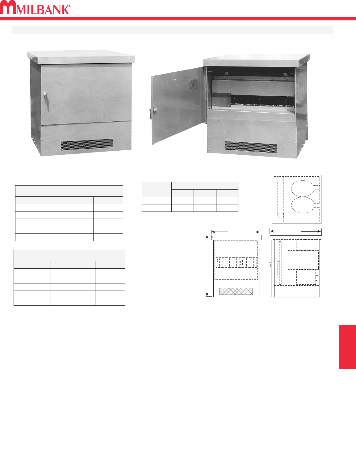
J1
TRANSFORMERS
GALVANIZED STEEL DISTRIBUTION TRANSFORMER–1
∅
J1
SECTION J
A
BC
480 VOLTS TO 120/240 SINGLE PHASE
KVA
75
CAT. NO.
7URMD
WT.
850#
100 10URMD 1050#
167 1
⁄
216URMD 1400#
200 20URMD 1650#
250 25URMD 1950#
2400 VOLTS TO 120/240 SINGLE PHASE
KVA
75
CAT. NO.*
7URMD24
WT.
1050#
100 10URMD24 1200#
167 1
⁄
216URMD24 1650#
200 20URMD24 1900#
250 25URMD24 2200#
VOLTAGE
480V, A 48″38″40″
2400V, A 48″41″53″
DIMENSIONS
ABC
Specifications
•Built in accordance with NEMA, ASA and AIEEE standards. Designed and tested to withstand 150% of rated load for
two hours continuously. 480 Volt units are UL listed. Consult local utility for acceptance of this product.
•Integrated design of the enclosure, core and coil, and secondary distribution panel permits convenient vertical
line and load terminations.
•Primary and / or secondary main circuit breaker protection available. Consult local utility for 480 volt overcurrent
protection requirements. Single fuse primary overcurrent protection provided on 2400 volt and above units.
•Other primary voltages available: 4160, 4800, 7200, 7960, & 12,470. Consult factory. Not UL listed.
CORE AND COIL:
• Aluminum wound (Copper available)
• Standard voltage taps @ 2FCAN and 4FCBN
• Rated at 150°C temperature rise
DISTRIBUTION BUS:
• 1600 Amp tin plated aluminum
• Space available for up to (12) circuit breakers – 1600 amp maximum
• Uses Milbank type UQFP-100 through 200 amp circuit breakers (See page 18)
ENCLOSURE:
• Type 3R enclosure
• Powder coated galvanized steel (aluminum available)
• Lockable primary and secondary doors
• Lifting hooks and fork lift slots provided
* These models are not UL listed.
DRY TYPE TRANSFORMERS WITH DISTRIBUTION FOR RV & MOBILE HOME PARK APPLICATIONS

NOTES
J2
NOTES
J2
SECTION J
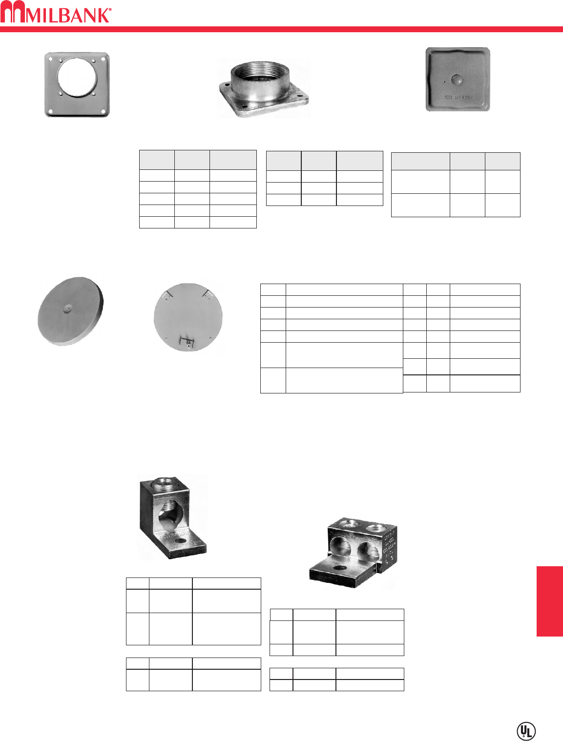
K1
ACCESSORIES & MISCELLANEOUS
ACCESSORIES
SECTION K
Utility requirements for this equipment may vary. Always consult the serving utility for their requirements before ordering or
installing equipment in this catalog.
HUB SUFFIX CHART
OPlain Top WL 1″For -RL Opening
YL 11
⁄
4″For -RL Opening
ZL 11
⁄
2″For -RL Opening
DL 2″For -RL Opening
EL
F
G
H
21
⁄
2″For -RL Opening
3″For -R Opening
31
⁄
2″For -R Opening
4″For -R Opening
RL Small Hub Opening
RLarge Hub Opening
XL Small Closing Plate
X
RXL Large Hub Opening
adapted to small Closing Plate
RRL Large Hub Opening
adapted to small Hub Opening
Large Closing Plate
HUB ADAPTER PLATE
(Converts 4″opening to 21
⁄
2″)
S8324
1″
WL
SIZESUFFIX MILBANK
NO.
YL
ZL
DL
EL
A7514
11
⁄
4″A7515
11
⁄
2″A7516
2″A7517
21
⁄
2″A7518
3″
F
SUFFIX SIZE MILBANK
NO.
G
H
A8110
31
⁄
2″A8111
4″A8112
SMALL “RL"
OPENING (STANDARD)
LARGE “R”
OPENING (HEAVY DUTY) REMOVABLE HUB
CLOSING PLATE
DESCRIPTION SUFFIX CAT. #
STANDARD
(for -RL opening)
-XL A7551
LARGE
(for -R opening) -X A9064
For use with 3/8”-16 stud
type units only
SINGLE
TWIN
K1350K2 6-350
K1350L
K1541
K2L
K4
6-350
Non-rotating
4-600
CATALOG #SUFFIX (3 per set) – 1 ∅
K3442K6 6-350
K3083K8 4-600
CATALOG #SUFFIX (4 per set) – 3 ∅
K3082K5 6-350
K3441K7 4-600 or
(2) 1/0-250
CATALOG #SUFFIX (4 per set) – 3 ∅
K1539K1 6-350
K1540
K1540L
K3
K3L
4-600 or
(2) 1/0-250
4-600 or
(2) 1/0-250
Non-rotating
CATALOG #SUFFIX (3 per set) – 1 ∅
CONNECTOR KITS
CLOSING COVERS
METER CLOSING PLATE
(Ring type / Ringless)
6003 (Gray Plastic)
6116 (Clear Plastic)
METAL CLOSING PLATE
(For Ringless sockets)
CP-21
(For Ring type sockets)
MCP
INTERCHANGEABLE UNIT HUBS
K1
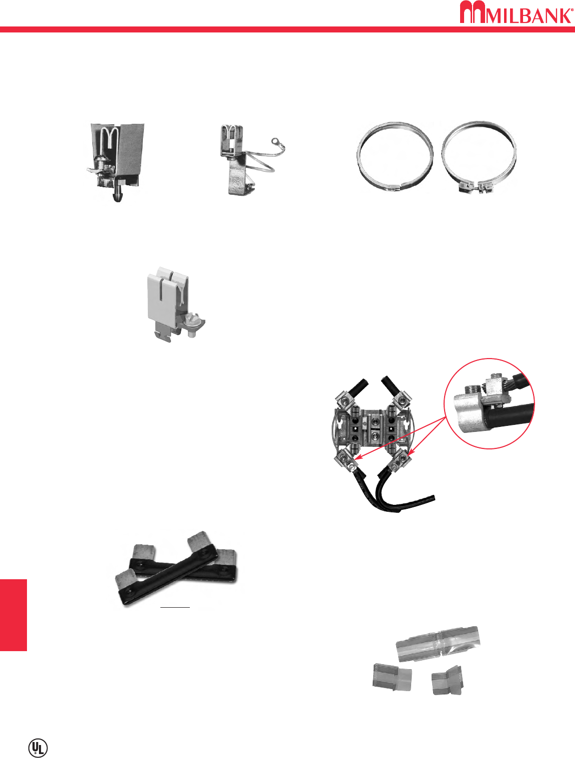
ACCESSORIES
K2
ACCESSORIES & MISCELLANEOUS
Utility requirements for this equipment may vary. Always consult the serving utility for their requirements before ordering or
installing equipment in this catalog.
K2
SEALING RINGS
LOAD TAP CONNECTORS
SNAP ACTION
MR-2
STAINLESS STEEL
MR2-SS
DISCONNECT SLEEVE *
M5-144
(*NOT TO BE USED WITH LEVER
BYPASS SOCKETS)
SCREW TYPE
(Stainless Steel)
MR-4
FIFTH TERMINALS
100-200 amp
“PLUG-IN” FIFTH TERMINAL
5T8K2
200 amp
FIFTH TERMINAL
K5T
(New style block with square hole)
HEAVY DUTY JAW
CLAMPING
K3865
(K3866 w/out neutral wire)
Consult factory for 5th terminal selection
BYPASS LINK
K8180
(Bypass links sold in pairs)
SECTION K
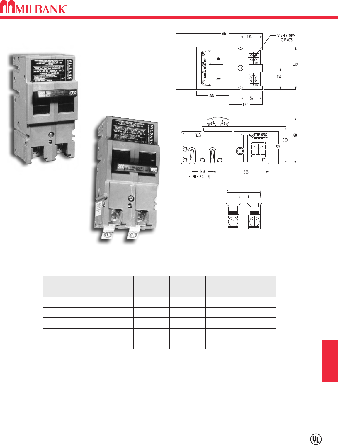
K3
ACCESSORIES & MISCELLANEOUS
UQFP PLUG-IN SERIES CIRCUIT BREAKERS
Utility requirements for this equipment may vary. Always consult the serving utility for their requirements before ordering or
installing equipment in this catalog.
K3
SECTION K
#3-#1 #1-1/0
#3-#1 #1-1/0
1/0-300 2/0-300
1/0-300 2/0-300
1/0-300 2/0-300
WIRE RANGE
CU AL
200 AMP FRAME—PLUG-IN—10,000 AIC & 22,000 AIC
TWO-POLE—COMMON TRIP
UL LISTED: For use with 60°C or 75°C wire.
UQFP: For parallel main circuit breaker applications
UQFP-M: For series main circuit breaker applications. Split load tab features allow for feed
through capability.
STANDARD PACKAGING: 5 units per 16 lb. carton.
UQFP
UQFP-M
AMPS
100 UQFP-100
125 UQFP-125
150 UQFP-150
175 UQFP-175
200 UQFP-200
10K AIC
PLUG-IN
UQFPH-100
UQFPH-125
UQFPH-150
UQFPH-175
UQFPH-200
22K AIC
PLUG-IN
UQFP-M-100
UQFP-M-125
UQFP-M-150
UQFP-M-175
UQFP-M-200
10K AIC
PLUG-IN
UQFPH-M-100
UQFPH-M-125
UQFPH-M-150
UQFPH-M-175
UQFPH-M-200
22K AIC
PLUG-IN
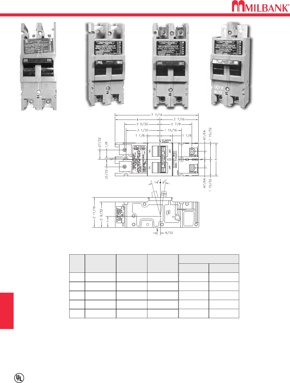
UQFB BOLT-ON SERIES CIRCUIT BREAKERS
K4
ACCESSORIES & MISCELLANEOUS
Utility requirements for this equipment may vary. Always consult the serving utility for their requirements before ordering or
installing equipment in this catalog.
K4
SECTION K
#3-#1 #1-1/0
#3-#1 #1-1/0
1/0-300 2/0-300
1/0-300 2/0-300
1/0-300 2/0-300
WIRE RANGE
CU AL
200 AMP FRAME—BOLT-ON—10K AIC & 22K AIC
TWO-POLE—COMMON TRIP
UL LISTED: For use with 60°C or 75°C wire.
UQFB: (2) 1/0-300 kcmil lugs provided on load and line side (cable-in, cable-out.)
UQFB3: Three pole available. Consult factory.
UQFB-X: (2) 1/0-300 kcmil lugs provided on load side and (2) line bar bus connections on line side.
UQFB-M: For series main circuit breaker applications. Split load tab features allow for feed through capability.
UQFB-X-MOD: Replacement circuit breaker with line barriers removed.
STANDARD PACKAGING: 5 units per 16 lb. carton.
UQFB-X UQFB-X-MOD
AMPS
100
125
150
175
200
UQFB-100
UQFB-125
UQFB-150
UQFB-175
UQFB-200
10K AIC
BOLT-ON
UQFB-100-X1
UQFB-125-X1
UQFB-150-X1
UQFB-175-X1
UQFB-200-X1
10K AIC
BOLT-ON
UQFBH-100
UQFBH-125
UQFBH-150
UQFBH-175
UQFBH-200
22K AIC
BOLT-ON
UQFB-X1 UQFB
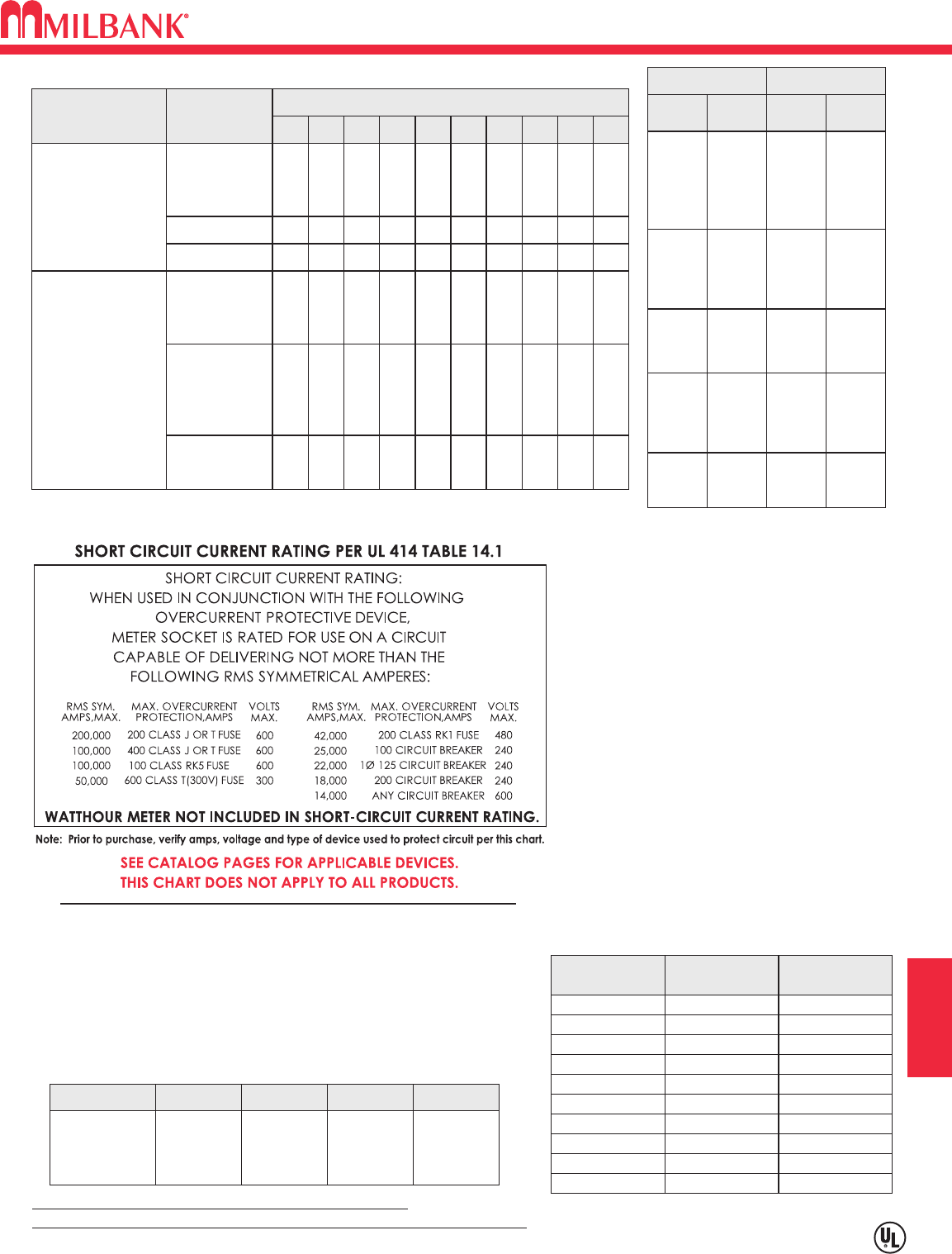
K5
ACCESSORIES & MISCELLANEOUS
CONDUIT, AMPACITY & SCCR INFORMATION
K5
SECTION K
Overall ampere ratings of UL Listed Milbank multiple position meter sockets are
based on 1993 N.E.C. Manual article 220-32 and ANSI / UL-414 (except where
restricted by line connector size.) These requirements provide for a diversity factor /
demand factor being utilized in determining the overall (main bus / lug) rating of a gang
socket. All Milbank UL Listed gang sockets meet or exceed these diversity
factor/demand factor requirements. Standard overall ampacity ratings for UL Listed
and non UL Listed gang sockets are as shown in the chart below. Ampere ratings of
meter sockets are based on the meter socket being wired with 75°C insulated wire
conductor, sized in accordance with Table 310-16 of the National Electric Code.
TYPE
RHW & RHH
(without outer covering)
THW
CONDUCTOR
SIZE
AWG,MCM
14
12
10
8
CONDUIT TRADE SIZES (INCHES)
1
⁄
23
⁄
4
11
1
⁄
4
1
1
⁄
2
22
1
⁄
2
33
1
⁄
2
4
6
4
4
1
10
8
6
3
16
13
11
5
29
24
19
10
40
32
26
13
65
53
43
22
93
76
61
32
143
117
95
49
192
157
127
66
163
85
6
1 2 3 7 10 16 23 36 48 62
3
1124610 15 23 31 40
1/0
2/0
3/0
4/0
250
300
350
400
500
600
700
750
1
1
1
1
1
1
1
2
1
1
1
3
3
2
1
5
5
4
3
8
7
6
5
12
10
9
7
16
14
12
10
21
18
15
13
1
1
1
1
1
1
1
1
1
1
1
1
2
2
1
1
1
4
3
3
2
1
6
5
4
4
3
8
7
6
5
4
10
9
8
7
6
1
1
1
1
1
1
1
1
1
3
2
2
4
3
3
5
4
4
TW
THW
FEPB (6 thru 2),
RHW and
RHH
(without outer covering)
RH, THHW
*This table is for concentric stranded conductors only. For cables with compact conductors
refer to N.E.C.
*CU
A
18
16
14
12
10
8
6
4
3
2
1
1/0
2/0
3/0
4/0
250
300
350
400
500
600
700
750
255
285
310
335
380
420
460
475
—
—
20
25
35
50
65
85
100
115
130
150
175
200
230
B
250
300
350
400
500
600
700
750
—
—
—
12
10
8
6
4
3
2
1
1/0
2/0
3/0
4/0
A
AL
or
Cu-Clad AL
205
230
250
270
310
340
375
385
—
—
—
20
30
40
50
65
75
90
100
120
135
155
180
C
AMBIENT
TEMP.C°
CORRECTION
FACTOR
AMBIENT
TEMP.F°
21 - 25 1.05 70 - 77
26 - 30 1.00 79 - 86
31 - 35 .94 88 - 95
36 - 40 .88 97 - 104
41 - 45 .82 106 - 113
46 - 50 .75 115 - 122
51 - 55 .67 124 - 131
56 - 60 .58 133 - 140
61 - 65 .33 142 - 158
66 - 70 —160 - 176
*Allowable ampacities of insulated
Copper & Aluminum conductors
(3W in conduit) 75°C (167°F)
Unless otherwise permitted elsewhere in
the Code, the overcurrent protection for
conductor types marked with an obelisk
() shall not exceed 15 amps for 14
AWG, 20 amps for 12 AWG, and 30
amps for 10 AWG copper: or 15 amps
for 12 AWG and 25 amps for 10 AWG
aluminum and copper-clad aluminum
after any correction factors for ambient
temperature and number of conductors
have been applied.
AMPACITY CORRECTION FACTORS
MAXIMUM NUMBER OF CONDUCTORS IN CONDUIT*
A = Size: AWG/MCM
B = Ampere Rating for Insulation
Types: FEPW, RH, RHW, THW,
THWN, XHHW, USE, 2W.
C = Ampere Rating for Insulation
Types: RH, RHW, THW, THWN,
XHHW, USE
(Per NEC table 310-16)
All meter sockets are 600 volt rated unless otherwise noted.
All meter socket ampacity ratings are continuous duty unless otherwise noted.
NO. OF METER
POSITIONS 100A / POS.
AMPACITY 125A / POS.
AMPACITY 150A / POS.
AMPACITY 200A / POS.
AMPACITY
2
3
4
5
6
200A
200A
200A
225A
270A
200A
225A
250A
285A
330A
200A
225A
270A
338A
396A
200A
270A
360A
450A
528A
GANG SOCKET OVERALL AMPACITIES
ENERGIZATION OF ELECTRICAL EQUIPMENT
K6
ACCESSORIES & MISCELLANEOUS
K6
BEFORE ENERGIZING
IMPORTANT NOTE
WHEN ENERGIZING
AFTER ENERGIZING
A. Give equipment a thorough visual examination to determine that:
1) No shipping or installation damage exists.
2) Proper clearances have been maintained.
3) All connections have been made.
4) Equipment is clean and dry.
B. Make a thorough examination to:
1) Verify tightness of all bolted connections (see table below).
2) Manually operate all circuit breakers, switches, relays, etc.
3) Check rigidity of all mountings, bus bars and components.
4) Use test equipment to check continuity of circuitry and integrity of insulation.
C. All switches and circuit breakers should be in the “off” position.
D. Verify that manual meter bypass (if applicable) is in non-bypass position.
E. Install cover and/or close doors.
F. If installation is not being energized at this time, follow “after-energizing” steps listed below. These
steps will secure the installation in case of accidental energization.
A. Use caution and follow established safety procedures:
1) Wear safety apparel.
2) Use safety equipment.
3) Take action to prevent injury to yourself and others in the event of failure of the installation.
4) Take action to prevent/decrease damage to property in the event of failure of the installation.
5) If you are unsure how to safely energize the installation, get someone who is knowledgeable to do it.
A. Secure the installation:
1) To prevent accidental contact with energized parts, cover all openings with approved filler devices.
2) To prevent unauthorized access, secure all covers and/or doors with approved security devices.
3) Attach/post information to advise others of potential hazards associated with the installation.
NOMINAL
SIZE
10
10
10
12
12
1/4
1/4
5/16
JOINT DESCRIPTION
SCREW NUT
BRASS
STEEL
STEEL
STEEL
STEEL
STEEL
STEEL
STEEL
Brass Nut or Extruded Hole
CU or AL Busbar <1/8″
Steel Nut or EH; CU or AL Busbar >1/8″
Aluminum Extruded Hole
Steel Nut or Extruded Hole
Aluminum Extruded Hole
Steel Nut or EH; CU or AL Busbar
Aluminum Extruded Hole
ALL
ALL
ALL
ALL
ALL
ALL
ALL
HEX
20-25 in. lbs.
25-30 in. lbs
30-35 in. lbs
30-35 in. lbs
40-50 in. lbs.
40-50 in. lbs.
50-60 in. lbs.
60-70 in. lbs.
5/16 STEEL Steel Nut or EH; CU or AL Busbar HEX 100-150 in. lbs.
3/8 STEEL Steel Nut HEX 150-200 in. lbs.
1/2 STEEL Steel Nut HEX 200-250 in. lbs.
HEAD TYPE TORQUE
( INCH LBS. )
*Interior labels typically indicate the required torque for wire connectors and studs, and should be referenced first.
EH: Extruded Hole
CU: Copper
AL: Aluminum
RECOMMENDED TORQUE FOR GENERAL APPLICATIONS*
In addition to national and local electrical codes, many utilities have specific requirements for metering
equipment. Always consult the serving utility for their specifications and requirements prior to ordering or
installing Milbank meter mounting equipment.
SECTION K

K7
ACCESSORIES & MISCELLANEOUS
MATERIALS AND FINISHES
K7
SECTION K
MATERIALS
STEEL SHEET
STEEL QUALITY
ALUMINUM EXTRUSION
ALUMINUM SHEET
COPPER SHEET & BUS
INSULATING MATERIALS
PROCESS
METAL FASTENERS
The meter equipment listed in this catalog is made of galvanized steel (AISI* G90) to afford the
best possible weather proofing. *American Iron and Steel Institute.
Light gray “state of the art” electrostatically applied powder paint offers a durable, non-fading
finish. For further information concerning the chemical analysis of the weather resistant finish,
please contact the factory.
Wire-Terminals: Alloy; 6061-T6, Tin-plated for CU/AL wire.
Bus Bar: Alloy; 6101-o & 6063-O
3000 series aluminum sheet, H14, or 5052 series aluminum sheet, H32. Where applicable
thicknesses range from .064 — .125
Electrolytic copper with tin plating in most applications.
Zinc-coated with a chromate dip.
• In most units, support bases for current-carrying components are molded from fiberglass
reinforced high-strength, track resistant, thermoset polyester molding compounds.
• Clear or black safety shields and polarity barriers are molded from high-strength, track resistant,
polycarbonate molding compounds.
• Various sheet insulating materials, as appropriate for the application are utilized in the
fabrication of flat, formed and punched component parts and barriers.
16 gauge, galvanized, sheet: 1 1/4 oz./ sq.ft. class zinc-coated.
(AISI G90)
14 gauge, galvanized, sheet: 1 1/4 oz./ sq.ft. class zinc-coated.
FINISH
NEMA RATING
Milbank meter sockets, CT cans and meter socket / breaker units have a type 3R rating.
RATING
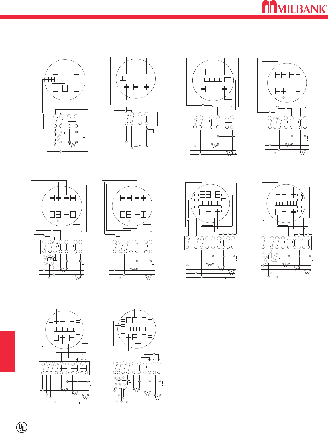
METER FORMS
K8
ACCESSORIES & MISCELLANEOUS
K8
SECTION K
DIAGRAM A
(ALT.LOC.)
+
+
+
+
I
LINE
(BONDED)
NC.T. LOAD
P1PNC+
1C1
P. T.
+
+
1
LINE
C.T.
LOAD
2
P1C+
1
++
3
+
+
PT PT
DIAGRAM E
P3P2C1C+
3C3
C.T.
+
+
1
LINE
C.T.
LOAD
2
P1C+
1
++
3
DIAGRAM F
P3P2C1C+
3C3
C.T.
+
+
1
LINE
C.T.
LOAD
2
P1
+
+
3
PNC
+
N
C.T.
C.T.
+
+
(BONDED)
++
PT PT
+
+
P3
PT
++
DIAGRAM J
P2CC
+CC+C
+
+
C.T.
LOAD
P1
+
+
P3
P
N
C+
C+
C.T.
C.T.
++
(BONDED)
DIAGRAM G
CC
C+
C
1
LINE 2
3
N
+
+
1
LINE
C.T.
LOAD
2
P1
+
+
3
P3
P
N
C+
N
C.T.
C.T.
++
(BONDED)
++
PT
PT
++
DIAGRAM H
CC
+
C+C
C
+
+
1
LINE
C.T.
LOAD
2
P1
+
+
3
P3PNC+
N
C.T.
C.T.
++
(BONDED)
P2
DIAGRAM I
CC+CC+C
(ALT.LOC.)
+
+
I
LINE
(BONDED)
NC.T. LOAD
2
DIAGRAM B
P
1
PNC+
1C1
+
+
I
LINE (BONDED)
N
C.T.
LOAD
2
P
1
P2C+
1C+
2C2
C+
2
++
DIAGRAM C
C.T.
+
+
I
LINE (BONDED)
N
C.T.
LOAD
2++
DIAGRAM D
P1P2C+
1C2
C+
2
PNC1
C.T.
DIAGRAM D
1∅3W or 3W Network with 2 C.T.ʼs
2 Stator Meter - Form 5S
8T Socket, Test Switch #TS07-0105
DIAGRAM E
3∅3W “Δ” with 2 P.T.ʼs & 2 C.T.ʼs
2 Stator Meter - Form 5S
8T Socket, Test Switch #TS07-0105
DIAGRAM F
3∅3W “Δ” with 2 C.T.ʼs
2 Stator Meter - Form 5S
8T Socket, Test Switch #TS07-0105
DIAGRAM G
3∅4W “Y” with 3 C.T.ʼs
2 1
⁄
2Stator Meter - Form 6S
13T Socket, Test Switch #TS10-0109
DIAGRAM H
3∅4W “Y” with 2 P.T.ʼs & 3 C.T.ʼs
2 1
⁄
2Stator Meter - Form 6S
13T Socket, Test Switch #TS10-0109
DIAGRAM I
3∅4W “Y” or “Δ” with 3 C.T.ʼs
“Y” 3 Stator Meter - Form 9S
“Δ” 2 Stator Meter - Form 8S
13T Socket, Test Switch #TS10-0109
DIAGRAM J
3∅4W “Y” with 3 P.T.ʼs & 3 C.T.ʼs
3 Stator Meter - Form 9S
13T Socket, Test Switch #TS10-0109
DIAGRAM A
1∅2W with 1 P.T. & 1 C.T.
Single Stator Meter(2W1∅) - Form 3S
5T Socket, Test Switch #TS04-0101
DIAGRAM B
1∅3W with 1 C.T.
Single Stator Meter(2W1∅) - Form 3S
5T Socket, Test Switch #TS04-0101
DIAGRAM C
1∅3W with 2 C.T.ʼs
Single Stator Meter(3W1∅) - Form 4S
6T Socket, Test Switch #TS07-0105
PREWIRING: If standard factory prewiring is
required, refer to wiring diagrams on this page.
Determine appropriate diagram and send a
copy with order. If custom factory prewiring is
required, specify on order. Be sure to include
meter socket catalog number, test switch make
and catalog number, meter form number and
provide a copy of your wiring diagram.
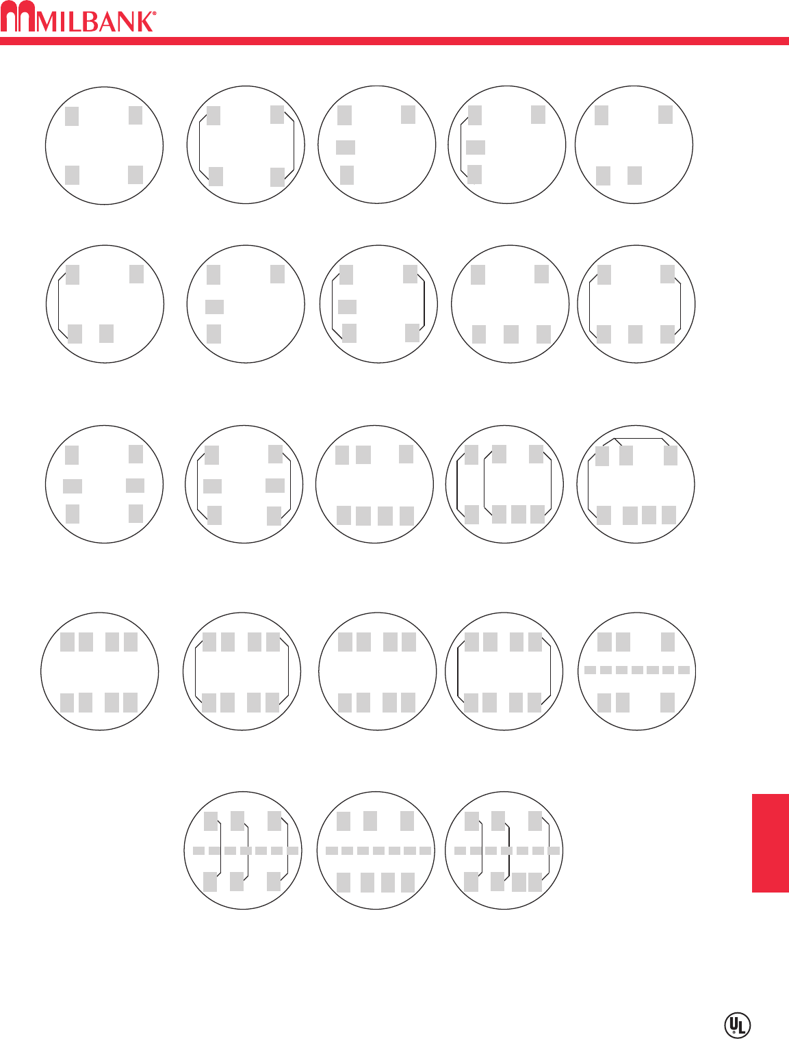
K9
ACCESSORIES & MISCELLANEOUS
Utility requirements for this equipment may vary. Always consult the serving utility for their requirements before ordering or
installing equipment in this catalog.
K9
SECTION K
WATTHOUR METER FORMS—STANDARD FORMS
TRANSFORMER RATED OR SELF-CONTAINED
SC SC TR TR TR
TR SC SC SC SC
TR TR SC SC TR
TR TR SC SC TR
TR TR TR
2 and 3-WIRE FORMS
1S & 2S
2 and 3-WIRE FORMS
1S & 2S with BYPASS
2-WIRE FORM 3S
5th Term. 9 o'clock
2-WIRE FORM 3S
with BYPASS
2-WIRE FORM 3S
5th Term.6 o'clock
2-WIRE FORM 3S
with BYPASS
2 ELEMENT
3-WIRE NETWORK
FORM 12S 5th
TERM. 9 o'clock
2 ELEMENT 3-WIRE
NETWORK FORM 12S
with BYPASS
5th Term. 9 o'clock
2 ELEMENT 3-WIRE
NETWORK FORM 12S
with BYPASS
5th Term. 6 o'clock
2 ELEMENT
3-WIRE NETWORK
FORM 12S 5th
TERM. 6 o'clock
3-WIRE FORM 4S 3-WIRE FORM 4S
WITH BYPASS
2 or 3 ELEMENT
3∅4W Y or ∆
Y FORM 14S
∆ FORM 15S
2 or 3 ELEMENT
3∅4W Y or ∆
FORMS 14S & 15S
with BYPASS
2 ELEMENT
3∅4W Y or ∆
Y FORM 7S
∆ FORM 24S
with BYPASS
2 ELEMENT
2∅3W, 2∅4W, 3∅3W
FORM 5S
2 ELEMENT 2∅3W,
2∅4W, 3∅3W
FORM 5S with
BYPASS
2 ELEMENT
2∅3W, 2∅4W, 3∅3W
FORM 13S
2 or 3 ELEMENT
2∅3W, 2∅4W, 3∅3W
FORM 13S with
BYPASS
2 or 3 ELEMENT
3∅4W Y or ∆
Y FORM 9S
∆ FORM 8S
2 or 3 ELEMENT
3∅4W Y or ∆
FORMS 8S & 9S
with BYPASS
2 ELEMENT
3∅4W Y
FORM 6S
2 ELEMENT
3∅4W Y
FORM 6S
with BYPASS
TR = TRANSFORMER RATED
SC = SELF CONTAINED
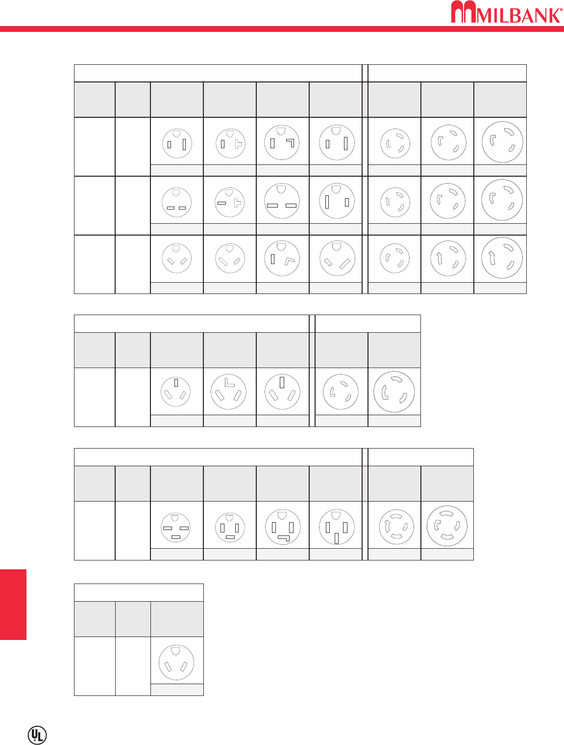
K10
ACCESSORIES & MISCELLANEOUS
Utility requirements for this equipment may vary. Always consult the serving utility for their requirements before ordering or
installing equipment in this catalog.
K10
SECTION K
STANDARD NEMA CONFIGURATIONS
125V 5
250V 6
277
VAC 7
2 POLE—3 WIRE—GROUNDING RECEPTACLES
3 POLE—3 WIRE—SPECIAL APPLICATIONS
3 POLE—4 WIRE—GROUNDING
VOLTS
STRAIGHT BLADE WIRING DEVICES TWIST-LOCK WIRING DEVICES
CODE 20
AMPS
30
AMPS
50
AMPS
15
AMPS
20
AMPS
30
AMPS
15
AMPS
5-15R 5-20R 5-30R 5-50R L5-15R L5-20R L5-30R
125V
250V 10
VOLTS
STRAIGHT BLADE WIRING DEVICES TWIST-LOCK
CODE 20
AMPS
30
AMPS
50
AMPS
20
AMPS
30
AMPS
10-20R 10-30R 10-50R L10-20R L10-30R
125V
250V 14
VOLTS
STRAIGHT BLADE WIRING DEVICES TWIST-LOCK
CODE 20
AMPS
30
AMPS
50
AMPS
20
AMPS
30
AMPS
15
AMPS
14-15R 14-20R 14-30R 14-50R L14-20R L14-30R
6-15R 6-20R 6-30R 6-50R L6-15R L6-20R L6-30R
7-15R 7-20R 7-30R 7-50R L7-15R L7-20R L7-30R
G
W
G
G
W
G
G
W
G
W
G
W
G
G
W
G
W
G
G
W
G
W
G
X
Y
G
W
G
W
G
X
Y
G
W
G
W
G
X
Y
G
W
W
X
Y
W
X
Y
W
X
Y
X
W
Y
X
W
Y
G
W
YX
G
W
YX
G
W
YX
G
W
YX
X
W
Y
G
X
W
Y
G
2 POLE—3 WIRE—GROUNDING—NEMA TRAILER
125V TT
VOLTS
STRAIGHT BLADE
CODE 30
AMPS
TT-30R
G
W
K11
ACCESSORIES & MISCELLANEOUS
ADDITIONAL MILBANK PRODUCTS
K11
SECTION K
COMMERCIAL ENCLOSURES
2007 PRICE LIST
Effective June 26, 2006
Supercedes and cancels all previous Milbank lists.
All prices listed within are subject to change without notice.
MILBANK MFG. CO.– ENCLOSURE GROUP
1601 South St. Louis Street
Concordia, MO 64020
Tel: 660-463-0805 Fax: 660-463-7950
Toll Free: 1-877-483-5314
www.milbankmfg.com
In addition to your local utility’s meter mounting
equipment, Milbank also manufactures
supporting products, such as...
Air Conditioner Disconnects
Hot Tub Disconnects
RV/Mobile Home Power Outlets
Terminal Boxes
Temporary Power Outlets
Commercial Pedestals
Commercial Enclosures
CT Enclosures
Circuit Breakers
Enclosed Circuit Breakers
Safety Switches
Test Switches
Contact your local distributor or go to
www.milbankmfg.com
to find additional product literature.
Other quality products available from Milbank

L1
ALPHA-NUMERIC INDEX
L1
SECTION L
ALPHA-NUMERIC INDEX
6003 .................................K1
6116 .................................K1
020-147-00-00-0 ............G10
020-148-00-00-0 ............G10
020-509-01-00-0 ............G10
105J..................................E2
114TB...............................D1
115TB...............................D1
116TB...............................D1
124TB...............................D1
125TB...............................D1
127TB...............................D1
214MTB............................D2
214MTB/22.......................D3
214MTB-48 ......................D4
214MTB-P ........................D5
214MTB-P48 ....................D5
215MTB............................D2
215MTB-48 ......................D4
215MTB-P ........................D5
215MTB-P48 ....................D5
217MTB............................D2
217MTB/22.......................D3
217MTB-48 ......................D4
217MTB-P ........................D5
217MTB-P48 ....................D5
224MTB............................D6
224MTB/22.......................D7
224MTB-P ........................D9
224MTB-P48 ....................D9
225MTB............................D6
225MTB-P ........................D9
225MTB-P48 ....................D9
227MTB............................D6
227MTB/22.......................D7
227MTB-125 ..................D14
227MTB-150 ..................D14
227MTB-175 ..................D14
227MTB-48 ......................D8
227MTB-P ........................D9
227MTB-P48 ....................D9
243210-LC3R-SP .............F1
323610-LC3R-SP .............F1
363016-CT3R ...................F1
363612-CT3R-SP .............F1
364812-CT3R-SP2 ...........F1
403456-SC.....................G11
403457-SC.....................G11
5T8K2...............................K2
701776-MO ....................H17
701776-MO........................I8
703997-MO........................I8
704995-MO........................I8
706761-MO........................I8
707915-MO........................I8
708080-MO ....................H17
708080-MO........................I8
708676-MO ....................H17
708777-MO........................I8
708784-MO ....................H18
708784-MO........................I8
708785-MO........................I8
A3800 ...............................A1
A7514 ...............................K1
A7515 ...............................K1
A7516 ...............................K1
A7517 ...............................K1
A7518 ...............................K1
A7551 ...............................K1
A8110 ...............................K1
A8111 ...............................K1
A8112 ...............................K1
A9064 ...............................K1
AP-2300-03 ......................B1
AP-2300-04 ......................B1
BC214 ............................D12
BC234 ............................D12
BC318 ............................D12
BC338 ............................D12
BC418 ............................D12
BC438 ............................D12
BC518 ............................D12
BC538 ............................D12
BC618 ............................D12
BC638 ............................D12
CL200.............................H16
CP-16PDMNT-CALT ........E2
CP-21 ...............................K1
CP-24PDMNT-CALT ........E2
CP3B11110A22SL1 .........E5
CP3B11115A22................E4
CP3B11115A42................E4
CP3B111IRASP ...............E7
CP3B111IRASS ...............E7
CP3B12110A22SL1 .........E5
CP3B12119A22................E4
CP3B1411JB22................E6
CP3B14120B22................E6
CP3B51110A22SL1 .........E5
CP3B51115A22................E4
CP3B511IRASP ...............E7
CP3B52110A22SL ...........E5
CP3B52119A22................E4
CP3B5411JB22................E6
CP3B8411JB22................E6
CP3B84120B22................E6
CP3B-AUX-1200 ............H11
CP-ABK5/8 .......................E2
CP-PE-HOA-3POS...........E2
CP-TC24H........................E2
CP-TC7D..........................E2
CP-TCWIRE .....................E2
CT203611-HC ..................F2
CT242411-SC...................F2
CT243011-HC ..................F2
CT243011-SC...................F2
CT24329-SC.....................F2
CT243611-HC ..................F2
CT243611-SC...................F2
CT244811-HC ..................F2
CT244811-SC...................F2
CT303011-SC...................F2
CT303611-HC ..................F2
CT303614-SC...................F2
CT304811-HC ..................F2
CT363611-SC...................F2
CT364211-SC...................F2
CT364811-HC ..................F2
CT364811-SC...................F2
CT364814-HC ..................F2
CT364814-SC...................F2
CT424211-SC...................F2
CT484811-HC ..................F2
CT484811-SC...................F2
CT484814-HC ..................F2
ED42B100......................D14
ED43B100......................D14
FXD62B200....................D14
FXD63B200....................D14
K1350 .............................B15
K1350 ...............................K1
K1350L .............................K1
K1539 .............................B15
K1539 ...............................K1
K1540 .............................B15
K1540 ...............................K1
K1540L .............................K1
K1541 .............................B15
K1541 ...............................K1
K3082 ...............................K1
K3083 ...............................K1
K3441 ...............................K1
K3442 ...............................K1
K3450 ...........................G5-7
K3865 ...............................E2
K3865 ...............................K2
K3866 ...............................K2
K4709-02........................H14
K4709-WS......................H14
K4722 ...............................F3
K4729 ...............................F3
K4793 ...............................F3
K4794 ...............................F3
K4795 ...............................F3
K4796 ...............................F3
K4797 ...............................F3
K4798 ...............................F3
K4800-01........................H16
K4903 ...............................F3
K4904 ...............................F3
K5035 ...........................G5-7
K5039 ...........................G5-7
K5193 ...........................G5-7
K5194 ...........................G5-7
K5400-1450 ......G5-9, H2-10
K5400-1450....................H17
K5400-1450 .......................I2
K5400-1450GB ................G9
K5400-1450GB ..................I2
K5400-520 ......................I2-7
K5400-520GB .............H2-10
K5400-520GR ...G5-9, H2-10
K5400-520GR ................H17
K5400-520GR....................I2
K5400-620 .......................G9
K5400-620 .........................I2
K5400-620GB ....................I2
K5400-620GR ..................G9
K5400-BLANK................H17
K5400-BRIDGE..............H17
K5400-BRIDGE-1POS..G5-9
K5400-BRIDGE-2POS..G5-9
K5400-GB ......................H17
K5400-NEUTRAL...........H17
K5400-TT30 ......G5-9, H2-10
K5400-TT30 ...................H17
K5400-TT30GB...........H2-10
K5410.............................H15
K5411.............................H13
K5412.............................H13
K5413.............................H13
K5415 ...........................G5-7
K5415.............................H15
K5421.............................H15
K5421.............................H15
K5747 ...............................F3
K5757 ...............................F3
K5T ...............................G5-7
K5T...................................K2
K8180 ...............................K2
KK3388.............................F7
KK3388-BLK-FL ...............F7
M400-APS........................C5
M400-APS-BS..................C5
M400-PAR........................C4
M400-PAR-UG .................C4
M400-UG-APS-F..............C6
M400-UG-APS-F-BS........C6
M400-UG-APS-LC ...........C6
M400-UG-APS-LC-BS .....C6
M400-UG-APS-P..............C6
M401-UG..........................C7
M401-UG-BS....................C7
M404-UG-LC....................C8
M404-UG-LC-BS..............C8
M5-144 .............................K2
MCP .................................K1
MN1020-TVB ....................J1
MN1100 ............................J1
MN1100-NG......................J1
MN-1100-TV .....................J1
MN2200 ............................J1
MN900 ..............................J1
MN900-B...........................J1
MPAP-100-78 ..................G2
MPAP-100-MB-78............G2
MPAP-200-20GR-78........G2
MPAP-200-78 ..................G2
MPAP-200-MB-78............G2
MPAP-BLANK-78.............G2
MPAP-BLANK-78-R.........G2
MPAPD-BLANK-78 ..........G2
MPAPD-BLANK-78R .......G2
MPRV-100-20GR-78........G1
MPRV-100-78 ..................G1
MPRV-100-MB-78............G1
MPRV-100-MBLC-80 .......G3
MPRV-200-MBLC-80 .......G3
MPRV-503020GR-78.......G1
MPRV-50-78 ....................G1
MPRV-BLANK-78 ............G1
MPRV-BLANK-78-R-5T ...G1
MR-2 ..............................H18
MR-2.................................K2
MR-2SS............................K2
MR-4.................................K2
MS24-TB ........................D16
MS27-TB ........................D16
P-10GR ..........................H16
P-13................................H16
P-54................................H16
PB-011 ...........................D11
PB-012 ...........................D11
PB-014 ...........................D11
PB-014-NK .....................D11
PB-018 ...........................D11
PB-018-NK .....................D11
PB-032 ...........................D11
PB-034 ...........................D11
PB-034-NK .....................D11
PB-038 ...........................D11
PF-BL.............................G11
PF-KR ............................G11
PT223.............................D16
PT224.............................D16
PT263.............................D16
PT264.............................D16
PT323.............................D16
PT324.............................D16
PT363.............................D16
PT364.............................D16
Q115 ..................................I8
Q120 ..............................H18
Q120 ..................................I8
Q130 ..............................H18
Q130 ..................................I8
Q220 ..................................I8
Q250 ..............................H18
Q250 ..................................I8
QJ22B200H....................D14
QJ23B200 ......................D14
QJH23B200L..................D14
RBK-1 ............................G10
S8324 ...............................K1
TB100-47 .......................D16
TB100-5 .........................D16
TB200-47 .......................D16
TB200-LL .......................D16
TB-BARR .......................D16
TS04-0049........................F8
TS04-0101........................F8
TS04-0104........................F8
TS04-0105........................F8
TS04-0106........................F8
TS10-0016........................F8

L2
ALPHA-NUMERIC INDEX
L2
SECTION L
ALPHA-NUMERIC INDEX
TS10-0109........................F8
TS10-0110........................F8
TS10-0111........................F8
TS10-0112........................F8
U1060-RL .........................B3
U1079-R .........................B10
U1129-O-K3L-K2L..........B10
U1211-RXL.......................B7
U1252-X-K1....................B13
U1253-X-K3....................B13
U1254-X-K3....................B13
U1255-X-K4....................B13
U1256-X-K4....................B13
U1431-R .........................B10
U1432-O.........................B10
U1527-O...........................B3
U1681-RL .........................B2
U1797-O-K3L-K2L..........B10
U1819-X .........................B10
U1980-O...........................B3
U2120-X .........................B11
U214MTB .........................D2
U214MTB/22 ....................D3
U214MTB-48....................D4
U214MTBL .....................D10
U214MTB-P .....................D5
U214MTB-P48 .................D5
U214MTBPL...................D10
U215MTB .........................D2
U215MTB-48....................D4
U215MTB-P .....................D5
U215MTB-P48 .................D5
U217MTB .........................D2
U217MTB/22 ....................D3
U217MTB-48....................D4
U217MTBL .....................D10
U217MTB-P .....................D5
U217MTB-P48 .................D5
U217MTBPL...................D10
U224MTB .........................D6
U224MTB/22 ....................D7
U224MTB-48....................D8
U224MTBL .....................D10
U224MTB-P .....................D9
U224MTB-P48 .................D9
U224MTBPL...................D10
U225MTB .........................D6
U225MTBL .....................D14
U227MTB .........................D6
U227MTB/22 ....................D7
U227MTB-125................D14
U227MTB-150................D14
U227MTB-175................D14
U227MTB-48....................D8
U227MTBL .....................D10
U227MTB-P .....................D9
U227MTB-P48 .................D9
U227MTBPL...................D10
U2594-X .........................B11
U2852-X .........................B15
U2853-X .........................B15
U2854-X .........................B15
U2855-X .........................B15
U2856-X .........................B15
U2862-X .........................B15
U2863-X .........................B15
U2864-X .........................B15
U2865-X .........................B15
U2866-X .........................B15
U3251-O-200-CB .............C6
U3320-R ...........................F4
U3322-R ...........................F4
U3328-RXL.......................B4
U3340-O ...........................F4
U3342-O ...........................F4
U3462-O.........................D13
U3463-O.........................D13
U3464-O.........................D13
U3465-O.........................D13
U3466-O.........................D13
U3504-XL .........................B9
U3507-XL .........................B9
U3514-XL .........................B9
U3517-XL .........................B9
U3522-XL-K1..................B12
U3523-XL-K1..................B12
U3524-XL-K2..................B12
U3525-XL-K2..................B12
U3532-X-K1....................B13
U3533-X-K3....................B13
U3548-X .........................B11
U3555-R ...........................F4
U3565-O ...........................F4
U3574-RL-200..................C1
U3577-RL-200..................C1
U3587-O-200 ...................C1
U3800...............................A1
U3801...............................A1
U3830...............................A1
U3860...............................A1
U3822-20GR ....................A2
U3852-XL .........................B7
U3854-O-200 ...................C1
U4015-KO ........................B5
U4015-O...........................B4
U4031-O-2/200 ................C4
U4517-DL-M4...................B4
U4517-KO ........................B5
U4518-KO ........................B5
U4518-O-W ......................B4
U4518-XL-W.....................B4
U4540-XL .......................H12
U4542-XL .......................H12
U4544-XL .......................H12
U4546-XL .......................H12
U4548-RXL ....................H12
U4549-RXL ....................H12
U4881-O-50GB ................A2
U4881-O-60GB ................A2
U4908-O ............................I2
U4908-O-11GR..................I2
U4908-O-55GBGR ............I2
U4909-O ............................I2
U4909-O-11GR..................I2
U4909-O-55GBGR ............I2
U4969-KO ........................B5
U5000-XL .........................H2
U5000-XL...........................I4
U5000-XL-332..................H2
U5000-XL-41....................H2
U5000-XL-55....................H2
U5000-XL-75....................H2
U5000-XL-75GB...............H2
U5001-RL-01 .....................I5
U5056-O.........................B10
U5059-X-2/200.................C4
U5100-XL .........................H4
U5100-XL...........................I7
U5100-XL-41....................H4
U5100-XL-55....................H4
U5100-XL-552GR ............H4
U5100-XL-75....................H4
U5100-XL-75GB...............H4
U5101-XL .........................H4
U5101-XL...........................I7
U5136-O ..........................G7
U5136-O-100S.................G7
U5136-O-200S.................G7
U5137-O ..........................G7
U5137-O-100S.................G7
U5137-O-200S.................G7
U5138-O ..........................G7
U5138-O-200S.................G7
U5168-100-KK-5T ............C2
U5168-150-KK-5T ............C2
U5168-XTL-100................C2
U5168-XTL-100-KK..........C2
U5168-XTL-150................C2
U5168-XTL-150-KK..........C2
U5168-XTL-200................C2
U5168-XTL-200-KK..........C2
U5169-XTL-100................C2
U5169-XTL-150................C2
U5169-XTL-200................C2
U5200-XL .........................H5
U5200-XL-332..................H5
U5200-XL-41....................H5
U5200-XL-75....................H5
U5200-XL-75GB...............H5
U5210-XL .........................H5
U5220-XL .........................H5
U5220-XL-41....................H5
U5220-XL-75....................H5
U5230-XL .........................H5
U5240-O ..........................G5
U5240-O-100S.................G5
U5240-O-200S.................G5
U5241-O ..........................G5
U5241-O-100S.................G5
U5241-O-200S.................G5
U5242-O-200S.................G5
U5243-O ..........................G5
U5252-O ..........................G5
U5268-XTL-150................C2
U5268-XTL-150-KK..........C2
U5268-XTL-200................C2
U5268-XTL-200-KK..........C2
U5269-XTL-200................C2
U5300-O.........................H10
U5300-O-41 ...................H10
U5300-O-55 ...................H10
U5300-O-552GR ............H10
U5300-O-75 ...................H10
U5310-O.........................H10
U5320-O.........................H10
U5330-O.........................H10
U5706-O-200S.................G9
U5706-O-200S-KK...........G9
U5707-O-200S.................G9
U5759-X-2/200.................C4
U7021-RL-TG..................`B3
U7040-XL-TG ...................B3
U7043-XL-TG ...................B3
U7422-RXL.......................B6
U7423-RXL.......................B6
U7487-O...........................B2
U7487-RL .........................B2
U7490-O...........................B2
U7490-RL .........................B2
U7573-RL .........................B6
U8032-XL .......................B12
U8033-XL .......................B12
U8034-XL .......................B12
U8035-XL .......................B12
U8036-XL .......................B12
U8100-RL .........................B6
U9319-XL .........................B7
U9320-RXL.......................B6
U9550-RRL ......................B8
U9551-RXL.......................B8
U9700-RRL ......................B8
U9701-RXL.......................B8
UC1290-XL.......................F5
UC1291-RL.......................F5
UC1299-XL.......................F5
UC1300-RL.......................F5
UC3423-XL.......................F6
UC3425-XL.......................F6
UC3426-XL.......................F6
UC3428-XL.......................F6
UC3433-XL.......................F6
UC3434-XL.......................F6
UC3435-XL.......................F6
UC3436-XL.......................F6
UC3438-XL.......................F6
UC7233-XL.......................F5
UC7235-XL.......................F5
UC7237-XL.......................F5
UC7461-YL-TGE-DES......F6
UC7544-RL.......................F5
UC7545-RL.......................F5
UC7582-RL.......................F5
UC7636-YL-TGE-DES......F6
UQFB-100 ........................K4
UQFB-100-X1...................K4
UQFB-125 ........................K4
UQFB-125-X1...................K4
UQFB-150 ........................K4
UQFB-150-X1...................K4
UQFB-175 ........................K4
UQFB-175-X1...................K4
UQFB-200 ........................K4
UQFB-200-X1...................K4
UQFBH-100......................K4
UQFBH-125......................K4
UQFBH-150......................K4
UQFBH-175......................K4
UQFBH-200......................K4
UQFP-100 ......................H11
UQFP-100 ........................K3
UQFP-125 ......................H11
UQFP-125 ........................K3
UQFP-150 ......................H11
UQFP-150 ........................K3
UQFP-175 ......................H11
UQFP-175 ........................K3
UQFP-200 ......................H11
UQFP-200 ........................K3
UQFP-225 ......................H11
UQFPG-100 .....................K3
UQFPG-125 .....................K3
UQFPG-150 .....................K3
UQFPG-175 .....................K3
UQFPG-200 .....................K3
UQFPH-100 ...................H11
UQFPH-125 ...................H11
UQFPH-150 ...................H11
UQFPH-175 ...................H11
UQFPH-200 ...................H11
UQFPH-225 ...................H11
UQFPH-M-100 .................K3
UQFPH-M-125 .................K3
UQFPH-M-150 .................K3
UQFPH-M-175 .................K3
UQFPH-M-200 .................K3
UQFP-M-100 ....................K3
UQFP-M-125 ....................K3
UQFP-M-150 ....................K3
UQFP-M-175 ....................K3
UQFP-M-200 ....................K3
USE-AP-200-MB ..............C3
USE-AP-200-ML ..............C3
Z020-148-00-00-0..............I8
Z020-509-11-00-0..............I8
Z818052-SC...................H18
Z818480-SC...................H18
Z915141-AC...................H18
Z917602-AC...................H18
Z918447-SC...................H18
Z918449-SC...................H18
Z918466-AC...................H18

L3
EUSERC INDEX
L3
SECTION L
EUSERC INDEX
EUSERC INDEX
U3574-RL-200 301 C1
U3577-RL-200 301 C1
U3584-O-200 301 C1
U3587-O-200 301 C1
U4015-O 301A B4
UF4015-KO 301A B5
U3548-X 302B B11
M400-UG-APS-F 302A C6
M400-UG-APS-F-BS 302 C6
M400-UG-APS-P 302A C6
M400-UG-APS-LC 302A C6
M400-UG-APS-LC-BS 302 C6
U3251-O-200-CB 302 C6
M401-UG 302A C7
M401-UG-BS 302 C7
M404-UG-LC 302A C8
M404-UG-LC-BS 302 C8
114TB 304, 311 D1
115TB 304, 311 D1
117TB 304, 311 D1
124TB 305, 311 D1
125TB 305, 311 D1
127TB 305, 311 D1
214MTB 305A, 311 D2
215MTB 305A, 311 D2
217MTB 305A, 311 D2
U214MTB 305A, 311 D2
U215MTB 305A, 311 D2
U217MTB 305A, 311 D2
214MTB/22 305A, 311 D3
217MTB/22 305A, 311 D3
U214MTB/22 305A, 311 D3
U217MTB/22 305A, 311 D3
214MTB-48 305A, 311 D4
215MTB-48 305A, 311 D4
217MTB-48 305A, 311 D4
U214MTB-48 305A, 311 D4
U215MTB-48 305A, 311 D4
U217MTB-48 305A, 311 D4
214MTB-P 305A, 311 D5
215MTB-P 305A, 311 D5
217MTB-P 305A, 311 D5
U214MTB-P 305A, 311 D5
U215MTB-P 305A, 311 D5
U217MTB-P 305A, 311 D5
214MTB-P48 305A, 311 D5
215MTB-P48 305A, 311 D5
217MTB-P48 305A, 311 D5
U214MTB-P48 305A, 311 D5
U215MTB-P48 305A, 311 D5
U217MTB-P48 305A, 311 D5
224MTB 305A, 311 D6
225MTB 305A, 311 D6
227MTB 305A, 311 D6
U224MTB 305A, 311 D6
U225MTB 305A, 311 D6
U227MTB 305A, 311 D6
224MTB/22 305A, 311 D7
227MTB/22 305A, 311 D7
U224MTB/22 305A, 311 D7
U227MTB/22 305A, 311 D7
227MTB-48 305A, 311 D8
U224MTB-48 305A, 311 D8
U227MTB-48 305A, 311 D8
224MTB-P 305A, 311 D9
225MTB-P 305A, 311 D9
227MTB-P 305A, 311 D9
U224MTB-P 305A, 311 D9
U227MTB-P 305A, 311 D9
224MTB-P48 305A, 311 D9
225MTB-P48 305A, 311 D9
227MTB-P48 305A, 311 D9
U224MTB-P48 305A, 311 D9
U227MTB-P48 305A, 311 D9
U214MTBL 305A, 311 D10
U214MTBPL 305A, 311 D10
U217MTBL 305A, 311 D10
U217MTBPL 305A, 311 D10
U224MTBL 305A, 311 D10
U224MTBPL 305A, 311 D10
U227MTBL 305A, 311 D10
U227MTBPL 305A, 311 D10
PB-011 343A D11
PB-012 343A D11
PB-014 343 D11
PB-014-NK 343 D11
PB-018 343 D11
PB-018-NK 343 D11
PB-032 343A D11
PB-034 343 D11
PB-034-NK 343 D11
PB-038 343 D11
U3320-R 313 F4
Single Phase Only
U3322-R 313 F4
U3555-R 313 F4
U3340-O 314 F4
Single Phase Only
U3342-O 314 F4
U3565-O 314 F4
CT244811-SC 316, 317 F2
CT364811-SC 316, 317, 318 F2
CT364814-SC 316, 317, 318 F2
CT484811-SC 316, 317 F2
CT244811-HC 316, 317 F2
CT304811-HC 316, 317 F2
CT364811-HC 316, 317, 318 F2
CT484811-HC 316, 317, 318 F2
CT484814-HC 316, 317, 318 F2
K4903 328B F3
K4904 329B F3
K4722 329B F3
K4729 328B F3
K4797 328A F3
K4798 329A F3
UC3435-XL 339 F6
UC3436-XL 339 F6
UC3438-XL 339 F6
UC3433-XL 339 F6
UC3434-XL 339 F6
Milbank Catalog EUSERC Catalog
Number Drawing Number Page
Milbank Catalog EUSERC Catalog
Number Drawing Number Page
Meter Mounting Equipment & More!
Commercial Electrical Enclosures
Residential & Commercial Metering
Commercial Meter Pedestals
Disconnect Devices
Current Transformer Enclosures
RV/MH Pedestals
Temporary Power Outlets
Circuit Breakers
Enclosed Circuit Breakers
Safety Switches
Test Switches
REPRESENTED BY:
WRC 4/08 (5K)
www.milbankmfg.com
MILBANK MFG. CO.
PO Box 419028
Kansas City, MO 64141-0028
Tel: 816-483-5314 Fax: 816-483-6357
Toll Free: 877-483-5314
www.milbankmfg.com
